JP7397360B2 - Video encoding method, video encoding device and computer program - Google Patents
Video encoding method, video encoding device and computer program Download PDFInfo
- Publication number
- JP7397360B2 JP7397360B2 JP2021555756A JP2021555756A JP7397360B2 JP 7397360 B2 JP7397360 B2 JP 7397360B2 JP 2021555756 A JP2021555756 A JP 2021555756A JP 2021555756 A JP2021555756 A JP 2021555756A JP 7397360 B2 JP7397360 B2 JP 7397360B2
- Authority
- JP
- Japan
- Prior art keywords
- image
- frames
- provisional
- encoding
- encoded
- Prior art date
- Legal status (The legal status is an assumption and is not a legal conclusion. Google has not performed a legal analysis and makes no representation as to the accuracy of the status listed.)
- Active
Links
- 238000000034 method Methods 0.000 title claims description 28
- 238000004590 computer program Methods 0.000 title claims description 3
- 238000006243 chemical reaction Methods 0.000 claims description 7
- 238000010008 shearing Methods 0.000 claims description 2
- 230000007774 longterm Effects 0.000 description 9
- 238000010586 diagram Methods 0.000 description 8
- 238000002474 experimental method Methods 0.000 description 6
- PXFBZOLANLWPMH-UHFFFAOYSA-N 16-Epiaffinine Natural products C1C(C2=CC=CC=C2N2)=C2C(=O)CC2C(=CC)CN(C)C1C2CO PXFBZOLANLWPMH-UHFFFAOYSA-N 0.000 description 5
- 230000009466 transformation Effects 0.000 description 5
- 230000008569 process Effects 0.000 description 4
- 230000009467 reduction Effects 0.000 description 4
- 230000008859 change Effects 0.000 description 2
- 230000000694 effects Effects 0.000 description 2
- 230000006870 function Effects 0.000 description 2
- 238000004091 panning Methods 0.000 description 2
- 238000013139 quantization Methods 0.000 description 2
- VBRBNWWNRIMAII-WYMLVPIESA-N 3-[(e)-5-(4-ethylphenoxy)-3-methylpent-3-enyl]-2,2-dimethyloxirane Chemical compound C1=CC(CC)=CC=C1OC\C=C(/C)CCC1C(C)(C)O1 VBRBNWWNRIMAII-WYMLVPIESA-N 0.000 description 1
- 230000008901 benefit Effects 0.000 description 1
- 230000006835 compression Effects 0.000 description 1
- 238000007906 compression Methods 0.000 description 1
- 230000007423 decrease Effects 0.000 description 1
- 230000006866 deterioration Effects 0.000 description 1
- 230000010365 information processing Effects 0.000 description 1
- 230000002123 temporal effect Effects 0.000 description 1
- 238000011282 treatment Methods 0.000 description 1
Images


Classifications
-
- H—ELECTRICITY
- H04—ELECTRIC COMMUNICATION TECHNIQUE
- H04N—PICTORIAL COMMUNICATION, e.g. TELEVISION
- H04N19/00—Methods or arrangements for coding, decoding, compressing or decompressing digital video signals
- H04N19/20—Methods or arrangements for coding, decoding, compressing or decompressing digital video signals using video object coding
- H04N19/23—Methods or arrangements for coding, decoding, compressing or decompressing digital video signals using video object coding with coding of regions that are present throughout a whole video segment, e.g. sprites, background or mosaic
-
- H—ELECTRICITY
- H04—ELECTRIC COMMUNICATION TECHNIQUE
- H04N—PICTORIAL COMMUNICATION, e.g. TELEVISION
- H04N19/00—Methods or arrangements for coding, decoding, compressing or decompressing digital video signals
- H04N19/10—Methods or arrangements for coding, decoding, compressing or decompressing digital video signals using adaptive coding
- H04N19/102—Methods or arrangements for coding, decoding, compressing or decompressing digital video signals using adaptive coding characterised by the element, parameter or selection affected or controlled by the adaptive coding
- H04N19/103—Selection of coding mode or of prediction mode
- H04N19/105—Selection of the reference unit for prediction within a chosen coding or prediction mode, e.g. adaptive choice of position and number of pixels used for prediction
-
- H—ELECTRICITY
- H04—ELECTRIC COMMUNICATION TECHNIQUE
- H04N—PICTORIAL COMMUNICATION, e.g. TELEVISION
- H04N19/00—Methods or arrangements for coding, decoding, compressing or decompressing digital video signals
- H04N19/60—Methods or arrangements for coding, decoding, compressing or decompressing digital video signals using transform coding
- H04N19/61—Methods or arrangements for coding, decoding, compressing or decompressing digital video signals using transform coding in combination with predictive coding
Description
本発明は、映像を符号化する技術に関する。 The present invention relates to a technique for encoding video.
映像を符号化する際の予測方法の1つであるインター予測では、符号化対象フレームとは異なるフレームが参照画像として利用される。インター予測では、符号化対象フレームよりも時間的に過去又は未来のフレームが参照画像として用いられることが一般的であった。しかし、過去又は未来のフレームの代わりに、複数の符号化対象フレームと相関が高くなるような画像を参照画像として生成し用いる技術が提案されている。そのような技術の一例として、非特許文献1に開示されているようなスプライトモードがある。
In inter prediction, which is one of the prediction methods when encoding video, a frame different from the encoding target frame is used as a reference image. In inter prediction, a frame temporally past or future than the encoding target frame is generally used as a reference image. However, a technique has been proposed in which an image that has a high correlation with a plurality of encoding target frames is generated and used as a reference image instead of a past or future frame. An example of such a technique is a sprite mode as disclosed in
スプライトモードを利用する例について説明する。複数の符号化対象フレームが撮影された環境において共通する背景の画像を用いてスプライト画像が生成される。スプライト画像は参照画像として利用され、スプライト画像に含まれなかった前景部分の画像は、オブジェクト符号化技術を利用して符号化される。このような処理によって、参照画像に用いられるビットサイズの低減が実現され、その結果として高効率での圧縮が可能となる。 An example of using sprite mode will be explained. A sprite image is generated using a common background image in an environment in which a plurality of frames to be encoded are photographed. The sprite image is used as a reference image, and the foreground image that is not included in the sprite image is encoded using object encoding technology. Through such processing, it is possible to reduce the bit size used for the reference image, and as a result, highly efficient compression becomes possible.
スプライト画像には符号化対象フレームよりも多い画素数が必要となる。視点が移動して撮影されたフレームやズームが変更して撮影されたフレーム等の複数のフレームが符号化対象フレームとなり、これらの複数の符号化対象フレームの背景画像がスプライト画像に含まれるためである。そのため、符号化対象フレームと参照画像との画素数が同じであるなどの制限を有する符号化技術ではスプライト画像を有効に用いることができないという問題があった。このような制限を有する符号化技術の具体例としてVVC(Versatile Video Coding)がある。このようなVVC等の符号化技術では、複数の符号化フレームごとに異なる背景として予測する場合がある。つまり、同一の空間内における、少なくとも一部異なる領域を撮像しているフレーム群であっても、同一の空間内ということを考慮せず、フレーム間での相関しか利用することができない。つまり、インター予測を行うフレーム間での相関を利用できているものの、上記同一の空間とフレームの背景との相関を利用することができない。このように、複数の符号化対象フレームに共通する背景、つまり参照画像間の相関を利用できず、結果として符号化効率が低下してしまう場合があった。 A sprite image requires a larger number of pixels than the frame to be encoded. This is because multiple frames, such as frames shot with a moving viewpoint or frames shot with a changed zoom, become frames to be encoded, and the background images of these multiple frames to be encoded are included in the sprite image. be. Therefore, there has been a problem in that sprite images cannot be used effectively with encoding techniques that have limitations such as the number of pixels in the encoding target frame and the reference image being the same. VVC (Versatile Video Coding) is a specific example of a coding technique having such limitations. In such encoding techniques such as VVC, different backgrounds may be predicted for each of a plurality of encoded frames. In other words, even if a group of frames capture images of at least partially different regions within the same space, only the correlation between the frames can be used without considering that they are within the same space. In other words, although it is possible to utilize the correlation between frames for which inter prediction is performed, it is not possible to utilize the correlation between the same space and the background of the frame. In this way, the common background of a plurality of frames to be encoded, that is, the correlation between reference images, cannot be used, and as a result, there are cases where the encoding efficiency decreases.
上記事情に鑑み、本発明は、参照画像の画素数が符号化対象フレームの画素数と同じであることが要求される符号化技術において符号化効率を向上させることが可能となる技術の提供を目的としている。 In view of the above circumstances, the present invention aims to provide a technique that can improve encoding efficiency in an encoding technique that requires the number of pixels of a reference image to be the same as the number of pixels of a frame to be encoded. The purpose is
本発明の一態様は、複数の符号化対象フレームから1の暫定画像を生成する暫定画像生成ステップと、生成された暫定画像を前記複数の符号化対象フレームと同じ画素数に変換する変換ステップと、変換された画像を参照画像として用いて、前記符号化対象フレーム毎に予測画像を生成する予測画像生成ステップと、を有する映像符号化方法である。 One aspect of the present invention includes a provisional image generation step of generating one provisional image from a plurality of frames to be encoded, and a conversion step of converting the generated provisional image to the same number of pixels as the plurality of frames to be encoded. , a predicted image generation step of generating a predicted image for each frame to be encoded using the converted image as a reference image.
本発明の一態様は、複数の符号化対象フレームから1の暫定画像を生成する暫定画像生成部と、生成された暫定画像を前記複数の符号化対象フレームと同じ画素数に変換する変換部と、変換された画像を参照画像として用いて、前記符号化対象フレーム毎に予測画像を生成する予測画像生成部と、を備える映像符号化装置である。 One aspect of the present invention includes a provisional image generation unit that generates one provisional image from a plurality of frames to be encoded, and a conversion unit that converts the generated provisional image to the same number of pixels as the plurality of frames to be encoded. and a predicted image generation unit that generates a predicted image for each frame to be encoded using the converted image as a reference image.
本発明の一態様は、上記の映像符号化方法をコンピューターに実行させるためのコンピュータープログラムである。 One aspect of the present invention is a computer program for causing a computer to execute the video encoding method described above.
本発明により、参照画像の画素数が符号化対象画像の画素数と同じであることが要求される符号化技術において符号化効率を向上させることが可能となる。 According to the present invention, it is possible to improve encoding efficiency in an encoding technique that requires the number of pixels of a reference image to be the same as the number of pixels of an image to be encoded.
本発明の符号化方法の実施形態について、図面を参照して詳細に説明する。
[概略]
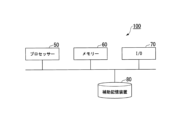
図1は、符号化装置100(映像符号化装置)の機能構成の概略を示す概略ブロック図である。符号化装置100は、例えばパーソナルコンピューターやサーバー装置等の情報処理装置を用いて構成される。図1に示す符号化装置100には、例えばVVC(Versatile Video Coding)が実装されてもよい。本発明の符号化装置100は、スプライト生成部10(暫定画像生成部)、サイズ変更部20(変換部)及び符号化部30(予測画像生成部)を備える。スプライト生成部10は、入力された映像信号に基づいて初期スプライト画像(暫定画像)を生成する。スプライト生成部10には、従来のスプライト画像の生成技術が適用されてもよい。スプライト生成部10によって生成される初期スプライト画像の大きさ(画素数)は、映像信号に含まれる符号化対象フレームよりも大きい。初期スプライト画像は、複数のフレームにより分割されて撮像されており、各フレームの前景の成分を除く若しくは削減した背景等が想定される。Embodiments of the encoding method of the present invention will be described in detail with reference to the drawings.
[Summary]
FIG. 1 is a schematic block diagram showing an outline of the functional configuration of an encoding device 100 (video encoding device). The
サイズ変更部20は、初期スプライト画像に対して画像処理を行うことによって変形スプライト画像を生成する。これは、HEVCまでではサポートされていなかったもののVVCでは画像処理(アフィン変換)を実装するため、作成した初期スプライト画像から所望のサイズの変形スプライト画像に変換することが可能になったためである。変形スプライト画像の大きさは、初期スプライト画像よりも小さい。変形スプライト画像の大きさは、例えば映像信号に含まれる符号化対象フレームの大きさと同じである。符号化部30は、変形スプライト画像を長期参照フレームとして適用し、映像信号に含まれる各符号化対象フレームを符号化する。
The resizing
このように、符号化装置100では、符号化対象フレームよりも大きい初期スプライト画像を生成し、初期スプライト画像を符号化対象フレームと同じ大きさに変形する。そのため、参照画像の画素数が符号化対象画像の画素数と同じであることが要求される符号化技術において符号化効率を向上させることが可能となる。以下、符号化装置100の詳細について説明する。
In this way, the
[詳細]
図2は、符号化装置100の処理の流れの具体例を示すフローチャートである。符号化装置100では、まずスプライト画像が生成される(ステップS101-NO)。具体的には、入力される映像信号(複数の符号化対象フレーム)に基づいてスプライト生成部10が初期スプライト画像を生成する(ステップS102)。スプライト生成部10が初期スプライト画像を生成する際に用いられる技術は、従来からあるスプライト画像の生成技術であってもよい。スプライト生成部10によって生成される初期スプライト画像の大きさ(画素数)は、映像信号に含まれる符号化対象フレームよりも大きい。[detail]
FIG. 2 is a flowchart showing a specific example of the processing flow of the
次に、サイズ変更部20は、初期スプライト画像に対してサイズ変更処理を含む画像処理を行うことによって、変形スプライト画像を生成する(ステップS103)。変形スプライト画像の大きさは、初期スプライト画像よりも小さい。変形スプライト画像の大きさは、例えば映像信号に含まれる符号化対象フレームと同じ大きさである。映像信号に含まれる符号化対象フレームが全て同じ大きさである場合には、これらの符号化対象フレームと変形スプライト画像とは全て同じ大きさとなる。
Next, the resizing
変形スプライト画像は、初期スプライト画像に含まれる全領域の画像を含むことが望ましい。そのため、変形スプライト画像の生成には、画像の縮小処理が用いられることが望ましい。また、変形スプライト画像の生成には、回転処理やせん断処理が用いられてもよい。この場合、変形スプライト画像の生成には、縮小画像と回転処理との組合せが用いられてもよいし、縮小画像とせん断処理との組合せが用いられてもよいし、縮小画像と回転処理とせん断処理との組合せが用いられてもよい。このような画像処理には、例えばアフィン変換が適用されてもよい。 It is desirable that the modified sprite image includes an image of the entire area included in the initial sprite image. Therefore, it is desirable to use image reduction processing to generate a modified sprite image. Further, rotation processing or shear processing may be used to generate the deformed sprite image. In this case, to generate the deformed sprite image, a combination of a reduced image and rotation processing may be used, a combination of a reduced image and shear processing may be used, or a combination of a reduced image and rotation processing and shear processing may be used. Combinations of treatments may also be used. For example, affine transformation may be applied to such image processing.
サイズ変更部20によって生成された変形スプライト画像は、符号化部30において長期参照フレーム(long-term reference)として用いられる。例えば、符号化部30に備えられるフレームメモリーにおいて、変形スプライト画像が長期参照フレームとして保存される(ステップS104)。
The modified sprite image generated by the resizing
長期参照フレームとして変形スプライト画像が保存された後は(ステップS101-YES)、入力される映像信号の各符号化対象フレームについて、長期参照フレームおよび既に復号済みで参照可能なフレームを用いて符号化処理が行われる。この符号化処理には、既存の符号化処理が適用されてもよい。本実施形態では、上述したようにVVCの符号化処理が適用される。具体的には、符号化部30は、長期参照フレームを用いて符号化対象フレームについて動き補償を行う(ステップS105)。符号化部30は、動き補償を行うことによって、符号化対象フレーム毎に予測画像を生成する。
After the modified sprite image is saved as a long-term reference frame (step S101-YES), each encoding target frame of the input video signal is encoded using the long-term reference frame and a frame that has already been decoded and can be referenced. Processing takes place. An existing encoding process may be applied to this encoding process. In this embodiment, VVC encoding processing is applied as described above. Specifically, the
符号化部30は、予測画像の生成において、初期スプライト画像を生成する際に用いられた符号化対象フレーム間の関係を利用して、変形スプライト画像における符号化対象領域に対応し、且つ、符号化対象領域の画素数と異なる画素数である参照領域を特定してもよい。符号化部30は、動き補償において、変形スプライト画像に対して変形処理を行ってもよい。変形処理とは、画像を変形する処理であり、例えば拡大縮小処理、回転処理、せん断処理などの処理である。このような変形処理はアフィン変換を用いて実行されてもよい。このような変形処理が行われるため、初期スプライト画像を縮小することで生成された変形スプライト画像を長期参照フレームとして用いても、スプライト画像を用いた場合と略同様の効果を得ることが可能となる。即ち、例えば縮小することで生成された変形スプライト画像であっても、初期スプライト画像と同じ大きさに拡大してから参照画像として用いられることで、初期スプライト画像を用いた場合と同様の効果を得ることができる。
In generating the predicted image, the
その後、符号化部30は、動き補償によって得られた予測信号と符号化対象フレームの映像信号とを減算することで予測残差信号を生成する。符号化部30は、予測残差信号に対し離散コサイン変換を行い(ステップS106)、量子化処理を行う(ステップS107)。そして、符号化部30は、量子化された予測残差信号に対して符号化処理を行うことで、符号化データを生成する(ステップS108)。
After that, the
図3は、符号化装置100のハードウェア構成の概略を示す図である。符号化装置100は、ハードウェア構成として、プロセッサー50、メモリー60、I/O70及び補助記憶装置80を備える。プロセッサー50は、メモリー60に記憶された符号化プログラムを実行することによって、スプライト生成部10、サイズ変更部20及び符号化部30として機能してもよい。メモリー60は、長期参照フレームを保持するメモリーとして機能してもよい。I/O70は、映像信号を入力したり、符号化データを出力したりしてもよい。補助記憶装置80は、映像信号を記憶したり、符号化データを記憶したりしてもよい。
FIG. 3 is a diagram schematically showing the hardware configuration of the
符号化プログラムは、コンピューター読み取り可能な記録媒体に記録されてもよい。コンピューター読み取り可能な記録媒体とは、例えばフレキシブルディスク、光磁気ディスク、ROM、CD-ROM等の可搬媒体、コンピューターシステムに内蔵されるハードディスク等の記憶装置などの非一時的な記憶媒体である。符号化プログラムは、電気通信回線を介して送信されてもよい。スプライト生成部10、サイズ変更部20及び符号化部30の動作の一部又は全部は、例えば、LSI、ASIC、PLD又はFPGA等を用いた電子回路を含むハードウェアを用いて実現されてもよい。
The encoded program may be recorded on a computer-readable recording medium. The computer-readable recording medium is a non-temporary storage medium such as a flexible disk, a magneto-optical disk, a ROM, a CD-ROM, or other portable medium, or a hard disk or other storage device built into a computer system. The encoded program may be transmitted via a telecommunications line. Part or all of the operations of the
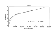
図4~図6は、本実施形態の符号化装置100と、従来の符号化装置との性能比較実験を行った結果を示す図である。実験用いられた映像は、カメラワークを含む実写映像Jets(1280x720,60Hz,先頭300フレーム)と、EBUKidsSoccer(8bit,4:2:0化、1920x1080,500フレーム、以後Soccer)である。初期スプライト画像の生成については、Jetsについては第300フレーム、Soccerについては第250フレームをキーフレームとした。Jetsはパン・ズームを含み、Soccerはパンが支配的である。初期スプライト画像は、全フレームが覆う領域について時間方向にメディアンフィルターを施すことで生成された。変形スプライト画像は、初期スプライト画像に対し、入力フレームサイズと同サイズに縦横変倍することで生成された。
4 to 6 are diagrams showing the results of a performance comparison experiment between the
符号化条件は以下の通りである。エンコーダーには、VVCの参照ソフトウェアVTM6.1が用いられた。符号化構造はLow Delay B、ベース量子化パラメータ(QP)は22,27,32,37である。デフォルト符号化設定で、アフィン動き補償の使用はon(Affine = 1)となっているが、これをより積極的に用いることを期待し、AffineAmvr= 1, AffineAmvrEncOpt = 1 と設定変更されている。まずスプライトをベースQP より10 小さいQP で長期参照フレームとして符号化し、続いて全入力シーケンスを符号化した。PSNRはスプライトを含まず評価し、符号量はスプライトを含み評価した。
The encoding conditions are as follows. The VVC reference software VTM6.1 was used as the encoder. The encoding structure is Low Delay B, and the base quantization parameters (QP) are 22, 27, 32, 37. In the default encoding settings, the use of affine motion compensation is on (Affine = 1), but in the hope that it will be used more actively, the settings have been changed to AffineAmvr = 1, AffineAmvrEncOpt = 1. We first encoded the sprite as a long-term reference frame with a
図4及び図5は、実験により得られたR-D曲線である。Soccerの高レート部で僅かな劣化が見られるが、これは画像縮小により拡大時PSNRに絶対限界が生じるためと考えられる。図6は、BD-Rate,相対符号化・復号時間を示す表である。Jetsでは32%、Soccerでは23%の符号量削減が実現できている。また、符号化時間は7~11%削減できている。復号時間は、プラスマイナス2%程度の変化に収まっていた。この結果は、スプライト画像を追加することによる符号化データの符号量の増加よりも、予測誤差の削減量の総和の方が大きくなる場合がある事を示している。 4 and 5 are R-D curves obtained through experiments. A slight deterioration is seen in the high rate portion of Soccer, but this is thought to be due to the fact that image reduction creates an absolute limit on PSNR when enlarged. FIG. 6 is a table showing BD-Rate and relative encoding/decoding times. A code amount reduction of 32% for Jets and 23% for Soccer was achieved. Furthermore, the encoding time can be reduced by 7 to 11%. The decoding time was within the range of plus or minus 2%. This result shows that the total amount of prediction error reduction may be larger than the increase in the code amount of encoded data due to the addition of sprite images.
以上説明したように、本実施形態の符号化装置100では、符号化対象フレームよりも大きい初期スプライト画像を生成し、初期スプライト画像を符号化対象フレームと同じ大きさに変形する。そのため、参照画像の画素数が符号化対象画像の画素数と同じであることが要求される符号化技術においても、スプライト画像を用いることの長所を得ることができる。その結果、符号化効率を向上させることが可能となる。
As described above, the
以上、この発明の実施形態について図面を参照して詳述してきたが、具体的な構成はこの実施形態に限られるものではなく、この発明の要旨を逸脱しない範囲の設計等も含まれる。 Although the embodiments of the present invention have been described above in detail with reference to the drawings, the specific configuration is not limited to these embodiments, and includes designs within the scope of the gist of the present invention.
本発明は、画像を符号化する技術に適用可能である。 The present invention is applicable to techniques for encoding images.
100…符号化装置、10…スプライト生成部、20…サイズ変更部、30…符号化部 100... Encoding device, 10... Sprite generation section, 20... Size changing section, 30... Encoding section
Claims (6)
生成された暫定画像を前記複数の符号化対象フレームと同じ画素数に変換する変換ステップと、
変換された画像を参照画像として用いて、前記符号化対象フレーム毎に予測画像を生成する予測画像生成ステップと、
を有し、
前記暫定画像生成ステップで生成された前記暫定画像は、前記符号化対象フレームよりも大きい画像であり、複数の符号化対象フレームの画像を含み、
前記予測画像生成ステップにおいて、前記変換ステップで前記複数の符号化対象フレームと同じ画素数に変換された前記暫定画像を、前記暫定画像生成ステップで生成された時点と同じ大きさに拡大してから前記参照画像として用いる、映像符号化方法。 a provisional image generation step of generating one sprite image as a provisional image from a plurality of frames to be encoded;
a conversion step of converting the generated provisional image to the same number of pixels as the plurality of encoding target frames;
a predicted image generation step of generating a predicted image for each encoding target frame using the converted image as a reference image;
has
The provisional image generated in the provisional image generation step is an image larger than the encoding target frame, and includes images of a plurality of encoding target frames,
In the predicted image generation step, the provisional image converted to the same number of pixels as the plurality of frames to be encoded in the conversion step is enlarged to the same size as when it was generated in the provisional image generation step, and then A video encoding method used as the reference image.
生成された暫定画像を前記複数の符号化対象フレームと同じ画素数に変換する変換部と、
変換された画像を参照画像として用いて、前記符号化対象フレーム毎に予測画像を生成する予測画像生成部と、
を備え、
前記暫定画像生成部によって生成された前記暫定画像は、前記符号化対象フレームよりも大きい画像であり、複数の符号化対象フレームの画像を含み、
前記予測画像生成部は、前記変換部によって前記複数の符号化対象フレームと同じ画素数に変換された前記暫定画像を、前記暫定画像生成部によって生成された時点と同じ大きさに拡大してから前記参照画像として用いる、映像符号化装置。 a temporary image generation unit that generates one sprite image as a temporary image from a plurality of frames to be encoded;
a conversion unit that converts the generated provisional image into the same number of pixels as the plurality of encoding target frames;
a predicted image generation unit that generates a predicted image for each encoding target frame using the converted image as a reference image;
Equipped with
The provisional image generated by the provisional image generation unit is an image larger than the encoding target frame, and includes images of a plurality of encoding target frames,
The predicted image generation unit enlarges the provisional image, which has been converted by the conversion unit to have the same number of pixels as the plurality of frames to be encoded, to the same size as when it was generated by the provisional image generation unit, and then A video encoding device used as the reference image.
Applications Claiming Priority (1)
| Application Number | Priority Date | Filing Date | Title |
|---|---|---|---|
| PCT/JP2019/044904 WO2021095242A1 (en) | 2019-11-15 | 2019-11-15 | Video encoding method, video encoding device and computer program |
Publications (2)
| Publication Number | Publication Date |
|---|---|
| JPWO2021095242A1 JPWO2021095242A1 (en) | 2021-05-20 |
| JP7397360B2 true JP7397360B2 (en) | 2023-12-13 |
Family
ID=75911415
Family Applications (1)
| Application Number | Title | Priority Date | Filing Date |
|---|---|---|---|
| JP2021555756A Active JP7397360B2 (en) | 2019-11-15 | 2019-11-15 | Video encoding method, video encoding device and computer program |
Country Status (3)
| Country | Link |
|---|---|
| US (1) | US20220377356A1 (en) |
| JP (1) | JP7397360B2 (en) |
| WO (1) | WO2021095242A1 (en) |
Citations (6)
| Publication number | Priority date | Publication date | Assignee | Title |
|---|---|---|---|---|
| JP2012120244A (en) | 1997-02-13 | 2012-06-21 | Mitsubishi Electric Corp | Moving image encoder, moving image encoding method, and moving image prediction device |
| JP2013509763A (en) | 2009-10-29 | 2013-03-14 | シコラ,トマス | Method and apparatus for processing video sequences |
| JP2014527736A (en) | 2011-07-18 | 2014-10-16 | トムソン ライセンシングThomson Licensing | Method and apparatus for encoding orientation vectors of connected components, corresponding decoding method and apparatus, and storage medium carrying such encoded data |
| JP2015180040A (en) | 2014-03-18 | 2015-10-08 | パナソニックIpマネジメント株式会社 | Prediction image generating method, image encoding method, image decoding method and prediction image generating device |
| JP2016096502A (en) | 2014-11-17 | 2016-05-26 | 株式会社東芝 | Image coding device, image decoding device and image transmission method |
| JP2017092886A (en) | 2015-11-17 | 2017-05-25 | 日本電信電話株式会社 | Video encoding method, video encoder and video encoding program |
Family Cites Families (5)
| Publication number | Priority date | Publication date | Assignee | Title |
|---|---|---|---|---|
| JP2952226B2 (en) * | 1997-02-14 | 1999-09-20 | 日本電信電話株式会社 | Predictive encoding method and decoding method for video, recording medium recording video prediction encoding or decoding program, and recording medium recording video prediction encoded data |
| TWI246338B (en) * | 2004-04-09 | 2005-12-21 | Asustek Comp Inc | A hybrid model sprite generator and a method to form a sprite |
| JP2010500818A (en) * | 2006-08-08 | 2010-01-07 | デジタル メディア カートリッジ,リミティド | System and method for comic animation compression |
| JP2010124397A (en) * | 2008-11-21 | 2010-06-03 | Toshiba Corp | Resolution enhancement device |
| US20220272378A1 (en) * | 2019-06-23 | 2022-08-25 | Sharp Kabushiki Kaisha | Systems and methods for performing an adaptive resolution change in video coding |
-
2019
- 2019-11-15 JP JP2021555756A patent/JP7397360B2/en active Active
- 2019-11-15 WO PCT/JP2019/044904 patent/WO2021095242A1/en active Application Filing
- 2019-11-15 US US17/773,987 patent/US20220377356A1/en active Pending
Patent Citations (6)
| Publication number | Priority date | Publication date | Assignee | Title |
|---|---|---|---|---|
| JP2012120244A (en) | 1997-02-13 | 2012-06-21 | Mitsubishi Electric Corp | Moving image encoder, moving image encoding method, and moving image prediction device |
| JP2013509763A (en) | 2009-10-29 | 2013-03-14 | シコラ,トマス | Method and apparatus for processing video sequences |
| JP2014527736A (en) | 2011-07-18 | 2014-10-16 | トムソン ライセンシングThomson Licensing | Method and apparatus for encoding orientation vectors of connected components, corresponding decoding method and apparatus, and storage medium carrying such encoded data |
| JP2015180040A (en) | 2014-03-18 | 2015-10-08 | パナソニックIpマネジメント株式会社 | Prediction image generating method, image encoding method, image decoding method and prediction image generating device |
| JP2016096502A (en) | 2014-11-17 | 2016-05-26 | 株式会社東芝 | Image coding device, image decoding device and image transmission method |
| JP2017092886A (en) | 2015-11-17 | 2017-05-25 | 日本電信電話株式会社 | Video encoding method, video encoder and video encoding program |
Non-Patent Citations (1)
| Title |
|---|
| J. Samuelsson, S. Deshpande, A. Segall,AHG8: Adaptive Resolution Change (ARC) with downsampling [online],Joint Video Experts Team (JVET) of ITU-T SG 16 WP 3 and ISO/IEC JTC 1/SC 29/WG 11,JVET-O0240-v1,2019年07月05日 |
Also Published As
| Publication number | Publication date |
|---|---|
| JPWO2021095242A1 (en) | 2021-05-20 |
| WO2021095242A1 (en) | 2021-05-20 |
| US20220377356A1 (en) | 2022-11-24 |
Similar Documents
| Publication | Publication Date | Title |
|---|---|---|
| JP4641892B2 (en) | Moving picture encoding apparatus, method, and program | |
| JPS62203496A (en) | Highly efficient encoding system for animation picture signal | |
| US10721485B2 (en) | Image coding apparatus, image coding method, and non-transitory computer-readable storage medium | |
| JP2006229411A (en) | Image decoder and image decoding method | |
| US8761246B2 (en) | Encoding/decoding device, encoding/decoding method and storage medium | |
| JP6480310B2 (en) | Video encoding method, video encoding apparatus, and video encoding program | |
| JP2007013298A (en) | Image coding apparatus | |
| CN106028031B (en) | Video encoding device and method, video decoding device and method | |
| JP2007228077A (en) | Moving picture coding apparatus and control method thereof, computer program, and storage medium | |
| Liu et al. | Neural video compression using spatio-temporal priors | |
| JP5294688B2 (en) | Video compression encoding device | |
| JP2008306510A (en) | Image coding method, image coding device, image decoding method and image decoding device | |
| JP5943733B2 (en) | Image encoding apparatus, control method therefor, and program | |
| JP7397360B2 (en) | Video encoding method, video encoding device and computer program | |
| KR20110024574A (en) | Integrated video encoding method and apparatus | |
| US8306110B2 (en) | Moving image coding apparatus and method using copy pictures depending on virtual buffer verifier occupancy | |
| JP7359653B2 (en) | Video encoding device | |
| JP5189618B2 (en) | Video encoding method, video encoding apparatus, and video encoding program | |
| KR100987922B1 (en) | Frame based reference frame fate distortion optimization using Motion Blur/Deblur post filter | |
| WO2013111747A1 (en) | Video encoding method, device, and program | |
| JP5355234B2 (en) | Encoding apparatus and encoding method | |
| JP2005323315A (en) | Prediction information/quantization value control compression coding apparatus, program, and method | |
| JP2005236723A (en) | Device and method for encoding moving image, and device and method for decoding the moving image | |
| JP5094750B2 (en) | Moving picture coding apparatus and moving picture coding method | |
| JP4878047B2 (en) | Video encoding method, video decoding method, video encoding device, video decoding device, video encoding program, video decoding program, and recording medium thereof |
Legal Events
| Date | Code | Title | Description |
|---|---|---|---|
| A621 | Written request for application examination |
Free format text: JAPANESE INTERMEDIATE CODE: A621 Effective date: 20220303 |
|
| A131 | Notification of reasons for refusal |
Free format text: JAPANESE INTERMEDIATE CODE: A131 Effective date: 20230411 |
|
| A521 | Request for written amendment filed |
Free format text: JAPANESE INTERMEDIATE CODE: A523 Effective date: 20230612 |
|
| A131 | Notification of reasons for refusal |
Free format text: JAPANESE INTERMEDIATE CODE: A131 Effective date: 20230815 |
|
| A521 | Request for written amendment filed |
Free format text: JAPANESE INTERMEDIATE CODE: A523 Effective date: 20231016 |
|
| TRDD | Decision of grant or rejection written | ||
| A01 | Written decision to grant a patent or to grant a registration (utility model) |
Free format text: JAPANESE INTERMEDIATE CODE: A01 Effective date: 20231031 |
|
| A61 | First payment of annual fees (during grant procedure) |
Free format text: JAPANESE INTERMEDIATE CODE: A61 Effective date: 20231113 |
|
| R150 | Certificate of patent or registration of utility model |
Ref document number: 7397360 Country of ref document: JP Free format text: JAPANESE INTERMEDIATE CODE: R150 |