JP7395365B2 - Image forming device - Google Patents
Image forming device Download PDFInfo
- Publication number
- JP7395365B2 JP7395365B2 JP2020008682A JP2020008682A JP7395365B2 JP 7395365 B2 JP7395365 B2 JP 7395365B2 JP 2020008682 A JP2020008682 A JP 2020008682A JP 2020008682 A JP2020008682 A JP 2020008682A JP 7395365 B2 JP7395365 B2 JP 7395365B2
- Authority
- JP
- Japan
- Prior art keywords
- image data
- mode
- density
- print mode
- color gamut
- Prior art date
- Legal status (The legal status is an assumption and is not a legal conclusion. Google has not performed a legal analysis and makes no representation as to the accuracy of the status listed.)
- Active
Links
- 238000012546 transfer Methods 0.000 claims description 46
- 238000001514 detection method Methods 0.000 claims description 43
- 238000012937 correction Methods 0.000 description 36
- 238000004364 calculation method Methods 0.000 description 28
- 238000010586 diagram Methods 0.000 description 24
- 238000006243 chemical reaction Methods 0.000 description 22
- 230000008859 change Effects 0.000 description 20
- 238000000034 method Methods 0.000 description 20
- 230000000052 comparative effect Effects 0.000 description 14
- 239000000463 material Substances 0.000 description 14
- 238000011161 development Methods 0.000 description 12
- 230000002093 peripheral effect Effects 0.000 description 11
- 230000008569 process Effects 0.000 description 11
- 238000012545 processing Methods 0.000 description 11
- 230000005684 electric field Effects 0.000 description 10
- 238000005259 measurement Methods 0.000 description 9
- 230000015572 biosynthetic process Effects 0.000 description 6
- 239000000123 paper Substances 0.000 description 6
- 230000001105 regulatory effect Effects 0.000 description 6
- 239000000969 carrier Substances 0.000 description 5
- 230000000875 corresponding effect Effects 0.000 description 4
- 238000004140 cleaning Methods 0.000 description 3
- 239000003086 colorant Substances 0.000 description 3
- 238000013213 extrapolation Methods 0.000 description 3
- 230000032258 transport Effects 0.000 description 3
- 230000001276 controlling effect Effects 0.000 description 2
- 230000006870 function Effects 0.000 description 2
- 239000002699 waste material Substances 0.000 description 2
- 238000005299 abrasion Methods 0.000 description 1
- XAGFODPZIPBFFR-UHFFFAOYSA-N aluminium Chemical compound [Al] XAGFODPZIPBFFR-UHFFFAOYSA-N 0.000 description 1
- 229910052782 aluminium Inorganic materials 0.000 description 1
- 238000004891 communication Methods 0.000 description 1
- 239000004020 conductor Substances 0.000 description 1
- 230000002596 correlated effect Effects 0.000 description 1
- 238000001739 density measurement Methods 0.000 description 1
- 230000006866 deterioration Effects 0.000 description 1
- 230000000694 effects Effects 0.000 description 1
- 230000007613 environmental effect Effects 0.000 description 1
- 238000010438 heat treatment Methods 0.000 description 1
- 238000009434 installation Methods 0.000 description 1
- 230000001678 irradiating effect Effects 0.000 description 1
- 239000004973 liquid crystal related substance Substances 0.000 description 1
- 239000011159 matrix material Substances 0.000 description 1
- 230000007246 mechanism Effects 0.000 description 1
- 239000002245 particle Substances 0.000 description 1
- 229920006395 saturated elastomer Polymers 0.000 description 1
- 230000002123 temporal effect Effects 0.000 description 1
Images


Classifications
-
- G—PHYSICS
- G03—PHOTOGRAPHY; CINEMATOGRAPHY; ANALOGOUS TECHNIQUES USING WAVES OTHER THAN OPTICAL WAVES; ELECTROGRAPHY; HOLOGRAPHY
- G03G—ELECTROGRAPHY; ELECTROPHOTOGRAPHY; MAGNETOGRAPHY
- G03G15/00—Apparatus for electrographic processes using a charge pattern
- G03G15/50—Machine control of apparatus for electrographic processes using a charge pattern, e.g. regulating differents parts of the machine, multimode copiers, microprocessor control
- G03G15/5054—Machine control of apparatus for electrographic processes using a charge pattern, e.g. regulating differents parts of the machine, multimode copiers, microprocessor control by measuring the characteristics of an intermediate image carrying member or the characteristics of an image on an intermediate image carrying member, e.g. intermediate transfer belt or drum, conveyor belt
- G03G15/5058—Machine control of apparatus for electrographic processes using a charge pattern, e.g. regulating differents parts of the machine, multimode copiers, microprocessor control by measuring the characteristics of an intermediate image carrying member or the characteristics of an image on an intermediate image carrying member, e.g. intermediate transfer belt or drum, conveyor belt using a test patch
-
- G—PHYSICS
- G03—PHOTOGRAPHY; CINEMATOGRAPHY; ANALOGOUS TECHNIQUES USING WAVES OTHER THAN OPTICAL WAVES; ELECTROGRAPHY; HOLOGRAPHY
- G03G—ELECTROGRAPHY; ELECTROPHOTOGRAPHY; MAGNETOGRAPHY
- G03G15/00—Apparatus for electrographic processes using a charge pattern
- G03G15/01—Apparatus for electrographic processes using a charge pattern for producing multicoloured copies
- G03G15/0105—Details of unit
- G03G15/0131—Details of unit for transferring a pattern to a second base
-
- G—PHYSICS
- G03—PHOTOGRAPHY; CINEMATOGRAPHY; ANALOGOUS TECHNIQUES USING WAVES OTHER THAN OPTICAL WAVES; ELECTROGRAPHY; HOLOGRAPHY
- G03G—ELECTROGRAPHY; ELECTROPHOTOGRAPHY; MAGNETOGRAPHY
- G03G15/00—Apparatus for electrographic processes using a charge pattern
- G03G15/01—Apparatus for electrographic processes using a charge pattern for producing multicoloured copies
- G03G15/0142—Structure of complete machines
- G03G15/0178—Structure of complete machines using more than one reusable electrographic recording member, e.g. one for every monocolour image
- G03G15/0194—Structure of complete machines using more than one reusable electrographic recording member, e.g. one for every monocolour image primary transfer to the final recording medium
-
- G—PHYSICS
- G03—PHOTOGRAPHY; CINEMATOGRAPHY; ANALOGOUS TECHNIQUES USING WAVES OTHER THAN OPTICAL WAVES; ELECTROGRAPHY; HOLOGRAPHY
- G03G—ELECTROGRAPHY; ELECTROPHOTOGRAPHY; MAGNETOGRAPHY
- G03G15/00—Apparatus for electrographic processes using a charge pattern
- G03G15/50—Machine control of apparatus for electrographic processes using a charge pattern, e.g. regulating differents parts of the machine, multimode copiers, microprocessor control
- G03G15/5033—Machine control of apparatus for electrographic processes using a charge pattern, e.g. regulating differents parts of the machine, multimode copiers, microprocessor control by measuring the photoconductor characteristics, e.g. temperature, or the characteristics of an image on the photoconductor
- G03G15/5041—Detecting a toner image, e.g. density, toner coverage, using a test patch
-
- G—PHYSICS
- G03—PHOTOGRAPHY; CINEMATOGRAPHY; ANALOGOUS TECHNIQUES USING WAVES OTHER THAN OPTICAL WAVES; ELECTROGRAPHY; HOLOGRAPHY
- G03G—ELECTROGRAPHY; ELECTROPHOTOGRAPHY; MAGNETOGRAPHY
- G03G2215/00—Apparatus for electrophotographic processes
- G03G2215/00025—Machine control, e.g. regulating different parts of the machine
- G03G2215/00029—Image density detection
- G03G2215/00033—Image density detection on recording member
- G03G2215/00037—Toner image detection
- G03G2215/00042—Optical detection
-
- G—PHYSICS
- G03—PHOTOGRAPHY; CINEMATOGRAPHY; ANALOGOUS TECHNIQUES USING WAVES OTHER THAN OPTICAL WAVES; ELECTROGRAPHY; HOLOGRAPHY
- G03G—ELECTROGRAPHY; ELECTROPHOTOGRAPHY; MAGNETOGRAPHY
- G03G2215/00—Apparatus for electrophotographic processes
- G03G2215/00025—Machine control, e.g. regulating different parts of the machine
- G03G2215/00029—Image density detection
- G03G2215/00059—Image density detection on intermediate image carrying member, e.g. transfer belt
-
- G—PHYSICS
- G03—PHOTOGRAPHY; CINEMATOGRAPHY; ANALOGOUS TECHNIQUES USING WAVES OTHER THAN OPTICAL WAVES; ELECTROGRAPHY; HOLOGRAPHY
- G03G—ELECTROGRAPHY; ELECTROPHOTOGRAPHY; MAGNETOGRAPHY
- G03G2215/00—Apparatus for electrophotographic processes
- G03G2215/00025—Machine control, e.g. regulating different parts of the machine
- G03G2215/00029—Image density detection
- G03G2215/00063—Colour
Description
本発明は、複数の画像形成モードを有することを特徴とする画像形成装置に関するものである。 The present invention relates to an image forming apparatus characterized by having a plurality of image forming modes.
画像形成装置における画質指標の一つとして色域(Color Gamut)が存在する。画像形成装置における色域とは画像形成装置が出力可能な色再現範囲のことであり、色域が広いほど色再現範囲が広く画像形成装置として優位であることを意味する。色域を拡大する手法としては、YMCKの4色の現像剤に加えて濃いYMCKの現像剤を別途追加する手法や、記録材上の現像剤量を増やす等の手法が考えられる。特許文献1には、様々な印字モードにおいて良好な印刷を行うための画像形成装置が記載されている。
Color gamut exists as one of the image quality indicators in an image forming apparatus. The color gamut of an image forming apparatus refers to the color reproduction range that the image forming apparatus can output, and the wider the color gamut, the wider the color reproduction range, which means that the image forming apparatus is advantageous. Possible methods for expanding the color gamut include adding a dark YMCK developer separately in addition to the four YMCK color developers, and increasing the amount of developer on the recording material.
また、従来、基準となる基準画像形成モードとは別にプロセス速度を低下させる別の画像形成モードを有する構成が提案されている。別の画像形成モードとは例えば、厚紙モード等である。このような、複数の画像形成モードを有する構成では、実測された基準画像形成モードにおける濃度情報から、演算によって別の画像形成モードにおける濃度を算出することが提案されている。これによりダウンタイムの追加なく別の画像形成モードにおける色味調整が可能になる。 Furthermore, conventionally, a configuration has been proposed that has an image forming mode that lowers the process speed in addition to the reference image forming mode that serves as a reference. Another image forming mode is, for example, a cardboard mode. In such a configuration having a plurality of image forming modes, it has been proposed to calculate the density in another image forming mode by calculation from actually measured density information in the reference image forming mode. This makes it possible to adjust the tint in another image forming mode without additional downtime.
しかしながら、上述したような複数の画像形成モードを有する構成では、以下のような課題がある。すなわち、基準画像形成モードにおいて濃度0と実測された入力画像データの中には、別の画像形成モードでも濃度0と実測される入力画像データもあれば、0以外の値を検知する入力画像データもある。そこで、上述したような複数の画像形成モードを有する構成において、高濃度部の算出結果からの外挿によって低濃度部の濃度を算出している。 However, the configuration having a plurality of image forming modes as described above has the following problems. That is, some input image data whose density is actually measured as 0 in the standard image forming mode may also be input image data whose density is actually measured as 0 in another image forming mode, and input image data for which a value other than 0 is detected. There is also. Therefore, in the configuration having a plurality of image forming modes as described above, the density of the low density part is calculated by extrapolation from the calculation result of the high density part.
図20は、外挿によって高濃度部の算出結果から低濃度部の濃度を算出する方法のイメージ図を記す。縦軸は濃度(OD)を示し、横軸は画像データの値を16進数で示す。
ここで、ある濃度の境界700を想定したときに、実測された濃度が境界700付近の値となるような画像データI1について考える。画像データ値がI1のとき、通常プリントモードにて形成された画像の濃度の実測値がD1だったとする。これを、実測結果701aとしてプロットする。この実測結果701aに基づいて、広色域プリントモードの濃度算出結果である算出点701bを算出する。続いて同様に、画像データ値がI2のとき、形成画像の濃度の実測値がD2だったとして、実測結果702aをプロットする。そして実測結果702aから、算出点702bを算出する。
そして、算出点701bおよび702bより、近似直線703aを算出する。この近似直線703aと、低濃度部LDに対応する画像データの値より、算出点704、705、706、707を算出する。
FIG. 20 shows an image diagram of a method of calculating the density of a low density part from the calculation result of a high density part by extrapolation. The vertical axis shows density (OD), and the horizontal axis shows the value of image data in hexadecimal.
Here, when assuming a
Then, an approximate
しかし、実測結果701aおよび702aから算出点701b、702bを算出する際には、各実測結果の上下のヒゲで示された範囲の誤差が含まれる。その誤差によって近似
直線は703bから703cまで変化しうる。この近似直線の変化により、算出点704、705、706、707にはそれぞれ、各算出結果の上下のヒゲで示された範囲の誤差が含まれる可能性がある。この誤差は、低濃度部LDにおける通常プリントモード時の濃度実測結果から広色域プリントモードにおける濃度を算出する際に発生する誤差と比べると、大きくなる。このような誤差は、画像データが小さくなり近似直線を算出した算出点701bから画像データが離れるにつれて、更に大きくなってしまう。
However, when calculating the
本発明は上記課題を解決するため、基準となる画像形成モードとは色域が異なる別の画像形成モードで画像形成可能な構成において、ダウンタイムを長期化させることなく画像の色味の誤差を低減させることを目的とする。 In order to solve the above-mentioned problems, the present invention eliminates errors in image color tone without prolonging downtime in a configuration that can form an image in a different image forming mode with a different color gamut from the standard image forming mode. The purpose is to reduce
本発明は、以下の構成を採用する。すなわち、
第1の色域で画像形成を行う第1のモードと、前記第1の色域と異なる第2の色域で画像形成を行う第2のモードで動作する、画像形成装置であって、
感光ドラムと、
前記感光ドラムを露光して静電潜像を形成する露光手段と、
前記露光手段によって前記感光ドラムに形成された前記静電潜像をトナーにより現像してトナー像を形成する現像ローラと、
前記現像ローラによって前記感光ドラムに形成された前記トナー像が転写される中間転写体と、
前記中間転写体に転写された前記トナー像の濃度を検知する濃度検知手段と、
入力される入力画像データの値に基づいて前記トナー像の濃度を調整する制御手段と、を備え、
前記制御手段は、前記第2のモードを実行する場合における前記現像ローラの前記感光ドラムに対する周速比が、前記第1のモードにおける前記周速比よりも大きくなるように制御し、
前記入力画像データのうち、形成される画像の濃度が低濃度域の側となるような少なくとも一部の入力画像データに関しては、前記第1のモードにより形成される前記トナー像の濃度が、前記第2のモードにより形成される前記トナー像の濃度よりも大きいことを特徴とする画像形成装置である。
The present invention employs the following configuration. That is,
An image forming apparatus that operates in a first mode that forms an image in a first color gamut and a second mode that forms an image in a second color gamut that is different from the first color gamut,
photosensitive drum,
exposure means for exposing the photosensitive drum to form an electrostatic latent image;
a developing roller that develops the electrostatic latent image formed on the photosensitive drum by the exposure means with toner to form a toner image;
an intermediate transfer member to which the toner image formed on the photosensitive drum by the developing roller is transferred;
density detection means for detecting the density of the toner image transferred to the intermediate transfer body;
control means for adjusting the density of the toner image based on the value of the input image data that is input,
The control means controls a circumferential speed ratio of the developing roller to the photosensitive drum when executing the second mode to be larger than the circumferential speed ratio in the first mode,
Among the input image data, at least some of the input image data in which the density of the image to be formed is on the low density range side, the density of the toner image formed in the first mode is , the image forming apparatus is characterized in that the density of the toner image formed in the second mode is higher than that of the toner image formed in the second mode.
本発明によれば、基準となる画像形成モードとは色域が異なる別の画像形成モードで画像形成可能な構成において、ダウンタイムを長期化させることなく画像の色味の誤差を低減させることができる。 According to the present invention, in a configuration in which an image can be formed in a different image forming mode with a different color gamut from the standard image forming mode, it is possible to reduce errors in image color without prolonging downtime. can.
以下に図面を参照しつつ、本発明の好適な実施の形態について説明する。ただし、以下に記載されている構成部品の寸法、材質、形状およびそれらの相対配置などは、発明が適用される装置の構成や各種条件により適宜変更されるべきものである。よって、この発明の範囲を以下の記載に限定する趣旨のものではない。 Preferred embodiments of the present invention will be described below with reference to the drawings. However, the dimensions, materials, shapes, and relative arrangement of the components described below should be changed as appropriate depending on the configuration of the device to which the invention is applied and various conditions. Therefore, the scope of the present invention is not intended to be limited to the following description.
[実施例1]
(画像形成装置の概略構成)
図1は本実施例の画像形成装置200の概略構成図である。画像形成装置200は、インライン方式、中間転写方式を採用したフルカラーレーザープリンタである。不図示のホストPCから、制御手段であるコントローラ(ビデオコントローラ)201を介しエンジンコントローラ202に入力される画像情報に従って、画像形成装置200は記録材203にフルカラー画像を形成する。本実施例では、基準画像形成モードが通常プリントモードであり、濃度可変画像形成モードが広色域プリントモードである。
[Example 1]
(Schematic configuration of image forming apparatus)
FIG. 1 is a schematic configuration diagram of an
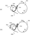
画像形成装置200は、色毎に画像形成ステーションSY、SM、SC、SKを有する。例としてイエローにおける画像形成ステーションSYを図2に記す。画像形成ステーションSYは、プロセスカートリッジ204Yと、図示矢印A方向に回転する中間転写ベルト205と、中間転写ベルト205を介してプロセスカートリッジ204Yと反対側に配置されている1次転写ローラ206Yから構成される。各画像形成ステーションSY、SM、SC、SKは中間転写ベルト205の回転方向に並んで配置されており、形成する色が異なることを除いて実質的に同じである。従って、以下、特に区別を要しない場合はいずれかの色用に設けられた要素であることを表すための添え字Y、M、C、Kは省略して総括的に説明する。
The
プロセスカートリッジ204は像担持体としての感光ドラム301を有する。感光ドラム301は不図示の駆動手段により図示矢印B方向に回転駆動される。帯電ローラ302は不図示の高圧電源から高圧を印加されることで感光ドラム301表面を均一に帯電する。次に、露光手段としてのスキャナユニット207がエンジンコントローラ202に入力される画像情報を元に感光ドラム301へレーザを照射し、感光ドラム301表面に静電潜像を形成する。現像剤供給手段としての現像ローラ303は不図示の駆動手段によって図示矢印C方向に回転しており、表面にコートされた電荷を帯びた現像剤としてのトナーが感光ドラム301表面の静電潜像に沿って付着することで静電潜像が可視像になる。以下、トナーによる可視像をトナー像と表記する。感光ドラム301の基層は接地されており、1次転写ローラ206は不図示の高圧電源によりトナーと逆極性の電圧が印加されている。そのため1次転写ローラ206と感光ドラム301の間のニップで転写電界が形成され、トナー像が感光ドラム301から、中間転写体としての中間転写ベルト205へ転写される。転写しきれず感光ドラム301表面に残ったトナーはドラムクリーニングブレード304によって感光ドラム301から除去され、廃トナー容器305に集められる。
The process cartridge 204 has a
トナー補給ローラ306は図示矢印D方向に回転することで現像ローラ303へトナーの補給を行い、攪拌機307は図示矢印E方向に回転することでトナー補給ローラ306へトナーの補給を行う。トナー規制ブレード308は固定されているため、現像ローラ303は自身の回転によりトナー規制ブレード308と摺擦する。現像ローラ303表面にコートされたトナーはこの摺擦部で帯電しながら量を規制され、その結果濃度の安定した現像が可能になる。以降、現像ローラ303、攪拌機307、トナー補給ローラ306、トナー規制ブレード308からなる構成をまとめて現像ユニット309と呼ぶ。また、感光ドラム301、帯電ローラ302、ドラムクリーニングブレード304、廃トナー容器305、からなる構成をまとめてドラムユニット310と呼ぶ。
The toner replenishing roller 306 replenishes toner to the developing
中間転写ベルト205が図示矢印A方向に回転することで、各色の画像ステーションSで生成されたトナー像が中間転写ベルト205上に形成され搬送される。給紙カセット208には記録材203が積載収納されている。給紙スタート信号に基づき給紙ローラ209が駆動されることで記録材203は給紙される。記録材203はレジストローラ対210を介して2次転写ローラ211と2次転写対向ローラ212の当接ニップ部に所定のタイミングで搬送される。具体的には、中間転写ベルト205上のトナー像先端部と記録材203の先端部が重なるタイミングで記録材203は搬送される。
As the
記録材203が2次転写ローラ211と2次転写対向ローラ212の間で狭持搬送される間、2次転写ローラ211には不図示の電源装置からトナーと逆極性の電圧が印加される。2次転写対向ローラ212が接地されているため、2次転写ローラ211と2次転写対向ローラ212の間には転写電界が形成される。この転写電界により中間転写ベルト205から記録材203へとトナー像が転写する。記録材203は2次転写ローラ211と2次転写対向ローラ212の間のニップを通過した後、定着装置213にて加熱及び加圧処理を受ける。これにより記録材203上のトナー像は記録材203に定着する。その後、記録材203が排紙口214から排紙トレイ215へ搬送され、画像形成プロセスが完了となる。一方、2次転写部で転写しきれなかった中間転写ベルト205上のトナーはクリーニング部材216にて中間転写ベルト205から除去され、中間転写ベルト205は再び画像形成が可能な状態にリフレッシュする。
While the
(制御ブロック図)
図18に、本実施例における画像形成装置のハードウェアブロック図を示す。画像形成装置200のエンジンコントローラ202には、各種算出処理を行ったり、後述するフローチャートにおける各種処理を実行したり、各周辺ユニットに指令を出力するCPU2021が備えられている。また、モータ等の駆動手段2026や高圧電源2025の制御に必要な情報が格納された装置本体側のメモリ2022等も備えられている。さらに、プロセスカートリッジ204のメモリm1に格納された情報は、メモリ通信部2028、入出力I/F2023を介してCPU2021に入力され読み取られる。各周辺ユニットへの
指令出力及び各周辺ユニットへの情報出力は入出力I/F2023を介してCPU202
1により行われる。またコントローラ201とエンジンコントローラ202との間の情報の授受や、ディスプレイ等の外部装置の情報の授受は外部I/F2024を介してCPU
2021により行われる。また、図中の画像形成部は、図1で説明した、スキャナユニット207、プロセスカートリッジ204、中間転写ベルト205、定着装置213、それらを動作させるための機械ギアの総称を指すものとする。また、高圧電源2025、駆動手段(モータ駆動部)2026を画像形成部の一部と解釈することもできる。なお、先の図1で説明したコントローラ201のブロック構成も、エンジンコントローラ202のそれと同様とする。
(Control block diagram)
FIG. 18 shows a hardware block diagram of the image forming apparatus in this embodiment. The
1. In addition, the exchange of information between the
It will be carried out by 2021. Furthermore, the image forming section in the figure is a general term for the
(感光ドラム層構成)
図3に感光ドラム301の層構成を示す。感光ドラム301の主な構成は下層から、ア
ルミニウム等の導電性材料からなるドラム基体311、光の干渉を抑え上層の接着性を向上させる下引き層312、キャリアを生成する電荷発生層313、発生したキャリアを輸送する電荷輸送層314、からなる。ドラム基体311は接地されており、感光ドラム301表面が帯電ローラ302により帯電することで感光ドラム301内側から外側に向けた電界が形成される。スキャナユニット207による光が感光ドラム301に照射されると電荷発生層313でキャリアが生成される。このキャリアは上記の電界により移動し、感光ドラム301表面の電荷と対になることで感光ドラム301の表面電位を変化させる。
(Photosensitive drum layer configuration)
FIG. 3 shows the layer structure of the
本構成では、第1のモードとしての通常プリントモードに加えて、第2のモードとしての広色域プリントモードを持つ。広色域プリントモードは通常プリントモードに対して色域を広げるためのプリントモードである。これは感光ドラム301上のトナー量を通常プリントモードに比べて大きくすることで実現する。感光ドラム301上のトナー量を増やすため、本実施例では現像ローラ303の感光ドラム301に対する周速比及び電位設定を最適化する。
This configuration has a wide color gamut print mode as a second mode in addition to a normal print mode as a first mode. The wide color gamut print mode is a print mode for widening the color gamut compared to the normal print mode. This is achieved by increasing the amount of toner on the
(現像ローラの周速の違いとトナー供給量)
周速比と感光ドラム301上トナー量の関係について図4を用いて説明する。図4(a)は通常プリントモードにおける単位時間内の現像ローラ303から感光ドラム301への現像量を表している。現像ローラ303は回転方向Cの方向に回転しており、表面にトナーがコーティングされている。感光ドラム301は回転方向Bの方向に回転しており現像ローラ303と当接している。トナー規制ブレード308により規制されたトナーは現像ローラ303と感光ドラム301のニップ部で現像ローラ303から感光ドラム301へ現像される。
(Difference in circumferential speed of developing roller and toner supply amount)
The relationship between the peripheral speed ratio and the amount of toner on the
ここで、現像ローラ303の周速をVan、感光ドラム301の周速をVbn、単位時間で現像した現像ローラ303表面の長さをLan、単位時間で現像された感光ドラム301表面の長さをLbn、とする。これらのパラメータ間には、式(1)の関係がある。
Van/Vbn=Lan/Lbn …(1)
広色域プリントモードにおいても通常プリントモードと同様に、現像ローラ303の周速をVaw、感光ドラム301の周速をVbw、単位時間で現像した現像ローラ303表面の長さをLaw、単位時間で現像された感光ドラム301表面の長さをLbw、と定義し、図4(b)に表す。この場合も、式(2)の関係になる。
Vaw/Vbw=Law/Lbw …(2)
Van/Vbn、および、Vaw/Vbw、を周速比と呼ぶ。本実施例では通常プリントモードの周速比Van/Vbn=1.4、広色域プリントモードの周速比Vaw/Vbw=2.2、とする。Lbn=Lbwの場合で考えると、Law/Lan=2.2/1.4、となる。これは、現像ローラ303から感光ドラム301への現像効率が100%とすると周速比が感光ドラム301表面のトナー量の比を表すことを意味する。なお、上で説明した、現像ローラ303の周速をVan、Vaw、感光ドラム301の周速をVbn、Vbw等とすることは、CPU2021が駆動手段2026に動作指示を行うことで実現される。
Here, the circumferential speed of the developing
Van / Vbn = Lan / Lbn ...(1)
In the wide color gamut print mode, as in the normal print mode, the circumferential speed of the developing
Va w /Vb w =Law / Lb w …(2)
Van /Vb n and Va w /Vb w are called circumferential speed ratios. In this embodiment, the circumferential speed ratio Va n /Vb n =1.4 in the normal print mode, and the circumferential speed ratio Va w /Vb w =2.2 in the wide color gamut print mode. Considering the case where Lb n =Lb w , Law / Lan = 2.2/1.4. This means that if the development efficiency from the developing
(感光ドラム表面電位)
通常プリントモードと広色域プリントモードの両モードにおいて現像効率を100%にするため、図5のように電位を設定する。まず、帯電ローラ302により感光ドラム301表面が帯電した電位を帯電電位Vdとする。その後露光されることによって感光ドラム301の表面電位は露光電位Vlに変化する。現像ローラ303は不図示の高圧電源により現像電位Vdcになるように電圧印加されている。現像電位Vdcは露光電位Vlと帯電電位Vdの間に設定するため、非露光部では現像ローラ303表面にコートされている
トナーが感光ドラム301側に現像される方向とは逆方向に電界が形成され、露光部では感光ドラム301側に現像される方向へ電界が形成される。この電界により露光部ではトナーが現像されるが、トナーが現像されるほどトナー電荷により感光ドラム301の表面電位が上昇するため露光部における電界は弱くなる。よって、周速比を大きくしてトナー供給量を増やそうとしても、ある周速比で感光ドラム301上のトナー量が飽和してしまう。感光ドラム301上のトナー量を増やすためには十分な電位コントラストVdc-Vl(≡Vcont)を設定する必要がある。しかしながら、帯電バイアスによる電荷が露光により十分消失した状態で露光量を増やしたとしても、感光ドラム301内部の電界が弱まっているため、電荷発生層313で生成されたキャリアが表面に移動することはなく、電位が変化しない。そのため、より高い電位コントラストを設定するためにはより高い帯電バイアスが必要になる。
(Photosensitive drum surface potential)
In order to make the
以上より、本実施例の構成における通常プリントモードでは、Vdn=-500V、Vdcn=-350V、Vln=-100Vを採用する。また、広色域プリントモードでは、Vdw=-850V、Vdcw=-600V、Vlw=-120V、を採用する。ここで、帯電バイアスVd、現像電位Vdc、露光電位Vlをそれぞれ、通常プリントモードではVdn、Vdcn、Vlnと表記し、広色域プリントモードではVdw、Vdcw、Vlwと表記している。上記各プリントモードにおける各電位は現像ローラ303表面にコートされているトナーを現像するのに必要十分な値で設定されている。
なお、上で説明した、Vdn=-500V、Vdcn=-350V、Vdw=-850V、Vdcw=-600Vは、帯電ローラ302、現像ローラ303に接続された不図示の高圧電源に対して、CPU2021が制御指示することで実現される。尚、先に説明した、高圧電源2025は、これら各部材に接続された高圧電源の総称とする。また、各部材への高圧電源は個別でなくとも、共通の高圧電源から抵抗分圧により各種所望の高圧を出力しても良い。
From the above, in the normal print mode in the configuration of this embodiment, Vd n =-500V, Vdc n =-350V, and Vl n =-100V are adopted. Further, in the wide color gamut print mode, Vd w =-850V, Vdc w =-600V, and Vl w =-120V. Here, the charging bias Vd, the development potential Vdc, and the exposure potential Vl are respectively expressed as Vd n , Vdc n , and Vl n in the normal print mode, and as Vd w , Vdc w , and Vl w in the wide color gamut print mode. ing. Each potential in each of the above print modes is set to a value necessary and sufficient to develop the toner coated on the surface of the developing
Note that Vd n =-500V, Vdc n =-350V, Vd w =-850V, and Vdc w =-600V explained above are based on the high-voltage power supply (not shown) connected to the charging roller 302 and the developing
(濃度検知)
電子写真方式の画像形成装置では、カートリッジの耐久状態や使用環境等いろいろな条件によって印刷物の色味が変化する。そのため、適宜濃度を測定し本体内の制御機構へフィードバックする必要がある。濃度検知手段としての濃度検知センサ218の概略構成を図6に記す。トナー像は画像形成ステーションSにて中間転写ベルト205表面に転写された後、中間転写ベルト205の回転に伴って対向ローラ217の位置まで搬送される。中間転写ベルト205を境に対向ローラ217と逆側に濃度検知センサ218が配置されている。濃度検知センサ218は主に発光素子219と正反射受光素子220と乱反射受光素子221から構成されている。発光素子219が赤外光を発光し、その光がトナー像Tの表面で反射する。正反射受光素子220はトナー像Tの位置に対し正反射方向に配置されており、トナー像Tの位置での正反射光を検知する。乱反射受光素子221はトナー像Tに対し正反射方向以外の位置に配置されており、トナー像Tの位置での乱反射光を検知する。
(concentration detection)
In electrophotographic image forming apparatuses, the color tone of printed matter changes depending on various conditions such as the durability of the cartridge and the environment in which it is used. Therefore, it is necessary to appropriately measure the concentration and feed it back to the control mechanism within the main body. FIG. 6 shows a schematic configuration of the
図7にセンサ出力結果を記す。トナー量が少ないトナー像Tの場合は、平滑な鏡面である中間転写ベルト205表面からの反射を多く検出するため正反射検知出力401が大きく乱反射検知出力402が小さい。中間転写ベルト205の表面性に比べてトナー粒径は大きいため、トナーが増えると正反射検知出力401が小さくなり、乱反射検知出力402が大きくなる。正反射検知出力401は乱反射成分を含んでいるため、正反射検知出力401から乱反射検知出力402をもとに乱反射成分を引くことで濃度と相関のあるセンサ出力403を得ることができる。またトナーパッチが形成された位置の中間転写ベルト205の下地の影響を除去することでより正確な濃度値をCPU2021は取得することができる。以上より、正反射光及び乱反射光の検知結果をもとに濃度が算出される。
Figure 7 shows the sensor output results. In the case of a toner image T with a small amount of toner, a large amount of reflection from the surface of the
(コントローラ処理フロー)
次に濃度検知センサ218によって得られた色味情報(濃度値を色度差に変換した値)がどのように補正に用いられるか説明する。図8にコントローラ処理フローの概要を示す。一般的にPCLやPostScriptなどのページ記述言語PDL(Page Description Language)で記述されたプリントジョブがホストPC222等からコントローラ201へ送られる。コントローラ201は、主にRIP(Raster Image Processor)部223、色変換部224、γ補正部225、ハーフトーニング部226を介してエンジンコントローラ202へYMCKのビットマップ情報を送る。具体的には、RIP部223はホストPC222から送られてきたPDLで記述されたプリントジョブをファイル解析(インタプリタ)し、画像形成装置200の解像度に応じたRGBのビットマップ化を行う。一般的に、液晶ディスプレイの色再現範囲に比べて電子写真方式の画像形成装置の色再現範囲の方が狭い。そのため、次の色変換部224においてデバイス間の色再現範囲の違いを考慮しできるだけ色味を一致させるようなカラーマッチングを行う。また、RGBデータからYMCKデータへの変換等も行う。その後、γ補正部225ではγ補正を行う。また、ハーフトーニング部226ではディザパターンやディザマトリクスを用いたディザリング(ディザ処理)などの階調表現処理が行われる。濃度検知センサ218によって得られる検知結果はγ補正部225にて適切な画像データを選択するために用いられる。
(Controller processing flow)
Next, a description will be given of how the color information (a value obtained by converting a density value into a chromaticity difference) obtained by the
(比較例のディザリングによるγ特性)
図9は比較例のディザリングにおけるγ特性の一例を表しており、図9を用いてγ補正部225におけるγ補正処理を説明する。図9は第3象限から第4象限、第1象限、第2象限という流れで移動することで、入力画像データと出力画像の色度差との関係を表現しているグラフである。
(γ characteristics due to dithering in comparative example)
FIG. 9 shows an example of γ characteristics in dithering in a comparative example, and γ correction processing in the
第3象限は、γ補正部225への入力画像データを、ルックアップテーブル(LUT)を用いて実際の入力画像データに変換する様子を示す。なお、「実際の入力画像データ」とは、ルックアップテーブルを用いた変換後の入力画像データであり、γ補正部225よりも後続の機能ブロック(ハーフトーニング部226)に入力されるデータのことを言う。変換前の入力画像データは、横軸左方向に行くにつれて大きくなり、本実施例では8bit(256階調)の分解能を持つ。それに対し、変換後の実際の入力画像データは、縦軸下方向に行くにつれて大きくなる。この両者の関係を示すテーブルをルックアップテーブルと呼び、γ補正部225はこのルックアップテーブルを変更することでγ補正を行う。
γ補正されていないルックアップテーブル501は、入力画像データと実際の入力画像データの値が同じように変化する、リニアな関係にある。γ補正の精度の観点から、実際の入力画像データは入力画像データに対して大きな分解能を持つことが望ましく、本実施例の構成では10bit(1024階調)の分解能を持つ。一方、γ補正後のルックアップテーブル511が、比較例で最終的に得られるルックアップテーブルである。
The third quadrant shows how input image data to the
The non-γ-corrected lookup table 501 has a linear relationship in which the values of input image data and actual input image data change in the same way. From the viewpoint of accuracy of γ correction, it is desirable that the actual input image data has a larger resolution than the input image data, and the configuration of this embodiment has a resolution of 10 bits (1024 gradations). On the other hand, the lookup table 511 after γ correction is the lookup table finally obtained in the comparative example.
第4象限は、露光時の実際の入力画像データに対してディザリングを行った結果どのような露光条件(レーザ照射率)に変換されているかの関係を表す。第4象限が示すものを、本実施例では「ディザリング」と呼ぶことにする。レーザ照射率は、単位面積あたりでレーザを照射する面積率(比率)を表しており、横軸右方向に行くにつれて大きくなる。例えばレーザ照射率が50%の場合、単位の半分の面積をレーザで露光している。具体的にはレーザ照射時の光量は変化しておらず、PWM変調により照射面積が変化している。図9ではパーセント表示をしているが、実際には1%刻みではなく、採用する線数やスクリーン角、PWMによって分解能が異なる。第4象限のディザリング502に示すように、比較例では、実際の入力画像データとレーザ照射率がリニアな関係であり、かつ、通常プリントモードと広色域モードで同じディザリング502が実行されている。なお、ディ
ザリング502の意味するところは、ある濃度の入力画像データを所定のレーザ照射率に変換するディザリング処理を意味する。
The fourth quadrant represents the relationship between what exposure conditions (laser irradiation rate) are converted into as a result of dithering the actual input image data at the time of exposure. In this embodiment, what the fourth quadrant indicates is called "dithering." The laser irradiation rate represents the area rate (ratio) of laser irradiation per unit area, and increases toward the right on the horizontal axis. For example, when the laser irradiation rate is 50%, half the area of the unit is exposed to the laser. Specifically, the amount of light during laser irradiation does not change, but the irradiation area changes due to PWM modulation. Although the percentage is shown in FIG. 9, the actual resolution is not in 1% increments, but varies depending on the number of lines, screen angle, and PWM employed. As shown in the dithering 502 in the fourth quadrant, in the comparative example, the actual input image data and the laser irradiation rate have a linear relationship, and the
第1象限は、レーザ照射率とΔEの関係を示し、本実施例では「エンジンγ特性」と呼ぶことにする。
縦軸上方向の値は、トナーが載っている部分と載っていない部分との色度差(ΔE)であり、縦軸の上方向に行くにつれて大きくなる。本実施例においてはΔEが、γ補正部225の補正対象である。ただし、対象は色度差(ΔE)には限られず、ΔEの代わりに濃度等を制御対象にしても構わない。例えば、検出及び変換された色度と、ある特定種の紙の白部の色度との差分を色度差とする。白部の色度は適宜変えても良い。
第1象限に示す、露光条件であるレーザ照射率と濃度との対応関係を示すエンジンγ特性は、画像形成モード、カートリッジの使用状況や本体の使用状況などの経時的条件、トナーの使用量や本体設置環境等の環境的条件などに応じて変化してしまう。そのため、画像形成装置を継続的に運用していく間、適宜ΔEを測定しγ補正部225でγ補正を行う必要がある。その際エンジンはプリント動作を止めて較正モードに入り、キャリブレーションシーケンスの動作を行う。
The first quadrant shows the relationship between the laser irradiation rate and ΔE, and will be referred to as the "engine γ characteristic" in this embodiment.
The value on the vertical axis is the chromaticity difference (ΔE) between the area where toner is applied and the area where toner is not applied, and increases as it goes upward on the vertical axis. In this embodiment, ΔE is the correction target of the
The engine γ characteristics shown in the first quadrant, which shows the correspondence between the exposure condition (laser irradiation rate and density), are based on the image forming mode, temporal conditions such as cartridge usage and main unit usage, toner usage, etc. It changes depending on environmental conditions such as the installation environment of the main unit. Therefore, while the image forming apparatus is continuously operated, it is necessary to appropriately measure ΔE and perform γ correction in the
キャリブレーションシーケンスではまず、γ補正されていないルックアップテーブル501を用いて画像形成を行う。通常プリントモードでは濃度検知センサ218により濃度検知を行い、その結果ΔEを算出する。また、このΔEを用いて広色域プリントモードにおけるΔEを算出する。このため、通常プリントモードにおけるΔEから広色域プリントモードにおけるΔEを算出する際に発生する誤差は、エンジンγ特性の誤差として現れる。またγ補正部225は、先ほど得られたγ特性を用いてルックアップテーブルの修正を行う。これによりγ補正が完了する。
なお、以上により得られた、入力画像データとΔEの関係を「入出力γ特性」と呼び、第2象限で表す。
In the calibration sequence, first, image formation is performed using the lookup table 501 that has not been γ-corrected. In the normal print mode, density detection is performed by the
Note that the relationship between the input image data and ΔE obtained as described above is called the "input/output γ characteristic" and is represented by the second quadrant.
具体例を示して、γ補正の流れを説明する。値が40hの入力画像データに基づく画像を形成した場合を考える。この入力画像データを図中に丸数字の1で記入する。以下、図中の丸数字1を、本明細書では「符号(1)」のように示す。γ補正されていないルックアップテーブル501によると、実際の入力画像データは255になる(符号(2))。ディザリング502により入力画像データ255をレーザ照射率に変換すると、25%になる(符号(3))。
また、濃度検知センサ218の測定結果より、ΔE=5、という結果が得られたものとする(符号(4))。符号(3)と符号(4)の交点が、入力画像データの値が40hのときのエンジンγ特性を示す(符号(5))。他の入力画像データについても同様に、レーザ照射率への変換とΔEの測定を行うことで、通常プリントモードにおけるエンジンγ特性503を得られる。
また、入力画像データが40hの時に、ΔE=5、という測定結果から、点504が得られる(符号(6))。他の入力画像データとΔEの関係についても同様にプロットを行うことで、通常プリントモードにおける入出力γ特性505を得られる。
The flow of γ correction will be explained using a specific example. Consider a case where an image is formed based on input image data with a value of 40h. This input image data is written in the figure as a circled
Further, it is assumed that ΔE=5 is obtained from the measurement result of the concentration detection sensor 218 (symbol (4)). The intersection of code (3) and code (4) indicates the engine γ characteristic when the value of the input image data is 40h (code (5)). Similarly, for other input image data, by converting to laser irradiation rate and measuring ΔE,
Further, when the input image data is 40h, a
ここで、入力画像データの値に応じてΔEがリニアに変化する関係を、通常プリントモードにおける理想の入出力γ特性506とする。すると、通常プリントモードにおける理想の入出力γ特性506と、(実際の)通常プリントモードにおける入出力γ特性505は異なる形状を示しているため、γ補正が必要ということが分かる。なお、通常プリントモードにおける理想の入出力γ特性506は、通常プリントモードの場合であり、広色域プリントモードの場合、通常プリントモードと同じ入力画像データに基づいて、通常プリントモードよりもΔEの大きい画像を形成するために、広色域プリントモードにおける理想の入出力γ特性514が目標となる。
通常プリントモードにおける理想の入出力γ特性506において、ΔE=5、となるような入力画像データは10hである(点507)。このような関係を成り立たせるためには、通常プリントモードにおけるエンジンγ特性503よりΔE=5のときのレーザ照射率が25%であることと、レーザ照射率を25%にするような実際の入力画像データが255であることと、に鑑みると、入力画像データ10hの時に実際の入力画像データが255であるべきである。よって、点508が導出される。他の入力画像データに関しても同様にプロットを行うことで、γ補正後のルックアップテーブル511が導出される。
Here, the relationship in which ΔE changes linearly according to the value of input image data is assumed to be the ideal input/output γ characteristic 506 in the normal print mode. Then, since the ideal input/output γ characteristic 506 in the normal print mode and the input/output γ characteristic 505 in the (actual) normal print mode have different shapes, it can be seen that γ correction is necessary. Note that the ideal input/output γ characteristic 506 in the normal print mode is for the normal print mode, and in the case of the wide color gamut print mode, based on the same input image data as in the normal print mode, ΔE is greater than that in the normal print mode. In order to form large images, ideal input/
In the ideal input/output γ characteristic 506 in the normal print mode, the input image data such that ΔE=5 is 10h (point 507). In order to establish such a relationship, the laser irradiation rate when ΔE=5 is 25% from the engine γ characteristic 503 in normal print mode, and the actual input that makes the
また他の方法として次のようにも導出できる。理想の通常入出力γ特性506の点509によると、入力画像が40hの場合には、ΔE=21、となるべきである。そのためにはエンジンγ特性503から、レーザ照射面積率を41%とする必要があることがわかる。ディザリング502を介して実際の入力画像データと入力画像データの関係をプロットすると、点510が導出される。
Alternatively, it can be derived as follows. According to the
しかし、これらのようにして得られたγ補正後のルックアップテーブル511を、広色域プリントモードでのエンジンγ特性512において利用して画像形成を行うと、入出力γ特性は理想の広色域γ特性514ではなく、実際の広色域γ特性513になる。
例えば、入力画像データの値が40hのときを考える(符号(1))。まず、γ補正後のルックアップテーブル511により、点510が求められる。次に、ディザリング502により、レーザ照射率に変換される(符号(7))。次に、広色域プリントモードにおけるエンジンγ特性512により、ΔEが決定される(符号(8))。そして、広色域モードのΔE(符号(8))と入力画像データの値40hをプロットする(符号(9))。このプロットを他の入力画像データにも実施することで、実際の広色域プリントモードにおける入出力γ特性513が得られる。
ここで、第1象限に示したように、通常のエンジンγ特性503、と広色域プリントモードにおけるエンジンγ特性512とは異なる。この異なりは、潜像形成やトナー層数の違いなどの理由で発生する。すなわち、広色域プリントモードの方が通常プリントモードよりもトナー層数が多く、かつスキャナユニット207による光量が大きく若干潜像が太るため、同じレーザ照射率で比較した場合にΔEが大きくなる。
However, if the lookup table 511 after γ correction obtained in this way is used to form an image in the
For example, consider a case where the value of input image data is 40h (symbol (1)). First, a
Here, as shown in the first quadrant, the normal engine γ characteristic 503 is different from the engine γ characteristic 512 in the wide color gamut print mode. This difference occurs due to reasons such as latent image formation and differences in the number of toner layers. That is, in the wide color gamut print mode, the number of toner layers is larger than in the normal print mode, and the amount of light from the
以上より、通常プリントモードにおいてγ補正されたルックアップテーブル511とは別に、広色域プリントモード用にγ補正されたルックアップテーブルが必要になる。そのためには広色域のエンジンγ特性512を適宜得る必要がある。しかし、広色域プリントモードのルックアップテーブルを作成するために、通常プリントモードのときと同じように画像形成や濃度検知を行い、エンジンγ特性を取得していたのでは、画像形成装置のダウンタイムが長期化してしまう。そこで本実施例では、ダウンタイムを低減する目的の下、通常プリントモードにおけるΔEから広色域プリントモードにおけるΔEを算出する。 As described above, in addition to the γ-corrected lookup table 511 in the normal print mode, a γ-corrected lookup table for the wide color gamut print mode is required. For this purpose, it is necessary to appropriately obtain a wide color gamut engine γ characteristic 512. However, in order to create a lookup table for wide color gamut print mode, image formation and density detection were performed in the same way as in normal print mode, and the engine γ characteristics were acquired, which would cause the image forming device to fail. The time becomes long. Therefore, in this embodiment, for the purpose of reducing downtime, ΔE in wide color gamut print mode is calculated from ΔE in normal print mode.
(広色域プリントモード色度算出テーブル)
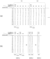
図10(a)に通常プリントモードにおけるΔE(以下、ΔE(Normal)と記す)から広色域プリントモードにおけるΔE(以下、ΔE(LGT)と記す)を算出するためのテーブル(第2変換テーブル)の一部を記す。先に説明したブロック図のメモリ2022に予め記憶されている。縦方向には、ΔE(Normal)の階調値が並んでおり、横方向にはドラム寿命毎のサブテーブルが並んでおり、左からドラム寿命100%の場合のサブテーブル521、ドラム寿命80%の場合のサブテーブル522、…、となっている。実際にはドラム寿命0%までのサブテーブルが存在するが、ΔE(LGT(広色域))の算出方法は同様であるため省略する。また、ドラム寿命毎の各サブテーブルには、現像器寿命毎の小テーブルが複数含まれている。
(Wide color gamut print mode chromaticity calculation table)
FIG. 10(a) shows a table (second conversion table) for calculating ΔE in the wide color gamut print mode (hereinafter referred to as ΔE(LGT)) from ΔE in the normal print mode (hereinafter referred to as ΔE(Normal)). ). It is stored in advance in the
ドラム寿命及び/または現像寿命が図10(a)に掲載されていない場合、各テーブル
から線形補間などの補間処理を行うことで所望の値を算出する。例として、図10(b)を参照して、ドラム寿命90%及び現像寿命90%の場合の、ΔE(LGT)の算出方法を説明する。
(STEP1)ドラム寿命90%を挟むようなサブテーブル521とサブテーブル522を選ぶ。また、現像寿命90%を挟むように、ドラム寿命100%のときの小テーブル521aおよび521b、ならびに、ドラム寿命80%のときの小テーブル522a、522bを選ぶ。
(STEP2)現像寿命により線形補間することで、現像寿命90%用の小テーブル521cと522cを導出する。
(STEP3)ドラム寿命により線形補間することで、ドラム寿命90%用かつ現像寿命90%用のサブテーブル523を導出する。
このサブテーブル523で示す値は、ΔE(LGT)-ΔE(Normal)である。よって、テーブルで示す値を、ΔE(Normal)に足すことで、ΔE(LGT)を算出/変換する。以上により、ΔE(LGT)が算出されるが、必要に応じて本体設置環境等の色味が変化する要因を含めた形にテーブルを細分化しても構わない。なお、必要なΔE(Normal)の値がサブテーブル523にない場合は、さらに線形補間を行ってもよい。
If the drum life and/or development life is not listed in FIG. 10(a), a desired value is calculated by performing interpolation processing such as linear interpolation from each table. As an example, with reference to FIG. 10(b), a method of calculating ΔE(LGT) in the case where the drum life is 90% and the developing life is 90% will be described.
(STEP 1)
(STEP 2) By performing linear interpolation using the development life, small tables 521c and 522c for a development life of 90% are derived.
(STEP 3) A sub-table 523 for 90% drum life and 90% development life is derived by performing linear interpolation using the drum life.
The value shown in this sub-table 523 is ΔE(LGT)−ΔE(Normal). Therefore, ΔE (LGT) is calculated/converted by adding the value shown in the table to ΔE (Normal). As described above, ΔE(LGT) is calculated, but if necessary, the table may be subdivided to include factors that change the color tone, such as the environment in which the main body is installed. Note that if the necessary value of ΔE (Normal) is not in the sub-table 523, linear interpolation may be further performed.
ここでは、画像形成装置の各構成要素の状態を、部品の寿命という形式で求めた。このような部品寿命は、使用の度合いと言い換えることもできる。そして例えば、コントローラ201が、各部品の稼働時間や、ドラムやローラの場合は回転数を計測し、想定稼働時間や想定回転数と比較することで取得できる。また、部品寿命ではなく、稼働時間や回転数などに応じたテーブルを作成してもよい。また、ΔE(LGT)を求める際に、上述した所定のテーブルの代わりにΔE(LGT)とΔE(Normal)の関係を示す数式を作成し利用してもよい。
Here, the condition of each component of the image forming apparatus was determined in the form of component lifespan. Such component life can also be expressed as the degree of use. For example, the
なお、図10のようなテーブルを作成する際には、実際に様々な条件下で、濃度検知センサ218によって測定された、通常プリントモードにおけるΔEと広色域プリントモードにおけるΔEを比較する。また、図10のテーブルは、各色毎に用意されメモリ2022に予め記憶されているものとする。
Note that when creating a table such as that shown in FIG. 10, ΔE in the normal print mode and ΔE in the wide color gamut print mode, which are actually measured by the
(本実施例のディザリングによるγ特性)
図11に本実施例におけるディザリングを採用した場合のある状態でのγ特性を示す。第4象限に示すように、本実施例では、通常プリントモードと広色域プリントモードの間で入力画像データの値に対する露光条件を変化させるために、通常プリントモードにおけるディザリング525と、広色域プリントモードにおけるディザリング527が異なっている。これは通常プリントモードと広色域プリントモードでディザパターンを変えているためである。具体的には、通常プリントモードに対して広色域プリントモードの方が低階調領域においてΔEが小さくなるようなディザパターンを採用する。上記説明したように、同じレーザ照射率を照射した場合、広色域プリントモードの方が通常プリントモードよりもΔEが大きくなってしまう。そのため、広色域プリントモードの方がエンジンγ特性を考慮した上でもΔEが小さくなるようレーザ照射率が小さくなるディザパターンを採用する。
(γ characteristics due to dithering in this example)
FIG. 11 shows the γ characteristics in a certain state when dithering in this embodiment is employed. As shown in the fourth quadrant, in this embodiment, in order to change the exposure conditions for the values of input image data between the normal print mode and the wide color gamut print mode, dithering 525 in the normal print mode and wide color gamut print mode are used. The dithering 527 in the area print mode is different. This is because the dither pattern is different between the normal print mode and the wide color gamut print mode. Specifically, a dither pattern is adopted such that ΔE is smaller in the low gradation area in the wide color gamut print mode than in the normal print mode. As explained above, when irradiating with the same laser irradiation rate, ΔE becomes larger in the wide color gamut print mode than in the normal print mode. Therefore, in the wide color gamut print mode, a dither pattern is adopted in which the laser irradiation rate is reduced so that ΔE is smaller even after considering the engine γ characteristics.
まず、通常プリントモードにおいて、入力画像データが40hのときの画像形成を考える(符号(1))。γ補正されていないルックアップテーブル501を用いると、実際の入力画像データは255となる(符号(2))。次に、通常プリントモードにおけるディザリング525により実際の入力画像データをレーザ照射率に変換する(符号(3))。次に、濃度検知センサにより測定されたΔEを元に、通常プリントモードにおけるエンジンγ特性503を得る(符号(4))。これにより、通常プリントモードにおいて入力画
像データが40hのΔEを、第2象限にプロットできる(符号(5))。このようなプロットを他の入力画像データ値についても行うことで、通常プリントモードにおける入出力γ特性526が得られる。なお、通常プリントモードにおけるエンジンγ特性503および広色域プリントモードにおけるエンジンγ特性512は、図9と同じである。この通常プリントモードにおけるエンジンγ特性503を、広色域プリントモードにおけるエンジンγ特性512に変換するテーブルがΔE(通常)からΔE(広色域)に変換する第2変換テーブルに相当する。
First, consider image formation when the input image data is 40h in the normal print mode (symbol (1)). If the lookup table 501 that is not γ-corrected is used, the actual input image data will be 255 (symbol (2)). Next, the actual input image data is converted into a laser irradiation rate by dithering 525 in the normal print mode (symbol (3)). Next, an engine γ characteristic 503 in the normal print mode is obtained based on ΔE measured by the concentration detection sensor (symbol (4)). As a result, ΔE when the input image data is 40 h in the normal print mode can be plotted in the second quadrant (symbol (5)). By performing such a plot for other input image data values, the input/output γ characteristic 526 in the normal print mode can be obtained. Note that the engine γ characteristic 503 in the normal print mode and the engine γ characteristic 512 in the wide color gamut print mode are the same as those in FIG. The table for converting the engine γ characteristic 503 in the normal print mode into the engine γ characteristic 512 in the wide color gamut print mode corresponds to the second conversion table for converting from ΔE (normal) to ΔE (wide color gamut).
広色域プリントモードにおいては、図10に示したテーブルを用いてΔEを算出する。これにより、広色域プリントモードにおける入出力γ特性を得られる。例えば通常プリントモードと同じく入力画像データが40hのとき、符号(1)から符号(2)に進んだのち、広色域プリントモードにおけるディザリング527により実際の入力画像データをレーザ照射率に変換する(符号(6))。広色域プリントモードにおけるエンジンγ特性512によりΔEが決定される(符号(7))。以上より、広色域プリントモードにおいて、入力画像データが40hのときのΔEを第2象限にプロットできる(符号(8))。これにより、広色域プリントモードにおける入出力γ特性528が得られる。 In the wide color gamut print mode, ΔE is calculated using the table shown in FIG. As a result, input/output γ characteristics in wide color gamut print mode can be obtained. For example, when the input image data is 40h as in the normal print mode, after proceeding from code (1) to code (2), the actual input image data is converted into a laser irradiation rate by dithering 527 in the wide color gamut print mode. (Sign (6)). ΔE is determined by the engine γ characteristic 512 in the wide color gamut print mode (symbol (7)). From the above, in the wide color gamut print mode, ΔE when the input image data is 40h can be plotted in the second quadrant (symbol (8)). As a result, an input/output γ characteristic 528 in the wide color gamut print mode is obtained.
使用状況によりエンジンγ特性は変化するが、この変化があったとしてもある程度入力画像データに対して線形性のある入出力γ特性が得られるように、通常プリントモードにおけるディザリング525を決めている。その結果、通常プリントモードにおける入出力γ特性526は、図9に示した理想の通常プリントモードにおける入出力γ特性506に比較的近い、線形性の高いものとなっている。
また、入力画像データが小さい領域において、ΔE(LGT)<ΔE(Normal)、になるように、広色域プリントモードにおけるディザリング527を設定しなくてはならない。例えば本実施例では、入力画像データの値が40h以下の場合は、常に、ΔE(LGT)<ΔE(Normal)、となるようにディザリング527を設定している。具体的に40hの場合を見ると、ディザリング525と通常プリントモードにおけるエンジンγ特性503を用いて求めたΔE(Normal)771は、ディザリング527と広色域プリントモードにおけるエンジンγ特性512を用いて求めたΔE(LGT)772よりも大きい。
The engine γ characteristics change depending on the usage conditions, but the dithering 525 in the normal print mode is determined so that even if this change occurs, input/output γ characteristics with some degree of linearity can be obtained for the input image data. . As a result, the input/output γ characteristic 526 in the normal print mode has high linearity and is relatively close to the input/output γ characteristic 506 in the ideal normal print mode shown in FIG.
Furthermore, in an area where the input image data is small, dithering 527 in the wide color gamut print mode must be set so that ΔE(LGT)<ΔE(Normal). For example, in this embodiment, when the value of the input image data is 40h or less, the dithering 527 is always set so that ΔE(LGT)<ΔE(Normal). Looking specifically at the case of 40 hours, ΔE (Normal) 771 obtained using dithering 525 and
また、理想の広色域プリントモードにおける入出力γ特性514になるように修正したルックアップテーブルが533である。破線534は、入力画像データが40hのときに、修正したルックアップテーブル533を用いた場合の各値を示す。すなわち、広色域プリントモードの場合、修正したルックアップテーブル533により実際の入力画像データが求められ(符号A)、広色域プリントモードにおけるディザリング527によりレーザ照射率が求められ(符号B)、広色域プリントモードにおけるエンジンγ特性512によりΔEが定まり(符号C)、入力画像データ40hとΔEのプロットにより広色域プリントモードにおける理想の入出力γ特性514に帰着する(符号D)。
なお、修正したルックアップテーブル533を作成する際には、実際に広色域プリントモード形成した画像のΔEを測定してもよいが、図10のような方法で通常プリントモードの測定結果から広色域プリントモードでのΔEを算出してもよい。かかる修正したルックアップテーブル533を作成することで、広色域プリントモードのγ変換を好適に実施できる。
なお、広色域プリントモードにおける入出力γ特性514、γ補正されていないルックアップテーブル501、広色域プリントモードにおけるディザリング527、通常プリントモードにおけるディザリング525の為のディザパターンは予めメモリ2022に記憶されている。ディザパターンについては適宜公知のものを利用することができるのでここでの詳細な説明は割愛する。また、その他の特性曲線は、その都度の濃度検知センサ218の検出値により変化し、変化後の特性曲線は、次の濃度測定までメモリ2022に記憶
されている。
Further, a lookup table 533 is modified to have the input/output γ characteristic 514 in the ideal wide color gamut print mode. A
Note that when creating the corrected lookup table 533, the ΔE of the image actually formed in the wide color gamut print mode may be measured, but the wide color gamut can be calculated from the measurement results of the normal print mode using the method shown in FIG. ΔE in the color gamut print mode may be calculated. By creating such a modified lookup table 533, γ conversion in wide color gamut print mode can be suitably performed.
Note that dither patterns for input/
(エンジンγ特性に応じた最適ディザリング)
図12を用いて、エンジンγ特性に応じてディザリングを調整する方が良い理由を説明する。図12は、図9や図11の入出力特性のグラフから第1象限および第4象限を抜き出し抽象化したグラフである。第1のディザリング529は、ある第1のエンジンγ特性531において、実際の入力画像データがRI1の時に色度差がΔE1となり、実際の入力画像データがRI2の時に色度差がΔE2となるディザリングである。第2のディザリング530は、その第1のエンジンγ特性531において、実際の入力画像データがRI1の時に色度差がΔE1となり、実際の入力画像データがRI2の時に色度差がΔE3となるディザリングである。ここで、色度差ΔE3は色度差ΔE2よりも大きいものとする。
(Optimal dithering according to engine γ characteristics)
The reason why it is better to adjust dithering according to the engine γ characteristics will be explained using FIG. 12. FIG. 12 is a graph obtained by extracting and abstracting the first and fourth quadrants from the input/output characteristic graphs of FIGS. 9 and 11. In the
仮に、RI1の次の実際の画像データがRI2だとすると、第2のディザリング530ではΔE1とΔE3の間の階調を表現できないということになる。これに対し、第1のディザリング529ではΔE1とΔE3の間の画像であるΔE2を形成できている。これは言い換えると、第1のディザリング529に対して第2のディザリング530の方が、実際の入力画像データに対するΔEの変化が大きく階調性が悪いということになる。
If the actual image data following RI 1 is RI 2 , this means that the
次に、あるエンジンγ特性531とは異なる、別の第2のエンジンγ特性532に対して特定のディザリングで画像形成する場合を考える。別の第2のエンジンγ特性532について、上と同様に検討する。第1のディザリング529について、実際の入力画像データがRI1の時に色度差がΔE1となり、実際の入力画像データがRI2の時に色度差がΔE3となる。第2のディザリング530について、実際の入力画像データがRI1の時に色度差がΔE1となり、実際の入力画像データがRI2の時に色度差がΔE4となる。
Next, consider a case where an image is formed using specific dithering for a second engine γ characteristic 532 that is different from a certain engine γ characteristic 531. Another second engine γ characteristic 532 will be considered in the same manner as above. Regarding the
以上より、ディザリングについてまとめると、第1のディザリング529を実行した場合の入力画像データに対するレーザ照射率の変化の度合いが、第2のディザリング530を実行した場合の入力画像データに対するレーザ照射率の変化の度合いよりも小さい。言い換えると、図12のように縦軸と横軸を取った場合、第1のディザリング529の傾きのほうが、第2のディザリング530の傾きよりも立っている。そして、かかる傾きの大小関係に起因して、第1のディザリング529を実行した方が、第2のディザリング530を実行した場合よりも階調性がよいことが分かる。
From the above, to summarize dithering, the degree of change in the laser irradiation rate for input image data when the
また、エンジンγ特性についてまとめると、同じ入力画像データの対が入力されたときに、第1のエンジンγ特性531の方が、第2のエンジンγ特性532の場合よりも階調性が良いことが分かる。これは、第1のエンジンγ特性531を用いた場合のレーザ照射率に対するΔEの変化の度合いが、第2のエンジンγ特性を用いた場合のレーザ照射率に対するΔEの変化の度合いよりも小さいことに起因する。言い換えると、図12のように縦軸と横軸を取った場合、第2のエンジンγ特性532の傾きの方が、第1のエンジンγ特性531の傾きよりも立っていることに起因する。 Also, to summarize the engine γ characteristics, when the same pair of input image data is input, the first engine γ characteristic 531 has better gradation than the second engine γ characteristic 532. I understand. This means that the degree of change in ΔE with respect to the laser irradiation rate when the first engine γ characteristic 531 is used is smaller than the degree of change in ΔE with respect to the laser irradiation rate when the second engine γ characteristic is used. caused by. In other words, when the vertical and horizontal axes are taken as shown in FIG. 12, this is because the slope of the second engine γ characteristic 532 is higher than the slope of the first engine γ characteristic 531.
このような、エンジンγ特性の傾きが立っている(レーザ照射率に対するΔEの変化の度合いが大きい)ことによるエンジンγ階調性の悪化を補償するためには、ディザリングの傾きを立てて(入力画像データに対するレーザ照射率の変化の度合いを小さくして)、階調性を良くしてやればよい。一方、エンジンγ特性の傾きが寝ておりエンジンγ階調性が比較的良好な領域では、ディザリングの傾きを寝かせて階調性が悪化したとしても、全体として濃度の階調性を保つことができる。
以上より、階調性が悪くなるようなエンジンγ特性を示す画像データ領域では、ディザリングの傾きを立てるとよく、また、階調性が良いエンジンγ特性を示す画像データ領域
ではディザリングの傾きを寝かすとよい。これにより、全ての画像データに対してバランスよく階調性を保つことができる。
In order to compensate for the deterioration of the engine γ gradation due to the steep slope of the engine γ characteristic (the degree of change in ΔE with respect to the laser irradiation rate is large), the slope of the dithering is increased ( The gradation may be improved by reducing the degree of change in the laser irradiation rate with respect to the input image data. On the other hand, in a region where the slope of the engine γ characteristic is flat and the engine γ gradation is relatively good, even if the slope of the dithering is flattened and the gradation deteriorates, the overall density gradation can be maintained. I can do it.
From the above, it is recommended to increase the slope of dithering in image data areas that exhibit engine γ characteristics that result in poor gradation, and to increase the slope of dithering in image data areas that exhibit engine γ characteristics that result in good gradation. It's a good idea to put it to bed. This makes it possible to maintain well-balanced gradation for all image data.
以上が、エンジンγ特性に応じてディザリングを調整することが望ましい理由である。本実施例では、通常プリントモードでは通常プリントモードにおけるディザリング525を採用し、広色域プリントモードでは広色域プリントモードにおけるディザリング527を実行する。エンジンγ特性は状態により変化するため、バランスをみて設計すべきである。 The above is the reason why it is desirable to adjust dithering according to the engine γ characteristics. In this embodiment, the dithering 525 in the normal print mode is employed in the normal print mode, and the dithering 527 in the wide color gamut print mode is executed in the wide color gamut print mode. Since the engine γ characteristics change depending on the state, it should be designed with a balance in mind.
(画像形成モードの違いに応じた低濃度域でのγ特性)
図13に、低濃度域での入出力γ特性を示している。比較例の広色域プリントモードでは、通常プリントモードでほぼΔE=0、となるような入力画像データにおいて、ΔE=0、となる場合もあれば、ΔE≠0、となる場合もあるため、近似直線による算出を行う必要があった。それに対し本実施例の広色域ディザリング527は、低濃度域において必ずΔE(LGT)<ΔE(Normal)、になるように作成されている。そのため、近似直線による算出の必要がない。そのため、ΔEの算出誤差は図10に示す算出テーブルのみに依存しており、低濃度域だけ誤差が大きくなることは無い。
(γ characteristics in low density range depending on image forming mode)
FIG. 13 shows the input/output γ characteristics in the low concentration region. In the wide color gamut print mode of the comparative example, input image data that is approximately ΔE = 0 in the normal print mode may be ΔE = 0, or ΔE≠0. It was necessary to perform calculations using approximate straight lines. In contrast, the wide color gamut dithering 527 of this embodiment is created so that ΔE(LGT)<ΔE(Normal) always holds in the low density region. Therefore, there is no need for calculation using an approximate straight line. Therefore, the calculation error of ΔE depends only on the calculation table shown in FIG. 10, and the error does not increase only in the low concentration region.
本実施例では、上記の低濃度域を00h~20hと定義する。低濃度域では出力が安定しないため、条件によっては入力画像データに鈍感である。すなわち、入力画像データを増加させてもしばらくΔE(Normal)=0、になる場合もあれば、比較的早くΔE(Normal)≠0、になる場合もある。本実施例の構成では、少なくとも20hであれば安定してΔE(Normal)≠0、となったため、低濃度域として00h~20hと定義する。この低濃度域の所定の上限値である20hという値はディザリング等で変化するため、必ずしも20hに一意に決まるわけではなく、エンジンγ特性やディザリング等に応じて変える必要がある。低濃度域に対応する入力画像データは、入力画像データを低濃度域の側と高濃度域の側に分けたときに、最小の値を持つ入力画像データを含む側、または、形成される画像の濃度が濃度検知センサ218により検知できないほど小さくなるような入力画像データを含む側として定義できる。
低濃度域に対応する入力画像データを決定する方法の一例を述べる。入力画像データを最小値(例えば上記例では00h)に設定し、少しずつ値を増やしながら濃度検知センサ218による濃度検知を繰り返して行き、適切な所定の上限値を決定する。
In this embodiment, the above-mentioned low concentration range is defined as 00h to 20h. Since the output is not stable in the low density region, it is insensitive to input image data depending on the conditions. That is, even if the input image data is increased, ΔE (Normal) may become 0 for a while, or ΔE (Normal)≠0 may occur relatively quickly. In the configuration of this embodiment, ΔE (Normal)≠0 is stably maintained for at least 20 hours, so the low concentration range is defined as 00h to 20h. The value of 20h, which is the predetermined upper limit value of this low concentration range, changes due to dithering and the like, so it is not necessarily uniquely determined to 20h, and needs to be changed depending on the engine γ characteristics, dithering, etc. The input image data corresponding to the low density area is the side containing the input image data having the minimum value when the input image data is divided into the low density area side and the high density area side, or the image to be formed. It can be defined as the side that includes input image data such that the density of the image becomes so small that it cannot be detected by the
An example of a method for determining input image data corresponding to a low density area will be described. The input image data is set to the minimum value (for example, 00h in the above example), and the density detection by the
(比較例における色度誤差の影響)
続いて、図14、図15を参照して、本実施例の効果について説明する。図14は、比較例のディザリング及び算出方法を採用した場合でのγ補正後のΔE(LGT)の誤差を示している。図14(a)および図14(b)は同じ状態を示しているが、図が複雑化したためキャリブレーションシーケンスの時系列に分離して図示している。
(Influence of chromaticity error in comparative example)
Next, the effects of this embodiment will be explained with reference to FIGS. 14 and 15. FIG. 14 shows the error in ΔE(LGT) after γ correction when the dithering and calculation method of the comparative example is adopted. 14(a) and 14(b) show the same state, but because the diagrams are complicated, they are shown separately in time series of the calibration sequence.
まず比較例の通常プリントモードについて説明する。入力画像データI3及びI4は、γ補正されていないルックアップテーブル501によりI3’およびI4’に変換され、ディザリング525によりレーザ照射率R3及びR4に変換される。通常プリントモードにおけるエンジンγ特性503の状態で画像形成し、濃度検知センサ218でセンシングすることで、ΔE3’およびΔE4’が得られる。その結果を第2象限にプロットして、通常プリントモードにおける入出力γ特性P3’およびP4’を得る。さらに他の入力画像データをプロットして、通常プリントモードにおける入出力γ特性526が得られる。
First, the normal print mode as a comparative example will be explained. Input image data I 3 and I 4 are converted to I 3 ′ and I 4 ′ by a non-γ-corrected lookup table 501 and converted to laser irradiation rates R 3 and R 4 by dithering 525. By forming an image in the state of the engine γ characteristic 503 in the normal print mode and sensing it with the
次に、比較例の、通常プリントモードから広色域プリントモードへの補正方法について説明する。上記で説明したように、通常プリントモード時の測定色差であるΔE3’およびΔE4’から、広色域プリントモードにおけるΔEであるΔE3およびΔE4を算出す
る。この際に算出誤差が発生する。例えば、入力画像データの値が比較的大きいI3やI4では、P3やP4に示すように、算出誤差は比較的小さい。しかし、外挿により低濃度領域(入力画像データの値が比較的小さいI1やI2付近)の値を求める場合、この算出誤差の影響が大きくなってしまい、P1やP2に示すような大きな算出誤差として表れる。この算出誤差により、外挿直線の傾きは、外挿直線535から外挿直線536の間で変化しうる。入力画像データI1およびI2における誤差は、この外挿直線535と外挿直線536から決まり、図14(a)中に示す矢印の長さE1およびE2になる。
Next, a correction method for changing from normal print mode to wide color gamut print mode in a comparative example will be described. As explained above, ΔE 3 and ΔE 4, which are ΔE in wide color gamut print mode, are calculated from ΔE 3 ′ and ΔE 4 ′, which are the measured color differences in normal print mode. At this time, a calculation error occurs. For example, for I 3 and I 4 where the value of input image data is relatively large, the calculation error is relatively small as shown in P 3 and P 4 . However, when calculating values in low-density areas (near I 1 and I 2 where the input image data values are relatively small) by extrapolation, the influence of this calculation error increases, as shown in P 1 and P 2 . This appears as a large calculation error. Due to this calculation error, the slope of the extrapolated straight line may change between the extrapolated
これらの誤差がある場合において、ルックアップテーブルの誤差とその結果生まれる出力誤差を図14(b)に示す。図14(a)中に示す点P1、P2、P3、P4の振れる範囲の上限値と下限値をそれぞれ、理想の広色域プリントモードにおける入出力γ特性514と比較することで、理想の入力画像データが算出される。これらの理想の入力画像データの値からルックアップテーブル537とルックアップテーブル538を算出する。
すなわち、P1~P4それぞれの誤差範囲の上限値と下限値を、理想の広色域入出力γ特性514と比較する。例えば入力画像データがI4のときのΔE4の上限値をΔE4(max)、下限値をΔE4(min)とする。これは、図14(a)の第2象限において、P4の上下に示されたヒゲの値に相当する。まず誤差が上限値の場合を考えると、γ補正されていないルックアップテーブル501を用いると入力画像データがI4のときに色差がΔE4(max)となってしまう。そこで、入力画像データがI4のときの色差が、広色域プリントモードにおける理想の入出力γ特性514上の点(符号(1))になるようにするために、ルックアップテーブル537上の点(符号(2))によって実際の入力画像データへの変換を行う。
また誤差が下限値の場合を考えると、γ補正されていないルックアップテーブル501を用いると入力画像データがI4のときに色差がΔE4(min)となってしまう。そこで、入力画像データがI4のときに色差が理想の広色域入出力γ特性514上の点(符号(1))になるようにするために、ルックアップテーブル538上の点(符号(3))によって実際の入力画像データへの変換を行う。
When these errors exist, the errors in the lookup table and the resulting output errors are shown in FIG. 14(b). By comparing the upper and lower limits of the swing range of points P 1 , P 2 , P 3 , and P 4 shown in FIG. 14(a) with the input/
That is, the upper and lower limit values of the error ranges of P 1 to P 4 are compared with the ideal wide color gamut input/output γ characteristic 514. For example, when the input image data is I 4 , the upper limit value of ΔE 4 is ΔE 4 (max), and the lower limit value is ΔE 4 (min). This corresponds to the whisker values shown above and below P4 in the second quadrant of FIG. 14(a). First, considering the case where the error is an upper limit value, if the lookup table 501 that is not γ-corrected is used, the color difference will be ΔE 4 (max) when the input image data is I 4 . Therefore, in order to make the color difference when the input image data is I4 become the point (symbol (1)) on the ideal input/output γ characteristic 514 in wide color gamut print mode, Conversion to actual input image data is performed using the point (symbol (2)).
Furthermore, considering the case where the error is at the lower limit value, if the lookup table 501 that is not γ-corrected is used, the color difference will be ΔE 4 (min) when the input image data is I 4 . Therefore, in order to make the color difference become the point (symbol (1)) on the ideal wide color gamut input/output γ characteristic 514 when the input image data is I4 , the point (symbol (1)) on the lookup table 538 is set. 3) Conversion to actual input image data is performed by step).
このようにして求められた、ルックアップテーブル537とルックアップテーブル538で挟まれる領域が、ルックアップテーブルの誤差である。例えば入力画像データI1の場合には、入力画像データの範囲は図中矢印で図示しているΔI1となる。この入力画像データの誤差が図中矢印で図示しているΔEの振れΔ(ΔE1)を生む。他の画像データにおいても同様にΔEの振れが算出される。このように比較例では、γ補正のときのルックアップテーブルの形状が色度誤差の影響を大きく受けるようになっていた。 The area sandwiched between lookup table 537 and lookup table 538 obtained in this way is the error of the lookup table. For example, in the case of input image data I1 , the range of the input image data is ΔI1 , which is indicated by an arrow in the figure. This error in the input image data causes a deviation Δ(ΔE 1 ) of ΔE, which is indicated by an arrow in the figure. The deviation of ΔE is similarly calculated for other image data. As described above, in the comparative example, the shape of the lookup table used in γ correction was greatly influenced by the chromaticity error.
(実施例1における色度誤差の影響)
次に図15(a)及び(b)を用いて、本実施例におけるディザリング及び算出方法を採用した場合での、γ補正後のΔE(LGT)の誤差を示す。
まず、図14(a)及び(b)と同様、入力画像データI1、I2、I3、I4の場合において、通常プリントモードにおけるΔEを算出する。次に上述の補正方法により、広色域プリントモードにおけるΔEを算出する。このとき求められるのは、広色域プリントモード用の広色域プリントモードにおけるディザリング527を実行した場合の結果になる。広色域プリントモードにおけるディザリング527によると、入力画像データI1、I2、I3、I4から変換された実際の入力画像データI1’、I2’、I3’、I4’はそれぞれ、レーザ照射率R12、R22、R32、R42になる。そして、広色域プリントモードにおけるエンジンγ特性512の状態では第2象限にP12、P22、P32、P42としてプロットされ、広色域プリントモードにおける入出力γ特性539が算出される。
(Influence of chromaticity error in Example 1)
Next, using FIGS. 15A and 15B, the error in ΔE(LGT) after γ correction is shown when the dithering and calculation method in this example is adopted.
First, as in FIGS. 14A and 14B, ΔE in the normal print mode is calculated for input image data I 1 , I 2 , I 3 , and I 4 . Next, ΔE in the wide color gamut print mode is calculated using the above-described correction method. What is obtained at this time is the result when dithering 527 is executed in the wide color gamut print mode for the wide color gamut print mode. According to the dithering 527 in wide color gamut print mode, the actual input image data I 1 ', I 2 ', I 3 ', I 4 ' converted from the input image data I 1 , I 2 , I 3 , I 4 are the laser irradiation rates R 1 2,
このとき、ディザリングとして広色域プリントモードにおけるエンジンγ特性512に
応じて決定された広色域プリントモードにおけるディザリング527が利用されている。その結果、各点における誤差は比較例よりも小さく、略一定であり、第1の入出力γ特性540から第2の入出力γ特性541の間となる。以下、図14の場合と同様にしてルックアップテーブルの誤差、及びその結果生まれる出力誤差を算出すると、図15(b)に示すΔI1及びΔ(ΔE1)のようになる。図に示す通り、本実施例では広色域プリントモードにおけるΔE算出の際の誤差が低濃度域において小さくなるため、ルックアップテーブルの誤差についても小さくなり、その結果γ補正後の出力誤差に関しても小さくなる。
At this time, dithering 527 in the wide color gamut print mode determined according to the engine γ characteristic 512 in the wide color gamut print mode is used as dithering. As a result, the error at each point is smaller than in the comparative example, is approximately constant, and falls between the first input-output γ characteristic 540 and the second input-output γ characteristic 541. Hereinafter, when the error of the lookup table and the resulting output error are calculated in the same manner as in the case of FIG. 14, the result will be ΔI 1 and Δ(ΔE 1 ) shown in FIG. 15(b). As shown in the figure, in this example, the error in calculating ΔE in wide color gamut print mode is smaller in the low density area, so the error in the lookup table is also smaller, and as a result, the output error after γ correction is also smaller. becomes smaller.
(画像形成装置によるγ補正のフローチャート)
図19のフローチャートを用い、画像形成装置200によるγ補正に係る処理を説明する。
まず、S1901で、CPU2021は、通常プリントモードで、トナー像形成に係るユニットを動作させる。より具体的には、CPU2021の指示に基づき、プロセスカートリッジ204は、中間転写ベルト205上に、濃度検知センサ218(図6)で濃度を検出する為の複数のパッチを形成させる。複数のパッチには、濃度の薄いパッチから濃いパッチまであり、各パッチの階調は異なっている。また各階調のパッチはYMCKの各色毎に形成される。
S1901から開始される通常プリントモードのγ補正においては、画像形成装置200は、上記に記したように、γ補正されていないルックアップテーブル501を参照してパッチを形成する。なお、画像形成装置200は、通常プリントモードのγ補正を行う際に、予めγ補正されたルックアップテーブルを参照してもよい。
次にS1902で、濃度検知センサ218は、中間転写ベルト205上に形成された各パッチの濃度を検知する。図6、7で説明した通り、測定された濃度値は、パッチからの正反射光と乱反射光に従う値となる。
(Flowchart of γ correction by image forming apparatus)
Processing related to γ correction by the
First, in S1901, the
In the γ correction in the normal print mode starting from S1901, the
Next, in S1902, the
S1903で、測定された反射光の値はCPU2021により取得される。CPU2021により取得される濃度値は、正反射検知出力401から乱反射検知出力402を引いた値そのものでも、それを更に濃度値に変換した値であっても良い。また、パッチが形成された中間転写ベルト205の下地の影響を除去した値でも良い。
次にS1904で、CPU2021は、S1903で演算された各階調の濃度値を、メモリ2022に予め記憶された第1変換テーブルに入力し、各階調の濃度値の変換値(ΔE(通常))を取得する。なお、変換テーブルは色毎に用意されており、第1変換テーブルからの出力値は色毎のΔE(通常)となる。
In S1903, the measured reflected light value is acquired by the
Next, in S1904, the
S1905で、CPU2021は、同じくメモリ2022に予め記憶された色毎の第2変換テーブルに、S1904で取得された階調ごと且つ色毎のΔE(通常)を入力し、図10に示した第2変換テーブルからの出力値ΔE(広色域)を取得する。第2変換テーブルからの出力値ΔE(広色域)は、図13で示した広色域(本実施例)のΔEに対応する。図11を参照し、図13の「広色域(本実施例)」のΔEと、「通常」のΔEと、の大小関係に関して詳細に説明する。
CPU2021は、通常プリントモードにおいて、入力画像データが40hのとき(符号(1))、γ補正されていないルックアップテーブル501を用いて、実際の入力画像データ255を取得する(符号(2))。次に、CPU2021は、通常プリントモードにおけるディザリング525により実際の入力画像データをレーザ照射率に変換する(符号(3))。次に、CPU2021は、濃度検知センサ218により測定されたΔEを元に、通常プリントモードにおけるエンジンγ特性503を得る(符号(4))。これにより、通常プリントモードにおいて入力画像データが40hのΔEを、第2象限にプロットできる(符号(5))。このときの符号(5)は、通常プリントモードの検出結果であるΔE(通常)となる。
一方、CPU2021は、広色域プリントモードにおいて、入力画像データが40hのとき(符号(1))、γ補正されていないルックアップテーブル501を用いて、実際の入力画像データ255を取得する(符号(2))。次に、CPU2021は、ディザリング527により実際の入力画像データをレーザ照射率に変換する(符号(6))。広色域プリントモードにおけるエンジンγ特性512によりΔEが決定される(符号(7))。以上より、広色域プリントモードにおいて、入力画像データが40hのときのΔEを第2象限にプロットできる(符号(8))。
そして、CPU2021は、各階調において、符号(5)と符号(8)に対応するΔEを検出する。CPU2021は、検出された通常プリントモードのΔEと広色域プリントモードのΔEとの関係性から、変換量を第2変換テーブルのように決定する。
なお、広色域プリントモードにおいて算出された符号(8)は、S1905において通常プリントモードの検出結果に基づいて第2変換テーブルを用いて広色域プリントモードに変換した場合に取得されるΔE(広色域)である。
ここで、形成される画像の濃度が低濃度域の側となるような少なくとも一部の入力画像データに関しては、通常プリントモードにおける符号(5)のΔEと、広色域プリントモードにおける符号(8)のΔEを比較すると、符号(5)に比べて符号(8)の方が、ΔEが小さくなるように制御する。
最後に、S1906で、CPU2021は、S1905で取得された色毎、階調ごとのΔE(広色域)から、ルックアップテーブル533を補正し、修正後のルックアップテーブル533をメモリ2022に記憶し、以後の広色域プリントモード実行時に用いる。CPU2021によるルックアップテーブル533の演算については、図11を中心に説明した通りなので、ここでの詳しい説明は省略する。
また、広色域プリントモードにおいて、広色域プリントモード用のディザパターン、ならびにγ補正されたルックアップテーブルを採用し、通常プリントモードに対して広色域プリントモードの方が低階調領域においてΔEが小さくなるように調整すればよい。
In S1905, the
In the normal print mode, when the input image data is 40h (symbol (1)), the
On the other hand, in the wide color gamut print mode, when the input image data is 40h (symbol (1)), the
Then, the
Note that the code (8) calculated in the wide color gamut print mode is ΔE( wide color gamut).
Here, regarding at least some input image data where the density of the image to be formed is on the low density region side, ΔE of code (5) in normal print mode and code (8) of code (8) in wide color gamut print mode. ), control is performed so that ΔE is smaller in code (8) than in code (5).
Finally, in S1906, the
In addition, in wide color gamut print mode, a dither pattern for wide color gamut print mode and a gamma-corrected lookup table are adopted, and wide color gamut print mode is better in low gradation areas than normal print mode. Adjustment may be made so that ΔE becomes small.
以上のように本実施例の画像形成装置では、基準となる画像形成モードの色味から別の色域を実現する画像形成モードにおける色味を算出する構成において、低濃度域の色味の算出においても誤差が大きくならない。本実施例の構成では制御対象を非画像形成部との色度差としたが、色度差に限定するものはなく、例えば濃度であっても構わない。また、広色域プリントモードを実現するにあたって現像ローラ303の周速比を採用したが、トナー供給量を制御するためのパラメータであればよく、周速比に限定されない。
As described above, in the image forming apparatus of this embodiment, in the configuration that calculates the tint in an image forming mode that realizes a different color gamut from the tint in the standard image forming mode, the tint in the low density area is calculated. The error does not become large even when In the configuration of this embodiment, the control target is the chromaticity difference with respect to the non-image forming portion, but the control target is not limited to the chromaticity difference, and may be, for example, the density. Further, although the circumferential speed ratio of the developing
[実施例2]
本実施例では、画像形成装置が動作するモードが実施例1と異なる。すなわち、第1のモードとしての通常プリントモードに対して、トナー消費を抑えた第2のモードとしてのトナー節約プリントモードを設ける例において説明する。すなわち本実施例では、基準画像形成モードが通常モードであり、濃度可変画像形成モードがトナー節約モードである。ただし、例えば、濃度検知センサ218により検出され検出値(濃度値)をΔE(通常)に変換する第1変換テーブルを備えていることなど、画像形成装置の構成は実施例1と同じなので省略する。
[Example 2]
In this embodiment, the mode in which the image forming apparatus operates is different from that in the first embodiment. That is, an example will be described in which a toner saving print mode is provided as a second mode in which toner consumption is suppressed in addition to a normal print mode as a first mode. That is, in this embodiment, the reference image forming mode is the normal mode, and the variable density image forming mode is the toner saving mode. However, since the configuration of the image forming apparatus is the same as in the first embodiment, for example, it is provided with a first conversion table that converts the detected value (density value) detected by the
(感光ドラム表面電位)
通常プリントモードとトナー節約プリントモードにおける感光ドラム301の表面電位について図16を用いて説明する。トナー節約プリントモードは、現像ローラ303の周速を下げることで周速比を下げ、感光ドラム301上の単位面積当たりのトナー量を減らすことでトナー消費を抑制する。また実施例1同様、周速比の変更と同時に感光ドラム301の表面電位を最適化する。電位コントラストVcontが通常プリントモードと同じだけあれば現像効率の観点からは問題無いのだが、放電量を少なくすることで電荷輸送層314の削れを抑制できる等のメリットがある。
(Photosensitive drum surface potential)
The surface potential of the
そのため本実施例の構成における通常プリントモードでは、周速比を1.4、Vdn=-500V、Vdcn=-350V、Vln=-100V、を採用する。また、トナー節約プリントモードでは、周速比を1.1、Vds=-380V、Vdcs=-250V、Vlns=-50V、を採用する。ここで、トナー節約プリントモードにおける帯電バイアスVd、現像電位Vdc、露光電位VlをそれぞれVds、Vdcs、Vls、と表記している。 Therefore, in the normal print mode in the configuration of this embodiment, the peripheral speed ratio is 1.4, Vd n =-500V, Vdc n =-350V, and Vl n =-100V. Further, in the toner saving print mode, the peripheral speed ratio is 1.1, Vd s =-380V, Vdc s =-250V, and Vl ns =-50V. Here, the charging bias Vd, development potential Vdc, and exposure potential Vl in the toner saving print mode are expressed as Vds , Vdcs , and Vls , respectively.
(本実施例のディザリングによるγ特性)
図17に通常プリントモード及びトナー節約プリントモードにおけるγ特性を記す。キャリブレーションシーケンスは実施例1と同じである。実施例1と同様にして、γ補正されていないルックアップテーブル601、通常プリントモードにおけるディザリング602及びトナー節約プリントモードにおけるディザリング603から、通常プリントモードにおけるエンジンγ特性604及びトナー節約プリントモードにおけるエンジンγ特性605を得る。エンジンγ特性604をエンジンγ特性605に変換するテーブルが第2変換テーブルに相当する。
(γ characteristics due to dithering in this example)
FIG. 17 shows the γ characteristics in the normal print mode and the toner saving print mode. The calibration sequence is the same as in the first embodiment. In the same manner as in Example 1, the
通常プリントモードにおける入出力γ特性606とトナー節約プリントモードにおける入出力γ特性607を低濃度域で比較すると、通常プリントモードでのΔEよりもトナー節約プリントモードにおけるΔEの方が小さい。そのため、本実施例でも低濃度域のエンジンγ特性605を得るのに高濃度域のエンジンγ特性605から算出する必要はない。そのため低濃度域でのエンジンγ特性605は振れが小さく抑えられる。 Comparing the input/output γ characteristic 606 in the normal print mode and the input/output γ characteristic 607 in the toner saving print mode in a low density region, ΔE in the toner saving print mode is smaller than ΔE in the normal printing mode. Therefore, in this embodiment as well, there is no need to calculate from the engine γ characteristic 605 in the high concentration region in order to obtain the engine γ characteristic 605 in the low concentration region. Therefore, fluctuations in the engine γ characteristic 605 in the low concentration range can be suppressed to a small level.
以上のように本実施例の画像形成装置では、基準となる画像形成モードの色味からトナー消費を抑えた画像形成モードにおける色味を算出する構成において、低濃度域の色味の算出においても誤差が大きくならない。 As described above, in the image forming apparatus of this embodiment, in the configuration in which the color tone in the image forming mode that suppresses toner consumption is calculated from the color tone in the reference image forming mode, the color tone in the low density region can also be calculated. The error will not become large.
(その他の実施例)
本発明は、上述の実施例の1以上の機能を実現するプログラムを、ネットワーク又は記憶媒体を介してシステム又は装置に供給し、そのシステム又は装置のコンピュータにおける1つ以上のプロセッサがプログラムを読出し実行する処理でも実現可能である。また、1以上の機能を実現する回路(例えば、ASIC)によっても実現可能である。
(Other examples)
The present invention provides a system or device with a program that implements one or more of the functions of the above-described embodiments via a network or storage medium, and one or more processors in the computer of the system or device reads and executes the program. This can also be achieved by processing. It can also be realized by a circuit (for example, ASIC) that realizes one or more functions.
200:画像形成装置、201:コントローラ、202:エンジンコントローラ、204:プロセスカートリッジ、205:中間転写ベルト、218:濃度検知センサ、302:帯電ローラ、303:現像ローラ 200: Image forming apparatus, 201: Controller, 202: Engine controller, 204: Process cartridge, 205: Intermediate transfer belt, 218: Density detection sensor, 302: Charging roller, 303: Developing roller
Claims (7)
感光ドラムと、
前記感光ドラムを露光して静電潜像を形成する露光手段と、
前記露光手段によって前記感光ドラムに形成された前記静電潜像をトナーにより現像してトナー像を形成する現像ローラと、
前記現像ローラによって前記感光ドラムに形成された前記トナー像が転写される中間転写体と、
前記中間転写体に転写された前記トナー像の濃度を検知する濃度検知手段と、
入力される入力画像データの値に基づいて前記トナー像の濃度を調整する制御手段と、を備え、
前記制御手段は、前記第2のモードを実行する場合における前記現像ローラの前記感光ドラムに対する周速比が、前記第1のモードにおける前記周速比よりも大きくなるように制御し、
前記入力画像データのうち、形成される画像の濃度が低濃度域の側となるような少なくとも一部の入力画像データに関しては、前記第1のモードにより形成される前記トナー像の濃度が、前記第2のモードにより形成される前記トナー像の濃度よりも大きいことを特徴とする画像形成装置。 An image forming apparatus that operates in a first mode that forms an image in a first color gamut and a second mode that forms an image in a second color gamut that is different from the first color gamut,
photosensitive drum,
exposure means for exposing the photosensitive drum to form an electrostatic latent image;
a developing roller that develops the electrostatic latent image formed on the photosensitive drum by the exposure means with toner to form a toner image;
an intermediate transfer member to which the toner image formed on the photosensitive drum by the developing roller is transferred;
density detection means for detecting the density of the toner image transferred to the intermediate transfer body;
control means for adjusting the density of the toner image based on the value of the input image data that is input,
The control means controls a circumferential speed ratio of the developing roller to the photosensitive drum when executing the second mode to be larger than the circumferential speed ratio in the first mode,
Among the input image data, at least some of the input image data in which the density of the image to be formed is on the low density range side, the density of the toner image formed in the first mode is , an image forming apparatus characterized in that the density is greater than the density of the toner image formed in the second mode .
を特徴とする請求項1~3のいずれか1項に記載の画像形成装置。 The control means calculates the density in the second mode using a predetermined table from the density obtained when the density detection means detects the image formed in the first mode. The image forming apparatus according to any one of claims 1 to 3 .
Applications Claiming Priority (2)
| Application Number | Priority Date | Filing Date | Title |
|---|---|---|---|
| JP2019009779 | 2019-01-23 | ||
| JP2019009779 | 2019-01-23 |
Publications (3)
| Publication Number | Publication Date |
|---|---|
| JP2020118974A JP2020118974A (en) | 2020-08-06 |
| JP2020118974A5 JP2020118974A5 (en) | 2023-01-30 |
| JP7395365B2 true JP7395365B2 (en) | 2023-12-11 |
Family
ID=71608929
Family Applications (1)
| Application Number | Title | Priority Date | Filing Date |
|---|---|---|---|
| JP2020008682A Active JP7395365B2 (en) | 2019-01-23 | 2020-01-22 | Image forming device |
Country Status (2)
| Country | Link |
|---|---|
| US (3) | US10838342B2 (en) |
| JP (1) | JP7395365B2 (en) |
Families Citing this family (1)
| Publication number | Priority date | Publication date | Assignee | Title |
|---|---|---|---|---|
| JP7395365B2 (en) * | 2019-01-23 | 2023-12-11 | キヤノン株式会社 | Image forming device |
Citations (3)
| Publication number | Priority date | Publication date | Assignee | Title |
|---|---|---|---|---|
| JP2008158050A (en) | 2006-12-21 | 2008-07-10 | Canon Inc | Image forming apparatus |
| JP2014102493A (en) | 2012-10-25 | 2014-06-05 | Fuji Xerox Co Ltd | Image forming apparatus and program |
| JP2017181964A (en) | 2016-03-31 | 2017-10-05 | キヤノン株式会社 | Image forming device |
Family Cites Families (5)
| Publication number | Priority date | Publication date | Assignee | Title |
|---|---|---|---|---|
| JP5847753B2 (en) | 2013-04-08 | 2016-01-27 | キヤノン株式会社 | Color image forming apparatus and image forming condition setting method in color image forming apparatus |
| JP6426939B2 (en) * | 2013-09-05 | 2018-11-21 | キヤノン株式会社 | Image forming device |
| JP6797532B2 (en) * | 2016-02-19 | 2020-12-09 | キヤノン株式会社 | Image forming device |
| US9904225B2 (en) * | 2016-03-22 | 2018-02-27 | Canon Kabushiki Kaisha | Image forming apparatus |
| JP7395365B2 (en) * | 2019-01-23 | 2023-12-11 | キヤノン株式会社 | Image forming device |
-
2020
- 2020-01-22 JP JP2020008682A patent/JP7395365B2/en active Active
- 2020-01-22 US US16/749,442 patent/US10838342B2/en active Active
- 2020-10-09 US US17/066,662 patent/US11237510B2/en active Active
-
2022
- 2022-01-05 US US17/569,292 patent/US11789392B2/en active Active
Patent Citations (3)
| Publication number | Priority date | Publication date | Assignee | Title |
|---|---|---|---|---|
| JP2008158050A (en) | 2006-12-21 | 2008-07-10 | Canon Inc | Image forming apparatus |
| JP2014102493A (en) | 2012-10-25 | 2014-06-05 | Fuji Xerox Co Ltd | Image forming apparatus and program |
| JP2017181964A (en) | 2016-03-31 | 2017-10-05 | キヤノン株式会社 | Image forming device |
Also Published As
| Publication number | Publication date |
|---|---|
| JP2020118974A (en) | 2020-08-06 |
| US11237510B2 (en) | 2022-02-01 |
| US11789392B2 (en) | 2023-10-17 |
| US20220128939A1 (en) | 2022-04-28 |
| US10838342B2 (en) | 2020-11-17 |
| US20210096494A1 (en) | 2021-04-01 |
| US20200233357A1 (en) | 2020-07-23 |
Similar Documents
| Publication | Publication Date | Title |
|---|---|---|
| KR101260129B1 (en) | Image forming device and image forming method | |
| US10962899B2 (en) | Image forming apparatus and image forming method determining characteristic relating image data and density | |
| US11294315B2 (en) | Image forming apparatus operable in modes having different color gamuts | |
| JP6672033B2 (en) | Image forming apparatus, image forming system, and program | |
| JP7395365B2 (en) | Image forming device | |
| JP2013182099A (en) | Image formation device | |
| JP2016090699A (en) | Image forming apparatus | |
| JP5739648B2 (en) | Image forming apparatus | |
| US20150117878A1 (en) | Image forming apparatus | |
| KR20190098069A (en) | Image forming apparatus | |
| US10416601B2 (en) | Adjusting imaging apparatuses | |
| JP2012186738A (en) | Color estimation device, image formation device, color estimation method, color estimation program, and recording medium | |
| JP2022000680A (en) | Image forming apparatus | |
| JP2003195583A (en) | Image forming apparatus | |
| JP2015087407A (en) | Image forming apparatus | |
| JP2014174231A (en) | Image forming apparatus | |
| JP5291244B2 (en) | Image forming apparatus and image forming method | |
| JP2014174230A (en) | Image forming apparatus | |
| JP2018031881A (en) | Image formation apparatus and image formation method | |
| JP2002036634A (en) | Image-forming apparatus |
Legal Events
| Date | Code | Title | Description |
|---|---|---|---|
| A521 | Request for written amendment filed |
Free format text: JAPANESE INTERMEDIATE CODE: A523 Effective date: 20230120 |
|
| A621 | Written request for application examination |
Free format text: JAPANESE INTERMEDIATE CODE: A621 Effective date: 20230120 |
|
| A977 | Report on retrieval |
Free format text: JAPANESE INTERMEDIATE CODE: A971007 Effective date: 20231006 |
|
| TRDD | Decision of grant or rejection written | ||
| A01 | Written decision to grant a patent or to grant a registration (utility model) |
Free format text: JAPANESE INTERMEDIATE CODE: A01 Effective date: 20231031 |
|
| A61 | First payment of annual fees (during grant procedure) |
Free format text: JAPANESE INTERMEDIATE CODE: A61 Effective date: 20231129 |
|
| R151 | Written notification of patent or utility model registration |
Ref document number: 7395365 Country of ref document: JP Free format text: JAPANESE INTERMEDIATE CODE: R151 |