JP7391250B2 - Packing base, outdoor unit, and refrigeration cycle equipment - Google Patents
Packing base, outdoor unit, and refrigeration cycle equipment Download PDFInfo
- Publication number
- JP7391250B2 JP7391250B2 JP2022579216A JP2022579216A JP7391250B2 JP 7391250 B2 JP7391250 B2 JP 7391250B2 JP 2022579216 A JP2022579216 A JP 2022579216A JP 2022579216 A JP2022579216 A JP 2022579216A JP 7391250 B2 JP7391250 B2 JP 7391250B2
- Authority
- JP
- Japan
- Prior art keywords
- longitudinal direction
- handle
- bent
- reinforcing square
- outdoor unit
- Prior art date
- Legal status (The legal status is an assumption and is not a legal conclusion. Google has not performed a legal analysis and makes no representation as to the accuracy of the status listed.)
- Active
Links
- 238000005057 refrigeration Methods 0.000 title claims description 21
- 238000012856 packing Methods 0.000 title description 2
- 230000003014 reinforcing effect Effects 0.000 claims description 51
- 238000004806 packaging method and process Methods 0.000 claims description 49
- 239000000463 material Substances 0.000 claims description 39
- 238000003780 insertion Methods 0.000 claims description 24
- 230000037431 insertion Effects 0.000 claims description 24
- 238000005452 bending Methods 0.000 claims description 13
- 239000003507 refrigerant Substances 0.000 description 10
- FXRLMCRCYDHQFW-UHFFFAOYSA-N 2,3,3,3-tetrafluoropropene Chemical compound FC(=C)C(F)(F)F FXRLMCRCYDHQFW-UHFFFAOYSA-N 0.000 description 3
- 239000002131 composite material Substances 0.000 description 3
- 239000004215 Carbon black (E152) Substances 0.000 description 2
- YCKRFDGAMUMZLT-UHFFFAOYSA-N Fluorine atom Chemical compound [F] YCKRFDGAMUMZLT-UHFFFAOYSA-N 0.000 description 2
- ATUOYWHBWRKTHZ-UHFFFAOYSA-N Propane Chemical compound CCC ATUOYWHBWRKTHZ-UHFFFAOYSA-N 0.000 description 2
- 210000000078 claw Anatomy 0.000 description 2
- 238000010586 diagram Methods 0.000 description 2
- 229910052731 fluorine Inorganic materials 0.000 description 2
- 239000011737 fluorine Substances 0.000 description 2
- 229930195733 hydrocarbon Natural products 0.000 description 2
- 150000002430 hydrocarbons Chemical class 0.000 description 2
- 238000001816 cooling Methods 0.000 description 1
- 238000006073 displacement reaction Methods 0.000 description 1
- 238000010438 heat treatment Methods 0.000 description 1
- 238000000034 method Methods 0.000 description 1
- 239000000123 paper Substances 0.000 description 1
- 239000001294 propane Substances 0.000 description 1
- 230000001105 regulatory effect Effects 0.000 description 1
- XLYOFNOQVPJJNP-UHFFFAOYSA-N water Substances O XLYOFNOQVPJJNP-UHFFFAOYSA-N 0.000 description 1
- 239000002023 wood Substances 0.000 description 1
Images


Classifications
-
- B—PERFORMING OPERATIONS; TRANSPORTING
- B65—CONVEYING; PACKING; STORING; HANDLING THIN OR FILAMENTARY MATERIAL
- B65D—CONTAINERS FOR STORAGE OR TRANSPORT OF ARTICLES OR MATERIALS, e.g. BAGS, BARRELS, BOTTLES, BOXES, CANS, CARTONS, CRATES, DRUMS, JARS, TANKS, HOPPERS, FORWARDING CONTAINERS; ACCESSORIES, CLOSURES, OR FITTINGS THEREFOR; PACKAGING ELEMENTS; PACKAGES
- B65D19/00—Pallets or like platforms, with or without side walls, for supporting loads to be lifted or lowered
- B65D19/0004—Rigid pallets without side walls
Landscapes
- Engineering & Computer Science (AREA)
- Mechanical Engineering (AREA)
- Packaging Of Machine Parts And Wound Products (AREA)
- Cartons (AREA)
Description
本開示は、梱包用基台、室外機、および冷凍サイクル装置に関する。 The present disclosure relates to a packaging base, an outdoor unit, and a refrigeration cycle device.
例えば、特許文献1には、空気調和機の室外機の梱包に関し、載置された物品の底部を保護する梱包用基台が開示されている。特許文献1に記載された梱包用基台は、段ボール基材、補強角材、載置板等を有する。段ボール基材は、上底板の長手方向両側に段板を介して張り出す側部トレーを有する。側部トレーには、物品が載置される載置板が嵌め込まれる。補強角材は、段板と側部トレーとの境界に位置するスリットに差し込まれる。補強角材は、上底板に対して段板とともに側部トレーを折り曲げた状態でスリットに差し込まれる。補強角材は、載置板が側部トレーに嵌め込まれる前にスリットに差し込まれる。
For example,
スリットに補強角材が差し込まれた後に、側部トレーは上底板に対して折り曲げた状態から段板に対して折り曲げられて、上底板から張り出す姿勢に復元される。補強角材は、上底板から張り出す姿勢に復元された側部トレーの枠板と向き合うことにより、長手方向の位置が規制される。側部トレーは、ステープル等によって補強角材に固定される。上底板から張り出した姿勢に復元された側部トレーには、載置板が嵌め込まれる。 After the reinforcing square members are inserted into the slits, the side trays are bent from the bent position relative to the upper base plate to the step plate, and are restored to a position extending from the upper base plate. The longitudinal position of the reinforcing square members is regulated by facing the frame plate of the side tray which has been restored to the position of protruding from the upper bottom plate. The side trays are secured to the reinforcing bars with staples or the like. A mounting plate is fitted into the side tray which has been restored to its position protruding from the upper bottom plate.
特許文献1に記載された梱包用基台では、スリットに補強角材を差し込む前に側部トレーを一旦折り曲げる必要がある。スリットに補強角材を差し込んだ後には、側部トレーの姿勢を復元させ、さらに載置板を側部トレーに嵌め込む必要があり基台作成に手間が掛かる。
In the packaging base described in
本開示は上記問題に鑑みてなされたものであり、簡単に組み立てることが可能な梱包用基台を提供することを目的の一つとする。また、そのような梱包用基台を備える室外機、および冷凍サイクル装置を提供することを目的の一つとする。 The present disclosure has been made in view of the above problems, and one of the objects is to provide a packaging base that can be easily assembled. Another object of the present invention is to provide an outdoor unit and a refrigeration cycle device including such a packaging base.
本開示の梱包用基台の一つの態様は、一方向に長い底面部を有する段ボール基材と、前記底面部の上側に設けられ前記底面部の長手方向に延びる複数の補強角材と、前記底面部の上側に前記長手方向に間隔をあけて配置され物品が載置される複数の載置板と、を備え、前記載置板は、前記長手方向と直交する前記底面部の短手方向の両端部に配置され、上側に向いて前記長手方向に延びる支持面を有し、前記補強角材の下面の一部は、前記支持面に支持され、前記段ボール基材は、前記底面部の前記長手方向の両側にそれぞれ配置され、前記底面部の前記短手方向の両側の端部からそれぞれ上側に折り曲げられた第1持ち手部と、前記底面部の前記長手方向の両側にそれぞれ配置され、前記底面部の前記長手方向の両側の端部からそれぞれ上側に折り曲げられ、前記補強角材の前記長手方向の端部より外側で前記補強角材の端部と向かい合う側面部と、上側に折り曲げられたそれぞれの前記側面部の端部から前記長手方向の内側に折り曲げられ、前記載置板における前記長手方向の端部の上面を覆う上面部と、前記長手方向の内側に折り曲げられた前記上面部の前記短手方向の両側の端部からそれぞれ下側に折り曲げられ、上側に折り曲げられた前記第1持ち手部に前記短手方向の外側から重ね合わされた第2持ち手部と、下側に折り曲げられた前記第2持ち手部の前記長手方向の外側の端部から前記短手方向の内側に折り曲げられ、前記長手方向で前記側面部と前記第1持ち手部との間の隙間に差し込まれた差し込み片と、を有する。 One aspect of the packaging base of the present disclosure includes a cardboard base material having a bottom part that is long in one direction, a plurality of reinforcing square members provided above the bottom part and extending in the longitudinal direction of the bottom part, and the bottom part. a plurality of placement plates on which articles are placed at intervals in the longitudinal direction on the upper side of the bottom section; It has supporting surfaces disposed at both ends thereof, facing upward and extending in the longitudinal direction, a portion of the lower surface of the reinforcing square material is supported by the supporting surfaces, and the corrugated cardboard base material first handle portions each arranged on both sides of the longitudinal direction of the bottom surface portion and bent upwardly from both ends of the short side direction of the bottom surface portion; side parts that are bent upward from both ends of the bottom part in the longitudinal direction and that face the ends of the reinforcing square bars on the outside of the ends of the reinforcing square bars in the longitudinal direction; an upper surface portion that is bent inward in the longitudinal direction from an end of the side surface portion and covers an upper surface of the end in the longitudinal direction of the mounting plate; and a short portion of the upper surface portion that is bent inward in the longitudinal direction. A second handle part is bent downward from both ends in the hand direction, and a second handle part overlaps the first handle part folded upward from the outside in the transverse direction, and the second handle part is bent downward. an insert that is bent from an outer end in the longitudinal direction of the second handle part inward in the transverse direction and inserted into a gap between the side surface part and the first handle part in the longitudinal direction; has a piece.
本開示の室外機の一つの態様は、上記の梱包用基台を有する。 One aspect of the outdoor unit of the present disclosure has the above-mentioned packaging base.
本開示の冷凍サイクル装置の一つの態様は、上記の室外機を有する。 One embodiment of the refrigeration cycle device of the present disclosure includes the above outdoor unit.
本開示の一つの態様によれば、梱包用基台において簡単に組み立てることができる。 According to one aspect of the present disclosure, it can be easily assembled on a packaging base.
以下、図面を参照しながら、本開示の実施の形態に係る梱包用基台、室外機、および冷凍サイクル装置について説明する。 なお、本開示の範囲は、以下の実施の形態に限定されず、本開示の技術的思想の範囲内で任意に変更可能である。また、以下の図面においては、各構成をわかりやすくするために、各構造における縮尺および数などを、実際の構造における縮尺および数などと異ならせる場合がある。 Hereinafter, a packaging base, an outdoor unit, and a refrigeration cycle device according to embodiments of the present disclosure will be described with reference to the drawings. Note that the scope of the present disclosure is not limited to the following embodiments, and can be arbitrarily modified within the scope of the technical idea of the present disclosure. Further, in the following drawings, in order to make each structure easier to understand, the scale and number of each structure may be different from the scale and number of the actual structure.
図1は、本実施の形態における冷凍サイクル装置100の概略構成を示す模式図である。冷凍サイクル装置100は、冷媒140が循環する冷凍サイクルを利用する装置である。本実施の形態において冷凍サイクル装置100は、空気調和機である。図1に示すように、冷凍サイクル装置100は、室外機110と、室内機120と、循環経路部130と、を備える。室外機110は、室外に配置されている。室内機120は、室内に配置されている。室外機110と室内機120とは、冷媒140が循環する循環経路部130によって互いに接続されている。
FIG. 1 is a schematic diagram showing a schematic configuration of a
冷凍サイクル装置100は、循環経路部130内を流れる冷媒140と室内機120が配置された室内の空気との間で熱交換を行うことによって、室内の空気の温度を調整可能である。冷媒140としては、例えば、フッ素系冷媒、および炭化水素系冷媒などが挙げられる。フッ素系冷媒としては、例えば、2,3,3,3-テトラフルオロプロペン(HFO-1234yf)、および2,3,3,3-テトラフルオロプロペンを含む混合冷媒などが挙げられる。炭化水素系冷媒としては、例えば、プロパンが挙げられる。
The
室内機120は、室内機120が配置された室内の空気を冷やす冷房運転と、室内機120が配置された室内の空気を暖める暖房運転とが可能である。室内機120は、室内機筐体121と、熱交換器122と、送風ファン123と、を有する。室内機筐体121の内部には、熱交換器122および送風ファン123が収容されている。図示は省略するが、室内機筐体121は、室内機120が配置された室内に開口する吹出口および吸気口を有する。
The
室外機110は、室外機筐体111と、圧縮機112と、熱交換器113と、流量調整弁114と、送風ファン115と、四方弁116と、電気品ユニット117と、を有する。室外機筐体111の内部には、圧縮機112、熱交換器113、流量調整弁114、送風ファン115、四方弁116、および電気品ユニット117が収容されている。
The
圧縮機112と熱交換器113と流量調整弁114と四方弁116とは、循環経路部130のうち室外機筐体111の内部に位置する部分に設けられている。圧縮機112と熱交換器113と流量調整弁114と四方弁116とは、循環経路部130のうち室外機筐体111の内部に位置する部分によって接続されている。
The
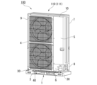
図2は、本実施の形態における梱包用基台1の上部に冷凍サイクル装置100の室外機110が物品として載置された斜視図である。
FIG. 2 is a perspective view of the
室外機110における室外機筐体111は、底板3と、正面パネル4と、サービスパネル5と、正面下側パネル6と、背面上側パネル7と、背面下側パネル8と、左側面パネル9と、天面パネル10と、脚部30を有する。底板3は、室外機110の底部に配置されている。正面パネル4は、室外機110の正面に設けられている。背面上側パネル7は、室外機110の背面における上側に設けられている。背面下側パネル8は、室外機110の背面における下側に設けられている。左側面パネル9は、室外機110の左側の側面に設けられている。天面パネル10は、室外機110の天面に設けられている。脚部30は、底板3よりも下側に突出して設けられている。脚部30は、正面パネル4よりも前側と背面下側パネル8よりも後ろ側に、間隔をあけてそれぞれ二つずつ設けられている。
The
図3は、梱包用基台1の斜視図である。梱包用基台1は、段ボール基材11と、補強角材12と、載置板13とを有する。
FIG. 3 is a perspective view of the
以下の梱包用基台1の説明においては、梱包用基台1において、載置された室外機110の天面パネル10が延びる方向を長手方向と呼ぶ。長手方向と直交し正面パネル4と背面上側パネル7とが並ぶ方向を短手方向と呼ぶ。長手方向と短手方向とに直交する方向であり、梱包用基台1に対して室外機110が載置される方向を高さ方向と呼ぶ。高さ方向は、梱包用基台1の厚さ方向である。短手方向において、正面パネル4が配置された側を前側と呼び、背面上側パネル7が配置された側を後ろ側と呼ぶ。高さ方向において、室外機110が配置される側を上側と呼び、梱包用基台1が配置される側を下側と呼ぶ。長手方向において、梱包用基台1の中心を向く側を長手方向内側と呼ぶ。長手方向において、梱包用基台1の中心と逆側を長手方向外側と呼ぶ。短手方向において、梱包用基台1の中心を向く側を短手方向内側と呼ぶ。短手方向において、梱包用基台1の中心と逆側を短手方向外側と呼ぶ。
In the following description of the
補強角材12は、第1補強角材12Aと、第2補強角材12Bとを含む。第1補強角材12Aと第2補強角材12Bとは、長手方向に延びている。第1補強角材12Aは、載置板13の上側に複数配置されている。第1補強角材12Aは、梱包用基台1における短手方向の両縁部と中央部とにそれぞれ配置されている。第2補強角材12Bは、載置板13の下側に配置されている。第2補強角材12Bは、短手方向の前側と後ろ側とにそれぞれ配置されている。補強角材12は、例えば、木材、または紙管で形成されている。
The reinforced
段ボール基材11は、底面部15と、側面部16と、上面部17と、持ち手部18とを有する。底面部15は、高さ方向と直交する平面に沿って配置された板状の部分である。底面部15は、段ボール基材11における下端に位置する。底面部15は、平面視で一方向に長い矩形状である。側面部16は、長手方向に間隔を空けて一対配置されている。一対の側面部16のそれぞれは、底面部15における長手方向の両端部のそれぞれから上側に突出している。側面部16は、長手方向と直交する平面に沿って配置された板状の部分である。上面部17は、高さ方向と直交する平面に沿って配置された板状の部分である。上面部17は、長手方向に間隔をあけて一対配置されている。一対の上面部17のそれぞれは、各側面部16の上端部から長手方向内側に突出している。上面部17は、段ボール基材11における上端に位置する。
The
持ち手部18は、短手方向と直交する平面に沿って配置された板状の部分である。持ち手部18は、複数設けられている。本実施の形態では、持ち手部18は、4つ設けられている。4つの持ち手部18は、段ボール基材11のうち長手方向一方側の端部における短手方向両側に設けられた2つの持ち手部18と、段ボール基材11のうち長手方向他方側の端部における短手方向両側に設けられた2つの持ち手部18と、を含む。持ち手部18のそれぞれは、開口部14を有する。なお、図3では、前側に位置する開口部14のみ図示している。開口部14のそれぞれは、短手方向に視たときに長手方向に長い矩形状である。開口部14のそれぞれは、持ち手部18を短手方向に貫通している。
The
図4は、梱包用基台1における段ボール基材11の展開図である。図4おいて破線は、折り曲げ線(罫線)である。図4において実線のうち、外形輪郭以外の実線は破断線である。
FIG. 4 is a developed view of the
段ボール基材11は、底面部15と、側面部16と、上面部17と、第1持ち手部18Aと、第2持ち手部18Bとを有する1枚構成である。展開図において、第1持ち手部18Aは、底面部15の長手方向の両側の端部から折り曲げ線を介して短手方向の前側および後ろ側にそれぞれ張り出す。第1持ち手部18Aのそれぞれは、開口部14Aを有する。開口部14Aは、第1持ち手部18Aを貫通している。
The corrugated
図5は、開口部14を含む長手方向の位置における、長手方向と直交する部分断面図である。
図5に示すように、第1持ち手部18Aは、底面部15の短手方向の端部から上側に折り曲げられる。第1持ち手部18Aは、持ち手部18の一部を形成する。開口部14Aは、開口部14の一部を形成する。FIG. 5 is a partial cross-sectional view orthogonal to the longitudinal direction at a longitudinal position including the
As shown in FIG. 5, the
図4に戻り、展開図において側面部16は、底面部15の長手方向の両端から折り曲げ線を介してそれぞれ長手方向外側に張り出す。展開図において上面部17は、側面部16の長手方向の端部から折り曲げ線を介してそれぞれ長手方向外側に張り出す。展開図において第2持ち手部18Bは、上面部17の短手方向の両側の端部から折り曲げ線を介して短手方向の前側および後ろ側にそれぞれ張り出す。
Returning to FIG. 4, in the developed view, the
第2持ち手部18Bのそれぞれは、差し込み片19と、第2差し込み片20とを有する。差し込み片19は、展開図において第2持ち手部18Bの長手方向内側の端部から折り曲げ線を介して長手方向内側に張り出す。第2差し込み片20は、第2持ち手部18Bの中央部分である。第2差し込み片20は、折り曲げ線と切込みとで囲まれた平面視略矩形状である。第2差し込み片20における折り曲げ線は、展開図において短手方向内側の辺に位置する。
Each of the
図3に示すように、側面部16は、底面部15の長手方向の両側の端部からそれぞれ上側に折り曲げられる。上側に折り曲げられた側面部16は、載置板13の上側に配置された複数の第1補強角材12Aにおける長手方向端部と長手方向外側でそれぞれ向かい合う。上面部17は、上側に折り曲げられた側面部16の端部から長手方向内側に折り曲げられる。第2持ち手部18Bは、図5に示すように、長手方向内側に折り曲げられた上面部17の短手方向の端部から下側に折り曲げられる。
As shown in FIG. 3, the
下側に折り曲げられた第2持ち手部18Bは、上側に折り曲げられた第1持ち手部18Aに短手方向外側から重ね合わされる。重ね合わされた第1持ち手部18Aと第2持ち手部18Bとは、複合壁として持ち手部18を形成する。持ち手部18が複合壁で形成されることにより、持ち手部18の強度が向上する。
The
図6は、持ち手部18を部分的に拡大した斜視図である。図6に示すように、第2持ち手部18Bを下側に折り曲げる際には、側面部16と第1持ち手部18Aとの長手方向の隙間21に、第2持ち手部18Bに対して短手方向内側に折り曲げた差し込み片19を短手方向外側から差し込む。隙間21に差し込まれた差し込み片19は、側面部16の長手方向内側に位置する。側面部16と第1持ち手部18Aとの間の隙間21に差し込み片19を差し込むことで、組み立てた段ボール基材11の強度が向上するとともに、分解しづらくなる。
FIG. 6 is a partially enlarged perspective view of the
第2持ち手部18Bを下側に折り曲げた際に、第2差し込み片20は第1持ち手部18Aの開口部14Aと向かい合う。下側に折り曲げられた第2持ち手部18Bに対しては、第2差し込み片20を折り曲げ線から短手方向内側に折り曲げ、第1持ち手部18Aの開口部14Aに差し込む。第1持ち手部18Aの開口部14Aに第2差し込み片20を差し込むことにより、さらに持ち手部18の強度を向上させることができる。
When the
第2差し込み片20を折り曲げることで、第2持ち手部18Bには開口部14Bが形成される。開口部14Bは、第2持ち手部18Bを短手方向に貫通している。開口部14Bは、第1持ち手部18Aの開口部14Aと短手方向につながり開口部14を形成する。開口部14に手指を挿入することで、持ち手部18を介して梱包用基台1を搬送することができる。
By bending the
図3に戻り、載置板13は、長手方向に間隔をあけて二つ配置されている。載置板13は、底面部15における長手方向の両端部にそれぞれ設けられている。載置板13は、図5および図6に示すように、平板部31と、突起部32と支持面33、34と保持面35とを有する。
Returning to FIG. 3, two mounting
平板部31は、底面部15における長手方向の端部に配置される。平板部31の上面31aは、段ボール基材11の上面部17に覆われている。平板部31の上面31aが上面部17に覆われることで、載置板13が段ボール基材11から外れにくくなる。平板部31の短手方向外側の端部は、平板部31の短手方向両側に配置された持ち手部18同士の間で保持される。従って、載置板13は、複合壁で形成され強度が向上した持ち手部18により短手方向に位置決めされる。
The
図5に示すように、平板部31の短手方向の端面には、短手方向内側に窪む窪み31bが形成されている。長手方向の窪み31bの位置は、開口部14と短手方向に向かい合う位置である。窪み31bは、上側に開口している。窪み31bの短手方向の深さは、第2差し込み片20の短手方向の長さよりも大きい。窪み31bの短手方向の深さが第2差し込み片20の短手方向の長さよりも大きいことで、第2差し込み片20が載置板13に接することを回避できる。開口部14と向かい合う位置に窪み31bが形成されていることで、開口部14に挿入した手指が載置板13に接することを抑制できる。
As shown in FIG. 5, a
突起部32は、短手方向に間隔をあけて配置されている。突起部32は、平板部31の長手方向内側に設けられている。突起部32の長手方向の位置は、室外機110の脚部30が配置される位置である。突起部32は、段ボール基材11の上面部17よりも上側に突出している。突起部32の短手方向外側面は、外側に向かうに従って下側に向かう方向に傾斜している。
The
支持面33は、突起部32よりも短手方向外側にそれぞれ配置されている。図5および図6に示すように、支持面33は、上側に向いて長手方向に延びている。支持面33は、載置板13の長手方向の幅全体に亘って形成されている。支持面33は、第1補強角材12Aの下面を下側から支持する。支持面34は、短手方向の中央に配置されている。支持面34は、上側に向いて長手方向に延びている。支持面34は、載置板13の長手方向の幅全体に亘って形成されている。支持面34は、第1補強角材12Aの下面を下側から支持する。支持面33の高さ方向の位置と、支持面34の高さ方向の位置は同一である。突起部32よりも長手方向の外側に位置する支持面33および支持面34に支持された第1補強角材12Aは、段ボール基材11の上面部17に上側から覆われる。突起部32よりも長手方向の外側に位置する第1補強角材12Aの上面が、段ボール基材11の上面部17に上側から覆われることで、第1補強角材12Aが段ボール基材11から外れにくくなる。
The support surfaces 33 are each arranged on the outer side of the
保持面35は、支持面33の短手方向内側の端部から上側に突出する。保持面35は、短手方向外側に向き長手方向に延びる。保持面35は、持ち手部18との間で、支持面33に支持された第1補強角材12Aを短手方向に保持する。より詳細には、保持面35は、第1持ち手部18Aの内面との間で、支持面33に支持された第1補強角材12Aを短手方向に保持する。支持面33に支持された第1補強角材12Aは、保持面35と第1持ち手部18Aの内面との間で保持されて短手方向に位置決めされる。
The holding
図5に示すように、載置板13は、短手方向の前側の端部において第2補強角材12Bの上面に載置される。第2補強角材12Bは、載置板13と段ボール基材11の底面部15との間で高さ方向に位置決めされる。従って、図2および図3に示されるように、高さ方向に離れた第1補強角材12Aと第2補強角材12Bとの間には、フォークリフトの爪の差込口40となる空隙が、長手方向に離れて配置された載置板13同士の間に形成される。
As shown in FIG. 5, the mounting
本実施の形態における梱包用基台1は、1枚構成の段ボール基材11における底面部15上に、第2補強角材12Bと、載置板13と、第1補強角材12Aとを順次載置する。その後、第1持ち手部18Aと、側面部16と、上面部17と、第1持ち手部18Aとを上述したように順次折り曲げるとともに、差し込み片19を隙間21に差し込むことで梱包用基台1が組み立てられる。
In the
本実施の形態における室外機110の脚部30は、組み立てられた梱包用基台1において突起部32の長手方向の位置にあり、短手方向の前側および後ろ側に配置された第1補強角材12A上に載置される。底板3における短手方向の中央に、下側に突出する突部が設けられた室外機110の場合は、短手方向の中央に配置された第1補強角材12A上に突部が載置される。
The
室外機110が載置された梱包用基台1に対しては、前側からフォークリフトの爪を差込口40に差し込むことで、第1補強角材12Aを介して室外機110を運搬することができる。また、開口部14から手指を挿入して持ち手部18を掴むことで、梱包用基台1を介して人手による室外機110の運搬も可能になる。
For the
フォークリフトにより梱包用基台1を介して室外機110を運搬できるため、別途パレットを使用することがなく、フォークリフトによる荷役作業が可能となる。従って、本実施の形態における室外機110では、運搬に際し、パレットの手配に要するコストや、梱包に要する手間を抑制することができる。
Since the
本実施の形態における梱包用基台1は、1枚構成の段ボール基材11を折り曲げることで簡単に組み立てることができる。本実施の形態における梱包用基台1は、差し込み片19を隙間21に差し込むことで、梱包用基台1が分解して補強角材12が外れることを抑制して梱包用基台1の強度を向上させることができる。本実施の形態における梱包用基台1は、第1補強角材12Aの長手方向端部の外側で側面部16が向かい合うため、第1補強角材12Aの長手方向の位置がずれることを抑制できる。
The
本実施の形態における梱包用基台1は、保持面35と第1持ち手部18Aの内面との間で、第1補強角材12Aを短手方向に保持する。従って、本実施の形態における梱包用基台1は、第1補強角材12Aを短手方向に位置決めすることができる。
The
工場のライン組み立て時に不具合が見られた場合などには、梱包が完全でない状態での搬送である裸搬送を行うときがある。本実施の形態においては、裸搬送を行う際にも、梱包用基台1が分解してしまうことを抑制できる。
If a problem is found during assembly on a factory line, there may be times when the product is transported unpacked (unpacked). In this embodiment, it is possible to prevent the
冷凍サイクル装置は、冷媒が循環する冷凍サイクルを利用する装置であればよく、空気調和装置に限られない。冷凍サイクル装置は、ヒートポンプを備えた給湯器などであってもよい。以上、本明細書において説明した各構成および各方法は、相互に矛盾しない範囲内において、適宜組み合わせることができる。 The refrigeration cycle device may be any device that utilizes a refrigeration cycle in which refrigerant circulates, and is not limited to an air conditioner. The refrigeration cycle device may be a water heater equipped with a heat pump. As mentioned above, each structure and each method explained in this specification can be combined as appropriate within a mutually consistent range.
1 梱包用基台、11 段ボール基材、12 補強角材、13 載置板、 14 開口部、15 底面部、16 側面部、17 上面部、18A 第1持ち手部、18B 第2持ち手部、19 差し込み片、20 第2差し込み片、33 支持面、 35 保持面、100 冷凍サイクル装置、110 室外機(物品) 1 Packing base, 11 Cardboard base material, 12 Reinforcing square material, 13 Placing plate, 14 Opening, 15 Bottom, 16 Side, 17 Top, 18A first handle, 18B second handle, 19 insertion piece, 20 second insertion piece, 33 support surface, 35 holding surface, 100 refrigeration cycle device, 110 outdoor unit (article)
Claims (6)
前記底面部の上側に設けられ前記底面部の長手方向に延びる複数の補強角材と、
前記底面部の上側に前記長手方向に間隔をあけて配置され物品が載置される複数の載置板と、
を備え、
前記載置板は、
前記長手方向と直交する前記底面部の短手方向の両端部に配置され、上側に向いて前記長手方向に延びる支持面を有し、
前記補強角材の下面の一部は、前記支持面に支持され、
前記段ボール基材は、
前記底面部の前記長手方向の両側にそれぞれ配置され、前記底面部の前記短手方向の両側の端部からそれぞれ上側に折り曲げられた第1持ち手部と、
前記底面部の前記長手方向の両側にそれぞれ配置され、前記底面部の前記長手方向の両側の端部からそれぞれ上側に折り曲げられ、前記補強角材の前記長手方向の端部より外側で前記補強角材の端部と向かい合う側面部と、
上側に折り曲げられたそれぞれの前記側面部の端部から前記長手方向の内側に折り曲げられ、前記載置板における前記長手方向の端部の上面を覆う上面部と、
前記長手方向の内側に折り曲げられた前記上面部の前記短手方向の両側の端部からそれぞれ下側に折り曲げられ、上側に折り曲げられた前記第1持ち手部に前記短手方向の外側から重ね合わされた第2持ち手部と、
下側に折り曲げられた前記第2持ち手部の前記長手方向の外側の端部から前記短手方向の内側に折り曲げられ、前記長手方向で前記側面部と前記第1持ち手部との間の隙間に差し込まれた差し込み片と、
を有する、梱包用基台。 A cardboard base material having a bottom portion that is long in one direction;
a plurality of reinforcing square members provided above the bottom surface portion and extending in the longitudinal direction of the bottom surface portion;
a plurality of placement plates arranged above the bottom surface at intervals in the longitudinal direction and on which articles are placed;
Equipped with
The above-mentioned mounting plate is
having support surfaces disposed at both ends in the short direction of the bottom part perpendicular to the longitudinal direction, facing upward and extending in the longitudinal direction;
A portion of the lower surface of the reinforcing square member is supported by the support surface,
The cardboard base material is
first handle parts arranged on both sides of the bottom part in the longitudinal direction and bent upward from both ends of the bottom part in the short direction;
The reinforcing square bars are arranged on both sides of the bottom part in the longitudinal direction, are bent upward from both ends of the bottom part in the longitudinal direction, and are bent upward from the ends of the reinforcing square bars in the longitudinal direction. a side face facing the end;
an upper surface portion that is bent inward in the longitudinal direction from an end of each side surface portion that is bent upward, and covers an upper surface of the end of the longitudinal direction of the mounting plate;
The upper surface portion is bent inward in the longitudinal direction, and is bent downward from both ends in the transverse direction, and overlapped with the first handle portion bent upward from the outside in the transverse direction. a second handle portion,
The second handle part is bent downward from the outer end in the longitudinal direction, and is bent inward in the transverse direction, and between the side face part and the first handle part in the longitudinal direction. The insert piece inserted into the gap,
A packaging base having a
前記支持面の前記短手方向の内側の端部から上側に突出し、前記短手方向の外側に向き前記長手方向に延びる保持面を有し、
前記補強角材は、上側に折り曲げられた前記第1持ち手部の内面と前記保持面との間で前記短手方向に保持されている、
請求項1に記載の梱包用基台。 The above-mentioned mounting plate is
a holding surface that protrudes upward from an inner end of the support surface in the transverse direction, faces outward in the transverse direction and extends in the longitudinal direction;
The reinforcing square material is held in the lateral direction between the inner surface of the first handle portion bent upward and the holding surface.
The packaging base according to claim 1.
前記第2持ち手部は、折り曲げ線と切込みとで囲まれ前記開口部と前記短手方向に向かい合う第2差し込み片を有し、
前記第2差し込み片は、下側に折り曲げられた前記第2持ち手部に対して、前記折り曲げ線から前記短手方向の内側に折り曲げられて前記開口部に差し込まれている、
請求項1または2に記載の梱包用基台。 The first handle portion has an opening that penetrates in the lateral direction,
The second handle portion has a second insertion piece that is surrounded by a bending line and a notch and faces the opening and the widthwise direction,
The second insertion piece is bent inward in the lateral direction from the bending line with respect to the second handle portion bent downward, and inserted into the opening.
The packaging base according to claim 1 or 2.
請求項1から3のいずれか一項に記載の梱包用基台。 The upper surface portion covers the upper surface of the longitudinal end of the reinforcing square material whose lower surface is supported by the support surface.
The packaging base according to any one of claims 1 to 3.
Applications Claiming Priority (1)
| Application Number | Priority Date | Filing Date | Title |
|---|---|---|---|
| PCT/JP2021/003957 WO2022168206A1 (en) | 2021-02-03 | 2021-02-03 | Packaging base, outdoor unit, and refrigeration cycle device |
Publications (2)
| Publication Number | Publication Date |
|---|---|
| JPWO2022168206A1 JPWO2022168206A1 (en) | 2022-08-11 |
| JP7391250B2 true JP7391250B2 (en) | 2023-12-04 |
Family
ID=82740957
Family Applications (1)
| Application Number | Title | Priority Date | Filing Date |
|---|---|---|---|
| JP2022579216A Active JP7391250B2 (en) | 2021-02-03 | 2021-02-03 | Packing base, outdoor unit, and refrigeration cycle equipment |
Country Status (2)
| Country | Link |
|---|---|
| JP (1) | JP7391250B2 (en) |
| WO (1) | WO2022168206A1 (en) |
Citations (1)
| Publication number | Priority date | Publication date | Assignee | Title |
|---|---|---|---|---|
| JP2000033972A (en) | 1998-07-17 | 2000-02-02 | Matsushita Electric Ind Co Ltd | Packaging member for laser printer |
Family Cites Families (1)
| Publication number | Priority date | Publication date | Assignee | Title |
|---|---|---|---|---|
| JPS5955121U (en) * | 1982-10-01 | 1984-04-11 | 株式会社東芝 | packaging equipment |
-
2021
- 2021-02-03 WO PCT/JP2021/003957 patent/WO2022168206A1/en active Application Filing
- 2021-02-03 JP JP2022579216A patent/JP7391250B2/en active Active
Patent Citations (1)
| Publication number | Priority date | Publication date | Assignee | Title |
|---|---|---|---|---|
| JP2000033972A (en) | 1998-07-17 | 2000-02-02 | Matsushita Electric Ind Co Ltd | Packaging member for laser printer |
Also Published As
| Publication number | Publication date |
|---|---|
| WO2022168206A1 (en) | 2022-08-11 |
| JPWO2022168206A1 (en) | 2022-08-11 |
Similar Documents
| Publication | Publication Date | Title |
|---|---|---|
| US7648026B2 (en) | Packaging assembly for containing and shipping articles | |
| JP7391250B2 (en) | Packing base, outdoor unit, and refrigeration cycle equipment | |
| JP2011158163A (en) | Heat source unit and packing material | |
| KR101156293B1 (en) | Air conditioner indoor unit | |
| JP5402987B2 (en) | Refrigeration unit outdoor unit | |
| JP6942260B2 (en) | Package of outdoor unit of refrigeration cycle equipment | |
| AU2008325729A1 (en) | Cushioning device | |
| JP7050956B2 (en) | Outdoor unit packing device | |
| JP6795834B2 (en) | Stove packing material and stove | |
| JP2007246118A (en) | Packaging material and packaging method | |
| JP7138733B2 (en) | Outdoor unit packing device | |
| JP5516476B2 (en) | Air conditioner packaging equipment | |
| JP5423752B2 (en) | Packing pad for packaging | |
| JP7001940B2 (en) | Transport refrigeration equipment and transport containers | |
| JP7113981B2 (en) | package | |
| JP6744656B2 (en) | Stove packaging material and stove | |
| KR100735187B1 (en) | A packing box for Accessories | |
| JP7191611B2 (en) | Transport container and its use | |
| JP2002104415A (en) | Cargo handling pallet using bar and wire | |
| JP7433544B2 (en) | heat exchange unit | |
| JPWO2019193694A1 (en) | Package | |
| JP7174137B1 (en) | Assembled tray | |
| WO2021177077A1 (en) | Refrigeration device and transport container | |
| JP5423753B2 (en) | Packing pad for packaging | |
| JP2010076825A (en) | Package apparatus for outdoor unit |
Legal Events
| Date | Code | Title | Description |
|---|---|---|---|
| A621 | Written request for application examination |
Free format text: JAPANESE INTERMEDIATE CODE: A621 Effective date: 20230105 |
|
| A131 | Notification of reasons for refusal |
Free format text: JAPANESE INTERMEDIATE CODE: A131 Effective date: 20230606 |
|
| A521 | Request for written amendment filed |
Free format text: JAPANESE INTERMEDIATE CODE: A523 Effective date: 20230707 |
|
| TRDD | Decision of grant or rejection written | ||
| A01 | Written decision to grant a patent or to grant a registration (utility model) |
Free format text: JAPANESE INTERMEDIATE CODE: A01 Effective date: 20231024 |
|
| A61 | First payment of annual fees (during grant procedure) |
Free format text: JAPANESE INTERMEDIATE CODE: A61 Effective date: 20231121 |
|
| R150 | Certificate of patent or registration of utility model |
Ref document number: 7391250 Country of ref document: JP Free format text: JAPANESE INTERMEDIATE CODE: R150 |