JP7388564B2 - PTP management system - Google Patents
PTP management system Download PDFInfo
- Publication number
- JP7388564B2 JP7388564B2 JP2022542548A JP2022542548A JP7388564B2 JP 7388564 B2 JP7388564 B2 JP 7388564B2 JP 2022542548 A JP2022542548 A JP 2022542548A JP 2022542548 A JP2022542548 A JP 2022542548A JP 7388564 B2 JP7388564 B2 JP 7388564B2
- Authority
- JP
- Japan
- Prior art keywords
- feature
- ptp
- ptp sheet
- feature point
- image
- Prior art date
- Legal status (The legal status is an assumption and is not a legal conclusion. Google has not performed a legal analysis and makes no representation as to the accuracy of the status listed.)
- Active
Links
Images


Classifications
-
- G—PHYSICS
- G06—COMPUTING OR CALCULATING; COUNTING
- G06T—IMAGE DATA PROCESSING OR GENERATION, IN GENERAL
- G06T7/00—Image analysis
- G06T7/70—Determining position or orientation of objects or cameras
- G06T7/73—Determining position or orientation of objects or cameras using feature-based methods
-
- G—PHYSICS
- G06—COMPUTING OR CALCULATING; COUNTING
- G06V—IMAGE OR VIDEO RECOGNITION OR UNDERSTANDING
- G06V10/00—Arrangements for image or video recognition or understanding
- G06V10/70—Arrangements for image or video recognition or understanding using pattern recognition or machine learning
- G06V10/74—Image or video pattern matching; Proximity measures in feature spaces
- G06V10/761—Proximity, similarity or dissimilarity measures
-
- G—PHYSICS
- G06—COMPUTING OR CALCULATING; COUNTING
- G06V—IMAGE OR VIDEO RECOGNITION OR UNDERSTANDING
- G06V10/00—Arrangements for image or video recognition or understanding
- G06V10/20—Image preprocessing
- G06V10/24—Aligning, centring, orientation detection or correction of the image
- G06V10/245—Aligning, centring, orientation detection or correction of the image by locating a pattern; Special marks for positioning
-
- G—PHYSICS
- G06—COMPUTING OR CALCULATING; COUNTING
- G06V—IMAGE OR VIDEO RECOGNITION OR UNDERSTANDING
- G06V10/00—Arrangements for image or video recognition or understanding
- G06V10/40—Extraction of image or video features
- G06V10/56—Extraction of image or video features relating to colour
-
- G—PHYSICS
- G06—COMPUTING OR CALCULATING; COUNTING
- G06V—IMAGE OR VIDEO RECOGNITION OR UNDERSTANDING
- G06V10/00—Arrangements for image or video recognition or understanding
- G06V10/40—Extraction of image or video features
- G06V10/60—Extraction of image or video features relating to illumination properties, e.g. using a reflectance or lighting model
Landscapes
- Engineering & Computer Science (AREA)
- Theoretical Computer Science (AREA)
- Physics & Mathematics (AREA)
- General Physics & Mathematics (AREA)
- Multimedia (AREA)
- Computer Vision & Pattern Recognition (AREA)
- Software Systems (AREA)
- Artificial Intelligence (AREA)
- Health & Medical Sciences (AREA)
- Computing Systems (AREA)
- Databases & Information Systems (AREA)
- Evolutionary Computation (AREA)
- General Health & Medical Sciences (AREA)
- Medical Informatics (AREA)
- Image Analysis (AREA)
- Medical Preparation Storing Or Oral Administration Devices (AREA)
Description
本発明は、PTPシートの個体を管理するPTP管理システム、PTP管理方法、および、記録媒体に関する。 The present invention relates to a PTP management system, a PTP management method, and a recording medium for managing individual PTP sheets.
医薬品包装の分野において、錠剤、カプセル剤等の固形製剤の包装体として、PTP(Press Through Pack)シートが広く用いられている。PTPシートは、一方の面に開口部を有する複数のポケット部と上記開口部の周縁に設けられ上記一方の面を構成するフランジ部とからなる容器フィルムの上記ポケット部に内容物である固形製剤を収容し、破断可能なカバーフィルムを上記フランジ部で熱接着して上記ポケット部を密封したものである。 In the field of pharmaceutical packaging, PTP (Press Through Pack) sheets are widely used as packaging bodies for solid preparations such as tablets and capsules. The PTP sheet is a container film that includes a plurality of pockets each having an opening on one surface and a flange that is provided around the opening and constitutes the one surface. A breakable cover film is thermally bonded to the flange portion to seal the pocket portion.
ところで、悪化し続ける医薬品の偽造問題と相まって、個々の医薬品の個体を管理する重要性が年々高まっている。そのため、医薬品を包装する形態として広く用いられているPTPシートにおいても、個体を識別できる個体識別機能を具備することが重要な課題となっている。 Incidentally, in conjunction with the problem of drug counterfeiting that continues to worsen, the importance of managing the individuality of individual drugs is increasing year by year. Therefore, it has become an important issue to provide PTP sheets, which are widely used as a form of packaging for pharmaceutical products, with an individual identification function that can identify individuals.
一般に物体に個体識別情報を設定する方法には、個体識別情報を印字したバーコードやQRコード(登録商標)などのラベルや、個体識別情報を格納したRFID(Radio Frequency Identifier)などを物体に貼り付ける方法がある。また、個体識別情報をレーザーマーカーやインクジェットなどによって物体に直接印刷する方法もある。しかし、個体識別情報を物体に付与する方法による個体識別では、物体に貼り付けるラベルや、物体に印刷する印刷設備などが必要となり、製造コストが増大する。また、個体識別情報を物体に付与する方法では、ラベルを物体に貼り付ける作業や、物体に個体識別情報を印刷する作業が必要になる。 Generally, methods for setting individual identification information on objects include attaching labels such as barcodes or QR codes (registered trademarks) with individual identification information printed on them, or RFID (Radio Frequency Identifier) that stores individual identification information on objects. There is a way to attach it. Another method is to print individual identification information directly onto objects using a laser marker or inkjet. However, individual identification using a method of attaching individual identification information to an object requires a label to be attached to the object, printing equipment to print on the object, etc., which increases manufacturing costs. Furthermore, the method of attaching individual identification information to an object requires the work of attaching a label to the object or printing the individual identification information on the object.
一方、印字にじみのような人工物メトリクスや、いわゆる物体指紋を用いて物体の個体を識別することが行われている(例えば、特許文献1、2参照)。このような方法によれば、個体識別情報を付与するための加工を必要とせずに物体の個体識別が行える。
On the other hand, individual objects have been identified using artifact metrics such as print bleeding or so-called object fingerprints (see, for example,
しかしながら、人工物メトリクスや物体指紋はマイクロメートルオーダーと非常にサイズが小さい。そのため、PTPシートの個体識別に適用する場合、高解像度の撮影手段が必要になる。 However, artifact metrics and object fingerprints are very small, on the order of micrometers. Therefore, when applied to individual identification of PTP sheets, a high resolution photographing means is required.
本発明は、上述した課題を解決するPTP管理システムを提供することにある。 An object of the present invention is to provide a PTP management system that solves the above-mentioned problems.
本発明の一形態に係るPTP管理システムは、
一方の面に複数設けられた開口部を有するポケット部と、前記ポケット部の周縁に設けられ前記一方の面を構成するフランジ部とからなる透明または半透明な容器フィルムの前記ポケット部内に内容物を収容し、少なくとも一方の面に所定の印刷部が形成された破断可能なカバーフィルムを前記フランジ部で熱接着して前記ポケット部を密封したPTPシートの個体を管理するシステムであって、
前記PTPシートを、前記印刷部が形成された前記ポケット部の開口部側または突出部側から撮影した画像を取得する取得手段と、
前記画像中の前記印刷部と前記熱接着時に前記カバーフィルムに形成される格子状パターンとの間の局所的な位置関係に依存する特徴量を抽出する抽出手段と、
前記抽出された特徴量から前記PTPシートの識別に用いられる個体識別情報を生成する生成手段と、
を備えるように構成されている。A PTP management system according to one embodiment of the present invention includes:
The contents are stored in the pocket of a transparent or translucent container film, which is made up of a pocket having a plurality of openings on one surface, and a flange provided on the periphery of the pocket and forming the one surface. A system for managing individual PTP sheets in which a breakable cover film having a predetermined printed portion formed on at least one surface is thermally bonded to the flange portion to seal the pocket portion, the system comprising:
an acquisition unit that acquires an image of the PTP sheet taken from the opening side or the protrusion side of the pocket portion where the printing portion is formed;
Extracting means for extracting a feature amount depending on a local positional relationship between the printed portion in the image and the grid pattern formed on the cover film during the thermal bonding;
generating means for generating individual identification information used for identifying the PTP sheet from the extracted feature amount;
It is configured to include.
また、本発明の他の形態に係るPTP管理方法は、
一方の面に複数設けられた開口部を有するポケット部と、前記ポケット部の周縁に設けられ前記一方の面を構成するフランジ部とからなる透明または半透明な容器フィルムの前記ポケット部内に内容物を収容し、少なくとも一方の面に所定の印刷部が形成された破断可能なカバーフィルムを前記フランジ部で熱接着して前記ポケット部を密封したPTPシートの個体を管理する方法であって、
前記PTPシートを、前記印刷部が形成された前記ポケット部の開口部側または突出部側から撮影した画像を取得し、
前記画像中の前記印刷部と前記熱接着時に前記カバーフィルムに形成される格子状パターンとの間の局所的な位置関係に依存する特徴量を抽出し、
前記抽出された特徴量から前記PTPシートの識別に用いられる個体識別情報を生成する、
ように構成されている。Further, a PTP management method according to another embodiment of the present invention includes:
The contents are stored in the pocket of a transparent or translucent container film, which is made up of a pocket having a plurality of openings on one surface, and a flange provided on the periphery of the pocket and forming the one surface. A method for managing an individual PTP sheet in which a breakable cover film having a predetermined printed portion formed on at least one surface is thermally bonded at the flange portion to seal the pocket portion, the method comprising:
Obtaining an image of the PTP sheet taken from the opening side or the protrusion side of the pocket portion where the printing portion is formed,
extracting a feature amount that depends on the local positional relationship between the printed portion in the image and the grid pattern formed on the cover film during the thermal bonding;
generating individual identification information used for identifying the PTP sheet from the extracted feature amount;
It is configured as follows.
また、本発明の他の形態に係るコンピュータ読み取り可能な記録媒体は、
一方の面に複数設けられた開口部を有するポケット部と、前記ポケット部の周縁に設けられ前記一方の面を構成するフランジ部とからなる透明または半透明な容器フィルムの前記ポケット部内に内容物を収容し、少なくとも一方の面に所定の印刷部が形成された破断可能なカバーフィルムを前記フランジ部で熱接着して前記ポケット部を密封したPTPシートの個体を管理するコンピュータに、
前記PTPシートを、前記印刷部が形成された前記ポケット部の開口部側または突出部側から撮影した画像を取得する処理と、
前記画像中の前記印刷部と前記熱接着時に前記カバーフィルムに形成される格子状パターンとの間の局所的な位置関係に依存する特徴量を抽出する処理と、
前記抽出された特徴量から前記PTPシートの識別に用いられる個体識別情報を生成する処理と、
を行わせるためのプログラムを記録するように構成されている。Further, a computer-readable recording medium according to another embodiment of the present invention includes:
The contents are stored in the pocket of a transparent or translucent container film, which is made up of a pocket having a plurality of openings on one surface, and a flange provided on the periphery of the pocket and forming the one surface. and a computer that manages an individual PTP sheet in which a breakable cover film having a predetermined printed portion formed on at least one surface is thermally bonded at the flange portion and the pocket portion is sealed;
a process of acquiring an image of the PTP sheet taken from an opening side or a protrusion side of the pocket portion where the printing portion is formed;
a process of extracting a feature quantity that depends on a local positional relationship between the printed portion in the image and the grid pattern formed on the cover film during the thermal bonding;
A process of generating individual identification information used for identifying the PTP sheet from the extracted feature amount;
The computer is configured to record a program for performing the following steps.
本発明は、上述した構成を有することにより、高解像度の撮影手段を必要とせずにPTPシートの個体識別が行える。 By having the above-described configuration, the present invention can individually identify a PTP sheet without requiring a high-resolution photographing means.
[第1の実施形態]
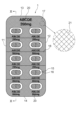
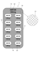
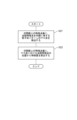
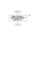
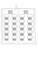
図1は、本発明の第1の実施形態において管理するPTPシート1の一例を示す平面図であり、PTPシート1をその表面側(ポケット部15の突出側)から見たものである。また、図2は、図1に示すPTPシート1をその裏面側(ポケット部15の開口部側)から見た平面図である。さらに、図3は、図1のX-X線に沿う断面図である。図1乃至図3を参照すると、PTPシート1は、平面視矩形状をなしており、その周縁部は、PTPシート1の長手方向に沿って延びるとともに、相対する平行の長辺部11、12と、両長辺部11、12間に設けられ、相対する平行な短辺部13、14とを有している。また、PTPシート1には、長辺部11、12方向に沿って配列された5個のポケット部15からなるポケット列が、短辺部13、14方向に2列形成されている。即ち、合計10個のポケット部15が形成されている。各ポケット部15には、内容物としての錠剤16が1つずつ収容されている。また、容器フィルム17は、透明または半透明の材料(例えば、無延伸ポリプロピレン等)により構成され、例えば2つのポケット部15が含まれたペア小片に切り離すことができるように複数の横スリット18が形成されている。カバーフィルム19は、不透明材料(例えば、アルミニウム箔など)により構成され、容器フィルム17に取着される側の面には、所定の印刷部20が設けられている。本例では、印刷部20は、「ABCDE」の文字列と「200mg」の文字列とを二段併記してなり、各ポケット部15に対応して1つずつ設けられるとともに、PTPシートの最上部(タグ部)にも1つ設けられている。これらの印刷部20は、図1に示すように容器フィルム17を透過してPTPシート1の表面側から視認可能になっている。また、容器フィルム17に対しカバーフィルム19を熱接着する際に形成された格子状の刻印は、カバーフィルム19のみならず容器フィルム17の取着面にも及ぶため、上記刻印による格子状パターン21は、図2に示すようにPTPシート1の裏面側(カバーフィルム19側)から視認可能であると共に、図1に示すように容器フィルム17を透過してPTPシート1の表面側(容器フィルム17側)からも視認可能になっている。[First embodiment]
FIG. 1 is a plan view showing an example of the
また、カバーフィルム19の容器フィルム17に取着される側とは反対側の面にも、所定の印刷部22が設けられている。本例では、印刷部22は、印刷部21と同様な「ABCDE」の文字列と「200mg」の文字列とを二段併記してなり、各ポケット部15に対応して1つずつ設けられるとともに、PTPシートの最上部(タグ部)にも1つ設けられている。従って、図2に示すように、PTPシート1の裏面側からは、印刷部22と格子状のパターン21とが視認可能になっている。なお、図2に示すように、ポケット部15の開口部に対応するカバーフィルム19の領域は熱接着時に押圧されないため、格子状パターン21は形成されていない。
Further, a
上述したようなPTPシート1は、PTP包装機によって製造される。例えば、PTP包装機は、帯状の透明または半透明な容器フィルム17に対しポケット部15を形成する工程、ポケット部15に錠剤16などの物品を充填する工程、容器フィルム17のフランジ部に対し帯状のカバーフィルム19を熱接着する工程、および、容器フィルム17およびカバーフィルム19からなる帯状のPTPフィルムをPTPシート単位に打抜く工程等を経て、多くのPTPシート1を短時間で大量に製造する。帯状のカバーフィルム19は、破断を容易にするために、アルミニウム箔などが用いられる。また、帯状のカバーフィルム19の両面には、印刷部20、21が事前に形成されている。容器フィルム17に対しカバーフィルム19を熱接着するシール工程では、接着時におけるカバーフィルム19の破れやピンホールの発生などを防止し、また強固なシールを実現するために、表面が凸状の格子状の柄に加工された金属製の熱板や熱ロールでカバーフィルム19側から強く圧接する。その結果、カバーフィルム19のポケット部15を除くフランジ部全体に格子状のパターン21が形成される。この格子状のパターン21は、カバーフィルム19側から視認できると共に、透明または半透明な容器フィルム17側からも視認できる。上記シール工程では、カバーフィルム19に印刷された文字列などの印刷部20、22がPTPシート単位で適切な位置にくるように、帯状の容器フィルム17に対する帯状のカバーフィルム19の取着位置が自動調整される。しかしながら、このような自動調整は格子状パターン21の形成位置を制御するものではないため、カバーフィルム19の僅かな伸びや縮の影響により、印刷部20、22と格子状のパターン21との間の位置関係は、PTPシート1の全ての個体で同じにならず、個体間で相違する現象が発生する。その一例を図4Aおよび図4Bに示す。
The
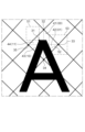
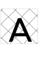
図4Aは、或る個体のPTPシート1に印刷された印刷部20の文字「A」付近の要部拡大平面図である。また、図4Bは、図4Aに示す個体とは異なる個体のPTPシート1の同じ個所の文字「A」付近の要部拡大平面図である。同じ個所の文字「A」であっても、その文字「A」とその周辺の格子状パターン21との位置関係が図4Aの個体と図4Bの個体とで相違している。
FIG. 4A is an enlarged plan view of the main part near the letter "A" of the
本実施形態は係る現象によって発生する印刷部20(または22)と格子状パターン21との間の個体毎に同じになるとは限らない局所的な位置関係を利用して、PTPシート1の識別に用いられる個体識別情報を生成するようにしている。以下、本実施形態に係るPTP管理装置100について詳細に説明する。
This embodiment utilizes the local positional relationship between the printing unit 20 (or 22) and the
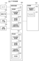
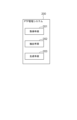
図5は、本発明の第1の実施形態に係るPTP管理装置100のブロック図である。図5に示すPTP管理装置100は、製造工程管理、品質管理、出荷管理、販売管理などのために、PTPシート1の個体を管理する情報処理装置である。
FIG. 5 is a block diagram of the PTP management device 100 according to the first embodiment of the present invention. The PTP management device 100 shown in FIG. 5 is an information processing device that manages
図5を参照すると、PTP管理装置100は、カメラ110と、通信I/F部120と、操作入力部130と、画面表示部140と、記憶部150と、演算処理部160とから構成されている。
Referring to FIG. 5, the PTP management device 100 includes a
カメラ110は、PTPシート1を撮影する撮影装置である。カメラ110は、例えば、数百万画素程度の画素容量を有するCCD(Charge-Coupled Device)イメージセンサやCMOS(Complementary MOS)イメージセンサを備えた可視光かつカラーカメラあるいは白黒カメラであってよい。
The
通信I/F部120は、データ通信回路から構成され、無線または有線によって外部装置との間でデータ通信を行うように構成されている。操作入力部130は、キーボードやマウスなどの装置から構成され、オペレータの操作を検出して演算処理部160に出力するように構成されている。画面表示部140は、LCD(Liquid Crystal Display)などの装置から構成され、演算処理部160からの指示に応じて、各種情報を画面表示するように構成されている。
The communication I/
記憶部150は、ハードディスクやメモリなどの記憶装置から構成され、演算処理部160における各種処理に必要な処理情報およびプログラム151を記憶するように構成されている。プログラム151は、演算処理部160に読み込まれて実行されることにより各種処理部を実現するプログラムであり、通信I/F部120などのデータ入出力機能を介して図示しない外部装置や記録媒体から予め読み込まれて記憶部150に保存される。記憶部150に記憶される主な処理情報には、個体識別情報DB152がある。
The
個体識別情報DB152は、登録対象のPTPシート1に係る個体識別情報を保存するデータベースである。
The individual
演算処理部160は、MPUなどのプロセッサとその周辺回路を有し、記憶部150からプログラム151を読み込んで実行することにより、上記ハードウェアとプログラム151とを協働させて各種処理部を実現するように構成されている。演算処理部160で実現される主な処理部は、登録部161、および照合部162である。
The
登録部161は、登録対象のPTPシート1の個体識別情報を生成し、個体識別情報DB152に登録するように構成されている。登録部161は、登録画像取得部1611と特徴量抽出部1612と個体識別情報生成部1613とを有する。
The
登録画像取得部1611は、登録対象のPTPシート1をポケット部15の開口部側または突出部側から撮影した画像(登録画像)をカメラ110から取得するように構成されている。
The registered
特徴量抽出部1612は、登録画像取得部1611によって取得されたPTPシート1の登録画像中の印刷部20または22と熱接着時にカバーフィルム19に形成される格子状パターン21との間の局所的な位置関係に依存する特徴量を抽出するように構成されている。
The
個体識別情報生成部1613は、登録画像取得部1611によって取得されたPTPシート1の登録画像毎に、特徴量抽出部1612によって抽出された特徴量からPTPシート1の識別に用いられる個体識別情報を生成し、個体識別情報DB152に保存するように構成されている。
The individual identification
照合部162は、個体識別情報に基づいてPTPシート1の照合を行うように構成されている。照合部162は、照合画像取得部1621と特徴量抽出部1622と個体識別情報生成部1623と判定部1624とを有する。
The
照合画像取得部1621は、照合対象のPTPシート1を撮影した画像(照合画像)をカメラ110から取得するように構成されている。
The verification
特徴量抽出部1622は、照合画像取得部1621によって取得された照合対象のPTPシート1の画像中の印刷部20または22と、熱接着時にカバーフィルム19に形成される格子状パターン21との間の局所的な位置関係に依存する特徴量を抽出するように構成されている。
The
個体識別情報生成部1623は、特徴量抽出部1622によって抽出された照合対象のPTPシート1に係る特徴量から照合対象のPTPシート1の識別に用いられる個体識別情報を生成するように構成されている。
The individual identification
判定部1624は、個体識別情報生成部1623によって生成された照合対象のPTPシート1に係る個体識別情報と個体識別情報DB152に保存されている登録対象のPTPシート1に係る個体識別情報とを比較することにより、照合対象のPTPシート1が何れの登録対象のPTPシート1と同一であるか否かを判定するように構成されている。また、判定部1624は、判定結果を画面表示部140に表示し、または/および、通信I/F部120を通じて外部の装置に出力するように構成されている。
The
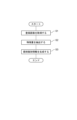
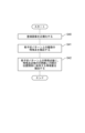
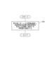
続いて、PTP管理装置100の動作を説明する。PTP管理装置100の動作は、登録動作と照合動作とに大別される。図6は、PTP管理装置100の登録動作の一例を示すフローチャートである。また、図7は、PTP管理装置100の照合動作の一例を示すフローチャートである。 Next, the operation of the PTP management device 100 will be explained. The operations of the PTP management device 100 are broadly divided into registration operations and verification operations. FIG. 6 is a flowchart showing an example of the registration operation of the PTP management device 100. Further, FIG. 7 is a flowchart showing an example of the verification operation of the PTP management device 100.
先ず、PTP管理装置100の登録動作を説明する。登録動作では、図6に示されるように、登録画像取得部1611は、登録対象のPTPシート1の個体毎に、そのPTPシート1を撮影した画像(登録画像)をカメラ110から取得する(ステップS1)。次に、特徴量抽出部1612は、登録画像取得部1611によって取得されたPTPシート1の個体の登録画像毎に、画像中の印刷部20または22と熱接着時にカバーフィルム19に形成された格子状パターン21との間の局所的な位置関係に依存する特徴量を抽出する(ステップS2)。次に、個体識別情報生成部1613は、登録画像取得部1611によって取得されたPTPシート1の個体の登録画像毎に、特徴量抽出部1612によって抽出された特徴量からPTPシート1の個体の識別に用いられる個体識別情報を生成し、個体識別情報DB152に保存する(ステップS3)。
First, the registration operation of the PTP management device 100 will be explained. In the registration operation, as shown in FIG. 6, the registered
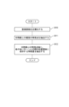
次に、照合動作を説明する。照合動作では、図7に示されるように、先ず、照合画像取得部1621は、照合対象のPTPシート1の個体を撮影した画像(照合画像)をカメラ110から取得する(ステップS4)。次に、特徴量抽出部1622は、照合画像取得部1621によって取得された照合対象のPTPシート1の個体の照合画像中の印刷部20または22と熱接着時にカバーフィルム19に形成された格子状パターン21との間の局所的な位置関係に依存する特徴量を抽出する(ステップS5)。次に、個体識別情報生成部1623は、特徴量抽出部1622によって抽出された特徴量から照合対象のPTPシート1の個体の識別に用いられる個体識別情報を生成する(ステップS6)。次に、判定部1624は、個体識別情報生成部1623によって生成された照合対象のPTPシート1の個体に係る個体識別情報と個体識別情報DB152に保存されている登録対象のPTPシート1の個体に係る個体識別情報とを比較することにより、照合対象のPTPシート1の個体が何れの登録対象のPTPシート1の個体と同一であるか否かを判定し、判定結果を出力する(ステップS7)。
Next, the matching operation will be explained. In the matching operation, as shown in FIG. 7, first, the matching
続いて、登録部161および照合部162について詳細に説明する。
Next, the
先ず、登録部161の登録画像取得部1611について詳細に説明する。
First, the registered
登録画像取得部1611は、例えば、PTP包装機によるPTPシート1の製造工程において、シート単位に打抜かれた後のPTPシート1を撮影した画像を取得するように構成してよい。
The registered
PTPシート1の製造工程では、例えば、打抜きが適正に行われているか否かなどの外観検査を行うために、打抜かれたPTPシート1を所定の姿勢で移送するコンベアに対応して、打抜き後検査装置を設けることがある。このような打抜き後検査装置は、PTPシート1に対し所定の光を照射する照明手段と、当該光の照射されたPTPシート1を撮影する撮影手段と、当該撮影手段で撮影されて得られた撮影画像に基づいて各種処理を行う処理装置とを備えている。登録画像取得部1611は、そのような打抜き後検査装置によって撮影されたPTPシート1の画像を登録画像として取得してよい。これによって、個体管理と外観検査とで別々に同じPTPシート1の個体を複数回にわたって撮影する手間とコストを削減することができる。但し、個体管理のためだけにPTPシート1を撮影するようにしてもよいことは勿論のことである。
In the manufacturing process of the
打抜かれたPTPシート1が、ポケット部15を上にした状態でコンベアによって搬送されているときに、コンベアの鉛直上方に配置された撮影手段によってコンベア上のPTPシート1を撮影した画像は、図1に示したように、PTPシート1をその表面側(ポケット部15の突出側)から撮影した画像となる。これは、登録画像取得部1611がPTPシート1をその表面側から撮影した登録画像を取得する一例である。
When the punched
また、打抜かれたPTPシート1が、ポケット部15を下にした状態でコンベアによって搬送されているときに、コンベアの鉛直上方に配置された撮影手段によってコンベア上のPTPシート1を撮影した画像は、図2に示したように、PTPシート1をその裏面側(ポケット部15の開口部側)から撮影した画像となる。これは、登録画像取得部1611がPTPシート1をその裏面側から撮影した登録画像を取得する一例である。
Further, while the punched
本実施形態が対象とするPTPシート1は、図1および図2に示したように、PTPシート1の表面側および裏面側の双方に印刷部20または22および格子状パターン21が形成されている。そのため、登録画像取得部1611は、PTPシート1をその表面側から撮影した登録画像を取得し、PTPシート1をその裏面側から撮影した画像は取得しないように構成されていてよい。或いは、登録画像取得部1611は、PTPシート1をその裏面側から撮影した登録画像を取得し、PTPシート1をその表面側から撮影した画像は取得しないように構成されていてよい。或いは、登録画像取得部1611は、PTPシート1をその表面側から撮影した登録画像と、PTPシート1をその裏面側から撮影した登録画像との双方を取得するように構成されていてよい。以下では、説明の便宜上、登録画像取得部1611は、PTPシート1をその表面側から撮影した登録画像だけを取得するように構成されているものとして説明する。
As shown in FIGS. 1 and 2, the
次に、登録部161の特徴量抽出部1612について詳細に説明する。
Next, the
図8は、特徴量抽出部1612の処理の一例を示すフローチャートである。図8を参照すると、先ず特徴量抽出部1612は、登録画像から正規化された登録画像を生成する(ステップS10)。正規化された登録画像は、PTPシートの向き及びサイズを一定に整えた画像である。正規化された登録画像を生成する方法は任意である。例えば、特徴量抽出部1612は、印刷部20(または22)と全く同じ印刷部を有するテンプレート画像と登録画像とのマッチングを行った結果に従って、正規化された登録画像を生成してよい。以下、正規化された登録画像を単に登録画像と呼ぶ。なお、照合部162の特徴量抽出部1622においても、登録画像の正規化と同様の方法により、照合画像から正規化された照合画像が生成される。
FIG. 8 is a flowchart illustrating an example of processing by the
次に、特徴量抽出部1612は、登録画像の印刷部20上の複数の特徴点を検出する(ステップS11)。印刷部20上の複数の特徴点は事前に定義されている。図9は、印刷部20上の複数の特徴点を定義したテーブルの例を示す。この例のテーブルは、複数のエントリから構成され、それぞれのエントリは、特徴点番号、印刷部番号、文字種類、位置の各項目から構成されている。特徴点番号の項目には、それぞれの特徴点を一意に識別する番号が設定される。印刷部番号の項目には、PTPシート1の表面に存在する11個の印刷部20から1つの印刷部を一意に識別する番号が設定される。例えば、図1に示したPTPシート1において、短辺部13側(タグ部側)を上、短辺部14側を下、長辺部11側を左、長辺部12側を右と定めた場合、左上から右下の方向に向かってラスタスキャン方向に印刷部20に連続番号を割り振ることで全ての印刷部20に一連番号を付与することができる。文字種類の項目には、印刷部番号で特定される印刷部20内に存在する複数の文字「ABCDE200mg」から1つの文字を特定する文字種類が設定される。文字種類でなく、先頭から何番目の文字であるかを示す文字番号によって1つの文字を特定してもよい。位置の項目には、文字種類で特定された1つの文字の部分を特定する位置が設定される。位置の項目に設定する値として、例えば、左上角、右上角、左下角、右下角、最上端、最下端、最右端、最左端などが考えられる。例えば、図9のテーブルの1行目は、特徴点番号1の特徴点は、印刷部番号1で特定される印刷部20内の文字種類Aで特定される文字「A」の左上角であることが定義されている。
Next, the
次に、特徴量抽出部1612は、特徴点のそれぞれについて、その特徴点とその特徴点近傍の格子状パターンとの間の位置関係に依存する特徴量を抽出する(ステップS12)。
Next, the feature
図10は、図8のステップS12の処理の一例を示すフローチャートである。図10を参照すると、特徴量抽出部1612は、特徴点のそれぞれについて、その特徴点を内部に有する格子状パターンのマス目を検出する(ステップS21)。例えば、図4Aに示す文字Aの左上角に定義された特徴点31の場合、その特徴点31を内部に有する格子状パターンのマス目は、4つの頂点32~35で規定されるマス目である。なお、特徴量抽出部1612は、特徴点の近傍に格子状パターンが存在しないため、特徴点を内部に有するマス目を検出しなかったときは、例えば、当該特徴点の特徴量を規定値とする。
FIG. 10 is a flowchart showing an example of the process of step S12 in FIG. Referring to FIG. 10, the
次に、特徴量抽出部1612は、特徴点のそれぞれについて、上記検出したマス目における当該特徴点の位置情報を当該特徴点の特徴量として抽出する(ステップS22)。マス目における特徴点の位置情報としては、各種の情報が考えられる。
Next, the feature
例えば、特徴量抽出部1612は、上記マス目における当該特徴点の位置情報として、マス目を所定の複数の部分領域に分割し、特徴点を内部に有する部分領域を特定する情報を当該特徴点の特徴量としてよい。例えば、図4Aに示す特徴点31の場合、特徴量抽出部1612は、特徴点31を内部に有するマス目を、図4Aの破線で示すように対向する頂点どうしを接続する線分によって4つの部分領域41~44に分割し、特徴点31を内部に有する部分領域44を特定する情報を特徴点31の特徴量とする。部分領域を特定する情報は、例えば、図4Aに示すように4つの部分領域41~44のそれぞれに割り振った番号(例えば、二進数で00、01、10、11)などを使用してよい。上記では、マス目を4分割したが、分割数は2以上であれば任意である。また、マス目を同じサイズに分割する以外に、異なるサイズに分割してもよい。
For example, the feature
また、特徴量抽出部1612は、上記マス目における当該特徴点の位置情報として、例えば、当該特徴点から前記マス目の所定の頂点へのベクトルを当該特徴点の特徴量としてよい。例えば、マス目の4つの頂点のうち左側の頂点を所定の頂点とする場合、図4Aに示す特徴点31の場合、特徴量抽出部1612は、特徴点31から頂点35へのベクトルを特徴点31の特徴量とする。また、例えば、マス目の4つの頂点のうち特徴点に最も近い頂点を所定の頂点とする場合、図4Aに示す特徴点31の場合、特徴量抽出部1612は特徴点31から頂点32へのベクトルを特徴点31の特徴量とする。
Further, the feature
上記したマス目における特徴点の位置情報は、例示であり、上記した情報に限定されないことは言うまでもない。 It goes without saying that the position information of the feature points in the squares described above is an example, and is not limited to the above information.
図11は、図8のステップS12の処理の他の例を示すフローチャートである。図11を参照すると、特徴量抽出部1612は、特徴点のそれぞれについて、その特徴点近傍の所定形状かつ所定サイズの局所領域の色または輝度に依存する特徴量を当該特徴点の特徴量として抽出する(ステップS31)。局所領域のサイズは、マス目のサイズと比較してあまりにも大きい場合や小さい場合、文字と格子状パターンとの局所的な位置ずれに依存する特徴量を抽出するのが難しくなるため、マス目の0.25倍から1.5倍程度のサイズであることが好ましい。また、局所領域の形状は、処理の容易化のために矩形であることが望ましいが、円形や三角形など矩形以外の形状であってもよい。また、特徴点と局所領域との位置関係は、文字領域の色や輝度の影響を受けないように、特徴点から見て局所領域が、特徴点が設定された文字の領域とは反対側に設定することが望ましい。例えば、図4Aに示す特徴点31の場合、特徴点31を1つの頂点とする同図の一点鎖線で記載する矩形領域を、特徴点31近傍の局所領域51としている。従って、特徴量抽出部1612は、局所領域51の色または輝度に依存する特徴量を特徴点31の特徴量として抽出する。なお、特徴点毎の局所領域の定義は、図9のテーブルに設定されていてもよい。
FIG. 11 is a flowchart showing another example of the process of step S12 in FIG. Referring to FIG. 11, for each feature point, the feature
或いは、特徴量抽出部1612は、上記局所領域の色または輝度から算出される色相または輝度の勾配の統計量に基づく特徴や、色相情報または輝度情報のフーリエ変換等によって得られる周波数特徴や、局所領域内の任意の画素ペアを取り出し、その輝度の大小関係から得られた二値特徴などを、当該特徴点の特徴量としてもよい。
Alternatively, the
図12は、特徴量抽出部1612の処理の他の例を示すフローチャートである。図12を参照すると、先ず特徴量抽出部1612は、図8と同様に登録画像から正規化された登録画像を生成する(ステップS40)。次に、特徴量抽出部1612は、登録画像の格子状パターン21上の複数の特徴点を検出する(ステップS41)。格子状パターン21上の複数の特徴点は事前に定義されている。図13は、格子状パターン21上の複数の特徴点を定義したテーブルの例を示す。この例のテーブルは、複数のエントリから構成され、それぞれのエントリは、特徴点番号、行番号、列番号、および位置の各項目から構成されている。特徴点番号の項目には、それぞれの特徴点を一意に識別する番号が設定される。行番号および列番号の項目には、それぞれの特徴点を所定の頂点として有するマス目を一意に識別する行番号および列番号が設定される。例えば、図1に示したPTPシート1において、短辺部13側(タグ部側)を上、短辺部14側を下、長辺部11側を左、長辺部12側を右と定め、上から下への並びを行方向、左から右への並びを列方向とする場合、格子状パターン21の各行および各列に連続した行番号および列番号を割り振ることでそれぞれの行および列を行番号および列番号で一意に識別することができる。そして、格子状パターン21のそれぞれのマス目は、行と列の交点に存在するため、行番号および列番号により一意に識別することができる。位置の項目には、マス目の4頂点のうちの1つの頂点を特定する情報が設定される。例えば、図13の1行目は、特徴点番号1の特徴点は、格子状パターン21の行番号5、列番号10で特定されるマス目の右頂点であることが定義されている。
FIG. 12 is a flowchart illustrating another example of the processing by the
次に、特徴量抽出部1612は、特徴点のそれぞれについて、その特徴点とその特徴点近傍の印刷部20との間の位置関係に依存する特徴量を当該特徴点の特徴量として抽出する(ステップS42)。
Next, for each feature point, the
図14は、図12のステップS42の処理の一例を示すフローチャートである。図14を参照すると、特徴量抽出部1612は、特徴点のそれぞれについて、その特徴点と印刷部20との最短距離およびその特徴点から最短距離地点への方向をその特徴点の特徴量として抽出する(ステップS51)。例えば、図4Aの頂点33が格子状パターン21の1つの特徴点である場合、当該特徴点と印刷部20との最短距離は、頂点33から文字Aへの垂線52で与えられる。また、当該特徴点から最短距離地点への方向は、垂線52の頂点33側の端点から垂線52の文字A側の端点への方向で与えられる。
FIG. 14 is a flowchart showing an example of the process of step S42 in FIG. Referring to FIG. 14, for each feature point, the
図15は、図12のステップS42の処理の他の例を示すフローチャートである。図15を参照すると、特徴量抽出部1612は、特徴点のそれぞれについて、その特徴点近傍の所定形状かつ所定サイズの局所領域の色または輝度に依存する特徴量を当該特徴点の特徴量として抽出する(ステップS61)。局所領域のサイズおよび形状の定め方は、ステップS31で説明した定め方と同じであってもよいし、違っていてもよい。例えば、図4Aに示す特徴点33の場合、特徴点33を重心とする同図の一点鎖線で記載する矩形領域を、特徴点33近傍の局所領域53としている。従って、特徴量抽出部1612は、局所領域53の色または輝度に依存する特徴量を特徴点33の特徴量として抽出する。
FIG. 15 is a flowchart showing another example of the process of step S42 in FIG. Referring to FIG. 15, for each feature point, the
次に、登録部161の個体識別情報生成部1613について詳細に説明する。
Next, the individual identification
個体識別情報生成部1613は、特徴量抽出部1612が特徴点毎に抽出した特徴量を組み合わせて、PTPシート1の登録画像の個体識別情報を生成する。例えば、個体識別情報生成部1613は、特徴点番号の番号順に、特徴点の特徴量を連結することによって、個体識別情報を生成してよい。特徴点の総数をn、1つの特徴点の特徴量のビット数をmとすると、PTPシート1の登録画像の個体識別情報のサイズはm×nビットになる。次に、個体識別情報生成部1613は、PTPシート1の登録画像の個体識別情報を個体識別情報DB152に保存する。
The individual identification
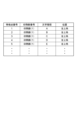
図16は、個体識別情報DB152の構成例を示す。この例の個体識別情報DB152は、PTPシート1の登録画像に1対1に対応する複数のエントリから構成され、各エントリは、個体識別情報、登録画像、および検査結果の各項目を有する。個体識別情報の項目には、登録画像から生成された個体識別情報が設定される。登録画像の項目には、登録画像を記録するファイル名が設定される。検査結果の項目には、PTPシート1の外観検査の検査結果を記録するファイル名が設定される。
FIG. 16 shows a configuration example of the individual
続いて、照合部162について詳細に説明する。なお、照合部162の特徴量抽出部1622および個体識別情報生成部1623は、登録部161の特徴量抽出部1612および個体識別情報生成部1623と比較して、対象となる画像が照合画像と登録画像で相違するだけであり、基本的な機能は同じである。従って、以下では、照合画像取得部1621と判定部1624について詳細に説明する。
Next, the
先ず、照合部162の照合画像取得部1621について詳細に説明する。
First, the matching
照合画像取得部1621は、例えば、真贋判定あるいは出所確認などが必要になったPTPシート1をカメラ110によって撮影した画像(照合画像)を取得するように構成してよい。照合画像取得部1621は、登録部161の登録画像取得部1611が取得した登録画像と同じ側のPTPシート1の画像を取得する。即ち、登録画像取得部1611がPTPシート1をその表面側から撮影した登録画像を取得し、その裏面側から撮影した画像は取得しないように構成されている場合、照合画像取得部1621は、照合対象のPTPシート1をその表面側から撮影した照合画像だけを取得してよい。また、登録画像取得部1611がPTPシート1をその裏面側から撮影した登録画像を取得し、その表面側から撮影した画像は取得しないように構成されている場合、照合画像取得部1621は、照合対象のPTPシート1をその裏面側から撮影した照合画像だけを取得してよい。また、登録画像取得部1611がPTPシート1をその表面側および裏面側の双方から撮影した登録画像を取得する場合、照合画像取得部1621は、照合対象のPTPシート1をその表面側および裏面側の双方から撮影した照合画像を取得する。
The verification
次に、照合部162の判定部1624について詳細に説明する。
Next, the
先ず、判定部1624は、個体識別情報DB152に保存されている登録画像の個体識別情報毎に、照合画像の個体識別情報との間の類似度を算出する。例えば、個体識別情報が上述したm×nビットで表現される場合、登録画像の個体識別情報を表すm×nビットと、照合画像の個体識別情報を表すm×nビットとの間のハミング距離を類似度として算出してよい。ハミング距離を類似度とするとき、類似度の値が0に近いほど、登録画像の個体識別情報と照合画像の個体識別情報とが類似する程度が高いことを表す。但し、類似度はハミング距離に限定されず、登録画像および照合画像の個体識別情報を構成する2つのベクトルのコサイン距離(コサイン類似度)あるいはユークリッド距離を2つの個体識別情報の類似度として算出してよい。
First, the
次に判定部1624は、上記算出した複数の類似度のうち最良の類似度が閾値より大きいか否かを判定する。前述したハミング距離を類似度とする場合、最良の類似度を示すハミング距離が閾値より小さいか否かを判定することになる。次に判定部1624は、最良の類似度が閾値より大きければ、照合画像に係るPTPシート1は最良の類似度が算出された個体識別情報を有する登録画像に係るPTPシート1と同一であると判定する。一方、判定部1624は、最良の類似度が閾値より小さければ、照合画像に係るPTPシート1と同一のPTPシート1は登録されていないと判定する。次に判定部1624は、判定結果を出力する。このとき、判定部1624は、照合画像に係るPTPシート1と同一と判定されたPTPシート1の検査結果を個体識別情報DB152から読み出して、判定結果と一緒に出力するようにしてもよい。
Next, the determining
このように本実施形態によれば、高解像度の撮影手段を必要とせずにPTPシートの個体識別が行える。その理由は、PTPシート1の画像中の印刷部20または22と熱接着時にカバーフィルム19に形成される格子状パターン21との間の局所的な位置関係に依存する特徴量からPTPシート1の識別に用いられる個体識別情報を生成するためである。例えば、格子状パターン21の1つのマス目の幅は0.5mmから1.5mm程度であるため、150dpi程度の解像度の撮影手段であれば、マス目と文字との局所的な位置関係を十分な精度で観測することができる。これに対して、印字にじみのような人工物メトリクスやいわゆる物体指紋はマイクロメートルオーダーのサイズであるため、150dpi程度の解像度では個体識別のための特徴量を抽出するのは困難である。
As described above, according to the present embodiment, individual PTP sheets can be identified without requiring high-resolution photographing means. The reason for this is that the
また、高速に大量のPTPシートを生産するPTP包装機の製造ラインに組み込まれた外観検査装置の撮影手段のPTPシート1の画像の解像度は、150dpi程度が限界である。そのため、本実施形態によれば、検査画像をそのまま使用して個体識別情報を生成することができる。
Furthermore, the resolution of the image of the
続いて、本実施形態の変形例について説明する。 Next, a modification of this embodiment will be described.
上記説明では、特徴量抽出部1612(および特徴量抽出部1622)は、PTPシート1の印刷部と格子状パターンとの間の局所的な位置関係に依存する特徴量だけからPTPシート1の個体識別情報を生成した。しかし、特徴量抽出部1612(および特徴量抽出部1622)は、PTPシート1の印刷部と格子状パターンとの間の局所的な位置関係に依存する特徴量以外に、PTPシート1の外周部(長辺部11、12、短辺部13、14)と印刷部20(または22)との間の位置関係に依存する特徴量、または、PTPシート1の上記外周部と格子状パターン21との間の位置関係に依存する特徴量を使用して、PTPシート1の個体識別情報を生成してもよい。その理由は、PTPシート1の外周部と印刷部20または格子状パターン21との間の位置関係は、全てのPTPシート1で同一であることは少なく、個体毎に相違するケースが多いためである。
In the above description, the feature extracting unit 1612 (and the feature extracting unit 1622) extracts the individual information on the
上記説明では、判定部1624は、個体識別情報を構成するビットを等しく扱って、登録画像の個体識別情報と照合画像の個体識別情報との類似度を算出した。しかし、個体識別情報を構成するビットには、信頼性の高いビットがある一方、信頼性の低いビットが存在する。例えば、図10のステップS22において、マス目を所定の複数の部分領域に分割し、特徴点を内部に有する部分領域を特定する情報を特徴点の特徴量とするとき、複数の部分領域の境界部分に位置する特徴点について抽出された特徴量は信頼性が低くなる。その理由は、僅かな撮影環境の違いによって、その特徴点が属する部分領域が変化するためである。そのため、特徴量抽出部1612(または1622)は、抽出した特徴量の信頼性の程度を示す信頼度を特徴量に付随して生成し、個体識別情報生成部1613(または1623)は、特徴点毎の特徴量を組み合わせて個体識別情報を生成する際、個体識別情報のビット毎にその生成元の特徴量に付随する信頼度に応じた信頼度ビットをあわせて生成する。そして、判定部1624は、信頼度ビットを考慮して、登録画像の個体識別情報と照合画像の個体識別情報との類似度を算出するようにしてもよい。例えば、判定部1624は、信頼度の高いビット間の類似度には大きな重みを乗じ、信頼度の低いビット間の類似度には小さな重みを乗じ、重み付け和で最終的な類似度を算出してよい。
In the above description, the determining
上記説明では、登録画像取得部1611は、PTP包装機によるPTPシート1の製造工程において、シート単位に打抜かれた後のPTPシート1を撮影した画像を取得した。しかし、登録画像取得部1611は、PTP包装機によるPTPシート1の製造工程において、打ち抜かれる前の最終的にPTPシート1となるシート予定部位を撮像した画像をPTPシート1の登録画像として取得してもよい。
In the above description, the registered
図17は、PTPシートを打ち抜く前のPTPフィルムをポケット部の突出側から見た模式図である。図17では、本来存在している格子状パターン21は図示を省略している。図17において、一点鎖線で囲まれた領域が最終的に1つのPTPシート1となるシート予定領域61である。
FIG. 17 is a schematic view of the PTP film before punching out the PTP sheet, viewed from the protruding side of the pocket portion. In FIG. 17, illustration of the
PTPシート1の製造工程では、例えば、錠剤割れ、欠錠、錠剤上の異物、シート上の異物などの検査を行うために、PTPシートに打抜かれる前の搬送中のPTPフィルムをポケット部の突出側から撮影して検査する装置を設けることがある。このような検査装置は、PTPフィルムに対し所定の光を照射する照明手段と、当該光の照射されたPTPフィルムのシート予定領域61を撮影する撮影手段と、当該撮影手段で撮影されて得られた撮影画像に基づいて各種処理を行う処理装置とを備えている。登録画像取得部1611は、そのような検査装置によって撮影されたシート予定領域61の画像を登録画像として取得してよい。これによって、個体管理と外観検査とで別々に同じPTPシート1の個体を複数回にわたって撮影する手間とコストを削減することができる。
In the manufacturing process of the
なお、PTPシートに打抜かれる前の搬送中のPTPフィルムに対しては、スリット形成装置によって横スリット18が形成される。従って、上記検査装置がスリット形成装置の上流側に配置されているときは、シート予定領域61には横スリット18は未だ形成されていないことになる。そのため、横スリット18が形成されていないシート予定領域61から特徴量を抽出する場合、特徴量抽出部1612は、横スリット18が形成される予定の領域を避けて、印刷部20と格子状パターン21との間の局所的な位置関係に依存する特徴量を抽出することが望ましい。また、シート予定領域61は、必ずしもコンマミリ単位で正確に打抜かれる保証はない。そして、打抜き誤差が生じると、図13に示した格子状パターンの特徴点の位置が打ち抜き前後でずれるため、図12で説明したように格子状パターン上に定義された特徴点とその周辺の印刷部20との間の位置関係も打ち抜き前後でずれることになる。これに対して、図8で説明した印刷部20上に定義される特徴点の位置は、打ち抜きの影響を受けない。そのため、打抜かれる前のPTPシート領域を登録画像として取得する場合、印刷部20上に定義された特徴点とその周辺の格子状パターンとの間の位置関係に依存する特徴量を抽出するようにすることが望ましい。
Note that a slit forming device forms
上記説明では、1台のPTP管理装置100が、登録部161および照合部162を備えていた。しかし、登録部161を備え、照合部162を備えないPTP管理装置や、照合部162を備え、登録部161を備えないPTP管理装置があってもよい。
In the above description, one PTP management device 100 was provided with the
[第2の実施の形態]
次に、本発明の第2の実施の形態について図18を参照して説明する。図18は、本実施の形態におけるPTP管理システム200のブロック図である。PTP管理システム200は、一方の面に複数設けられた開口部を有するポケット部と、上記ポケット部の周縁に設けられ前記一方の面を構成するフランジ部とからなる透明または半透明な容器フィルムの上記ポケット部内に内容物を収容し、少なくとも一方の面に所定の印刷部が形成された破断可能なカバーフィルムを上記フランジ部で熱接着して上記ポケット部を密封したPTPシートの個体を管理するシステムである。[Second embodiment]
Next, a second embodiment of the present invention will be described with reference to FIG. 18. FIG. 18 is a block diagram of
図18を参照すると、PTP管理システム200は、取得手段201と抽出手段202と生成手段203とを備えている。
Referring to FIG. 18, the
取得手段201は、PTPシートを、印刷部が形成されたポケット部の開口部側または突出部側から撮影した画像を取得するように構成されている。取得手段201は、例えば、図5の登録画像取得部1611と同様に構成することができるが、それに限定されない。
The
抽出手段202は、取得手段201によって取得された画像中の印刷部と熱接着時にカバーフィルムに形成される格子状パターンとの間の局所的な位置関係に依存する特徴量を抽出するように構成されている。抽出手段202は、例えば、図5の特徴量抽出部1612と同様に構成することができるが、それに限定されない。
The extracting means 202 is configured to extract a feature quantity that depends on the local positional relationship between the printed part in the image acquired by the acquiring means 201 and the grid pattern formed on the cover film during thermal bonding. has been done. The extraction means 202 can be configured in the same manner as the feature
生成手段203は、抽出手段202によって抽出された特徴量からPTPシートの識別に用いられる個体識別情報を生成するように構成されている。生成手段203は、例えば、図5の個体識別情報生成部1613と同様に構成することができるが、それに限定されない。
The generating means 203 is configured to generate individual identification information used for identifying the PTP sheet from the feature quantity extracted by the extracting
以上のように構成されたPTP管理システム200は、以下のように動作する。即ち、先ず取得手段201は、PTPシートを、印刷部が形成されたポケット部の開口部側または突出部側から撮影した画像を取得する。次に抽出手段202は、取得手段201によって取得された画像中の印刷部と熱接着時にカバーフィルムに形成される格子状パターンとの間の局所的な位置関係に依存する特徴量を抽出する。次に生成手段203は、抽出手段202によって抽出された特徴量からPTPシートの識別に用いられる個体識別情報を生成する。
The
本実施形態に係るPTP管理システム200は、以上のように構成され動作することにより、高解像度の撮影手段を必要とせずにPTPシートの個体識別が行える。その理由は、PTPシートの画像中の印刷部と熱接着時にカバーフィルムに形成される格子状パターンとの間の局所的な位置関係に依存する特徴量からPTPシートの識別に用いられる個体識別情報を生成するためである。
By being configured and operating as described above, the
以上、上記各実施形態を参照して本発明を説明したが、本発明は、上述した実施形態に限定されるものではない。本発明の構成や詳細には、本発明の範囲内で当業者が理解しうる様々な変更をすることができる。 Although the present invention has been described above with reference to the embodiments described above, the present invention is not limited to the embodiments described above. The configuration and details of the present invention may be modified in various ways within the scope of the present invention by those skilled in the art.
本発明は、PTPシートの真贋判定や個体識別のためにPTPシートを一意に識別する個体識別情報を生成するのに利用できる。 INDUSTRIAL APPLICABILITY The present invention can be used to generate individual identification information that uniquely identifies a PTP sheet in order to determine the authenticity of the PTP sheet and to identify the individual.
上記の実施形態の一部又は全部は、以下の付記のようにも記載され得るが、以下には限られない。
[付記1]
一方の面に複数設けられた開口部を有するポケット部と、前記ポケット部の周縁に設けられ前記一方の面を構成するフランジ部とからなる透明または半透明な容器フィルムの前記ポケット部内に内容物を収容し、少なくとも一方の面に所定の印刷部が形成された破断可能なカバーフィルムを前記フランジ部で熱接着して前記ポケット部を密封したPTPシートの個体を管理するシステムであって、
前記PTPシートを、前記印刷部が形成された前記ポケット部の開口部側または突出部側から撮影した画像を取得する取得手段と、
前記画像中の前記印刷部と前記熱接着時に前記カバーフィルムに形成される格子状パターンとの間の局所的な位置関係に依存する特徴量を抽出する抽出手段と、
前記抽出された特徴量から前記PTPシートの識別に用いられる個体識別情報を生成する生成手段と、
を備えるPTP管理システム。
[付記2]
前記抽出手段は、前記印刷部から複数の特徴点を検出し、前記特徴点それぞれについて、前記特徴点と前記特徴点近傍の前記格子状パターンとの間の位置関係に依存する特徴量を抽出する、
付記1に記載のPTP管理システム。
[付記3]
前記抽出手段は、前記特徴点それぞれについて、前記特徴点を内部に有する前記格子状パターンのマス目を検出し、前記マス目における前記特徴点の位置情報を前記特徴量として抽出する、
付記2に記載のPTP管理システム。
[付記4]
前記抽出手段は、前記マス目を所定の複数の部分領域に分割し、前記特徴点を内部に有する前記部分領域を特定する情報を前記特徴量として抽出する、
付記3に記載のPTP管理システム。
[付記5]
前記抽出手段は、前記特徴点それぞれについて、前記特徴点を内部に有する前記格子状パターンのマス目を検出し、前記特徴点から前記マス目の所定の頂点へのベクトルを前記特徴量として抽出する、
付記2に記載のPTP管理システム。
[付記6]
前記抽出手段は、前記印刷部から複数の特徴点を検出し、前記特徴点それぞれについて、前記特徴点近傍の局所領域の色または輝度に依存する特徴量を抽出する、
付記1に記載のPTP管理システム。
[付記7]
前記抽出手段は、前記格子状パターンから複数の特徴点を検出し、前記特徴点それぞれについて、前記特徴点と前記特徴点近傍の前記印刷部との間の位置関係に依存する特徴量を抽出する、
付記2に記載のPTP管理システム。
[付記8]
前記抽出手段は、前記特徴点それぞれについて、前記特徴点から前記特徴点に最も近い前記印刷部へのベクトルを前記特徴量として抽出する、
付記7に記載のPTP管理システム。
[付記9]
前記抽出手段は、前記格子状パターンから複数の特徴点を検出し、前記特徴点それぞれについて、前記特徴点近傍の局所領域の色または輝度に依存する特徴量を抽出する、
付記2に記載のPTP管理システム。
[付記10]
前記取得手段は、前記ポケット部の形成された帯状の容器フィルムに対し内容物を充填した後、前記容器フィルムに対し前記ポケット部を塞ぐようにして所定の印刷パターンが形成されたカバーフィルムを熱接着することでPTPフィルムとし、前記PTPフィルムをシート単位に打ち抜くことにより前記PTPシートを製造するPTP包装機に設けられ、前記打ち抜かれた後の前記PTPシートを撮像する撮影手段から、前記画像を取得する、
付記1乃至9の何れかに記載のPTP管理システム。
[付記11]
前記取得手段は、前記ポケット部の形成された帯状の容器フィルムに対し内容物を充填した後、前記容器フィルムに対し前記ポケット部を塞ぐようにして所定の印刷パターンが形成されたカバーフィルムを熱接着することでPTPフィルムとし、前記PTPフィルムをシート単位に打ち抜くことにより前記PTPシートを製造するPTP包装機に設けられ、前記打ち抜かれる前の最終的に前記PTPシートとなるシート予定部位を撮像するカメラから、前記画像を取得する、
付記1乃至9の何れかに記載のPTP管理システム。
[付記12]
一方の面に複数設けられた開口部を有するポケット部と、前記ポケット部の周縁に設けられ前記一方の面を構成するフランジ部とからなる透明または半透明な容器フィルムの前記ポケット部内に内容物を収容し、少なくとも一方の面に所定の印刷部が形成された破断可能なカバーフィルムを前記フランジ部で熱接着して前記ポケット部を密封したPTPシートの個体を管理する方法であって、
前記PTPシートを、前記印刷部が形成された前記ポケット部の開口部側または突出部側から撮影した画像を取得し、
前記画像中の前記印刷部と前記熱接着時に前記カバーフィルムに形成される格子状パターンとの間の局所的な位置関係に依存する特徴量を抽出し、
前記抽出された特徴量から前記PTPシートの識別に用いられる個体識別情報を生成する、
PTP管理方法。
[付記13]
前記抽出では、前記印刷部から複数の特徴点を検出し、前記特徴点それぞれについて、前記特徴点と前記特徴点近傍の前記格子状パターンとの間の位置関係に依存する特徴量を抽出する、
付記12に記載のPTP管理方法。
[付記14]
前記抽出では、前記特徴点それぞれについて、前記特徴点を内部に有する前記格子状パターンのマス目を検出し、前記マス目における前記特徴点の位置情報を前記特徴量として抽出する、
付記13に記載のPTP管理方法。
[付記15]
前記抽出では、前記マス目を所定の複数の部分領域に分割し、前記特徴点を内部に有する前記部分領域を特定する情報を前記特徴量として抽出する、
付記14に記載のPTP管理方法。
[付記16]
前記抽出では、前記特徴点それぞれについて、前記特徴点を内部に有する前記格子状パターンのマス目を検出し、前記特徴点から前記マス目の所定の頂点へのベクトルを前記特徴量として抽出する、
付記13に記載のPTP管理方法。
[付記17]
前記抽出では、前記印刷部から複数の特徴点を検出し、前記特徴点それぞれについて、前記特徴点近傍の局所領域の色または輝度に依存する特徴量を抽出する、
付記12に記載のPTP管理方法。
[付記18]
前記抽出では、前記格子状パターンから複数の特徴点を検出し、前記特徴点それぞれについて、前記特徴点と前記特徴点近傍の前記印刷部との間の位置関係に依存する特徴量を抽出する、
付記13に記載のPTP管理方法。
[付記19]
前記抽出では、前記特徴点それぞれについて、前記特徴点から前記特徴点に最も近い前記印刷部へのベクトルを前記特徴量として抽出する、
付記18に記載のPTP管理方法。
[付記20]
前記抽出では、前記格子状パターンから複数の特徴点を検出し、前記特徴点それぞれについて、前記特徴点近傍の局所領域の色または輝度に依存する特徴量を抽出する、
付記13に記載のPTP管理方法。
[付記21]
前記取得では、前記ポケット部の形成された帯状の容器フィルムに対し内容物を充填した後、前記容器フィルムに対し前記ポケット部を塞ぐようにして所定の印刷パターンが形成されたカバーフィルムを熱接着することでPTPフィルムとし、前記PTPフィルムをシート単位に打ち抜くことにより前記PTPシートを製造するPTP包装機に設けられ、前記打ち抜かれた後の前記PTPシートを撮像する撮影手段から、前記画像を取得する、
付記12乃至20の何れかに記載のPTP管理方法。
[付記22]
前記取得では、前記ポケット部の形成された帯状の容器フィルムに対し内容物を充填した後、前記容器フィルムに対し前記ポケット部を塞ぐようにして所定の印刷パターンが形成されたカバーフィルムを熱接着することでPTPフィルムとし、前記PTPフィルムをシート単位に打ち抜くことにより前記PTPシートを製造するPTP包装機に設けられ、前記打ち抜かれる前の最終的に前記PTPシートとなるシート予定部位を撮像するカメラから、前記画像を取得する、
付記12乃至20の何れかに記載のPTP管理方法。
[付記23]
一方の面に複数設けられた開口部を有するポケット部と、前記ポケット部の周縁に設けられ前記一方の面を構成するフランジ部とからなる透明または半透明な容器フィルムの前記ポケット部内に内容物を収容し、少なくとも一方の面に所定の印刷部が形成された破断可能なカバーフィルムを前記フランジ部で熱接着して前記ポケット部を密封したPTPシートの個体を管理するコンピュータに、
前記PTPシートを、前記印刷部が形成された前記ポケット部の開口部側または突出部側から撮影した画像を取得する処理と、
前記画像中の前記印刷部と前記熱接着時に前記カバーフィルムに形成される格子状パターンとの間の局所的な位置関係に依存する特徴量を抽出する処理と、
前記抽出された特徴量から前記PTPシートの識別に用いられる個体識別情報を生成する処理と、
を行わせるためのプログラムを記録したコンピュータ読み取り可能な記録媒体。Part or all of the above embodiments may be described as in the following additional notes, but are not limited to the following.
[Additional note 1]
The contents are stored in the pocket of a transparent or translucent container film, which is made up of a pocket having a plurality of openings on one surface, and a flange provided on the periphery of the pocket and forming the one surface. A system for managing individual PTP sheets in which a breakable cover film having a predetermined printed portion formed on at least one surface is thermally bonded to the flange portion to seal the pocket portion, the system comprising:
an acquisition unit that acquires an image of the PTP sheet taken from the opening side or the protrusion side of the pocket portion where the printing portion is formed;
Extracting means for extracting a feature amount depending on a local positional relationship between the printed portion in the image and the grid pattern formed on the cover film during the thermal bonding;
generating means for generating individual identification information used for identifying the PTP sheet from the extracted feature amount;
A PTP management system equipped with
[Additional note 2]
The extracting means detects a plurality of feature points from the printing unit, and extracts, for each of the feature points, a feature amount that depends on a positional relationship between the feature point and the grid pattern in the vicinity of the feature point. ,
PTP management system described in
[Additional note 3]
The extraction means detects, for each of the feature points, a square of the grid pattern that includes the feature point therein, and extracts position information of the feature point in the grid as the feature amount.
PTP management system described in
[Additional note 4]
The extraction means divides the square into a plurality of predetermined partial regions, and extracts information specifying the partial region having the feature point therein as the feature amount.
PTP management system described in
[Additional note 5]
The extraction means detects, for each of the feature points, a square of the grid pattern that includes the feature point therein, and extracts a vector from the feature point to a predetermined vertex of the grid as the feature quantity. ,
PTP management system described in
[Additional note 6]
The extraction means detects a plurality of feature points from the printing unit, and extracts, for each of the feature points, a feature amount that depends on the color or brightness of a local area near the feature point.
PTP management system described in
[Additional note 7]
The extraction means detects a plurality of feature points from the grid pattern, and extracts, for each of the feature points, a feature amount that depends on a positional relationship between the feature point and the printing unit near the feature point. ,
PTP management system described in
[Additional note 8]
The extraction means extracts, for each of the feature points, a vector from the feature point to the printing unit closest to the feature point as the feature amount;
PTP management system described in Appendix 7.
[Additional note 9]
The extraction means detects a plurality of feature points from the grid pattern, and extracts, for each of the feature points, a feature amount that depends on the color or brightness of a local area near the feature point.
PTP management system described in
[Additional note 10]
After filling the strip-shaped container film with the pocket portion formed with the contents, the acquiring means heats a cover film on which a predetermined printing pattern is formed so as to close the pocket portion with respect to the container film. The image is captured from a photographing means installed in a PTP packaging machine that manufactures the PTP sheet by bonding it into a PTP film and punching out the PTP film sheet by sheet, and taking an image of the punched PTP sheet. get,
The PTP management system according to any one of
[Additional note 11]
After filling the strip-shaped container film with the pocket portion formed with the contents, the acquiring means heats a cover film on which a predetermined printing pattern is formed so as to close the pocket portion with respect to the container film. It is installed in a PTP packaging machine that produces a PTP film by adhering it and produces the PTP sheet by punching out the PTP film sheet by sheet, and images a portion of the sheet that will eventually become the PTP sheet before being punched out. obtaining the image from a camera;
The PTP management system according to any one of
[Additional note 12]
The contents are stored in the pocket of a transparent or translucent container film, which is made up of a pocket having a plurality of openings on one surface, and a flange provided on the periphery of the pocket and forming the one surface. A method for managing an individual PTP sheet in which a breakable cover film having a predetermined printed portion formed on at least one surface is thermally bonded at the flange portion to seal the pocket portion, the method comprising:
Obtaining an image of the PTP sheet taken from the opening side or the protrusion side of the pocket portion where the printing portion is formed,
extracting a feature amount that depends on the local positional relationship between the printed portion in the image and the grid pattern formed on the cover film during the thermal bonding;
generating individual identification information used for identifying the PTP sheet from the extracted feature amount;
PTP management method.
[Additional note 13]
In the extraction, a plurality of feature points are detected from the printing unit, and for each of the feature points, a feature quantity that depends on a positional relationship between the feature point and the grid pattern in the vicinity of the feature point is extracted.
PTP management method described in
[Additional note 14]
In the extraction, for each of the feature points, a grid of the grid pattern having the feature point inside is detected, and position information of the feature point in the grid is extracted as the feature quantity.
PTP management method described in
[Additional note 15]
In the extraction, the grid is divided into a plurality of predetermined partial regions, and information specifying the partial region having the feature point inside is extracted as the feature amount.
PTP management method described in
[Additional note 16]
In the extraction, for each of the feature points, a grid of the lattice pattern having the feature point inside is detected, and a vector from the feature point to a predetermined vertex of the grid is extracted as the feature amount.
PTP management method described in
[Additional note 17]
In the extraction, a plurality of feature points are detected from the printing unit, and for each of the feature points, a feature quantity that depends on the color or brightness of a local area near the feature point is extracted.
PTP management method described in
[Additional note 18]
In the extraction, a plurality of feature points are detected from the grid pattern, and for each of the feature points, a feature quantity that depends on a positional relationship between the feature point and the printing unit in the vicinity of the feature point is extracted.
PTP management method described in
[Additional note 19]
In the extraction, for each of the feature points, a vector from the feature point to the printing unit closest to the feature point is extracted as the feature amount;
PTP management method described in
[Additional note 20]
In the extraction, a plurality of feature points are detected from the grid pattern, and for each feature point, a feature quantity that depends on the color or brightness of a local area near the feature point is extracted.
PTP management method described in
[Additional note 21]
In the acquisition, after the contents are filled into the belt-shaped container film on which the pocket portion is formed, a cover film on which a predetermined printing pattern is formed is thermally bonded to the container film so as to close the pocket portion. The image is obtained from a photographing means provided in a PTP packaging machine that manufactures the PTP sheet by punching out the PTP film into sheet units, and that photographs the PTP sheet after the punching. do,
The PTP management method according to any one of
[Additional note 22]
In the acquisition, after the contents are filled into the belt-shaped container film on which the pocket portion is formed, a cover film on which a predetermined printing pattern is formed is thermally bonded to the container film so as to close the pocket portion. A camera is installed in a PTP packaging machine that manufactures the PTP sheet by punching out the PTP film into sheet units, and images a portion of the sheet that will eventually become the PTP sheet before being punched out. obtaining said image from;
The PTP management method according to any one of
[Additional note 23]
The contents are stored in the pocket of a transparent or translucent container film, which is made up of a pocket having a plurality of openings on one surface, and a flange provided on the periphery of the pocket and forming the one surface. and a computer that manages an individual PTP sheet in which a breakable cover film having a predetermined printed portion formed on at least one side is thermally bonded at the flange portion to seal the pocket portion;
a process of acquiring an image of the PTP sheet taken from the opening side or the protrusion side of the pocket portion where the printing portion is formed;
a process of extracting a feature amount that depends on a local positional relationship between the printed portion in the image and the grid pattern formed on the cover film during the thermal bonding;
A process of generating individual identification information used for identifying the PTP sheet from the extracted feature amount;
A computer-readable recording medium that records a program for performing.
1 PTPシート
11~12 長辺部
13~14 短辺部
15 ポケット部
16 錠剤
17 容器フィルム
18 横スリット
19 カバーフィルム
20 印刷部
21 格子状パターン
22 印刷部
31 特徴点
32~35 頂点
41~44 部分領域
51、53 局所領域
52 垂線
61 シート予定領域
100 PTP管理装置
110 カメラ
120 通信I/F部
130 操作入力部
140 画面表示部
150 記憶部
151 プログラム
152 個体識別情報DB
160 演算処理部
161 登録部
1611 登録画像取得部
1612 特徴量抽出部
1613 個体識別情報生成部
162 照合部
1621 照合画像取得部
1622 特徴量抽出部
1623 個体識別情報生成部
1624 判定部1 PTP sheet 11-12 Long side 13-14
160
Claims (10)
前記PTPシートを、前記印刷部が形成された前記ポケット部の開口部側または突出部側から撮影した画像を取得する取得手段と、
前記画像中の前記印刷部と前記熱接着時に前記カバーフィルムに形成される格子状パターンとの間の局所的な位置関係に依存する特徴量を抽出する抽出手段と、
前記抽出された特徴量から前記PTPシートの識別に用いられる個体識別情報を生成する生成手段と、
を備えるPTP管理システム。 The contents are stored in the pocket portion of a container film, which includes a pocket portion having a plurality of openings on one surface, and a flange portion provided on the periphery of the pocket portion and forming the one surface. , a system for managing individual PTP sheets in which a breakable cover film having a predetermined printed portion formed on at least one surface is thermally bonded at the flange portion to seal the pocket portion;
an acquisition unit that acquires an image of the PTP sheet taken from the opening side or the protrusion side of the pocket portion where the printing portion is formed;
Extracting means for extracting a feature amount depending on a local positional relationship between the printed portion in the image and the grid pattern formed on the cover film during the thermal bonding;
generating means for generating individual identification information used for identifying the PTP sheet from the extracted feature amount;
A PTP management system equipped with
請求項1に記載のPTP管理システム。 The extracting means detects a plurality of feature points from the printing unit, and extracts, for each of the feature points, a feature amount that depends on a positional relationship between the feature point and the grid pattern in the vicinity of the feature point. ,
The PTP management system according to claim 1.
請求項2に記載のPTP管理システム。 The extraction means detects, for each of the feature points, a square of the grid pattern that includes the feature point therein, and extracts position information of the feature point in the grid as the feature amount.
The PTP management system according to claim 2.
請求項3に記載のPTP管理システム。 The extraction means divides the square into a plurality of predetermined partial regions, and extracts information specifying the partial region having the feature point therein as the feature amount.
The PTP management system according to claim 3.
請求項2に記載のPTP管理システム。 The extraction means detects, for each of the feature points, a square of the grid pattern that includes the feature point therein, and extracts a vector from the feature point to a predetermined vertex of the grid as the feature quantity. ,
The PTP management system according to claim 2.
請求項1に記載のPTP管理システム。 The extraction means detects a plurality of feature points from the printing unit, and extracts, for each of the feature points, a feature amount that depends on the color or brightness of a local area near the feature point.
The PTP management system according to claim 1.
請求項2に記載のPTP管理システム。 The extraction means detects a plurality of feature points from the grid pattern, and extracts, for each of the feature points, a feature amount that depends on a positional relationship between the feature point and the printing unit near the feature point. ,
The PTP management system according to claim 2.
請求項7に記載のPTP管理システム。 The extraction means extracts, for each of the feature points, a vector from the feature point to the printing unit closest to the feature point as the feature amount;
The PTP management system according to claim 7.
前記PTPシートを、前記印刷部が形成された前記ポケット部の開口部側または突出部側から撮影した画像を取得し、
前記画像中の前記印刷部と前記熱接着時に前記カバーフィルムに形成される格子状パターンとの間の局所的な位置関係に依存する特徴量を抽出し、
前記抽出された特徴量から前記PTPシートの識別に用いられる個体識別情報を生成する、
PTP管理方法。 The contents are stored in the pocket portion of a container film, which includes a pocket portion having a plurality of openings on one surface, and a flange portion provided on the periphery of the pocket portion and forming the one surface. A method for managing an individual PTP sheet in which a breakable cover film having a predetermined printed portion formed on at least one surface is thermally bonded at the flange portion to seal the pocket portion, the method comprising:
Obtaining an image of the PTP sheet taken from the opening side or the protrusion side of the pocket portion where the printing portion is formed,
extracting a feature amount that depends on the local positional relationship between the printed portion in the image and the grid pattern formed on the cover film during the thermal bonding;
generating individual identification information used for identifying the PTP sheet from the extracted feature amount;
PTP management method.
前記PTPシートを、前記印刷部が形成された前記ポケット部の開口部側または突出部側から撮影した画像を取得する処理と、
前記画像中の前記印刷部と前記熱接着時に前記カバーフィルムに形成される格子状パターンとの間の局所的な位置関係に依存する特徴量を抽出する処理と、
前記抽出された特徴量から前記PTPシートの識別に用いられる個体識別情報を生成する処理と、
を行わせるためのプログラム。 The contents are stored in the pocket portion of a container film, which includes a pocket portion having a plurality of openings on one surface, and a flange portion provided on the periphery of the pocket portion and forming the one surface. , a computer that manages an individual PTP sheet in which a breakable cover film having a predetermined printed portion formed on at least one surface is thermally bonded to the flange portion and the pocket portion is sealed;
a process of acquiring an image of the PTP sheet taken from the opening side or the protrusion side of the pocket portion where the printing portion is formed;
a process of extracting a feature quantity that depends on a local positional relationship between the printed portion in the image and the grid pattern formed on the cover film during the thermal bonding;
A process of generating individual identification information used for identifying the PTP sheet from the extracted feature amount;
A program to do this.
Applications Claiming Priority (1)
| Application Number | Priority Date | Filing Date | Title |
|---|---|---|---|
| PCT/JP2020/030763 WO2022034667A1 (en) | 2020-08-13 | 2020-08-13 | Ptp management system |
Publications (3)
| Publication Number | Publication Date |
|---|---|
| JPWO2022034667A1 JPWO2022034667A1 (en) | 2022-02-17 |
| JPWO2022034667A5 JPWO2022034667A5 (en) | 2023-04-14 |
| JP7388564B2 true JP7388564B2 (en) | 2023-11-29 |
Family
ID=80247076
Family Applications (1)
| Application Number | Title | Priority Date | Filing Date |
|---|---|---|---|
| JP2022542548A Active JP7388564B2 (en) | 2020-08-13 | 2020-08-13 | PTP management system |
Country Status (3)
| Country | Link |
|---|---|
| US (1) | US20230326068A1 (en) |
| JP (1) | JP7388564B2 (en) |
| WO (1) | WO2022034667A1 (en) |
Cited By (1)
| Publication number | Priority date | Publication date | Assignee | Title |
|---|---|---|---|---|
| JP7703743B1 (en) | 2024-05-21 | 2025-07-07 | Ckd株式会社 | Seat information confirmation system |
Family Cites Families (6)
| Publication number | Priority date | Publication date | Assignee | Title |
|---|---|---|---|---|
| JPH08193954A (en) * | 1995-01-17 | 1996-07-30 | Omron Corp | Apparatus and method for detecting sheet peeling in package |
| JP4251325B2 (en) * | 2004-09-15 | 2009-04-08 | シーケーディ株式会社 | Appearance inspection device and PTP packaging machine |
| JP6330483B2 (en) * | 2013-06-13 | 2018-05-30 | キヤノンマーケティングジャパン株式会社 | Tablet supply device, its control method and program |
| JP6751521B2 (en) * | 2015-11-18 | 2020-09-09 | 富士ゼロックス株式会社 | Data acquisition device, printing device, authenticity judgment device and program |
| JP2019017913A (en) * | 2017-07-21 | 2019-02-07 | キヤノンマーケティングジャパン株式会社 | Information processing system, control method for information processing system, and program |
| US11288862B2 (en) * | 2020-07-31 | 2022-03-29 | John Davidson | System and method for transforming graphical images |
-
2020
- 2020-08-13 JP JP2022542548A patent/JP7388564B2/en active Active
- 2020-08-13 US US18/019,117 patent/US20230326068A1/en active Pending
- 2020-08-13 WO PCT/JP2020/030763 patent/WO2022034667A1/en not_active Ceased
Cited By (3)
| Publication number | Priority date | Publication date | Assignee | Title |
|---|---|---|---|---|
| JP7703743B1 (en) | 2024-05-21 | 2025-07-07 | Ckd株式会社 | Seat information confirmation system |
| WO2025243590A1 (en) * | 2024-05-21 | 2025-11-27 | Ckd株式会社 | Sheet information confirmation system |
| JP2025176309A (en) * | 2024-05-21 | 2025-12-04 | Ckd株式会社 | Seat information confirmation system |
Also Published As
| Publication number | Publication date |
|---|---|
| US20230326068A1 (en) | 2023-10-12 |
| WO2022034667A1 (en) | 2022-02-17 |
| JPWO2022034667A1 (en) | 2022-02-17 |
Similar Documents
| Publication | Publication Date | Title |
|---|---|---|
| JP6742859B2 (en) | Tablet detection method, tablet detection device, and tablet detection program | |
| RU2336571C2 (en) | Method and device for product labeling | |
| US9224196B2 (en) | System and method for authentication | |
| JP5163985B2 (en) | Granular product type inspection device | |
| TWI608422B (en) | Optical character recognition device, optical character recognition method, and recording medium | |
| CN102439607B (en) | Generation of an individual glyph, and system and method for inspecting individual glyphs | |
| US20140217177A1 (en) | Monitoring moving articles | |
| US20160275368A1 (en) | Management system, list production device, method, computer readable recording medium, data structure, and printed label | |
| JP5228459B2 (en) | Inspection group data management system | |
| WO2014098133A1 (en) | Information code, information code generation method, information code reader device, and information code usage system | |
| CN106408063B (en) | Printing medium, method of generating the same, method of scanning the same, and label | |
| CN102708391B (en) | A kind of antifalsification label based on fractal graph and anti-counterfeit authentication method | |
| US10937152B2 (en) | Inspection support method and inspection support device | |
| JP7238295B2 (en) | Product manufacturing method, product manufacturing device, determination device and program | |
| TW201835816A (en) | Method for generating image data of a code, and method for determining authenticity or false of the code | |
| CN117121067A (en) | A system and method for uniquely identifying and authenticating products | |
| JP7388564B2 (en) | PTP management system | |
| JP2010518473A (en) | Virtual code window | |
| US20210312210A1 (en) | Object matching device | |
| JP2012174101A (en) | Label inspection system, label inspection apparatus and label inspection program | |
| JP7708186B2 (en) | PTP Management System | |
| CN120125248A (en) | A visual tracking system and visual tracking method for agricultural products | |
| JP6454249B2 (en) | Drug inspection apparatus and method | |
| JP6277880B2 (en) | Information code medium and information code utilization system | |
| JP7135993B2 (en) | Article recognition system |
Legal Events
| Date | Code | Title | Description |
|---|---|---|---|
| A521 | Request for written amendment filed |
Free format text: JAPANESE INTERMEDIATE CODE: A523 Effective date: 20230127 |
|
| A621 | Written request for application examination |
Free format text: JAPANESE INTERMEDIATE CODE: A621 Effective date: 20230127 |
|
| TRDD | Decision of grant or rejection written | ||
| A01 | Written decision to grant a patent or to grant a registration (utility model) |
Free format text: JAPANESE INTERMEDIATE CODE: A01 Effective date: 20231017 |
|
| A61 | First payment of annual fees (during grant procedure) |
Free format text: JAPANESE INTERMEDIATE CODE: A61 Effective date: 20231030 |
|
| R151 | Written notification of patent or utility model registration |
Ref document number: 7388564 Country of ref document: JP Free format text: JAPANESE INTERMEDIATE CODE: R151 |