JP7388530B2 - Gate device, gate device control method and program - Google Patents
Gate device, gate device control method and program Download PDFInfo
- Publication number
- JP7388530B2 JP7388530B2 JP2022501430A JP2022501430A JP7388530B2 JP 7388530 B2 JP7388530 B2 JP 7388530B2 JP 2022501430 A JP2022501430 A JP 2022501430A JP 2022501430 A JP2022501430 A JP 2022501430A JP 7388530 B2 JP7388530 B2 JP 7388530B2
- Authority
- JP
- Japan
- Prior art keywords
- user
- gate device
- illumination
- luminous intensity
- lighting
- Prior art date
- Legal status (The legal status is an assumption and is not a legal conclusion. Google has not performed a legal analysis and makes no representation as to the accuracy of the status listed.)
- Active
Links
- 238000000034 method Methods 0.000 title claims description 38
- 238000005286 illumination Methods 0.000 claims description 130
- 230000001815 facial effect Effects 0.000 claims description 49
- 238000012795 verification Methods 0.000 claims description 19
- 230000008569 process Effects 0.000 claims description 18
- 239000000284 extract Substances 0.000 claims description 9
- 238000001514 detection method Methods 0.000 description 29
- 238000007689 inspection Methods 0.000 description 26
- 238000004891 communication Methods 0.000 description 21
- 238000010586 diagram Methods 0.000 description 21
- 238000012545 processing Methods 0.000 description 18
- 230000006870 function Effects 0.000 description 13
- 238000012216 screening Methods 0.000 description 13
- 230000000694 effects Effects 0.000 description 6
- 239000011521 glass Substances 0.000 description 5
- 238000012986 modification Methods 0.000 description 4
- 230000004048 modification Effects 0.000 description 4
- 230000005540 biological transmission Effects 0.000 description 3
- 239000013598 vector Substances 0.000 description 3
- 244000205754 Colocasia esculenta Species 0.000 description 2
- 235000006481 Colocasia esculenta Nutrition 0.000 description 2
- 230000008859 change Effects 0.000 description 2
- 238000005516 engineering process Methods 0.000 description 2
- 239000004973 liquid crystal related substance Substances 0.000 description 2
- 238000010801 machine learning Methods 0.000 description 2
- 230000004044 response Effects 0.000 description 2
- 239000004065 semiconductor Substances 0.000 description 2
- 238000012706 support-vector machine Methods 0.000 description 2
- 238000013528 artificial neural network Methods 0.000 description 1
- 230000002457 bidirectional effect Effects 0.000 description 1
- 238000004590 computer program Methods 0.000 description 1
- 239000006185 dispersion Substances 0.000 description 1
- 238000000605 extraction Methods 0.000 description 1
- 230000010365 information processing Effects 0.000 description 1
- 238000012544 monitoring process Methods 0.000 description 1
- 238000011017 operating method Methods 0.000 description 1
- 230000003287 optical effect Effects 0.000 description 1
- 230000001151 other effect Effects 0.000 description 1
- 239000007787 solid Substances 0.000 description 1
- 238000012549 training Methods 0.000 description 1
Images


Classifications
-
- A—HUMAN NECESSITIES
- A61—MEDICAL OR VETERINARY SCIENCE; HYGIENE
- A61B—DIAGNOSIS; SURGERY; IDENTIFICATION
- A61B5/00—Measuring for diagnostic purposes; Identification of persons
- A61B5/117—Identification of persons
- A61B5/1171—Identification of persons based on the shapes or appearances of their bodies or parts thereof
- A61B5/1176—Recognition of faces
-
- G—PHYSICS
- G06—COMPUTING; CALCULATING OR COUNTING
- G06V—IMAGE OR VIDEO RECOGNITION OR UNDERSTANDING
- G06V10/00—Arrangements for image or video recognition or understanding
- G06V10/10—Image acquisition
- G06V10/12—Details of acquisition arrangements; Constructional details thereof
- G06V10/14—Optical characteristics of the device performing the acquisition or on the illumination arrangements
- G06V10/141—Control of illumination
-
- A—HUMAN NECESSITIES
- A61—MEDICAL OR VETERINARY SCIENCE; HYGIENE
- A61B—DIAGNOSIS; SURGERY; IDENTIFICATION
- A61B5/00—Measuring for diagnostic purposes; Identification of persons
- A61B5/103—Detecting, measuring or recording devices for testing the shape, pattern, colour, size or movement of the body or parts thereof, for diagnostic purposes
- A61B5/107—Measuring physical dimensions, e.g. size of the entire body or parts thereof
- A61B5/1072—Measuring physical dimensions, e.g. size of the entire body or parts thereof measuring distances on the body, e.g. measuring length, height or thickness
-
- A—HUMAN NECESSITIES
- A61—MEDICAL OR VETERINARY SCIENCE; HYGIENE
- A61B—DIAGNOSIS; SURGERY; IDENTIFICATION
- A61B5/00—Measuring for diagnostic purposes; Identification of persons
- A61B5/103—Detecting, measuring or recording devices for testing the shape, pattern, colour, size or movement of the body or parts thereof, for diagnostic purposes
- A61B5/107—Measuring physical dimensions, e.g. size of the entire body or parts thereof
- A61B5/1075—Measuring physical dimensions, e.g. size of the entire body or parts thereof for measuring dimensions by non-invasive methods, e.g. for determining thickness of tissue layer
-
- A—HUMAN NECESSITIES
- A61—MEDICAL OR VETERINARY SCIENCE; HYGIENE
- A61B—DIAGNOSIS; SURGERY; IDENTIFICATION
- A61B5/00—Measuring for diagnostic purposes; Identification of persons
- A61B5/103—Detecting, measuring or recording devices for testing the shape, pattern, colour, size or movement of the body or parts thereof, for diagnostic purposes
- A61B5/107—Measuring physical dimensions, e.g. size of the entire body or parts thereof
- A61B5/1079—Measuring physical dimensions, e.g. size of the entire body or parts thereof using optical or photographic means
-
- A—HUMAN NECESSITIES
- A61—MEDICAL OR VETERINARY SCIENCE; HYGIENE
- A61B—DIAGNOSIS; SURGERY; IDENTIFICATION
- A61B5/00—Measuring for diagnostic purposes; Identification of persons
- A61B5/68—Arrangements of detecting, measuring or recording means, e.g. sensors, in relation to patient
- A61B5/6887—Arrangements of detecting, measuring or recording means, e.g. sensors, in relation to patient mounted on external non-worn devices, e.g. non-medical devices
- A61B5/6891—Furniture
-
- G—PHYSICS
- G03—PHOTOGRAPHY; CINEMATOGRAPHY; ANALOGOUS TECHNIQUES USING WAVES OTHER THAN OPTICAL WAVES; ELECTROGRAPHY; HOLOGRAPHY
- G03B—APPARATUS OR ARRANGEMENTS FOR TAKING PHOTOGRAPHS OR FOR PROJECTING OR VIEWING THEM; APPARATUS OR ARRANGEMENTS EMPLOYING ANALOGOUS TECHNIQUES USING WAVES OTHER THAN OPTICAL WAVES; ACCESSORIES THEREFOR
- G03B15/00—Special procedures for taking photographs; Apparatus therefor
- G03B15/02—Illuminating scene
- G03B15/06—Special arrangements of screening, diffusing, or reflecting devices, e.g. in studio
- G03B15/07—Arrangements of lamps in studios
-
- G—PHYSICS
- G06—COMPUTING; CALCULATING OR COUNTING
- G06T—IMAGE DATA PROCESSING OR GENERATION, IN GENERAL
- G06T7/00—Image analysis
- G06T7/70—Determining position or orientation of objects or cameras
-
- G—PHYSICS
- G06—COMPUTING; CALCULATING OR COUNTING
- G06V—IMAGE OR VIDEO RECOGNITION OR UNDERSTANDING
- G06V20/00—Scenes; Scene-specific elements
- G06V20/50—Context or environment of the image
- G06V20/52—Surveillance or monitoring of activities, e.g. for recognising suspicious objects
-
- G—PHYSICS
- G06—COMPUTING; CALCULATING OR COUNTING
- G06V—IMAGE OR VIDEO RECOGNITION OR UNDERSTANDING
- G06V40/00—Recognition of biometric, human-related or animal-related patterns in image or video data
- G06V40/10—Human or animal bodies, e.g. vehicle occupants or pedestrians; Body parts, e.g. hands
- G06V40/12—Fingerprints or palmprints
- G06V40/13—Sensors therefor
-
- G—PHYSICS
- G06—COMPUTING; CALCULATING OR COUNTING
- G06V—IMAGE OR VIDEO RECOGNITION OR UNDERSTANDING
- G06V40/00—Recognition of biometric, human-related or animal-related patterns in image or video data
- G06V40/10—Human or animal bodies, e.g. vehicle occupants or pedestrians; Body parts, e.g. hands
- G06V40/12—Fingerprints or palmprints
- G06V40/1365—Matching; Classification
-
- G—PHYSICS
- G06—COMPUTING; CALCULATING OR COUNTING
- G06V—IMAGE OR VIDEO RECOGNITION OR UNDERSTANDING
- G06V40/00—Recognition of biometric, human-related or animal-related patterns in image or video data
- G06V40/10—Human or animal bodies, e.g. vehicle occupants or pedestrians; Body parts, e.g. hands
- G06V40/16—Human faces, e.g. facial parts, sketches or expressions
- G06V40/161—Detection; Localisation; Normalisation
- G06V40/166—Detection; Localisation; Normalisation using acquisition arrangements
-
- G—PHYSICS
- G06—COMPUTING; CALCULATING OR COUNTING
- G06V—IMAGE OR VIDEO RECOGNITION OR UNDERSTANDING
- G06V40/00—Recognition of biometric, human-related or animal-related patterns in image or video data
- G06V40/10—Human or animal bodies, e.g. vehicle occupants or pedestrians; Body parts, e.g. hands
- G06V40/16—Human faces, e.g. facial parts, sketches or expressions
- G06V40/172—Classification, e.g. identification
-
- G—PHYSICS
- G06—COMPUTING; CALCULATING OR COUNTING
- G06V—IMAGE OR VIDEO RECOGNITION OR UNDERSTANDING
- G06V40/00—Recognition of biometric, human-related or animal-related patterns in image or video data
- G06V40/70—Multimodal biometrics, e.g. combining information from different biometric modalities
-
- G—PHYSICS
- G07—CHECKING-DEVICES
- G07C—TIME OR ATTENDANCE REGISTERS; REGISTERING OR INDICATING THE WORKING OF MACHINES; GENERATING RANDOM NUMBERS; VOTING OR LOTTERY APPARATUS; ARRANGEMENTS, SYSTEMS OR APPARATUS FOR CHECKING NOT PROVIDED FOR ELSEWHERE
- G07C9/00—Individual registration on entry or exit
- G07C9/10—Movable barriers with registering means
- G07C9/15—Movable barriers with registering means with arrangements to prevent the passage of more than one individual at a time
-
- G—PHYSICS
- G07—CHECKING-DEVICES
- G07C—TIME OR ATTENDANCE REGISTERS; REGISTERING OR INDICATING THE WORKING OF MACHINES; GENERATING RANDOM NUMBERS; VOTING OR LOTTERY APPARATUS; ARRANGEMENTS, SYSTEMS OR APPARATUS FOR CHECKING NOT PROVIDED FOR ELSEWHERE
- G07C9/00—Individual registration on entry or exit
- G07C9/20—Individual registration on entry or exit involving the use of a pass
- G07C9/22—Individual registration on entry or exit involving the use of a pass in combination with an identity check of the pass holder
- G07C9/25—Individual registration on entry or exit involving the use of a pass in combination with an identity check of the pass holder using biometric data, e.g. fingerprints, iris scans or voice recognition
- G07C9/257—Individual registration on entry or exit involving the use of a pass in combination with an identity check of the pass holder using biometric data, e.g. fingerprints, iris scans or voice recognition electronically
-
- H—ELECTRICITY
- H04—ELECTRIC COMMUNICATION TECHNIQUE
- H04N—PICTORIAL COMMUNICATION, e.g. TELEVISION
- H04N23/00—Cameras or camera modules comprising electronic image sensors; Control thereof
- H04N23/60—Control of cameras or camera modules
-
- H—ELECTRICITY
- H04—ELECTRIC COMMUNICATION TECHNIQUE
- H04N—PICTORIAL COMMUNICATION, e.g. TELEVISION
- H04N23/00—Cameras or camera modules comprising electronic image sensors; Control thereof
- H04N23/60—Control of cameras or camera modules
- H04N23/61—Control of cameras or camera modules based on recognised objects
- H04N23/611—Control of cameras or camera modules based on recognised objects where the recognised objects include parts of the human body
-
- H—ELECTRICITY
- H04—ELECTRIC COMMUNICATION TECHNIQUE
- H04N—PICTORIAL COMMUNICATION, e.g. TELEVISION
- H04N23/00—Cameras or camera modules comprising electronic image sensors; Control thereof
- H04N23/70—Circuitry for compensating brightness variation in the scene
- H04N23/74—Circuitry for compensating brightness variation in the scene by influencing the scene brightness using illuminating means
-
- H—ELECTRICITY
- H05—ELECTRIC TECHNIQUES NOT OTHERWISE PROVIDED FOR
- H05B—ELECTRIC HEATING; ELECTRIC LIGHT SOURCES NOT OTHERWISE PROVIDED FOR; CIRCUIT ARRANGEMENTS FOR ELECTRIC LIGHT SOURCES, IN GENERAL
- H05B47/00—Circuit arrangements for operating light sources in general, i.e. where the type of light source is not relevant
- H05B47/10—Controlling the light source
- H05B47/105—Controlling the light source in response to determined parameters
-
- A—HUMAN NECESSITIES
- A61—MEDICAL OR VETERINARY SCIENCE; HYGIENE
- A61B—DIAGNOSIS; SURGERY; IDENTIFICATION
- A61B5/00—Measuring for diagnostic purposes; Identification of persons
- A61B5/0059—Measuring for diagnostic purposes; Identification of persons using light, e.g. diagnosis by transillumination, diascopy, fluorescence
- A61B5/0077—Devices for viewing the surface of the body, e.g. camera, magnifying lens
- A61B5/0079—Devices for viewing the surface of the body, e.g. camera, magnifying lens using mirrors, i.e. for self-examination
-
- A—HUMAN NECESSITIES
- A61—MEDICAL OR VETERINARY SCIENCE; HYGIENE
- A61B—DIAGNOSIS; SURGERY; IDENTIFICATION
- A61B5/00—Measuring for diagnostic purposes; Identification of persons
- A61B5/117—Identification of persons
- A61B5/1171—Identification of persons based on the shapes or appearances of their bodies or parts thereof
- A61B5/1172—Identification of persons based on the shapes or appearances of their bodies or parts thereof using fingerprinting
-
- A—HUMAN NECESSITIES
- A61—MEDICAL OR VETERINARY SCIENCE; HYGIENE
- A61B—DIAGNOSIS; SURGERY; IDENTIFICATION
- A61B5/00—Measuring for diagnostic purposes; Identification of persons
- A61B5/72—Signal processing specially adapted for physiological signals or for diagnostic purposes
- A61B5/7235—Details of waveform analysis
- A61B5/7264—Classification of physiological signals or data, e.g. using neural networks, statistical classifiers, expert systems or fuzzy systems
-
- G—PHYSICS
- G06—COMPUTING; CALCULATING OR COUNTING
- G06T—IMAGE DATA PROCESSING OR GENERATION, IN GENERAL
- G06T2207/00—Indexing scheme for image analysis or image enhancement
- G06T2207/10—Image acquisition modality
- G06T2207/10141—Special mode during image acquisition
- G06T2207/10152—Varying illumination
-
- G—PHYSICS
- G06—COMPUTING; CALCULATING OR COUNTING
- G06T—IMAGE DATA PROCESSING OR GENERATION, IN GENERAL
- G06T2207/00—Indexing scheme for image analysis or image enhancement
- G06T2207/30—Subject of image; Context of image processing
- G06T2207/30196—Human being; Person
- G06T2207/30201—Face
-
- H—ELECTRICITY
- H04—ELECTRIC COMMUNICATION TECHNIQUE
- H04N—PICTORIAL COMMUNICATION, e.g. TELEVISION
- H04N23/00—Cameras or camera modules comprising electronic image sensors; Control thereof
- H04N23/56—Cameras or camera modules comprising electronic image sensors; Control thereof provided with illuminating means
Landscapes
- Engineering & Computer Science (AREA)
- Health & Medical Sciences (AREA)
- Physics & Mathematics (AREA)
- Life Sciences & Earth Sciences (AREA)
- General Physics & Mathematics (AREA)
- Multimedia (AREA)
- Theoretical Computer Science (AREA)
- General Health & Medical Sciences (AREA)
- Human Computer Interaction (AREA)
- Oral & Maxillofacial Surgery (AREA)
- Pathology (AREA)
- Surgery (AREA)
- Veterinary Medicine (AREA)
- Biomedical Technology (AREA)
- Heart & Thoracic Surgery (AREA)
- Medical Informatics (AREA)
- Molecular Biology (AREA)
- Biophysics (AREA)
- Animal Behavior & Ethology (AREA)
- Public Health (AREA)
- Dentistry (AREA)
- Signal Processing (AREA)
- Computer Vision & Pattern Recognition (AREA)
- Collating Specific Patterns (AREA)
- Devices For Checking Fares Or Tickets At Control Points (AREA)
Description
本発明は、ゲート装置、ゲート装置の制御方法及び記憶媒体に関する。 The present invention relates to a gate device, a gate device control method, and a storage medium.
空港において出入国審査が行われる。当該出入国審査の担当官は、パスポートに貼付された顔写真と面前の人物の顔を比較し、パスポートの顔画像と面前の人物の顔が一致しない場合に当該人物の出入国を許可しない。 Immigration inspection will be conducted at the airport. The immigration officer will compare the face photo affixed to the passport with the face of the person in front of the person, and if the face image on the passport and the face of the person in front of the person do not match, the person will not be allowed to enter or exit the country.
近年、上記出入国審査を自動的に行う装置が導入されている。例えば、非特許文献1に開示されたゲート装置において、事前登録された生体情報とゲート装置が取得した生体情報の比較により出入国が審査される。 In recent years, devices have been introduced that automatically perform the above immigration inspections. For example, in the gate device disclosed in Non-Patent Document 1, immigration is examined by comparing pre-registered biometric information and biometric information acquired by the gate device.
上記非特許文献1に開示されたゲート装置のように、空港等の各種手続きにおいて顔認証の利用が始まっている。顔認証システムでは、端末が面前の利用者の顔画像を取得する必要がある。その際、顔認証端末が取得する画像(顔画像)の品質に要求されるレベルは高い。即ち、高精度な照合を実現するためには、照合側、登録側共に品質の高い画像を用いる必要がある。例えば、場所によって輝度がばらつくような画像は認証用途には不適である。 As with the gate device disclosed in Non-Patent Document 1, facial recognition has begun to be used in various procedures at airports and the like. Facial recognition systems require a device to capture an image of the user's face. At that time, the quality of the image (facial image) acquired by the facial recognition terminal is required to be at a high level. That is, in order to achieve highly accurate matching, it is necessary to use high-quality images on both the matching side and the registration side. For example, images whose brightness varies depending on location are not suitable for authentication purposes.
本発明は、認証用途に適した生体情報を取得することに寄与する、ゲート装置、ゲート装置の制御方法及び記憶媒体を提供することを主たる目的とする。 The main object of the present invention is to provide a gate device, a control method for the gate device, and a storage medium that contribute to acquiring biometric information suitable for authentication purposes.
本発明の第1の視点によれば、利用者の生体情報を取得する、取得部と、前記利用者の上方から光を照射する上段照明と、前記利用者の下方から光を照射する下段照明と、前記利用者の生体情報が取得される際に、前記上段照明及び前記下段照明のそれぞれから照射される光の光度を変更する、照明制御部と、を備える、ゲート装置が提供される。 According to a first aspect of the present invention, there is provided an acquisition unit that acquires biometric information of a user, an upper stage illumination that emits light from above the user, and a lower stage illumination that emits light from below the user. and a lighting control unit that changes the intensity of light emitted from each of the upper lighting and the lower lighting when biometric information of the user is acquired.
本発明の第2の視点によれば、利用者の上方から光を照射する上段照明と、前記利用者の下方から光を照射する下段照明と、を備えるゲート装置において、前記上段照明及び前記下段照明のそれぞれから照射される光の光度を変更し、前記利用者の生体情報を取得する、ゲート装置の制御方法が提供される。 According to a second aspect of the present invention, in a gate device including an upper stage illumination that irradiates light from above a user and a lower stage illumination that irradiates light from below the user, the upper stage illumination and the lower stage illumination are provided. A method of controlling a gate device is provided, which changes the luminous intensity of light emitted from each of the lights and acquires biological information of the user.
本発明の第3の視点によれば、利用者の上方から光を照射する上段照明と、前記利用者の下方から光を照射する下段照明と、を備えるゲート装置に搭載されたコンピュータに、前記上段照明及び前記下段照明のそれぞれから照射される光の光度を変更する処理と、前記利用者の生体情報を取得する処理と、を実行させるためのプログラムを記憶する、コンピュータ読取可能な記憶媒体が提供される。 According to a third aspect of the present invention, the computer installed in the gate device includes an upper stage illumination that emits light from above the user and a lower stage illumination that emits light from below the user. A computer-readable storage medium that stores a program for executing a process of changing the luminous intensity of light emitted from each of the upper stage illumination and the lower stage illumination, and a process of acquiring biometric information of the user. provided.
本発明の各視点によれば、認証用途に適した生体情報を取得することに寄与する、ゲート装置、ゲート装置の制御方法及び記憶媒体が提供される。なお、本発明の効果は上記に限定されない。本発明により、当該効果の代わりに、又は当該効果と共に、他の効果が奏されてもよい。 According to each aspect of the present invention, a gate device, a control method for the gate device, and a storage medium are provided that contribute to acquiring biometric information suitable for authentication purposes. Note that the effects of the present invention are not limited to the above. According to the present invention, other effects may be achieved instead of or in addition to the above effects.
はじめに、一実施形態の概要について説明する。なお、この概要に付記した図面参照符号は、理解を助けるための一例として各要素に便宜上付記したものであり、この概要の記載はなんらの限定を意図するものではない。また、特段の釈明がない場合には、各図面に記載されたブロックはハードウェア単位の構成ではなく、機能単位の構成を表す。各図におけるブロック間の接続線は、双方向及び単方向の双方を含む。一方向矢印については、主たる信号(データ)の流れを模式的に示すものであり、双方向性を排除するものではない。なお、本明細書及び図面において、同様に説明されることが可能な要素については、同一の符号を付することにより重複説明が省略され得る。 First, an overview of one embodiment will be explained. Note that the drawing reference numerals added to this summary are added to each element for convenience as an example to aid understanding, and the description of this summary is not intended to be limiting in any way. Furthermore, unless otherwise specified, the blocks depicted in each drawing represent the configuration of functional units rather than the configuration of hardware units. Connection lines between blocks in each figure include both bidirectional and unidirectional connections. The unidirectional arrows schematically indicate the main signal (data) flow, and do not exclude bidirectionality. Note that, in this specification and the drawings, elements that can be explained in the same manner may be designated by the same reference numerals, so that redundant explanation can be omitted.
一実施形態に係るゲート装置100は、利用者の上方から光を照射する上段照明101と、利用者の下方から光を照射する下段照明102と、照明制御部103と、取得部104と、を備える。取得部104は、利用者の生体情報を取得する。照明制御部103は、利用者の生体情報が取得される際に、上段照明101及び下段照明102のそれぞれから照射される光の光度を変更する。
The
上記ゲート装置100は、利用者の生体情報(例えば、顔画像や虹彩画像)を取得する際、上段照明101及び下段照明102から照射される光の光度を制御する。例えば、ゲート装置100は、利用者に照射された光の照度が均一となるように上段照明101及び下段照明102のそれぞれ照射される光の光度を変更する。具体的には、ゲート装置100は、顔等に照射された光の輝度が均一となるように2つの光源を制御する。その結果、認証用途に適した生体情報が取得される。
The
以下に具体的な実施形態について、図面を参照してさらに詳しく説明する。 Specific embodiments will be described in more detail below with reference to the drawings.
[第1の実施形態]
第1の実施形態について、図面を用いてより詳細に説明する。[First embodiment]
The first embodiment will be described in more detail using the drawings.
[システム構成]
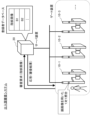
図2は、第1の実施形態に係る出入国審査システムの概略構成の一例を示す図である。図2を参照すると、出入国審査システムには、複数のゲート装置10-1~10-3と、サーバ装置20と、が含まれる。なお、以降の説明において、ゲート装置10-1~10-3を区別する特段の理由がない場合には単に「ゲート装置10」と表記する。また、図2には3台のゲート装置10を図示しているが、システムに含まれるゲート装置10の台数を限定する趣旨ではないことは勿論である。出入国審査システムには、少なくとも1台以上のゲート装置10が含まれていればよい。[System configuration]
FIG. 2 is a diagram showing an example of a schematic configuration of the immigration inspection system according to the first embodiment. Referring to FIG. 2, the immigration inspection system includes a plurality of gate devices 10-1 to 10-3 and a
ゲート装置10とサーバ装置20は、有線又は無線の通信手段により相互に通信可能に構成されている。サーバ装置20は、ゲート装置10と同じ空港内に設置されていてもよいし、ネットワーク(クラウド)上に設置されていてもよい。
The
ゲート装置10は、利用者の出入国に関する審査手続きを自動的に行う装置である。ゲート装置10は、開閉可能に構成されたゲートを備えている。ゲート装置10は、自装置の面前に立つ人物が出入国の審査を通過し、且つ、当該人物が正しい旅券(パスポート)を所持していると判断した場合に、ゲートを開門して利用者の通過を許可する。このように、ゲート装置10は、利用者の出入国審査の結果に応じてゲートを制御する。
The
サーバ装置20は、上記ゲート装置10による出入国の審査を実現するための装置である。サーバ装置20は、ゲート装置10を利用可能な利用者に関する情報(以下、ゲート利用者情報と表記する)を記憶する。
The
ゲート装置10による自動審査を希望する利用者は、事前にシステム登録を行う必要がある。例えば、利用者は、パスポートの発行所等に赴きパスポートを担当職員に提出する。担当職員は、パスポートを提供した利用者が真にパスポートの所持者であるか否かを審査する。審査の結果、利用者は正しいパスポートの所持者であると判断した担当職員は、当該利用者の指紋画像を取得する。具体的には、指紋スキャナ等を利用して指紋画像が取得される。当該指紋画像はサーバ装置20に入力される。
Users who desire automatic screening by the
サーバ装置20は、取得した指紋画像をデータベース(以下、登録者データベースと表記する)に追加する。登録する指紋画像は少なくとも1以上の指から採取された指紋画像であればよい。さらに、登録者データベースには審査を通過した利用者の指紋画像に加え、他の情報(例えば、氏名、パスポート番号)が指紋画像と関連付けられて登録されていてもよい。あるいは、登録者データベースには、指紋画像を用いた照合処理に必要となる特徴量(特徴点の種類、位置等)が指紋画像と対応付けて登録されていてもよい。
The
[システム動作概略]
続いて、図2を参照しつつ、第1の実施形態に係る出入国審査システムの概略動作について説明する。[System operation overview]
Next, the general operation of the immigration inspection system according to the first embodiment will be described with reference to FIG. 2.
利用者は、ゲート装置10の前に到達すると、ゲート装置10の指示に従い指をスキャナの上に置く。ゲート装置10は、利用者の指紋画像を取得し、当該取得した指紋画像を含む審査要求をサーバ装置20に送信する。
When the user arrives in front of the
サーバ装置20は、取得した指紋画像と登録者データベースに登録された複数の指紋画像を用いた照合処理(1対N照合;Nは正の整数、以下同じ)を行う。サーバ装置20は、取得した指紋画像と実質的に一致する指紋画像が登録者データベースに登録されていれば、審査結果を「出入国許可」に設定する。
The
対して、サーバ装置20は、取得した指紋画像と実質的に一致する指紋画像が登録者データベースに登録されていなければ、審査結果を「出入国不許可」に設定する。サーバ装置20は、審査結果を審査要求の送信元であるゲート装置10に返信する。
On the other hand, if a fingerprint image that substantially matches the acquired fingerprint image is not registered in the registrant database, the
ゲート装置10は、審査結果を受信した後、又は、審査要求を送信した後に、面前の利用者が正しいパスポート(利用者本人のパスポート)を所持しているか否かを判定する。具体的には、ゲート装置10は、利用者に対してパスポートを開いてスキャナに置くことを指示する。ゲート装置10は、スキャナのカードリーダ機能を用いてパスポートのIC(Integrated Circuit)チップから顔画像等を読み出す。ゲート装置10は、カメラ装置を用いて利用者の顔画像を取得する。ゲート装置10は、2つの顔画像それぞれから特徴量(以下、顔特徴量と表記する)を生成し、2つの特徴量が実質的に一致するか否かの判定を行う。即ち、ゲート装置10は、面前の利用者を撮影することで得られる顔特徴量とパスポートのICチップから得られる顔特徴量を用いた1対1照合を行う。
After receiving the examination result or transmitting the examination request, the
ゲート装置10は、1対1照合に成功し、且つ、サーバ装置20による審査結果が「出入国許可」である場合に、ゲートを開き利用者が通行可能とする。
The
続いて、第1の実施形態に係る出入国審査システムに含まれる各装置の詳細について説明する。 Next, details of each device included in the immigration inspection system according to the first embodiment will be explained.
[サーバ装置]
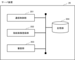
図3は、第1の実施形態に係るサーバ装置20の処理構成(処理モジュール)の一例を示す図である。図3を参照すると、サーバ装置20は、通信制御部201と、指紋画像登録部202と、審査部203と、記憶部204と、を含む。[Server device]
FIG. 3 is a diagram illustrating an example of a processing configuration (processing module) of the
通信制御部201は、他の装置との間の通信を制御する手段である。具体的には、通信制御部201は、ゲート装置10からデータ(パケット)を受信する。また、通信制御部201は、ゲート装置10に向けてデータを送信する。
The
指紋画像登録部202は、取得した指紋画像を記憶部204に構築された登録者データベースに登録する手段である。なお、指紋画像の取得には任意の方法を用いることができる。
The fingerprint
例えば、パスポートの発行窓口において担当職員が指紋画像をサーバ装置20に入力してもよい。具体的には、担当職員が指紋スキャナを操作し、利用者の指紋画像を取得する。担当職員は、端末(発行窓口に設置されたコンピュータ)を操作し、上記取得した指紋画像をサーバ装置20に送信する。あるいは、USB(Universal Serial Bus)メモリ等の外部記憶装置を介して上記読み取られたデータがサーバ装置20に入力されてもよい。
For example, a staff member at a passport issuing counter may input a fingerprint image into the
審査部203は、ゲート装置10が送信する審査要求を処理する手段である。具体的には、審査部203は、審査要求に含まれる指紋画像(生体情報)を照合対象に設定し、登録利用者データベースに登録された指紋画像との間で照合処理を行う。
The
より具体的には、審査部203は、審査要求から取り出した指紋画像を照合対象に設定し、登録者データベースに登録されている複数の指紋画像との間で1対N照合を実行する。審査部203は、照合対象の指紋画像と登録側の複数の指紋画像それぞれとの間のスコア(類似度)を計算する。
More specifically, the
審査部203は、照合側、登録側それぞれの指紋画像から特徴点(端点、分岐点)を抽出する。審査部203は、抽出した特徴点等に基づいて2つの指紋画像の類似度を示すスコアを算出する。具体的には、審査部203は、2つの指紋画像のコア領域(指紋の中心領域)を一致させ、コア領域からみた特徴点の位置や数、特徴点の間に存在する芯線の数等に基づいて上記スコアを算出する。スコアが高いほど2つの指紋画像の類似度は高いことを示す。
The
なお、指紋画像から特徴点を抽出する際の処理や特徴点からスコアを算出する際の処理は既存の技術を使用することができ、且つ、当業者にとって明らかであるので更なる説明を省略する。 Note that existing technology can be used for the process of extracting feature points from a fingerprint image and the process of calculating a score from the feature points, and since it is obvious to those skilled in the art, further explanation will be omitted. .
審査部203は、登録者データベースに登録された複数の指紋画像のうち、照合対象の指紋画像との間のスコアが所定の値以上の指紋画像が少なくとも1つ以上存在するか否かを判定する。
The
審査部203は、上記スコアが所定の値以上の指紋画像が登録者データベースに存在すれば、審査結果を「出入国許可」に設定する。対して、審査部203は、上記スコアが所定の値以上の指紋画像が登録者データベースに存在しなければ、審査結果を「出入国不許可」に設定する。審査部203は、審査結果を審査要求の送信元のゲート装置10に送信する。
The
記憶部204は、サーバ装置20の動作に必要な各種情報を記憶する。また、記憶部204に登録者データベースが構築される。
The
図4は、第1の実施形態に係るサーバ装置20のハードウェア構成の一例を示す図である。サーバ装置20は、情報処理装置(所謂、コンピュータ)により構成可能であり、図4に例示する構成を備える。例えば、サーバ装置20は、プロセッサ211、メモリ212、入出力インターフェイス213及び通信インターフェイス214等を備える。上記プロセッサ211等の構成要素は内部バス等により接続され、相互に通信可能に構成されている。
FIG. 4 is a diagram showing an example of the hardware configuration of the
但し、図4に示す構成は、サーバ装置20のハードウェア構成を限定する趣旨ではない。サーバ装置20は、図示しないハードウェアを含んでもよいし、必要に応じて入出力インターフェイス213を備えていなくともよい。また、サーバ装置20に含まれるプロセッサ211等の数も図4の例示に限定する趣旨ではなく、例えば、複数のプロセッサ211がサーバ装置20に含まれていてもよい。
However, the configuration shown in FIG. 4 is not intended to limit the hardware configuration of the
プロセッサ211は、例えば、CPU(Central Processing Unit)、MPU(Micro Processing Unit)、DSP(Digital Signal Processor)等のプログラマブルなデバイスである。あるいは、プロセッサ211は、FPGA(Field Programmable Gate Array)、ASIC(Application Specific Integrated Circuit)等のデバイスであってもよい。プロセッサ211は、オペレーティングシステム(OS;Operating System)を含む各種プログラムを実行する。
The
メモリ212は、RAM(Random Access Memory)、ROM(Read Only Memory)、HDD(Hard Disk Drive)、SSD(Solid State Drive)等である。メモリ212は、OSプログラム、アプリケーションプログラム、各種データを格納する。
The
入出力インターフェイス213は、図示しない表示装置や入力装置のインターフェイスである。表示装置は、例えば、液晶ディスプレイ等である。入力装置は、例えば、キーボードやマウス等のユーザ操作を受け付ける装置である。
The input/
通信インターフェイス214は、他の装置と通信を行う回路、モジュール等である。例えば、通信インターフェイス214は、NIC(Network Interface Card)等を備える。
The
サーバ装置20の機能は、各種処理モジュールにより実現される。当該処理モジュールは、例えば、メモリ212に格納されたプログラムをプロセッサ211が実行することで実現される。また、当該プログラムは、コンピュータが読み取り可能な記憶媒体に記録することができる。記憶媒体は、半導体メモリ、ハードディスク、磁気記録媒体、光記録媒体等の非トランジェント(non-transitory)なものとすることができる。即ち、本発明は、コンピュータプログラム製品として具現することも可能である。また、上記プログラムは、ネットワークを介してダウンロードするか、あるいは、プログラムを記憶した記憶媒体を用いて、更新することができる。さらに、上記処理モジュールは、半導体チップにより実現されてもよい。
The functions of the
[ゲート装置]
図5は、第1の実施形態に係るゲート装置10の外観の一例を示す図である。上述のように、ゲート装置10は、利用者に出入国に関する審査を自動的に行う装置である。[Gate device]
FIG. 5 is a diagram showing an example of the appearance of the
ゲート装置10は、自装置の前に利用者の存在を検出すると、ディスプレイ401に出入国審査を自動的に行う際に利用者に対して要求する操作手順等を表示する。
When the
ゲート装置10は、利用者に対して、指(予め定められた指;登録者データベースに登録された指紋画像に対応する指)をスキャナ402に置くように指示する。ゲート装置10は、スキャナ402を制御し置かれた指を撮像する。ゲート装置10は、得られた指紋画像を含む審査要求をサーバ装置20に送信する。
The
指紋画像の取得が終了すると、ゲート装置10は、利用者に対して顔を撮影する旨を通知すると共に、カメラ装置403を制御して利用者を撮像する。その際、ゲート装置10は、上下に取り付けられた上段照明404と下段照明405の光度を制御する。
When the acquisition of the fingerprint image is completed, the
上段照明404は、ゲート装置10の本体から鉛直方向上向きに延びる支持部406に取り付けられた天井部407に設置されている。より具体的には、上段照明404は天井部407の内部に埋め込まれるように設置されている。なお、図5に示すように、支持部406の構造を幅広とすることで、ディスプレイ401やカメラ装置403を当該支持部406に取り付けることが可能となる。
The
下段照明405は、ゲート装置10の本体に埋め込まれるように設置されている。なお、ゲート装置10の「本体」とは、ゲート装置10の中心をなす構造体であり、床と接触し、ゲート408や支持部406が取り付けられた部材である。
The
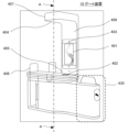
図6は、図5に示すA-A間の断面を模式的に示す図である。なお、図6には理解の容易のためにゲート装置10の利用者(審査対象者)を図示している。図6に示すように、上段照明404は利用者の上方から当該利用者に光が照射されるように設置されている。また、下段照明405は利用者の下方(より正確には利用者の顔の下方)から当該利用者に光が照射されるように配置されている。
FIG. 6 is a diagram schematically showing a cross section taken along line AA shown in FIG. Note that in FIG. 6, users of the gate device 10 (examined persons) are illustrated for ease of understanding. As shown in FIG. 6, the
なお、図6に示す2つの照明の配置は例示であって種々の変形が考えられる。例えば、上段照明404は支持部406に設置されていてもよい。あるいは、上段照明404が支持部406に設置され、天井部407に向けて光を照射するように取り付けられていてもよい。この場合、天井部407に反射板(例えば、鏡)を配置し、上段照明404から照射された光が鏡で反射し、反射光が利用者の上方より照射されてもよい。このように、上段照明404は天井部407の方向に光を照射するように設置され、ゲート装置10は、上段照明404から照射された光を反射する反射板を備えていてもよい。
Note that the arrangement of the two lights shown in FIG. 6 is an example, and various modifications are possible. For example, the
同様に、下段照明405は支持部406の下方に設置されていてもよい。あるいは、下段照明405は、ゲート装置10の本体に取り付けられた鏡に光を照射するように設置されていてもよい。この場合、下段照明405から照射された光は鏡で反射し、反射光が利用者の下方より照射されることになる。このように、下段照明405は、ゲート装置10の本体の方向に光を照射するように設置され、ゲート装置10は、下段照明405から照射された光を反射する反射板を備えていてもよい。
Similarly, the
ゲート装置10は、後述する顔画像を用いた照合処理に適した顔画像が取得できるように上記2つの照明の光度を制御する。ゲート装置10による照明の制御に関する詳細は後述する。
The
利用者の撮像を終えると、ゲート装置10は、画像から顔領域を抽出し、顔画像を取得する。
When the image of the user is finished, the
また、ゲート装置10は、利用者に対して、所持するパスポートの顔写真が写ったページを開き、当該開かれたパスポートをスキャナ402に置くように指示する。ゲート装置10は、パスポートの機械読取領域(Machine Readable Zone;MRZ)に記載された情報(以下、MRZ情報)を読み取る。ゲート装置10は、当該MRZ情報を用いてパスポートのICチップに格納された顔画像を取得する。
Further, the
ゲート装置10は、カメラ装置403から取得した顔画像とパスポートのICチップから取得した顔画像を用いた照合(1対1照合)を実行する。ゲート装置10は、当該照合に成功すれば(2つの顔画像が実質的に一致すれば)、利用者は正しいパスポートを所持していると判定する。対して、ゲート装置10は、当該照合に失敗すれば(2つの顔画像が異なれば)、利用者は正しいパスポートを所持していないと判定する。
The
ゲート装置10は、サーバ装置20からの審査結果が「出入国許可」、且つ、利用者が正しいパスポートを所持していると判定された場合に、ゲート408を開き、利用者(審査対象者)の通行を可能とする。
The
サーバ装置20からの審査結果が「出入国不許可」又は利用者が「正しいパスポートを所持していない」と判定された場合には、ゲート装置10は、ゲート408を閉じたままとし、事前に定めたメッセージ等をディスプレイ401に表示する。例えば、ゲート装置10は、有人の審査ブースに向かうような表示をしたり、自動審査に係る操作のやり直しを指示したりする。
If the examination result from the
ゲート装置10は、荷物置き場430の状態を監視する。図7は、ゲート装置10が備える荷物置き場430を模式的に図示した正面図の一例である。図7は、利用者がゲート装置10に向かって歩いて来る方向から荷物置き場430を視認した際の図である。
The
利用者は、ゲート装置10を操作する際、手荷物を荷物置き場430の天板領域431や側部432に置く。ゲート装置10は、天板領域431や側部432に物体が存在するか否かを検出する。例えば、ゲート装置10は、重量センサ、圧力センサ等の手段を用いて天板領域431に置かれた物体を検出する。あるいは、ゲート装置10は、赤外線を使った距離センサやカメラから得られる画像を解析することで側部432に置かれた物体を検出する。
When operating the
なお、上記ゲート装置10による物体の検出方法は例示であって、ゲート装置10は任意の方法、手段を用いて荷物置き場430に置かれた物体を検出できればよい。また、ゲート装置10による物体(利用者の荷物)の検出領域は天板領域431や側部432に限定されず、利用者が荷物を置く可能性のある領域が検出領域に設定される。即ち、ゲート装置10は、荷物置き場430の鉛直方向上側又は側部に位置する物体の存在を検出するだけでなく、利用者が荷物を置く可能性のある場所における物体の有無を検出する。
Note that the method of detecting an object by the
ゲート装置10は、荷物置き場430に物体の存在を検出すると、「荷物検出フラグ」を「1」にセットする。ゲート装置10は、荷物置き場430から物体が検出されなければ、「荷物検出フラグ」を「0」にクリアする。
When the
ゲート装置10は、審査対象者の出入国審査が終了した時点(審査結果の受信、且つ、パスポート所持の判定が終了)で、荷物検出フラグが「1」に設定されていれば、利用者に対して荷物の取り忘れを通知(警告)する。例えば、ゲート装置10は、ディスプレイ401に上記警告に関するメッセージを表示してもよいし、音声等で警告してもよい。
If the baggage detection flag is set to "1" at the time when the immigration inspection of the person to be screened is completed (reception of the screening result and determination of whether the person has a passport is completed), the
また、ゲート装置10は、ゲート408の開閉制御に関し、荷物検出フラグが「0」にクリアされていることを、ゲート408を開ける条件の1つとする。利用者が上記荷物取り忘れに係る表示や音声に気が付かなかったとしても、ゲート408が開かないので利用者が荷物を置き忘れたまま次の手続きに進むことが防止される。
Furthermore, regarding the opening/closing control of the
図8は、第1の実施形態に係るゲート装置10のハードウェア構成の一例を示す図である。図8を参照すると、ゲート装置10は、プロセッサ311と、メモリ312と、通信インターフェイス313と、を備える。さらに、ゲート装置10は、ディスプレイ401と、スキャナ402と、カメラ装置403と、上段照明404と、下段照明405と、ゲート408と、物体検出器409と、を備える。上記プロセッサ311等の構成要素は内部バス等により接続され、相互に通信可能に構成されている。なお、図8には、プロセッサ311に接続(電気的に接続)される構成要素に限り図示している。図8には、支持部406、天井部407、荷物置き場430の図示を省略している。また、図5に示すように、ゲート装置の本体、支持部406及び天井部407はコの字形状を形成する。より詳細には、ゲート装置10の本体(支持部406を支える筐体)と天井部407は向かい合って対向している。本体と天井部407は支持部406により接続されている。ゲート装置10をこのような構成とすることで、本体、支持部406及び天井部407によりコの字形状(文字「c」の左右が反転された形状)が形成される。
FIG. 8 is a diagram showing an example of the hardware configuration of the
なお、プロセッサ311、メモリ312及び通信インターフェイス313に関しては、図4を用いて説明したサーバ装置20の対応する要素と同一の内容とすることができるので詳細な説明を省略する。
Note that the
ディスプレイ401は、情報を出力するための装置(例えば、液晶モニタ等)である。
The
スキャナ402は、パスポートからMRZ情報を読み取ったり利用者の指紋画像を取得したりする装置である。また、スキャナ402は、パスポートに搭載されたICチップにアクセスする機能も備える。スキャナ402は任意の場所に設置することができる。ただし、スキャナ402は、利用者がパスポートや指を容易に当該装置に置くことができる場所に設置されるのが好ましい。なお、本願開示では、スキャナ402は、ICチップにアクセスするカードリーダとしての機能と、パスポートからMRZ情報を読み出すパスポートスキャナとしての機能と、指から指紋画像を取得する指紋スキャナとして機能と、を有する場合について説明する。しかし、これらの機能が分離され、カードリーダ、パスポートスキャナ、指紋スキャナのそれぞれがゲート装置10に設けられていてもよい。
The
カメラ装置403は、例えば、ゲート装置10の前方を撮影可能に設置されたデジタルカメラである。カメラ装置403は任意の場所に設置することができる。例えば、カメラ装置403はゲート装置10の本体に設置されていてもよいし、ゲート装置10から離れた場所に設置されていてもよい。カメラ装置403は、ゲート装置10の面前に立つ利用者(特に、利用者の顔)を撮影可能であれば、どのような場所に設置されていてもよい。
The
上述のように、上段照明404は利用者の上方から光を照射するように設置された光源である。また、下段照明405は利用者の下方から光を照射するように設置された光源である。上段照明404及び下段照明405は、その光度が制御可能に構成されている。上段照明404及び下段照明405の光度が可変されることで、利用者に照射される照度が変化する。即ち、上段照明404及び下段照明405の光度が変化することで、カメラ装置403からみた利用者の輝度が変化する。なお、上段照明404及び下段照明405には、光度を変更可能な任意の光源を用いることができる。例えば、LED(Light Emitting Diode)を上段照明404、下段照明405として用いることができる。光源にLEDを用いる場合、当該LEDに流れる電流を制御することで光度を変更することができる。
As described above, the
ゲート408は、利用者が出入国審査を通過した場合に、利用者の通行を遮る待機時の閉鎖状態から利用者の通行を許可する開放状態に移行する。ゲート408の方式は、特に限定されるものではなく、例えば、通路の片側又は両側から設けられたフラッパーが開閉するフラッパーゲート、3本バーが回転するターンスタイルゲート等である。
When the user passes through immigration, the
物体検出器409は、荷物置き場430に置かれた物体を検出するためのデバイスである。上述のように、物体検出器409には重量センサや距離センサ等を用いることができる。
ゲート装置10の機能は、サーバ装置20と同様に、各種処理モジュールにより実現される。当該処理モジュールは、例えば、メモリ312に格納されたプログラムをプロセッサ311が実行することで実現される。
Similar to the
図9は、第1の実施形態に係るゲート装置10の処理構成(処理モジュール)の一例を示す図である。ゲート装置10は、通信制御部301と、指紋画像取得部302と、審査要求部303と、顔画像取得部304と、パスポート所持判定部305と、荷物検出部306と、荷物置き忘れ警告部307と、ゲート制御部308と、記憶部309と、を備える。
FIG. 9 is a diagram showing an example of a processing configuration (processing module) of the
通信制御部301は、他の装置との間の通信を制御する手段である。具体的には、通信制御部301は、サーバ装置20からデータ(パケット)を受信する。また、通信制御部301は、サーバ装置20に向けてデータを送信する。
The
指紋画像取得部302は、ゲート装置10の面前に立つ利用者の指紋画像を取得する手段である。指紋画像取得部302は、スキャナ402を制御し、利用者の指紋画像を取得する。指紋画像取得部302は、取得した指紋画像を審査要求部303に引き渡す。
The fingerprint
審査要求部303は、審査対象者(ゲート装置10の面前に立つ利用者)の出入国に関する審査をサーバ装置20に要求する手段である。具体的には、審査要求部303は、取得した指紋画像(生体情報)を含む審査要求を生成し、通信制御部301を介して当該生成した審査請求をサーバ装置20に送信する。
The
例えば、審査要求部303は、自装置の識別子(以下、ゲート識別子と表記する)、指紋画像等を含む審査要求を生成する(図10参照)。なお、ゲート識別子には、ゲート装置10のMAC(Media Access Control)アドレスやIP(Internet Protocol)アドレスを用いることができる。
For example, the
審査要求部303は、通信制御部301を介して審査要求に対するサーバ装置20からの応答を受信する。審査要求部303は、サーバ装置20からの応答(審査結果;出入国許可、又は、出入国不許可)を荷物置き忘れ警告部307とゲート制御部308に引き渡す。
The
顔画像取得部304は、ゲート装置10の面前に立つ利用者の顔画像(生体情報)を取得する手段である。例えば、顔画像取得部304は、カメラ装置403を制御し、利用者の顔画像を取得する。顔画像取得部304は、取得した顔画像をパスポート所持判定部305に引き渡す。
The face
上述のように、ゲート装置10は、利用者を撮像する際、上段照明404と下段照明405の光度を制御する。具体的には、顔画像取得部304は、利用者の撮影時における当該利用者の顔に照射された光の照度が実質的に均一となるように上段照明404、下段照明405の光度を制御する。なお、顔画像取得部304は、上記均一化を実現することができれば、上段照明404及び下段照明405のいずれか一方の光度を制御してもよい。顔画像取得部304は、少なくとも2以上の照明を制御する照明制御部としての機能と、利用者の生体情報を取得する取得部としての機能と、を備える。
As described above, the
例えば、顔画像取得部304は、利用者(被撮影者)の身体的特徴に応じて上段照明404と下段照明405の光度を決定する。例えば、顔画像取得部304は、身長の高い利用者の場合(身長が第1の閾値より高い場合)には、下段照明405の光度を上段照明404の光度よりも相対的に高くする。逆に、顔画像取得部304は、身長の低い利用者の場合(身長が第2の閾値より低い場合)には、上段照明404の光度を下段照明405の光度よりも相対的に高くする。なお、顔画像取得部304は、利用者の身長が第1及び第2の閾値から定まる範囲である場合(利用者が平均的な身長の場合)には、2つの照明の光度を同一に設定してもよい。顔画像取得部304は、上記のように2つの照明の光度を制御することで、利用者の撮影時における当該利用者に照射された光の照度が均一となるようにする。
For example, the face
上記照度の均一化に際し、顔画像取得部304は利用者の身長を計測する。その後、顔画像取得部304は、身長と2つの光源の光度を予め定めたテーブル情報を参照する。顔画像取得部304は、当該テーブル情報から得られた光度となるように上段照明404、下段照明405を制御する。
When equalizing the illuminance, the face
図11は、身長と2つの光源の光度を定めたテーブル情報の一例を示す図である。顔画像取得部304は、利用者の身長に基づいて上段照明404、下段照明405それぞれの光度を取得する。顔画像取得部304は、取得した光度による光が照射されるように、上段照明404、下段照明405それぞれに流れる電流を制御する。なお、光度から電流値を決定する際、顔画像取得部304は、これらの関係を予め定めたテーブル情報や関数(光度を入力すると電流値が出力される関数)を使用すればよい。また、光源の電流値を可変する場合には、光源と電源の間に接続された抵抗値を変更してもよいし、PWM(Pulse Width Modulation:パルス幅変調)技術等を用いて光源に印加される電圧を変更してもよい。
FIG. 11 is a diagram illustrating an example of table information that defines height and luminous intensity of two light sources. The face
なお、顔画像取得部304は、任意の方法で利用者の身長を取得する。例えば、ゲート装置10の支持部406に複数のセンサ(例えば、赤外線距離センサ)を鉛直方向に配置する。より具体的には、複数のセンサが所定の間隔で鉛直方向に配置される。顔画像取得部304は、当該複数のセンサそれぞれの出力を監視し、各センサの出力値(赤外線距離センサの場合には電圧値)の相違から利用者の身長を計測する。即ち、利用者の身長が低ければ利用者に反応するセンサの数が少なく、利用者の身長が高ければ反応するセンサの数が多くなる。顔画像取得部304は、利用者の身長の相違に起因するセンサの出力変化に応じて利用者の身長を特定する。即ち、顔画像取得部304は、利用者の身長に応じて反応するセンサの位置に応じて利用者の身長を特定する。
Note that the face
あるいは、顔画像取得部304は、認証(照合)用の顔画像取得に先立ち、利用者を撮像し、得られる画像を解析することで利用者の身長を特定してもよい。なお、その際の上段照明404や下段照明405の光度は初期値(デフォルト値)に設定される。
Alternatively, the face
顔画像取得部304は、身長特定用の画像を取得すると、当該画像から顔領域を抽出する。顔画像取得部304は、抽出した顔画像の上記身長特定用の画像における位置に応じて利用者の身長を特定(推定)する。具体的には、顔画像取得部304は、オリジナル画像の上側に顔画像が位置している場合には、当該利用者の身長を高く推定する。対して、顔画像取得部304は、オリジナル画像の下側に顔画像が位置している場合には、当該利用者の身長を低く推定する。
Upon acquiring the height identification image, the facial
あるいは、利用者の身長の特定において機械学習により得られた学習モデルが使用されてもよい。例えば、利用者が写る画像と当該利用者の身長をラベルとする教師データを多数用意し、学習モデルを生成する。顔画像取得部304は、当該生成された学習モデルに身長特定用の画像を入力し、身長を取得してもよい。学習モデルの生成には、サポートベクタマシン、ブースティングやニューラルネットワーク等の任意のアルゴリズムを用いることができる。なお、上記サポートベクタマシン等のアルゴリズムは公知の技術を使用することができるので、その説明を省略する。
Alternatively, a learning model obtained by machine learning may be used to identify the user's height. For example, a learning model is generated by preparing a large amount of training data with images of the user and the user's height as labels. The face
上記説明したように、ゲート装置10は、利用者の身長を特定せず、画像処理により顔検出やセンサの出力値に基づいて、上段照明404、下段照明405の光度を制御してもよい。
As described above, the
パスポート所持判定部305は、利用者が正しいパスポートを所持しているか否かを判定する手段である。パスポート所持判定部305は、スキャナ402を制御してパスポートの機械読取領域に記載されたMRZ情報を取得する。パスポート所持判定部305は、当該取得したMRZ情報を用いてICチップに記憶された情報を読み出す。
The passport
ここで、下記参考文献1の「IC旅券の安全対策」に記載されたように、パスポートのICチップに格納された情報は、同じパスポートに記載されたMRZ情報をパスワードとして暗号化(変換)されている。
<参考文献1>
https://www.mofa.go.jp/mofaj/toko/passport/ic_faq.html#11Here, as described in "Security Measures for IC Passports" in Reference 1 below, the information stored in the IC chip of the passport is encrypted (converted) using the MRZ information written on the same passport as a password. ing.
<Reference 1>
https://www.mofa.go.jp/mofaj/toko/passport/ic_faq.html#11
パスポート所持判定部305は、スキャナ402から取得したMRZ情報を用いてICチップから読み出した情報を復号し、当該ICチップに格納された顔画像を取得する。
The passport
パスポート所持判定部305は、顔画像取得部304から取得した顔画像とICチップから取得した顔画像それぞれから特徴点を抽出する。なお、特徴点の抽出処理に関しては既存の技術を用いることができるのでその詳細な説明を省略する。例えば、パスポート所持判定部305は、顔画像から目、鼻、口等を特徴点として抽出する。その後、パスポート所持判定部305は、特徴点それぞれの位置や各特徴点間の距離を特徴量として計算し、複数の特徴量からなる特徴ベクトル(顔画像を特徴づけるベクトル情報)を生成する。
The passport
パスポート所持判定部305は、2つの特徴量(特徴ベクトル)の類似度を計算する。当該類似度には、カイ二乗距離やユークリッド距離等を用いることができる。なお、距離が離れているほど類似度は低く、距離が近いほど類似度が高い。
The passport
パスポート所持判定部305は、上記計算された類似度が所定の値以上である場合に、照合に成功したと判断する。即ち、パスポート所持判定部305は、上記計算された類似度が所定の値以上である場合に、2つの顔画像は同一人物の顔を撮像した画像であると判断する。
The passport
パスポート所持判定部305は、1対1照合に成功した場合に、面前に立つ利用者は正しいパスポートを所持していると判定する。パスポート所持判定部305は、判定結果(利用者は正しいパスポートを所持しているか否か)を荷物置き忘れ警告部307とゲート制御部308に通知する。
If the one-on-one verification is successful, the passport
荷物検出部306は、荷物置き場430に物体が存在するか否かの検出を行う手段である。荷物検出部306は、物体検出器409の出力を監視し、当該検出器(物体検出センサ)が物体の存在を感知した場合に、「荷物検出フラグ」を「1」にセットする。また、荷物検出部306は、物体検出器409の出力から物体の存在が感知できなくなった場合に、「荷物検出フラグ」を「0」にクリアする。
The
荷物置き忘れ警告部307は、荷物置き場430に物体が存在する場合に、荷物置き忘れに関する警告を行う手段である。より具体的には、荷物置き忘れ警告部307は、利用者が荷物を荷物置き場430に置き忘れていると判断した際、その旨の警告を行う。荷物置き忘れ警告部307は、ゲート装置10による出入国審査が終了したタイミングにて荷物検出フラグを確認する。
The left-
より具体的には、荷物置き忘れ警告部307は、通信制御部301を介してサーバ装置20から審査結果を受信し、且つ、パスポート所持判定部305から判定結果を受信している状況を「出入国審査の終了」と判断する。荷物置き忘れ警告部307は、2つの結果(審査結果、判定結果)が揃ったタイミングにて荷物検出フラグを確認する。
More specifically, the left
荷物置き忘れ警告部307は、上記タイミングで荷物検出フラグが「1」であれば、利用者が荷物を置き忘れていると判断し、その旨を警告する。例えば、荷物置き忘れ警告部307は、図12に示すような表示をディスプレイ401に行う。あるいは、荷物置き忘れ警告部307は、利用者が荷物を置き忘れている旨の音声をスピーカから出力してもよい。あるいは、荷物置き忘れ警告部307は、利用者が荷物を置き忘れている旨を利用者が所持する端末に通知してもよい。
If the baggage detection flag is "1" at the above-mentioned timing, the baggage left behind
ゲート制御部308は、ゲート装置10が備えるゲート408を制御する手段である。ゲート制御部308は、少なくとも荷物置き場430に物体が存在しない場合に、審査対象者が通行可能となるようにゲート408を制御する。換言すれば、ゲート制御部308は、荷物置き場430に物体(荷物)が存在する場合、審査対象者が通行できないようにゲート408を制御する。
The
具体的には、ゲート制御部308は、3つの条件が揃っている場合にゲート408を開門する。より詳細には、ゲート制御部308は、サーバ装置20の審査結果が「出入国許可」、パスポート所持判定結果が「パスポート所持」及び荷物検出フラグが「0」である場合に、ゲート408を開門する。ゲート制御部308は、原則として、上記3つの条件が満たされなければゲート408を開門しない。
Specifically, the
ゲート制御部308は、ゲート408の通行が許可された利用者(出入国審査を通過した利用者)がゲート408を通過した後に当該ゲート408を閉門する。
The
記憶部309は、ゲート装置10の動作に必要な情報を記憶する手段である。
The
[出入国審査システムの動作]
次に、第1の実施形態に係る出入国審査システムの動作について説明する。[Operation of immigration inspection system]
Next, the operation of the immigration inspection system according to the first embodiment will be explained.
図13は、第1の実施形態に係る出入国審査システムの動作の一例を示すシーケンス図である。なお、図13は、利用者の搭乗日におけるシステム動作の一例を示すシーケンス図である。図13の動作に先立ち、利用者の「ゲート利用者情報(指紋画像)」は予めサーバ装置20に登録されているものとする。
FIG. 13 is a sequence diagram showing an example of the operation of the immigration inspection system according to the first embodiment. Note that FIG. 13 is a sequence diagram illustrating an example of system operation on the boarding date of the user. It is assumed that the user's "gate user information (fingerprint image)" has been registered in the
事前にシステムの利用登録を行った利用者は、ゲート装置10の前に移動する。ゲート装置10は、当該利用者の指紋画像を取得する(ステップS01)。
A user who has registered to use the system in advance moves in front of the
ゲート装置10は、指紋画像を含む審査要求をサーバ装置20に送信する(ステップS02)。
The
サーバ装置20は、取得した指紋画像を照合側(被認証側)、登録者データベースに記憶された指紋画像を登録側にそれぞれ設定し、1対N照合を実行する(ステップS03)。
The
サーバ装置20は、上記1対N照合により得られる審査結果(出入国許可、出入国不許可)を審査要求の送信元のゲート装置10に送信する(ステップS04)。
The
このように、ゲート装置10は、審査対象者の指紋画像を取得する。その後、ゲート装置10は、出入国が許可された利用者の指紋画像を記憶するサーバ装置に、当該取得された指紋画像を含む審査要求を送信することで審査対象者の入出国に関する審査を要求する。サーバ装置20は、事前に登録された指紋画像を用いた照合(1対N照合)により審査結果を決定し、当該審査結果をゲート装置10に送信する。
In this way, the
ゲート装置10は、利用者を撮影し顔画像を取得すると共に、パスポートのICチップから顔画像を読み出す(顔画像の取得;ステップS05)。利用者を撮影する際、ゲート装置10は当該利用者の身長を推定し、利用者の身長に適した光度となるように2つの光源を制御する。
The
ゲート装置10は、2つの顔画像を用いた1対1照合を行い利用者が正しいパスポートを所持しているか否かを判定する(ステップS06)。ゲート装置10は、カメラ装置403を制御して審査対象者の第1の顔画像を取得する。その後、ゲート装置10は、審査対象者が所持するパスポートに記憶された第2の顔画像を取得し、第1及び第2の顔画像の照合を行うことで、審査対象者が正しいパスポートを所持しているか否かを判定する。
The
ゲート装置10は、上記ステップS01~S06の動作と並行して荷物置き場430に荷物が置かれているか否かを検出する。具体的には、ゲート装置10は、物体検出器409の出力を監視し、荷物置き場430の状態を検出する。荷物が荷物置き場430に置かれている場合には、荷物検出フラグが「1」にセットされる。荷物が荷物置き場430から取り除かれた場合には、荷物検出フラグが「0」にクリアされる。
The
ゲート装置10は、出入国審査が終了したタイミング(サーバ装置20から審査結果を受信し、パスポートの所持判定が終了したタイミング)にて荷物検出フラグが「1」にセットされているか否かを確認する(ステップS07)。
The
荷物検出フラグが「1」にセットされていれば(ステップS07、Yes分岐)、ゲート装置10は、荷物置き忘れに関する警告を行う(ステップS08)。
If the baggage detection flag is set to "1" (step S07, Yes branch), the
このように、ゲート装置10は、サーバ装置20から審査結果を受信し、且つ、パスポート所持に関する判定が終了したタイミングにおいて荷物置き場430に物体が存在する場合に、荷物置き忘れに関する警告を行う。その際、ゲート装置10は、荷物置き場430に物体が存在する場合に荷物検出フラグをセットし、荷物置き場430に物体が存在しない場合に荷物検出フラグをクリアする。ゲート装置10は、上記荷物検出フラグの制御を行うと共に、サーバ装置20から審査結果を受信し、且つ、パスポート所持に関する判定が終了したタイミングで荷物検出フラグを確認することで荷物置き忘れの有無を判定する。
In this way, the
ゲート装置10は、荷物置き場430の監視を続け荷物置き場430から荷物が取り除かれたか否かを検出する。つまり、ゲート装置10は、荷物検出フラグの監視を続ける(ステップS09)。
The
ゲート装置10は、荷物検出フラグが「0」にクリアされ(ステップS09、Yes分岐)、サーバ装置20による審査結果が「出入国許可」且つ利用者が「正しいパスポートを所持している」場合に、ゲート408を開門する(ステップS10)。このように、ゲート装置10は、サーバ装置20からの審査結果が出入国許可であり、審査対象者が正しいパスポートを所持し、荷物置き場430に物体が存在しない場合に、審査対象者が通行可能となるようにゲート408を制御する。換言すれば、ゲート装置10は、サーバ装置20からの審査結果が「出入国不許可」である場合、又は、審査対象者が正しいパスポートを所持していない場合、当該審査対象者が通行できないようにゲート408を制御する。
When the baggage detection flag is cleared to "0" (step S09, Yes branch), the examination result by the
以上のように、第1の実施形態に係るゲート装置10は、生体情報(指紋画像)を用いた照合要求(審査要求)をサーバ装置20に対して行い、当該サーバ装置20から照合結果(審査結果)を受信する。また、ゲート装置10は、利用者の顔に照射された光の照度が均一となるように2つの光源を制御し顔画像を取得する。ゲート装置10は、当該取得された顔画像とパスポートのICチップから読み出した顔画像の照合を行い、利用者が正しいパスポートを所持しているか否かの照合を行う。ゲート装置10は、審査対象者が荷物を荷物置き場430に置き忘れていると判断した場合、その旨の警告を行う。さらに、ゲート装置10は、利用者が荷物置き場430から荷物を移動させないと、当該利用者の出入国に関する審査が終了していてもゲート408を開門しない。その結果、利用者が荷物を置き忘れてしまうことを防止できる。
As described above, the
また、第1の実施形態に係るゲート装置10は、利用者の身長に応じて2つの光源(上段照明404、下段照明405)を制御することで、顔照合に適した顔画像を得ることができる。即ち、ゲート装置10は、異なる照明の光度を最適に制御することで、利用者の身長によらず高品質な画像(顔画像)を得ることができる。より具体的には、ゲート装置10は、利用者に照射された光の照度が均一となるように上段照明404、下段照明405のそれぞれから照射される光の光度を変更する。その結果、顔等に照射された光の輝度が場所によってばらつく等の事態が発生せず、認証用途に適した生体情報が取得される。
Further, the
また、第1の実施形態に係るゲート装置10は、上段照明404が天井部407に取り付けられている。このルーフ付き照明(天井部407に埋め込まれた上段照明404)が外光等の光を遮る。その結果、ゲート装置10は、時間帯等によらず利用者の顔画像を取得するのに適した環境を作り出すことができる。即ち、ゲート装置10は、ルーフ付き照明を備えることで外乱による顔認証の精度低下を抑制することができる。また、当該ルーフ付き照明は支持部406により吊り下げられ、当該支持部406を厚みのある平板形状とすることで、当該支持部406にディスプレイ401を設置したり内部に配線を通したりすることができる。
Further, in the
[変形例]
なお、上記実施形態にて説明した出入国審査システムの構成、動作等は例示であって、システムの構成等を限定する趣旨ではない。例えば、上記実施形態では、ゲート装置10が顔画像に係る生体情報を取得する際に、上段照明404、下段照明405の光度を制御する場合について説明した。しかし、虹彩画像を認証用途で取得する場合や指紋画像を認証用途で取得する場合にも、2つの光源に関する制御は適用可能である。即ち、虹彩画像や指紋画像の取得に際し、目の領域や指に照射される光の光度が均一となるように2つの光源が制御されてもよい。[Modified example]
Note that the configuration, operation, etc. of the immigration inspection system described in the above embodiments are merely examples, and are not intended to limit the configuration, etc. of the system. For example, in the embodiment described above, a case has been described in which the
例えば、サーバ装置20の持つ機能の全部又は一部がゲート装置10にて実現されてもよい。例えば、ゲート装置10に登録者データベースが構築され、ゲート装置10が当該データベースを用いて審査対象者の出入国に関する審査を行ってもよい。あるいは、サーバ装置20が備える登録者データベースは他のデータベースサーバに構築されていてもよい。
For example, all or part of the functions of the
上記実施形態では、利用者から取得した指紋画像がサーバ装置20に登録されているか否かの判定を行った後、利用者が正しいパスポートを所持しているか否かの判定を行っている。しかし、これら2つの判定は並行して実施されてもよいし、実行の順序が逆であってもよい。つまり、正しいパスポートを所持しているか否かの判定後、指紋画像がサーバ装置20に登録されているか否かの判定が行われてもよい。
In the embodiment described above, after determining whether the fingerprint image acquired from the user is registered in the
上記実施形態では、ゲート装置10が取得した指紋画像は、出入国審査を事前に済ませた利用者の特定に利用されているが、利用者が犯罪者等に該当しないことの確認に利用されてもよい。例えば、サーバ装置20は、取得した指紋画像と、犯罪者の指紋を集めたブラックリストに格納された指紋画像と、を用いた照合を行ってもよい。
In the above embodiment, the fingerprint image acquired by the
上記実施形態では、サーバ装置20に指紋画像という生体情報が記憶される場合について説明したが、他の生体情報がサーバ装置20に記憶されていてもよい。例えば、顔画像、声紋情報、虹彩情報等やこれらの特徴量が生体情報として記憶されていてもよい。同様に、パスポートから顔画像以外の生体情報が取得できる場合には、当該顔画像以外の生体情報を用いて審査対象者が正しいパスポートを所持しているか否かの判定が行われてもよい。
In the above embodiment, a case has been described in which biometric information such as a fingerprint image is stored in the
ゲート装置10とサーバ装置20の間のデータ送受信の形態は特に限定されないが、これら装置間で送受信されるデータは暗号化されていてもよい。指紋画像は個人情報であり当該個人情報を適切に保護するためには、暗号化されたデータが送受信されることが望ましい。また、ゲート装置10は、デジタル署名付きの審査要求をサーバ装置20に送信してもよい。サーバ装置20は、当該デジタル署名の検証に成功した場合に、取得した審査要求を処理してもよい。このように、サーバ装置20は、デジタル署名を検証することで審査要求の送信元であるゲート装置10の正当性を検証可能としてもよい。
Although the form of data transmission and reception between the
上記実施形態では、パスポートのICチップからMRZ情報を用いて情報を取得する場合について説明したが、当該本願開示の手法は他の方法にも適用可能である。つまり、パスポートに類似するカード等に搭載されたICチップから情報を読み出す際にMRZ情報に相当する情報が用いられてもよい。 In the above embodiment, a case has been described in which information is acquired from the IC chip of a passport using MRZ information, but the technique disclosed in the present application is also applicable to other methods. That is, information equivalent to MRZ information may be used when reading information from an IC chip mounted on a card similar to a passport.
上記実施形態では、上段照明404及び下段照明405のそれぞれは1つの光源から構成されている場合について説明したが、上段照明404及び下段照明405のうちいずれか一方は複数の光源から構成されていてもよい。この場合、顔画像取得部304は、複数の光源のうち点灯する光源の数を制御することで上段照明404、下段照明405の光度を変更してもよい。即ち、ゲート装置10は、複数の光源を対象にしたデジタル制御により利用者の顔に照射される光の光度を制御してもよい。
In the above embodiment, a case has been described in which each of the
上記実施形態では、2つの光源(上段照明404、下段照明405)がゲート装置10に取り付けられている場合について説明したが、上記2つの光源に加え中段照明がゲート装置10に取り付けられていてもよい。つまり、上段照明404と下段照明405の間に中段照明が設置され、当該中段照明の光度が制御されてもよい。この場合、顔画像取得部304は、利用者の身長に応じて3つの光源の光度を制御してもよい。即ち、ゲート装置10は、複数の光源の光度を制御し、利用者における照度が均一となるようにすればよい。
In the above embodiment, a case has been described in which two light sources (the
上記実施形態では、利用者の身長に基づき複数の光源から照射される光の光度を制御する場合について説明したが、他の情報に基づいて上記光度の制御が行われてもよい。例えば、頭髪の長さや眼鏡を装着しているか否かに応じて、光源の光度が制御されてもよい。あるいは、複数の要素(身長、眼鏡の有無)が総合的に勘案されて光源の光度が制御されてもよい。具体的には、高身長で眼鏡を装着している利用者と低身長で眼鏡を装着している利用者では、2つの光源から照射される光の光度が異なっていてもよい。なお、利用者が眼鏡を装着しているか否かは、テンプレートを用いた画像処理や機械学習により得られた学習モデルを使って判断できる。 In the above embodiment, a case has been described in which the luminous intensity of light emitted from a plurality of light sources is controlled based on the user's height, but the luminous intensity may be controlled based on other information. For example, the luminous intensity of the light source may be controlled depending on the length of the hair or whether the user is wearing glasses. Alternatively, the luminous intensity of the light source may be controlled by comprehensively considering a plurality of factors (height, presence or absence of glasses). Specifically, the luminous intensity of the light emitted from the two light sources may be different for a user who is tall and wears glasses and a user who is short and wears glasses. Note that whether or not the user is wearing glasses can be determined using a learning model obtained by image processing using a template or machine learning.
ゲート装置10は、撮像した顔画像を解析し、当該顔画像の解析結果に基づいて2つの光源の光度を制御してもよい。例えば、ゲート装置10(顔画像取得部304)は、顔画像を複数の領域に分割し、当該分割された小領域を構成する画素の輝度の平均値を計算する。ゲート装置10は、計算された平均値が、所定の値以上、且つ、各小領域の輝度のばらつき(例えば、分散値、標準偏差)が閾値よりも小さくなるように2つの光源を制御してもよい。即ち、ゲート装置10は、撮像した顔画像の解析結果を2つの構成の制御にフィードバックし、輝度が均一となるような顔画像を取得してもよい。
The
ゲート装置10は、パスポートから得られる情報を用いて荷物置き忘れに関する警告の内容を決定してもよい。具体的には、荷物置き忘れ警告部307は、パスポートのMRZやICチップから得られる情報に基づいてメッセージの内容や表現方法を変更してもよい。例えば、荷物置き忘れ警告部307は、利用者の氏名を使って警告メッセージを生成してもよい。例えば、利用者の名前が「太郎」であれば、荷物置き忘れ警告部307は、「太郎さん、荷物を置き忘れています」といった内容の警告メッセージを出力してもよい。
The
あるいは、荷物置き忘れ警告部307は、利用者の国籍に応じて警告メッセージの言語を切り替えてもよい。例えば、利用者が日本国籍を有すれば日本語、利用者が中国国籍を有すれば中国語の警告メッセージを出力(ディスプレイ401に表示、スピーカから音声を出力)してもよい。あるいは、荷物置き忘れ警告部307は、複数の言語による警告メッセージを生成してもよい。例えば、荷物置き忘れ警告部307は、第1言語は「英語」に固定し、第2言語を国籍に応じた言語に設定して警告メッセージを生成してもよい。
Alternatively, the left
荷物置き忘れ警告部307は、音声により荷物の置き忘れを警告する際、指向性の強いパラメトリックスピーカー等を用いて上記警告を行ってもよい。パラメトリックスピーカー等を用いることで、警告メッセージを利用者に確実に通知することが可能となる。
When the left-
上記説明で用いた流れ図(フローチャート、シーケンス図)では、複数の工程(処理)が順番に記載されているが、実施形態で実行される工程の実行順序は、その記載の順番に制限されない。実施形態では、例えば各処理を並行して実行する等、図示される工程の順番を内容的に支障のない範囲で変更することができる。 In the flowchart (flowchart, sequence diagram) used in the above description, a plurality of steps (processes) are described in order, but the order in which the steps are executed in the embodiment is not limited to the order in which they are described. In the embodiment, the order of the illustrated steps can be changed within a range that does not affect the content, such as executing each process in parallel, for example.
上記の実施形態は本願開示の理解を容易にするために詳細に説明したものであり、上記説明したすべての構成が必要であることを意図したものではない。また、複数の実施形態について説明した場合には、各実施形態は単独で用いてもよいし、組み合わせて用いてもよい。例えば、実施形態の構成の一部を他の実施形態の構成に置き換えることや、実施形態の構成に他の実施形態の構成を加えることも可能である。さらに、実施形態の構成の一部について他の構成の追加、削除、置換が可能である。 The above embodiments have been described in detail to facilitate understanding of the present disclosure, and it is not intended that all the configurations described above are necessary. Further, when a plurality of embodiments are described, each embodiment may be used alone or in combination. For example, it is also possible to replace a part of the configuration of the embodiment with the configuration of another embodiment, or to add the configuration of another embodiment to the configuration of the embodiment. Furthermore, it is possible to add, delete, or replace some of the configurations of the embodiments with other configurations.
上記の説明により、本発明の産業上の利用可能性は明らかであるが、本発明は、空港の出入国審査システムなどに好適に適用可能である。 The industrial applicability of the present invention is clear from the above description, and the present invention is suitably applicable to airport immigration inspection systems and the like.
上記の実施形態の一部又は全部は、以下の付記のようにも記載され得るが、以下には限られない。
[付記1]
利用者の生体情報を取得する、取得部と、
前記利用者の上方から光を照射する上段照明と、
前記利用者の下方から光を照射する下段照明と、
前記利用者の生体情報が取得される際に、前記上段照明及び前記下段照明のそれぞれから照射される光の光度を変更する、照明制御部と、
を備える、ゲート装置。
[付記2]
前記照明制御部は、前記利用者に照射された光の照度が均一となるように前記上段照明及び前記下段照明のそれぞれから照射される光の光度を変更する、付記1に記載のゲート装置。
[付記3]
前記照明制御部は、前記利用者の身体的特徴に基づき前記上段照明及び前記下段照明のそれぞれから照射される光の光度を変更する、付記1又は2に記載のゲート装置。
[付記4]
前記照明制御部は、前記利用者の身長に応じて前記上段照明及び前記下段照明のそれぞれから照射される光の光度を変更する、付記3に記載のゲート装置。
[付記5]
前記照明制御部は、前記利用者の身長が第1の閾値よりも高ければ前記下段照明の光度を前記上段照明の光度よりも相対的に高くする、付記4に記載のゲート装置。
[付記6]
前記照明制御部は、前記利用者の身長が第2の閾値よりも低ければ前記上段照明の光度を前記下段照明の光度よりも相対的に高くする、付記5に記載のゲート装置。
[付記7]
前記照明制御部は、前記利用者を撮像した画像から顔領域を抽出し、前記抽出された顔領域の前記撮像された画像における位置に応じて、前記上段照明及び前記下段照明のそれぞれから照射される光の光度を変更する、付記4乃至6のいずれか一に記載のゲート装置。
[付記8]
本体から鉛直方向上向きに配置され、前記利用者の身長を検出するための複数のセンサをさらに備え、
前記照明制御部は、前記複数のセンサそれぞれから得られる出力値に基づき、前記上段照明及び前記下段照明のそれぞれから照射される光の光度を変更する、付記4乃至6のいずれか一に記載のゲート装置。
[付記9]
前記照明制御部は、前記上段照明及び前記下段照明のそれぞれから照射される光の光度を制御することで、顔照合に適した画像が取得される、付記1乃至8のいずれか一項に記載のゲート装置。
[付記10]
利用者の上方から光を照射する上段照明と、前記利用者の下方から光を照射する下段照明と、を備えるゲート装置において、
前記上段照明及び前記下段照明のそれぞれから照射される光の光度を変更し、
前記利用者の生体情報を取得する、ゲート装置の制御方法。
[付記11]
利用者の上方から光を照射する上段照明と、前記利用者の下方から光を照射する下段照明と、を備えるゲート装置に搭載されたコンピュータに、
前記上段照明及び前記下段照明のそれぞれから照射される光の光度を変更する処理と、
前記利用者の生体情報を取得する処理と、
を実行させるためのプログラムを記憶する、コンピュータ読取可能な記憶媒体。
なお、付記10及び付記11の形態は、付記1の形態と同様に、付記2~付記9の形態に展開することが可能である。Part or all of the above embodiments may be described as in the following additional notes, but are not limited to the following.
[Additional note 1]
an acquisition unit that acquires biometric information of the user;
upper lighting that irradiates light from above the user;
a lower stage illumination that emits light from below the user;
a lighting control unit that changes the luminous intensity of light emitted from each of the upper lighting and the lower lighting when the user's biometric information is acquired;
A gate device comprising:
[Additional note 2]
The gate device according to supplementary note 1, wherein the lighting control unit changes the luminous intensity of the light irradiated from each of the upper lighting and the lower lighting so that the illuminance of the light irradiated to the user becomes uniform.
[Additional note 3]
The gate device according to appendix 1 or 2, wherein the lighting control unit changes the luminous intensity of the light emitted from each of the upper lighting and the lower lighting based on the physical characteristics of the user.
[Additional note 4]
The gate device according to appendix 3, wherein the lighting control unit changes the luminous intensity of the light emitted from each of the upper lighting and the lower lighting depending on the height of the user.
[Additional note 5]
The gate device according to appendix 4, wherein the lighting control unit makes the luminous intensity of the lower lighting relatively higher than the luminous intensity of the upper lighting if the height of the user is higher than a first threshold.
[Additional note 6]
The gate device according to appendix 5, wherein the lighting control unit makes the luminous intensity of the upper lighting relatively higher than the luminous intensity of the lower lighting if the height of the user is lower than a second threshold.
[Additional note 7]
The lighting control unit extracts a face area from the captured image of the user, and the lighting control unit extracts a face area from the captured image of the user, and causes the area to be irradiated from each of the upper lighting and the lower lighting depending on the position of the extracted facial area in the captured image. The gate device according to any one of Supplementary Notes 4 to 6, which changes the luminous intensity of the light.
[Additional note 8]
further comprising a plurality of sensors arranged vertically upward from the main body for detecting the user's height;
According to any one of appendices 4 to 6, the lighting control unit changes the luminous intensity of the light emitted from each of the upper stage illumination and the lower stage illumination based on the output value obtained from each of the plurality of sensors. gate device.
[Additional note 9]
According to any one of Supplementary Notes 1 to 8, the illumination control unit acquires an image suitable for face verification by controlling the luminous intensity of light emitted from each of the upper stage illumination and the lower stage illumination. gate device.
[Additional note 10]
A gate device comprising an upper stage illumination that emits light from above the user, and a lower stage illumination that emits light from below the user,
Changing the luminous intensity of the light emitted from each of the upper stage illumination and the lower stage illumination,
A method for controlling a gate device, which acquires biometric information of the user.
[Additional note 11]
A computer installed in a gate device including an upper stage illumination that emits light from above the user and a lower stage illumination that emits light from below the user,
A process of changing the luminous intensity of the light emitted from each of the upper stage illumination and the lower stage illumination,
a process of acquiring biometric information of the user;
A computer-readable storage medium that stores a program for executing.
Note that the forms of
なお、引用した上記の先行技術文献の各開示は、本書に引用をもって繰り込むものとする。以上、本発明の実施形態を説明したが、本発明はこれらの実施形態に限定されるものではない。これらの実施形態は例示にすぎないということ、及び、本発明のスコープ及び精神から逸脱することなく様々な変形が可能であるということは、当業者に理解されるであろう。即ち、本発明は、請求の範囲を含む全開示、技術的思想にしたがって当業者であればなし得る各種変形、修正を含むことは勿論である。 In addition, each disclosure of the cited prior art documents mentioned above shall be incorporated into this document by reference. Although the embodiments of the present invention have been described above, the present invention is not limited to these embodiments. It will be understood by those skilled in the art that these embodiments are illustrative only and that various modifications can be made without departing from the scope and spirit of the invention. That is, it goes without saying that the present invention includes the entire disclosure including the claims and various modifications and modifications that can be made by those skilled in the art in accordance with the technical idea.
10、10-1~10-3、100 ゲート装置
20 サーバ装置
101、404 上段照明
102、405 下段照明
103 照明制御部
104 取得部
201、301 通信制御部
202 指紋画像登録部
203 審査部
204、309 記憶部
211、311 プロセッサ
212、312 メモリ
213 入出力インターフェイス
214、313 通信インターフェイス
302 指紋画像取得部
303 審査要求部
304 顔画像取得部
305 パスポート所持判定部
306 荷物検出部
307 荷物置き忘れ警告部
308 ゲート制御部
401 ディスプレイ
402 スキャナ
403 カメラ装置
406 支持部
407 天井部
408 ゲート
409 物体検出器
430 荷物置き場
431 天板領域
432 側部10, 10-1 to 10-3, 100
Claims (11)
前記利用者の上方から光を照射する上段照明と、
前記利用者の下方から光を照射する下段照明と、
前記利用者の顔画像が取得される際に、前記上段照明及び前記下段照明のそれぞれから照射される光の光度を変更する、照明制御部と、
を備え、
前記照明制御部は、前記取得された利用者の顔画像を解析し、解析結果に応じて、前記上段照明及び前記下段照明のそれぞれから照射される光の光度を再び変更するものであって、前記取得された利用者の顔画像を複数の領域に分割し、前記分割された小領域を構成する画素の輝度の平均値を計算すると共に、前記計算された平均値が、所定の値以上、且つ、各小領域の輝度のばらつきが閾値よりも小さくなるように前記上段照明及び前記下段照明のそれぞれから照射される光の光度を再び変更し、
前記取得部は、前記解析結果に応じて変更された前記上段照明と前記下段照明の光度の状態であって、前記各小領域の輝度のばらつきが閾値よりも小さくなるように前記上段照明及び前記下段照明のそれぞれが制御された状態で前記利用者の顔画像を再び取得する、ゲート装置。 an acquisition unit that acquires a face image of a user;
upper lighting that irradiates light from above the user;
a lower stage illumination that emits light from below the user;
a lighting control unit that changes the intensity of light emitted from each of the upper lighting and the lower lighting when the user's face image is acquired;
Equipped with
The lighting control unit analyzes the acquired facial image of the user and changes again the luminous intensity of the light emitted from each of the upper lighting and the lower lighting according to the analysis result, The obtained face image of the user is divided into a plurality of regions, and the average value of the brightness of pixels constituting the divided small regions is calculated, and the calculated average value is equal to or larger than a predetermined value, and changing the luminous intensity of the light emitted from each of the upper stage illumination and the lower stage illumination again so that the variation in brightness of each small area is smaller than a threshold value,
The acquisition unit is configured to obtain a luminous intensity state of the upper illumination and the lower illumination that has been changed according to the analysis result, and to adjust the luminance of the upper illumination and the lower illumination so that the variation in brightness of each of the small areas is smaller than a threshold value. A gate device that reacquires a facial image of the user while each of the lower lights is controlled .
前記照明制御部は、前記複数のセンサそれぞれから得られる出力値に基づき、前記上段照明及び前記下段照明のそれぞれから照射される光の光度を変更する、請求項4乃至6のいずれか一項に記載のゲート装置。 further comprising a plurality of sensors arranged vertically upward from the main body for detecting the user's height;
7. The lighting control unit according to any one of claims 4 to 6, wherein the lighting control unit changes the luminous intensity of the light emitted from each of the upper lighting and the lower lighting based on the output value obtained from each of the plurality of sensors. Gate device as described.
前記上段照明及び前記下段照明のそれぞれから照射される光の光度を変更し、
前記上段照明及び前記下段照明のそれぞれから照射される光の光度が変更された状態で前記利用者の顔画像を取得し、
前記取得された利用者の顔画像を解析し、解析結果に応じて、前記上段照明及び前記下段照明のそれぞれから照射される光の光度を再び変更し、前記光の光度を再び変更する際、前記取得された利用者の顔画像を複数の領域に分割し、前記分割された小領域を構成する画素の輝度の平均値を計算すると共に、前記計算された平均値が、所定の値以上、且つ、各小領域の輝度のばらつきが閾値よりも小さくなるように前記上段照明及び前記下段照明のそれぞれから照射される光の光度を再び変更し、
前記解析結果に応じて変更された前記上段照明と前記下段照明の光度の状態であって、前記各小領域の輝度のばらつきが閾値よりも小さくなるように前記上段照明及び前記下段照明のそれぞれが制御された状態で前記利用者の顔画像を再び取得する、ゲート装置の制御方法。 A gate device comprising an upper stage illumination that emits light from above the user, and a lower stage illumination that emits light from below the user,
Changing the luminous intensity of the light emitted from each of the upper stage illumination and the lower stage illumination,
acquiring a face image of the user while the luminous intensity of light emitted from each of the upper stage illumination and the lower stage illumination is changed;
Analyzing the acquired face image of the user and changing again the luminous intensity of the light emitted from each of the upper stage illumination and the lower stage illumination according to the analysis result , and changing the luminous intensity of the light again, The obtained face image of the user is divided into a plurality of regions, and the average value of the brightness of pixels constituting the divided small regions is calculated, and the calculated average value is equal to or larger than a predetermined value, and changing the luminous intensity of the light emitted from each of the upper stage illumination and the lower stage illumination again so that the variation in brightness of each small area is smaller than a threshold value,
The state of the luminous intensity of the upper illumination and the lower illumination changed according to the analysis result, wherein each of the upper illumination and the lower illumination is A method for controlling a gate device, wherein a facial image of the user is acquired again in a controlled state .
前記上段照明及び前記下段照明のそれぞれから照射される光の光度を変更する処理と、
前記上段照明及び前記下段照明のそれぞれから照射される光の光度が変更された状態で前記利用者の顔画像を取得する処理と、
前記取得された利用者の顔画像を解析し、解析結果に応じて、前記上段照明及び前記下段照明のそれぞれから照射される光の光度を再び変更する処理であって、前記取得された利用者の顔画像を複数の領域に分割し、前記分割された小領域を構成する画素の輝度の平均値を計算すると共に、前記計算された平均値が、所定の値以上、且つ、各小領域の輝度のばらつきが閾値よりも小さくなるように前記上段照明及び前記下段照明のそれぞれから照射される光の光度を再び変更する処理と、
前記解析結果に応じて変更された前記上段照明と前記下段照明の光度の状態であって、前記各小領域の輝度のばらつきが閾値よりも小さくなるように前記上段照明及び前記下段照明のそれぞれが制御された状態で前記利用者の顔画像を再び取得する処理と、
を実行させるためのプログラム。 A computer installed in a gate device including an upper stage illumination that emits light from above the user and a lower stage illumination that emits light from below the user,
A process of changing the luminous intensity of the light emitted from each of the upper stage illumination and the lower stage illumination,
a process of acquiring a face image of the user while the luminous intensity of the light emitted from each of the upper stage illumination and the lower stage illumination is changed;
The process of analyzing the acquired user's face image and changing again the luminous intensity of the light emitted from each of the upper stage illumination and the lower stage illumination according to the analysis result, the process of analyzing the acquired user's face image. The face image of is divided into a plurality of regions, and the average value of the brightness of pixels constituting the divided small regions is calculated, and the calculated average value is greater than or equal to a predetermined value, and A process of changing again the luminous intensity of the light emitted from each of the upper stage illumination and the lower stage illumination so that the variation in brightness becomes smaller than a threshold value;
The state of the luminous intensity of the upper illumination and the lower illumination changed according to the analysis result, wherein each of the upper illumination and the lower illumination is a process of reacquiring the user's facial image in a controlled state ;
A program to run.
Applications Claiming Priority (1)
| Application Number | Priority Date | Filing Date | Title |
|---|---|---|---|
| PCT/JP2020/006194 WO2021166061A1 (en) | 2020-02-18 | 2020-02-18 | Gate device, control method for gate device, and storage medium |
Publications (3)
| Publication Number | Publication Date |
|---|---|
| JPWO2021166061A1 JPWO2021166061A1 (en) | 2021-08-26 |
| JPWO2021166061A5 JPWO2021166061A5 (en) | 2022-10-25 |
| JP7388530B2 true JP7388530B2 (en) | 2023-11-29 |
Family
ID=77390723
Family Applications (1)
| Application Number | Title | Priority Date | Filing Date |
|---|---|---|---|
| JP2022501430A Active JP7388530B2 (en) | 2020-02-18 | 2020-02-18 | Gate device, gate device control method and program |
Country Status (4)
| Country | Link |
|---|---|
| US (1) | US20230067694A1 (en) |
| EP (1) | EP4109873A4 (en) |
| JP (1) | JP7388530B2 (en) |
| WO (1) | WO2021166061A1 (en) |
Citations (6)
| Publication number | Priority date | Publication date | Assignee | Title |
|---|---|---|---|---|
| JP2003015211A (en) | 2001-06-28 | 2003-01-15 | Konica Corp | Photographing device, photographing method and photographing system |
| JP2003308303A (en) | 2002-04-18 | 2003-10-31 | Toshiba Corp | Person authentication system, and passing control system |
| JP2004030156A (en) | 2002-06-25 | 2004-01-29 | Toshiba Corp | Face authentication apparatus and passage control device |
| JP2006019901A (en) | 2004-06-30 | 2006-01-19 | Omron Corp | Visual sensor |
| JP2010009106A (en) | 2008-06-24 | 2010-01-14 | Oki Electric Ind Co Ltd | Iris imaging device |
| JP2019078823A (en) | 2017-10-20 | 2019-05-23 | 辰巳電子工業株式会社 | Imaging apparatus, imaging method, and imaging processing program |
Family Cites Families (5)
| Publication number | Priority date | Publication date | Assignee | Title |
|---|---|---|---|---|
| TWI299471B (en) * | 2001-08-24 | 2008-08-01 | Toshiba Kk | Person recognition apparatus |
| WO2008055181A2 (en) * | 2006-10-30 | 2008-05-08 | Cryptometrics, Inc. | Computerized biometric passenger identification system and method |
| EP2382605B1 (en) * | 2009-01-07 | 2020-07-15 | Magnetic Autocontrol GmbH | Apparatus for a checkpoint |
| EP3074924A4 (en) * | 2013-10-08 | 2017-11-22 | Princeton Identity, Inc. | Iris biometric recognition module and access control assembly |
| CA3041572A1 (en) * | 2015-10-23 | 2017-04-27 | Xivix Holdings Llc | System and method for authentication using a mobile device |
-
2020
- 2020-02-18 JP JP2022501430A patent/JP7388530B2/en active Active
- 2020-02-18 US US17/796,338 patent/US20230067694A1/en active Pending
- 2020-02-18 WO PCT/JP2020/006194 patent/WO2021166061A1/en unknown
- 2020-02-18 EP EP20920411.4A patent/EP4109873A4/en active Pending
Patent Citations (6)
| Publication number | Priority date | Publication date | Assignee | Title |
|---|---|---|---|---|
| JP2003015211A (en) | 2001-06-28 | 2003-01-15 | Konica Corp | Photographing device, photographing method and photographing system |
| JP2003308303A (en) | 2002-04-18 | 2003-10-31 | Toshiba Corp | Person authentication system, and passing control system |
| JP2004030156A (en) | 2002-06-25 | 2004-01-29 | Toshiba Corp | Face authentication apparatus and passage control device |
| JP2006019901A (en) | 2004-06-30 | 2006-01-19 | Omron Corp | Visual sensor |
| JP2010009106A (en) | 2008-06-24 | 2010-01-14 | Oki Electric Ind Co Ltd | Iris imaging device |
| JP2019078823A (en) | 2017-10-20 | 2019-05-23 | 辰巳電子工業株式会社 | Imaging apparatus, imaging method, and imaging processing program |
Non-Patent Citations (1)
| Title |
|---|
| 土居 元紀、外2名,"照明環境の変化にロバストな顔画像照合",システム制御情報学会論文誌,日本,システム制御情報学会,1998年10月15日,Vol.11, No.10,pp.546-553 |
Also Published As
| Publication number | Publication date |
|---|---|
| EP4109873A4 (en) | 2023-03-01 |
| EP4109873A1 (en) | 2022-12-28 |
| US20230067694A1 (en) | 2023-03-02 |
| JPWO2021166061A1 (en) | 2021-08-26 |
| WO2021166061A1 (en) | 2021-08-26 |
Similar Documents
| Publication | Publication Date | Title |
|---|---|---|
| JP7544179B2 (en) | Gate device, method and program for controlling gate device | |
| US9886640B1 (en) | Method and apparatus to identify a live face image using a thermal radiation sensor and a visual radiation sensor | |
| EP3118810A1 (en) | Information processing method and information processing system | |
| US20130088685A1 (en) | Iris Cameras | |
| US11756338B2 (en) | Authentication device, authentication method, and recording medium | |
| CA3065992A1 (en) | Device with biometric system | |
| US12050393B2 (en) | Gate apparatus | |
| US9946929B2 (en) | Method of detecting boundaries of the human eye | |
| JP6792986B2 (en) | Biometric device | |
| KR20150069799A (en) | Method for certifying face and apparatus thereof | |
| JP2023138550A (en) | Gate device, immigration examination system, method for controlling gate device, and program | |
| AU2024202070A1 (en) | Gate device, authentication system, gate control method, and storage medium | |
| US11531742B2 (en) | AdHoc enrollment process | |
| JP7533705B2 (en) | Processing device, processing device control method and program | |
| JP7388530B2 (en) | Gate device, gate device control method and program | |
| JP2023153176A (en) | Gate device, gate device control method, and program | |
| EP4123110A1 (en) | Gate device, authentication system, gate device control method, and storage medium | |
| JP7287566B2 (en) | GATE DEVICE, GATE DEVICE CONTROL METHOD AND PROGRAM | |
| KR102530141B1 (en) | Method and apparatus for face authentication using face matching rate calculation based on artificial intelligence | |
| RU2791821C1 (en) | Biometric identification system and method for biometric identification | |
| US11256939B2 (en) | Methods, systems and computer program products for eye based spoof detection | |
| WO2023229498A1 (en) | Biometric identification system and method for biometric identification | |
| Jacobs | FRAnC: A System for Digital Facial Recognition |
Legal Events
| Date | Code | Title | Description |
|---|---|---|---|
| A521 | Request for written amendment filed |
Free format text: JAPANESE INTERMEDIATE CODE: A523 Effective date: 20220719 |
|
| A621 | Written request for application examination |
Free format text: JAPANESE INTERMEDIATE CODE: A621 Effective date: 20220719 |
|
| A131 | Notification of reasons for refusal |
Free format text: JAPANESE INTERMEDIATE CODE: A131 Effective date: 20230606 |
|
| A521 | Request for written amendment filed |
Free format text: JAPANESE INTERMEDIATE CODE: A523 Effective date: 20230626 |
|
| A131 | Notification of reasons for refusal |
Free format text: JAPANESE INTERMEDIATE CODE: A131 Effective date: 20230815 |
|
| A521 | Request for written amendment filed |
Free format text: JAPANESE INTERMEDIATE CODE: A523 Effective date: 20230927 |
|
| TRDD | Decision of grant or rejection written | ||
| A01 | Written decision to grant a patent or to grant a registration (utility model) |
Free format text: JAPANESE INTERMEDIATE CODE: A01 Effective date: 20231017 |
|
| A61 | First payment of annual fees (during grant procedure) |
Free format text: JAPANESE INTERMEDIATE CODE: A61 Effective date: 20231030 |
|
| R151 | Written notification of patent or utility model registration |
Ref document number: 7388530 Country of ref document: JP Free format text: JAPANESE INTERMEDIATE CODE: R151 |