JP7386701B2 - Support plates for food-appropriate packaging - Google Patents
Support plates for food-appropriate packaging Download PDFInfo
- Publication number
- JP7386701B2 JP7386701B2 JP2019505528A JP2019505528A JP7386701B2 JP 7386701 B2 JP7386701 B2 JP 7386701B2 JP 2019505528 A JP2019505528 A JP 2019505528A JP 2019505528 A JP2019505528 A JP 2019505528A JP 7386701 B2 JP7386701 B2 JP 7386701B2
- Authority
- JP
- Japan
- Prior art keywords
- package
- support plate
- support
- filling
- wall
- Prior art date
- Legal status (The legal status is an assumption and is not a legal conclusion. Google has not performed a legal analysis and makes no representation as to the accuracy of the status listed.)
- Active
Links
- 238000004806 packaging method and process Methods 0.000 title description 2
- 235000013305 food Nutrition 0.000 claims description 14
- 238000007789 sealing Methods 0.000 claims description 7
- MHAJPDPJQMAIIY-UHFFFAOYSA-N Hydrogen peroxide Chemical compound OO MHAJPDPJQMAIIY-UHFFFAOYSA-N 0.000 claims description 6
- 229930040373 Paraformaldehyde Natural products 0.000 claims description 4
- -1 polyoxymethylene Polymers 0.000 claims description 4
- 229920006324 polyoxymethylene Polymers 0.000 claims description 4
- 230000008878 coupling Effects 0.000 claims description 3
- 238000010168 coupling process Methods 0.000 claims description 3
- 238000005859 coupling reaction Methods 0.000 claims description 3
- 230000001954 sterilising effect Effects 0.000 claims description 3
- 238000004659 sterilization and disinfection Methods 0.000 claims description 3
- 229920003171 Poly (ethylene oxide) Polymers 0.000 claims description 2
- 238000002347 injection Methods 0.000 claims description 2
- 239000007924 injection Substances 0.000 claims description 2
- 239000002184 metal Substances 0.000 claims description 2
- 230000000295 complement effect Effects 0.000 description 1
- 238000005034 decoration Methods 0.000 description 1
- 238000005429 filling process Methods 0.000 description 1
- 238000007689 inspection Methods 0.000 description 1
- 210000003813 thumb Anatomy 0.000 description 1
Images


Classifications
-
- B—PERFORMING OPERATIONS; TRANSPORTING
- B65—CONVEYING; PACKING; STORING; HANDLING THIN OR FILAMENTARY MATERIAL
- B65B—MACHINES, APPARATUS OR DEVICES FOR, OR METHODS OF, PACKAGING ARTICLES OR MATERIALS; UNPACKING
- B65B43/00—Forming, feeding, opening or setting-up containers or receptacles in association with packaging
- B65B43/42—Feeding or positioning bags, boxes, or cartons in the distended, opened, or set-up state; Feeding preformed rigid containers, e.g. tins, capsules, glass tubes, glasses, to the packaging position; Locating containers or receptacles at the filling position; Supporting containers or receptacles during the filling operation
- B65B43/54—Means for supporting containers or receptacles during the filling operation
-
- B—PERFORMING OPERATIONS; TRANSPORTING
- B65—CONVEYING; PACKING; STORING; HANDLING THIN OR FILAMENTARY MATERIAL
- B65B—MACHINES, APPARATUS OR DEVICES FOR, OR METHODS OF, PACKAGING ARTICLES OR MATERIALS; UNPACKING
- B65B51/00—Devices for, or methods of, sealing or securing package folds or closures; Devices for gathering or twisting wrappers, or necks of bags
-
- B—PERFORMING OPERATIONS; TRANSPORTING
- B65—CONVEYING; PACKING; STORING; HANDLING THIN OR FILAMENTARY MATERIAL
- B65B—MACHINES, APPARATUS OR DEVICES FOR, OR METHODS OF, PACKAGING ARTICLES OR MATERIALS; UNPACKING
- B65B55/00—Preserving, protecting or purifying packages or package contents in association with packaging
- B65B55/02—Sterilising, e.g. of complete packages
- B65B55/04—Sterilising wrappers or receptacles prior to, or during, packaging
- B65B55/08—Sterilising wrappers or receptacles prior to, or during, packaging by irradiation
-
- B—PERFORMING OPERATIONS; TRANSPORTING
- B65—CONVEYING; PACKING; STORING; HANDLING THIN OR FILAMENTARY MATERIAL
- B65B—MACHINES, APPARATUS OR DEVICES FOR, OR METHODS OF, PACKAGING ARTICLES OR MATERIALS; UNPACKING
- B65B55/00—Preserving, protecting or purifying packages or package contents in association with packaging
- B65B55/02—Sterilising, e.g. of complete packages
- B65B55/04—Sterilising wrappers or receptacles prior to, or during, packaging
- B65B55/10—Sterilising wrappers or receptacles prior to, or during, packaging by liquids or gases
Description
本発明は、食品を含有するのに適したパッケージのための支持プレートに関する。また本発明は、支持プレートを含むシステムおよびシステムを含む充填機にも関する。 The present invention relates to a support plate for a package suitable for containing food products. The invention also relates to a system including a support plate and a filling machine including the system.
食品用のパッケージ容器は周知である。Tetra Top(登録商標)パッケージとして公知のパッケージの1つの型は、4つの垂直側壁に向かって外方および下方に延在する凸面または直線面によって包囲された、閉鎖部(ネジキャップなど)を備えた上部を有する。充填操作中、この型のパッケージは、パッケージが上からパッケージの反対側の端部、すなわち消費者に理解されるようなパッケージの底面を最終的に形成する端部を通して食品を充填される前に、下方に向いた閉鎖部で維持される。次いで底部は封止され、充填されたパッケージは充填操作から取り外される。 Food packaging containers are well known. One type of package, known as a Tetra Top® package, includes a closure (such as a screw cap) surrounded by a convex or straight surface extending outwardly and downwardly toward four vertical sidewalls. It has an upper part. During the filling operation, this type of package is used before the package is filled with food from the top through the opposite end of the package, i.e. the end that ultimately forms the bottom of the package as understood by the consumer. , maintained with a downwardly directed closure. The bottom is then sealed and the filled package is removed from the filling operation.
より最近のパッケージは、パッケージの上部上に凹面を、また2つの隣接した垂直壁の間の縁部などのパッケージのどこかに凹面を含む。凹面および凹縁部は見栄えがよく、食品がパッケージから注がれるときに使用者に親指用グリップとして機能することがある。遺憾ながら、パッケージの上部上の凹面および凹縁部を備えたパッケージは、充填操作中に回転または歪む傾向がある。これによりパッケージの充填が不完全になり、充填操作時に停止する。 More recent packages include a concave surface on the top of the package and elsewhere on the package, such as at the edge between two adjacent vertical walls. The concave surface and concave edges look good and may act as a thumb grip for the user when the food is poured from the package. Unfortunately, packages with concave surfaces and concave edges on the top of the package tend to rotate or distort during filling operations. This results in incomplete filling of the package and stalls during the filling operation.
国際公開第2015/086362号パンフレットは、四面体形状のパッケージ用のパッケージ搬送装置を開示している。しかしこのようなパッケージ搬送装置は、凹面を備えた上部を有するパッケージの使用に適さない。また国際公開第2015/086362号パンフレットのパッケージ搬送装置は、隣接した側壁間の縁部などのパッケージの別の場所に凹面を有するパッケージの使用にも適さない。 International Publication No. 2015/086362 pamphlet discloses a package transport device for tetrahedral-shaped packages. However, such package transport devices are not suitable for use with packages having concave tops. The package transport device of WO 2015/086362 is also not suitable for use with packages that have concave surfaces elsewhere on the package, such as at the edges between adjacent side walls.
したがって凹上面およびパッケージ上のどこかに凹面を備えるパッケージの充填を改善することが必要とされている。 Therefore, there is a need to improve the filling of packages with concave top surfaces and concave surfaces elsewhere on the package.
第1の態様によれば、食品を充填中にパッケージを支持するための支持プレートが提供され、支持プレートは、
パッケージの上部を受けるための空洞を画定する壁であって、
壁はパッケージの上部を補完する傾斜内面を有する、壁と、
壁に平行方向に壁から離れて延在する支持突起部であって、支持突起部はパッケージの凹上面および凹面を含む上部を補完し、上部に当接するための、支持突起部とを含む。
According to a first aspect, a support plate is provided for supporting a package during filling with a food product, the support plate comprising:
a wall defining a cavity for receiving the top of the package;
a wall, the wall having a sloped inner surface that complements the top of the package;
a support protrusion extending away from the wall in a direction parallel to the wall, the support protrusion complementing and abutting the concave top surface and the top portion including the concave surface of the package;
第2の態様によれば、充填機内で使用するためのシステムが提供され、システムは、
パッケージガイドと、
食品を充填中にパッケージを支持するための上記の第1の態様による支持プレートとを含み、
支持プレートはパッケージガイド上に装着され、パッケージガイドはパッケージを受けるように構成される。
According to a second aspect, there is provided a system for use in a filling machine, the system comprising:
package guide and
a support plate according to the first aspect above for supporting the package during filling with food;
A support plate is mounted on the package guide, and the package guide is configured to receive the package.
第3の態様によれば、
回転支持部と、
回転支持部上に装着された上記の第2の態様による複数のシステムと、
パッケージが各システムの支持プレートによって支持されているとき、食品をパッケージに充填するための充填ステーションとを含む、充填機が提供される。
According to the third aspect,
a rotation support part;
a plurality of systems according to the second aspect above mounted on a rotating support;
A filling machine is provided, including a filling station for filling the package with food product when the package is supported by the support plate of each system.
本発明の一部の好ましい非限定的な実施形態について、例として添付図面を参照して記載する。 Some preferred non-limiting embodiments of the invention will now be described, by way of example, with reference to the accompanying drawings.
以下の表は、図を参照して以下に記載する実施形態の様々な特徴およびそれらの各参照番号を収載する。 The table below lists various features of the embodiments described below with reference to the figures and their respective reference numbers.

図1Aおよび1Bは、以下に記載される図3Aおよび3Bに描かれたパッケージとともに使用するのに適した、支持プレート100および150のそれぞれを示す。支持プレート100および150は、それぞれが空洞112、162を包囲する壁104、154を含む。壁104および154は、支持プレート150に対して図2に最も良く示された傾斜内面108、158を有する。支持突起部116、166は垂直上方に、壁104および154から延在する。クリップ部材120、170は、ほぼ長方形形状の連結部128、178の対向する端部に配置される。各クリップ120、170は、図2に描かれたようなクリップ凹部174を有する。把持部材132、182は、連結部128、178の長手方向側面上に配置される。把持部材132、182は、必要に応じて支持プレートを異なる高さまたは場所に動かすために、充填機の自動アーム(図示せず)と係合するように構成される。支持プレート100、150は、ポリオキシメチレン(POM)またはポリオキシエチレンなどのプラスチックから射出成形される。好ましくは、プラスチックは充填機または充填工程においてパッケージの滅菌中に使用される際の過酸化水素水および/または紫外線に耐性がある。
1A and 1B illustrate
壁104および154上の支持突起部116および166の場所が、支持プレート100と150との間の唯一の差異である。プレート100および150は、どちらも充填機内のプレートの場所、およびプレート100、150とともに使用されるパッケージの配向に依存して充填機内で使用されてもよい。支持突起部116および166は壁104および154の1つの角に示されているが、支持突起部116および166は壁角部に配置される必要はない。例えば支持突起部116および166は壁104および154の側面上、すなわち壁104および154の2つの隣接した角の間に配置することも可能である。
The location of
傾斜内面108、158および空洞112、162はパッケージの上部ドームを受けるように構成される。支持突起部116、166の形状は、突起部116、166が凹上面および凹面(例えば凹縁部)に当接し、支持することができるように、パッケージの凹上面および別の凹面(凹縁部など)を補完する。これは以下で図4に関してより明らかになる。
The sloped
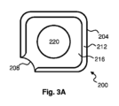
図3Aおよび3Bは、図1Aおよび1Bにおける支持プレート100および150とともに使用するのに適したパッケージ200を示す。パッケージ200は、4つの横壁204および2つの隣接した横壁204の間の縁部に凹面208を有する。パッケージ200の上部ドームは、凸上壁212および凹上面216を含む。封止リング224は、上部ドームを横壁204および凹面208に接合させる。ドームの頂部の閉鎖部220はパッケージ200を封止する。閉鎖部220は再封止可能なネジキャップまたはピールバック式(peel-back)蓋であってもよい。
3A and 3B illustrate a
図4は、食品充填機内で使用するためのシステム320を示す。システム320は、パッケージガイド300およびパッケージガイド300上に装着された図1Bに記載されたような支持プレート150を含む。当然のことながら、支持プレート100はシステム320内で支持プレート150の代わりに使用されてもよい。パッケージガイド300は、充填機の内側で回転支持部(図示せず)に装着するように構成される。
FIG. 4 shows a
ガイド300は、破線で描かれたようなパッケージ200を受けるために全体が管状の形状である。使用時にパッケージ200は斜角端部312でガイド300に入り、パッケージの上部ドームの凸上壁212および凹上面216が、壁104、154の補完的な傾斜内面108、158上に置かれるまで、ガイド300を通って下がる。この位置において、パッケージ200の凹面208も支持プレート100、150の支持突起部116、166に載る。一旦パッケージ200がガイド300内でプレート100、150によって支持されると、パッケージは、最終的にパッケージ200の底面になるものを封止する前に、閉鎖部220の端部を逆向きにして食品が充填される。
パッケージガイド300は、ガイド300の対向する外面上に配置された複数の支持リッジ304を有する。支持リッジ304は対で配置され、所与の対の各部材はガイド300上で同じ高さに配置される。このようにして1対のリッジ304は、クリップ部材120、170のクリップ凹部174によって受けることができる。これにより支持プレート100、150は、充填されるパッケージ200の容積に依存してガイド300上で異なる高さに調節することができる。上述のように、支持プレート100、150の高さは把持部材132、182と自動アーム(図示せず)との間の協働によって調節されてもよい。
また観察穴308も、パッケージ200の装飾または他の特徴の検査を促進するためにパッケージガイド300上に提供される。
Observation holes 308 are also provided on
パッケージガイド300は好ましくは金属から作成される。
図5Aおよび5Bは、矢印の方向に回転する回転支持部404に装着された複数のシステム320を含む、充填機400を示す。また充填機400は、紫外線ランプ、HEPA(高性能微粒子空気)清浄器、および/または過酸化水素噴霧器などの滅菌装置408も含む。図示されていないが、充填機400はパッケージをシステム320に提供するためのパッケージ供給装置、パッケージに食品を充填するための充填ステーション、および充填後にパッケージの底面を封止するための封止ステーションも含んでもよい。図5Bは、充填機の一方の側面が支持プレート100を備えたシステム320を含んでもよいと同時に、反対の側面が支持プレート150を備えたシステム320を含んでもよいことを描いている。支持プレートのこの配置は、パッケージ200を充填機400内でシステム320のすべてに1方向のみに提供するように構成されたパッケージ供給装置とともに使用するのに適している。パッケージ200のすべての凹面208は支持突起部116および166で適正に配向される。滅菌装置408は、わかりやすくするために図5Bから省かれている。
5A and 5B show a filling
突起部116および166により凹面208およびパッケージ200の上部ドーム(これは凹上面216を含む)に提供された支持は、パッケージ200が回転または歪むのを防ぐだけでなく、パッケージ200が充填操作中に適正な高さに確実に保持される役に立つ。また支持プレート100、150は、充填中にパッケージ200を損傷することなくパッケージ200上に発生した追加の圧力を吸収する。
The support provided by
また突起部116および166によって提供された支持により、封止リング224への必要条件を低減または除去し、それによってパッケージ200の外観を向上させることもできる。
The support provided by
Claims (15)
前記パッケージ(200)の上部を受けるための空洞(112、162)を画定する壁(104、154)であって、
前記壁(104、154)は、傾斜内面(108、158)を有し、
前記壁(104、154)から垂直上方に延在し、前記パッケージ(200)の前記上部に設けられた凹上面(216)および前記パッケージ(200)の凹面(208)に当接するための、1つの支持突起部(116、166)とを含む、支持プレート(100、150)。 a support plate (100, 150) for supporting the package (200) during filling with food;
a wall (104, 154) defining a cavity (112, 162) for receiving the top of the package (200);
the wall (104, 154) has an inclined inner surface (108, 158);
extending vertically upward from the wall (104, 154) to abut a concave top surface (216) provided at the top of the package (200) and a concave surface (208) of the package (200); a support plate (100, 150) including one support protrusion (116, 166) of.
前記パッケージ(200)の上部を受けるための空洞(112、162)を画定する壁(104、154)であって、
前記壁(104、154)は、傾斜内面(108、158)を有し、
前記壁(104、154)から垂直上方に延在した支持突起部(116、166)と、
前記壁の外側に配置された1対のクリップ部材(120、170)と、前記1対のクリップ部材に接続された連結部(128、178)と、を含む支持プレート(100、150)。 a support plate (100, 150) for supporting the package (200) during filling with food;
a wall (104, 154) defining a cavity (112, 162) for receiving the top of the package (200);
the wall (104, 154) has an inclined inner surface (108, 158);
a support protrusion (116, 166) extending vertically upward from the wall (104, 154);
A support plate (100, 150) comprising a pair of clip members (120, 170) arranged on the outside of the wall and a connecting part (128, 178) connected to the pair of clip members.
パッケージガイド(300)と、
食品を充填中にパッケージ(200)を支持するための請求項1~5のいずれか一項に記載の支持プレート(100、150)とを含み、
前記支持プレート(100、150)は前記パッケージガイド(300)上に装着され、前記パッケージガイド(300)は前記パッケージ(200)を受けるように構成される、システム(320)。 A system (320) for use in a filling machine (400), comprising:
Package guide (300) and
a support plate (100, 150) according to any one of claims 1 to 5 for supporting a package (200) during filling with a food product;
A system (320), wherein the support plate (100, 150) is mounted on the package guide (300), and the package guide (300) is configured to receive the package (200).
前記回転支持部(404)上に装着された請求項6~10のいずれか一項に記載の複数のシステム(320)と、
前記パッケージ(200)が各システム(320)の前記支持プレート(100、150)によって支持されているとき、食品をパッケージ(200)に充填するための充填ステーションとを含む、充填機(400)。 a rotation support part (404);
a plurality of systems (320) according to any one of claims 6 to 10 mounted on the rotational support (404);
a filling station for filling a package (200) with a food product when the package (200) is supported by the support plate (100, 150) of each system (320).
Applications Claiming Priority (3)
| Application Number | Priority Date | Filing Date | Title |
|---|---|---|---|
| EP16182847.0 | 2016-08-04 | ||
| EP16182847 | 2016-08-04 | ||
| PCT/EP2017/069344 WO2018024685A1 (en) | 2016-08-04 | 2017-07-31 | Support plate for a package suitable for a food product |
Publications (3)
| Publication Number | Publication Date |
|---|---|
| JP2019523190A JP2019523190A (en) | 2019-08-22 |
| JP2019523190A5 JP2019523190A5 (en) | 2020-08-20 |
| JP7386701B2 true JP7386701B2 (en) | 2023-11-27 |
Family
ID=56737914
Family Applications (2)
| Application Number | Title | Priority Date | Filing Date |
|---|---|---|---|
| JP2019505528A Active JP7386701B2 (en) | 2016-08-04 | 2017-07-31 | Support plates for food-appropriate packaging |
| JP2019505521A Active JP7262384B2 (en) | 2016-08-04 | 2017-07-31 | Supports for packaging containers |
Family Applications After (1)
| Application Number | Title | Priority Date | Filing Date |
|---|---|---|---|
| JP2019505521A Active JP7262384B2 (en) | 2016-08-04 | 2017-07-31 | Supports for packaging containers |
Country Status (5)
| Country | Link |
|---|---|
| US (2) | US11577871B2 (en) |
| EP (2) | EP3279097B1 (en) |
| JP (2) | JP7386701B2 (en) |
| CN (2) | CN109476390B (en) |
| WO (2) | WO2018024685A1 (en) |
Families Citing this family (3)
| Publication number | Priority date | Publication date | Assignee | Title |
|---|---|---|---|---|
| US11577871B2 (en) | 2016-08-04 | 2023-02-14 | Tetra Laval Holdings & Finance S.A. | Support plate for a package suitable for a food product |
| DE102020109978A1 (en) * | 2020-04-09 | 2021-12-02 | Sig Technology Ag | Cell traverse for a transport device of a filling machine for filling composite packs as well as cell chain, use of a cell traverse and filling machine |
| DE102021115287A1 (en) | 2021-06-14 | 2022-12-15 | Krones Aktiengesellschaft | Container transport in a container treatment plant |
Citations (9)
| Publication number | Priority date | Publication date | Assignee | Title |
|---|---|---|---|---|
| JP2003341620A (en) | 2002-05-27 | 2003-12-03 | Yl Kogyo Kk | Transfer apparatus in filling and sealing machine for resinous tube |
| JP2004059014A (en) | 2002-07-25 | 2004-02-26 | Nihon Tetra Pak Kk | Sterilization method, sterilizing apparatus, and packaging/filling apparatus for food packaging container |
| JP2005008268A (en) | 2003-06-23 | 2005-01-13 | Toyo Seikan Kaisha Ltd | Holding cup for container |
| JP2007216984A (en) | 2006-02-14 | 2007-08-30 | Fuji Seal International Inc | Manufacturing method for labelled container and labelled container |
| JP2007528329A (en) | 2004-03-11 | 2007-10-11 | フィリップ シーツ | Process and apparatus for transporting deformed containers |
| JP2007320646A (en) | 2006-06-05 | 2007-12-13 | Ishida Co Ltd | Packing device and method of the same |
| JP2008013186A (en) | 2006-07-03 | 2008-01-24 | Hokkai Can Co Ltd | Method for manufacturing content filling bottle, and apparatus therefor |
| US20120024673A1 (en) | 2010-07-30 | 2012-02-02 | Advantage Puck Technologies, Inc. | Product holding puck with noise reducing bumpers |
| JP2012134026A (en) | 2010-12-22 | 2012-07-12 | Tokyo Parts Ind Co Ltd | Push switch and manufacturing method thereof |
Family Cites Families (57)
| Publication number | Priority date | Publication date | Assignee | Title |
|---|---|---|---|---|
| US1647232A (en) * | 1925-03-18 | 1927-11-01 | Kiefer Karl | Method of filling containers with pastes and the like |
| US2574157A (en) | 1949-02-07 | 1951-11-06 | Reichert August | Self-centering holder for container filling machines |
| US2698076A (en) * | 1951-04-20 | 1954-12-28 | Arenco Ab | Means for conveying containers |
| US2689076A (en) | 1951-10-17 | 1954-09-14 | William E Jenkins | Combined beverage carton and imbibing tube |
| US2725169A (en) * | 1953-01-21 | 1955-11-29 | Pfaudler Co Inc | Filling machine |
| US2767744A (en) * | 1954-12-27 | 1956-10-23 | Beerman Jack | Liquid transfer device |
| US2987082A (en) | 1958-10-21 | 1961-06-06 | Corn Products Co | Rotary filling machine |
| US3052340A (en) * | 1959-08-26 | 1962-09-04 | Merck & Co Inc | Article handling and conveyor apparatus |
| US3199552A (en) * | 1961-10-10 | 1965-08-10 | Nordfors Arthur Warren | Container holder |
| US3147018A (en) * | 1962-08-01 | 1964-09-01 | Reichert August | Self-centering holder for automatic tube filling machines and a jaw member therefor |
| US3248120A (en) * | 1963-10-23 | 1966-04-26 | Volpe Michael | Adjustable tube holder |
| DE1275438B (en) | 1966-02-25 | 1968-08-14 | Karlsruhe Augsburg Iweka | Self-centering holder for tubes on a tube filling and closing machine |
| US3480049A (en) * | 1966-06-14 | 1969-11-25 | Mitsubishi Heavy Ind Ltd | Bottle filling apparatus |
| IT1061958B (en) * | 1967-04-28 | 1983-04-30 | Gamberini Ernesto | REFINEMENT OF AN AUTOMATIC MACHINE FOR THE DOSAGE FILLING OF CONTAINERS, PARTICULARLY BOTTLES WITH INCONERENT PULVERULENT TYPE PRODUCTS |
| US3538997A (en) * | 1968-11-05 | 1970-11-10 | Aei Corp | Endless conveyor flight with replaceable holders |
| US3675759A (en) | 1971-03-05 | 1972-07-11 | Exact Weight Scale Corp | Interchangeable carton holder for chain conveyor |
| US4114511A (en) * | 1977-05-25 | 1978-09-19 | General Electric Company | Endless conveyor mechanism |
| FR2395208A2 (en) * | 1977-06-22 | 1979-01-19 | Manurhin | PARTS TRANSPORT VEHICLE, ESPECIALLY ON A CONTINUOUS KINEMATICS PROCESSING FACILITY |
| DE3217156A1 (en) * | 1982-05-07 | 1983-11-10 | Altstaedter Verpack Vertrieb | PACKAGE FOR FLOWABLE FILLING PRODUCTS WITH RE-CLOSABLE OPENING DEVICE |
| JPS5919599A (en) | 1982-07-23 | 1984-02-01 | Toshiba Corp | Anaerobic digestion |
| JPS5919599U (en) * | 1982-07-30 | 1984-02-06 | 東洋食品機械株式会社 | Container holding device in liquid filling valve |
| JPS61144008A (en) | 1984-12-18 | 1986-07-01 | Matsushita Electric Ind Co Ltd | Manufacture of magnet rol |
| JPH059293Y2 (en) * | 1985-02-27 | 1993-03-08 | ||
| JPH072406Y2 (en) * | 1987-07-14 | 1995-01-25 | ポーラ化成工業株式会社 | Container holder |
| US4936442A (en) * | 1988-12-30 | 1990-06-26 | Barry-Wehmiller Company | Combination box beam carrier for nonmetallic container pockets |
| JPH0554326A (en) | 1991-08-23 | 1993-03-05 | Mitsubishi Electric Corp | Pattern forming method and production of plane thin-film magnetic head using the same |
| JPH0554326U (en) * | 1991-12-20 | 1993-07-20 | 凸版印刷株式会社 | Bottle type bag in box |
| US5484052A (en) * | 1994-05-06 | 1996-01-16 | Dowbrands L.P. | Carrier puck |
| US5853077A (en) * | 1994-12-23 | 1998-12-29 | Hoppmann Corporation | Article handling device, combination and methods |
| JP3532993B2 (en) * | 1995-02-07 | 2004-05-31 | 武内プレス工業株式会社 | Tube container holder |
| JP3443804B2 (en) * | 1995-02-14 | 2003-09-08 | 花王株式会社 | Article holding device |
| JPH0912041A (en) * | 1995-06-30 | 1997-01-14 | Kao Corp | Standing pouch, and conveying method therefor |
| KR20000064741A (en) | 1996-03-21 | 2000-11-06 | 포스베르크 라스-에케 | Blanks for Packaging and Packaging |
| AU732628B2 (en) * | 1996-09-06 | 2001-04-26 | Merck & Co., Inc. | Customer specific packaging line |
| JPH1111431A (en) * | 1997-04-24 | 1999-01-19 | Takeuchi Press Ind Co Ltd | Tubular container holder |
| US5975158A (en) * | 1998-08-10 | 1999-11-02 | International Paper Company | Method for preventing bulge of liquid packaging |
| JP5647381B2 (en) * | 2001-05-14 | 2014-12-24 | ホーユー株式会社 | Decoloring and hair coloring products |
| US6698160B2 (en) * | 2002-02-19 | 2004-03-02 | Fci, Inc. | Apparatus and method to prevent bottle rotation |
| JP3942553B2 (en) * | 2002-05-01 | 2007-07-11 | 花王株式会社 | Article holder |
| JP5035569B2 (en) * | 2003-02-19 | 2012-09-26 | 大日本印刷株式会社 | Paper container |
| SE530101C2 (en) | 2006-07-05 | 2008-03-04 | Tetra Laval Holdings & Finance | Method and apparatus for injection molding part of packaging container |
| JP4973979B2 (en) * | 2006-09-25 | 2012-07-11 | 日本テトラパック株式会社 | Packaging container manufacturing method |
| RS52250B (en) * | 2008-05-02 | 2012-10-31 | Indag Gesellschaft für Industriebedarf mbH & Co. Betriebs KG | Device for handling flexible bags |
| SE532765C2 (en) | 2008-06-19 | 2010-04-06 | Tetra Laval Holdings & Finance | Method and apparatus for injection molding in the manufacture of packaging containers |
| JP5482187B2 (en) | 2009-03-10 | 2014-04-23 | 大日本印刷株式会社 | Method and apparatus for sterilizing cup-shaped container |
| CN102470939B (en) * | 2009-07-03 | 2013-08-07 | 利乐拉瓦尔集团及财务有限公司 | A device and a method for maintaining a gas flow barrier between two interconnected volumes |
| AU2010357202B2 (en) * | 2010-07-08 | 2013-10-10 | Colgate-Palmolive Company | A container orienting holder with roller supports and a container orienting method |
| JP2012134056A (en) * | 2010-12-22 | 2012-07-12 | Kansai Electric Power Co Inc:The | Fuel battery system and method for operating fuel battery system |
| JP5831172B2 (en) * | 2011-11-29 | 2015-12-09 | 凸版印刷株式会社 | Blank and liquid paper container using the same |
| KR101655726B1 (en) * | 2012-05-03 | 2016-09-07 | 쇼오트 아게 | Method and device for treating containers and substances stored therein for medical, pharmaceutical or cosmetic applications |
| JP2014091554A (en) * | 2012-11-02 | 2014-05-19 | Daizo:Kk | Container holder |
| CN105050636B (en) * | 2012-11-12 | 2017-11-03 | 肖特股份有限公司 | Processing or processing method and equipment for the container of the material of medical treatment, pharmacy or cosmetic applications |
| DE102013204602A1 (en) * | 2013-03-15 | 2014-09-18 | Flecotec Ag | Flexible container and filling device for such a flexible container and corresponding filling method |
| JP6202915B2 (en) * | 2013-07-17 | 2017-09-27 | 花王株式会社 | Article supply device |
| EP3079989B1 (en) | 2013-12-09 | 2018-01-31 | Tetra Laval Holdings & Finance S.A. | A system for filling and packing tetrahedral packages |
| CN204642284U (en) * | 2015-05-13 | 2015-09-16 | 泰尔精蜡(上海)有限公司 | Flexible packaging material supporting case |
| US11577871B2 (en) | 2016-08-04 | 2023-02-14 | Tetra Laval Holdings & Finance S.A. | Support plate for a package suitable for a food product |
-
2017
- 2017-07-31 US US16/322,868 patent/US11577871B2/en active Active
- 2017-07-31 WO PCT/EP2017/069344 patent/WO2018024685A1/en active Application Filing
- 2017-07-31 JP JP2019505528A patent/JP7386701B2/en active Active
- 2017-07-31 EP EP17184073.9A patent/EP3279097B1/en active Active
- 2017-07-31 CN CN201780045368.1A patent/CN109476390B/en active Active
- 2017-07-31 WO PCT/EP2017/069343 patent/WO2018024684A1/en unknown
- 2017-07-31 CN CN201780048035.4A patent/CN109562851B/en active Active
- 2017-07-31 US US16/322,892 patent/US11673699B2/en active Active
- 2017-07-31 JP JP2019505521A patent/JP7262384B2/en active Active
- 2017-07-31 EP EP17751059.1A patent/EP3494053A1/en active Pending
Patent Citations (9)
| Publication number | Priority date | Publication date | Assignee | Title |
|---|---|---|---|---|
| JP2003341620A (en) | 2002-05-27 | 2003-12-03 | Yl Kogyo Kk | Transfer apparatus in filling and sealing machine for resinous tube |
| JP2004059014A (en) | 2002-07-25 | 2004-02-26 | Nihon Tetra Pak Kk | Sterilization method, sterilizing apparatus, and packaging/filling apparatus for food packaging container |
| JP2005008268A (en) | 2003-06-23 | 2005-01-13 | Toyo Seikan Kaisha Ltd | Holding cup for container |
| JP2007528329A (en) | 2004-03-11 | 2007-10-11 | フィリップ シーツ | Process and apparatus for transporting deformed containers |
| JP2007216984A (en) | 2006-02-14 | 2007-08-30 | Fuji Seal International Inc | Manufacturing method for labelled container and labelled container |
| JP2007320646A (en) | 2006-06-05 | 2007-12-13 | Ishida Co Ltd | Packing device and method of the same |
| JP2008013186A (en) | 2006-07-03 | 2008-01-24 | Hokkai Can Co Ltd | Method for manufacturing content filling bottle, and apparatus therefor |
| US20120024673A1 (en) | 2010-07-30 | 2012-02-02 | Advantage Puck Technologies, Inc. | Product holding puck with noise reducing bumpers |
| JP2012134026A (en) | 2010-12-22 | 2012-07-12 | Tokyo Parts Ind Co Ltd | Push switch and manufacturing method thereof |
Also Published As
| Publication number | Publication date |
|---|---|
| CN109476390B (en) | 2021-07-09 |
| CN109562851A (en) | 2019-04-02 |
| EP3279097B1 (en) | 2020-11-25 |
| WO2018024685A1 (en) | 2018-02-08 |
| US20210380296A1 (en) | 2021-12-09 |
| JP2019523190A (en) | 2019-08-22 |
| CN109562851B (en) | 2021-07-16 |
| US11673699B2 (en) | 2023-06-13 |
| US20210380295A1 (en) | 2021-12-09 |
| US11577871B2 (en) | 2023-02-14 |
| CN109476390A (en) | 2019-03-15 |
| JP7262384B2 (en) | 2023-04-21 |
| WO2018024684A1 (en) | 2018-02-08 |
| EP3494053A1 (en) | 2019-06-12 |
| EP3279097A1 (en) | 2018-02-07 |
| JP2019524576A (en) | 2019-09-05 |
Similar Documents
| Publication | Publication Date | Title |
|---|---|---|
| JP7386701B2 (en) | Support plates for food-appropriate packaging | |
| US11472602B2 (en) | Holding structure with a plurality of containers held thereon for substances for pharmaceutical, medical or cosmetic applications, and transport or packaging container having same | |
| AU2016249109B2 (en) | Method for closing cartridges, supporting structure for supporting cartridge closures and transport or packaging container | |
| JP5559880B2 (en) | Tray for positioning elongated objects, especially syringe body or syringe | |
| EP2663348B1 (en) | Packaging for containers | |
| CN110481984B (en) | Support structure for simultaneously supporting a plurality of containers and transport structure comprising same | |
| ITMI20100747A1 (en) | PACKAGING STRUCTURE FOR PHARMACEUTICAL CONTAINERS | |
| WO2018020505A1 (en) | Method for closing vials, supporting structure for vial stopper members and transport or packaging container | |
| CN103096950A (en) | Packaging for cylindrical containers | |
| AR053201A1 (en) | PACK OF CONTACT LENS THAT ARE INTERCONNECTED | |
| RU2018103455A (en) | SYSTEM FOR PERFORMING STERIALIZATION OF THIN-WALLED FLEXIBLE CONTAINERS (DOI-PACK) | |
| CN111196416A (en) | Holding structure for holding a plurality of containers, transport unit therefor, and transport or packaging container | |
| JP2019523190A5 (en) | ||
| WO2007027094A3 (en) | Transport container with improved ventilation properties for flowers | |
| CN103832685A (en) | Bottle drying stand | |
| KR200389381Y1 (en) | Wafer box fixing unit | |
| KR200451876Y1 (en) | Cans containers | |
| JP2010215264A (en) | Packaging container | |
| TW202005885A (en) | Holding device for recipients comprising a filling tube and use thereof | |
| ES2201640T3 (en) | PACKING DEVICE FOR REQUESON PACKING CONTAINERS. | |
| JP5978254B2 (en) | Vial standing tray and vial packaging structure | |
| JP2022175811A (en) | pouch container holder | |
| JP2022541480A (en) | Structure for packaging primary containers for pharmaceutical applications | |
| KR20190019787A (en) | Winged cup with protrusions | |
| CA2427561A1 (en) | Container for spoonable food products |
Legal Events
| Date | Code | Title | Description |
|---|---|---|---|
| A521 | Request for written amendment filed |
Free format text: JAPANESE INTERMEDIATE CODE: A523 Effective date: 20200710 |
|
| A621 | Written request for application examination |
Free format text: JAPANESE INTERMEDIATE CODE: A621 Effective date: 20200710 |
|
| A977 | Report on retrieval |
Free format text: JAPANESE INTERMEDIATE CODE: A971007 Effective date: 20210811 |
|
| A131 | Notification of reasons for refusal |
Free format text: JAPANESE INTERMEDIATE CODE: A131 Effective date: 20210824 |
|
| A601 | Written request for extension of time |
Free format text: JAPANESE INTERMEDIATE CODE: A601 Effective date: 20211122 |
|
| A521 | Request for written amendment filed |
Free format text: JAPANESE INTERMEDIATE CODE: A523 Effective date: 20220124 |
|
| A131 | Notification of reasons for refusal |
Free format text: JAPANESE INTERMEDIATE CODE: A131 Effective date: 20220510 |
|
| A601 | Written request for extension of time |
Free format text: JAPANESE INTERMEDIATE CODE: A601 Effective date: 20220809 |
|
| A601 | Written request for extension of time |
Free format text: JAPANESE INTERMEDIATE CODE: A601 Effective date: 20221011 |
|
| A521 | Request for written amendment filed |
Free format text: JAPANESE INTERMEDIATE CODE: A523 Effective date: 20221109 |
|
| A131 | Notification of reasons for refusal |
Free format text: JAPANESE INTERMEDIATE CODE: A131 Effective date: 20230322 |
|
| A601 | Written request for extension of time |
Free format text: JAPANESE INTERMEDIATE CODE: A601 Effective date: 20230619 |
|
| A601 | Written request for extension of time |
Free format text: JAPANESE INTERMEDIATE CODE: A601 Effective date: 20230822 |
|
| A521 | Request for written amendment filed |
Free format text: JAPANESE INTERMEDIATE CODE: A523 Effective date: 20230922 |
|
| TRDD | Decision of grant or rejection written | ||
| A01 | Written decision to grant a patent or to grant a registration (utility model) |
Free format text: JAPANESE INTERMEDIATE CODE: A01 Effective date: 20231017 |
|
| A61 | First payment of annual fees (during grant procedure) |
Free format text: JAPANESE INTERMEDIATE CODE: A61 Effective date: 20231114 |
|
| R150 | Certificate of patent or registration of utility model |
Ref document number: 7386701 Country of ref document: JP Free format text: JAPANESE INTERMEDIATE CODE: R150 |