JP7383623B2 - Flip-flop circuits, drive circuits, display panels, display devices, input/output devices, information processing devices - Google Patents
Flip-flop circuits, drive circuits, display panels, display devices, input/output devices, information processing devices Download PDFInfo
- Publication number
- JP7383623B2 JP7383623B2 JP2020547467A JP2020547467A JP7383623B2 JP 7383623 B2 JP7383623 B2 JP 7383623B2 JP 2020547467 A JP2020547467 A JP 2020547467A JP 2020547467 A JP2020547467 A JP 2020547467A JP 7383623 B2 JP7383623 B2 JP 7383623B2
- Authority
- JP
- Japan
- Prior art keywords
- transistor
- electrically connected
- supplied
- information
- input
- Prior art date
- Legal status (The legal status is an assumption and is not a legal conclusion. Google has not performed a legal analysis and makes no representation as to the accuracy of the status listed.)
- Active
Links
- 230000010365 information processing Effects 0.000 title claims description 82
- 238000001514 detection method Methods 0.000 claims description 78
- 239000002346 layers by function Substances 0.000 claims description 18
- 238000003384 imaging method Methods 0.000 claims description 5
- 239000000463 material Substances 0.000 description 103
- 230000006870 function Effects 0.000 description 90
- 239000004065 semiconductor Substances 0.000 description 73
- 239000002585 base Substances 0.000 description 47
- 238000010586 diagram Methods 0.000 description 47
- 238000000034 method Methods 0.000 description 40
- 239000004973 liquid crystal related substance Substances 0.000 description 38
- 239000010410 layer Substances 0.000 description 37
- 238000012545 processing Methods 0.000 description 32
- 239000008186 active pharmaceutical agent Substances 0.000 description 21
- 238000004891 communication Methods 0.000 description 18
- 238000013473 artificial intelligence Methods 0.000 description 17
- 229920005989 resin Polymers 0.000 description 17
- 239000011347 resin Substances 0.000 description 17
- 239000000758 substrate Substances 0.000 description 14
- 238000003860 storage Methods 0.000 description 13
- IJGRMHOSHXDMSA-UHFFFAOYSA-N Atomic nitrogen Chemical compound N#N IJGRMHOSHXDMSA-UHFFFAOYSA-N 0.000 description 12
- XUIMIQQOPSSXEZ-UHFFFAOYSA-N Silicon Chemical compound [Si] XUIMIQQOPSSXEZ-UHFFFAOYSA-N 0.000 description 12
- 238000004519 manufacturing process Methods 0.000 description 12
- 229910052710 silicon Inorganic materials 0.000 description 12
- 239000010703 silicon Substances 0.000 description 12
- 239000011368 organic material Substances 0.000 description 11
- 229910021417 amorphous silicon Inorganic materials 0.000 description 10
- 229910010272 inorganic material Inorganic materials 0.000 description 10
- 239000011147 inorganic material Substances 0.000 description 10
- 230000005540 biological transmission Effects 0.000 description 9
- 238000004364 calculation method Methods 0.000 description 9
- 239000000178 monomer Substances 0.000 description 9
- 229910052581 Si3N4 Inorganic materials 0.000 description 8
- 238000009792 diffusion process Methods 0.000 description 8
- 230000005684 electric field Effects 0.000 description 8
- 239000011521 glass Substances 0.000 description 8
- 229910052751 metal Inorganic materials 0.000 description 8
- 230000008569 process Effects 0.000 description 8
- HQVNEWCFYHHQES-UHFFFAOYSA-N silicon nitride Chemical compound N12[Si]34N5[Si]62N3[Si]51N64 HQVNEWCFYHHQES-UHFFFAOYSA-N 0.000 description 8
- RTAQQCXQSZGOHL-UHFFFAOYSA-N Titanium Chemical compound [Ti] RTAQQCXQSZGOHL-UHFFFAOYSA-N 0.000 description 7
- 239000002131 composite material Substances 0.000 description 7
- 229910052719 titanium Inorganic materials 0.000 description 7
- 239000010936 titanium Substances 0.000 description 7
- 229910052721 tungsten Inorganic materials 0.000 description 7
- 239000010937 tungsten Substances 0.000 description 7
- OKTJSMMVPCPJKN-UHFFFAOYSA-N Carbon Chemical compound [C] OKTJSMMVPCPJKN-UHFFFAOYSA-N 0.000 description 6
- 239000004020 conductor Substances 0.000 description 6
- 230000014509 gene expression Effects 0.000 description 6
- 239000012535 impurity Substances 0.000 description 6
- 239000002184 metal Substances 0.000 description 6
- 229910052757 nitrogen Inorganic materials 0.000 description 6
- 229920001721 polyimide Polymers 0.000 description 6
- WFKWXMTUELFFGS-UHFFFAOYSA-N tungsten Chemical compound [W] WFKWXMTUELFFGS-UHFFFAOYSA-N 0.000 description 6
- 239000004642 Polyimide Substances 0.000 description 5
- VYPSYNLAJGMNEJ-UHFFFAOYSA-N Silicium dioxide Chemical compound O=[Si]=O VYPSYNLAJGMNEJ-UHFFFAOYSA-N 0.000 description 5
- 230000001133 acceleration Effects 0.000 description 5
- 239000000853 adhesive Substances 0.000 description 5
- 230000001070 adhesive effect Effects 0.000 description 5
- 229910052782 aluminium Inorganic materials 0.000 description 5
- XAGFODPZIPBFFR-UHFFFAOYSA-N aluminium Chemical compound [Al] XAGFODPZIPBFFR-UHFFFAOYSA-N 0.000 description 5
- 230000008859 change Effects 0.000 description 5
- 229910021389 graphene Inorganic materials 0.000 description 5
- 239000002648 laminated material Substances 0.000 description 5
- 239000000203 mixture Substances 0.000 description 5
- 229910021420 polycrystalline silicon Inorganic materials 0.000 description 5
- 229920005591 polysilicon Polymers 0.000 description 5
- 239000003566 sealing material Substances 0.000 description 5
- 239000004925 Acrylic resin Substances 0.000 description 4
- 229920000178 Acrylic resin Polymers 0.000 description 4
- XLOMVQKBTHCTTD-UHFFFAOYSA-N Zinc monoxide Chemical compound [Zn]=O XLOMVQKBTHCTTD-UHFFFAOYSA-N 0.000 description 4
- QVGXLLKOCUKJST-UHFFFAOYSA-N atomic oxygen Chemical compound [O] QVGXLLKOCUKJST-UHFFFAOYSA-N 0.000 description 4
- 239000003990 capacitor Substances 0.000 description 4
- 238000006243 chemical reaction Methods 0.000 description 4
- 230000006837 decompression Effects 0.000 description 4
- 230000000694 effects Effects 0.000 description 4
- 229910052760 oxygen Inorganic materials 0.000 description 4
- 239000001301 oxygen Substances 0.000 description 4
- -1 polysiloxane Polymers 0.000 description 4
- 229910052814 silicon oxide Inorganic materials 0.000 description 4
- RYGMFSIKBFXOCR-UHFFFAOYSA-N Copper Chemical compound [Cu] RYGMFSIKBFXOCR-UHFFFAOYSA-N 0.000 description 3
- GYHNNYVSQQEPJS-UHFFFAOYSA-N Gallium Chemical compound [Ga] GYHNNYVSQQEPJS-UHFFFAOYSA-N 0.000 description 3
- NRTOMJZYCJJWKI-UHFFFAOYSA-N Titanium nitride Chemical compound [Ti]#N NRTOMJZYCJJWKI-UHFFFAOYSA-N 0.000 description 3
- 229910052802 copper Inorganic materials 0.000 description 3
- 239000010949 copper Substances 0.000 description 3
- 238000005520 cutting process Methods 0.000 description 3
- 238000011156 evaluation Methods 0.000 description 3
- 229910052733 gallium Inorganic materials 0.000 description 3
- 229910052738 indium Inorganic materials 0.000 description 3
- APFVFJFRJDLVQX-UHFFFAOYSA-N indium atom Chemical compound [In] APFVFJFRJDLVQX-UHFFFAOYSA-N 0.000 description 3
- 229910021421 monocrystalline silicon Inorganic materials 0.000 description 3
- 238000003058 natural language processing Methods 0.000 description 3
- 150000004767 nitrides Chemical class 0.000 description 3
- 230000003287 optical effect Effects 0.000 description 3
- TWNQGVIAIRXVLR-UHFFFAOYSA-N oxo(oxoalumanyloxy)alumane Chemical compound O=[Al]O[Al]=O TWNQGVIAIRXVLR-UHFFFAOYSA-N 0.000 description 3
- FCJSHPDYVMKCHI-UHFFFAOYSA-N phenyl benzoate Chemical group C=1C=CC=CC=1C(=O)OC1=CC=CC=C1 FCJSHPDYVMKCHI-UHFFFAOYSA-N 0.000 description 3
- 230000004044 response Effects 0.000 description 3
- 239000000565 sealant Substances 0.000 description 3
- 229910052715 tantalum Inorganic materials 0.000 description 3
- GUVRBAGPIYLISA-UHFFFAOYSA-N tantalum atom Chemical compound [Ta] GUVRBAGPIYLISA-UHFFFAOYSA-N 0.000 description 3
- XLYOFNOQVPJJNP-UHFFFAOYSA-N water Substances O XLYOFNOQVPJJNP-UHFFFAOYSA-N 0.000 description 3
- 229910001868 water Inorganic materials 0.000 description 3
- 102100027310 Bromodomain adjacent to zinc finger domain protein 1A Human genes 0.000 description 2
- 229920000089 Cyclic olefin copolymer Polymers 0.000 description 2
- 102100040862 Dual specificity protein kinase CLK1 Human genes 0.000 description 2
- 101000937778 Homo sapiens Bromodomain adjacent to zinc finger domain protein 1A Proteins 0.000 description 2
- 101000749294 Homo sapiens Dual specificity protein kinase CLK1 Proteins 0.000 description 2
- XEEYBQQBJWHFJM-UHFFFAOYSA-N Iron Chemical compound [Fe] XEEYBQQBJWHFJM-UHFFFAOYSA-N 0.000 description 2
- PWHULOQIROXLJO-UHFFFAOYSA-N Manganese Chemical compound [Mn] PWHULOQIROXLJO-UHFFFAOYSA-N 0.000 description 2
- PXHVJJICTQNCMI-UHFFFAOYSA-N Nickel Chemical compound [Ni] PXHVJJICTQNCMI-UHFFFAOYSA-N 0.000 description 2
- KDLHZDBZIXYQEI-UHFFFAOYSA-N Palladium Chemical compound [Pd] KDLHZDBZIXYQEI-UHFFFAOYSA-N 0.000 description 2
- 239000004952 Polyamide Substances 0.000 description 2
- HCHKCACWOHOZIP-UHFFFAOYSA-N Zinc Chemical compound [Zn] HCHKCACWOHOZIP-UHFFFAOYSA-N 0.000 description 2
- 239000005354 aluminosilicate glass Substances 0.000 description 2
- 238000013459 approach Methods 0.000 description 2
- 230000036760 body temperature Effects 0.000 description 2
- DQXBYHZEEUGOBF-UHFFFAOYSA-N but-3-enoic acid;ethene Chemical compound C=C.OC(=O)CC=C DQXBYHZEEUGOBF-UHFFFAOYSA-N 0.000 description 2
- 239000000919 ceramic Substances 0.000 description 2
- 239000005345 chemically strengthened glass Substances 0.000 description 2
- 150000001875 compounds Chemical class 0.000 description 2
- 239000013256 coordination polymer Substances 0.000 description 2
- 229920001577 copolymer Polymers 0.000 description 2
- PMHQVHHXPFUNSP-UHFFFAOYSA-M copper(1+);methylsulfanylmethane;bromide Chemical compound Br[Cu].CSC PMHQVHHXPFUNSP-UHFFFAOYSA-M 0.000 description 2
- 238000012937 correction Methods 0.000 description 2
- HHNHBFLGXIUXCM-GFCCVEGCSA-N cyclohexylbenzene Chemical group [CH]1CCCC[C@@H]1C1=CC=CC=C1 HHNHBFLGXIUXCM-GFCCVEGCSA-N 0.000 description 2
- 230000005674 electromagnetic induction Effects 0.000 description 2
- 230000008451 emotion Effects 0.000 description 2
- 230000007613 environmental effect Effects 0.000 description 2
- 239000003822 epoxy resin Substances 0.000 description 2
- 239000005038 ethylene vinyl acetate Substances 0.000 description 2
- 239000000284 extract Substances 0.000 description 2
- 239000005262 ferroelectric liquid crystals (FLCs) Substances 0.000 description 2
- 229910052809 inorganic oxide Inorganic materials 0.000 description 2
- 238000010030 laminating Methods 0.000 description 2
- MRELNEQAGSRDBK-UHFFFAOYSA-N lanthanum(3+);oxygen(2-) Chemical compound [O-2].[O-2].[O-2].[La+3].[La+3] MRELNEQAGSRDBK-UHFFFAOYSA-N 0.000 description 2
- 239000011572 manganese Substances 0.000 description 2
- 239000002070 nanowire Substances 0.000 description 2
- PLDDOISOJJCEMH-UHFFFAOYSA-N neodymium(3+);oxygen(2-) Chemical compound [O-2].[O-2].[O-2].[Nd+3].[Nd+3] PLDDOISOJJCEMH-UHFFFAOYSA-N 0.000 description 2
- BASFCYQUMIYNBI-UHFFFAOYSA-N platinum Chemical compound [Pt] BASFCYQUMIYNBI-UHFFFAOYSA-N 0.000 description 2
- 229920001200 poly(ethylene-vinyl acetate) Polymers 0.000 description 2
- 229920002037 poly(vinyl butyral) polymer Polymers 0.000 description 2
- 229920002647 polyamide Polymers 0.000 description 2
- 239000004417 polycarbonate Substances 0.000 description 2
- 229920000515 polycarbonate Polymers 0.000 description 2
- 229920000647 polyepoxide Polymers 0.000 description 2
- 229920000728 polyester Polymers 0.000 description 2
- 229920000139 polyethylene terephthalate Polymers 0.000 description 2
- 239000005020 polyethylene terephthalate Substances 0.000 description 2
- 229920000098 polyolefin Polymers 0.000 description 2
- 229920000915 polyvinyl chloride Polymers 0.000 description 2
- 239000004800 polyvinyl chloride Substances 0.000 description 2
- 239000005871 repellent Substances 0.000 description 2
- 239000010980 sapphire Substances 0.000 description 2
- 229910052594 sapphire Inorganic materials 0.000 description 2
- 229910052709 silver Inorganic materials 0.000 description 2
- 239000004332 silver Substances 0.000 description 2
- 239000005341 toughened glass Substances 0.000 description 2
- 229910052725 zinc Inorganic materials 0.000 description 2
- 239000011701 zinc Substances 0.000 description 2
- 239000011787 zinc oxide Substances 0.000 description 2
- 229920003026 Acene Polymers 0.000 description 1
- NIXOWILDQLNWCW-UHFFFAOYSA-M Acrylate Chemical compound [O-]C(=O)C=C NIXOWILDQLNWCW-UHFFFAOYSA-M 0.000 description 1
- JBRZTFJDHDCESZ-UHFFFAOYSA-N AsGa Chemical compound [As]#[Ga] JBRZTFJDHDCESZ-UHFFFAOYSA-N 0.000 description 1
- VYZAMTAEIAYCRO-UHFFFAOYSA-N Chromium Chemical compound [Cr] VYZAMTAEIAYCRO-UHFFFAOYSA-N 0.000 description 1
- 229910000881 Cu alloy Inorganic materials 0.000 description 1
- 102100040844 Dual specificity protein kinase CLK2 Human genes 0.000 description 1
- 102100040856 Dual specificity protein kinase CLK3 Human genes 0.000 description 1
- 102100040858 Dual specificity protein kinase CLK4 Human genes 0.000 description 1
- 229910001218 Gallium arsenide Inorganic materials 0.000 description 1
- 101000749291 Homo sapiens Dual specificity protein kinase CLK2 Proteins 0.000 description 1
- 101000749304 Homo sapiens Dual specificity protein kinase CLK3 Proteins 0.000 description 1
- 101000749298 Homo sapiens Dual specificity protein kinase CLK4 Proteins 0.000 description 1
- 229910000914 Mn alloy Inorganic materials 0.000 description 1
- ZOKXTWBITQBERF-UHFFFAOYSA-N Molybdenum Chemical compound [Mo] ZOKXTWBITQBERF-UHFFFAOYSA-N 0.000 description 1
- 239000004677 Nylon Substances 0.000 description 1
- 229920012266 Poly(ether sulfone) PES Polymers 0.000 description 1
- KWYUFKZDYYNOTN-UHFFFAOYSA-M Potassium hydroxide Chemical compound [OH-].[K+] KWYUFKZDYYNOTN-UHFFFAOYSA-M 0.000 description 1
- 229910000577 Silicon-germanium Inorganic materials 0.000 description 1
- BQCADISMDOOEFD-UHFFFAOYSA-N Silver Chemical compound [Ag] BQCADISMDOOEFD-UHFFFAOYSA-N 0.000 description 1
- 241001422033 Thestylus Species 0.000 description 1
- LEVVHYCKPQWKOP-UHFFFAOYSA-N [Si].[Ge] Chemical compound [Si].[Ge] LEVVHYCKPQWKOP-UHFFFAOYSA-N 0.000 description 1
- 229910052783 alkali metal Inorganic materials 0.000 description 1
- 150000001340 alkali metals Chemical class 0.000 description 1
- 229910052784 alkaline earth metal Inorganic materials 0.000 description 1
- 150000001342 alkaline earth metals Chemical class 0.000 description 1
- 229910045601 alloy Inorganic materials 0.000 description 1
- 239000000956 alloy Substances 0.000 description 1
- 238000004458 analytical method Methods 0.000 description 1
- 239000004760 aramid Substances 0.000 description 1
- 229920003235 aromatic polyamide Polymers 0.000 description 1
- 230000003190 augmentative effect Effects 0.000 description 1
- 229910052800 carbon group element Inorganic materials 0.000 description 1
- 229910000420 cerium oxide Inorganic materials 0.000 description 1
- 239000003638 chemical reducing agent Substances 0.000 description 1
- 229910052804 chromium Inorganic materials 0.000 description 1
- 239000011651 chromium Substances 0.000 description 1
- 229910017052 cobalt Inorganic materials 0.000 description 1
- 239000010941 cobalt Substances 0.000 description 1
- GUTLYIVDDKVIGB-UHFFFAOYSA-N cobalt atom Chemical compound [Co] GUTLYIVDDKVIGB-UHFFFAOYSA-N 0.000 description 1
- 239000003086 colorant Substances 0.000 description 1
- 229920001940 conductive polymer Polymers 0.000 description 1
- 239000000470 constituent Substances 0.000 description 1
- 239000013078 crystal Substances 0.000 description 1
- 238000001723 curing Methods 0.000 description 1
- 125000000113 cyclohexyl group Chemical group [H]C1([H])C([H])([H])C([H])([H])C([H])(*)C([H])([H])C1([H])[H] 0.000 description 1
- 230000006866 deterioration Effects 0.000 description 1
- 125000004386 diacrylate group Chemical group 0.000 description 1
- AJNVQOSZGJRYEI-UHFFFAOYSA-N digallium;oxygen(2-) Chemical compound [O-2].[O-2].[O-2].[Ga+3].[Ga+3] AJNVQOSZGJRYEI-UHFFFAOYSA-N 0.000 description 1
- 239000000428 dust Substances 0.000 description 1
- 230000005669 field effect Effects 0.000 description 1
- 229910001195 gallium oxide Inorganic materials 0.000 description 1
- 230000007274 generation of a signal involved in cell-cell signaling Effects 0.000 description 1
- PCHJSUWPFVWCPO-UHFFFAOYSA-N gold Chemical compound [Au] PCHJSUWPFVWCPO-UHFFFAOYSA-N 0.000 description 1
- 229910052737 gold Inorganic materials 0.000 description 1
- 239000010931 gold Substances 0.000 description 1
- 229910002804 graphite Inorganic materials 0.000 description 1
- 239000010439 graphite Substances 0.000 description 1
- 229910000449 hafnium oxide Inorganic materials 0.000 description 1
- WIHZLLGSGQNAGK-UHFFFAOYSA-N hafnium(4+);oxygen(2-) Chemical compound [O-2].[O-2].[Hf+4] WIHZLLGSGQNAGK-UHFFFAOYSA-N 0.000 description 1
- 230000003760 hair shine Effects 0.000 description 1
- 230000020169 heat generation Effects 0.000 description 1
- 238000010438 heat treatment Methods 0.000 description 1
- 239000012943 hotmelt Substances 0.000 description 1
- 239000001257 hydrogen Substances 0.000 description 1
- 229910052739 hydrogen Inorganic materials 0.000 description 1
- 125000004435 hydrogen atom Chemical class [H]* 0.000 description 1
- 238000005286 illumination Methods 0.000 description 1
- 150000003949 imides Chemical class 0.000 description 1
- 229910003437 indium oxide Inorganic materials 0.000 description 1
- PJXISJQVUVHSOJ-UHFFFAOYSA-N indium(iii) oxide Chemical compound [O-2].[O-2].[O-2].[In+3].[In+3] PJXISJQVUVHSOJ-UHFFFAOYSA-N 0.000 description 1
- AMGQUBHHOARCQH-UHFFFAOYSA-N indium;oxotin Chemical compound [In].[Sn]=O AMGQUBHHOARCQH-UHFFFAOYSA-N 0.000 description 1
- 238000009413 insulation Methods 0.000 description 1
- 229910052742 iron Inorganic materials 0.000 description 1
- 239000005355 lead glass Substances 0.000 description 1
- 239000007788 liquid Substances 0.000 description 1
- 239000000395 magnesium oxide Substances 0.000 description 1
- CPLXHLVBOLITMK-UHFFFAOYSA-N magnesium oxide Inorganic materials [Mg]=O CPLXHLVBOLITMK-UHFFFAOYSA-N 0.000 description 1
- AXZKOIWUVFPNLO-UHFFFAOYSA-N magnesium;oxygen(2-) Chemical compound [O-2].[Mg+2] AXZKOIWUVFPNLO-UHFFFAOYSA-N 0.000 description 1
- 229910052748 manganese Inorganic materials 0.000 description 1
- 239000012528 membrane Substances 0.000 description 1
- 229910044991 metal oxide Inorganic materials 0.000 description 1
- 150000004706 metal oxides Chemical class 0.000 description 1
- 150000002739 metals Chemical class 0.000 description 1
- 229910021424 microcrystalline silicon Inorganic materials 0.000 description 1
- 238000012986 modification Methods 0.000 description 1
- 230000004048 modification Effects 0.000 description 1
- 229910052750 molybdenum Inorganic materials 0.000 description 1
- 239000011733 molybdenum Substances 0.000 description 1
- 229910052759 nickel Inorganic materials 0.000 description 1
- 229920001778 nylon Polymers 0.000 description 1
- 230000010355 oscillation Effects 0.000 description 1
- 230000001151 other effect Effects 0.000 description 1
- BMMGVYCKOGBVEV-UHFFFAOYSA-N oxo(oxoceriooxy)cerium Chemical compound [Ce]=O.O=[Ce]=O BMMGVYCKOGBVEV-UHFFFAOYSA-N 0.000 description 1
- SIWVEOZUMHYXCS-UHFFFAOYSA-N oxo(oxoyttriooxy)yttrium Chemical compound O=[Y]O[Y]=O SIWVEOZUMHYXCS-UHFFFAOYSA-N 0.000 description 1
- BPUBBGLMJRNUCC-UHFFFAOYSA-N oxygen(2-);tantalum(5+) Chemical compound [O-2].[O-2].[O-2].[O-2].[O-2].[Ta+5].[Ta+5] BPUBBGLMJRNUCC-UHFFFAOYSA-N 0.000 description 1
- RVTZCBVAJQQJTK-UHFFFAOYSA-N oxygen(2-);zirconium(4+) Chemical compound [O-2].[O-2].[Zr+4] RVTZCBVAJQQJTK-UHFFFAOYSA-N 0.000 description 1
- 229910052763 palladium Inorganic materials 0.000 description 1
- 239000005011 phenolic resin Substances 0.000 description 1
- 238000000016 photochemical curing Methods 0.000 description 1
- 229920003023 plastic Polymers 0.000 description 1
- 239000004033 plastic Substances 0.000 description 1
- 229910052697 platinum Inorganic materials 0.000 description 1
- 239000011112 polyethylene naphthalate Substances 0.000 description 1
- 239000009719 polyimide resin Substances 0.000 description 1
- 229920000642 polymer Polymers 0.000 description 1
- 239000002861 polymer material Substances 0.000 description 1
- 229920001296 polysiloxane Polymers 0.000 description 1
- 229920002635 polyurethane Polymers 0.000 description 1
- 239000004814 polyurethane Substances 0.000 description 1
- 229940072033 potash Drugs 0.000 description 1
- BWHMMNNQKKPAPP-UHFFFAOYSA-L potassium carbonate Substances [K+].[K+].[O-]C([O-])=O BWHMMNNQKKPAPP-UHFFFAOYSA-L 0.000 description 1
- 235000015320 potassium carbonate Nutrition 0.000 description 1
- 230000000750 progressive effect Effects 0.000 description 1
- 239000010453 quartz Substances 0.000 description 1
- HBMJWWWQQXIZIP-UHFFFAOYSA-N silicon carbide Chemical compound [Si+]#[C-] HBMJWWWQQXIZIP-UHFFFAOYSA-N 0.000 description 1
- 229910010271 silicon carbide Inorganic materials 0.000 description 1
- 229920002050 silicone resin Polymers 0.000 description 1
- 239000002356 single layer Substances 0.000 description 1
- 239000004984 smart glass Substances 0.000 description 1
- 239000005361 soda-lime glass Substances 0.000 description 1
- 239000010935 stainless steel Substances 0.000 description 1
- 229910001220 stainless steel Inorganic materials 0.000 description 1
- 239000000126 substance Substances 0.000 description 1
- 125000001424 substituent group Chemical group 0.000 description 1
- 230000001360 synchronised effect Effects 0.000 description 1
- MZLGASXMSKOWSE-UHFFFAOYSA-N tantalum nitride Chemical compound [Ta]#N MZLGASXMSKOWSE-UHFFFAOYSA-N 0.000 description 1
- 229910001936 tantalum oxide Inorganic materials 0.000 description 1
- 229920001187 thermosetting polymer Polymers 0.000 description 1
- 238000002834 transmittance Methods 0.000 description 1
- 238000001039 wet etching Methods 0.000 description 1
- 239000002023 wood Substances 0.000 description 1
- YVTHLONGBIQYBO-UHFFFAOYSA-N zinc indium(3+) oxygen(2-) Chemical compound [O--].[Zn++].[In+3] YVTHLONGBIQYBO-UHFFFAOYSA-N 0.000 description 1
- 229910001928 zirconium oxide Inorganic materials 0.000 description 1
Images


Classifications
-
- G—PHYSICS
- G09—EDUCATION; CRYPTOGRAPHY; DISPLAY; ADVERTISING; SEALS
- G09G—ARRANGEMENTS OR CIRCUITS FOR CONTROL OF INDICATING DEVICES USING STATIC MEANS TO PRESENT VARIABLE INFORMATION
- G09G3/00—Control arrangements or circuits, of interest only in connection with visual indicators other than cathode-ray tubes
- G09G3/20—Control arrangements or circuits, of interest only in connection with visual indicators other than cathode-ray tubes for presentation of an assembly of a number of characters, e.g. a page, by composing the assembly by combination of individual elements arranged in a matrix no fixed position being assigned to or needed to be assigned to the individual characters or partial characters
- G09G3/34—Control arrangements or circuits, of interest only in connection with visual indicators other than cathode-ray tubes for presentation of an assembly of a number of characters, e.g. a page, by composing the assembly by combination of individual elements arranged in a matrix no fixed position being assigned to or needed to be assigned to the individual characters or partial characters by control of light from an independent source
- G09G3/36—Control arrangements or circuits, of interest only in connection with visual indicators other than cathode-ray tubes for presentation of an assembly of a number of characters, e.g. a page, by composing the assembly by combination of individual elements arranged in a matrix no fixed position being assigned to or needed to be assigned to the individual characters or partial characters by control of light from an independent source using liquid crystals
- G09G3/3611—Control of matrices with row and column drivers
- G09G3/3674—Details of drivers for scan electrodes
- G09G3/3677—Details of drivers for scan electrodes suitable for active matrices only
-
- G—PHYSICS
- G09—EDUCATION; CRYPTOGRAPHY; DISPLAY; ADVERTISING; SEALS
- G09G—ARRANGEMENTS OR CIRCUITS FOR CONTROL OF INDICATING DEVICES USING STATIC MEANS TO PRESENT VARIABLE INFORMATION
- G09G3/00—Control arrangements or circuits, of interest only in connection with visual indicators other than cathode-ray tubes
- G09G3/20—Control arrangements or circuits, of interest only in connection with visual indicators other than cathode-ray tubes for presentation of an assembly of a number of characters, e.g. a page, by composing the assembly by combination of individual elements arranged in a matrix no fixed position being assigned to or needed to be assigned to the individual characters or partial characters
- G09G3/22—Control arrangements or circuits, of interest only in connection with visual indicators other than cathode-ray tubes for presentation of an assembly of a number of characters, e.g. a page, by composing the assembly by combination of individual elements arranged in a matrix no fixed position being assigned to or needed to be assigned to the individual characters or partial characters using controlled light sources
- G09G3/30—Control arrangements or circuits, of interest only in connection with visual indicators other than cathode-ray tubes for presentation of an assembly of a number of characters, e.g. a page, by composing the assembly by combination of individual elements arranged in a matrix no fixed position being assigned to or needed to be assigned to the individual characters or partial characters using controlled light sources using electroluminescent panels
- G09G3/32—Control arrangements or circuits, of interest only in connection with visual indicators other than cathode-ray tubes for presentation of an assembly of a number of characters, e.g. a page, by composing the assembly by combination of individual elements arranged in a matrix no fixed position being assigned to or needed to be assigned to the individual characters or partial characters using controlled light sources using electroluminescent panels semiconductive, e.g. using light-emitting diodes [LED]
- G09G3/3208—Control arrangements or circuits, of interest only in connection with visual indicators other than cathode-ray tubes for presentation of an assembly of a number of characters, e.g. a page, by composing the assembly by combination of individual elements arranged in a matrix no fixed position being assigned to or needed to be assigned to the individual characters or partial characters using controlled light sources using electroluminescent panels semiconductive, e.g. using light-emitting diodes [LED] organic, e.g. using organic light-emitting diodes [OLED]
- G09G3/3266—Details of drivers for scan electrodes
-
- G—PHYSICS
- G02—OPTICS
- G02F—OPTICAL DEVICES OR ARRANGEMENTS FOR THE CONTROL OF LIGHT BY MODIFICATION OF THE OPTICAL PROPERTIES OF THE MEDIA OF THE ELEMENTS INVOLVED THEREIN; NON-LINEAR OPTICS; FREQUENCY-CHANGING OF LIGHT; OPTICAL LOGIC ELEMENTS; OPTICAL ANALOGUE/DIGITAL CONVERTERS
- G02F1/00—Devices or arrangements for the control of the intensity, colour, phase, polarisation or direction of light arriving from an independent light source, e.g. switching, gating or modulating; Non-linear optics
- G02F1/01—Devices or arrangements for the control of the intensity, colour, phase, polarisation or direction of light arriving from an independent light source, e.g. switching, gating or modulating; Non-linear optics for the control of the intensity, phase, polarisation or colour
- G02F1/13—Devices or arrangements for the control of the intensity, colour, phase, polarisation or direction of light arriving from an independent light source, e.g. switching, gating or modulating; Non-linear optics for the control of the intensity, phase, polarisation or colour based on liquid crystals, e.g. single liquid crystal display cells
- G02F1/133—Constructional arrangements; Operation of liquid crystal cells; Circuit arrangements
-
- G—PHYSICS
- G09—EDUCATION; CRYPTOGRAPHY; DISPLAY; ADVERTISING; SEALS
- G09G—ARRANGEMENTS OR CIRCUITS FOR CONTROL OF INDICATING DEVICES USING STATIC MEANS TO PRESENT VARIABLE INFORMATION
- G09G3/00—Control arrangements or circuits, of interest only in connection with visual indicators other than cathode-ray tubes
- G09G3/20—Control arrangements or circuits, of interest only in connection with visual indicators other than cathode-ray tubes for presentation of an assembly of a number of characters, e.g. a page, by composing the assembly by combination of individual elements arranged in a matrix no fixed position being assigned to or needed to be assigned to the individual characters or partial characters
- G09G3/22—Control arrangements or circuits, of interest only in connection with visual indicators other than cathode-ray tubes for presentation of an assembly of a number of characters, e.g. a page, by composing the assembly by combination of individual elements arranged in a matrix no fixed position being assigned to or needed to be assigned to the individual characters or partial characters using controlled light sources
- G09G3/30—Control arrangements or circuits, of interest only in connection with visual indicators other than cathode-ray tubes for presentation of an assembly of a number of characters, e.g. a page, by composing the assembly by combination of individual elements arranged in a matrix no fixed position being assigned to or needed to be assigned to the individual characters or partial characters using controlled light sources using electroluminescent panels
- G09G3/32—Control arrangements or circuits, of interest only in connection with visual indicators other than cathode-ray tubes for presentation of an assembly of a number of characters, e.g. a page, by composing the assembly by combination of individual elements arranged in a matrix no fixed position being assigned to or needed to be assigned to the individual characters or partial characters using controlled light sources using electroluminescent panels semiconductive, e.g. using light-emitting diodes [LED]
- G09G3/3208—Control arrangements or circuits, of interest only in connection with visual indicators other than cathode-ray tubes for presentation of an assembly of a number of characters, e.g. a page, by composing the assembly by combination of individual elements arranged in a matrix no fixed position being assigned to or needed to be assigned to the individual characters or partial characters using controlled light sources using electroluminescent panels semiconductive, e.g. using light-emitting diodes [LED] organic, e.g. using organic light-emitting diodes [OLED]
- G09G3/3225—Control arrangements or circuits, of interest only in connection with visual indicators other than cathode-ray tubes for presentation of an assembly of a number of characters, e.g. a page, by composing the assembly by combination of individual elements arranged in a matrix no fixed position being assigned to or needed to be assigned to the individual characters or partial characters using controlled light sources using electroluminescent panels semiconductive, e.g. using light-emitting diodes [LED] organic, e.g. using organic light-emitting diodes [OLED] using an active matrix
- G09G3/3233—Control arrangements or circuits, of interest only in connection with visual indicators other than cathode-ray tubes for presentation of an assembly of a number of characters, e.g. a page, by composing the assembly by combination of individual elements arranged in a matrix no fixed position being assigned to or needed to be assigned to the individual characters or partial characters using controlled light sources using electroluminescent panels semiconductive, e.g. using light-emitting diodes [LED] organic, e.g. using organic light-emitting diodes [OLED] using an active matrix with pixel circuitry controlling the current through the light-emitting element
-
- G—PHYSICS
- G09—EDUCATION; CRYPTOGRAPHY; DISPLAY; ADVERTISING; SEALS
- G09G—ARRANGEMENTS OR CIRCUITS FOR CONTROL OF INDICATING DEVICES USING STATIC MEANS TO PRESENT VARIABLE INFORMATION
- G09G3/00—Control arrangements or circuits, of interest only in connection with visual indicators other than cathode-ray tubes
- G09G3/20—Control arrangements or circuits, of interest only in connection with visual indicators other than cathode-ray tubes for presentation of an assembly of a number of characters, e.g. a page, by composing the assembly by combination of individual elements arranged in a matrix no fixed position being assigned to or needed to be assigned to the individual characters or partial characters
- G09G3/34—Control arrangements or circuits, of interest only in connection with visual indicators other than cathode-ray tubes for presentation of an assembly of a number of characters, e.g. a page, by composing the assembly by combination of individual elements arranged in a matrix no fixed position being assigned to or needed to be assigned to the individual characters or partial characters by control of light from an independent source
- G09G3/36—Control arrangements or circuits, of interest only in connection with visual indicators other than cathode-ray tubes for presentation of an assembly of a number of characters, e.g. a page, by composing the assembly by combination of individual elements arranged in a matrix no fixed position being assigned to or needed to be assigned to the individual characters or partial characters by control of light from an independent source using liquid crystals
-
- G—PHYSICS
- G11—INFORMATION STORAGE
- G11C—STATIC STORES
- G11C19/00—Digital stores in which the information is moved stepwise, e.g. shift registers
- G11C19/28—Digital stores in which the information is moved stepwise, e.g. shift registers using semiconductor elements
-
- G—PHYSICS
- G06—COMPUTING; CALCULATING OR COUNTING
- G06F—ELECTRIC DIGITAL DATA PROCESSING
- G06F3/00—Input arrangements for transferring data to be processed into a form capable of being handled by the computer; Output arrangements for transferring data from processing unit to output unit, e.g. interface arrangements
- G06F3/01—Input arrangements or combined input and output arrangements for interaction between user and computer
- G06F3/03—Arrangements for converting the position or the displacement of a member into a coded form
- G06F3/041—Digitisers, e.g. for touch screens or touch pads, characterised by the transducing means
-
- G—PHYSICS
- G09—EDUCATION; CRYPTOGRAPHY; DISPLAY; ADVERTISING; SEALS
- G09G—ARRANGEMENTS OR CIRCUITS FOR CONTROL OF INDICATING DEVICES USING STATIC MEANS TO PRESENT VARIABLE INFORMATION
- G09G2300/00—Aspects of the constitution of display devices
- G09G2300/04—Structural and physical details of display devices
- G09G2300/0421—Structural details of the set of electrodes
- G09G2300/0426—Layout of electrodes and connections
-
- G—PHYSICS
- G09—EDUCATION; CRYPTOGRAPHY; DISPLAY; ADVERTISING; SEALS
- G09G—ARRANGEMENTS OR CIRCUITS FOR CONTROL OF INDICATING DEVICES USING STATIC MEANS TO PRESENT VARIABLE INFORMATION
- G09G2300/00—Aspects of the constitution of display devices
- G09G2300/08—Active matrix structure, i.e. with use of active elements, inclusive of non-linear two terminal elements, in the pixels together with light emitting or modulating elements
- G09G2300/0809—Several active elements per pixel in active matrix panels
- G09G2300/0842—Several active elements per pixel in active matrix panels forming a memory circuit, e.g. a dynamic memory with one capacitor
- G09G2300/0857—Static memory circuit, e.g. flip-flop
-
- G—PHYSICS
- G09—EDUCATION; CRYPTOGRAPHY; DISPLAY; ADVERTISING; SEALS
- G09G—ARRANGEMENTS OR CIRCUITS FOR CONTROL OF INDICATING DEVICES USING STATIC MEANS TO PRESENT VARIABLE INFORMATION
- G09G2310/00—Command of the display device
- G09G2310/02—Addressing, scanning or driving the display screen or processing steps related thereto
- G09G2310/0235—Field-sequential colour display
-
- G—PHYSICS
- G09—EDUCATION; CRYPTOGRAPHY; DISPLAY; ADVERTISING; SEALS
- G09G—ARRANGEMENTS OR CIRCUITS FOR CONTROL OF INDICATING DEVICES USING STATIC MEANS TO PRESENT VARIABLE INFORMATION
- G09G2310/00—Command of the display device
- G09G2310/02—Addressing, scanning or driving the display screen or processing steps related thereto
- G09G2310/0264—Details of driving circuits
- G09G2310/0267—Details of drivers for scan electrodes, other than drivers for liquid crystal, plasma or OLED displays
-
- G—PHYSICS
- G09—EDUCATION; CRYPTOGRAPHY; DISPLAY; ADVERTISING; SEALS
- G09G—ARRANGEMENTS OR CIRCUITS FOR CONTROL OF INDICATING DEVICES USING STATIC MEANS TO PRESENT VARIABLE INFORMATION
- G09G2310/00—Command of the display device
- G09G2310/02—Addressing, scanning or driving the display screen or processing steps related thereto
- G09G2310/0264—Details of driving circuits
- G09G2310/0286—Details of a shift registers arranged for use in a driving circuit
-
- G—PHYSICS
- G09—EDUCATION; CRYPTOGRAPHY; DISPLAY; ADVERTISING; SEALS
- G09G—ARRANGEMENTS OR CIRCUITS FOR CONTROL OF INDICATING DEVICES USING STATIC MEANS TO PRESENT VARIABLE INFORMATION
- G09G2310/00—Command of the display device
- G09G2310/04—Partial updating of the display screen
-
- G—PHYSICS
- G09—EDUCATION; CRYPTOGRAPHY; DISPLAY; ADVERTISING; SEALS
- G09G—ARRANGEMENTS OR CIRCUITS FOR CONTROL OF INDICATING DEVICES USING STATIC MEANS TO PRESENT VARIABLE INFORMATION
- G09G2310/00—Command of the display device
- G09G2310/08—Details of timing specific for flat panels, other than clock recovery
-
- G—PHYSICS
- G09—EDUCATION; CRYPTOGRAPHY; DISPLAY; ADVERTISING; SEALS
- G09G—ARRANGEMENTS OR CIRCUITS FOR CONTROL OF INDICATING DEVICES USING STATIC MEANS TO PRESENT VARIABLE INFORMATION
- G09G2320/00—Control of display operating conditions
- G09G2320/02—Improving the quality of display appearance
- G09G2320/0247—Flicker reduction other than flicker reduction circuits used for single beam cathode-ray tubes
-
- G—PHYSICS
- G09—EDUCATION; CRYPTOGRAPHY; DISPLAY; ADVERTISING; SEALS
- G09G—ARRANGEMENTS OR CIRCUITS FOR CONTROL OF INDICATING DEVICES USING STATIC MEANS TO PRESENT VARIABLE INFORMATION
- G09G2354/00—Aspects of interface with display user
Description
本発明の一態様は、フリップ・フロップ回路、駆動回路、表示パネル、表示装置、入出力装置、情報処理装置または半導体装置に関する。One embodiment of the present invention relates to a flip-flop circuit, a driver circuit, a display panel, a display device, an input/output device, an information processing device, or a semiconductor device.
なお、本発明の一態様は、上記の技術分野に限定されない。本明細書等で開示する発明の一態様の技術分野は、物、方法、または、製造方法に関するものである。または、本発明の一態様は、プロセス、マシン、マニュファクチャ、または、組成物(コンポジション・オブ・マター)に関するものである。そのため、より具体的に本明細書で開示する本発明の一態様の技術分野としては、半導体装置、表示装置、発光装置、蓄電装置、記憶装置、それらの駆動方法、または、それらの製造方法、を一例として挙げることができる。Note that one embodiment of the present invention is not limited to the above technical field. The technical field of one embodiment of the invention disclosed in this specification and the like relates to products, methods, or manufacturing methods. Alternatively, one aspect of the present invention relates to a process, machine, manufacture, or composition of matter. Therefore, more specifically, the technical fields of one embodiment of the present invention disclosed in this specification include semiconductor devices, display devices, light-emitting devices, power storage devices, storage devices, driving methods thereof, or manufacturing methods thereof; can be cited as an example.
走査線駆動回路が有するシフトレジスタにおける選択信号のシフトと、走査線に対する選択信号の供給と、を独立に制御する表示装置が知られている(特許文献1)。これにより、任意の領域のみに対して画像の書き換えを行うことが可能である。また、上記の動作を、クロック信号又は固定電位を示す信号を供給する配線を設けることによって実現する。そのため、当該配線を有する表示装置は、部分駆動が可能な表示装置でありながら、配線を含めた回路の構成を簡略化することができる。2. Description of the Related Art A display device is known that independently controls the shifting of a selection signal in a shift register included in a scanning line driving circuit and the supply of a selection signal to a scanning line (Patent Document 1). Thereby, it is possible to rewrite the image only in an arbitrary area. Further, the above operation is realized by providing a wiring for supplying a clock signal or a signal indicating a fixed potential. Therefore, a display device having the wiring can simplify the configuration of a circuit including the wiring, even though it is a display device that can be partially driven.
本発明の一態様は、利便性、有用性または信頼性に優れた新規なフリップ・フロップ回路を提供することを課題の一とする。または、利便性、有用性または信頼性に優れた新規な駆動回路を提供することを課題の一とする。または、利便性、有用性または信頼性に優れた新規な表示パネルを提供することを課題の一とする。または、利便性、有用性または信頼性に優れた新規な表示装置を提供することを課題の一とする。または、利便性、有用性または信頼性に優れた新規な入出力装置を提供することを課題の一とする。または、利便性、有用性または信頼性に優れた新規な情報処理装置を提供することを課題の一とする。または、新規なフリップ・フロップ回路、新規な駆動回路、新規な表示パネル、新規な表示装置、新規な入出力装置、新規な情報処理装置または新規な半導体装置を提供することを課題の一とする。An object of one aspect of the present invention is to provide a novel flip-flop circuit that is highly convenient, useful, and reliable. Another object of the present invention is to provide a novel drive circuit that is convenient, useful, or reliable. Another object of the present invention is to provide a novel display panel that is convenient, useful, or reliable. Another object of the present invention is to provide a novel display device that is convenient, useful, or reliable. Another object of the present invention is to provide a new input/output device that is convenient, useful, or reliable. Alternatively, one of the objects is to provide a new information processing device that is excellent in convenience, usefulness, or reliability. Alternatively, one of the tasks is to provide a new flip-flop circuit, a new drive circuit, a new display panel, a new display device, a new input/output device, a new information processing device, or a new semiconductor device. .
なお、これらの課題の記載は、他の課題の存在を妨げるものではない。なお、本発明の一態様は、これらの課題の全てを解決する必要はないものとする。なお、これら以外の課題は、明細書、図面、請求項などの記載から、自ずと明らかとなるものであり、明細書、図面、請求項などの記載から、これら以外の課題を抽出することが可能である。Note that the description of these issues does not preclude the existence of other issues. Note that one embodiment of the present invention does not need to solve all of these problems. Note that issues other than these will naturally become clear from the description, drawings, claims, etc., and it is possible to extract issues other than these from the description, drawings, claims, etc. It is.
(1)本発明の一態様は、第1の入力端子LIN(i)と、第2の入力端子RIN(i)と、第3の入力端子E(i)と、第4の入力端子A(i)と、第5の入力端子B(i)と、第1の出力端子G1(i)と、第2の出力端子G2(i)と、第3の出力端子OUT(i)と、を有するフリップ・フロップ回路SR(i)である。(1) One aspect of the present invention provides a first input terminal LIN(i), a second input terminal RIN(i), a third input terminal E(i), and a fourth input terminal A( i), a fifth input terminal B(i), a first output terminal G1(i), a second output terminal G2(i), and a third output terminal OUT(i). This is a flip-flop circuit SR(i).
第1の入力端子LIN(i)は第1のトリガ信号を供給され、第2の入力端子RIN(i)は第2のトリガ信号を供給され、第3の入力端子E(i)は一括選択信号を供給され、第4の入力端子A(i)は第1のパルス幅変調信号を供給され、第5の入力端子B(i)は第2のパルス幅変調信号を供給される。The first input terminal LIN(i) is supplied with a first trigger signal, the second input terminal RIN(i) is supplied with a second trigger signal, and the third input terminal E(i) is supplied with a collective selection. The fourth input terminal A(i) is supplied with the first pulse width modulated signal and the fifth input terminal B(i) is supplied with the second pulse width modulated signal.
第1の出力端子G1(i)は第1のトリガ信号が供給されてから第2のトリガ信号が供給されるまでの期間において、第1のパルス幅変調信号に基づいて、第1の選択信号を供給する機能を備え、第1の出力端子G1(i)は一括選択信号が供給されている期間、第1の選択信号を供給する機能を備える。The first output terminal G1(i) receives the first selection signal based on the first pulse width modulation signal during the period from when the first trigger signal is supplied until when the second trigger signal is supplied. The first output terminal G1(i) has a function of supplying the first selection signal during the period when the collective selection signal is supplied.
第2の出力端子G2(i)は第1のトリガ信号が供給されてから第2のトリガ信号が供給されるまでの期間において、第2のパルス幅変調信号に基づいて、第2の選択信号を供給する。The second output terminal G2(i) outputs the second selection signal based on the second pulse width modulation signal during the period from when the first trigger signal is supplied until when the second trigger signal is supplied. supply.
第3の出力端子OUT(i)は第3のトリガ信号を供給する。A third output terminal OUT(i) provides a third trigger signal.
(2)また、本発明の一態様は、第1のトランジスタM13と、第2のトランジスタM23と、第3のトランジスタM7と、ノードGN1(i)と、第1の配線GVSSと、を有する上記のフリップ・フロップ回路SR(i)である。(2) Further, one embodiment of the present invention provides the above structure including the first transistor M13, the second transistor M23, the third transistor M7, the node GN1(i), and the first wiring GVSS. This is a flip-flop circuit SR(i).
第1のトランジスタM13は、ノードGN1(i)と電気的に接続されるゲート電極、第1の出力端子G1(i)と電気的に接続される第1の電極および第3の入力端子E(i)と電気的に接続される第2の電極を備える。また、第1のトランジスタM13は、第1のトリガ信号が供給されてから第2のトリガ信号が供給されるまでの期間において、非導通状態である。The first transistor M13 has a gate electrode electrically connected to the node GN1(i), a first electrode electrically connected to the first output terminal G1(i), and a third input terminal E( i) and a second electrode electrically connected to the second electrode. Further, the first transistor M13 is in a non-conductive state during a period from when the first trigger signal is supplied until when the second trigger signal is supplied.
第2のトランジスタM23は、ノードGN1(i)と電気的に接続されるゲート電極、第2の出力端子G2(i)と電気的に接続される第1の電極および第1の配線GVSSと電気的に接続される第2の電極を備える。また、第2のトランジスタM23は、第1のトリガ信号が供給されてから第2のトリガ信号が供給されるまでの期間において、非導通状態である。The second transistor M23 has a gate electrode electrically connected to the node GN1(i), a first electrode electrically connected to the second output terminal G2(i), and a first wiring GVSS. and a second electrode connected to the electrode. Further, the second transistor M23 is in a non-conductive state during a period from when the first trigger signal is supplied until when the second trigger signal is supplied.
第3のトランジスタM7は、ノードGN1(i)と電気的に接続されるゲート電極、第3の出力端子OUT(i)と電気的に接続される第1の電極および第1の配線GVSSと電気的に接続される第2の電極を備える。また、第3のトランジスタM7は、第1のトリガ信号が供給されてから第2のトリガ信号が供給されるまでの期間において、非導通状態である。The third transistor M7 has a gate electrode electrically connected to the node GN1(i), a first electrode electrically connected to the third output terminal OUT(i), and a first wiring GVSS. and a second electrode connected to the electrode. Furthermore, the third transistor M7 is in a non-conductive state during a period from when the first trigger signal is supplied until when the second trigger signal is supplied.
これにより、第1のトリガ信号が供給されてから第2のトリガ信号が供給されるまでの期間において、第1の選択信号および第2の選択信号を供給することができる。または、一括選択信号が供給されている期間に第1の選択信号を供給することができる。その結果、利便性、有用性または信頼性に優れた新規なフリップ・フロップ回路を提供することができる。Thereby, the first selection signal and the second selection signal can be supplied during the period from when the first trigger signal is supplied until when the second trigger signal is supplied. Alternatively, the first selection signal can be supplied during the period when the collective selection signal is supplied. As a result, a novel flip-flop circuit with excellent convenience, usefulness, and reliability can be provided.
(3)また、本発明の一態様は、第4のトランジスタM24と、第2の配線GVDDと、を有する、上記フリップ・フロップ回路SR(i)である。(3) Further, one embodiment of the present invention is the flip-flop circuit SR(i), which includes the fourth transistor M24 and the second wiring GVDD.
第4のトランジスタM24は、第2の配線GVDDと電気的に接続されるゲート電極、ノードGN1(i)と電気的に接続される第1の電極および第1のトランジスタM13のゲート電極と電気的に接続される第2の電極と、を備える。The fourth transistor M24 has a gate electrode electrically connected to the second wiring GVDD, a first electrode electrically connected to the node GN1(i), and a gate electrode of the first transistor M13. and a second electrode connected to.
これにより、第1のトリガ信号が供給されてから第2のトリガ信号が供給されるまでの期間を除く、一括選択信号がハイである期間TBにおいて、第4のトランジスタM24を非導通状態にすることができる。または、ノードGN1(i)の電位を、GVDDが供給する電位からトランジスタM24のしきい値電圧を減じた電位より低く抑制することができる。または、ノードGN1(i)の電位の上昇が第1のトランジスタM13、第2のトランジスタM23、第3のトランジスタM7、トランジスタM5およびトランジスタM18にもたらすストレスを、抑制することができる。または、ノードGN1(i)の電位の上昇がトランジスタM15およびトランジスタM19にもたらすストレスを、抑制することができる。その結果、利便性、有用性または信頼性に優れた新規なフリップ・フロップ回路を提供することができる。This makes the fourth transistor M24 non-conductive during the period TB during which the collective selection signal is high, excluding the period from when the first trigger signal is supplied until when the second trigger signal is supplied. be able to. Alternatively, the potential of the node GN1(i) can be suppressed to be lower than the potential obtained by subtracting the threshold voltage of the transistor M24 from the potential supplied by GVDD. Alternatively, stress caused by a rise in the potential of the node GN1(i) on the first transistor M13, the second transistor M23, the third transistor M7, the transistor M5, and the transistor M18 can be suppressed. Alternatively, stress caused to transistor M15 and transistor M19 by a rise in the potential of node GN1(i) can be suppressed. As a result, a novel flip-flop circuit with excellent convenience, usefulness, and reliability can be provided.
(4)また、本発明の一態様は、一群のフリップ・フロップ回路SR(1)乃至フリップ・フロップ回路SR(m+2)と、第3の配線VEEと、を有する駆動回路GDである。(4) Further, one aspect of the present invention is a drive circuit GD having a group of flip-flop circuits SR(1) to flip-flop circuits SR(m+2) and a third wiring VEE.
一群のフリップ・フロップ回路SR(1)乃至フリップ・フロップ回路SR(m+2)は、上記の第1のフリップ・フロップ回路SR(i)、第2のフリップ・フロップ回路SR(i+1)および第3のフリップ・フロップ回路SR(i+2)を含む。A group of flip-flop circuits SR(1) to flip-flop circuits SR(m+2) are composed of the first flip-flop circuit SR(i), the second flip-flop circuit SR(i+1), and the third flip-flop circuit SR(i+1). It includes a flip-flop circuit SR(i+2).
第2のフリップ・フロップ回路SR(i+1)は第1のフリップ・フロップ回路SR(i)と電気的に接続され、第2のフリップ・フロップ回路SR(i+1)は第3のフリップ・フロップ回路SR(i+2)と電気的に接続され、第2のフリップ・フロップ回路SR(i+1)は第3のトリガ信号を供給される。The second flip-flop circuit SR(i+1) is electrically connected to the first flip-flop circuit SR(i), and the second flip-flop circuit SR(i+1) is connected to the third flip-flop circuit SR. (i+2), and the second flip-flop circuit SR(i+1) is supplied with the third trigger signal.
第3のフリップ・フロップ回路SR(i+2)は第2のトリガ信号を供給する。A third flip-flop circuit SR(i+2) provides a second trigger signal.
第3の配線VEEは一括選択信号を供給する。第3の配線VEEは一群のフリップ・フロップ回路SR(1)乃至フリップ・フロップ回路SR(m+2)と電気的に接続される。The third wiring VEE supplies a batch selection signal. The third wiring VEE is electrically connected to a group of flip-flop circuits SR(1) to flip-flop circuits SR(m+2).
これにより、一群のフリップ・フロップ回路は、第1の選択信号を所定の順番で供給することができる。または、一群のフリップ・フロップ回路は、第2の選択信号を所定の順番で供給することができる。または、一群のフリップ・フロップ回路は、第1の選択信号を一斉に供給することができる。その結果、利便性、有用性または信頼性に優れた新規な駆動回路を提供することができる。This allows the group of flip-flop circuits to supply the first selection signals in a predetermined order. Alternatively, the group of flip-flop circuits can provide the second selection signal in a predetermined order. Alternatively, the group of flip-flop circuits can provide the first selection signal in unison. As a result, a novel drive circuit with excellent convenience, usefulness, and reliability can be provided.
(5)また、本発明の一態様は、表示領域231と、上記の駆動回路GDと、を有する表示パネルである。(5) Further, one embodiment of the present invention is a display panel including the
表示領域231は、第1の走査線GL1(i)、第2の走査線GL2(i)、第1の信号線SL1(j)、第2の信号線SL2(j)および画素702(i,j)を備える。The
画素702(i,j)は、表示素子750(i,j)および画素回路530(i,j)を備える。Pixel 702(i,j) includes a display element 750(i,j) and a pixel circuit 530(i,j).
表示素子750(i,j)は、画素回路530(i,j)と電気的に接続される。Display element 750(i,j) is electrically connected to pixel circuit 530(i,j).
画素回路530(i,j)は、第1の走査線GL1(i)、第2の走査線GL2(i)、第1の信号線SL1(j)および第2の信号線SL2(j)と電気的に接続される。The pixel circuit 530(i,j) includes a first scanning line GL1(i), a second scanning line GL2(i), a first signal line SL1(j), and a second signal line SL2(j). electrically connected.
第1の走査線GL1(i)は第1の出力端子G1(i)と電気的に接続され、第2の走査線GL2(i)は第2の出力端子G2(i)と電気的に接続される。The first scanning line GL1(i) is electrically connected to the first output terminal G1(i), and the second scanning line GL2(i) is electrically connected to the second output terminal G2(i). be done.
これにより、第1の選択信号を第1の走査線GL1(i)に供給することができる。または、第2の選択信号を第2の走査線GL2(i)に供給することができる。または、第1の選択信号または第2の選択信号を用いて画素702(i,j)を駆動することができる。その結果、利便性、有用性または信頼性に優れた新規な表示パネルを提供することができる。Thereby, the first selection signal can be supplied to the first scanning line GL1(i). Alternatively, the second selection signal can be supplied to the second scan line GL2(i). Alternatively, pixel 702(i,j) can be driven using the first selection signal or the second selection signal. As a result, a novel display panel with excellent convenience, usefulness, and reliability can be provided.
(6)また、本発明の一態様は、表示領域231が一群の画素702(i,1)乃至画素702(i,n)および他の一群の画素702(1,j)乃至画素702(m,j)を備える上記の表示パネルである。(6) Further, in one embodiment of the present invention, the
一群の画素702(i,1)乃至画素702(i,n)は、行方向に配設され、一群の画素702(i,1)乃至画素702(i,n)は、画素702(i,j)を含む。A group of pixels 702(i,1) to 702(i,n) are arranged in the row direction, and a group of pixels 702(i,1) to 702(i,n) are arranged in the row direction. j).
他の一群の画素702(1,j)乃至画素702(m,j)は、行方向と交差する列方向に配設され、他の一群の画素702(1,j)乃至画素702(m,j)は画素702(i,j)を含む。Another group of pixels 702(1,j) to 702(m,j) are arranged in the column direction intersecting the row direction, and the other group of pixels 702(1,j) to 702(m, j) includes pixel 702(i,j).
第1の走査線GL1(i)は一群の画素702(i,1)乃至画素702(i,n)と電気的に接続され、第2の走査線GL2(i)は一群の画素702(i,1)乃至画素702(i,n)と電気的に接続される。The first scanning line GL1(i) is electrically connected to a group of pixels 702(i,1) to 702(i,n), and the second scanning line GL2(i) is electrically connected to a group of pixels 702(i,1) to 702(i,n). , 1) to the pixels 702(i,n).
第1の信号線SL1(j)は他の一群の画素702(1,j)乃至画素702(m,j)と電気的に接続され、第2の信号線SL2(j)は他の一群の画素702(1,j)乃至画素702(m,j)と電気的に接続される。The first signal line SL1 (j) is electrically connected to another group of pixels 702 (1, j) to 702 (m, j), and the second signal line SL2 (j) is connected to another group of pixels 702 (1, j) to 702 (m, j). It is electrically connected to pixels 702(1,j) to 702(m,j).
これにより、複数の画素に画像情報を供給することができる。その結果、利便性、有用性または信頼性に優れた新規な表示パネルを提供することができる。This allows image information to be supplied to multiple pixels. As a result, a novel display panel with excellent convenience, usefulness, and reliability can be provided.
(7)また、本発明の一態様は、機能層520を有する上記の表示パネルである。機能層520は駆動回路GDおよび画素回路530(i,j)を含む。(7) Further, one embodiment of the present invention is the above display panel including the
これにより、画素回路530(i,j)のトランジスタに用いる半導体膜を形成する工程において、駆動回路GDのトランジスタに用いる半導体膜を形成することができる。または、部品点数を削減することができる。その結果、利便性、有用性または信頼性に優れた新規な表示パネルを提供することができる。Accordingly, in the step of forming a semiconductor film used for the transistor of the pixel circuit 530 (i, j), a semiconductor film used for the transistor of the driver circuit GD can be formed. Alternatively, the number of parts can be reduced. As a result, a novel display panel with excellent convenience, usefulness, and reliability can be provided.
(8)また、本発明の一態様は、上記の表示パネル700と、制御部238と、を有する表示装置である。(8) Further, one embodiment of the present invention is a display device including the
制御部238は画像情報VIおよび制御情報CIを供給され、制御部238は画像情報VIに基づいて情報V11を生成し、制御部238は制御情報CIに基づいて制御信号SPを生成する。また、制御部238は情報V11および制御信号SPを供給する。The
表示パネル700は情報V11および制御信号SPを供給され、画素702(i,j)は情報V11に基づいて表示する。The
これにより、表示素子を用いて画像情報を表示することができる。その結果、利便性、有用性または信頼性に優れた新規な表示装置を提供することができる。Thereby, image information can be displayed using the display element. As a result, a novel display device with excellent convenience, usefulness, and reliability can be provided.
(9)また、本発明の一態様は、入力部240と、表示部230と、を有する入出力装置である。(9) Further, one aspect of the present invention is an input/output device that includes an
表示部230は上記の表示パネル700を備える。The
入力部240は、検知領域241を備え、入力部240は検知領域241に近接するものを検知する。The
検知領域241は、画素702(i,j)と重なる領域を備える。The
これにより、表示部を用いて画像情報を表示しながら、表示部と重なる領域に近接するものを検知することができる。または、表示部に近接させる指などをポインタに用いて、位置情報を入力することができる。または、位置情報を表示部に表示する画像情報に関連付けることができる。その結果、利便性、有用性または信頼性に優れた新規な入出力装置を提供することができる。Thereby, while displaying image information using the display section, it is possible to detect objects that are close to the area overlapping with the display section. Alternatively, position information can be input by using a finger or the like brought close to the display unit as a pointer. Alternatively, position information can be associated with image information displayed on the display unit. As a result, a novel input/output device with excellent convenience, usefulness, and reliability can be provided.
(10)また、本発明の一態様は、演算装置210と、入出力装置220と、を有する情報処理装置である。(10) Further, one aspect of the present invention is an information processing device including an
演算装置210は入力情報IIまたは検知情報DSを供給され、演算装置210は入力情報IIまたは検知情報DSに基づいて、制御情報CIおよび画像情報VIを生成する。また、演算装置210は制御情報CIおよび画像情報VIを供給する。The
入出力装置220は入力情報IIおよび検知情報DSを供給し、入出力装置220は制御情報CIおよび画像情報VIを供給され、入出力装置220は、表示部230、入力部240および検知部250を備える。The input/
表示部230は上記の表示パネル700を備え、表示部230は制御情報CIに基づいて、画像情報VIを表示する。The
入力部240は入力情報IIを生成し、検知部250は検知情報DSを生成する。The
これにより、入力情報IIまたは検知情報DSに基づいて、制御情報CIを生成することができる。または、入力情報IIまたは検知情報DSに基づいて、画像情報VIを表示することができる。その結果、利便性、有用性または信頼性に優れた新規な情報処理装置を提供することができる。Thereby, control information CI can be generated based on input information II or detection information DS. Alternatively, image information VI can be displayed based on input information II or detection information DS. As a result, a novel information processing device with excellent convenience, usefulness, and reliability can be provided.
(11)また、本発明の一態様は、キーボード、ハードウェアボタン、ポインティングデバイス、タッチセンサ、照度センサ、撮像装置、音声入力装置、視線入力装置、姿勢検出装置、のうち一以上と、上記の表示パネルと、を含む、情報処理装置である。(11) Further, one aspect of the present invention provides one or more of the following: a keyboard, a hardware button, a pointing device, a touch sensor, an illumination sensor, an imaging device, an audio input device, a line of sight input device, and an attitude detection device; An information processing device including a display panel.
これにより、さまざまな入力装置を用いて供給する情報に基づいて、画像情報または制御情報を演算装置に生成させることができる。その結果、利便性、有用性または信頼性に優れた新規な情報処理装置を提供することができる。This allows the arithmetic device to generate image information or control information based on information supplied using various input devices. As a result, a novel information processing device with excellent convenience, usefulness, and reliability can be provided.
本明細書に添付した図面では、構成要素を機能ごとに分類し、互いに独立したブロックとしてブロック図を示しているが、実際の構成要素は機能ごとに完全に切り分けることが難しく、一つの構成要素が複数の機能に係わることもあり得る。In the drawings attached to this specification, the components are categorized by function and block diagrams are shown as mutually independent blocks, but it is difficult to completely separate the actual components by function, so they are separated into one component. may be involved in multiple functions.
本明細書においてトランジスタが有するソースとドレインは、トランジスタの極性及び各端子に与えられる電位の高低によって、その呼び方が入れ替わる。一般的に、nチャネル型トランジスタでは、低い電位が与えられる端子がソースと呼ばれ、高い電位が与えられる端子がドレインと呼ばれる。また、pチャネル型トランジスタでは、低い電位が与えられる端子がドレインと呼ばれ、高い電位が与えられる端子がソースと呼ばれる。本明細書では、便宜上、ソースとドレインとが固定されているものと仮定して、トランジスタの接続関係を説明する場合があるが、実際には上記電位の関係に従ってソースとドレインの呼び方が入れ替わる。In this specification, the names of a source and a drain of a transistor are interchanged depending on the polarity of the transistor and the level of potential applied to each terminal. Generally, in an n-channel transistor, a terminal to which a low potential is applied is called a source, and a terminal to which a high potential is applied is called a drain. Further, in a p-channel transistor, a terminal to which a low potential is applied is called a drain, and a terminal to which a high potential is applied is called a source. In this specification, for convenience, the connection relationship of a transistor may be explained assuming that the source and drain are fixed; however, in reality, the names of source and drain are interchanged according to the above-mentioned potential relationship. .
本明細書においてトランジスタのソースとは、活性層として機能する半導体膜の一部であるソース領域、或いは上記半導体膜に接続されたソース電極を意味する。同様に、トランジスタのドレインとは、上記半導体膜の一部であるドレイン領域、或いは上記半導体膜に接続されたドレイン電極を意味する。また、ゲートはゲート電極を意味する。In this specification, the source of a transistor means a source region that is part of a semiconductor film that functions as an active layer, or a source electrode connected to the semiconductor film. Similarly, the drain of a transistor means a drain region that is part of the semiconductor film or a drain electrode connected to the semiconductor film. Moreover, gate means a gate electrode.
本明細書においてトランジスタが直列に接続されている状態とは、例えば、第1のトランジスタのソースまたはドレインの一方のみが、第2のトランジスタのソースまたはドレインの一方のみに接続されている状態を意味する。また、トランジスタが並列に接続されている状態とは、第1のトランジスタのソースまたはドレインの一方が第2のトランジスタのソースまたはドレインの一方に接続され、第1のトランジスタのソースまたはドレインの他方が第2のトランジスタのソースまたはドレインの他方に接続されている状態を意味する。In this specification, a state in which transistors are connected in series means, for example, a state in which only one of the source or drain of a first transistor is connected to only one of the source or drain of a second transistor. do. Furthermore, a state in which transistors are connected in parallel means that one of the source or drain of the first transistor is connected to one of the source or drain of the second transistor, and the other of the source or drain of the first transistor is connected to one of the source or drain of the second transistor. This means that it is connected to the other of the source or drain of the second transistor.
本明細書において接続とは、電気的な接続を意味しており、電流、電圧または電位が、供給可能、或いは伝送可能な状態に相当する。従って、接続している状態とは、直接接続している状態を必ずしも指すわけではなく、電流、電圧または電位が、供給可能、或いは伝送可能であるように、配線、抵抗、ダイオード、トランジスタなどの回路素子を介して間接的に接続している状態も、その範疇に含む。In this specification, connection means electrical connection, and corresponds to a state in which current, voltage, or potential can be supplied or transmitted. Therefore, the state of being connected does not necessarily refer to the state of being directly connected, but rather the state of wiring, resistors, diodes, transistors, etc., so that current, voltage, or potential can be supplied or transmitted. The state of indirect connection via circuit elements is also included in this category.
本明細書において回路図上は独立している構成要素どうしが接続されている場合であっても、実際には、例えば配線の一部が電極として機能する場合など、一の導電膜が、複数の構成要素の機能を併せ持っている場合もある。本明細書において接続とは、このような、一の導電膜が、複数の構成要素の機能を併せ持っている場合も、その範疇に含める。In this specification, even if components that are independent on the circuit diagram are connected, in reality, one conductive film may be connected to multiple It may also have the functions of its constituent elements. In this specification, connection also includes a case where one conductive film has the functions of a plurality of components.
また、本明細書中において、トランジスタの第1の電極または第2の電極の一方がソース電極を、他方がドレイン電極を指す。Further, in this specification, one of the first electrode and the second electrode of a transistor refers to a source electrode, and the other refers to a drain electrode.
本発明の一態様によれば、利便性、有用性または信頼性に優れた新規なフリップ・フロップ回路を提供することができる。または、利便性、有用性または信頼性に優れた新規な駆動回路を提供することができる。または、利便性、有用性または信頼性に優れた新規な表示パネルを提供することができる。または、利便性、有用性または信頼性に優れた新規な表示装置を提供することができる。または、利便性、有用性または信頼性に優れた新規な入出力装置を提供することができる。または、利便性、有用性または信頼性に優れた新規な情報処理装置を提供することができる。または、新規なフリップ・フロップ回路、新規な駆動回路、新規な表示パネル、新規な表示装置、新規な入出力装置、新規な情報処理装置または、新規な半導体装置を提供することができる。According to one aspect of the present invention, it is possible to provide a novel flip-flop circuit that is highly convenient, useful, and reliable. Alternatively, a novel drive circuit with excellent convenience, usefulness, or reliability can be provided. Alternatively, a novel display panel with excellent convenience, usefulness, or reliability can be provided. Alternatively, a novel display device with excellent convenience, usefulness, or reliability can be provided. Alternatively, a novel input/output device with excellent convenience, usefulness, or reliability can be provided. Alternatively, it is possible to provide a novel information processing device with excellent convenience, usefulness, or reliability. Alternatively, a new flip-flop circuit, a new drive circuit, a new display panel, a new display device, a new input/output device, a new information processing device, or a new semiconductor device can be provided.
なお、これらの効果の記載は、他の効果の存在を妨げるものではない。なお、本発明の一態様は、必ずしも、これらの効果の全てを有する必要はない。なお、これら以外の効果は、明細書、図面、請求項などの記載から、自ずと明らかとなるものであり、明細書、図面、請求項などの記載から、これら以外の効果を抽出することが可能である。Note that the description of these effects does not preclude the existence of other effects. Note that one embodiment of the present invention does not necessarily need to have all of these effects. Note that effects other than these will become obvious from the description, drawings, claims, etc., and effects other than these can be extracted from the description, drawings, claims, etc. It is.
図1A乃至図1Cは、実施の形態に係るフリップ・フロップ回路の構成を説明するブロック図である。
図2Aおよび図2Bは、実施の形態に係るフリップ・フロップ回路の構成を説明する回路図である。
図3Aおよび図3Bは、実施の形態に係るフリップ・フロップ回路の構成を説明する回路図である。
図4Aおよび図4Bは、実施の形態に係るフリップ・フロップ回路を含む駆動回路の動作を説明するタイミングチャートである。
図5Aおよび図5Bは、実施の形態に係るフリップ・フロップ回路を含む駆動回路の動作を説明するタイミングチャートである。
図6は、実施の形態に係る駆動回路の構成を説明するブロック図である。
図7Aおよび図7Bは、実施の形態に係る表示パネルの構成を説明する図である。
図8Aおよび図8Bは、実施の形態に係る表示パネルの構成を説明する図である。
図9は、実施の形態に係る表示パネルの構成を説明する図である。
図10は、実施の形態に係る表示パネルの構成を説明するブロック図である。
図11Aおよび図11Bは、実施の形態に係る表示パネルの構成を説明する断面図である。
図12Aおよび図12Bは、実施の形態に係る表示パネルの構成を説明する断面図である。
図13A乃至図13Dは、実施の形態に係る表示装置の構成を説明する図である。
図14A乃至図14Cは、実施の形態に係る表示装置の構成を説明する図である。
図15は、実施の形態に係る入出力装置の構成を説明するブロック図である。
図16A乃至図16Cは、実施の形態に係る情報処理装置の構成を説明するブロック図および投影図である。
図17Aおよび図17Bは、実施の形態に係る情報処理装置の駆動方法を説明するフローチャートである。
図18A乃至図18Cは、実施の形態に係る情報処理装置の駆動方法を説明する図である。
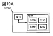
図19A乃至図19Eは、実施の形態に係る情報処理装置の構成を説明する図である。
図20A乃至図20Eは、実施の形態に係る情報処理装置の構成を説明する図である。
図21Aおよび図21Bは、実施の形態に係る情報処理装置の構成を説明する図である。
図22は実施例に係る作製した表示装置の表示状態を説明する写真である。1A to 1C are block diagrams illustrating the configuration of a flip-flop circuit according to an embodiment.
2A and 2B are circuit diagrams illustrating the configuration of a flip-flop circuit according to an embodiment.
3A and 3B are circuit diagrams illustrating the configuration of a flip-flop circuit according to an embodiment.
FIGS. 4A and 4B are timing charts illustrating the operation of the drive circuit including the flip-flop circuit according to the embodiment.
5A and 5B are timing charts illustrating the operation of the drive circuit including the flip-flop circuit according to the embodiment.
FIG. 6 is a block diagram illustrating the configuration of the drive circuit according to the embodiment.
7A and 7B are diagrams illustrating the configuration of a display panel according to an embodiment.
8A and 8B are diagrams illustrating the configuration of a display panel according to an embodiment.
FIG. 9 is a diagram illustrating the configuration of the display panel according to the embodiment.
FIG. 10 is a block diagram illustrating the configuration of the display panel according to the embodiment.
FIGS. 11A and 11B are cross-sectional views illustrating the configuration of a display panel according to an embodiment.
12A and 12B are cross-sectional views illustrating the configuration of a display panel according to an embodiment.
13A to 13D are diagrams illustrating the configuration of a display device according to an embodiment.
14A to 14C are diagrams illustrating the configuration of a display device according to an embodiment.
FIG. 15 is a block diagram illustrating the configuration of the input/output device according to the embodiment.
16A to 16C are a block diagram and a projection diagram illustrating the configuration of an information processing device according to an embodiment.
17A and 17B are flowcharts illustrating a method for driving an information processing apparatus according to an embodiment.
18A to 18C are diagrams illustrating a method for driving an information processing device according to an embodiment.
19A to 19E are diagrams illustrating the configuration of an information processing device according to an embodiment.
20A to 20E are diagrams illustrating the configuration of an information processing device according to an embodiment.
21A and 21B are diagrams illustrating the configuration of an information processing device according to an embodiment.
FIG. 22 is a photograph illustrating the display state of the display device manufactured according to the example.
本発明の一態様のフリップ・フロップ回路は、第1乃至第5の入力端子および第1乃至第3の出力端子を有する。第1の入力端子は第1のトリガ信号を供給され、第2の入力端子は第2のトリガ信号を供給され、第3の入力端子は一括選択信号を供給され、第4の入力端子は第1のパルス幅変調信号を供給され、第5の入力端子は、第2のパルス幅変調信号を供給される。また、第1の出力端子は第1のトリガ信号が供給されてから第2のトリガ信号が供給されるまでの期間において、第1のパルス幅変調信号に基づいて、第1の選択信号を供給し、第1の出力端子は一括選択信号が供給されている期間、第1の選択信号を供給し、第2の出力端子は第1のトリガ信号が供給されてから第2のトリガ信号が供給されるまでの期間において、第2のパルス幅変調信号に基づいて、第2の選択信号を供給し、第3の出力端子は、第3のトリガ信号を供給する。A flip-flop circuit according to one aspect of the present invention has first to fifth input terminals and first to third output terminals. The first input terminal is supplied with the first trigger signal, the second input terminal is supplied with the second trigger signal, the third input terminal is supplied with the bulk selection signal, and the fourth input terminal is supplied with the bulk selection signal. A fifth input terminal is supplied with a second pulse width modulated signal and a fifth input terminal is supplied with a second pulse width modulated signal. Further, the first output terminal supplies the first selection signal based on the first pulse width modulation signal during a period from when the first trigger signal is supplied until when the second trigger signal is supplied. The first output terminal supplies the first selection signal while the collective selection signal is supplied, and the second output terminal supplies the second trigger signal after the first trigger signal is supplied. A second selection signal is provided based on the second pulse width modulated signal, and the third output terminal provides a third trigger signal.
これにより、第1のトリガ信号が供給されてから第2のトリガ信号が供給されるまでの期間において、第1の選択信号および第2の選択信号を供給することができる。または、一括選択信号が供給されている期間に第1の選択信号を供給することができる。その結果、利便性、有用性または信頼性に優れた新規なフリップ・フロップ回路を提供することができる。Thereby, the first selection signal and the second selection signal can be supplied during the period from when the first trigger signal is supplied until when the second trigger signal is supplied. Alternatively, the first selection signal can be supplied during the period when the collective selection signal is supplied. As a result, a novel flip-flop circuit with excellent convenience, usefulness, and reliability can be provided.
実施の形態について、図面を用いて詳細に説明する。但し、本発明は以下の説明に限定されず、本発明の趣旨及びその範囲から逸脱することなくその形態及び詳細を様々に変更し得ることは当業者であれば容易に理解される。従って、本発明は以下に示す実施の形態の記載内容に限定して解釈されるものではない。なお、以下に説明する発明の構成において、同一部分又は同様な機能を有する部分には同一の符号を異なる図面間で共通して用い、その繰り返しの説明は省略する。Embodiments will be described in detail using the drawings. However, those skilled in the art will easily understand that the present invention is not limited to the following description, and that the form and details thereof can be changed in various ways without departing from the spirit and scope of the present invention. Therefore, the present invention should not be interpreted as being limited to the contents described in the embodiments shown below. In the configuration of the invention described below, the same parts or parts having similar functions are designated by the same reference numerals in different drawings, and repeated explanation thereof will be omitted.
(実施の形態1)
本実施の形態では、本発明の一態様のフリップ・フロップ回路の構成について、図1乃至図5を参照しながら説明する。(Embodiment 1)
In this embodiment, the structure of a flip-flop circuit according to one embodiment of the present invention will be described with reference to FIGS. 1 to 5.
図1は本発明の一態様のフリップ・フロップ回路の構成を説明するブロック図である。図1Aおよび図1Bは本発明の一態様のフリップ・フロップ回路が備える端子の構成を説明するブロック図であり、図1Cは本発明の一態様の複数のフリップ・フロップ回路を接続する例を説明するブロック図である。FIG. 1 is a block diagram illustrating the configuration of a flip-flop circuit according to one embodiment of the present invention. 1A and 1B are block diagrams illustrating the configuration of terminals included in a flip-flop circuit according to one embodiment of the present invention, and FIG. 1C is a block diagram illustrating an example of connecting a plurality of flip-flop circuits according to one embodiment of the present invention. FIG.
図2は本発明の一態様のフリップ・フロップ回路の構成を説明する図である。図2Aは本発明の一態様のフリップ・フロップ回路の回路図であり、図2Bは図2Aのフリップ・フロップ回路に接続して用いることができるフリップ・フロップ回路の回路図である。FIG. 2 is a diagram illustrating the configuration of a flip-flop circuit according to one embodiment of the present invention. FIG. 2A is a circuit diagram of a flip-flop circuit according to one embodiment of the present invention, and FIG. 2B is a circuit diagram of a flip-flop circuit that can be used in connection with the flip-flop circuit of FIG. 2A.
図3は本発明の一態様のフリップ・フロップ回路の構成を説明する図である。図3Aは本発明の一態様のフリップ・フロップ回路の回路図であり、図3Bは図3Aのフリップ・フロップ回路に接続して用いることができるフリップ・フロップ回路の回路図である。FIG. 3 is a diagram illustrating the configuration of a flip-flop circuit according to one embodiment of the present invention. FIG. 3A is a circuit diagram of a flip-flop circuit according to one embodiment of the present invention, and FIG. 3B is a circuit diagram of a flip-flop circuit that can be used in connection with the flip-flop circuit of FIG. 3A.
図4は本発明の一態様のフリップ・フロップ回路の動作を説明する図である。図4Aは図2に示す本発明の一態様のフリップ・フロップ回路を含む駆動回路の動作を説明するタイミングチャートであり、図4Bは図3に示す本発明の一態様のフリップ・フロップ回路を含む駆動回路の動作を説明するタイミングチャートである。FIG. 4 is a diagram illustrating the operation of a flip-flop circuit according to one embodiment of the present invention. 4A is a timing chart illustrating the operation of a drive circuit including the flip-flop circuit of one embodiment of the present invention shown in FIG. 2, and FIG. 4B is a timing chart including the flip-flop circuit of one embodiment of the present invention shown in FIG. 5 is a timing chart illustrating the operation of the drive circuit.
図5は本発明の一態様のフリップ・フロップ回路の動作を説明する図である。図5Aは図2に示す本発明の一態様のフリップ・フロップ回路を含む駆動回路の、図4Aとは異なる動作を説明するタイミングチャートであり、図5Bは図3に示す本発明の一態様のフリップ・フロップ回路を含む駆動回路の、図4Bとは異なる動作を説明するタイミングチャートである。FIG. 5 is a diagram illustrating the operation of a flip-flop circuit according to one embodiment of the present invention. 5A is a timing chart illustrating a different operation from FIG. 4A of a drive circuit including a flip-flop circuit according to one embodiment of the present invention shown in FIG. 4B is a timing chart illustrating an operation of a drive circuit including a flip-flop circuit, which is different from that in FIG. 4B. FIG.
なお、本明細書において、1以上の整数を値にとる変数を符号に用いる場合がある。例えば、1以上の整数の値をとる変数pを含む(p)を、最大p個の構成要素のいずれかを特定する符号の一部に用いる場合がある。また、例えば、1以上の整数の値をとる変数mおよび変数nを含む(m,n)を、最大m×n個の構成要素のいずれかを特定する符号の一部に用いる場合がある。Note that in this specification, a variable whose value is an integer of 1 or more may be used as a sign. For example, (p), which includes a variable p that takes an integer value of 1 or more, may be used as part of a code that specifies any one of the maximum p components. Further, for example, (m, n), which includes a variable m and a variable n that take an integer value of 1 or more, may be used as a part of a code that specifies one of the maximum m×n components.
<フリップ・フロップ回路の構成例1.>
本実施の形態で説明するフリップ・フロップ回路SR(i)は、入力端子LIN(i)と、入力端子RIN(i)と、入力端子E(i)と、入力端子A(i)と、入力端子B(i)を有する。また、出力端子G1(i)と、出力端子G2(i)と、出力端子OUT(i)と、を有する(図1A参照)。また、端子C1(i)、端子C2(i)および端子C3(i)を有する。なお、配線CLK1乃至配線CLK4から一を選んで、端子C1(i)乃至端子C3(i)の一と電気的に接続する。例えば、端子C1(i)を配線CLK1と電気的に接続し、端子C2(i)を配線CLK2と電気的に接続し、端子C3(i)を配線CLK3と電気的に接続する。これにより、位相がシフトする複数のクロック信号を、端子C1(i)乃至端子C3(i)に供給することができる。<Configuration example 1 of flip-flop circuit. >
The flip-flop circuit SR(i) described in this embodiment has an input terminal LIN(i), an input terminal RIN(i), an input terminal E(i), an input terminal A(i), an input terminal It has a terminal B(i). It also has an output terminal G1(i), an output terminal G2(i), and an output terminal OUT(i) (see FIG. 1A). It also has a terminal C1(i), a terminal C2(i), and a terminal C3(i). Note that one of the wirings CLK1 to CLK4 is selected and electrically connected to one of the terminals C1(i) to C3(i). For example, the terminal C1(i) is electrically connected to the wiring CLK1, the terminal C2(i) is electrically connected to the wiring CLK2, and the terminal C3(i) is electrically connected to the wiring CLK3. Thereby, a plurality of clock signals whose phases are shifted can be supplied to the terminals C1(i) to C3(i).
《入力端子》
入力端子LIN(i)は第1のトリガ信号を供給され、入力端子RIN(i)は、第2のトリガ信号を供給される(図4A参照)。《Input terminal》
The input terminal LIN(i) is supplied with a first trigger signal, and the input terminal RIN(i) is supplied with a second trigger signal (see FIG. 4A).
入力端子E(i)は一括選択信号を供給される。Input terminal E(i) is supplied with a batch selection signal.
入力端子A(i)は第1のパルス幅変調信号を供給され、入力端子B(i)は第2のパルス幅変調信号を供給される。Input terminal A(i) is supplied with a first pulse width modulated signal and input terminal B(i) is supplied with a second pulse width modulated signal.
《出力端子》
出力端子G1(i)は、第1のトリガ信号が供給されてから第2のトリガ信号が供給されるまでの期間において、第1のパルス幅変調信号に基づいて、第1の選択信号を供給する。また、出力端子G1(i)は、一括選択信号が供給されている期間、第1の選択信号を供給する(図4Aおよび図5A参照)。《Output terminal》
The output terminal G1(i) supplies the first selection signal based on the first pulse width modulation signal during the period from when the first trigger signal is supplied until when the second trigger signal is supplied. do. Further, the output terminal G1(i) supplies the first selection signal during the period when the collective selection signal is supplied (see FIGS. 4A and 5A).
出力端子G2(i)は、第1のトリガ信号が供給されてから第2のトリガ信号が供給されるまでの期間において、第2のパルス幅変調信号に基づいて、第2の選択信号を供給する。The output terminal G2(i) supplies a second selection signal based on the second pulse width modulation signal during a period from when the first trigger signal is supplied until when the second trigger signal is supplied. do.
出力端子OUT(i)は、第3のトリガ信号を供給する。The output terminal OUT(i) provides the third trigger signal.
<フリップ・フロップ回路の構成例2.>
例えば、トランジスタM1、トランジスタM16、トランジスタM3、トランジスタM4、トランジスタM6、トランジスタM12、トランジスタM22、トランジスタM5、トランジスタM15、トランジスタM7、トランジスタM13およびトランジスタM23を、フリップ・フロップ回路SR(i)に用いることができる(図2A参照)。また、トランジスタM17、トランジスタM21、トランジスタM31、トランジスタM18,トランジスタM19をフリップ・フロップ回路SR(i)に用いることができる。また、容量素子C1、容量素子C2、容量素子C3、容量素子C4および容量素子C5を用いることができる。<Configuration example 2 of flip-flop circuit. >
For example, transistor M1, transistor M16, transistor M3, transistor M4, transistor M6, transistor M12, transistor M22, transistor M5, transistor M15, transistor M7, transistor M13, and transistor M23 may be used in the flip-flop circuit SR(i). (See Figure 2A). Further, the transistor M17, the transistor M21, the transistor M31, the transistor M18, and the transistor M19 can be used for the flip-flop circuit SR(i). Further, a capacitive element C1, a capacitive element C2, a capacitive element C3, a capacitive element C4, and a capacitive element C5 can be used.
なお、本発明の一態様のフリップ・フロップ回路は、単極性のトランジスタで構成することができる。具体的には、n型動作をするトランジスタで構成することができる。Note that the flip-flop circuit of one embodiment of the present invention can be formed using a unipolar transistor. Specifically, it can be configured with a transistor that performs n-type operation.
《トランジスタM1、トランジスタM15、トランジスタM19》
トランジスタM1、トランジスタM15およびトランジスタM19は、第1のトリガ信号を供給されるゲート電極を備える。なお、第1のトリガ信号に基づいて、トランジスタM1は配線GVDDの電位をノードGN4(i)に供給する機能を備える。<<Transistor M1, transistor M15, transistor M19>>
Transistor M1, transistor M15 and transistor M19 have gate electrodes supplied with a first trigger signal. Note that the transistor M1 has a function of supplying the potential of the wiring GVDD to the node GN4(i) based on the first trigger signal.
また、第1のトリガ信号に基づいて、トランジスタM15およびトランジスタM19は配線GVSSの電位をノードGN1(i)に供給する機能を備える。これにより、フリップ・フロップ回路SR(i)の動作を開始することができる。または、配線GVSSの電位をノードGN1(i)に供給するまで、ノードGN1(i)をフローティング状態に保つことができる。Further, based on the first trigger signal, the transistor M15 and the transistor M19 have a function of supplying the potential of the wiring GVSS to the node GN1(i). Thereby, the operation of flip-flop circuit SR(i) can be started. Alternatively, the node GN1(i) can be kept in a floating state until the potential of the wiring GVSS is supplied to the node GN1(i).
《トランジスタM4》
トランジスタM4は、第2のトリガ信号を供給されるゲート電極を備える。なお、第2のトリガ信号に基づいて、トランジスタM4は配線GVDDの電位をノードGN1(i)に供給する機能を備える。《Transistor M4》
Transistor M4 has a gate electrode supplied with the second trigger signal. Note that the transistor M4 has a function of supplying the potential of the wiring GVDD to the node GN1(i) based on the second trigger signal.
《トランジスタM6、トランジスタM12、トランジスタM22》
トランジスタM6、トランジスタM12およびトランジスタM22は、ノードGN4(i)と電気的に接続されるゲート電極を備える。なお、ノードGN4(i)の電位に基づいて、トランジスタM6は、第1のクロック信号を出力端子OUT(i)に供給する機能を備え、トランジスタM12は、第1のパルス幅変調信号を出力端子G1(i)に供給する機能を備え、トランジスタM22は、第2のパルス幅変調信号を出力端子G2(i)に供給する機能を備える。<<Transistor M6, transistor M12, transistor M22>>
Transistor M6, transistor M12, and transistor M22 each include a gate electrode electrically connected to node GN4(i). Note that, based on the potential of the node GN4(i), the transistor M6 has a function of supplying the first clock signal to the output terminal OUT(i), and the transistor M12 has a function of supplying the first pulse width modulation signal to the output terminal OUT(i). The transistor M22 has the function of supplying the second pulse width modulated signal to the output terminal G2(i).
《トランジスタM5、トランジスタM18、トランジスタM7、トランジスタM13、トランジスタM23》
トランジスタM5、トランジスタM18、トランジスタM7、トランジスタM13およびトランジスタM23は、ノードGN1(i)と電気的に接続されるゲート電極を備える。なお、ノードGN1(i)の電位に基づいて、トランジスタM5およびトランジスタM18は、配線GVSSの電位をノードGN4(i)に供給する機能を備え、トランジスタM7は配線GVSSの電位を出力端子OUT(i)に供給する機能を備え、トランジスタM13は入力端子E(i)の電位を出力端子G1(i)に供給する機能を備え、トランジスタM23は配線GVSSの電位を出力端子G2(i)に供給する機能を備える。<<Transistor M5, transistor M18, transistor M7, transistor M13, transistor M23>>
Transistor M5, transistor M18, transistor M7, transistor M13, and transistor M23 each include a gate electrode electrically connected to node GN1(i). Note that, based on the potential of the node GN1(i), the transistor M5 and the transistor M18 have a function of supplying the potential of the wiring GVSS to the node GN4(i), and the transistor M7 supplies the potential of the wiring GVSS to the output terminal OUT(i). ), the transistor M13 has a function of supplying the potential of the input terminal E(i) to the output terminal G1(i), and the transistor M23 supplies the potential of the wiring GVSS to the output terminal G2(i). Equipped with functions.
《トランジスタM16、トランジスタM3》
トランジスタM16は、第2のクロック信号を供給されるゲート電極を備え、トランジスタM3は、第3のクロック信号を供給されるゲート電極を備える。なお、第2のクロック信号および第3のクロック信号が重なる期間、トランジスタM16およびトランジスタM3は、配線GVDDの電位をノードGN1(i)に供給する機能を備える。《Transistor M16, Transistor M3》
Transistor M16 has a gate electrode supplied with the second clock signal, and transistor M3 has a gate electrode supplied with the third clock signal. Note that during the period when the second clock signal and the third clock signal overlap, the transistor M16 and the transistor M3 have a function of supplying the potential of the wiring GVDD to the node GN1(i).
《トランジスタM20》
トランジスタM20は、端子R(i)と電気的に接続されるゲート電極を備える。なお、端子R(i)の電位に基づいて、トランジスタM20は配線GVDDの電位をノードGN1(i)に供給する。例えば、リセット信号を端子R(i)に供給することができる。これにより、フリップ・フロップ回路SR(i)をリセットすることができる。または、フリップ・フロップ回路SR(i)を備えるシフトレジスタ回路をリセットすることができる。なお、フリップ・フロップ回路SR(i)は、クロック信号を用いてリセットすることもできる。《Transistor M20》
Transistor M20 includes a gate electrode electrically connected to terminal R(i). Note that, based on the potential of the terminal R(i), the transistor M20 supplies the potential of the wiring GVDD to the node GN1(i). For example, a reset signal can be provided to terminal R(i). This allows flip-flop circuit SR(i) to be reset. Alternatively, the shift register circuit including the flip-flop circuit SR(i) can be reset. Note that the flip-flop circuit SR(i) can also be reset using a clock signal.
《トランジスタM17、トランジスタM21、トランジスタM31》
トランジスタM17、トランジスタM21およびトランジスタM31は、配線GVDDの電位が供給されるゲート電極を備える。これにより、例えば、ノードGN4(i)の電位が配線GVDDの電位より高くなる場合において、トランジスタM6、トランジスタM12およびトランジスタM22に加わるストレスを抑制することができる。または、ノードGN4(i)を用いて、出力を安定して供給できる。または、トランジスタM1、トランジスタM5およびトランジスタM18が備える第1の電極および第2の電極間に加わるストレスを抑制することができる。<<Transistor M17, Transistor M21, Transistor M31>>
The transistor M17, the transistor M21, and the transistor M31 each include a gate electrode to which the potential of the wiring GVDD is supplied. Thereby, for example, when the potential of the node GN4(i) becomes higher than the potential of the wiring GVDD, stress applied to the transistor M6, the transistor M12, and the transistor M22 can be suppressed. Alternatively, the output can be stably supplied using node GN4(i). Alternatively, stress applied between the first electrode and the second electrode of the transistor M1, the transistor M5, and the transistor M18 can be suppressed.
なお、フリップ・フロップ回路SR(m+1)は、入力端子RIN(i)およびトランジスタM4を備えない点が異なるほかは、フリップ・フロップ回路SR(i)と同様の構成を備える(図1Bおよび図2B参照)。また、シフトレジスタ回路の終段に用いることができる。なお、フリップ・フロップ回路SR(i)に用いるトランジスタと比較して、チャネルが形成される領域の幅が広いトランジスタが、フリップ・フロップ回路SR(m+1)に好適である。具体的には、フリップ・フロップ回路SR(m+1)が備えるトランジスタM3またはトランジスタM16のチャネルが形成される領域の幅は、フリップ・フロップ回路SR(i)が備えるトランジスタM3またはトランジスタM16のチャネルが形成される領域の幅より広い。Note that the flip-flop circuit SR(m+1) has the same configuration as the flip-flop circuit SR(i) except that it does not include the input terminal RIN(i) and the transistor M4 (FIGS. 1B and 2B). reference). Further, it can be used as the final stage of a shift register circuit. Note that, compared to the transistor used in the flip-flop circuit SR(i), a transistor having a wider region in which a channel is formed is suitable for the flip-flop circuit SR(m+1). Specifically, the width of the region where the channel of transistor M3 or transistor M16 included in flip-flop circuit SR(m+1) is formed is the same as the width of the region where the channel of transistor M3 or transistor M16 included in flip-flop circuit SR(i) is formed. Wider than the width of the area.
<フリップ・フロップ回路の構成例3.>
また、本実施の形態で説明するフリップ・フロップ回路SR(i)は、トランジスタM13と、トランジスタM23と、トランジスタM7と、ノードGN1(i)と、配線GVSSと、を有する(図2A、図2B、図3Aおよび図3B参照)。<Configuration example 3 of flip-flop circuit. >
Further, the flip-flop circuit SR(i) described in this embodiment includes a transistor M13, a transistor M23, a transistor M7, a node GN1(i), and a wiring GVSS (FIGS. 2A and 2B). , see Figures 3A and 3B).
《トランジスタM13》
トランジスタM13は、ノードGN1(i)と電気的に接続されるゲート電極、出力端子G1(i)と電気的に接続される第1の電極および入力端子E(i)と電気的に接続される第2の電極を備える。《Transistor M13》
Transistor M13 is electrically connected to a gate electrode electrically connected to node GN1(i), a first electrode electrically connected to output terminal G1(i), and input terminal E(i). A second electrode is provided.
トランジスタM13は、第1のトリガ信号が供給されてから第2のトリガ信号が供給されるまでの期間において、非導通状態である。The transistor M13 is in a non-conductive state during a period from when the first trigger signal is supplied until when the second trigger signal is supplied.
《トランジスタM23》
トランジスタM23は、ノードGN1(i)と電気的に接続されるゲート電極、出力端子G2(i)と電気的に接続される第1の電極および配線GVSSと電気的に接続される第2の電極を備える。《Transistor M23》
The transistor M23 has a gate electrode electrically connected to the node GN1(i), a first electrode electrically connected to the output terminal G2(i), and a second electrode electrically connected to the wiring GVSS. Equipped with
トランジスタM23は、第1のトリガ信号が供給されてから第2のトリガ信号が供給されるまでの期間において、非導通状態である。Transistor M23 is in a non-conductive state during a period from when the first trigger signal is supplied until when the second trigger signal is supplied.
《トランジスタM7》
トランジスタM7は、ノードGN1(i)と電気的に接続されるゲート電極、出力端子OUT(i)と電気的に接続される第1の電極および配線GVSSと電気的に接続される第2の電極を備える。《Transistor M7》
The transistor M7 has a gate electrode electrically connected to the node GN1(i), a first electrode electrically connected to the output terminal OUT(i), and a second electrode electrically connected to the wiring GVSS. Equipped with
トランジスタM7は、第1のトリガ信号が供給されてから第2のトリガ信号が供給されるまでの期間において、非導通状態である。Transistor M7 is non-conductive during the period from when the first trigger signal is supplied until when the second trigger signal is supplied.
これにより、第1のトリガ信号が供給されてから第2のトリガ信号が供給されるまでの期間において、第1の選択信号および第2の選択信号を供給することができる。または、一括選択信号が供給されている期間に第1の選択信号を供給することができる。その結果、利便性、有用性または信頼性に優れた新規なフリップ・フロップ回路を提供することができる。Thereby, the first selection signal and the second selection signal can be supplied during the period from when the first trigger signal is supplied until when the second trigger signal is supplied. Alternatively, the first selection signal can be supplied during the period when the collective selection signal is supplied. As a result, a novel flip-flop circuit with excellent convenience, usefulness, and reliability can be provided.
<フリップ・フロップ回路の構成例4.>
また、本実施の形態で説明するフリップ・フロップ回路SR(i)は、トランジスタM24と、配線GVDDと、を有する(図3Aおよび図3B参照)。<Configuration example of flip-flop circuit 4. >
Furthermore, the flip-flop circuit SR(i) described in this embodiment includes a transistor M24 and a wiring GVDD (see FIGS. 3A and 3B).
トランジスタM24は、配線GVDDと電気的に接続されるゲート電極、ノードGN1(i)と電気的に接続される第1の電極およびトランジスタM13のゲート電極と電気的に接続される第2の電極と、を備える。The transistor M24 has a gate electrode electrically connected to the wiring GVDD, a first electrode electrically connected to the node GN1(i), and a second electrode electrically connected to the gate electrode of the transistor M13. , is provided.
これにより、第1のトリガ信号が供給されてから第2のトリガ信号が供給されるまでの期間を除く、一括選択信号がハイである期間TBにおいて、トランジスタM24を非導通状態にすることができる(図3Bまたは図4B参照)。または、ノードGN1(i)の電位を、配線GVDDが供給する電位からトランジスタM24のしきい値電圧を減じた電位より低く抑制することができる。または、ノードGN1(i)の電位の上昇がトランジスタM23、トランジスタM7、トランジスタM5およびトランジスタM18にもたらすストレスを、抑制することができる。または、ノードGN1(i)の電位の上昇がトランジスタM15およびトランジスタM19にもたらすストレスを、抑制することができる。その結果、利便性、有用性または信頼性に優れた新規なフリップ・フロップ回路を提供することができる。As a result, the transistor M24 can be rendered non-conductive during the period TB during which the collective selection signal is high, excluding the period from when the first trigger signal is supplied until when the second trigger signal is supplied. (See Figure 3B or Figure 4B). Alternatively, the potential of the node GN1(i) can be suppressed to be lower than the potential obtained by subtracting the threshold voltage of the transistor M24 from the potential supplied by the wiring GVDD. Alternatively, stress caused to transistor M23, transistor M7, transistor M5, and transistor M18 by the increase in the potential of node GN1(i) can be suppressed. Alternatively, stress caused to transistor M15 and transistor M19 by a rise in the potential of node GN1(i) can be suppressed. As a result, a novel flip-flop circuit with excellent convenience, usefulness, and reliability can be provided.
《ノードGN2(i)の電位》
ノードGN2(i)は、第1のトリガ信号がハイである期間において配線GVDDの電位が供給される(図2A、図2Bおよび図4AT1参照)。また、ノードGN2(i)は、第1のトリガ信号および第2のトリガ信号がローであり、ノードGN1(i)の電位が、トランジスタM5のしきい値電圧を配線GVDDが供給する電位に加えた値より低い期間、または、トランジスタM18のしきい値電圧を配線GVDDが供給する電位に加えた値より低い期間、においてフローティング状態を保つ(図4AT2参照)。<<Potential of node GN2(i)>>
The potential of the wiring GVDD is supplied to the node GN2(i) during the period in which the first trigger signal is high (see FIGS. 2A, 2B, and 4AT1). Further, at the node GN2(i), the first trigger signal and the second trigger signal are low, and the potential of the node GN1(i) adds the threshold voltage of the transistor M5 to the potential supplied by the wiring GVDD. The floating state is maintained during a period lower than the value given by the transistor M18, or a period lower than the sum of the threshold voltage of the transistor M18 and the potential supplied by the wiring GVDD (see FIG. 4AT2).
なお、ノードGN2(i)は、例えば、容量素子C2を介して、出力端子G1(i)と容量結合する。Note that the node GN2(i) is capacitively coupled to the output terminal G1(i) via, for example, the capacitive element C2.
《ノードGN1(i)の電位》
ノードGN1(i)は、第1のトリガ信号がハイである期間において配線GVSSの電位が供給される(図2A、図2Bおよび図4AT1参照)。また、ノードGN1(i)は、第1のトリガ信号および第2のトリガ信号がローである期間においてフローティング状態を保つ(図4AT2参照)。<<Potential of node GN1(i)>>
The potential of the wiring GVSS is supplied to the node GN1(i) during the period in which the first trigger signal is high (see FIGS. 2A, 2B, and 4AT1). Further, the node GN1(i) maintains a floating state during the period when the first trigger signal and the second trigger signal are low (see FIG. 4AT2).
なお、例えば、容量素子C5を介して、ノードGN1(i)は、入力端子E(i)と容量結合する。Note that, for example, the node GN1(i) is capacitively coupled to the input terminal E(i) via the capacitive element C5.
例えば、フリップ・フロップ回路SR(i)がトランジスタM24を備えない場合、これにより、ノードGN1(i)の電位は入力端子E(i)の電位の影響を受ける。または、ノードGN1(i)の電位は、例えば、一括選択信号の影響を受けて上昇する(図2A、図2Bおよび図4AT3参照)。または、ノードGN1(i)の電位は、例えば、配線GVDDが供給する電位に一括選択信号が供給する電圧を加えた電位に近づく。For example, if the flip-flop circuit SR(i) does not include the transistor M24, the potential of the node GN1(i) is thereby influenced by the potential of the input terminal E(i). Alternatively, the potential of the node GN1(i) increases, for example, under the influence of the collective selection signal (see FIGS. 2A, 2B, and 4AT3). Alternatively, the potential of the node GN1(i) approaches, for example, the potential obtained by adding the voltage supplied by the batch selection signal to the potential supplied by the wiring GVDD.
一方、フリップ・フロップ回路SR(i)がトランジスタM24を備える場合、これにより、ノードGN3(i)の電位は入力端子E(i)の電位の影響を受ける。または、ノードGN3(i)の電位は、例えば、一括選択信号の影響を受けて上昇する(図3A、図3Bおよび図4BT3参照)。または、ノードGN3(i)の電位は、例えば、配線GVDDが供給する電位に一括選択信号がハイである電圧を加えた電位に近づく。または、トランジスタM24は、非導通状態になる。または、ノードGN1(i)の電位に対する一括選択信号の影響を抑制することができる。または、ノードGN1(i)の電位を、配線GVDDが供給する電圧からトランジスタM24のしきい値電圧を減じた電位より低く抑制することができる。または、一括選択信号がノードGN1(i)の電位におよぼす影響をなくすことができる。または、ノードGN1(i)と電気的に接続されるゲート電極を備えるトランジスタに与えるストレスを抑制することができる。または、トランジスタM13、トランジスタM23、トランジスタM7、トランジスタM5およびトランジスタM18に与えるストレスを抑制することができる。または、トランジスタM15およびトランジスタM19に与えるストレスを抑制することができる。または、トランジスタM16、トランジスタM4およびトランジスタM20に与えるストレスを抑制することができる。その結果、利便性、有用性または信頼性に優れた新規なフリップ・フロップ回路を提供することができる。On the other hand, when the flip-flop circuit SR(i) includes the transistor M24, the potential of the node GN3(i) is thereby influenced by the potential of the input terminal E(i). Alternatively, the potential of the node GN3(i) increases, for example, under the influence of the collective selection signal (see FIGS. 3A, 3B, and 4BT3). Alternatively, the potential of the node GN3(i) approaches, for example, the potential obtained by adding the voltage at which the collective selection signal is high to the potential supplied by the wiring GVDD. Alternatively, transistor M24 becomes non-conductive. Alternatively, the influence of the collective selection signal on the potential of node GN1(i) can be suppressed. Alternatively, the potential of the node GN1(i) can be suppressed to be lower than the potential obtained by subtracting the threshold voltage of the transistor M24 from the voltage supplied by the wiring GVDD. Alternatively, the influence of the collective selection signal on the potential of node GN1(i) can be eliminated. Alternatively, stress applied to a transistor including a gate electrode electrically connected to node GN1(i) can be suppressed. Alternatively, stress applied to the transistor M13, the transistor M23, the transistor M7, the transistor M5, and the transistor M18 can be suppressed. Alternatively, stress applied to transistor M15 and transistor M19 can be suppressed. Alternatively, stress applied to the transistor M16, the transistor M4, and the transistor M20 can be suppressed. As a result, a novel flip-flop circuit with excellent convenience, usefulness, and reliability can be provided.
なお、本実施の形態は、本明細書で示す他の実施の形態と適宜組み合わせることができる。Note that this embodiment can be combined with other embodiments shown in this specification as appropriate.
(実施の形態2)
本実施の形態では、本発明の一態様の駆動回路の構成について、図1および図6を参照しながら説明する。(Embodiment 2)
In this embodiment, the structure of a driver circuit according to one embodiment of the present invention will be described with reference to FIGS. 1 and 6.
図6は本発明の一態様の駆動回路の構成を説明するブロック図である。FIG. 6 is a block diagram illustrating the configuration of a drive circuit according to one embodiment of the present invention.
<駆動回路GDの構成例>
本実施の形態で説明する駆動回路GDは、一群のフリップ・フロップ回路SR(1)乃至フリップ・フロップ回路SR(m+2)と、配線VEEと、を有する(図6参照)。また、配線RES、配線DUM1(1)、配線DUM2(1)、配線DUM1(2)および配線DUM2(2)を有する。<Configuration example of drive circuit GD>
The drive circuit GD described in this embodiment includes a group of flip-flop circuits SR(1) to flip-flop circuits SR(m+2) and a wiring VEE (see FIG. 6). It also includes a wiring RES, a wiring DUM1 (1), a wiring DUM2 (1), a wiring DUM1 (2), and a wiring DUM2 (2).
一群のフリップ・フロップ回路SR(1)乃至フリップ・フロップ回路SR(m+2)は、実施の形態1に記載のフリップ・フロップ回路SR(i)、フリップ・フロップ回路SR(i+1)およびフリップ・フロップ回路SR(i+2)を含む。A group of flip-flop circuits SR(1) to flip-flop circuits SR(m+2) are the flip-flop circuits SR(i), flip-flop circuits SR(i+1), and flip-flop circuits described in
《フリップ・フロップ回路SR(i+1)》
フリップ・フロップ回路SR(i+1)はフリップ・フロップ回路SR(i)と電気的に接続され、フリップ・フロップ回路SR(i+1)は第3のトリガ信号を供給される(図1C参照)。《Flip-flop circuit SR (i+1)》
The flip-flop circuit SR(i+1) is electrically connected to the flip-flop circuit SR(i), and the flip-flop circuit SR(i+1) is supplied with the third trigger signal (see FIG. 1C).
フリップ・フロップ回路SR(i+1)は、フリップ・フロップ回路SR(i+2)と電気的に接続される。Flip-flop circuit SR(i+1) is electrically connected to flip-flop circuit SR(i+2).
フリップ・フロップ回路SR(i+2)は、第2のトリガ信号を供給する。Flip-flop circuit SR(i+2) provides a second trigger signal.
《配線VEE》
配線VEEは一括選択信号を供給し、配線VEEは一群のフリップ・フロップ回路SR(1)乃至フリップ・フロップ回路SR(m+2)と電気的に接続される。《Wiring VEE》
The wiring VEE supplies a collective selection signal, and the wiring VEE is electrically connected to a group of flip-flop circuits SR(1) to flip-flop circuits SR(m+2).
これにより、一群のフリップ・フロップ回路は、第1の選択信号を所定の順番で供給することができる。または、一群のフリップ・フロップ回路は、第2の選択信号を所定の順番で供給することができる。または、一群のフリップ・フロップ回路は、第1の選択信号を一斉に供給することができる。その結果、利便性、有用性または信頼性に優れた新規な駆動回路を提供することができる。This allows the group of flip-flop circuits to supply the first selection signals in a predetermined order. Alternatively, the group of flip-flop circuits can provide the second selection signal in a predetermined order. Alternatively, the group of flip-flop circuits can provide the first selection signal in unison. As a result, a novel drive circuit with excellent convenience, usefulness, and reliability can be provided.
《入力端子の接続例》
例えば、入力端子LIN(i)は配線SPLまたはフリップ・フロップ回路SR(i-1)の出力端子OUT(i-1)と電気的に接続される(図1Cおよび図6参照)。なお、配線SPLはスタートパルス信号を供給し、フリップ・フロップ回路SR(i-1)の出力端子OUT(i-1)は、第1のトリガ信号を供給する。《Input terminal connection example》
For example, the input terminal LIN(i) is electrically connected to the wiring SPL or the output terminal OUT(i-1) of the flip-flop circuit SR(i-1) (see FIG. 1C and FIG. 6). Note that the wiring SPL supplies a start pulse signal, and the output terminal OUT(i-1) of the flip-flop circuit SR(i-1) supplies a first trigger signal.
入力端子RIN(i)はフリップ・フロップ回路SR(i+2)のOUT(i+2)と電気的に接続される。なお、フリップ・フロップ回路SR(i+2)の出力端子OUT(i+2)は第2のトリガ信号を供給する。Input terminal RIN(i) is electrically connected to OUT(i+2) of flip-flop circuit SR(i+2). Note that the output terminal OUT(i+2) of the flip-flop circuit SR(i+2) supplies the second trigger signal.
入力端子E(i)は配線VEEと電気的に接続される。なお、配線VEEは一括選択信号を供給する。Input terminal E(i) is electrically connected to wiring VEE. Note that the wiring VEE supplies a batch selection signal.
入力端子A(i)は配線PWCA1乃至配線PWCA4のいずれか一と電気的に接続される。なお、配線PWCA1乃至配線PWCA4はいずれも第1のパルス幅変調信号を供給する。例えば、矩形波を第1のパルス幅変調信号に用いることができる(図4Aまたは図5A参照)。Input terminal A(i) is electrically connected to any one of wiring PWCA1 to wiring PWCA4. Note that each of the wirings PWCA1 to PWCA4 supplies the first pulse width modulation signal. For example, a square wave can be used for the first pulse width modulated signal (see FIG. 4A or FIG. 5A).
入力端子B(i)は配線PWCB1乃至配線PWCB4のいずれか一と電気的に接続される。なお、配線PWCB1乃至配線PWCB4はいずれもパルス幅変調信号を供給する。例えば、第1のパルス幅変調信号と同じ信号を第2のパルス幅変調信号に用いることができる(図4A参照)。または、第1のパルス幅変調信号とは異なるパルス幅の信号を第2のパルス幅変調信号に用いることができる。具体的には、第1のパルス幅変調信号より短いパルス幅の信号を第2のパルス幅変調信号に用いることができる(図5A参照)。Input terminal B(i) is electrically connected to any one of wiring PWCB1 to wiring PWCB4. Note that each of the wirings PWCB1 to PWCB4 supplies a pulse width modulation signal. For example, the same signal as the first pulse width modulation signal can be used for the second pulse width modulation signal (see FIG. 4A). Alternatively, a signal with a different pulse width than the first pulse width modulation signal can be used as the second pulse width modulation signal. Specifically, a signal with a shorter pulse width than the first pulse width modulation signal can be used as the second pulse width modulation signal (see FIG. 5A).
《出力端子の接続例》
出力端子G1(i)は走査線GL1(i)と電気的に接続され、出力端子G2(i)は走査線GL2(i)と電気的に接続される(図1Cおよび図6参照)。《Output terminal connection example》
The output terminal G1(i) is electrically connected to the scanning line GL1(i), and the output terminal G2(i) is electrically connected to the scanning line GL2(i) (see FIG. 1C and FIG. 6).
出力端子OUT(i)はフリップ・フロップ回路SR(i+1)のLIN(i+1)およびフリップ・フロップ回路SR(i-2)のRIN(i)と電気的に接続される(図6参照)。The output terminal OUT(i) is electrically connected to LIN(i+1) of the flip-flop circuit SR(i+1) and RIN(i) of the flip-flop circuit SR(i-2) (see FIG. 6).
<駆動回路GDの動作例>
本発明の一態様の駆動回路GDは、選択信号を順番に供給する。例えば、期間TAの間に、フリップ・フロップ回路SR(1)乃至フリップ・フロップ回路SR(m+2)は、順番に、選択信号を供給する(図4Aおよび図5A参照)。<Operation example of drive circuit GD>
A drive circuit GD according to one embodiment of the present invention sequentially supplies selection signals. For example, during period TA, flip-flop circuits SR(1) to flip-flop circuits SR(m+2) sequentially supply selection signals (see FIGS. 4A and 5A).
また、本発明の一態様の駆動回路GDは、一括選択信号を供給する。例えば、期間TBの間に、フリップ・フロップ回路SR(1)乃至フリップ・フロップ回路SR(m+2)は、同時に、選択信号を供給する。Further, the drive circuit GD according to one embodiment of the present invention supplies a collective selection signal. For example, during period TB, flip-flop circuits SR(1) to flip-flop circuits SR(m+2) simultaneously supply selection signals.
なお、期間TAおよび期間TBを含む期間を1サブフレーム(SUB FRAME)期間ということができる。Note that a period including period TA and period TB can be referred to as one subframe (SUB FRAME) period.
また、表示パネルの表示素子に、例えば、液晶素子を用いる場合は、1サブフレーム期間の終了後に、光源を点灯する期間LIGHTを設けることができる(図4Aおよび図5A参照)。Further, when using, for example, a liquid crystal element as the display element of the display panel, a period LIGHT in which the light source is turned on can be provided after one subframe period (see FIGS. 4A and 5A).
なお、本実施の形態は、本明細書で示す他の実施の形態と適宜組み合わせることができる。Note that this embodiment can be combined with other embodiments shown in this specification as appropriate.
(実施の形態3)
本実施の形態では、本発明の一態様の表示パネルの構成について、図7、図8および図10を参照しながら説明する。(Embodiment 3)
In this embodiment, a structure of a display panel according to one embodiment of the present invention will be described with reference to FIGS. 7, 8, and 10.
図7は本発明の一態様の表示パネルの構成を説明する図である。図7Aは本発明の一態様の表示パネルの上面図であり、図7Bは図7Aの一部である。FIG. 7 is a diagram illustrating the structure of a display panel according to one embodiment of the present invention. FIG. 7A is a top view of a display panel according to one embodiment of the present invention, and FIG. 7B is a part of FIG. 7A.
図8は本発明の一態様の表示パネルの構成を説明する図である。図8Aは図7Aの切断線X1-X2、X3-X4、X9-X10および画素における断面図であり、図8Bは画素回路530(i,j)の構成を説明する回路図である。FIG. 8 is a diagram illustrating the structure of a display panel according to one embodiment of the present invention. FIG. 8A is a sectional view taken along cutting lines X1-X2, X3-X4, and X9-X10 in FIG. 7A and a pixel, and FIG. 8B is a circuit diagram illustrating the configuration of the pixel circuit 530(i,j).
図10は、本発明の一態様の表示パネルの構成を説明する図である。FIG. 10 is a diagram illustrating the structure of a display panel according to one embodiment of the present invention.
<表示パネルの構成例1.>
本実施の形態で説明する表示パネルは、表示領域231と、実施の形態2に記載の駆動回路GDと、を有する(図10参照)。<Example of configuration of display panel 1. >
The display panel described in this embodiment includes a
《表示領域231の構成例1.》
表示領域231は、走査線GL1(i)、走査線GL2(i)、信号線SL1(j)、信号線SL2(j)および画素702(i,j)を備える。<<Configuration example 1 of display area 231. 》
The
《画素702(i,j)の構成例1.》
画素702(i,j)は、表示素子750(i,j)および画素回路530(i,j)を備える(図8A参照)。<<Configuration example 1 of pixel 702 (i, j). 》
The pixel 702(i,j) includes a display element 750(i,j) and a pixel circuit 530(i,j) (see FIG. 8A).
《表示素子750(i,j)の構成例》
表示素子750(i,j)は、画素回路530(i,j)と電気的に接続される(図8Aおよび図8B参照)。<<Configuration example of display element 750 (i, j)>>
Display element 750(i,j) is electrically connected to pixel circuit 530(i,j) (see FIGS. 8A and 8B).
例えば、光の反射、光の透過または光の射出を制御する素子を表示素子に用いることができる。具体的には、電気光学素子または発光素子を表示素子に用いることができる。For example, an element that controls light reflection, light transmission, or light emission can be used as a display element. Specifically, an electro-optical element or a light emitting element can be used as a display element.
《画素回路530(i,j)の構成例1.》
画素回路530(i,j)は、走査線GL1(i)、走査線GL2(i)、信号線SL1(j)および信号線SL2(j)と電気的に接続される(図8B参照)。<<Configuration example 1 of pixel circuit 530 (i, j). 》
Pixel circuit 530(i,j) is electrically connected to scanning line GL1(i), scanning line GL2(i), signal line SL1(j), and signal line SL2(j) (see FIG. 8B).
走査線GL1(i)は出力端子G1(i)と電気的に接続され、走査線GL2(i)は出力端子G2(i)と電気的に接続される(図6参照)。The scanning line GL1(i) is electrically connected to the output terminal G1(i), and the scanning line GL2(i) is electrically connected to the output terminal G2(i) (see FIG. 6).
これにより、第1の選択信号を第1の走査線GL1(i)に供給することができる。または、第2の選択信号を第2の走査線GL2(i)に供給することができる。または、第1の選択信号または第2の選択信号を用いて画素702(i,j)を駆動することができる。その結果、利便性、有用性または信頼性に優れた新規な表示パネルを提供することができる。Thereby, the first selection signal can be supplied to the first scanning line GL1(i). Alternatively, the second selection signal can be supplied to the second scan line GL2(i). Alternatively, pixel 702(i,j) can be driven using the first selection signal or the second selection signal. As a result, a novel display panel with excellent convenience, usefulness, and reliability can be provided.
例えば、スイッチ、トランジスタ、ダイオード、抵抗素子、インダクタまたは容量素子等を画素回路530(i,j)に用いることができる。具体的には、トランジスタをスイッチに用いることができる。For example, a switch, a transistor, a diode, a resistive element, an inductor, a capacitive element, or the like can be used for the pixel circuit 530 (i, j). Specifically, a transistor can be used as a switch.
例えば、複数のトランジスタを画素回路に用いる場合、一のトランジスタの半導体膜を形成する工程において、他方の半導体膜を形成することができる。For example, when a plurality of transistors are used in a pixel circuit, the semiconductor film of one transistor can be formed in the process of forming the semiconductor film of the other transistor.
《画素702(i,j)の構成例2.》
画素702(i,j)は、表示素子750(i,j)に液晶素子を用いることができる。<<Configuration example 2 of pixel 702 (i, j). 》
In the pixel 702 (i, j), a liquid crystal element can be used as the display element 750 (i, j).
《画素回路530(i,j)の構成例2.》
画素回路530(i,j)は、容量素子C11、スイッチSW11およびノードN1(i,j)を備える(図8B参照)。<<Configuration example 2 of pixel circuit 530 (i, j). 》
The pixel circuit 530 (i, j) includes a capacitive element C11, a switch SW11, and a node N1 (i, j) (see FIG. 8B).
スイッチSW11は、信号線SL2(j)と電気的に接続される第1の端子を備え、表示素子750(i,j)の第1の電極と電気的に接続される第2の端子を備える。なお、スイッチSW11は、選択信号に基づいて導通状態または非導通状態を切り替える機能を備える。The switch SW11 includes a first terminal electrically connected to the signal line SL2(j), and a second terminal electrically connected to the first electrode of the display element 750(i,j). . Note that the switch SW11 has a function of switching between a conductive state and a non-conductive state based on a selection signal.
容量素子C11は、スイッチSW11の第2の端子と電気的に接続される第1の電極と、導電膜CSCOMと電気的に接続される第2の電極と、を備える。The capacitive element C11 includes a first electrode electrically connected to the second terminal of the switch SW11, and a second electrode electrically connected to the conductive film CSCOM.
表示素子750(i,j)はノードN1(i,j)の電位VNに基づいて表示をする。Display element 750 (i, j) displays based on potential VN of node N1 (i, j).
《画素回路530(i,j)の構成例3.》
画素回路530(i,j)は、容量素子C11、容量素子C12、スイッチSW11、スイッチSW12およびノードN1(i,j)を備える。<<Configuration example 3 of pixel circuit 530 (i, j). 》
The pixel circuit 530 (i, j) includes a capacitive element C11, a capacitive element C12, a switch SW11, a switch SW12, and a node N1 (i, j).
スイッチSW11は、信号線SL2(j)と電気的に接続される第1の端子を備え、表示素子750(i,j)の第1の電極と電気的に接続される第2の端子を備える。なお、スイッチSW11は、第2の選択信号に基づいて導通状態または非導通状態を切り替える機能を備える。The switch SW11 includes a first terminal electrically connected to the signal line SL2(j), and a second terminal electrically connected to the first electrode of the display element 750(i,j). . Note that the switch SW11 has a function of switching between a conductive state and a non-conductive state based on the second selection signal.
容量素子C11は、スイッチSW11の第2の端子と電気的に接続される第1の電極と、導電膜CSCOMと電気的に接続される第2の電極と、を備える。The capacitive element C11 includes a first electrode electrically connected to the second terminal of the switch SW11, and a second electrode electrically connected to the conductive film CSCOM.
スイッチSW12は、信号線SL1(j)と電気的に接続される第1の端子を備える。なお、スイッチSW12は、第1の選択信号に基づいて導通状態または非導通状態を切り替える機能を備える。The switch SW12 includes a first terminal electrically connected to the signal line SL1(j). Note that the switch SW12 has a function of switching between a conductive state and a non-conductive state based on the first selection signal.
容量素子C12は、スイッチSW12の第2の端子と電気的に接続される第1の電極と、スイッチSW11の第2の端子と電気的に接続される第2の電極と、を備える。Capacitive element C12 includes a first electrode electrically connected to the second terminal of switch SW12, and a second electrode electrically connected to the second terminal of switch SW11.
表示素子750(i,j)はノードN1(i,j)の電位VNに基づいて表示をする。Display element 750 (i, j) displays based on potential VN of node N1 (i, j).
なお、スイッチSW11が非導通状態であるときに、スイッチSW12を非導通状態から導通状態に変化することができる。また、スイッチSW11が非導通状態であるときに、スイッチSW12を導通状態から非導通状態に変化することができる。Note that when the switch SW11 is in the non-conducting state, the switch SW12 can be changed from the non-conducting state to the conducting state. Further, when the switch SW11 is in a non-conducting state, the switch SW12 can be changed from a conducting state to a non-conducting state.
[第1のステップ]
第1のステップにおいて、スイッチSW11およびスイッチSW12を導通状態にする。例えば、第1の選択信号を走査線GL1(i)に供給し、第2の選択信号を走査線GL2(i)に供給する。[First step]
In the first step, switch SW11 and switch SW12 are brought into conduction. For example, the first selection signal is supplied to the scanning line GL1(i), and the second selection signal is supplied to the scanning line GL2(i).
また、画像信号を容量素子C12に供給する。例えば、信号線SL1(j)が供給する電位と信号線SL2(j)が供給する電位の電位差を用いて、画像信号を供給する。Further, the image signal is supplied to the capacitive element C12. For example, the image signal is supplied using the potential difference between the potential supplied by the signal line SL1(j) and the potential supplied by the signal line SL2(j).
[第2のステップ]
第2のステップにおいて、スイッチSW11を非導通状態に保ちながら、スイッチSW12を導通状態にする。例えば、一括選択信号を走査線GL1(i)に供給する。[Second step]
In the second step, the switch SW12 is made conductive while keeping the switch SW11 non-conductive. For example, a batch selection signal is supplied to the scanning line GL1(i).
また、信号線SL1(i)に所定の電位を供給し、容量素子C12を介してノードN1(i,j)の電位をオフセットする。Further, a predetermined potential is supplied to the signal line SL1(i) to offset the potential of the node N1(i,j) via the capacitive element C12.
[第3のステップ]
第3のステップにおいて、スイッチSW11およびスイッチSW12を非導通状態に保ちながら、ノードN1(i,j)の電位に基づいて、表示素子750(i,j)を用いて表示する。[Third step]
In the third step, display is performed using the display element 750 (i, j) based on the potential of the node N1 (i, j) while keeping the switch SW11 and the switch SW12 in a non-conductive state.
これにより、ノードN1(i,j)の電位をスイッチSW11およびスイッチSW12を用いて制御することができる。または、スイッチSW11を用いてノードN1(i,j)の電位を制御し、スイッチSW12を用いてノードN1(i,j)の電位を変化することができる。または、変化する電位を表示素子750(i,j)に供給することができる。または、変化する電位に基づいて表示をすることができる。または、表示素子750(i,j)の表示を変化することができる。または、表示素子750(i,j)の動作を強調することができる。または、表示素子750(i,j)の応答を速めることができる。その結果、利便性、有用性または信頼性に優れた新規な表示パネルを提供することができる。Thereby, the potential of node N1 (i, j) can be controlled using switch SW11 and switch SW12. Alternatively, the potential of the node N1 (i, j) can be controlled using the switch SW11, and the potential of the node N1 (i, j) can be changed using the switch SW12. Alternatively, a changing potential can be supplied to display element 750(i,j). Alternatively, the display can be based on a changing potential. Alternatively, the display of display element 750(i,j) can be changed. Alternatively, the operation of display element 750(i,j) can be emphasized. Alternatively, the response of display element 750 (i, j) can be accelerated. As a result, a novel display panel with excellent convenience, usefulness, and reliability can be provided.
または、これにより、表示素子750(i,j)に高い電圧を供給することができる。または、例えば、表示素子750(i,j)の液晶材料を含む層753に大きな電界を印加することができる。または、高分子安定化された液晶材料の配向を制御することができる。その結果、利便性、有用性または信頼性に優れた新規な入出力装置を提供することができる。Alternatively, with this, a high voltage can be supplied to the display element 750 (i, j). Alternatively, for example, a large electric field can be applied to the
《画素702(i,j)の構成例3.》
画素702(i,j)は、表示素子750(i,j)に発光素子を用いることができる(図9参照)。例えば、有機EL素子を表示素子750(i,j)に用いることができる。<<Configuration example 3 of pixel 702 (i, j). 》
In the pixel 702 (i, j), a light emitting element can be used as the display element 750 (i, j) (see FIG. 9). For example, an organic EL element can be used as the display element 750 (i, j).
《画素回路530(i,j)の構成例4.》
画素回路530(i,j)は、トランジスタM、容量素子C21、スイッチSW21、ノードN1(i,j)、容量素子C22およびスイッチSW22を備える(図9参照)。また、画素回路530(i,j)は、ノードN2(i,j)、スイッチSW23およびスイッチSW24を備える。<<Configuration example 4 of pixel circuit 530 (i, j). 》
The pixel circuit 530(i,j) includes a transistor M, a capacitive element C21, a switch SW21, a node N1(i,j), a capacitive element C22, and a switch SW22 (see FIG. 9). Further, the pixel circuit 530 (i, j) includes a node N2 (i, j), a switch SW23, and a switch SW24.
トランジスタMは、導電膜ANOと電気的に接続される第1の電極を備える。The transistor M includes a first electrode electrically connected to the conductive film ANO.
容量素子C21は、トランジスタMのゲート電極と電気的に接続される第1の電極と、トランジスタMの第2の電極と電気的に接続される第2の電極を備える。The capacitive element C21 includes a first electrode electrically connected to the gate electrode of the transistor M, and a second electrode electrically connected to the second electrode of the transistor M.
スイッチSW21は、信号線SL2(j)と電気的に接続される第1の端子を備え、トランジスタMのゲート電極と電気的に接続される第2の端子を備える。なお、スイッチSW21は、第2の選択信号に基づいて導通状態または非導通状態を切り替える機能を備える。The switch SW21 includes a first terminal electrically connected to the signal line SL2(j), and a second terminal electrically connected to the gate electrode of the transistor M. Note that the switch SW21 has a function of switching between a conductive state and a non-conductive state based on the second selection signal.
容量素子C22は、トランジスタMのゲート電極と電気的に接続される第1の電極を備える。Capacitive element C22 includes a first electrode electrically connected to the gate electrode of transistor M.
スイッチSW22は、信号線SL1(j)と電気的に接続される第1の端子を備え、容量素子C22の第2の電極と電気的に接続される第2の端子を備える。なお、スイッチSW22は、第1の選択信号に基づいて導通状態または非導通状態を切り替える機能を備える。The switch SW22 includes a first terminal electrically connected to the signal line SL1(j), and a second terminal electrically connected to the second electrode of the capacitive element C22. Note that the switch SW22 has a function of switching between a conductive state and a non-conductive state based on the first selection signal.
スイッチSW23は、トランジスタMの第2の電極と電気的に接続される第1の端子と、導電膜V0と電気的に接続される第2の端子を備える。なお、スイッチSW23は、第1の選択信号に基づいて導通状態または非導通状態を切り替える機能を備える。The switch SW23 includes a first terminal electrically connected to the second electrode of the transistor M, and a second terminal electrically connected to the conductive film V0. Note that the switch SW23 has a function of switching between a conductive state and a non-conductive state based on the first selection signal.
スイッチSW24は、トランジスタMの第2の電極と電気的に接続される第1の端子と、表示素子750(i,j)と電気的に接続される第2の端子を備える。なお、スイッチSW24は、第3の選択信号に基づいて導通状態または非導通状態を切り替える機能を備える。なお、走査線GL3(i)を用いて、第3の選択信号を供給することができる。The switch SW24 includes a first terminal electrically connected to the second electrode of the transistor M and a second terminal electrically connected to the display element 750(i,j). Note that the switch SW24 has a function of switching between a conductive state and a non-conductive state based on the third selection signal. Note that the third selection signal can be supplied using the scanning line GL3(i).
なお、スイッチSW21が非導通状態であるときに、スイッチSW22を非導通状態から導通状態に変化することができる。また、スイッチSW21が非導通状態であるときに、スイッチSW22を導通状態から非導通状態に変化することができる。Note that when the switch SW21 is in the non-conducting state, the switch SW22 can be changed from the non-conducting state to the conducting state. Further, when the switch SW21 is in a non-conducting state, the switch SW22 can be changed from a conducting state to a non-conducting state.
表示素子750(i,j)はノードN1(i,j)の電位VNに基づいて表示をする。Display element 750 (i, j) displays based on potential VN of node N1 (i, j).
これにより、ノードN1(i,j)の電位をスイッチSW21およびスイッチSW22を用いて制御することができる。または、スイッチSW21を用いてノードN1(i,j)の電位を制御し、スイッチSW22を用いてノードN1(i,j)の電位を変化することができる。または、変化する電位を表示素子750(i,j)に供給することができる。または、変化する電位に基づいて表示をすることができる。または、表示素子750(i,j)の表示を変化することができる。または、表示素子750(i,j)の動作を強調することができる。または、表示素子750(i,j)の応答を速めることができる。その結果、利便性、有用性または信頼性に優れた新規な表示パネルを提供することができる。Thereby, the potential of node N1 (i, j) can be controlled using switch SW21 and switch SW22. Alternatively, the potential of the node N1 (i, j) can be controlled using the switch SW21, and the potential of the node N1 (i, j) can be changed using the switch SW22. Alternatively, a changing potential can be supplied to display element 750(i,j). Alternatively, the display can be based on a changing potential. Alternatively, the display of display element 750(i,j) can be changed. Alternatively, the operation of display element 750(i,j) can be emphasized. Alternatively, the response of display element 750 (i, j) can be accelerated. As a result, a novel display panel with excellent convenience, usefulness, and reliability can be provided.
《表示領域231の構成例2.》
表示領域231は、一群の画素702(i,1)乃至画素702(i,n)および他の一群の画素702(1,j)乃至画素702(m,j)を備える(図10参照)。<<Configuration example 2 of display area 231. 》
The
また、図示しないが、表示領域231は、導電膜CSCOMおよび導電膜VCOM1を有する。Although not shown, the
一群の画素702(i,1)乃至画素702(i,n)は、行方向(図中に矢印R1で示す方向)に配設され、一群の画素702(i,1)乃至画素702(i,n)は画素702(i,j)を含む。A group of pixels 702 (i, 1) to 702 (i, n) are arranged in the row direction (direction indicated by arrow R1 in the figure), and a group of pixels 702 (i, 1) to 702 (i, , n) includes pixel 702(i,j).
他の一群の画素702(1,j)乃至画素702(m,j)は、行方向と交差する列方向(図中に矢印C1で示す方向)に配設され、他の一群の画素702(1,j)乃至画素702(m,j)は、画素702(i,j)を含む。Another group of pixels 702(1,j) to 702(m,j) are arranged in the column direction (direction indicated by arrow C1 in the figure) intersecting the row direction, and the other group of pixels 702( 1,j) to 702(m,j) include pixel 702(i,j).
走査線GL1(i)は一群の画素702(i,1)乃至画素702(i,n)と電気的に接続され、走査線GL2(i)は一群の画素702(i,1)乃至画素702(i,n)と電気的に接続される。The scanning line GL1(i) is electrically connected to a group of pixels 702(i,1) to 702(i,n), and the scanning line GL2(i) is electrically connected to a group of pixels 702(i,1) to 702. (i, n) is electrically connected.
信号線SL1(j)は他の一群の画素702(1,j)乃至画素702(m,j)と電気的に接続され、信号線SL2(j)は、他の一群の画素702(1,j)乃至画素702(m,j)と電気的に接続される。The signal line SL1(j) is electrically connected to another group of pixels 702(1,j) to 702(m,j), and the signal line SL2(j) is electrically connected to another group of pixels 702(1,j) to 702(m,j). j) to pixels 702 (m, j).
これにより、複数の画素に画像情報を供給することができる。その結果、利便性、有用性または信頼性に優れた新規な表示パネルを提供することができる。This allows image information to be supplied to multiple pixels. As a result, a novel display panel with excellent convenience, usefulness, and reliability can be provided.
《駆動回路GDA、駆動回路GDB》
駆動回路GDAおよび駆動回路GDBを駆動回路GDに用いることができる。例えば、駆動回路GDAおよび駆動回路GDBは、制御信号SPに基づいて選択信号を供給する機能を有する。<<Drive circuit GDA, drive circuit GDB>>
Drive circuit GDA and drive circuit GDB can be used as drive circuit GD. For example, drive circuit GDA and drive circuit GDB have a function of supplying a selection signal based on control signal SP.
具体的には、制御信号SPに基づいて、30Hz以上、好ましくは60Hz以上の頻度で、選択信号を一の走査線に供給する機能を備える。これにより、動画像をなめらかに表示することができる。Specifically, it has a function of supplying a selection signal to one scanning line at a frequency of 30 Hz or more, preferably 60 Hz or more, based on the control signal SP. This allows moving images to be displayed smoothly.
または、制御信号SPに基づいて、30Hz未満、好ましくは1Hz未満、より好ましくは一分に一回未満の頻度で選択信号を一の走査線に供給する機能を備える。これにより、フリッカーが抑制された静止画像を表示することができる。Alternatively, it has a function of supplying a selection signal to one scanning line at a frequency of less than 30 Hz, preferably less than 1 Hz, more preferably less than once a minute, based on the control signal SP. Thereby, a still image with flicker suppressed can be displayed.
複数の駆動回路を備える場合、例えば、駆動回路GDAが選択信号を供給する頻度と、駆動回路GDBが選択信号を供給する頻度とを、異ならせることができる。具体的には、静止画像を表示する一の領域に選択信号を供給する頻度より高い頻度で、動画像を表示する他の領域に選択信号を供給することができる。これにより、一の領域にフリッカーが抑制された静止画像を表示し、他の領域に滑らかに動画像を表示することができる。When a plurality of drive circuits are provided, for example, the frequency at which the drive circuit GDA supplies the selection signal and the frequency at which the drive circuit GDB supplies the selection signal can be made different. Specifically, the selection signal can be supplied to another area displaying a moving image more frequently than the selection signal is supplied to one area displaying a still image. Thereby, a still image with suppressed flicker can be displayed in one area, and a moving image can be smoothly displayed in the other area.
ところで、フレーム周波数を可変にすることができる。または、例えば、1Hz以上120Hz以下のフレーム周波数で表示をすることができる。または、プログレッシブ方式を用いて、120Hzのフレーム周波数で表示をすることができる。By the way, the frame frequency can be made variable. Alternatively, for example, display can be performed at a frame frequency of 1 Hz or more and 120 Hz or less. Alternatively, it is possible to display at a frame frequency of 120 Hz using a progressive method.
《駆動回路SD》
駆動回路SDは、情報V11に基づいて画像信号を生成する機能と、当該画像信号を一の表示素子と電気的に接続される画素回路に供給する機能を備える(図10参照)。《Drive circuit SD》
The drive circuit SD has a function of generating an image signal based on the information V11 and a function of supplying the image signal to a pixel circuit electrically connected to one display element (see FIG. 10).
例えば、シフトレジスタ等のさまざまな順序回路等を駆動回路SDに用いることができる。For example, various sequential circuits such as shift registers can be used for the drive circuit SD.
例えば、シリコン基板上に形成された集積回路を駆動回路SDに用いることができる。For example, an integrated circuit formed on a silicon substrate can be used for the drive circuit SD.
例えば、COG(Chip on glass)法またはCOF(Chip on Film)法を用いて、集積回路を端子に接続することができる。具体的には、異方性導電膜を用いて、集積回路を端子に接続することができる。For example, an integrated circuit can be connected to a terminal using a COG (Chip on Glass) method or a COF (Chip on Film) method. Specifically, an anisotropic conductive film can be used to connect integrated circuits to terminals.
なお、本実施の形態は、本明細書で示す他の実施の形態と適宜組み合わせることができる。Note that this embodiment can be combined with other embodiments shown in this specification as appropriate.
(実施の形態4)
本実施の形態では、本発明の一態様の表示パネルに用いることができる画素の構成について、図7乃至図12を参照しながら説明する。(Embodiment 4)
In this embodiment, a structure of a pixel that can be used in a display panel of one embodiment of the present invention will be described with reference to FIGS. 7 to 12.
図11は本発明の一態様の表示パネルの構成を説明する図である。図11Aは図7Bの切断線Y1-Y2における画素702(i,j)の断面図であり、図11Bは図11Aの一部を説明する断面図である。FIG. 11 is a diagram illustrating the structure of a display panel according to one embodiment of the present invention. FIG. 11A is a cross-sectional view of the pixel 702 (i, j) along cutting line Y1-Y2 in FIG. 7B, and FIG. 11B is a cross-sectional view explaining a part of FIG. 11A.
図12は本発明の一態様の表示パネルの構成を説明する図である。図12Aは図7Aの切断線X1-X2およびX3-X4における断面図であり、図12Bは図12Aの一部(MG1)を説明する断面図である。FIG. 12 is a diagram illustrating the structure of a display panel according to one embodiment of the present invention. 12A is a sectional view taken along cutting lines X1-X2 and X3-X4 in FIG. 7A, and FIG. 12B is a sectional view illustrating a part (MG1) of FIG. 12A.
<表示パネル700の構成例1.>
本実施の形態で説明する表示パネルは、機能層520を有する(図8A参照)。<Configuration example 1 of display panel 700. >
The display panel described in this embodiment has a functional layer 520 (see FIG. 8A).
《機能層520》
機能層520は、実施の形態2に記載の駆動回路GDおよび実施の形態3に記載の画素回路530(i,j)を含む。なお、機能層520は開口部591Aを備え、画素回路530(i,j)は、開口部591Aにおいて表示素子750(i,j)と電気的に接続される。《
これにより、画素回路530(i,j)のトランジスタに用いる半導体膜を形成する工程において、駆動回路GDのトランジスタに用いる半導体膜を形成することができる。または、部品点数を削減することができる。その結果、利便性、有用性または信頼性に優れた新規な表示パネルを提供することができる。Accordingly, in the step of forming a semiconductor film used for the transistor of the pixel circuit 530 (i, j), a semiconductor film used for the transistor of the driver circuit GD can be formed. Alternatively, the number of parts can be reduced. As a result, a novel display panel with excellent convenience, usefulness, and reliability can be provided.
《トランジスタの構成例》
例えば、ボトムゲート型のトランジスタまたはトップゲート型のトランジスタなどを、駆動回路GDおよび画素回路530(i,j)に用いることができる(図11および図12参照)。《Transistor configuration example》
For example, a bottom-gate transistor, a top-gate transistor, or the like can be used for the drive circuit GD and the pixel circuit 530 (i, j) (see FIGS. 11 and 12).
トランジスタは、半導体膜508、導電膜504、導電膜512Aおよび導電膜512Bを備える(図11B参照)。The transistor includes a
半導体膜508は、導電膜512Aと電気的に接続される領域508A、導電膜512Bと電気的に接続される領域508Bを備える。半導体膜508は、領域508Aおよび領域508Bの間に領域508Cを備える。The
導電膜504は領域508Cと重なる領域を備え、導電膜504はゲート電極の機能を備える。The
絶縁膜506は、半導体膜508および導電膜504の間に挟まれる領域を備える。絶縁膜506はゲート絶縁膜の機能を備える。The insulating
導電膜512Aはソース電極の機能またはドレイン電極の機能の一方を備え、導電膜512Bはソース電極の機能またはドレイン電極の機能の他方を備える。The
また、導電膜524をトランジスタに用いることができる。導電膜524は、導電膜504との間に半導体膜508を挟む領域を備える。導電膜524は、第2のゲート電極の機能を備える。導電膜524を、例えば、導電膜504と電気的に接続することができる。なお、導電膜524を走査線GL2(i)に用いることができる。Further, the
なお、画素回路530(i,j)のトランジスタに用いる半導体膜を形成する工程において、駆動回路GDのトランジスタに用いる半導体膜を形成することができる。Note that in the step of forming a semiconductor film used for a transistor of the pixel circuit 530 (i, j), a semiconductor film used for a transistor of the driver circuit GD can be formed.
《半導体膜508の構成例1.》
例えば、14族の元素を含む半導体を半導体膜508に用いることができる。具体的には、シリコンを含む半導体を半導体膜508に用いることができる。<<Configuration example 1 of semiconductor film 508. 》
For example, a semiconductor containing a Group 14 element can be used for the
[水素化アモルファスシリコン]
例えば、水素化アモルファスシリコンを半導体膜508に用いることができる。または、微結晶シリコンなどを半導体膜508に用いることができる。これにより、例えば、ポリシリコンを半導体膜508に用いる表示パネルより、表示ムラが少ない表示パネルを提供することができる。または、表示パネルの大型化が容易である。[Hydrogenated amorphous silicon]
For example, hydrogenated amorphous silicon can be used for the
[ポリシリコン]
例えば、ポリシリコンを半導体膜508に用いることができる。これにより、例えば、水素化アモルファスシリコンを半導体膜508に用いるトランジスタより、トランジスタの電界効果移動度を高くすることができる。または、例えば、水素化アモルファスシリコンを半導体膜508に用いるトランジスタより、駆動能力を高めることができる。または、例えば、水素化アモルファスシリコンを半導体膜508に用いるトランジスタより、画素の開口率を向上することができる。[Polysilicon]
For example, polysilicon can be used for the
または、例えば、水素化アモルファスシリコンを半導体膜508に用いるトランジスタより、トランジスタの信頼性を高めることができる。Alternatively, for example, the reliability of the transistor can be improved compared to a transistor in which hydrogenated amorphous silicon is used for the
または、トランジスタの作製に要する温度を、例えば、単結晶シリコンを用いるトランジスタより、低くすることができる。Alternatively, the temperature required to manufacture the transistor can be lower than, for example, a transistor using single crystal silicon.
または、駆動回路のトランジスタに用いる半導体膜を、画素回路のトランジスタに用いる半導体膜と同一の工程で形成することができる。または、画素回路を形成する基板と同一の基板上に駆動回路を形成することができる。または、電子機器を構成する部品数を低減することができる。Alternatively, a semiconductor film used for a transistor in a driver circuit can be formed in the same process as a semiconductor film used for a transistor in a pixel circuit. Alternatively, the drive circuit can be formed over the same substrate as the pixel circuit. Alternatively, the number of parts constituting the electronic device can be reduced.
[単結晶シリコン]
例えば、単結晶シリコンを半導体膜508に用いることができる。これにより、例えば、水素化アモルファスシリコンを半導体膜508に用いる表示パネルより、精細度を高めることができる。または、例えば、ポリシリコンを半導体膜508に用いる表示パネルより、表示ムラが少ない表示パネルを提供することができる。または、例えば、スマートグラスまたはヘッドマウントディスプレイを提供することができる。[Single crystal silicon]
For example, single crystal silicon can be used for the
《半導体膜508の構成例2.》
例えば、金属酸化物を半導体膜508に用いることができる。これにより、アモルファスシリコンを半導体膜に用いたトランジスタを利用する画素回路と比較して、画素回路が画像信号を保持することができる時間を長くすることができる。具体的には、フリッカーの発生を抑制しながら、選択信号を30Hz未満、好ましくは1Hz未満、より好ましくは一分に一回未満の頻度で供給することができる。その結果、情報処理装置の使用者に蓄積する疲労を低減することができる。また、駆動に伴う消費電力を低減することができる。<<Configuration example 2 of semiconductor film 508. 》
For example, a metal oxide can be used for the
例えば、酸化物半導体を用いるトランジスタを利用することができる。具体的には、インジウムを含む酸化物半導体またはインジウムとガリウムと亜鉛を含む酸化物半導体を半導体膜に用いることができる。For example, a transistor using an oxide semiconductor can be used. Specifically, an oxide semiconductor containing indium or an oxide semiconductor containing indium, gallium, and zinc can be used for the semiconductor film.
一例を挙げれば、オフ状態におけるリーク電流が、半導体膜にアモルファスシリコンを用いたトランジスタより小さいトランジスタを用いることができる。具体的には、酸化物半導体を半導体膜に用いたトランジスタを用いることができる。For example, a transistor whose leakage current in an off state is smaller than that of a transistor whose semiconductor film is made of amorphous silicon can be used. Specifically, a transistor using an oxide semiconductor for a semiconductor film can be used.
例えば、インジウム、ガリウムおよび亜鉛を含む厚さ25nmの膜を、半導体膜508に用いることができる。For example, a 25 nm thick film containing indium, gallium, and zinc can be used as the
例えば、タンタルおよび窒素を含む厚さ10nmの膜と、銅を含む厚さ300nmの膜と、を積層した導電膜を導電膜504に用いることができる。なお、銅を含む膜は、絶縁膜506との間に、タンタルおよび窒素を含む膜を挟む領域を備える。For example, a conductive film in which a 10 nm thick film containing tantalum and nitrogen and a 300 nm thick film containing copper are stacked can be used as the
例えば、シリコンおよび窒素を含む厚さ400nmの膜と、シリコン、酸素および窒素を含む厚さ200nmの膜と、を積層した積層膜を、絶縁膜506に用いることができる。なお、シリコンおよび窒素を含む膜は、半導体膜508との間に、シリコン、酸素および窒素を含む膜を挟む領域を備える。For example, a stacked film in which a 400 nm thick film containing silicon and nitrogen and a 200 nm thick film containing silicon, oxygen, and nitrogen are stacked can be used as the insulating
例えば、タングステンを含む厚さ50nmの膜と、アルミニウムを含む厚さ400nmの膜と、チタンを含む厚さ100nmの膜と、をこの順で積層した導電膜を、導電膜512Aまたは導電膜512Bに用いることができる。なお、タングステンを含む膜は、半導体膜508と接する領域を備える。For example, a conductive film in which a 50 nm thick film containing tungsten, a 400 nm thick film containing aluminum, and a 100 nm thick film containing titanium are laminated in this order is used as the
ところで、例えば、アモルファスシリコンを半導体に用いるボトムゲート型のトランジスタの製造ラインは、酸化物半導体を半導体に用いるボトムゲート型のトランジスタの製造ラインに容易に改造できる。また、例えばポリシリコンを半導体に用いるトップゲート型のトランジスタの製造ラインは、酸化物半導体を半導体に用いるトップゲート型のトランジスタの製造ラインに容易に改造できる。いずれの改造も、既存の製造ラインを有効に活用することができる。By the way, for example, a manufacturing line for bottom-gate transistors using amorphous silicon as a semiconductor can be easily modified to a manufacturing line for bottom-gate transistors using an oxide semiconductor as a semiconductor. Further, for example, a manufacturing line for top-gate transistors using polysilicon as a semiconductor can be easily converted into a manufacturing line for top-gate transistors using an oxide semiconductor as a semiconductor. Both modifications can make effective use of existing production lines.
これにより、チラツキを抑制することができる。または、消費電力を低減することができる。または、動きの速い動画を滑らかに表示することができる。または、豊かな階調で写真等を表示することができる。その結果、利便性、有用性または信頼性に優れた新規な表示パネルを提供することができる。Thereby, flickering can be suppressed. Alternatively, power consumption can be reduced. Or you can display fast-moving videos smoothly. Alternatively, photos and the like can be displayed with rich gradation. As a result, a novel display panel with excellent convenience, usefulness, and reliability can be provided.
《半導体膜508の構成例3.》
例えば、化合物半導体をトランジスタの半導体に用いることができる。具体的には、ガリウムヒ素を含む半導体を用いることができる。<<Configuration example 3 of semiconductor film 508. 》
For example, a compound semiconductor can be used as a transistor semiconductor. Specifically, a semiconductor containing gallium arsenide can be used.
例えば、有機半導体をトランジスタの半導体に用いることができる。具体的には、ポリアセン類またはグラフェンを含む有機半導体を半導体膜に用いることができる。For example, organic semiconductors can be used as semiconductors for transistors. Specifically, an organic semiconductor containing polyacenes or graphene can be used for the semiconductor film.
《容量素子の構成例1.》
容量素子は、一の導電膜、他の導電膜および絶縁膜を備える。当該絶縁膜は一の導電膜および他の導電膜の間に挟まる領域を備える。<<Configuration example 1 of capacitive element. 》
The capacitive element includes one conductive film, another conductive film, and an insulating film. The insulating film includes a region sandwiched between one conductive film and another conductive film.
例えば、導電膜504と、導電膜512Aと、絶縁膜506を容量素子に用いることができる。For example, the
容量素子C12は、導電膜754(i,j)、電極751(i,j)および絶縁膜521Bを備える(図11A参照)。The capacitive element C12 includes a conductive film 754 (i, j), an electrode 751 (i, j), and an insulating
《機能層520の構成例1.》
また、機能層520は、絶縁膜521、絶縁膜518、絶縁膜516、絶縁膜506および絶縁膜501C等を備える(図11A参照)。<<Configuration example 1 of functional layer 520. 》
Further, the
絶縁膜521は、画素回路530(i,j)および表示素子750(i,j)の間に挟まれる領域を備える。The insulating film 521 includes a region sandwiched between the pixel circuit 530 (i, j) and the display element 750 (i, j).
絶縁膜518は、絶縁膜521および絶縁膜501Cの間に挟まれる領域を備える。The insulating
絶縁膜516は絶縁膜518および絶縁膜501Cの間に挟まれる領域を備える。The insulating
絶縁膜506は絶縁膜516および絶縁膜501Cの間に挟まれる領域を備える。The insulating
[絶縁膜521]
例えば、絶縁性の無機材料、絶縁性の有機材料または無機材料と有機材料を含む絶縁性の複合材料を、絶縁膜521に用いることができる。[Insulating film 521]
For example, an insulating inorganic material, an insulating organic material, or an insulating composite material containing an inorganic material and an organic material can be used for the insulating film 521.
具体的には、無機酸化物膜、無機窒化物膜または無機酸化窒化物膜等またはこれらから選ばれた複数を積層した積層材料を、絶縁膜521に用いることができる。Specifically, an inorganic oxide film, an inorganic nitride film, an inorganic oxynitride film, or a laminated material obtained by laminating a plurality of layers selected from these can be used for the insulating film 521.
例えば、酸化シリコン膜、窒化シリコン膜、酸化窒化シリコン膜、酸化アルミニウム膜等またはこれらから選ばれた複数を積層した積層材料を含む膜を、絶縁膜521に用いることができる。なお、窒化シリコン膜は緻密な膜であり、不純物の拡散を抑制する機能に優れる。For example, the insulating film 521 can be a silicon oxide film, a silicon nitride film, a silicon oxynitride film, an aluminum oxide film, or a film containing a laminated material obtained by laminating a plurality of layers selected from these. Note that the silicon nitride film is a dense film and has an excellent function of suppressing diffusion of impurities.
例えば、ポリエステル、ポリオレフィン、ポリアミド、ポリイミド、ポリカーボネート、ポリシロキサン若しくはアクリル樹脂等またはこれらから選択された複数の樹脂の積層材料もしくは複合材料などを絶縁膜521に用いることができる。また、感光性を有する材料を用いて形成してもよい。これにより、絶縁膜521は、例えば、絶縁膜521と重なるさまざまな構造に由来する段差を平坦化することができる。For example, polyester, polyolefin, polyamide, polyimide, polycarbonate, polysiloxane, acrylic resin, or a laminated material or composite material of a plurality of resins selected from these can be used for the insulating film 521. Alternatively, it may be formed using a photosensitive material. Thereby, the insulating film 521 can, for example, flatten differences in level caused by various structures overlapping with the insulating film 521.
なお、ポリイミドは熱的安定性、絶縁性、靱性、低誘電率、低熱膨張率、耐薬品性などの特性において他の有機材料に比べて優れた特性を備える。これにより、特にポリイミドを絶縁膜521等に好適に用いることができる。Note that polyimide has superior properties compared to other organic materials in properties such as thermal stability, insulation, toughness, low dielectric constant, low coefficient of thermal expansion, and chemical resistance. Thereby, polyimide can be particularly preferably used for the insulating film 521 and the like.
例えば、感光性を有する材料を用いて形成された膜を絶縁膜521に用いることができる。具体的には、感光性のポリイミドまたは感光性のアクリル樹脂等を用いて形成された膜を絶縁膜521に用いることができる。For example, a film formed using a photosensitive material can be used as the insulating film 521. Specifically, a film formed using photosensitive polyimide, photosensitive acrylic resin, or the like can be used as the insulating film 521.
[絶縁膜518]
例えば、絶縁膜521に用いることができる材料を含む絶縁膜518に用いることができる。[Insulating film 518]
For example, it can be used for the insulating
例えば、酸素、水素、水、アルカリ金属、アルカリ土類金属等の拡散を抑制する機能を備える材料を絶縁膜518に用いることができる。具体的には、窒化物絶縁膜を絶縁膜518に用いることができる。例えば、窒化シリコン、窒化酸化シリコン、窒化アルミニウム、窒化酸化アルミニウム等を絶縁膜518に用いることができる。これにより、トランジスタの半導体膜への不純物の拡散を抑制することができる。For example, a material that has a function of suppressing diffusion of oxygen, hydrogen, water, alkali metals, alkaline earth metals, or the like can be used for the insulating
[絶縁膜516]
例えば、絶縁膜521に用いることができる材料を絶縁膜516に用いることができる。[Insulating film 516]
For example, a material that can be used for the insulating film 521 can be used for the insulating
具体的には、絶縁膜518とは作製方法が異なる膜を絶縁膜516に用いることができる。Specifically, a film manufactured using a different method from that of the insulating
[絶縁膜506]
例えば、絶縁膜521に用いることができる材料を絶縁膜506に用いることができる。[Insulating film 506]
For example, a material that can be used for the insulating film 521 can be used for the insulating
具体的には、酸化シリコン膜、酸化窒化シリコン膜、窒化酸化シリコン膜、窒化シリコン膜、酸化アルミニウム膜、酸化ハフニウム膜、酸化イットリウム膜、酸化ジルコニウム膜、酸化ガリウム膜、酸化タンタル膜、酸化マグネシウム膜、酸化ランタン膜、酸化セリウム膜または酸化ネオジム膜を含む膜を絶縁膜506に用いることができる。Specifically, silicon oxide film, silicon oxynitride film, silicon nitride oxide film, silicon nitride film, aluminum oxide film, hafnium oxide film, yttrium oxide film, zirconium oxide film, gallium oxide film, tantalum oxide film, magnesium oxide film A film containing a lanthanum oxide film, a cerium oxide film, or a neodymium oxide film can be used as the insulating
[絶縁膜501C]
例えば、絶縁膜521に用いることができる材料を絶縁膜501Cに用いることができる。具体的には、シリコンおよび酸素を含む材料を絶縁膜501Cに用いることができる。これにより、画素回路または表示素子等への不純物の拡散を抑制することができる。[Insulating
For example, a material that can be used for the insulating film 521 can be used for the insulating
《機能層520の構成例2.》
機能層520は、導電膜、配線および端子を備える。導電性を備える材料を配線、電極、端子、導電膜等に用いることができる。<<Configuration example 2 of functional layer 520. 》
The
《配線等》
例えば、無機導電性材料、有機導電性材料、金属または導電性セラミックスなどを配線等に用いることができる。《Wiring, etc.》
For example, inorganic conductive materials, organic conductive materials, metals, conductive ceramics, and the like can be used for wiring and the like.
具体的には、アルミニウム、金、白金、銀、銅、クロム、タンタル、チタン、モリブデン、タングステン、ニッケル、鉄、コバルト、パラジウムまたはマンガンから選ばれた金属元素などを、配線等に用いることができる。または、上述した金属元素を含む合金などを、配線等に用いることができる。特に、銅とマンガンの合金がウエットエッチング法を用いた微細加工に好適である。Specifically, metal elements selected from aluminum, gold, platinum, silver, copper, chromium, tantalum, titanium, molybdenum, tungsten, nickel, iron, cobalt, palladium, or manganese can be used for wiring, etc. . Alternatively, an alloy containing the above-mentioned metal elements or the like can be used for the wiring or the like. In particular, alloys of copper and manganese are suitable for microfabrication using wet etching.
具体的には、アルミニウム膜上にチタン膜を積層する二層構造、窒化チタン膜上にチタン膜を積層する二層構造、窒化チタン膜上にタングステン膜を積層する二層構造、窒化タンタル膜または窒化タングステン膜上にタングステン膜を積層する二層構造、チタン膜と、そのチタン膜上にアルミニウム膜を積層し、さらにその上にチタン膜を形成する三層構造等を配線等に用いることができる。Specifically, a two-layer structure in which a titanium film is stacked on an aluminum film, a two-layer structure in which a titanium film is stacked on a titanium nitride film, a two-layer structure in which a tungsten film is stacked on a titanium nitride film, a tantalum nitride film, or a two-layer structure in which a tungsten film is stacked on a titanium nitride film. A two-layer structure in which a tungsten film is laminated on a tungsten nitride film, a three-layer structure in which a titanium film is laminated, an aluminum film is laminated on the titanium film, and a titanium film is further formed on top of that, etc. can be used for wiring, etc. .
具体的には、酸化インジウム、インジウム錫酸化物、インジウム亜鉛酸化物、酸化亜鉛、ガリウムを添加した酸化亜鉛などの導電性酸化物を、配線等に用いることができる。Specifically, conductive oxides such as indium oxide, indium tin oxide, indium zinc oxide, zinc oxide, and zinc oxide added with gallium can be used for wiring and the like.
具体的には、グラフェンまたはグラファイトを含む膜を配線等に用いることができる。Specifically, a film containing graphene or graphite can be used for wiring and the like.
例えば、酸化グラフェンを含む膜を形成し、酸化グラフェンを含む膜を還元することにより、グラフェンを含む膜を形成することができる。還元する方法としては、熱を加える方法や還元剤を用いる方法等を挙げることができる。For example, a film containing graphene can be formed by forming a film containing graphene oxide and reducing the film containing graphene oxide. Examples of the reducing method include a method of applying heat and a method of using a reducing agent.
例えば、金属ナノワイヤーを含む膜を配線等に用いることができる。具体的には、銀を含むナノワイヤーを用いることができる。For example, a film containing metal nanowires can be used for wiring, etc. Specifically, nanowires containing silver can be used.
具体的には、導電性高分子を配線等に用いることができる。Specifically, conductive polymers can be used for wiring and the like.
なお、例えば、導電材料ACF1を用いて、端子519Bをフレキシブルプリント基板FPC1と電気的に接続することができる(図8A参照)。具体的には、導電材料CPを用いて、端子519Bをフレキシブルプリント基板FPC1と電気的に接続することができる。Note that, for example, the terminal 519B can be electrically connected to the flexible printed circuit board FPC1 using the conductive material ACF1 (see FIG. 8A). Specifically, the terminal 519B can be electrically connected to the flexible printed circuit board FPC1 using the conductive material CP.
<表示パネル700の構成例2.>
また、表示パネル700は、基材510、基材770および封止材705を備える(図12A参照)。<Configuration example 2 of display panel 700. >
Furthermore, the
《基材510、基材770》
透光性を備える材料を、基材510または基材770に用いることができる。<<
A light-transmitting material can be used for the
例えば、可撓性を有する材料を基材510または基材770に用いることができる。これにより、可撓性を備える表示パネルを提供することができる。For example, a flexible material can be used for the
例えば、厚さ0.7mm以下厚さ0.1mm以上の材料を用いることができる。具体的には、厚さ0.1mm程度まで研磨した材料を用いることができる。これにより、重量を低減することができる。For example, a material having a thickness of 0.7 mm or less and 0.1 mm or more can be used. Specifically, a material polished to a thickness of about 0.1 mm can be used. Thereby, weight can be reduced.
ところで、第6世代(1500mm×1850mm)、第7世代(1870mm×2200mm)、第8世代(2200mm×2400mm)、第9世代(2400mm×2800mm)、第10世代(2950mm×3400mm)等のガラス基板を基材510または基材770に用いることができる。これにより、大型の表示装置を作製することができる。By the way, glass substrates such as 6th generation (1500mm x 1850mm), 7th generation (1870mm x 2200mm), 8th generation (2200mm x 2400mm), 9th generation (2400mm x 2800mm), 10th generation (2950mm x 3400mm), etc. can be used for the
有機材料、無機材料または有機材料と無機材料等の複合材料等を基材510または基材770に用いることができる。An organic material, an inorganic material, a composite material of an organic material and an inorganic material, or the like can be used for the
例えば、ガラス、セラミックス、金属等の無機材料を用いることができる。具体的には、無アルカリガラス、ソーダ石灰ガラス、カリガラス、クリスタルガラス、アルミノ珪酸ガラス、強化ガラス、化学強化ガラス、石英またはサファイア等を、基材510または基材770に用いることができる。または、アルミノ珪酸ガラス、強化ガラス、化学強化ガラスまたはサファイア等を、表示パネルの使用者に近い側に配置される基材510または基材770に好適に用いることができる。これにより、使用に伴う表示パネルの破損や傷付きを防止することができる。For example, inorganic materials such as glass, ceramics, and metal can be used. Specifically, alkali-free glass, soda lime glass, potash glass, crystal glass, aluminosilicate glass, tempered glass, chemically strengthened glass, quartz, sapphire, or the like can be used for the
具体的には、無機酸化物膜、無機窒化物膜または無機酸窒化物膜等を用いることができる。例えば、酸化シリコン膜、窒化シリコン膜、酸化窒化シリコン膜、酸化アルミニウム膜等を用いることができる。ステンレス・スチールまたはアルミニウム等を基材510または基材770に用いることができる。Specifically, an inorganic oxide film, an inorganic nitride film, an inorganic oxynitride film, or the like can be used. For example, a silicon oxide film, a silicon nitride film, a silicon oxynitride film, an aluminum oxide film, or the like can be used. Stainless steel or aluminum or the like can be used for
例えば、シリコンや炭化シリコンからなる単結晶半導体基板、多結晶半導体基板、シリコンゲルマニウム等の化合物半導体基板、SOI基板等を基材510または基材770に用いることができる。これにより、半導体素子を基材510または基材770に形成することができる。For example, a single crystal semiconductor substrate made of silicon or silicon carbide, a polycrystalline semiconductor substrate, a compound semiconductor substrate such as silicon germanium, an SOI substrate, or the like can be used for the
例えば、樹脂、樹脂フィルムまたはプラスチック等の有機材料を基材510または基材770に用いることができる。具体的には、ポリエステル、ポリオレフィン、ポリアミド(ナイロン、アラミド等)、ポリイミド、ポリカーボネート、ポリウレタンまたはアクリル樹脂、エポキシ樹脂含またはシロキサン結合を有する樹脂を含む材料を基材510または基材770に用いることができる。例えば、これらの材料を含む樹脂フィルム、樹脂板または積層材料等を用いることができる。これにより、重量を低減することができる。または、例えば、落下に伴う破損等の発生頻度を低減することができる。For example, organic materials such as resins, resin films, or plastics can be used for the
具体的には、ポリエチレンテレフタレート(PET)、ポリエチレンナフタレート(PEN)、ポリエーテルサルフォン(PES)、シクロオレフィンポリマー(COP)またはシクロオレフィンコポリマー(COC)等を基材510または基材770に用いることができる。Specifically, polyethylene terephthalate (PET), polyethylene naphthalate (PEN), polyethersulfone (PES), cycloolefin polymer (COP), cycloolefin copolymer (COC), or the like is used for the
例えば、金属板、薄板状のガラス板または無機材料等の膜と樹脂フィルム等を貼り合わせた複合材料を基材510または基材770に用いることができる。例えば、繊維状または粒子状の金属、ガラスもしくは無機材料等を樹脂に分散した複合材料を基材510または基材770に用いることができる。例えば、繊維状または粒子状の樹脂もしくは有機材料等を無機材料に分散した複合材料を基材510または基材770に用いることができる。For example, the
また、単層の材料または複数の層が積層された材料を、基材510または基材770に用いることができる。例えば、絶縁膜等が積層された材料を用いることができる。具体的には、酸化シリコン層、窒化シリコン層または酸化窒化シリコン層等から選ばれた一または複数の膜が積層された材料を用いることができる。これにより、例えば、基材に含まれる不純物の拡散を防ぐことができる。または、ガラスまたは樹脂に含まれる不純物の拡散を防ぐことができる。または、樹脂を透過する不純物の拡散を防ぐことができる。Further, a single-layer material or a laminated material of multiple layers can be used for the
また、紙または木材などを基材510または基材770に用いることができる。Further, paper, wood, or the like can be used for the
例えば、作製工程中の熱処理に耐えうる程度の耐熱性を有する材料を基材510または基材770に用いることができる。具体的には、トランジスタまたは容量素子等を直接形成する作成工程中に加わる熱に耐熱性を有する材料を、基材510または基材770に用いることができる。For example, a material having enough heat resistance to withstand heat treatment during the manufacturing process can be used for the
例えば、作製工程中に加わる熱に耐熱性を有する工程用基板に絶縁膜、トランジスタまたは容量素子等を形成し、形成された絶縁膜、トランジスタまたは容量素子等を、例えば、基材510または基材770に転置する方法を用いることができる。これにより、例えば、可撓性を有する基板に絶縁膜、トランジスタまたは容量素子等を形成できる。For example, an insulating film, a transistor, a capacitor, or the like is formed on a process substrate that is resistant to heat applied during the manufacturing process, and the formed insulating film, transistor, capacitor, or the like is transferred to the
《封止材705》
封止材705は、機能層520および基材770の間に挟まれる領域を備え、機能層520および基材770を貼り合わせる機能を備える(図12参照)。《Sealing material 705》
The sealing material 705 includes a region sandwiched between the
無機材料、有機材料または無機材料と有機材料の複合材料等を封止材705に用いることができる。An inorganic material, an organic material, a composite material of an inorganic material and an organic material, or the like can be used for the sealing material 705.
例えば、熱溶融性の樹脂または硬化性の樹脂等の有機材料を、封止材705に用いることができる。For example, an organic material such as a hot-melt resin or a curable resin can be used for the sealant 705.
例えば、反応硬化型接着剤、光硬化型接着剤、熱硬化型接着剤または/および嫌気型接着剤等の有機材料を封止材705に用いることができる。For example, an organic material such as a reaction-curing adhesive, a photo-curing adhesive, a thermosetting adhesive, and/or an anaerobic adhesive can be used for the sealant 705.
具体的には、エポキシ樹脂、アクリル樹脂、シリコーン樹脂、フェノール樹脂、ポリイミド樹脂、イミド樹脂、PVC(ポリビニルクロライド)樹脂、PVB(ポリビニルブチラル)樹脂、EVA(エチレンビニルアセテート)樹脂等を含む接着剤を封止材705に用いることができる。Specifically, adhesives containing epoxy resin, acrylic resin, silicone resin, phenol resin, polyimide resin, imide resin, PVC (polyvinyl chloride) resin, PVB (polyvinyl butyral) resin, EVA (ethylene vinyl acetate) resin, etc. can be used as the sealant 705.
<表示パネル700の構成例3.>
表示パネル700は、構造体KB1または機能膜770Pなどを備える(図11A参照)。なお、着色膜または遮光膜などを機能層520および基材770の間に用いることができる。<Configuration example 3 of display panel 700. >
The
《構造体KB1》
構造体KB1は、機能層520および基材770の間に挟まれる領域を備える。また、構造体KB1は、機能層520および基材770の間に所定の間隙を設ける機能を備える。《Structure KB1》
Structure KB1 includes a region sandwiched between
《機能膜770P等》
機能膜770Pは、表示素子750(i,j)と重なる領域を備える。《
The
例えば、反射防止フィルム、偏光フィルム、位相差フィルム、光拡散フィルムまたは集光フィルム等を機能膜770Pに用いることができる。For example, an antireflection film, a polarizing film, a retardation film, a light diffusion film, a light collecting film, or the like can be used for the
例えば、厚さ1μm以下の反射防止膜を、機能膜770Pに用いることができる。具体的には、誘電体を3層以上、好ましくは5層以上、より好ましくは15層以上積層した積層膜を機能膜770Pに用いることができる。これにより、反射率を0.5%以下好ましくは0.08%以下に抑制することができる。For example, an antireflection film with a thickness of 1 μm or less can be used as the
例えば、円偏光フィルムを機能膜770Pに用いることができる。For example, a circularly polarizing film can be used for the
また、ゴミの付着を抑制する帯電防止膜、汚れを付着しにくくする撥水性の膜、汚れを付着しにくくする撥油性の膜、反射防止膜(アンチ・リフレクション膜)、非光沢処理膜(アンチ・グレア膜)、使用に伴う傷の発生を抑制するハードコート膜、使用に伴う傷の発生を抑制する自己修復性のフィルムなどを、機能膜770Pに用いることができる。In addition, we have an antistatic film that suppresses the adhesion of dust, a water-repellent film that prevents dirt from adhering, an oil-repellent film that prevents dirt from adhering, an anti-reflection film, and a non-glossy treatment film (anti-reflection film). A hard coat film that suppresses the occurrence of scratches due to use, a self-healing film that suppresses the occurrence of scratches due to use, etc. can be used for the
《表示素子の構成例》
例えば、光の反射、光の透過または光の射出を制御する素子を表示素子に用いることができる。具体的には、電気光学素子または発光素子を表示素子に用いることができる。《Example of configuration of display element》
For example, an element that controls light reflection, light transmission, or light emission can be used as a display element. Specifically, an electro-optical element or a light emitting element can be used as a display element.
《表示素子750(i,j)の構成例1.》
例えば、液晶素子、電気泳動素子、電子インクなどを、表示素子750(i,j)に用いることができる(図11A参照)。<<Configuration example 1 of display element 750 (i, j). 》
For example, a liquid crystal element, an electrophoretic element, electronic ink, or the like can be used for the display element 750 (i, j) (see FIG. 11A).
例えば、反射型の液晶素子を表示素子750(i,j)に用いることができる。反射型の表示素子を用いることにより、表示パネルの消費電力を抑制することができる。For example, a reflective liquid crystal element can be used as the display element 750 (i, j). By using a reflective display element, power consumption of the display panel can be suppressed.
例えば、透過型の液晶素子を表示素子750(i,j)に用いることができる。また、表示パネル700は、バックライトBLが射出する光の透過を制御して、画像を表示する機能を備える。For example, a transmissive liquid crystal element can be used as the display element 750 (i, j). The
《液晶素子の構成例1.》
例えば、IPS(In-Plane-Switching)モード、TN(Twisted Nematic)モード、FFS(Fringe Field Switching)モード、ASM(Axially Symmetric aligned Micro-cell)モード、OCB(Optically Compensated Birefringence)モード、FLC(Ferroelectric Liquid Crystal)モード、AFLC(Anti Ferroelectric Liquid Crystal)モードなどの駆動方法を用いて駆動することができる液晶素子を用いることができる。<<Configuration example 1 of liquid crystal element. 》
For example, IPS (In-Plane-Switching) mode, TN (Twisted Nematic) mode, FFS (Fringe Field Switching) mode, ASM (Axially Symmetrically aligned Micro-cell) mode, OC B (Optically Compensated Birefringence) mode, FLC (Ferroelectric Liquid) A liquid crystal element that can be driven using a driving method such as an anti-ferroelectric liquid crystal (FLC) mode or an anti-ferroelectric liquid crystal (AFLC) mode can be used.
また、例えば垂直配向(VA)モード、具体的には、MVA(Multi-Domain Vertical Alignment)モード、PVA(Patterned Vertical Alignment)モード、ECB(Electrically Controlled Birefringence)モード、CPA(Continuous Pinwheel Alignment)モード、ASV(Advanced Super-View)モードなどの駆動方法を用いて駆動することができる液晶素子を用いることができる。Further, for example, a vertical alignment (VA) mode, specifically, an MVA (Multi-Domain Vertical Alignment) mode, a PVA (Patterned Vertical Alignment) mode, an ECB (Electrically Controlled Biref) (Continuous Pinwheel Alignment) mode, CPA (Continuous Pinwheel Alignment) mode, ASV A liquid crystal element that can be driven using a driving method such as (Advanced Super-View) mode can be used.
《表示素子750(i,j)の構成例2.》
表示素子750(i,j)は、電極751(i,j)、電極752および液晶材料を含む層753を備える。また、表示素子750(i,j)は、配向膜AF1および配向膜AF2を備える。<<Configuration example 2 of display element 750 (i, j). 》
The display element 750(i,j) includes an electrode 751(i,j), an
電極751(i,j)は、開口部591Aにおいて画素回路530(i,j)と電気的に接続される。The electrode 751(i,j) is electrically connected to the pixel circuit 530(i,j) at the
電極752は、液晶材料の配向を制御する電界を、電極751(i,j)との間に形成するように配設される。
《液晶材料を含む層753》
液晶材料を含む層753は、配向膜AF1および配向膜AF2に挟まれる領域を備える。<<Layer 753 containing liquid crystal material>>
The
例えば、1.0×10¹³Ω・cm以上、好ましくは1.0×10¹⁴Ω・cm以上、さらに好ましくは1.0×10¹⁵Ω・cm以上の固有抵抗率を備える液晶材料を、液晶材料を含む層753に用いることができる。For example, a liquid crystal material having a specific resistivity of 1.0×10 13 Ω・cm or more, preferably 1.0×10 14 Ω・cm or more, and more preferably 1.0×10 15 Ω・cm or more is used as a liquid crystal material. It can be used for the
これにより、液晶材料を含む層753を電流が流れにくくすることができる。または、液晶材料を含む層753に加わる電界を維持することができる。または、表示素子750(i,j)の透過率の変動を抑制することができる。または、表示素子750(i,j)のチラツキを抑制することができる。または、表示素子750(i,j)を書き換える頻度を低減することができる。This makes it difficult for current to flow through the
《表示素子750(i,j)の構成例3.》
本実施の形態で説明する表示素子750(i,j)は、電極751(i,j)、電極752および液晶材料を含む層753を備える。また、配向膜AF1および配向膜AF2を有する(図11A参照)。<<Configuration example 3 of display element 750 (i, j). 》
A display element 750(i,j) described in this embodiment includes an electrode 751(i,j), an
《配向膜AF1および配向膜AF2の構成例》
配向膜AF1は、電極751(i,j)および液晶材料を含む層753の間に挟まれる領域を備える。また、配向膜AF2は、電極752および液晶材料を含む層753の間に挟まれる領域を備える。<<Configuration example of alignment film AF1 and alignment film AF2>>
The alignment film AF1 includes a region sandwiched between an electrode 751 (i, j) and a
およそ水平方向に液晶を配向する配向膜を配向膜AF1および配向膜AF2に用いることができる。例えば、2°から5°程度の角度を、プレチルト角にすることができる。An alignment film that aligns liquid crystal approximately horizontally can be used as the alignment film AF1 and the alignment film AF2. For example, the pretilt angle can be about 2° to 5°.
なお、配向膜AF2は、配向膜AF1に対してアンチパラレルになるようにラビング処理される。また、配向膜AF1または配向膜AF2の厚さを、例えば、70nmにすることができる。Note that the alignment film AF2 is subjected to a rubbing treatment so as to be anti-parallel to the alignment film AF1. Further, the thickness of the alignment film AF1 or the alignment film AF2 can be set to, for example, 70 nm.
《電極751(i,j)および電極752の構成例》
電極752は、電極751(i,j)との間に、液晶材料を含む層753を横切る電界を形成するように配置される。<<Configuration example of electrode 751 (i, j) and
《液晶材料を含む層753の構成例1.》
液晶材料を含む層753は、電界が第1の状態において、入射光I0を第1の散乱強度で散乱する。<<Configuration example 1 of
The
また、液晶材料を含む層753は、電界が第1の状態より大きい第2の状態において、入射光I0を第2の散乱強度で散乱する。なお、第2の散乱強度は、第1の散乱強度より大きい。Further, the
なお、液晶材料を含む層753の厚さを、例えば、2.5μ以上6.0μm以下にすることができる。Note that the thickness of the
《液晶材料を含む層753の構成例2.》
液晶材料を含む層753は、液晶材料および高分子材料を含み、液晶材料を含む層753は、高分子で安定化される。<<Configuration example 2 of
The
《液晶材料の構成例》
例えば、メルク社製液晶材料MDA-00-3506を、液晶材料を含む層753に用いることができる。《Example of composition of liquid crystal material》
For example, liquid crystal material MDA-00-3506 manufactured by Merck & Co., Ltd. can be used for the
《高分子材料の構成例》
高分子材料は、多官能モノマーおよび単官能モノマーの共重合体である。《Example of composition of polymer material》
The polymeric material is a copolymer of polyfunctional and monofunctional monomers.
《多官能モノマーの構成例》
多官能モノマーは、安息香酸フェニル骨格を備える。例えば、安息香酸フェニル骨格を有するジアクリレートを多官能モノマーに用いることができる。具体的には、下記の構造式(1)で表す材料を、多官能モノマーに用いることができる。《Example of composition of polyfunctional monomer》
The polyfunctional monomer has a phenyl benzoate skeleton. For example, diacrylate having a phenyl benzoate skeleton can be used as the polyfunctional monomer. Specifically, a material represented by the following structural formula (1) can be used as the polyfunctional monomer.

《単官能モノマーの構成例》
単官能モノマーは、シクロヘキシルベンゼン骨格を備える。例えば、シクロヘキシル骨格を有するアクリレートを単官能モノマーに用いることができる。具体的には、下記の構造式(2)乃至構造式(4)で表す材料を、単官能モノマーに用いることができる。《Example of composition of monofunctional monomer》
The monofunctional monomer has a cyclohexylbenzene skeleton. For example, acrylate having a cyclohexyl skeleton can be used as the monofunctional monomer. Specifically, materials represented by the following structural formulas (2) to (4) can be used as monofunctional monomers.


これにより、第1の電界強度より大きい第2の電界強度において、入射光をより強く散乱することができる。または、入射光を透過しやすい状態において消費する電力を少なくできる。その結果、利便性、有用性または信頼性に優れた新規な液晶素子を提供することができる。Thereby, the incident light can be scattered more strongly at the second electric field intensity that is greater than the first electric field intensity. Alternatively, power consumption can be reduced in a state where incident light is easily transmitted. As a result, a novel liquid crystal element with excellent convenience, usefulness, and reliability can be provided.
なお、安息香酸フェニルは構造式(5)で表す構造を有し、シクロヘキシルベンゼンは構造式(6)で表す構造を有する。また、いずれも置換基を有していてもよい。Note that phenyl benzoate has a structure represented by structural formula (5), and cyclohexylbenzene has a structure represented by structural formula (6). Moreover, all may have a substituent.


<液晶素子の構成例2.>
また、本実施の形態で説明する液晶素子は、第2の散乱強度が、第1の散乱強度の10倍以上である。<Configuration example 2 of liquid crystal element. >
Further, in the liquid crystal element described in this embodiment, the second scattering intensity is 10 times or more the first scattering intensity.
これにより、入射光を透過する状態と、入射光を散乱する状態のコントラストを大きくすることができる。その結果、利便性、有用性または信頼性に優れた新規な液晶素子を提供することができる。This can increase the contrast between the state in which incident light is transmitted and the state in which incident light is scattered. As a result, a novel liquid crystal element with excellent convenience, usefulness, and reliability can be provided.
なお、本実施の形態は、本明細書で示す他の実施の形態と適宜組み合わせることができる。Note that this embodiment can be combined with other embodiments shown in this specification as appropriate.
(実施の形態5)
本実施の形態では、本発明の一態様の表示装置の構成について、図13を参照しながら説明する。(Embodiment 5)
In this embodiment, the structure of a display device that is one embodiment of the present invention will be described with reference to FIG. 13.
図13は本発明の一態様の表示装置の構成を説明する図である。図13Aは本発明の一態様の表示装置のブロック図であり、図13B乃至図13Dは本発明の一態様の表示装置の外観を説明する投影図である。FIG. 13 is a diagram illustrating the structure of a display device according to one embodiment of the present invention. FIG. 13A is a block diagram of a display device according to one embodiment of the present invention, and FIGS. 13B to 13D are projection views illustrating the appearance of the display device according to one embodiment of the present invention.
<表示装置の構成例1.>
本実施の形態で説明する表示装置は、表示パネル700と制御部238を有する(図13A参照)。<Configuration example 1 of display device. >
The display device described in this embodiment includes a
《制御部238の構成例1.》
制御部238は、画像情報VIおよび制御情報CIを供給される。例えば、クロック信号またはタイミング信号などを制御情報CIに用いることができる。<<Configuration example 1 of control unit 238. 》
The
制御部238は画像情報VIに基づいて情報V11を生成し、制御情報CIに基づいて制御信号SPを生成する。また、制御部238は情報V11および制御信号SPを供給する。The
例えば、情報V11は、8bit以上好ましくは12bit以上の階調を含む。また、例えば、駆動回路に用いるシフトレジスタのクロック信号またはスタートパルスなどを、制御信号SPに用いることができる。For example, the information V11 includes gradations of 8 bits or more, preferably 12 bits or more. Further, for example, a clock signal or a start pulse of a shift register used in the drive circuit can be used as the control signal SP.
《制御部238の構成例2.》
例えば、伸張回路234および画像処理回路235を制御部238に用いることができる。<<Configuration example 2 of control unit 238. 》
For example, the
《伸張回路234》
伸張回路234は、圧縮された状態で供給される画像情報VIを伸張する機能を備える。伸張回路234は、記憶部を備える。記憶部は、例えば伸張された画像情報を記憶する機能を備える。
The
《画像処理回路235》
画像処理回路235は、例えば、記憶領域を備える。記憶領域は、例えば、画像情報VIに含まれる情報を記憶する機能を備える。《
The
画像処理回路235は、例えば、所定の特性曲線に基づいて画像情報VIを補正して情報V11を生成する機能と、情報V11を供給する機能を備える。The
《表示パネルの構成例1.》
表示パネル700は情報V11および制御信号SPを供給される。例えば、駆動回路を表示パネル700に用いることができる。具体的には、実施の形態3または実施の形態4において説明する表示パネル700を用いることができる。《Display panel configuration example 1. 》
《駆動回路》
駆動回路は制御信号SPに基づいて動作する。制御信号SPを用いることにより、複数の駆動回路の動作を同期することができる。《Drive circuit》
The drive circuit operates based on the control signal SP. By using the control signal SP, the operations of the plurality of drive circuits can be synchronized.
例えば、駆動回路GDA(1)、駆動回路GDA(2)、駆動回路GDB(1)および駆動回路GDB(2)を表示パネルに用いることができる。具体的には、実施の形態2において説明する駆動回路を用いることができる。また、駆動回路GDA(1)、駆動回路GDA(2)、駆動回路GDB(1)および駆動回路GDB(2)は、制御信号SPを供給され、選択信号を供給する機能を備える。For example, drive circuit GDA(1), drive circuit GDA(2), drive circuit GDB(1), and drive circuit GDB(2) can be used for a display panel. Specifically, the drive circuit described in
例えば、駆動回路SDA(1)、駆動回路SDA(2)、駆動回路SDB(1)、駆動回路SDB(2)、駆動回路SDC(1)および駆動回路SDC(2)を表示パネルに用いることができる。また、駆動回路SDA(1)、駆動回路SDA(2)、駆動回路SDB(1)、駆動回路SDB(2)、駆動回路SDC(1)および駆動回路SDC(2)は、制御信号SPおよび情報V11を供給され、画像信号を供給することができる。For example, drive circuit SDA(1), drive circuit SDA(2), drive circuit SDB(1), drive circuit SDB(2), drive circuit SDC(1), and drive circuit SDC(2) can be used for a display panel. can. Further, drive circuit SDA(1), drive circuit SDA(2), drive circuit SDB(1), drive circuit SDB(2), drive circuit SDC(1), and drive circuit SDC(2) control signal SP and information. V11 and can supply an image signal.
《画素702(i,j)の構成例》
画素702(i,j)は、情報V11に基づいて表示する。<<Configuration example of pixel 702 (i, j)>>
Pixel 702 (i, j) displays based on information V11.
これにより、表示素子を用いて画像情報を表示することができる。その結果、利便性、有用性または信頼性に優れた新規な表示装置を提供することができる。または、例えば、テレビジョン受像システム(図13B参照)、映像モニター(図13C参照)またはノートブックコンピュータ(図13D参照)などを提供することができる。Thereby, image information can be displayed using the display element. As a result, a novel display device with excellent convenience, usefulness, and reliability can be provided. Or, for example, a television reception system (see FIG. 13B), a video monitor (see FIG. 13C), or a notebook computer (see FIG. 13D) can be provided.
《表示パネルの構成例2.》
例えば、制御回路233を表示パネル700に用いることができる。具体的には、リジッド基板上に形成された制御回路233を表示パネル700に用いることができる。また、リジッド基板上に形成された制御回路233を、フレキシブルプリント基板を用いて、制御部238と電気的に接続することができる。《Display panel configuration example 2. 》
For example,
《制御回路233》
制御回路233は制御信号SPを生成し、供給する機能を備える。例えば、クロック信号またはタイミング信号などを制御信号SPに用いることができる。具体的には、タイミングコントローラを制御回路233に用いることができる。<<
The
<表示装置の構成例2.>
本実施の形態で説明する表示装置は、表示パネル700と、制御部238と、を有する(図14Aおよび図14B参照)。また、光源SL、演算装置210、センサSENS、駆動部MVおよびバッテリBTを有する。<Example 2 of configuration of display device. >
The display device described in this embodiment includes a
例えば、実施の形態3または実施の形態4に記載する表示パネルを、表示パネル700に用いることができる。For example, the display panel described in
《光源SLの構成例1.》
光源SLは、制御情報CIを供給される。例えば、クロック信号またはタイミング信号などを制御情報CIに用いることができる。<<Configuration example 1 of light source SL. 》
The light source SL is supplied with control information CI. For example, a clock signal or a timing signal can be used for the control information CI.
光源SLは、発光素子および駆動回路を備える。また、発光素子は駆動回路と電気的に接続される。The light source SL includes a light emitting element and a drive circuit. Further, the light emitting element is electrically connected to the drive circuit.
例えば、LED、有機EL素子などを光源SLに用いることができる。具体的には、白色の光を射出する発光素子を光源SLに用いることができる。または、青色の光を射出する発光素子、緑色の光を射出する発光素子および赤色の光を射出する発光素子を光源SLに用いることができる。For example, an LED, an organic EL element, or the like can be used as the light source SL. Specifically, a light emitting element that emits white light can be used as the light source SL. Alternatively, a light emitting element that emits blue light, a light emitting element that emits green light, and a light emitting element that emits red light can be used as the light source SL.
駆動回路は、青色の光を射出する発光素子、緑色の光を射出する発光素子および赤色の光を射出する発光素子を同時に点灯することができる。または、青色の光を射出する発光素子、緑色の光を射出する発光素子および赤色の光を射出する発光素子を順番に点灯することができる。The drive circuit can simultaneously turn on a light emitting element that emits blue light, a light emitting element that emits green light, and a light emitting element that emits red light. Alternatively, a light emitting element that emits blue light, a light emitting element that emits green light, and a light emitting element that emits red light can be turned on in order.
《光源SLの構成例2.》
光源SLは、制御情報CIに基づいて、例えば、フィールド・シーケンシャル方式を用いて画像情報VIを表示することができる(図14C参照)。<<Configuration example 2 of light source SL. 》
Based on the control information CI, the light source SL can display the image information VI using, for example, a field sequential method (see FIG. 14C).
[第1のステップ]
第1の副画像情報として、例えば、所定の画像情報に含まれる赤色の成分を供給する(図14C(W1)参照)。[First step]
For example, a red component included in predetermined image information is supplied as the first sub-image information (see FIG. 14C (W1)).
[第2のステップ]
光源SLを用いて赤色の光を照射して、第1の副画像情報を表示する(図14C(W2)参照)。[Second step]
The first sub-image information is displayed by emitting red light using the light source SL (see FIG. 14C (W2)).
[第3のステップ]
第2の副画像情報として、例えば、所定の画像情報に含まれる緑色の成分を供給する(図14C(W3)参照)。[Third step]
For example, a green component included in predetermined image information is supplied as the second sub-image information (see FIG. 14C (W3)).
[第4のステップ]
光源SLを用いて緑色の光を照射して、第2の副画像情報を表示する(図14C(W4)参照)。[Fourth step]
The second sub-image information is displayed by emitting green light using the light source SL (see FIG. 14C (W4)).
[第5のステップ]
第3の副画像情報として、例えば、所定の画像情報に含まれる青色の成分を供給する(図14C(W5)参照)。[Fifth step]
For example, a blue component included in predetermined image information is supplied as the third sub-image information (see FIG. 14C (W5)).
[第6のステップ]
光源SLを用いて青色の光を照射して、第3の副画像情報を表示する(図14C(W6)参照)。[Sixth step]
Third sub-image information is displayed by emitting blue light using the light source SL (see FIG. 14C (W6)).
《センサSENS》
センサSENSは、検知情報DSを供給する。例えば、脈拍センサ、温度センサまたは圧力センサ等をセンサSENSに用いることができる。《Sensor SENS》
The sensor SENS supplies sensing information DS. For example, a pulse sensor, a temperature sensor or a pressure sensor can be used as the sensor SENS.
《演算装置210》
演算装置210は検知情報DSを供給される。演算装置210は、検知情報DSに基づいて画像情報VIを生成する。《
The
例えば、検知情報DSに基づいて、使用者の脈拍、体温などを表示する画像情報VIを生成することができる。または、検知情報DSに基づいて、気温、標高または水深などを表示する画像情報VIを生成することができる。For example, image information VI that displays the user's pulse, body temperature, etc. can be generated based on the detection information DS. Alternatively, image information VI that displays temperature, altitude, water depth, etc. can be generated based on the detection information DS.
また、演算装置210は、時刻情報などを供給する。Further, the
《駆動部MV》
駆動部MVは、例えば、短針、長針、秒針、電動機および駆動回路を備える。駆動部MVは、時刻情報などを供給され、時刻などを表示する。例えば、短針、長針、秒針を所定の速度で回転することができる。また、脈拍、体温、気温、標高または水深などを表示することができる。《Drive part MV》
The drive unit MV includes, for example, a short hand, a long hand, a second hand, an electric motor, and a drive circuit. The drive unit MV is supplied with time information and the like, and displays the time and the like. For example, the hour hand, minute hand, and second hand can be rotated at a predetermined speed. It can also display pulse, body temperature, temperature, altitude, water depth, etc.
なお、使用者と駆動部MVの間に、表示パネル700を挟むように配置する。これにより、例えば、短針、長針、秒針などの指針より手前に、画像情報を表示することができる。または、画像情報VIを短針、長針、秒針などの指針に重ねて表示することができる。または、短針、長針、秒針などの指針に遮られることなく、画像情報VIを表示することができる。Note that the
《バッテリBT》
バッテリBTは、表示パネル700、制御部238、光源SL、センサSENS、演算装置210および駆動部MVと電気的に接続される。また、バッテリBTは、電力を供給する。《Battery BT》
Battery BT is electrically connected to display
なお、本実施の形態は、本明細書で示す他の実施の形態と適宜組み合わせることができる。Note that this embodiment can be combined with other embodiments shown in this specification as appropriate.
(実施の形態6)
本実施の形態では、本発明の一態様の入出力装置の構成について、図15を参照しながら説明する。(Embodiment 6)
In this embodiment, a configuration of an input/output device according to one embodiment of the present invention will be described with reference to FIG. 15.
図15は本発明の一態様の入出力装置の構成を説明するブロック図である。FIG. 15 is a block diagram illustrating the configuration of an input/output device according to one embodiment of the present invention.
<入出力装置の構成例1.>
本実施の形態で説明する入出力装置は、入力部240と、表示部230と、を有する(図15参照)。<Configuration example 1 of input/output device. >
The input/output device described in this embodiment includes an
《表示部230》
表示部230は表示パネルを備える。例えば、実施の形態3または実施の形態4に記載の表示パネル700を表示部230に用いることができる。なお、入力部240および表示部230を有する構成を入出力パネル700TPということができる。《
The
《入力部240の構成例1.》
入力部240は検知領域241を備える。入力部240は検知領域241に近接するものを検知する機能を備える。<<Configuration example 1 of input section 240. 》
The
検知領域241は、画素702(i,j)と重なる領域を備える。The
これにより、表示部を用いて画像情報を表示しながら、表示部と重なる領域に近接するものを検知することができる。または、表示部に近接させる指などをポインタに用いて、位置情報を入力することができる。または、位置情報を表示部に表示する画像情報に関連付けることができる。その結果、利便性、有用性または信頼性に優れた新規な入出力装置を提供することができる。Thereby, while displaying image information using the display section, it is possible to detect objects that are close to the area overlapping with the display section. Alternatively, position information can be input by using a finger or the like brought close to the display unit as a pointer. Alternatively, position information can be associated with image information displayed on the display unit. As a result, a novel input/output device with excellent convenience, usefulness, and reliability can be provided.
《検知領域241の構成例1.》
検知領域241は、例えば、単数または複数の検知器を備える。<<Configuration example 1 of detection area 241. 》
The
検知領域241は、一群の検知器802(g,1)乃至検知器802(g,q)と、他の一群の検知器802(1,h)乃至検知器802(p,h)と、を有する。なお、gは1以上p以下の整数であり、hは1以上q以下の整数であり、pおよびqは1以上の整数である。The
一群の検知器802(g,1)乃至検知器802(g,q)は、検知器802(g,h)を含み、行方向(図中に矢印R2で示す方向)に配設され、配線CL(g)と電気的に接続されている。なお、矢印R2で示す方向は、矢印R1で示す方向と同じであっても良いし、異なっていてもよい。The group of detectors 802 (g, 1) to 802 (g, q) includes the detector 802 (g, h), is arranged in the row direction (direction indicated by arrow R2 in the figure), and is wired. It is electrically connected to CL(g). Note that the direction indicated by arrow R2 may be the same as or different from the direction indicated by arrow R1.
また、他の一群の検知器802(1,h)乃至検知器802(p,h)は、検知器802(g,h)を含み、行方向と交差する列方向(図中に矢印C2で示す方向)に配設され、配線ML(h)と電気的に接続されている。The other group of detectors 802 (1, h) to 802 (p, h) includes the detector 802 (g, h), and includes the detector 802 (g, h) in the column direction (indicated by arrow C2 in the figure) that intersects the row direction. direction) and is electrically connected to the wiring ML(h).
《検知器》
検知器は近接するポインタを検知する機能を備える。例えば、指やスタイラスペン等をポインタに用いることができる。例えば、金属片またはコイル等を、スタイラスペンに用いることができる。《Detector》
The detector has a function of detecting a nearby pointer. For example, a finger, a stylus pen, or the like can be used as a pointer. For example, a metal strip or coil or the like can be used in a stylus.
具体的には、静電容量方式の近接センサ、電磁誘導方式の近接センサ、光学方式の近接センサ、抵抗膜方式の近接センサなどを、検知器に用いることができる。Specifically, a capacitance type proximity sensor, an electromagnetic induction type proximity sensor, an optical type proximity sensor, a resistive film type proximity sensor, etc. can be used as the detector.
また、複数の方式の検知器を併用することもできる。例えば、指を検知する検知器と、スタイラスペンを検知する検知器とを、併用することができる。Furthermore, detectors of multiple types can be used together. For example, a detector that detects a finger and a detector that detects a stylus pen can be used together.
これにより、ポインタの種類を判別することができる。または、判別したポインタの種類に基づいて、異なる命令を検知情報に関連付けることができる。具体的には、ポインタに指を用いたと判別した場合は、検知情報をジェスチャーと関連付けることができる。または、ポインタにスタイラスペンを用いたと判別した場合は、検知情報を描画処理と関連付けることができる。This allows the type of pointer to be determined. Alternatively, different instructions can be associated with the sensed information based on the determined type of pointer. Specifically, if it is determined that a finger is used as a pointer, the detection information can be associated with the gesture. Alternatively, if it is determined that a stylus pen is used as the pointer, the detection information can be associated with the drawing process.
具体的には、静電容量方式、感圧方式または光学方式の近接センサを用いて、指を検知することができる。または、電磁誘導方式または光学方式の近接センサを用いて、スタイラスペンを検知することができる。Specifically, a finger can be detected using a capacitive, pressure-sensitive, or optical proximity sensor. Alternatively, the stylus pen can be detected using an electromagnetic induction or optical proximity sensor.
《入力部240の構成例2.》
入力部240は発振回路OSCおよび検知回路DCを備える(図15参照)。<<Configuration example 2 of input section 240. 》
The
発振回路OSCは探索信号を検知器802(g,h)に供給する。例えば、矩形波、のこぎり波、三角波、サイン波等を、探索信号に用いることができる。Oscillator circuit OSC provides a search signal to detector 802(g,h). For example, a rectangular wave, a sawtooth wave, a triangular wave, a sine wave, etc. can be used as the search signal.
検知器802(g,h)は、検知器802(g,h)に近接するポインタまでの距離および探索信号に基づいて変化する検知信号を生成し供給する。Detector 802(g,h) generates and provides a detection signal that varies based on the distance to the pointer proximate to detector 802(g,h) and the search signal.
検知回路DCは検知信号に基づいて入力情報を供給する。The detection circuit DC provides input information based on the detection signal.
これにより、近接するポインタから検知領域241までの距離を検知することができる。または、検知領域241内においてポインタが最も近接する位置を検知することができる。Thereby, the distance from the nearby pointer to the
なお、本実施の形態は、本明細書で示す他の実施の形態と適宜組み合わせることができる。Note that this embodiment can be combined with other embodiments shown in this specification as appropriate.
(実施の形態7)
本実施の形態では、本発明の一態様の情報処理装置の構成について、図16乃至図18を参照しながら説明する。(Embodiment 7)
In this embodiment, a configuration of an information processing device according to one embodiment of the present invention will be described with reference to FIGS. 16 to 18.
図16Aは本発明の一態様の情報処理装置の構成を説明するブロック図である。図16Bおよび図16Cは、情報処理装置の外観の一例を説明する投影図である。FIG. 16A is a block diagram illustrating the configuration of an information processing device according to one embodiment of the present invention. 16B and 16C are projection views illustrating an example of the appearance of the information processing device.
図17は、本発明の一態様のプログラムを説明するフローチャートである。図17Aは、本発明の一態様のプログラムの主の処理を説明するフローチャートであり、図17Bは、割り込み処理を説明するフローチャートである。FIG. 17 is a flowchart illustrating a program according to one embodiment of the present invention. FIG. 17A is a flowchart illustrating main processing of a program according to one embodiment of the present invention, and FIG. 17B is a flowchart illustrating interrupt processing.
図18は、本発明の一態様のプログラムを説明する図である。図18Aは、本発明の一態様のプログラムの割り込み処理を説明するフローチャートである。また、図18Bは、情報処理装置の操作を説明する模式図であり、図18Cは、本発明の一態様の情報処理装置の動作を説明するタイミングチャートであり、1フレーム(1Frame)と時間(Time)を示す。FIG. 18 is a diagram illustrating a program according to one embodiment of the present invention. FIG. 18A is a flowchart illustrating interrupt processing of a program according to one embodiment of the present invention. Further, FIG. 18B is a schematic diagram illustrating the operation of the information processing device, and FIG. 18C is a timing chart illustrating the operation of the information processing device according to one embodiment of the present invention. Time).
<情報処理装置の構成例1.>
本実施の形態で説明する情報処理装置は、演算装置210と、入出力装置220と、を有する(図16A参照)。なお、入出力装置220は、演算装置210と電気的に接続される。また、情報処理装置200は筐体を備えることができる(図16Bおよび図16C参照)。<Configuration example 1 of information processing device. >
The information processing device described in this embodiment includes an
《演算装置210の構成例1.》
演算装置210は入力情報IIまたは検知情報DSを供給される。演算装置210は入力情報IIまたは検知情報DSに基づいて、制御情報CIおよび画像情報VIを生成し、制御情報CIおよび画像情報VIを供給する。<<Configuration example 1 of arithmetic device 210. 》
The
演算装置210は、演算部211および記憶部212を備える。また、演算装置210は、伝送路214および入出力インターフェース215を備える。The
伝送路214は、演算部211、記憶部212、および入出力インターフェース215と電気的に接続される。The
《演算部211》
演算部211は、例えばプログラムを実行する機能を備える。《
The
《記憶部212》
記憶部212は、例えば演算部211が実行するプログラム、初期情報、設定情報または画像等を記憶する機能を有する。
The
具体的には、ハードディスク、フラッシュメモリまたは酸化物半導体を含むトランジスタを用いたメモリ等を用いることができる。Specifically, a hard disk, a flash memory, a memory using a transistor containing an oxide semiconductor, or the like can be used.
《入出力インターフェース215、伝送路214》
入出力インターフェース215は端子または配線を備え、情報を供給し、情報を供給される機能を備える。例えば、伝送路214と電気的に接続することができる。また、入出力装置220と電気的に接続することができる。《I/
The input/
伝送路214は配線を備え、情報を供給し、情報を供給される機能を備える。例えば、入出力インターフェース215と電気的に接続することができる。また、演算部211、記憶部212または入出力インターフェース215と電気的に接続することができる。The
《入出力装置220の構成例》
入出力装置220は、入力情報IIおよび検知情報DSを供給する。入出力装置220は、制御情報CIおよび画像情報VIを供給される(図16A参照)。<<Configuration example of input/
The input/
例えば、キーボードのスキャンコード、位置情報、ボタンの操作情報、音声情報または画像情報等を入力情報IIに用いることができる。または、例えば、情報処理装置200が使用される環境等の照度情報、姿勢情報、加速度情報、方位情報、圧力情報、温度情報または湿度情報等を検知情報DSに用いることができる。For example, a keyboard scan code, position information, button operation information, audio information, image information, etc. can be used as the input information II. Alternatively, for example, illuminance information, posture information, acceleration information, direction information, pressure information, temperature information, humidity information, etc. of the environment in which the
例えば、画像情報VIを表示する輝度を制御する信号、彩度を制御する信号、色相を制御する信号を、制御情報CIに用いることができる。または、画像情報VIの一部の表示を変化する信号を、制御情報CIに用いることができる。For example, a signal for controlling brightness, a signal for controlling saturation, and a signal for controlling hue for displaying the image information VI can be used for the control information CI. Alternatively, a signal that changes the display of part of the image information VI can be used for the control information CI.
入出力装置220は、表示部230、入力部240および検知部250を備える。例えば、実施の形態6において説明する入出力装置を入出力装置220に用いることができる。また、入出力装置220は通信部290を備えることができる。The input/
《表示部230の構成例》
表示部230は制御情報CIに基づいて、画像情報VIを表示する。<<Configuration example of
表示部230は、制御部238と、駆動回路GDと、駆動回路SDと、表示パネル700と、を有する(図13参照)。例えば、実施の形態5において説明する表示装置を表示部230に用いることができる。The
《入力部240の構成例》
入力部240は入力情報IIを生成する。例えば、入力部240は、位置情報P1を供給する機能を備える。<<Configuration example of
The
例えば、ヒューマンインターフェイス等を入力部240に用いることができる(図16A参照)。具体的には、キーボード、マウス、タッチセンサ、マイクまたはカメラ等を入力部240に用いることができる。For example, a human interface or the like can be used as the input unit 240 (see FIG. 16A). Specifically, a keyboard, a mouse, a touch sensor, a microphone, a camera, or the like can be used as the
また、表示部230に重なる領域を備えるタッチセンサを用いることができる。なお、表示部230と表示部230に重なる領域を備えるタッチセンサを備える入出力装置を、タッチパネルまたはタッチスクリーンということができる。Further, a touch sensor including a region overlapping the
例えば、使用者は、タッチパネルに触れた指をポインタに用いて様々なジェスチャー(タップ、ドラッグ、スワイプまたはピンチイン等)をすることができる。For example, a user can perform various gestures (tap, drag, swipe, pinch-in, etc.) using a finger touching the touch panel as a pointer.
例えば、演算装置210は、タッチパネルに接触する指の位置または軌跡等の情報を解析し、解析結果が所定の条件を満たすとき、所定のジェスチャーが供給されたとすることができる。これにより、使用者は、所定のジェスチャーにあらかじめ関連付けられた所定の操作命令を、当該ジェスチャーを用いて供給できる。For example, the
一例を挙げれば、使用者は、画像情報の表示位置を変更する「スクロール命令」を、タッチパネルに沿ってタッチパネルに接触する指を移動するジェスチャーを用いて供給できる。For example, a user can provide a "scroll command" to change the display position of image information using a gesture of moving a finger along the touch panel in contact with the touch panel.
また、使用者は、表示領域231の端部にナビゲーションパネルNPを引き出して表示する「ドラッグ命令」を、表示領域231の端部に接する指を移動するジェスチャーを用いて供給できる(図16C参照)。また、使用者は、ナビゲーションパネルNPにインデックス画像IND、他のページの一部または他のページのサムネイル画像TNを、所定の順番でパラパラ表示する「リーフスルー命令」を、指を強く押し付ける位置を移動するジェスチャーを用いて供給できる。または、指を押し付ける圧力を用いて供給できる。これにより、紙の書籍のページをパラパラめくるように、電子書籍のページをめくることができる。または、サムネイル画像TNまたはインデックス画像INDを頼りに、所定のページを探すことができる。Further, the user can supply a "drag command" to pull out and display the navigation panel NP at the edge of the
《検知部250の構成例》
検知部250は検知情報DSを生成する。例えば、検知部250は、情報処理装置200が使用される環境の照度を検出する機能を備え、照度情報を供給する機能を備える。<<Configuration example of
The
検知部250は、周囲の状態を検知して検知情報を供給する機能を備える。具体的には、照度情報、姿勢情報、加速度情報、方位情報、圧力情報、温度情報または湿度情報等を供給できる。The
例えば、光検出器、姿勢検出器、加速度センサ、方位センサ、GPS(Global positioning System)信号受信回路、感圧スイッチ、圧力センサ、温度センサ、湿度センサまたはカメラ等を、検知部250に用いることができる。For example, a photodetector, a posture detector, an acceleration sensor, a direction sensor, a GPS (Global Positioning System) signal receiving circuit, a pressure-sensitive switch, a pressure sensor, a temperature sensor, a humidity sensor, a camera, or the like can be used for the
《通信部290》
通信部290は、ネットワークに情報を供給し、ネットワークから情報を取得する機能を備える。
The
《筐体》
なお、筐体は入出力装置220または演算装置210を収納する機能を備える。または、筐体は表示部230または演算装置210を支持する機能を備える。《Housing》
Note that the casing has a function of accommodating the input/
これにより、入力情報または検知情報に基づいて、制御情報を生成することができる。または、入力情報または検知情報に基づいて、画像情報を表示することができる。または、情報処理装置は、情報処理装置が使用される環境において、情報処理装置の筐体が受ける光の強さを把握して動作することができる。または、情報処理装置の使用者は、表示方法を選択することができる。その結果、利便性、有用性または信頼性に優れた新規な情報処理装置を提供することができる。Thereby, control information can be generated based on input information or detection information. Alternatively, image information can be displayed based on input information or sensed information. Alternatively, the information processing device can operate by understanding the intensity of light received by the casing of the information processing device in the environment in which the information processing device is used. Alternatively, the user of the information processing device can select the display method. As a result, a novel information processing device with excellent convenience, usefulness, and reliability can be provided.
なお、これらの構成は明確に分離できず、一つの構成が他の構成を兼ねる場合や他の構成の一部を含む場合がある。例えばタッチセンサが表示パネルに重ねられたタッチパネルは、表示部であるとともに入力部でもある。Note that these configurations cannot be clearly separated, and one configuration may double as another configuration or include a part of another configuration. For example, a touch panel in which a touch sensor is stacked on a display panel is both a display section and an input section.
《演算装置210の構成例2.》
演算装置210は人工知能部213を備える(図16A参照)。<<Configuration example 2 of arithmetic unit 210. 》
The
人工知能部213は入力情報IIまたは検知情報DSを供給され、人工知能部213は入力情報IIまたは検知情報DSに基づいて、制御情報CIを推論する。また、人工知能部213は制御情報CIを供給する。The
これにより、好適であると感じられるように表示する制御情報CIを生成することができる。または、好適であると感じられるように表示することができる。または、快適であると感じられるように表示する制御情報CIを生成することができる。または、快適であると感じられるように表示することができる。その結果、利便性、有用性または信頼性に優れた新規な情報処理装置を提供することができる。Thereby, it is possible to generate control information CI that is displayed in a manner that is felt to be suitable. Alternatively, it can be displayed in a way that is felt to be suitable. Alternatively, it is possible to generate control information CI that is displayed in a way that makes the user feel comfortable. Or you can display it in a way that makes you feel comfortable. As a result, a novel information processing device with excellent convenience, usefulness, and reliability can be provided.
[入力情報IIに対する自然言語処理]
具体的には、人工知能部213は入力情報IIを自然言語処理して、入力情報II全体から1つの特徴を抽出することができる。例えば、人工知能部213は、入力情報IIに込められた感情等を推論し特徴にすることができる。また、当該特徴に好適であると経験的に感じられる色彩、模様または書体等を推論することができる。また、人工知能部213は、文字の色、模様または書体を指定する情報、背景の色または模様を指定する情報を生成し、制御情報CIに用いることができる。[Natural language processing for input information II]
Specifically, the
具体的には、人工知能部213は入力情報IIを自然言語処理して、入力情報IIに含まれる一部の言葉を抽出することができる。例えば、人工知能部213は文法的な誤り、事実誤認または感情を含む表現等を抽出することができる。また、人工知能部213は、抽出した一部を他の一部とは異なる色彩、模様または書体等で表示する制御情報CIを生成し、制御情報CIに用いることができる。Specifically, the
[入力情報IIに対する画像処理]
具体的には、人工知能部213は入力情報IIを画像処理して、入力情報IIから1つの特徴を抽出することができる。例えば、人工知能部213は、入力情報IIが撮影された年代、屋内または屋外、昼または夜等を推論し特徴にすることができる。また、当該特徴に好適であると経験的に感じられる色調を推論し、当該色調を表示に用いるための制御情報CIを生成することができる。具体的には、濃淡の表現に用いる色(例えば、フルカラー、白黒または茶褐色等)を指定する情報を制御情報CIに用いることができる。[Image processing for input information II]
Specifically, the
具体的には、人工知能部213は入力情報IIを画像処理して、入力情報IIに含まれる一部の画像を抽出することができる。例えば、抽出した画像の一部と他の一部の間に境界を表示する制御情報CIを生成することができる。具体的には、抽出した画像の一部を囲む矩形を表示する制御情報CIを生成することができる。Specifically, the
[検知情報DSを用いる推論]
具体的には、人工知能部213は検知情報DSを用いて、推論RIを生成することができる。または、推論RIに基づいて、情報処理装置200の使用者が快適であると感じられるように制御情報CIを生成することができる。[Inference using detection information DS]
Specifically, the
具体的には、環境の照度等に基づいて、人工知能部213は、表示の明るさが快適であると感じられるように、表示の明るさを調整する制御情報CIを生成することができる。または、人工知能部213は環境の騒音等に基づいて大きさが快適であると感じられるように、音量を調整する制御情報CIを生成することができる。Specifically, based on the illuminance of the environment and the like, the
なお、表示部230が備える制御部238に供給するクロック信号またはタイミング信号などを制御情報CIに用いることができる。または、入力部240が備える制御部248に供給するクロック信号またはタイミング信号などを制御情報CIに用いることができる。Note that a clock signal, a timing signal, or the like supplied to the
<情報処理装置の構成例2.>
本発明の一態様の情報処理装置の別の構成について、図17Aおよび図17Bを参照しながら説明する。<Configuration example 2 of information processing device. >
Another structure of the information processing device according to one embodiment of the present invention will be described with reference to FIGS. 17A and 17B.
《プログラム》
本発明の一態様のプログラムは、下記のステップを有する(図17A参照)。"program"
A program according to one embodiment of the present invention has the following steps (see FIG. 17A).
[第1のステップ]
第1のステップにおいて、設定を初期化する(図17A(S1)参照)。[First step]
In the first step, settings are initialized (see FIG. 17A (S1)).
例えば、起動時に表示する所定の画像情報と、当該画像情報を表示する所定のモードと、当該画像情報を表示する所定の表示方法を特定する情報と、を記憶部212から取得する。具体的には、一の静止画像情報または他の動画像情報を所定の画像情報に用いることができる。また、第1のモードまたは第2のモードを所定のモードに用いることができる。For example, information specifying predetermined image information to be displayed at startup, a predetermined mode for displaying the image information, and a predetermined display method for displaying the image information is acquired from the
[第2のステップ]
第2のステップにおいて、割り込み処理を許可する(図17A(S2)参照)。なお、割り込み処理が許可された演算装置は、主の処理と並行して割り込み処理を行うことができる。割り込み処理から主の処理に復帰した演算装置は、割り込み処理をして得た結果を主の処理に反映することができる。[Second step]
In the second step, interrupt processing is permitted (see FIG. 17A (S2)). Note that an arithmetic device that is permitted to perform interrupt processing can perform interrupt processing in parallel with the main processing. The arithmetic unit that returns to the main processing from the interrupt processing can reflect the results obtained from the interrupt processing in the main processing.
なお、カウンタの値が初期値であるとき、演算装置に割り込み処理をさせ、割り込み処理から復帰する際に、カウンタを初期値以外の値としてもよい。これにより、プログラムを起動した後に常に割り込み処理をさせることができる。Note that when the value of the counter is the initial value, the arithmetic unit may be caused to perform interrupt processing, and when returning from the interrupt processing, the counter may be set to a value other than the initial value. This allows interrupt processing to always be performed after the program is started.
[第3のステップ]
第3のステップにおいて、第1のステップまたは割り込み処理において選択された、所定のモードまたは所定の表示方法を用いて画像情報を表示する(図17A(S3)参照)。なお、所定のモードは情報を表示するモードを特定し、所定の表示方法は画像情報を表示する方法を特定する。また、例えば、画像情報VIを表示する情報に用いることができる。[Third step]
In the third step, image information is displayed using a predetermined mode or a predetermined display method selected in the first step or interrupt processing (see FIG. 17A (S3)). Note that the predetermined mode specifies a mode for displaying information, and the predetermined display method specifies a method for displaying image information. Further, for example, it can be used for information to display image information VI.
例えば、画像情報VIを表示する一の方法を、第1のモードに関連付けることができる。または、画像情報VIを表示する他の方法を第2のモードに関連付けることができる。これにより、選択されたモードに基づいて表示方法を選択することができる。For example, one method of displaying image information VI can be associated with a first mode. Alternatively, other ways of displaying the image information VI can be associated with the second mode. This allows the display method to be selected based on the selected mode.
《第1のモード》
具体的には、30Hz以上、好ましくは60Hz以上の頻度で一の走査線に選択信号を供給し、選択信号に基づいて表示をする方法を、第1のモードに関連付けることができる。《First mode》
Specifically, a method of supplying a selection signal to one scanning line at a frequency of 30 Hz or more, preferably 60 Hz or more, and displaying based on the selection signal can be associated with the first mode.
例えば、30Hz以上、好ましくは60Hz以上の頻度で選択信号を供給すると、動画像の動きを滑らかに表示することができる。For example, if the selection signal is supplied at a frequency of 30 Hz or more, preferably 60 Hz or more, the motion of the moving image can be displayed smoothly.
例えば、30Hz以上、好ましくは60Hz以上の頻度で画像を更新すると、使用者の操作に滑らかに追従するように変化する画像を、使用者が操作中の情報処理装置200に表示することができる。For example, if the image is updated at a frequency of 30 Hz or more, preferably 60 Hz or more, an image that changes smoothly to follow the user's operations can be displayed on the
《第2のモード》
具体的には、30Hz未満、好ましくは1Hz未満、より好ましくは1分に1回未満の頻度で一の走査線に選択信号を供給し、選択信号に基づいて表示をする方法を、第2のモードに関連付けることができる。《Second mode》
Specifically, a method of supplying a selection signal to one scanning line at a frequency of less than 30 Hz, preferably less than 1 Hz, more preferably less than once per minute, and displaying based on the selection signal is described in the second method. Can be associated with a mode.
30Hz未満、好ましくは1Hz未満、より好ましくは1分に1回未満の頻度で選択信号を供給すると、フリッカーまたはちらつきが抑制された表示をすることができる。また、消費電力を低減することができる。If the selection signal is supplied at a frequency of less than 30 Hz, preferably less than 1 Hz, more preferably less than once per minute, a display with reduced flicker or flicker can be produced. Moreover, power consumption can be reduced.
例えば、情報処理装置200を時計に用いる場合、1秒に1回の頻度または1分に1回の頻度等で表示を更新することができる。For example, when the
ところで、例えば、発光素子を表示素子に用いる場合、発光素子をパルス状に発光させて、画像情報を表示することができる。具体的には、パルス状に有機EL素子を発光させて、その残光を表示に用いることができる。有機EL素子は優れた周波数特性を備えるため、発光素子を駆動する時間を短縮し、消費電力を低減することができる場合がある。または、発熱が抑制されるため、発光素子の劣化を軽減することができる場合がある。By the way, for example, when a light emitting element is used as a display element, image information can be displayed by causing the light emitting element to emit light in a pulsed manner. Specifically, the organic EL element can be caused to emit light in a pulsed manner, and the afterglow can be used for display. Since organic EL elements have excellent frequency characteristics, it may be possible to shorten the time to drive the light emitting element and reduce power consumption. Alternatively, since heat generation is suppressed, deterioration of the light emitting element may be reduced.
[第4のステップ]
第4のステップにおいて、終了命令が供給された場合(Yes)は第5のステップに進み、終了命令が供給されなかった場合(No)は第3のステップに進むように選択する(図17A(S4)参照)。[Fourth step]
In the fourth step, if the termination command is supplied (Yes), proceed to the fifth step, and if the termination instruction is not supplied (No), proceed to the third step (Fig. 17A ( (See S4).
例えば、割り込み処理において供給された終了命令を判断に用いてもよい。For example, a termination instruction supplied during interrupt processing may be used for the determination.
[第5のステップ]
第5のステップにおいて、終了する(図17A(S5)参照)。[Fifth step]
In the fifth step, the process ends (see FIG. 17A (S5)).
《割り込み処理》
割り込み処理は以下の第6のステップ乃至第8のステップを備える(図17B参照)。《Interrupt handling》
The interrupt processing includes the following sixth to eighth steps (see FIG. 17B).
[第6のステップ]
第6のステップにおいて、例えば、検知部250を用いて、情報処理装置200が使用される環境の照度を検出する(図17B(S6)参照)。なお、環境の照度に代えて環境光の色温度や色度を検出してもよい。[Sixth step]
In the sixth step, for example, the
[第7のステップ]
第7のステップにおいて、検出した照度情報に基づいて表示方法を決定する(図17B(S7)参照)。例えば、表示の明るさを暗すぎないように、または明るすぎないように決定する。[Seventh step]
In the seventh step, a display method is determined based on the detected illuminance information (see FIG. 17B (S7)). For example, the brightness of the display is determined so that it is not too dark or too bright.
なお、第6のステップにおいて環境光の色温度や環境光の色度を検出した場合は、表示の色味を調節してもよい。Note that when the color temperature of the ambient light or the chromaticity of the ambient light is detected in the sixth step, the color tone of the display may be adjusted.
[第8のステップ]
第8のステップにおいて、割り込み処理を終了する(図17B(S8)参照)。[Eighth step]
In the eighth step, the interrupt processing is ended (see FIG. 17B (S8)).
<情報処理装置の構成例3.>
本発明の一態様の情報処理装置の別の構成について、図18を参照しながら説明する。<Configuration example 3 of information processing device. >
Another configuration of the information processing device according to one embodiment of the present invention will be described with reference to FIG. 18.
図18Aは、本発明の一態様のプログラムを説明するフローチャートである。図18Aは、図17Bに示す割り込み処理とは異なる割り込み処理を説明するフローチャートである。FIG. 18A is a flowchart illustrating a program according to one embodiment of the present invention. FIG. 18A is a flowchart illustrating interrupt processing different from the interrupt processing shown in FIG. 17B.
なお、情報処理装置の構成例3は、供給された所定のイベントに基づいて、モードを変更するステップを割り込み処理に有する点が、図17Bを参照しながら説明する割り込み処理とは異なる。ここでは、異なる部分について詳細に説明し、同様の構成を用いることができる部分について上記の説明を援用する。Note that configuration example 3 of the information processing device differs from the interrupt processing described with reference to FIG. 17B in that the interrupt processing includes a step of changing the mode based on a supplied predetermined event. Here, different parts will be explained in detail, and the above description will be used for parts where similar configurations can be used.
《割り込み処理》
割り込み処理は以下の第6のステップ乃至第8のステップを備える(図18A参照)。《Interrupt handling》
The interrupt processing includes the following sixth to eighth steps (see FIG. 18A).
[第6のステップ]
第6のステップにおいて、所定のイベントが供給された場合(Yes)は、第7のステップに進み、所定のイベントが供給されなかった場合(No)は、第8のステップに進む(図18A(U6)参照)。例えば、所定の期間に所定のイベントが供給されたか否かを条件に用いることができる。具体的には、5秒以下、1秒以下または0.5秒以下好ましくは0.1秒以下であって0秒より長い期間を所定の期間とすることができる。[Sixth step]
In the sixth step, if the predetermined event is supplied (Yes), proceed to the seventh step; if the predetermined event is not supplied (No), proceed to the eighth step (FIG. 18A ( (See U6). For example, whether or not a predetermined event has been supplied within a predetermined period can be used as a condition. Specifically, the predetermined period can be 5 seconds or less, 1 second or less, or 0.5 seconds or less, preferably 0.1 seconds or less, and longer than 0 seconds.
[第7のステップ]
第7のステップにおいて、モードを変更する(図18A(U7)参照)。具体的には、第1のモードを選択していた場合は、第2のモードを選択し、第2のモードを選択していた場合は、第1のモードを選択する。[Seventh step]
In the seventh step, the mode is changed (see FIG. 18A (U7)). Specifically, if the first mode has been selected, the second mode is selected, and if the second mode has been selected, the first mode is selected.
例えば、表示部230の一部の領域について、表示モードを変更することができる。具体的には、駆動回路GDA、駆動回路GDBおよび駆動回路GDCを備える表示部230の一の駆動回路が選択信号を供給する領域について、表示モードを変更することができる(図18B参照)。For example, the display mode of a part of the
例えば、駆動回路GDBが選択信号を供給する領域と重なる領域にある入力部240に、所定のイベントが供給された場合に、駆動回路GDBが選択信号を供給する領域の表示モードを変更することができる(図18Bおよび図18C参照)。具体的には、指等を用いてタッチパネルに供給する「タップ」イベントに応じて、駆動回路GDBが供給する選択信号の頻度を変更することができる。For example, when a predetermined event is supplied to the
なお、信号GCLKは駆動回路GDBの動作を制御するクロック信号であり、信号PWC1および信号PWC2は駆動回路GDBの動作を制御するパルス幅変調信号である。駆動回路GDBは、信号GCLK、信号PWC1および信号PWC2等に基づいて、選択信号を走査線G2(m+1)乃至走査線G2(2m)に供給する。Note that the signal GCLK is a clock signal that controls the operation of the drive circuit GDB, and the signal PWC1 and the signal PWC2 are pulse width modulation signals that control the operation of the drive circuit GDB. The drive circuit GDB supplies selection signals to the scanning lines G2(m+1) to G2(2m) based on the signal GCLK, the signal PWC1, the signal PWC2, and the like.
これにより、例えば、駆動回路GDAおよび駆動回路GDCが選択信号を供給することなく、駆動回路GDBが選択信号を供給することができる。または、駆動回路GDAおよび駆動回路GDCが選択信号を供給する領域の表示を変えることなく、駆動回路GDBが選択信号を供給する領域の表示を更新することができる。または、駆動回路が消費する電力を抑制することができる。Thereby, for example, the drive circuit GDB can supply the selection signal without the drive circuit GDA and the drive circuit GDC supplying the selection signal. Alternatively, the display of the region to which the drive circuit GDB supplies the selection signal can be updated without changing the display of the region to which the drive circuit GDA and the drive circuit GDC supply the selection signal. Alternatively, the power consumed by the drive circuit can be suppressed.
[第8のステップ]
第8のステップにおいて、割り込み処理を終了する(図18A(U8)参照)。なお、主の処理を実行している期間に割り込み処理を繰り返し実行してもよい。[Eighth step]
In the eighth step, the interrupt processing is ended (see FIG. 18A (U8)). Note that the interrupt process may be repeatedly executed during the period when the main process is executed.
《所定のイベント》
例えば、マウス等のポインティング装置を用いて供給する、「クリック」や「ドラッグ」等のイベント、指等をポインタに用いてタッチパネルに供給する、「タップ」、「ドラッグ」または「スワイプ」等のイベントを用いることができる。《Predetermined event》
For example, events such as "click" or "drag" that are supplied using a pointing device such as a mouse, or events such as "tap", "drag", or "swipe" that are supplied to a touch panel using a finger or the like as a pointer. can be used.
また、例えば、ポインタが指し示すスライドバーの位置、スワイプの速度、ドラッグの速度等を用いて、所定のイベントに関連付けられた命令の引数を与えることができる。Further, for example, the position of the slide bar pointed to by the pointer, the speed of swiping, the speed of dragging, etc. can be used to provide an argument for a command associated with a predetermined event.
例えば、検知部250が検知した情報をあらかじめ設定された閾値と比較して、比較結果をイベントに用いることができる。For example, the information detected by the
具体的には、筐体に押し込むことができるように配設されたボタン等に接する感圧検知器等を検知部250に用いることができる。Specifically, a pressure-sensitive detector or the like that comes into contact with a button or the like that is arranged so as to be able to be pushed into the housing can be used as the
《所定のイベントに関連付ける命令》
例えば、終了命令を、所定のイベントに関連付けることができる。《Instruction associated with a predetermined event》
For example, a termination instruction can be associated with a predetermined event.
例えば、表示されている一の画像情報から他の画像情報に表示を切り替える「ページめくり命令」を、所定のイベントに関連付けることができる。なお、「ページめくり命令」を実行する際に用いるページをめくる速度などを決定する引数を、所定のイベントを用いて与えることができる。For example, a "page turning command" for switching the display from one image information being displayed to another image information can be associated with a predetermined event. Note that an argument that determines the page turning speed used when executing the "page turning command" can be given using a predetermined event.
例えば、一の画像情報の表示されている一部分の表示位置を移動して、一部分に連続する他の部分を表示する「スクロール命令」などを、所定のイベントに関連付けることができる。なお、「スクロール命令」を実行する際に用いる表示を移動する速度などを決定する引数を、所定のイベントを用いて与えることができる。For example, a "scroll command" for moving the display position of a displayed part of a piece of image information and displaying another part that is continuous with the part can be associated with a predetermined event. Note that an argument that determines the speed of moving the display used when executing the "scroll command" can be given using a predetermined event.
例えば、表示方法を設定する命令または画像情報を生成する命令などを、所定のイベントに関連付けることができる。なお、生成する画像の明るさを決定する引数を所定のイベントに関連付けることができる。また、生成する画像の明るさを決定する引数を、検知部250が検知する環境の明るさに基づいて決定してもよい。For example, an instruction to set a display method or an instruction to generate image information can be associated with a predetermined event. Note that an argument that determines the brightness of an image to be generated can be associated with a predetermined event. Further, the argument for determining the brightness of the image to be generated may be determined based on the brightness of the environment detected by the
例えば、プッシュ型のサービスを用いて配信される情報を、通信部290を用いて取得する命令などを、所定のイベントに関連付けることができる。For example, a command to use the
なお、情報を取得する資格の有無を、検知部250が検知する位置情報を用いて判断してもよい。具体的には、所定の教室、学校、会議室、企業、建物等の内部または領域にいる場合に、情報を取得する資格を有すると判断してもよい。これにより、例えば、学校または大学等の教室で配信される教材を受信して、情報処理装置200を教科書等に用いることができる(図16C参照)。または、企業等の会議室で配信される資料を受信して、会議資料に用いることができる。Note that position information detected by the
なお、本実施の形態は、本明細書で示す他の実施の形態と適宜組み合わせることができる。Note that this embodiment can be combined with other embodiments shown in this specification as appropriate.
(実施の形態8)
本実施の形態では、本発明の一態様の情報処理装置の構成について、図19乃至図21を参照しながら説明する。(Embodiment 8)
In this embodiment, a configuration of an information processing apparatus according to one embodiment of the present invention will be described with reference to FIGS. 19 to 21.
図19乃至図21は、本発明の一態様の情報処理装置の構成を説明する図である。図19Aは情報処理装置のブロック図であり、図19B乃至図19Eは情報処理装置の構成を説明する斜視図である。また、図20A乃至図20Eは情報処理装置の構成を説明する斜視図である。また、図21Aおよび図21Bは情報処理装置の構成を説明する斜視図である。19 to 21 are diagrams illustrating the configuration of an information processing device according to one embodiment of the present invention. FIG. 19A is a block diagram of the information processing device, and FIGS. 19B to 19E are perspective views illustrating the configuration of the information processing device. Further, FIGS. 20A to 20E are perspective views illustrating the configuration of the information processing device. Further, FIGS. 21A and 21B are perspective views illustrating the configuration of the information processing device.
<情報処理装置>
本実施の形態で説明する情報処理装置5200Bは、演算装置5210と、入出力装置5220と、を有する(図19A参照)。<Information processing device>
演算装置5210は、操作情報を供給される機能を備え、操作情報に基づいて画像情報を供給する機能を備える。The
入出力装置5220は、表示部5230、入力部5240、検知部5250、通信部5290、操作情報を供給する機能および画像情報を供給される機能を備える。また、入出力装置5220は、検知情報を供給する機能、通信情報を供給する機能および通信情報を供給される機能を備える。The input/
入力部5240は操作情報を供給する機能を備える。例えば、入力部5240は、情報処理装置5200Bの使用者の操作に基づいて操作情報を供給する。The
具体的には、キーボード、ハードウェアボタン、ポインティングデバイス、タッチセンサ、照度センサ、撮像装置、音声入力装置、視線入力装置、姿勢検出装置などを、入力部5240に用いることができる。Specifically, a keyboard, a hardware button, a pointing device, a touch sensor, an illuminance sensor, an imaging device, a voice input device, a line of sight input device, a posture detection device, and the like can be used for the
表示部5230は表示パネルおよび画像情報を表示する機能を備える。例えば、実施の形態3または実施の形態4において説明する表示パネルを表示部5230に用いることができる。The
検知部5250は検知情報を供給する機能を備える。例えば、情報処理装置が使用されている周辺の環境を検知して、検知情報として供給する機能を備える。The
具体的には、照度センサ、撮像装置、姿勢検出装置、圧力センサ、人感センサなどを検知部5250に用いることができる。Specifically, an illuminance sensor, an imaging device, a posture detection device, a pressure sensor, a human sensor, or the like can be used for the
通信部5290は通信情報を供給される機能および供給する機能を備える。例えば、無線通信または有線通信により、他の電子機器または通信網と接続する機能を備える。具体的には、無線構内通信、電話通信、近距離無線通信などの機能を備える。The
《情報処理装置の構成例1.》
例えば、円筒状の柱などに沿った外形を表示部5230に適用することができる(図19B参照)。また、使用環境の照度に応じて、表示方法を変更する機能を備える。また、人の存在を検知して、表示内容を変更する機能を備える。これにより、例えば、建物の柱に設置することができる。または、広告または案内等を表示することができる。または、デジタル・サイネージ等に用いることができる。<<Configuration example 1 of information processing device. 》
For example, an external shape along a cylindrical column or the like can be applied to the display portion 5230 (see FIG. 19B). It also has a function to change the display method depending on the illuminance of the usage environment. It also has the ability to detect the presence of a person and change the display content. This allows it to be installed, for example, on a pillar of a building. Alternatively, advertisements, guidance, etc. can be displayed. Alternatively, it can be used for digital signage, etc.
《情報処理装置の構成例2.》
例えば、使用者が使用するポインタの軌跡に基づいて画像情報を生成する機能を備える(図19C参照)。具体的には、対角線の長さが20インチ以上、好ましくは40インチ以上、より好ましくは55インチ以上の表示パネルを用いることができる。または、複数の表示パネルを並べて1つの表示領域に用いることができる。または、複数の表示パネルを並べてマルチスクリーンに用いることができる。これにより、例えば、電子黒板、電子掲示板、電子看板等に用いることができる。<<Configuration example 2 of information processing device. 》
For example, it has a function of generating image information based on the trajectory of a pointer used by a user (see FIG. 19C). Specifically, a display panel with a diagonal length of 20 inches or more, preferably 40 inches or more, and more preferably 55 inches or more can be used. Alternatively, a plurality of display panels can be lined up and used in one display area. Alternatively, a plurality of display panels can be lined up and used as a multi-screen. As a result, it can be used for, for example, electronic blackboards, electronic bulletin boards, electronic signboards, and the like.
《情報処理装置の構成例3.》
他の装置から情報を受信して、表示部5230に表示することができる(図19D参照)。または、いくつかの選択肢を表示できる。または、使用者は選択肢からいくつかを選択し、当該情報の送信元に返信できる。または、例えば、使用環境の照度に応じて、表示方法を変更する機能を備える。これにより、例えば、スマートウオッチの消費電力を低減することができる。または、例えば、晴天の屋外等の外光の強い環境においても好適に使用できるように、画像をスマートウオッチに表示することができる。<<Configuration example 3 of information processing device. 》
Information can be received from other devices and displayed on display 5230 (see FIG. 19D). Or you can display several options. Alternatively, the user can select some of the options and reply to the source of the information. Alternatively, for example, it has a function of changing the display method depending on the illuminance of the usage environment. Thereby, for example, the power consumption of the smart watch can be reduced. Alternatively, the image can be displayed on the smartwatch so that it can be suitably used even in an environment with strong external light, such as outdoors on a sunny day.
《情報処理装置の構成例4.》
表示部5230は、例えば、筐体の側面に沿って緩やかに曲がる曲面を備える(図19E参照)。または、表示部5230は表示パネルを備え、表示パネルは、例えば、前面、側面、上面および背面に表示する機能を備える。これにより、例えば、携帯電話の前面だけでなく、側面、上面および背面に情報を表示することができる。<<Configuration example 4 of information processing device. 》
The
《情報処理装置の構成例5.》
例えば、インターネットから情報を受信して、表示部5230に表示することができる(図20A参照)。または、作成したメッセージを表示部5230で確認することができる。または、作成したメッセージを他の装置に送信できる。または、例えば、使用環境の照度に応じて、表示方法を変更する機能を備える。これにより、スマートフォンの消費電力を低減することができる。または、例えば、晴天の屋外等の外光の強い環境においても好適に使用できるように、画像をスマートフォンに表示することができる。<<Configuration example 5 of information processing device. 》
For example, information can be received from the Internet and displayed on the display unit 5230 (see FIG. 20A). Alternatively, the created message can be confirmed on the
《情報処理装置の構成例6.》
リモートコントローラーを入力部5240に用いることができる(図20B参照)。または、例えば、放送局またはインターネットから情報を受信して、表示部5230に表示することができる。または、検知部5250を用いて使用者を撮影できる。または、使用者の映像を送信できる。または、使用者の視聴履歴を取得して、クラウド・サービスに提供できる。または、クラウド・サービスから、レコメンド情報を取得して、表示部5230に表示できる。または、レコメンド情報に基づいて、番組または動画を表示できる。または、例えば、使用環境の照度に応じて、表示方法を変更する機能を備える。これにより、晴天の日に屋内に差し込む強い外光が当たっても好適に使用できるように、映像をテレビジョンシステムに表示することができる。<<Configuration example 6 of information processing device. 》
A remote controller can be used for input 5240 (see FIG. 20B). Alternatively, for example, information can be received from a broadcast station or the Internet and displayed on the
《情報処理装置の構成例7.》
例えば、インターネットから教材を受信して、表示部5230に表示することができる(図20C参照)。または、入力部5240を用いて、レポートを入力し、インターネットに送信することができる。または、クラウド・サービスから、レポートの添削結果または評価を取得して、表示部5230に表示できる。または、評価に基づいて、好適な教材を選択し、表示できる。<<Configuration example 7 of information processing device. 》
For example, teaching materials can be received from the Internet and displayed on the display unit 5230 (see FIG. 20C). Alternatively, the
例えば、他の情報処理装置から画像信号を受信して、表示部5230に表示することができる。または、スタンドなどに立てかけて、表示部5230をサブディスプレイに用いることができる。これにより、例えば、晴天の屋外等の外光の強い環境においても好適に使用できるように、画像をタブレットコンピュータに表示することができる。For example, an image signal can be received from another information processing device and displayed on the
《情報処理装置の構成例8.》
情報処理装置は、例えば、複数の表示部5230を備える(図20D参照)。例えば、検知部5250で撮影しながら表示部5230に表示することができる。または、撮影した映像を検知部に表示することができる。または、入力部5240を用いて、撮影した映像に装飾を施せる。または、撮影した映像にメッセージを添付できる。または、インターネットに送信できる。または、使用環境の照度に応じて、撮影条件を変更する機能を備える。これにより、例えば、晴天の屋外等の外光の強い環境においても好適に閲覧できるように、被写体をデジタルカメラに表示することができる。<<Configuration example 8 of information processing device. 》
The information processing device includes, for example, a plurality of display units 5230 (see FIG. 20D). For example, the image can be displayed on the
《情報処理装置の構成例9.》
例えば、他の情報処理装置をスレイブに用い、本実施の形態の情報処理装置をマスターに用いて、他の情報処理装置を制御することができる(図20E参照)。または、例えば、画像情報の一部を表示部5230に表示し、画像情報の他の一部を他の情報処理装置の表示部に表示することができる。画像信号を供給することができる。または、通信部5290を用いて、他の情報処理装置の入力部から書き込む情報を取得できる。これにより、例えば、携帯可能なパーソナルコンピュータを用いて、広い表示領域を利用することができる。<<Configuration example 9 of information processing device. 》
For example, the other information processing apparatus can be used as a slave and the information processing apparatus of this embodiment can be used as a master to control the other information processing apparatus (see FIG. 20E). Alternatively, for example, part of the image information can be displayed on the
《情報処理装置の構成例10.》
情報処理装置は、例えば、加速度または方位を検知する検知部5250を備える(図21A参照)。または、検知部5250は、使用者の位置または使用者が向いている方向に係る情報を供給することができる。または、情報処理装置は、使用者の位置または使用者が向いている方向に基づいて、右目用の画像情報および左目用の画像情報を生成することができる。または、表示部5230は、右目用の表示領域および左目用の表示領域を備える。これにより、例えば、没入感を得られる仮想現実空間の映像を、ゴーグル型の情報処理装置に表示することができる。<<Configuration example 10 of information processing device. 》
The information processing device includes, for example, a
《情報処理装置の構成例11.》
情報処理装置は、例えば、撮像装置、加速度または方位を検知する検知部5250を備える(図21B参照)。または、検知部5250は、使用者の位置または使用者が向いている方向に係る情報を供給することができる。または、情報処理装置は、使用者の位置または使用者が向いている方向に基づいて、画像情報を生成することができる。これにより、例えば、現実の風景に情報を添付して表示することができる。または、拡張現実空間の映像を、めがね型の情報処理装置に表示することができる。<<Configuration example 11 of information processing device. 》
The information processing device includes, for example, an imaging device and a
なお、本実施の形態は、本明細書で示す他の実施の形態と適宜組み合わせることができる。Note that this embodiment can be combined with other embodiments shown in this specification as appropriate.
本実施例では、作製した本発明の一態様の表示装置の構成と評価結果について、図22を参照しながら説明する。In this example, the structure and evaluation results of a manufactured display device of one embodiment of the present invention will be described with reference to FIG. 22.
図22は本発明の一態様の表示装置の表示性能を説明する図である。FIG. 22 is a diagram illustrating display performance of a display device according to one embodiment of the present invention.
<作製した表示装置の構成>
表示装置は、表示パネルおよび光源を有する。<Configuration of the manufactured display device>
The display device has a display panel and a light source.
《表示装置の構成》
作製した表示装置の仕様を表1に示す。《Display device configuration》
Table 1 shows the specifications of the manufactured display device.

<表示結果>
作製した表示装置に画像を表示した(図22参照)。<Display results>
An image was displayed on the manufactured display device (see FIG. 22).
なお、本実施例は、本明細書で示す他の実施の形態と適宜組み合わせることができる。Note that this example can be combined with other embodiments shown in this specification as appropriate.
例えば、本明細書等において、XとYとが接続されている、と明示的に記載されている場合は、XとYとが電気的に接続されている場合と、XとYとが機能的に接続されている場合と、XとYとが直接接続されている場合とが、本明細書等に開示されているものとする。したがって、所定の接続関係、例えば、図または文章に示された接続関係に限定されず、図または文章に示された接続関係以外のものも、図または文章に開示されているものとする。For example, in this specification etc., when it is explicitly stated that X and Y are connected, there is a case where X and Y are electrically connected, and a case where X and Y are functionally connected. A case where X and Y are directly connected and a case where X and Y are directly connected are disclosed in this specification and the like. Therefore, the present invention is not limited to predetermined connection relationships, for example, the connection relationships shown in the figures or text, and connection relationships other than those shown in the figures or text are also disclosed in the figures or text.
ここで、X、Yは、対象物(例えば、装置、素子、回路、配線、電極、端子、導電膜、層、など)であるとする。Here, X and Y are assumed to be objects (eg, devices, elements, circuits, wiring, electrodes, terminals, conductive films, layers, etc.).
XとYとが直接的に接続されている場合の一例としては、XとYとの電気的な接続を可能とする素子(例えば、スイッチ、トランジスタ、容量素子、インダクタ、抵抗素子、ダイオード、表示素子、発光素子、負荷など)が、XとYとの間に接続されていない場合であり、XとYとの電気的な接続を可能とする素子(例えば、スイッチ、トランジスタ、容量素子、インダクタ、抵抗素子、ダイオード、表示素子、発光素子、負荷など)を介さずに、XとYとが、接続されている場合である。An example of a case where X and Y are directly connected is an element that enables electrical connection between X and Y (for example, a switch, a transistor, a capacitive element, an inductor, a resistive element, a diode, a display element, light emitting element, load, etc.) is not connected between X and Y, and an element that enables electrical connection between X and Y (e.g., switch, transistor, capacitive element, inductor) is not connected between X and Y. , a resistive element, a diode, a display element, a light emitting element, a load, etc.).
XとYとが電気的に接続されている場合の一例としては、XとYとの電気的な接続を可能とする素子(例えば、スイッチ、トランジスタ、容量素子、インダクタ、抵抗素子、ダイオード、表示素子、発光素子、負荷など)が、XとYとの間に1個以上接続されることが可能である。なお、スイッチは、オンオフが制御される機能を有している。つまり、スイッチは、導通状態(オン状態)、または、非導通状態(オフ状態)になり、電流を流すか流さないかを制御する機能を有している。または、スイッチは、電流を流す経路を選択して切り替える機能を有している。なお、XとYとが電気的に接続されている場合は、XとYとが直接的に接続されている場合を含むものとする。An example of a case where X and Y are electrically connected is an element that enables electrical connection between X and Y (for example, a switch, a transistor, a capacitive element, an inductor, a resistive element, a diode, a display (e.g., light emitting device, light emitting device, load, etc.) can be connected between X and Y. Note that the switch has a function of controlling on/off. That is, the switch is in a conductive state (on state) or in a non-conductive state (off state), and has a function of controlling whether or not current flows. Alternatively, the switch has a function of selecting and switching a path through which current flows. Note that the case where X and Y are electrically connected includes the case where X and Y are directly connected.
XとYとが機能的に接続されている場合の一例としては、XとYとの機能的な接続を可能とする回路(例えば、論理回路(インバータ、NAND回路、NOR回路など)、信号変換回路(DA変換回路、AD変換回路、ガンマ補正回路など)、電位レベル変換回路(電源回路(昇圧回路、降圧回路など)、信号の電位レベルを変えるレベルシフタ回路など)、電圧源、電流源、切り替え回路、増幅回路(信号振幅または電流量などを大きく出来る回路、オペアンプ、差動増幅回路、ソースフォロワ回路、バッファ回路など)、信号生成回路、記憶回路、制御回路など)が、XとYとの間に1個以上接続されることが可能である。なお、一例として、XとYとの間に別の回路を挟んでいても、Xから出力された信号がYへ伝達される場合は、XとYとは機能的に接続されているものとする。なお、XとYとが機能的に接続されている場合は、XとYとが直接的に接続されている場合と、XとYとが電気的に接続されている場合とを含むものとする。An example of a case where X and Y are functionally connected is a circuit that enables functional connection between X and Y (for example, a logic circuit (inverter, NAND circuit, NOR circuit, etc.), signal conversion Circuits (DA conversion circuits, AD conversion circuits, gamma correction circuits, etc.), potential level conversion circuits (power supply circuits (boost circuits, step-down circuits, etc.), level shifter circuits that change the signal potential level, etc.), voltage sources, current sources, switching circuits, amplifier circuits (circuits that can increase signal amplitude or current amount, operational amplifiers, differential amplifier circuits, source follower circuits, buffer circuits, etc.), signal generation circuits, memory circuits, control circuits, etc.) are One or more can be connected between them. As an example, even if another circuit is sandwiched between X and Y, if a signal output from X is transmitted to Y, then X and Y are considered to be functionally connected. do. Note that the case where X and Y are functionally connected includes the case where X and Y are directly connected and the case where X and Y are electrically connected.
なお、XとYとが電気的に接続されている、と明示的に記載されている場合は、XとYとが電気的に接続されている場合(つまり、XとYとの間に別の素子又は別の回路を挟んで接続されている場合)と、XとYとが機能的に接続されている場合(つまり、XとYとの間に別の回路を挟んで機能的に接続されている場合)と、XとYとが直接接続されている場合(つまり、XとYとの間に別の素子又は別の回路を挟まずに接続されている場合)とが、本明細書等に開示されているものとする。つまり、電気的に接続されている、と明示的に記載されている場合は、単に、接続されている、とのみ明示的に記載されている場合と同様な内容が、本明細書等に開示されているものとする。Note that when it is explicitly stated that X and Y are electrically connected, it means that X and Y are electrically connected (in other words, there is no separate connection between (i.e., when X and Y are connected across an element or another circuit) and when X and Y are functionally connected (i.e., X and Y are functionally connected through another circuit between them). In this specification, there is a case where X and Y are directly connected (that is, a case where X and Y are connected without another element or another circuit between them). The information shall be disclosed in a document, etc. In other words, when it is explicitly stated that they are electrically connected, the same content is disclosed in this specification etc. as when it is explicitly stated that they are simply connected. It is assumed that
なお、例えば、トランジスタのソース(又は第1の端子など)が、Z1を介して(又は介さず)、Xと電気的に接続され、トランジスタのドレイン(又は第2の端子など)が、Z2を介して(又は介さず)、Yと電気的に接続されている場合や、トランジスタのソース(又は第1の端子など)が、Z1の一部と直接的に接続され、Z1の別の一部がXと直接的に接続され、トランジスタのドレイン(又は第2の端子など)が、Z2の一部と直接的に接続され、Z2の別の一部がYと直接的に接続されている場合では、以下のように表現することが出来る。Note that, for example, the source (or first terminal, etc.) of the transistor is electrically connected to X via (or not) Z1, and the drain (or second terminal, etc.) of the transistor is electrically connected to Z2. In some cases, the source (or the first terminal, etc.) of the transistor is directly connected to one part of Z1, and the other part of Z1 is electrically connected to Y via (or not) is directly connected to X, the drain (or second terminal, etc.) of the transistor is directly connected to a part of Z2, and another part of Z2 is directly connected to Y. Now, it can be expressed as follows.
例えば、「XとYとトランジスタのソース(又は第1の端子など)とドレイン(又は第2の端子など)とは、互いに電気的に接続されており、X、トランジスタのソース(又は第1の端子など)、トランジスタのドレイン(又は第2の端子など)、Yの順序で電気的に接続されている。」と表現することができる。または、「トランジスタのソース(又は第1の端子など)は、Xと電気的に接続され、トランジスタのドレイン(又は第2の端子など)はYと電気的に接続され、X、トランジスタのソース(又は第1の端子など)、トランジスタのドレイン(又は第2の端子など)、Yは、この順序で電気的に接続されている」と表現することができる。または、「Xは、トランジスタのソース(又は第1の端子など)とドレイン(又は第2の端子など)とを介して、Yと電気的に接続され、X、トランジスタのソース(又は第1の端子など)、トランジスタのドレイン(又は第2の端子など)、Yは、この接続順序で設けられている」と表現することができる。これらの例と同様な表現方法を用いて、回路構成における接続の順序について規定することにより、トランジスタのソース(又は第1の端子など)と、ドレイン(又は第2の端子など)とを、区別して、技術的範囲を決定することができる。For example, "X, Y, the source (or first terminal, etc.) and drain (or second terminal, etc.) of the transistor are electrically connected to each other, and terminal, etc.), the drain of the transistor (or the second terminal, etc.), and Y. Or, "The source of the transistor (or the first terminal, etc.) is electrically connected to X, the drain of the transistor (or the second terminal, etc.) is electrically connected to Y, and X, the source of the transistor ( or the first terminal, etc.), the drain of the transistor (or the second terminal, etc.), and Y are electrically connected in this order.'' Or, "X is electrically connected to Y via the source (or first terminal, etc.) and drain (or second terminal, etc.) of the transistor, and terminal, etc.), the drain of the transistor (or the second terminal, etc.), and Y are provided in this connection order.'' By specifying the order of connections in the circuit configuration using expressions similar to these examples, it is possible to distinguish between the source (or first terminal, etc.) and drain (or second terminal, etc.) of a transistor. The technical scope can be determined separately.
または、別の表現方法として、例えば、「トランジスタのソース(又は第1の端子など)は、少なくとも第1の接続経路を介して、Xと電気的に接続され、前記第1の接続経路は、第2の接続経路を有しておらず、前記第2の接続経路は、トランジスタを介した、トランジスタのソース(又は第1の端子など)とトランジスタのドレイン(又は第2の端子など)との間の経路であり、前記第1の接続経路は、Z1を介した経路であり、トランジスタのドレイン(又は第2の端子など)は、少なくとも第3の接続経路を介して、Yと電気的に接続され、前記第3の接続経路は、前記第2の接続経路を有しておらず、前記第3の接続経路は、Z2を介した経路である。」と表現することができる。または、「トランジスタのソース(又は第1の端子など)は、少なくとも第1の接続経路によって、Z1を介して、Xと電気的に接続され、前記第1の接続経路は、第2の接続経路を有しておらず、前記第2の接続経路は、トランジスタを介した接続経路を有し、トランジスタのドレイン(又は第2の端子など)は、少なくとも第3の接続経路によって、Z2を介して、Yと電気的に接続され、前記第3の接続経路は、前記第2の接続経路を有していない。」と表現することができる。または、「トランジスタのソース(又は第1の端子など)は、少なくとも第1の電気的パスによって、Z1を介して、Xと電気的に接続され、前記第1の電気的パスは、第2の電気的パスを有しておらず、前記第2の電気的パスは、トランジスタのソース(又は第1の端子など)からトランジスタのドレイン(又は第2の端子など)への電気的パスであり、トランジスタのドレイン(又は第2の端子など)は、少なくとも第3の電気的パスによって、Z2を介して、Yと電気的に接続され、前記第3の電気的パスは、第4の電気的パスを有しておらず、前記第4の電気的パスは、トランジスタのドレイン(又は第2の端子など)からトランジスタのソース(又は第1の端子など)への電気的パスである。」と表現することができる。これらの例と同様な表現方法を用いて、回路構成における接続経路について規定することにより、トランジスタのソース(又は第1の端子など)と、ドレイン(又は第2の端子など)とを、区別して、技術的範囲を決定することができる。Or, as another expression, for example, "The source (or first terminal, etc.) of the transistor is electrically connected to X via at least a first connection path, and the first connection path is It does not have a second connection path, and the second connection path is a connection between the source (or first terminal, etc.) of the transistor and the drain (or second terminal, etc.) of the transistor, via the transistor. The first connection path is a path through Z1, and the drain (or second terminal, etc.) of the transistor is electrically connected to Y through at least a third connection path. the third connection path does not have the second connection path, and the third connection path is a path via Z2.'' Or, “the source (or first terminal, etc.) of the transistor is electrically connected to X via Z1 by at least a first connection path, and the first connection path is connected to a second connection path. , the second connection path has a connection path via a transistor, and the drain (or second terminal, etc.) of the transistor is connected via Z2 by at least a third connection path. , Y, and the third connection path does not have the second connection path.'' or "the source (or first terminal, etc.) of the transistor is electrically connected to X via Z1 by at least a first electrical path, said first electrical path is connected to a second does not have an electrical path, and the second electrical path is an electrical path from the source (or first terminal, etc.) of the transistor to the drain (or second terminal, etc.) of the transistor, The drain (or second terminal, etc.) of the transistor is electrically connected to Y via Z2 by at least a third electrical path, said third electrical path being connected to a fourth electrical path. The fourth electrical path is an electrical path from the drain (or second terminal, etc.) of the transistor to the source (or first terminal, etc.) of the transistor. can do. By specifying the connection path in the circuit configuration using expressions similar to these examples, it is possible to distinguish between the source (or first terminal, etc.) and drain (or second terminal, etc.) of a transistor. , the technical scope can be determined.
なお、これらの表現方法は、一例であり、これらの表現方法に限定されない。ここで、X、Y、Z1、Z2は、対象物(例えば、装置、素子、回路、配線、電極、端子、導電膜、層、など)であるとする。Note that these expression methods are just examples and are not limited to these expression methods. Here, it is assumed that X, Y, Z1, and Z2 are objects (eg, devices, elements, circuits, wiring, electrodes, terminals, conductive films, layers, etc.).
なお、回路図上は独立している構成要素同士が電気的に接続しているように図示されている場合であっても、1つの構成要素が、複数の構成要素の機能を併せ持っている場合もある。例えば配線の一部が電極としても機能する場合は、一の導電膜が、配線の機能、及び電極の機能の両方の構成要素の機能を併せ持っている。したがって、本明細書における電気的に接続とは、このような、一の導電膜が、複数の構成要素の機能を併せ持っている場合も、その範疇に含める。Furthermore, even if independent components are shown to be electrically connected on the circuit diagram, if one component has the functions of multiple components. There is also. For example, when part of the wiring also functions as an electrode, one conductive film has both the functions of the wiring and the function of the electrode. Therefore, the term "electrical connection" in this specification also includes a case where one conductive film has the functions of a plurality of components.
A:入力端子、ACF1:導電材料、AF1:配向膜、AF2:配向膜、ANO:導電膜、B:入力端子、C1:容量素子、C2:容量素子、C3:容量素子、C4:容量素子、C5:容量素子、C11:容量素子、C12:容量素子、C21:容量素子、C22:容量素子、CI:制御情報、CSCOM:導電膜、CP:導電材料、DS:検知情報、E:入力端子、G1:出力端子、G2:出力端子、GCLK:信号、GL1:走査線、GL2:走査線、GN1:ノード、GN2:ノード、GN3:ノード、GN4:ノード、GVDD:配線、GVSS:配線、II:入力情報、KB1:構造体、LIN:入力端子、M:トランジスタ、M1:トランジスタ、M3:トランジスタ、M4:トランジスタ、M5:トランジスタ、M6:トランジスタ、M7:トランジスタ、M12:トランジスタ、M13:トランジスタ、M15:トランジスタ、M16:トランジスタ、M17:トランジスタ、M18:トランジスタ、M19:トランジスタ、M20:トランジスタ、M21:トランジスタ、M22:トランジスタ、M23:トランジスタ、M24:トランジスタ、M31:トランジスタ、N1:ノード、N2:ノード、OUT:出力端子、P1:位置情報、PWC1:信号、PWC2:信号、PWCA1:配線、PWCA4:配線、PWCB1:配線、PWCB4:配線、R:端子、RIN:入力端子、SL1:信号線、SL2:信号線、SP:制御信号、SPL:配線、SW11:スイッチ、SW12:スイッチ、SW21:スイッチ、SW22:スイッチ、SW23:スイッチ、SW24:スイッチ、V0:導電膜、V11:情報、VCOM1:導電膜、VEE:配線、VI:画像情報、FPC1:フレキシブルプリント基板、200:情報処理装置、210:演算装置、211:演算部、212:記憶部、213:人工知能部、214:伝送路、215:入出力インターフェース、220:入出力装置、230:表示部、231:表示領域、233:制御回路、234:伸張回路、235:画像処理回路、238:制御部、240:入力部、241:検知領域、248:制御部、250:検知部、290:通信部、501C:絶縁膜、504:導電膜、506:絶縁膜、508:半導体膜、508A:領域、508B:領域、508C:領域、510:基材、512A:導電膜、512B:導電膜、516:絶縁膜、518:絶縁膜、519B:端子、520:機能層、521:絶縁膜、521B:絶縁膜、524:導電膜、530:画素回路、591A:開口部、700:表示パネル、700TP:入出力パネル、702:画素、705:封止材、750:表示素子、751:電極、752:電極、753:層、754:導電膜、770:基材、770P:機能膜、802:検知器、5200B:情報処理装置、5210:演算装置、5220:入出力装置、5230:表示部、5240:入力部、5250:検知部、5290:通信部A: input terminal, ACF1: conductive material, AF1: alignment film, AF2: alignment film, ANO: conductive film, B: input terminal, C1: capacitive element, C2: capacitive element, C3: capacitive element, C4: capacitive element, C5: capacitive element, C11: capacitive element, C12: capacitive element, C21: capacitive element, C22: capacitive element, CI: control information, CSCOM: conductive film, CP: conductive material, DS: detection information, E: input terminal, G1: Output terminal, G2: Output terminal, GCLK: Signal, GL1: Scanning line, GL2: Scanning line, GN1: Node, GN2: Node, GN3: Node, GN4: Node, GVDD: Wiring, GVSS: Wiring, II: Input information, KB1: Structure, LIN: Input terminal, M: Transistor, M1: Transistor, M3: Transistor, M4: Transistor, M5: Transistor, M6: Transistor, M7: Transistor, M12: Transistor, M13: Transistor, M15 : transistor, M16: transistor, M17: transistor, M18: transistor, M19: transistor, M20: transistor, M21: transistor, M22: transistor, M23: transistor, M24: transistor, M31: transistor, N1: node, N2: node , OUT: Output terminal, P1: Position information, PWC1: Signal, PWC2: Signal, PWCA1: Wiring, PWCA4: Wiring, PWCB1: Wiring, PWCB4: Wiring, R: Terminal, RIN: Input terminal, SL1: Signal line, SL2 : Signal line, SP: Control signal, SPL: Wiring, SW11: Switch, SW12: Switch, SW21: Switch, SW22: Switch, SW23: Switch, SW24: Switch, V0: Conductive film, V11: Information, VCOM1: Conductive film , VEE: Wiring, VI: Image information, FPC1: Flexible printed circuit board, 200: Information processing device, 210: Arithmetic device, 211: Arithmetic unit, 212: Storage unit, 213: Artificial intelligence unit, 214: Transmission line, 215: Input/output interface, 220: Input/output device, 230: Display unit, 231: Display area, 233: Control circuit, 234: Decompression circuit, 235: Image processing circuit, 238: Control unit, 240: Input unit, 241: Detection area , 248: control section, 250: detection section, 290: communication section, 501C: insulating film, 504: conductive film, 506: insulating film, 508: semiconductor film, 508A: region, 508B: region, 508C: region, 510: Base material, 512A: conductive film, 512B: conductive film, 516: insulating film, 518: insulating film, 519B: terminal, 520: functional layer, 521: insulating film, 521B: insulating film, 524: conductive film, 530: pixel circuit, 591A: opening, 700: display panel, 700TP: input/output panel, 702: pixel, 705: sealing material, 750: display element, 751: electrode, 752: electrode, 753: layer, 754: conductive film, 770: Base material, 770P: Functional film, 802: Detector, 5200B: Information processing device, 5210: Arithmetic device, 5220: Input/output device, 5230: Display section, 5240: Input section, 5250: Detection section, 5290: Communication Department
Claims (11)
前記第1の入力端子は、第1のトリガ信号を供給され、
前記第2の入力端子は、第2のトリガ信号を供給され、
前記第3の入力端子は、一括選択信号を供給され、
前記第4の入力端子は、第1のパルス幅変調信号を供給され、
前記第5の入力端子は、第2のパルス幅変調信号を供給され、
前記第1の出力端子は、前記第1のトリガ信号が供給されてから前記第2のトリガ信号が供給されるまでの期間において、前記第1のパルス幅変調信号に基づいて、第1の選択信号を供給する機能を備え、
前記第1の出力端子は、前記一括選択信号が供給されている期間、前記第1の選択信号を供給する機能を備え、
前記第2の出力端子は、前記第1のトリガ信号が供給されてから前記第2のトリガ信号が供給されるまでの期間において、前記第2のパルス幅変調信号に基づいて、第2の選択信号を供給し、
前記第3の出力端子は、第3のトリガ信号を供給し、
前記第1のトランジスタは、前記ノードと電気的に接続されるゲート電極、前記第1の出力端子と電気的に接続される第1の電極および前記第3の入力端子と電気的に接続される第2の電極を備え、
前記第1のトランジスタは、前記第1のトリガ信号が供給されてから前記第2のトリガ信号が供給されるまでの期間において、非導通状態であり、
前記第2のトランジスタは、前記ノードと電気的に接続されるゲート電極、前記第2の出力端子と電気的に接続される第1の電極および前記第1の配線と電気的に接続される第2の電極を備え、
前記第2のトランジスタは、前記第1のトリガ信号が供給されてから前記第2のトリガ信号が供給されるまでの期間において、非導通状態であり、
前記第3のトランジスタは、前記ノードと電気的に接続されるゲート電極、前記第3の出力端子と電気的に接続される第1の電極および前記第1の配線と電気的に接続される第2の電極を備え、
前記第3のトランジスタは、前記第1のトリガ信号が供給されてから前記第2のトリガ信号が供給されるまでの期間において、非導通状態であり、
前記第4のトランジスタは、前記第2の配線と電気的に接続されるゲート電極、前記ノードと電気的に接続される第1の電極および前記第1のトランジスタのゲート電極と電気的に接続される第2の電極と、を備える、フリップ・フロップ回路。 a first input terminal, a second input terminal, a third input terminal, a fourth input terminal, a fifth input terminal, a first output terminal, a second output terminal, and a third input terminal. 3 output terminals, a first transistor, a second transistor, a third transistor, a node, a first wiring, a fourth transistor, and a second wiring,
the first input terminal is supplied with a first trigger signal;
the second input terminal is supplied with a second trigger signal;
the third input terminal is supplied with a batch selection signal;
the fourth input terminal is supplied with a first pulse width modulated signal;
the fifth input terminal is supplied with a second pulse width modulated signal;
The first output terminal selects a first selection based on the first pulse width modulation signal during a period from when the first trigger signal is supplied until when the second trigger signal is supplied. Equipped with a function to supply signals,
The first output terminal has a function of supplying the first selection signal during a period when the collective selection signal is supplied,
The second output terminal selects a second selection based on the second pulse width modulation signal during a period from when the first trigger signal is supplied to when the second trigger signal is supplied. supply the signal,
the third output terminal provides a third trigger signal;
The first transistor is electrically connected to a gate electrode electrically connected to the node, a first electrode electrically connected to the first output terminal, and the third input terminal. comprising a second electrode;
The first transistor is in a non-conducting state during a period from when the first trigger signal is supplied until when the second trigger signal is supplied,
The second transistor includes a gate electrode electrically connected to the node, a first electrode electrically connected to the second output terminal, and a first electrode electrically connected to the first wiring. Equipped with 2 electrodes,
the second transistor is in a non-conducting state during a period from when the first trigger signal is supplied until when the second trigger signal is supplied;
The third transistor includes a gate electrode electrically connected to the node, a first electrode electrically connected to the third output terminal, and a first electrode electrically connected to the first wiring. Equipped with 2 electrodes,
The third transistor is in a non-conducting state during a period from when the first trigger signal is supplied until when the second trigger signal is supplied,
The fourth transistor has a gate electrode electrically connected to the second wiring, a first electrode electrically connected to the node, and a gate electrode of the first transistor. A flip-flop circuit comprising a second electrode.
前記第1のトランジスタは、前記ノードと電気的に接続されるゲート電極、前記第1の出力端子と電気的に接続される第1の電極および前記第3の入力端子と電気的に接続される第2の電極を備え、
前記第1のトランジスタは、前記第1のトリガ信号が供給されてから前記第2のトリガ信号が供給されるまでの期間において、非導通状態であり、
前記第2のトランジスタは、前記ノードと電気的に接続されるゲート電極、前記第2の出力端子と電気的に接続される第1の電極および前記第1の配線と電気的に接続される第2の電極を備え、
前記第2のトランジスタは、前記第1のトリガ信号が供給されてから前記第2のトリガ信号が供給されるまでの期間において、非導通状態であり、
前記第3のトランジスタは、前記ノードと電気的に接続されるゲート電極、前記第3の出力端子と電気的に接続される第1の電極および前記第1の配線と電気的に接続される第2の電極を備え、
前記第3のトランジスタは、前記第1のトリガ信号が供給されてから前記第2のトリガ信号が供給されるまでの期間において、非導通状態である、請求項1に記載のフリップ・フロップ回路。 It has a first transistor, a second transistor, a third transistor, a node, and a first wiring,
The first transistor is electrically connected to a gate electrode electrically connected to the node, a first electrode electrically connected to the first output terminal, and the third input terminal. comprising a second electrode;
The first transistor is in a non-conducting state during a period from when the first trigger signal is supplied until when the second trigger signal is supplied,
The second transistor includes a gate electrode electrically connected to the node, a first electrode electrically connected to the second output terminal, and a first electrode electrically connected to the first wiring. Equipped with 2 electrodes,
the second transistor is in a non-conducting state during a period from when the first trigger signal is supplied until when the second trigger signal is supplied;
The third transistor includes a gate electrode electrically connected to the node, a first electrode electrically connected to the third output terminal, and a first electrode electrically connected to the first wiring. Equipped with 2 electrodes,
2. The flip-flop circuit according to claim 1 , wherein the third transistor is non-conductive during a period from when the first trigger signal is supplied until when the second trigger signal is supplied.
前記第4のトランジスタは、前記第2の配線と電気的に接続されるゲート電極、前記ノードと電気的に接続される第1の電極および前記第1のトランジスタのゲート電極と電気的に接続される第2の電極と、を備える、請求項2に記載のフリップ・フロップ回路。 having a fourth transistor and a second wiring;
The fourth transistor has a gate electrode electrically connected to the second wiring, a first electrode electrically connected to the node, and a gate electrode of the first transistor. 3. The flip-flop circuit according to claim 2 , further comprising a second electrode.
前記一群のフリップ・フロップ回路は、請求項2または請求項3に記載の第1のフリップ・フロップ回路、第2のフリップ・フロップ回路および第3のフリップ・フロップ回路を含み、
前記第2のフリップ・フロップ回路は、前記第1のフリップ・フロップ回路と電気的に接続され、
前記第2のフリップ・フロップ回路は、前記第3のフリップ・フロップ回路と電気的に接続され、
前記第2のフリップ・フロップ回路は、前記第3のトリガ信号を供給され、
前記第3のフリップ・フロップ回路は、前記第2のトリガ信号を供給し、
前記第3の配線は、前記一括選択信号を供給し、
前記第3の配線は、前記一群のフリップ・フロップ回路と電気的に接続される、駆動回路。 comprising a group of flip-flop circuits and a third wiring,
The group of flip-flop circuits includes the first flip-flop circuit, the second flip-flop circuit, and the third flip-flop circuit according to claim 2 or 3 ,
the second flip-flop circuit is electrically connected to the first flip-flop circuit,
the second flip-flop circuit is electrically connected to the third flip-flop circuit,
the second flip-flop circuit is supplied with the third trigger signal;
the third flip-flop circuit provides the second trigger signal;
the third wiring supplies the batch selection signal;
The third wiring is a drive circuit electrically connected to the group of flip-flop circuits.
前記表示領域は、第1の走査線、第2の走査線、第1の信号線、第2の信号線および画素を備え、
前記画素は、表示素子および画素回路を備え、
前記表示素子は、前記画素回路と電気的に接続され、
前記画素回路は、前記第1の走査線、前記第2の走査線、前記第1の信号線および前記第2の信号線と電気的に接続され、
前記第1の走査線は、前記第1の出力端子と電気的に接続され、
前記第2の走査線は、前記第2の出力端子と電気的に接続される、表示パネル。 comprising a display area and a drive circuit according to claim 4 ,
The display area includes a first scanning line, a second scanning line, a first signal line, a second signal line, and a pixel,
The pixel includes a display element and a pixel circuit,
The display element is electrically connected to the pixel circuit,
The pixel circuit is electrically connected to the first scanning line, the second scanning line, the first signal line, and the second signal line,
the first scanning line is electrically connected to the first output terminal,
A display panel, wherein the second scanning line is electrically connected to the second output terminal.
前記一群の画素は、行方向に配設され、
前記一群の画素は、前記画素を含み、
前記他の一群の画素は、前記行方向と交差する列方向に配設され、
前記他の一群の画素は、前記画素を含み、
前記第1の走査線は、前記一群の画素と電気的に接続され、
前記第2の走査線は、前記一群の画素と電気的に接続され、
前記第1の信号線は、前記他の一群の画素と電気的に接続され、
前記第2の信号線は、前記他の一群の画素と電気的に接続される、請求項5に記載の表示パネル。 The display area includes one group of pixels and another group of pixels,
The group of pixels is arranged in a row direction,
The group of pixels includes the pixels,
The other group of pixels are arranged in a column direction intersecting the row direction,
The other group of pixels includes the pixel,
the first scanning line is electrically connected to the group of pixels;
the second scanning line is electrically connected to the group of pixels;
the first signal line is electrically connected to the other group of pixels;
The display panel according to claim 5 , wherein the second signal line is electrically connected to the other group of pixels.
前記機能層は、前記駆動回路および前記画素回路を含む、請求項5または請求項6に記載の表示パネル。 Has a functional layer,
The display panel according to claim 5 or 6 , wherein the functional layer includes the drive circuit and the pixel circuit.
前記制御部は、画像情報および制御情報を供給され、
前記制御部は、前記画像情報に基づいて情報を生成し、
前記制御部は、前記制御情報に基づいて制御信号を生成し、
前記制御部は、前記情報および前記制御信号を供給し、
前記表示パネルは、前記情報および前記制御信号を供給され、
前記画素は、前記情報に基づいて表示する、表示装置。 comprising the display panel according to any one of claims 5 to 7 and a control section,
The control unit is supplied with image information and control information,
The control unit generates information based on the image information,
The control unit generates a control signal based on the control information,
The control unit supplies the information and the control signal,
the display panel is supplied with the information and the control signal;
A display device in which the pixels display images based on the information.
前記表示部は、請求項5乃至請求項8のいずれか一に記載の表示パネルを備え、
前記入力部は、検知領域を備え、
前記入力部は、前記検知領域に近接するものを検知し、
前記検知領域は、前記画素と重なる領域を備える入出力装置。 It has an input section and a display section,
The display section includes the display panel according to any one of claims 5 to 8 ,
The input section includes a detection area,
The input unit detects something close to the detection area,
The detection area is an input/output device including an area overlapping with the pixel.
前記演算装置は、入力情報または検知情報を供給され、
前記演算装置は、前記入力情報または前記検知情報に基づいて、制御情報および画像情報を生成し、
前記演算装置は、前記制御情報および前記画像情報を供給し、
前記入出力装置は、前記入力情報および前記検知情報を供給し、
前記入出力装置は、前記制御情報および前記画像情報を供給され、
前記入出力装置は、表示部、入力部および検知部を備え、
前記表示部は、請求項5乃至請求項8のいずれか一に記載の表示パネルを備え、
前記表示部は、前記制御情報に基づいて、前記画像情報を表示し、
前記入力部は、前記入力情報を生成し、
前記検知部は、前記検知情報を生成する、情報処理装置。 It has an arithmetic device and an input/output device,
The computing device is supplied with input information or detection information,
The arithmetic device generates control information and image information based on the input information or the detection information,
the arithmetic device supplies the control information and the image information;
The input/output device supplies the input information and the detection information,
the input/output device is supplied with the control information and the image information;
The input/output device includes a display section, an input section, and a detection section,
The display section includes the display panel according to any one of claims 5 to 8 ,
The display unit displays the image information based on the control information,
The input unit generates the input information,
The detection unit is an information processing device that generates the detection information.
Priority Applications (1)
| Application Number | Priority Date | Filing Date | Title |
|---|---|---|---|
| JP2023190836A JP2024023253A (en) | 2018-09-21 | 2023-11-08 | transistor |
Applications Claiming Priority (3)
| Application Number | Priority Date | Filing Date | Title |
|---|---|---|---|
| JP2018177156 | 2018-09-21 | ||
| JP2018177156 | 2018-09-21 | ||
| PCT/IB2019/057561 WO2020058799A1 (en) | 2018-09-21 | 2019-09-09 | Flip-flop circuit, drive circuit, display panel, display device, input/output device, and information processing device |
Related Child Applications (1)
| Application Number | Title | Priority Date | Filing Date |
|---|---|---|---|
| JP2023190836A Division JP2024023253A (en) | 2018-09-21 | 2023-11-08 | transistor |
Publications (2)
| Publication Number | Publication Date |
|---|---|
| JPWO2020058799A1 JPWO2020058799A1 (en) | 2021-11-11 |
| JP7383623B2 true JP7383623B2 (en) | 2023-11-20 |
Family
ID=69888404
Family Applications (2)
| Application Number | Title | Priority Date | Filing Date |
|---|---|---|---|
| JP2020547467A Active JP7383623B2 (en) | 2018-09-21 | 2019-09-09 | Flip-flop circuits, drive circuits, display panels, display devices, input/output devices, information processing devices |
| JP2023190836A Pending JP2024023253A (en) | 2018-09-21 | 2023-11-08 | transistor |
Family Applications After (1)
| Application Number | Title | Priority Date | Filing Date |
|---|---|---|---|
| JP2023190836A Pending JP2024023253A (en) | 2018-09-21 | 2023-11-08 | transistor |
Country Status (5)
| Country | Link |
|---|---|
| US (2) | US11562675B2 (en) |
| JP (2) | JP7383623B2 (en) |
| KR (1) | KR20210062661A (en) |
| CN (1) | CN112655039A (en) |
| WO (1) | WO2020058799A1 (en) |
Families Citing this family (2)
| Publication number | Priority date | Publication date | Assignee | Title |
|---|---|---|---|---|
| US11735134B2 (en) | 2019-02-05 | 2023-08-22 | Semiconductor Energy Laboratory Co., Ltd. | Display apparatus and electronic device |
| WO2022071881A1 (en) | 2020-09-29 | 2022-04-07 | Cashshield Pte. Ltd. | Continuous risk assessment for mobile devices |
Citations (2)
| Publication number | Priority date | Publication date | Assignee | Title |
|---|---|---|---|---|
| US20130093565A1 (en) | 2011-10-18 | 2013-04-18 | Accenture Global Services Limited | Biometric matching system |
| JP2021532385A (en) | 2018-07-25 | 2021-11-25 | 京東方科技集團股▲ふん▼有限公司Boe Technology Group Co., Ltd. | Shift register unit and its drive method, gate drive circuit and display device |
Family Cites Families (26)
| Publication number | Priority date | Publication date | Assignee | Title |
|---|---|---|---|---|
| JP4310939B2 (en) * | 2001-06-29 | 2009-08-12 | カシオ計算機株式会社 | Shift register and electronic device |
| US7325992B2 (en) * | 2002-01-30 | 2008-02-05 | Mitsubishi Pencil Kabushiki Kaisha | Gas-pressurized writing instrument and writing instrument refill |
| JP5046657B2 (en) * | 2006-01-13 | 2012-10-10 | 株式会社半導体エネルギー研究所 | Display device |
| JP2007317288A (en) * | 2006-05-25 | 2007-12-06 | Mitsubishi Electric Corp | Shift register circuit and image display equipped therewith |
| JP5116277B2 (en) | 2006-09-29 | 2013-01-09 | 株式会社半導体エネルギー研究所 | Semiconductor device, display device, liquid crystal display device, display module, and electronic apparatus |
| TWI675358B (en) | 2006-09-29 | 2019-10-21 | 日商半導體能源研究所股份有限公司 | Display device and electronic device |
| JP4932415B2 (en) | 2006-09-29 | 2012-05-16 | 株式会社半導体エネルギー研究所 | Semiconductor device |
| JP2009134814A (en) * | 2007-11-30 | 2009-06-18 | Mitsubishi Electric Corp | Shift register and picture display device provided therewith |
| JP5063706B2 (en) * | 2007-12-27 | 2012-10-31 | シャープ株式会社 | Shift register and display device |
| US8314765B2 (en) * | 2008-06-17 | 2012-11-20 | Semiconductor Energy Laboratory Co., Ltd. | Driver circuit, display device, and electronic device |
| TWI626634B (en) * | 2009-09-10 | 2018-06-11 | 半導體能源研究所股份有限公司 | Semiconductor device and display device |
| CN102754021B (en) * | 2010-02-15 | 2015-04-15 | 夏普株式会社 | Active matrix substrate, liquid crystal panel, liquid crystal display device, television receiver |
| KR101798260B1 (en) | 2010-03-12 | 2017-11-15 | 가부시키가이샤 한도오따이 에네루기 켄큐쇼 | Display device |
| JP5669453B2 (en) * | 2010-06-22 | 2015-02-12 | 株式会社ジャパンディスプレイ | Bidirectional shift register and image display device using the same |
| WO2012008186A1 (en) * | 2010-07-13 | 2012-01-19 | シャープ株式会社 | Shift register and display device provided with same |
| DE112012002065T5 (en) * | 2011-05-13 | 2014-02-20 | Semiconductor Energy Laboratory Co., Ltd. | display device |
| US10014068B2 (en) * | 2011-10-07 | 2018-07-03 | Semiconductor Energy Laboratory Co., Ltd. | Semiconductor device |
| CN106663403B (en) | 2014-06-10 | 2020-10-02 | 夏普株式会社 | Display device and driving method thereof |
| US10297331B2 (en) * | 2015-10-30 | 2019-05-21 | Semiconductor Energy Laboratory Co., Ltd. | Semiconductor device and electronic device |
| CN107293264B (en) * | 2016-04-04 | 2021-07-20 | 株式会社半导体能源研究所 | Display device, display module, and electronic apparatus |
| TWI753908B (en) * | 2016-05-20 | 2022-02-01 | 日商半導體能源硏究所股份有限公司 | Semiconductor device, display device, and electronic device |
| US10475408B2 (en) * | 2017-11-07 | 2019-11-12 | Shenzhen China Star Optoelectronics Semiconductor Display Technology Co., Ltd | Liquid crystal display panel with a polarity reversion and gate driving circuit thereof |
| CN108538238A (en) * | 2018-05-24 | 2018-09-14 | 京东方科技集团股份有限公司 | Shift register cell and driving method, gate driving circuit and display device |
| CN108877639A (en) * | 2018-09-25 | 2018-11-23 | 京东方科技集团股份有限公司 | Driving method, driving circuit, display panel and the display device of display panel |
| US20200211668A1 (en) * | 2018-12-28 | 2020-07-02 | Int Tech Co., Ltd. | Shift register and method thereof |
| US11151944B2 (en) * | 2019-02-27 | 2021-10-19 | Novatek Microelectronics Corp. | Driving circuit, display apparatus and driving method thereof |
-
2019
- 2019-09-09 WO PCT/IB2019/057561 patent/WO2020058799A1/en active Application Filing
- 2019-09-09 JP JP2020547467A patent/JP7383623B2/en active Active
- 2019-09-09 KR KR1020217011446A patent/KR20210062661A/en active Search and Examination
- 2019-09-09 US US17/269,736 patent/US11562675B2/en active Active
- 2019-09-09 CN CN201980058671.4A patent/CN112655039A/en active Pending
-
2023
- 2023-01-12 US US18/096,117 patent/US20230154369A1/en active Pending
- 2023-11-08 JP JP2023190836A patent/JP2024023253A/en active Pending
Patent Citations (2)
| Publication number | Priority date | Publication date | Assignee | Title |
|---|---|---|---|---|
| US20130093565A1 (en) | 2011-10-18 | 2013-04-18 | Accenture Global Services Limited | Biometric matching system |
| JP2021532385A (en) | 2018-07-25 | 2021-11-25 | 京東方科技集團股▲ふん▼有限公司Boe Technology Group Co., Ltd. | Shift register unit and its drive method, gate drive circuit and display device |
Also Published As
| Publication number | Publication date |
|---|---|
| JP2024023253A (en) | 2024-02-21 |
| JPWO2020058799A1 (en) | 2021-11-11 |
| WO2020058799A1 (en) | 2020-03-26 |
| CN112655039A (en) | 2021-04-13 |
| US20230154369A1 (en) | 2023-05-18 |
| US20210183294A1 (en) | 2021-06-17 |
| US11562675B2 (en) | 2023-01-24 |
| KR20210062661A (en) | 2021-05-31 |
Similar Documents
| Publication | Publication Date | Title |
|---|---|---|
| JP7433493B2 (en) | display panel | |
| JP2024023253A (en) | transistor | |
| JP2023139059A (en) | display panel | |
| WO2019234555A1 (en) | Display panel, display device, input/output device and information processing device | |
| US11536889B2 (en) | Display device and data processing device | |
| WO2019215537A1 (en) | Display panel, display device, input-output device, and information processing device | |
| JP7055592B2 (en) | Display panel, display device, input / output device, information processing device | |
| JP7362486B2 (en) | Display panel, display device, input/output device, information processing device | |
| US11074881B2 (en) | Method for driving a display device | |
| JP7391851B2 (en) | display device | |
| JP6915977B2 (en) | Display panel, display device, input / output device, information processing device | |
| WO2020084405A1 (en) | Information processing device | |
| JP6839973B2 (en) | Display panel | |
| JP2024056788A (en) | Display Panel |
Legal Events
| Date | Code | Title | Description |
|---|---|---|---|
| A621 | Written request for application examination |
Free format text: JAPANESE INTERMEDIATE CODE: A621 Effective date: 20220823 |
|
| A131 | Notification of reasons for refusal |
Free format text: JAPANESE INTERMEDIATE CODE: A131 Effective date: 20230725 |
|
| A521 | Request for written amendment filed |
Free format text: JAPANESE INTERMEDIATE CODE: A523 Effective date: 20230810 |
|
| TRDD | Decision of grant or rejection written | ||
| A01 | Written decision to grant a patent or to grant a registration (utility model) |
Free format text: JAPANESE INTERMEDIATE CODE: A01 Effective date: 20231017 |
|
| A61 | First payment of annual fees (during grant procedure) |
Free format text: JAPANESE INTERMEDIATE CODE: A61 Effective date: 20231108 |
|
| R150 | Certificate of patent or registration of utility model |
Ref document number: 7383623 Country of ref document: JP Free format text: JAPANESE INTERMEDIATE CODE: R150 |