JP7375811B2 - Counterweight and work equipment - Google Patents
Counterweight and work equipment Download PDFInfo
- Publication number
- JP7375811B2 JP7375811B2 JP2021509290A JP2021509290A JP7375811B2 JP 7375811 B2 JP7375811 B2 JP 7375811B2 JP 2021509290 A JP2021509290 A JP 2021509290A JP 2021509290 A JP2021509290 A JP 2021509290A JP 7375811 B2 JP7375811 B2 JP 7375811B2
- Authority
- JP
- Japan
- Prior art keywords
- counterweight
- weight
- work machine
- engagement
- work
- Prior art date
- Legal status (The legal status is an assumption and is not a legal conclusion. Google has not performed a legal analysis and makes no representation as to the accuracy of the status listed.)
- Active
Links
- 239000000945 filler Substances 0.000 claims description 36
- 230000007246 mechanism Effects 0.000 claims description 32
- 230000005484 gravity Effects 0.000 claims description 20
- 230000004308 accommodation Effects 0.000 claims description 4
- 230000008878 coupling Effects 0.000 description 83
- 238000010168 coupling process Methods 0.000 description 83
- 238000005859 coupling reaction Methods 0.000 description 83
- NJPPVKZQTLUDBO-UHFFFAOYSA-N novaluron Chemical compound C1=C(Cl)C(OC(F)(F)C(OC(F)(F)F)F)=CC=C1NC(=O)NC(=O)C1=C(F)C=CC=C1F NJPPVKZQTLUDBO-UHFFFAOYSA-N 0.000 description 38
- 230000002265 prevention Effects 0.000 description 15
- XEEYBQQBJWHFJM-UHFFFAOYSA-N Iron Chemical compound [Fe] XEEYBQQBJWHFJM-UHFFFAOYSA-N 0.000 description 14
- 239000000463 material Substances 0.000 description 8
- 229910052742 iron Inorganic materials 0.000 description 7
- 238000010586 diagram Methods 0.000 description 5
- 239000004567 concrete Substances 0.000 description 3
- 239000004576 sand Substances 0.000 description 3
- 238000010276 construction Methods 0.000 description 2
- 238000003466 welding Methods 0.000 description 2
- 229910000831 Steel Inorganic materials 0.000 description 1
- 238000007792 addition Methods 0.000 description 1
- 230000000694 effects Effects 0.000 description 1
- 238000003780 insertion Methods 0.000 description 1
- 230000037431 insertion Effects 0.000 description 1
- 238000005192 partition Methods 0.000 description 1
- 239000002689 soil Substances 0.000 description 1
- 239000010959 steel Substances 0.000 description 1
Images


Classifications
-
- B—PERFORMING OPERATIONS; TRANSPORTING
- B66—HOISTING; LIFTING; HAULING
- B66C—CRANES; LOAD-ENGAGING ELEMENTS OR DEVICES FOR CRANES, CAPSTANS, WINCHES, OR TACKLES
- B66C23/00—Cranes comprising essentially a beam, boom, or triangular structure acting as a cantilever and mounted for translatory of swinging movements in vertical or horizontal planes or a combination of such movements, e.g. jib-cranes, derricks, tower cranes
- B66C23/62—Constructional features or details
- B66C23/72—Counterweights or supports for balancing lifting couples
- B66C23/74—Counterweights or supports for balancing lifting couples separate from jib
-
- E—FIXED CONSTRUCTIONS
- E02—HYDRAULIC ENGINEERING; FOUNDATIONS; SOIL SHIFTING
- E02F—DREDGING; SOIL-SHIFTING
- E02F9/00—Component parts of dredgers or soil-shifting machines, not restricted to one of the kinds covered by groups E02F3/00 - E02F7/00
- E02F9/18—Counterweights
Landscapes
- Engineering & Computer Science (AREA)
- Mining & Mineral Resources (AREA)
- Civil Engineering (AREA)
- General Engineering & Computer Science (AREA)
- Structural Engineering (AREA)
- Mechanical Engineering (AREA)
- Jib Cranes (AREA)
- Component Parts Of Construction Machinery (AREA)
Description
本発明は、カウンタウエイト及び作業機に関する。 The present invention relates to a counterweight and a working machine.
従来、クレーン車、高所作業車、梯子車のようなブーム等を備えた車両、油圧ショベル、ホイールローダ等の建設機械、及び農業機械等の作業機では、旋回台において作業機器とは反対側にバランスを確保するためにカウンタウエイトが設けられている。 Conventionally, in vehicles equipped with booms such as crane trucks, aerial work vehicles, and ladder trucks, construction machinery such as hydraulic excavators and wheel loaders, and work equipment such as agricultural machinery, the swivel platform is placed on the opposite side of the work equipment. A counterweight is provided to ensure balance.
このようなカウンタウエイトとして、カウンタウエイトケースの内部に、鉄鉱石、砂鉄、鉄屑、及び/又は生コンクリート等の重量物を充填材として充填したものが知られている(例えば、特許文献1及び特許文献2参照)。 As such a counterweight, one in which a heavy material such as iron ore, iron sand, iron scrap, and/or ready-mixed concrete is filled as a filler inside a counterweight case is known (for example, Patent Document 1 and (See Patent Document 2).
これら従来のカウンタウエイトは、カウンタウエイトに充填材が出し入れ可能となっており、作業機の状態に応じて充填材の量及び/又は材質を変更して、カウンタウエイトの重量を変更可能としている。 In these conventional counterweights, a filler can be inserted into and taken out of the counterweight, and the weight of the counterweight can be changed by changing the amount and/or material of the filler depending on the state of the work machine.
ところで、作業機は、機種によりその作業能力が異なる。又、カウンタウエイトの重量は、カウンタウエイトが搭載される作業機の機種に応じて異なる。このように、機種に応じたカウンタウエイトを設計する場合、カウンタウエイトケースの寸法は、カウンタウエイトが搭載される作業機の大きさ、及び/又は、カウンタウエイトケースに充填される充填材の容量に応じて設定される。例えば、カウンタウエイトケースの幅方向における寸法は、作業機の旋回台の幅寸法に応じて設定される。又、カウンタウエイトケースにおける幅方向における寸法以外の寸法は、カウンタウエイトケースに充填される充填材の容積に応じて設定される。 By the way, the working capacity of working machines differs depending on the model. Further, the weight of the counterweight differs depending on the model of the work machine on which the counterweight is mounted. In this way, when designing a counterweight according to the model, the dimensions of the counterweight case should be determined depending on the size of the work equipment on which the counterweight is mounted and/or the capacity of the filler to be filled into the counterweight case. It will be set accordingly. For example, the width dimension of the counterweight case is set according to the width dimension of the swivel base of the working machine. Further, the dimensions of the counterweight case other than the dimensions in the width direction are set according to the volume of the filler filled in the counterweight case.
しかしながら、カウンタウエイトケースを、カウンタウエイトが搭載される作業機の機種に応じて設計すると、必要なカウンタウエイトケースの種類が多くなり、コストアップを招く。 However, if the counterweight case is designed according to the model of the work machine on which the counterweight is mounted, the number of types of counterweight cases required increases, leading to an increase in cost.
本発明は、複数の機種に搭載されるカウンタウエイトにおいて、コストを抑えることが可能なカウンタウエイトを提供することを目的とする。 An object of the present invention is to provide a counterweight that can be installed in a plurality of models and can reduce costs.
本発明に係るカウンタウエイトの一態様は、
作業機に固定されるカウンタウエイトであって、
機種が異なる作業機について共通化されたケースと、
ケースに設けられ、機種が異なる作業機について共通化され、作業機にカウンタウエイトを固定するためのウエイト側固定機構と、
カウンタウエイトの重量が機種毎に設定された重量となるように、ケースに充填された充填材と、
を備える。
このようなカウンタウエイトを実施する場合に、カウンタウエイトは、ケースに設けられ、機種毎に設定された形状を有するウエイト側係合部を有してもよい。
又、ウエイト側固定機構は、ウエイト側係合部と作業機に設けられた作業機側係合部との係合が適切な場合に、作業機に対してカウンタウエイトを固定可能な状態となり、係合が不適切な場合に、作業機に対してカウンタウエイトを固定不可能な状態となるように構成されてもよい。
One aspect of the counterweight according to the present invention is
A counterweight fixed to a work machine,
Cases in which work machines of different models are standardized,
A weight-side fixing mechanism that is provided in the case and is common for different types of work machines and that fixes the counterweight to the work machine;
The filling material filled in the case so that the weight of the counterweight is the weight set for each model,
Equipped with
When implementing such a counterweight, the counterweight may have a weight-side engaging portion provided in the case and having a shape set for each model.
Further, the weight side fixing mechanism is in a state where the counterweight can be fixed to the work machine when the weight side engaging part and the work machine side engaging part provided on the work machine are appropriately engaged, The counterweight may be configured to become unable to be fixed to the working machine if the engagement is inappropriate.
又、本発明に係る作業機の一態様は、
上述のカウンタウエイトを搭載可能な作業機であって、
カウンタウエイトを支持するウエイト支持部と、
カウンタウエイトをウエイト支持部に固定するための作業機側固定機構と、
作業機の機種毎に設定された形状を有する作業機側係合部と、を備え、
作業機側固定機構は、
作業機側係合部とカウンタウエイトに設けられたウエイト側係合部との係合が適切な場合に、ウエイト支持部に対してカウンタウエイトを直接的又は間接的に連結可能な状態となり、
係合が不適切な場合に、カウンタウエイトと連結不可能な状態となる。
Moreover, one aspect of the working machine according to the present invention is
A work machine capable of mounting the above-mentioned counterweight,
a weight support part that supports a counterweight;
a work machine side fixing mechanism for fixing the counterweight to the weight support part;
A work machine side engaging portion having a shape set for each model of work machine,
The work equipment side fixing mechanism is
When the engagement between the work equipment side engagement part and the weight side engagement part provided on the counterweight is appropriate, the counterweight becomes capable of being connected directly or indirectly to the weight support part,
If the engagement is inappropriate, it becomes impossible to connect with the counterweight.
本発明によれば、コストダウンを図ることができる。 According to the present invention, cost reduction can be achieved.
以下に、本発明に係るカウンタウエイト及び作業機の実施形態について、図面を参照しつつ説明する。尚、本発明は、後述の実施形態によって限定されるものではない。 Embodiments of a counterweight and a work machine according to the present invention will be described below with reference to the drawings. Note that the present invention is not limited to the embodiments described below.
[実施形態1]
以下、実施形態1に係るカウンタウエイト10及びクレーン車CC(作業機)について説明する。カウンタウエイト10は、図1に示すように、クレーン車CCに搭載されている。そこで、先ず、クレーン車CCについて説明する。[Embodiment 1]
The counterweight 10 and crane vehicle CC (work machine) according to the first embodiment will be described below. The
(クレーン車)
クレーン車CCは、走行体20と、旋回台30と、ブーム40と、アウトリガ50と、を備える。走行体20は、車輪21を備えた自走可能な車両の車体である。旋回台30は、走行体20に水平方向に360度旋回可能に設けられている。(crane truck)
The crane vehicle CC includes a
ブーム40は、旋回台30に、起伏可能且つ伸縮可能に設けられている。尚、ブーム40の起伏は、ブーム40と旋回台30との間に設けられた起伏シリンダ41の伸縮により実行される。又、ブーム40の伸縮は、ブーム40の内部に設けられた伸縮シリンダ(図示省略)の伸縮により実行される。
The
図1において、ブーム40は、最小長さに短縮された倒伏状態であり、且つ、その先端が走行体20の前方を向いた格納姿勢(走行体20が走行する場合の姿勢)である。ブーム40は、旋回台30の旋回に伴い、旋回する。
In FIG. 1, the
作業機のオペレータ(以下、単に「オペレータ」と称する。)は、ブーム40(旋回台30)を旋回させたり、ブーム40を格納姿勢から伸長及び/又は起立させることにより、作業を行う。
The operator of the work machine (hereinafter simply referred to as "operator") performs work by rotating the boom 40 (swivel base 30), or by extending and/or raising the
尚、各図において、矢印FRがクレーン車CCの前方を示し、矢印RRがクレーン車CCの後方を示し、矢印L(図2参照)がクレーン車CCの左方向を示し、矢印R(図2参照)がクレーン車CCの右方向を示す。クレーン車CCにおける左右方向は、クレーン車CCを後側から見た場合の左右方向を意味する。以下の説明において、幅方向は、クレーン車CCの車幅方向(左右方向)を意味する。 In each figure, arrow FR indicates the front of crane vehicle CC, arrow RR indicates the rear of crane vehicle CC, arrow L (see FIG. 2) indicates the left direction of crane vehicle CC, and arrow R (see FIG. 2) indicates the left direction of crane vehicle CC. ) indicates the right direction of crane truck CC. The left and right direction in crane truck CC means the left and right direction when crane truck CC is viewed from the rear side. In the following description, the width direction means the vehicle width direction (left-right direction) of the crane truck CC.
アウトリガ50は、走行体20において、前後に左右一対設けられている。オペレータは、4か所のアウトリガ50を接地させて作業時の走行体20の姿勢を安定させる。
A pair of left and
カウンタウエイト10は、ブーム40の作業能力(吊り上げ能力)を大きくするため、旋回台30の後部に設けられている。カウンタウエイト10は、旋回台30に着脱可能である。
The
以下、カウンタウエイト10の着脱構造について説明する。旋回台30の後部には、走行体20に対して上方に間隔を空けた高さでカウンタウエイト支持部31が設けられている。カウンタウエイト支持部31は、旋回台30の後部から後方に突出している。
The structure for attaching and detaching the
(カウンタウエイト支持部)
カウンタウエイト支持部31は、ウエイト支持部の一例に該当する。カウンタウエイト支持部31は、図2に示すように、本体311、上側アーム部312a、312b、及び下側アーム部313a、313bを有する。(Counterweight support part)
The
本体311は、矩形枠状であって、前後方向に延在している。本体311は、幅方向における第一側面(左側面)及び幅方向における第二側面(右側面)を有する。
The
上側アーム部312aは、本体311の左側面の上端部に設けられている。上側アーム部312aは、本体311の左側面から左側に延在している。
The
上側アーム部312bは、本体311の右側面の上端部に設けられている。上側アーム部312bは、本体311の右側面から右側に延在している。
The
下側アーム部313aは、本体311の左側面の下端部に設けられている。下側アーム部313aは、本体311の左側面から左側に延在している。下側アーム部313aの先端部(左端部)は、上側アーム部312aの先端部(左端部)よりも、本体311に近い。
The
下側アーム部313bは、本体311の右側面の下端部に設けられている。下側アーム部313bは、本体311の右側面から右側に延在している。下側アーム部313bの先端部(右端部)は、上側アーム部312bの先端部(右端部)よりも、本体311に近い。
The
上側アーム部312a、312bはそれぞれ、後述の着脱シリンダ14a、14bと連結可能な、支持部側連結部314a、314bを有する。支持部側連結部314a、314bにはそれぞれ、カウンタウエイト10の結合状態において、着脱シリンダ14a、14bの上端部が連結される。
The
下側アーム部313a、313bはそれぞれ、第2結合用孔62を有する。第2結合用孔62は、下側アーム部313a、313bを前後方向に貫通している。第2結合用孔62は、作業機側固定機構、作業機側固定部、及び作業機側貫通孔の一例に該当し、後述の結合機構60を構成する。
Each of the
本実施形態の場合、下側アーム部313aの第2結合用孔62は、幅方向において、上側アーム部312aの支持部側連結部314aよりも、本体311に近い。又、下側アーム部313bの第2結合用孔62は、幅方向において、上側アーム部312bの支持部側連結部314bよりも、本体311に近い。
In the case of this embodiment, the
(カウンタウエイト)
カウンタウエイト10は、後述の着脱シリンダ14a、14b及び結合機構60により、カウンタウエイト支持部31に結合される(解除可能に固定される)。カウンタウエイト10がカウンタウエイト支持部31に結合された状態を、カウンタウエイト10の結合状態と称する。(Counterweight)
The
(カウンタウエイトケース)
カウンタウエイト10は、ケースの一例に該当し、カウンタウエイトケース13を有する。カウンタウエイトケース13は、組み合わされた複数の箱状部材により構成されている。尚、カウンタウエイトケース13は、一つの箱状部材であってもよい。(Counterweight case)
The
カウンタウエイトケース13は、収容部131を有する。本実施形態の場合、カウンタウエイトケース13は、複数の収容部131a~131gを有する。複数の収容部131a~131gには、充填材8が充填されている。
The
収容部131aは、幅方向において、カウンタウエイトケース13の中央部に設けられている。収容部131b及び収容部131cは、幅方向において、収容部131aの左側に隣接して設けられている。収容部131bは、収容部131cよりも後側に設けられている。
The
収容部131d及び収容部131eは、幅方向において、収容部131aの右側に隣接して設けられている。収容部131dは、収容部131eよりも後側に設けられている。
The
収容部131fは、幅方向において、収容部131b及び収容部131bの左側に隣接して設けられている。又、収容部131gは、幅方向において、収容部131d及び収容部131eの右側に隣接して設けられている。
The
このようなカウンタウエイトケース13は、機種が異なる作業機について共通化されたものである。尚、カウンタウエイトケース13の共通化の対象となる機種は、少なくとも2種類の機種であればよい。但し、コスト低減の観点から、カウンタウエイトケース13の共通化の対象となる機種は、多いほうが好ましい。
Such a
ここで、作業機に関する複数の機種を含む群を対象機種群と称する。対象機種群に含まれる作業機の機種において、少なくともカウンタウエイトが結合される旋回台の諸元情報(例えば、寸法や形状)が同一であると好ましい。この理由は、旋回台の諸元情報が同一であれば、共通化したカウンタウエイト(例えば、同一形状のカウンタウエイトケースを有するカウンタウエイト)を使用することが可能だからである。 Here, a group including a plurality of types of working machines is referred to as a target model group. It is preferable that at least the specification information (for example, dimensions and shape) of the swivel base to which the counterweight is coupled is the same among the working machine models included in the target model group. The reason for this is that if the specification information of the swivel base is the same, it is possible to use a common counterweight (for example, a counterweight having a counterweight case of the same shape).
一つの対象機種群は、例えば、同一メーカーの作業機の機種により構成される。又、一つの対象機種群は、例えば、同一メーカーにおける同一シリーズの作業機の機種により構成される。 One target model group includes, for example, models of working machines from the same manufacturer. Further, one target model group is composed of, for example, working machine models of the same series from the same manufacturer.
本実施形態の場合、カウンタウエイトケース13は、例えば、一つの対象機種群に含まれる作業機の機種(少なくとも2種類の機種)について、仕様(換言すれば、諸元情報)が共通化されたものである。
In the case of the present embodiment, the
このような収容部131a~131gには、比重が異なる充填材が充填されている。例えば、収容部131aには、第一比重を有する第一充填材が充填されている。又、収容部131b~131gには、第二比重を有する第二充填材が充填されている。収容部131b~131gに充填されている充填材の比重は、互いに異なってもよい。
The
尚、収容部131a~131gに充填されている充填材の比重は、総てにおいて異なっている必要はない。又、収容部131a~131gに充填されている充填材の比重は、総て同じでもよい。収容部131a~131gに充填する充填材の比重を調整することにより、同じ仕様のカウンタウエイトケース13を使用した場合でも、カウンタウエイト10の重量を適宜調整できる。つまり、同じ仕様のカウンタウエイトケース13を有し、且つ、重量が異なる複数種類のカウンタウエイト10を実現できる。
Note that the specific gravities of the fillers filled in the
カウンタウエイトケース13は、ベースウエイト部11と、側部ウエイト部12と、を有する。
The
(ベースウエイト部)
ベースウエイト部11は、箱状である。ベースウエイト部11は、幅方向における一方の側面である第一側面(左側面)と、幅方向における他方の側面である第二側面(右側面)と、を有する。又、ベースウエイト部11は、上下方向における一方の側面である第三側面(上側面)を有する。(Base weight part)
The
ベースウエイト部11は、既述の収容部131a~131eを有する。本実施形態の場合、収容部131a~131e同士は、仕切られている。つまり、収容部131a~131e同士は、連通していない。
The
(側部ウエイト部)
側部ウエイト部12は、左側ウエイト部12a及び右側ウエイト部12bを有する。左側ウエイト部12a及び右側ウエイト部12bはそれぞれ、幅方向における一方の側面である第一側面(左側面)と、幅方向における他方の側面である第二側面(右側面)と、を有する。(Side weight part)
The side weight section 12 has a left
左側ウエイト部12aは、既述の131fを有する箱状である。左側ウエイト部12aの右側面は、ベースウエイト部11の左側面に、溶接又は締結部品(例えば、ボルト及びナット)等の固定手段により固定されている。収容部131fは、ベースウエイト部11の131a~131eに連通していない。
The
右側ウエイト部12bは、既述の収容部131gを有する箱状である。右側ウエイト部12bの左側面は、ベースウエイト部11の右側面に、溶接又は締結部品(例えば、ボルト及びナット)等の固定手段により固定されている。収容部131gは、ベースウエイト部11の収容部131a~131eに連通していない。
The
左側ウエイト部12aの上側面と、右側ウエイト部12bの上側面とは、同一平面上に位置している。左側ウエイト部12aの上側面と、右側ウエイト部12bの上側面とは、ベースウエイト部11の上側面よりも上方に位置している。
The upper side of the
このようなカウンタウエイト10は、後方からカウンタウエイト10を見た場合の形状が、カウンタウエイト支持部31の下面及び幅方向における両側面(左側面及び右側面)を囲む凹状である。
When the
そして、カウンタウエイトケース13の収容部131a~131gには、鉄鉱石、砂鉄、鉄屑、又は生コンクリート等の重量物、若しくは、これら各重量物を適宜組み合わせた重量物が充填材として充填されている。
The
(着脱シリンダ)
更に、カウンタウエイト10は、着脱シリンダ14a、14bを有する。着脱シリンダ14a、14bは、カウンタウエイト10をカウンタウエイト支持部31に支持するためのものである。着脱シリンダ14a、14bは、上下方向に伸縮可能である。本実施形態の場合、カウンタウエイト10は、右側の着脱シリンダ14a及び左側の着脱シリンダ14bを有する。(Detachable cylinder)
Furthermore, the
着脱シリンダ14a、14bは、ベースウエイト部11の上側面において左右方向に離隔した2箇所位置に設けられている。このような着脱シリンダ14a、14bは、一つの対象機種群に含まれる作業機の機種(少なくとも2種類の機種)について、仕様(換言すれば、諸元情報)が共通化されたものである。尚、カウンタウエイトケース13と着脱シリンダ14a、14bとは、同じ対象機種群に対して共通化されている。
The
カウンタウエイト10をカウンタウエイト支持部31に組み付ける際、先ず、作業者は、カウンタウエイト10を走行体20の前部に載置する。次に、作業者は、旋回台30を回転させて、カウンタウエイト支持部31をカウンタウエイト10の上方に配置させる。
When assembling the
次に、作業者は、着脱シリンダ14a、14bを伸長させて、その上端部を上側アーム部312a、312bに係合させる。次に、作業者は、着脱シリンダ14a、14bを収縮させることにより、カウンタウエイト10を、図2に示す結合位置まで上昇させる。又、作業者は、着脱シリンダ14a、14bを伸長させることにより、図2に示す結合位置に配置されたカウンタウエイト10を下降させることができる。
Next, the operator extends the attachment/
(支持ブラケット)
又、カウンタウエイト10は、支持ブラケット15a、15bを有する。支持ブラケット15a、15bは、ベースウエイト部11の上側面に設けられている。本実施形態の場合、カウンタウエイト10は、左側の支持ブラケット15a及び右側の支持ブラケット15bを有する。(Support bracket)
The
支持ブラケット15a、15bは、ベースウエイト部11の上側面において左右方向に離隔した2箇所位置に設けられている。支持ブラケット15a、15bはそれぞれ、前後方向に対面した2枚のプレート部材151、152を有する。プレート部材151は、プレート部材152よりも前側に設けられている。プレート部材151、152はそれぞれ、略L字の板状である。
The
このような支持ブラケット15a、15bは、一つの対象機種群に含まれる作業機の機種(少なくとも2種類の機種)について、仕様(換言すれば、諸元情報)が共通化されたものである。尚、カウンタウエイトケース13、着脱シリンダ14a、14b、及び着脱シリンダ14a、14bは、同じ対象機種群に対して共通化されている。
着脱シリンダ14a、14bの下端部は、支持ブラケット15a、15bに支持されている。具体的には、左側の着脱シリンダ14aの下端部は、左側の支持ブラケット15aに支持されている。又、右側の着脱シリンダ14bの下端部は、右側の支持ブラケット15bに支持されている。
The lower ends of the
プレート部材151、152は、幅方向における内側の半部である第一半部(内側半部)と、幅方向における外側の半部である第二半部(外側半部)と、を有する。尚、幅方向における内側とは、プレート部材151、152を基準として、クレーン車CCの車幅方向において中央に近い側を意味する。幅方向における外側とは、プレート部材151、152を基準として、クレーン車CCの車幅方向において中央から遠い側を意味する。
The
プレート部材151、152の内側半部の上端部は、プレート部材151、152の外側半部の上端部よりも、下方に位置している。プレート部材151、152の内側半部はそれぞれ、第1結合用孔61を有する。第1結合用孔61はそれぞれ、プレート部材151、152を前後方向に貫通している。第1結合用孔61は、ウエイト側固定機構、ウエイト側固定部、及びウエイト側貫通孔の一例に該当する。
The upper ends of the inner halves of the
プレート部材151、152の外側半部は、着脱シリンダ14a、14bが固定される部分である、シリンダ固定部153を有する。本実施形態の場合、シリンダ固定部153は、プレート部材151、152の外側半部を前後方向に貫通した貫通孔により構成されている。着脱シリンダ14a、14bは、シリンダ固定部153に挿通されたピン154を介して、プレート部材151、152の外側半部(つまり、支持ブラケット15a、15b)に固定されている。
The outer half portions of the
(結合機構)
更に、結合位置に位置するカウンタウエイト10は、結合機構60により、カウンタウエイト支持部31に結合される。結合機構60は、一つの対象機種群に含まれる作業機の機種(少なくとも2種類の機種)について、仕様(換言すれば、諸元情報)が共通化されたものである。尚、カウンタウエイトケース13、着脱シリンダ14a、14b、着脱シリンダ14a、14b、及び結合機構60は、同じ対象機種群に対して共通化されている。以下、結合機構60について説明する。(Coupling mechanism)
Furthermore, the
結合機構60は、結合位置に位置するカウンタウエイト10と、カウンタウエイト支持部31とを結合するためのものである。結合機構60は、カウンタウエイト10とカウンタウエイト支持部31とを結合した結合状態と、カウンタウエイト10とカウンタウエイト支持部31との結合を解除した結合解除状態と、を取り得る。
The
結合機構60は、カウンタウエイト10に設けられた第1結合用孔61(図3参照)と、旋回台30のカウンタウエイト支持部31に設けられた第2結合用孔62(図7A参照)と、第1結合用孔61及び第2結合用孔62に挿通された状態でカウンタウエイト支持部31に締結される固定ピン63と、を備える。固定ピン63は、軸部材の一例に該当する。
The
第1結合用孔61は、ウエイト側固定機構の一例に該当する。第1結合用孔61は、図5及び図6Aに示すように、着脱シリンダ14a、14bを支持する支持ブラケット15a、15bにおけるプレート部材151、152に設けられている。プレート部材151の第1結合用孔61の中心軸と、プレート部材152の第1結合用孔61の中心軸とは、前後方向に平行な同一直線上に位置している。
The
又、第2結合用孔62は、既述のように、旋回台30におけるカウンタウエイト支持部31の下側アーム部313a、313bに設けられている。第2結合用孔62は、図7A、図7Bに示すように、下側アーム部313a、313bを前後方向に貫通している。
Further, the
又、第2結合用孔62は、第1結合用孔61よりも左右方向及び上下方向に大きく、左右方向に長い楕円形状である。そして、第2結合用孔62は、クレーン車CCに適合するカウンタウエイト10を結合位置に配置した際に、カウンタウエイト10の第1結合用孔61と同軸となる位置に配置されている。第1結合用孔61と第2結合用孔62との配置関係については、後述する。
Further, the
固定ピン63は、第1結合用孔61及び第2結合用孔62に挿通された状態で、カウンタウエイト支持部31に締結されることにより、カウンタウエイト10をカウンタウエイト支持部31に固定する。
The fixing
以下、カウンタウエイト10の重量について説明する。カウンタウエイト10は、クレーン車CCの作業能力(吊り上げ能力)に応じてその重量が設定されている。本実施形態では、クレーン車CCの機種として、相対的に作業能力(吊上能力)が高い機種(以下、第一機種と称する。)と、相対的に作業能力が低い機種(以下、第二機種と称する。)とが設定されている。
The weight of the
又、第一機種及び第二機種のクレーン車CCにおいて、走行体20及び旋回台30は、同じ仕様(換言すれば、諸元情報が同じである。)である。従って、クレーン車CCとして作業能力(機種)毎に走行体20や旋回台30を設計するものと比較して、コストダウンを図ることができる。
Further, in the first model and the second model crane vehicle CC, the traveling
そして、カウンタウエイト10も、上述のようにクレーン車CCの各機種の作業能力に応じて、重量が異なる2種類のカウンタウエイト、即ち、相対的に重いカウンタウエイト(第一カウンタウエイトとも称する。)と相対的に軽いカウンタウエイト(第二カウンタウエイトとも称する。)とが設定されている。
As described above, the
以下の説明において、第一カウンタウエイトをカウンタウエイト10(a)と表記し、第二カウンタウエイトをカウンタウエイト10(b)と表記する。又、カウンタウエイト10(a)を固定することが可能なカウンタウエイト支持部を、カウンタウエイト支持部31(a)と表記する。又、カウンタウエイト10(b)を固定することが可能なカウンタウエイト支持部を、カウンタウエイト支持部31(b)と表記する。 In the following description, the first counterweight will be referred to as a counterweight 10(a), and the second counterweight will be referred to as a counterweight 10(b). Further, a counterweight support portion to which the counterweight 10(a) can be fixed is referred to as a counterweight support portion 31(a). Further, the counterweight support portion to which the counterweight 10(b) can be fixed is referred to as a counterweight support portion 31(b).
上述のように、重量が異なる2種類のカウンタウエイト10(a)、10(b)を設定するにあたり、第一機種及び第二機種のクレーン車CC同士は、旋回台30を共通化しているため(諸元情報が同じため)、カウンタウエイトケース13も、共用している。このように、カウンタウエイトケース13を共通化することで、異なるカウンタウエイトケースを用いるものと比較して、コスト低減を図ることができる。
As mentioned above, when setting the two types of counterweights 10(a) and 10(b) with different weights, the first and second types of crane trucks CC share the
更に、本実施形態では、カウンタウエイト10(a)とカウンタウエイト10(b)とで、共通化した(換言すれば、諸元情報が同じ)カウンタウエイトケース13を用いつつ、重量を異ならせるために、充填材の比重を異ならせている。これによりカウンタウエイトケース13に充填する充填材の容積を大きく変えることなく、カウンタウエイトの重量を異ならせることができる。
Furthermore, in this embodiment, the counterweight 10(a) and the counterweight 10(b) use a common counterweight case 13 (in other words, have the same specification information), but have different weights. In addition, the specific gravity of the filler is varied. This allows the weight of the counterweight to be varied without significantly changing the volume of the filler filled in the
例えば、カウンタウエイト10(a)には、比重5程度の充填材を充填し、カウンタウエイト10(b)には比重4程度の充填材を充填している。又、この比重の調整は、例えば、比重4、5よりも比重の大きな鉄や鋼等の充填材と、比重4、5よりも比重の小さなコンクリート、土、砂等の充填材との混合割合を調整することにより行ってもよい。或いは、使用する充填材の材質そのものを異ならせることにより、カウンタウエイトの重量を調整してもよい。 For example, the counterweight 10(a) is filled with a filler having a specific gravity of approximately 5, and the counterweight 10(b) is filled with a filler having a specific gravity of approximately 4. In addition, this specific gravity can be adjusted, for example, by adjusting the mixing ratio of a filler such as iron or steel, which has a specific gravity greater than specific gravity 4 or 5, and a filler such as concrete, soil, or sand, which has a specific gravity smaller than specific gravity 4 or 5. This may be done by adjusting. Alternatively, the weight of the counterweight may be adjusted by changing the material of the filler used.
尚、クレーン車CCの作業能力の違いによる機種の数や、それに応じたカウンタウエイト10の種類の数は、2種類に限定されるものではなく、3以上の複数種類設定することが可能である。
Note that the number of models depending on the working capacity of the crane truck CC and the corresponding number of types of
ところで、上記のように、カウンタウエイトケース13を共通化した場合、カウンタウエイト10(a)とカウンタウエイト10(b)との外観上の区別がつきにくい。このため、適正な機種以外のクレーン車CCの旋回台30(カウンタウエイト支持部31(a)、31(b))に、カウンタウエイトを誤って組み付ける可能性がある。
By the way, as described above, when the
そこで、本実施形態では、カウンタウエイト10とカウンタウエイト支持部31との間に、誤組付防止構造70が設けられている。以下、誤組付防止構造70を、図6A、図6B、図7A、及び図7Bを参照して説明する。
Therefore, in this embodiment, an incorrect
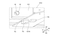
誤組付防止構造70は、カウンタウエイトケース13の上面に設けられたウエイト側突き当て部71(図6A、図6B参照)と、カウンタウエイト支持部31の下面に設けられた旋回台側突き当て部72(図7A、図7B参照)とを備える。
The incorrect
ウエイト側突き当て部71は、ウエイト側係合部の一例に該当する。又、旋回台側突き当て部72は、作業機側係合部の一例に該当する。
The weight
尚、図6Aは、作業能力が高い機種(第一機種)のクレーン車CCに搭載用のカウンタウエイト10(a)のウエイト側突き当て部71を示す。一方、図6Bは、作業能力が低い機種(第二機種)のクレーン車CCに搭載用のカウンタウエイト10(b)のウエイト側突き当て部71を示す。
Note that FIG. 6A shows the weight
カウンタウエイト10(b)の重量は、カウンタウエイト10(a)の重量よりも軽い。但し、カウンタウエイト10(b)のカウンタウエイトケース13と、カウンタウエイト10(b)のカウンタウエイトケース13とは、同一の仕様である(換言すれば、同一の諸元情報を有する)。
The weight of the counterweight 10(b) is lighter than the weight of the counterweight 10(a). However, the
又、図7Aは作業能力が高いクレーン車CCに設けられたカウンタウエイト支持部31(a)の旋回台側突き当て部72を示す。又、図7Bは、作業能力が低いクレーン車CCの旋回台30に設けられたカウンタウエイト支持部31(b)の旋回台側突き当て部72を示す。
Moreover, FIG. 7A shows the swivel table
カウンタウエイト10(a)、10(b)のウエイト側突き当て部71は、図6A及び図6Bに示すように、第1台座71aと、第2台座71bとを備える。第1台座71a及び第2台座71bは、カウンタウエイトケース13の上面において、支持ブラケット15a、15bそれぞれの幅方向における内側に設けられている。
The weight
第1台座71aと第2台座71bとは、幅方向において所定の間隔を空けて設けられている。本実施形態の場合、第1台座71aは、第2台座71bよりも幅方向における外側に設けられている。カウンタウエイト10(a)及びカウンタウエイト10(b)において、第1台座71aと第2台座71bとは、同じ構造を有する。又、カウンタウエイト10(a)及びカウンタウエイト10(b)において、第1台座71aと第2台座71bとは、同じ位置に配置されている。
The
そして、図6Aに示すカウンタウエイト10(a)において、第1台座71aの上面に、略直方体の突き当て部材71cが、ボルト等の締結部品により強固に固定されている。突き当て部材71cの上面は、第2台座71bの上面よりも上側に位置している。突き当て部材71cの上面は、ウエイト側突き当て面の一例に該当する。
In the counterweight 10(a) shown in FIG. 6A, a substantially rectangular
一方、図6Bに示すカウンタウエイト10(b)において、第2台座71bの上面に、突き当て部材71cが、ボルト等の締結部品により強固に固定されている。突き当て部材71cの上面は、第1台座71aの上面よりも上側に位置している。
On the other hand, in the counterweight 10(b) shown in FIG. 6B, an
カウンタウエイト支持部31(a)、31(b)の旋回台側突き当て部72は、図7A及び図7Bに示すように、第1台座72aと、第2台座72bとを備える。第1台座72a及び第2台座72bは、カウンタウエイト支持部31の下面であって、カウンタウエイト10(a)、10(b)を搭載する際に、ウエイト側突き当て部71の第1台座71a及び第2台座71bと、上下方向において対面する位置に配置されている。
As shown in FIGS. 7A and 7B, the swivel-
そして、図7Aに示す高性能のクレーン車CCの旋回台30のカウンタウエイト支持部31(a)では、第2台座72bの下面に、略直方体の突き当て部材72cが、ボルト等の締結部品により強固に固定されている。突き当て部材72cの下面は、第1台座72aの下面よりも下側に位置している。突き当て部材72cの下面は、作業機側突き当て面の一例に該当する。尚、突き当て部材72cの上下方向寸法は、カウンタウエイトケース13の突き当て部材71cの上下方向寸法よりも大きな寸法に形成されている。
In the counterweight support portion 31(a) of the
一方、図7Bに示す低性能のクレーン車CCの旋回台30のカウンタウエイト支持部31(b)では、第1台座72aの上面に、突き当て部材72cがボルト等の締結部品により強固に固定されている。突き当て部材72cの下面は、第2台座72bの下面よりも下側に位置している。
On the other hand, in the counterweight support part 31(b) of the
次に、誤組付防止構造70の作用を説明する。簡単に説明すると、誤組付防止構造70では、カウンタウエイト10(a)、10(b)のウエイト側突き当て部71の突き当て部材71cが、旋回台側突き当て部72の第1台座72a及び第2台座72bの下面に直接当接した場合は、カウンタウエイト10(a)、10(b)を結合位置に配置することができる。換言すれば、ウエイト側突き当て部71と旋回台側突き当て部72とが、適切な状態で係合した場合に、カウンタウエイト10(a)、10(b)を結合位置に配置できる。
Next, the operation of the incorrect
一方、誤組付防止構造70では、ウエイト側突き当て部71の突き当て部材71cが、旋回台側突き当て部72の突き当て部材72cに当接した場合は、カウンタウエイト10(a)、10(b)を結合位置まで上昇させることができない。換言すれば、ウエイト側突き当て部71と旋回台側突き当て部72とが、不適切な状態で係合した場合に、カウンタウエイト10(a)、10(b)を結合位置に配置できない。
On the other hand, in the incorrect
以下、上記作用を詳細に説明する。先ず、カウンタウエイト10(a)を作業機に組み付ける場合について説明する。 The above action will be explained in detail below. First, the case of assembling the counterweight 10(a) to a working machine will be described.
図8Aは、カウンタウエイト10(a)を、適合機種である作業能力が高いクレーン車CCの旋回台30のカウンタウエイト支持部31(a)に搭載する場合について説明する。この場合、カウンタウエイト10(a)を、カウンタウエイト支持部31(a)の下方位置から着脱シリンダ14a、14bにより上昇させると、図示のように、カウンタウエイト10(a)の突き当て部材71cが、カウンタウエイト支持部31(a)の第1台座72aに、直接当接する。換言すれば、ウエイト側突き当て部71と旋回台側突き当て部72とが、適切な状態で係合する。
FIG. 8A describes a case where the counterweight 10(a) is mounted on the counterweight support portion 31(a) of the
このときのカウンタウエイト10(a)の位置は、結合位置であって、図示のように、カウンタウエイト10(a)に設けた第2結合用孔62と、カウンタウエイト支持部31(a)に設けた第1結合用孔61とが、同軸に配置される。よって、第1結合用孔61及び第2結合用孔62に、固定ピン63を挿通できる。この結果、固定ピン63により、カウンタウエイト支持部31(a)とカウンタウエイト10(a)とを結合できる。
The position of the counterweight 10(a) at this time is the coupling position, and as shown in the figure, the
このように、ウエイト側突き当て部71と旋回台側突き当て部72とが適切な状態で係合した場合に、第1結合用孔61と第2結合用孔62とは、固定ピン63を挿通可能な状態となる。つまり、第1結合用孔61と第2結合用孔62とは、カウンタウエイト支持部31(a)に対してカウンタウエイト10を直接的又は間接的に連結可能な状態となる。
In this way, when the weight-
一方、図8Bは、カウンタウエイト10(a)を、不適合機種である作業能力が低いクレーン車CCの旋回台30のカウンタウエイト支持部31(b)に誤って搭載する場合について説明する。この場合、カウンタウエイト10(a)をカウンタウエイト支持部31(b)に引き上げると、図示のように、カウンタウエイト10(a)の突き当て部材71cが、カウンタウエイト支持部31(b)の第1台座72aに設けた突き当て部材72cに当接する。換言すれば、ウエイト側突き当て部71と旋回台側突き当て部72とが、不適切な状態で係合する。
On the other hand, FIG. 8B describes a case where the counterweight 10(a) is erroneously mounted on the counterweight support portion 31(b) of the
従って、カウンタウエイト10(a)を結合位置まで上昇させることができず、カウンタウエイト10(a)に設けた第2結合用孔62と、カウンタウエイト支持部31(b)に設けた第1結合用孔61との位置がずれる。よって、固定ピン63を、第1結合用孔61及び第2結合用孔62に挿通できない。
Therefore, the counterweight 10(a) cannot be raised to the coupling position, and the
このように、ウエイト側突き当て部71と旋回台側突き当て部72とが不適切な状態で係合した場合に、第1結合用孔61と第2結合用孔62との位置がずれるため、固定ピン63を挿通できない。つまり、第1結合用孔61と第2結合用孔62とは、カウンタウエイト支持部31(a)に対してカウンタウエイト10を連結不可能な状態となる。この結果、カウンタウエイト10(a)を不適合機種のカウンタウエイト支持部31(b)に組み付けることができず、誤組み付けを防止できる。
In this way, when the weight-
次に、カウンタウエイト10(b)を、作業機に組み付ける場合について説明する。 Next, a case where the counterweight 10(b) is assembled to a working machine will be described.
図9Aは、カウンタウエイト10(b)を、適合機種である相対的に作業能力が低いクレーン車CCの旋回台30のカウンタウエイト支持部31(b)に組み付ける場合について説明する。この場合、カウンタウエイト10(b)を、カウンタウエイト支持部31の下方位置から着脱シリンダ14a、14bにより引き上げると、図示のように、カウンタウエイト10(b)の突き当て部材71cが、カウンタウエイト支持部31(b)の第2台座72bに当接する。換言すれば、ウエイト側突き当て部71と旋回台側突き当て部72とが、適切な状態で係合する。
FIG. 9A describes a case where the counterweight 10(b) is assembled to the counterweight support portion 31(b) of the
このときのカウンタウエイト10(b)の位置が結合位置であって、カウンタウエイト10(b)に設けた第2結合用孔62と、カウンタウエイト支持部31(b)に設けた第1結合用孔61とが、同軸に配置される。よって、第1結合用孔61及び第2結合用孔62に、固定ピン63を挿通できる。この結果、固定ピン63により、カウンタウエイト支持部31(b)とカウンタウエイト10(b)とを、結合できる。
The position of the counterweight 10(b) at this time is the coupling position, and the
一方、図9Bは、カウンタウエイト10(b)を、不適合機種である作業能力が高いクレーン車CCの旋回台30のカウンタウエイト支持部31(a)に誤って組み付ける場合について説明する。この場合、カウンタウエイト10(b)の突き当て部材71cが、カウンタウエイト支持部31(a)の第2台座72bに設けた突き当て部材72cに当接する。換言すれば、ウエイト側突き当て部71と旋回台側突き当て部72とが、不適切な状態で係合する。
On the other hand, FIG. 9B describes a case where the counterweight 10(b) is erroneously assembled to the counterweight support portion 31(a) of the
従って、カウンタウエイト10(b)を結合位置まで上昇させることができず、カウンタウエイト10(b)に設けた第2結合用孔62と、カウンタウエイト支持部31(a)に設けた第1結合用孔61との位置がずれる。よって、固定ピン63を、第1結合用孔61及び第2結合用孔62に挿通できない。この結果、カウンタウエイト10(b)を不適合機種のカウンタウエイト支持部31(a)に組み付けることができず、誤組み付けを防止できる。
Therefore, the counterweight 10(b) cannot be raised to the coupling position, and the
(実施形態1の効果)
本実施形態のカウンタウエイト10は、クレーン車CCに搭載されるカウンタウエイトケース13と、カウンタウエイトケース13に充填される充填材と、を備えたカウンタウエイト10である。そして、カウンタウエイトケース13は、仕様が異なる複数の機種のクレーン車CCに搭載可能に形成され、且つ、充填材は、充填量と材質との少なくとも一方を異ならせて、クレーン車CCの機種の違いに応じて複数の種類の重量(カウンタウエイト10(a)、10(b))に設定されている。従って、重量が異なるカウンタウエイト10(a)、10(b)を形成する際、カウンタウエイトケース13を共用できるため、コストの低減を図ることができる。(Effects of Embodiment 1)
The
又、本実施形態のカウンタウエイト10の場合、比重が異なる充填材をカウンタウエイトケース13に充填することにより、カウンタウエイトケース13が共通であり、且つ、重量が異なるカウンタウエイトを実現している。つまり、カウンタウエイトケース13に充填する充填材の量が同じであっても、カウンタウエイトの重量を異ならせることができる。よって、カウンタウエイトケース13に充填材を隙間なく充填した場合であっても、カウンタウエイトの重量を異ならせることができる。このように、カウンタウエイトケース13の収容部の隙間を少なくすることができるため、作業時にこの収容部で充填材が移動することを防止できる。この結果、作業の安定性が向上する。
Further, in the case of the
又、本実施形態によれば、既述のような誤組付防止構造70を設けている。このため、カウンタウエイトを、不適合なクレーン車CCに誤って組み付けてしまうことを防止できる。
Further, according to the present embodiment, the erroneous
しかも、誤組付防止構造70は、単純に、機械的な構造により、結合機構60によるカウンタウエイト10とカウンタウエイト支持部31との誤った組み付けを防止している。このため、人為的なミスが生じることを防止できる。又、本実施形態の誤組付防止構造70によれば、部品点数を抑え、コスト低減を図ることができる。
Moreover, the erroneous
以上、実施形態1について説明したが、本発明に係るカウンタウエイト及び作業機の具体的な構成については上述の実施形態に限られるものではなく、本発明の要旨を逸脱しない限り、設計の変更や追加等は許容される。 Although Embodiment 1 has been described above, the specific configurations of the counterweight and work machine according to the present invention are not limited to the above-described embodiments, and the design may be changed without departing from the gist of the present invention. Additions, etc. are allowed.
本実施形態では、カウンタウエイト10を搭載する作業機としてクレーン車CCを示したが、作業機としては、クレーン車CCに限るものではない。本発明は、例えば、高所作業車及び梯子車のようなブームを備えた車両、油圧ショベル及びホイールローダといった建設機械、並びに農業機械等のようにカウンタウエイトを備えた作業機全般に適用することができる。
In the present embodiment, the crane truck CC is shown as a working machine on which the
又、本実施形態ではカウンタウエイト10(a)とカウンタウエイト10(b)とでは、充填材の比重を異ならせた例を示したが、これに限定されず、単に充填量を変えてもよい。さらに、このような場合に、予め、カウンタウエイトケース13には、充填材の移動を規制する隔壁等を設けていてもよい。
Further, in this embodiment, an example is shown in which the specific gravity of the filler is different between the counterweight 10(a) and the counterweight 10(b), but the present invention is not limited to this, and the filling amount may simply be changed. . Furthermore, in such a case, the
又、本実施形態では、結合機構60として、カウンタウエイト10と旋回台30とに設けた第1結合用孔61及び第2結合用孔62に固定ピン63を挿通するものを示したが、結合機構のこれに限定されない。結合機構として、例えば、カウンタウエイト10と旋回台30との一方に設けたボルトを他方に設けた孔に挿通して締結する機構、又は、一方に設けたフックを他方のピンに引っ掛けるもの等、種々の機構を用いることができる。要は、結合機構は、特定の結合位置で結合でき、結合位置からずれると結合できない構造であればよい。
Further, in this embodiment, as the
又、本実施形態では、誤組付防止構造70の構造も、本実施形態の場合に限定されない。誤組付防止構造は、例えば、台座と突き当て部材とを一体にした形状の突起を組み付けるようにしてもよい。或いは、誤組付防止構造は、突き上げ部材と台座との関係を、ピンと孔としてもよい。この場合、適合機種の場合には、ピンが孔の底に突き当たるまで相対移動して結合位置に配置され、不適合機種の場合には、ピンが孔に入らず、結合位置まで移動できない構造等としてもよい。尚、この場合も、ピンをカウンタウエイトケース13とは別体とすることで、カウンタウエイトケース13の共通化が可能である。
Further, in this embodiment, the structure of the erroneous
2019年3月25日出願の特願2019-56851の日本出願に含まれる明細書、図面、及び要約書の開示内容は、すべて本願に援用される。 The disclosure contents of the specification, drawings, and abstract included in the Japanese patent application No. 2019-56851 filed on March 25, 2019 are all incorporated into the present application.
本発明は、種々の作業機に適用可能である。 The present invention is applicable to various working machines.
10 カウンタウエイト
11 ベースウエイト部
12 側部ウエイト部
12a 左側ウエイト部
12b 右側ウエイト部
13 カウンタウエイトケース
131 収容部
14a、14b 着脱シリンダ
15a、15b 支持ブラケット
151、152 プレート部材
153 シリンダ固定部
154 ピン
20 走行体
30 旋回台
31 カウンタウエイト支持部
311 本体
312a、312b 上側アーム部
313a、313b 下側アーム部
314a、314b 支持部側連結部
40 ブーム
50 アウトリガ
60 結合機構
61 第1結合用孔
62 第2結合用孔
63 固定ピン
70 誤組付防止構造
71 ウエイト側突き当て部
71a 第1台座
71b 第2台座
71c 突き当て部材
72 旋回台側突き当て部
72a 第1台座
72b 第2台座
72c 突き当て部材
8 充填材
CC クレーン車(作業機)10
Claims (9)
機種が異なる作業機について共通化されたケースと、
前記ケースに設けられ、機種が異なる作業機について共通化され、前記作業機に前記カウンタウエイトを固定するためのウエイト側固定機構と、
前記カウンタウエイトの重量が前記機種毎に設定された重量となるように、前記ケースに充填された充填材と、
前記ケースに設けられ、前記機種毎に設定された形状を有するウエイト側係合部と、
を備え
前記ウエイト側固定機構は、
前記ウエイト側係合部と前記作業機に設けられた作業機側係合部との係合が適切な場合に、前記作業機に対して前記カウンタウエイトを固定可能な状態となり、
前記係合が不適切な場合に、前記作業機に対して前記カウンタウエイトを固定不可能な状態となる、
カウンタウエイト。 A counterweight fixed to a work machine,
Cases in which work machines of different models are standardized,
a weight-side fixing mechanism provided in the case and shared by different types of work machines for fixing the counterweight to the work machine;
a filler filled in the case so that the weight of the counterweight is a weight set for each model;
a weight-side engaging portion provided in the case and having a shape set for each model;
equipped with
The weight side fixing mechanism is
When the weight side engaging part and the work machine side engaging part provided on the work machine are appropriately engaged, the counterweight is in a state where it can be fixed to the work machine,
If the engagement is inappropriate, the counterweight cannot be fixed to the work machine;
Counterweight.
前記充填材は、複数の収容部のそれぞれに充填されている、請求項1に記載のカウンタウエイト。 The case has a plurality of storage sections partitioned from each other,
The counterweight according to claim 1, wherein each of the plurality of accommodating parts is filled with the filler.
前記第一充填材と前記第二充填材とは、異なる前記収容部に充填されている、請求項2に記載のカウンタウエイト。 The filler includes a first filler having a first specific gravity and a second filler having a second specific gravity different from the first specific gravity,
The counterweight according to claim 2, wherein the first filler and the second filler are filled in different accommodation parts.
前記カウンタウエイトが前記作業機に固定された固定状態において、前記着脱シリンダの第二端部は、前記作業機に連結される、請求項1~3の何れか一項に記載のカウンタウエイト。 further comprising a detachable cylinder having a first end fixed to the case,
The counterweight according to any one of claims 1 to 3, wherein the second end of the detachable cylinder is connected to the work machine in a fixed state in which the counterweight is fixed to the work machine.
前記ウエイト側突き当て面が、前記作業機側係合部の作業機側突き当て面に直接当接した場合に、前記係合が適切となる、請求項1~4の何れか一項に記載のカウンタウエイト。 The weight side engaging portion has a weight side abutting surface,
According to any one of claims 1 to 4 , the engagement becomes appropriate when the weight-side abutment surface directly abuts the work-machine-side abutment surface of the work-machine-side engagement portion. counterweight.
前記カウンタウエイトを支持するウエイト支持部と、
前記カウンタウエイトを前記ウエイト支持部に固定するための作業機側固定機構と、
前記作業機の機種毎に設定された形状を有する作業機側係合部と、を備え、
前記作業機側固定機構は、
前記作業機側係合部と前記カウンタウエイトに設けられた前記ウエイト側係合部との係合が適切な場合に、前記ウエイト支持部に対して前記カウンタウエイトを直接的又は間接的に連結可能な状態となり、
前記係合が不適切な場合に、前記カウンタウエイトと連結不可能な状態となる、
作業機。 A work machine capable of mounting the counterweight according to any one of claims 1 to 5 ,
a weight support part that supports the counterweight;
a work machine side fixing mechanism for fixing the counterweight to the weight support part;
a work machine side engaging portion having a shape set for each model of the work machine,
The work machine side fixing mechanism is
The counterweight can be connected directly or indirectly to the weight support part when the engagement between the work machine side engagement part and the weight side engagement part provided on the counterweight is appropriate. It becomes a state,
If the engagement is inappropriate, it becomes impossible to connect with the counterweight;
work equipment.
前記作業機側固定部は、前記係合が適切な場合に、前記カウンタウエイトに設けられたウエイト側固定部と直接的又は間接的に連結可能な状態となる、請求項6に記載の作業機。 The work machine side fixing mechanism has a work machine side fixing part provided on the weight support part,
The work machine according to claim 6 , wherein the work machine side fixing part is in a state where it can be directly or indirectly connected to the weight side fixing part provided on the counterweight when the engagement is appropriate. .
前記作業機側貫通孔は、前記係合が適切な場合に、前記ウエイト側固定部のウエイト側貫通孔と対面し、
前記作業機側貫通孔は、前記係合が不適切な場合に、前記ウエイト側貫通孔と対面せず、
前記カウンタウエイトは、前記係合が適切な場合に、前記作業機側貫通孔及び前記ウエイト側貫通孔に挿通された軸部材を介して、前記ウエイト支持部に支持される、請求項7に記載の作業機。 The work machine side fixing part has a work machine side through hole provided in the weight support part,
The work machine side through hole faces the weight side through hole of the weight side fixing part when the engagement is appropriate,
The work machine side through hole does not face the weight side through hole when the engagement is inappropriate,
The counterweight is supported by the weight support portion via a shaft member inserted into the work machine side through hole and the weight side through hole when the engagement is appropriate. work equipment.
前記作業機側突き当て面が前記ウエイト側係合部のウエイト側突き当て面に直接当接した場合に、前記係合が適切となる、請求項6~8の何れか一項に記載の作業機。 The work machine side engaging portion has a work machine side abutting surface,
The work according to any one of claims 6 to 8 , wherein the engagement becomes appropriate when the work machine side abutment surface directly abuts the weight side abutment surface of the weight side engagement portion. Machine.
Applications Claiming Priority (3)
| Application Number | Priority Date | Filing Date | Title |
|---|---|---|---|
| JP2019056851 | 2019-03-25 | ||
| JP2019056851 | 2019-03-25 | ||
| PCT/JP2020/012195 WO2020196221A1 (en) | 2019-03-25 | 2020-03-19 | Counterweight and work machine |
Publications (2)
| Publication Number | Publication Date |
|---|---|
| JPWO2020196221A1 JPWO2020196221A1 (en) | 2020-10-01 |
| JP7375811B2 true JP7375811B2 (en) | 2023-11-08 |
Family
ID=72611912
Family Applications (1)
| Application Number | Title | Priority Date | Filing Date |
|---|---|---|---|
| JP2021509290A Active JP7375811B2 (en) | 2019-03-25 | 2020-03-19 | Counterweight and work equipment |
Country Status (3)
| Country | Link |
|---|---|
| JP (1) | JP7375811B2 (en) |
| CN (1) | CN113574226B (en) |
| WO (1) | WO2020196221A1 (en) |
Citations (2)
| Publication number | Priority date | Publication date | Assignee | Title |
|---|---|---|---|---|
| JP2001151470A (en) | 1999-11-30 | 2001-06-05 | Aichi Corp | Counter weight for working vehicle |
| JP2010006554A (en) | 2008-06-27 | 2010-01-14 | Hitachi Sumitomo Heavy Industries Construction Crane Co Ltd | Counterweight attaching/detaching device and truck crane |
Family Cites Families (7)
| Publication number | Priority date | Publication date | Assignee | Title |
|---|---|---|---|---|
| JP2516865Y2 (en) * | 1990-07-20 | 1996-11-13 | 株式会社タダノ | Counterweight mounting state detection device for mobile cranes |
| JP2546949Y2 (en) * | 1991-11-15 | 1997-09-03 | 株式会社小松製作所 | Construction vehicle counterweight |
| JPH0649490U (en) * | 1992-12-17 | 1994-07-08 | 東洋運搬機株式会社 | Counter weight |
| JPH10128490A (en) * | 1996-10-21 | 1998-05-19 | Toyota Autom Loom Works Ltd | Manufacture of counter weight for industrial vehicle |
| JP3862575B2 (en) * | 2001-09-28 | 2006-12-27 | 新キャタピラー三菱株式会社 | Counterweight and recycling method |
| JP5242987B2 (en) * | 2007-10-18 | 2013-07-24 | 株式会社小松製作所 | Counter weight |
| US9702114B2 (en) * | 2012-04-03 | 2017-07-11 | Harnischfeger Technologies, Inc. | Counterweight system for an industrial machine |
-
2020
- 2020-03-19 JP JP2021509290A patent/JP7375811B2/en active Active
- 2020-03-19 WO PCT/JP2020/012195 patent/WO2020196221A1/en active Application Filing
- 2020-03-19 CN CN202080021676.2A patent/CN113574226B/en active Active
Patent Citations (2)
| Publication number | Priority date | Publication date | Assignee | Title |
|---|---|---|---|---|
| JP2001151470A (en) | 1999-11-30 | 2001-06-05 | Aichi Corp | Counter weight for working vehicle |
| JP2010006554A (en) | 2008-06-27 | 2010-01-14 | Hitachi Sumitomo Heavy Industries Construction Crane Co Ltd | Counterweight attaching/detaching device and truck crane |
Also Published As
| Publication number | Publication date |
|---|---|
| CN113574226B (en) | 2023-01-06 |
| JPWO2020196221A1 (en) | 2020-10-01 |
| CN113574226A (en) | 2021-10-29 |
| WO2020196221A1 (en) | 2020-10-01 |
Similar Documents
| Publication | Publication Date | Title |
|---|---|---|
| CN107257772B (en) | Moving device for counterweight | |
| RU2521085C2 (en) | Counterweight blocks and counterweight units for cranes | |
| US8684198B2 (en) | Working machine | |
| US6860706B2 (en) | Method of verifying coupling of an implement to a work machine | |
| US6609587B1 (en) | Frame assembly for a work machine | |
| JP4468503B2 (en) | Linkage assembly for connecting a work implement to a work machine | |
| JP2007205100A (en) | Body frame of construction machinery and the construction machinery | |
| WO2018143193A1 (en) | Construction machine | |
| JP4730343B2 (en) | Detachable transportation platform for construction machine attachments | |
| JP4438697B2 (en) | Crawler work vehicle | |
| JP7375811B2 (en) | Counterweight and work equipment | |
| JP6610314B2 (en) | Swivel work machine and float device used therefor | |
| JP6260284B2 (en) | Construction machinery side frame | |
| JP2019206301A (en) | Crawler crane | |
| JP6847528B2 (en) | Construction machinery | |
| JP6460132B2 (en) | Construction machinery | |
| JP5307760B2 (en) | Side step device for work equipment | |
| JPH11335096A (en) | Lift assembly unit for work machine | |
| JP3540806B2 (en) | Construction equipment with cab | |
| JP2001171977A (en) | Wheel type construction machine | |
| JP6622514B2 (en) | Installation method of construction machine and car body weight | |
| JP6996376B2 (en) | Outrigger device | |
| JP6962425B2 (en) | adapter | |
| WO2022124097A1 (en) | Crane | |
| JP6703758B2 (en) | Construction machinery |
Legal Events
| Date | Code | Title | Description |
|---|---|---|---|
| A521 | Request for written amendment filed |
Free format text: JAPANESE INTERMEDIATE CODE: A523 Effective date: 20210927 |
|
| A621 | Written request for application examination |
Free format text: JAPANESE INTERMEDIATE CODE: A621 Effective date: 20230104 |
|
| TRDD | Decision of grant or rejection written | ||
| A01 | Written decision to grant a patent or to grant a registration (utility model) |
Free format text: JAPANESE INTERMEDIATE CODE: A01 Effective date: 20230926 |
|
| A61 | First payment of annual fees (during grant procedure) |
Free format text: JAPANESE INTERMEDIATE CODE: A61 Effective date: 20231009 |
|
| R150 | Certificate of patent or registration of utility model |
Ref document number: 7375811 Country of ref document: JP Free format text: JAPANESE INTERMEDIATE CODE: R150 |