JP7373230B1 - rubber balloon - Google Patents
rubber balloon Download PDFInfo
- Publication number
- JP7373230B1 JP7373230B1 JP2022091716A JP2022091716A JP7373230B1 JP 7373230 B1 JP7373230 B1 JP 7373230B1 JP 2022091716 A JP2022091716 A JP 2022091716A JP 2022091716 A JP2022091716 A JP 2022091716A JP 7373230 B1 JP7373230 B1 JP 7373230B1
- Authority
- JP
- Japan
- Prior art keywords
- balloon
- mouthpiece
- cylinder
- supply nozzle
- air supply
- Prior art date
- Legal status (The legal status is an assumption and is not a legal conclusion. Google has not performed a legal analysis and makes no representation as to the accuracy of the status listed.)
- Active
Links
- 229920001971 elastomer Polymers 0.000 title claims abstract description 54
- 230000002093 peripheral effect Effects 0.000 claims description 30
- 238000007664 blowing Methods 0.000 abstract description 14
- 238000010586 diagram Methods 0.000 abstract 1
- 239000007789 gas Substances 0.000 description 24
- 238000002347 injection Methods 0.000 description 18
- 239000007924 injection Substances 0.000 description 18
- 210000000078 claw Anatomy 0.000 description 16
- 238000004891 communication Methods 0.000 description 12
- 238000010304 firing Methods 0.000 description 8
- 238000012986 modification Methods 0.000 description 3
- 230000004048 modification Effects 0.000 description 3
- IJGRMHOSHXDMSA-UHFFFAOYSA-N Atomic nitrogen Chemical compound N#N IJGRMHOSHXDMSA-UHFFFAOYSA-N 0.000 description 2
- 238000013459 approach Methods 0.000 description 2
- 230000000694 effects Effects 0.000 description 2
- 210000004072 lung Anatomy 0.000 description 2
- 241000711573 Coronaviridae Species 0.000 description 1
- 244000043261 Hevea brasiliensis Species 0.000 description 1
- 239000000853 adhesive Substances 0.000 description 1
- 230000001070 adhesive effect Effects 0.000 description 1
- 238000001802 infusion Methods 0.000 description 1
- 238000003780 insertion Methods 0.000 description 1
- 230000037431 insertion Effects 0.000 description 1
- 239000000463 material Substances 0.000 description 1
- 229920003052 natural elastomer Polymers 0.000 description 1
- 229920001194 natural rubber Polymers 0.000 description 1
- 229910052757 nitrogen Inorganic materials 0.000 description 1
- 230000001141 propulsive effect Effects 0.000 description 1
- 239000000126 substance Substances 0.000 description 1
- 230000002195 synergetic effect Effects 0.000 description 1
Images


Landscapes
- Toys (AREA)
Abstract
【課題】人が口筒を咥えて息を吹き込んで直接膨らませるのを防止でき、衛生上の問題の発生をなくせるようにする。【解決手段】本発明のゴム風船2は、風船本体5の開口端部に口筒6が取り付けられる。口筒6には、風船本体とは逆方向に延びる突出部としてのテーパー筒部9が設けられる。テーパー筒部9における外向き開口部9aの外径D9は、口筒6の外径D6よりも大径に設定される。【選択図】図2[Problem] To prevent a person from holding a mouthpiece in their mouth and blowing into it to directly inflate it, thereby eliminating hygiene problems. In the rubber balloon 2 of the present invention, a spout 6 is attached to the open end of the balloon body 5. The spout 6 is provided with a tapered cylindrical portion 9 as a protruding portion extending in a direction opposite to the balloon body. The outer diameter D9 of the outward opening 9a in the tapered cylinder portion 9 is set to be larger than the outer diameter D6 of the mouth tube 6. [Selection diagram] Figure 2
Description
本発明は、ゴム風船に関するものである。 The present invention relates to rubber balloons .
スポーツ観戦、特に野球観戦やサッカー観戦においては、ファンがひいきチームを応援する手法の一環として、内部に空気を入れた細長形状のゴム風船を空中に飛ばすことが広く行われている。例えばプロ野球観戦では、選手達を鼓舞するために7回の攻撃前にゴム風船を一斉に飛ばしたり、勝利を祝う目的で試合終了後にゴム風船を一斉に飛ばしたりしている。 BACKGROUND OF THE INVENTION When watching sports, especially baseball or soccer games, it is common practice for fans to release elongated rubber balloons filled with air into the air as a way to support their favorite teams. For example, when watching a professional baseball game, rubber balloons are released all at once before the seventh inning to encourage the players, and rubber balloons are released all at once after the game to celebrate a victory.
この種のゴム風船は、人が口筒を口に咥えて空気を入れて細長形状に膨らませ、空気が漏れないように口筒を手指で塞ぎ、タイミングを見計らって口筒から手指を離して、ゴム風船内部の空気を口筒から外部に噴出させ、当該噴出力を推進力として空中に飛ばされる。ゴム風船の口筒は一般に、笛機能を有していて、口筒から空気を噴出する際には「ピー」という音が発生する。 This type of rubber balloon is made by a person who holds the tube in their mouth, fills it with air to inflate it into a long and thin shape, then closes the tube with their fingers to prevent air from leaking, and then removes their fingers from the tube at the right time. The air inside the rubber balloon is blown out from the mouthpiece, and the blown air is used as a propulsion force to be blown into the air. The mouthpiece of a rubber balloon generally has a whistle function, and when air is ejected from the mouthpiece, a "beep" sound is generated.
ところで、この種のゴム風船は前述の通り、人が口筒を口に咥えて息を吹き込み、細長形状に膨らませるのが一般的である。 By the way, as mentioned above, this type of rubber balloon is generally inflated into an elongated shape by a person holding the tube in their mouth and blowing into it.
しかし、口筒を口で咥えて息を吹き込んでゴム風船を膨らますのは、衛生上好ましくない。例えば球場で多数のゴム風船を一斉に飛翔させると、ゴム風船内に吹き込まれた人の息が下方に、すなわち球場内に向けて放出されて大気中に拡散し、観客の皮膚や食べ物に付着する可能性がある。 However, it is not sanitary to inflate a rubber balloon by holding the mouthpiece in your mouth and blowing into it. For example, when a large number of rubber balloons are released all at once at a baseball stadium, the breath of people blown into the balloons is emitted downward, into the stadium, and spreads into the atmosphere, adhering to the skin and food of spectators. there's a possibility that.
昨今の新型コロナウイルスの世界的な感染拡大を考慮すると、ゴム風船の口筒を口に咥えて息を吹き込む行為に起因する衛生上の問題は軽視できるものではないと解される。例えばプロ野球観戦において現状は、ゴム風船の使用が禁止されており、せっかくの観戦にも拘らず、試合を盛り上げて楽しむためのグッズを使えない状況にある。ゴム風船の使用を解禁するには、前述した衛生上の問題の発生をなくすなんらかの具体的な対策が必要である。 Considering the recent global spread of the new coronavirus, the hygiene problems caused by the act of holding a rubber balloon in your mouth and blowing into it cannot be taken lightly. For example, the current situation is that the use of rubber balloons is prohibited when watching professional baseball games, so even if you are watching the game, you cannot use the goods that would make the game more exciting and enjoyable. In order to lift the ban on the use of rubber balloons, it is necessary to take some concrete measures to eliminate the sanitary problems mentioned above.
本発明は、上記の現状に鑑みてなされたものであり、人が口筒を咥えて息を吹き込んで直接膨らませるのを防止でき、衛生上の問題の発生をなくせるゴム風船を提供することを技術的課題とするものである。 The present invention has been made in view of the above-mentioned current situation, and provides a rubber balloon that can prevent a person from directly inflating the balloon by holding the mouthpiece in their mouth and blowing into it, thereby eliminating the occurrence of hygiene problems. This is a technical issue.
本発明は、風船本体の開口端部に口筒が取り付けられたゴム風船に係るものであり、前記口筒には、その外径よりも大径に構成されかつ前記風船本体とは逆方向に延びるテーパー筒部が設けられており、前記テーパー筒部における外向き開口部の外径が前記口筒の外径よりも大径になっているというものである。 The present invention relates to a rubber balloon in which a mouthpiece is attached to an open end of a balloon body, and the mouthpiece has a diameter larger than an outer diameter of the mouthpiece and a diameter opposite to that of the balloon body. A tapered cylindrical portion is provided, and an outer diameter of an outward opening in the tapered cylindrical portion is larger than an outer diameter of the mouth tube.
請求項2の発明は、請求項1に記載したゴム風船において、前記テーパー筒部の周壁部には、少なくとも1つの溝形状又は穴形状の気体逃し凹所が形成されているというものである。 According to a second aspect of the present invention, in the rubber balloon according to the first aspect, at least one groove-shaped or hole-shaped gas relief recess is formed in the peripheral wall of the tapered cylindrical portion.
本発明によると、口筒に設けられた突出部やテーパー筒部の大きな外径の分だけ前記口筒を口で咥えるのが困難になり、人が前記口筒を咥えて息を直接吹き込んで前記風船本体を膨らませるのを効果的に抑制でき、前記風船本体に直接息を吹き込む行為に起因する衛生上の問題の発生をなくせる。 According to the present invention, it becomes difficult for a person to hold the mouthpiece in their mouth due to the large outer diameter of the protrusion and tapered tube provided on the mouthpiece, and it is difficult for a person to hold the mouthpiece in their mouth and breathe directly into the mouth. This effectively prevents the balloon body from being inflated, thereby eliminating sanitary problems caused by the act of blowing directly into the balloon body.
また、前記テーパー筒部の周壁部に、少なくとも1つの溝形状又は穴形状の気体逃し凹所が形成されるようにすると、前記テーパー筒部ごと前記口筒を無理して咥えない限り、前記風船本体に直接息を吹き込むことができない(前記気体逃し凹所から息が漏れるため)。従って、人が前記口筒を咥えて息を直接吹き込んで前記風船本体を膨らませるのをより確実に防止できる。 Further, if at least one groove-shaped or hole-shaped gas relief recess is formed in the peripheral wall of the tapered cylinder part , unless the mouthpiece is forcibly held together with the tapered cylinder part, the It is not possible to blow air directly into the balloon body (because the air leaks from the gas relief recess). Therefore, it is possible to more reliably prevent a person from inflating the balloon body by holding the mouthpiece in their mouth and blowing directly into the balloon body.
ゴム風船における風船本体の開口端部に取り付けられた口筒を把持したり把持解除したりする発射具であって、縦長筒状の給気ノズルと、前記給気ノズルを挟んで両側に配置された一対の把持レバーとを有しており、前記給気ノズルの基端側には、前記風船本体に気体を注入する注入ポンプにおけるシリンダの先端側に設けられる雄型又は雌型係合部に係合可能な雌型もしくは雄型係合部が設けられるようにすると、気体注入用の前記注入ポンプを前記発射具に簡単に取り付けできる。 A launcher that grips and releases the mouthpiece attached to the open end of the balloon body of a rubber balloon, and includes a vertically cylindrical air supply nozzle and is placed on both sides of the air supply nozzle. A pair of gripping levers are provided on the proximal end side of the air supply nozzle, and a male or female engagement portion provided on the distal end side of the cylinder of an injection pump for injecting gas into the balloon body. By providing a female or male type engaging portion that can be engaged with the injection pump, the injection pump for injecting gas can be easily attached to the firing tool.
このため、例えば肺活量の小さい子供や女性のように、息を直接吹き込んで前記風船本体を膨らませるのが困難だった人であっても、前記発射具を介した前記注入ポンプを用いて、前記風船本体を楽に膨らませることができる。前記風船本体に息を直接吹き込んで膨らませる必要がなくなる。前記ゴム風船を前記発射具で把持している間に空気抜けする懸念もない。 Therefore, even people who have difficulty inflating the balloon body by directly blowing into the balloon, such as children and women with small lung capacity, can use the injection pump via the ejector to You can easily inflate the balloon itself. There is no need to blow directly into the balloon body to inflate it. There is no concern that the air will escape while the rubber balloon is being held by the launcher.
前記各把持レバーには、前記給気ノズルに向けて延び且つ口筒の肩部分に係合可能なロック爪と、前記給気ノズルに向けて片持ち梁状に延びるストッパー片とが形成されており、前記各ストッパー片は、前記給気ノズルの先端側に前記口筒を装着した状態で、前記口筒の底側を下支えするように構成されていると、前記給気ノズルの先端側に前記口筒を装着した状態では、前記ロック爪と前記ストッパー片とで前記口筒を安定的に離脱不能に保持できる。 Each of the gripping levers is formed with a lock claw that extends toward the air supply nozzle and is engageable with a shoulder portion of the spout, and a stopper piece that extends in a cantilever shape toward the air supply nozzle. Each of the stopper pieces is configured to support the bottom side of the mouthpiece when the mouthpiece is attached to the tip side of the air supply nozzle. When the mouthpiece is attached to the mouthpiece, the locking pawl and the stopper piece can stably hold the mouthpiece in a manner that cannot be removed.
前記ゴム風船と前記発射具と前記注入ポンプとからなるゴム風船発射セットを採用すれば、人が前記風船本体に直接息を吹き込んで膨らませるのを防止でき、衛生上の問題の発生をなくせるのである。 By adopting a rubber balloon launch set consisting of the rubber balloon , the launch tool, and the injection pump, it is possible to prevent people from directly blowing into the balloon body to inflate it, thereby eliminating hygienic problems. It is to make it possible.
次に、本発明の実施形態について図面を参照して詳細に説明する。なお、以下の説明では、ゴム風船2において口筒6から風船本体5を見る方向を「上」、その反対方向を「下」とし、発射具3では、口筒6を装着する側を「上」、注入ポンプ4を装着する側を「下」とし、注入ポンプ4では、発射具3を装着する側を「上」、ピストン杆13の把手14側を「下」としている。ただし、これらの用語は説明の便宜上用いたものであり、本発明の技術的範囲を限定するものではない。
Next, embodiments of the present invention will be described in detail with reference to the drawings. In the following explanation, the direction in which the
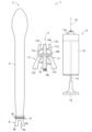
図1に示すように、本発明のゴム風船発射セット1は、ゴム風船2と、ゴム風船2の口筒6を把持したり把持解除したりする発射具3と、ゴム風船2に空気を入れる注入ポンプ4とを備えている。
As shown in FIG. 1, a rubber balloon launcher set 1 of the present invention includes a
ゴム風船2は、例えば天然ゴムのように伸縮性のある素材製の風船本体5と、風船本体5の下端開口部(開口端部)に取り付けられる口筒6とで構成されている。風船本体5は、内部に空気等の気体が注入されると、膨らんで細長い略円筒状の形状になる。ただし、風船本体5の膨らんだ形状は、上記のものに限るわけではなく、どんな形状であってもよい。風船本体5内に注入されるものは空気以外でもよい。例えば窒素等の他の気体でも差し支えない。風船本体5における下端開口部の周縁は、厚肉に構成された厚肉部5aになっている。
The
図1、図2(a)~(c)及び図5には、風船本体5の下端開口部(開口端部)に取り付けられる口筒6の第1実施形態を示している。図2(a)~(c)に詳細に示すように、口筒6は、上筒体7及び下筒体8を互いに嵌め合わせて一体的に連結することによって、全体的に略円筒形状に形成されたものである。すなわち、第1実施形態の口筒6は、上筒体7と下筒体8とからなる2パーツ式のものである。
1, FIGS. 2(a) to 2(c), and FIG. 5 show a first embodiment of a
上筒体7は下向き開口筒状に形成されていて、その天板部7aに円形の上連通穴7cが形成されている。下筒体8は上向き開口筒状に形成されていて、その底板部8aに円形の下連通穴8bが形成されている。両筒体7,8の連通穴7c,8cは、両筒体7,8を互いに嵌め合わせた状態で相対向する位置関係に設定されている。
The upper
上筒体7における周壁部7bの上側には、半径方向外向きに突出する上環状フランジ7dが形成されている。上筒体7における周壁部7bの下側には、上環状フランジ7dよりも突出高さが低い係止突条7eが半径方向外向きに突出形成されている。下筒体8における周壁部8bの上側には、半径方向外向きに突出する下環状フランジ8dが形成されている。下筒体8における周壁部8bの下側には、下環状フランジ8dよりも突出高さが低い係止突条8eが半径方向内向きに突出形成されている。
An upper
両筒体7,8の開口を互いに向き合わせ、下筒体8の周壁部8bを上筒体7の周壁部7bに外嵌状態で嵌合させ、上筒体7を下筒体8内に押し込むと、上筒体7の係止突条7eが下筒体8の係止突条8eを乗り越えて、係止突条7e,8e同士が係合される。その結果、上筒体7と下筒体8とが外れにくい状態に一体的に連結される。すなわち、上筒体7と下筒体8とを互いに嵌め合わせた状態では、下筒体8の周壁部8bが上筒体7の周壁部7bに外側から被さっている。
With the openings of both
口筒6の周壁部7b,8b(上筒体7と下筒体8とを互いに嵌め合わせた状態での周壁部7b,8b)には、2条の環状フランジ7d,8dが平行状に突出している。風船本体5の下端開口部は、口筒6に対して上筒体7側から外嵌状態で被せ付けられている。この場合、2条の環状フランジ7d,8d間の周溝内に厚肉部5aが嵌まり込んでいるため、風船本体5が口筒6から離脱しにくくなっている。
Two
なお、口筒6は、風船本体5内部の空気が両連通穴7c,8cを通過すると音を発する笛機能を有している。また、上筒体7における周壁部7bの内面には、一対の回転用突起7fが相対向する状態で半径方向内向きに突出形成されている(図2(b)に一方のみ示す)。
Note that the
図1、図2(a)~(c)及び図5に示すように、口筒6には、風船本体5とは逆方向に延びる突出部の一例としてのテーパー筒部9が設けられている。第1実施形態では、下筒体8の下端側に、テーパー筒部9が末広がりの漏斗状に延びるように一体形成されている。テーパー筒部9における外向き開口部9aの外径D9は、口筒6の外径D6よりも大径に設定されている。
As shown in FIGS. 1, 2(a) to 2(c), and FIG. 5, the
第1実施形態において口筒6の外径D6とは、両環状フランジ7d,8dの外径D6がそれに当たるものであり、両筒体7,8を互いに嵌め合わせた状態で、テーパー筒部9における外向き開口部9aの外径D9が、両環状フランジ7d,8dの外径D6よりも大径になっている(D9>D6)。
In the first embodiment, the outer diameter D6 of the
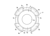
テーパー筒部9における末広がり傾斜状の周壁部9bには、少なくとも1つの溝形状又は穴形状の気体逃し凹所9cが形成されている。当該気体逃し凹所9cは基本的に、風船本体5内部から口筒6の両連通穴7c,8cを通過した空気がスムーズに外部に放出させるためのものである。
At least one groove-shaped or hole-shaped
第1実施形態では、テーパー筒部9の周壁部9bに、上向きに凹んだ溝形状の気体逃し凹所9cが相対向して一対(2箇所)形成されている(図2(a)(b)には一方のみ、図2(c)には両方示す)。各気体逃し凹所9cは、その上端縁が下筒体8の底板部8a近くに位置するほど上下に長く形成されている。
In the first embodiment, a pair (two locations) of upwardly recessed groove-shaped gas release recesses 9c are formed in the
上記の構成によると、口筒6には、風船本体5とは逆方向に延びるテーパー筒部9が設けられており、テーパー筒部9における外向き開口部9aの外径D9は、口筒6の外径D6よりも大径になっているから、テーパー筒部9の大きな外径の分だけ口筒6を口で咥えるのが困難であり、人が口筒6を咥えて息を直接吹き込んで風船本体5を膨らませるのを効果的に抑制でき、風船本体5に直接息を吹き込む行為に起因する衛生上の問題の発生をなくせるのである。
According to the above configuration, the
特に第1実施形態では、テーパー筒部9の周壁部に、少なくとも1つの溝形状又は穴形状の気体逃し凹所9cが形成されているから、テーパー筒部9ごと口筒6を無理して咥えない限り、風船本体5に直接息を吹き込むことができない(気体逃し凹所9cから息が漏れるため)。従って、人が口筒6を咥えて息を直接吹き込んで風船本体5を膨らませるのをより確実に防止できる。
In particular, in the first embodiment, since at least one groove-shaped or hole-shaped
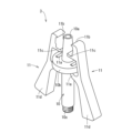
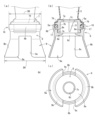
図1及び図3~図5に示すように、ゴム風船2の口筒6を把持したり把持解除したりする発射具3は、縦長筒状の給気ノズル10と、給気ノズル10を挟んで両側に配置された一対の把持レバー11とを有している。
As shown in FIG. 1 and FIGS. 3 to 5, the
給気ノズル10の筒穴10aは上下に貫通している。給気ノズル10の上端側(先端側)は先窄まり状に形成されている。給気ノズル10の上端側に口筒6が装着される。すなわち、給気ノズル10の上端側は、口筒6の少なくとも下連通穴8cに下方から挿し込まれる。給気ノズル10の下端側(基端側)には、雄型係合部としての雄ねじ部10cが形成されている。雄ねじ部10cは、注入ポンプ4におけるシリンダ12上端側(先端側)の雌型係合部である雌ねじ部12cに係脱可能に構成されている(詳細は後述する)。
The
各把持レバー11は、いわゆる十手形状に形成されたものであり、給気ノズル10の長手中途部に形成された胴部フランジ10bに連結された鉤状アーム11aを有している。各鉤状アーム11aは、対応する把持レバー11の長手中途部から給気ノズル10に向けて突出形成されている。この場合、給気ノズル10と各把持レバー11とは別体で構成されているが、一体形成したものであってもよいことは言うまでもない。
Each gripping
各把持レバー11の上端側(先端側)には、給気ノズル10に向けて延びるロック爪11bが形成されている。各ロック爪11bは、給気ノズル10の上端側にゴム風船2の口筒6を装着した状態で、口筒6のうち風船本体5が被さった上環状フランジ7d(口筒6の肩部分に相当)に上方から係合するように構成されている。両ロック爪11bが口筒6の上環状フランジ7dに上方から係合することによって、口筒6ひいてはゴム風船2が発射具3に対して離脱不能に保持される。
A
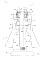
各把持レバー11のうちロック爪11bと鉤状アーム11aとの間には、給気ノズル10に向けて片持ち梁状に延びるストッパー片11cが形成されている。各ストッパー片11cは、給気ノズル10の上端側にゴム風船2の口筒6を装着した状態で、対応する気体逃し凹所9cを通過して、下筒体8の底板部8aを下支えするように構成されている(口筒6の過剰な挿し込みを規制している)。
A
両把持レバー11は、その上端側が給気ノズル10の上端側に対して、両ロック爪11bが給気ノズル10に近接するロック姿勢と、両ロック爪11bが給気ノズル10から離反するロック解除姿勢とに姿勢変更可能に構成されている。
Both gripping
両把持レバー11における下端側(基端側)のグリップ部11dを給気ノズル10に近づくように握ると、両把持レバー11は、鉤状アーム11a周辺の弾性に抗して変形して、ロック爪11b及びストッパー片11cが給気ノズル10から離れる方向に移動し、両把持レバー11はロック解除姿勢になる。
When the lower end side (base end side)
それから、ロック解除状態で、給気ノズル10の上端側にゴム風船2の口筒6を装着する(口筒6の少なくとも下連通穴8cに、給気ノズル10の上端側を挿し込む)。このとき、テーパー筒部9の各気体逃し凹所9cには、それぞれ対応するストッパー片11cが挿し込まれる。
Then, in the unlocked state, the
両グリップ部11dの握りを緩めると、両把持レバー11は、弾性復元力にて戻り変形して、ロック爪11b及びストッパー片11cが給気ノズル10に近付く方向に移動し、両ロック爪11bが口筒6の上環状フランジ7dに上方から係合して、両把持レバー11がロック姿勢になる。その結果、口筒6ひいてはゴム風船2が発射具3に対して離脱不能に保持される(図5参照)。
When the
このような状態(ゴム風船2を発射具3で把持した状態)では、口筒6の下連通穴8cが給気ノズル10の上端寄りの中途部分にきっちりと密接する(図5参照)。このため、ゴム風船2内の空気が口筒6の下連通穴8cから漏れ出すおそれがなく、風船本体5を楽に膨らませることができる。その上、ゴム風船2を発射具3で把持している間に空気抜けする懸念もないのである。
In this state (the state in which the
図1及び図5に示すように、ゴム風船2に空気を入れる注入ポンプ4は、空気を貯留可能な長筒状のシリンダ12と、シリンダ12に進退動可能に装着されたピストン杆13とを有している。シリンダ12の下端側(基端側)からはピストン杆13の一部が突出していて、その下端部(基端部)には把手14が設けられている。
As shown in FIGS. 1 and 5, the
シリンダ12の上端側には、給気ノズル10下端側(基端側)に形成された雄ねじ部10cを係合(ねじ込み)可能な雌型係合部としての雌ねじ部12cが設けられている。ピストン杆13を押し引きすることによって、シリンダ12上端側(雌ねじ部12c)からシリンダ12内の空気が送り出される。
A female threaded
なお、シリンダ12上端側の雌ねじ部12cには、空気針15の雄型係合部である雄ねじ部(図示省略)も係脱可能である。この場合、シリンダ12上端側(先端側)に雌型係合部(雌ねじ部12c)を形成し、給気ノズル10下端側(基端側)に雄型係合部(雄ねじ部10c)を形成しているが、雌雄の関係を逆にしてもよい。雄型係合部と雌型係合部とは、ねじ式であるに限らず、いったん嵌め合わせると離脱しない構成にしてもよいし、係合爪を変形させる等して離脱させる構成であってもよい。給気ノズル10(発射具3)とシリンダ12(注入ポンプ4)とを一体的に構成してもよい。
Note that a male threaded portion (not shown), which is a male engagement portion of the
ゴム風船発射セット1を使用する場合は、ゴム風船2を発射具3で把持するとともに、注入ポンプ4におけるシリンダ12上端側の雌ねじ部12cに、発射具3における給気ノズル10下端側の雄ねじ部10cを係合させ、ピストン杆13を押し引きすることによって、シリンダ12内の空気を発射具3の給気ノズル10及び口筒6経由で風船本体5内に送り込んで、風船本体5を膨らませる。
When using the rubber balloon launch set 1, hold the
風船本体5が適当な大きさになったところで、ピストン杆13の押し引きを止めると、風船本体5の膨張が停止して、この状態で、空気漏れなく勝手に離脱することなく、ゴム風船2が発射具3に保持される。
When the
その後、タイミングを見計らって、両把持レバー11のグリップ部11dを給気ノズル10に近付くように握ることによって、両把持レバー11はロック解除姿勢になり、両ロック爪11bが口筒6の上環状フランジ7dから離脱する。そうすると、風船本体5内部の空気が口筒6から外向きに噴出して、給気ノズル10の上端側からゴム風船2の口筒6が上方に離脱し、空気の噴出力を推進力として、ゴム風船2が空中に飛び出すのである。
Thereafter, by grasping the
上記の構成によると、ゴム風船2用の発射具3であって、縦長筒状の給気ノズル10と、給気ノズル10を挟んで両側に配置された一対の把持レバー11とを有しており、給気ノズル10の基端側には、風船本体5に気体を注入する注入ポンプ4におけるシリンダ12の先端側に設けられる雄型又は雌型係合部12cに係合可能な雌型もしくは雄型係合部10cが設けられているから、気体注入用の注入ポンプ4を発射具3に簡単に取り付けできる。このため、例えば肺活量の小さい子供や女性のように、息を直接吹き込んで風船本体5を膨らませるのが困難だった人であっても、発射具3を介した注入ポンプ4を用いて、風船本体5を楽に膨らませることができる。風船本体5に息を直接吹き込んで膨らませる必要がなくなる。ゴム風船2を発射具3で把持している間に空気抜けする懸念もない。
According to the above configuration, the
また、各把持レバー11には、給気ノズル10に向けて延び且つ口筒6の肩部分(上環状フランジ7d)に係合可能なロック爪11bと、給気ノズル10に向けて片持ち梁状に延びるストッパー片11cが形成されており、各ストッパー片11cは、給気ノズル10の先端側に口筒6を装着した状態で、口筒6の底側を下支えするように構成されているから、給気ノズル10の先端側に口筒6を装着した状態では、ロック爪11bとストッパー片11cとで口筒6を安定的に離脱不能に保持できる。テーパー筒部9がある場合は、ストッパー片11cが気体逃し凹所9cに挿通されることによって、発射具3に対する口筒6の保持安定性が極めて高い。テーパー筒部9がない場合であっても、ロック爪11bとストッパー片11cとの相乗作用によって、発射具3に対して口筒6を安定保持できる。
Furthermore, each gripping
そして、前述したようなゴム風船2と発射具3と注入ポンプ4とからなるゴム風船発射セット1を用いれば、人が風船本体5に直接息を吹き込んで膨らませるのを防止でき、衛生上の問題の発生をなくせるのである。
By using the rubber balloon launch set 1 consisting of the
図6及び図7には、第1実施形態の口筒の別例を示している。第1実施形態では、下筒体8の下端側に、テーパー筒部9が末広がりの漏斗状に延びるように一体形成されていたが、図6に示す別例の口筒6のように、下筒体8の下端側に、別体のテーパー筒部9を接着等で取り付けたりしてもよい。また、図7の別例に示すように、テーパー筒部9の周壁部9bに形成される気体逃し凹所9cは、少なくとも1つの溝形状又は穴形状であればよく、複数個あっても構わない。発射具3に一対のストッパー片11cを形成した場合は、2箇所の気体逃し凹所9cを相対向した溝形状にするのが好適である。図6及び図7の場合も、第1実施形態と同様の作用効果を奏することは言うまでもない。
6 and 7 show another example of the mouthpiece of the first embodiment. In the first embodiment, the tapered
図8以降には、口筒の他の実施形態を示している。ここで、第2実施形態以降において、構成及び作用が第1実施形態とほぼ共通するものには、第1実施形態と共通の符号を付してその詳細な説明を省略する。 From FIG. 8 onwards, other embodiments of the mouthpiece are shown. Here, in the second embodiment and subsequent embodiments, components having substantially the same configuration and operation as those of the first embodiment are given the same reference numerals as those of the first embodiment, and detailed explanation thereof will be omitted.
図8(a)~(c)に示す第2実施形態の口筒16は、第1実施形態と同様の2パーツ式のものであるが、下筒体8から下環状フランジ8dをなくしている。その代わり、下筒体8の周壁部8b内面に、上側の内径が大径で下側の内径が小径の段差部17が形成されている。段差部17の内周角部が係止突条8eになっている。
The
第2実施形態において上筒体7と下筒体8とを互いに嵌め合わせると、上筒体7の周壁部7b、上環状フランジ7d、下筒体8の周壁部8b及び段差部17によって囲まれた隙間空間が形成される。当該隙間空間内に風船本体5の厚肉部5aが嵌め込まれている。このため、風船本体5は、上筒体7と下筒体8とを分離しない限り、口筒6から離脱しない。第2実施形態において口筒16の外径D6とは、下筒体8の周壁部8bの外径D6がそれに当たる。
In the second embodiment, when the
図9(a)~(c)に示す第3実施形態の口筒26は、第2実施形態の変形例である。下筒体8の周壁部8b内面に、上側の内径が大径で下側の内径が小径の段差部27が形成されている。上筒体7と下筒体8とを互いに嵌め合わせ、上筒体7の周壁部7b、上環状フランジ7d、下筒体8の周壁部8b及び段差部27によって囲まれた隙間空間内に、風船本体5の厚肉部5aが嵌め込まれている。上筒体7の底板部に下向きに突出した延長筒部28が形成され、下筒体8の下連通穴8cに、延長筒部28が挿し込まれている。延長筒部28の筒穴28aに給気ノズル10が挿し込まれることになる。延長筒部28の下端縁に、半径方向外向きに突出する環状爪29が形成されている。第3実施形態において口筒26の外径D6とは、下筒体8の周壁部8bの外径D6がそれに当たる。
The
図10及び図11には、3パーツ式の口筒36,46を採用した場合を示している。図10に示す第4実施形態の口筒36では、上筒体7と下筒体8との間に中筒体37を嵌め込むように構成されている。風船本体5の厚肉部5aは、上筒体7と中筒体37とで挟み込まれる。第4実施形態において口筒36の外径D6とは、下筒体8の周壁部8bの外径D6がそれに当たる。
10 and 11 show a case where three-
図11に示す第5実施形態の口筒46では、上筒体7の周壁部7bを下筒体8の周壁部8bに外嵌状態で嵌合させ、上筒体7の外周側に外筒体47を被嵌するように構成されている。風船本体5の厚肉部5aは、外筒体47と上筒体7とで挟み込まれる。第4実施形態において口筒36の外径D6とは、下筒体8の周壁部8bの外径D6がそれに当たる。第5実施形態において口筒46の外径D6とは、外筒体47の外径D6がそれに当たる。
In the
図12(a)(b)に示す第6実施形態は、第1実施形態の変形例であり、第1実施形態と同様の2パーツ式のものである。第6実施形態の口筒56では、テーパー筒部を省略し、下筒体8の下環状フランジ8dの一部を半径方向外向きに延出させて突出部9に構成した点において、第1実施形態のものと相違している。図13(a)(b)に示す第7実施形態は、第2実施形態の変形例であり、第1及び第2実施形態と同様の2パーツ式のものである。第7実施形態の口筒66でも、テーパー筒部を省略し、下筒体8の周壁部8bの一部を半径方向外向きに延出させて突出部9に構成した点において、第2実施形態のものと相違している。
The sixth embodiment shown in FIGS. 12(a) and 12(b) is a modification of the first embodiment, and is a two-part type similar to the first embodiment. In the
第2実施形態以降のいずれの口筒16~66を採用した場合も、第1実施形態と同様の作用効果を奏することは言うまでもない。また、第2~第5実施形態以降のいずれの場合も、テーパー筒部9を下筒体8と別体に構成したり、複数個の気体逃し凹所9cを形成したりしてよい。突出部の形態は、上述の実施形態に限定されない。発射具3や注入ポンプ4との組合せの点は、第2~第7実施形態のいずれにおいても、図1~図5に示した第1実施形態と同様に実現できる。給気ノズル10と各把持レバー11とは別体に構成してもよいし、一体に構成してもよい。
Needless to say, when any of the
なお、本発明における各部の構成は図示の実施形態に限定されるものではなく、本発明の趣旨を逸脱しない範囲で種々変更可能である。 Note that the configuration of each part in the present invention is not limited to the illustrated embodiment, and can be variously modified without departing from the spirit of the present invention.
D6 口筒の外径
D9 外向き開口部の外径
1 ゴム風船発射セット
2 ゴム風船
3 発射具
4 注入ポンプ
5 風船本体
5a 厚肉部
6 口筒
7 上筒体
7a 天板部
7b 周壁部
7c 上連通穴
7d 上環状フランジ
8 下筒体
8a 底板部
8b 周壁部
8c 下連通穴
8d 下環状フランジ
9 テーパー筒部
9a 外向き開口部
9b 周壁部
9c 気体逃し凹所
10 給気ノズル
10a 筒穴
10b 胴部フランジ
10c 雄型係合部としての雄ねじ部
11 把持レバー
11a 鉤状アーム
11b ロック爪
11c ストッパー片
11d グリップ部
12 シリンダ
12c 雌型係合部としての雌ねじ部
13 ピストン杆
D6 Outer diameter of the mouthpiece D9 Outer diameter of the
Claims (2)
前記口筒には、その外径よりも大径に構成されかつ前記風船本体とは逆方向に延びるテーパー筒部が設けられており、前記テーパー筒部における外向き開口部の外径が前記口筒の外径よりも大径になっている、
ゴム風船。 A rubber balloon with a mouthpiece attached to the open end of the balloon body,
The mouth tube is provided with a tapered cylindrical portion configured to have a larger diameter than the outer diameter and extend in a direction opposite to the balloon body, and the outer diameter of the outward opening of the tapered tube portion is larger than the outer diameter of the mouth tube. The diameter is larger than the outside diameter of the tube,
rubber balloon.
請求項1に記載したゴム風船。 At least one groove-shaped or hole-shaped gas relief recess is formed in the peripheral wall portion of the tapered cylindrical portion.
The rubber balloon according to claim 1.
Priority Applications (3)
| Application Number | Priority Date | Filing Date | Title |
|---|---|---|---|
| JP2022091716A JP7373230B1 (en) | 2022-06-06 | 2022-06-06 | rubber balloon |
| JP2023150936A JP7381156B1 (en) | 2022-06-06 | 2023-09-19 | Launcher for rubber balloons |
| JP2023183986A JP2023178978A (en) | 2022-06-06 | 2023-10-26 | Rubber balloon, launcher thereof, and rubber balloon launch set |
Applications Claiming Priority (1)
| Application Number | Priority Date | Filing Date | Title |
|---|---|---|---|
| JP2022091716A JP7373230B1 (en) | 2022-06-06 | 2022-06-06 | rubber balloon |
Related Child Applications (1)
| Application Number | Title | Priority Date | Filing Date |
|---|---|---|---|
| JP2023150936A Division JP7381156B1 (en) | 2022-06-06 | 2023-09-19 | Launcher for rubber balloons |
Publications (2)
| Publication Number | Publication Date |
|---|---|
| JP7373230B1 true JP7373230B1 (en) | 2023-11-02 |
| JP2023178804A JP2023178804A (en) | 2023-12-18 |
Family
ID=88509876
Family Applications (3)
| Application Number | Title | Priority Date | Filing Date |
|---|---|---|---|
| JP2022091716A Active JP7373230B1 (en) | 2022-06-06 | 2022-06-06 | rubber balloon |
| JP2023150936A Active JP7381156B1 (en) | 2022-06-06 | 2023-09-19 | Launcher for rubber balloons |
| JP2023183986A Pending JP2023178978A (en) | 2022-06-06 | 2023-10-26 | Rubber balloon, launcher thereof, and rubber balloon launch set |
Family Applications After (2)
| Application Number | Title | Priority Date | Filing Date |
|---|---|---|---|
| JP2023150936A Active JP7381156B1 (en) | 2022-06-06 | 2023-09-19 | Launcher for rubber balloons |
| JP2023183986A Pending JP2023178978A (en) | 2022-06-06 | 2023-10-26 | Rubber balloon, launcher thereof, and rubber balloon launch set |
Country Status (1)
| Country | Link |
|---|---|
| JP (3) | JP7373230B1 (en) |
Citations (2)
| Publication number | Priority date | Publication date | Assignee | Title |
|---|---|---|---|---|
| JP2010154910A (en) | 2008-12-26 | 2010-07-15 | Tiger Gomme:Kk | Rubber balloon shooting device |
| JP2014097218A (en) | 2012-11-15 | 2014-05-29 | Tiger Gomme:Kk | Flight rubber balloon |
-
2022
- 2022-06-06 JP JP2022091716A patent/JP7373230B1/en active Active
-
2023
- 2023-09-19 JP JP2023150936A patent/JP7381156B1/en active Active
- 2023-10-26 JP JP2023183986A patent/JP2023178978A/en active Pending
Patent Citations (2)
| Publication number | Priority date | Publication date | Assignee | Title |
|---|---|---|---|---|
| JP2010154910A (en) | 2008-12-26 | 2010-07-15 | Tiger Gomme:Kk | Rubber balloon shooting device |
| JP2014097218A (en) | 2012-11-15 | 2014-05-29 | Tiger Gomme:Kk | Flight rubber balloon |
Also Published As
| Publication number | Publication date |
|---|---|
| JP7381156B1 (en) | 2023-11-15 |
| JP2023178804A (en) | 2023-12-18 |
| JP2023178978A (en) | 2023-12-18 |
| JP2023178975A (en) | 2023-12-18 |
Similar Documents
| Publication | Publication Date | Title |
|---|---|---|
| US9731213B2 (en) | Balloons adaptor | |
| US8307612B1 (en) | Balloon filling and tying device | |
| US8479783B2 (en) | Balloon tying apparatus and method | |
| JP7373230B1 (en) | rubber balloon | |
| JP2005529741A (en) | Dispenser head with check valve | |
| US20020069880A1 (en) | Supraglottic airway structure specifically used for anesthesia | |
| KR102486928B1 (en) | Catheter for chest | |
| KR101618194B1 (en) | Suture using lifting | |
| JP3153581U (en) | Balloon toys | |
| US9732744B2 (en) | Detachable ball inflation and deflation device | |
| US20060229555A1 (en) | Safety syringe with a needle seat | |
| JP3202068U (en) | Shaker container and shaker device using the same | |
| US6387079B1 (en) | Safety syringe | |
| JP2010246920A (en) | Bronchial valve and plug | |
| JP4929166B2 (en) | Balloon holder | |
| US7189216B2 (en) | Coupling structure for self-destruction and safety syringe | |
| JP6360508B2 (en) | Rubber balloon blowing member | |
| KR200464393Y1 (en) | .Elevating part at the top of the head equipped with a toy hammer. | |
| JPH0117343Y2 (en) | ||
| US3785083A (en) | Reaction toy arrangement and method | |
| JP3136577U (en) | Nozzle cap | |
| JPH1176879A (en) | Rotary jet structure rotatable around upper end part of push button | |
| KR20230070733A (en) | A golf bag to protect the golf club | |
| CN207679500U (en) | A kind of cricothyroid membrane puncture needle component | |
| JP3062434U (en) | Balloon ball |
Legal Events
| Date | Code | Title | Description |
|---|---|---|---|
| A521 | Request for written amendment filed |
Free format text: JAPANESE INTERMEDIATE CODE: A523 Effective date: 20220610 |
|
| A521 | Request for written amendment filed |
Free format text: JAPANESE INTERMEDIATE CODE: A821 Effective date: 20220610 |
|
| A621 | Written request for application examination |
Free format text: JAPANESE INTERMEDIATE CODE: A621 Effective date: 20230803 |
|
| A871 | Explanation of circumstances concerning accelerated examination |
Free format text: JAPANESE INTERMEDIATE CODE: A871 Effective date: 20230804 |
|
| A131 | Notification of reasons for refusal |
Free format text: JAPANESE INTERMEDIATE CODE: A131 Effective date: 20230906 |
|
| A521 | Request for written amendment filed |
Free format text: JAPANESE INTERMEDIATE CODE: A523 Effective date: 20230919 |
|
| TRDD | Decision of grant or rejection written | ||
| A01 | Written decision to grant a patent or to grant a registration (utility model) |
Free format text: JAPANESE INTERMEDIATE CODE: A01 Effective date: 20231011 |
|
| A61 | First payment of annual fees (during grant procedure) |
Free format text: JAPANESE INTERMEDIATE CODE: A61 Effective date: 20231016 |
|
| R150 | Certificate of patent or registration of utility model |
Ref document number: 7373230 Country of ref document: JP Free format text: JAPANESE INTERMEDIATE CODE: R150 |