JP7371909B2 - How to replace fluid equipment - Google Patents

How to replace fluid equipment Download PDF

Info

Publication number
JP7371909B2
JP7371909B2 JP2019236216A JP2019236216A JP7371909B2 JP 7371909 B2 JP7371909 B2 JP 7371909B2 JP 2019236216 A JP2019236216 A JP 2019236216A JP 2019236216 A JP2019236216 A JP 2019236216A JP 7371909 B2 JP7371909 B2 JP 7371909B2
Authority
JP
Japan
Prior art keywords
fluid device
installation area
branch port
new fluid
discharge pipe
Prior art date
Legal status (The legal status is an assumption and is not a legal conclusion. Google has not performed a legal analysis and makes no representation as to the accuracy of the status listed.)
Active
Application number
JP2019236216A
Other languages
Japanese (ja)
Other versions
JP2021105411A (en
Inventor
浩之 戸次
大介 酒井
隆寛 大西
Current Assignee (The listed assignees may be inaccurate. Google has not performed a legal analysis and makes no representation or warranty as to the accuracy of the list.)
Waterworks Technology Development Organization Co Ltd
Original Assignee
Waterworks Technology Development Organization Co Ltd
Priority date (The priority date is an assumption and is not a legal conclusion. Google has not performed a legal analysis and makes no representation as to the accuracy of the date listed.)
Filing date
Publication date
Application filed by Waterworks Technology Development Organization Co Ltd filed Critical Waterworks Technology Development Organization Co Ltd
Priority to JP2019236216A priority Critical patent/JP7371909B2/en
Publication of JP2021105411A publication Critical patent/JP2021105411A/en
Application granted granted Critical
Publication of JP7371909B2 publication Critical patent/JP7371909B2/en
Active legal-status Critical Current
Anticipated expiration legal-status Critical

Links

Images

Description

本開示は、既設の流体機器を不断水状態で取り替える方法に関する。 The present disclosure relates to a method of replacing existing fluidic equipment without water interruption.

開閉弁などの流体機器の老朽化に伴い、パッキンの劣化や締結具の破断などを生じると、密封状態が維持されずに漏水が発生することがある。その場合、漏水が発生し続ける状況において、既設の流体機器を不断水状態で取り替えることが求められる。しかし、取替作業は、地面を掘削して形成された施工ピット(作業ピット)内で行われるため、施工ピットに水が溜まって浸水する恐れがあり、作業者の安全性を確保する必要があった。 As fluid equipment such as on-off valves ages, if the packing deteriorates or fasteners break, a sealed state may not be maintained and water leaks may occur. In that case, in situations where water leakage continues to occur, existing fluid equipment must be replaced without water interruption. However, since the replacement work is carried out in a construction pit (work pit) formed by excavating the ground, there is a risk of water collecting in the construction pit and flooding, so it is necessary to ensure the safety of workers. there were.

特許文献1には、水道管の管壁に形成された分岐口をゴム筒で一時的に閉塞し、既設の流体機器を不断水状態で取り替える手法が記載されている。しかし、細かい操作が要求されるため、漏水が発生し続ける状況での実施は困難であると考えられる。 Patent Document 1 describes a method of temporarily closing a branch port formed in the wall of a water pipe with a rubber tube and replacing existing fluid equipment without water interruption. However, since it requires detailed operations, it is thought to be difficult to implement in situations where water leaks continue to occur.

特許文献2には、水道管の管壁に形成された分岐口を金属製の止水板で一時的に閉塞し、既設の流体機器を不断水状態で取り替える手法が記載されている。しかし、漏水が発生し続ける状況において作業者の安全性を確保できるのか不明である。また、分岐口に装着された防錆コアが水道管の外面から突出している場合には、止水板を利用できない。 Patent Document 2 describes a method of temporarily closing a branch port formed in the wall of a water pipe with a metal water stop plate and replacing existing fluid equipment without water interruption. However, it is unclear whether worker safety can be ensured in situations where water leaks continue to occur. Further, if the anticorrosion core attached to the branch port protrudes from the outer surface of the water pipe, the water stop plate cannot be used.

特開2009-127731号公報Japanese Patent Application Publication No. 2009-127731 特開2008-128349号公報Japanese Patent Application Publication No. 2008-128349

本開示の目的は、漏水が発生し続ける状況において、不断水状態で流体機器を安全に取り替えられる流体機器の取替方法を提供することにある。 An object of the present disclosure is to provide a fluid device replacement method that allows fluid devices to be safely replaced without water interruption in a situation where water leakage continues to occur.

本開示に係る流体機器の取替方法は、水道管の管壁に形成された分岐口を密封状態で囲繞する既設流体機器を、不断水状態で新規流体機器に取り替える流体機器の取替方法であって、前記分岐口を密封囲繞可能な設置領域から前記既設流体機器を撤去する工程と、分割構造を有する前記新規流体機器を前記設置領域に配置するとともに、前記分岐口と連通して前記新規流体機器の外部で延在する排出管路を設ける工程と、前記分岐口から漏出する水を前記排出管路へ流しながら、前記新規流体機器を前記設置領域に締結固定する工程と、を備えるものである。 A fluid equipment replacement method according to the present disclosure is a fluid equipment replacement method in which an existing fluid equipment that seals a branch port formed in a water pipe wall is replaced with a new fluid equipment without water interruption. a step of removing the existing fluid equipment from an installation area where the branch port can be hermetically surrounded; and placing the new fluid equipment having a split structure in the installation area, communicating with the branch port and installing the new fluid equipment. A method comprising: providing a discharge pipe extending outside the fluid device; and fastening and fixing the new fluid device to the installation area while allowing water leaking from the branch port to flow into the discharge pipe. It is.

既設流体機器の周辺に形成された施工ピットを示す(A)正面図と(B)側面図(A) Front view and (B) side view showing the construction pit formed around the existing fluid equipment. 第1実施形態において保持部材を水道管に装着した状態を示す(A)正面図と(B)側面視断面図(A) A front view and (B) a side cross-sectional view showing a state in which the holding member is attached to a water pipe in the first embodiment. 第1実施形態において水道管の設置領域に配置した新規流体機器を示す部分断面図A partial sectional view showing a new fluid device placed in a water pipe installation area in the first embodiment 第1実施形態において水道管の設置領域に配置した新規流体機器を示す半断面図A half-sectional view showing a new fluid device placed in the water pipe installation area in the first embodiment 第1実施形態における取替作業後の新規流体機器を示す半断面図A half-sectional view showing a new fluid device after replacement work in the first embodiment 第2実施形態で用いる新規流体機器の(A)正面視断面図と(B)側面図(A) Front cross-sectional view and (B) side view of the new fluid device used in the second embodiment 第2実施形態で用いる閉鎖部材の(A)側面図と(B)X-X断面図(A) Side view and (B) XX sectional view of the closing member used in the second embodiment 第2実施形態における撤去工程の直後から排出管路設定工程までの過程を示す断面図A sectional view showing the process from immediately after the removal process to the discharge pipe setting process in the second embodiment 第3実施形態で用いる新規流体機器の(A)正面図と(B)側面図(A) Front view and (B) side view of the new fluid device used in the third embodiment 第3実施形態で用いる新規流体機器の斜視図A perspective view of a new fluid device used in the third embodiment 第3実施形態において分岐口と対面することになるサドル部の分解斜視図An exploded perspective view of the saddle portion that faces the branch port in the third embodiment 図9(B)のY-Y断面を示す要部斜視図A perspective view of the main parts showing the YY cross section of FIG. 9(B) 第3実施形態で用いる閉鎖部材の(A)斜視図、(B)反対側を示す斜視図、及び、(C)側面図(A) perspective view, (B) perspective view showing the opposite side, and (C) side view of the closure member used in the third embodiment 第3実施形態で用いる新規流体機器のオフセット状態を示す(A)正面図と(B)側面図(A) Front view and (B) side view showing the offset state of the new fluid device used in the third embodiment 第3実施形態で用いる新規流体機器のオフセット状態を示す斜視図A perspective view showing an offset state of a new fluid device used in the third embodiment 第3実施形態で用いるスペーサの斜視図A perspective view of a spacer used in the third embodiment

本開示の流体機器の取替方法の実施形態について、図面を参照しながら説明する。 An embodiment of the fluid device replacement method of the present disclosure will be described with reference to the drawings.

[第1実施形態]
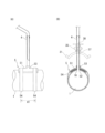
まずは、図1を参照しながら、既設流体機器について説明する。図1では、既設の水道管1が土中に埋設されている。水道管1は、ダクタイル鋳鉄管であるが、これに限られない。水道管1には、分割構造を有する既設流体機器2(以下、単に「流体機器2」と呼ぶ場合がある)が装着されており、その周辺の地面を掘削して施工ピットPが形成されている。通常、施工ピットPは、コストの削減や掘削時間の短縮のために、作業性や安全性を確保できる限りにおいて、必要最小限の比較的狭い空間とされる。
[First embodiment]
First, the existing fluid equipment will be explained with reference to FIG. In FIG. 1, an existing water pipe 1 is buried in the ground. The water pipe 1 is a ductile cast iron pipe, but is not limited thereto. An existing fluid equipment 2 (hereinafter sometimes simply referred to as "fluid equipment 2") having a split structure is attached to the water pipe 1, and the ground around it is excavated to form a construction pit P. There is. Usually, in order to reduce costs and shorten excavation time, the construction pit P is a relatively narrow space with the minimum necessary size as long as workability and safety can be ensured.

流体機器2は、水道管1の管壁に形成された分岐口10(図2など参照)を密封状態で囲繞している。第1実施形態では採用されていないが、分岐口10には円筒状の防錆コアが装着されている場合もある(図8など参照)。図1において、流体機器2は、分岐口10を密封囲繞可能な設置領域A1に配置されている。仮設領域A2は、管軸方向において設置領域A1と隣接する領域であり、図1では設置領域A1の左側に位置するが、反対側でも構わない。 The fluid device 2 hermetically surrounds a branch port 10 (see FIG. 2, etc.) formed in the wall of the water pipe 1. Although not adopted in the first embodiment, a cylindrical anticorrosive core may be attached to the branch port 10 (see FIG. 8, etc.). In FIG. 1, the fluidic device 2 is arranged in an installation area A1 that can tightly surround the branch port 10. The temporary area A2 is an area adjacent to the installation area A1 in the tube axis direction, and is located on the left side of the installation area A1 in FIG. 1, but may be on the opposite side.

流体機器2は、管周方向に沿って連接される複数(図1の例では二つ)の円弧状のサドル部21,22と、それらの管周方向の端部に装着された締結具23と、分岐口10に対面する上側のサドル部21に設けられた開閉弁24とを備える。締結具23は、ボルト23a及びナット23bを含み、これらを締め付けることによりサドル部21,22が水道管1を挟持し、流体機器2が水道管1に締結固定される。上側のサドル部21には、分岐口10の周囲を密封するリング状のパッキン(図示せず)が装着されている。 The fluid device 2 includes a plurality of (two in the example of FIG. 1) arc-shaped saddle parts 21 and 22 connected along the circumferential direction of the pipe, and fasteners 23 attached to the ends of the saddle parts in the circumferential direction of the saddle parts 21 and 22. and an on-off valve 24 provided on the upper saddle portion 21 facing the branch port 10. The fastener 23 includes a bolt 23a and a nut 23b, and by tightening these, the saddle parts 21 and 22 sandwich the water pipe 1, and the fluid equipment 2 is fastened and fixed to the water pipe 1. A ring-shaped packing (not shown) that seals around the branch port 10 is attached to the upper saddle portion 21 .

開閉弁24は、その内部に形成された流路を開閉可能な弁体(図示せず)と、その弁体を操作するための操作部24aとを有する。本実施形態では、開閉弁24が仕切弁(ゲート弁)により形成されている例を示すが、これに限られず、例えばボール弁やバタフライ弁でもよい。開閉弁24の内部の流路は、丁字状や十字状でもよい。開閉弁24は、サドル部21と一体的に設けられていてもよいし、ねじ構造などを利用してサドル部21に着脱自在に接続されていてもよい。尚、流体機器2の構成は特に限られず、従来公知のサドル付き開閉弁などを特に制約なく利用可能である。 The on-off valve 24 includes a valve body (not shown) that can open and close a flow path formed therein, and an operating section 24a for operating the valve body. In this embodiment, an example is shown in which the on-off valve 24 is formed by a gate valve, but the present invention is not limited to this, and may be, for example, a ball valve or a butterfly valve. The flow path inside the on-off valve 24 may be T-shaped or cross-shaped. The on-off valve 24 may be provided integrally with the saddle portion 21, or may be detachably connected to the saddle portion 21 using a screw structure or the like. Note that the configuration of the fluid device 2 is not particularly limited, and a conventionally known on-off valve with a saddle or the like can be used without particular restrictions.

流体機器2の老朽化に伴い、分岐口10の周囲を密封するパッキンが劣化したり、流体機器2を締結固定しているボルト23aが破断したりすると、密封状態が維持されずに漏水が発生することがある。その場合、漏水が発生し続ける状況において、不断水状態で流体機器2の取替作業を行うことが求められる。但し、施工ピットPに水が溜まって浸水する恐れがあるため、作業者の安全性を確保する必要がある。 As the fluid equipment 2 ages, if the packing that seals around the branch port 10 deteriorates or the bolts 23a that fasten and fix the fluid equipment 2 break, the sealed state is not maintained and water leaks. There are things to do. In that case, in a situation where water leakage continues to occur, it is required to replace the fluid device 2 without water interruption. However, since water may accumulate in the construction pit P and cause flooding, it is necessary to ensure the safety of the workers.

次に、図2~5を参照しながら、流体機器を取り替える方法について説明する。流体機器の取替方法の第1実施形態は、分岐口10を密封囲繞可能な設置領域A1から流体機器2を撤去する工程(撤去工程)と、分割構造を有する新規流体機器3(以下、単に「流体機器3」と呼ぶ場合がある)を設置領域A1に配置するとともに、その分岐口10と連通して流体機器3の外部で延在する排出管路4を設ける工程(排出管路設定工程)と、分岐口10から漏出する水を排出管路4へ流しながら、流体機器3を設置領域A1に締結固定する工程(締結固定工程)とを備える。 Next, a method for replacing fluid equipment will be described with reference to FIGS. 2 to 5. The first embodiment of the fluid device replacement method includes a step of removing the fluid device 2 from the installation area A1 that can seal the branch port 10 (removal step), and a new fluid device 3 having a split structure (hereinafter simply referred to as (sometimes referred to as "fluid equipment 3") in the installation area A1, and a step of providing a discharge pipe 4 that communicates with the branch port 10 and extends outside the fluid equipment 3 (discharge pipe setting step) ) and a step of fastening and fixing the fluid device 3 to the installation area A1 while flowing water leaking from the branch port 10 to the discharge pipe 4 (fastening and fixing step).

第1実施形態で用いられる新規流体機器3は、図3~5に示すように、管周方向に沿って連接される複数(この例では三つ)の円弧状のサドル部31~33と、それらの管周方向の端部に装着された締結具34と、分岐口10に対面する上側のサドル部31に設けられた開閉部としての開閉弁35とを備える。締結具34は、ボルト34a及びナット34bを含み、これらを締め付けることによりサドル部31~33が水道管1を挟持し、流体機器3が水道管1に締結固定される。サドル部31~33の内面には、それぞれ水道管1の外面と流体機器3の内面との隙間を密封するパッキン36が装着されている。 As shown in FIGS. 3 to 5, the new fluid device 3 used in the first embodiment includes a plurality of (three in this example) arc-shaped saddle portions 31 to 33 connected along the tube circumferential direction, It includes a fastener 34 attached to the ends in the circumferential direction of the tubes, and an on-off valve 35 as an on-off part provided on the upper saddle part 31 facing the branch port 10. The fastener 34 includes a bolt 34a and a nut 34b, and by tightening these, the saddle parts 31 to 33 sandwich the water pipe 1, and the fluid equipment 3 is fastened and fixed to the water pipe 1. A packing 36 for sealing the gap between the outer surface of the water pipe 1 and the inner surface of the fluid device 3 is attached to the inner surface of each of the saddle parts 31 to 33.

開閉弁35は、その内部に形成された流路を開閉可能な弁体(図示せず)と、その弁体を操作するための操作部35aとを有する。本実施形態では、開閉弁35が仕切弁(ゲート弁)により形成されている例を示すが、これに限られず、例えばボール弁やバタフライ弁でもよい。開閉弁35の内部の流路は、丁字状や十字状でもよい。開閉弁35は、サドル部31と一体的に設けられていてもよいし、ねじ構造などを利用してサドル部31に着脱自在に接続されていてもよい。開閉弁35の代わりに、開閉式のプラグ機器などを使用することも可能である。 The on-off valve 35 includes a valve body (not shown) that can open and close a flow path formed therein, and an operating section 35a for operating the valve body. In this embodiment, an example is shown in which the on-off valve 35 is formed by a gate valve, but the present invention is not limited to this, and may be a ball valve or a butterfly valve, for example. The flow path inside the on-off valve 35 may be T-shaped or cross-shaped. The on-off valve 35 may be provided integrally with the saddle portion 31, or may be detachably connected to the saddle portion 31 using a screw structure or the like. Instead of the on-off valve 35, it is also possible to use an on-off type plug device or the like.

撤去工程では、設置領域A1から流体機器2を撤去する。例えば、開閉弁24を開いたうえで、開閉弁24の流路に上方から棒材(図示せず)を突っ込んで分岐口10を閉塞し、締結具23を解体して棒材と一緒に流体機器2を水道管1から取り外す。設置領域A1から流体機器2を撤去した後、図2のように排出管路4を保持する保持部材5を水道管1に装着して、分岐口10から漏出する水が排出管路4へ流れる状態とする。排出管路4の末端部(図示せず)は施工ピットPの外部に配置されており、そこから排水溝などへ排水することができる。 In the removal process, the fluid device 2 is removed from the installation area A1. For example, after opening the on-off valve 24, a bar (not shown) is inserted from above into the flow path of the on-off valve 24 to close the branch port 10, and the fastener 23 is dismantled and the fluid is removed together with the bar. Remove equipment 2 from water pipe 1. After removing the fluid equipment 2 from the installation area A1, the holding member 5 that holds the discharge pipe line 4 is attached to the water pipe 1 as shown in FIG. 2, and water leaking from the branch port 10 flows to the discharge pipe line 4. state. The end portion (not shown) of the discharge pipe 4 is disposed outside the construction pit P, and water can be drained from there to a drainage ditch or the like.

保持部材5は、分岐口10と対面するように配置される本体51と、その分岐口10の周囲を密封するシート状のパッキン52とを備える。本体51は、管周方向に沿った円弧状に形成され、その内部にパッキン52が装着されている。分岐口10に防錆コアが装着されている場合は、防錆コアを収容可能な内部空間が形成されるよう、比較的内径の大きい保持部材が用いられる。本体51には、筒状の接続口53が形成されており、その接続口53に排出管路4が着脱自在に接続されている。これらはバヨネット構造によって接続されているが、ねじ構造など他の接続形式を適用してもよい。 The holding member 5 includes a main body 51 arranged to face the branch port 10 and a sheet-like packing 52 that seals the periphery of the branch port 10 . The main body 51 is formed in an arc shape along the tube circumferential direction, and a packing 52 is mounted inside the main body 51. When a rust preventive core is attached to the branch port 10, a holding member having a relatively large inner diameter is used so that an internal space capable of accommodating the rust preventive core is formed. A cylindrical connection port 53 is formed in the main body 51, and the discharge pipe line 4 is detachably connected to the connection port 53. Although these are connected by a bayonet structure, other types of connections may be applied, such as a threaded structure.

図2の例では、ラッシングベルトやバンドなどの固定部材54によって保持部材5を水道管1に固定しているが、これに限られない。分岐口10から漏出する水を排出管路4へ流しているので、水圧に抗して作業者が人手で押さえることも可能である。保持部材5は、固定部材54を緩めた状態で、予め仮設領域A2に仮装着しておいてもよい。その場合、設置領域A1から流体機器2を撤去した直後に、保持部材5を管軸方向にスライドさせて設置領域A1に配置することができる。排出管路4は、設置領域A1に配置する前の保持部材5の接続口53に予め接続しておくことが好ましい。 In the example of FIG. 2, the holding member 5 is fixed to the water pipe 1 by a fixing member 54 such as a lashing belt or a band, but the present invention is not limited to this. Since the water leaking from the branch port 10 is allowed to flow into the discharge pipe 4, it is possible for an operator to manually hold it down against the water pressure. The holding member 5 may be temporarily attached to the temporary area A2 in advance with the fixing member 54 loosened. In that case, immediately after removing the fluidic device 2 from the installation area A1, the holding member 5 can be slid in the tube axis direction and placed in the installation area A1. It is preferable that the discharge pipe line 4 is connected in advance to the connection port 53 of the holding member 5 before it is placed in the installation area A1.

排出管路設定工程では、図3のように、流体機器3を設置領域A1に配置するとともに、分岐口10と連通して流体機器3の外部で延在する排出管路4を設ける。排出管路4は、流体機器3の流入口37から流出口38に至る流路に挿通された状態になっている。本実施形態では、排出管路4を挿通させた流体機器3を保持部材5に被せることで、その流体機器3を設置領域A1に配置する。より具体的には、図2(B)に破線で示すように、排出管路4をサドル部31及び開閉弁35に挿通させ、それらをサドル部32,33と組み合わせて水道管1の設置領域A1に装着する。 In the discharge pipe setting step, as shown in FIG. 3, the fluid device 3 is placed in the installation area A1, and a discharge pipe 4 is provided that communicates with the branch port 10 and extends outside the fluid device 3. The discharge pipe line 4 is inserted into a flow path from an inlet 37 to an outlet 38 of the fluid device 3. In this embodiment, the fluid device 3 through which the discharge pipe line 4 is inserted is placed on the holding member 5, so that the fluid device 3 is placed in the installation area A1. More specifically, as shown by the broken line in FIG. 2(B), the discharge pipe line 4 is inserted through the saddle part 31 and the on-off valve 35, and these are combined with the saddle parts 32 and 33 to separate the installation area of the water pipe 1. Attach it to A1.

締結固定工程では、分岐口10から漏出する水を排出管路4へ流しながら、流体機器3を設置領域A1に締結固定する。その際、締結具34を締め付け操作し、流体機器3によって分岐口10を密封状態で囲繞する。流体機器3を設置領域A1に締結固定した後は、図4に示すように、保持部材5と排出管路4との接続を解除し、流体機器3の内部に保持部材5を残置させて排出管路4を撤去する。本実施形態では、排出管路4を軸線周りに回すことにより接続口53との接続が解除される。 In the fastening and fixing process, the fluid device 3 is fastened and fixed to the installation area A1 while flowing water leaking from the branch port 10 to the discharge pipe 4. At this time, the fastener 34 is tightened and the fluid device 3 surrounds the branch port 10 in a sealed state. After the fluid device 3 is fastened and fixed to the installation area A1, as shown in FIG. Remove conduit 4. In this embodiment, the connection with the connection port 53 is released by rotating the discharge pipe 4 around the axis.

本実施形態では、接続口53から排出管路4を取り外したときの漏水を抑えるために、流体機器3の流出口38に漏水防止用のカップ41を取り付けている。但し、カップ41の使用は任意であり、省略しても構わない。図4のように流体機器3の流路から排出管路4を引き抜いた後、すぐさま開閉弁35を閉じて止水することで、カップ41を使わなくても漏水を最小限に抑えられる。開閉弁35を閉じたら、カップ41を流出口38から取り外し、排出管路4とともに撤去する。そして、図5のように流体機器3の流出口38に分岐管路39を接続し、流体機器3を介して給水可能な状態にする。 In this embodiment, in order to suppress water leakage when the discharge pipe line 4 is removed from the connection port 53, a water leakage prevention cup 41 is attached to the outflow port 38 of the fluid device 3. However, the use of the cup 41 is optional and may be omitted. As shown in FIG. 4, after the discharge pipe line 4 is pulled out from the flow path of the fluid device 3, the on-off valve 35 is immediately closed to shut off the water, thereby minimizing water leakage without using the cup 41. After closing the on-off valve 35, the cup 41 is removed from the outlet 38 and removed together with the discharge pipe 4. Then, as shown in FIG. 5, a branch pipe line 39 is connected to the outlet 38 of the fluid device 3, so that water can be supplied via the fluid device 3.

[第2実施形態]
次に、図6~8を参照しながら、流体機器の取替方法の第2実施形態について説明する。第2実施形態は、以下に説明する構成を除いて第1実施形態と同様に構成できるため、共通点の説明を省略し、主に相違点について説明する。第1実施形態において既に説明した構成には、同一の符号を付し、重複した説明を省略する。
[Second embodiment]
Next, a second embodiment of a fluid device replacement method will be described with reference to FIGS. 6 to 8. Since the second embodiment can be configured in the same manner as the first embodiment except for the configuration described below, the explanation of the common features will be omitted and the differences will be mainly explained. The same reference numerals are given to the configurations already described in the first embodiment, and redundant explanations will be omitted.

流体機器の取替方法の第2実施形態は、分岐口10を密封囲繞可能な設置領域A1から既設流体機器2(図1参照)を撤去する工程(撤去工程)と、分割構造を有する新規流体機器6(以下、単に「流体機器6」と呼ぶ場合がある)を設置領域A1に配置するとともに、分岐口10と連通して流体機器6の外部で延在する排出管路4を設ける工程(排出管路設定工程)と、分岐口10から漏出する水を排出管路4へ流しながら、流体機器6を設置領域A1に締結固定する工程(締結固定工程)とを備える。 The second embodiment of the fluid equipment replacement method includes a step (removal step) of removing the existing fluid equipment 2 (see FIG. 1) from an installation area A1 that can seal the branch port 10, and a new fluid equipment replacement method having a split structure. A step of arranging the device 6 (hereinafter sometimes simply referred to as "fluid device 6") in the installation area A1 and providing a discharge pipe 4 that communicates with the branch port 10 and extends outside the fluid device 6 ( (discharge pipe setting step) and a step of fastening and fixing the fluid device 6 to the installation area A1 while flowing water leaking from the branch port 10 to the discharge pipe 4 (fastening and fixing step).

第2実施形態で用いられる新規流体機器6は、図6に示すように、管周方向に沿って連接される複数(この例では二つ)の円弧状のサドル部61,62と、それらの管周方向の端部に装着された締結具63と、上側のサドル部61に設けられた開閉部としての開閉プラグ64とを備える。締結具63は、ボルト63a及びナット63bを含み、これらを締め付けることによりサドル部61,62が水道管1を挟持し、流体機器6が水道管1に締結固定される。サドル部61,62の内面には、それぞれ水道管1の外面と流体機器6の内面との隙間を密封するパッキン65が装着されている。 As shown in FIG. 6, the new fluid device 6 used in the second embodiment includes a plurality of (two in this example) arc-shaped saddle portions 61 and 62 connected along the tube circumferential direction, and their It includes a fastener 63 attached to the end in the circumferential direction of the pipe, and an opening/closing plug 64 as an opening/closing part provided on the upper saddle part 61. The fastener 63 includes a bolt 63a and a nut 63b, and by tightening these, the saddle parts 61 and 62 sandwich the water pipe 1, and the fluid equipment 6 is fastened and fixed to the water pipe 1. Packings 65 are attached to the inner surfaces of the saddle parts 61 and 62, respectively, to seal the gap between the outer surface of the water pipe 1 and the inner surface of the fluid device 6.

開閉プラグ64は、分岐口10と対面することになるサドル部61に形成された貫通孔61aに装着されている。開閉プラグ64は、その貫通孔61aの開口を開閉操作可能に構成されている。流体機器6の流入口66は、貫通孔61aないし開閉プラグ64の底部によって形成される。排出管路4は、開閉プラグ64に対して着脱自在に接続される。開閉プラグ64としては、従来公知の開閉式のプラグ機器を特に制約なく使用できる。開閉プラグ64の代わりに、前述の第1実施形態で使用したような開閉弁を取り付けることも可能である。 The opening/closing plug 64 is attached to a through hole 61a formed in the saddle portion 61 facing the branch port 10. The opening/closing plug 64 is configured to be able to open/close the opening of the through hole 61a. The inlet 66 of the fluid device 6 is formed by the through hole 61a or the bottom of the opening/closing plug 64. The discharge pipe line 4 is detachably connected to the open/close plug 64. As the opening/closing plug 64, any conventionally known opening/closing type plug device can be used without any particular restrictions. Instead of the on-off plug 64, it is also possible to install an on-off valve like the one used in the first embodiment described above.

流体機器6は、管周方向で部分的に内径を拡大させ且つ管軸方向に向けて開口した通過孔部61bと、その通過孔部61bを閉鎖可能な閉鎖機構60とを有する。通過孔部61bは、サドル部61の管軸方向の一端部(図6の右端部)に設けられている。通過孔部61bの設定箇所では、パッキン65も部分的に内径を拡大させている。通過孔部61bは、水道管1の外面を基準とした拡径高さHを有し、流体機器6の内部空間と外部空間とを連通するようにして管軸方向に延びている。拡径高さHは、締結具63を緩めて管軸方向にスライド可能な状態の流体機器6において、後述する防錆コア11の突出高さと同じか、それよりも大きく設定される。 The fluid device 6 includes a passage hole 61b whose inner diameter is partially enlarged in the tube circumferential direction and opened in the tube axis direction, and a closing mechanism 60 capable of closing the passage hole 61b. The passage hole portion 61b is provided at one end of the saddle portion 61 in the tube axis direction (the right end in FIG. 6). The inner diameter of the packing 65 is also partially enlarged at the location where the passage hole portion 61b is set. The passage hole portion 61b has an enlarged diameter height H based on the outer surface of the water pipe 1, and extends in the pipe axis direction so as to communicate the internal space and external space of the fluid device 6. The diameter expansion height H is set to be the same as or larger than the protrusion height of the anticorrosive core 11, which will be described later, in the fluid device 6 in a state where the fastener 63 is loosened and the fluid device 6 is slidable in the tube axis direction.

閉鎖機構60は、水道管1の外面に向けて開口した収容凹部67に配置された閉鎖部材68と、その閉鎖部材68を移動操作するための操作具としての押ボルト69とを含む。収容凹部67は、パッキン65の外側に隣接して且つ通過孔部61bの管径方向外側に形成されている。図6(及び図8)では簡略的に描かれているが、図7に示すように、閉鎖部材68は、金属などの堅牢な材料で形成された本体部68aと、その本体部68aにライニングされた弾性体としてのゴム部68bとを有する。閉鎖部材68の底部は、管周方向に沿って湾曲している。押ボルト69は、管径方向に沿って閉鎖部材68を移動可能に構成されている。 The closing mechanism 60 includes a closing member 68 disposed in a housing recess 67 that opens toward the outer surface of the water pipe 1, and a push bolt 69 as an operating tool for moving and operating the closing member 68. The accommodation recess 67 is formed adjacent to the outside of the packing 65 and outside the passage hole 61b in the radial direction. Although shown in a simplified manner in FIG. 6 (and FIG. 8), as shown in FIG. It has a rubber part 68b as an elastic body. The bottom of the closure member 68 is curved along the tube circumferential direction. The push bolt 69 is configured to be able to move the closing member 68 along the tube diameter direction.

流体機器6は、締結具63を緩めた状態で、予め仮設領域A2に仮装着しておくことができる。そして、設置領域A1から流体機器2を撤去した後、設置領域A1に隣接する仮設領域A2に仮装着した流体機器6を管軸方向にスライドさせて設置領域A1に配置し、分岐口10から漏出する水を流体機器6に接続された排出管路4へ流す。排出管路4は、流体機器6を設置領域A1に配置する前に予め接続しておくことが好ましい。図8は、このような撤去工程の直後から排出管路設定工程までの過程を示している。 The fluid device 6 can be temporarily attached in advance to the temporary area A2 with the fastener 63 loosened. After removing the fluid equipment 2 from the installation area A1, the fluid equipment 6 temporarily installed in the temporary area A2 adjacent to the installation area A1 is slid in the pipe axis direction and placed in the installation area A1, and the leakage from the branch port 10 is The water that flows into the discharge pipe 4 connected to the fluid equipment 6 is passed. It is preferable to connect the discharge pipe line 4 in advance before placing the fluid device 6 in the installation area A1. FIG. 8 shows the process from immediately after such a removal process to the discharge pipe setting process.

図8(A)は、設置領域A1から流体機器2を撤去した直後の状態を示す。流体機器2の撤去によって露出した分岐口10から水が漏出している。防錆コア11は、分岐口10に装着され水道管1の外面から突出している。防錆コア11は、ステンレスなどの耐蝕性に優れた材料で形成されており、分岐口10の内周面の腐蝕や錆びの発生を抑制する。仮設領域A2には流体機器6が仮装着されている。設置領域A1から流体機器2を撤去したら、すぐさま流体機器6を管軸方向にスライドさせ、図8(B)のように分岐口10を囲繞する。 FIG. 8(A) shows the state immediately after the fluid device 2 is removed from the installation area A1. Water is leaking from the branch port 10 exposed by the removal of the fluid device 2. The antirust core 11 is attached to the branch port 10 and protrudes from the outer surface of the water pipe 1. The antirust core 11 is made of a material with excellent corrosion resistance, such as stainless steel, and suppresses corrosion and rust on the inner circumferential surface of the branch port 10. The fluid equipment 6 is temporarily installed in the temporary area A2. Immediately after removing the fluid device 2 from the installation area A1, the fluid device 6 is slid in the tube axis direction to surround the branch port 10 as shown in FIG. 8(B).

図8(A)から図8(B)に至る過程では、防錆コア11が通過孔部61bを通って流体機器6の内部に配置されるように、流体機器6を管軸方向にスライドさせて設置領域A1に配置する。このため、締結具63を軽く緩めておくだけで、水道管1の外面から突出する防錆コア11を容易に躱すことができる。流体機器6に作用する水圧を低減できるよう、開閉プラグ64は開いておく。図8(B)の状態では、分岐口10から漏出した水が、流入口66と通過孔部61bから流出する。排出管路4を接続していることにより、流入口66からの流出は、施工ピットP内での漏水の問題を引き起こす原因にならない。 In the process from FIG. 8(A) to FIG. 8(B), the fluid device 6 is slid in the tube axis direction so that the anticorrosion core 11 is disposed inside the fluid device 6 through the passage hole 61b. and place it in the installation area A1. Therefore, by simply loosening the fastener 63 slightly, the anticorrosion core 11 protruding from the outer surface of the water pipe 1 can be easily avoided. The open/close plug 64 is kept open so that the water pressure acting on the fluid device 6 can be reduced. In the state shown in FIG. 8(B), water leaking from the branch port 10 flows out from the inlet 66 and the passage hole portion 61b. By connecting the discharge pipe 4, the outflow from the inlet 66 does not cause a problem of water leakage in the construction pit P.

流体機器6を管軸方向にスライドさせて設置領域A1に配置した後、図8(C)のように、流体機器6に取り付けられた押ボルト69を介して、流体機器6が備える閉鎖部材68を移動操作し、それによって通過孔部61bの隙間を密封する。閉鎖部材68を管径方向内側に移動させると、水道管1の外面にゴム部68bが密着するとともに、本体部68aに形成された傾斜面68c(図7参照)の作用によりゴム部68bが止水側(図8の左側)に誘導されてパッキン65に密着する。これにより、水道管1の外面と流体機器6の内面との隙間が密封され、通過孔部61bからの水の流出を止めることができる。 After sliding the fluid device 6 in the tube axis direction and placing it in the installation area A1, as shown in FIG. is moved, thereby sealing the gap in the passage hole 61b. When the closing member 68 is moved inward in the pipe radial direction, the rubber portion 68b comes into close contact with the outer surface of the water pipe 1, and the rubber portion 68b is stopped by the action of the inclined surface 68c (see FIG. 7) formed on the main body portion 68a. It is guided to the water side (left side in FIG. 8) and comes into close contact with the packing 65. Thereby, the gap between the outer surface of the water pipe 1 and the inner surface of the fluid device 6 is sealed, and water can be stopped from flowing out from the passage hole 61b.

締結固定工程では、分岐口10から漏出する水を排出管路4へ流しながら、流体機器6を設置領域A1に締結固定する。上述のように排出管路設定工程では締結具63を軽く緩めるだけでよいため、締結具63を締め付ける作業が簡便になる。閉鎖機構60で通過孔部61bを閉鎖する作業は、流体機器6を設置領域A1に締結固定した後でも構わないが、施工ピットP内での漏水量を減らす観点から、締結固定する前に行うことが好ましい。流体機器6を設置領域A1に締結固定したら、開閉プラグ64を閉めて排出管路4を撤去し、代わりに分岐管路(図示せず)を接続して、流体機器6を介して給水可能な状態にする。 In the fastening and fixing process, the fluid equipment 6 is fastened and fixed to the installation area A1 while flowing water leaking from the branch port 10 to the discharge pipe 4. As described above, in the discharge pipe setting process, it is only necessary to lightly loosen the fastener 63, so the work of tightening the fastener 63 becomes simple. The work of closing the passage hole portion 61b with the closing mechanism 60 may be performed after the fluid equipment 6 is fastened and fixed in the installation area A1, but from the viewpoint of reducing the amount of water leakage in the construction pit P, it is performed before the work is fastened and fixed. It is preferable. After the fluid equipment 6 is fastened and fixed in the installation area A1, the open/close plug 64 is closed, the discharge pipe 4 is removed, and a branch pipe (not shown) is connected instead, so that water can be supplied via the fluid equipment 6. state.

[第3実施形態]
次に、図9~16を参照しながら、流体機器の取替方法の第3実施形態について説明する。第3実施形態は、以下に説明する構成を除いて第2実施形態と同様に構成できるため、共通点の説明を省略し、主に相違点について説明する。第1,2実施形態において既に説明した構成には、同一の符号を付し、重複した説明を省略する。
[Third embodiment]
Next, a third embodiment of a fluid device replacement method will be described with reference to FIGS. 9 to 16. Since the third embodiment can be configured in the same manner as the second embodiment except for the configuration described below, the explanation of the common features will be omitted and the differences will be mainly explained. The same reference numerals are given to the configurations already described in the first and second embodiments, and redundant explanation will be omitted.

流体機器の取替方法の第3実施形態は、分岐口10を密封囲繞可能な設置領域A1から既設流体機器2(図1参照)を撤去する工程(撤去工程)と、分割構造を有する新規流体機器7(以下、単に「流体機器7」と呼ぶ場合がある)を設置領域A1に配置するとともに、分岐口10と連通して流体機器7の外部で延在する排出管路4を設ける工程(排出管路設定工程)と、分岐口10から漏出する水を排出管路4へ流しながら、流体機器7を設置領域A1に締結固定する工程(締結固定工程)とを備える。 The third embodiment of the fluid device replacement method includes a step (removal step) of removing the existing fluid device 2 (see FIG. 1) from the installation area A1 that can seal the branch port 10, and a new fluid device having a split structure. A step of arranging the device 7 (hereinafter sometimes simply referred to as "fluid device 7") in the installation area A1 and providing a discharge pipe 4 that communicates with the branch port 10 and extends outside the fluid device 7 ( (discharge pipe setting step) and a step of fastening and fixing the fluid device 7 to the installation area A1 while flowing water leaking from the branch port 10 to the discharge pipe 4 (fastening and fixing step).

第3実施形態で用いられる新規流体機器7は、図9~12に示すように、管周方向に沿って連接される複数(この例では三つ)の円弧状のサドル部71~73と、それらの管周方向の端部に装着された締結具74と、分岐口10と対面することになる上側のサドル部71に設けられた開閉部としての開閉プラグ75とを備える。締結具74は、ボルト74a及びナット74bを含み、これらを締め付けることによりサドル部71~73が水道管1を挟持し、流体機器7が水道管1に締結固定される。サドル部71~73の内面には、それぞれ水道管1の外面と流体機器7の内面との隙間を密封するパッキン76が装着されている。 As shown in FIGS. 9 to 12, the novel fluid device 7 used in the third embodiment includes a plurality of (three in this example) arc-shaped saddle portions 71 to 73 connected along the pipe circumferential direction, It includes a fastener 74 attached to the ends in the circumferential direction, and an opening/closing plug 75 as an opening/closing part provided on the upper saddle part 71 facing the branch port 10. The fastener 74 includes a bolt 74a and a nut 74b, and by tightening these, the saddle portions 71 to 73 sandwich the water pipe 1, and the fluid device 7 is fastened and fixed to the water pipe 1. Packings 76 for sealing the gaps between the outer surface of the water pipe 1 and the inner surface of the fluid device 7 are attached to the inner surfaces of the saddle portions 71 to 73, respectively.

図11のように、サドル部71の管軸方向の一端部には、切欠部71aが設けられている。切欠部71aは、平面視矩形状をなす空所により形成されている。サドル部71の内面に装着されたパッキン76の管軸方向の一端部には、切欠部76aが設けられている。切欠部76aは、管周方向に沿って延びる円弧状部分の中央を欠落させることにより形成されている。切欠部71a,76aの管周方向における端面は、それぞれ上下方向に沿って形成されているが、これに限られない。他のサドル部72,73には、このような切欠部が設けられていない。サドル部72,73の内面に装着されるパッキン76は、切欠部76aを有さず、環状に形成されている。 As shown in FIG. 11, a notch 71a is provided at one end of the saddle portion 71 in the tube axis direction. The cutout portion 71a is formed by a space having a rectangular shape in plan view. A notch 76a is provided at one end of the packing 76 in the tube axis direction, which is attached to the inner surface of the saddle portion 71. The notch 76a is formed by cutting out the center of an arcuate portion extending along the tube circumferential direction. Although the end faces of the notches 71a and 76a in the circumferential direction are formed along the vertical direction, the present invention is not limited thereto. The other saddle parts 72 and 73 are not provided with such a notch. The packing 76 attached to the inner surfaces of the saddle parts 72 and 73 does not have a notch 76a and is formed in an annular shape.

サドル部71の管軸方向の一端部には、締結具74を介して閉鎖部材8が取り付けられている。閉鎖部材8は、管周方向に沿った円弧状をなし、その両端部にはボルト74aを挿通するためのボルト孔81が形成されている。閉鎖部材8は、管径方向内側に向けて突出した突部82を有する。突部82は、閉鎖部材8の管軸方向の一端部に設けられている。突部82は、サドル部71の切欠部71aに嵌入可能に構成されている。突部82は、管周方向に沿って円弧状に延び、その長さは切欠部71aの長さに比べて僅かに小さい。図9,10,12では、突部82の嵌入によって切欠部71aが埋められた状態になっている。 A closing member 8 is attached to one end of the saddle portion 71 in the tube axis direction via a fastener 74. The closing member 8 has an arcuate shape along the tube circumferential direction, and bolt holes 81 for inserting the bolts 74a are formed at both ends thereof. The closing member 8 has a protrusion 82 that protrudes inward in the radial direction. The protrusion 82 is provided at one end of the closure member 8 in the tube axis direction. The protrusion 82 is configured to be able to fit into the notch 71a of the saddle portion 71. The protrusion 82 extends in an arc shape along the tube circumferential direction, and its length is slightly smaller than the length of the notch 71a. In FIGS. 9, 10, and 12, the notch 71a is in a state where the protrusion 82 is inserted into the notch 71a.

図12,13に示すように、突部82の管周方向における側面82a,82bは、それぞれ上下方向に沿って形成されているが、これに限られない。突部82の管軸方向一方側(図12の右側)の側面82cは、管径方向に沿って平坦に形成されている。側面82cは、閉鎖部材8の端面の一部を形成し、サドル部71の端面と面一に配置されている。また、突部82の管軸方向他方側(図12の左側)の側面82dは、パッキン片9の側面93に対応した階段状に形成されている。尚、図12では、開閉プラグ75の図示を省略している。 As shown in FIGS. 12 and 13, the side surfaces 82a and 82b of the protrusion 82 in the circumferential direction are formed along the vertical direction, but the present invention is not limited thereto. A side surface 82c of the protrusion 82 on one side in the tube axis direction (right side in FIG. 12) is formed flat along the tube diameter direction. The side surface 82c forms a part of the end surface of the closing member 8, and is arranged flush with the end surface of the saddle portion 71. Further, a side surface 82d of the protrusion 82 on the other side in the tube axis direction (left side in FIG. 12) is formed in a stepped shape corresponding to the side surface 93 of the packing piece 9. In addition, in FIG. 12, illustration of the opening/closing plug 75 is omitted.

閉鎖部材8は、サドル部71の外面(具体的には、切欠部71aの縁)に被さるように配置されるガイド部83を有する。ガイド部83は、閉鎖部材8の管軸方向の他端部に設けられている。ガイド部83には、サドル部71に形成されたテーパ面71b(図11参照)と接触可能なテーパ面83aが形成されている。テーパ面71b,83aは、それぞれ管周方向に沿って円弧状に延びている。閉鎖部材8を管径方向内側に移動させると、テーパ面71bに対してテーパ面83aが摺動し、ボルト74aとボルト孔81との遊びの範囲内で、閉鎖部材8が管軸方向他方側(図12の左側)にガイドされる。 The closing member 8 has a guide portion 83 arranged to cover the outer surface of the saddle portion 71 (specifically, the edge of the notch portion 71a). The guide portion 83 is provided at the other end of the closure member 8 in the tube axis direction. The guide portion 83 is formed with a tapered surface 83a that can come into contact with the tapered surface 71b (see FIG. 11) formed on the saddle portion 71. The tapered surfaces 71b and 83a each extend in an arc shape along the tube circumferential direction. When the closing member 8 is moved inward in the tube radial direction, the tapered surface 83a slides against the tapered surface 71b, and within the range of play between the bolt 74a and the bolt hole 81, the closing member 8 is moved to the other side in the tube axial direction. (left side in FIG. 12).

閉鎖部材8の内面に配置されるパッキン片9は、パッキン76の切欠部76aに嵌入可能に構成されている。パッキン片9は、管周方向に沿って円弧状に延び、その長さは切欠部76aの長さに比べて僅かに小さい。図9,10,12では、パッキン片9の嵌入によって切欠部76aが埋められた状態になっている。パッキン片9の管周方向における端面91,92は、それぞれ上下方向に沿って形成されているが、これに限られない。パッキン片9の管軸方向一方側の側面93は階段状に形成されている。パッキン片9の管軸方向他方側の側面には、サドル部71に対する密着性を高めるために突起94が形成されている。この例では、断面半円形状をなす突起94が一対で形成されている。 The packing piece 9 arranged on the inner surface of the closing member 8 is configured to be able to fit into the notch 76a of the packing 76. The packing piece 9 extends in an arc shape along the tube circumferential direction, and its length is slightly smaller than the length of the notch 76a. In FIGS. 9, 10, and 12, the notch 76a is in a state where the packing piece 9 is inserted into the notch 76a. Although the end faces 91 and 92 of the packing piece 9 in the circumferential direction are formed along the vertical direction, the present invention is not limited thereto. A side surface 93 of the packing piece 9 on one side in the tube axis direction is formed in a stepped shape. A protrusion 94 is formed on the other side of the packing piece 9 in the tube axis direction in order to improve the adhesion to the saddle portion 71. In this example, a pair of protrusions 94 each having a semicircular cross section are formed.

図14,15は、ボルト孔81に装着されている締結具74を緩め、サドル部71に対して閉鎖部材8を管径方向外側(図14の上側)へ移動させた状態(以下、「オフセット状態」と呼ぶ)を示す。隠れて見えないが、閉鎖部材8と一緒にパッキン片9も管径方向外側に移動している。パッキン片9は、例えば接着剤などを用いて閉鎖部材8の内面に固着されている。オフセット状態において、流体機器7は、管周方向で部分的に内径を拡大させ且つ管軸方向に向けて開口した通過孔部71cを有する。通過孔部71cは、サドル部71の管軸方向の一端部に設けられている。 14 and 15 show a state (hereinafter referred to as “offset state). Although it is hidden from view, the packing piece 9 is also moving outward in the pipe diameter direction together with the closing member 8. The packing piece 9 is fixed to the inner surface of the closing member 8 using, for example, adhesive. In the offset state, the fluid device 7 has a passage hole 71c whose inner diameter is partially enlarged in the tube circumferential direction and opened in the tube axis direction. The passage hole portion 71c is provided at one end of the saddle portion 71 in the tube axis direction.

流体機器7は、更に、通過孔部71cを閉鎖可能な閉鎖機構70を有する。閉鎖機構70は、閉鎖部材8(及びパッキン片9)と、その閉鎖部材8を移動操作するための操作具としての締結具74とを含む。後述するように、オフセット状態から締結具74を締め付けることにより、閉鎖部材8を管径方向内側(図14の下側)に移動できる。このように、第3実施形態では、閉鎖部材8を操作するための操作具が、流体機器7を締結固定するための締結具74を兼ねている。 The fluid device 7 further includes a closing mechanism 70 that can close the passage hole 71c. The closing mechanism 70 includes a closing member 8 (and a packing piece 9) and a fastener 74 as an operating tool for moving and operating the closing member 8. As will be described later, by tightening the fastener 74 from the offset state, the closing member 8 can be moved radially inward (downward in FIG. 14). Thus, in the third embodiment, the operating tool for operating the closing member 8 also serves as the fastening tool 74 for fastening and fixing the fluid device 7.

本実施形態では、オフセット状態において通過孔部71cが安定して保持されるよう、図16に示す治具84を装着している。治具84は、作業者が挟持するための摘まみ部84aと、サドル部71と閉鎖部材8との間隔を確保するためのスペーサ部84bと、サドル部71とサドル部72またはサドル部73との間隔を確保するためのスペーサ部84cとを有する。スペーサ部84b,84cには、それぞれボルト74aを挿通するための挿通孔85と、その挿通孔85に通じるスリット86とが形成されている。治具84は、例えば樹脂材によって形成される。 In this embodiment, a jig 84 shown in FIG. 16 is installed so that the passage hole portion 71c is stably held in the offset state. The jig 84 includes a knob portion 84a to be held by an operator, a spacer portion 84b to ensure a distance between the saddle portion 71 and the closing member 8, and a saddle portion 71 and the saddle portion 72 or the saddle portion 73. It has a spacer portion 84c for ensuring a distance between the two. An insertion hole 85 through which the bolt 74a is inserted, and a slit 86 communicating with the insertion hole 85 are formed in the spacer portions 84b and 84c, respectively. The jig 84 is made of, for example, a resin material.

流体機器7は、締結具74を緩めたオフセット状態で、予め仮設領域A2に仮装着しておくことができる。図14(A)は、設置領域A1から流体機器2を撤去した直後の状態を示す。設置領域A1から流体機器2を撤去した後、設置領域A1に隣接する仮設領域A2に仮装着した流体機器7を管軸方向にスライドさせて設置領域A1に配置し、分岐口10から漏出する水を流体機器7に接続された排出管路4へ流す。その際、防錆コア11が通過孔部71cを通って流体機器7の内部に配置されるように、流体機器7を管軸方向にスライドさせる。かかる工程は、第2実施形態と同様に実施できるため、詳しい説明を省略する。 The fluid device 7 can be temporarily installed in the temporary area A2 in advance in an offset state with the fastener 74 loosened. FIG. 14(A) shows the state immediately after the fluidic device 2 is removed from the installation area A1. After removing the fluid equipment 2 from the installation area A1, the fluid equipment 7 temporarily installed in the temporary area A2 adjacent to the installation area A1 is slid in the pipe axis direction and placed in the installation area A1, and the water leaking from the branch port 10 is removed. flows into the discharge pipe 4 connected to the fluid equipment 7. At this time, the fluid device 7 is slid in the tube axis direction so that the anticorrosion core 11 is disposed inside the fluid device 7 through the passage hole portion 71c. Since this process can be performed in the same manner as in the second embodiment, detailed explanation will be omitted.

流体機器7を管軸方向にスライドさせて設置領域A1に配置した後、流体機器7に取り付けられた締結具74を介して、流体機器7が備える閉鎖部材8を移動操作し、それによって通過孔部71cの隙間を密封する。これにより、水道管1の外面と流体機器7の内面との隙間が密封され、通過孔部71cからの水の流出を止めることができる。閉鎖部材8は、治具84を取り外して締結具74を締め付けることにより、管径方向内側に移動できる。摘まみ部84aを引っ張ると、スペーサ部84b,84cが変形してスリット86が拡がるので、治具84を簡単に引き抜いて取り外すことができる。 After the fluid device 7 is slid in the tube axis direction and placed in the installation area A1, the closing member 8 of the fluid device 7 is moved via the fastener 74 attached to the fluid device 7, thereby closing the passage hole. The gap between the portions 71c is sealed. Thereby, the gap between the outer surface of the water pipe 1 and the inner surface of the fluid device 7 is sealed, and water can be stopped from flowing out from the passage hole 71c. The closing member 8 can be moved radially inward by removing the jig 84 and tightening the fastener 74. When the knob part 84a is pulled, the spacer parts 84b and 84c are deformed and the slit 86 is widened, so that the jig 84 can be easily pulled out and removed.

閉鎖部材8が管径方向内側に移動すると、閉鎖部材8で押圧されたパッキン片9が切欠部76aに嵌入され、図12のように水道管1の外面に密着する。しかも、ガイド部83の作用によって、閉鎖部材8が管軸方向他方側(図12の左側)にガイドされる。その際、突部82の側面82dがパッキン片9の側面93を管軸方向一方側(図12の右側)から支持しているため、切欠部71aの管軸方向の端面にパッキン片9の突起94が密着する。更に、パッキン片9の端面91,92は、それぞれ切欠部76aの管周方向の端面に密着する。このようにして通過孔部71cの隙間が密封される。 When the closing member 8 moves inward in the radial direction of the pipe, the packing piece 9 pressed by the closing member 8 is fitted into the notch 76a and comes into close contact with the outer surface of the water pipe 1 as shown in FIG. Furthermore, the action of the guide portion 83 guides the closing member 8 to the other side in the tube axis direction (left side in FIG. 12). At this time, since the side surface 82d of the protrusion 82 supports the side surface 93 of the packing piece 9 from one side in the tube axis direction (the right side in FIG. 94 is in close contact. Furthermore, the end surfaces 91 and 92 of the packing piece 9 are in close contact with the end surfaces of the notch portion 76a in the tube circumferential direction, respectively. In this way, the gap between the passage hole portion 71c is sealed.

流体機器7を設置領域A1に配置したら、分岐口10から漏出する水を排出管路4へ流しながら、流体機器7を設置領域A1に締結固定する。第3実施形態では、閉鎖部材8を操作するための操作具が締結具74を兼ねているため、通過孔部71cを閉鎖する作業を行うことにより、流体機器7の締結固定が行われる。流体機器7を設置領域A1に締結固定したら、開閉プラグ75を閉めて排出管路4を撤去し、代わりに分岐管路(図示せず)を接続して、流体機器7を介して給水可能な状態にする。 After the fluid device 7 is placed in the installation area A1, the fluid device 7 is fastened and fixed to the installation area A1 while flowing water leaking from the branch port 10 to the discharge pipe 4. In the third embodiment, since the operating tool for operating the closing member 8 also serves as the fastening tool 74, the fluid device 7 is fastened and fixed by closing the passage hole 71c. After the fluid device 7 is fastened and fixed to the installation area A1, the open/close plug 75 is closed and the discharge pipe 4 is removed, and a branch pipe (not shown) is connected instead, so that water can be supplied via the fluid device 7. state.

上記の通り、第1~第3実施形態の流体機器の取替方法は、水道管1の管壁に形成された分岐口10を密封状態で囲繞する既設流体機器2を、不断水状態で新規流体機器3,6,7に取り替える流体機器の取替方法であって、分岐口10を密封囲繞可能な設置領域A1から既設流体機器2を撤去する工程と、分割構造を有する新規流体機器3,6,7を設置領域A1に配置するとともに、分岐口10と連通して新規流体機器3,6,7の外部で延在する排出管路4を設ける工程と、分岐口10から漏出する水を排出管路4へ流しながら、新規流体機器3,6,7を設置領域A1に締結固定する工程と、を備える。これにより、漏水が発生し続ける状況において、不断水状態で流体機器を安全に取り替えることができる。 As described above, the method for replacing fluid equipment according to the first to third embodiments is to replace the existing fluid equipment 2, which seals the branch port 10 formed in the wall of the water pipe 1, with a new one without water interruption. A method for replacing fluid equipment 3, 6, and 7, which includes a step of removing an existing fluid equipment 2 from an installation area A1 that can seal and surround a branch port 10, and a new fluid equipment 3 having a split structure. 6, 7 in the installation area A1, and a step of providing a discharge pipe 4 that communicates with the branch port 10 and extends outside the new fluid devices 3, 6, 7, and drains water leaking from the branch port 10. The method includes a step of fastening and fixing the new fluid devices 3, 6, and 7 to the installation area A1 while flowing into the discharge pipe 4. As a result, in a situation where water leakage continues to occur, fluid equipment can be safely replaced without water interruption.

第1実施形態の流体機器の取替方法では、既設流体機器2を撤去した後、排出管路4を保持する保持部材5を水道管1に装着して、分岐口10から漏出する水が排出管路4へ流れる状態とし、排出管路4を挿通させた新規流体機器3を保持部材5に被せることで、新規流体機器3を設置領域A1に配置する。これにより、新規流体機器3を設置領域A1に配置する前に、分岐口10から漏出する水が排出管路4へ流れる状態となるため、より安全に施工できる。 In the fluid equipment replacement method of the first embodiment, after removing the existing fluid equipment 2, the holding member 5 that holds the discharge pipe line 4 is attached to the water pipe 1, and water leaking from the branch port 10 is discharged. The new fluid device 3 is placed in the installation area A1 by placing the new fluid device 3 in a state where it flows into the pipe line 4 and inserting the discharge pipe line 4 over the holding member 5. As a result, water leaking from the branch port 10 is allowed to flow into the discharge pipe 4 before the new fluid device 3 is placed in the installation area A1, so construction can be carried out more safely.

第1実施形態の流体機器の取替方法では、新規流体機器3を設置領域A1に締結固定した後、保持部材5と排出管路4との接続を解除し、新規流体機器3の内部に保持部材5を残置させて排出管路4を撤去することが好ましい。これにより、新規流体機器3を設置領域A1に締結固定した後の作業が簡単になる。 In the fluid device replacement method of the first embodiment, after the new fluid device 3 is fastened and fixed in the installation area A1, the connection between the holding member 5 and the discharge pipe line 4 is released, and the fluid device 3 is retained inside the new fluid device 3. It is preferable to remove the discharge pipe 4 while leaving the member 5 in place. This simplifies the work after fastening and fixing the new fluid device 3 to the installation area A1.

第2,第3実施形態の流体機器の取替方法では、設置領域A1から既設流体機器2を撤去した後、設置領域A1に隣接する仮設領域A2に仮装着した新規流体機器6,7を管軸方向にスライドさせて設置領域A1に配置し、分岐口10から漏出する水を新規流体機器6,7に接続された排出管路4へ流す。これにより、新規流体機器6,7を設置領域A1に配置して締結固定する作業が簡単になり、作業時間の短縮によって施工ピットP内での漏水量が抑えられる。 In the fluid device replacement methods of the second and third embodiments, after removing the existing fluid device 2 from the installation area A1, the new fluid devices 6 and 7 temporarily installed in the temporary area A2 adjacent to the installation area A1 are installed. It is slid in the axial direction and placed in the installation area A1, and water leaking from the branch port 10 flows into the discharge pipe 4 connected to the new fluid devices 6 and 7. This simplifies the work of arranging and fastening the new fluid devices 6 and 7 in the installation area A1, and reduces the amount of water leakage in the construction pit P by shortening the work time.

第2,第3実施形態の流体機器の取替方法では、新規流体機器6,7が、管周方向で部分的に内径を拡大させ且つ管軸方向に向けて開口した通過孔部61b,71cを有し、分岐口10に装着され水道管1の外面から突出している防錆コア11が通過孔部61b,71cを通って新規流体機器6,7の内部に配置されるように、新規流体機器6,7を管軸方向にスライドさせて設置領域A1に配置する。これにより、水道管1の外面から突出している防錆コア11を容易に躱して、新規流体機器6,7を設置領域A1に円滑に配置できる。それ故、防錆コア11の有無に影響されることなく、不断水状態で流体機器を取り替えることができる。 In the fluid device replacement methods of the second and third embodiments, the new fluid devices 6 and 7 have passage holes 61b and 71c whose inner diameters are partially enlarged in the tube circumferential direction and which are open in the tube axis direction. The new fluid is installed so that the anticorrosion core 11 attached to the branch port 10 and protruding from the outer surface of the water pipe 1 passes through the passage holes 61b and 71c and is disposed inside the new fluid devices 6 and 7. The devices 6 and 7 are slid in the tube axis direction and placed in the installation area A1. Thereby, the anti-rust core 11 protruding from the outer surface of the water pipe 1 can be easily avoided, and the new fluid devices 6 and 7 can be smoothly placed in the installation area A1. Therefore, the fluid equipment can be replaced without being affected by the presence or absence of the anticorrosive core 11 without water interruption.

第2,第3実施形態の流体機器の取替方法では、新規流体機器6,7を管軸方向にスライドさせて設置領域A1に配置した後、新規流体機器6,7に取り付けられた操作具(押ボルト69、締結具74)を介して、新規流体機器6,7が備える閉鎖部材68,8を移動操作し、それによって通過孔部61b,71cの隙間を密封する。これにより、通過孔部61b,71cからの水の流出を止めることができる。 In the fluid device replacement methods of the second and third embodiments, after the new fluid devices 6 and 7 are slid in the tube axis direction and placed in the installation area A1, the operating tool attached to the new fluid devices 6 and 7 is The closing members 68 and 8 of the new fluid devices 6 and 7 are moved via the push bolts 69 and fasteners 74, thereby sealing the gap between the passage holes 61b and 71c. This makes it possible to stop water from flowing out from the passage holes 61b and 71c.

第3実施形態の流体機器の取替方法では、前記操作具が、新規流体機器7を締結固定するための締結具74を兼ねている。これにより、閉鎖部材8を移動操作しながら、それと同時に新規流体機器7を水道管1に締結固定することができる。 In the fluid device replacement method of the third embodiment, the operating tool also serves as a fastener 74 for fastening and fixing the new fluid device 7. Thereby, the new fluid device 7 can be fastened and fixed to the water pipe 1 at the same time as the closing member 8 is moved.

以上、本開示の実施形態について説明したが、具体的な構成は、これらの実施形態に限定されるものではないと考えられるべきである。本開示の範囲は、上記した実施形態の説明だけではなく、特許請求の範囲によって示され、更には特許請求の範囲と均等の意味及び範囲内での全ての変更が含まれる。 Although the embodiments of the present disclosure have been described above, it should be understood that the specific configuration is not limited to these embodiments. The scope of the present disclosure is indicated not only by the description of the embodiments described above, but also by the claims, and further includes all changes within the meaning and scope equivalent to the claims.

流体機器の分割数は特に限定されない。第1,第3実施形態では、それぞれ流体機器3,7が管周方向に三分割された構造であったが、例えば二分割構造にしてもよい。また、第2実施形態では、流体機器6が管周方向に二分割された構造であったが、例えば三分割構造にしてもよい。 The number of divisions of the fluid device is not particularly limited. In the first and third embodiments, the fluid devices 3 and 7 each have a structure divided into three parts in the tube circumferential direction, but they may have a two-part structure, for example. Further, in the second embodiment, the fluid device 6 has a structure in which it is divided into two in the tube circumferential direction, but it may have a structure in which it is divided into three, for example.

本開示の流体機器の取替方法は、上述した実施形態に何ら限定されるものではなく、その趣旨を逸脱しない範囲内で種々の改良変更が可能である。上述した第1~第3実施形態で採用されている各構成を、任意に組み合わせて採用しても構わない。 The fluid device replacement method of the present disclosure is not limited to the above-described embodiments, and various improvements and changes can be made without departing from the spirit thereof. The configurations employed in the first to third embodiments described above may be employed in any combination.

1 水道管
2 既設流体機器
3 新規流体機器
4 排出管路
5 保持部材
6 新規流体機器
7 新規流体機器
8 閉鎖部材
9 パッキン片
10 分岐口
11 防錆コア
35 開閉弁(開閉部の一例)
37 流入口
61b 通過孔部
64 開閉プラグ(開閉部の一例)
68 閉鎖部材
69 押ボルト(操作具の一例)
71c 通過孔部
74 締結具(操作具の一例)
75 開閉プラグ(開閉部の一例)
A1 設置領域
A2 仮設領域
1 Water pipe 2 Existing fluid equipment 3 New fluid equipment 4 Discharge pipe line 5 Holding member 6 New fluid equipment 7 New fluid equipment 8 Closing member 9 Packing piece 10 Branch port 11 Rust-proof core 35 Opening/closing valve (an example of opening/closing part)
37 Inflow port 61b Passage hole 64 Opening/closing plug (an example of opening/closing part)
68 Closing member 69 Push bolt (an example of an operating tool)
71c Passing hole portion 74 Fastener (an example of an operating tool)
75 Opening/closing plug (example of opening/closing part)
A1 Installation area A2 Temporary area

Claims (7)

水道管の管壁に形成された分岐口を密封状態で囲繞する既設流体機器を、不断水状態で新規流体機器に取り替える流体機器の取替方法であって、
前記分岐口を密封囲繞可能な設置領域から前記既設流体機器を撤去する工程と、
分割構造を有する前記新規流体機器を前記設置領域に配置するとともに、前記分岐口と連通して前記新規流体機器の外部で延在する排出管路を設ける工程と、
前記分岐口から漏出する水を前記新規流体機器に装着された前記排出管路へ流しながら、前記新規流体機器を前記設置領域に締結固定する工程と、を備えることを特徴とする、流体機器の取替方法。
A fluid equipment replacement method for replacing an existing fluid equipment sealingly surrounding a branch port formed in a pipe wall of a water pipe with a new fluid equipment without water interruption, the method comprising:
removing the existing fluid equipment from an installation area that can seal and surround the branch port;
arranging the new fluid device having a split structure in the installation area, and providing a discharge pipe that communicates with the branch port and extends outside the new fluid device;
A step of fastening and fixing the new fluid device to the installation area while flowing water leaking from the branch port to the discharge pipe attached to the new fluid device. Replacement method.
水道管の管壁に形成された分岐口を密封状態で囲繞する既設流体機器を、不断水状態で新規流体機器に取り替える流体機器の取替方法であって、
前記分岐口を密封囲繞可能な設置領域から前記既設流体機器を撤去する工程と、
分割構造を有する前記新規流体機器を前記設置領域に配置するとともに、前記分岐口と連通して前記新規流体機器の外部で延在する排出管路を設ける工程と、
前記分岐口から漏出する水を前記排出管路へ流しながら、前記新規流体機器を前記設置領域に締結固定する工程と、を備え、
前記既設流体機器を撤去した後、前記排出管路を保持する保持部材を前記水道管に装着して、前記分岐口から漏出する水が前記排出管路へ流れる状態とし、
前記排出管路を挿通させた前記新規流体機器を前記保持部材に被せることで、前記新規流体機器を前記設置領域に配置する、流体機器の取替方法。
A fluid equipment replacement method for replacing an existing fluid equipment sealingly surrounding a branch port formed in a pipe wall of a water pipe with a new fluid equipment without water interruption, the method comprising:
removing the existing fluid equipment from an installation area that can seal and surround the branch port;
arranging the new fluid device having a split structure in the installation area, and providing a discharge pipe that communicates with the branch port and extends outside the new fluid device;
fastening and fixing the new fluid device to the installation area while causing water leaking from the branch port to flow into the discharge pipe,
After removing the existing fluid equipment, attaching a holding member that holds the discharge pipe to the water pipe so that water leaking from the branch port flows to the discharge pipe;
A method for replacing a fluid device, comprising placing the new fluid device into the installation area by placing the new fluid device with the discharge pipe inserted therethrough over the holding member.
前記新規流体機器を前記設置領域に締結固定した後、前記保持部材と前記排出管路との接続を解除し、前記新規流体機器の内部に前記保持部材を残置させて前記排出管路を撤去する、請求項2に記載の流体機器の取替方法。 After the new fluid device is fastened and fixed to the installation area, the connection between the holding member and the discharge pipe is released, and the holding member is left inside the new fluid device and the discharge pipe is removed. The method for replacing a fluidic device according to claim 2. 水道管の管壁に形成された分岐口を密封状態で囲繞する既設流体機器を、不断水状態で新規流体機器に取り替える流体機器の取替方法であって、
前記分岐口を密封囲繞可能な設置領域から前記既設流体機器を撤去する工程と、
分割構造を有する前記新規流体機器を前記設置領域に配置するとともに、前記分岐口と連通して前記新規流体機器の外部で延在する排出管路を設ける工程と、
前記分岐口から漏出する水を前記排出管路へ流しながら、前記新規流体機器を前記設置領域に締結固定する工程と、を備え、
前記設置領域から前記既設流体機器を撤去した後、前記設置領域に隣接する仮設領域に仮装着した前記新規流体機器を管軸方向にスライドさせて前記設置領域に配置し、前記分岐口から漏出する水を前記新規流体機器に接続された前記排出管路へ流す、流体機器の取替方法。
A fluid equipment replacement method for replacing an existing fluid equipment sealingly surrounding a branch port formed in a pipe wall of a water pipe with a new fluid equipment without water interruption, the method comprising:
removing the existing fluid equipment from an installation area that can seal and surround the branch port;
arranging the new fluid device having a split structure in the installation area, and providing a discharge pipe that communicates with the branch port and extends outside the new fluid device;
fastening and fixing the new fluid device to the installation area while causing water leaking from the branch port to flow into the discharge pipe,
After removing the existing fluid equipment from the installation area, the new fluid equipment temporarily installed in a temporary area adjacent to the installation area is slid in the pipe axis direction and placed in the installation area, and leaks from the branch port. A method for replacing a fluid device, comprising flowing water into the discharge pipe connected to the new fluid device.
前記新規流体機器が、管周方向で部分的に内径を拡大させ且つ管軸方向に向けて開口した通過孔部を有し、
前記分岐口に装着され前記水道管の外面から突出している防錆コアが前記通過孔部を通って前記新規流体機器の内部に配置されるように、前記新規流体機器を管軸方向にスライドさせて前記設置領域に配置する、請求項4に記載の流体機器の取替方法。
The new fluid device has a passage hole portion whose inner diameter is partially enlarged in the circumferential direction of the tube and opened in the axial direction of the tube,
Slide the new fluid device in the axial direction of the pipe so that the anti-corrosion core attached to the branch port and protruding from the outer surface of the water pipe passes through the passage hole and is disposed inside the new fluid device. 5. The fluid device replacement method according to claim 4, wherein the fluid device is placed in the installation area.
前記新規流体機器を管軸方向にスライドさせて前記設置領域に配置した後、前記新規流体機器に取り付けられた操作具を介して、前記新規流体機器が備える閉鎖部材を移動操作し、それによって前記通過孔部の隙間を密封する、請求項5に記載の流体機器の取替方法。 After sliding the new fluid device in the tube axis direction and placing it in the installation area, the closing member of the new fluid device is operated to move through the operating tool attached to the new fluid device, thereby 6. The fluid device replacement method according to claim 5, wherein the gap in the passage hole is sealed. 前記操作具が、前記新規流体機器を締結固定するための締結具を兼ねている、請求項6に記載の流体機器の取替方法。 7. The fluid device replacement method according to claim 6, wherein the operating tool also serves as a fastener for fastening and fixing the new fluid device.
JP2019236216A 2019-12-26 2019-12-26 How to replace fluid equipment Active JP7371909B2 (en)

Priority Applications (1)

Application Number Priority Date Filing Date Title
JP2019236216A JP7371909B2 (en) 2019-12-26 2019-12-26 How to replace fluid equipment

Applications Claiming Priority (1)

Application Number Priority Date Filing Date Title
JP2019236216A JP7371909B2 (en) 2019-12-26 2019-12-26 How to replace fluid equipment

Publications (2)

Publication Number Publication Date
JP2021105411A JP2021105411A (en) 2021-07-26
JP7371909B2 true JP7371909B2 (en) 2023-10-31

Family

ID=76918789

Family Applications (1)

Application Number Title Priority Date Filing Date
JP2019236216A Active JP7371909B2 (en) 2019-12-26 2019-12-26 How to replace fluid equipment

Country Status (1)

Country Link
JP (1) JP7371909B2 (en)

Citations (8)

* Cited by examiner, † Cited by third party
Publication number Priority date Publication date Assignee Title
JP2000088179A (en) 1998-09-17 2000-03-31 Tokyo Gas Co Ltd Repairing method for resin pipe, closing plug used in the method, and closing tool
JP2002013693A (en) 2000-06-29 2002-01-18 Sekisui Chem Co Ltd Method for repairing synthetic resin line for distributing water
US20090126803A1 (en) 2007-11-20 2009-05-21 Danny Earp Effluent Containment Device
JP2009127731A (en) 2007-11-22 2009-06-11 Maezawa Kyuso Industries Co Ltd Saddle snap tap replacer, its water passage closing mechanism, and replacement method for saddle snap tap
JP2016020729A (en) 2014-07-15 2016-02-04 王子ホールディングス株式会社 Pipeline joint cover, fitting method of pipeline joint cover and fluid scattering prevention device of pipeline joint part
KR101748380B1 (en) 2016-08-18 2017-06-16 주식회사 이준엔지니어링 Water Pipe Renovation Device for work under water supply
JP2018128036A (en) 2017-02-06 2018-08-16 コスモ工機株式会社 Leakage prevention tool
JP2019183950A (en) 2018-04-09 2019-10-24 三菱電機株式会社 Pipeline repair method

Patent Citations (8)

* Cited by examiner, † Cited by third party
Publication number Priority date Publication date Assignee Title
JP2000088179A (en) 1998-09-17 2000-03-31 Tokyo Gas Co Ltd Repairing method for resin pipe, closing plug used in the method, and closing tool
JP2002013693A (en) 2000-06-29 2002-01-18 Sekisui Chem Co Ltd Method for repairing synthetic resin line for distributing water
US20090126803A1 (en) 2007-11-20 2009-05-21 Danny Earp Effluent Containment Device
JP2009127731A (en) 2007-11-22 2009-06-11 Maezawa Kyuso Industries Co Ltd Saddle snap tap replacer, its water passage closing mechanism, and replacement method for saddle snap tap
JP2016020729A (en) 2014-07-15 2016-02-04 王子ホールディングス株式会社 Pipeline joint cover, fitting method of pipeline joint cover and fluid scattering prevention device of pipeline joint part
KR101748380B1 (en) 2016-08-18 2017-06-16 주식회사 이준엔지니어링 Water Pipe Renovation Device for work under water supply
JP2018128036A (en) 2017-02-06 2018-08-16 コスモ工機株式会社 Leakage prevention tool
JP2019183950A (en) 2018-04-09 2019-10-24 三菱電機株式会社 Pipeline repair method

Also Published As

Publication number Publication date
JP2021105411A (en) 2021-07-26

Similar Documents

Publication Publication Date Title
AU2013267192B2 (en) Gate valve assembly for installation in pressurized pipes
EP3271628B1 (en) Shut-off device
JP7370629B2 (en) Valve device and fluid pipe structure
US8695626B2 (en) Systems and methods for valve insertion and linestopping
CA2782607C (en) Device for work implementation without stopping flow, and method for work implementation without stopping flow
NO20121284A1 (en) Gasket assembly in ball valve and ball valve comprising the same
JP6608025B2 (en) Valve device mounting method and valve device removal method
JP2024036421A (en) How to remove fluid tubes
JP7371909B2 (en) How to replace fluid equipment
JP7290464B2 (en) Fluidic device replacement method and device replacement jig
JP2016223528A (en) Installation body fitting method
EP3282163B1 (en) Corrosion prevention device and corrosion prevention method for cut surfaces of pipe
JP4660186B2 (en) Joint holding member and instrument comprising joint holding member and joint member
GB2259124A (en) Fitting a flow control valve into a service pipe
JP6562700B2 (en) Flow path forming method
JP6872778B2 (en) Valve body mounting structure and removable sluice valve
JP5823273B2 (en) Fluid control holding method and engagement tool used at that time
JP2019203602A (en) Flow channel forming means
JP6280893B2 (en) Valve body removal device and valve body removal method
JP5882513B2 (en) Work tool installation method
GB2609925A (en) Fluid valve
JP2018066480A (en) Valve body removal device and valve body removal method
JP2018123949A (en) Connection member detachment method and desorption device

Legal Events

Date Code Title Description
A621 Written request for application examination

Free format text: JAPANESE INTERMEDIATE CODE: A621

Effective date: 20220720

A131 Notification of reasons for refusal

Free format text: JAPANESE INTERMEDIATE CODE: A131

Effective date: 20230523

A977 Report on retrieval

Free format text: JAPANESE INTERMEDIATE CODE: A971007

Effective date: 20230524

A521 Request for written amendment filed

Free format text: JAPANESE INTERMEDIATE CODE: A523

Effective date: 20230620

TRDD Decision of grant or rejection written
A01 Written decision to grant a patent or to grant a registration (utility model)

Free format text: JAPANESE INTERMEDIATE CODE: A01

Effective date: 20230929

A61 First payment of annual fees (during grant procedure)

Free format text: JAPANESE INTERMEDIATE CODE: A61

Effective date: 20231012

R150 Certificate of patent or registration of utility model

Ref document number: 7371909

Country of ref document: JP

Free format text: JAPANESE INTERMEDIATE CODE: R150