JP7370994B2 - Overhead electrical cable and method of manufacturing the overhead electrical cable - Google Patents
Overhead electrical cable and method of manufacturing the overhead electrical cable Download PDFInfo
- Publication number
- JP7370994B2 JP7370994B2 JP2020545331A JP2020545331A JP7370994B2 JP 7370994 B2 JP7370994 B2 JP 7370994B2 JP 2020545331 A JP2020545331 A JP 2020545331A JP 2020545331 A JP2020545331 A JP 2020545331A JP 7370994 B2 JP7370994 B2 JP 7370994B2
- Authority
- JP
- Japan
- Prior art keywords
- conductive layer
- aluminum material
- strands
- electrical cable
- aluminum
- Prior art date
- Legal status (The legal status is an assumption and is not a legal conclusion. Google has not performed a legal analysis and makes no representation as to the accuracy of the status listed.)
- Active
Links
Images


Classifications
-
- H—ELECTRICITY
- H01—ELECTRIC ELEMENTS
- H01B—CABLES; CONDUCTORS; INSULATORS; SELECTION OF MATERIALS FOR THEIR CONDUCTIVE, INSULATING OR DIELECTRIC PROPERTIES
- H01B5/00—Non-insulated conductors or conductive bodies characterised by their form
- H01B5/08—Several wires or the like stranded in the form of a rope
- H01B5/10—Several wires or the like stranded in the form of a rope stranded around a space, insulating material, or dissimilar conducting material
- H01B5/102—Several wires or the like stranded in the form of a rope stranded around a space, insulating material, or dissimilar conducting material stranded around a high tensile strength core
- H01B5/104—Several wires or the like stranded in the form of a rope stranded around a space, insulating material, or dissimilar conducting material stranded around a high tensile strength core composed of metallic wires, e.g. steel wires
-
- H—ELECTRICITY
- H01—ELECTRIC ELEMENTS
- H01B—CABLES; CONDUCTORS; INSULATORS; SELECTION OF MATERIALS FOR THEIR CONDUCTIVE, INSULATING OR DIELECTRIC PROPERTIES
- H01B9/00—Power cables
- H01B9/006—Constructional features relating to the conductors
-
- H—ELECTRICITY
- H01—ELECTRIC ELEMENTS
- H01B—CABLES; CONDUCTORS; INSULATORS; SELECTION OF MATERIALS FOR THEIR CONDUCTIVE, INSULATING OR DIELECTRIC PROPERTIES
- H01B5/00—Non-insulated conductors or conductive bodies characterised by their form
- H01B5/08—Several wires or the like stranded in the form of a rope
- H01B5/10—Several wires or the like stranded in the form of a rope stranded around a space, insulating material, or dissimilar conducting material
- H01B5/102—Several wires or the like stranded in the form of a rope stranded around a space, insulating material, or dissimilar conducting material stranded around a high tensile strength core
-
- H—ELECTRICITY
- H01—ELECTRIC ELEMENTS
- H01B—CABLES; CONDUCTORS; INSULATORS; SELECTION OF MATERIALS FOR THEIR CONDUCTIVE, INSULATING OR DIELECTRIC PROPERTIES
- H01B1/00—Conductors or conductive bodies characterised by the conductive materials; Selection of materials as conductors
- H01B1/02—Conductors or conductive bodies characterised by the conductive materials; Selection of materials as conductors mainly consisting of metals or alloys
- H01B1/023—Alloys based on aluminium
-
- H—ELECTRICITY
- H01—ELECTRIC ELEMENTS
- H01B—CABLES; CONDUCTORS; INSULATORS; SELECTION OF MATERIALS FOR THEIR CONDUCTIVE, INSULATING OR DIELECTRIC PROPERTIES
- H01B13/00—Apparatus or processes specially adapted for manufacturing conductors or cables
- H01B13/02—Stranding-up
- H01B13/0207—Details; Auxiliary devices
-
- H—ELECTRICITY
- H01—ELECTRIC ELEMENTS
- H01B—CABLES; CONDUCTORS; INSULATORS; SELECTION OF MATERIALS FOR THEIR CONDUCTIVE, INSULATING OR DIELECTRIC PROPERTIES
- H01B5/00—Non-insulated conductors or conductive bodies characterised by their form
- H01B5/08—Several wires or the like stranded in the form of a rope
- H01B5/10—Several wires or the like stranded in the form of a rope stranded around a space, insulating material, or dissimilar conducting material
- H01B5/102—Several wires or the like stranded in the form of a rope stranded around a space, insulating material, or dissimilar conducting material stranded around a high tensile strength core
- H01B5/105—Several wires or the like stranded in the form of a rope stranded around a space, insulating material, or dissimilar conducting material stranded around a high tensile strength core composed of synthetic filaments, e.g. glass-fibres
-
- H—ELECTRICITY
- H01—ELECTRIC ELEMENTS
- H01B—CABLES; CONDUCTORS; INSULATORS; SELECTION OF MATERIALS FOR THEIR CONDUCTIVE, INSULATING OR DIELECTRIC PROPERTIES
- H01B7/00—Insulated conductors or cables characterised by their form
- H01B7/17—Protection against damage caused by external factors, e.g. sheaths or armouring
- H01B7/18—Protection against damage caused by wear, mechanical force or pressure; Sheaths; Armouring
-
- H—ELECTRICITY
- H01—ELECTRIC ELEMENTS
- H01B—CABLES; CONDUCTORS; INSULATORS; SELECTION OF MATERIALS FOR THEIR CONDUCTIVE, INSULATING OR DIELECTRIC PROPERTIES
- H01B9/00—Power cables
- H01B9/008—Power cables for overhead application
-
- H—ELECTRICITY
- H02—GENERATION; CONVERSION OR DISTRIBUTION OF ELECTRIC POWER
- H02G—INSTALLATION OF ELECTRIC CABLES OR LINES, OR OF COMBINED OPTICAL AND ELECTRIC CABLES OR LINES
- H02G1/00—Methods or apparatus specially adapted for installing, maintaining, repairing or dismantling electric cables or lines
- H02G1/02—Methods or apparatus specially adapted for installing, maintaining, repairing or dismantling electric cables or lines for overhead lines or cables
- H02G1/04—Methods or apparatus specially adapted for installing, maintaining, repairing or dismantling electric cables or lines for overhead lines or cables for mounting or stretching
-
- H—ELECTRICITY
- H02—GENERATION; CONVERSION OR DISTRIBUTION OF ELECTRIC POWER
- H02G—INSTALLATION OF ELECTRIC CABLES OR LINES, OR OF COMBINED OPTICAL AND ELECTRIC CABLES OR LINES
- H02G7/00—Overhead installations of electric lines or cables
-
- H—ELECTRICITY
- H02—GENERATION; CONVERSION OR DISTRIBUTION OF ELECTRIC POWER
- H02G—INSTALLATION OF ELECTRIC CABLES OR LINES, OR OF COMBINED OPTICAL AND ELECTRIC CABLES OR LINES
- H02G1/00—Methods or apparatus specially adapted for installing, maintaining, repairing or dismantling electric cables or lines
- H02G1/02—Methods or apparatus specially adapted for installing, maintaining, repairing or dismantling electric cables or lines for overhead lines or cables
Description
本開示は、電気の伝送および分配用の架空電気ケーブルの分野に関する。 The present disclosure relates to the field of overhead electrical cables for the transmission and distribution of electricity.
電気の伝送および分配用の架空電気ケーブルは、典型的には、高電圧の電気を安全に伝送するのに充分な直径(例えば、断面積)を有する、むき出しの電気伝導体を備える。アルミニウムは、質量に対して高い比率の伝導率を有するが、いくつかのアルミニウム合金は、支持構造間(例えば、タワー間)に張られるときに自己支持するにはあまりに弱く、大きい弛みを生じ、アルミニウム伝導体を支持するように中央強度部材を用いる必要がある。典型的な構成では、別個の金属(例えば、アルミニウム)伝導ストランドは、中央強度部材の周りに螺旋状に巻かれ、中央強度部材により支持される。設置されるとき、強度部材は、機械的(例えば、引張)荷重の大部分を支え、高い引張荷重の下にて設置される。従来は、強度部材は、巻き合わせられた複数の鋼ストランドからなり、ケーブル構成は鋼心補強アルミニウム導体(ACSR)と呼ばれる。最近では、高い引張強度、低い熱膨張係数(CTE)および他の所望の熱特性および機械特性を有する、進歩した繊維補強複合材料などの、他の材料が強度部材に利用されている。 Overhead electrical cables for the transmission and distribution of electricity typically include bare electrical conductors of sufficient diameter (eg, cross-sectional area) to safely transmit high voltage electricity. Aluminum has a high conductivity to mass ratio, but some aluminum alloys are too weak to be self-supporting when stretched between support structures (e.g., between towers), resulting in large sag and A central strength member must be used to support the aluminum conductors. In a typical configuration, separate metal (eg, aluminum) conductive strands are helically wrapped around and supported by a central strength member. When installed, the strength members support the majority of mechanical (eg, tensile) loads and are installed under high tensile loads. Traditionally, strength members consist of multiple steel strands wound together, and the cable construction is referred to as a steel core reinforced aluminum conductor (ACSR). Recently, other materials have been utilized for strength members, such as advanced fiber-reinforced composite materials that have high tensile strength, low coefficients of thermal expansion (CTE), and other desirable thermal and mechanical properties.
そうした複合強度部材を有する架空電気ケーブルの1つの例は、アメリカ合衆国カリフォルニア州アーバインのCTCグローバル社から入手可能であるACCC(登録商標)架空電気ケーブルである。例えば、ヒエル(Hiel)らによる特許文献1を参照されたい。特許文献1は、参照によりその全体が本明細書に組み込まれる。そうした複合強度部材の使用は、有利には、外側導電ストランドについて、高い導電率の、完全アニーリングされたアルミニウムの使用を可能とする。ACCC(登録商標)複合強度部材に用いられるカーボン繊維の弾性率は、鋼の率よりも高い(カーボン繊維について約235GPa対鋼について約200GPa)。しかしながら、ACCC(登録商標)強度部材では、カーボンを包囲するガラス繊維(約45.6GPaの弾性率)の外側層は、鋼よりも低い、約GPaのACCC(登録商標)複合強度部材の組み合わされた率となる。ガラス繊維のこの外側層は、衝撃抵抗を向上させるように、また伝導体のフレキシビリティを増加させるように用いられ、さらに、ガルバニック腐食を防止するべく、カーボン繊維をアルミニウムストランドから絶縁するように機能する。 One example of an overhead electrical cable having such a composite strength member is the ACCC® overhead electrical cable available from CTC Global, Inc., Irvine, Calif., USA. See, for example, US Pat. Patent Document 1 is incorporated herein by reference in its entirety. The use of such composite strength members advantageously allows the use of high conductivity, fully annealed aluminum for the outer conductive strands. The elastic modulus of carbon fiber used in ACCC® composite strength members is higher than that of steel (about 235 GPa for carbon fiber vs. about 200 GPa for steel). However, in ACCC® strength members, the outer layer of glass fibers (modulus of elasticity of about 45.6 GPa) surrounding the carbon is lower than that of steel, which is lower than that of steel in the combination of ACCC® composite strength members. The rate will be This outer layer of glass fiber is used to improve impact resistance and increase the flexibility of the conductor, and also acts to insulate the carbon fiber from the aluminum strands to prevent galvanic corrosion. do.
多数の設計基準によって架空電気ケーブルの構成が検討されており、それらの設計基準は、電気ケーブルがデプロイされる場所における局所気候に依存することが多い。例えば、電気ケーブルが、降雪および氷雪イベントが一般的である寒冷気候エリアに設置されるとき、氷雪は、規則的な動作状態下において通常存在する熱の不足に起因して、むき出しの架空電気ケーブルを通じてわずかな電流しか流れないか電流が流れないとき、低荷重またはラインオフ状態下にて外側伝導体の表面に蓄積し得る。氷雪が非常に重いエリアにおける電気の利用は、氷が付着した伝導体の重さを計算するのに、2インチ(50mm)と同程度の氷雪厚さを使用する。氷雪蓄積の追加された重量は、ケーブル上の張力を増加させ、ケーブルの指示点と最下点との間において、ケーブルの弛みの大幅な増加(すなわち、垂直方向の増加)を生じ得る。高電圧のむき出しの架空電気ケーブルは、道路、木および/または低電圧架空電気分配ケーブルを横切ることが多い。これらの高電圧伝送ケーブルが氷雪による荷重を受け、弛みがこれらの対象物に非常に近接しすぎると、高電圧伝送ケーブルは、非常に危険となり、故障に至り、停電を生じ得る。 A number of design criteria govern the configuration of overhead electrical cables, and those design criteria often depend on the local climate where the electrical cable is deployed. For example, when electrical cables are installed in cold climate areas where snowfall and ice events are common, ice and snow can cause exposed overhead electrical cables to deteriorate due to the lack of heat that normally exists under regular operating conditions. It can accumulate on the surface of the outer conductor under low load or line-off conditions when little or no current flows through it. Electrical applications in areas with very heavy ice and snow use ice and snow thicknesses on the order of 2 inches (50 mm) to calculate the weight of ice-covered conductors. The added weight of ice and snow accumulation increases the tension on the cable and can result in a significant increase in cable sag (i.e., vertical increase) between the pointing point and the lowest point of the cable. High voltage exposed overhead electrical cables often cross roads, trees and/or low voltage overhead electrical distribution cables. When these high voltage transmission cables are subjected to ice and snow loading and the slack is too close to these objects, the high voltage transmission cables become extremely dangerous and can lead to failure and power outages.
同時に、架空電気ケーブルは電気の需要が最高である温暖な夏の数ヵ月中に、増加した電気荷重(例えば、増加した電圧)を安全に伝送できる必要もある。そうした増加した荷重は、ケーブルの温度を上昇させ得(抵抗加熱に起因して)、ケーブルを熱膨張させ(長くし)、弛みが地表に向かい、氷雪荷重に起因して経験され得るのと同一の問題を生じる。 At the same time, overhead electrical cables also need to be able to safely carry increased electrical loads (eg, increased voltage) during the warm summer months when electrical demand is highest. Such increased loads can increase the temperature of the cable (due to resistive heating), cause the cable to thermally expand (lengthen), and slack is directed toward the ground, similar to that which can be experienced due to ice and snow loads. This causes problems.
これらの問題の1つの解決策は、ケーブルを支持するためにより高いタワーを利用することである。しかしながら、この解決策は、コストの増加を伴う。氷雪荷重の問題に対する別の解決策は、繊維補強複合材の強度部材などの非常に高い引張強度を有する強度部材を利用すること、また支持構造間に非常に高い張力にてケーブルを設置することである。 One solution to these problems is to utilize taller towers to support the cables. However, this solution comes with increased costs. Another solution to the problem of ice and snow loading is to utilize strength members with very high tensile strength, such as fiber-reinforced composite strength members, and to install cables at very high tension between supporting structures. It is.
重い氷雪荷重は、架空電気ケーブルの永久的な伸長を生じ得る。氷雪の追加された重さに起因するケーブルの張力の増加の結果として、ケーブルは、その初期の降伏点を超えて延びる場合があり、それによって、氷雪が減少した後に、ケーブルがその初期の弛みまたは張力状態に戻ることを妨げ得る。ACCC(登録商標)強度部材などの繊維補強複合強度部材の向上した弾性は、氷雪荷重が散逸した後に、ケーブルがその初期の弛みおよび張力状態に戻ることを可能とする。 Heavy ice and snow loads can cause permanent stretching of overhead electrical cables. As a result of the increased tension in the cable due to the added weight of ice and snow, the cable may be stretched beyond its initial yield point, thereby causing the cable to recover from its initial slack after the ice and snow have diminished. or may prevent it from returning to tension. The enhanced resiliency of fiber-reinforced composite strength members, such as ACCC® strength members, allows the cable to return to its initial relaxed and tensioned state after the ice and snow loads have dissipated.
重い氷雪荷重状態下と非常に高い電流の状態下との両方において使用できる複合強度部材を有し、一方で複合強度部材の使用に関連する他の利益を提供する、架空電気ケーブルの必要性が存在する。 There is a need for an overhead electrical cable that has composite strength members that can be used both under heavy ice and snow loading conditions and under very high current conditions, while providing other benefits associated with the use of composite strength members. exist.
1つの実施形態では、そうした架空電気ケーブルが開示される。架空電気ケーブルは、強度部材と、前記強度部材を包囲する第1伝導層であって、第1アルミニウム材料のストランドを備える第1伝導層と、を備える。第2伝導層は、前記第1伝導層を包囲し、第2伝導層は、第2アルミニウム材料のストランドを備える。前記第2アルミニウム材料の1つ以上の材料特性は、前記第1アルミニウム材料の該材料特性とは異なる。 In one embodiment, such an overhead electrical cable is disclosed. The overhead electrical cable includes a strength member and a first conductive layer surrounding the strength member, the first conductive layer comprising strands of a first aluminum material. A second conductive layer surrounds the first conductive layer, the second conductive layer comprising a strand of a second aluminum material. One or more material properties of the second aluminum material are different from the material properties of the first aluminum material.
上述の架空電気ケーブルは、単独または任意の組合せにより実装され得る、フィーチャの改良および/または追加のフィーチャを有することを特徴としてよい。1つの特定の特徴では、第1アルミニウム材料と第2アルミニウム材料との間の異なる材料特性は、降伏応力、弾性率、硬度、電気伝導率、および引張強度からなる特性の群から選択される。1つの特定の特徴では、1つの異なる材料特性は、降伏応力である。1つの改良では、前記第2アルミニウム材料の降伏応力は、前記第1アルミニウム材料の前記降伏応力よりも大きい。別の特定の特徴では、前記第1アルミニウム材料と前記第2アルミニウム材料との間の異なる材料特性は、引張強度である。1つの改良では、前記第2アルミニウム材料の引張強度は、前記第1アルミニウム材料の引張強度未満である。さらに別の特徴では、前記第1アルミニウム材料と前記第2アルミニウム材料との間の異なる材料特性は、電気伝導率である。1つの改良では、前記第2アルミニウム材料の電気伝導率は、前記第1アルミニウム材料の前記電気伝導率よりも大きい。 The above-mentioned overhead electrical cables may be characterized by feature modifications and/or additional features, which may be implemented singly or in any combination. In one particular feature, the different material properties between the first aluminum material and the second aluminum material are selected from the group of properties consisting of yield stress, elastic modulus, hardness, electrical conductivity, and tensile strength. In one particular feature, one different material property is yield stress. In one refinement, the yield stress of the second aluminum material is greater than the yield stress of the first aluminum material. In another particular feature, the different material property between the first aluminum material and the second aluminum material is tensile strength. In one refinement, the tensile strength of the second aluminum material is less than the tensile strength of the first aluminum material. In yet another feature, the different material property between the first aluminum material and the second aluminum material is electrical conductivity. In one refinement, the electrical conductivity of the second aluminum material is greater than the electrical conductivity of the first aluminum material.
別の特徴では、前記第1アルミニウム材料と前記第2アルミニウム材料とのうちの少なくとも一方は、約60%IACS(国際軟銅規格)以上の電気伝導率を有する。さらなる改良では、前記第1アルミニウム材料と前記第2アルミニウム材料とのうちの少なくとも一方は、約62%IACS以上の伝導率を有する。またさらなる改良では、前記第2アルミニウム材料は、約62%IACS以上の電気伝導率を有する。別の特徴では、前記第2アルミニウム材料は1350-Oアニーリングアルミニウム合金である。さらに別の特徴では、前記第1アルミニウム材料は、アルミニウム-ジルコニウム(AlZr)アルミニウム合金および1350-H19アルミニウム合金から選択される。 In another feature, at least one of the first aluminum material and the second aluminum material has an electrical conductivity of about 60% IACS (International Annealed Copper Standard) or greater. In a further refinement, at least one of the first aluminum material and the second aluminum material has a conductivity of about 62% IACS or greater. In yet a further refinement, the second aluminum material has an electrical conductivity of about 62% IACS or greater. In another feature, the second aluminum material is a 1350-O annealed aluminum alloy. In yet another feature, the first aluminum material is selected from aluminum-zirconium (AlZr) aluminum alloy and 1350-H19 aluminum alloy.
伝導ストランドは、円形、楕円形、多角形を含む様々な断面を有してよい。1つの特徴では、前記第1アルミニウム材料ストランドと前記第2アルミニウム材料ストランドとのうちの少なくとも一方は、台形ストランドである。さらなる改良では、前記第1アルミニウム材料ストランドと前記第2アルミニウム材料ストランドとの両方が、台形ストランドである。架空電気ケーブルは、伝導ストランドの2つ以上の層を備えてよい。1つの特徴では、架空電気ケーブルは、前記第1伝導層と前記第2伝導層との間に配置された第3伝導層を備える。1つの改良では、前記第3伝導層は、前記第1アルミニウム材料と異なり前記第2アルミニウム材料と異なる、第3アルミニウム材料のストランドを備える。別の改良では、前記第3伝導層は、前記第1アルミニウム材料のストランドを備える。さらに別の改良では、前記第3伝導層は、前記第2アルミニウム材料のストランドを備える。さらに別の特徴では、前記架空電気ケーブルは、前記第3伝導層と前記第2伝導層との間に配置された少なくとも第4伝導層を備える。 Conductive strands may have a variety of cross-sections, including circular, oval, and polygonal. In one feature, at least one of the first strand of aluminum material and the second strand of aluminum material is a trapezoidal strand. In a further refinement, both the first strand of aluminum material and the second strand of aluminum material are trapezoidal strands. Overhead electrical cables may include two or more layers of conductive strands. In one feature, the overhead electrical cable includes a third conductive layer disposed between the first conductive layer and the second conductive layer. In one refinement, the third conductive layer comprises strands of a third aluminum material, which is different from the first aluminum material and different from the second aluminum material. In another refinement, the third conductive layer comprises strands of the first aluminum material. In yet another refinement, said third conductive layer comprises strands of said second aluminum material. In yet another feature, the overhead electrical cable includes at least a fourth conductive layer disposed between the third conductive layer and the second conductive layer.
別の特徴では、前記強度部材は繊維補強複合強度要素を備える。1つの改良では、前記繊維補強複合強度要素は、結合マトリクス中に配置されたほぼ連続した補強カーボン繊維を含む。別の改良では、前記強度部材は、約30mm以下の直径を有する。さらなる改良では、前記強度部材は、約3mm以上の直径を有する。別の特徴では、前記強度部材は、約1700MPa以上の極限引張強度(UTS)を有する。 In another feature, the strength member comprises a fiber reinforced composite strength element. In one refinement, the fiber-reinforced composite strength element comprises substantially continuous reinforcing carbon fibers arranged in a bonding matrix. In another refinement, the strength member has a diameter of about 30 mm or less. In a further refinement, the strength member has a diameter of about 3 mm or more. In another feature, the strength member has an ultimate tensile strength (UTS) of about 1700 MPa or greater.
別の実施形態では、架空電気ケーブルの製造のための方法が開示される。前記方法は、第1伝導層を形成するように、第1アルミニウム材料の複数の第1ストランドを強度部材に対し巻く工程と、第2伝導層を形成するように、第2アルミニウム材料の複数の第2ストランドを前記第1伝導層の周りに巻く工程と、を備える。前記第2アルミニウム材料の1つ以上の材料特性は、前記第1アルミニウム材料の該材料特性の値とは異なる値を有する。 In another embodiment, a method for manufacturing an overhead electrical cable is disclosed. The method includes winding a plurality of first strands of a first aluminum material around a strength member to form a first conductive layer; and winding a plurality of first strands of a second aluminum material to form a second conductive layer. wrapping a second strand around the first conductive layer. The one or more material properties of the second aluminum material have different values than the values of the material properties of the first aluminum material.
上述の方法は、単独または任意の組合せにより実装され得る、改良および/または追加の工程を有することを特徴としてよい。1つの特徴では、前記第1アルミニウム材料の前記複数の第1ストランドは、台形の断面を有する。1つの改良では、前記第2アルミニウム材料の前記複数の第2ストランドは、台形の断面を有する。 The methods described above may be characterized by refinements and/or additional steps, which may be implemented singly or in any combination. In one feature, the plurality of first strands of the first aluminum material have a trapezoidal cross section. In one refinement, the plurality of second strands of the second aluminum material have a trapezoidal cross section.
別の特徴では、前記第2伝導ストランドの前記第1伝導層の周りの巻付けの前に、第3アルミニウム材料の複数の第3ストランドを前記第1伝導層の周りに巻く工程を備える。さらなる改良では、前記方法は、前記第3伝導ストランドの前記第1伝導層の周りの巻付けの前に、第4アルミニウム材料の複数の第4ストランドを前記第1伝導層の周りに巻く工程を備える。 In another feature, the method includes wrapping a plurality of third strands of a third aluminum material around the first conductive layer prior to wrapping the second conductive strands around the first conductive layer. In a further refinement, the method comprises the step of winding a plurality of fourth strands of a fourth aluminum material around the first conductive layer, prior to winding the third conductive strand around the first conductive layer. Be prepared.
別の実施形態では、電気伝送ラインの設置のための方法が開示される。前記方法は、架空電気ケーブルを2つ以上の支持構造間に張る工程と、前記架空電気ケーブルに張力を加える工程と、を備える。前記架空電気ケーブルが加えられた前記張力下にありながら、前記架空電気ケーブルが前記2つの支持構造により少なくとも部分的には支持され、挟み込み張力にて張られるように、前記架空電気ケーブルの第1端および第2端が挟まれる。前記架空電気ケーブルは、強度部材と、前記強度部材を包囲する第1伝導層であって、第1アルミニウム材料のストランドを備える、第1伝導層と、前記第1伝導層を包囲する第2伝導層であって、前記第1アルミニウム材料とは異なる第2アルミニウム材料の伝導ストランドを備える、第2伝導層と、を備え、前記第2アルミニウム材料の1つ以上の材料特性は、前記第1アルミニウム材料の該材料特性とは異なる。 In another embodiment, a method for installation of electrical transmission lines is disclosed. The method includes stretching an overhead electrical cable between two or more support structures and applying tension to the overhead electrical cable. a first of said overhead electrical cables such that said overhead electrical cable is at least partially supported by said two support structures and tensioned at a pinch tension while said overhead electrical cables are under said applied tension; The end and the second end are pinched. The overhead electrical cable includes a strength member and a first conductive layer surrounding the strength member, the first conductive layer comprising a strand of a first aluminum material, and a second conductive layer surrounding the first conductive layer. a second conductive layer comprising conductive strands of a second aluminum material different from the first aluminum material, wherein one or more material properties of the second aluminum material are different from the first aluminum material. The material properties of the material are different.
1つの実施形態では、むき出しの架空電気ケーブルが開示される。架空電気ケーブルは、強度部材と、強度部材を包囲する第1伝導層と、第1伝導層を包囲する第2伝導層とを備える。第1伝導層は、第1伝導材料のストランドを備え、第2伝導層は、第2伝導材料のストランドを備える。第2伝導材料の1つ以上の材料特性は、第1伝導材料の該材料特性とは異なる(例えば、異なる値を有する)。 In one embodiment, an exposed overhead electrical cable is disclosed. The overhead electrical cable includes a strength member, a first conductive layer surrounding the strength member, and a second conductive layer surrounding the first conductive layer. The first conductive layer comprises strands of a first conductive material and the second conductive layer comprises strands of a second conductive material. One or more material properties of the second conductive material are different (eg, have different values) than the material properties of the first conductive material.
図1は、本開示の一実施形態に係る架空電気ケーブル100の概略的な断面を示す。図1に示されるように、強度部材110は、強度部材110を形成するように組み合わされる(例えば、螺旋状に巻かれる)7つの別個の強度要素112(例えば、ロッド)を備える。強度要素112は鋼から製造されてよく、その場合、電気ケーブル100はACSR(鋼心補強アルミニウム導体)伝導体と呼ばれる。これに代えて、強度要素112は、結合マトリクス(すなわち、複合材料を形成するように、マトリクスが構造繊維とともに結合するところ)中に配置された構造(例えば、補強する)繊維を含む複合材料などの、複合材料から製造されてよい。そうした複合材料の例は、以下に詳細に説明される。
FIG. 1 shows a schematic cross-section of an overhead
第1伝導ストランド126および第2伝導ストランド128は、電気伝導材料(特に、銅またはアルミニウムなどの金属)から製造される。むき出しの架空電気ケーブルでは、アルミニウムが、その優れた伝導率および低密度(例えば、軽量)に起因して、一般に好まれる。以下においてより詳細に説明されるように、1つの実施形態によれば、第1伝導層120は第1アルミニウム材料のストランド126を備え、第2伝導層122は第2アルミニウム材料のストランド128を備え、ここで、第2アルミニウム材料の1つ以上の材料特性は、第1アルミニウム材料の該材料特性とは異なる(例えば、異なる値を有する)。
First
図2は、架空電気ケーブル200についての別の構成を概略的に示す。図2に示されるように、強度部材210も、図1の実施形態と同様にして、強度部材210を形成するように組み合わされる(例えば、螺旋状に巻かれる)7つの別個の強度要素212を備える。強度要素212は、例えば、図1に関して説明されたように、鋼または補強複合材から製造されてよい。第1伝導ストランド226および第2伝導ストランド228も、図1に関して説明されたように、電気伝導材料から製造される。以下においてより詳細に説明されるように、1つの実施形態によれば、第1伝導層220は第1アルミニウム材料のストランド226を備え、第2伝導層222は第2アルミニウム材料のストランド228を備え、第2アルミニウム材料の1つ以上の材料特性は、第1アルミニウム材料の該材料特性とは異なる。図2に示される実施形態は、伝導ストランド226/228が多角形の(例えば、台形の)断面を有する点において、図1における実施形態とは異なる。そうした多角形の断面の使用は、高密度の伝導層220/222が形成されることを可能とする。すなわち、同一の伝導層にあるか伝導層同士の間における、隣接する伝導ストランド同士の間に、空隙がほぼ存在しない。これによって、同一の実効量のアルミニウムについて、丸形の伝導ストランドが用いられる場合(図1)よりも、架空電気ケーブル200の外径が減少する(例えば、より小さくなる)ことが可能となる。より小さい外径は、氷雪荷重イベント中の架空ケーブル上の氷雪の重量を減少させてよい。すなわち、直径が2.54cm(1インチ)であるケーブルに対して、直径が2.03cm(0.8インチ)である架空ケーブル上の氷雪の同一の厚さは、架空ケーブルに対して、より小さい氷雪重量とより小さい張力としか生成しない。
FIG. 2 schematically depicts another configuration for an overhead
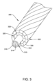
図3は、架空電気ケーブル300についてのさらに別の構成を概略的に示す。図3に示されるように、第1伝導層320の第1伝導ストランド326および第2伝導層322の第2伝導ストランド328も、図1に関して説明されたように、電気伝導材料(特に、アルミニウム)から製造される。ストランド326/328は、図2に関して説明されたように、台形の断面を有する。同様に、第1伝導層320は第1アルミニウム材料のストランド326を備え、第2伝導層322は第2アルミニウム材料のストランド328を備える。
FIG. 3 schematically shows yet another configuration for an overhead
図3に示されるように、強度部材310は、単一の強度要素312を備える。単一の強度要素312は、例えば、図1に関して説明されたように、補強された複合材料から製造されてよい。図3に示される実施形態は、内側コア314とその内側コア314を包囲する外側層316とを有する単一の強度要素312を特に備える。そうした強度要素は、例えば、高強度カーボン繊維を含む内側コアとガラス繊維を含む外側層とを、すなわち、ACCC(登録商標)と呼ばれておりアメリカ合衆国カリフォルニア州アーバインのCTCグローバル社から入手可能である構成を備えてよい。上記のヒエルらによる特許文献1を参照されたい。
As shown in FIG. 3,
図4は、架空電気ケーブル400についてのさらに別の構成を概略的に示す。図4に示されるように、第1伝導層420の第1伝導ストランド426および第2伝導層422の第2伝導ストランド428も、図1に関して説明されたように、電気伝導材料(特に、アルミニウム)から製造され、図2に関して説明されたように、台形の断面を有する。同様に、第1伝導層420は第1アルミニウム材料のストランド426を備え、第2伝導層422は、第1アルミニウム材料とは異なる第2アルミニウム材料のストランド428を備える。補強部材410は、図3に関して説明されたように、単一の強度要素412を備える。
FIG. 4 schematically shows yet another configuration for an overhead
図4に示されるように、架空電気ケーブル400は、伝導ストランド430(例えば、第3伝導ストランド)を備える第3伝導層424を備える。第3伝導層424は、強度部材410を包囲し、また第1伝導層420を包囲する。別の方法による特徴では、第3伝導層424は、第1伝導層420と第2伝導層422との間に配置されている。第3伝導層424は、例えば、追加の伝導体断面を提供することによる高電圧伝送のために(例えば、図3に示される実施形態と比較して)、架空電気ケーブルの電流容量を有利に増加させてよい。第3伝導ストランド430は、第1伝導ストランド426と同一の伝導材料から製造されてよく、第2伝導ストランド428と同一の伝導材料から製造されてよく、または1つ以上の材料特性が第1伝導ストランド426および第2伝導ストランド428の該材料特性とは異なる(例えば、異なる値を有する)伝導材料から製造されてよい。
As shown in FIG. 4, the overhead
図1~図4に示される架空電気ケーブルについての構成は、例示のためであり、本開示の架空電気ケーブルは、それらの特定の構成に限定されない。例えば、別の構成は、図1に示される丸形の伝導ストランドを有する、図3に示されるような単一要素の強度部材を備えてよい。他の構成が、当業者に明らかである。 The configurations for the overhead electrical cables shown in FIGS. 1-4 are for illustrative purposes, and the overhead electrical cables of the present disclosure are not limited to those particular configurations. For example, another configuration may include a single element strength member as shown in FIG. 3 with round conductive strands as shown in FIG. Other configurations will be apparent to those skilled in the art.
本開示によれば、1つの伝導層における伝導ストランドの1つ以上の材料特性は、別の伝導層における伝導ストランドの該材料特性とは異なる(例えば、異なる値を有する)。すなわち、それぞれの伝導ストランドを形成する伝導(例えば、金属の)材料は、異なる化学組成を有してよく(例えば、異なる合金であってよく)、および/または異なる材料特性を生じるように処理されていてよい。例えば、いくつかの金属材料の加熱処理(例えば、アニーリング)によって、加熱処理されていない同一の材料(同一の化学組成)の伝導ストランドと比較して異なる特性を有する伝導ストランドを生成してよい。同様に、同一の化学組成を有する合金の加工硬化によって、異なる機械特性が生じてよい。 According to the present disclosure, one or more material properties of conductive strands in one conductive layer are different (eg, have different values) than the material properties of conductive strands in another conductive layer. That is, the conductive (e.g., metallic) materials forming each conductive strand may have different chemical compositions (e.g., may be different alloys) and/or be processed to produce different material properties. It's okay to stay. For example, heat treatment (e.g., annealing) of some metallic materials may produce conductive strands that have different properties compared to conductive strands of the same material (same chemical composition) that have not been heat treated. Similarly, work hardening of alloys with the same chemical composition may result in different mechanical properties.
例として、複数の伝導ストランド間において異なる材料特性は、降伏応力、弾性率、硬度、引張強度および電気伝導率のうちの1つまたは複数であってよい。1つの特定の実施形態では、複数の伝導ストランド間において異なる1つ以上の材料特性は、降伏応力である。弾性率(すなわち、ヤング率)は、伝導ストランドの引張弾性(すなわち、引張ひずみに対する引張応力の比)である。材料が引張応力を受けると、材料は、いくつかの引張応力にて降伏(塑性変形)し始め、この点が降伏応力と呼ばれる。異なるアルミニウム合金および同様の複数の合金間の異なる調質(テンパー)は、異なる降伏応力を有してよい。1つの特定の特徴では、外側伝導層の(例えば、外側層ストランドの)降伏応力は、内側伝導層の降伏応力よりも(例えば、内側層ストランドよりも)大きい。すなわち、引張応力が伝導層に加えられるとき、内側伝導層は、外側伝導層の塑性変形の前に塑性変形(降伏)する。例えば、図1を参照すると、(外側)伝導ストランド128は、(内側)伝導ストランド126よりも高い降伏応力を有してよい。同様に、図2および図3では、伝導ストランド228/328は、伝導ストランド226/326よりも高い降伏応力を有してよい。図4の実施形態では、第1伝導層420の伝導ストランド426は、第2伝導層422の伝導ストランド428よりも低い降伏応力を有してよい。間にある第3伝導層424は、ほぼ第1伝導層420のストランド426以上の降伏応力を有する材料のストランド430を備えてよい。さらに、間にある第3伝導層424は、第2伝導層422における伝導ストランド428の降伏応力以下の降伏応力を有する材料のストランド430を備えてよい。
By way of example, the material properties that differ between the plurality of conductive strands may be one or more of yield stress, modulus, hardness, tensile strength, and electrical conductivity. In one particular embodiment, the one or more material properties that differ between the plurality of conductive strands is yield stress. The elastic modulus (ie, Young's modulus) is the tensile elasticity (ie, the ratio of tensile stress to tensile strain) of a conductive strand. When a material is subjected to a tensile stress, it begins to yield (plastically deform) at some tensile stress, and this point is called the yield stress. Different tempers between different aluminum alloys and similar alloys may have different yield stresses. In one particular feature, the yield stress of the outer conductive layer (eg, of the outer layer strands) is greater than the yield stress of the inner conductive layer (eg, than the inner layer strands). That is, when tensile stress is applied to the conductive layer, the inner conductive layer plastically deforms (yields) before the plastic deformation of the outer conductive layer. For example, referring to FIG. 1, the (outer)
別の特徴では、特定の複数の伝導ストランド間において異なる1つの材料特性は、引張強度である。1つの特定の特徴では、最も外側の伝導層は、内側伝導層の引張強度よりも大きい引張強度を有する。例えば、図1を参照すると、(外側)伝導ストランド128は、(内側)伝導ストランド126よりも高い引張強度を有してよい。同様に、図2および図3では、伝導ストランド228/328は、ほぼ伝導ストランド226/326以上の引張強度を有してよい。図4の実施形態では、第1伝導層420の伝導ストランド426は、第2伝導層422の伝導ストランド428よりも低い引張強度を有してよい。間にある第3伝導層424は、第1伝導層420のストランド426の引張強度よりも高い引張強度を有する材料のストランド430を備えてよい。さらに、間にある第3伝導層424は、第2伝導層422における伝導ストランド428の引張強度以下の引張強度を有する材料のストランド430を備えてよい。より高い引張強度を有する伝導ストランドには、例えば、6201-T81および6101などのアルミニウム合金が用いられてよい。
In another feature, one material property that differs between a particular plurality of conductive strands is tensile strength. In one particular feature, the outermost conductive layer has a tensile strength that is greater than the tensile strength of the inner conductive layer. For example, referring to FIG. 1, the (outer)
表1は、いくつかのアルミニウム材料についての伝導率、引張強度、降伏応力および最大(連続)動作温度を示す。 Table 1 shows the conductivity, tensile strength, yield stress and maximum (continuous) operating temperature for several aluminum materials.
別の特徴では、特定の複数の伝導ストランド間において異なる1つの材料特性は、電気伝導率である。1つの特定の特徴では、最も外側の伝導層は、内側の伝導層の電気伝導率よりも大きい電気伝導率を有する。例えば、図1を参照すると、(外側)伝導ストランド128は、(内側)伝導ストランド126よりも高い電気伝導率を有してよい。同様に、図2および図3では、伝導ストランド228/328は、ほぼ伝導ストランド226/326以上の電気伝導率を有してよい。図4の実施形態では、第1伝導層420の伝導ストランド426は、第2伝導層422の伝導ストランド428よりも低い電気伝導率を有してよい。間にある第3伝導層424は、第1伝導層420のストランド426の電気伝導率よりも高い電気伝導率を有する材料のストランド430を備えてよい。さらに、間にある第3伝導層424は、第2伝導層422における伝導ストランド428の電気伝導率以下の電気伝導率を有する材料のストランド430を備えてよい。上述の構成のいずれにおいても、より高い電気伝導率を有する伝導ストランドは、約62%IACS以上などの、約60%IACS以上の伝導率を有するアルミニウムから製造されてよい。1つの特定の特徴では、より高い電気伝導率を有する伝導ストランドは、1350-Oアニーリングアルミニウム合金などの、アニーリングされたアルミニウム合金から製造されてよい。別の特徴では、より低い伝導率のストランド(例えば、図3における伝導ストランド326)は、表1に載っている耐熱AlZr合金などの、AlZr合金から製造されてよい。
In another feature, the one material property that differs between a particular plurality of conductive strands is electrical conductivity. In one particular feature, the outermost conductive layer has an electrical conductivity that is greater than the electrical conductivity of the inner conductive layer. For example, referring to FIG. 1, the (outer)
図に関して上に説明されたように、架空電気ケーブルは、伝導層が巻かれる強度部材を備える。強度部材は、複数の強度要素を含んでよく(例えば、図1および図2)、または単一の強度要素を備えてよい(例えば、図3および図4)。強度要素は、鋼などの金属からなってよく、または繊維補強複合材などの他の材料からなってよい。そうした複合材は、結合マトリクス中に配置された補強繊維を含んでよい。補強繊維は、強度部材の長さに沿って延びる、ほぼ連続した補強繊維であってよく、および/または結合マトリクスを通じて分散した短い補強繊維(例えば、繊維ウィスカまたは切断された繊維(チョップド・ファイバ))を含んでよい。繊維は、カーボン、ガラス、ホウ素、金属酸化物、金属炭化物、アラミド繊維またはフルオロポリマー繊維などの高強度ポリマー、バサルト繊維などを含むがこれらに限定されない、広範囲の材料から選択されてよい。マトリクス材料は、例えば、熱可塑性ポリマーまたは熱硬化性ポリマーなどのプラスチック(例えば、ポリマー)を含んでよい。マトリクスは、アルミニウムマトリクスなどの金属マトリクスであってもよい。アルミニウムマトリクスの複合強度部材の1つの例は、マクロウ(McCullough)らによる米国特許第6,245,425号明細書に示され、参照によりその全体が本明細書に組み込まれる。 As explained above with respect to the figures, an overhead electrical cable comprises a strength member around which a conductive layer is wrapped. The strength member may include multiple strength elements (eg, FIGS. 1 and 2) or may comprise a single strength element (eg, FIGS. 3 and 4). The strength elements may be made of metal, such as steel, or of other materials, such as fiber-reinforced composites. Such composites may include reinforcing fibers disposed in a bonding matrix. The reinforcing fibers may be substantially continuous reinforcing fibers extending along the length of the strength member, and/or short reinforcing fibers dispersed through the bonding matrix (e.g., fiber whiskers or chopped fibers). ) may be included. The fibers may be selected from a wide variety of materials including, but not limited to, carbon, glass, boron, metal oxides, metal carbides, high strength polymers such as aramid fibers or fluoropolymer fibers, basalt fibers, and the like. The matrix material may include a plastic (eg, polymer), such as a thermoplastic or thermoset polymer. The matrix may be a metal matrix such as an aluminum matrix. One example of an aluminum matrix composite strength member is shown in US Pat. No. 6,245,425 to McCullough et al., incorporated herein by reference in its entirety.
そうした繊維補強複合強度部材の1つの特定の例は、アメリカ合衆国カリフォルニア州アーバインのCTCグローバル社により製造されるACCC(登録商標)架空電気ケーブルにおいて用いられる。そうした架空電気ケーブルは、例えば、ヒエルらによる特許文献1に示される。この高度部材は、向上したフレキシビリティを提供するように、またカーボン繊維をアルミニウムから遮蔽することによるアルミニウム伝導体のガルバニック腐食に対する耐性を提供するように、ガラス繊維層によって包囲された高強度カーボン繊維の内側コアを備える。図3および図4は、単一要素の強度部材としてのそうした複合材料の使用を示す。単一要素の強度部材の使用(図3および図4)は、例えば、同一の引張特性について(例えば、同一の引張強度について)複数要素の強度部材(図1および図2)と比較して、強度部材が減少した直径を有することを可能としてよい。 One particular example of such fiber-reinforced composite strength members is used in ACCC® overhead electrical cables manufactured by CTC Global, Inc. of Irvine, Calif., USA. Such an overhead electrical cable is shown, for example, in U.S. Pat. This advanced component consists of high-strength carbon fibers surrounded by a glass fiber layer to provide improved flexibility and resistance to galvanic corrosion of the aluminum conductor by shielding the carbon fibers from the aluminum. with an inner core. Figures 3 and 4 illustrate the use of such a composite material as a single element strength member. The use of single-element strength members (Figs. 3 and 4), for example, compared to multi-element strength members (Figs. 1 and 2) for the same tensile properties (e.g., for the same tensile strength) It may be possible to allow the strength member to have a reduced diameter.
1つの特徴では、強度部材は、約5mm以上などの、約3mm以上の直径を有する。そうした強度部材は、有利には、例えば、高強度カーボン繊維を用いて製造されるとき、高い引張強度を有することが可能である。例えば、強度部材は、約1800MPa以上など、約1900MPa以上、または約2000MPa以上もの、約1700MPa以上の極限引張強度(UTS)を有してよい。別の特徴では、強度部材は、約125kN以上など、または約150kN以上もの、約100kN以上の定格破壊強度を有する。 In one feature, the strength member has a diameter of about 3 mm or more, such as about 5 mm or more. Such strength members can advantageously have high tensile strength, for example when manufactured using high strength carbon fibres. For example, the strength member may have an ultimate tensile strength (UTS) of about 1700 MPa or more, such as about 1800 MPa or more, such as about 1900 MPa or more, or about 2000 MPa or more. In another feature, the strength member has a rated breaking strength of about 100 kN or more, such as about 125 kN or more, or even about 150 kN or more.
本明細書に開示される伝導(例えば、アルミニウム)ストランドの構成は、重い氷雪荷重を経験する地域では、特に有用であり得る。この点について、氷雪荷重の効果をさらに減少させるように、架空電気ケーブルは、大きい直径および/または非常に高い引張強度を有する強度部材を利用してよい。1つの特徴では、強度部材は、約9mm以上などの、または約10mm以上もの、約8mm以上の直径を有する。実際には、例えば、貯蔵および輸送用に、強度部材の直径は、約20mm以下など、約30mm以下である。別の特徴では、強度部材は、約2300MPa以上など、約2400MPa以上など、または約2500MPa以上もの、約2200MPa以上の極限引張強度(UTS)を有する。任意の特定の最大UTSに限定されないが、UTSは、典型的には約3700MPa以下である。別の特徴では、強度部材は、約160kN以上など、約170kN以上、または約180kNもの、約150kN以上の定格破壊強度を有する。 The conductive (eg, aluminum) strand configurations disclosed herein may be particularly useful in areas that experience heavy ice and snow loads. In this regard, to further reduce the effects of ice and snow loads, overhead electrical cables may utilize strength members having large diameters and/or very high tensile strengths. In one feature, the strength member has a diameter of about 8 mm or more, such as about 9 mm or more, or even about 10 mm or more. In practice, for example, for storage and transportation, the diameter of the strength member will be about 30 mm or less, such as about 20 mm or less. In another feature, the strength member has an ultimate tensile strength (UTS) of about 2200 MPa or more, such as about 2300 MPa or more, such as about 2400 MPa or more, or about 2500 MPa or more. Although not limited to any particular maximum UTS, the UTS is typically about 3700 MPa or less. In another feature, the strength member has a rated breaking strength of about 150 kN or more, such as about 160 kN or more, such as about 170 kN or more, or about 180 kN or more.
繊維補強複合強度部材を用いる架空ケーブルは、熱的ニーポイントを有する。初期は、設置されたケーブルの引張荷重は、強度部材と伝導ストランドとにより共有される。増加した電流に伴ってケーブルの温度が上昇すると、伝導ストランドの熱膨張係数(CTE)によって、伝導ストランドがより低いCTEの強度部材よりも素早く伸長する。温度が上昇すると、伝導ストランドは緩和し、伝導ストランドの引張荷重を強度部材に対し移送する。この移送の頂点は、熱的ニーポイントと呼ばれる。強度部材のCTEは伝導ストランドのCTEよりも低いため、熱的ニーポイントの上では伝導体の弛みは減少する。ACCC伝導体のより低いCTEおよびより低い熱的ニーポイントは、熱的弛み(例えば、ケーブルの熱膨張に起因する弛み)を減少させてよい。 Overhead cables using fiber-reinforced composite strength members have thermal knee points. Initially, the tensile load of the installed cable is shared by the strength members and the conductive strands. As the temperature of the cable increases with increased current, the coefficient of thermal expansion (CTE) of the conductive strands causes them to expand more quickly than lower CTE strength members. As the temperature increases, the conductive strands relax and transfer the tensile load of the conductive strands to the strength member. The apex of this transport is called the thermal knee point. Since the CTE of the strength member is lower than the CTE of the conductive strand, the sag of the conductor is reduced above the thermal knee point. The lower CTE and lower thermal knee point of the ACCC conductor may reduce thermal sag (eg, sag due to thermal expansion of the cable).
ACCC(登録商標)構成におけるものなど、非常に高い引張強度を有する強度部材は、完全アニーリングされたアルミニウムの伝導ストランドの使用を可能とする。完全アニーリングされたアルミニウムは、アニーリングされていないアルミニウムよりも高い伝導率を有し、したがって、電流容量を増加させ、ライン損失を減少させることが可能である。しかしながら、完全アニーリングされたアルミニウムは、いくつかの物理特性を欠いている。例えば、完全アニーリングされたアルミニウムの使用は、比較的小さい引張ひずみでしかアルミニウムを塑性変形させず、導体における張力を減少させるため、静的荷重(例えば、氷雪荷重)下における増加したラインの弛みを生じ得る。1つの構成では、架空電気ケーブルは、アニーリングされたアルミニウムの内側伝導層と、Al-Zr合金などのより硬質のアルミニウムの外側伝導層とを備える。例えば、図3を参照すると、第1伝導層320のストランド326は、完全アニーリングされたアルミニウムから形成されてよく、第2伝導層322のストランド328は、Al-Zr合金などのより硬質のアルミニウムから製造されてよい。高伝導率アルミニウムの内側層およびより高い硬度のアルミニウムの外側層の使用は、有利には、氷雪荷重からなどの機械的弛みを減少させながら、高い全伝導率(高い電流容量)を提供してよい。これは、より硬質のアルミニウムのより大きいひずみ範囲に起因し、より硬質のアルミニウムはその範囲内において弾性変形する。これに代えて、電気ケーブルは、内側伝導層に高い硬度の層を、また外側伝導層に高伝導率のアニーリングされたアルミニウムを備えてよい。しかしながら、より硬質のアルミニウムの外側層における配置は、より高い摩耗抵抗の追加の利益を提供してよい。
Strength members with very high tensile strengths, such as those in the ACCC® configuration, allow the use of fully annealed aluminum conductive strands. Fully annealed aluminum has a higher conductivity than non-annealed aluminum and is therefore capable of increasing current carrying capacity and decreasing line loss. However, fully annealed aluminum lacks some physical properties. For example, the use of fully annealed aluminum deforms the aluminum plastically only at relatively small tensile strains, reducing tension in the conductor and thus increasing line slack under static loads (e.g. ice and snow loads). can occur. In one configuration, the overhead electrical cable comprises an inner conductive layer of annealed aluminum and an outer conductive layer of harder aluminum, such as an Al-Zr alloy. For example, referring to FIG. 3, the
本開示は、架空電気ケーブルの製造のための(例えば、上の実施形態のいずれかに記載される架空電気ケーブルの製造のための)方法にも関する。1つの例では、架空電気ケーブルの製造のための方法が開示され、第1伝導層を形成するように、第1アルミニウム材料の複数の伝導ストランドを強度部材に対し第1に巻く工程と、第2伝導層を形成するように、第2アルミニウム材料の複数の伝導ストランドを前記第1伝導層に対し第2に巻く工程と、を備える。前記第2アルミニウム材料の1つ以上の材料特性は、前記第1アルミニウム材料の該材料特性の特性値とは異なる特性値を有する。 The present disclosure also relates to a method for manufacturing an overhead electrical cable (eg, for manufacturing an overhead electrical cable as described in any of the embodiments above). In one example, a method for manufacturing an overhead electrical cable is disclosed that includes first winding a plurality of conductive strands of a first aluminum material against a strength member to form a first conductive layer; and second wrapping a plurality of conductive strands of a second aluminum material around the first conductive layer to form two conductive layers. The one or more material properties of the second aluminum material have different property values than the property values of the material properties of the first aluminum material.
本開示は、電気伝送ラインの設置のための方法にも関する。1つの実施形態では、前記方法は、架空電気ケーブルを2つ以上の支持構造間に張る工程と、前記架空電気ケーブルに張力を加える工程と、を備え、前記架空電気ケーブルが加えられた前記張力下にありながら、前記架空電気ケーブルが前記2つの支持構造により少なくとも部分的には支持されるように、前記架空電気ケーブルの第1端および第2端を挟む。
前記架空電気ケーブルは、強度部材と、前記強度部材を包囲する第1伝導層であって、第1アルミニウム材料の伝導ストランドを備える、第1伝導層と、前記第1伝導層を包囲する第2伝導層であって、前記第1アルミニウム材料とは異なる第2アルミニウム材料の伝導ストランドを備える、第2伝導層と、を備える。前記第2アルミニウム材料の1つ以上の材料特性は、前記第1アルミニウム材料の該材料特性とは異なる。
The present disclosure also relates to a method for the installation of electrical transmission lines. In one embodiment, the method comprises the steps of: tensioning an overhead electrical cable between two or more support structures; and applying tension to the overhead electrical cable; sandwiching the first and second ends of the overhead electrical cable such that the overhead electrical cable is at least partially supported by the two support structures.
The overhead electrical cable includes a strength member and a first conductive layer surrounding the strength member, the first conductive layer comprising conductive strands of a first aluminum material, and a second conductive layer surrounding the first conductive layer. a second conductive layer comprising conductive strands of a second aluminum material different from the first aluminum material. One or more material properties of the second aluminum material are different from the material properties of the first aluminum material.
本開示は、架空電気ケーブルを備える架空電気伝送ラインにも関する。架空電気伝送線は、2つ以上の支持構造に対し高い張力で張られる。架空電気ケーブルは、強度部材と、前記強度部材を包囲する第1伝導層であって、第1アルミニウム材料の伝導ストランドを備える第1伝導層と、前記第1伝導層を包囲する第2伝導層であって、前記第2アルミニウム材料とは異なる第2アルミニウム材料の導電ストランドを備える、第2伝導層と、を備える。前記第2アルミニウム材料の1つ以上の材料特性は、前記第1アルミニウム材料の該材料特性とは異なる。 The present disclosure also relates to an overhead electrical transmission line comprising an overhead electrical cable. Overhead electrical transmission lines are stretched under high tension to two or more support structures. The overhead electrical cable includes a strength member, a first conductive layer surrounding the strength member, the first conductive layer comprising conductive strands of a first aluminum material, and a second conductive layer surrounding the first conductive layer. a second conductive layer comprising conductive strands of a second aluminum material different from the second aluminum material. One or more material properties of the second aluminum material are different from the material properties of the first aluminum material.
架空電気ケーブル、架空電気ケーブルを作る方法、電気伝送ラインの設置のための方法および架空電気伝送ラインの様々な実施形態が詳細に記載されているが、それらの実施形態の修正および改造が当業者に想到されることが明らかである。しかしながら、そうした修正および改造が本開示の趣旨および範囲内であることが明確に理解される。 Although various embodiments of overhead electrical cables, methods of making overhead electrical cables, methods for installing electrical transmission lines, and overhead electrical transmission lines are described in detail, modifications and adaptations of those embodiments will be apparent to those skilled in the art. It is clear that the idea has been reached. However, it is clearly understood that such modifications and adaptations are within the spirit and scope of this disclosure.
Claims (18)
2000MPa以上の極限引張強度(UTS)を有する繊維補強複合強度部材と、
前記繊維補強複合強度部材を包囲する第1伝導層であって、第1アルミニウム材料のストランドを備える第1伝導層であって、前記第1アルミニウム材料は完全アニーリングされたアルミニウム合金である、第1伝導層と、
前記第1伝導層を包囲する第2伝導層であって、第2アルミニウム材料のストランドを備える第2伝導層であって、前記第2アルミニウム材料は硬化アルミニウム合金である、第2伝導層と、を備え、
前記第2アルミニウム材料の硬度は、前記第1アルミニウム材料の硬度よりも大きく、
前記第1アルミニウム材料の前記ストランドと前記第2アルミニウム材料の前記ストランドとの両方が、台形ストランドである、架空電気ケーブル。 An overhead electric cable,
A fiber-reinforced composite strength member having an ultimate tensile strength (UTS) of 2000 MPa or more,
a first conductive layer surrounding the fiber reinforced composite strength member, the first conductive layer comprising strands of a first aluminum material , the first aluminum material being a fully annealed aluminum alloy; a conductive layer ;
a second conductive layer surrounding the first conductive layer, the second conductive layer comprising strands of a second aluminum material, the second conductive layer being a hardened aluminum alloy ; Equipped with
The hardness of the second aluminum material is greater than the hardness of the first aluminum material,
An overhead electrical cable, wherein both the strands of the first aluminum material and the strands of the second aluminum material are trapezoidal strands.
第1伝導層を形成するように、第1アルミニウム材料の複数の第1台形ストランドを2000MPa以上の極限引張強度(UTS)を有する繊維補強複合強度部材に対し巻く工程であって、前記第1アルミニウム材料は完全アニーリングされたアルミニウム合金である、工程と、
第2伝導層を形成するように、第2アルミニウム材料の複数の第2台形ストランドを前記第1伝導層の周りに巻く工程であって、前記第2アルミニウム材料は硬化アルミニウム合金である、工程と、を備え、
前記第2アルミニウム材料の硬度は、前記第1アルミニウム材料の硬度よりも大きい、方法。 A method for manufacturing an overhead electrical cable, the method comprising:
winding a plurality of first trapezoidal strands of a first aluminum material around a fiber-reinforced composite strength member having an ultimate tensile strength (UTS) of 2000 MPa or more to form a first conductive layer; The material is fully annealed aluminum alloy, the process ;
Wrapping a plurality of second trapezoidal strands of a second aluminum material around the first conductive layer to form a second conductive layer , the second aluminum material being a hardened aluminum alloy; , comprising;
The hardness of the second aluminum material is greater than the hardness of the first aluminum material.
架空電気ケーブルを2つ以上の支持構造間に張る工程と、
前記架空電気ケーブルに張力を加える工程と、
前記架空電気ケーブルが前記張力を加えられている状態において、前記架空電気ケーブルが前記2つの支持構造により少なくとも部分的には支持されるとともに、ある挟み込み張力にて張られるように、前記架空電気ケーブルの第1端および第2端を挟む工程と、を備え、
前記架空電気ケーブルは、
2000MPa以上の極限引張強度(UTS)を有する繊維補強複合強度部材と、
前記繊維補強複合強度部材を包囲する第1伝導層であって、第1アルミニウム材料のストランドを備える第1伝導層であって、前記第1アルミニウム材料は1350-O完全アニーリングアルミニウムである、第1伝導層と、
前記第1伝導層を包囲する第2伝導層であって、前記第1アルミニウム材料とは異なる第2アルミニウム材料の伝導ストランドを備える第2伝導層と、を備え、前記第2アルミニウム材料は、アルミニウム-ジルコニウム(AlZr)合金および1350-H19アルミニウム合金から選択される硬化アルミニウム材料であり、
前記第2アルミニウム材料の硬度は、前記第1アルミニウム材料の硬度よりも大きく、
前記第1アルミニウム材料の前記ストランドと前記第2アルミニウム材料の前記ストランドとの両方が、台形ストランドである、方法。 A method for the installation of an electrical transmission line, the method comprising:
Stretching an overhead electrical cable between two or more support structures;
applying tension to the overhead electrical cable;
the overhead electrical cable such that, in the tensioned state of the overhead electrical cable, the overhead electrical cable is at least partially supported by the two support structures and tensioned at a pinching tension; sandwiching the first end and the second end of the
The above-mentioned overhead electric cable is
A fiber-reinforced composite strength member having an ultimate tensile strength (UTS) of 2000 MPa or more,
a first conductive layer surrounding the fiber reinforced composite strength member, the first conductive layer comprising strands of a first aluminum material , the first aluminum material being 1350-O fully annealed aluminum; 1 conductive layer ;
a second conductive layer surrounding the first conductive layer, the second conductive layer comprising conductive strands of a second aluminum material different from the first aluminum material, the second conductive layer comprising: a hardened aluminum material selected from aluminum-zirconium (AlZr) alloy and 1350-H19 aluminum alloy;
The hardness of the second aluminum material is greater than the hardness of the first aluminum material,
The method, wherein both the strands of the first aluminum material and the strands of the second aluminum material are trapezoidal strands.
2つ以上の支持構造と、
少なくとも、前記支持構造により支持された第1電気ケーブルと、を備え、前記第1電気ケーブルは請求項1~14のいずれか一項に記載の第1電気ケーブルである、架空電気伝送ライン。 An overhead electrical transmission line,
two or more support structures;
at least a first electrical cable supported by the support structure, wherein the first electrical cable is a first electrical cable according to any one of claims 1 to 14 .
Applications Claiming Priority (3)
| Application Number | Priority Date | Filing Date | Title |
|---|---|---|---|
| US201862638436P | 2018-03-05 | 2018-03-05 | |
| US62/638,436 | 2018-03-05 | ||
| PCT/US2019/020855 WO2019173414A1 (en) | 2018-03-05 | 2019-03-05 | Overhead electrical cables and method for fabricating same |
Publications (3)
| Publication Number | Publication Date |
|---|---|
| JP2021516418A JP2021516418A (en) | 2021-07-01 |
| JP2021516418A5 JP2021516418A5 (en) | 2021-12-02 |
| JP7370994B2 true JP7370994B2 (en) | 2023-10-30 |
Family
ID=67847435
Family Applications (1)
| Application Number | Title | Priority Date | Filing Date |
|---|---|---|---|
| JP2020545331A Active JP7370994B2 (en) | 2018-03-05 | 2019-03-05 | Overhead electrical cable and method of manufacturing the overhead electrical cable |
Country Status (10)
| Country | Link |
|---|---|
| US (1) | US20200411210A1 (en) |
| EP (1) | EP3762949A4 (en) |
| JP (1) | JP7370994B2 (en) |
| KR (1) | KR20200119343A (en) |
| CN (1) | CN111801747A (en) |
| BR (1) | BR112020017936A2 (en) |
| CA (1) | CA3090822C (en) |
| EA (1) | EA202091677A1 (en) |
| MA (1) | MA54679A (en) |
| WO (1) | WO2019173414A1 (en) |
Citations (3)
| Publication number | Priority date | Publication date | Assignee | Title |
|---|---|---|---|---|
| JP2004327254A (en) | 2003-04-24 | 2004-11-18 | Fujikura Ltd | Highly corrosion resistant aluminum cable steel reinforced |
| JP2010062029A (en) | 2008-09-04 | 2010-03-18 | Sumitomo Electric Ind Ltd | Overhead transmission line |
| JP2014507758A (en) | 2011-01-05 | 2014-03-27 | アルカン プロダクツ コーポレーション | Reinforced aluminum alloy conductor composite for high voltage overhead transmission lines. |
Family Cites Families (13)
| Publication number | Priority date | Publication date | Assignee | Title |
|---|---|---|---|---|
| US3261908A (en) * | 1964-03-26 | 1966-07-19 | Kaiser Aluminium Chem Corp | Composite aluminum electrical conductor cable |
| JPH0731941B2 (en) * | 1986-07-02 | 1995-04-10 | 住友電気工業株式会社 | Overhead power line |
| US6245425B1 (en) * | 1995-06-21 | 2001-06-12 | 3M Innovative Properties Company | Fiber reinforced aluminum matrix composite wire |
| JPH10295017A (en) * | 1997-04-16 | 1998-11-04 | Hitachi Cable Ltd | Manufacture of tightened slack electrical wire |
| AP1807A (en) | 2002-04-23 | 2007-12-14 | Composite Tech Corporation | Aluminium conductor composite core reinforced cable and method of manufacture. |
| CN1898085B (en) * | 2003-10-22 | 2014-12-17 | Ctc电缆公司 | Aluminum conductor composite core reinforced cable and method of manufacture |
| US20050279526A1 (en) * | 2004-06-17 | 2005-12-22 | Johnson Douglas E | Cable and method of making the same |
| US20100059249A1 (en) * | 2008-09-09 | 2010-03-11 | Powers Wilber F | Enhanced Strength Conductor |
| KR101705827B1 (en) * | 2010-02-05 | 2017-02-10 | 엘에스전선 주식회사 | Overhead transmission line with high capacity and low sag |
| CN102982883A (en) * | 2012-11-26 | 2013-03-20 | 晶锋集团股份有限公司 | Insulation water retaining aerial cable and manufacture method thereof |
| US9490050B2 (en) | 2013-03-11 | 2016-11-08 | Southwire Company, Llc | Hybrid conductor core |
| CN103854807B (en) * | 2014-02-26 | 2016-10-19 | 远东电缆有限公司 | A kind of high-conductivity hard aluminum wire and preparation technology thereof |
| KR101785890B1 (en) | 2016-08-29 | 2017-10-17 | 엘에스전선 주식회사 | Central tension member for an overhead cable and the overhead cable comprising the same |
-
2019
- 2019-03-05 MA MA054679A patent/MA54679A/en unknown
- 2019-03-05 EP EP19763603.8A patent/EP3762949A4/en active Pending
- 2019-03-05 WO PCT/US2019/020855 patent/WO2019173414A1/en unknown
- 2019-03-05 KR KR1020207028363A patent/KR20200119343A/en active IP Right Grant
- 2019-03-05 US US16/978,252 patent/US20200411210A1/en active Pending
- 2019-03-05 CN CN201980016506.2A patent/CN111801747A/en active Pending
- 2019-03-05 JP JP2020545331A patent/JP7370994B2/en active Active
- 2019-03-05 BR BR112020017936-1A patent/BR112020017936A2/en active Search and Examination
- 2019-03-05 EA EA202091677A patent/EA202091677A1/en unknown
- 2019-03-05 CA CA3090822A patent/CA3090822C/en active Active
Patent Citations (3)
| Publication number | Priority date | Publication date | Assignee | Title |
|---|---|---|---|---|
| JP2004327254A (en) | 2003-04-24 | 2004-11-18 | Fujikura Ltd | Highly corrosion resistant aluminum cable steel reinforced |
| JP2010062029A (en) | 2008-09-04 | 2010-03-18 | Sumitomo Electric Ind Ltd | Overhead transmission line |
| JP2014507758A (en) | 2011-01-05 | 2014-03-27 | アルカン プロダクツ コーポレーション | Reinforced aluminum alloy conductor composite for high voltage overhead transmission lines. |
Also Published As
| Publication number | Publication date |
|---|---|
| MA54679A (en) | 2021-11-17 |
| EP3762949A4 (en) | 2021-11-17 |
| EP3762949A1 (en) | 2021-01-13 |
| KR20200119343A (en) | 2020-10-19 |
| CN111801747A (en) | 2020-10-20 |
| CA3090822A1 (en) | 2019-09-12 |
| JP2021516418A (en) | 2021-07-01 |
| BR112020017936A2 (en) | 2021-03-09 |
| CA3090822C (en) | 2023-03-21 |
| US20200411210A1 (en) | 2020-12-31 |
| EA202091677A1 (en) | 2020-10-21 |
| WO2019173414A1 (en) | 2019-09-12 |
Similar Documents
| Publication | Publication Date | Title |
|---|---|---|
| RU2405234C1 (en) | Overhead power transmission line | |
| RU2548568C2 (en) | Stranded thermoplastic polymer composite cables, methods for production and use thereof | |
| US10020094B2 (en) | Hybrid conductor core | |
| US20110100677A1 (en) | Fiber-polymer composite | |
| JP7469233B2 (en) | Termination configurations for overhead electrical cables | |
| US20120170900A1 (en) | Aluminum Alloy Conductor Composite Reinforced for High Voltage Overhead Power Lines | |
| JP2001291429A (en) | Overhead power line and optical fiber composite overhead earth-wire | |
| KR102605243B1 (en) | Central tension member for an overhead cable and the overhead cable comprising the same | |
| JP7370994B2 (en) | Overhead electrical cable and method of manufacturing the overhead electrical cable | |
| JPH10321047A (en) | High tension wire material, and lightweight, low dip overhead wire using the same | |
| JPH10321048A (en) | Tension member and lightweight/low slackness overhead wire using the tension member | |
| JP3845175B2 (en) | Composite wire and lightweight low-sag overhead electric wire using the same | |
| OA19728A (en) | Overhead electrical cables and method for fabricating same | |
| JP2983589B2 (en) | Twisted wire | |
| JP2020009620A (en) | Heat-resistant core for electric wire | |
| KR102461640B1 (en) | Central tension member for an overhead cable and the overhead cable comprising the same | |
| OA21033A (en) | Termination arrangement for an overhead electrical cable. | |
| JP2021516418A5 (en) | ||
| JP2015122172A (en) | Power transmission line | |
| JPH10321046A (en) | Composite strand and manufacture thereof and lightweight/low slackness overhead wire using composite strand |
Legal Events
| Date | Code | Title | Description |
|---|---|---|---|
| A521 | Request for written amendment filed |
Free format text: JAPANESE INTERMEDIATE CODE: A523 Effective date: 20211019 |
|
| A621 | Written request for application examination |
Free format text: JAPANESE INTERMEDIATE CODE: A621 Effective date: 20211019 |
|
| A977 | Report on retrieval |
Free format text: JAPANESE INTERMEDIATE CODE: A971007 Effective date: 20220530 |
|
| A131 | Notification of reasons for refusal |
Free format text: JAPANESE INTERMEDIATE CODE: A131 Effective date: 20220621 |
|
| A601 | Written request for extension of time |
Free format text: JAPANESE INTERMEDIATE CODE: A601 Effective date: 20220921 |
|
| A521 | Request for written amendment filed |
Free format text: JAPANESE INTERMEDIATE CODE: A523 Effective date: 20221221 |
|
| A131 | Notification of reasons for refusal |
Free format text: JAPANESE INTERMEDIATE CODE: A131 Effective date: 20230207 |
|
| A601 | Written request for extension of time |
Free format text: JAPANESE INTERMEDIATE CODE: A601 Effective date: 20230508 |
|
| A521 | Request for written amendment filed |
Free format text: JAPANESE INTERMEDIATE CODE: A523 Effective date: 20230807 |
|
| TRDD | Decision of grant or rejection written | ||
| A01 | Written decision to grant a patent or to grant a registration (utility model) |
Free format text: JAPANESE INTERMEDIATE CODE: A01 Effective date: 20230919 |
|
| A61 | First payment of annual fees (during grant procedure) |
Free format text: JAPANESE INTERMEDIATE CODE: A61 Effective date: 20231018 |
|
| R150 | Certificate of patent or registration of utility model |
Ref document number: 7370994 Country of ref document: JP Free format text: JAPANESE INTERMEDIATE CODE: R150 |