JP7370350B2 - Lighting devices and diffusers - Google Patents

Lighting devices and diffusers Download PDF

Info

Publication number
JP7370350B2
JP7370350B2 JP2021027044A JP2021027044A JP7370350B2 JP 7370350 B2 JP7370350 B2 JP 7370350B2 JP 2021027044 A JP2021027044 A JP 2021027044A JP 2021027044 A JP2021027044 A JP 2021027044A JP 7370350 B2 JP7370350 B2 JP 7370350B2
Authority
JP
Japan
Prior art keywords
light
layer
refractive index
scattering layer
scattering
Prior art date
Legal status (The legal status is an assumption and is not a legal conclusion. Google has not performed a legal analysis and makes no representation as to the accuracy of the status listed.)
Active
Application number
JP2021027044A
Other languages
Japanese (ja)
Other versions
JP2021093369A (en
JP2021093369A5 (en
Inventor
泰之 新田
覚 岡垣
佑輔 藤井
はるか 山▲崎▼
護 寺井
Current Assignee (The listed assignees may be inaccurate. Google has not performed a legal analysis and makes no representation or warranty as to the accuracy of the list.)
Mitsubishi Electric Corp
Original Assignee
Mitsubishi Electric Corp
Priority date (The priority date is an assumption and is not a legal conclusion. Google has not performed a legal analysis and makes no representation as to the accuracy of the date listed.)
Filing date
Publication date
Priority claimed from JP2020535271A external-priority patent/JPWO2021117119A1/en
Application filed by Mitsubishi Electric Corp filed Critical Mitsubishi Electric Corp
Priority to JP2021027044A priority Critical patent/JP7370350B2/en
Publication of JP2021093369A publication Critical patent/JP2021093369A/en
Publication of JP2021093369A5 publication Critical patent/JP2021093369A5/ja
Application granted granted Critical
Publication of JP7370350B2 publication Critical patent/JP7370350B2/en
Active legal-status Critical Current
Anticipated expiration legal-status Critical

Links

Images

Description

本発明は、散乱層で散乱させた光を出射する照明装置および拡散体に関する。 The present invention relates to a lighting device and a diffuser that emit light scattered by a scattering layer.

青空といった自然光を摸擬する照明装置は、光源から出力された光を散乱層で散乱させ、散乱させた光を観測者に観測させている。 Illumination devices that simulate natural light such as a blue sky scatter light output from a light source with a scattering layer, and allow an observer to observe the scattered light.

特許文献1に記載の照明装置では、散乱層が照明装置の底部に配置され、光源が照明装置の上部に配置されている。この照明装置では、例えばレイリー散乱光を発生させるフィラーが、散乱層の母材中に分散されており、フィラーで散乱されたレイリー散乱光を散乱層の下面から出射している。 In the lighting device described in Patent Document 1, the scattering layer is arranged at the bottom of the lighting device, and the light source is arranged at the top of the lighting device. In this lighting device, for example, a filler that generates Rayleigh scattered light is dispersed in the base material of the scattering layer, and the Rayleigh scattered light scattered by the filler is emitted from the lower surface of the scattering layer.

特開2015-207554号公報Japanese Patent Application Publication No. 2015-207554

しかしながら、レイリー散乱光は、全方位に対して光を放出するので、上記特許文献1の照明装置では、散乱層中で発せられたレイリー散乱光が、目的の光出射面である下面だけでなく、上面にも発せられてしまい、レイリー散乱光の光量を大幅にロスしてしまう。効率良くレイリー散乱光を利用するためには、拡散層の上面に反射層を設置し、光源から出力された光を散乱層の側面から入射させることが考えられるが、散乱層と反射層とが密着してしまうと、散乱層中に入射した光の直達光、または散乱層中で全反射している白色光が、反射層で拡散されてしまう。この場合、散乱層の下面から出射される光の発光色が白みを帯びてしまい、レイリー散乱光独特の色感を損なってしまう。 However, since Rayleigh scattered light emits light in all directions, in the illumination device of Patent Document 1, the Rayleigh scattered light emitted in the scattering layer is transmitted not only to the lower surface, which is the target light exit surface. , the light is also emitted from the upper surface, resulting in a significant loss of the amount of Rayleigh scattered light. In order to efficiently utilize Rayleigh scattered light, it is possible to install a reflective layer on the top surface of the diffusing layer and make the light output from the light source enter from the side of the scattering layer. If they come into close contact, the light that has entered the scattering layer directly or the white light that is totally reflected in the scattering layer will be diffused by the reflective layer. In this case, the color of the light emitted from the lower surface of the scattering layer becomes whitish, impairing the color sense unique to Rayleigh scattered light.

本発明は、上記に鑑みてなされたものであって、レイリー散乱光を効率良く利用しつつ、色感を損なわない自然光を出力する照明装置を得ることを目的とする。 The present invention has been made in view of the above, and an object of the present invention is to obtain a lighting device that outputs natural light without impairing the color sense while efficiently utilizing Rayleigh scattered light.

上述した課題を解決し、目的を達成するために、本発明の照明装置は、青空を含む自然光を模擬する照明装置であり、相関色温度が2000ケルビン以上の光源と、上面と下面と側面とを有する板形状であるとともに、光源が照射した光が側面から入射され、入射された光をレイリー散乱させることで発生させた散乱光を下面から出射する散乱層と、散乱層の上面に対向する位置に配置されて散乱光を反射する反射層と、を備える。また、本発明の照明装置は、散乱層と反射層との間に配置されて、散乱層が有する第1の屈折率よりも低い第2の屈折率を有する低屈折率層を備え、自然光は、散乱層の下面から出射される光によって模擬され、反射層のうち散乱層の上面に対向する面の表面の算術平均粗さが0.03μm以上である。 In order to solve the above-mentioned problems and achieve the objectives, the lighting device of the present invention is a lighting device that simulates natural light including blue sky, and includes a light source with a correlated color temperature of 2000 Kelvin or more, and a top surface, a bottom surface, and a side surface. The light emitted by the light source enters from the side, and the scattering layer emits the scattered light generated by Rayleigh scattering the incident light from the bottom surface, and the scattering layer faces the top surface. a reflective layer disposed at a position to reflect scattered light. Further, the lighting device of the present invention includes a low refractive index layer that is disposed between the scattering layer and the reflective layer and has a second refractive index lower than the first refractive index of the scattering layer, and the natural light is , simulated by light emitted from the lower surface of the scattering layer, and the arithmetic mean roughness of the surface of the reflective layer facing the upper surface of the scattering layer is 0.03 μm or more.

本発明にかかる照明装置は、レイリー散乱光を効率良く利用しつつ、色感を損なわない自然光を出力することができるという効果を奏する。 The lighting device according to the present invention has the effect of being able to efficiently utilize Rayleigh scattered light while outputting natural light that does not impair the color sense.

実施の形態にかかる照明装置の構成を示す断面図A cross-sectional view showing the configuration of a lighting device according to an embodiment. 実施の形態にかかる照明装置の構成を示す斜視図A perspective view showing the configuration of a lighting device according to an embodiment. 実施の形態にかかる照明装置が備える反射層の構成を示す斜視図A perspective view showing the configuration of a reflective layer included in the lighting device according to the embodiment. 実施の形態にかかる照明装置の反射層と散乱層との層間の構成を示す断面図A cross-sectional view showing an interlayer structure between a reflective layer and a scattering layer of a lighting device according to an embodiment. 実施の形態にかかる照明装置の色度を説明するための図Diagram for explaining chromaticity of a lighting device according to an embodiment

以下に、本発明の実施の形態にかかる照明装置および拡散体を図面に基づいて詳細に説明する。なお、この実施の形態によりこの発明が限定されるものではない。 EMBODIMENT OF THE INVENTION Below, the illuminating device and diffuser concerning embodiment of this invention are demonstrated in detail based on drawing. Note that the present invention is not limited to this embodiment.

実施の形態.
図1は、実施の形態にかかる照明装置の構成を示す断面図である。図2は、実施の形態にかかる照明装置の構成を示す斜視図である。照明装置100は、拡散体10、光源4、および仕切板8を備えている。照明装置100は、板状の拡散体10の側面に対向するよう光源4が配置されたエッジ入射方式の照明装置である。
Embodiment.
FIG. 1 is a sectional view showing the configuration of a lighting device according to an embodiment. FIG. 2 is a perspective view showing the configuration of the lighting device according to the embodiment. The lighting device 100 includes a diffuser 10, a light source 4, and a partition plate 8. The lighting device 100 is an edge incident lighting device in which a light source 4 is arranged to face a side surface of a plate-shaped diffuser 10.

光源4は、基板41と、基板41上に配置された1つ以上の発光素子を備えている。発光素子の例は、LED(発光ダイオード:Light Emitting Diode)素子42である。図2の例では、光源4は、アレイ状に配列された複数のLED素子42を有している。光源4は、LED素子42からの光を拡散体10に出力する。 The light source 4 includes a substrate 41 and one or more light emitting elements arranged on the substrate 41. An example of the light emitting element is an LED (Light Emitting Diode) element 42. In the example of FIG. 2, the light source 4 includes a plurality of LED elements 42 arranged in an array. Light source 4 outputs light from LED element 42 to diffuser 10 .

拡散体10は、例えば、矩形の上面および下面と、4つの側面とを有した板形状である。この場合、拡散体10が有する4つの側面のうち第1の側面と第2の側面とが対向し、第3の側面と第4の側面とが対向する。なお、拡散体10の上面および下面は、円形などの矩形以外の形状であってもよい。 The diffuser 10 has, for example, a plate shape having rectangular upper and lower surfaces and four side surfaces. In this case, among the four side surfaces of the diffuser 10, the first side and the second side face each other, and the third side face and the fourth side face each other. Note that the upper and lower surfaces of the diffuser 10 may have a shape other than a rectangle, such as a circle.

拡散体10は、反射層1と、低屈折率層2と、散乱層3とを備えている。反射層1、低屈折率層2、および散乱層3は、例えば板状の部材を用いて構成されている。反射層1の上面、低屈折率層2の上面、および散乱層3の上面は、いずれも同じ形状で同じ大きさである。 The diffuser 10 includes a reflective layer 1, a low refractive index layer 2, and a scattering layer 3. The reflective layer 1, the low refractive index layer 2, and the scattering layer 3 are configured using, for example, plate-shaped members. The upper surface of the reflective layer 1, the upper surface of the low refractive index layer 2, and the upper surface of the scattering layer 3 all have the same shape and the same size.

拡散体10では、散乱層3の上面と低屈折率層2とが隣接し、低屈折率層2の上面と反射層1の下面12とが隣接している。換言すると、拡散体10では、反射層1の下面12側(光出射面32側)に低屈折率層2が設けられており、低屈折率層2の下面側に散乱層3が設けられている。 In the diffuser 10, the upper surface of the scattering layer 3 and the low refractive index layer 2 are adjacent to each other, and the upper surface of the low refractive index layer 2 and the lower surface 12 of the reflective layer 1 are adjacent to each other. In other words, in the diffuser 10, the low refractive index layer 2 is provided on the lower surface 12 side (light exit surface 32 side) of the reflective layer 1, and the scattering layer 3 is provided on the lower surface side of the low refractive index layer 2. There is.

図1および図2では、反射層1の上面、低屈折率層2の上面、および散乱層3の上面がXY平面に平行であり、反射層1、低屈折率層2、および散乱層3の積層方向がZ方向である場合を示している。拡散体10が有する4つの側面のうち第1の側面および第2の側面がX方向に延設され、第3の側面および第4の側面がY方向に延設されている。すなわち、反射層1、低屈折率層2、および散乱層3は、それぞれX方向に延びる2つの側面と、Y方向に延びる2つの側面とを有している。なお、以下の説明では、拡散体10のうち、反射層1の配置されている側を照明装置100の上側といい、散乱層3の配置されている側を照明装置100の下側という場合がある。 1 and 2, the upper surface of the reflective layer 1, the upper surface of the low refractive index layer 2, and the upper surface of the scattering layer 3 are parallel to the XY plane, and the upper surface of the reflective layer 1, the low refractive index layer 2, and the scattering layer 3 are The case where the stacking direction is the Z direction is shown. Among the four side surfaces of the diffuser 10, the first side surface and the second side surface extend in the X direction, and the third side surface and the fourth side surface extend in the Y direction. That is, the reflective layer 1, the low refractive index layer 2, and the scattering layer 3 each have two side surfaces extending in the X direction and two side surfaces extending in the Y direction. In the following description, the side of the diffuser 10 on which the reflective layer 1 is arranged will be referred to as the upper side of the lighting device 100, and the side on which the scattering layer 3 is arranged will be referred to as the lower side of the lighting device 100. be.

散乱層3は、光源4から入射された光を散乱させる層である。低屈折率層2は、屈折率が散乱層3の屈折率よりも低い層である。反射層1は、散乱層3で発生した散乱光7を散乱層3側に反射する層である。 The scattering layer 3 is a layer that scatters the light incident from the light source 4. The low refractive index layer 2 is a layer whose refractive index is lower than the refractive index of the scattering layer 3. The reflective layer 1 is a layer that reflects the scattered light 7 generated in the scattering layer 3 toward the scattering layer 3 side.

散乱層3は、下面である光出射面32と、上面である背面33と、光出射面32と背面33とを繋ぐ側面とを有している。光出射面32は、光を出射する面である。背面33は、光出射面32とは反対側の面(上面)である。背面33と光出射面32とは平行である。 The scattering layer 3 has a light emitting surface 32 as a lower surface, a back surface 33 as an upper surface, and a side surface connecting the light emitting surface 32 and the back surface 33. The light emitting surface 32 is a surface that emits light. The back surface 33 is a surface (upper surface) opposite to the light exit surface 32 . The back surface 33 and the light exit surface 32 are parallel.

なお、散乱層3の板形状は、平板以外の形状であってもよい。散乱層3の板形状は、例えば、湾曲した形状であってもよい。散乱層3の板形状は、光出射面32および背面33のいずれか一方、またはこれらの両方が湾曲した形状であってもよい。この湾曲した形状は、凸に湾曲した形状であってもよいし、凹に湾曲した形状であってもよい。 Note that the plate shape of the scattering layer 3 may be other than a flat plate. The plate shape of the scattering layer 3 may be, for example, a curved shape. The plate shape of the scattering layer 3 may be such that one or both of the light exit surface 32 and the back surface 33 are curved. This curved shape may be a convexly curved shape or a concavely curved shape.

散乱層3が有する側面のうちの1つ以上の側面が光入射面31である。すなわち、散乱層3が4つの側面を有している場合、4つの側面のうちの少なくとも1面が光入射面31である。以下の説明では、散乱層3が有する側面のうちの1つの側面が光入射面31である場合について説明する。 One or more of the side surfaces that the scattering layer 3 has is the light incident surface 31 . That is, when the scattering layer 3 has four side surfaces, at least one of the four side surfaces is the light entrance surface 31. In the following description, a case will be described in which one of the side surfaces of the scattering layer 3 is the light entrance surface 31.

光入射面31は、散乱層3のX方向の端部に形成され、光源4から出力された光が入射される。すなわち、光源4で発生した入射光5は、散乱層3の光入射面31から散乱層3内に入射する。入射光5は、散乱層3内を導光する。 The light incident surface 31 is formed at the end of the scattering layer 3 in the X direction, and the light output from the light source 4 is incident thereon. That is, the incident light 5 generated by the light source 4 enters into the scattering layer 3 from the light incidence surface 31 of the scattering layer 3 . The incident light 5 is guided through the scattering layer 3 .

散乱層3は、基材34とフィラー6とを有する。フィラー6は、ナノメートル[nm]オーダーの大きさを持つ粒子であり、入射光5をレイリー散乱させる。フィラー6は、例えば球形であるが、他の形状であってもよい。フィラー6は、真球または楕円体であってもよい。フィラー6の粒子径は、1nm以上300nm以下の範囲内であることが望ましい。フィラー6の粒子径が1nm以下である場合、入射光5がほとんど散乱することがなく、レイリー散乱がほとんど生じない。フィラー6の粒子径が300nm以上である場合、レイリー散乱ではなくミー散乱が生じてしまうので、レイリー散乱の色感が損なわれる。 The scattering layer 3 has a base material 34 and a filler 6. The filler 6 is a particle having a size on the order of nanometers (nm), and causes Rayleigh scattering of the incident light 5. The filler 6 is, for example, spherical, but may have another shape. The filler 6 may be a true sphere or an ellipsoid. The particle diameter of the filler 6 is desirably within the range of 1 nm or more and 300 nm or less. When the particle size of the filler 6 is 1 nm or less, the incident light 5 is hardly scattered and Rayleigh scattering hardly occurs. When the particle size of the filler 6 is 300 nm or more, Mie scattering occurs instead of Rayleigh scattering, and the color appearance of Rayleigh scattering is impaired.

また、フィラー6の粒子径は、60nm以上150nm以下の範囲内であることがより望ましい。ただし、基材34内に分散されるフィラー6が、複数種類のフィラー6を含む場合などには、一部のフィラー6の粒子径は、上記範囲内でなくてもよい。例えば、基材34内に、フィラー6以外の粒子であるマイクロオーダーの光散乱粒子が含まれていてもよい。 Further, it is more desirable that the particle diameter of the filler 6 is within the range of 60 nm or more and 150 nm or less. However, in a case where the filler 6 dispersed in the base material 34 includes a plurality of types of fillers 6, the particle diameter of some of the fillers 6 may not be within the above range. For example, the base material 34 may contain micro-order light scattering particles that are particles other than the filler 6.

フィラー6は、例えば、無機酸化物である。この無機酸化物は、ZnO(酸化亜鉛:Zinc Oxide)、TiO2(二酸化チタン(IV):Titanium Dioxide)、ZrO2(二酸化ジルコニウム:Zirconium Dioxide)、SiO2(二酸化ケイ素:Silicon Dioxide)、Sb25(五酸化二アンチモン:Diantimony Pentoxide)、Al23(三酸化二アルミニウム:Dialuminium Trioxide)などのいずれか1つ以上である。フィラー6は、入射光5を散乱させて散乱光7を生成する。言い換えれば、フィラー6は、導光される光を散乱させて散乱光7を生成する。 The filler 6 is, for example, an inorganic oxide. These inorganic oxides include ZnO (Zinc Oxide), TiO 2 (Titanium Dioxide), ZrO 2 (Zirconium Dioxide), SiO 2 (Silicon Dioxide), and Sb 2 One or more of O 5 (Diantimony Pentoxide), Al 2 O 3 (Dialuminium Trioxide), and the like. Filler 6 scatters incident light 5 to generate scattered light 7 . In other words, the filler 6 scatters the guided light to generate scattered light 7.

フィラー6は、例えば、有機系ポリマーでもよい。この有機系ポリマーは、アクリル系、スチレン系、ウレタン系、ポリエステル系、ポリエチレン系、メラミン系などのいずれか1つ以上である。 The filler 6 may be, for example, an organic polymer. This organic polymer is one or more of acrylic, styrene, urethane, polyester, polyethylene, melamine, and the like.

基材34中では、フィラー6が分散されている。散乱層3は、フィラー6が基材34に添加されることによって形成される。基材34は、光を透過する材料から形成される。散乱層3は、例えば、複数種類のフィラー6を含んだ基材34を用いて形成される。 The filler 6 is dispersed in the base material 34. Scattering layer 3 is formed by adding filler 6 to base material 34 . The base material 34 is formed from a material that transmits light. The scattering layer 3 is formed using, for example, a base material 34 containing a plurality of types of fillers 6.

基材34中の導光距離5mmにおける入射光5の透過率(すなわち、直進透過率)は、設計波長において90%以上であることが好ましい。また、この透過率は、95%以上であることがより好ましい。また、この透過率は、99%以上であることが一層好ましい。ここで、設計波長は、光源4から出力される入射光5の波長のうち予め定められた波長をいう。設計波長は、1つの波長に限定されず、複数の波長であってもよい。この場合、上記の直進透過率の値は、設計波長の全てにおいて満たされることが望ましい。設計波長は、例えば、450nmから650nmまでの範囲内の波長であればよい。光源4が白色光源である場合は、設計波長は、例えば、450nm、550nm、および650nmのいずれかである。 The transmittance of the incident light 5 at a light guide distance of 5 mm in the base material 34 (that is, straight transmittance) is preferably 90% or more at the design wavelength. Moreover, it is more preferable that this transmittance is 95% or more. Moreover, it is more preferable that this transmittance is 99% or more. Here, the design wavelength refers to a predetermined wavelength among the wavelengths of the incident light 5 output from the light source 4. The design wavelength is not limited to one wavelength, and may be a plurality of wavelengths. In this case, it is desirable that the above straight transmittance value be satisfied at all design wavelengths. The design wavelength may be, for example, a wavelength within the range of 450 nm to 650 nm. When the light source 4 is a white light source, the design wavelength is, for example, one of 450 nm, 550 nm, and 650 nm.

基材34は、固体である。基材34は、例えば、熱可塑性ポリマー、熱硬化性樹脂、または光重合性樹脂などを用いた樹脂板から形成されている。また、樹脂板としては、アクリル系ポリマー、オレフィン系ポリマー、ビニル系ポリマー、セルロース系ポリマー、アミド系ポリマー、フッ素系ポリマー、ウレタン系ポリマー、シリコーン系ポリマー、イミド系ポリマーなどのうちの1つ以上の材料または複数の材料を用いることができる。なお、基材34は、液体、液晶、ゲル、ゾルまたは気体であってもよい。 The base material 34 is solid. The base material 34 is formed from a resin plate using, for example, a thermoplastic polymer, a thermosetting resin, or a photopolymerizable resin. The resin plate may be made of one or more of acrylic polymers, olefin polymers, vinyl polymers, cellulose polymers, amide polymers, fluorine polymers, urethane polymers, silicone polymers, imide polymers, etc. A material or materials can be used. Note that the base material 34 may be a liquid, liquid crystal, gel, sol, or gas.

散乱層3は、有機ハイブリッド樹脂または無機ハイブリッド樹脂であってもよい。有機ハイブリッド樹脂および無機ハイブリッド樹脂は、例えば、樹脂と無機酸化物とのハイブリッド樹脂である。この場合、フィラー6は、基材34をベースとしてゾル‐ゲル硬化によって生成された無機酸化物である。 The scattering layer 3 may be an organic hybrid resin or an inorganic hybrid resin. The organic hybrid resin and the inorganic hybrid resin are, for example, a hybrid resin of a resin and an inorganic oxide. In this case, the filler 6 is an inorganic oxide produced by sol-gel curing based on the substrate 34.

また、散乱層3は、例えば、固体の透明基材の第1表面および第2表面のいずれか一方または両方に、フィラー6を含む薄膜をコーティングして形成されてもよい。すなわち、基材34の全体にフィラー6が配置されていなくてもよく、基材34の上面または下面にフィラー6が配置されていてもよい。この場合、薄膜が散乱層3である。また、散乱層3の下面、上面、および側面の少なくとも1面には、硬度1H以上のハードコート層が配置されてもよい。 Further, the scattering layer 3 may be formed, for example, by coating one or both of the first surface and the second surface of a solid transparent base material with a thin film containing the filler 6. That is, the filler 6 may not be arranged on the entire base material 34, but may be arranged on the upper surface or the lower surface of the base material 34. In this case, the thin film is the scattering layer 3. Further, a hard coat layer having a hardness of 1H or more may be disposed on at least one of the lower surface, upper surface, and side surface of the scattering layer 3.

拡散体10の前面である光出射面32、背面33、および側面の少なくともいずれかの面に、耐擦傷性コート、対候性コート、反射防止コート、防汚コート、遮熱コートなど、透過性の機能性コーティングまたはハードコーティングが施されてもよい。 A transparent coating such as an abrasion-resistant coat, a weather-resistant coat, an anti-reflection coat, an anti-fouling coat, or a heat-shielding coat is applied to at least one of the light output surface 32, the back surface 33, and the side surfaces, which are the front surface of the diffuser 10. A functional coating or a hard coating may be applied.

散乱層3内を導光される入射光5は、光出射面32と背面33とで反射されて導光される。入射光5は、例えば、全反射によって導光される。 The incident light 5 guided through the scattering layer 3 is reflected by the light exit surface 32 and the back surface 33 and is guided. The incident light 5 is guided by, for example, total internal reflection.

光出射面32は、フィラー6で散乱された散乱光7を出射する。光出射面32は、高い平滑性を有することが望ましい。これは、光出射面32に微細な傷または微細な凹凸が生じた場合には、拡散体10内を導光される光が、光出射面32より僅かに漏れ出るからである。 The light emitting surface 32 emits the scattered light 7 scattered by the filler 6. It is desirable that the light exit surface 32 has high smoothness. This is because if minute scratches or minute irregularities occur on the light exit surface 32, the light guided within the diffuser 10 will slightly leak out from the light exit surface 32.

光出射面32は、観測者側に向けられる面である。この場合、背面33から出射する散乱光7は、損失となる。照明装置100では、背面33から出射する散乱光7を利用するために、散乱層3の背面33側に光を反射する反射層1が配置されている。反射層1は、例えば、白色反射体である。反射層1は、青色などの有色反射体でもよい。 The light exit surface 32 is a surface facing toward the observer. In this case, the scattered light 7 emitted from the back surface 33 becomes a loss. In the lighting device 100, in order to utilize the scattered light 7 emitted from the back surface 33, a reflective layer 1 that reflects light is arranged on the back surface 33 side of the scattering layer 3. The reflective layer 1 is, for example, a white reflector. The reflective layer 1 may be a colored reflector such as blue.

照明装置100では、光源4より発せられた入射光5が、散乱層3内部で反射して導光方向に向かって進む。散乱層3中にはフィラー6が均一に分散されているので、入射光5がフィラー6に当たると散乱光7が発生する。散乱光7にはレイリー散乱光が含まれる。 In the illumination device 100, incident light 5 emitted from the light source 4 is reflected inside the scattering layer 3 and travels toward the light guide direction. Since the filler 6 is uniformly dispersed in the scattering layer 3, when the incident light 5 hits the filler 6, scattered light 7 is generated. The scattered light 7 includes Rayleigh scattered light.

本実施の形態では、照明装置100が、拡散体10の側面から入射光5を入射する構成(エッジ入射方式)であるので、導光距離は、散乱層3の光入射面31から、光入射面31の対面までの距離となる。入射光の導光方向が、散乱層の厚み方向である場合、すなわち、照明装置が直下型方式である場合、導光距離は散乱層の厚み分の長さとなるので、本実施の形態の照明装置100と比較して導光距離が短くなる。 In this embodiment, since the illumination device 100 has a configuration (edge incidence method) in which the incident light 5 enters from the side surface of the diffuser 10, the light guide distance is from the light incidence surface 31 of the scattering layer 3 to This is the distance to the facing surface 31. When the light guide direction of the incident light is in the thickness direction of the scattering layer, that is, when the lighting device is a direct lighting system, the light guide distance is the length of the scattering layer thickness, so the illumination of this embodiment The light guide distance is shorter than that of the device 100.

照明装置100のように導光距離が長くなることで、入射光5がフィラー6と接触する頻度が上がり、散乱光7が効率良く発生する。そのため、本実施の形態では、拡散体10が同じサイズであれば、同等の散乱光7を発生させるのに必要なフィラー濃度を低くすることができる。 As the light guide distance becomes longer as in the lighting device 100, the frequency with which the incident light 5 comes into contact with the filler 6 increases, and the scattered light 7 is efficiently generated. Therefore, in this embodiment, if the diffuser 10 has the same size, the filler concentration required to generate the same amount of scattered light 7 can be lowered.

散乱層中のフィラー濃度が高いと、粒子間の距離が近くなるので、粒子の凝集が生じやすくなる。そして、粒子の凝集体のサイズが光の波長と同等になると、散乱光中のミー散乱が多くなってしまう。そうなるとレイリー散乱光の色感が阻害され、目的の色が表現できなくなる。また、散乱層の厚みを増やして導光距離を長くする場合には、照明装置全体が大型となってしまう。本実施の形態の照明装置100は、散乱層3内のミー散乱を抑制しつつ、効率良く発せられたレイリー散乱光である散乱光7を散乱層3の下面に出射できるよう、フィラー濃度が適切に調整されており、拡散体10の側面から入射光5を入射させる。これにより、観測者は、ミー散乱が抑制され効率良く発生したレイリー散乱光を、光出射面32から観測することとなる。 When the filler concentration in the scattering layer is high, the distance between the particles becomes short, so that particle aggregation is likely to occur. When the size of particle aggregates becomes equal to the wavelength of light, Mie scattering in the scattered light increases. If this happens, the color sense of the Rayleigh scattered light will be impaired, making it impossible to express the desired color. Furthermore, if the light guide distance is increased by increasing the thickness of the scattering layer, the entire lighting device will become larger. The illumination device 100 of the present embodiment has an appropriate filler concentration so that the scattered light 7, which is efficiently emitted Rayleigh scattered light, can be emitted to the lower surface of the scattering layer 3 while suppressing Mie scattering within the scattering layer 3. The incident light 5 is adjusted to enter from the side surface of the diffuser 10. As a result, the observer observes the Rayleigh scattered light generated efficiently by suppressing Mie scattering from the light exit surface 32.

ところで、レイリー散乱光は全方位に発せられるので、散乱光7は散乱層3の上面などにも発せられる。この上面(背面33)に発せられた散乱光7は、まず低屈折率層2に入射されることになるが、この散乱光7の入射角度がある一定以下の角度である場合は低屈折率層2で反射し、散乱層3の下面に返される。一方、散乱層3の上面に発せられた散乱光7は、ある一定角よりも高角に入射されると低屈折率層2を透過し、反射層1で反射されて、散乱層3の下面に返されることとなる。低屈折率層2で反射される散乱光7の入射角度は散乱層3と低屈折率層2との屈折率差によって決まる。 By the way, since the Rayleigh scattered light is emitted in all directions, the scattered light 7 is also emitted on the upper surface of the scattering layer 3, etc. The scattered light 7 emitted from the upper surface (back surface 33) first enters the low refractive index layer 2, but if the incident angle of the scattered light 7 is below a certain level, the low refractive index It is reflected by layer 2 and returned to the lower surface of scattering layer 3. On the other hand, when the scattered light 7 emitted from the upper surface of the scattering layer 3 is incident at an angle higher than a certain angle, it passes through the low refractive index layer 2, is reflected by the reflective layer 1, and reaches the lower surface of the scattering layer 3. It will be returned. The incident angle of the scattered light 7 reflected by the low refractive index layer 2 is determined by the refractive index difference between the scattering layer 3 and the low refractive index layer 2.

低屈折率層2の役割は、散乱層3中で全反射している入射光5を反射層1で反射または散乱させないことである。仮に低屈折率層2がなく、散乱層3の上面に反射層1が直接密着する構成であった場合、散乱層3中で全反射している入射光5が直上の反射層1で反射してしまい、その反射光が光出射面32から出射される。入射光5の反射光は散乱層3中で発生したレイリー散乱光よりも発光強度が高いので、入射光5の反射光が光出射面32から出射されると、レイリー散乱光の色感が損なわれる。本実施の形態では、散乱層3と反射層1との間に低屈折率層2が設けられているので、入射光5は散乱層3中で全反射し、反射層1まで到達できない。 The role of the low refractive index layer 2 is to prevent the incident light 5 that has been totally reflected in the scattering layer 3 from being reflected or scattered by the reflective layer 1 . If there is no low refractive index layer 2 and the reflective layer 1 is in direct contact with the upper surface of the scattering layer 3, the incident light 5 that is totally reflected in the scattering layer 3 will be reflected by the reflective layer 1 directly above it. The reflected light is emitted from the light emitting surface 32. Since the reflected light of the incident light 5 has a higher emission intensity than the Rayleigh scattered light generated in the scattering layer 3, when the reflected light of the incident light 5 is emitted from the light output surface 32, the color sense of the Rayleigh scattered light is impaired. It will be done. In this embodiment, since the low refractive index layer 2 is provided between the scattering layer 3 and the reflective layer 1, the incident light 5 is totally reflected in the scattering layer 3 and cannot reach the reflective layer 1.

また、本実施の形態の光源4の下部または周囲には、遮光性の仕切板8が設置されており、観測者が光源4を直接視認できないようになっている。すなわち、仕切板8は、照明装置100の外部と内部とを隔てている。仕切板8は、例えば、散乱層3の下面側で下面の外周部に配置されている。 Further, a light-shielding partition plate 8 is installed below or around the light source 4 in this embodiment, so that the observer cannot directly view the light source 4. That is, the partition plate 8 separates the outside and the inside of the lighting device 100. The partition plate 8 is arranged, for example, on the lower surface side of the scattering layer 3 at the outer periphery of the lower surface.

散乱層3の下面が矩形である場合、仕切板8は、散乱層3の下面のうちの光源4の配置される辺に配置される。なお、仕切板8は、光源4が配置されている辺と、光源4が配置されていない辺と、の両方に配置されてもよい。例えば、仕切板8は、散乱層3の下面のうちの外周領域の1周分に配置されてもよい。すなわち、散乱層3の下面が矩形である場合、仕切板8は、散乱層3の下面のうちの4つの辺に配置されてもよい。この場合、仕切板8の下面形状は、散乱層3の下面のうちの外周領域に沿った環状である。 When the lower surface of the scattering layer 3 is rectangular, the partition plate 8 is arranged on the side of the lower surface of the scattering layer 3 where the light source 4 is arranged. Note that the partition plate 8 may be placed on both the side where the light source 4 is placed and the side where the light source 4 is not placed. For example, the partition plate 8 may be arranged around one circumference of the outer peripheral region of the lower surface of the scattering layer 3. That is, when the lower surface of the scattering layer 3 is rectangular, the partition plates 8 may be arranged on four sides of the lower surface of the scattering layer 3. In this case, the lower surface shape of the partition plate 8 is annular along the outer peripheral region of the lower surface of the scattering layer 3 .

照明装置100は、例えば天井に設置される。この場合、光出射面32が地面側を向くよう、照明装置100が天井に設置される。観測者は、天井方向を見ることによって、光出射面32から出射される光を観測することとなる。なお、照明装置100は、壁などに設置されてもよい。 The lighting device 100 is installed, for example, on the ceiling. In this case, the lighting device 100 is installed on the ceiling so that the light exit surface 32 faces the ground side. The observer observes the light emitted from the light emitting surface 32 by looking toward the ceiling. Note that the lighting device 100 may be installed on a wall or the like.

図3は、実施の形態にかかる照明装置が備える反射層の構成を示す斜視図である。図4は、実施の形態にかかる照明装置の反射層と散乱層との層間の構成を示す断面図である。図3では、反射層1の下面12を上側にして図示している。 FIG. 3 is a perspective view showing the configuration of a reflective layer included in the lighting device according to the embodiment. FIG. 4 is a cross-sectional view showing an interlayer structure between a reflective layer and a scattering layer of the lighting device according to the embodiment. In FIG. 3, the lower surface 12 of the reflective layer 1 is shown on the upper side.

反射層1の下面12は、細かな粗さを有している。具体的には、反射層1の下面12に複数の凸部11が設けられている。これにより、散乱層3の直上に反射層1が設置された場合に、反射層1の微小凹凸である凸部11によって反射層1と散乱層3とが完全に密着することはなく、凸部11の高さ分の領域に極薄の低屈折率層2を設けることが可能となる。これにより省スペース化を実現できるので、照明装置100を小型化することができる。 The lower surface 12 of the reflective layer 1 has fine roughness. Specifically, a plurality of convex portions 11 are provided on the lower surface 12 of the reflective layer 1 . As a result, when the reflective layer 1 is installed directly above the scattering layer 3, the reflective layer 1 and the scattering layer 3 are not completely brought into close contact with each other due to the convex portions 11, which are minute irregularities of the reflective layer 1, and the convex portions It becomes possible to provide an extremely thin low refractive index layer 2 in an area corresponding to the height of 11. As a result, space saving can be realized, so that the lighting device 100 can be downsized.

反射層1の下面12には、少なくとも3つの凸部11があればよい。これにより、散乱層3は、少なくとも3つの凸部11で反射層1を支えることができるので、反射層1と散乱層3との間に隙間を設けることができる。例えば、反射層1の下面12の四隅に凸部11が配置されることによって、反射層1と散乱層3との間の隙間に低屈折率層2を設けることができる。なお、反射層1は、上面および側面が細かな粗さを有していてもよい。すなわち、反射層1の上面および側面にも凸部11が設けられてもよい。 It is sufficient that the lower surface 12 of the reflective layer 1 has at least three convex portions 11 . Thereby, the scattering layer 3 can support the reflective layer 1 with at least three convex parts 11, so that a gap can be provided between the reflective layer 1 and the scattering layer 3. For example, by arranging the convex portions 11 at the four corners of the lower surface 12 of the reflective layer 1, the low refractive index layer 2 can be provided in the gap between the reflective layer 1 and the scattering layer 3. Note that the reflective layer 1 may have fine roughness on the top surface and side surfaces. That is, the convex portions 11 may also be provided on the upper surface and side surfaces of the reflective layer 1.

反射層1の算術平均粗さである表面粗さRaは、0.03μm以上が望ましい。0.03μmよりも小さな表面粗さRaになると反射層1と散乱層3とが密着してしまい、反射層1と散乱層3との間の領域において、低屈折率層2が面内の一部もしくは全面内において消失する。また、反射層1と散乱層3との間の密着度を、さらに低くするためには、表面粗さRaは0.2μm以上が望ましい。 The surface roughness Ra, which is the arithmetic mean roughness of the reflective layer 1, is desirably 0.03 μm or more. When the surface roughness Ra is smaller than 0.03 μm, the reflective layer 1 and the scattering layer 3 will come into close contact with each other, and in the region between the reflective layer 1 and the scattering layer 3, the low refractive index layer 2 will be It disappears within the area or the entire surface. Furthermore, in order to further reduce the degree of adhesion between the reflective layer 1 and the scattering layer 3, the surface roughness Ra is desirably 0.2 μm or more.

低屈折率層2の屈折率n2は、散乱層3の屈折率n3よりも低い。散乱層3の屈折率n3が第1の屈折率であり、低屈折率層2の屈折率n2が第2の屈折率である。低屈折率層2と散乱層3との間の屈折率差は、(n3-n2)≧0.05であることが望ましい。屈折率差が0.05より小さくなると、散乱層3中で全反射する入射光5が、低屈折率層2への入射角度によっては全反射せず、低屈折率層2へ透過し、反射層1で反射されてしまう。そうすると、入射光5の反射光が観測者に届くこととなり、レイリー散乱光を含む散乱光7の色感が損なわれてしまう。 The refractive index n 2 of the low refractive index layer 2 is lower than the refractive index n 3 of the scattering layer 3. The refractive index n 3 of the scattering layer 3 is the first refractive index, and the refractive index n 2 of the low refractive index layer 2 is the second refractive index. The refractive index difference between the low refractive index layer 2 and the scattering layer 3 is preferably (n 3 −n 2 )≧0.05. When the refractive index difference becomes smaller than 0.05, the incident light 5 that is totally reflected in the scattering layer 3 is not totally reflected depending on the angle of incidence on the low refractive index layer 2, but is transmitted to the low refractive index layer 2 and reflected. It will be reflected by layer 1. In this case, the reflected light of the incident light 5 will reach the observer, and the color sense of the scattered light 7 including the Rayleigh scattered light will be impaired.

屈折率差が(n3-n2)≧0.05である場合、散乱層3内で全反射する入射角度の臨界角は75°となる。このとき光源4から発せられる入射角度が25°以内であれば全反射が起こる。光源4の入射角度が25°よりも大きくなる場合、挟角レンズなどによって入射角度を絞れば入射角度を変更することが可能である。 When the refractive index difference is (n 3 −n 2 )≧0.05, the critical angle of incidence for total reflection within the scattering layer 3 is 75°. At this time, if the incident angle of light emitted from the light source 4 is within 25 degrees, total internal reflection will occur. When the angle of incidence of the light source 4 is larger than 25°, it is possible to change the angle of incidence by narrowing down the angle of incidence with a narrow-angle lens or the like.

なお、屈折率差は(n3-n2)≧0.05である場合よりも、(n3-n2)≧0.3である方が望ましい。(n3-n2)≧0.3であればLEDなどの一般的な光源の入射角度で全反射が起こる。 Note that it is more desirable for the refractive index difference to be (n 3 −n 2 )≧0.3 than (n 3 −n 2 )≧0.05. If (n 3 −n 2 )≧0.3, total reflection occurs at the incident angle of a general light source such as an LED.

低屈折率層2の厚みtは、0<t≦1mmであることが望ましい。低屈折率層2の厚みが0mm、つまり散乱層3と反射層1とが完全に密着している状態では、入射光5が反射層1によって反射してしまい、レイリー散乱光を含む散乱光7の色感を損なうので、低屈折率層2は0mmより厚くならなければならない。したがって、本実施の形態の低屈折率層2は0mmよりも厚い。また、低屈折率層2の厚みが1mm以上になると、観測者が真横に近い角度で照明装置100の外部から照明装置100を見た際に照明装置100の内部が見えてしまい、照明装置100の見栄えが悪くなる。したがって、本実施の形態の低屈折率層2は、1mmよりも薄い方が望ましい。 The thickness t of the low refractive index layer 2 is preferably 0<t≦1 mm. When the thickness of the low refractive index layer 2 is 0 mm, that is, when the scattering layer 3 and the reflective layer 1 are in complete contact with each other, the incident light 5 is reflected by the reflective layer 1, resulting in scattered light 7 including Rayleigh scattered light. The low refractive index layer 2 must be thicker than 0 mm because it impairs the color sense. Therefore, the low refractive index layer 2 of this embodiment is thicker than 0 mm. Further, if the thickness of the low refractive index layer 2 is 1 mm or more, when an observer looks at the lighting device 100 from outside the lighting device 100 at an angle close to the side, the inside of the lighting device 100 is visible, and the lighting device 100 looks bad. Therefore, it is desirable that the low refractive index layer 2 of this embodiment is thinner than 1 mm.

また、光源4がLEDである場合、光源4からの入射光5が、直接反射層1に照射されると、入射光5の反射層1による反射光が観測者に届くこととなり、レイリー散乱光の色感が損なわれる。このため、照明装置100では、光源4がLEDである場合には、光源4からの入射光5が、直接反射層1に照射されないようにされている。 In addition, when the light source 4 is an LED, when the incident light 5 from the light source 4 is directly irradiated onto the reflective layer 1, the reflected light from the reflective layer 1 of the incident light 5 reaches the observer, and the Rayleigh scattered light The color sense is impaired. Therefore, in the lighting device 100, when the light source 4 is an LED, the incident light 5 from the light source 4 is prevented from directly irradiating the reflective layer 1.

低屈折率層2の厚さは、反射層1が持つ表面粗さRaまたは凹凸に基づいて決定されてもよいし、低屈折率層2の材質に粘着性または接着性がある場合には低屈折率層2の材料の性質を利用して調整されてもよい。また、低屈折率層2の厚さは、スペーサーなどを用いて調整されてもよい。 The thickness of the low refractive index layer 2 may be determined based on the surface roughness Ra or unevenness of the reflective layer 1, or if the material of the low refractive index layer 2 has adhesiveness or adhesiveness, It may be adjusted using the properties of the material of the refractive index layer 2. Further, the thickness of the low refractive index layer 2 may be adjusted using a spacer or the like.

低屈折率層2は、例えばフッ素系ポリマー、シリコーンポリマー、アクリルポリマー、ポリプロピレン、ウレタンポリマーなどの低屈折率樹脂である。また、低屈折率層2は、ガラなどの固体であってもよいし、水、メチルアルコール、エタノール、アセトン、酢酸などの液体であってもよい。また、低屈折率層2は、空気、ヘリウム、窒素、酸素などの気体であってもよいし、エアロゾル、ゲルなどであってもよい。 The low refractive index layer 2 is a low refractive index resin such as a fluorine-based polymer, silicone polymer, acrylic polymer, polypropylene, or urethane polymer. Further, the low refractive index layer 2 may be a solid such as glass, or a liquid such as water, methyl alcohol, ethanol, acetone, or acetic acid. Moreover, the low refractive index layer 2 may be a gas such as air, helium, nitrogen, or oxygen, or may be an aerosol, a gel, or the like.

光源4は、相関色温度Tciの光を発する。相関色温度Tciは、例えば、6500K(ケルビン)である。相関色温度Tciは、5000Kであってもよい。「相関色温度」とは、発光体の色と最も近い色に見える黒体放射の色温度を意味する。光源4は、例えば、相関色温度Tciの光として白色光を出射する光源であってもよい。 The light source 4 emits light with a correlated color temperature T ci . The correlated color temperature T ci is, for example, 6500K (Kelvin). The correlated color temperature T ci may be 5000K. "Correlated color temperature" means the color temperature of blackbody radiation that appears to be the closest color to the color of the light emitter. The light source 4 may be, for example, a light source that emits white light as light having a correlated color temperature Tci .

光源4が備える複数のLED素子42の各々は、同じ相関色温度Tciの光を発するように構成されている。なお、光源4には、互いに異なる相関色温度Tciの光を発する複数種類のLED素子42が含まれていてもよい。例えば、複数のLED素子42が発する光は、赤色光、緑色光、および青色光の3色の光を含んでもよい。この場合、光源4のLED素子42には、赤色光を発するLED素子42と、緑色光を発するLED素子42と、青色光を発するLED素子42とが含まれている。 Each of the plurality of LED elements 42 included in the light source 4 is configured to emit light of the same correlated color temperature Tci . Note that the light source 4 may include multiple types of LED elements 42 that emit light with mutually different correlated color temperatures Tci . For example, the light emitted by the plurality of LED elements 42 may include three colors of red light, green light, and blue light. In this case, the LED elements 42 of the light source 4 include an LED element 42 that emits red light, an LED element 42 that emits green light, and an LED element 42 that emits blue light.

また、複数のLED素子42が発する光は、白色光、緑色光、および青色光の3色の光を含んでもよい。この場合、光源4のLED素子42には、白色光を発するLED素子42と、緑色光を発するLED素子42と、青色光を発するLED素子42とが含まれる。 Further, the light emitted by the plurality of LED elements 42 may include light of three colors: white light, green light, and blue light. In this case, the LED elements 42 of the light source 4 include an LED element 42 that emits white light, an LED element 42 that emits green light, and an LED element 42 that emits blue light.

また、複数のLED素子42が発する光は、白色光、緑色光、青色光、および橙色光の4色の光を含んでもよい。この場合、光源4のLED素子42には、白色光を発するLED素子42と、緑色光を発するLED素子42と、青色光を発するLED素子42と、橙色光を発するLED素子42とが含まれる。 Further, the light emitted by the plurality of LED elements 42 may include light of four colors: white light, green light, blue light, and orange light. In this case, the LED elements 42 of the light source 4 include an LED element 42 that emits white light, an LED element 42 that emits green light, an LED element 42 that emits blue light, and an LED element 42 that emits orange light. .

複数のLED素子42の各々は、独立してオン制御およびオフ制御が行われてもよい。また、複数のLED素子42の各々は、独立して発光量制御が行われてもよいし、独立して発光色制御が行われてもよい。すなわち、複数のLED素子42の各々は、独立して、オン-オフ制御、発光量制御、および発光色制御の少なくとも1つが行われてもよい。これらの制御によって、照明装置100は、青空だけでなく、夕方または日没後の空を表現することも可能である。 Each of the plurality of LED elements 42 may be independently turned on and turned off. Further, each of the plurality of LED elements 42 may be independently controlled in amount of light emitted, or may be controlled in color of emitted light. That is, each of the plurality of LED elements 42 may be independently subjected to at least one of on-off control, light emission amount control, and light emission color control. Through these controls, the lighting device 100 can express not only a blue sky but also a sky in the evening or after sunset.

また、光源4は、LED素子42の各々への独立したオン制御およびオフ制御と、発光量制御と、発光色制御とを実行することで、白色の光を発することができる。なお、光源4から出力される光の色は、白色以外の色であってもよい。例えば、光源4を制御する制御回路が、複数のLED素子42の各々を独立して制御することによって、白色光のスペクトルを調整すること、または、白色以外の光を出射させることが可能となる。 Furthermore, the light source 4 can emit white light by independently controlling each of the LED elements 42 on and off, controlling the amount of light emitted, and controlling the color of the light emitted. Note that the color of the light output from the light source 4 may be other than white. For example, by independently controlling each of the plurality of LED elements 42 by the control circuit that controls the light source 4, it becomes possible to adjust the spectrum of white light or to emit light other than white. .

光源4に含まれているLED素子42の発光色の組み合わせは、上述した組み合わせに限定されない。例えば、光源4は、白色光、緑色光、および橙色光のうちの1つ以上の色の光を発するLED素子42を含むことができる。或いは、光源4は、白色光、緑色光、橙色光および青色光のうちの1つ以上の色の光を発するLED素子42を含むことができる。 The combination of emitted light colors of the LED elements 42 included in the light source 4 is not limited to the above-mentioned combinations. For example, light source 4 may include an LED element 42 that emits light of one or more of white light, green light, and orange light. Alternatively, the light source 4 may include an LED element 42 that emits light in one or more of white light, green light, orange light, and blue light.

また、光源4は、低い色温度の白色光を発するLED素子42と、高い色温度の白色光を発するLED素子42とを含むことができる。ここで、高い色温度の白色光と低い色温度の白色光との色温度の差は、例えば、2500K以上である。高い色温度の白色光と低い色温度の白色光との色温度の差は、4000K以上であってもよい。また、高い色温度の白色光と低い色温度の白色光との色温度の差は、8500Kであってもよい。 Further, the light source 4 can include an LED element 42 that emits white light with a low color temperature and an LED element 42 that emits white light with a high color temperature. Here, the difference in color temperature between white light with a high color temperature and white light with a low color temperature is, for example, 2500K or more. The difference in color temperature between the high color temperature white light and the low color temperature white light may be 4000K or more. Further, the difference in color temperature between white light with a high color temperature and white light with a low color temperature may be 8500K.

高い色温度の白色光の相関色温度Tcwhは、例えば、6500K以上である。高い色温度の白色光の相関色温度Tcwhの例は、11000Kである。低い色温度の白色光の相関色温度Tcwlは、例えば、2000K以上である。低い色温度の白色光の相関色温度Tcwlの例は、4000Kである。ただし、光入射面31に入射する入射光5または各LED素子42が発する光の色温度が、色度図(例えば、CIE(国際照明委員会)1931色度図)上で黒体軌跡より大きく外れており、相関色温度による表現が難しい場合には、光の色温度は、上記値に限定されない。 The correlated color temperature T cwh of white light with a high color temperature is, for example, 6500K or more. An example of a correlated color temperature T cwh of high color temperature white light is 11000K. The correlated color temperature T cwl of white light with a low color temperature is, for example, 2000K or more. An example of a correlated color temperature T cwl of white light with a low color temperature is 4000K. However, the color temperature of the incident light 5 entering the light incidence surface 31 or the light emitted by each LED element 42 is larger than the black body locus on the chromaticity diagram (for example, the CIE (Commission Internationale de l'Eclairage) 1931 chromaticity diagram). If it is outside the range and difficult to express using correlated color temperature, the color temperature of the light is not limited to the above value.

光源4は、光を出射する光出射面を備えている。光源4の光出射面は、光入射面31に対向する位置に配置されてもよいし、光出射面32に対向する位置に配置されてもよい。光源4が図1に示す位置に配置される場合、散乱光7は、光出射面32から出射されてもよいし、光入射面31に対向する側面から出射されてもよい。また、光源4は、散乱層3の複数の側面に配置されてもよい。この場合、各光源4は、各光入射面31に対向する位置に配置される。 The light source 4 includes a light emitting surface that emits light. The light output surface of the light source 4 may be placed at a position opposite to the light input surface 31 or may be placed at a position opposite to the light output surface 32. When the light source 4 is arranged at the position shown in FIG. 1, the scattered light 7 may be emitted from the light exit surface 32, or may be emitted from the side surface facing the light entrance surface 31. Further, the light sources 4 may be arranged on multiple sides of the scattering layer 3. In this case, each light source 4 is arranged at a position facing each light incident surface 31.

つぎに、本実施の形態の拡散体10が発する散乱光7の色度について説明する。ここでは、本実施の形態の第1の拡散体10と、本実施の形態の第2の拡散体10と、比較例の拡散体とをそれぞれ製造して測定した色度について説明する。比較例の拡散体は、本実施の形態の拡散体10と同様の、散乱層3および低屈折率層2を備えているものとする。なお、以下の説明では、本実施の形態の第1の拡散体10と、本実施の形態の第2の拡散体10と、比較例の拡散体とを、3つの拡散体という場合がある。 Next, the chromaticity of the scattered light 7 emitted by the diffuser 10 of this embodiment will be explained. Here, the chromaticity measured by manufacturing and measuring the first diffuser 10 of the present embodiment, the second diffuser 10 of the present embodiment, and the diffuser of a comparative example will be described. It is assumed that the diffuser of the comparative example includes a scattering layer 3 and a low refractive index layer 2 similar to the diffuser 10 of the present embodiment. Note that in the following description, the first diffuser 10 of the present embodiment, the second diffuser 10 of the present embodiment, and the diffuser of the comparative example may be referred to as three diffusers.

第1の拡散体10は、透明樹脂中にナノフィラーを添加した樹脂板が散乱層3であり、散乱層3の背面33側に反射層1として、表面粗さRa=0.03μmの白板が設置されている。 In the first diffuser 10, the scattering layer 3 is a resin plate in which a nanofiller is added to a transparent resin, and a white plate with a surface roughness Ra = 0.03 μm is provided as a reflective layer 1 on the back surface 33 side of the scattering layer 3. is set up.

第2の拡散体10は、透明樹脂中にナノフィラーを添加した樹脂板が散乱層3であり、散乱層3の背面33側に反射層1として、表面粗さRa=0.2μmの白板が設置されている。 In the second diffuser 10, the scattering layer 3 is a resin plate in which a nanofiller is added to a transparent resin, and a white plate with a surface roughness Ra=0.2 μm is provided as a reflective layer 1 on the back surface 33 side of the scattering layer 3. is set up.

比較例の拡散体は、透明樹脂中にナノフィラーを添加した樹脂板が散乱層3であり、散乱層3の背面33側に反射層1として、表面粗さRa=0.02μmの白板が設置されている。 In the diffuser of the comparative example, the scattering layer 3 is a resin plate in which nanofiller is added to a transparent resin, and a white plate with a surface roughness Ra = 0.02 μm is installed as the reflective layer 1 on the back surface 33 side of the scattering layer 3. has been done.

3つの拡散体は、いずれも低屈折率層2が空気層である。これらの低屈折率層2の厚みは、それぞれの反射層1の表面粗さRaに依存し、いずれも1mm以下であった。また、3つの拡散体では、いずれも散乱層3と低屈折率層2との屈折率差は(n3-n2)≧0.3となる。3つの拡散体に対しては、散乱層3の側面から光が入るよう、光源4として相関色温度6500Kの白色LEDを配置した。 In all three diffusers, the low refractive index layer 2 is an air layer. The thicknesses of these low refractive index layers 2 depended on the surface roughness Ra of each reflective layer 1, and were all 1 mm or less. Further, in all three diffusers, the difference in refractive index between the scattering layer 3 and the low refractive index layer 2 is (n 3 −n 2 )≧0.3. For the three diffusers, a white LED with a correlated color temperature of 6500 K was arranged as a light source 4 so that light could enter from the side surface of the scattering layer 3.

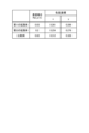
表面粗さRaを変化させた3つの拡散体に対して、光出射面32から発せられるCIE1931色度を測定した。図5は、実施の形態にかかる照明装置の色度を説明するための図である。図5では、3つの拡散体の表面粗さRaと、色度座標との対応関係を示している。 CIE1931 chromaticity emitted from the light exit surface 32 was measured for three diffusers with different surface roughness Ra. FIG. 5 is a diagram for explaining the chromaticity of the lighting device according to the embodiment. FIG. 5 shows the correspondence between the surface roughness Ra of three diffusers and the chromaticity coordinates.

3つの拡散体に対しては、光源4からXY平面に平行な面内で100mm離れた箇所の色度を測定した。図5では、3つの拡散体に対する色度の測定結果を示している。表面粗さRaが0.03μmである第1の拡散体10では、色度は(x,y)=(0.261,0.289)となり、青みのある発光色が確認された。 For the three diffusers, the chromaticity was measured at a location 100 mm away from the light source 4 in a plane parallel to the XY plane. FIG. 5 shows the measurement results of chromaticity for three diffusers. In the first diffuser 10 having a surface roughness Ra of 0.03 μm, the chromaticity was (x, y)=(0.261, 0.289), and a bluish emission color was confirmed.

また、表面粗さRaが0.2μmである第2の拡散体10では、色度は(x,y)=(0.254,0.276)となり、第1の拡散体10よりも青みが強い色度となった。 Further, in the second diffuser 10 whose surface roughness Ra is 0.2 μm, the chromaticity is (x, y) = (0.254, 0.276), which is more bluish than the first diffuser 10. It has a strong chromaticity.

表面粗さRaが0.02μmである比較例の拡散体では、散乱層3と反射層1との密着が確認され、密着部分から発せられる入射光5の反射光によって、光源4の白色LEDに近い色味となった。比較例の拡散体での色度は(x,y)=(0.312,0.328)となった。 In the comparative example diffuser with a surface roughness Ra of 0.02 μm, close contact between the scattering layer 3 and the reflective layer 1 was confirmed, and the reflected light of the incident light 5 emitted from the close contact portion caused the white LED of the light source 4 to be illuminated. The color was similar. The chromaticity of the comparative example diffuser was (x, y)=(0.312, 0.328).

このように実施の形態では、照明装置100が、散乱層3と、低屈折率層2と、反射層1とを備えており、反射層1のうち、散乱層3の背面33に対向する下面12の表面粗さRaが0.03μm以上であるので、拡散体10は、レイリー散乱光を効率良く利用しつつ、色感を損なわない自然光を出力することができる。 In this embodiment, the illumination device 100 includes the scattering layer 3, the low refractive index layer 2, and the reflective layer 1. Since the surface roughness Ra of 12 is 0.03 μm or more, the diffuser 10 can efficiently utilize Rayleigh scattered light while outputting natural light that does not impair the color sense.

また、実施の形態では、拡散体10の側面部に光源4が配置されているので、照明装置100の厚みを抑制することができる。また、実施の形態では、散乱層3の光出射面32側に仕切板8が配置されているので、光出射面32以外からは、散乱光7が観測者に観測されない。 Further, in the embodiment, since the light source 4 is arranged on the side surface of the diffuser 10, the thickness of the lighting device 100 can be suppressed. Further, in the embodiment, since the partition plate 8 is arranged on the light exit surface 32 side of the scattering layer 3, the scattered light 7 is not observed by the observer from any side other than the light exit surface 32.

以上の実施の形態に示した構成は、本発明の内容の一例を示すものであり、別の公知の技術と組み合わせることも可能であるし、本発明の要旨を逸脱しない範囲で、構成の一部を省略、変更することも可能である。 The configurations shown in the embodiments described above are examples of the contents of the present invention, and can be combined with other known techniques, and the configurations can be modified without departing from the gist of the present invention. It is also possible to omit or change parts.

1 反射層、2 低屈折率層、3 散乱層、4 光源、5 入射光、6 フィラー、7 散乱光、8 仕切板、10 拡散体、11 凸部、12 下面、31 光入射面、32 光出射面、33 背面、34 基材、41 基板、42 LED素子、100 照明装置。 1 reflective layer, 2 low refractive index layer, 3 scattering layer, 4 light source, 5 incident light, 6 filler, 7 scattered light, 8 partition plate, 10 diffuser, 11 convex portion, 12 lower surface, 31 light incidence surface, 32 light Output surface, 33 back surface, 34 base material, 41 substrate, 42 LED element, 100 lighting device.

Claims (8)

青空を含む自然光を模擬する照明装置であり、
相関色温度が2000ケルビン以上の光源と、
上面と下面と側面とを有する板形状であるとともに、前記光源が照射した光が前記側面から入射され、入射された前記光をレイリー散乱させることで発生させた散乱光を前記下面から出射する散乱層と、
前記上面に対向する位置に配置されて前記散乱光を反射する反射層と、
前記散乱層と前記反射層との間に配置されて、前記散乱層が有する第1の屈折率よりも低い第2の屈折率を有する低屈折率層とを備え、
前記自然光は、前記下面から出射される光によって模擬され、
前記反射層のうち前記上面に対向する面の表面の算術平均粗さが0.03μm以上である、
ことを特徴とする照明装置。
It is a lighting device that simulates natural light including blue sky.
A light source with a correlated color temperature of 2000 Kelvin or more,
The scattering device has a plate shape having an upper surface, a lower surface, and a side surface, and the light emitted by the light source is incident from the side surface, and the scattered light generated by Rayleigh scattering the incident light is emitted from the lower surface. layer and
a reflective layer disposed at a position facing the top surface and reflecting the scattered light;
a low refractive index layer disposed between the scattering layer and the reflective layer and having a second refractive index lower than the first refractive index of the scattering layer;
The natural light is simulated by light emitted from the lower surface,
The surface of the reflective layer facing the upper surface has an arithmetic mean roughness of 0.03 μm or more;
A lighting device characterized by:
前記側面から入射された光は、前記散乱層内において前記上面と前記下面とで反射されて導光され、
前記散乱層は、当該散乱層内を導光される前記光をレイリー散乱させて、前記自然光を模擬する光とされる前記散乱光を生成する、
ことを特徴とする請求項1に記載の照明装置。
The light incident from the side surface is reflected and guided by the upper surface and the lower surface within the scattering layer,
The scattering layer performs Rayleigh scattering on the light guided through the scattering layer to generate the scattered light that simulates the natural light.
The lighting device according to claim 1, characterized in that:
前記反射層は、有色反射体である、
ことを特徴とする請求項1または2に記載の照明装置。
The reflective layer is a colored reflector.
The lighting device according to claim 1 or 2, characterized in that:
前記下面の外周部に配置された遮光性の仕切板をさらに備える、
ことを特徴とする請求項1から3の何れか1つに記載の照明装置。
further comprising a light-shielding partition plate disposed on the outer periphery of the lower surface;
The lighting device according to any one of claims 1 to 3, characterized in that:
前記第1の屈折率と、前記第2の屈折率との差が0.05以上であ
前記光源から前記側面に入射される光の入射角度は25°以内である、
ことを特徴とする請求項1から4の何れか1つに記載の照明装置。
The difference between the first refractive index and the second refractive index is 0.05 or more,
The angle of incidence of light incident on the side surface from the light source is within 25°;
The lighting device according to any one of claims 1 to 4.
前記低屈折率層の厚みは0よりも大きく1mm以下である、
ことを特徴とする請求項1から5の何れか1つに記載の照明装置。
The thickness of the low refractive index layer is greater than 0 and less than 1 mm,
The lighting device according to any one of claims 1 to 5.
前記散乱層では、透明樹脂に粒子径が300nm以下のフィラーが分散配置されている、
ことを特徴とする請求項1から6の何れか1つに記載の照明装置。
In the scattering layer, a filler having a particle size of 300 nm or less is dispersed in a transparent resin,
The lighting device according to any one of claims 1 to 6, characterized in that:
青空を含む自然光を模擬する照明装置に用いられる拡散体であって、
上面と下面と側面とを有する板形状であるとともに、相関色温度が2000ケルビン以上の光が前記側面から入射され、入射された前記光をレイリー散乱させることで発生させた散乱光を前記下面から出射する散乱層と、
前記上面に対向する位置に配置されて前記散乱光を反射する反射層と、
前記散乱層と前記反射層との間に配置されて、前記散乱層が有する第1の屈折率よりも低い第2の屈折率を有する低屈折率層とを備え、
前記自然光は、前記下面から出射される光によって模擬され、
前記反射層のうち前記上面に対向する面の表面の算術平均粗さが0.03μm以上であ
ことを特徴とする拡散体。
A diffuser used in a lighting device that simulates natural light including blue sky,
It has a plate shape having an upper surface, a lower surface, and a side surface, and light having a correlated color temperature of 2000 Kelvin or more is incident from the side surface, and scattered light generated by Rayleigh scattering the incident light is emitted from the lower surface. a scattering layer that emits;
a reflective layer disposed at a position facing the top surface and reflecting the scattered light;
a low refractive index layer disposed between the scattering layer and the reflective layer and having a second refractive index lower than the first refractive index of the scattering layer;
The natural light is simulated by light emitted from the lower surface,
The surface of the reflective layer facing the upper surface has an arithmetic mean roughness of 0.03 μm or more;
A diffuser characterized by:
JP2021027044A 2019-12-10 2021-02-24 Lighting devices and diffusers Active JP7370350B2 (en)

Priority Applications (1)

Application Number Priority Date Filing Date Title
JP2021027044A JP7370350B2 (en) 2019-12-10 2021-02-24 Lighting devices and diffusers

Applications Claiming Priority (2)

Application Number Priority Date Filing Date Title
JP2020535271A JPWO2021117119A1 (en) 2019-12-10 2019-12-10 Lighting equipment and diffusers
JP2021027044A JP7370350B2 (en) 2019-12-10 2021-02-24 Lighting devices and diffusers

Related Parent Applications (1)

Application Number Title Priority Date Filing Date
JP2020535271A Division JPWO2021117119A1 (en) 2019-12-10 2019-12-10 Lighting equipment and diffusers

Publications (3)

Publication Number Publication Date
JP2021093369A JP2021093369A (en) 2021-06-17
JP2021093369A5 JP2021093369A5 (en) 2022-12-19
JP7370350B2 true JP7370350B2 (en) 2023-10-27

Family

ID=76313226

Family Applications (1)

Application Number Title Priority Date Filing Date
JP2021027044A Active JP7370350B2 (en) 2019-12-10 2021-02-24 Lighting devices and diffusers

Country Status (1)

Country Link
JP (1) JP7370350B2 (en)

Families Citing this family (1)

* Cited by examiner, † Cited by third party
Publication number Priority date Publication date Assignee Title
JPWO2023276705A1 (en) * 2021-06-29 2023-01-05

Citations (7)

* Cited by examiner, † Cited by third party
Publication number Priority date Publication date Assignee Title
JP2006294343A (en) 2005-04-07 2006-10-26 Mitsubishi Rayon Co Ltd Planar led light source device
JP2008130279A (en) 2006-11-17 2008-06-05 Nichia Chem Ind Ltd Surface light emitting device, and its manufacturing method
JP2010267610A (en) 2009-05-14 2010-11-25 Young Lighting Technology Inc Lighting system
JP2011099899A (en) 2009-11-04 2011-05-19 Maruzen Chemicals Co Ltd Light scattering member and method for producing the same
JP2011113773A (en) 2009-11-26 2011-06-09 Yowa:Kk Surface light source device and lighting device
JP2014237267A (en) 2013-06-07 2014-12-18 古河電気工業株式会社 Foam sheet, light reflection plate, back light panel, resin sheet for production of foam sheet and method of producing foam sheet
JP2015207554A (en) 2014-03-10 2015-11-19 コエルクス・エッセ・エッレ・エッレCoeLux S.r.l. lighting system

Patent Citations (7)

* Cited by examiner, † Cited by third party
Publication number Priority date Publication date Assignee Title
JP2006294343A (en) 2005-04-07 2006-10-26 Mitsubishi Rayon Co Ltd Planar led light source device
JP2008130279A (en) 2006-11-17 2008-06-05 Nichia Chem Ind Ltd Surface light emitting device, and its manufacturing method
JP2010267610A (en) 2009-05-14 2010-11-25 Young Lighting Technology Inc Lighting system
JP2011099899A (en) 2009-11-04 2011-05-19 Maruzen Chemicals Co Ltd Light scattering member and method for producing the same
JP2011113773A (en) 2009-11-26 2011-06-09 Yowa:Kk Surface light source device and lighting device
JP2014237267A (en) 2013-06-07 2014-12-18 古河電気工業株式会社 Foam sheet, light reflection plate, back light panel, resin sheet for production of foam sheet and method of producing foam sheet
JP2015207554A (en) 2014-03-10 2015-11-19 コエルクス・エッセ・エッレ・エッレCoeLux S.r.l. lighting system

Also Published As

Publication number Publication date
JP2021093369A (en) 2021-06-17

Similar Documents

Publication Publication Date Title
JP6806775B2 (en) Large area light source and large area luminaire
US8348458B2 (en) White light-emitting device
US9939563B2 (en) Sky-dome lighting system
JP2015526863A (en) Diffractive illumination device with a three-dimensional appearance
TWI752234B (en) Light-emitting device with optical lens for extremely thin direct-lit backlight
US10352521B2 (en) Vehicle lamp
KR20180114219A (en) Sun-sky imitation mining system with enlarged crust window area
US9671087B2 (en) Illumination device
JP7370350B2 (en) Lighting devices and diffusers
TW201535018A (en) Optical device including remote downconverter
US20220099867A1 (en) Lighting device and optical member
US9377180B2 (en) Luminous flux control member, light emission device, and illumination device
JP2017502477A (en) Color mixed output for high brightness LED light source
JP2008300298A (en) Plane lighting light source device and plane lighting device
US11874431B2 (en) Diffuser and lighting device
WO2021117119A1 (en) Illumination device and diffusion body
JP6644233B2 (en) Light emitting device
US11561334B2 (en) Diffusive body and illumination device
JP2014002968A (en) Luminaire
EP3440401A1 (en) A lens with slits
JP2021093369A5 (en)
US20240093842A1 (en) Light emitting device having a mixing chamber
WO2021070948A1 (en) Light flux control member, light-emitting device, area light source device, and display device
JP7297071B2 (en) lighting equipment
US20230027535A1 (en) Beam splitting element and projection device

Legal Events

Date Code Title Description
A521 Request for written amendment filed

Free format text: JAPANESE INTERMEDIATE CODE: A523

Effective date: 20221209

A621 Written request for application examination

Free format text: JAPANESE INTERMEDIATE CODE: A621

Effective date: 20221209

A977 Report on retrieval

Free format text: JAPANESE INTERMEDIATE CODE: A971007

Effective date: 20230823

TRDD Decision of grant or rejection written
A01 Written decision to grant a patent or to grant a registration (utility model)

Free format text: JAPANESE INTERMEDIATE CODE: A01

Effective date: 20230919

A61 First payment of annual fees (during grant procedure)

Free format text: JAPANESE INTERMEDIATE CODE: A61

Effective date: 20231017

R150 Certificate of patent or registration of utility model

Ref document number: 7370350

Country of ref document: JP

Free format text: JAPANESE INTERMEDIATE CODE: R150