JP7369965B2 - Frame for electric bicycle and electric bicycle - Google Patents
Frame for electric bicycle and electric bicycle Download PDFInfo
- Publication number
- JP7369965B2 JP7369965B2 JP2019208974A JP2019208974A JP7369965B2 JP 7369965 B2 JP7369965 B2 JP 7369965B2 JP 2019208974 A JP2019208974 A JP 2019208974A JP 2019208974 A JP2019208974 A JP 2019208974A JP 7369965 B2 JP7369965 B2 JP 7369965B2
- Authority
- JP
- Japan
- Prior art keywords
- down tube
- front wall
- opening
- electric bicycle
- bracket
- Prior art date
- Legal status (The legal status is an assumption and is not a legal conclusion. Google has not performed a legal analysis and makes no representation as to the accuracy of the status listed.)
- Active
Links
- XLYOFNOQVPJJNP-UHFFFAOYSA-N water Substances O XLYOFNOQVPJJNP-UHFFFAOYSA-N 0.000 claims description 27
- 230000035515 penetration Effects 0.000 claims description 23
- 230000003014 reinforcing effect Effects 0.000 claims description 12
- 230000000149 penetrating effect Effects 0.000 claims description 10
- 229910052751 metal Inorganic materials 0.000 description 16
- 239000002184 metal Substances 0.000 description 16
- 238000005452 bending Methods 0.000 description 6
- 229910052782 aluminium Inorganic materials 0.000 description 5
- XAGFODPZIPBFFR-UHFFFAOYSA-N aluminium Chemical compound [Al] XAGFODPZIPBFFR-UHFFFAOYSA-N 0.000 description 5
- 239000011324 bead Substances 0.000 description 5
- 238000003466 welding Methods 0.000 description 4
- 229910000838 Al alloy Inorganic materials 0.000 description 3
- 230000003247 decreasing effect Effects 0.000 description 2
- 230000000694 effects Effects 0.000 description 2
- 150000002739 metals Chemical class 0.000 description 2
- 229910052755 nonmetal Inorganic materials 0.000 description 2
- 150000002843 nonmetals Chemical class 0.000 description 2
- FYYHWMGAXLPEAU-UHFFFAOYSA-N Magnesium Chemical compound [Mg] FYYHWMGAXLPEAU-UHFFFAOYSA-N 0.000 description 1
- 229910000831 Steel Inorganic materials 0.000 description 1
- RTAQQCXQSZGOHL-UHFFFAOYSA-N Titanium Chemical compound [Ti] RTAQQCXQSZGOHL-UHFFFAOYSA-N 0.000 description 1
- 229910045601 alloy Inorganic materials 0.000 description 1
- 239000000956 alloy Substances 0.000 description 1
- 238000005219 brazing Methods 0.000 description 1
- 238000007599 discharging Methods 0.000 description 1
- 229910052749 magnesium Inorganic materials 0.000 description 1
- 239000011777 magnesium Substances 0.000 description 1
- 239000000463 material Substances 0.000 description 1
- 230000004048 modification Effects 0.000 description 1
- 238000012986 modification Methods 0.000 description 1
- 230000002787 reinforcement Effects 0.000 description 1
- 239000010959 steel Substances 0.000 description 1
- 239000010936 titanium Substances 0.000 description 1
- 229910052719 titanium Inorganic materials 0.000 description 1
- 238000005493 welding type Methods 0.000 description 1
Images


Description
本開示は、電動自転車用のフレーム及び電動自転車に関する。 The present disclosure relates to a frame for an electric bicycle and an electric bicycle.
特許文献1には、電動自転車が開示されている。この電動自転車は、ブラケットとダウンチューブとを備え、ダウンチューブ内に配線を通すように構成されており、この構造においてはダウンチューブ内に水が浸入しやすいことから、ダウンチューブの端部下面に、排水用の開口部を設けている。
上記した従来の電動自転車においては、ダウンチューブの端部下面に排水用の開口部を設けるため、ダウンチューブの強度が低下するという問題がある。 In the above-mentioned conventional electric bicycle, there is a problem in that the strength of the down tube is reduced because an opening for water drainage is provided on the lower surface of the end of the down tube.
本開示は、電動自転車用のフレーム及び電動自転車において、ダウンチューブの強度の低下を抑えながら、ダウンチューブ内の水抜き性を高めることを目的とする。 An object of the present disclosure is to improve water drainage inside the down tube while suppressing a decrease in the strength of the down tube in a frame for an electric bicycle and an electric bicycle.
本開示の一態様に係る電動自転車用のフレームは、前壁部を含むブラケットと、長手方向の一端側に開口縁部を有するダウンチューブと、を備える。前記開口縁部は、前記ダウンチューブが前記ブラケットから伸びる姿勢となるように、前記前壁部に対して連結される部分である。前記前壁部は、前記ダウンチューブ内の配線を後方に引き出すように設けられた開口部と、前記開口部とは別に、前記ダウンチューブ内の水を排出するように設けられた貫通部と、を有する。前記貫通部は、前記前壁部のうち、前記ダウンチューブの前記開口縁部に囲まれる部分に位置する。 A frame for an electric bicycle according to one aspect of the present disclosure includes a bracket including a front wall portion, and a down tube having an open edge at one end in the longitudinal direction. The opening edge is a portion connected to the front wall so that the down tube extends from the bracket. The front wall portion includes an opening provided to draw out the wiring in the down tube rearward, and a penetration portion provided separately from the opening to drain water in the down tube. has. The penetrating portion is located in a portion of the front wall portion surrounded by the opening edge of the down tube.
本開示の一態様に係る電動自転車は、前記フレームと、前記フレームに装着されるバッテリーとを備える。 An electric bicycle according to one aspect of the present disclosure includes the frame and a battery attached to the frame.
本開示の電動自転車用のフレーム及び電動自転車は、ダウンチューブの強度の低下を抑えながら、ダウンチューブ内の水抜き性を高めることができるという効果を奏する。 The frame for an electric bicycle and the electric bicycle of the present disclosure have the effect that water drainage inside the down tube can be improved while suppressing a decrease in the strength of the down tube.
(一実施形態)
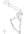
図1には、一実施形態の電動自転車1を示している。一実施形態の電動自転車1は、電動アシスト自転車である。
(One embodiment)
FIG. 1 shows an
一実施形態の電動自転車1は、電動自転車用のフレーム10と、フレーム10に支持された駆動ユニット11と、駆動ユニット11に電力を供給するようにフレーム10に着脱自在に装着されたバッテリー12とを備える。
An
更に、一実施形態の電動自転車1は、フレーム10の前部に支持されたフロントフォーク13と、フロントフォーク13の下部に回転自在に連結された前輪142と、フレーム10の後部に回転自在に連結された後輪144と、フレーム10の中央部に軸支されたペダル155付きのクランク15と、フロントフォーク13の上部に連結されたハンドル16とを備える。
Furthermore, the
更に、一実施形態の電動自転車1は、フレーム10に装着されたサドル17付きのシートピラー175と、フレーム10に連結されたリアキャリア18と、リアキャリア18に連結されたリアフェンダー19とを備える。
Furthermore, the
一実施形態の電動自転車1では、運転者がペダル155を漕いでクランク15を回転させる動力と、駆動ユニット11から出力される駆動力とが、駆動ユニット11と後輪144の間に架け渡されるチェイン115を介して後輪144に伝達されることで、後輪144が回転駆動される。
In the
本文において用いる前後、上下等の各方向は、水平面上に前輪142と後輪144を乗せた電動自転車1の運転者を基準として、定義される。運転者が電動自転車1に乗って進行する方向が前方、これの反対側が後方である。以下、各構成について詳しく説明する。
The directions used in this text, such as front and back and up and down, are defined based on the driver of the
(フレーム)
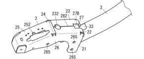
図2等に示すように、電動自転車用のフレーム10は、フレーム10の中心部に位置するブラケット2と、ダウンチューブ3と、シートチューブ4と、チェーンステー5と、シートステー6と、ヘッドパイプ7とを備える。
(flame)
As shown in FIG. 2 etc., the
フレーム10(つまりフレーム10を構成する上記の各部)は、一例としてアルミニウム合金で形成されているが、アルミニウム合金以外のスチール、チタン、マグネシウム等の他の金属で形成されてもよい。フレーム10は、複数種類の金属で形成されてもよいし、一部に非金属を含んでもよいし、あるいは、フレーム10全体が非金属で形成されてもよい。
The frame 10 (that is, the above-mentioned parts constituting the frame 10) is made of an aluminum alloy, as an example, but may be made of other metals other than the aluminum alloy, such as steel, titanium, and magnesium. The
ブラケット2は、駆動用の機器が支持される金属部材である。ブラケット2は、前壁部21と、第1屈曲部22と、中間壁部23と、第2屈曲部24と、後壁部25と、左右の側壁部26とを一体に有するように、アルミニウム合金製の板材(以下「アルミ板」という。)を曲げ加工して全体が形成されている。
The
一実施形態の電動自転車1において、ブラケット2に支持される駆動用の機器は、電動モーターが内蔵された駆動ユニット11であるが、ブラケット2に支持される駆動用の機器はこれに限定されず、例えばセンサー、制御装置等の他の機器がブラケット2に支持されてもよい。
In the
ダウンチューブ3は、ブラケット2から前斜め上方に伸びるように、ブラケット2の前壁部21に連結されている。ダウンチューブ3は、楕円状の断面を有する中空の金属部材である(図6等参照)。ダウンチューブ3のうちブラケット2に連結される部分は、ダウンチューブ3の下端部であり、換言するとダウンチューブ3の後端部である。
The
シートチューブ4は、ブラケット2から後ろ斜め上方に伸びるように、ブラケット2の中間壁部23に連結されている。シートチューブ4は、円形状の断面を有する中空の金属部材である。シートチューブ4の上端部に、サドル17を支持するシートピラー175が挿入される(図1参照)。シートチューブ4のうちブラケット2に連結される部分は、シートチューブ4の下端部である。
The
チェーンステー5は、ブラケット2から後方に伸びるように、ブラケット2の後部側面に連結されている。チェーンステー5は、円形状の断面を有する左右の筒状のチェーンステー部材52を含む。チェーンステー5の前端部(つまり左右のチェーンステー部材52の前端部)がブラケット2に連結され、チェーンステー5の後端部(つまり左右のチェーンステー部材52の後端部)が後輪144を軸支するように構成されている。
The
シートステー6は、チェーンステー5の後端部とシートチューブ4の上端部とをつなぐ金属部材である。シートステー6は、円形状の断面を有する左右の筒状のシートステー部材62を含む。シートステー6はチェーンステー5の後端部から前斜め上方に伸び(つまり左右のシートステー部材62が、左右のチェーンステー部材52のそれぞれの後端部から前斜め上方に伸び)、シートチューブ4の上端部に連結されている。
The seat stay 6 is a metal member that connects the rear end of the
換言すると、シートステー6は、シートチューブ4の上端部から後ろ斜め下方に伸びて、チェーンステー5の後端部に連結されている(つまり左右のシートステー部材62が、シートチューブ4の上端部から後ろ斜め下方に伸びて、左右のチェーンステー部材52のそれぞれの後端部に連結されている)。シートチューブ4、チェーンステー5及びシートステー6は、ブラケット2を介して、側面視において三角形状をなすように連結されている。
In other words, the
ヘッドパイプ7は、フロントフォーク13を回転自在に支持するために、ダウンチューブ3の上端部(換言するとダウンチューブ3の前端部)に連結された金属部材である。
The
なお、上記のダウンチューブ3、シートチューブ4、左右チェーンステー部材52及び左右のシートステー部材62の断面形状は一例に過ぎず、いずれの断面形状においても、楕円形状、真円形状、台形状等の適宜の断面形状に設定することが可能である。
Note that the cross-sectional shapes of the
更に、電動自転車用のフレーム10には、下ガセット91と上ガセット92が連結されている。
Further, a
下ガセット91は、ダウンチューブ3の下端部の下面に連結され、かつブラケット2の前壁部21に連結される補強用の金属部材である。
The
上ガセット92は、ダウンチューブ3の下端部の上面に連結され、かつシートチューブ4の下端部の前面に連結される補強用の金属部材である。上ガセット92は、ダウンチューブ3の下端部を挟んで下ガセット91の上方に設置される。
The
以上、一実施形態の電動自転車1の基本的な構成について説明した。以下においては、電動自転車用のフレーム10が備える更に特徴的な構成について、詳しく説明する。
The basic configuration of the
(ブラケット)
上記したように、ブラケット2においては、一枚のアルミ板をプレス加工(より詳しくは曲げ加工)することによって、前壁部21、第1屈曲部22、中間壁部23、第2屈曲部24、後壁部25及び左右の側壁部26を一つながりに形成している。
(bracket)
As mentioned above, in the
前壁部21は平板状の壁で構成されており、下側の部分ほど後方に位置するように、鉛直面P1を基準として角度αだけ傾斜している(図4参照)。ここでの鉛直面P1は、前後方向と直交する鉛直面である。角度αは10°程度であるが、例えば0°から20°の範囲内の角度であることが好ましく、5°から15°の範囲内の角度であることが更に好ましい。
The
前壁部21は、互いに反対側を向く平坦な正面21aと背面21bとを有する。ここでの平坦は、厳密な意味での平坦に限定されず、全体として平らなものを含む。前壁部21の正面21aと背面21bは、下側の部分ほど後方に位置するように、鉛直面P1を基準として角度αだけ傾斜している。
The
中間壁部23は、平板状の壁で構成されており、前斜め上方を向く平坦な上面を有している。前壁部21と中間壁部23は、曲げ加工により直角に折り曲げられた第1屈曲部22を介して、L字に連続している。ここでの直角は厳密な意味での直角に限定されず、略直角な場合を含む。
The
後壁部25は、平板状の壁で構成されており、後ろ斜め上方を向く平坦な上面を有している。後壁部25と中間壁部23は、曲げ加工により折り曲げられた第2屈曲部24を介して、鈍角をなすように連続している。
The
左右の側壁部26は、それぞれ平板状の壁で構成されており、左右に距離をあけて互いに平行に位置している。各側壁部26は、中間壁部23と後壁部25の側縁部から下方に伸びるように形成されている。左右の側壁部26には、中間壁部23と後壁部25の下方に駆動ユニット11を固定するための複数の固定孔265が形成されている。
The left and right
上記の各部を有するブラケット2には、配線を挿通することができる開口部27と、開口部27につながるスリット281,282とが形成されている。
The
開口部27は、ブラケット2のうち前壁部21と第1屈曲部22と中間壁部23とに跨るように、一方向に長く形成されている。後述するように、開口部27は、ダウンチューブ3内に通された配線90(図4参照)を、ダウンチューブ3の下端部から更に後方に向けて引き出すために設けられている。
The
スリット281,282は、前壁部21に形成されたスリット281と、中間壁部23に形成されたスリット282である。これらスリット281,282は、アルミ板を曲げ加工してブラケット2を形成するときの突き合わせ部分に形成されたスリットであるが、別途の加工で同様のスリットを形成することも可能である。
The
前壁部21のスリット281は、開口部27の下側の開口縁から、前壁部21を下方に貫くように一直線状に形成されている(図5等参照)。スリット281は、前壁部21を前後に貫通するスリットである。後述するように、ダウンチューブ3内に浸入した水は、このスリット281を通じて後方に排出される。
The
前壁部21の背面21bのうち開口部27より下側の部分には、スリット281の上下方向の一部を跨ぐように、左右に長い補強板29が連結されている。補強板29は、後ろ側の部分ほど下側に位置するように傾いた姿勢を有する。補強板29の上面は、後ろ斜め上方を向くように傾斜しているが、補強板29の上面が鉛直上方を向くように設置されてもよい。
A laterally long reinforcing
中間壁部23のスリット282は、開口部27のうち中間壁部23に位置する部分から、後方に向けて一直線状に形成されている(図7等参照)。スリット282は、中間壁部23を上下に貫通するスリットである。スリット282のうちシートチューブ4に覆われる部分には、上下に貫通する丸孔状の貫通孔232が形成されている。
The
後壁部25には、前後に長い形状の貫通孔252が形成されている。貫通孔252は、駆動ユニット11とこれの上方に位置するバッテリー12とを電気的に接続させる図示略の接続機器が、挿し通される貫通孔である。バッテリー12は、この接続機器を介して後壁部25の上方に支持された状態で、シートチューブ4の後面に沿って位置する(図1参照)。
A through
一実施形態の電動自転車1では、ブラケット2が上記の構造を備えるので、一枚のアルミ板を曲げ加工して強度の高いブラケット2を構成することが可能である。一実施形態のブラケット2において、前壁部21は、下側の部分ほど後方に位置するように傾斜しているので、前壁部21とダウンチューブ3との接合面積を確保しやすく、これによりブラケット2とダウンチューブ3との接合強度を高めることができる。
In the
ブラケット2の上記の構造は一例に過ぎず、例えば、前壁部21が平板状であることは必須ではない。ブラケット2を、複数の板材を接合させて構成することも可能である。
The above-described structure of the
(ダウンチューブ)
ダウンチューブ3は、その長手方向の一端側(ダウンチューブ3の下端部)に設けられた開口縁部31(図6等参照)と、開口縁部31の一部から前方に向けて切り欠かれた切欠部33とを有する。ここでの開口縁部31の一部は、開口縁部31の上部(より具体的には開口縁部31の上端部)である。
(down tube)
The down
ダウンチューブ3のうち開口縁部31で囲まれた開口310と、この開口310につながる切欠部33は、後述するように、配線90を挿し通すために用いられる。
An
ダウンチューブ3の開口縁部31は、前壁部21の正面21aに、溶接によって固定される(図3、図4参照)。溶接は、例えばアーク溶接であるが、アーク溶接とは別の種類の溶接(ろう付け溶接を除く)を行うことも可能である。
The opening
前壁部21の正面21aには、ダウンチューブ3の下端部をブラケット2に接合させる溶接ビード35が設けられている。溶接ビード35は、スリット281を左右に跨ぐように、ダウンチューブ3の開口縁部31の外周縁に沿ってU字状に形成されている。スリット281の上下方向の一部において、前後方向の貫通は溶接ビード35によって塞がれる。
A
図4等に示すように、前壁部21にダウンチューブ3が接合された状態で、ブラケット2の開口部27の一部(以下「第1開口部分27A」という。)は、ダウンチューブ3の開口縁部31の内側に位置する。開口部27の別の部分(以下「第2開口部分27B」という。)は、ダウンチューブ3の開口縁部31の外側に位置する。
As shown in FIG. 4, etc., when the
第1開口部分27Aは、ダウンチューブ3の内部に直接つながる開口部分であって、開口部27のうち、前壁部21に位置する領域の一部で構成される。第2開口部分27Bは、第1開口部分27Aに連続して形成された開口部分である。第2開口部分27Bは、開口部27のうち、前壁部21に位置する領域の残りの部分と、第1屈曲部22及び中間壁部23に位置する領域とで、構成される。
The
(下ガセット)
図6等に示すように、下ガセット91は、ダウンチューブ3の下端部の下面に当たるように設けられた第1縁部911と、ブラケット2の前壁部21の正面21aに当たるように設けられた第2縁部912とを有する。第1縁部911と第2縁部912はともにU字状であり、全体として環状につながるように連続している。
(Lower gusset)
As shown in FIG. 6 and the like, the
フレーム10に下ガセット91が固定されることによって、ブラケット2とダウンチューブ3が補強される。
By fixing the
(上ガセット)
上ガセット92は、ダウンチューブ3の下端部の上面に当たるように設けられた第1縁部921と、シートチューブ4の下端部の前面に当たるように設けられた第2縁部922と、ブラケット2の上面に当たるように設けられた第3縁部923とを有する。第1縁部921と第2縁部922はともにU字状である。第3縁部923は、第1縁部921と第2縁部922をつなぐ左右の縁部で構成されている。第1縁部921と第2縁部922と第3縁部923とは、全体として環状につながるように連続している。
(upper gusset)
The
フレーム10に上ガセット92が固定されることによって、ダウンチューブ3とシートチューブ4とが効果的に補強される。
By fixing the
図7に示すように、仮に上ガセット92が装着されていないと、ダウンチューブ3の切欠部33は上方に向けて開放され、また、ブラケット2の第2開口部分27Bは上方に向けて開放される。これに対して、一実施形態の電動自転車1においては、フレーム10に固定された上ガセット92によって、切欠部33と第2開口部分27Bとが上方から覆い隠される。
As shown in FIG. 7, if the
(ダウンチューブからの排水)
次に、ダウンチューブ3内に浸入した水を排出する排水構造について、更に詳述する。上記したように、ダウンチューブ3からの排水には、ブラケット2の前壁部21のスリット281が利用される。
(Drainage from down tube)
Next, the drainage structure for discharging water that has entered the
図4、図5に示すように、一実施形態の電動自転車1では、開口部27の下側に位置するスリット281のうち、ダウンチューブ3の開口縁部31に囲まれる領域に位置する部分(つまりスリット281の上側部分)で、排水用の貫通部213が構成されている。貫通部213は、ダウンチューブ3内の水を後方に排出するように前壁部21を前後に貫通した部分である。貫通部213の左右の幅は、配線90の幅よりも小さく、かつ水は流通することができる幅である。
As shown in FIGS. 4 and 5, in the
更に、スリット281のうち、貫通部213を構成する上側部分を除いた部分(つまりスリット281の下側部分)で、前壁部21の背面21bの溝部215が構成されている。溝部215は、貫通部213から下方に一直線状に延長された溝部である。溝部215のうち、正面側にダウンチューブ3の開口縁部31と溶接ビード35が位置する部分は、開口縁部31と溶接ビード35に塞がれることで前後に非貫通であり、他の部分では前後に貫通している。
Furthermore, the
一実施形態の電動自転車1は、上記の排水構造を有することで、ダウンチューブ3の下端部に水が溜まらないように、ブラケット2の貫通部213(つまりスリット281の上側部分)を通じて、ブラケット2側に水を排出することができる。ブラケット2側に排出された水は、補強板29の上面を伝って下方に流れることもあるし、貫通部213につながる溝部215を通じて下方に流れることもある。
The
なお、スリット281によらず貫通部213と溝部215を形成することも可能である。つまり、前壁部21に対してスリット281とは関係なく排水用の貫通孔(貫通部213)を形成することも可能であるし、前壁部21の背面21bに対してスリット281とは関係なく排水用の溝(溝部215)を形成することも可能である。
Note that it is also possible to form the through
(ダウンチューブからの配線の引き出し)
次に、ダウンチューブ3内に通された配線90をブラケット2側に引き出すための構造について、更に説明する。上記したように、ダウンチューブ3からブラケット2への配線90の引き出しには、ダウンチューブ3側の開口310及び切欠部33と、ブラケット2側の開口部27とが用いられる。
(Extracting the wiring from the down tube)
Next, a structure for pulling out the
一実施形態の電動自転車1では、ダウンチューブ3の開口縁部31の上端部から前方に切り欠かれた形状の切欠部33に、配線90を逃がすことができ、これによって配線90にかかる負荷を抑えながら、配線90を取り回すことが可能となっている。
In the
加えて、一実施形態の電動自転車1では、ブラケット2の開口部27のうち、ダウンチューブ3の開口縁部31の外側に位置するように第1開口部分27Aから上方及び後方に延長された第2開口部分27Bが、平面視において切欠部33の後方に並ぶように位置している(図4、図7等参照)。切欠部33を通じてダウンチューブ3内から後方に引き出された配線90は、そのまま第2開口部分27Bを通じてブラケット2内に(つまり中間壁部23及び後壁部25の下方の空間に)引き出される。
In addition, in the
そのため、一実施形態の電動自転車1では、配線90にかかる負荷を一層抑えながら取り回すことが可能となっている。
Therefore, in the
配線90は、例えば、電動自転車1のハンドル16に設置された図示略の操作器と駆動ユニット11とを電気的に接続する配線であるが、これに限定されず、他の機能を有する配線でもよい。
The
(リアキャリア)
次に、リアキャリア18について説明する。図8、図9及び図10に示すように、リアキャリア18は、アルミニウム合金等の金属製のパイプを用いて全体が構成されている。
(Rear carrier)
Next, the
リアキャリア18は、荷物等を載せることができるキャリア本体181と、キャリア本体181を自転車用のフレーム10に連結させるためにキャリア本体181の前端部に形成された左右の連結部185と、キャリア本体181と後輪144の支軸1442との間に介在される左右のキャリアステー187とを備える。キャリア本体181と左右のキャリアステー187は、いずれも金属製のパイプを用いて形成されている。
The
キャリア本体181は、U字状に曲げられた金属製の主パイプ182のうち左右に距離をあけて位置する部分の間に、前後に距離をあけて複数の連結部材183を架設したものである。U字状の主パイプ182の両端部(つまり前端部)に、左右の連結部185が形成されている。左右の連結部185はともに、左右に潰された二重筒構造を有する(図9参照)。
The carrier
各連結部185の二重筒構造は、主パイプ182の端部開口を通じて金属製の短い補助パイプ184を挿入したうえで、主パイプ182の端部と補助パイプ184とを左右に一括的に潰した構造である。これにより強度が増大された各連結部185には、主パイプ182と補助パイプ184とを左右に貫く連結孔186が形成されている。各連結部185は、連結孔186に挿入される連結具65を介して、フレーム10のシートステー6に連結される(図1参照)。
The double-tube structure of each connecting
左右のキャリアステー187の長手方向の両端部には、それぞれ連結部1875が形成されている。連結部1875は、連結部185と同様の二重筒構造を有する。つまり、各連結部185の二重筒構造は、キャリアステー187を形成する金属パイプの端部開口を通じて金属製の短い補助パイプを挿入したうえで、この金属パイプの端部と補助パイプとを左右に一括的に潰した構造である。各連結部1875には、連結孔1876が左右に貫通形成されている。
左右のキャリアステー187のそれぞれにおいて、上側に位置する連結部1875は、この連結部1875の連結孔1876に挿入される連結具188を介して、キャリア本体181に連結される。下側に位置する連結部1875は、この連結部1875の連結孔1876を介して、後輪144の支軸1442に連結される。
In each of the left and right carrier stays 187, a connecting
更に、リアキャリア18は、キャリア本体181に取り付けられたフェンダー支持部材189を備える。フェンダー支持部材189は、複数の連結部材183の一つを兼ねる左右に長い平板状の連結部材1892と、連結部材1892と一体に形成された側面視L字状の支持体1894とを有する。
Further, the
支持体1894は、連結部材1892の左右方向の中間部から下方に延長された縦部分と、該縦部分の下端部から後方に延長された横部分とを有し、この横部分に、後輪用のリアフェンダー19を固定するための固定孔1896が上下に貫通形成されている。
The
リアフェンダー19は、固定孔1896に上方から挿入される図示略の固定具を介して、キャリアステー187(ひいてはリアキャリア18を介してフレーム10)に固定される。荷置き部11と、支持部16と、後側ステー20と、前側ステー30と、を備えている。
The
(変形例)
一実施形態の電動自転車1が備える各構成は、いずれも一例に過ぎず、同様の作用効果を奏する範囲内において適宜変形を施すことが可能である。
(Modified example)
Each of the configurations included in the
例えば、一実施形態の電動自転車1は、駆動ユニット11が搭載された電動アシスト自転車であるが、例えば電動モーターの回転力だけで前輪142と後輪144の少なくとも一方を回転駆動させることのできる電動自転車でもよい。また、一実施形態の電動自転車1では前輪142と後輪144の二つの車輪を備えているが、車輪の数は特に限定されず、例えば車輪を三つ備えてもよい。
For example, the
(態様)
上記した一実施形態及び変形例の説明から明らかなように、第1の態様の電動自転車用のフレーム(10)は、前壁部(21)を含むブラケット(2)と、長手方向の一端側に開口縁部(31)を有するダウンチューブ(3)とを備える。開口縁部(31)は、ダウンチューブ(3)がブラケット(2)から伸びる姿勢となるように、前壁部(21)に対して連結される。前壁部(21)は、ダウンチューブ(3)内の配線(90)を後方に引き出すように設けられた開口部(27)と、この開口部(27)とは別に、ダウンチューブ(3)内の水を排出するように設けられた貫通部(213)とを有する。貫通部(213)は、前壁部(21)のうち、ダウンチューブ(3)の開口縁部(31)に囲まれる部分に位置する。
(mode)
As is clear from the description of the above-described embodiment and modification, the frame (10) for an electric bicycle of the first aspect includes a bracket (2) including a front wall portion (21), and one end side in the longitudinal direction. and a down tube (3) having an open edge (31). The opening edge (31) is connected to the front wall (21) such that the down tube (3) is in a position extending from the bracket (2). The front wall (21) includes an opening (27) provided to draw out the wiring (90) inside the down tube (3) rearward, and, apart from this opening (27), an opening (27) provided in the down tube (3). It has a penetration part (213) provided so as to discharge water therein. The penetrating portion (213) is located in a portion of the front wall (21) surrounded by the opening edge (31) of the down tube (3).
第1の態様の電動自転車用のフレーム(10)によれば、ダウンチューブ(3)内に浸入した水を、貫通部(213)を通じてブラケット(2)側に抜くことができ、ダウンチューブ(3)内の水抜き性を高めることができる。しかも、水抜き用の貫通部(213)は、ダウンチューブ(3)側ではなくブラケット(2)側に設けられているので、ダウンチューブ(3)の強度が低下することは抑えられる。 According to the frame (10) for an electric bicycle of the first aspect, water that has entered the down tube (3) can be drained to the bracket (2) side through the penetration part (213), ) can improve water drainage properties. Furthermore, since the water draining penetration portion (213) is provided on the bracket (2) side rather than on the down tube (3) side, the strength of the down tube (3) is prevented from decreasing.
第2の態様の電動自転車用のフレーム(10)は、第1の態様との組み合わせにより実現される。第2の態様の電動自転車用のフレーム(10)において、貫通部(213)は、前壁部(21)において開口部(27)の下側に位置する。 The frame (10) for an electric bicycle according to the second aspect is realized in combination with the first aspect. In the electric bicycle frame (10) of the second aspect, the penetration portion (213) is located below the opening (27) in the front wall (21).
第2の態様の電動自転車用のフレーム(10)によれば、開口部(27)とは別に設けられた貫通部(213)が、開口部(27)の下側に位置するので、この下側の貫通部(213)を通じて効率的に排水を行うことができる。 According to the frame (10) for an electric bicycle of the second aspect, the penetration part (213) provided separately from the opening (27) is located below the opening (27). Drainage can be efficiently carried out through the side penetration part (213).
第3の態様の電動自転車用のフレーム(10)は、第1又は第2の態様との組み合わせにより実現される。第3の態様の電動自転車用のフレーム(10)において、ブラケット(2)は、前壁部(21)の背面(21b)に連結された補強板(29)を更に有する。 The frame (10) for an electric bicycle according to the third aspect is realized by a combination with the first or second aspect. In the electric bicycle frame (10) of the third aspect, the bracket (2) further includes a reinforcing plate (29) connected to the back surface (21b) of the front wall (21).
第3の態様の電動自転車用のフレーム(10)によれば、水抜き用の貫通部(213)が設けられたブラケット(2)を補強板(29)で補強し、フレーム(10)全体の強度を高めることができる。 According to the frame (10) for an electric bicycle of the third aspect, the bracket (2) provided with the water drainage penetration part (213) is reinforced with the reinforcing plate (29), and the entire frame (10) is Strength can be increased.
第4の態様の電動自転車用のフレーム(10)は、第1から第3のいずれか一つの態様との組み合わせにより実現される。第4の態様の電動自転車用のフレーム(10)において、ブラケット(2)は、貫通部(213)とつながるように前壁部(21)の背面(21b)に形成された溝部(215)を更に有する。 The frame (10) for an electric bicycle of the fourth aspect is realized by a combination with any one of the first to third aspects. In the frame (10) for an electric bicycle according to the fourth aspect, the bracket (2) has a groove (215) formed in the back surface (21b) of the front wall (21) so as to connect with the penetration part (213). Furthermore, it has
第4の態様の電動自転車用のフレーム(10)によれば、ダウンチューブ(3)内から貫通部(213)を通じて排出された水を、溝部(215)を通じてより円滑に流すことができる。 According to the electric bicycle frame (10) of the fourth aspect, water discharged from the down tube (3) through the penetration portion (213) can flow more smoothly through the groove portion (215).
第5の態様の電動自転車用のフレーム(10)は、第1から第4のいずれか一つの態様との組み合わせにより実現される。第5の態様の電動自転車用のフレーム(10)は、ダウンチューブ(3)の下端部の下面とブラケット(2)の前壁部(21)とに連結される補強用の下ガセット(91)を、更に備える。 The frame (10) for an electric bicycle according to the fifth aspect is realized by a combination with any one of the first to fourth aspects. The electric bicycle frame (10) of the fifth aspect includes a reinforcing lower gusset (91) connected to the lower surface of the lower end of the down tube (3) and the front wall (21) of the bracket (2). It further includes:
第5の態様の電動自転車用のフレーム(10)によれば、水抜き用の貫通部(213)が設けられたブラケット(2)とダウンチューブ(3)とを、下ガセット(91)で補強し、フレーム(10)全体の強度を高めることができる。 According to the frame (10) for an electric bicycle of the fifth aspect, the bracket (2) provided with the water drainage penetration part (213) and the down tube (3) are reinforced with the lower gusset (91). However, the strength of the entire frame (10) can be increased.
第1の態様の電動自転車(1)は、第1から第5のいずれか一つの態様の電動自転車用のフレーム(10)と、フレームに装着されるバッテリー(12)とを備える。 The electric bicycle (1) of the first aspect includes a frame (10) for an electric bicycle according to any one of the first to fifth aspects, and a battery (12) attached to the frame.
第1の態様の電動自転車(1)によれば、フレーム(10)においてダウンチューブ(3)内に浸入した水を、貫通部(213)を通じてブラケット(2)側に抜くことができ、ダウンチューブ(3)内の水抜き性を高めることができる。しかも、水抜き用の貫通部(213)は、ダウンチューブ(3)側ではなくブラケット(2)側に設けられているので、ダウンチューブ(3)の強度が低下することは抑えられる。 According to the electric bicycle (1) of the first aspect, water that has entered the down tube (3) in the frame (10) can be drained to the bracket (2) side through the penetration part (213), and the down tube (3) Water drainage properties can be improved. Furthermore, since the water draining penetration portion (213) is provided on the bracket (2) side rather than on the down tube (3) side, the strength of the down tube (3) is prevented from decreasing.
1 電動自転車
10 フレーム
12 バッテリー
2 ブラケット
21 前壁部
21b 背面
213 貫通部
215 溝部
29 補強板
3 ダウンチューブ
31 開口縁部
90 配線
91 下ガセット
1
Claims (6)
長手方向の一端側に開口縁部を有するダウンチューブと、を備え、
前記開口縁部は、前記ダウンチューブが前記ブラケットから伸びる姿勢となるように、前記前壁部に対して連結され、
前記前壁部は、
前記ダウンチューブ内の配線を後方に引き出すように設けられた開口部と、
前記開口部とは別に、前記ダウンチューブ内の水を排出するように設けられた貫通部と、を有し、
前記貫通部は、前記前壁部のうち、前記ダウンチューブの前記開口縁部に囲まれる部分に位置し、
前記ブラケットは、前記貫通部とつながるように前記前壁部の背面に形成された溝部を、更に有する
電動自転車用のフレーム。 a bracket including a front wall;
A down tube having an open edge at one end in the longitudinal direction,
the opening edge is connected to the front wall so that the down tube extends from the bracket;
The front wall portion is
an opening provided to draw out the wiring in the down tube rearward;
Separately from the opening, a penetration part provided to drain water in the down tube,
The penetrating portion is located in a portion of the front wall portion surrounded by the opening edge of the down tube ,
The bracket further includes a groove formed on the back surface of the front wall so as to connect with the penetration part.
Frame for electric bicycle.
長手方向の一端側に開口縁部を有するダウンチューブと、を備え、 A down tube having an open edge at one end in the longitudinal direction,
前記開口縁部は、前記ダウンチューブが前記ブラケットから伸びる姿勢となるように、前記前壁部に対して連結され、 the opening edge is connected to the front wall so that the down tube extends from the bracket;
前記前壁部は、 The front wall portion is
前記ダウンチューブ内の配線を後方に引き出すように設けられた開口部と、 an opening provided to draw out the wiring in the down tube rearward;
前記開口部とは別に、前記ダウンチューブ内の水を排出するように設けられた貫通部と、を有し、 Separately from the opening, a penetration part provided to drain water in the down tube,
前記貫通部は、前記前壁部のうち、前記ダウンチューブの前記開口縁部に囲まれる部分に位置し、 The penetrating portion is located in a portion of the front wall portion surrounded by the opening edge of the down tube,
前記前壁部は、前記開口部の下側の開口縁から下方に伸びるスリットを更に有し、このスリットのうち、前記ダウンチューブの前記開口縁部に囲まれる領域に位置する部分で、前記貫通部が構成されている The front wall further includes a slit extending downward from the lower opening edge of the opening, and a portion of the slit located in a region surrounded by the opening edge of the down tube is a portion of the slit that extends downward from the opening edge of the down tube. The department is made up of
電動自転車用のフレーム。 Frame for electric bicycle.
長手方向の一端側に開口縁部を有するダウンチューブと、を備え、 A down tube having an open edge at one end in the longitudinal direction,
前記開口縁部は、前記ダウンチューブが前記ブラケットから伸びる姿勢となるように、前記前壁部に対して連結され、 the opening edge is connected to the front wall so that the down tube extends from the bracket;
前記前壁部は、 The front wall portion is
前記ダウンチューブ内の配線を後方に引き出すように設けられた開口部と、 an opening provided to draw out the wiring in the down tube rearward;
前記開口部とは別に、前記ダウンチューブ内の水を排出するように設けられた貫通部と、を有し、 Separately from the opening, a penetration part provided to drain water in the down tube,
前記貫通部は、前記前壁部のうち、前記開口縁部との連結箇所と前記開口部との間であり、かつ前記ダウンチューブの前記開口縁部に囲まれる部分に位置し、 The penetrating portion is located in a portion of the front wall between a connection point with the opening edge and the opening and surrounded by the opening edge of the down tube,
前記貫通部は、前記前壁部において前記開口部の下側に位置する The penetrating portion is located below the opening in the front wall.
電動自転車用のフレーム。 Frame for electric bicycle.
請求項1から3のいずれか一項の電動自転車用のフレーム。 The frame for an electric bicycle according to any one of claims 1 to 3.
請求項1から4のいずれか一項の電動自転車用のフレーム。 The frame for an electric bicycle according to any one of claims 1 to 4, further comprising a reinforcing lower gusset connected to the lower surface of the lower end of the down tube and the front wall of the bracket.
前記フレームに装着されるバッテリーと、を備える
電動自転車。 A frame for an electric bicycle according to any one of claims 1 to 5,
An electric bicycle, comprising: a battery attached to the frame.
Priority Applications (1)
| Application Number | Priority Date | Filing Date | Title |
|---|---|---|---|
| JP2019208974A JP7369965B2 (en) | 2019-11-19 | 2019-11-19 | Frame for electric bicycle and electric bicycle |
Applications Claiming Priority (1)
| Application Number | Priority Date | Filing Date | Title |
|---|---|---|---|
| JP2019208974A JP7369965B2 (en) | 2019-11-19 | 2019-11-19 | Frame for electric bicycle and electric bicycle |
Publications (2)
| Publication Number | Publication Date |
|---|---|
| JP2021079829A JP2021079829A (en) | 2021-05-27 |
| JP7369965B2 true JP7369965B2 (en) | 2023-10-27 |
Family
ID=75963860
Family Applications (1)
| Application Number | Title | Priority Date | Filing Date |
|---|---|---|---|
| JP2019208974A Active JP7369965B2 (en) | 2019-11-19 | 2019-11-19 | Frame for electric bicycle and electric bicycle |
Country Status (1)
| Country | Link |
|---|---|
| JP (1) | JP7369965B2 (en) |
Citations (5)
| Publication number | Priority date | Publication date | Assignee | Title |
|---|---|---|---|---|
| JP2000318670A (en) | 1999-05-13 | 2000-11-21 | Mitsubishi Heavy Ind Ltd | Body frame structure for motor-assisted bicycle |
| US20110115193A1 (en) | 2008-06-06 | 2011-05-19 | Michel Giroux | Bicycle frame and bottom bracket shell assembly for internally routed cables |
| JP3208246U (en) | 2016-04-13 | 2016-12-28 | 太宇工業股▲分▼有限公司 | Bicycle frame with built-in articulated battery |
| JP2018016283A (en) | 2016-07-29 | 2018-02-01 | ヤマハ発動機株式会社 | Electric power assisted bicycle |
| JP2019156186A (en) | 2018-03-13 | 2019-09-19 | パナソニックIpマネジメント株式会社 | Mounting structure for case and electric vehicle |
-
2019
- 2019-11-19 JP JP2019208974A patent/JP7369965B2/en active Active
Patent Citations (5)
| Publication number | Priority date | Publication date | Assignee | Title |
|---|---|---|---|---|
| JP2000318670A (en) | 1999-05-13 | 2000-11-21 | Mitsubishi Heavy Ind Ltd | Body frame structure for motor-assisted bicycle |
| US20110115193A1 (en) | 2008-06-06 | 2011-05-19 | Michel Giroux | Bicycle frame and bottom bracket shell assembly for internally routed cables |
| JP3208246U (en) | 2016-04-13 | 2016-12-28 | 太宇工業股▲分▼有限公司 | Bicycle frame with built-in articulated battery |
| JP2018016283A (en) | 2016-07-29 | 2018-02-01 | ヤマハ発動機株式会社 | Electric power assisted bicycle |
| JP2019156186A (en) | 2018-03-13 | 2019-09-19 | パナソニックIpマネジメント株式会社 | Mounting structure for case and electric vehicle |
Also Published As
| Publication number | Publication date |
|---|---|
| JP2021079829A (en) | 2021-05-27 |
Similar Documents
| Publication | Publication Date | Title |
|---|---|---|
| JP6140664B2 (en) | Body frame structure for saddle-ride type vehicles | |
| JP4243257B2 (en) | Body frame for motorcycle | |
| JP2004299464A (en) | Body frame of motorcycle | |
| EP2457815B1 (en) | Saddle-ride type vehicle | |
| JP2012071644A (en) | Motorcycle | |
| JP4519632B2 (en) | Frame for motorcycle | |
| JP6045903B2 (en) | Motorcycle | |
| JP6008769B2 (en) | Rough terrain vehicle | |
| JP2017071377A (en) | Saddle-riding type vehicle | |
| JP5460511B2 (en) | Rear fender for vehicles | |
| JP2008230416A (en) | Frame structure of motorcycle | |
| CN109689488B (en) | Body frame of motorcycle | |
| JP7369965B2 (en) | Frame for electric bicycle and electric bicycle | |
| JP7390575B2 (en) | Frame for electric bicycle and electric bicycle | |
| JP5734417B2 (en) | Motorcycle frame | |
| JP6755894B2 (en) | Saddle-type vehicle | |
| JP6220702B2 (en) | Body frame structure of saddle riding type vehicle | |
| JP6649971B2 (en) | Saddle type vehicle | |
| JP6222852B2 (en) | Body frame structure of motorcycle | |
| WO2017042884A1 (en) | Vehicle-body frame for automatic two-wheel vehicle | |
| JP2000233768A (en) | Body structure of automobile | |
| US11260931B2 (en) | Body frame of saddle riding vehicle | |
| JP6208734B2 (en) | Saddle riding | |
| JP6977146B2 (en) | Reinforced structure of pipe frame | |
| WO2017042883A1 (en) | Vehicle-body frame for automatic two-wheel vehicle |
Legal Events
| Date | Code | Title | Description |
|---|---|---|---|
| A621 | Written request for application examination |
Free format text: JAPANESE INTERMEDIATE CODE: A621 Effective date: 20221017 |
|
| A977 | Report on retrieval |
Free format text: JAPANESE INTERMEDIATE CODE: A971007 Effective date: 20230511 |
|
| A131 | Notification of reasons for refusal |
Free format text: JAPANESE INTERMEDIATE CODE: A131 Effective date: 20230523 |
|
| A521 | Request for written amendment filed |
Free format text: JAPANESE INTERMEDIATE CODE: A523 Effective date: 20230724 |
|
| TRDD | Decision of grant or rejection written | ||
| A01 | Written decision to grant a patent or to grant a registration (utility model) |
Free format text: JAPANESE INTERMEDIATE CODE: A01 Effective date: 20230905 |
|
| A61 | First payment of annual fees (during grant procedure) |
Free format text: JAPANESE INTERMEDIATE CODE: A61 Effective date: 20231005 |
|
| R151 | Written notification of patent or utility model registration |
Ref document number: 7369965 Country of ref document: JP Free format text: JAPANESE INTERMEDIATE CODE: R151 |