JP7369698B2 - Suturing device, needle and method for minimally invasive surgery - Google Patents

Suturing device, needle and method for minimally invasive surgery Download PDF

Info

Publication number
JP7369698B2
JP7369698B2 JP2020539045A JP2020539045A JP7369698B2 JP 7369698 B2 JP7369698 B2 JP 7369698B2 JP 2020539045 A JP2020539045 A JP 2020539045A JP 2020539045 A JP2020539045 A JP 2020539045A JP 7369698 B2 JP7369698 B2 JP 7369698B2
Authority
JP
Japan
Prior art keywords
needle
ferrule
suturing device
tissue
suture
Prior art date
Legal status (The legal status is an assumption and is not a legal conclusion. Google has not performed a legal analysis and makes no representation as to the accuracy of the status listed.)
Active
Application number
JP2020539045A
Other languages
Japanese (ja)
Other versions
JP2021511855A (en
JP2021511855A5 (en
Inventor
ジュード, エス. サウアー,
マシュー, アール. ウロナ,
Original Assignee
エルエスアイ ソルーションズ インコーポレーテッド
Priority date (The priority date is an assumption and is not a legal conclusion. Google has not performed a legal analysis and makes no representation as to the accuracy of the date listed.)
Filing date
Publication date
Application filed by エルエスアイ ソルーションズ インコーポレーテッド filed Critical エルエスアイ ソルーションズ インコーポレーテッド
Publication of JP2021511855A publication Critical patent/JP2021511855A/en
Publication of JP2021511855A5 publication Critical patent/JP2021511855A5/ja
Application granted granted Critical
Publication of JP7369698B2 publication Critical patent/JP7369698B2/en
Active legal-status Critical Current
Anticipated expiration legal-status Critical

Links

Images

Classifications

    • AHUMAN NECESSITIES
    • A61MEDICAL OR VETERINARY SCIENCE; HYGIENE
    • A61BDIAGNOSIS; SURGERY; IDENTIFICATION
    • A61B17/00Surgical instruments, devices or methods, e.g. tourniquets
    • A61B17/04Surgical instruments, devices or methods, e.g. tourniquets for suturing wounds; Holders or packages for needles or suture materials
    • A61B17/06Needles ; Sutures; Needle-suture combinations; Holders or packages for needles or suture materials
    • A61B17/062Needle manipulators
    • A61B17/0625Needle manipulators the needle being specially adapted to interact with the manipulator, e.g. being ridged to snap fit in a hole of the manipulator
    • AHUMAN NECESSITIES
    • A61MEDICAL OR VETERINARY SCIENCE; HYGIENE
    • A61BDIAGNOSIS; SURGERY; IDENTIFICATION
    • A61B17/00Surgical instruments, devices or methods, e.g. tourniquets
    • A61B17/04Surgical instruments, devices or methods, e.g. tourniquets for suturing wounds; Holders or packages for needles or suture materials
    • A61B17/0469Suturing instruments for use in minimally invasive surgery, e.g. endoscopic surgery
    • AHUMAN NECESSITIES
    • A61MEDICAL OR VETERINARY SCIENCE; HYGIENE
    • A61BDIAGNOSIS; SURGERY; IDENTIFICATION
    • A61B17/00Surgical instruments, devices or methods, e.g. tourniquets
    • A61B17/04Surgical instruments, devices or methods, e.g. tourniquets for suturing wounds; Holders or packages for needles or suture materials
    • A61B17/0482Needle or suture guides
    • AHUMAN NECESSITIES
    • A61MEDICAL OR VETERINARY SCIENCE; HYGIENE
    • A61BDIAGNOSIS; SURGERY; IDENTIFICATION
    • A61B17/00Surgical instruments, devices or methods, e.g. tourniquets
    • A61B17/04Surgical instruments, devices or methods, e.g. tourniquets for suturing wounds; Holders or packages for needles or suture materials
    • A61B17/06Needles ; Sutures; Needle-suture combinations; Holders or packages for needles or suture materials
    • A61B17/06004Means for attaching suture to needle
    • AHUMAN NECESSITIES
    • A61MEDICAL OR VETERINARY SCIENCE; HYGIENE
    • A61BDIAGNOSIS; SURGERY; IDENTIFICATION
    • A61B17/00Surgical instruments, devices or methods, e.g. tourniquets
    • A61B17/04Surgical instruments, devices or methods, e.g. tourniquets for suturing wounds; Holders or packages for needles or suture materials
    • A61B17/06Needles ; Sutures; Needle-suture combinations; Holders or packages for needles or suture materials
    • A61B17/06066Needles, e.g. needle tip configurations
    • AHUMAN NECESSITIES
    • A61MEDICAL OR VETERINARY SCIENCE; HYGIENE
    • A61BDIAGNOSIS; SURGERY; IDENTIFICATION
    • A61B17/00Surgical instruments, devices or methods, e.g. tourniquets
    • A61B17/04Surgical instruments, devices or methods, e.g. tourniquets for suturing wounds; Holders or packages for needles or suture materials
    • A61B17/06Needles ; Sutures; Needle-suture combinations; Holders or packages for needles or suture materials
    • A61B17/062Needle manipulators
    • AHUMAN NECESSITIES
    • A61MEDICAL OR VETERINARY SCIENCE; HYGIENE
    • A61FFILTERS IMPLANTABLE INTO BLOOD VESSELS; PROSTHESES; DEVICES PROVIDING PATENCY TO, OR PREVENTING COLLAPSING OF, TUBULAR STRUCTURES OF THE BODY, e.g. STENTS; ORTHOPAEDIC, NURSING OR CONTRACEPTIVE DEVICES; FOMENTATION; TREATMENT OR PROTECTION OF EYES OR EARS; BANDAGES, DRESSINGS OR ABSORBENT PADS; FIRST-AID KITS
    • A61F2/00Filters implantable into blood vessels; Prostheses, i.e. artificial substitutes or replacements for parts of the body; Appliances for connecting them with the body; Devices providing patency to, or preventing collapsing of, tubular structures of the body, e.g. stents
    • A61F2/02Prostheses implantable into the body
    • A61F2/24Heart valves ; Vascular valves, e.g. venous valves; Heart implants, e.g. passive devices for improving the function of the native valve or the heart muscle; Transmyocardial revascularisation [TMR] devices; Valves implantable in the body
    • A61F2/2409Support rings therefor, e.g. for connecting valves to tissue
    • AHUMAN NECESSITIES
    • A61MEDICAL OR VETERINARY SCIENCE; HYGIENE
    • A61FFILTERS IMPLANTABLE INTO BLOOD VESSELS; PROSTHESES; DEVICES PROVIDING PATENCY TO, OR PREVENTING COLLAPSING OF, TUBULAR STRUCTURES OF THE BODY, e.g. STENTS; ORTHOPAEDIC, NURSING OR CONTRACEPTIVE DEVICES; FOMENTATION; TREATMENT OR PROTECTION OF EYES OR EARS; BANDAGES, DRESSINGS OR ABSORBENT PADS; FIRST-AID KITS
    • A61F2/00Filters implantable into blood vessels; Prostheses, i.e. artificial substitutes or replacements for parts of the body; Appliances for connecting them with the body; Devices providing patency to, or preventing collapsing of, tubular structures of the body, e.g. stents
    • A61F2/02Prostheses implantable into the body
    • A61F2/24Heart valves ; Vascular valves, e.g. venous valves; Heart implants, e.g. passive devices for improving the function of the native valve or the heart muscle; Transmyocardial revascularisation [TMR] devices; Valves implantable in the body
    • A61F2/2442Annuloplasty rings or inserts for correcting the valve shape; Implants for improving the function of a native heart valve
    • A61F2/2445Annuloplasty rings in direct contact with the valve annulus
    • A61F2/2448D-shaped rings
    • AHUMAN NECESSITIES
    • A61MEDICAL OR VETERINARY SCIENCE; HYGIENE
    • A61FFILTERS IMPLANTABLE INTO BLOOD VESSELS; PROSTHESES; DEVICES PROVIDING PATENCY TO, OR PREVENTING COLLAPSING OF, TUBULAR STRUCTURES OF THE BODY, e.g. STENTS; ORTHOPAEDIC, NURSING OR CONTRACEPTIVE DEVICES; FOMENTATION; TREATMENT OR PROTECTION OF EYES OR EARS; BANDAGES, DRESSINGS OR ABSORBENT PADS; FIRST-AID KITS
    • A61F2/00Filters implantable into blood vessels; Prostheses, i.e. artificial substitutes or replacements for parts of the body; Appliances for connecting them with the body; Devices providing patency to, or preventing collapsing of, tubular structures of the body, e.g. stents
    • A61F2/02Prostheses implantable into the body
    • A61F2/24Heart valves ; Vascular valves, e.g. venous valves; Heart implants, e.g. passive devices for improving the function of the native valve or the heart muscle; Transmyocardial revascularisation [TMR] devices; Valves implantable in the body
    • A61F2/2442Annuloplasty rings or inserts for correcting the valve shape; Implants for improving the function of a native heart valve
    • A61F2/2454Means for preventing inversion of the valve leaflets, e.g. chordae tendineae prostheses
    • A61F2/2457Chordae tendineae prostheses
    • AHUMAN NECESSITIES
    • A61MEDICAL OR VETERINARY SCIENCE; HYGIENE
    • A61FFILTERS IMPLANTABLE INTO BLOOD VESSELS; PROSTHESES; DEVICES PROVIDING PATENCY TO, OR PREVENTING COLLAPSING OF, TUBULAR STRUCTURES OF THE BODY, e.g. STENTS; ORTHOPAEDIC, NURSING OR CONTRACEPTIVE DEVICES; FOMENTATION; TREATMENT OR PROTECTION OF EYES OR EARS; BANDAGES, DRESSINGS OR ABSORBENT PADS; FIRST-AID KITS
    • A61F2/00Filters implantable into blood vessels; Prostheses, i.e. artificial substitutes or replacements for parts of the body; Appliances for connecting them with the body; Devices providing patency to, or preventing collapsing of, tubular structures of the body, e.g. stents
    • A61F2/02Prostheses implantable into the body
    • A61F2/24Heart valves ; Vascular valves, e.g. venous valves; Heart implants, e.g. passive devices for improving the function of the native valve or the heart muscle; Transmyocardial revascularisation [TMR] devices; Valves implantable in the body
    • A61F2/2442Annuloplasty rings or inserts for correcting the valve shape; Implants for improving the function of a native heart valve
    • A61F2/2466Delivery devices therefor
    • AHUMAN NECESSITIES
    • A61MEDICAL OR VETERINARY SCIENCE; HYGIENE
    • A61BDIAGNOSIS; SURGERY; IDENTIFICATION
    • A61B17/00Surgical instruments, devices or methods, e.g. tourniquets
    • A61B17/00234Surgical instruments, devices or methods, e.g. tourniquets for minimally invasive surgery
    • A61B2017/00238Type of minimally invasive operation
    • A61B2017/00243Type of minimally invasive operation cardiac
    • AHUMAN NECESSITIES
    • A61MEDICAL OR VETERINARY SCIENCE; HYGIENE
    • A61BDIAGNOSIS; SURGERY; IDENTIFICATION
    • A61B17/00Surgical instruments, devices or methods, e.g. tourniquets
    • A61B2017/00367Details of actuation of instruments, e.g. relations between pushing buttons, or the like, and activation of the tool, working tip, or the like
    • AHUMAN NECESSITIES
    • A61MEDICAL OR VETERINARY SCIENCE; HYGIENE
    • A61BDIAGNOSIS; SURGERY; IDENTIFICATION
    • A61B17/00Surgical instruments, devices or methods, e.g. tourniquets
    • A61B2017/00743Type of operation; Specification of treatment sites
    • A61B2017/00778Operations on blood vessels
    • A61B2017/00783Valvuloplasty
    • AHUMAN NECESSITIES
    • A61MEDICAL OR VETERINARY SCIENCE; HYGIENE
    • A61BDIAGNOSIS; SURGERY; IDENTIFICATION
    • A61B17/00Surgical instruments, devices or methods, e.g. tourniquets
    • A61B17/04Surgical instruments, devices or methods, e.g. tourniquets for suturing wounds; Holders or packages for needles or suture materials
    • A61B17/0469Suturing instruments for use in minimally invasive surgery, e.g. endoscopic surgery
    • A61B2017/0472Multiple-needled, e.g. double-needled, instruments
    • AHUMAN NECESSITIES
    • A61MEDICAL OR VETERINARY SCIENCE; HYGIENE
    • A61BDIAGNOSIS; SURGERY; IDENTIFICATION
    • A61B17/00Surgical instruments, devices or methods, e.g. tourniquets
    • A61B17/04Surgical instruments, devices or methods, e.g. tourniquets for suturing wounds; Holders or packages for needles or suture materials
    • A61B17/06Needles ; Sutures; Needle-suture combinations; Holders or packages for needles or suture materials
    • A61B17/06004Means for attaching suture to needle
    • A61B2017/06042Means for attaching suture to needle located close to needle tip
    • AHUMAN NECESSITIES
    • A61MEDICAL OR VETERINARY SCIENCE; HYGIENE
    • A61BDIAGNOSIS; SURGERY; IDENTIFICATION
    • A61B17/00Surgical instruments, devices or methods, e.g. tourniquets
    • A61B17/04Surgical instruments, devices or methods, e.g. tourniquets for suturing wounds; Holders or packages for needles or suture materials
    • A61B17/06Needles ; Sutures; Needle-suture combinations; Holders or packages for needles or suture materials
    • A61B17/06066Needles, e.g. needle tip configurations
    • A61B2017/0608J-shaped

Description

本発明は、外科縫合に関し、より具体的には、低侵襲手術用の縫合装置、針、並びに、組織および人工器官(補綴具)を縫合するための方法に関する。組織としては乳頭筋、大動脈根等があり、人口器官としては弁輪形成リング等であるが、これらに限定されない。 The present invention relates to surgical suturing, and more particularly to suturing devices, needles, and methods for suturing tissue and prostheses for minimally invasive surgery. Tissues include papillary muscles, aortic roots, etc., and prosthetic organs include, but are not limited to, annuloplasty rings.

人間の心臓は、心臓のチャンバーを通る血液の流れの制御を助ける一連の一方向弁に依存している。例えば、図1を参照すると、脱酸素化血液は、上大静脈22および下大静脈24を介して、心臓20に戻り、右心房26に入る。心筋組織は、リズミカルで協調した心拍で収縮し、最初は心房収縮を伴い、右心房26内の血液が三尖弁28を通って右心室30に入るのを助ける。心房収縮の後、心室収縮が起こり、三尖弁28が閉じる。心室収縮は、心房収縮よりも強く、血流が肺動脈弁32を通って心臓20から出て、酸素受け取りのために肺動脈34を介して肺(図示せず)に流れるのを助ける。心室収縮の後、肺動脈弁32は閉鎖し、肺動脈34から心臓20への血液の逆流を防止する。 The human heart relies on a series of one-way valves that help control the flow of blood through the heart's chambers. For example, referring to FIG. 1, deoxygenated blood returns to the heart 20 via the superior vena cava 22 and inferior vena cava 24 and enters the right atrium 26. Myocardial tissue contracts in a rhythmic, coordinated heartbeat, initially accompanied by atrial contraction, which helps blood in the right atrium 26 pass through the tricuspid valve 28 and into the right ventricle 30. After atrial contraction, ventricular contraction occurs and tricuspid valve 28 closes. Ventricular contractions are stronger than atrial contractions and help blood flow leave the heart 20 through the pulmonary valve 32 and flow through the pulmonary artery 34 to the lungs (not shown) for oxygen reception. After ventricular contraction, pulmonary valve 32 closes, preventing backflow of blood from pulmonary artery 34 to heart 20.

酸素化された血液は、肺静脈36を介して心臓20に戻り、左心房38に入る。左心房収縮は、左心房38内の血液が僧帽弁40を通過して左心室42に入るのを助ける。心房収縮の後の心室収縮は、僧帽弁40を閉鎖させ、酸素化された血液を左心室42から大動脈弁44を通って大動脈46に押し込み、そこから体全体に循環させる。名目上の条件では、僧帽弁40の弁膜(leaflet;小葉)と乳頭筋40Bとの間に取り付けられた腱索40Aにより、心室収縮の間における僧帽弁40の逸脱が防止される。左心室収縮の後、大動脈弁44は閉鎖し、大動脈46から心臓20への血液の逆流を防止する。 Oxygenated blood returns to heart 20 via pulmonary vein 36 and enters left atrium 38 . Left atrial contraction helps blood in the left atrium 38 pass through the mitral valve 40 and into the left ventricle 42. Ventricular contraction following atrial contraction causes the mitral valve 40 to close, forcing oxygenated blood from the left ventricle 42 through the aortic valve 44 and into the aorta 46, from where it is circulated throughout the body. Under nominal conditions, chordae tendineae 40A attached between the leaflets of mitral valve 40 and papillary muscles 40B prevent prolapse of mitral valve 40 during ventricular contraction. After left ventricular contraction, aortic valve 44 closes, preventing backflow of blood from aorta 46 to heart 20.

残念なことに、人の心臓の弁28,32,40及び44のうちの1つ以上が、問題を抱え、それらの機能に悪影響を及ぼし、結果として人の健康に悪影響を与える可能性がある。一般に、心臓の弁の問題は、2つのカテゴリー、すなわち、逆流および/または狭窄に分類することができる。逆流は、心臓の弁がしっかりと密閉されず、これにより、血液を前進させて心臓に通しまたは心臓から出すのではなく、血液がチャンバーに戻ることを許容してしまう場合に起こる。これは、心臓が効果的なポンプとして働くのを困難にする。逆流は、僧帽弁40が心室収縮中に適切に閉じることができない場合にしばしば観察される。僧帽弁逆流は、心臓内の他の構造変化とともに、腱索40Aの伸張、裂傷または断裂によって引き起こされる。 Unfortunately, one or more of the valves 28, 32, 40, and 44 in a person's heart can have problems that can adversely affect their function and, as a result, affect the person's health. . Generally, heart valve problems can be divided into two categories: regurgitation and/or stenosis. Regurgitation occurs when the valves of the heart do not seal tightly, allowing blood to return to the chambers instead of moving it forward through and out of the heart. This makes it difficult for the heart to work as an effective pump. Regurgitation is often observed when the mitral valve 40 fails to close properly during ventricular contraction. Mitral regurgitation is caused by stretching, tearing, or tearing chordae tendineae 40A, along with other structural changes within the heart.

逆流を減少させるために、伸びたり裂けた腱索を置換することは、1つの選択肢である。このような手術では、置換されるべき腱索を特定し、必要に応じて切り取る。乳頭縫合糸は、切り取られた腱索に対応して乳頭筋に配置される。乳頭縫合糸は、乳頭筋の片側または両側に選択的に留置することができる。弁膜縫合糸もまた、対応する僧帽弁の弁膜に配置される。乳頭縫合糸と弁膜縫合糸を結ぶか、または別の方法で一緒に固定して置換腱索を作成し、これにより僧帽弁の弁膜を支持し、逆流防止を助ける。 Replacing stretched or torn chordae tendineae is one option to reduce reflux. In such surgeries, the chordae tendineae to be replaced are identified and cut out if necessary. Papillary sutures are placed in the papillary muscles corresponding to the cut chordae tendineae. Papillary sutures can be placed selectively on one or both sides of the papillary muscle. A valvular suture is also placed on the corresponding mitral valve leaflet. The papillary and valvular sutures are tied or otherwise secured together to create replacement chordae that support the mitral valve leaflets and help prevent regurgitation.

僧帽弁または大動脈弁での逆流は、弁膜が適切に接合しないときにも起こり得る。 そ
のような状況では、弁膜が依然として動作可能である場合、外科医は、不適当な接合が、疾患、患者の遺伝的原因や老化に起因して、周囲の環状組織(弁輪組織)が変化し、弁輪が歪んでいることによって引き起こされている、と判断する。そのような状況での可能な処置の1つは、弁輪形成であり、これにより、デバイス(通常はリング)が心臓の弁の周
りに縫合され、弁膜を一緒に引っ張るのを助ける。
Regurgitation in the mitral or aortic valve can also occur when the valve leaflets do not coapt properly. In such situations, if the valve leaflets are still operable, the surgeon may suspect that improper coaptation is due to changes in the surrounding annular tissue (annulus tissue) due to disease, patient genetics or aging. , it is determined that the condition is caused by a distorted valve annulus. One possible treatment in such situations is annuloplasty, in which a device (usually a ring) is sutured around the heart valve to help pull the valve leaflets together.

狭窄の場合、すなわち、硬い又は融着した弁膜、血流路の狭窄、または閉塞物質の蓄積(例えば、カルシウム)のために心臓弁が完全に開かない場合、置換心臓弁の設置がより適切である。これらの状況では、罹患した心臓弁を除去し、次に置換弁を周囲の組織に縫合する。 In cases of stenosis, that is, when the heart valve does not open fully due to stiff or fused leaflets, narrowing of the blood flow path, or buildup of obstructive substances (e.g., calcium), placement of a replacement heart valve may be more appropriate. be. In these situations, the diseased heart valve is removed and the replacement valve is then sutured to the surrounding tissue.

残念ながら、上記技術の多くは心臓弁修復の実績のある方法であるが、技術難題が、特に低侵襲心臓手術において、それらの広範な利用を妨げる。特に、腱索置換、弁輪形成術または弁置換術において縫合糸を配置するために、鉗子を低侵襲性の開口に通して縫合針を操作することには、困難が伴うとともに時間がかかる。様々な外科的状況のために縫合糸を遠隔的に送り確実に固定する革新的なシステムは、アクセス可能性および心臓手術や他の手術後の臨床結果を劇的に改善する。 Unfortunately, while many of the above techniques are proven methods of heart valve repair, technical challenges prevent their widespread use, particularly in minimally invasive cardiac surgery. In particular, manipulating suture needles through minimally invasive openings with forceps to place sutures in chordae replacement, annuloplasty, or valve replacement procedures is difficult and time consuming. An innovative system that remotely delivers and securely secures sutures for a variety of surgical situations will dramatically improve accessibility and clinical outcomes after cardiac and other surgeries.

したがって、縫合の有効性を犠牲にすることなく、外科医が心臓および他の処置のために低侵襲的進入ポイントを利用することを可能にする、効率的で正確な低侵襲手術の縫合装置が必要とされている。 Therefore, there is a need for an efficient and precise minimally invasive surgical suturing device that allows surgeons to utilize minimally invasive entry points for cardiac and other procedures without sacrificing suturing effectiveness. It is said that

低侵襲手術のための縫合装置が開示されている。縫合装置は、1つ以上のフェルールホルダおよび組織咬合領域を画成するヘッドを備えている。縫合装置は、さらにシャフトを備えている。シャフトの先端にはヘッドが連結されており、組織咬合領域はシャフトの長手軸と実質的に平行な方向を向いている。縫合装置はまた、第1針を備えている。第1針は、フライホイール部と、フライホイール部から延びる1つ以上の湾曲アームとを有している。1つ以上の湾曲アームの各々はフェルール係合チップを含んでいる。第1針はヘッドに回動可能に連結されている。縫合装置はさらに、第1針に結合された第1アクチュエータを備えている。第1アクチュエータは、第1針を、1つ以上の湾曲アームのフェルール係合チップが1つ以上のフェルールホルダから離れた後退位置から、組織咬合領域を通り、1つ以上の湾曲アームのフェルール係合チップが1つ以上のフェルールホルダと作用的にアライメントされた係合位置へと、回動させるように構成されている。
低侵襲手術のための別の縫合装置が開示されている。この縫合装置は、第1、第2のフェルールホルダおよび組織咬合領域を画成するヘッドを備えている。
縫合装置はまた、シャフトを含んでいる。シャフトはその先端でヘッドと連結されている。組織咬合領域はシャフトの長手軸と実質的に平行な方向を向いている。縫合装置はまた、ヘッドに回動可能に連結された針を備えている。針は、1)フライホイール部と、2)フライホイール部から延び、第1フェルール係合チップを含む第1湾曲アームと、3)フライホイール部から延び、第2フェルール係合チップを含む第2湾曲アームと、を有する。縫合装置はアクチュエータを備えている。アクチュエータは、針に結合された駆動リンクを有している。駆動リンクは、針を、1)第1、第2のフェルール係合チップが第1、第2のフェルールホルダから離れた位置から、2)前記組織咬合領域を通り、3)係合位置へと、回動させるように構成されている。係合位置では、第1フェルール係合チップが第1フェルールホルダと作用的にアライメントされ、第2フェルール係合チップが第2フェルールホルダと作用的にアライメントされる。
A suturing device for minimally invasive surgery is disclosed. The suturing device includes one or more ferrule holders and a head that defines a tissue occlusion region. The suturing device further includes a shaft. A head is coupled to the distal end of the shaft, and the tissue occlusion region is oriented substantially parallel to the longitudinal axis of the shaft. The suturing device also includes a first needle. The first needle has a flywheel portion and one or more curved arms extending from the flywheel portion. Each of the one or more curved arms includes a ferrule-engaging tip. The first needle is rotatably connected to the head. The suturing device further includes a first actuator coupled to the first needle. The first actuator moves the first needle through the tissue occlusal region from a retracted position in which the ferrule-engaging tip of the one or more curved arms is spaced from the one or more ferrule holders. The mating tip is configured to be pivoted into an engaged position in operative alignment with the one or more ferrule holders.
Another suturing device for minimally invasive surgery is disclosed. The suturing device includes first and second ferrule holders and a head defining a tissue occlusion region.
The suturing device also includes a shaft. The shaft is connected to the head at its tip. The tissue occlusion region is oriented substantially parallel to the longitudinal axis of the shaft. The suturing device also includes a needle pivotally connected to the head. The needle includes: 1) a flywheel portion; 2) a first curved arm extending from the flywheel portion and including a first ferrule-engaging tip; and 3) a second curved arm extending from the flywheel portion and including a second ferrule-engaging tip. and a curved arm. The suturing device includes an actuator. The actuator has a drive link coupled to the needle. The drive link moves the needle 1) from a position where the first and second ferrule engagement tips are spaced from the first and second ferrule holders, 2) through the tissue occlusion region, and 3) into an engagement position. , configured to rotate. In the engaged position, the first ferrule engagement tip is operatively aligned with the first ferrule holder and the second ferrule engagement tip is operatively aligned with the second ferrule holder.

心臓の断面図であり、その中で機能するチャンバーおよび弁を示している。1 is a cross-sectional view of the heart showing the chambers and valves that function therein. 外科用縫合装置の一実施形態の斜視図である。1 is a perspective view of one embodiment of a surgical suturing device. FIG. 図2の実施形態の外科用縫合装置の分解斜視図であり、ハウジングと針アクチュエータを省略して示す。3 is an exploded perspective view of the embodiment of the surgical suturing device of FIG. 2, with the housing and needle actuator omitted; FIG.

外科用縫合装置用の針の一実施形態の正面図である。1 is a front view of one embodiment of a needle for a surgical suturing device; FIG. 同針の右側面図である。It is a right side view of the same needle. 同針の左側面図である。It is a left side view of the same needle. 同針の上面図である。It is a top view of the same needle. 同針の底面図である。It is a bottom view of the same needle. 同針の背面図である。It is a back view of the same needle.

図2の外科用縫合装置の先端部を部分的に断面にして示す斜視図であり、縫合糸が装填され、針が後退位置にある状態を示す。FIG. 3 is a perspective view, partially in section, of the distal end of the surgical suturing device of FIG. 2 with a suture loaded and the needle in a retracted position. 同外科用縫合装置の先端部を部分的に断面にして示す斜視図であり、針が動いて係合位置に達した状態を示す。FIG. 2 is a partially cross-sectional perspective view of the distal end of the surgical suturing device, showing a state in which the needle has moved and reached an engagement position. 同外科用縫合装置の先端部を部分的に断面にして示す斜視図であり、針が後退位置に戻った状態を示す。FIG. 2 is a partially cross-sectional perspective view of the distal end of the surgical suturing device, showing the needle returned to the retracted position.

図2の外科用縫合装置の先端部を部分的に断面にして示す側面図であり、縫合糸が装填され、針が後退位置にある状態を示す。FIG. 3 is a side view, partially in section, of the distal end of the surgical suturing device of FIG. 2 with a suture loaded and the needle in a retracted position. 同外科用縫合装置の先端部を部分的に断面にして示す側面図であり、針が動いて係合位置に達した状態を示す。FIG. 2 is a partially cross-sectional side view of the distal end of the surgical suturing device, showing a state in which the needle has moved and reached an engagement position. 同外科用縫合装置の先端部を部分的に断面にして示す側面図であり、針が後退位置に戻った状態を示す。FIG. 3 is a partially cross-sectional side view of the distal end of the surgical suturing device, showing the needle returned to the retracted position.

図2の外科用縫合装置を用いて乳頭筋に縫合糸を配置する方法を示す。3 illustrates a method of placing a suture in a papillary muscle using the surgical suturing device of FIG. 2; FIG. 同縫合糸配置方法において図7Aに続く工程を示す。7B shows the steps following FIG. 7A in the same suture placement method. 同縫合糸配置方法において図7Bに続く工程を示す。7B shows the steps following FIG. 7B in the same suture placement method. 同縫合糸配置方法において図7Cに続く工程を示す。7C shows the steps following FIG. 7C in the same suture placement method. 同縫合糸配置方法において図7Dに続く工程を示す。7D shows the steps following FIG. 7D in the same suture placement method. 心臓の腱索を置換するために、機械的締結具を用いて、乳頭筋に配置された第1の縫合糸と弁膜に配置された第2の縫合糸を互いに結合する方法を示す。FIG. 7 shows how to use mechanical fasteners to join together a first suture placed in a papillary muscle and a second suture placed in a valvular leaflet to replace chordae tendineae of the heart. 同結合方法において図7Fに続く工程を示す。The process following FIG. 7F in the same bonding method is shown.

外科用縫合装置の別の実施形態の斜視図である。FIG. 3 is a perspective view of another embodiment of a surgical suturing device. 図8の外科用縫合装置の分解斜視図であり、ハウジングと針アクチュエータを省略して示す。9 is an exploded perspective view of the surgical suturing device of FIG. 8, with the housing and needle actuator omitted; FIG.

外科用縫合装置用の針の別の実施形態の正面図である。FIG. 3 is a front view of another embodiment of a needle for a surgical suturing device. 同針の右側面図である。It is a right side view of the same needle. 同針の左側面図である。It is a left side view of the same needle. 同針の上面図である。It is a top view of the same needle. 同針の底面図である。It is a bottom view of the same needle. 同針の背面図である。It is a back view of the same needle.

図8の外科用縫合装置の先端部を部分的に断面にして示す斜視図であり、縫合糸が装填され、針が後退位置にある状態を示す。9 is a perspective view, partially in section, of the distal end of the surgical suturing device of FIG. 8 with a suture loaded and the needle in a retracted position; FIG. 同外科用縫合装置の先端部を部分的に断面にして示す斜視図であり、針が動いて係合位置に達した状態を示す。FIG. 2 is a partially cross-sectional perspective view of the distal end of the surgical suturing device, showing a state in which the needle has moved and reached an engagement position. 同外科用縫合装置の先端部を部分的に断面にして示す斜視図であり、針が後退位置に戻った状態を示す。FIG. 2 is a partially cross-sectional perspective view of the distal end of the surgical suturing device, showing the needle returned to the retracted position.

図8の外科用縫合装置の先端部を部分的に断面にして示す側面図であり、縫合糸が装填され、針が後退位置にある状態を示す。9 is a side view, partially in section, of the distal end of the surgical suturing device of FIG. 8 with a suture loaded and the needle in a retracted position; FIG. 同外科用縫合装置の先端部を部分的に断面にして示す側面図であり、針が動いて係合位置に達した状態を示す。FIG. 2 is a partially cross-sectional side view of the distal end of the surgical suturing device, showing a state in which the needle has moved and reached an engagement position. 同外科用縫合装置の先端部を部分的に断面にして示す側面図であり、針が後退位置に戻った状態を示す。FIG. 3 is a partially cross-sectional side view of the distal end of the surgical suturing device, showing the needle returned to the retracted position.

図8の外科用縫合装置を用いて、罹患した弁膜が除去された弁輪に、プレジェット(綿撒糸)付きの縫合糸を配置する方法を示す。9 illustrates the use of the surgical suturing device of FIG. 8 to place sutures with pledgets into a valve annulus from which diseased leaflets have been removed; FIG. 同縫合糸配置方法において、図13Aに続く工程を示す。The steps following FIG. 13A in the same suture placement method are shown. 同縫合糸配置方法において、図13Bに続く工程を示す。The steps following FIG. 13B in the same suture placement method are shown. 同縫合糸配置方法において、図13Cに続く工程を示す。The steps following FIG. 13C in the same suture placement method are shown. 同縫合糸配置方法において、図13Dに続く工程を示す。The steps following FIG. 13D in the same suture placement method are shown. 同縫合糸配置方法において、図13Eに続く工程を示す。The steps following FIG. 13E in the same suture placement method are shown. 同縫合糸配置方法において、図13Fに続く工程を示す。The steps following FIG. 13F in the same suture placement method are shown. 心臓弁置換術の一部として、機械的締結具を用いて、弁輪に配置された複数の縫合糸を置換心臓弁の縫合カフに結合する方法を示す。FIG. 7 illustrates a method of using mechanical fasteners to connect multiple sutures placed in a valve annulus to a suture cuff of a replacement heart valve as part of a heart valve replacement procedure. 同方法において図13Hに続く工程を示す。The steps following FIG. 13H in the same method are shown.

外科用縫合装置のさらなる実施形態の斜視図である。FIG. 6 is a perspective view of a further embodiment of a surgical suturing device. 図14の外科用縫合装置の分解斜視図であり、ハウジングと針アクチュエータを省略して示す。15 is an exploded perspective view of the surgical suturing device of FIG. 14, with the housing and needle actuator omitted; FIG.

外科用縫合装置用の針のさらなる実施形態の正面図である。FIG. 6 is a front view of a further embodiment of a needle for a surgical suturing device. 同針の右側面図である。It is a right side view of the same needle. 同針の左側面図である。It is a left side view of the same needle. 同針の上面図である。It is a top view of the same needle. 同針の底面図である。It is a bottom view of the same needle. 同針の背面図である。It is a back view of the same needle.

図14の外科用縫合装置の先端部を部分的に断面にして示す斜視図である。FIG. 15 is a perspective view, partially in section, of the distal end of the surgical suturing device of FIG. 14; 図14の外科用縫合装置の先端部を部分的に断面にして示す側面図であり、縫合糸が装填され、針が後退位置にある状態を示す。FIG. 15 is a side view, partially in section, of the distal end of the surgical suturing device of FIG. 14 with a suture loaded and the needle in a retracted position; 同外科用縫合装置の先端部を部分的に断面にして示す側面図であり、針が動いて係合位置に達した状態を示す。FIG. 2 is a partially cross-sectional side view of the distal end of the surgical suturing device, showing a state in which the needle has moved and reached an engagement position. 同外科用縫合装置の先端部を部分的に断面にして示す側面図であり、針が後退位置に戻った状態を示す。FIG. 3 is a partially cross-sectional side view of the distal end of the surgical suturing device, showing the needle returned to the retracted position. 図14の外科用縫合装置の先端部を部分的に断面にして示す側面図であり、湾曲アームのフェルール係合チップが初めに縫合糸フェルールに結合された状態で、針が後退位置から係合位置まで移動した状態を示す。15 is a side view, partially in section, of the distal end of the surgical suturing device of FIG. 14 with the needle engaged from a retracted position with the ferrule-engaging tip of the curved arm initially coupled to the suture ferrule; FIG. Indicates the state of movement to the position. 図14の外科用縫合装置の先端部を部分的に断面にして示す側面図であり、湾曲アームのフェルール係合チップが初めに縫合糸フェルールに結合された状態で、針が係合位置にある状態を示す。15 is a side view, partially in section, of the distal end of the surgical suturing device of FIG. 14 with the needle in an engaged position with the ferrule-engaging tip of the curved arm initially coupled to the suture ferrule; FIG. Indicates the condition. 図14の外科用縫合装置の先端部を部分的に断面にして示す側面図であり、湾曲アームのフェルール係合チップが初めに縫合糸フェルールに結合された状態において、縫合糸フェルールをフェルールホルダに戻すために、針が後退位置まで戻った状態を示す。15 is a side view, partially in section, of the distal end of the surgical suturing device of FIG. 14, with the ferrule-engaging tip of the curved arm initially coupled to the suture ferrule; and FIG. Indicates the state in which the needle has returned to the retracted position for reversal.

図14の外科用縫合装置を用いて、弁輪形成リングおよびその下の組織に縫合糸を配置する方法を示す。15 illustrates a method of placing sutures in an annuloplasty ring and underlying tissue using the surgical suturing device of FIG. 14; FIG. 同縫合糸配置方法において、図19Aに続く工程を示す。The steps following FIG. 19A in the same suture placement method are shown. 同縫合糸配置方法において、図19Bに続く工程を示す。The steps following FIG. 19B in the same suture placement method are shown. 同縫合糸配置方法において、図19Cに続く工程を示す。The steps following FIG. 19C in the same suture placement method are shown. 同縫合糸配置方法において、図13Dに続く工程を示す。The steps following FIG. 13D in the same suture placement method are shown. 同縫合糸配置方法において、図19Eに続く工程を示す。The steps following FIG. 19E in the same suture placement method are shown. 同縫合糸配置方法において、図19Fに続く工程を示す。The steps following FIG. 19F in the same suture placement method are shown. 同縫合糸配置方法において、図19Gに続く工程を示す。The steps following FIG. 19G in the same suture placement method are shown. 弁輪形成術の一部として、弁輪形成リングおよびその下の組織に配置された第1の縫合糸を結合する方法を示す。A method of joining the annuloplasty ring and the first suture placed in the underlying tissue as part of an annuloplasty procedure is shown. 同弁輪形成リングおよびその下の組織に配置された複数の縫合糸を結合する方法を示す。FIG. 10 shows a method of joining multiple sutures placed in the same annuloplasty ring and underlying tissue.

外科用縫合装置の別の実施形態を概略的に示す上面図であり、この実施形態の針は、複数対の湾曲アームを有し、各対の湾曲アームは異なる半径を有する経路をたどる。FIG. 7 is a schematic top view of another embodiment of a surgical suturing device in which the needle has multiple pairs of curved arms, each pair of curved arms following a path having a different radius. 同外科用縫合装置の側面図である。It is a side view of the same surgical suturing device. 図20A、図21Bの外科用縫合装置による、組織への縫合糸の配置を概略的に示す上面図である。20B is a top view schematically illustrating placement of a suture into tissue by the surgical suturing device of FIGS. 20A and 21B; FIG. 同縫合糸の配置の側面図である。FIG. 3 is a side view of the same suture arrangement.

外科用縫合装置の別の実施形態を概略的に示す上面図であり、この実施形態の針は、複数対の湾曲アームを有し、各対の湾曲アームは実質的に等しい半径を有する経路をたどる。FIG. 6 is a schematic top view of another embodiment of a surgical suturing device in which the needle has multiple pairs of curved arms, each pair of curved arms having a path having a substantially equal radius; Follow. 同外科用縫合装置の側面図である。It is a side view of the same surgical suturing device. 図22A、図22Bの外科用縫合装置による、組織への縫合糸の配置を概略的に示す上面図である。22B is a top view schematically illustrating placement of a suture into tissue by the surgical suturing device of FIGS. 22A and 22B; FIG. 同縫合糸の配置の側面図である。FIG. 3 is a side view of the same suture arrangement.

外科用縫合装置の別の実施形態を概略的に示す上面図であり、この実施形態は複数の針を有し、各針は一対の湾曲アームを有し、この一対の湾曲アームは他の一対の湾曲アームと異なる方向に係合し、異なる半径を有する経路をたどる。2 is a schematic top view of another embodiment of a surgical suturing device having a plurality of needles, each needle having a pair of curved arms, the pair of curved arms interfacing with the other pair; FIG. The curved arms of the curved arms engage in different directions and follow paths with different radii. 同外科用縫合装置の側面図である。It is a side view of the same surgical suturing device.

図24A、図24Bの外科用縫合装置による、組織への縫合糸の配置を概略的に示す上面図である。24B is a top view schematically illustrating placement of a suture into tissue by the surgical suturing device of FIGS. 24A and 24B; FIG. 同縫合糸の配置の側面図である。FIG. 3 is a side view of the same suture arrangement.

外科用縫合装置のさらなる実施形態を概略的に示す上面図であり、この実施形態は複数の針、すなわち一対の湾曲アームを有する中央の針と、2つの外側の針とを有し、各外側の針の湾曲アームは、中央の針の一対の湾曲アームと異なる方向に係合するが、実質的に等しい半径を有する。FIG. 6 is a schematic top view of a further embodiment of a surgical suturing device having a plurality of needles, a central needle with a pair of curved arms and two outer needles, each outer needle having a plurality of needles; The curved arms of the needles engage the pair of curved arms of the central needle in different directions but have substantially equal radii. 同外科用縫合装置の側面図である。It is a side view of the same surgical suturing device.

図26A、図26Bの外科用縫合装置による、組織への縫合糸の配置を概略的に示す上面図である。26B is a top view schematically illustrating placement of a suture into tissue by the surgical suturing device of FIGS. 26A and 26B; FIG. 同縫合糸の配置の側面図である。FIG. 3 is a side view of the same suture arrangement.

外科用縫合装置の別の実施形態を示し、この実施形態の針は1つ以上の湾曲アームを有し、針の回動軸と湾曲針の円弧中心は一致しない。Another embodiment of a surgical suturing device is shown in which the needle has one or more curved arms, and the axis of rotation of the needle and the arcuate center of the curved needle are not coincident. 図28Aの外科用縫合装置の異なる状態を示す。28B shows different states of the surgical suturing device of FIG. 28A.

図14の外科用縫合装置を用いて弁輪形成リングをその下の組織に縫合する別の方法を示す。15 illustrates another method of suturing an annuloplasty ring to underlying tissue using the surgical suturing device of FIG. 14; FIG. 同縫合方法において、図29Aに続く工程を示す。In the same suturing method, the steps following FIG. 29A are shown. 同縫合方法において、図29Bに続く工程を示す。In the same suturing method, the steps following FIG. 29B are shown. 同縫合方法において、図29Cに続く工程を示す。In the same suturing method, the steps following FIG. 29C are shown. 同縫合方法において、図29Dに続く工程を示す。In the same suturing method, the steps following FIG. 29D are shown. 同縫合方法において、図29Eに続く工程を示す。In the same suturing method, the steps following FIG. 29E are shown. 同縫合方法において、図29Fに続く工程を示す。In the same suturing method, the steps following FIG. 29F are shown. 同縫合方法において、図29Gに続く工程を示す。In the same suturing method, the steps following FIG. 29G are shown. 同縫合方法において、図29Hに続く工程を示す。In the same suturing method, the steps following FIG. 29H are shown. 同縫合方法において、図29Iに続く工程を示す。In the same suturing method, the steps following FIG. 29I are shown. 同縫合方法において、図29Jに続く工程を示す。In the same suturing method, the steps following FIG. 29J are shown. 同縫合方法において、図29Kに続く工程を示す。In the same suturing method, the steps following FIG. 29K are shown. 同縫合方法において、図29Lに続く工程を示す。In the same suturing method, the steps following FIG. 29L are shown. 同縫合方法において、図29Mに続く工程を示す。In the same suturing method, the steps following FIG. 29M are shown.

外科用縫合装置のための再装備ツールの一実施形態の斜視図である。1 is a perspective view of one embodiment of a reequipment tool for a surgical suturing device; FIG. 図32の再装備ツールを用いて再装備される外科用縫合装置を部分的に断面にした側面図である。33 is a side view, partially in section, of a surgical suturing device being retooled using the reloading tool of FIG. 32; FIG. 同外科用縫合装置を部分的に断面にした側面図であり、図31Aと異なる状態を示す。31A is a partially cross-sectional side view of the same surgical suturing device, showing a different state from FIG. 31A. FIG. 同外科用縫合装置を部分的に断面にした側面図であり、図31A、図31Bと異なる状態を示す。FIG. 31 is a partially cross-sectional side view of the same surgical suturing device, showing a state different from FIGS. 31A and 31B.

図2の外科用縫合装置を用いて心臓の腱索を置き換える別の方法を示す。3 illustrates another method of replacing cardiac chordae tendineae using the surgical suturing device of FIG. 2; FIG. 同方法において、図32Aに続く工程を示す。In the same method, the steps following FIG. 32A are shown. 同方法において、図32Bに続く工程を示す。In the same method, the steps following FIG. 32B are shown. 同方法において、図32Cに続く工程を示す。In the same method, the steps following FIG. 32C are shown. 同方法において、図32Dに続く工程を示す。In the same method, the steps following FIG. 32D are shown. 同方法において、図32Eに続く工程を示す。In the same method, the steps following FIG. 32E are shown. 同方法において、図32Fに続く工程を示す。In the same method, the steps following FIG. 32F are shown. 同方法において、図32Gに続く工程を示す。In the same method, the steps following FIG. 32G are shown. 同方法において、図32Hに続く工程を示す。In the same method, the steps following FIG. 32H are shown. 同方法において、図32Iに続く工程を示す。In the same method, the steps following FIG. 32I are shown.

外科用縫合装置の別の実施形態の先端を、縫合糸が装填された状態で露出して示す側面図であり、縫合糸を組織に通すために、針が後退位置から係合位置へと移動し、後退位置へと戻るまでの過程の最初の工程を示す。FIG. 6 is a side view showing the exposed tip of another embodiment of a surgical suturing device loaded with a suture, with the needle being moved from a retracted position to an engaged position to pass the suture through tissue; This shows the first step in the process of returning to the retracted position. 同過程において、図33Aに続く工程を示す。In the same process, a step subsequent to FIG. 33A is shown. 同過程において、図33Bに続く工程を示す。In the same process, the step following FIG. 33B is shown.

図33A~図33Cの外科用縫合装置の先端を露出して示す側面図であり、湾曲アームのフェルール係合チップが最初に縫合糸フェルールに結合されており、湾曲ワームのフェルール係合チップから縫合糸フェルールを外すために、針が後退位置から延長後退位置へと移動する過程の最初の工程を示す。33A-33C is a side view showing the exposed distal end of the surgical suturing device of FIGS. 33A-33C, with the ferrule-engaging tip of the curved arm initially coupled to a suture ferrule, and the suture being removed from the ferrule-engaging tip of the curved worm; FIG. The first step in the process of moving the needle from the retracted position to the extended retracted position to remove the thread ferrule is shown. 同過程において、図33Dに続く工程を示す。In the same process, the step following FIG. 33D is shown.

明確にするために、また適切であると思われる場合には、対応する特徴部を示すために図面において参照番号が繰り返されていること、および特徴をより良く示すために図面の様々な要素は必ずしも縮尺通りに描かれていないことを理解されたい。 For clarity and where appropriate, reference numbers have been repeated in the drawings to indicate corresponding features, and various elements of the drawings have been replaced to better illustrate the features. It should be understood that the drawings are not necessarily drawn to scale.

図2は、外科用縫合装置48の一実施形態の斜視図である。外科用縫合装置48は、シャフト54の先端部52に配置された装置チップ50を有しており、これについては以下でより詳細に説明する。外科用縫合装置48はまた、アクチュエータロッド58に結合されたアクチュエータ56を有している。アクチュエータ56は、ハウジング62に支持されたアクチュエータ回動点60を有する。アクチュエータスプリング63がアクチュエータ56とハウジング62との間に連結され、アクチュエータ56を図1に示す後退位置に向かって付勢する。
この実施形態では、アクチュエータ56のハンドル64は、図2の後退位置から係合位置へと移動され、この時、アクチュエータ56が回動点60を中心に回動され、ハンドル64がハウジング64のグリップ65に近づくように動かされる。この実施形態では、回動点60が、ハンドル64と、アクチュエータロッド58がアクチュエータ56と結合する点との間にあるので、ハンドル64がグリップ65に向かって絞られると、アクチュエータロッド58は、装置チップ50に向かって先端方向に移動する。逆に、この実施形態では、ハンドル64がグリップ65から離れる方向に動かされると、アクチュエータロッド58はハウジング62に向かって基端方向に移動する。
この実施形態のアクチュエータ56はレバーを含むが、他の実施形態では、制御ノブ、制御ホイール、ソレノイド、スライダ、ネジ、1つ以上の歯車、1つ以上のプーリー、モータ、またはそれらの任意の組み合わせ等、様々な他のアクチュエータを用いることができる。
FIG. 2 is a perspective view of one embodiment of a surgical suturing device 48. As shown in FIG. Surgical suturing device 48 has a device tip 50 located at a distal end 52 of shaft 54, which will be described in more detail below. Surgical suturing device 48 also includes an actuator 56 coupled to an actuator rod 58. Actuator 56 has an actuator pivot point 60 supported by housing 62 . An actuator spring 63 is connected between actuator 56 and housing 62 and biases actuator 56 toward the retracted position shown in FIG.
In this embodiment, the handle 64 of the actuator 56 is moved from the retracted position of FIG. Moved closer to 65. In this embodiment, the pivot point 60 is between the handle 64 and the point where the actuator rod 58 joins the actuator 56, so that when the handle 64 is squeezed toward the grip 65, the actuator rod 58 It moves in the distal direction toward the tip 50. Conversely, in this embodiment, when handle 64 is moved away from grip 65, actuator rod 58 moves proximally toward housing 62.
The actuator 56 in this embodiment includes a lever, but in other embodiments, the actuator 56 includes a control knob, a control wheel, a solenoid, a slider, a screw, one or more gears, one or more pulleys, a motor, or any combination thereof. Various other actuators can be used, such as.

図3は、図1の外科用縫合装置の分解斜視図である。ハウジングと針アクチュエータは省かれている。装置チップ50はヘッド66を備えている。このヘッド66は、フェルール解放フィーチャ68(ferrule release feature)が挿入される第1開口部67を有す
る。
アクチュエータロッド58は、アクチュエータロッド58の先端に結合されたアクチュエータエンドエフェクタ70を有している。アクチュエータエンドエフェクタ70は、針74によって画成されたアクチュエータカプラ72に挿入されている。
針74は、ヘッド66の第1開口部67とは反対側の針アクセス穴76に挿入され、アクチュエータロッド58は、ヘッド66によって画成されたアクチュエータアクセスチャンネル78内に配置することができる。
アクチュエータロッド58は、ヘッド66から延び出て、シャフト54内に嵌められたアクチュエータロッドガイド80内に嵌めることができる。他の実施形態は、アクチュエータロッドガイド80を省略してもよく、その代わりに、シャフト54を使用してアクチュエータロッド58を収容してもよい。ヘッド66はシャフト54に連結されている。
3 is an exploded perspective view of the surgical suturing device of FIG. 1. FIG. The housing and needle actuator have been omitted. Device chip 50 includes a head 66 . This head 66 has a first opening 67 into which a ferrule release feature 68 is inserted.
Actuator rod 58 has an actuator end effector 70 coupled to the tip of actuator rod 58 . Actuator end effector 70 is inserted into actuator coupler 72 defined by needle 74 .
The needle 74 may be inserted into a needle access hole 76 opposite the first opening 67 of the head 66 and the actuator rod 58 may be positioned within an actuator access channel 78 defined by the head 66 .
Actuator rod 58 may extend from head 66 and fit within an actuator rod guide 80 that is fitted within shaft 54 . Other embodiments may omit actuator rod guide 80 and instead use shaft 54 to house actuator rod 58. Head 66 is connected to shaft 54.

針74はまた、針回動軸82を画成する。この針回動軸82は、ヘッド66の1つ以上の穴84と整列することができる。針回動軸82は、ピボットピン86により、1つ以上の穴84と整列した状態を維持される。ピボットピン86は、1つ以上の穴84と針回動軸82に挿入される。
図3の実施形態の分解アッセンブリは、多くの可能なアッセンブリのうちの1つに過
ぎない。当業者であれば、特許請求の範囲に記載の外科用縫合装置およびその等価物が得られる他のアセンブリ構成およびアセンブリ方法を実現できることは、理解されるべきである。そのようなアセンブリ方法およびそれらの均等物は、本開示の範囲に含まれる。
Needle 74 also defines a needle pivot axis 82 . This needle pivot axis 82 can be aligned with one or more holes 84 in head 66 . Needle pivot axis 82 is maintained in alignment with one or more holes 84 by pivot pin 86 . Pivot pin 86 is inserted into one or more holes 84 and needle pivot axis 82 .
The disassembled assembly of the embodiment of FIG. 3 is only one of many possible assemblies. It should be understood by those skilled in the art that other assembly configurations and methods may be realized that result in the claimed surgical suturing devices and equivalents thereof. Such assembly methods and their equivalents are within the scope of this disclosure.

図4A~図4Fは、それぞれ、外科用縫合装置用の針74の一実施形態の正面図、右側面図、左側面図、上面図、底面図、および背面図である。先に述べたように、この実施形態では、針74は、アクチュエータカプラ72および針回動軸82を画成する。この実施形態では、針回動軸82は、軸ピンが挿入され得る円筒形のチャンネルである。他の実施形態では、針回動軸82は、針74の1つ以上の側面の突起によって画成されてもよい。針74はまた、フライホイール部87を有している。このフライホイール部87については後に詳述する。 4A-4F are front, right, left, top, bottom, and rear views, respectively, of one embodiment of a needle 74 for a surgical suturing device. As mentioned above, in this embodiment, needle 74 defines actuator coupler 72 and needle pivot axis 82. In this embodiment, the needle pivot shaft 82 is a cylindrical channel into which a shaft pin can be inserted. In other embodiments, needle pivot axis 82 may be defined by a protrusion on one or more sides of needle 74. Needle 74 also has a flywheel portion 87 . This flywheel portion 87 will be described in detail later.

この実施形態では、針74は、フライホイール部87から延びる第1および第2の湾曲アーム88、92を有する。第1湾曲アーム88は、フライホイール部87から離れた端部に第1フェルール係合チップ90を有する。同様に、第2湾曲アーム92は、フライホイール部87から離れた端部に第2フェルール係合チップ94を有する。第1、第2のフェルール係合チップ90,94および湾曲アーム88、92は、針74が針回動軸82の周りを回動するときに、組織を突き通すことができるように構成されている。第1、第2のフェルール係合チップ90、94は、縫合糸に取り付けられたフェルール(針はフェルールを含まないため、ここでは図示されていない)に、解放可能に係合するように構成されている。 In this embodiment, needle 74 has first and second curved arms 88, 92 extending from flywheel portion 87. The first curved arm 88 has a first ferrule engagement tip 90 at the end remote from the flywheel portion 87 . Similarly, second curved arm 92 has a second ferrule engagement tip 94 at its end remote from flywheel portion 87 . The first and second ferrule-engaging tips 90, 94 and curved arms 88, 92 are configured to allow tissue to be penetrated as the needle 74 rotates about the needle rotation axis 82. . The first and second ferrule-engaging tips 90, 94 are configured to releasably engage a ferrule (not shown here since the needle does not include a ferrule) attached to the suture. ing.

この実施形態では、第1、第2の湾曲アーム88,92は、フライホイール部87から、実質的に平行な経路に沿って実質的に同一の円弧上にそれぞれ延びている。さらに、この実施形態では、第1、第2の湾曲アーム88,92の各々は、その円弧の中心点が針回動軸82上に位置する。また、この実施形態では、第1、第2の湾曲アーム88,92の各々は、実質的に正方形の断面を有する。他の実施形態では、実質的に丸い断面または実質的に三角形の断面を含むが、これに限定されない他の断面形状を有してもよい。 In this embodiment, the first and second curved arms 88, 92 each extend from the flywheel portion 87 along substantially parallel paths and on substantially the same arc. Furthermore, in this embodiment, the center point of the arc of each of the first and second curved arms 88, 92 is located on the needle rotation axis 82. Also, in this embodiment, each of the first and second curved arms 88, 92 has a substantially square cross section. Other embodiments may have other cross-sectional shapes including, but not limited to, a substantially round cross-section or a substantially triangular cross-section.

この実施形態では、針74の第1湾曲アーム88は、第1フェルール係合チップ90に隣接する第1解放ランプ96(傾斜部;ramp)を含む。同様に、第2湾曲アーム92は、第2フェルール係合チップ94に隣接する第2解放ランプ98を含む。第1、第2の解放ランプ96,98は、フェルール解放フィーチャの一部(針の一部ではないのでここでは図示していない)が第1、第2の湾曲アーム82,92に対して付勢されるのを可能にする。そして、針の回動位置に応じて、フェルール解放フィーチャが第1、第2解放ランプ96、98に乗り上げることにより、第1、第2フェルール係合チップ90、94の各々からフェルールを押し出すことができる。 In this embodiment, the first curved arm 88 of the needle 74 includes a first release ramp 96 adjacent a first ferrule-engaging tip 90 . Similarly, second curved arm 92 includes a second release ramp 98 adjacent second ferrule engagement tip 94 . The first and second release ramps 96,98 have a portion of the ferrule release feature (not shown here as it is not part of the needle) attached to the first and second curved arms 82,92. enable one to be influenced; Depending on the rotational position of the needle, the ferrule release feature rides on the first and second release ramps 96 and 98, thereby pushing the ferrule out of each of the first and second ferrule engagement tips 90 and 94. can.

上述したように、フライホイール部87は、アクチュエータカプラ72を画成する。
この実施形態では、アクチュエータカプラ72は、針74の回動軸82に平行な第1の方向にアクセス可能である。第1の方向におけるアクチュエータカプラ72へのアクセスは、図4Aおよび図4Fで見ることができる。アクチュエータカプラ72はまた、針74の回動軸82と垂直な第2の方向にアクセス可能である。この実施形態では、フライホイール部87はまた、第2の方向におけるアクチュエータカプラ72へのアクセスを容易にするアクチュエータアクセススロット100を画成する。アクチュエータカプラ72へのアクセスは、いくつかの実施形態では重要である。これにより、アクチュエータロッド上のアクチュエータエンドエフェクタ(これらは針の一部ではないので、ここに示されていない)が針74に結合され、アクチュエータが(この実施形態ではアクチュエータロッドを介して)針74を回動させることができる。
As mentioned above, flywheel portion 87 defines actuator coupler 72 .
In this embodiment, actuator coupler 72 is accessible in a first direction parallel to pivot axis 82 of needle 74 . Access to actuator coupler 72 in the first direction can be seen in FIGS. 4A and 4F. Actuator coupler 72 is also accessible in a second direction perpendicular to pivot axis 82 of needle 74 . In this embodiment, flywheel portion 87 also defines an actuator access slot 100 that facilitates access to actuator coupler 72 in the second direction. Access to actuator coupler 72 is important in some embodiments. This couples the actuator end effectors on the actuator rod (not shown here as they are not part of the needle) to the needle 74 and causes the actuator (in this embodiment via the actuator rod) to connect to the needle 74. can be rotated.

針74は、金属、合金、プラスチック、ポリマー、ガラス、セラミック、シリコン、およびそれらの任意の組合せ等、様々な材料から作製することができる。 針74のフライ
ホイール部87は、針に質量を加え、これにより針の円滑な回動を確実にする。また、針74を装置ヘッドの1つ以上の内面に対して安定させることによって、針が組織を通って
移動する際の針74の向きを制御するのを助ける。多くの実施形態では、フライホイール部87の質量は、針74の1つ以上の湾曲アーム88,92の質量以上であってもよい。
他の実施形態では、針74の1つ以上の湾曲アーム88,92の質量より小さくてもよい
。フライホイール部87の質量は、湾曲アーム88,92のためのガイドを省くことができる。なぜなら、フライホイール部87の質量および寸法によって、針74は安定化するからである。
図4A及び図4Fに示すように、フライホイール部87は、針回動軸82の画成を助けることに加えて、約90度の弧にわたって広がっている。他の実施形態では、より小さな、より大きな、または同じサイズの1つ以上の弧にわたって広がる。図4B、図4C、図4D及び図4Eに示すように、フライホイール部87は、2つの湾曲アーム88,92間にわたる幅を有する。他の実施形態では、フライホイール部は、より狭いまたはより広い幅を有してもよい。フライホイール部87はまた、以下の実施例で説明するように、組織係合部を含むことができる。
Needle 74 can be made from a variety of materials, such as metals, metal alloys, plastics, polymers, glass, ceramics, silicon, and any combinations thereof. The flywheel portion 87 of the needle 74 adds mass to the needle, thereby ensuring smooth rotation of the needle. Stabilizing the needle 74 against one or more interior surfaces of the device head also helps control the orientation of the needle 74 as it moves through tissue. In many embodiments, the mass of flywheel portion 87 may be greater than or equal to the mass of one or more curved arms 88, 92 of needle 74.
In other embodiments, it may be less than the mass of one or more curved arms 88, 92 of needle 74. The mass of the flywheel section 87 can eliminate the need for guides for the curved arms 88,92. This is because the mass and dimensions of flywheel portion 87 stabilize needle 74.
As shown in FIGS. 4A and 4F, flywheel portion 87, in addition to helping define needle pivot axis 82, extends over an arc of approximately 90 degrees. In other embodiments, it spans one or more arcs of smaller, larger, or the same size. As shown in FIGS. 4B, 4C, 4D, and 4E, the flywheel portion 87 has a width that spans between the two curved arms 88, 92. In other embodiments, the flywheel portion may have a narrower or wider width. The flywheel portion 87 may also include a tissue engaging portion, as described in the Examples below.

図5A~図5Cは、図2の外科用縫合装置の先端部を部分的に断面にして示す斜視図であり、針74の動きを示す。図5Aは図6Aに対応し、図5Bは図6Bに対応し、図5Cは図6Cに対応する。図5Aでは、針74が後退位置にあり、第1フェルール係合チップ90および第2フェルール係合チップ(この図では見えない)が、それぞれ第1および第2のフェルールホルダ102,104から離れている。フェルールホルダ102,104は、装置ヘッド66から形成されるか、または装置ヘッド66に結合されている。第1フェルール106および第2フェルール108は、第1および第2のフェルールホルダ102,104にそれぞれ取り付けられて保持されている。 第1フェルール106は、縫合
糸114の第1端部110に結合され、第2フェルール108は、縫合糸114の第2端部112に結合されている。縫合糸114は、様々な長さであってもよく、便宜上、縫合糸114のループ部分は示されていない。
本明細書で使用される「縫合糸」という用語は、糸、ケーブル、ワイヤ、フィラメント、ストランド、ライン、ヤーン、ガットまたは同様の構造を含み、天然および/または合成を含み、モノフィラメント、複合フィラメントまたはマルチフィラメント形態(編み、織り、撚り、または他の方法によるもの)を含み、それらの均等物、置換、組合せを含む。
5A-5C are perspective views, partially in section, of the distal end of the surgical suturing device of FIG. 2, illustrating movement of needle 74. FIG. 5A corresponds to FIG. 6A, FIG. 5B corresponds to FIG. 6B, and FIG. 5C corresponds to FIG. 6C. In FIG. 5A, needle 74 is in the retracted position and first ferrule-engaging tip 90 and second ferrule-engaging tip (not visible in this view) are spaced apart from first and second ferrule holders 102, 104, respectively. There is. Ferrule holders 102, 104 are formed from or coupled to device head 66. The first ferrule 106 and the second ferrule 108 are attached and held by the first and second ferrule holders 102 and 104, respectively. First ferrule 106 is coupled to first end 110 of suture 114 and second ferrule 108 is coupled to second end 112 of suture 114. Suture 114 may be of various lengths, and for convenience, loop portions of suture 114 are not shown.
The term "suture" as used herein includes threads, cables, wires, filaments, strands, lines, yarns, strings or similar structures, including natural and/or synthetic, monofilaments, composite filaments or Including multifilament forms (knitted, woven, twisted, or otherwise), including equivalents, permutations, and combinations thereof.

ヘッド66は、針74のフライホイール部の組織係合面115と共に、組織咬合領域124を画成する。 この実施形態では、図6Aに示すように、組織咬合領域124は、シ
ャフト54の長手方向軸125に対して実質的に垂直な方向を向いている。
The head 66, together with the tissue engaging surface 115 of the flywheel portion of the needle 74, defines a tissue engaging region 124. In this embodiment, the tissue occlusion region 124 is oriented substantially perpendicular to the longitudinal axis 125 of the shaft 54, as shown in FIG. 6A.

図5Bおよび図6Bに示すように、アクチュエータロッド58を先端方向116に動かすことができ、これにより針74を回動軸を中心にして第1方向118に回動させる。この第1方向118の回動の間、湾曲アーム88,92のフェルール係合チップ90,94は、それらの後退位置(図5A、6Aに示す)から組織咬合領域124を通り、係合位置(図5B、6Bに示す)に至る。この実施形態では、フェルール係合チップ90,94は、ヘッド66の先端からヘッド66の基端側に向かって円弧状経路に沿って移動する。図5B、図6Bに示す係合位置において、フェルール係合チップ90,94は、対応するフェルール106,108に結合される。この結合は、締まりばめ又は他の代替取り付け機構によるが、その選択は当業者に知られている。フェルール係合チップ90,94と対応するフェルール106,108とのこの結合は、作用的アライメント(作用的整列;operational alignment)と呼ぶことができる。 As shown in FIGS. 5B and 6B, actuator rod 58 can be moved in a distal direction 116, thereby causing needle 74 to pivot in a first direction 118 about a pivot axis. During this rotation in the first direction 118, the ferrule-engaging tips 90, 94 of the curved arms 88, 92 pass through the tissue-occlusal region 124 from their retracted position (shown in FIGS. 5A, 6A) to the engaged position ( 5B and 6B). In this embodiment, the ferrule-engaging tips 90, 94 move along an arcuate path from the distal end of the head 66 toward the proximal end of the head 66. In the engaged position shown in FIGS. 5B and 6B, the ferrule engagement tips 90, 94 are coupled to the corresponding ferrules 106, 108. This coupling may be by interference fit or other alternative attachment mechanisms, the choices of which are known to those skilled in the art. This coupling of the ferrule-engaging tips 90, 94 and the corresponding ferrules 106, 108 may be referred to as operational alignment.

図5Cおよび図6Cに示すように、アクチュエータロッド58を基端方向120に移動させると、針74は針回動軸を中心に第2方向122(第1方向118と逆方向)に回動する。この第2方向122の回動の間、湾曲アーム88,92のフェルール係合チップ9
0,94(及びそれらに結合されたフェルール106,108)は、それらの係合位置(
図5B及び6Bに示す)から、組織咬合領域124を通って、図5Cおよび図6Cに示す後退位置に戻る。この実施形態では、後退位置に戻る間、フェルール係合チップ90,94は、ヘッド66の基端側からヘッド66の先端側へ円弧状経路に沿って移動する。実施形態に応じて、フェルール解放フィーチャ68が装置に存在する場合、フェルール解放フィーチャ68は、湾曲アームに乗るように配置された構成要素を備えることができる。この構成要素は、チップ90,94が後退位置に戻る時に、湾曲アームの解放ランプに乗り上げて、フェルール106,108に対向して配置され、フェルール係合チップ90,94からフェルール106,108を取り外す。
他の実施形態では、捕捉されたフェルールをフェルール解放フィーチャ68へ係合させるために、アクチュエータ58は、必要に応じて、針を係合位置から離れ後退位置を越えて選択的に回動させるように構成することができる。ある実施形態では、フェルール解放フィーチャを全く含んでいなくてもよい。
As shown in FIGS. 5C and 6C, when the actuator rod 58 is moved in the proximal direction 120, the needle 74 rotates in a second direction 122 (opposite to the first direction 118) about the needle rotation axis. . During this rotation in the second direction 122, the ferrule engagement tips 9 of the curved arms 88, 92
0,94 (and the ferrules 106, 108 coupled thereto) in their engaged position (
5B and 6B), through the tissue occlusion region 124 and back to the retracted position shown in FIGS. 5C and 6C. In this embodiment, while returning to the retracted position, the ferrule engagement tips 90, 94 move along an arcuate path from the proximal end of the head 66 to the distal end of the head 66. Depending on the embodiment, if a ferrule release feature 68 is present in the device, the ferrule release feature 68 may comprise a component positioned to ride on a curved arm. This component rides up the release ramp of the curved arm and is positioned opposite the ferrule 106, 108 to remove the ferrule 106, 108 from the ferrule-engaging tip 90, 94 when the tip 90, 94 returns to the retracted position. .
In other embodiments, the actuator 58 is configured to selectively rotate the needle away from the engaged position and beyond the retracted position, as necessary, to engage the captured ferrule with the ferrule release feature 68. It can be configured as follows. Some embodiments may not include any ferrule release features.

図7A~図7Eは、図2の外科用縫合装置を用いて乳頭筋40Bに縫合糸を配置する方法を示す。図7Aは、外科的状況を概略的に示す。心臓の左心室への低侵襲的アクセスが得られている。図示の乳頭筋40Bから疾患のある腱索が除去され、縫合装置48が使用できる状態になっている。便宜上、これらの図には、ハンドル、アクチュエータは示されておらず、シャフトも全体は示されていない。前述のように、装置48は、シャフト54の端部において、ヘッド66によって少なくとも一部に画成された組織咬合領域124を有する。縫合糸114の端部に結合された第1および第2のフェルール106,108は、装置ヘッド66における組織咬合領域124の基端側のフェルールホルダに保持される。第1および第2の湾曲アーム88,92およびそれらの第1および第2のフェルール係合チップ90,94は、組織咬合領域124の先端側の後退位置にある。 7A-7E illustrate how to place a suture in papillary muscle 40B using the surgical suturing device of FIG. 2. FIG. Figure 7A schematically depicts the surgical situation. Minimally invasive access to the left ventricle of the heart has been obtained. The diseased chordae tendineae have been removed from the illustrated papillary muscle 40B, and the suturing device 48 is ready for use. For convenience, the handle, actuator, and shaft are not shown in their entirety in these figures. As previously discussed, device 48 has a tissue-biting region 124 defined at least in part by head 66 at the end of shaft 54 . First and second ferrules 106, 108 coupled to the ends of suture 114 are retained in a ferrule holder proximal to tissue-occlusal region 124 in device head 66. The first and second curved arms 88 , 92 and their first and second ferrule-engaging tips 90 , 94 are in retracted positions distal to the tissue occlusion region 124 .

図7Bに示すように、組織咬合領域124は乳頭筋40B上に配置される。図7Cに示すように、針が作動され、第1、第2の湾曲アーム88,92およびそれらのフェルール係合チップが組織咬合領域内の乳頭筋を通過し、対応する第1、第2のフェルール106,108に係合する。図7Dに示すように、針が作動され、第1、第2の湾曲アーム88,92およびそれらのフェルール係合チップ、並びにこれらフェルール係合チップに保持されたフェルール106,108が引き戻されて組織咬合領域内の組織40Bを通過し、再び後退位置に至る。 縫合糸114の端部がフェルール106,108に連結されているので、縫合糸114も引かれて乳頭筋40Bを通る。図7Eに示すように、縫合糸114の弛みをとるために、縫合装置48を、乳頭筋40Bから離す方向(符号126で示す方向)に引く。この実施形態では、縫合糸114にプレジェットを用いることを示していない、他の実施形態では、縫合糸114に予め装着されたプレジェットを含んでいてもよい。フェルール106,108は、縫合糸から除去することができる。 As shown in FIG. 7B, tissue occlusion region 124 is positioned over papillary muscle 40B. As shown in FIG. 7C, the needle is actuated and the first and second curved arms 88, 92 and their ferrule-engaging tips pass through the papillary muscles within the tissue-occlusal region and the corresponding first and second Engages with ferrules 106 and 108. As shown in FIG. 7D, the needle is actuated and the first and second curved arms 88, 92 and their ferrule-engaging tips, as well as the ferrules 106, 108 held by these ferrule-engaging tips, are pulled back to remove the tissue. It passes through the tissue 40B in the occlusal area and reaches the retracted position again. Since the ends of suture 114 are connected to ferrules 106, 108, suture 114 is also pulled through papillary muscle 40B. As shown in FIG. 7E, in order to take up the slack in the suture thread 114, the suturing device 48 is pulled in a direction away from the papillary muscle 40B (in the direction indicated by reference numeral 126). Although this embodiment does not show the use of a pledget on the suture 114, other embodiments may include a pledget pre-attached to the suture 114. Ferrules 106, 108 can be removed from the suture.

図7F~図7Gは、心臓の腱索を置換するために、機械的締結具136を用いて、乳頭筋40Bに配置された第1の縫合糸114と、弁膜130に配置された第2の縫合糸128とを互いに結合する方法を示す。図7Fは、僧帽弁40の弁膜130に縫い付けられた後の第2の縫合糸128を示している。当業者であれば、第2の縫合糸128を縫い付ける様々な方法に精通しているであろう。図7Gは、機械的締結具136を示している。機械的ファスナ136は、この機械的ファスナ136を通過した第1の縫合糸114の糸端部110,112(第1組の糸端部)を保持するように締結されている。機械的締結具136はまた、機械的締結具136を下方に向かって通された第2の縫合糸128の糸端部132,134(第2組の糸端部)を保持する。2組の縫合糸端部をこのように一緒に締結するための1つの適切な方法は、2014年9月18日に公開された米国特許出願公開第2014/0276979号(2013年3月15日出願の米国特許出願第13 /840,481号)に開示されており、ここで参照することにより本願に組み込まれる。 7F-7G show a first suture 114 placed in the papillary muscle 40B and a second suture placed in the valvular leaflet 130 using mechanical fasteners 136 to replace the chordae tendineae of the heart. 3 shows how sutures 128 are joined together. FIG. 7F shows the second suture 128 after it has been sewn to the leaflets 130 of the mitral valve 40. Those skilled in the art will be familiar with various methods of sewing second suture 128. FIG. 7G shows mechanical fasteners 136. Mechanical fastener 136 is fastened to retain thread ends 110, 112 (first set of thread ends) of first suture 114 that have passed through mechanical fastener 136. Mechanical fastener 136 also retains thread ends 132, 134 (second set of thread ends) of second suture 128 threaded downwardly through mechanical fastener 136. One suitable method for tying two sets of suture ends together in this manner is described in U.S. Patent Application Publication No. 2014/0276979, published September 18, 2014 (March 15, 2013). No. 13/840,481), herein incorporated by reference.

図8は、外科用縫合装置138の別の実施形態を示す斜視図である。この外科用縫合装置138は、シャフト144の先端部142に配置された装置チップ140を有しており、これについては以下でより詳細に説明する。外科用縫合装置138はまた、アクチュエータロッド148に結合されたアクチュエータ146を有する。アクチュエータ146は、ハウジング152に支持されたアクチュエータ回動点150を有する。アクチュエータスプリング153は、アクチュエータ146とハウジング152との間に連結され、アクチュエータ146を図8に示す後退位置に向かって付勢する。この実施形態では、アクチュエータ146のハンドル154は、図8の後退位置から係合位置まで移動し、ここでアクチュエータ146が回動点150の周りに回動されて、ハンドル154がハウジング152のグリップ155に近づくように移動する。この実施形態では、アクチュエータロッド148がアクチュエータ146に結合する点が、ハンドル154と回動点150との間にあるので、ハンドル154がグリップに向かって絞られると、アクチュエータロッド148は、装置チップ140から遠ざかる基端方向に移動する。これとは逆に、ハンドル154がグリップ155から離れる方向に動くと、アクチュエータロッド148は、装置チップ140に向かって先端方向に移動する。
この実施形態のアクチュエータ146はレバーを含むが、他の実施形態では、制御ノブ、制御ホイール、ソレノイド、スライダ、ネジ、1つ以上の歯車、1つ以上のプーリー、モータ、またはそれらの任意の組み合わせ等、様々な他のアクチュエータを用いることができる。
FIG. 8 is a perspective view of another embodiment of a surgical suturing device 138. The surgical suturing device 138 includes a device tip 140 located at a distal end 142 of a shaft 144, which will be described in more detail below. Surgical suturing device 138 also has an actuator 146 coupled to an actuator rod 148. Actuator 146 has an actuator pivot point 150 supported by housing 152 . Actuator spring 153 is connected between actuator 146 and housing 152 and urges actuator 146 toward the retracted position shown in FIG. In this embodiment, the handle 154 of the actuator 146 is moved from the retracted position of FIG. move closer to. In this embodiment, the point where actuator rod 148 couples to actuator 146 is between handle 154 and pivot point 150 so that when handle 154 is squeezed toward the grip, actuator rod 148 move in the proximal direction away from. Conversely, when handle 154 moves away from grip 155 , actuator rod 148 moves distally toward device tip 140 .
The actuator 146 in this embodiment includes a lever, but in other embodiments, the actuator 146 includes a control knob, a control wheel, a solenoid, a slider, a screw, one or more gears, one or more pulleys, a motor, or any combination thereof. Various other actuators can be used, such as.

図9は、図8の外科用縫合装置の分解斜視図であり、ハウジングと針アクチュエータ
を省略して示す。装置チップ140は、第1の開口部161を有するヘッド160を含む。第1の開口部161を介してフェルール解放フィーチャ156が挿入され、ピン158で適所に保持される。アクチュエータロッド148は、シャフト144内に嵌められたアクチュエータロッドガイド162を通すことができる。アクチュエータロッド148はまた、ヘッド160によって画成されたアクチュエータアクセスチャネル164を通る。アクチュエータロッド148は、ヘッド160において第1の開口部161とは反対側に画成された針アクセス穴166を一時的に通ることができる。アクチュエータロッド148は、針176によって画成されたアクチュエータアクセススロット168を通って、アクチュエータエンドエフェクタ172の受穴170に入り込む。アクチュエータエンドエフェクタ172は、針176によって画成されたアクチュエータカプラ174内に嵌合される。アクチュエータロッド148は、アクチュエータエンドエフェクタ172に連結されている。針176は針アクセス穴166に挿入され、ヘッド160はシャフト144に連結されている。
FIG. 9 is an exploded perspective view of the surgical suturing device of FIG. 8, with the housing and needle actuator omitted. Device chip 140 includes a head 160 having a first opening 161 . Ferrule release feature 156 is inserted through first opening 161 and held in place with pin 158. Actuator rod 148 can pass through an actuator rod guide 162 that is fitted within shaft 144 . Actuator rod 148 also passes through an actuator access channel 164 defined by head 160. Actuator rod 148 can temporarily pass through a needle access hole 166 defined in head 160 opposite first opening 161 . Actuator rod 148 passes through actuator access slot 168 defined by needle 176 and into receiving hole 170 of actuator end effector 172 . Actuator end effector 172 fits within actuator coupler 174 defined by needle 176. Actuator rod 148 is coupled to actuator end effector 172. Needle 176 is inserted into needle access hole 166 and head 160 is connected to shaft 144 .

針176はまた、針回動軸178を画成し、針回動軸178は、ヘッド160内の1つ以上の穴180と整列させることができる。 針回動軸178は、1つ以上の穴180お
よび針回動軸178に挿入可能なピボットピン182によって、1つ以上の穴180と整列した状態に維持される。図9の実施形態の分解アッセンブリは、多くの可能なアッセンブリの1つであり、当業者であれば、特許請求の範囲に記載の外科用縫合装置およびその等価物を製造することができる他のアセンブリ構成およびアッセンブリ方法を実現できることは、理解されるべきである。そのようなアセンブリ方法およびその均等物は、本開示の範囲に含まれる。
Needle 176 also defines a needle rotation axis 178 that can be aligned with one or more holes 180 in head 160. Needle pivot shaft 178 is maintained in alignment with one or more holes 180 by one or more holes 180 and a pivot pin 182 insertable into needle pivot shaft 178 . The disassembled assembly of the embodiment of FIG. It should be understood that assembly configurations and methods are possible. Such assembly methods and equivalents thereof are within the scope of this disclosure.

図10A~図10Fは、外科用縫合装置用の針176の一実施形態の正面図、右側面図、左側面図、上面図、底面図、および背面図である。前述したように、この実施形態では、針176は、アクチュエータカプラ174および針回動軸178を画成する。この実施形態では、針回動軸178は、軸ピンが挿入され得る針内の円筒形のチャンネルである。他の実施形態では、針回動軸は、針176の1つ以上の側面の突起によって画成されてもよい。針176はまた、フライホイール部183を有しており、これについては後に詳述する。 10A-10F are front, right, left, top, bottom, and rear views of one embodiment of a needle 176 for a surgical suturing device. As previously mentioned, in this embodiment, the needle 176 defines an actuator coupler 174 and a needle pivot axis 178. In this embodiment, needle pivot axis 178 is a cylindrical channel within the needle into which an axis pin may be inserted. In other embodiments, the needle rotation axis may be defined by a protrusion on one or more sides of needle 176. The needle 176 also has a flywheel portion 183, which will be discussed in more detail below.

この実施形態では、針176は、フライホイール部183から延びる第1、第2の湾曲アーム184、188を有する。第1湾曲アーム184は、フライホイール部183から離れた端部に第1フェルール係合チップ186を有する。 同様に、第2湾曲アーム18
8は、フライホイール部183から離れた端部に第2フェルール係合チップ190を有する。第1、第2のフェルール係合チップ186,190およびそれらの湾曲アーム184,188は、針176が針回動軸178の周りを回動するときに組織を突き通すことができるように構成されている。第1、第2のフェルール係合チップ186,190はそれぞれ、縫合糸に取り付けられたフェルール(針はフェルールを含まないため、ここでは図示されていない)に解放可能に係合するように構成されている。
In this embodiment, needle 176 has first and second curved arms 184, 188 extending from flywheel portion 183. The first curved arm 184 has a first ferrule engagement tip 186 at the end remote from the flywheel portion 183 . Similarly, the second curved arm 18
8 has a second ferrule engagement tip 190 at the end remote from the flywheel portion 183. The first and second ferrule-engaging tips 186, 190 and their curved arms 184, 188 are configured to allow the needle 176 to penetrate tissue as it rotates about the needle rotation axis 178. There is. The first and second ferrule-engaging tips 186, 190 are each configured to releasably engage a ferrule (not shown here since the needle does not include a ferrule) attached to the suture. ing.

この実施形態では、第1、第2の湾曲アーム184,188はそれぞれ、実質的に平行な経路をたどる実質的に同一の円弧に沿ってフライホイール部183から延びている。さらに、この実施形態では、第1、第2の湾曲アーム184,188の円弧の中心点は、それぞれ針回動軸178上に位置する。また、この実施形態では、第1および第2の湾曲アーム184,188のそれぞれは、実質的に円形の断面を有する。他の実施形態は、実質的に正方形の断面または実質的に三角形の断面を含むが、これに限定されない他の断面形状を有してもよい。 In this embodiment, first and second curved arms 184, 188 each extend from flywheel portion 183 along substantially identical arcs that follow substantially parallel paths. Furthermore, in this embodiment, the center points of the arcs of the first and second curved arms 184, 188 are located on the needle rotation axis 178, respectively. Also, in this embodiment, each of the first and second curved arms 184, 188 has a substantially circular cross section. Other embodiments may have other cross-sectional shapes including, but not limited to, a substantially square cross-section or a substantially triangular cross-section.

この実施形態では、針176の第1湾曲アーム184は、第1フェルール係合チップ186に隣接する第1解放ランプ192を含む。 同様に、第2湾曲アーム188は、第2
フェルール係合チップ190に隣接する第2解放ランプ194を含む。第1、第2の解放プ192,194は、フェルール解放フィーチャ(針の一部ではないため、ここでは図示しない)の一部を、第1、第2の湾曲アーム184,188に対して付勢することができる。針176の回動位置に依存して、フェルール解放フィーチャが第1、第2の解放ランプ192,194に乗り上げ、これにより、第1、第2のフェルール係合チップ186,190の各々からフェルールを押し出すことができる。
In this embodiment, the first curved arm 184 of the needle 176 includes a first release ramp 192 adjacent the first ferrule-engaging tip 186. Similarly, the second curved arm 188
A second release ramp 194 is included adjacent the ferrule engagement tip 190. The first and second release plates 192 and 194 attach a portion of the ferrule release feature (not shown here as it is not part of the needle) to the first and second curved arms 184 and 188. can be strengthened. Depending on the rotational position of the needle 176, the ferrule release feature rides up the first and second release ramps 192, 194, thereby removing the ferrule from each of the first and second ferrule engagement tips 186, 190. It can be pushed out.

上述したように、フライホイール部183は、アクチュエータカプラ174を画成する。この実施形態では、アクチュエータカプラ174は、針176の回動軸178に平行な第1の方向にアクセス可能である。第1の方向におけるアクチュエータカプラ174へのこのアクセスは、図10Aおよび図10Fで見ることができる。アクチュエータカプラ174はまた、針176の回動軸178に垂直な第2の方向にアクセス可能である。この実施形態では、フライホイール部183は、第2の方向のアクチュエータカプラ174へのアクセスを容易にするアクチュエータアクセススロット168を画成する。アクチュエータカプラ174へのアクセスは、いくつかの実施形態では重要である。アクチュエータロッドのアクチュエータエンドエフェクタ(これらは針の一部ではないので、ここに示されていない)が針176に結合され、アクチュエータが、(この例ではアクチュエータロッドを介して)、針176を回動させることができる。 As mentioned above, flywheel portion 183 defines actuator coupler 174. In this embodiment, actuator coupler 174 is accessible in a first direction parallel to pivot axis 178 of needle 176. This access to actuator coupler 174 in the first direction can be seen in FIGS. 10A and 10F. Actuator coupler 174 is also accessible in a second direction perpendicular to pivot axis 178 of needle 176. In this embodiment, flywheel portion 183 defines an actuator access slot 168 that facilitates access to actuator coupler 174 in the second direction. Access to actuator coupler 174 is important in some embodiments. Actuator end effectors of the actuator rod (not shown here as they are not part of the needle) are coupled to the needle 176 and the actuator rotates the needle 176 (via the actuator rod in this example). can be done.

前の実施形態と同様に、針176は、1つ以上の金属、合金、プラスチック、ポリマー
、ガラス、セラミック、シリコン、および任意の組み合わせ等、様々な材料で作ることができる。
針176のフライホイール部183は、針に質量を加えて、円滑な針の回動を確実にし、装置ヘッドの1つ以上の内面に対して針176を安定させることによって、針の向きを制御するのを助ける。多くの実施形態では、フライホイール部183の質量は、針176の1つ以上の湾曲アーム184,188の質量以上にすることができる。他の実施形態では、フライホイール部183の質量は、針176の1つ以上の湾曲アーム184,188の質量より小さくてもよい。フライホイール部183の質量および寸法によって針176が安定化され得るので、湾曲アーム184,188のためのガイドを省くこともできる。図10Aおよび図10Fに示すように、フライホイール部183は、針回動軸178を画成するのに加えて、約90度の弧にわたって広がる。他の実施形態では、より小さい、より大きい、または同様のサイズの1つ以上の弧を含むことができる。図10B、図IOC、図10D、及び図10Eに示すように、フライホイール部183は2つの湾曲アーム184,188の間にわたる幅を有する。他の実施形態では、フライホイール部183は、より狭いまたはより広い幅を有してもよい。フライホイール部183は、以下の実施例で説明するように、組織係合部を含むことができる。
Similar to the previous embodiment, needle 176 can be made of a variety of materials, such as one or more metals, alloys, plastics, polymers, glass, ceramics, silicone, and any combinations.
The flywheel portion 183 of the needle 176 controls needle orientation by adding mass to the needle, ensuring smooth needle rotation, and stabilizing the needle 176 against one or more interior surfaces of the device head. help you. In many embodiments, the mass of flywheel portion 183 can be greater than or equal to the mass of one or more curved arms 184, 188 of needle 176. In other embodiments, the mass of flywheel portion 183 may be less than the mass of one or more curved arms 184, 188 of needle 176. Since the needle 176 can be stabilized by the mass and dimensions of the flywheel section 183, guides for the curved arms 184, 188 can also be omitted. As shown in FIGS. 10A and 10F, flywheel portion 183 spans an arc of approximately 90 degrees in addition to defining needle pivot axis 178. Other embodiments may include one or more arcs of smaller, larger, or similar size. As shown in FIGS. 10B, IOC, 10D, and 10E, flywheel portion 183 has a width spanning between two curved arms 184, 188. In other embodiments, flywheel portion 183 may have a narrower or wider width. Flywheel portion 183 may include a tissue engaging portion, as described in the examples below.

図11A~図11Cは、図8の外科用縫合装置の先端部を部分的に断面にして示す斜視図であり、針176の動きを示している。図11Aは図12Aに対応し、図11Bは図12Bに対応し、図11Cは図12Cに対応する。図11Aにおいて、針176は、第1フェルール係合チップ186および第2フェルール係合チップ(この図では見えない)がそれぞれ第1、第2のフェルールホルダ196,198から離れた後退位置で示されている。フェルールホルダ196,198は、装置ヘッド160から形成されるか、または装置ヘッド160に結合されている。第1フェルール200および第2フェルール202はそれぞれ、第1、第2のフェルールホルダ196,198にそれぞれ取り付けられ、保持される。第1フェルール200は、縫合糸208の第1端部204に結合され、第2フェルール202は、縫合糸208の第2端部206に結合されている。縫合糸208は、様々な長さであってもよい。便宜上、縫合糸208のループ部分は図示されていない。
前述のように、本明細書で使用される「縫合糸」という用語は、糸、ケーブル、ワイヤ、フィラメント、ストランド、ライン、ヤーン、ガットまたは同様の構造を含み、天然および/または合成を含み、モノフィラメント、複合フィラメントまたはマルチフィラメント形態(編み、織り、撚り、または他の方法にもの)を含み、ならびにそれらの均等物、置換、組合せを含む。
11A-11C are perspective views, partially in section, of the distal end of the surgical suturing device of FIG. 8, illustrating movement of needle 176. FIG. 11A corresponds to FIG. 12A, FIG. 11B corresponds to FIG. 12B, and FIG. 11C corresponds to FIG. 12C. In FIG. 11A, needle 176 is shown in a retracted position with first ferrule-engaging tip 186 and second ferrule-engaging tip (not visible in this view) away from first and second ferrule holders 196, 198, respectively. ing. Ferrule holders 196, 198 are formed from or coupled to device head 160. The first ferrule 200 and the second ferrule 202 are respectively attached to and held in first and second ferrule holders 196 and 198, respectively. First ferrule 200 is coupled to first end 204 of suture 208 and second ferrule 202 is coupled to second end 206 of suture 208. Suture 208 may be of various lengths. For convenience, the loop portion of suture 208 is not shown.
As mentioned above, the term "suture" as used herein includes threads, cables, wires, filaments, strands, lines, yarns, strings or similar structures, including natural and/or synthetic; Including monofilament, composite filament or multifilament forms (knitted, woven, twisted or otherwise), as well as equivalents, permutations and combinations thereof.

ヘッド160は、針176のフライホイール部の組織係合面209と共に、組織咬合領域218を画成する。この実施形態では、図12Aに示すように、組織咬合領域218は、シャフト144の長手方向軸219に対して実質的に傾斜した方向に臨んでいる。 The head 160, together with the tissue engaging surface 209 of the flywheel portion of the needle 176, defines a tissue engaging region 218. In this embodiment, the tissue occlusal region 218 faces in a substantially oblique direction relative to the longitudinal axis 219 of the shaft 144, as shown in FIG. 12A.

図11Bおよび図12Bに示すように、アクチュエータロッド148は、基端方向210に移動することができ、これにより針176を針回動軸を中心に第1の方向212に回動させる。この第1の方向212に回動している間、湾曲アーム184,188のフェルール係合チップ186,190は、それらの後退位置(図11A、図12Aに示す)から組織咬合領域218を通り、係合位置(図11B、図12Bに示す)に至る。この実施形態では、フェルール係合チップ186,190は、ヘッド160の基端側からヘッド160の先端側に向かって円弧状の経路に沿って移動する。図11B、図12Bの係合位置において、フェルール係合チップ186,190は、それぞれ対応するフェルール200,202に結合されている。この結合は、締まりばめまたは他の取り付け機構によるが、その選択は当業者に知られている。 フェルール係合チップと対応するフェルールとの結合
は、作用的アライメントと呼ぶことができる。
As shown in FIGS. 11B and 12B, actuator rod 148 can move in a proximal direction 210, thereby rotating needle 176 in a first direction 212 about the needle rotation axis. During this rotation in the first direction 212, the ferrule-engaging tips 186, 190 of the curved arms 184, 188 pass through the tissue-occlusal region 218 from their retracted positions (shown in FIGS. 11A, 12A). The engaged position (shown in FIGS. 11B and 12B) is reached. In this embodiment, the ferrule-engaging tips 186, 190 move along an arcuate path from the proximal end of the head 160 toward the distal end of the head 160. In the engaged position of FIGS. 11B and 12B, ferrule engagement tips 186 and 190 are coupled to corresponding ferrules 200 and 202, respectively. This coupling is by an interference fit or other attachment mechanism, the choice of which is known to those skilled in the art. The coupling of a ferrule-engaging tip and a corresponding ferrule can be referred to as operative alignment.

図11Cおよび図12Cに示すように、アクチュエータロッド148は先端方向214に移動させることができ、これにより針176を針回動軸の周りで(第1の方向212とは反対の)第2の方向216に回動させる。この第2の方向216の回動の間に、湾曲アーム184,188のフェルール係合チップ186,190(およびそれらに結合されたフェルール200,202)は、それらの係合位置(図11Bおよび図12Bに示す)から、組織咬合領域218を通って、図11Cおよび図12Cに示す後退位置へと戻る。この実施形態では、後退位置に戻る間に、フェルール係合チップ186,190は、ヘッド160の先端側からヘッド160の基端側まで円弧状経路に沿って移動する。実施形態に応じて、フェルール解放フィーチャ156が装置に存在する場合、フェルール解放フィーチャ156は、湾曲アームに乗るように配置された構成要素を有している。この構成要素は、湾曲アームの解放ランプに乗り上げて、フェルール200に対向して配置され、チップ186,190が後退位置に戻る時に、フェルール係合チップ186,190からフェルール200,202を外す。
他の実施形態では、捕捉されたフェルールをフェルール解放フィーチャ68へ係合させるために、アクチュエータ58は、必要に応じて、針を係合位置から離れ後退位置を越えて選択的に回動させるように構成することができる。ある実施形態では、フェルール解放フィーチャを全く含んでいなくてもよい。
As shown in FIGS. 11C and 12C, the actuator rod 148 can be moved in a distal direction 214, thereby moving the needle 176 in a second direction (opposite the first direction 212) about the needle rotation axis. Rotate in direction 216. During this rotation in the second direction 216, the ferrule-engaging tips 186, 190 (and the ferrules 200, 202 coupled thereto) of the curved arms 184, 188 move into their engaged positions (Figs. 12B) through tissue occlusion region 218 and back to the retracted position shown in FIGS. 11C and 12C. In this embodiment, while returning to the retracted position, the ferrule-engaging tips 186, 190 move along an arcuate path from the distal end of the head 160 to the proximal end of the head 160. Depending on the embodiment, if a ferrule release feature 156 is present on the device, the ferrule release feature 156 has a component positioned to ride on a curved arm. This component rides on the release ramp of the curved arm and is positioned opposite the ferrule 200 to disengage the ferrule 200, 202 from the ferrule-engaging tip 186, 190 as the tip 186, 190 returns to the retracted position.
In other embodiments, the actuator 58 is configured to selectively rotate the needle away from the engaged position and beyond the retracted position, as necessary, to engage the captured ferrule with the ferrule release feature 68. It can be configured as follows. Some embodiments may not include any ferrule release features.

図13A~図13Gは、図8の外科用縫合装置を用いて、罹患した弁膜が除去された弁輪にプレジェット付きの縫合糸を配置する方法を示す。図13Aは、置換が必要な罹患した心臓弁220を概略的に示す。第1の動作として、外科医は、罹患した弁220にアクセスして、弁膜を切開し、図13Bに示すように、弁輪222を置換心臓弁の設置に備えた状態にする。図13Cに示すように、縫合装置138を準備する。便宜上、これらの図には、ハンドル、アクチュエータを示さず、シャフトも全体を示さない。前述のように、装置138は、シャフト144の端部のヘッド160によって少なくとも一部が画成された組織咬合領域218を有する。 縫合糸208の端部に結合された第1、第2のフェル
ール200,202は、装置ヘッド160における組織咬合領域218の先端側のフェルールホルダに保持される。第1、第2の湾曲アーム184,188およびそれらの第1、第2のフェルール係合チップ186,190は、組織咬合領域218の基端側の後退位置にある。この実施形態では、縫合糸208には予めプレジェット224が装着されている。
13A-13G illustrate the use of the surgical suturing device of FIG. 8 to place a pledgetted suture into a valve annulus from which diseased leaflets have been removed. FIG. 13A schematically depicts a diseased heart valve 220 in need of replacement. As a first action, the surgeon accesses the diseased valve 220 and dissects the leaflets, leaving the annulus 222 ready for installation of a replacement heart valve, as shown in FIG. 13B. As shown in FIG. 13C, suturing device 138 is prepared. For convenience, the handle, actuator, and shaft are not shown in their entirety in these figures. As previously discussed, device 138 has a tissue-biting region 218 defined at least in part by head 160 at the end of shaft 144 . First and second ferrules 200 , 202 coupled to the ends of suture 208 are retained in a ferrule holder distal to tissue occlusion region 218 in device head 160 . The first and second curved arms 184 , 188 and their first and second ferrule engaging tips 186 , 190 are in a retracted position proximal to the tissue occlusion region 218 . In this embodiment, the suture 208 is preloaded with a pledget 224.

この実施形態では、置換心臓弁を残された弁輪222に取り付けることが望ましい。したがって、図13Dに示すように、外科用縫合装置138の組織咬合領域218は、いくつかの取付ステッチを作ることが望まれる弁輪222の一部の上に配置する。 In this embodiment, it is desirable to attach a replacement heart valve to the remaining valve annulus 222. Thus, as shown in FIG. 13D, the tissue-engaging region 218 of the surgical suturing device 138 is positioned over the portion of the annulus 222 where it is desired to make several attachment stitches.

図13Eに示すように、針が作動され、これにより、第1、第2の湾曲アーム184,188およびそれらのフェルール係合チップが、組織咬合領域内の弁輪222を通過し、対応する第1、第2のフェルール200,202と係合する。次に、図13Fに示すように、針が逆に作動され、これにより、第1、第2の湾曲アーム184,188およびそれらのフェルール係合チップおよびこれらフェルール係合チップによって保持されたフェルール200,202が引かれて、組織咬合領域内の弁輪222を通り、再び後退位置に戻る。縫合糸208の端部がフェルール200,202に連結されているので、縫合糸208もまた、引かれて環状部222を通る。装置138は矢印226で示すように引き戻され、これにより縫合糸208の一部228がプレジェット224に対して締め付けられ、ひいては弁輪222に対して締め付けられる。 As shown in FIG. 13E, the needle is actuated, causing the first and second curved arms 184, 188 and their ferrule-engaging tips to pass through the annulus 222 within the tissue-occlusal region and the corresponding 1. Engages with the second ferrules 200 and 202. The needle is then actuated in reverse, as shown in FIG. 13F, thereby causing the first and second curved arms 184, 188 and their ferrule-engaging tips and the ferrule 200 held by the ferrule-engaging tips to , 202 is pulled through the annulus 222 within the tissue occlusal region and back to the retracted position. Since the ends of suture 208 are connected to ferrules 200, 202, suture 208 is also pulled through annulus 222. Device 138 is pulled back as shown by arrow 226, thereby tightening portion 228 of suture 208 against pledget 224 and, in turn, against annulus 222.

縫合糸208の端部に取り付けられたフェルール200,202は、解放されるか、さもなければ除去することができる。別の縫合糸を装置に装填することができ、外科医が所望する回数だけ上記工程を弁輪222の周りで繰り返すことができる。簡単な例として、図13Hは、装置138で4回上記工程を実行した結果を示す。4つの縫合糸208A、
208B、208C、208Dが、弁輪222を通して所望の位置に配置されている。
これらの4つの縫合糸208A、208B、208C、208Dは、置換心臓弁230の縫合カフ229の対応する位置に配置されている。当業者は、縫合カフ229に縫合ステッチを配置する方法に精通している。各縫合糸208A、208B、208C、208Dは、環状部222と縫合カフ229の両方に2度通され、これにより、弁輪222に対してそれぞれのプレジェット224A、224B、224C、224Dを保持し、それぞれ対をなす糸端部232A、232B、232C、232Dを有する。実際には、この工程は任意の数の縫合に適用することができる。ここでは説明の便宜のために、4本の縫合糸が示されている。
Ferrules 200, 202 attached to the ends of suture 208 can be released or otherwise removed. Another suture can be loaded into the device and the process can be repeated around the annulus 222 as many times as the surgeon desires. As a simple example, FIG. 13H shows the results of performing the above steps four times on device 138. four sutures 208A,
208B, 208C, 208D are positioned through the annulus 222 at desired locations.
These four sutures 208A, 208B, 208C, 208D are placed in corresponding locations on suture cuff 229 of replacement heart valve 230. Those skilled in the art are familiar with how to place suture stitches on suture cuff 229. Each suture 208A, 208B, 208C, 208D is threaded twice through both the annulus 222 and the suture cuff 229, thereby holding the respective pledget 224A, 224B, 224C, 224D against the annulus 222. , each having a pair of yarn end portions 232A, 232B, 232C, and 232D. In fact, this process can be applied to any number of sutures. Four sutures are shown here for convenience of explanation.

交換弁230が弁輪222に向かって下方に移動する間、糸端部232A、232B、232C、232Dは張力を維持することができる。次いで、糸端部232A、232B、232C、232Dの各対は、縫合カフ229に対して、結ばれ、クランプされ、または他の方法で固定されて、弁230を定位置に保持することができる。図13Iに示すように、 1つの非限定的な例として、端部232A、232B、232C、232Dの各対は、機械的ノット234A、234B、234C、234Dで結ぶことができる。機械的ノット234A、234B、234C、234Dとして、例えば、ニューヨーク州ビクター(Victor、NY)のLSI Solutions、Inc.から入手可能なCOR-KNOT(登録商標)を用いることができる。(発注方法の情報としては、www.lsisolutions.com参照)。置換解剖学的構造の取り付けを完了するために、他の機械的ノットまたは他のタイプのノットを用いてもよい。 Thread ends 232A, 232B, 232C, 232D can maintain tension while replacement valve 230 moves downwardly toward annulus 222. Each pair of thread ends 232A, 232B, 232C, 232D can then be tied, clamped, or otherwise secured to suture cuff 229 to hold valve 230 in place. . As shown in FIG. 13I, as one non-limiting example, each pair of ends 232A, 232B, 232C, 232D can be tied with a mechanical knot 234A, 234B, 234C, 234D. Mechanical knots 234A, 234B, 234C, 234D are manufactured by, for example, LSI Solutions, Inc. of Victor, NY. COR-KNOT (registered trademark) available from COR-KNOT® can be used. (See www.lsisolutions.com for ordering information). Other mechanical knots or other types of knots may be used to complete attachment of the replacement anatomical structure.

図14は、外科用縫合装置236の一実施形態の斜視図である。外科用縫合装置236は、シャフト242の先端部240に配置された装置チップ238を有しており、これについては以下でより詳細に説明する。外科用縫合装置236は、アクチュエータロッド246に連結されたアクチュエータ244を有している。アクチュエータ244は、ハウジング250によって支持されたアクチュエータ回動点248を有する。アクチュエータばね251が、アクチュエータ244とハウジング250との間に連結されており、アクチュエータ244を図14に示す後退位置に向けて付勢する。この実施形態では、アクチュエータ244のハンドル252は、図14の後退位置から係合位置へと移動するようになっており、アクチュエータ244が回動点248を中心に回動され、ハンドル252がハウジング250のグリップ253に近づく。この実施形態では、回動点248は、ハンドル252と、アクチュエータロッド246がアクチュエータ244に結合する点との間にあるので、ハンドル252がグリップ253に向かって絞られた時に、アクチュエータロッド246は、装置チップ238に向かって先端方向に移動する。これとは逆に、ハンドル252がグリップ253から離れる方向に動かされると、アクチュエータロッド246はハウジング250に向かって基端方向に移動する。この実施形態のアクチュエータ244はレバーを含むが、他の実施形態では、制御ノブ、制御ホイール、ソレノイド、スライダ、ネジ、1つ以上のギア、1つ以上のプーリー、モータ、またはそれらの任意の組み合わせ等を用いることができる。 FIG. 14 is a perspective view of one embodiment of a surgical suturing device 236. Surgical suturing device 236 has a device tip 238 located at a distal end 240 of shaft 242, which will be described in more detail below. Surgical suturing device 236 has an actuator 244 coupled to an actuator rod 246. Actuator 244 has an actuator pivot point 248 supported by housing 250. An actuator spring 251 is coupled between actuator 244 and housing 250 and urges actuator 244 toward the retracted position shown in FIG. In this embodiment, the handle 252 of the actuator 244 is adapted to move from the retracted position of FIG. approach the grip 253 of. In this embodiment, the pivot point 248 is between the handle 252 and the point where the actuator rod 246 couples to the actuator 244 so that when the handle 252 is squeezed toward the grip 253, the actuator rod 246 Move distally toward device tip 238. Conversely, when handle 252 is moved away from grip 253, actuator rod 246 moves proximally toward housing 250. The actuator 244 in this embodiment includes a lever, but in other embodiments, the actuator 244 includes a control knob, a control wheel, a solenoid, a slider, a screw, one or more gears, one or more pulleys, a motor, or any combination thereof. etc. can be used.

図15は、図14の実施形態の外科用縫合装置236の分解斜視図であり、ハウジングと針アクチュエータを省略して示す。装置チップ238はヘッド254を含み、このヘッド254は、第1のフェルール解放フィーチャ259が挿入される第1の開口部256を有する。第1のフェルール解放フィーチャ259は、ヘッド254の1つ以上の穴261
と整列することができるピボットノッチ260を画成することができる。ピン262は、第1のフェルール解放フィーチャ259を定位置に保持するのを助けるために、1つ以上
の穴261およびピボットノッチ260に挿入される。
FIG. 15 is an exploded perspective view of the embodiment of surgical suturing device 236 of FIG. 14 with the housing and needle actuator omitted. Device chip 238 includes a head 254 having a first opening 256 into which a first ferrule release feature 259 is inserted. First ferrule release feature 259 extends through one or more holes 261 of head 254.
A pivot notch 260 can be defined that can be aligned with. Pin 262 is inserted into one or more holes 261 and pivot notch 260 to help hold first ferrule release feature 259 in place.

アクチュエータロッド246の先端部は、アクチュエータエンドエフェクタ263に結合される。アクチュエータエンドエフェクタ263は、針266によって画成されたアクチュエータカプラ264に挿入される。アクチュエータロッド246の基端部268および針266は、ヘッド254における第1の開口部256とは反対側の針アクセス穴258に挿入することができる。アクチュエータロッド246は、ヘッド254により画成されたアクチュエータアクセスチャンネル270内に配置される。アクチュエータロッド246は、ヘッド254から延出され、シャフト242内に嵌め込まれたアクチュエータロッドガイド286内に嵌合される。他の実施形態では、アクチュエータロッドガイド286を省略してもよく、その代わりに、アクチュエータロッド246を収容するためにシャフト242を用いてもよい。ヘッド254は、シャフト242に結合されている。 The tip of actuator rod 246 is coupled to actuator end effector 263 . Actuator end effector 263 is inserted into actuator coupler 264 defined by needle 266. A proximal end 268 of actuator rod 246 and needle 266 may be inserted into needle access hole 258 opposite first opening 256 in head 254 . Actuator rod 246 is positioned within an actuator access channel 270 defined by head 254. Actuator rod 246 extends from head 254 and fits within an actuator rod guide 286 that is fitted within shaft 242 . In other embodiments, actuator rod guide 286 may be omitted and shaft 242 may instead be used to accommodate actuator rod 246. Head 254 is coupled to shaft 242.

針266は、ヘッド254の1つ以上の穴274と整列することができる針回動軸272を画成する。針回動軸272は、1つ以上の穴274および針回動軸272に挿入され
るピボットピン276によって、1つ以上の穴274と整列した状態に保つことができる
。第2のフェルール解放フィーチャ278は、ヘッド254の第2のアクセス穴258を介して装着することができる。第2のフェルール解放フィーチャ278は、ヘッド254の1つ以上の穴282と整列できる回動点280を画成する。ピボットピン284が、第
2のフェルール解放フィーチャ278を位置決めし保持するために、回動点280を通り1つ以上の穴282に挿入される。
図15の実施形態の分解アッセンブリは、実施可能な多くのアッセンブリの1つに過ぎない。当業者であれば、特許請求の範囲に記載の外科用縫合装置およびその等価物を製造することができる他のアセンブリ構成およびアセンブリ方法を実現できることは、理解されるべきである。そのようなアセンブリ方法およびそれらの均等物は、本開示の範囲に含まれる。
Needle 266 defines a needle pivot axis 272 that can be aligned with one or more holes 274 in head 254 . Needle pivot shaft 272 can be kept aligned with one or more holes 274 by one or more holes 274 and a pivot pin 276 inserted into needle pivot shaft 272 . A second ferrule release feature 278 can be installed through a second access hole 258 in head 254. Second ferrule release feature 278 defines a pivot point 280 that can be aligned with one or more holes 282 in head 254 . A pivot pin 284 is inserted through the pivot point 280 and into one or more holes 282 to position and retain the second ferrule release feature 278.
The disassembled assembly of the embodiment of FIG. 15 is just one of many possible assemblies. It should be understood that those skilled in the art may realize other assembly configurations and methods by which the claimed surgical suturing devices and equivalents thereof may be manufactured. Such assembly methods and their equivalents are within the scope of this disclosure.

図16A~図16Fは、外科用縫合装置用の針266の一実施形態の正面図、右側面図、左側面図、上面図、底面図、および背面図である。前述したように、この実施形態では、針266は、アクチュエータカプラ264および針回動軸272を画成する。この実施形態では、針回動軸272は、軸ピンを挿入することができる針の円筒形の通路である。他の実施形態では、針回動軸は、針266の1つ以上の側面の突起であってもよい。 針はまた、フライホイール部288を有しており、これについては後に詳述する。 16A-16F are front, right, left, top, bottom, and rear views of one embodiment of a needle 266 for a surgical suturing device. As previously mentioned, in this embodiment, needle 266 defines an actuator coupler 264 and a needle pivot axis 272. In this embodiment, needle pivot axis 272 is a cylindrical passageway in the needle into which an axis pin can be inserted. In other embodiments, the needle pivot axis may be a protrusion on one or more sides of needle 266. The needle also has a flywheel portion 288, which will be discussed in more detail below.

この実施形態では、針266は、フライホイール部288から延びる湾曲アーム290を有している。湾曲アーム290は、フライホイール部288から離れた端部にフェルール係合チップ292を有する。フェルール係合チップ292および湾曲アーム290は、針266が針回動軸272の周りを回動するときに組織を突き通すことができるように構成されている。フェルール係合チップ292は、縫合糸に取り付けられたフェルール(針はフェルールを含まないため、ここでは図示されていない)に解放可能に係合するように構成されている。 In this embodiment, needle 266 has a curved arm 290 extending from flywheel portion 288. Curved arm 290 has a ferrule-engaging tip 292 at the end remote from flywheel portion 288 . Ferrule-engaging tip 292 and curved arm 290 are configured to allow needle 266 to penetrate tissue as it rotates about needle rotation axis 272. Ferrule-engaging tip 292 is configured to releasably engage a ferrule (not shown here since the needle does not include a ferrule) attached to the suture.

この実施形態では、湾曲アーム290は、針回動軸272上に位置する円弧中心点を有する。この実施形態では、湾曲アーム290は実質的に正方形の断面を有する。他の実施形態では、実質的に丸い断面や、実質的に三角形の断面や、他の断面形状を有してもよい。 In this embodiment, curved arm 290 has an arcuate center point located on needle rotation axis 272. In this embodiment, curved arm 290 has a substantially square cross section. Other embodiments may have a substantially round cross-section, a substantially triangular cross-section, or other cross-sectional shapes.

この実施形態では、針266の湾曲アーム290は、フェルール係合チップ292に隣接する解放ランプ293も含む。解放ランプ293は、フェルール解放フィーチャ(ここでは図示せず)の一部が湾曲アーム290に対して付勢されることを可能にする。針266の回動位置に依存して、フェルール解放フィーチャが解放ランプ293に乗り上げ、フェルール係合チップ292からフェルールを押し出す。 In this embodiment, curved arm 290 of needle 266 also includes a release ramp 293 adjacent ferrule engagement tip 292. Release ramp 293 allows a portion of a ferrule release feature (not shown here) to be biased against curved arm 290. Depending on the rotational position of the needle 266, the ferrule release feature rides up the release ramp 293 and forces the ferrule out of the ferrule engaging tip 292.

上述のように、フライホイール部288は、アクチュエータカプラ264を画成する。この実施形態では、アクチュエータカプラ264は、針266の回動軸272に平行な第1の方向にアクセス可能である。このアクチュエータカプラ264への第1の方向のアク
セスは、図16Aおよび16Fで見ることができる。アクチュエータカプラ264は、針266の回動軸272に対して垂直な第2の方向でもアクセス可能である。この実施形態では、フライホイール部288は、アクチュエータカプラ264への第2の方向のアクセスを容易にするアクチュエータアクセススロット294を画成する。アクチュエータカプラ264へのアクセスは、いくつかの実施形態では重要である。これにより、アクチュエータロッドに取り付けられたアクチュエータエンドエフェクタ(これらは針の一部ではないので、ここに示されていない)が針266に結合され、アクチュエータが(この例ではアクチュエータロッドを介して)針266を回動させることができる。
As mentioned above, flywheel portion 288 defines actuator coupler 264. In this embodiment, actuator coupler 264 is accessible in a first direction parallel to pivot axis 272 of needle 266. This first direction of access to actuator coupler 264 can be seen in FIGS. 16A and 16F. Actuator coupler 264 is also accessible in a second direction perpendicular to pivot axis 272 of needle 266 . In this embodiment, flywheel portion 288 defines an actuator access slot 294 that facilitates access to actuator coupler 264 in a second direction. Access to actuator coupler 264 is important in some embodiments. This causes the actuator end effector attached to the actuator rod (not shown here as they are not part of the needle) to be coupled to the needle 266 and the actuator (in this example via the actuator rod) to the needle 266. 266 can be rotated.

先に述べたように、針266は、1つ以上の金属、合金、プラスチック、ポリマー、ガ
ラス、セラミックス、シリコン、およびそれらの任意の組合せ等、様々な材料から作製することができる。針266のフライホイール部288は、針に質量を加えて、針の円滑な回動を確実にし、針266を装置ヘッドの1つ以上の内面に対して安定させることによっ
て、針が組織を通って移動する際の針の向きの制御を助ける。
多くの実施形態では、フライホイール部288の質量は、針266の湾曲アーム290の質量より大きくすることができる。他の実施形態では、フライホイール部288の質量は、湾曲アーム290の質量よりも小さくてもよいが、これは単一の湾曲アームの針の実施形態では好ましくない。フライホイール部288の質量および寸法によって針266を安定化せることができるので、湾曲アーム290のためのガイドを省略することもできる。フライホイール部288はまた、以下の実施例で説明するように、組織係合部分を含むことができる。
As previously mentioned, needle 266 can be made from a variety of materials, such as one or more of metals, alloys, plastics, polymers, glass, ceramics, silicon, and any combinations thereof. The flywheel portion 288 of the needle 266 helps the needle pass through tissue by adding mass to the needle, ensuring smooth rotation of the needle, and stabilizing the needle 266 against one or more interior surfaces of the device head. This helps control the direction of the needle when moving.
In many embodiments, the mass of flywheel portion 288 can be greater than the mass of curved arm 290 of needle 266. In other embodiments, the mass of flywheel portion 288 may be less than the mass of curved arm 290, although this is not preferred in single curved arm needle embodiments. The guide for the curved arm 290 can also be omitted since the mass and dimensions of the flywheel section 288 can stabilize the needle 266. Flywheel portion 288 may also include a tissue engaging portion, as described in the Examples below.

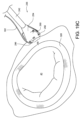
図17は、図14の外科用縫合装置の先端部を部分的に断面して示す斜視図である。第2のフェルール解放フィーチャ278が示されている。この第2のフェルール解放フィーチャ278は、ピボットピン284に回動可能に支持され、湾曲アーム290に乗るようにばね部283によって付勢される。この第2のフェルール解放フィーチャ278は、前述したフェルール解放フィーチャと同様に動作し、フェルールおよびその縫合糸を装置から解放するのに用いられる。 FIG. 17 is a perspective view, partially in section, of the distal end of the surgical suturing device of FIG. 14. A second ferrule release feature 278 is shown. This second ferrule release feature 278 is rotatably supported on pivot pin 284 and biased by spring portion 283 to ride on curved arm 290 . This second ferrule release feature 278 operates similarly to the ferrule release features previously described and is used to release the ferrule and its suture from the device.

第1フェルール解放フィーチャ259は、図17の部分断面図にも示されている。第1フェルール解放フィーチャ259は、ピボットピン262に回動可能に支持され、ばね部265によって湾曲アーム290の移動経路から離れる方向に付勢されている。手動ボタン267がヘッド254に向かって押し込まれない限り、第1フェルール解放フィーチャ259は湾曲アーム290に係合しない。第1フェルール解放フィーチャ259の動作については、以下でより詳細に説明する。 First ferrule release feature 259 is also shown in partial cross-section in FIG. First ferrule release feature 259 is rotatably supported on pivot pin 262 and biased away from the path of movement of curved arm 290 by spring portion 265 . First ferrule release feature 259 does not engage curved arm 290 unless manual button 267 is pushed toward head 254 . The operation of first ferrule release feature 259 will be described in more detail below.

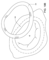
図18A~図18Cは、図14の外科用縫合装置の先端部を部分的に断面にして示す側面図であり。針266の動きを示す。図18Aでは、針266は、フェルール係合チップ292がフェルールホルダ288から離れた後退位置で示されている。フェルールホルダ288は、装置ヘッド254から形成されるか、または装置ヘッド254に結合されている。フェルール296は、フェルールホルダ288内に保持されている。フェルール296は、縫合糸302の第1端部298に結合されている。縫合糸302の第2端部300は、この実施形態ではフェルールを有していないものとして示されているが、いくつかの実施形態では、縫合糸302の第2端部300もフェルールを有することができる。
前述のように、本明細書で使用される「縫合糸」という用語は、糸、ケーブル、ワイヤ、フィラメント、ストランド、ライン、ヤーン、ガットまたは同様の構造を含み、天然および/または合成を含み、モノフィラメント、複合フィラメントまたはマルチフィラメント形態(編み、織り、撚り、または他の方法にもの)を含み、ならびにそれらの均等物、置換、組合せを含む。
18A to 18C are side views, partially in section, of the distal end of the surgical suturing device of FIG. 14. The movement of the needle 266 is shown. In FIG. 18A, needle 266 is shown in a retracted position with ferrule-engaging tip 292 spaced from ferrule holder 288. Ferrule holder 288 is formed from or coupled to device head 254 . Ferrule 296 is held within ferrule holder 288. Ferrule 296 is coupled to first end 298 of suture 302. Although the second end 300 of the suture 302 is shown without a ferrule in this embodiment, in some embodiments the second end 300 of the suture 302 also has a ferrule. I can do it.
As mentioned above, the term "suture" as used herein includes threads, cables, wires, filaments, strands, lines, yarns, strings or similar structures, including natural and/or synthetic; Including monofilament, composite filament or multifilament forms (knitted, woven, twisted or otherwise), as well as equivalents, permutations and combinations thereof.

ヘッド254は、針266のフライホイール部の組織係合面303と共に、組織咬合領域295を画成する。この実施形態では、組織咬合領域295は、シャフト242の長手方向軸305と実質的に平行な方向を向いている。 The head 254, together with the tissue engaging surface 303 of the flywheel portion of the needle 266, defines a tissue engaging region 295. In this embodiment, tissue occlusion region 295 is oriented substantially parallel to longitudinal axis 305 of shaft 242.

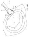
図18Bに示すように、アクチュエータロッド246を先端方向304に移動させると、針266は針回動軸の周りで第1方向306に回動する。この第1方向306の回動の間、湾曲アーム290のフェルール係合チップ292は、その後退位置(図18Aに示す)から組織咬合領域295を通り、係合位置(図18Bに示す)に至る。この実施形態では、フェルール係合チップ292は、シャフト242の長手方向軸線305を実質的に横切る円弧状経路に沿って移動する。図18Bの係合位置では、フェルール係合チップ292はフェルール296に結合される。この結合は、締まりばめまたは代替取り付け機構によるが、その選択は当業者に知られている。このフェルール係合チップと対応するフェルールとの結合は、作用的アライメントと呼ぶことができる。 As shown in FIG. 18B, moving the actuator rod 246 in the distal direction 304 causes the needle 266 to rotate in a first direction 306 about the needle rotation axis. During this rotation in the first direction 306, the ferrule-engaging tip 292 of the curved arm 290 passes from its retracted position (as shown in FIG. 18A) through the tissue-occlusal region 295 to the engaged position (as shown in FIG. 18B). . In this embodiment, ferrule-engaging tip 292 moves along an arcuate path substantially transverse to longitudinal axis 305 of shaft 242. In the engaged position of FIG. 18B, ferrule engagement tip 292 is coupled to ferrule 296. This coupling may be by interference fit or alternative attachment mechanisms, the choice of which is known to those skilled in the art. This coupling of a ferrule-engaging tip with a corresponding ferrule can be referred to as operative alignment.

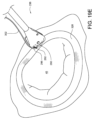
図18Cに示すように、アクチュエータロッド246は基端方向308に移動させることができ、これにより針266を針回動軸の周りで(第1方向306とは反対の)第2方向310に回動させる。この第2方向310の回動の間、湾曲アーム290のフェルール係合チップ292(およびそれに結合されたフェルール296)は、その係合位置(図18Bに示す)から組織咬合領域295を通り、図18Cに示す後退位置に至る。この実施形態では、後退位置に向かって戻っている間に、フェルール係合チップ292は円弧状経路に沿って移動する。 As shown in FIG. 18C, the actuator rod 246 can be moved in a proximal direction 308, thereby rotating the needle 266 in a second direction 310 (opposite the first direction 306) about the needle rotation axis. make it move. During this rotation in the second direction 310, the ferrule-engaging tip 292 (and the ferrule 296 coupled thereto) of the curved arm 290 passes from its engaged position (shown in FIG. 18B) through the tissue-occlusal region 295, as shown in FIG. The retracted position shown in 18C is reached. In this embodiment, while returning toward the retracted position, the ferrule-engaging tip 292 moves along an arcuate path.

第2フェルール解放フィーチャ278の先端312がフェルール係合チップ292からフェルール296を取り外すのに十分なほど、針266が回動しない場合、フェルール296および装置をリセットして初期位置にするために、図18D~図18Fに示す動作が実行される。図18Dに示すように、アクチュエータロッド246は、先端方向314に再び移動することができ、これにより針266は、その針回動軸の周りで第1方向316に回動される。この第1方向306の回動の間、湾曲アーム290のフェルール係合チップ292(およびそれに結合されたフェルール296)は、その開始位置(図18Cに示す
)から組織咬合領域295を通り、図18Dに示す係合位置に至る。装置は、理想的には、
この工程の前に縫合糸が通過していたかもしれない組織から離れるように移動する。フェルール係合チップ292はフェルール296に依然として結合されているが、フェルール296はフェルールホルダ288内に配置されている。
If the needle 266 does not pivot enough for the tip 312 of the second ferrule release feature 278 to remove the ferrule 296 from the ferrule-engaging tip 292, the ferrule 296 and device are reset to the initial position as shown in FIG. The operations shown in 18D to 18F are performed. As shown in FIG. 18D, the actuator rod 246 can be moved again in the distal direction 314, thereby causing the needle 266 to rotate about its needle rotation axis in a first direction 316. During this rotation in the first direction 306, the ferrule-engaging tip 292 (and the ferrule 296 coupled thereto) of the curved arm 290 passes from its starting position (shown in FIG. 18C) through the tissue-occlusal region 295 and in FIG. 18D. The engaged position shown in is reached. The device ideally
Move the suture away from the tissue it may have passed through prior to this step. Ferrule engagement tip 292 is still coupled to ferrule 296, but ferrule 296 is positioned within ferrule holder 288.

図18Eに示すように、第1フェルール解放フィーチャ259の先端318は、第1フェルール解放機構259のボタン267を押し下げることによって、フェルール296の下方で湾曲アーム290に係合することができる。 As shown in FIG. 18E, the tip 318 of the first ferrule release feature 259 can engage the curved arm 290 below the ferrule 296 by depressing the button 267 of the first ferrule release mechanism 259.

第1フェルール解放フィーチャ259が図18Eの位置に維持された状態で、図18Fに示すように、アクチュエータロッド246を基端方向322に移動させると、針266は針回動軸を中心に第2方向324(第1方向316の逆方向)に回動する。この第2方向324の回動の間、第1フェルール解放フィーチャ259はフェルールホルダ288内のフェルール296を保持し、湾曲アーム290のフェルール係合チップ292は、フェルール296なしに、その係合位置(図18Eに示す)から、組織咬合領域295を通って、図18Fに示す後退位置へと戻る。これにより装置はリセットされ、必要に応じて、同じ縫合糸で別のステッチを形成することができる。 With the first ferrule release feature 259 maintained in the position of FIG. 18E, moving the actuator rod 246 in the proximal direction 322, as shown in FIG. 18F, causes the needle 266 to move into the second Rotation in direction 324 (opposite direction of first direction 316). During this rotation in the second direction 324, the first ferrule release feature 259 retains the ferrule 296 in the ferrule holder 288 and the ferrule engagement tip 292 of the curved arm 290 moves into its engaged position (without the ferrule 296). 18E) through tissue occlusion region 295 and back to the retracted position shown in FIG. 18F. This resets the device and allows another stitch to be made with the same suture, if desired.

図19A~図19Jは、図14の外科用縫合装置236を用い、弁輪形成リングと対応する環状組織に縫合糸を通して配置し、心臓弁機能の回復を助ける方法を示す。図19Aは、外科的状況を概略的に示す。心臓のチャンバーに低侵襲のアクセスが形成されている。僧帽弁40を取り囲む環状組織326が拡張し、その結果、弁膜はもはや適切な僧帽弁閉鎖を維持することができなくなっている。所望のサイズの弁輪形成リングを環状組織の上に設置することができ、これにより、環状組織が人工器官に向かって内側に張られ、好ましい、より小さい僧帽弁輪を再確立する。
図19Bに示されているように、弁輪形成リング328を心臓に導入し、図19Cに示すように環状組織326の上に配置する。図19Cに示すように、縫合装置236は使用の準備が整っている。便宜上、これらの図には、ハンドル、アクチュエータが示されておらず、シャフトも全体は示されていない。前述のように、装置236は、シャフト242の端部のヘッド254によって少なくとも一部が画成された咬合領域295を有している。縫合糸302の端部に結合されたフェルール296は、装置ヘッド254において、咬合領域295の一方側に配置されたフェルールホルダに保持されている。湾曲アーム290およびフェルール係合チップ292は、咬合領域295の他方側の後退位置にある。
19A-19J illustrate how the surgical suturing device 236 of FIG. 14 can be used to place a suture through an annuloplasty ring and corresponding annular tissue to aid in restoring heart valve function. Figure 19A schematically depicts the surgical situation. Minimally invasive access is created into the chambers of the heart. The annular tissue 326 surrounding the mitral valve 40 has expanded such that the leaflets are no longer able to maintain proper mitral valve closure. An annuloplasty ring of the desired size can be placed over the annulus, thereby tensioning the annulus inwardly toward the prosthesis and reestablishing the preferred smaller mitral annulus.
An annuloplasty ring 328 is introduced into the heart, as shown in FIG. 19B, and placed over the annular tissue 326, as shown in FIG. 19C. As shown in FIG. 19C, suturing device 236 is ready for use. For convenience, the handle, actuator, and shaft are not shown in their entirety in these figures. As previously discussed, device 236 has an occlusal region 295 defined at least in part by head 254 at the end of shaft 242 . A ferrule 296 coupled to the end of the suture 302 is held in a ferrule holder located on one side of the occlusal region 295 in the device head 254. Curved arm 290 and ferrule-engaging tip 292 are in a retracted position on the other side of occlusal region 295.

図19Dに示すように、組織咬合領域295は、環状組織326の上に載っている弁輪形成リング328上に配置される。図19Eに示すように針が作動され、これにより、湾曲アーム290およびそのフェルール係合チップ292が、弁輪形成リング328を通り、その下の環状組織を通り、再び弁輪形成リング328を通って、フェルール296と結合する。
図19Fに示すように、針の作動が解除され、これにより、湾曲アーム290およびそのフェルール係合チップ292が(取り付けられたフェルール296と共に)引き戻され、弁輪形成リングおよびその下の環状組織を通って、再び後退位置に至る。縫合糸302の端部がフェルール296に連結されているので、縫合糸302の一部も引かれて弁輪形成リングおよび環状組織を通る。
図19Gに示されるように、縫合装置236は、弁輪形成リング328から引き離され、これにより、縫合糸302をステッチから引き出す。図19Hに示すように、フェルール296を縫合糸302から除去し、縫合糸302を弁輪形成リング328およびその下の環状組織に縫合したままにし、2つの自由な糸端部298,300を弁輪形成リング328から突出させておく。
図19Iに示すように、緩い糸端部298,300は、弁輪形成リング328を定位置に保持するのを助ける機械的締結具332で固定することができる。図19Jに示すように、弁輪形成リング328を下の組織に完全に固定するために、弁輪形成リング328の複数箇所で上記縫合工程を繰り返すことができる。例えば機械的締結具332A~332Nを用いて縫合糸302A~302Nを保持する。
As shown in FIG. 19D, tissue-biting region 295 is positioned on annuloplasty ring 328, which rests on annular tissue 326. As shown in FIG. The needle is actuated as shown in FIG. 19E, which causes the curved arm 290 and its ferrule-engaging tip 292 to pass through the annuloplasty ring 328, through the underlying annular tissue, and back through the annuloplasty ring 328. and is coupled to the ferrule 296.
As shown in FIG. 19F, the needle is deactuated, which causes the curved arm 290 and its ferrule-engaging tip 292 (along with the attached ferrule 296) to pull back and engage the annuloplasty ring and underlying annular tissue. through and reach the retreat position again. Since the end of suture 302 is connected to ferrule 296, a portion of suture 302 is also pulled through the annuloplasty ring and annular tissue.
As shown in FIG. 19G, suturing device 236 is pulled away from annuloplasty ring 328, thereby pulling suture 302 out of the stitch. As shown in FIG. 19H, ferrule 296 is removed from suture 302, leaving suture 302 sutured to annuloplasty ring 328 and the underlying annular tissue, and the two free thread ends 298, 300 are removed from the annuloplasty ring 328 and the underlying annular tissue. It is made to protrude from the annular formation ring 328.
As shown in FIG. 19I, the loose thread ends 298, 300 can be secured with mechanical fasteners 332 that help hold the annuloplasty ring 328 in place. As shown in FIG. 19J, the above suturing process can be repeated at multiple locations on the annuloplasty ring 328 to fully secure the annuloplasty ring 328 to the underlying tissue. For example, mechanical fasteners 332A-332N are used to hold sutures 302A-302N.

ここまでの実施形態の針は、最大で一対の湾曲アームを有している。しかしながら、他の実施形態の針は、2対以上の湾曲アームを有することが可能である。例えば、図20Aよび図20Bは、外科用縫合装置の別の実施形態を概略的に示す上面図と側面図である。この実施形態の針334は、複数対の湾曲アームを有している。各対の湾曲アームは、他の対とは異なる半径を有する円弧状通路をたどるようになっている。
針334は、前述したフライホイール部と同様のフライホイール部336を有している。針334は、第1対の湾曲アーム338A、338Bと第2対の湾曲アーム340A、340Bとを有する。この実施形態では、第2対の湾曲アーム340A、340Bは、第1対の湾曲アーム338A、338Bの間に配置される。先の実施形態と同様に、針334は針回動軸342を画成し、アクチュエータ344は針334に結合され、針334を回動軸342の周りに回動させる。この実施形態では、アクチュエータ344が針344から離れる方向346に移動すると、針は第1方向348に回動する。 針334が第1方向348に回動すると、湾曲アーム338A、338B、340A、340Bのフェルール係合チップは、対応するフェルール350A、350B、352A、352Bに向かって円弧状経路上を移動する。第1対のフェルール350A、350Bは第1縫合糸354の異なる端部に結合され、第2対のフェルール352A、352Bは第2縫合糸356の異なる端部に結合されている。
湾曲アーム338A、338B、340A、340Bが、組織に通され、それらの対応するフェルールと係合され、次いで、戻り方向に回動して第1および第2の縫合糸354,356を引いて組織を通すと、結果として得られる組織358での縫合糸の配置は図21A(上面図)および図21B(左側面図)に概略的に示すようになる。第1縫合糸354の各端部は、第2縫合糸356の端部が組織358に出入りする場合よりも、潜在的な切開点360から遠い箇所で同じ組織358に出入りする。
第1対の湾曲アーム338A、338Bの円弧(より大きい円弧)と、第2対の湾曲アーム340A、340B(より小さな円弧)との相違のために、第1縫合糸354は第2縫合糸356よりも深く組織に通される。図21Aおよび図21Bに示す縫合ステッチは、それらの間に切開部を形成する前に巾着縫合閉鎖部を設定するのに有用である。これにより、外科処置中に、必要に応じて切開部を閉じたり引き寄せたりすることができる。
The needles of the embodiments so far have at most a pair of curved arms. However, other embodiments of the needle can have more than one pair of curved arms. For example, FIGS. 20A and 20B are top and side views schematically illustrating another embodiment of a surgical suturing device. The needle 334 in this embodiment has multiple pairs of curved arms. Each pair of curved arms follows an arcuate path having a different radius than the other pairs.
Needle 334 has a flywheel portion 336 similar to the flywheel portion described above. Needle 334 has a first pair of curved arms 338A, 338B and a second pair of curved arms 340A, 340B. In this embodiment, the second pair of curved arms 340A, 340B is positioned between the first pair of curved arms 338A, 338B. Similar to the previous embodiment, needle 334 defines a needle rotation axis 342 and an actuator 344 is coupled to needle 334 to rotate needle 334 about rotation axis 342 . In this embodiment, when the actuator 344 moves in a direction 346 away from the needle 344, the needle rotates in a first direction 348. As the needle 334 pivots in the first direction 348, the ferrule-engaging tips of the curved arms 338A, 338B, 340A, 340B move on an arcuate path toward the corresponding ferrules 350A, 350B, 352A, 352B. A first pair of ferrules 350A, 350B are coupled to different ends of a first suture 354, and a second pair of ferrules 352A, 352B are coupled to different ends of a second suture 356.
The curved arms 338A, 338B, 340A, 340B are threaded through the tissue, engaged with their corresponding ferrules, and then pivoted in a return direction to pull the first and second sutures 354, 356 through the tissue. Once passed, the resulting suture placement in tissue 358 is as shown schematically in FIG. 21A (top view) and FIG. 21B (left side view). Each end of the first suture 354 enters and exits the same tissue 358 farther from the potential incision point 360 than the end of the second suture 356 enters and exits the tissue 358.
Due to the difference between the arc of the first pair of curved arms 338A, 338B (larger arc) and the second pair of curved arms 340A, 340B (smaller arc), the first suture 354 is connected to the second suture 356. It goes deeper into the organization. The suture stitches shown in FIGS. 21A and 21B are useful for establishing a purse string closure prior to forming an incision therebetween. This allows the incision to be closed or retracted as needed during the surgical procedure.

図22Aおよび図22Bは、外科用縫合装置のさらなる実施形態を概略的に示す上面図と側面図である。この実施形態の針362は、複数対の湾曲アームを有している。各対の湾曲アームは、同様の円弧状経路をたどる。針362は、前述のフライホイール部と同様のフライホイール部364を有している。針362はまた、第1対の湾曲アーム366A、366Bと、第2対の湾曲アーム368A、368Bとを有する。この実施形態では、第2対の湾曲アーム368A、368Bは、第1対の湾曲アーム366A、366Bの間に配置されている。先の実施形態と同様に、針362は針回動軸370を画成し、アクチュエータ372は針362に結合されて針362を回動軸370の周りに回動させる。この実施形態では、アクチュエータ372が針362から離れる方向374に移動すると、針は第1方向376に回動する。針362が第1方向376に回動すると、湾曲アーム366A、366B、368A、368Bのフェルール係合チップは、対応するフェルール378A、378B、380A、380Bに向かって円弧状経路上を移動する。第1対のフェルール378A、378Bはそれぞれ第1縫合糸382の異なる端部に結合され、第2対のフェルール380A、380Bは第2縫合糸384の異なる端部にそれぞれ結合されている。
湾曲アーム366A、366B、368A、368Bが、組織に通され、対応するフェルールと係合され、次いで戻り方向に回動して、第1、第2の縫合糸382,384を引いて組織に通す。その結果として生じる組織386での縫合糸の配置が、図23A(上面図)および図23B(左側面図)に概略的に示されている。第1縫合糸382の各端部は、第2縫合糸384の端部が組織386に出入りする場合よりも、潜在的な切開点388から遠い箇所で同じ組織386に出入りする。 しかしながら、前の実施形態とは異なり、第1対の湾曲アーム366A、366Bの円弧と第2対の湾曲アーム368A、368Bの円弧とは実質的に同じであるので、第1縫合糸382と第2縫合糸384は組織386に同じ深さで通っている。図23Aおよび図23Bに示す縫合ステッチは、それらの間に切開部を形成する前に巾着縫合閉鎖部を設定するのに有用である。これにより、外科処置中に、必要に応じて切開部を閉じたり引き寄せたりすることができる。
22A and 22B are top and side views schematically illustrating a further embodiment of a surgical suturing device. The needle 362 in this embodiment has multiple pairs of curved arms. Each pair of curved arms follows a similar arcuate path. Needle 362 has a flywheel portion 364 similar to the flywheel portion described above. Needle 362 also has a first pair of curved arms 366A, 366B and a second pair of curved arms 368A, 368B. In this embodiment, the second pair of curved arms 368A, 368B is positioned between the first pair of curved arms 366A, 366B. Similar to the previous embodiment, needle 362 defines a needle rotation axis 370 and an actuator 372 is coupled to needle 362 to rotate needle 362 about rotation axis 370. In this embodiment, when the actuator 372 moves in a direction 374 away from the needle 362, the needle rotates in a first direction 376. As the needle 362 pivots in the first direction 376, the ferrule-engaging tips of the curved arms 366A, 366B, 368A, 368B move on an arcuate path toward the corresponding ferrules 378A, 378B, 380A, 380B. A first pair of ferrules 378A, 378B are each coupled to a different end of a first suture 382, and a second pair of ferrules 380A, 380B are each coupled to a different end of a second suture 384.
The curved arms 366A, 366B, 368A, 368B are threaded through the tissue, engaged with the corresponding ferrules, and then pivoted in a return direction to pull the first and second sutures 382, 384 through the tissue. . The resulting placement of the suture in tissue 386 is shown schematically in FIG. 23A (top view) and FIG. 23B (left side view). Each end of the first suture 382 enters and exits the same tissue 386 at a point farther from the potential incision point 388 than the end of the second suture 384 enters and exits the tissue 386. However, unlike previous embodiments, the arcs of the first pair of curved arms 366A, 366B and the second pair of curved arms 368A, 368B are substantially the same, so that the first suture 382 and Two sutures 384 pass through tissue 386 at the same depth. The suture stitches shown in FIGS. 23A and 23B are useful for establishing a purse string closure prior to forming the incision therebetween. This allows the incision to be closed or retracted as needed during the surgical procedure.

ここまでの実施形態は、様々な数の湾曲アームを有する単一の針を有していた。しかしながら、他の実施形態では、複数の針を有することが可能である。例えば、図24Aおよび図24Bは、外科用縫合装置の別の実施形態を概略的に示す上面図と側面図である。この実施形態は、複数の針390、408を有する。第1針390は、前述のフライホイール部と同様のフライホイール部392を有する。第1針390はまた、ブッシュ面393を有している。このブッシュ面393は、フライホイール部392の一部に結合されるか、またはフライホイール部392の一部として形成され、第2針408が回動するための表面を提供するように構成されている。第1針390はまた、一対の湾曲アーム394A、394Bを有する。先の実施形態と同様に、第1針390は針回動軸396を画成し、第1アクチュエータロッド398は第1針390に結合されて針390を回動軸396の周りに回動させる。この実施形態では、第1アクチュエータロッド398が第1針390から離れる方向400に移動すると、第1針390は第1の方向402に回動する。第1針390が第1の方向402に回動すると、湾曲アーム394A、394Bのそれぞれのフェルール係合チップは、対応するフェルール404A、404Bに向かって円弧状経路上を移動する。第1対のフェルール404A、404Bは、それぞれ第1縫合糸406の異なる端部に結合されている。 Previous embodiments have had a single needle with varying numbers of curved arms. However, other embodiments can have multiple needles. For example, FIGS. 24A and 24B schematically depict top and side views of another embodiment of a surgical suturing device. This embodiment has multiple needles 390, 408. The first needle 390 has a flywheel portion 392 similar to the flywheel portion described above. First needle 390 also has a bushing surface 393. This bushing surface 393 is coupled to or formed as part of the flywheel portion 392 and is configured to provide a surface for the second needle 408 to rotate. There is. First needle 390 also has a pair of curved arms 394A, 394B. Similar to the previous embodiment, the first needle 390 defines a needle rotation axis 396 and the first actuator rod 398 is coupled to the first needle 390 to rotate the needle 390 about the rotation axis 396. . In this embodiment, when the first actuator rod 398 moves in a direction 400 away from the first needle 390, the first needle 390 rotates in a first direction 402. As the first needle 390 rotates in the first direction 402, each ferrule-engaging tip of the curved arms 394A, 394B moves on an arcuate path toward the corresponding ferrule 404A, 404B. The first pair of ferrules 404A, 404B are each coupled to different ends of the first suture 406.

同様に、第2針408は、前述のフライホイール部と同様のフライホイール部410を有している。第2針408はまた、一対の湾曲アーム412A、412Bを有している。先の実施形態と同様に、第2針408は、針回動軸396を画成するが、この実施形態では、第2針408は、第1針390のブッシング面393の周りを回動する。第2アクチュエータロッド414は、第2針408に連結され、第2針408をブッシュ面393の周りに、したがって回動軸396の周りに回動させる。この実施形態では、第2アクチュエータロッド414が第2針408に向かう方向416に移動すると、第2針408は第2の方向418に回動する。第2針408が第2の方向418に回動すると、湾曲アーム412A、412Bのそれぞれのフェルール係合チップは、対応するフェルール420A、420Bに向かって円弧状経路上を移動する。この第2対のフェルール412A、412Bはそれぞれ、第2縫合糸422の異なる端部に結合されている。 Similarly, the second needle 408 has a flywheel portion 410 similar to the flywheel portion described above. The second needle 408 also has a pair of curved arms 412A, 412B. Similar to the previous embodiment, the second needle 408 defines a needle rotation axis 396, but in this embodiment, the second needle 408 pivots about the bushing surface 393 of the first needle 390. . A second actuator rod 414 is coupled to the second needle 408 and rotates the second needle 408 about the bushing surface 393 and thus about the pivot axis 396. In this embodiment, when the second actuator rod 414 moves in a direction 416 toward the second needle 408, the second needle 408 rotates in a second direction 418. As the second needle 408 pivots in the second direction 418, each ferrule-engaging tip of the curved arms 412A, 412B moves on an arcuate path toward the corresponding ferrule 420A, 420B. This second pair of ferrules 412A, 412B are each coupled to a different end of second suture 422.

各対の湾曲アーム394A、394Bおよび412A、412Bが組織に(この実施形態では反対方向に)通され、それらの対応するフェルールと係合し、次いで、戻り方向に回動して第1、第2の縫合糸406,422を引いて組織に通した場合、その結果として得られる組織424における縫合糸の配置は、図25A(上面図)および図25B(左側面図)に概略的に示すようになる。第1縫合糸406の各端部は、第2縫合糸422の端部が組織424に出入りする場合よりも、潜在的切開点426から離れた箇所で同じ組織424に出入りする。第1対の湾曲アーム394A、394Bの円弧(より大きな円弧)と第2対の湾曲アーム412A、412Bの円弧(より小さな円弧)との相違により、第1縫合糸406は第2縫合糸422よりも深く組織に入り込む。この実施形態では、配置された縫合糸406,422の端部が反対方向に向いている。図25Aおよび図25Bに示す縫合ステッチは、それらの間に切開部を形成する前に巾着縫合閉鎖部を設定するのに有用である。これにより、外科処置中に必要に応じて切開部を閉じたり、引き寄せたりすることができる。 Each pair of curved arms 394A, 394B and 412A, 412B are passed through the tissue (in opposite directions in this embodiment), engage their corresponding ferrules, and then pivoted in the return direction to When two sutures 406, 422 are pulled through the tissue, the resulting placement of the sutures in the tissue 424 is as shown schematically in FIG. 25A (top view) and FIG. 25B (left side view). become. Each end of the first suture 406 enters and exits the same tissue 424 at a farther distance from the potential incision point 426 than the end of the second suture 422 enters and exits the tissue 424. Due to the difference between the arc of the first pair of curved arms 394A, 394B (larger arc) and the arc of the second pair of curved arms 412A, 412B (smaller arc), the first suture 406 is more flexible than the second suture 422. penetrate deeply into the organization. In this embodiment, the ends of the disposed sutures 406, 422 are oriented in opposite directions. The suture stitches shown in FIGS. 25A and 25B are useful for establishing a purse string closure prior to forming an incision therebetween. This allows the incision to be closed or retracted as needed during the surgical procedure.

図26Aおよび図26Bは、外科用縫合装置のさらなる実施形態を概略的に示す上面図と側面図である。この実施形態は、複数の針428,442、および454を有する。第1針428は、前述のフライホイール部と同様のフライホイール部430を有する。第1針428は、単一の湾曲アーム432を有する。先の実施形態と同様に、第1針428は針回動軸434を画成し、第1アクチュエータロッド435は針428を回動軸434の周りに回動させるために第1針428に結合される。この実施形態では、第1アクチュエータロッド435が第1針428から離れる方向436に移動すると、第1針428は第1方向438に回動する。第1針428が第1方向438に回動すると、湾曲アーム43
2のフェルール係合チップは、対応するフェルール440に向かって円弧状経路上を移動する。
26A and 26B are top and side views schematically illustrating a further embodiment of a surgical suturing device. This embodiment has multiple needles 428, 442, and 454. The first needle 428 has a flywheel portion 430 similar to the flywheel portion described above. First needle 428 has a single curved arm 432. Similar to the previous embodiment, the first needle 428 defines a needle rotation axis 434 and the first actuator rod 435 is coupled to the first needle 428 to rotate the needle 428 about the rotation axis 434. be done. In this embodiment, when the first actuator rod 435 moves in a direction 436 away from the first needle 428, the first needle 428 rotates in a first direction 438. When the first needle 428 rotates in the first direction 438, the curved arm 43
The two ferrule-engaging tips move on an arcuate path toward the corresponding ferrule 440.

第2針442は、前述のフライホイール部と同様に、フライホイール部(この図では容易には見えない)を有する。第2針442は、単一の湾曲アーム444を有する。先の実施形態と同様に、第2針442は針回動軸434を画成し、第2アクチュエータロッド446は第2針442に結合されて針442を回動軸434の周りに回動させる。この実施形態では、第2アクチュエータロッド446が第2針442から離れる方向448に移動すると、第2の針442は第1方向438に回動する。第2針442が第1方向438に回動すると、湾曲アーム444のフェルール係合チップは、対応するフェルール450に向かって円弧状経路上を移動する。第1対のフェルール440,450はそれぞれ、第1縫合糸452の異なる端部に結合されている。 The second needle 442 has a flywheel portion (not readily visible in this view), similar to the flywheel portion described above. Second needle 442 has a single curved arm 444. Similar to the previous embodiment, the second needle 442 defines a needle rotation axis 434 and a second actuator rod 446 is coupled to the second needle 442 to rotate the needle 442 about the rotation axis 434. . In this embodiment, when the second actuator rod 446 moves in a direction 448 away from the second needle 442, the second needle 442 rotates in the first direction 438. As the second needle 442 rotates in the first direction 438, the ferrule-engaging tip of the curved arm 444 moves on an arcuate path toward the corresponding ferrule 450. A first pair of ferrules 440, 450 are each coupled to a different end of a first suture 452.

第3針454は、前述のフライホイール部と同様にフライホイール部(この図では容易には見えない)を有する。第3針454は、一対の湾曲アーム456A、456Bを有する。先の実施形態の場合と同様に、第3針454は針回動軸434を画成する。第3アクチュエータロッド458は、第3針454に連結され、第3針454を回動軸434の周りに回動させる。この実施形態では、第3アクチュエータロッド458が第3針454に向かう方向460に移動すると、第3針454が第2方向462に回動する。第3針454が第2方向462に回動すると、湾曲アーム456A、456Bのそれぞれのフェルール係合チップは、対応するフェルール464A、464Bに向かって円弧状経路上を移動する。この第2対のフェルール464A、464Bはそれぞれ、第2縫合糸466の異なる端部に結合されている。 The third needle 454 has a flywheel portion (not readily visible in this view) similar to the flywheel portion described above. The third needle 454 has a pair of curved arms 456A, 456B. As in the previous embodiment, the third needle 454 defines a needle rotation axis 434. Third actuator rod 458 is coupled to third needle 454 and rotates third needle 454 about pivot axis 434 . In this embodiment, when the third actuator rod 458 moves in a direction 460 toward the third needle 454, the third needle 454 rotates in a second direction 462. When the third needle 454 rotates in the second direction 462, each ferrule-engaging tip of the curved arms 456A, 456B moves on an arcuate path toward the corresponding ferrule 464A, 464B. This second pair of ferrules 464A, 464B are each coupled to a different end of second suture 466.

各対の湾曲アーム432,444および456A、456Bが組織に(この実施形態では反対方向に)通され、それらの対応するフェルールと係合し、次に戻り方向に回動して第1および第2の縫合糸452,466を組織に通す。その結果として得られる組織468における縫合糸の配置が、図27A(上面図)および図27B(左側面図)に示されている。第1縫合糸452の各端部は、第2縫合糸466の端部が組織468に出入りする場合よりも、潜在的切開点470から離れた位置で同じ組織468に出入りする。この実施形態では、配置された縫合糸452,466の端部も反対方向を向いている。しかしながら、第1湾曲アーム432,444の円弧と第2湾曲アーム456A、456Bの円弧とが実質的に同じであるので、第1縫合糸452と第2縫合糸466は、同じ深さまで組織468に入り込んでいる。
図27Aおよび図27Bに示す縫合ステッチは、それらの間に切開部を形成する前に巾着縫合閉鎖部を設定するのに有用である。これにより、外科処置中に必要に応じて切開部を閉じたり、引き寄せたりすることができる。
Each pair of curved arms 432, 444 and 456A, 456B are passed through the tissue (in opposite directions in this embodiment), engage their corresponding ferrules, and then pivoted in the return direction to Two sutures 452, 466 are passed through the tissue. The resulting placement of sutures in tissue 468 is shown in FIG. 27A (top view) and FIG. 27B (left side view). Each end of the first suture 452 enters and exits the same tissue 468 at a location further from the potential incision point 470 than the end of the second suture 466 enters and exits the tissue 468. In this embodiment, the ends of the disposed sutures 452, 466 also point in opposite directions. However, because the arcs of first curved arms 432, 444 and second curved arms 456A, 456B are substantially the same, first suture 452 and second suture 466 penetrate tissue 468 to the same depth. I'm getting into it.
The suture stitches shown in FIGS. 27A and 27B are useful for establishing a purse string closure prior to forming the incision therebetween. This allows the incision to be closed or retracted as needed during the surgical procedure.

図28Aおよび図28Bは、ヘッド476内で回動可能な針474を有する外科用縫合装置472の別の実施形態を示す。先の実施形態と同様に、ヘッド476はシャフト478に結合され、アクチュエータ480はアクチュエータエンドエフェクタ482によって針474に結合されている。針474は回動軸484を画成し、前述のフライホイール部と同様のフライホイール部486を有する。しかし、この実施形態では、針474の1つ
以上の湾曲アーム488は、針回動軸484と一致しない円弧の中心点490Aを有する。1つ以上の湾曲アーム488の各々は、装置ヘッド476のフェルールホルダ496によって保持された対応するフェルール494と係合してピックアップするようなサイズのフェルール係合チップ492を有している。前述のように、フェルール494は、縫合糸498に連結されている。図28Aに示すように、装置ヘッド476は、針474のフライホイール部と共に、咬合領域500を画成する。
28A and 28B illustrate another embodiment of a surgical suturing device 472 having a needle 474 that is rotatable within a head 476. Similar to the previous embodiment, head 476 is coupled to shaft 478 and actuator 480 is coupled to needle 474 by actuator end effector 482. Needle 474 defines a pivot axis 484 and has a flywheel portion 486 similar to the flywheel portion described above. However, in this embodiment, one or more curved arms 488 of needle 474 have an arcuate center point 490A that does not coincide with needle rotation axis 484. Each of the one or more curved arms 488 has a ferrule-engaging tip 492 sized to engage and pick up a corresponding ferrule 494 held by a ferrule holder 496 of the device head 476 . As previously discussed, ferrule 494 is coupled to suture 498. As shown in FIG. 28A, the device head 476, together with the flywheel portion of the needle 474, defines an occlusal region 500.

図28Bに示すように、この実施形態では、アクチュエータロッド502がヘッド476に向かって移動すると、針474は針回動軸484の周りを第1方向504に回動する。フェルール係合チップ492は、先の実施形態のようにフェルール494をピックアップすることができるが、この実施形態では、円弧中心点490Bは、湾曲アームが係合したときに新たな位置にあることに留意すべきである。なぜなら、円弧中心点(図28Aに符号490Aで示し、図28Bに符号490Bで示す)が、針回動軸484と一致しないからである。この実施形態は、湾曲アーム488が咬合領域500内の組織を引っ張る傾向があるので、いくつかの用途には好ましくないが、別の可能性のある実施形態となる。 As shown in FIG. 28B, in this embodiment, as actuator rod 502 moves toward head 476, needle 474 rotates about needle rotation axis 484 in first direction 504. The ferrule engagement tip 492 can pick up the ferrule 494 as in the previous embodiment, but in this embodiment, the arc center point 490B is in a new position when the curved arm is engaged. It should be kept in mind. This is because the arc center point (indicated by reference numeral 490A in FIG. 28A and reference numeral 490B in FIG. 28B) does not coincide with needle rotation axis 484. Although this embodiment is not preferred for some applications because the curved arm 488 tends to pull tissue within the occlusal region 500, it is another possible embodiment.

図29A~図29Nは、図14の外科用縫合装置を用いて弁輪形成リングをその下の組織に縫合する別の方法を示す。図29Aは、外科的状況を概略的に示す。 心臓のチャン
バーに低侵襲的アクセスが形成されている。僧帽弁40を囲む環状組織326が拡張し、その結果、弁膜がもはや適切な僧帽弁閉鎖を維持することができなくなっている。所望のサイズの弁輪形成リングを環状組織の上に設置することができ、これにより、環状組織が人工器官に向かって内側に張られ、好ましい、より小さい僧帽弁輪を再確立する。弁輪形成リング328は、最初は環状組織から離れており、例えば患者の体外に配置される。縫合装置236は使用準備ができている。便宜上、これらの図には、ハンドル、アクチュエータが省略され、シャフトも全体は示されていない。前述のように、装置236は、シャフト242の端部のヘッド254によって少なくとも一部が画成された咬合領域295を有している。縫合糸302の端部に結合されたフェルール296は、装置ヘッド254の咬合領域295の一方側のフェルールホルダに保持される。湾曲アーム290およびそのフェルール係合チップ292は、咬合領域295の他方側の後退位置にある。
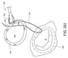
29A-29N illustrate another method of suturing an annuloplasty ring to underlying tissue using the surgical suturing device of FIG. 14. Figure 29A schematically depicts the surgical situation. Minimally invasive access is created into the chambers of the heart. The annular tissue 326 surrounding the mitral valve 40 has expanded such that the valve leaflets are no longer able to maintain proper mitral valve closure. An annuloplasty ring of the desired size can be placed over the annulus, thereby tensioning the annulus inwardly toward the prosthesis and reestablishing the preferred smaller mitral annulus. The annuloplasty ring 328 is initially separated from the annular tissue, eg, placed outside the patient's body. Suturing device 236 is ready for use. For convenience, the handle, actuator, and shaft are not shown in their entirety in these figures. As previously discussed, device 236 has an occlusal region 295 defined at least in part by head 254 at the end of shaft 242 . A ferrule 296 coupled to the end of the suture 302 is retained in a ferrule holder on one side of the occlusal region 295 of the device head 254. Curved arm 290 and its ferrule-engaging tip 292 are in a retracted position on the other side of occlusal region 295.

図29Bに示すように、組織咬合領域295が弁輪形成リング328に対して側方から配置される。すなわち、湾曲アーム290が係合されるのであれば、湾曲アーム290がフェルール296に向かう途中で弁輪形成リング328を一回だけ通過するように、組織咬合領域295が配置される。図29Cに示すように、針が作動して、湾曲アーム290およびそのフェルール係合チップ292が弁輪形成リング328を通ってフェルール296と結合する。図29Dに示すように、針が作動解除されると、湾曲アーム290およびそのフェルール係合チップ292が、取り付けられたフェルールと共に、弁輪形成リング328を通って引き戻され、再び後退位置に至る。
図29Eに示されるように、縫合装置236は、弁輪形成リング328から矢印506方向に引き離され、それにより、弁輪形成リング328のステッチから縫合糸302をより大きく引き出すことができる。図18D~図18Fに関して説明したように、フェルール296は、フェルール解放フィーチャ259を用いてフェルールホルダ(この図では見えない)に戻すことができる。装置236は、第2のステッチを配置する準備ができる。
As shown in FIG. 29B, tissue-occluding region 295 is laterally positioned relative to annuloplasty ring 328. That is, tissue-occlusal region 295 is positioned such that if curved arm 290 is engaged, curved arm 290 passes through annuloplasty ring 328 only once on its way to ferrule 296. The needle is actuated to cause the curved arm 290 and its ferrule-engaging tip 292 to pass through the annuloplasty ring 328 and engage the ferrule 296, as shown in FIG. 29C. As shown in FIG. 29D, when the needle is deactuated, the curved arm 290 and its ferrule-engaging tip 292, along with the attached ferrule, are pulled back through the annuloplasty ring 328 and again into the retracted position.
As shown in FIG. 29E, suturing device 236 is pulled away from annuloplasty ring 328 in the direction of arrow 506, thereby allowing greater withdrawal of suture 302 from the stitches of annuloplasty ring 328. As described with respect to FIGS. 18D-18F, ferrule 296 can be returned to the ferrule holder (not visible in this view) using ferrule release feature 259. Device 236 is ready to place the second stitch.

図29Fに示すように、組織咬合領域295は、弁輪形成リングに既に配置された第1
のステッチに対応する位置で、環状組織326上に配置される。図29Gに示ように、針が作動され、これにより、湾曲アーム290およびそのフェルール係合チップ292が下方に向かって環状組織326を通り、上方に戻ってフェルール296と結合する。
図29Hに示すように、針が作動解除されると、湾曲アーム290およびそのフェルール係合チップ292が、取り付けられたフェルール296と共に、環状組織236を通って引き戻されて後退位置に至る。縫合糸302の端部がフェルール296に連結されているので、縫合糸302の一部も引かれて環状組織236を通る。
図29Iに示すように、縫合装置236が環状組織326から矢印508方向に引き離され、それにより、環状組織326のステッチから縫合糸302をより大きく引き出すことができる。図18D~図18Fに関して説明したように、フェルール296は、フェルール解放フィーチャ259を用いてフェルールホルダ(この図では見えない)に戻すことができる。装置236は、第3のステッチを配置する準備ができる。
As shown in FIG. 29F, the tissue occluding region 295 is located at the first annuloplasty ring.
is placed on the annular tissue 326 at a location corresponding to the stitches in the annular tissue 326 . The needle is actuated, causing the curved arm 290 and its ferrule-engaging tip 292 to pass downwardly through the annular tissue 326 and back upwardly to engage the ferrule 296, as shown in FIG. 29G.
When the needle is deactuated, the curved arm 290 and its ferrule-engaging tip 292, along with the attached ferrule 296, are pulled back through the annular tissue 236 to a retracted position, as shown in FIG. 29H. Because the end of suture 302 is connected to ferrule 296, a portion of suture 302 is also pulled through annular tissue 236.
As shown in FIG. 29I, suturing device 236 is pulled away from annular tissue 326 in the direction of arrow 508, thereby allowing greater withdrawal of suture 302 from the stitches in annular tissue 326. As described with respect to FIGS. 18D-18F, ferrule 296 can be returned to the ferrule holder (not visible in this view) using ferrule release feature 259. Device 236 is ready to place the third stitch.

図29Jに示すように、組織咬合領域295が側方から弁輪形成リング328に再度配置される。すなわち、湾曲アーム290が係合されるのであれば、湾曲アーム290がフェルール296に向かう途中で弁輪形成リング328を一回だけ通過するように、組織咬合領域295が配置される。図29Kに示すように、針が作動して、湾曲アーム290およびそのフェルール係合チップ292が弁輪形成リング328を通ってフェルール296と結合する。図29Lに示すように、針が作動解除されると、湾曲アーム290およびそのフェルール係合チップ292が、取り付けられたフェルールと共に、弁輪形成リング328を通って引き戻され、再び後退位置に至る。
図29Mに示すように、縫合装置236が弁輪形成リング328から矢印510方向に引き離され、それにより、弁輪形成328の第2のステッチから縫合糸302をより大きく引き出すことができる。フェルール296は縫合糸302から除去され、縫合糸302の第1端部512および第2端部514は、弁輪形成リング328から上方に突出する。必要に応じて、上記の方法を、1つ以上の追加の縫合糸を用いて、1つ以上の追加の位置で繰り返すことができる。しかしながら、簡略化のために、この例では、2つの縫合糸端部512,514を有するただ1つの縫合糸302について説明する。図29Nに示すように、緩い糸端部512,514は、弁輪形成リング328を定位置に保持するのを助けるために、機械的締結具516で固定することができる。縫合糸端部512,514が図29Nに示されている。
As shown in FIG. 29J, tissue occlusion region 295 is laterally repositioned onto annuloplasty ring 328. That is, tissue-occlusal region 295 is positioned such that if curved arm 290 is engaged, curved arm 290 passes through annuloplasty ring 328 only once on its way to ferrule 296. As shown in FIG. 29K, the needle is actuated to cause the curved arm 290 and its ferrule-engaging tip 292 to pass through the annuloplasty ring 328 and engage the ferrule 296. As shown in FIG. 29L, when the needle is deactuated, the curved arm 290 and its ferrule-engaging tip 292, along with the attached ferrule, are pulled back through the annuloplasty ring 328 and again into the retracted position.
As shown in FIG. 29M, suturing device 236 is pulled away from annuloplasty ring 328 in the direction of arrow 510, thereby allowing greater withdrawal of suture 302 from the second stitch of annuloplasty 328. Ferrule 296 is removed from suture 302 and first end 512 and second end 514 of suture 302 protrude upwardly from annuloplasty ring 328. If desired, the above method can be repeated at one or more additional locations using one or more additional sutures. However, for simplicity, this example describes only one suture 302 having two suture ends 512, 514. As shown in FIG. 29N, the loose thread ends 512, 514 can be secured with mechanical fasteners 516 to help hold the annuloplasty ring 328 in place. Suture ends 512, 514 are shown in FIG. 29N.

図14~図15に示す外科用縫合装置のような、上述の実施形態のいくつかは、フェルール解放フィーチャ259を有する。このフェルール解放フィーチャは、フェルールがフェルール係合チップによって捕捉された後に、フェルールをフェルールホルダに戻すように配置されている。このフェルールのリセット(または再装備)は、外科用縫合装置を用いて、単一の縫合糸で連続ステッチを実行することを可能にする。しかしながら、再装填するための一体的なフェルール解放フィーチャを有さない外科用縫合装置の他の実施形態では、外科用縫合装置の再装備を可能にする構成および方法を有することが望ましい。図30は、外科用縫合装置のための再装備ツール518の一実施形態の斜視図である。再装備ツール518は、針ランプ520と、針ランプ520に結合された位置決めフレーム522とを有する。この実施形態では、位置決めフレーム522は、外科用縫合装置の組織咬合領域と係合するように構成される。他の実施形態では、位置決めフレームは、1つ以
上の針の1つ以上のフェルール係合チップの移動経路に対して、針ランプ520を位置決
めするために、外科用縫合装置の任意の部分に係合するように構成してもよい。
Some of the embodiments described above, such as the surgical suturing device shown in FIGS. 14-15, have a ferrule release feature 259. The ferrule release feature is positioned to return the ferrule to the ferrule holder after the ferrule has been captured by the ferrule-engaging tip. This resetting (or re-equipping) of the ferrule allows continuous stitches to be performed with a single suture using a surgical suturing device. However, in other embodiments of surgical suturing devices that do not have an integral ferrule release feature for reloading, it is desirable to have a configuration and method that allows reloading of the surgical suturing device. FIG. 30 is a perspective view of one embodiment of a retooling tool 518 for a surgical suturing device. Retooling tool 518 has a needle lamp 520 and a positioning frame 522 coupled to needle lamp 520. In this embodiment, positioning frame 522 is configured to engage the tissue-occlusal region of the surgical suturing device. In other embodiments, the positioning frame engages any portion of the surgical suturing apparatus to position the needle ramp 520 relative to the path of travel of the one or more ferrule-engaging tips of the one or more needles. It may be configured to match.

針ランプ520は、先導エッジ524(leading edge)と、針対向面526と、後尾エッジ528(trailing edge)とを有する。この実施形態では、先導エッジ524は丸みを
帯びているが、他の実施形態では、より鋭いまたは異なる形状の縁を有することができる。この実施形態では、針ランプ520は、以下でより詳細に説明するように、針の1つ以上の湾曲アームの円弧状経路に対応する形状の円弧状の面を有する。この実施形態では、針対向面526は、円弧状の針ランプ520の凸側にある。
Needle ramp 520 has a leading edge 524, a needle facing surface 526, and a trailing edge 528. In this embodiment, leading edge 524 is rounded, but other embodiments can have sharper or differently shaped edges. In this embodiment, needle ramp 520 has an arcuate surface shaped to correspond to the arcuate path of one or more curved arms of the needle, as described in more detail below. In this embodiment, the needle facing surface 526 is on the convex side of the arcuate needle ramp 520.

この実施形態では、後尾エッジ528は、位置決めフレーム522を針ランプ520に結合するバネ要素530によって、針対向面520から離れる方向に付勢されている。ばね要素の適切な例としては、圧縮ばね、引張りばね、ねじりばね、一定力のばね、可変力のばね、板ばね、らせんばね、および加工されたばねが挙げられるが、これらに限定されない。この実施形態では、後尾エッジ528は針ランプ520と一体であるが、他の実施形態では、後尾エッジは針ランプ520と別体をなして針ランプに対して移動可能であってもよい。(例えば、針ランプがバネ要素なしで位置決めフレームに結合され、別体をなす後尾エッジが位置決めフレームに結合されたバネ要素によって付勢されている場合等がある。) In this embodiment, trailing edge 528 is biased away from needle facing surface 520 by a spring element 530 that couples positioning frame 522 to needle ramp 520 . Suitable examples of spring elements include, but are not limited to, compression springs, tension springs, torsion springs, constant force springs, variable force springs, leaf springs, helical springs, and textured springs. In this embodiment, the trailing edge 528 is integral with the needle ramp 520, but in other embodiments the trailing edge may be separate from the needle ramp 520 and movable relative to the needle ramp. (For example, the needle lamp may be coupled to the positioning frame without a spring element, and a separate trailing edge may be biased by a spring element coupled to the positioning frame.)

図31A~図31Cは、図30の再装備ツールを用いて再装備される外科用縫合装置を部分的に断面して示す側面図である。図31A~図31Cの縫合装置は、前述した図2の縫合装置48と同じである。図31Aで示す状況は、図6Cの状況と同様である。図31Aにおいて、アクチュエータロッド58が基端方向532に移動され、針74は針回動軸を中心に符号534で示す方向に回動する。この実施形態では、針74とこれに対応するフェルール係合チップを複数有するが、側面視では、単一の湾曲アーム88と、そのフェルール係合チップ90、および縫合糸114に取り付けられた対応するフェルール106が、どのように作用するかを示す。しかしながら、説明された再装備工程が、複数の湾曲アームで同時に同様に生じ得ることを理解されたい。湾曲アーム88のフェルール係合チップ90(およびそれら結合されたフェルール106)は、後退位置にある。この状況は、例えば組織または他の対象に最初のステッチを形成するために装置48が使用された後に生じる。 31A-31C are side views, partially in section, of a surgical suturing device being retooled using the reloading tool of FIG. 30. The suturing device of FIGS. 31A to 31C is the same as the suturing device 48 of FIG. 2 described above. The situation shown in FIG. 31A is similar to the situation in FIG. 6C. In FIG. 31A, actuator rod 58 is moved in a proximal direction 532, and needle 74 rotates about the needle rotation axis in a direction indicated by 534. Although this embodiment has multiple needles 74 and corresponding ferrule-engaging tips, in side view, a single curved arm 88 with its ferrule-engaging tips 90 and corresponding ferrule-engaging tips attached to suture 114 It shows how the ferrule 106 works. However, it should be understood that the described reequipment process may similarly occur on multiple curved arms simultaneously. Ferrule engaging tips 90 (and their associated ferrules 106) of curved arm 88 are in a retracted position. This situation occurs, for example, after device 48 has been used to form a first stitch in tissue or other object.

図31Aに示すように、再装備ツール518は、装置48の咬合領域115内に配置されている。この実施形態では、位置決めフレーム522は、装置ヘッド66の外側に係合し、また、組織咬合領域115を通っている。図31Aは部分的に露出した図であるため、位置決めフレーム522の背面側の脚部が隠れていて破線で示され、手前側の脚部が図示されていない。 As shown in FIG. 31A, the refitting tool 518 is positioned within the occlusal region 115 of the device 48. In this embodiment, positioning frame 522 engages the outside of device head 66 and also passes through tissue occlusion region 115. Since FIG. 31A is a partially exposed view, the legs on the back side of the positioning frame 522 are hidden and shown in broken lines, and the legs on the front side are not shown.

図31Bに示すように再装備ツール518が配置されており、これにより、アクチュエータロッド58が先端方向536に移動され、針74が針回動軸を中心に弧状方向538に回動している時に、フェルール106は、湾曲アーム88のフェルール係合チップ90によって保持されている状態で、針ランプ520に接近して乗るか又は横切るようになっている。弧状方向538の回動の間に、湾曲アーム88のフェルール係合チップ90は、その後退位置から針ランプ520を通過し、後尾エッジ528を越え、フェルール106をフェルールホルダ102に戻す。しかし、この時点で、フェルール106は、依然として、湾曲アーム88のフェルール係合チップ90に結合されている。 As shown in FIG. 31B, a reloading tool 518 is positioned to move the actuator rod 58 in a distal direction 536 while the needle 74 is pivoted in an arcuate direction 538 about the needle rotation axis. , the ferrule 106 is adapted to ride close to or across the needle ramp 520 while being held by the ferrule engagement tip 90 of the curved arm 88 . During rotation in arcuate direction 538, ferrule-engaging tip 90 of curved arm 88 passes from its retracted position past needle ramp 520, over trailing edge 528, and returns ferrule 106 to ferrule holder 102. However, at this point, ferrule 106 is still coupled to ferrule engagement tip 90 of curved arm 88.

再装備ツール518の後尾エッジ528は針対向面から離れるように(この実施形態では針74の湾曲アーム88に向かって)付勢されているので、後尾エッジ528は、フェルール係合チップ90にあるフェルールに出会う直前に、湾曲アーム88に接する。この位置において、図31Bに示すように、後尾エッジ528は、針74が後退位置に戻るように回動された場合でも、フェルール106がフェルール係合チップ90と共に戻るのを禁じる。図31Cに示すように、針74は、アクチュエータロッド58の基端方向532の移動に伴い、戻り方向に回動されて後退位置に至る。再装備ツール518の後尾エッジ528は、フェルール106をフェルールホルダ102内に保持しており、湾曲アーム88のフェルール係合チップ90は、フェルールが無い状態である。この段階で、再装備ツール518を取り外し、装置は、所望の組織または対象物の位置に別のステッチを配置する準備が整う。再装備ツール518およびその等価物は、複数のステッチの間で縫合糸に連結されたフェルールを処理する必要なく、複数のステッチを同じ縫合糸を用いて配置する場合に、有用である。 The trailing edge 528 of the refitting tool 518 is biased away from the needle facing surface (in this embodiment toward the curved arm 88 of the needle 74) so that the trailing edge 528 is at the ferrule engagement tip 90. Just before meeting the ferrule, it contacts the curved arm 88. In this position, as shown in FIG. 31B, trailing edge 528 inhibits ferrule 106 from returning with ferrule-engaging tip 90 even if needle 74 is rotated back to the retracted position. As shown in FIG. 31C, the needle 74 is rotated in the return direction and reaches the retracted position as the actuator rod 58 moves in the proximal direction 532. The trailing edge 528 of the refitting tool 518 retains the ferrule 106 within the ferrule holder 102, and the ferrule engaging tip 90 of the curved arm 88 is free of the ferrule. At this stage, the refitting tool 518 is removed and the device is ready to place another stitch at the desired tissue or object location. Refitting tool 518 and its equivalents are useful when placing multiple stitches with the same suture without having to manipulate ferrules connected to the suture between the multiple stitches.

図32A~32Jは、図2の外科用縫合装置を使用して心臓の腱索を置換する別の方法を示す。図32Aは手術状況を示す。心臓の左心室に低侵襲的アクセスが形成されている。図示の乳頭筋40Bから疾患のある腱索が除去され、縫合装置48が使用できる状態になっている。便宜上、これらの図には、ハンドル、アクチュエータが省略され、シャフトも全体は示されていない。前述のように、装置48は、シャフト54の端部のヘッド66によって少なくとも部分的に画成された組織咬合領域124を有する。縫合糸114の端部に結合された第1、第2のフェルール106,108は、装置ヘッド66の組織咬合領域124の基端側のフェルールホルダ(この図では見えない)に保持される。第1、第2の湾曲アーム88,92およびそれぞれの第1、第2のフェルール係合チップ90,94は、組織咬合領域124の先端側の後退位置にある。 
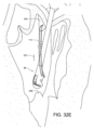
32A-32J illustrate another method of replacing cardiac chordae tendineae using the surgical suturing device of FIG. 2. FIG. Figure 32A shows the surgical situation. Minimally invasive access is created into the left ventricle of the heart. The diseased chordae tendineae have been removed from the illustrated papillary muscle 40B, and the suturing device 48 is ready for use. For convenience, the handle, actuator, and shaft are not shown in their entirety in these figures. As previously discussed, device 48 has a tissue-biting region 124 defined at least in part by head 66 at the end of shaft 54 . First and second ferrules 106, 108 coupled to the ends of suture 114 are retained in a ferrule holder (not visible in this view) proximal to tissue-occlusal region 124 of device head 66. The first and second curved arms 88 and 92 and the respective first and second ferrule engaging tips 90 and 94 are in retracted positions distal to the tissue occlusion region 124.

図32Bに示すように、組織咬合領域124は、僧帽弁40の弁膜540上に配置される。図32Cに示すように、針が作動されると、第1,第2の湾曲アーム88,92およびフェルール係合チップが、組織咬合領域内の弁膜540を通過し、対応する第1、第2のフェルール106,108と係合する。図32Dに示すように、針が作動解除されると、第1、第2湾曲アーム88,92およびそれらのフェルール係合チップ(ならびにこれらのフェルール係合チップによって保持された各フェルール106,108)が引かれて、組織咬合領域内の弁膜540を通り、再び後退位置に戻る。縫合糸114の端部がフェルール106,108に連結されているので、縫合糸114もまた、引かれて弁膜540を通る。図32Eに示すように、縫合装置114は、縫合糸114のたるみを取り除くために、弁膜540から方向542へ引き離すことができる。 As shown in FIG. 32B, tissue occlusion region 124 is positioned on leaflet 540 of mitral valve 40. As shown in FIG. As shown in FIG. 32C, when the needle is actuated, the first and second curved arms 88, 92 and the ferrule-engaging tip pass through the leaflet 540 within the tissue-occlusal region, causing the corresponding first and second The ferrules 106 and 108 of the As shown in FIG. 32D, when the needle is deactuated, the first and second curved arms 88, 92 and their ferrule-engaging tips (as well as each ferrule 106, 108 held by these ferrule-engaging tips) is pulled back through the leaflets 540 in the tissue occlusal region and back to the retracted position. Since the ends of suture 114 are connected to ferrules 106, 108, suture 114 is also pulled through leaflet 540. As shown in FIG. 32E, suturing device 114 can be pulled away from leaflet 540 in direction 542 to take up slack in suture 114.

図32Fに示すように、組織咬合領域124は、乳頭筋40B上に配置される。図32Gに示すように、針が作動されると、第1、第2の湾曲アーム88,92およびそれらのフェルール係合チップが組織咬合領域内の乳頭筋40Bを通過し、対応する第1、第2のフェルール106,108と係合する。図32Hに示すように、針が作動解除されると、第1、第2の湾曲アーム88,92およびそれらのフェルール係合チップ(ならびにこれらのフェルール係合チップによって保持されたフェルール106,108)が引かれて、組織咬合領域内の組織40Bを通り、再び後退位置に戻る。縫合糸114の端部がフェルール106,108に結合されているので、縫合糸114も引かれて乳頭筋40Bを通る。図32Iに示すように、縫合糸114のたるみを吸収するために、縫合装置48を方向544に乳頭筋40Bから引き離すことができる。フェルール106,108は縫合糸114から除去することができ、縫合糸114を調節することによって、所望の置換腱索長さ550が選択された後で、糸端部546を機械的締結具548で固定することができる。 As shown in FIG. 32F, tissue occlusion region 124 is positioned over papillary muscle 40B. As shown in FIG. 32G, when the needle is actuated, the first and second curved arms 88, 92 and their ferrule-engaging tips pass through the papillary muscles 40B in the tissue-occlusal region, causing the corresponding first, Engages with second ferrules 106,108. As shown in FIG. 32H, when the needle is deactuated, the first and second curved arms 88, 92 and their ferrule-engaging tips (as well as the ferrules 106, 108 held by these ferrule-engaging tips) is pulled through the tissue 40B in the tissue occlusion area and back to the retracted position. Since the ends of suture 114 are coupled to ferrules 106, 108, suture 114 is also pulled through papillary muscle 40B. As shown in FIG. 32I, suturing device 48 can be pulled away from papillary muscle 4OB in direction 544 to take up slack in suture 114. The ferrules 106, 108 can be removed from the suture 114 and the thread ends 546 are secured with mechanical fasteners 548 after the desired replacement chordae length 550 is selected by adjusting the suture 114. Can be fixed.

図33A~33Cは、図18Aの実施形態と同様の外科用縫合装置600の別の実施形態の先端を示す。ただし、異なる針、より広い組織咬合領域を有し、さらに湾曲アームのチップからのフェルールの除去を可能にするのを助けるリンクを有する。図33Aは、露出側面図であり、針602の動きを示している。図33Aでは、針602は後退位置で示されている。この後退位置では、フェルール係合チップ604がフェルールホルダ606から離れている。フェルールホルダ606は、装置ヘッド608と一体に形成されるか、または別体をなして装置ヘッド608と連結されている。フェルール610は、フェルールホルダ606内に装填され保持されている。フェルール610は、縫合糸614の第1端612に結合されている。前述したように、本明細書で使用される「縫合糸」という用語は、糸、ケーブル、ワイヤ、フィラメント、ストランド、ライン、ヤーン、ガットまたは同様の構造を含み、天然または合成のいずれであってもよく、モノフィラメント、複合フィラメントまたはマルチフィラメント形態(編み、織り、撚り、または他の方法によるもの)を含み、それらの均等物、置換、組合せを含む。 33A-33C illustrate the tip of another embodiment of a surgical suturing device 600 similar to the embodiment of FIG. 18A. However, it has a different needle, a wider tissue-biting area, and also has a link to help allow removal of the ferrule from the tip of the curved arm. FIG. 33A is an exposed side view showing movement of needle 602. In FIG. 33A, needle 602 is shown in a retracted position. In this retracted position, ferrule engagement tip 604 is separated from ferrule holder 606. The ferrule holder 606 is either integrally formed with the device head 608 or is connected to the device head 608 as a separate body. Ferrule 610 is loaded and held within ferrule holder 606. Ferrule 610 is coupled to first end 612 of suture 614. As previously stated, the term "suture" as used herein includes threads, cables, wires, filaments, strands, lines, yarns, strings or similar structures, whether natural or synthetic. It may also include monofilament, composite filament or multifilament forms (by knitting, weaving, twisting or other methods), and equivalents, permutations and combinations thereof.

ヘッド608は、針602のフライホイール部の組織係合面616とともに、組織咬合領域618を画成する。この実施形態では、組織咬合領域618は、シャフト622の長手軸620と実質的に平行な方向を向いている。この実施形態では、アクチュエータロッド624は、針602に直接連結されていない。その代わりに、アクチュエータロッド624は、駆動リンク626によって針602に連結されている。 The head 608, together with a tissue engaging surface 616 of the flywheel portion of the needle 602, defines a tissue engaging region 618. In this embodiment, tissue occlusion region 618 is oriented substantially parallel to longitudinal axis 620 of shaft 622. In this embodiment, actuator rod 624 is not directly coupled to needle 602. Instead, actuator rod 624 is connected to needle 602 by drive link 626.

図33Bに示すように、アクチュエータロッド624は、アクチュエータ(図示せず)によって基端方向(手元方向)628に移動させることができる(通常、レバーをハンドルに向かって引き絞ることによって達成される)。これにより、駆動リンク626が針602をその回転軸632を中心にして第1方向630に回転させる。この第1方向630の回転の過程で、湾曲アーム634のフェルール係合チップ604は、その後退位置(図33Aに示す)から、組織咬合領域618内の組織636を通って、係合位置(図33Bに示す)に至る。この実施形態では、フェルール係合チップ604は、シャフト622の長手軸620を実質的に横切る円弧の経路に沿って動く。図33Bの係合位置では、フェルール係合チップ604は、締まりばめまたは代替の取り付け機構によってフェルール610に結合されるが、この選択は当業者に知られている。フェルール係合チップとフェルールの結合は、作用的アライメント(operational alignment)と呼ばれることがある。ここでは直線状のシャフトについて論じてきたが、シャフトの他の構成(屈曲シャフト、湾曲シャフト、可撓性シャフト、直線シャフト、またはそれらの組み合わせを含む)を採用することができる。 As shown in FIG. 33B, the actuator rod 624 can be moved in a proximal direction 628 by an actuator (not shown) (typically accomplished by squeezing a lever toward the handle). . This causes drive link 626 to rotate needle 602 about its axis of rotation 632 in a first direction 630 . During the course of rotation in this first direction 630, the ferrule-engaging tip 604 of the curved arm 634 moves from its retracted position (as shown in FIG. 33B). In this embodiment, ferrule-engaging tip 604 moves along an arcuate path substantially transverse to longitudinal axis 620 of shaft 622. In the engaged position of FIG. 33B, ferrule engagement tip 604 is coupled to ferrule 610 by an interference fit or alternative attachment mechanism, options known to those skilled in the art. The coupling of the ferrule-engaging tip and ferrule is sometimes referred to as operational alignment. Although straight shafts have been discussed herein, other configurations of shafts may be employed, including bent shafts, curved shafts, flexible shafts, straight shafts, or combinations thereof.

図33Cに示されるように、アクチュエータロッド624は、先端方向638に移動することができる(通常、ハンドルから離れるように付勢されているレバーを解放して、最初の位置に戻すことによって達成される)。これにより、駆動リンク626を先端に向かって押し、針602を、その回転軸632を中心に第2方向640(第1方向630の逆方向)に回転させる。この第2方向640の回転の過程で、湾曲アーム634のフェルール係合チップ604(およびそれに結合されているフェルール610)が、その係合位置(図33Bに示される)から組織咬合領域618内の組織636を通って図33Cに示す後退位置まで戻る。 As shown in FIG. 33C, the actuator rod 624 can be moved in a distal direction 638 (typically accomplished by releasing a lever that is biased away from the handle and returning to its initial position). ). This pushes the drive link 626 toward the tip, causing the needle 602 to rotate about its axis of rotation 632 in a second direction 640 (opposite the first direction 630). During this rotation in the second direction 640, the ferrule-engaging tip 604 (and the ferrule 610 coupled thereto) of the curved arm 634 moves from its engaged position (shown in FIG. 33B) into the tissue-occlusal region 618. Return through tissue 636 to the retracted position shown in Figure 33C.

図33Dに示すように、ステッチ642が組織636内に形成されたので、装置ヘッド608を、組織636から離れるように引く(方向644で示す)。この実施形態では、装置600はフェルール解放機構646を有する。このフェルール解放機構646は、針602が図33Dの後退位置にある時に、フェルール係合チップ604がフェルール610に結合されている箇所のすぐ手前で、湾曲アーム634を付勢している。図33Eに示されるように、アクチュエータロッド624は、さらに先端方向648に移動することができる(通常、レバーがハンドルから離れるように超過突出(hyper-extending)することにより達成される。ちなみに、針の湾曲アームを組織に通して前進する時にはレバーはハンドルに向かって引き絞られる。)。アクチュエータロッド624がさらに先端方向648に移動すると、駆動リンク626は、針602をさらに方向640に回転させ、これにより、フェルール610がフェルール解放機構646に接触し、フェルール係合チップ604から除去される。駆動リンク626は、運動制限ノッチ650を有している。運動制限ノッチ650は、針602のカム面652に当接し、これにより、湾曲アーム634がフェルール係合チップ604をフェルール解放機構646を通過するように回転させるのを、制限する。これにより、フェルール係合チップ604への損傷を回避することができ、後続の縫合糸がさらなる縫合のために装置に装填されることを可能にする。 As shown in FIG. 33D, now that the stitch 642 has been formed within the tissue 636, the device head 608 is pulled away from the tissue 636 (indicated by direction 644). In this embodiment, device 600 has a ferrule release mechanism 646. The ferrule release mechanism 646 biases the curved arm 634 just in front of where the ferrule-engaging tip 604 is coupled to the ferrule 610 when the needle 602 is in the retracted position of FIG. 33D. As shown in FIG. 33E, the actuator rod 624 can be moved further distally 648 (usually accomplished by hyper-extending the lever away from the handle. Incidentally, the needle (The lever is squeezed toward the handle when the curved arm of the lever is advanced through the tissue.) As actuator rod 624 moves further distally 648 , drive link 626 rotates needle 602 further in direction 640 such that ferrule 610 contacts ferrule release mechanism 646 and is removed from ferrule-engaging tip 604 . Drive link 626 has a movement limiting notch 650. A motion-limiting notch 650 abuts a camming surface 652 of the needle 602, thereby restricting the curved arm 634 from rotating the ferrule-engaging tip 604 past the ferrule-release mechanism 646. This avoids damage to the ferrule-engaging tip 604 and allows subsequent sutures to be loaded into the device for further suturing.

低侵襲手術のための縫合装置およびその針および方法の様々な利点は、上記で議論されている。実施形態を、本明細書の例により記述した。詳細な開示は、単なる例示として提示されることが意図されており、限定するものではないことは、当業者には明らかであろう。様々な変更、改良、および修正は、本明細書に明示的に述べられていないが、当業者には意図されることである。これらの改変、改良、および改変は、特許請求の範囲で記述する発明の精神の範囲内である。さらに、処理要素またはシーケンスの列挙された順序、または数字、文字、または名称の使用は、請求項に特定されている場合を除いて、限定することを意図するものではない。したがって、本発明は、添付の特許請求の範囲およびそれと同等のものによってのみ限定される。 Various advantages of suturing devices and their needles and methods for minimally invasive surgery are discussed above. Embodiments have been described by way of example herein. It will be apparent to those skilled in the art that the detailed disclosure is intended to be presented by way of example only and not as a limitation. Various changes, improvements, and modifications not expressly stated herein will occur to those skilled in the art. These modifications, improvements, and modifications are within the spirit of the invention as described in the claims. Furthermore, the listed order of processing elements or sequences or the use of numbers, letters, or names are not intended to be limiting, other than as specified in the claims. Accordingly, the invention is limited only by the appended claims and the equivalents thereof.

Claims (15)

1つ以上のフェルールホルダおよび組織咬合領域を画成するとともに、フェルール解放フィーチャを含み、前記1つ以上のフェルールホルダの各々が、縫合糸に結合されたフェルールを解放可能に保持するヘッドと、
前記ヘッドが先端に連結されたシャフトと、
前記シャフトの内部を通って延びるアクチュエータロッドと、
フライホイール部と、前記フライホイール部から延びるとともに各々がフェルール係合チップを含む1つ以上の湾曲アームと、を有し、前記ヘッドに回動可能に結合され、その回転軸に沿って突出する突起を含む針と、
前記アクチュエータロッドの先端に連結された第1部分と前記針に連結された第2部分を有するとともにノッチを含む駆動リンクと、
を備え、
前記アクチュエータロッドの前記先端の第1方向の移動が、前記針を、前記1つ以上の湾曲アームの各々の前記フェルール係合チップが前記1つ以上のフェルールホルダから離れ前記組織咬合領域から後退した後退位置から、前記組織咬合領域を通って、前記1つ以上の湾曲アームの各々の前記フェルール係合チップが前記1つ以上のフェルールホルダと作用的にアライメントされて前記フェルールと結合される係合位置へと、回動させるように構成され、
前記針はさらに前記後退位置から、前記フェルール係合チップが前記組織咬合領域から遠ざかる方向に超過位置へと回動されるように構成され、この超過位置では、前記突起の一部が前記駆動リンクの前記ノッチ内に配置され、これにより、前記針の前記1つ以上の湾曲アームの各々の前記フェルール係合チップが、前記組織咬合領域からさらに遠ざかるように移動するのを制限され、
前記針が前記後退位置から前記超過位置へと回動される時に、前記1つ以上の湾曲ワームの各々の前記フェルール係合チップに結合された前記フェルールが、前記ヘッドに配置された前記フェルール解放フィーチャに接し、前記1つ以上の湾曲アームの各々のフェルール係合チップから離脱させられる、低侵襲手術のための縫合装置。
a head defining one or more ferrule holders and a tissue occlusion region and including a ferrule release feature, each of the one or more ferrule holders releasably retaining a ferrule coupled to a suture;
a shaft with the head connected to the tip;
an actuator rod extending through the interior of the shaft;
a flywheel portion; and one or more curved arms extending from the flywheel portion and each including a ferrule-engaging tip, rotatably coupled to the head and projecting along an axis of rotation thereof. a needle including a protrusion;
a drive link having a first portion connected to the tip of the actuator rod and a second portion connected to the needle, and including a notch;
Equipped with
Movement of the tip of the actuator rod in a first direction causes the needle to move the ferrule-engaging tip of each of the one or more curved arms away from the one or more ferrule holders and retracted from the tissue-occlusal region. From a retracted position, the ferrule-engaging tip of each of the one or more curved arms is operatively aligned and engaged with the ferrule through the tissue-occlusal region. configured to be rotated into position;
The needle is further configured to be rotated from the retracted position into an overposition position in which the ferrule-engaging tip is directed away from the tissue occlusal region, in which a portion of the projection engages the drive link. disposed within the notch of the needle, thereby restricting the ferrule-engaging tip of each of the one or more curved arms of the needle from moving further away from the tissue occlusion region;
The ferrule coupled to the ferrule-engaging tip of each of the one or more curved worms releases the ferrule disposed in the head when the needle is rotated from the retracted position to the overload position. A suturing device for minimally invasive surgery, the suturing device contacting a feature and being disengaged from a ferrule-engaging tip of each of the one or more curved arms.
前記ヘッドが、前記1つ以上の湾曲アームのためのガイドを備えていない、請求項1に
記載の縫合装置。
The suturing device of claim 1, wherein the head does not include a guide for the one or more curved arms.
前記ヘッドが、アクチュエータアクセスチャネルをさらに画成する、請求項1に記載の縫合装置。 The suturing device of claim 1, wherein the head further defines an actuator access channel. 前記針の前記フライホイール部が、前記組織咬合領域を画成するのを助ける組織係合面を有する、請求項1に記載の縫合装置。 The suturing device of claim 1, wherein the flywheel portion of the needle has a tissue engaging surface that helps define the tissue occlusion region. 前記駆動リンクが、前記アクチュエータロッドの前記先端に回動可能に連結されている、請求項1に記載の縫合装置。 The suturing device of claim 1, wherein the drive link is rotatably coupled to the distal end of the actuator rod. 前記アクチュエータロッドの前記先端の第2方向の移動により、前記針が前記超過位置へと回動するように構成されている、請求項1に記載の縫合装置。The suturing device of claim 1, wherein movement of the distal end of the actuator rod in a second direction is configured to rotate the needle to the overload position. 前記針が前記後退位置から前記係合位置へと回動する時および前記係合位置から前記後退位置へと回動する時に、前記突起の一部が前記駆動リンクの前記ノッチ内に配置されていない、請求項1に記載の縫合装置。A portion of the protrusion is disposed within the notch of the drive link when the needle pivots from the retracted position to the engaged position and when the needle pivots from the engaged position to the retracted position. 2. The suturing device of claim 1, wherein the suturing device is free. 前記ノッチが、前記駆動リンクの前記第1部分と前記第2部分の間に配置されている、請求項1に記載の縫合装置。The suturing device of claim 1, wherein the notch is located between the first portion and the second portion of the drive link. 前記駆動リンクは細長く基端から先端まで延びており、前記駆動リンクの前記第1部分は前記駆動リンクの前記基端またはその近傍に配置され、前記駆動リンクの前記第2部分は前記駆動リンクの前記先端又はその近傍に配置されている、請求項8に記載の縫合装置。The drive link is elongate and extends from a proximal end to a distal end, the first portion of the drive link being located at or near the proximal end of the drive link, and the second portion of the drive link being disposed at or near the proximal end of the drive link. The suturing device according to claim 8, wherein the suturing device is located at or near the tip. 前記針の前記突起の外周面は円筒面形状をなし、前記ノッチは、前記突起の半径と等しい半径を有する円筒面形状の部分を有している、請求項1に記載の縫合装置。The suturing device according to claim 1, wherein the outer peripheral surface of the protrusion of the needle has a cylindrical shape, and the notch has a cylindrical portion having a radius equal to the radius of the protrusion. 前記シャフトは、直線状のシャフト、屈曲したシャフト、湾曲したシャフト、および可撓性シャフトからなる群から選択される、請求項1に記載の縫合装置。 The suturing device of claim 1, wherein the shaft is selected from the group consisting of a straight shaft, a bent shaft, a curved shaft, and a flexible shaft. 前記針が、前記後退位置から前記組織咬合領域を通って前記係合位置へと回動される際に、前記1つ以上の湾曲アームの前記フェルール係合チップが、前記ヘッドの基端側と先端側との間の軸線を横切るようにして前記組織咬合領域を通るように構成されている、請求項1に記載の縫合装置。 The ferrule-engaging tips of the one or more curved arms engage the proximal side of the head as the needle is rotated from the retracted position through the tissue-occlusal region to the engaged position. The suturing device according to claim 1, wherein the suturing device is configured to pass through the tissue occlusion region so as to cross an axis between the suturing device and the distal end side. 前記アクチュエータロッドの前記第1方向の移動が、前記アクチュエータロッドの基端方向の移動である、請求項1に記載の縫合装置。 The suturing device according to claim 1, wherein the movement of the actuator rod in the first direction is movement of the actuator rod in a proximal direction . 前記アクチュエータロッドの第1方向の移動が、前記アクチュエータロッドの先端方向の移動である、請求項1に記載の縫合装置。 The suturing device according to claim 1, wherein the movement of the actuator rod in the first direction is movement of the actuator rod in a distal direction . 前記駆動リンクは、前記駆動リンクの前記第2部分で前記針に回動可能に連結されている、請求項5に記載の縫合装置。 6. The suturing device of claim 5, wherein the drive link is pivotally coupled to the needle at the second portion of the drive link.
JP2020539045A 2018-01-28 2019-01-28 Suturing device, needle and method for minimally invasive surgery Active JP7369698B2 (en)

Applications Claiming Priority (3)

Application Number Priority Date Filing Date Title
US201862622923P 2018-01-28 2018-01-28
US62/622,923 2018-01-28
PCT/US2019/015430 WO2019152317A1 (en) 2018-01-28 2019-01-28 Suturing device for minimally invasive surgery and needles and methods thereof

Publications (3)

Publication Number Publication Date
JP2021511855A JP2021511855A (en) 2021-05-13
JP2021511855A5 JP2021511855A5 (en) 2021-11-11
JP7369698B2 true JP7369698B2 (en) 2023-10-26

Family

ID=67478905

Family Applications (1)

Application Number Title Priority Date Filing Date
JP2020539045A Active JP7369698B2 (en) 2018-01-28 2019-01-28 Suturing device, needle and method for minimally invasive surgery

Country Status (6)

Country Link
US (2) US11337688B2 (en)
EP (1) EP3723626A4 (en)
JP (1) JP7369698B2 (en)
AU (1) AU2019215435A1 (en)
CA (1) CA3089814A1 (en)
WO (1) WO2019152317A1 (en)

Families Citing this family (2)

* Cited by examiner, † Cited by third party
Publication number Priority date Publication date Assignee Title
US10492779B2 (en) * 2017-02-20 2019-12-03 Edwards Lifesciences Corporation Suturing devices for heart valve surgery
BR102021003388A2 (en) * 2021-02-23 2022-09-06 José Leonardo Rocha De Faria MENISCUS SUTURE DEVICE

Citations (6)

* Cited by examiner, † Cited by third party
Publication number Priority date Publication date Assignee Title
JP2002159499A (en) 2000-09-29 2002-06-04 Shoshi Sho Suturing instrument for endoscope
JP2007283097A (en) 2006-03-31 2007-11-01 Ethicon Endo Surgery Inc Suture thread equipped with adhesive or sealant delivering mechanism
JP2014509209A (en) 2010-12-23 2014-04-17 サージマティクス,インコーポレーテッド Skin suturing device using a rotating needle
JP2014531916A (en) 2011-08-08 2014-12-04 エンドエボリューション,エルエルシー Apparatus and method for minimally invasive sutures
JP2016500298A (en) 2012-12-13 2016-01-12 エシコン・エンド−サージェリィ・インコーポレイテッドEthicon Endo−Surgery,Inc. Circular needle applier
US20160345961A1 (en) 2015-06-01 2016-12-01 Lsi Solutions, Inc. Re-arming apparatus for a minimally invasive surgical suturing device

Family Cites Families (55)

* Cited by examiner, † Cited by third party
Publication number Priority date Publication date Assignee Title
US1822330A (en) 1930-01-13 1931-09-08 Ainslie George Suturing instrument
US2646045A (en) 1951-05-01 1953-07-21 Bruno S Priestley Mechanical suturing device
SE441643B (en) 1983-02-08 1985-10-28 Innova Ab suturing instrument
US5403328A (en) 1992-04-22 1995-04-04 United States Surgical Corporation Surgical apparatus and method for suturing body tissue
US5578044A (en) 1992-09-04 1996-11-26 Laurus Medical Corporation Endoscopic suture system
US5713910A (en) 1992-09-04 1998-02-03 Laurus Medical Corporation Needle guidance system for endoscopic suture device
US5527321A (en) 1993-07-14 1996-06-18 United States Surgical Corporation Instrument for closing trocar puncture wounds
WO1995011630A1 (en) 1993-10-25 1995-05-04 Children's Medical Center Corporation Retractable suture needle with self-contained driver
US5431666A (en) 1994-02-24 1995-07-11 Lasersurge, Inc. Surgical suture instrument
US5562686A (en) 1995-04-19 1996-10-08 United States Surgical Corporation Apparaus and method for suturing body tissue
AU6858896A (en) 1995-08-24 1997-03-19 Nobles-Lai Engineering, Inc. Method and apparatus for suturing
US5911727A (en) 1996-02-20 1999-06-15 Cardiothoracic Systems, Inc. Stitcher
US5766183A (en) 1996-10-21 1998-06-16 Lasersurge, Inc. Vascular hole closure
US6059719A (en) 1997-08-06 2000-05-09 Olympus Optical Co., Ltd. Endoscope system
JPH11299799A (en) * 1998-04-23 1999-11-02 Olympus Optical Co Ltd Forceps
US6641592B1 (en) 1999-11-19 2003-11-04 Lsi Solutions, Inc. System for wound closure
US6475135B1 (en) 2000-05-25 2002-11-05 Urogyn Ltd. Finger-guided suture device
US6533796B1 (en) 2000-10-11 2003-03-18 Lsi Solutions, Inc. Loader for surgical suturing instrument
US8313496B2 (en) 2001-02-02 2012-11-20 Lsi Solutions, Inc. System for endoscopic suturing
US6997931B2 (en) 2001-02-02 2006-02-14 Lsi Solutions, Inc. System for endoscopic suturing
US7144401B2 (en) * 2001-06-07 2006-12-05 Olympus Optical Co., Ltd. Suturing device for endoscope
CA2450662C (en) 2001-06-14 2010-06-15 Suturtek Incorporated Apparatus and method for surgical suturing with thread management
US7344545B2 (en) 2002-01-30 2008-03-18 Olympus Corporation Endoscopic suturing system
US7232447B2 (en) 2002-06-12 2007-06-19 Boston Scientific Scimed, Inc. Suturing instrument with deflectable head
US20100042116A1 (en) 2002-10-03 2010-02-18 Faising Chui Cycling suturing and knot-tying device
US7338504B2 (en) 2002-10-03 2008-03-04 Gibbens Group, L.L.C. Cycling suturing and knot-tying device
US7935128B2 (en) 2003-05-21 2011-05-03 Boston Scientific Scimed, Inc. Remotely-reloadable suturing device
US7211093B2 (en) 2004-01-14 2007-05-01 Lsi Solutions, Inc. Sew-right running stitch instrument
US8123764B2 (en) 2004-09-20 2012-02-28 Endoevolution, Llc Apparatus and method for minimally invasive suturing
EP1791476B1 (en) 2004-09-20 2015-12-23 Endoevolution, Llc Apparatus for minimally invasive suturing
US7993354B1 (en) 2010-10-01 2011-08-09 Endoevolution, Llc Devices and methods for minimally invasive suturing
US8211143B2 (en) 2005-03-31 2012-07-03 David Stefanchik Suturing device
US20060282088A1 (en) 2005-06-08 2006-12-14 Ryan Timothy J Apparatus and methods for delivering sutures
US7766925B2 (en) 2005-06-13 2010-08-03 Ethicon Endo-Surgery, Inc. Surgical suturing apparatus
US20070162052A1 (en) 2006-01-06 2007-07-12 Olympus Medical Systems Corp. Loading device for indwelling implement
US7731727B2 (en) 2006-04-26 2010-06-08 Lsi Solutions, Inc. Medical instrument to place a pursestring suture, open a hole and pass a guidewire
US20090222027A1 (en) 2008-02-28 2009-09-03 Lsi Solutions, Inc. Ferrule holder with suture relief lobes
DK200970073A (en) 2009-07-22 2011-01-23 Coloplast As Suturing system and assembly
US8398657B2 (en) 2009-11-19 2013-03-19 Lsi Solutions, Inc. Multi-fire suturing instrument with proximal ferrule release feature
WO2011094619A1 (en) 2010-01-29 2011-08-04 Med-Venture Investments, Llc Methods and apparatuses for suturing of cardiac openings
US8926640B2 (en) 2010-07-13 2015-01-06 Lsi Solutions, Inc. Method and apparatus for closing an opening in thick, moving tissue
US9125644B2 (en) 2011-08-14 2015-09-08 SafePath Medical, Inc. Apparatus and method for suturing tissue
WO2013027210A1 (en) 2011-08-24 2013-02-28 Mininvasive Ltd. Circular bone tunneling device employing a stabilizing element
US9017346B2 (en) 2011-12-14 2015-04-28 Msk, Llc Automated suture device
WO2013126748A1 (en) 2012-02-22 2013-08-29 SafePath Medical, Inc. Means and methods for suturing tissue
GB201208024D0 (en) 2012-05-08 2012-06-20 Berry Alexander C Suturing device
ES2661377T3 (en) 2012-09-26 2018-03-28 Children's National Medical Center Anastomosis ligation tool with half loop clip
JP2016506858A (en) 2013-02-15 2016-03-07 サージマティクス, インコーポレーテッドSurgimatix, Inc. Medical fixation device
US10231728B2 (en) 2013-02-15 2019-03-19 Surgimatix, Inc. Medical fastening device
US9943391B2 (en) 2013-03-12 2018-04-17 Boston Scientific Scimed, Inc. Medical device and method for delivering an implant
US9554793B2 (en) 2013-03-16 2017-01-31 SafePath Medical, Inc. Means and methods for suturing tissue
WO2015048465A1 (en) 2013-09-26 2015-04-02 Surgimatix, Inc. Laparoscopic suture device with autoloading and suture capture
US10512458B2 (en) 2013-12-06 2019-12-24 Med-Venture Investments, Llc Suturing methods and apparatuses
US9554781B2 (en) * 2014-01-23 2017-01-31 Lsi Solutions, Inc. Minimally invasive surgical suturing device and method
US10945723B2 (en) * 2016-11-17 2021-03-16 SafePath Medical, Inc. Systems and methods for suturing tissue

Patent Citations (6)

* Cited by examiner, † Cited by third party
Publication number Priority date Publication date Assignee Title
JP2002159499A (en) 2000-09-29 2002-06-04 Shoshi Sho Suturing instrument for endoscope
JP2007283097A (en) 2006-03-31 2007-11-01 Ethicon Endo Surgery Inc Suture thread equipped with adhesive or sealant delivering mechanism
JP2014509209A (en) 2010-12-23 2014-04-17 サージマティクス,インコーポレーテッド Skin suturing device using a rotating needle
JP2014531916A (en) 2011-08-08 2014-12-04 エンドエボリューション,エルエルシー Apparatus and method for minimally invasive sutures
JP2016500298A (en) 2012-12-13 2016-01-12 エシコン・エンド−サージェリィ・インコーポレイテッドEthicon Endo−Surgery,Inc. Circular needle applier
US20160345961A1 (en) 2015-06-01 2016-12-01 Lsi Solutions, Inc. Re-arming apparatus for a minimally invasive surgical suturing device

Also Published As

Publication number Publication date
JP2021511855A (en) 2021-05-13
CA3089814A1 (en) 2019-08-08
US11337688B2 (en) 2022-05-24
WO2019152317A1 (en) 2019-08-08
US11350927B2 (en) 2022-06-07
US20210077089A1 (en) 2021-03-18
EP3723626A4 (en) 2021-08-18
AU2019215435A1 (en) 2020-07-30
US20190150915A1 (en) 2019-05-23
EP3723626A1 (en) 2020-10-21

Similar Documents

Publication Publication Date Title
JP6617160B2 (en) Suture device and its needle and method for minimally invasive surgery
US10820998B2 (en) Valve repair device
US10736624B2 (en) Minimally invasive surgical suturing device for papillary muscles and methods thereof
CA2990397C (en) Needle for a minimally invasive surgical suturing device
JP7369698B2 (en) Suturing device, needle and method for minimally invasive surgery
US10835233B2 (en) Suturing backstop for minimally invasive surgery
JP2023126564A (en) Device, system, and method for artificial chordae tendineae
US20220240926A1 (en) Suturing device for minimally invasive surgery and needles and methods thereof
WO2016187406A1 (en) Minimally invasive surgical suturing device for papillary muscles and methods thereof

Legal Events

Date Code Title Description
A521 Request for written amendment filed

Free format text: JAPANESE INTERMEDIATE CODE: A523

Effective date: 20210930

A621 Written request for application examination

Free format text: JAPANESE INTERMEDIATE CODE: A621

Effective date: 20210930

A977 Report on retrieval

Free format text: JAPANESE INTERMEDIATE CODE: A971007

Effective date: 20220930

A131 Notification of reasons for refusal

Free format text: JAPANESE INTERMEDIATE CODE: A131

Effective date: 20221011

A601 Written request for extension of time

Free format text: JAPANESE INTERMEDIATE CODE: A601

Effective date: 20230110

A521 Request for written amendment filed

Free format text: JAPANESE INTERMEDIATE CODE: A523

Effective date: 20230113

A131 Notification of reasons for refusal

Free format text: JAPANESE INTERMEDIATE CODE: A131

Effective date: 20230418

A521 Request for written amendment filed

Free format text: JAPANESE INTERMEDIATE CODE: A523

Effective date: 20230628

TRDD Decision of grant or rejection written
A01 Written decision to grant a patent or to grant a registration (utility model)

Free format text: JAPANESE INTERMEDIATE CODE: A01

Effective date: 20230926

A61 First payment of annual fees (during grant procedure)

Free format text: JAPANESE INTERMEDIATE CODE: A61

Effective date: 20231016

R150 Certificate of patent or registration of utility model

Ref document number: 7369698

Country of ref document: JP

Free format text: JAPANESE INTERMEDIATE CODE: R150