JP2016506858A - Medical fixation device - Google Patents
Medical fixation device Download PDFInfo
- Publication number
- JP2016506858A JP2016506858A JP2015558149A JP2015558149A JP2016506858A JP 2016506858 A JP2016506858 A JP 2016506858A JP 2015558149 A JP2015558149 A JP 2015558149A JP 2015558149 A JP2015558149 A JP 2015558149A JP 2016506858 A JP2016506858 A JP 2016506858A
- Authority
- JP
- Japan
- Prior art keywords
- needle
- tissue
- arcuate needle
- arcuate
- fixing device
- Prior art date
- Legal status (The legal status is an assumption and is not a legal conclusion. Google has not performed a legal analysis and makes no representation as to the accuracy of the status listed.)
- Pending
Links
- JAPMJSVZDUYFKL-UHFFFAOYSA-N C1C2C1CCC2 Chemical compound C1C2C1CCC2 JAPMJSVZDUYFKL-UHFFFAOYSA-N 0.000 description 1
Images


Classifications
-
- A—HUMAN NECESSITIES
- A61—MEDICAL OR VETERINARY SCIENCE; HYGIENE
- A61B—DIAGNOSIS; SURGERY; IDENTIFICATION
- A61B17/00—Surgical instruments, devices or methods, e.g. tourniquets
- A61B17/04—Surgical instruments, devices or methods, e.g. tourniquets for suturing wounds; Holders or packages for needles or suture materials
- A61B17/0469—Suturing instruments for use in minimally invasive surgery, e.g. endoscopic surgery
-
- A—HUMAN NECESSITIES
- A61—MEDICAL OR VETERINARY SCIENCE; HYGIENE
- A61B—DIAGNOSIS; SURGERY; IDENTIFICATION
- A61B17/00—Surgical instruments, devices or methods, e.g. tourniquets
- A61B17/04—Surgical instruments, devices or methods, e.g. tourniquets for suturing wounds; Holders or packages for needles or suture materials
- A61B17/0401—Suture anchors, buttons or pledgets, i.e. means for attaching sutures to bone, cartilage or soft tissue; Instruments for applying or removing suture anchors
-
- A—HUMAN NECESSITIES
- A61—MEDICAL OR VETERINARY SCIENCE; HYGIENE
- A61B—DIAGNOSIS; SURGERY; IDENTIFICATION
- A61B17/00—Surgical instruments, devices or methods, e.g. tourniquets
- A61B17/04—Surgical instruments, devices or methods, e.g. tourniquets for suturing wounds; Holders or packages for needles or suture materials
- A61B17/0482—Needle or suture guides
-
- A—HUMAN NECESSITIES
- A61—MEDICAL OR VETERINARY SCIENCE; HYGIENE
- A61B—DIAGNOSIS; SURGERY; IDENTIFICATION
- A61B17/00—Surgical instruments, devices or methods, e.g. tourniquets
- A61B17/04—Surgical instruments, devices or methods, e.g. tourniquets for suturing wounds; Holders or packages for needles or suture materials
- A61B17/06—Needles ; Sutures; Needle-suture combinations; Holders or packages for needles or suture materials
- A61B17/06004—Means for attaching suture to needle
-
- A—HUMAN NECESSITIES
- A61—MEDICAL OR VETERINARY SCIENCE; HYGIENE
- A61B—DIAGNOSIS; SURGERY; IDENTIFICATION
- A61B17/00—Surgical instruments, devices or methods, e.g. tourniquets
- A61B17/04—Surgical instruments, devices or methods, e.g. tourniquets for suturing wounds; Holders or packages for needles or suture materials
- A61B17/06—Needles ; Sutures; Needle-suture combinations; Holders or packages for needles or suture materials
- A61B17/06166—Sutures
-
- A—HUMAN NECESSITIES
- A61—MEDICAL OR VETERINARY SCIENCE; HYGIENE
- A61F—FILTERS IMPLANTABLE INTO BLOOD VESSELS; PROSTHESES; DEVICES PROVIDING PATENCY TO, OR PREVENTING COLLAPSING OF, TUBULAR STRUCTURES OF THE BODY, e.g. STENTS; ORTHOPAEDIC, NURSING OR CONTRACEPTIVE DEVICES; FOMENTATION; TREATMENT OR PROTECTION OF EYES OR EARS; BANDAGES, DRESSINGS OR ABSORBENT PADS; FIRST-AID KITS
- A61F2/00—Filters implantable into blood vessels; Prostheses, i.e. artificial substitutes or replacements for parts of the body; Appliances for connecting them with the body; Devices providing patency to, or preventing collapsing of, tubular structures of the body, e.g. stents
- A61F2/0063—Implantable repair or support meshes, e.g. hernia meshes
-
- A—HUMAN NECESSITIES
- A61—MEDICAL OR VETERINARY SCIENCE; HYGIENE
- A61B—DIAGNOSIS; SURGERY; IDENTIFICATION
- A61B17/00—Surgical instruments, devices or methods, e.g. tourniquets
- A61B2017/00367—Details of actuation of instruments, e.g. relations between pushing buttons, or the like, and activation of the tool, working tip, or the like
- A61B2017/00398—Details of actuation of instruments, e.g. relations between pushing buttons, or the like, and activation of the tool, working tip, or the like using powered actuators, e.g. stepper motors, solenoids
-
- A—HUMAN NECESSITIES
- A61—MEDICAL OR VETERINARY SCIENCE; HYGIENE
- A61B—DIAGNOSIS; SURGERY; IDENTIFICATION
- A61B17/00—Surgical instruments, devices or methods, e.g. tourniquets
- A61B17/04—Surgical instruments, devices or methods, e.g. tourniquets for suturing wounds; Holders or packages for needles or suture materials
- A61B17/0401—Suture anchors, buttons or pledgets, i.e. means for attaching sutures to bone, cartilage or soft tissue; Instruments for applying or removing suture anchors
- A61B2017/0404—Buttons
-
- A—HUMAN NECESSITIES
- A61—MEDICAL OR VETERINARY SCIENCE; HYGIENE
- A61B—DIAGNOSIS; SURGERY; IDENTIFICATION
- A61B17/00—Surgical instruments, devices or methods, e.g. tourniquets
- A61B17/04—Surgical instruments, devices or methods, e.g. tourniquets for suturing wounds; Holders or packages for needles or suture materials
- A61B17/0401—Suture anchors, buttons or pledgets, i.e. means for attaching sutures to bone, cartilage or soft tissue; Instruments for applying or removing suture anchors
- A61B2017/0409—Instruments for applying suture anchors
-
- A—HUMAN NECESSITIES
- A61—MEDICAL OR VETERINARY SCIENCE; HYGIENE
- A61B—DIAGNOSIS; SURGERY; IDENTIFICATION
- A61B17/00—Surgical instruments, devices or methods, e.g. tourniquets
- A61B17/04—Surgical instruments, devices or methods, e.g. tourniquets for suturing wounds; Holders or packages for needles or suture materials
- A61B17/0401—Suture anchors, buttons or pledgets, i.e. means for attaching sutures to bone, cartilage or soft tissue; Instruments for applying or removing suture anchors
- A61B2017/0417—T-fasteners
-
- A—HUMAN NECESSITIES
- A61—MEDICAL OR VETERINARY SCIENCE; HYGIENE
- A61B—DIAGNOSIS; SURGERY; IDENTIFICATION
- A61B17/00—Surgical instruments, devices or methods, e.g. tourniquets
- A61B17/04—Surgical instruments, devices or methods, e.g. tourniquets for suturing wounds; Holders or packages for needles or suture materials
- A61B17/0401—Suture anchors, buttons or pledgets, i.e. means for attaching sutures to bone, cartilage or soft tissue; Instruments for applying or removing suture anchors
- A61B2017/0419—H-fasteners
-
- A—HUMAN NECESSITIES
- A61—MEDICAL OR VETERINARY SCIENCE; HYGIENE
- A61B—DIAGNOSIS; SURGERY; IDENTIFICATION
- A61B17/00—Surgical instruments, devices or methods, e.g. tourniquets
- A61B17/04—Surgical instruments, devices or methods, e.g. tourniquets for suturing wounds; Holders or packages for needles or suture materials
- A61B17/0401—Suture anchors, buttons or pledgets, i.e. means for attaching sutures to bone, cartilage or soft tissue; Instruments for applying or removing suture anchors
- A61B2017/0427—Suture anchors, buttons or pledgets, i.e. means for attaching sutures to bone, cartilage or soft tissue; Instruments for applying or removing suture anchors having anchoring barbs or pins extending outwardly from the anchor body
-
- A—HUMAN NECESSITIES
- A61—MEDICAL OR VETERINARY SCIENCE; HYGIENE
- A61B—DIAGNOSIS; SURGERY; IDENTIFICATION
- A61B17/00—Surgical instruments, devices or methods, e.g. tourniquets
- A61B17/04—Surgical instruments, devices or methods, e.g. tourniquets for suturing wounds; Holders or packages for needles or suture materials
- A61B17/0469—Suturing instruments for use in minimally invasive surgery, e.g. endoscopic surgery
- A61B2017/0472—Multiple-needled, e.g. double-needled, instruments
-
- A—HUMAN NECESSITIES
- A61—MEDICAL OR VETERINARY SCIENCE; HYGIENE
- A61B—DIAGNOSIS; SURGERY; IDENTIFICATION
- A61B17/00—Surgical instruments, devices or methods, e.g. tourniquets
- A61B17/04—Surgical instruments, devices or methods, e.g. tourniquets for suturing wounds; Holders or packages for needles or suture materials
- A61B17/06—Needles ; Sutures; Needle-suture combinations; Holders or packages for needles or suture materials
- A61B17/06004—Means for attaching suture to needle
- A61B2017/06042—Means for attaching suture to needle located close to needle tip
-
- A—HUMAN NECESSITIES
- A61—MEDICAL OR VETERINARY SCIENCE; HYGIENE
- A61F—FILTERS IMPLANTABLE INTO BLOOD VESSELS; PROSTHESES; DEVICES PROVIDING PATENCY TO, OR PREVENTING COLLAPSING OF, TUBULAR STRUCTURES OF THE BODY, e.g. STENTS; ORTHOPAEDIC, NURSING OR CONTRACEPTIVE DEVICES; FOMENTATION; TREATMENT OR PROTECTION OF EYES OR EARS; BANDAGES, DRESSINGS OR ABSORBENT PADS; FIRST-AID KITS
- A61F2/00—Filters implantable into blood vessels; Prostheses, i.e. artificial substitutes or replacements for parts of the body; Appliances for connecting them with the body; Devices providing patency to, or preventing collapsing of, tubular structures of the body, e.g. stents
- A61F2/0063—Implantable repair or support meshes, e.g. hernia meshes
- A61F2002/0072—Delivery tools therefor
Abstract
医療用の固定装置が提供される。固定装置は、第1軸周りに第1方向に回転し、組織及び補綴材の内の一つにおける第1部分を貫通して入り、組織及び補綴材の内の一つにおける第2部分を貫通して出る第1弧状針と、第2軸周りに第2方向に回転し、組織及び補綴材の内の一つにおける第2部分を貫通して入り、組織及び補綴材の内の一つにおける第1部分から出る第2弧状針と、第1及び第2弧状針のそれぞれに操作可能に連結され、後退位置と延出位置との間で第1及び第2弧状針のそれぞれに操作可能に連結される駆動機構とを備えている。A medical fixation device is provided. The fixation device rotates in a first direction about a first axis, enters through a first portion in one of the tissue and prosthetic material, and penetrates a second portion in one of the tissue and prosthetic material. A first arcuate needle that exits and rotates in a second direction about a second axis and enters through a second portion of one of the tissue and prosthetic material, in one of the tissue and prosthetic material A second arcuate needle exiting from the first portion and each of the first and second arcuate needles are operably connected to each other, and each of the first and second arcuate needles is operable between a retracted position and an extended position. And a drive mechanism to be coupled.
Description
関連出願のクロスリファレンス
本出願は,2013年2月15日に出願した米国仮出願番号第61/765,460号を基礎とする優先権を主張する。
This application claims priority based on US Provisional Application No. 61 / 765,460, filed Feb. 15, 2013.
本開示は一般的には医療装置に関し、より具体的には、組織または補綴材を固定するための医療用固定装置に関する。 The present disclosure relates generally to medical devices, and more specifically to medical fixation devices for fixing tissue or prosthetics.
医療業界において、組織を固定することが長く要請されてきており、それに応じて、限られた数の固定装置が異なる適用及び使用のために開発されてきた。これらの装置の中には腹腔鏡下での固定装置またはタッカーがあり、これらはヘルニアの腹腔鏡下修復術などの低侵襲手術で多く用いられている。典型的な腹腔鏡手術には、腹壁のヘルニア欠損に内部からアクセスするために、薄く、細長い器具を腹部における比較的小さな切開箇所またはアクセスポートに挿入することが含まれる。更に、腹腔鏡器具を用いて、人工メッシュを欠損部に配置し、タックなどを使用して人工メッシュを腹壁の内側に固定する。 There has long been a need in the medical industry to fix tissue, and accordingly, a limited number of fixation devices have been developed for different applications and uses. Among these devices are laparoscopic fixation devices or tuckers, which are often used in minimally invasive surgery such as hernia laparoscopic repair. A typical laparoscopic procedure involves inserting a thin, elongated instrument into a relatively small incision or access port in the abdomen to gain access to the hernia defect in the abdominal wall from the inside. Furthermore, using an laparoscopic instrument, the artificial mesh is placed in the defect, and the artificial mesh is fixed to the inside of the abdominal wall using a tack or the like.
従来の腹腔鏡タッカーは、比較的薄く細長い管状部材を備えている。この管状部材は、留付け可能なタックを有し、その遠位端に端部発射機構を有している。具体的には、端部発射機構は、細長い部材の先端から軸方向に直接タックを留付けるように構成されている。従って、細長い部材を、タックが留付けられる組織表面に対して垂直に位置させることが理想的である。しかしながら、腹腔鏡タッカーが比較的剛性で細長いこと、利用可能なアクセスポートの位置と数が限定されていること、及びヘルニア欠損の典型的な位置によって、腹腔鏡装置の端部を腹部内壁に対して垂直に位置させることは、困難であるか殆ど不可能である。実際には、腹腔鏡タッカーを用いる外科医は、時には器具を僅かに曲げさえしながら片手でタッカーの位置決めをする一方、もう片方の手で腹部外壁を押圧して、タックを取付けるためにベストな角度を実現する。 Conventional laparoscopic tuckers comprise a relatively thin and elongated tubular member. This tubular member has a tackable tack and has an end firing mechanism at its distal end. Specifically, the end firing mechanism is configured to clamp the tack directly in the axial direction from the tip of the elongated member. Thus, it is ideal to position the elongate member perpendicular to the tissue surface where the tack is to be secured. However, due to the relatively rigid and elongated laparoscopic tucker, the limited location and number of available access ports, and the typical location of hernia defects, the end of the laparoscopic device is placed against the abdominal inner wall. It is difficult or almost impossible to position it vertically. In practice, a surgeon using a laparoscopic tucker sometimes positions the tucker with one hand, sometimes even slightly bending the instrument, while pressing the abdominal outer wall with the other hand, the best angle to attach the tack To realize.
更に、ヘルニア欠損へのアクセスが限られていること、典型的なヘルニア修復は低侵襲に行われることから、腹腔鏡タッカーは、タックを留付ける動作が単純なタイプの機構を用いる傾向にあり、それに対応して、人工メッシュを腹部内壁に固定する手段が単純なタックを採用する傾向にある。より具体的には、従来のタッカーはねじ型または単純なプッシュ型の動作を採用しており、腹部の組織内にタックを埋め込む助けとなるねじ又はかかり(barb)付きのタックを取付ける。金属製のコイル状タックの場合は、時間の経過に伴って、タックによって患者が刺激や痛みを感じたり、タックが腹壁から外れたり、術後に別の合併症の原因となることもある。このような金属製タックの欠点に対処するために、吸収性のタックが開発され採用されている。吸収性のタックは最終的に体内に吸収されるように設計されており、時間が経過しても刺激や痛みを起こしにくい。しかしながら、吸収性タックが備えている保持強度または引張り強度は、最適値に達していない傾向にある。そのような場合、ヘルニア欠損を縫合する、或いは人工メッシュを腹壁に縫合する方が、より効果的であるとされることもある。しかしながら、縫合に関する比較的複雑な事情により、腹腔鏡を介して、或いは他の低侵襲な手段によって、ヘルニア欠損に対して縫合器を使用することは困難である。 Furthermore, because of limited access to hernia defects and typical hernia repairs are minimally invasive, laparoscopic tuckers tend to use a type of mechanism that is simple to fasten the tack, Correspondingly, the means for fixing the artificial mesh to the abdominal inner wall tends to employ a simple tack. More specifically, conventional tackers employ a screw-type or simple push-type operation to attach a screw or barbed tack that helps to embed the tack in the abdominal tissue. In the case of a metal coil-shaped tack, over time, the tack may cause the patient to feel irritation and pain, the tack may come off the abdominal wall, and cause other complications after surgery. Absorbent tacks have been developed and employed to address the shortcomings of such metal tacks. Absorbable tack is designed to be finally absorbed into the body and is less prone to irritation and pain over time. However, the holding strength or tensile strength of the absorbent tack tends to not reach the optimum value. In such cases, it may be considered more effective to sew the hernia defect or to sew the artificial mesh to the abdominal wall. However, due to the relative complexity of suturing, it is difficult to use a suturing device for hernia defects through a laparoscope or by other minimally invasive means.
従って、組織の固定または組織の縫合について、外科医またはユーザのインストール手順を実質的に容易にする低侵襲手段または腹腔鏡手段が要請されている。組織を閉じるため、また或いは、人工メッシュを組織に固定するために、より効果的で確実な手段を提供する医療用固定装置も要請されている。更に、組織の保持強度に悪影響を及ぼすことなく、患者の刺激、痛み、及び他の合併症を低減できる固定具を採用している医療用固定装置も要請されている。 Accordingly, there is a need for minimally invasive or laparoscopic means that substantially facilitate the surgeon or user's installation procedure for tissue fixation or tissue suturing. There is also a need for medical fixation devices that provide a more effective and reliable means for closing tissue and / or fixing artificial mesh to tissue. Further, there is a need for a medical fixation device that employs a fixture that can reduce patient irritation, pain, and other complications without adversely affecting tissue retention strength.
本開示の一つの態様によれば、固定装置が提供される。固定装置は、第1軸周りに第1方向に回転するようにされた第1弧状針であって、組織及び補綴材の内の一つにおける第1部分を貫通して入り、組織及び補綴材の内の一つにおける第2部分を貫通して出る第1弧状針と、第2軸周りに第2方向に回転するようにされた第2弧状針であって、組織及び補綴材の内の一つにおける第2部分を貫通して入り、組織及び補綴材の内の一つにおける第1部分から出る第2弧状針と、第1弧状針及び第2弧状針のそれぞれに操作可能に連結され、後退位置と延出位置との間で、第1弧状針及び第2弧状針のそれぞれと係合するように構成された駆動機構と、を備えている。 According to one aspect of the present disclosure, a fixation device is provided. The fixation device is a first arcuate needle adapted to rotate in a first direction about a first axis and enters through a first portion of one of the tissue and prosthetic material, the tissue and prosthetic material A first arcuate needle exiting through a second portion of one of the first and second arcuate needles adapted to rotate in a second direction about a second axis, wherein the second arcuate needle is within the tissue and prosthesis. Operatively connected to each of the second arcuate needle, the first arcuate needle and the second arcuate needle, which enter through the second part in one and exit from the first part in one of the tissue and prosthesis. A drive mechanism configured to engage each of the first arcuate needle and the second arcuate needle between the retracted position and the extended position.
本開示の他の態様によれば、組織固定装置が提供される。組織固定装置は、発射用開口を有する作業端部と制御端部との間に延在する細長い部材と、作業端部の発射用開口内に配置され、第1軸周りに第1方向に回転するようにされ、組織及び補綴材の内の一つにおける第1部分を貫通して入り、組織及び補綴材の内の一つにおける第2部分を貫通して出る第1弧状針と、作業端部の発射用開口内に配置され、第2軸周りに第2方向に回転するようにされ、組織及び補綴材の内の一つにおける第2部分を貫通して入り、組織及び補綴材の内の一つにおける第1部分を貫通して出る第2弧状針と、第1弧状針及び第2弧状針のそれぞれに操作可能に連結され、制御端部を介して受けたユーザ入力に応じて、後退位置と延出位置との間で、第1弧状針及び第2弧状針のそれぞれと係合するように構成された駆動機構と、を備えている。 According to another aspect of the present disclosure, a tissue fixation device is provided. The tissue fixation device is disposed within the firing opening at the working end and extending in a first direction about a first axis, and is disposed in the firing opening at the working end and extending between the working end having the firing opening and the control end. A first arcuate needle adapted to enter through a first portion of one of the tissue and prosthesis and exit through a second portion of one of the tissue and prosthesis; and a working end Disposed in the firing opening of the section and adapted to rotate in a second direction about a second axis and penetrate through a second portion of one of the tissue and prosthetic material, A second arcuate needle exiting through the first portion of one of the two, an operably connected to each of the first arcuate needle and the second arcuate needle, and in response to a user input received via the control end, It is configured to engage with each of the first arcuate needle and the second arcuate needle between the retracted position and the extended position. It includes a drive mechanism.
本開示の他の態様によれば、組織固定装置が提供される。組織固定装置は、発射用開口を有する作業端部と制御端部との間に延在する細長い部材と、作業端部の発射用開口内に配置され、後退位置と延出位置との間で回転可能であって、固定具の端部と係合して内部で受け止め可能に構成された凹部を有する弧状針と、弧状針と操作可能に連結されており、動作時には弧状針を延出方向の回転により組織及び補綴材の内の一つを貫通して前進させて、取付けられる固定具の端部と係合させ、解放時には弧状針を逆回転により組織及び補綴材の内の一つを貫通して後退させて、固定具の係合している端部を引張るように構成された駆動機構と、を備えている。 According to another aspect of the present disclosure, a tissue fixation device is provided. The tissue fixation device is disposed within the firing opening at the working end and an elongated member extending between the working end having the firing opening and the control end, between the retracted position and the extended position. An arcuate needle having a recess configured to be rotatable and engageable with the end of the fixture to be received internally, and the arcuate needle operably connected to the arcuate needle in the extending direction during operation To advance through one of the tissue and the prosthesis and engage the end of the fixture to be attached, and when released, the arcuate needle is rotated to reverse one of the tissue and the prosthesis. A drive mechanism configured to penetrate and retract and pull the engaged end of the fixture.
本開示の更に別の態様によれば、組織固定具が提供される。組織固定具は、先導端部及び末端部を有する細長いフィラメントと、先導端部上に配された針ガイドと、末端部上に配された保持部材とを備えており、保持部材は、組織及び補綴材の内の少なくとも一つを貫通する前進に抵抗するように構成されている。 According to yet another aspect of the present disclosure, a tissue fastener is provided. The tissue fixture includes an elongated filament having a leading end and a distal end, a needle guide disposed on the leading end, and a retaining member disposed on the distal end, the retaining member comprising tissue and It is configured to resist advancement through at least one of the prosthetic materials.
本開示の上記態様と特徴、及び他の態様と特徴は、以下の詳細な説明を添付図面と共に参照することによって、より理解される。 The above aspects and features of the present disclosure, as well as other aspects and features, will be better understood by reference to the following detailed description taken in conjunction with the accompanying drawings.
本開示には種々の変更及び代替構成が可能であるが、以下に例示的な実施形態を図示すると共に詳細に説明する。ただし、開示する特定の形態に本発明を限定する意図はなく、その反対に、本開示の要旨及び範囲に含まれる全ての変更構成、代替構成、及び均等物を包含することを意図している。 While the disclosure is susceptible to various modifications and alternative constructions, exemplary embodiments are shown and described in detail below. However, it is not intended that the invention be limited to the specific forms disclosed, but on the contrary is intended to encompass all modifications, alternatives, and equivalents falling within the spirit and scope of the disclosure. .
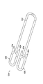
添付図面、特に図1を参照すると、本開示の教示に従って構成された医療用の固定装置は符号20で示されている。固定装置20は、以下で更に詳述するように、外科手術環境下で固定具を送り出す効果的な手段として有用である。開示されている実施形態は、腹腔鏡手術などの低侵襲外科手術における固定具の取付けをより容易にする。図1〜図7に示す第1実施形態の固定装置20は、例えば、ヘルニアの腹腔鏡治療では、腹部領域内またはその周辺で組織下に配されて、腹壁の組織を固定し、或いは人工メッシュを腹壁に内部から固定する。ここでは、腹腔鏡下で行われる組織固定の実施形態を開示しているが、本開示は他の医療処置にも同様に適用することができる。
With reference to the accompanying drawings and in particular with reference to FIG. The
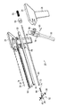
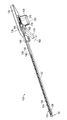
図1〜図3に示すように、固定装置20は、近位端に配された制御端部24と遠位端に配された作業端部26との間で延びている細長い部材22を備えている。制御端部24は、グリップ28と、トリガ30(圧縮トリガ)と、ユーザからの入力を受け、ユーザ入力を固定装置20の作業端部26で行なわれる固定動作に変換するための手段を備えている。作業端部26は、側面発射用開口32、つまり長手方向に対する側面に配された固定用のインターフェイスを備えており、ここから固定具34が取付けられる。更に、一又は複数の固定具34は、細長い部材22において長手方向に延びる一又は複数の部分に沿って配されたガイド36を通って、作業端部26の側面発射用開口32に向かって前進させられ、供給される。
As shown in FIGS. 1-3, the
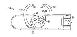
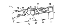
更に図4〜図7に詳細に示すように、固定装置20の作業端部26では、第1弧状針38及び第2弧状針40が少なくとも部分的に囲い込まれており、それぞれ初期位置つまりデフォルト位置において、作業端部26の側面発射用開口32の内部に実質的に隠れている。具体的には、第1弧状針38は、第1矢印44で示すように第1軸42周りに第1方向に回転して前進し、逆方向に回転して後退する。同様に、第2弧状針40は、第2矢印48で示すように、第1軸42から軸方向がずれている第2軸46周りに第2方向に回転して前進し、逆方向に回転して後退する。加えて、第1弧状針38及び第2弧状針40は、それぞれの内縁に、固定具34を引掛けて係合するように構成されたフック状、溝状、歯状、傾斜面状、その他の適宜形状の凹部50を備えている。ここでは、第1弧状針38及び第2弧状針40が、後退中に固定具34と係合するように構成された逆方向型の凹部50を備えている実施形態を示しているが、針の前進中に固定具34と係合する順方向型の凹部など、他の構成も同様に採用し得る。他の変更例では、凹部は第1弧状針38及び第2弧状針40それぞれの外縁上に設けられてもよい。他の変更例では、作業端部26の発射用開口は、端部発射用開口、傾斜発射用開口、その他の適宜の構成とすることができる。
As further shown in detail in FIGS. 4-7, at the working
更に図4〜図7に示すように、固定装置20は少なくとも一つの駆動機構52を備えている。駆動機構52は、第1弧状針38及び第2弧状針40それぞれに操作可能に連結されており、制御端部24を通じて受け取ったユーザ入力に応答して、第1弧状針38及び第2状針40のそれぞれを後退位置と延出位置との間で回転させ係合させるように構成されている。例えば、図4に示すように、駆動機構52は、第1弧状針38に直接連結された第1歯車54と、第2弧状針40に直接連結された第2歯車56と、第1弧状針38及び第1歯車54のそれぞれに直接連結された駆動歯車58とを備えている。より具体的には、第1歯車54及び第2歯車56は軸方向がずれているが、回転により互いに噛合し、第1歯車54の回転に直接対応して第2歯車56は逆方向に同じだけ回転する。逆回転の場合も同様である。更に、駆動機構52は長手方向に移動する歯車ラック60を備えている。歯車ラック60は、少なくとも一部が作業端部26の内部に配置されており、少なくとも駆動歯車58と直接に機械的に連動する。
Further, as shown in FIGS. 4 to 7, the fixing
従って、図4〜図7に示す具体的な実施形態では、例えば、歯車ラック60が近位方向、つまり矢印62で示すように制御端部24に向かって移動すると、駆動歯車58が矢印44で示すように反時計回りに回転し、それに伴い第1弧状針38と第1歯車54が回転する。更に、第1歯車54が回転するのに伴い、第2歯車56と第2弧状針40は、矢印48で示すように、逆方向つまり時計回りに、同時に同じだけ回転する。或いは、歯車ラック60が遠位方向、つまり作業端部26に向かって移動すると、駆動歯車58が時計回りに回転するのに伴い、第1弧状針38と第1歯車54とが回転し、第2歯車56と第2弧状針40は、反時計回りに同時に同じだけ回転する。図面では一例のみを示しているが、添付の特許請求の範囲から逸脱することなく他の駆動機構及び/又は他の歯車構成も可能であることは、当業者には明らかであろう。例えば、他の変更例の固定装置20は、何れかが逆方向に回転する3以上の弧状針を備えてもよいし、互いが同一の方向に回転する3以上の弧状針を備えてもよい。他の代替的な変更例では、第1弧状針38及び第2弧状針40は、互いが同時に回転するのではなく、順に連続して回転するように構成されてもよいし、及び/又は、互いに異なる角速度で回転するように構成されてもよい。更なる変更例では、第1弧状針38及び第2弧状針40は、軸方向がずれているのではなく、共通の軸周りに回転するように構成されてもよい。更なる変更例の固定装置20は、細長い部材22に平行な軸周り、或いは細長い部材22に対して直角ではない軸周りに、回転するように構成された弧状針を備えてもよい。更に別の変更例では、固定装置20の作業端部26は、細長い部材22に対して、一又は複数の軸周りに枢動または移動可能に連結されていてもよい。
Thus, in the specific embodiment shown in FIGS. 4-7, for example, when the
図4〜図7に示す駆動機構52は、更に、任意の数の異なる動作手段を採用する制御端部24に合わせて適合され、及び/又は拡張されてもよく、その動作手段は、機械的、電気的、電子機械的、電磁手段など、駆動機構52の動作を可能とする適宜の手段を含む。例えば、図5〜図7に示すように、グリップ28及びトリガ30(圧縮トリガ)を備える制御端部24は、アクチュエータロッド64、駆動カラー66、駆動ピン68、圧縮ばね70などの機械的アセンブリを使用して構成されてもよい。アクチュエータロッド64は、細長い部材22内に摺動可能に配されており、少なくとも作業端部26の歯車ラック60と制御端部24との間で軸方向に延びるように構成されている。より具体的には、アクチュエータロッド64の遠位端は、歯車ラック60の穴74にロッドピン72をしっかりと固定する手段によって、または他の適宜の手段によって、歯車ラック60の近位端に直接連結されている。駆動カラー66は、アクチュエータロッド64の近位端に同軸に固定されており、これによって、少なくともアクチュエータロッド64、細長い部材22、及び駆動カラー66の全てが、制御端部24に対して同時に回転可能となっている。駆動カラー66は、更に、その周りに周方向に配された溝76を備えており、溝76の一部を駆動ピン68が通るように構成されている。
The
図4〜図7に示すように、トリガ30は、横軸のアンカーピン80周りに枢動可能に制御端部24に軸支されたヨーク78を介して、枢動可能に制御端部24に連結されている。駆動ピン68は、トリガ30のヨーク78を横切るように連結されており、駆動カラー66、アクチュエータロッド64及び細長い部材22の回転位置に関係なく、駆動ピン68を駆動カラー66の溝76に対して少なくとも部分的に付勢するように構成されている。更に、トリガ30のヨーク78は、駆動カラー66の周りに十分なクリアランスを持って取付けられるように構成されている。加えて、圧縮ばね70は、アクチュエータロッド64の近位端の周りに同軸に配されており、駆動カラー66を軸方向に付勢することにより、アクチュエータロッド64を固定装置20の遠位端に向かって軸方向に付勢する。トリガ30の初期位置つまり開始位置は、弧状針が完全に後退している針位置、すなわち、第1弧状針38及び第2弧状針40がそれぞれ作業端部26の側面発射用開口32内部に没入している針位置に対応している。
As shown in FIGS. 4-7, the
駆動機構52を動作させるには、トリガ30を圧縮、つまり矢印82で示すようにグリップ28に向かって枢動させ、これにより、駆動ピン68は駆動カラー66とアクチュエータロッド64の双方を固定装置20の近位端に向かって押す。より具体的には、作業端部26から離れるようにアクチュエータロッド64が引張られると、その遠位端のロッドピン72は歯車ラック60を同様に、図4で矢印62によって示したように近位方向に引張る。更に、歯車ラック60が矢印62の方向に引張られると、駆動歯車58が回転し、第1歯車54及び第2歯車56が回転する。第1歯車54及び第2歯車56がそれぞれ回転すると、第1弧状針38及び第2弧状針40は、針が完全に延出した位置に達するまで、反対の方向44,48に同時に回転する。駆動機構52を反対に動作させるには、トリガ30を減圧し、初期位置まで戻す。トリガ30を解放することによって、駆動ピン68、駆動カラー66及びアクチュエータロッド64が、制御端部24から離れるように固定装置20の遠位端に向かって押され、圧縮ばね70が解放されて負荷が初期状態まで低減する。更に、トリガ30が解放されるのに伴い、アクチュエータロッド64のロッドピン72は、歯車ラック60を長手方向に押して初期位置まで戻し、第1弧状針38及び第2弧状針40を、それぞれデフォルト位置つまり完全に後退した針位置に復帰させる。
To operate the
図8〜図13は、作業端部26の第1弧状針38及び第2弧状針40の前進における異なる段階を示すものであり、図4〜図7に示した駆動機構52の動作中のものである。初期位置である後退した針位置では、図8及び図11に示すように、第1弧状針38及び第2弧状針40はそれぞれ作業端部26の側面発射用開口32内部及び下部に配され、実質的に隠れている。加えて、取付けられる一又は複数の固定具34は、その端部または針ガイド86,88を第1弧状針38及び第2弧状針40との係合が容易となるように位置させた状態で、側面発射用開口32に沿って取外し可能に保持されていてもよい。前進する間、第1弧状針38及び第2弧状針40はそれぞれ、図9及び図12に示すように、関連する組織部分、及び/又は該当する場合には補綴材を貫通して、回転により延出しながら前進する。図10及び図13に示すように、完全に延出した針位置では、第1弧状針38及び第2弧状針40はそれぞれ、取付けられる固定具34それぞれの針ガイド86,88と係合する位置となる。具体的には、図10及び図13に示すように、第1弧状針38のフック(凹部50)は第1端部または針ガイド86と係合し、第2弧状針ガイド40のフック(凹部50)は第2端部または針ガイド88と係合する。
FIGS. 8 to 13 show different stages in the advancement of the first
しっかりと係合したら、固定具34の留付けのために、ユーザによってトリガ30が解放され、これにより駆動機構52が解放される。解放後、第1弧状針38及び第2弧状針40はそれぞれ、図10及び図13に示した延出した針位置から後退させられ、関連する組織部分、及び/又は補綴材を貫通して後退し、それぞれ固定具34の端部(針ガイド86,88)を引張りながら、図8及び図11に示す初期位置、つまり後退した針位置に戻る。具体的には、第1弧状針38及び第2弧状針40が図8及び図11に示す完全に後退した針位置に到達するまで、第1弧状針38のフック(凹部50)は、係合している固定具34の第1針ガイド86を第1弧状針38の経路を通って後退しながら引張り、一方、第2弧状針40のフック(凹部50)は、固定具34の第2針ガイド88を第2弧状針40の経路を通って後退しながら引張る。図8及び図11に示すように、留付けられた状態では、固定具34の第1端部(針ガイド86)は、完全に後退した針位置の第1弧状針38の近傍の組織部分の内部に、少なくとも一部が取付けられる。一方、固定具34の第2端部(針ガイド88)は、完全に後退した針位置の第2弧状針40の近傍の組織部分の内部に、少なくとも一部が取付けられる。より一般的には、固定具34は、一又は複数の組織、及び/又は補綴材の内部に、実質的に螺旋状の構成となった状態で取付けられる。この螺旋状の構成は、部分的に、固定具34の端部(針ガイド86,88)上に配置される保持要素などによって維持されてもよい。例えば、固定具34の端部(針ガイド86,88)は、組織への進入は容易であるが、いったん留付けられたら、後退への抵抗となり、固定具34が組織内に留付けられた状態を維持するような構成としてもよい。
Once firmly engaged, the
図8〜図10に示すように、第1弧状針38及び第2弧状針40それぞれの外形は、真の円弧状である必要はなく、むしろ傾いた弧状形とすることができる。従って、第1弧状針38及び第2弧状針40それぞれの経路は、完全な円形である必要はない。むしろ、このような構成によって、第1弧状針38及び第2弧状針40それぞれが、完全に後退した針位置では、図8及び図11に示すように低プロファイルを維持することができ、前進している間は、図9及び図12に示すように組織の内部まで延出して最適に到達することができる。このような前進では、第1弧状針38が組織の第1部分を通って入り組織の第2部分を通って出る一方、これと同時に第2弧状針40が、組織の第2部分を通って入り組織の第1部分を通って出る。反対に、解放及び後退中には、第1弧状針38が、組織の第2部分を通って後退し組織の第1部分を通って出る一方、これと同時に第2弧状針40が、組織の第1部分を通って後退し組織の第2部分を通って出る。更に、第1弧状針38及び第2弧状針40それぞれは、形状により、及び/又は、カム方式で回転させる他の態様により、組織を通って移動するにつれて次第に引張り力が強くなり、組織をより締め付けて固定するように構成されてもよい。
As shown in FIGS. 8 to 10, the outer shape of each of the first arc-shaped
図5,図6及び図14に示すように、固定装置20は更に、取付けられる一又は複数の固定具34を、例えば、カートリッジ、ストリング、リボン90、その他適宜の固定具34の集合体の態様で備えていてもよい。例えば図5,図6及び図14の実施形態では、固定具34のリボン90は、少なくとも制御端部24から作業端部26の遠位端まで延びている細長い部材22に沿って、ガイド36間に長手方向に配されている。より具体的には、細長い部材22は、リボン90の新しいセグメントを供給するように構成される供給経路92を備えており、取付けられる固定具34は作業端部26の側面発射用開口32に向けて保持される。同様に、細長い部材22は、リボン90の使用済みセグメントを制御端部24に配された戻りロール91に向かって戻すように構成された戻り経路94を備えていている。更に固定装置20は、使用済みのリボン90が交換可能であり、新しいリボン90が着脱可能にコンパートメント96内に取付けられ、または挿入されるように構成されてもよい。そのようなコンパートメント96は、内部に収容されたリボン90が、細長い部材22の供給経路92及び/又は戻り経路94に対して適切に位置合わせされるように配置される。例えば、図5,図6及び図14で示すように、コンパートメント96は細長い部材22に直接連結されていてもよく、更に、供給経路92及び戻り経路94とリボン90との間の配置関係を維持するように、細長い部材22の軸方向に回転するものとすることができる。
As shown in FIGS. 5, 6, and 14, the fixing
一つの可能性のある変更例では、例えば図15に示すように、留付けられる固定具34の多数を長くつなげた供給ロール93が、図14のリボン90に更に接合されているものとすることができ、供給ロール93は予め固定装置20に充填される。例えば、供給ロール93は、固定装置20のコンパートメント内に収容させ、作業端部26に向かって徐々に送られる供給経路92に連結することができる。加えて、図16に示すように、固定具34は、連続した固定具34のリボン98として供給されてもよい。更に、リボン90,98は、例えば、それらに沿って保持されている各固定具34が、第1弧状針38及び第2弧状針40によって係合さたら外れるように構成されてもよい。各固定具34はまた、それらの端部または針ガイド86,88が、対応する第1弧状針38及び第2弧状針40に対して適切に位置合わせされて係合し得るように、それぞれのリボン90,98上に間隔をあけて位置させておくことができる。固定装置20、駆動機構52、リボン90,98、及び/又はコンパートメント96は更に、側面発射用開口32、第1弧状針38及び第2弧状針40の上に、新しい固定具34が適切に配置されるように、リボン90,98を徐々に前進させる構成としてもよい。リボン90,98は更に、手動、半自動、または自動的に前進させられるものとすることができる。
In one possible modification, for example, as shown in FIG. 15, a
図17〜図19では、医療用の固定装置120の代替的な実施形態を示している。図1〜図7に示した実施形態と同様に、固定装置120は、近位に配された制御端部124と遠位に配された作業端部126との間で延びている細長い部材122を備えている。制御端部124は、グリップ128と、それに向かって圧縮されるトリガ130を備えるものが図示されているが、制御端部124は、ユーザからの入力を受け、ユーザ入力に応じて固定装置120を動作させるための他の適宜な手段を採用するものであってもよい。上述の実施形態と同様に、作業端部126は、側面発射用開口132、つまり長手方向の側面に配される固定用インターフェイスを備えており、これを介して固定具134が取付けられる。更に、一又は複数の固定具134は、例えば近位に配されたコンパートメント196から、固定具134のリボン190として送り出されるものであり、細長い部材122の一又は複数の長手方向の部分に沿って配されたガイド136を通って、作業端部126の側面発射用開口132に向かって前進させられ供給される。他の変更例では、作業端部126の発射用開口は、端部発射用開口、傾斜発射用開口、その他の適宜の構成とすることができる。更に別の変更例では、固定装置120の作業端部126は、細長い部材122に対して、一又は複数の軸周りに枢動または移動可能に連結されていてもよい。
In FIGS. 17-19, an alternative embodiment of a
固定装置120の作業端部126は、図18,図19により具体的に図示するように、単一針の構成を採用しており、この構成では、例えば単一の弧状針140は少なくとも部分的に囲い込まれており、初期位置つまり完全に後退した針位置にある間、作業端部126の側面発射用開口132の内部に実質的に隠れている。上述の実施形態における第2弧状針40と同様に、図18及び図19に示す弧状針140は、一又は複数の組織部分を通って、横軸146周りに、第1矢印148で示す第1方向に回転して前進し、反対に、逆方向に回転して一又は複数の組織部分から後退する。加えて、弧状針140は、その内縁は、固定具134を引掛けて係合するように構成されたフック状、溝状、歯状、傾斜面状、その他の適宜形状の凹部150を備えている。ここでは、弧状針140が、後退中に固定具14と係合するように構成された逆方向型の凹部150を備えている実施形態を示しているが、針の前進中に固定具134と係合する順方向型の凹部など、他の構成も同様に採用し得る。他の変更例では、凹部は弧状針140の外縁上に設けられてもよい。
The working
更に図17〜図19に示すように、固定装置120は上述の実施形態の駆動機構52と同様の駆動機構152を備えている。詳細な説明は省略するが、駆動機構152は同様に弧状針140と操作可能に連結されており、制御端部124で受け取ったユーザ入力に応答して、弧状針140を後退位置と延出位置との間で回転させ係合するように構成されている。具体的には、駆動機構152は、トリガ130を矢印182で示す方向に圧縮したとき、弧状針140を図示した回転方向148に回転させることによって、例えば、関連する組織部分、及び/又は、適宜の補綴材を貫通して、完全に延出した針位置に到達するまで前進させるように構成されている。更に、完全に延出した針位置は、トリガ130がグリップ128に対して完全に圧縮された位置に、直接対応するものであってもよい。更に、駆動機構152は、矢印182の方向とは反対方向にトリガ130を解放したとき、矢印148の方向とは反対方向に弧状針140が回転し、完全に後退した針位置に達するまで関連する組織部分から後退するように構成される。完全に後退した針位置は、トリガ130がグリップ128に対して完全に解放された位置に直接対応するものであってもよい。図17〜図19に示す駆動機構152は、固定装置120の制御端部124を介した弧状針140の制御を可能とするための歯車ラック及び歯車セット、またはその他の適切な機構を使用して構成されていてもよい。他の変更例では、固定装置120は、例えば、図1の固定装置20の第1弧状針38と同様に、延出し回転するように構成された弧状針を採用可能である。更なる他の変更例では、固定装置120は、細長い部材122に平行な軸周り、或いは細長い部材122に対して直角ではない軸周りに、回転するように構成された弧状針を備えてもよい。
Further, as shown in FIGS. 17 to 19, the fixing
更に、図17〜図19に示す駆動機構152は、任意の動作手段の組合せを採用する制御端部124に合わせて適合されてもよく、その動作手段は、機械的、電気的、電子機械的、電磁手段などを含む。図17に示すように、グリップ128及びトリガ130を備える制御端部124は、上述の実施形態と同様に、駆動カラー166、駆動ピン168、圧縮ばね170などのアセンブリを使用して構成されている。更に、駆動カラー166は、作業端部126の駆動機構152に連結されており、これによって、少なくとも細長い部材122及び駆動カラー166の全てが制御端部124に対して同時に回転可能となっている。駆動カラー166は、更に、その周りに周方向に配された溝176を備えており、溝176の一部を駆動ピン168が通るように構成されている。トリガ130は、横軸のアンカーピン180周りに枢動可能に制御端部124に軸支されたヨーク178を介して、枢動可能に制御端部124に連結されている。駆動ピン168は、トリガ130のヨーク178を横切るように連結されており、駆動カラー166及び細長い部材122の回転位置に関係なく、駆動ピン168を駆動カラー166の溝176に対して少なくとも部分的に付勢するように構成されている。具体的には、トリガ130のヨーク178は、駆動カラー166の周りに十分なクリアランスを持って取付けられるように構成されている。更に、圧縮ばね170は、細長い部材122に対して同軸に配されており、駆動カラー166を軸方向に付勢することによって、弧状針140を初期位置である完全に後退した針位置に向かって付勢するように構成されている。
Further, the
図20〜図22は、作業端部126の弧状針140の前進における異なる段階を示すものであり、駆動機構152の動作中のものである。後退した針位置では、例えば図20に示すように、弧状針140は作業端部126の側面発射用開口132の内部及び下部に配され、実質的に隠れている。更に、取付けられる一又は複数の固定具134は、側面発射用開口132に沿って離脱可能に保持されており、端部(針ガイド186,188)は弧状針140との係合が容易な位置に配される。弧状針140は前進する間、例えば図21〜図22に示すように、関連する組織部分を貫通し、回転しながら延出する。完全に延出した針位置では、弧状針140は、取付けられる固定具134の先導端部または針ガイド188と係合する位置となる。針ガイド188と係合したら、固定具134を取付けるためにユーザによってトリガ130が解放され、弧状針140は延出した針位置から関連する組織部分を貫通して後退し、固定具134の先導端部または針ガイド188を引張りながら、図20に示す初期位置つまり後退した針位置に戻る。留付けられた状態では、固定具134は、組織及び/又は補綴材の一又は複数の部分内に取付けられており、固定具134の一又は複数の端部(針ガイド186,188)上に配された保持部材、保持要素などによって、部分的に保持させることができる。例えば、固定具134の端部(針ガイド186,188)は、組織への固定具134の進入を促進するが後退に抵抗し、且つ、固定具134が組織内に留付けられている形状を保持するような態様とされる。
20 to 22 show different stages in the advancement of the
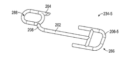
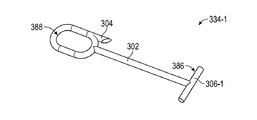
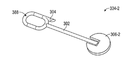
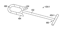
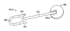
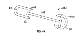
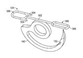
図23〜図40は、例えば図17〜図22に示す単一針型の医療用の固定装置120と共に使用することが可能な、種々の例示的な実施形態の固定具234,334,434を示している。図示するように、固定具234,334,434はそれぞれ、先導端部288,388,488と末端部286,386,486との間で延在する細長いフィラメント202,302,402を備えている。先導端部288,388,488は、弧状針140の凹部150(フック)などと接続または係合するように構成された、針ガイドの形状とすることができる。具体的には、先導端部288,388,488(針ガイド)はそれぞれ、留付けに際して弧状針140と係合可能なループ、円、長円、楕円、多角形、その他の適宜の形状とすることができる。更に、先導端部288,388,488(針ガイド)はそれぞれ、少なくとも一つの保持要素204,304,404を備えていてもよい。保持要素204,304,404は、先導端部288,388,488(針ガイド)の上に配されて、そこから接線方向に延出し、一旦取付けられた組織からの後退に抵抗するように構成される。保持要素204,304,404は、一又は複数の歯、フィン、返し要素(canted element)などを備えていてもよい。更に、先導端部288,388,488(針ガイド)及び保持要素204,304,404は、組織部分を貫通する前進は促進するが組織部分からの後退には抵抗するような構成とすることができる。また更に、固定具234,334,434の末端部286,386,486は、組織部分を貫通する前進に抵抗するように構成された保持部材206,306,406を備えていてもよい。例えば、各保持部材206,306,406はそれぞれ、先導端部288,388,488(針ガイド)の平面に対して同一の平面、或いは、それらの平面と交差する平面内、或いは、それらを任意の組み合わせた平面内で、少なくとも一つの外方向に延出する要素を備えていてもよい。
23-40 illustrate various exemplary embodiments of fasteners 234, 334, 434 that can be used with, for example, the single needle
具体的には、図23〜図28の実施形態によれば、固定具234(234−1〜234−6)はそれぞれ、全体的に線形ではあるが一又は複数の非線形部分208も含む、細長いフィラメント202を備えている。図23〜図28で示すように、細長いフィラメント202は、その線形部分と、先導端部288またはその針ガイドとの間に配された、湾曲した非線形部分208を有している。このような構成は、例えば、弧状針140との係合を補助すると共に、弧状針140が控えている側面発射用開口132に固定具234を位置させることを補助する点で、有利である。更に、図23〜図28の実施形態の先導端部288(針ガイド)はそれぞれ、そこから接線方向に延出する単一の保持要素204を有するループ形状である。更に、保持要素204は、一旦留付けられたなら固定具234の後退に抵抗するように構成された、返し要素の形態とすることができる。
Specifically, according to the embodiment of FIGS. 23-28, the fasteners 234 (234-1 to 234-6) are each elongated, which is generally linear but also includes one or more
図23〜図28の固定具234と比較すると、図29〜図34の固定具334(334−1〜334−6)はそれぞれ、非線形部分のない完全に線形な細長いフィラメント302を備えているが、先導端部388(針ガイド)としては同様の構成を備えている。より具体的には、図29〜図34の先導端部388(針ガイド)はそれぞれ、そこから接線方向に延出し、一旦留付けられたなら固定具334の後退に抵抗するように構成された単一の返し状の保持要素304を有するループ形状である。更なる比較では、図35〜図40の固定具434(434−1〜434−6)はそれぞれ、図29〜図34の固定具334と同様に、非線形部分のない完全に線形な細長いフィラメント402を備えていると共に、図23〜図34の固定具234,334と同様に、ループ形状の先導端部488(針ガイド)を備えている。しかしながら、対照的に、固定具434はそれぞれ、そこから接線方向に延出する二つの返し状の保持要素404を有する先導端部488(針ガイド)を備えている。これら二つの保持要素404は、固定具434の後退に抵抗するため、その方向を先導端部488から末端部486に向かう方向とすることができる。
Compared to fixture 234 of FIGS. 23-28, fixtures 334 (334-1 to 334-6) of FIGS. 29-34 each include a completely linear
図23〜図40の固定具234,334,434は、例えば、その保持部材206,306,406を変更することにより、変形例とすることができる。例えば、図23,図29及び35に示すように、保持部材206−1,306−1,406−1は、それぞれの固定具234−1,334−1,434−1の平面と同一の平面内で、横方向に延出する線形の要素である。図24,図30及び図36に示す保持部材206−2,306−2,406−2は、それぞれ固定具234−2,334−2,434−2の更なる前進に抵抗するように構成された内向きのスロットを備える、同一平面上にあるディスク状の要素である。図25,図31及び図37に示す保持部材206−3,306−3,406−3は、それぞれ固定具234−3,334−3,434−3の末端部286,386,486から径方向に延出したディスクである。他の実施形態とは対照的に、図25,図31及び図37の保持部材206−3,306−3,406−3は、それぞれ固定具234−3,334−3,434−3の平面に対して直角な平面内にある。 The fixtures 234, 334, and 434 in FIGS. 23 to 40 can be modified by changing the holding members 206, 306, and 406, for example. For example, as shown in FIGS. 23, 29, and 35, the holding members 206-1, 306-1, and 406-1 are the same plane as the planes of the respective fixtures 234-1, 334-1, and 434-1. It is a linear element extending in the horizontal direction. The holding members 206-2, 306-2, and 406-2 shown in FIGS. 24, 30, and 36 are configured to resist further advancement of the fixtures 234-2, 334-2, and 434-2, respectively. A coplanar disc-like element with an inward slot. The holding members 206-3, 306-3, and 406-3 shown in FIG. 25, FIG. 31 and FIG. It is a disc extended to. In contrast to the other embodiments, the holding members 206-3, 306-3, and 406-3 of FIGS. 25, 31, and 37 are planes of the fixtures 234-3, 334-3, and 434-3, respectively. In a plane perpendicular to.
加えて、図26,図32及び図38に示す保持部材206−4,306−4,406−4は、それぞれのフィラメント202,302,402に対して平行であり、それぞれの固定具234−4,334−4,434−4と同一の平面上にある、H字型の突起である。図27,図33及び図39に示す保持部材206−5,306−5,406−5は、それぞれ組織を貫通する前進に対抗する向きに配された、それぞれの固定具234−5,334−5,434−5と同一の平面上にある、A字型の突起である。同様に、図28,図34及び図40に示す保持部材206−6,306−6,406−6は、それぞれ組織を貫通する前進に対抗するように内向きに丸く曲げられた構成で、それぞれの固定具234−6,334−6,434−6と同一の平面上にある突起である。図23〜図40を用いて一定の実施形態の固定具234,334,434のみを示してきたが、添付の特許請求の範囲から逸脱することのない更なる代替例または変形例が、当業者にとって明らかであることが理解されよう。
In addition, the holding members 206-4, 306-4, and 406-4 shown in FIGS. 26, 32, and 38 are parallel to the
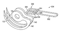
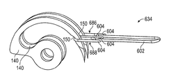
図41〜図46では、単一針の構成と共に用いられうる他の実施形態の固定具534を示している。上述の実施形態と同様に、固定具534は、先導端部588と末端部586との間で線形に延びている細長いフィラメント502を備えている。固定具534は、先導端部588において、組織を貫通する固定具534の前進を促進するが後退には抵抗するように、そこから接線方向に延出している返し状の保持要素504を有する針ガイドの構成を備えている。固定具534は、末端部586において、一旦取付けられたなら先導端部588と連結されるように構成された、開口した保持部材506を備えている。より具体的には、取付けられる固定具534の開口した末端部586は、図43で示すように、単一の弧状針140の前進方向の端部上に直接的に配置されている。これにより、動作した弧状針140は、図44で示すように、末端部586を貫通して前進する。完全に延出した状態では、弧状針140の凹部150(フック)は、固定具534の先導端部588と係合するように構成されている。弧状針140が後退するのに伴い、固定具534の可撓性の先導端部588は、開口した末端部586を通り完全に挿通される。図45〜図46に示すように、先導端部588の保持要素504と末端部586の開口した保持部材506の引掛りによる連結によって、固定具534が組織内に保持される。
41-46 show another
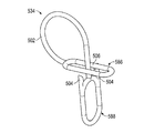
図47〜図50では、本開示による教示と共に用いられうる更に他の実施形態の固定具634を示している。図示するように、固定具634は、何れも先導端部の形態で構成された第1端部686及び第2端部688を備えている。より具体的には、第1端部686及び第2端部688はそれぞれ、そこから接線方向に延出しており、組織を貫通する前進は促進するが後退に抵抗するように構成された、一又は複数の保持要素604を有している。更に、図47〜図48の固定具634は、図49〜図50に示すように、二重針の構成、つまり互いに同軸に配置された二つの弧状針140を有する構成を採用している固定装置を使用することにより、取付けることができる。更に、それぞれの弧状針140は、駆動機構によって操作可能に駆動されるものとすることができ、動作すると、図50で示すように、双方の弧状針140は前進方向の回転により組織を貫通して同時に前進し、取付けられる固定具634の第1端部686及び第2端部688それぞれと係合するように構成されている。一方、解放時には、双方の弧状針140は逆方向の回転により組織を貫通して同時に後退し、係合している固定具634の第1端部686及び第2端部688を引張るように構成されている。
47-50 illustrate yet another embodiment of a
上記のように、本開示の医療用の固定装置によれば、組織、及び/又は、適宜の補綴材を固定するために、迅速かつ確実に固定具を取付けることができる。本装置は、単に、組織を固定するために要する時間を著しく短縮するだけではなく、他の方法に比べて使用が非常に容易である。更に、本開示で示した要素を独自に組み合わせることにより、患者に対する刺激と他の合併症のおそれを低減し、且つ、取付けや閉止の完全性に悪影響を及ぼすことなく、組織の固定状態をより確実に保持することができる。
As described above, according to the medical fixing device of the present disclosure, it is possible to quickly and reliably attach the fixing tool in order to fix the tissue and / or an appropriate prosthetic material. The device not only significantly reduces the time required to fix the tissue, but is much easier to use than other methods. In addition, the unique combination of the elements shown in this disclosure reduces the risk of patient irritation and other complications, and improves tissue fixation without adversely affecting attachment and closure integrity. It can be held securely.
Claims (45)
第2軸周りに第2方向に回転し、前記組織及び前記補綴材の内の一つの前記第2部分を貫通して入り、前記組織及び前記補綴材の内の一つの前記第1部分を貫通して出る第2弧状針と、
前記第1弧状針及び前記第2弧状針のそれぞれに操作可能に連結され、後退位置と延出位置との間で前記第1弧状針及び前記第2弧状針のそれぞれと係合するように構成されており、前記第1弧状針及び前記第2弧状針のそれぞれを前記後退位置において低プロファイルに維持するように構成された駆動機構と、
を備える固定装置。 Rotate in a first direction about a first axis, penetrate through a first portion in one of the tissue and prosthetic material, and penetrate a second portion in one of the tissue and the prosthetic material A first arcuate needle exiting;
Rotates in a second direction about a second axis, penetrates through the second part of the tissue and the prosthetic material, and penetrates the first part of the tissue and the prosthetic material The second arcuate needle that comes out,
Operatively connected to each of the first arcuate needle and the second arcuate needle and configured to engage with each of the first arcuate needle and the second arcuate needle between a retracted position and an extended position. A drive mechanism configured to maintain each of the first arcuate needle and the second arcuate needle in a low profile at the retracted position;
A fixing device comprising:
請求項1に記載の固定装置。 The first axis is displaced in the axial direction from the second axis;
The fixing device according to claim 1.
請求項1に記載の固定装置。 The first axis is coaxial with the second axis;
The fixing device according to claim 1.
請求項1に記載の固定装置。 The first direction is the same as the second direction;
The fixing device according to claim 1.
請求項1に記載の固定装置。 The first direction is opposite to the second direction;
The fixing device according to claim 1.
請求項5に記載の固定装置。 And at least one arcuate needle configured to rotate about a third axis in a third direction, wherein the third axis is coaxial with at least one of the first axis and the second axis, The direction is the same as one of the first direction and the second direction.
The fixing device according to claim 5.
請求項1に記載の固定装置。 Each of the first arcuate needle and the second arcuate needle includes a recess configured to receive an end of a fixture in an engageable manner therein.
The fixing device according to claim 1.
請求項1に記載の固定装置。 The first arc-shaped needle and the second arc-shaped needle are rotated at an angular velocity that is the same in size and symmetrical in direction.
The fixing device according to claim 1.
請求項1に記載の固定装置。 The first arcuate needle and the second arcuate needle rotate at an asymmetric angular velocity;
The fixing device according to claim 1.
請求項1に記載の固定装置。 The first arcuate needle and the second arcuate needle are continuously rotated,
The fixing device according to claim 1.
請求項1に記載の固定装置。 As the first arcuate needle and the second arcuate needle are retracted, the drive mechanism connects one end of a fixture to which the first arcuate needle and the second arcuate needle are attached to the tissue and the prosthesis, respectively. It is configured in a reverse mold that pulls through the first part and the second part in one of the materials,
The fixing device according to claim 1.
請求項1に記載の固定装置。 In operation, the drive mechanism is attached by advancing the first arcuate needle and the second arcuate needle through the tissue and one of the prosthetic materials by rotation in the extending direction, respectively. The first arcuate needle and the second arcuate needle are retracted through one of the tissue and the prosthetic material by rotating in the opposite directions, respectively, when engaged with the end of the fixture and released. And is configured to pull the end engaged with the fixture into a spiral shape,
The fixing device according to claim 1.
請求項1に記載の固定装置。 As the first arcuate needle and the second arcuate needle advance, the drive mechanism connects one end of a fixture to which the first arcuate needle and the second arcuate needle are attached to the tissue and the prosthesis, respectively. A forward mold that pulls through the first part and the second part in one of the materials,
The fixing device according to claim 1.
前記作業端部の前記発射用開口内に配されており、第1軸周りに第1方向に回転し、組織及び補綴材の内の一つにおける第1部分を貫通して入り、前記組織及び前記補綴材の内の一つにおける第2部分を貫通して出る第1弧状針と、
前記作業端部の前記発射用開口内に配されており、第2軸周りに第2方向に回転し、前記組織及び前記補綴材の内の一つにおける前記第2部分を貫通して入り、前記組織及び前記補綴材の内の一つにおける前記第1部分を貫通して出る第2弧状針と、
前記第1弧状針及び前記第2弧状針のそれぞれに操作可能に連結され、前記制御端部を介して受けたユーザ入力に応答して、後退位置と延出位置との間で前記第1弧状針及び前記第2弧状針のそれぞれと係合するように構成された駆動機構と、
を備える組織固定装置。 An elongate member extending between a working end and a control end, the control end having at least one guide for receiving one or more fixtures, wherein the working end is at least An elongate member having a firing opening in communication with the one guide;
Disposed within the firing opening of the working end, rotates about a first axis in a first direction, enters through a first portion of one of the tissue and prosthetic material, the tissue and A first arcuate needle extending through a second portion of one of the prosthetic materials;
Arranged in the launch opening of the working end, rotating in a second direction about a second axis, and penetrating through the second portion in one of the tissue and the prosthetic material; A second arcuate needle extending through the first portion of one of the tissue and the prosthetic material;
The first arcuate needle is operatively connected to each of the first arcuate needle and the second arcuate needle and in response to a user input received through the control end, the first arcuate needle between a retracted position and an extended position. A drive mechanism configured to engage a needle and each of the second arcuate needles;
A tissue fixing device comprising:
請求項14に記載の組織固定装置。 The drive mechanism is manually operated by use of a trigger disposed at the control end, the trigger being movable between an engagement position and a non-engagement position, the engagement position being the extension position. Corresponding to the exit position, the disengaged position corresponding to the retracted position,
The tissue fixing device according to claim 14.
請求項14に記載の組織固定装置。 A ribbon cartridge further comprising a ribbon cartridge in which a plurality of fixtures holds a linearly arranged ribbon, wherein the ribbon cartridge holds and releases at least one fixture over the firing opening of the working end prior to installation. The fixture is configured to engage the first arcuate needle and the second arcuate needle,
The tissue fixing device according to claim 14.
請求項16に記載の組織固定装置。 The ribbon is advanced to hold a subsequent fixture over the firing aperture with each fixture installation.
The tissue fixing device according to claim 16.
請求項14に記載の組織固定装置。 One or more of the working end and the elongate member are rotatable relative to the control end about a common axis in their longitudinal direction;
The tissue fixing device according to claim 14.
請求項14に記載の組織固定装置。 The working end is movable relative to the elongated member;
The tissue fixing device according to claim 14.
請求項14に記載の組織固定装置。 Each of the first arcuate needle and the second arcuate needle includes a recess configured to receive an end of a fixture in an engageable manner therein.
The tissue fixing device according to claim 14.
請求項14に記載の組織固定装置。 As the first arcuate needle and the second arcuate needle are retracted, the drive mechanism is configured so that the first arcuate needle and the second arcuate needle are respectively in one of the tissue and the prosthetic material. It is configured in a reverse direction that penetrates the first part and the second part and pulls one end of the fixture.
The tissue fixing device according to claim 14.
請求項14に記載の組織固定装置。 In operation, the drive mechanism is fixed by advancing the first arcuate needle and the second arcuate needle through the tissue and one of the prosthetic materials by rotation in the extending direction, respectively. The first arcuate needle and the second arcuate needle are respectively retracted through the tissue and one of the prosthetic materials by rotating in the opposite directions when engaged with the end of the device and released. , Configured to pull the end engaged with the fixture to have a helical configuration,
The tissue fixing device according to claim 14.
請求項14に記載の組織固定装置。 As the first arcuate needle and the second arcuate needle advance, the drive mechanism is configured so that the first arcuate needle and the second arcuate needle are respectively in one of the tissue and the prosthetic material. It is configured in a forward direction type that penetrates the first part and the second part and pulls one end of the fixture.
The tissue fixing device according to claim 14.
請求項14に記載の組織固定装置。 The first axis is displaced in the axial direction from the second axis;
The tissue fixing device according to claim 14.
請求項14に記載の組織固定装置。 The first axis is coaxial with the second axis;
The tissue fixing device according to claim 14.
請求項14に記載の組織固定装置。 The first direction is the same as the second direction;
The tissue fixing device according to claim 14.
請求項14に記載の組織固定装置。 The first direction is opposite to the second direction;
The tissue fixing device according to claim 14.
請求項27に記載の組織固定装置。 And at least one arcuate needle configured to rotate about a third axis in a third direction, wherein the third axis is coaxial with at least one of the first axis and the second axis, The direction is the same as one of the first direction and the second direction.
28. The tissue fixation device according to claim 27.
請求項14に記載の組織固定装置。 The first arc-shaped needle and the second arc-shaped needle are rotated at an angular velocity that is the same in size and symmetrical in direction.
The tissue fixing device according to claim 14.
請求項14に記載の組織固定装置。 The first arcuate needle and the second arcuate needle rotate at an asymmetric angular velocity;
The tissue fixing device according to claim 14.
請求項14に記載の組織固定装置。 The first arcuate needle and the second arcuate needle are continuously rotated,
The tissue fixing device according to claim 14.
請求項14に記載の組織固定装置。 The launch opening is configured as one of a side launch opening, an end launch opening, and an inclined launch opening with respect to the working end.
The tissue fixing device according to claim 14.
前記作業端部の前記発射用開口内に配置されており、後退位置と延出位置との間で回転可能であり、固定具の端部を係合可能にその内部に受け止めるように構成された凹部を備えている弧状針と、
前記弧状針に操作可能に連結され、動作の際は、前記弧状針を延出方向の回転により前記組織及び前記補綴材の内の一つを貫通して前進させ、取付けられる固定具の端部と係合させ、解放の際は、前記弧状針を逆方向の回転により前記組織及び前記補綴材の内の一つを貫通して後退させて、前記固定具の係合した前記端部を引張るように構成された駆動機構と、
を備える組織固定装置。 An elongate member extending between a working end and a control end, the control end having at least one guide for receiving one or more fixtures, wherein the working end is at least An elongate member having a firing opening in communication with the one guide;
Arranged in the launch opening of the working end, rotatable between a retracted position and an extended position, and configured to receive the end of the fixture in an engageable manner therein An arcuate needle having a recess;
An end of a fixture that is operably coupled to the arcuate needle, and in operation, advances the arcuate needle through one of the tissue and the prosthetic material by rotation in an extending direction. And when releasing, the arcuate needle is retracted back through one of the tissue and the prosthetic material by rotating in the opposite direction to pull the engaged end of the fixture A drive mechanism configured as follows:
A tissue fixing device comprising:
請求項33に記載の組織固定装置。 The drive mechanism is manually operated by use of a trigger disposed at the control end, the trigger being movable between an engagement position and a non-engagement position, the engagement position being the extension position. Corresponding to the exit position, the disengaged position corresponding to the retracted position,
34. The tissue fixation device according to claim 33.
請求項33に記載の組織固定装置。 A ribbon cartridge further comprising a ribbon cartridge in which a plurality of fixtures holds a linearly arranged ribbon, wherein the ribbon cartridge holds and releases at least one fixture over the firing opening of the working end prior to installation. The fixed fixture is configured to engage the arcuate needle,
34. The tissue fixation device according to claim 33.
請求項33に記載の組織固定装置。 A second arcuate needle disposed in the firing opening and rotatable between the retracted position and the extended position, wherein the second arcuate needle is relative to the first arcuate needle; Comprising a recess that is coaxial and configured to receive the second end of the fixture therein in an engagable manner;
34. The tissue fixation device according to claim 33.
請求項36に記載の組織固定装置。 The drive mechanism is operably connected to each of the first arc-shaped needle and the second arc-shaped needle, and simultaneously extends the first arc-shaped needle and the second arc-shaped needle during operation. Rotation of the direction simultaneously advances through one of the tissue and the prosthetic material, engages the end of the fixture to be attached, and when released, the first arcuate needle and the second Each of the arcuate needles is configured to retract simultaneously through one of the tissue and the prosthetic material by reverse rotation and pull the engaged end of the fixture.
37. The tissue fixation device according to claim 36.
請求項36に記載の組織固定装置。 And at least one arcuate needle disposed between the first arcuate needle and the second arcuate needle and configured to rotate in a direction opposite to each of the first arcuate needle and the second arcuate needle. Prepare
37. The tissue fixation device according to claim 36.
前記先導端部上に配された針ガイドと、
前記末端部上に配され、組織及び補綴材の内の少なくとも一つを貫通する前進に抵抗するように構成された保持部材と、
を備える組織固定具。 An elongated filament having a leading end and a distal end;
A needle guide disposed on the leading end;
A retention member disposed on the distal end and configured to resist advancement through at least one of the tissue and the prosthesis;
A tissue fixture comprising:
請求項39に記載の組織固定具。 The needle guide is one of a loop, a circle, an ellipse, an ellipse, and a polygon, and is configured to be engaged by an anchoring needle, the needle guide comprising the tissue and Configured to resist advancement while facilitating advancement through at least one of the prosthetics,
40. The tissue fastener of claim 39.
請求項39に記載の組織固定具。 The needle guide at the leading end includes at least one retaining element extending tangentially from the needle guide, the retaining element retracting through at least one of the tissue and the prosthetic material. Configured to resist
40. The tissue fastener of claim 39.
請求項39に記載の組織固定具。 The leading end comprises at least one retaining element having one or more of teeth, fins and barbs, the retaining element being configured to resist retraction thereof;
40. The tissue fastener of claim 39.
請求項39の組織固定具。 The elongated filament has one or more linear and non-linear portions,
40. The tissue fastener of claim 39.
請求項39に記載の組織固定具。 The retaining member has at least one element extending in an outward direction in a plane at least partially intersecting the plane of the needle guide;
40. The tissue fastener of claim 39.
請求項39に記載の組織固定具。
The holding member has an open loop, and the open loop is configured to receive the needle guide of the leading end portion passing therethrough and to be connected to the needle guide at the time of mounting.
40. The tissue fastener of claim 39.
Applications Claiming Priority (3)
| Application Number | Priority Date | Filing Date | Title |
|---|---|---|---|
| US201361765460P | 2013-02-15 | 2013-02-15 | |
| US61/765,460 | 2013-02-15 | ||
| PCT/US2014/016442 WO2014127216A1 (en) | 2013-02-15 | 2014-02-14 | Medical fastening device |
Related Child Applications (1)
| Application Number | Title | Priority Date | Filing Date |
|---|---|---|---|
| JP2018009435A Division JP6662924B2 (en) | 2013-02-15 | 2018-01-24 | Tissue anchor and tissue anchor |
Publications (1)
| Publication Number | Publication Date |
|---|---|
| JP2016506858A true JP2016506858A (en) | 2016-03-07 |
Family
ID=51351768
Family Applications (2)
| Application Number | Title | Priority Date | Filing Date |
|---|---|---|---|
| JP2015558149A Pending JP2016506858A (en) | 2013-02-15 | 2014-02-14 | Medical fixation device |
| JP2018009435A Active JP6662924B2 (en) | 2013-02-15 | 2018-01-24 | Tissue anchor and tissue anchor |
Family Applications After (1)
| Application Number | Title | Priority Date | Filing Date |
|---|---|---|---|
| JP2018009435A Active JP6662924B2 (en) | 2013-02-15 | 2018-01-24 | Tissue anchor and tissue anchor |
Country Status (11)
| Country | Link |
|---|---|
| US (2) | US9439646B2 (en) |
| EP (2) | EP3354206B1 (en) |
| JP (2) | JP2016506858A (en) |
| KR (1) | KR102274864B1 (en) |
| CN (1) | CN105142539B (en) |
| AU (2) | AU2014216180B2 (en) |
| BR (1) | BR112015019519A2 (en) |
| CA (1) | CA2900385A1 (en) |
| ES (1) | ES2676560T3 (en) |
| IL (1) | IL240576B (en) |
| WO (1) | WO2014127216A1 (en) |
Cited By (1)
| Publication number | Priority date | Publication date | Assignee | Title |
|---|---|---|---|---|
| US10492778B2 (en) | 2013-02-15 | 2019-12-03 | Surgimatix, Inc. | Medical fastening device |
Families Citing this family (20)
| Publication number | Priority date | Publication date | Assignee | Title |
|---|---|---|---|---|
| US10231728B2 (en) * | 2013-02-15 | 2019-03-19 | Surgimatix, Inc. | Medical fastening device |
| WO2014150468A1 (en) * | 2013-03-15 | 2014-09-25 | Ams Research Corporation | Systems, tools, and methods for connecting to tissue |
| US9867609B2 (en) * | 2013-09-26 | 2018-01-16 | Surgimatix, Inc. | Laparoscopic suture device with stripper plate |
| CA2924605A1 (en) * | 2013-09-26 | 2015-04-02 | Surgimatix, Inc. | Laparoscopic suture device with autoloading and suture capture |
| US9936942B2 (en) | 2013-09-26 | 2018-04-10 | Surgimatix, Inc. | Laparoscopic suture device with release mechanism |
| US11246583B2 (en) * | 2014-06-18 | 2022-02-15 | Boston Scientific Scimed, Inc. | Insertion devices, anchors, and methods for securing an implant |
| KR101796685B1 (en) * | 2014-12-08 | 2017-11-10 | 육상수 | A suture knot and knot suture device |
| KR101648014B1 (en) * | 2014-12-26 | 2016-08-12 | 국립암센터 | Apparatus for suturing an operation |
| CA2972804A1 (en) * | 2014-12-30 | 2016-07-07 | Surgimatix, Inc. | Laparoscopic suture device with impulse deployment |
| US11918204B2 (en) * | 2015-06-01 | 2024-03-05 | Lsi Solutions, Inc. | Suturing device for minimally invasive surgery and needles and methods thereof |
| CA2990397C (en) * | 2015-06-01 | 2020-03-31 | Jude S. Sauer | Needle for a minimally invasive surgical suturing device |
| US11033260B2 (en) * | 2015-06-01 | 2021-06-15 | Lsi Solutions, Inc. | Suturing device for minimally invasive surgery and needles and methods thereof |
| EP3373824B1 (en) * | 2015-11-12 | 2024-05-01 | Surgimatix, Inc. | Laparoscopic suture device with stripper plate |
| US9439647B1 (en) | 2016-03-02 | 2016-09-13 | Arthrogenx, LLC. | Suture passing instruments and methods |
| AU201612825S (en) * | 2016-05-27 | 2017-01-10 | Medical fastening device | |
| US11344294B2 (en) * | 2016-10-24 | 2022-05-31 | ReViable Surgical, Inc. | Laparoscopic suturing devices, needles, sutures, and drive systems |
| US10143465B2 (en) | 2016-10-24 | 2018-12-04 | ReViable Surgical, Inc. | Laparoscopic suturing devices, needles, sutures, and drive systems |
| US10603031B2 (en) * | 2017-02-03 | 2020-03-31 | Lsi Solutions, Inc. | Suturing device for minimally invasive surgery |
| WO2019152317A1 (en) | 2018-01-28 | 2019-08-08 | Lsi Solutions, Inc. | Suturing device for minimally invasive surgery and needles and methods thereof |
| CN109303595B (en) * | 2018-10-31 | 2021-08-03 | 江苏海泽医疗科技发展有限公司 | Puncture outfit with sewing function |
Citations (5)
| Publication number | Priority date | Publication date | Assignee | Title |
|---|---|---|---|---|
| JPH08501005A (en) * | 1992-09-04 | 1996-02-06 | ローラス・メディカル・コーポレイション | Endoscopic suturing system |
| JP2007537017A (en) * | 2004-05-14 | 2007-12-20 | クイル メディカル、インコーポレイテッド | Suture method and apparatus |
| WO2008069816A1 (en) * | 2006-12-06 | 2008-06-12 | Ryan Timothy J | Apparatus and methods for delivering sutures |
| JP2009178568A (en) * | 2001-06-07 | 2009-08-13 | Olympus Corp | Suture device for endoscope |
| WO2012088232A2 (en) * | 2010-12-23 | 2012-06-28 | Surgimatix, Inc. | Skin suturing device using rotating needles |
Family Cites Families (24)
| Publication number | Priority date | Publication date | Assignee | Title |
|---|---|---|---|---|
| US4950283A (en) * | 1988-12-29 | 1990-08-21 | John Lezdey | Surgical clip |
| US5074874A (en) * | 1989-05-16 | 1991-12-24 | Inbae Yoon | Suture devices particularly useful in endoscopic surgery |
| US5527321A (en) * | 1993-07-14 | 1996-06-18 | United States Surgical Corporation | Instrument for closing trocar puncture wounds |
| US5470338A (en) * | 1993-10-08 | 1995-11-28 | United States Surgical Corporation | Instrument for closing trocar puncture wounds |
| US5755728A (en) * | 1996-03-07 | 1998-05-26 | Maki; Neil J. | Suture apparatus with loop end portions |
| JP4136020B2 (en) * | 1996-04-17 | 2008-08-20 | オリンパス株式会社 | Medical ligature |
| CA2224366C (en) * | 1996-12-11 | 2006-10-31 | Ethicon, Inc. | Meniscal repair device |
| US6206895B1 (en) * | 1999-07-13 | 2001-03-27 | Scion Cardio-Vascular, Inc. | Suture with toggle and delivery system |
| GB9929599D0 (en) * | 1999-12-15 | 2000-02-09 | Atlantech Medical Devices Limi | A graft suspension device |
| DE60328490D1 (en) | 2002-06-12 | 2009-09-03 | Boston Scient Ltd | SEAM INSTRUMENTS |
| US6726705B2 (en) * | 2002-06-25 | 2004-04-27 | Incisive Surgical, Inc. | Mechanical method and apparatus for bilateral tissue fastening |
| US20080132919A1 (en) * | 2002-10-03 | 2008-06-05 | Faising Chui | Cycling suturing and knot-tying device |
| US8123764B2 (en) * | 2004-09-20 | 2012-02-28 | Endoevolution, Llc | Apparatus and method for minimally invasive suturing |
| ATE497730T1 (en) * | 2006-05-16 | 2011-02-15 | Marlen Andreevich Sulamanidze | SURGICAL SUTURE MATERIAL |
| US20090093824A1 (en) * | 2007-10-04 | 2009-04-09 | Hasan Jafar S | Wound closure fasteners and device for tissue approximation and fastener application |
| US8932327B2 (en) * | 2008-04-01 | 2015-01-13 | Covidien Lp | Anchoring device |
| MX339174B (en) * | 2008-11-03 | 2016-05-12 | Ethicon Llc | Length of self-retaining suture and method and device for using the same. |
| WO2010141695A1 (en) * | 2009-06-03 | 2010-12-09 | Herron Daniel M | Interrupted tissue apposition devices, interrupted suture elements, and methods of use |
| US8876841B2 (en) | 2009-07-20 | 2014-11-04 | Industrial Technology Research Institute | Spinal disc anulus repair method and apparatus |
| JP5882337B2 (en) * | 2010-09-30 | 2016-03-09 | スミス アンド ネフュー インコーポレーテッドSmith & Nephew,Inc. | Tissue fixture |
| CN103200882A (en) * | 2010-11-09 | 2013-07-10 | 伊西康有限责任公司 | Emergency self-retaining sutures and packaging |
| RU2746457C2 (en) * | 2011-03-23 | 2021-04-14 | ЭТИКОН ЭлЭлСи | Self-retaining suture with an adjustable loop |
| US9237887B2 (en) * | 2011-05-19 | 2016-01-19 | Biomet Sports Medicine, Llc | Tissue engaging member |
| KR102274864B1 (en) | 2013-02-15 | 2021-07-08 | 서지매틱스, 아이엔씨. | Medical fastening device |
-
2014
- 2014-02-14 KR KR1020157024542A patent/KR102274864B1/en active IP Right Grant
- 2014-02-14 CN CN201480009057.6A patent/CN105142539B/en not_active Expired - Fee Related
- 2014-02-14 BR BR112015019519A patent/BR112015019519A2/en not_active IP Right Cessation
- 2014-02-14 AU AU2014216180A patent/AU2014216180B2/en not_active Ceased
- 2014-02-14 EP EP18161654.1A patent/EP3354206B1/en active Active
- 2014-02-14 CA CA2900385A patent/CA2900385A1/en not_active Abandoned
- 2014-02-14 JP JP2015558149A patent/JP2016506858A/en active Pending
- 2014-02-14 WO PCT/US2014/016442 patent/WO2014127216A1/en active Application Filing
- 2014-02-14 US US14/180,884 patent/US9439646B2/en active Active
- 2014-02-14 EP EP14752059.7A patent/EP2956067B1/en active Active
- 2014-02-14 ES ES14752059.7T patent/ES2676560T3/en active Active
-
2015
- 2015-08-13 IL IL240576A patent/IL240576B/en not_active IP Right Cessation
-
2016
- 2016-09-08 US US15/259,987 patent/US10492778B2/en active Active
-
2018
- 2018-01-24 JP JP2018009435A patent/JP6662924B2/en active Active
- 2018-07-10 AU AU2018205091A patent/AU2018205091B9/en not_active Ceased
Patent Citations (5)
| Publication number | Priority date | Publication date | Assignee | Title |
|---|---|---|---|---|
| JPH08501005A (en) * | 1992-09-04 | 1996-02-06 | ローラス・メディカル・コーポレイション | Endoscopic suturing system |
| JP2009178568A (en) * | 2001-06-07 | 2009-08-13 | Olympus Corp | Suture device for endoscope |
| JP2007537017A (en) * | 2004-05-14 | 2007-12-20 | クイル メディカル、インコーポレイテッド | Suture method and apparatus |
| WO2008069816A1 (en) * | 2006-12-06 | 2008-06-12 | Ryan Timothy J | Apparatus and methods for delivering sutures |
| WO2012088232A2 (en) * | 2010-12-23 | 2012-06-28 | Surgimatix, Inc. | Skin suturing device using rotating needles |
Cited By (1)
| Publication number | Priority date | Publication date | Assignee | Title |
|---|---|---|---|---|
| US10492778B2 (en) | 2013-02-15 | 2019-12-03 | Surgimatix, Inc. | Medical fastening device |
Also Published As
| Publication number | Publication date |
|---|---|
| US10492778B2 (en) | 2019-12-03 |
| AU2014216180A1 (en) | 2015-08-20 |
| AU2014216180B2 (en) | 2018-08-02 |
| EP2956067A4 (en) | 2016-12-21 |
| WO2014127216A4 (en) | 2014-11-20 |
| EP2956067B1 (en) | 2018-04-18 |
| KR20150121043A (en) | 2015-10-28 |
| AU2018205091B9 (en) | 2020-01-16 |
| US9439646B2 (en) | 2016-09-13 |
| US20140236193A1 (en) | 2014-08-21 |
| KR102274864B1 (en) | 2021-07-08 |
| EP3354206B1 (en) | 2020-06-17 |
| JP2018083101A (en) | 2018-05-31 |
| US20160374663A1 (en) | 2016-12-29 |
| WO2014127216A1 (en) | 2014-08-21 |
| JP6662924B2 (en) | 2020-03-11 |
| CA2900385A1 (en) | 2014-08-21 |
| BR112015019519A2 (en) | 2017-07-18 |
| AU2018205091A1 (en) | 2018-07-26 |
| ES2676560T3 (en) | 2018-07-20 |
| IL240576B (en) | 2020-06-30 |
| EP2956067A1 (en) | 2015-12-23 |
| CN105142539A (en) | 2015-12-09 |
| CN105142539B (en) | 2019-04-05 |
| EP3354206A1 (en) | 2018-08-01 |
| IL240576A0 (en) | 2015-09-24 |
| AU2018205091B2 (en) | 2019-12-05 |
Similar Documents
| Publication | Publication Date | Title |
|---|---|---|
| JP6662924B2 (en) | Tissue anchor and tissue anchor | |
| US10231728B2 (en) | Medical fastening device | |
| CA2767160C (en) | Instrument for applying a surgical fastener | |
| ES2356571T3 (en) | COIL FIXER APPLICATOR WITH FLEXIBLE TREE. | |
| US5830221A (en) | Coil fastener applier | |
| JP6073685B2 (en) | Tissue repair implant, delivery device and delivery method | |
| JP5073333B2 (en) | Surgical fasteners and surgical instruments | |
| JP6258335B2 (en) | Anastomosis clip tool with half loop clip | |
| AU2015275683B2 (en) | Apparatus and method for suturing a tissue | |
| JP2011526803A (en) | Incision-Stapling surgical stapling device and method of use |
Legal Events
| Date | Code | Title | Description |
|---|---|---|---|
| A521 | Request for written amendment filed |
Free format text: JAPANESE INTERMEDIATE CODE: A821 Effective date: 20151013 |
|
| A621 | Written request for application examination |
Free format text: JAPANESE INTERMEDIATE CODE: A621 Effective date: 20161110 |
|
| A977 | Report on retrieval |
Free format text: JAPANESE INTERMEDIATE CODE: A971007 Effective date: 20170726 |
|
| A131 | Notification of reasons for refusal |
Free format text: JAPANESE INTERMEDIATE CODE: A131 Effective date: 20170801 |
|
| A601 | Written request for extension of time |
Free format text: JAPANESE INTERMEDIATE CODE: A601 Effective date: 20171026 |
|
| A521 | Request for written amendment filed |
Free format text: JAPANESE INTERMEDIATE CODE: A821 Effective date: 20180125 Free format text: JAPANESE INTERMEDIATE CODE: A523 Effective date: 20180125 |
|
| A02 | Decision of refusal |
Free format text: JAPANESE INTERMEDIATE CODE: A02 Effective date: 20180710 |