JP7367652B2 - Vehicle preview vibration damping control device and method - Google Patents
Vehicle preview vibration damping control device and method Download PDFInfo
- Publication number
- JP7367652B2 JP7367652B2 JP2020170064A JP2020170064A JP7367652B2 JP 7367652 B2 JP7367652 B2 JP 7367652B2 JP 2020170064 A JP2020170064 A JP 2020170064A JP 2020170064 A JP2020170064 A JP 2020170064A JP 7367652 B2 JP7367652 B2 JP 7367652B2
- Authority
- JP
- Japan
- Prior art keywords
- road surface
- preview
- surface displacement
- vehicle
- damping control
- Prior art date
- Legal status (The legal status is an assumption and is not a legal conclusion. Google has not performed a legal analysis and makes no representation as to the accuracy of the status listed.)
- Active
Links
- 238000013016 damping Methods 0.000 title claims description 199
- 238000000034 method Methods 0.000 title claims description 21
- 238000006073 displacement reaction Methods 0.000 claims description 515
- 238000001514 detection method Methods 0.000 claims description 33
- 238000000605 extraction Methods 0.000 claims description 26
- 238000004891 communication Methods 0.000 claims description 21
- 239000000284 extract Substances 0.000 claims description 6
- 238000005192 partition Methods 0.000 claims 4
- 239000000725 suspension Substances 0.000 description 32
- 230000001133 acceleration Effects 0.000 description 26
- 230000000295 complement effect Effects 0.000 description 12
- 238000012986 modification Methods 0.000 description 8
- 230000004048 modification Effects 0.000 description 8
- 238000012545 processing Methods 0.000 description 8
- 239000006096 absorbing agent Substances 0.000 description 7
- 230000035939 shock Effects 0.000 description 7
- 238000010586 diagram Methods 0.000 description 5
- 238000012935 Averaging Methods 0.000 description 3
- 238000012952 Resampling Methods 0.000 description 3
- 238000005070 sampling Methods 0.000 description 3
- 238000012546 transfer Methods 0.000 description 3
- 238000001914 filtration Methods 0.000 description 2
- 230000010354 integration Effects 0.000 description 2
- 230000003044 adaptive effect Effects 0.000 description 1
- 230000001934 delay Effects 0.000 description 1
- 230000000694 effects Effects 0.000 description 1
- 230000005489 elastic deformation Effects 0.000 description 1
- 239000003381 stabilizer Substances 0.000 description 1
Images


Classifications
-
- B—PERFORMING OPERATIONS; TRANSPORTING
- B60—VEHICLES IN GENERAL
- B60G—VEHICLE SUSPENSION ARRANGEMENTS
- B60G17/00—Resilient suspensions having means for adjusting the spring or vibration-damper characteristics, for regulating the distance between a supporting surface and a sprung part of vehicle or for locking suspension during use to meet varying vehicular or surface conditions, e.g. due to speed or load
- B60G17/015—Resilient suspensions having means for adjusting the spring or vibration-damper characteristics, for regulating the distance between a supporting surface and a sprung part of vehicle or for locking suspension during use to meet varying vehicular or surface conditions, e.g. due to speed or load the regulating means comprising electric or electronic elements
- B60G17/016—Resilient suspensions having means for adjusting the spring or vibration-damper characteristics, for regulating the distance between a supporting surface and a sprung part of vehicle or for locking suspension during use to meet varying vehicular or surface conditions, e.g. due to speed or load the regulating means comprising electric or electronic elements characterised by their responsiveness, when the vehicle is travelling, to specific motion, a specific condition, or driver input
- B60G17/0165—Resilient suspensions having means for adjusting the spring or vibration-damper characteristics, for regulating the distance between a supporting surface and a sprung part of vehicle or for locking suspension during use to meet varying vehicular or surface conditions, e.g. due to speed or load the regulating means comprising electric or electronic elements characterised by their responsiveness, when the vehicle is travelling, to specific motion, a specific condition, or driver input to an external condition, e.g. rough road surface, side wind
-
- B—PERFORMING OPERATIONS; TRANSPORTING
- B60—VEHICLES IN GENERAL
- B60G—VEHICLE SUSPENSION ARRANGEMENTS
- B60G17/00—Resilient suspensions having means for adjusting the spring or vibration-damper characteristics, for regulating the distance between a supporting surface and a sprung part of vehicle or for locking suspension during use to meet varying vehicular or surface conditions, e.g. due to speed or load
- B60G17/015—Resilient suspensions having means for adjusting the spring or vibration-damper characteristics, for regulating the distance between a supporting surface and a sprung part of vehicle or for locking suspension during use to meet varying vehicular or surface conditions, e.g. due to speed or load the regulating means comprising electric or electronic elements
- B60G17/016—Resilient suspensions having means for adjusting the spring or vibration-damper characteristics, for regulating the distance between a supporting surface and a sprung part of vehicle or for locking suspension during use to meet varying vehicular or surface conditions, e.g. due to speed or load the regulating means comprising electric or electronic elements characterised by their responsiveness, when the vehicle is travelling, to specific motion, a specific condition, or driver input
- B60G17/0161—Resilient suspensions having means for adjusting the spring or vibration-damper characteristics, for regulating the distance between a supporting surface and a sprung part of vehicle or for locking suspension during use to meet varying vehicular or surface conditions, e.g. due to speed or load the regulating means comprising electric or electronic elements characterised by their responsiveness, when the vehicle is travelling, to specific motion, a specific condition, or driver input mainly during straight-line motion
-
- B—PERFORMING OPERATIONS; TRANSPORTING
- B60—VEHICLES IN GENERAL
- B60G—VEHICLE SUSPENSION ARRANGEMENTS
- B60G17/00—Resilient suspensions having means for adjusting the spring or vibration-damper characteristics, for regulating the distance between a supporting surface and a sprung part of vehicle or for locking suspension during use to meet varying vehicular or surface conditions, e.g. due to speed or load
- B60G17/015—Resilient suspensions having means for adjusting the spring or vibration-damper characteristics, for regulating the distance between a supporting surface and a sprung part of vehicle or for locking suspension during use to meet varying vehicular or surface conditions, e.g. due to speed or load the regulating means comprising electric or electronic elements
- B60G17/018—Resilient suspensions having means for adjusting the spring or vibration-damper characteristics, for regulating the distance between a supporting surface and a sprung part of vehicle or for locking suspension during use to meet varying vehicular or surface conditions, e.g. due to speed or load the regulating means comprising electric or electronic elements characterised by the use of a specific signal treatment or control method
-
- B—PERFORMING OPERATIONS; TRANSPORTING
- B60—VEHICLES IN GENERAL
- B60G—VEHICLE SUSPENSION ARRANGEMENTS
- B60G17/00—Resilient suspensions having means for adjusting the spring or vibration-damper characteristics, for regulating the distance between a supporting surface and a sprung part of vehicle or for locking suspension during use to meet varying vehicular or surface conditions, e.g. due to speed or load
- B60G17/015—Resilient suspensions having means for adjusting the spring or vibration-damper characteristics, for regulating the distance between a supporting surface and a sprung part of vehicle or for locking suspension during use to meet varying vehicular or surface conditions, e.g. due to speed or load the regulating means comprising electric or electronic elements
- B60G17/019—Resilient suspensions having means for adjusting the spring or vibration-damper characteristics, for regulating the distance between a supporting surface and a sprung part of vehicle or for locking suspension during use to meet varying vehicular or surface conditions, e.g. due to speed or load the regulating means comprising electric or electronic elements characterised by the type of sensor or the arrangement thereof
- B60G17/01908—Acceleration or inclination sensors
-
- B—PERFORMING OPERATIONS; TRANSPORTING
- B60—VEHICLES IN GENERAL
- B60G—VEHICLE SUSPENSION ARRANGEMENTS
- B60G17/00—Resilient suspensions having means for adjusting the spring or vibration-damper characteristics, for regulating the distance between a supporting surface and a sprung part of vehicle or for locking suspension during use to meet varying vehicular or surface conditions, e.g. due to speed or load
- B60G17/06—Characteristics of dampers, e.g. mechanical dampers
-
- B—PERFORMING OPERATIONS; TRANSPORTING
- B60—VEHICLES IN GENERAL
- B60G—VEHICLE SUSPENSION ARRANGEMENTS
- B60G2202/00—Indexing codes relating to the type of spring, damper or actuator
- B60G2202/40—Type of actuator
-
- B—PERFORMING OPERATIONS; TRANSPORTING
- B60—VEHICLES IN GENERAL
- B60G—VEHICLE SUSPENSION ARRANGEMENTS
- B60G2400/00—Indexing codes relating to detected, measured or calculated conditions or factors
- B60G2400/05—Attitude
- B60G2400/051—Angle
- B60G2400/0514—Wheel angle detection
-
- B—PERFORMING OPERATIONS; TRANSPORTING
- B60—VEHICLES IN GENERAL
- B60G—VEHICLE SUSPENSION ARRANGEMENTS
- B60G2400/00—Indexing codes relating to detected, measured or calculated conditions or factors
- B60G2400/10—Acceleration; Deceleration
- B60G2400/102—Acceleration; Deceleration vertical
-
- B—PERFORMING OPERATIONS; TRANSPORTING
- B60—VEHICLES IN GENERAL
- B60G—VEHICLE SUSPENSION ARRANGEMENTS
- B60G2400/00—Indexing codes relating to detected, measured or calculated conditions or factors
- B60G2400/25—Stroke; Height; Displacement
- B60G2400/252—Stroke; Height; Displacement vertical
-
- B—PERFORMING OPERATIONS; TRANSPORTING
- B60—VEHICLES IN GENERAL
- B60G—VEHICLE SUSPENSION ARRANGEMENTS
- B60G2400/00—Indexing codes relating to detected, measured or calculated conditions or factors
- B60G2400/80—Exterior conditions
- B60G2400/82—Ground surface
-
- B—PERFORMING OPERATIONS; TRANSPORTING
- B60—VEHICLES IN GENERAL
- B60G—VEHICLE SUSPENSION ARRANGEMENTS
- B60G2401/00—Indexing codes relating to the type of sensors based on the principle of their operation
- B60G2401/16—GPS track data
-
- B—PERFORMING OPERATIONS; TRANSPORTING
- B60—VEHICLES IN GENERAL
- B60G—VEHICLE SUSPENSION ARRANGEMENTS
- B60G2500/00—Indexing codes relating to the regulated action or device
- B60G2500/10—Damping action or damper
-
- B—PERFORMING OPERATIONS; TRANSPORTING
- B60—VEHICLES IN GENERAL
- B60G—VEHICLE SUSPENSION ARRANGEMENTS
- B60G2600/00—Indexing codes relating to particular elements, systems or processes used on suspension systems or suspension control systems
- B60G2600/18—Automatic control means
- B60G2600/182—Active control means
Description
本発明は、自動車などの車両のためのプレビュー制振制御装置及び方法に係る。 The present invention relates to a preview damping control device and method for a vehicle such as an automobile.
プレビュー制振制御は、制御の遅れを補償すべく、車両の前方の路面の上下変位などの路面情報に基づいて、ばね上とばね下との間に作用する力を制御することによりばね上の振動を低減する制御、即ち路面情報を先読みして制振力を制御する制御である。情報を先読みする手段として、路面情報をクラウドに保存してデータベースを構築し、車両の走行時にデータベースから通信により路面情報を取得することが知られている。この種のプレビュー制振制御の一例として、例えば下記の特許文献1に記載されているように、車載のカメラ、レーダーセンサなどのセンサにより路面情報を取得するプレビュー制振制御が知られている。
Preview vibration damping control controls the force acting between the sprung mass and the unsprung mass based on road surface information such as the vertical displacement of the road surface in front of the vehicle, in order to compensate for control delays. This is control to reduce vibration, that is, control to control vibration damping force by reading road surface information in advance. As a means of pre-reading information, it is known to store road surface information in the cloud, construct a database, and acquire road surface information from the database through communication while the vehicle is running. As an example of this type of preview damping control, there is known preview damping control that acquires road surface information using a sensor such as an on-vehicle camera or a radar sensor, as described in
〔発明が解決しようとする課題〕
カメラ、レーダーセンサなどのセンサによれば、車両の進行方向を横切る比較的広い範囲について車両の前方の路面情報を取得することができる。車両の前方の路面情報はレーザーセンサによっても取得することができ、ばね下の加速度センサのような車両の上下方向の運動状態量を検出するセンサによれば、車輪の位置における路面情報としてばね下の上下変位やその微分値を取得することができる。
[Problem to be solved by the invention]
With sensors such as cameras and radar sensors, it is possible to obtain road surface information in front of the vehicle over a relatively wide range across the direction of travel of the vehicle. Road surface information in front of the vehicle can also be obtained by a laser sensor. According to a sensor that detects the vertical motion state of the vehicle, such as an acceleration sensor under the spring, the road surface information at the wheel position can be obtained from the unsprung surface. It is possible to obtain the vertical displacement and its differential value.
レーザーセンサ及び車両の上下方向の運動状態量を検出するセンサによれば、カメラ、レーダーセンサなどのセンサに比して正確に路面情報を取得することができる。よって、レーザーセンサ又は運動状態量検出センサにより取得された路面情報を使用するプレビュー制振制御によれば、カメラ、レーダーセンサなどにより取得された路面情報を使用するプレビュー制振制御に比して、ばね上の振動を効果的に低減することができる。 Laser sensors and sensors that detect the vertical motion state of a vehicle can obtain road surface information more accurately than sensors such as cameras and radar sensors. Therefore, according to preview vibration damping control that uses road surface information acquired by a laser sensor or motion state quantity detection sensor, compared to preview vibration damping control that uses road surface information acquired by a camera, radar sensor, etc. Vibration on the spring can be effectively reduced.
しかし、レーザーセンサ及び運動状態量検出センサにより路面情報を取得することができる横方向の範囲、即ち車両の進行方向を横切る方向の範囲は、カメラ、レーダーセンサなどのセンサに比して遥かに狭い。そのため、道路や車線の全幅に亘る路面情報が保存された有効なデータベースを構築するためには、多数の車両が同一の道路を様々な横方向位置にて走行し、レーザーセンサなどにより大量の路面情報を取得しなければならないという技術的問題がある。 However, the lateral range in which road surface information can be acquired by laser sensors and motion state quantity detection sensors, that is, the range in the direction across the vehicle's traveling direction, is much narrower than that by sensors such as cameras and radar sensors. . Therefore, in order to build an effective database that stores road surface information over the entire width of roads and lanes, many vehicles drive on the same road at various lateral positions, and a large amount of road surface information is collected using laser sensors, etc. There is a technical problem in obtaining information.
本発明の主要な課題は、上記技術的問題に鑑み、多数の車両が同一の道路を様々な横方向位置にて走行しなくても、有効な路面情報を先読みしてばね上を制振することができるプレビュー制振制御装置及び方法を提供することである。
〔課題を解決するための手段及び発明の効果〕
In view of the above-mentioned technical problem, the main object of the present invention is to suppress the vibration of the sprung mass by anticipating effective road surface information without the need for many vehicles to travel on the same road at various lateral positions. An object of the present invention is to provide a preview vibration damping control device and method that can perform preview vibration damping control.
[Means for solving the problem and effects of the invention]
本発明によれば、車両(V1)の走行中に車輪(11)の位置及び車輪の前方の位置の少なくとも一方の路面の上下変位に関連する路面変位関連情報を検出する路面変位関連情報検出装置(上下加速度センサ31、ストロークセンサ32)と、路面変位関連情報検出装置を制御する第一の制御ユニット(ECU30)と、を備えた車載制御装置(102)と、
プレビュー参照データベース(45)を記憶する記憶装置(44)と、記憶装置を制御する第二の制御ユニット(管理サーバ42)と、を備えたプレビュー参照データベース制御装置(104)と、
を備え、
第一の制御ユニット(30)は、路面変位関連情報検出装置により検出された路面変位関連情報と該路面変位関連情報が検出された位置を特定可能な位置情報とを紐づけて第二の制御ユニット(42)へ送信するよう構成され、
第二の制御ユニット(42)は、車両又は他車から送信される検出された路面変位関連情報に基づいて路面の上下変位に関連する路面変位関連値(z1)を演算し、該路面変位関連値とそれに対応する位置情報とが紐づけられたデータのセットをプレビュー参照データベース(45)の一部として記憶装置(44)に記憶するよう構成され、
更に、第一の制御ユニット(30)は、プレビュー参照データベースの路面変位関連値及び位置情報を使用して車両のばね上の振動を低減するプレビュー制振制御を行うよう構成された、
車両用プレビュー制振制御装置(100)(本発明の基本の構成)が提供される。
According to the present invention, the road surface displacement related information detection device detects the road surface displacement related information related to the vertical displacement of the road surface in at least one of the position of the wheel (11) and the position in front of the wheel while the vehicle (V1) is running. (vertical acceleration sensor 31, stroke sensor 32); and a first control unit (ECU 30) that controls a road surface displacement related information detection device.
a preview reference database control device (104) comprising a storage device (44) that stores a preview reference database (45) and a second control unit (management server 42) that controls the storage device;
Equipped with
The first control unit (30) performs second control by linking the road surface displacement-related information detected by the road surface displacement-related information detection device with position information that can specify the position where the road surface displacement-related information is detected. configured to transmit to the unit (42);
The second control unit (42) calculates a road surface displacement related value (z 1 ) related to the vertical displacement of the road surface based on the detected road surface displacement related information transmitted from the vehicle or another vehicle, and calculates the road surface displacement related value (z 1 ) related to the vertical displacement of the road surface. configured to store a set of data in which related values and corresponding location information are linked in the storage device (44) as part of the preview reference database (45);
Furthermore, the first control unit (30) is configured to perform preview vibration damping control to reduce vibrations on the sprung surface of the vehicle using the road surface displacement related values and position information of the preview reference database.
A vehicle preview damping control device (100) (basic configuration of the present invention) is provided.
上記本発明の基本の構成において、第一及び第二の制御ユニットの少なくとも一方は、路面変位関連情報取得装置により路面変位関連情報が検出された地点に対し車両の進行方向を横切る方向に位置する所定の隣接領域の路面変位関連値が、前記地点の路面変位関連値と同一であると仮定するよう構成され、第二の制御ユニット(42)は、所定の隣接領域について、仮定された路面変位関連値の低周波成分を抽出処理し、抽出処理後の仮定された路面変位関連値と所定の隣接領域の位置を特定可能な位置情報とが紐づけられた仮定のデータのセットを、プレビュー参照データベースの一部として記憶装置に記憶するよう構成される(第一の構成)。 In the above basic configuration of the present invention, at least one of the first and second control units is located in a direction transverse to the direction of travel of the vehicle with respect to the point where the road surface displacement related information is detected by the road surface displacement related information acquisition device. The second control unit (42) is configured to assume that the road surface displacement related value of the predetermined adjacent region is the same as the road surface displacement related value of the point, and the second control unit (42) is configured to The low-frequency components of the displacement-related values are extracted, and a hypothetical data set is previewed in which the assumed road surface displacement-related values after the extraction process are associated with position information that can specify the position of a predetermined adjacent area. and configured to be stored in a storage device as part of a reference database (first configuration) .
上記の構成によれば、路面変位関連情報検出装置により検出された路面変位関連情報と該路面変位関連情報が検出された位置を特定可能な位置情報とが紐づけられて第二の制御ユニットへ送信される。また、車両又は他車から送信される検出された路面変位関連情報に基づいて路面の上下変位に関連する路面変位関連値が演算され、該路面変位関連値とそれに対応する位置情報とが紐づけられたデータのセットがプレビュー参照データベースの一部として記憶装置に記憶される。更に、プレビュー参照データベースの路面変位関連値及び位置情報を使用して車両のばね上の振動を低減するプレビュー制振制御が行われる。 According to the above configuration, the road surface displacement related information detected by the road surface displacement related information detection device and the position information that can identify the position where the road surface displacement related information is detected are linked and sent to the second control unit. Sent. In addition, a road surface displacement related value related to the vertical displacement of the road surface is calculated based on the detected road surface displacement related information transmitted from the vehicle or another vehicle, and the road surface displacement related value and the corresponding position information are linked. The resulting set of data is stored in a storage device as part of a preview reference database. Further, preview vibration damping control is performed to reduce vibrations on the vehicle's springs using road surface displacement related values and position information in the preview reference database.
よって、第一の制御ユニットは、記憶装置に記憶されたプレビュー参照データベースの路面変位関連値及び位置情報を先読みしてプレビュー制振制御を行うことにより、車両のばね上の振動を低減することができる。 Therefore, the first control unit can reduce the vibrations on the sprung surface of the vehicle by pre-reading the road surface displacement related values and position information in the preview reference database stored in the storage device and performing preview vibration damping control. can.
一般に、路面変位関連情報取得装置により路面変位関連情報が検出される地点の路面変位関連値及びそれに隣接する領域、特に車両の進行方向を横切る方向に位置する隣接領域の路面変位関連値は同一である可能性が高い。よって、路面変位関連情報が検出される地点に対し車両の進行方向を横切る方向に位置する所定の隣接領域の路面変位関連値は、前記地点の路面変位関連値と同一であるとみなされてよい。 In general, the road surface displacement related value at the point where the road surface displacement related information is detected by the road surface displacement related information acquisition device and the road surface displacement related value in the area adjacent thereto, especially in the adjacent area located in the direction transverse to the direction of travel of the vehicle, are the same. There is a high possibility that there is. Therefore, the road surface displacement related value of a predetermined adjacent area located in a direction transverse to the traveling direction of the vehicle with respect to the point where road surface displacement related information is detected may be considered to be the same as the road surface displacement related value of the point. .
上記の構成によれば、路面変位関連情報取得装置により路面変位関連情報が検出された地点に対し車両の進行方向を横切る方向に位置する所定の隣接領域の路面変位関連値が、前記地点の路面変位関連値と同一であると仮定される。 According to the above configuration, the road surface displacement related value of a predetermined adjacent area located in a direction transverse to the traveling direction of the vehicle with respect to the point where the road surface displacement related information is detected by the road surface displacement related information acquisition device is It is assumed to be the same as the displacement related value.
よって、路面変位関連情報検出装置により路面変位関連情報が検出された地点の路面変位関連値が特定されるだけでなく、所定の隣接領域の路面変位関連値も、検出された路面変位関連情報に基づいて演算された路面変位関連値であると特定される。従って、路面変位関連情報が検出された地点及び所定の隣接領域についてのデータのセットを使用してプレビュー制振制御を行うことができるので、多数の車両が同一の道路を様々な横方向位置にて走行しなくても、有効な路面変位関連値を先読みし、ばね上を制振することができる。
更に、所定の隣接領域について、仮定された路面変位関連値の低周波成分が抽出処理され、抽出処理後の仮定された路面変位関連値と所定の隣接領域の位置を特定可能な位置情報とが紐づけられた仮定のデータのセットが、プレビュー参照データベースの一部として記憶装置に記憶される。よって、所定の隣接領域については、抽出処理後の仮定された路面変位関連値と所定の隣接領域の位置を特定可能な位置情報とが紐づけられた仮定のデータのセットをプレビュー参照データベースの一部として記憶装置に記憶することができる。
一般に、路面変位関連値の周波数が高いほど、路面の平坦性が低く、互いに隣接する路面部位の路面変位関連値の間の相違量が大きい可能性が高くなる。換言すれば、路面変位関連値の周波数が高いほど、路面変位関連値が同一であると仮定することができる路面の範囲が狭くなる。しかし、路面変位関連値の低周波成分は路面の比較的広い範囲に亘り同一である。
上記の第一の構成によれば、仮定された路面変位関連値の低周波成分が抽出処理される。よって、仮定された路面変位関連値の低周波成分が抽出処理されない場合に比して、路面の平坦性が低い状況においても、所定の隣接領域について仮定されたばね下変位が、その領域の実際のばね下変位と大きく相違する虞を低減することができる。従って、仮定されたばね下変位と実際のばね下変位と大きく相違することに起因して不適切な制御力にてプレビュー制振制御が行われる虞を低減することができる。
Therefore, not only the road surface displacement-related value at the point where the road surface displacement-related information is detected by the road surface displacement-related information detection device is specified, but also the road surface displacement-related value in a predetermined adjacent area is determined based on the detected road surface displacement-related information. It is specified that the road surface displacement related value is calculated based on the road surface displacement value. Therefore, preview damping control can be performed using a set of data about the point where road surface displacement related information is detected and a predetermined adjacent area, so that a large number of vehicles can move on the same road at various lateral positions. It is possible to read in advance effective road surface displacement-related values and suppress vibrations on the sprung mass even if the vehicle does not have to drive.
Furthermore, the low frequency component of the assumed road surface displacement related value is extracted for the predetermined adjacent area, and the assumed road surface displacement related value after the extraction process and position information that allows the position of the predetermined adjacent area to be specified are extracted. A set of linked hypothetical data is stored in a storage device as part of a preview reference database. Therefore, for a predetermined adjacent area, a set of hypothetical data in which the assumed road surface displacement-related values after extraction processing are linked with position information that allows the position of the predetermined adjacent area to be specified is previewed in the reference database. can be stored in a storage device as a copy.
Generally, the higher the frequency of the road surface displacement related values, the lower the flatness of the road surface, and the higher the possibility that the amount of difference between the road surface displacement related values of mutually adjacent road surface portions will be large. In other words, the higher the frequency of the road surface displacement related value, the narrower the range of road surfaces that can be assumed to have the same road surface displacement related value. However, the low frequency component of the road surface displacement related value is the same over a relatively wide range of the road surface.
According to the first configuration described above, the low frequency component of the assumed road surface displacement related value is extracted. Therefore, compared to the case where the low-frequency components of the assumed road surface displacement-related values are not extracted and processed, even in situations where the road surface is low in flatness, the assumed unsprung displacement for a given adjacent area is more accurate than the actual value of that area. It is possible to reduce the possibility that the displacement differs greatly from the unsprung displacement. Therefore, it is possible to reduce the possibility that the preview damping control will be performed with an inappropriate control force due to a large difference between the assumed unsprung displacement and the actual unsprung displacement.
上記第一の構成の一つの態様においては、第二の制御ユニット(42)は、仮定のデータのセットをプレビュー参照データベース(45)の一部として記憶装置に記憶する場合には、路面変位関連値が仮定された路面変位関連値であることを示す識別情報(フラグ66)と共に仮定のデータのセットをプレビュー参照データベースの一部として記憶装置に記憶するよう構成される。 In one embodiment of the first configuration , the second control unit (42) stores the set of hypothetical data in the storage device as part of the preview reference database (45). The set of hypothetical data is arranged to be stored in the storage device as part of the preview reference database, together with identification information (flag 66) indicating that the value is a hypothetical road surface displacement related value.
上記態様によれば、仮定のデータのセットがプレビュー参照データベースの一部として記憶装置に記憶される場合には、路面変位関連値が仮定された路面変位関連値であることを示す識別情報と共に仮定のデータのセットがプレビュー参照データベースの一部として記憶装置に記憶される。 According to the above aspect, when the hypothetical set of data is stored in the storage device as part of the preview reference database, the hypothetical data set is assumed together with identification information indicating that the road surface displacement-related value is the assumed road surface displacement-related value. A set of data is stored in a storage device as part of a preview reference database.
よって、記憶装置に記憶されているプレビュー参照データベースの路面変位関連値及び位置情報を使用してプレビュー制振制御を行う際に、路面変位関連値が仮定された路面変位関連値であるか否かを識別情報によって判別することができる。 Therefore, when performing preview damping control using the road surface displacement related value and position information of the preview reference database stored in the storage device, it is difficult to determine whether the road surface displacement related value is the assumed road surface displacement related value. can be determined by identification information.
更に、上記第一の構成の他の一つの態様においては、第二の制御ユニット(42)は、所定の隣接領域の位置について車両又は他車が走行する際に検出された路面変位関連情報に基づいて演算された路面変位関連値と位置情報とが紐づけられたデータのセットが記憶装置(44)に既に記憶されていると判定したときには、仮定のデータのセットを記憶装置に記憶しないよう構成される。 Furthermore, in another aspect of the first configuration , the second control unit (42) uses road surface displacement related information detected when the vehicle or another vehicle is traveling about the position of the predetermined adjacent area. When it is determined that a set of data in which the road surface displacement related value calculated based on the calculated value and position information are linked is already stored in the storage device (44), the hypothetical data set is not stored in the storage device. configured.
上記態様によれば、所定の隣接領域の位置について車両又は他車が走行する際に検出された路面変位関連情報に基づいて演算された路面変位関連値と位置情報とが紐づけられたデータのセットが記憶装置に既に記憶されていると判定したときには、仮定のデータのセットは記憶装置に記憶されない。 According to the above aspect, the data in which the road surface displacement related value calculated based on the road surface displacement related information detected when the vehicle or another vehicle travels at the position of the predetermined adjacent area and the position information are linked. The hypothetical set of data is not stored in the storage device when it is determined that the set is already stored in the storage device.
よって、検出された路面変位関連情報に基づいて演算された路面変位関連値と位置情報とが紐づけられ記憶装置に既に記憶されているデータのセットが、仮定のデータのセットによって上書きされて記憶されることを防止することができる。 Therefore, the set of data in which the road surface displacement-related value calculated based on the detected road surface displacement-related information and the position information are linked and already stored in the storage device is overwritten and stored with the hypothetical set of data. It is possible to prevent this from happening.
更に、上記第一の構成の他の一つの態様においては、第二の制御ユニットは、抽出処理により抽出する成分の周波数が低いほど、所定の隣接領域の車両の進行方向を横切る方向の大きさを大きくするよう構成される。 Furthermore, in another aspect of the first configuration , the second control unit controls the magnitude of the predetermined adjacent region in the direction transverse to the direction of travel of the vehicle, as the frequency of the component extracted by the extraction process is lower. is configured to increase the
後に説明するように、路面変位関連値が同一であると仮定することができる範囲は、路面変位関連値の波長が長いほど大きくてよく、路面変位関連値の波長はばね下変位の周波数が低いほど大きい。よって、路面変位関連値が同一であると仮定する隣接領域の車両の進行方向を横切る方向の大きさは、抽出処理により抽出される成分の周波数が低いほど大きくされてよい。 As will be explained later, the range in which the road surface displacement related values can be assumed to be the same may be larger as the wavelength of the road surface displacement related values is longer, and the wavelength of the road surface displacement related values is larger when the frequency of the unsprung displacement is lower. As big as it is. Therefore, the size in the direction transverse to the traveling direction of the vehicle of adjacent regions that are assumed to have the same road surface displacement related value may be increased as the frequency of the component extracted by the extraction process is lower.
上記態様によれば、抽出処理により抽出する成分の周波数が低いほど、所定の隣接領域の車両の進行方向を横切る方向の大きさが大きくされる。よって、路面の平坦性が高い状況においては、所定の隣接領域の上記方向の大きさを大きくし、これにより路面変位関連値が同一であると仮定する範囲を大きくすることができる。逆に、路面の平坦性が低い状況においては、所定の隣接領域の上記方向の大きさを小さくし、所定の隣接領域について仮定された路面変位関連値が、その領域の実際の路面変位関連値と大きく相違する虞を低減することができる。 According to the above aspect, the lower the frequency of the component extracted by the extraction process, the larger the size of the predetermined adjacent region in the direction across the direction of travel of the vehicle. Therefore, in a situation where the road surface is highly flat, the size of the predetermined adjacent region in the above direction can be increased, thereby increasing the range in which the road surface displacement related values are assumed to be the same. Conversely, in situations where the road surface is poorly flat, the size of the predetermined adjacent region in the above direction is reduced so that the road surface displacement-related value assumed for the predetermined adjacent region becomes the actual road surface displacement-related value for that region. It is possible to reduce the possibility that there will be a large difference.
更に、上記第一の構成の他の一つの態様においては、車両(V1)は、ばね上とばね下との間に作用する制御力を発生するよう構成された制御力発生装置(アクティブアクチュエータ17)を有し、第一の制御ユニット(30)は、車輪(11)が通過すると予測される車輪通過予測位置を決定し、プレビュー参照データベースのうち車輪通過予測位置の路面変位関連値又は仮定された路面変位関連値を通信により取得し、取得した路面変位関連値又は仮定された路面変位関連値に基づいて、車輪が車輪通過予測位置を通過する際のばね上の振動を低減するための目標プレビュー制振制御力(Fct)を演算し、車輪が車輪通過予測位置を通過する際に制御力発生装置により発生される制御力が目標プレビュー制振制御力になるように制御力発生装置を制御するよう構成される。 Furthermore, in another aspect of the first configuration , the vehicle (V1) includes a control force generating device (active actuator 17) configured to generate a control force that acts between the sprung mass and the unsprung mass. ), the first control unit (30) determines a predicted wheel passing position through which the wheel (11) is predicted to pass, and selects a road surface displacement related value or an assumed value of the predicted wheel passing position from the preview reference database. A goal is to reduce the vibration on the spring when the wheel passes through the predicted wheel passing position based on the acquired road surface displacement related value or the assumed road surface displacement related value. Calculate the preview damping control force (Fct) and control the control force generating device so that the control force generated by the control force generating device when the wheel passes through the predicted wheel passing position becomes the target preview damping control force. configured to do so.
上記態様によれば、車輪が通過すると予測される車輪通過予測位置が決定され、プレビュー参照データベースのうち車輪通過予測位置の路面変位関連値又は仮定された路面変位関連値が通信により取得される。取得された路面変位関連値又は仮定された路面変位関連値に基づいて、車輪が車輪通過予測位置を通過する際のばね上の振動を低減するための目標プレビュー制振制御力が演算される。更に、車輪が車輪通過予測位置を通過する際に制御力発生装置により発生される制御力が目標プレビュー制振制御力になるように制御力発生装置が制御される。 According to the above aspect, the predicted wheel passing position where the wheel is predicted to pass is determined, and the road surface displacement related value or the assumed road surface displacement related value of the predicted wheel passing position from the preview reference database is acquired through communication. Based on the acquired road surface displacement related value or the assumed road surface displacement related value, a target preview vibration damping control force for reducing vibrations on the spring when the wheel passes through the predicted wheel passing position is calculated. Further, the control force generation device is controlled so that the control force generated by the control force generation device when the wheel passes through the predicted wheel passage position becomes the target preview vibration damping control force.
よって、プレビュー参照データベースのうち車輪通過予測位置の路面変位関連値が、仮定された路面変位関連値である場合にも、その仮定された路面変位関連値に基づいて目標プレビュー制振制御力を演算し、目標プレビュー制振制御力に基づいてプレビュー制振制御を行うことができる。 Therefore, even if the road surface displacement related value of the predicted wheel passing position in the preview reference database is the assumed road surface displacement related value, the target preview damping control force is calculated based on the assumed road surface displacement related value. However, preview damping control can be performed based on the target preview damping control force.
また、本発明によれば、上記本発明の基本構成において、
第一及び第二の制御ユニットの少なくとも一方は、路面変位関連情報検出装置により路面変位関連情報が検出された地点に対し車両の進行方向を横切る方向に位置する所定の隣接領域の路面変位関連値が、地点の路面変位関連値と同一であると仮定するよう構成され、
車両(V1)は、ばね上とばね下との間に作用する制御力を発生するよう構成された制御力発生装置(アクティブアクチュエータ17)を有し、
第一の制御ユニット(30)は、車輪(11)が通過すると予測される車輪通過予測位置を決定し、プレビュー参照データベースのうち車輪通過予測位置の路面変位関連値又は仮定された路面変位関連値を通信により取得し、取得した路面変位関連値又は仮定された路面変位関連値に基づいて、車輪が車輪通過予測位置を通過する際のばね上の振動を低減するための目標プレビュー制振制御力(Fct)を演算し、車輪が車輪通過予測位置を通過する際に制御力発生装置により発生される制御力が目標プレビュー制振制御力になるように制御力発生装置を制御するよう構成され、
更に、第一の制御ユニット(30)は、仮定された路面変位関連値を通信により取得したときには、仮定された路面変位関連値の低周波成分を抽出処理し、抽出処理後の仮定された路面変位関連値に基づいて、車輪(11)が車輪通過予測位置を通過する際のばね上の振動を低減するための目標プレビュー制振制御力(Fct)を演算するよう構成される(第二の構成)。
上記の第二の構成によれば、車輪が通過すると予測される車輪通過予測位置が決定され、プレビュー参照データベースのうち車輪通過予測位置の路面変位関連値又は仮定された路面変位関連値が通信により取得される。取得された路面変位関連値又は仮定された路面変位関連値に基づいて、車輪が車輪通過予測位置を通過する際のばね上の振動を低減するための目標プレビュー制振制御力が演算される。更に、車輪が車輪通過予測位置を通過する際に制御力発生装置により発生される制御力が目標プレビュー制振制御力になるように制御力発生装置が制御される。
よって、プレビュー参照データベースのうち車輪通過予測位置の路面変位関連値が、仮定された路面変位関連値である場合にも、その仮定された路面変位関連値に基づいて目標プレビュー制振制御力を演算し、目標プレビュー制振制御力に基づいてプレビュー制振制御を行うことができる。
Further, according to the present invention, in the basic configuration of the present invention,
At least one of the first and second control units includes a road surface displacement related value in a predetermined adjacent area located in a direction transverse to the traveling direction of the vehicle with respect to the point where the road surface displacement related information is detected by the road surface displacement related information detection device. is configured to assume that is the same as the road surface displacement related value at the point,
The vehicle (V1) has a control force generating device (active actuator 17) configured to generate a control force that acts between the sprung mass and the unsprung mass,
The first control unit (30) determines a predicted wheel passing position through which the wheel (11) is predicted to pass, and a road surface displacement related value or an assumed road surface displacement related value of the predicted wheel passing position from the preview reference database. is acquired through communication, and based on the acquired road surface displacement-related value or the assumed road surface displacement-related value, a target preview vibration damping control force for reducing vibration on the spring when the wheel passes through the predicted wheel passing position. (Fct), and controls the control force generation device so that the control force generated by the control force generation device when the wheel passes through the predicted wheel passing position becomes a target preview vibration damping control force,
Furthermore, when the assumed road surface displacement related value is acquired through communication, the first control unit (30) extracts a low frequency component of the assumed road surface displacement related value, and extracts the low frequency component of the assumed road surface displacement related value. Based on the displacement-related value, the target preview damping control force (Fct) for reducing the vibration on the spring when the wheel (11) passes through the predicted wheel passing position is calculated (the second configuration) .
According to the second configuration, the predicted wheel passing position where the wheel is predicted to pass is determined, and the road surface displacement related value or the assumed road surface displacement related value of the predicted wheel passing position in the preview reference database is determined by communication. be obtained. Based on the acquired road surface displacement related value or the assumed road surface displacement related value, a target preview vibration damping control force for reducing vibrations on the spring when the wheel passes through the predicted wheel passing position is calculated. Further, the control force generation device is controlled so that the control force generated by the control force generation device when the wheel passes through the predicted wheel passage position becomes the target preview vibration damping control force.
Therefore, even if the road surface displacement related value of the predicted wheel passing position in the preview reference database is the assumed road surface displacement related value, the target preview damping control force is calculated based on the assumed road surface displacement related value. However, preview damping control can be performed based on the target preview damping control force.
更に、上記の第二の構成によれば、仮定された路面変位関連値が通信により取得されたときには、仮定された路面変位関連値の低周波成分が抽出処理される。よって、路面変位関連値の低周波成分が抽出処理されない場合に比して、路面の平坦性が低い状況においても、所定の隣接領域について仮定された路面変位関連値が、その領域の実際の路面変位関連値と大きく相違する虞を低減することができる。従って、仮定された路面変位関連値と実際の路面変位関連値とが大きく相違することに起因して不適切な制御力にてプレビュー制振制御が行われる虞を低減することができる。 Furthermore, according to the second configuration , when the assumed road surface displacement related value is acquired through communication, the low frequency component of the assumed road surface displacement related value is extracted. Therefore, compared to the case where low-frequency components of road surface displacement-related values are not extracted, even in situations where the road surface is less flat, the road surface displacement-related values assumed for a predetermined adjacent region are more accurate than the actual road surface in that region. It is possible to reduce the possibility that the value differs greatly from the displacement-related value. Therefore, it is possible to reduce the possibility that preview damping control will be performed with inappropriate control force due to a large difference between the assumed road surface displacement related value and the actual road surface displacement related value.
更に、上記の第二の構成の一つの態様においては、第一の制御ユニット(30)は、抽出処理により抽出する成分の周波数が低いほど、所定の隣接領域の車両(V1)の進行方向を横切る方向の大きさ(W)を大きくするよう構成される。 Furthermore, in one aspect of the second configuration , the first control unit (30) determines the traveling direction of the vehicle (V1) in the predetermined adjacent region as the frequency of the component extracted by the extraction process is lower. It is configured to increase the size (W) in the transverse direction.
上記態様によれば、抽出処理により抽出する成分の周波数が低いほど、所定の隣接領域の車両の進行方向を横切る方向の大きさが大きくされる。よって、路面の平坦性が高い状況においては、所定の隣接領域の上記方向の大きさを大きくし、これにより路面変位関連値が同一であると仮定する範囲を大きくすることができる。逆に、路面の平坦性が低い状況においては、所定の隣接領域の上記方向の大きさを小さくし、所定の隣接領域にについて仮定された路面変位関連値が、その領域の実際の路面変位関連値と大きく相違する虞を低減することができる。 According to the above aspect, the lower the frequency of the component extracted by the extraction process, the larger the size of the predetermined adjacent region in the direction across the direction of travel of the vehicle. Therefore, in a situation where the road surface is highly flat, the size of the predetermined adjacent region in the above direction can be increased, thereby increasing the range in which the road surface displacement related values are assumed to be the same. Conversely, in situations where the road surface is poorly flat, the size of the predetermined adjacent region in the above direction is reduced so that the road surface displacement-related value assumed for the predetermined adjacent region becomes the actual road surface displacement-related value of that region. It is possible to reduce the possibility that the value differs greatly.
更に、上記の第二の構成の他の一つの態様においては、第一の制御ユニット(30)は、通信により取得した車輪通過予測位置の路面変位関連値が仮定された路面変位関連値であると判定したときには、目標プレビュー制振制御力を低減するよう構成される。 Furthermore, in another aspect of the above second configuration , the first control unit (30) is configured such that the road surface displacement related value of the predicted wheel passing position acquired through communication is the assumed road surface displacement related value. When it is determined that the preview damping control force is reduced, the target preview damping control force is reduced.
仮定された路面変位関連値の信頼性は検出値に基づく路面変位関連値の信頼性よりも低いので、仮定された路面変位関連値に基づいて演算される目標プレビュー制振制御力の信頼性は、検出値に基づく路面変位関連値に基づいて演算される目標プレビュー制振制御力の信頼性よりも低い。 Since the reliability of the assumed road surface displacement related value is lower than the reliability of the road surface displacement related value based on the detected value, the reliability of the target preview damping control force calculated based on the assumed road surface displacement related value is , is lower than the reliability of the target preview damping control force calculated based on the road surface displacement related value based on the detected value.
上記態様によれば、通信により取得した車輪通過予測位置の路面変位関連値が仮定された路面変位関連値であると判定されたときには、目標プレビュー制振制御力が低減され、発生される制御力が低減される。よって、路面変位関連値が仮定された路面変位関連値であるときにも目標プレビュー制振制御力が低減されない場合に比して、不適切な大きい制振制御力が発生される虞れを低減することができる。 According to the above aspect, when it is determined that the road surface displacement related value of the predicted wheel passing position acquired through communication is the assumed road surface displacement related value, the target preview damping control force is reduced, and the generated control force is is reduced. Therefore, compared to the case where the target preview vibration damping control force is not reduced even when the road surface displacement related value is the assumed road surface displacement related value, the possibility that an inappropriately large vibration damping control force will be generated is reduced. can do.
更に、上記の第二の構成の他の一つの態様においては、車載制御装置(102)は、目標プレビュー制振制御力以外の他の目標制振制御力を演算し、車輪が車輪通過予測位置を通過する際に制御力発生装置により発生される制御力が他の目標制振制御力になるように制御力発生装置を制御する他の制振制御を行うよう構成され、第一の制御ユニットは、通信により取得した車輪通過予測位置の路面変位関連値が仮定された路面変位関連値であると判定したときには、他の目標制振制御力に基づいて発生される制御力を増大させるよう構成される。 Furthermore, in another aspect of the above second configuration , the in-vehicle control device (102) calculates a target vibration damping control force other than the target preview vibration damping control force, and adjusts the wheel to the predicted wheel passing position. the first control unit; is configured to increase the control force generated based on other target vibration damping control forces when it is determined that the road surface displacement related value of the predicted wheel passing position acquired through communication is the assumed road surface displacement related value. be done.
上記態様によれば、目標プレビュー制振制御以外の他の目標制振制御力が演算され、車輪が車輪通過予測位置を通過する際に制御力発生装置により発生される制御力が他の目標制振制御力になるように制御力発生装置を制御する他の制振制御が行われる。更に、通信により取得された車輪通過予測位置の路面変位関連値が仮定された路面変位関連値であると判定されたときには、他の目標制振制御力に基づいて発生される制御力が増大される。 According to the above aspect, a target vibration damping control force other than the target preview vibration damping control is calculated, and the control force generated by the control force generating device when the wheel passes through the predicted wheel passing position is applied to the other target vibration damping control force. Other vibration damping control is performed to control the control force generating device so as to provide a vibration control force. Further, when it is determined that the road surface displacement related value of the predicted wheel passing position acquired through communication is the assumed road surface displacement related value, the control force generated based on the other target vibration damping control force is increased. Ru.
よって、他の制振制御が行われない場合に比して、路面変位関連値が仮定された路面変位関連値であるときにもばね上の振動を効果的に低減することができる。特に、路面変位関連値が仮定された路面変位関連値であるときに、目標プレビュー制振制御力に基づいて発生される制御力が低減される場合には、他の制振制御の制御力によって制振制御力が不足する虞れを他の制振制御の制御力によって低減することができる。 Therefore, compared to the case where no other vibration damping control is performed, the vibration on the spring can be effectively reduced even when the road surface displacement related value is the assumed road surface displacement related value. In particular, if the control force generated based on the target preview damping control force is reduced when the road surface displacement related value is the assumed road surface displacement related value, the control force generated based on the target preview damping control force is reduced. The possibility that the vibration damping control force will be insufficient can be reduced by using other vibration damping control forces.
更に、上記の第二の構成の他の一つの態様においては、第二の制御ユニット(42)は、プレビュー参照データベース(45)における各道路の路面が複数の路面区画(64)に予め区分された路面区画情報(68)を記憶しており、演算した路面変位関連値に対応する位置情報として、路面区画を特定可能な位置情報を記憶装置(44)に記憶するよう構成される。 Furthermore, in another aspect of the above second configuration , the second control unit (42) is configured such that the road surface of each road in the preview reference database (45) is divided in advance into a plurality of road surface sections (64). The storage device (44) is configured to store road surface section information (68) that allows the road surface section to be identified as position information corresponding to the calculated road surface displacement related value.
上記態様によれば、プレビュー参照データベースにおける各道路の路面が複数の路面区画に予め区分された路面区画情報が記憶されており、演算された路面変位関連値に対応する位置情報として、路面区画を特定可能な位置情報が記憶装置に記憶される。 According to the above aspect, road surface section information in which the road surface of each road in the preview reference database is divided in advance into a plurality of road surface sections is stored, and the road surface section is used as position information corresponding to the calculated road surface displacement related value. Identifiable location information is stored in a storage device.
よって、各路面区画についてのデータのセットよりなるプレビュー参照データベースを記憶装置に記憶することができる。従って、路面変位関連情報が検出される各地点及び隣接領域の各地点についてのデータのセットが、プレビュー参照データベースの一部として記憶装置に記憶される場合に比して、データのセットの数を低減し、記憶装置の記憶容量を低減することができる。 Thus, a preview reference database consisting of a set of data for each road surface section can be stored in the storage device. Therefore, the number of data sets for each point where road surface displacement related information is detected and for each point in the adjacent area is stored in the storage device as part of the preview reference database. It is possible to reduce the storage capacity of the storage device.
更に、本発明によれば、車両(V1)の走行中に車輪(11)の位置及び車輪の前方の位置の少なくとも一方の路面の上下変位に関連する路面変位関連情報を検出する路面変位関連情報検出装置(上下加速度センサ31、ストロークセンサ32)と、路面変位関連情報検出装置を制御する第一の制御ユニット(ECU30)と、を備えた車載制御装置(102)と、プレビュー参照データベース(45)を記憶する記憶装置(44)と、記憶装置を制御する第二の制御ユニット(管理サーバ42)と、を備えたプレビュー参照データベース制御装置(104)と、を使用して車両のばね上の振動を低減する車両用プレビュー制振制御方法が提供される。 Furthermore, according to the present invention, road surface displacement related information that detects road surface displacement related information related to vertical displacement of the road surface in at least one of the position of the wheel (11) and the position in front of the wheel while the vehicle (V1) is running. An on-vehicle control device (102) including a detection device (vertical acceleration sensor 31, stroke sensor 32) and a first control unit (ECU 30) that controls the road surface displacement related information detection device, and a preview reference database (45). a preview reference database control device (104) comprising: a storage device (44) for storing the data; a second control unit (management server 42) for controlling the storage device; A preview vibration damping control method for a vehicle is provided that reduces the vibration damping.
車両用プレビュー制振制御方法は、路面変位関連情報検出装置により検出された路面変位関連情報と該路面変位関連情報が検出された位置を特定可能な位置情報とを紐づけて第二の制御ユニットへ送信するステップと、車両又は他車から送信される路面変位関連情報に基づいて路面の上下変位に関連する路面変位関連値(z1)を演算するステップと、演算された路面変位関連値とそれに対応する位置情報とが紐づけられたデータのセットをプレビュー参照データベースの一部として記憶装置に記憶するステップと、プレビュー参照データベースの路面変位関連情報及び位置情報を使用してプレビュー制振制御を行うステップと、データのセットを記憶装置に記憶するステップ及びプレビュー制振制御を行うステップの少なくとも一方において、路面変位関連情報検出装置により路面変位関連情報が検出された地点に対し車両の進行方向を横切る方向に位置する所定の隣接領域の路面変位関連値が、前記地点の路面変位関連値と同一であると仮定するステップと、を含み、データのセットを記憶装置に記憶するステップ及びプレビュー制振制御を行うステップの少なくとも一方において、所定の隣接領域について、仮定された路面変位関連値の低周波成分を抽出処理し、抽出処理後の仮定された路面変位関連値と所定の隣接領域の位置を特定可能な位置情報とが紐づけられた仮定のデータのセットを使用するステップ、を含む。 The preview vibration damping control method for a vehicle includes linking road surface displacement related information detected by a road surface displacement related information detection device with positional information that can specify the position where the road surface displacement related information is detected, and controlling the second control unit. a step of calculating a road surface displacement related value (z 1 ) related to the vertical displacement of the road surface based on the road surface displacement related information transmitted from the vehicle or another vehicle; A step of storing a set of data associated with the corresponding position information in a storage device as part of a preview reference database, and performing preview vibration damping control using the road surface displacement related information and position information of the preview reference database. In at least one of the step of storing the data set in the storage device and the step of performing preview vibration damping control, the traveling direction of the vehicle is determined with respect to the point where the road surface displacement related information is detected by the road surface displacement related information detection device. assuming that the road surface displacement related value of a predetermined adjacent area located in the transverse direction is the same as the road surface displacement related value of the point , storing the data set in a storage device and preview damping. In at least one of the steps of performing control, a low frequency component of an assumed road surface displacement-related value is extracted for a predetermined adjacent region, and the assumed road surface displacement-related value after the extraction processing and the position of the predetermined adjacent region are using a hypothetical set of data associated with identifiable location information .
よって、上記制御方法によれば、上記プレビュー制振制御装置と同様に、記憶装置に記憶されたプレビュー参照データベースの路面変位関連値及び位置情報を先読みしてプレビュー制振制御を行うことにより、車両のばね上の振動を低減することができる。 Therefore, according to the above control method, similarly to the above preview vibration damping control device, the vehicle Vibration on the spring can be reduced.
更に、上記の制御方法によれば、路面変位関連情報が検出された地点及び所定の隣接領域についてのデータのセットを記憶装置に記憶することができる。よって、多数の車両が同一の道路を様々な横方向位置にて走行しなくても、有効な路面変位関連値を先読みし、ばね上を制振することができる。
更に、上記の制御方法によれば、所定の隣接領域について、仮定された路面変位関連値の低周波成分が抽出処理され、抽出処理後の仮定された路面変位関連値と所定の隣接領域の位置を特定可能な位置情報とが紐づけられた仮定のデータのセットが使用される。よって、仮定された路面変位関連値の低周波成分が抽出処理されない場合に比して、路面の平坦性が低い状況においても、所定の隣接領域について仮定されたばね下変位が、その領域の実際のばね下変位と大きく相違する虞を低減することができる。従って、仮定されたばね下変位と実際のばね下変位と大きく相違することに起因して不適切な制御力にてプレビュー制振制御が行われる虞を低減することができる。
Further, according to the above control method, a set of data regarding the point where road surface displacement related information is detected and a predetermined adjacent area can be stored in the storage device. Therefore, even if a large number of vehicles do not travel on the same road at various lateral positions, effective road surface displacement related values can be read in advance and vibrations on the sprung mass can be suppressed.
Further, according to the above control method, the low frequency component of the assumed road surface displacement related value is extracted for the predetermined adjacent region, and the assumed road surface displacement related value after the extraction process and the position of the predetermined adjacent region are extracted. A hypothetical set of data is used that is linked to location information that can identify the location. Therefore, compared to the case where the low-frequency components of the assumed road surface displacement-related values are not extracted and processed, even in situations where the road surface is low in flatness, the assumed unsprung displacement for a given adjacent area is more accurate than the actual value of that area. It is possible to reduce the possibility that the displacement differs greatly from the unsprung displacement. Therefore, it is possible to reduce the possibility that the preview damping control will be performed with an inappropriate control force due to a large difference between the assumed unsprung displacement and the actual unsprung displacement.
上記説明においては、本発明の理解を助けるために、後述する実施形態に対応する発明の構成に対し、その実施形態で用いられる名称及び/又は符号が括弧書きで添えられている。しかし、本発明の各構成要素は、括弧書きで添えられた名称及び/又は符号に対応する実施形態の構成要素に限定されるものではない。本発明の他の目的、他の特徴及び付随する利点は、以下の図面を参照しつつ記述される本発明の実施形態についての説明から容易に理解されるであろう。 In the above description, in order to facilitate understanding of the present invention, the names and/or symbols used in the embodiments are added in parentheses to the structures of the invention corresponding to the embodiments to be described later. However, each component of the present invention is not limited to the component of the embodiment corresponding to the name and/or code added in parentheses. Other objects, other features and attendant advantages of the present invention will be readily understood from the following description of embodiments of the invention with reference to the drawings.
[第一の実施形態]
<構成>
第一の実施形態においては、プレビュー制振制御装置100は、図1に示すように、車両V1に搭載された車載装置102及び車外に設置されたプレビュー参照データベース制御装置104を含んでいる。
[First embodiment]
<Configuration>
In the first embodiment, the preview damping
車載装置102は、第一の制御ユニットとして機能するECU30、記憶装置30a、位置情報取得装置33及び無線通信装置34を含んでいる。更に、車載装置102は、車両V1の左前輪11FL、右前輪11FR、左後輪11RL及び右後輪11RLにそれぞれ対応して設けられたアクティブアクチュエータ17FL、17FR、17RL及び17RRを含んでいる。左前輪11FL、右前輪11FR、左後輪11RL及び右後輪11RLは、必要に応じて車輪11と呼称される。アクティブアクチュエータ17FL乃至17RRは、ばね上とばね下との間に作用する制御力を発生するよう構成された制御力発生装置として機能し、必要に応じてアクティブアクチュエータ17と呼称される。
The in-
なお、制御力発生装置は、発生可能な制御力は制限されるが、アクティブスタビライザ装置、減衰力可変式のショックアブソーバなどであってもよい。更に、制御力を発生可能なサスペンションとして、車輪がインホイールモータを含むサスペンション、即ち車輪の前後力がサスペンションのジオメトリを利用して上下力に変換されるサスペンション、AVS(Adaptive Variable Suspension System)などであってもよい。 Note that the control force generating device may be an active stabilizer device, a variable damping force type shock absorber, or the like, although the control force that can be generated is limited. Furthermore, suspensions that can generate control force include suspensions in which the wheels include in-wheel motors, that is, suspensions in which the longitudinal force of the wheels is converted into vertical force using the geometry of the suspension, and AVS (Adaptive Variable Suspension System). There may be.
図2に示すように、車両V1の各車輪11は、車輪支持部材12により回転可能に支持されている。車両V1は、各車輪11に対応してサスペンション13を備えており、サスペンション13は独立懸架式のサスペンションであることが好ましい。各サスペンション13は、対応する車輪を車体10から懸架しており、サスペンションアーム14、ショックアブソーバ15及びサスペンションスプリング16を含んでいる。
As shown in FIG. 2, each
サスペンションアーム14は、車輪支持部材12を車体10に連結している。なお、図2においては、サスペンションアーム14は、一つのサスペンション13に対して一つしか図示されていないが、サスペンションアーム14は一つのサスペンション13に対して複数設けられていてよい。
The
図2においては、ショックアブソーバ15及びサスペンションスプリング16は、車体10とサスペンションアーム14との間に配設されているが、車体10と車輪支持部材12との間に配設されていてもよい。サスペンションスプリング16は、コイルスプリング以外のスプリングであってもよい。
In FIG. 2, the
周知のように、車両V1の車体10及びショックアブソーバ15等の部材のうちサスペンションスプリング16よりも車体10の側の部分がばね上21である。これに対し、車両V1の車輪11及びショックアブソーバ15等の部材のうちサスペンションスプリング16より車輪11の側の部分がばね下22である。
As is well known, of the
更に、アクティブアクチュエータ17は、ショックアブソーバ15及びサスペンションスプリング16に対して並列に、車体10とサスペンションアーム14との間に配設されている。アクティブアクチュエータ17は、ばね上21とばね下22との間に作用する制御力を発生するよう構成されており、制御力はアクティブアクチュエータ17がECU30によって制御されることにより制御される。
Furthermore, the
ECU30は、マイクロコンピュータを含み、マイクロコンピュータは、CPU、ROM、RAM、及びインターフェース(I/F)等を含んでいる。CPUは、ROMに格納されたインストラクション(プログラム、ルーチン)を実行することにより各種機能を実現する。
The
ECU30は、情報の読み書きが可能な不揮発性の記憶装置30aと接続されている。ECU30は、情報を記憶装置30aに記憶し(保存し)、記憶装置30aに記憶された(保存された)情報を読み出すことができる。なお、記憶装置30aは、本実施形態においてはハードディスクドライブであるが、ハードディスクドライブに限定されず、情報の読み書きが可能な周知の記憶装置又は記憶媒体であればよい。
The
車載装置102には、左右の前輪11FL、11FRに対応してばね上の上下加速度センサ31FR、31FR及びストロークセンサ32FR、32FRが設けられている。これらの上下加速度センサ及びストロークセンサは車載のセンサであり、ECU30に接続されている。これらの上下加速度センサ及びストロークセンサは、車両V1の走行中に左右の前輪の位置の路面の上下変位に関連する路面変位関連情報を所定の時間毎に検出する路面変位関連情報検出装置として機能する。
The on-
なお、「路面変位関連情報」は、車両のばね下の上下変位を表すばね下変位、ばね下変位の時間微分値であるばね下速度、路面の上下変位を表す路面変位及び路面変位の時間微分値である路面変位速度、又はこれらの演算の基礎とし得る物理量の少なくとも一つであってよい。更に、後述の「路面変位関連値」は、車両のばね下の上下変位を表すばね下変位及び路面の上下変位を表す路面変位の一方であってよい。よって、「路面変位関連情報」及び「路面変位関連値」は、具体的には路面の凹凸、非平坦性、横傾斜、縦傾斜などに関連する情報及び値である。 The "road surface displacement related information" includes unsprung displacement that represents the vertical displacement of the unsprung part of the vehicle, unsprung speed that is the time differential value of the unsprung displacement, road surface displacement that represents the vertical displacement of the road surface, and time derivative of the road surface displacement. It may be the road surface displacement speed, which is a value, or at least one of the physical quantities that can be used as the basis for these calculations. Furthermore, the "road surface displacement-related value" described later may be either an unsprung displacement representing the vertical displacement of the vehicle under the spring or a road surface displacement representing the vertical displacement of the road surface. Therefore, "road surface displacement related information" and "road surface displacement related value" are specifically information and values related to road surface unevenness, non-flatness, lateral inclination, vertical inclination, and the like.
左右の前輪の位置の路面変位関連情報を検出する路面変位関連情報検出装置は、ばね下22の上下加速度を検出する上下加速度センサであってもよい。更に、左右の前輪の前方の位置の路面変位関連情報を検出する路面変位関連情報検出装置として、レーザーセンサが採用さてもよい。
The road surface displacement related information detection device that detects the road surface displacement related information of the positions of the left and right front wheels may be a vertical acceleration sensor that detects the vertical acceleration of the
上下加速度センサ31FR及び31FRは、車体10(ばね上)のそれぞれ左右の前輪に対応する部位に設けられている。上下加速度センサ31FR及び31FRは、それぞればね上20の対応する部位の上下加速度(ばね上加速度ddz2fl及びddz2fr)を検出し、それらの上下加速度を表す信号をECU30へ出力する。なお、上下加速度センサ31FR及び31FRは、これらを区別する必要がない場合、「上下加速度センサ31」と称呼される。同様に、ばね上加速度ddz2fl及びddz2frは、「ばね上加速度ddz2」と称呼される。
The vertical acceleration sensors 31FR and 31FR are provided at portions of the vehicle body 10 (sprung) corresponding to the left and right front wheels, respectively. The vertical acceleration sensors 31FR and 31FR detect vertical accelerations (spring mass accelerations ddz 2 fl and ddz 2 fr) of corresponding parts of the sprung
ストロークセンサ32FR及び32FRは、それぞれ左右の前輪サスペンション13に設けられている。ストロークセンサ32FR及び32FRは、それぞれ対応するサスペンション13の上下方向のストロークHfl及びHfrを検出し、その上下ストロークを表す信号をECU30へ出力する。ストロークHfl及びHfrは、それぞれ左右の前輪の位置に対応する車体10(ばね上)と対応する車輪支持部材12(ばね下)との間の上下方向の相対変位である。なお、ストロークセンサ32FR及び32FRは、これらを区別する必要がない場合、「ストロークセンサ32」と称呼される。同様に、ストロークHfl及びHfrは、「ストロークH」と称呼される。
The stroke sensors 32FR and 32FR are provided on the left and right
更に、ECU30は、図1に示されているように、位置情報取得装置33及び無線通信装置34に接続されている。
Furthermore, the
位置情報取得装置33は、GNSS(Global Navigation Satellite System)受信機及び地図データベースを備えている。GNSS受信機は、車両V1の現時刻の位置(現在位置)を検出するための「人工衛星からの信号(例えば、GNSS信号)」を受信する。地図データベースには、道路地図情報等が記憶されている。位置情報取得装置33は、GNSS信号に基づいて車両V1の現在位置(例えば、緯度及び経度)を取得する装置であり、例えば、ナビゲーション装置である。
The position
無線通信装置34は、クラウド40に収容されたプレビュー参照データベース制御装置104とネットワークNを介して通信するための無線通信端末である。図1に示されているように、他車V2及びV3も車両V1の車載装置102と同様の車載装置を有し、それらの無線通信装置もネットワークNを介してプレビュー参照データベース制御装置104と通信可能である。なお、図1に示された本実施形態においては、他車はV2及びV3の2台であるが、3台以上の多数であってよい。
The
制御装置104は、ネットワークに接続された管理サーバ42及び複数の記憶装置44A乃至44Nを備えており、管理サーバ42は第二の制御ユニットとして機能する。一つ又は複数の記憶装置44A乃至44Nは、これらを区別する必要がない場合、「記憶装置44」と称呼される。記憶装置44は、プレビュー制振制御装置100の車外の記憶装置として機能する。
The
管理サーバ42は、CPU、ROM、RAM及びインターフェース(I/F)等を備えたECUであってよい。管理サーバ42は、記憶装置44に記憶されたデータの検索及び読み出しを行うと共に、データを記憶装置44に書き込む。
The
記憶装置44には、プレビュー制振制御用マップであるプレビュー参照データベース(以下、単に「データベース」という)45が記憶されている。データベース45には、車両V1又は他車V2又はV3が実際に走行したときに検出された路面変位関連情報に基づいて演算されたばね下変位z1が、路面変位関連情報が検出された位置を特定可能な位置情報と紐付けられて登録されている。よって、データベース45は、路面変位関連情報に基づいて演算されたばね下変位z1と、路面変位関連情報が検出された位置を特定可能な位置情報との組合せのデータである。ばね下変位z1の演算及び位置情報については、後に詳細に説明する。
The
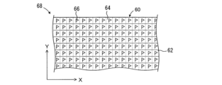
本実施形態においては、管理サーバ42は、各道路の情報を記憶すると共に、図3に示されているように、データベース45において各道路の路面領域を示す地図情報として、各道路60の路面62が複数の路面区画64に予め区分された路面区画情報68を記憶している。X方向は例えば方位の北の方向であり、Y方向はX方向に垂直な方向であってよい。各路面区画64のX方向及びY方向の位置は、それぞれ指標Xm(m=1、2、3・・・)及び指標Yn(n=1、2、3・・・)により表される。
In this embodiment, the
なお、図3において、実線にて示される帯状の領域は、道路60に対応する領域であり、点線は路面区画64を示す線である。路面区画64の大きさはデータベース(マップ)45の解像度に影響する。即ち、路面区画64の大きさが大きいほど、データベース45の解像度が低下し、逆に路面区画64の大きさが小さいほど、データベース45の解像度が向上する。各路面区画64の大きさ及び形状は、車輪のタイヤの接地領域の大きさ及び形状及び制御の容易性に則して決定されてよく、本実施形態の路面区画は一辺の長さが50~150mmの一定値(典型的には100mm)である正方形である。
In addition, in FIG. 3, the strip-shaped area indicated by the solid line is an area corresponding to the
データベース45の初期状態においては、各路面区画64のばね下変位z1は、初期値(例えば0)に仮定されており、各路面区画64の仮定フラグ66がオンに設定されている。なお、仮定フラグ66がオンであることは、対応する路面区画64について記憶装置44に記憶されているばね下変位が、初期値又は仮定されたばね下変位であることを意味する。仮定されたばね下変位については後述する。よって、仮定フラグ66は、記憶装置44に記憶されているばね下変位が、初期値又は仮定されたばね下変位であるか否かを示す識別情報として機能する。
In the initial state of the
本実施形態において、管理サーバ42が記憶装置44に記憶する位置情報は、路面区画64を特定可能な位置情報である。データベース45に登録される例えばばね下変位z1cに紐付けられる位置情報は、図1に示されているように、路面区画64を特定する「ZjXmYn」(Zjは各道路60の識別番号で、jは正の整数)と表記されてよい。
In this embodiment, the positional information that the
更に、ECU30は、左前輪アクティブアクチュエータ17FL、右前輪アクティブアクチュエータ17FR、左後輪アクティブアクチュエータ17RL及び右後輪アクティブアクチュエータ17RRのそれぞれに駆動回路(図示せず)を介して接続されている。
Further, the
ECU30は、各車輪11の後述の通過予測位置のばね下変位z1に基づいて各車輪11のばね上の振動を低減するための目標制御力Fctを演算し、各車輪11が通過予測位置を通過するときにアクティブアクチュエータ17が発生する制御力Fcが目標制御力Fctになるようにアクティブアクチュエータ17を制御する。
The
<プレビュー制振制御の概要>
次に、車載装置102のECU30が実行するプレビュー制振制御の概要について説明する。
<Overview of preview vibration damping control>
Next, an overview of the preview damping control executed by the
図には示されていないが、ばね上の質量をm2とし、ばね下変位、即ちばね下の上下方向の変位をz1とする。ばね上変位、即ち各車輪11の位置におけるばね上の上下方向の変位をz2とする。サスペンション13のスプリング(サスペンションスプリング16など)のばね定数(等価ばね定数)をKとし、サスペンション13のダンパ(ショックアブソーバ15など)の減衰係数(等価減衰係数)をCとする。アクチュエータ17が発生する制御力をFとする。
Although not shown in the figure, the mass on the spring is assumed to be m2 , and the unsprung displacement, that is, the displacement in the vertical direction under the spring is z1 . The sprung mass displacement, that is, the vertical displacement of the sprung mass at the position of each
更に、z1及びz2の時間微分値を、それぞれdz1及びdz2とし、z1及びz2の二階時間微分値を、それぞれddz1及びddz2とする。なお、z1及びz2については上方への変位が正であり、スプリング、ダンパ及びアクチュエータ17などが発生する力については上向きが正であるとする。
Further, the time differential values of z 1 and z 2 are respectively dz 1 and dz 2 , and the second-order time differential values of z 1 and z 2 are ddz 1 and ddz 2 , respectively. Note that for z 1 and z 2 , upward displacement is positive, and for the forces generated by the spring, damper,
車両V1のばね上20の上下方向の運動についての運動方程式は、下記の式(1)にて表わされる。
m2ddz2=C(dz1-dz2)+K(z1-z2)-Fc・・・(1)
The equation of motion for the vertical movement of the sprung
m 2 ddz 2 = C (dz 1 - dz 2 ) + K (z 1 - z 2 ) - Fc... (1)
式(1)における減衰係数Cは一定であると仮定する。しかし、実際の減衰係数はサスペンション13のストローク速度に応じて変化するので、例えばストロークHの時間微分値に応じて可変設定されてもよい。
It is assumed that the damping coefficient C in equation (1) is constant. However, since the actual damping coefficient changes depending on the stroke speed of the
更に、制御力Fcによってばね上の振動が完全に打ち消された場合(即ち、ばね上加速度ddz2、ばね上速度dz2及びばね上変位z2がそれぞれゼロになる場合)、制御力Fcは、式(2)で表される。
Fc=Cdz1+Kz1・・・(2)
Furthermore, when the vibrations on the sprung mass are completely canceled by the control force Fc (that is, when the sprung mass acceleration ddz 2 , the sprung mass velocity dz 2 and the sprung mass displacement z 2 are each zero), the control force Fc is It is expressed by formula (2).
Fc= Cdz1 + Kz1 ...(2)
従って、ばね上の振動を低減する制御力Fcは、制御ゲインをαとして、式(3)で表わすことができる。なお、制御ゲインαは、0より大きく且つ1以下の任意の定数である。
Fc=α(Cdz1+Kz1)・・・(3)
Therefore, the control force Fc that reduces the vibration on the spring can be expressed by equation (3), where α is the control gain. Note that the control gain α is an arbitrary constant greater than 0 and less than or equal to 1.
Fc=α(Cdz 1 +Kz 1 )...(3)
更に、式(3)を式(1)に適用すると、式(1)は式(4)で表すことができる。
m2ddz2=C(dz1-dz2)+K(z1-z2)-α(Cdz1+Kz1)・・・(4)
Furthermore, when formula (3) is applied to formula (1), formula (1) can be expressed as formula (4).
m 2 ddz 2 = C (dz 1 - dz 2 ) + K (z 1 - z 2 ) - α (Cdz 1 + Kz 1 )... (4)
この式(4)をラプラス変換して整理すると、式(4)は式(5)で表される。即ち、ばね下変位z1からばね上変位z2への伝達関数が式(5)で表される。なお、式(5)中の「s」はラプラス演算子である。 When formula (4) is rearranged by Laplace transform, formula (4) is expressed as formula (5). That is, the transfer function from the unsprung displacement z 1 to the sprung mass displacement z 2 is expressed by equation (5). Note that "s" in equation (5) is a Laplace operator.

式(5)によれば、αに応じて伝達関数の値は変化し、αが1である場合、伝達関数の値が最小になる。このことから、目標制御力Fctを式(3)に対応する下記の式(6)で表すことができる。なお、式(6)におけるゲインβ1はαCsに相当し、ゲインβ2はαKに相当する。
Fct=β1×dz1+β2×z1・・・(6)
According to Equation (5), the value of the transfer function changes according to α, and when α is 1, the value of the transfer function becomes the minimum. From this, the target control force Fct can be expressed by the following equation (6), which corresponds to equation (3). Note that the gain β1 in equation (6) corresponds to αCs, and the gain β2 corresponds to αK.
Fct= β1 × dz1 + β2 × z1 ...(6)
よって、車載装置102のECU30は、車輪11が後に通過する位置(通過予測位置)のばね下変位z1及びその時間微分値dz1をデータベース制御装置104から通信により予め取得し(先読みし)、ばね下変位z1を式(6)に適用することによって目標制御力Fctを演算する。そして、ECU30は、車輪11が通過予測位置を通過するタイミングで(即ち、式(6)に適用されたばね下変位z1が生じるタイミングで)、目標制御力Fctに対応する制御力Fcをアクチュエータ17に発生させる。このようにすれば、車輪11が通過予測位置を通過する際に生じるばね上の振動を低減することができる。
Therefore, the
以上がばね上の制振制御であり、この予め取得したばね下変位z1に基づくばね上の制振制御が、本実施形態及び後述の他の実施形態におけるプレビュー制振制御である。 The above is the vibration damping control on the spring, and the vibration damping control on the spring based on the pre-obtained unsprung displacement z1 is the preview damping control in this embodiment and other embodiments to be described later.
なお、上述の説明においては、ばね下の質量及びタイヤの弾性変形が無視され、路面変位z0及びばね下変位z1が同一である仮定されている。従って、ばね下変位z1に代えて路面変位z0を用いて、同様のプレビュー制振制御が実行されてもよい。 Note that in the above description, the unsprung mass and the elastic deformation of the tire are ignored, and it is assumed that the road surface displacement z 0 and the unsprung displacement z 1 are the same. Therefore, similar preview damping control may be performed using the road surface displacement z 0 instead of the unsprung displacement z 1 .
下記の式(7)は、上記式(6)の微分項(β1×dz1)を省略して、目標制御力Fctを簡便に演算する式である。目標制御力Fctが式(7)に従って演算される場合にも、ばね上の振動を低減する制御力(=β2×z1)がアクチュエータ17により発生されるので、この制御力が発生されない場合に比べて、ばね上の振動を低減することができる。
Fct=β2×z1・・・(7)
The following equation (7) is an equation for simply calculating the target control force Fct by omitting the differential term (β 1 ×dz 1 ) in the above equation (6). Even when the target control force Fct is calculated according to equation (7), the
Fct=β 2 ×z 1 ...(7)
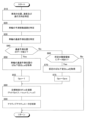
<第一の実施形態のデータベース作成ルーチン>
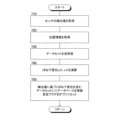
第一の実施形態においては、図5のフローチャートに示されたデータベースの作成ルーチンが所定の経過時間毎に実行されることにより、データベースが作成される。なお、ステップ510~530はECU30のCPUにより実行され、ステップ530~580は管理サーバ42のCPUにより実行される。更に、ステップ540~580がばね下変位z1fl及びz1frについて実行されてもよく、ばね下変位z1flについてステップ540~580が実行され、その後ばね下変位z1frについてステップ540~580が実行されてもよい。
<Database creation routine of first embodiment>
In the first embodiment, a database is created by executing the database creation routine shown in the flowchart of FIG. 5 every predetermined elapsed time. Note that steps 510 to 530 are executed by the CPU of the
まず、ステップ510において、CPUは、上下加速度センサ31FR、31FRにより検出されたばね上加速度ddz2fl、ddz2fr及びストロークセンサ32FR、32FRにより検出されたストロークHfl、Hfrを取得する。これらの情報は、左右の前輪の位置の路面の上下変位に関連する路面変位関連情報である。
First, in
ステップ520において、CPUは、位置情報取得装置33から車両V1の走行経路に基づく現在位置及び進行方向を取得し、それらに基づいて路面変位関連情報が取得された位置(車輪11の位置)を特定可能な位置情報を取得する。この場合、位置情報取得装置33は、自動運転に関する情報、GNSSに関する情報などに基づいて現在位置及び進行方向を特定する。現在位置及び進行方向の特定には、既存の種々の方法が採用されてよいので、現在位置及び進行方向の特定についての詳細な説明を省略する。車両V1の現在位置及び進行方向は、路面変位関連情報が取得された位置を特定可能な位置情報である。
In
ステップ530において、ECU30のCPUは、ステップ510及び520において取得した路面変位関連情報と位置情報とが紐づけられたデータのセットとして、無線通信装置34及びネットワークを介して管理サーバ42へ送信する。管理サーバ42のCPUは、受信した情報を図1には示されていない記憶装置に記憶する。
In
なお、ECU30のCPUは、ステップ510及び520の完了毎に逐次行われてもよいが、ステップ510及び520において取得された情報が記憶装置30aなどに一時的に記憶され、一時的に記憶された一連の情報が所定の時間毎に管理サーバ42へ送信されることが好ましい。
Note that the CPU of the
ステップ540において、CPUは、ステップ530において受信したばね上加速度ddz2fl、ddz2fr及びストロークHfl、Hfrに基づいて、オフラインのデータ処理によりそれぞれ左右の前輪に対応するばね下変位z1fl、z1frを演算する。ばね下変位は、当技術分野において公知の任意の要領にて演算されてよく、例えばオフラインフィルタ及び理想積分を使用して、ばね下変位の2階積分値とストロークとの差として演算されてよい。 In step 540, the CPU calculates unsprung displacements z 1 fl and Calculate z 1 fr. The unsprung displacement may be calculated in any manner known in the art, such as using an offline filter and ideal integration, as the difference between the second-order integral of the unsprung displacement and the stroke. .
なお、ばね下変位z1は、左右の前輪に対応して設けられたばね下の上下加速度センサにより検出されるばね下の上下加速度を2階積分することにより演算されてもよい。また、ばね下変位z1は、各車輪の位置におけるばね上の上下加速度、サスペンションストローク、及びばね下の上下加速度の少なくも一つに基づいて、当技術分野において公知のオブザーバを用いて演算されてもよい。更に、ばね下変位z1は、レーザーセンサにより検出される左右の前輪の前方の位置の路面の上下変位に基づいて演算されてもよい。 Note that the unsprung displacement z 1 may be calculated by performing second-order integration of the unsprung vertical acceleration detected by the unsprung vertical acceleration sensors provided corresponding to the left and right front wheels. Further, the unsprung displacement z 1 is calculated using an observer known in the art based on at least one of the vertical acceleration on the spring, the suspension stroke, and the vertical acceleration on the unsprung at the position of each wheel. It's okay. Furthermore, the unsprung displacement z 1 may be calculated based on the vertical displacement of the road surface in front of the left and right front wheels detected by a laser sensor.
特に、本実施形態においては、ばね下変位z1は、各路面区画64について演算される。路面区画についてのばね下変位z1の演算要領を。図4を参照して説明する。
In particular, in this embodiment, the unsprung displacement z 1 is calculated for each
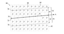
図4において、太い実線70は、車輪11のタイヤの接地領域の中心(図示せず)の移動軌跡の一例に対応する直線を示している。なお、矢印Aは車輪11の移動方向を示しており、説明の便宜上、車輪11の移動方向は車両V1の進行方向と同一であるとする。
In FIG. 4, a thick
太い実線70上の黒丸72は、ばね上の上下加速度センサ31FLなどのセンサにより検出値が検出された地点を示しており、検出値に基づくばね下変位はこれらの地点が属する路面区画のばね下変位として演算される。なお、データベース45において路面領域を示す路面区画情報68における黒72の位置は、ステップ530において受信されるデータのセットに含まれる検出値と、車両V1の位置及び進行方向に基づいて決定される車輪11の位置との同期をとることにより求められてよい。
各センサの検出値は、センサのサンプリング周波数に応じた頻度で取得される。サンプリング周波数は一定であるので、検出値が取得される地点間の距離(即ち、図4の黒丸72の間隔)は、車速Vv1が大きくなるほど大きくなる。例えば、サンプリング周波数が100Hzであり、車速が時速100kmであるとすると、検出値が取得される地点間の距離は、約278mmとなり、路面区画64の辺及び対角線の長さよりも大きい。
The detection value of each sensor is acquired at a frequency according to the sampling frequency of the sensor. Since the sampling frequency is constant, the distance between the points where detected values are acquired (ie, the interval between the
よって、車輪の移動方向に沿う黒丸72の数は、車輪の移動方向に沿う路面区画64の数よりも少ない。そこで、管理サーバ42のCPUは、検出値に基づいて相前後して演算された二つのばね下変位に対応する二つの地点、即ち互いに隣接する二つの黒丸72の間の領域について、ばね下変位を補完するリサンプリングを行う。即ち、二つの黒丸72の間に例えば10mm毎に推定のばね下変位が存在するよう、ステップ530において受信されるデータのセットに含まれる検出値がリサンプリングされ、リサンプリングされた検出値に基づいて補完ばね下変位が演算される。図4の白丸74は、補完ばね下変位に対応する地点を示している。
Therefore, the number of
なお、検出値のリサンプリングは、当技術分野に於いて公知の任意の要領にて実行されてよいので。検出値のリサンプリングについての説明を省略する。 Note that the resampling of the detected values may be performed in any manner known in the art. A description of resampling of detected values will be omitted.
更に、管理サーバ42のCPUは、各路面区画64に属する補完ばね下変位及び検出値に基づくばね下変位の平均値又は補完ばね下変位の平均値を当該路面区画のばね下変位として演算する。よって、図4において太い実線70が通る全ての路面区画64について検出値に基づくばね下変位が求められる。
Furthermore, the CPU of the
ステップ550において、CPUは、ステップ530において受信した位置情報に基づいて路面変位関連情報が取得された位置に対応する路面区画を特定する。更に、CPUは、特定した路面区画とステップ540において演算されたばね下変位(検出値に基づくばね下変位)とが紐づけられたデータのセットをデータベースの一部として記憶装置44に記憶する。即ち、CPUは、特定した路面区画について、検出値に基づくばね下変位にてデータベースを更新する。
In
なお、CPUは、特定した路面区画の仮定フラグがオンであるときには、仮定フラグをオフに切り替える。更に、特定した路面区画について検出値に基づくばね下変位が既に記憶されているときには、ステップ540において演算されたばね下変位が上書きにより記憶されてもよく、或いは既に記憶されているばね下変位と演算されたばね下変位との平均値が記憶されてもよい。
Note that when the assumption flag of the identified road surface section is on, the CPU switches the assumption flag to off. Furthermore, when the unsprung displacement based on the detected value for the specified road surface section is already stored, the unsprung displacement calculated in
ステップ560において、CPUは、ステップ550において特定した路面区画に隣接する所定の隣接領域にある路面区画のばね下変位が、特定した路面区画のばね下変位と同一であると仮定する。これにより、所定の隣接領域にある路面区画のばね下変位が、検出値に基づくばね下変位に基づいて演算される仮定のばね下変位に決定される。
In
例えば、図4に示されているように、CPUは、上述のように特定した太い実線70上の黒丸72及び白丸74を、太い実線70の両側に太い実線に垂直な方向へ所定量移動してコピーする。図4において、破線76は太い実線70がコピーされた位置を示している。コピーされた黒丸72c及び白丸74cに対応する検出値に基づくばね下変位及び補完ばね下変位は、それぞれコピー元の黒丸72及び白丸74に対応する検出値に基づくばね下変位及び補完ばね下変位と同一である。なお、コピーに際し移動する方向は、車両V1の進行方向を横切る方向であればよく、太い実線70に垂直な方向でなくてもよい。
For example, as shown in FIG. 4, the CPU moves the
更に、CPUは、太い実線70上の黒丸72及び白丸74について行われた上述のばね下変位の演算と同一の要領にて、各路面区画64についてコピーされた補完ばね下変位及び検出値に基づくばね下変位に基づいて仮定のばね下変位を演算する。よって、車輪が通過する路面区画64に隣接し且つ車輪が通過しない路面区画について、車輪が通過する路面区画64の検出値に基づくばね下変位に基づいて仮定のばね下変位が求められる。
Further, the CPU calculates the unsprung displacement based on the complementary unsprung displacement copied for each
なお、本実施形態においては、隣接は車両V1の進行方向に垂直な方向の隣接であるが、隣接の方向は車両V1の進行方向を横切る方向であればよく、例えば車両V1の長手方向に垂直な方向、車線に対し垂直な方向であってもよい。また、所定の隣接領域78の車両V1の進行方向を横切る方向の幅Wは、車輪11のタイヤ(図示せず)の幅よりも大きく、車線を越えない範囲に設定される。更に、太い実線70の両側の幅Wは、互いに異なる値であってもよい。
Note that in this embodiment, adjacency is adjacency in a direction perpendicular to the traveling direction of vehicle V1, but the adjoining direction may be any direction that crosses the traveling direction of vehicle V1, for example, perpendicular to the longitudinal direction of vehicle V1. The direction may be perpendicular to the traffic lane. Further, the width W of the predetermined
特に幅Wが大きい場合には、所定の隣接領域内の全ての路面区画64について仮定のばね下変位が演算されるよう、上述の検出値に基づくばね下変位及び補完ばね下変位のコピーは、太い実線70の両側において必要に応じて複数回行われてよい。
In particular, when the width W is large, the copies of the unsprung displacement and complementary unsprung displacement based on the above-described detected values are This may be performed multiple times on both sides of the thick
前述のように、ばね下変位の周波数が高いほど、路面の平坦性が低く、互いに隣接する路面部位のばね下変位の間の相違量が大きい可能性が高くなる。換言すれば、ばね下変位の周波数が高いほど、ばね下変位が同一であると仮定することができる路面の範囲が狭くなる。よって、ステップ560において、所定の隣接領域のばね下変位の低周波成分を抽出する処理、例えばローバスフィルタ処理又は移動平均処理が行われ、抽出処理後のばね下変位が仮定のばね下変位z1aiとされてよい。
As described above, the higher the frequency of the unsprung displacement, the lower the flatness of the road surface, and the greater the possibility that the amount of difference between the unsprung displacements of adjacent road surface regions will be large. In other words, the higher the frequency of the unsprung displacement, the narrower the range of road surfaces that can be assumed to have the same unsprung displacement. Therefore, in
低周波成分抽出処理によれば、低周波成分抽出処理が行われない場合に比して、路面の平坦性が低い状況においても、所定の隣接領域にある路面区画について仮定されたばね下変位が、その路面区画の実際のばね下変位と大きく相違する虞を低減することができる。従って、仮定されたばね下変位と実際のばね下変位とが大きく相違することに起因して不適切な制御力にてプレビュー制振制御が行われる虞を低減することができる。 According to the low-frequency component extraction process, even in a situation where the road surface is less flat than when the low-frequency component extraction process is not performed, the assumed unsprung displacement of the road surface section in a predetermined adjacent area is It is possible to reduce the possibility that the unsprung displacement of the road section differs greatly from the actual unsprung displacement. Therefore, it is possible to reduce the possibility that the preview damping control will be performed with an inappropriate control force due to a large difference between the assumed unsprung displacement and the actual unsprung displacement.
また、ばね下変位が同一であると仮定することができる範囲は、ばね下変位の波長が長いほど大きくてよく、ばね下変位の波長はばね下変位の周波数が低いほど大きい。よって、ばね下変位が同一であると仮定する隣接領域の幅Wは、抽出処理により抽出される成分の周波数に応じて、例えばローバスフィルタ処理のカットオフ周波数又は移動平均処理の平均する期間の長さに応じて変更されてよい。 Further, the range in which the unsprung displacements can be assumed to be the same may be larger as the wavelength of the unsprung displacements becomes longer, and the wavelength of the unsprung displacements becomes larger as the frequency of the unsprung displacements becomes lower. Therefore, the width W of the adjacent region assuming the same unsprung displacement depends on the frequency of the component extracted by the extraction process, for example, the cutoff frequency of the low-pass filter process or the averaging period of the moving average process. It may be changed depending on the length.
例えば、車速V1が36km/hであるときの周波数が1Hzのばね下変位の1波長は10mである。1波長のばね下変位のうち10分の1の範囲(この範囲に特別の根拠はない)が同一の値であるとすると、ばね下変位が同一であると仮定する隣接領域78の幅Wは、±0.5mの幅、即ち車輪の通過予測位置の両側の0.5mの幅が有効である。なお、+及び-は、それぞれ車輪に対し車両の横方向外側及び車両の横方向内側を意味する。
For example, when the vehicle speed V1 is 36 km/h, one wavelength of unsprung displacement with a frequency of 1 Hz is 10 m. Assuming that one-tenth of the unsprung displacement of one wavelength (there is no particular basis for this range) has the same value, the width W of the
また、車速V1が36km/hであるときの周波数が2Hzのばね下変位の1波長は5mである。ばね下変位が同一であると仮定する隣接領域78の幅Wは、±0.25mの幅、即ち車輪の通過予測位置の両側の0.25mの幅が有効である。よって、ばね下変位が同一であると仮定する隣接領域78の幅Wは、抽出処理により抽出される成分の周波数が低いほど大きくなるよう、可変設定されてよい。例えば、ローバスフィルタ処理のカットオフ周波数が低いほど、或いは移動平均処理の平均する期間の長さが長いほど、大きくなるよう、可変設定されてよい。
Furthermore, when the vehicle speed V1 is 36 km/h, one wavelength of the unsprung displacement with a frequency of 2 Hz is 5 m. Assuming that the unsprung displacement is the same, an effective width W of the
上述の隣接領域78の幅Wの可変設定によれば、路面の平坦性が高い状況においては、隣接領域78の幅Wを大きくし、これによりばね下変位が同一であると仮定する範囲を大きくすることができる。逆に、路面の平坦性が低い状況においては、隣接領域78の幅Wを小さくし、所定の隣接領域にある路面区画について仮定されたばね下変位が、その路面区画の実際のばね下変位と大きく相違する虞を低減することができる。
According to the variable setting of the width W of the
ステップ570において、CPUは、所定の隣接領域にある各路面区画について、仮定フラグがオンであるか否かを順次判別する。更に、CPUは、各判別において否定判別をすると、即ち検出値に基づくばね下変位を含むデータのセットが既に記憶されていると判別すると、データのセットを記憶することなく、図5に示されたルーチンによる制御を一旦終了する。
In
これに対し、CPUは、肯定判別をすると、ステップ580において同一であると仮定されたばね下変位(仮定されたばね下変位)と路面区画とが紐づけられたデータのセットをデータベースの一部として記憶装置44に記憶する。即ち、CPUは、所定の隣接領域にある路面区画について、仮定されたばね下変位にてデータベースを更新する。
On the other hand, if the CPU makes a positive determination, the CPU stores a data set in which the unsprung displacement (assumed unsprung displacement) assumed to be the same in
<第一の実施形態のプレビュー制振制御ルーチン>
第一の実施形態においては、図6のフローチャートに示された制振制御ルーチンがECU30のCPUによって所定の経過時間毎に実行されることにより、プレビュー制振制御が実行される。なお、プレビュー制振制御は、例えば左前輪、右前輪、左後輪及び右後輪の順に各車輪の位置について実行されてよい。
<Preview damping control routine of first embodiment>
In the first embodiment, the preview vibration damping control is executed by executing the vibration damping control routine shown in the flowchart of FIG. 6 by the CPU of the
まず、ステップ610において、CPUは、位置情報取得装置33から車両V1の位置に関する履歴情報を取得し、履歴情報に基づいて各車輪11の現在位置、車速Vv1及び車両V1の進行方向Tdを取得する。
First, in
なお、ECU30のROMは、車両V1におけるGNSS受信機の搭載位置と各車輪11の位置との関係を記憶している。位置情報取得装置33から取得される車両V1の現在位置はGNSS受信機の搭載位置であり、CPUは、車両V1の現在位置、車両V1の進行方向Td及び上記位置関係に基づいて各車輪11の現在位置を特定する。更に、位置情報取得装置33が受信するGNSS信号は車両V1の移動速度に関する情報を含んでおり、CPUは、GNSS信号に基づいて車速Vv1を取得する。
Note that the ROM of the
ステップ620において、CPUは、各車輪11の現在位置、車両V1の進行方向Td及び上記位置関係に基づいて、左右の前輪及び左右の後輪の移動予測進路を特定する。前輪及び後輪の移動予測進路は、それぞれ前輪11F及び後輪11Rが今後移動すると予測される進路である。
In
ステップ630において、CPUは、左右の前輪及び左右の後輪の移動予測進路及び車速V1に基づいて、所定の時間後の左右の前輪の通過予測位置及び左右の後輪の通過予測位置を特定する。
In
ステップ640において、CPUは、クラウド40のデータベース45から左前輪、右前輪、左後輪及び右後輪の通過予測位置に対応する路面区画64のばね下変位z1ai(i=fl、fr、rl及びrr)を取得する。
In
なお、ばね下変位z1aiの取得は、制御サイクル毎に逐次行われてもよく、また車輪毎に一連の通過予測位置に対応する路面区画64のばね下変位z1aiがまとめて取得され、ECU30のRAMに保存されてもよい。
Note that the unsprung displacement z 1 ai may be acquired sequentially for each control cycle, or the unsprung displacement z 1 ai of the
ステップ650において、CPUは、車輪の通過予測位置に対応する路面区画64の仮定フラグ66がオンであるか否かを判別する。更に、CPUは、否定判別をすると、即ち通過予測位置に対応する路面区画64のばね下変位が検出値に基づくばね下変位であると判別すると、ステップ660においてプレビュー制振制御のゲインGpvを標準値である1に設定する。これに対し、CPUは、肯定判別をすると、ステップ670においてプレビュー制振制御のゲインGpvを標準値よりも小さい正の値Gpva、例えば0.8に設定する。
In
なお、プレビュー制振制御に加えてばね上の振動を低減するためのフィードバック制振制御が行われる場合には、ステップ670においてプレビュー制振制御のゲインGpvが低減されることなく、フィードバック制振制御のゲインが増大されてもよい。更に、ステップ670においてプレビュー制振制御のゲインGpvが低減されると共にフィードバック制振制御のゲインが増大されてもよい。換言すれば、プレビュー制振制御以外の他の制振制御も行われる車両の場合には、プレビュー制振制御量が低減されることなく、他の制振制御量が増大されてもよく、プレビュー制振制御量が低減されると共に他の制振制御量が増大されてもよい。
Note that when feedback damping control for reducing vibration on the spring is performed in addition to preview damping control, the gain Gpv of preview damping control is not reduced in
なお、他の制振制御は、フィードバック制振制御に限定されない。例えば、他の制振制御は、レーザーセンサのようなプレビューセンサにより車輪の前方の位置の路面変位関連情報が取得され、路面変位関連情報に基づく路面変位関連値に基づいて制御力が制御される制振制御であってもよい。 Note that other damping controls are not limited to feedback damping control. For example, in other vibration damping controls, road surface displacement related information at the position in front of the wheels is acquired by a preview sensor such as a laser sensor, and the control force is controlled based on a road surface displacement related value based on the road surface displacement related information. It may also be vibration damping control.
ステップ680において、CPUは、上記式(6)に対応する下記の式(8)により、ばね下変位z1ai及びその時間微分値dz1aiに基づいて、各車輪のアクティブアクチュエータ17FL~17RRの目標制御力Fcti(i=fl、fr、rl及びrr)を演算する。
Fcti=Gpv(β1×dz1ai+β2×z1ai)・・・(8)
In
Fcti=Gpv(β 1 ×dz 1 ai+β 2 ×z 1 ai)...(8)
ステップ690において、CPUは、目標制御力Fctiを含む制御指令を各車輪のアクティブアクチュエータ17FL~17RRへ出力することにより、各アクティブアクチュエータが発生する制御力Fcが目標制御力Fctiになるように制御する。なお、各アクティブアクチュエータは、各車輪11が対応する通過予測位置を通過するタイミングで目標制御力Fctiに対応する制御力を出力する。
In
なお、本発明の車両用プレビュー制振制御方法は、
路面変位関連情報検出装置により検出された路面変位関連情報と該路面変位関連情報が検出された位置を特定可能な位置情報とを紐づけて第二の制御ユニットへ送信するステップAと、
車両又は他車から送信される路面変位関連情報に基づいて路面の上下変位に関連する路面変位関連値を演算するステップBと、
演算された路面変位関連値とそれに対応する位置情報とが紐づけられたデータのセットをデータベースの一部として記憶装置に記憶するステップCと、
データベースの路面変位関連情報及び位置情報を使用してプレビュー制振制御を行うステップDと、
データのセットを記憶装置に記憶するステップ及びプレビュー制振制御を行うステップの少なくとも一方において、路面変位関連情報検出装置により路面変位関連情報が検出された地点に対し車両の進行方向を横切る方向に位置する所定の隣接領域の路面変位関連値が、前記地点の路面変位関連値と同一であると仮定するステップEと、
を含んでいる。
Note that the vehicle preview damping control method of the present invention includes:
Step A of linking the road surface displacement related information detected by the road surface displacement related information detection device with position information that can specify the position where the road surface displacement related information is detected, and transmitting the linked information to the second control unit;
Step B of calculating a road surface displacement related value related to the vertical displacement of the road surface based on road surface displacement related information transmitted from the vehicle or another vehicle;
Step C: storing a set of data in which the calculated road surface displacement related value and the corresponding position information are linked in a storage device as part of a database;
Step D of performing preview damping control using road surface displacement related information and position information in the database;
In at least one of the step of storing a data set in a storage device and the step of performing preview vibration damping control, the position is located in a direction transverse to the traveling direction of the vehicle with respect to a point where road surface displacement related information is detected by the road surface displacement related information detection device. a step E of assuming that the road surface displacement related value of the predetermined adjacent area is the same as the road surface displacement related value of the point;
Contains.
第一の実施形態においては、ステップ510~530がステップAに対応し、ステップ540がステップBに対応する。ステップ550がステップCに対応し、ステップ610~690がステップDに対応する。更に、ステップ560がステップEに対応する。よって、これらのステップによって本発明の車両用プレビュー制振制御方法が実行される。
In the first embodiment, steps 510 to 530 correspond to step A, and step 540 corresponds to step
[第二の実施形態]
<第二の実施形態のデータベース作成ルーチン>
第二の実施形態においては、データベース作成は、図7のフローチャートに示されたデータベース作成ルーチンが所定の経過時間毎に実行されることにより行われる。ステップ710~730は第一の実施形態のステップ510~530と同様にECU30のCPUにより実行され、ステップ730~750は第一の実施形態のステップ530~550と同様に管理サーバ42のCPUにより実行される。
[Second embodiment]
<Database creation routine of second embodiment>
In the second embodiment, database creation is performed by executing the database creation routine shown in the flowchart of FIG. 7 at predetermined elapsed time intervals.
よって、第二の実施形態のデータベース作成ルーチンについての説明を省略する。なお、図7と図5との比較から解るように、第二の実施形態においては、第一の実施形態のステップ560~580に対応するステップは実行されない。
Therefore, a description of the database creation routine of the second embodiment will be omitted. Note that, as can be seen from a comparison between FIG. 7 and FIG. 5, in the second embodiment, steps corresponding to
<第二の実施形態のプレビュー制振制御ルーチン>
第二の実施形態においては、図8のフローチャートに示された制振制御ルーチンがECU30のCPUによって所定の経過時間毎に実行されることにより、プレビュー制振制御が実行される。なお、本実施形態のプレビュー制振制御も、例えば左前輪、右前輪、左後輪及び右後輪の順に各車輪の位置について実行されてよい。ステップ810~830は第一の実施形態のステップ610~630と同様に実行され、ステップ855及び875はそれぞれ第一の実施形態のステップ660及び670と同様に実行される。更に、ステップ880及び890はそれぞれ第一の実施形態のステップ680及び690と同様に実行される。
<Preview damping control routine of second embodiment>
In the second embodiment, the preview vibration damping control is executed by executing the vibration damping control routine shown in the flowchart of FIG. 8 by the CPU of the
CPUは、ステップ830を完了すると、ステップ840において、車輪の通過予測位置及びそれに隣接する領域の路面区画64のばね下変位z1i(i=fl、fr、rl及びrr)をデータベース45から取得する。更に、CPUは、車輪の通過予測位置に対応する路面区画64に検出値に基づくばね下変位z1aiのデータがあるか否かを判別する。
After completing
CPUは、肯定判別をすると、ステップ850においてデータベース45から取得したばね下変位z1iのうち、車輪の通過予測位置に対応する路面区画64のばね下変位z1ai(i=fl、fr、rl及びrr)を取得する。更に、CPUは、ステップ855においてプレビュー制振制御のゲインGpvを標準値である1に設定する。
If the CPU makes a positive determination, the CPU selects the unsprung displacement z 1 ai (i=fl, fr , rl and rr). Further, in
これに対し、CPUは、否定判別をすると、即ち車輪の通過予測位置に対応する路面区画64に検出値に基づくばね下変位のデータがないと判別すると、ステップ860において車輪の通過予測位置に対応する路面区画64に隣接する路面区画に検出値に基づくばね下変位のデータがあるか否かを判別する。
On the other hand, if the CPU makes a negative determination, that is, if it determines that there is no unsprung displacement data based on the detected value in the
本実施形態においても、隣接は車両V1の進行方向に垂直な方向の隣接であるが、隣接の方向は車両V1の進行方向を横切る方向であればよく、例えば車両V1の長手方向に垂直な方向、車線に対し垂直な方向であってもよい。なお、隣接の範囲は第一の実施形態における隣接の範囲と異なっていてよい。 In this embodiment as well, the adjacency is the adjacency in the direction perpendicular to the traveling direction of the vehicle V1, but the adjacent direction may be any direction that crosses the traveling direction of the vehicle V1, for example, the direction perpendicular to the longitudinal direction of the vehicle V1. , or in a direction perpendicular to the lane. Note that the adjacent range may be different from the adjacent range in the first embodiment.
CPUは、否定判別をすると、ステップ880及び890を実行することなく、換言すれば、プレビュー制振制御の制御力を制御することなく、図8のフローチャートに示された制振制御ルーチンを一旦終了する。なお、CPUは、否定判別をする場合には、フィードバック制振制御を行ってもよく、更にはプレビュー制振制御及びフィードバック制振制御以外の他の制振制御を行ってもよい。
When the CPU makes a negative determination, the CPU temporarily ends the vibration damping control routine shown in the flowchart of FIG. 8 without executing
これに対し、CPUは、肯定判別をすると、ステップ870において車輪の通過予測位置のばね下変位は、隣接する路面区画領域(所定の隣接領域)のばね下変位と同一であると仮定し、その仮定のばね下変位z1aiを取得する。更に、CPUは、ステップ875においてプレビュー制振制御のゲインGpvを標準値よりも小さい正の値Gpva、例えば0.8に設定する。
On the other hand, if the CPU makes an affirmative determination, it assumes that the unsprung displacement of the predicted passing position of the wheel is the same as the unsprung displacement of the adjacent road surface section area (predetermined adjacent area) in
図9は仮定のばね下変位を取得する要領の一例を示している。図9において、太い実線80は、車輪11のタイヤの接地領域の中心(図示せず)の移動進路の一例に対応する直線を示している。太い実線80上の四角82は、車輪11のタイヤの接地領域の中心の通過予測位置を示している。これらの移動進路及び通過予測位置は、それぞれステップ820及び830において特定された車輪の予測移動進路及び車輪の通過予測位置に基づいて決定される。更に、図9において、符号84は所定の隣接領域を示している。太い実線80の両側の所定の隣接領域84の幅Wは互いに異なる値であってもよい。
FIG. 9 shows an example of how to obtain a hypothetical unsprung displacement. In FIG. 9, a thick solid line 80 indicates a straight line corresponding to an example of a moving path of the center (not shown) of the ground contact area of the tire of the
なお、矢印Bは車輪11の移動方向を示しており、説明の便宜上、車輪11の移動方向は車両V1の進行方向と同一であるとする。図9に示されているように、太い実線80が通る路面区画64の少なくとも一部については検出値に基づくばね下変位z1は記憶されておらず、フラグ66がオンであるが、所定の隣接領域84の路面区画64の少なくとも一部については検出値に基づくばね下変位z1が記憶され、フラグ66がオフであるとする。
Note that arrow B indicates the moving direction of the
図9において破線の矢印にて示されているように、所定の隣接領域84の路面区画64の検出値に基づくばね下変位z1が、太い実線70が通る路面区画64のばね下変位としてコピーされる。そしてコピーされたばね下変位z1が、車輪の通過予測位置の路面区画64についての仮定のばね下変位z1aiとして記憶装置30aに記憶される。この場合、コピーされるべきばね下変位z1が複数であるときには、コピーされるばね下変位は、太い実線70に最も近い路面区画のばね下変位のみであってもよく、複数のばね下変位の平均値がコピーされてもよい。平均値は、太い実線70に近いほど重みが大きい重み平均値であってもよい。
As shown by the dashed arrow in FIG. 9, the unsprung displacement z 1 based on the detected value of the
車輪の通過予測位置の路面区画(「制御対象の路面区画」という)について、検出値に基づくばね下変位z1が記憶されていないときには、図9において破線の矢印にて示されているように、当該制御対象の路面区画のばね下変位は、隣接領域の路面区画のばね下変位と同一であると仮定される。更に、制御対象の路面区画についてのプレビュー制振制御は、仮定されたばね下変位に基づいて演算される目標制御力に基づいて行われる。 When the unsprung displacement z 1 based on the detected value is not stored for the road surface section at the predicted passing position of the wheel (referred to as "the road surface section to be controlled"), as shown by the dashed arrow in FIG. , it is assumed that the unsprung displacement of the road section to be controlled is the same as the unsprung displacement of the road section in the adjacent region. Further, the preview damping control for the road surface section to be controlled is performed based on the target control force calculated based on the assumed unsprung displacement.
これに対し、制御対象の路面区画について、検出値に基づくばね下変位z1が記憶されているときには、図9において破線の矢印が示されていないように、ばね下変位の仮定は行われない。更に、制御対象の路面区画についてのプレビュー制振制御は、記憶されているばね下変位に基づいて演算される目標制御力に基づいて行われる。 On the other hand, when the unsprung displacement z 1 based on the detected value is stored for the road surface section to be controlled, the unsprung displacement is not assumed, as indicated by the dashed arrow in FIG. . Further, the preview damping control for the road surface section to be controlled is performed based on the target control force calculated based on the stored unsprung displacement.
前述のように、ばね下変位の周波数が高いほど、ばね下変位が同一であると仮定することができる路面の範囲が狭くなる。よって、ステップ870において、所定の隣接領域のばね下変位の低周波成分を抽出する処理、例えばローバスフィルタ処理又は移動平均処理が行われ、抽出処理後のばね下変位が仮定のばね下変位z1aiとされてよい。
As mentioned above, the higher the frequency of the unsprung displacement, the narrower the range of road surfaces that can be assumed to have the same unsprung displacement. Therefore, in
第一の実施形態と同様に、低周波成分抽出処理によれば、低周波成分抽出処理が行われない場合に比して、路面の平坦性が低い状況においても、所定の隣接領域にある路面区画について仮定されたばね下変位が、その路面区画の実際のばね下変位と大きく相違する虞を低減することができる。従って、仮定されたばね下変位と実際のばね下変位と大きく相違することに起因して不適切な制御力にてプレビュー制振制御が行われる虞を低減することができる。 Similarly to the first embodiment, according to the low frequency component extraction process, even in a situation where the road surface is less flat than when the low frequency component extraction process is not performed, the road surface in the predetermined adjacent area can be It is possible to reduce the possibility that the unsprung displacement assumed for the section differs greatly from the actual unsprung displacement of the road surface section. Therefore, it is possible to reduce the possibility that the preview damping control will be performed with an inappropriate control force due to a large difference between the assumed unsprung displacement and the actual unsprung displacement.
また、前述のように、ばね下変位が同一であると仮定することができる範囲は、ばね下変位の波長が長いほど大きくてよく、ばね下変位の波長はばね下変位の周波数が低いほど大きい。よって、ばね下変位が同一であると仮定する隣接領域84の幅Wは、抽出処理により抽出される成分の周波数が低いほど大きくなるよう、可変設定されてよい。例えば、ローバスフィルタ処理のカットオフ周波数が低いほど、或いは移動平均処理の平均する期間の長さが長いほど、大きくなるよう、可変設定されてよい。
Additionally, as mentioned above, the range in which unsprung displacements can be assumed to be the same may be larger as the wavelength of unsprung displacements becomes longer, and the wavelength of unsprung displacements becomes larger as the frequency of unsprung displacements becomes lower. . Therefore, the width W of the
上述の隣接領域84の幅Wの可変設定によれば、路面の平坦性が高い状況においては、隣接領域84の幅Wを大きくし、これによりばね下変位が同一であると仮定する範囲を大きくすることができる。逆に、路面の平坦性が低い状況においては、隣接領域78の幅Wを小さくし、所定の隣接領域にある路面区画について仮定されたばね下変位が、その路面区画の実際のばね下変位と大きく相違する虞を低減することができる。
According to the variable setting of the width W of the
なお、プレビュー制振制御に加えてばね上の振動を低減するためのフィードバック制振制御が行われる場合には、ステップ875においてプレビュー制振制御のゲインGpvが低減されることなく、フィードバック制振制御のゲインが増大されてもよい。更に、ステップ875においてプレビュー制振制御のゲインGpvが低減されると共にフィードバック制振制御のゲインが増大されてもよい。換言すれば、プレビュー制振制御以外の他の制振制御も行われる車両の場合には、プレビュー制振制御量が低減されることなく、他の制振制御量が増大されてもよく、プレビュー制振制御量が低減されると共に他の制振制御量が増大されてもよい。
Note that when feedback damping control is performed to reduce vibrations on the spring in addition to preview damping control, the gain Gpv of preview damping control is not reduced in
前述のように、本発明の車両用プレビュー制振制御方法は、ステップA~Eを含んでいる。第二の実施形態においては、ステップ710~730がステップAに対応し、ステップ740がステップBに対応する。ステップ750がステップCに対応し、ステップ810~855及びステップ880~890がステップDに対応する。更に、ステップ860~875がステップEに対応する。よって、これらのステップによって本発明の車両用プレビュー制振制御方法が実行される。
As described above, the vehicle preview damping control method of the present invention includes steps A to E. In the second embodiment, steps 710-730 correspond to step A, and step 740 corresponds to step
以上の説明より解るように、第一及び第二の実施形態によれば、記憶装置44に記憶されたデータベース45のばね下変位z1を通信により先読みしてプレビュー制振制御を行うことにより、車両のばね上の振動を低減することができる。特に、路面変位関連情報が検出された位置及び所定の隣接領域についてのデータのセットを使用してプレビュー制振制御を行うことができる。よって、多数の車両が同一の道路を様々な横方向位置にて走行しなくても、有効なばね下変位z1aiを先読みしてばね上を制振することができる。
As can be seen from the above description, according to the first and second embodiments, by pre-reading the unsprung displacement z 1 of the
特に、第一の実施形態によれば、ばね下変位z1が仮定されたばね下変位である場合には、そのことを示す識別標識である仮定フラグ66がオンに設定される。よって、データベース45のばね下変位z1を使用してプレビュー制振制御を行う際に、ばね下変位が検出された路面変位関連情報に基づいて演算されたばね下変位であるか否かを仮定フラグ66によって判別することができる。
In particular, according to the first embodiment, when the unsprung displacement z 1 is the assumed unsprung displacement, the
また、第一の実施形態によれば、所定の隣接領域の位置について車両又は他車が走行する際に検出された路面変位関連情報に基づいて演算されたばね下変位z1と位置情報とが紐づけられたデータのセットが記憶装置44に既に記憶されているときには、仮定のデータのセットは記憶装置に記憶されない。よって、検出された路面変位関連情報に基づいて演算されたばね下変位と位置情報とが紐づけられ記憶装置に既に記憶されているデータのセットが、仮定のデータのセットによって上書きされて記憶されることを防止することができる。
Further, according to the first embodiment, the unsprung displacement z 1 calculated based on the road surface displacement related information detected when the vehicle or another vehicle travels at the position of the predetermined adjacent area and the position information are linked. If the assigned data set is already stored in the
また、第一及び第二の実施形態によれば、車輪通過予測位置のばね下変位z1aiが仮定されたばね下変位である場合にも、その仮定されたばね下変位に基づいて目標プレビュー制振制御力を演算し、目標プレビュー制振制御力に基づいてプレビュー制振制御を行うことができる。 Further, according to the first and second embodiments, even when the unsprung displacement z 1 ai of the predicted wheel passing position is the assumed unsprung displacement, the target preview damping is performed based on the assumed unsprung displacement. It is possible to calculate the control force and perform preview vibration damping control based on the target preview vibration damping control force.
また、第一及び第二の実施形態によれば、取得した車輪通過予測位置のばね下変位が仮定されたばね下変位であると判定されたときには、目標プレビュー制振制御力Fctiが低減されることにより、それに基づいて発生される制御力が低減される。よって、ばね下変位が仮定されたばね下変位であるときにも目標プレビュー制振制御力が低減されない場合に比して、不適切な大きい制振制御力が発生される虞れを低減することができる。 Further, according to the first and second embodiments, when it is determined that the unsprung displacement of the acquired predicted wheel passing position is the assumed unsprung displacement, the target preview damping control force Fcti is reduced. Therefore, the control force generated based on it is reduced. Therefore, compared to the case where the target preview damping control force is not reduced even when the unsprung displacement is the assumed unsprung displacement, it is possible to reduce the possibility that an inappropriately large vibration damping control force will be generated. can.
また、第一及び第二の実施形態によれば、目標プレビュー制振制御以外の他の制振制御が行われない場合に比して、ばね下変位が仮定されたばね下変位であるときにもばね上の振動を効果的に低減することができる。特に、ばね下変位が仮定されたばね下変位であるときに、目標プレビュー制振制御力に基づいて発生される制御力が低減される場合には、制振制御力が不足する虞れを他の制振制御の制御力によって制振制御力が不足する虞れを低減することができる。 Furthermore, according to the first and second embodiments, when the unsprung displacement is the assumed unsprung displacement, compared to the case where no other vibration damping control other than the target preview vibration damping control is performed, Vibration on the spring can be effectively reduced. In particular, if the control force generated based on the target preview damping control force is reduced when the unsprung displacement is the assumed unsprung displacement, there is a risk that the vibration damping control force will be insufficient. It is possible to reduce the possibility that the vibration damping control force will be insufficient due to the control force of the vibration damping control.
また、第一及び第二の実施形態によれば、各路面区画64についてのデータのセットよりなるデータベース45を記憶装置44に記憶することができる。よって、例えば路面変位関連情報が検出される各地点及び隣接領域の各地点についてのデータのセットが、データベースの一部として記憶装置に記憶される場合に比して、データのセットの数を低減し、記憶装置の記憶容量を低減することができる。
Further, according to the first and second embodiments, the
特に、第一の実施形態によれば、所定の隣接領域の位置についてのばね下変位の仮定は、データベース制御装置104において行われる。よって、所定の隣接領域の位置についてのばね下変位の仮定が各車両において行われる第二の実施形態に比して、各車両においてプレビュー制振制御を効率的に行うことができる。
In particular, according to the first embodiment, the assumption of the unsprung displacement for the position of the predetermined adjacent region is made in the
逆に、第二の実施形態によれば、第一の実施形態によってもデータのセットが道路の全幅に亘り記憶装置44に記憶されていない状況においても、プレビュー制振制御を実行する可能性を増大させることができる。換言すれば、車輪通過予測位置に検出値に基づくばね下変位がない状況においても、仮定されたばね下変位に基づいてプレビュー制振制御を実行する可能性を増大させることができる。
Conversely, according to the second embodiment, even in a situation where the data set is not stored in the
[第一の変形例]
上述の第一の実施形態においては、記憶装置44に記憶されているばね下変位が、初期値又は仮定されたばね下変位であるか否かを示す識別標識として、仮定フラグ66が使用されている。本変形例においては、仮定フラグ66に代えて、「車輪11が各路面区画64を通過した回数PN」が使用される。回数PNが0であることは、車輪11が通過していないことを意味し、回数PNが1以上であることは、当該路面区画について検出値に基づくばね下変位z1が既に記憶装置44に記憶されていることを意味する。よって、回数PNによれば、仮定フラグ66のオンからオフへの切り替えが不要になる。
[First modification]
In the first embodiment described above, the
なお、第一の実施形態において回数PNが採用される場合には、ステップ570及び650において、仮定フラグ66がオンであるか否かの判別に代えて、回数PNが0であるか否かの判別が行われる。
Note that when the number of times PN is adopted in the first embodiment, in
[第二の変形例]
本変形例は、第一の実施形態の変形例である。本変形例のフローチャートは図示されていないが、データベース作成ルーチン及びプレビュー制振制御ルーチンは、ステップ560を除き、それぞれ図5及び図6のフローチャートに示されたルーチンと同一である。
[Second modification]
This modification is a modification of the first embodiment. Although the flowchart of this modification is not shown, the database creation routine and preview damping control routine are the same as the routines shown in the flowcharts of FIGS. 5 and 6, respectively, except for
前述のように、第一の実施形態のステップ560においては、図4に示されているように、太い実線70上の黒丸72及び白丸74が太い実線70の両側に太い実線に垂直な方向へ所定量移動してコピーされる。更に、コピー後の黒丸72及び白丸74のばね下変位に基づいて、即ち各路面区画64についてコピーされた検出値に基づくばね下変位及び補完ばね下変位に基づいて各路面区画64の仮定のばね下変位が演算される。
As described above, in
これに対し、本変形例のステップ560においては、ステップ550において演算された各路面区画64のばね下変位が、太い実線70に対し車両の進行方向を横切る方向に隣接する所定の隣接領域内の路面区画64のばね下変位とみなされる。即ち、検出値に基づくばね下変位が求められた路面区画64に隣接する所定の隣接領域内の路面区画64のばね下変位は、検出値に基づくばね下変位と同一であると仮定される。なお、同一であると仮定されるばね下変位が複数である場合には、複数のばね下変位の平均値が仮定のばね下変位として演算されてよい。平均値は、太い実線70に近いほど重みが大きい重み平均値であってもよい。
On the other hand, in
本変形例によれば、所定の隣接領域内の各路面区画について、コピーされた検出値に基づくばね下変位及び補完ばね下変位に基づいて仮定のばね下変位を演算する必要がない。よって、第一の実施形態に比して簡便に所定の隣接領域内の各路面区画の仮定のばね下変位を求めることができる。 According to this modification, it is not necessary to calculate the hypothetical unsprung displacement for each road surface section within a predetermined adjacent region based on the unsprung displacement based on the copied detection value and the complementary unsprung displacement. Therefore, the hypothetical unsprung displacement of each road surface section within a predetermined adjacent region can be determined more easily than in the first embodiment.
以上においては本発明を特定の実施形態について詳細に説明したが、本発明は上述の実施形態に限定されるものではなく、本発明の範囲内にて他の種々の実施形態が可能であることは当業者にとって明らかであろう。 Although the present invention has been described in detail with respect to specific embodiments above, the present invention is not limited to the above-described embodiments, and various other embodiments are possible within the scope of the present invention. will be clear to those skilled in the art.
例えば、上述の各実施形態においては、路面変位関連情報に基づく路面変位関連値はばね下変位であるが、路面変位であってもよい。 For example, in each of the embodiments described above, the road surface displacement related value based on the road surface displacement related information is the unsprung displacement, but it may be the road surface displacement.
上述の各実施形態においては、データベース作成ルーチンの後半部分は、車外に設置されたデータベース制御装置104の管理サーバ42により実行される。しかし、データベース作成ルーチンの後半部分の少なくとも一部が、エッジの側、即ち車両において行われてもよい。データベース45は、クラウド40の記憶装置44に記憶されている必要はなく、記憶装置30aに記憶されていてもよい。
In each of the embodiments described above, the latter half of the database creation routine is executed by the
また、上述の各実施形態においては、車載装置102からデータベース制御装置104へ車速Vv1の情報は送信されない。しかし、例えばGNSS受信機が取得する車両V1の現在位置に基づいて車速Vv1が取得され、車速Vv1の情報がデータのセットの一部として車載装置102からデータベース制御装置104へ送信されてもよい。また、その場合には、車速Vv1の情報がばね下変位及び位置情報と紐づけられてデータベース45の一部として記憶装置44に保存されてもよい。
Furthermore, in each of the embodiments described above, information on the vehicle speed Vv1 is not transmitted from the on-
上述の各実施形態においては、アクティブアクチュエータ17の目標制御力Fctiは、上記式(6)に対応する上記式(8)により、ばね下変位z1ai及びその時間微分値dz1aiに基づいて演算される。しかし、目標制御力Fctiは、上記式(7)に対応する下記の式(9)により、ばね下変位z1aiに基づいて簡便に演算されてもよい。
Fcti=Gpv×β2×z1ai・・・(9)
In each of the embodiments described above, the target control force Fcti of the
Fcti=Gpv×β 2 ×z 1 ai...(9)
上述の第一の実施形態においては、仮定フラグ66がオンであることは、対応する路面区画64について記憶装置44に記憶されているばね下変位が、初期値又は仮定されたばね下変位であることを意味する。しかし、記憶装置44に記憶されているばね下変位が仮定されたばね下変位であることを示すフラグは、ばね下変位が初期値であることを示すフラグとは別のフラグであってもよい。これらのフラグが使用される場合には、記憶装置44に記憶されているばね下変位が仮定されたばね下変位であるか初期値であるかを識別することができる。
In the first embodiment described above, the fact that the
更に、上述の第一及び実施形態が組み合せて実施されてもよい。例えば、データベース作成ルーチンが図5のフローチャートに示されたルーチンに従って実行され、プレビュー制振制御ルーチンが図8のフローチャートに示されたルーチンに従って実行されてよい。 Furthermore, the first and embodiments described above may be implemented in combination. For example, the database creation routine may be executed according to the routine shown in the flowchart of FIG. 5, and the preview damping control routine may be executed according to the routine shown in the flowchart of FIG.
V1…車両、11…車輪、13…サスペンション、17…アクティブアクチュエータ、30…電子制御装置、30a…記憶装置、31…上下加速度センサ、32…ストロークセンサ、40…クラウド、42…管理サーバ、44A~44N…記憶装置、45…プレビュー参照データベース、64…路面区画、68…地図情報、68…路面区画情報、100…プレビュー制振制御装置、102…車載装置、104…データベース制御装置 V1...Vehicle, 11...Wheel, 13...Suspension, 17...Active actuator, 30...Electronic control device, 30a...Storage device, 31...Vertical acceleration sensor, 32...Stroke sensor, 40...Cloud, 42...Management server, 44A~ 44N...Storage device, 45...Preview reference database, 64...Road surface section, 68...Map information, 68...Road surface section information, 100...Preview vibration damping control device, 102...In-vehicle device, 104...Database control device
Claims (12)
プレビュー参照データベースを記憶する記憶装置と、前記記憶装置を制御する第二の制御ユニットと、を備えたプレビュー参照データベース制御装置と、
を備え、
前記第一の制御ユニットは、前記路面変位関連情報検出装置により検出された路面変位関連情報と該路面変位関連情報が検出された位置を特定可能な位置情報とを紐づけて前記第二の制御ユニットへ送信するよう構成され、
前記第二の制御ユニットは、前記車両又は他車から送信される検出された路面変位関連情報に基づいて路面の上下変位に関連する路面変位関連値を演算し、該路面変位関連値とそれに対応する位置情報とが紐づけられたデータのセットをプレビュー参照データベースの一部として前記記憶装置に記憶するよう構成され、
更に、前記第一の制御ユニットは、前記プレビュー参照データベースの前記路面変位関連値及び前記位置情報を使用して前記車両のばね上の振動を低減するプレビュー制振制御を行うよう構成された、
車両用プレビュー制振制御装置において、
前記第一及び第二の制御ユニットの少なくとも一方は、前記路面変位関連情報検出装置により路面変位関連情報が検出された地点に対し前記車両の進行方向を横切る方向に位置する所定の隣接領域の路面変位関連値が、前記地点の路面変位関連値と同一であると仮定するよう構成され、
前記第二の制御ユニットは、前記所定の隣接領域について、仮定された路面変位関連値の低周波成分を抽出処理し、抽出処理後の仮定された路面変位関連値と前記所定の隣接領域の位置を特定可能な位置情報とが紐づけられた仮定のデータのセットを、前記プレビュー参照データベースの一部として前記記憶装置に記憶するよう構成された、
車両用プレビュー制振制御装置。 A road surface displacement related information detection device that detects road surface displacement related information related to vertical displacement of a road surface in at least one of a wheel position and a position in front of the wheel while the vehicle is running; and controlling the road surface displacement related information detection device. an in-vehicle control device comprising: a first control unit;
a preview reference database control device comprising a storage device that stores a preview reference database; and a second control unit that controls the storage device;
Equipped with
The first control unit performs the second control by associating the road surface displacement related information detected by the road surface displacement related information detection device with position information that can specify the position where the road surface displacement related information is detected. configured to send to the unit;
The second control unit calculates a road surface displacement related value related to the vertical displacement of the road surface based on the detected road surface displacement related information transmitted from the vehicle or another vehicle, and calculates the road surface displacement related value and its corresponding value. The storage device is configured to store a set of data associated with location information as part of a preview reference database,
Furthermore, the first control unit is configured to perform preview vibration damping control to reduce vibrations on a spring of the vehicle using the road surface displacement related value and the position information of the preview reference database.
In the vehicle preview vibration damping control device,
At least one of the first and second control units controls a road surface in a predetermined adjacent area located in a direction transverse to the traveling direction of the vehicle with respect to a point where road surface displacement related information is detected by the road surface displacement related information detection device. configured to assume that the displacement-related value is the same as the road surface displacement-related value at the point ;
The second control unit extracts a low frequency component of the assumed road surface displacement related value for the predetermined adjacent area, and extracts the assumed road surface displacement related value and the position of the predetermined adjacent area after the extraction process. a set of hypothetical data associated with position information that can be identified, in the storage device as part of the preview reference database;
Preview vibration damping control device for vehicles.
前記車両は、前記ばね上とばね下との間に作用する制御力を発生するよう構成された制御力発生装置を有し、
前記第一の制御ユニットは、前記車輪が通過すると予測される車輪通過予測位置を決定し、前記プレビュー参照データベースのうち前記車輪通過予測位置の路面変位関連値又は仮定された路面変位関連値を通信により取得し、取得した路面変位関連値又は仮定された路面変位関連値に基づいて、前記車輪が前記車輪通過予測位置を通過する際の前記ばね上の振動を低減するための目標プレビュー制振制御力を演算し、前記車輪が前記車輪通過予測位置を通過する際に前記制御力発生装置により発生される制御力が前記目標プレビュー制振制御力になるように前記制御力発生装置を制御するよう構成された、
車両用プレビュー制振制御装置。 The preview vibration damping control device for a vehicle according to any one of claims 1 to 4 ,
The vehicle has a control force generating device configured to generate a control force acting between the sprung mass and the sprung mass,
The first control unit determines a predicted wheel passing position through which the wheel is predicted to pass, and communicates a road surface displacement related value or an assumed road surface displacement related value of the predicted wheel passing position from the preview reference database. target preview damping control for reducing vibrations on the spring when the wheel passes through the predicted wheel passing position, based on the acquired road surface displacement related value or the assumed road surface displacement related value. and controlling the control force generation device so that the control force generated by the control force generation device when the wheel passes through the predicted wheel passage position becomes the target preview vibration damping control force. configured,
Preview vibration damping control device for vehicles.
プレビュー参照データベースを記憶する記憶装置と、前記記憶装置を制御する第二の制御ユニットと、を備えたプレビュー参照データベース制御装置と、
を備え、
前記第一の制御ユニットは、前記路面変位関連情報検出装置により検出された路面変位関連情報と該路面変位関連情報が検出された位置を特定可能な位置情報とを紐づけて前記第二の制御ユニットへ送信するよう構成され、
前記第二の制御ユニットは、前記車両又は他車から送信される検出された路面変位関連情報に基づいて路面の上下変位に関連する路面変位関連値を演算し、該路面変位関連値とそれに対応する位置情報とが紐づけられたデータのセットをプレビュー参照データベースの一部として前記記憶装置に記憶するよう構成され、
更に、前記第一の制御ユニットは、前記プレビュー参照データベースの前記路面変位関連値及び前記位置情報を使用して前記車両のばね上の振動を低減するプレビュー制振制御を行うよう構成された、
車両用プレビュー制振制御装置において、
前記第一及び第二の制御ユニットの少なくとも一方は、前記路面変位関連情報検出装置により路面変位関連情報が検出された地点に対し前記車両の進行方向を横切る方向に位置する所定の隣接領域の路面変位関連値が、前記地点の路面変位関連値と同一であると仮定するよう構成され、
前記車両は、前記ばね上とばね下との間に作用する制御力を発生するよう構成された制御力発生装置を有し、
前記第一の制御ユニットは、前記車輪が通過すると予測される車輪通過予測位置を決定し、前記プレビュー参照データベースのうち前記車輪通過予測位置の路面変位関連値又は仮定された路面変位関連値を通信により取得し、取得した路面変位関連値又は仮定された路面変位関連値に基づいて、前記車輪が前記車輪通過予測位置を通過する際の前記ばね上の振動を低減するための目標プレビュー制振制御力を演算し、前記車輪が前記車輪通過予測位置を通過する際に前記制御力発生装置により発生される制御力が前記目標プレビュー制振制御力になるように前記制御力発生装置を制御するよう構成され、
更に、前記第一の制御ユニットは、仮定された路面変位関連値を通信により取得したときには、仮定された路面変位関連値の低周波成分を抽出処理し、抽出処理後の仮定された路面変位関連値に基づいて、前記車輪が前記車輪通過予測位置を通過する際の前記ばね上の振動を低減するための目標プレビュー制振制御力を演算するよう構成された、
車両用プレビュー制振制御装置。 A road surface displacement related information detection device that detects road surface displacement related information related to vertical displacement of a road surface in at least one of a wheel position and a position in front of the wheel while the vehicle is running; and controlling the road surface displacement related information detection device. an in-vehicle control device comprising: a first control unit;
a preview reference database control device comprising a storage device that stores a preview reference database; and a second control unit that controls the storage device;
Equipped with
The first control unit performs the second control by associating the road surface displacement related information detected by the road surface displacement related information detection device with position information that can specify the position where the road surface displacement related information is detected. configured to send to the unit;
The second control unit calculates a road surface displacement related value related to the vertical displacement of the road surface based on the detected road surface displacement related information transmitted from the vehicle or another vehicle, and calculates the road surface displacement related value and its corresponding value. The storage device is configured to store a set of data associated with location information as part of a preview reference database,
Furthermore, the first control unit is configured to perform preview vibration damping control to reduce vibrations on a spring of the vehicle using the road surface displacement related value and the position information of the preview reference database.
In the vehicle preview vibration damping control device,
At least one of the first and second control units controls a road surface in a predetermined adjacent area located in a direction transverse to the traveling direction of the vehicle with respect to a point where road surface displacement related information is detected by the road surface displacement related information detection device. configured to assume that the displacement-related value is the same as the road surface displacement-related value at the point;
The vehicle has a control force generating device configured to generate a control force acting between the sprung mass and the sprung mass,
The first control unit determines a predicted wheel passing position through which the wheel is predicted to pass, and communicates a road surface displacement related value or an assumed road surface displacement related value of the predicted wheel passing position from the preview reference database. target preview damping control for reducing vibrations on the spring when the wheel passes through the predicted wheel passing position, based on the acquired road surface displacement related value or the assumed road surface displacement related value. and controlling the control force generation device so that the control force generated by the control force generation device when the wheel passes through the predicted wheel passage position becomes the target preview vibration damping control force. configured,
Further, when the assumed road surface displacement related value is acquired through communication, the first control unit extracts a low frequency component of the assumed road surface displacement related value, and extracts the assumed road surface displacement related value after the extraction process. Based on the value, the target preview vibration damping control force is configured to calculate a target preview vibration damping control force for reducing vibrations on the spring when the wheel passes the predicted wheel passing position .
Preview vibration damping control device for vehicles.
前記車載制御装置は、前記目標プレビュー制振制御力以外の他の目標制振制御力を演算し、前記車輪が前記車輪通過予測位置を通過する際に前記制御力発生装置により発生される制御力が前記他の目標制振制御力になるように前記制御力発生装置を制御する他の制振制御を行うよう構成され、
前記第一の制御ユニットは、通信により取得した前記車輪通過予測位置の路面変位関連値が仮定された路面変位関連値であると判定したときには、前記他の目標制振制御力を増大させるよう構成された、
車両用プレビュー制振制御装置。 The preview vibration damping control device for a vehicle according to any one of claims 7 to 9 ,
The in-vehicle control device calculates a target vibration damping control force other than the target preview vibration damping control force, and calculates a control force generated by the control force generation device when the wheel passes the predicted wheel passing position. is configured to perform another vibration damping control that controls the control force generating device so that the target vibration damping control force becomes the other target damping control force,
The first control unit is configured to increase the other target damping control force when determining that the road surface displacement related value of the predicted wheel passing position acquired through communication is the assumed road surface displacement related value. was done,
Preview vibration damping control device for vehicles.
プレビュー参照データベースを記憶する記憶装置と、前記記憶装置を制御する第二の制御ユニットと、を備えたプレビュー参照データベース制御装置と、
を使用して前記車両のばね上の振動を低減する車両用プレビュー制振制御方法において、
前記路面変位関連情報検出装置により検出された路面変位関連情報と該路面変位関連情報が検出された位置を特定可能な位置情報とを紐づけて前記第二の制御ユニットへ送信するステップと、
前記車両又は他車から送信される路面変位関連情報に基づいて路面の上下変位に関連する路面変位関連値を演算するステップと、
演算された路面変位関連値とそれに対応する位置情報とが紐づけられたデータのセットをプレビュー参照データベースの一部として前記記憶装置に記憶するステップと、
前記プレビュー参照データベースの前記路面変位関連情報及び前記位置情報を使用してプレビュー制振制御を行うステップと、
前記データのセットを前記記憶装置に記憶するステップ及び前記プレビュー制振制御を行うステップの少なくとも一方において、前記路面変位関連情報検出装置により路面変位関連情報が検出された地点に対し前記車両の進行方向を横切る方向に位置する所定の隣接領域の路面変位関連値が、前記地点の路面変位関連値と同一であると仮定するステップと、を含み、
前記データのセットを前記記憶装置に記憶するステップ及び前記プレビュー制振制御を行うステップの少なくとも一方において、前記所定の隣接領域について、仮定された路面変位関連値の低周波成分を抽出処理し、抽出処理後の仮定された路面変位関連値と前記所定の隣接領域の位置を特定可能な位置情報とが紐づけられた仮定のデータのセットを使用するステップ、
を含む、車両用プレビュー制振制御方法。 A road surface displacement related information detection device that detects road surface displacement related information related to vertical displacement of a road surface in at least one of a wheel position and a position in front of the wheel while the vehicle is running; and controlling the road surface displacement related information detection device. an on-vehicle control device comprising: a first control unit;
a preview reference database control device comprising a storage device that stores a preview reference database; and a second control unit that controls the storage device;
In a preview vibration damping control method for a vehicle that reduces vibrations on a sprung surface of the vehicle using the
a step of linking the road surface displacement related information detected by the road surface displacement related information detection device with position information that allows specifying the position where the road surface displacement related information is detected, and transmitting the linked information to the second control unit;
calculating a road surface displacement related value related to vertical displacement of the road surface based on road surface displacement related information transmitted from the vehicle or another vehicle;
storing a set of data in which the calculated road surface displacement related values and corresponding position information are linked in the storage device as part of a preview reference database;
performing preview vibration damping control using the road surface displacement related information and the position information of the preview reference database;
In at least one of the step of storing the data set in the storage device and the step of performing the preview damping control, the traveling direction of the vehicle is determined with respect to a point where road surface displacement related information is detected by the road surface displacement related information detection device. assuming that a road surface displacement related value of a predetermined adjacent area located in a direction crossing the point is the same as a road surface displacement related value of the point,
In at least one of the step of storing the data set in the storage device and the step of performing the preview vibration damping control, extracting a low frequency component of a hypothetical road surface displacement related value for the predetermined adjacent region; using a hypothetical data set in which a post-processed hypothetical road surface displacement-related value is associated with position information that allows the position of the predetermined adjacent area to be specified;
A preview vibration damping control method for a vehicle, including:
Priority Applications (3)
| Application Number | Priority Date | Filing Date | Title |
|---|---|---|---|
| JP2020170064A JP7367652B2 (en) | 2020-10-07 | 2020-10-07 | Vehicle preview vibration damping control device and method |
| CN202111165455.5A CN114290865B (en) | 2020-10-07 | 2021-09-30 | Vehicle foreseeable vibration damping control device and method |
| US17/494,378 US11945273B2 (en) | 2020-10-07 | 2021-10-05 | Preview damping control apparatus and method for a vehicle |
Applications Claiming Priority (1)
| Application Number | Priority Date | Filing Date | Title |
|---|---|---|---|
| JP2020170064A JP7367652B2 (en) | 2020-10-07 | 2020-10-07 | Vehicle preview vibration damping control device and method |
Publications (2)
| Publication Number | Publication Date |
|---|---|
| JP2022061856A JP2022061856A (en) | 2022-04-19 |
| JP7367652B2 true JP7367652B2 (en) | 2023-10-24 |
Family
ID=80931947
Family Applications (1)
| Application Number | Title | Priority Date | Filing Date |
|---|---|---|---|
| JP2020170064A Active JP7367652B2 (en) | 2020-10-07 | 2020-10-07 | Vehicle preview vibration damping control device and method |
Country Status (3)
| Country | Link |
|---|---|
| US (1) | US11945273B2 (en) |
| JP (1) | JP7367652B2 (en) |
| CN (1) | CN114290865B (en) |
Families Citing this family (10)
| Publication number | Priority date | Publication date | Assignee | Title |
|---|---|---|---|---|
| JP7180640B2 (en) * | 2020-06-10 | 2022-11-30 | トヨタ自動車株式会社 | Vehicle damping control device and damping control method |
| JP7314869B2 (en) * | 2020-06-24 | 2023-07-26 | トヨタ自動車株式会社 | Vehicle damping control device and method |
| JP7314897B2 (en) * | 2020-10-07 | 2023-07-26 | トヨタ自動車株式会社 | VEHICLE PREVIEW DAMAGE CONTROL DEVICE AND METHOD |
| US20230111977A1 (en) * | 2021-10-12 | 2023-04-13 | DRiV Automotive Inc. | Kinetic Suspension System With Roll And Pitch Stiffness Deactivation Based On Road Profile Information |
| US11904841B2 (en) | 2021-10-12 | 2024-02-20 | DRiV Automotive Inc. | Suspension system integration with advanced driver assistance system |
| US11865889B2 (en) | 2021-10-12 | 2024-01-09 | DRiV Automotive Inc. | Suspension system with comfort valves between cross-over hydraulic circuits |
| US11919355B2 (en) | 2021-10-12 | 2024-03-05 | DRiV Automotive Inc. | Valve diagnostic systems and methods |
| US11938772B2 (en) | 2021-10-12 | 2024-03-26 | DRiV Automotive Inc. | System for grading filling of a hydraulic suspension system |
| US11865887B2 (en) | 2021-10-12 | 2024-01-09 | DRiV Automotive Inc. | Suspension system with incremental roll and pitch stiffness control |
| US11912092B2 (en) | 2021-10-12 | 2024-02-27 | DRiV Automotive Inc. | Suspension leak check systems and methods |
Citations (7)
| Publication number | Priority date | Publication date | Assignee | Title |
|---|---|---|---|---|
| JP2009257812A (en) | 2008-04-14 | 2009-11-05 | Mitsutoyo Corp | Shape measuring method and shape measuring device |
| JP2013205196A (en) | 2012-03-28 | 2013-10-07 | Toyota Motor Corp | Road surface condition estimation device |
| DE102014001691A1 (en) | 2014-02-07 | 2015-08-13 | Audi Ag | Method for operating an active chassis system of a motor vehicle and motor vehicle |
| US20150294161A1 (en) | 2012-10-31 | 2015-10-15 | Tk Holdings, Inc. | Vehicular path sensing system and method |
| JP2016111501A (en) | 2014-12-05 | 2016-06-20 | 旭化成エレクトロニクス株式会社 | Sensor and output method of sensor data and sensor system |
| JP2016190621A (en) | 2015-03-31 | 2016-11-10 | Kyb株式会社 | Suspension vibration information estimation device |
| JP2017226270A (en) | 2016-06-21 | 2017-12-28 | Kyb株式会社 | Vehicle control device |
Family Cites Families (13)
| Publication number | Priority date | Publication date | Assignee | Title |
|---|---|---|---|---|
| US20070260438A1 (en) * | 2006-05-08 | 2007-11-08 | Langer William J | Vehicle testing and simulation using integrated simulation model and physical parts |
| JP4525651B2 (en) * | 2006-09-15 | 2010-08-18 | トヨタ自動車株式会社 | Vehicle suspension system |
| EP2364866B1 (en) * | 2008-12-01 | 2013-08-28 | Toyota Jidosha Kabushiki Kaisha | Electromagnetic suspension system |
| DE102009027939A1 (en) * | 2009-02-03 | 2010-08-05 | Robert Bosch Gmbh | Method for suspension control of a motor vehicle, and device for implementation |
| US8788146B1 (en) | 2013-01-08 | 2014-07-22 | Ford Global Technologies, Llc | Adaptive active suspension system with road preview |
| WO2014145018A2 (en) | 2013-03-15 | 2014-09-18 | Levant Power Corporation | Active vehicle suspension improvements |
| DE102015002595A1 (en) * | 2015-02-28 | 2016-09-01 | Audi Ag | Method for compensating vertical movements |
| US10053148B2 (en) | 2015-06-15 | 2018-08-21 | GM Global Technology Operations LLC | Toe optimization system for a vehicle |
| US10315481B2 (en) * | 2015-11-05 | 2019-06-11 | Ford Global Technologies, Llc | Systems and methods for vehicle dynamics assignment |
| CN105818633B (en) * | 2016-03-24 | 2019-01-08 | 江苏大学 | It is a kind of based on intelligent network connection multi-state suspension take aim at system and its control method in advance |
| US10828954B2 (en) * | 2016-07-13 | 2020-11-10 | Ford Global Technologies, Llc | Ride performance optimization systems and devices, and related methods |
| US10613919B1 (en) * | 2019-10-28 | 2020-04-07 | Capital One Services, Llc | System and method for data error notification in interconnected data production systems |
| JP7314897B2 (en) * | 2020-10-07 | 2023-07-26 | トヨタ自動車株式会社 | VEHICLE PREVIEW DAMAGE CONTROL DEVICE AND METHOD |
-
2020
- 2020-10-07 JP JP2020170064A patent/JP7367652B2/en active Active
-
2021
- 2021-09-30 CN CN202111165455.5A patent/CN114290865B/en active Active
- 2021-10-05 US US17/494,378 patent/US11945273B2/en active Active
Patent Citations (7)
| Publication number | Priority date | Publication date | Assignee | Title |
|---|---|---|---|---|
| JP2009257812A (en) | 2008-04-14 | 2009-11-05 | Mitsutoyo Corp | Shape measuring method and shape measuring device |
| JP2013205196A (en) | 2012-03-28 | 2013-10-07 | Toyota Motor Corp | Road surface condition estimation device |
| US20150294161A1 (en) | 2012-10-31 | 2015-10-15 | Tk Holdings, Inc. | Vehicular path sensing system and method |
| DE102014001691A1 (en) | 2014-02-07 | 2015-08-13 | Audi Ag | Method for operating an active chassis system of a motor vehicle and motor vehicle |
| JP2016111501A (en) | 2014-12-05 | 2016-06-20 | 旭化成エレクトロニクス株式会社 | Sensor and output method of sensor data and sensor system |
| JP2016190621A (en) | 2015-03-31 | 2016-11-10 | Kyb株式会社 | Suspension vibration information estimation device |
| JP2017226270A (en) | 2016-06-21 | 2017-12-28 | Kyb株式会社 | Vehicle control device |
Also Published As
| Publication number | Publication date |
|---|---|
| JP2022061856A (en) | 2022-04-19 |
| US20220105771A1 (en) | 2022-04-07 |
| CN114290865A (en) | 2022-04-08 |
| US11945273B2 (en) | 2024-04-02 |
| CN114290865B (en) | 2024-03-29 |
Similar Documents
| Publication | Publication Date | Title |
|---|---|---|
| JP7367652B2 (en) | Vehicle preview vibration damping control device and method | |
| JP7314897B2 (en) | VEHICLE PREVIEW DAMAGE CONTROL DEVICE AND METHOD | |
| JP7322855B2 (en) | Road surface information creation device and vehicle control system | |
| JP7252521B2 (en) | Vehicle damping control device and method | |
| JP2021138241A (en) | Vehicular preview vibration damping control device and vehicular preview vibration damping control method | |
| CN114347742A (en) | Vibration damping control device | |
| CN114425934B (en) | Control method and control device for vehicle | |
| JP7188413B2 (en) | Vehicle damping control device and method | |
| JP2021187354A (en) | Damping control apparatus and damping control method | |
| CN114435056B (en) | Vibration damping control device | |
| CN113771571A (en) | Vibration damping control device and vibration damping control method for vehicle | |
| JP7314869B2 (en) | Vehicle damping control device and method | |
| JP7180638B2 (en) | VEHICLE RUNNING STATE CONTROL DEVICE AND METHOD | |
| CN114290863B (en) | Vibration damping control device and data management device | |
| CN114435057B (en) | Vibration damping control system for vehicle | |
| CN113561724B (en) | Vibration damping control device and vibration damping control method for vehicle | |
| CN113759408A (en) | Position estimation device and position estimation method | |
| JP7306362B2 (en) | Database creation method for vehicle preview damping control | |
| CN113815635B (en) | Data processing device and data processing system | |
| CN114379302B (en) | Control method and control device for vehicle | |
| CN113771572A (en) | Vibration damping control device and vibration damping control method for vehicle |
Legal Events
| Date | Code | Title | Description |
|---|---|---|---|
| A621 | Written request for application examination |
Free format text: JAPANESE INTERMEDIATE CODE: A621 Effective date: 20220824 |
|
| A977 | Report on retrieval |
Free format text: JAPANESE INTERMEDIATE CODE: A971007 Effective date: 20230518 |
|
| A131 | Notification of reasons for refusal |
Free format text: JAPANESE INTERMEDIATE CODE: A131 Effective date: 20230531 |
|
| A521 | Request for written amendment filed |
Free format text: JAPANESE INTERMEDIATE CODE: A523 Effective date: 20230706 |
|
| TRDD | Decision of grant or rejection written | ||
| A01 | Written decision to grant a patent or to grant a registration (utility model) |
Free format text: JAPANESE INTERMEDIATE CODE: A01 Effective date: 20230912 |
|
| A61 | First payment of annual fees (during grant procedure) |
Free format text: JAPANESE INTERMEDIATE CODE: A61 Effective date: 20230925 |
|
| R151 | Written notification of patent or utility model registration |
Ref document number: 7367652 Country of ref document: JP Free format text: JAPANESE INTERMEDIATE CODE: R151 |