JP7367480B2 - Electrocardiogram measuring device - Google Patents
Electrocardiogram measuring device Download PDFInfo
- Publication number
- JP7367480B2 JP7367480B2 JP2019207138A JP2019207138A JP7367480B2 JP 7367480 B2 JP7367480 B2 JP 7367480B2 JP 2019207138 A JP2019207138 A JP 2019207138A JP 2019207138 A JP2019207138 A JP 2019207138A JP 7367480 B2 JP7367480 B2 JP 7367480B2
- Authority
- JP
- Japan
- Prior art keywords
- electrocardiogram
- measuring device
- led display
- measurement
- led
- Prior art date
- Legal status (The legal status is an assumption and is not a legal conclusion. Google has not performed a legal analysis and makes no representation as to the accuracy of the status listed.)
- Active
Links
Images
Classifications
-
- A—HUMAN NECESSITIES
- A61—MEDICAL OR VETERINARY SCIENCE; HYGIENE
- A61B—DIAGNOSIS; SURGERY; IDENTIFICATION
- A61B5/00—Measuring for diagnostic purposes; Identification of persons
- A61B5/24—Detecting, measuring or recording bioelectric or biomagnetic signals of the body or parts thereof
- A61B5/316—Modalities, i.e. specific diagnostic methods
- A61B5/318—Heart-related electrical modalities, e.g. electrocardiography [ECG]
- A61B5/339—Displays specially adapted therefor
-
- A—HUMAN NECESSITIES
- A61—MEDICAL OR VETERINARY SCIENCE; HYGIENE
- A61B—DIAGNOSIS; SURGERY; IDENTIFICATION
- A61B5/00—Measuring for diagnostic purposes; Identification of persons
- A61B5/24—Detecting, measuring or recording bioelectric or biomagnetic signals of the body or parts thereof
- A61B5/316—Modalities, i.e. specific diagnostic methods
- A61B5/318—Heart-related electrical modalities, e.g. electrocardiography [ECG]
- A61B5/332—Portable devices specially adapted therefor
-
- A—HUMAN NECESSITIES
- A61—MEDICAL OR VETERINARY SCIENCE; HYGIENE
- A61B—DIAGNOSIS; SURGERY; IDENTIFICATION
- A61B5/00—Measuring for diagnostic purposes; Identification of persons
- A61B5/24—Detecting, measuring or recording bioelectric or biomagnetic signals of the body or parts thereof
- A61B5/25—Bioelectric electrodes therefor
- A61B5/279—Bioelectric electrodes therefor specially adapted for particular uses
- A61B5/28—Bioelectric electrodes therefor specially adapted for particular uses for electrocardiography [ECG]
-
- A—HUMAN NECESSITIES
- A61—MEDICAL OR VETERINARY SCIENCE; HYGIENE
- A61B—DIAGNOSIS; SURGERY; IDENTIFICATION
- A61B5/00—Measuring for diagnostic purposes; Identification of persons
- A61B5/02—Detecting, measuring or recording pulse, heart rate, blood pressure or blood flow; Combined pulse/heart-rate/blood pressure determination; Evaluating a cardiovascular condition not otherwise provided for, e.g. using combinations of techniques provided for in this group with electrocardiography or electroauscultation; Heart catheters for measuring blood pressure
- A61B5/024—Detecting, measuring or recording pulse rate or heart rate
Description
本発明は、ヘルスケア関連の技術分野に属し、特に、心電計測装置に関する。 TECHNICAL FIELD The present invention belongs to the technical field related to healthcare, and particularly relates to an electrocardiogram measuring device.
近年、血圧値、心電波形などの、個人の身体・健康に関する情報(以下、生体情報ともいう)を計測機器によって計測し、当該計測結果を情報端末で記録、分析することで、健康管理を行うことが普及しつつある。 In recent years, health management has become possible by measuring information related to an individual's body and health (hereinafter also referred to as biological information), such as blood pressure values and electrocardiogram waveforms, using measuring devices, and recording and analyzing the measurement results using information terminals. It is becoming popular to do this.
上記のような計測機器の一例として、日常生活において胸部の痛みや動悸などの異常発生時にすぐに心電波形を測定する携帯型の心電計測装置が提案されており、心疾患の早期発見や適切な治療への貢献が期待されている(例えば、特許文献1、2など)。 As an example of the above-mentioned measuring device, a portable electrocardiogram measuring device has been proposed, which measures electrocardiogram waveforms immediately when abnormalities such as chest pain or palpitations occur in daily life, and is useful for early detection of heart disease. It is expected to contribute to appropriate treatment (for example, Patent Documents 1 and 2).
特許文献1には本体にセンサー部、制御部、入力部、表示部、タイマ部を備え、心電波形の計測から測定中の表示、解析結果の表示、結果の記憶等を同一本体で行う携帯型の心電計測装置が記載されている。一方、特許文献2には、このような携帯型の生体情報測定器の本体にLEDを備える表示部を設け、測定中の状態情報若しくは測定した生体情報をLEDの点灯・点滅によって示すことが記載されている。このような方法で情報を表示することにより、携帯型の装置の表示部に係る構成を小型化・簡略化することが可能になり、携帯型装置の利便性を高めることが可能になる。 Patent Document 1 discloses a portable device that has a sensor section, a control section, an input section, a display section, and a timer section in its main body, and performs functions such as measuring electrocardiographic waveforms, displaying measurement results, displaying analysis results, and storing results in the same main body. A type of electrocardiogram measuring device is described. On the other hand, Patent Document 2 describes that the main body of such a portable biological information measuring device is provided with a display section equipped with an LED, and status information during measurement or measured biological information is indicated by lighting or blinking of the LED. has been done. By displaying information in this manner, it becomes possible to downsize and simplify the configuration of the display section of a portable device, and it becomes possible to improve the convenience of the portable device.
しかしながら、正確な心電計測には、計測時におけるユーザーの心理的な安定性が重要であるところ、心電計測装置にこのような方法を用いた場合、LEDの点灯・点滅動作が潜在的な不安を惹起するなどユーザーの心理に悪影響を与える虞があり、正確な心電計測に影響を及ぼす可能性があるという問題がある。 However, for accurate electrocardiogram measurement, the psychological stability of the user during measurement is important, and when such a method is used for an electrocardiogram measurement device, the lighting and blinking of the LED may cause potential problems. There is a problem that it may have a negative impact on the user's psychology, such as causing anxiety, and may affect accurate electrocardiogram measurement.
上記のような従来の技術に鑑み、本発明は、ユーザーに与える不安感を抑止して精度よく心電の計測を行うことが可能な技術を提供することを目的とする。 In view of the above-mentioned conventional techniques, an object of the present invention is to provide a technique capable of accurately measuring electrocardiograms while suppressing the user's sense of anxiety.
上記の課題を解決するため、本発明に係る心電計測装置は、
心電波形を計測可能なセンサと、LED表示部と、前記センサを制御することで前記心電波形の計測処理を実行するとともに、該計測処理中には、前記LED表示部を制御して点滅させる制御手段とを備える心電計測装置であって、
前記制御手段は、前記センサによる前記心電波形の計測中において、前記LED表示部を点滅させる際には、前記LED表示部の輝度が時間に対して所定以上の傾きを伴って変化するように制御する、
ことを特徴とする。
In order to solve the above problems, an electrocardiogram measuring device according to the present invention includes:
A sensor capable of measuring an electrocardiogram waveform, an LED display section, and controlling the sensor to execute the measurement process of the electrocardiogram waveform, and during the measurement process, control the LED display section to blink. An electrocardiogram measuring device comprising a control means for causing
The control means is configured to cause the brightness of the LED display unit to change with time with a slope of a predetermined level or more when blinking the LED display unit while the electrocardiogram waveform is being measured by the sensor. Control,
It is characterized by
このような構成によれば、心電の計測中にLEDの点滅によりユーザーに通知を行う場合に、穏やかな輝度の変化でLEDを点滅させることができるため、ユーザーに与える心
理的な負荷を軽減し、心電計測に与える悪影響を抑止することができる。
With this configuration, when notifying the user by blinking the LED during electrocardiogram measurement, the LED can be blinked with a gentle change in brightness, reducing the psychological burden on the user. Therefore, it is possible to suppress adverse effects on electrocardiogram measurement.
また、前記LED表示部の、時間に対して所定以上の傾きを伴った輝度の変化は、三角波の形状、或いは半円形状の波となってもよい。 Further, the change in brightness of the LED display unit with respect to time with a slope of a predetermined value or more may be in the form of a triangular wave or a semicircular wave.
また、前記制御手段は、計測対象の心拍数と同期した周期で前記LED表示部への電圧の印加を行うようにしてもよい。このような構成であれば、計測を行うユーザーは自身の心拍と同期したリズムで点滅するLEDにより、より心理的に安定した状態となることが期待できる。 Further, the control means may apply the voltage to the LED display section at a cycle synchronized with the heart rate of the object to be measured. With such a configuration, the user performing the measurement can be expected to be in a more psychologically stable state due to the LED blinking at a rhythm synchronized with his or her own heartbeat.
また、前記制御手段は、前記LED表示部への電圧の印加を1分間に40乃至60回の周期で行うようにしてもよい。また、前記制御手段は、前記LED表示部の点灯時間が消灯時間よりも長くなるように、前記LED表示部への電圧の印加を行うようにしてもよい。 Further, the control means may apply the voltage to the LED display section at a cycle of 40 to 60 times per minute. Further, the control means may apply a voltage to the LED display section so that a lighting time of the LED display section is longer than a light-off time.
また、前記心電計測装置は、携帯型の心電計測装置であってもよい。 Further, the electrocardiogram measuring device may be a portable electrocardiogram measuring device.
本発明によれば、ユーザーに与える不安感を抑止して精度よく心電の計測を行うことができる心電計測装置を提供することができる。 According to the present invention, it is possible to provide an electrocardiogram measuring device that can measure electrocardiograms with high precision while suppressing the feeling of anxiety given to the user.
<実施形態1>
以下、本発明の具体的な実施形態について図面に基づいて説明する。ただし、この実施形態に記載されている構成部品の寸法、材質、形状、その相対配置などは、特に記載がない限りは、この発明の範囲をそれらのみに限定する趣旨のものではない。
<Embodiment 1>
Hereinafter, specific embodiments of the present invention will be described based on the drawings. However, unless otherwise specified, the dimensions, materials, shapes, relative positions, etc. of the components described in this embodiment are not intended to limit the scope of the present invention.
(心電計測装置)
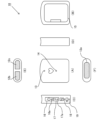
図1は、本実施形態における携帯型心電計10の構成を示す図である。図1Aは本体の正面を示す正面図であり、同様に図1Bは背面図、図1C左側面図、図1Dは右側面図、図1Eは平面図、図1Fは底面図、となっている。
(electrocardiogram measuring device)
FIG. 1 is a diagram showing the configuration of a
携帯型心電計10の底面には、心電計測時に身体の左側に接触させる左側電極12aが設けられており、反対側面の上面側には、同様に右手人差し指の腹を接触させる第一右側電極12bと、右手人指し指の中節を接触させる第二右側電極12cが設けられている。
なお、第一右側電極12bはGND電極としての機能を果たす電極である。
The bottom of the
Note that the first
心電計測時には、右手で携帯型心電計10を保持し、右手人差し指を、第一右側電極12b、第二右側電極12cに正しく接触するように携帯型心電計10の上面部に配置する。そのうえで、左側電極を所望の計測法に対応する一の皮膚に接触させる。例えば、いわゆるI誘導で計測を行う場合には、左側電極を左手の掌に当てて接触させ、いわゆるV4誘導で計測を行う場合には、左胸部の心窩部やや左方・乳頭下方の肌に接触させる。
When measuring an electrocardiogram, hold the
また、携帯型心電計10の左側面には各種の操作部、及びインジケータが配置されている。具体的には、電源スイッチ16、電源LED16a、BLE(Bluetooth(登録商標) Low Energy)通信ボタン17、BLE通信LED17a、メモリー残表示LED18、電池交換LED19、等を備えている。
Furthermore, various operating units and indicators are arranged on the left side of the
また、携帯型心電計10の正面には、計測状態通知LED13、解析結果通知LED14、が設けられ、携帯型心電計10の背面には、バッテリーの収容口、電池カバー15が配置されている。
Furthermore, a measurement
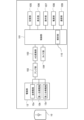
また、図2には携帯型心電計10の機能構成を示すブロック図が記載されている。図2に示すように、携帯型心電計10は制御部101、電極部12、アンプ部102、AD(Analog to Digital)変換部103、タイマ部104、記憶部105、表示部106、操作部107、電源部108、通信部109、解析部110の各機能部を備える構成となっている。
Further, FIG. 2 shows a block diagram showing the functional configuration of the
制御部101は、携帯型心電計10の制御を司る手段であり、例えば、CPU(Central Processing Unit)などを含んで構成される。制御部101は、操作部107を介してユーザーの操作を受け付けると、所定のプログラムに従って心電計測、情報通信など各種の処理を実行するように携帯型心電計10の各構成要素を制御する。なお、所定のプログラムは後述の記憶部105に保存され、ここから読み出される。
The
また、制御部101は、機能モジュールとして、心電波形の解析を行う解析部110を備えている。解析部110は計測された心電波形について、波形の乱れの有無などを解析し、少なくとも計測時の心電波形が正常か否かの結果をアウトプットする。
The
電極部12は、左側電極12a、第一右側電極12b、第二右側電極12cからなり、心電波形の検出するセンサとして機能する。アンプ部102は、電極部12から出力された信号を増幅する機能を有している。AD変換部103は、アンプ102で増幅されたアナログ信号をデジタル信号に変換し、制御部101へ伝送する機能を有している。
The
タイマ部104はRTC(Real Time Clock)を参照して、時間を計測する機能を有している。後述するように、例えば、心電計測時に計測終了までの時間をカウントし、これをアウトプットする。
The
記憶部105は、RAM(Random Access Memory)などの主記憶装置を含んで構成され、アプリケーションプログラム、計測心電波形、解析結果などの各種の情報を記憶する。また、RAMに加えて、例えばフラッシュメモリなどの長期記憶媒体を備えていても良い。
The
表示部106は、前述の電源LED16a、BLE通信LED17a、メモリー残表示LED18、電池交換LED19などを含んで構成され、LEDの点灯、点滅などによって装置の状態をユーザーに伝達する。また、操作部107は、電源スイッチ16、通信ボ
タン17等を含み、ユーザーからの入力操作を受け付け、制御部101に操作に応じた処理を実行させるための機能を有する。
The
電源部108は、装置の稼働に必要な電力を供給するバッテリーを含んで構成される。バッテリーは、例えばリチウムイオンバッテリーなどの二次電池であっても良いし、一次電池としても良い。
The
通信部109は、無線通信用のアンテナを含み、少なくともBLE通信により、情報処理端末などの他の機器と通信する機能を有する。また、有線による通信のための端子を備えていても良い。
The
(携帯型心電計を用いた心電計測処理)
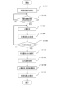
次に、心電計測を行う際の携帯型心電計10の動作について、図1、図2及び図3に基づいて説明する。図3は、携帯型心電計10を用いて心電計測を行う際の処理の手順を示すフローチャートである。
(Electrocardiogram measurement processing using a portable electrocardiograph)
Next, the operation of the
ユーザーはまず、計測に先立ち、電源スイッチ16を操作し携帯型心電計10の電源をONにする。そうすると、電源LEDが点灯して電源がONであることを表示する。そして、右手で携帯型心電計10を保持し、右手人差し指を、12b、12cに接触させ、計測を行う箇所の肌に、12aを接触させる。そうすると、制御部101は電極部12を介して接触状態を検出し(S1101)、正しく電極が接触された状態で所定時間が経過したか否かを判定する処理を行う(S1102)。ここで、制御部101は所定時間が経過していないと判断すれば所定時間が経過するまで同じ処理を繰り返し、所定時間が経過したと判断すると、ステップS1103に進み、実際の心電計測を実行する。
Prior to measurement, the user first operates the
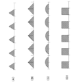
制御部101は、心電計測を行っている間は、随時計測値を記憶部105に保存するとともに、本体正面の計測状態通知LED13を所定のリズムで点滅させることにより、心電計測中であることを表示する(S1104)。ここで、計測状態通知LED13の点滅について図4に基づいて詳細に説明する。図4に示す各波形は、計測状態通知LED13への電圧の印加の態様を示している。
The
一般的に、正確な心電計測には、計測時におけるユーザーの心理的な安定性が重要であるところ、例えば図4のDに示すような波形でLEDに電圧を印加して点滅させると、点灯と消灯とが急激に切り替わり、チカチカとした点滅動作となる。このような警告灯のような点滅の仕方であると、これを目にしたユーザーの不安感、緊張感を惹起する虞があり、そのような心理状態で計測を行うと、正確な心電計測ができない可能性がある。 Generally, for accurate electrocardiogram measurement, the psychological stability of the user during measurement is important. The light switches between being on and off rapidly, resulting in a flickering motion. If the warning light blinks like this, there is a risk that it will cause a feeling of anxiety and tension in the user who sees it, and if measurements are performed in such a psychological state, accurate electrocardiogram measurement may be difficult. may not be possible.
そのため、本実施形態に係る携帯型心電計10においては、制御部101は、図4のA、Bのように三角波の形状の波形、或いは図4のCのように半円状の波形として例示するように、計測状態通知LED13の輝度が時間に対して所定以上の傾きを伴って変化するように制御することで、LEDを穏やかに点滅させるようにしている。さらに、図4A、図4B、図4Cに示すように、制御部101は計測状態通知LED13を、点灯時間が消灯時間よりも長くなるように点滅させるよう制御を行う。これにより、心電計測中であることを通知するLEDの点滅を見ても、ユーザーは不安感を感じにくく、正確な心電計測に資することが可能になる。また、計測時のユーザーの心拍と同期した周期で点滅を行うようにしても良い。
Therefore, in the
心電計測の処理の流れの説明に戻ると、制御部101はステップS1105で、心電計測の時間が所定の計測時間(例えば30秒)を経過したか否かを判定する処理を行う。ここで、まだ所定の時間を経過していないと判断した場合には、ステップS1103に戻って以降の処理を繰り返す。一方、所定の計測時間が経過したと判断した場合には、計測を終了するとともに、計測状態通知LED13の点滅を終了する処理を行う(ステップS1
106)。
Returning to the explanation of the flow of the electrocardiogram measurement process, in step S1105, the
106).
次に、制御部101の解析部110により、記憶部105に保存された計測データ(心電波形)の解析が行われ(S1107)、解析結果は、心電波形と共に長期記憶装置に保存される(S1108)。そして、制御部101は、解析結果通知LED14により、解析の結果を表示して(S1109)、一連の処理を終了する。なお、解析結果の表示は、例えば、心電波形に異常がみられる場合のみLEDを点灯するのであっても良いし、解析結果に応じた点灯・点滅方法によりLEDを点灯させるようにしても良い。
Next, the
以上のような構成の本実施形態に係る携帯型心電計10によれば、心電計測中であることを示すLEDが、穏やかな輝度の変化で点滅するため、ユーザーに与える不安感を抑止することができる。
According to the
<その他>
上記の実施形態の説明は、本発明を例示的に説明するものに過ぎず、本発明は上記の具体的な形態には限定されない。本発明は、その技術的思想の範囲内で種々の変形及び組み合わせが可能である。
<Others>
The above description of the embodiments is merely for illustratively explaining the present invention, and the present invention is not limited to the above-described specific forms. The present invention can be modified and combined in various ways within the scope of its technical idea.
例えば、LEDの点灯、点滅を用いた各種の通知は、LEDの表示色を変更することにより、通知内容を示すようにしてもよい。このような構成によれば、通知内容を多様化することも可能になる。 For example, various notifications using lighting or blinking of an LED may be made to indicate the content of the notification by changing the display color of the LED. According to such a configuration, it is also possible to diversify notification contents.
また、上記の実施形態の携帯型心電計は、BLE通信機能を備える構成となっていたが、通信機能は必須の構成ではなく、通信機能を備えない心電計とすることも可能である。 Further, although the portable electrocardiograph of the above embodiment has a configuration including a BLE communication function, the communication function is not an essential configuration, and an electrocardiograph that does not include a communication function is also possible. .
10・・・携帯型心電計
13・・・計測状態通知LED
14・・・解析結果通知LED
15・・・電池カバー
16・・・電源スイッチ
16a・・・電源LED
17・・・通信ボタン
17a・・・BLE通信LED
18・・・メモリー残表示LED
19・・・電池交換LED
10...
14...Analysis result notification LED
15...
17...
18...Memory remaining display LED
19...Battery replacement LED
Claims (5)
前記制御手段は、前記センサによる前記心電波形の計測中において、前記LED表示部を点滅させる際には、前記LED表示部の輝度が時間に対して所定以上の傾きを伴って変化するように制御し、
前記LED表示部の、時間に対して所定以上の傾きを伴った輝度の変化が、三角波の形状又は半円形状の波となる、心電計測装置。 A sensor capable of measuring an electrocardiogram waveform, an LED display section, and controlling the sensor to execute the measurement process of the electrocardiogram waveform, and during the measurement process, control the LED display section to blink. An electrocardiogram measuring device comprising a control means for causing
The control means is configured to cause the brightness of the LED display unit to change with time with a slope of a predetermined level or more when blinking the LED display unit while the electrocardiogram waveform is being measured by the sensor. control ,
An electrocardiogram measuring device , wherein a change in brightness of the LED display section with a slope of a predetermined value or more with respect to time takes the form of a triangular wave or a semicircular wave.
ことを特徴とする、請求項1に記載の心電計測装置。 The control means causes the LED display unit to blink at a period synchronized with the heart rate of the measurement target.
The electrocardiogram measuring device according to claim 1 , characterized in that:
ことを特徴とする、請求項1又は2に記載の心電計測装置。 The control means blinks the LED display section at a cycle of 40 to 60 times per minute.
The electrocardiogram measuring device according to claim 1 or 2 , characterized in that:
前記制御手段は、前記センサによる前記心電波形の計測中において、前記LED表示部を点滅させる際には、前記LED表示部の輝度が時間に対して所定以上の傾きを伴って変化するように、かつ、前記LED表示部の点灯時間が消灯時間よりも長くなるように、前記LED表示部を点滅させる、
ことを特徴とする心電計測装置。 A sensor capable of measuring an electrocardiogram waveform, an LED display section, and controlling the sensor to execute the measurement process of the electrocardiogram waveform, and during the measurement process, control the LED display section to blink. An electrocardiogram measuring device comprising a control means for causing
The control means is configured to cause the brightness of the LED display unit to change with time with a slope of a predetermined level or more when blinking the LED display unit while the electrocardiogram waveform is being measured by the sensor. , and blinking the LED display unit so that the lighting time of the LED display unit is longer than the turn-off time,
An electrocardiogram measuring device characterized by:
ことを特徴とする、請求項1から4のいずれか一項に記載の心電計測装置。 The electrocardiographic measuring device according to any one of claims 1 to 4 , wherein the electrocardiographic measuring device is a portable electrocardiographic measuring device.
Priority Applications (5)
| Application Number | Priority Date | Filing Date | Title |
|---|---|---|---|
| JP2019207138A JP7367480B2 (en) | 2019-11-15 | 2019-11-15 | Electrocardiogram measuring device |
| PCT/JP2020/041467 WO2021095646A1 (en) | 2019-11-15 | 2020-11-06 | Electrocardiograph |
| CN202080071499.9A CN114554960A (en) | 2019-11-15 | 2020-11-06 | Electrocardiogram measuring device |
| DE112020004960.4T DE112020004960T9 (en) | 2019-11-15 | 2020-11-06 | ELECTROCARDIOGRAPHIC MEASUREMENT DEVICE |
| US17/662,776 US20220330873A1 (en) | 2019-11-15 | 2022-05-10 | Electrocardiographic measurement device |
Applications Claiming Priority (1)
| Application Number | Priority Date | Filing Date | Title |
|---|---|---|---|
| JP2019207138A JP7367480B2 (en) | 2019-11-15 | 2019-11-15 | Electrocardiogram measuring device |
Publications (3)
| Publication Number | Publication Date |
|---|---|
| JP2021078596A JP2021078596A (en) | 2021-05-27 |
| JP2021078596A5 JP2021078596A5 (en) | 2022-11-21 |
| JP7367480B2 true JP7367480B2 (en) | 2023-10-24 |
Family
ID=75912952
Family Applications (1)
| Application Number | Title | Priority Date | Filing Date |
|---|---|---|---|
| JP2019207138A Active JP7367480B2 (en) | 2019-11-15 | 2019-11-15 | Electrocardiogram measuring device |
Country Status (5)
| Country | Link |
|---|---|
| US (1) | US20220330873A1 (en) |
| JP (1) | JP7367480B2 (en) |
| CN (1) | CN114554960A (en) |
| DE (1) | DE112020004960T9 (en) |
| WO (1) | WO2021095646A1 (en) |
Citations (1)
| Publication number | Priority date | Publication date | Assignee | Title |
|---|---|---|---|---|
| US4350164A (en) | 1980-06-03 | 1982-09-21 | Allain Jr Joseph L | Portable, life monitor, medical instrument |
Family Cites Families (11)
| Publication number | Priority date | Publication date | Assignee | Title |
|---|---|---|---|---|
| JPH02154740A (en) * | 1988-12-08 | 1990-06-14 | Fukuda Denshi Co Ltd | Small-sized electrocardiogram monitoring apparatus |
| JP2005000420A (en) * | 2003-06-12 | 2005-01-06 | Omron Healthcare Co Ltd | Electrocardiograph, and control method therefor |
| JP2007105316A (en) | 2005-10-14 | 2007-04-26 | Konica Minolta Sensing Inc | Bioinformation measuring instrument |
| JP2007279020A (en) * | 2006-03-13 | 2007-10-25 | Citizen Holdings Co Ltd | Wearable electronic device and biometric apparatus using wearable electronic device |
| CN105984375A (en) * | 2015-01-27 | 2016-10-05 | 戴姆勒大中华区投资有限公司 | Vehicular atmosphere lamp control system and vehicular atmosphere lamp control method |
| CN105326490A (en) * | 2015-09-23 | 2016-02-17 | 广东小天才科技有限公司 | Method and device for controlling breath lamp |
| CN205814814U (en) * | 2016-04-28 | 2016-12-21 | 康泰医学系统(秦皇岛)股份有限公司 | A kind of oxygen uptake control system |
| CN107517536B (en) * | 2017-08-30 | 2020-01-17 | 深圳市新国都支付技术有限公司 | Breathing lamp control circuit and electronic equipment |
| CN207166186U (en) * | 2017-09-12 | 2018-03-30 | 一汽-大众汽车有限公司 | A kind of vehicle-mounted charge display circuit and motor vehicle |
| CN208942107U (en) * | 2018-03-23 | 2019-06-07 | 广州诺安医疗科技有限公司 | Acquire sensing device and system |
| CN108550306A (en) * | 2018-06-15 | 2018-09-18 | 广西职业技术学院 | A kind of heart rate for integrated operational amplifier circuit teaching synchronizes breath light |
-
2019
- 2019-11-15 JP JP2019207138A patent/JP7367480B2/en active Active
-
2020
- 2020-11-06 CN CN202080071499.9A patent/CN114554960A/en active Pending
- 2020-11-06 WO PCT/JP2020/041467 patent/WO2021095646A1/en active Application Filing
- 2020-11-06 DE DE112020004960.4T patent/DE112020004960T9/en active Active
-
2022
- 2022-05-10 US US17/662,776 patent/US20220330873A1/en active Pending
Patent Citations (1)
| Publication number | Priority date | Publication date | Assignee | Title |
|---|---|---|---|---|
| US4350164A (en) | 1980-06-03 | 1982-09-21 | Allain Jr Joseph L | Portable, life monitor, medical instrument |
Also Published As
| Publication number | Publication date |
|---|---|
| DE112020004960T5 (en) | 2022-07-21 |
| US20220330873A1 (en) | 2022-10-20 |
| CN114554960A (en) | 2022-05-27 |
| JP2021078596A (en) | 2021-05-27 |
| WO2021095646A1 (en) | 2021-05-20 |
| DE112020004960T9 (en) | 2023-02-09 |
Similar Documents
| Publication | Publication Date | Title |
|---|---|---|
| KR101000467B1 (en) | Wrist wearable type apparatus for measuring pulse and method for controlling the same | |
| US7310550B2 (en) | Electrocardiograph and display method for electrocardiograph | |
| KR20190065102A (en) | Electrocardiography Device | |
| TW201526868A (en) | Modular sensor platform | |
| JP2016185288A (en) | Portable electrocardiograph and computer program | |
| CN204500639U (en) | Portable physiological parameter detector | |
| JP3250810B2 (en) | Device for recording health status values | |
| US20040260190A1 (en) | Electrocardiograph and electrocardiograph control method | |
| CN114287911A (en) | Wristwatch type sleep apnea monitoring device, wristwatch type sleep apnea monitoring system and storage medium | |
| JP7367480B2 (en) | Electrocardiogram measuring device | |
| US20220346718A1 (en) | Biological information measuring device | |
| CN209391926U (en) | Multiple physiological detection device | |
| JP7396010B2 (en) | Electrocardiogram waveform measuring device, information management system, control method for electrocardiographic waveform measuring device, and program | |
| JP7380130B2 (en) | Biometric information management system and biometric information management method | |
| JP3132458U (en) | Portable weak signal recording device | |
| JP6531843B2 (en) | Heart beat measuring device, heart beat measuring method, heart beat measuring program | |
| CN209003989U (en) | Multiple physiological detection device | |
| WO2021100486A1 (en) | Biological information measurement device, biological information management system, and control method for biological information measurement device | |
| WO2014002519A1 (en) | Biological information recording device | |
| US20140298095A1 (en) | Medical test signal generator and interface | |
| JP7404951B2 (en) | Biological information measuring device, control method and program for biological information measuring device | |
| WO2024042749A1 (en) | Biometric information measurement device | |
| WO2021187246A1 (en) | Portable electrocardiograph, electrocardiograph system, and program | |
| JP2021078596A5 (en) | ||
| WO2023286254A1 (en) | Biological information measurement device |
Legal Events
| Date | Code | Title | Description |
|---|---|---|---|
| A521 | Request for written amendment filed |
Free format text: JAPANESE INTERMEDIATE CODE: A523 Effective date: 20221111 |
|
| A621 | Written request for application examination |
Free format text: JAPANESE INTERMEDIATE CODE: A621 Effective date: 20221111 |
|
| TRDD | Decision of grant or rejection written | ||
| A01 | Written decision to grant a patent or to grant a registration (utility model) |
Free format text: JAPANESE INTERMEDIATE CODE: A01 Effective date: 20230912 |
|
| A61 | First payment of annual fees (during grant procedure) |
Free format text: JAPANESE INTERMEDIATE CODE: A61 Effective date: 20230925 |
|
| R150 | Certificate of patent or registration of utility model |
Ref document number: 7367480 Country of ref document: JP Free format text: JAPANESE INTERMEDIATE CODE: R150 |