JP7380130B2 - Biometric information management system and biometric information management method - Google Patents
Biometric information management system and biometric information management method Download PDFInfo
- Publication number
- JP7380130B2 JP7380130B2 JP2019209906A JP2019209906A JP7380130B2 JP 7380130 B2 JP7380130 B2 JP 7380130B2 JP 2019209906 A JP2019209906 A JP 2019209906A JP 2019209906 A JP2019209906 A JP 2019209906A JP 7380130 B2 JP7380130 B2 JP 7380130B2
- Authority
- JP
- Japan
- Prior art keywords
- biological information
- information
- analysis result
- measuring device
- processing terminal
- Prior art date
- Legal status (The legal status is an assumption and is not a legal conclusion. Google has not performed a legal analysis and makes no representation as to the accuracy of the status listed.)
- Active
Links
- 238000007726 management method Methods 0.000 title claims description 29
- 238000004458 analytical method Methods 0.000 claims description 90
- 230000006854 communication Effects 0.000 claims description 62
- 238000004891 communication Methods 0.000 claims description 61
- 238000000034 method Methods 0.000 claims description 42
- 230000010365 information processing Effects 0.000 claims description 40
- 230000005540 biological transmission Effects 0.000 claims description 11
- 238000005259 measurement Methods 0.000 description 47
- 230000006870 function Effects 0.000 description 12
- 238000010586 diagram Methods 0.000 description 8
- 230000036772 blood pressure Effects 0.000 description 4
- 238000005516 engineering process Methods 0.000 description 4
- 230000004397 blinking Effects 0.000 description 3
- 230000007774 longterm Effects 0.000 description 3
- 230000005856 abnormality Effects 0.000 description 2
- 238000006243 chemical reaction Methods 0.000 description 2
- 206010008479 Chest Pain Diseases 0.000 description 1
- HBBGRARXTFLTSG-UHFFFAOYSA-N Lithium ion Chemical compound [Li+] HBBGRARXTFLTSG-UHFFFAOYSA-N 0.000 description 1
- 206010033557 Palpitations Diseases 0.000 description 1
- 230000003213 activating effect Effects 0.000 description 1
- 230000004071 biological effect Effects 0.000 description 1
- 230000036760 body temperature Effects 0.000 description 1
- 210000000038 chest Anatomy 0.000 description 1
- 238000001514 detection method Methods 0.000 description 1
- 208000019622 heart disease Diseases 0.000 description 1
- 229910001416 lithium ion Inorganic materials 0.000 description 1
- 239000000463 material Substances 0.000 description 1
- 238000000691 measurement method Methods 0.000 description 1
- 239000000203 mixture Substances 0.000 description 1
- 210000002445 nipple Anatomy 0.000 description 1
- 230000035485 pulse pressure Effects 0.000 description 1
- 230000033764 rhythmic process Effects 0.000 description 1
Images


Classifications
-
- A—HUMAN NECESSITIES
- A61—MEDICAL OR VETERINARY SCIENCE; HYGIENE
- A61B—DIAGNOSIS; SURGERY; IDENTIFICATION
- A61B5/00—Measuring for diagnostic purposes; Identification of persons
- A61B5/24—Detecting, measuring or recording bioelectric or biomagnetic signals of the body or parts thereof
- A61B5/316—Modalities, i.e. specific diagnostic methods
- A61B5/318—Heart-related electrical modalities, e.g. electrocardiography [ECG]
- A61B5/332—Portable devices specially adapted therefor
-
- H—ELECTRICITY
- H04—ELECTRIC COMMUNICATION TECHNIQUE
- H04L—TRANSMISSION OF DIGITAL INFORMATION, e.g. TELEGRAPHIC COMMUNICATION
- H04L67/00—Network arrangements or protocols for supporting network services or applications
- H04L67/01—Protocols
- H04L67/12—Protocols specially adapted for proprietary or special-purpose networking environments, e.g. medical networks, sensor networks, networks in vehicles or remote metering networks
-
- A—HUMAN NECESSITIES
- A61—MEDICAL OR VETERINARY SCIENCE; HYGIENE
- A61B—DIAGNOSIS; SURGERY; IDENTIFICATION
- A61B5/00—Measuring for diagnostic purposes; Identification of persons
-
- A—HUMAN NECESSITIES
- A61—MEDICAL OR VETERINARY SCIENCE; HYGIENE
- A61B—DIAGNOSIS; SURGERY; IDENTIFICATION
- A61B5/00—Measuring for diagnostic purposes; Identification of persons
- A61B5/0002—Remote monitoring of patients using telemetry, e.g. transmission of vital signals via a communication network
- A61B5/0004—Remote monitoring of patients using telemetry, e.g. transmission of vital signals via a communication network characterised by the type of physiological signal transmitted
- A61B5/0006—ECG or EEG signals
-
- A—HUMAN NECESSITIES
- A61—MEDICAL OR VETERINARY SCIENCE; HYGIENE
- A61B—DIAGNOSIS; SURGERY; IDENTIFICATION
- A61B5/00—Measuring for diagnostic purposes; Identification of persons
- A61B5/02—Detecting, measuring or recording pulse, heart rate, blood pressure or blood flow; Combined pulse/heart-rate/blood pressure determination; Evaluating a cardiovascular condition not otherwise provided for, e.g. using combinations of techniques provided for in this group with electrocardiography or electroauscultation; Heart catheters for measuring blood pressure
- A61B5/0205—Simultaneously evaluating both cardiovascular conditions and different types of body conditions, e.g. heart and respiratory condition
-
- A—HUMAN NECESSITIES
- A61—MEDICAL OR VETERINARY SCIENCE; HYGIENE
- A61B—DIAGNOSIS; SURGERY; IDENTIFICATION
- A61B5/00—Measuring for diagnostic purposes; Identification of persons
- A61B5/02—Detecting, measuring or recording pulse, heart rate, blood pressure or blood flow; Combined pulse/heart-rate/blood pressure determination; Evaluating a cardiovascular condition not otherwise provided for, e.g. using combinations of techniques provided for in this group with electrocardiography or electroauscultation; Heart catheters for measuring blood pressure
- A61B5/024—Detecting, measuring or recording pulse rate or heart rate
- A61B5/02438—Detecting, measuring or recording pulse rate or heart rate with portable devices, e.g. worn by the patient
-
- A—HUMAN NECESSITIES
- A61—MEDICAL OR VETERINARY SCIENCE; HYGIENE
- A61B—DIAGNOSIS; SURGERY; IDENTIFICATION
- A61B5/00—Measuring for diagnostic purposes; Identification of persons
- A61B5/02—Detecting, measuring or recording pulse, heart rate, blood pressure or blood flow; Combined pulse/heart-rate/blood pressure determination; Evaluating a cardiovascular condition not otherwise provided for, e.g. using combinations of techniques provided for in this group with electrocardiography or electroauscultation; Heart catheters for measuring blood pressure
- A61B5/024—Detecting, measuring or recording pulse rate or heart rate
- A61B5/0245—Detecting, measuring or recording pulse rate or heart rate by using sensing means generating electric signals, i.e. ECG signals
-
- A—HUMAN NECESSITIES
- A61—MEDICAL OR VETERINARY SCIENCE; HYGIENE
- A61B—DIAGNOSIS; SURGERY; IDENTIFICATION
- A61B5/00—Measuring for diagnostic purposes; Identification of persons
- A61B5/24—Detecting, measuring or recording bioelectric or biomagnetic signals of the body or parts thereof
- A61B5/25—Bioelectric electrodes therefor
- A61B5/279—Bioelectric electrodes therefor specially adapted for particular uses
- A61B5/28—Bioelectric electrodes therefor specially adapted for particular uses for electrocardiography [ECG]
-
- A—HUMAN NECESSITIES
- A61—MEDICAL OR VETERINARY SCIENCE; HYGIENE
- A61B—DIAGNOSIS; SURGERY; IDENTIFICATION
- A61B5/00—Measuring for diagnostic purposes; Identification of persons
- A61B5/24—Detecting, measuring or recording bioelectric or biomagnetic signals of the body or parts thereof
- A61B5/30—Input circuits therefor
- A61B5/307—Input circuits therefor specially adapted for particular uses
- A61B5/308—Input circuits therefor specially adapted for particular uses for electrocardiography [ECG]
-
- A—HUMAN NECESSITIES
- A61—MEDICAL OR VETERINARY SCIENCE; HYGIENE
- A61B—DIAGNOSIS; SURGERY; IDENTIFICATION
- A61B5/00—Measuring for diagnostic purposes; Identification of persons
- A61B5/24—Detecting, measuring or recording bioelectric or biomagnetic signals of the body or parts thereof
- A61B5/316—Modalities, i.e. specific diagnostic methods
- A61B5/318—Heart-related electrical modalities, e.g. electrocardiography [ECG]
- A61B5/321—Accessories or supplementary instruments therefor, e.g. cord hangers
-
- A—HUMAN NECESSITIES
- A61—MEDICAL OR VETERINARY SCIENCE; HYGIENE
- A61B—DIAGNOSIS; SURGERY; IDENTIFICATION
- A61B5/00—Measuring for diagnostic purposes; Identification of persons
- A61B5/24—Detecting, measuring or recording bioelectric or biomagnetic signals of the body or parts thereof
- A61B5/316—Modalities, i.e. specific diagnostic methods
- A61B5/318—Heart-related electrical modalities, e.g. electrocardiography [ECG]
- A61B5/333—Recording apparatus specially adapted therefor
-
- A—HUMAN NECESSITIES
- A61—MEDICAL OR VETERINARY SCIENCE; HYGIENE
- A61B—DIAGNOSIS; SURGERY; IDENTIFICATION
- A61B5/00—Measuring for diagnostic purposes; Identification of persons
- A61B5/24—Detecting, measuring or recording bioelectric or biomagnetic signals of the body or parts thereof
- A61B5/316—Modalities, i.e. specific diagnostic methods
- A61B5/318—Heart-related electrical modalities, e.g. electrocardiography [ECG]
- A61B5/339—Displays specially adapted therefor
-
- A—HUMAN NECESSITIES
- A61—MEDICAL OR VETERINARY SCIENCE; HYGIENE
- A61B—DIAGNOSIS; SURGERY; IDENTIFICATION
- A61B5/00—Measuring for diagnostic purposes; Identification of persons
- A61B5/24—Detecting, measuring or recording bioelectric or biomagnetic signals of the body or parts thereof
- A61B5/316—Modalities, i.e. specific diagnostic methods
- A61B5/318—Heart-related electrical modalities, e.g. electrocardiography [ECG]
- A61B5/346—Analysis of electrocardiograms
-
- A—HUMAN NECESSITIES
- A61—MEDICAL OR VETERINARY SCIENCE; HYGIENE
- A61B—DIAGNOSIS; SURGERY; IDENTIFICATION
- A61B5/00—Measuring for diagnostic purposes; Identification of persons
- A61B5/68—Arrangements of detecting, measuring or recording means, e.g. sensors, in relation to patient
- A61B5/6887—Arrangements of detecting, measuring or recording means, e.g. sensors, in relation to patient mounted on external non-worn devices, e.g. non-medical devices
- A61B5/6898—Portable consumer electronic devices, e.g. music players, telephones, tablet computers
-
- H—ELECTRICITY
- H04—ELECTRIC COMMUNICATION TECHNIQUE
- H04L—TRANSMISSION OF DIGITAL INFORMATION, e.g. TELEGRAPHIC COMMUNICATION
- H04L65/00—Network arrangements, protocols or services for supporting real-time applications in data packet communication
- H04L65/60—Network streaming of media packets
- H04L65/61—Network streaming of media packets for supporting one-way streaming services, e.g. Internet radio
-
- A—HUMAN NECESSITIES
- A61—MEDICAL OR VETERINARY SCIENCE; HYGIENE
- A61B—DIAGNOSIS; SURGERY; IDENTIFICATION
- A61B5/00—Measuring for diagnostic purposes; Identification of persons
- A61B5/0002—Remote monitoring of patients using telemetry, e.g. transmission of vital signals via a communication network
- A61B5/0004—Remote monitoring of patients using telemetry, e.g. transmission of vital signals via a communication network characterised by the type of physiological signal transmitted
Description
本発明は、ヘルスケア関連の技術分野に属し、特に、生体情報管理システム、及び、生体情報管理方法に関する。 The present invention belongs to the technical field related to healthcare, and particularly relates to a biological information management system and a biological information management method.
近年、血圧値、心電波形などの、個人の身体・健康に関する情報(以下、生体情報ともいう)を計測機器によって計測し、当該計測結果を情報端末で記録、分析することで、健康管理を行うことが普及しつつある。 In recent years, health management has become possible by measuring information related to an individual's body and health (hereinafter also referred to as biological information), such as blood pressure values and electrocardiogram waveforms, using measuring devices, and recording and analyzing the measurement results using information terminals. It is becoming popular to do this.
上記のような計測機器の一例として、日常生活において胸部の痛みや動悸などの異常発生時にすぐに心電波形を測定する携帯型の心電測定装置が提案されており、心疾患の早期発見や適切な治療への貢献が期待されている(例えば、特許文献1、2など)。
As an example of the above-mentioned measuring equipment, a portable electrocardiogram measuring device has been proposed that measures electrocardiogram waveforms immediately when abnormalities such as chest pain or palpitations occur in daily life, and is useful for early detection of heart disease. It is expected to contribute to appropriate treatment (for example,
特許文献1には本体にセンサ部、制御部、入力部、表示部、タイマ部を備え、心電波形の計測から測定中の表示、解析結果の表示、結果の記憶等を同一本体で行う携帯型の心電測定装置が記載されている。このような構成であるため、測定、表示、記憶などの全ての処理を当該装置のみで完結させることが可能ではあるものの、これらの機能に係る構成を全て備えるため、装置が大型化し、携帯するのに不便という問題がある。
一方、特許文献2には、本体にセンサ部、制御部、タイマ部、送信部を備え、計測した心電波形データを超音波や赤外線、Bluetooth(登録商標)などの無線通信機能により、別体の情報処理端末(スマートフォンなどを含む)に送信して、当該端末の表示手段によって各種表示を行い、情報の記憶も情報処理端末側で行う心電計測装置が開示されている。これによると、計測装置自体には表示部を備えないため、装置の小型化が可能である。しかしながら、特許文献2に記載の技術によると、携帯型心電装置から心電波形を送信し、情報処理端末側のアプリケーションで測定開始と測定終了を決定し表示しているので、携帯型心電装置が測定可能な状態になっても、情報処理端末との通信の確立、及び、情報処理端末のアプリケーションを介した測定開始指示が実行されるまでは、心電装置による測定を行うことができず、ユーザーにとって不便である。
On the other hand,
これに対しては、例えば上記特許文献1と特許文献2とを組み合わせて、表示部を省略した心電装置において計測した心電波形を、該装置で保存及び解析し、当該解析結果及び波形データを後でまとめて情報処理端末に送信して表示させることも考えられる。しかしながら、このような方法によっても、詳細な心電波形のデータはデータ容量が大きく、情報処理端末において表示可能になるまでに時間を要するという問題がある。
For this purpose, for example, by combining
上記のような従来の技術に鑑み、本発明は、生体情報計測装置と情報処理端末とを連携して用いる情報管理システムにおいて、生体情報の受信のための待ち時間の不便さを軽減することが可能な技術を提供することを目的とする。 In view of the above-mentioned conventional technology, the present invention provides an information management system that uses a biological information measuring device and an information processing terminal in cooperation with each other to reduce the inconvenience of waiting time for receiving biological information. The purpose is to provide possible technology.
上記の課題を解決するため、本発明に係る生体情報管理システムは、
生体情報を計測可能なセンサと、前記センサによって計測された前記生体情報の解析を行う解析手段と、前記センサによって計測された前記生体情報、及び、当該生体情報を前記解析手段により解析した結果である解析結果情報とを少なくとも一対保存する記憶手段と、通信手段と、第1の制御手段と、を備える生体情報計測装置、及び、通信手段と、表示手段と、第2の制御手段と、を備える情報処理端末、を有する生体情報管理システムであって、
前記第1の制御手段は、前記記憶手段に保存された前記解析結果情報を前記情報処理端末に送信する処理の後に、前記解析結果情報に対応する前記生体情報を前記情報処理端末に送信する処理を実行し、
前記第2の制御手段は、前記解析結果情報を受信した場合には、該解析結果情報を即時に前記表示手段に表示させたうえで、前記解析結果情報に対応する前記生体情報を全て受信した後に、当該生体情報を前記表示手段に表示させる処理を実行する。
In order to solve the above problems, the biological information management system according to the present invention includes:
A sensor capable of measuring biological information, an analysis means for analyzing the biological information measured by the sensor, the biological information measured by the sensor, and a result of analyzing the biological information by the analysis means. A biological information measuring device comprising a storage means for storing at least one pair of certain analysis result information, a communication means, and a first control means, and a communication means, a display means, and a second control means. A biometric information management system comprising an information processing terminal,
The first control means performs a process of transmitting the biological information corresponding to the analysis result information to the information processing terminal after transmitting the analysis result information stored in the storage means to the information processing terminal. Run
When the second control means receives the analysis result information, the second control means immediately displays the analysis result information on the display means and receives all the biological information corresponding to the analysis result information. Afterwards, a process of displaying the biometric information on the display means is executed.
ここで、生体情報とは、生体活動を示す各種の情報であり、例えば、心電波形、体温、脈拍、血圧、などを例示することができる。このような構成によれば、ユーザーは情報量が多く、受信に時間がかかる(即ち、待ち時間が発生する)生体情報を情報処理端末で受信するのに先立ち、生体情報に係る解析の結果を閲覧することが可能になり、当該閲覧中にバックグラウンドで情報量の大きいデータを受信することで、待ち時間の不便さを軽減することが可能になる。 Here, biological information refers to various types of information indicating biological activities, such as an electrocardiogram waveform, body temperature, pulse, and blood pressure. According to such a configuration, the user can check the results of analysis related to the biometric information before receiving the biometric information, which has a large amount of information and takes a long time to receive (that is, a waiting time occurs), on the information processing terminal. By receiving large amounts of data in the background during viewing, it becomes possible to reduce the inconvenience of waiting time.
また、前記生体情報計測装置は、前記解析結果情報を表示する表示手段をさらに備えていてもよい。このような構成であれば、情報処理端末との通信接続を確立していなくても、計測処理の実行とその計測データの解析結果の確認を行うことが可能になる。また、前記生体情報計測装置の表示手段は、LED表示灯であってもよい。 Furthermore, the biological information measuring device may further include a display means for displaying the analysis result information. With such a configuration, even if a communication connection with the information processing terminal is not established, it is possible to execute measurement processing and check the analysis results of the measurement data. Further, the display means of the biological information measuring device may be an LED indicator light.
また、前記解析結果情報は、ストリーミング方式で送受信されるものであってもよい。このような方式により、解析結果情報を送受信することにより、速やかに情報処理端末で、解析結果を閲覧することが可能になる。 Further, the analysis result information may be transmitted and received using a streaming method. By transmitting and receiving analysis result information using such a method, it becomes possible to quickly view the analysis results on an information processing terminal.
また、前記生体情報計測装置は、携帯型心電計測装置であり、前記生体情報は、心電波形であってもよいし、前記情報処理端末は、スマートフォンであってもよい。 Further, the biological information measuring device may be a portable electrocardiographic measuring device, the biological information may be an electrocardiographic waveform, and the information processing terminal may be a smartphone.
また、本発明に係る生体情報の管理方法は、生体情報計測装置と、情報処理端末とを用いて生体情報の管理を行う方法であって
前記生体情報計測装置により生体情報を計測する計測ステップと、
前記計測された生体情報を前記生体情報計測装置において記録する第1記録ステップと、
前記計測された生体情報を前記生体情報計測装置により解析する解析ステップと、
前記解析ステップにおいて解析された前記生体情報の解析結果を、前記情報処理端末に送信する第1送信ステップと、
前記第1送信ステップにおいて送信された前記生体情報の解析結果を、前記情報処理端末で表示する解析結果表示ステップと、
前記第1記録ステップにおいて記録された前記生体情報を、前記情報処理端末に送信する第2送信ステップと、
前記第2送信ステップにおいて送信された前記生体情報を、前記情報処理端末で表示する生体情報表示ステップと、を有しており、
前記解析結果表示ステップの後に前記第2送信ステップが実行される、
ことを特徴とする。
Further, the biometric information management method according to the present invention is a method for managing biometric information using a biometric information measuring device and an information processing terminal, comprising: a measuring step of measuring biometric information by the biometric information measuring device; ,
a first recording step of recording the measured biological information in the biological information measuring device;
an analysis step of analyzing the measured biological information by the biological information measuring device;
a first transmission step of transmitting the analysis result of the biological information analyzed in the analysis step to the information processing terminal;
an analysis result display step of displaying the analysis result of the biological information transmitted in the first transmission step on the information processing terminal;
a second transmitting step of transmitting the biological information recorded in the first recording step to the information processing terminal;
a biometric information display step of displaying the biometric information transmitted in the second transmission step on the information processing terminal;
The second sending step is performed after the analysis result displaying step.
It is characterized by
また、前記第1送信ステップと前記解析結果表示ステップとが、ストリーミング方式による情報の送受信によって実行されてもよい。また、前記生体情報計測装置において、前記解析結果を表示する、計測側解析結果表示ステップ、をさらに有しててもよい。前記生体情報計測装置は、携帯型心電計測装置であり、前記生体情報は、心電波形であってよい。 Further, the first transmitting step and the analysis result displaying step may be performed by transmitting and receiving information using a streaming method. Further, the biological information measuring device may further include a measurement-side analysis result display step of displaying the analysis result. The biological information measuring device may be a portable electrocardiogram measuring device, and the biological information may be an electrocardiographic waveform.
本発明によれば、生体情報計測装置と情報処理端末とを連携して用いる情報管理システムにおいて、生体情報の受信のための待ち時間の不便さを軽減することが可能な技術を提供することができる。 According to the present invention, it is possible to provide a technology that can reduce the inconvenience of waiting time for receiving biological information in an information management system that uses a biological information measuring device and an information processing terminal in cooperation. can.
<実施形態1>
以下、本発明の具体的な実施形態について図面に基づいて説明する。ただし、この実施形態に記載されている構成部品の寸法、材質、形状、その相対配置などは、特に記載がない限りは、この発明の範囲をそれらのみに限定する趣旨のものではない。
<
Hereinafter, specific embodiments of the present invention will be described based on the drawings. However, unless otherwise specified, the dimensions, materials, shapes, relative positions, etc. of the components described in this embodiment are not intended to limit the scope of the present invention.
(システム構成)
図1は本実施形態に係る生体情報管理システム1の構成例を示す概略図である。図1に示すように、生体情報管理システム1は、生体情報計測装置の一例としての携帯型心電計10と、情報処理端末の一例としてのスマートフォン20を含み、これらが通信接続可能に構成されている。
(System configuration)
FIG. 1 is a schematic diagram showing a configuration example of a biological
(心電計測装置)
図2は、本実施形態における携帯型心電計10の構成を示す図である。図2Aは本体の正面を示す正面図であり、同様に図2Bは背面図、図2C左側面図、図2Dは右側面図、図2Eは平面図、図2Fは底面図、となっている。
(electrocardiogram measuring device)
FIG. 2 is a diagram showing the configuration of the
携帯型心電計10の底面には、心電計測時に身体の左側に接触させる左側電極12aが設けられており、反対側面の上面側には、同様に右手人差し指の中節を接触させる第一右側電極12bと、右手人指し指の基節を接触させる第二右側電極12cが設けられている。なお、第一右側電極12bはGND電極としての機能を果たす電極である。
A
心電計測時には、右手で携帯型心電計10を保持し、右手人差し指を、第一右側電極12b、第二右側電極12cに正しく接触するように携帯型心電計10の上面部に配置する。そのうえで、左側電極を所望の計測法に対応する一の皮膚に接触させる。例えば、いわゆるI誘導で計測を行う場合には、左側電極を左手の掌に当てて接触させ、いわゆるV4誘導で計測を行う場合には、左胸部の心窩部やや左方・乳頭下方の肌に接触させる。
When measuring an electrocardiogram, hold the
また、携帯型心電計10の左側面には各種の操作部、及びインジケータが配置されている。具体的には、電源スイッチ16、電源LED16a、BLE(Bluetooth(登録商標) Low Energy)通信ボタン17、BLE通信LED17a、メモリー残表示LED18、電池交換LED19、等を備えている。
Furthermore, various operating units and indicators are arranged on the left side of the
また、携帯型心電計10の正面には、計測状態通知LED13、解析結果通知LED14、が設けられ、携帯型心電計10の背面には、バッテリーの収容口、電池カバー15が配置されている。
Furthermore, a measurement
また、図1には携帯型心電計10の機能構成を示すブロック図が記載されている。図1に示すように、携帯型心電計10は制御部101、電極部12、アンプ部102、AD(Analog to Digital)変換部103、タイマ部104、記憶部105、表示部106、操作部107、電源部108、通信部109、解析部110の各機能部を備える構成となっている。
Further, FIG. 1 shows a block diagram showing the functional configuration of the
制御部101は、携帯型心電計10の制御を司る手段であり、例えば、CPU(Central Processing Unit)などを含んで構成される。制御部101は、操作部107を介してユーザーの操作を受け付けると、所定のプログラムに従って心電計測、情報通信など各種の処理を実行するように携帯型心電計10の各構成要素を制御する。なお、所定のプログラムは後述の記憶部105に保存され、ここから読み出される。
The
また、制御部101は、機能モジュールとして、心電波形の解析を行う解析部110を備えている。解析部110は計測された心電波形について、波形の乱れの有無などを解析し、少なくとも計測時の心電波形が正常か否かの結果をアウトプットする。
The
電極部12は、左側電極12a、第一右側電極12b、第二右側電極12cからなり、心電波形の検出するセンサとして機能する。アンプ部102は、電極部12から出力された信号を増幅する機能を有している。AD変換部103は、アンプ102で増幅されたアナログ信号をデジタル信号に変換し、制御部101へ伝送する機能を有している。
The
タイマ部104はRTC(Real Time Clock)を参照して、時間を計測する機能を有している。後述するように、例えば、心電計測時に計測終了までの時間をカウントし、これをアウトプットする。
The
記憶部105は、RAM(Random Access Memory)などの主記憶装置を含んで構成され、アプリケーションプログラム、計測心電波形、解析結果などの各種の情報を記憶する。また、RAMに加えて、例えばフラッシュメモリなどの長期記憶媒体を備えていても良い。
The
表示部106は、前述の電源LED16a、BLE通信LED17a、メモリー残表示LED18、電池交換LED19などを含んで構成され、LEDの点灯、点滅などによって装置の状態をユーザーに伝達する。また、操作部107は、電源スイッチ16、通信ボタン17等を含み、ユーザーからの入力操作を受け付け、制御部101に操作に応じた処理を実行させるための機能を有する。
The
電源部108は、装置の稼働に必要な電力を供給するバッテリーを含んで構成される。バッテリーは、例えばリチウムイオンバッテリーなどの二次電池であっても良いし、一次電池としても良い。
The
通信部109は、無線通信用のアンテナを含み、少なくともBLE通信により、後述する情報処理端末などの他の機器と通信する機能を有する。また、有線による通信のための端子を備えていても良い。
The
(情報処理端末)
情報処理端末の一例であるスマートフォン20は、図1に示すように、制御部21、通信部22、タッチパネルディスプレイ23、記憶部24、を含んで構成される。制御部21はスマートフォン20の制御を司る手段であり、例えばCPUなどを含んで構成され、記憶部24に格納された各種プログラムを実行することにより、これらに応じた機能を発揮する。通信部22は、無線通信用のアンテナを含み、携帯型心電計10などの他の機器、無線基地局との通信を行う機能である。また、有線通信のための端子を備えていてもよい。
(information processing terminal)
As shown in FIG. 1, the
タッチパネルディスプレイ23は、出力手段の一つとしての表示手段と入力手段とを兼ねており、後述するように、携帯型心電計10と通信接続が確立されている場合には、計測終了時までの残り時間などのステータス情報、心電波形のグラフデータ、などを表示することができる。その他、各種の入力用画像を介してユーザーからの操作を受け付ける。
The
記憶部24は、RAMなどの主記憶装置の他、例えばフラッシュメモリなどの長期記憶媒体を含んで構成され、アプリケーションプログラム、計測心電波形、解析結果などの各種の情報を記憶する。
The
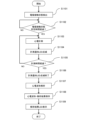
(携帯型心電計を用いた心電計測処理)
次に、心電計測を行う際の携帯型心電計10の動作について、図1、図2及び図3に基づいて説明する。図3は、携帯型心電計10を用いて心電計測を行う際の処理の手順を示すフローチャートである。
(Electrocardiogram measurement processing using a portable electrocardiograph)
Next, the operation of the
ユーザーはまず、計測に先立ち、電源スイッチ16を操作し携帯型心電計10の電源をONにする。そうすると、電源LEDが点灯して電源がONであることを表示する。そして、右手で携帯型心電計10を保持し、右手人差し指を、12b、12cに接触させ、計測を行う箇所の肌に、12aを接触させる。そうすると、制御部101は電極部12を介して接触状態を検出し(S1101)、正しく電極が接触された状態で所定時間が経過したか否かを判定する処理を行う(S1102)。ここで、制御部101は所定時間が経過していないと判断すれば所定時間が経過するまで同じ処理を繰り返し、所定時間が経過し
たと判断すると、ステップS1103に進み、実際の心電計測を実行する。
Prior to measurement, the user first operates the
制御部101は、心電計測を行っている間は、随時計測値を記憶部105に保存するとともに、本体正面の計測状態通知LED13を所定のリズムで点滅させることにより、心電計測中であることを表示する(S1104)。
The
次に、制御部101は心電計測の時間が所定の計測時間(例えば30秒)を経過したか否かを判定する処理を行う(ステップS1105)。ここで、まだ所定の時間を経過していないと判断した場合には、ステップS1103に戻って以降の処理を繰り返す。一方、所定の計測時間が経過したと判断した場合には、計測を終了するとともに、計測状態通知LED13の点滅を終了する処理を行う(ステップS1106)。
Next, the
次に、制御部101の解析部110により、記憶部105に保存された計測データ(心電波形)の解析が行われ(S1107)、解析結果は、心電波形と共に長期記憶装置に保存される(S1108)。そして、制御部101は、解析結果通知LED14により、解析の結果を表示して(S1109)、一連の処理を終了する。なお、解析結果の表示は、例えば、心電波形に異常がみられる場合のみLEDを点灯するのであっても良いし、解析結果に応じた点灯・点滅方法によりLEDを点灯させるようにしても良い。
Next, the
(情報処理端末との連携)
以上のように、携帯型心電計10は、それ単体でも心電計測、計測データの解析及び解析結果の表示を行うことが可能であるが、情報処理端末と通信接続して用いることで、より利便性を高めることができる。以下、図4から図9に基づいて、スマートフォン20と通信接続して携帯型心電計10を用いる場合について説明する。
(Cooperation with information processing terminal)
As described above, the
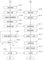
図4及び図5は、携帯型心電計10とスマートフォン20とをBLE通信で連携させて心電計測を行う場合のそれぞれの処理の流れと、機器間の情報の伝達のタイミングを示す図である。なお、携帯型心電計10の処理の流れについて、上述したものについては同一の符号を付し、詳細な説明を省略する。
FIGS. 4 and 5 are diagrams showing the respective processing flows and the timing of information transmission between the devices when the
ユーザーが携帯型心電計10の電源スイッチ16を操作して電源をONにすると、携帯型心電計10において、BLE通信のためのサブルーチンの処理が実行される(S1201)。
When the user operates the
図6は当該サブルーチンの処理の流れを示すフローチャートである。携帯型心電計10の制御部101は、電源がONされると、通信部109からBLE通信のためのアドバタイズ信号を発信する(S1901)。次に、制御部101は他の情報処理端末からBLE通信の接続要求を受信したか否かの判定を行う(S1902)。ここで、BLE通信の接続要求を受信していないと判断すると、所定時間の経過、或いは操作部107の操作により、BLE通信の処理がキャンセルされるまで同様の処理を繰り返す。一方、BLE通信の接続要求を受信したと判断した場合には、ステップS1903に進み、当該接続要求を送信した機器とのBLE接続を行う。BLE通信接続が確立されると、制御部101はサブルーチンを終了する。なお、当該サブルーチンの開始トリガーは電源ONに限らず、例えばBLE通信ボタン17の操作によるものであってもよい。
FIG. 6 is a flowchart showing the processing flow of the subroutine. When the power is turned on, the
一方、ユーザーはスマートフォン20を、携帯型心電計10とBLE通信が可能な状態にする。具体的にはタッチパネルディスプレイ23を操作して、設定メニュー等から、BLE接続設定をONにする。或いは、携帯型心電計10と連携するための専用のアプリケーションプログラムを起動させることによってBLE接続設定をONにするのであってもよい。
Meanwhile, the user puts the
BLE接続設定がONになると、スマートフォン20の制御部21は、通信部22を介してBLE通信のためのアドバタイズ信号を受信し(S2101)、携帯型心電計10に対して、BLEの接続要求を送信する(S2102)。そして、携帯型心電計10とBLE接続を行い(S2103。S1904に対応。)、通信開始要求を送信する(S2104)。
When the BLE connection setting is turned ON, the
一方、携帯型心電計10の制御部101は電極接触状態を検出(S1101)した後、BLE接続済みか否かを判定する処理を行う(S1202)。ここで、BLE接続されていると判断した場合には、電極接触状態に係る情報がスマートフォン20に向けて送信され(S1203)、スマートフォン20において当該情報が受信される(S2105)。なお、仮にステップS1202で、BLE接続されていないと判断された場合には、ステップS1203の処理を飛ばして、S1102に進み、電極接触状態で所定時間が経過したか否かの判定処理を行う。
On the other hand, after detecting the electrode contact state (S1101), the
電極接触状態の情報を受信したスマートフォン20では、タッチパネルディスプレイ23に電極接触状態が表示される。例えば、「電極は適切に接触しています」或いは「電極は正しく接触していません」などのメッセージを表示してもよい。
In the
一方、携帯型心電計10の制御部101はステップS1103で心電計測を実行し、BLE接続済みか否かを判定する処理を行う(S1204)。ここで、BLE接続済みであると判断すると、スマートフォン20に対して、心電計測時間(計測終了までの残り時間)を送信する処理を実行する(S1205)。BLE接続されていないと判断した場合には、ステップS1105に進み、所定の計測時間が経過したか否かを判定する処理を行う。
On the other hand, the
ステップS1205で、携帯型心電計10から送信された心電計測時間は、スマートフォン20において受信され(S2107)、タッチパネルディスプレイ23に心電計測時間が表示される(S2108)。具体的には、例えば「心電計測終了まで〇〇秒」というようなカウントダウンのメッセージが表示されるようにしてもよい。
The electrocardiogram measurement time transmitted from the
携帯型心電計10は解析部110において心電波形の解析を行い(S1107)、解析処理の実行中、BLE接続されているスマートフォン20があれば、解析中である旨の情報を送信する(S1206)。スマートフォン20の制御部21は、通信部22を介して当該解析中である旨の情報を受信すると(S2109)、タッチパネルディスプレイ23に当該情報を表示する(S2110)。図7Aに解析中である旨の情報が表示された画面の例を示す。
The
また、携帯型心電計10の制御部101は心電波形の解析が終了すると、当該情報を保存し(S1108)、LEDの点灯により解析結果を表示する(S1109)とともに、BLE接続されているスマートフォン20があれば、当該解析結果を送信する処理を実行する(S1207)。
Furthermore, when the analysis of the electrocardiogram waveform is completed, the
スマートフォン20の制御部21は、送信された解析結果を通信部22を介して受信すると(S2111)、当該結果をタッチパネルディスプレイ23に表示させる(S2112)。図7Bに解析結果が表示された画面の一例を示す。一方、携帯型心電計10の制御部101は、BLE接続されているスマートフォン20があれば、心電波形のデータを送信する(S1208)。ここで、スマートフォン20の制御部21はタッチパネルディスプレイ23に解析結果の表示を継続しつつ、バックグラウンドで通信部22を介して心電波形のデータを受信する(S2113)。このように、情報量が多く送受信に時間のかか
る心電波形のデータの送信中に、心電波形の解析結果のみを先に表示することにより、送受信が完了するまでの待ち時間に対するユーザーの不便さを軽減することができる。なお、ステップS1208において、記憶部105に未送信の解析結果が存在する場合には、当該解析結果を心電波形データとともに送信するようにしてもよい。
When the
スマートフォン20の制御部21は心電波形のデータを全て受信すると、心電波形をタッチパネルディスプレイ23に表示させる(S2114)。図8にステップS2114で表示される画面の一例を示す。その後、通信部22を介して携帯型心電計10に通信終了要求を送信して(S2115)、BLE接続を切断し(S2116)、スマートフォン20側の処理を終了する。なおスマートフォン20において受信した解析結果、心電波形データといった各種情報は、記憶部24に保存し、有効活用することができる。
When the
一方、携帯型心電計10の制御部101はステップS1208の後、心電波形のデータ(及び解析結果)が全て送信されたか否かを判定する処理を実行する(S1209)。ここで、未送信の心電波形データ(及び解析結果)があると判断すれば、ステップS1208に戻って以降の処理を繰り返す。一方、心電波形データ(及び解析結果)が全て送信されたと判断した場合には、スマートフォン20からの通信終了要求の受信を待って、BLE接続を切断し(S1210)、携帯型心電計10側の処理を終了する。
On the other hand, after step S1208, the
以上、本実施形態で説明した携帯型心電計10、及び生体情報管理システム1によれば、スマートフォン20などの情報処理端末と連携して用いることにより、心電波形データ等の各種データをディスプレイに表示させて閲覧することができる。また、受信したデータを保存して、アプリケーションプログラムなどを用いて有効活用することもできる。
As described above, according to the
一方、携帯型心電計10はスマートフォン20とは独立して、心電波形の計測および保存、心電波形データの解析、解析結果の表示および保存、が可能であるため、スマートフォン20との通信確立を待つことなく、任意のタイミングで心電計測することが可能である。
On the other hand, the
また、携帯型心電計10とスマートフォン20とを通信接続する場合であっても、計測処理を行う際に通信が確立されている必要はなく、計測処理終了後に、携帯型心電計10に保存されているデータの送受信を行うために通信接続を行うようにしてもよい。携帯型心電計10の記憶部105には、少なくとも直近に行った計測処理に係る心電波形データと、その解析結果の情報が保存されているため、これらのデータをスマートフォン20に送信して、スマートフォン20のタッチパネルディスプレイ23で閲覧することも可能である。図9に基づいて、このような送受信を行う場合の処理の流れを説明する。
Furthermore, even when the
図9は、携帯型心電計10の計測処理が終了した後に、スマートフォン20とBLE接続を行う場合の処理の流れを示すフローチャートである。図9に示すように、携帯型心電計10とスマートフォン20とは、互いにBLE接続のための処理を行い、接続を確立する(S301、S401)。なお、BLE接続を確立する際のそれぞれの機器の処理の詳細な説明は、既に述べた内容と重複するため省略する。
FIG. 9 is a flowchart showing the flow of processing when BLE connection is established with the
BLE接続が確立されると、スマートフォン20は、解析結果を送信する信号を、携帯型心電計10に送信する(S402)。当該信号を受信した携帯型心電計10は、解析結果データを送信し(S302)、スマートフォン20がこれを受信する(S403)。スマートフォン20の制御部21は、解析結果を受信すると、タッチパネルディスプレイ23に解析結果を表示させ(S404)、さらに携帯型心電計10に対して、心電波形データを送信するように要求する(S405)。
Once the BLE connection is established, the
心電波形データの送信要求を受信した携帯型心電計10の制御部は、心電波形データをスマートフォン20に対して送信し(S303)、スマートフォン20は心電波形データを受信する(S406)。当該データを受信する間、スマートフォン20の制御部21は、タッチパネルディスプレイ23に、解析結果の情報を表示し続ける処理を行う。そして、直近一回分の心電波形データを全て受信すると、解析結果とともに、心電波形をタッチパネルディスプレイ23に表示する処理を行う(S407)。
The control unit of the
その後、スマートフォン20の制御部21は、通信部22を介して携帯型心電計10に通信終了要求を送信し(S408)、当該信号を携帯型心電計10が受信すると、携帯型心電計10及びスマートフォン20はそれぞれBLE接続を切断する処理を行い(S304、S409)、一連の処理が終了する。
After that, the
このような処理を行うことで、何らかの事情で心電計測時にはスマートフォンとの通信接続を確立できなかった場合であっても、事後的に接続を確立することで、解析結果、心電波形をスマートフォンで閲覧することが可能になる。なお、携帯型心電計10の記憶部105に、直近一回分とは異なる(即ち、より以前の)未送信の心電計測時の解析結果及び心電波形データが存在する場合には、上記のステップS303及びステップS406において、これらを併せて送受信し、スマートフォン20の記憶部24に保存するようにしてもよい。
By performing such processing, even if a communication connection with the smartphone cannot be established at the time of electrocardiogram measurement for some reason, by establishing a connection after the fact, the analysis results and electrocardiogram waveforms can be transferred to the smartphone. It will be possible to view it at. Note that if the
なお、上記実施形態において、電極接触状態、心電計測時間、解析中画面情報、解析結果情報、などのステータス情報と、心電波形データとは異なる送受信方式によって送受信されてもよい。具体的には、比較的データ容量の小さいステータス情報を、ストリーミング形式で送受信し、データ容量の大きい心電波形データを高速データ通信によって、送受信するようにしてもよい。 In the above embodiments, status information such as electrode contact state, electrocardiogram measurement time, analysis screen information, analysis result information, and the electrocardiogram waveform data may be transmitted and received using different transmission and reception methods. Specifically, status information having a relatively small data volume may be transmitted and received in a streaming format, and electrocardiographic waveform data having a large data volume may be transmitted and received by high-speed data communication.
<その他>
上記の各例の説明は、本発明を例示的に説明するものに過ぎず、本発明は上記の具体的な形態には限定されない。本発明は、その技術的思想の範囲内で種々の変形及び組み合わせが可能である。
<Others>
The description of each example above is merely for illustratively explaining the present invention, and the present invention is not limited to the above-mentioned specific forms. The present invention can be modified and combined in various ways within the scope of its technical idea.
例えば、計測装置は携帯型心電計以外に、血圧計、体組成計、脈拍計、体温計などの他の生体情報測定機器であってもよい。即ち、計測対象となる生体情報も心電波形に限られず、血圧、脈拍などであってもよい。なお、上記の例ではシステムを構成する計測装置は携帯型心電計のみであったが、複数の異なる計測装置を含んでシステムが構成されてもよい。 For example, the measuring device may be a biological information measuring device other than a portable electrocardiograph, such as a blood pressure monitor, a body composition monitor, a pulse meter, or a thermometer. That is, the biological information to be measured is not limited to electrocardiographic waveforms, but may also be blood pressure, pulse, etc. In the above example, the measuring device constituting the system was only a portable electrocardiograph, but the system may be configured including a plurality of different measuring devices.
また、情報処理端末はスマートフォンにかぎらず、タブレット端末などの他の携帯情報処理端末であってもよいし、据置型の端末であってもよい。また、通信部は、BLE通信を行うためのものに限らず、Wi-Fi(登録商標)、赤外線通信など他の無線通信を行うことが可能なアンテナであってもよい。また、有線接続による通信を行う物であってもよい。 Further, the information processing terminal is not limited to a smartphone, but may be another portable information processing terminal such as a tablet terminal, or may be a stationary terminal. Further, the communication unit is not limited to one for performing BLE communication, but may be an antenna capable of performing other wireless communication such as Wi-Fi (registered trademark) or infrared communication. Alternatively, it may be a device that performs communication through a wired connection.
1・・・生体情報管理システム
10・・・携帯型心電計
13・・・計測状態通知LED
14・・・解析結果通知LED
15・・・電池カバー
16・・・電源スイッチ
16a・・・電源LED
17・・・通信ボタン
17a・・・BLE通信LED
18・・・メモリー残表示LED
19・・・電池交換LED
1... Biological
14...Analysis result notification LED
15...
17...
18...Memory remaining display LED
19...Battery replacement LED
Claims (10)
前記第1の制御手段は、前記記憶手段に保存された前記解析結果情報を前記情報処理端末に送信する処理の後に、前記解析結果情報に対応する前記生体情報を前記情報処理端末に送信する処理を実行し、
前記第2の制御手段は、前記解析結果情報を受信した場合には、該解析結果情報を即時に前記表示手段に表示させたうえで、前記解析結果情報に対応する前記生体情報を全て受信した後に、当該生体情報を前記表示手段に表示させる処理を実行する、
ことを特徴とする、生体情報管理システム。 A sensor capable of measuring biological information, an analysis means for analyzing the biological information measured by the sensor, the biological information measured by the sensor, and a result of analyzing the biological information by the analysis means. A biological information measuring device comprising a storage means for storing at least one pair of certain analysis result information, a communication means, and a first control means, and a communication means, a display means, and a second control means. A biometric information management system comprising an information processing terminal,
The first control means performs a process of transmitting the biological information corresponding to the analysis result information to the information processing terminal after transmitting the analysis result information stored in the storage means to the information processing terminal. Run
When the second control means receives the analysis result information, the second control means immediately displays the analysis result information on the display means and receives all the biological information corresponding to the analysis result information. Afterwards, executing a process of displaying the biometric information on the display means,
A biological information management system characterized by:
ことを特徴とする、請求項1に記載の生体情報管理システム。 The biological information measuring device further includes a display means for displaying the analysis result information.
The biological information management system according to claim 1, characterized in that:
ことを特徴とする、請求項2に記載の生体情報管理システム。 The display means of the biological information measuring device is an LED indicator light,
The biological information management system according to claim 2, characterized in that:
ことを特徴とする、請求項1から3のいずれか一項に記載の生体情報管理システム。 The analysis result information is transmitted and received in a streaming manner.
The biological information management system according to any one of claims 1 to 3, characterized in that:
前記生体情報は、心電波形である、
ことを特徴とする、請求項1から4のいずれか一項に記載の生体情報管理システム。 The biological information measuring device is a portable electrocardiogram measuring device,
The biological information is an electrocardiogram waveform.
The biological information management system according to any one of claims 1 to 4.
ことを特徴とする、請求項1から5のいずれか一項に記載の生体情報管理システム。 the information processing terminal is a smartphone;
The biological information management system according to any one of claims 1 to 5.
前記生体情報計測装置により生体情報を計測する計測ステップと、
前記計測された生体情報を前記生体情報計測装置において記録する第1記録ステップと、
前記計測された生体情報を前記生体情報計測装置により解析する解析ステップと、
前記解析ステップにおいて解析された前記生体情報の解析結果を、前記情報処理端末に送信する第1送信ステップと、
前記第1送信ステップにおいて送信された前記生体情報の解析結果を、前記情報処理端末で表示する解析結果表示ステップと、
前記第1記録ステップにおいて記録された前記生体情報を、前記情報処理端末に送信する第2送信ステップと、
前記第2送信ステップにおいて送信された前記生体情報を、前記情報処理端末で表示する生体情報表示ステップと、を有しており、
前記解析結果表示ステップの後に前記第2送信ステップが実行される、
ことを特徴とする、生体情報管理方法。 A method for managing biological information using a biological information measuring device and an information processing terminal, the method comprising: measuring biological information with the biological information measuring device;
a first recording step of recording the measured biological information in the biological information measuring device;
an analysis step of analyzing the measured biological information by the biological information measuring device;
a first transmission step of transmitting the analysis result of the biological information analyzed in the analysis step to the information processing terminal;
an analysis result display step of displaying the analysis result of the biological information transmitted in the first transmission step on the information processing terminal;
a second transmitting step of transmitting the biological information recorded in the first recording step to the information processing terminal;
a biometric information display step of displaying the biometric information transmitted in the second transmission step on the information processing terminal;
The second sending step is performed after the analysis result displaying step.
A biological information management method characterized by:
ことを特徴とする請求項7に記載の生体情報管理方法。 The first transmitting step and the analysis result displaying step are performed by transmitting and receiving information using a streaming method.
8. The biometric information management method according to claim 7.
ことを特徴とする、請求項7又は8に記載の生体情報管理方法。 The biological information measuring device further includes a measurement-side analysis result display step of displaying the analysis result.
The biological information management method according to claim 7 or 8, characterized in that:
前記生体情報は、心電波形である、
ことを特徴とする、請求項7から9のいずれか一項に記載の生体情報管理方法。 The biological information measuring device is a portable electrocardiogram measuring device,
The biological information is an electrocardiogram waveform.
The biological information management method according to any one of claims 7 to 9, characterized in that:
Priority Applications (5)
| Application Number | Priority Date | Filing Date | Title |
|---|---|---|---|
| JP2019209906A JP7380130B2 (en) | 2019-11-20 | 2019-11-20 | Biometric information management system and biometric information management method |
| CN202080073442.2A CN114599284A (en) | 2019-11-20 | 2020-11-06 | Biological information management system and biological information management method |
| DE112020005104.8T DE112020005104T5 (en) | 2019-11-20 | 2020-11-06 | BIOLOGICAL INFORMATION MANAGEMENT SYSTEM AND BIOLOGICAL INFORMATION MANAGEMENT METHODS |
| PCT/JP2020/041469 WO2021100487A1 (en) | 2019-11-20 | 2020-11-06 | Biological information management system and biological information management method |
| US17/663,612 US20220273222A1 (en) | 2019-11-20 | 2022-05-16 | Biological information management system and biological information management method |
Applications Claiming Priority (1)
| Application Number | Priority Date | Filing Date | Title |
|---|---|---|---|
| JP2019209906A JP7380130B2 (en) | 2019-11-20 | 2019-11-20 | Biometric information management system and biometric information management method |
Publications (3)
| Publication Number | Publication Date |
|---|---|
| JP2021078889A JP2021078889A (en) | 2021-05-27 |
| JP2021078889A5 JP2021078889A5 (en) | 2022-12-28 |
| JP7380130B2 true JP7380130B2 (en) | 2023-11-15 |
Family
ID=75961685
Family Applications (1)
| Application Number | Title | Priority Date | Filing Date |
|---|---|---|---|
| JP2019209906A Active JP7380130B2 (en) | 2019-11-20 | 2019-11-20 | Biometric information management system and biometric information management method |
Country Status (5)
| Country | Link |
|---|---|
| US (1) | US20220273222A1 (en) |
| JP (1) | JP7380130B2 (en) |
| CN (1) | CN114599284A (en) |
| DE (1) | DE112020005104T5 (en) |
| WO (1) | WO2021100487A1 (en) |
Families Citing this family (1)
| Publication number | Priority date | Publication date | Assignee | Title |
|---|---|---|---|---|
| CN114711741B (en) * | 2022-06-09 | 2022-09-20 | 中国人民解放军总医院第六医学中心 | A integrated device that is used for health management system of breast cancer postoperative |
Citations (4)
| Publication number | Priority date | Publication date | Assignee | Title |
|---|---|---|---|---|
| JP2002282218A (en) | 2001-03-28 | 2002-10-02 | Matsushita Electric Ind Co Ltd | Portable examination terminal, examination system, communication terminal and method of examination |
| JP2004135757A (en) | 2002-10-16 | 2004-05-13 | Matsushita Electric Ind Co Ltd | Health control support device |
| JP2004152236A (en) | 2002-11-01 | 2004-05-27 | Matsushita Electric Ind Co Ltd | Health management support device |
| JP2010269082A (en) | 2009-05-25 | 2010-12-02 | Olympus Corp | Medical wireless telemeter system |
Family Cites Families (3)
| Publication number | Priority date | Publication date | Assignee | Title |
|---|---|---|---|---|
| JP2005000420A (en) | 2003-06-12 | 2005-01-06 | Omron Healthcare Co Ltd | Electrocardiograph, and control method therefor |
| JP2008073456A (en) * | 2006-09-25 | 2008-04-03 | Toshiba Corp | Biological information measuring system, measuring device, biological information measuring method and biological information measuring program |
| WO2015035251A1 (en) | 2013-09-06 | 2015-03-12 | Alivecor, Inc. | Universal ecg electrode module for smartphone |
-
2019
- 2019-11-20 JP JP2019209906A patent/JP7380130B2/en active Active
-
2020
- 2020-11-06 CN CN202080073442.2A patent/CN114599284A/en active Pending
- 2020-11-06 DE DE112020005104.8T patent/DE112020005104T5/en active Pending
- 2020-11-06 WO PCT/JP2020/041469 patent/WO2021100487A1/en active Application Filing
-
2022
- 2022-05-16 US US17/663,612 patent/US20220273222A1/en active Pending
Patent Citations (4)
| Publication number | Priority date | Publication date | Assignee | Title |
|---|---|---|---|---|
| JP2002282218A (en) | 2001-03-28 | 2002-10-02 | Matsushita Electric Ind Co Ltd | Portable examination terminal, examination system, communication terminal and method of examination |
| JP2004135757A (en) | 2002-10-16 | 2004-05-13 | Matsushita Electric Ind Co Ltd | Health control support device |
| JP2004152236A (en) | 2002-11-01 | 2004-05-27 | Matsushita Electric Ind Co Ltd | Health management support device |
| JP2010269082A (en) | 2009-05-25 | 2010-12-02 | Olympus Corp | Medical wireless telemeter system |
Also Published As
| Publication number | Publication date |
|---|---|
| US20220273222A1 (en) | 2022-09-01 |
| CN114599284A (en) | 2022-06-07 |
| JP2021078889A (en) | 2021-05-27 |
| DE112020005104T5 (en) | 2022-08-25 |
| WO2021100487A1 (en) | 2021-05-27 |
Similar Documents
| Publication | Publication Date | Title |
|---|---|---|
| CN107438406A (en) | For non-invasively monitoring equipment, the system and method for physiological parameter | |
| JP7380130B2 (en) | Biometric information management system and biometric information management method | |
| KR20170143083A (en) | Apparatus for Measuring Complex Biological Signals | |
| CN204500690U (en) | Watch type intelligent body function detector | |
| JP7396010B2 (en) | Electrocardiogram waveform measuring device, information management system, control method for electrocardiographic waveform measuring device, and program | |
| WO2021100486A1 (en) | Biological information measurement device, biological information management system, and control method for biological information measurement device | |
| CN215687809U (en) | Hand-held heart rate detector | |
| CN202801606U (en) | Portable electrocardiogram recording device | |
| JP3132458U (en) | Portable weak signal recording device | |
| CN210185568U (en) | Sign monitoring device based on smart phone platform | |
| JP7424036B2 (en) | Portable electrocardiographic waveform measuring device, information management system, control method for portable electrocardiographic waveform measuring device, and program | |
| WO2014002519A1 (en) | Biological information recording device | |
| JP2021078889A5 (en) | ||
| WO2021095646A1 (en) | Electrocardiograph | |
| CN104622462A (en) | Novel heart and blood vessel monitoring device with electrocardiosignal measuring function | |
| CN110786831A (en) | Physiological data acquisition system, physiological data acquisition method and related product | |
| JP7404951B2 (en) | Biological information measuring device, control method and program for biological information measuring device | |
| US20230000418A1 (en) | Portable electrocardiograph, electrocardiograph system, and non-transitory recording medium having program recorded therein | |
| CN213606322U (en) | Remote electrocardiogram monitoring system | |
| JP7439527B2 (en) | Portable electrocardiogram device and biological information management system | |
| JP3131953U (en) | Event electrocardiograph with wireless portable diagnostic function | |
| JP2017086773A (en) | Biological information measuring instrument | |
| JP3131385U (en) | Event electrocardiograph with wireless portable diagnostic function | |
| TW201540260A (en) | Neck-mounted electrocardio detection device | |
| TWM530131U (en) | Neckband electrocardiograph |
Legal Events
| Date | Code | Title | Description |
|---|---|---|---|
| A621 | Written request for application examination |
Free format text: JAPANESE INTERMEDIATE CODE: A621 Effective date: 20221024 |
|
| A521 | Request for written amendment filed |
Free format text: JAPANESE INTERMEDIATE CODE: A523 Effective date: 20221220 |
|
| TRDD | Decision of grant or rejection written | ||
| A01 | Written decision to grant a patent or to grant a registration (utility model) |
Free format text: JAPANESE INTERMEDIATE CODE: A01 Effective date: 20231003 |
|
| A61 | First payment of annual fees (during grant procedure) |
Free format text: JAPANESE INTERMEDIATE CODE: A61 Effective date: 20231016 |
|
| R150 | Certificate of patent or registration of utility model |
Ref document number: 7380130 Country of ref document: JP Free format text: JAPANESE INTERMEDIATE CODE: R150 |