JP7367425B2 - blood purification device - Google Patents
blood purification device Download PDFInfo
- Publication number
- JP7367425B2 JP7367425B2 JP2019173227A JP2019173227A JP7367425B2 JP 7367425 B2 JP7367425 B2 JP 7367425B2 JP 2019173227 A JP2019173227 A JP 2019173227A JP 2019173227 A JP2019173227 A JP 2019173227A JP 7367425 B2 JP7367425 B2 JP 7367425B2
- Authority
- JP
- Japan
- Prior art keywords
- blood
- dialysate
- line
- venous
- arterial
- Prior art date
- Legal status (The legal status is an assumption and is not a legal conclusion. Google has not performed a legal analysis and makes no representation as to the accuracy of the status listed.)
- Active
Links
Images


Classifications
-
- A—HUMAN NECESSITIES
- A61—MEDICAL OR VETERINARY SCIENCE; HYGIENE
- A61M—DEVICES FOR INTRODUCING MEDIA INTO, OR ONTO, THE BODY; DEVICES FOR TRANSDUCING BODY MEDIA OR FOR TAKING MEDIA FROM THE BODY; DEVICES FOR PRODUCING OR ENDING SLEEP OR STUPOR
- A61M1/00—Suction or pumping devices for medical purposes; Devices for carrying-off, for treatment of, or for carrying-over, body-liquids; Drainage systems
- A61M1/14—Dialysis systems; Artificial kidneys; Blood oxygenators ; Reciprocating systems for treatment of body fluids, e.g. single needle systems for hemofiltration or pheresis
- A61M1/16—Dialysis systems; Artificial kidneys; Blood oxygenators ; Reciprocating systems for treatment of body fluids, e.g. single needle systems for hemofiltration or pheresis with membranes
-
- A—HUMAN NECESSITIES
- A61—MEDICAL OR VETERINARY SCIENCE; HYGIENE
- A61M—DEVICES FOR INTRODUCING MEDIA INTO, OR ONTO, THE BODY; DEVICES FOR TRANSDUCING BODY MEDIA OR FOR TAKING MEDIA FROM THE BODY; DEVICES FOR PRODUCING OR ENDING SLEEP OR STUPOR
- A61M1/00—Suction or pumping devices for medical purposes; Devices for carrying-off, for treatment of, or for carrying-over, body-liquids; Drainage systems
- A61M1/34—Filtering material out of the blood by passing it through a membrane, i.e. hemofiltration or diafiltration
-
- A—HUMAN NECESSITIES
- A61—MEDICAL OR VETERINARY SCIENCE; HYGIENE
- A61M—DEVICES FOR INTRODUCING MEDIA INTO, OR ONTO, THE BODY; DEVICES FOR TRANSDUCING BODY MEDIA OR FOR TAKING MEDIA FROM THE BODY; DEVICES FOR PRODUCING OR ENDING SLEEP OR STUPOR
- A61M1/00—Suction or pumping devices for medical purposes; Devices for carrying-off, for treatment of, or for carrying-over, body-liquids; Drainage systems
- A61M1/36—Other treatment of blood in a by-pass of the natural circulatory system, e.g. temperature adaptation, irradiation ; Extra-corporeal blood circuits
Description
本発明は、血液再循環を測定可能な血液浄化装置に関する。 The present invention relates to a blood purification device capable of measuring blood recirculation.
血液透析療法は、血液の体外循環を行うために、患者の動脈と動脈にそれぞれ留置針を穿刺する必要がある。慢性腎不全患者においては、週に3回の血液透析治療の度に穿刺を行うことは、患者及び医療従事者の双方にとって大きな負担であり、医療事故の発生リスクが大きい。
そのため、従来、患者の血液の出入り口として、内シャント、外シャント、動脈表在化、人工血管による内シャント、ダブルルーメンカテーテル等が用いられてきた。それらの中で、長期の開存性や衛生面、管理のしやすさ等の観点から、内シャントが優れており、現在では主流となっている。内シャントは、上腕の動脈と静脈の一部をバイパス吻合することにより動脈の流れのよい血液を直接静脈に流すことにより、透析治療に必要な血流量を得る。
Hemodialysis therapy requires indwelling needles to be inserted into each of the patient's arteries in order to circulate blood outside the body. For patients with chronic renal failure, performing puncture every time hemodialysis treatment is performed three times a week is a heavy burden on both the patient and medical staff, and there is a high risk of medical accidents occurring.
Therefore, conventionally, internal shunts, external shunts, arterial superficialization, internal shunts using artificial blood vessels, double lumen catheters, and the like have been used as entrances and exits for the patient's blood. Among these, internal shunts are superior in terms of long-term patency, hygiene, and ease of management, and are currently the mainstream. An internal shunt bypasses a portion of the artery and vein in the brachia, allowing blood with good flow from the artery to flow directly into the vein, thereby obtaining the blood flow necessary for dialysis treatment.
しかしながら、この血管吻合による血液の流れは、正常な血管の流れとは異なるため、長期の透析治療における穿刺等が負担となって内シャントに瘤ができ、血流量が十分に確保できない状態や、静脈側に返ってきた血液がそのまま動脈側から脱血されて血液浄化器へ流れてしまう状態が発生することがある。このような状態を血液再循環と言い、この血液再循環の割合である血液再循環率が大きくなると、一部の血液が何度も血液浄化器で浄化・除水されて濃縮化し、一方、体内に残されて血液浄化器に送られない血液は浄化・除水が不十分となり、十分な治療効果を得ることができなくなってしまう。
そのため、静脈及び動脈の血流量の測定を行うと共に可能であれば血液再循環の測定を行うことが推奨されている。例えば、特許文献1には、静脈側ラインに生理食塩水の注入ラインを接続して生理食塩水を所定の速度で注入し、動脈側ラインを流れる血液の濃度等の変化に基づいて血液再循環を測定する方法が記載されている。
However, the flow of blood through this vascular anastomosis is different from the flow of normal blood vessels, so punctures during long-term dialysis treatment can cause aneurysms to form in the internal shunt, making it impossible to secure sufficient blood flow. A situation may occur in which blood that has returned to the venous side is directly removed from the arterial side and flows to the blood purifier. This state is called blood recirculation, and as the blood recirculation rate increases, some of the blood is purified and dehydrated in the blood purifier many times and becomes concentrated. Blood that remains in the body and is not sent to the blood purifier is insufficiently purified and dehydrated, making it impossible to obtain sufficient therapeutic effects.
Therefore, it is recommended to measure venous and arterial blood flow and, if possible, measure blood recirculation. For example, in Patent Document 1, a physiological saline injection line is connected to a venous line, physiological saline is injected at a predetermined rate, and blood is recirculated based on changes in the concentration of blood flowing through the arterial line. A method for measuring is described.
上述の特許文献1に記載の方法では、血液再循環を測定するために生理食塩水の注入ラインを接続する必要がある。また、医療従事者が所定量の生理食塩水を注入する必要がある等、測定に係る操作が煩雑であり、透析毎に多くの患者についてそれぞれの血液再循環を測定するのは、実際には困難である。 In the method described in the above-mentioned patent document 1, it is necessary to connect a saline injection line to measure blood recirculation. In addition, the measurement operations are complicated, such as the need for medical personnel to inject a predetermined amount of saline, and it is difficult to measure blood recirculation for each patient during each dialysis session. Have difficulty.
従って、本発明は、血液再循環を容易に測定可能な血液浄化装置を提供することを目的とする。 Therefore, it is an object of the present invention to provide a blood purification device that allows blood recirculation to be easily measured.
本発明は、血液浄化器と、前記血液浄化器に血液を送る動脈側ラインと、前記血液浄化器で浄化された血液を患者に戻す静脈側ラインと、前記血液浄化器、前記動脈側ライン又は前記静脈側ラインに補液を注入する補液注入手段と、前記動脈側ラインに設けられ、該動脈側ラインを流通する血液の状態を測定する動脈側測定手段と、前記補液注入手段及び前記動脈側測定手段を制御する制御部と、を備え、前記制御部は、前記補液注入手段により補液が注入されている状態において、前記動脈側測定手段により測定される血液の状態の変化に基づいて、血液再循環を測定する血液浄化装置に関する。 The present invention provides a blood purifier, an arterial line that sends blood to the blood purifier, a venous line that returns blood purified by the blood purifier to a patient, the blood purifier, the arterial line, or a replacement fluid injection means for injecting replacement fluid into the venous line; an arterial measurement means provided on the arterial line for measuring the state of blood flowing through the arterial line; the replacement fluid injection means and the arterial measurement. and a control section for controlling the blood replenishment means based on a change in the state of the blood measured by the arterial side measurement means while the replacement fluid is being injected by the replacement fluid injection means. The present invention relates to a blood purification device that measures circulation.
また、前記制御部は、前記補液注入手段による補液の注入を、間欠的に複数回行うことが好ましい。 Further, it is preferable that the control unit injects the replacement fluid by the replacement fluid injection means intermittently a plurality of times.
また、血液浄化装置は、前記静脈側ラインに設けられ、該静脈側ラインを流通する血液の状態を測定する静脈側測定手段を更に備え、前記制御部は、前記動脈側測定手段で測定される血液の状態の変化と前記静脈側測定手段で測定される血液の状態の変化とを比較して血液再循環を測定することが好ましい。 Further, the blood purification device further includes a venous measuring means that is provided in the venous line and measures the state of blood flowing through the venous line, and the control unit is configured to measure the state of the blood flowing through the venous line, and the control unit is configured to measure the state of blood flowing through the venous line. Preferably, blood recirculation is measured by comparing a change in blood condition with a change in blood condition measured by the venous measuring means.
また、前記血液浄化器は、血液側流路及び透析液側流路を有し、該血液浄化装置は、前記透析液側流路に透析液を導入する透析液導入ライン、前記透析液側流路から透析液を導出する透析液導出ライン、及び前記透析液導入ラインを介して前記透析液側流路に透析液を送る透析液送液部を有する透析液回路を更に備え、前記補液注入手段は、前記透析液回路及び前記血液浄化器を介して前記静脈側ラインに透析液を補液として注入することが好ましい。 The blood purifier has a blood side flow path and a dialysate side flow path, and the blood purification device includes a dialysate introduction line for introducing dialysate into the dialysate side flow path, and a dialysate side flow path. The dialysate circuit further comprises a dialysate circuit having a dialysate lead-out line for leading out the dialysate from the dialysate flow path, and a dialysate feed section that feeds the dialysate to the dialysate-side flow path via the dialysate introduction line, and the replacement fluid injection means Preferably, dialysate is injected as a replacement fluid into the venous line via the dialysate circuit and the blood purifier.
また、前記血液浄化器は、血液側流路及び透析液側流路を有し、該血液浄化装置は、前記透析液側流路に透析液を導入する透析液導入ライン、前記透析液側流路から透析液を導出する透析液導出ライン、及び前記透析液導入ラインを介して前記透析液側流路に透析液を送る透析液送液部を有する透析液回路と、前記透析液導入ライン又は前記透析液導出ラインと前記動脈側ライン又は前記静脈側ラインとを接続する置換液ラインと、前記置換液ラインを介して前記動脈側ライン又は前記静脈側ラインに透析液を送る置換液ポンプと、を更に備え、前記補液注入手段は、前記置換液ラインを介して前記動脈側ライン又は前記静脈側ラインに透析液を補液として注入することが好ましい。 The blood purifier has a blood side flow path and a dialysate side flow path, and the blood purification device includes a dialysate introduction line for introducing dialysate into the dialysate side flow path, and a dialysate side flow path. a dialysate circuit having a dialysate lead-out line for leading out the dialysate from the dialysate channel, and a dialysate supply section that sends the dialysate to the dialysate-side flow path via the dialysate introduction line; a substituent fluid line that connects the dialysate lead-out line and the arterial line or the venous line; a substituent pump that sends the dialysate to the arterial line or the venous line via the substituent line; It is preferable that the replacement fluid injecting means inject dialysate as a replacement fluid into the arterial line or the venous line via the replacement fluid line.
本発明によれば、血液再循環を容易に測定可能な血液浄化装置を提供できる。 According to the present invention, it is possible to provide a blood purification device that can easily measure blood recirculation.
以下、本発明の血液浄化装置の好ましい各実施形態について、図面を参照しながら説明する。
本発明の血液浄化装置は、腎不全患者や薬物中毒患者の血液を浄化すると共に、血液中の余分な水分を除去する透析工程、及び、血液中に水分を補充(補液)して患者の循環血液量を増加させる補液工程を行うことができるように構成されている。また、本発明の血液浄化装置は、プライミング工程、脱血工程、補液工程、返血工程等の各工程を、血液回路内へ注入する透析液の流れを制御することで連続して自動的に行う自動血液浄化装置である。
Hereinafter, preferred embodiments of the blood purification device of the present invention will be described with reference to the drawings.
The blood purification device of the present invention purifies the blood of patients with renal failure or drug addiction, as well as a dialysis process that removes excess water from the blood, and a dialysis process that replenishes water in the blood (replenishment) to improve the patient's circulation. It is configured to be able to perform a fluid replacement step to increase blood volume. Furthermore, the blood purification device of the present invention continuously and automatically performs each process such as the priming process, blood removal process, fluid replacement process, and blood return process by controlling the flow of dialysate injected into the blood circuit. This is an automatic blood purification device.
<第1実施形態>
図1~図6を参照して第1実施形態について詳細に説明する。
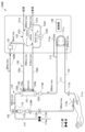
図1は、本発明の第1実施形態に係る血液浄化装置100の概略構成を示す図であり、図2は、血液浄化装置100のブロック図である。
<First embodiment>
The first embodiment will be described in detail with reference to FIGS. 1 to 6.
FIG. 1 is a diagram showing a schematic configuration of a
図1に示すように、血液浄化装置100は、血液回路110と、血液浄化器120と、動脈側測定手段111Mと、静脈側測定手段112Mと、透析液回路130と、制御部140と、を備える。
As shown in FIG. 1, the
血液回路110は、動脈側ライン111と、静脈側ライン112と、薬剤ライン113と、排液ライン114と、を有する。動脈側ライン111、静脈側ライン112、薬剤ライン113及び排液ライン114は、いずれも液体が流通可能な可撓性を有する軟質のチューブを主体として構成される。
動脈側ライン111は、一端側が後述する血液浄化器120の血液導入口122aに接続される。動脈側ライン111には、動脈側接続部111a、動脈側気泡検知器111b、血液ポンプ111cが配置される。
動脈側接続部111aは、動脈側ライン111の他端側に配置される。動脈側接続部111aには、患者の血管に穿刺される針が接続される。
動脈側気泡検知器111bは、チューブ内の気泡の有無を検出する。
血液ポンプ111cは、動脈側ライン111における動脈側気泡検知器111bよりも下流側に配置される。血液ポンプ111cは、動脈側ライン111を構成するチューブをローラーでしごくことにより、動脈側ライン111の内部の血液やプライミング液等の液体を送出する。
One end of the
The artery
The arterial
The
静脈側ライン112は、一端側が後述する血液浄化器120の血液導出口122bに接続される。静脈側ライン112には、静脈側接続部112a、静脈側気泡検知器112b、ドリップチャンバ112c、及び静脈側クランプ112dが配置される。
静脈側接続部112aは、静脈側ライン112の他端側に配置される。静脈側接続部112aには、患者の血管に穿刺される針が接続される。
静脈側気泡検知器112bは、チューブ内の気泡の有無を検出する。
ドリップチャンバ112cは、静脈側気泡検知器112bよりも上流側に配置される。ドリップチャンバ112cは、静脈側ライン112に混入した気泡や凝固した血液等を除去するため、また、静脈圧を測定するため、一定量の血液又は空気を貯留する。
静脈側クランプ112dは、静脈側気泡検知器112bよりも下流側に配置される。静脈側クランプ112dは、静脈側気泡検知器112bによる気泡の検出結果に応じて制御され、静脈側ライン112の流路を開閉する。
One end of the
The
The venous
The
The
薬剤ライン113は、血液透析中に必要な薬剤を動脈側ライン111に供給する。薬剤ライン113は、一端側が薬剤を送り出す薬液ポンプ113aに接続され、他端側が動脈側ライン111に接続される。また、薬剤ライン113には不図示のクランプ手段が設けられており、薬剤を注入するとき以外は、クランプ手段により流路は閉鎖された状態である。第1実施形態では、薬剤ライン113の他端側は、動脈側ライン111における血液ポンプ111cよりも下流側に接続される。
The
排液ライン114は、ドリップチャンバ112cに接続される。排液ライン114には、排液ラインクランプ114aが配置される。排液ライン114は、血液回路110及び血液浄化器120を洗浄して清浄化するプライミング工程でプライミング液を排液するためのラインである。
血液浄化器120は、筒状に形成された容器本体121と、この容器本体121の内部に収容された透析膜(図示せず)と、を備え、容器本体121の内部は、透析膜により血液側流路と透析液側流路とに区画される(いずれも図示せず)。容器本体121には、血液回路110に連通する血液導入口122a及び血液導出口122bと、透析液回路130に連通する透析液導入口123a及び透析液導出口123bと、が形成される。
The
動脈側測定手段111Mは、患者から取り出す血液の状態を測定するためのセンサであり、動脈側ライン111に設けられる。第1実施形態では、動脈側測定手段111Mは、動脈側ライン111のうち血液浄化器120の血液導入口122a近傍に配置される。
The arterial side measuring means 111M is a sensor for measuring the state of blood taken out from a patient, and is provided in the
静脈側測定手段112Mは、患者に戻す血液の状態を測定するためのセンサであり、静脈側ライン112に設けられる。第1実施形態では、静脈側測定手段112Mは、静脈側ライン112のうち血液浄化器120とドリップチャンバ112cとの間に配置される。静脈側測定手段112Mは、血液再循環を測定する際に必須ではないが、動脈側ライン111の血液の状態の変化のみに基づいて血液再循環を測定する場合に比べて、動脈側ライン111及び静脈側ライン112の両者の血液の状態の変化を測定して比較することで、血液再循環の測定精度を向上させることができる。
The venous measuring means 112M is a sensor for measuring the state of blood returned to the patient, and is provided in the
動脈側測定手段111M及び静脈側測定手段112Mで測定する血液の状態とは、具体的には、血液の濃度に応じて変化するヘマトクリット値、ヘモグロビン値、電気抵抗率等が挙げられる。第1実施形態では、血液の状態を示す指標としてヘマトクリット値を測定するものとした。 Specifically, the state of the blood measured by the arterial side measuring means 111M and the venous side measuring means 112M includes the hematocrit value, hemoglobin value, electrical resistivity, etc., which change depending on the blood concentration. In the first embodiment, the hematocrit value is measured as an index indicating the state of blood.
以上の血液回路110及び血液浄化器120によれば、対象者(透析患者)の動脈から取り出された血液は、血液ポンプ111cにより動脈側ライン111を流通して血液浄化器120の血液側流路に導入される。血液浄化器120に導入された血液は、透析膜を介して後述する透析液回路130を流通する透析液により浄化される。血液浄化器120において浄化された血液は、静脈側ライン112を流通して対象者の静脈に返血される。
According to the above-described
透析液回路130は、第1実施形態では、いわゆる密閉容量制御方式の透析液回路130により構成される。この透析液回路130は、透析液供給ライン131aと、透析液排液ライン131bと、透析液導入ライン132aと、透析液導出ライン132bと、透析液送液部133と、を備える。
In the first embodiment, the
透析液送液部133は、透析液チャンバ1331と、バイパスライン1332と、除水/逆濾過ポンプ1333と、を備える。
透析液チャンバ1331は、一定容量(例えば、300mL~500mL)の透析液を収容可能な硬質の容器で構成され、この容器の内部は軟質の隔膜(ダイアフラム)により、送液収容部1331a及び排液収容部1331bに区画される。
バイパスライン1332は、透析液導出ライン132bと透析液排液ライン131bとを接続する。
The
The
除水/逆濾過ポンプ1333は、バイパスライン1332に配置される。除水/逆濾過ポンプ1333は、バイパスライン1332の内部の透析液を透析液排液ライン131b側に流通させる方向(除水方向)及び透析液導出ライン132b側に流通させる方向(逆濾過方向)に送液可能に駆動するポンプにより構成される。
A water removal/
透析液供給ライン131aは、基端側が透析液供給装置(図示せず)に接続され、先端側が透析液チャンバ1331に接続される。透析液供給ライン131aは透析液チャンバ1331の送液収容部1331aに透析液を供給する。
The
透析液導入ライン132aは、透析液チャンバ1331と血液浄化器120の透析液導入口123aとを接続し、透析液チャンバ1331の送液収容部1331aに収容された透析液を血液浄化器120の透析液側流路に導入する。
The
透析液導出ライン132bは、血液浄化器120の透析液導出口123bと透析液チャンバ1331とを接続し、血液浄化器120の透析液側流路から排出された透析液を透析液チャンバ1331の排液収容部1331bに導出する。
The
透析液排液ライン131bは、基端側が透析液チャンバ1331に接続され、排液収容部1331bに収容された透析液の排液を排出する。
The
以上の透析液回路130によれば、透析液チャンバ1331を構成する硬質の容器の内部を軟質の隔膜(ダイアフラム)により区画することで、透析液チャンバ1331からの透析液の導出量(送液収容部1331aへの透析液の供給量)と、透析液チャンバ1331(排液収容部1331b)に回収される排液の量と、を同量にできる。
これにより、除水/逆濾過ポンプ1333を停止させた状態では、血液浄化器120に導入される透析液の流量と血液浄化器120から導出される透析液(排液)の量とを同量にできる。また、除水/逆濾過ポンプ1333を除水方向に送液するように駆動させた場合は、血液浄化器120において、血液から所定の速度で所定量の除水が行われる。また、除水/逆濾過ポンプ1333を逆濾過方向に送液するように駆動させた場合は、血液浄化器120において、血液回路110に所定量の透析液が注入(逆濾過)される。
According to the
As a result, when the water removal/
制御部140は、情報処理装置(コンピュータ)により構成され、制御プログラムを実行することにより、血液浄化装置100の動作を制御する。
具体的には、図2に示すように、制御部140は、血液回路110及び透析液回路130に配置された各種のポンプやクランプ等の動作を制御して、血液浄化装置100により行われる各種工程、例えば、プライミング工程、脱血工程、透析工程、補液工程、返血工程等を実行する。
The
Specifically, as shown in FIG. 2, the
上述の各種工程のうち、本発明に関わる透析工程及び補液工程について図3及び図4を参照して簡単に説明する。 Among the various steps described above, the dialysis step and fluid replacement step related to the present invention will be briefly described with reference to FIGS. 3 and 4.
透析工程では、患者の余剰水分の除水及び老廃物の除去が行われる。
透析工程において、動脈側接続部111aから導入される患者の血液は、動脈側ライン111を通って血液浄化器120で浄化され、静脈側ライン112を通って静脈側接続部112aから患者に戻される。
In the dialysis process, excess water from the patient is removed and waste products are removed.
In the dialysis process, the patient's blood introduced from the
透析工程では、図3に示すように、動脈側接続部111a及び静脈側接続部112aは、それぞれ患者の血管に穿刺される針に接続された状態であり、排液ラインクランプ114aは閉状態、静脈側クランプ112dは開状態である。
In the dialysis process, as shown in FIG. 3, the arterial
不図示の透析液供給装置は、透析液チャンバ1331に対して、例えば平均500mL/minの送液量で透析液を供給及び排出し、除水/逆濾過ポンプ1333を、除水方向に一例として10mLで送液するように作動させる。これにより、血液浄化器120において、10mL/minの除水が行われる。
血液ポンプ111cは、例えば200mL/minの流量で動脈側接続部111a側から血液浄化器120側に血液を送出する。
血液浄化器120内には、血液導入口122aから200mL/minの流量で血液が流入し、10mL/minの流量で除水されて、血液導出口122bから190mL/minの流量で導出される。また、透析排液は、透析液導出口123bから導出される。
このようにして、透析工程において10mL/minの流量で除水が行われる。
A dialysate supply device (not shown) supplies and discharges dialysate to and from the
The
Blood flows into the
In this way, water removal is performed at a flow rate of 10 mL/min in the dialysis step.
次に図4を参照して補液工程について説明する。
補液工程は、患者の循環血液量を増加させるために行われるものであり、透析工程中に血圧低下や身体のつり等の症状が生じた場合に必要に応じて行う他、血圧低下の予防や末梢循環改善を目的として、透析工程中に計画的に複数回、一定の間隔で行うこともできる。第1実施形態では、補液注入手段として血液浄化器120、透析液導入ライン132a、透析液導出ライン132b及び透析液送液部133を用い、血液浄化器120を介して静脈側ライン112に注入される逆濾過透析液を補液として用いることができる。
尚、第1実施形態では、血液浄化器120を介して静脈側ライン112に補液の注入を行う場合について説明したが、血液回路110の構成によっては、動脈側ライン111に直接、補液を注入してもよい(第2実施形態参照)。
Next, the fluid replacement step will be explained with reference to FIG.
The fluid replacement process is performed to increase the patient's circulating blood volume, and is performed as necessary if symptoms such as a drop in blood pressure or body heaviness occur during the dialysis process. For the purpose of improving peripheral circulation, it can also be performed systematically multiple times at regular intervals during the dialysis process. In the first embodiment, a
In the first embodiment, a case has been described in which the replacement fluid is injected into the
補液工程では、図4に示すように、透析工程と同様に動脈側接続部111a及び静脈側接続部112aは、それぞれ患者の血管に穿刺される針に接続された状態であり排液ラインクランプ114aは閉状態、静脈側クランプ112dは開状態である。
In the fluid replacement step, as shown in FIG. 4, similarly to the dialysis step, the arterial
不図示の透析液供給装置は、透析液チャンバ1331に対して、例えば平均500mL/minの送液量で透析液を供給及び排出し、除水/逆濾過ポンプ1333を、逆濾過方向(図4のバイパスライン1332に矢印で示す方向)に送液するように作動させる。例えば、200mLの補液を行う場合には、除水/逆濾過ポンプ1333の逆濾過速度を一例として100mL/minとすることで、血液浄化器120において、200mLの注水が約120秒で行われる。
血液ポンプ111cは、透析工程中の200mL/minから50mL/min程度まで流量を減少させ、動脈側接続部111a側から血液浄化器120側に血液を送出する。
血液浄化器120内には、血液導入口122aから50mL/minの流量で血液が流入し、逆濾過透析液が100mL/minの流量で注水されて、血液導出口122bから希釈された血液が150mL/minの流量で導出される。このようにして、補液工程において約120秒で血液中に急速に水分が補充され、患者の循環血液量を増加させる。
A dialysate supply device (not shown) supplies and discharges dialysate to and from the
The
Blood flows into the
以上、説明したように、補液工程により注入された補液量の分だけ患者の循環血液量が増加する。よって、透析工程において患者の目標体重まで除水するには、除水速度が一定の場合には透析工程の時間を延長する必要がある。また、補液で増加した分を除水するように除水速度を上乗せすることで、透析工程の時間を延長せずに目標体重まで除水することも可能である。 As described above, the patient's circulating blood volume increases by the amount of fluid injected in the fluid replacement step. Therefore, in order to remove water to the patient's target weight in the dialysis process, it is necessary to extend the time of the dialysis process if the water removal rate is constant. Furthermore, by increasing the water removal rate to remove water increased by fluid replacement, it is possible to remove water to the target weight without extending the time of the dialysis process.
次に、第1実施形態における具体的な血液再循環の測定方法について図5及び図6を参照して説明する。 Next, a specific method for measuring blood recirculation in the first embodiment will be described with reference to FIGS. 5 and 6.
(測定方法)
本発明の血液浄化装置100は、補液注入手段を利用して静脈側ライン112に所定量の補液(逆濾過透析液)を注入して患者に戻される血液を希釈し、動脈側測定手段111Mにより測定される血液の状態(ヘマトクリット値)の変化に基づいて、血液再循環を測定する。ここで、血液再循環を測定するためだけに補液の注入を行ってもよいが、この場合、前述したように患者の循環血液量が増加することにより、透析工程の時間の延長や除水速度の増加の必要が生じる。透析工程の時間の延長は患者の負担となり、また、除水速度の急激な増加は血圧低下や血液の過濃縮を招くため注意が必要となる。
(Measuring method)
The
そこで、第1実施形態では、前述の計画された補液工程を行う際に、併せて血液再循環を測定するものとした。これにより、補液した量は透析工程の時間内で除水するため、患者の負担となる透析工程の時間の延長や血液の過濃縮、血圧低下の要因となる除水速度の急激な増加を招くことなく、血液再循環を測定することができる。特に、補液工程において所定時間(30分)毎に所定量(200mL)の補液の注入を計画的に行う場合、併せて血液再循環の測定を行うことで、血液再循環の経時的な変化を観察することができる。よって、例えば、透析治療の途中で再循環率が増加すれば(つまり、複数回の補液工程のうちの2回目以降の補液工程において再循環率が増加すれば)、穿刺の位置やシャント不全等が原因ではなく、補液工程と補液工程との間における体位の変化が原因であると推測できる。
また、従来の血液再循環の測定においては、例えば、生理食塩水を10mL静脈側ラインに急速に注入する等の方法で行われており、希釈量が少なかったが、本発明において、補液工程と共に血液再循環を測定する場合、例えば100mL/minで200mLの補液を注入する等、従来に比べて希釈量が多いため、測定精度を向上させることができる。
Therefore, in the first embodiment, when performing the above-mentioned planned fluid replacement step, blood recirculation is also measured. As a result, the amount of fluid that has been replaced is removed within the time required for the dialysis process, resulting in an extension of the dialysis process time that is a burden on the patient, hyperconcentration of the blood, and a rapid increase in the water removal rate that causes a drop in blood pressure. Blood recirculation can be measured without In particular, when a predetermined amount (200 mL) of replacement fluid is systematically injected every predetermined time (30 minutes) during the fluid replacement process, blood recirculation can be measured at the same time to assess changes in blood recirculation over time. can be observed. Therefore, for example, if the recirculation rate increases during dialysis treatment (that is, if the recirculation rate increases in the second and subsequent fluid replacement steps of multiple fluid replacement steps), the position of the puncture, shunt failure, etc. It can be inferred that this is not the cause, but rather a change in body position between the fluid replacement steps.
In addition, in the conventional measurement of blood recirculation, for example, it was performed by rapidly injecting 10 mL of physiological saline into the venous line, and the amount of dilution was small, but in the present invention, in addition to the fluid replacement step, When measuring blood recirculation, for example, by injecting 200 mL of replacement fluid at 100 mL/min, the amount of dilution is greater than in the past, so measurement accuracy can be improved.
血液再循環の具体的な測定方法について説明する。血液の再循環率が低い、即ち、静脈側接続部112aから患者に戻される希釈された血液のほとんどが静脈を順流して、逆流が少ない場合、動脈側ライン111を流れる血液はほとんど希釈されないので、動脈側測定手段111Mにより測定される血液の状態(ヘマトクリット値)の変化は、図5(a)に示すようになる。図5(a)において、縦軸はヘマトクリット値を示し、横軸は時間を示す。また、図5(b)及び図6についても同様である。
一方、血液の再循環率が高い、即ち、静脈側接続部112aから患者に戻される希釈された血液の多くが逆流する場合、動脈側ライン111を流れる血液は希釈されて、動脈側測定手段111Mにより測定される血液の状態(ヘマトクリット値)の変化は、図5(b)に示すようになる。
A specific method for measuring blood recirculation will be explained. If the blood recirculation rate is low, that is, most of the diluted blood returned to the patient from the
On the other hand, if the blood recirculation rate is high, that is, much of the diluted blood returned to the patient from the
また、更に静脈側ライン112に静脈側測定手段112Mを設けて、患者に戻す希釈された血液の状態の変化を測定することにより、静脈側ライン112で測定される希釈された血液の状態の変化と、動脈側ライン111で測定される血液の状態の変化とを比較することで、血液再循環の測定精度を向上させることができる。
具体的には、補液を注入した際の静脈側測定手段112Mにより測定される血液の状態(ヘマトクリット値)の変化は、図6に示すようになる。図6で示すヘマトクリット値の減少面積を基準として、図5(a)、(b)で示すヘマトクリット値の減少面積を比較することで血液の再循環率を精度よく測定することができる。
Furthermore, by providing a venous measuring means 112M in the
Specifically, the change in the blood condition (hematocrit value) measured by the venous measuring means 112M when the replacement fluid is injected is as shown in FIG. The blood recirculation rate can be accurately measured by comparing the area of decrease in hematocrit value shown in FIGS. 5(a) and 5(b) using the area of decrease in hematocrit value shown in FIG. 6 as a reference.
以上説明した第1実施形態の血液浄化装置100によれば、以下のような効果を奏する。
According to the
(1)血液浄化装置100を、血液浄化器120と、動脈側ライン111と、静脈側ライン112と、補液注入手段と、血液の状態を測定する動脈側測定手段111Mと、制御部140と、を含んで構成し、制御部140に、補液注入手段により補液が注入されている状態において、動脈側測定手段111Mにより測定される血液の状態の変化に基づいて、血液再循環を測定させた。これにより、補液工程を行うための構成を利用して血液再循環測定のための補液を行うことができるので、別途、補液注入用ラインを設けたり、生理食塩水等の液体を注入したりすることなく血液再循環を測定できる。よって、容易に血液再循環を測定することができる。また、補液工程と別に血液再循環測定のためだけに補液を注入する場合に比べて、除水すべき量を増やさなくてよい。よって透析時間の延長や除水速度を増大させることを行わなくてもよい。また、補液工程により血液を十分に希釈することができるので、再循環を精度よく測定することができる。
(1) The
(2)制御部140に、補液注入手段による補液の注入(補液工程)を、間欠的に複数回行わせた。これにより、血液再循環の経時的な変化を測定できるので、例えば、透析治療の途中で再循環が増加すれば、穿刺の位置やシャント不全等が原因ではなく、体位の変化が原因であると推測できる。
(2) The
(3)血液浄化装置100を、静脈側ライン112に設けられ、患者に戻される血液の状態を測定する静脈側測定手段112Mを更に含んで構成し、制御部140に、動脈側測定手段111Mで測定される血液の状態の変化と静脈側測定手段112Mで測定される血液の状態の変化とを比較して血液再循環を測定させた。これにより、動脈側のみを測定する場合に比べて、血液再循環の測定精度を向上させることができる。
(3) The
(4)血液浄化器120を、血液側流路及び透析液側流路を含んで構成すると共に、血液浄化装置100を、透析液流路に透析液を導入する透析液導入ライン132a、透析液側流路から透析液を導出する透析液導出ライン132b、透析液導入ライン132a及び透析液導出ライン132bを介して透析液側流路に透析液を送る透析液送液部133を有する透析液回路130を含んで構成した。そして、補液注入手段に、透析液回路130及び血液浄化器120を介して静脈側ライン112に透析液を補液として注入させた。これにより、逆濾過透析液を補液として用いることができるので、従来の生理食塩水を用いる場合等に比べて、血液再循環を測定するためのコスト増を抑えることができる。
(4) The
<第2実施形態>
次に、第2実施形態に係る血液浄化装置について図7~図11を参照して説明する。第2実施形態の血液浄化装置では、第1実施形態とは回路の構成が異なっており、血液浄化装置は、置換液(補液)としての透析液を直接、血液回路110に注入するための置換液ラインを備えるように構成される。
図7は、本発明の第2実施形態に係る血液浄化装置100A、100Bの構成を示すブロック図である。図8及び図9を参照して、前希釈によるオンライン血液濾過透析(以下、前希釈オンラインHDFとする)について説明し、図10及び図11を参照して、後希釈によるオンラインHDFについて説明する。第1実施形態で説明したものと同様の構成のものは、同じ符号を付して説明を省略する。
<Second embodiment>
Next, a blood purification device according to a second embodiment will be described with reference to FIGS. 7 to 11. The blood purification device of the second embodiment has a circuit configuration different from that of the first embodiment. The liquid line is configured to include a liquid line.
FIG. 7 is a block diagram showing the configuration of
ここでHDFとは、血液浄化器120において濾過する置換液量を増やすために置換液を注入し、血液透析よりも濾過を多量に行うことで、血液透析では透析膜を通り抜けにくい低中分子蛋白をより多く取り除くことが可能な透析治療の一つである。そして、血液浄化器120の上流側で置換液を注入するものが前希釈式であり、下流側で注入するものが後希釈式である。置換液として透析液を用い、透析液回路から置換液を注入する方法がオンラインHDFであり、置換液バッグ等を用いて、置換液を注入する方法がオフラインHDFである。第2実施形態では、オンラインHDFを実施可能な血液浄化装置100A、100Bを一例として説明するが、オフラインHDFを実施可能な血液浄化装置も、本発明の範囲に含まれる。
Here, HDF refers to a low-middle-molecular-weight protein that is difficult to pass through a dialysis membrane in hemodialysis by injecting a replacement fluid to increase the amount of replacement fluid to be filtered in the
まず、前希釈によるオンラインHDFについて説明する。
図8に示す血液浄化装置100Aは、前希釈によるオンラインHDFによる透析工程を実施可能であり、血液回路110と、血液浄化器120と、動脈側測定手段111Mと、静脈側測定手段112Mと、透析液回路130と、制御部140と、置換液ライン150Aと、置換液ポンプ151と、を備える。
First, online HDF using pre-dilution will be explained.
The
置換液ライン150Aは、透析液回路130内の透析液を血液回路110に直接注入するためのラインであり、液体が流通可能な可撓性を有する軟質のチューブを主体として構成される。図8に示すように、置換液ライン150Aの上流側は、透析液回路130の透析液導入ライン132aに接続されている。置換液ライン150Aの下流側には、置換液ラインクランプ152が配置されており、動脈側ライン111のうち血液ポンプ111cの下流側に接続される。
置換液ラインクランプ152は、制御部140により制御され、置換液ライン150Aの流路を開閉する。
The
The substituent
置換液ポンプ151は、置換液ライン150Aに配置され、透析液回路130から透析液を取り出して、血液回路110(動脈側ライン111)に送液する。
The
動脈側測定手段111Mは、患者から取り出す血液の状態を測定するためのセンサであり、動脈側ライン111に設けられる。第2実施形態の前希釈方式の場合は、動脈側測定手段111Mは、動脈側ライン111のうち、置換液ライン150Aからの置換液の流入の影響を受けない位置に配置すればよい。本実施形態では、動脈側測定手段111Mは、置換液ライン150Aとの接続部よりも上流側に配置される。
The arterial side measuring means 111M is a sensor for measuring the state of blood taken out from a patient, and is provided in the
静脈側測定手段112Mは、患者に戻す血液の状態を測定するためのセンサであり、静脈側ライン112に設けられる。第2実施形態の前希釈方式では、静脈側測定手段112Mは、静脈側ライン112のうち血液浄化器120とドリップチャンバ112cとの間に配置される。静脈側測定手段112Mは、血液再循環を測定する際に必須ではないが、動脈側ライン111の血液の状態の変化のみに基づいて血液再循環を測定する場合に比べて、動脈側ライン111及び静脈側ライン112の両者の血液の状態の変化を測定して比較することで、血液再循環の測定精度を向上させることができる。
The venous measuring means 112M is a sensor for measuring the state of blood returned to the patient, and is provided in the
次に、血液浄化装置100Aを用いた前希釈オンラインHDFにおける透析工程及び補液工程について図8及び図9を参照して簡単に説明する。
Next, the dialysis process and fluid replacement process in pre-dilution online HDF using the
透析工程では、血液浄化器120において、患者の余剰水分及び置換液の除水と老廃物の除去とが行われる。
透析工程において、動脈側接続部111aから導入される患者の血液は、動脈側ライン111を通って置換液と共に血液浄化器120で浄化され、静脈側ライン112を通って静脈側接続部112aから患者に戻される。
In the dialysis process, the
In the dialysis process, the patient's blood introduced from the
透析工程では、図8に示すように、動脈側接続部111a及び静脈側接続部112aは、それぞれ患者の血管に穿刺される針に接続された状態であり、排液ラインクランプ114aは閉状態、静脈側クランプ112dは開状態、置換液ラインクランプ152は開状態である。
In the dialysis process, as shown in FIG. 8, the arterial
不図示の透析液供給装置は、透析液チャンバ1331に対して、例えば平均500mL/minの送液量で透析液を供給及び排出し、除水/逆濾過ポンプ1333を、除水方向に一例として10mLで送液するように作動させる。置換液ポンプ151により300mL/minで透析液が動脈側ライン111に注入され、血液浄化器120において、310mL/minの除水が行われる。
血液ポンプ111cは、例えば200mL/minの流量で動脈側接続部111a側から血液浄化器120側に血液を送出する。
血液浄化器120内には、血液導入口122aから500mL/minの流量で血液及び置換液(透析液)が流入し、310mL/minの流量で除水されて、血液導出口122bから190mL/minの流量で導出される。また、透析排液は、透析液導出口123bから導出される。
このようにして、透析工程において10mL/minの流量で除水が行われる。
A dialysate supply device (not shown) supplies and discharges dialysate to and from the
The
Blood and replacement fluid (dialysate) flow into the
In this way, water removal is performed at a flow rate of 10 mL/min in the dialysis step.
次に図9を参照して補液工程について説明する。
第2実施形態における前希釈方式では、補液注入手段として血液浄化器120、透析液導入ライン132a、透析液導出ライン132b、透析液送液部133、置換液ライン150A及び置換液ポンプ151を用い、置換液ライン150Aを介して動脈側ライン111に注入されるオンライン透析液を補液として用いることができる。
Next, the fluid replacement step will be explained with reference to FIG.
In the pre-dilution method in the second embodiment, a
補液工程では、図9に示すように、透析工程と同様に動脈側接続部111a及び静脈側接続部112aは、それぞれ患者の血管に穿刺される針に接続された状態であり排液ラインクランプ114aは閉状態、静脈側クランプ112d、置換液ラインクランプ152は開状態である。
In the fluid replacement process, as shown in FIG. 9, the arterial
不図示の透析液供給装置は、透析液チャンバ1331に対して、例えば平均500mL/minの送液量で透析液を供給及び排出し、除水/逆濾過ポンプ1333を、逆濾過方向(図9のバイパスライン1332に矢印で示す方向)に送液するように作動させる。例えば、200mLの補液を行う場合には、除水/逆濾過ポンプ1333の逆濾過速度を一例として100mL/minとした。置換液ポンプ151は、透析工程と同様に流量を300mL/minとした場合は、血液浄化器120において、除水される量が透析工程の場合の310mL/minから200mL/minに減ることで、置換液ライン150Aから実質的に200mlの注水が約120秒で行われる。尚、置換液ポンプ151の流量を0mL/minとして、血液浄化器120において、100mL/minの流量で逆濾過透析液を注入してもよい。つまり、実質的に所定量の補液が注入できるように、置換液ライン150Aを介したオンライン透析液及び血液浄化器120を介した逆濾過透析液の両方又はいずれか一方を用いればよい。
A dialysate supply device (not shown) supplies and discharges dialysate to and from the
血液ポンプ111cは、透析工程中の200mL/minから50mL/min程度まで流量を減少させ、動脈側接続部111a側から血液浄化器120側に血液を送出する。
血液浄化器120内には、血液導入口122aから350mL/minの流量で血液、置換液及び補液が流入し、200mL/minの流量で除水されて、血液導出口122bから希釈された血液が150mL/minの流量で導出される。このようにして、補液工程において約120秒で血液中に急速に水分が補充され、患者の循環血液量を増加させる。
The
Blood, replacement fluid, and replacement fluid flow into the
次に、後希釈によるオンラインHDFについて説明する。
図10に示す血液浄化装置100Bは、後希釈によるオンラインHDFによる透析工程を実施可能であり、血液回路110と、血液浄化器120と、動脈側測定手段111Mと、静脈側測定手段112Mと、透析液回路130と、制御部140と、置換液ライン150Bと、置換液ポンプ151と、を備える。
Next, online HDF using post-dilution will be explained.
The
置換液ライン150Bは、透析液回路130内の透析液を血液回路110に直接注入するためのラインであり、液体が流通可能な可撓性を有する軟質のチューブを主体として構成される。図10に示すように、置換液ライン150Bの上流側は、透析液回路130の透析液導入ライン132aに接続されている。置換液ライン150Bの下流側は、置換液ラインクランプ152が配置されており、静脈側ライン112に配置されるドリップチャンバ112cに接続される。
置換液ラインクランプ152は、制御部140により制御され、置換液ライン150Bの流路を開閉する。
The
The substituent
置換液ポンプ151は、置換液ライン150Bに配置され、透析液回路130から透析液を取り出して、血液回路110(静脈側ライン112)に送液する。
The
動脈側測定手段111Mは、患者から取り出す血液の状態を測定するためのセンサであり、動脈側ライン111に設けられる。第2実施形態の後希釈方式では、動脈側測定手段111Mは、動脈側ライン111のうち血液浄化器120の血液導入口122a近傍に配置される。
The arterial side measuring means 111M is a sensor for measuring the state of blood taken out from a patient, and is provided in the
静脈側測定手段112Mは、患者に戻す血液の状態を測定するためのセンサであり、静脈側ライン112に設けられる。第2実施形態の後希釈方式では、静脈側測定手段112Mは、置換液及び補液が注入された後の血液の状態を測定するため、静脈側ライン112のうち、置換液ライン150Bが接続されるドリップチャンバ112cの下流側に配置される。静脈側測定手段112Mは、血液再循環を測定する際に必須ではないが、動脈側ライン111の血液の状態の変化のみに基づいて血液再循環を測定する場合に比べて、動脈側ライン111及び静脈側ライン112の両者の血液の状態の変化を測定して比較することで、血液再循環の測定精度を向上させることができる。
The venous measuring means 112M is a sensor for measuring the state of blood returned to the patient, and is provided in the
次に、血液浄化装置100Bを用いた後希釈オンラインHDFにおける透析工程及び補液工程について図10及び図11を参照して簡単に説明する。
Next, the dialysis process and fluid replacement process in post-dilution online HDF using the
透析工程では、血液浄化器120において、患者の余剰水分及び老廃物の除去が行われる。後希釈方式では、血液浄化器120において濾過量を多くし、余分に濾過した分を置換液により補充する。
透析工程において、動脈側接続部111aから導入される患者の血液は、動脈側ライン111を通って血液浄化器120で浄化され、静脈側ライン112を通って静脈側接続部112aから患者に戻される。
In the dialysis process, excess water and waste products from the patient are removed in the
In the dialysis process, the patient's blood introduced from the
透析工程では、図10に示すように、動脈側接続部111a及び静脈側接続部112aは、それぞれ患者の血管に穿刺される針に接続された状態であり、排液ラインクランプ114aは閉状態、静脈側クランプ112dは開状態、置換液ラインクランプ152は開状態である。
In the dialysis process, as shown in FIG. 10, the arterial
不図示の透析液供給装置は、透析液チャンバ1331に対して、例えば平均500mL/minの送液量で透析液を供給及び排出し、除水/逆濾過ポンプ1333を、除水方向に一例として10mL/minで送液するように作動させる。置換液ポンプ151により50mL/minで透析液が静脈側ライン112(ドリップチャンバ112c)に注入され、血液浄化器120において、60mL/minの除水が行われる。
血液ポンプ111cは、例えば200mL/minの流量で動脈側接続部111a側から血液浄化器120側に血液を送出する。
血液浄化器120内には、血液導入口122aから200mL/minの流量で血液が流入し、60mL/minの流量で除水されて、血液導出口122bから140mL/minの流量で導出される。静脈側ライン112では、50mL/minの流量で置換液(透析液)が流入し、190mL/minの流量で患者に血液が戻される。また、透析排液は、透析液導出口123bから導出される。
このようにして、透析工程において10mL/minの流量で除水が行われる。
A dialysate supply device (not shown) supplies and discharges dialysate to and from the
The
Blood flows into the
In this way, water removal is performed at a flow rate of 10 mL/min in the dialysis step.
次に図11を参照して補液工程について説明する。
補液工程は、第1実施形態で説明したものと同様の目的で行われ、第2実施形態では、補液注入手段として血液浄化器120、透析液導入ライン132a、透析液導出ライン132b、透析液送液部133、置換液ライン150B及び置換液ポンプ151を用いることができる。
Next, the fluid replacement step will be explained with reference to FIG.
The fluid replacement step is performed for the same purpose as that described in the first embodiment, and in the second embodiment, a
補液工程では、図11に示すように、透析工程と同様に動脈側接続部111a及び静脈側接続部112aは、それぞれ患者の血管に穿刺される針に接続された状態であり排液ラインクランプ114aは閉状態、静脈側クランプ112d、置換液ラインクランプ152は開状態である。
In the fluid replacement step, as shown in FIG. 11, similarly to the dialysis step, the arterial
不図示の透析液供給装置は、透析液チャンバ1331に対して、例えば平均500mL/minの送液量で透析液を供給及び排出し、除水/逆濾過ポンプ1333を、逆濾過方向(図11のバイパスライン1332に矢印で示す方向)に送液するように作動させる。例えば、200mLの補液を行う場合には、除水/逆濾過ポンプ1333の逆濾過速度を一例として100mL/minとした。置換液ポンプ151は、透析工程と同様に流量を50mL/minとした場合は、血液浄化器120において、50mL/minの流量で逆濾過透析液が注入される。このようにして、血液浄化器120及び置換液ライン150Bを介して実質的に200mlの注水が約120秒で行われる。尚、置換液ポンプ151の流量を0mL/minとして、血液浄化器120において、100mL/minの流量で逆濾過透析液を注入してもよい。つまり、実質的に所定量の補液が注入できるように、置換液ライン150Bを介したオンライン透析液及び血液浄化器120を介した逆濾過透析液の両方又はいずれか一方を用いればよい。
血液ポンプ111cは、透析工程中の200mL/minから50mL/min程度まで流量を減少させ、動脈側接続部111a側から血液浄化器120側に血液を送出する。
血液浄化器120内には、血液導入口122aから50mL/minの流量で血液が流入し、100mL/minの流量で逆濾過透析液が注入されて、血液導出口122bから希釈された血液が150mL/minの流量で導出される。このようにして、補液工程において約120秒で血液中に急速に水分が補充され、患者の循環血液量を増加させる。
A dialysate supply device (not shown) supplies and discharges dialysate to and from the
The
Blood flows into the
第2実施形態における血液再循環の測定方法については、第1実施形態の場合と同様であるので、説明を省略する。 The method for measuring blood recirculation in the second embodiment is the same as that in the first embodiment, so a description thereof will be omitted.
以上説明した第2実施形態の血液浄化装置100A、100Bによれば、上述の効果(1)~(5)に加えて、以下のような効果を奏する。
According to the
(6)血液浄化装置100A(100B)を、透析液導入ライン132a又は透析液導出ライン132bと動脈側ライン111又は静脈側ライン112とを接続する置換液ライン150A(150B)と、置換液ライン150A(150B)を介して動脈側ライン111又は静脈側ライン112に置換液として透析液を送る置換液ポンプ151と、を含んで構成し、補液注入手段に、置換液ラインを介して動脈側ライン111又は静脈側ライン112に透析液を補液として注入させた。これにより、補液にオンライン透析液を用いることができるので、従来の生理食塩水を用いる場合等に比べて、血液再循環を測定するためのコスト増を抑えることができる。
(6) The
以上、本発明の血液浄化装置の好ましい各実施形態について説明したが、本発明は、上述した各実施形態に制限されるものではなく、適宜変更が可能である。 Although preferred embodiments of the blood purification device of the present invention have been described above, the present invention is not limited to the embodiments described above, and can be modified as appropriate.
例えば、上述の各実施形態では、補液工程を行うと共に血液再循環を測定するものとしたが、補液工程とは別に、補液注入手段により補液を注入して血液を希釈し、血液再循環を測定してもよい。 For example, in each of the embodiments described above, blood recirculation is measured while performing a fluid replacement step, but apart from the fluid replacement step, fluid is injected by a fluid replacement means to dilute the blood, and blood recirculation is measured. You may.
また、第2実施形態では、補液を注入する場合に置換液ポンプの流量を透析工程の場合と同じ流量としたが、適宜、置換液ポンプの流量を調整し、逆濾過透析液及びオンライン透析液の両方又はいずれか一方を用いて所定の補液量を注入すればよい。 In addition, in the second embodiment, when injecting replacement fluid, the flow rate of the substituent fluid pump was set to be the same as that in the dialysis process, but the flow rate of the substituent fluid pump was adjusted as appropriate, and the flow rate of the substituent fluid pump was adjusted as appropriate. A predetermined amount of replacement fluid may be injected using either or both of the above.
また、第2実施形態では、補液工程で用いる補液としてオンライン透析液を用いる場合を示したが、これに限らない。例えば、後希釈HDFの場合において、生理食塩水ラインを接続して補液として生理食塩水を用いてもよく、血液再循環の測定の際に、補液として生理食塩水及び逆濾過透析液の両方又はいずれか一方を用いてもよい。 Further, in the second embodiment, a case is shown in which an online dialysate is used as the replacement fluid used in the fluid replacement step, but the present invention is not limited to this. For example, in the case of post-dilution HDF, a saline line may be connected and saline may be used as a replacement fluid, and when measuring blood recirculation, both saline and back-filtered dialysate or Either one may be used.
また、第1実施形態では、補液工程において、逆濾過により補液を注入したが、これに限らない。即ち、血液浄化装置を、第2実施形態に示すように置換液ライン及び置換液ポンプを含んで構成してもよい。そして、この場合、透析工程においては置換液ポンプを停止させると共に除水/逆濾過ポンプを除水方向に作動させて所定の流量で除水を行い(つまり、HDFは行わない)、補液工程において置換液ポンプを作動させると共に除水/逆濾過ポンプを逆濾過方向に作動させる(例えば、図9に示すのと同様の動作をさせる)ことで、置換液ラインを介して補液を行ってもよい。 Further, in the first embodiment, the replacement fluid is injected by back filtration in the fluid replacement step, but the invention is not limited to this. That is, the blood purification device may be configured to include a substituent liquid line and a substituent pump as shown in the second embodiment. In this case, in the dialysis process, the substituate pump is stopped and the water removal/reverse filtration pump is operated in the water removal direction to remove water at a predetermined flow rate (that is, HDF is not performed), and in the fluid replacement process, Fluid replacement may be performed through the substituent line by activating the substituent pump and operating the water removal/reverse filtration pump in the reverse filtration direction (e.g., an operation similar to that shown in FIG. 9). .
100、100A、100B 透析装置
110 血液回路
111 動脈側ライン
111c 血液ポンプ
112 静脈側ライン
120 血液浄化器
130 透析液回路
133 透析液送液部
140 制御部
150A、150B 置換液ライン
151 置換液ポンプ
100, 100A,
Claims (4)
前記血液浄化器に血液を送る動脈側ラインと、
前記血液浄化器で浄化された血液を患者に戻す静脈側ラインと、
前記血液浄化器、前記動脈側ライン又は前記静脈側ラインに補液を注入する補液注入手段と、
前記動脈側ラインに設けられ、該動脈側ラインを流通する血液の状態を測定する動脈側測定手段と、
前記静脈側ラインに設けられ、該静脈側ラインを流通する血液の状態を測定する静脈側測定手段と、
前記補液注入手段、前記動脈側測定手段及び前記静脈側測定手段を制御する制御部と、を備え、
前記制御部は、前記補液注入手段により補液が注入されている状態において、前記動脈側測定手段及び前記静脈側測定手段により測定される血液の状態の変化に基づいて、血液再循環を測定し、
前記動脈側測定手段及び前記静脈側測定手段は、血液の状態を示す指標としてヘマトクリット値を測定し、
前記制御部は、前記静脈側測定手段で測定されるヘマトクリット値を時間で積分した積分値を基準として、前記動脈側測定手段で測定されるヘマトクリット値を時間で積分した積分値を比較して血液再循環を測定する血液浄化装置。 blood purifier,
an arterial line that sends blood to the blood purifier;
a venous line that returns the blood purified by the blood purifier to the patient;
A replacement fluid injection means for injecting replacement fluid into the blood purifier, the arterial line, or the venous line;
an artery-side measuring means provided on the artery-side line and measuring the state of blood flowing through the artery-side line;
a venous measuring means provided in the venous line and measuring the state of blood flowing through the venous line;
A control unit that controls the replacement fluid injection means, the arterial side measuring means, and the venous side measuring means,
The control unit measures blood recirculation based on changes in the state of blood measured by the arterial side measurement means and the venous side measurement means in a state where the replacement fluid is injected by the replacement fluid injection means ,
The arterial side measuring means and the venous side measuring means measure a hematocrit value as an index indicating the state of blood,
The control unit compares the integral value obtained by integrating the hematocrit value measured by the arterial side measuring means with respect to time, with the integral value obtained by integrating the hematocrit value measured by the arterial side measuring means over time as a reference, and determines the blood flow rate. Blood purification device that measures recirculation .
該血液浄化装置は、
前記透析液側流路に透析液を導入する透析液導入ライン、前記透析液側流路から透析液を導出する透析液導出ライン、及び前記透析液導入ラインを介して前記透析液側流路に透析液を送る透析液送液部を有する透析液回路を更に備え、
前記補液注入手段は、前記透析液回路及び前記血液浄化器を介して前記静脈側ラインに透析液を補液として注入する請求項1又は2に記載の血液浄化装置。 The blood purifier has a blood side flow path and a dialysate side flow path,
The blood purification device is
A dialysate introduction line that introduces the dialysate into the dialysate side flow path, a dialysate lead-out line that leads the dialysate from the dialysate side flow path, and a dialysate side flow path via the dialysate introduction line. further comprising a dialysate circuit having a dialysate sending section for sending dialysate;
3. The blood purification apparatus according to claim 1 , wherein the replacement fluid injection means injects dialysate as a replacement fluid into the venous line via the dialysate circuit and the blood purifier.
該血液浄化装置は、
前記透析液側流路に透析液を導入する透析液導入ライン、前記透析液側流路から透析液を導出する透析液導出ライン、及び前記透析液導入ラインを介して前記透析液側流路に透析液を送る透析液送液部を有する透析液回路と、
前記透析液導入ライン又は前記透析液導出ラインと前記動脈側ライン又は前記静脈側ラインとを接続する置換液ラインと、
前記置換液ラインを介して前記動脈側ライン又は前記静脈側ラインに透析液を送る置換液ポンプと、を更に備え、
前記補液注入手段は、前記置換液ラインを介して前記動脈側ライン又は前記静脈側ラインに透析液を補液として注入する請求項1~3のいずれかに記載の血液浄化装置。 The blood purifier has a blood side flow path and a dialysate side flow path,
The blood purification device is
A dialysate introduction line that introduces the dialysate into the dialysate side flow path, a dialysate lead-out line that leads the dialysate from the dialysate side flow path, and a dialysate side flow path via the dialysate introduction line. a dialysate circuit having a dialysate sending section that sends dialysate;
a replacement fluid line connecting the dialysate introduction line or the dialysate discharge line and the arterial line or the venous line;
further comprising a substituent fluid pump that sends dialysate to the arterial line or the venous line via the substituent line,
4. The blood purification apparatus according to claim 1, wherein the replacement fluid injecting means injects dialysate as a replacement fluid into the arterial line or the venous line via the replacement fluid line.
Priority Applications (2)
| Application Number | Priority Date | Filing Date | Title |
|---|---|---|---|
| JP2019173227A JP7367425B2 (en) | 2019-09-24 | 2019-09-24 | blood purification device |
| PCT/JP2020/031682 WO2021059817A1 (en) | 2019-09-24 | 2020-08-21 | Blood purification device |
Applications Claiming Priority (1)
| Application Number | Priority Date | Filing Date | Title |
|---|---|---|---|
| JP2019173227A JP7367425B2 (en) | 2019-09-24 | 2019-09-24 | blood purification device |
Publications (2)
| Publication Number | Publication Date |
|---|---|
| JP2021049060A JP2021049060A (en) | 2021-04-01 |
| JP7367425B2 true JP7367425B2 (en) | 2023-10-24 |
Family
ID=75154949
Family Applications (1)
| Application Number | Title | Priority Date | Filing Date |
|---|---|---|---|
| JP2019173227A Active JP7367425B2 (en) | 2019-09-24 | 2019-09-24 | blood purification device |
Country Status (2)
| Country | Link |
|---|---|
| JP (1) | JP7367425B2 (en) |
| WO (1) | WO2021059817A1 (en) |
Citations (4)
| Publication number | Priority date | Publication date | Assignee | Title |
|---|---|---|---|---|
| JP2009527343A (en) | 2006-02-22 | 2009-07-30 | ヘンリー フォード ヘルス システム | Topical citrate anticoagulant delivery system and method to extracorporeal blood circuit |
| US20100268090A1 (en) | 2007-11-06 | 2010-10-21 | Rubinstein Eduardo H | Measurement of hematocrit and cardiac output from optical transmission and reflection changes |
| JP2011200407A (en) | 2010-03-25 | 2011-10-13 | Nikkiso Co Ltd | Blood purification device |
| JP2017012648A (en) | 2015-07-06 | 2017-01-19 | 日機装株式会社 | Blood purification device and flow calculation method of access blood vessel by blood purification device |
Family Cites Families (1)
| Publication number | Priority date | Publication date | Assignee | Title |
|---|---|---|---|---|
| FR2680975B1 (en) * | 1991-09-10 | 1998-12-31 | Hospal Ind | ARTIFICIAL KIDNEY WITH MEANS FOR DETERMINING A SUBSTANCE IN BLOOD. |
-
2019
- 2019-09-24 JP JP2019173227A patent/JP7367425B2/en active Active
-
2020
- 2020-08-21 WO PCT/JP2020/031682 patent/WO2021059817A1/en active Application Filing
Patent Citations (4)
| Publication number | Priority date | Publication date | Assignee | Title |
|---|---|---|---|---|
| JP2009527343A (en) | 2006-02-22 | 2009-07-30 | ヘンリー フォード ヘルス システム | Topical citrate anticoagulant delivery system and method to extracorporeal blood circuit |
| US20100268090A1 (en) | 2007-11-06 | 2010-10-21 | Rubinstein Eduardo H | Measurement of hematocrit and cardiac output from optical transmission and reflection changes |
| JP2011200407A (en) | 2010-03-25 | 2011-10-13 | Nikkiso Co Ltd | Blood purification device |
| JP2017012648A (en) | 2015-07-06 | 2017-01-19 | 日機装株式会社 | Blood purification device and flow calculation method of access blood vessel by blood purification device |
Also Published As
| Publication number | Publication date |
|---|---|
| JP2021049060A (en) | 2021-04-01 |
| WO2021059817A1 (en) | 2021-04-01 |
Similar Documents
| Publication | Publication Date | Title |
|---|---|---|
| JP5259159B2 (en) | Chemical treatment flow control system and method | |
| US20020068015A1 (en) | Apparatus and method for control of ultrafiltration in extracorporeal treatment of blood | |
| JP5586476B2 (en) | Method for determining the ratio of intra-fistula recirculation and / or cardiopulmonary recirculation to total recirculation of fistula recirculation and cardiopulmonary recirculation | |
| US20130338560A1 (en) | Method and apparatus for determining access flow | |
| JP2001511679A (en) | Blood filtration system | |
| JP6900756B2 (en) | Method and device for determining the connection status of the replenisher line to the blood circuit in the hemodialysis machine | |
| CN102781496A (en) | Device and method for monitoring a vascular access for an extracorporeal blood treatment | |
| CN112312941B (en) | Dialysis device and fluid replacement control method | |
| JPWO2008120803A1 (en) | Continuous blood purification device with syringe pump | |
| JP7367425B2 (en) | blood purification device | |
| US20040020852A1 (en) | Method and apparatus for calcium profiling in dialysis | |
| JP7396180B2 (en) | Dialysis device and control method | |
| WO2021059573A1 (en) | Blood purification device | |
| JP2022185796A (en) | Blood purification device | |
| JP6642695B2 (en) | Hemodialysis machine and control program | |
| JP2023005175A (en) | Blood purification device | |
| JP2023517466A (en) | Method and device for determining when to collect pressure measurements | |
| JP2022137868A (en) | Blood purification device | |
| JP2024036776A (en) | blood purification system | |
| IT202100028082A1 (en) | Apparatus for extracorporeal blood treatment | |
| JP2003260129A (en) | Hypertonic solution injector | |
| JP2020151034A (en) | Dialyzer and determination method of circuit set |
Legal Events
| Date | Code | Title | Description |
|---|---|---|---|
| A621 | Written request for application examination |
Free format text: JAPANESE INTERMEDIATE CODE: A621 Effective date: 20220913 |
|
| A131 | Notification of reasons for refusal |
Free format text: JAPANESE INTERMEDIATE CODE: A131 Effective date: 20230404 |
|
| A521 | Request for written amendment filed |
Free format text: JAPANESE INTERMEDIATE CODE: A523 Effective date: 20230602 |
|
| TRDD | Decision of grant or rejection written | ||
| A01 | Written decision to grant a patent or to grant a registration (utility model) |
Free format text: JAPANESE INTERMEDIATE CODE: A01 Effective date: 20230912 |
|
| A61 | First payment of annual fees (during grant procedure) |
Free format text: JAPANESE INTERMEDIATE CODE: A61 Effective date: 20230925 |
|
| R150 | Certificate of patent or registration of utility model |
Ref document number: 7367425 Country of ref document: JP Free format text: JAPANESE INTERMEDIATE CODE: R150 |