JP7366648B2 - Image forming device, image forming method and program - Google Patents
Image forming device, image forming method and program Download PDFInfo
- Publication number
- JP7366648B2 JP7366648B2 JP2019157043A JP2019157043A JP7366648B2 JP 7366648 B2 JP7366648 B2 JP 7366648B2 JP 2019157043 A JP2019157043 A JP 2019157043A JP 2019157043 A JP2019157043 A JP 2019157043A JP 7366648 B2 JP7366648 B2 JP 7366648B2
- Authority
- JP
- Japan
- Prior art keywords
- moving average
- sub
- scanning direction
- image forming
- average value
- Prior art date
- Legal status (The legal status is an assumption and is not a legal conclusion. Google has not performed a legal analysis and makes no representation as to the accuracy of the status listed.)
- Active
Links
- 238000000034 method Methods 0.000 title claims description 51
- 239000000463 material Substances 0.000 claims description 74
- 238000010438 heat treatment Methods 0.000 claims description 35
- 238000012545 processing Methods 0.000 description 103
- 239000010408 film Substances 0.000 description 56
- 238000011144 upstream manufacturing Methods 0.000 description 22
- 238000010586 diagram Methods 0.000 description 20
- 230000000052 comparative effect Effects 0.000 description 18
- 230000008569 process Effects 0.000 description 17
- 239000010410 layer Substances 0.000 description 16
- 238000012546 transfer Methods 0.000 description 13
- 238000011156 evaluation Methods 0.000 description 9
- 238000009826 distribution Methods 0.000 description 8
- 238000004364 calculation method Methods 0.000 description 6
- 229910052751 metal Inorganic materials 0.000 description 6
- 239000002184 metal Substances 0.000 description 6
- 239000000758 substrate Substances 0.000 description 6
- 230000007423 decrease Effects 0.000 description 5
- 238000004140 cleaning Methods 0.000 description 4
- 230000006870 function Effects 0.000 description 4
- 239000011521 glass Substances 0.000 description 4
- 230000015572 biosynthetic process Effects 0.000 description 3
- 238000001514 detection method Methods 0.000 description 3
- 238000011161 development Methods 0.000 description 3
- 239000007787 solid Substances 0.000 description 3
- OKTJSMMVPCPJKN-UHFFFAOYSA-N Carbon Chemical compound [C] OKTJSMMVPCPJKN-UHFFFAOYSA-N 0.000 description 2
- XEEYBQQBJWHFJM-UHFFFAOYSA-N Iron Chemical compound [Fe] XEEYBQQBJWHFJM-UHFFFAOYSA-N 0.000 description 2
- 229920000106 Liquid crystal polymer Polymers 0.000 description 2
- 239000004977 Liquid-crystal polymers (LCPs) Substances 0.000 description 2
- PXHVJJICTQNCMI-UHFFFAOYSA-N Nickel Chemical compound [Ni] PXHVJJICTQNCMI-UHFFFAOYSA-N 0.000 description 2
- 239000004642 Polyimide Substances 0.000 description 2
- 241000519995 Stachys sylvatica Species 0.000 description 2
- 239000012790 adhesive layer Substances 0.000 description 2
- PNEYBMLMFCGWSK-UHFFFAOYSA-N aluminium oxide Inorganic materials [O-2].[O-2].[O-2].[Al+3].[Al+3] PNEYBMLMFCGWSK-UHFFFAOYSA-N 0.000 description 2
- 230000008901 benefit Effects 0.000 description 2
- 230000008859 change Effects 0.000 description 2
- 230000000694 effects Effects 0.000 description 2
- 230000009191 jumping Effects 0.000 description 2
- 230000002093 peripheral effect Effects 0.000 description 2
- 229920001721 polyimide Polymers 0.000 description 2
- 239000004810 polytetrafluoroethylene Substances 0.000 description 2
- 229920001343 polytetrafluoroethylene Polymers 0.000 description 2
- 239000004945 silicone rubber Substances 0.000 description 2
- 229910000838 Al alloy Inorganic materials 0.000 description 1
- 229910001252 Pd alloy Inorganic materials 0.000 description 1
- 239000004696 Poly ether ether ketone Substances 0.000 description 1
- 239000004734 Polyphenylene sulfide Substances 0.000 description 1
- 102100040160 Rabankyrin-5 Human genes 0.000 description 1
- 101710086049 Rabankyrin-5 Proteins 0.000 description 1
- 238000005299 abrasion Methods 0.000 description 1
- 239000000853 adhesive Substances 0.000 description 1
- 230000001070 adhesive effect Effects 0.000 description 1
- 229910021417 amorphous silicon Inorganic materials 0.000 description 1
- 238000004458 analytical method Methods 0.000 description 1
- JUPQTSLXMOCDHR-UHFFFAOYSA-N benzene-1,4-diol;bis(4-fluorophenyl)methanone Chemical compound OC1=CC=C(O)C=C1.C1=CC(F)=CC=C1C(=O)C1=CC=C(F)C=C1 JUPQTSLXMOCDHR-UHFFFAOYSA-N 0.000 description 1
- 229910052799 carbon Inorganic materials 0.000 description 1
- 239000000919 ceramic Substances 0.000 description 1
- 239000003086 colorant Substances 0.000 description 1
- 239000002131 composite material Substances 0.000 description 1
- 239000006258 conductive agent Substances 0.000 description 1
- 239000011231 conductive filler Substances 0.000 description 1
- 238000007796 conventional method Methods 0.000 description 1
- PMHQVHHXPFUNSP-UHFFFAOYSA-M copper(1+);methylsulfanylmethane;bromide Chemical compound Br[Cu].CSC PMHQVHHXPFUNSP-UHFFFAOYSA-M 0.000 description 1
- 230000003247 decreasing effect Effects 0.000 description 1
- 230000007547 defect Effects 0.000 description 1
- 229920001971 elastomer Polymers 0.000 description 1
- 229920001973 fluoroelastomer Polymers 0.000 description 1
- 238000005187 foaming Methods 0.000 description 1
- 229910002804 graphite Inorganic materials 0.000 description 1
- 239000010439 graphite Substances 0.000 description 1
- 239000004519 grease Substances 0.000 description 1
- 229920006015 heat resistant resin Polymers 0.000 description 1
- 238000010191 image analysis Methods 0.000 description 1
- 238000009413 insulation Methods 0.000 description 1
- 229910052742 iron Inorganic materials 0.000 description 1
- 238000004898 kneading Methods 0.000 description 1
- 239000000314 lubricant Substances 0.000 description 1
- 238000012544 monitoring process Methods 0.000 description 1
- 229910052759 nickel Inorganic materials 0.000 description 1
- 230000003287 optical effect Effects 0.000 description 1
- SWELZOZIOHGSPA-UHFFFAOYSA-N palladium silver Chemical compound [Pd].[Ag] SWELZOZIOHGSPA-UHFFFAOYSA-N 0.000 description 1
- 239000005011 phenolic resin Substances 0.000 description 1
- 229920002530 polyetherether ketone Polymers 0.000 description 1
- 229920000069 polyphenylene sulfide Polymers 0.000 description 1
- 230000005855 radiation Effects 0.000 description 1
- 230000004044 response Effects 0.000 description 1
- 229920002631 room-temperature vulcanizate silicone Polymers 0.000 description 1
- 239000004065 semiconductor Substances 0.000 description 1
- 238000004904 shortening Methods 0.000 description 1
- 229920002379 silicone rubber Polymers 0.000 description 1
- 238000003860 storage Methods 0.000 description 1
- 239000010409 thin film Substances 0.000 description 1
Images


Classifications
-
- G—PHYSICS
- G03—PHOTOGRAPHY; CINEMATOGRAPHY; ANALOGOUS TECHNIQUES USING WAVES OTHER THAN OPTICAL WAVES; ELECTROGRAPHY; HOLOGRAPHY
- G03G—ELECTROGRAPHY; ELECTROPHOTOGRAPHY; MAGNETOGRAPHY
- G03G15/00—Apparatus for electrographic processes using a charge pattern
- G03G15/20—Apparatus for electrographic processes using a charge pattern for fixing, e.g. by using heat
- G03G15/2003—Apparatus for electrographic processes using a charge pattern for fixing, e.g. by using heat using heat
- G03G15/2014—Apparatus for electrographic processes using a charge pattern for fixing, e.g. by using heat using heat using contact heat
- G03G15/2039—Apparatus for electrographic processes using a charge pattern for fixing, e.g. by using heat using heat using contact heat with means for controlling the fixing temperature
- G03G15/205—Apparatus for electrographic processes using a charge pattern for fixing, e.g. by using heat using heat using contact heat with means for controlling the fixing temperature specially for the mode of operation, e.g. standby, warming-up, error
-
- G—PHYSICS
- G03—PHOTOGRAPHY; CINEMATOGRAPHY; ANALOGOUS TECHNIQUES USING WAVES OTHER THAN OPTICAL WAVES; ELECTROGRAPHY; HOLOGRAPHY
- G03G—ELECTROGRAPHY; ELECTROPHOTOGRAPHY; MAGNETOGRAPHY
- G03G2215/00—Apparatus for electrophotographic processes
- G03G2215/20—Details of the fixing device or porcess
- G03G2215/2003—Structural features of the fixing device
- G03G2215/2016—Heating belt
- G03G2215/2035—Heating belt the fixing nip having a stationary belt support member opposing a pressure member
Landscapes
- Physics & Mathematics (AREA)
- General Physics & Mathematics (AREA)
- Fixing For Electrophotography (AREA)
- Control Or Security For Electrophotography (AREA)
Description
本発明は、レーザプリンタ、LEDプリンタ等のプリンタ、デジタル複写機等の電子写真方式、静電記録方式を用いた画像形成装置に関する。 The present invention relates to an image forming apparatus using an electrophotographic method or an electrostatic recording method, such as a printer such as a laser printer or an LED printer, or a digital copying machine.
画像データから求めた画像上のトナー量(トナー載り量)に応じて、定着器の温度を制御する技術がある。特許文献1には、画像データを32ドット×32ドット等のエリアに区切って、全てのエリアの中で最もトナー量が多いエリアのトナー量と画像全体の印字率から定着の目標温度を決定する方法が開示されている。最大トナー量が多ければ目標温度を上げ、最大トナー量が少なければ目標温度を下げて定着を行っている。このようにすることで、不必要に高い目標温度でトナー画像を定着することを避け、画像形成装置の消費電力を低減することを図っている。
There is a technique for controlling the temperature of a fixing device according to the amount of toner on an image (amount of applied toner) determined from image data.
従来技術のように、最大トナー量に応じて目標温度を制御する方法では、例えば最大トナー量は同じでも、記録材の搬送方向における2つのエリアに画像が跨っているなどの画像の特徴によっては、目標温度を変えなければならないような状況への対応は難しい。つまり、記録材の搬送方向である副走査方向における2つの領域に画像が跨っているなどの画像の特徴によっては、目標温度が適切な温度とならない可能性がある。本発明は上記課題に鑑みてなされたものであり、画像に応じた適切な目標温度を決定することを目的とする。 In the conventional method of controlling the target temperature according to the maximum toner amount, for example, even if the maximum toner amount is the same, depending on the characteristics of the image, such as the image spanning two areas in the recording material conveyance direction, , it is difficult to deal with situations where the target temperature must be changed. In other words, the target temperature may not be an appropriate temperature depending on the characteristics of the image, such as the image spanning two areas in the sub-scanning direction, which is the conveyance direction of the recording material. The present invention has been made in view of the above problems, and an object of the present invention is to determine an appropriate target temperature according to an image.
上記目的を達成するため、本発明の画像形成装置は、
画像データに応じたトナー像を記録材に形成する画像形成部と、
内部に加熱部材が設けられた定着部材と加圧部材との間に形成されたニップ部で前記記録材を挟持し、前記トナー像を前記記録材に定着する定着部と、
を備える画像形成装置であって、
前記画像データを副走査方向に複数のブロックに区分し、
前記複数のブロックのうち前記副走査方向に連続している第1の数のブロックの幅を第1の移動平均幅として設定し、前記第1の移動平均幅を前記副走査方向にブロック単位で移動しながら、前記第1の移動平均幅に含まれる複数のブロックにおける1ブロック当たりの所定値以上の濃度を有するピクセルの総数の平均値を第1の移動平均値として算出し、
前記複数のブロックのうち、前記副走査方向に連続している第2の数のブロックであって前記第1の数よりも大きい第2の数のブロックの幅を第2の移動平均幅として設定し、前記第2の移動平均幅を前記副走査方向にブロック単位で移動しながら、前記第2の移動平均幅に含まれる複数のブロックにおける1ブロック当たりの前記所定値以上の濃度を有するピクセルの総数の平均値を第2の移動平均値として算出し、前記第1の移動平均値と
前記第2の移動平均値を取得する取得部と、
前記第1の移動平均値と前記第2の移動平均値とに基づいて、前記記録材に前記トナー像を定着させるときの前記加熱部材の目標温度を決定する決定部と、
前記加熱部材の温度が前記目標温度を維持するように、前記加熱部材に供給する電力を制御する制御部と
を備えることを特徴とする。
In order to achieve the above object, the image forming apparatus of the present invention includes:
an image forming unit that forms a toner image on a recording material according to the image data;
a fixing unit that fixes the toner image on the recording material by sandwiching the recording material in a nip formed between a fixing member having a heating member provided therein and a pressure member;
An image forming apparatus comprising:
dividing the image data into a plurality of blocks in the sub-scanning direction;
The width of a first number of blocks that are continuous in the sub-scanning direction among the plurality of blocks is set as a first moving average width, and the first moving average width is set in units of blocks in the sub-scanning direction. While moving, calculate the average value of the total number of pixels having a density equal to or higher than a predetermined value per block in a plurality of blocks included in the first moving average width as a first moving average value ;
Among the plurality of blocks, the width of a second number of blocks that are continuous in the sub-scanning direction and is larger than the first number is set as a second moving average width. setting, and while moving the second moving average width block by block in the sub-scanning direction, pixels having a density equal to or higher than the predetermined value per block in a plurality of blocks included in the second moving average width. The average value of the total number of is calculated as a second moving average value, and the average value of the total number of
an acquisition unit that acquires the second moving average value ;
a determining unit that determines a target temperature of the heating member when fixing the toner image on the recording material based on the first moving average value and the second moving average value;
A control unit that controls electric power supplied to the heating member so that the temperature of the heating member maintains the target temperature.
上記目的を達成するため、本発明の画像形成方法は、
画像データに応じたトナー像を記録材に形成する画像形成部と、内部に加熱部材が設けられた定着部材と加圧部材との間に形成されたニップ部で前記記録材を挟持し、前記トナー像を前記記録材に定着する定着部と、を備える画像形成装置の画像形成方法であって、
コンピュータが、
前記画像データを副走査方向に複数のブロックに区分するステップ、
前記複数のブロックのうち前記副走査方向に連続している第1の数のブロックの幅を第1の移動平均幅として設定し、前記第1の移動平均幅を前記副走査方向にブロック単位で移動しながら、前記第1の移動平均幅に含まれる複数のブロックにおける1ブロック当たりの所定値以上の濃度を有するピクセルの総数の平均値を第1の移動平均値として算出し、前記第1の移動平均値を取得するステップ、
前記複数のブロックのうち、前記副走査方向に連続している第2の数のブロックであって前記第1の数よりも大きい第2の数のブロックの幅を第2の移動平均幅として設定し、前記第2の移動平均幅を前記副走査方向にブロック単位で移動しながら、前記第2の移動平均幅に含まれる複数のブロックにおける1ブロック当たりの前記所定値以上の濃度を有するピクセルの総数の平均値を第2の移動平均値として算出し、前記第2の移動平均値を取得するステップ
を有する取得ステップと、
前記第1の移動平均値と前記第2の移動平均値とに基づいて、前記記録材に前記トナー像を定着させるときの前記加熱部材の目標温度を決定する決定ステップと、
前記加熱部材の温度が前記目標温度を維持するように、前記加熱部材に供給する電力を制御する制御ステップと
を実行することを特徴とする。
In order to achieve the above object, the image forming method of the present invention includes:
The recording material is held between an image forming section that forms a toner image on the recording material according to the image data, a fixing member that is provided with a heating member therein, and a pressure member. An image forming method for an image forming apparatus, comprising: a fixing section that fixes a toner image on the recording material,
The computer is
dividing the image data into a plurality of blocks in the sub-scanning direction;
The width of a first number of blocks that are continuous in the sub-scanning direction among the plurality of blocks is set as a first moving average width, and the first moving average width is set in units of blocks in the sub-scanning direction. While moving, calculate the average value of the total number of pixels having a density equal to or higher than a predetermined value per block in a plurality of blocks included in the first moving average width as a first moving average value , and a step of obtaining the moving average value of
Among the plurality of blocks, the width of a second number of blocks that are continuous in the sub-scanning direction and is larger than the first number is set as a second moving average width. setting, and while moving the second moving average width block by block in the sub-scanning direction, pixels having a density equal to or higher than the predetermined value per block in a plurality of blocks included in the second moving average width. an obtaining step comprising: calculating the average value of the total number as a second moving average value , and obtaining the second moving average value;
a determining step of determining a target temperature of the heating member when fixing the toner image on the recording material based on the first moving average value and the second moving average value;
A control step of controlling electric power supplied to the heating member so that the temperature of the heating member maintains the target temperature.
本発明によれば、画像に応じた適切な目標温度を決定することができる。 According to the present invention, it is possible to determine an appropriate target temperature according to an image.
以下、図面を参照して本発明の実施形態について詳細に説明する。ただし、実施形態に記載されている構成部品の寸法や材質や形状やそれらの相対配置などは、発明が適用される装置の構成や各種条件などにより適宜変更されるべきものであり、この発明の範囲を以下の実施形態に限定する趣旨ではない。 Hereinafter, embodiments of the present invention will be described in detail with reference to the drawings. However, the dimensions, materials, shapes, and relative arrangement of the components described in the embodiments should be changed as appropriate depending on the configuration of the device to which the invention is applied, various conditions, etc. It is not intended to limit the scope to the following embodiments.
(実施例1)
(画像形成装置)
図1に、本発明に係る画像形成装置、すなわち本発明に係る加熱定着装置とプリンタ制御装置を備えた画像形成装置を示す。なお、図1は、実施例1に係る画像形成装置の一例としてのレーザプリンタの概略構成を示す縦断面図である。まず、図1を参照してレーザプリンタ(以下「画像形成装置」という)の構成を詳細に説明する。画像形成装置100は、例えば、レーザプリンタ、LEDプリンタ等のプリンタ、デジタル複写機等の電子写真方式、静電記録方式を用いた画像形成装置である。
(Example 1)
(Image forming device)
FIG. 1 shows an image forming apparatus according to the present invention, that is, an image forming apparatus equipped with a heat fixing device and a printer control device according to the present invention. Note that FIG. 1 is a vertical cross-sectional view showing a schematic configuration of a laser printer as an example of an image forming apparatus according to the first embodiment. First, the configuration of a laser printer (hereinafter referred to as "image forming apparatus") will be described in detail with reference to FIG. The
図1に示す画像形成装置100は、画像形成部50を備える。画像形成部50は、像担持体としてドラム型の電子写真感光体(以下「感光ドラム」と記載)1、帯電ローラ2、レーザスキャナ3、現像装置4、転写ローラ5、加熱定着装置6及びクリーニング装置7
を備える。画像形成部50は、画像データに応じたトナー像を記録材Pに形成する。感光ドラム1は、OPC(有機光半導体)、アモルファスシリコン等の感光材料を、アルミニウム合金やニッケルなどで形成されたシリンダ上のドラム基体上に設けて構成したものである。感光ドラム1は、駆動手段(不図示)によって矢印R1方向に所定のプロセススピード(周速度)で回転駆動される。感光ドラム1は、その表面が帯電ローラ(帯電手段)2によって、所定の極性・電位に均一に帯電される。帯電後の感光ドラム1は、レーザスキャナ(露光手段)3からのレーザビームEによって静電潜像が形成される。レーザスキャナ3は、画像情報に応じてON/OFF制御された走査露光を感光ドラム1の長手方向に行い、露光部分の電荷を除去して感光ドラム1の表面に静電潜像を形成する。この静電潜像は、現像装置(現像手段)4で現像され、可視化される。現像方法としては、ジャンピング現像法、2成分現像法、接触現像法などが用いられ、イメージ露光と反転現像とを組み合わせて用いてもよい。上述の静電潜像は現像ローラ41によってトナーが付着され、トナー像(トナー画像)として現像される。実施例1ではジャンピング現像法を使用している。
The
Equipped with The
感光ドラム1上のトナー像は、記録材(転写材)Pの表面に転写される。給紙トレイ101に収納された記録材Pが、給紙ローラ102によって1枚ずつ給紙され、搬送ローラ103等を介して、感光ドラム1と転写ローラ5との間の転写ニップ部Ntに供給される。この際、記録材Pの先端は、トップセンサ104によって検知され、このトップセンサ104の位置と転写ニップ部Ntとの位置、及び記録材Pの搬送速度から、記録材Pの先端が転写ニップ部Ntに到達するタイミングが検知される。感光ドラム1上のトナー像は、上述のようにして所定タイミングで給紙、搬送されてきた記録材P上に、転写ローラ(転写手段)5に転写バイアスを印加することで転写される。
The toner image on the
トナー像が転写された記録材Pは、加熱定着装置(定着手段)6へ搬送される。記録材Pが、加熱定着装置6におけるフィルムユニット10と加圧ローラ20との間の定着ニップ部にて挟持搬送されつつ、加熱・加圧されることで、記録材Pの表面にトナー像が定着される。その後、記録材Pは、排紙ローラ106により画像形成装置100上面に形成されている排紙トレイ107上に排出される。尚、この間、排紙センサ105が、記録材Pの先端及び後端が通過するタイミングを検知することにより、ジャム等の発生の有無がモニターされる。一方、トナー像が転写された後の感光ドラム1においては、記録材Pに転写されないで表面に残ったトナー(転写残トナー)がクリーニング装置(クリーニング手段)7のクリーニングブレード71によって除去されて、転写残トナーが次の画像形成に供される。以上の動作を繰り返すことで、次々と画像形成を行うことができる。尚、実施例1の画像形成装置100は、解像度600dpi、30枚/分(LTR縦送り:プロセススピード約200mm/s)、寿命10万枚の装置例である。
The recording material P onto which the toner image has been transferred is conveyed to a heat fixing device (fixing means) 6. The recording material P is held and conveyed in the fixing nip between the
(プリンタ制御装置)
図2Aを用いて、実施例1に係るプリンタ制御装置304について説明する。プリンタ制御装置304は、ホストコンピュータ300と通信を行う画像形成装置100に組み込まれている。図2Aは実施例1に係るプリンタシステム(画像形成システム)の構成図である。ホストコンピュータ300は、例えば、インターネットやローカルエリアネットワーク(LAN)等のネットワーク上のサーバーやパーソナルコンピュータであってもよいし、スマートフォンやタブレット端末等の携帯情報端末であってもよい。プリンタ制御装置304は、コントローラインターフェイス305を用いてホストコンピュータ300と通信を行う。プリンタ制御装置304は、大別してコントローラ301とエンジン制御部302に分かれている。コントローラ301は、画像処理部303及びコントローラインターフェイス305を有する。画像処理部303は、コントローラインターフェイス305を介してホストコンピュータ300から受信した情報を基に、文字コードのビットマップ化やグレイスケール画像のハーフトーニング処理等を行う。またコントローラ301は
、コントローラインターフェイス305を介してエンジン制御部302のビデオインターフェイス310へ画像情報を送信する。画像情報には画像処理部303により算出した加熱ヒータ11の温度を維持するための目標温度(以下、目標温度と表記する)についての情報も含まれる。算出方法については後で詳述する。
(Printer control device)
The
コントローラ301は、レーザスキャナ3の点灯タイミングの情報をASIC(Application Specific Integrated Circuit、特定用途向け集積回路)314に送信する。一方
、コントローラ301は、プリントモード及び画像サイズ情報をCPU(Central Processing Unit、中央演算処理装置)311に送信する。なお、コントローラ301は、レー
ザスキャナ3の点灯タイミングの情報をCPU311に送信してもよい。CPU311は、プロセッサとも呼ばれる。CPU311は、単一のプロセッサに限定される訳ではなく、マルチプロセッサ構成であってもよい。CPU311は、ROM312やRAM313を用いて、エンジン制御部302の各種制御を行う。コントローラ301は、ユーザがホストコンピュータ300上で行った指示に応じて、プリント命令、キャンセル指示などをエンジン制御部302に送信し、印字動作の開始や中止などの動作を制御する。
The
図2Bは、実施例1に係るエンジン制御部302の機能ブロックの一例を示す図である。図2Bに示すように、エンジン制御部302は、定着制御部320、給紙搬送制御部330及び画像形成制御部340を有する。CPU311は、必要に応じて、RAM313に情報をストアする、ROM312若しくはRAM313に保存されたプログラムを使用する、ROM312若しくはRAM313に保存された情報を参照するなどを行う。CPU311が、このような処理を行うことにより、エンジン制御部302は、図2Bに示す各部として機能する。定着制御部320は、加熱定着装置6の温度を制御する。給紙搬送制御部330は、給紙ローラ102の動作間隔を制御する。画像形成制御部340は、プロセススピード制御、現像制御、帯電制御及び転写制御等を行う。画像形成装置100が行う処理の一部をホストコンピュータ300やネットワーク上のサーバーが行ってもよい。エンジン制御部302、画像処理部303が行う処理の一部又は全部をホストコンピュータ300やネットワーク上のサーバーが行ってもよい。ホストコンピュータ300及びネットワーク上のサーバーは、処理装置の一例である。また、エンジン制御部302が行う処理の一部又は全部を画像処理部303が行ってもよいし、画像処理部303が行う処理の一部又は全部をエンジン制御部302が行ってもよい。
FIG. 2B is a diagram illustrating an example of functional blocks of the
(定着装置)
図3を用いて、本実施形態に係るフィルム加熱方式の加熱定着装置6について説明する。加熱定着装置6は加熱装置としてのフィルムユニット10と加圧ローラ20で構成される。フィルムユニット10は、伝熱部材としての加熱用回転体である定着フィルム(耐熱性フィルム)13と、加熱部材である加熱ヒータ11と、ヒータ保持部材であるホルダー12で構成される。定着フィルム13の内部に加熱ヒータ11が設けられている。また、加熱定着装置6には、フィルムユニット10に対向した対向部材としての加圧ローラ(加圧用回転体)20が設けられる。この様に構成された加熱定着装置6は、定着フィルム13と加圧ローラ20との間に形成された定着ニップ部(圧接ニップ部、ニップ部)において、トナー像tが形成された記録材Pを挟持搬送させる。これにより、定着フィルム13と一緒に搬送されるトナー像tが、記録材Pに定着される。加熱定着装置6は、定着部の一例である。定着フィルム13は、定着部材の一例である。加圧ローラ20は、加圧部材の一例である。
(Fixing device)
The film heating type
図3に示すように、加熱ヒータ11における定着フィルム13との摺動面の反対側の面には、温度検知部材としてのサーミスタ14が当接配置されている。エンジン制御部302は、サーミスタ14の検知温度に基づいて、加熱ヒータ11の温度が所望の温度を維持するように加熱ヒータ11の電流の制御を行っている。例えば、サーミスタ14の信号に
応じて、定着制御部320が加熱ヒータ11に流す電流を制御することで、加熱ヒータ11の温度を調整している。
As shown in FIG. 3, a
(定着フィルム)
定着フィルム13は、SUS等の薄い金属製素管の表面に直接又はプライマ層を介してPFA、PTFE、FEP等の離型性層をコーティング又はチューブ被覆した複合層フィルムである。金属製素管に代えて、ポリイミド等の耐熱樹脂とグラファイトなどの熱伝導フィラーを混練したものを筒状に成型した基層を用いてもよい。実施例1の定着フィルム13は、基層ポリイミドにPFAをコーティングしたフィルムを用いた。定着フィルム13の総膜厚は80μmで、定着フィルム13の外周長は56mmである。定着フィルム13は内部の加熱ヒータ11及びホルダー12に摺擦しながら回転するため、加熱ヒータ11及びホルダー12と定着フィルム13の間の摩擦抵抗を小さく抑える必要がある。このため、加熱ヒータ11及びホルダー12の表面に耐熱性グリース等の潤滑剤を少量介在させてある。これにより、定着フィルム13はスムーズに回転することが可能である。
(Fixing film)
The fixing
(加圧ローラ)
図3に示す加圧ローラ20は、鉄等からなる芯金21、弾性層22及び離型層23を有する。芯金21の上に絶縁性のシリコーンゴムやフッ素ゴム等の耐熱ゴムを発泡することにより弾性層22が形成され、弾性層22の上に接着層としてプライマ処理されて接着性をもつRTVシリコーンゴムが塗布されている。PFA、PTFE、FEP等にカーボン等の導電剤を分散させたチューブを被覆又はコーティング塗工した離型層23を、接着層を介して弾性層22に形成している。実施例1では、加圧ローラ20の外径は20mm、加圧ローラ20の硬度は48°(Asker-C 600g加重)である。加圧ローラ20は不図示の加圧手段により、長手方向両端部から加熱定着に必要なニップ部を形成するべく15kg・fで加圧されている。また、加圧ローラ20は、長手方向端部から芯金21を介して不図示の回転駆動により、図3の矢印R2の方向(反時計周り)に回転駆動される。これにより、定着フィルム13はホルダー12の外側を図3の矢印R3の方向(時計周り)に従動回転する。
(pressure roller)
The
(加熱ヒータ)
図3に示すように、加熱ヒータ11は定着フィルム13の内部に具備されている。加熱ヒータ11は、セラミックであるアルミナ又は窒化アルミから成る基板(絶縁基板)113と、基板113上に形成された抵抗発熱層(発熱体)112を有する。抵抗発熱層112の絶縁と耐摩耗性の為に、抵抗発熱層112が薄肉のオーバーコートガラス111で覆われており、オーバーコートガラス111が定着フィルム13の内周面に接触している。オーバーコートガラス111は耐電圧と耐摩耗性に優れており、定着フィルム13に摺動する様に構成されている。実施例1のオーバーコートガラス111について、熱伝導率が1.0W/m・Kであり、耐圧特性が2.5KV以上であり、膜厚が70μmである。実施例1の加熱ヒータ11の基板113には、アルミナが用いられている。基板113の寸法については、幅6.0mm、長さ260.0mm、厚み1.00mmであり、基板113の熱膨張率は7.6×10-6/℃である。実施例1の抵抗発熱層112は、銀パラジウム合金で形成されており、抵抗発熱層112の総抵抗値は20Ω、抵抗率の温度依存性は700ppm/℃である。加熱ヒータ11は、加熱部材の一例である。
(heater)
As shown in FIG. 3, the
(ホルダー)
ホルダー12は、加熱ヒータ11を保持すると共に、ニップ部の裏側への放熱を防ぐ断熱ステイホルダーであり、液晶ポリマー、フェノール樹脂、PPS、PEEK等により形成されている。定着フィルム13が余裕をもってホルダー12に外嵌され、定着フィルム13が回転自在に配置されている。実施例1では、ホルダー12の材質が液晶ポリマーであり、ホルダー12は260℃の耐熱性を有し、ホルダー12の熱膨張率が6.4×10
-5である。
(holder)
The
-5 .
(エンジン制御部)
エンジン制御部302は制御プログラムを有し、サーミスタ14の検知温度を基に加熱ヒータ11の温度を所定の目標温度に制御する。すなわち、エンジン制御部302は、加熱ヒータ11の温度が目標温度を維持するように、加熱ヒータ11に供給する電力を制御する。エンジン制御部302は、制御部の一例である。制御手段としては、比例項、積算項、微分項からなるPID制御が好ましい。制御式1を以下に示す。
f(t)=α1×e(t)+α2×Σe(t)+α3×(e(t)-e(t-1))・・・(式1)
t:制御タイミング
f(t):制御タイミング(t)での制御周期内のヒータ通電時間割合(1以上がフル点灯)
e(t):現在の制御タイミング(t)の目標温度と実温度との温度差
e(t-1):前回の制御タイミング(t-1)での目標温度と実温度の温度差
α1~α3:ゲイン定数
α1:P(比例)項ゲイン
α2:I(積分)項ゲイン
α3:D(微分)項ゲイン
(Engine control section)
The
f(t)=α1×e(t)+α2×Σe(t)+α3×(e(t)-e(t-1))...(Formula 1)
t: control timing
f(t): Heater energization time ratio within the control cycle at control timing (t) (1 or more means full lighting)
e(t): Temperature difference between target temperature and actual temperature at current control timing (t)
e(t-1): Temperature difference between target temperature and actual temperature at previous control timing (t-1) α1 to α3: Gain constant α1: P (proportional) term gain α2: I (integral) term gain α3: D (differential) term gain
式1の右辺の第1項から順に、比例制御、積分制御、微分制御に対応している。ここでα1~α3は制御周期内の加熱ヒータ11の通電時間割合の増減量に重み付けを行う為の比例係数である。加熱定着装置6の特性に応じてα1~α3を設定することで、適切な温度制御を可能にする。エンジン制御部302は、f(t)の値に応じて制御周期内での加熱ヒータ11の通電時間を決定し、不図示のヒータ通電時間制御回路を駆動させて、加熱ヒータ11の出力電力を決定する。また、D項ゲインを0に設定することでP項とI項のみが機能する制御をPI制御と呼び、D項が必要でなければ、PI制御で制御しても良い。実施例1では、制御タイミングは制御周期100msec間隔で更新され、P項ゲイン(α1)
を0.05℃-1、I項ゲインを0.01℃-1(α2)、D項ゲインを0.001℃-
1(α3)とする。実施例1では、f(t)値が1のとき制御周期内の通電時間が最大となり
、計算結果が1より大きい場合は制御周期内の最大通電時間を通電する設定とする。
The first term on the right side of
is 0.05℃-1, I-term gain is 0.01℃-1 (α2), and D-term gain is 0.001℃-1.
1 (α3). In the first embodiment, when the f(t) value is 1, the energization time within the control cycle becomes maximum, and when the calculation result is greater than 1, the setting is such that the energization is performed for the maximum energization time within the control cycle.
また、画像形成装置100の印字動作ステップに対応して、加熱ヒータ11の温度が図4に示す目標温度の制御シーケンスにより制御される。図4に示すように、前回転中(印字動作の開始から記録材Pの先端が定着ニップ部に突入するまでの間)の加熱ヒータ11の温度が目標温度Toを維持するように加熱ヒータ11への電力供給が制御される。目標温度Toは180℃である。図4に示すように、通紙中(記録材Pの先端が定着ニップ部に突入から記録材Pの後端が定着ニップ部を抜けるまでの間)の加熱ヒータ11の温度が目標温度Tを維持するように加熱ヒータ11への電力供給が制御される。また、紙間(記録材Pの後端が定着ニップ部を抜けてから後続の記録材Pが定着ニップ部に突入までの間)の加熱ヒータ11の温度が目標温度を維持するように加熱ヒータ11への電力供給が制御される。通紙中の目標温度Tは190℃以上204℃以下の範囲で後述する算出方法によって決定される。紙間の目標温度は、例えば、190℃である。
Further, in correspondence with the printing operation steps of the
(画像情報から目標温度を算出する行程)
画像処理部303は、CPU等のプロセッサ及びROM、RAM等のメモリを有する。画像処理部303は、グレイスケール画像のハーフトーニング処理の他に画像情報から目標温度を算出する処理も行う。以下では、1枚の記録材Pの表面に画像データに応じたトナー像が形成される場合の画像処理部303の処理の一例を説明する。
(Process of calculating target temperature from image information)
The
実施例1では、画像データを副走査方向(記録材Pの搬送方向)に区分(分割)し、主走査方向(記録材Pの搬送方向と直交する方向)における画像データの全域×副走査方向
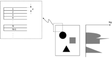
における画像データの長さd(=2mm)を1ブロックと定義する。従って、1ブロックにおける主走査方向のピクセルの数(第1の数)が、1ブロックにおける副走査方向のピクセルの数(第2の数)よりも多い。すなわち、1ブロックの主走査方向の解像度(第1の解像度)が、1ブロックの副走査方向の解像度(第2の解像度)よりも高い。画像処理部303は、画像データを副走査方向に複数のブロックに区分し、各ブロックに含まれる所定値以上の濃度を有するピクセルの総数をカウントする。例えば、画像処理部303は、各ブロックについて、4%以上のグレイ濃度を有するピクセルの総数をカウントする。各ブロックに含まれる印字ピクセル(所定値以上の濃度を有するピクセル)の総数をNp(個)とする。図5は、画像データから得られる情報を図示した概念図である。図5において、中央部分に画像データを示し、左部分に画像データの点線で囲んだ箇所を示し、右部分に副走査方向(図5のR4方向)における印字ピクセルの数(Np)の分布を示している。実施例1では4%以上のグレイ濃度を有するピクセルを全て印字ピクセルとしてカウントしている。
In the first embodiment, the image data is divided (divided) into the sub-scanning direction (the conveyance direction of the recording material P), and the entire area of the image data in the main scanning direction (the direction perpendicular to the conveyance direction of the recording material P) x the sub-scanning direction. The length d (=2 mm) of the image data in is defined as one block. Therefore, the number of pixels in the main scanning direction in one block (the first number) is greater than the number of pixels in the sub-scanning direction in one block (the second number). That is, the resolution of one block in the main scanning direction (first resolution) is higher than the resolution of one block in the sub-scanning direction (second resolution). The
例えば、電子写真方式のレーザプリンタでは、記録材Pの搬送方向に対して垂直方向(主走査方向)に画像データを読み込み、パルス幅等のデータに変換してレーザスキャナ3に順次データ送信する。そのため、目標温度を決定するための画像処理を行う際にも、主走査方向に読みこんだ画像データを利用してスキャナにデータを送る処理と共通化する。これにより、例えば32ピクセルの正方形の領域に画像データの全体を区切って画像解析するよりもメモリの使用領域を小さくし、処理時間を短縮することができる。
For example, in an electrophotographic laser printer, image data is read in a direction perpendicular to the conveyance direction of the recording material P (main scanning direction), converted into data such as pulse width, and sequentially transmitted to the
画像処理部303は、各ブロックの印字ピクセルの総数(ピクセル情報)に対して、移動平均値を算出する。各ブロックの印字ピクセルの総数は、ブロック毎にカウントされた所定値以上の濃度を有するピクセルの合計数である。移動平均法は、X個のブロックにおける1ブロック当たりの印字ピクセルの総数の平均値を副走査方向に移動しながら求める処理である。換言すれば、移動平均法は、副走査方向に連続している所定数のブロックの幅を移動平均幅として設定し、移動平均幅を副走査方向にブロック単位で移動して1ブロック当たりの印字ピクセルの総数の平均値(移動平均値)を算出する処理である。従って、移動平均幅に含まれる複数のブロックにおける印字ピクセルの総数を移動平均幅に含まれるブロックの数で除算した平均値(移動平均値)が、副走査方向における移動平均幅の位置を変更する毎に算出される。
The
図6Aに各ブロックにおける移動平均値の算出処理フローを示す。図6Bに、3個のブロック(X=3)を用いて印字ピクセルの総数の移動平均値を算出する場合の例を示す。S601において、画像処理部303は、初期値Nを算出する(初期値N=(X+1)/2)。例えば、X=3の場合、初期値Nは2である。S602において、画像処理部303は、第Nブロックを中心として、第[N-(X-1)/2]ブロックから第[N+(X-1)/2]ブロックまでの各ブロックの印字ピクセルの総数の平均を算出する。S603において、画像処理部303は、初期値Nを更新する(N=N+1)。S604において、画像処理部303は、第[N+(X-1)/2]ブロックが副走査方向における画像データの後端を含むか否かを判定する。第[N+(X-1)/2]ブロックが副走査方向における画像データの後端を含む場合(S604:YES)、移動平均値の算出処理フローが終了する。一方、第[N+(X-1)/2]ブロックが副走査方向における画像データの後端を含まない場合(S604:NO)、処理がS602に戻る。例えば、X=3の場合、第2ブロックにおける印字ピクセルの総数の移動平均値は、第1ブロックから第3ブロックまでの各ブロックの印字ピクセルの総数を平均した数である。例えば、X=3の場合、第3ブロックにおける印字ピクセルの総数の移動平均値は、第2ブロックから第4ブロックまでの各ブロックの印字ピクセルの総数を平均した数である。
FIG. 6A shows a processing flow for calculating the moving average value in each block. FIG. 6B shows an example of calculating the moving average value of the total number of print pixels using three blocks (X=3). In S601, the
実施例1では、X=3、X=28の2種類の移動平均幅Xを用いて、印字ピクセルの総
数の移動平均値を算出する例について説明している。2種類の移動平均幅X(X=3、X=28)を用いて印字ピクセルの総数の移動平均値を算出したときのそれぞれの移動平均分布を移動平均分布A3、A28と表記する。副走査方向に対する印字ピクセルの総数の移動平均値の例を図7(A)及び(B)に示す。図7(A)に示す横線の画像では、移動平均分布A3はピーキー(急峻)な形状を有し、移動平均分布A28はなだらかな形状を有する。一方、図7(B)に示す縦線の画像では、移動平均分布A3及びA28の形状は略同じであり、移動平均値の最大値は同じである。
In the first embodiment, an example is described in which the moving average value of the total number of print pixels is calculated using two types of moving average widths X, X=3 and X=28. When the moving average value of the total number of print pixels is calculated using two types of moving average widths X (X=3, X=28), the respective moving average distributions are expressed as moving average distributions A3 and A28. Examples of moving average values of the total number of print pixels in the sub-scanning direction are shown in FIGS. 7A and 7B. In the horizontal line image shown in FIG. 7A, the moving average distribution A3 has a peaky (steep) shape, and the moving average distribution A28 has a gentle shape. On the other hand, in the vertical line image shown in FIG. 7(B), the shapes of the moving average distributions A3 and A28 are substantially the same, and the maximum values of the moving average values are the same.
画像処理部303の処理の一例を説明する。画像処理部303は、移動平均幅X(X=3)を副走査方向にブロック単位で移動して複数のブロックにおける印字ピクセルの総数の移動平均値を複数のブロック毎に取得する。また、画像処理部303は、移動平均幅X(X=28)を副走査方向にブロック単位で移動して複数のブロックにおける印字ピクセルの総数の移動平均値を複数のブロック毎に取得する。移動平均幅X(X=3)と移動平均幅X(X=28)とは副走査方向における幅が異なる。副走査方向における移動平均幅X(X=3)は、副走査方向における移動平均幅X(X=28)よりも狭い。換言すれば、副走査方向における移動平均幅X(X=28)は、副走査方向における移動平均幅X(X=3)よりも広い。移動平均幅X(X=3)は、第1の幅の一例である。移動平均幅X(X=28)は、第2の幅の一例である。画像処理部303は、副走査方向に幅が異なる複数の移動平均幅を副走査方向にブロック単位で移動して複数のブロックにおける印字ピクセルの総数の移動平均値を複数のブロック毎に取得する。画像処理部303は、取得部の一例である。
An example of processing by the
画像処理部303は、画像データを副走査方向に複数のブロックを有する複数の領域に区分(分割)する。定着フィルム13の外周の長さを所定距離(Dfmm)とすると、副走査方向において画像データの先端から所定距離(Dfmm)離れた第1の位置までの領域を第1の領域とする。副走査方向において第1の領域の後端(画像データの先端からDfmm離れた位置)から所定距離(Dfmm)離れた第2の位置までの領域を第2の領域とする。副走査方向において第2の領域の後端(画像データの先端から2Dfmm離れた位置)から所定距離(Dfmm)離れた第3の位置までの領域を第3の領域とする。副走査方向において第3の領域の後端(画像データの先端から3Dfmm離れた位置)から所定距離(Dfmm)離れた第4の位置までの領域を第4の領域とする。副走査方向において第4の領域の後端(画像データの先端から4Dfmm離れた位置)から画像データの後端までの領域を第5の領域とする。
The
第1~第5の領域の位置関係について説明する。
(1)第1の領域は、第2、第3、第4及び第5の領域よりも副走査方向の上流側に位置する上流領域である。
(2)第1及び第2の領域の位置関係において、第2の領域は、第1の領域よりも副走査方向の下流側に位置する下流領域である。第2、第3、第4及び第5の領域の位置関係において、第2の領域は、第3、第4及び第5の領域よりも副走査方向の上流側に位置する上流領域である。
(3)第1、第2及び第3の領域の位置関係において、第3の領域は、第1及び第2の領域よりも副走査方向の下流側に位置する下流領域である。第3、第4及び第5の領域の位置関係において、第3の領域は、第4及び第5の領域よりも副走査方向の上流側に位置する上流領域である。
(4)第1、第2、第3及び第4の領域の位置関係において、第4の領域は、第1、第2及び第3の領域よりも副走査方向の下流側に位置する下流領域である。第4及び第5の領域の位置関係において、第4の領域は、第5の領域よりも副走査方向の上流側に位置する上流領域である。
(5)第5の領域は、第1、第2、第3、第4及び第5の領域よりも副走査方向の下流
側に位置する下流領域である。
The positional relationship between the first to fifth regions will be explained.
(1) The first region is an upstream region located upstream in the sub-scanning direction from the second, third, fourth, and fifth regions.
(2) In the positional relationship between the first and second regions, the second region is a downstream region located downstream of the first region in the sub-scanning direction. In the positional relationship between the second, third, fourth, and fifth regions, the second region is an upstream region located upstream in the sub-scanning direction than the third, fourth, and fifth regions.
(3) In the positional relationship between the first, second, and third regions, the third region is a downstream region located downstream of the first and second regions in the sub-scanning direction. In the positional relationship between the third, fourth, and fifth regions, the third region is an upstream region located upstream in the sub-scanning direction than the fourth and fifth regions.
(4) In the positional relationship between the first, second, third, and fourth regions, the fourth region is a downstream region located downstream of the first, second, and third regions in the sub-scanning direction. It is. In the positional relationship between the fourth and fifth regions, the fourth region is an upstream region located upstream of the fifth region in the sub-scanning direction.
(5) The fifth region is a downstream region located downstream in the sub-scanning direction from the first, second, third, fourth, and fifth regions.
A4サイズの記録材Pの長さが、定着フィルム13の外周の長さの約5倍であるため、画像データの領域の数を5個に設定している。例えば、定着フィルム13の外周の長さが、所定距離(Dfmm)よりも短い場合や、リーガルサイズの記録材Pを用いる場合には、画像データの領域の数を5個よりも多く設定する。画像処理部303は、第1の領域から第5の領域の各領域について、複数のブロックにおける印字ピクセルの総数の移動平均値の最大値(移動平均最大値)を算出する。このように、画像処理部303は、各領域に含まれる複数のブロックにおける印字ピクセルの総数の移動平均最大値を複数の領域毎に決定する。以下、移動平均分布A3の移動平均値の最大値を移動平均最大値(M3)と表記し、移動平均分布A28の移動平均値の最大値を移動平均最大値(M28)と表記する。画像処理部303は、第1の領域から第5の領域の各領域における移動平均最大値(M3、M28)を算出する。
Since the length of the A4 size recording material P is approximately five times the length of the outer periphery of the fixing
画像処理部303の処理の一例を示す。画像処理部303は、副走査方向において、移動平均幅X(X=3)における印字ピクセルの総数の移動最大平均値(M3)と、移動平均幅X(X=28)における印字ピクセルの総数の移動最大平均値(M28)と、を複数の領域毎に取得する。移動平均幅X(X=3)における印字ピクセルの総数の移動最大平均値(M3)は、“第1の幅における所定値以上の濃度を有するピクセルに関する第1の値”の一例である。移動平均幅X(X=28)における印字ピクセルの総数の移動最大平均値(M28)は、“第2の幅における所定値以上の濃度を有するピクセルに関する第2の値”の一例である。画像処理部303は、移動平均幅X(X=3)に含まれる複数のブロックにおける印字ピクセルの総数を移動平均幅X(X=3)に含まれるブロックの数で除算した第1平均値を、副走査方向における移動平均幅X(X=3)の位置を変更する毎に算出する。移動平均幅X(X=3)を用いて算出された移動平均値は、第1平均値の一例である。画像処理部303は、各領域について、複数の第1平均値を算出する。画像処理部303は、第1平均値に基づいて、移動平均幅X(X=3)における印字ピクセルの総数の移動最大平均値を取得する。具体的には、画像処理部303は、各領域の複数の第1平均値のうちの最大値を選択することにより、移動平均幅X(X=3)における印字ピクセルの総数の移動最大平均値(M3)を取得する。画像処理部303は、移動平均幅X(X=28)に含まれる複数のブロックにおける印字ピクセルの総数を移動平均幅X(X=28)に含まれるブロックの数で除算した第2平均値を、副走査方向における移動平均幅X(X=28)の位置を変更する毎に算出する。画像処理部303は、各領域について、複数の第2平均値を算出する。移動平均幅X(X=28)を用いて算出された移動平均値は、第2平均値の一例である。画像処理部303は、第2平均値に基づいて、移動平均幅X(X=28)における印字ピクセルの総数の移動最大平均値を取得する。具体的には、画像処理部303は、各領域の複数の第2平均値のうちの最大値を選択することにより、移動平均幅X(X=28)における印字ピクセルの総数の移動最大平均値(M28)を取得する。以下、画像処理部303が、移動平均最大値(M3、M28)に基づいて目標温度Tを決定する処理について説明する。画像処理部303は、決定部の一例である。画像処理部303は、各領域における移動平均最大値(M3、M28)を、下記の表1に示す閾値テーブルを用いて6つのランク(0~5)に分類する。

画像処理部303は、第1の領域から第5の領域の各領域の目標温度テーブルを参照し、各領域の移動平均最大値(M3、M28)のランクに対応する各値を用いて、第1の領域から第5の領域の各領域の個別目標温度を決定する。このように、画像処理部303は、複数の領域毎に決定された移動平均最大値に基づいて複数の領域の個別目標温度を決定する。目標温度テーブルは、画像処理部303のメモリに格納されていてもよい。図8は、第1の領域から第5の領域の各領域の目標温度テーブルを示す図である。図8に示す目標温度テーブルの各値は、基準温度(204℃)からの減算値を示している。基準温度は、例えば、画像データに最も定着が困難な画像パターンが含まれる場合に、記録材Pにトナー像を定着することが可能な温度である。
The
例えば、第1領域の移動平均最大値(M3)がランク4に分類され、第1領域の移動平均最大値(M28)がランク3に分類される場合について説明する。この場合、画像処理部303は、第1の領域の目標温度テーブルを参照し、第1領域の移動平均最大値(M3、M28)に対応する値(12℃)を、基準温度(204℃)から減算することにより、第1の領域の個別目標温度(192℃)を決定する。移動平均最大値(M28)のランクの値が小さいほど、記録材Pに形成されるトナー像の大きさが小さくなるので、個別目標温度を下げることが可能である。印字ピクセルが全く無いベタ白が画像の場合、移動平均最大値(M3、M28)がランク0に分類されるため、減算値は14℃である。ベタ黒画像等の印字率の高い画像の場合、移動平均最大値(M3、M28)がランク5に分類されるため、減算値は0℃であり、個別目標温度は204℃である。
For example, a case will be described in which the moving average maximum value (M3) of the first region is classified as
表1に示すように、第1の領域の移動平均最大値(M3)及び移動平均最大値(M28)がそれぞれ2000である場合、第1の領域の移動平均最大値(M3)及び移動平均最大値(M28)はそれぞれランク1に分類される。また、表1に示すように、第4の領域の移動平均最大値(M3)及び移動平均最大値(M28)がそれぞれ2000である場合、第4の領域の移動平均最大値(M3)及び移動平均最大値(M28)はそれぞれランク1に分類される。図8に示すように、第1の領域の移動平均最大値(M3、M28)がランク1に分類される場合、第1の領域の個別目標温度は190℃(204℃-14℃)である。図8に示すように、第4の領域の移動平均最大値(M3、M28)がランク1に分類される場合、第4領域の個別目標温度は193℃(204℃-11℃)である。第1の領域の移動平均最大値(M3)に対する第1の領域の個別目標温度の増加率は、9.50%(=190/2000)である。第4の領域の移動平均最大値(M3)に対する第4の領域の個別目標温度の増加率は、9.65%(=193/2000)である。従って、第4の領域の移動平均最大値(M3)に対する第4の領域の個別目標温度の増加率が、第1
の領域の移動平均最大値(M3)に対する第1の領域の個別目標温度の増加率よりも大きい。このように、下流領域の移動平均最大値(M3)に対する下流領域の個別目標温度の増加率が、上流領域の移動平均最大値(M3)に対する上流領域の個別目標温度の増加率よりも大きい。下流領域の移動平均最大値(M3)に対する下流領域の個別目標温度の増加率は、“下流領域の第1の値に対する下流領域の目標温度の増加率”の一例である。上流領域の移動平均最大値(M3)に対する上流領域の個別目標温度の増加率は、“上流領域の第1の値に対する上流領域の目標温度の増加率”の一例である。
As shown in Table 1, when the moving average maximum value (M3) and the moving average maximum value (M28) of the first region are each 2000, the moving average maximum value (M3) and the moving average maximum value of the first region Each value (M28) is classified into
is larger than the rate of increase of the individual target temperature of the first region with respect to the moving average maximum value (M3) of the region. In this way, the rate of increase in the individual target temperature of the downstream region with respect to the maximum moving average value (M3) of the downstream region is greater than the rate of increase of the individual target temperature of the upstream region with respect to the maximum moving average value (M3) of the upstream region. The rate of increase in the individual target temperature of the downstream region with respect to the moving average maximum value (M3) of the downstream region is an example of "the rate of increase of the target temperature of the downstream region with respect to the first value of the downstream region." The rate of increase in the individual target temperature of the upstream region with respect to the moving average maximum value (M3) of the upstream region is an example of "the rate of increase of the target temperature of the upstream region with respect to the first value of the upstream region."
第1の領域の移動平均最大値(M28)に対する第1の領域の個別目標温度の増加率は、9.50%(=190/2000)である。第4の領域の移動平均最大値(M28)に対する第4の領域の個別目標温度の増加率は、9.65%(=193/2000)である。従って、第4の領域の移動平均最大値(M28)に対する第4の領域の個別目標温度の増加率が、第1の領域の移動平均最大値(M28)に対する第1の領域の個別目標温度の増加率よりも大きい。このように、下流領域の移動平均最大値(M28)に対する下流領域の個別目標温度の増加率が、上流領域の移動平均最大値(M28)に対する上流領域の個別目標温度の増加率よりも大きい。下流領域の移動平均最大値(M28)に対する下流領域の個別目標温度の増加率は、“下流領域の第2の値に対する下流領域の目標温度の増加率”の一例である。上流領域の移動平均最大値(M28)に対する上流領域の個別目標温度の増加率は、“上流領域の第2の値に対する上流領域の目標温度の増加率”の一例である。 The rate of increase of the individual target temperature of the first region with respect to the moving average maximum value (M28) of the first region is 9.50% (=190/2000). The increase rate of the individual target temperature in the fourth region with respect to the moving average maximum value (M28) in the fourth region is 9.65% (=193/2000). Therefore, the rate of increase of the individual target temperature of the fourth region with respect to the moving average maximum value (M28) of the fourth region is the same as the rate of increase of the individual target temperature of the first region with respect to the moving average maximum value (M28) of the first region. greater than the rate of increase. In this way, the rate of increase in the individual target temperature of the downstream region with respect to the moving average maximum value (M28) of the downstream region is greater than the rate of increase of the individual target temperature of the upstream region with respect to the moving average maximum value (M28) of the upstream region. The rate of increase in the individual target temperature of the downstream region with respect to the moving average maximum value (M28) of the downstream region is an example of "the rate of increase of the target temperature of the downstream region with respect to the second value of the downstream region." The rate of increase in the individual target temperature of the upstream region with respect to the moving average maximum value (M28) of the upstream region is an example of "the rate of increase of the target temperature of the upstream region with respect to the second value of the upstream region."
表2に、移動平均最大値(M3、M28)の一例と、目標温度Tの算出結果を示す。

表2に示すように、各領域の個別目標温度のうちの最も高い温度(第3領域の198℃)が、目標温度Tである。記録材P上のトナー像に対して過小な熱量しか与えられない場合にはコールドオフセットが発生する可能性がある。コールドオフセットは、トナー像を記録材P上に定着させるための熱量が不足することである。コールドオフセット等の定着不良の発生を抑止するため、各領域の個別目標温度のうちの最も高い温度を目標温度Tとして決定している。画像処理部303は、第1の領域から第5の領域の各領域の個別目標温度のうちの最も高い温度を目標温度Tと決定する。エンジン制御部302は、加熱ヒータ11の温度が第1の領域から第5の領域の各領域の個別目標温度のうちの最も高い温度(目標温度T)を維持するように、加熱ヒータ11に供給する電力を制御する。
As shown in Table 2, the highest temperature (198° C. in the third region) of the individual target temperatures of each region is the target temperature T. If too little heat is applied to the toner image on the recording material P, cold offset may occur. Cold offset is a phenomenon in which the amount of heat required to fix the toner image on the recording material P is insufficient. In order to suppress the occurrence of fixing failures such as cold offset, the highest temperature among the individual target temperatures of each region is determined as the target temperature T. The
目標温度の決定処理フローを図9に示す。S901において、画像処理部303は、各ブロックの印字ピクセルの総数(合計数)を算出する。S902において、画像処理部303は、移動平均幅X(X=3、X=28)を用いて、各ブロックの印字ピクセルの総数の移動平均値を算出する。S903において、画像処理部303は、各領域における移動平均最大値(M3、M28)を算出する。S904において、画像処理部303は、各領域における移動平均最大値(M3、M28)を複数のランク(ランク0~6)に分類する。S905において、画像処理部303は、各領域の目標温度テーブルに基づいて各領域の個別目標温度を決定する。S906において、画像処理部303は、各領域の個別目標温度のうちの最も高い温度を目標温度Tと決定する。
FIG. 9 shows a process flow for determining the target temperature. In S901, the
(移動平均法を使用する理由)
定着フィルム13に薄いフィルムを使用する場合、定着フィルム13の熱容量が小さいため、加熱ヒータ11の温度が目標温度Tに達するまでの時間が短く、FPOT(First Print Out Time)を短縮できるというメリットがある。一方、記録材Pが加熱定着装置6に搬送され、定着フィルム13が1周、2周、3周・・・と記録材P上を回転する毎に定着フィルム13の表面から記録材Pやトナーへと徐々に熱が奪われ、記録材Pの後端部分では定着性が悪くなることが懸念される。
(Reason for using the moving average method)
When a thin film is used as the fixing
従って、画像データの先端から副走査方向に向かって、定着フィルム13の1周目に対応する領域を第1の領域とし、定着フィルム13の2周目に対応する領域を第2の領域とし、定着フィルム13の3周目に対応する領域を第3の領域とする。更に、画像データの先端から副走査方向に向かって、定着フィルム13の4周目に対応する領域を第4の領域とし、定着フィルム13の5周目に対応する領域を第5の領域とする。そして、各領域にどの程度の濃度でどのくらいの大きさの画像が存在するかを検知し、画像データの後半部分に定着性の厳しい画像が存在している場合、定着不良を防ぐために予め高い目標温度Tを設定することが好ましい。一方、画像データの後半部分に定着性の厳しい画像が無い場合、消費電力低減のために目標温度Tを予め下げることが好ましい。
Therefore, from the leading edge of the image data toward the sub-scanning direction, the area corresponding to the first rotation of the fixing
また、記録材P上のトナー像の大きさが大きい場合や、記録材P上のトナー像が記録材Pの搬送方向に対して長い場合、加熱ヒータ11から熱を奪い続けるため、定着性が厳しくなる。そして、隣接する領域を跨って画像が存在する場合、画像の大きさを把握して、目標温度Tを決定する必要がある。各領域にどのくらいの大きさの画像が存在するかを判定する最も単純な方法は、各領域の印字率を算出する方法である。しかし、図10(A)に示す画像を例にとると、印字率を算出する方法では、図10(B)に示すように、隣接する2つの領域を跨って存在する画像について、誤判定する可能性がある。すなわち、隣接する2つの領域を跨って画像が存在する場合、1つの領域に画像が存在する場合と比べて、隣接する2つの領域のそれぞれの印字率が半分になる。これに対して、移動平均法を使用することにより、図10(C)に示すように、隣接する2つの領域を跨って画像が存在する場合についても、画像の位置と大きさを把握することが可能である。
Furthermore, when the size of the toner image on the recording material P is large or when the toner image on the recording material P is long with respect to the conveyance direction of the recording material P, heat is continuously taken away from the
(移動平均幅について)
移動平均幅については、定着フィルム13の1周の長さに近いことが好ましい。すなわち、移動平均幅は、各領域の副走査方向の長さに相当する長さであることが好ましい。そのようにすれば、第1~第5の領域の各領域の印字率と、各領域を跨がって存在する画像の大きさとを同時に把握することができる。第1の移動平均幅(X=28)が、各領域の副走査方向の長さに相当する。また、副走査方向に対してフィルム1周以上の長さを持つ縦帯のような画像は、定着フィルム13の特定の部分について、トナーによって熱が連続して奪われるため、画像全体の印字率が低くともトナーの定着性が厳しくなる。副走査方向に対してフィルム1周以上の長さを有する画像が存在する場合、目標温度Tをより高くする必要がある。移動平均最大値M28のランクが大きい場合、副走査方向に対してフィ
ルム1周以上の長さを持つ縦帯のような画像が存在する可能性が高い。副走査方向における第1の移動平均幅(X=28)の長さは、定着フィルム13の外周の1周分の長さ(距離)に対応する。
(About moving average width)
The moving average width is preferably close to the length of one circumference of the fixing
実施例1では、画像処理部303は、第1の移動平均幅(X=28)と共に、第2の移動平均幅(X=3)を用いて、各ブロックの印字ピクセルの総数についての移動平均値を算出する。基本的な目標温度は、上述の観点から第1の移動平均幅(X=28)を用いて決定することが好ましいが、それに加えて、第2の移動平均幅(X=3)を用いることで、目標温度Tを下げることができるケースもある。移動平均最大値M28のランクが大きい場合でも、図7(A)の横方向(主走査方向)に長い画像は加熱ヒータ11や定着フィルム13等の特定の部分の熱を奪い続けることが無いため、目標温度Tを下げることが可能である。また、横書きのテキストについても、横線と同様に、縦方向(副走査方向)の繋がりが少ないので、定着が容易であり、且つ、移動平均最大値(M3)のランクが大きくなる傾向にある。図8の目標温度テーブルでは、移動平均最大値(M28)のランクが同じ値(例えば、ランク2)で比較すると、移動平均最大値(M3)のランクが大きくなるにつれて減算値が大きくなり、目標温度Tが下がる。
In the first embodiment, the
定着ニップ部の幅と略同じ幅、又は、定着ニップ部の幅以下の幅の横線画像やテキスト画像については、それらの画像を定着ニップ部で包み込むことが可能となるため、定着が容易であり、目標温度Tをかなり下げることができる。副走査方向における第2の移動平均幅(X=3)の長さは、副走査方向における定着ニップ部の幅の長さ(約6mm)に対応する。 Horizontal line images or text images with a width that is approximately the same as the width of the fixing nip or less than the width of the fixing nip can be easily fixed because they can be wrapped in the fixing nip. , the target temperature T can be lowered considerably. The length of the second moving average width (X=3) in the sub-scanning direction corresponds to the length of the width of the fixing nip portion in the sub-scanning direction (approximately 6 mm).
(定着性評価方法)
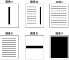
実施例1の効果を確認するために、気温25℃、湿度50%の環境で、図11に示す画像A~Fを各10枚連続で印字して、定着性と電力の評価を行った。図11の画像A~Eは全て印字率8%の画像であり、図11の画像Fは印字率100%のベタ黒画像である。A4サイズの紙(CANON社製、Red Label 80g/cm2)を用いて、目視により定着性の評価を行った。定着性評価の目安は以下のとおりである。
○・・・定着不良に起因する画像不良が全く見られず、問題ない。
△・・・定着不良に起因する白抜けがわずかに見られるが、実用上問題ない。
×・・・定着不良に起因する白抜けが多くみられる。また、定着フィルム13にトナーが一部付着し、画像後端の余白部分にトナー汚れが見られ、実用上NGである。
電力の測定は加熱ヒータ11に対して直列に電力計(横河計測株式会社製、ディジタルパワーメータWT310)を繋ぎ、10枚連続で印字した後の測定値を読み取ることで行った。定着性の評価及び電力値を公平に比較するため、前の検討が終わってから十分時間をとって、加熱定着装置6の温度が室温近くまで下がったことを確認してから次の検討を行った。また、以下に示す比較例1、2についても同様に比較検討を行った。
(Fixability evaluation method)
In order to confirm the effects of Example 1, 10 images A to F shown in FIG. 11 were each continuously printed in an environment with a temperature of 25° C. and a humidity of 50%, and the fixability and power were evaluated. Images A to E in FIG. 11 are all images with a printing rate of 8%, and image F in FIG. 11 is a solid black image with a printing rate of 100%. Fixability was visually evaluated using A4 size paper (manufactured by CANON, Red Label 80 g/cm 2 ). The standard for evaluation of fixability is as follows.
Good: No image defects due to poor fixing were observed, and there was no problem.
Δ: Slight white spots due to poor fixing are observed, but there is no practical problem.
×: Many white spots are observed due to poor fixing. In addition, some of the toner adhered to the fixing
The power was measured by connecting a power meter (Digital Power Meter WT310, manufactured by Yokogawa Keizoku Co., Ltd.) in series with the
(比較例1)
比較例1では、特許文献1のように、画像全体の印字率から目標温度Tを決定する方法を採用している。装置構成については実施例1と全く同様である。比較例1の印字率と目標温度T(℃)の関係を表3に示す。

Comparative Example 1 employs a method of determining the target temperature T from the printing rate of the entire image, as in
(比較例2)
比較例2では、1つの移動平均幅X(X=28)のみを用いて、第1の領域から第5の領域の各領域の個別目標温度を決定している。図12は、比較例2における目標温度テーブルを示す図である。図12には、第1の領域から第5の領域の各領域の目標温度テーブルが示されている。比較例2について、各領域の移動平均最大値M28のランクの閾値は、実施例1の表1の閾値と同様である。比較例2では、第1の領域から第5の領域の各領域の目標温度テーブルが参照され、各領域の移動平均最大値M28のランクに対応する各値を用いて、第1の領域から第5の領域の各領域の個別目標温度が決定される。また、比較例2では、各領域の個別目標温度のうちの最も高い温度を目標温度Tとして決定している。
(Comparative example 2)
In Comparative Example 2, only one moving average width X (X=28) is used to determine the individual target temperatures for each region from the first region to the fifth region. FIG. 12 is a diagram showing a target temperature table in Comparative Example 2. FIG. 12 shows a target temperature table for each region from the first region to the fifth region. Regarding Comparative Example 2, the rank threshold of the moving average maximum value M28 of each region is the same as the threshold in Table 1 of Example 1. In Comparative Example 2, the target temperature table of each region from the first region to the fifth region is referred to, and each value corresponding to the rank of the moving average maximum value M28 of each region is used to change the temperature from the first region to the fifth region. Individual target temperatures for each of the five regions are determined. Further, in Comparative Example 2, the highest temperature among the individual target temperatures of each region is determined as the target temperature T.
(評価結果)
表4~6に、実施例1、比較例1及び2の評価結果を示す。


Tables 4 to 6 show the evaluation results of Example 1 and Comparative Examples 1 and 2.
表4に示すように、実施例1では、画像A~Fの全ての画像で定着性の評価が良好であり、且つ、それぞれの画像で適切な目標温度Tが選択されているため、画像によっては消費電力を下げることが可能である。一方、画像A~Eの印字率が同じであるため、表5に示すように、比較例1では、画像A~Eの目標温度Tが同じ温度である。そのため、比較例1では、定着性の厳しい画像AやBについて、定着不良が発生し、比較的に定着が容易な画像CやDについて、実施例1よりも消費電力が大きい。表6に示すように、比較例2では、画像A~Fの全ての画像で定着性の評価が良好であるが、画像C~Eについて、実施例1よりも目標温度Tが高くなり、消費電力も大きい。上記の評価結果から、実施例1では、画像A~Fの全ての画像において、定着性が良好であり、横線画像やテキスト画像等の定着が容易な画像では、比較例2よりも消費電力が低く抑えられていることがわかる。比較例1では、表3の目標温度テーブルの目標温度Tを全体的に数度高く設定することにより、画像A~Fの全ての画像についての定着性が良好になるが、消費電力が増加する。 As shown in Table 4, in Example 1, all of the images A to F had a good evaluation of the fixability, and an appropriate target temperature T was selected for each image, so that depending on the image, can reduce power consumption. On the other hand, since the printing rates of images A to E are the same, as shown in Table 5, in Comparative Example 1, the target temperatures T of images A to E are the same temperature. Therefore, in Comparative Example 1, poor fixing occurs for images A and B, which are difficult to fix, and power consumption is higher than in Example 1 for images C and D, which are relatively easy to fix. As shown in Table 6, in Comparative Example 2, all images A to F have a good fixation evaluation, but for images C to E, the target temperature T is higher than in Example 1, and the consumption It also has a lot of power. From the above evaluation results, Example 1 has good fixing performance for all images A to F, and consumes less power than Comparative Example 2 for images that are easy to fix, such as horizontal line images and text images. You can see that it is kept low. In Comparative Example 1, by setting the target temperature T in the target temperature table in Table 3 several degrees higher overall, the fixing properties of all images A to F are improved, but power consumption increases. .
上記では、画像処理部303が、画像データを副走査方向に複数のブロックを有する複数の領域に分割する処理について説明している。この処理に限定されず、画像処理部303は、画像データを複数の領域に分割せずに、画像データに含まれる複数のブロックの移動平均最大値に基づいて目標温度Tを決定してもよい。
The above describes a process in which the
(実施例2)
実施例1では、各領域の個別目標温度のうちの最も高い温度を目標温度Tとして決定しているのに対し、実施例2では、各領域に対して目標温度T1~T5を決定する。以下では、実施例1と実施例2との相違点について説明し、実施例2における実施例1と同一の構成要素については、実施例1と同一の符号を付し、その説明を省略する。
(Example 2)
In the first embodiment, the highest temperature among the individual target temperatures of each region is determined as the target temperature T, whereas in the second embodiment, target temperatures T1 to T5 are determined for each region. Below, differences between Example 1 and Example 2 will be explained, and the same components in Example 2 as in Example 1 are given the same reference numerals as in Example 1, and the explanation thereof will be omitted.
画像処理部303は、第1の領域から第5の領域の各領域の個別目標温度を決定し、各領域の個別目標温度を目標温度T1~T5として決定する。第1の領域から第5の領域の各領域の個別目標温度の決定処理は、実施例1と同様である。従って、画像処理部303は、複数の領域毎に決定された移動平均最大値に基づいて複数の領域の目標温度T1~T5を決定する。
The
表2を参照して、実施例2の処理の一例を説明する。画像処理部303は、第1の領域に対応する記録材Pの第1の部分が定着ニップ部を通過しているときの目標温度T1を192℃と決定する。画像処理部303は、第2の領域に対応する記録材Pの第2の部分が定着ニップ部を通過しているときの目標温度T2を193℃と決定する。画像処理部303は、第3の領域に対応する記録材Pの第3の部分が定着ニップ部を通過しているときの目標温度T3を198℃と決定する。画像処理部303は、第4の領域に対応する記録材Pの第4の部分が定着ニップ部を通過しているときの目標温度T4を195℃と決定する。画像処理部303は、第5の領域に対応する記録材Pの第5の部分が定着ニップ部を通過しているときの目標温度T5を190℃と決定する。このように、画像処理部303は、複数の領域のそれぞれに対応する記録材Pの複数の部分が定着ニップ部に突入するタイミングに応じて、複数の領域の目標温度T(T1~T5)を切り替える。
An example of the processing of the second embodiment will be described with reference to Table 2. The
エンジン制御部302は、加熱ヒータ11の温度が切り替え後の目標温度T(T1~T5)を維持するように、加熱ヒータ11に供給する電力を制御する。目標温度Tを切り替えてから定着ニップ部の温度が変化するまでにディレイがあるので、画像処理部303は、記録材Pの対象部分が定着ニップ部に突入する20msec前に目標温度Tの切り替えを行う。例えば、画像処理部303は、第2の領域に対応する記録材Pの第2の部分が定着ニップ部に突入する20msec前に、目標温度T1から目標温度T2に切り替える。目標温度T1から目標温度T2への切り替えが行われた場合、エンジン制御部302は、加熱ヒータ11の温度が目標温度T2を維持するように、加熱ヒータ11に供給する電力を制御する。また、エンジン制御部302は、複数の領域のそれぞれに対応する記録材Pの複数の部分が定着ニップ部に突入するタイミングに応じて、複数の領域の目標温度T(T1~T5)を切り替えてもよい。エンジン制御部302は、加熱ヒータ11の温度が切り替えられた目標温度T(T1~T5)を維持するように、加熱ヒータ11に供給する電力を制御してもよい。
The
実施例1では、厚さ80μmの定着フィルム13を用いるのに対して、実施例2では、厚さ50μmの定着フィルム13を用いてもよい。これにより、目標温度T1~T5の切り替え処理に対する定着ニップ部の温度の追従性を向上することができる。
In Example 1, the fixing
表7に、画像A~Fに対する定着性と電力を評価した結果を示す。画像A~F及び評価方法については、実施例1と同様である。

実施例2では、各領域の目標温度T(T1~T5)を決定するので、領域毎に目標温度T(T1~T5)を下げることができるため、実施例1よりも更に消費電力を低減することができる。目標温度Tを領域毎に切り替えて、定着ニップ部の温度を目標温度Tに追従させるためには、上述のように定着フィルム13の膜厚を薄くすることが好ましい。一方、定着フィルム13の膜厚を薄くするとフィルム耐久性が低下するため、装置の寿命が短くるなる。装置の寿命等も鑑みて、実施例1のように一つの目標温度Tを採用するか、実施例2のように領域個別の目標温度T(T1~T5)を採用するかを判断すればよい。また、実施例1と同様に、下流領域の移動平均最大値(M3、28)に対する下流領域の目標温度Tの増加率が、上流領域の移動平均最大値(M3、28)に対する上流領域の目標温度Tの増加率よりも大きい。
In the second embodiment, since the target temperature T (T1 to T5) of each region is determined, the target temperature T (T1 to T5) can be lowered for each region, so that power consumption is further reduced than in the first embodiment. be able to. In order to change the target temperature T for each region and make the temperature of the fixing nip follow the target temperature T, it is preferable to reduce the thickness of the fixing
(変形例)
実施例1、2では、移動平均最大値(M3、M28)を同じ閾値テーブルを用いてランク分けしている。これに限らず、移動平均最大値(M3)を複数のランクに分類する第1の閾値テーブルと、移動平均最大値(M28)を複数のランクに分類する第2の閾値テーブルとを用いてもよい。
(Modified example)
In Examples 1 and 2, the moving average maximum values (M3, M28) are ranked using the same threshold table. The present invention is not limited to this, and a first threshold table that classifies the moving average maximum value (M3) into multiple ranks and a second threshold table that classifies the moving average maximum value (M28) into multiple ranks may also be used. good.
実施例1、2では、定着フィルム13の外周長相当と定着ニップ部の長さ相当の2種類の移動平均幅X(X=3、X=28)を用いて移動平均値を算出して、目標温度Tを決定している。この例に限らず、移動平均幅Xの種類が3種類以上であってもよい。画像処理部303は、副走査方向における長さがそれぞれ異なる3種類以上の移動平均幅Xから2種類の移動平均幅Xを選択してもよい。画像処理部303は、3種類以上の移動平均幅Xを用いて移動平均値を算出して、目標温度Tを決定してもよい。例えば、記録材Pの先端が定着ニップ部に突入してから加圧ローラ20が1周、2周と回転するにつれて、加圧ローラ20の熱が記録材Pに奪われていき、加圧ローラ20の表面温度は低下していく。加圧ローラ20の外周長は62.8mm(20mm×3.14)であり、第3の移動平均幅(X=31)を用いて、各ブロックの印字ピクセルの総数についての移動平均値を算出してもよい。副走査方向における第3の移動平均幅(X=31)の長さは、加圧ローラ20の外周の1周分の長さ(距離)に対応する。
In Examples 1 and 2, the moving average value is calculated using two types of moving average widths X (X=3, X=28) corresponding to the outer circumference length of the fixing
加圧ローラ20の芯金21の温度が低い場合、加圧ローラ20が回転していくに従って加圧ローラ20の表面温度が大きく低下し、定着性に対する影響が大きい。この場合、画
像処理部303は、加圧ローラ20の外周長相当の移動平均幅(X=31)と、定着ニップ部の長さ相当の移動平均幅(X=3)を用いて、各ブロックの印字ピクセルの総数についての移動平均値を算出する。画像処理部303は、各領域における移動平均値最大値(M3、M31)を算出する。画像処理部303は、各領域における移動平均最大値(M3、M31)を複数のランク(ランク0~6)に分類する。画像処理部303は、各領域の目標温度テーブルに基づいて、各領域の個別目標温度を決定する。画像処理部303は、各領域の個別目標温度のうちの最も高い温度を目標温度Tと決定する。また、実施例2のように、画像処理部303は、第1の領域から第5の領域の各領域の個別目標温度を、各領域の目標温度T(T1~T5)として決定してもよい。
When the temperature of the
一方、加圧ローラ20の芯金21がある程度温かい状態では、加圧ローラ20の表面の温度低下が小さく、定着性に対する影響が小さい。この場合、画像処理部303は、定着フィルム13の外周長相当の移動平均幅X(X=28)と、定着ニップ部の長さ相当の移動平均幅X(X=3)を用いて、各ブロックの印字ピクセルの総数についての移動平均値を算出する。
On the other hand, when the
画像形成装置100は、加圧ローラ20の表面の温度を検知する検知部を備えてもよい。検知部によって検知された加圧ローラ20の表面の温度は、画像処理部303に送られる。画像処理部303は、加圧ローラ20の表面の温度に応じて複数種類の移動平均幅を選択する。複数種類の移動平均幅は、画像処理部303のメモリに格納されていてもよい。加圧ローラ20の表面の温度が所定温度未満である場合、画像処理部303は、第1の移動平均幅(X=3)及び第2の移動平均幅(X=28)を選択して、各ブロックの印字ピクセルの総数についての移動平均値を算出してもよい。一方、加圧ローラ20の表面の温度が所定温度以上である場合、画像処理部303は、第1の移動平均幅(X=3)及び第3の移動平均幅(X=31)を選択して、各ブロックの印字ピクセルの総数についての移動平均値を算出してもよい。このように、画像処理部303は、加圧ローラ20の表面の温度に応じて、第2の移動平均幅(X=28)と第3の移動平均幅(X=31)とを切り替えて、各ブロックの印字ピクセルの総数についての移動平均値を算出してもよい。
The
画像処理部303は、3種類の移動平均値及び3種類の移動平均最大値(M3、M28、M31)を算出し、加熱定着装置6の状態に応じて3種類の移動平均最大値(M3、M28、M31)のうちの何れかを選択してもよい。また、移動平均最大値(M3)を複数のランクに分類する第1の閾値テーブルと、移動平均最大値(M28)を複数のランクに分類する第2の閾値テーブルと、移動平均最大値(M31)を複数のランクに分類する第3の閾値テーブルとを用いてもよい。
The
また、実施例1、2では、所定値以上の濃度を有するピクセルの総数をカウントしているが、複数の閾値を用いて、濃度別にピクセルの総数をカウントして移動平均値を算出し、濃度別の目標温度テーブルに基づいて、目標温度Tを決定してもよい。閾値テーブルの各閾値、移動平均幅及び1ブロックを定義する際の副走査方向における画像データの長さd等は、各実施例で示した値以外の値であってもよい。例えば、トナーの種類、加熱定着装置6における部材の特徴、計算処理のし易さ、或いは温度設定の分解能等に応じて、閾値テーブルの各閾値、移動平均幅及び1ブロックを定義する際の副走査方向における画像データの長さd等を適宜変更してもよい。
In addition, in Examples 1 and 2, the total number of pixels having a density equal to or higher than a predetermined value is counted, but the total number of pixels is counted for each density using a plurality of threshold values, and a moving average value is calculated. The target temperature T may be determined based on another target temperature table. Each threshold in the threshold table, the moving average width, the length d of image data in the sub-scanning direction when defining one block, etc. may be values other than those shown in each embodiment. For example, depending on the type of toner, the characteristics of the members in the
各実施例では、副走査方向に画像データを分割して解析を行うことにより、画像処理の効率を上げ、メモリの使用領域を小さくし、処理時間を短縮することができる。一方、図13に示すような斜めの線が描かれた画像Gの場合、斜め線は定着容易な画像であるが、各実施例の手法では定着性の厳しい画像と判別されるため、目標温度Tの下げ幅が小さい。ただし、プリンタで出力されるライン画像の多くは縦線か横線であり、斜め線のライン
画像の比率は小さいため、斜め線が定着性の厳しい画像と判別されたときの影響は小さい。
In each embodiment, by dividing image data in the sub-scanning direction and performing analysis, it is possible to increase the efficiency of image processing, reduce the memory usage area, and shorten processing time. On the other hand, in the case of image G in which diagonal lines are drawn as shown in FIG. The amount of decrease in T is small. However, most of the line images output by a printer are vertical lines or horizontal lines, and the ratio of diagonal lines to line images is small, so that the influence when diagonal lines are determined to be images with poor fixability is small.
以上、実施例1、2ではモノクロタイプのレーザビームプリンタで説明を行ってきたが、カラーレーザビームプリンタでも同様の処理が可能である。イエロー、マゼンタ、シアン、ブラックの4色のカラーレーザビームプリンタを例とすると、各色の最大濃度を100%とし、各色の合計濃度が100%以上のピクセルの総数をカウントしてもよい。 Although the first and second embodiments have been described above using a monochrome laser beam printer, similar processing is possible with a color laser beam printer. Taking a color laser beam printer of four colors, yellow, magenta, cyan, and black as an example, the maximum density of each color may be set to 100%, and the total number of pixels where the total density of each color is 100% or more may be counted.
(その他の実施例)
本発明は、各実施例の1以上の機能を実現するプログラムを、ネットワーク又は記憶媒体を介してシステム又は装置に供給し、そのシステム又は装置のコンピュータにおける1つ以上のプロセッサがプログラムを読出し実行する処理でも実現可能である。また、1以上の機能を実現する回路(例えば、ASIC)によっても実現可能である。
(Other examples)
The present invention provides a program that implements one or more functions of each embodiment to a system or device via a network or a storage medium, and one or more processors in a computer of the system or device reads and executes the program. This can also be achieved through processing. It can also be realized by a circuit (for example, ASIC) that realizes one or more functions.
また、コンピュータが当該プログラムを実行する方法(画像形成方法)により、各実施例における各処理を実現してもよい。上記プログラムは、例えば、ネットワークを通じて、又は、非一時的にデータを保持するコンピュータ読取可能な記録媒体等から上記コンピュータに提供されてもよい。上記プログラムをコンピュータ読取可能な記録媒体等に記録してもよい。 Further, each process in each embodiment may be realized by a method (image forming method) in which a computer executes the program. The program may be provided to the computer via a network or from a computer-readable recording medium that non-temporarily stores data, for example. The above program may be recorded on a computer-readable recording medium.
6…加熱定着装置、11…加熱ヒータ、13…定着フィルム、20…加圧ローラ、50…画像形成部、100…画像形成装置、302…エンジン制御部、303…画像処理部、P…記録材 6... Heat fixing device, 11... Heater, 13... Fixing film, 20... Pressure roller, 50... Image forming section, 100... Image forming device, 302... Engine control section, 303... Image processing section, P... Recording material
Claims (17)
内部に加熱部材が設けられた定着部材と加圧部材との間に形成されたニップ部で前記記録材を挟持し、前記トナー像を前記記録材に定着する定着部と、
を備える画像形成装置であって、
前記画像データを副走査方向に複数のブロックに区分し、
前記複数のブロックのうち前記副走査方向に連続している第1の数のブロックの幅を第1の移動平均幅として設定し、前記第1の移動平均幅を前記副走査方向にブロック単位で移動しながら、前記第1の移動平均幅に含まれる複数のブロックにおける1ブロック当たりの所定値以上の濃度を有するピクセルの総数の平均値を第1の移動平均値として算出し、
前記複数のブロックのうち、前記副走査方向に連続している第2の数のブロックであって前記第1の数よりも大きい第2の数のブロックの幅を第2の移動平均幅として設定し、前記第2の移動平均幅を前記副走査方向にブロック単位で移動しながら、前記第2の移動平均幅に含まれる複数のブロックにおける1ブロック当たりの前記所定値以上の濃度を有するピクセルの総数の平均値を第2の移動平均値として算出し、前記第1の移動平均値と前記第2の移動平均値を取得する取得部と、
前記第1の移動平均値と前記第2の移動平均値とに基づいて、前記記録材に前記トナー像を定着させるときの前記加熱部材の目標温度を決定する決定部と、
前記加熱部材の温度が前記目標温度を維持するように、前記加熱部材に供給する電力を制御する制御部と
を備えることを特徴とする画像形成装置。 an image forming unit that forms a toner image on a recording material according to the image data;
a fixing unit that fixes the toner image on the recording material by sandwiching the recording material in a nip formed between a fixing member having a heating member provided therein and a pressure member;
An image forming apparatus comprising:
dividing the image data into a plurality of blocks in the sub-scanning direction;
The width of a first number of blocks that are continuous in the sub-scanning direction among the plurality of blocks is set as a first moving average width, and the first moving average width is set in units of blocks in the sub-scanning direction. While moving, calculate the average value of the total number of pixels having a density equal to or higher than a predetermined value per block in a plurality of blocks included in the first moving average width as a first moving average value ;
Among the plurality of blocks, the width of a second number of blocks that are continuous in the sub-scanning direction and is larger than the first number is set as a second moving average width. setting, and while moving the second moving average width block by block in the sub-scanning direction, pixels having a density equal to or higher than the predetermined value per block in a plurality of blocks included in the second moving average width. an acquisition unit that calculates the average value of the total number as a second moving average value and acquires the first moving average value and the second moving average value ;
a determining unit that determines a target temperature of the heating member when fixing the toner image on the recording material based on the first moving average value and the second moving average value;
An image forming apparatus comprising: a control section that controls power supplied to the heating member so that the temperature of the heating member maintains the target temperature.
コンピュータが、
前記画像データを副走査方向に複数のブロックに区分するステップ、
前記複数のブロックのうち前記副走査方向に連続している第1の数のブロックの幅を第1の移動平均幅として設定し、前記第1の移動平均幅を前記副走査方向にブロック単位で移動しながら、前記第1の移動平均幅に含まれる複数のブロックにおける1ブロック当たりの所定値以上の濃度を有するピクセルの総数の平均値を第1の移動平均値として算出し、前記第1の移動平均値を取得するステップ、
前記複数のブロックのうち、前記副走査方向に連続している第2の数のブロックであって前記第1の数よりも大きい第2の数のブロックの幅を第2の移動平均幅として設定し、前記第2の移動平均幅を前記副走査方向にブロック単位で移動しながら、前記第2の移動平均幅に含まれる複数のブロックにおける1ブロック当たりの前記所定値以上の濃度を有するピクセルの総数の平均値を第2の移動平均値として算出し、前記第2の移動平均値を取得するステップ
を有する取得ステップと、
前記第1の移動平均値と前記第2の移動平均値とに基づいて、前記記録材に前記トナー像を定着させるときの前記加熱部材の目標温度を決定する決定ステップと、
前記加熱部材の温度が前記目標温度を維持するように、前記加熱部材に供給する電力を制御する制御ステップと
を実行することを特徴とする画像形成方法。 The recording material is held between an image forming section that forms a toner image on the recording material according to the image data, a fixing member that is provided with a heating member therein, and a pressure member. An image forming method for an image forming apparatus, comprising: a fixing section that fixes a toner image on the recording material,
The computer is
dividing the image data into a plurality of blocks in the sub-scanning direction;
The width of a first number of blocks that are continuous in the sub-scanning direction among the plurality of blocks is set as a first moving average width, and the first moving average width is set in units of blocks in the sub-scanning direction. While moving, calculate the average value of the total number of pixels having a density equal to or higher than a predetermined value per block in a plurality of blocks included in the first moving average width as a first moving average value , and a step of obtaining the moving average value of
Among the plurality of blocks, the width of a second number of blocks that are continuous in the sub-scanning direction and is larger than the first number is set as a second moving average width. setting, and while moving the second moving average width block by block in the sub-scanning direction, pixels having a density equal to or higher than the predetermined value per block in a plurality of blocks included in the second moving average width. an obtaining step comprising: calculating the average value of the total number as a second moving average value , and obtaining the second moving average value;
a determining step of determining a target temperature of the heating member when fixing the toner image on the recording material based on the first moving average value and the second moving average value;
An image forming method, comprising: controlling power supplied to the heating member so that the temperature of the heating member maintains the target temperature.
。 11. The image forming method according to claim 9, wherein the length of the first moving average width in the sub-scanning direction corresponds to the width of the nip portion in the sub-scanning direction.
Priority Applications (2)
| Application Number | Priority Date | Filing Date | Title |
|---|---|---|---|
| JP2019157043A JP7366648B2 (en) | 2019-08-29 | 2019-08-29 | Image forming device, image forming method and program |
| US17/003,079 US11237504B2 (en) | 2019-08-29 | 2020-08-26 | Image forming apparatus, image forming method, and computer-readable recording medium with program recorded therein |
Applications Claiming Priority (1)
| Application Number | Priority Date | Filing Date | Title |
|---|---|---|---|
| JP2019157043A JP7366648B2 (en) | 2019-08-29 | 2019-08-29 | Image forming device, image forming method and program |
Publications (3)
| Publication Number | Publication Date |
|---|---|
| JP2021033225A JP2021033225A (en) | 2021-03-01 |
| JP2021033225A5 JP2021033225A5 (en) | 2022-09-02 |
| JP7366648B2 true JP7366648B2 (en) | 2023-10-23 |
Family
ID=74677390
Family Applications (1)
| Application Number | Title | Priority Date | Filing Date |
|---|---|---|---|
| JP2019157043A Active JP7366648B2 (en) | 2019-08-29 | 2019-08-29 | Image forming device, image forming method and program |
Country Status (2)
| Country | Link |
|---|---|
| US (1) | US11237504B2 (en) |
| JP (1) | JP7366648B2 (en) |
Families Citing this family (2)
| Publication number | Priority date | Publication date | Assignee | Title |
|---|---|---|---|---|
| JP2022057608A (en) * | 2020-09-30 | 2022-04-11 | キヤノン株式会社 | Image forming apparatus |
| JP2022130158A (en) * | 2021-02-25 | 2022-09-06 | キヤノン株式会社 | Image forming apparatus and method for controlling the same |
Citations (8)
| Publication number | Priority date | Publication date | Assignee | Title |
|---|---|---|---|---|
| JP2005346074A (en) | 2004-05-31 | 2005-12-15 | Samsung Electronics Co Ltd | Method for controlling fusing temperature and fan speed based on toner coverage computed from data to be printed, and apparatus using the same |
| JP2007271870A (en) | 2006-03-31 | 2007-10-18 | Kyocera Mita Corp | Image forming apparatus |
| JP2010231139A (en) | 2009-03-30 | 2010-10-14 | Oki Data Corp | Image forming device |
| JP2011253127A (en) | 2010-06-03 | 2011-12-15 | Casio Electronics Co Ltd | Fixing temperature control device, printer and program |
| JP2012048043A (en) | 2010-08-27 | 2012-03-08 | Casio Electronics Co Ltd | Heater control device, printer, and program |
| JP2018040874A (en) | 2016-09-06 | 2018-03-15 | キヤノン株式会社 | Image formation device, image formation device control method and program |
| US20190129336A1 (en) | 2017-10-30 | 2019-05-02 | Lexmark International, Inc. | Fuser temperature control in an imaging device |
| JP2019066824A5 (en) | 2018-07-05 | 2021-08-12 |
Family Cites Families (11)
| Publication number | Priority date | Publication date | Assignee | Title |
|---|---|---|---|---|
| JP6248714B2 (en) * | 2013-03-14 | 2017-12-20 | 株式会社リコー | Fixing control apparatus, fixing control method, and image forming apparatus |
| JP2016004231A (en) | 2014-06-19 | 2016-01-12 | キヤノン株式会社 | Image processor, control method thereof and program |
| JP6132209B2 (en) * | 2014-07-01 | 2017-05-24 | コニカミノルタ株式会社 | Image forming apparatus, fixing temperature control method, and fixing temperature control program |
| JP6723845B2 (en) * | 2016-07-01 | 2020-07-15 | キヤノン株式会社 | Image heating device and image forming device |
| JP6833377B2 (en) * | 2016-07-21 | 2021-02-24 | キヤノン株式会社 | Image forming device and fixing device |
| JP7433753B2 (en) | 2017-10-04 | 2024-02-20 | キヤノン株式会社 | image forming device |
| US10520864B2 (en) * | 2017-10-04 | 2019-12-31 | Canon Kabushiki Kaisha | Image forming apparatus that controls a target temperature of a heating member based on whether pixels for forming an image are a predetermined density or more |
| JP2019078872A (en) * | 2017-10-24 | 2019-05-23 | 株式会社東芝 | Image forming apparatus |
| JP7163033B2 (en) | 2018-02-06 | 2022-10-31 | キヤノン株式会社 | image forming device |
| JP7301585B2 (en) * | 2019-04-16 | 2023-07-03 | キヤノン株式会社 | Image heating device and image forming device |
| JP7277233B2 (en) * | 2019-04-16 | 2023-05-18 | キヤノン株式会社 | Image heating device and image forming device |
-
2019
- 2019-08-29 JP JP2019157043A patent/JP7366648B2/en active Active
-
2020
- 2020-08-26 US US17/003,079 patent/US11237504B2/en active Active
Patent Citations (8)
| Publication number | Priority date | Publication date | Assignee | Title |
|---|---|---|---|---|
| JP2005346074A (en) | 2004-05-31 | 2005-12-15 | Samsung Electronics Co Ltd | Method for controlling fusing temperature and fan speed based on toner coverage computed from data to be printed, and apparatus using the same |
| JP2007271870A (en) | 2006-03-31 | 2007-10-18 | Kyocera Mita Corp | Image forming apparatus |
| JP2010231139A (en) | 2009-03-30 | 2010-10-14 | Oki Data Corp | Image forming device |
| JP2011253127A (en) | 2010-06-03 | 2011-12-15 | Casio Electronics Co Ltd | Fixing temperature control device, printer and program |
| JP2012048043A (en) | 2010-08-27 | 2012-03-08 | Casio Electronics Co Ltd | Heater control device, printer, and program |
| JP2018040874A (en) | 2016-09-06 | 2018-03-15 | キヤノン株式会社 | Image formation device, image formation device control method and program |
| US20190129336A1 (en) | 2017-10-30 | 2019-05-02 | Lexmark International, Inc. | Fuser temperature control in an imaging device |
| JP2019066824A5 (en) | 2018-07-05 | 2021-08-12 |
Also Published As
| Publication number | Publication date |
|---|---|
| US11237504B2 (en) | 2022-02-01 |
| US20210063924A1 (en) | 2021-03-04 |
| JP2021033225A (en) | 2021-03-01 |
Similar Documents
| Publication | Publication Date | Title |
|---|---|---|
| JP6321507B2 (en) | Fixing apparatus and image forming apparatus | |
| JP4610629B2 (en) | Fixing device and image forming apparatus having the same | |
| JP7163033B2 (en) | image forming device | |
| US11099508B2 (en) | Image forming apparatus, image forming method, and computer readable recording medium for recording program | |
| JP7366648B2 (en) | Image forming device, image forming method and program | |
| JP6335580B2 (en) | Image forming apparatus | |
| US20190101854A1 (en) | Image forming apparatus | |
| US20200264547A1 (en) | Image forming apparatus | |
| US10656576B2 (en) | Image forming apparatus, image forming system, and image forming method each controlling fixing temperature | |
| JP2012063398A (en) | Image forming apparatus | |
| JP2006195162A (en) | Image forming apparatus | |
| JP2006047739A (en) | Image forming apparatus | |
| JP2009223291A (en) | Fixer and image forming device equipped with it | |
| JP2019197171A (en) | Image forming apparatus, processor, image forming system, image forming method, and program | |
| JP7397405B2 (en) | Image forming device | |
| JP6079419B2 (en) | Image forming apparatus | |
| JP7541877B2 (en) | Image forming apparatus and control method thereof | |
| US11709445B2 (en) | Image forming apparatus and method for controlling same | |
| US20230102072A1 (en) | Image forming apparatus | |
| JP7446922B2 (en) | image forming device | |
| JP2006154540A (en) | Fixing device and image forming device | |
| JP2006072207A (en) | Image forming apparatus | |
| JP2015045744A (en) | Image forming apparatus | |
| JP2003076197A (en) | Image forming apparatus | |
| JP2021113865A (en) | Image forming apparatus |
Legal Events
| Date | Code | Title | Description |
|---|---|---|---|
| A521 | Request for written amendment filed |
Free format text: JAPANESE INTERMEDIATE CODE: A523 Effective date: 20220824 |
|
| A621 | Written request for application examination |
Free format text: JAPANESE INTERMEDIATE CODE: A621 Effective date: 20220824 |
|
| A977 | Report on retrieval |
Free format text: JAPANESE INTERMEDIATE CODE: A971007 Effective date: 20230412 |
|
| A131 | Notification of reasons for refusal |
Free format text: JAPANESE INTERMEDIATE CODE: A131 Effective date: 20230418 |
|
| A521 | Request for written amendment filed |
Free format text: JAPANESE INTERMEDIATE CODE: A523 Effective date: 20230609 |
|
| A131 | Notification of reasons for refusal |
Free format text: JAPANESE INTERMEDIATE CODE: A131 Effective date: 20230627 |
|
| A521 | Request for written amendment filed |
Free format text: JAPANESE INTERMEDIATE CODE: A523 Effective date: 20230807 |
|
| TRDD | Decision of grant or rejection written | ||
| A01 | Written decision to grant a patent or to grant a registration (utility model) |
Free format text: JAPANESE INTERMEDIATE CODE: A01 Effective date: 20230912 |
|
| A61 | First payment of annual fees (during grant procedure) |
Free format text: JAPANESE INTERMEDIATE CODE: A61 Effective date: 20231011 |
|
| R151 | Written notification of patent or utility model registration |
Ref document number: 7366648 Country of ref document: JP Free format text: JAPANESE INTERMEDIATE CODE: R151 |