JP7364579B2 - Building material-integrated solar cell module and roof structure equipped with it - Google Patents

Building material-integrated solar cell module and roof structure equipped with it Download PDF

Info

Publication number
JP7364579B2
JP7364579B2 JP2020546801A JP2020546801A JP7364579B2 JP 7364579 B2 JP7364579 B2 JP 7364579B2 JP 2020546801 A JP2020546801 A JP 2020546801A JP 2020546801 A JP2020546801 A JP 2020546801A JP 7364579 B2 JP7364579 B2 JP 7364579B2
Authority
JP
Japan
Prior art keywords
solar cell
ridge
building material
cell module
integrated solar
Prior art date
Legal status (The legal status is an assumption and is not a legal conclusion. Google has not performed a legal analysis and makes no representation as to the accuracy of the status listed.)
Active
Application number
JP2020546801A
Other languages
Japanese (ja)
Other versions
JPWO2020054338A1 (en
Inventor
謙介 石田
秀樹 大江
武彦 吉岡
祐毅 藤
泰雅 佐野
将史 桐村
裕之 山口
Current Assignee (The listed assignees may be inaccurate. Google has not performed a legal analysis and makes no representation or warranty as to the accuracy of the list.)
Kaneka Corp
Original Assignee
Kaneka Corp
Priority date (The priority date is an assumption and is not a legal conclusion. Google has not performed a legal analysis and makes no representation as to the accuracy of the date listed.)
Filing date
Publication date
Application filed by Kaneka Corp filed Critical Kaneka Corp
Publication of JPWO2020054338A1 publication Critical patent/JPWO2020054338A1/en
Application granted granted Critical
Publication of JP7364579B2 publication Critical patent/JP7364579B2/en
Active legal-status Critical Current
Anticipated expiration legal-status Critical

Links

Images

Classifications

    • HELECTRICITY
    • H02GENERATION; CONVERSION OR DISTRIBUTION OF ELECTRIC POWER
    • H02SGENERATION OF ELECTRIC POWER BY CONVERSION OF INFRARED RADIATION, VISIBLE LIGHT OR ULTRAVIOLET LIGHT, e.g. USING PHOTOVOLTAIC [PV] MODULES
    • H02S20/00Supporting structures for PV modules
    • H02S20/20Supporting structures directly fixed to an immovable object
    • H02S20/22Supporting structures directly fixed to an immovable object specially adapted for buildings
    • H02S20/23Supporting structures directly fixed to an immovable object specially adapted for buildings specially adapted for roof structures
    • H02S20/25Roof tile elements
    • HELECTRICITY
    • H02GENERATION; CONVERSION OR DISTRIBUTION OF ELECTRIC POWER
    • H02SGENERATION OF ELECTRIC POWER BY CONVERSION OF INFRARED RADIATION, VISIBLE LIGHT OR ULTRAVIOLET LIGHT, e.g. USING PHOTOVOLTAIC [PV] MODULES
    • H02S40/00Components or accessories in combination with PV modules, not provided for in groups H02S10/00 - H02S30/00
    • H02S40/30Electrical components
    • H02S40/36Electrical components characterised by special electrical interconnection means between two or more PV modules, e.g. electrical module-to-module connection
    • EFIXED CONSTRUCTIONS
    • E04BUILDING
    • E04DROOF COVERINGS; SKY-LIGHTS; GUTTERS; ROOF-WORKING TOOLS
    • E04D1/00Roof covering by making use of tiles, slates, shingles, or other small roofing elements
    • E04D1/30Special roof-covering elements, e.g. ridge tiles, gutter tiles, gable tiles, ventilation tiles
    • E04D2001/308Special roof-covering elements, e.g. ridge tiles, gutter tiles, gable tiles, ventilation tiles for special purposes not otherwise provided for, e.g. turfing tiles, step tiles
    • YGENERAL TAGGING OF NEW TECHNOLOGICAL DEVELOPMENTS; GENERAL TAGGING OF CROSS-SECTIONAL TECHNOLOGIES SPANNING OVER SEVERAL SECTIONS OF THE IPC; TECHNICAL SUBJECTS COVERED BY FORMER USPC CROSS-REFERENCE ART COLLECTIONS [XRACs] AND DIGESTS
    • Y02TECHNOLOGIES OR APPLICATIONS FOR MITIGATION OR ADAPTATION AGAINST CLIMATE CHANGE
    • Y02BCLIMATE CHANGE MITIGATION TECHNOLOGIES RELATED TO BUILDINGS, e.g. HOUSING, HOUSE APPLIANCES OR RELATED END-USER APPLICATIONS
    • Y02B10/00Integration of renewable energy sources in buildings
    • Y02B10/10Photovoltaic [PV]
    • YGENERAL TAGGING OF NEW TECHNOLOGICAL DEVELOPMENTS; GENERAL TAGGING OF CROSS-SECTIONAL TECHNOLOGIES SPANNING OVER SEVERAL SECTIONS OF THE IPC; TECHNICAL SUBJECTS COVERED BY FORMER USPC CROSS-REFERENCE ART COLLECTIONS [XRACs] AND DIGESTS
    • Y02TECHNOLOGIES OR APPLICATIONS FOR MITIGATION OR ADAPTATION AGAINST CLIMATE CHANGE
    • Y02EREDUCTION OF GREENHOUSE GAS [GHG] EMISSIONS, RELATED TO ENERGY GENERATION, TRANSMISSION OR DISTRIBUTION
    • Y02E10/00Energy generation through renewable energy sources
    • Y02E10/50Photovoltaic [PV] energy

Description

本発明は、建材一体型の太陽電池モジュールと、その太陽電池モジュールを並べて敷設して形成される屋根構造に関する。 The present invention relates to a building material-integrated solar cell module and a roof structure formed by laying the solar cell modules side by side.

特許文献1には、太陽電池の裏面側に屋根本体表面に当接する断熱支持材(緩衝材に相当)を設けた太陽電池モジュール及びこれを屋根本体上に配列設置してなる発電機能付き屋根が開示されている。特許文献1では、太陽電池の裏面側に固定された断熱支持材が屋根本体の表面に当接するように構成され、断熱支持材に設けたケーブル保持溝により、施工後の出力ケーブルを下地シートから浮いた状態で保持している。 Patent Document 1 discloses a solar cell module in which a heat insulating support material (corresponding to a cushioning material) that contacts the surface of a roof body is provided on the back side of a solar cell, and a roof with a power generation function formed by arranging and installing the same on the roof body. Disclosed. In Patent Document 1, a heat insulating support material fixed to the back side of a solar cell is configured to come into contact with the surface of the roof main body, and a cable holding groove provided in the heat insulating support material allows the output cable after installation to be removed from the base sheet. It is kept floating.

特許第4759904号公報Patent No. 4759904

近年、太陽電池モジュールの出力能力の向上等に伴い、ケーブルに流れる電流や出力電圧が上昇する傾向にある。そこで、防火性能等の安全性をより高めた建材一体型の太陽電池モジュールが望まれている。 In recent years, as the output capacity of solar cell modules has improved, the current flowing through cables and the output voltage have tended to increase. Therefore, there is a need for a building material-integrated solar cell module with improved safety such as fire prevention performance.

本発明は、かかる点に鑑みてなされたものであり、その目的とするところは、建材一体型の太陽電池モジュールにおいて防火性能を高めることにある。 The present invention has been made in view of this point, and its purpose is to improve fire prevention performance in a building material-integrated solar cell module.

本発明は、屋根下地上に取り付けられる建材一体型太陽電池モジュールにおいて、前記建材一体型太陽電池モジュールに含まれる太陽電池パネルと、前記太陽電池パネルの裏面側に配置された緩衝材と、前記緩衝材を支持する不燃材で形成されたベースプレートと、前記太陽電池パネルの裏面側から引き出され、前記ベースプレートの表側に配線されたケーブルとを備えている。 The present invention provides a building material-integrated solar cell module that is installed on a roof substratum, comprising: a solar cell panel included in the building material-integrated solar cell module; a buffer material disposed on the back side of the solar cell panel; The solar panel includes a base plate made of a noncombustible material that supports the solar cell panel, and a cable that is pulled out from the back side of the solar cell panel and wired to the front side of the base plate.

本発明によれば、ベースプレートの表側にケーブルを配線しているので、防火性能が高い。 According to the present invention, since the cable is routed on the front side of the base plate, fireproof performance is high.

実施形態1に係る太陽電池パネルの設置構造が適用された屋根面を示す平面図である。FIG. 2 is a plan view showing a roof surface to which the solar cell panel installation structure according to Embodiment 1 is applied. 太陽電池パネルを外した状態における屋根面を示す斜視図である。FIG. 3 is a perspective view showing the roof surface with the solar panel removed. 太陽電池パネルを外した状態で建材一体型太陽電池モジュールを屋根面の表側から見た図である。FIG. 2 is a view of the building material-integrated solar cell module viewed from the front side of the roof surface with the solar cell panel removed. 建材一体型太陽電池モジュールを屋根面の裏側から見た図である。FIG. 3 is a diagram of the building material-integrated solar cell module viewed from the back side of the roof surface. ベースプレートのIVa-IVa線に対応する断面図である。FIG. 3 is a cross-sectional view of the base plate taken along line IVa-IVa. ベースプレートのIVb-IVb線に対応する断面図である。FIG. 3 is a cross-sectional view of the base plate taken along line IVb-IVb. 太陽電池パネルを外した状態における桁方向に隣り合う3つの建材一体型太陽電池モジュールの正面図である。FIG. 3 is a front view of three building material-integrated solar cell modules adjacent in the girder direction with the solar cell panels removed. ケーブル、棟側フレーム部材、ガスケット、及び棟側フレーム部材周りのベースプレートの斜視図である。It is a perspective view of a base plate around a cable, a ridge side frame member, a gasket, and a ridge side frame member. 棟側フレーム部材、ガスケット、及び棟側フレーム部材周りのベースプレートの斜視図である。It is a perspective view of a ridge side frame member, a gasket, and a base plate around the ridge side frame member. 軒側フレーム部材、ガスケット、カバー部材、及び軒側フレーム部材周りのベースプレートの斜視図である。It is a perspective view of the eave side frame member, the gasket, the cover member, and the base plate around the eave side frame member. 軒側フレーム部材、及び下側フレーム部材周りのベースプレートの斜視図である。It is a perspective view of the base plate around the eave side frame member and the lower frame member. 図1BのX-X線における断面図である。FIG. 1B is a cross-sectional view taken along line XX in FIG. 1B. 軒側部材の斜視図である。It is a perspective view of an eaves side member. 図11のXII-XII線における断面図である。12 is a sectional view taken along the line XII-XII in FIG. 11. FIG. 第1棟側カバー周りの斜視図である。It is a perspective view of the periphery of the first building side cover. 実施形態2の図3相当図である。FIG. 3 is a diagram corresponding to FIG. 3 of Embodiment 2; 実施形態2の図7相当図である。FIG. 7 is a diagram corresponding to FIG. 7 of Embodiment 2. 実施形態2の図8相当図である。FIG. 8 is a diagram corresponding to FIG. 8 of Embodiment 2; 建材一体型太陽電池モジュールと第1の水切り部材の斜視図である。It is a perspective view of a building materials integrated solar cell module and a 1st draining member. 図17のXVIII-XVIII線に対応する断面図である。18 is a sectional view corresponding to the line XVIII-XVIII in FIG. 17. FIG. 第2の水切り部材の斜視図である。It is a perspective view of a 2nd draining member. 実施形態2の変形例1の図18相当図である。FIG. 19 is a diagram corresponding to FIG. 18 of Modification 1 of Embodiment 2; 実施形態2の変形例2の図18相当図である。FIG. 18 is a diagram corresponding to FIG. 18 of Modification 2 of Embodiment 2; 実施形態3の図1B相当図である。1B is a diagram corresponding to FIG. 1B of Embodiment 3. FIG. 実施形態3の変形例1の図22相当図である。FIG. 22 is a diagram corresponding to Modification 1 of Embodiment 3; 実施形態3の変形例2の図22相当図である。FIG. 22 is a diagram corresponding to Modification 2 of Embodiment 3; 3段用水切り部材の斜視図である。It is a perspective view of the draining member for 3 stages.

以下、本発明の実施形態について図面に基づいて説明する。 Embodiments of the present invention will be described below based on the drawings.

(実施形態1)
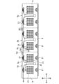
図1A及び図1Bは、寄棟屋根を構成する1対の屋根面1の一方を示す。各屋根面1は、野地板3a及び防水シート3bで構成された屋根下地3を備え、野地板3aの表面が、全体に亘って防水シート3bで覆われている(図10参照)。以下、屋根面1を外から見た場合の手前側、すなわち、太陽が当たる側を表側と呼び、その反対側を裏側と呼ぶ。屋根面1の表側から見て軒棟方向と直交する方向を桁方向と呼ぶものとする。また、桁方向のうち、屋根面1の表側から見て右側(図1A中右側)を右側、屋根面1の表側から見て左側(図1A中左側)を左側と呼ぶ。
(Embodiment 1)
1A and 1B show one of a pair of roof surfaces 1 that constitute a hipped roof. Each roof surface 1 includes a roof base 3 composed of a sheath board 3a and a waterproof sheet 3b, and the entire surface of the sheath board 3a is covered with a waterproof sheet 3b (see FIG. 10). Hereinafter, when the roof surface 1 is viewed from the outside, the front side, that is, the side exposed to the sun, will be referred to as the front side, and the opposite side will be referred to as the back side. The direction perpendicular to the eave direction when viewed from the front side of the roof surface 1 is referred to as the girder direction. Further, among the girder directions, the right side when viewed from the front side of the roof surface 1 (the right side in FIG. 1A) is called the right side, and the left side when viewed from the front side of the roof surface 1 (the left side in FIG. 1A) is called the left side.

屋根下地3表面(防水シート3bの表面)の桁方向中央(一部)の領域には、6つの建材一体型の太陽電池モジュール5a~5f(以下、単に太陽電池モジュールという)が敷設されている。詳しくは、屋根下地3表面の軒側端部において、桁方向の中央部に、太陽電池モジュール5a~5cが右側から順に敷設されている。そして、太陽電池モジュール5a~5cの棟側に太陽電池モジュール5d,5eが右側から順に敷設され、これら太陽電池モジュール5d,5eの棟側に太陽電池モジュール5fが敷設されている。太陽電池モジュール5a~5fは、共通の構成を有しているので、区別する必要のない場合には符号5を付す。太陽電池モジュール5a~5fの非敷設領域には、複数のスレート7(屋根材に相当)が敷設されている。 Six building material-integrated solar cell modules 5a to 5f (hereinafter simply referred to as solar cell modules) are laid in the center (partial) area of the roof base 3 surface (the surface of the waterproof sheet 3b) in the girder direction. . Specifically, at the eave side end of the surface of the roof base 3, solar cell modules 5a to 5c are laid in order from the right side at the center in the girder direction. Solar cell modules 5d and 5e are installed in order from the right side on the ridge side of the solar cell modules 5a to 5c, and a solar cell module 5f is installed on the ridge side of these solar cell modules 5d and 5e. Since the solar cell modules 5a to 5f have a common configuration, they are designated by the reference numeral 5 when there is no need to distinguish them. A plurality of slates 7 (corresponding to roofing material) are laid in areas where solar cell modules 5a to 5f are not laid.

<太陽電池モジュールの構成>
ここで、まず、本出願における「太陽電池モジュール」とは、電気的に接続された複数の太陽電池セルを含み、それらが樹脂等の封止材で保護された太陽電池パネルに対して、フレーム等を付随させた製品を意味する。
<Configuration of solar cell module>
First, the term "solar cell module" in this application refers to a solar cell panel that includes a plurality of electrically connected solar cells, which are protected by an encapsulant such as resin, and which is attached to a frame. It means a product accompanied by such items.

図2及び図3に示すように、各太陽電池モジュール5は、不燃材としてのメッキ鋼板で形成された平面視台形状のベースプレート9と、本発明の実施形態に係る設置構造を適用してベースプレート9の表側に配設される太陽電池パネル11とを有している。ベースプレート9を構成する不燃材として、アルミ、ステンレス等、メッキ鋼板以外の金属を採用してもよい。なお、図2中、太陽電池パネル11を2点鎖線で示す。 As shown in FIGS. 2 and 3, each solar cell module 5 includes a base plate 9 formed of a plated steel plate as a noncombustible material and having a trapezoidal shape in plan view, and a base plate 9 formed by applying the installation structure according to the embodiment of the present invention. It has a solar cell panel 11 arranged on the front side of 9. As the noncombustible material constituting the base plate 9, metals other than plated steel plates, such as aluminum and stainless steel, may be used. In addition, in FIG. 2, the solar cell panel 11 is shown by a two-dot chain line.

-ベースプレート-
図2に示すように、ベースプレート9は、後述する棟側フレーム部材15よりも棟側に延伸された棟側延伸部9mと、表側から見た正面視において、太陽電池パネル11の桁方向の少なくとも一方の端部(図2では左側の端部)よりも外側に延伸された桁側延伸部9nとを備えている。
-Base plate-
As shown in FIG. 2, the base plate 9 has a ridge-side extension portion 9m that extends further toward the ridge than a ridge-side frame member 15, which will be described later, and at least the ridge side extension portion 9m of the solar cell panel 11 in the girder direction when viewed from the front side. It includes a girder-side extending portion 9n extending outward from one end (the left end in FIG. 2).

図4Aに示すように、ベースプレート9の桁方向一端(左側の端部)には、表側に向かって断面U字状に折れ曲がった左側折曲部9aが形成されている。左側折曲部9aは、ベースプレート9上に存在する水が左外側に侵出するのを防ぐための水返しとして機能する。一方で、ベースプレート9の桁方向他端(右側の端部)には、裏側に向かって断面U字状に折れ曲がった右側折曲部9bが形成されている。このようなハゼ折構成にすることで、太陽電池モジュール5が屋根下地3上において、桁方向に並べて敷設されたときに、屋根下地3の表面に雨水等を浸水させないための「水切り構造」が構成される。「水切り構造」については、後述する「屋根構造」の中で詳細に説明する。 As shown in FIG. 4A, at one end (left end) of the base plate 9 in the beam direction, a left bent portion 9a is formed that is bent toward the front side and has a U-shaped cross section. The left bent portion 9a functions as a water return to prevent water present on the base plate 9 from leaking to the left outer side. On the other hand, at the other end (right end) of the base plate 9 in the digit direction, a right bent portion 9b is formed which is bent toward the back side and has a U-shaped cross section. By adopting such a dovetail configuration, when the solar cell modules 5 are laid side by side in the girder direction on the roof base 3, a "drainage structure" is created to prevent rainwater from seeping into the surface of the roof base 3. configured. The "draining structure" will be explained in detail in the "roof structure" section below.

図4Bに示すように、ベースプレート9の軒棟方向一端(棟側の端部)には、右側端部を除く全長に亘って、表側に向かって断面U字状に折れ曲がった棟側折曲部9cが形成されている。棟側折曲部9cは、ベースプレート9上に存在する水が棟方向外側に侵出するのを防ぐための水返しとして機能する。一方で、ベースプレート9の軒棟方向他端(軒側の端部)には、裏側に向かって断面U字状に折れ曲がった軒側折曲部9jが形成されている。このように、軒棟方向においてもハゼ折構成にして、太陽電池モジュール5が、軒棟方向に並べて敷設されたときに、図4Aの場合と同様に「水切り構造」として機能する。こちらの「水切り構造」についても、後述する「屋根構造」の中で詳細に説明する。 As shown in FIG. 4B, at one end of the base plate 9 in the eave direction (end on the ridge side), there is a ridge side bent part that is bent toward the front side in a U-shaped cross section over the entire length except for the right end. 9c is formed. The ridge side bent portion 9c functions as a water return for preventing water present on the base plate 9 from seeping outward in the ridge direction. On the other hand, at the other end of the base plate 9 in the eave direction (end on the eave side), an eave side bent portion 9j is formed which is bent toward the back side and has a U-shaped cross section. In this way, when the solar cell modules 5 are laid side by side in the eaves direction with a dovetail configuration also in the eave ridge direction, they function as a "draining structure" as in the case of FIG. 4A. This "draining structure" will also be explained in detail in the "roof structure" section below.

なお、図4Aでは、左側折曲部9a及び右側折曲部9bが断面U字状に折れ曲がっているものとしたが、これに限定されない。例えば、左側折曲部9a及び右側折曲部9bが、断面L字状に折れ曲がった形状であったり、折り返されて表裏方向に完全につぶれたような形状であってもよい。同様に、棟側折曲部9c及び軒側折曲部9j(図4B参照)は、断面U字状に限定されるものではなく、断面L字状に折れ曲がった形状であったり、折り返されて表裏方向につぶれたような形状であってもよい。 Note that in FIG. 4A, the left side bent portion 9a and the right side bent portion 9b are bent to have a U-shaped cross section, but the present invention is not limited thereto. For example, the left side bent portion 9a and the right side bent portion 9b may be bent into an L-shaped cross section, or may be folded back and completely collapsed in the front and back directions. Similarly, the ridge side bent portion 9c and the eave side bent portion 9j (see FIG. 4B) are not limited to a U-shaped cross section, but may be bent into an L-shaped cross section, or may be folded back. The shape may be crushed in the front and back directions.

図5に示すように、ベースプレート9の軒側の辺(端縁)は、略水平に延びる一方、ベースプレート9の棟側の辺(端縁)は、軒側の辺に対して桁方向一方(図5中右側)に向けて軒側に傾斜している。これにより、桁方向に隣接配置された太陽電池モジュール5のベースプレート9の桁方向端部同士を重ねて配置する場合でも、棟側折曲部9c同士が重なり合わず、ベースプレート9間に厚さ方向の段差が生じにくい。 As shown in FIG. 5, the eave side side (edge) of the base plate 9 extends approximately horizontally, while the ridge side side (edge) of the base plate 9 extends in one direction in the girder direction with respect to the eave side side ( The roof slopes toward the eaves (right side in Figure 5). As a result, even when the ends of the base plates 9 of the solar cell modules 5 that are arranged adjacent to each other in the girder direction are arranged overlapping each other, the ridge side bent portions 9c do not overlap each other, and the base plates 9 are spaced in the thickness direction. Level differences are less likely to occur.

また、ベースプレート9の棟側端縁における棟側折曲部9cに右側から隣接する箇所には、コ字状の切欠部9dが形成されている。ベースプレート9の棟側端縁近傍には、6つの棟側取付孔9eが桁方向に間隔を空けて貫通形成されている。 Further, a U-shaped notch 9d is formed at a location adjacent to the ridge-side bent portion 9c from the right side on the ridge-side edge of the base plate 9. Six ridge-side mounting holes 9e are formed in the vicinity of the ridge-side edge of the base plate 9 at intervals in the girder direction.

ベースプレート9の棟側端部には、表側に膨出する1対の棟側膨出部9f(図2参照)が桁方向に間隔を空けて形成されている。棟側膨出部9fは、平面視で桁方向に長い長方形状をなしている。棟側膨出部9fには、1対の棟側ネジ挿通孔9g(図3参照)が桁方向に間隔を空けて形成されている。ベースプレート9の下端部における棟側膨出部9fと軒棟方向(流れ方向)に対向する位置には、表側に膨出し、かつ軒側に開放する1対の軒側膨出部9h(図2参照)が桁方向に間隔を空けて形成されている。この軒側膨出部9hは、平面視で、棟側端部が棟側に向けて徐々に細くなり、かつ上端部を除く領域が一定の幅で軒棟方向に延びる略五角形状をなしている。軒側膨出部9hには、1対の軒側ネジ挿通孔9i(図3参照)が桁方向に間隔を空けて形成されている。軒側膨出部9hの膨出高さH1(図10参照)は、棟側膨出部9fの膨出高さH2(図10参照)よりも高くなっている。 A pair of ridge-side bulging portions 9f (see FIG. 2) bulging toward the front side are formed at the ridge-side end portion of the base plate 9 at intervals in the beam direction. The ridge side bulging portion 9f has a rectangular shape that is long in the girder direction when viewed from above. A pair of ridge-side screw insertion holes 9g (see FIG. 3) are formed in the ridge-side bulging portion 9f at intervals in the girder direction. At the lower end of the base plate 9, a pair of eave side bulges 9h (Fig. 2 ) are formed at intervals in the digit direction. The eave-side bulging portion 9h has a substantially pentagonal shape in plan view, with the ridge-side end gradually becoming thinner toward the ridge, and the area excluding the upper end extending in the direction of the eave ridge with a constant width. There is. A pair of eave side screw insertion holes 9i (see FIG. 3) are formed in the eave side bulging portion 9h at intervals in the girder direction. The bulge height H1 (see FIG. 10) of the eave side bulge portion 9h is higher than the bulge height H2 (see FIG. 10) of the ridge side bulge portion 9f.

-緩衝材-
各ベースプレート9の表面(反屋根下地3側の面)には、2つの平面視矩形状の略板状の緩衝材13がその板面をベースプレート9の表面に沿わせた状態で互いに間隔を空けるとともにベースプレート9の外周縁との間に間隔を空けて配置されている。緩衝材13は、発泡ポリスチレン等、衝撃吸収機能及び断熱機能の少なくとも一方を有する樹脂で形成される。
-Cushioning material-
On the surface of each base plate 9 (the surface on the side opposite to the roof base 3), two substantially plate-shaped cushioning materials 13 having a rectangular shape in plan view are spaced apart from each other with their plate surfaces along the surface of the base plate 9. and the outer peripheral edge of the base plate 9 with a space therebetween. The cushioning material 13 is made of a resin having at least one of a shock absorbing function and a heat insulating function, such as expanded polystyrene.

図6に示すように、緩衝材13の裏面には、表裏方向の裏側に向かって徐々に幅広となる断面浅皿形状で軒棟方向全体に延びる1本の第1裏側溝部13a(第1溝部に相当)及び2本の第2裏側溝部13b(第1溝部に相当)が互いに桁方向に間隔を空けて形成されている。これにより、第1裏側溝部13aとベースプレート9との間及び第2裏側溝部13bとベースプレート9との間に、断面台形状で軒棟方向に延び、雨水等を通過させるための空間部が形成される。なお、第1溝部(第1裏側溝部13aと2本の第2裏側溝部13b)の形状や数配置等は特に限定されるものではない。例えば、第1溝部の形状が断面半円形状のような他の形状であってもよい。図6では、一例として、第1裏側溝部13aが2本の第2裏側溝部13bに桁方向両側から挟まれるように配置されている例を示している。また、図6では、桁方向において、緩衝材13の中心とベースプレート9の軒側膨出部9hの中心との位置合わせをしやすくする観点から、第1裏側溝部13aが第2裏側溝部13bよりも幅狭に形成されている。 As shown in FIG. 6, on the back side of the cushioning material 13, there is one first back side groove part 13a (first groove part ) and two second back side grooves 13b (corresponding to the first grooves) are formed spaced apart from each other in the digit direction. As a result, a space portion is formed between the first back side groove portion 13a and the base plate 9 and between the second back side groove portion 13b and the base plate 9, and has a trapezoidal cross section and extends in the direction of the eave ridge, and allows rainwater etc. to pass therethrough. Ru. Note that the shape, number arrangement, etc. of the first groove portions (the first back side groove portion 13a and the two second back side groove portions 13b) are not particularly limited. For example, the first groove may have another shape such as a semicircular cross section. As an example, FIG. 6 shows an example in which the first back side groove 13a is arranged so as to be sandwiched between two second back side grooves 13b from both sides in the digit direction. In addition, in FIG. 6, in the girder direction, from the viewpoint of making it easier to align the center of the cushioning material 13 and the center of the eaves-side bulge 9h of the base plate 9, the first back groove 13a is closer to the second back groove 13b. It is also formed narrowly.

一方、緩衝材13の表面には、表裏方向の表側に向かって徐々に幅広となる断面浅皿形状で軒棟方向全体に延びる4本の第1表側溝部13c(第3溝部に相当)が桁方向に互いに間隔を空けて形成されている。これにより、第1表側溝部13cと太陽電池パネル11との間に、断面台形状で軒棟方向に延びる空間部が形成されている。換言すると、緩衝材13の表面には、例えば、軒棟方向に長い5つの第1表側溝部13cの非形成領域を有し、この非形成領域で太陽電池パネル11の桁方向及び軒棟方向の中間部分を支持している。これにより、太陽電池パネル11裏側の通気性が確保され、太陽電池パネル11の温度上昇を抑えている。なお、第1表側溝部13cの非形成領域の数は、5つに限定されるものではなく、例えば、緩衝材13のサイズ等に応じて4つ以下または6つ以上であってもよい。 On the other hand, on the surface of the cushioning material 13, there are four first front side grooves 13c (corresponding to the third grooves) that extend in the entire eave ridge direction and have a shallow dish-shaped cross section that gradually becomes wider toward the front side in the front-back direction. They are formed spaced apart from each other in the digit direction. As a result, a space portion having a trapezoidal cross section and extending in the direction of the eaves is formed between the first front side groove portion 13c and the solar cell panel 11. In other words, the surface of the cushioning material 13 has, for example, five regions in which the first front groove portions 13c, which are long in the direction of the eave ridge, are not formed, and in these non-formed regions, the solar cell panel 11 is formed in the girder direction and in the direction of the eave ridge. supports the middle part of Thereby, ventilation on the back side of the solar cell panel 11 is ensured, and a rise in temperature of the solar cell panel 11 is suppressed. Note that the number of regions where the first front side groove portion 13c is not formed is not limited to five, and may be four or less or six or more, depending on the size of the cushioning material 13, for example.

各第1表側溝部13c非形成領域には、表裏方向の表側に向かって徐々に幅広となる断面浅皿形状で桁方向全体に延びる3本の第2表側溝部13d(第2溝部に相当)が軒棟方向に互いに間隔を空けて形成されている。これにより、第2表側溝部13dと太陽電池パネル11との間には、断面台形状で軒方向に延びる空間部が形成される。 In each first front side groove 13c non-forming region, there are three second front side grooves 13d (equivalent to second grooves) extending in the entire beam direction and having a shallow dish-shaped cross section that gradually becomes wider toward the front side in the front and back direction. ) are formed at intervals from each other in the direction of the eaves. Thereby, a space part having a trapezoidal cross section and extending in the direction of the eaves is formed between the second front side groove part 13d and the solar cell panel 11.

なお、緩衝材13の表面に形成される溝部の形状、数、及び配置は、上述したような第1表側溝部13c及び第2表側溝部13dの形状、数、及び配置に限定されない。 Note that the shape, number, and arrangement of the grooves formed on the surface of the cushioning material 13 are not limited to the shape, number, and arrangement of the first front groove 13c and the second front groove 13d as described above.

緩衝材13表面の水の排出をスムーズにする観点から、(1)第2表側溝部13dの軒側の側壁は、桁方向一方(図2では右側)に向かって軒方向に傾斜し、(2)第1表側溝部13cの深さは、第2表側溝部13dの深さよりも深くなっている。 From the viewpoint of smooth drainage of water from the surface of the cushioning material 13, (1) the eave-side side wall of the second front side groove portion 13d is inclined toward the eaves toward one side in the girder direction (the right side in FIG. 2); 2) The depth of the first front side groove 13c is deeper than the depth of the second front side groove 13d.

緩衝材13の裏面における第1裏側溝部13a及び第2裏側溝部13bの形成されていない領域は、ベースプレート9の表面に両面テープにより接着されている。また、緩衝材13の表面における第1表側溝部13c及び第2表側溝部13dの形成されていない領域は、太陽電池パネル11の裏面に接着されていない。 The area on the back surface of the cushioning material 13 where the first back groove 13a and the second back groove 13b are not formed is adhered to the surface of the base plate 9 with double-sided tape. Further, the area on the surface of the cushioning material 13 where the first front side groove portion 13c and the second front side groove portion 13d are not formed is not bonded to the back surface of the solar cell panel 11.

-棟側フレーム部材-
図7に示すように、ベースプレート9の各棟側膨出部9fには、太陽電池パネル11の棟側端部を支持する金属製の棟側フレーム部材15(棟側支持部材に相当)が桁方向に間隔を空けて表側から取り付けられている。また、棟側フレーム部材15と対応する位置において、各棟側膨出部9fの裏側には、長方形状の棟側補助板17が取り付けられている(図3参照)。棟側補助板17には、1対の棟側締結孔17aが長手方向に間隔を空けて形成されている。
-Building side frame member-
As shown in FIG. 7, a metal ridge-side frame member 15 (corresponding to a ridge-side support member) that supports the ridge-side end of the solar cell panel 11 is attached to each ridge-side bulge portion 9f of the base plate 9. They are attached from the front side at intervals in the direction. Furthermore, a rectangular ridge-side auxiliary plate 17 is attached to the back side of each ridge-side bulge 9f at a position corresponding to the ridge-side frame member 15 (see FIG. 3). A pair of ridge-side fastening holes 17a are formed in the ridge-side auxiliary plate 17 at intervals in the longitudinal direction.

棟側フレーム部材15は、その一方の面をベースプレート9に当接させて桁方向に延びる平面視長方形板状の取付面部15aを備えている。取付面部15aには、1対の棟側ネジ孔15b(図3参照)が上記ベースプレート9の棟側ネジ挿通孔9gに対応するように長手方向(桁方向)に間隔を空けて形成されている。該取付面部15aの長手方向に延びる軒側の端縁には、板面を軒棟方向に向けてベースプレート9表方向に突出する板状の立面部15cが一体に形成されている。立面部15cは、取付面部15aと同一の幅で連続する中央部15dと、該中央部15dの基端部を除く部分から桁方向両側に延出する1対の延出部15eとで平面視略T字状に形成されている。立面部15cの先端縁、すなわち中央部15d及び延出部15eの立面部15c先端側の端縁には、第1挟持壁部15fが軒側に向けて一体に突設されている。また、各延出部15eの立面部15c基端側の端縁には、棟側当接面部としての第2挟持壁部15gが上記第1挟持壁部15fに対向し、かつ第1挟持壁部15fよりも桁方向両外側に張り出すように一体に突設されている。第2挟持壁部15gにおける第1挟持壁部15fの桁方向両端縁に対向する箇所には、軒棟方向に延びる棟側突出部としての突条部15hが表側に向けて一体に突設されている。また、両第2挟持壁部15gの桁方向外側に張り出した部分には、棟側に延出する延出壁部15iが第2挟持壁部15gと面一をなすように一体に形成され、該延出壁部15iの先端部には、突出片部15jが表側に向けて一体に突設されている。これら延出壁部15iと突出片部15jとで、ケーブルを所定の高さ位置に保持するためのケーブルフック15k(保持部に相当)が構成されている。第1挟持壁部15fの先端縁には、表側に突出して棟側に屈曲する3つの屈曲壁部15mが、桁方向に互いに間隔を空けて一体に突設されている。各屈曲壁部15mと第1挟持壁部15fとで、桁方向に延びて棟側に開放する係合部としての溝15nが形成されている。 The ridge-side frame member 15 includes a mounting surface portion 15a that has a rectangular plate shape in plan view and extends in the girder direction with one surface abutting the base plate 9. A pair of ridge side screw holes 15b (see FIG. 3) are formed in the mounting surface portion 15a at intervals in the longitudinal direction (girder direction) so as to correspond to the ridge side screw insertion holes 9g of the base plate 9. . A plate-shaped vertical surface portion 15c that protrudes toward the surface of the base plate 9 with the plate surface facing toward the eave ridge is integrally formed on the edge of the mounting surface portion 15a on the eave side extending in the longitudinal direction. The vertical surface portion 15c has a flat surface with a central portion 15d that has the same width as the mounting surface portion 15a and continues, and a pair of extending portions 15e that extend from a portion of the central portion 15d excluding the base end to both sides in the girder direction. It is formed into a T-shape when viewed. A first clamping wall portion 15f is integrally provided on the tip edge of the vertical portion 15c, that is, on the edge of the central portion 15d and the edge of the extending portion 15e on the tip side of the vertical portion 15c, projecting toward the eave side. Further, at the proximal end edge of the vertical surface portion 15c of each extension portion 15e, a second clamping wall portion 15g serving as a ridge-side contact surface portion faces the first clamping wall portion 15f, and a first clamping wall portion 15g serves as a ridge side contact surface portion. It is integrally provided so as to protrude outward from the wall portion 15f on both sides in the girder direction. A protrusion 15h as a ridge-side protrusion extending in the direction of the eave ridge is provided integrally protruding toward the front side at a portion of the second clamping wall 15g that faces both edges in the girder direction of the first clamping wall 15f. ing. Further, an extending wall portion 15i extending toward the ridge side is integrally formed in a portion of both second clamping wall portions 15g extending outward in the girder direction so as to be flush with the second clamping wall portion 15g. A protruding piece 15j is integrally provided at the tip of the extending wall 15i to protrude toward the front side. The extending wall portion 15i and the protruding piece portion 15j constitute a cable hook 15k (corresponding to a holding portion) for holding the cable at a predetermined height position. Three bending walls 15m projecting toward the front side and bending toward the ridge side are integrally provided at the tip edge of the first clamping wall portion 15f, spaced apart from each other in the girder direction. Each bent wall portion 15m and the first clamping wall portion 15f form a groove 15n as an engaging portion that extends in the girder direction and opens toward the ridge side.

上述のように構成された棟側フレーム部材15は、該棟側フレーム部材15の取付面部15aの棟側ネジ孔15b、ベースプレート9の棟側ネジ挿通孔9g、及び棟側補助板17の棟側締結孔17aに表側から順にネジ19を挿通することにより、ベースプレート9に締結されている。 The ridge side frame member 15 configured as described above has the ridge side screw hole 15b of the mounting surface portion 15a of the ridge side frame member 15, the ridge side screw insertion hole 9g of the base plate 9, and the ridge side of the ridge side auxiliary plate 17. It is fastened to the base plate 9 by inserting screws 19 into the fastening holes 17a in order from the front side.

-軒側フレーム部材-
図8及び図9に示すように、ベースプレート9の各軒側膨出部9hには、太陽電池パネル11の軒側端部を支持する金属製の軒側フレーム部材21(軒側支持部材に相当)が棟側フレーム部材15と軒棟方向に対向する位置に桁方向に間隔を空けて取り付けられている。また、棟側フレーム部材15と対応する位置において、各軒側膨出部9hの裏側には、長方形状の軒側補助板23が取り付けられている(図3参照)。軒側補助板23には、1対の軒側締結孔23aが長手方向に間隔を空けて形成されている。
-Eave side frame member-
As shown in FIGS. 8 and 9, each eave-side bulge 9h of the base plate 9 is provided with a metal eave-side frame member 21 (equivalent to an eave-side support member) that supports the eave-side end of the solar cell panel 11. ) are attached at positions facing the ridge-side frame member 15 in the direction of the eaves and spaced apart in the direction of the girder. Moreover, a rectangular eave side auxiliary plate 23 is attached to the back side of each eave side bulge portion 9h at a position corresponding to the ridge side frame member 15 (see FIG. 3). A pair of eave side fastening holes 23a are formed in the eave side auxiliary plate 23 at intervals in the longitudinal direction.

軒側フレーム部材21は、その一方の面をベースプレート9に当接させた桁方向に長い平面視長方形板状の取付壁部21aを備えている。取付壁部21aには、1対の軒側ネジ孔21b(図3参照)が上記ベースプレート9の軒側ネジ挿通孔9iに対応するように長手方向(桁方向)に間隔を空けて形成されている。上記ベースプレート9の取付壁部21aの軒側の端縁には、板面を軒棟方向に向けてベースプレート9表方向に突出する板状の立壁部21cが一体に形成されている。立壁部21cの桁方向両端部は、取付壁部21aよりも桁方向両外側に突出している。該立壁部21cの先端縁には、板面を表裏方向に向けた平面視略長方形状の長板部21dがその長手方向両端部を立壁部21cの桁方向外側に張り出した状態で棟側に向けて一体に突設されている。長板部21dの先端縁の桁方向両端部には、板状の1対の突出壁部21eが軒側に向かって表側に傾斜するように一体に突設されている。したがって、突出壁部21eの基端は、若干折れ曲がっている。また、長板部21dの先端縁の桁方向中央部には、板状の中央壁部21fが上記突出壁部21eとの間に間隔を空けて軒側に向けて一体に突設されている。中央壁部21fの先端近傍には、1対のフレーム側貫通孔21gが桁方向に間隔を空けて形成されている。また、長板部21dの先端縁における突出壁部21e突設箇所と中央壁部21f突設箇所との間には、板状の段差形成面部21hが裏側に向けて一体に突設されている。該段差形成面部21hの先端には、桁方向に延び、かつ軒側に向けて突出する突出片21iが一体に突設されている。右側の軒側フレーム部材21の突出片21i、及び右側の棟側フレーム部材15の溝15nの太陽電池パネル11に対する桁方向の相対位置は互いに等しくなっており、左側の軒側フレーム部材21の突出片21i、及び左側の棟側フレーム部材15の溝15nの太陽電池パネル11に対する桁方向の相対位置も互いに等しくなっている。 The eave-side frame member 21 includes a mounting wall portion 21a that is shaped like a rectangular plate in a plan view and is long in the girder direction and has one surface abutted against the base plate 9. A pair of eave side screw holes 21b (see FIG. 3) are formed in the mounting wall portion 21a at intervals in the longitudinal direction (girder direction) so as to correspond to the eave side screw insertion holes 9i of the base plate 9. There is. A plate-shaped vertical wall portion 21c is integrally formed on the edge of the mounting wall portion 21a of the base plate 9 on the eave side, and projects toward the surface of the base plate 9 with the plate surface facing toward the eave ridge. Both end portions of the standing wall portion 21c in the girder direction protrude further outwards in the girder direction than the mounting wall portion 21a. At the tip edge of the standing wall portion 21c, a long plate portion 21d having a generally rectangular shape in plan view with its plate surface facing in the front and back direction extends toward the ridge side with both longitudinal ends thereof extending outward in the girder direction of the standing wall portion 21c. It is integrally protruded towards the A pair of plate-shaped protruding walls 21e are integrally provided at both end portions of the tip edge of the long plate portion 21d in the girder direction so as to incline toward the front side toward the eaves. Therefore, the proximal end of the protruding wall portion 21e is slightly bent. Furthermore, a plate-shaped central wall portion 21f is integrally provided at the center in the girder direction of the tip edge of the long plate portion 21d, with a space provided between the projecting wall portion 21e and the projecting wall portion 21e. . Near the tip of the central wall portion 21f, a pair of frame-side through holes 21g are formed at intervals in the digit direction. Furthermore, a plate-shaped step-forming surface portion 21h is integrally provided to protrude toward the back side between the protruding portion of the protruding wall portion 21e and the protruding portion of the central wall portion 21f on the tip edge of the long plate portion 21d. . A projecting piece 21i extending in the girder direction and projecting toward the eaves is integrally provided at the tip of the step forming surface portion 21h. The relative positions of the protruding piece 21i of the right eave side frame member 21 and the groove 15n of the right ridge side frame member 15 in the girder direction with respect to the solar cell panel 11 are equal to each other, and the protrusion of the left eave side frame member 21 is The relative positions of the piece 21i and the groove 15n of the left ridge frame member 15 in the beam direction with respect to the solar cell panel 11 are also equal to each other.

上述のように構成された軒側フレーム部材21は、該軒側フレーム部材21の取付壁部21aの軒側ネジ孔21b、ベースプレート9の軒側ネジ挿通孔9i、及び軒側補助板23の軒側締結孔23aに表側から順にネジ25を挿通することにより、ベースプレート9に締結されている。 The eave side frame member 21 configured as described above has the eave side screw holes 21b of the mounting wall portion 21a of the eave side frame member 21, the eave side screw insertion holes 9i of the base plate 9, and the eave side screw holes 9i of the eave side auxiliary plate 23. It is fastened to the base plate 9 by inserting screws 25 into the side fastening holes 23a in order from the front side.

-太陽電池パネル-
太陽電池パネル11は、長方形板状をなし、その長手方向を桁方向に向けて設置されている。また、太陽電池パネル11の表裏面は、軒側に向かってベースプレート9の表面から離間するように傾斜している。
-Solar panel-
The solar cell panel 11 has a rectangular plate shape and is installed with its longitudinal direction facing the girder direction. Moreover, the front and back surfaces of the solar cell panel 11 are inclined so as to be spaced apart from the surface of the base plate 9 toward the eaves.

太陽電池パネル11は、551×908mmの横長な矩形状のガラス基板裏面に、酸化スズ等の透明電極層、光半導体層、及び金属等の裏面電極層を順次形成し、これら各層をレーザ加工等でパターニングすることで発電部、配線部が形成された太陽電池素子を配置した後、EVA(エチレン酢酸ビニル共重合体)、ポリオレフィン等の充填材、ガラス、PETフィルム、又はテドラーフィルム等で上記素子形成面側を封止保護することで形成されている。 In the solar cell panel 11, a transparent electrode layer such as a tin oxide layer, an optical semiconductor layer, and a back electrode layer such as a metal layer are sequentially formed on the back surface of a horizontally long rectangular glass substrate measuring 551 x 908 mm, and each of these layers is processed by laser processing, etc. After arranging the solar cell element in which the power generation part and the wiring part are formed by patterning with the above-mentioned material, filler such as EVA (ethylene vinyl acetate copolymer), polyolefin, glass, PET film, Tedlar film, etc. It is formed by sealing and protecting the element forming surface side.

-ガスケット-
各太陽電池パネル11の棟側端部には、断面略コ字状で延びる1対の長尺状のゴム製のガスケット27が桁方向に互いに間隔を空けて取り付けられている。ガスケット27は、図10に示すように、長板状の連結壁部27aと、該連結壁部27aの長手方向に延びる両端縁に突設された一対の長板状の対向壁部27bとを有し、連結壁部27aの反対向壁部27b突設側の面には、連結壁部27aの長手方向に延びる一対のリブ27cが互いに間隔を空けて突設されている。
-gasket-
A pair of elongated rubber gaskets 27 extending in a substantially U-shaped cross section are attached to the ridge side end of each solar cell panel 11 at intervals in the girder direction. As shown in FIG. 10, the gasket 27 includes a long plate-shaped connecting wall portion 27a and a pair of long plate-like opposing wall portions 27b protruding from both ends extending in the longitudinal direction of the connecting wall portion 27a. A pair of ribs 27c extending in the longitudinal direction of the connecting wall 27a are spaced from each other and projecting from the surface of the connecting wall 27a on the side where the opposite wall 27b protrudes.

そして、ガスケット27の両対向壁部27bは、太陽電池パネル11の棟側端部を厚さ方向両側から挟持している。また、棟側フレーム部材15の第1挟持壁部15fと第2挟持壁部15gとが、ガスケット27及び太陽電池パネル11の棟側端部を挟持している。したがって、棟側フレーム部材15の第2挟持壁部15gは、ガスケット27に太陽電池パネル11裏方向から当接している。一方、棟側フレーム部材15の突条部15h(図7等参照)は、第2挟持壁部15gよりも太陽電池パネル11表方向に突出してガスケット27に桁方向両外側から対向することで、ガスケット27の桁方向の移動を規制している。また、棟側フレーム部材15の立面部15cは、ガスケット27の両リブ27cに棟側から当接している。また、棟側フレーム部材15の溝15nは、該棟側フレーム部材15が取り付けられる太陽電池パネル11の棟側端部の表側に位置している。このようにして、共通のベースプレート9に取り付けられた1対の棟側フレーム部材15が、太陽電池パネル11の棟側端部にガスケット27を介して桁方向に互いに間隔を空けて取り付けられている。 Both opposing wall portions 27b of the gasket 27 sandwich the ridge side end portion of the solar cell panel 11 from both sides in the thickness direction. Further, the first clamping wall 15f and the second clamping wall 15g of the ridge-side frame member 15 clamp the gasket 27 and the ridge-side end of the solar cell panel 11. Therefore, the second clamping wall portion 15g of the ridge side frame member 15 is in contact with the gasket 27 from the back side of the solar cell panel 11. On the other hand, the protrusions 15h (see FIG. 7, etc.) of the ridge side frame member 15 protrude toward the surface of the solar panel 11 from the second clamping wall 15g and face the gasket 27 from both outside sides in the girder direction. Movement of the gasket 27 in the digit direction is restricted. Further, the vertical surface portion 15c of the ridge-side frame member 15 is in contact with both ribs 27c of the gasket 27 from the ridge side. Moreover, the groove 15n of the ridge-side frame member 15 is located on the front side of the ridge-side end of the solar cell panel 11 to which the ridge-side frame member 15 is attached. In this way, a pair of ridge-side frame members 15 attached to the common base plate 9 are attached to the ridge-side end of the solar cell panel 11 via gaskets 27 at intervals from each other in the girder direction. .

一方、各太陽電池パネル11の軒側端部にも、棟側端部と同様に、1対の軒側挟持部材としてのガスケット27が桁方向に互いに間隔を空けて取り付けられている。そして、軒側フレーム部材21の中央壁部21fの基端部が、ガスケット27に太陽電池パネル11裏方向から当接している。したがって、軒側フレーム部材21の突出片21iは、該軒側フレーム部材21が取り付けられる太陽電池パネル11の軒側端部の裏側に位置している。また、軒側フレーム部材21の突出壁部21eが、中央壁部21fの桁方向両外側で中央壁部21fよりも太陽電池パネル11表方向に突出してガスケット27に桁方向両外側から対向することで、ガスケット27の桁方向の移動を規制している。 On the other hand, a pair of gaskets 27 as eave-side holding members are attached to the eave-side end of each solar cell panel 11 at intervals in the girder direction, similarly to the ridge-side end. The base end portion of the central wall portion 21f of the eave-side frame member 21 is in contact with the gasket 27 from the back side of the solar cell panel 11. Therefore, the protruding piece 21i of the eave side frame member 21 is located on the back side of the eave side end of the solar cell panel 11 to which the eave side frame member 21 is attached. Further, the protruding wall portions 21e of the eave side frame member 21 protrude toward the front side of the solar cell panel 11 from the center wall portion 21f on both outer sides in the girder direction than the center wall portion 21f, and face the gasket 27 from both outer sides in the girder direction. This restricts the movement of the gasket 27 in the digit direction.

さらに、各太陽電池パネル11の軒側端部に取り付けられたガスケット27の太陽電池パネル11表側の対向壁部27bには、長尺状のカバー部材29が各太陽電池パネル11の軒側端部を全長に亘って覆うように取り付けられている。カバー部材29は、太陽電池パネル11の軒側端部に表側から対向して該軒側端部を全長に亘って被覆する長板状の第1面部29aと、該第1面部29aの軒側端縁から裏側に延出して太陽電池パネル11の軒側端面を全長に亘って被覆する長板状の第2面部29bと、該第2面部29bの裏側端縁から軒側に延出する長板状の第3面部29cを備えている。第3面部29cのガスケット27取付領域には、1対のカバー側貫通孔29d(図3参照)が長手方向に間隔を空けて形成されている。第3面部29cのガスケット27取付領域を除く部分の軒側端縁には、太陽電池パネル11裏方向に延出する長板状の第4面部29eが形成されている。 Further, a long cover member 29 is attached to the opposite wall 27b on the front side of the solar panel 11 of the gasket 27 attached to the eave side end of each solar panel 11. It is attached so as to cover the entire length. The cover member 29 includes a long plate-shaped first surface portion 29a that faces the eave-side end of the solar cell panel 11 from the front side and covers the eave-side end over the entire length, and an eave-side surface of the first surface portion 29a. A long plate-shaped second surface portion 29b extending from the edge to the back side and covering the entire length of the eaves side end surface of the solar cell panel 11; and a long plate-shaped second surface portion 29b extending from the back side edge of the second surface portion 29b toward the eaves side. A plate-shaped third surface portion 29c is provided. A pair of cover-side through holes 29d (see FIG. 3) are formed at intervals in the longitudinal direction in the gasket 27 mounting area of the third surface portion 29c. A long plate-shaped fourth surface portion 29e extending toward the back of the solar cell panel 11 is formed at the edge of the eaves side of the third surface portion 29c excluding the gasket 27 mounting area.

上述のように構成されたカバー部材29は、該カバー部材29の第3面部29cのカバー側貫通孔29d、及び軒側フレーム部材21のフレーム側貫通孔21gに太陽電池パネル11表側から順にネジ31を挿通することにより、軒側フレーム部材21に締結されている。このようにして、共通のベースプレート9に取り付けられた1対の軒側フレーム部材21が、太陽電池パネル11の軒側端部にガスケット27を介して桁方向に互いに間隔を空けて取り付けられている。 The cover member 29 configured as described above has screws 31 inserted into the cover side through hole 29d of the third surface portion 29c of the cover member 29 and the frame side through hole 21g of the eaves side frame member 21 in order from the front side of the solar cell panel 11. It is fastened to the eaves side frame member 21 by inserting it. In this way, a pair of eave-side frame members 21 attached to the common base plate 9 are attached to the eave-side end of the solar panel 11 via gaskets 27 with a space between them in the girder direction. .

-端子箱、ケーブル、ケーブルフック(ケーブルの保持構造)-
ベースプレート9表面の緩衝材13よりも軒側でかつ、緩衝材13に桁方向に挟まれた位置には、端子箱33が設置されている。端子箱33には、1対のケーブル35の基端部が収容され、各ケーブル35の先端部には、コネクタ37が接続されている。コネクタ37は、隣接する太陽電池モジュール5のコネクタ37との接続や、パワーコンディショナ(図示省略)から引き出されたケーブルのコネクタ(図示省略)との接続に用いられる。
-Terminal box, cable, cable hook (cable retention structure)-
A terminal box 33 is installed on the surface of the base plate 9 at a position closer to the eaves than the cushioning material 13 and sandwiched between the cushioning materials 13 in the digit direction. The terminal box 33 accommodates the base end portions of a pair of cables 35, and a connector 37 is connected to the distal end portion of each cable 35. The connector 37 is used to connect with the connector 37 of the adjacent solar cell module 5 or to connect with a connector (not shown) of a cable pulled out from a power conditioner (not shown).

ケーブル35は、先端部に接続されたコネクタ37が、ケーブルフック15kの近傍に配置されるように、ケーブルフック15kに保持されている。 The cable 35 is held by the cable hook 15k such that the connector 37 connected to the tip thereof is disposed near the cable hook 15k.

具体的に、一方のケーブル35(例えば右側のケーブル、以下「右ケーブル35」ともいう)は、先端部近傍が、右側の棟側フレーム部材15の左側のケーブルフック15kの表側に当接するように置かれることで、所定の高さ位置に保持されている。このとき、右ケーブル35のコネクタ37は、棟側フレーム部材15の延出部15eの棟側に位置している。 Specifically, one cable 35 (for example, the right cable, hereinafter also referred to as "right cable 35") is arranged so that the vicinity of its tip abuts the front side of the left cable hook 15k of the right ridge frame member 15. By placing it, it is held at a predetermined height position. At this time, the connector 37 of the right cable 35 is located on the ridge side of the extending portion 15e of the ridge side frame member 15.

他方のケーブル35(例えば左側のケーブル、以下「左ケーブル35」ともいう)は、長手方向の中途部分が、左側の棟側フレーム部材15のケーブルフック15kに保持される。具体的に、左ケーブル35は、左側の棟側フレーム部材15の右側のケーブルフック15kの下側を経由して左側のケーブルフック15kの上側に通されることで、長手方向の中途部分が所定の高さ位置に保持される。 The other cable 35 (for example, the left cable, hereinafter also referred to as "left cable 35") has a midway portion in the longitudinal direction held by the cable hook 15k of the left ridge side frame member 15. Specifically, the left cable 35 is passed through the upper side of the left cable hook 15k via the lower side of the right cable hook 15k of the left ridge side frame member 15, so that the midway portion in the longitudinal direction is set in a predetermined position. It is held at a height of .

左ケーブル35は、左側に隣接する太陽電池モジュール5の右側の棟側フレーム部材1に向かって延びている。そして、左ケーブル35のコネクタ37は、左側に隣接する太陽電池モジュール5の右ケーブル35のコネクタ37に接続されている。このとき、左ケーブル35の先端部近傍が、左側に隣接する太陽電池モジュール5の右側の棟側フレーム部材15の右側のケーブルフック15kの表側に当接するように置かれる(図6参照)。これにより、左ケーブル35のコネクタが、所定の高さ位置に保持される。また、このとき、左ケーブル35のコネクタ37は、棟側フレーム部材15の延出部15eの棟側に位置している。 The left cable 35 extends toward the ridge-side frame member 1 on the right side of the solar cell module 5 adjacent to the left side. The connector 37 of the left cable 35 is connected to the connector 37 of the right cable 35 of the solar cell module 5 adjacent to the left side. At this time, the vicinity of the tip of the left cable 35 is placed in contact with the front side of the right cable hook 15k of the right ridge frame member 15 of the solar cell module 5 adjacent to the left (see FIG. 6). Thereby, the connector of the left cable 35 is held at a predetermined height position. Further, at this time, the connector 37 of the left cable 35 is located on the ridge side of the extension portion 15e of the ridge side frame member 15.

さらに、棟側フレーム部材15の延出部15eの棟側は、棟側に隣接する太陽電池モジュール5の軒側フレーム部材21の立壁部21c及び長板部21dにより覆われている(図10参照)。これにより、隣接する太陽電池モジュール5の左ケーブル35と右ケーブル35のコネクタ37同士の接続部分が、表方向及び軒棟方向からの水やゴミ等の侵入から保護される。 Further, the ridge side of the extension portion 15e of the ridge side frame member 15 is covered by the standing wall portion 21c and the long plate portion 21d of the eave side frame member 21 of the solar cell module 5 adjacent to the ridge side (see FIG. 10). ). Thereby, the connection portion between the connectors 37 of the left cable 35 and right cable 35 of the adjacent solar cell modules 5 is protected from intrusion of water, dirt, etc. from the front side and the eaves direction.

<屋根構造>
図1A,Bに戻り、建材一体型の太陽電池モジュール5を並べて敷設して形成される屋根構造(以下、単に屋根構造という)について説明する。
<Roof structure>
Returning to FIGS. 1A and 1B, a roof structure (hereinafter simply referred to as roof structure) formed by laying building material-integrated solar cell modules 5 side by side will be described.

上述のように構成された太陽電池モジュール5a~5fは、ベースプレート9の裏面が屋根下地3(防水シート3b)の表面に当接し、かつ軒棟方向に隣り合う太陽電池パネル11の位置が桁方向に1/2ずれるように並べて敷設されている。 In the solar cell modules 5a to 5f configured as described above, the back surface of the base plate 9 is in contact with the surface of the roof base 3 (waterproof sheet 3b), and the positions of the solar cell panels 11 adjacent to each other in the direction of the eaves are in the direction of the girder. They are laid side by side so that they are offset by 1/2.

具体的には、太陽電池モジュール5aの太陽電池パネル11の左側半分が、太陽電池モジュール5dの太陽電池パネル11の右側半分に軒側から隣接し、太陽電池モジュール5bの太陽電池パネル11の右側半分が、太陽電池モジュール5dの太陽電池パネル11の左側半分に軒側から隣接している。同様に、太陽電池モジュール5bの太陽電池パネル11の左側半分が、太陽電池モジュール5eの太陽電池パネル11の右側半分に軒側から隣接し、太陽電池モジュール5cの太陽電池パネル11の右側半分が、太陽電池モジュール5eの太陽電池パネル11の左側半分に軒側から隣接している。また、太陽電池モジュール5dの太陽電池パネル11の左側半分が太陽電池モジュール5fの右側半分に軒側から隣接し、太陽電池モジュール5eの太陽電池パネル11の右側半分が太陽電池モジュール5fの左側半分に軒側から隣接している。 Specifically, the left half of the solar cell panel 11 of the solar cell module 5a is adjacent to the right half of the solar cell panel 11 of the solar cell module 5d from the eave side, and the right half of the solar cell panel 11 of the solar cell module 5b is adjacent to the right half of the solar cell panel 11 of the solar cell module 5d. is adjacent to the left half of the solar cell panel 11 of the solar cell module 5d from the eave side. Similarly, the left half of the solar panel 11 of the solar cell module 5b is adjacent to the right half of the solar panel 11 of the solar cell module 5e from the eave side, and the right half of the solar panel 11 of the solar cell module 5c is It is adjacent to the left half of the solar cell panel 11 of the solar cell module 5e from the eave side. Further, the left half of the solar cell panel 11 of the solar cell module 5d is adjacent to the right half of the solar cell module 5f from the eave side, and the right half of the solar cell panel 11 of the solar cell module 5e is adjacent to the left half of the solar cell module 5f. Adjacent from the eave side.

また、軒棟方向に隣接して配置された2つの太陽電池モジュール5a~5fのうち、棟側の太陽電池モジュール5d~5fのベースプレート9の軒側膨出部9hが、軒側の太陽電池モジュール5a~5eのベースプレート9の棟側膨出部9fにベースプレート9表側から重なっている。 Further, among the two solar cell modules 5a to 5f arranged adjacently in the direction of the eaves, the eave side bulges 9h of the base plates 9 of the solar cell modules 5d to 5f on the eaves side are It overlaps the ridge side bulge portion 9f of the base plate 9 of 5a to 5e from the front side of the base plate 9.

そして、図10に示すように、軒棟方向に隣り合う2枚の太陽電池パネル11のうち、軒側の太陽電池パネル11における棟側の太陽電池パネル11との隣接部分に取り付けられた棟側フレーム部材15の溝15nには、棟側の太陽電池パネル11における軒側の太陽電池パネル11との隣接部分に取り付けられた軒側フレーム部材21の突出片21iが挿入されて係合している。したがって、太陽電池モジュール5d,5eの太陽電池パネル11に軒側から隣り合う太陽電池モジュール5bの太陽電池パネル11の右側の棟側フレーム部材15の溝15nには、太陽電池モジュール5eの太陽電池パネル11の左側の軒側フレーム部材21の突出片21iが挿入されて係合し、太陽電池モジュール5bの太陽電池パネル11の左側の棟側フレーム部材15の溝15nには、太陽電池モジュール5dの太陽電池パネル11の右側の軒側フレーム部材21の突出片21iが挿入されて係合している。 As shown in FIG. 10, among the two solar panels 11 adjacent in the direction of the eave, the ridge side solar panel 11 is attached to the adjacent portion of the eave side solar panel 11 to the ridge side solar panel 11. The protruding piece 21i of the eave-side frame member 21 attached to the adjacent portion of the ridge-side solar cell panel 11 to the eave-side solar cell panel 11 is inserted into the groove 15n of the frame member 15 and engaged. . Therefore, the groove 15n of the right ridge side frame member 15 of the solar cell panel 11 of the solar cell module 5b, which is adjacent to the solar cell panel 11 of the solar cell module 5d, 5e from the eave side, is filled with the solar cell panel of the solar cell module 5e. The protruding piece 21i of the left eave side frame member 21 of the solar cell module 5b is inserted into the groove 15n of the left eave side frame member 15 of the solar cell panel 11 of the solar cell module 5b. The protruding piece 21i of the eave side frame member 21 on the right side of the battery panel 11 is inserted and engaged.

また、軒側に隣接する太陽電池モジュール5がない太陽電池モジュール5a~5cの軒側フレーム部材21には、図11及び図12に示す軒側部材39が取り付けられている。軒側部材39は、その一方の面を防水シート3bに当接させて桁方向に延びる長板状の取付板部39aを有している。取付板部39aには、5つの軒側取付孔39bが桁方向に互いに間隔を空けて形成されている。これら軒側取付孔39b、防水シート3b及び屋根下地3にねじ(図示せず)を挿通させて締結することで、軒側部材39が屋根下地3に固定されている。取付板部39aの長手方向に延びる軒側の端縁には、軒側に向かって屋根下地3表側に傾斜する傾斜板部39cが取付板部39aと桁方向に同じ長さで延設され、該傾斜板部39cの延出端には、取付板部39aと略平行に延びる延出板部39dが取付板部39aと桁方向に同じ長さで延設されている。該延出板部39dの延出端には、立板部39eが屋根下地3表側に向かって立設されている。立板部39eの先端には、板面を屋根下地3表裏方向に向けた1対の板状の差込部39fが桁方向に互いに間隔を空けて棟側に向けて突設されている。これら差込部39fは、軒側フレーム部材21の突出片21iにベースプレート9表側から対向して軒側フレーム部材21のベースプレート9表側への移動を規制するとともに、軒側フレーム部材21の中央壁部21fにベースプレート9裏側から対向して軒側フレーム部材21の裏側への移動を規制している。したがって、軒側フレーム部材21の表裏方向へのぐらつきが防止される。 Furthermore, an eave side member 39 shown in FIGS. 11 and 12 is attached to the eave side frame member 21 of the solar cell modules 5a to 5c that do not have a solar cell module 5 adjacent to the eave side. The eave side member 39 has a long plate-shaped mounting plate portion 39a that extends in the girder direction with one surface thereof in contact with the waterproof sheet 3b. Five eave-side mounting holes 39b are formed in the mounting plate portion 39a at intervals from each other in the girder direction. The eave side member 39 is fixed to the roof base 3 by inserting and fastening screws (not shown) through the eave side attachment hole 39b, the waterproof sheet 3b, and the roof base 3. At the edge of the eave side extending in the longitudinal direction of the mounting plate part 39a, an inclined plate part 39c that slopes toward the front side of the roof base 3 toward the eave side is provided and extends the same length in the girder direction as the mounting plate part 39a, At the extending end of the inclined plate part 39c, an extending plate part 39d extending substantially parallel to the mounting plate part 39a is provided with the same length in the beam direction as the mounting plate part 39a. At the extending end of the extending plate part 39d, an upright plate part 39e is erected toward the front side of the roof base 3. At the tip of the upright plate part 39e, a pair of plate-shaped insertion parts 39f with the plate surfaces facing the front and back directions of the roof base 3 are provided so as to protrude toward the ridge side at a distance from each other in the girder direction. These insertion portions 39f face the protruding pieces 21i of the eave side frame member 21 from the front side of the base plate 9 to restrict movement of the eave side frame member 21 toward the front side of the base plate 9, and the central wall portion of the eave side frame member 21 21f from the back side of the base plate 9 to restrict movement of the eaves side frame member 21 to the back side. Therefore, the eaves side frame member 21 is prevented from wobbling in the front and back directions.

また、棟側に隣接する太陽電池パネル11がない太陽電池パネル11、すなわち太陽電池モジュール5fの太陽電池パネル11の棟側には、第1棟側カバー41が配設されている。第1棟側カバー41は、板状の第1主面部41aとそれに対して棟側に位置する第1棟側板部41dとを備えている。第1主面部41aは、太陽電池モジュール5fの棟側の屋根下地3(防水シート3b)を表側から覆っている。また、第1主面部41aの棟側に位置する第1棟側板部41dは、第1棟側カバー41の棟側に配置されるスレート7によって表側から覆われている(図1A参照)。なお、図13では、第1棟側板部41dを覆うスレート7の図示を省略している。第1主面部41aの桁方向両端縁には、第1側面部41bが裏側に向かって突設されている。第1棟側カバー41の第1主面部41aの第1棟側板部41dには、4つのビス孔41cが桁方向に間隔を空けて形成されている。これらビス孔41c及び屋根下地3にねじ(図示せず)を挿通して締結することで、第1棟側カバー41の第1棟側板部41dとスレート7とが屋根下地3に固定されている(共締めされている)。 Further, a first ridge side cover 41 is disposed on the ridge side of the solar cell panel 11 that does not have a solar panel 11 adjacent to the ridge side, that is, the solar cell panel 11 of the solar cell module 5f. The first ridge side cover 41 includes a plate-shaped first main surface portion 41a and a first ridge side plate portion 41d located on the ridge side with respect to the first main surface portion 41a. The first main surface portion 41a covers the roof base 3 (waterproof sheet 3b) on the ridge side of the solar cell module 5f from the front side. Further, the first ridge side plate portion 41d located on the ridge side of the first main surface portion 41a is covered from the front side by the slate 7 disposed on the ridge side of the first ridge side cover 41 (see FIG. 1A). Note that in FIG. 13, illustration of the slate 7 that covers the first ridge side plate portion 41d is omitted. A first side surface portion 41b is provided on both ends of the first main surface portion 41a in the beam direction to protrude toward the back side. Four screw holes 41c are formed in the first ridge side plate portion 41d of the first main surface portion 41a of the first ridge side cover 41 at intervals in the girder direction. The first ridge side plate portion 41d of the first ridge side cover 41 and the slate 7 are fixed to the roof substrate 3 by inserting screws (not shown) into these screw holes 41c and the roof substrate 3 and fastening them. (They are fastened together).

また、第1棟側カバー41の第1主面部41aの軒側端部は、図13にも示すように、太陽電池モジュール5fの両棟側フレーム部材15の溝15nに挿入されて係合されている。 Further, as shown in FIG. 13, the eave side end portion of the first main surface portion 41a of the first ridge side cover 41 is inserted into and engaged with the groove 15n of the both ridge side frame members 15 of the solar cell module 5f. ing.

また、桁方向半分がスレート7に軒側から隣接する太陽電池パネル11(太陽電池モジュール5a,5c,5d,5eの太陽電池パネル11)のスレート7隣接部分の棟側には、第2棟側カバー43が配設されている。第2棟側カバー43は、板状の第2主面部43aとそれに対して棟側に位置する第2棟側板部43dを備えている。第2主面部43aは、軒側から隣接する太陽電池モジュール5(例えば、太陽電池モジュール5a,5c,5d,5e)の棟側の屋根下地3(防水シート3b)を表側から覆っている。また、第2主面部43aの棟側に位置する第2棟側板部43dは、第2棟側カバー43の棟側に配置されるスレート7によって表側から覆われている(図1A参照)。該第2主面部43aの桁方向両端縁には、第2側面部43bが裏側に向かって突設されている。第2棟側カバー43の第2主面部43aの第2棟側板部43dには、2つのビス孔43cが桁方向に間隔を空けて形成されている。これらビス孔43c及び屋根下地3にねじ(図示せず)を挿通して締結することで、第2棟側カバー43の第2棟側板部43dとスレート7とが屋根下地3に固定されている(共締めされている)。一方、第2棟側カバー43の第2主面部43aの軒側端部は、太陽電池モジュール5a,5c,5d,5eの太陽電池パネル11のスレート隣接部分に取り付けられた棟側フレーム部材15の溝15nに挿入されている。 In addition, on the ridge side of the portion adjacent to the slate 7 of the solar panel 11 (solar panel 11 of the solar cell modules 5a, 5c, 5d, 5e) whose half in the girder direction is adjacent to the slate 7 from the eave side, the second ridge side A cover 43 is provided. The second ridge side cover 43 includes a plate-shaped second main surface portion 43a and a second ridge side plate portion 43d located on the ridge side with respect to the second main surface portion 43a. The second main surface portion 43a covers from the front side the roof base 3 (waterproof sheet 3b) on the ridge side of the solar cell module 5 (for example, solar cell modules 5a, 5c, 5d, 5e) adjacent from the eave side. Further, the second ridge side plate portion 43d located on the ridge side of the second main surface portion 43a is covered from the front side by the slate 7 disposed on the ridge side of the second ridge side cover 43 (see FIG. 1A). A second side surface portion 43b is provided on both ends of the second main surface portion 43a in the beam direction to protrude toward the back side. Two screw holes 43c are formed in the second ridge side plate portion 43d of the second main surface portion 43a of the second ridge side cover 43 at intervals in the girder direction. The second ridge side plate portion 43d of the second ridge side cover 43 and the slate 7 are fixed to the roof substrate 3 by inserting screws (not shown) into these screw holes 43c and the roof substrate 3 and fastening them. (They are fastened together). On the other hand, the eave-side end of the second main surface 43a of the second ridge-side cover 43 is connected to the ridge-side frame member 15 attached to the slate-adjacent portion of the solar panel 11 of the solar cell modules 5a, 5c, 5d, and 5e. It is inserted into the groove 15n.

-水切り構造-
次に、屋根構造の水切り構造について説明する。
-Draining structure-
Next, the drainage structure of the roof structure will be explained.

図4A及び図5に示すように、桁方向に隣接して配置された2つの太陽電池モジュール5(例えば、5aと5b、5bと5c、5dと5e)のうち、右側の太陽電池モジュール5b,5c,5eのベースプレート9(以下、右側ベースプレート9という)の桁側延伸部9nの表側には、左側の太陽電池モジュール5a,5b,5dのベースプレート9(以下、左側ベースプレート9という)の右側端部が重なっている。換言すると、右側ベースプレート9の左側折曲部9aの表側に、左側ベースプレート9の右側折曲部9bが重なるように敷設されている。前述のとおり、ベースプレート9の左側折曲部9a及び棟側折曲部9cは、表側に向かって断面U字状に折り曲げられ、水返しとして機能するので、隣接配置されたベースプレート9の桁方向の境界部分から水が侵入しても屋根下地3表面は浸水しない。 As shown in FIGS. 4A and 5, among the two solar cell modules 5 (for example, 5a and 5b, 5b and 5c, 5d and 5e) arranged adjacent to each other in the girder direction, the right solar cell module 5b, The right end of the base plate 9 of the left solar cell modules 5a, 5b, 5d (hereinafter referred to as the left base plate 9) is on the front side of the girder side extension portion 9n of the base plate 9 of the left solar cell modules 5a, 5b, 5d (hereinafter referred to as the left base plate 9). are overlapping. In other words, the right bent portion 9b of the left base plate 9 is laid so as to overlap the front side of the left bent portion 9a of the right base plate 9. As mentioned above, the left side bent part 9a and the ridge side bent part 9c of the base plate 9 are bent toward the front side to have a U-shaped cross section and function as a water return. Even if water enters from the boundary part, the surface of the roof base 3 will not be flooded.

なお、桁方向に隣接する太陽電池モジュール5(例えば、5aと5b、5bと5c、5dと5e)のベースプレート9の重なり幅W1(図5参照)、すなわち桁側延伸部9nの桁方向の幅W1は、毛細管現象による水の侵入量よりも幅広に設定する観点から、50mm以上に設定させるのが好ましい。これにより、桁方向に隣接配置されたベースプレート9の境界部分から水が侵入しても、その水が右側ベースプレート9の左側端部まで到達しない。 Note that the overlap width W1 (see FIG. 5) of the base plates 9 of the solar cell modules 5 (for example, 5a and 5b, 5b and 5c, 5d and 5e) adjacent in the digit direction, that is, the width of the digit side extension portion 9n in the digit direction W1 is preferably set to 50 mm or more from the viewpoint of setting the width wider than the amount of water intrusion due to capillary action. As a result, even if water enters from the boundary between the base plates 9 that are arranged adjacent to each other in the girder direction, the water does not reach the left end of the right base plate 9.

図4B及び図10に示すように、軒棟方向に隣接して配置された2つの太陽電池モジュール5のうち、軒側の太陽電池モジュール5d,5eのベースプレート9(以下、軒側ベースプレート9という)の棟側延伸部9mの表側には、棟側の太陽電池モジュール5fのベースプレート9(以下、棟側ベースプレート9という)の軒側端部が重なっている。軒側ベースプレート9の棟側折曲部9cの表側に、棟側ベースプレート9の軒側折曲部9jが重なるように敷設されている。前述のとおり、ベースプレート9の棟側折曲部9cは、表側に向かって断面U字状に折り曲げられ、水返しとして機能するので、軒棟方向に隣接配置されたベースプレート9の境界部分から水が侵入しても屋根下地3表面は浸水しない。 As shown in FIGS. 4B and 10, among the two solar cell modules 5 arranged adjacently in the direction of the eaves, the base plates 9 of the solar cell modules 5d and 5e on the eaves side (hereinafter referred to as the eave side base plate 9) The eaves-side end of the base plate 9 (hereinafter referred to as ridge-side base plate 9) of the ridge-side solar cell module 5f overlaps with the front side of the ridge-side extension portion 9m. The eave side bent portion 9j of the ridge side base plate 9 is laid so as to overlap the front side of the ridge side bent portion 9c of the eave side base plate 9. As mentioned above, the ridge-side bent portion 9c of the base plate 9 is bent toward the front side to have a U-shaped cross section and functions as a water return, so that water does not escape from the boundary between the base plates 9 adjacent to each other in the direction of the eave ridge. Even if water enters the roof, the surface of the roof base 3 will not be flooded.

なお、軒棟方向に隣接する太陽電池モジュール5のベースプレート9の重なり幅W2(図10参照)、すなわち棟側延伸部9mの軒棟方向の幅W2は、毛細管現象による水の侵入量よりも幅広に設定する観点から、50mm以上に設定させるのが好ましい。これにより、軒棟方向に隣接配置されたベースプレート9の境界部分から水が侵入しても、その水
が軒側ベースプレート9の棟側端部まで到達しない。
Note that the overlapping width W2 (see FIG. 10) of the base plates 9 of the solar cell modules 5 adjacent to each other in the direction of the eave ridge, that is, the width W2 of the ridge side extension portion 9m in the direction of the eave ridge is wider than the amount of water intrusion due to capillary phenomenon. From the viewpoint of setting it to 50 mm or more, it is preferable to set it to 50 mm or more. Thereby, even if water enters from the boundary portion of the base plates 9 arranged adjacently in the direction of the eave ridge, the water does not reach the ridge side end of the eave side base plate 9.

また、太陽電池モジュール5のベースプレート9と当該ベースプレート9に桁方向に隣接するスレート7との境界には、図1Bに示すように、当該境界をその全長に亘って跨がる長尺状の水切りプレート45(水切部材に相当)が設けられている。 Further, at the boundary between the base plate 9 of the solar cell module 5 and the slate 7 adjacent to the base plate 9 in the girder direction, as shown in FIG. A plate 45 (corresponding to a draining member) is provided.

建材一体型太陽電池モジュール5a,5d,5fのベースプレート9の右側に位置する各水切りプレート45の左側部分は、ベースプレート9の裏側でかつ、防水シート3bの表側に位置している。一方、上記ベースプレート9の右側に位置する各水切りプレート45の右側部分は、スレート7の裏側でかつ、防水シート3bの表側に位置している。 The left side portion of each drainage plate 45 located on the right side of the base plate 9 of the building material-integrated solar cell modules 5a, 5d, and 5f is located on the back side of the base plate 9 and on the front side of the waterproof sheet 3b. On the other hand, the right side of each draining plate 45 located on the right side of the base plate 9 is located on the back side of the slate 7 and on the front side of the waterproof sheet 3b.

建材一体型太陽電池モジュール5c,5e,5fのベースプレート9の左側に位置する各水切りプレート45の右側部分は、ベースプレート9の表側でかつ、太陽電池パネル11の裏側に位置している。一方、ベースプレート9の左側に位置する各水切りプレート45の左側部分は、ベースプレート9の表側でかつ、スレート7の裏側に位置している。 The right side of each drainage plate 45 located on the left side of the base plate 9 of the building material-integrated solar cell modules 5c, 5e, and 5f is located on the front side of the base plate 9 and on the back side of the solar cell panel 11. On the other hand, the left side portion of each draining plate 45 located on the left side of the base plate 9 is located on the front side of the base plate 9 and on the back side of the slate 7.

水切りプレート45の第1棟側カバー41又は第2棟側カバー43と重なる領域は、第1棟側カバー41又は第2棟側カバー43の裏側でかつ、防水シート3bの表側に位置している。 The area of the draining plate 45 that overlaps with the first ridge side cover 41 or the second ridge side cover 43 is located on the back side of the first ridge side cover 41 or the second ridge side cover 43 and on the front side of the waterproof sheet 3b. .

上述のように構成された屋根面1は、屋根下地3表面全体を防水シート3bで覆った状態で、建材一体型太陽電池モジュール5a~5fを敷設し、次に、建材一体型太陽電池モジュール5a,5d,5fの右側の水切りプレート45を、その左側部分が建材一体型太陽電池モジュール5a,5d,5fのベースプレート9と防水シート3bで挟み込まれるように敷設するとともに、建材一体型太陽電池モジュール5c,5e,5fの左側の水切りプレート45を、その右側部分が建材一体型太陽電池モジュール5c,5e,5fのベースプレート9の表面側に位置するように敷設し、最後にスレート7を敷設することによって施工できる。 For the roof surface 1 configured as described above, the building material-integrated solar cell modules 5a to 5f are laid with the entire surface of the roof base 3 covered with the waterproof sheet 3b, and then the building material-integrated solar cell modules 5a are installed. , 5d, 5f, so that the left side portion thereof is sandwiched between the base plate 9 and the waterproof sheet 3b of the building material integrated solar cell modules 5a, 5d, 5f, and the building material integrated solar cell module 5c. , 5e, 5f so that the right side part thereof is located on the surface side of the base plate 9 of the building material-integrated solar cell module 5c, 5e, 5f, and finally, by laying the slate 7. Can be constructed.

また、水切りプレート45は、ベースプレート9の棟側端縁よりも棟側に延出した棟側延出部45aを備えている。棟側延出部45aは、屋根構造として敷設された場合には、桁方向に並べて配置されたスレート7と第2棟側カバー43との境界に延出することになる。そして、棟側延出部45aを含む水切りプレート45の桁方向の両端は、表側に向かって断面U字状に折り曲げられていて、水返しとしての機能を有する。これにより、ベースプレート9に桁方向に隣接するスレート7との境界、スレート7と第2棟側カバー43との境界に侵入した水が、水切りプレート45により軒棟方向に流される。また、水返しがあるので、水切りプレート45の桁方向端部から野地板3aに浸水することがない。 Further, the draining plate 45 includes a ridge-side extension portion 45a extending toward the ridge side from the ridge-side edge of the base plate 9. When the ridge-side extension portion 45a is installed as a roof structure, it extends to the boundary between the slates 7 and the second ridge-side cover 43, which are arranged side by side in the girder direction. Both ends of the drain plate 45 including the ridge side extension portion 45a in the girder direction are bent toward the front side to have a U-shaped cross section, and have a function as a water return. As a result, water that has entered the boundary between the base plate 9 and the slate 7 adjacent in the girder direction and the boundary between the slate 7 and the second ridge side cover 43 is flowed away by the draining plate 45 in the direction of the eaves. Moreover, since there is a water return, water does not flood into the shedding board 3a from the end of the draining plate 45 in the girder direction.

-接地構造-
次に、屋根構造の接地構造について説明する。
-Grounding structure-
Next, the grounding structure of the roof structure will be explained.

左側の太陽電池モジュール5a,5b,5dのベースプレート9の右端の棟側取付孔9eが、右側の太陽電池モジュール5b,5c,5eのベースプレート9の左端の棟側取付孔9eが重なっている。そして、左側の太陽電池モジュール5a,5b,5dのベースプレート9の右端の棟側取付孔9eに座金(図示せず)を表側から対向させた状態で、座金(図示せず)、左側の太陽電池モジュール5a,5b,5dのベースプレート9の右端の棟側取付孔9e及び右側の太陽電池モジュール5b,5c,5eのベースプレート9の左端の棟側取付孔9eにベースプレート9表側から順に固定ネジ(図示せず)が挿入されて締結されている。これにより、桁方向に隣接配置された太陽電池モジュール5同士が接地される。ここで用いられる座金(図示せず)のベースプレート9との対向面は、ギザギザ状の凹凸面を構成している。したがって、前記固定ネジ(図示せず)を締結させる過程で、ベースプレート9の表面のメッキが座金(図示せず)の凹凸面との接触により剥がされ、固定ネジが座金を介してベースプレート9と導通される。また、軒棟方向に隣接する太陽電池モジュール5のベースプレート9は、軒側に位置する太陽電池モジュール5の棟側フレーム部材15と、棟側に位置する太陽電池モジュール5の軒側フレーム部材21とが係合された際に、互いに導通するように構成されている。したがって、軒棟方向に隣接する太陽電池モジュール5同士も接地されている。 The ridge side attachment holes 9e at the right end of the base plates 9 of the left solar cell modules 5a, 5b, 5d overlap with the ridge side attachment holes 9e at the left ends of the base plates 9 of the right solar cell modules 5b, 5c, 5e. Then, with a washer (not shown) facing the ridge side mounting hole 9e at the right end of the base plate 9 of the left solar cell modules 5a, 5b, 5d from the front side, insert the washer (not shown) and the left solar cell. Insert fixing screws (not shown) into the ridge side mounting holes 9e at the right end of the base plates 9 of the modules 5a, 5b, 5d and the ridge side mounting holes 9e at the left end of the base plates 9 of the right solar cell modules 5b, 5c, 5e from the front side of the base plate 9. ) has been inserted and fastened. Thereby, the solar cell modules 5 arranged adjacently in the girder direction are grounded. The surface of the washer (not shown) used here that faces the base plate 9 forms a jagged uneven surface. Therefore, in the process of fastening the fixing screw (not shown), the plating on the surface of the base plate 9 is peeled off due to contact with the uneven surface of the washer (not shown), and the fixing screw is electrically connected to the base plate 9 through the washer. be done. Furthermore, the base plates 9 of the solar cell modules 5 adjacent to each other in the direction of the eave ridge are connected to the ridge side frame member 15 of the solar cell module 5 located on the eave side, and the eave side frame member 21 of the solar cell module 5 located on the ridge side. When the two are engaged, they are configured to conduct with each other. Therefore, the solar cell modules 5 adjacent to each other in the direction of the eaves are also grounded.

以上のように、本実施形態によると、太陽電池パネル11の裏面側から引き出されたケーブル35が、金属等の不燃材で形成されたベースプレート9の表側に配線されている。すなわち、ケーブル35やコネクタ37等と、屋根下地3との間に、ベースプレート9が介在されるので、防火性能等の安全性が高い。 As described above, according to this embodiment, the cable 35 pulled out from the back side of the solar cell panel 11 is wired to the front side of the base plate 9 formed of a noncombustible material such as metal. That is, since the base plate 9 is interposed between the cable 35, connector 37, etc. and the roof base 3, safety such as fire prevention performance is high.

また、棟側フレーム部材15の棟側に、ケーブル35を所定の高さ位置に保持するケーブルフック15kを設け、ケーブルコネクタ37が、ケーブルフック15kの近傍に配置されている。これにより、ケーブルコネクタ37とベースプレート9との間の距離を確保しており、防火性能等の安全性が高い。 Further, a cable hook 15k for holding the cable 35 at a predetermined height position is provided on the ridge side of the ridge side frame member 15, and a cable connector 37 is arranged near the cable hook 15k. Thereby, a distance between the cable connector 37 and the base plate 9 is ensured, and safety such as fire prevention performance is high.

また、ベースプレート9の桁方向及び軒棟方向において、ハゼ折構造を採用しているので、水切り構造として機能させることができる。例えば、太陽電池モジュール5を並べて敷設した際に、表側に向かって折り曲げられた側の端部が裏側にくるように重ねて敷設することで、隣接する太陽電池モジュール5の境界部分から侵入した水により屋根下地3が浸水しない。 Further, since the base plate 9 has a zigzag structure in the girder direction and the eave direction, it can function as a draining structure. For example, when solar cell modules 5 are laid side by side, by stacking them so that the ends bent toward the front side are on the back side, water that enters from the boundary between adjacent solar cell modules 5 can be removed. This prevents the roof base 3 from flooding.

また、緩衝材13を離散的に配置し、緩衝材13の表面及び裏面のそれぞれに、軒棟方向全体に延びる溝部を形成している。さらに、緩衝材13の表面には、第1表側溝部13c非形成領域に延びる第2表側溝部13dを形成している。これにより、第1及び第2表側溝部13cと太陽電池パネル11との間、並びに、第1及び第2裏側溝部13a,13bとベースプレート9との間に空間部が形成される。これにより、通気性、排水性、及びケーブル配線領域を確保している。 Further, the cushioning materials 13 are arranged discretely, and grooves extending in the entire eaves direction are formed on each of the front and back surfaces of the cushioning materials 13. Further, on the surface of the cushioning material 13, a second front side groove portion 13d is formed which extends to an area where the first front side groove portion 13c is not formed. Thereby, spaces are formed between the first and second front side grooves 13c and the solar cell panel 11, and between the first and second back side grooves 13a, 13b and the base plate 9. This ensures ventilation, drainage, and cable wiring area.

また、ベースプレート9の棟側の辺を、軒側の辺に対して軒棟方向のいずれか一方に傾斜させているので、太陽電池モジュール5を桁方向に並べて敷設する際において、ベースプレート9の端部同士が互いに重なる場合においても、隣接するベースプレート9の水返し構造(U字状の折返し部分)が互い違いに配置されるので、重なり合わない。 In addition, since the edge of the base plate 9 on the ridge side is inclined in either direction in the eave ridge direction with respect to the edge of the eave side, when the solar cell modules 5 are laid side by side in the girder direction, the edge of the base plate 9 Even when the parts overlap each other, they do not overlap because the water return structures (U-shaped folded parts) of adjacent base plates 9 are arranged alternately.

(実施形態2)
図14は、実施形態2の図3相当図である。本実施形態2では、ベースプレート9の軒棟方向中程に、軒棟方向に長い長手形状をなし、かつ裏側に膨出する4つの補強用膨出部9kが桁方向に互いに間隔を空けて形成されている。
(Embodiment 2)
FIG. 14 is a diagram corresponding to FIG. 3 of the second embodiment. In the second embodiment, four reinforcing bulges 9k, which have a long longitudinal shape in the eave ridge direction and bulge on the back side, are formed in the middle of the base plate 9 in the eave ridge direction, and are spaced apart from each other in the girder direction. has been done.

また、図15に示すように、棟側フレーム部材15の各延出壁部15iの先端部に、円形の接続部としてのアース孔15pが貫通形成されている。また、棟側フレーム部材15の屈曲壁部15mが、第1挟持壁部15fの先端縁の桁方向両端部だけに1つずつ突設されている。また、棟側フレーム部材15の第1挟持壁部15f、立面部15cの延出部15e、及び第2挟持壁部15gの桁方向両端から若干内側に離れた箇所に、切欠部15qが第1挟持壁部15fの突出方向(軒棟方向)全体、延出部15eのベースプレート9の厚さ方向全体、及び第2挟持壁部15gの基端部分(棟側部分)に亘って連続して形成されている。各切欠部15qの第1挟持壁部15f側端縁には、棟方向に突出する細長形状の突片部15rが形成されている。突片部15rの先端には、ベースプレート9側に折れ曲がった先端折曲部15sが形成されている。当該突片部15rは、上記切欠部15q対応箇所を切り欠いて折り曲げることにより形成される。 Further, as shown in FIG. 15, a ground hole 15p serving as a circular connection portion is formed through the tip of each extending wall portion 15i of the ridge side frame member 15. Further, one bent wall portion 15m of the ridge side frame member 15 is provided to protrude only at both ends in the girder direction of the tip edge of the first clamping wall portion 15f. In addition, cutout portions 15q are provided at locations slightly inward from both ends in the girder direction of the first clamping wall portion 15f of the ridge side frame member 15, the extension portion 15e of the vertical surface portion 15c, and the second clamping wall portion 15g. Continuously over the entire protruding direction (ridge direction) of the first clamping wall part 15f, the entire thickness direction of the base plate 9 of the extension part 15e, and the base end part (ridge side part) of the second clamping wall part 15g. It is formed. An elongated projecting piece 15r that projects in the direction of the ridge is formed on the edge of each notch 15q on the side of the first holding wall 15f. A tip bent portion 15s bent toward the base plate 9 is formed at the tip of the projecting piece 15r. The projecting piece 15r is formed by cutting out and bending a portion corresponding to the notch 15q.

そして、軒棟方向に隣り合う2つの太陽電池パネル11に取り付けられた棟側フレーム部材15のアース孔15pに、アース線47の端部に取り付けられた丸穴端子47aをねじ49で締結することにより、両太陽電池パネル11に取り付けられた棟側フレーム部材15のアース孔15p周縁がアース線47を介して接続され、軒棟方向に隣り合う太陽電池パネル11が電気的に接続されている。 Then, the round hole terminal 47a attached to the end of the ground wire 47 is fastened with the screw 49 to the ground hole 15p of the ridge side frame member 15 attached to the two solar panels 11 adjacent in the direction of the eave ridge. As a result, the edges of the ground holes 15p of the ridge-side frame members 15 attached to both solar cell panels 11 are connected via the ground wire 47, and the solar cell panels 11 adjacent in the direction of the eaves are electrically connected.

また、図16に示すように、カバー部材29の第1面部29aのガスケット27取付領域の棟側端部に、その板面を軒棟方向に向けて桁方向に延びる長方形板状の雪止め部29fが一体に突設されている。なお、図16では、カバー部材29に雪止め部29fを設けている例を示したが、設けなくてもよい。また、複数のカバー部材29のうちの一部だけに設けるようにしてもよい。他の実施形態及び変形例についても同様である。 Further, as shown in FIG. 16, a rectangular plate-shaped snow stopper part is provided at the ridge side end of the gasket 27 attachment area of the first surface part 29a of the cover member 29, and extends in the girder direction with its plate surface facing the eave ridge direction. 29f is integrally provided in a protruding manner. Although FIG. 16 shows an example in which the snow stopper portion 29f is provided on the cover member 29, it is not necessary to provide the snow stopper portion 29f. Further, it may be provided only on some of the plurality of cover members 29. The same applies to other embodiments and modifications.

また、軒側端部に位置する建材一体型太陽電池モジュール5a,5cのベースプレート9と当該ベースプレート9に桁方向に隣接するスレート7との境界に、水切りプレート45に代えて、図17及び図18に示す長尺状の第1の水切り部材51が設けられている。また、軒側端部に位置しない建材一体型太陽電池モジュール5d~5fのベースプレート9と当該ベースプレート9に桁方向に隣接するスレート7との境界に、水切りプレート45に代えて、図19に示す長尺状の第2の水切り部材53が設けられている。 17 and 18 in place of the drain plate 45 at the boundary between the base plate 9 of the building material-integrated solar cell modules 5a, 5c located at the end of the eaves and the slate 7 adjacent to the base plate 9 in the girder direction. An elongated first draining member 51 shown in FIG. In addition, instead of the draining plate 45, a length shown in FIG. A second draining member 53 having a square shape is provided.

各水切り部材51,53は、長板状(略長板状を含む)の本体部材55を備え、当該本体部材55の幅方向両端部には、長手方向他端部を除く長手方向全体に亘って一方の面側の幅方向内側に折り返された断面U字状の折返部55aが形成されている。また、本体部材55には、上記一方の面側に突出するように断面略V字状に屈曲し、かつ幅方向に短い間隔を空けて隣接する4対の屈曲部55bが、幅方向に略等しい間隔を空けて長手方向全体に亘って形成されている。これにより、各対を構成する2つの屈曲部55bと、両屈曲部55b間の本体部材55とで、長手方向に延びる溝部55cが構成されている。本体部材55は、1枚のプレートを折り曲げることで構成されている。 Each of the draining members 51, 53 includes a main body member 55 in the shape of a long plate (including a substantially long plate shape), and at both ends of the main body member 55 in the width direction, the main body member 55 has a main body member 55 extending over the entire length in the longitudinal direction except for the other end in the longitudinal direction. A folded portion 55a having a U-shaped cross section is formed by folding back inward in the width direction on one surface side. Further, the main body member 55 has four pairs of bent portions 55b which are bent in a substantially V-shaped cross section so as to protrude toward the one surface side, and which are adjacent to each other at short intervals in the width direction. They are formed at equal intervals throughout the longitudinal direction. As a result, the two bent portions 55b constituting each pair and the main body member 55 between both bent portions 55b form a groove portion 55c extending in the longitudinal direction. The main body member 55 is constructed by bending one plate.

上記本体部材55の上記一方の面の幅方向中央部には、その長手方向一端部を除く全長に亘って突出部材57が固定されている。突出部材57は、1枚のプレートを折り曲げることで構成されている。突出部材57は、互いに対向する1対の台形板部57aを備え、各台形板部57aは、平面視で長手方向一端から他端に向かって徐々に幅広となる互いに等しい台形状をなしている。両台形板部57aの幅方向一端縁は、互いに連結されている一方、両台形板部57aの幅方向他端縁には、張出板部57bが互いに離れる方向に張出形成されている。そして、両張出板部57bが、台形板部57aの幅狭側を上記本体部材55の長手方向一端部側に向けた状態で、上記本体部材55の上記一方の面の幅方向中央部に、本体部材55の上記長手方向一端部を除く全長に亘ってかしめ固定されている。 A protruding member 57 is fixed to the center portion of the one surface of the main body member 55 in the width direction over the entire length thereof except for one end portion in the longitudinal direction. The protruding member 57 is constructed by bending one plate. The protruding member 57 includes a pair of trapezoidal plate portions 57a facing each other, and each trapezoidal plate portion 57a has an equal trapezoidal shape that gradually becomes wider from one longitudinal end to the other end in plan view. . One end edge in the width direction of both the trapezoidal plate parts 57a is connected to each other, while an overhanging plate part 57b is formed to project from the other end edge in the width direction of both the trapezoidal plate parts 57a in a direction away from each other. Then, both projecting plate portions 57b are attached to the center portion in the width direction of the one surface of the main body member 55 with the narrow side of the trapezoidal plate portion 57a facing toward one end in the longitudinal direction of the main body member 55. , is caulked and fixed over the entire length of the main body member 55 except for one end in the longitudinal direction.

第2の水切り部材53の両台形板部57aの幅広側端縁の基端部には、切欠凹部57cが幅狭側に凹むように形成されている一方、第1の水切り部材51には、切欠凹部57cが形成されていない。 A notch recess 57c is formed at the proximal end of the wide side edge of both trapezoidal plate portions 57a of the second draining member 53 so as to be recessed toward the narrow side. Notch recess 57c is not formed.

そして、上述のように構成された各水切り部材51,53の本体部材55の長手方向一端部(突出部材57非配設領域)を除く部分は、その板面をベースプレート9表面(屋根下地3表面)に沿わせた状態で、建材一体型太陽電池モジュール5a,5c~5fのベースプレート9と当該ベースプレート9に桁方向に隣接するスレート7との境界を跨いでいる。各水切り部材51,53の両台形板部57aは、ベースプレート9とスレート7との境界に対応する位置で表側に突出している。両台形板部57aの先端は、太陽電池パネル11の表面に沿うように、ベースプレート9の表面に対して傾斜し、太陽電池パネル11の端縁に接近している。さらに、両台形板部57aの先端は、太陽電池パネル11の表面から突出しないように形成されている。 The portion of each of the draining members 51 and 53 configured as described above, excluding one longitudinal end of the main body member 55 (the area where the protruding member 57 is not provided), is connected to the surface of the base plate 9 (the surface of the roof base 3). ), it straddles the boundary between the base plate 9 of the building material-integrated solar cell modules 5a, 5c to 5f and the slate 7 adjacent to the base plate 9 in the digit direction. Both trapezoidal plate portions 57a of each draining member 51, 53 protrude to the front side at a position corresponding to the boundary between the base plate 9 and the slate 7. The tips of both trapezoidal plate portions 57a are inclined with respect to the surface of the base plate 9 so as to follow the surface of the solar cell panel 11, and are close to the edge of the solar cell panel 11. Further, the tips of both trapezoidal plate portions 57a are formed so as not to protrude from the surface of the solar cell panel 11.

本実施形態においても、実施形態1と同様に、建材一体型太陽電池モジュール5a,5d,5fのベースプレート9の右側に位置する各水切り部材51,53の左側部分は、ベースプレート9の裏側でかつ、防水シート3bの表側に位置している。一方、上記ベースプレート9の右側に位置する各水切り部材51,53の右側部分は、スレート7の裏側でかつ、防水シート3bの表側に位置している。 In this embodiment as well, as in Embodiment 1, the left side portions of the draining members 51 and 53 located on the right side of the base plate 9 of the building material-integrated solar cell modules 5a, 5d, and 5f are on the back side of the base plate 9, and It is located on the front side of the waterproof sheet 3b. On the other hand, the right side portions of the draining members 51 and 53 located on the right side of the base plate 9 are located on the back side of the slate 7 and on the front side of the waterproof sheet 3b.

建材一体型太陽電池モジュール5c,5e,5fのベースプレート9の左側に位置する各水切り部材51,53の右側部分は、ベースプレート9の表側でかつ、太陽電池パネル11の裏側に位置している。一方、上記ベースプレート9の左側に位置する各水切り部材51,53の左側部分は、ベースプレート9の表側でかつ、スレート7の裏側に位置している。 The right side of each drainage member 51, 53 located on the left side of the base plate 9 of the building material-integrated solar cell modules 5c, 5e, 5f is located on the front side of the base plate 9 and on the back side of the solar cell panel 11. On the other hand, the left side portions of the draining members 51 and 53 located on the left side of the base plate 9 are located on the front side of the base plate 9 and on the back side of the slate 7.

また、各水切り部材51,53の本体部材55の長手方向一端部(突出部材57の非配設領域)は、ベースプレート9とスレート7との境界よりも棟側に延出している。各水切り部材51,53の本体部材55の長手方向一端部の第1棟側カバー41又は第2棟側カバー43と重なる領域は、第1棟側カバー41又は第2棟側カバー43の裏側でかつ、防水シート3bの表側に位置している。 Further, one end in the longitudinal direction of the main body member 55 of each of the draining members 51 and 53 (an area where the protruding member 57 is not provided) extends toward the ridge side from the boundary between the base plate 9 and the slate 7. The region of each draining member 51, 53 that overlaps with the first ridge side cover 41 or the second ridge side cover 43 at one longitudinal end of the main body member 55 is the back side of the first ridge side cover 41 or the second ridge side cover 43. Moreover, it is located on the front side of the waterproof sheet 3b.

各第2の水切り部材53の切欠凹部57cには、当該第2の水切り部材53に軒側から隣接する太陽電池パネル11の棟側端部が嵌合している。 The ridge side end portion of the solar cell panel 11 adjacent to the second draining member 53 from the eave side is fitted into the cutout recess 57c of each second draining member 53.

その他の構成は、実施形態1と同じであるので、同一の構成要素には同一の符号を付してその詳細な説明を省略する。 Since the other configurations are the same as those in the first embodiment, the same components are given the same reference numerals and detailed explanation thereof will be omitted.

したがって、本実施形態2によれば、ベースプレート9に補強用膨出部9kを形成したので、ベースプレート9の変形が防止される。 Therefore, according to the second embodiment, since the reinforcing bulge 9k is formed on the base plate 9, deformation of the base plate 9 is prevented.

また、棟側フレーム部材15にアース孔15pを設けたので、アース孔15pを設けるための部材を、棟側フレーム部材15とは別に設ける場合に比べ、部品点数を削減できる。 Further, since the ground hole 15p is provided in the ridge side frame member 15, the number of parts can be reduced compared to the case where a member for providing the ground hole 15p is provided separately from the ridge side frame member 15.

また、カバー部材29に雪止め部29fを一体に設けたので、雪止め用の部品を雪止め部29fとは別に設ける場合に比べ、部品点数を削減できる。また、雪止め用の部品をカバー部材29又は太陽電池パネル11に取り付ける手間が不要になるので、施工を容易にできる。 Moreover, since the snow stopper part 29f is integrally provided in the cover member 29, the number of parts can be reduced compared to the case where the snow stopper part is provided separately from the snow stopper part 29f. Further, since it is not necessary to attach snow prevention parts to the cover member 29 or the solar cell panel 11, construction can be facilitated.

また、各水切り部材51,53に台形板部57aを設けたので、太陽電池パネル11の裏側に桁方向外側から水、虫、及び小動物が侵入するのを抑制できる。 Further, since the trapezoidal plate portion 57a is provided on each of the draining members 51 and 53, it is possible to prevent water, insects, and small animals from entering the back side of the solar panel 11 from the outside in the direction of the girder.

また、各水切り部材51,53の両台形板部57aの先端が、太陽電池パネル11の表面から突出しないように形成されているので、台形板部57aが太陽光を遮ることがない。 Further, since the tips of both trapezoidal plate portions 57a of each draining member 51, 53 are formed so as not to protrude from the surface of the solar cell panel 11, the trapezoidal plate portions 57a do not block sunlight.

また、各水切り部材51,53の両台形板部57aの先端が、太陽電池パネル11の端縁に接近しているので、太陽電池パネル11と台形板部57aの先端との間から水、虫、及び小動物が侵入するのを抑制できる。 In addition, since the tips of both trapezoidal plates 57a of each draining member 51, 53 are close to the edge of the solar panel 11, water and insects can escape from between the solar panel 11 and the tips of the trapezoidal plates 57a. , and can prevent small animals from entering.

また、スレート7を敷設する際、各水切り部材51,53の台形板部57aにスレート7の桁方向端縁を当接させることにより、スレート7を桁方向に位置決めできる。 Further, when laying the slate 7, the slate 7 can be positioned in the digit direction by bringing the edge of the slate 7 in the digit direction into contact with the trapezoidal plate portion 57a of each draining member 51, 53.

また、各水切り部材51,53を本体部材55と突出部材57とで構成したので、各水切り部材51,53全体を一部材で構成する場合に比べ、曲げ加工の対象となるプレートの大きさを小さくでき、持ち運びし易くなるので、曲げ加工が容易になる。また、水切り部材51,53の構成部材の打ち抜き加工における材料の利用率を高めることができる。 In addition, since each of the draining members 51 and 53 is composed of the main body member 55 and the protruding member 57, the size of the plate to be bent can be reduced compared to the case where each of the draining members 51 and 53 is entirely composed of one member. Since it can be made smaller and easier to carry, bending becomes easier. Moreover, the utilization rate of materials in punching the constituent members of the draining members 51 and 53 can be increased.

また、各水切り部材51,53の溝部55cの側壁、すなわち屈曲部55bが、溝部55cの内側に付着した水が溝部55cの外側に広がるのを抑制するので、排水性が向上する。 Furthermore, the side walls of the grooves 55c of each of the draining members 51, 53, that is, the bent portions 55b, suppress the water adhering to the inside of the grooves 55c from spreading to the outside of the grooves 55c, thereby improving drainage performance.

また、各水切り部材51,53の折返部55aが、各水切り部材51,53の折返部55aよりも幅方向内側に付着した水が幅方向外側に広がるのを抑制するので、各水切り部材51,53の裏側への水の浸入が抑制される。 Further, since the folded portion 55a of each draining member 51, 53 suppresses water adhering to the inner side in the width direction from spreading outward in the width direction than the folded portion 55a of each draining member 51, 53, each draining member 51, Infiltration of water to the back side of 53 is suppressed.

(実施形態2の変形例1)
図20は、実施形態2の変形例1の図18相当図である。本変形例1では、各水切り部材51,53が、本体部材55に代えて、左側水切り構成部材59と当該左側水切り構成部材59に右側から隣接するように配設された右側水切り構成部材61を備えている。左側水切り構成部材59及び右側水切り構成部材61は、それぞれ略長板状の主板部63を備えている。そして、上記屈曲部55bが、各主板部63の幅方向中途部に2対ずつ幅方向に間隔を空けて形成されている。また、上記折返部55aが、左側水切り構成部材59の主板部63の左側端部、及び右側水切り構成部材61の主板部63の右側端部に形成されている。また、左側水切り構成部材59の右側端縁及び右側水切り構成部材61の左側端縁には、突壁部65が棟側端部を除く長手方向全体に亘って突設されている。また、突出部材57に張出板部57bが形成されておらず、左側の台形板部57aが左側水切り構成部材59の突壁部65にかしめ固定され、かつ右側の台形板部57aが右側水切り構成部材61の突壁部65にかしめ固定されている。
(Modification 1 of Embodiment 2)
FIG. 20 is a diagram corresponding to FIG. 18 of Modification 1 of Embodiment 2. In the present modification example 1, each of the draining members 51 and 53 includes a left draining component 59 and a right draining component 61 disposed adjacent to the left draining component 59 from the right side, instead of the main body member 55. We are prepared. The left side drainer component 59 and the right side drainer component 61 each include a main plate portion 63 having a substantially long plate shape. Two pairs of the bent portions 55b are formed in the middle of each main plate portion 63 in the width direction at intervals in the width direction. Further, the folded portions 55a are formed at the left end of the main plate portion 63 of the left drainer component 59 and at the right end of the main plate portion 63 of the right drainer component 61. Furthermore, a protruding wall portion 65 is provided on the right edge of the left side drain member 59 and the left side edge of the right side drain member 61 in a protruding manner over the entire longitudinal direction except for the ridge side end. Further, the projecting member 57 is not formed with the projecting plate portion 57b, the left side trapezoidal plate portion 57a is caulked and fixed to the projecting wall portion 65 of the left side drainer component 59, and the right side trapezoidal plate portion 57a is fixed to the right side drainer component 59. It is caulked and fixed to the projecting wall portion 65 of the component 61.

その他の構成は、実施形態2と同じであるので、同一の構成要素には同一の符号を付してその詳細な説明を省略する。 Since the other configurations are the same as those in the second embodiment, the same components are given the same reference numerals and detailed explanation thereof will be omitted.

(実施形態2の変形例2)
図21は、実施形態2の変形例2の図18相当図である。本変形例2では、各水切り部材51,53が、本体部材55の一部材だけで構成されている。本体部材55の幅方向中央部を折り曲げることで、上記台形板部57aが構成されている。
(Modification 2 of Embodiment 2)
FIG. 21 is a diagram corresponding to FIG. 18 of Modification 2 of Embodiment 2. In the second modification, each of the draining members 51 and 53 is made up of only one member of the main body member 55. The trapezoidal plate portion 57a is formed by bending the central portion of the main body member 55 in the width direction.

その他の構成は、実施形態2と同じであるので、同一の構成要素には同一の符号を付してその詳細な説明を省略する。 Since the other configurations are the same as those in the second embodiment, the same components are given the same reference numerals and detailed explanation thereof will be omitted.

(実施形態3)
図22は、実施形態3の図1B相当図である。本実施形態3では、屋根面1に、建材一体型太陽電池モジュール5が3行3列に配設されている。そして、軒棟方向に隣り合う水切り部材51,53のうち、棟側の水切り部材53の軒側端部(折返部55a非形成領域)が、軒側の水切り部材51,53の本体部材55の棟側端部(突出部材57非配設領域)に表側から重なっている。棟側の水切り部材53の軒側端部の幅方向両端部は、軒側の水切り部材51,53の本体部材55の棟側端部の折返部55aにより、表側への移動が規制されている。
(Embodiment 3)
FIG. 22 is a diagram corresponding to FIG. 1B of the third embodiment. In the third embodiment, building material-integrated solar cell modules 5 are arranged on the roof surface 1 in three rows and three columns. Of the draining members 51 and 53 adjacent to each other in the direction of the eave ridge, the eave side end portion (the area where the folded portion 55a is not formed) of the draining member 53 on the ridge side is connected to the main body member 55 of the draining member 51 and 53 on the eave side. It overlaps the ridge side end (region where the protrusion member 57 is not provided) from the front side. Both ends in the width direction of the eave side end of the ridge side draining member 53 are restricted from moving toward the front side by folded portions 55a at the ridge side end of the main body member 55 of the eave side draining members 51, 53. .

その他の構成は、実施形態2と同じであるので、同一の構成要素には同一の符号を付してその詳細な説明を省略する。 Since the other configurations are the same as those in the second embodiment, the same components are given the same reference numerals and detailed explanation thereof will be omitted.

したがって、本実施形態3によれば、軒棟方向に隣り合う水切り部材51,53のうち、棟側の水切り部材53の軒側端部には、折返部55aが形成されていないので、折返部55aを形成した場合に比べ、棟側の水切り部材53の軒側端部を軒側の水切り部材51,53の棟側端部に表側から重ね易い。 Therefore, according to the third embodiment, the folded portion 55a is not formed at the eave side end of the draining member 53 on the ridge side among the draining members 51 and 53 adjacent in the direction of the eave ridge. 55a, it is easier to overlap the eave-side end of the ridge-side drainage member 53 with the ridge-side end of the eave-side drainage members 51, 53 from the front side.

(実施形態3の変形例1)
図23は、実施形態3の変形例1の図22相当図である。本変形例1では、本体部材55が、棟側に向かって徐々に幅広となる等脚台形板状に形成されている。また、折返部55aが、本体部材55の幅方向両端部の長手方向全体に亘って形成されている。
(Modification 1 of Embodiment 3)
FIG. 23 is a diagram corresponding to FIG. 22 of Modification 1 of Embodiment 3. In Modification 1, the main body member 55 is formed into an isosceles trapezoid plate shape that gradually becomes wider toward the ridge. Further, folded portions 55a are formed over the entire widthwise end portions of the main body member 55 in the longitudinal direction.

その他の構成は、実施形態3と同じであるので、同一の構成要素には同一の符号を付してその詳細な説明を省略する。 Since the other configurations are the same as those in the third embodiment, the same components are given the same reference numerals and detailed explanation thereof will be omitted.

したがって、本変形例1によれば、軒棟方向に隣り合う水切り部材51,53のうち、棟側の水切り部材53の軒側端部が、軒側の水切り部材51,53の本体部材55の棟側端部よりも幅狭となるので、棟側の水切り部材53の軒側端部を軒側の水切り部材51,53の棟側端部に表側から重ね易い。 Therefore, according to the present modification example 1, among the draining members 51 and 53 that are adjacent to each other in the direction of the eave ridge, the eave side end of the draining member 53 on the ridge side is the same as the main body member 55 of the draining member 51 and 53 on the eave side. Since the width is narrower than the ridge side end, the eave side end of the ridge side draining member 53 can be easily overlapped with the ridge side end of the eave side draining members 51 and 53 from the front side.

(実施形態3の変形例2)
図24は、実施形態3の変形例2の図22相当図である。本変形例2では、軒棟方向に並んだ3つの水切り部材51,53に代えて、図25に示す長尺状の3段用水切り部材67がその長手方向を軒棟方向に向けて配設されている。当該3段用水切り部材67は、その板面をベースプレート9表面(屋根下地3表面)に沿わせた略長板状の本体部材69を備えている。当該本体部材69の幅方向中央部における棟側端部を除く部分には、3つの突出部材57がその台形板部57aを表側に突出させ、かつ台形板部57aの幅狭側を棟側に向けた状態で軒棟方向に互いに隣り合うように固定されている。本体部材69には、上記折返部55a及び屈曲部55bが長手方向全体に亘って形成されている。
(Modification 2 of Embodiment 3)
FIG. 24 is a diagram corresponding to FIG. 22 of the second modification of the third embodiment. In this modification 2, instead of the three draining members 51 and 53 arranged in the direction of the eave ridge, a long three-stage draining member 67 shown in FIG. 25 is arranged with its longitudinal direction facing the direction of the eave ridge. has been done. The third-stage draining member 67 includes a substantially long plate-shaped main body member 69 whose plate surface is along the surface of the base plate 9 (the surface of the roof underlayment 3). In the central part of the main body member 69 in the width direction excluding the ridge side end, three protruding members 57 have their trapezoidal plate portions 57a protruding toward the front side, and the narrow side of the trapezoidal plate portion 57a is directed toward the ridge side. They are fixed so that they are next to each other in the direction of the eave ridge. The main body member 69 has the folded portion 55a and the bent portion 55b formed over the entire length thereof.

その他の構成は、実施形態3と同じであるので、同一の構成要素には同一の符号を付してその詳細な説明を省略する。 Since the other configurations are the same as those in the third embodiment, the same components are given the same reference numerals and detailed explanation thereof will be omitted.

したがって、本変形例2によれば、3つの水切り部材51,53を互いに重ねる手間が不要となるので、施工作業を容易にできる。 Therefore, according to the second modification, it is not necessary to stack the three draining members 51 and 53 on top of each other, so that the construction work can be facilitated.

(その他の実施形態)
上記の説明では、屋根構造が寄棟屋根である例について説明したが、本開示の技術は、切妻屋根にも適用することができ、同様の効果を得ることができる。具体的に、切妻屋根の場合、太陽電池パネルの桁方向の位置を揃えて敷設することになるが、太陽電池モジュール5としては、上記実施形態と同じものを適用することができる。なお、寄棟屋根と切妻屋根とは、例えば、最大設置が可能な方を採用するとよい。
(Other embodiments)
In the above description, an example in which the roof structure is a hip roof has been described, but the technology of the present disclosure can also be applied to a gable roof, and similar effects can be obtained. Specifically, in the case of a gable roof, the solar cell panels are installed with their positions aligned in the girder direction, but the same solar cell modules 5 as in the above embodiment can be applied. In addition, it is preferable to adopt the hipped roof and the gable roof, for example, whichever allows the maximum number of roofs to be installed.

3 屋根下地
5 太陽電池モジュール(建材一体型太陽電池モジュール)
9 ベースプレート
9m 棟側延伸部
9n 桁側延伸部
11 太陽電池パネル
13 緩衝材
13a 第1裏側溝部(第1溝部)
13b 第2裏側溝部(第1溝部)
13c 第1表側溝部(第3溝部)
13d 第2表側溝部(第2溝部)
15 棟側フレーム部材(棟側支持部材)
15k ケーブルフック(保持部)
21 軒側フレーム部材(軒側支持部材)
35 ケーブル
41 第1棟側カバー(棟カバー)
45 水切りプレート(水切部材)
45a 棟側延出部
51,53 水切部材
55 本体部材
57 突出部材
3 Roof base 5 Solar cell module (building material integrated solar cell module)
9 Base plate 9m Ridge side extension 9n Girder side extension 11 Solar panel 13 Cushioning material 13a First back groove (first groove)
13b Second back side groove (first groove)
13c First front groove (third groove)
13d Second front groove (second groove)
15 Ridge side frame member (ridge side support member)
15k cable hook (holding part)
21 Eave side frame member (eave side support member)
35 Cable 41 1st building side cover (building cover)
45 Draining plate (draining member)
45a Ridge side extensions 51, 53 Draining member 55 Main body member 57 Projecting member

Claims (18)

屋根下地上に取り付けられる建材一体型太陽電池モジュールであって、
前記建材一体型太陽電池モジュールに含まれる太陽電池パネルと、
前記太陽電池パネルの裏面側に配置された緩衝材と、
前記緩衝材を支持する不燃材で形成されたベースプレートと、
前記太陽電池パネルの裏面側から引き出され、前記ベースプレートの表側に配線されたケーブルとを備え、
前記ベースプレートの表側には、太陽電池パネルの棟側端部を支持する棟側支持部材と、太陽電池パネルの軒側の端部を支持する軒側支持部材とが、設けられ、
前記棟側支持部材の棟側には、前記ケーブルを所定の高さ位置に保持する保持部が設けられ、
前記ケーブルは、該ケーブルの先端に接続されたコネクタが、前記保持部の近傍に配置されるように前記保持部に保持されている
ことを特徴とする建材一体型太陽電池モジュール。
A building material-integrated solar cell module that is installed on the roof subsurface,
a solar cell panel included in the building material-integrated solar cell module;
a cushioning material placed on the back side of the solar panel;
a base plate made of a noncombustible material that supports the buffer material;
a cable pulled out from the back side of the solar cell panel and wired to the front side of the base plate,
A ridge side support member that supports the ridge side end of the solar cell panel and an eave side support member that supports the eave side end of the solar cell panel are provided on the front side of the base plate,
A holding part for holding the cable at a predetermined height position is provided on the ridge side of the ridge side support member,
The building material-integrated solar cell module is characterized in that the cable is held by the holding part such that a connector connected to the tip of the cable is disposed near the holding part.
請求項1に記載の建材一体型太陽電池モジュールにおいて、
前記ベースプレートは、前記棟側支持部材よりも棟側に延伸された棟側延伸部と、表側から見た正面視において、前記太陽電池パネルの桁方向の少なくとも一方の端部よりも外側に延伸された桁側延伸部を備え、桁方向及び軒棟方向のうちの一方向またはその両方向において、該方向に沿う一端が表側に向かって折り曲げられ、他端が裏側に向かって折り曲げられている
ことを特徴とする建材一体型太陽電池モジュール。
The building material integrated solar cell module according to claim 1,
The base plate has a ridge-side extension part that extends further toward the ridge than the ridge-side support member, and a ridge-side extension part that extends outward from at least one end in the girder direction of the solar cell panel when viewed from the front side. In one or both of the girder direction and the eaves direction, one end along the direction is bent toward the front side, and the other end is bent toward the back side. Features: Building material-integrated solar cell module.
請求項1に記載の建材一体型太陽電池モジュールにおいて、
前記緩衝材は、複数個に分割され、前記ベースプレート上に離散的に配置され、
前記緩衝材の裏面に、軒棟方向に沿って延びる第1溝部が形成され、
前記緩衝材の表面に、桁方向に沿って延びる第2溝部と、軒棟方向に沿って延び、前記第2溝部よりも表裏方向に深い第3溝部とが形成されている
ことを特徴とする建材一体型太陽電池モジュール。
The building material integrated solar cell module according to claim 1,
The buffer material is divided into a plurality of pieces and arranged discretely on the base plate,
A first groove extending along the eave ridge direction is formed on the back surface of the cushioning material,
A second groove extending along the girder direction and a third groove extending along the eave ridge direction and deeper in the front and back direction than the second groove are formed on the surface of the cushioning material. Building material-integrated solar cell module.
請求項3に記載の建材一体型太陽電池モジュールにおいて、
前記緩衝材の第2溝部は、軒方向の側壁が、隣接する第3溝部間において水平方向に対して軒方向に傾斜している
ことを特徴とする建材一体型太陽電池モジュール。
In the building materials integrated solar cell module according to claim 3,
The building material-integrated solar cell module is characterized in that the second groove portion of the buffer material has a side wall in the eave direction that is inclined in the eave direction with respect to the horizontal direction between adjacent third groove portions.
請求項1に記載の建材一体型太陽電池モジュールにおいて、
前記ベースプレートは、棟側の辺が、軒側の辺に対して軒棟方向のいずれか一方に傾斜している
ことを特徴とする建材一体型太陽電池モジュール。
The building material integrated solar cell module according to claim 1,
The building material-integrated solar cell module is characterized in that the base plate has a ridge-side side inclined in one direction in the eave-ridge direction with respect to an eave-side side.
複数の請求項1から5のいずれかに記載の建材一体型太陽電池モジュールを、前記ベースプレートの裏面が屋根下地の表面に当接するように並べて敷設して形成される屋根構造であって、
前記複数の建材一体型太陽電池モジュールは、隣接して配置された前記建材一体型太陽電池モジュールの軒棟方向及び/または桁方向における前記ベースプレートの端部同士が互いに重なるように敷設されていることを特徴とする屋根構造。
A roof structure formed by laying a plurality of building material-integrated solar cell modules according to any one of claims 1 to 5 side by side so that the back surface of the base plate is in contact with the surface of the roof base,
The plurality of building material-integrated solar cell modules are laid so that the ends of the base plates in the eave ridge direction and/or girder direction of the building material-integrated solar cell modules arranged adjacently overlap each other. A roof structure featuring
請求項6に記載の屋根構造において、
前記隣接する建材一体型太陽電池モジュールのベースプレートの端部同士の重なり幅は、50mm以上である
ことを特徴とする屋根構造。
The roof structure according to claim 6,
A roof structure characterized in that the overlapping width between the ends of the base plates of the adjacent building material-integrated solar cell modules is 50 mm or more.
請求項6に記載の屋根構造において、
前記建材一体型太陽電池モジュールの桁方向に隣接して配置された桁側屋根材を備え、
前記建材一体型太陽電池モジュールと前記桁側屋根材との境界部分において、前記桁側屋根材と前記屋根下地との間から桁方向に前記建材一体型太陽電池モジュールの太陽電池パネルの下側まで延出しかつ軒棟方向に沿って延びる水切部材が敷設されており、
前記水切部材は、建材一体型太陽電池モジュールのベースプレートの棟方向端よりも棟方向に延出する棟側延出部を有する
ことを特徴とする屋根構造。
The roof structure according to claim 6,
comprising a girder side roofing material disposed adjacent to the building material-integrated solar cell module in the girder direction,
At the boundary between the building material-integrated solar cell module and the girder-side roof material, from between the girder-side roof material and the roof base to the lower side of the solar cell panel of the building material-integrated solar cell module in the girder direction. A drainage member is installed that extends and extends along the direction of the eaves.
The roof structure is characterized in that the drainage member has a ridge-side extension portion that extends in the ridge direction from the ridge-direction end of the base plate of the building material-integrated solar cell module.
請求項8に記載の屋根構造において、
前記水切部材は、長板状の本体部材を備え、前記本体部材の表面の幅方向中央部には、その長手方向一端部を除く全長に亘って延びる突出部材が固定されている
ことを特徴とする屋根構造。
The roof structure according to claim 8,
The draining member includes a main body member in the form of a long plate, and a projecting member extending over the entire length of the main body member except for one end in the longitudinal direction is fixed to the central part of the surface of the main body member in the width direction. roof structure.
請求項9に記載の屋根構造において、
前記水切部材の突出部材は、前記太陽電池パネルの表面に沿うように、かつ、前記太陽電池パネルの表面から表側に突出しないように、前記ベースプレートの表面に対して傾斜している
ことを特徴とする屋根構造。
The roof structure according to claim 9,
The projecting member of the draining member is inclined with respect to the surface of the base plate so as to follow the surface of the solar cell panel and not protrude toward the front side from the surface of the solar cell panel. roof structure.
請求項10に記載の屋根構造において、
前記水切部材の突出部材は、前記太陽電池パネルの端縁に接近している
ことを特徴とする屋根構造。
The roof structure according to claim 10,
A roof structure characterized in that a protruding member of the draining member is close to an edge of the solar panel.
請求項8に記載の屋根構造において、
前記水切部材は、棟側に向かって徐々に幅広となる等脚台形板状に形成されている
ことを特徴とする屋根構造。
The roof structure according to claim 8,
The roof structure is characterized in that the drainage member is formed in the shape of an isosceles trapezoid plate that gradually becomes wider toward the ridge.
請求項8に記載の屋根構造において、
前記水切部材は、長板状の本体部材を備え、前記本体部材の桁方向両端部は、軒棟方向の一方の端部を除く長手方向全体に亘って表面側の幅方向内側に折り返された折返部が形成されている
ことを特徴とする屋根構造。
The roof structure according to claim 8,
The draining member includes a long plate-shaped main body member, and both ends of the main body member in the girder direction are folded back inward in the width direction on the surface side over the entire length direction except for one end in the eave ridge direction. A roof structure characterized by a folded part.
請求項6に記載の屋根構造において、
棟側の端に配置された前記建材一体型太陽電池モジュールである第1建材一体型太陽電池モジュールの棟側には、棟カバーが配置され、
前記棟カバーの軒側端部は、前記第1建材一体型太陽電池モジュールを構成する前記太陽電池パネルの棟側支持部材に固定されている
ことを特徴とする屋根構造。
The roof structure according to claim 6,
A ridge cover is arranged on the ridge side of the first building material-integrated solar cell module, which is the building material-integrated solar cell module arranged at the end of the ridge side,
A roof structure characterized in that an eave-side end portion of the ridge cover is fixed to a ridge-side support member of the solar cell panel constituting the first building material-integrated solar cell module.
屋根下地上に取り付けられる建材一体型太陽電池モジュールに含まれる太陽電池パネルと、
前記太陽電池パネルの裏面側に配置された緩衝材と、
前記緩衝材を支持する不燃材で形成されたベースプレートと、
前記太陽電池パネルの裏面側から引き出され、前記ベースプレートの表側に配線されたケーブルとを備える前記建材一体型太陽電池モジュールを、前記ベースプレートの裏面が屋根下地の表面に当接するように並べて敷設して形成される屋根構造であって、
前記複数の建材一体型太陽電池モジュールは、隣接して配置された前記建材一体型太陽電池モジュールの軒棟方向及び/または桁方向における前記ベースプレートの端部同士が互いに重なるように敷設され、
前記建材一体型太陽電池モジュールの桁方向に隣接して配置された桁側屋根材を備え、
前記建材一体型太陽電池モジュールと前記桁側屋根材との境界部分において、前記桁側屋根材と前記屋根下地との間から桁方向に前記建材一体型太陽電池モジュールの太陽電池パネルの下側まで延出しかつ軒棟方向に沿って延びる水切部材が敷設されており、
前記水切部材は、建材一体型太陽電池モジュールのベースプレートの棟方向端よりも棟方向に延出する棟側延出部を有し、
前記水切部材は、長板状の本体部材を備え、前記本体部材の表面の幅方向中央部には、その長手方向一端部を除く全長に亘って延びる突出部材が固定されており、
前記水切部材の突出部材は、前記太陽電池パネルの表面に沿うように、かつ、前記太陽電池パネルの表面から表側に突出しないように、前記ベースプレートの表面に対して傾斜している
ことを特徴とする屋根構造。
A solar cell panel included in a building material-integrated solar cell module that is installed on the roof subsurface,
a cushioning material placed on the back side of the solar panel;
a base plate made of a noncombustible material that supports the buffer material;
The building material-integrated solar cell module comprising a cable pulled out from the back side of the solar cell panel and wired to the front side of the base plate is laid side by side so that the back side of the base plate is in contact with the surface of the roof base. A roof structure formed,
The plurality of building material-integrated solar cell modules are laid so that the ends of the base plates in the eave ridge direction and/or girder direction of the building material-integrated solar cell modules arranged adjacently overlap each other,
comprising a girder side roofing material disposed adjacent to the building material-integrated solar cell module in the girder direction,
At the boundary between the building material-integrated solar cell module and the girder-side roof material, from between the girder-side roof material and the roof base to the lower side of the solar cell panel of the building material-integrated solar cell module in the girder direction. A drainage member is installed that extends and extends along the direction of the eaves.
The draining member has a ridge-side extension portion extending in the ridge direction from the ridge-direction end of the base plate of the building material-integrated solar cell module,
The draining member includes a long plate-shaped main body member, and a protruding member extending over the entire length of the main body member except for one end in the longitudinal direction is fixed to a central part in the width direction of the surface of the main body member,
The protruding member of the draining member is inclined with respect to the surface of the base plate so as to follow the surface of the solar cell panel and not protrude toward the front side from the surface of the solar cell panel. roof structure.
請求項15に記載の屋根構造において、
前記水切部材の突出部材は、前記太陽電池パネルの端縁に接近している
ことを特徴とする屋根構造。
The roof structure according to claim 15,
A roof structure characterized in that a protruding member of the draining member is close to an edge of the solar panel.
屋根下地上に取り付けられる建材一体型太陽電池モジュールに含まれる太陽電池パネル
と、
前記太陽電池パネルの裏面側に配置された緩衝材と、
前記緩衝材を支持する不燃材で形成されたベースプレートと、
前記太陽電池パネルの裏面側から引き出され、前記ベースプレートの表側に配線されたケーブルとを備える前記建材一体型太陽電池モジュールを、前記ベースプレートの裏面が屋根下地の表面に当接するように並べて敷設して形成される屋根構造であって、
前記複数の建材一体型太陽電池モジュールは、隣接して配置された前記建材一体型太陽電池モジュールの軒棟方向及び/または桁方向における前記ベースプレートの端部同士が互いに重なるように敷設され、
前記建材一体型太陽電池モジュールの桁方向に隣接して配置された桁側屋根材を備え、
前記建材一体型太陽電池モジュールと前記桁側屋根材との境界部分において、前記桁側屋根材と前記屋根下地との間から桁方向に前記建材一体型太陽電池モジュールの太陽電池パネルの下側まで延出しかつ軒棟方向に沿って延びる水切部材が敷設されており、
前記水切部材は、建材一体型太陽電池モジュールのベースプレートの棟方向端よりも棟方向に延出する棟側延出部を有し、
前記水切部材は、長板状の本体部材を備え、前記本体部材の桁方向両端部は、軒棟方向の一方の端部を除く長手方向全体に亘って表面側の幅方向内側に折り返された折返部が形成されている
ことを特徴とする屋根構造。
A solar cell panel included in a building material-integrated solar cell module that is installed on the roof subsurface,
a cushioning material placed on the back side of the solar panel;
a base plate made of a noncombustible material that supports the buffer material;
The building material-integrated solar cell module comprising a cable pulled out from the back side of the solar cell panel and wired to the front side of the base plate is laid side by side so that the back side of the base plate is in contact with the surface of the roof base. A roof structure formed,
The plurality of building material-integrated solar cell modules are laid so that the ends of the base plates in the eave ridge direction and/or girder direction of the building material-integrated solar cell modules arranged adjacently overlap each other,
comprising a girder side roofing material disposed adjacent to the building material-integrated solar cell module in the girder direction,
At the boundary between the building material-integrated solar cell module and the girder-side roof material, from between the girder-side roof material and the roof base to the lower side of the solar cell panel of the building material-integrated solar cell module in the girder direction. A drainage member is installed that extends and extends along the direction of the eaves.
The draining member has a ridge-side extension portion extending in the ridge direction from the ridge-direction end of the base plate of the building material-integrated solar cell module,
The draining member includes a long plate-shaped main body member, and both ends of the main body member in the girder direction are folded back inward in the width direction on the surface side over the entire length direction except for one end in the eave ridge direction. A roof structure characterized by a folded part.
屋根下地上に取り付けられる建材一体型太陽電池モジュールに含まれる太陽電池パネルと、
前記太陽電池パネルの裏面側に配置された緩衝材と、
前記緩衝材を支持する不燃材で形成されたベースプレートと、
前記太陽電池パネルの裏面側から引き出され、前記ベースプレートの表側に配線されたケーブルとを備える前記建材一体型太陽電池モジュールを、前記ベースプレートの裏面が屋根下地の表面に当接するように並べて敷設して形成される屋根構造であって、
前記複数の建材一体型太陽電池モジュールは、隣接して配置された前記建材一体型太陽電池モジュールの軒棟方向及び/または桁方向における前記ベースプレートの端部同士が互いに重なるように敷設され、
棟側の端に配置された前記建材一体型太陽電池モジュールである第1建材一体型太陽電池モジュールの棟側には、棟カバーが配置され、
前記棟カバーの軒側端部は、前記第1建材一体型太陽電池モジュールを構成する前記太陽電池パネルの棟側支持部材に固定されている
ことを特徴とする屋根構造。
A solar cell panel included in a building material-integrated solar cell module that is installed on the roof subsurface,
a cushioning material placed on the back side of the solar panel;
a base plate made of a noncombustible material that supports the buffer material;
The building material-integrated solar cell module comprising a cable pulled out from the back side of the solar cell panel and wired to the front side of the base plate is laid side by side so that the back side of the base plate is in contact with the surface of the roof base. A roof structure formed,
The plurality of building material-integrated solar cell modules are laid so that the ends of the base plates in the eave ridge direction and/or girder direction of the building material-integrated solar cell modules arranged adjacently overlap each other,
A ridge cover is arranged on the ridge side of the first building material-integrated solar cell module, which is the building material-integrated solar cell module arranged at the end of the ridge side,
A roof structure characterized in that an eave-side end portion of the ridge cover is fixed to a ridge-side support member of the solar cell panel constituting the first building material-integrated solar cell module.
JP2020546801A 2018-09-10 2019-08-21 Building material-integrated solar cell module and roof structure equipped with it Active JP7364579B2 (en)

Applications Claiming Priority (5)

Application Number Priority Date Filing Date Title
JP2018168590 2018-09-10
JP2019073954 2019-04-09
PCT/JP2019/032625 WO2020054338A1 (en) 2018-09-10 2019-08-21 Building material-integrated solar cell module and roof structure provided with same

Publications (2)

Publication Number Publication Date
JPWO2020054338A1 JPWO2020054338A1 (en) 2021-09-24
JP7364579B2 true JP7364579B2 (en) 2023-10-18

Family

ID=69777496

Family Applications (1)

Application Number Title Priority Date Filing Date
JP2020546801A Active JP7364579B2 (en) 2018-09-10 2019-08-21 Building material-integrated solar cell module and roof structure equipped with it

Country Status (3)

Country Link
US (1) US11463041B2 (en)
JP (1) JP7364579B2 (en)
WO (1) WO2020054338A1 (en)

Citations (5)

* Cited by examiner, † Cited by third party
Publication number Priority date Publication date Assignee Title
JP2002115372A (en) 2000-10-10 2002-04-19 Kanegafuchi Chem Ind Co Ltd Solar cell module roof tile
JP2005518486A (en) 2002-02-20 2005-06-23 パワーライト・コーポレイション Roof plate system and method
US20120210660A1 (en) 2010-12-31 2012-08-23 Livsey Robert D Roofing Product with Integrated Photovoltaic Elements and Flashing System
US20140157694A1 (en) 2009-03-24 2014-06-12 Certainteed Corporation Photovoltaic systems, methods for installing photovoltaic systems, and kits for installing photovoltaic systems
US20140259973A1 (en) 2013-03-15 2014-09-18 Certainteed Corporation Roofing Flashings And Roofing Systems And Photovoltaic Roofing Systems Using The Same

Family Cites Families (23)

* Cited by examiner, † Cited by third party
Publication number Priority date Publication date Assignee Title
JPH09107119A (en) * 1995-10-11 1997-04-22 Canon Inc Solar cell module and its manufacture
JPH11159090A (en) * 1997-11-27 1999-06-15 Canon Inc Solar battery roof and its execution method
JP2000269535A (en) * 1999-01-14 2000-09-29 Canon Inc Solar battery module and power generating device and method for separating the solar battery module and method for reproducing the module
JP4044237B2 (en) * 1999-03-25 2008-02-06 株式会社カネカ Solar panel installation structure and installation method
US6365824B1 (en) * 1999-07-21 2002-04-02 Kaneka Corporation Roof tile-cum-solar battery module
US6360497B1 (en) * 1999-07-21 2002-03-26 Kaneka Corporation Photovoltaic cell module tile
EP1270842B1 (en) 2000-03-28 2012-05-02 Kaneka Corporation Solar cell module and roof equipped with power generating function using it
NZ507270A (en) * 2000-09-29 2003-04-29 Andrew Leo Haynes Flexible tile trim flashings
US6730841B2 (en) * 2001-03-14 2004-05-04 United Solar Systems Corporation Method and apparatus for mounting a photovoltaic roofing material
US20030154667A1 (en) * 2002-02-20 2003-08-21 Dinwoodie Thomas L. Shingle system
US7578102B2 (en) * 2002-08-16 2009-08-25 Mark Banister Electric tile modules
US20040221886A1 (en) * 2003-02-26 2004-11-11 Kyocera Corporation Solar cell module and solar cell array using same
JP3850404B2 (en) * 2003-10-14 2006-11-29 シャープ株式会社 Roof type solar cell module
GB2407634B (en) * 2003-10-31 2006-01-18 Solar Century Holdings Ltd Solar tiles
US20050191957A1 (en) * 2004-02-23 2005-09-01 Demetry Paul M. Attic ventilation system
US7101279B2 (en) * 2004-04-27 2006-09-05 O'hagin Harry T Solar-powered attic vent with a one-piece, fitted skeleton
WO2006010261A1 (en) * 2004-07-27 2006-02-02 Ats Automation Tooling Systems Inc. Solar panel overlay and solar panel overlay assembly
US20080149163A1 (en) * 2004-08-31 2008-06-26 Ron Gangemi System and method for mounting photovoltaic cells
US7509775B2 (en) * 2006-06-30 2009-03-31 Lumeta, Inc. Profile roof tile with integrated photovoltaic module
US20080271774A1 (en) * 2007-05-01 2008-11-06 Kalkanoglu Husnu M Photovoltaic Roofing Wiring Array, Photovoltaic Roofing Wiring System and Roofs Using Them
US8471141B2 (en) * 2007-05-07 2013-06-25 Nanosolar, Inc Structures for low cost, reliable solar roofing
US20080289272A1 (en) * 2007-05-26 2008-11-27 Lumeta, Inc. Flat roof tile with integrated photovoltaic module
US20100132775A1 (en) * 2009-03-05 2010-06-03 Applied Materials, Inc. Adhesion between azo and ag for the back contact in tandem junction cell by metal alloy

Patent Citations (5)

* Cited by examiner, † Cited by third party
Publication number Priority date Publication date Assignee Title
JP2002115372A (en) 2000-10-10 2002-04-19 Kanegafuchi Chem Ind Co Ltd Solar cell module roof tile
JP2005518486A (en) 2002-02-20 2005-06-23 パワーライト・コーポレイション Roof plate system and method
US20140157694A1 (en) 2009-03-24 2014-06-12 Certainteed Corporation Photovoltaic systems, methods for installing photovoltaic systems, and kits for installing photovoltaic systems
US20120210660A1 (en) 2010-12-31 2012-08-23 Livsey Robert D Roofing Product with Integrated Photovoltaic Elements and Flashing System
US20140259973A1 (en) 2013-03-15 2014-09-18 Certainteed Corporation Roofing Flashings And Roofing Systems And Photovoltaic Roofing Systems Using The Same

Also Published As

Publication number Publication date
US20210194413A1 (en) 2021-06-24
WO2020054338A1 (en) 2020-03-19
US11463041B2 (en) 2022-10-04
JPWO2020054338A1 (en) 2021-09-24

Similar Documents

Publication Publication Date Title
JP2975998B1 (en) Solar cell roof structure
US5524401A (en) Roof with solar battery
RU2670820C9 (en) Panel, panel assembly and roofing
RU2682816C1 (en) Photogalvanic installation electrical connection device
JP7324214B2 (en) Solar panel installation structure
JP3627597B2 (en) Solar cell panel and roof structure using solar cell panel
EP2925940B1 (en) A composite insulating panel
RU2680375C1 (en) Photo-voltaic installation electrical connection device
KR102166202B1 (en) Electrical connection device for photovoltaic systems
JP7364579B2 (en) Building material-integrated solar cell module and roof structure equipped with it
EP2738318A1 (en) A composite insulating panel
JP2020094409A (en) Light-shielding system, light-shielding metal fitting, and method for constructing light-shielding system
JP3499725B2 (en) Roof structure with solar cell module
JP7377623B2 (en) roof structure
JP3652318B2 (en) Roofing with solar cells
AU2016213891B2 (en) Solar Roof tile
JP6151061B2 (en) Wiring retractor
JP7413139B2 (en) Roof structure and cover members
JP6782475B2 (en) Metal vertical roofing material and roof structure with solar cells
WO2018158806A1 (en) Solar cell module
JP2004060262A (en) Photovoltaic panel device
JP2002339518A (en) Roofing material
JPH04258449A (en) Exterior structure for building
JP2002270886A (en) Solar cell module
JP2001152634A (en) Roof provided with solar batteries and method for setting solar battery panels

Legal Events

Date Code Title Description
A621 Written request for application examination

Free format text: JAPANESE INTERMEDIATE CODE: A621

Effective date: 20220623

A131 Notification of reasons for refusal

Free format text: JAPANESE INTERMEDIATE CODE: A131

Effective date: 20230509

A521 Request for written amendment filed

Free format text: JAPANESE INTERMEDIATE CODE: A523

Effective date: 20230707

A131 Notification of reasons for refusal

Free format text: JAPANESE INTERMEDIATE CODE: A131

Effective date: 20230801

A521 Request for written amendment filed

Free format text: JAPANESE INTERMEDIATE CODE: A523

Effective date: 20230828

TRDD Decision of grant or rejection written
A01 Written decision to grant a patent or to grant a registration (utility model)

Free format text: JAPANESE INTERMEDIATE CODE: A01

Effective date: 20230919

A61 First payment of annual fees (during grant procedure)

Free format text: JAPANESE INTERMEDIATE CODE: A61

Effective date: 20231005

R150 Certificate of patent or registration of utility model

Ref document number: 7364579

Country of ref document: JP

Free format text: JAPANESE INTERMEDIATE CODE: R150