JP7363674B2 - fuel cell system - Google Patents
fuel cell system Download PDFInfo
- Publication number
- JP7363674B2 JP7363674B2 JP2020094364A JP2020094364A JP7363674B2 JP 7363674 B2 JP7363674 B2 JP 7363674B2 JP 2020094364 A JP2020094364 A JP 2020094364A JP 2020094364 A JP2020094364 A JP 2020094364A JP 7363674 B2 JP7363674 B2 JP 7363674B2
- Authority
- JP
- Japan
- Prior art keywords
- fuel cell
- temperature
- power generation
- value
- scavenging mode
- Prior art date
- Legal status (The legal status is an assumption and is not a legal conclusion. Google has not performed a legal analysis and makes no representation as to the accuracy of the status listed.)
- Active
Links
- 239000000446 fuel Substances 0.000 title claims description 181
- 238000010248 power generation Methods 0.000 claims description 144
- 230000002000 scavenging effect Effects 0.000 claims description 71
- XLYOFNOQVPJJNP-UHFFFAOYSA-N water Substances O XLYOFNOQVPJJNP-UHFFFAOYSA-N 0.000 claims description 42
- 239000007789 gas Substances 0.000 claims description 39
- 239000012528 membrane Substances 0.000 claims description 20
- 230000005611 electricity Effects 0.000 claims description 19
- 239000003792 electrolyte Substances 0.000 claims description 10
- 238000003487 electrochemical reaction Methods 0.000 claims description 9
- 238000007710 freezing Methods 0.000 claims description 9
- 230000008014 freezing Effects 0.000 claims description 9
- 230000001186 cumulative effect Effects 0.000 claims description 6
- 239000002737 fuel gas Substances 0.000 claims description 5
- 239000007800 oxidant agent Substances 0.000 claims description 5
- 230000001590 oxidative effect Effects 0.000 claims description 5
- 239000001257 hydrogen Substances 0.000 description 58
- 229910052739 hydrogen Inorganic materials 0.000 description 58
- UFHFLCQGNIYNRP-UHFFFAOYSA-N Hydrogen Chemical compound [H][H] UFHFLCQGNIYNRP-UHFFFAOYSA-N 0.000 description 55
- 238000000034 method Methods 0.000 description 20
- 239000007788 liquid Substances 0.000 description 18
- QVGXLLKOCUKJST-UHFFFAOYSA-N atomic oxygen Chemical compound [O] QVGXLLKOCUKJST-UHFFFAOYSA-N 0.000 description 16
- 239000001301 oxygen Substances 0.000 description 16
- 229910052760 oxygen Inorganic materials 0.000 description 16
- 238000010586 diagram Methods 0.000 description 13
- 230000001276 controlling effect Effects 0.000 description 10
- 238000010926 purge Methods 0.000 description 10
- 230000007423 decrease Effects 0.000 description 9
- 238000010438 heat treatment Methods 0.000 description 7
- 238000012545 processing Methods 0.000 description 6
- 101100508413 Caenorhabditis elegans ifc-1 gene Proteins 0.000 description 5
- IJGRMHOSHXDMSA-UHFFFAOYSA-N Atomic nitrogen Chemical compound N#N IJGRMHOSHXDMSA-UHFFFAOYSA-N 0.000 description 4
- 230000002457 bidirectional effect Effects 0.000 description 3
- 239000003054 catalyst Substances 0.000 description 3
- 230000000875 corresponding effect Effects 0.000 description 3
- 230000006870 function Effects 0.000 description 3
- 101150115593 ifc-2 gene Proteins 0.000 description 3
- 230000002123 temporal effect Effects 0.000 description 3
- 238000012937 correction Methods 0.000 description 2
- 230000003247 decreasing effect Effects 0.000 description 2
- 238000009792 diffusion process Methods 0.000 description 2
- 239000011261 inert gas Substances 0.000 description 2
- 229910052757 nitrogen Inorganic materials 0.000 description 2
- BASFCYQUMIYNBI-UHFFFAOYSA-N platinum Chemical compound [Pt] BASFCYQUMIYNBI-UHFFFAOYSA-N 0.000 description 2
- 238000010792 warming Methods 0.000 description 2
- HBBGRARXTFLTSG-UHFFFAOYSA-N Lithium ion Chemical compound [Li+] HBBGRARXTFLTSG-UHFFFAOYSA-N 0.000 description 1
- OJIJEKBXJYRIBZ-UHFFFAOYSA-N cadmium nickel Chemical compound [Ni].[Cd] OJIJEKBXJYRIBZ-UHFFFAOYSA-N 0.000 description 1
- 239000003575 carbonaceous material Substances 0.000 description 1
- 239000000498 cooling water Substances 0.000 description 1
- 230000002596 correlated effect Effects 0.000 description 1
- 230000002542 deteriorative effect Effects 0.000 description 1
- 238000001035 drying Methods 0.000 description 1
- 230000000694 effects Effects 0.000 description 1
- 230000020169 heat generation Effects 0.000 description 1
- 150000002431 hydrogen Chemical class 0.000 description 1
- 125000004435 hydrogen atom Chemical group [H]* 0.000 description 1
- 239000003014 ion exchange membrane Substances 0.000 description 1
- 229910001416 lithium ion Inorganic materials 0.000 description 1
- 238000011017 operating method Methods 0.000 description 1
- 229910052697 platinum Inorganic materials 0.000 description 1
- 239000002861 polymer material Substances 0.000 description 1
- 230000001737 promoting effect Effects 0.000 description 1
- 238000006722 reduction reaction Methods 0.000 description 1
- 238000011160 research Methods 0.000 description 1
- 239000007787 solid Substances 0.000 description 1
- 230000001360 synchronised effect Effects 0.000 description 1
- 238000011144 upstream manufacturing Methods 0.000 description 1
Images


Classifications
-
- H—ELECTRICITY
- H01—ELECTRIC ELEMENTS
- H01M—PROCESSES OR MEANS, e.g. BATTERIES, FOR THE DIRECT CONVERSION OF CHEMICAL ENERGY INTO ELECTRICAL ENERGY
- H01M8/00—Fuel cells; Manufacture thereof
- H01M8/04—Auxiliary arrangements, e.g. for control of pressure or for circulation of fluids
- H01M8/04298—Processes for controlling fuel cells or fuel cell systems
- H01M8/04313—Processes for controlling fuel cells or fuel cell systems characterised by the detection or assessment of variables; characterised by the detection or assessment of failure or abnormal function
- H01M8/0432—Temperature; Ambient temperature
-
- H—ELECTRICITY
- H01—ELECTRIC ELEMENTS
- H01M—PROCESSES OR MEANS, e.g. BATTERIES, FOR THE DIRECT CONVERSION OF CHEMICAL ENERGY INTO ELECTRICAL ENERGY
- H01M8/00—Fuel cells; Manufacture thereof
- H01M8/04—Auxiliary arrangements, e.g. for control of pressure or for circulation of fluids
- H01M8/04298—Processes for controlling fuel cells or fuel cell systems
- H01M8/043—Processes for controlling fuel cells or fuel cell systems applied during specific periods
- H01M8/04302—Processes for controlling fuel cells or fuel cell systems applied during specific periods applied during start-up
-
- H—ELECTRICITY
- H01—ELECTRIC ELEMENTS
- H01M—PROCESSES OR MEANS, e.g. BATTERIES, FOR THE DIRECT CONVERSION OF CHEMICAL ENERGY INTO ELECTRICAL ENERGY
- H01M8/00—Fuel cells; Manufacture thereof
- H01M8/04—Auxiliary arrangements, e.g. for control of pressure or for circulation of fluids
- H01M8/04082—Arrangements for control of reactant parameters, e.g. pressure or concentration
- H01M8/04089—Arrangements for control of reactant parameters, e.g. pressure or concentration of gaseous reactants
- H01M8/04119—Arrangements for control of reactant parameters, e.g. pressure or concentration of gaseous reactants with simultaneous supply or evacuation of electrolyte; Humidifying or dehumidifying
- H01M8/04156—Arrangements for control of reactant parameters, e.g. pressure or concentration of gaseous reactants with simultaneous supply or evacuation of electrolyte; Humidifying or dehumidifying with product water removal
- H01M8/04179—Arrangements for control of reactant parameters, e.g. pressure or concentration of gaseous reactants with simultaneous supply or evacuation of electrolyte; Humidifying or dehumidifying with product water removal by purging or increasing flow or pressure of reactants
-
- H—ELECTRICITY
- H01—ELECTRIC ELEMENTS
- H01M—PROCESSES OR MEANS, e.g. BATTERIES, FOR THE DIRECT CONVERSION OF CHEMICAL ENERGY INTO ELECTRICAL ENERGY
- H01M8/00—Fuel cells; Manufacture thereof
- H01M8/04—Auxiliary arrangements, e.g. for control of pressure or for circulation of fluids
- H01M8/04223—Auxiliary arrangements, e.g. for control of pressure or for circulation of fluids during start-up or shut-down; Depolarisation or activation, e.g. purging; Means for short-circuiting defective fuel cells
- H01M8/04225—Auxiliary arrangements, e.g. for control of pressure or for circulation of fluids during start-up or shut-down; Depolarisation or activation, e.g. purging; Means for short-circuiting defective fuel cells during start-up
-
- H—ELECTRICITY
- H01—ELECTRIC ELEMENTS
- H01M—PROCESSES OR MEANS, e.g. BATTERIES, FOR THE DIRECT CONVERSION OF CHEMICAL ENERGY INTO ELECTRICAL ENERGY
- H01M8/00—Fuel cells; Manufacture thereof
- H01M8/04—Auxiliary arrangements, e.g. for control of pressure or for circulation of fluids
- H01M8/04223—Auxiliary arrangements, e.g. for control of pressure or for circulation of fluids during start-up or shut-down; Depolarisation or activation, e.g. purging; Means for short-circuiting defective fuel cells
- H01M8/04228—Auxiliary arrangements, e.g. for control of pressure or for circulation of fluids during start-up or shut-down; Depolarisation or activation, e.g. purging; Means for short-circuiting defective fuel cells during shut-down
-
- H—ELECTRICITY
- H01—ELECTRIC ELEMENTS
- H01M—PROCESSES OR MEANS, e.g. BATTERIES, FOR THE DIRECT CONVERSION OF CHEMICAL ENERGY INTO ELECTRICAL ENERGY
- H01M8/00—Fuel cells; Manufacture thereof
- H01M8/04—Auxiliary arrangements, e.g. for control of pressure or for circulation of fluids
- H01M8/04223—Auxiliary arrangements, e.g. for control of pressure or for circulation of fluids during start-up or shut-down; Depolarisation or activation, e.g. purging; Means for short-circuiting defective fuel cells
- H01M8/04231—Purging of the reactants
-
- H—ELECTRICITY
- H01—ELECTRIC ELEMENTS
- H01M—PROCESSES OR MEANS, e.g. BATTERIES, FOR THE DIRECT CONVERSION OF CHEMICAL ENERGY INTO ELECTRICAL ENERGY
- H01M8/00—Fuel cells; Manufacture thereof
- H01M8/04—Auxiliary arrangements, e.g. for control of pressure or for circulation of fluids
- H01M8/04223—Auxiliary arrangements, e.g. for control of pressure or for circulation of fluids during start-up or shut-down; Depolarisation or activation, e.g. purging; Means for short-circuiting defective fuel cells
- H01M8/04268—Heating of fuel cells during the start-up of the fuel cells
-
- H—ELECTRICITY
- H01—ELECTRIC ELEMENTS
- H01M—PROCESSES OR MEANS, e.g. BATTERIES, FOR THE DIRECT CONVERSION OF CHEMICAL ENERGY INTO ELECTRICAL ENERGY
- H01M8/00—Fuel cells; Manufacture thereof
- H01M8/04—Auxiliary arrangements, e.g. for control of pressure or for circulation of fluids
- H01M8/04298—Processes for controlling fuel cells or fuel cell systems
- H01M8/04313—Processes for controlling fuel cells or fuel cell systems characterised by the detection or assessment of variables; characterised by the detection or assessment of failure or abnormal function
- H01M8/0432—Temperature; Ambient temperature
- H01M8/04365—Temperature; Ambient temperature of other components of a fuel cell or fuel cell stacks
-
- H—ELECTRICITY
- H01—ELECTRIC ELEMENTS
- H01M—PROCESSES OR MEANS, e.g. BATTERIES, FOR THE DIRECT CONVERSION OF CHEMICAL ENERGY INTO ELECTRICAL ENERGY
- H01M8/00—Fuel cells; Manufacture thereof
- H01M8/04—Auxiliary arrangements, e.g. for control of pressure or for circulation of fluids
- H01M8/04298—Processes for controlling fuel cells or fuel cell systems
- H01M8/04313—Processes for controlling fuel cells or fuel cell systems characterised by the detection or assessment of variables; characterised by the detection or assessment of failure or abnormal function
- H01M8/04537—Electric variables
- H01M8/04574—Current
-
- H—ELECTRICITY
- H01—ELECTRIC ELEMENTS
- H01M—PROCESSES OR MEANS, e.g. BATTERIES, FOR THE DIRECT CONVERSION OF CHEMICAL ENERGY INTO ELECTRICAL ENERGY
- H01M8/00—Fuel cells; Manufacture thereof
- H01M8/04—Auxiliary arrangements, e.g. for control of pressure or for circulation of fluids
- H01M8/04298—Processes for controlling fuel cells or fuel cell systems
- H01M8/04694—Processes for controlling fuel cells or fuel cell systems characterised by variables to be controlled
- H01M8/04701—Temperature
- H01M8/04731—Temperature of other components of a fuel cell or fuel cell stacks
-
- H—ELECTRICITY
- H01—ELECTRIC ELEMENTS
- H01M—PROCESSES OR MEANS, e.g. BATTERIES, FOR THE DIRECT CONVERSION OF CHEMICAL ENERGY INTO ELECTRICAL ENERGY
- H01M8/00—Fuel cells; Manufacture thereof
- H01M8/04—Auxiliary arrangements, e.g. for control of pressure or for circulation of fluids
- H01M8/04298—Processes for controlling fuel cells or fuel cell systems
- H01M8/04694—Processes for controlling fuel cells or fuel cell systems characterised by variables to be controlled
- H01M8/04858—Electric variables
- H01M8/04895—Current
- H01M8/04902—Current of the individual fuel cell
-
- H—ELECTRICITY
- H01—ELECTRIC ELEMENTS
- H01M—PROCESSES OR MEANS, e.g. BATTERIES, FOR THE DIRECT CONVERSION OF CHEMICAL ENERGY INTO ELECTRICAL ENERGY
- H01M8/00—Fuel cells; Manufacture thereof
- H01M8/04—Auxiliary arrangements, e.g. for control of pressure or for circulation of fluids
- H01M8/04298—Processes for controlling fuel cells or fuel cell systems
- H01M8/04694—Processes for controlling fuel cells or fuel cell systems characterised by variables to be controlled
- H01M8/04858—Electric variables
- H01M8/04895—Current
- H01M8/0491—Current of fuel cell stacks
-
- H—ELECTRICITY
- H01—ELECTRIC ELEMENTS
- H01M—PROCESSES OR MEANS, e.g. BATTERIES, FOR THE DIRECT CONVERSION OF CHEMICAL ENERGY INTO ELECTRICAL ENERGY
- H01M8/00—Fuel cells; Manufacture thereof
- H01M8/04—Auxiliary arrangements, e.g. for control of pressure or for circulation of fluids
- H01M8/04298—Processes for controlling fuel cells or fuel cell systems
- H01M8/04694—Processes for controlling fuel cells or fuel cell systems characterised by variables to be controlled
- H01M8/04858—Electric variables
- H01M8/04925—Power, energy, capacity or load
- H01M8/04932—Power, energy, capacity or load of the individual fuel cell
-
- H—ELECTRICITY
- H01—ELECTRIC ELEMENTS
- H01M—PROCESSES OR MEANS, e.g. BATTERIES, FOR THE DIRECT CONVERSION OF CHEMICAL ENERGY INTO ELECTRICAL ENERGY
- H01M8/00—Fuel cells; Manufacture thereof
- H01M8/04—Auxiliary arrangements, e.g. for control of pressure or for circulation of fluids
- H01M8/04298—Processes for controlling fuel cells or fuel cell systems
- H01M8/04694—Processes for controlling fuel cells or fuel cell systems characterised by variables to be controlled
- H01M8/04858—Electric variables
- H01M8/04925—Power, energy, capacity or load
- H01M8/0494—Power, energy, capacity or load of fuel cell stacks
-
- H—ELECTRICITY
- H01—ELECTRIC ELEMENTS
- H01M—PROCESSES OR MEANS, e.g. BATTERIES, FOR THE DIRECT CONVERSION OF CHEMICAL ENERGY INTO ELECTRICAL ENERGY
- H01M2250/00—Fuel cells for particular applications; Specific features of fuel cell system
- H01M2250/20—Fuel cells in motive systems, e.g. vehicle, ship, plane
-
- Y—GENERAL TAGGING OF NEW TECHNOLOGICAL DEVELOPMENTS; GENERAL TAGGING OF CROSS-SECTIONAL TECHNOLOGIES SPANNING OVER SEVERAL SECTIONS OF THE IPC; TECHNICAL SUBJECTS COVERED BY FORMER USPC CROSS-REFERENCE ART COLLECTIONS [XRACs] AND DIGESTS
- Y02—TECHNOLOGIES OR APPLICATIONS FOR MITIGATION OR ADAPTATION AGAINST CLIMATE CHANGE
- Y02E—REDUCTION OF GREENHOUSE GAS [GHG] EMISSIONS, RELATED TO ENERGY GENERATION, TRANSMISSION OR DISTRIBUTION
- Y02E60/00—Enabling technologies; Technologies with a potential or indirect contribution to GHG emissions mitigation
- Y02E60/30—Hydrogen technology
- Y02E60/50—Fuel cells
-
- Y—GENERAL TAGGING OF NEW TECHNOLOGICAL DEVELOPMENTS; GENERAL TAGGING OF CROSS-SECTIONAL TECHNOLOGIES SPANNING OVER SEVERAL SECTIONS OF THE IPC; TECHNICAL SUBJECTS COVERED BY FORMER USPC CROSS-REFERENCE ART COLLECTIONS [XRACs] AND DIGESTS
- Y02—TECHNOLOGIES OR APPLICATIONS FOR MITIGATION OR ADAPTATION AGAINST CLIMATE CHANGE
- Y02T—CLIMATE CHANGE MITIGATION TECHNOLOGIES RELATED TO TRANSPORTATION
- Y02T90/00—Enabling technologies or technologies with a potential or indirect contribution to GHG emissions mitigation
- Y02T90/40—Application of hydrogen technology to transportation, e.g. using fuel cells
Landscapes
- Life Sciences & Earth Sciences (AREA)
- Engineering & Computer Science (AREA)
- Manufacturing & Machinery (AREA)
- Sustainable Development (AREA)
- Sustainable Energy (AREA)
- Chemical & Material Sciences (AREA)
- Chemical Kinetics & Catalysis (AREA)
- Electrochemistry (AREA)
- General Chemical & Material Sciences (AREA)
- Fuel Cell (AREA)
Description
本発明は燃料電池システムに関する。 The present invention relates to a fuel cell system.
特許文献1には、従来の燃料電池システムとして、システム始動時に通常発電と比べて発電損失が大きくなる低効率発電を実施することで、燃料電池の自己発熱量を増大させて燃料電池を急速に暖機させる急速暖機運転を実施するものが開示されている。
燃料電池の抵抗は、燃料電池の温度が低いときほど、また当該燃料電池の電解質膜が乾燥しているときほど、高くなる傾向にある。電圧降下の要因となる抵抗過電圧は、燃料電池の抵抗の増加に比例して大きくなると共に、当該燃料電池の出力電流の増加に比例して大きくなる。そして、低効率発電時は、発電電力が同じであれば、通常発電時より燃料電池の出力電流が大きくなるため、燃料電池の温度が低いときに、燃料電池が乾燥した状態で低効率発電が行われると、抵抗過電圧の増大に伴って燃料電池の電圧が低下し、負電圧になるおそれがある。燃料電池の電圧が負電圧になると、当該燃料電池が劣化するおそれがある。 The resistance of a fuel cell tends to be higher as the temperature of the fuel cell is lower and as the electrolyte membrane of the fuel cell is drier. Resistance overvoltage, which causes a voltage drop, increases in proportion to an increase in the resistance of the fuel cell, and also increases in proportion to an increase in the output current of the fuel cell. During low-efficiency power generation, the output current of the fuel cell is larger than during normal power generation if the generated power is the same, so when the temperature of the fuel cell is low, low-efficiency power generation occurs when the fuel cell is dry. If this happens, the voltage of the fuel cell will decrease as the resistance overvoltage increases, potentially resulting in a negative voltage. If the voltage of the fuel cell becomes negative, there is a risk that the fuel cell will deteriorate.
本発明はこのような問題点に着目してなされたものであり、低効率発電時に燃料電池の電圧が負電圧になるのを抑制することを目的とする。 The present invention has been made with attention to such problems, and an object of the present invention is to suppress the voltage of a fuel cell from becoming a negative voltage during low-efficiency power generation.
上記課題を解決するために、本発明のある態様による燃料電池システムは、燃料ガスと酸化剤ガスとの電気化学反応により電力を発生する燃料電池と、制御装置と、を備える。制御装置は、通常発電と比べて発電損失の大きい低効率発電を実施する低効率発電実施部を備える。低効率発電実施部は、燃料電池の発電開始時における燃料電池の温度が基準温度未満のときは、発電損失に伴う燃料電池の発熱量が第1発熱量となるように燃料電池を発電させ、発熱量が第1発熱量となるように燃料電池を発電させている期間の電流積算値が所定積算値以上になったときは、発熱量が第1発熱量よりも大きい第2発熱量となるように燃料電池を発電させるように構成される。 In order to solve the above problems, a fuel cell system according to an aspect of the present invention includes a fuel cell that generates electric power through an electrochemical reaction between a fuel gas and an oxidant gas, and a control device. The control device includes a low-efficiency power generation unit that performs low-efficiency power generation with a larger power generation loss than normal power generation. The low-efficiency power generation implementation unit causes the fuel cell to generate power so that the amount of heat generated by the fuel cell due to power generation loss becomes the first amount of heat when the temperature of the fuel cell at the time of starting power generation of the fuel cell is lower than the reference temperature; When the cumulative current value during the period during which the fuel cell is generating electricity so that the calorific value becomes the first calorific value is equal to or greater than a predetermined cumulative value, the calorific value becomes a second calorific value that is larger than the first calorific value. The fuel cell is configured to generate electricity.
本発明のこの態様によれば、燃料電池の温度が基準温度よりも低いときは、相対的に発熱量を抑えた低効率発電が実施される。すなわち、燃料電池の温度が基準温度よりも低いときは、相対的に燃料電池の出力電流を抑えた低効率発電が実施されるため、仮に燃料電池が乾燥していたとしても、当該燃料電池の抵抗過電圧を抑えることができる。そのため、低効率発電時に燃料電池の電圧が負電圧になるのを抑制することができる。 According to this aspect of the present invention, when the temperature of the fuel cell is lower than the reference temperature, low-efficiency power generation with relatively suppressed calorific value is performed. In other words, when the temperature of the fuel cell is lower than the reference temperature, low-efficiency power generation is performed by relatively suppressing the output current of the fuel cell, so even if the fuel cell is dry, the Resistance overvoltage can be suppressed. Therefore, it is possible to suppress the voltage of the fuel cell from becoming a negative voltage during low-efficiency power generation.
以下、図面を参照して本発明の実施形態について詳細に説明する。なお、以下の説明では、同様な構成要素には同一の参照番号を付す。 Hereinafter, embodiments of the present invention will be described in detail with reference to the drawings. In addition, in the following description, the same reference number is attached to the same component.
(第1実施形態)
図1は、車両に搭載される本発明の第1実施形態による燃料電池システム100の概略構成図である。
(First embodiment)
FIG. 1 is a schematic configuration diagram of a
燃料電池システム100は、燃料電池スタック10と、燃料電池スタック10にアノードガス(燃料ガス)としての水素を供給するための水素供給装置20と、燃料電池スタック10にカソードガス(酸化剤ガス)としての空気を供給するための空気供給装置30と、燃料電池スタック10の出力端子に電気的に接続される電気負荷部50と、燃料電池システム100の各種の制御部品を統括的に制御するための電子制御ユニット200と、を備える。
The
燃料電池スタック10は、複数の燃料電池単セル(以下「単セル」という。)を積層方向に沿って互いに積層し、各単セルを電気的に直列に接続したものである。各単セルは、MEA(Membrane Electrode Assembly)を備える。 The fuel cell stack 10 includes a plurality of fuel cell single cells (hereinafter referred to as "single cells") stacked on top of each other along the stacking direction, and the single cells are electrically connected in series. Each single cell includes an MEA (Membrane Electrode Assembly).
MEAは、固体高分子材料で形成されたプロトン伝導性のイオン交換膜(以下「電解質膜」という。)の一方の表面にアノード電極を形成し、他方の表面にカソード電極を形成してそれらを一体化したものである。燃料電池スタック10で発電が行われているときは、アノード電極及びカソード電極で以下の電気化学反応が起こる。
アノード電極 : 2H2→4H++4e- …(1)
カソード電極 : 4H++4e-+O2 →2H2O …(2)
MEA is a proton-conducting ion exchange membrane (hereinafter referred to as an "electrolyte membrane") made of a solid polymer material. An anode electrode is formed on one surface of the membrane and a cathode electrode is formed on the other surface. It is integrated. When power is generated in the fuel cell stack 10, the following electrochemical reaction occurs at the anode electrode and the cathode electrode.
Anode electrode: 2H 2 →4H + +4e -... (1)
Cathode electrode: 4H + +4e - +O 2 →2H 2 O...(2)
アノード電極及びカソード電極は、多孔質のカーボン素材に触媒を担持させた触媒層をそれぞれ備えており、各触媒層には水素と酸素との電気化学反応((1)式の水素酸化反応と(2)式の酸素還元反応)を促進させるための触媒として白金が含まれている。なお、MEAの両外側に、さらにアノードガス拡散層及びカソードガス拡散層を備えていてもよい。 The anode electrode and the cathode electrode are each equipped with a catalyst layer in which a catalyst is supported on a porous carbon material. Platinum is included as a catalyst for promoting the oxygen reduction reaction in formula 2). Note that an anode gas diffusion layer and a cathode gas diffusion layer may be further provided on both outer sides of the MEA.
水素供給装置20は、水素供給管21と、水素源としての高圧水素タンク22と、水素供給制御部23と、アノードオフガス管24と、気液分離器25と、水素戻し管26と、水素循環ポンプ27と、パージ管28と、パージ制御弁29と、を備える。
The
水素供給管21は、燃料電池スタック10に供給する水素が流れる配管であって、一端が高圧水素タンク22に連結され、他端が燃料電池スタック10に連結される。
The
高圧水素タンク22は、水素供給管21を介して燃料電池スタック10、ひいては各単セルのアノード電極に供給するための水素を貯蔵する。
The high-
水素供給制御部23は、主止弁231と、レギュレータ232と、インジェクタ233と、を備える。
The hydrogen
主止弁231は、電子制御ユニット200によって開閉される電磁弁であり、水素供給管21に設けられる。主止弁231が開かれると、高圧水素タンク22から水素供給管21に水素が流出する。主止弁231が閉じられると、高圧水素タンク22からの水素の流出が停止される。
The
レギュレータ232は、主止弁231よりも下流の水素供給管21に設けられる。レギュレータ232は、連続的又は段階的に開度を調整することができる圧力制御弁であり、その開度は電子制御ユニット200によって制御される。レギュレータ232の開度を制御することで、レギュレータ232よりも下流側の水素の圧力、すなわちインジェクタ233から噴射される水素の圧力が制御される。
The
インジェクタ233は、レギュレータ232よりも下流の水素供給管21に設けられる。インジェクタ233は、例えばニードル弁であり、電子制御ユニット200によって開閉制御される。インジェクタ233の開弁時間を制御することで、インジェクタ233から噴射される水素の流量が制御される。
The
このように、水素供給制御部23によって、高圧水素タンク22から燃料電池スタック10への水素の供給が制御される。すなわち、水素供給制御部23によって、所望の圧力及び流量に制御された水素が燃料電池スタック10に供給される。
In this way, the hydrogen
アノードオフガス管24は、燃料電池スタック10から流出してきたアノードオフガスが流れる配管であって、一端が燃料電池スタック10に連結され、他端が気液分離器25のガス流入口25aに連結される。アノードオフガスは、各単セル内で電気化学反応に使用されなかった余剰の水素や、カソード電極側からMEA1aを介してアノード電極側に透過してきた窒素等の不活性ガス及び水分(液水や水蒸気)を含むガスである。
The anode off-
気液分離器25は、ガス流入口25aと、ガス流出口25bと、液水流出口25cと、を備える。気液分離器25は、ガス流入口25aから内部に流入してきたアノードオフガス中の水を分離する。そして気液分離器25は、分離した水を液水流出口25cからパージ管28に排出すると共に、水が分離された水素を含むアノードオフガスをガス流出口25bから水素戻し管26に排出する。
The gas-
水素戻し管26は、一端が気液分離器25のガス流出口25bに連結され、他端が水素供給制御部23よりも下流の水素供給管21に連結される配管である。水素戻し管26には、気液分離器25のガス流出口25bから排出されたアノードオフガスが流れる。
The
水素循環ポンプ27は、水素戻し管26に設けられる。水素循環ポンプ27は、アノードオフガス中に含まれる水素、すなわち各単セル内で電気化学反応に使用されなかった余剰の水素を水素供給管21に戻して循環させるためのポンプである。水素循環ポンプ27は、気液分離器25のガス流出口25bから排出されたアノードオフガスを加圧して水素供給管21に圧送する。
パージ管28は、一端が気液分離器25の液水流出口25cに連結され、他端が後述するカソードオフガス管38に連結される配管である。
The
パージ制御弁29は、電子制御ユニット200によって開閉される電磁弁であり、パージ管28に設けられる。パージ制御弁29は、通常は閉弁されており、周期的に短時間にわたり開弁される。パージ制御弁29が開弁されると、気液分離器25内で分離された水が、パージ管28を介してカソードオフガス管38から外部に排出される。
The
このように本実施形態による燃料電池システム100は、水素通路2から流出したアノードオフガスを水素供給管21に戻して循環させる水素循環式の燃料電池システムであるが、水素通路2から流出したアノードオフガスを水素供給管21に戻さない水素非循環式の燃料電池システムとしても良い。
As described above, the
空気供給装置30は、空気供給管31と、エアクリーナ32と、コンプレッサ33と、インタークーラ34と、カソード入口弁35と、バイパス管36と、分流弁37と、カソードオフガス管38と、カソード圧力制御弁39と、を備える。
The
空気供給管31は、燃料電池スタック10に供給する空気が流れる配管であって、一端がエアクリーナ32に連結され、他端が燃料電池スタック10に連結される。
The
エアクリーナ32は、空気供給管31に吸入される空気中の異物を取り除く。エアクリーナ32は、酸素源32aとなる大気中に配置される。すなわち、酸素源32aはエアクリーナ32を介して空気供給管31と連通している。
The
コンプレッサ33は、例えば遠心式又は軸流式のターボコンプレッサであり、空気供給管31に設けられる。コンプレッサ33は、エアクリーナ32を介して空気供給管31に吸入した空気を圧縮して吐出する。なお、コンプレッサ33よりも上流の空気供給管31には、コンプレッサ33によって吸入されて吐出される空気の流量(以下「総エア供給量」という)Qacp[NL/min]を検出するためのカソード流量センサ211が設けられる。
The compressor 33 is, for example, a centrifugal or axial turbo compressor, and is provided in the
インタークーラ34は、コンプレッサ33よりも下流の空気供給管31に設けられ、コンプレッサ33から吐出された空気を例えば走行風や冷却水などで冷却する。
The intercooler 34 is provided in the
カソード入口弁35は、電子制御ユニット200によって開閉される電磁弁であり、インタークーラ34よりも下流の空気供給管31に設けられる。カソード入口弁35は、燃料電池スタック10に空気を供給する必要があるときに開弁される。
The
バイパス管36は、コンプレッサ33から吐出された空気の一部又は全部を、必要に応じて燃料電池スタック10を経由させずに後述するカソードオフガス管38に直接流入させるための配管である。バイパス管36は、一端がインタークーラ34とカソード入口弁35との間の空気供給管31に連結され、他端が後述するカソード圧力制御弁39よりも下流のカソードオフガス管38に連結される。
The
分流弁37は、バイパス管36に設けられる。分流弁37は、連続的又は段階的に開度を調整することができる電磁弁であり、その開度は電子制御ユニット200によって制御される。
The
カソードオフガス管38は、燃料電池スタック10から流出したカソードオフガスが流れる配管であって、一端が燃料電池スタック10に連結され、他端が大気に開口している。カソードオフガスは、各単セル内で電気化学反応に使用されなかった余剰の酸素や、窒素等の不活性ガス、電気化学反応によって生じた水分(液水や水蒸気)を含むガスである。
The cathode off-
カソード圧力制御弁39は、カソードオフガス管38に設けられる。カソード圧力制御弁39は、連続的又は段階的に開度を調整することができる電磁弁であり、その開度は電子制御ユニット200によって制御される。カソード圧力制御弁39の開度を制御することで、燃料電池スタック10内の圧力であるカソード圧力が制御される。
A cathode
コンプレッサ33、ひいては総エア供給量Qafcと、カソード入口弁35、分流弁37及びカソード圧力制御弁39のそれぞれの開度とを制御することで、コンプレッサ33から吐出される空気のうち、燃料電池スタック10に供給される空気の流量(以下「FCエア供給量」という)Qfc[NL/min]が制御される。
By controlling the compressor 33, and by extension the total air supply amount Qafc, and the respective opening degrees of the
電気負荷部50は、第1コンバータ51と、回路遮断器52と、バッテリ53と、第2コンバータ54と、モータジェネレータ55と、インバータ56と、を備える。
電気負荷部50と燃料電池スタック10の出力端子との接続ライン57には、燃料電池スタック10から取り出される電流(以下「FC電流」という。)Ifc[A]を検出するための電流センサ212と、燃料電池スタック10の出力端子の端子間電圧(以下「FC電圧」という。)Vfc[V]を検出するための電圧センサ213と、が設けられる。
The
第1コンバータ51は、一次側端子の端子間電圧を昇降圧させることが可能な電気回路を備えた双方向性のDC/DCコンバータであり、一次側端子が燃料電池スタック10の出力端子に接続され、二次側端子がインバータ56の直流側端子に接続される。第1コンバータ51は、電子制御ユニット200からの制御信号に基づいて一次側の端子間電圧となるFC電圧Vfcを昇降圧させ、これによりFC電流Ifcを燃料電池システム100の運転状態に応じて設定される目標FC電流Itgに制御する。
The
回路遮断器52は、電子制御ユニット200によって開閉され、燃料電池スタック10と電気負荷部50とを電気的、物理的に接続又は遮断する。
The
バッテリ53は、例えばニッケル・カドミウム蓄電池やニッケル・水素蓄電池、リチウムイオン電池などの充放電可能な二次電池である。バッテリ53には、燃料電池スタック10の余剰電力及びモータジェネレータ55の回生電力が充電される。バッテリ53に充電された電力は、必要に応じてモータジェネレータ55やコンプレッサ33等の燃料電池システム100が備える各種の制御部品を駆動するために使用される。
The
第2コンバータ54は、例えば二次側端子の端子間電圧を昇降圧させることが可能な電気回路を備えた双方向性のDC/DCコンバータであり、一次側端子がバッテリ53の出力端子に接続され、二次側端子がインバータ56の直流側端子に接続される。第2コンバータ54は、電子制御ユニット200からの制御信号に基づいて二次側の端子間電圧となるインバータ56の入力電圧を昇降圧させる。
The
モータジェネレータ55は、例えば三相の永久磁石型同期モータであり、燃料電池システム100が搭載される車両の動力を発生させるモータとしての機能と、車両の減速時に発電するジュネレータとしての機能と、を備える。モータジェネレータ55は、インバータ56の交流側端子に接続され、燃料電池スタック10の発電電力及びバッテリ53の電力によって駆動される。
The
インバータ56は、電子制御ユニット200からの制御信号に基づいて直流側端子から入力された直流電流を交流電流に変換して交流側端子から出力し、逆に電子制御ユニット200からの制御信号に基づいて交流側端子から入力された交流電流を直流電流に変換して直流側端子から出力することが可能な電気回路を備える。インバータ56の直流側端子は第1コンバータ51及び第2コンバータ54の二次側端子に接続され、インバータ56の交流側端子はモータジェネレータ55の入出力端子に接続される。インバータ56は、モータジェネレータ55をモータとして機能させるときは、燃料電池スタック10及びバッテリ53からの直流電流を交流電流(本実施形態では三相交流電流)に変換してモータジェネレータ55に供給する。一方でインバータ56は、モータジェネレータ55をジュネレータとして機能させるときは、モータジェネレータ55からの交流電流を直流電流に変換してバッテリ53等に供給する。
The
電子制御ユニット200は、デジタルコンピュータから構成され、双方性バス201によって互いに接続されたROM(リードオンリメモリ)202、RAM(ランダムアクセスメモリ)203、CPU(マイクロプロセッサ)204、入力ポート205及び出力ポート206を備える。
The
入力ポート205には、前述したカソード流量センサ211や電流センサ212、電圧センサ213の他にも、燃料電池スタック10の温度(以下「FC温度」という。)Tfc[℃]を検出するためのFC温度センサ214や、アクセルペダルの踏み込み量(以下「アクセル踏込量」という。)を検出するための負荷センサ215などの出力信号が、対応する各AD変換器207を介して入力される。
In addition to the cathode
出力ポート206には、対応する駆動回路208を介して、水素供給制御部23(主止弁231、レギュレータ232及びインジェクタ233)や水素循環ポンプ27、パージ制御弁29、コンプレッサ33、カソード入口弁35、分流弁37、カソード圧力制御弁39、第1コンバータ51、回路遮断器52、第2コンバータ54、インバータ56などの各制御部品が電気的に接続される。
The
電子制御ユニット200は、入力ポート205に入力された各種センサの出力信号に基づいて、各制御部品を制御するための制御信号を出力ポート206から出力して燃料電池システム100を制御する。以下、電子制御ユニット200が実施する燃料電池システム100の制御、特に燃料電池システム100の急速暖機制御について説明する。
The
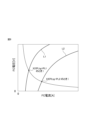
図2は、スタック温度Tfcが或る温度のときの燃料電池スタック10の基準となる電流電圧特性(以下「基準IV特性」という。)を示した図である。基準IV特性は、発電時に生じる各種の発電損失を抑えた高効率発電(通常発電)を実施したときのIV特性である。 FIG. 2 is a diagram showing the reference current-voltage characteristics (hereinafter referred to as "reference IV characteristics") of the fuel cell stack 10 when the stack temperature Tfc is a certain temperature. The reference IV characteristic is an IV characteristic when performing high-efficiency power generation (normal power generation) that suppresses various power generation losses that occur during power generation.
電子制御ユニット200は、燃料電池システム100の運転状態に基づいて、燃料電池スタック10の目標発電電力Ptg[kW]を算出する。本実施形態では電子制御ユニット200は、アクセル踏込量などに基づいて算出されるモータジェネレータ55の要求電力と、コンプレッサ33等の各種の補機類の要求電力と、の合計値を目標発電電力Ptgとして算出する。
The
そして図2に示すように、電子制御ユニット200は、燃料電池スタック10の暖機が完了した後の高効率発電を実施する通常運転時には、FC電流Ifc及びFC電圧Vfcによって規定される動作点Xが、基準IV特性上で目標発電電力Ptgを発電可能な通常動作点X1となるように、エアストイキ比、ひいてはFCエア供給量Qfcを制御する。
As shown in FIG. 2, during normal operation in which high efficiency power generation is performed after the fuel cell stack 10 has been warmed up, the
エアストイキ比とは、目標発電電力Ptgを発電するために最低限必要なFCエア供給量(以下「理論FCエア供給量」という。)Qstに対する、実際のFCエア供給量Qfcの比である。したがって、エアストイキ比(=Qfc/Qst)が1.0よりも大きくなるにつれて、実際のFCエア供給量Qfcが理論FCエア供給量Qstよりも多くなる。 The air stoichiometric ratio is the ratio of the actual FC air supply amount Qfc to the minimum required FC air supply amount (hereinafter referred to as "theoretical FC air supply amount") Qst to generate the target generated power Ptg. Therefore, as the air stoichiometric ratio (=Qfc/Qst) becomes larger than 1.0, the actual FC air supply amount Qfc becomes larger than the theoretical FC air supply amount Qst.
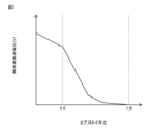
図3は、エアストイキ比と、発電損失の一要因となる酸素濃度過電圧(発電時に酸素不足によって生じる発電損失)と、の関係について説明する図である。 FIG. 3 is a diagram illustrating the relationship between the air stoichiometric ratio and oxygen concentration overvoltage (power generation loss caused by lack of oxygen during power generation), which is a factor in power generation loss.
図3に示すように、酸素濃度過電圧は、エアストイキ比が大きいときに比べて、小さいときのほうが、大きくなる傾向にある。換言すれば、酸素濃度過電圧を要因とする発電損失(電圧降下量)は、エアストイキ比が大きいときに比べて、小さいときのほうが、大きくなる傾向にある。 As shown in FIG. 3, the oxygen concentration overvoltage tends to be larger when the air stoichiometric ratio is small than when it is large. In other words, power generation loss (voltage drop amount) caused by oxygen concentration overvoltage tends to be larger when the air stoichiometric ratio is small than when it is large.
したがって電子制御ユニット200は、通常運転時には、発電損失を抑えた高効率発電を実施するために、エアストイキ比が、酸素濃度過電圧をほぼ無視できる通常領域内のエアストイキ比(図3に示す例では、例えば1.5近傍のエアストイキ比)となるようにFCエア供給量Qfcを制御する。
Therefore, during normal operation, the
一方で電子制御ユニット200は、氷点下の環境で燃料電池システム100を始動して運転するときは、発電に伴って生じる生成水の凍結を抑制しつつ、低温時ほど悪化するIV特性を早期に回復させるため、急速暖機運転を実施する。急速暖機運転は、FCエア供給量Qfcを制御して通常運転時よりも酸素濃度過電圧を増大させることで意図的に発電損失を増大させ、これにより燃料電池スタック10の自己発熱量を増大させて暖機の促進を図る運転方法である。
On the other hand, when starting and operating the
電子制御ユニット200は、急速暖機運転時には、目標発電電力Ptgを発電しつつ、通常運転時よりも発電損失(自己発熱量)を増大させた低効率発電を実施するために、エアストイキ比が、酸素濃度過電圧を無視できなくなる急速暖機領域内のエアストイキ比(図3に示す例では、例えば1.0近傍のエアストイキ比)となるようにFCエア供給量Qfcを制御する。
During the rapid warm-up operation, the
これにより、図2において基準IV特性上で高効率発電を行った場合と比較して、エアストイキ比に応じた酸素濃度過電圧分だけFC電圧Vfcを降下させることできる。そのため、FC電流Ifcを制御しつつ、エアストイキ比、ひいてはFCエア供給量Qfcを適切に制御することで、図2に示すように、通常動作点X1と等電力線(破線参照)上にある、通常動作点X1よりも発電損失を増大させた、所望の自己発熱量が得られる急速暖機動作点X2で発電を行うことができるので、燃料電池スタック10の暖機の促進を図ることができる。 As a result, the FC voltage Vfc can be lowered by the oxygen concentration overvoltage corresponding to the air stoichiometric ratio, compared to the case where high efficiency power generation is performed on the reference IV characteristic in FIG. 2 . Therefore, by appropriately controlling the air stoichiometric ratio and ultimately the FC air supply amount Qfc while controlling the FC current Ifc, as shown in FIG. Since power generation can be performed at the rapid warm-up operating point X2, where the desired self-heating amount is obtained and the power generation loss is increased compared to the operating point X1, warming up of the fuel cell stack 10 can be promoted.
ここで、発明者らの鋭意研究の結果、急速暖機運転中に負電圧になる単セルが発生する場合があることがわかった。負電圧になる単セルが発生すると、当該単セル、ひいては燃料電池スタック10を劣化させるおそれがあるため、急速暖機運転中に負電圧になる単セルが発生しないような措置を講じる必要がある。以下、図4を参照して、まず急速暖機運転中に負電圧になる単セルが発生する原因について説明する。 As a result of intensive research by the inventors, it has been found that a single cell may have a negative voltage during rapid warm-up operation. If a single cell becomes negative voltage, there is a risk of deteriorating the single cell and, by extension, the fuel cell stack 10, so it is necessary to take measures to prevent the occurrence of a single cell becoming negative voltage during rapid warm-up operation. . Hereinafter, with reference to FIG. 4, the cause of generation of a single cell having a negative voltage during rapid warm-up operation will be explained.
図4は、単セルの温度(以下「セル温度」という。)と、当該単セルの抵抗(以下「セル抵抗」という。)との関係を、当該単セルの電解質膜の水分量(以下「膜水分量」という。)に応じて示した図である。 Figure 4 shows the relationship between the temperature of a single cell (hereinafter referred to as "cell temperature") and the resistance of the single cell (hereinafter referred to as "cell resistance"), and the water content of the electrolyte membrane of the single cell (hereinafter referred to as "cell resistance"). FIG.
図4に示すように、セル抵抗は、セル温度が低くなるにつれて増加すると共に、膜水分量が或る一定量よりも少なくなると膜水分量が少なくなるにつれて増加する傾向にある。そして、セル温度が氷点下以下の所定温度T1未満の領域では、膜水分量が或る一定量よりも少ないとセル抵抗が顕著に増加する。なお、以下の説明において、単セルが過乾燥状態であるとは、当該単セルの膜水分量がこの或る一定量よりも少ない状態を指すものとする。 As shown in FIG. 4, the cell resistance tends to increase as the cell temperature decreases, and also tends to increase as the membrane moisture content decreases when the membrane moisture content becomes less than a certain constant amount. In a region where the cell temperature is below a predetermined temperature T1 below freezing point, the cell resistance increases significantly if the film water content is less than a certain fixed amount. In the following description, the term "a single cell is in an overdried state" refers to a state in which the membrane water content of the single cell is less than this certain amount.
発電時における単セルの抵抗過電圧は、当該単セルのセル抵抗の増加に比例して大きくなると共に、当該単セルの出力電流の増加に比例して大きくなる。そして、前述した図2の等電力線の形状から分かるように、発電電力が同じであれば、発電損失(自己発熱量)を大きくするほど、FC電流Ifcは大きくなる。 The resistance overvoltage of a single cell during power generation increases in proportion to an increase in the cell resistance of the single cell, and also increases in proportion to an increase in the output current of the single cell. As can be seen from the shape of the equal power lines in FIG. 2 described above, if the generated power is the same, the larger the power generation loss (self-heating amount) is, the larger the FC current Ifc becomes.
したがって、FC温度Tfcが所定温度T1未満のときに、過乾燥状態の単セルが存在する状態で低効率発電が行われると、過乾燥状態の単セルのセル抵抗が非常に大きくなって当該単セルの電圧(以下「セル電圧」という。)が大きく低下する。その結果、過乾燥状態の単セルのセル電圧が負電圧になるものと考えられる。すなわち、急速暖機運転中に負電圧となる単セルが発生するのは、FC温度Tfcが所定温度T1未満のときに、過乾燥状態の単セルが存在する状態で低効率発電が行われることが原因と考えられる。 Therefore, if low-efficiency power generation is performed in the presence of an over-dried single cell when the FC temperature Tfc is less than the predetermined temperature T1, the cell resistance of the over-dried single cell becomes extremely large and The cell voltage (hereinafter referred to as "cell voltage") drops significantly. As a result, it is thought that the cell voltage of the overdried single cell becomes a negative voltage. In other words, the reason why a single cell having a negative voltage occurs during rapid warm-up operation is that when the FC temperature Tfc is lower than the predetermined temperature T1, low efficiency power generation is performed in the presence of an overdried single cell. This is thought to be the cause.
そこで本実施形態では、システム始動時のFC温度Tfcが所定温度T1未満のときは、発電に伴って生じる生成水量が所定量に達するまで、通常の低効率発電(後述する第2低効率発電)よりも発電損失(自己発熱量)を抑えた第1低効率発電を実施することとした。所定量は、仮に或る単セルが過乾燥状態であったとしても、過乾燥状態が解消されたと判断可能な生成水量とされる。 Therefore, in this embodiment, when the FC temperature Tfc at the time of system startup is less than the predetermined temperature T1, normal low-efficiency power generation (second low-efficiency power generation to be described later) is performed until the amount of water produced during power generation reaches a predetermined amount. We decided to implement the first low-efficiency power generation method, which suppresses power generation loss (self-heating amount). The predetermined amount is the amount of produced water at which it can be determined that even if a certain unit cell is in an overdry state, the overdry state has been resolved.
これにより、仮に或る単セルが過乾燥状態であったとしても、発電に伴って生じる生成水によってその単セルの過乾燥状態が解消されるまでの間、FC電流Ifcを低く抑えることができるので、抵抗過電圧を小さくすることができる。そのため、負電圧となる単セルが発生するのを抑制することができる。 As a result, even if a certain single cell is in an over-dry state, the FC current Ifc can be kept low until the over-dry state of the single cell is resolved by the water produced during power generation. Therefore, resistance overvoltage can be reduced. Therefore, it is possible to suppress the occurrence of a single cell having a negative voltage.
そして、生成水量が所定量以上になったら、第1低効率発電よりも発電損失(自己発熱量)を増大させた通常の低効率発電である第2低効率発電を実施して、燃料電池スタック10の暖機の促進を図ることとした。 When the amount of generated water exceeds a predetermined amount, the second low-efficiency power generation, which is normal low-efficiency power generation with increased power generation loss (self-heating amount) than the first low-efficiency power generation, is performed to stack the fuel cell. We decided to promote warm-up of 10.
図5は、この本実施形態による燃料電池システム100の急速暖機制御について説明するフローチャートである。電子制御ユニット200は、本ルーチンを所定の演算周期(例えば10[ms])で繰り返し実行する。
FIG. 5 is a flowchart illustrating rapid warm-up control of the
ステップS1において、電子制御ユニット200は、第1フラグF1及び第2フラグF2が、それぞれ0に設定されているか否かを判定する。第1フラフF1は、急速暖機運転中において、前述した第1低効率発電を実施しているときに1に設定されるフラグであって、初期値は0に設定される。第2フラグF2は、急速暖機運転中において、前述した第2低効率発電を実施しているときに1に設定されるフラグであって、初期値は0に設定される。電子制御ユニット200は、第1フラグF1及び第2フラグF2が、それぞれ0に設定されていれば、ステップS2の処理に進む。一方で電子制御ユニット200は、第1フラグF1又は第2フラグF2が1に設定されていればステップS6の処理に進む。
In step S1, the
ステップS2において、電子制御ユニット200は、急速暖機運転の実施要求があるか否かを判定する。本実施形態では電子制御ユニット200は、システム始動時におけるFC温度Tfcが所定の急速暖機要求温度(例えば0[℃])以下であれば急速暖機運転の実施要求があると判定する。電子制御ユニット200は、急速暖機運転の実施要求があると判定したときは、ステップS3の処理に進む。一方で電子制御ユニット200は、急速暖機運転の実施要求がないと判定したときは、今回の処理を終了する。
In step S2, the
ステップS3において、電子制御ユニット200は、急速暖機運転の実施要求があるときに、第1低効率発電を実施してから第2抵抗率発電をするか、又は第1低効率発電を実施せずに最初から第2低効率発電を実施するかを決定する。本実施形態では電子制御ユニット200は、システム始動時におけるFC温度Tfcを所定の基準温度Tthrと比較することで、第1低効率発電を実施してから第2抵抗率発電をするか、又は第1低効率発電を実施せずに最初から第2低効率発電を実施するかを決定する。本実施形態では基準温度Tthrは、図4を参照して前述した所定温度T1とされる。
In step S3, when there is a request to perform rapid warm-up operation, the
電子制御ユニット200は、システム始動時におけるFC温度Tfcが、基準温度Tthr未満であれば、第1低効率発電を実施してから第2抵抗率発電を実施するべく、ステップS4の処理に進む。一方で電子制御ユニット200は、システム始動時におけるFC温度Tfcが、基準温度Tthr以上であれば、仮に過乾燥状態の単セルが存在していたとしても、当該単セルのセル抵抗の増加が許容範囲であり、当該単セルのセル電圧が負電圧になるほどではないと判断し、システム始動時から第2低効率発電を実施して暖機の促進を図るべく、ステップS5の処理に進む。
If the FC temperature Tfc at the time of system startup is less than the reference temperature Tthr, the
ステップS4において、電子制御ユニット200は、第1低効率発電を実施してから第2抵抗率発電を実施するべく、第1フラグF1を1に設定する。
In step S4, the
ステップS5において、電子制御ユニット200は、システム始動時から第2低効率発電を実施するべく、第2フラグF2を1に設定する。
In step S5, the
ステップS6において、電子制御ユニット200は、急速暖機運転中における燃料電池スタック10の目標発熱量PLtg[kW]を設定するための処理を実施する。この目標発熱量設定処理の詳細については、図6のフローチャートを参照して説明する。
In step S6, the
ステップS61において、電子制御ユニット200は、第1フラグF1が1に設定されているか否かを判定する。電子制御ユニット200は、第1フラグF1が1に設定されていれば、ステップS62の処理に進む。一方で電子制御ユニット200は、第1フラグF1が0に設定されていれば(第2フラグF2が1に設定されていれば)、ステップS66の処理に進む。
In step S61, the
ステップS62において、電子制御ユニット200は、発電に伴って生じる生成水量と相関関係にあるパラメータとして、第1低効率発電を開始してからのFC電流Ifcの積算値(以下「電流積算値」という。)q[C]を算出する。
In step S62, the
ステップS63において、電子制御ユニット200は、発電に伴って生じる生成水量が所定量に達したか否かを判定する。本実施形態では電子制御ユニット200は、電流積算値qが所定積算値qthr未満であれば、発電に伴って生じる生成水量がまだ所定量に達していないと判定してステップS64の処理に進む。一方で電子制御ユニット200は、電気量qが所定積算値qthr以上であれば、発電に伴って生じる生成水量が所定量に達した判定してステップS65の処理に進む。
In step S63, the
所定積算値qthrは、仮に燃料電池システム100の始動時において或る単セルが過乾燥状態であったとしても、発電に伴って生じる生成水によって当該単セルの過乾燥状態が解消された判断可能な電流積算値とされる。
The predetermined integrated value qthr makes it possible to determine that even if a certain unit cell is in an over-dry state at the time of starting the
ステップS64において、電子制御ユニット200は、第1低効率発電を実施するべく、目標発熱量PLtgを、第1発熱量PL1(例えば、15~25[kW])に設定する。
In step S64, the
ステップS65において、電子制御ユニット200は、第1フラグF1を0に戻すと共に、第1低効率発電から第2低効率発電に切り替えるべく、第2フラグF2を1に設定する。
In step S65, the
ステップS66において、電子制御ユニット200は、第2低効率発電を実施するべく、目標発熱量PLtgを、第1発熱量PL1よりも大きい第2発熱量PL2(例えば、50~60[kW])に設定する。
In step S66, the
図5に戻り、ステップS7において、電子制御ユニット200は、低効率発電を実施する。低効率発電時の詳細な処理については、図7を参照して後述する。
Returning to FIG. 5, in step S7, the
ステップS8において、電子制御ユニット200は、燃料電池スタック10の暖機が完了したか否かを判定する。本実施形態では電子制御ユニット200は、FC温度Tfcが、所定の急速暖機完了温度(例えば70[℃])以上になったか否かを判定する。電子制御ユニット200は、FC温度Tfcが急速暖機完了温度以上であれば、ステップS9の処理に進む。一方で電子制御ユニット200は、FC温度Tfcが急速暖機完了温度未満であれば、今回の処理を終了する。
In step S8,
ステップS9において、電子制御ユニット200は、急速暖機運転を終了し、第1フラグF1及び第2フラグF2をそれぞれ0に戻すと共に、電流積算値qの値をゼロに戻す。
In step S9, the
図7は、低効率発電時の詳細な処理について説明するフローチャートである。 FIG. 7 is a flowchart illustrating detailed processing during low efficiency power generation.
ステップS71において、電子制御ユニット200は、燃料電池システム100の運転状態に基づいて、燃料電池スタック10の目標発電電力Ptgを算出する。本実施形態では電子制御ユニット200は、前述した通り、モータジェネレータ55の要求電力と、コンプレッサ33等の各種の補機類の要求電力と、の合計値を目標発電電力Ptgとして算出する。
In step S71, the
ステップS72において、電子制御ユニット200は、図8に示す等電力線と等発熱量線とが描かれたIV特性マップを参照し、目標発電電力Ptgと、目標発熱量PLtgと、基づいて、急速暖機動作点X2、すなわち目標FC電流Itg[A]及び目標FC電圧Vtg[V]を算出する。
In step S72, the
具体的には電子制御ユニット200は、図9に示すように、等電力線の中から目標発電電力Ptgを発電することが可能な等電力線を選択し、選択した等電力線と、IV特性マップ上で発熱量を目標発熱量PLtgにすることが可能な等発熱量線と、が交わる点を急速暖機動作点X2として算出する。
Specifically, as shown in FIG. 9, the
なお図8及び図9において、等発熱量線L1が、発熱量を第1発熱量PL1にすることが可能な等発熱量線であり、等発熱量線L2が、発熱量を第2発熱量PL2にすることが可能な等発熱量線である。 In FIGS. 8 and 9, the equal calorific value line L1 is an equal calorific value line that can change the calorific value to the first calorific value PL1, and the equal calorific value line L2 can change the calorific value to the second calorific value. This is an isothermal value line that can be set to PL2.
ステップS73において、電子制御ユニット200は、図10に示す基準IV特性マップを参照し、基準IV特性上でFC電流Ifcを目標FC電流Itgに制御したときのFC電圧(以下「基準FC電圧」という。)Vstdを算出する。基準FC電圧Vstdは、換言すれば、高効率発電(通常発電)を実施してFC電流Ifcを目標FC電流Itgに制御したときのFC電圧である。
In step S73, the
なお基準IV特性は、FC温度Tfcに応じて変化するため、基準IV特性マップはFC温度毎に複数用意されている。したがって電子制御ユニット200は、複数の基準IV特性マップの中から、現在のFC温度Tfcに応じた最適な基準IV特性マップを参照して基準FC電圧Vstdを算出している。
Note that since the reference IV characteristic changes depending on the FC temperature Tfc, a plurality of reference IV characteristic maps are prepared for each FC temperature. Therefore, the
ステップS74において、電子制御ユニット200は、図3と同様の図11に示すエアストイキ比と酸素濃度過電圧との関係を表すマップを参照し、基準FC電圧Vstdと目標FC電圧Vtgとの差分(すなわち、基準FC電圧Vstdを目標FC電圧Vtgまで低下させるために発生させる必要のある酸素濃度過電圧)ΔV1(=Vstd-Vtg)に基づいて、基準エアストイキ比SRstdを算出する。
In step S74, the
ステップS75において、電子制御ユニット200は、目標FC電圧Vtgと、FC電圧Vfcと、の偏差(以下「FC電圧偏差」という。)ΔV2(=Vtg-Vfc)に基づいて、基準エアストイキ比SRstdに対するフィードバック補正値を算出し、基準エアストイキ比SRstdに当該フィードバック補正値を加算することで、目標エアストイキ比SRtgを算出する。
In step S75, the
ステップS76において、電子制御ユニット200は、目標発電電力Ptgを発電するために必要な理論FCエア供給量Qthに目標エアストイキ比SRtgを掛け合わせることで、目標FCエア供給量Qtgを算出する。
In step S76, the
ステップS77において、電子制御ユニット200は、FC電流Ifc及びFC電圧Vfcによって規定される動作点Xが、急速暖機動作点X2となるように、各制御部品を制御する。
In step S77, the
具体的には電子制御ユニット200は、第1コンバータ51を制御してFC電流Ifcを目標FC電流Itgに制御すると共に、FCエア供給量Qfcを目標エア供給量Qtgに制御する。このとき電子制御ユニット200は、総エア供給量Qafcが一定になるようにコンプレッサ33を制御し、カソード入口弁35、分流弁37及びカソード圧力制御弁39の各開度を制御することで、FCエア供給量Qfcを目標エア供給量Qtgに制御する。
Specifically,
図12A及び図12Bは、それぞれ本実施形態による急速暖機制御を実施したときの作用効果について説明する図である。 FIGS. 12A and 12B are diagrams each illustrating the effects when performing rapid warm-up control according to this embodiment.
図12Aは、FC電流Ifcを横軸として、本実施形態による急速暖機制御を実施したときの、過乾燥状態の単セルのセル電圧(実線参照)、燃料電池スタック10の平均セル電圧(破線参照)、及び電流積算値q(一点鎖線参照)の時間的変化を示した図である。なお、図12Aにおいて、FC電流Ifc1は、第1低効率発電を実施したとき、すなわち目標発熱量PLtgを第1発熱量PL1に設定したときの目標FC電流である。FC電流Ifc2は、第2低効率発電を実施したとき、すなわち目標発熱量PLtgを第2発熱量PL2に設定したときの目標FC電流である。 FIG. 12A shows the cell voltage of an overdried single cell (see solid line) and the average cell voltage of the fuel cell stack 10 (dashed line) when performing rapid warm-up control according to the present embodiment, with FC current Ifc as the horizontal axis. FIG. 3 is a diagram showing temporal changes in the current integrated value q (see the dashed line) and the current integrated value q (see the dashed line). Note that in FIG. 12A, the FC current Ifc1 is the target FC current when the first low-efficiency power generation is performed, that is, when the target calorific value PLtg is set to the first calorific value PL1. The FC current Ifc2 is the target FC current when the second low-efficiency power generation is performed, that is, when the target calorific value PLtg is set to the second calorific value PL2.
図12Aに示すように、急速暖機運転の開始時に第1低効率発電が実施されると、FC電流Ifcが第1低効率発電時の目標FC電流Ifc1まで増加させられ、電流積算値qが第1積算値q1まで増加する。FC電流Ifcの増加に伴って過乾燥状態の単セルのセル電圧は低下することになるが、第1低効率発電時の目標FC電流Ifc1は、第2低効率発電時の目標FC電流Ifc2よりも小さくなるため、抵抗過電圧を抑えて過乾燥状態の単セルのセル電圧の低下を概ね0[V]付近までに抑えることができる。 As shown in FIG. 12A, when the first low-efficiency power generation is performed at the start of the rapid warm-up operation, the FC current Ifc is increased to the target FC current Ifc1 during the first low-efficiency power generation, and the current integrated value q is increased. It increases to the first integrated value q1. As the FC current Ifc increases, the cell voltage of the overdried single cell will decrease, but the target FC current Ifc1 during the first low-efficiency power generation is lower than the target FC current Ifc2 during the second low-efficiency power generation. Therefore, the resistance overvoltage can be suppressed and the drop in cell voltage of a single cell in an overdried state can be suppressed to about 0 [V].
そして、第1低効率発電が実施されている期間(FC電流IfcがIfc1に制御されている期間)に発生する生成水によって過乾燥状態の単セルの膜水分量が徐々に増加し、これにより過乾燥状態の単セルの抵抗過電圧が徐々に低下していくので、過乾燥状態の単セルのセル電圧が徐々に回復(増加)していく。 Then, the membrane moisture content of the overdried single cell gradually increases due to the generated water generated during the period when the first low-efficiency power generation is being performed (the period when the FC current Ifc is controlled to Ifc1), and this causes Since the resistance overvoltage of the over-dried single cell gradually decreases, the cell voltage of the over-dried single cell gradually recovers (increases).
そして、第1低効率発電が実施されている期間の電流積算値qが第2積算値q2に達して、過乾燥状態の単セルのセル電圧が、燃料電池スタック10の平均セル電圧と同等になるまで回復(増加)したら、FC電流Ifcが第2低効率発電時の目標FC電流Ifc2まで増加させられて、暖機の促進が図られる。 Then, the current integrated value q during the period in which the first low-efficiency power generation is performed reaches the second integrated value q2, and the cell voltage of the over-dried single cell becomes equal to the average cell voltage of the fuel cell stack 10. When the FC current Ifc is recovered (increased) to the point where it is, the FC current Ifc is increased to the target FC current Ifc2 during the second low-efficiency power generation, and warm-up is promoted.
本実施形態では、この第2積算値q2を、発電に伴って生じる生成水量が所定量に達したか否かを判定するための所定積算値qthr、すなわち、仮にシステム始動時において或る単セルが過乾燥状態であったとしても、発電に伴って生じる生成水によって当該単セルの過乾燥状態が解消されたと判断可能な所定積算値qthrとしている。 In the present embodiment, this second integrated value q2 is used as a predetermined integrated value qthr for determining whether the amount of water generated during power generation has reached a predetermined amount, that is, if a certain single cell is used at the time of system startup. Even if the unit cell is in an over-dry state, the predetermined integrated value qthr is set such that it can be determined that the over-dry state of the unit cell has been resolved by the generated water generated during power generation.
図12Bは、電流積算値qを横軸として、本実施形態による急速暖機制御を実施したときの、過乾燥状態の単セルのセル電圧、及び燃料電池スタック10の平均セル電圧の時間的変化を示した図である。 FIG. 12B shows temporal changes in the cell voltage of a single cell in an overdried state and the average cell voltage of the fuel cell stack 10 when the rapid warm-up control according to the present embodiment is performed with the current integrated value q as the horizontal axis. FIG.
図12Bに示すように、電流積算値qが第1積算値q1になるまでの間、すなわち、急速暖機運転の開始時に第1低効率発電が実施されて、FC電流Ifcが第1低効率発電時の目標FC電流Ifc1まで増加させられるまでは、FC電流Ifcの増加に伴って過乾燥状態の単セルのセル電圧は低下する。 As shown in FIG. 12B, the first low efficiency power generation is performed until the current integrated value q reaches the first integrated value q1, that is, at the start of the rapid warm-up operation, and the FC current Ifc becomes the first low efficiency power generation. Until the FC current Ifc is increased to the target FC current Ifc1 during power generation, the cell voltage of the overdried single cell decreases as the FC current Ifc increases.
そして、電流積算値qが第1積算値q1から第2積算値q2になるまでの間は、第1低効率発電時に発生する生成水によって過乾燥状態の単セルの膜水分量が徐々に増加し、これにより過乾燥状態の単セルの抵抗過電圧が徐々に低下していくので、過乾燥状態の単セルのセル電圧が徐々に回復(増加)していく。 Then, until the current integrated value q changes from the first integrated value q1 to the second integrated value q2, the membrane water content of the overdried single cell gradually increases due to the water generated during the first low-efficiency power generation. However, as a result, the resistance overvoltage of the overdried single cell gradually decreases, so that the cell voltage of the overdried single cell gradually recovers (increases).
そして、電流積算値qが第2積算値q2になると、過乾燥状態の単セルのセル電圧が、燃料電池スタック10の平均セル電圧と同等になるまで回復(増加)する。 Then, when the current integrated value q reaches the second integrated value q2, the cell voltage of the overdried single cell recovers (increases) until it becomes equal to the average cell voltage of the fuel cell stack 10.
なお前述した通り、本実施形態では、この第2積算値q2を所定積算値qthrとしている。第2積算値q2は、換言すれば、過乾燥状態の単セルが存在していたとしても、発電に伴って生じる生成水によって当該単セルの過乾燥状態が完全に解消された判断可能な電流積算値である。 As described above, in this embodiment, this second integrated value q2 is set as the predetermined integrated value qthr. In other words, the second integrated value q2 is a current that can be determined to indicate that even if there is a single cell in an over-dry state, the over-dry state of the single cell has been completely eliminated by the water produced during power generation. This is an integrated value.
しかしながら、これに限らず、第1積算値q1から第2積算値q2までの間の任意の電流積算値を所定積算値qthrとして設定し、過乾燥状態が或る程度解消された時点で、第2低効率発電を実施するようしてもよい。なお、電極面積が200[cm2]から400[cm2]の単セルの場合、第1積算値q1は概ね100[C]であり、第2積算値q2は概ね400[C]であった。 However, the present invention is not limited to this, and an arbitrary current integrated value between the first integrated value q1 and the second integrated value q2 can be set as the predetermined integrated value qthr, and when the over-drying state has been resolved to a certain extent, the 2 Low-efficiency power generation may be performed. In addition, in the case of a single cell with an electrode area of 200 [cm 2 ] to 400 [cm 2 ], the first integrated value q1 was approximately 100 [C], and the second integrated value q2 was approximately 400 [C]. .
また本実施形態では、所定積算値qthrを第2積算値q2に固定していたが、可変値としてもよい。例えば、システム始動時におけるFC温度Tfcが相対的に高いときには、電流積算値qが所定積算値qthrに達する前に、FC温度Tfcが過乾燥状態の単セルのセル抵抗が許容範囲となる温度(例えば、少なくとも0℃以上の温度)まで早期に上昇することも考えられる。このような場合には、FC温度Tfcが過乾燥状態の単セルのセル抵抗が許容範囲内となる温度に達した時点で第2低効率発電を実施しても、過乾燥状態の単セルのセル電圧が負電圧になるのを抑制できる。したがって、システム始動時におけるFC温度Tfcが高いときには、低いときに比べて所定積算値qthrが小さくなるように、所定積算値qthrを、システム始動時におけるFC温度Tfcに応じた可変値としてもよい。 Further, in this embodiment, the predetermined integrated value qthr is fixed to the second integrated value q2, but it may be a variable value. For example, when the FC temperature Tfc at the time of system startup is relatively high, before the current integrated value q reaches the predetermined integrated value qthr, the FC temperature Tfc reaches the temperature ( For example, it is also conceivable that the temperature rises early to at least 0° C. or higher. In such a case, even if the second low-efficiency power generation is performed when the FC temperature Tfc reaches a temperature at which the cell resistance of the overdried single cell is within the allowable range, the It is possible to suppress the cell voltage from becoming a negative voltage. Therefore, the predetermined integrated value qthr may be a variable value depending on the FC temperature Tfc at the time of system startup so that when the FC temperature Tfc at the time of system startup is high, the predetermined integrated value qthr is smaller than when it is low.
以上説明した本実施形態による燃料電池システム100は、燃料ガスと酸化剤ガスとの電気化学反応により電力を発生する燃料電池スタック10(燃料電池)と、電子制御ユニット200(制御装置)と、を備える。電子制御ユニット200は、通常発電と比べて発電損失の大きい低効率発電を実施する低効率発電実施部を備える。
The
そして低効率発電実施部は、燃料電池スタック10の発電開始時におけるFC温度Tfcが基準温度Tthr未満のときは、発電損失に伴う燃料電池スタック10の発熱量が第1発熱量PL1となるように燃料電池スタック10を発電させるように構成される。また低効率発電実施部は、発電損失に伴う燃料電池スタック10の発熱量が第1発熱量PL1となるように燃料電池スタック10を発電させている期間の電流積算値qが所定積算値qthr以上になったときは、発熱量が第1発熱量PL1よりも大きい第2発熱量PL2となるように燃料電池スタック10を発電させるように構成される。 Then, when the FC temperature Tfc at the start of power generation of the fuel cell stack 10 is less than the reference temperature Tthr, the low efficiency power generation execution unit sets the heat value of the fuel cell stack 10 due to power generation loss to be the first heat value PL1. The fuel cell stack 10 is configured to generate electricity. In addition, the low-efficiency power generation implementation unit determines whether the current integrated value q during the period in which the fuel cell stack 10 is generating power is equal to or greater than a predetermined integrated value qthr so that the heat value of the fuel cell stack 10 due to power generation loss becomes the first heat value PL1. When this happens, the fuel cell stack 10 is configured to generate electricity so that the calorific value becomes the second calorific value PL2, which is larger than the first calorific value PL1.
本実施形態では基準温度Tthrは、所定温度T1とされる。所定温度T1は、FC温度Tfcが所定温度T1未満になると、FC温度Tfcが所定温度T1以上のときと比べて、電解質膜の水分量が所定量よりも少ない過乾燥状態の単セルの抵抗値の増加がより顕著となる温度である。また所定積算値qthrは、燃料電池スタック10の発電に伴って生じる、燃料電池スタック10の発電開始時からの生成水の量が、所定量以上となる値である。 In this embodiment, the reference temperature Tthr is a predetermined temperature T1. The predetermined temperature T1 is the resistance value of a single cell in an overdried state where the moisture content of the electrolyte membrane is less than the predetermined amount when the FC temperature Tfc becomes less than the predetermined temperature T1 compared to when the FC temperature Tfc is equal to or higher than the predetermined temperature T1. This is the temperature at which the increase in . Further, the predetermined integrated value qthr is a value at which the amount of water generated from the start of power generation of the fuel cell stack 10, which occurs as the fuel cell stack 10 generates power, is equal to or greater than a predetermined amount.
これにより、FC温度Tfcが、過乾燥状態の単セルのセル抵抗が顕著に増加し始める所定温度T1未満のときには、仮に過乾燥状態の単セルが存在していたとしても、生成水量が所定量以上となってその単セルの過乾燥状態が解消されるまで、発熱量を第1発熱量PL1に抑えた第1低効率発電を実施することができる。すなわち、仮に過乾燥状態の単セルが存在していたとしても、生成水量が所定量以上となってその単セルの過乾燥状態が解消されるまで、発電中のFC電流Ifcを低く抑えることができる。そのため、仮に過乾燥状態の単セルが存在していたとしても、その単セルの抵抗過電圧を小さくすることができる。したがって、仮に過乾燥状態の単セルが存在していたとしても、急速暖機運転中に負電圧になる単セルが発生するのを抑制することができる。 As a result, when the FC temperature Tfc is less than a predetermined temperature T1 at which the cell resistance of an overdried single cell starts to increase significantly, even if an overdried single cell exists, the amount of water produced is reduced to a predetermined amount. Until the over-dry state of the single cell is resolved, the first low-efficiency power generation in which the calorific value is suppressed to the first calorific value PL1 can be performed. In other words, even if there is a single cell in an overdry state, the FC current Ifc during power generation cannot be kept low until the amount of water produced exceeds a predetermined amount and the overdry state of the single cell is resolved. can. Therefore, even if an overdried single cell exists, the resistance overvoltage of that single cell can be reduced. Therefore, even if there are single cells in an overdry state, it is possible to suppress the occurrence of a single cell having a negative voltage during rapid warm-up operation.
(第2実施形態)
次に、本発明の第2実施形態について説明する。本実施形態は、急速暖機運転の開始時に第1低効率発電を実施するか、又は第1低効率発電を実施せずに第2低効率発電を実施するかを判断するための基準温度Tfcを可変値とした点で、第1実施形態と相違する。以下、その相違点を中心に説明する。
(Second embodiment)
Next, a second embodiment of the present invention will be described. This embodiment uses a reference temperature Tfc for determining whether to perform the first low-efficiency power generation or to perform the second low-efficiency power generation without performing the first low-efficiency power generation at the start of rapid warm-up operation. This embodiment differs from the first embodiment in that is set as a variable value. The differences will be mainly explained below.
図13は、図4と同様の図であり、単セルのセル温度と、当該単セルのセル抵抗と、の関係を、当該単セルの膜水分量に応じて示した図である。 FIG. 13 is a diagram similar to FIG. 4, and is a diagram showing the relationship between the cell temperature of a single cell and the cell resistance of the single cell, depending on the film moisture content of the single cell.
前述した第1実施形態では、急速暖機運転の開始時に過乾燥状態の単セルが実際に存在するか否かにかかわらず、過乾燥状態の単セルが存在することを前提に、過乾燥状態の単セルのセル抵抗が顕著に増加し始める所定温度T1を基準温度Tfcとして設定していた。 In the first embodiment described above, regardless of whether or not an overdry unit cell actually exists at the start of rapid warm-up operation, the overdry state is determined based on the premise that an overdry unit cell exists. A predetermined temperature T1 at which the cell resistance of a single cell begins to increase significantly was set as the reference temperature Tfc.
しかしながら、急速暖機運転の開始時において、過乾燥状態の単セルが存在しないと判断できるのであれば、例えば図13に示すように、基準温度Tfcを、過乾燥状態ではない湿潤状態の単セルのセル抵抗が増加し始める所定温度T2まで下げることができる。基準温度Tfcを下げることができれば、急速暖機運転の開始時から第2低効率発電を実施できる機会を増やすことができる。急速暖機運転の開始時から第2低効率発電を実施することで、第1低効率発電を実施してから第2低効率発電を実施したときよりも、暖機完了までの時間(暖機時間)を短くすることができる。その結果、短時間で暖機を完了させることができる機会を増やすことができる。 However, if it can be determined that there are no over-dry single cells at the start of rapid warm-up operation, for example, as shown in FIG. The temperature can be lowered to a predetermined temperature T2 at which the cell resistance begins to increase. If the reference temperature Tfc can be lowered, it is possible to increase the chances of performing the second low-efficiency power generation from the start of the rapid warm-up operation. By performing the second low-efficiency power generation from the start of rapid warm-up operation, the time required to complete warm-up (warm-up time) can be shortened. As a result, it is possible to increase the chances of completing warm-up in a short time.
ここで、システム運転中に発生した液水が、システム停止後も燃料電池スタック10内に残留したままになっていると、システム停止期間中に液水が凍結し、システム始動時の発電性能が悪化するおそれがある。そのため、本実施形態による電子制御ユニット200は、システム停止後に、必要に応じて燃料電池スタック10にアノードガスやカソードガスを供給し、燃料電池スタック10内の液水を外部に排出するための掃気処理を実施するように構成されている。
Here, if the liquid water generated during system operation remains in the fuel cell stack 10 even after the system is stopped, the liquid water will freeze during the system stop period, and the power generation performance at the time of system startup will deteriorate. It may get worse. Therefore, after the system is stopped, the
具体的には電子制御ユニット200は、燃料電池システム100の掃気モードを、例えば、直近数日間の最低気温の平均値に応じて第1掃気モード又は第2掃気モードに設定しており、掃気モードが、直近数日間の最低気温の平均値が氷点下よりも高いときに設定される第1掃気モード(通常掃気モード)のときには、システム停止期間中のFC温度Tfcが氷点下以下になったときに限り、燃料電池スタック10で発電を行わずに燃料電池スタック10内の掃気を例外的に実施するように構成されている。そして電子制御ユニット200は、直近数日間の最低気温の平均値が氷点下以下のときに設定される第2掃気モード(冬季掃気モード)のときには、システム停止時に燃料電池スタック10を発電させた状態で燃料電池スタック10内の掃気を必ず実施するように構成されている。
Specifically, the
なお、第2掃気モードへの切替条件は、上記の条件に限られるものではなく、例えば、システム運転中に一定期間外気温が氷点下以下になったときに第2掃気モードへ切り替えるようにしてもよいし、システム終了時に外気温が氷点下以下であれば第2掃気モードへ切り替えるようにしてもよい。 Note that the conditions for switching to the second scavenging mode are not limited to the above conditions; for example, the switching to the second scavenging mode may be performed when the outside temperature drops below freezing for a certain period of time during system operation. It is also possible to switch to the second scavenging mode if the outside temperature is below freezing when the system is terminated.
掃気モードが第1掃気モードのときに行われる掃気処理は、発電を行わずに予め設定された所定時間だけ燃料電池スタック10内の掃気を行うものなので、システム停止時の各単セルの膜水分量に応じて、過乾燥状態になる単セルが発生する場合がある。一方で掃気モードが第2掃気モードのときに行われる掃気処理は、発電を実施しつつ、システム停止後の各単セルの膜水分量が所定量以下となるように燃料電池スタック10内の掃気を行うものなので、基本的に過乾燥状態になる単セルが発生するおそれがない。 The scavenging process performed when the scavenging mode is the first scavenging mode is to scavenge the air inside the fuel cell stack 10 for a preset period of time without generating electricity, so that the membrane moisture of each single cell when the system is stopped is Depending on the amount, over-dry single cells may occur. On the other hand, the scavenging process performed when the scavenging mode is the second scavenging mode is to scavenge the air in the fuel cell stack 10 so that the membrane water content of each single cell after the system is stopped is equal to or less than a predetermined amount while generating electricity. Basically, there is no risk of single cells becoming overly dry.
そこで本実施形態では、掃気モードが第1掃気モードに設定されていて、かつ、システム停止期間中に燃料電池スタック10内の掃気が行われたときは、過乾燥状態の単セルが存在する可能性があるため、第1実施形態と同様に、基準温度Tthrを所定温度T1に設定することとした。 Therefore, in this embodiment, when the scavenging mode is set to the first scavenging mode and the scavenging inside the fuel cell stack 10 is performed during the system stop period, there is a possibility that an over-dry single cell may exist. Therefore, as in the first embodiment, the reference temperature Tthr is set to the predetermined temperature T1.
そして、掃気モードが第2掃気モードに設定されているときは、システム停止時に膜水分量を管理しながら燃料電池スタック10内の掃気が必ず行われ、これにより、前述した通り基本的に過乾燥状態になる単セルが発生するおそれがないので、基準温度を所定温度T1よりも低温の所定温度T2に設定することとした。 When the scavenging mode is set to the second scavenging mode, scavenging inside the fuel cell stack 10 is always performed while managing the membrane water content when the system is stopped. Since there is no possibility that a single cell will be in this state, the reference temperature is set to a predetermined temperature T2 that is lower than the predetermined temperature T1.
図14は、本実施形態による急速暖機制御について説明するフローチャートである。電子制御ユニット200は、本ルーチンを所定の演算周期(例えば10[ms])で繰り返し実行する。図14において、ステップS1からステップS9までの処理の内容は、前述した第1実施形態の処理の内容と同じなので、ここでは説明を省略する。
FIG. 14 is a flowchart illustrating rapid warm-up control according to this embodiment. The
ステップS10において、電子制御ユニット200は、基準温度切替処理を実施する。基準温度切替処理の詳細については、図15を参照して説明する。
In step S10, the
図15は、基準温度切替処理について説明するフローチャートである。 FIG. 15 is a flowchart illustrating the reference temperature switching process.
ステップS101において、電子制御ユニット200は、掃気モードが第1掃気モードであるか、又は第2掃気モードであるかを判定する。電子制御ユニット200は、掃気モードが第1掃気モードであれば、ステップS102の処理に進む。一方で電子制御ユニット200は、掃気モードが第2掃気モードであれば、ステップS104の処理に進む。
In step S101, the
ステップS102において、電子制御ユニット200は、システム停止期間中に燃料電池スタック10内の掃気が行われたか否かを判定する。電子制御ユニット200は、システム停止期間中に燃料電池スタック10内の掃気が行われていれば、ステップS103の処理に進む。一方で電子制御ユニット200は、システム停止期間中に燃料電池スタック10内の掃気が行われていなければ、ステップS104の処理に進む。
In step S102, the
ステップS103において、電子制御ユニット200は、基準温度Tthrを、所定温度T1に設定する。所定温度T1は、例えば-10[℃]前後の温度である。
In step S103, the
ステップS104において、電子制御ユニット200は、基準温度Tthrを、所定温度T1よりも低い所定温度T2に設定する。所定温度T2は、例えば-20[℃]前後の温度である。
In step S104, the
以上説明した本実施形態によれば、電子制御ユニット200は、前述した低効率発電実施部に加え、燃料電池スタック10の掃気モードを、第1掃気モード又は第2掃気モードに切り替える掃気モード切替部をさらに備える。第1掃気モードは、燃料電池システム100の停止期間中において、FC温度Tfcが氷点下以下になったときに限り、燃料電池スタック10を発電させずに燃料電池スタック10内の掃気を実施する掃気モードである。第2掃気モードは、燃料電池システム100の停止時に燃料電池スタック10を発電させた状態で燃料電池スタック10内の掃気を実施する掃気モードである。
According to the present embodiment described above, the
そして本実施形態による低効率発電実施部は、燃料電池スタック10の掃気モードが第2掃気モードのときは、第1掃気モードの場合に燃料電池スタック10内の掃気が実施されたときと比較して、基準温度Tthrを低くするように構成される。 The low-efficiency power generation implementation unit according to the present embodiment performs scavenging in the fuel cell stack 10 when the scavenging mode of the fuel cell stack 10 is the second scavenging mode compared to when the scavenging inside the fuel cell stack 10 is performed in the first scavenging mode. Thus, the reference temperature Tthr is lowered.
低効率発電実施部は、より詳細には、掃気モードが前記第1掃気モードの場合に燃料電池スタック10内の掃気が実施されたときは、基準温度Tthrを所定の第1温度T1に設定し、掃気モードが第2掃気モードのときは、基準温度Tthrを第1温度T1よりも低い所定の第2温度T2に設定するように構成される。 More specifically, when scavenging is performed in the fuel cell stack 10 when the scavenging mode is the first scavenging mode, the low efficiency power generation execution unit sets the reference temperature Tthr to a predetermined first temperature T1. When the scavenging mode is the second scavenging mode, the reference temperature Tthr is set to a predetermined second temperature T2 lower than the first temperature T1.
第1温度T1は、FC温度Tfcが第1温度T1未満になると、FC温度Tfcが第1温度T1以上のときと比べて、電解質膜の水分量が所定量よりも少ない過乾燥状態の単セルの抵抗値の増加がより顕著となる温度である。第2温度T2は、FC温度Tfcが第2温度T2未満になると、FC温度Tfcが第2温度T2以上のときと比べて、電解質膜の水分量が所定量よりも多い湿潤状態の単セルの抵抗値の増加がより顕著となる温度である。 When the FC temperature Tfc becomes less than the first temperature T1, the first temperature T1 is a single cell in an overdried state in which the amount of water in the electrolyte membrane is less than a predetermined amount compared to when the FC temperature Tfc is equal to or higher than the first temperature T1. This is the temperature at which the increase in resistance value becomes more significant. When the FC temperature Tfc becomes less than the second temperature T2, the second temperature T2 is determined as follows: When the FC temperature Tfc becomes less than the second temperature T2, the moisture content of the electrolyte membrane is higher than a predetermined amount, compared to when the FC temperature Tfc is the second temperature T2 or higher. This is the temperature at which the increase in resistance becomes more significant.
このように本実施形態では、急速暖機運転の開始時において、過乾燥状態の単セルが存在しないと判断できる場合には基準温度Tthrを下げることができるので、急速暖機運転の開始時から第2低効率発電を実施できる機会を増やすことができる。急速暖機運転の開始時から第2低効率発電を実施することで、第1低効率発電を実施してから第2低効率発電を実施したときよりも、暖機完了までの時間(暖機時間)を短くすることができる。その結果、短時間で暖機を完了させることができる機会を増やすことができる。 In this way, in this embodiment, if it is determined that there are no overdried single cells at the start of the rapid warm-up operation, the reference temperature Tthr can be lowered. It is possible to increase the chances of implementing second low-efficiency power generation. By performing the second low-efficiency power generation from the start of rapid warm-up operation, the time required to complete warm-up (warm-up time) can be shortened. As a result, it is possible to increase the chances of completing warm-up in a short time.
以上、本発明の実施形態について説明したが、上記実施形態は本発明の適用例の一部を示したに過ぎず、本発明の技術的範囲を上記実施形態の具体的構成に限定する趣旨ではない。 Although the embodiments of the present invention have been described above, the above embodiments merely show a part of the application examples of the present invention, and are not intended to limit the technical scope of the present invention to the specific configurations of the above embodiments. do not have.
例えば上記の実施形態では、燃料電池システム100を車両に搭載した場合を例にとって説明したが、車両に限らず各種の移動体に搭載してもよいし、定置式の発電設備に搭載してよい。
For example, in the above embodiment, the case where the
10 燃料電池スタック(燃料電池)
100 燃料電池システム
200 電子制御ユニット(制御装置)
10 Fuel cell stack (fuel cell)
100
Claims (5)
制御装置と、
を備える燃料電池システムであって、
前記制御装置は、
通常発電と比べて発電損失の大きい低効率発電を実施する低効率発電実施部を備え、
前記低効率発電実施部は、
前記燃料電池の発電開始時における前記燃料電池の温度が基準温度未満のときは、前記発電損失に伴う前記燃料電池の発熱量が第1発熱量となるように前記燃料電池を発電させ、
前記発熱量が前記第1発熱量となるように前記燃料電池を発電させている期間の電流積算値が所定積算値以上になったときは、前記発熱量が前記第1発熱量よりも大きい第2発熱量となるように前記燃料電池を発電させるように構成され、
前記基準温度は、前記燃料電池の温度が前記基準温度未満になると、前記燃料電池の温度が前記基準温度以上のときと比べて、電解質膜の水分量が所定量よりも少ない過乾燥状態の前記燃料電池の抵抗値の増加がより顕著となる温度である、
燃料電池システム。 A fuel cell that generates electricity through an electrochemical reaction between fuel gas and oxidant gas;
a control device;
A fuel cell system comprising:
The control device includes:
Equipped with a low-efficiency power generation section that performs low-efficiency power generation with greater power generation loss than normal power generation.
The low efficiency power generation implementation department is
When the temperature of the fuel cell at the time of starting power generation of the fuel cell is lower than a reference temperature, causing the fuel cell to generate power so that the amount of heat generated by the fuel cell due to the power generation loss becomes a first amount of heat,
When the cumulative current value during the period during which the fuel cell is generating electricity so that the calorific value becomes the first calorific value is equal to or greater than a predetermined cumulative value, the calorific value is greater than the first calorific value. The fuel cell is configured to generate electricity so that the amount of heat generated is 2 ,
The reference temperature means that when the temperature of the fuel cell becomes less than the reference temperature, the water content of the electrolyte membrane is less than a predetermined amount compared to when the temperature of the fuel cell is equal to or higher than the reference temperature. This is the temperature at which the increase in the resistance value of the fuel cell becomes more noticeable.
fuel cell system.
制御装置と、
を備える燃料電池システムであって、
前記制御装置は、
通常発電と比べて発電損失の大きい低効率発電を実施する低効率発電実施部を備え、
前記低効率発電実施部は、
前記燃料電池の発電開始時における前記燃料電池の温度が基準温度未満のときは、前記発電損失に伴う前記燃料電池の発熱量が第1発熱量となるように前記燃料電池を発電させ、
前記発熱量が前記第1発熱量となるように前記燃料電池を発電させている期間の電流積算値が所定積算値以上になったときは、前記発熱量が前記第1発熱量よりも大きい第2発熱量となるように前記燃料電池を発電させるように構成され、
前記制御装置は、
前記燃料電池の掃気モードを、第1掃気モード又は第2掃気モードに切り替える掃気モード切替部をさらに備え、
前記第1掃気モードは、前記燃料電池システムの停止期間中において、前記燃料電池の温度が氷点下以下になったときに限り、前記燃料電池を発電させずに前記燃料電池内の掃気を実施する掃気モードであり、
前記第2掃気モードは、前記燃料電池システムの停止時に前記燃料電池を発電させた状態で前記燃料電池内の掃気を実施する掃気モードであり、
前記低効率発電実施部は、
前記燃料電池の掃気モードが前記第2掃気モードのときは、前記第1掃気モードの場合に前記燃料電池内の掃気が実施されたときと比較して、前記基準温度を低くするように構成される、
燃料電池システム。 A fuel cell that generates electricity through an electrochemical reaction between fuel gas and oxidant gas;
a control device;
A fuel cell system comprising:
The control device includes:
Equipped with a low-efficiency power generation section that performs low-efficiency power generation with greater power generation loss than normal power generation.
The low efficiency power generation implementation department is
When the temperature of the fuel cell at the time of starting power generation of the fuel cell is lower than a reference temperature, causing the fuel cell to generate power so that the amount of heat generated by the fuel cell due to the power generation loss becomes a first amount of heat,
When the cumulative current value during the period during which the fuel cell is generating electricity so that the calorific value becomes the first calorific value is equal to or greater than a predetermined cumulative value, the calorific value is greater than the first calorific value. The fuel cell is configured to generate electricity so that the amount of heat generated is 2,
The control device includes:
further comprising a scavenging mode switching unit that switches the scavenging mode of the fuel cell to a first scavenging mode or a second scavenging mode,
The first scavenging mode is a scavenging mode in which air is scavenged in the fuel cell without causing the fuel cell to generate electricity only when the temperature of the fuel cell is below freezing during the stop period of the fuel cell system. mode,
The second scavenging mode is a scavenging mode in which the fuel cell is scavenged while the fuel cell is generating electricity when the fuel cell system is stopped;
The low efficiency power generation implementation department is
When the scavenging mode of the fuel cell is the second scavenging mode, the reference temperature is configured to be lower than when scavenging in the fuel cell is performed in the first scavenging mode. Ru,
fuel cell system.
前記掃気モードが前記第1掃気モードの場合に前記燃料電池内の掃気が実施されたときは、前記基準温度を所定の第1温度に設定し、
前記掃気モードが前記第2掃気モードのときは、前記基準温度を前記第1温度よりも低い所定の第2温度に設定するように構成され、
前記第1温度は、前記燃料電池の温度が前記第1温度未満になると、前記燃料電池の温度が前記第1温度以上のときと比べて、電解質膜の水分量が所定量よりも少ない過乾燥状態の前記燃料電池の抵抗値の増加がより顕著となる温度であり、
前記第2温度は、前記燃料電池の温度が前記第2温度未満になると、前記燃料電池の温度が前記第2温度以上のときと比べて、電解質膜の水分量が前記所定量よりも多い湿潤状態の前記燃料電池の抵抗値の増加がより顕著となる温度である、
請求項2に記載の燃料電池システム。 The low efficiency power generation implementation department is
When scavenging in the fuel cell is performed when the scavenging mode is the first scavenging mode, setting the reference temperature to a predetermined first temperature;
When the scavenging mode is the second scavenging mode, the reference temperature is configured to be set to a predetermined second temperature lower than the first temperature,
The first temperature is such that when the temperature of the fuel cell becomes less than the first temperature, the amount of moisture in the electrolyte membrane is less than a predetermined amount compared to when the temperature of the fuel cell is equal to or higher than the first temperature. a temperature at which the increase in resistance value of the fuel cell becomes more significant;
The second temperature is such that when the temperature of the fuel cell becomes lower than the second temperature, the moisture content of the electrolyte membrane is higher than the predetermined amount compared to when the temperature of the fuel cell is higher than or equal to the second temperature. a temperature at which the increase in resistance value of the fuel cell becomes more significant;
The fuel cell system according to claim 2 .
請求項1から請求項3までのいずれか1項に記載の燃料電池システム。 The predetermined integrated value is a value at which the amount of water generated from the start of power generation of the fuel cell, which occurs with power generation of the fuel cell, is equal to or greater than a predetermined amount;
The fuel cell system according to any one of claims 1 to 3 .
請求項1から請求項4までのいずれか1項に記載の燃料電池システム。 The predetermined integrated value is an arbitrary value selected from a range from 100 [C] to 400 [C],
The fuel cell system according to any one of claims 1 to 4 .
Priority Applications (4)
| Application Number | Priority Date | Filing Date | Title |
|---|---|---|---|
| JP2020094364A JP7363674B2 (en) | 2020-05-29 | 2020-05-29 | fuel cell system |
| US17/233,869 US11695136B2 (en) | 2020-05-29 | 2021-04-19 | Fuel cell system and control method for fuel cell system |
| DE102021109882.3A DE102021109882A1 (en) | 2020-05-29 | 2021-04-20 | FUEL CELL SYSTEM |
| CN202110583158.6A CN113745594B (en) | 2020-05-29 | 2021-05-27 | Fuel cell system |
Applications Claiming Priority (1)
| Application Number | Priority Date | Filing Date | Title |
|---|---|---|---|
| JP2020094364A JP7363674B2 (en) | 2020-05-29 | 2020-05-29 | fuel cell system |
Publications (2)
| Publication Number | Publication Date |
|---|---|
| JP2021190299A JP2021190299A (en) | 2021-12-13 |
| JP7363674B2 true JP7363674B2 (en) | 2023-10-18 |
Family
ID=78509275
Family Applications (1)
| Application Number | Title | Priority Date | Filing Date |
|---|---|---|---|
| JP2020094364A Active JP7363674B2 (en) | 2020-05-29 | 2020-05-29 | fuel cell system |
Country Status (4)
| Country | Link |
|---|---|
| US (1) | US11695136B2 (en) |
| JP (1) | JP7363674B2 (en) |
| CN (1) | CN113745594B (en) |
| DE (1) | DE102021109882A1 (en) |
Families Citing this family (2)
| Publication number | Priority date | Publication date | Assignee | Title |
|---|---|---|---|---|
| DE102022101757A1 (en) | 2022-01-26 | 2023-07-27 | MTU Aero Engines AG | Fuel cell device, compressor device, control device and method for operating a control device |
| CN116908240A (en) * | 2023-07-06 | 2023-10-20 | 浙江省计量科学研究院 | Heat value measuring device and method based on fuel cell |
Citations (8)
| Publication number | Priority date | Publication date | Assignee | Title |
|---|---|---|---|---|
| JP2009099341A (en) | 2007-10-16 | 2009-05-07 | Toyota Motor Corp | Fuel cell system |
| WO2011148426A1 (en) | 2010-05-27 | 2011-12-01 | トヨタ自動車株式会社 | Fuel cell system |
| JP2013239290A (en) | 2012-05-14 | 2013-11-28 | Honda Motor Co Ltd | Fuel cell system and control method thereof |
| JP2014010914A (en) | 2012-06-27 | 2014-01-20 | Honda Motor Co Ltd | Fuel cell system and operation method thereof |
| JP2018507510A (en) | 2015-01-21 | 2018-03-15 | イーシー パワー,エルエルシー | Self-heating fuel cell system |
| JP2020014353A (en) | 2018-07-20 | 2020-01-23 | トヨタ自動車株式会社 | Fuel cell vehicle |
| JP2020064757A (en) | 2018-10-17 | 2020-04-23 | トヨタ自動車株式会社 | Fuel cell vehicle and control method for fuel cell vehicle |
| JP2021184352A (en) | 2020-05-22 | 2021-12-02 | トヨタ自動車株式会社 | Fuel cell system |
Family Cites Families (15)
| Publication number | Priority date | Publication date | Assignee | Title |
|---|---|---|---|---|
| JPH0766120B2 (en) | 1989-05-09 | 1995-07-19 | セイコーエプソン株式会社 | Liquid crystal display |
| JP3157420B2 (en) | 1995-06-21 | 2001-04-16 | シャープ株式会社 | Developer and method for producing the developer |
| JP2004311277A (en) | 2003-04-09 | 2004-11-04 | Toyota Motor Corp | Fuel cell system |
| JP5001540B2 (en) * | 2005-08-31 | 2012-08-15 | 本田技研工業株式会社 | Fuel cell system and operation method thereof |
| JP4515362B2 (en) * | 2005-09-07 | 2010-07-28 | 本田技研工業株式会社 | Fuel cell vehicle and fuel cell control method |
| US8597848B2 (en) * | 2005-10-21 | 2013-12-03 | Toyota Jidosha Kabushiki Kaisha | Fuel cell system, estimation device of amount of anode gas to be generated and estimation method of amount of anode gas to be generated |
| JP2007280827A (en) * | 2006-04-10 | 2007-10-25 | Toyota Motor Corp | Temperature control system for fuel cell |
| JP5007927B2 (en) * | 2006-10-27 | 2012-08-22 | トヨタ自動車株式会社 | Fuel cell system |
| JP4831417B2 (en) * | 2006-12-12 | 2011-12-07 | トヨタ自動車株式会社 | Fuel cell system |
| JP2008300262A (en) | 2007-06-01 | 2008-12-11 | Honda Motor Co Ltd | Fuel cell system and operation method of fuel cell system |
| EP2323208A4 (en) * | 2008-08-18 | 2014-01-08 | Sony Corp | Fuel cell system and electronic device |
| JP4962919B2 (en) * | 2009-02-10 | 2012-06-27 | トヨタ自動車株式会社 | FUEL CELL SYSTEM AND START-UP CONTROL METHOD IN THE SYSTEM |
| JP2012060784A (en) * | 2010-09-09 | 2012-03-22 | Honda Motor Co Ltd | Fuel cell system for vehicle |
| CN104871356B (en) * | 2013-01-09 | 2016-09-07 | 日产自动车株式会社 | Fuel cell system and control method thereof |
| JP6187774B2 (en) | 2014-11-14 | 2017-08-30 | トヨタ自動車株式会社 | FUEL CELL SYSTEM AND FUEL CELL SYSTEM OPERATION CONTROL METHOD |
-
2020
- 2020-05-29 JP JP2020094364A patent/JP7363674B2/en active Active
-
2021
- 2021-04-19 US US17/233,869 patent/US11695136B2/en active Active
- 2021-04-20 DE DE102021109882.3A patent/DE102021109882A1/en active Pending
- 2021-05-27 CN CN202110583158.6A patent/CN113745594B/en active Active
Patent Citations (8)
| Publication number | Priority date | Publication date | Assignee | Title |
|---|---|---|---|---|
| JP2009099341A (en) | 2007-10-16 | 2009-05-07 | Toyota Motor Corp | Fuel cell system |
| WO2011148426A1 (en) | 2010-05-27 | 2011-12-01 | トヨタ自動車株式会社 | Fuel cell system |
| JP2013239290A (en) | 2012-05-14 | 2013-11-28 | Honda Motor Co Ltd | Fuel cell system and control method thereof |
| JP2014010914A (en) | 2012-06-27 | 2014-01-20 | Honda Motor Co Ltd | Fuel cell system and operation method thereof |
| JP2018507510A (en) | 2015-01-21 | 2018-03-15 | イーシー パワー,エルエルシー | Self-heating fuel cell system |
| JP2020014353A (en) | 2018-07-20 | 2020-01-23 | トヨタ自動車株式会社 | Fuel cell vehicle |
| JP2020064757A (en) | 2018-10-17 | 2020-04-23 | トヨタ自動車株式会社 | Fuel cell vehicle and control method for fuel cell vehicle |
| JP2021184352A (en) | 2020-05-22 | 2021-12-02 | トヨタ自動車株式会社 | Fuel cell system |
Also Published As
| Publication number | Publication date |
|---|---|
| JP2021190299A (en) | 2021-12-13 |
| CN113745594A (en) | 2021-12-03 |
| DE102021109882A1 (en) | 2021-12-02 |
| US11695136B2 (en) | 2023-07-04 |
| CN113745594B (en) | 2024-06-25 |
| US20210376347A1 (en) | 2021-12-02 |
Similar Documents
| Publication | Publication Date | Title |
|---|---|---|
| KR101837254B1 (en) | Fuel cell system and method of controlling operation of fuel cell | |
| US9806357B2 (en) | Fuel cell system | |
| JP5804205B2 (en) | Fuel cell system | |
| US11962048B2 (en) | Fuel cell system with improved low temperature operation | |
| KR102579695B1 (en) | Fuel cell system | |
| JP7363674B2 (en) | fuel cell system | |
| KR102627125B1 (en) | Fuel cell system | |
| JP7327280B2 (en) | fuel cell system | |
| JP7342731B2 (en) | fuel cell system | |
| JP7306327B2 (en) | fuel cell system | |
| US11158873B2 (en) | Control device for fuel cell system | |
| JP2016134258A (en) | Control device for fuel battery system | |
| JP2021106102A (en) | Fuel cell system | |
| CN116805702A (en) | fuel cell system |
Legal Events
| Date | Code | Title | Description |
|---|---|---|---|
| A621 | Written request for application examination |
Free format text: JAPANESE INTERMEDIATE CODE: A621 Effective date: 20220523 |
|
| A977 | Report on retrieval |
Free format text: JAPANESE INTERMEDIATE CODE: A971007 Effective date: 20230322 |
|
| A131 | Notification of reasons for refusal |
Free format text: JAPANESE INTERMEDIATE CODE: A131 Effective date: 20230425 |
|
| A521 | Request for written amendment filed |
Free format text: JAPANESE INTERMEDIATE CODE: A523 Effective date: 20230508 |
|
| TRDD | Decision of grant or rejection written | ||
| A01 | Written decision to grant a patent or to grant a registration (utility model) |
Free format text: JAPANESE INTERMEDIATE CODE: A01 Effective date: 20230905 |
|
| A61 | First payment of annual fees (during grant procedure) |
Free format text: JAPANESE INTERMEDIATE CODE: A61 Effective date: 20230918 |
|
| R151 | Written notification of patent or utility model registration |
Ref document number: 7363674 Country of ref document: JP Free format text: JAPANESE INTERMEDIATE CODE: R151 |