JP7363528B2 - Motor magnet temperature estimation device and hybrid vehicle equipped with the same - Google Patents
Motor magnet temperature estimation device and hybrid vehicle equipped with the same Download PDFInfo
- Publication number
- JP7363528B2 JP7363528B2 JP2020012002A JP2020012002A JP7363528B2 JP 7363528 B2 JP7363528 B2 JP 7363528B2 JP 2020012002 A JP2020012002 A JP 2020012002A JP 2020012002 A JP2020012002 A JP 2020012002A JP 7363528 B2 JP7363528 B2 JP 7363528B2
- Authority
- JP
- Japan
- Prior art keywords
- magnet
- motor
- temperature
- induced voltage
- rotor
- Prior art date
- Legal status (The legal status is an assumption and is not a legal conclusion. Google has not performed a legal analysis and makes no representation as to the accuracy of the status listed.)
- Active
Links
Images


Classifications
-
- H—ELECTRICITY
- H02—GENERATION; CONVERSION OR DISTRIBUTION OF ELECTRIC POWER
- H02P—CONTROL OR REGULATION OF ELECTRIC MOTORS, ELECTRIC GENERATORS OR DYNAMO-ELECTRIC CONVERTERS; CONTROLLING TRANSFORMERS, REACTORS OR CHOKE COILS
- H02P29/00—Arrangements for regulating or controlling electric motors, appropriate for both AC and DC motors
- H02P29/60—Controlling or determining the temperature of the motor or of the drive
- H02P29/66—Controlling or determining the temperature of the rotor
- H02P29/662—Controlling or determining the temperature of the rotor the rotor having permanent magnets
-
- G—PHYSICS
- G01—MEASURING; TESTING
- G01K—MEASURING TEMPERATURE; MEASURING QUANTITY OF HEAT; THERMALLY-SENSITIVE ELEMENTS NOT OTHERWISE PROVIDED FOR
- G01K13/00—Thermometers specially adapted for specific purposes
- G01K13/04—Thermometers specially adapted for specific purposes for measuring temperature of moving solid bodies
- G01K13/08—Thermometers specially adapted for specific purposes for measuring temperature of moving solid bodies in rotary movement
-
- B—PERFORMING OPERATIONS; TRANSPORTING
- B60—VEHICLES IN GENERAL
- B60K—ARRANGEMENT OR MOUNTING OF PROPULSION UNITS OR OF TRANSMISSIONS IN VEHICLES; ARRANGEMENT OR MOUNTING OF PLURAL DIVERSE PRIME-MOVERS IN VEHICLES; AUXILIARY DRIVES FOR VEHICLES; INSTRUMENTATION OR DASHBOARDS FOR VEHICLES; ARRANGEMENTS IN CONNECTION WITH COOLING, AIR INTAKE, GAS EXHAUST OR FUEL SUPPLY OF PROPULSION UNITS IN VEHICLES
- B60K6/00—Arrangement or mounting of plural diverse prime-movers for mutual or common propulsion, e.g. hybrid propulsion systems comprising electric motors and internal combustion engines ; Control systems therefor, i.e. systems controlling two or more prime movers, or controlling one of these prime movers and any of the transmission, drive or drive units Informative references: mechanical gearings with secondary electric drive F16H3/72; arrangements for handling mechanical energy structurally associated with the dynamo-electric machine H02K7/00; machines comprising structurally interrelated motor and generator parts H02K51/00; dynamo-electric machines not otherwise provided for in H02K see H02K99/00
- B60K6/20—Arrangement or mounting of plural diverse prime-movers for mutual or common propulsion, e.g. hybrid propulsion systems comprising electric motors and internal combustion engines ; Control systems therefor, i.e. systems controlling two or more prime movers, or controlling one of these prime movers and any of the transmission, drive or drive units Informative references: mechanical gearings with secondary electric drive F16H3/72; arrangements for handling mechanical energy structurally associated with the dynamo-electric machine H02K7/00; machines comprising structurally interrelated motor and generator parts H02K51/00; dynamo-electric machines not otherwise provided for in H02K see H02K99/00 the prime-movers consisting of electric motors and internal combustion engines, e.g. HEVs
- B60K6/22—Arrangement or mounting of plural diverse prime-movers for mutual or common propulsion, e.g. hybrid propulsion systems comprising electric motors and internal combustion engines ; Control systems therefor, i.e. systems controlling two or more prime movers, or controlling one of these prime movers and any of the transmission, drive or drive units Informative references: mechanical gearings with secondary electric drive F16H3/72; arrangements for handling mechanical energy structurally associated with the dynamo-electric machine H02K7/00; machines comprising structurally interrelated motor and generator parts H02K51/00; dynamo-electric machines not otherwise provided for in H02K see H02K99/00 the prime-movers consisting of electric motors and internal combustion engines, e.g. HEVs characterised by apparatus, components or means specially adapted for HEVs
- B60K6/24—Arrangement or mounting of plural diverse prime-movers for mutual or common propulsion, e.g. hybrid propulsion systems comprising electric motors and internal combustion engines ; Control systems therefor, i.e. systems controlling two or more prime movers, or controlling one of these prime movers and any of the transmission, drive or drive units Informative references: mechanical gearings with secondary electric drive F16H3/72; arrangements for handling mechanical energy structurally associated with the dynamo-electric machine H02K7/00; machines comprising structurally interrelated motor and generator parts H02K51/00; dynamo-electric machines not otherwise provided for in H02K see H02K99/00 the prime-movers consisting of electric motors and internal combustion engines, e.g. HEVs characterised by apparatus, components or means specially adapted for HEVs characterised by the combustion engines
-
- B—PERFORMING OPERATIONS; TRANSPORTING
- B60—VEHICLES IN GENERAL
- B60K—ARRANGEMENT OR MOUNTING OF PROPULSION UNITS OR OF TRANSMISSIONS IN VEHICLES; ARRANGEMENT OR MOUNTING OF PLURAL DIVERSE PRIME-MOVERS IN VEHICLES; AUXILIARY DRIVES FOR VEHICLES; INSTRUMENTATION OR DASHBOARDS FOR VEHICLES; ARRANGEMENTS IN CONNECTION WITH COOLING, AIR INTAKE, GAS EXHAUST OR FUEL SUPPLY OF PROPULSION UNITS IN VEHICLES
- B60K6/00—Arrangement or mounting of plural diverse prime-movers for mutual or common propulsion, e.g. hybrid propulsion systems comprising electric motors and internal combustion engines ; Control systems therefor, i.e. systems controlling two or more prime movers, or controlling one of these prime movers and any of the transmission, drive or drive units Informative references: mechanical gearings with secondary electric drive F16H3/72; arrangements for handling mechanical energy structurally associated with the dynamo-electric machine H02K7/00; machines comprising structurally interrelated motor and generator parts H02K51/00; dynamo-electric machines not otherwise provided for in H02K see H02K99/00
- B60K6/20—Arrangement or mounting of plural diverse prime-movers for mutual or common propulsion, e.g. hybrid propulsion systems comprising electric motors and internal combustion engines ; Control systems therefor, i.e. systems controlling two or more prime movers, or controlling one of these prime movers and any of the transmission, drive or drive units Informative references: mechanical gearings with secondary electric drive F16H3/72; arrangements for handling mechanical energy structurally associated with the dynamo-electric machine H02K7/00; machines comprising structurally interrelated motor and generator parts H02K51/00; dynamo-electric machines not otherwise provided for in H02K see H02K99/00 the prime-movers consisting of electric motors and internal combustion engines, e.g. HEVs
- B60K6/22—Arrangement or mounting of plural diverse prime-movers for mutual or common propulsion, e.g. hybrid propulsion systems comprising electric motors and internal combustion engines ; Control systems therefor, i.e. systems controlling two or more prime movers, or controlling one of these prime movers and any of the transmission, drive or drive units Informative references: mechanical gearings with secondary electric drive F16H3/72; arrangements for handling mechanical energy structurally associated with the dynamo-electric machine H02K7/00; machines comprising structurally interrelated motor and generator parts H02K51/00; dynamo-electric machines not otherwise provided for in H02K see H02K99/00 the prime-movers consisting of electric motors and internal combustion engines, e.g. HEVs characterised by apparatus, components or means specially adapted for HEVs
- B60K6/26—Arrangement or mounting of plural diverse prime-movers for mutual or common propulsion, e.g. hybrid propulsion systems comprising electric motors and internal combustion engines ; Control systems therefor, i.e. systems controlling two or more prime movers, or controlling one of these prime movers and any of the transmission, drive or drive units Informative references: mechanical gearings with secondary electric drive F16H3/72; arrangements for handling mechanical energy structurally associated with the dynamo-electric machine H02K7/00; machines comprising structurally interrelated motor and generator parts H02K51/00; dynamo-electric machines not otherwise provided for in H02K see H02K99/00 the prime-movers consisting of electric motors and internal combustion engines, e.g. HEVs characterised by apparatus, components or means specially adapted for HEVs characterised by the motors or the generators
-
- G—PHYSICS
- G01—MEASURING; TESTING
- G01K—MEASURING TEMPERATURE; MEASURING QUANTITY OF HEAT; THERMALLY-SENSITIVE ELEMENTS NOT OTHERWISE PROVIDED FOR
- G01K7/00—Measuring temperature based on the use of electric or magnetic elements directly sensitive to heat ; Power supply therefor, e.g. using thermoelectric elements
- G01K7/36—Measuring temperature based on the use of electric or magnetic elements directly sensitive to heat ; Power supply therefor, e.g. using thermoelectric elements using magnetic elements, e.g. magnets, coils
-
- G—PHYSICS
- G01—MEASURING; TESTING
- G01K—MEASURING TEMPERATURE; MEASURING QUANTITY OF HEAT; THERMALLY-SENSITIVE ELEMENTS NOT OTHERWISE PROVIDED FOR
- G01K7/00—Measuring temperature based on the use of electric or magnetic elements directly sensitive to heat ; Power supply therefor, e.g. using thermoelectric elements
- G01K7/42—Circuits effecting compensation of thermal inertia; Circuits for predicting the stationary value of a temperature
-
- H—ELECTRICITY
- H02—GENERATION; CONVERSION OR DISTRIBUTION OF ELECTRIC POWER
- H02P—CONTROL OR REGULATION OF ELECTRIC MOTORS, ELECTRIC GENERATORS OR DYNAMO-ELECTRIC CONVERTERS; CONTROLLING TRANSFORMERS, REACTORS OR CHOKE COILS
- H02P29/00—Arrangements for regulating or controlling electric motors, appropriate for both AC and DC motors
- H02P29/60—Controlling or determining the temperature of the motor or of the drive
- H02P29/67—Controlling or determining the motor temperature by back electromotive force [back-EMF] evaluation
-
- B—PERFORMING OPERATIONS; TRANSPORTING
- B60—VEHICLES IN GENERAL
- B60Y—INDEXING SCHEME RELATING TO ASPECTS CROSS-CUTTING VEHICLE TECHNOLOGY
- B60Y2200/00—Type of vehicle
- B60Y2200/90—Vehicles comprising electric prime movers
- B60Y2200/92—Hybrid vehicles
-
- B—PERFORMING OPERATIONS; TRANSPORTING
- B60—VEHICLES IN GENERAL
- B60Y—INDEXING SCHEME RELATING TO ASPECTS CROSS-CUTTING VEHICLE TECHNOLOGY
- B60Y2400/00—Special features of vehicle units
- B60Y2400/30—Sensors
- B60Y2400/308—Electric sensors
- B60Y2400/3086—Electric voltages sensors
-
- G—PHYSICS
- G01—MEASURING; TESTING
- G01K—MEASURING TEMPERATURE; MEASURING QUANTITY OF HEAT; THERMALLY-SENSITIVE ELEMENTS NOT OTHERWISE PROVIDED FOR
- G01K2205/00—Application of thermometers in motors, e.g. of a vehicle
-
- G—PHYSICS
- G01—MEASURING; TESTING
- G01K—MEASURING TEMPERATURE; MEASURING QUANTITY OF HEAT; THERMALLY-SENSITIVE ELEMENTS NOT OTHERWISE PROVIDED FOR
- G01K2217/00—Temperature measurement using electric or magnetic components already present in the system to be measured
Description
ここに開示する技術は、モータの磁石温度推定装置、及びそれを備えるハイブリッド車に関する。 The technology disclosed herein relates to a motor magnet temperature estimation device and a hybrid vehicle equipped with the same.
特許文献1には、モータの磁石温度推定装置の一例として、永久磁石型回転機の永久磁石の温度推定装置が開示されている。具体的に、この特許文献1に開示されている装置は、永久磁石の磁束密度を抽出するとともに、抽出された磁束密度に基づいて、永久磁石の温度を推定する。
また、特許文献2には、モータの磁石温度推定装置の別例として、電動車両用モータの冷却制御装置が開示されている。具体的に、この特許文献2に開示されている装置は、モータの駆動によって生じる誘起電圧を検知し、検知された誘起電圧に基づいて、モータの磁石温度を推定する。
Further,
ところで、モータのロータを構成する磁石は、過度に高温になると不可逆的に減磁してしまう。したがって、モータの性能を保つためには、磁石が高温になったときに磁石温度を低下させる必要がある。磁石温度をより確実に低下させるためには、磁石温度を精度よく推定することが求められる。 By the way, the magnets that make up the rotor of the motor irreversibly demagnetize when the temperature becomes excessively high. Therefore, in order to maintain the performance of the motor, it is necessary to lower the magnet temperature when the magnet becomes hot. In order to more reliably lower the magnet temperature, it is required to estimate the magnet temperature with high accuracy.
ここで、磁石温度の推定方法としては、前記特許文献2に開示されているように、モータの駆動によって生じる誘起電圧を用いることが考えられる。しかしながら、モータの駆動中、ロータの回転に伴う磁束変化に起因して、誘起電圧は変動することになる。このことは、磁石温度を精度よく推定するには不都合である。
Here, as a method for estimating the magnet temperature, it is possible to use an induced voltage generated by driving a motor, as disclosed in the above-mentioned
ここに開示する技術は、かかる点に鑑みてなされたものであり、その目的とするところは、誘起電圧の変動を抑制し、ひいては磁石温度の推定精度を高めることにある。 The technology disclosed herein has been developed in view of this point, and its purpose is to suppress fluctuations in induced voltage and, in turn, to improve estimation accuracy of magnet temperature.
本開示は、磁石を有しかつ回転動力を出力するロータと、前記ロータに対しギャップを隔てて対向する複数のコイルを有するステータと、を備えるモータの磁石温度推定装置に係る。 The present disclosure relates to a magnet temperature estimating device for a motor, which includes a rotor that has a magnet and outputs rotational power, and a stator that has a plurality of coils that face the rotor across a gap.
そして、本開示の第1の態様によれば、前記モータの磁石温度推定装置は、前記ロータの回転に応じて生じる誘起電圧を検出するセンサと、前記ロータの回転数及び回転位置を検出するモータ回転センサと、前記センサ及び前記モータ回転センサの検出信号が入力され、前記複数のコイルへの通電を通じて前記モータを制御するコントローラと、を備え、前記ロータには、該ロータの回転方向において前記磁石と隣接する空隙が設けられ、前記コントローラは、前記ロータの回転に伴って、前記磁石と、前記複数のコイルのうちの一のコイルと、がすれ違う際の所定期間にわたって検出される前記誘起電圧に基づいて、前記磁石の温度を推定し、前記所定期間とは、前記磁石及び該磁石に隣接する他の磁石の中間に位置する部位と、前記一のコイルの中心軸線とが交わるタイミングを含まないように、該タイミングの前後に設定された期間であって、該期間に相当する電気角の範囲が、予め前記コントローラに記憶された期間であり、前記コントローラは、前記電気角の範囲と、前記モータ回転センサの検出信号とに基づいて、前記所定期間にわたって前記誘起電圧を取得するとともに、該所定期間にわたって取得された前記誘起電圧の平均値に基づいて、前記磁石の温度を推定する。 According to a first aspect of the present disclosure, the motor magnet temperature estimation device includes a sensor that detects an induced voltage generated in accordance with the rotation of the rotor, and a motor that detects the rotation speed and rotational position of the rotor. a rotation sensor; and a controller that receives detection signals from the sensor and the motor rotation sensor and controls the motor by energizing the plurality of coils; An air gap is provided adjacent to the magnet , and the controller controls the induced voltage detected over a predetermined period when the magnet and one of the plurality of coils pass each other as the rotor rotates. The temperature of the magnet is estimated based on the temperature of the magnet, and the predetermined period does not include the timing at which a portion located between the magnet and another magnet adjacent to the magnet intersects with the central axis of the one coil. , a period set before and after the timing, and a range of electrical angles corresponding to the period is a period stored in advance in the controller, and the controller The induced voltage is acquired over the predetermined period based on the detection signal of the motor rotation sensor, and the temperature of the magnet is estimated based on the average value of the induced voltage acquired over the predetermined period.
ここで、「誘起電圧」の語は、磁石から発せられる磁束に起因した誘導起電力を指す。 Here, the term "induced voltage" refers to an induced electromotive force caused by magnetic flux emitted from a magnet.
一般に、ファラデーの誘導法則から明らかなように、誘起電圧の大きさは、一コイルに鎖交する磁束の時間変化に比例する。したがって、磁束の時間変化が相対的に大きく変化するときには、誘起電圧もまた、相対的に大きく変動することになる。換言すれば、磁束の時間変化が可能な限り抑制されるようなタイミングで誘起電圧を検出することで、誘起電圧の変動を抑制することができる。 Generally, as is clear from Faraday's law of induction, the magnitude of the induced voltage is proportional to the time change in the magnetic flux interlinking with one coil. Therefore, when the time change of the magnetic flux changes relatively greatly, the induced voltage also changes relatively greatly. In other words, fluctuations in the induced voltage can be suppressed by detecting the induced voltage at a timing such that the temporal change in the magnetic flux is suppressed as much as possible.
本願発明者らが鋭意検討を重ねた結果、得られた知見によれば、ロータの回転に際して磁石とコイルとが向かい合うタイミングこそが、磁束の時間変化が抑制されるタイミングに他ならない。したがって、前記モータの磁石温度推定装置は、磁石とコイルとが向かい合う際に検出される誘起電圧に基づいて磁石温度を推定する。このように構成することで、誘起電圧の時間変動を可能な限り抑制することができる。 As a result of extensive studies, the inventors of the present application have found that the timing at which the magnets and the coils face each other when the rotor rotates is the timing at which the temporal change in magnetic flux is suppressed. Therefore, the motor magnet temperature estimating device estimates the magnet temperature based on the induced voltage detected when the magnet and the coil face each other. With this configuration, it is possible to suppress temporal fluctuations in the induced voltage as much as possible.
また、前述のタイミングにおける誘起電圧の時間変化は、ロータに空隙を設けることでより一層抑制される。この現象は、各空隙がフラックスバリアとして機能することで、一コイルに向かい合う磁石の端部からの磁束漏れを低減し、その端部における磁束量変化を安定化するとともに、一コイルに向かい合う磁石に隣接した他の磁石からの磁束の回り込みが抑制されて発生する。 Moreover, the time change in the induced voltage at the above-mentioned timing is further suppressed by providing a gap in the rotor. This phenomenon occurs because each air gap functions as a flux barrier, reducing magnetic flux leakage from the end of the magnet facing one coil, stabilizing changes in the amount of magnetic flux at that end, and at the same time reducing flux leakage from the end of the magnet facing one coil. This occurs because magnetic flux from other adjacent magnets is suppressed from going around.
このように、磁石とコイルとが向かい合う際に検出される誘起電圧を用いることと、空隙をフラックスバリアとして機能させることとが相まって、誘起電圧の検出に際し、その時間変動を可能な限り抑制することができる。これにより、磁石温度を精度よく推定することができるようになる。 In this way, by using the induced voltage detected when the magnet and the coil face each other and by making the air gap function as a flux barrier, it is possible to suppress the time fluctuation as much as possible when detecting the induced voltage. I can do it. This makes it possible to estimate the magnet temperature with high accuracy.
ところで、誘起電圧に基づいて磁石温度を把握する術としては、誘起電圧の実効値、平均値及び最大値等を用いたり、誘起電圧を周波数成分に分解したときの最低次高調波を用いたりすることも考えられる。しかしながら、それらの方法を用いた場合、磁石全体の温度こそ推定できるものの、各磁石の温度を個別に推定するには不向きである。 By the way, methods to understand the magnet temperature based on the induced voltage include using the effective value, average value, maximum value, etc. of the induced voltage, or using the lowest harmonic when the induced voltage is decomposed into frequency components. It is also possible. However, when these methods are used, although the temperature of the entire magnet can be estimated, they are not suitable for estimating the temperature of each magnet individually.
一方、前記の構成によれば、磁石毎に誘起電圧を検出することで、磁石温度を個別に推定することが可能となる。このように、前記の構成は、各磁石の温度を個別にかつ精度よく推定できるという点で有効である。 On the other hand, according to the above configuration, by detecting the induced voltage for each magnet, it is possible to estimate the magnet temperature individually. In this way, the above configuration is effective in that the temperature of each magnet can be estimated individually and accurately.
また、前記構成によれば、前記コントローラは、誘起電圧の平均値に基づいて磁石温度を推定する。特定のタイミングで検出される誘起電圧ではなく、平均化を施した誘起電圧を用いることで、ノイズ等に起因した誘起電圧のバラツキの影響を低減することができる。これにより、磁石温度を精度よく推定する上で有利になる。 Further, according to the configuration, the controller estimates the magnet temperature based on the average value of the induced voltage. By using an averaged induced voltage instead of an induced voltage detected at a specific timing, it is possible to reduce the influence of variations in induced voltage caused by noise or the like. This is advantageous in accurately estimating the magnet temperature.
また、本開示の第2の態様によれば、前記ロータの回転軸に垂直な断面上で、前記回転方向における前記空隙の寸法をD1とし、前記回転方向における前記コイルの直径をD2とすると、
D1≧D2/4 …(A)
の関係が満足される、としてもよい。
Further, according to the second aspect of the present disclosure, on a cross section perpendicular to the rotational axis of the rotor, if the dimension of the gap in the rotational direction is D1, and the diameter of the coil in the rotational direction is D2,
D1≧D2/4…(A)
It may be assumed that the relationship is satisfied.
この構成によれば、回転方向における空隙の寸法を長くすることで、そのフラックスバリアとしての効果を高めることができる。本願発明者らが鋭意検討を重ねた結果、得られた知見によれば、上式(A)が満足されるときに、フラックスバリアとしての機能を十分に発揮させることが可能となる。このことは、誘起電圧の時間変動をより確実に抑制し、ひいては、磁石温度を精度よく推定する上で有効である。 According to this configuration, by increasing the size of the gap in the rotation direction, the effect as a flux barrier can be enhanced. According to the knowledge obtained as a result of extensive studies by the inventors of the present application, when the above formula (A) is satisfied, it becomes possible to fully exhibit the function as a flux barrier. This is effective in more reliably suppressing the time fluctuation of the induced voltage and in estimating the magnet temperature with high accuracy.
また、本開示の第3の態様によれば、前記空隙は、前記回転方向に沿って延び、前記空隙は、前記回転方向において前記磁石から離間するにつれて、前記ロータの径方向における寸法が短くなる、としてもよい。 Further, according to a third aspect of the present disclosure, the air gap extends along the rotation direction, and the size of the air gap in the radial direction of the rotor decreases as the gap moves away from the magnet in the rotation direction. , may also be used.
この構成によれば、空隙において磁石に近接する部位は、径方向における寸法が相対的に長くなる分だけ断面積が広く確保され、フラックスバリアとしての機能を発揮させる上で有利になる。一方、空隙において磁石から離間する部位は、径方向における寸法が徐々に短くなって先細となるため、ロータの機械的強度を確保する上で有利になる。 According to this configuration, the portion of the gap close to the magnet is ensured to have a large cross-sectional area corresponding to the relatively long dimension in the radial direction, which is advantageous in exerting the function as a flux barrier. On the other hand, the portion of the air gap that is spaced apart from the magnets has a radial dimension that gradually becomes shorter and tapers, which is advantageous in ensuring the mechanical strength of the rotor.
このように、前記の構成によれば、フラックスバリアとしての機能を高めつつも、機械的強度を確保することができるようになる。 In this way, according to the above configuration, it is possible to ensure mechanical strength while enhancing the function as a flux barrier.
また、本開示の第4の態様によれば、前記空隙は、前記ロータにおける前記磁石の収容スペースと連通し、前記収容スペースは、前記径方向における両側から前記磁石を挟持する一対の支持面を有し、前記一対の支持面のうちの少なくとも一方は、前記空隙の内周面と面一に繋がっている、としてもよい。 According to a fourth aspect of the present disclosure, the air gap communicates with a housing space for the magnet in the rotor, and the housing space includes a pair of support surfaces that sandwich the magnet from both sides in the radial direction. At least one of the pair of support surfaces may be flush with the inner circumferential surface of the gap.
この構成によれば、支持面と空隙の内周面とを面一に繋げることで、両面をスムースに接続することが可能となる。この構成は、支持面と前記内周面との間に段差が存する構成に比して、誘起電圧を滑らかに変動させることが可能となる。これにより、誘起電圧の時間変動をより確実に抑制し、ひいては、磁石温度を精度よく推定する上で有利になる。 According to this configuration, by connecting the support surface and the inner circumferential surface of the gap flush, it is possible to connect both surfaces smoothly. This configuration allows the induced voltage to vary more smoothly than a configuration in which a step exists between the support surface and the inner circumferential surface. This is advantageous in more reliably suppressing the time fluctuation of the induced voltage and in estimating the magnet temperature with high accuracy.
また、本開示の第5の態様によれば、前記センサは、前記複数のコイルのうちの1つに重畳されるサーチコイルからなり、前記サーチコイルは、前記モータを駆動するインバータとは独立した回路に接続され、前記コントローラは、前記サーチコイルに生じる誘起電圧に基づいて前記磁石の温度を推定する、としてもよい。 Further, according to a fifth aspect of the present disclosure, the sensor includes a search coil superimposed on one of the plurality of coils, and the search coil is independent of an inverter that drives the motor. The controller may be connected to a circuit, and the controller may estimate the temperature of the magnet based on the induced voltage generated in the search coil.
この構成によれば、サーチコイルを介することで、そのサーチコイルが重畳されたコイルに生じる誘起電圧を間接的に検出することが可能となる。この場合、前記モータの磁石温度推定装置は、ロータの回転に際し、サーチコイルが重畳されたコイルに対向する磁石の温度を検出することになる。これにより、磁石温度を個別に推定することが可能になる。 According to this configuration, it is possible to indirectly detect the induced voltage generated in the coil on which the search coil is superimposed via the search coil. In this case, the motor magnet temperature estimating device detects the temperature of the magnet facing the coil on which the search coil is superimposed when the rotor rotates. This makes it possible to estimate the magnet temperature individually.
また、本開示の第6の態様によれば、前記コントローラは、前記磁石の温度の推定結果に基づいて、該磁石の温度状態を判定し、前記コントローラは、前記温度状態が異常であると判定される場合、前記モータの出力を制限する、としてもよい。 Further, according to a sixth aspect of the present disclosure, the controller determines the temperature state of the magnet based on the estimation result of the temperature of the magnet, and the controller determines that the temperature state is abnormal. In this case, the output of the motor may be limited.
この構成によれば、前述のように、磁石温度を精度よく推定することで、磁石の温度状態を精度よく判定することができるようになる。これにより、モータの出力を制限するべきタイミングを従来よりも的確に判定することができ、ひいては、モータをより適切に制御することができるようになる。 According to this configuration, as described above, by accurately estimating the magnet temperature, it becomes possible to accurately determine the temperature state of the magnet. As a result, the timing at which the motor output should be limited can be determined more accurately than before, and the motor can be controlled more appropriately.
また、本開示の第7の態様は、ハイブリッド車に係る。このハイブリッド車は、前記モータの磁石温度推定装置と、前記モータと、前記モータと協働するエンジンと、を備える。 Further, a seventh aspect of the present disclosure relates to a hybrid vehicle. This hybrid vehicle includes a magnet temperature estimation device for the motor, the motor, and an engine that cooperates with the motor.
この構成によれば、モータの磁石温度を精度よく推定することで、磁石温度の上昇をより的確なタイミングで抑制することができる。これにより、モータの性能をより長期間にわたり保持することができるようになる。このことは、ハイブリッド車の長寿命化に資する。 According to this configuration, by accurately estimating the magnet temperature of the motor, it is possible to suppress an increase in magnet temperature at a more accurate timing. This makes it possible to maintain the performance of the motor for a longer period of time. This contributes to extending the life of the hybrid vehicle.
以上説明したように、本開示によれば、誘起電圧の変動を抑制し、ひいては磁石温度の推定精度を高めることができる。 As described above, according to the present disclosure, it is possible to suppress fluctuations in induced voltage and improve estimation accuracy of magnet temperature.
以下、本開示の実施形態を図面に基づいて説明する。なお、以下の説明は例示である。 Embodiments of the present disclosure will be described below based on the drawings. Note that the following explanation is an example.
(1)移動体
(1-1)全体構成
図1は、移動体としての自動車1の構成を例示する概略図である。図1に示す自動車1は、4輪のハイブリッド車である。ハイブリッド車としての自動車1は、駆動源として、モータ3と、このモータ3と協働するエンジン2と、を備える。エンジン2及びモータ3は、互いに協働することで、4つの車輪4F,4F,4R,4Rのうち、車体の後側に位置する駆動輪4R,4Rを回転駆動する。この回転駆動によって、自動車1が移動(走行)する。
(1) Mobile body (1-1) Overall configuration FIG. 1 is a schematic diagram illustrating the configuration of an
この自動車1の場合、エンジン2は車体の前側に配置され、駆動輪4Rは前述のように車体の後側に配置される。すなわち、自動車1は、いわゆるFR車である。さらに、この自動車1の場合、モータ3よりもエンジン2が主体となって動力を発生する。モータ3は、エンジン2の駆動をアシストする形で利用される。すなわち、自動車1は、いわゆるマイルドハイブリッド車である。また、モータ3は、駆動源として機能するばかりでなく、回生時には発電機としても利用される。
In the case of this
なお、自動車1は、マイルドハイブリッド車に限定されない。自動車1は、モータ3が主体となって動力を発生するように構成された、いわゆるフルハイブリッド車とすることもできる。
Note that the
自動車1は、エンジン2及びモータ3の他、駆動系の装置として、第1クラッチ5、インバータ6、第2クラッチ7、変速機8、デファレンシャルギア9、バッテリ10などを備える。これら装置の複合体(駆動システム)の作用により、自動車1は走行する。
In addition to an
自動車1はまた、制御系の装置として、エンジンコントロールユニット(ECU)20、モータコントロールユニット(MCU)21、変速機コントロールユニット(TCU)22、ブレーキコントロール(BCU)23、総合コントロールユニット(GCU)24などを備える。
The
制御系の装置には、各種センサが電気的に接続されている。後述のように、自動車1は、特にモータ3に関連したセンサとして、モータ回転センサ51と、サーチコイル55と、電圧センサ56と、を備える。
Various sensors are electrically connected to the control system device. As will be described later, the
(1-2)駆動系の装置
エンジン2は、例えばガソリンを燃料にして燃焼を行う内燃機関である。エンジン2は、いわゆる4サイクルエンジンである。すなわち、本実施形態に係るエンジン2は、吸気、圧縮、膨張及び排気の各サイクルを繰り返すことで回転動力を発生させる。なお、エンジン2の種類及び形態は、本実施形態に示すものに限定されない。エンジン2は、ディーゼルエンジン等、様々な形態を取り得る。
(1-2) Drive system device The
エンジン2は、回転動力を出力する出力軸(不図示)を備える。この出力軸は、車体の前後方向に沿わせた状態で、車幅方向における略中央部に配置される。自動車1は、吸気システム、排気システム、燃料供給システムなど、エンジン2に付随した様々なシステムを備える。それらのシステムの図示及び説明は、省略する。
The
図2Aは、モータ3の構成を概略的に例示する側面図である。図2Bは、モータ3の構成を概略的に例示する断面図である。図2A及び図2Bに示すモータ3は、図1に例示するようにエンジン2の後方に配置される。このモータ3は、第1クラッチ5を介してエンジン2と直列に連結される。モータ3は、3相交流によって駆動される永久磁石型の同期モータである。図2Aに示すように、モータ3は、大略、モータケース31と、シャフト32と、ロータ33と、ステータ34と、を備える。
FIG. 2A is a side view schematically illustrating the configuration of the
モータケース31は、円柱状のスペースを区画する円筒状の容器からなる。モータケース31は、その中心軸方向における両端面が封止された状態で、自動車1の車体に固定され。ロータ33及びステータ34は、モータケース31に収容される。シャフト32は、その中心軸方向における両端部をそれぞれモータケース31から突出させた状態で、モータケース31に回転自在に支持される。
The
第1クラッチ5は、シャフト32の一端部(前端部)と、エンジン2の出力軸との間に介在するように設置される。第1クラッチ5は、出力軸とシャフト32とが連結された状態(連結状態)と、出力軸とシャフト32とが分離した状態(解放状態)と、の間で切替可能に構成される。
The
第2クラッチ7は、シャフト32の他端部(後端部)と、変速機8の入力軸との間に介在するように設置される。第2クラッチ7は、シャフト32と入力軸とが連結された状態(連結状態)と、シャフト32と入力軸とが分離した状態(解放状態)と、の間で切替可能に構成されている。
The second clutch 7 is installed so as to be interposed between the other end (rear end) of the
なお、第1クラッチ5及び第2クラッチ7は、それぞれ、前述の連結状態と解放状態との間の状態(部分連結状態)において、シャフト32を介して伝達される動力の大きさを調整可能に構成される。
Note that the
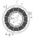
ロータ33は、磁石35を有しかつ回転動力を出力するように構成される。具体的に、本実施形態に係るロータ33は、円柱状の部材からなる。この円柱状の部材は、中心に軸孔を有する複数の金属板を、その中心軸方向に沿って積層することで構成される。ロータ33の軸孔に対してシャフト32の中間部分を固定することで、ロータ33は、シャフト32と一体化される。
The
ロータ33の外周部分には、該ロータ33の回転方向に沿って、複数の磁石35が配置される。複数の磁石35は、ステータ34の内周面にS極を指向させた第1磁石35aと、回転方向において第1磁石35aと隣接しかつステータ34の内周面にN極を指向させた第2磁石35bと、を含む。
A plurality of
なお、「ロータ33の回転方向」は、該ロータ33、ひいてはステータ34及びモータ3の周方向に等しい。以下の記載では、「ロータ33の回転方向」の語を、単に「回転方向」という。同様に、「ロータ33の径方向」の語を、以下の記載では単に「径方向」という。
Note that the “rotation direction of the
また、以下の記載では、ステータ34に対する第1磁石35aの姿勢を明確にするために、第1磁石35aをS磁石35aともいう。同様に、第2磁石35bをN磁石35bともいう。
Furthermore, in the following description, in order to clarify the attitude of the
複数の磁石35は、例えば図2Aに示す構成では、4個の第1磁石35aと、4個の第2磁石35bと、からなる。第1磁石35a及び第2磁石35bは、回転方向に沿って、等間隔で交互に並ぶように配置される。
For example, in the configuration shown in FIG. 2A, the plurality of
また、複数の磁石35は、2A及び図2Bに示す断面、つまりシャフト32に垂直な断面上では、それぞれ、径方向の寸法に比して回転方向の寸法が長い矩形状に形成される。
Furthermore, in the cross sections shown in FIGS. 2A and 2B, that is, in the cross section perpendicular to the
また、複数の磁石35は、いずれも、いわゆる磁力可変マグネットとして構成される。すなわち、複数の磁石35は、それぞれ、各磁石35から発せられる磁力の大きさを大小に可変することができる。通常、この種のモータ3には、その磁力を長期にわたり保持できるよう、保磁力(Coercivity)が大きい永久磁石が使用される。このモータ3では、磁力を比較的容易に変更できるように、通常よりも保持力の小さい永久磁石が磁石35として用いられる。
Furthermore, all of the plurality of
磁石35として用いられる永久磁石には、フェライト磁石、ネオジム磁石、サマリウムコバルト磁石、アルニコ磁石など、様々な種類があり、保持力も様々である。磁石35の素材は、使用に応じて選択可能であり、特に限定されない。
There are various types of permanent magnets used as the
また、各磁石35は、ロータ33の周縁に沿って区画された収容スペース37に収容される。図2Bに例示するように、収容スペース37は、磁石35を支持するための一対の支持面37a,37bによって区画される。一対の支持面37a,37bは、径方向における両側から磁石35を挟持する。
Further, each
ステータ34は、ロータ33に対しギャップを隔てて対向するように配置された複数のコイル36を有する。具体的に、本実施形態に係るステータ34は、複数の金属板を積層してなるステータコア34aと、そのステータコア34aに電線を巻回してなる複数のコイル36と、を有する。
The
このうち、ステータコア34aには、径方向に沿って放射状に延びる複数のティース34bが設けられる。複数のティース34bの間に区画されるスロットには、所定の順序で電線が巻回される。そうして巻き掛けられた電線によって、複数のコイル36が形成される。すなわち、複数のコイル36は、それぞれ、いわゆる集中巻きのコイルとして構成されている。
Among these, the
複数のコイル36は、流れる電流の位相が異なるU相、V相及びW相からなる3相のコイル群を構成する。各コイル群は、回転方向に沿って順番に配置される。例えば図2Aに示す構成では、複数のコイル36は、計12個のコイル36からなる。12個のコイル36は、4つのコイル36からなるU相コイル群と、4つのコイル36からなるV相コイル群と、4つのコイル36からなるW相コイル群と、に区分される。
The plurality of
以下、U相コイル群に属するコイル36をU相コイル36uと呼称し、V相コイル群に属するコイル36をV相コイル36vと呼称し、W相コイル群に属するコイル36をW相コイル36wと呼称する場合がある(図2B等を参照)。
Hereinafter, the
なお、本実施形態では、8極12スロットのモータ3を例示したが、モータ3の構成は、この例に限定されない。モータ3は、より多くの極数及びスロット数を有するよう構成してもよい。例えば、Nを整数として、2×N個の磁石35と、3×N個のスロットとでモータ3を構成することができる。
In addition, in this embodiment, although the
コイル36に通電するために、これらコイル36には3本の接続ケーブル36a,36a,36aが接続される。3本の接続ケーブル36a,36a,36aは、U相のコイル群に接続される接続ケーブル36aと、V相のコイル群に接続される接続ケーブル36aと、W相のコイル群に接続される接続ケーブル36aと、を有する。これら接続ケーブル36a,36a,36aは、モータケース31の外側に導出されるとともに、インバータ6を介してバッテリ10と接続される。この自動車1の場合、バッテリ10は、50V以下の定格電圧とされたバッテリ、具体的には48Vの直流バッテリ(低電圧バッテリ)が用いられる。
In order to energize the
本実施形態に係るバッテリ10は、従来知られたハイブリッド車に搭載されるバッテリのように高電圧ではない。そのため、バッテリ10自体を軽量かつコンパクトにすることができる。さらに、高度な感電対策が不要となるため、絶縁部材等も簡素化することができる。この簡素化によって、バッテリ10をより軽量かつコンパクトにすることができる。このように、自動車1の重量を抑制することができるため、燃費及び電力消費を抑制することができる。
The
バッテリ10は、インバータ6に直流電流を供給する。インバータ6は、その直流電流をU相、V相及びW相からなる3相の交流電流に変換する。インバータ6は、U相に変換された交流電流をU相コイル群に通電し、V相に変換された交流電流をV相コイル群に通電し、W相に変換された交流電流をW相コイル群に通電する。
交流電流の通電により、各コイル群をなすコイル36が磁界を生成する。そうして、磁界を生成したコイル36と、各磁石35とが互いに引力または斥力を及ぼし合うことで、ロータ33が回転駆動される。回転駆動されたロータ33は、シャフト32を介して回転動力を出力する。この回転動力は、シャフト32及び第2クラッチ7を介して変速機8に入力される。
By applying alternating current, the
この自動車1の場合、変速機8は、多段式自動変速機、いわゆるATである。変速機8は、一方の端部に入力軸を有し、他方の端部に出力軸を有する。これら入力軸と出力軸との間に、複数の遊星歯車機構、クラッチ、ブレーキなどの変速機構が組み込まれる。そうした変速機構を切り替えることで、自動車1の前進又は後退を切り替えたり、変速機8の入力軸と出力軸との間で回転数を変更したりすることができる。変速機8の出力軸は、車体の前後方向に沿って延びる。この出力軸は、該出力軸と同軸に配置されるプロペラシャフト11を介してデファレンシャルギア9に連結される。
In the case of this
デファレンシャルギア9は、一対の駆動シャフト13,13に連結される。一対の駆動シャフト13,13は、車幅方向に延びて左右の駆動輪4R,4Rに連結される。プロペラシャフト11を介して出力される回転動力は、デファレンシャルギア9によって各駆動シャフト13に振り分けられた後、各駆動シャフト13を通じて各駆動輪4Rに伝達される。各車輪4F,4F,4R,4Rには、その回転を制動するためのブレーキ14が取り付けられる。
The
また、本実施形態に係るモータ3は、ロータ33を構成する磁石35の温度(以下、単に「磁石温度」という)を判定するために、2種類のセンサ55,56を備える。2種類のセンサ55,56は、サーチコイル55と、電圧センサ56と、からなる(図3参照)。これらのセンサ55,56は、双方とも、ロータ33の回転に応じて生じる誘起電圧を検出することができる。
Furthermore, the
このうち、サーチコイル55は、図2Bに例示するように、複数のコイル36のうちのいずれか1つに電線を重畳することで構成される。サーチコイル55は、電線が重畳されたコイル36と同軸になる。サーチコイル55は、サーチ用接続ケーブル36bを介することでMCU21に接続される。サーチ用接続ケーブル36bは、インバータ6に通じる3本の接続ケーブル36a,36a,36aとは電気的に切り離されている。すなわち、サーチ用接続ケーブル36bは、モータ3を駆動するインバータ6とは独立した回路に接続されるようになっている。
Among these, the
サーチコイル55は、ロータ33の回転に際し、サーチコイル55が構成されたコイル36を磁石35が通り過ぎるときに生じる誘起電圧を検出し、その検出信号をMCU21に入力する。
The
一方、電圧センサ56は、詳細な図示は省略するが、モータ3の中性点と、各接続ケーブル36a,36a,36aとの間の電圧を検出し、その検出信号をMCU21に入力する。
On the other hand, although detailed illustration is omitted, the
ここで、図1等に示すモータ3は、サーチコイル55及び電圧センサ56による誘起電圧の検出に適した特徴部を備える。具体的に、本実施形態に係るロータ33には、回転方向において磁石35と隣接する空隙38が設けられる。この空隙38は、回転方向における磁石35の両端に隣接して配置される。
Here, the
各空隙38は、いわゆるフラックスバリアとして機能する。すなわち、空隙38は、ある磁石35が発する磁束が、ロータ33内で他の磁石35に回り込むのを抑制する機能をなす。これにより、ギャップを介してステータ33と鎖交する磁束を増やすことができる。
Each void 38 functions as a so-called flux barrier. That is, the
詳しくは、各空隙38は、回転方向に沿って、対応する磁石35から離間する方向に延びる。回転方向における各空隙38の寸法は、コイル36の寸法に基づいて規定される。具体的に、ロータ33の回転軸(シャフト32)に垂直な断面、つまり図2Bに示す断面上で、回転方向における空隙38の寸法をD1とし、回転方向におけるコイル36の直径をD2とすると、
D1≧D2/4 …(A)
の関係が満足される。式(A)は、回転方向における空隙38の寸法の下限を規定する。また、図2Bに示す断面上で、回転方向における磁石35同士の間隔をD3とすると、
D3≧2×D1 …(B)
の関係が満足される。式(B)は、回転方向における空隙38の寸法の上限を規定する。
Specifically, each
D 1 ≧D 2 /4...(A)
relationship is satisfied. Equation (A) defines a lower limit for the size of the
D3 ≧2× D1 ...(B)
relationship is satisfied. Equation (B) defines an upper limit for the size of the
式(A)及び式(B)より、下式(C)に示す関係が満足される。 From equations (A) and (B), the relationship shown in equation (C) below is satisfied.
D2/4≦D1≦D3/2 …(C)
また、各空隙38は、回転方向において磁石35から離間するにつれて、径方向における寸法が短くなる。すなわち、各空隙38は、図2Bに例示するように先細に形成される。同図に示すように、各空隙38の先端部は、回転方向において互いに向かい合う。
D2 /4≦ D1 ≦ D3 /2…(C)
Furthermore, the dimension in the radial direction of each
また、空隙38は、ロータ33における磁石35の収容スペース37と連通する。図2Bに示すように、収容スペース37を区画する支持面37a,37bのうち、径方向の外側に位置する支持面37aは、空隙38の内周面と面一に繋がっている。一方、径方向の内側に位置する支持面37bは、空隙38の内周面に対し、段差を介して繋がっている。
Furthermore, the
(1-3)制御系の装置
自動車1は、該自動車1の走行をコントロールするために、前述したECU20、MCU21、TCU22、BCU23及びGCU24を備える。これらのユニットのうち、ECU20は、エンジン2の作動を主に制御するユニットである。MCU21は、モータ3の作動を主に制御するユニットである。TCU22は、第1クラッチ5、第2クラッチ7及び変速機8の作動を主に制御するユニットである。BCU23は、ブレーキ14の作動を主に制御するユニットである。GCU24は、ECU20、MCU21、TCU22及びBCU23と電気的に接続され、これらのユニットを総合的に制御する上位ユニットである。
(1-3) Control System Device The
前述したユニットのうち、MCU21は、「モータの制御装置」の主体を構成する。MCU21は、コントローラの一例である。図3に示すように、MCU21は、マイクロコンピュータ211と、メモリ212と、I/F回路213と、を備える。マイクロコンピュータ211は、プログラムを実行する。メモリ212は、プログラム及びデータを格納する。メモリ212は、例えばRAM(Random Access Memory)やROM(Read Only Memory)である。I/F回路213は、電気信号の入出力を行う。
Among the units described above, the
また、GCU24等、MCU21以外の各ユニットは、MCU21と協働することによって「モータの制御装置」を構成する。各ユニットは、MCU21と同様に、マイクロコンピュータ(不図示)と、メモリ(不図示)と、I/F回路(不図示)と、を備える。
Further, each unit other than the
MCU21には、センサとしてのサーチコイル55及び電圧センサ56が接続される。サーチコイル55及び電圧センサ56の検出信号は、それぞれMCU21に入力される。サーチコイル55及び電圧センサ56以外のセンサのうち、自動車1の走行に関連するものとしては、以下のセンサ50-54が上げられる。
A
まず、エンジン回転センサ50は、エンジン2の回転数を検出してECU20に入力する。エンジン回転センサ50は、エンジン2に取り付けられる。モータ回転センサ51は、ロータ33の回転数及び回転位置を検出してMCU21に入力する。モータ回転センサ51は、モータ3に取り付けられる。電流センサ52は、各コイル36に通電される電流値を検出してMCU21に入力する。電流センサ52は、接続ケーブル36aに取り付けられる。
First, the
磁気センサ53は、磁石35が発する磁界を検出し、その強度を示す信号をMCU21に入力する。磁気センサ53は、モータ3に取り付けられる。アクセルセンサ54は、自動車1の駆動に要求される出力に相当するアクセル開度を検出し、その大きさを示す信号をECU20に入力する。アクセルセンサ54は、運転者が自動車1を駆動するときに踏み込まれるアクセルペダル15に取り付けられる。
The
これらセンサから入力される検出信号に基づいて、各ユニットが協働して駆動システムを制御することで自動車1が走行する。エンジン2の駆動によって自動車1が走行するときには、アクセルセンサ54及びエンジン回転センサ50の検出信号に基づいて、ECU20がエンジン2の運転を制御する。
Based on detection signals input from these sensors, each unit cooperates to control the drive system, thereby causing the
そして、TCU22は、第1クラッチ5及び第2クラッチ7が連結状態になるように制御する。自動車1の制動時には、BCU23が各ブレーキ14を制御する。回生による制動時には、TCU22は、第1クラッチ5が解放状態又は部分連結状態となるように制御するとともに、第2クラッチ7が連結状態となるように制御する。こうすることで、MCU21は、モータ3によって発電を実行し、その発電によって生成される電力がバッテリ10に回収されるように制御する。
The
一方、MCU21は、複数のコイル36への通電を通じてモータ3を制御する。詳しくは、MCU21は、モータ3が単独で回転動力を出力する状態で、あるいは、モータ3がエンジン2の駆動をアシストする状態で、モータ3の回転動力によって自動車1が走行するように制御する。
On the other hand, the
具体的に、アクセルセンサ54、エンジン回転センサ50等の検出値に基づいて、ECU20がエンジン2の回転動力を設定する。それに伴い、予め設定されたエンジン2とモータ3との間での出力の分配比率に従って、所定の出力範囲に収まるように、GCU24がモータ3の回転動力の要求量を設定する。MCU21は、その要求量が出力されるように、モータ3に流れる3相交流を介してモータ3を制御する。
Specifically, the
さらに詳しくは、MCU21は、3相交流におけるトルク電流成分を制御することで、ロータ33に発生するトルクを変更する。それによって、モータ3に、回転動力の要求量を出力させる。
More specifically, the
MCU21はまた、3相交流における磁化電流成分を制御することで、コイル36に発生する磁界強度を変更する。詳細は省略するが、コイル36に発生する磁界強度を変更することで、磁石35によって生成される磁界強度(磁石35の磁力)を変更することができる。具体的に、磁石35の磁力は、駆動電流によってコイル36に発生する磁界強度と略一致するように変更される。
The
また、MCU21は、予め定められている制御ロジックに従って、磁石温度の推定と、磁石温度に基づいたモータ制御と、を実行することができる。以下、磁石温度を推定するための制御ロジックについて詳細に説明する。
Furthermore, the
(2)磁石温度の推定ロジック
MCU21は、磁石温度を判定するための制御ロジックとして、2種類の推定ロジックを単体で又は組み合わせて実行することができる。すなわち、MCU21は、「モータの磁石温度推定装置」を構成する。モータの磁石温度推定装置としてのMCU21の構成は、図4に示す通りである。
(2) Magnet temperature estimation logic The
2種類の推定ロジックのうち、第1の推定ロジックは、誘起電圧が平坦となるタイミングに着目した制御ロジックである。また、第2の推定ロジックは、誘起電圧の高調波成分に着目した制御ロジックである。2種類の推定ロジックは、予めメモリ212に記憶されている。
Of the two types of estimation logic, the first estimation logic is a control logic that focuses on the timing when the induced voltage becomes flat. Further, the second estimation logic is a control logic that focuses on harmonic components of the induced voltage. Two types of estimation logic are stored in
(2-1)第1の推定ロジック
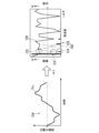
図5は、コイル36に生じる誘起電圧を例示するグラフである。図6は、空隙面積と電圧安定性及び機械強度との関係を例示するグラフである。ここでは、図5及び図6を参照しながら、第1の推定ロジックについて説明する。
(2-1) First Estimation Logic FIG. 5 is a graph illustrating the induced voltage generated in the
図5に示すグラフG1は、U相コイル36uに生じる誘起電圧Vu、V相コイル36vに生じる誘起電圧Vv、及びW相コイル36wに生じる誘起電圧Vwそれぞれの時間変化を例示している。
A graph G1 shown in FIG. 5 illustrates temporal changes in the induced voltage Vu generated in the
以下、U相コイル36uに生じる誘起電圧Vuを例に取り説明する。この場合、誘起電圧Vuは、4つのU相コイル36uのうちの1つにサーチコイル55を重畳した上で、そのサーチコイル55における電圧をモニターすることで検出される。以下の説明は、V相コイル36v及びW相コイル36wについても同様である。
The induced voltage Vu generated in the
図5の下部に示すように、S磁石(第1磁石)35aが生成する磁束のうち、このS磁石35aを貫く磁束は、径方向の内側を指向する(矢印Asを参照)。一方、N磁石(第2磁石)35bが生成する磁束のうち、このN磁石35bを貫く磁束は、径方向の外側を指向する(矢印Anを参照)。S磁石35a及びN磁石35bによって生成される磁束と、例えばU相コイル36uと、が鎖交することで、U相コイル36uに誘起電圧Vuが生じる。
As shown in the lower part of FIG. 5, of the magnetic flux generated by the S magnet (first magnet) 35a, the magnetic flux that passes through the
ここで、ファラデーの誘導法則から明らかなように、誘起電圧Vuの大きさは、U相コイル36uに鎖交する磁束の時間変化に比例する。したがって、磁束の時間変化が最大となるタイミングで、誘起電圧Vuはピークを迎えることになる。
Here, as is clear from Faraday's law of induction, the magnitude of the induced voltage Vu is proportional to the time change in the magnetic flux interlinking with the
具体的に、磁束の時間変化が最大となるタイミングは、ロータ33の外周部のうちS磁石35aとN磁石35bとの中間に位置する部位と、U相コイル36uの中心軸線Lcと、が交わるタイミングに等しい(図5の囲み部C2を参照)。このタイミングは、U相コイル36uに鎖交する磁束の向きが反転するタイミングに相当する。
Specifically, the timing at which the temporal change in magnetic flux becomes maximum is when a portion of the outer circumferential portion of the
一方、磁束の時間変化が最小あるいは可及的に小さくなるタイミングにおいては、誘起電圧Vuの時間変化を可能な限り抑制することができる。具体的に、S磁石35a又はN磁石35bと、U相コイル36uと、が向かい合うタイミングにおいて、誘起電圧Vuの時間変化は最小となる(図5の囲み部C1及びC3を参照)。さらに詳しくは、回転方向におけるS磁石35a又はN磁石35bの中央部と、U相コイル36uの中心軸線Lc、とが交わるタイミング(以下、「最小タイミング」ともいう)において、誘起電圧Vuの時間変化は最小となる。
On the other hand, at the timing when the temporal change in the magnetic flux is minimum or as small as possible, the temporal change in the induced voltage Vu can be suppressed as much as possible. Specifically, at the timing when the
図5の上部に示す例では、囲み部C1及びC3において誘起電圧Vuが実質的に平坦となることが見て取れよう。具体的に、囲み部C1においては、N磁石35bによる磁束が主体となって生じる誘起電圧Vuが平坦となる。囲み部C3においては、S磁石35aによる磁束が主体となって生じる誘起電圧Vuが平坦となる。以下、誘起電圧Vuにおいて平坦となる部分を「誘起電圧の肩部」と呼称する。
In the example shown in the upper part of FIG. 5, it can be seen that the induced voltage Vu is substantially flat in the enclosed portions C1 and C3. Specifically, in the enclosed portion C1, the induced voltage Vu mainly generated by the magnetic flux from the
また、誘起電圧Vuの肩部における時間変化は、ロータ33に空隙38を設けることでより平坦となる。この現象は、空隙38がフラックスバリアとして機能することで、U相コイル36uに向かい合う磁石35の端部からの磁束漏れを低減し、その端部における磁束量変化を安定化するとともに、U相コイル36uに向かい合う磁石35に隣接した他の磁石35からの磁束の回り込みが抑制されて発生する。
Moreover, the temporal change of the induced voltage Vu at the shoulder portion becomes more flat by providing the
空隙38が奏する効果は、図6に示す通りである。図6の上段に示すグラフG2は、空隙面積と電圧安定性との関係を示す。一方、図6の下段に示すグラフG3は、空隙面積と電圧安定性との関係を示す。ここで、「空隙面積」の語は、シャフト32に垂直な断面、すなわち図2Bに示す断面上での各空隙38の断面積を意味する。一方、「電圧安定性」の語は、誘起電圧Vuの時間変化の大小を意味する。誘起電圧Vuの時間変化が大きいとき、該時間変化が小さいときに比して、電圧安定性は低くなる。また、「機械強度」の語は、ロータ33の機械的強度を意味する。
The effect produced by the void 38 is as shown in FIG. Graph G2 shown in the upper part of FIG. 6 shows the relationship between gap area and voltage stability. On the other hand, a graph G3 shown in the lower part of FIG. 6 shows the relationship between the gap area and the voltage stability. Here, the term "gap area" refers to the cross-sectional area of each void 38 on a cross section perpendicular to
図6のグラフG2に示すように、空隙面積が大きいときには、それが小さいときに比して電圧安定性は高くなる。しかしながら、同図のグラフG3に示すように、空隙面積が大きいときには、それが小さいときに比して機械強度は低くなる。図6に示すように、所定の範囲R1内に収まるように空隙面積を設定することで、電圧安定性と機械強度を両立することができる。この範囲R1内に空隙面積を設定した場合、その空隙38の寸法D1は、上式(C)を満足することになる。上式(C)、ひいては式(A)を満足するように構成することで、各空隙38に、フラックスバリアとしての機能を十分に発揮させることが可能となる。 As shown in graph G2 of FIG. 6, when the gap area is large, the voltage stability is higher than when it is small. However, as shown in graph G3 in the figure, when the void area is large, the mechanical strength is lower than when it is small. As shown in FIG. 6, by setting the gap area to fall within a predetermined range R1, it is possible to achieve both voltage stability and mechanical strength. When the void area is set within this range R1, the dimension D1 of the void 38 satisfies the above formula (C). By configuring so as to satisfy the above formula (C), and by extension, formula (A), it becomes possible for each void 38 to fully exhibit its function as a flux barrier.
以上の知見を踏まえ、本願発明者らは、第1の推定ロジックを以下の如く構築した。 Based on the above knowledge, the inventors constructed the first estimation logic as follows.
すなわち、本実施形態に係るMCU21は、ロータ33の回転に伴って磁石35と複数のコイル36のいずれか1つとが向かい合う際に検出される誘起電圧Vuに基づいて、磁石温度を推定する。
That is, the
具体的に、MCU21は、サーチコイル55を介して誘起電圧Vuの肩部を検出する。誘起電圧Vuの肩部を検出することは、時間変化が最小となるタイミングで誘起電圧Vuを検出することに等しい。誘起電圧Vuの肩部を検出することと、空隙38をフラックスバリアとして機能させることとが相まって、誘起電圧Vuの検出に際し、その時間変動を可能な限り抑制することができる。これにより、誘起電圧Vuの検出精度を高めることができる。
Specifically, the
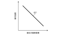
MCU21は、そうして検出された誘起電圧Vuに基づいて、磁石温度を推定する。周知のように、誘起電圧Vuと、磁石35が発する磁束密度と、は比例関係にある。また、図8のグラフG7に例示するように、磁石35が発する磁束密度と、磁石温度と、は直線状の関係をなす。したがって、誘起電圧Vuを検出することで、磁束密度を介して磁石温度を算出することができる。
The
特に本実施形態では、MCU21のメモリ212には、磁束密度と磁石温度との関係を示すテーブルが予め記憶されている。したがって、MCU21は、誘起電圧Vuに基づいて磁束密度を算出するとともに、そうして算出された磁束密度とメモリ212に記憶されたテーブルとを用いることで、磁石温度を推定することができる。誘起電圧Vuの検出精度を高めた状態で磁石温度を推定することで、磁石温度を精度よく推定することができるようになる。
In particular, in this embodiment, the
また、MCU21のメモリ212には、ロータ33の回転に際し、回転方向における磁石35の中央部と、複数のコイル36の各々の中心軸線Lcと、が交わるタイミング(最小タイミング)が予め記憶されており、MCU21は、その最小タイミングで誘起電圧Vuを取得する。最小タイミングは、誘起電圧Vuの時間変化が最小となるタイミングに等しい。したがって、最小タイミングで誘起電圧Vuを検出することは、その検出精度を高める上で有効である。また、最小タイミングを予め記憶しておくことで、誘起電圧Vuをより確実に抑制することが可能となり、ひいては、磁石温度を精度よく推定する上で有利になる。
Furthermore, the
また、MCU21による誘起電圧Vuの検出は、最小タイミングにおいてのみ実行されるのではなく、最小タイミングを含んだ所定期間Tsにわたり実行することもできる。
Further, the detection of the induced voltage Vu by the
具体的に、MCU21は、最小タイミングを含んだ所定期間Tsにわたって誘起電圧Vuを取得するとともに、その所定期間Tsにわたって取得された誘起電圧Vuの平均値に基づいて、磁石温度を推定する。特定のタイミングで検出される誘起電圧Vuではなく、その平均値を用いることで、誘起電圧Vuの時間変動の影響を可能な限り抑制したり、ノイズ等に起因した誘起電圧Vuのバラツキの影響を低減したりすることができる。これにより、磁石温度を精度よく推定する上で有利になる。
Specifically, the
なお、本実施形態に係る所定期間Tsは、誘起電圧Vuがピークを迎えるタイミングを含まないように設定される。すなわち、所定期間Tsは、回転方向において2つの磁石35の中間に位置する部位と、コイル36の中心軸線Lcと、が交わるタイミングを含まない期間として設定される。
Note that the predetermined period Ts according to the present embodiment is set so as not to include the timing at which the induced voltage Vu reaches its peak. That is, the predetermined period Ts is set as a period that does not include the timing at which a portion located between the two
また、MCU21は、モータ3の駆動に要するコイル36ではなく、それらコイル36のうちの1つに重畳されるサーチコイル55に生じる誘起電圧Vuに基づいて、磁石温度を推定する。サーチコイル55を用いることで、そのサーチコイル55が重畳されたコイル36に生じる誘起電圧を間接的に検出することが可能となる。これにより、サーチコイル55とすれ違う各磁石35の温度を個別に推定することができるようになり、ひいては磁石温度をより正確に判定することができるようになる。磁石温度の正確な判定は、後述のように、磁石温度に基づいたモータ制御を実行するときに、取り分け有効となる。
Furthermore, the
なお、誘起電圧Vuに基づいて磁石温度を把握する術としては、誘起電圧Vuの実効値、平均値及び最大値等を用いたり、第2の推定ロジックのように、誘起電圧Vuを周波数成分に分解したときの最低次高調波を用いたりすることも考えられる。しかしながら、それらの方法を用いた場合、磁石35全体の温度や、磁石35間の温度差こそ精度よく推定できるものの、各磁石35の温度を個別に推定するには不向きである。
Note that methods for understanding the magnet temperature based on the induced voltage Vu include using the effective value, average value, maximum value, etc. of the induced voltage Vu, or converting the induced voltage Vu into frequency components as in the second estimation logic. It is also conceivable to use the lowest order harmonic when decomposed. However, when these methods are used, although the temperature of the
一方、第1の推定ロジックによれば、磁石35毎に誘起電圧を検出することで、磁石温度を個別に推定することが可能となる。このように、第1の推定ロジックは、各磁石35の温度を個別にかつ精度よく推定できるという点で有効である。
On the other hand, according to the first estimation logic, by detecting the induced voltage for each
また、図2Bに例示したように、各空隙38は、回転方向において磁石35から離間するにつれて、ロータ33の径方向における寸法が短くなる。この場合、空隙38において磁石35に近接する部位は、径方向における寸法が相対的に長くなる分だけ断面積が広く確保され、フラックスバリアとしての機能を発揮させる上で有利になる。一方、空隙38において磁石から離間する部位は、径方向における寸法が徐々に短くなって先細となるため、ロータ33の機械的強度を確保する上で有利になる。
Furthermore, as illustrated in FIG. 2B, the dimension of each
また、図2Bに例示したように、一対の支持面37a,37bのうち、径方向の外側に位置する一方の支持面37aは、空隙38の内周面と面一に繋がっている。支持面37aと空隙38の内周面とを面一に繋げることで、両面をスムースに接続することが可能となる。この構成は、支持面37aと空隙38の内周面との間に段差が存する構成に比して、誘起電圧Vuを滑らかに変動させることが可能となる。これにより、誘起電圧Vuの時間変動をより確実に抑制し、ひいては、磁石温度を精度よく推定する上で有利になる。
Further, as illustrated in FIG. 2B, one of the pair of
(2-2)第2の推定ロジック
図7は、誘起電圧の高速フーリエ変換によって得られる振幅及び位相を例示する図である。図8は、磁石35の磁束密度と磁石温度との関係を例示するグラフである。ここでは、図7及び図8を参照しながら、第2の推定ロジックについて説明する。
(2-2) Second Estimation Logic FIG. 7 is a diagram illustrating the amplitude and phase obtained by fast Fourier transform of the induced voltage. FIG. 8 is a graph illustrating the relationship between the magnetic flux density of the
以下、U相コイル36uに生じる誘起電圧Vuを例に取り説明する。この場合、誘起電圧Vuは、モータ3の中性点と、U相コイル36uに接続される接続ケーブル36aとの間の電位差をモニターすることで検出される。以下の説明は、V相コイル36v及びW相コイル36wについても同様である。
The induced voltage Vu generated in the
図7の左部に示すグラフG4は、U相コイル36uに生じる誘起電圧Vuを示す。一方、図7の右部に示す棒グラフG5は、その誘起電圧Vuを高速フーリエ変換(Fast Fourier Transform:FFT)をすることで得られる周波数スペクトルの絶対値(振幅)を示す。また、図7の右部に示す折れ線グラフG6は、FFTによって得られる周波数スペクトルの偏角(位相)を示す。
Graph G4 shown on the left side of FIG. 7 shows the induced voltage Vu generated in the
また、図7の右部に示す折れ線グラフG6’は、S磁石35bとN磁石35bとの温度差がグラフG6と同一であり、かつ、S磁石35bとN磁石35bとの温度の大小関係が、グラフG6に示す状況とは逆転した場合を示す。
In addition, in the line graph G6' shown in the right part of FIG. 7, the temperature difference between the
グラフG4に示すように、誘起電圧Vuの波形は、正弦波から相違する。このことは、第1の推定ロジックの説明の際に言及したように、ロータ33の回転に伴って磁石35とコイル36との位置関係が変化することに起因する。見方を変えると、グラフG4に示す波形は、所定周波数を有する正弦波(基本波)に対し、その所定周波数の整数倍の周波数成分(高調波)が重畳することで実現されると捉えることもできる。
As shown in graph G4, the waveform of induced voltage Vu differs from a sine wave. This is because, as mentioned in the explanation of the first estimation logic, the positional relationship between the
ここで、基本波の周波数をf0とし、最低次高調波の周波数をf1とし、モータ3の極数をNpとし、モータ回転数をRmとし、1極の磁石35の数(一極対あたりの磁石35の個数)をNmとすると、
f0=Np×Rm …(D)
f1=Nm×f0 …(E)
の関係が満足される。本実施形態の場合、Np=8であり、Nm=2である。したがって、最低次高調波は、基本波に対し2倍の周波数を有する2次高調波となる。なお、前記磁石35の代わりに分割磁石を用いた場合、Nmは4以上の整数となり得る。
Here, the frequency of the fundamental wave is f0, the frequency of the lowest harmonic is f1, the number of poles of the
f0=Np×Rm...(D)
f1=Nm×f0...(E)
relationship is satisfied. In the case of this embodiment, Np=8 and Nm=2. Therefore, the lowest harmonic is a second harmonic having twice the frequency of the fundamental wave. Note that when a divided magnet is used instead of the
本願発明者らは、鋭意検討を重ねた結果、誘起電圧VuにFFTを施すことで得られる周波数スペクトルのうち、最低次高調波の周波数スペクトルには、第1磁石35aとしてのS磁石35aと、第2磁石35bとしてのN磁石35bと、の温度差を間接的に示す情報が含まれることを突き止めた。
As a result of extensive studies, the inventors of the present application found that among the frequency spectrum obtained by applying FFT to the induced voltage Vu, the frequency spectrum of the lowest harmonic includes the
本願発明者らによって得られた知見によれば、最低次高調波の周波数スペクトルの振幅は、S磁石35aとN磁石35bとの温度差に比例する。例えば、高調波に係る振幅は、磁石間の温度差が大きいときには、その温度差が小さいときに比して大きくなる。図7に示す例では、S磁石35aとN磁石35bとの温度差が大きくなるにつれて、囲み部C4に示す振幅がより大きくなる。
According to the knowledge obtained by the inventors of the present application, the amplitude of the frequency spectrum of the lowest harmonic is proportional to the temperature difference between the
また、本願発明者らによれば、高調波の周波数スペクトルの位相は、S磁石35aに比してN磁石35bが高温のときと、N磁石35bに比してS磁石35aが高温のときと、で位相が反転する。図7に示す例は、N磁石35bに比してS磁石35aが高温の場合を示している。この場合、高調波の位相の符号は、囲み部C5に示すように正となる。一方、磁石35間の温度差が図7に示す例と同じであったとしても、S磁石35aに比してN磁石35bが高温の場合には、囲み部C5と同一周波数における位相の符号は、囲み部C5’に示すように反転して負となる。
Further, according to the inventors of the present application, the phase of the harmonic frequency spectrum changes when the
さらに、本願発明者らによれば、基本波の周波数スペクトルの振幅は、S磁石35a及びN磁石35bの平均温度と関連する。詳しくは、基本波に係る振幅は、S磁石35a及びN磁石35bが発する磁束密度の平均値が大きいときには、その平均値が小さいときに比して大きくなる。一方、磁束密度の大きさは、前述のように、磁石温度と直線状の関係にある。したがって、基本波に係る振幅を用いることで、各磁石35が取り得る平均温度を推定することができる。
Furthermore, according to the inventors of the present application, the amplitude of the frequency spectrum of the fundamental wave is related to the average temperature of the
以上の知見を踏まえ、本願発明者らは、第2の推定ロジックを以下の如く構築した。 Based on the above knowledge, the inventors of the present application constructed the second estimation logic as follows.
すなわち、本実施形態に係るMCU21は、誘起電圧を構成する周波数成分のうち、所定周波数に対応した周波数スペクトルに基づいて磁石温度を推定する。
That is, the
具体的に、MCU21は、所定周波数に対応した周波数スペクトルを取得するべく、誘起電圧に対してFFTを実行する。ここで、所定周波数は、磁石35の個数に応じて規定される第n次高調波(nは整数)のうち、最低次高調波(本実施形態では、2次高調波)の周波数である。
Specifically, the
次いで、MCU21は、FFTを通じて得られた周波数スペクトルの振幅に基づいて、磁石35が発する磁束密度を推定する。具体的に、MCU21は、基本波に係る振幅と、最低次高調波に係る振幅と、を加算する。これにより、磁石35間の温度差を考慮した振幅の最大値(最大振幅)を算出することができる。この演算を行うべく、本実施形態に係るMCU21は、FFTを通じて得られた周波数スペクトルが入力されるバンドパスフィルタ57を備える。このバンドパスフィルタ57の構成は、最低次高調波の周波数に応じて、適宜変更することができる。
Next, the
そして、MCU21は、そうして得られた最大振幅に基づいて磁束密度を算出し、その磁束密度に基づいて磁石温度を推定する。最大振幅は、磁石35間の温度差を考慮した誘起電圧Vuの最大値を示す。一方、誘起電圧Vuと、磁石35が発する磁束密度と、は前述のように比例関係にある。また、磁石35が発する磁束密度と、磁石温度と、は直線状の関係をなす。したがって、誘起電圧Vuを検出することで、磁束密度を介して磁石温度を算出することができる。
Then, the
MCU21はまた、FFTを通じて得られた周波数スペクトルの位相に基づいて、N磁石35bとS磁石35bとのうち、相対的に高温又は低温な磁石35を特定することができる。この機能は、磁石温度を用いた後述のモータ制御に用いられる。
The
このように、第2の推定ロジックによれば、誘起電圧Vuにフーリエ変換を施すことで得られる周波数スペクトルの振幅を用いることで、磁石温度を精度よく推定できる。 In this manner, according to the second estimation logic, the magnet temperature can be accurately estimated by using the amplitude of the frequency spectrum obtained by subjecting the induced voltage Vu to Fourier transformation.
ところで、誘起電圧Vuに基づいて磁石温度を把握する術としては、第1の推定ロジックのように、特定のタイミングで検出される誘起電圧Vuに基づいて磁石温度を推定することも考えられる。しかしながら、この方法を用いるためには、誘起電圧をA/D変換する際のサンプリング周波数を、モータ3の回転数に見合うように高く設定する必要がある。このような方法は、モータが高回転となる場合には不都合である。
By the way, as a method of grasping the magnet temperature based on the induced voltage Vu, it is also possible to estimate the magnet temperature based on the induced voltage Vu detected at a specific timing, as in the first estimation logic. However, in order to use this method, it is necessary to set the sampling frequency when A/D converting the induced voltage to be high enough to match the rotational speed of the
一方、第2の推定ロジックは、特定のタイミングで誘起電圧Vuを検出せずとも磁石温度を推定することができるため、従来よりもサンプリング周波数を低く抑えることができる。サンプリング周波数を低く抑えることで、フィルタリング処理等、誘起電圧Vuに対する処理を簡素化することが可能になる。また、誘起電圧Vuに対する処理の簡素化は、磁石温度をより迅速に推定したり、より確実に推定したりする上で有効である。 On the other hand, since the second estimation logic can estimate the magnet temperature without detecting the induced voltage Vu at a specific timing, the sampling frequency can be kept lower than in the past. By keeping the sampling frequency low, processing for the induced voltage Vu, such as filtering processing, can be simplified. Furthermore, simplifying the process for the induced voltage Vu is effective in estimating the magnet temperature more quickly and more reliably.
また、第2の推定ロジックによれば、周波数スペクトルの位相を用いることで、S磁石35aとN磁石35bのうち、相対的に高温な磁石35を特定することができる。このことは、各磁石35の温度をきめ細かく制御する上で有効である。
Further, according to the second estimation logic, by using the phase of the frequency spectrum, it is possible to specify which
特に、最低次高調波の振幅及び位相を用いることで、各磁石35の温度差を精度よく推定したり、より高温な磁石35を精度よく特定したりすることができる。このことは、各磁石35の温度をより的確に推定する上で有効である。
In particular, by using the amplitude and phase of the lowest order harmonic, it is possible to accurately estimate the temperature difference between the
また、前述のように、最低次高調波の振幅と、基本波の振幅とを加算してなる最大振幅を用いて磁石温度を推定することで、各磁石35が取り得る温度ばらつきを考慮した温度推定を実現することができる。これにより、磁石温度を過小評価することなく、より安全サイドに立って磁石温度を推定することができる。
Furthermore, as described above, by estimating the magnet temperature using the maximum amplitude obtained by adding the amplitude of the lowest harmonic and the amplitude of the fundamental wave, the temperature can be adjusted to take into account the temperature variation that each
(3)磁石温度の推定装置
図4は、モータの磁石温度推定装置の構成を例示するブロック図である。
(3) Magnet temperature estimating device FIG. 4 is a block diagram illustrating the configuration of a motor magnet temperature estimating device.
図4に示す推定装置は、複数の機能ブロックを備えてなる。具体的に、この推定装置は、第1及び第2の推定ロジックのうちの一方を選択する推定方法選択部214と、第1の推定ロジックを実行する第1推定部215と、第2の推定ロジックを実行する第2推定部216と、第1推定部215又は第2推定部216の実行結果に基づいてモータ3を制御するモータ制御部217と、を備える。
The estimation device shown in FIG. 4 includes a plurality of functional blocks. Specifically, this estimation device includes an estimation
以下、各機能ブロックについて順番に説明する。 Each functional block will be explained in order below.
(3-1)推定方法選択部
推定方法選択部214は、ロータ33の回転数に基づいて、第1推定部215によって第1の推定ロジックを実行するか、或いは、第2推定部216によって第2の推定ロジックを実行するかを選択する。
(3-1) Estimation method selection unit The estimation
具体的に、推定方法選択部214は、モータ回転数センサ41からの検出信号に基づいて、ロータ33の回転数が所定閾値未満の場合は第1推定部215を選択し、ロータ33の回転数が所定閾値以上の場合は第2推定部216を選択する。推定方法選択部214は、第1推定部215及び第2推定部216のうち、選択された一方を介して温度推定を実行させる。
Specifically, the estimation
第1推定部215による磁石温度の推定は、磁石温度を個別にかつ精度よく推定することができる。一方、第2推定部216による磁石温度の推定は、従来よりもサンプリング周波数を低く抑えることができるため、モータ3の回転数が高い場合であっても、磁石温度を確実に推定することができる。
The magnet temperature can be estimated individually and accurately by the
そこで、図4に示す推定方法選択部は、モータ3の回転数が相対的に低い場合は第1推定部215による温度推定を実行させる一方、モータ3の回転数が高い場合は第2推定部216による温度推定を実行させる。このように構成することで、磁石温度の推定精度を可能な限り確保しつつも、モータ3の回転数が高い場合であっても、磁石温度を確実に推定することができるようになる。
Therefore, the estimation method selection section shown in FIG. 4 causes the
なお、推定方法選択部214による選択の基準となる所定閾値は、モータ3の仕様に応じて規定される。この所定閾値は、MCU21のメモリ212に予め記憶される。
Note that a predetermined threshold value, which is a criterion for selection by the estimation
(3-2)第1推定部
第1推定部215は、第1の推定ロジックを実行するための機能ブロックとして、誘起電圧検出部21aと、平均電圧算出部21bと、磁束密度算出部21cと、磁石温度推定部21dと、制限量算出部21eと、を有する。
(3-2) First estimation unit The
このうち、誘起電圧検出部21aは、サーチコイル55を介して誘起電圧Vuを検出する。この誘起電圧Vuは、計12個のコイル36のうち、サーチコイル55が重畳されたU相コイル36uに生じる誘起電圧と略一致する。具体的に、誘起電圧検出部21aは、不図示のA/Dコンバータを介して誘起電圧Vuを検出し、それをディジタル信号に変換する。誘起電圧検出部21aによってディジタル信号に変換された誘起電圧Vuは、平均電圧算出部21bに入力される。
Of these, the induced
平均電圧算出部21bは、誘起電圧検出部21aから入力される誘起電圧Vuに基づいて、前述した肩部、具体的には最小タイミングを含んだ所定期間Tsにおける平均電圧を算出する。平均電圧の算出は、N磁石35bに起因して生じる肩部(図5の囲み部C1参照)と、N磁石35bに起因して生じる肩部(図5の囲み部C3参照)と、の双方に対し、個別に実行される。また、この所定期間Tsに相当する電気角の範囲は、予めメモリ212に記憶されている。平均電圧算出部21bは、メモリ212に記憶されている電気角の範囲と、モータ回転センサ51の検出信号と、に基づいて、所定期間Tsにおける誘起電圧Vuの平均値を算出する。そうして算出された平均値は、磁束密度算出部21cに入力される。
The average
以下、平均電圧算出部21bによって算出される平均値のうち、N磁石35bに係る平均値を第1電圧Vnと呼称し、S磁石35aに係る平均値を第2電圧Vpと呼称する。
Hereinafter, among the average values calculated by the average
磁束密度算出部21cは、平均電圧算出部21bから入力される第1電圧Vn及び第2電圧Vpに基づいて、N磁石35bから発せられる磁束密度Bnと、S磁石35aから発せられる磁束密度Bpと、を算出する。具体的に、磁束密度算出部21cは、下式(F),(G)に基づいて磁束密度Bn,Bpを算出する。
The magnetic flux
Bn=Vn/(Rm×Nc×c) …(F)
Bp=Vs/(Rm×Nc×c) …(G)
上式(F),(G)において、Rmはモータ回転数であり、Ncはコイル巻き数であり、cは定数である。モータ回転数Rmは、モータ回転センサ51によって都度検出される。コイル巻き数Ncと定数cは、メモリ212に予め記憶され、磁束密度Bn,Bpの算出に際して読み込まれる。磁束密度算出部21cによって推定された磁束密度Bn,Bpは、磁石温度推定部21dに入力される。
Bn=Vn/(Rm×Nc×c)…(F)
Bp=Vs/(Rm×Nc×c)…(G)
In the above formulas (F) and (G), Rm is the motor rotation speed, Nc is the number of coil turns, and c is a constant. The motor rotation speed Rm is detected each time by the
磁石温度推定部21dは、磁束密度算出部21cにより推定された磁束密度Bn,Bpに基づいて、S磁石35aの磁石温度Tpと、N磁石35bの磁石温度Tnと、を推定する。具体的に、磁石温度推定部21dは、図8のグラフG7に対応したテーブルをメモリ212から読み込んで、そのテーブルと磁束密度Bn,Bpとを照らし合わせることで磁石温度Tp,Tnを推定する。磁石温度推定部21dによって推定された磁石温度Tn,Tpは、制限量算出部21eに入力される。
The magnet
制限量算出部21eは、磁石温度推定部21dによって推定された磁石温度Tn,Tpに基づいて、各磁石35a,35bの温度状態を判定する。制限量算出部21eは、その温度状態が異常であると判定される場合、モータ3の出力を制限するためのモータ制限量Pmを算出する。
The
具体的に、制限量算出部21eは、各磁石温度Tn,Tpと、予め設定された上限温度Tmaxと、を比較する。制限量算出部21eは、N磁石35bに係る磁石温度Tnと、S磁石35aに係る磁石温度Tpと、が双方とも上限温度Tmaxを上回る場合、磁石35の温度状態が異常であると判定する。ここで、上限温度Tmaxは、モータ3の仕様、設計に応じて規定され、メモリ212に予め記憶される。磁石35の温度状態が異常であると判定された場合、制限量算出部21eは、下式(H)を通じてパワー制限量を算出する。
Specifically, the limit
パワー制限量=K1|Tn-Tmax|+K1|Tp-Tmax| …(H)
上式(H)において、定数Kは、メモリ212に予め記憶されており、パワー制限量の算出に際して読み込まれる。制限量算出部21eにより算出されたパワー制限量は、モータ制御部217に入力される。
Power limit amount = K1 | Tn - Tmax | +K1 | Tp - Tmax | ... (H)
In the above equation (H), the constant K is stored in advance in the
なお、磁石温度Tn,Tpのうちの少なくとも一方が上限温度Tmax以下となった場合、制限量算出部21eは、磁石35の温度状態は正常であると判定する。この場合、パワー制限量の算出は実行されない。
Note that when at least one of the magnet temperatures Tn and Tp becomes equal to or lower than the upper limit temperature Tmax, the limit
(3-3)第2推定部
第2推定部216は、第2の推定ロジックを実行するための機能ブロックとして、誘起電圧検出部21fと、FFT実行部21gと、温度ばらつき算出部21hと、磁束密度算出部21iと、磁石温度推定部21jと、制限量算出部21kと、を有する。
(3-3) Second estimation unit The
このうち、誘起電圧検出部21fは、電圧センサ56を介して誘起電圧Vuを検出する。この誘起電圧Vuは、計12個のコイル36のうち、4個のU相コイル36uに生じる誘起電圧と略一致する。具体的に、誘起電圧検出部21aは、不図示のA/Dコンバータを介して誘起電圧Vuを検出し、それをディジタル信号に変換する。誘起電圧検出部21fによってディジタル信号に変換された誘起電圧Vuは、平均電圧算出部21bに入力される。
Among these, the induced
FFT実行部21gは、誘起電圧検出部21fから入力される誘起電圧Vuに対しFFTを実行し、誘起電圧Vuを周波数スペクトルに変換する。具体的に、FFT実行部21gは、誘起電圧Vuのうち、N周期にわたるデータに対してFFTを実行する。なお、ここでいう「N周期」とは、モータ回転数が大きく変化しない範囲を指す。Nの大きさは、予めメモリ212に記憶してもよいし、モータ回転センサ51の検出信号に基づいて都度算出してもよい。
The FFT execution unit 21g performs FFT on the induced voltage Vu input from the induced
FFT実行部21gは、誘起電圧VuにFFTを施すことで、実時間から周波数へと変数変換してなる周波数スペクトルを得る。より詳細には、FFT実行部21gによって得られる周波数スペクトルは、周波数スペクトルの絶対値(振幅)と、周波数スペクトルの偏角(位相)と、からなる。 The FFT execution unit 21g performs FFT on the induced voltage Vu to obtain a frequency spectrum obtained by converting variables from real time to frequency. More specifically, the frequency spectrum obtained by the FFT execution unit 21g consists of an absolute value (amplitude) of the frequency spectrum and an argument (phase) of the frequency spectrum.
そうして得られた周波数スペクトルに対し、FFT実行部21gは、バンドパスフィルタ57によるフィルタリングを施す。このフィルタリングによって、FFT実行部21gは、少なくとも、基本波の振幅Faと、最低次高調波の振幅Fb及び位相Pbと、を導出し、それらを温度ばらつき算出部21hに入力する。
The FFT execution unit 21g applies filtering using a
温度ばらつき算出部21hは、FFT実行部21gからの入力信号に基づいて、温度ばらつきに起因した振幅の最大値(最大振幅)Fmaxを算出する。具体的に、温度ばらつき算出部21hは、下式(I)に基づいて最大振幅Fmaxを算出する。
The temperature
Fmax=Fa+Fb …(I)
上式(I)に示すように、温度ばらつき算出部21hは、基本波の振幅Faと、最低次高調波の振幅Fbと、を加算することで最大振幅Fmaxを算出する。温度ばらつき算出部21hによって算出された最大振幅Fmaxは、磁束密度算出部21iに入力される。
Fmax=Fa+Fb...(I)
As shown in the above formula (I), the temperature
磁束密度算出部21iは、温度ばらつき算出部21hによって算出された最大振幅Fmaxに基づいて、各磁石35から発せられる磁束密度Bmを算出する。具体的に、磁束密度算出部21iは、下式(J)に基づいて磁束密度Bmを算出する。
The magnetic flux
Bm=Vn/(Rm×Nc×c) …(J)
引数Rm、Nc、cが意味するところは、上式(J),(G)と共通である。磁束密度算出部21cによって推定された磁束密度Bn,Bpは、磁石温度推定部21dに入力される。
Bm=Vn/(Rm×Nc×c)…(J)
The meanings of the arguments Rm, Nc, and c are the same as in the above equations (J) and (G). The magnetic flux densities Bn and Bp estimated by the magnetic flux
磁石温度推定部21jは、磁束密度算出部21iにより推定された磁束密度Bmに基づいて、各磁石35の磁石温度Tmを推定する。具体的に、磁石温度推定部21jは、図8のグラフG7に対応したテーブルをメモリ212から読み込んで、そのテーブルと磁束密度Bmとを照らし合わせることで磁石温度Tmを推定する。磁石温度推定部21jによって推定された磁石温度Tmは、制限量算出部21kに入力される。
The magnet
制限量算出部21kは、磁石温度推定部21jによって推定された磁石温度Tmに基づいて、各磁石35の温度状態を判定する。制限量算出部21kは、その温度状態が異常であると判定される場合、モータ3の出力を制限するためのモータ制限量Pmを算出する。
The
具体的に、制限量算出部21kは、磁石温度Tmと、予め設定された上限温度Tmaxと、を比較する。制限量算出部21kは、磁石温度Tmが上限温度Tmaxを上回る場合、磁石35の温度状態が異常であると判定する。ここで、上限温度Tmaxは、第1推定部215における制限量算出部21eと同様に、メモリ212に予め記憶される。磁石35の温度状態が異常であると判定された場合、制限量算出部21kは、下式(K)を通じてパワー制限量を算出する。
Specifically, the limit
パワー制限量=K2|Tm-Tmax| …(K)
上式(K)において、定数K2は、メモリ212に予め記憶されており、パワー制限量の算出に際して読み込まれる。制限量算出部21kにより算出されたパワー制限量は、モータ制御部217に入力される。
Power limit amount = K2 | Tm - Tmax | ... (K)
In the above equation (K), the constant K2 is stored in advance in the
なお、磁石温度Tmが上限温度Tmax以下となった場合、制限量算出部21kは、磁石35の温度状態は正常であると判定する。この場合、パワー制限量の算出は実行されない。
Note that when the magnet temperature Tm becomes equal to or lower than the upper limit temperature Tmax, the limit
(3-4)モータ制御部
モータ制御部217は、第1推定部215又は第2推定部216によって算出されたパワー制限量に基づいた制御を実行する。具体的に、モータ制御部217は、パワー制限量とモータ3の要求出力とを比較し、要求出力がパワー制限量を上回っているか否かを判定する。
(3-4) Motor Control Unit The
ここで、要求出力がパワー制限量を上回っている場合、モータ制御部217は、磁石35の温度異常に対応するための高温対策制御を実行しつつ、インバータ6を介してモータ3を駆動する。一方、要求出力がパワー制限量以下の場合、磁石35の温度異常への対応は不要と判定し、通常通り、インバータ6を介してモータ3を駆動する。
Here, if the required output exceeds the power limit amount, the
なお、モータ制御部217は、高温対策制御として、自動車1の加速度を制限したり、バッテリ10の充電量を制限したりすることで、モータ3の出力を制限する。モータ3の出力を制限する代わりに、モータ制御部217は、冷却液の流量を増大させたり、強制空冷を実行したりすることで、モータ3の冷却量を増大させてもよい。あるいは、モータ制御部217は、コイル36に通電される交流電流を変調することで、渦電流に起因したジュール熱の発生を抑制することもできる。
Note that the
(4)モータ制御の具体例
以下、MCU21が実行するモータ制御の具体例を説明する。図9は、第1及び第2推定制御に関連する処理を例示するフローチャートである。また、図10は、第1推定部215による磁石温度の推定手順を例示するフローチャートであり、図11は、第2推定部216による磁石温度の推定手順を例示するフローチャートであうr。
(4) Specific example of motor control A specific example of motor control executed by the
まず、図9のステップS1において、MCU21は、モータ3の要求トルクがゼロであるか否かを判定する。この判定は、アクセルセンサ54等、各種センサの検出信号に基づいて実行される。モータ3の要求トルクがゼロという状況は、自動車1の加減速が要求されていない状態、モータ3に発電が要求されていない状態等が該当する。ステップS1の判定がNOの場合、制御プロセスはステップS8に進む。ステップS1の判定がYESの場合、制御プロセスはステップS2に進む。
First, in step S1 of FIG. 9, the
ステップS2において、MCU21は、インバータ6のスイッチングを停止する。具体的に、MCU21は、インバータ6の内部でスイッチング素子のオンオフ制御を停止する。
In step S2, the
続くステップS3において、MCU21は、各種センサの検出信号を読み込む。ステップS3で読み込まれる検出信号には、少なくとも、モータ回転センサ51の検出信号が含まれる。
In subsequent step S3, the
続くステップS4において、MCU21における推定方法選択部214が、モータ3の回転数が所定閾値以上か否かを判定し、所定閾値以上の場合はステップS5に進み、所定閾値未満の場合はステップS6へ進む。
In the following step S4, the estimation
ステップS5においては、第1推定部215が、第1の推定ロジックに基づいた制御(第1推定制御)を実行し、磁石温度を推定する。一方、ステップS6においては、第2推定部216が、第2の推定ロジックに基づいた制御(第2推定制御)を実行し、磁石温度を推定する。
In step S5, the
図10は、図9におけるステップS5の詳細を例示するフローチャートである。すなわち、図10のステップS51~S58が、図9のステップS5を構成することになる。 FIG. 10 is a flowchart illustrating details of step S5 in FIG. 9. That is, steps S51 to S58 in FIG. 10 constitute step S5 in FIG. 9.
まず、ステップS51において、誘起電圧検出部21aに、U相コイル36uに生じる誘起電圧Vuが入力される。誘起電圧検出部21aに入力される誘起電圧Vuは、サーチコイル55によって検出される誘起電圧Vuに等しい。
First, in step S51, the induced voltage Vu generated in the
続くステップS52において、平均電圧算出部21bは、誘起電圧Vuのピーク手前側の肩部(すなわち、N磁石35bに起因して生じる肩部)における電圧値を平均し、それを第1電圧Vnとする。ここでいう肩部は、前述した所定期間Tsに相当する。この所定期間Tsは、例えば40°以上50°以下の電気角とすることができる。
In the subsequent step S52, the average
続くステップS53において、平均電圧算出部21bは、誘起電圧Vuのピーク通過後の肩部(すなわち、S磁石35aに起因して生じる肩部)における電圧値を平均し、それを第2電圧Vpとする。ピーク通過後の肩部に相当する所定期間Tsは、例えば130°以上140°以下の電気角とすることができる。
In subsequent step S53, the average
続くステップS54において、磁束密度算出部21cは、第1電圧Vnに基づいて、N磁石35bの磁束密度Bnを算出する。磁束密度Bnの算出は、前述した式(F)に基づいて行われる。
In the subsequent step S54, the magnetic flux
続くステップS55において、磁束密度算出部21cは、第2電圧Vpに基づいて、S磁石35aの磁束密度Bpを算出する。磁束密度Bpの算出は、前述した式(G)に基づいて行われる。
In the subsequent step S55, the magnetic flux
続くステップS56において、磁石温度推定部21dは、メモリ212に記憶されているテーブルと、N磁石35b及びS磁石35aの磁束密度Bn,Bpと、を照らし合わせることで、N磁石35bの磁束密度Bnに対応した磁石温度Tnと、S磁石35aの磁束密度Bpに対応した磁石温度Tpと、を読み出す。
In subsequent step S56, the magnet
続くステップS57において、制限量算出部21eは、N磁石35bの磁石温度Tnと上限温度Tmaxとの比較と、S磁石35aの磁石温度Tsと上限温度Tmaxとの比較と、を実行する。そして、制限量算出部21eは、2つの磁石温度Tn,Tsが双方とも上限温度Tmaxよりも大きい場合にはステップS58に進む。制限量算出部21eはまた、2つの磁石温度Tn,Tsのうちの一方が上限温度Tmax以下の場合にはステップS58をスキップしてリターンする。
In the subsequent step S57, the limit
ステップS58において、制限量算出部21eは、上式(H)を用いてパワー制限量を算出してリターンする。制御プロセスは、図10に示すフローから戻り、図9のステップS7に進む。
In step S58, the limit
一方、図11は、図9におけるステップS6の詳細を例示するフローチャートである。すなわち、図11のステップS61~S69が、図9のステップS6を構成することになる。 On the other hand, FIG. 11 is a flowchart illustrating details of step S6 in FIG. 9. That is, steps S61 to S69 in FIG. 11 constitute step S6 in FIG. 9.
まず、ステップS61において、誘起電圧検出部21fに、U相コイル36uに生じる誘起電圧Vuが入力される。誘起電圧検出部21aに入力される誘起電圧Vuは、電圧センサ56によって検出される誘起電圧Vuに等しい。
First, in step S61, the induced voltage Vu generated in the
続くステップS62において、FFT実行部21gは、誘起電圧VuのN周期データに対し、FFTを実行する。前述のように、N周期とは、モータ回転数が大きく変化しない期間を指す。FFT実行部21gはまた、FFTによって得られる周波数スペクトルをバンドパスフィルタ57でフィルタリングすることで、基本波の振幅Faと、最低次高調波の振幅Fb及び位相Pbを出力する。
In the subsequent step S62, the FFT execution unit 21g performs FFT on the N period data of the induced voltage Vu. As mentioned above, the N period refers to a period in which the motor rotation speed does not change significantly. The FFT execution unit 21g also outputs the amplitude Fa of the fundamental wave, and the amplitude Fb and phase Pb of the lowest harmonic by filtering the frequency spectrum obtained by FFT using the
続くステップS63において、温度ばらつき算出部21hは、FFTによって得られた基本波の振幅Faを読み込む。それに続くステップS64において、温度ばらつき算出部21hは、FFTによって得られた最低次高調波の振幅Fb及び位相Pbを読み込む。
In the subsequent step S63, the temperature
続くステップS65において、温度ばらつき算出部21hは、基本波の振幅Faと最低次高調波の振幅Fbとを加算することで、温度ばらつきの最大値に対応する最大振幅Fmaxを算出する。
In the subsequent step S65, the temperature
続くステップS66において、磁束密度算出部21iは、最大振幅Fmaxに基づいて、磁石35の磁束密度Bmを算出する。磁束密度Bmの算出は、前述した式(J)に基づいて行われる。
In the subsequent step S66, the magnetic flux
続くステップS67において、磁石温度推定部21jは、メモリ212に記憶されているテーブルと、磁石35の磁束密度Bmと、を照らし合わせることで、磁束密度Bmに対応した磁石温度Tmを読み出す。
In subsequent step S67, the magnet
続くステップS68において、制限量算出部21kは、磁石温度Tmと上限温度Tmaxとの比較を実行する。そして、制限量算出部21kは、磁石温度Tmが上限温度Tmaxよりも大きい場合にはステップS69に進む。制限量算出部21kはまた、磁石温度Tmが上限温度Tmax以下の場合にはステップS69をスキップしてリターンする。
In subsequent step S68, the limit
ステップS58において、制限量算出部21eは、上式(K)に基づいてパワー制限量を算出してリターンする。制御プロセスは、図11に示すフローから戻り、図9のステップS7に進む。
In step S58, the limit
図9のフローに戻ると、ステップS5及びステップS6から続くステップS7において、MCU21は、インバータ6のスイッチングを停止する。具体的に、MCU21は、インバータ6の内部でスイッチング素子のオンオフ制御を開始する。
Returning to the flow of FIG. 9, in step S7 following step S5 and step S6, the
続くステップS8において、モータ制御部217は、モータ3の要求出力がパワー制限量を上回っているか否かを判定する。この判定がYESの場合、制御プロセスはステップS9に進む一方、NOの場合、制御プロセスは、ステップS9をスキップして終了する。
In subsequent step S8, the
ステップS9において、MCU21は、前述した高温対策制御を実行する。高温対策制御を実行することで、例えば、モータ3の出力を制限したり、モータ3の冷却量を増大させたり、渦電流に起因したジュール熱の発生を抑制したりすることが可能となる。
In step S9, the
《他の実施形態》
前記実施形態では、第1推定部215は、サーチコイル55の検出信号に基づいて第1の推定ロジックを実行するように構成されていたが、本開示は、その構成には限定されない。第1推定部215は、例えば、電圧センサ56の検出信号に基づいて第1の推定ロジックを実行することができる。
《Other embodiments》
In the embodiment, the
同様に、前記実施形態では、第2推定部216は、電圧センサ56の検出信号に基づいて第2の推定ロジックを実行するように構成されていたが、本開示は、その構成には限定されない。第2推定部216は、例えば、サーチコイル55の検出信号に基づいて第2の推定ロジックを実行することができる。
Similarly, in the embodiment, the
1 自動車
2 エンジン
21 MCU(コントローラ)
214 推定方法選択部
215 第1推定部
216 第2推定部
217 モータ制御部
21g FFT実行部
3 モータ
35 磁石
35a S磁石(第1磁石)
35b N磁石(第2磁石)
36 コイル
36u U相コイル
36v V相コイル
36w W相コイル
37 収容スペース
37a 支持面
37b 支持面
38 空隙
51 モータ回転センサ
55 サーチコイル(センサ)
56 電圧センサ(センサ)
57 バンドパスフィルタ
6 インバータ
Lc 中心軸線
Ts 所定期間
1
214 Estimation
35b N magnet (second magnet)
36
56 Voltage sensor (sensor)
57
Claims (7)
前記ロータの回転に応じて生じる誘起電圧を検出するセンサと、
前記ロータの回転数及び回転位置を検出するモータ回転センサと、
前記センサ及び前記モータ回転センサの検出信号が入力され、前記複数のコイルへの通電を通じて前記モータを制御するコントローラと、を備え、
前記ロータには、該ロータの回転方向において前記磁石と隣接する空隙が設けられ、
前記コントローラは、前記ロータの回転に伴って、前記磁石と、前記複数のコイルのうちの一のコイルと、がすれ違う際の所定期間にわたって検出される前記誘起電圧に基づいて、前記磁石の温度を推定し、
前記所定期間とは、前記磁石及び該磁石に隣接する他の磁石の中間に位置する部位と、前記一のコイルの中心軸線とが交わるタイミングを含まないように、該タイミングの前後に設定された期間であって、該期間に相当する電気角の範囲が、予め前記コントローラに記憶された期間であり、
前記コントローラは、前記電気角の範囲と、前記モータ回転センサの検出信号とに基づいて、前記所定期間にわたって前記誘起電圧を取得するとともに、該所定期間にわたって取得された前記誘起電圧の平均値に基づいて、前記磁石の温度を推定する
ことを特徴とするモータの磁石温度推定装置。 A motor magnet temperature estimation device comprising a rotor having a magnet and outputting rotational power, and a stator having a plurality of coils facing the rotor with a gap therebetween,
a sensor that detects an induced voltage generated in accordance with the rotation of the rotor;
a motor rotation sensor that detects the rotational speed and rotational position of the rotor;
a controller to which detection signals from the sensor and the motor rotation sensor are input, and which controls the motor by energizing the plurality of coils;
The rotor is provided with an air gap adjacent to the magnet in the rotational direction of the rotor,
The controller controls the temperature of the magnet based on the induced voltage detected over a predetermined period when the magnet and one of the plurality of coils pass each other as the rotor rotates. Estimate ,
The predetermined period is set before and after the timing so as not to include the timing at which the center axis of the first coil intersects with a portion located between the magnet and another magnet adjacent to the magnet. a period, and an electrical angle range corresponding to the period is a period stored in the controller in advance,
The controller acquires the induced voltage over the predetermined period based on the electrical angle range and the detection signal of the motor rotation sensor, and based on the average value of the induced voltage acquired over the predetermined period. and estimate the temperature of the magnet.
A motor magnet temperature estimation device characterized by:
前記ロータの回転軸に垂直な断面上で、前記回転方向における前記空隙の寸法をD1とし、前記回転方向における前記コイルの直径をD2とすると、
D1≧D2/4 …(A)
の関係が満足される
ことを特徴とするモータの磁石温度推定装置。 The motor magnet temperature estimation device according to claim 1 ,
On a cross section perpendicular to the rotational axis of the rotor, if the dimension of the gap in the rotational direction is D1, and the diameter of the coil in the rotational direction is D2,
D1≧D2/4…(A)
A motor magnet temperature estimation device characterized in that the following relationship is satisfied.
前記空隙は、前記回転方向に沿って延び、
前記空隙は、前記回転方向において前記磁石から離間するにつれて、前記ロータの径方向における寸法が短くなる
ことを特徴とするモータの磁石温度推定装置。 The motor magnet temperature estimation device according to claim 1 or 2 ,
The void extends along the rotation direction,
An apparatus for estimating a magnet temperature of a motor, wherein a dimension of the air gap in a radial direction of the rotor decreases as the gap moves away from the magnet in the rotation direction.
前記空隙は、前記ロータにおける前記磁石の収容スペースと連通し、
前記収容スペースは、前記径方向における両側から前記磁石を挟持する一対の支持面を有し、
前記一対の支持面のうちの少なくとも一方は、前記空隙の内周面と面一に繋がっている
ことを特徴とするモータの磁石温度推定装置。 In the motor magnet temperature estimation device according to claim 3 ,
the air gap communicates with a space for accommodating the magnet in the rotor;
The accommodation space has a pair of support surfaces that sandwich the magnet from both sides in the radial direction,
A motor magnet temperature estimating device, wherein at least one of the pair of support surfaces is flush with an inner circumferential surface of the gap.
前記センサは、前記複数のコイルのうちの1つに重畳されるサーチコイルからなり、
前記サーチコイルは、前記モータを駆動するインバータとは独立した回路に接続され、
前記コントローラは、前記サーチコイルに生じる誘起電圧に基づいて前記磁石の温度を推定する
ことを特徴とするモータの磁石温度推定装置。 The motor magnet temperature estimation device according to any one of claims 1 to 4 ,
The sensor includes a search coil superimposed on one of the plurality of coils,
The search coil is connected to a circuit independent of an inverter that drives the motor,
A motor magnet temperature estimating device, wherein the controller estimates the temperature of the magnet based on an induced voltage generated in the search coil.
前記コントローラは、前記磁石の温度の推定結果に基づいて、該磁石の温度状態を判定し、
前記コントローラは、前記温度状態が異常であると判定される場合、前記モータの出力を制限する
ことを特徴とするモータの磁石温度推定装置。 The motor magnet temperature estimation device according to any one of claims 1 to 5 ,
The controller determines the temperature state of the magnet based on the estimation result of the temperature of the magnet,
A motor magnet temperature estimating device, wherein the controller limits an output of the motor when it is determined that the temperature state is abnormal.
前記モータと、
前記モータと協働するエンジンと、を備える
ことを特徴とするハイブリッド車。 A motor magnet temperature estimation device according to any one of claims 1 to 6 ;
the motor;
A hybrid vehicle comprising: an engine that cooperates with the motor.
Priority Applications (3)
| Application Number | Priority Date | Filing Date | Title |
|---|---|---|---|
| JP2020012002A JP7363528B2 (en) | 2020-01-28 | 2020-01-28 | Motor magnet temperature estimation device and hybrid vehicle equipped with the same |
| EP20215966.1A EP3859292B1 (en) | 2020-01-28 | 2020-12-21 | Magnet temperature estimating device for motor, hybrid vehicle provided with the same, and method of estimating magnet temperature |
| US17/131,064 US11581842B2 (en) | 2020-01-28 | 2020-12-22 | Magnet temperature estimating device for motor and hybrid vehicle provided with the same |
Applications Claiming Priority (1)
| Application Number | Priority Date | Filing Date | Title |
|---|---|---|---|
| JP2020012002A JP7363528B2 (en) | 2020-01-28 | 2020-01-28 | Motor magnet temperature estimation device and hybrid vehicle equipped with the same |
Publications (2)
| Publication Number | Publication Date |
|---|---|
| JP2021118652A JP2021118652A (en) | 2021-08-10 |
| JP7363528B2 true JP7363528B2 (en) | 2023-10-18 |
Family
ID=73856115
Family Applications (1)
| Application Number | Title | Priority Date | Filing Date |
|---|---|---|---|
| JP2020012002A Active JP7363528B2 (en) | 2020-01-28 | 2020-01-28 | Motor magnet temperature estimation device and hybrid vehicle equipped with the same |
Country Status (3)
| Country | Link |
|---|---|
| US (1) | US11581842B2 (en) |
| EP (1) | EP3859292B1 (en) |
| JP (1) | JP7363528B2 (en) |
Families Citing this family (2)
| Publication number | Priority date | Publication date | Assignee | Title |
|---|---|---|---|---|
| EP3974222B1 (en) * | 2019-09-27 | 2023-01-04 | Aisin Corporation | Vehicle driving device |
| DE102020129685A1 (en) * | 2020-11-11 | 2021-12-09 | Audi Aktiengesellschaft | System for operating a vehicle |
Citations (6)
| Publication number | Priority date | Publication date | Assignee | Title |
|---|---|---|---|---|
| JP2002354721A (en) | 2001-05-29 | 2002-12-06 | Hitachi Ltd | Rotating electric machine comprising permanent magnet rotor |
| JP2006074887A (en) | 2004-09-01 | 2006-03-16 | Suzuki Motor Corp | Rotor of motor |
| JP2006304462A (en) | 2005-04-19 | 2006-11-02 | Mitsubishi Heavy Ind Ltd | Motor drive system and control method for permanent magnet motor |
| JP2009278733A (en) | 2008-05-13 | 2009-11-26 | Asmo Co Ltd | Motor controller |
| JP2013081312A (en) | 2011-10-04 | 2013-05-02 | Nsk Ltd | Motor for motor-driven power steering and motor-driven power steering device |
| JP2017108568A (en) | 2015-12-11 | 2017-06-15 | 株式会社エクセディ | Motor control device, and drive control device for hybrid type vehicle |
Family Cites Families (10)
| Publication number | Priority date | Publication date | Assignee | Title |
|---|---|---|---|---|
| JP4668721B2 (en) * | 2004-11-30 | 2011-04-13 | 日立オートモティブシステムズ株式会社 | Permanent magnet rotating electric machine |
| DE102005062588A1 (en) * | 2005-12-27 | 2007-06-28 | Robert Bosch Gmbh | Permanently excited synchronous machine`s magnet temperature determining method, involves measuring phase voltage and rotational speed of machine, and determining magnet temperature of machine from measured phase voltage and speed |
| JP4853124B2 (en) | 2006-06-15 | 2012-01-11 | 日産自動車株式会社 | Permanent magnet temperature detector for permanent magnet type rotating machine |
| JP5616409B2 (en) * | 2012-09-06 | 2014-10-29 | ファナック株式会社 | Control device for permanent magnet synchronous motor for preventing irreversible demagnetization of permanent magnet and control system provided with such control device |
| FR2995742B1 (en) * | 2012-09-18 | 2015-10-16 | Renault Sas | MONITORING A PERMANENT MAGNET MOTOR |
| JP2014107956A (en) * | 2012-11-28 | 2014-06-09 | Hitachi Automotive Systems Ltd | Motor, control device, and motor driving device |
| JP6158115B2 (en) * | 2013-02-21 | 2017-07-05 | 株式会社東芝 | Magnet magnetic flux amount estimation device, abnormal demagnetization determination device, synchronous motor drive device, and electric vehicle |
| US9623753B2 (en) | 2013-04-11 | 2017-04-18 | Mitsubishi Electric Corporation | Cooling control apparatus and cooling control method for an electric vehicle motor |
| JP6190327B2 (en) * | 2014-06-19 | 2017-08-30 | 本田技研工業株式会社 | Electric motor control system |
| WO2017043858A1 (en) * | 2015-09-08 | 2017-03-16 | 엘지전자 주식회사 | Rotor and motor including same |
-
2020
- 2020-01-28 JP JP2020012002A patent/JP7363528B2/en active Active
- 2020-12-21 EP EP20215966.1A patent/EP3859292B1/en active Active
- 2020-12-22 US US17/131,064 patent/US11581842B2/en active Active
Patent Citations (6)
| Publication number | Priority date | Publication date | Assignee | Title |
|---|---|---|---|---|
| JP2002354721A (en) | 2001-05-29 | 2002-12-06 | Hitachi Ltd | Rotating electric machine comprising permanent magnet rotor |
| JP2006074887A (en) | 2004-09-01 | 2006-03-16 | Suzuki Motor Corp | Rotor of motor |
| JP2006304462A (en) | 2005-04-19 | 2006-11-02 | Mitsubishi Heavy Ind Ltd | Motor drive system and control method for permanent magnet motor |
| JP2009278733A (en) | 2008-05-13 | 2009-11-26 | Asmo Co Ltd | Motor controller |
| JP2013081312A (en) | 2011-10-04 | 2013-05-02 | Nsk Ltd | Motor for motor-driven power steering and motor-driven power steering device |
| JP2017108568A (en) | 2015-12-11 | 2017-06-15 | 株式会社エクセディ | Motor control device, and drive control device for hybrid type vehicle |
Also Published As
| Publication number | Publication date |
|---|---|
| JP2021118652A (en) | 2021-08-10 |
| EP3859292A1 (en) | 2021-08-04 |
| EP3859292B1 (en) | 2024-01-31 |
| US11581842B2 (en) | 2023-02-14 |
| US20210234495A1 (en) | 2021-07-29 |
Similar Documents
| Publication | Publication Date | Title |
|---|---|---|
| Lindh et al. | Multidisciplinary design of a permanent-magnet traction motor for a hybrid bus taking the load cycle into account | |
| JP6500872B2 (en) | Drive and car | |
| JP7363528B2 (en) | Motor magnet temperature estimation device and hybrid vehicle equipped with the same | |
| WO2013051618A1 (en) | Rotary electric machine and electric vehicle | |
| JP6865184B2 (en) | Drive motor and electric vehicle | |
| Rahim et al. | Design of axial flux permanent magnet brushless DC motor for direct drive of electric vehicle | |
| US11271504B2 (en) | Motor control system | |
| JP7347250B2 (en) | Mobile control device | |
| JP2007267514A (en) | Electric four-wheel drive vehicle and electric motor for use therein | |
| JP7363529B2 (en) | Motor magnet temperature estimation device and hybrid vehicle equipped with the same | |
| JP5573769B2 (en) | Rotating electrical machine apparatus, vehicle driving apparatus, rotating electrical machine control method, and vehicle driving apparatus control method | |
| JP7363530B2 (en) | Motor control device and hybrid vehicle equipped with the same | |
| JP7404916B2 (en) | Mobile control device | |
| JP2007259575A (en) | Field winding synchronous motor and electric drive device | |
| Rix | Design, comparison and experimental evaluation of non-overlap winding radial flux permanent magnet hub drives for electric vehicles | |
| JP2001169406A (en) | Brake for car | |
| US11342873B2 (en) | Controller for switched reluctance motor | |
| EP3490137B1 (en) | Controller for switched reluctance motor | |
| JP7206723B2 (en) | motor generator controller | |
| Jelden et al. | The electric powertrain matrix from volkswagen | |
| NAGARJUNA REDDY | REGENERATIVE BRAKING OF PMSM AT LOW SPEEDS BY DISTRIBUTING BATTERY PACK | |
| JP2023145910A (en) | electric vehicle | |
| JP2021129438A (en) | Motor control device | |
| JP2022187700A (en) | Electric vehicle controlling device | |
| JP2019047573A (en) | Switched reluctance motor control apparatus |
Legal Events
| Date | Code | Title | Description |
|---|---|---|---|
| A621 | Written request for application examination |
Free format text: JAPANESE INTERMEDIATE CODE: A621 Effective date: 20220720 |
|
| A977 | Report on retrieval |
Free format text: JAPANESE INTERMEDIATE CODE: A971007 Effective date: 20230523 |
|
| A131 | Notification of reasons for refusal |
Free format text: JAPANESE INTERMEDIATE CODE: A131 Effective date: 20230627 |
|
| A521 | Request for written amendment filed |
Free format text: JAPANESE INTERMEDIATE CODE: A523 Effective date: 20230828 |
|
| TRDD | Decision of grant or rejection written | ||
| A01 | Written decision to grant a patent or to grant a registration (utility model) |
Free format text: JAPANESE INTERMEDIATE CODE: A01 Effective date: 20230905 |
|
| A61 | First payment of annual fees (during grant procedure) |
Free format text: JAPANESE INTERMEDIATE CODE: A61 Effective date: 20230918 |
|
| R150 | Certificate of patent or registration of utility model |
Ref document number: 7363528 Country of ref document: JP Free format text: JAPANESE INTERMEDIATE CODE: R150 |