JP7363367B2 - Power distribution control equipment and systems - Google Patents
Power distribution control equipment and systems Download PDFInfo
- Publication number
- JP7363367B2 JP7363367B2 JP2019195558A JP2019195558A JP7363367B2 JP 7363367 B2 JP7363367 B2 JP 7363367B2 JP 2019195558 A JP2019195558 A JP 2019195558A JP 2019195558 A JP2019195558 A JP 2019195558A JP 7363367 B2 JP7363367 B2 JP 7363367B2
- Authority
- JP
- Japan
- Prior art keywords
- power
- distribution
- line
- power transmission
- transmission line
- Prior art date
- Legal status (The legal status is an assumption and is not a legal conclusion. Google has not performed a legal analysis and makes no representation as to the accuracy of the status listed.)
- Active
Links
Images


Classifications
-
- Y—GENERAL TAGGING OF NEW TECHNOLOGICAL DEVELOPMENTS; GENERAL TAGGING OF CROSS-SECTIONAL TECHNOLOGIES SPANNING OVER SEVERAL SECTIONS OF THE IPC; TECHNICAL SUBJECTS COVERED BY FORMER USPC CROSS-REFERENCE ART COLLECTIONS [XRACs] AND DIGESTS
- Y02—TECHNOLOGIES OR APPLICATIONS FOR MITIGATION OR ADAPTATION AGAINST CLIMATE CHANGE
- Y02E—REDUCTION OF GREENHOUSE GAS [GHG] EMISSIONS, RELATED TO ENERGY GENERATION, TRANSMISSION OR DISTRIBUTION
- Y02E40/00—Technologies for an efficient electrical power generation, transmission or distribution
- Y02E40/70—Smart grids as climate change mitigation technology in the energy generation sector
-
- Y—GENERAL TAGGING OF NEW TECHNOLOGICAL DEVELOPMENTS; GENERAL TAGGING OF CROSS-SECTIONAL TECHNOLOGIES SPANNING OVER SEVERAL SECTIONS OF THE IPC; TECHNICAL SUBJECTS COVERED BY FORMER USPC CROSS-REFERENCE ART COLLECTIONS [XRACs] AND DIGESTS
- Y04—INFORMATION OR COMMUNICATION TECHNOLOGIES HAVING AN IMPACT ON OTHER TECHNOLOGY AREAS
- Y04S—SYSTEMS INTEGRATING TECHNOLOGIES RELATED TO POWER NETWORK OPERATION, COMMUNICATION OR INFORMATION TECHNOLOGIES FOR IMPROVING THE ELECTRICAL POWER GENERATION, TRANSMISSION, DISTRIBUTION, MANAGEMENT OR USAGE, i.e. SMART GRIDS
- Y04S10/00—Systems supporting electrical power generation, transmission or distribution
- Y04S10/12—Monitoring or controlling equipment for energy generation units, e.g. distributed energy generation [DER] or load-side generation
Landscapes
- Remote Monitoring And Control Of Power-Distribution Networks (AREA)
- Supply And Distribution Of Alternating Current (AREA)
Description
本発明は、配電制御装置およびシステムに関する。 The present invention relates to a power distribution control device and system.
従来から、配電自動化システムが知られている(たとえば、特許文献1参照)。配電自動化システムは、配電自動化サーバとも呼ばれる配電制御装置を含む。配電制御装置は、異なる配電線間を接続する開閉器を制御する。
[先行技術文献]
[特許文献]
[特許文献1] 特開2019-115182号公報
BACKGROUND ART Power distribution automation systems are conventionally known (for example, see Patent Document 1). The power distribution automation system includes a power distribution control device, also called a power distribution automation server. The power distribution control device controls switches that connect different power distribution lines.
[Prior art documents]
[Patent document]
[Patent Document 1] Japanese Unexamined Patent Publication No. 2019-115182
送電線などの送電設備においては、許容電流等に起因して送電可能な電力の上限が送電容量として定められている。送電設備に電気的に接続される分散型電源の増加に対応するためには、送電容量に対する送電電力の割合である利用率を高めることが望ましい。 In power transmission equipment such as power transmission lines, the upper limit of the power that can be transmitted is determined as the power transmission capacity due to the allowable current and the like. In order to cope with the increase in distributed power sources electrically connected to power transmission equipment, it is desirable to increase the utilization rate, which is the ratio of transmitted power to power transmission capacity.
本発明の第1の態様においては、配電制御装置を提供する。配電制御装置は、混雑度取得部を備えてよい。混雑度取得部は、複数の送電線のそれぞれの混雑度に関する情報を取得してよい。配電制御装置は、制御部を備えてよい。制御部は、少なくとも一つの開閉器を混雑度に基づいて制御して、分散型電源が電気的に接続される送電線を切り替えてよい。開閉器は、複数の送電線のいずれかに変圧設備を介して分散型電源を電気的に接続可能であってよい。 In a first aspect of the present invention, a power distribution control device is provided. The power distribution control device may include a congestion degree acquisition unit. The congestion degree acquisition unit may acquire information regarding the congestion degree of each of the plurality of power transmission lines. The power distribution control device may include a control section. The control unit may control at least one switch based on the degree of congestion to switch the power transmission line to which the distributed power source is electrically connected. The switch may be capable of electrically connecting the distributed power source to any of the plurality of power transmission lines via transformer equipment.
混雑度取得部は、第1送電線の混雑度に関する情報および第2送電線の混雑度に関する情報を取得してよい。制御部は、第1送電線の混雑度が第2送電線の混雑度より高い場合に、第1送電線に電気的に接続されている一または複数の分散型電源のうち少なくとも一部が第2送電線に電気的に接続されるように開閉器を制御してよい。 The congestion degree acquisition unit may acquire information regarding the congestion degree of the first power transmission line and information regarding the congestion degree of the second power transmission line. The control unit is configured to cause at least some of the one or more distributed power sources electrically connected to the first power transmission line to operate in the first power transmission line when the degree of congestion of the first power transmission line is higher than the degree of congestion of the second power transmission line. The switch may be controlled so that it is electrically connected to the two power transmission lines.
混雑度取得部は、第1送電線の混雑度に関する情報および第2送電線の混雑度に関する情報を取得してよい。制御部は、第1送電線の混雑度が第2送電線の混雑度より高く、かつ、第1送電線の混雑度が予め定められた第1閾値より高い場合に、第1送電線に電気的に接続されている一または複数の分散型電源のうち少なくとも一部が第2送電線に電気的に接続されるように開閉器を制御してよい。 The congestion degree acquisition unit may acquire information regarding the congestion degree of the first power transmission line and information regarding the congestion degree of the second power transmission line. The control unit is configured to supply electricity to the first power transmission line when the congestion degree of the first power transmission line is higher than the congestion degree of the second power transmission line, and the congestion degree of the first power transmission line is higher than a predetermined first threshold value. The switch may be controlled such that at least some of the one or more distributed power sources connected to the second power transmission line are electrically connected to the second power transmission line.
制御部は、第1送電線の混雑度および第2送電線の混雑度に基づいて、第1送電線に電気的に接続されている一または複数の分散型電源のうち、第2送電線に電気的に接続されるように切り替えられる分散型電源の数または種類を決定してよい。 The control unit connects one or more distributed power sources electrically connected to the first power transmission line to the second power transmission line based on the congestion degree of the first power transmission line and the congestion degree of the second power transmission line. The number or types of distributed power sources that are switched to be electrically connected may be determined.
第1送電線には、第1の変圧設備を介して第1の配電系統が電気的に接続されていてよい。第2送電線には、第2の変圧設備を介して第2の配電系統が電気的に接続されていてよい。分散型電源は、接続切替対象の分散型電源を含んでよい。接続切替対象の分散型電源は、少なくとも一つの第1開閉器を介して第1の配電系統に接続可能であるともに、少なくとも一つの第2開閉器を介して第2の配電系統にも接続可能であってよい。制御部は、第1送電線の混雑度が第2送電線の混雑度より高く、かつ、第1送電線の混雑度が予め定められた第1閾値より高い場合に、接続切替対象の分散型電源の少なくとも一部を第1の配電系統から電気的に遮断するように第1開閉器の少なくとも一つをオフに切り換えるとともに、第2の配電系統に電気的に接続するように第2開閉器をオンに切り換えてよい。 A first power distribution system may be electrically connected to the first power transmission line via a first transformer equipment. A second power distribution system may be electrically connected to the second power transmission line via a second voltage transformation facility. The distributed power source may include a distributed power source whose connection is to be switched. The distributed power source to be connected can be connected to the first distribution system via at least one first switch, and can also be connected to the second distribution system via at least one second switch. It may be. The control unit is configured to switch the connection switching target distributed type when the congestion degree of the first power transmission line is higher than the congestion degree of the second power transmission line, and the congestion degree of the first power transmission line is higher than a predetermined first threshold value. switching off at least one of the first switches to electrically disconnect at least a portion of the power source from the first electrical distribution system, and a second switch to electrically connect the power to the second electrical distribution system; You can switch it on.
制御部は、第1開閉器の少なくとも一つをオフに切り換えるとともに第2開閉器をオンに切り換えた後に、第1送電線の混雑度が、第1閾値以下の値に予め定められた第2閾値以下となった場合には、第1開閉器をオンに戻すとともに、第2開閉器の少なくとも一つをオフに戻してよい。 After switching off at least one of the first switches and switching on the second switch, the control unit controls the congestion degree of the first power transmission line to a predetermined value equal to or less than the first threshold value. When it becomes below the threshold value, the first switch may be turned back on, and at least one of the second switches may be turned off.
第1の配電系統は、第1の変圧設備に電気的に接続される一または複数の第1配電線を含んでいてよい。第2の配電系統は、第2の変圧設備に電気的に接続される一または複数の第2配電線を含んでいてよい。配電制御装置は、算出部をさらに備えてよい。算出部は、第1配電線内の複数点での電気計測結果に基づいて、第1配電線内の複数区間における負荷および分散型電源の発電電力を算出してよい。算出部は、第2配電線内の複数点での電気計測結果に基づいて、第2配電線内の複数区間における負荷および分散型電源の発電電力を算出してよい。算出部は、第1開閉器の少なくとも一つがオフに切り換えられるとともに、第2開閉器がオンに切り換えられた状態において、第1配電線内での複数区間および第2配電線内での複数区間における負荷および分散型電源の発電電力を算出してよい。 The first power distribution system may include one or more first power distribution lines electrically connected to the first transformer equipment. The second power distribution system may include one or more second power distribution lines electrically connected to the second transformer equipment. The power distribution control device may further include a calculation unit. The calculation unit may calculate the load in the plurality of sections in the first distribution line and the generated power of the distributed power source based on the electrical measurement results at the plurality of points in the first distribution line. The calculation unit may calculate the load and the generated power of the distributed power source in the plurality of sections in the second distribution line based on the electrical measurement results at the plurality of points in the second distribution line. The calculation unit calculates a plurality of sections within the first distribution line and a plurality of sections within the second distribution line in a state where at least one of the first switches is switched off and the second switch is switched on. The load and the power generated by the distributed power source may be calculated.
配電制御装置は、制御情報取得部をさらに備えてよい。制御情報取得部は、各第1配電線または各第2配電線に接続されている分散型電源の出力制限に用いられる制御情報を取得してよい。算出部は、制御情報と、電気計測結果とに基づいて、各第1配電線内の複数区間および各第2配電線内の複数区間における負荷および分散型電源の発電電力を算出してよい。 The power distribution control device may further include a control information acquisition unit. The control information acquisition unit may acquire control information used to limit the output of the distributed power sources connected to each first distribution line or each second distribution line. The calculation unit may calculate the load and the generated power of the distributed power source in the plurality of sections within each first distribution line and the plurality of sections within each second distribution line, based on the control information and the electrical measurement results.
送電線の混雑度は、送電線が送電可能な電力を示す送電容量に対する実際の潮流電力の割合、または送電線に接続されている分散型電源に対して発電電力を抑制させる発電抑制情報を含んでよい。 The degree of congestion of a power transmission line includes the ratio of actual tidal power to the power transmission capacity, which indicates the power that the transmission line can transmit, or power generation suppression information that causes distributed power sources connected to the transmission line to suppress the generated power. That's fine.
本発明の第2の態様においては、システムを提供する。システムは、上記のいずれかの一つの配電制御装置を備えてよい。システムは、配電制御装置と通信可能に接続されている端末装置を備えてよい。 In a second aspect of the invention, a system is provided. The system may include any one power distribution controller described above. The system may include a terminal device communicably connected to the power distribution control device.
本発明の第3の態様においては、配電制御装置を提供する。配線制御装置は、制御情報取得部を備えてよい。制御情報取得部は、分散型電源の出力制限に用いられる制御情報を取得してよい。分散型電源は、少なくとも一つの配電線に接続されてよい。配電線は、送電線に変圧設備を介して接続されてよい。配線制御装置は、計測結果取得部を備えてよい。計測結果取得部は、配電線内での複数点での電気計測結果を取得してよい。配線制御装置は、算出部を備えてよい。算出部は、制御情報と、電気計測結果とに基づいて、配電線内の複数区間における負荷および分散型電源の発電電力を算出してよい。 In a third aspect of the present invention, a power distribution control device is provided. The wiring control device may include a control information acquisition section. The control information acquisition unit may acquire control information used to limit the output of the distributed power source. The distributed power source may be connected to at least one distribution line. The power distribution line may be connected to the power transmission line via transformer equipment. The wiring control device may include a measurement result acquisition section. The measurement result acquisition unit may acquire electrical measurement results at multiple points within the power distribution line. The wiring control device may include a calculation unit. The calculation unit may calculate the load in multiple sections within the distribution line and the power generated by the distributed power source based on the control information and the electrical measurement results.
制御情報は、送電線の故障情報を含んでよい。 The control information may include power transmission line failure information.
制御情報は、分散型電源に対して発電電力を抑制させる発電抑制情報を含んでよい。 The control information may include power generation suppression information that causes the distributed power source to suppress generated power.
計測結果取得部は、配電線内の複数点における電流、電圧、および力率の計測結果を取得してよい。算出部は、配電線の領域内での電流、電圧、および力率の計測結果と、制御情報から得られる配電線での分散型電源の状態に基づいて、配電線内の複数区間における負荷および分散型電源の発電電力を算出してよい。 The measurement result acquisition unit may acquire measurement results of current, voltage, and power factor at multiple points within the distribution line. The calculation unit calculates the load and load in multiple sections within the distribution line based on the measurement results of current, voltage, and power factor within the area of the distribution line and the status of the distributed power source on the distribution line obtained from the control information. The power generated by the distributed power source may be calculated.
一または複数の配電線は、一の配電線と他の配電線を含んでよい。計測結果取得部は、一の配電線内の複数点および他の配電線内の複数点での電気計測結果をそれぞれ取得してよい。算出部は、制御情報と、電気計測結果とに基づいて、一の配電線内の複数区間および他の配電線内の複数区間における負荷および分散型電源の発電電力を算出してよい。配電制御装置は、算出部によって算出された負荷および分散型電源の発電電力に基づいて、一の配電線と他の配電線との間が接続可能か否かについて判定してよい。 The one or more distribution lines may include one distribution line and another distribution line. The measurement result acquisition unit may acquire electrical measurement results at multiple points within one power distribution line and at multiple points within another power distribution line. The calculation unit may calculate loads and generated power of the distributed power source in multiple sections within one distribution line and multiple sections within another distribution line based on the control information and the electrical measurement results. The power distribution control device may determine whether or not one power distribution line can be connected to another power distribution line based on the load calculated by the calculation unit and the generated power of the distributed power source.
算出部は、一の配電線において故障が発生した場合に、一の配電線内の複数区間および他の配電線内の複数区間における負荷および分散型電源の発電電力を算出してよい。判定部は、一の配電線において故障が発生した場合に、一の配電線と他の配電線との間が接続可能か否かについて判定してよい。 The calculation unit may calculate the load and the generated power of the distributed power source in multiple sections within one distribution line and multiple sections within another distribution line when a failure occurs in one distribution line. The determination unit may determine whether connection is possible between one distribution line and another distribution line when a failure occurs in one distribution line.
算出部が算出した算出結果を記憶する記憶部をさらに備えてよい。算出部は、一の配電線において故障が発生したか否かによらず、一の配電線内の複数区間および他の配電線内の複数区間における負荷および分散型電源の発電電力を算出してよい。判定部は、一の配電線において故障が発生した場合に、記憶部に記憶された算出結果に基づいて、一の配電線と他の配電線との間が接続可能か否かについて判定してよい。 The computer may further include a storage unit that stores the calculation results calculated by the calculation unit. The calculation unit calculates the loads and the generated power of the distributed power source in multiple sections of one distribution line and multiple sections of other distribution lines, regardless of whether a failure has occurred in one distribution line. good. The determination unit determines whether connection is possible between the first distribution line and the other distribution line based on the calculation result stored in the storage unit when a failure occurs in the first distribution line. good.
制御情報は、送電線の故障情報を含んでよい。送電線の故障情報に基づいて、複数の配電線の中から、一の配電線が接続される他の配電線が選択されてよい。 The control information may include power transmission line failure information. Based on the failure information of the power transmission line, another power distribution line to which one power distribution line is connected may be selected from among the plurality of power distribution lines.
制御情報取得部は、分散型電源に対して制御指令を送信する指令装置から通信回線を通じて制御情報を取得してよい。 The control information acquisition unit may acquire control information from a command device that transmits control commands to the distributed power sources through a communication line.
本発明の第4の態様においては、システムを提供する。システムは、上記のいずれかの一つの配電制御装置を備えてよい。システムは、配電制御装置と通信可能に接続されている端末装置を備えてよい。 In a fourth aspect of the invention, a system is provided. The system may include any one power distribution controller described above. The system may include a terminal device communicably connected to the power distribution control device.
なお、上記の発明の概要は、本発明の必要な特徴の全てを列挙したものではない。また、これらの特徴群のサブコンビネーションもまた、発明となりうる。 Note that the above summary of the invention does not list all the necessary features of the invention. Furthermore, subcombinations of these features may also constitute inventions.
以下、発明の実施の形態を通じて本発明を説明するが、以下の実施形態は特許請求の範囲にかかる発明を限定するものではない。また、実施形態の中で説明されている特徴の組み合わせの全てが発明の解決手段に必須であるとは限らない。 Hereinafter, the present invention will be described through embodiments of the invention, but the following embodiments do not limit the invention according to the claims. Furthermore, not all combinations of features described in the embodiments are essential to the solution of the invention.
[第1実施形態] [First embodiment]
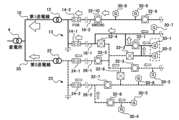
図1は、電力系統の概略の一例を示す図である。一例において、電力系統400は、基幹送電系統402を含む。基幹送電系統402には、火力発電所412、水力発電所413、揚水発電所414、およびPPS(特定規模電気事業者)電源415等の各種発電設備が電気的に接続されてよい。基幹送電系統402に接続される発電設備は、図1に示されるものに限定されない。基幹送電系統402には、他の基幹送電系統との間で連系するための連系線403が接続されてよい。
FIG. 1 is a diagram schematically showing an example of an electric power system. In one example,
基幹送電系統402には、複数の送電線10、20が電気的に接続されてよい。複数の送電線10、20は、送電系統とも呼ばれる。送電線10には、揚水発電所424、太陽光発電設備426、および風力発電設備428等の各種の発電設備が電気的に接続されてよい。
A plurality of
送電線10には、第1変圧設備12を介して第1配電系統13が電気的に接続されている。第1変圧設備12は、たとえば、配電用変電所である。第1配電系統13には、分散型電源30および負荷が電気的に接続されてよい。分散型電源30は、たとえば、太陽光発電設備または風力発電設備である。送電線20においても、送電線10と同様に、配電系統が接続されており、配電系統には、分散型電源が電気的に接続されてよい。
A first
本例においては、中央給電指令装置502が基幹送電系統402に接続される各種発電設備を制御している。指令装置500は中央給電指令装置502からの制御指令を受信する。指令装置500は、系統制御所または系統制御装置とも呼ばれる。指令装置500は、送電線10に接続される揚水発電所424、太陽光発電設備426、および風力発電設備428等の各種発電設備に制御指令を送信する。指令装置500は、複数の送電線10、20内の各種発電設備を制御してよい。また、指令装置500は、第1配電系統13に接続される複数の分散型電源30に制御指令を送信して制御してよい。
In this example, a central power
配電自動化システム1は、第1配電系統13および他の配電系統に設けられた複数の開閉器を制御する。開閉器については後述する。一例において、配電自動化システム1は、停電が発生した場合において、停電区域を局所化して停電時間を短縮する。配電自動化システム1は、電気の安定供給のために設備を維持管理してよい。また、配電自動化システム1は、現場の安全を確保してよい。なお、配電自動化システム1は、開閉器を遠隔で制御するものであればよく、監視システムまたは制御システム等のように他の名称で呼ばれる場合がある。
The power
本実施形態の配電自動化システム1は、上位システムである指令装置500から各発電設備に対して送信される制御情報を取得してよい。配電自動化システム1は、各送電線10、20における送電の混雑度の情報を指令装置500から取得してよい。配電自動化システム1は、指令装置500から取得した各種情報を用いて配電系統内の開閉器を制御する。
The power
図2は、第1実施形態における配電制御装置100の制御内容の一例を示す図である。配電自動化システム1は、配電制御装置100および端末装置101を備える。配電制御装置100は、配電自動化サーバとも呼ばれる。端末装置101は、クライアント端末とも呼ばれる。配電自動化システム1は、複数の端末装置101を有してよい。配電制御装置100と端末装置101とは通信回線を介して通信可能に接続されている。
FIG. 2 is a diagram illustrating an example of control contents of the power
配電制御装置100は、たとえば、電力会社の統括営業所に設置され、端末装置101は、たとえば、各営業所に設置される。本明細書において、配電制御装置100は、配電系統において開閉器を遠隔で制御する装置であればよく、監視装置、制御装置、監視サーバ、または制御サーバ等のように他の名称で呼ばれる装置であってよい。
The power
配電制御装置100は、指令装置500から、複数の送電線10、20のそれぞれの混雑度に関する情報(以下、混雑情報と称する)を取得する。そして、配電制御装置100は、第1送電線である送電線10および第2送電線である送電線20を含む複数の送電線のそれぞれの混雑度に基づいて開閉器32-1から32-4(開閉器32と総称する場合がある)を制御する。開閉器32-1から32-4は、分散型電源30-1、30-2が電気的に接続される接続先を送電線10および送電線20の間で切り替える。
The power
図2においては、送電線10には、計測器11が設けられている。計測器11は、送電線10の混雑度を算出するために電気計測を実行する。送電線20には、計測器21が設けられている。計測器21は、送電線20の混雑度を算出するために電気計測を実行する。計測器11、21は、たとえば電力計である。計測器11、21による計測結果は、指令装置500によって混雑情報として取得される。
In FIG. 2, the
本実施形態において、送電線の混雑度は、各送電線10、20が送電可能な電力を示す送電容量に対する実際の潮流電力の割合(利用率)または、当該割合(利用率)に関連づけられた情報であってよい。一例において、送電線の混雑度は、送電線10、20に接続されている分散型電源30-1から30-4(分散型電源30と総称する場合がある)に対して発電電力を抑制させるための発電抑制指令に関する情報であってもよい。発電抑制の度合いが高くなることは、送電線の混雑度が高くなることに対応する。
In this embodiment, the congestion degree of the power transmission line is the ratio (utilization rate) of actual power flow to the power transmission capacity indicating the power that can be transmitted by each
指令装置500は、送電線の混雑度に基づいて、分散型電源30-1から30-4に対して発電電力を抑制させるための発電抑制指令を送信してよい。発電抑制情報は、この発電抑制指令の情報であってもよい。混雑度は、実際の混雑状況であってもよく、将来の混雑予測情報であってもよい。
The
送電線10には、第1変圧設備12を介して第1配電系統13が電気的に接続されている。第1配電系統13は、複数の配電線16-1から16-3を含む。配電線16-1から16-3は、それぞれ、第1変圧設備12を介して送電線10に電気的に接続されている。配電線16-1から16-3と、第1変圧設備12との間には、それぞれフィーダ遮断器(FCB)14-1から14-3が設けられている。フィーダ遮断器14-1から14-3は、配電制御装置100等からの指令を受けると、それぞれの配電線16-1から16-3を送電線10から電気的に遮断する。
A first
送電線20には、第2変圧設備22を介して第2配電系統23が電気的に接続されている。第2配電系統23は、複数の配電線26-1から26-3を含む。配電線26-1から26-3は、それぞれ、第2変圧設備22を介して送電線20に電気的に接続されている。配電線26-1から26-3と、第2変圧設備22との間には、フィーダ遮断器(FCB)24-1から24-3が設けられている。フィーダ遮断器(FCB)24-1から24-3は、配電制御装置100等からの指令を受けると、それぞれの配電線26-1から26-3を送電線20から電気的に遮断する。
A second
複数の分散型電源30-1から30-4は、接続切替対象の分散型電源30-1および30-2を含む。分散型電源30-1は、少なくとも一つの開閉器32-1を介して第1配電系統13に接続可能であるとともに、少なくとも一つの開閉器32-2を介して第2配電系統23にも接続可能である。同様に、分散型電源30-2は、少なくとも一つの開閉器32-3を介して第1配電系統13に接続可能であるとともに、少なくとも一つの開閉器32-4を介して第2配電系統23にも接続可能である。
The plurality of distributed power sources 30-1 to 30-4 include distributed power sources 30-1 and 30-2 that are subject to connection switching. The distributed power source 30-1 is connectable to the
開閉器32-1および開閉器32-3は、それぞれ第1開閉器の一例である。開閉器32-2および開閉器32-4は、それぞれ第2開閉器の一例である。なお、第1開閉器および第2開閉器は、本例と異なり、それぞれ複数の開閉器が直列に接続されて構成されてよい。 The switch 32-1 and the switch 32-3 are each an example of a first switch. The switch 32-2 and the switch 32-4 are each an example of a second switch. Note that, unlike this example, the first switch and the second switch may each be configured by connecting a plurality of switches in series.
図3は、第1実施形態における配電制御装置100の概略構成の一例を示すブロック図である。図2および図3を参照しつつ、配電制御装置100の概略構成を説明する。配電制御装置100は、混雑度取得部102および制御部104を備える。混雑度取得部102および制御部104は、CPU(中央演算処理装置)の一機能として実現されてよい。
FIG. 3 is a block diagram showing an example of a schematic configuration of the power
混雑度取得部102は、送電線10および送電線20のそれぞれの混雑情報を取得する。制御部104は、送電線10および送電線20のいずれかに変圧設備を介して分散型電源30-1および30-2を電気的に接続可能な少なくとも一つの開閉器32-1から32-4を混雑度に基づいて制御する。本例では、制御部104は、開閉器32-1から32-4を混雑度に基づいてオン(閉)またはオフ(開)に制御することによって、制御分散型電源30-1および30-2が電気的に接続される送電線を切り替える。
The congestion
図2において、送電線10の混雑度が送電線10の混雑度より高く、かつ、送電線10の混雑度が予め定められた第1閾値より高い場合には、制御部104は、送電線10に電気的に接続されている一または複数の分散型電源30-1、30-2、および30-3のうち少なくとも一部が他の送電線20に電気的に接続されるように開閉器32-1から32-4を制御する。第1閾値は、予め設定されており、記憶部106に記憶されてよい。制御部104は、開閉器32-1をオフに制御するとともに、開閉器32-2をオンに制御してよい。これにより、接続切替対象の分散型電源30-1が、混雑度が送電線10より低い送電線20に電気的に接続される。同様に、配電制御装置100は、開閉器32-3をオフに制御するとともに、開閉器32-4をオンに制御してよい。これにより、接続切替対象の分散型電源30-2が、混雑度が送電線10より低い送電線20に電気的に接続される。
In FIG. 2, when the congestion degree of the
制御部104は、送電線10の混雑度および送電線20の混雑度に基づいて、初期状態において送電線10に電気的に接続されている一または複数の分散型電源30-1、30-2のうち、送電線20に電気的に接続されるように切り替えられる分散型電源の数または種類を決定してよい。制御部104は、送電線10の混雑度および送電線20の混雑度に基づいて、接続切替対象の分散型電源30-1および30-2のうち、いずれか一方のみを送電線10から送電線20に電気的に接続するように切り替えてよく、分散型電源30-1および30-2の双方を送電線10から送電線20に電気的に接続するように切り替えてよい。たとえば、送電線20の混雑度と送電線20の混雑度の差が大きくなるほど、送電線20に電気的に接続されるように切り替えられる分散型電源の数を多くしてよい。たとえば、送電線20の混雑度と送電線20の混雑度の差が大きくなるほど、送電線20に電気的に接続されるように切り替えられる分散型電源の種類を増やしてもよい。
The
図3において、配電制御装置100は、記憶部106、発電情報取得部108、算出部110、計測結果取得部112、発電抑制変更指示部114、および通信部116を備えてよい。記憶部106は、各種のデータおよびパラメータを記憶する。記憶部106は、送電線(10、20)、配電系統(13、23)、複数の開閉器32、および複数の分散型電源30等の配置、接続、定格等の仕様についての情報を含む設備情報を予め記憶してよい。
In FIG. 3 , the power
記憶部106は、算出部110が算出した算出結果を記憶してよい。発電情報取得部108は、分散型電源30-1から30-4の発電電力実測情報を取得する。発電電力実測情報は、発電電力実測値または発電電力実測値に関連づけられた値であってよい。たとえば、発電電力実測値は、太陽光発電設備による発電電力実測値である。計測結果取得部112は、配電線内での複数点での電気計測結果を取得する。
The
計測結果取得部112は、図2における配電線(フィーダ)16-1から16-3、および26-1から26-3のそれぞれにおいて、複数地点での電気計測結果を取得してよい。たとえば、各配電線の複数地点に設けられた計測器によって電圧、電流、および力率が測定される。計測器は、開閉器32-1から32-4に内蔵されていてもよく、別途に設けられていてもよい。計測結果取得部112は、配電線内での複数点での電気計測結果を計測器から受信してよい。
The measurement
算出部110は、電気計測結果および発電電力実測情報から、各配電線内の複数区間における負荷と分散型電源30の発電電力とを算出する。具体的には、算出部110は、それぞれの配電線16-1から16-3、26-1から26-3での分散型電源30の状態と、各配電線16-1から16-3、26-1から26-3の領域内における複数点での電流、電圧、および力率の計測結果とに基づいて、各配電線16-1から16-3、26-1から26-3内の複数区間における負荷と分散型電源の発電電力とを算出してよい。たとえば、算出部110は、配電線16-1内の複数区間における負荷および発電電力を算出する。同様に、算出部110は、配電線26-1内の複数区間における負荷および発電電力を算出する。
The
算出部110は、各配電線の複数区間における負荷および発電電力に基づいて潮流計算を実行してよい。制御部104は、算出部110による潮流計算の結果に基づいて、接続切替対象の分散型電源30-1および30-2の接続先の配電線を切り替えた場合に、予め定められた条件を満たすか否かを判断してもよい。
The
制御部104は、各配電線(フィーダ)16-1から16-3、26-1から26-3において電圧および電流が予め定められた範囲を超えないか否かを判断してよい。制御部104は、供給電力が配電線(フィーダ)16-1から16-3、26-1から26-3の限界を超えないかを判断してよい。配電制御装置100は、制御部104以外に判定部(シミュレータ)を有してもよい。この場合、判定部は、接続切替対象の分散型電源30-1および30-2の接続先の配電線を切り替えた場合に、予め定められた条件を満たすか否かを判定してよい。制御部104は、算出部110による潮流計算の結果に基づいて、接続切替対象の分散型電源30-1および30-2の接続先の配電線を切り替える範囲を調整してよい。
The
図3において、通信部116は、開閉器32-1から32-4の開閉制御信号を送信する。発電抑制変更指示部114は、接続切替対象の分散型電源30-1および30-2の少なくとも一つが電気的に接続される送電線10、20が切り替わった場合に、指令装置500に対して発電抑制変更を通知または指示してよい。送電線10の混雑度が送電線20の混雑度より高い場合、指令装置500は、送電線10に電気的に接続される各分散型電源30に対して発電抑制指令を送信している場合がある。本実施形態の配電制御装置100によれば、混雑度が軽減されるので、各分散型電源30に対する発電抑制が不要または軽減される。
In FIG. 3, the
分散型電源30の数、種類は、図3に示される場合に限定されない。また、第1配電系統13および第2配電系統23の接続形態、送電線10および送電線20の数も、図3に示される場合に限定されない。
The number and types of distributed
図4および図5は、第1実施形態における分散型電源30の接続関係を切り替える処理の一例を示す図である。図4は、分散型電源30の接続関係を切り替える前の状態の一例を示し、図5は、分散型電源30の接続関係を切り替えた後の状態の一例を示す。なお、送電線10および送電線20は、変電所4を介して、図1に示される基幹送電系統402に電気的に接続されてよい。
4 and 5 are diagrams illustrating an example of a process for switching the connection relationship of the distributed
図4および図5において、矢印の太さは、それぞれの地点における潮流電力の大きさを模式的に示している。図4および図5において、開閉器32において丸印は、開閉器32がオン(閉)になっていることを意味する。開閉器32において×印は、開閉器32がオフ(開)になっていることを意味する。 In FIGS. 4 and 5, the thickness of the arrows schematically indicates the magnitude of the tidal power at each point. In FIGS. 4 and 5, a circle mark in the switch 32 means that the switch 32 is turned on (closed). The x mark in the switch 32 means that the switch 32 is off (open).
図4および図5に示される例において、分散型電源30-1から30-9は、接続切替対象の分散型電源30-1および30-2を含んでいる。接続切替対象の分散型電源30-1および30-2は、少なくとも一つの第1開閉器32-1を介して第1配電系統13に接続可能であるとともに、少なくとも一つの第2開閉器32-2を介して第2配電系統23にも接続可能である。
In the examples shown in FIGS. 4 and 5, distributed power sources 30-1 to 30-9 include distributed power sources 30-1 and 30-2 to which connection switching is to be performed. The distributed power sources 30-1 and 30-2 to be connected are connectable to the first
送電線10の混雑度が送電線20の混雑度より高く、かつ、送電線10の混雑度が予め定められた第1閾値より高い場合に、制御部104は、接続切替対象の分散型電源30-1および30-2の少なくとも一部を第1配電系統13(図4、図5では、配電線16-1)から電気的に遮断するように開閉器32-1(第1開閉器)をオフに切り換えるとともに、第2配電系統23(図4、図5では、配電線26-1)に電気的に接続するように開閉器32-2(第2開閉器)をオンに切り換える。このような制御により、接続切替対象の分散型電源30-1および30-2が、複数の配電系統に電気的に接続されてループ回路を構成する状態を可及的に防止することができる。なお、図4および図5に示される例においては、一組の第1開閉器32-1および第2開閉器32-2で、複数の分散型電源30-1および30-2の接続先の配電系統を切り替えることができる。
When the congestion degree of the
図6は、配電制御装置100の処理の一例を示すフローチャートである。混雑度取得部102は、各送電線10、20の混雑情報を取得する(ステップS101)。本例において、制御部104は、混雑度が第1閾値以上となっている一の送電線(第1送電線)があるか否かを判断する(ステップS102)。混雑度が第1閾値以上となっている送電線がある場合には(ステップS102:YES)、制御部104は、送電線10(第1送電線)に電気的に接続されている分散型電源30が、他の送電線に電気的に接続されるように、開閉器32を制御する(ステップS103)。発電抑制変更指示部114は、発電抑制可能な系統を指令装置500に通知してよい(ステップS104)。
FIG. 6 is a flowchart illustrating an example of processing by the power
図6に示される例では、指令装置500が、各送電線の混雑度に応じて分散型電源30の発電抑制を指示した後に、配電制御装置100が発電抑制指令の内容に基づいて接続切替対象の分散型電源30-1および30-2の接続先の送電線を切り替える。但し、本実施形態の配電制御装置100は、この場合に限られない。指令装置500が各送電線の混雑度に応じて分散型電源30の発電抑制を実際に指示する前の段階で、配電制御装置100の混雑度取得部102は、各送電線の混雑度に関する情報を取得してよい。指令装置500が分散型電源30に対して発電抑制指令を送信する前に、制御部104が、各送電線の混雑度に応じて接続切替対象の分散型電源30-1および30-2の接続先の送電線を切り替えてもよい。この場合、分散型電源30が実際に発電抑制されることを事前に防止することができる。
In the example shown in FIG. 6, after the
また、図6に示される例では、制御部104は、混雑度が第1閾値以上となっている送電線(第1送電線)があるか否かを判断する(ステップS102)。しかしながら、本実施形態の配電制御装置100は、この場合に限定されない。たとえば、制御部104は、混雑度を第1閾値と比較するのに代えて、第1送電線の混雑度が第2送電線の混雑度に比べて予め定められた値以上に高くなった場合、すなわち、第1送電線の混雑度と第2送電線の混雑度とが予め定められた程度を超えてアンバランスになった場合に、送電線10に電気的に接続されている分散型電源30のうち少なくとも一部が送電線20に電気的に接続されるように制御部104が開閉器32を制御してもよい。
Further, in the example shown in FIG. 6, the
図7は、配電制御装置100による開閉器の制御処理の一例を示すフローチャートである。図7は、図6のフローチャートのステップS103のサブルーチンであってよい。図4および図5を参照しつつ、図7に示される制御処理を説明する。
FIG. 7 is a flowchart illustrating an example of switch control processing by the power
制御部104は、記憶部106に記憶された設備情報を読み出す。制御部104は、配電制御装置100の外部から設備情報を受信してもよい。制御部104は、設備情報に基いて、第1配電系統13に開閉器32-1(第1開閉器)を介して接続可能であるとともに他の配電系統(たとえば、第2配電系統23)に他の開閉器32-2(第2開閉器)を介して接続可能である、接続切替対象の分散型電源30-1および30-2の情報を取得する(ステップS10)。
The
制御部104は、接続切替対象の分散型電源30-1および30-2が電気的に接続可能な他の送電線を選択する(ステップS11)。図4および図5に示される例では、送電線20が選択される。混雑度取得部102は、選択された他の送電線の混雑度を取得する(ステップS12)。なお、図7に示される場合においては、混雑度取得部102は、選択された他の送電線の混雑度を順次に指令装置500から取得する。但し、本実施形態の配電制御装置100は、この場合に限られない。混雑度取得部102は、すべての送電線の混雑度を予め指令装置500から取得してもよい。
The
制御部104は、第1送電線である送電線10の混雑度と選択された他の送電線の混雑度を比較する(ステップS13)。第1送電線の混雑度が、選択された他の送電線の混雑度より高い場合には(ステップS13:YES)、制御部104は、選択された送電線を、着目している接続切替対象の分散型電源30-1および30-2の接続変更先の候補の一つに決定する(ステップS14)。制御部104は、接続可能なすべての他の送電線の選択が完了するまで(ステップS15:YES)、ステップS11からステップS15の処理を繰り返してよい。
The
接続切替対象の分散型電源30-1および30-2の接続変更先の候補となる他の送電線が複数存在する場合もある。制御部104は、複数の接続先候補の送電線の混雑度と、接続切替対象の分散型電源30の電力予測値等とに基づいて、各分散型電源30が接続される接続先の送電線(第2送電線)を決定してよい(ステップS16)。また、制御部104は、送電線10の混雑度と他の送電線の混雑度とに基づいて、接続切替対象の分散型電源30の種類および数を決定してよい(ステップS16)。各分散型電源30-1および30-2が、別々の送電線に電気的に接続されるように、各分散型電源30の接続変更先の送電線が決定されてもよい。
There may also be a plurality of other power transmission lines that are candidates for the connection change destination of the distributed power sources 30-1 and 30-2 to be connected. The
制御部104は、接続切替対象の分散型電源30が、ステップS16で接続変更先として決定された送電線20に電気的に接続されるように、開閉器32を制御する(ステップS17)。具体的には、制御部104は、通信部116から開閉制御信号を対応する開閉器32に送信する。
The
図8は、配電制御装置100による分散型電源の接続関係を元に戻す処理の一例を示すフローチャートである。混雑度取得部102は、各送電線10、20の混雑度に関する情報を取得する(ステップS111)。制御部104は、第1開閉器(図4、図5における開閉器32-1等)の少なくとも一つをオフに切り換えるとともに第2開閉器(図4、図5における開閉器32-2等)をオンに切り換えた後に(図6のステップS103)、送電線10の混雑度が、第1閾値以下の値に予め定められた第2閾値以下となった場合には(ステップS112:YES)、制御部104は、送電線20に電気的に接続されている分散型電源30-1および30-2が元の送電線10に電気的に接続されるように、開閉器32を制御してよい。制御部104は、第1開閉器(図4、図5における開閉器32-1等)をオンに切り換えるとともに、第2配電系統に電気的に接続するように第2開閉器(図4、図5における開閉器32-2等)の少なくとも一つをオフに切り換える。
FIG. 8 is a flowchart illustrating an example of a process performed by the power
以上のように、本実施形態の配電制御装置100によれば、上位システムである指令装置500との連係を図ることにより送電容量不足を解消することができる。特に、配電制御装置100によれば、配電自動化システム1において、送電容量確保に寄与するように配電系統を組み替えることができる。配電制御装置100は、混雑した送電系統配下の配電系統に対して逆潮流電圧の大きな分散型電源30を接続切替(シフト)しない。配電制御装置100は、混雑していない送電線に電気的に接続されるように分散型電源30を接続切替することで、発電抑制を防止または軽減することができる。したがって、分散型電源30の発電電力を抑制することによる逸失利益を低減することができる。
As described above, according to the power
図9は、第1実施形態の変形例における配電制御装置の制御内容の一例を示す図である。本例において、第2配電系統23は、一または複数の第2配電線26-1および26-2を含む。特に、第2配電線26-1における接続状態は、上述した図5において、第1開閉器の少なくとも一つである開閉器32-1がオフに切り換えられるとともに、第2開閉器である開閉器32-2がオンに切り換えられた状態に対応している。
FIG. 9 is a diagram illustrating an example of control contents of the power distribution control device in a modification of the first embodiment. In this example, the second
図9に示される例では、第2配電線26-1および第2配電線26-2が第2変圧設備22を介して送電線20に接続してよい。第2配電線26-1と第2変圧設備22との間には、フィーダ遮断器24-1が設けられている。第2配電線26-2と第2変圧設備22との間には、フィーダ遮断器24-2が設けられている。
In the example shown in FIG. 9, the second power distribution line 26-1 and the second power distribution line 26-2 may be connected to the
第2配電線26-1内の複数点には計測器28-1、28-2、28-3、および28-4が設けられている。第2配電線26-1は、第1区間、第2区間、および第3区間を含む複数区間に区分されている。計測器28-1と28-2の間の第1区間には、分散型電源30-1と負荷36-1とが接続されている。計測器28-2と28-3の間の第2区間には、分散型電源30-2と負荷36-2とが接続されている。計測器28-3と28-4の間の第3区間には、分散型電源30-3と負荷36-3とが接続されている。計測器28-1、28-2、28-3、および28-4は、第2配電線26-1内の複数点における電流、電圧、および力率を計測する。 Measuring instruments 28-1, 28-2, 28-3, and 28-4 are provided at multiple points within the second power distribution line 26-1. The second distribution line 26-1 is divided into multiple sections including a first section, a second section, and a third section. A distributed power source 30-1 and a load 36-1 are connected to the first section between the measuring instruments 28-1 and 28-2. A distributed power source 30-2 and a load 36-2 are connected to the second section between the measuring instruments 28-2 and 28-3. A distributed power source 30-3 and a load 36-3 are connected to the third section between the measuring instruments 28-3 and 28-4. Measuring devices 28-1, 28-2, 28-3, and 28-4 measure current, voltage, and power factor at multiple points within second distribution line 26-1.
同様に、第2配電線26-2内の複数点には計測器28-5、28-6、28-7、および28-8が設けられている。計測器28-5と28-6の間の第1区間には、分散型電源30-4と負荷36-4とが接続されている。計測器28-6と28-7の間の第2区間には、分散型電源30-5と負荷36-5とが接続されている。計測器28-7と28-8の間の第3区間には、分散型電源30-6と負荷36-6とが接続されている。計測器28-5、28-6、28-7、および28-8は、第2配電線26-2内の複数点における電流、電圧、および力率を計測する。なお、図9においては、第2配電系統23が示されているが、第1配電系統13においても、図9に示される構成が設けられてよい。
Similarly, measuring instruments 28-5, 28-6, 28-7, and 28-8 are provided at multiple points within the second power distribution line 26-2. A distributed power source 30-4 and a load 36-4 are connected to the first section between the measuring instruments 28-5 and 28-6. A distributed power source 30-5 and a load 36-5 are connected to the second section between the measuring instruments 28-6 and 28-7. A distributed power source 30-6 and a load 36-6 are connected to the third section between the measuring instruments 28-7 and 28-8. Measuring devices 28-5, 28-6, 28-7, and 28-8 measure current, voltage, and power factor at multiple points within second distribution line 26-2. Although the second
図10は、第1実施形態の変形例における配電制御装置100の概略構成の一例を示すブロック図である。配電制御装置100は、図3に示される構成に加えて、制御情報取得部113および判定部117を備える。図4および図5に示されるように送電線10の混雑度および第2送電線の混雑度に応じて、開閉器32-1(第1開閉器の少なくとも一つ)がオフに切り換えられるとともに、開閉器32-2(第2開閉器)がオンに切り換えられた状態において、後述するように、算出部110は、各第1配電線16内の複数点での電気計測結果に基づいて、第1配電線16内の複数区間におけるそれぞれの負荷と分散型電源30の発電電力とを算出する。同様に、開閉器32-1がオフに切り換えられるとともに、開閉器32-2がオンに切り換えられた状態において、算出部110は、後述するように、各第2配電線26内の複数点での電気計測結果に基づいて、第2配電線26内の複数区間におけるそれぞれの負荷と分散型電源30の発電電力とを算出する。
FIG. 10 is a block diagram showing an example of a schematic configuration of the power
制御情報取得部113は、指令装置500から制御情報を取得する。制御情報は、各第1配電線16-1、16-2または各第2配電線26-1、26-2に接続されている分散型電源30の出力制限に用いられる情報である。算出部110は、制御情報と、電気計測結果とに基づいて、各第1配電線内の複数区間および各第2配電線内の複数区間における負荷と分散型電源30の発電電力とを算出してよい。特に、算出部110は、電気計測結果、発電電力実測情報、および制御情報から、各配電線内の複数区間における負荷と分散型電源30の発電電力とを算出する。さらに、算出部110は、各配電線の複数区間における負荷と分散型電源30の発電電力とに基づいて潮流計算を実行してよい。
The control
図10において、判定部117は、算出部110によって算出された負荷と分散型電源30の発電電力とに基づいて、一の配電線と他の配電線との間が接続可能か否かについて判定する。たとえば、判定部117は、図9において、第2配電線26-2(一の配電線)と第2配電線26-1(他の配電線)との間が接続可能か否かについて判定する。判定部117は、一の配電線および他の配電線のそれぞれの複数区間における負荷と分散型電源30の発電電力とに基づいて潮流計算を実行してよい。判定部117は、潮流計算によって、一の配電線と他の配電線との間を接続した場合に、予め定められた条件を満たすか否かを判定する。予め定められた条件には、電圧が適正範囲に維持されるか否か、配電線の供給電力が予め定められた上限を超えないか、および一の配電線から他の配電線に送電された場合に他の配電線内の自動電圧調整器が誤作動しないか等の条件の少なくとも一つが含まれてよい。
In FIG. 10, the
一の配電線(たとえば、図9における配電線26-1)の一部において故障が発生する場合、配電制御装置100からの指令を受けたフィーダ遮断器24-1は、配電線26-1を送電線20から遮断する。また、配電制御装置100は、一の配電線26-1における分散型電源30-1、30-2、および30-3を一の配電線26-1から遮断するように制御する。そして、判定部117が、一の配電線26-1と他の配電線26-2との間が接続可能であると判定した場合には、制御部104は、一の配電線26-1と他の配電線26-2とを連結する開閉器32-6をオン(閉)にする。これにより故障が発生してフィーダ遮断器24-1によって送電線20との間の電気的接続が遮断した配電線(たとえば、第2配電線26-1)の少なくとも一部に対して他の配電線(たとえば、第2配電線26-2)から電力を融通することができる。
When a failure occurs in a part of one distribution line (for example, distribution line 26-1 in FIG. 9), feeder circuit breaker 24-1 receives a command from
図11は、第1実施形態の変形例における複数の配電線間を接続する処理の一例を示すフローチャートである。算出部110は、一の配電線において故障が発生した場合(ステップS201:YES)、一の配電線内および他の配電線内の複数区間における負荷と分散型電源30の発電電力とを算出する(ステップS202)。判定部117は、故障が発生した一の配電線に対して開閉器32を介して接続される他の配電線を選択する(ステップS203)。一の配電線において故障が発生した場合において、判定部117は、故障が発生した一の配電線と他の配電線とが接続可能か否かを判定する(ステップS204)。一の配電線と他の配電線とが接続可能でない場合(ステップS204:NO)、判定部117は、別の配電線を選択する(ステップS203)。一の配電線と他の配電線とが接続可能であると判定された場合(ステップS204:YES)、制御部104は、一の配電線と他の配電線とを接続する開閉器32をオン(閉)に制御して、一の配電線と他の配線線とを電気的に接続する(ステップS205)。但し、配電制御装置100の処理は、図11に示される場合に限られない。
FIG. 11 is a flowchart illustrating an example of a process for connecting a plurality of power distribution lines in a modification of the first embodiment. When a failure occurs in one distribution line (step S201: YES), the
図12は、第1実施形態の変形例における複数の配電線間を接続する処理の他例を示すフローチャートである。算出部110は、一の配電線において故障が発生したか否かによらず、一の配電線内の複数区間および他の配電線内の複数区間における負荷と分散型電源30の発電電力とを算出してよい(ステップS301)。発電電力および負荷の算出結果は、記憶部106に記憶される(ステップS302)。そして、判定部117は、一の配電線において故障が発生した場合に(ステップS303:YES)、記憶部106に記憶された算出結果に基づいて、一の配電線と他の配電線との間が接続可能か否かについて判定する(ステップS304およびステップS305)。制御部104は、一の配電線と他の配電線とを接続する開閉器32をオン(閉)に制御して、一の配電線と他の配線線とを電気的に接続する(ステップS306).図12において、他の処理内容は、図11における処理と同様である。したがって、繰り返しの説明を省略する。
FIG. 12 is a flowchart showing another example of the process of connecting a plurality of power distribution lines in a modification of the first embodiment. The
図13は、第1実施形態の変形例における電力および負荷の算出処理の一例を示すフローチャートである。図13は、図11のステップS202または図12のステップS301における処理のサブルーチンであってよい。 FIG. 13 is a flowchart illustrating an example of power and load calculation processing in a modification of the first embodiment. FIG. 13 may be a subroutine of the process in step S202 of FIG. 11 or step S301 of FIG. 12.
計測結果取得部112は、各配電線内の複数の地点における電流、電圧、および力率等の計測結果を取得する(ステップS21)。特に、図9に示されるとおり、各配電線(図9における第2配電線26-1、26-2)に配置された複数の計測器28-1から28-8による計測結果を計測結果取得部112が受信してよい。発電情報取得部108は、各分散型電源30からの発電電力実測情報を取得する(ステップS22)。たとえば、発電電力実測情報は、太陽光発電設備による発電電力実測値である。図9に示されるように、算出部110は、各配電線(図9における第2配電線26-1、26-2)内の複数区間(図9における第1区間、第2区間、および第3区間)における発電電力および負荷を算出する(ステップS23)。
The measurement
制御情報取得部113は、指令装置500から制御情報を取得する(ステップS24)。制御情報は、各第1配電線16-1、16-2または各第2配電線26-1、26-2に接続されている分散型電源30の出力制限に用いられる情報である。算出部110は、制御情報を用いて、各配電線(たとえば、図9における第2配電線26-1、26-2)内の複数区間(図9における第1区間、第2区間、および第3区間)における発電電力および負荷を再計算(補正計算)する(ステップS25)。なお、ステップS21、ステップS22、およびステップS24の処理順序は一例にすぎず、配電制御装置100は、制御情報と、電気計測結果とに基づいて、配電線内の複数区間における負荷および分散型電源の発電電力を算出するものであればよい。また、配電制御装置100は、発電電力実測情報と、電気計測結果とに基づいて、配電線内の複数区間における負荷および分散型電源の発電電力を算出するものであってもよい。
The control
ステップS24における制御情報は、いずれかの送電線(たとえば、送電線10または送電線20)における故障情報であってよい。故障情報は、N-1電制情報(N-1電源制限情報)であってよい。N-1電制を採用する場合、いずれかの送電線において故障が発生すると、リレー装置506は、故障が発生した送電線に電気的に接続されている分散型電源30を送電線から遮断(解列)する。この場合、算出部110は、発電情報取得部108によって取得された発電電力実測情報によらず、それぞれの分散型電源30からの電力をゼロとして、各配電線(図9における配電線26-1、26-2)内の複数区間(図9における第1区間、第2区間、および第3区間)における発電電力および負荷を再計算(補正計算)してよい(ステップS25)。これによって、分散型電源30の遮断を反映して正確な発電電力推定および負荷推定を実行することができる。
The control information in step S24 may be failure information on any power transmission line (for example,
制御情報は、分散型電源30に対して発電電力を抑制させる発電抑制情報であってよい。指令装置500から各分散型電源30に対して発電抑制指令が送信される場合、分散型電源30から配電線に供給される電力が抑制される。分散型電源30で発生された残りの電力は蓄電池等に蓄えられる場合がある。この場合、算出部110は、発電情報取得部108によって取得された発電電力実測情報によらず、それぞれの分散型電源30からの電力に対して抑制指令に応じた係数を乗じた上で、各配電線(図9における配電線26-1、26-2)内の複数区間(図9における第1区間、第2区間、および第3区間)における発電電力および負荷を再計算(補正計算)してよい。これによって、発電抑制指令の内容を分散型電源出力に反映して正確な発電電力推定および負荷推定を実行することができる。
The control information may be power generation suppression information that causes the distributed
なお、一の配電線と接続可能な他の配電線が複数存在する場合がある。この場合、判定部117は、一の配電線に距離が近い順に他の配電線を選択してもよい。また、仮想的に一の配電線と電気的に接続した場合における送電線の混雑度が低くなる順に、他の配電線を選択してもよい。また、以下に説明するように、故障が発生していない送電線に電気的に接続された配線線が先的に他の配電線として選択されてもよい。
Note that there may be a plurality of other power distribution lines that can be connected to one power distribution line. In this case, the
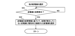
図14は、第1実施形態の変形例において一の配電線が接続される他の配電線を選択する処理の一例を示すフローチャートである。図14の処理は、図11に示されるステップS203または図12に示されるステップS304の処理の一例である。制御情報は、送電線の故障情報を含んでいてよい。送電線に故障が発生した場合(ステップS31)、制御情報取得部113は、送電線の故障情報を取得する。判定部117は、送電線の故障情報に基づいて、複数の配電線の中から、一の配電線が接続される他の配電線が選択される(ステップS32)。
FIG. 14 is a flowchart illustrating an example of a process for selecting another power distribution line to which one power distribution line is connected in a modification of the first embodiment. The process in FIG. 14 is an example of the process in step S203 shown in FIG. 11 or step S304 shown in FIG. 12. The control information may include power transmission line failure information. When a failure occurs in the power transmission line (step S31), the control
図15は、第1実施形態の変形例における一の配電線が接続される他の配電線を選択する処理の一例を示す図である。図15には、一の配電線として第2配電線26-2が示されている。図15には、第2配電線26-2において故障が発生した場合が示されている。他の配電線として、第2配電線26-1と第2配電線26-3が候補になっている。配電線26-3が電気的に接続されている送電線20cには故障が発生していない。一方、配電線26-1が電気的に接続されている送電線20aには故障が発生している。この場合、判定部117は、各送電線20a、20b、20cについての故障情報に基づいて、故障が発生した送電線20aに電気的に接続された配電線26-1を避けて、故障が発生していない送電線20cに電気的に接続された配電線26-3を他の配電線として選択してよい。
FIG. 15 is a diagram illustrating an example of a process for selecting another power distribution line to which one power distribution line is connected in a modification of the first embodiment. In FIG. 15, a second power distribution line 26-2 is shown as one power distribution line. FIG. 15 shows a case where a failure occurs in the second distribution line 26-2. As other distribution lines, the second distribution line 26-1 and the second distribution line 26-3 are candidates. No failure has occurred in the
以上のとおり、第1実施形態の変形例における配電制御装置によれば、送電線の混雑度に基づいて複数の分散型電源30-1および30-2が接続される接続先の配電系統が切り替えられている状態において、さらに、配電系統の一の配電線に故障が発生した場合においても、他の配電線にから電力を融通することが可能となる。 As described above, according to the power distribution control device in the modification of the first embodiment, the power distribution system to which the plurality of distributed power sources 30-1 and 30-2 are connected is switched based on the congestion degree of the power transmission line. In this state, even if a failure occurs in one distribution line of the distribution system, it becomes possible to transfer power from other distribution lines.
[第2実施形態] [Second embodiment]
図16は、第2実施形態における配電制御装置200の制御内容の一例を示す図である。第1実施形態における配電制御装置100は、送電線の混雑度に基づいて、分散型電源の接続先を変更する構成を有していたが、本発明は、この場合に限られない。
FIG. 16 is a diagram illustrating an example of control contents of the power
第2実施形態における配電自動化システム5は、上位システムである指令装置500から各発電設備に対して送信される制御情報を取得してよい。配電自動化システム5は、指令装置500から取得した各種情報を用いて配線線内の開閉器を制御する。配電自動化システム5は、開閉器を遠隔で制御するものであればよく、監視システムまたは制御システム等のように他の名称で呼ばれる場合がある。
The power
配電自動化システム5は、配電制御装置200および端末装置201を備える。配電制御装置200は、配電自動化サーバとも呼ばれる。端末装置201は、クライアント端末とも呼ばれる。配電自動化システム5は、複数の端末装置201を有してよい。配電制御装置200と端末装置201とは通信回線を介して通信可能に接続されている。配電自動化サーバは、たとえば、電力会社の統括営業所に設置され、端末装置201は、たとえば、各営業所に設置される。本明細書において、配電制御装置200は、配電系統において開閉器を遠隔で制御する装置であればよく、監視装置、制御装置、監視サーバ、または制御サーバ等のように他の名称で呼ばれる装置であってよい。
The power
送電線40a-1、40b-1には、変圧設備42-1を介して配電線46-1が電気的に接続される。送電線40a-2、40b-2には、変圧設備42-2を介して配電線46-2が電気的に接続される。なお、配電線46-1および配電線46-2を総称して配電線46と称する場合がある。電力系統の信頼性の観点から、1回線分の送電線40a-1が故障した場合でも、送電可能な送電容量を確保するために、もう1回戦分の送電線40b-1が設けられている。
A power distribution line 46-1 is electrically connected to the
したがって、送電線40a-1、40b-1は、2回線分の送電容量を確保している。同様に、送電線40a-2、40b-2は、2回線分の送電容量を確保している。なお、配電線46-1と配電線46-2は、図16に示されるように、互いに別の送電線に電気的に接続されていてよい。図16に示される場合と異なり、配電線46-1と配電線46-2は、同じ送電線に電気的に接続されていてもよい。
Therefore, the
配電線46-1と、変圧設備42-1との間には、フィーダ遮断器(FCB)44-1が設けられている。フィーダ遮断器(FCB)44-1は、配電制御装置200等からの指令を受けると、配電線46-1を送電線40a-1、40b-1から電気的に遮断する。同様に、配電線46-2と、変圧設備42-2との間には、フィーダ遮断器44-2が設けられている。フィーダ遮断器44-2は、配電制御装置200等からの指令を受けると、配電線46-2を送電線40a-2、40b-2から電気的に遮断する。
A feeder circuit breaker (FCB) 44-1 is provided between the power distribution line 46-1 and the transformer equipment 42-1. When receiving a command from the power
送電線40a-1、40b-1には、複数のフィーダ遮断器を介して複数の配電線が設けられてよい。複数の配電線は、配電系統を構成してよい。同様に、送電線40a-2、40b-2にも、複数のフィーダ遮断器を介して複数の配電線が設けられてよい。
A plurality of power distribution lines may be provided to the
各配電線46-1、46-2には、分散型電源50-1から50-6(分散型電源50と総称する場合がある)が電気的に接続されてよい。分散型電源50は、たとえば、太陽光発電設備または風力発電設備である。また、各配電線には、負荷56-1から56-6(負荷56と総称する場合がある)が設けられている。 Distributed power sources 50-1 to 50-6 (sometimes collectively referred to as distributed power sources 50) may be electrically connected to each distribution line 46-1, 46-2. Distributed power source 50 is, for example, solar power generation equipment or wind power generation equipment. Further, each distribution line is provided with loads 56-1 to 56-6 (sometimes collectively referred to as loads 56).
配電線46-1内の複数点には計測器48-1、48-2、48-3、および48-4が設けられている。計測器48-1と48-2の間の第1区間には、分散型電源50-1と負荷56-1とが接続されている。計測器48-2と48-3の間の第2区間には、分散型電源50-2と負荷56-2とが接続されている。計測器48-3と48-4の間の第3区間には、分散型電源50-3と負荷56-3とが接続されている。計測器48-1、48-2、48-3、および48-4は、配電線46-1内の複数点における電流、電圧、および力率を計測する。 Measuring devices 48-1, 48-2, 48-3, and 48-4 are provided at multiple points within the power distribution line 46-1. A distributed power source 50-1 and a load 56-1 are connected to the first section between the measuring instruments 48-1 and 48-2. A distributed power source 50-2 and a load 56-2 are connected to the second section between the measuring instruments 48-2 and 48-3. A distributed power source 50-3 and a load 56-3 are connected to the third section between the measuring instruments 48-3 and 48-4. Measuring devices 48-1, 48-2, 48-3, and 48-4 measure current, voltage, and power factor at multiple points within power distribution line 46-1.
同様に、他の配電線46-2内の複数点には計測器48-5、48-6、48-7、および48-8が設けられている。計測器48-5と48-6の間の第1区間には、分散型電源50-4と負荷56-4とが接続されている。計測器48-6と48-7の間の第2区間には、分散型電源50-5と負荷56-5とが接続されている。計測器48-7と48-8の間の第3区間には、分散型電源50-6と負荷56-6とが接続されている。計測器28-5、28-6、28-7、および28-8は、他の配電線46-2内の複数点における電流、電圧、および力率を計測する。 Similarly, measuring devices 48-5, 48-6, 48-7, and 48-8 are provided at multiple points within the other power distribution line 46-2. A distributed power source 50-4 and a load 56-4 are connected to the first section between the measuring instruments 48-5 and 48-6. A distributed power source 50-5 and a load 56-5 are connected to the second section between the measuring instruments 48-6 and 48-7. A distributed power source 50-6 and a load 56-6 are connected to the third section between the measuring instruments 48-7 and 48-8. Measuring devices 28-5, 28-6, 28-7, and 28-8 measure current, voltage, and power factor at multiple points within another power distribution line 46-2.
リレー装置506は、送電線40a-1、40b-1の1回線に故障(N-1故障と呼ばれる)が発生すると、送電線40a-1、40b-1に電気的に接続されている各分散型電源50-1から50-3を配電線46-1(配電系統)から遮断(解列)する。このように送電線40a-1、40b-1の1回線に故障が生じた場合に瞬時に電源抑制(電源制限)を実行することを前提として運用容量を拡大する。このような処理は「N-1電制」と呼ばれる。なお、他の送電線40a-2、40b-2にも、リレー装置が設けられて、同様の処理を実行してよい。指令装置500は、リレー装置506から、送電線40a-1、40b-1の1回線の故障の発生についての情報を故障情報として取得する。
When a failure (referred to as an N-1 failure) occurs in one line of the
図17は、N-1電制の処理内容の一例を示す図である。通常運用時は、送電線40a-1、40b-1は、2回線分の送電容量上限以下において、1回線分の送電容量上限を超えて送電を許容する。一方、送電線40a-1、40b-1のうちの1回線に故障が生じた場合に瞬時に電源抑制(電源電力制限)を実行する。このような故障時の処理をN-1電制(N-1電源制限)と称する。たとえば、N-1電制を採用する場合、いずれかの送電線において故障が発生すると、リレー装置506は、故障が発生した送電線に電気的に接続されている分散型電源50を送電線から遮断(解列)する。
FIG. 17 is a diagram illustrating an example of the processing contents of the N-1 electricity restriction. During normal operation, the
図18は、第2実施形態における配電制御装置200の概略構成の一例を示すブロック図である。一例において、配電制御装置200は、制御情報取得部202、計測結果取得部204、発電情報取得部206、算出部208、判定部210、記憶部212、制御部213、および通信部214を備える。
FIG. 18 is a block diagram showing an example of a schematic configuration of a power
制御情報取得部202は、一または複数の配電線46-1、46-2(配電線46と総称する場合がある)に接続される分散型電源50の出力制限に用いられる制御情報を取得する。配電線46は、各送電線40a-1、40b-1、40a-2、40b-2(送電線40a、40bと総称する場合がある)に変圧設備42-1および変圧設備42-2(変圧設備42と総称する場合がある)を介して接続されている。制御情報取得部202は、指令装置500から通信回線を介して制御情報を取得してよい。本例では、制御情報は、いずれかの送電線40-1、40-2等における故障情報(N-1電制情報)を含む。
The control
計測結果取得部204は、配電線46内での複数点での電気計測結果を取得する。計測結果取得部204は、図16に示される各計測器48-1から48-8から、配電線46内の複数点における電流、電圧、および力率の計測結果を取得してよい。発電情報取得部206は、分散型電源50-1から50-8の発電電力実測情報を取得する。たとえば、発電電力実測情報は、太陽光発電設備による発電電力実測値である。
The measurement
算出部208は、制御情報と、電気計測結果とに基づいて、各配電線内の複数区間における負荷と分散型電源の発電電力とを算出する。具体的には、算出部208は、配電線での分散型電源50の状態と、配電線の領域内の複数点での電流、電圧、および力率の計測結果とに基づいて、配電線内の複数区間における負荷と分散型電源の発電電力とを算出してよい。
The
配電線での分散型電源50の状態は、制御情報から得られる。算出部208は、故障情報(N-1電制情報)と、電気計測結果と、発電電力実測値とに基づいて、各配電線内の複数区間における負荷と分散型電源50の発電電力とを算出する。算出部208は、配電線46-1内の複数区間における負荷と分散型電源50の発電電力とを算出する。同様に、算出部208は、配電線46-2内の複数区間における負荷と分散型電源50の発電電力とを算出する。
The status of the distributed power sources 50 on the distribution line is obtained from the control information. The
図19は、電源制限前の電力および負荷の一例である。図20は、電源制限後の電力および負荷の一例である。図19および図20において、第1区間、第2区間、および3区間は、図16における配電線46-1における複数区間である第1区間、第2区間、および第3区間を意味してよい。 FIG. 19 is an example of power and load before power limitation. FIG. 20 is an example of power and load after power limitation. In FIGS. 19 and 20, the first section, the second section, and the third section may mean the first section, the second section, and the third section, which are multiple sections in the distribution line 46-1 in FIG. 16. .
図19および図20に示される例では、N-1電制前において、第1区間において配電線46-1へ出力される電力が10KW、第2区間において配電線46-1へ出力される電力が30KW、および第3区間において配電線46-1へ出力される電力が20KWである。一方、N-1電制後においては、分散型電源50-1、50-2、および50-3が配電線46-1から遮断(解列)されるため、第1区間において配電線46-1へ出力される電力が0KW、第2区間において配電線46-1へ出力される電力が0KW、および第3区間において配電線46-1へ出力される電力が0KWである。図19および図20に示されるとおり、本例では、N-1電制前とN-1電制後で負荷は変化しない。 In the example shown in FIGS. 19 and 20, before the N-1 power outage, the power output to the distribution line 46-1 in the first section is 10 KW, and the power output to the distribution line 46-1 in the second section is 30 KW, and the power output to the distribution line 46-1 in the third section is 20 KW. On the other hand, after the N-1 power outage, the distributed power sources 50-1, 50-2, and 50-3 are cut off (disconnected) from the distribution line 46-1, so the distribution line 46- 1, the power output to the distribution line 46-1 in the second section is 0KW, and the power output to the distribution line 46-1 in the third section is 0KW. As shown in FIGS. 19 and 20, in this example, the load does not change before the N-1 power cutoff and after the N-1 power cutoff.
図18において、判定部210は、算出部110によって算出された負荷と分散型電源50の発電電力とに基づいて、一の配電線と他の配電線との間が接続可能か否かについて判定する。たとえば、上述した図16において、判定部210は、配電線46-1(一の配電線)と配電線46-2(他の配電線)との間が接続可能か否かについて判定する。判定部210は、一の配電線および他の配電線のそれぞれの複数区間における負荷と分散型電源50の発電電力とに基づいて潮流計算を実行してよい。判定部210は、潮流計算によって、一の配電線と他の配電線との間を接続した場合に、予め定められた条件を満たすか否かを判定する。予め定められた条件には、電圧が適正範囲に維持されるか否か、配電線の供給電力が予め定められた上限を超えないか、および一の配電線から他の配電線に送電された場合に他の配電線内の自動電圧調整器が誤作動しないか等の条件の少なくとも一つが含まれてよい。
In FIG. 18, the
一の配電線(たとえば、図16における配電線46-1)の一部において故障が発生する場合、配電制御装置200からの指令を受けたフィーダ遮断器44-1は、配電線46-1を送電線40a-1、40b-1から遮断する。また、配電制御装置100は、一の配電線における分散型電源50-1、50-2、および50-3を一の配電線から遮断するように制御する。そして、判定部210が、一の配電線と他の配電線との間が接続可能であると判定した場合には、判定部210は、通信部214を介して一の配電線と他の配電線とを連結する開閉器52-1をオン(閉)にする。これにより故障が発生してフィーダ遮断器44-1によって送電線40a-1、40b-1との間の電気的接続が遮断した配電線(たとえば、配電線46-1)の少なくとも一部に対して他の配電線(たとえば、配電線46-2)から電力を供給、すなわち融通することができる。
When a failure occurs in a part of one distribution line (for example, distribution line 46-1 in FIG. 16), feeder breaker 44-1 receives a command from
算出部208は、発電情報取得部206によって取得された発電電力実測情報によらず、それぞれの分散型電源50からの電力をゼロとして(図20参照)、各配電線(図16における配電線46-1、46-2)内の複数区間(図16における第1区間、第2区間、および第3区間)における発電電力および負荷を再計算(補正計算)してよい。これによって、N-1電制による分散型電源50の遮断を反映して正確な発電電力推定および負荷推定を実行することができる。
The
図21は、比較例による配電制御装置200bの制御内容の一例を示す図である。図21に示される配電制御装置200bは、分散型電源50-1から50-8の発電電力実測情報を取得する。配電制御装置200bは、各計測器48-1から48-8から、配電線内の複数点における電流、電圧、および力率の計測結果を取得する。しかし、図16および図18に示される配電制御装置200と異なり、上位システムである指令装置500から送電線40a-1、40b-1の1回線の故障の発生についての故障情報を取得しない。比較例では、発電電力実測情報と電気計測結果とに基づいて、配電線内の複数区間における負荷と分散型電源50の発電電力とを算出する。したがって、配電制御装置200bは、N-1電制によって分散型電源50-1、50-2、および50-3が配電線から遮断されることに起因して分散型電源50-1、50-2、および50-3の配電線への出力電力がゼロとなっていること(図20参照)を考慮しない。したがって、比較例の配電制御装置200bでは正確な発電電力推定および負荷推定を実行することが困難である。
FIG. 21 is a diagram illustrating an example of control contents of the power
図22は、第2実施形態における配電制御装置の処理の一例を示すフローチャートである。計測結果取得部204は、各配電線内の複数の地点における電流、電圧、および力率等の計測結果を取得する(ステップS41)。特に、図16に示されるとおり、各配電線46-1、46-2に配置された複数の計測器48-1から48-8による計測結果を計測結果取得部204が受信してよい。発電情報取得部206は、各分散型電源50からの発電電力実測情報を取得する(ステップS42)。たとえば、発電電力実測情報は、太陽光発電設備による発電電力実測値である。図16に示されるように、算出部208は、各配電線(図16における配電線46-1、46-2)内の複数区間(図16における第1区間、第2区間、および第3区間)における発電電力および負荷を算出する(ステップS43)。
FIG. 22 is a flowchart illustrating an example of processing of the power distribution control device in the second embodiment. The measurement
制御情報取得部202は、指令装置500から制御情報を取得する(ステップS44)。制御情報は、各配電線46-1または配電線46-2に接続されている分散型電源50の出力制限に用いられる情報である。算出部208は、制御情報を用いて、各配電線(たとえば、図16における配電線46-1、46-2)内の複数区間(図16における第1区間、第2区間、および第3区間)における発電電力および負荷を再計算(補正計算)する(ステップS45)。なお、ステップS41、ステップS42、およびステップS44の処理順序は一例にすぎず、配電制御装置200は、制御情報と、電気計測結果とに基づいて、配電線内の複数区間における負荷および分散型電源の発電電力を算出するものであればよい。
The control
ステップS44における制御情報は、いずれかの送電線(たとえば、送電線40a-1および40b-1または送電線40a-2および40b-2)における故障情報であってよい。故障情報は、N-1電制に関する情報(N-1電制情報)であってよい。N-1電制を採用する場合、指令装置500は、いずれかの送電線において故障が発生すると、配電制御装置200は、故障が発生した送電線に電気的に接続されている分散型電源50を送電線から遮断(解列)する。この場合、算出部208は、発電情報取得部206によって取得された発電電力実測情報によらず、それぞれの分散型電源50からの電力をゼロとして、各配電線(図16における配電線46-1、46-2)内の複数区間(図16における第1区間、第2区間、および第3区間)における発電電力および負荷を再計算(補正計算)してよい(ステップS45)。これによって、分散型電源50の遮断を反映して正確な発電電力推定および負荷推定を実行することができる。
The control information in step S44 may be failure information on any power transmission line (for example,
図23は、第2実施形態における複数の配電線間を接続する処理の一例を示すフローチャートである。算出部208は、一の配電線において故障が発生した場合(ステップS401:YES)、一の配電線内および他の配電線内の複数区間における負荷と分散型電源50の発電電力とを算出する(ステップS402)。ステップS402の処理内容は、図22に示される処理であってよい。判定部210は、故障が発生した一の配電線に対して開閉器52を介して接続される他の配電線を選択する(ステップS403)。一の配電線において故障が発生した場合において、判定部210は、故障が発生した一の配電線と他の配電線とが接続可能か否かを判定する(ステップS404)。一の配電線と他の配電線とが接続可能でない場合(ステップS404:NO)、判定部210は、別の配電線を選択する(ステップS403)。一の配電線と他の配電線とが接続可能であると判定された場合(ステップS404:YES)、制御部213は、一の配電線と他の配電線とを接続する開閉器52をオン(閉)に制御して、一の配電線と他の配線線とを電気的に接続する(ステップS405)。但し、配電制御装置200の処理は、図23に示される場合に限られない。
FIG. 23 is a flowchart illustrating an example of a process for connecting a plurality of power distribution lines in the second embodiment. When a failure occurs in one distribution line (step S401: YES), the
図24は、第2実施形態における複数の配電線間を接続する処理の他例を示すフローチャートである。算出部208は、一の配電線において故障が発生したか否かによらず、一の配電線内の複数区間および他の配電線内の複数区間における負荷と分散型電源50の発電電力とを算出してよい(ステップS501)。ステップS501の処理は、図22に示される処理であってよい。発電電力および負荷の算出結果は、記憶部212に記憶される(ステップS502)。そして、判定部210は、一の配電線において故障が発生した場合に(ステップS503:YES)、記憶部212に記憶された算出結果に基づいて、一の配電線と他の配電線との間が接続可能か否かについて判定する(ステップS504およびステップS505)。制御部213は、一の配電線と他の配電線とを接続する開閉器52をオン(閉)に制御して、一の配電線と他の配線線とを電気的に接続する(ステップS506).図24において、他の処理内容は、図23における処理と同様である。したがって、繰り返しの説明を省略する。
FIG. 24 is a flowchart showing another example of the process of connecting a plurality of power distribution lines in the second embodiment. The
図25は、第2実施形態において一の配電線が接続される他の配電線を選択する処理の一例を示すフローチャートである。図25の処理は、図23に示されるステップS403または図24に示されるステップS504の処理の一例である。制御情報は、送電線の故障情報を含んでいてよい。送電線に故障が発生した場合(ステップS51)、制御情報取得部113は、送電線の故障情報を取得する。判定部210は、送電線の故障情報に基づいて、複数の配電線の中から、一の配電線が接続される他の配電線が選択される(ステップS32)。
FIG. 25 is a flowchart illustrating an example of a process for selecting another power distribution line to which one power distribution line is connected in the second embodiment. The process in FIG. 25 is an example of the process in step S403 shown in FIG. 23 or step S504 shown in FIG. 24. The control information may include power transmission line failure information. When a failure occurs in the power transmission line (step S51), the control
図26は、第2実施形態における一の配電線が接続される他の配電線を選択する処理の一例を示す図である。図26には、一の配電線として配電線46-2が示されている。図26には、配電線46-2において故障が発生した場合が示されている。電力の供給を受けるための接続先である他の配電線として、配電線46-1と配電線46-3が候補になっている。配電線46-3が電気的に接続されている送電線40a-3、40b-3には故障が発生していない。一方、配電線46-1が電気的に接続されている送電線40a-1、40b-1には故障が発生している。この場合、判定部210は、各送電線40a-1、40b-1、40a-2、40b-2、および40a-3、40b-3についての故障情報に基づいて、故障が発生した送電線40a-1、40b-1に電気的に接続された配電線46-1を避けて、故障が発生していない送電線40a-3、40b-3に電気的に接続された配電線46-3を他の配電線として選択してよい。
FIG. 26 is a diagram illustrating an example of a process of selecting another distribution line to which one distribution line is connected in the second embodiment. In FIG. 26, a power distribution line 46-2 is shown as one power distribution line. FIG. 26 shows a case where a failure occurs in the power distribution line 46-2. The power distribution lines 46-1 and 46-3 are candidates as other power distribution lines that are connection destinations for receiving power supply. No failure has occurred in the
以上のとおり、第2実施形態の配電制御装置200によれば、配電系統の一の配電線に故障が発生した場合であっても、他の配電線に接続することで、電力を融通することが可能となる。
As described above, according to the power
図27は、第2実施形態の変形例における配電制御装置の制御内容の一例を示す図である。本変形例における配電自動化システム5は、上位システムである指令装置500から各発電設備に対して送信される制御情報を取得してよい。図27において、送電線40a-1、40b-1には、計測器507が設けられている。計測器507は、送電線40a-1、40b-1の混雑度を算出するために電気計測を実行する。計測器507による計測結果は、指令装置500によって送電線混雑情報として取得される。他の送電線40a-2、40b-2にも、同様に計測器が設けられてよい。
FIG. 27 is a diagram illustrating an example of control contents of the power distribution control device in a modification of the second embodiment. The power
本変形例において、送電線の混雑度は、送電線が送電可能な電力を示す送電容量に対する実際の潮流電力の割合(利用率)または、当該割合(利用率)に関連づけられた情報であってよい。指令装置500は、送電線の混雑度に基づいて、分散型電源50-1から50-3に対して発電電力を抑制させるための発電抑制指令を送信する。
In this modification, the degree of congestion of a power transmission line is the ratio (utilization rate) of actual power flow to the power transmission capacity indicating the power that can be transmitted by the transmission line, or information associated with the ratio (utilization rate). good. The
図28は、発電抑制内容の一例を示す図である。指令装置500が分散型電源50-1から50-3に対して発電抑制指令を送信することで、通常運用時に比べて、送電線における送電電力を抑制することができる。なお、変形例において、配電制御装置200が指令装置500から取得する発電抑制情報は、発電抑制指令自体であってもよく、発電抑制指令の内容に関連づけられた情報であってもよい。
FIG. 28 is a diagram illustrating an example of power generation suppression content. By the
指令装置500から各分散型電源50-1から50-3に対して発電抑制指令が送信される場合、分散型電源50-1から50-3から配電線に供給される電力が抑制される。分散型電源50-1から50-3で発生された残りの電力は蓄電池等に蓄えられる場合がある。発電抑制情報は、定格電力に対して最大出力できる電力の割合、定格電力に対して抑制すべき電力の割合、最大出力できる電力の値、抑制すべき電力の値、現在の発電電力実測値に対して最大出力できる電力の割合、または現在の発電電力実測値に対して抑制すべき電力の割合などについての情報であってよい。
When the
本変形例における配電制御装置200の概略構成は、制御情報取得部が指令装置500から取得する制御情報の内容を除いて、図18に示される第2実施形態の配電制御装置200の概略構成と同様である。制御情報取得部202は、送電線40a、40bに変圧設備42を介して接続される一または複数の配電線46に接続される分散型電源50の出力制限に用いられる制御情報を取得する。制御情報取得部202は、指令装置500から通信回線を介して制御情報を取得してよい。通信回線は、インターネットであってもよい。本例では、制御情報は、分散型電源50-1から50-3に対して発電電力を抑制させる発電抑制情報を含む。
The schematic configuration of the power
計測結果取得部204は、配電線46内での複数点での電気計測結果を取得する。測結果取得部204は、図27に示される各計測器48-1から48-8によって計測された配電線内の複数点における電流、電圧、および力率の計測結果を取得してよい。また、発電情報取得部206は、分散型電源50-1から50-8の発電電力実測情報を取得する。発電電力実測情報は、発電電力実測値または発電電力実測値に関連づけられた値であってよい。たとえば、発電電力実測値は、太陽光発電設備による発電電力実測値である。
The measurement
算出部208は、制御情報と、電気計測結果とに基づいて、配電線内の複数区間における負荷と複数区間における分散型電源の発電電力とを算出する。具体的には、算出部208は、配電線での分散型電源50の状態と、配電線の領域内の複数点における電流、電圧、および力率の計測結果とに基づいて、配電線内の複数区間における負荷と分散型電源の発電電力とを算出してよい。配電線での分散型電源50の状態は、制御情報から得られてよい。本実施形態においては、算出部208は、発電抑制情報と、電気計測結果と、発電電力実測情報とに基づいて、各配電線内の複数区間における負荷と分散型電源50-1から50-3の発電電力とを算出する。算出部208は、発電抑制情報に基づいて算出した抑制係数を、抑制前の発電電力実測値に乗算して、各配電線内の複数区間における発電電力および負荷を算出してよい。算出部208は、記憶部212に記憶されている各分散型電源の50の定格電力に対して、発電抑制情報に基づいて算出した抑制係数を乗算してもよい。算出部208は、配電線46-1内の複数区間における負荷と発電電力とを算出する。同様に、算出部208は、配電線46-2内の複数区間における負荷と分散型電源50の発電電力とを算出してよい。
The
図29は、発電抑制後の電力および負荷の一例である。なお、発電抑制前の電力および負荷の一例は、図19に示される値と同様である。図19および図29において、第1区間、第2区間、および3区間は、図27における配電線46-1における複数区間である第1区間、第2区間、および第3区間を意味してよい。 FIG. 29 is an example of electric power and load after power generation is suppressed. Note that an example of the power and load before power generation is suppressed is the same as the values shown in FIG. 19 . In FIGS. 19 and 29, the first section, second section, and third section may mean the first section, second section, and third section that are multiple sections of the distribution line 46-1 in FIG. 27. .
図19および図29に示される例では、発電抑制前において、第1区間において配電線46-1へ出力される電力が10KW、第2区間において配電線46-1へ出力される電力が30KW、および第3区間において配電線46-1へ出力される電力が20KWである。一方、図29に示される例では、発電抑制情報に基づいて抑制係数が0.7と計算される。したがって、図29に示される例では、抑制前の発電電力実測値に対して抑制係数0.7を乗じた値が発電抑制後に配電線46-1へ出力される電力として計算される。 In the examples shown in FIGS. 19 and 29, before power generation is suppressed, the power output to the distribution line 46-1 in the first section is 10KW, the power output to the distribution line 46-1 in the second section is 30KW, In the third section, the power output to the power distribution line 46-1 is 20 KW. On the other hand, in the example shown in FIG. 29, the suppression coefficient is calculated to be 0.7 based on the power generation suppression information. Therefore, in the example shown in FIG. 29, a value obtained by multiplying the measured value of the generated power before suppression by a suppression coefficient of 0.7 is calculated as the power output to the distribution line 46-1 after the generation is suppressed.
発電抑制後においては、分散型電源50-1、50-2、および50-3から配電線46-1へ出力される電力が抑制されるため、図29に示される例では、第1区間において配電線46-1へ出力される電力が7KW、第2区間において配電線46-1へ出力される電力が21KW、および第3区間において配電線46-1へ出力される電力が14KWである。発電抑制後の電力は、発電抑制情報によって異なる。算出部208は、発電抑制情報に基づいて発電抑制後の電力値を計算してよい。図19および図29に示される例では、電力抑制前後で負荷は変化しない。
After power generation is suppressed, the power output from the distributed power sources 50-1, 50-2, and 50-3 to the distribution line 46-1 is suppressed, so in the example shown in FIG. The power output to the distribution line 46-1 is 7KW, the power output to the distribution line 46-1 in the second section is 21KW, and the power output to the distribution line 46-1 in the third section is 14KW. The electric power after power generation suppression differs depending on the power generation suppression information. The
図30は、第2実施形態の変形例における配電制御装置の処理の一例を示すフローチャートである。ステップS51からステップS53の処理は、図22におけるステップS41からステップS43の処理と同様である。したがって、繰り返しの説明を省略する。 FIG. 30 is a flowchart illustrating an example of processing of the power distribution control device in a modification of the second embodiment. The processing from step S51 to step S53 is similar to the processing from step S41 to step S43 in FIG. 22. Therefore, repeated explanation will be omitted.
制御情報取得部113は、指令装置500から制御情報を取得する(ステップS54)。制御情報は、各第1配電線16-1、16-2または各第2配電線26-1、26-2に接続されている分散型電源50の出力制限に用いられる情報である。本例においては、制御情報は、分散型電源50に対して発電電力を抑制させる発電抑制情報を含んでいる。
The control
算出部208は、発電情報取得部206によって取得された発電電力実測情報から得られたそれぞれの分散型電源50の電力に対して発電抑制情報に応じて得られた抑制係数を乗じることによって、各配電線(図9における配電線46-1、26-2)内の複数区間(図9における第1区間、第2区間、および第3区間)における発電電力および負荷を再計算(補正計算)してよい(ステップS55)。
The
なお、第2実施形態の変更例における配電制御装置200は、図30に示した処理を用いて、図23および図24に示された複数の配電線間を接続する処理を実行してよい。また、配電制御装置200は、図25に示された他の配電線を選択する処理を実行してよい。
Note that the power
第2実施形態の変形例の配電制御装置200によれば、発電抑制指令を分散型電源出力に反映することによって正確な発電電力および負荷を推定することができる。したがって、配電系統の電圧および電流の想定精度を向上することができる。なお、第2実施形態においては、正確な発電電力の推定および負荷の推定によって、隣接する配電線間での接続の可否の判定を実行する場合を例示した。しかしながら、上位システムから制御情報を取得することによって、発電電力の推定および負荷の推定の精度を高くする処理は、潮流計算等を実行するすべての処理において精度を向上することができることは明らかである。
According to the power
以上、本発明を実施の形態を用いて説明したが、本発明の技術的範囲は上記実施の形態に記載の範囲には限定されない。上記実施の形態に、多様な変更又は改良を加えることが可能であることが当業者に明らかである。その様な変更又は改良を加えた形態も本発明の技術的範囲に含まれ得ることが、特許請求の範囲の記載から明らかである。 Although the present invention has been described above using the embodiments, the technical scope of the present invention is not limited to the range described in the above embodiments. It will be apparent to those skilled in the art that various changes or improvements can be made to the embodiments described above. It is clear from the claims that such modifications or improvements may be included within the technical scope of the present invention.
特許請求の範囲、明細書、および図面中において示した装置、システム、プログラム、および方法における動作、手順、ステップ、および段階等の各処理の実行順序は、特段「より前に」、「先立って」等と明示しておらず、また、前の処理の出力を後の処理で用いるのでない限り、任意の順序で実現しうることに留意すべきである。特許請求の範囲、明細書、および図面中の動作フローに関して、便宜上「まず、」、「次に、」等を用いて説明したとしても、この順序で実施することが必須であることを意味するものではない。
[項目1]
複数の送電線のそれぞれの混雑度に関する情報を取得する混雑度取得部と、
前記複数の送電線のいずれかに変圧設備を介して分散型電源を電気的に接続可能な少なくとも一つの開閉器を前記混雑度に基づいて制御して、前記分散型電源が電気的に接続される送電線を切り替える制御部と、を備える、
配電制御装置。
[項目2]
前記混雑度取得部は、第1送電線の混雑度に関する情報および第2送電線の混雑度に関する情報を取得し、
前記制御部は、前記第1送電線の混雑度が前記第2送電線の混雑度より高い場合に、前記第1送電線に電気的に接続されている一または複数の前記分散型電源のうち少なくとも一部が前記第2送電線に電気的に接続されるように前記開閉器を制御する、
項目1に記載の配電制御装置。
[項目3]
前記混雑度取得部は、第1送電線の混雑度に関する情報および第2送電線の混雑度に関する情報を取得し、
前記制御部は、前記第1送電線の混雑度が前記第2送電線の混雑度より高く、かつ、前記第1送電線の混雑度が予め定められた第1閾値より高い場合に、前記第1送電線に電気的に接続されている一または複数の前記分散型電源のうち少なくとも一部が前記第2送電線に電気的に接続されるように前記開閉器を制御する、
項目1に記載の配電制御装置。
[項目4]
前記制御部は、前記第1送電線の混雑度および前記第2送電線の混雑度に基づいて、前記第1送電線に電気的に接続されている一または複数の前記分散型電源のうち、前記第2送電線に電気的に接続されるように切り替えられる分散型電源の数または種類を決定する、
項目2または3に記載の配電制御装置。
[項目5]
前記第1送電線には、第1の変圧設備を介して第1の配電系統が電気的に接続されており、
前記第2送電線には、第2の変圧設備を介して第2の配電系統が電気的に接続されており、
前記分散型電源は、少なくとも一つの第1開閉器を介して前記第1の配電系統に接続可能であるとともに、少なくとも一つの第2開閉器を介して前記第2の配電系統にも接続可能である接続切替対象の分散型電源を含んでおり、
前記制御部は、前記第1送電線の混雑度が第2送電線の混雑度より高く、かつ、第1送電線の混雑度が予め定められた第1閾値より高い場合に、前記接続切替対象の分散型電源の少なくとも一部を前記第1の配電系統から電気的に遮断するように前記第1開閉器の少なくとも一つをオフに切り換えるとともに、前記第2の配電系統に電気的に接続するように前記第2開閉器をオンに切り換える、
項目2から4の何れか一項に記載の配電制御装置。
[項目6]
前記制御部は、前記第1開閉器の少なくとも一つをオフに切り換えるとともに前記第2開閉器をオンに切り換えた後に、前記第1送電線の混雑度が、前記第1閾値以下の値に予め定められた第2閾値以下となった場合には、前記第1開閉器をオンに戻すとともに、前記第2開閉器の少なくとも一つをオフに戻す、項目5に記載の配電制御装置。
[項目7]
前記第1の配電系統は、前記第1の変圧設備に電気的に接続される一または複数の第1配電線を含んでおり、
前記第2の配電系統は、前記第2の変圧設備に電気的に接続される一または複数の第2配電線を含んでおり、
前記第1開閉器の少なくとも一つがオフに切り換えられるとともに、前記第2開閉器がオンに切り換えられた状態において、
第1配電線内の複数点での電気計測結果に基づいて、第1配電線内の複数区間における負荷および前記分散型電源の発電電力を算出し、かつ、第2配電線内の複数点での電気計測結果に基づいて、第2配電線内の複数区間における負荷および前記分散型電源の発電電力を算出する算出部をさらに備える、
項目5または6に記載の配電制御装置。
[項目8]
各第1配電線または各第2配電線に接続されている前記分散型電源の出力制限に用いられる制御情報を取得する制御情報取得部をさらに備えており、
前記算出部は、前記制御情報と、前記電気計測結果とに基づいて、各第1配電線内の前記複数区間および各第2配電線内の前記複数区間における前記負荷および前記分散型電源の前記発電電力を算出する、
項目7に記載の配電制御装置。
[項目9]
前記送電線の混雑度は、前記送電線が送電可能な電力を示す送電容量に対する実際の潮流電力の割合、または前記送電線に接続されている前記分散型電源に対して発電電力を抑制させる発電抑制情報を含む、項目1から8の何れか一項に記載の配電制御装置。
[項目10]
項目1から9の何れか一項に記載の配電制御装置と、
前記配電制御装置と通信可能に接続されている端末装置と、を備える、
システム。
[項目11]
送電線に変圧設備を介して接続される少なくとも一つの配電線に接続される分散型電源の出力制限に用いられる制御情報を取得する制御情報取得部と、
前記配電線内での複数点での電気計測結果を取得する計測結果取得部と、
前記制御情報と、前記電気計測結果とに基づいて、配電線内の複数区間における負荷および前記分散型電源の発電電力を算出する算出部と、を備える配電制御装置。
[項目12]
前記制御情報は、前記送電線の故障情報を含む、項目11に記載の配電制御装置。
[項目13]
前記制御情報は、前記分散型電源に対して発電電力を抑制させる発電抑制情報を含む、項目11に記載の配電制御装置。
[項目14]
前記計測結果取得部は、前記配電線内の複数点における電流、電圧、および力率の計測結果を取得し、
前記算出部は、前記配電線の領域内での前記電流、前記電圧、および前記力率の前記計測結果と、前記制御情報から得られる前記配電線での前記分散型電源の状態とに基づいて、前記配電線内の前記複数区間における前記負荷および前記分散型電源の前記発電電力を算出する、
項目11から13の何れか一項に記載の配電制御装置。
[項目15]
前記一または複数の配電線は、一の配電線と他の配電線を含んでおり、
前記計測結果取得部は、前記一の配電線内の複数点および前記他の配電線内の複数点での電気計測結果をそれぞれ取得し、
前記算出部は、前記制御情報と、前記電気計測結果とに基づいて、前記一の配電線内の複数区間および前記他の配電線内の複数区間における前記負荷および前記分散型電源の前記発電電力を算出し、
前記配電制御装置は、前記算出部によって算出された前記負荷および前記分散型電源の前記発電電力に基づいて、前記一の配電線と前記他の配電線との間が接続可能か否かについて判定する判定部をさらに備える、
項目11から14の何れか一項に記載の配電制御装置。
[項目16]
前記算出部は、前記一の配電線において故障が発生した場合に、前記一の配電線内の複数区間および前記他の配電線内の複数区間における前記負荷および前記分散型電源の前記発電電力を算出し、
前記判定部は、前記一の配電線において故障が発生した場合に、前記一の配電線と前記他の配電線との間が接続可能か否かについて判定する、
項目15に記載の配電制御装置。
[項目17]
前記算出部が算出した算出結果を記憶する記憶部をさらに備えており、
前記算出部は、前記一の配電線において故障が発生したか否かによらず、前記一の配電線内の複数区間および前記他の配電線内の複数区間における前記負荷および前記分散型電源の前記発電電力を算出し、
前記判定部は、前記一の配電線において故障が発生した場合に、前記記憶部に記憶された前記算出結果に基づいて、前記一の配電線と前記他の配電線との間が接続可能か否かについて判定する、
項目15に記載の配電制御装置。
[項目18]
前記制御情報は、前記送電線の故障情報を含んでおり、
前記送電線の故障情報に基づいて、複数の配電線の中から、前記一の配電線が接続される前記他の配電線が選択される、
項目15から17の何れか一項に記載の配電制御装置。
[項目19]
前記制御情報取得部は、前記分散型電源に対して制御指令を送信する指令装置から通信回線を通じて前記制御情報を取得する、項目11から18の何れか一項に記載の配電制御装置。
[項目20]
項目1から9の何れか一項に記載の配電制御装置と、
前記配電制御装置と通信可能に接続されている端末装置と、を備える、
システム。
The order of execution of each process, such as the operation, procedure, step, and stage in the apparatus, system, program, and method shown in the claims, specification, and drawings, is specifically defined as "before" or "before". It should be noted that they can be implemented in any order unless the output of the previous process is used in the subsequent process. Even if the claims, specifications, and operational flows in the drawings are explained using "first,""next," etc. for convenience, this does not mean that it is essential to carry out the operations in this order. It's not a thing.
[Item 1]
a congestion degree acquisition unit that acquires information regarding the congestion degree of each of the plurality of power transmission lines;
The distributed power source is electrically connected by controlling at least one switch capable of electrically connecting the distributed power source to any of the plurality of power transmission lines via a transformer equipment based on the congestion degree. a control unit that switches the power transmission line,
Power distribution control equipment.
[Item 2]
The congestion degree acquisition unit acquires information regarding the congestion degree of the first power transmission line and information regarding the congestion degree of the second power transmission line,
The control unit is configured to control one of the one or more distributed power sources electrically connected to the first power transmission line when the congestion degree of the first power transmission line is higher than the congestion degree of the second power transmission line. controlling the switch so that at least a portion thereof is electrically connected to the second power transmission line;
The power distribution control device according to
[Item 3]
The congestion degree acquisition unit acquires information regarding the congestion degree of the first power transmission line and information regarding the congestion degree of the second power transmission line,
The control unit is configured to control the first power transmission line when the congestion degree of the first power transmission line is higher than the congestion degree of the second power transmission line, and the congestion degree of the first power transmission line is higher than a predetermined first threshold value. controlling the switch so that at least some of the one or more distributed power sources electrically connected to one power transmission line are electrically connected to the second power transmission line;
The power distribution control device according to
[Item 4]
The control unit selects one or more of the distributed power sources electrically connected to the first power transmission line, based on the congestion degree of the first power transmission line and the congestion degree of the second power transmission line. determining the number or type of distributed power sources that are switched to be electrically connected to the second power transmission line;
The power distribution control device according to
[Item 5]
A first power distribution system is electrically connected to the first power transmission line via a first transformer equipment,
A second power distribution system is electrically connected to the second power transmission line via a second transformer equipment,
The distributed power source is connectable to the first power distribution system via at least one first switch, and also connectable to the second power distribution system via at least one second switch. Contains a distributed power source that is subject to connection switching,
The control unit controls the connection switching target when the congestion degree of the first power transmission line is higher than the congestion degree of the second power transmission line, and the congestion degree of the first power transmission line is higher than a predetermined first threshold value. switching off at least one of the first switches to electrically disconnect at least a portion of the distributed power source from the first power distribution system, and electrically connecting to the second power distribution system; switching the second switch on so that
The power distribution control device according to any one of
[Item 6]
The control unit is configured to previously set the degree of congestion of the first power transmission line to a value equal to or less than the first threshold after switching off at least one of the first switches and switching on the second switch. The power distribution control device according to
[Item 7]
The first power distribution system includes one or more first power distribution lines electrically connected to the first transformer equipment,
The second power distribution system includes one or more second power distribution lines electrically connected to the second transformer equipment,
In a state where at least one of the first switches is switched off and the second switch is switched on,
Based on the electrical measurement results at multiple points within the first distribution line, the loads in multiple sections within the first distribution line and the generated power of the distributed power source are calculated; further comprising a calculation unit that calculates the load in a plurality of sections in the second distribution line and the generated power of the distributed power source based on the electrical measurement results of
The power distribution control device according to
[Item 8]
further comprising a control information acquisition unit that acquires control information used to limit the output of the distributed power source connected to each first distribution line or each second distribution line,
The calculation unit calculates the load in the plurality of sections in each first distribution line and the plurality of sections in each second distribution line and the distributed power source based on the control information and the electrical measurement result. Calculate the generated power,
The power distribution control device according to
[Item 9]
The degree of congestion of the power transmission line is the ratio of actual power flow to the power transmission capacity indicating the power that can be transmitted by the power transmission line, or the power generation rate that causes the distributed power source connected to the power transmission line to suppress the generated power. The power distribution control device according to any one of
[Item 10]
The power distribution control device according to any one of
a terminal device communicably connected to the power distribution control device;
system.
[Item 11]
a control information acquisition unit that acquires control information used to limit the output of a distributed power source connected to at least one distribution line connected to the power transmission line via a transformer;
a measurement result acquisition unit that acquires electrical measurement results at multiple points within the distribution line;
A power distribution control device comprising: a calculation unit that calculates loads in a plurality of sections in a distribution line and power generated by the distributed power source based on the control information and the electrical measurement results.
[Item 12]
The power distribution control device according to
[Item 13]
The power distribution control device according to
[Item 14]
The measurement result acquisition unit acquires measurement results of current, voltage, and power factor at multiple points within the distribution line,
The calculation unit is based on the measurement results of the current, the voltage, and the power factor within the area of the distribution line, and the state of the distributed power source on the distribution line obtained from the control information. , calculating the generated power of the load and the distributed power source in the plurality of sections in the distribution line;
The power distribution control device according to any one of
[Item 15]
The one or more distribution lines include one distribution line and another distribution line,
The measurement result acquisition unit acquires electrical measurement results at multiple points within the one distribution line and at multiple points within the other distribution line,
The calculation unit calculates the generated power of the load and the distributed power source in multiple sections of the one distribution line and multiple sections of the other distribution line based on the control information and the electrical measurement results. Calculate,
The power distribution control device determines whether connection is possible between the one distribution line and the other distribution line based on the load calculated by the calculation unit and the generated power of the distributed power source. further comprising a determination unit that
The power distribution control device according to any one of
[Item 16]
The calculation unit calculates the generated power of the load and the distributed power source in multiple sections of the one distribution line and multiple sections of the other distribution line when a failure occurs in the one distribution line. Calculate,
The determination unit determines whether connection is possible between the one distribution line and the other distribution line when a failure occurs in the one distribution line.
The power distribution control device according to item 15.
[Item 17]
further comprising a storage unit that stores the calculation result calculated by the calculation unit,
The calculation unit calculates the load of the load and the distributed power source in the plurality of sections in the one distribution line and the plurality of sections in the other distribution line, regardless of whether a failure has occurred in the one distribution line. Calculating the generated power,
The determination unit determines whether connection is possible between the one distribution line and the other distribution line based on the calculation result stored in the storage unit when a failure occurs in the one distribution line. determine whether or not
The power distribution control device according to item 15.
[Item 18]
The control information includes failure information of the power transmission line,
The other distribution line to which the one distribution line is connected is selected from among the plurality of distribution lines based on the failure information of the transmission line.
The power distribution control device according to any one of items 15 to 17.
[Item 19]
The power distribution control device according to any one of
[Item 20]
The power distribution control device according to any one of
a terminal device communicably connected to the power distribution control device;
system.
1・・配電自動化システム、4・・変電所、5・・配電自動化システム、10・・送電線、11・・計測器、12・・第1変圧設備、13・・第1配電系統、14・・フィーダ遮断器、16・・配電線、20・・送電線、21・・計測器、22・・第2変圧設備、23・・第2配電系統、24・・フィーダ遮断器、26・・配電線、28・・計測器、30・・分散型電源、32・・開閉器、36・・負荷、40・・送電線、42・・変圧設備、44・・フィーダ遮断器、46・・配電線、48・・計測器、50・・分散型電源、52・・開閉器、56・・負荷、100・・配電制御装置、101・・端末装置、102・・混雑度取得部、104・・制御部、106・・記憶部、108・・発電情報取得部、110・・算出部、112・・計測結果取得部、113・・制御情報取得部、114・・発電抑制変更指示部、116・・通信部、117・・判定部、200・・配電制御装置、201・・端末装置、202・・制御情報取得部、204・・計測結果取得部、206・・発電情報取得部、208・・算出部、210・・判定部、212・・記憶部、213・・制御部、214・・通信部、400・・電力系統、402・・基幹送電系統、403・・連系線、412・・火力発電所、413・・水力発電所、414・・揚水発電所、415・・電源、424・・揚水発電所、426・・太陽光発電設備、428・・風力発電設備、500・・指令装置、502・・中央給電指令装置、506・・リレー装置、507・・計測器 1. Distribution automation system, 4. Substation, 5. Distribution automation system, 10. Power transmission line, 11. Measuring instrument, 12. 1st transformer equipment, 13. 1st distribution system, 14. - Feeder breaker, 16... Distribution line, 20... Transmission line, 21... Measuring instrument, 22... Second transformer equipment, 23... Second distribution system, 24... Feeder breaker, 26... Distribution Electric wire, 28...Measuring instrument, 30...Distributed power source, 32...Switch, 36...Load, 40...Transmission line, 42...Transformer equipment, 44...Feeder circuit breaker, 46...Distribution line , 48... Measuring device, 50... Distributed power source, 52... Switch, 56... Load, 100... Power distribution control device, 101... Terminal device, 102... Congestion degree acquisition unit, 104... Control 106... Storage unit, 108... Power generation information acquisition unit, 110... Calculation unit, 112... Measurement result acquisition unit, 113... Control information acquisition unit, 114... Power generation suppression change instruction unit, 116... Communication unit, 117... Judgment unit, 200... Power distribution control device, 201... Terminal device, 202... Control information acquisition unit, 204... Measurement result acquisition unit, 206... Power generation information acquisition unit, 208... Calculation Part, 210... Judgment part, 212... Storage part, 213... Control part, 214... Communication part, 400... Power system, 402... Main power transmission system, 403... Interconnection line, 412... Thermal power Power plant, 413...Hydroelectric power plant, 414...Pumped storage power plant, 415...Power supply, 424...Pumped storage power plant, 426...Solar power generation equipment, 428...Wind power generation equipment, 500...Command device, 502...Central power supply command device, 506...Relay device, 507...Measuring instrument
Claims (19)
前記複数の送電線のいずれかに変圧設備を介して分散型電源を電気的に接続可能な少なくとも一つの開閉器を前記混雑度に基づいて制御して、前記分散型電源が電気的に接続される送電線を切り替える制御部と、を備え、
前記混雑度取得部は、第1送電線の混雑度に関する情報および第2送電線の混雑度に関する情報を取得し、
前記制御部は、前記第1送電線の混雑度が前記第2送電線の混雑度より高い場合に、前記第1送電線に電気的に接続されている一または複数の前記分散型電源のうち少なくとも一部が前記第2送電線に電気的に接続されるように前記開閉器を制御する、
配電制御装置。 a congestion degree acquisition unit that acquires information regarding the congestion degree of each of the plurality of power transmission lines;
The distributed power source is electrically connected by controlling at least one switch capable of electrically connecting the distributed power source to any of the plurality of power transmission lines via a transformer equipment based on the congestion degree. a control unit that switches the power transmission line ,
The congestion degree acquisition unit acquires information regarding the congestion degree of the first power transmission line and information regarding the congestion degree of the second power transmission line,
The control unit is configured to control one of the one or more distributed power sources electrically connected to the first power transmission line when the congestion degree of the first power transmission line is higher than the congestion degree of the second power transmission line. controlling the switch so that at least a portion thereof is electrically connected to the second power transmission line;
Power distribution control equipment.
前記第1送電線および前記第2送電線のいずれかに変圧設備を介して分散型電源を電気的に接続可能な少なくとも一つの開閉器を前記混雑度に基づいて制御して、前記分散型電源が電気的に接続される送電線を切り替える制御部と、
を備え、
前記制御部は、前記第1送電線の混雑度が前記第2送電線の混雑度より高く、かつ、前記第1送電線の混雑度が予め定められた第1閾値より高い場合に、前記第1送電線に電気的に接続されている一または複数の前記分散型電源のうち少なくとも一部が前記第2送電線に電気的に接続されるように前記開閉器を制御する、
配電制御装置。 a congestion degree acquisition unit that acquires information regarding the congestion degree of the first power transmission line and information regarding the congestion degree of the second power transmission line;
Controlling at least one switch capable of electrically connecting a distributed power source to either the first power transmission line or the second power transmission line via a transformer equipment based on the congestion degree, a control unit that switches the power transmission line to which the is electrically connected;
Equipped with
The control unit is configured to control the first power transmission line when the congestion degree of the first power transmission line is higher than the congestion degree of the second power transmission line, and the congestion degree of the first power transmission line is higher than a predetermined first threshold value. controlling the switch so that at least some of the one or more distributed power sources electrically connected to one power transmission line are electrically connected to the second power transmission line;
Power distribution control equipment.
請求項1または2に記載の配電制御装置。 The control unit selects one or more of the distributed power sources electrically connected to the first power transmission line, based on the congestion degree of the first power transmission line and the congestion degree of the second power transmission line. determining the number or type of distributed power sources that are switched to be electrically connected to the second power transmission line;
The power distribution control device according to claim 1 or 2 .
前記第2送電線には、第2の変圧設備を介して第2の配電系統が電気的に接続されており、
前記分散型電源は、少なくとも一つの第1開閉器を介して前記第1の配電系統に接続可能であるとともに、少なくとも一つの第2開閉器を介して前記第2の配電系統にも接続可能である接続切替対象の分散型電源を含んでおり、
前記制御部は、前記第1送電線の混雑度が第2送電線の混雑度より高く、かつ、第1送電線の混雑度が予め定められた第1閾値より高い場合に、前記接続切替対象の分散型電源の少なくとも一部を前記第1の配電系統から電気的に遮断するように前記第1開閉器の少なくとも一つをオフに切り換えるとともに、前記第2の配電系統に電気的に接続するように前記第2開閉器をオンに切り換える、
請求項1から3の何れか一項に記載の配電制御装置。 A first power distribution system is electrically connected to the first power transmission line via a first transformer equipment,
A second power distribution system is electrically connected to the second power transmission line via a second transformer equipment,
The distributed power source is connectable to the first power distribution system via at least one first switch, and also connectable to the second power distribution system via at least one second switch. Contains a distributed power source that is subject to connection switching,
The control unit controls the connection switching target when the congestion degree of the first power transmission line is higher than the congestion degree of the second power transmission line, and the congestion degree of the first power transmission line is higher than a predetermined first threshold value. switching off at least one of the first switches to electrically disconnect at least a portion of the distributed power source from the first power distribution system, and electrically connecting to the second power distribution system; switching the second switch on so that
The power distribution control device according to any one of claims 1 to 3 .
請求項4に記載の配電制御装置。 The control unit is configured to previously set the degree of congestion of the first power transmission line to a value equal to or less than the first threshold after switching off at least one of the first switches and switching on the second switch. If the value falls below a predetermined second threshold, the first switch is turned back on, and at least one of the second switches is turned off.
The power distribution control device according to claim 4 .
前記第2の配電系統は、前記第2の変圧設備に電気的に接続される一または複数の第2配電線を含んでおり、
前記第1開閉器の少なくとも一つがオフに切り換えられるとともに、前記第2開閉器がオンに切り換えられた状態において、
第1配電線内の複数点での電気計測結果に基づいて、第1配電線内の複数区間における負荷および前記分散型電源の発電電力を算出し、かつ、第2配電線内の複数点での電気計測結果に基づいて、第2配電線内の複数区間における負荷および前記分散型電源の発電電力を算出する算出部をさらに備える、
請求項4または5に記載の配電制御装置。 The first power distribution system includes one or more first power distribution lines electrically connected to the first transformer equipment,
The second power distribution system includes one or more second power distribution lines electrically connected to the second transformer equipment,
In a state where at least one of the first switches is switched off and the second switch is switched on,
Based on the electrical measurement results at multiple points within the first distribution line, the loads in multiple sections within the first distribution line and the generated power of the distributed power source are calculated; further comprising a calculation unit that calculates the load in a plurality of sections in the second distribution line and the generated power of the distributed power source based on the electrical measurement results of
The power distribution control device according to claim 4 or 5 .
前記算出部は、前記制御情報と、前記電気計測結果とに基づいて、各第1配電線内の前記複数区間および各第2配電線内の前記複数区間における前記負荷および前記分散型電源の前記発電電力を算出する、
請求項6に記載の配電制御装置。 further comprising a control information acquisition unit that acquires control information used to limit the output of the distributed power source connected to each first distribution line or each second distribution line,
The calculation unit calculates the load in the plurality of sections in each first distribution line and the plurality of sections in each second distribution line and the distributed power source based on the control information and the electrical measurement result. Calculate the generated power,
The power distribution control device according to claim 6 .
請求項1から7の何れか一項に記載の配電制御装置。 The degree of congestion of the power transmission line is the ratio of actual power flow to the power transmission capacity indicating the power that can be transmitted by the power transmission line, or the power generation rate that causes the distributed power source connected to the power transmission line to suppress the generated power. Contains suppression information,
The power distribution control device according to any one of claims 1 to 7 .
前記配電制御装置と通信可能に接続されている端末装置と、を備える、
システム。 The power distribution control device according to any one of claims 1 to 8 ,
a terminal device communicably connected to the power distribution control device;
system.
前記配電線内での複数点での電気計測結果を取得する計測結果取得部と、
前記制御情報と、前記電気計測結果とに基づいて、配電線内の複数区間における負荷および前記分散型電源の発電電力を算出する算出部と、を備え、
前記制御情報は、前記送電線の故障情報を含む、
配電制御装置。 a control information acquisition unit that acquires control information used to limit the output of a distributed power source connected to at least one distribution line connected to the power transmission line via a transformer;
a measurement result acquisition unit that acquires electrical measurement results at multiple points within the distribution line;
a calculation unit that calculates the load in multiple sections in the distribution line and the generated power of the distributed power source based on the control information and the electrical measurement results ,
The control information includes failure information of the power transmission line.
Power distribution control equipment.
前記配電線内での複数点での電気計測結果を取得する計測結果取得部と、
前記制御情報と、前記電気計測結果とに基づいて、配電線内の複数区間における負荷および前記分散型電源の発電電力を算出する算出部と、
を備え、
前記制御情報は、前記分散型電源に対して発電電力を抑制させる発電抑制情報を含む、
配電制御装置。 a control information acquisition unit that acquires control information used to limit the output of a distributed power source connected to at least one distribution line connected to the power transmission line via a transformer;
a measurement result acquisition unit that acquires electrical measurement results at multiple points within the distribution line;
a calculation unit that calculates loads in multiple sections within the distribution line and power generated by the distributed power source based on the control information and the electrical measurement results;
Equipped with
The control information includes power generation suppression information that causes the distributed power source to suppress generated power.
Power distribution control equipment.
前記配電線内での複数点での電気計測結果を取得する計測結果取得部と、 a measurement result acquisition unit that acquires electrical measurement results at multiple points within the distribution line;
前記制御情報と、前記電気計測結果とに基づいて、配電線内の複数区間における負荷および前記分散型電源の発電電力を算出する算出部と、 a calculation unit that calculates loads in multiple sections within the distribution line and power generated by the distributed power source based on the control information and the electrical measurement results;
を備え、 Equipped with
前記制御情報取得部は、前記分散型電源に対して制御指令を送信する指令装置から通信回線を通じて前記制御情報を取得する、 The control information acquisition unit acquires the control information from a command device that transmits a control command to the distributed power source through a communication line.
配電制御装置。 Power distribution control equipment.
前記算出部は、前記配電線の領域内での前記電流、前記電圧、および前記力率の前記計測結果と、前記制御情報から得られる前記配電線での前記分散型電源の状態とに基づいて、前記配電線内の前記複数区間における前記負荷および前記分散型電源の前記発電電力を算出する、
請求項10から12の何れか一項に記載の配電制御装置。 The measurement result acquisition unit acquires measurement results of current, voltage, and power factor at multiple points in the distribution line,
The calculation unit is based on the measurement results of the current, the voltage, and the power factor within the area of the distribution line, and the state of the distributed power source on the distribution line obtained from the control information. , calculating the generated power of the load and the distributed power source in the plurality of sections in the distribution line;
The power distribution control device according to any one of claims 10 to 12 .
前記一の配電線内の複数点および前記他の配電線内の複数点での電気計測結果を取得する計測結果取得部と、
前記制御情報と、前記電気計測結果とに基づいて、前記一の配電線内の複数区間および前記他の配電線内の複数区間における負荷および前記分散型電源の発電電力を算出する算出部と、
前記算出部によって算出された前記負荷および前記分散型電源の前記発電電力に基づいて、前記一の配電線と前記他の配電線との間が接続可能か否かについて判定する判定部と、
を備え、
前記制御情報は、前記送電線の故障情報を含んでおり、
前記送電線の故障情報に基づいて、複数の配電線の中から、前記一の配電線が接続される前記他の配電線が選択される、
配電制御装置。 a control information acquisition unit that acquires control information used to limit the output of a distributed power source connected to one distribution line and another distribution line connected to the power transmission line via a transformer equipment;
a measurement result acquisition unit that acquires electrical measurement results at multiple points within the one power distribution line and at multiple points within the other power distribution line;
a calculation unit that calculates loads and generated power of the distributed power source in multiple sections within the one distribution line and multiple sections within the other distribution line, based on the control information and the electrical measurement results;
a determination unit that determines whether connection is possible between the one distribution line and the other distribution line based on the load calculated by the calculation unit and the generated power of the distributed power source ;
Equipped with
The control information includes failure information of the power transmission line,
The other distribution line to which the one distribution line is connected is selected from among the plurality of distribution lines based on the failure information of the transmission line.
Power distribution control equipment.
前記判定部は、前記一の配電線において故障が発生した場合に、前記一の配電線と前記他の配電線との間が接続可能か否かについて判定する、
請求項14に記載の配電制御装置。 The calculation unit calculates the generated power of the load and the distributed power source in multiple sections of the one distribution line and multiple sections of the other distribution line when a failure occurs in the one distribution line. Calculate,
The determination unit determines whether connection is possible between the one distribution line and the other distribution line when a failure occurs in the one distribution line.
The power distribution control device according to claim 14 .
前記判定部は、前記一の配電線において故障が発生した場合に、前記算出部が算出した算出結果に基づいて、前記一の配電線と前記他の配電線との間が接続可能か否かについて判定する、
請求項14に記載の配電制御装置。 The calculation unit calculates the load and the distributed power source in multiple sections within the one distribution line and multiple sections within the other distribution line, regardless of whether a failure has occurred in the one distribution line. Calculate the generated power of
The determination unit determines whether connection is possible between the one distribution line and the other distribution line based on the calculation result calculated by the calculation unit when a failure occurs in the one distribution line. to judge about
The power distribution control device according to claim 14 .
請求項14から17の何れか一項に記載の配電制御装置。 The control information acquisition unit acquires the control information from a command device that transmits a control command to the distributed power source through a communication line.
The power distribution control device according to any one of claims 14 to 17 .
前記配電制御装置と通信可能に接続されている端末装置と、を備える、
システム。 The power distribution control device according to any one of claims 10 to 18 ,
a terminal device communicably connected to the power distribution control device;
system.
Priority Applications (1)
| Application Number | Priority Date | Filing Date | Title |
|---|---|---|---|
| JP2019195558A JP7363367B2 (en) | 2019-10-28 | 2019-10-28 | Power distribution control equipment and systems |
Applications Claiming Priority (1)
| Application Number | Priority Date | Filing Date | Title |
|---|---|---|---|
| JP2019195558A JP7363367B2 (en) | 2019-10-28 | 2019-10-28 | Power distribution control equipment and systems |
Publications (2)
| Publication Number | Publication Date |
|---|---|
| JP2021069263A JP2021069263A (en) | 2021-04-30 |
| JP7363367B2 true JP7363367B2 (en) | 2023-10-18 |
Family
ID=75637665
Family Applications (1)
| Application Number | Title | Priority Date | Filing Date |
|---|---|---|---|
| JP2019195558A Active JP7363367B2 (en) | 2019-10-28 | 2019-10-28 | Power distribution control equipment and systems |
Country Status (1)
| Country | Link |
|---|---|
| JP (1) | JP7363367B2 (en) |
Citations (4)
| Publication number | Priority date | Publication date | Assignee | Title |
|---|---|---|---|---|
| JP2005094870A (en) | 2003-09-16 | 2005-04-07 | Kansai Electric Power Co Inc:The | Method for evaluating supply reliability of distribution system |
| JP2007028769A (en) | 2005-07-14 | 2007-02-01 | Chugoku Electric Power Co Inc:The | Method for recovery from accident in distribution line system, and power distribution control device |
| JP2015139320A (en) | 2014-01-23 | 2015-07-30 | 富士電機株式会社 | Method for recovery from accident in power distribution system, device and method of estimating actual load and width of power distribution system, and program |
| JP2019115182A (en) | 2017-12-25 | 2019-07-11 | 愛知電機株式会社 | Master station device of power distribution automated system |
-
2019
- 2019-10-28 JP JP2019195558A patent/JP7363367B2/en active Active
Patent Citations (4)
| Publication number | Priority date | Publication date | Assignee | Title |
|---|---|---|---|---|
| JP2005094870A (en) | 2003-09-16 | 2005-04-07 | Kansai Electric Power Co Inc:The | Method for evaluating supply reliability of distribution system |
| JP2007028769A (en) | 2005-07-14 | 2007-02-01 | Chugoku Electric Power Co Inc:The | Method for recovery from accident in distribution line system, and power distribution control device |
| JP2015139320A (en) | 2014-01-23 | 2015-07-30 | 富士電機株式会社 | Method for recovery from accident in power distribution system, device and method of estimating actual load and width of power distribution system, and program |
| JP2019115182A (en) | 2017-12-25 | 2019-07-11 | 愛知電機株式会社 | Master station device of power distribution automated system |
Also Published As
| Publication number | Publication date |
|---|---|
| JP2021069263A (en) | 2021-04-30 |
Similar Documents
| Publication | Publication Date | Title |
|---|---|---|
| US7356422B2 (en) | Apparatus and method for high-speed load shedding in an electrical power system | |
| AU2011238726B2 (en) | Systems and method for obtaining a load model and related parameters based on load dynamics | |
| EP3484000B1 (en) | Power grid stabilization system and stabilization method | |
| JP5624353B2 (en) | Distribution system voltage control device and program | |
| JP5393934B1 (en) | Voltage monitoring control device, voltage control device, and voltage monitoring control method | |
| EP1134867A1 (en) | Method and device for assessing the stability of an electric power transmission network | |
| JP2016036252A (en) | Distribution system voltage control system, distribution system voltage control method, centralized voltage control device, and local voltage control device | |
| KR102325452B1 (en) | Methods and apparatus for detecting and correcting instabilites within a power distribution system | |
| US20130282317A1 (en) | Method of controlling fault current in system for monitoring and controlling power system | |
| WO2011033044A2 (en) | Fault tolerant damping of electromechanical oscillations in power systems | |
| JP5147739B2 (en) | Distribution system ground fault protection system, distribution system ground fault protection method, program | |
| US8798800B2 (en) | Control of a power transmission system | |
| JP2007053866A (en) | Method of operating distributed power supply system and distributed power supply system | |
| JPH09322404A (en) | Power distribution system controller | |
| US8817444B2 (en) | Control arrangement | |
| KR20160025367A (en) | Section load calculation system for distribution network based on ami power usage | |
| JP7363367B2 (en) | Power distribution control equipment and systems | |
| JPWO2019150586A1 (en) | Centralized voltage controller and centralized voltage control system | |
| KR101926306B1 (en) | Distribution Automation System | |
| KR101926308B1 (en) | Distribution automation system having dispersion generation | |
| JP2000102171A (en) | Method and device for controlling power system voltage | |
| JPH11206018A (en) | Controller for substation voltage and reactive power | |
| KR20150045081A (en) | Method and Apparatus for Predictive Contol for Operating Point of FACTS Device | |
| KR101926307B1 (en) | Control method of distribution Automation System | |
| KR101926309B1 (en) | Control Method of distribution automation system having dispersion generation |
Legal Events
| Date | Code | Title | Description |
|---|---|---|---|
| A621 | Written request for application examination |
Free format text: JAPANESE INTERMEDIATE CODE: A621 Effective date: 20220913 |
|
| A977 | Report on retrieval |
Free format text: JAPANESE INTERMEDIATE CODE: A971007 Effective date: 20230525 |
|
| A131 | Notification of reasons for refusal |
Free format text: JAPANESE INTERMEDIATE CODE: A131 Effective date: 20230620 |
|
| A521 | Request for written amendment filed |
Free format text: JAPANESE INTERMEDIATE CODE: A523 Effective date: 20230817 |
|
| TRDD | Decision of grant or rejection written | ||
| A01 | Written decision to grant a patent or to grant a registration (utility model) |
Free format text: JAPANESE INTERMEDIATE CODE: A01 Effective date: 20230905 |
|
| A61 | First payment of annual fees (during grant procedure) |
Free format text: JAPANESE INTERMEDIATE CODE: A61 Effective date: 20230918 |
|
| R150 | Certificate of patent or registration of utility model |
Ref document number: 7363367 Country of ref document: JP Free format text: JAPANESE INTERMEDIATE CODE: R150 |