JP7363208B2 - tire - Google Patents
tire Download PDFInfo
- Publication number
- JP7363208B2 JP7363208B2 JP2019157536A JP2019157536A JP7363208B2 JP 7363208 B2 JP7363208 B2 JP 7363208B2 JP 2019157536 A JP2019157536 A JP 2019157536A JP 2019157536 A JP2019157536 A JP 2019157536A JP 7363208 B2 JP7363208 B2 JP 7363208B2
- Authority
- JP
- Japan
- Prior art keywords
- tire
- profile
- tread
- groove
- land portion
- Prior art date
- Legal status (The legal status is an assumption and is not a legal conclusion. Google has not performed a legal analysis and makes no representation as to the accuracy of the status listed.)
- Active
Links
Images


Classifications
-
- B—PERFORMING OPERATIONS; TRANSPORTING
- B60—VEHICLES IN GENERAL
- B60C—VEHICLE TYRES; TYRE INFLATION; TYRE CHANGING; CONNECTING VALVES TO INFLATABLE ELASTIC BODIES IN GENERAL; DEVICES OR ARRANGEMENTS RELATED TO TYRES
- B60C11/00—Tyre tread bands; Tread patterns; Anti-skid inserts
- B60C11/03—Tread patterns
- B60C11/0304—Asymmetric patterns
-
- B—PERFORMING OPERATIONS; TRANSPORTING
- B60—VEHICLES IN GENERAL
- B60C—VEHICLE TYRES; TYRE INFLATION; TYRE CHANGING; CONNECTING VALVES TO INFLATABLE ELASTIC BODIES IN GENERAL; DEVICES OR ARRANGEMENTS RELATED TO TYRES
- B60C11/00—Tyre tread bands; Tread patterns; Anti-skid inserts
- B60C11/0083—Tyre tread bands; Tread patterns; Anti-skid inserts characterised by the curvature of the tyre tread
-
- B—PERFORMING OPERATIONS; TRANSPORTING
- B60—VEHICLES IN GENERAL
- B60C—VEHICLE TYRES; TYRE INFLATION; TYRE CHANGING; CONNECTING VALVES TO INFLATABLE ELASTIC BODIES IN GENERAL; DEVICES OR ARRANGEMENTS RELATED TO TYRES
- B60C11/00—Tyre tread bands; Tread patterns; Anti-skid inserts
- B60C11/03—Tread patterns
- B60C11/13—Tread patterns characterised by the groove cross-section, e.g. for buttressing or preventing stone-trapping
- B60C11/1376—Three dimensional block surfaces departing from the enveloping tread contour
- B60C11/1392—Three dimensional block surfaces departing from the enveloping tread contour with chamfered block edges
-
- B—PERFORMING OPERATIONS; TRANSPORTING
- B60—VEHICLES IN GENERAL
- B60C—VEHICLE TYRES; TYRE INFLATION; TYRE CHANGING; CONNECTING VALVES TO INFLATABLE ELASTIC BODIES IN GENERAL; DEVICES OR ARRANGEMENTS RELATED TO TYRES
- B60C11/00—Tyre tread bands; Tread patterns; Anti-skid inserts
- B60C11/03—Tread patterns
- B60C11/0306—Patterns comprising block rows or discontinuous ribs
- B60C11/0309—Patterns comprising block rows or discontinuous ribs further characterised by the groove cross-section
-
- B—PERFORMING OPERATIONS; TRANSPORTING
- B60—VEHICLES IN GENERAL
- B60C—VEHICLE TYRES; TYRE INFLATION; TYRE CHANGING; CONNECTING VALVES TO INFLATABLE ELASTIC BODIES IN GENERAL; DEVICES OR ARRANGEMENTS RELATED TO TYRES
- B60C11/00—Tyre tread bands; Tread patterns; Anti-skid inserts
- B60C11/03—Tread patterns
- B60C2011/0337—Tread patterns characterised by particular design features of the pattern
- B60C2011/0339—Grooves
- B60C2011/0341—Circumferential grooves
-
- B—PERFORMING OPERATIONS; TRANSPORTING
- B60—VEHICLES IN GENERAL
- B60C—VEHICLE TYRES; TYRE INFLATION; TYRE CHANGING; CONNECTING VALVES TO INFLATABLE ELASTIC BODIES IN GENERAL; DEVICES OR ARRANGEMENTS RELATED TO TYRES
- B60C11/00—Tyre tread bands; Tread patterns; Anti-skid inserts
- B60C11/03—Tread patterns
- B60C2011/0337—Tread patterns characterised by particular design features of the pattern
- B60C2011/0386—Continuous ribs
- B60C2011/0393—Narrow ribs, i.e. having a rib width of less than 8 mm
- B60C2011/0395—Narrow ribs, i.e. having a rib width of less than 8 mm for linking shoulder blocks
Description
本発明は、タイヤに関し、詳しくは、車両への装着の向きが指定されたトレッド部を有するタイヤに関する。 TECHNICAL FIELD The present invention relates to a tire, and more particularly to a tire having a tread portion with a designated orientation for mounting on a vehicle.
例えば、下記特許文献1には、車両への装着の向きが指定されたトレッド部を有するタイヤが提案されている。このタイヤは、ショルダー主溝の幅と、センター主溝の幅との総和が特定されることにより、ドライ路面及びウェット路面での操縦安定性能の向上が期待されている。
For example,
ところで、車両への装着の向きが指定されたトレッド部を有するタイヤは、車両装着時に最も車両外側に位置する陸部の踏面付近での耐摩耗性が低いという問題があった。また、操縦安定性をさらに向上させたいという要請もあった。 Incidentally, a tire having a tread portion whose mounting direction on a vehicle is specified has a problem in that when mounted on a vehicle, wear resistance is low near the tread of the land portion located furthest outside the vehicle. There was also a request to further improve handling stability.
本発明は、以上のような実状に鑑み案出されたもので、車両への装着の向きが指定されたトレッド部を有するタイヤにおいて、優れた耐摩耗性及び操縦安定性を発揮させることを主たる目的としている。 The present invention was devised in view of the above-mentioned circumstances, and its main purpose is to exhibit excellent wear resistance and handling stability in a tire having a tread portion that is oriented in a specified direction for mounting on a vehicle. The purpose is
本発明は、車両への装着の向きが指定されたトレッド部を有するタイヤであって、前記トレッド部は、車両装着時に車両外側に位置する外側トレッド端と、前記外側トレッド端とタイヤ赤道との間に設けられた外側ショルダー主溝と、前記外側トレッド端と前記外側ショルダー主溝との間に区分された外側ショルダー陸部と、前記外側ショルダー主溝のタイヤ赤道側に隣接する外側ミドル陸部とを含み、前記タイヤが正規リムに装着されかつ正規内圧が充填された正規状態でのタイヤ回転軸を含む子午線断面において、前記トレッド部は、タイヤ半径方向外側に凸に湾曲したプロファイルを有し、前記外側ミドル陸部の踏面は、前記外側ショルダー主溝の溝縁から少なくとも前記外側ミドル陸部の踏面のタイヤ軸方向の中心まで延びる曲率半径R1の円弧からなる第1プロファイルを含み、前記外側ショルダー陸部の踏面は、曲率半径R2の円弧からなる第2プロファイルと、前記第2プロファイルのタイヤ軸方向の内端から前記外側ショルダー主溝の溝縁に延び、かつ、前記曲率半径R2よりも小さい曲率半径R3の円弧からなる第3プロファイルとを含む。 The present invention provides a tire having a tread portion whose mounting direction on a vehicle is designated, wherein the tread portion has an outer tread end located on the outside of the vehicle when mounted on the vehicle, and a junction between the outer tread end and the tire equator. an outer shoulder main groove provided therebetween, an outer shoulder land section divided between the outer tread end and the outer shoulder main groove, and an outer middle land section adjacent to the tire equator side of the outer shoulder main groove. In a meridian cross section including the rotational axis of the tire in a normal state in which the tire is mounted on a normal rim and filled with normal internal pressure, the tread portion has a profile that is convexly curved outward in the tire radial direction. , the tread surface of the outer middle land portion includes a first profile consisting of an arc having a radius of curvature R1 extending from the groove edge of the outer shoulder main groove to at least the center of the tread surface of the outer middle land portion in the axial direction of the tire; The tread surface of the shoulder land portion has a second profile formed of a circular arc with a radius of curvature R2, and extends from the inner end of the second profile in the tire axial direction to the groove edge of the outer shoulder main groove, and has a radius of curvature R2 greater than the radius of curvature R2. and a third profile consisting of a circular arc with a small radius of curvature R3.
本発明のタイヤにおいて、前記第1プロファイルと前記第2プロファイルとは、単一円弧上を延びているのが望ましい。 In the tire of the present invention, it is desirable that the first profile and the second profile extend on a single circular arc.
本発明のタイヤにおいて、前記単一円弧と前記第3プロファイルとの間のタイヤ半径方向の最大の距離は、0.5mm以下であるのが望ましい。 In the tire of the present invention, the maximum distance in the tire radial direction between the single circular arc and the third profile is preferably 0.5 mm or less.
本発明のタイヤにおいて、前記外側ショルダー陸部には、前記外側トレッド端から延びかつ前記外側ショルダー陸部内で途切れる複数の外側ショルダー横溝が設けられ、前記外側ショルダー横溝のタイヤ軸方向の内端は、前記第2プロファイルと前記第3プロファイルとの交点よりもタイヤ軸方向内側に位置しているのが望ましい。 In the tire of the present invention, the outer shoulder land portion is provided with a plurality of outer shoulder lateral grooves extending from the outer tread end and discontinuing within the outer shoulder land portion, and the inner end of the outer shoulder lateral groove in the tire axial direction is It is desirable that the tire be located axially more inward than the intersection of the second profile and the third profile.
本発明のタイヤにおいて、前記外側ショルダー横溝の前記内端から前記交点までのタイヤ軸方向の距離は、3.0mm以下であるのが望ましい。 In the tire of the present invention, it is preferable that the distance in the tire axial direction from the inner end of the outer shoulder lateral groove to the intersection point is 3.0 mm or less.
本発明のタイヤにおいて、前記外側ショルダー横溝は、その溝底部からタイヤ半径方向外側に延びる溝壁本体と、前記溝壁本体に連なりかつタイヤ半径方向に対して前記溝壁本体よりも大きい角度で傾斜する面取り部とを含むのが望ましい。 In the tire of the present invention, the outer shoulder lateral groove has a groove wall body extending outward in the tire radial direction from the groove bottom, and a groove wall body that is connected to the groove wall body and is inclined at a larger angle than the groove wall body in the tire radial direction. It is desirable to include a chamfered portion.
本発明のタイヤにおいて、前記トレッド部は、車両装着時に車両内側に位置する内側トレッド端と、前記内側トレッド端とタイヤ赤道との間に設けられた内側ショルダー主溝と、前記内側トレッド端と前記内側ショルダー主溝との間に区分された内側ショルダー陸部と、前記内側ショルダー主溝のタイヤ赤道側に隣接する内側ミドル陸部とを含み、タイヤ回転軸を含む子午線断面において、前記内側ミドル陸部の踏面は、前記内側ショルダー主溝の溝縁から少なくとも前記内側ミドル陸部の踏面のタイヤ軸方向の中心まで延びる曲率半径R4の円弧からなる第4プロファイルを含み、前記内側ショルダー陸部の踏面は、曲率半径R5の円弧からなる第5プロファイルと、前記第5プロファイルのタイヤ軸方向の内端から前記内側ショルダー主溝の溝縁に延び、かつ、前記曲率半径R5よりも小さい曲率半径R6の円弧からなる第6プロファイルとを含むのが望ましい。 In the tire of the present invention, the tread portion includes an inner tread end located on the inside of the vehicle when mounted on the vehicle, an inner shoulder main groove provided between the inner tread end and the tire equator, and an inner shoulder main groove provided between the inner tread end and the tire equator. In a meridian cross section including the axis of tire rotation, the inner middle land portion includes an inner shoulder land portion divided between the inner shoulder main groove and an inner middle land portion adjacent to the tire equator side of the inner shoulder main groove. The tread surface of the inner shoulder main groove includes a fourth profile consisting of an arc having a radius of curvature R4 extending from the groove edge of the inner shoulder main groove to at least the center of the tread surface of the inner middle land portion in the axial direction of the tire; is a fifth profile consisting of a circular arc with a radius of curvature R5, and a radius of curvature R6 extending from the inner end of the fifth profile in the tire axial direction to the groove edge of the inner shoulder main groove and smaller than the radius of curvature R5. It is desirable to include a sixth profile consisting of a circular arc.
本発明のタイヤにおいて、前記内側ショルダー陸部には、前記内側トレッド端から前記内側ショルダー主溝まで延びる複数の内側ショルダー横溝が設けられ、前記内側ショルダー横溝は、タイヤ軸方向の内端部で溝底が隆起したタイバーを含むのが望ましい。 In the tire of the present invention, the inner shoulder land portion is provided with a plurality of inner shoulder lateral grooves extending from the inner tread end to the inner shoulder main groove, and the inner shoulder lateral grooves are grooved at the inner end in the axial direction of the tire. Preferably it includes a tie bar with a raised bottom.
本発明のタイヤにおいて、前記タイバーのタイヤ軸方向の外端は、前記第5プロファイルと前記第6プロファイルとの交点よりもタイヤ軸方向外側に位置しているのが望ましい。 In the tire of the present invention, it is preferable that the outer end of the tie bar in the tire axial direction is located on the outer side in the tire axial direction than the intersection of the fifth profile and the sixth profile.
発明者らは、車両への装着の向きが指定されたトレッド部を有するタイヤについて、外側ショルダー陸部及び外側ミドル陸部の踏面のプロファイルに着目した。その結果、タイヤがリムに装着されて内圧が充填されたときに、前記外側ショルダー陸部のプロファイルの一部が、前記外側ミドル陸部のプロファイルの延長線よりもタイヤ半径方向外側に僅かに突出する傾向があることが判明した。また、前記傾向が原因となって、前記外側ショルダー陸部の踏面の突出した部分付近に大きな接地圧が作用し、耐摩耗性や操縦安定性が損なわれていることが判明した。発明者らは、このような知見を得て、本発明を完成させるに至った。 The inventors focused on the profile of the tread of the outer shoulder land portion and the outer middle land portion of a tire having a tread portion with a specified orientation for mounting on a vehicle. As a result, when the tire is mounted on the rim and filled with internal pressure, a portion of the profile of the outer shoulder land portion slightly protrudes outward in the tire radial direction from the extension line of the profile of the outer middle land portion. It has been found that there is a tendency to It has also been found that due to the above-mentioned tendency, a large ground pressure acts near the protruding portion of the tread of the outer shoulder land portion, impairing wear resistance and handling stability. The inventors obtained this knowledge and completed the present invention.
本発明のタイヤの外側ショルダー陸部の踏面は、曲率半径R2の円弧からなる第2プロファイルと、前記第2プロファイルのタイヤ軸方向の内端から外側ショルダー主溝の溝縁に延び、かつ、前記曲率半径R2よりも小さい曲率半径R3の円弧からなる第3プロファイルとを含む。このような前記外側ショルダー陸部は、前記第3プロファイルに大きな接地圧が作用せず、優れた耐摩耗性を発揮する。また、本発明のタイヤは、上述の構成により、前記外側ショルダー陸部及び前記外側ミドル陸部の踏面の全体に均一に接地圧が作用するため、優れた操縦安定性も発揮できる。 The tread surface of the outer shoulder land portion of the tire of the present invention has a second profile consisting of an arc with a radius of curvature R2, and extends from the inner end of the second profile in the tire axial direction to the groove edge of the outer shoulder main groove, and and a third profile consisting of a circular arc with a radius of curvature R3 smaller than the radius of curvature R2. In such an outer shoulder land portion, a large ground pressure does not act on the third profile, and exhibits excellent wear resistance. Further, the tire of the present invention can exhibit excellent steering stability because the above-described configuration applies ground contact pressure uniformly to the entire tread surface of the outer shoulder land portion and the outer middle land portion.
以下、本発明の実施の一形態が図面に基づき説明される。
図1は、本発明の一実施形態を示すタイヤ1のトレッド部2の展開図である。本実施形態のタイヤ1は、例えば、乗用車用の空気入りタイヤとして好適に使用される。但し、本発明は、このような態様に限定されるものではない。
Hereinafter, one embodiment of the present invention will be described based on the drawings.
FIG. 1 is a developed view of a
図1に示されるように、本発明のタイヤ1は、車両への装着の向きが指定されたトレッド部2を有する。トレッド部2は、タイヤ1の車両装着時に車両外側に位置する外側トレッド端Toと、車両装着時に車両内側に位置する内側トレッド端Tiとを有する。車両への装着の向きは、例えば、サイドウォール部(図示省略)に、文字又は記号で表示される。
As shown in FIG. 1, the
外側トレッド端To及び内側トレッド端Tiは、空気入りタイヤの場合、正規状態のタイヤ1に正規荷重が負荷されキャンバー角0°で平面に接地したときの最もタイヤ軸方向外側の接地位置である。正規状態とは、タイヤが正規リムにリム組みされかつ正規内圧が充填され、しかも、無負荷の状態である。本明細書において、特に断りがない場合、タイヤ各部の寸法等は、前記正規状態で測定された値である。
In the case of a pneumatic tire, the outer tread end To and the inner tread end Ti are the outermost ground contact positions in the axial direction of the tire when a normal load is applied to the
「正規リム」は、タイヤが基づいている規格を含む規格体系において、当該規格がタイヤ毎に定めるリムであり、例えばJATMAであれば "標準リム" 、TRAであれば "Design Rim" 、ETRTOであれば"Measuring Rim" である。 A "regular rim" is a rim specified for each tire by the standard in the standard system that includes the standard on which the tire is based.For example, it is a "standard rim" for JATMA, "Design Rim" for TRA, and a "design rim" for ETRTO. If so, it is "Measuring Rim".
「正規内圧」は、タイヤが基づいている規格を含む規格体系において、各規格がタイヤ毎に定めている空気圧であり、JATMAであれば "最高空気圧" 、TRAであれば表 "TIRE LOAD LIMITS AT VARIOUS COLD INFLATION PRESSURES" に記載の最大値、ETRTOであれば "INFLATION PRESSURE" である。 "Regular internal pressure" is the air pressure specified for each tire by each standard in the standard system including the standard on which the tire is based, and for JATMA it is the "maximum air pressure", and for TRA it is the air pressure specified in the table "TIRE LOAD LIMITS AT". The maximum value listed in "VARIOUS COLD INFLATION PRESSURES" is "INFLATION PRESSURE" for ETRTO.
「正規荷重」は、タイヤが基づいている規格を含む規格体系において、各規格がタイヤ毎に定めている荷重であり、JATMAであれば "最大負荷能力" 、TRAであれば表 "TIRE LOAD LIMITS AT VARIOUS COLD INFLATION PRESSURES" に記載の最大値、ETRTOであれば "LOAD CAPACITY" である。 "Regular load" is the load specified for each tire by each standard in the standard system including the standard on which the tire is based, and for JATMA it is "maximum load capacity", and for TRA it is the load specified in the table "TIRE LOAD LIMITS". The maximum value listed in "AT VARIOUS COLD INFLATION PRESSURES" is "LOAD CAPACITY" for ETRTO.
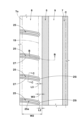
図2には、前記正規状態におけるトレッド部2の横断面図が示されている。図2は、タイヤ回転軸を含むタイヤ1の子午線断面であり、図1のA-A線断面図に相当する。図2に示されるように、トレッド部2は、タイヤ半径方向外側に凸に湾曲したプロファイルを有している。
FIG. 2 shows a cross-sectional view of the
図1に示されるように、本実施形態のトレッド部2には、タイヤ周方向に連続して延びる複数の主溝3が設けられている。なお、理解し易いように、本明細書の各図において、主溝3は、着色されている。本実施形態の主溝3は、タイヤ周方向に平行に直線状に延びている。主溝3は、少なくとも3mm以上の溝幅を有する。このため、本実施形態において、主溝3は、3mm未満の溝幅で延びる縦細溝とは区別される。主溝3の溝幅W1は、例えば、8~12mmであるのが望ましい。トレッド幅TWは、前記正規状態における、外側トレッド端Toから内側トレッド端Tiまでのタイヤ軸方向の距離である。主溝3の深さは、例えば、5~10mmであるのが望ましい。
As shown in FIG. 1, the
本実施形態では、トレッド部2に3本の主溝3が設けられている。これにより、トレッド部2は、4つの陸部4に区分されている。但し、本発明は、このような態様に限定されるものではなく、トレッド部2は、例えば、4本の主溝3に区分された5つの陸部4で構成されても良い。
In this embodiment, three
主溝3は、外側ショルダー主溝5、内側ショルダー主溝6及びクラウン主溝7を含む。外側ショルダー主溝5は、外側トレッド端Toとタイヤ赤道Cとの間に設けられている。外側ショルダー主溝5は、3本の主溝3の内、最も外側トレッド端To側に設けられている。
The
内側ショルダー主溝6は、内側トレッド端Tiとタイヤ赤道Cとの間に設けられている。内側ショルダー主溝6は、3本の主溝3の内、最も内側トレッド端Ti側に設けられている。クラウン主溝7は、外側ショルダー主溝5と内側ショルダー主溝6との間に設けられている。本実施形態のクラウン主溝7は、例えば、タイヤ赤道C上に設けられている。
The inner shoulder
タイヤ赤道Cから外側ショルダー主溝5又は内側ショルダー主溝6の溝中心線までのタイヤ軸方向の距離L1は、例えば、トレッド幅TWの0.20~0.30倍であるのが望ましい。
It is desirable that the distance L1 in the tire axial direction from the tire equator C to the groove center line of the outer shoulder
トレッド部2は、外側ショルダー陸部8と外側ミドル陸部9とを含んでいる。外側ショルダー陸部8は、外側トレッド端Toと外側ショルダー主溝5との間に区分されている。外側ミドル陸部9は、外側ショルダー主溝5のタイヤ赤道C側に隣接しており、本実施形態では外側ショルダー主溝5とクラウン主溝7との間に区分されている。
The
本実施形態のトレッド部2は、内側ショルダー陸部10と内側ミドル陸部11とを含んでいる。内側ショルダー陸部10は、内側トレッド端Tiと内側ショルダー主溝6との間に区分されている。内側ミドル陸部11は、内側ショルダー主溝6とクラウン主溝7との間に区分されている。
The
図3には、外側ショルダー陸部8及び外側ミドル陸部9の拡大図が示されている。図4には、図3のB-B線断面図が示されている。図4は、タイヤ回転軸を含む子午線断面に相当する。図4に示されるように、外側ミドル陸部9の踏面は、外側ショルダー主溝5の溝縁から少なくとも外側ミドル陸部9の踏面のタイヤ軸方向の中心まで延びる曲率半径R1の円弧からなる第1プロファイル16を含む。
FIG. 3 shows an enlarged view of the outer
外側ショルダー陸部8の踏面は、曲率半径R2の円弧からなる第2プロファイル17と、第2プロファイル17のタイヤ軸方向の内端から外側ショルダー主溝5の溝縁に延び、かつ、曲率半径R2よりも小さい曲率半径R3の円弧からなる第3プロファイル18とを含む。
The tread surface of the outer
上述のプロファイルを有する本発明のタイヤは、走行時において外側ショルダー陸部8の第3プロファイル18に局部的な接地圧が作用せず、第2プロファイル17及び第1プロファイル16の全体に均一に接地圧が作用する。これにより、耐摩耗性及び操縦安定性が向上する。
The tire of the present invention having the above-mentioned profile has no local ground contact pressure acting on the
第1プロファイル16は、例えば、外側ショルダー主溝5の溝縁からクラウン主溝7の溝縁まで延びているのが望ましい。前記曲率半径R1は、例えば、90~350mmであるのが望ましい。
It is desirable that the
第2プロファイル17は、例えば、外側トレッド端Toから第3プロファイル18との交点19まで延びているのが望ましい。曲率半径R2は、例えば、90~350mmであるのが望ましい。
It is desirable that the
本実施形態では、第1プロファイル16の曲率半径R1と第2プロファイル17の曲率半径R2とが同一である。さらに望ましい態様では、第2プロファイル17と第1プロファイル16とは、単一円弧20上を延びている。これにより、外側ショルダー陸部8と外側ミドル陸部9とに均一に接地圧が作用し、耐摩耗性及び操縦安定性が向上する。
In this embodiment, the radius of curvature R1 of the
第3プロファイル18の曲率半径R3は、例えば、50~160mmであるのが望ましい。また、前記曲率半径R3は、前記曲率半径R2の0.2~0.5倍であるのが望ましい。このような第3プロファイル18により、外側ショルダー陸部8の全体に接地圧が均一に作用する。
It is desirable that the radius of curvature R3 of the
図3に示されるように、第3プロファイル18で構成された踏面のタイヤ軸方向の幅W3は、外側ショルダー陸部8のタイヤ軸方向の幅W2の0.10~0.25倍であるのが望ましい。なお、前記幅W3は、第2プロファイル17と第3プロファイル18との交点19(図3では2点鎖線で示されている。)から外側ショルダー主溝5までのタイヤ軸方向の距離に相当する。
As shown in FIG. 3, the axial width W3 of the tread formed by the
図4に示されるように、同様の観点から、単一円弧20と前記第3プロファイル18との間のタイヤ半径方向の最大の距離d1は、0.5mm以下である。このような第3プロファイル18は、外側ショルダー陸部8に作用する接地圧をさらに均一にし、耐摩耗性及び操縦安定性をさらに向上させる。
As shown in FIG. 4, from the same point of view, the maximum distance d1 in the tire radial direction between the single
図3に示されるように、本実施形態の外側ショルダー陸部8には、外側トレッド端Toから延びかつ外側ショルダー陸部8内で途切れる複数の外側ショルダー横溝25が設けられている。このような外側ショルダー横溝25は、外側ショルダー陸部8の剛性を維持しつつ、ウェット性能を高めるのに役立つ。
As shown in FIG. 3, the outer
外側ショルダー横溝25は、例えば、タイヤ軸方向に対して一方向(図3では右下がりである。)に傾斜しているのが望ましい。外側ショルダー横溝25は、例えば、外側ショルダー主溝5と外側トレッド端Toとの間において、100~150mmの曲率半径で湾曲した湾曲部25aを含んでいる。湾曲部25aは、例えば、タイヤ軸方向に対して10~15°の角度で傾斜している。本実施形態の外側ショルダー横溝25は、外側トレッド端Toよりもタイヤ軸方向外側において、タイヤ軸方向に対して0~10°の角度で直線状に延びている(図1に示す)。但し、外側ショルダー横溝25は、このような態様に限定されるものではない。
For example, the outer shoulder
外側ショルダー横溝25の最大の深さは、外側ショルダー主溝5の深さの0.80~1.00倍であるのが望ましい。より望ましい態様では、外側ショルダー横溝25の深さは、外側トレッド端Toから外側ショルダー主溝5側に向かって漸減しているのが望ましい。
The maximum depth of the outer shoulder
ドライ路面での操縦安定性とウェット性能とをバランス良く高めるために、外側ショルダー横溝25の内端25iから外側ショルダー主溝5までのタイヤ軸方向の距離L2は、例えば、トレッド幅TW(図1に示す)の2.5%~5.0%であるのが望ましい。
In order to improve steering stability on a dry road surface and wet performance in a well-balanced manner, the distance L2 in the tire axial direction from the
外側ショルダー横溝25のタイヤ軸方向の内端25iは、第2プロファイル17と第3プロファイル18との交点19よりもタイヤ軸方向内側に位置している。外側ショルダー横溝25の内端25iから交点19までのタイヤ軸方向の距離L3は、7.5mm以下であるのが望ましい。これにより、外側ショルダー陸部8の耐摩耗性がさらに向上する。
The
図5には、図3の外側ショルダー横溝25のC-C線断面図が示されている。図5に示されるように、外側ショルダー横溝25は、その溝底部からタイヤ半径方向外側に延びる溝壁本体26と、溝壁本体26に連なりかつタイヤ半径方向に対して溝壁本体26よりも大きい角度で傾斜する面取り部27とを含むのが望ましい。面取り部27の幅及び深さは、例えば、1.0~2.0mmであるのが望ましい。このような面取り部27は、外側ショルダー陸部8に作用する接地圧が大きい場合に接地し、外側ショルダー陸部8の耐摩耗性及び操縦安定性を向上させるのに役立つ。
FIG. 5 shows a cross-sectional view taken along the line CC of the outer shoulder
図3に示されるように、上述の効果を十分に発揮させるために、上述の面取り部27は、例えば、外側ショルダー横溝25の全周に配されているのが望ましい。理解し易いように、本明細書の各図において、外側ショルダー横溝25は、面取り部27を除く領域が着色されている。
As shown in FIG. 3, in order to fully exhibit the above-mentioned effects, it is desirable that the above-mentioned
図6には、内側ショルダー陸部10及び内側ミドル陸部11の拡大図が示されている。図7には、図6のD-D線断面図が示されている。図7は、タイヤ回転軸を含む子午線断面に相当する。図7に示されるように、内側ミドル陸部11の踏面は、内側ショルダー主溝6の溝縁から少なくとも内側ミドル陸部11の踏面のタイヤ軸方向の中心まで延びる曲率半径R4の円弧からなる第4プロファイル31を含む。本実施形態では、曲率半径R4は、曲率半径R1と同一とされる。
FIG. 6 shows an enlarged view of the inner
内側ショルダー陸部10の踏面は、曲率半径R5の円弧からなる第5プロファイル32と、第5プロファイル32のタイヤ軸方向の内端から内側ショルダー主溝6の溝縁に延び、かつ、曲率半径R5よりも小さい曲率半径R6の円弧からなる第6プロファイル33とを含む。本実施形態では、曲率半径R5は、曲率半径R2と同一とされ、曲率半径R6は、曲率半径R3と同一とされる。
The tread surface of the inner
このような内側ショルダー陸部10及び内側ミドル陸部11は、外側ショルダー陸部8及び外側ミドル陸部9と同様、耐摩耗性及び操縦安定性を向上させることができる。
The inner
外側ショルダー陸部8及び外側ミドル陸部9のプロファイルの構成は、内側ショルダー陸部10及び内側ミドル陸部11に適用することができる。このため、単一円弧35と前記第6プロファイル33との間のタイヤ半径方向の最大の距離d2は、0.5mm以下であるのが望ましい。このような第6プロファイル33は、内側ショルダー陸部10に作用する接地圧をさらに均一にし、耐摩耗性及び操縦安定性をさらに向上させる。
The profile configurations of the outer
図6に示されるように、ウェット性能を高めるために、本実施形態の内側ショルダー陸部10には、内側トレッド端Tiから内側ショルダー主溝6まで延びる複数の内側ショルダー横溝40が設けられている。
As shown in FIG. 6, in order to improve wet performance, the inner
内側ショルダー横溝40は、例えば、タイヤ軸方向に対して外側ショルダー横溝25と同じ向きに傾斜しているのが望ましい。内側ショルダー横溝40は、例えば、内側ショルダー主溝6と内側トレッド端Tiとの間において、100~150mmの曲率半径で湾曲した湾曲部40aを含んでいる。湾曲部40aは、例えば、タイヤ軸方向に対して10~15°の角度で傾斜している。本実施形態の内側ショルダー横溝40は、内側トレッド端Tiよりもタイヤ軸方向外側において、タイヤ軸方向に対して0~10°の角度で直線状に延びている(図1に示す)。但し、内側ショルダー横溝40は、このような態様に限定されるものではない。
For example, the inner shoulder
内側ショルダー横溝40は、外側ショルダー横溝25と同様、その溝底部からタイヤ半径方向外側に延びる溝壁本体と、溝壁本体に連なりかつタイヤ半径方向に対して溝壁本体よりも大きい角度で傾斜する面取り部42とを含むのが望ましい。内側ショルダー横溝40の面取り部42の各寸法は、上述の外側ショルダー横溝25の面取り部27の寸法を適用することができる。また、本明細書の各図において、内側ショルダー横溝40は、面取り部42を除く領域が着色されている。
Like the outer shoulder
図1に示されるように、本実施形態では、各内側ショルダー横溝40をタイヤ軸方向に平行に投影した領域が、外側ショルダー横溝25と重複しないのが望ましい。このような内側ショルダー横溝40の配置は、トレッド部2全体の耐摩耗性を高めるのに役立つ。
As shown in FIG. 1, in this embodiment, it is preferable that the area in which each inner shoulder
図7に示されるように、内側ショルダー横溝40は、タイヤ軸方向の内端部で溝底が隆起したタイバー41を含むのが望ましい。タイバーの深さは、例えば、内側ショルダー主溝6の深さの0.50~0.60倍である。このような内側ショルダー横溝40は、ウェット性能と操縦安定性とをバランス良く高めるのに役立つ。
As shown in FIG. 7, the inner shoulder
タイバー41のタイヤ軸方向の外端41oは、第5プロファイル32と第6プロファイル33との交点34よりもタイヤ軸方向外側に位置しているのが望ましい。このようなタイバー41は、内側ショルダー陸部10の耐摩耗性をさらに高めることができる。
It is desirable that the outer end 41o of the
図1に示されるように、本実施形態の外側ミドル陸部9及び内側ミドル陸部11は、溝及びサイプ(幅が1.5mm以下の切れ込みを意味する。)が配されていない平坦陸部であるのが望ましい。このような外側ミドル陸部9及び内側ミドル陸部11は、高い剛性を有し、優れた操縦安定性を発揮できる。なお、本発明の他の実施形態では、外側ミドル陸部9及び内側ミドル陸部11に複数のサイプが設けられても良い。このような態様は、優れた操縦安定性を発揮しつつ、ウェット性能も確保することができる。
As shown in FIG. 1, the outer
以上、本発明の一実施形態のタイヤが詳細に説明されたが、本発明は、上記の具体的な実施形態に限定されることなく、種々の態様に変更して実施され得る。 Although the tire of one embodiment of the present invention has been described in detail above, the present invention is not limited to the above-described specific embodiment, and can be implemented by changing various aspects.
図1の基本パターンを有するサイズ195/65R15のタイヤが、表1の仕様に基づき試作された。比較例として、図8に示されるように、外側ショルダー陸部a及び内側ミドル陸部bの踏面のプロファイルが単一円弧cで構成されているタイヤが試作された。各テストタイヤの耐摩耗性及び操縦安定性がテストされた。各テストタイヤの共通仕様やテスト方法は、以下の通りである。
装着リム:15×6.0J
タイヤ内圧:230kPa
テスト車両:前輪駆動車、排気量1600cc
タイヤ装着位置:全輪
テスト方法は、以下の通りである。
A tire of size 195/65R15 having the basic pattern shown in FIG. 1 was prototyped based on the specifications shown in Table 1. As a comparative example, as shown in FIG. 8, a tire was prototyped in which the profile of the tread of the outer shoulder land portion a and the inner middle land portion b was constituted by a single circular arc c. Each test tire was tested for wear resistance and handling stability. The common specifications and test methods for each test tire are as follows.
Mounted rim: 15 x 6.0J
Tire internal pressure: 230kPa
Test vehicle: Front wheel drive vehicle, displacement 1600cc
Tire mounting position: All wheels The test method is as follows.
<耐摩耗性>
上記テスト車両で市街地を10000km走行したときの外側ショルダー陸部の残存量が測定された。結果は、比較例の前記残存量を100とする指数であり、数値が大きい程、耐摩耗性が優れていることを示す。
<Abrasion resistance>
The remaining amount of the outer shoulder land portion was measured when the test vehicle was driven for 10,000 km in an urban area. The result is an index with the residual amount of the comparative example as 100, and the larger the value, the better the wear resistance.
<操縦安定性>
上記テスト車両でドライ路面を走行したときの操縦安定性が、運転者の官能により評価された。結果は、比較例を100とする評点であり、数値が大きい程、操縦安定性が優れていることを示す。
テストの結果が表1に示される。
<Driving stability>
The steering stability of the above test vehicle when driving on a dry road surface was evaluated based on the driver's senses. The results are scores with the comparative example being 100, and the larger the value, the better the steering stability is.
The results of the test are shown in Table 1.

テストの結果、実施例のタイヤは、優れた耐摩耗性及び操縦安定性を発揮していることが確認できた。 As a result of the test, it was confirmed that the tires of the examples exhibited excellent wear resistance and handling stability.
2 トレッド部
5 外側ショルダー主溝
8 外側ショルダー陸部
9 外側ミドル陸部
16 第1プロファイル
17 第2プロファイル
18 第3プロファイル
To 外側トレッド端
2 Tread
Claims (8)
前記トレッド部は、車両装着時に車両外側に位置する外側トレッド端と、前記外側トレッド端とタイヤ赤道との間に設けられた外側ショルダー主溝と、前記外側トレッド端と前記外側ショルダー主溝との間に区分された外側ショルダー陸部と、前記外側ショルダー主溝のタイヤ赤道側に隣接する外側ミドル陸部とを含み、
前記タイヤが正規リムに装着されかつ正規内圧が充填された正規状態でのタイヤ回転軸を含む子午線断面において、
前記トレッド部は、タイヤ半径方向外側に凸に湾曲したプロファイルを有し、
前記外側ミドル陸部の踏面は、前記外側ショルダー主溝の溝縁から少なくとも前記外側ミドル陸部の踏面のタイヤ軸方向の中心まで延びる曲率半径R1の円弧からなる第1プロファイルを含み、
前記外側ショルダー陸部の踏面は、
曲率半径R2の円弧からなる第2プロファイルと、
前記第2プロファイルのタイヤ軸方向の内端から前記外側ショルダー主溝の溝縁に延び、かつ、前記曲率半径R2よりも小さい曲率半径R3の円弧からなる第3プロファイルとを含み、
前記第1プロファイルと前記第2プロファイルとは、単一円弧上を延びている、
タイヤ。 A tire having a tread portion whose mounting direction on a vehicle is specified,
The tread portion includes an outer tread end located on the outer side of the vehicle when mounted on the vehicle, an outer shoulder main groove provided between the outer tread end and the tire equator, and an outer shoulder main groove between the outer tread end and the outer shoulder main groove. and an outer middle land portion adjacent to the tire equator side of the outer shoulder main groove,
In a meridian cross section including the tire rotation axis in a normal state where the tire is mounted on a normal rim and filled with normal internal pressure,
The tread portion has a profile convexly curved outward in the tire radial direction,
The tread surface of the outer middle land portion includes a first profile consisting of an arc with a radius of curvature R1 extending from the groove edge of the outer shoulder main groove to at least the center of the tread surface of the outer middle land portion in the axial direction of the tire;
The tread surface of the outer shoulder land portion is
a second profile consisting of a circular arc with a radius of curvature R2;
and a third profile extending from the inner end in the tire axial direction of the second profile to the groove edge of the outer shoulder main groove and consisting of an arc having a radius of curvature R3 smaller than the radius of curvature R2,
the first profile and the second profile extend on a single circular arc;
tire.
前記トレッド部は、車両装着時に車両外側に位置する外側トレッド端と、前記外側トレッド端とタイヤ赤道との間に設けられた外側ショルダー主溝と、前記外側トレッド端と前記外側ショルダー主溝との間に区分された外側ショルダー陸部と、前記外側ショルダー主溝のタイヤ赤道側に隣接する外側ミドル陸部とを含み、The tread portion includes an outer tread end located on the outer side of the vehicle when mounted on the vehicle, an outer shoulder main groove provided between the outer tread end and the tire equator, and an outer shoulder main groove between the outer tread end and the outer shoulder main groove. and an outer middle land portion adjacent to the tire equator side of the outer shoulder main groove,
前記タイヤが正規リムに装着されかつ正規内圧が充填された正規状態でのタイヤ回転軸を含む子午線断面において、In a meridian cross section including the tire rotation axis in a normal state where the tire is mounted on a normal rim and filled with normal internal pressure,
前記トレッド部は、タイヤ半径方向外側に凸に湾曲したプロファイルを有し、The tread portion has a profile convexly curved outward in the tire radial direction,
前記外側ミドル陸部の踏面は、前記外側ショルダー主溝の溝縁から少なくとも前記外側ミドル陸部の踏面のタイヤ軸方向の中心まで延びる曲率半径R1の円弧からなる第1プロファイルを含み、The tread surface of the outer middle land portion includes a first profile consisting of an arc with a radius of curvature R1 extending from the groove edge of the outer shoulder main groove to at least the center of the tread surface of the outer middle land portion in the axial direction of the tire;
前記外側ショルダー陸部の踏面は、The tread surface of the outer shoulder land portion is
曲率半径R2の円弧からなる第2プロファイルと、a second profile consisting of a circular arc with a radius of curvature R2;
前記第2プロファイルのタイヤ軸方向の内端から前記外側ショルダー主溝の溝縁に延び、かつ、前記曲率半径R2よりも小さい曲率半径R3の円弧からなる第3プロファイルとを含み、and a third profile extending from the inner end in the tire axial direction of the second profile to the groove edge of the outer shoulder main groove and consisting of an arc having a radius of curvature R3 smaller than the radius of curvature R2,
前記外側ショルダー陸部には、前記外側トレッド端から延びかつ前記外側ショルダー陸部内で途切れる複数の外側ショルダー横溝が設けられ、The outer shoulder land portion is provided with a plurality of outer shoulder lateral grooves extending from the outer tread end and discontinuing within the outer shoulder land portion,
前記外側ショルダー横溝のタイヤ軸方向の内端は、前記第2プロファイルと前記第3プロファイルとの交点よりもタイヤ軸方向内側に位置している、The inner end of the outer shoulder lateral groove in the tire axial direction is located further inward in the tire axial direction than the intersection of the second profile and the third profile,
タイヤ。tire.
タイヤ回転軸を含む子午線断面において、In the meridian section including the tire rotation axis,
前記内側ミドル陸部の踏面は、前記内側ショルダー主溝の溝縁から少なくとも前記内側ミドル陸部の踏面のタイヤ軸方向の中心まで延びる曲率半径R4の円弧からなる第4プロファイルを含み、The tread surface of the inner middle land portion includes a fourth profile consisting of an arc with a radius of curvature R4 extending from the groove edge of the inner shoulder main groove to at least the center of the tread surface of the inner middle land portion in the tire axial direction,
前記内側ショルダー陸部の踏面は、The tread surface of the inner shoulder land portion is
曲率半径R5の円弧からなる第5プロファイルと、a fifth profile consisting of a circular arc with a radius of curvature R5;
前記第5プロファイルのタイヤ軸方向の内端から前記内側ショルダー主溝の溝縁に延び、かつ、前記曲率半径R5よりも小さい曲率半径R6の円弧からなる第6プロファイルとを含む、請求項1ないし5のいずれかに記載のタイヤ。and a sixth profile extending from the inner end of the fifth profile in the tire axial direction to the groove edge of the inner shoulder main groove and having a radius of curvature R6 smaller than the radius of curvature R5. 5. The tire according to any one of 5.
前記内側ショルダー横溝は、タイヤ軸方向の内端部で溝底が隆起したタイバーを含む、請求項6記載のタイヤ。7. The tire according to claim 6, wherein the inner shoulder lateral groove includes a tie bar having a raised groove bottom at an inner end in the tire axial direction.
Priority Applications (2)
| Application Number | Priority Date | Filing Date | Title |
|---|---|---|---|
| JP2019157536A JP7363208B2 (en) | 2019-08-30 | 2019-08-30 | tire |
| EP20190671.6A EP3785940B1 (en) | 2019-08-30 | 2020-08-12 | Tire |
Applications Claiming Priority (1)
| Application Number | Priority Date | Filing Date | Title |
|---|---|---|---|
| JP2019157536A JP7363208B2 (en) | 2019-08-30 | 2019-08-30 | tire |
Publications (2)
| Publication Number | Publication Date |
|---|---|
| JP2021035784A JP2021035784A (en) | 2021-03-04 |
| JP7363208B2 true JP7363208B2 (en) | 2023-10-18 |
Family
ID=72050715
Family Applications (1)
| Application Number | Title | Priority Date | Filing Date |
|---|---|---|---|
| JP2019157536A Active JP7363208B2 (en) | 2019-08-30 | 2019-08-30 | tire |
Country Status (2)
| Country | Link |
|---|---|
| EP (1) | EP3785940B1 (en) |
| JP (1) | JP7363208B2 (en) |
Citations (9)
| Publication number | Priority date | Publication date | Assignee | Title |
|---|---|---|---|---|
| JP2000142030A (en) | 1998-11-04 | 2000-05-23 | Bridgestone Corp | Pneumatic tire |
| JP2004284500A (en) | 2003-03-24 | 2004-10-14 | Yokohama Rubber Co Ltd:The | Pneumatic radial tire for heavy load |
| JP2010215128A (en) | 2009-03-17 | 2010-09-30 | Bridgestone Corp | Pneumatic tire |
| JP2011225084A (en) | 2010-04-19 | 2011-11-10 | Sumitomo Rubber Ind Ltd | Pneumatic tire |
| JP2012116410A (en) | 2010-12-02 | 2012-06-21 | Sumitomo Rubber Ind Ltd | Pneumatic tire |
| JP2014101040A (en) | 2012-11-20 | 2014-06-05 | Sumitomo Rubber Ind Ltd | Pneumatic tire |
| JP2015140047A (en) | 2014-01-27 | 2015-08-03 | 住友ゴム工業株式会社 | pneumatic tire |
| JP2015171840A (en) | 2014-03-11 | 2015-10-01 | 住友ゴム工業株式会社 | pneumatic tire |
| JP2017024454A (en) | 2015-07-16 | 2017-02-02 | 住友ゴム工業株式会社 | Pneumatic tire |
-
2019
- 2019-08-30 JP JP2019157536A patent/JP7363208B2/en active Active
-
2020
- 2020-08-12 EP EP20190671.6A patent/EP3785940B1/en active Active
Patent Citations (9)
| Publication number | Priority date | Publication date | Assignee | Title |
|---|---|---|---|---|
| JP2000142030A (en) | 1998-11-04 | 2000-05-23 | Bridgestone Corp | Pneumatic tire |
| JP2004284500A (en) | 2003-03-24 | 2004-10-14 | Yokohama Rubber Co Ltd:The | Pneumatic radial tire for heavy load |
| JP2010215128A (en) | 2009-03-17 | 2010-09-30 | Bridgestone Corp | Pneumatic tire |
| JP2011225084A (en) | 2010-04-19 | 2011-11-10 | Sumitomo Rubber Ind Ltd | Pneumatic tire |
| JP2012116410A (en) | 2010-12-02 | 2012-06-21 | Sumitomo Rubber Ind Ltd | Pneumatic tire |
| JP2014101040A (en) | 2012-11-20 | 2014-06-05 | Sumitomo Rubber Ind Ltd | Pneumatic tire |
| JP2015140047A (en) | 2014-01-27 | 2015-08-03 | 住友ゴム工業株式会社 | pneumatic tire |
| JP2015171840A (en) | 2014-03-11 | 2015-10-01 | 住友ゴム工業株式会社 | pneumatic tire |
| JP2017024454A (en) | 2015-07-16 | 2017-02-02 | 住友ゴム工業株式会社 | Pneumatic tire |
Also Published As
| Publication number | Publication date |
|---|---|
| JP2021035784A (en) | 2021-03-04 |
| EP3785940A1 (en) | 2021-03-03 |
| EP3785940B1 (en) | 2022-01-19 |
Similar Documents
| Publication | Publication Date | Title |
|---|---|---|
| JP6786794B2 (en) | Pneumatic tires | |
| EP3025874B1 (en) | Pneumatic tire | |
| US9789736B2 (en) | Pneumatic tire | |
| US10792957B2 (en) | Pneumatic tire | |
| US11207922B2 (en) | Tire | |
| JP6014092B2 (en) | Pneumatic tire | |
| JP6819133B2 (en) | tire | |
| JP2018047798A (en) | Pneumatic tire | |
| CN109501524B (en) | Tyre for vehicle wheels | |
| JP6819110B2 (en) | tire | |
| JP7206952B2 (en) | tire | |
| EP3689642B1 (en) | Tire | |
| US20190337339A1 (en) | Tyre | |
| JP4102151B2 (en) | Pneumatic tire | |
| JP2018111453A (en) | Pneumatic tire | |
| JP2019051862A (en) | tire | |
| JP7400429B2 (en) | tire | |
| JP7363208B2 (en) | tire | |
| JP7099063B2 (en) | tire | |
| JP2018111452A (en) | Pneumatic tire | |
| JP2021020635A (en) | tire | |
| JP2020111261A (en) | tire | |
| JP6511365B2 (en) | Pneumatic tire | |
| US11420476B2 (en) | Tire | |
| US11420475B2 (en) | Tire |
Legal Events
| Date | Code | Title | Description |
|---|---|---|---|
| A621 | Written request for application examination |
Free format text: JAPANESE INTERMEDIATE CODE: A621 Effective date: 20220617 |
|
| A977 | Report on retrieval |
Free format text: JAPANESE INTERMEDIATE CODE: A971007 Effective date: 20230418 |
|
| A131 | Notification of reasons for refusal |
Free format text: JAPANESE INTERMEDIATE CODE: A131 Effective date: 20230502 |
|
| A521 | Request for written amendment filed |
Free format text: JAPANESE INTERMEDIATE CODE: A523 Effective date: 20230608 |
|
| TRDD | Decision of grant or rejection written | ||
| A01 | Written decision to grant a patent or to grant a registration (utility model) |
Free format text: JAPANESE INTERMEDIATE CODE: A01 Effective date: 20230905 |
|
| A61 | First payment of annual fees (during grant procedure) |
Free format text: JAPANESE INTERMEDIATE CODE: A61 Effective date: 20230918 |
|
| R150 | Certificate of patent or registration of utility model |
Ref document number: 7363208 Country of ref document: JP Free format text: JAPANESE INTERMEDIATE CODE: R150 |