JP7362425B2 - Routing material - Google Patents
Routing material Download PDFInfo
- Publication number
- JP7362425B2 JP7362425B2 JP2019195863A JP2019195863A JP7362425B2 JP 7362425 B2 JP7362425 B2 JP 7362425B2 JP 2019195863 A JP2019195863 A JP 2019195863A JP 2019195863 A JP2019195863 A JP 2019195863A JP 7362425 B2 JP7362425 B2 JP 7362425B2
- Authority
- JP
- Japan
- Prior art keywords
- cylindrical portion
- cylindrical part
- covering
- axial direction
- end cylindrical
- Prior art date
- Legal status (The legal status is an assumption and is not a legal conclusion. Google has not performed a legal analysis and makes no representation as to the accuracy of the status listed.)
- Active
Links
- 239000000463 material Substances 0.000 title claims description 98
- 229920003002 synthetic resin Polymers 0.000 claims description 4
- 239000000057 synthetic resin Substances 0.000 claims description 4
- 238000010438 heat treatment Methods 0.000 description 43
- 229910052751 metal Inorganic materials 0.000 description 17
- 239000002184 metal Substances 0.000 description 17
- 230000007704 transition Effects 0.000 description 14
- 230000002093 peripheral effect Effects 0.000 description 13
- 238000004519 manufacturing process Methods 0.000 description 5
- 229910052782 aluminium Inorganic materials 0.000 description 3
- XAGFODPZIPBFFR-UHFFFAOYSA-N aluminium Chemical compound [Al] XAGFODPZIPBFFR-UHFFFAOYSA-N 0.000 description 3
- 238000000034 method Methods 0.000 description 2
- 238000000465 moulding Methods 0.000 description 2
- 229910000838 Al alloy Inorganic materials 0.000 description 1
- VEXZGXHMUGYJMC-UHFFFAOYSA-M Chloride anion Chemical compound [Cl-] VEXZGXHMUGYJMC-UHFFFAOYSA-M 0.000 description 1
- RYGMFSIKBFXOCR-UHFFFAOYSA-N Copper Chemical compound [Cu] RYGMFSIKBFXOCR-UHFFFAOYSA-N 0.000 description 1
- 229910000881 Cu alloy Inorganic materials 0.000 description 1
- 229920000181 Ethylene propylene rubber Polymers 0.000 description 1
- 239000004743 Polypropylene Substances 0.000 description 1
- 238000004891 communication Methods 0.000 description 1
- 229910052802 copper Inorganic materials 0.000 description 1
- 239000010949 copper Substances 0.000 description 1
- 238000009413 insulation Methods 0.000 description 1
- -1 polypropylene Polymers 0.000 description 1
- 229920001155 polypropylene Polymers 0.000 description 1
- 230000001012 protector Effects 0.000 description 1
Images


Landscapes
- Insulated Conductors (AREA)
- Connections Effected By Soldering, Adhesion, Or Permanent Deformation (AREA)
Description
本発明は、配索材に関する。 The present invention relates to a wiring material.
従来、2本の電線を繋いで1本の配索材を形成する技術がある(例えば、特許文献1参照)。この配索材は、2本の電線の接合部分を跨って一方の電線の被覆部から他方の電線の被覆部までを、絶縁性の1つの熱収縮チューブで覆う。このため、配索材を構成する一方の電線の被覆部の外周面に熱収縮チューブが密着し、配索材を構成する他方の電線の被覆部の外周面に熱収縮チューブが密着し、かつ、接合部分の外面に熱収縮チューブが密着する。 Conventionally, there is a technique of connecting two electric wires to form one wiring member (for example, see Patent Document 1). This wiring material straddles the joint portion of two electric wires and covers from the covering part of one electric wire to the covering part of the other electric wire with one insulating heat shrink tube. For this reason, the heat-shrinkable tube is in close contact with the outer circumferential surface of the sheathing part of one of the electric wires constituting the wiring material, and the heat-shrinkable tube is in close contact with the outer circumferential surface of the sheathing part of the other electric wire constituting the wiring material, and , the heat shrink tube is tightly attached to the outer surface of the joint.
上記配索材は、一方の電線の被覆部の一部、他方の電線の被覆部の一部、及び、接合部分に対して熱収縮チューブが一様に密着する。このため、接合部分の製造過程における加工によって、接合部の外周面から突出する突起が発生した場合、接合部分を適正に被覆する観点で改良の余地がある。 In the above-mentioned wiring material, the heat shrink tube uniformly adheres to a part of the sheathing part of one electric wire, a part of the sheathing part of the other electric wire, and a joint part. Therefore, if a protrusion protruding from the outer circumferential surface of the joint occurs due to processing during the manufacturing process of the joint, there is room for improvement in terms of properly covering the joint.
本発明は、上記の事情に鑑みてなされたものであって、接合部分を適正に被覆することができる配索材を提供することを目的とする。 The present invention has been made in view of the above-mentioned circumstances, and an object of the present invention is to provide a wiring material that can appropriately cover the joint portion.
上記の課題を解決するため、本発明に係る配索材は、軸線方向に延在する第1芯線、及び、前記第1芯線を被覆する第1被覆部を有する第1電線と、前記軸線方向に延在する第2芯線、及び、前記第2芯線を被覆する第2被覆部を有する第2電線と、前記軸線方向において、前記第1芯線と前記第2芯線との間に位置し、前記第1芯線と前記第2芯線とが接合された接合部分と、少なくとも、前記第1被覆部の一部、前記接合部分、及び、前記第2被覆部の一部を被覆する絶縁性の被覆部と、を備え、前記被覆部は、前記軸線方向と直交する直交方向において、前記接合部分に対向する中央筒状部と、前記軸線方向において、前記中央筒状部を挟んだ一方側に位置する第1端部筒状部、及び、他方側に位置する第2端部筒状部と、を有し、前記第1端部筒状部を構成する熱収縮チューブ、および、前記第2端部筒状部を構成する熱収縮チューブは、前記中央筒状部を構成する熱収縮チューブよりも収縮率が大きい合成樹脂材料で形成され、前記中央筒状部の前記軸線方向における一方側の端部は、前記第1端部筒状部における他方側の端部と全周にわたって接触し、前記中央筒状部の前記軸線方向における他方側の端部は、前記第2端部筒状部における一方側の端部と全周にわたって接触し、前記第1端部筒状部の内周面は、前記第1被覆部における一部の外周面と全周にわたって密着し、前記第2端部筒状部の内周面は、前記第2被覆部における一部の外周面と全周にわたって密着し、前記中央筒状部は、前記接合部分の外面と全周にわたって非密着状態であることを特徴とする。 In order to solve the above problems, the wiring material according to the present invention includes a first electric wire having a first core wire extending in the axial direction, a first covering portion covering the first core wire, and a first wire having a first core wire extending in the axial direction. a second electric wire having a second core wire extending to the second core wire and a second covering portion covering the second core wire; A joint part where the first core wire and the second core wire are joined, and an insulating covering part that covers at least a part of the first covering part, the joining part, and a part of the second covering part. and a central cylindrical portion facing the joint portion in an orthogonal direction perpendicular to the axial direction, and a central cylindrical portion located on one side across the central cylindrical portion in the axial direction. a heat-shrinkable tube that has a first cylindrical end portion and a second cylindrical end portion located on the other side, and constitutes the first cylindrical end portion; and the second end portion The heat-shrinkable tube constituting the cylindrical portion is formed of a synthetic resin material having a higher shrinkage rate than the heat-shrinkable tube constituting the central cylindrical portion, and the one end of the central cylindrical portion in the axial direction is in contact with the other end of the first end cylindrical part over the entire circumference, and the other end of the central cylindrical part in the axial direction is in contact with one end of the second end cylindrical part. The inner circumferential surface of the first end cylindrical portion is in close contact with the outer circumferential surface of a portion of the first covering portion over the entire circumference, and the second end cylindrical portion The inner circumferential surface of the part is in close contact with the outer circumferential surface of a part of the second covering part over the entire circumference, and the central cylindrical part is not in close contact with the outer surface of the joint part over the entire circumference. It is characterized by
また、上記配索材において、前記軸線方向から視た場合には、前記接合部分と前記中央筒状部との間には空間部が形成される、ことが好ましい。 Moreover, in the above-mentioned wiring material, it is preferable that a space is formed between the joint portion and the central cylindrical portion when viewed from the axial direction.
また、上記配索材において、前記第1端部筒状部を構成する熱収縮チューブ、および、前記第2端部筒状部を構成する熱収縮チューブは、同一の材料で形成されている。 Moreover, in the above-mentioned wiring material, the heat-shrinkable tube that constitutes the first end cylindrical portion and the heat-shrinkable tube that constitutes the second end cylindrical portion are formed of the same material.
また、上記配索材において、前記中央筒状部、前記第1端部筒状部、及び、前記第2端部筒状部が別個に形成され、前記中央筒状部における前記軸線方向の一方側の端部は、前記第1端部筒状部の一部とオーバラップし、前記軸線方向から視た場合には前記第1端部筒状部の内側に位置し、前記中央筒状部における前記軸線方向の他方側の端部は、前記第2端部筒状部の一部とオーバラップし、前記軸線方向から視た場合には前記第2端部筒状部の内側に位置する、ことが好ましい。 In the wiring material, the central cylindrical part, the first end cylindrical part, and the second end cylindrical part are formed separately, and one of the axial directions of the central cylindrical part is formed separately. The side end portion overlaps a part of the first end cylindrical portion, is located inside the first end cylindrical portion when viewed from the axial direction, and is located within the first end cylindrical portion. The other end in the axial direction overlaps a part of the second end cylindrical part and is located inside the second end cylindrical part when viewed from the axial direction. , is preferable.
また、上記配索材において、前記中央筒状部、前記第1端部筒状部、及び、前記第2端部筒状部が一体に形成され、前記中央筒状部、及び、前記第1端部筒状部は、前記第1端部筒状部の前記軸線方向における他方側に位置する第1筒状部他方側端面と、前記中央筒状部の前記軸線方向における一方側に位置する中央筒状部一方側端面とが前記軸線方向へ連続し、前記中央筒状部、及び、前記第2端部筒状部は、前記第2端部筒状部の前記軸線方向における一方側に位置する第2筒状部一方側端面と、前記中央筒状部の前記軸線方向における他方側に位置する中央筒状部他方側端面とが前記軸線方向へ連続する、ことが好ましい。 Further, in the wiring material, the central cylindrical portion, the first end cylindrical portion, and the second end cylindrical portion are integrally formed, and the central cylindrical portion and the first end cylindrical portion are integrally formed. The end cylindrical portion is located at the other side end surface of the first cylindrical portion located on the other side in the axial direction of the first end cylindrical portion, and on one side of the central cylindrical portion in the axial direction. one side end surface of the central cylindrical part is continuous in the axial direction, and the central cylindrical part and the second end cylindrical part are connected to one side of the second end cylindrical part in the axial direction. It is preferable that an end surface on one side of the second cylindrical portion located on one side and an end surface on the other side of the central cylindrical portion located on the other side in the axial direction of the central cylindrical portion are continuous in the axial direction.
本発明に係る配索材は、以下に記載する構成を有する。第1端部筒状部の内周面は、第1被覆部における一部の外周面と全周にわたって密着する。第2端部筒状部の内周面は、第2被覆部における一部の外周面と全周にわたって密着する。中央筒状部は、接合部分の外面と全周にわって非密着状態である。これらによって、本発明に係る配索材は、接合部分を適正に被覆することができる。 The wiring material according to the present invention has the configuration described below. The inner circumferential surface of the first end cylindrical portion is in close contact with a part of the outer circumferential surface of the first covering portion over the entire circumference. The inner circumferential surface of the second end cylindrical portion is in close contact with a part of the outer circumferential surface of the second covering portion over the entire circumference. The central cylindrical portion is not in close contact with the outer surface of the joint portion over the entire circumference. Due to these, the wiring material according to the present invention can appropriately cover the joint portion.
以下に、本発明に係る配索材100の実施形態を図面に基づいて説明する。なお、この実施形態によりこの発明が限定されるものではない。また、下記の実施形態における構成要素には、当業者が置換可能かつ容易なもの、あるいは実質的に同一のものが含まれる。
EMBODIMENT OF THE INVENTION Below, embodiment of the
[第1実施形態]
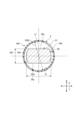
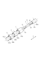
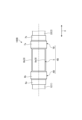
図1は、第1実施形態に係る配索材100を示す斜視図である。図2は、配索材100の縦断面図である。図3は、配索材の横断面図である。図4は、配索材100の製造過程を示す斜視図である。なお、図4では、中央筒状部5の一部、及び、第1端部筒状部6の一部を破断して示してある。
[First embodiment]
FIG. 1 is a perspective view showing a
以下の説明では、互いに直交する3つの方向(第1方向、第2方向、及び、第3方向)のうち、第1電線1の軸線方向であり、第2電線2の軸線方向を第1方向Xという。
In the following explanation, among the three directions (first direction, second direction, and third direction) that are orthogonal to each other, the axial direction of the first
図1、図2に示す本実施形態に係る配索材100は、自動車等の車両に搭載されるワイヤハーネスWH1を構成するものである。ワイヤハーネスWH1は、例えば、車両に搭載される各機器間の接続のために、電源供給や信号通信に用いられる複数の配索材100を束にして集合部品とし、コネクタ等で複数の配索材100を各機器に接続するものである。ワイヤハーネスWH1は、例えば、複数の配索材100を備える。なお、ワイヤハーネスWH1は、この他、さらに、電気接続箱、グロメット、プロテクタ、及び、コネクタ等を含んで構成されてもよい。以下、各図を参照して配索材100の構成について詳細に説明する。
The
配索材100は、第1電線1と、第2電線2と、接合部分3と、被覆部4とを備える。第1電線1は、第1方向Xに延在して導電性を有する第1芯線11、及び、第1芯線11を被覆する第1被覆部12を有する。
The
第2電線2は、第1方向Xに延在して導電性を有する第2芯線21、及び、第2芯線21を被覆する第2被覆部22を有する。
The second
第1芯線11、及び、第2芯線21は、例えば、導電性を有する銅、銅合金、アルミニウム、アルミニウム合金等によって形成される金属素線を含み、複数の金属素線を撚り合わせて構成したものである。
The first core wire 11 and the
第1被覆部12、及び、第2被覆部22は、例えば、絶縁性を有する合成樹脂材料(例えば、ポリプロピレン、ポリ塩化ボニル等)によって形成される。
The first covering
本実施形態における配索材100は、第1芯線11の外径11oと、第2芯線21の外径21oとが同一である。また、本実施形態における配索材100は、第1被覆部12の径方向の厚さと、第2被覆部22の径方向の厚さとが同一である。さらに、本実施形態における配索材100は、第1電線1の外径と、第2電線2の外径とが同一である。
In the
接合部分3は、第1芯線11と第2芯線21とが接合された部分である。本実施形態の接合部分3は、第1芯線11と第2芯線21とを超音波接合することによって形成してある。接合部分3は、例えば、アルミニウム製の第1芯線11の先端と、アルミニウム製の第2芯線21の先端とを超音波接合することによって柱状に形成される。第1芯線11を構成する複数の金属素線において、任意の金属素線と、当該金属素線に対して第1方向Xと直交する直交方向に隣接する他の金属素線との間には、空間部が形成される。同様に、第2芯線21を構成する複数の金属素線において、任意の金属素線と、当該金属素線に対して第1方向Xと直交する直交方向に隣接する他の金属素線との間には、空間部が形成される。これらのような第1芯線11の先端、及び、第2芯線21の先端に、不図示の一対の振動子を介して超音波振動を印加することによって、両者が混在した接合部分3が形成される。より具体的に説明すると、一対の振動子は、第1方向Xに対して直交する高さ方向において対向するホーンとアンビルとによって構成され、ホーンとアンビルとの間に、第1芯線11の先端、及び、第2芯線21の先端が配置される。この状態において、第1芯線11の先端、及び、第2芯線21の先端に高さ方向へ圧縮するように圧力を加えながら、ホーンとアンビルとによって、第1芯線11の先端、及び、第2芯線21の先端に超音波振動が印加される。このため、接合部分3は、図3に示すように、一方向(高さ方向)Zの長さが、他方向(幅方向)Yの長さよりも短くなる柱状に形成される。その上、接合部分3は、上述した任意の金属素線と、当該金属素線に隣接する他の金属素線との間の空間部が消滅して密度が増加し、接合部分3の高さ方向Zにおける長さ30zは、第1芯線11の外径D11o、及び、第2芯線21の外径D21oよりも短い。加えて、接合部分3の幅方向Yにおける長さ30yは、第1芯線11の外径D11o、及び、第2芯線21の外径D21oよりも短い。さらに、本実施形態に係る配索材100は、接合部分3を形成する際に、第1移行部分13、及び、第2移行部分23が生じる。第1移行部分13、及び、第2移行部分23は、第1方向Xにおいて、接合部分3に隣接して位置する。第1移行部13は、第1芯線11における複数の金属素線の間の空間部が圧縮された部分である。第2移行部23は、第2芯線21における複数の金属素線の間の空間部が圧縮された部分である。また、超音波接合することによって接合部分3を形成すると、ホーンに接触していた接合部分3の上面30u(図3参照)、又は、アンビルに接触していた接合部分3の下面30d(図3参照)には、外側に向けて突出する突起31が発生する場合がある。さらに、接合部分3の外面3oは、上面30u、下面30d、及び、両側面30s、30tによって構成される。
The
被覆部4は、絶縁性を有し、筒状に形成され、第1被覆部12における一部12a、第1移行部13、接合部分3、第2移行部23、第2被覆部22における一部22aを被覆する。このような被覆部4は、中央筒状部5と、第1端部筒状部6と、第2端部筒状部7とを有する。本実施形態における被覆部4は、中央筒状部5、第1端部筒状部6、及び、第2端部筒状部7が別体に形成される。なお、以下の説明において、中央筒状部5、第1端部筒状部6、及び、第2端部筒状部7は、特に説明がない場合には、加熱処理をした後の状態である。
The covering
中央筒状部5は、第1方向Xへ延在し、第1方向Xにおける一方側の端部5aと、第1方向Xにおける他方側の端部5bと、一方側の端部5aと他方側の端部5bとの間に位置する中間部5cとを有する。中央筒状部5における第1方向Xの一方側の端部5aは、第1端部筒状部6の一部(第1端部筒状部6の他方側の端部6b)とオーバラップし、第1方向Xから視た場合には第1端部筒状部6の内側に位置する。中央筒状部5における第1方向Xの他方側の端部5bは、第2端部筒状部7の一部(第2端部筒状部7の一方側の端部7a)とオーバラップし、第1方向Xから視た場合には前記第2端部筒状部7の内側に位置する。中間部5cは、第1方向Xに直交する直交方向において、接合部分3に対向し、第1移行部13に対向し、かつ、第2移行部23に対向する。換言すれば、中央筒状部5は、第1方向Xと直交する直交方向において、接合部分3に対向し、第1移行部13に対向し、かつ、第2移行部23に対向する。
The central
第1端部筒状部6は、第1方向Xにおいて、中央筒状部5を挟んだ一方側に位置し、第2端部筒状部7は、第1方向Xにおいて、中央筒状部5を挟んだ他方側に位置する。また、第1端部筒状部6は、第1方向Xにおいて、接合部分3に対して対向する部分から外れた位置に配置される。また、第1端部筒状部6は、第1方向Xにおける一方側の端部6aと、第1方向Xにおける他方側の端部6bとを有する。他方側の端部6bは、中央筒状部5の第1方向Xの一方側の端部5aに接触する。換言すれば、第1端部筒状部6は、中央筒状部5における第1方向Xの一方側の端部5aに接触する。一方側の端部6aは、第1被覆部12に接触する。より具体的に説明すると、一方側の端部6aの内周面6iは、第1被覆部12の外周面12oに接触する。換言すれば、第1端部筒状部6の内周面6iは、第1被覆部12の外周面12oに接触する。
The first end
第2端部筒状部7は、第1方向Xにおいて、接合部分3に対して対向する部分から外れた位置に配置される。また、第2端部筒状部7は、第1方向Xにおける一方側の端部7aと、第1方向Xにおける他方側の端部7bとを有する。一方側の端部7aは、中央筒状部5の第1方向Xの他方側の端部5bに接触する。換言すれば、第2端部筒状部7は、中央筒状部5における第1方向Xの他方側の端部5bに接触する。他方側の端部7bは、第2被覆部22に接触する。より具体的に説明すると、他方側の端部7bの内周面7iは、第2被覆部22の外周面22oに接触する。換言すれば、第2端部筒状部7の内周面7iは、第2被覆部22の外周面22oに接触する。
In the first direction Further, the second end
第1端部筒状部6、及び、第2端部筒状部7は、例えば、同一の材料で形成してあり、かつ、第1方向X、及び、第1方向Xと直交する直交方向の大きさが同一である。別言すれば、第1端部筒状部6、及び、第2端部筒状部7は、同一の形状に形成してあって、諸元が同一である。
The first end
中央筒状部5は、例えば、第1端部筒状部6の材料とは異なる材料で形成してあり、かつ、第2端部筒状部7の材料とは異なる材料で形成してある。また、中央筒状部5は、第1方向Xの長さが、第1端部筒状部6の第1方向Xの長さよりも長く、かつ、第2端部筒状部7の第1方向Xの長さよりも長い。
The central
中央筒状部5、第1端部筒状部6、及び、第2端部筒状部7は、加熱処理後の熱収縮チューブである。別言すれば、中央筒状部5、第1端部筒状部6、及び、第2端部筒状部7は、例えば、エチレンプロピレンゴム等の合成樹脂材料によって形成された熱収縮チューブである。さらに、第1端部筒状部6を構成する熱収縮チューブ、及び、第2端部筒状部7を構成する熱収縮チューブは、中央筒状部5を構成する熱収縮チューブよりも収縮率が大きい。収縮率は、加熱処理をする前の筒状部の直径を100としたときにおける、加熱処理をした後の筒状部における直径の割合を示すものである。第1端部筒状部6を構成する熱収縮チューブ、及び、第2端部筒状部7を構成する熱収縮チューブの収縮率は、例えば50%であり、中央筒状部5を構成する熱収縮チューブの収縮率は、例えば80%である。収縮率が50%とは、加熱処理をする前の筒状部の直径を100としたとき、加熱処理をした後の筒状部の直径が50であり、加熱によって直径の50が収縮して失われる。収縮率が80%とは、加熱処理をする前の筒状部の直径を100としたとき、加熱処理をした後の筒状部の直径が80であり、加熱によって直径の20が収縮して失われる。したがって、収縮率50%によって失われる長さは、収縮率80%によって失われる長さよりも大きいため、収縮率50%は収縮率80%よりも収縮率が大きいと言える。
The central
また、加熱処理をする前の状態において、図4に示すように、第1端部筒状部6の内径D60i、及び、第2端部筒状部7の内径D70iは、中央筒状部5の外径D50oよりも大きい。そのため、第1端部筒状部6の内側に中央筒状部5を配置することが可能であり、かつ、第2端部筒状部7の内側に中央筒状部5を配置することが可能である。そして、内側に物を配置しないで加熱処理をした後の状態では、第1端部筒状部6の内径D60i、及び、第2端部筒状部7の内径D70iは、中央筒状部5の外径D50oよりも小さい。本実施形態の配索材100は、第1端部筒状部6の内側に中央筒状部5を配置し、かつ、第2端部筒状部7の内側に中央筒状部5を配置した状態で加熱処理をする。このため、加熱処理後、第1端部筒状部6の内周面6iは、中央筒状部5の外周面5oと全周にわたって密着し、かつ、第2端部筒状部7の内周面7iは、中央筒状部5の外周面5oと全周にわたって密着する。例えば、加熱処理をする前の状態において、第1端部筒状部6の内径D60iは20mmであり、第2端部筒状部7の内径D70iは20mmであり、中央筒状部5の外径D50oは、17mmである。そして、内側に物を配置しないで加熱処理をした後の状態では、例えば、第1端部筒状部6の内径D60iは、10mmであり、第2端部筒状部7の内径D70iは10mmであり、中央筒状部5の外径D50oは、13.6mmである。
In addition, in the state before the heat treatment, as shown in FIG. is larger than the outer diameter D50o of. Therefore, it is possible to arrange the central
また、加熱処理をする前の状態において、第1端部筒状部6の内径D60iは、第1被覆部12の外径D12oよりも大きい。そのため、第1端部筒状部6の内側に第1被覆部12を配置することが可能である。そして、内側に物を配置しないで加熱処理をした後の状態では、第1端部筒状部6の内径D60iは、第1被覆部12の外径D12oよりも小さい。本実施形態の配索材100は、第1端部筒状部6の内側に第1被覆部12を配置した状態で加熱処理をするため、加熱処理後、第1端部筒状部6の内周面6iは、第1被覆部12における一部12aの外周面12oと全周にわたって密着する。例えば、加熱処理をする前の状態において、第1端部筒状部6の内径D60iは20mmである。また、第1被覆部12の外径D12oは、12mmである。そして、内側に物を配置しないで加熱処理をした後の状態では、第1端部筒状部6の内径D60iは、10mmである。
Moreover, in the state before the heat treatment, the inner diameter D60i of the first end
さらに、加熱処理をする前の状態において、第2端部筒状部7の内径D70iは、第2被覆部22の外径D22oよりも大きい。そのため、第2端部筒状部7の内側に第2被覆部22を配置することが可能である。そして、内側に物を配置しないで加熱処理をした後の状態では、第2端部筒状部7の内径D70iは、第2被覆部22の外径D22oよりも小さい。本実施形態の配索材100は、第2端部筒状部7の内側に第2被覆部22を配置した状態で加熱処理をするため、加熱処理後、第2端部筒状部7の内周面7iは、第2被覆部22における一部22aの外周面22oと全周にわたって密着する。例えば、加熱処理をする前の状態において、第2端部筒状部7の内径D70iは20mmである。また、第2被覆部22の外径D22oは、12mmである。そして、内側に物を配置しないで加熱処理をした後の状態では、第2端部筒状部7の内径D70iは、10mmである。
Furthermore, in the state before heat treatment, the inner diameter D70i of the second end
また、加熱処理をする前の状態において、中央筒状部5の内径D50i(図4参照)は、一方向(高さ方向)Zにおける接合部分3の長さ30zよりも長く、かつ、他方向(幅方向)Yにおける接合部分3の長さ30yよりも長い。そして、加熱処理をした後の状態において、中央筒状部5の内径D50iは、高さ方向Xにおける接合部分3の長さ30zよりも長く、かつ、幅方向Yにおける接合部分3の長さ30yよりも長い。例えば、加熱処理をする前の状態において、中央筒状部5の内径D50iは15mmであり、加熱処理をした後の状態では、中央筒状部5の内径D50iは、12mmである。一方、接合部分3において、高さ方向Xにおける接合部分3の長さ30zは、8mmであり、幅方向Yにおける接合部分の幅30yは、10mmである。従って、本実施形態において、接合部分3及び中央筒状部5は、高さ方向Zにおいて、接合部分3の上面30u、及び、下面30dと中央筒状部5の内周面5iとの間には空間部s1が形成され、幅方向Yにおいて、接合部分3の両側面30s、30tと中央筒状部5の内周面5iとの間には空間部s1が形成される。換言すると、中央筒状部5は、接合部分3の外面3oと全周にわたって非密着状態である。本実施形態において、中央筒状部5が接合部分3の外面3oと全周にわたって非密着状態であるとは、接合部分3に対する中央筒状部5の締付力が、第1被覆部12に対する第1端部筒状部6の締付力よりも小さく、かつ、第2被覆部22に対する第2端部筒状部7の締付力よりも小さい状態をいう。従って、この状態には、上述したように、接合部分3と中央筒状部5との間に空間部s1が形成される一方、第1端部筒状部5が第1被覆部12に接触し、かつ、第2端部筒状部6が第2被覆部22に接触する状態が含まれる。さらに、中央筒状部5が接合部分3に接触し、第1端部筒状部5が第1被覆部12に接触し、かつ、第2端部筒状部6が第2被覆部22に接触する状態において、接合部分3に対する中央筒状部5の締付力が、第1被覆部12に対する第1端部筒状部5の締付力よりも小さく、かつ、第2被覆部22に対する第2端部筒状部6の締付力が小さい状態が含まれる。被覆部4は、上記のように構成されるため、第1端部筒状部6、及び、第2端部筒状部7に加えられる応力は、中央筒状部5に加えられる応力よりも大きい。
In addition, in the state before heat treatment, the inner diameter D50i (see FIG. 4) of the central
上記のような構成を有する配索材100は、以下のようにして組み立てる。先ず、作業者は、例えば、第1電線1における第1方向Xの他方側に位置する端部の第1被覆部12を除去し、第1方向Xの他方側に位置する端部において、第1被覆部12の外部に第1芯線11を露出させる。また、作業者は、第2電線2における第1方向Xの一方側に位置する端部の第2被覆部22を除去し、第1方向Xの一方側に位置する端部において、第2被覆部22の外部に第2芯線21を露出させる。
The
次に、作業者は、例えば、第1端部筒状部6の内側に第1電線1を挿通し、中央筒状部5の内側に第1電線1を挿通し、かつ、第2端部筒状部7の内側に第1電線1を挿通する。
Next, the worker, for example, inserts the first
次いで、作業者は、超音波接合装置の一対の振動子の間に、第1被覆部12から外部に露出した第1芯線11と、第2被覆部22から外部に露出した第2芯線21とを配置し、第1芯線11と第2芯線21とを超音波接合することによって、図4に示すように、接合部分3を形成する。
Next, the operator places the first core wire 11 exposed to the outside from the
次に、作業者は、第1方向Xと直交する直交方向において、第1被覆部12に対向するよう第1端部筒状部6を移動させる。また、作業者は、第1方向Xと直交する直交方向において、接合部分3に対向するよう中央筒状部5を移動させる。さらに、作業者は、第1方向Xと直交する直交方向において、第2被覆部22に対向するよう第2端部筒状部7を移動させる。
Next, the operator moves the first end
次いで、作業者は、中央筒状部5、第1端部筒状部6、及び、第2端部筒状部7に加熱処理を行い、中央筒状部5、第1端部筒状部6、及び、第2端部筒状部7を縮径させて、配索材100を得る。この加熱処理によって、第1端部筒状部6の内周面6iは、第1被覆部12における一部12aの外周面12oと全周にわたって密着し、第2端部筒状部7の内周面7iは、第2被覆部22における一部22aの外周面22oと全周にわたって密着する。また、加熱処理によって、中央筒状部5は、接合部分3の外面3oと全周にわたって非密着状態である。
Next, the operator heats the central
本実施形態に係る配索材100は、第1端部筒状部6の内周面6iが第1被覆部12の外周面12oに密着するため、第1端部筒状部6と第1被覆部12との間に隙間が発生することを防止することができる。さらに、本実施形態に係る配索材100は、第2端部筒状部7の内周面7iが第2被覆部22の外周面22oに密着するため、第2端部筒状部7と第2被覆部22との間に隙間が発生することを防止することができる。その上、本実施形態に係る配索材100の中央筒状部5は、接合部分3の外面3oと全周にわって非密着状態であるため、接合部分3の製造過程における加工によって、接合部分3の外面3oから突出する突起31が発生した場合であっても、突起31に中央筒状部5が接触することを防止することができる。この結果、中央筒状部5に対して突起31が接触することによる、中央筒状部5の一部に大きな力が加わることを防止することができる。その上、中央筒状部5の第1方向Xにおける一方側の端部5aは、第1端部筒状部6における他方側の端部6bと全周にわたって接触するため、中央筒状部5の第1方向Xにおける一方側の端部5aと、第1端部筒状部6における他方側の端部6bとの間に隙間が発生することを防止することができる。加えて、中央筒状部5の第1方向Xにおける他方側の端部5bは、第2端部筒状部7における一方側の端部7aと全周にわたって接触するため、中央筒状部5の第1方向Xにおける他方側の端部5bと、第2端部筒状部7における一方側の端部7aとの間に隙間が発生することを防止することができる。従って、本実施形態に係る配索材100は、中央筒状部5、第1端部筒状部6、及び、第2端部筒状部7によって、接合部分3を適正に被覆することができる。
In the
本実施形態に係る配索材100は、以下の構成を有する。接合部分3と中央筒状部5とは、第1方向Xから視た場合には、空間部s1が間に形成される。このため、本実施形態に係る配索材100は、中央筒状部5が接合部分3に密着することを抑制することができる。この結果、本実施形態に係る配索材100は、接合部分3の製造過程における加工によって、接合部分3の外面3oから突出する突起31が発生した場合であっても、空間部s1が介在するため、中央筒状部5によって、接合部分3をより適正に被覆することができる。なお、本実施形態において、接合部分3及び中央筒状部5は、第1方向Xと直交する平面において、接合部分3の外面3oの全周に空間部s1が形成される。このため、接合部分3の外面3oのいずれかに突起31が発生する場合に接合部分3を中央筒状部5によって適正に被覆することができる。
The
本実施形態に係る配索材100は、以下の構成を有する。中央筒状部5、第1端部筒状部6、及び、第2端部筒状部7が別個に形成される。中央筒状部5における第1方向Xの一方側の端部5aは、第1端部筒状部6の一部(第1端部筒状部6の他方側の端部6b)とオーバラップし、第1方向Xから視た場合には第1端部筒状部6の内側に位置する。中央筒状部5における第1方向Xの他方側の端部5bは、第2端部筒状部7の一部(第2端部筒状部7の一方側の端部7a)とオーバラップし、第1方向Xから視た場合には第2端部筒状部7の内側に位置する。このため、本実施形態に係る配索材100は、第1端部筒状部6及び第2端部筒状部7を介して中央筒状部5を、第1被覆部12及び第2被覆部22に固定することができる。この結果、本実施形態に係る配索材100は、接合部分3に中央筒状部5が密着することを確実に抑制しながら中央筒状部5を第1被覆部12及び第2被覆部22に固定することができる。
The
[第2実施形態]
図5は、第2実施形態に係る配索材100Aの横断面図である。第2実施形態における
配索材100Aは、中央筒状部5Aに対する接合部分3の大きさが第1実施形態における配索材100と異なるが、第2実施形態に係る配索材100Aのその他の構成は、第1実施形態の配索材100と同様である。このため、第2実施形態に係る配索材100Aは、第1実施形態の配索材100と異なる点についてのみ以下に説明し、同様の構成については説明を省略する。
[Second embodiment]
FIG. 5 is a cross-sectional view of the
本実施形態の中央筒状部5Aの内径D50iAは、加熱処理をした後の状態において、一方向(高さ方向)Xにおける接合部分3の長さ30zよりも長く、かつ、他方向(幅方向)Yにおける接合部分3の長さ30yよりも長い。例えば、加熱処理をする前の状態において、中央筒状部5Aの内径D50iAは15mmであり、加熱処理をした後の状態では、中央筒状部5の内径D50iAは、12mmである。一方、高さ方向Xにおける接合部分3の長さ30zは、10mmであり、幅方向Yにおける接合部分3の長さ30yは、12mmである。従って、接合部分3及び中央筒状部5Aは、高さ方向Zにおいて、接合部分3の上面30u、及び、下面30dと中央筒状部5Aの内周面5iAとの間には空間部s1Aが形成される一方、幅方向Yにおいて、接合部分3の側面30s、30tと中央筒状部5Aの内周面5iAとが接触する。別言すると、加熱処理後の中央筒状部5A及び接合部分3は、第1方向Xと直交する平面において、中央筒状部5Aの内周面5iAの周長50Lが、接合部分3の周長30Lよりも長い。一方、第1端部筒状部6A、第2端部筒状部7A、第1被覆部12、及び、第2被覆部22の構成は、第1実施形態と同一である。
The inner diameter D50iA of the central
これらによって、中央筒状部5Aが接合部分3に接触し、第1端部筒状部5Aが第1被覆部12に接触し、かつ、第2端部筒状部6Aが第2被覆部22に接触する状態において、接合部分3に対する中央筒状部5Aの締付力が、第1被覆部12に対する第1端部筒状部5Aの締付力よりも小さく、かつ、第2被覆部22に対する第2端部筒状部6Aの締付力が小さい。そのため、第1端部筒状部5Aの内周面は、第1被覆部12における一部の外周面と全周にわたって密着し、第2端部筒状部6Aの内周面は、第2被覆部22における一部の外周面と全周にわたって密着し、かつ、中央筒状部5Aは、接合部分3の外面3oと全周にわたって非密着状態である。
As a result, the central
接合部分3に発生する突起31は、ホーンに接触していた接合部分3の上面30u(図3参照)、又は、アンビルに接触していた接合部分3の下面30d(図3参照)に形成される場合がある。しかし、本実施形態の配索材100Aは、接合部分3の上面30uAと、中央筒状部5Aの内周面5iAとの間には、空間部s1Aが形成され、かつ、接合部分3の下面30dAと、中央筒状部5Aの内周面5iAとの間には、空間部s1Aが形成される。このため、接合部分3の製造過程における加工によって、接合部分3の上面30u又は下面30dから外側に向けて突出する突起31が発生した場合であっても、突起31に中央筒状部5Aが接触することを防止することができる。この結果、中央筒状部5Aに対して突起31が接触することによる、中央筒状部5Aの一部に大きな力が加わることを防止することができる。なお、本実施形態では、接合部分3の特定の箇所に突起31が発生するおそれがあることをあらかじめ把握できる場合、その特定の箇所に対応するように空間部s1Aを形成することによって、接合部分3を中央筒状部5Aによって適正に被覆することができる。
The
[第3実施形態]
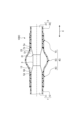
図6は、第3実施形態に係る配索材100Bの側面図であり、図7は、第3実施形態に係る配索材100Bの平面図である。第3実施形態における被覆部4Bは、第1端部筒状部6Bと第2端部筒状部7Bとが一体に形成されるが、第3実施形態に係る配索材100Bのその他の構成は、第1実施形態の配索材100と同様である。このため、第3実施形態に係る配索材100Bは、第1実施形態の配索材100と異なる点についてのみ以下に説明し、同様の構成については説明を省略する。
[Third embodiment]
FIG. 6 is a side view of the
第1端部筒状部6B及び第2端部筒状部7Bは、第1方向Xにおいて、第1端部筒状部6Bと第2端部筒状部7Bとの間に位置し、中央筒状部5が配置された部分を連結する連結部8を有する。連結部8は、例えば、第1方向Xに延在する棒状に形成してある。このような連結部8は、第1連結部8a、及び、第2連結部8bによって構成される。第1連結部8a、及び、第2連結部8bは、第1方向Xと直交する方向において対向する。
The first end
本実施形態に係る配索材100Bは、以下の構成を有する。本実施形態に係る配索材100Bの被覆部4Bは、第1端部筒状部6Bと第2端部筒状部7Bとが一体に形成される。このため、本実施形態に係る配索材100Bは、第1端部筒状部6Bと第2端部筒状部7Bとが別体に形成されたものと比較すると、組み立て時の作業性を向上することができる。
The
[第4実施形態]
図8は、第4実施形態に係る配索材100Cの断面図である。第4実施形態における被覆部4における中央筒状部5C、第1端部筒状部6C、及び、第2端部筒状部7Cは、例えば二色成形などの成形方法によって、中央筒状部5C、第1端部筒状部6C、及び、第2端部筒状部7Cが一体に形成される。一方、第4実施形態に係る配索材100Cのその他の構成は、第1実施形態の配索材100と同様である。このため、第4実施形態に係る配索材100Cは、第1実施形態の配索材100と異なる点についてのみ以下に説明し、同様の構成については説明を省略する。
[Fourth embodiment]
FIG. 8 is a cross-sectional view of a
本実施形態に係る配索材100Cの被覆部4Cは、加熱処理をする前の状態において、中央筒状部5Cの内径D50iと、第1端部筒状部6Cの内径D60iと、第2端部筒状部7Cの内径D70iとが同一である。また、本実施形態に係る配索材100Cの被覆部4Cは、中央筒状部5Cの外径D50oと、第1端部筒状部6Cの外径D60oと、第2端部筒状部7Cの外径D70oとが同一である。
The covering
中央筒状部5C、第1端部筒状部6C、及び、第2端部筒状部7Cは、加熱処理後の熱収縮チューブである。第1端部筒状部6Cを構成する熱収縮チューブ、及び、第2端部筒状部7Cを構成する熱収縮チューブは、中央筒状部5Cを構成する熱収縮チューブよりも収縮率が大きい。従って、加熱処理をした後の状態では、中央筒状部5Cの内径D50iは、第1端部筒状部6Cの内径D60i、及び、第2端部筒状部7Cの内径D70iよりも大きい。かつ、中央筒状部5Cの外径D70oは、第1端部筒状部6Cの外径D60o、及び、第2端部筒状部7Cの外径D70oよりも大きい。従って、中央筒状部5Cは、径方向の外側に膨らむように変形し、接合部分3の外面から離隔し、接合部分3の外面と全周にわたって非密着状態である。一方、第1端部筒状部6Cの内周面6iは、第1被覆部12における一部12aの外周面12oと全周にわたって密着し、第2端部筒状部7の内周面7iは、第2被覆部22における一部22aの外周面22oと全周にわたって密着する。
The central
中央筒状部5C、及び、第1端部筒状部6Cは、第1端部筒状部6Cの第1方向Xにおける他方側に位置する第1筒状部他方側端面6dと、中央筒状部5の第1方向Xにおける一方側に位置する中央筒状部一方側端面5dとが第1方向Xへ連続する。
The central
中央筒状部5、及び、第2端部筒状部7は、第2端部筒状部7の第1方向Xにおける一方側に位置する第2筒状部一方側端面7dと、中央筒状部5の第1方向Xにおける他方側に位置する中央筒状部他方側端面5eとが第1方向Xへ連続する。
The central
本実施形態に係る配索材100Cは、以下の構成を有する。本実施形態に係る配索材100は、中央筒状部5C、第1端部筒状部6C、及び、第2端部筒状部7Cが一体に形成される。このため、本実施形態に係る配索材100は、中央筒状部5C、第1端部筒状部6C、及び、第2端部筒状部7Cが別体に形成されたものと比較すると、組み立て時の作業性を向上することができる。
The
なお、上述した実施形態の配索材100、100A、100B、100Cの第1芯線11、及び、第2芯線21は、導電性を有する複数の金属素線を撚り合わせて構成したものを説明した。しかし、この発明は、それに限られず、第1芯線11、及び、第2芯線21は、例えば、導電性を有する金属棒によって構成してもよい。
In addition, the first core wire 11 and the
また、上述した実施形態の配索材100、100A、100B、100Cは、第1芯線11の外径11oと、第2芯線21の外径21oとが同一であり、第1被覆部12の径方向の厚さと、第2被覆部22の径方向の厚さとが同一であり、第1電線1の外径と、第2電線2の外径とが同一であるものを説明した。しかし、この発明はそれに限られず、第1芯線11の外径D11oと第2芯線21の外径D21oが異なってもよいし、第1被覆部12の径方向の厚さと第2被覆部22の径方向の厚さとが異なってもよいし、第1電線1の外径と第2電線2の外径とが異なってもよい。
Further, in the
さらに、上述した実施形態の配索材100、100A、100B、100Cは、超音波接合することによって接合部分3を形成するものを説明した。しかし、この発明はそれに限られず、熱圧着接合、またはスプライスジョイント等の端子接合によって接合部分3を形成してもよい。
Furthermore, the
また、上述した実施形態の中央筒状部5、5A、5Cは、加熱処理後の熱収縮チューブであるものを説明した。しかし、この発明は、それに限られず、中央筒状部5、5A、5Cは、加熱処理によって径方向の内側に収縮しないチューブを用いてもよい。この場合、加熱処理の前の状態において、第1方向Xから視た場合には、接合部分3と中央筒状部5、5A、5Cと間に空間部s1が形成される。このため、加熱処理の後においても、第1方向Xから視た場合には、接合部分3と中央筒状部5、5A、5Cと間に空間部s1が形成され、中央筒状部5、5A、5Cは、接合部3の外周面3oと全周にわって非密着状態となる。
Furthermore, the central
1 第1電線
11 第1芯線
12 第1被覆部
12a 第1被覆部における一部
12o 外周面
13 第1移行部
2 第2電線
21 第2芯線
22 第2被覆部
22a 第2被覆部における一部
22o 外周面
23 第2移行部
3 接合部分
3o (接合部分の)外面
4、4A、4B、4C 被覆部
5、5A、5C 中央筒状部
5a 一方側の端部
5b 他方側の端部
5d 中央筒状部一方側端面
5e 中央筒状部他方側端面
6、6A、6B、6C 第1端部筒状部
6b 第1端部筒状部における他方側の端部(第1端部筒状部における一部)
6d 第1筒状部他方側端面
6i 内周面
7、7A、7B、7C 第2端部筒状部
7a 第2端部筒状部における一方側の端部(第2端部筒状部における一部)
7d 第2筒状部一方側端面
7i 内周面
s1 空間部
100、100A、100B、100C 配索材
X 第1方向(軸線方向)
Y (幅方向)他方向
Z (高さ方向)一方向
1 First electric wire 11
6d First cylindrical part other
7d Second cylindrical part one
Y (width direction) other direction Z (height direction) one direction
Claims (5)
前記軸線方向に延在する第2芯線、及び、前記第2芯線を被覆する第2被覆部を有する第2電線と、
前記軸線方向において、前記第1芯線と前記第2芯線との間に位置し、前記第1芯線と前記第2芯線とが接合された接合部分と、
少なくとも、前記第1被覆部の一部、前記接合部分、及び、前記第2被覆部の一部を被覆する絶縁性の被覆部と、
を備え、
前記被覆部は、
前記軸線方向と直交する直交方向において、前記接合部分に対向する中央筒状部と、
前記軸線方向において、前記中央筒状部を挟んだ一方側に位置する第1端部筒状部、及び、他方側に位置する第2端部筒状部と、
を有し、
前記第1端部筒状部を構成する熱収縮チューブ、および、前記第2端部筒状部を構成する熱収縮チューブは、前記中央筒状部を構成する熱収縮チューブよりも収縮率が大きい合成樹脂材料で形成され、
前記中央筒状部の前記軸線方向における一方側の端部は、前記第1端部筒状部における他方側の端部と全周にわたって接触し、
前記中央筒状部の前記軸線方向における他方側の端部は、前記第2端部筒状部における一方側の端部と全周にわたって接触し、
前記第1端部筒状部の内周面は、前記第1被覆部における一部の外周面と全周にわたって密着し、
前記第2端部筒状部の内周面は、前記第2被覆部における一部の外周面と全周にわたって密着し、
前記中央筒状部は、前記接合部分の外面と全周にわたって非密着状態であることを特徴とする、
配索材。 a first electric wire having a first core wire extending in the axial direction and a first covering portion covering the first core wire;
a second electric wire having a second core wire extending in the axial direction and a second covering portion covering the second core wire;
a joint portion located between the first core wire and the second core wire in the axial direction, and where the first core wire and the second core wire are joined;
an insulating covering part that covers at least a part of the first covering part, the joint part, and a part of the second covering part;
Equipped with
The covering portion is
a central cylindrical portion facing the joint portion in an orthogonal direction perpendicular to the axial direction;
In the axial direction, a first end cylindrical part located on one side of the central cylindrical part, and a second end cylindrical part located on the other side;
has
The heat-shrinkable tube forming the first end cylindrical portion and the heat-shrinkable tube forming the second end cylindrical portion have a higher shrinkage rate than the heat-shrinkable tube forming the central cylindrical portion. Made of synthetic resin material,
One end of the central cylindrical part in the axial direction contacts the other end of the first end cylindrical part over the entire circumference,
The other end of the central cylindrical part in the axial direction contacts the one end of the second end cylindrical part over the entire circumference,
The inner circumferential surface of the first end cylindrical portion is in close contact with a part of the outer circumferential surface of the first covering portion over the entire circumference,
The inner circumferential surface of the second end cylindrical portion is in close contact with a part of the outer circumferential surface of the second covering portion over the entire circumference,
The central cylindrical portion is not in close contact with the outer surface of the joint portion over the entire circumference,
Routing material.
請求項1に記載の配索材。 When viewed from the axial direction, a space is formed between the joint portion and the central cylindrical portion;
The wiring material according to claim 1.
請求項1又は2に記載の配索材。 The heat-shrinkable tube forming the first cylindrical end portion and the heat-shrinkable tube forming the second cylindrical end portion are formed of the same material.
The wiring material according to claim 1 or 2.
前記中央筒状部における前記軸線方向の一方側の端部は、前記第1端部筒状部の一部とオーバラップし、前記軸線方向から視た場合には前記第1端部筒状部の一部の内側に位置し、
前記中央筒状部における前記軸線方向の他方側の端部は、前記第2端部筒状部の一部とオーバラップし、前記軸線方向から視た場合には前記第2端部筒状部の一部の内側に位置する、
請求項1又は2に記載の配索材。 The central cylindrical part, the first end cylindrical part, and the second end cylindrical part are formed separately,
One end of the central cylindrical part in the axial direction overlaps a part of the first end cylindrical part, and when viewed from the axial direction, the first end cylindrical part overlaps with a part of the first end cylindrical part. located inside a part of
The other end of the central cylindrical part in the axial direction overlaps a part of the second end cylindrical part, and when viewed from the axial direction, the second end cylindrical part overlaps with a part of the second end cylindrical part. located inside a part of
The wiring material according to claim 1 or 2.
前記中央筒状部、及び、前記第1端部筒状部は、前記第1端部筒状部の前記軸線方向における他方側に位置する第1筒状部他方側端面と、前記中央筒状部の前記軸線方向における一方側に位置する中央筒状部一方側端面とが前記軸線方向へ連続し、
前記中央筒状部、及び、前記第2端部筒状部は、前記第2端部筒状部の前記軸線方向における一方側に位置する第2筒状部一方側端面と、前記中央筒状部の前記軸線方向における他方側に位置する中央筒状部他方側端面とが前記軸線方向へ連続する、
請求項1又は2に記載の配索材。 The central cylindrical part, the first end cylindrical part, and the second end cylindrical part are integrally formed,
The central cylindrical portion and the first end cylindrical portion are connected to the other side end surface of the first cylindrical portion located on the other side in the axial direction of the first end cylindrical portion, and the central cylindrical portion. one side end surface of the central cylindrical part located on one side in the axial direction of the part is continuous in the axial direction,
The central cylindrical part and the second end cylindrical part are connected to one side end surface of the second cylindrical part located on one side in the axial direction of the second end cylindrical part, and the central cylindrical part. The other side end surface of the central cylindrical part located on the other side in the axial direction of the part is continuous in the axial direction,
The wiring material according to claim 1 or 2.
Priority Applications (1)
| Application Number | Priority Date | Filing Date | Title |
|---|---|---|---|
| JP2019195863A JP7362425B2 (en) | 2019-10-29 | 2019-10-29 | Routing material |
Applications Claiming Priority (1)
| Application Number | Priority Date | Filing Date | Title |
|---|---|---|---|
| JP2019195863A JP7362425B2 (en) | 2019-10-29 | 2019-10-29 | Routing material |
Publications (2)
| Publication Number | Publication Date |
|---|---|
| JP2021072155A JP2021072155A (en) | 2021-05-06 |
| JP7362425B2 true JP7362425B2 (en) | 2023-10-17 |
Family
ID=75713735
Family Applications (1)
| Application Number | Title | Priority Date | Filing Date |
|---|---|---|---|
| JP2019195863A Active JP7362425B2 (en) | 2019-10-29 | 2019-10-29 | Routing material |
Country Status (1)
| Country | Link |
|---|---|
| JP (1) | JP7362425B2 (en) |
Family Cites Families (2)
| Publication number | Priority date | Publication date | Assignee | Title |
|---|---|---|---|---|
| JPS5918201B2 (en) * | 1976-05-24 | 1984-04-26 | 住友電気工業株式会社 | heat shrinkable tube |
| JPH1169594A (en) * | 1997-08-07 | 1999-03-09 | Hitachi Cable Ltd | Cold shrinkable cover for insulated wires |
-
2019
- 2019-10-29 JP JP2019195863A patent/JP7362425B2/en active Active
Also Published As
| Publication number | Publication date |
|---|---|
| JP2021072155A (en) | 2021-05-06 |
Similar Documents
| Publication | Publication Date | Title |
|---|---|---|
| JP6983941B2 (en) | Methods and cables made by splice connecting shielded wire cables | |
| JP6048859B2 (en) | Conductive wire, conductive wire manufacturing method, and conductive wire routing structure | |
| JP5913851B2 (en) | Wire connection method | |
| JP6406023B2 (en) | Electric wire, electric wire with terminal, and method for manufacturing electric wire with terminal | |
| CN111210927B (en) | Conductive member | |
| JP7342755B2 (en) | wire harness | |
| JP6996974B2 (en) | Manufacturing method of electric wire with terminal and electric wire with terminal | |
| JP6813630B2 (en) | Wiring assembly for equipment | |
| JP7362425B2 (en) | Routing material | |
| CN108075242B (en) | Wire connection structure and wire harness | |
| JP2020004543A (en) | Wire harness | |
| CN107045905A (en) | Wire harness manufacture method | |
| CN118380784A (en) | Terminal fittings and electric wires with terminals | |
| JP6719873B2 (en) | Wiring assembly for vehicle equipment | |
| JP7022360B2 (en) | Wiring assembly for equipment | |
| JP7547245B2 (en) | Conductor joining structure and method for ultrasonically joining a conductor | |
| JP2016167340A (en) | Joint member and wire harness | |
| CN108886205A (en) | The connection structure and harness of conductor | |
| JP5640907B2 (en) | Wire harness and method of manufacturing wire harness | |
| JP7598800B2 (en) | Electric wire with terminal, wiring harness, and method for manufacturing electric wire with terminal | |
| JP6109011B2 (en) | Power cable connection | |
| JP2024100333A (en) | Ultrasonic junction device and electric wire with terminal | |
| JP2025025058A (en) | Ultrasonic bonding device and wire harness | |
| JP2024138708A (en) | Electric wire with terminal, manufacturing method of electric wire with terminal, and manufacturing device of electric wire with terminal | |
| JP2024114161A (en) | Ultrasonic bonding method |
Legal Events
| Date | Code | Title | Description |
|---|---|---|---|
| A621 | Written request for application examination |
Free format text: JAPANESE INTERMEDIATE CODE: A621 Effective date: 20220915 |
|
| A131 | Notification of reasons for refusal |
Free format text: JAPANESE INTERMEDIATE CODE: A131 Effective date: 20230523 |
|
| A977 | Report on retrieval |
Free format text: JAPANESE INTERMEDIATE CODE: A971007 Effective date: 20230524 |
|
| A521 | Request for written amendment filed |
Free format text: JAPANESE INTERMEDIATE CODE: A523 Effective date: 20230629 |
|
| TRDD | Decision of grant or rejection written | ||
| A01 | Written decision to grant a patent or to grant a registration (utility model) |
Free format text: JAPANESE INTERMEDIATE CODE: A01 Effective date: 20231003 |
|
| A61 | First payment of annual fees (during grant procedure) |
Free format text: JAPANESE INTERMEDIATE CODE: A61 Effective date: 20231004 |
|
| R150 | Certificate of patent or registration of utility model |
Ref document number: 7362425 Country of ref document: JP Free format text: JAPANESE INTERMEDIATE CODE: R150 |