JP7361946B2 - non-return valve - Google Patents

non-return valve Download PDF

Info

Publication number
JP7361946B2
JP7361946B2 JP2022561240A JP2022561240A JP7361946B2 JP 7361946 B2 JP7361946 B2 JP 7361946B2 JP 2022561240 A JP2022561240 A JP 2022561240A JP 2022561240 A JP2022561240 A JP 2022561240A JP 7361946 B2 JP7361946 B2 JP 7361946B2
Authority
JP
Japan
Prior art keywords
valve body
valve
guide
guide member
check valve
Prior art date
Legal status (The legal status is an assumption and is not a legal conclusion. Google has not performed a legal analysis and makes no representation as to the accuracy of the status listed.)
Active
Application number
JP2022561240A
Other languages
Japanese (ja)
Other versions
JPWO2022102123A1 (en
JPWO2022102123A5 (en
Inventor
充宏 池田
雄大 森川
Current Assignee (The listed assignees may be inaccurate. Google has not performed a legal analysis and makes no representation or warranty as to the accuracy of the list.)
Mitsubishi Electric Corp
Original Assignee
Mitsubishi Electric Corp
Priority date (The priority date is an assumption and is not a legal conclusion. Google has not performed a legal analysis and makes no representation as to the accuracy of the date listed.)
Filing date
Publication date
Application filed by Mitsubishi Electric Corp filed Critical Mitsubishi Electric Corp
Publication of JPWO2022102123A1 publication Critical patent/JPWO2022102123A1/ja
Publication of JPWO2022102123A5 publication Critical patent/JPWO2022102123A5/ja
Application granted granted Critical
Publication of JP7361946B2 publication Critical patent/JP7361946B2/en
Active legal-status Critical Current
Anticipated expiration legal-status Critical

Links

Images

Classifications

    • FMECHANICAL ENGINEERING; LIGHTING; HEATING; WEAPONS; BLASTING
    • F16ENGINEERING ELEMENTS AND UNITS; GENERAL MEASURES FOR PRODUCING AND MAINTAINING EFFECTIVE FUNCTIONING OF MACHINES OR INSTALLATIONS; THERMAL INSULATION IN GENERAL
    • F16KVALVES; TAPS; COCKS; ACTUATING-FLOATS; DEVICES FOR VENTING OR AERATING
    • F16K15/00Check valves
    • F16K15/02Check valves with guided rigid valve members
    • F16K15/06Check valves with guided rigid valve members with guided stems

Description

本開示は、空気調和機の冷凍サイクルの冷媒配管に取り付けられる逆止弁に関するものである。 The present disclosure relates to a check valve attached to a refrigerant pipe of a refrigeration cycle of an air conditioner.

従来、空気調和機における冷凍サイクルの冷媒配管には、冷媒等の逆流を防止するために逆止弁が設けられることがある。逆止弁は、通過する冷媒等の流体の背圧により、内部に設けられた弁体が流体の逆流を防止するように動作する。 BACKGROUND ART Conventionally, refrigerant piping of a refrigeration cycle in an air conditioner is sometimes provided with a check valve to prevent backflow of refrigerant and the like. In the check valve, a valve body provided inside the check valve operates to prevent backflow of fluid due to back pressure of a fluid such as a refrigerant passing through the check valve.

例えば、特許文献1には、弁シート部を有する弁本体と、弁本体の内部に摺動自在に配設され、弁シート部を閉塞する弁部を有する弁体と、弁体の開弁作動限を規制する規制ピンとを備えた逆止弁が開示されている。この逆止弁では、弁体の開弁作動時に、弁体が規制ピンに線接触することにより、弁体の開弁作動限が規制ピンにより規制されるとともに、係合手段により弁体の回り止めが行われる。 For example, Patent Document 1 discloses a valve body having a valve seat portion, a valve body having a valve portion slidably disposed inside the valve body and closing the valve seat portion, and a valve opening operation of the valve body. A check valve is disclosed that includes a restriction pin that restricts the limit of the check valve. In this check valve, when the valve body is opened, the valve body comes into line contact with the regulation pin, so that the limit of the valve opening operation of the valve body is regulated by the regulation pin, and the engaging means moves the valve body around the valve body. A stop is made.

特許第3395731号公報Patent No. 3395731

しかしながら、特許文献1に記載の逆止弁では、弁体の開弁作動限を規制する規制ピンが流体の流れる流路に配置されているため、圧力損失が生じてしまうという課題があった。また、弁体が開弁した場合には、弁体が規制ピンに線接触するが、このときの弁体と規制ピンとの接触面積が少ないため、規制ピンに加わる衝撃力が過大となり、規制ピンのがたつきおよび外れといった不具合が発生する虞がある。 However, the check valve described in Patent Document 1 has a problem in that a pressure loss occurs because the regulating pin that regulates the valve opening operating limit of the valve body is disposed in a flow path through which fluid flows. In addition, when the valve body opens, the valve body comes into line contact with the regulation pin, but since the contact area between the valve body and the regulation pin at this time is small, the impact force applied to the regulation pin becomes excessive, and the regulation pin There is a risk that problems such as rattling and coming off may occur.

本開示は、上記従来の技術における課題に鑑みてなされたものであって、流体が通過する際の圧力損失を抑えるとともに、弁体が開弁した際の規制手段の強度を確保することができる逆止弁を提供することを目的とする。 The present disclosure has been made in view of the problems in the conventional technology described above, and is capable of suppressing pressure loss when fluid passes through it and ensuring the strength of the regulating means when the valve body opens. The purpose is to provide check valves.

本開示の逆止弁は、円筒状に形成された弁本体と、前記弁本体内に設けられ、前記弁本体の軸方向に移動する弁体とを備え、前記弁本体は、円筒状に形成され、前記弁体を収容する収容部と、一端に形成され、流体が流入する流入部と、他端に形成され、前記流体が流出する流出部とを有し、前記収容部は、収容された前記弁体を案内する案内部と、前記案内部の前記流入側が内側に折り曲げられて形成され、弁座として機能する曲げ部とを有する案内部材と、前記案内部材と別体で形成されるとともに、前記案内部材の前記流出部側に円筒状に形成され、前記弁体の前記流出部側への移動を規制する弁体止め部材とを有するものである。 The check valve of the present disclosure includes a valve body formed in a cylindrical shape, and a valve body provided in the valve body and movable in the axial direction of the valve body, wherein the valve body is formed in a cylindrical shape. and has an accommodating part for accommodating the valve body, an inflow part formed at one end into which the fluid flows, and an outflow part formed at the other end from which the fluid flows out, and the accommodating part has a accommodating part in which the fluid flows out. a guide member having a guide part that guides the valve body; a bent part formed by bending the inflow side of the guide part inward and functioning as a valve seat; and a guide member formed separately from the guide member. In addition, a valve body stopping member is formed in a cylindrical shape on the outflow side of the guide member and restricts movement of the valve body toward the outflow side.

以上のように、本開示によれば、弁体の流出部側への移動を規制する弁体止め部材が円筒状に形成されている。これにより、逆止弁を通過する流体の流れを妨げることが抑制されるため、流体が通過する際の圧力損失を抑えることができる。また、開弁時に弁体が弁体止め部材に対して面接触するため、弁体が開弁した際の規制手段の強度を確保することができる。 As described above, according to the present disclosure, the valve body stopper member that restricts the movement of the valve body toward the outflow portion side is formed in a cylindrical shape. This prevents the flow of fluid passing through the check valve from being obstructed, thereby suppressing pressure loss when fluid passes. Further, since the valve body makes surface contact with the valve body stop member when the valve is opened, the strength of the regulating means when the valve body is opened can be ensured.

実施の形態1に係る逆止弁の外観の一例を示す斜視図である。1 is a perspective view showing an example of the appearance of a check valve according to Embodiment 1. FIG. 図1の逆止弁の内部構造の一例を示す模式断面図である。FIG. 2 is a schematic cross-sectional view showing an example of the internal structure of the check valve shown in FIG. 1. FIG. 図2の案内部材の下部周辺を拡大して示す概略図である。FIG. 3 is a schematic diagram showing an enlarged view of the lower part of the guide member shown in FIG. 2; 図2の案内部材の上部周辺を拡大して示す概略図である。FIG. 3 is a schematic diagram showing an enlarged view of the upper part of the guide member shown in FIG. 2; 図2の弁体の構成の一例を示す斜視図である。3 is a perspective view showing an example of the configuration of the valve body of FIG. 2. FIG. 実施の形態2に係る逆止弁の内部構造の一例を示す模式断面図である。FIG. 3 is a schematic cross-sectional view showing an example of an internal structure of a check valve according to a second embodiment. 図6の弁体止め部材の周辺を拡大して示す概略図である。FIG. 7 is a schematic diagram showing an enlarged view of the periphery of the valve body stopper member shown in FIG. 6; 案内部材と弁体止め部材とが一体的に形成された場合の逆止弁の内部構造の一例を示す模式断面図である。It is a schematic sectional view showing an example of the internal structure of a check valve when a guide member and a valve body stopping member are formed integrally.

以下、本開示の実施の形態について、図面を参照して説明する。本開示は、以下の実施の形態に限定されるものではなく、本開示の主旨を逸脱しない範囲で種々に変形することが可能である。また、本開示は、以下の各実施の形態に示す構成のうち、組合せ可能な構成のあらゆる組合せを含むものである。また、各図に記載の構成について、その形状、大きさ、および配置等は、本開示の範囲内で適宜変更することができる。 Embodiments of the present disclosure will be described below with reference to the drawings. The present disclosure is not limited to the following embodiments, and can be variously modified without departing from the gist of the present disclosure. Further, the present disclosure includes all combinations of configurations that can be combined among the configurations shown in the following embodiments. Furthermore, the shape, size, arrangement, etc. of the configurations shown in each figure can be changed as appropriate within the scope of the present disclosure.

また、以下の説明において、理解を容易にするために方向を表す用語(例えば「上」、「下」、「右」、「左」、「前」および「後」など)を適宜用いるが、これらの用語は説明のためのものであって、本開示を限定するものではない。また、以下に説明する実施の形態では、据付板を正面視した状態において、「上」、「下」、「右」、「左」、「前」および「後」などを使用する。なお、それぞれの図面において、各構成部材の相対的な寸法関係または形状等が実際のものとは異なる場合がある。 In addition, in the following description, terms indicating directions (for example, "top", "bottom", "right", "left", "front", and "back") are used as appropriate to facilitate understanding. These terms are for purposes of explanation and do not limit this disclosure. In the embodiment described below, "upper", "lower", "right", "left", "front", "rear", etc. are used when the installation plate is viewed from the front. Note that in each drawing, the relative dimensional relationship or shape of each component may differ from the actual one.

実施の形態1.
以下、本実施の形態1に係る逆止弁について説明する。本実施の形態1に係る逆止弁は、例えば空気調和機の配管に配置され、冷媒等の流体の逆流を防止し、流体が一方向にのみ流れるように規制するものである。具体的には、逆止弁は、流体が一端部から流入した際に、内部の弁体が開弁する。また、流体が他端部から流入した場合には、弁体が閉弁する。
Embodiment 1.
The check valve according to the first embodiment will be described below. The check valve according to the first embodiment is arranged, for example, in the piping of an air conditioner, and prevents the backflow of fluid such as refrigerant and restricts the fluid to flow in only one direction. Specifically, in the check valve, an internal valve body opens when fluid flows in from one end. Moreover, when fluid flows in from the other end, the valve body closes.

[逆止弁1の構成]
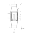
図1は、本実施の形態1に係る逆止弁の外観の一例を示す斜視図である。図2は、図1の逆止弁の内部構造の一例を示す模式断面図である。図2は、図1の逆止弁1の中心軸を通過するxy平面で切断した場合の断面の一例を示す。図1および図2に示すように、逆止弁1は、弁本体10および弁体20を含んで構成されている。
[Configuration of check valve 1]
FIG. 1 is a perspective view showing an example of the appearance of the check valve according to the first embodiment. FIG. 2 is a schematic cross-sectional view showing an example of the internal structure of the check valve shown in FIG. FIG. 2 shows an example of a cross section taken along an xy plane passing through the central axis of the check valve 1 shown in FIG. As shown in FIGS. 1 and 2, the check valve 1 includes a valve body 10 and a valve body 20.

(弁本体10)
弁本体10は、例えば、円筒状に形成されている。弁本体10には、収容部11、流入部12および流出部13が形成されている。また、弁本体10の内部には、案内部材14および弁体止め部材15が形成されている。通常、弁本体10には、図1の実線矢印で示すように、流入部12から流出部13に向かって冷媒等の流体が流れる。
(Valve body 10)
The valve body 10 is, for example, formed in a cylindrical shape. The valve body 10 is formed with a housing section 11, an inflow section 12, and an outflow section 13. Further, a guide member 14 and a valve body stopper member 15 are formed inside the valve body 10. Normally, a fluid such as a refrigerant flows through the valve body 10 from an inlet 12 toward an outlet 13, as shown by the solid arrow in FIG.

収容部11は、弁本体10の中央部分に形成され、案内部材14、弁体止め部材15および弁体20を収容する。流入部12は、弁本体10の一端に形成され、逆止弁1に流入する流体の入口となっている。流出部13は、弁本体10の他端に形成され、逆止弁1を通過する流体の出口となっている。 The accommodating portion 11 is formed in the central portion of the valve body 10 and accommodates the guide member 14, the valve body stopper member 15, and the valve body 20. The inflow portion 12 is formed at one end of the valve body 10 and serves as an inlet for fluid flowing into the check valve 1 . The outflow portion 13 is formed at the other end of the valve body 10 and serves as an outlet for fluid passing through the check valve 1 .

流入部12および流出部13には、溶接等によって配管が接続される。配管は、溶接に限られず、例えば、ねじまたはフランジを用いて接続されてもよい。この例では、溶接によって配管が接続された場合について説明する。また、流入部12および流出部13は、それぞれの内径が異なるように形成されている。このように、流入部12および流出部13のそれぞれに接続できる配管の径が異なるため、弁本体10に対する配管の誤接続が防止される。これにより、流体の流れを阻止したい方向に逆止弁1を正しく設置することができる。 Pipes are connected to the inflow section 12 and the outflow section 13 by welding or the like. Piping is not limited to welding, and may be connected using screws or flanges, for example. In this example, a case will be described in which pipes are connected by welding. Further, the inflow portion 12 and the outflow portion 13 are formed to have different inner diameters. In this way, since the diameters of the pipes that can be connected to each of the inflow part 12 and the outflow part 13 are different, incorrect connection of the pipes to the valve body 10 is prevented. Thereby, the check valve 1 can be correctly installed in the direction in which it is desired to block the flow of fluid.

弁本体10には、収容部11から流入部12および流出部13のそれぞれに向かって径が徐々に小さくなるように、絞り加工が施されている。絞り加工が施されることにより、案内部材14および弁体止め部材15の位置決めが行われる。なお、以下では、弁本体10の流入部12側を「下部」と称し、流出部13側を「上部」と称して説明することがある。 The valve body 10 is drawn so that the diameter thereof gradually decreases from the accommodating portion 11 toward the inflow portion 12 and the outflow portion 13, respectively. By performing the drawing process, the guide member 14 and the valve body stopper member 15 are positioned. In addition, below, the inflow part 12 side of the valve body 10 may be called a "lower part," and the outflow part 13 side may be called an "upper part" and demonstrated.

弁本体10の内部に設けられた案内部材14は、円筒状に形成され、内部に配置された弁体20を案内する。案内部材14は、案内部14aおよび曲げ部14bを有している。案内部14aは、弁本体10の収容部11に接するように配置されている。案内部14aの下部には、突出するように内側に折り曲げられて案内部14aと一体的に形成された曲げ部14bが設けられている。曲げ部14bは、弁体20に対する弁座として機能する。 The guide member 14 provided inside the valve body 10 is formed in a cylindrical shape and guides the valve body 20 disposed inside. The guide member 14 has a guide portion 14a and a bent portion 14b. The guide portion 14a is arranged so as to be in contact with the accommodating portion 11 of the valve body 10. A bent portion 14b is provided at the lower part of the guide portion 14a and is bent inward so as to project and is integrally formed with the guide portion 14a. The bent portion 14b functions as a valve seat for the valve body 20.

図3は、図2の案内部材の下部周辺を拡大して示す概略図である。図3に示すように、曲げ部14bの内周側上部(点線丸印内)には、合わせ部14cが形成されている。合わせ部14cは、弁体20が流入部12側に移動した際に接触する。合わせ部14cには、R面取りが施されている。これは、流体の逆流によって弁体20が曲げ部14bに接触した際に、弁体20の損傷を防止するためである。また、曲げ部14bの内周側下部(流入部12側の内周)には、面取り加工が施されている。これは、流入部12から流体が流入し、曲げ部14bの内周内側を通過する際に生じる圧力損失を低減させるためである。 FIG. 3 is a schematic diagram showing an enlarged view of the lower part of the guide member shown in FIG. 2. FIG. As shown in FIG. 3, a mating portion 14c is formed at the upper portion of the inner peripheral side of the bent portion 14b (inside the dotted line circle). The mating portion 14c comes into contact with the valve body 20 when it moves toward the inflow portion 12 side. The mating portion 14c is rounded. This is to prevent damage to the valve body 20 when the valve body 20 comes into contact with the bent portion 14b due to backflow of fluid. Further, a lower portion of the inner circumference of the bent portion 14b (inner circumference on the inflow portion 12 side) is chamfered. This is to reduce the pressure loss that occurs when the fluid flows in from the inflow portion 12 and passes inside the inner circumference of the bent portion 14b.

案内部14aと曲げ部14bとの境界部分における内側曲げ部には、任意のR面取りが施されている。これは、弁体20が軸方向(x方向)に移動した際、および、流体が流れた際に加わる応力を緩和するためである。また、案内部14aと曲げ部14bとの境界部分における外側曲げ部にも、任意のR面取りが施されている。これは、弁本体10に対して絞り加工を施した際に、外側曲げ部が弁本体10の絞り箇所の内面を損傷させることを防止するためである。 An arbitrary rounded chamfer is applied to the inner bent portion at the boundary between the guide portion 14a and the bent portion 14b. This is to relieve stress applied when the valve body 20 moves in the axial direction (x direction) and when fluid flows. Further, an arbitrary rounded chamfer is also applied to the outer bent portion at the boundary between the guide portion 14a and the bent portion 14b. This is to prevent the outer bent portion from damaging the inner surface of the valve body 10 at the throttle location when the valve body 10 is subjected to the drawing process.

曲げ部14bの流体が流れる方向(x方向)の厚みは、例えば、逆止弁1の内部を流れる流体の圧力、あるいは、逆流する流体によって弁体20が曲げ部14bに接触した際に加わる圧力に耐える程度の厚みとすると好ましい。 The thickness of the bent portion 14b in the direction in which the fluid flows (x direction) is determined by, for example, the pressure of the fluid flowing inside the check valve 1, or the pressure applied when the valve body 20 contacts the bent portion 14b due to fluid flowing backwards. It is preferable to have a thickness that can withstand.

図2に示すように、案内部材14において、案内部14aの内周面と、曲げ部14bの内周面とは、同一の軸心となっている。これにより、流体が流出部13側から流れて逆流した際に、弁体20で流体の流れを遮断するときの軸ぶれにより、流体が流入部12側に流れる流体漏れを防止している。 As shown in FIG. 2, in the guide member 14, the inner circumferential surface of the guide portion 14a and the inner circumferential surface of the bent portion 14b have the same axis. This prevents fluid from leaking toward the inflow section 12 due to shaft wobbling when the valve body 20 blocks the fluid flow when the fluid flows from the outflow section 13 side and flows backward.

本実施の形態1では、弁体20と案内部材14の内面との隙間が少なくなるように、弁体20および案内部材14が形成されている。これにより、弁体20が軸方向(x方向)に移動する際のぶれが少なくなるため、軸ぶれによる流体漏れを防止することができる。また、案内部材14は、内面の面粗度をより高くし、弁体20との摩擦抵抗を低減している。これにより、弁体20をスムーズに軸方向(x方向)に移動させることができる。 In the first embodiment, the valve body 20 and the guide member 14 are formed so that the gap between the valve body 20 and the inner surface of the guide member 14 is reduced. This reduces wobbling when the valve body 20 moves in the axial direction (x direction), so fluid leakage due to shaft wobbling can be prevented. Further, the guide member 14 has a higher inner surface roughness to reduce frictional resistance with the valve body 20. Thereby, the valve body 20 can be smoothly moved in the axial direction (x direction).

案内部材14における案内部14aの外周面には、内側に凹となる凹溝が形成され、凹溝にシール部材16が設けられている。案内部材14が収容部11に配置された状態において、シール部材16は、案内部材14の外周面と収容部11の内周面との間に流れる流体を遮断する。シール部材16は、例えば、ゴム、樹脂または金属等の、案内部材14と収容部11との間の隙間を流れる流体の流れを遮断することができる材料で形成されている。 A groove that is concave inward is formed on the outer peripheral surface of the guide portion 14a of the guide member 14, and a seal member 16 is provided in the groove. In a state in which the guide member 14 is disposed in the housing portion 11 , the seal member 16 blocks fluid flowing between the outer peripheral surface of the guide member 14 and the inner peripheral surface of the housing portion 11 . The sealing member 16 is made of a material capable of blocking the flow of fluid flowing through the gap between the guide member 14 and the housing portion 11, such as rubber, resin, or metal.

シール部材16は、例えば、案内部14aの軸方向(x方向)における中央部分に配置されている。逆止弁1を作製する場合、弁本体10の両端面にろう付け等が行われるが、このように、シール部材16が案内部14aの中央部分に配置されることにより、シール部材16が弁本体10の両端面から最も離れた位置に配置される。そのため、ろう付け等によるシール部材16の熱溶けを防止することができる。 The seal member 16 is disposed, for example, at the center of the guide portion 14a in the axial direction (x direction). When manufacturing the check valve 1, brazing or the like is performed on both end surfaces of the valve body 10, but by arranging the seal member 16 in the center portion of the guide portion 14a in this way, the seal member 16 is attached to the valve body 10. It is located at the farthest position from both end faces of the main body 10. Therefore, thermal melting of the seal member 16 due to brazing or the like can be prevented.

案内部材14(案内部14a)の内周面と外周面との間の厚み(y方向の厚み)は、製品寿命期間において、流体が流れた場合、および弁体20が軸方向(x方向)に移動した場合でも、厚みがなくならない程度の厚みとする。また、案内部材14は、弁体20よりも固い材料を用いて形成される。これは、弁体20が案内部材14を軸方向(x方向)に移動する際に、案内部材14が損傷しないようにするためである。 The thickness between the inner circumferential surface and the outer circumferential surface of the guide member 14 (guide portion 14a) (thickness in the y direction) is the same as that when fluid flows and when the valve body 20 is in the axial direction (x direction) during the product life. The thickness shall be such that it will not lose its thickness even if it is moved. Further, the guide member 14 is formed using a harder material than the valve body 20. This is to prevent the guide member 14 from being damaged when the valve body 20 moves the guide member 14 in the axial direction (x direction).

図4は、図2の案内部材の上部周辺を拡大して示す概略図である。図4に示すように、弁体止め部材15は、円筒状に形成され、弁体20および案内部材14の上部に位置するように設けられている。弁体止め部材15は、弁体20が開弁して上部に移動した際に、弁体20が弁体止め部材15よりも上部に移動しないように、ストッパとして機能する。すなわち、弁体止め部材15は、弁体20の開弁作動限を規制する規制手段として設けられている。 FIG. 4 is a schematic diagram showing an enlarged view of the upper part of the guide member shown in FIG. 2. FIG. As shown in FIG. 4, the valve body stopper member 15 is formed in a cylindrical shape and is provided so as to be located above the valve body 20 and the guide member 14. The valve body stop member 15 functions as a stopper to prevent the valve body 20 from moving above the valve body stop member 15 when the valve body 20 opens and moves upward. That is, the valve body stopper member 15 is provided as a regulating means for regulating the valve opening operation limit of the valve body 20.

弁体止め部材15は、案内部材14と別体で形成されている。これにより、逆止弁1の圧力損失を改善するために、弁体止め部材15に追加工構造を設ける等、それぞれの部材の形状が制約されることなく逆止弁1を設計することができる。また、弁体止め部材15と案内部材14とが別体で形成されることにより、それぞれの部材の形状を簡素化することができる。 The valve body stopper member 15 is formed separately from the guide member 14. Thereby, in order to improve the pressure loss of the check valve 1, it is possible to design the check valve 1 without being restricted in the shape of each member, such as by providing an additional structure on the valve body stop member 15. . Further, by forming the valve body stopper member 15 and the guide member 14 separately, the shape of each member can be simplified.

さらに、弁体止め部材15と案内部材14とが別体で形成されることにより、逆止弁1を作製する際に発生する各種の不具合を抑制することができる。例えば、弁本体10には絞り加工が施されるが、その際に、弁体止め部材15が変形した場合でも、案内部材14と別体となっているため、案内部材14(特に、弁体20が摺動する箇所)の変形を防ぐことができる。また、例えば、弁体止め部材15と案内部材14とを弁本体10に収容させる前の段階で一体化させる場合には、案内部材14(特に、弁体20が摺動する箇所)が変形する可能性がある。しかし、弁体止め部材15と案内部材14とを別体とすることにより、このような部材の変形を防ぐことができる。 Furthermore, by forming the valve body stopper member 15 and the guide member 14 separately, various problems that occur when manufacturing the check valve 1 can be suppressed. For example, the valve body 10 is subjected to a drawing process, but even if the valve body stopper 15 is deformed during this process, since it is separate from the guide member 14, the guide member 14 (especially the valve body 20 can be prevented from deforming. Further, for example, when the valve body stopper member 15 and the guide member 14 are integrated at a stage before being housed in the valve body 10, the guide member 14 (particularly the portion where the valve body 20 slides) may be deformed. there is a possibility. However, by making the valve body stopper member 15 and the guide member 14 separate, such deformation of the members can be prevented.

さらにまた、本実施の形態1では、案内部材14および弁体止め部材15が収容された状態で絞り加工が施されることによって弁本体10が作製される。これにより、案内部材14および弁体止め部材15の一体化加工が削減されるため、逆止弁1の作成工程を簡略化することができる。 Furthermore, in Embodiment 1, the valve body 10 is manufactured by performing a drawing process while the guide member 14 and the valve body stopper member 15 are accommodated. This reduces the need for integrating the guide member 14 and the valve body stopper member 15, thereby simplifying the process for manufacturing the check valve 1.

弁体止め部材15の厚みは、例えば、逆止弁1の内部を流れる流体の圧力、あるいは、流れる流体によって弁体20が開弁した際に弁体止め部材15に衝突する弁体20の衝撃力に耐える程度の厚みとする。 The thickness of the valve body stop member 15 is determined by, for example, the pressure of the fluid flowing inside the check valve 1 or the impact of the valve body 20 that collides with the valve body stop member 15 when the valve body 20 is opened by the flowing fluid. It should be thick enough to withstand the force.

弁体止め部材15の外周側上部(外周の流出部13側)の角部は、R面取りが施されている。弁体止め部材15は、弁本体10の上部に施された絞り加工によって位置決めされるが、角部が面取り加工されていることにより、絞り加工が施された際に、弁体止め部材15の角部が弁本体10の内面に接触することによる弁本体10の損傷が防止される。 The corner portion of the upper outer circumferential side (outflow portion 13 side of the outer circumference) of the valve body stopper member 15 is rounded. The valve body stop member 15 is positioned by the drawing process performed on the upper part of the valve body 10, but since the corners are chamfered, the valve body stop member 15 is positioned when the drawing process is performed. Damage to the valve body 10 due to the corner coming into contact with the inner surface of the valve body 10 is prevented.

弁体止め部材15が円筒状に形成されることにより、弁体20が弁体止め部材15に面接触する。この場合、弁体20が線接触する場合と比較して、弁体止め部材15に加わる衝撃力が分散するため、弁体止め部材15の損傷等の不具合の発生を抑制することができる。 Since the valve body stop member 15 is formed into a cylindrical shape, the valve body 20 comes into surface contact with the valve body stop member 15 . In this case, compared to the case where the valve body 20 is in line contact, the impact force applied to the valve body stopper member 15 is dispersed, so that problems such as damage to the valve body stopper member 15 can be suppressed.

なお、弁体止め部材15の内径は、可能な限り大きくすることが好ましい。これは、逆止弁1を流れる流体の流れを妨げることがないようにするためである。また、例えば、弁体止め部材15は、内周側の角部にR面取りが施されてもよい。これは、流体が弁体止め部材15を通過する際の急激な流れの変化を抑制するためである。 Note that the inner diameter of the valve body stopper member 15 is preferably made as large as possible. This is to prevent the flow of fluid flowing through the check valve 1 from being obstructed. Further, for example, the valve body stopper member 15 may have an R-chamfered corner portion on the inner peripheral side. This is to suppress sudden changes in the flow when the fluid passes through the valve stopper member 15.

また、上述した弁本体10は、配管内を流れる流体の設計圧力の5倍以上の圧力に耐えることができる肉厚を有していると好ましい。これは、一般的な逆止弁についての日本国内および海外における各種の製品安全規格(KHK規格およびUL規格など)のうち、最も厳しいUL(Underwriters Laboratories)規格の5倍圧破壊試験を満足できるようにするためである。 Moreover, it is preferable that the valve main body 10 described above has a wall thickness that can withstand a pressure that is five times or more the design pressure of the fluid flowing inside the pipe. This product is designed to satisfy the 5x pressure burst test of the UL (Underwriters Laboratories) standard, which is the strictest of the various product safety standards (KHK standard and UL standard, etc.) for general check valves in Japan and overseas. This is to make it happen.

さらに、弁本体10の全長(x方向)は、140mm以上であると好ましい。上述したように、逆止弁1を作製する場合、弁本体10の両端面にろう付け等が行われるが、この場合に、案内部材14に設けられたシール部材16への熱の影響を防ぐためには、70mm以上の距離が必要であることがわかった。そこで、弁本体10の両端面へのろう付け等によるシール部材16の熱溶けを防止するためには、弁本体10の全長が140mm以上である必要がある。このように、弁本体10の全長(x方向)を140mm以上とすることにより、案内部材14に設けられたシール部材16の熱溶けを防止することができる。 Furthermore, the total length (x direction) of the valve body 10 is preferably 140 mm or more. As described above, when manufacturing the check valve 1, brazing or the like is performed on both end surfaces of the valve body 10, but in this case, it is necessary to prevent the influence of heat on the seal member 16 provided on the guide member 14. It has been found that a distance of 70 mm or more is required in order to Therefore, in order to prevent heat melting of the seal member 16 due to brazing or the like to both end faces of the valve body 10, the total length of the valve body 10 needs to be 140 mm or more. In this way, by setting the entire length (x direction) of the valve body 10 to 140 mm or more, it is possible to prevent the seal member 16 provided on the guide member 14 from melting due to heat.

(弁体20)
図2の弁体20は、収容部11に設けられた案内部材14の曲げ部14bと弁体止め部材15との間に配置され、流体の流れる方向によって収容部11内を軸方向(x方向)に移動する。流体が流入部12から流出部13へ流れる場合、弁体20は収容部11内の流出側に移動する。これにより、流体が逆止弁1内を通過する。一方、流体が流出部13から流入部12へ流れる場合、弁体20は収容部11内の流入側に移動し、弁座として機能する曲げ部14bに接触する。これにより、流体が遮断され、逆止弁1内の逆流が防止される。
(Valve body 20)
The valve body 20 in FIG. 2 is arranged between the bent part 14b of the guide member 14 provided in the housing part 11 and the valve body stopper member 15, and is arranged in the housing part 11 in the axial direction (x direction) depending on the direction of fluid flow. ). When fluid flows from the inflow section 12 to the outflow section 13 , the valve body 20 moves to the outflow side within the housing section 11 . As a result, fluid passes through the check valve 1. On the other hand, when the fluid flows from the outflow section 13 to the inflow section 12, the valve body 20 moves toward the inflow side within the housing section 11 and comes into contact with the bent section 14b that functions as a valve seat. This blocks the fluid and prevents backflow within the check valve 1.

図5は、図2の弁体の構成の一例を示す斜視図である。図5に示すように、弁体20は、弁部21およびガイド部22を備えている。 FIG. 5 is a perspective view showing an example of the configuration of the valve body in FIG. 2. FIG. As shown in FIG. 5, the valve body 20 includes a valve portion 21 and a guide portion 22.

弁部21は、流体が流出部13から流入部12に逆流する際に、弁本体10の弁座として機能する案内部材14の曲げ部14bに接触する。これにより、曲げ部14bによって形成された流体の流路が弁部21によって閉塞されるため、流体の逆流が防止される。 The valve portion 21 contacts the bent portion 14b of the guide member 14, which functions as a valve seat of the valve body 10, when the fluid flows back from the outflow portion 13 to the inflow portion 12. As a result, the fluid flow path formed by the bent portion 14b is closed by the valve portion 21, so that backflow of fluid is prevented.

ガイド部22は、弁体20が案内部材14を軸方向に移動するときに弁体20を案内する。ガイド部22の外径は、弁本体10の案内部材14の内径と略等しい。ガイド部22は、中心軸から等角度間隔で外周方向に突出する複数の羽根を有している。これにより、弁本体10の流入部12から流入し、曲げ部14bによって形成される流路を通過した流体は、複数の羽根の間を通って流出部13から流出する。本実施の形態1において、ガイド部22は、4つの羽根を有しているが、これに限られず、ガイド部22は、安定性を考慮すると、3つ以上であればよい。 The guide portion 22 guides the valve body 20 when the valve body 20 moves the guide member 14 in the axial direction. The outer diameter of the guide portion 22 is approximately equal to the inner diameter of the guide member 14 of the valve body 10. The guide portion 22 has a plurality of blades that protrude in the outer circumferential direction at equal angular intervals from the central axis. Thereby, the fluid that flows in from the inflow portion 12 of the valve body 10 and passes through the flow path formed by the bent portion 14b flows out from the outflow portion 13 through between the plurality of blades. In the first embodiment, the guide portion 22 has four blades, but the number is not limited to this, and the guide portion 22 may have three or more blades in consideration of stability.

また、ガイド部22の羽根は、流体が通過する際に規則的に回転する形状とする。このように、ガイド部22の羽根が回転する形状に形成されることにより、ガイド部22の羽根が一定の場所で軸方向(x方向)に移動して、案内部材14の内面の特定の箇所のみを擦って損傷することを防止することができる。 Further, the blades of the guide portion 22 have a shape that rotates regularly when the fluid passes through them. In this way, by forming the blades of the guide part 22 into a rotating shape, the blades of the guide part 22 move in the axial direction (x direction) at a fixed location, and can be moved to a specific location on the inner surface of the guide member 14. This can prevent damage caused by rubbing the chisel.

弁体20は、流体が流入部12から流出部13へ流れた際に、流出部13側に移動するように、流体の圧力で移動できる程度の質量とする。また、弁体20は、樹脂などで形成され、案内部材14よりも軟らかい材料を用いて形成される。これは、弁体20が案内部材14を軸方向(x方向)に移動する際に、案内部材14を損傷させないようにするためである。 The valve body 20 has such a mass that it can be moved by the pressure of the fluid so that it moves toward the outflow section 13 when the fluid flows from the inflow section 12 to the outflow section 13. Further, the valve body 20 is made of resin or the like, and is made of a softer material than the guide member 14 . This is to prevent the guide member 14 from being damaged when the valve body 20 moves the guide member 14 in the axial direction (x direction).

なお、弁体20の弁部21には、穴部21aが形成されてもよい。穴部21aは、弁体20が流入部12側に移動し、弁本体10の曲げ部14bに接触した際に、流入部12側の流路と流出部13側の流路とを連通させる。穴部21aが設けられることにより、弁本体10の下部(流入部12側)が完全に閉塞され、配管が破損することを防止することができる。穴部21aの直径は、0.4mm以下程度とすると好ましい。これは、配管の破損を防ぎつつ、逆流する流体を遮断できるようにするためである。 Note that a hole 21a may be formed in the valve portion 21 of the valve body 20. The hole portion 21a allows the flow path on the inflow portion 12 side and the flow path on the outflow portion 13 side to communicate with each other when the valve body 20 moves toward the inflow portion 12 side and contacts the bent portion 14b of the valve body 10. By providing the hole portion 21a, the lower portion of the valve body 10 (on the inflow portion 12 side) is completely closed, and damage to the piping can be prevented. The diameter of the hole 21a is preferably about 0.4 mm or less. This is to prevent fluid from flowing backward while preventing damage to the piping.

[逆止弁1の動作]
このようにして形成された逆止弁1において、配管内を流れる流体が弁本体10の流入部12から流入すると、弁体20が流入部12側から圧力を受けることで軸方向(x方向)の流出部13側に移動する。そして、弁体20は、案内部材14の流出部13側に配置された弁体止め部材15に接触する。このとき、流入した流体は、弁座として機能する案内部材14の曲げ部14bを介して弁体20におけるガイド部22の羽根の間を通過し、流出部13から流出する。
[Operation of check valve 1]
In the check valve 1 formed in this way, when the fluid flowing in the pipe flows in from the inflow part 12 of the valve body 10, the valve body 20 receives pressure from the inflow part 12 side, so that the fluid flows in the axial direction (x direction). move to the outflow portion 13 side. Then, the valve body 20 comes into contact with the valve body stopper member 15 disposed on the outflow portion 13 side of the guide member 14 . At this time, the inflowing fluid passes between the blades of the guide portion 22 in the valve body 20 via the bent portion 14b of the guide member 14 that functions as a valve seat, and flows out from the outflow portion 13.

一方、配管内を流れる流体が弁本体10の流出部13から流入すると、弁体20が流出部13側から圧力を受けることで軸方向(x方向)の流入部12側に移動する。そして、案内部材14の流入部12側に設けられた弁座として機能する曲げ部14bに、弁体20の弁部21が接触する。これにより、流出部13から流入した流体が遮断される。 On the other hand, when the fluid flowing in the pipe flows in from the outflow section 13 of the valve body 10, the valve body 20 receives pressure from the outflow section 13 side and moves toward the inflow section 12 side in the axial direction (x direction). Then, the valve portion 21 of the valve body 20 comes into contact with the bent portion 14b that is provided on the inlet portion 12 side of the guide member 14 and functions as a valve seat. As a result, the fluid flowing in from the outflow portion 13 is blocked.

以上のように、本実施の形態1に係る逆止弁1は、収容部11に設けられた案内部材14の流出部13側に円筒状に形成された弁体止め部材15が設けられている。これにより、流体が逆止弁1を通過する際に、流体の流れが妨げられることが抑制されるため、圧力損失を抑制することができる。また、弁体止め部材15が円筒状に形成されることにより、開弁時に弁体20が弁体止め部材15に対して面接触し、接触した際の衝撃力が分散されるため、弁体20が開弁した際の弁体止め部材15の強度を確保することができる。 As described above, in the check valve 1 according to the first embodiment, the valve body stop member 15 formed in a cylindrical shape is provided on the outflow portion 13 side of the guide member 14 provided in the housing portion 11. . Thereby, when the fluid passes through the check valve 1, the flow of the fluid is prevented from being obstructed, so that pressure loss can be suppressed. In addition, since the valve body stop member 15 is formed in a cylindrical shape, the valve body 20 comes into surface contact with the valve body stop member 15 when the valve is opened, and the impact force at the time of contact is dispersed. The strength of the valve body stopper member 15 when the valve 20 is opened can be ensured.

逆止弁1において、案内部14aの外周には凹溝が設けられ、この凹溝にシール部材16が設けられている。これにより、案内部材14の外周面と収容部11の内周面との間に流れる流体が遮断されるため、流体が逆流した際の流体の漏洩を防ぐことができる。 In the check valve 1, a groove is provided on the outer periphery of the guide portion 14a, and a seal member 16 is provided in this groove. This blocks the fluid flowing between the outer circumferential surface of the guide member 14 and the inner circumferential surface of the accommodating portion 11, thereby preventing fluid leakage when the fluid flows backward.

逆止弁1において、案内部14aに設けられたシール部材16は、逆止弁1の軸方向の中央部分に設けられている。これにより、逆止弁1の両端面に対してろう付け等を行って逆止弁1を作製する場合の、シール部材16の熱溶けを防止することができる。 In the check valve 1, the sealing member 16 provided in the guide portion 14a is provided in the central portion of the check valve 1 in the axial direction. Thereby, it is possible to prevent the seal member 16 from melting due to heat when the check valve 1 is manufactured by performing brazing or the like on both end surfaces of the check valve 1.

逆止弁1において、案内部材14における案内部14aの内周と曲げ部14bの内周とは、同一の軸心となっている。これにより、流体が流出部13側から流れて逆流した際に、弁体20で流体の流れを遮断するときの軸ぶれによる流入部12側への流体漏れを防止することができる。 In the check valve 1, the inner periphery of the guide portion 14a and the inner periphery of the bent portion 14b of the guide member 14 have the same axis. Thereby, when fluid flows from the outflow part 13 side and flows backward, it is possible to prevent fluid leakage to the inflow part 12 side due to shaft wobbling when the valve body 20 blocks the flow of the fluid.

逆止弁1において、案内部材14の曲げ部14bは、内周の流出部13側に形成された合わせ部14cに面取り加工が施されている。これにより、流体の逆流によって弁体20が曲げ部14bに接触した際に、弁体20の損傷を防止することができる。 In the check valve 1, the bent portion 14b of the guide member 14 has a mating portion 14c formed on the inner periphery on the outflow portion 13 side, which is chamfered. Thereby, damage to the valve body 20 can be prevented when the valve body 20 comes into contact with the bent portion 14b due to backflow of fluid.

逆止弁1において、曲げ部14bは、内周の流入部12側に面取り加工が施されている。これにより、流入部12から流体が流入した際に生じる圧力損失をより低減させることができる。 In the check valve 1, the bent portion 14b is chamfered on the inner periphery on the inflow portion 12 side. Thereby, the pressure loss that occurs when fluid flows in from the inflow portion 12 can be further reduced.

逆止弁1において、案内部材14における案内部14aと曲げ部14bとの境界には、面取り加工が施されている。これにより、流体が流れた際に加わる応力を緩和することができるとともに、弁本体10に対して絞り加工を施した際に、弁本体10の絞り箇所の内面を損傷させることを防止することができる。 In the check valve 1, the boundary between the guide portion 14a and the bent portion 14b in the guide member 14 is chamfered. This makes it possible to alleviate the stress applied when fluid flows, and also prevents damage to the inner surface of the throttle area of the valve body 10 when the valve body 10 is subjected to a drawing process. can.

逆止弁1において、弁体止め部材15は、外周の流出部13側に面取り加工が施されている。これにより、弁本体10に絞り加工が施された際に、弁体止め部材15の角部が弁本体10の内面に接触することによる弁本体10の損傷を防止することができる。 In the check valve 1, the valve body stop member 15 is chamfered on the outer periphery on the outflow portion 13 side. Thereby, when the valve body 10 is subjected to the drawing process, damage to the valve body 10 due to the corners of the valve body stopper member 15 coming into contact with the inner surface of the valve body 10 can be prevented.

逆止弁1において、弁体止め部材15は、案内部材14と別体で形成されている。これにより、案内部材14および弁体止め部材15の形状を簡略化することができる。また、逆止弁1を作製する際の不具合を抑制することができるとともに、作製工程を簡略化することができる。 In the check valve 1, the valve body stop member 15 is formed separately from the guide member 14. Thereby, the shapes of the guide member 14 and the valve body stopper member 15 can be simplified. Further, it is possible to suppress problems when manufacturing the check valve 1, and to simplify the manufacturing process.

実施の形態2.
次に、本実施の形態2について説明する。本実施の形態2は、弁本体10の収容部11に、案内部材14と弁体止め部材15との間に突起が設けられる点で、実施の形態1と相違する。なお、本実施の形態2において、実施の形態1と共通する部分には同一の符号を付し、詳細な説明を省略する。
Embodiment 2.
Next, Embodiment 2 will be described. The second embodiment differs from the first embodiment in that a protrusion is provided in the housing portion 11 of the valve body 10 between the guide member 14 and the valve body stopper member 15. In the second embodiment, parts common to those in the first embodiment are denoted by the same reference numerals, and detailed description thereof will be omitted.

図6は、本実施の形態2に係る逆止弁の内部構造の一例を示す模式断面図である。図6は、実施の形態1と同様に、図1に示す外観を有する逆止弁1の中心軸を通過するxy平面で切断した場合の断面の一例を示す。図6に示すように、逆止弁1は、弁本体10および弁体20を含んで構成されている。また、弁本体10には、案内部材14および弁体止め部材15が設けられた収容部11、流入部12および流出部13が形成されている。 FIG. 6 is a schematic cross-sectional view showing an example of the internal structure of the check valve according to the second embodiment. Similar to Embodiment 1, FIG. 6 shows an example of a cross section taken along an xy plane passing through the central axis of check valve 1 having the appearance shown in FIG. As shown in FIG. 6, the check valve 1 includes a valve body 10 and a valve body 20. Further, the valve body 10 is formed with an accommodating portion 11 in which a guide member 14 and a valve body stopper member 15 are provided, an inflow portion 12, and an outflow portion 13.

本実施の形態2において、収容部11には、内側に突出する突出部17が形成されている。突出部17は、案内部材14と弁体止め部材15との間に設けられ、双方の部材の位置決めを行うために設けられている。突出部17は、収容部11の内周全体に設けられてもよいし、内周の一部に設けられてもよい。すなわち、突出部17は、案内部材14および弁体止め部材15の位置決めを行うことができれば、どのように設けられてもよい。 In the second embodiment, the housing portion 11 is formed with a protrusion 17 that protrudes inward. The protrusion 17 is provided between the guide member 14 and the valve body stopper member 15, and is provided for positioning both members. The protruding portion 17 may be provided on the entire inner periphery of the accommodating portion 11 or may be provided on a part of the inner periphery. That is, the protrusion 17 may be provided in any manner as long as it can position the guide member 14 and the valve body stopper member 15.

このように突出部17が設けられることにより、案内部材14と弁体止め部材15とが接触することがない。そのため、案内部材14および弁体止め部材15を接触させることなく、容易に位置決めを行うことができる。 By providing the protruding portion 17 in this manner, the guide member 14 and the valve body stopper member 15 do not come into contact with each other. Therefore, positioning can be easily performed without bringing the guide member 14 and the valve body stopper member 15 into contact with each other.

図7は、図6の弁体止め部材の周辺を拡大して示す概略図である。図7に示すように、案内部材14の案内部14aにおいて、流出部13側の面(上面)の角部(点線丸印内)には、R面取りが施されている。これは、案内部材14が突出部17に接触した際に、突出部17を傷つけないようにするためである。また、弁体止め部材15において、流入部12側の面(下面)の角部(一点鎖線丸印内)にも、突出部17を傷つけないようにするためのR面取りが施されている。 FIG. 7 is an enlarged schematic diagram showing the vicinity of the valve body stopper member in FIG. 6. As shown in FIG. 7, in the guide portion 14a of the guide member 14, the corners (inside the dotted circle) of the surface (top surface) on the outflow portion 13 side are rounded. This is to prevent the protrusion 17 from being damaged when the guide member 14 comes into contact with the protrusion 17. Further, in the valve body stopper member 15, the corners (inside the dot-dashed line circles) of the surface (lower surface) on the inflow portion 12 side are also rounded to prevent damage to the protruding portion 17.

以上のように、本実施の形態2において、収容部11には、案内部材14と弁体止め部材15との間に、内側に突出する突出部17が設けられている。これにより、案内部材14および弁体止め部材15を接触させることなく、容易に位置決めを行うことができる。 As described above, in the second embodiment, the housing portion 11 is provided with the protruding portion 17 that protrudes inward between the guide member 14 and the valve body stopper member 15. Thereby, positioning can be easily performed without bringing the guide member 14 and the valve body stopper member 15 into contact with each other.

以上、実施の形態1および2について説明したが、本開示は、上述した実施の形態1および2に限定されるものではなく、本開示要旨を逸脱しない範囲内で様々な変形や応用が可能である。例えば、実施の形態1および2では、案内部材14と弁体止め部材15とが別体で形成されている場合について説明したが、これに限られず、案内部材14と弁体止め部材15とは、一体的に形成されてもよい。 Although the first and second embodiments have been described above, the present disclosure is not limited to the first and second embodiments described above, and various modifications and applications are possible without departing from the gist of the present disclosure. be. For example, in Embodiments 1 and 2, a case has been described in which the guide member 14 and the valve body stopper member 15 are formed separately, but the guide member 14 and the valve body stopper member 15 are not limited to this. , may be integrally formed.

図8は、案内部材と弁体止め部材とが一体的に形成された場合の逆止弁の内部構造の一例を示す模式断面図である。図8に示すように、この例の逆止弁1では、収容部11に形成された案内部材14の上部に、弁体止め部14dが形成されている。 FIG. 8 is a schematic cross-sectional view showing an example of the internal structure of a check valve in which the guide member and the valve body stopper member are integrally formed. As shown in FIG. 8, in the check valve 1 of this example, a valve body stop portion 14d is formed on the upper part of the guide member 14 formed in the housing portion 11. As shown in FIG.

弁体止め部14dは、内側に折り曲げられて案内部14aと一体的に形成されている。弁体止め部14dは、実施の形態1および2における弁体止め部材15として機能する。 The valve body stop portion 14d is bent inward and formed integrally with the guide portion 14a. The valve body stop portion 14d functions as the valve body stop member 15 in the first and second embodiments.

また、この場合、弁体20は、案内部材14に内包される。そして、流体が弁本体10の流入部12から流入すると、弁体20は、流入部12側から流出部13側に軸方向(x方向)に移動し、弁体止め部14dに接触する。一方、流体が弁本体10の流出部13から流入すると、弁体20は、流出部13側から流入部12側に軸方向(x方向)に移動し、曲げ部14bに接触する。 Further, in this case, the valve body 20 is included in the guide member 14. Then, when the fluid flows in from the inflow section 12 of the valve body 10, the valve body 20 moves in the axial direction (x direction) from the inflow section 12 side to the outflow section 13 side, and comes into contact with the valve body stop part 14d. On the other hand, when fluid flows in from the outflow part 13 of the valve body 10, the valve body 20 moves in the axial direction (x direction) from the outflow part 13 side to the inflow part 12 side, and comes into contact with the bent part 14b.

このように、案内部14aおよび弁体止め部14dが一体的に形成されている場合でも、実施の形態1および2と同様に、逆止弁1を流体が流れる際に生じる圧力損失を抑制することができるとともに、弁体20が開弁した際の強度を確保することができる。 In this way, even when the guide portion 14a and the valve body stop portion 14d are integrally formed, the pressure loss that occurs when fluid flows through the check valve 1 can be suppressed, as in the first and second embodiments. At the same time, it is possible to ensure the strength when the valve body 20 is opened.

なお、このような逆止弁1の案内部材14は、例えば、プレス加工を行うことにより作製することができる。具体的には、案内部材14を形成する筒状の部材に弁体20が収容された状態で両端にプレス加工が行われることにより、内側に折り曲げられた曲げ部14bおよび弁体止め部14dが形成される。 In addition, the guide member 14 of such a check valve 1 can be produced by performing press working, for example. Specifically, by pressing both ends of the cylindrical member forming the guide member 14 with the valve body 20 housed therein, the inwardly bent bent portion 14b and the valve body stop portion 14d are formed. It is formed.

1 逆止弁、10 弁本体、11 収容部、12 流入部、13 流出部、14 案内部材、14a 案内部、14b 曲げ部、14c 合わせ部、14d 弁体止め部、15
弁体止め部材、16 シール部材、17 突出部、20 弁体、21 弁部、22 ガイド部。
Reference Signs List 1 Check valve, 10 Valve body, 11 Storage part, 12 Inflow part, 13 Outflow part, 14 Guide member, 14a Guide part, 14b Bend part, 14c Matching part, 14d Valve body stop part, 15
Valve body stop member, 16 Seal member, 17 Projection portion, 20 Valve body, 21 Valve portion, 22 Guide portion.

Claims (9)

円筒状に形成された弁本体と、
前記弁本体内に設けられ、前記弁本体の軸方向に移動する弁体と
を備え、
前記弁本体は、
円筒状に形成され、前記弁体を収容する収容部と、
一端に形成され、流体が流入する流入部と、
他端に形成され、前記流体が流出する流出部と
を有し、
前記収容部は、
収容された前記弁体を案内する案内部と、前記案内部の前記流入側が内側に折り曲げられて形成され、弁座として機能する曲げ部とを有する案内部材と、
前記案内部材と別体で形成されるとともに、前記案内部材の前記流出部側に円筒状に形成され、前記弁体の前記流出部側への移動を規制する弁体止め部材と
を有する
逆止弁。
A valve body formed in a cylindrical shape,
a valve body provided within the valve body and movable in the axial direction of the valve body;
The valve body is
an accommodating portion formed in a cylindrical shape and accommodating the valve body;
an inflow portion formed at one end into which fluid flows;
an outflow portion formed at the other end from which the fluid flows out;
The accommodating part is
a guide member having a guide portion that guides the accommodated valve body; and a bent portion that is formed by bending the inflow side of the guide portion inward and functions as a valve seat;
A check that is formed separately from the guide member and has a cylindrical valve stopper member formed on the outlet side of the guide member to restrict movement of the valve body toward the outlet side. valve.
前記案内部は、
外周に凹溝が設けられ、
前記凹溝にシール部材が設けられている
請求項1に記載の逆止弁。
The guide section is
A groove is provided on the outer periphery,
The check valve according to claim 1, wherein a sealing member is provided in the groove.
前記案内部は、
前記シール部材が前記軸方向の中央部分に設けられている
請求項2に記載の逆止弁。
The guide section is
The check valve according to claim 2, wherein the sealing member is provided at the central portion in the axial direction.
前記案内部材は、
前記案内部の内周と前記曲げ部の内周とが同一の軸心となっている
請求項1~3のいずれか一項に記載の逆止弁。
The guide member is
The check valve according to any one of claims 1 to 3, wherein the inner periphery of the guide portion and the inner periphery of the bent portion have the same axis.
前記曲げ部は、
内周の前記流出部側に、前記弁体と接触する合わせ部が形成され、
前記合わせ部に面取り加工が施されている
請求項1~4のいずれか一項に記載の逆止弁。
The bent portion is
A mating portion that contacts the valve body is formed on the outflow portion side of the inner periphery,
The check valve according to any one of claims 1 to 4, wherein the mating portion is chamfered.
前記曲げ部は、
内周の前記流入部側に面取り加工が施されている
請求項1~5のいずれか一項に記載の逆止弁。
The bent portion is
The check valve according to any one of claims 1 to 5, wherein the inner circumference of the check valve is chamfered on the inlet side.
前記案内部材は、
前記案内部と前記曲げ部との境界に面取り加工が施されている
請求項1~6のいずれか一項に記載の逆止弁。
The guide member is
The check valve according to any one of claims 1 to 6, wherein a boundary between the guide portion and the bent portion is chamfered.
前記弁体止め部材は、
外周の前記流出部側に面取り加工が施されている
請求項1~7のいずれか一項に記載の逆止弁。
The valve body stopper member is
The check valve according to any one of claims 1 to 7, wherein the outer periphery of the outflow portion side is chamfered.
前記収容部は、
前記案内部材と前記弁体止め部材との間に、内側に突出する突出部が設けられている
請求項1~8のいずれか一項に記載の逆止弁。
The accommodating part is
The check valve according to any one of claims 1 to 8, wherein a protrusion protruding inward is provided between the guide member and the valve stopper member.
JP2022561240A 2020-11-16 2020-11-16 non-return valve Active JP7361946B2 (en)

Applications Claiming Priority (1)

Application Number Priority Date Filing Date Title
PCT/JP2020/042603 WO2022102123A1 (en) 2020-11-16 2020-11-16 Check valve

Publications (3)

Publication Number Publication Date
JPWO2022102123A1 JPWO2022102123A1 (en) 2022-05-19
JPWO2022102123A5 JPWO2022102123A5 (en) 2022-12-02
JP7361946B2 true JP7361946B2 (en) 2023-10-16

Family

ID=81602372

Family Applications (1)

Application Number Title Priority Date Filing Date
JP2022561240A Active JP7361946B2 (en) 2020-11-16 2020-11-16 non-return valve

Country Status (2)

Country Link
JP (1) JP7361946B2 (en)
WO (1) WO2022102123A1 (en)

Citations (5)

* Cited by examiner, † Cited by third party
Publication number Priority date Publication date Assignee Title
JP2001304442A (en) 2000-04-25 2001-10-31 Chiyoda Kucho Kiki Kk Check valve and coolant bridge circuit using the same
JP2013044418A (en) 2011-08-26 2013-03-04 Fuji Koki Corp Check valve device
US20140345706A1 (en) 2011-12-09 2014-11-27 Illinois Tool Works Inc. Non-return valve
WO2017064796A1 (en) 2015-10-15 2017-04-20 三菱電機株式会社 Check valve and refrigeration cycle device
WO2021199139A1 (en) 2020-03-30 2021-10-07 三菱電機株式会社 Check valve unit, air conditioner, and method for manufacturing check valve unit

Patent Citations (5)

* Cited by examiner, † Cited by third party
Publication number Priority date Publication date Assignee Title
JP2001304442A (en) 2000-04-25 2001-10-31 Chiyoda Kucho Kiki Kk Check valve and coolant bridge circuit using the same
JP2013044418A (en) 2011-08-26 2013-03-04 Fuji Koki Corp Check valve device
US20140345706A1 (en) 2011-12-09 2014-11-27 Illinois Tool Works Inc. Non-return valve
WO2017064796A1 (en) 2015-10-15 2017-04-20 三菱電機株式会社 Check valve and refrigeration cycle device
WO2021199139A1 (en) 2020-03-30 2021-10-07 三菱電機株式会社 Check valve unit, air conditioner, and method for manufacturing check valve unit

Also Published As

Publication number Publication date
JPWO2022102123A1 (en) 2022-05-19
WO2022102123A1 (en) 2022-05-19

Similar Documents

Publication Publication Date Title
JP7040545B2 (en) Valve device
JP2020101291A (en) Valve device
TW200300487A (en) Valve
US11149627B2 (en) Cooling-water control valve device
JP7340044B2 (en) Fluid management unit and thermal management system
EP3739245B1 (en) Butterfly valve
JP7471489B2 (en) Manufacturing method of check valve unit
JP7361946B2 (en) non-return valve
JP5651730B2 (en) Check valve
US20240003440A1 (en) Valve device
JP7325661B2 (en) non-return valve
EP3187356B1 (en) Fuel tank check valve
CN217977421U (en) Stop valve
KR101634084B1 (en) Valve assembly mounted with compressing differential pressure reducing structure
US11873909B2 (en) Valve device
JP2022101907A (en) Check valve
US20190178542A1 (en) Expansion valve
JP2024506481A (en) control valve
KR200470135Y1 (en) Core assembly and check valve incorporating the same
JP2853050B2 (en) Check valve
JP7033794B2 (en) non-return valve
JPH0543327Y2 (en)
JP2013019442A (en) Check valve
JP2022164452A (en) valve device
JP6624995B2 (en) Check valve

Legal Events

Date Code Title Description
A521 Request for written amendment filed

Free format text: JAPANESE INTERMEDIATE CODE: A523

Effective date: 20220906

A621 Written request for application examination

Free format text: JAPANESE INTERMEDIATE CODE: A621

Effective date: 20220906

TRDD Decision of grant or rejection written
A01 Written decision to grant a patent or to grant a registration (utility model)

Free format text: JAPANESE INTERMEDIATE CODE: A01

Effective date: 20230905

A61 First payment of annual fees (during grant procedure)

Free format text: JAPANESE INTERMEDIATE CODE: A61

Effective date: 20231003

R150 Certificate of patent or registration of utility model

Ref document number: 7361946

Country of ref document: JP

Free format text: JAPANESE INTERMEDIATE CODE: R150