JP7361717B2 - Thin fluid-absorbent core - absorbent paper - Google Patents
Thin fluid-absorbent core - absorbent paper Download PDFInfo
- Publication number
- JP7361717B2 JP7361717B2 JP2020557905A JP2020557905A JP7361717B2 JP 7361717 B2 JP7361717 B2 JP 7361717B2 JP 2020557905 A JP2020557905 A JP 2020557905A JP 2020557905 A JP2020557905 A JP 2020557905A JP 7361717 B2 JP7361717 B2 JP 7361717B2
- Authority
- JP
- Japan
- Prior art keywords
- water
- fluid
- polymer particles
- absorbent
- weight
- Prior art date
- Legal status (The legal status is an assumption and is not a legal conclusion. Google has not performed a legal analysis and makes no representation as to the accuracy of the status listed.)
- Active
Links
Images


Classifications
-
- A—HUMAN NECESSITIES
- A61—MEDICAL OR VETERINARY SCIENCE; HYGIENE
- A61F—FILTERS IMPLANTABLE INTO BLOOD VESSELS; PROSTHESES; DEVICES PROVIDING PATENCY TO, OR PREVENTING COLLAPSING OF, TUBULAR STRUCTURES OF THE BODY, e.g. STENTS; ORTHOPAEDIC, NURSING OR CONTRACEPTIVE DEVICES; FOMENTATION; TREATMENT OR PROTECTION OF EYES OR EARS; BANDAGES, DRESSINGS OR ABSORBENT PADS; FIRST-AID KITS
- A61F13/00—Bandages or dressings; Absorbent pads
- A61F13/15—Absorbent pads, e.g. sanitary towels, swabs or tampons for external or internal application to the body; Supporting or fastening means therefor; Tampon applicators
- A61F13/53—Absorbent pads, e.g. sanitary towels, swabs or tampons for external or internal application to the body; Supporting or fastening means therefor; Tampon applicators characterised by the absorbing medium
-
- A—HUMAN NECESSITIES
- A61—MEDICAL OR VETERINARY SCIENCE; HYGIENE
- A61L—METHODS OR APPARATUS FOR STERILISING MATERIALS OR OBJECTS IN GENERAL; DISINFECTION, STERILISATION OR DEODORISATION OF AIR; CHEMICAL ASPECTS OF BANDAGES, DRESSINGS, ABSORBENT PADS OR SURGICAL ARTICLES; MATERIALS FOR BANDAGES, DRESSINGS, ABSORBENT PADS OR SURGICAL ARTICLES
- A61L15/00—Chemical aspects of, or use of materials for, bandages, dressings or absorbent pads
- A61L15/16—Bandages, dressings or absorbent pads for physiological fluids such as urine or blood, e.g. sanitary towels, tampons
- A61L15/22—Bandages, dressings or absorbent pads for physiological fluids such as urine or blood, e.g. sanitary towels, tampons containing macromolecular materials
- A61L15/24—Macromolecular compounds obtained by reactions only involving carbon-to-carbon unsaturated bonds; Derivatives thereof
-
- A—HUMAN NECESSITIES
- A61—MEDICAL OR VETERINARY SCIENCE; HYGIENE
- A61L—METHODS OR APPARATUS FOR STERILISING MATERIALS OR OBJECTS IN GENERAL; DISINFECTION, STERILISATION OR DEODORISATION OF AIR; CHEMICAL ASPECTS OF BANDAGES, DRESSINGS, ABSORBENT PADS OR SURGICAL ARTICLES; MATERIALS FOR BANDAGES, DRESSINGS, ABSORBENT PADS OR SURGICAL ARTICLES
- A61L15/00—Chemical aspects of, or use of materials for, bandages, dressings or absorbent pads
- A61L15/16—Bandages, dressings or absorbent pads for physiological fluids such as urine or blood, e.g. sanitary towels, tampons
- A61L15/42—Use of materials characterised by their function or physical properties
- A61L15/60—Liquid-swellable gel-forming materials, e.g. super-absorbents
-
- A—HUMAN NECESSITIES
- A61—MEDICAL OR VETERINARY SCIENCE; HYGIENE
- A61F—FILTERS IMPLANTABLE INTO BLOOD VESSELS; PROSTHESES; DEVICES PROVIDING PATENCY TO, OR PREVENTING COLLAPSING OF, TUBULAR STRUCTURES OF THE BODY, e.g. STENTS; ORTHOPAEDIC, NURSING OR CONTRACEPTIVE DEVICES; FOMENTATION; TREATMENT OR PROTECTION OF EYES OR EARS; BANDAGES, DRESSINGS OR ABSORBENT PADS; FIRST-AID KITS
- A61F13/00—Bandages or dressings; Absorbent pads
- A61F13/15—Absorbent pads, e.g. sanitary towels, swabs or tampons for external or internal application to the body; Supporting or fastening means therefor; Tampon applicators
- A61F13/53—Absorbent pads, e.g. sanitary towels, swabs or tampons for external or internal application to the body; Supporting or fastening means therefor; Tampon applicators characterised by the absorbing medium
- A61F13/534—Absorbent pads, e.g. sanitary towels, swabs or tampons for external or internal application to the body; Supporting or fastening means therefor; Tampon applicators characterised by the absorbing medium having an inhomogeneous composition through the thickness of the pad
- A61F13/537—Absorbent pads, e.g. sanitary towels, swabs or tampons for external or internal application to the body; Supporting or fastening means therefor; Tampon applicators characterised by the absorbing medium having an inhomogeneous composition through the thickness of the pad characterised by a layer facilitating or inhibiting flow in one direction or plane, e.g. a wicking layer
-
- A—HUMAN NECESSITIES
- A61—MEDICAL OR VETERINARY SCIENCE; HYGIENE
- A61F—FILTERS IMPLANTABLE INTO BLOOD VESSELS; PROSTHESES; DEVICES PROVIDING PATENCY TO, OR PREVENTING COLLAPSING OF, TUBULAR STRUCTURES OF THE BODY, e.g. STENTS; ORTHOPAEDIC, NURSING OR CONTRACEPTIVE DEVICES; FOMENTATION; TREATMENT OR PROTECTION OF EYES OR EARS; BANDAGES, DRESSINGS OR ABSORBENT PADS; FIRST-AID KITS
- A61F13/00—Bandages or dressings; Absorbent pads
- A61F13/15—Absorbent pads, e.g. sanitary towels, swabs or tampons for external or internal application to the body; Supporting or fastening means therefor; Tampon applicators
- A61F13/53—Absorbent pads, e.g. sanitary towels, swabs or tampons for external or internal application to the body; Supporting or fastening means therefor; Tampon applicators characterised by the absorbing medium
- A61F2013/530437—Absorbent pads, e.g. sanitary towels, swabs or tampons for external or internal application to the body; Supporting or fastening means therefor; Tampon applicators characterised by the absorbing medium having a part with elevated absorption means
-
- A—HUMAN NECESSITIES
- A61—MEDICAL OR VETERINARY SCIENCE; HYGIENE
- A61F—FILTERS IMPLANTABLE INTO BLOOD VESSELS; PROSTHESES; DEVICES PROVIDING PATENCY TO, OR PREVENTING COLLAPSING OF, TUBULAR STRUCTURES OF THE BODY, e.g. STENTS; ORTHOPAEDIC, NURSING OR CONTRACEPTIVE DEVICES; FOMENTATION; TREATMENT OR PROTECTION OF EYES OR EARS; BANDAGES, DRESSINGS OR ABSORBENT PADS; FIRST-AID KITS
- A61F13/00—Bandages or dressings; Absorbent pads
- A61F13/15—Absorbent pads, e.g. sanitary towels, swabs or tampons for external or internal application to the body; Supporting or fastening means therefor; Tampon applicators
- A61F13/53—Absorbent pads, e.g. sanitary towels, swabs or tampons for external or internal application to the body; Supporting or fastening means therefor; Tampon applicators characterised by the absorbing medium
- A61F2013/530481—Absorbent pads, e.g. sanitary towels, swabs or tampons for external or internal application to the body; Supporting or fastening means therefor; Tampon applicators characterised by the absorbing medium having superabsorbent materials, i.e. highly absorbent polymer gel materials
- A61F2013/530583—Absorbent pads, e.g. sanitary towels, swabs or tampons for external or internal application to the body; Supporting or fastening means therefor; Tampon applicators characterised by the absorbing medium having superabsorbent materials, i.e. highly absorbent polymer gel materials characterized by the form
- A61F2013/530591—Absorbent pads, e.g. sanitary towels, swabs or tampons for external or internal application to the body; Supporting or fastening means therefor; Tampon applicators characterised by the absorbing medium having superabsorbent materials, i.e. highly absorbent polymer gel materials characterized by the form in granules or particles
-
- A—HUMAN NECESSITIES
- A61—MEDICAL OR VETERINARY SCIENCE; HYGIENE
- A61F—FILTERS IMPLANTABLE INTO BLOOD VESSELS; PROSTHESES; DEVICES PROVIDING PATENCY TO, OR PREVENTING COLLAPSING OF, TUBULAR STRUCTURES OF THE BODY, e.g. STENTS; ORTHOPAEDIC, NURSING OR CONTRACEPTIVE DEVICES; FOMENTATION; TREATMENT OR PROTECTION OF EYES OR EARS; BANDAGES, DRESSINGS OR ABSORBENT PADS; FIRST-AID KITS
- A61F13/00—Bandages or dressings; Absorbent pads
- A61F13/15—Absorbent pads, e.g. sanitary towels, swabs or tampons for external or internal application to the body; Supporting or fastening means therefor; Tampon applicators
- A61F13/53—Absorbent pads, e.g. sanitary towels, swabs or tampons for external or internal application to the body; Supporting or fastening means therefor; Tampon applicators characterised by the absorbing medium
- A61F2013/530481—Absorbent pads, e.g. sanitary towels, swabs or tampons for external or internal application to the body; Supporting or fastening means therefor; Tampon applicators characterised by the absorbing medium having superabsorbent materials, i.e. highly absorbent polymer gel materials
- A61F2013/530708—Absorbent pads, e.g. sanitary towels, swabs or tampons for external or internal application to the body; Supporting or fastening means therefor; Tampon applicators characterised by the absorbing medium having superabsorbent materials, i.e. highly absorbent polymer gel materials characterized by the absorbency properties
Description
本発明は、少なくとも1つの吸収層を含む流体吸収性コア(80)であって、該層は、少なくとも80重量%の吸水性ポリマー粒子、0~10重量%の接着剤、及び0~10重量%の繊維状材料を含み、吸収層内の吸水性ポリマー粒子は、40s以下のボルテックスを有し、かつ0.79~0.85の真円度及び/又は38g/g~85g/gのCRCを有する吸水性ポリマー粒子Hである、流体吸収性コア(80)に関する。 The present invention provides a fluid-absorbent core (80) comprising at least one absorbent layer, the layer comprising at least 80% by weight water-absorbing polymer particles, 0-10% by weight adhesive, and 0-10% by weight % of fibrous material, the water-absorbent polymer particles in the absorbent layer have a vortex of 40s or less, and have a roundness of 0.79 to 0.85 and/or a CRC of 38g/g to 85g/g. The present invention relates to a fluid absorbent core (80) which is a polymeric particle H.
流体吸収性物品の生成は、モノグラフ「Modern Superabsorbent Polymer Technology」、F.L. Buchholz and A.T. Graham、Wiley-VCH、1998年、第252~258頁に記載される。 The production of fluid-absorbent articles is described in the monograph "Modern Superabsorbent Polymer Technology", F.L. Buchholz and A.T. Graham, Wiley-VCH, 1998, pages 252-258.
現在市販されている使い捨ておむつは、典型的には、液体透過性トップシート(89)、液体不透過性バックシート(83)、層(89)と(83)との間の吸水性貯蔵層(吸収性コア)(80)、及び層(89)と(80)との間の取得分配層(70)からなる。 Disposable diapers currently on the market typically include a liquid-permeable topsheet (89), a liquid-impermeable backsheet (83), and an absorbent storage layer between layers (89) and (83). an absorbent core (80), and an acquisition distribution layer (70) between layers (89) and (80).
通常、流体吸収性物品のいくつかの層は、上部液体透過性層についての乾燥性、下部液体不透過性層についてのウェットスルーのない蒸気透過性などの明確な機能を果たし、柔軟で蒸気透過性の流体吸収性コアは、速い吸収速度を示し、かつ大量の体液を保持することができ、上層とコアとの間の任意選択の取得-分配層は、排出された体液の移動及び分配層として作用する。 Typically, several layers of a fluid-absorbent article serve distinct functions, such as dryness for the top liquid-permeable layer, vapor permeability without wet-through for the bottom liquid-impermeable layer, and are flexible and vapor permeable. The fluid-absorbent core exhibits a fast absorption rate and can retain a large amount of body fluid, and the optional acquisition-distribution layer between the upper layer and the core is a transfer and distribution layer for expelled body fluids. It acts as.
吸水性ポリマー粒子の調製は、一般に、モノグラフ「Modern Superabsorbent Polymer Technology」、F.L. Buchholz and A.T. Graham、Wiley-VCH、1998年、第71~103頁に記載される。吸水性ポリマー粒子は、「流体吸収性ポリマー粒子」、「超吸収性ポリマー」又は「超吸収性物質」とも呼ばれる。 The preparation of water-absorbent polymer particles is generally described in the monograph "Modern Superabsorbent Polymer Technology", F.L. Buchholz and A.T. Graham, Wiley-VCH, 1998, pages 71-103. Water-absorbing polymer particles are also referred to as "fluid-absorbing polymer particles," "superabsorbent polymers," or "superabsorbent materials."
モノマー溶液の液滴を重合することによる吸水性ポリマー粒子の調製は、例えば、EP 0 348 180 A1、WO 96/40427 A1、US 5,269,980、WO 2008/009580 A1、WO 2008/052971 A1、WO2011/026876 A1、WO 2011/117263 A1、WO 2014/079694、W2015/028327及びWO 2015/028158に記載される。 The preparation of water-absorbing polymer particles by polymerizing droplets of monomer solutions is described, for example, in EP 0 348 180 A1, WO 96/40427 A1, US 5,269,980, WO 2008/009580 A1, WO 2008/052971 A1, WO2011/026876 A1, WO 2011/117263 A1, WO 2014/079694, W2015/028327 and WO 2015/028158.
ここ数年、非常に薄い使い捨ておむつへの傾向がある。薄い使い捨ておむつを生成するために、吸水性貯蔵層におけるセルロース繊維の割合が、低下しているか、又はほとんどなくなっている。 In recent years, there has been a trend towards very thin disposable diapers. To produce thin disposable diapers, the proportion of cellulose fibers in the absorbent storage layer is reduced or almost eliminated.
薄い流体吸収性製品のコア構造は、吸収紙から形成することができる。このような構造は、例えば、WO2011/086842、EP 2 565 031 A1、EP 2 668 936 A1に記載される。しかし、吸収紙構造を含む公知の薄い流体吸収性製品は、流体取得、漏出、及びリウェット(rewet)特性に関して欠点を有する。
The core structure of thin fluid absorbent products can be formed from absorbent paper. Such structures are described, for example, in WO2011/086842,
漏出及び濡れ感覚を防止するために、体液を吸収する時間が好ましくは短くなるように、より厚い取得-分配層を有することが好ましい。しかし、これは、より薄い吸収性物品への傾向に反する。吸収性物品に関して、特に目立ちやすさ(成人用物品について)及びまた妨害(特に乳児のおむつ及びズボンについて)に関しても、厚みは大きな問題であるからである。 To prevent leakage and wetness sensations, it is preferred to have a thicker acquisition-distribution layer so that the time to absorb body fluids is preferably shorter. However, this goes against the trend towards thinner absorbent articles. For absorbent articles, thickness is a major issue, especially with regard to conspicuousness (for adult articles) and also with regard to obstruction (especially for infant diapers and trousers).
別の問題は、ゲルブロッキングである(吸収性コア内に繊維の量が少ない、又はさらには繊維がないため)。液体を吸収すると、吸水性ポリマー粒子は、柔らかいゲルを形成し、そのため、吸収性材料の内部への液体の透過がブロックされる。 Another problem is gel blocking (due to low amount of fiber or even no fiber within the absorbent core). Upon absorbing liquid, the water-absorbing polymer particles form a soft gel, thus blocking the passage of liquid into the interior of the absorbent material.
さらに、繊維の低減は、吸水性ポリマー粒子の固定に関する問題を引き起こし、コアの形状保持能力を低減し、そのため、液体吸収の前又は後に変形が生じ得る。 Furthermore, the reduction of fibers causes problems with the immobilization of the water-absorbing polymer particles and reduces the shape retention ability of the core, so that deformation can occur before or after liquid absorption.
したがって、本発明の目的は、ゲルブロッキングを防止して、繊維を全く含有しない又は少量しか含有しない場合(最大10重量%の繊維状材料)でさえ、改善された性能を有する流体吸収性製品のための流体吸収性コアを提供することである。 It is therefore an object of the present invention to prevent gel blocking and to produce fluid absorbent products with improved performance even when containing no or only small amounts of fibers (up to 10% by weight of fibrous material). The objective is to provide a fluid-absorbent core for.
本発明の目的はまた、漏出を回避するために改善された流体貯蔵能力を有する吸収性コアを提供することである。 It is also an object of the present invention to provide an absorbent core with improved fluid storage capacity to avoid leakage.
さらに、本発明の目的は、改善されたリウェット性能を有する吸収性コアを提供することである。 Furthermore, it is an object of the present invention to provide an absorbent core with improved rewet performance.
本発明の目的はまた、改善されたコア構造を有する吸収性物品を提供することである。 It is also an object of the present invention to provide an absorbent article with an improved core structure.
本発明の目的はまた、速い表面乾燥性(注水リウェット)及び長時間の乾燥性(特に、吸水性ポリマー粒子の抽出可能物含有量及びCRCに依存する)を有する吸収性物品を提供することである。抽出可能物は時間とともに膨潤ゲル粒子から漏出し、それによって、SAPの吸収性が低減するため、好ましくは、抽出可能物(16h)の含有量は低い。結果として、リウェットは時間とともに増加する。 It is also an object of the present invention to provide an absorbent article with fast surface drying (water rewetting) and long drying (depending in particular on the extractables content and CRC of the water-absorbing polymer particles). be. Preferably, the content of extractables (16h) is low, since extractables leak out of the swollen gel particles over time, thereby reducing the absorption of SAP. As a result, rewetting increases over time.
さらに、本発明の目的は、改善された長時間の乾燥性を有する吸収性物品を提供することである。 Furthermore, it is an object of the present invention to provide an absorbent article with improved long-term drying properties.
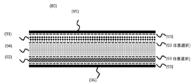
この目的は、少なくとも1つの吸収層を含む流体吸収性コア(80)であって、該層は、少なくとも80重量%の吸水性ポリマー粒子、0~10重量%の接着剤、及び0~10重量%の繊維状材料を含み、吸収層内の吸水性ポリマー粒子は、40s以下のボルテックスを有し、かつ0.79~0.85の真円度及び/又は38g/g~85g/gのCRCを有する吸水性ポリマー粒子Hである、流体吸収性コア(80)によって達成される。本発明によれば、吸水性ポリマー粒子Hは、表面後架橋されていることがさらに好ましい。本発明によれば、流体吸収性コア(80)は、少なくとも2つの吸収層、上層(91)及び底層(92)を含み、少なくとも底層(92)は、吸水性ポリマー粒子Hを含むことが好ましい。 The object is a fluid-absorbent core (80) comprising at least one absorbent layer, the layer comprising at least 80% by weight of water-absorbing polymer particles, 0-10% by weight of an adhesive, and 0-10% by weight of an adhesive. % of fibrous material, the water-absorbent polymer particles in the absorbent layer have a vortex of 40s or less, and have a roundness of 0.79 to 0.85 and/or a CRC of 38g/g to 85g/g. This is achieved by a fluid-absorbing core (80), which is a polymeric particle H. According to the invention, it is further preferred that the water-absorbing polymer particles H are surface post-crosslinked. According to the invention, the fluid-absorbent core (80) comprises at least two absorbent layers, a top layer (91) and a bottom layer (92), preferably at least the bottom layer (92) comprising water-absorbing polymer particles H. .
本発明の別の実施形態によれば、流体吸収性コア(80)内で、不織布材料(94)の少なくとも1つの層は、上層(91)と下層(92)との間に挟まれている。 According to another embodiment of the invention, within the fluid-absorbent core (80), at least one layer of nonwoven material (94) is sandwiched between an upper layer (91) and a lower layer (92). .
本発明の一実施形態では、吸水性ポリマー粒子Hは、38g/g~85g/g、好ましくは40g/g~80g/g、より好ましくは42g/g~75g/gのCRCを有する。 In one embodiment of the invention, the water-absorbing polymer particles H have a CRC of 38 g/g to 85 g/g, preferably 40 g/g to 80 g/g, more preferably 42 g/g to 75 g/g.
本発明によれば、吸水性ポリマー粒子Hは、40s以下のボルテックス、22g/g~60g/gのAUL(21g cm-2)、38g/g~85g/gのCRC、1000s以下のVAUL(τ=21g cm-2)、1000s以下のT20、少なくとも25g/g/sのFSC(1分)、及び1.5g以下のSAP-リウェット(3分)を有する。 According to the present invention, the water-absorbing polymer particles H are vortexed for 40s or less, AUL (21g cm -2 ) of 22g/g to 60g/g, CRC of 38g/g to 85g/g, and VAUL (τ =21 g cm-2), T 20 ≤1000 s, FSC of at least 25 g/g/s (1 min), and SAP-Rewet (3 min) of ≤1.5 g.
本発明の一実施形態によれば、本明細書に開示される方法「注水試験」に従って測定して、本発明の流体吸収性コア(80)の注水時間は、28s以下であり、流体吸収性コア(80)の注水リウェットは、3.5g以下である。 According to one embodiment of the present invention, the fluid-absorbent core (80) of the present invention has a water-filling time of 28 seconds or less, as measured according to the method "Water-filling Test" disclosed herein, and the fluid-absorbing The water rewet of the core (80) is 3.5g or less.
本発明によれば、本記載に開示される方法「ストライクスルー/リウェット」に従って測定して、流体吸収性コア(80)は、少なくとも245mmの液体拡散長、45s以下の総ストライクスルー時間、及び40g以下の総リウェットを有する。 According to the present invention, the fluid-absorbent core (80) has a liquid diffusion length of at least 245 mm, a total strike-through time of 45 s or less, and a total strike-through time of 40 g, as measured according to the method "Strike Through/Rewet" disclosed herein. Has the following total rewet:
本発明の流体吸収性コアは、吸収性物品の一部であってもよい。 The fluid absorbent core of the present invention may be part of an absorbent article.
本発明によれば、本発明の吸収性物品は、
上部液体透過性シート(89)、
下部液体不透過性シート(83)、
本発明の吸収性コアの任意の実施形態による流体吸収性コア(80);
上部液体透過性シート(89)と流体吸収性コア(80)との間の任意選択の取得分配層(70)、
他の任意選択の構成要素
を含む。
According to the invention, the absorbent article of the invention comprises:
Upper liquid permeable sheet (89),
Lower liquid impermeable sheet (83),
a fluid absorbent core (80) according to any embodiment of the absorbent core of the present invention;
an optional acquisition distribution layer (70) between the top liquid permeable sheet (89) and the fluid absorbent core (80);
Contains other optional components.
発明の詳細な説明
定義
本明細書で使用される場合、用語「流体吸収性物品」は、身体から排出された流体を取得及び貯蔵することができる任意の三次元固体材料を指す。好ましい流体吸収性物品は、使用者の身体と接触して着用するように設計された使い捨て流体吸収性物品、例えば、使い捨て流体吸収性パンティーライナー、生理用ナプキン、生理用品、失禁用インサート/パッド、おむつ、トレーニングパンツおむつ、乳房パッド、陰唇間インサート/パッド、又は体液を吸収するのに有用な他の物品である。
DETAILED DESCRIPTION OF THE INVENTION Definitions As used herein, the term "fluid-absorbent article" refers to any three-dimensional solid material capable of capturing and storing fluid expelled from the body. Preferred fluid-absorbent articles are disposable fluid-absorbent articles designed to be worn in contact with the user's body, such as disposable fluid-absorbent panty liners, sanitary napkins, sanitary products, incontinence inserts/pads, Diapers, training pant diapers, breast pads, interlabial inserts/pads, or other articles useful for absorbing body fluids.
本明細書で使用される場合、用語「流体吸収性組成物」は、体液の取得、移動、分配及び貯蔵を含む、流体吸収性物品の流体処理を主に担う流体吸収性物品の構成要素を指す。 As used herein, the term "fluid-absorbent composition" refers to the component of a fluid-absorbent article that is primarily responsible for the fluid handling of the fluid-absorbent article, including the acquisition, transfer, distribution, and storage of body fluids. Point.
本明細書で使用される場合、用語「流体吸収性コア」、「吸収性コア」又は「吸収紙」は、吸水性ポリマー粒子及び任意選択で繊維状材料(最大10重量%の繊維状材料)の少なくとも1つ、好ましくは少なくとも2つの層、例えば上層及び下層; 不織布材料及びティッシュ材料、及び任意選択で接着剤を含む、流体吸収性組成物を指す。流体吸収性コアは、主に、体液の取得、移動、分配及び貯蔵を含む、流体吸収性物品の流体処理を担う。本発明による流体吸収性コアは図2に示される。 As used herein, the term "fluid-absorbent core", "absorbent core" or "absorbent paper" refers to water-absorbing polymer particles and optionally fibrous material (up to 10% by weight fibrous material) refers to a fluid-absorbing composition comprising at least one, preferably at least two layers, such as a top layer and a bottom layer; a nonwoven material and a tissue material, and optionally an adhesive. The fluid-absorbent core is primarily responsible for fluid handling of the fluid-absorbent article, including acquisition, transfer, distribution, and storage of body fluids. A fluid absorbent core according to the invention is shown in FIG.
本明細書で使用される場合、用語「層」は、その主要寸法がその長さ及び幅に沿ったものである流体吸収性組成物を指す。したがって、層は、通常、吸水性ポリマー粒子及び任意選択で繊維状材料を含み、層は、積層物、複合物、異なる材料のいくつかのシート又はウェブの組み合わせを含むことができる。 As used herein, the term "layer" refers to a fluid-absorbent composition whose major dimensions are along its length and width. Thus, the layer usually comprises water-absorbing polymer particles and optionally a fibrous material, and the layer may comprise a laminate, a composite, a combination of several sheets or webs of different materials.
本明細書で使用される場合、用語「x寸法」は、流体吸収性組成物、層、コア又は物品の長さを指し、用語「y寸法」は、幅を指す。一般に、用語「x-y寸法」は、流体吸収性組成物、層、コア又は物品の高さ又は厚さに直交する平面を指す。 As used herein, the term "x-dimension" refers to the length of a fluid-absorbent composition, layer, core or article, and the term "y-dimension" refers to the width. Generally, the term "x-y dimension" refers to a plane perpendicular to the height or thickness of a fluid-absorbent composition, layer, core or article.
本明細書で使用される場合、用語「z寸法」は、流体吸収性組成物、層、コア又は物品の長さ及び幅に直交する寸法を指す。一般に、用語「z寸法」は、流体吸収性組成物、層、コア又は物品の高さを指す。 As used herein, the term "z dimension" refers to the dimension perpendicular to the length and width of a fluid-absorbent composition, layer, core or article. Generally, the term "z dimension" refers to the height of a fluid absorbent composition, layer, core or article.
本明細書で使用される場合、用語「坪量」は、1平方メートルあたりの流体吸収性コア又は任意のティッシュの重量を示し、流体吸収性物品のシャーシを含まない。坪量は、それぞれ、流体吸収性コア又は任意のティッシュの少なくとも2つの異なる領域で決定され、少なくとも2つの結果の平均として取得される。 As used herein, the term "basis weight" refers to the weight of the fluid-absorbent core or any tissue per square meter and does not include the chassis of the fluid-absorbent article. The basis weight is determined in at least two different regions of the fluid-absorbent core or any tissue, respectively, and taken as the average of the at least two results.
さらに、用語「上部」は、流体吸収性物品の着用者により近い流体吸収性組成物を指すことを理解すべきである。一般に、吸収性物品におけるトップシートは、流体吸収性物品の着用者に最も近い組成物であり、本明細書中で以降、「上部液体透過性層」と記載される。反対に、用語「下部」は、流体吸収性物品の着用者から離れている流体吸収性組成物を指す。一般に、バックシートは、流体吸収性物品の着用者から最も離れた構成要素であり、本明細書中で以降、「下部液体不透過性層」と記載される。 Additionally, it should be understood that the term "upper" refers to the fluid absorbent composition closer to the wearer of the fluid absorbent article. Generally, the topsheet in an absorbent article is the composition closest to the wearer of the fluid-absorbent article, hereinafter referred to as the "top liquid permeable layer." Conversely, the term "lower" refers to the fluid-absorbent composition that is remote from the wearer of the fluid-absorbent article. Generally, the backsheet is the component of the fluid-absorbent article furthest from the wearer, and is hereinafter referred to as the "lower liquid-impermeable layer."
本明細書で使用される場合、用語「液体透過性」は、液体、すなわち、体液、例えば、尿、月経分泌物及び/又は膣液が、その厚みを容易に浸透することを可能にする基体、層又は積層物を指す。 As used herein, the term "liquid permeable" refers to a substrate that allows liquids, i.e. body fluids, such as urine, menstrual secretions and/or vaginal fluids, to readily penetrate through its thickness. , refers to layers or laminates.
本明細書で使用される場合、用語「液体不透過性」は、通常の使用条件下で液体接触点で、体液が層の平面に概して垂直な方向に通過することを可能にしない基体、層又は積層物を指す。 As used herein, the term "liquid impermeable" refers to a substrate, layer, or layer that does not allow body fluids to pass through in a direction generally perpendicular to the plane of the layer at the point of liquid contact under conditions of normal use. Or refers to laminates.
本明細書で使用される場合、用語「シャーシ」は、上部液体透過性層及び下部液体不透過性層、吸収性物品についての弾性及び閉鎖システムを含む流体吸収性材料を指す。 As used herein, the term "chassis" refers to a fluid absorbent material that includes an upper liquid permeable layer and a lower liquid impermeable layer, an elastic and closure system for the absorbent article.
本明細書で使用される場合、用語「親水性」は、繊維に付着した水によるこれらの繊維の濡れ性を指す。用語「親水性」は、体液の接触角及び表面張力によって定義される。1964年のAmerican Chemical Societyの刊行物「Contact angle, wettability and adhesion」におけるRobert F. Gouldの定義によると、液体と繊維、特に繊維表面との間の接触角が90゜未満の場合、又は液体が同じ表面上に自発的に広がる傾向がある場合、繊維は親水性であると言われる。 As used herein, the term "hydrophilic" refers to the wettability of these fibers by water attached to them. The term "hydrophilic" is defined by the contact angle and surface tension of body fluids. According to Robert F. Gould's definition in the 1964 American Chemical Society publication "Contact angle, wettability and adhesion," when the contact angle between a liquid and a fiber, especially a fiber surface, is less than 90°, or when the liquid Fibers are said to be hydrophilic if they tend to spread spontaneously over the same surface.
反対に、用語「疎水性」は、90゜を超える接触角を示すか、又は繊維の表面全体にわたって液体が自発的に広がらない繊維を指す。 Conversely, the term "hydrophobic" refers to fibers that exhibit contact angles greater than 90° or that do not allow liquid to spontaneously spread across the surface of the fiber.
本明細書で使用される場合、用語「体液」は、ヒト又は動物の体によって生成及び排出される任意の流体、例えば、尿、月経液、糞、膣分泌物などを指す。 As used herein, the term "body fluid" refers to any fluid produced and excreted by the human or animal body, such as urine, menstrual fluids, feces, vaginal secretions, and the like.
本明細書で使用される場合、用語「通気性のある」は、流体が漏出するのを防止しながら、蒸気が流体吸収性物品から逃げることを可能にする基体、層、フィルム又は積層物を指す。通気性のある基体、層、フィルム又は積層物は、多孔性ポリマーフィルム、不織布積層物(スパンボンド及びメルトブロー層から)、積層物(多孔性ポリマーフィルム及び不織布から)であってもよい。 As used herein, the term "breathable" refers to a substrate, layer, film or laminate that allows vapor to escape from a fluid-absorbent article while preventing fluid from escaping. Point. The breathable substrate, layer, film or laminate may be a porous polymeric film, a nonwoven laminate (from spunbond and meltblown layers), a laminate (from porous polymeric films and nonwovens).
本明細書で使用される場合、用語「長手方向」は、流体吸収性物品のウエストエッジから反対側のウエストエッジまで垂直に走る方向を指す。 As used herein, the term "longitudinal" refers to the direction running perpendicularly from the waist edge to the opposite waist edge of a fluid-absorbent article.
吸水性ポリマー粒子
本発明による吸水性ポリマー粒子は、
a)酸基を有し、少なくとも部分的に中和されていてもよい少なくとも1つのエチレン性不飽和モノマー、
b)1つ以上の架橋剤、
c)少なくとも1つの開始剤、
d)水
を含むモノマー溶液を、周囲の加熱された気相中で重合することによって吸水性ポリマー粒子を形成するステップ、吸水性ポリマー粒子を少なくとも1つの表面後架橋剤でコーティングするステップ、及びコーティングされた吸水性ポリマー粒子を熱表面後架橋するステップを含む方法によって調製される。
Water-absorbing polymer particles The water-absorbing polymer particles according to the present invention are
a) at least one ethylenically unsaturated monomer having acid groups and which may be at least partially neutralized;
b) one or more crosslinkers;
c) at least one initiator;
d) forming water-absorbing polymer particles by polymerizing a monomer solution comprising water in a surrounding heated gas phase, coating the water-absorbing polymer particles with at least one surface post-crosslinking agent; and coating. The method includes thermal surface post-crosslinking of the water-absorbing polymer particles.
吸水性ポリマー粒子は、典型的には、水に不溶性であるが、膨潤性である。 Water-absorbing polymer particles are typically insoluble in water, but swellable.
モノマーa)は好ましくは水溶性であり、すなわち、23℃での水への溶解度は、典型的には少なくとも1g/100gの水、好ましくは少なくとも5g/100gの水、より好ましくは少なくとも25g/100gの水、最も好ましくは少なくとも35g/100gの水である。 Monomer a) is preferably water soluble, i.e. its solubility in water at 23°C is typically at least 1 g/100 g water, preferably at least 5 g/100 g water, more preferably at least 25 g/100 g water. of water, most preferably at least 35g/100g of water.
適切なモノマーa)は、例えば、エチレン性不飽和カルボン酸、例えば、アクリル酸、メタクリル酸、マレイン酸、及びイタコン酸である。特に好ましいモノマーは、アクリル酸及びメタクリル酸である。0~2重量%、より好ましくは0.0001~1重量%、最も好ましくは0.0002~0.5重量%のジアクリル酸の濃度を有するアクリル酸が非常に特に好ましい。 Suitable monomers a) are, for example, ethylenically unsaturated carboxylic acids such as acrylic acid, methacrylic acid, maleic acid and itaconic acid. Particularly preferred monomers are acrylic acid and methacrylic acid. Very particular preference is given to acrylic acid having a concentration of diacrylic acid of 0 to 2% by weight, more preferably 0.0001 to 1% by weight, most preferably 0.0002 to 0.5% by weight.
モノマーa)の酸基は、典型的には部分的に中和され(好ましくは25~85mol%の程度まで、優先的には50~80mol%、より好ましくは60~75mol%の程度まで)、このために通例の中和剤、好ましくはアルカリ金属水酸化物、アルカリ金属酸化物、アルカリ金属炭酸塩又はアルカリ金属炭酸水素塩、及びそれらの混合物を使用することができる。 The acid groups of monomer a) are typically partially neutralized (preferably to the extent of 25 to 85 mol%, preferentially to the extent of 50 to 80 mol%, more preferably to the extent of 60 to 75 mol%); For this purpose, the customary neutralizing agents can be used, preferably alkali metal hydroxides, alkali metal oxides, alkali metal carbonates or alkali metal bicarbonates, and mixtures thereof.
アクリル酸は、典型的には、貯蔵安定剤として、重合阻害剤、好ましくはヒドロキノンモノエーテルを含む。 Acrylic acid typically contains a polymerization inhibitor, preferably hydroquinone monoether, as a storage stabilizer.
適切な架橋剤b)は、架橋に適した少なくとも2つの基を有する化合物である。そのような基は、例えば、フリーラジカル機構によってポリマー鎖に重合することができるエチレン性不飽和基、及びモノマーa)の酸基と共有結合を形成することができる官能基である。さらに、モノマーa)の少なくとも2つの酸基と配位結合を形成することができる多価金属イオンもまた、適切な架橋剤b)である。架橋剤b)は、好ましくは、フリーラジカル機構によってポリマーネットワークに重合することができる少なくとも2つのフリーラジカル重合性基を有する化合物である。適切な架橋剤b)は、例えば、エチレングリコールジメタクリレート、ジエチレングリコールジアクリレート、ポリエチレングリコールジアクリレート、アリルメタクリレート、トリメチロールプロパントリアクリレート、トリアリルアミン、テトラアリルアンモニウムクロリド、テトラアリルオキシエタン(EP 0 530 438 A1に記載)、ジアクリレート及びトリアクリレート(EP 0 547 847 A1、EP 0 559 476 A1、EP 0 632 068 A1、WO 93/21237 A1、WO 2003/104299 A1、WO 2003/104300 A1、WO 2003/104301 A1及びDE 103 31 450 A1に記載)、アクリレート基と同様にさらなるエチレン性不飽和基を含む混合アクリレート(DE 103 314 56 A1及びDE 103 55 401 A1に記載)、又は架橋剤混合物(例えば、DE 195 43 368 A1、DE 196 46 484 A1、WO 90/15830 A1及びWO 2002/32962 A2に記載)である。 Suitable crosslinkers b) are compounds having at least two groups suitable for crosslinking. Such groups are, for example, ethylenically unsaturated groups that can be polymerized into polymer chains by free radical mechanisms, and functional groups that can form covalent bonds with the acid groups of monomer a). Furthermore, polyvalent metal ions capable of forming coordinate bonds with at least two acid groups of monomer a) are also suitable crosslinkers b). Crosslinking agent b) is preferably a compound having at least two free-radically polymerizable groups that can be polymerized into a polymer network by a free-radical mechanism. Suitable crosslinkers b) are, for example, ethylene glycol dimethacrylate, diethylene glycol diacrylate, polyethylene glycol diacrylate, allyl methacrylate, trimethylolpropane triacrylate, triallylamine, tetraallylammonium chloride, tetraallyloxyethane (EP 0 530 438 A1), diacrylates and triacrylates (EP 0 547 847 A1, EP 0 559 476 A1, EP 0 632 068 A1, WO 93/21237 A1, WO 2003/104299 A1, WO 2003/104300 A1, WO 2003/ 104301 A1 and DE 103 31 450 A1), mixed acrylates containing further ethylenically unsaturated groups as well as acrylate groups (as described in DE 103 314 56 A1 and DE 103 55 401 A1), or crosslinking agent mixtures (e.g. DE 195 43 368 A1, DE 196 46 484 A1, WO 90/15830 A1 and WO 2002/32962 A2).
架橋剤b)の量は、それぞれの場合にモノマーa)に基づいて、好ましくは0.0001~0.6重量%、より好ましくは0.0015~0.2重量%、最も好ましくは0.01~0.06重量%である。架橋剤b)の量を増やすと、遠心分離機保持能力(CRC)が減少し、21.0g/cm2の圧力下での吸収(AUL)が最大を経験する。 The amount of crosslinker b) is preferably from 0.0001 to 0.6% by weight, more preferably from 0.0015 to 0.2% by weight, most preferably from 0.01 to 0.06% by weight, in each case based on monomer a). Increasing the amount of crosslinker b) decreases the centrifuge retention capacity (CRC) and experiences a maximum absorption under pressure (AUL) of 21.0 g/ cm2 .
使用される開始剤c)は、重合条件下でフリーラジカルに崩壊する全ての化合物、例えば、過酸化物、ヒドロペルオキシド、過酸化水素、過硫酸塩、アゾ化合物及びレドックス開始剤であってもよい。水溶性開始剤の使用が好ましい。いくつかの場合に、様々な開始剤の混合物、例えば、過酸化水素とペルオキソ二硫酸ナトリウム又はカリウムとの混合物を使用することが有利である。過酸化水素とペルオキソ二硫酸ナトリウムとの混合物は、任意の比で使用することができる。開始剤c)は、水溶性であるべきである。 The initiators c) used may be all compounds which decompose to free radicals under the polymerization conditions, such as peroxides, hydroperoxides, hydrogen peroxide, persulfates, azo compounds and redox initiators. . Preference is given to using water-soluble initiators. In some cases it is advantageous to use mixtures of different initiators, for example mixtures of hydrogen peroxide and sodium or potassium peroxodisulfate. Mixtures of hydrogen peroxide and sodium peroxodisulfate can be used in any ratio. Initiator c) should be water-soluble.
特に好ましい開始剤c)は、アゾ開始剤、例えば、2,2'-アゾビス[2-(2-イミダゾリン-2-イル)プロパン]ジヒドロクロリド、2,2'-アゾビス[2-(5-メチル-2-イミダゾリン-2-イル)プロパン]ジヒドロクロリド、2,2'-アゾビス(2-アミジノプロパン)ジヒドロクロリド、4,4'-アゾビス(4-シアノペンタン酸)、4,4'-アゾビス(4-シアノペンタン酸)ナトリウム塩、2,2'-アゾビス[2-メチル-N-(2-ヒドロキシエチル)-プロピオンアミド及び2,2'-アゾビス[2-(5-メチル-2-イミダゾリン-2-イル)プロパン]ジヒドロクロリド、及び光開始剤、例えば、2-ヒドロキシ-2-メチルプロピオフェノン及び1-[4-(2-ヒドロキシエトキシ)フェニル]-2-ヒドロキシ-2-メチル-1-プロパン-1-オン、レドックス開始剤、例えば、過硫酸ナトリウム/ヒドロキシメチルスルフィン酸、ペルオキソ二硫酸アンモニウム/ヒドロキシメチルスルフィン酸、過酸化水素/ヒドロキシメチルスルフィン酸、過硫酸ナトリウム/アスコルビン酸、ペルオキソ二硫酸アンモニウム/アスコルビン酸及び過酸化水素/アスコルビン酸、光開始剤、例えば、1-[4-(2-ヒドロキシエトキシ)フェニル]-2-ヒドロキシ-2-メチル-1-プロパン-1-オン、及びそれらの混合物である。しかし、使用される還元成分は、好ましくは、2-ヒドロキシ-2-スルフィナト酢酸のナトリウム塩、2-ヒドロキシ-2-スルホナト酢酸の二ナトリウム塩及び重亜硫酸ナトリウムの混合物である。このような混合物は、Bruggolite(登録商標)FF6及びBruggolite(登録商標)FF7(Bruggemann Chemicals; Heilbronn; Germany)として入手可能である。当然のことながら、本発明の範囲内で、2-ヒドロキシ-2-スルフィナト酢酸及び2-ヒドロキシ-2-スルホナト酢酸(後者は商品名Blancolen(登録商標)HP(Bruggemann Chemicals; Heilbronn; Germany)でナトリウム塩として入手可能である)の精製された塩又は酸を使用することも可能である。 Particularly preferred initiators c) are azo initiators, for example 2,2'-azobis[2-(2-imidazolin-2-yl)propane]dihydrochloride, 2,2'-azobis[2-(5-methyl -2-imidazolin-2-yl)propane] dihydrochloride, 2,2'-azobis(2-amidinopropane) dihydrochloride, 4,4'-azobis(4-cyanopentanoic acid), 4,4'-azobis( 4-cyanopentanoic acid) sodium salt, 2,2'-azobis[2-methyl-N-(2-hydroxyethyl)-propionamide and 2,2'-azobis[2-(5-methyl-2-imidazoline-) 2-yl)propane] dihydrochloride, and photoinitiators such as 2-hydroxy-2-methylpropiophenone and 1-[4-(2-hydroxyethoxy)phenyl]-2-hydroxy-2-methyl-1 -Propan-1-one, redox initiators such as sodium persulfate/hydroxymethylsulfinic acid, ammonium peroxodisulfate/hydroxymethylsulfinic acid, hydrogen peroxide/hydroxymethylsulfinic acid, sodium persulfate/ascorbic acid, ammonium peroxodisulfate /Ascorbic acid and hydrogen peroxide/Ascorbic acid, photoinitiators such as 1-[4-(2-hydroxyethoxy)phenyl]-2-hydroxy-2-methyl-1-propan-1-one, and their It is a mixture. However, the reducing component used is preferably a mixture of the sodium salt of 2-hydroxy-2-sulfinatoacetic acid, the disodium salt of 2-hydroxy-2-sulfonatoacetic acid and sodium bisulfite. Such mixtures are available as Bruggolite® FF6 and Bruggolite® FF7 (Bruggemann Chemicals; Heilbronn; Germany). It will be understood that within the scope of the invention 2-hydroxy-2-sulfinatoacetic acid and 2-hydroxy-2-sulfonatoacetic acid (the latter with the trade name Blancolen® HP (Bruggemann Chemicals; Heilbronn; Germany)) It is also possible to use purified salts or acids (available as salts).
本発明の好ましい実施形態では、少なくとも1つの過硫酸塩c1)と少なくとも1つのアゾ開始剤c2)との組み合わせが、開始剤c)として使用される。 In a preferred embodiment of the invention, a combination of at least one persulfate c1) and at least one azo initiator c2) is used as initiator c).
使用されるべき過硫酸塩c1)の量は、それぞれモノマーa)に基づいて、好ましくは0.01~0.25重量%、より好ましくは0.05~0.2重量%、最も好ましくは0.1~0.15重量%である。過硫酸塩の量が少なすぎると、十分な低レベルの残留モノマーを達成することができない。過硫酸塩の量が多すぎると、吸水性ポリマー粒子は、十分な白色度を有さず、加熱すると分解を受ける可能性がある。 The amount of persulfate c1) to be used is preferably from 0.01 to 0.25% by weight, more preferably from 0.05 to 0.2% by weight, most preferably from 0.1 to 0.15% by weight, in each case based on monomer a). If the amount of persulfate is too low, a sufficiently low level of residual monomer cannot be achieved. If the amount of persulfate is too high, the water-absorbing polymer particles will not have sufficient whiteness and may undergo decomposition when heated.
使用されるべきアゾ開始剤c2)の量は、それぞれモノマーa)に基づいて、好ましくは0.1~2重量%、より好ましくは0.15~1重量%、最も好ましくは0.2~0.5重量%である。アゾ開始剤の量が少なすぎると、高い遠心分離機保持能力(CRC)を達成することができない。アゾ開始剤の量が多すぎると、プロセスが高額になる。 The amount of azo initiator c2) to be used is preferably from 0.1 to 2% by weight, more preferably from 0.15 to 1% by weight, most preferably from 0.2 to 0.5% by weight, in each case based on monomer a). If the amount of azo initiator is too low, high centrifuge retention capacity (CRC) cannot be achieved. Too much azo initiator will make the process expensive.
本発明のより好ましい実施形態では、少なくとも1つの過硫酸塩c1)、還元成分、及び少なくとも1つのアゾ開始剤c2)の組み合わせが、開始剤c)として使用される。 In a more preferred embodiment of the invention, a combination of at least one persulfate c1), a reducing component and at least one azo initiator c2 ) is used as initiator c).
使用されるべき還元成分の量は、それぞれモノマーa)に基づいて、好ましくは0.0002~1重量%、より好ましくは0.0001~0.8重量%、より好ましくは0.0005~0.6重量%、最も好ましくは0.001~0.4重量%である。 The amount of reducing component to be used is preferably 0.0002 to 1% by weight, more preferably 0.0001 to 0.8% by weight, more preferably 0.0005 to 0.6% by weight, most preferably 0.001 to 0.4% by weight, in each case based on monomer a). Weight%.
最適な作用のために、好ましい重合阻害剤は、溶存酸素を必要とする。したがって、モノマー溶液は、不活性化によって、すなわち不活性ガス、好ましくは窒素とともに流れることによって、重合前に溶存酸素を除去することができる。還元剤を添加することによって、溶存酸素の濃度を低減することも可能である。モノマー溶液の酸素含有量は、好ましくは、重合前に1重量ppm未満、より好ましくは0.5重量ppm未満に低下される。 For optimal action, preferred polymerization inhibitors require dissolved oxygen. The monomer solution can thus be freed of dissolved oxygen before polymerization by inertization, ie by flowing with an inert gas, preferably nitrogen. It is also possible to reduce the concentration of dissolved oxygen by adding a reducing agent. The oxygen content of the monomer solution is preferably reduced to less than 1 ppm by weight, more preferably less than 0.5 ppm by weight, before polymerization.
モノマー溶液の含水量は、好ましくは65重量%未満、優先的には62重量%未満、より好ましくは60重量%未満、最も好ましくは58重量%未満である。 The water content of the monomer solution is preferably less than 65% by weight, preferentially less than 62% by weight, more preferably less than 60% by weight and most preferably less than 58% by weight.
モノマー溶液は、20℃で、好ましくは0.002~0.02Pa・s、より好ましくは0.004~0.015Pa・s、最も好ましくは0.005~0.01Pa・sの力学的粘度(dynamic viscosity)を有する。液滴生成における平均液滴直径は、力学的粘度の上昇とともに上昇する。 The monomer solution has a dynamic viscosity at 20° C. of preferably 0.002 to 0.02 Pa·s, more preferably 0.004 to 0.015 Pa·s, most preferably 0.005 to 0.01 Pa·s. The average droplet diameter during droplet generation increases with increasing mechanical viscosity.
モノマー溶液は、20℃で、好ましくは1~1.3g/cm3、より好ましくは1.05~1.25g/cm3、最も好ましくは1.1~1.2g/cm3の密度を有する。 The monomer solution preferably has a density at 20° C. of 1 to 1.3 g/cm 3 , more preferably 1.05 to 1.25 g/cm 3 and most preferably 1.1 to 1.2 g/cm 3 .
モノマー溶液は、20℃で、0.02~0.06N/m、より好ましくは0.03~0.05N/m、最も好ましくは0.035~0.045N/mの表面張力を有する。液滴生成における平均液滴直径は、表面張力の上昇とともに上昇する。 The monomer solution has a surface tension at 20° C. of 0.02 to 0.06 N/m, more preferably 0.03 to 0.05 N/m, most preferably 0.035 to 0.045 N/m. The average droplet diameter in droplet production increases with increasing surface tension.
色安定性のための添加剤及び残留モノマーを低減するための添加剤もまた、モノマー溶液に添加することができる。モノマー溶液中の色安定性のための添加剤の好ましい量は、それぞれモノマーa)に基づいて、少なくとも0.001%、好ましくは0.005重量%~5重量%、より好ましくは0.01~3重量%、最も好ましくは0.02~2重量%である。 Additives for color stability and for reducing residual monomer can also be added to the monomer solution. Preferred amounts of additives for color stability in the monomer solution are at least 0.001%, preferably from 0.005% to 5%, more preferably from 0.01 to 3%, most preferably from 0.01% to 3% by weight, each based on monomer a). is 0.02 to 2% by weight.
吸水性ポリマー粒子は、例えば、WO 2008/040715 A2、WO 2008/052971 A1、WO 2008/069639 A1及びWO 2008/086976 A1に記載されるシステムを使用して、周囲の加熱された気相中で、又は例えば、WO 2008/068208 A1及びWO 2008/084031 A1に記載されるシステムを使用して、周囲の疎水性溶媒中で、モノマーの液滴を重合することによって生成される。 The water-absorbing polymer particles are grown in an ambient heated gas phase using, for example, the systems described in WO 2008/040715 A2, WO 2008/052971 A1, WO 2008/069639 A1 and WO 2008/086976 A1. , or produced by polymerizing droplets of monomer in a surrounding hydrophobic solvent using, for example, the systems described in WO 2008/068208 A1 and WO 2008/084031 A1.
液滴は、好ましくは、液滴プレートによって生成される。液滴プレートは、多数の穴を有するプレートであり、液体は上部から穴に入る。液滴プレート又は液体は振動させることができ、これにより、液滴プレートの下側の各穴に理想的には単分散の液滴鎖が生成される。好ましい実施形態では、液滴プレートを揺り動かさない。 The droplets are preferably generated by a droplet plate. A droplet plate is a plate with a large number of holes, and the liquid enters the holes from the top. The droplet plate or liquid can be vibrated, which creates an ideally monodisperse chain of droplets in each hole on the underside of the droplet plate. In a preferred embodiment, the droplet plate is not agitated.
穴の数及びサイズは、所望の容量及び液滴サイズに従って選択される。液滴の直径は、典型的には、穴の直径の1.9倍である。ここで重要なのは、液滴化されるべき液体が、穴をあまり速く通過せず、穴にわたる圧力降下が大きすぎないことである。そうでなければ、液体は液滴化されず、むしろ、高い運動エネルギーのために、液体ジェットはばらばらになる(噴霧される)。本発明の好ましい実施形態では、圧力降下は、4~5barである。穴1つあたりの処理量及び穴の直径に基づくレイノルズ数は、好ましくは2000未満、優先的には1600未満、より好ましくは1400未満、最も好ましくは1200未満である。 The number and size of holes are selected according to the desired volume and droplet size. The droplet diameter is typically 1.9 times the hole diameter. It is important here that the liquid to be dropletized does not pass through the hole too quickly and that the pressure drop across the hole is not too large. Otherwise, the liquid will not be dropletized, but rather the liquid jet will break up (atomize) due to the high kinetic energy. In a preferred embodiment of the invention the pressure drop is between 4 and 5 bar. The Reynolds number based on throughput per hole and hole diameter is preferably less than 2000, preferentially less than 1600, more preferably less than 1400 and most preferably less than 1200.
液滴プレートの下側は、水に関して、少なくとも部分的に、好ましくは少なくとも60゜、より好ましくは少なくとも75゜、最も好ましくは少なくとも90゜の接触角を有する。 The underside of the droplet plate has a contact angle with respect to water, at least partially, preferably at least 60°, more preferably at least 75°, most preferably at least 90°.
接触角は、表面に関する液体、特に水の濡れ挙動の尺度であり、例えば、ASTM D 5725に従って、従来の方法を使用して決定することができる。低い接触角は、良好な濡れ性を示し、高い接触角は、不十分な濡れ性を示す。 Contact angle is a measure of the wetting behavior of a liquid, especially water, with respect to a surface and can be determined using conventional methods, eg, according to ASTM D 5725. A low contact angle indicates good wetting, and a high contact angle indicates poor wetting.
液滴プレートは、水に関してより低い接触角を有する材料、例えば、ドイツ建築材料コード番号1.4571を有する鋼からなること、及び水に関してより大きな接触角を有する材料でコーティングされることも可能である。 The droplet plate can also be made of a material with a lower contact angle with respect to water, for example steel with German Building Materials Code No. 1.4571, and coated with a material with a higher contact angle with respect to water.
狭い液滴サイズ分布の単分散液滴の生成をもたらすのは、液滴プレートの不十分な濡れ性である。 It is the insufficient wettability of the droplet plate that results in the production of monodisperse droplets with narrow droplet size distribution.
液滴プレートは、好ましくは少なくとも5個、より好ましくは少なくとも25個、最も好ましくは少なくとも50個、好ましくは最大2000個、より好ましくは最大1500個の穴、最も好ましくは最大1000個の穴を有する。穴の直径は、所望の液滴サイズに調整される。 The droplet plate preferably has at least 5 holes, more preferably at least 25 holes, most preferably at least 50 holes, preferably at most 2000 holes, more preferably at most 1500 holes, most preferably at most 1000 holes. . The hole diameter is adjusted to the desired droplet size.
穴の間隔は、通常、2~50mm、好ましくは3~40mm、より好ましくは4~30mm、最も好ましくは5~25mm、優先的には4~9mmである。穴の間隔がより狭いと、重合する液滴の凝集を引き起こす可能性がある。 The hole spacing is usually 2 to 50 mm, preferably 3 to 40 mm, more preferably 4 to 30 mm, most preferably 5 to 25 mm, preferentially 4 to 9 mm. Closer hole spacing can cause agglomeration of polymerizing droplets.
穴サイズ領域の直径は、1900~22300μm2、より好ましくは7800~20100μm2、最も好ましくは11300~17700μm2である。50~170μm、より好ましくは100~160μm、最も好ましくは120~150μmの穴サイズを有する円形穴が好ましい。 The diameter of the hole size region is between 1900 and 22300 μm 2 , more preferably between 7800 and 20100 μm 2 and most preferably between 11300 and 17700 μm 2 . Circular holes with a hole size of 50-170 μm, more preferably 100-160 μm, most preferably 120-150 μm are preferred.
平均粒子直径を最適化するために、異なる穴直径を有する液滴プレートを使用することができる。1つのプレート上の異なる穴によって、又は各プレートが異なる穴直径を有する異なるプレートを使用することによって、バリエーションを行うことができる。平均粒径分布は、単峰性、二峰性、又は多峰性であり得る。最も好ましくは、それは単峰性又は二峰性である。 Droplet plates with different hole diameters can be used to optimize the average particle diameter. Variations can be made by different holes on one plate or by using different plates, each plate having a different hole diameter. The average particle size distribution can be unimodal, bimodal, or multimodal. Most preferably it is unimodal or bimodal.
穴を通過する際のモノマー溶液の温度は、好ましくは5~80℃、より好ましくは10~70℃、最も好ましくは30~60℃である。 The temperature of the monomer solution as it passes through the holes is preferably 5-80°C, more preferably 10-70°C, and most preferably 30-60°C.
キャリアガスは、反応ゾーンを流れる。モノマー溶液の自由落下する液滴に並流で、すなわち上から下に向かって反応ゾーンを通って、キャリアガスを導いてもよい。1回の通過後、ガスは、好ましくは、少なくとも部分的に、好ましくは少なくとも50%の程度まで、より好ましくは少なくとも75%の程度まで、サイクルガスとして反応ゾーンに再循環される。典型的には、キャリアガスの一部は、各通過の後に、好ましくは最大10%、より好ましくは最大3%、最も好ましくは最大1%排出される。 A carrier gas flows through the reaction zone. A carrier gas may be conducted cocurrently with the free-falling droplets of monomer solution, ie from top to bottom through the reaction zone. After one pass, the gas is preferably at least partially recycled to the reaction zone as cycle gas, preferably to an extent of at least 50%, more preferably to an extent of at least 75%. Typically, a portion of the carrier gas is vented after each pass, preferably at most 10%, more preferably at most 3%, and most preferably at most 1%.
キャリアガスの酸素含有量は、好ましくは0.1~25体積%、より好ましくは1~10体積%、最も好ましくは2~7重量%である。本発明の範囲において、酸素を含まないキャリアガスを使用することも可能である。 The oxygen content of the carrier gas is preferably 0.1-25% by volume, more preferably 1-10% by volume, most preferably 2-7% by weight. Within the scope of the invention it is also possible to use oxygen-free carrier gases.
酸素と同様に、キャリアガスは、好ましくは窒素を含む。ガスの窒素含有量は、好ましくは少なくとも80体積%、より好ましくは少なくとも90体積%、最も好ましくは少なくとも95体積%である。他の可能なキャリアガスは、二酸化炭素、アルゴン、キセノン、クリプトン、ネオン、ヘリウム、六フッ化硫黄から選択してもよい。キャリアガスの任意の混合物を使用してもよい。キャリアガスとして空気を使用することも可能である。キャリアガスには、水及び/又はアクリル酸蒸気が負荷されてもよい。 As well as oxygen, the carrier gas preferably includes nitrogen. The nitrogen content of the gas is preferably at least 80% by volume, more preferably at least 90% by volume, most preferably at least 95% by volume. Other possible carrier gases may be selected from carbon dioxide, argon, xenon, krypton, neon, helium, sulfur hexafluoride. Any mixture of carrier gases may be used. It is also possible to use air as carrier gas. The carrier gas may be loaded with water and/or acrylic acid vapor.
ガス速度は、好ましくは、反応ゾーン(5)における流れが方向付けられるように、例えば、一般的な流れ方向と反対の対流が存在しないように調整され、好ましくは0.1~2.5m/s、より好ましくは0.3~1.5m/s、さらにより好ましくは0.5~1.2m/s、最も好ましくは0.7~0.9m/sである。 The gas velocity is preferably adjusted such that the flow in the reaction zone (5) is directed, for example so that there is no convection opposite to the general direction of flow, preferably from 0.1 to 2.5 m/s, and more. Preferably 0.3 to 1.5 m/s, even more preferably 0.5 to 1.2 m/s, most preferably 0.7 to 0.9 m/s.
ガス入口温度、すなわち、ガスが反応ゾーンに入る温度は、好ましくは160~200℃、より好ましくは165~195℃、さらにより好ましくは170~190℃、最も好ましくは175~185℃である。 The gas inlet temperature, ie the temperature at which the gas enters the reaction zone, is preferably 160-200°C, more preferably 165-195°C, even more preferably 170-190°C, most preferably 175-185°C.
反応ゾーンに入るガスの蒸気含有量は、好ましくは乾燥ガス1kgあたり0.01~0.15kg、より好ましくは乾燥ガス1kgあたり0.02~0.12kg、最も好ましくは乾燥ガス1kgあたり0.03~0.10kgである。 The vapor content of the gas entering the reaction zone is preferably between 0.01 and 0.15 kg per kg of dry gas, more preferably between 0.02 and 0.12 kg per kg of dry gas, and most preferably between 0.03 and 0.10 kg per kg of dry gas.
ガス入口温度は、ガス出口温度、すなわち、ガスが反応ゾーンを出る温度が、150℃未満、好ましくは90~140℃、より好ましくは100~130℃、さらにより好ましくは105~125℃、最も好ましくは110~120℃であるように制御される。 The gas inlet temperature is such that the gas outlet temperature, i.e. the temperature at which the gas leaves the reaction zone, is less than 150°C, preferably 90-140°C, more preferably 100-130°C, even more preferably 105-125°C, most preferably is controlled to be between 110 and 120°C.
最も好ましくは、ガス入口温度は、175~185℃であり、ガスが反応ゾーンを出る温度は、好ましくは110~120℃である。 Most preferably, the gas inlet temperature is 175-185°C and the temperature at which the gas exits the reaction zone is preferably 110-120°C.
吸水性ポリマー粒子は、3つのカテゴリーに分けることができる: タイプ1の吸水性ポリマー粒子は、1つの空洞を有する粒子であり、タイプ2の吸水性ポリマー粒子は、2つ以上の空洞を有する粒子であり、タイプ3の吸水性ポリマー粒子は、目に見える空洞のない固体粒子である。
Water-absorbing polymer particles can be divided into three categories:
吸水性ポリマー粒子の形態は、重合中の反応条件によって制御することができる。1つの空洞を有する大量の粒子を有する吸水性ポリマー粒子(タイプ1)は、低いガス速度及び高いガス出口温度を使用することによって調製することができる。2つ以上の空洞を有する大量の粒子を有する吸水性ポリマー粒子(タイプ2)は、高いガス速度及び低いガス出口温度を使用することによって調製することができる。 The morphology of the water-absorbing polymer particles can be controlled by the reaction conditions during polymerization. Water-absorbing polymer particles with a large number of particles with one cavity (type 1) can be prepared by using low gas velocities and high gas exit temperatures. Water-absorbing polymer particles (type 2) with a large amount of particles with two or more cavities can be prepared by using high gas velocities and low gas exit temperatures.
2つ以上の空洞を有する吸水性ポリマー粒子(タイプ2)は、改善された機械的安定性を示す。 Water-absorbing polymer particles with two or more cavities (type 2) exhibit improved mechanical stability.
反応は、高圧下又は減圧下、好ましくは周囲圧力より1~100mbar下、より好ましくは周囲圧力より1.5~50mbar下、最も好ましくは周囲圧力より2~10mbar下で実施することができる。 The reaction may be carried out under elevated or reduced pressure, preferably between 1 and 100 mbar below ambient pressure, more preferably between 1.5 and 50 mbar below ambient pressure, and most preferably between 2 and 10 mbar below ambient pressure.
反応オフガス、すなわち、反応ゾーンを出るガスは、熱交換器で冷却してもよい。これにより、水及び未変換モノマーa)が凝縮する。次いで、反応オフガスを少なくとも部分的に再加熱し、サイクルガスとして反応ゾーンに再循環させることができる。反応オフガスの一部を排出して、新鮮なガスによって置き換えることができ、その場合、反応オフガス中に存在する水及び未変換モノマーa)を除去して再循環させることができる。 The reaction off-gas, ie the gas leaving the reaction zone, may be cooled in a heat exchanger. This condenses water and unconverted monomer a). The reaction off-gas can then be at least partially reheated and recycled to the reaction zone as cycle gas. A portion of the reaction off-gas can be discharged and replaced by fresh gas, in which case the water and unconverted monomer a) present in the reaction off-gas can be removed and recycled.
熱的に統合されたシステムが特に好ましく、すなわち、オフガスの冷却における廃熱の一部は、サイクルガスを加熱するために使用される。 A thermally integrated system is particularly preferred, ie part of the waste heat in cooling the off-gas is used to heat the cycle gas.
反応器はトレース加熱することができる。この場合、トレース加熱は、壁の温度が内部表面温度より少なくとも5℃高くなり、表面での凝縮が確実に防止されるように調整される。 The reactor can be trace heated. In this case, the trace heating is adjusted to ensure that the wall temperature is at least 5 °C higher than the internal surface temperature and that condensation on the surfaces is prevented.
形成された吸水性ポリマー粒子は、流動床で熱後処理される。本発明の好ましい実施形態では、内部流動床が使用される。内部流動床は、液滴化重合の生成物が、反応ゾーンの下の流動床に蓄積されることを意味する。 The water-absorbing polymer particles formed are thermally post-treated in a fluidized bed. In a preferred embodiment of the invention, an internal fluidized bed is used. Internal fluidized bed means that the products of droplet polymerization are accumulated in a fluidized bed below the reaction zone.
残留モノマーは、熱後処理中に除去することができる。ここで重要なのは、吸水性ポリマー粒子が乾燥しすぎないことである。過度に乾燥した粒子の場合、残留モノマーはごくわずかしか減少しない。含水量が高すぎると、吸水性ポリマー粒子の固化傾向が高まる。 Residual monomers can be removed during thermal post-treatment. What is important here is that the water-absorbing polymer particles do not become too dry. In the case of overly dried particles, the residual monomer is only slightly reduced. If the water content is too high, the tendency of the water-absorbing polymer particles to solidify increases.
流動化状態では、ポリマー粒子の運動エネルギーは、ポリマー粒子間の凝集又は接着ポテンシャルよりも大きい。 In the fluidized state, the kinetic energy of the polymer particles is greater than the cohesive or adhesive potential between the polymer particles.
流動化状態は、流動床によって達成することができる。この床では、吸水性ポリマー粒子に向かって上向きの流れがあり、そのため、粒子は流動床を形成する。流動床の高さは、ガス比率及びガス速度によって、すなわち、流動床の圧力降下(ガスの運動エネルギー)によって調整される。 Fluidized conditions can be achieved by a fluidized bed. In this bed there is an upward flow towards the water-absorbing polymer particles, so that the particles form a fluidized bed. The height of the fluidized bed is adjusted by the gas ratio and gas velocity, ie by the pressure drop across the fluidized bed (kinetic energy of the gas).
流動床におけるガス流の速度は、好ましくは0.3~2.5m/s、より好ましくは0.4~2.0m/s、最も好ましくは0.5~1.5m/sである。 The velocity of the gas flow in the fluidized bed is preferably between 0.3 and 2.5 m/s, more preferably between 0.4 and 2.0 m/s, and most preferably between 0.5 and 1.5 m/s.
内部流動床の底部にわたる圧力降下は、好ましくは1~100mbar、より好ましくは3~50mbar、最も好ましくは5~25mbarである。 The pressure drop across the bottom of the internal fluidized bed is preferably between 1 and 100 mbar, more preferably between 3 and 50 mbar, most preferably between 5 and 25 mbar.
熱後処理の終わりの吸水性ポリマー粒子の含水量は、好ましくは1~20重量%、より好ましくは2~15重量%、さらにより好ましくは3~12重量%、最も好ましくは6~9重量%である。 The water content of the water-absorbing polymer particles at the end of the thermal post-treatment is preferably between 1 and 20% by weight, more preferably between 2 and 15% by weight, even more preferably between 3 and 12% by weight, most preferably between 6 and 9% by weight. It is.
熱後処理中の吸水性ポリマー粒子の温度は、20~140℃、好ましくは40~110℃、より好ましくは50~105℃、最も好ましくは60~100℃である。 The temperature of the water-absorbing polymer particles during thermal post-treatment is 20-140°C, preferably 40-110°C, more preferably 50-105°C, most preferably 60-100°C.
内部流動床における平均滞留時間は、10~300分、好ましくは60~270分、より好ましくは40~250分、最も好ましくは120~240分である。 The average residence time in the internal fluidized bed is between 10 and 300 minutes, preferably between 60 and 270 minutes, more preferably between 40 and 250 minutes, most preferably between 120 and 240 minutes.
本発明の一実施形態では、熱後処理は、完全に又は少なくとも部分的に外部流動床で行われる。外部流動床の操作条件は、上記のように内部流動床の範囲内である。 In one embodiment of the invention, the thermal post-treatment is carried out completely or at least partially in an external fluidized bed. The operating conditions for the external fluidized bed are within the range of the internal fluidized bed as described above.
残留モノマーのレベルは、WO 2011/117215 A1に記載されるように、回転混合ツールを有するミキサーでの追加の熱後処理によってさらに低減することができる。 The level of residual monomers can be further reduced by additional thermal post-treatment in a mixer with a rotating mixing tool, as described in WO 2011/117215 A1.
吸水性ポリマー粒子の形態は、熱後処理中の反応条件によって制御することもできる。1つの空洞を有する大量の粒子を有する吸水性ポリマー粒子(タイプ1)は、高い生成物温度及び短い滞留時間を使用することによって調製することができる。2つ以上の空洞を有する大量の粒子を有する吸水性ポリマー粒子(タイプ2)は、低い生成物温度及び長い滞留時間を使用することによって調製することができる。 The morphology of the water-absorbing polymer particles can also be controlled by reaction conditions during thermal post-treatment. Water-absorbing polymer particles with a large number of particles with one cavity (type 1) can be prepared by using high product temperatures and short residence times. Water-absorbing polymer particles (type 2) with a large amount of particles with two or more cavities can be prepared by using low product temperatures and long residence times.
特性をさらに改善するために、ポリマー粒子は、その後、熱的に表面後架橋してもよい。 To further improve the properties, the polymer particles may then be thermally surface post-crosslinked.
表面後架橋剤は、ポリマー粒子のカルボキシレート基と少なくとも2つの共有結合を形成することができる基を含む化合物である。適切な化合物は、例えば、多官能性アミン、多官能性アミドアミン、多官能性エポキシド(EP 0 083 022 A2、EP 0 543 303 A1及びEP 0 937 736 A2に記載)、二官能性又は多官能性アルコール(DE 33 14 019 A1、DE 35 23 617 A1及びEP 0 450 922 A2に記載)、又はβ-ヒドロキシアルキルアミド(DE 102 04 938 A1及びUS 6,239,230に記載)である。また、エチレンオキシド、アジリジン、グリシドール、オキセタン及びその誘導体を使用してもよい。
Surface postcrosslinkers are compounds that contain groups capable of forming at least two covalent bonds with the carboxylate groups of the polymer particles. Suitable compounds are, for example, polyfunctional amines, polyfunctional amidoamines, polyfunctional epoxides (as described in EP 0 083 022 A2, EP 0 543 303 A1 and EP 0 937 736 A2), difunctional or polyfunctional alcohols (described in
ポリビニルアミン、ポリアミドアミン及びポリビニルアルコールは、多官能性ポリマー表面後架橋剤の例である。 Polyvinylamine, polyamidoamine and polyvinyl alcohol are examples of polyfunctional polymeric surface post-crosslinking agents.
さらに、適切な表面後架橋剤として、DE 40 20 780 C1は、アルキレンカーボネートを記載し、DE 198 07 502 A1は、1,3-オキサゾリジン-2-オン及びその誘導体、例えば、2-ヒドロキシエチル-1,3-オキサゾリジン-2-オンを記載し、DE 198 07 992 C1は、ビス-及びポリ-1,3-オキサゾリジン-2-オンを記載し、EP 0 999 238 A1は、ビス-及びポリ-1,3-オキサゾリジンを記載し、DE 198 54 573 A1は、2-オキソテトラヒドロ-1,3-オキサジン及びその誘導体を記載し、DE 198 54 574 A1は、N-アシル-1,3-オキサゾリジン-2-オンを記載し、DE 102 04 937 A1は、環状尿素を記載し、DE 103 34 584 A1は、二環式アミドアセタールを記載し、EP 1 199 327 A2は、オキセタン及び環状尿素を記載し、WO 2003/31482 A1は、モルホリン-2,3-ジオン及びその誘導体を記載する。
Furthermore, as suitable surface postcrosslinkers DE 40 20 780 C1 describes alkylene carbonates, DE 198 07 502 A1 describes 1,3-oxazolidin-2-one and its derivatives, such as 2-hydroxyethyl- DE 198 07 992 C1 describes bis- and poly-1,3-oxazolidin-2-ones; EP 0 999 238 A1 describes bis- and poly-1,3-oxazolidin-2-ones; DE 198 54 573 A1 describes 2-oxotetrahydro-1,3-oxazine and its derivatives; DE 198 54 574 A1 describes N-acyl-1,3-oxazolidine- DE 102 04 937 A1 describes cyclic ureas, DE 103 34 584 A1 describes bicyclic amide acetals,
さらに、DE 37 13 601 A1に記載されるように、追加の重合可能なエチレン性不飽和基を含む表面後架橋剤を使用することも可能である。
Furthermore, it is also possible to use surface postcrosslinkers containing additional polymerizable ethylenically unsaturated groups, as described in
本発明の好ましい実施形態では、少なくとも1つの表面後架橋剤は、アルキレンカーボネート、1,3-オキサゾリジン-2-オン、ビス-及びポリ-1,3-オキサゾリジン-2-オン、ビス-及びポリ-1,3-オキサゾリジン、2-オキソテトラヒドロ-1,3-オキサジン、N-アシル-1,3-オキサゾリジン-2-オン、N-ヒドロキシエチル-1,3-オキサゾリジン-2-オン、環状尿素、二環式アミドアセタール、オキセタン、及びモルホリン-2,3-ジオンから選択される。 In a preferred embodiment of the invention, the at least one surface postcrosslinker is an alkylene carbonate, 1,3-oxazolidin-2-one, bis- and poly-1,3-oxazolidin-2-one, bis- and poly- 1,3-oxazolidine, 2-oxotetrahydro-1,3-oxazine, N-acyl-1,3-oxazolidin-2-one, N-hydroxyethyl-1,3-oxazolidin-2-one, cyclic urea, di selected from cyclic amide acetals, oxetanes, and morpholine-2,3-diones.
表面後架橋剤の任意の適切な混合物を使用することも可能である。1,3-ジオキソラン-2-オン(エチレンカーボネート)と1,3-オキサゾリジン-2-オンとの混合物を使用することが特に好ましい。 It is also possible to use any suitable mixture of surface postcrosslinkers. Particular preference is given to using a mixture of 1,3-dioxolan-2-one (ethylene carbonate) and 1,3-oxazolidin-2-one.
本発明のより好ましい実施形態では、少なくとも1つのアルキレンカーボネートが、表面後架橋剤として使用される。適切なアルキレンカーボネートは、1,3-ジオキソラン-2-オン(エチレンカーボネート)、4-メチル-1,3-ジオキソラン-2-オン(プロピレンカーボネート)、4,5-ジメチル-1,3-ジオキソラン-2-オン、最も好ましくは1,3-ジオキソラン-2-オン(エチレンカーボネート)である。 In a more preferred embodiment of the invention, at least one alkylene carbonate is used as surface postcrosslinker. Suitable alkylene carbonates are 1,3-dioxolan-2-one (ethylene carbonate), 4-methyl-1,3-dioxolan-2-one (propylene carbonate), 4,5-dimethyl-1,3-dioxolan- 2-one, most preferably 1,3-dioxolan-2-one (ethylene carbonate).
本発明の最も好ましい実施形態では、エチレンカーボネートとジグリシジルエーテルとの混合物、例えば、モノ-、ジ-及びポリエチレングリコールジグリシジルエーテルが、表面後架橋剤として使用される。 In the most preferred embodiment of the invention, mixtures of ethylene carbonate and diglycidyl ethers, such as mono-, di- and polyethylene glycol diglycidyl ethers, are used as surface post-crosslinking agents.
表面後架橋剤の量は、それぞれの場合にポリマーに基づいて、好ましくは0.01~10重量%、より好ましくは0.5~7.5重量%、最も好ましくは1~5重量%である。 The amount of surface postcrosslinker is preferably from 0.01 to 10% by weight, more preferably from 0.5 to 7.5% by weight, most preferably from 1 to 5% by weight, in each case based on the polymer.
表面後架橋剤でコーティングする前の吸水性ポリマー粒子中の残留モノマーの含有量は、0.03~15重量%、好ましくは0.05~12重量%、より好ましくは0.1~10重量%、さらにより好ましくは0.15~7.5重量%、最も好ましくは0.2~5重量%、さらに最も好ましくは0.25~2.5重量%の範囲である。 The content of residual monomers in the water-absorbing polymer particles before coating with the surface post-crosslinking agent is between 0.03 and 15% by weight, preferably between 0.05 and 12% by weight, more preferably between 0.1 and 10% by weight, even more preferably 0.15%. It ranges from 7.5% by weight, most preferably from 0.2 to 5% by weight, and most preferably from 0.25 to 2.5% by weight.
熱表面後架橋の前の吸水性ポリマー粒子の含水量は、好ましくは1~20重量%、より好ましくは2~15重量%、最も好ましくは3~10重量%である。 The water content of the water-absorbing polymer particles before thermal surface post-crosslinking is preferably between 1 and 20% by weight, more preferably between 2 and 15% by weight, and most preferably between 3 and 10% by weight.
本発明の好ましい実施形態では、多価カチオンは、熱表面後架橋の前、最中、又は後に、表面後架橋剤に加えて粒子表面に適用される。 In a preferred embodiment of the invention, polyvalent cations are applied to the particle surface in addition to the surface post-crosslinking agent before, during, or after thermal surface post-crosslinking.
本発明による方法で使用可能な多価カチオンは、例えば、三価カチオン、例えば、アルミニウム、鉄、クロム、希土類及びマンガンのカチオン、四価カチオン、例えば、チタン及びジルコニウムのカチオン、及びそれらの混合物である。可能な対イオンは、塩化物イオン、臭化物イオン、硫酸イオン、硫酸水素イオン、炭酸イオン、炭酸水素イオン、硝酸イオン、水酸化物イオン、リン酸イオン、リン酸水素イオン、リン酸二水素イオン及びカルボン酸イオン、例えば、酢酸イオン、グリコール酸イオン、酒石酸イオン、ギ酸イオン、プロピオン酸イオン、3-ヒドロキシプロピオン酸イオン、ラクトアミド及び乳酸イオン、並びにそれらの混合物である。硫酸アルミニウム、酢酸アルミニウム、及び乳酸アルミニウムが好ましい。単一の金属塩、並びに上記の金属塩及び/又はポリアミンの任意の混合物を使用することができる。 Polyvalent cations which can be used in the process according to the invention are, for example, trivalent cations, such as cations of aluminium, iron, chromium, rare earths and manganese, tetravalent cations, such as cations of titanium and zirconium, and mixtures thereof. be. Possible counterions are chloride, bromide, sulfate, hydrogen sulfate, carbonate, bicarbonate, nitrate, hydroxide, phosphate, hydrogen phosphate, dihydrogen phosphate and Carboxylate ions such as acetate, glycolate, tartrate, formate, propionate, 3-hydroxypropionate, lactamide and lactate, and mixtures thereof. Aluminum sulfate, aluminum acetate, and aluminum lactate are preferred. Single metal salts as well as any mixtures of the above metal salts and/or polyamines can be used.
好ましい多価カチオン及び対応するアニオンは、WO 2012/045705 A1に開示されており、参照により本明細書に明示的に組み込まれる。好ましいポリビニルアミンは、WO 2004/024816 A1に開示されており、参照により本明細書に明示的に組み込まれる。 Preferred polyvalent cations and corresponding anions are disclosed in WO 2012/045705 A1, expressly incorporated herein by reference. Preferred polyvinylamines are disclosed in WO 2004/024816 A1, expressly incorporated herein by reference.
使用される多価カチオンの量は、それぞれの場合にポリマーに基づいて、例えば0.001~1.5重量%、好ましくは0.005~1重量%、より好ましくは0.02~0.8重量%である。 The amount of polyvalent cations used is, in each case based on the polymer, from 0.001 to 1.5% by weight, preferably from 0.005 to 1% by weight, more preferably from 0.02 to 0.8% by weight.
多価金属カチオンの添加は、表面後架橋の前、後、又は同時に行うことができる。使用される処方及び操作条件に応じて、多価カチオンの均一な表面コーティング及び分布、又は不均一な典型的にはむらのあるコーティングを得ることが可能である。両方のタイプのコーティング及びそれらの間の任意の混合物は、本発明の範囲内で有用である。 Addition of polyvalent metal cations can be carried out before, after, or simultaneously with surface post-crosslinking. Depending on the formulation and operating conditions used, it is possible to obtain a uniform surface coating and distribution of polyvalent cations, or a non-uniform, typically spotty coating. Both types of coatings and any mixtures between them are useful within the scope of this invention.
表面後架橋は、典型的には、表面後架橋剤の溶液が、ヒドロゲル又は乾燥ポリマー粒子上に噴霧されるように実施される。噴霧後、表面後架橋剤でコーティングされたポリマー粒子は熱的に乾燥され、冷却される。 Surface postcrosslinking is typically performed such that a solution of the surface postcrosslinker is sprayed onto the hydrogel or dry polymer particles. After spraying, the polymer particles coated with the surface post-crosslinker are thermally dried and cooled.
表面後架橋剤の溶液の噴霧は、好ましくは、スクリューミキサー、ディスクミキサー及びパドルミキサーなどの移動混合ツールを有するミキサーで実施される。適切なミキサーは、例えば、垂直式Schugi Flexomix(登録商標)ミキサー(Hosokawa Micron BV; Doetinchem; the Netherlands)、Turbolizers(登録商標)ミキサー(Hosokawa Micron BV; Doetinchem; the Netherlands)、水平式Pflugschar(登録商標)すき刃ミキサー(Gebr. Lodige Maschinenbau GmbH; Paderborn; Germany)、Vrieco-Nauta連続式ミキサー(Hosokawa Micron BV; Doetinchem; the Netherlands)、Processall Mixmillミキサー(Processall Incorporated; Cincinnati; US)及びRuberg連続流式ミキサー(Gebruder Ruberg GmbH & Co KG, Nieheim, Germany)である。Ruberg連続流式ミキサー及び水平式Pflugschar(登録商標)すき刃ミキサーが好ましい。表面後架橋剤溶液はまた、流動床に噴霧することもできる。 Spraying of the solution of surface post-crosslinker is preferably carried out in mixers with moving mixing tools such as screw mixers, disc mixers and paddle mixers. Suitable mixers are, for example, vertical Schugi Flexomix® mixers (Hosokawa Micron BV; Doetinchem; the Netherlands), Turbolizers® mixers (Hosokawa Micron BV; Doetinchem; the Netherlands), horizontal Pflugschar® ) plowshare mixer (Gebr. Lodige Maschinenbau GmbH; Paderborn; Germany), Vrieco-Nauta continuous mixer (Hosokawa Micron BV; Doetinchem; the Netherlands), Processall Mixmill mixer (Processall Incorporated; Cincinnati; US) and Ruberg continuous flow mixer (Gebruder Ruberg GmbH & Co KG, Nieheim, Germany). Ruberg continuous flow mixers and horizontal Pflugschar® plowshare mixers are preferred. The surface post-crosslinker solution can also be sprayed into the fluidized bed.
表面後架橋剤の溶液はまた、熱後処理中に吸水性ポリマー粒子上に噴霧することができる。そのような場合、表面後架橋剤は、熱後処理ミキサーの軸に沿って1回で又は複数回で添加することができる。一実施形態では、熱後処理ステップの終わりに表面後架橋剤を添加することが好ましい。熱後処理ステップ中に表面後架橋剤の溶液を添加することの特定の利点として、別個の表面後架橋剤添加ミキサーについての技術的労力を排除又は低減することが可能であり得る。 A solution of surface post-crosslinker can also be sprayed onto the water-absorbing polymer particles during thermal post-treatment. In such cases, the surface post-crosslinking agent can be added in one or multiple additions along the axis of the thermal post-treatment mixer. In one embodiment, it is preferred to add the surface post-crosslinker at the end of the thermal post-treatment step. A particular advantage of adding a solution of surface post-crosslinker during the thermal post-treatment step is that it may be possible to eliminate or reduce the technical effort for a separate surface post-crosslinker addition mixer.
表面後架橋剤は、典型的には、水溶液として使用される。非水性溶媒の添加を使用して、表面後架橋剤のポリマー粒子への浸透深さを調整することができる。 Surface postcrosslinkers are typically used as aqueous solutions. Addition of a non-aqueous solvent can be used to adjust the depth of penetration of the surface post-crosslinker into the polymer particles.
熱表面後架橋は、好ましくは接触乾燥機、より好ましくはパドル乾燥機、最も好ましくはディスク乾燥機で実施される。適切な乾燥機は、例えば、Hosokawa Bepex(登録商標)水平式パドル乾燥機(Hosokawa Micron GmbH; Leingarten; Germany)、Hosokawa Bepex(登録商標)ディスク乾燥機(Hosokawa Micron GmbH; Leingarten; Germany)、Holo-Flite(登録商標)乾燥機(Metso Minerals Industries Inc.; Danville; U.S.A.)及びNaraパドル乾燥機(NARA Machinery Europe; Frechen; Germany)である。Naraパドル乾燥機、及び低いプロセス温度(<160℃)の場合、例えば多官能性エポキシドを使用する場合は、Holo-Flite(登録商標)乾燥機が好ましい。さらに、流動床乾燥機を使用することも可能である。後者の場合、反応時間は、他の実施形態と比較して短くてもよい。 Hot surface post-crosslinking is preferably carried out in a contact dryer, more preferably a paddle dryer, most preferably a disc dryer. Suitable dryers are, for example, Hosokawa Bepex® horizontal paddle dryers (Hosokawa Micron GmbH; Leingarten; Germany), Hosokawa Bepex® disc dryers (Hosokawa Micron GmbH; Leingarten; Germany), Holo- Flite® dryer (Metso Minerals Industries Inc.; Danville; U.S.A.) and Nara paddle dryer (NARA Machinery Europe; Frechen; Germany). Nara paddle dryers and Holo-Flite® dryers are preferred for low process temperatures (<160° C.), for example when using multifunctional epoxides. Furthermore, it is also possible to use a fluidized bed dryer. In the latter case, the reaction time may be short compared to other embodiments.
水平式乾燥機が使用される場合、乾燥機を通して適切な生成物の流れを与えるために、地表に対して数度の傾斜角で乾燥機を設置することがしばしば有利である。角度は固定することができ、又は調整可能であってもよく、典型的には0~10度、好ましくは1~6度、最も好ましくは2~4度の間である。 When a horizontal dryer is used, it is often advantageous to install the dryer at an angle of inclination of several degrees to the ground surface in order to provide adequate product flow through the dryer. The angle may be fixed or adjustable, typically between 0 and 10 degrees, preferably between 1 and 6 degrees, and most preferably between 2 and 4 degrees.
本発明の一実施形態では、1つの装置において2つの異なる加熱ゾーンを有する接触乾燥機が使用される。例えば、1つのみの加熱ゾーン又は2つの加熱ゾーンを有するNaraパドル乾燥機を利用可能である。2つ以上の加熱ゾーンの乾燥機を使用することの利点は、熱後処理及び/又は後表面架橋の異なる段階を組み合わせることができることである。 In one embodiment of the invention, a contact dryer with two different heating zones in one device is used. For example, Nara paddle dryers with only one heating zone or two heating zones are available. The advantage of using a dryer with two or more heating zones is that different stages of thermal post-treatment and/or post-surface crosslinking can be combined.
本発明の1つの好ましい実施形態では、熱い第1の加熱ゾーンを有し、その後に同じ乾燥機中の温度保持ゾーンが続く、接触乾燥機が使用される。この設定により、最初の加熱ゾーンにおける生成物温度の急速な上昇及び余剰液体の蒸発が可能になるが、乾燥機の残りは、反応を完了させるために、生成物温度を安定に保持するにすぎない。 In one preferred embodiment of the invention, a contact dryer is used with a hot first heating zone followed by a temperature holding zone in the same dryer. This setup allows for a rapid rise in product temperature and evaporation of excess liquid in the first heating zone, while the rest of the dryer only maintains the product temperature steady to complete the reaction. do not have.
本発明の別の好ましい実施形態では、温かい第1の加熱ゾーンを有し、次いで熱い加熱ゾーンが続く、接触乾燥機が使用される。最初の温かいゾーンでは、熱後処理が影響を受けるか又は完了するが、表面後架橋は、後続の熱いゾーンで行われる。 In another preferred embodiment of the invention, a contact dryer is used which has a warm first heating zone followed by a hot heating zone. In the first warm zone, the thermal post-treatment is affected or completed, while the surface post-crosslinking takes place in the subsequent hot zone.
典型的な実施形態では、1つの温度ゾーンのみを有するパドル加熱器が使用される。 In a typical embodiment, a paddle heater with only one temperature zone is used.
当業者は、所望の最終生成物の特性、及び重合ステップから利用可能なベースポリマーの品質に応じて、これらの設定のいずれか1つを選択する。 A person skilled in the art will choose any one of these settings depending on the desired end product properties and the quality of the base polymer available from the polymerization step.
熱表面後架橋は、ジャケットを加熱し、温かい空気又は蒸気を吹き込むことによって、ミキサー自体で行うことができる。同様に適切なのは、下流乾燥機、例えば、棚乾燥機、回転管オーブン、又は加熱可能スクリューである。流動床乾燥機で混合及び乾燥させることは特に有利である。 Hot surface post-crosslinking can be carried out in the mixer itself by heating the jacket and blowing in warm air or steam. Also suitable are downstream dryers, for example shelf dryers, rotary tube ovens or heatable screws. Mixing and drying in a fluidized bed dryer is particularly advantageous.
好ましい熱表面後架橋温度は、100~180℃、好ましくは120~170℃、より好ましくは130~165℃、最も好ましくは140~160℃の範囲である。反応ミキサー又は乾燥機におけるこの温度での好ましい滞留時間は、好ましくは少なくとも5分、より好ましくは少なくとも20分、最も好ましくは少なくとも40分、典型的には最大120分である。 Preferred hot surface postcrosslinking temperatures range from 100 to 180°C, preferably from 120 to 170°C, more preferably from 130 to 165°C, and most preferably from 140 to 160°C. Preferred residence times at this temperature in the reaction mixer or dryer are preferably at least 5 minutes, more preferably at least 20 minutes, most preferably at least 40 minutes, and typically at most 120 minutes.
熱表面後架橋の後にポリマー粒子を冷却することが好ましい。冷却は、好ましくは接触冷却機、より好ましくはパドル冷却機、最も好ましくはディスク冷却機で実施される。適切な冷却機は、例えば、Hosokawa Bepex(登録商標)水平式パドル冷却機(Hosokawa Micron GmbH; Leingarten; Germany)、Hosokawa Bepex(登録商標)ディスク冷却機(Hosokawa Micron GmbH; Leingarten; Germany)、Holo-Flite(登録商標)冷却機(Metso Minerals Industries Inc.; Danville; U.S.A.)及びNaraパドル冷却機(NARA Machinery Europe; Frechen; Germany)である。さらに、流動床冷却機を使用することも可能である。 Preferably, the polymer particles are cooled after hot surface post-crosslinking. Cooling is preferably carried out in a contact cooler, more preferably a paddle cooler and most preferably a disk cooler. Suitable coolers are, for example, Hosokawa Bepex® horizontal paddle coolers (Hosokawa Micron GmbH; Leingarten; Germany), Hosokawa Bepex® disc coolers (Hosokawa Micron GmbH; Leingarten; Germany), Holo- Flite® chiller (Metso Minerals Industries Inc.; Danville; U.S.A.) and Nara paddle chiller (NARA Machinery Europe; Frechen; Germany). Furthermore, it is also possible to use fluidized bed coolers.
冷却機において、ポリマー粒子は、20~150℃、好ましくは40~120℃、より好ましくは60~100℃、最も好ましくは70~90℃の範囲の温度まで冷却される。特に接触冷却機が使用される場合、温水を使用した冷却が好ましい。 In the cooler, the polymer particles are cooled to a temperature in the range of 20-150°C, preferably 40-120°C, more preferably 60-100°C, most preferably 70-90°C. Cooling using hot water is preferred, especially if a contact cooler is used.
特性を改善するために、例えば、WO2016124905に記載されるように、吸水性ポリマー粒子は、コーティングする及び/又は場合により湿らせることができる。熱後処理に使用される内部流動床、外部流動床及び/若しくは外部ミキサー、並びに/又は別個のコーティング機(ミキサー)を、吸水性ポリマー粒子のコーティングに使用することができる。さらに、冷却機及び/又は別個のコーティング機(ミキサー)を、表面後架橋した吸水性ポリマー粒子をコーティングする/湿らせるために使用することができる。吸水性ポリマー粒子は、さらに選択的に凝集させることができる。凝集は、重合後の任意のプロセスステップの後に行うことができる。 To improve the properties, the water-absorbing polymer particles can be coated and/or optionally moistened, for example as described in WO2016124905. Internal fluidized beds, external fluidized beds and/or external mixers and/or separate coating machines (mixers) used for thermal post-treatment can be used for coating the water-absorbing polymer particles. Additionally, a cooler and/or a separate coating machine (mixer) can be used to coat/wet the surface post-crosslinked water-absorbing polymer particles. The water-absorbing polymer particles can be further selectively aggregated. Coagulation can be performed after any process step after polymerization.
吸水性ポリマー粒子は、水及び/又は蒸気でさらに湿らせて、損傷安定性を改善し、静電荷化するそれらの傾向を改善することができる。含水量は、吸水性ポリマー粒子に基づいて、好ましくは少なくとも1重量%、より好ましくは2~20重量%、最も好ましくは5~12重量%である。 Water-absorbing polymer particles can be further moistened with water and/or steam to improve damage stability and improve their tendency to electrostatically charge. The water content is preferably at least 1% by weight, more preferably from 2 to 20%, most preferably from 5 to 12% by weight, based on the water-absorbing polymer particles.
取得挙動を制御し、透過性を改善するのに適したコーティング(SFC又はGBP)は、例えば無機不活性物質、例えば水不溶性金属塩、有機ポリマー、カチオン性ポリマー、アニオン性ポリマー及び多価金属カチオンである。色安定性を改善するのに適したコーティングは、例えば、還元剤、キレート剤及び酸化防止剤である。ダスト結合に適したコーティングは、例えば、ポリオールである。ポリマー粒子の望ましくない固化傾向に対抗する適切なコーティングは、例えばヒュームドシリカ、例えばAerosil(登録商標)200、及び界面活性剤、例えばSpan(登録商標)20である。好ましいコーティングは、アルミニウムジヒドロキシモノアセテート、硫酸アルミニウム、乳酸アルミニウム、3-ヒドロキシプロピオン酸アルミニウム、酢酸ジルコニウム、クエン酸又はその水溶性塩、ジ-及びモノ-リン酸又はそれらの水溶性塩、Blancolen(登録商標)、Bruggolite(登録商標)FF7、Cublen(登録商標)、Plantacare(登録商標)818UP及びSpan(登録商標)20である。
Suitable coatings (SFC or GBP) for controlling the acquisition behavior and improving the permeability include, for example, inorganic inert substances, such as water-insoluble metal salts, organic polymers, cationic polymers, anionic polymers and polyvalent metal cations. It is. Coatings suitable for improving color stability are, for example, reducing agents, chelating agents and antioxidants. Coatings suitable for dust binding are, for example, polyols. Suitable coatings to counteract the undesired tendency of the polymer particles to solidify are, for example, fumed silicas, such as Aerosil® 200, and surfactants, such as
好ましい実施形態は以下に記載される: Preferred embodiments are described below:
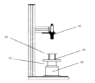
乾燥ガスは、図6に示されるように、噴霧乾燥機の最上部でガス分配器(3)を介して供給される。乾燥ガスは、部分的にバグハウスフィルター又はサイクロンユニット(9)及び凝縮器カラム(12)を介して再循環される(乾燥ガスループ)。噴霧乾燥機内の圧力は、周囲圧力を下回る。 Drying gas is supplied via a gas distributor (3) at the top of the spray dryer, as shown in FIG. The drying gas is partially recycled via the baghouse filter or cyclone unit (9) and the condenser column (12) (drying gas loop). The pressure within the spray dryer is below ambient pressure.
噴霧乾燥機の出口温度は、好ましくは、図7に示されるように、円筒形部分の端部の円周の周りの3点で測定される。個々の測定値(43)を使用して、円筒形噴霧乾燥機の平均出口温度を計算する。 The outlet temperature of the spray dryer is preferably measured at three points around the circumference of the end of the cylindrical part, as shown in Figure 7. The individual measurements (43) are used to calculate the average outlet temperature of the cylindrical spray dryer.
本発明の一実施形態では、乾燥ガスループは加熱され、モノマー溶液の投入が開始される。この時から、熱交換器(20)を介してガス入口温度を調整することによって、噴霧乾燥機の出口温度は、少なくとも115℃、好ましくは少なくとも117℃、より好ましくは118℃に制御される。ガス入口温度は、少なくとも169℃、好ましくは少なくとも173℃、より好ましくは少なくとも176℃、最も好ましくは179℃である。 In one embodiment of the invention, the drying gas loop is heated and monomer solution input is initiated. From this time on, by adjusting the gas inlet temperature via the heat exchanger (20), the spray dryer outlet temperature is controlled to at least 115°C, preferably at least 117°C, more preferably 118°C. The gas inlet temperature is at least 169°C, preferably at least 173°C, more preferably at least 176°C, most preferably 179°C.
1つの好ましい実施形態では、モノマー分離器ユニット(38)は、凝縮器カラム(12)からモノマー供給物(35)へのモノマーの再循環のために使用される。このモノマー分離器ユニットは、例えば、特に、モノマーを水及びポリマー粒子から分離するための、マイクロ-、ウルトラ-、ナノ濾過及び浸透膜ユニットの組み合わせである。適切な膜分離器システムは、例えば、モノグラフ「Membranen: Grundlagen, Verfahren und Industrielle Anwendungen」、K. Ohlrogge and K. Ebert、Wiley-VCH、2012(ISBN: 978-3-527-66033-9)に記載される。 In one preferred embodiment, a monomer separator unit (38) is used for recycling monomer from the condenser column (12) to the monomer feed (35). This monomer separator unit is, for example, a combination of micro-, ultra-, nanofiltration and osmotic membrane units, especially for separating monomer from water and polymer particles. Suitable membrane separator systems are described, for example, in the monograph "Membranen: Grundlagen, Verfahren und Industrielle Anwendungen", K. Ohlrogge and K. Ebert, Wiley-VCH, 2012 (ISBN: 978-3-527-66033-9) be written.
生成物は、内部流動床(27)に蓄積した。調整された内部流動床ガスは、ライン(25)を介して内部流動床(27)に供給される。本発明の一実施形態では、ガスは、好ましくは105℃、より好ましくは106℃の温度を有する。内部流動床ガスの相対湿度は、好ましくは、凝縮器カラム(12)中の温度及びモリエル線図を使用することによって制御される。 The product accumulated in an internal fluidized bed (27). Conditioned internal fluidized bed gas is fed to the internal fluidized bed (27) via line (25). In one embodiment of the invention, the gas preferably has a temperature of 105°C, more preferably 106°C. The relative humidity of the internal fluidized bed gas is preferably controlled by the temperature in the condenser column (12) and by using a Mollier diagram.
噴霧乾燥機のオフガスは、ダスト分離ユニット(9)で濾過され、クエンチ/冷却のために凝縮器カラム(12)に送られる。ダスト分離(9)後、凝縮器カラム(12)の後にガスを予熱するための回復熱交換器システムを使用することができる。ダスト分離ユニット(9)は、好ましくは80~180℃、より好ましくは90~150℃、最も好ましくは100~140℃の温度でヒートトレースしてもよい。 The spray dryer off-gas is filtered in the dust separation unit (9) and sent to the condenser column (12) for quenching/cooling. After dust separation (9), a recuperative heat exchanger system can be used to preheat the gas after the condenser column (12). The dust separation unit (9) may be heat traced at a temperature of preferably 80-180°C, more preferably 90-150°C, most preferably 100-140°C.
ダスト分離ユニットについての例は、バグハウスフィルター、メンブレン、サイクロン、ダスト圧縮機であり、例えば、モノグラフ「Staubabscheiden」、F. Loffler、Georg Thieme Verlag、Stuttgart、1988年(ISBN 978-3137122012)及び「Staubabscheidung mit Schlauchfiltern und Taschenfiltern」、F. Loffler、H. Dietrich及びW. Flatt、Vieweg、Braunschweig、1991年(ISBN 978-3540670629)に記載される。 Examples for dust separation units are baghouse filters, membranes, cyclones, dust compactors, e.g. in the monograph "Staubabscheiden", F. Loffler, Georg Thieme Verlag, Stuttgart, 1988 (ISBN 978-3137122012) and " F. Loffler, H. Dietrich and W. Flatt, Vieweg, Braunschweig, 1991 (ISBN 978-3540670629).
最も好ましいのはサイクロン、例えば、LTG AktiengesellschaftのタイプZSA/ZSB/ZSCのサイクロン/遠心分離器、及びVentilatorenfabrik Oelde GmbH、Camfil Farr International及びMikroPul GmbHのサイクロン分離器である。 Most preferred are cyclones, such as cyclones/centrifuges of type ZSA/ZSB/ZSC from LTG Aktiengesellschaft and cyclone separators from Ventilatorenfabrik Oelde GmbH, Camfil Farr International and MikroPul GmbH.
余剰水は、凝縮器カラム(12)において(一定の)充填レベルを制御することによって、凝縮器カラム(12)からポンプで排出される。凝縮器カラム(12)における水は、クエンチノズル(11)を介してガスに向流でポンプ輸送され、熱交換器(13)によって冷却され、そのため、凝縮器カラム(12)における温度は、好ましくは40~71℃、より好ましくは46~69℃、最も好ましくは49~65℃、さらにより好ましくは51~60℃である。凝縮器カラム(12)における水は、中和剤を投入してモノマーa)の蒸気を洗い流すことによって、アルカリ性pHに設定される。凝縮器カラム(12)からの水溶液は、モノマー溶液の調製のために送り返すことができる。 Excess water is pumped out of the condenser column (12) by controlling the (constant) filling level in the condenser column (12). The water in the condenser column (12) is pumped countercurrently to the gas through the quench nozzle (11) and cooled by the heat exchanger (13), so that the temperature in the condenser column (12) is preferably is 40-71°C, more preferably 46-69°C, most preferably 49-65°C, even more preferably 51-60°C. The water in the condenser column (12) is set to an alkaline pH by dosing with a neutralizer to wash out the vapors of monomer a). The aqueous solution from the condenser column (12) can be sent back for the preparation of the monomer solution.
凝縮器カラムのオフガスは、ガス乾燥ユニット(37)及び調整された内部流動床ガス(27)に分割してもよい。 The condenser column off-gas may be split into a gas drying unit (37) and a conditioned internal fluidized bed gas (27).
ガス乾燥ユニットの原理は、モノグラフ「Leitfaden fur Luftungs- und Klimaanlagen - Grundlagen der Thermodynamik Komponenten einer Vollklimaanlage Normen und Vorschriften」、L. Keller、Oldenbourg Industrieverlag、2009年(ISBN 978-3835631656)に記載される。 The principle of the gas drying unit is described in the monograph "Leitfaden fur Luftungs- und Klimaanlagen - Grundlagen der Thermodynamik Komponenten einer Vollklimaanlage Normen und Vorschriften", L. Keller, Oldenbourg Industrieverlag, 2009 (ISBN 978-3835631656).
ガス乾燥ユニットとして、例えば、ガスミスト除去器又は液滴分離器(デミスター)、例えば、水平流用(例えば、Munters AB, SwedenのタイプDH5000)又は垂直流用(例えば、Munters AB, SwedenのタイプDV270)の羽根型液滴分離器と組み合わせた空気ガス冷却システムを使用することができる。羽根型デミスターは、慣性衝突によって連続ガス流から液滴を除去する。同伴された液滴を運ぶガスが、羽根の正弦曲線経路を通って移動する際、より高密度の液滴は追従することができず、結果として、羽根が回転する度に、これらの液滴は羽根表面に衝突する。大部分の液滴は、羽根の壁に付着する。液滴が同じ場所で羽根に衝突すると、合体が生じる。次いで、合体した液滴は、重力によって排出される。 As gas drying units, e.g. gas mist eliminators or droplet separators (demisters), e.g. impellers for horizontal flow (e.g. type DH5000 from Munters AB, Sweden) or for vertical flow (e.g. type DV270 from Munters AB, Sweden) An air-gas cooling system combined with a type droplet separator can be used. Vane-type demisters remove droplets from a continuous gas stream by inertial impingement. As the gas carrying the entrained droplets moves through the sinusoidal path of the vane, the denser droplets are unable to follow, and as a result, each time the vane rotates, these droplets collides with the blade surface. Most of the droplets stick to the walls of the vanes. Coalescence occurs when the droplets strike the vane at the same location. The combined droplets are then ejected by gravity.
空気ガス冷却システムとして、任意のガス/ガス又はガス/液体熱交換器を使用することができる。密封プレート熱交換器が好ましい。 Any gas/gas or gas/liquid heat exchanger can be used as an air-gas cooling system. Sealed plate heat exchangers are preferred.
水は、ガス乾燥ユニット(37)で凝縮され、凝縮器カラム(12)のための洗浄水として部分的に使用されるか、又は処分することができる。 The water is condensed in the gas drying unit (37) and can be partially used as wash water for the condenser column (12) or disposed of.
ガス温度は、熱交換器(20)及び(22)を介して制御される。熱い乾燥ガスは、ガス分配器(3)を介して並流噴霧乾燥機に供給される。ガス分配器(3)は、好ましくは、乾燥ガス量に応じて、好ましくは1~100mbar、より好ましくは2~30mbar、最も好ましくは4~20mbarの圧力降下を提供するプレートのセットからなる。所望の場合、ガスノズル又はバッフルプレートを使用することによって、乱流及び/又は遠心分離速度を乾燥ガスに導入することもできる。 Gas temperature is controlled via heat exchangers (20) and (22). Hot drying gas is fed to the co-current spray dryer via a gas distributor (3). The gas distributor (3) preferably consists of a set of plates providing a pressure drop of preferably 1 to 100 mbar, more preferably 2 to 30 mbar, most preferably 4 to 20 mbar, depending on the amount of drying gas. If desired, turbulence and/or centrifugal velocity can also be introduced into the drying gas by using gas nozzles or baffle plates.
調整された内部流動床ガスは、ライン(25)を介して内部流動床(27)に供給される。流動床ガスの蒸気含有量は、凝縮器カラム(12)における温度によって制御することができる。内部流動床(27)における生成物ホールドアップは、回転バルブ(28)の回転速度によって制御することができる。 Conditioned internal fluidized bed gas is fed to the internal fluidized bed (27) via line (25). The vapor content of the fluidized bed gas can be controlled by the temperature in the condenser column (12). Product hold-up in the internal fluidized bed (27) can be controlled by the rotation speed of the rotary valve (28).
内部流動床(27)におけるガスの量は、粒子が内部流動床(27)において自由に乱流で移動するように選択される。内部流動床(27)における生成物の高さは、ガスがある場合、ガスがない場合よりも好ましくは少なくとも10%、より好ましくは少なくとも20%、より好ましくは少なくとも30%、さらにより好ましくは少なくとも40%高い。 The amount of gas in the internal fluidized bed (27) is selected such that the particles move freely and turbulently in the internal fluidized bed (27). The product height in the internal fluidized bed (27) is preferably at least 10% higher with gas than without gas, more preferably at least 20%, more preferably at least 30%, even more preferably at least 40% more expensive.
生成物は、回転バルブ(28)を介して内部流動床(27)から排出される。内部流動床(27)における生成物ホールドアップは、回転バルブ(28)の回転速度によって制御することができる。ふるい(29)は、過大物/塊をふるい分けるために使用される。 The product is discharged from the internal fluidized bed (27) via a rotary valve (28). Product hold-up in the internal fluidized bed (27) can be controlled by the rotation speed of the rotary valve (28). The sieve (29) is used to screen out oversized material/clumps.
モノマー溶液は、好ましくは、第一にモノマーa)を中和剤と混合し、第二に架橋剤b)と混合することによって調製される。中和の間の温度は、熱交換器を使用し、ループにおいてポンプ輸送することによって、好ましくは5~60℃、より好ましくは8~40℃、最も好ましくは10~30℃に制御される。フィルターユニットは、好ましくは、ポンプの後のループにおいて使用される。開始剤は、図6に示されるように、静的ミキサー(31)及び(32)によってライン(33)及び(34)を介して液滴化機の上流のモノマー溶液に計量導入される。好ましくは5~60℃、より好ましくは10~50℃、最も好ましくは15~40℃の温度を有する過酸化物溶液が、ライン(33)を介して添加されることが好ましく、好ましくは2~30℃、より好ましくは3~15℃、最も好ましくは4~8℃の温度を有するアゾ開始剤溶液が、ライン(34)を介して添加されることが好ましい。それぞれの開始剤は、好ましくは、ループにおいてポンプ輸送され、制御バルブを介して各液滴化機ユニットに投入される。第2フィルターユニットは、好ましくは、静的ミキサー(32)の後に使用される。液滴化の前の配管における全開始剤パッケージと混合されたモノマー溶液の平均滞留時間は、好ましくは60s未満、より好ましくは30s未満、最も好ましくは10s未満である。 The monomer solution is preferably prepared by firstly mixing monomer a) with the neutralizing agent and secondly with the crosslinking agent b). The temperature during neutralization is preferably controlled at 5-60°C, more preferably 8-40°C, most preferably 10-30°C using a heat exchanger and by pumping in a loop. A filter unit is preferably used in the loop after the pump. The initiator is metered into the monomer solution upstream of the dropletizer via lines (33) and (34) by static mixers (31) and (32), as shown in FIG. Preferably, a peroxide solution having a temperature of preferably 5 to 60°C, more preferably 10 to 50°C, most preferably 15 to 40°C is added via line (33), preferably 2 to 40°C. Preferably, an azo initiator solution having a temperature of 30°C, more preferably 3-15°C, most preferably 4-8°C is added via line (34). Each initiator is preferably pumped in a loop and injected into each dropletizer unit via a control valve. A second filter unit is preferably used after the static mixer (32). The average residence time of the monomer solution mixed with the entire initiator package in the piping before dropletization is preferably less than 60s, more preferably less than 30s, most preferably less than 10s.
噴霧乾燥機の最上部にモノマー溶液を投入するために、WO 2016/134905 A1の図4に示されるように、好ましくは3つの液滴化機ユニットが使用される。しかし、プロセスの処理量及び生成物の品質を最適化するために必要とされる任意の数の液滴化機を使用することができる。したがって、本発明では、少なくとも1つの液滴化機が使用され、形状的に許容される限り多くの液滴化機を使用してもよい。 For dosing the monomer solution at the top of the spray dryer, preferably three dropletizer units are used, as shown in Figure 4 of WO 2016/134905 A1. However, any number of droplets can be used as needed to optimize process throughput and product quality. Therefore, in the present invention, at least one dropletizer is used, and as many dropletizers as the geometry allows.
液滴化機ユニットは、WO2016/134905A1の図7に示されるように、液滴化機カセット(49)についての開口部を有する外側パイプ(47)からなる。液滴化機カセット(49)は、内側パイプ(48)と連結している。封止として端部にPTFEブロック(50)を有する内側パイプ(48)を、維持管理の目的でプロセスの操作の際に外側パイプ(51)の中に押し込む及び外に押し出すことができる。 The dropletizer unit consists of an outer pipe (47) with an opening for the dropletizer cassette (49), as shown in Figure 7 of WO2016/134905A1. The dropletizer cassette (49) is connected to the inner pipe (48). An inner pipe (48) with a PTFE block (50) at the end as a seal can be pushed into and out of the outer pipe (51) during operation of the process for maintenance purposes.
液滴化機カセット(57)の温度は、WO2016/134905A1の図8に示されるように、流路(55)における水によって、好ましくは5~80℃、より好ましくは10~70℃、最も好ましくは30~60℃に制御される。 The temperature of the dropletizer cassette (57) is preferably 5-80°C, more preferably 10-70°C, most preferably, by the water in the channel (55), as shown in Figure 8 of WO2016/134905A1. is controlled at 30-60℃.
液滴化機カセットは、好ましくは10~2000個の穴、より好ましくは50~1500個の穴、最も好ましくは100~1000個の穴を有する。穴サイズ領域の直径は、1900~22300μ2、より好ましくは7800~20100μm2、最も好ましくは11300~17700μm2である。穴は、円形、長方形、三角形又は任意の他の形状であり得る。50~170μm、より好ましくは100~160μm、最も好ましくは120~150μmの穴サイズを有する円形穴が好ましい。穴の直径に対する穴の長さの比は、好ましくは0.5~10、より好ましくは0.8~5、最も好ましくは1~3である。液滴プレート(53)は、入口穴チャネルを使用する場合、穴の長さよりも大きい厚さを有することができる。液滴プレート(53)は、WO 2008/086976 A1に開示されるように、好ましくは長くて狭い。液滴プレートごとに複数列の穴、好ましくは1~20列、より好ましくは2~5列の穴を使用することができる。 The dropletizer cassette preferably has 10-2000 holes, more preferably 50-1500 holes, most preferably 100-1000 holes. The diameter of the hole size region is between 1900 and 22300 μm 2 , more preferably between 7800 and 20100 μm 2 and most preferably between 11300 and 17700 μm 2 . The holes may be circular, rectangular, triangular or any other shape. Circular holes with a hole size of 50-170 μm, more preferably 100-160 μm, most preferably 120-150 μm are preferred. The ratio of hole length to hole diameter is preferably from 0.5 to 10, more preferably from 0.8 to 5, most preferably from 1 to 3. The droplet plate (53) can have a thickness that is greater than the length of the holes when using inlet hole channels. The droplet plate (53) is preferably long and narrow, as disclosed in WO 2008/086976 A1. Multiple rows of holes can be used per droplet plate, preferably 1 to 20 rows, more preferably 2 to 5 rows of holes.
液滴化機カセット(57)は、予め混合されたモノマー及び開始剤溶液の均一な分布のための本質的に停滞した体積のない流路(56)、及び2つの液滴プレート(53)からなる。液滴プレート(53)は、好ましくは1~90゜、より好ましくは3~45゜、最も好ましくは5~20゜の角度で、角度のある構成を有してもよい。各液滴プレート(53)は、好ましくは、耐熱性及び/又は耐薬品性材料、例えば、ステンレス鋼、ポリエーテルエーテルケトン、ポリカーボネート、ポリアリールスルホン、例えば、ポリスルホン、又はポリフェニルスルホン、又はフルオラスポリマー、例えば、ペルフルオロアルコキシエチレン、ポリテトラフルオロエチレン、ポリフッ化ビニリデン、エチレン-クロロトリフルオロエチレンコポリマー、エチレン-テトラフルオロエチレンコポリマー及びフッ素化ポリエチレンでできている。WO 2007/031441 A1に開示されるコーティングされた液滴プレートも使用することができる。液滴形成が機能しなければならないことを除いて、液滴プレートについての材料の選択は制限されず、その表面での重合の開始を触媒しない材料を使用することが好ましい。 The dropletizer cassette (57) has an essentially stagnant, volumeless flow path (56) for uniform distribution of premixed monomer and initiator solutions, and two droplet plates (53). Become. The droplet plate (53) may have an angular configuration, preferably at an angle of 1 to 90°, more preferably 3 to 45°, most preferably 5 to 20°. Each droplet plate (53) is preferably made of a heat- and/or chemical-resistant material, such as stainless steel, polyetheretherketone, polycarbonate, polyarylsulfone, such as polysulfone, or polyphenylsulfone, or a fluorous polymer. , made of, for example, perfluoroalkoxyethylene, polytetrafluoroethylene, polyvinylidene fluoride, ethylene-chlorotrifluoroethylene copolymer, ethylene-tetrafluoroethylene copolymer and fluorinated polyethylene. Coated droplet plates as disclosed in WO 2007/031441 A1 can also be used. The choice of material for the droplet plate is not restricted, except that droplet formation must be functional, and it is preferred to use materials that do not catalyze the initiation of polymerization on its surface.
液滴化機カセットの配置は、好ましくは、回転対称であるか、又は噴霧乾燥機中に均一に分布される(例えば、WO 2016/134905 A1の図4~5を参照のこと)。 The arrangement of the dropletizer cassettes is preferably rotationally symmetrical or uniformly distributed in the spray dryer (see, for example, Figures 4-5 of WO 2016/134905 A1).
好ましい実施形態では、液滴プレート(53)の角度構成は、中央部でより低く、次いで外側であり、例えば、4a=3°、4b=5°及び4c=8°である(WO 2016/134905 A1の図6)。 In a preferred embodiment, the angular configuration of the droplet plate (53) is lower in the middle and then on the outside, for example 4a=3°, 4b=5° and 4c=8° (WO 2016/134905 Figure 6 in A1).
液滴化機ユニット1つあたりの開始剤溶液を含むモノマーの処理量は、好ましくは10~4000kg/h、より好ましくは100~1000kg/h、最も好ましくは200~600kg/hである。穴1つあたりの処理量は、好ましくは0.1~10kg/h、より好ましくは0.5~5kg/h、最も好ましくは0.7~2kg/hである。 The throughput of monomer including initiator solution per dropletizer unit is preferably from 10 to 4000 kg/h, more preferably from 100 to 1000 kg/h, most preferably from 200 to 600 kg/h. The throughput per hole is preferably 0.1 to 10 kg/h, more preferably 0.5 to 5 kg/h, and most preferably 0.7 to 2 kg/h.
本発明は、吸水性ポリマー粒子Hを提供する。 The present invention provides water-absorbing polymer particles H.
一実施形態では、吸水性ポリマー粒子Hは、38g/g~85g/g、好ましくは40g/g~80g/g、より好ましくは42g/g~75g/gのCRCを有する。 In one embodiment, the water-absorbing polymer particles H have a CRC of 38 g/g to 85 g/g, preferably 40 g/g to 80 g/g, more preferably 42 g/g to 75 g/g.
本発明の一実施形態では、吸水性ポリマー粒子Hは、40s以下、好ましくは35s以下、より好ましくは30s以下のボルテックスを有する。 In one embodiment of the invention, the water-absorbing polymer particles H have a vortex of 40s or less, preferably 35s or less, more preferably 30s or less.
本発明によれば、吸水性ポリマー粒子Hは、5~40s、好ましくは8~35sのボルテックスを有する。 According to the invention, the water-absorbing polymer particles H have a vortex of 5 to 40 s, preferably 8 to 35 s.
本発明によれば、吸水性ポリマー粒子Hは、22g/g~60g/g、好ましくは25g/g~60g/g、より好ましくは27g/g~58g/g、最も好ましくは少なくとも28g/g~55g/gのAUL(21g cm-2)を有する。 According to the invention, the water-absorbing polymer particles H are comprised between 22g/g and 60g/g, preferably between 25g/g and 60g/g, more preferably between 27g/g and 58g/g, most preferably between at least 28g/g and It has an AUL of 55g/g (21g cm -2 ).
本発明によれば、吸収性コア(80)内の吸水性ポリマー粒子Hは、1000s以下、好ましくは700s以下、より好ましくは500s以下のVAUL(τ=21g cm-2)を有する。 According to the invention, the water-absorbing polymer particles H in the absorbent core (80) have a VAUL (τ=21 g cm -2 ) of 1000 s or less, preferably 700 s or less, more preferably 500 s or less.
本発明の一実施形態では、流体吸収性コア(80)は、1000s以下、好ましくは900s以下、より好ましくは800s以下、最も好ましくは700s以下のT20を有する吸水性ポリマー粒子Hを含む。 In one embodiment of the invention, the fluid-absorbent core (80) comprises water-absorbing polymer particles H having a T20 of 1000s or less, preferably 900s or less, more preferably 800s or less, most preferably 700s or less.
本発明の流体吸収性コア(80)は、少なくとも25g/g/s、好ましくは少なくとも27g/g/s、より好ましくは少なくとも28g/g/s、最も好ましくは少なくとも30g/g/sのFSC(1分)を有する吸水性ポリマー粒子Hを含む。 The fluid absorbent core (80) of the present invention has an FSC ( 1 minute) containing water-absorbing polymer particles H.
本発明の流体吸収性コア(80)内の吸水性ポリマー粒子Hは、1.5g以下、好ましくは1.3g以下、より好ましくは1.1g以下、最も好ましくは1.0g以下のSAP-リウェット(3分)を有する。 The water-absorbing polymer particles H in the fluid-absorbing core (80) of the present invention are 1.5 g or less, preferably 1.3 g or less, more preferably 1.1 g or less, most preferably 1.0 g or less SAP-rewet (3 minutes) has.
吸水性ポリマー粒子Hは、0.79~0.85、好ましくは0.80~0.85、より好ましくは0.80~0.84、最も好ましくは0.80~0.83の真円度を有する。真円度は、体積平均の真円度である。 The water-absorbing polymer particles H have a roundness of 0.79 to 0.85, preferably 0.80 to 0.85, more preferably 0.80 to 0.84, and most preferably 0.80 to 0.83. Roundness is the volume average roundness.
本発明の流体吸収性コア(80)内の吸水性ポリマー粒子Hは、10wt%以下、好ましくは8.5wt%以下、より好ましくは7wt%以下、最も好ましくは6wt%以下の抽出可能物含有量(16h)を有する。 The water-absorbing polymer particles H within the fluid-absorbent core (80) of the present invention have an extractables content ( 16h).
本発明によれば、吸水性ポリマー粒子Hは、表面架橋されている。 According to the invention, the water-absorbing polymer particles H are surface crosslinked.
請求項1~12のいずれか一項に記載の流体吸収性コア(80)に特に適した吸水性ポリマー粒子H。
Water-absorbing polymer particles H particularly suitable for a fluid-absorbing core (80) according to any one of
流体吸収性コア(80)-吸収紙
本発明による吸収性コア(80)は、吸水性ポリマー粒子の少なくとも1つの層、好ましくは少なくとも2つの層を含む。吸水性ポリマー粒子の少なくとも2つの層の一方は、最上面に配置され(91)、もう一方は底面に配置される(92)。
Fluid-Absorbent Core (80) - Absorbent Paper The absorbent core (80) according to the invention comprises at least one layer, preferably at least two layers, of water-absorbing polymer particles. One of the at least two layers of water-absorbing polymer particles is disposed on the top surface (91) and the other on the bottom surface (92).
第1の吸水性ポリマー又は吸水性ポリマーの混合物(91)は、不織布材料(94)の片面に滴下される。接着剤(93)は、上層(最上部ティッシュ層)(95)に塗布される。ティッシュ層(95)は、吸水性ポリマー(91)を有する不織布(94)の側面と積層される。第2の吸水性ポリマー(92)は、不織布(94)のもう一方の側面に滴下される。接着剤(93)は、底層(下部ティッシュ層)(96)に塗布される。ティッシュ層(96)は、吸水性ポリマー(92)を有する不織布(94)の側面と積層される。 A first water-absorbing polymer or mixture of water-absorbing polymers (91) is dropped onto one side of the nonwoven material (94). An adhesive (93) is applied to the top layer (top tissue layer) (95). The tissue layer (95) is laminated with a side surface of a nonwoven fabric (94) having a water-absorbing polymer (91). The second water-absorbing polymer (92) is dropped onto the other side of the nonwoven fabric (94). An adhesive (93) is applied to the bottom layer (lower tissue layer) (96). The tissue layer (96) is laminated with a side surface of a nonwoven fabric (94) having a water-absorbing polymer (92).
図4は、本発明による吸収性コアを示す。 Figure 4 shows an absorbent core according to the invention.
流体吸収性コア(80)の完全性を高めるために、コアは、場合によりカバー(86)(例えば、ティッシュラップ)を備えていてもよい。このカバー(86)は、ホットメルト、超音波接着、熱接着又は当業者に公知の接着技術の組み合わせによって側面接合部で接着及び/又は遠位接合部で接着して、流体吸収性コア(80)の最上部及び/又は底部にあってもよい。さらに、このカバー(86)は、単一の材料シートで流体吸収性コア全体を含んでもよく、したがって、ラップとして機能してもよい。ラッピングは、全体的ラップ、部分的ラップ又はC-ラップとして可能である。 To enhance the integrity of the fluid-absorbent core (80), the core may optionally include a cover (86) (eg, tissue wrap). The cover (86) is attached to the fluid absorbent core (86) by hot melting, ultrasonic bonding, thermal bonding or a combination of bonding techniques known to those skilled in the art, adhesively bonded at the lateral joints and/or bonded at the distal joint. ) may be at the top and/or bottom. Additionally, the cover (86) may include the entire fluid-absorbent core in a single sheet of material and thus function as a wrap. Wrapping is possible as a full wrap, a partial wrap or a C-wrap.
本発明の吸収性コア(80)の一実施形態の概略図は図4に示される。 A schematic diagram of one embodiment of an absorbent core (80) of the present invention is shown in FIG.
コアカバー(86)の材料は、不織布、ウェブ、衣服、テキスタイル、フィルム、ティッシュ、及び2つ以上の基体若しくはウェブの積層物を含む、任意の公知のタイプの基体を含んでもよい。コアカバー材料は、天然繊維、例えば、セルロース、綿、亜麻、リネン、麻、羊毛、絹、毛皮、毛髪及び天然に存在する鉱物繊維を含んでもよい。コアカバー材料はまた、合成繊維、例えば、レーヨン及びリヨセル(セルロースから得られる)、多糖類(デンプン)、ポリオレフィン繊維(ポリプロピレン、ポリエチレン)、ポリアミド、ポリエステル、ブタジエン-スチレンブロックコポリマー、ポリウレタン及びそれらの組み合わせを含んでもよい。好ましくは、コアカバー(86)は、合成繊維又はティッシュを含む。 The material of the core cover (86) may include any known type of substrate, including nonwovens, webs, garments, textiles, films, tissues, and laminates of two or more substrates or webs. The core cover material may include natural fibers such as cellulose, cotton, flax, linen, hemp, wool, silk, fur, hair and naturally occurring mineral fibers. The core cover material can also be made of synthetic fibers such as rayon and lyocell (derived from cellulose), polysaccharides (starch), polyolefin fibers (polypropylene, polyethylene), polyamides, polyesters, butadiene-styrene block copolymers, polyurethanes and combinations thereof. May include. Preferably, the core cover (86) comprises synthetic fibers or tissue.
繊維は、単成分又は多成分であってもよい。多成分繊維は、ホモポリマー、コポリマー又はそれらの混合物を含んでもよい。 Fibers may be monocomponent or multicomponent. Multicomponent fibers may include homopolymers, copolymers or mixtures thereof.
本発明によれば、吸収性コア(80)は、適切な吸収性材料の少なくとも2つの薄く柔軟な単層(91、92)を含む。これらの層のそれぞれは、巨視的には二次元で、平面であり、他の次元と比較して非常に薄い厚さである。前記層は、層全体に超吸収性材料を組み込んでもよい。 According to the invention, the absorbent core (80) comprises at least two thin flexible monolayers (91, 92) of suitable absorbent material. Each of these layers is macroscopically two-dimensional, planar, and of very small thickness compared to other dimensions. The layer may incorporate superabsorbent material throughout the layer.
層は、約90~100重量%、好ましくは95~100重量%、より好ましくは98~100重量%の範囲の濃度を示す、異なる濃度及び異なる吸水性ポリマー材料を有してもよい。 The layers may have different concentrations and different water-absorbing polymeric materials exhibiting concentrations in the range of about 90-100%, preferably 95-100%, more preferably 98-100% by weight.
層(91、92)は、好ましくは、例えば接着剤(93)の添加によって、又は機械的、熱的若しくは超音波接着又はそれらの組み合わせによって、それぞれ上層及び/又は底層(95、96)に接合されるが、接着剤が好ましい。 The layers (91, 92) are preferably bonded to the top and/or bottom layer (95, 96), respectively, for example by the addition of an adhesive (93) or by mechanical, thermal or ultrasonic bonding or a combination thereof. However, adhesives are preferred.
本発明の別の実施形態によれば、層(91)及び/又は(92)の少なくとも1つは、少なくとも2種類の吸水性ポリマー粒子の混合物を含有する。 According to another embodiment of the invention, at least one of the layers (91) and/or (92) contains a mixture of at least two types of water-absorbing polymer particles.
さらに、吸水性ポリマー粒子は、例えば少なくとも接着剤によって支持された、別個の領域、チャンバー又はポケットにおいて、コア(80)内、特に、各層(91、92)内に配置されることが好ましい。特にそれぞれの層(91、92)における吸収性コアへの吸水性ポリマー材料の適用の技術は、当業者に公知であり、体積測定、重量減少、又は重量測定であってもよい。公知の技術としては、振動システム、単一及び複数のオーガー(auger)システム、投入ロール、計量ベルト、流動床体積測定システム並びに重力スプリンクル及び/若しくは噴霧システムによる適用が挙げられる。挿入のさらなる技術は、落下投入システムコンセンサス、及び対向する空気アプリケーション、又は流体吸収性ポリマー材料を適用する真空印刷方法である。 Furthermore, the water-absorbing polymer particles are preferably arranged within the core (80), in particular within each layer (91, 92), for example in separate regions, chambers or pockets, supported by at least an adhesive. Techniques for the application of water-absorbing polymeric materials to the absorbent core, particularly in the respective layers (91, 92), are known to those skilled in the art and may be volumetric, weight-reducing or gravimetric. Known techniques include applications with vibrating systems, single and multiple auger systems, dosing rolls, metering belts, fluidized bed volumetric systems, and gravity sprinkle and/or atomizing systems. Further techniques of insertion are the drop-in system consensus and opposing pneumatic applications or vacuum printing methods applying fluid-absorbing polymeric materials.
流体吸収性コア(80)内の吸水性ポリマー粒子の量は、特大おむつ(サイズL)の場合は100~500gsm、好ましくは200~400gsm、より好ましくは250~300gsmであり、各層は、少なくとも50gsmの吸水性ポリマー粒子、好ましくは少なくとも100gsmの吸水性ポリマー粒子を含有する。 The amount of water-absorbing polymer particles in the fluid-absorbent core (80) is between 100 and 500 gsm, preferably between 200 and 400 gsm, more preferably between 250 and 300 gsm for extra-large diapers (size L), with each layer having at least 50 gsm. of water-absorbing polymer particles, preferably at least 100 gsm.
吸収性コア(80)はまた、短繊維エアレイド(air-laid)不織布材料(94); 不織布材料、例えば、ポリエチレン、ポリプロピレン、ナイロン、ポリエステルなど; セルロース繊維状材料、例えば、当技術分野で公知の紙ティッシュ又はタオル、ワックスコート紙、段ボール紙材料など; 又はフラッフパルプなどの他の材料の少なくとも1つの層を含んでもよい。前記層は、二成分結合繊維をさらに組み込んでもよい。 The absorbent core (80) may also be comprised of short fiber air-laid nonwoven materials (94); nonwoven materials such as polyethylene, polypropylene, nylon, polyester, etc.; cellulosic fibrous materials such as those known in the art. It may include at least one layer of other materials such as paper tissue or towels, wax-coated paper, corrugated paper materials, etc.; or fluff pulp. The layer may further incorporate bicomponent bonding fibers.
吸収性コア(80)内の不織布(94)は、典型的には、例えばエアスルー接着プロセスによって製造された、単層である。その総坪量は、約10~100gsm、好ましくは40~60である。 The nonwoven fabric (94) within the absorbent core (80) is typically a single layer, for example produced by an air-through bonding process. Its total basis weight is about 10-100 gsm, preferably 40-60 gsm.
吸収性コア(80)は、さらに、少なくとも2つのティッシュ層(95、96)を含んでもよい。ティッシュ層は、紙などのティッシュ材料に制限されず、不織布も指す。 The absorbent core (80) may further include at least two tissue layers (95, 96). Tissue layer is not limited to tissue materials such as paper, but also refers to non-woven fabrics.
層(95、96)の材料は、ウェブ、衣服、テキスタイル及びフィルムを含む、任意の公知のタイプの基体を含んでもよい。ティッシュ層(95、96)は、天然繊維、例えば、セルロース、綿、亜麻、リネン、麻、羊毛、絹、毛皮、毛髪及び天然に存在する鉱物繊維を含んでもよい。ティッシュ層(95、96)はまた、合成繊維、例えば、レーヨン及びリヨセル(セルロースから得られる)、多糖類(デンプン)、ポリオレフィン繊維(ポリプロピレン、ポリエチレン)、ポリアミド、ポリエステル、ブタジエン-スチレンブロックコポリマー、ポリウレタン及びそれらの組み合わせを含んでもよい。好ましくは、ティッシュ層は、セルロース繊維を含む。ティッシュ層は、引張強度及び完全性を提供するために、>45gsmで、約50%木材パルプ及び50%化学ビスコース繊維から製造されることが好ましい。 The material of the layers (95, 96) may include any known type of substrate, including webs, garments, textiles and films. The tissue layer (95, 96) may include natural fibers such as cellulose, cotton, flax, linen, hemp, wool, silk, fur, hair and naturally occurring mineral fibers. Tissue layers (95, 96) can also be made of synthetic fibers, such as rayon and lyocell (derived from cellulose), polysaccharides (starch), polyolefin fibers (polypropylene, polyethylene), polyamides, polyesters, butadiene-styrene block copolymers, polyurethanes. and combinations thereof. Preferably, the tissue layer includes cellulose fibers. The tissue layer is preferably made from about 50% wood pulp and 50% synthetic viscose fibers at >45 gsm to provide tensile strength and integrity.
本発明によれば、上部及び下部ティッシュ層(95、96)のそれぞれの総坪量は、10~100gsm、好ましくは30~80gsmである。 According to the invention, the total basis weight of each of the upper and lower tissue layers (95, 96) is between 10 and 100 gsm, preferably between 30 and 80 gsm.
本発明によれば、流体吸収性コア(80)は、20重量%以下の接着剤、好ましくは10重量%以下の接着剤、より好ましくは5重量%以下の接着剤を含むことが好ましい。好ましくは、接着剤は、ホットメルト接着剤である。 According to the invention, the fluid-absorbent core (80) preferably comprises no more than 20% by weight adhesive, preferably no more than 10% adhesive, more preferably no more than 5% adhesive. Preferably the adhesive is a hot melt adhesive.
吸収性コア(80)は、それぞれ、約150gsm~約2000gsm、好ましくは約300gsm~約750gsm、より好ましくは約500gsm~約650gsmの範囲の総坪量を有する。 The absorbent cores (80) each have a total basis weight ranging from about 150 gsm to about 2000 gsm, preferably from about 300 gsm to about 750 gsm, and more preferably from about 500 gsm to about 650 gsm.
本発明によれば、流体吸収性コア(80)は、少なくとも1つの吸収層を含み、該層は、少なくとも80重量%の吸水性ポリマー粒子、好ましくは少なくとも90重量%、より好ましくは少なくとも95重量%、最も好ましくは少なくとも98重量%の吸水性ポリマー粒子; 0~10重量%の接着剤、好ましくは0~5重量%の接着剤、及び0~10重量%、好ましくは0~5重量%、より好ましくは0~2重量%の繊維状材料を含み、吸収層内の吸水性ポリマー粒子は、40s以下のボルテックスを有し、かつ0.79~0.85の真円度及び/又は38g/g~85g/gのCRCを有する吸水性ポリマー粒子Hである。 According to the invention, the fluid-absorbent core (80) comprises at least one absorbent layer comprising at least 80% by weight of water-absorbing polymer particles, preferably at least 90% by weight, more preferably at least 95% by weight. %, most preferably at least 98% by weight of water-absorbing polymer particles; 0-10% by weight adhesive, preferably 0-5% adhesive; and 0-10% by weight, preferably 0-5% by weight; More preferably comprising 0-2% by weight of fibrous material, the water-absorbing polymer particles in the absorbent layer have a vortex of less than 40s and a circularity of 0.79-0.85 and/or 38g/g-85g/ The water-absorbing polymer particles H have a CRC of g.
本発明によれば、流体吸収性コア(80)は、少なくとも2つの吸収層、上層(91)及び底層(92)を含み、少なくとも底層(92)は、40s以下のボルテックスを有し、かつ0.79~0.85の真円度及び/又は38g/g~85g/gのCRCを有する吸水性ポリマー粒子Hを含むことが好ましい。上層(91)及び底(下)層(92)の層のそれぞれは、少なくとも80重量%の吸水性ポリマー粒子、好ましくは少なくとも90重量%、より好ましくは少なくとも95重量%、最も好ましくは少なくとも98重量%の吸水性ポリマー粒子; 0~10重量%の接着剤、好ましくは0~5重量%の接着剤、及び0~10重量%、好ましくは0~5重量%、より好ましくは0~2重量%の繊維状材料を含む。 According to the invention, the fluid-absorbent core (80) includes at least two absorbent layers, a top layer (91) and a bottom layer (92), wherein at least the bottom layer (92) has a vortex of 40 s or less and 0.79 It is preferred to include water-absorbing polymer particles H having a circularity of ~0.85 and/or a CRC of 38 g/g to 85 g/g. Each of the top (91) and bottom (92) layers comprises at least 80% by weight water-absorbing polymer particles, preferably at least 90%, more preferably at least 95%, most preferably at least 98% by weight. % of water-absorbing polymer particles; 0-10% by weight of adhesive, preferably 0-5% by weight of adhesive, and 0-10% by weight, preferably 0-5% by weight, more preferably 0-2% by weight. fibrous material.
本発明の1つの好ましい実施形態では、吸水性ポリマー粒子Hは、38g/g~85g/g、好ましくは40g/g~80g/g、より好ましくは42g/g~75g/gのCRCを有する。 In one preferred embodiment of the invention, the water-absorbing polymer particles H have a CRC of 38 g/g to 85 g/g, preferably 40 g/g to 80 g/g, more preferably 42 g/g to 75 g/g.
本発明の一実施形態では、吸水性ポリマー粒子Hは、40s以下、好ましくは35s以下、より好ましくは30s以下のボルテックスを有する。 In one embodiment of the invention, the water-absorbing polymer particles H have a vortex of 40s or less, preferably 35s or less, more preferably 30s or less.
本発明の別の好ましい実施形態では、吸水性ポリマー粒子Hは、5~40s、好ましくは8~35sのボルテックスを有する。 In another preferred embodiment of the invention, the water-absorbing polymer particles H have a vortex of 5 to 40 s, preferably 8 to 35 s.
本発明によれば、吸水性ポリマー粒子Hは、22g/g~60g/g、好ましくは少なくとも25g/g~60g/g、より好ましくは27g/g~58g/g、最も好ましくは少なくとも28g/g~55g/gのAUL(21g cm-2)を有する。 According to the invention, the water-absorbing polymer particles H are 22g/g to 60g/g, preferably at least 25g/g to 60g/g, more preferably 27g/g to 58g/g, most preferably at least 28g/g It has an AUL of ~55g/g (21g cm -2 ).
本発明によれば、吸収性コア(80)内の吸水性ポリマー粒子Hは、1000s以下、好ましくは700s以下、より好ましくは500s以下のVAUL(τ=21g cm-2)を有する。 According to the invention, the water-absorbing polymer particles H in the absorbent core (80) have a VAUL (τ=21 g cm -2 ) of 1000 s or less, preferably 700 s or less, more preferably 500 s or less.
本発明の一実施形態では、流体吸収性コア(80)は、1000s以下、好ましくは900s以下、より好ましくは800s以下、最も好ましくは700s以下のT20を有する吸水性ポリマー粒子Hを含む。 In one embodiment of the invention, the fluid-absorbent core (80) comprises water-absorbing polymer particles H having a T20 of 1000s or less, preferably 900s or less, more preferably 800s or less, most preferably 700s or less.
本発明の流体吸収性コア(80)は、少なくとも25g/g/s、好ましくは少なくとも27g/g/s、より好ましくは少なくとも28g/g/s、最も好ましくは少なくとも30g/g/sのFSC(1分)を有する吸水性ポリマー粒子Hを含む。 The fluid absorbent core (80) of the present invention has an FSC ( 1 minute) containing water-absorbing polymer particles H.
本発明の流体吸収性コア(80)内の吸水性ポリマー粒子Hは、1.5g以下、好ましくは1.3g以下、より好ましくは1.1g以下、最も好ましくは1.0g以下のSAP-リウェット(3分)を有する。 The water-absorbing polymer particles H in the fluid-absorbing core (80) of the present invention are 1.5 g or less, preferably 1.3 g or less, more preferably 1.1 g or less, most preferably 1.0 g or less SAP-rewet (3 minutes) has.
本発明の流体吸収性コア(80)は、0.79~0.85、好ましくは0.80~0.85、より好ましくは0.80~0.84、最も好ましくは0.80~0.83の真円度を有する吸水性ポリマー粒子Hを含む。真円度は、体積平均の真円度である。 The fluid-absorbent core (80) of the present invention comprises water-absorbing polymer particles H having a circularity of 0.79 to 0.85, preferably 0.80 to 0.85, more preferably 0.80 to 0.84, most preferably 0.80 to 0.83. Roundness is the volume average roundness.
本発明の流体吸収性コア(80)内の吸水性ポリマー粒子Hは、10wt%以下、好ましくは8.5wt%以下、より好ましくは7wt%以下、最も好ましくは6wt%以下の抽出可能物含有量(16h)を有する。 The water-absorbing polymer particles H within the fluid-absorbent core (80) of the present invention have an extractables content ( 16h).
本発明によれば、吸水性ポリマー粒子Hは、表面架橋されている。 According to the invention, the water-absorbing polymer particles H are surface crosslinked.
本発明による1つの好ましい流体吸収性コア(80)は、下層(92)内に、38g/g~85g/gのCRC及び40s以下のボルテックスを有し、好ましくは40g/g~80g/gのCRC及び35s以下のボルテックスを有し、より好ましくは42g/g~75g/gのCRC及び35s以下のボルテックスを有する吸水性ポリマー粒子Hを含む。 One preferred fluid absorbent core (80) according to the present invention has a CRC of 38 g/g to 85 g/g and a vortex of 40 s or less, preferably 40 g/g to 80 g/g, in the lower layer (92). It contains water-absorbing polymer particles H having a CRC and a vortex of 35 seconds or less, more preferably a CRC of 42 g/g to 75 g/g and a vortex of 35 seconds or less.
下層(92)内に、40s以下のボルテックス及び0.79~0.85の真円度を有し、好ましくは35s以下のボルテックス及び0.80~0.85の真円度を有し、より好ましくは35s以下のボルテックス及び0.80~0.84の真円度を有する吸水性ポリマー粒子Hを含む本発明による流体吸収性コア(80)も好ましい。 The lower layer (92) has a vortex of 40 seconds or less and a circularity of 0.79 to 0.85, preferably a vortex of 35 seconds or less and a circularity of 0.80 to 0.85, more preferably a vortex of 35 seconds or less and a circularity of 0.80. Also preferred is a fluid-absorbing core (80) according to the invention comprising water-absorbing polymer particles H with a roundness of ˜0.84.
本発明による別の好ましい流体吸収性コア(80)は、下層(92)内に、38g/g~85g/gのCRC及び40s以下のボルテックス及び0.79~0.85の真円度を有し、好ましくは40g/g~80g/gのCRC及び35s以下のボルテックス及び0.80~0.85の真円度を有し、より好ましくは42g/g~75g/gのCRC及び35s以下のボルテックス及び0.80~0.84の真円度を有する吸水性ポリマー粒子Hを含む。 Another preferred fluid absorbent core (80) according to the invention has a CRC of 38 g/g to 85 g/g and a vortex of 40 s or less and a roundness of 0.79 to 0.85, preferably in the lower layer (92). CRC of 40g/g to 80g/g, vortex of 35s or less and roundness of 0.80 to 0.85, more preferably CRC of 42g/g to 75g/g, vortex of 35s or less and roundness of 0.80 to 0.84. Contains water-absorbing polymer particles H having a
ボルテックス及びCRCは、例えば、吸水性ポリマー粒子の架橋密度又は粒径分布を変更することによって適合させることができる。 Vortex and CRC can be adapted, for example, by changing the crosslinking density or particle size distribution of the water-absorbing polymer particles.
本発明の一実施形態によれば、本明細書に開示される方法「注水試験」に従って測定して、本発明の流体吸収性コア(80)の注水時間は、28s以下、好ましくは26s、より好ましくは25s以下であり、流体吸収性コア(80)の注水リウェットは、3.5g以下、好ましくは3.3以下である。 According to one embodiment of the invention, the water filling time of the fluid-absorbent core (80) of the present invention is less than or equal to 28 s, preferably less than 26 s, as measured according to the method "Water Filling Test" disclosed herein. It is preferably 25 seconds or less, and the water rewetting time of the fluid absorbent core (80) is 3.5 g or less, preferably 3.3 g or less.
本発明の吸収性コアは、低いリウェットと相まって、流体を非常に速く吸収する(注水時間)。これは、吸収された流体が、すばやく吸収され、圧力下でもコア内に保持されることを意味する。 The absorbent core of the present invention absorbs fluids very quickly (filling time) coupled with low rewetting. This means that the absorbed fluid is quickly absorbed and retained within the core even under pressure.
本発明によれば、本記載に開示される方法「ストライクスルー/リウェット」に従って測定して、流体吸収性コア(80)は、少なくとも245mm、好ましくは少なくとも250mm、より好ましくは260mmを超え、最も好ましくは270mmを超える液体拡散長、50s以下、好ましくは48s以下、より好ましくは45s以下の総ストライクスルー時間、及び40g以下、好ましくは35g以下、より好ましくは30g以下の総リウェットを有する。 According to the present invention, the fluid-absorbent core (80) is at least 245 mm, preferably at least 250 mm, more preferably greater than 260 mm, and most preferably has a liquid diffusion length of more than 270 mm, a total strike-through time of less than 50s, preferably less than 48s, more preferably less than 45s, and a total rewet of less than 40g, preferably less than 35g, more preferably less than 30g.
特に、少なくとも245mmの液体拡散長は、本発明の吸収性コア内の流体が、コア全体に分布していることを示す。流体はコアのわずかな部分のみに固定されるわけではない。そのため、コア領域全体が使用され、ゲルブロッキングが防止される。 In particular, a liquid diffusion length of at least 245 mm indicates that the fluid within the absorbent core of the present invention is distributed throughout the core. The fluid is not fixed to only a small portion of the core. Therefore, the entire core area is used and gel blocking is prevented.
流体吸収性コア(80)は、典型的には、均一なサイズ又はプロファイルを有する。適切な流体吸収性コアはまた、コアの形状及び/又は吸水性ポリマー粒子の含有量及び/又は吸水性ポリマー粒子の分布及び/又は異なる層の寸法(層状の流体吸収性コアが存在する場合)に関して、プロファイル化構造を有することができる。 The fluid-absorbent core (80) typically has a uniform size or profile. A suitable fluid-absorbent core also depends on the shape of the core and/or the content of water-absorbing polymer particles and/or the distribution of water-absorbing polymer particles and/or the dimensions of the different layers (if a layered fluid-absorbent core is present). can have a profiled structure.
上から見たコアの形状(x-y寸法)は、長方形、解剖学的形状(より狭い股領域を有する)、又は任意の他の形状であってよい。 The shape of the core (x-y dimensions) viewed from above may be rectangular, anatomical (with a narrower crotch area), or any other shape.
流体吸収性コア(80)の上面面積は、好ましくは少なくとも200cm2、より好ましくは少なくとも250cm2、最も好ましくは少なくとも300cm2である。上面面積は、上部液体透過性層と向かい合っているコアの部分である。 The upper surface area of the fluid-absorbent core (80) is preferably at least 200 cm 2 , more preferably at least 250 cm 2 and most preferably at least 300 cm 2 . The top surface area is the portion of the core that faces the top liquid permeable layer.
流体吸収性コアは、当技術分野で公知の流体吸収性物品に典型的に存在する追加の添加剤を含んでもよい。例示的な添加剤は、流体吸収性コアを補強及び安定化するための繊維である。好ましくは、ポリエチレンは、流体吸収性コアを補強するために使用される。 The fluid-absorbent core may include additional additives typically present in fluid-absorbent articles known in the art. Exemplary additives are fibers to reinforce and stabilize the fluid absorbent core. Preferably polyethylene is used to reinforce the fluid absorbent core.
流体吸収性コアを補強するためのさらに適切な安定剤は、結合剤として作用する材料である。 Further suitable stabilizers for reinforcing the fluid-absorbent core are materials that act as binders.
流体吸収性コアの異なる領域に使用される結合剤材料の種類又は結合剤の量を変更する際に、プロファイル化された安定化を得ることが可能である。例えば、異なる溶融温度を示す異なる結合剤材料が、流体吸収性コアの領域に使用されてもよい(例えば、コアの中央領域におけるより低い溶融温度、及び遠位領域におけるより高い溶融)。 Profiled stabilization can be obtained when varying the type of binder material or amount of binder used in different regions of the fluid-absorbent core. For example, different binder materials exhibiting different melting temperatures may be used in regions of the fluid-absorbent core (eg, lower melting temperature in the central region of the core and higher melting temperature in the distal regions).
適切な結合剤材料は、接着性又は非接着性繊維、連続的又は不連続的に押し出された繊維、二成分ステープル繊維、非エラストマー繊維及び噴霧液体結合剤、又はこれらの結合剤材料の任意の組み合わせであってもよい。 Suitable binder materials include adhesive or non-adhesive fibers, continuously or discontinuously extruded fibers, bicomponent staple fibers, non-elastomeric fibers and sprayed liquid binders, or any of these binder materials. It may be a combination.
さらに、熱可塑性組成物は、通常、コア層の完全性を高めるために添加される。熱可塑性組成物は、単一のタイプの熱可塑性ポリマー、又は熱可塑性ポリマーの混合物を含んでもよい。あるいは、熱可塑性組成物は、粘着付与剤、可塑剤又は他の添加剤、例えば酸化防止剤などの、熱可塑性希釈剤とともに少なくとも1つの熱可塑性ポリマーを含むホットメルト接着剤を含んでもよい。熱可塑性組成物は、例えば、結晶性ポリプロピレン及び非晶質ポリアルファオレフィン又はスチレンブロックコポリマー、及びワックスの混合物を含む感圧性ホットメルト接着剤をさらに含んでもよい。 Additionally, thermoplastic compositions are typically added to enhance the integrity of the core layer. Thermoplastic compositions may include a single type of thermoplastic polymer or a mixture of thermoplastic polymers. Alternatively, the thermoplastic composition may include a hot melt adhesive comprising at least one thermoplastic polymer along with a thermoplastic diluent, such as a tackifier, plasticizer or other additives, such as antioxidants. The thermoplastic composition may further include a pressure sensitive hot melt adhesive comprising, for example, a mixture of crystalline polypropylene and amorphous polyalphaolefin or styrene block copolymer and wax.
臭気制御に関しては、香料及び/又は臭気制御添加剤が場合により添加される。適切な臭気制御添加剤は、当技術分野で公知の、時間とともに保有している流体吸収性物品中で発生される臭気を低減する全ての物質である。したがって、適切な臭気制御添加剤は、無機材料、例えば、ゼオライト、活性炭、ベントナイト、シリカ、アエロジル(aerosile)、珪藻土、粘土; キレート剤、例えば、エチレンジアミン四酢酸(EDTA)、シクロデキストリン、アミノポリカルボン酸、エチレンジアミンテトラメチレンホスホン酸、アミノホスフェート、多官能性アロメート(polyfunctional aromate)、N,N-ジコハク酸である。適切な臭気制御添加剤は、さらなる抗微生物剤である。 For odor control, fragrances and/or odor control additives are optionally added. Suitable odor control additives are all substances known in the art that reduce odors generated in fluid absorbent articles over time. Suitable odor control additives therefore include inorganic materials such as zeolites, activated carbon, bentonite, silica, aerosile, diatomaceous earth, clays; chelating agents such as ethylenediaminetetraacetic acid (EDTA), cyclodextrins, aminopolycarbonates acids, ethylenediaminetetramethylenephosphonic acid, aminophosphate, polyfunctional aromate, N,N-disuccinic acid. Suitable odor control additives are further antimicrobial agents.
適切な臭気制御添加剤は、無水物基を有するさらなる化合物、例えば、マレイン酸、イタコン酸、ポリマレイン酸又はポリイタコン酸無水物、マレイン酸とC2~C8オレフィン又はスチレンとのコポリマー、ポリマレイン酸無水物、又はマレイン酸無水物とイソブテン、ジ-イソブテン又はスチレンとのコポリマー、酸基を有する化合物、例えば、アスコルビン酸、安息香酸、クエン酸、サリチル酸又はソルビン酸、並びにモノマーと酸基との流体溶解性ポリマー、C3~C5モノ不飽和カルボン酸のホモポリマー若しくはコポリマーである。 Suitable odor control additives are further compounds having anhydride groups, such as maleic acid, itaconic acid, polymaleic acid or polyitaconic anhydride, copolymers of maleic acid with C2-C8 olefins or styrene, polymaleic anhydride, or copolymers of maleic anhydride with isobutene, di-isobutene or styrene, compounds with acid groups such as ascorbic acid, benzoic acid, citric acid, salicylic acid or sorbic acid, and fluid-soluble polymers of monomers and acid groups. , a homopolymer or copolymer of C3-C5 monounsaturated carboxylic acids.
最新の開発は、濡れ表示添加剤の添加を提案する。 The latest developments propose the addition of wetness indicating additives.
適切な濡れ表示添加剤は、ソルビタンモノオレエートとポリエトキシル化水素化ヒマシ油との混合物を含む。好ましくは、濡れ表示添加剤の量は、流体吸収性コアの重量に関して約0.0001~2重量%の範囲である。 Suitable wetness indicating additives include mixtures of sorbitan monooleate and polyethoxylated hydrogenated castor oil. Preferably, the amount of wetness indicating additive ranges from about 0.0001 to 2% by weight relative to the weight of the fluid-absorbent core.
本発明によれば、吸収性コア(80)は、1平方メートルあたりそれぞれ100~200(g/m2又はgsm)、好ましくは120~160gsm、最も好ましくは130~150gsmを含有する吸水性ポリマー粒子の最上層(91)及び底層(92)を含む。両方の層は、1~0.2gsm、好ましくは0.7~0.3gsm、より好ましくは0.6~0.4gsmのホットメルト接着剤で、100~30gsm、好ましくは80~40gsm、より好ましくは45~60gsmのエアスルー接着不織布材料(94)上に接着され(93)、次いで、2.4~1.0gsm、好ましくは2.3~1.5gsm、より好ましくは2.2~1.8gsmで表面に塗布されたホットメルト接着剤を使用して、最上部(95)及び底部(96)における70~20gsm、好ましくは60~30gsm、より好ましくは40~50gsmの凝縮ティッシュ層の2つの層で挟まれる。使用されるホットメルト接着剤の合計は、最上層と底層の両方についてそれぞれ2.5g/m2である。番号は図4を参照する。 According to the invention, the absorbent core (80) is made of water-absorbing polymer particles each containing 100 to 200 (g/m 2 or gsm) per square meter, preferably 120 to 160 gsm, most preferably 130 to 150 gsm. Includes top layer (91) and bottom layer (92). Both layers are 1-0.2 gsm, preferably 0.7-0.3 gsm, more preferably 0.6-0.4 gsm hot melt adhesive with 100-30 gsm, preferably 80-40 gsm, more preferably 45-60 gsm air-through adhesive. The final adhesive is bonded (93) onto the non-woven material (94) and then applied to the surface at 2.4-1.0 gsm, preferably 2.3-1.5 gsm, more preferably 2.2-1.8 gsm. Sandwiched between two layers of condensed tissue layers of 70-20 gsm, preferably 60-30 gsm, more preferably 40-50 gsm at the top (95) and bottom (96). The total hot melt adhesive used is 2.5 g/m 2 for both top and bottom layers each. See Figure 4 for numbers.
吸収紙積層物コアを製造するための標準的なプロセスは以下に記載される: A standard process for manufacturing absorbent paper laminate cores is described below:
接着剤(2)(好ましくはホットメルト接着剤)は、ティッシュ(1)(例えば、凝縮したティッシュ)上に噴霧される。超吸収性SAP(3)若しくは(4)、又は両方は、ローラーフィーダー(市販のSAPフィーダーローラータイプ)を使用して、ハイロフト不織布材料ATB(7)(例えば、ポリエステルのエアスルー接着不織布)上に適用される。次いで、SAPを含有する不織布は、位置(10)で、接着剤が塗布されたティッシュ層(1)と積層される。 An adhesive (2) (preferably a hot melt adhesive) is sprayed onto the tissue (1) (eg a condensed tissue). Superabsorbent SAP(3) or (4), or both, are applied onto high-loft nonwoven material ATB(7) (e.g. polyester air-through bonded nonwoven) using a roller feeder (commercially available SAP feeder roller type) be done. The SAP-containing nonwoven is then laminated with the adhesive coated tissue layer (1) at location (10).
接着剤(8)(好ましくはホットメルト接着剤)は、ティッシュ(9)上に噴霧される。超吸収性SAP(5)若しくは(6)、又は両方は、ハイロフト不織布材料ATB(7)のもう一方の側面上に適用される。次いで、SAPを含有する不織布は、位置(15)で、接着剤が塗布されたティッシュ層(9)と積層される。 An adhesive (8), preferably a hot melt adhesive, is sprayed onto the tissue (9). Superabsorbent SAP (5) or (6), or both, are applied on the other side of the high loft nonwoven material ATB (7). The SAP-containing nonwoven is then laminated with the adhesive coated tissue layer (9) at location (15).
これにより、5層の吸収紙構造が得られ; 最後に、積層物はスリッター(11)によって所望の幅に切断される。番号は図2を参照する: This results in a five-layer absorbent paper structure; finally, the laminate is cut to the desired width by a slitter (11). Numbers refer to Figure 2:
本発明によれば、好ましい吸収性コア(80)は、1平方メートルあたりそれぞれ130グラム(g/m2又はgsm)を含有する吸水性ポリマー粒子の最上層(91)及び底層(92)を含み、2つの層(91)と(92)との間に50g/m2のエアスルー接着不織布材料(94)がある。次いで、両方の層は、2.5g/m2で表面に塗布されたホットメルト接着剤(93)を使用して、最上部(95)及び底部(96)における45g/m2の凝縮ティッシュ層の2つの層で挟まれる。使用されるホットメルト接着剤の合計は、最上層と底層の両方についてそれぞれ2.5g/m2である。番号は図4を参照する。 According to the invention, a preferred absorbent core (80) comprises a top layer (91) and a bottom layer (92) of water-absorbing polymer particles each containing 130 grams per square meter (g/m 2 or gsm); Between the two layers (91) and (92) there is 50 g/m 2 of air-through adhesive non-woven material (94). Both layers were then bonded with a condensed tissue layer of 45 g/m 2 at the top (95) and bottom (96) using hot melt adhesive (93) applied to the surface at 2.5 g/m 2 . Sandwiched between two layers. The total hot melt adhesive used is 2.5 g/m 2 for both top and bottom layers each. See Figure 4 for numbers.
流体吸収性コアの密度は、0.1~0.25g/cm3、好ましくは0.1~0.28g/cm3の範囲である。流体吸収性コアの厚さは、おむつの場合は、1~8mm、好ましくは1~5mm、より好ましくは1.5~3mmの範囲であり、成人用失禁製品の場合は、3~15mmの範囲である。 The density of the fluid-absorbent core ranges from 0.1 to 0.25 g/cm 3 , preferably from 0.1 to 0.28 g/cm 3 . The thickness of the fluid absorbent core ranges from 1 to 8 mm, preferably from 1 to 5 mm, more preferably from 1.5 to 3 mm for diapers and from 3 to 15 mm for adult incontinence products. .
流体吸収性物品
本発明によれば、本発明の流体吸収性コアは、流体吸収性物品の一部である。
Fluid Absorbent Article According to the invention, the fluid absorbent core of the invention is part of a fluid absorbent article.
本発明によれば、流体吸収性物品は、
(A)上部液体透過性層(89)
(B)下部液体不透過性層(83)
(C)少なくとも1つの層を含む、(89)と(83)との間の本発明による流体吸収性コア(80)であって、該層は、吸水性ポリマー材料及び繊維状材料の合計に基づいて、0~10重量%の繊維状材料及び90~100重量%の吸水性ポリマー粒子;
好ましくは0~5重量%の繊維状材料及び95~100重量%の吸水性ポリマー粒子;
より好ましくは0~5重量%の繊維状材料及び95~100重量%の吸水性ポリマー粒子; 最も好ましくは0重量%の繊維状材料及び100重量%の吸水性ポリマー粒子を含む、流体吸収性コア(80);
(D)(A)と(C)との間の任意選択の取得-分配層(70)及び
(F)他の任意選択の構成要素
を含む。
According to the invention, the fluid absorbent article comprises:
(A) Upper liquid permeable layer (89)
(B) Lower liquid impermeable layer (83)
(C) A fluid-absorbent core (80) according to the invention between (89) and (83) comprising at least one layer, the layer comprising a total of water-absorbing polymeric material and fibrous material. Based on 0-10% by weight of fibrous material and 90-100% by weight of water-absorbing polymer particles;
Preferably 0-5% by weight of fibrous material and 95-100% by weight of water-absorbing polymer particles;
More preferably 0-5% by weight fibrous material and 95-100% by weight water-absorbing polymer particles; most preferably 0-5% by weight fibrous material and 100% by weight water-absorbing polymer particles. (80);
(D) An optional acquisition-distribution layer (70) between (A) and (C) and
(F) Contains other optional components.
本発明の別の実施形態によれば、流体吸収性物品は、
(A)上部液体透過性層(89)
(B)下部液体不透過性層(83)
(C)少なくとも2つの層を含む、(89)と(83)との間の本発明による流体吸収性コア(80)であって、各層は、吸水性ポリマー材料及び繊維状材料の合計に基づいて、0~10重量%の繊維状材料及び90~100重量%の吸水性ポリマー粒子;
好ましくは0~5重量%の繊維状材料及び95~100重量%の吸水性ポリマー粒子;
より好ましくは0~5重量%の繊維状材料及び95~100重量%の吸水性ポリマー粒子; 最も好ましくは0重量%の繊維状材料及び100重量%の吸水性ポリマー粒子を含む、流体吸収性コア(80);
(D)(A)と(C)との間の任意選択の取得-分配層(70)及び
(F)他の任意選択の構成要素
を含む。
According to another embodiment of the invention, the fluid absorbent article comprises:
(A) Upper liquid permeable layer (89)
(B) Lower liquid impermeable layer (83)
(C) A fluid-absorbent core (80) according to the invention between (89) and (83) comprising at least two layers, each layer based on the sum of a water-absorbing polymeric material and a fibrous material. 0-10% by weight of fibrous material and 90-100% by weight of water-absorbing polymer particles;
Preferably 0-5% by weight of fibrous material and 95-100% by weight of water-absorbing polymer particles;
More preferably 0-5% by weight fibrous material and 95-100% by weight water-absorbing polymer particles; most preferably 0-5% by weight fibrous material and 100% by weight water-absorbing polymer particles. (80);
(D) An optional acquisition-distribution layer (70) between (A) and (C) and
(F) Contains other optional components.
流体吸収性コア(80)は、上部液体透過性シート(89)と下部液体不透過性シート(83)との間に配置される。 A fluid absorbent core (80) is disposed between an upper liquid permeable sheet (89) and a lower liquid impermeable sheet (83).
流体吸収性物品は、例えば、成人用の失禁パッド及び失禁ブリーフ、又は乳児用のおむつ及びトレーニングパンツを意味すると理解される。適切な流体吸収性物品は、基体、層、シート及び/又は流体吸収性コアのための繊維状ウェブ又はマトリックスを形成するための、繊維状材料及び任意選択で吸水性ポリマー粒子を含む流体吸収性組成物を含む。 Fluid-absorbent articles are understood to mean, for example, incontinence pads and incontinence briefs for adults, or diapers and training pants for infants. Suitable fluid-absorbent articles include fibrous materials and optionally water-absorbing polymer particles to form a fibrous web or matrix for the substrate, layer, sheet and/or fluid-absorbent core. Contains a composition.
適切な流体吸収性物品は、個々の要素が、好ましくは、上部液体透過性層(89)についての乾燥性、下部液体不透過性層(83)についてのウェットスルーのない蒸気透過性などの明確な機能的パラメーターを示さなければならないいくつかの層、速い吸収速度を示し、かつ大量の体液を保持することができる柔軟で蒸気透過性の薄い流体吸収性コア(80)、及び排出された体液の移動及び分配層として作用する、上層(89)とコア(80)との間の任意選択の取得-分配層(70)で構成される。これらの個々の要素は、得られる流体吸収性物品が、柔軟性、水蒸気通気性、乾燥性、使用者に向いた面の着用の快適さ及び保護、並びに液体の保持、リウェット、及び衣服側のウェットスルーの防止に関する全体的な基準を満たすように組み合わされる。これらの層の具体的な組み合わせは、消費者に高い保護レベル及び高い快適さの両方をもたらす流体吸収性物品を提供する。 Suitable fluid-absorbent articles preferably have distinct elements, such as dryness for the upper liquid-permeable layer (89) and vapor permeability without wet-through for the lower liquid-impermeable layer (83). several layers that must exhibit good functional parameters, a flexible, vapor-permeable, thin fluid-absorbent core (80) that exhibits fast absorption rates and is capable of retaining large amounts of body fluids, and expelled body fluids. an optional acquisition-distribution layer (70) between the top layer (89) and the core (80), which acts as a transfer and distribution layer for the core (80). These individual factors ensure that the resulting fluid-absorbent article has flexibility, moisture vapor permeability, drying properties, wearing comfort and protection on the user-facing side, and liquid retention, rewetting, and garment-side properties. combined to meet the overall criteria for preventing wet-through. The specific combination of these layers provides a fluid absorbent article that provides both a high level of protection and high comfort for the consumer.
流体吸収性物品を製造する方法は、例えば、以下の刊行物及びそこに引用される文献に記載され、本発明に明示的に組み込まれる: EP 2 301 499 A1、EP 2 314 264 A1、EP 2 387 981 A1、EP 2 486 901 A1、EP 2 524 679 A1、EP 2 524 679 A1、EP 2 524 680 A1、EP 2 565 031 A1、US 6,972,011、US 2011/0162989、US2011/0270204、WO 2010/004894 A1、WO 2010/004895 A1、WO 2010/076857 A1、WO2010/082373 A1、WO 2010/118409 A1、WO 2010/133529 A2、WO 2010/143635 A1、WO2011/084981 A1、WO 2011/086841 A1、WO 2011/086842 A1、WO 2011/086843 A1、WO2011/086844 A1、WO 2011/117997 A1、WO 2011/136087 A1、WO 2012/048879 A1、WO2012/052173 A1及びWO 2012/052172 A1。
Methods for manufacturing fluid-absorbent articles are described, for example, in the following publications and the documents cited therein, which are expressly incorporated into the present invention:
図5は、本発明による流体吸収性物品の概略図である: FIG. 5 is a schematic diagram of a fluid absorbent article according to the invention:
流体吸収性物品は、吸水性ポリマー粒子の少なくとも2つの層、最上層(91)、底層(92)(場合により少なくとも2つのティッシュ層、最上層(95)及び底層(96)によって挟まれている)及び少なくとも1つの不織布(94)(例えば、ハイロフトエアスルー接着不織布)(吸水性ポリマー粒子の少なくとも2つの層(91、92)によって挟まれている)を含む、吸収性コア(80)を含む。層は、例えば、接着剤、超音波接着、又は任意の他の適切な方法によって、場合により互いに連結されている(93)。全コア構造(80)は、場合により、さらなる不織布シート又はティッシュ層(86)、いわゆるコアラップ(これはまた、場合により、接着剤によってサンドイッチ構造の吸収性コア(80)に連結されている)によって囲まれ/包まれる。 The fluid-absorbent article comprises at least two layers of water-absorbing polymeric particles, a top layer (91), a bottom layer (92), optionally sandwiched by at least two tissue layers, a top layer (95) and a bottom layer (96). ) and at least one nonwoven fabric (94) (eg, a high loft air-through adhesive nonwoven fabric) sandwiched by at least two layers (91, 92) of water-absorbing polymer particles. The layers are optionally connected to each other (93), for example, by adhesive, ultrasonic bonding, or any other suitable method. The all-core structure (80) is optionally provided with a further nonwoven sheet or tissue layer (86), a so-called core wrap, which is also optionally connected to the absorbent core (80) of the sandwich structure by an adhesive. surrounded/enfolded.
さらに、吸収性物品は、それぞれ、上部液体透過性シート(89)(例えば、エンボス加工されたスパンボンド不織布)の下のコア(80)又はコアラップ(86)の上部にある取得分配層(70)、及び下部液体不透過性シート(83)を含む。脚部カフス(81)及び何らかの弾性体(88)も存在してよい。 Additionally, the absorbent article includes an acquisition distribution layer (70) on top of a core (80) or core wrap (86) below a top liquid permeable sheet (89) (e.g., an embossed spunbond nonwoven), respectively. , and a lower liquid-impermeable sheet (83). Leg cuffs (81) and some elastic (88) may also be present.
液体透過性シート又は液体透過性層(89)
液体透過性シート(89)は、皮膚と直接接触する層である。したがって、液体透過性シート(89)は、好ましくは、しなやかで、柔らかな感触であり、消費者の皮膚を刺激しない。一般に、用語「液体透過性」は、液体、すなわち体液、例えば尿、月経分泌物及び/又は膣液が、その厚みを容易に浸透することを可能にすることと理解される。液体透過性シート(89)の重要な機能は、着用者からの流体吸収性コアへの体液の取得及び移動である。典型的には、液体透過性層(89)は、不織布材料、フィルム又はそれらの組み合わせなどの当技術分野で公知の任意の材料から形成される。適切な液体透過性シート(89)は、ポリエステル、ポリオレフィン、レーヨンの通例の合成若しくは半合成繊維又は二成分繊維若しくはフィルム、又は天然繊維又はそれらの任意の組み合わせからなる。不織布材料の場合、繊維は、一般に、ポリアクリレートなどの結合剤によって結合されるべきである。さらに、液体透過性シートは、弾性組成物を含有してもよく、したがって、一方向又は二方向に伸ばすことを可能にする弾性特性を示してもよい。
Liquid permeable sheet or liquid permeable layer (89)
The liquid permeable sheet (89) is the layer that comes into direct contact with the skin. Therefore, the liquid permeable sheet (89) is preferably pliable, soft to the touch, and does not irritate the consumer's skin. In general, the term "liquid permeable" is understood to allow liquids, ie body fluids, such as urine, menstrual secretions and/or vaginal fluids, to easily penetrate its thickness. An important function of the liquid permeable sheet (89) is the acquisition and transfer of bodily fluids from the wearer to the fluid absorbent core. Typically, the liquid permeable layer (89) is formed from any material known in the art, such as nonwoven materials, films, or combinations thereof. Suitable liquid-permeable sheets (89) consist of customary synthetic or semi-synthetic fibers or bicomponent fibers or films of polyester, polyolefin, rayon, or natural fibers or any combination thereof. In the case of nonwoven materials, the fibers should generally be bound by a binder such as polyacrylate. Additionally, the liquid-permeable sheet may contain an elastic composition and thus exhibit elastic properties that allow it to be stretched in one or two directions.
適切な合成繊維は、ポリ塩化ビニル、ポリフッ化ビニル、ポリテトラフルオロエチレン、ポリ塩化ビニリデン、ポリアクリル、ポリ酢酸ビニル、ポリエチルビニルアセテート、不溶性又は可溶性ポリビニルアルコール、ポリオレフィン、例えば、ポリエチレン、ポリプロピレン、ポリアミド、ポリエステル、ポリウレタン、ポリスチレンなどから製造される。 Suitable synthetic fibers include polyvinyl chloride, polyvinyl fluoride, polytetrafluoroethylene, polyvinylidene chloride, polyacrylic, polyvinyl acetate, polyethyl vinyl acetate, insoluble or soluble polyvinyl alcohol, polyolefins such as polyethylene, polypropylene, polyamide. Manufactured from polyester, polyurethane, polystyrene, etc.
フィルムについての例は、開口形成熱可塑性フィルム(apertured formed thermoplastic film)、開口プラスチックフィルム(apertured plastic film)、ハイドロフォームド熱可塑性フィルム(hydroformed thermoplastic film)、網状熱可塑性フィルム、多孔性フォーム、網状フォーム、及び熱可塑性スクリムである。 Examples of films include apertured formed thermoplastic film, apertured plastic film, hydroformed thermoplastic film, reticulated thermoplastic film, porous foam, reticulated foam. , and thermoplastic scrim.
適切な変性又は非変性天然繊維の例としては、綿、バガス、ケンプ、亜麻、絹、羊毛、木材パルプ、化学変性木材パルプ、ジュート、レーヨン、エチルセルロース、及び酢酸セルロースが挙げられる。 Examples of suitable modified or unmodified natural fibers include cotton, bagasse, kemp, flax, silk, wool, wood pulp, chemically modified wood pulp, jute, rayon, ethylcellulose, and cellulose acetate.
繊維状材料は、天然繊維若しくは合成繊維のみ、又はそれらの任意の組み合わせを含んでもよい。好ましい材料は、ポリエステル、レーヨン及びそれらの混合物、ポリエチレン、及びポリプロピレンである。流体吸収性組成物の成分としての繊維状材料は、親水性、疎水性であってもよく、又は親水性繊維と疎水性繊維の両方の組み合わせであってもよい。親水性/疎水性の比率の選択、及びしたがって流体吸収性組成物内の親水性繊維及び疎水性繊維の量は、得られる流体吸収性組成物の流体処理特性及び吸水性ポリマー粒子の量に依存する。 The fibrous material may include only natural or synthetic fibers, or any combination thereof. Preferred materials are polyester, rayon and mixtures thereof, polyethylene, and polypropylene. The fibrous material as a component of the fluid-absorbing composition may be hydrophilic, hydrophobic, or a combination of both hydrophilic and hydrophobic fibers. The selection of the hydrophilic/hydrophobic ratio, and therefore the amount of hydrophilic and hydrophobic fibers within the fluid-absorbent composition, depends on the fluid handling properties of the resulting fluid-absorbent composition and the amount of water-absorbing polymer particles. do.
親水性繊維の例は、セルロース繊維、変性セルロース繊維、レーヨン、ポリエステル繊維、例えば、ポリエチレンテレフタレート、親水性ナイロンなどである。親水性繊維はまた、例えば界面活性剤処理又はシリカ処理によって親水化される疎水性繊維から得ることができる。したがって、親水性熱可塑性繊維は、界面活性剤処理又はシリカ処理によって、ポリオレフィン、例えば、ポリプロピレン、ポリアミド、ポリスチレンなどから誘導される。 Examples of hydrophilic fibers are cellulose fibers, modified cellulose fibers, rayon, polyester fibers, such as polyethylene terephthalate, hydrophilic nylon, and the like. Hydrophilic fibers can also be obtained from hydrophobic fibers that are rendered hydrophilic, for example by surfactant treatment or silica treatment. Hydrophilic thermoplastic fibers are thus derived from polyolefins, such as polypropylene, polyamide, polystyrene, etc., by surfactant treatment or silica treatment.
上層の強度及び完全性を高めるために、繊維は、一般に、層内の繊維間の架橋として作用する接着部位を示すべきである。 To increase the strength and integrity of the top layer, the fibers should generally exhibit adhesive sites that act as bridges between fibers within the layer.
ウェブにおいて繊維を固めるための技術は、機械接着、熱接着及び化学接着である。機械接着のプロセスでは、繊維は、例えば水ジェット(スパンレース)によって機械的に絡み合い、ウェブに完全性を与える。熱接着は、低溶融ポリマーの存在下で温度を上げることによって実施される。熱接着プロセスの例は、スパンボンディング、スルーエア接着及び樹脂接着である。 Techniques for consolidating fibers in webs are mechanical bonding, thermal bonding and chemical bonding. In the process of mechanical bonding, the fibers are mechanically intertwined, for example by water jets (spunlacing), giving integrity to the web. Thermal bonding is carried out by increasing the temperature in the presence of low melting polymers. Examples of thermal bonding processes are spunbonding, through-air bonding, and resin bonding.
完全性を高めるための好ましい手段は、熱接着、スパンボンディング、樹脂接着、スルーエア接着及び/又はスパンレースである。 Preferred means for increasing integrity are thermal bonding, spunbonding, resin bonding, through-air bonding and/or spunlacing.
熱接着の場合、熱可塑性材料が繊維に添加される。熱処理すると、この熱可塑性材料の少なくとも一部は、溶融し、毛細管効果によって繊維の交差部へ移動する。これらの交差部は、冷却後に固化して接着部位になり、繊維状マトリックスの完全性を高める。さらに、化学的に硬化されたセルロース繊維の場合、熱可塑性材料の溶融及び移動は、その密度及び坪量を維持しながら、得られる繊維層の孔径を増加させる効果を有する。濡れても、層の構造及び完全性は安定したままである。要約すると、熱可塑性材料の添加は、排出された体液の改善された流体透過性、及びしたがって改善された取得特性をもたらす。 In the case of thermal bonding, thermoplastic material is added to the fibers. Upon heat treatment, at least a portion of this thermoplastic material melts and moves by capillary effect to the fiber intersections. These intersections solidify into adhesive sites after cooling, increasing the integrity of the fibrous matrix. Furthermore, in the case of chemically cured cellulose fibers, melting and migration of the thermoplastic material has the effect of increasing the pore size of the resulting fibrous layer while maintaining its density and basis weight. Even when wet, the structure and integrity of the layer remains stable. In summary, the addition of thermoplastic materials results in improved fluid permeability of expelled body fluids and thus improved retrieval properties.
適切な熱可塑性材料としては、ポリオレフィン、例えば、ポリエチレン及びポリプロピレン、ポリエステル、コポリエステル、ポリ酢酸ビニル、ポリエチルビニルアセテート、ポリ塩化ビニル、ポリ塩化ビニリデン、ポリアクリル、ポリアミド、コポリアミド、ポリスチレン、ポリウレタン、及び言及されたポリマーのいずれかのコポリマーが挙げられる。 Suitable thermoplastic materials include polyolefins, such as polyethylene and polypropylene, polyesters, copolyesters, polyvinyl acetate, polyethyl vinyl acetate, polyvinyl chloride, polyvinylidene chloride, polyacrylics, polyamides, copolyamides, polystyrene, polyurethanes, and copolymers of any of the mentioned polymers.
適切な熱可塑性繊維は、一成分繊維である単一ポリマーから製造することができる。あるいは、それらは、2つ以上のポリマー、例えば、二成分又は多成分繊維から製造することができる。用語「二成分繊維」は、シェルとは異なる繊維状材料から製造されたコア繊維を含む熱可塑性繊維を指す。典型的には、両方の繊維状材料は、異なる融点を有し、一般にシースはより低い温度で溶融する。二成分繊維は、シースが、二成分繊維の断面領域を通して一様な又は一様ではない厚さを有するかどうかに応じて同心又は偏心であり得る。より小さな繊維厚さでより大きな圧縮強度を示す偏心二成分繊維が有利である。さらなる二成分繊維は、「クリンプしていない」(曲がっていない)又は「クリンプした」(曲がった)特徴を示すことができ、さらなる二成分繊維は、表面潤滑性の異なる様相を示すことができる。 Suitable thermoplastic fibers can be made from a single polymer that is a monocomponent fiber. Alternatively, they can be made from two or more polymers, such as bicomponent or multicomponent fibers. The term "bicomponent fiber" refers to a thermoplastic fiber that includes a core fiber made from a different fibrous material than the shell. Typically, both fibrous materials have different melting points, with the sheath generally melting at a lower temperature. Bicomponent fibers can be concentric or eccentric depending on whether the sheath has a uniform or non-uniform thickness throughout the cross-sectional area of the bicomponent fiber. Eccentric bicomponent fibers that exhibit greater compressive strength at smaller fiber thicknesses are advantageous. Additional bicomponent fibers can exhibit "uncrimped" (unbent) or "crimped" (curved) characteristics, and additional bicomponent fibers can exhibit different aspects of surface lubricity. .
二成分繊維の例としては、以下のポリマーの組み合わせ: ポリエチレン/ポリプロピレン、ポリエチルビニルアセテート/ポリプロピレン、ポリエチレン/ポリエステル、ポリプロピレン/ポリエステル、コポリエステル/ポリエステルなどが挙げられる。 Examples of bicomponent fibers include the following polymer combinations: polyethylene/polypropylene, polyethyl vinyl acetate/polypropylene, polyethylene/polyester, polypropylene/polyester, copolyester/polyester, and the like.
適切な熱可塑性材料は、層の繊維を損傷するより低い温度(ただし、流体吸収性物品が通常保管される温度より低くはない)の融点を有する。好ましくは、融点は、約75℃~175℃の間である。熱可塑性繊維の典型的な長さは、約0.4~6cm、好ましくは約0.5~1cmである。熱可塑性繊維の直径は、デニール(9000メートルあたりのグラム数)又はdtex(10000メートルあたりのグラム数)のいずれかに関して定義される。典型的な熱可塑性繊維は、約1.2~20、好ましくは約1.4~10の範囲のdtexを有する。 Suitable thermoplastic materials have a melting point below the temperature that would damage the fibers of the layer, but not below the temperature at which the fluid-absorbent article is typically stored. Preferably, the melting point is between about 75°C and 175°C. Typical lengths of thermoplastic fibers are about 0.4-6 cm, preferably about 0.5-1 cm. The diameter of thermoplastic fibers is defined in terms of either denier (grams per 9000 meters) or dtex (grams per 10000 meters). Typical thermoplastic fibers have a dtex ranging from about 1.2 to 20, preferably from about 1.4 to 10.
流体吸収性組成物の完全性を高めるさらなる手段は、スパンボンディング技術である。スパンボンディングによる繊維層の生成の性質は、ポリマー顆粒を連続フィラメントへと直接紡糸し、続いて繊維層を製造することに基づく。 A further means of increasing the integrity of fluid-absorbing compositions is the spunbonding technique. The nature of the production of fibrous layers by spunbonding is based on the direct spinning of polymer granules into continuous filaments and subsequent production of fibrous layers.
スパンボンド布は、押し出された紡糸繊維を移動ベルト上に均一にランダムに配置させ、続いて繊維を熱接着することによって生成される。繊維は、ウェブ堆積(web laying)プロセス中にエアジェットによって分離される。繊維接着は、加熱されたロール又は高温針を適用してポリマーを部分的に溶融し、繊維を融合することによって生成される。分子配向により融点が上昇するため、延伸性の高くない繊維を熱結合繊維として使用することができる。ポリエチレン又はランダムエチレン/プロピレンコポリマーは、低溶融接着部位として使用される。 Spunbond fabrics are produced by uniformly and randomly disposing extruded spun fibers onto a moving belt, followed by thermal bonding of the fibers. The fibers are separated by air jets during the web laying process. Fiber bonds are produced by applying heated rolls or hot needles to partially melt the polymer and fuse the fibers. Because molecular orientation increases the melting point, fibers that are not highly extensible can be used as thermal bonding fibers. Polyethylene or random ethylene/propylene copolymers are used as low melt bond sites.
スパンボンディングの他に、樹脂接着の技術も熱接着対象に属する。この技術を使用して接着部位を生成し、例えば、エポキシ、ポリウレタン及びアクリルに基づく特定の接着剤を繊維状材料に添加し、得られたマトリックスを熱的に処理する。したがって、ウェブは、繊維状材料内に分散された樹脂及び/又は熱可塑性樹脂と接着される。 In addition to spunbonding, resin bonding technology also falls under the category of thermal bonding. Using this technique, adhesive sites are created, for example by adding certain adhesives based on epoxies, polyurethanes and acrylics to the fibrous material and thermally treating the resulting matrix. The web is thus bonded with resin and/or thermoplastic resin dispersed within the fibrous material.
さらなる熱接着技術として、スルーエア接着は、繊維状布の表面に熱気を適用することを含む。熱気は繊維状布の真上で循環されるが、繊維状布を押し通さない。接着部位は、結合剤の添加によって生成される。スルーエア熱接着に使用される適切な結合剤は、結晶性結合剤繊維、二成分結合剤繊維、及び粉末を含む。結晶性結合剤繊維又は粉末を使用する場合、結合剤は完全に溶融し、不織布の断面全体に溶融液滴を形成する。接着は、冷却時にこれらの点で生じる。シース/コア結合剤繊維の場合、シースは結合剤であり、コアはキャリア繊維である。スルーエアオーブンを使用して製造された生成物は、かさ高く、開放的で、柔らかく、強く、伸張性があり、通気性があり、吸収性がある傾向がある。スルーエア接着とそれに続く即時のコールドカレンダー加工により、ホットロールカレンダー加工生成物と、圧縮せずにスルーエア接着された生成物との間に厚みが生じる。コールドカレンダー加工後でも、この生成物は、エリア接着ホットカレンダー加工材料よりも柔らかく、柔軟性があり、伸張性がある。 As a further thermal bonding technique, through-air bonding involves applying hot air to the surface of the fibrous fabric. The hot air is circulated directly above the fibrous fabric, but does not push through the fibrous fabric. Adhesive sites are created by the addition of a binder. Suitable binders for use in through-air thermal bonding include crystalline binder fibers, bicomponent binder fibers, and powders. If crystalline binder fibers or powders are used, the binder will completely melt and form molten droplets over the entire cross-section of the nonwoven. Adhesion occurs at these points upon cooling. For sheath/core binder fibers, the sheath is the binder and the core is the carrier fiber. Products made using through-air ovens tend to be bulky, open, soft, strong, stretchy, breathable, and absorbent. Through-air bonding followed by immediate cold calendering creates a thickness between the hot roll calendered product and the product that is through-air bonded without compression. Even after cold calendering, this product is softer, more flexible, and more extensible than area-bonded hot calendered materials.
スパンレーシング(「水流交絡」)は、ウェブの完全性を高めるさらなる方法である。緩い繊維の形成されたウェブ(通常はエアレイド又はウェットレイド)は、最初に圧縮され、予め湿らされてエアポケットを除去する。スパンレーシングの技術は、複数列の微細な高速ジェット水を使用して、多孔性ベルト又は移動する穴を開けた若しくはパターン化されたスクリーン上でウェブを打ちつけ、繊維が互いに結びつくようにする。水圧は、一般に、最初のインジェクターから最後のインジェクターへ増加する。水ジェットをウェブに向けるために、150barもの高い圧力が使用される。この圧力は、ほとんどの不織布繊維に十分であるが、特殊な用途ではより高い圧力が使用される。 Spunlacing ("hydroentangling") is a further method of increasing web integrity. The formed web of loose fibers (usually air-laid or wet-laid) is first compressed and pre-wetted to eliminate air pockets. The technique of spunlacing uses multiple rows of fine, high-velocity jets of water to beat the web onto a porous belt or moving perforated or patterned screen, causing the fibers to bind together. Water pressure generally increases from the first injector to the last injector. Pressures as high as 150 bar are used to direct the water jet onto the web. This pressure is sufficient for most nonwoven fibers, but higher pressures are used in special applications.
スパンレースプロセスは、水のジェットを使用して繊維を絡ませ、それによって布の完全性を提供する不織布製造システムである。柔らかさ、ドレープ、適合性、及び比較的高い強度は、スパンレース不織布の主な特徴である。 The spunlacing process is a nonwoven fabric manufacturing system that uses a jet of water to entangle the fibers, thereby providing fabric integrity. Softness, drape, conformability, and relatively high strength are the main characteristics of spunlace nonwoven fabrics.
最新の研究では、得られた液体透過性層のいくつかの構造的特徴に利点が見られる。例えば、層の厚さは、非常に重要であり、そのx-y寸法とともに、層の取得-分配挙動に影響を与える。統合されたさらなる何らかのプロファイル化構造がある場合は、層の三次元構造に応じて、取得-分配挙動を導くことができる。したがって、液体透過性層の機能における3D-ポリエチレンが好ましい。このような3D構造を作製するための適切な技術は、例えば、エンボス加工、ニードルパンチング、又はステッチングである。 The latest research shows advantages in several structural features of the resulting liquid-permeable layers. For example, the thickness of the layer is very important and, together with its x-y dimensions, influences the acquisition-dispensing behavior of the layer. If there is some additional profiling structure integrated, the acquisition-distribution behavior can be guided depending on the three-dimensional structure of the layer. Therefore, 3D-polyethylene in the function of liquid-permeable layer is preferred. Suitable techniques for creating such 3D structures are, for example, embossing, needle punching or stitching.
したがって、適切な液体透過性シート(89)は、熱接着、スパンボンディング、樹脂接着又はスルーエア接着によって上記の繊維から形成された不織布層である。さらに適切な液体透過性層は、3D-ポリエチレン層及びスパンレースである。 Suitable liquid-permeable sheets (89) are therefore non-woven layers formed from the above-mentioned fibers by thermal bonding, spunbonding, resin bonding or through-air bonding. Further suitable liquid-permeable layers are 3D-polyethylene layers and spunlace.
好ましくは、3D-ポリエチレン層及びスパンレースは、12~22gsmの坪量を示す。 Preferably, the 3D-polyethylene layer and spunlace exhibit a basis weight of 12 to 22 gsm.
取得-分配層は任意選択である。多くの吸収紙おむつは、ADLを有しないが、高度なトップシート(3D構造を有するエアスルー接着不織布; しばしば、2つのトップシートの組み合わせ)を有する。 The acquisition-distribution layer is optional. Many absorbent diapers do not have ADL, but have advanced topsheets (air-through bonded nonwovens with 3D structure; often a combination of two topsheets).
取得-分配層の代わりにもなり得る好ましいトップシートは、3D構造を有するエアスルー不織布である。 A preferred topsheet, which can also replace the acquisition-distribution layer, is an air-through nonwoven with a 3D structure.
最も好ましいのは、2層のトップシートの使用である。外側の層は3D構造を有し、内側の層は3D構造を有しない。両方のシートは、外側のトップシート層の3D構造が、流体吸収性物品、例えばおむつの製造プロセス中の任意の延伸ステップによって破壊されることを防止するために接着される。 Most preferred is the use of a two-layer topsheet. The outer layer has a 3D structure and the inner layer does not have a 3D structure. Both sheets are glued to prevent the 3D structure of the outer topsheet layer from being destroyed by any stretching steps during the manufacturing process of fluid absorbent articles, such as diapers.
典型的には、液体透過性シート(89)は、流体吸収性構造にわたって部分的又は全体的に延在し、全ての好ましい側方フラップ、側方ラッピング要素、翼及び耳部の部分に延在し、及び/又はそれを形成することができる。 Typically, the liquid-permeable sheet (89) extends partially or completely over the fluid-absorbing structure, extending into all preferred side flaps, side wrapping elements, wing and ear portions. and/or form it.
液体不透過性シート又は液体不透過性層(83)
液体不透過性シート(83)は、流体吸収性コアによって吸収及び保持された浸出液が、流体吸収性物品と接触している物品、例えば、ベッドシート、ズボン、パジャマ及び下着を濡らすのを防止する。したがって、液体不透過性シート(83)は、織布又は不織布材料、ポリマーフィルム、例えば、ポリエチレン又はポリプロピレンの熱可塑性フィルム、又は複合材料、例えば、フィルムコーティングされた不織布材料を含んでもよい。
Liquid-impermeable sheet or liquid-impermeable layer (83)
The liquid-impermeable sheet (83) prevents exudate absorbed and retained by the fluid-absorbent core from wetting articles that are in contact with the fluid-absorbent article, such as bedsheets, pants, pajamas, and underwear. . The liquid-impermeable sheet (83) may thus comprise a woven or non-woven material, a polymer film, such as a thermoplastic film of polyethylene or polypropylene, or a composite material, such as a film-coated non-woven material.
適切な液体不透過性シート(83)は、不織布、プラスチック、及び/又はプラスチックと不織布の積層物を含む。プラスチック、及び/又はプラスチックと不織布の積層物の両方は適切に通気性であってよく、すなわち、液体不透過性層(83)は、蒸気が流体吸収性材料から逃げることを可能にすることができる。したがって、液体不透過性シートは、一定の水蒸気透過率及び同時に不透過性のレベルを有する必要がある。これらの特徴を組み合わせるために、適切な液体不透過性層は、少なくとも2つの層、例えば、指定された坪量及び孔径を有する繊維状不織布からの積層物、及び指定された厚さ及び任意選択で孔構造を有する第2の層としてのポリビニルアルコールなどの連続三次元フィルムを含む。このような積層物は、障壁として作用し、液体の移動又はウェットスルーを示さない。したがって、適切な液体不透過性層は、繊維状不織布である多孔性ウェブ、例えば、合成繊維から製造されたメルトブロー不織布層の又はスパンボンド不織布層の複合ウェブの少なくとも第1の通気性層、及び液体不透過性ポリマーフィルム、例えば、場合により毛細管として作用する細孔(好ましくはフィルムの平面に対して垂直ではないが、フィルムの平面に対して90゜未満の角度で配置される)を有するプラスチックからなる弾力性のある三次元ウェブの少なくとも第2の層を含む。 Suitable liquid-impermeable sheets (83) include nonwovens, plastics, and/or laminates of plastics and nonwovens. The plastic and/or both the plastic and nonwoven laminate may be suitably breathable, i.e. the liquid-impermeable layer (83) may allow vapor to escape from the fluid-absorbent material. can. Therefore, liquid-impermeable sheets need to have a certain water vapor transmission rate and at the same time a level of impermeability. To combine these characteristics, a suitable liquid-impermeable layer is a laminate of at least two layers, such as a laminate of fibrous nonwovens with a specified basis weight and pore size, and a specified thickness and optionally Contains a continuous three-dimensional film such as polyvinyl alcohol as the second layer with a pore structure. Such a laminate acts as a barrier and exhibits no liquid migration or wet-through. Suitable liquid-impermeable layers are therefore at least a first breathable layer of a porous web that is a fibrous nonwoven, for example a composite web of a meltblown nonwoven layer made from synthetic fibres, or of a spunbond nonwoven layer, and Liquid-impermeable polymeric films, for example plastics with pores that optionally act as capillaries (preferably arranged not perpendicular to the plane of the film, but at an angle of less than 90° to the plane of the film) at least a second layer of a resilient three-dimensional web comprising:
適切な液体不透過性シートは、蒸気について透過性である。好ましくは、液体不透過性シートは、24時間あたり少なくとも約100gsm、好ましくは24時間あたり少なくとも約250gsm、最も好ましくは24時間あたり少なくとも約500gsmの水蒸気透過率(WVTR)を示す蒸気透過性材料から構築される。 Suitable liquid-impermeable sheets are permeable to vapor. Preferably, the liquid impermeable sheet is constructed from a vapor permeable material that exhibits a water vapor transmission rate (WVTR) of at least about 100 gsm per 24 hours, preferably at least about 250 gsm per 24 hours, and most preferably at least about 500 gsm per 24 hours. be done.
好ましくは、液体不透過性シート(83)は、疎水性材料、例えば、合成繊維を含む不織布、又はプラスチック、例えば、ポリエチレンを含む液体不透過性ポリマーフィルムでできている。液体不透過性シートの厚さは、好ましくは15~30μmである。 Preferably, the liquid-impermeable sheet (83) is made of a hydrophobic material, for example a non-woven fabric comprising synthetic fibers, or a liquid-impermeable polymer film comprising a plastic, for example polyethylene. The thickness of the liquid-impermeable sheet is preferably 15-30 μm.
さらに、液体不透過性シート(83)は、好ましくは、不織布及びプラスチック(12~15gsmの密度を有する不織布を含む)及びポリエチレン層(約10~20μmの厚さを有する)の積層物でできている。 Furthermore, the liquid-impermeable sheet (83) is preferably made of a laminate of non-woven fabrics and plastics (including non-woven fabrics having a density of 12-15 gsm) and polyethylene layers (having a thickness of approximately 10-20 μm). There is.
典型的には、液体不透過性シート(83)は、流体吸収性構造にわたって部分的又は全体的に延在し、全ての好ましい側方フラップ、側方ラッピング要素、翼及び耳部の部分に延在し、及び/又はそれを形成することができる。 Typically, the liquid-impermeable sheet (83) extends partially or fully over the fluid-absorbent structure, extending over all preferred side flaps, side wrapping elements, wing and ear portions. exists and/or can be formed.
取得-分配層(70)
流体吸収性物品の場合、特に流体分配に関して、取得-分配層を有することが有利である。非常に透過性のある吸水性ポリマー粒子を含む流体吸収性コアを有する流体吸収性物品の場合、小さくて薄い取得-分配層(70)を使用することができる。
Acquisition-Distribution Layer(70)
In the case of fluid-absorbent articles, it is advantageous to have an acquisition-distribution layer, especially with regard to fluid distribution. For fluid-absorbent articles having a fluid-absorbent core comprising highly permeable water-absorbing polymer particles, a small, thin acquisition-distribution layer (70) can be used.
取得-分配層(70)は、排出された体液の移動及び分配層として作用し、典型的には、下にある流体吸収性コアとの効率的な液体分配に影響を与えるように最適化される。したがって、迅速な一時的な液体保持のために、それは必要な空間を提供し、一方、下にある流体吸収性コアのそのエリアカバレッジは、必要な液体分配に影響を与える必要があり、流体吸収性コアが取得-分配層を迅速に脱水する能力に適合される。 The acquisition-distribution layer (70) acts as a transfer and distribution layer for expelled body fluids and is typically optimized to affect efficient fluid distribution with the underlying fluid-absorbent core. Ru. Therefore, for quick temporary liquid retention, it provides the necessary space, while its area coverage of the underlying fluid-absorbent core must influence the required liquid distribution and fluid absorption. The sexual core is adapted to the ability to quickly dehydrate the acquisition-distribution layer.
取得-分配層(70)は、上層(A)(89)と流体吸収性コア(80)との間に配置され、好ましくは、排出された体液を効率的に取得し、それらを流体吸収性組成物の他の領域に又は他の層に移送及び分配するように構築され、そこで、体液は固定され貯蔵される。したがって、上層は、排出された液体を取得-分配層(D)に移送して、それを流体吸収性コアに分配する。 An acquisition-distribution layer (70) is located between the upper layer (A) (89) and the fluid-absorbent core (80) and preferably efficiently acquires expelled body fluids and transfers them into a fluid-absorbent The composition is constructed to transport and distribute to other areas or layers, where body fluids are immobilized and stored. The upper layer thus transfers the ejected liquid to the acquisition-distribution layer (D) to distribute it to the fluid-absorbent core.
取得-分配層(70)は、繊維状材料及び任意選択で吸水性ポリマー粒子を含む。繊維状材料は、親水性、疎水性であってもよく、又は親水性繊維と疎水性繊維の両方の組み合わせであってもよい。それは、天然繊維、合成繊維、又は両方の組み合わせに由来してもよい。 The acquisition-distribution layer (70) comprises fibrous material and optionally water-absorbing polymer particles. The fibrous material may be hydrophilic, hydrophobic, or a combination of both hydrophilic and hydrophobic fibers. It may be derived from natural fibers, synthetic fibers, or a combination of both.
適切な取得-分配層は、セルロース繊維及び/又は変性セルロース繊維及び/又は合成物又はそれらの組み合わせから形成される。したがって、適切な取得-分配層は、セルロース繊維、特に木材パルプフラッフを含有してもよい。さらに適切な親水性繊維、疎水性繊維、並びに変性若しくは非変性天然繊維の例は、上記の章「液体透過性シート又は液体透過性層(89)」に記載される。 Suitable acquisition-distribution layers are formed from cellulose fibers and/or modified cellulose fibers and/or composites or combinations thereof. A suitable acquisition-distribution layer may therefore contain cellulose fibers, especially wood pulp fluff. Further examples of suitable hydrophilic fibers, hydrophobic fibers and modified or unmodified natural fibers are described in the above chapter "Liquid-permeable sheets or layers (89)".
特に、流体の取得及び分配特性の両方を提供するために、変性セルロース繊維の使用が好ましい。変性セルロース繊維の例は、化学的に処理されたセルロース繊維、特に化学的に硬化されたセルロース繊維である。用語「化学的に硬化されたセルロース繊維」は、繊維の硬さを高めるために化学的手段によって硬化されたセルロース繊維を意味する。そのような手段としては、表面コーティング、表面架橋及び含浸物の形態での化学硬化剤の添加が挙げられる。適切なポリマー硬化剤としては、窒素含有基を有するカチオン性加工デンプン、ラテックス、湿潤強度樹脂、例えば、ポリアミド-エピクロロヒドリン樹脂、ポリアクリルアミド、尿素ホルムアルデヒド及びメラミンホルムアルデヒド樹脂、及びポリエチレンイミン樹脂が挙げられる。 In particular, the use of modified cellulose fibers is preferred to provide both fluid acquisition and distribution properties. Examples of modified cellulose fibers are chemically treated cellulose fibers, especially chemically hardened cellulose fibers. The term "chemically hardened cellulose fibers" means cellulose fibers that have been hardened by chemical means to increase the stiffness of the fibers. Such means include surface coatings, surface crosslinking and addition of chemical hardeners in the form of impregnates. Suitable polymeric curing agents include cationic modified starches, latexes, wet strength resins with nitrogen-containing groups, such as polyamide-epichlorohydrin resins, polyacrylamides, urea formaldehyde and melamine formaldehyde resins, and polyethylene imine resins. It will be done.
硬化はまた、例えばポリマー鎖を架橋することによる、化学構造の変更を含んでもよい。したがって、架橋剤は、繊維内架橋接着を化学的に形成させる繊維に適用することができる。さらなるセルロース繊維は、個別化された形態において架橋接着によって硬化されてもよい。適切な化学的硬化剤は、典型的には、モノマー架橋剤、例えば、C2~C8ジアルデヒド、C2~C8モノアルデヒド(酸官能基を有する)、及び特にC2~C9ポリカルボン酸である。 Curing may also involve changing the chemical structure, for example by crosslinking the polymer chains. Thus, crosslinking agents can be applied to the fibers to chemically form intrafiber crosslinked bonds. Further cellulose fibers may be cured by cross-bonding in individualized form. Suitable chemical curing agents are typically monomeric crosslinkers, such as C2-C8 dialdehydes, C2-C8 monoaldehydes (with acid functionality), and especially C2-C9 polycarboxylic acids.
好ましくは、変性セルロース繊維は、化学的に処理されたセルロース繊維である。特に好ましいのは、セルロース繊維をクエン酸で処理することによって得ることができるカールした繊維である。好ましくは、セルロース繊維及び変性セルロース繊維の坪量は、50~200gsmである。 Preferably, the modified cellulose fibers are chemically treated cellulose fibers. Particularly preferred are curled fibers which can be obtained by treating cellulose fibers with citric acid. Preferably, the basis weight of the cellulose fibers and modified cellulose fibers is between 50 and 200 gsm.
適切な取得-分配層は、合成繊維をさらに含む。合成繊維の公知の例は、上記の章「液体透過性シート又は液体透過性層(89)」に見出される。利用可能な別の可能性は、液体透過性層(89)及び取得-分配層としての二重の機能を有する3D-ポリエチレンフィルムである。 Suitable acquisition-distribution layers further include synthetic fibers. Known examples of synthetic fibers are found in the above chapter "Liquid-permeable sheets or layers (89)". Another possibility available is a 3D-polyethylene film with a dual function as a liquid-permeable layer (89) and an acquisition-distribution layer.
さらに親水性合成繊維が好ましい。親水性合成繊維は、疎水性繊維の化学修飾によって得てもよい。好ましくは、親水化は、疎水性繊維の界面活性剤処理によって実施される。したがって、疎水性繊維の表面は、非イオン性又はイオン性界面活性剤で処理することによって、例えば、繊維に界面活性剤を噴霧することによって、又は繊維を界面活性剤に浸すことによって、親水性にすることができる。さらに好ましいのは、永続的な親水性合成繊維である。 Furthermore, hydrophilic synthetic fibers are preferred. Hydrophilic synthetic fibers may be obtained by chemical modification of hydrophobic fibers. Preferably, hydrophilization is carried out by surfactant treatment of the hydrophobic fibers. Therefore, the surface of hydrophobic fibers can be made hydrophilic by treatment with nonionic or ionic surfactants, for example by spraying the fibers with surfactants or by soaking the fibers in surfactants. It can be done. Further preferred are permanently hydrophilic synthetic fibers.
取得-分配層の繊維状材料は、層の強度及び完全性を高めるために固定してもよい。ウェブにおいて繊維を固めるための技術は、機械接着、熱接着及び化学接着である。ウェブの完全性を高める様々な方法の詳細な説明は、上記の章「液体透過性シート又は液体透過性層(89)」に記載される。 The fibrous material of the acquisition-distribution layer may be fixed to increase the strength and integrity of the layer. Techniques for consolidating fibers in webs are mechanical bonding, thermal bonding and chemical bonding. A detailed description of various methods of increasing web integrity is provided in the above chapter "Liquid Permeable Sheets or Layers (89)".
好ましい取得-分配層は、繊維状材料及びその中に分布された吸水性ポリマー粒子を含む。吸水性ポリマー粒子は、緩い繊維から層を形成するプロセス中に添加してもよく、あるいは、層の形成後にモノマー溶液を添加し、UV誘導重合技術によってコーティング溶液を重合することが可能である。したがって、「その場(in situ)」重合は、吸水性ポリマーを適用するためのさらなる方法である。したがって、適切な取得-分配層は、80~100重量%の繊維状材料及び0~20重量%の吸水性ポリマー粒子; 好ましくは85~99.9重量%の繊維状材料及び0.1~15重量%の吸水性ポリマー粒子; より好ましくは90~99.5重量%の繊維状材料及び0.5~10重量%の吸水性ポリマー粒子; 最も好ましくは95~99重量%の繊維状材料及び1~5重量%の吸水性ポリマー粒子を含む。 A preferred acquisition-distribution layer comprises a fibrous material and water-absorbing polymer particles distributed therein. The water-absorbing polymer particles may be added during the process of forming the layer from the loose fibers, or the monomer solution can be added after the layer is formed and the coating solution polymerized by UV-induced polymerization techniques. Therefore, "in situ" polymerization is a further method for applying water-absorbing polymers. A suitable acquisition-distribution layer therefore includes 80-100% by weight fibrous material and 0-20% by weight water-absorbing polymer particles; preferably 85-99.9% by weight fibrous material and 0.1-15% by weight water absorption. more preferably 90-99.5% by weight fibrous material and 0.5-10% by weight water-absorbing polymer particles; most preferably 95-99% by weight fibrous material and 1-5% by weight water-absorbing polymer Contains particles.
あるいは、液体不透過性層は、分配層(70)として作用し、かつ供給された尿を表面に沿って流体吸収性コア(80)の上部側面部分に迅速に移動させる、(89)と(80)との間にある合成樹脂フィルムを含む。好ましくは、上部液体不透過性層(70)は、下にある流体吸収性コア(80)よりも小さい。液体不透過性層(70)の材料に特に制限はない。ポリエチレン、ポリプロピレン、ポリエチレンテレフタレート、ポリウレタン、又は架橋ポリビニルアルコールなどの樹脂でできているこのようなフィルム、及び上記の樹脂でできている、空気透過性であるが液体不透過性である、いわゆる「通気性」フィルムを使用してもよい。 Alternatively, the liquid-impermeable layer acts as a distribution layer (70) and rapidly moves the supplied urine along the surface to the upper side portion of the fluid-absorbent core (80). 80) including the synthetic resin film between the Preferably, the upper liquid-impermeable layer (70) is smaller than the underlying fluid-absorbent core (80). There is no particular restriction on the material of the liquid-impermeable layer (70). Such films made of resins such as polyethylene, polypropylene, polyethylene terephthalate, polyurethane or cross-linked polyvinyl alcohol, and so-called "vented" films made of the above resins, which are air permeable but liquid impermeable, A "transparent" film may also be used.
好ましくは、上部液体不透過性層(70)は、流体の迅速な取得及び分配の両方のための多孔性ポリエチレンフィルムを含む。 Preferably, the upper liquid impermeable layer (70) comprises a porous polyethylene film for both rapid acquisition and distribution of fluids.
あるいは、流体吸収性コアの上部に緩く分布した取得-分配層として作用する合成繊維の束を使用してもよい。適切な合成繊維は、コポリエステル、ポリアミド、コポリアミド、ポリ乳酸、ポリプロピレン又はポリエチレン、ビスコース又はそれらの混合物のものである。さらに二成分繊維を使用することができる。合成繊維成分は、円形断面を有する単一繊維タイプ、又は異なる断面形状を有する2つの繊維タイプの混合物のいずれかで構成されてもよい。そのように配置された合成繊維は、非常に速い液体移動及び運河化(canalisation)を確実にする。好ましくは、ポリエチレン繊維の束が使用される。 Alternatively, bundles of synthetic fibers may be used to act as a loosely distributed acquisition-distribution layer on top of the fluid-absorbent core. Suitable synthetic fibers are those of copolyester, polyamide, copolyamide, polylactic acid, polypropylene or polyethylene, viscose or mixtures thereof. Furthermore, bicomponent fibers can be used. The synthetic fiber component may be composed of either a single fiber type with a circular cross-section or a mixture of two fiber types with different cross-sectional shapes. The synthetic fibers so arranged ensure very fast liquid transfer and canalisation. Preferably, bundles of polyethylene fibers are used.
本発明によれば、取得分配層のない流体吸収性物品を有することが好ましい。これらの物品は、ADLが存在する物品よりも薄く、柔らかく、安価であるなどのいくつかの利点を有する。さらに、吸収性物品の生成プロセスは、費用効率が低く、少ないステップを含み、例えば、ADLの切断及び配置は必要ない。 According to the invention, it is preferred to have a fluid absorbent article without an acquisition distribution layer. These articles have several advantages such as being thinner, softer, and cheaper than articles with ADLs. Additionally, the process for producing absorbent articles is cost-effective and includes fewer steps, such as not requiring cutting and placement of ADLs.
他の任意選択の構成要素
脚部カフス
典型的な脚部カフスは、繊維及び不織布材料が同時に形成される直接押し出しプロセスによって、又は後の時点で不織布材料へと堆積させることができる予め形成された繊維の堆積プロセスによって形成することができる不織布材料を含む。直接押し出しプロセスの例としては、スパンボンディング、メルトブローイング、溶媒紡糸、電界紡糸及びそれらの組み合わせが挙げられる。堆積プロセスの例としては、湿式堆積及び乾式堆積(例えば、エア堆積、カーディング)方法が挙げられる。上記のプロセスの組み合わせとしては、スパンボンド-メルトブロー-スパンボンド(sms)、スパンボンド-メルトブロー-メルトブロー-スパンボンド(smms)、スパンボンド-カーデッド(sc)、スパンボンド-エアレイド(sa)、メルトブロー-エアレイド(ma)及びそれらの組み合わせが挙げられる。直接押し出しを含む組み合わせは、同じ時点又はその後の時点で組み合わせることができる。上記の例では、1つ以上の個々の層を各プロセスによって生成することができる。したがって、「sms」は、3層の不織布材料を意味し、「smsms」又は「ssmms」は、5層の不織布材料を意味する。通常、小文字(sms)は、個々の層を示し、一方、大文字(SMS)は、同様の隣接する層の収集を示す。
Other Optional Components Leg Cuffs Typical leg cuffs are made by a direct extrusion process in which the fibers and nonwoven material are formed simultaneously, or by a preformed material that can be deposited into the nonwoven material at a later point. Includes nonwoven materials that can be formed by a fiber deposition process. Examples of direct extrusion processes include spunbonding, meltblowing, solvent spinning, electrospinning, and combinations thereof. Examples of deposition processes include wet deposition and dry deposition (eg, air deposition, carding) methods. Combinations of the above processes include: spunbond-meltblown-spunbond (sms), spunbond-meltblown-meltblown-spunbond (smms), spunbond-carded (sc), spunbond-airlaid (sa), meltblown- Includes air raid (ma) and combinations thereof. Combinations involving direct extrusion can be combined at the same time or at a later time. In the example above, one or more individual layers may be produced by each process. Thus, "sms" means 3 layers of non-woven material and "smsms" or "ssmms" means 5 layers of non-woven material. Typically, lowercase letters (sms) indicate individual layers, while uppercase letters (SMS) indicate collections of similar adjacent layers.
さらに、適切な脚部カフスは、弾性ストランドを備える。 Furthermore, suitable leg cuffs include elastic strands.
層の組み合わせsms、smms又はsmsmsを示す合成繊維からの脚部カフスが好ましい。13~17gsmの密度を有する不織布が好ましい。好ましくは、脚部カフスは、2つの弾性ストランドを備える。 Preference is given to leg cuffs made of synthetic fibers exhibiting a layer combination SMS, smms or smsms. Nonwovens having a density of 13 to 17 gsm are preferred. Preferably the leg cuff comprises two elastic strands.
方法:
別段記載されない限り、測定は、23±2℃の周囲温度及び50±10%の相対大気湿度で実施するべきである。超吸収性ポリマーは、測定前に完全に混合される。
Method:
Unless otherwise stated, measurements should be performed at an ambient temperature of 23±2° C. and a relative atmospheric humidity of 50±10%. The superabsorbent polymer is thoroughly mixed before measurement.
無負荷下の吸収性(AUNL)
超吸収性ポリマー粒子の無負荷下での吸収性は、21.0g/cm2の重量の代わりに0.0g/cm2の重量を使用することを除いて、EDANA推奨試験方法No. WSP 242.2(05)「圧力下での吸収の重量測定」と同様に決定される。
Absorbency under no load (AUNL)
The unloaded absorbency of superabsorbent polymer particles was determined according to EDANA Recommended Test Method No. WSP 242.2(05 ) is determined similarly to "Gravimetric determination of absorption under pressure".
負荷下の吸収性(AUL)
超吸収性ポリマー粒子の負荷下での吸収性は、EDANA推奨試験方法No. WSP 242.2(05)「圧力下での吸収の重量測定」によって決定される。
Absorbency under load (AUL)
The absorbency under load of superabsorbent polymer particles is determined by EDANA Recommended Test Method No. WSP 242.2(05) "Gravimetric determination of absorption under pressure."
高負荷下の吸収性(AUHL)
超吸収性ポリマー粒子の高負荷下での吸収性は、21.0g/cm2の重量の代わりに49.2g/cm2の重量を使用することを除いて、EDANA推奨試験方法No. WSP 242.2(05)「圧力下での吸収の重量測定」と同様に決定される。
Absorption under high load (AUHL)
The absorbency under high load of superabsorbent polymer particles was determined according to EDANA Recommended Test Method No. WSP 242.2(05 ) is determined similarly to "Gravimetric determination of absorption under pressure".
かさ密度
超吸収性ポリマー粒子のかさ密度は、EDANA推奨試験方法No. WSP 260.2(05)「密度の重量測定」によって決定される。
Bulk Density The bulk density of superabsorbent polymer particles is determined by EDANA Recommended Test Method No. WSP 260.2(05) "Gravimetric Determination of Density."
固化(40℃/80%r.h./1h)
5gの超吸収性ポリマー粒子をアルミニウム計量皿(57mm×15mm)に入れ、40℃及び80%の相対湿度で1時間保管する。サンプルを周囲温度まで冷却し、計量する。穴のサイズ1.68mmのふるい((ASTM No. 12)、ふるいの直径>57mm及び<100mm)に対してふるいにかけた後、ふるいを通過する量を計量して、非固化ポリマー粒子の質量を決定する。ふるいプロセスは、以下のように記載される:
Solidification (40℃/80%rh/1h)
5 g of superabsorbent polymer particles are placed in an aluminum weighing pan (57 mm x 15 mm) and stored for 1 hour at 40° C. and 80% relative humidity. Cool the sample to ambient temperature and weigh. Determine the mass of unsolidified polymer particles by weighing the amount passing through the sieve after sieving against a 1.68 mm hole size sieve ((ASTM No. 12), sieve diameters >57 mm and <100 mm). do. The sieving process is described as follows:
水和ポリマーを含有するアルミニウム皿を注意深く取り、片手でまっすぐに保持する。ふるい-パンアセンブリ(sieve-pan assembly)を皿の上に反転させ、1つの連続動作で、ふるい、パン、及びポリマーを含有する計量皿を静かに反転させ、皿がふるいの網の上で反転するようする。アルミニウム計量皿を含むふるいの網に蓋を追加し、アセンブリをふるい振とう機に置く。Retsch(登録商標)Vibratory Sieve Shaker AS 200コントロールを用いて、0.20mmの振幅で、ふるいアセンブリを1分間振動させる。 Carefully take the aluminum pan containing the hydrated polymer and hold it upright with one hand. Invert the sieve-pan assembly onto the pan and, in one continuous motion, gently invert the sieve, pan, and weighing pan containing the polymer until the pan is inverted over the sieve screen. I will do what I do. Add a lid to the sieve screen containing the aluminum weighing pan and place the assembly on a sieve shaker. Vibrate the sieve assembly for 1 minute at an amplitude of 0.20 mm using a Retsch® Vibratory Sieve Shaker AS 200 control.
次いで、非固化粒子の割合は、以下の式によって決定される: The proportion of unsolidified particles is then determined by the following formula:

遠心分離機保持能力(CRC)
超吸収性ポリマー粒子の遠心分離機保持能力は、EDANA推奨試験方法No. WSP 241.2(05)「遠心分離後の生理食塩水中の流体保持能力の重量測定」(遠心分離機保持能力のより高い値について、ラガーティーバッグ(lager tea bag)を使用する必要がある)によって決定される。
Centrifuge Retention Capacity (CRC)
The centrifuge retention capacity of superabsorbent polymer particles is determined by EDANA Recommended Test Method No. WSP 241.2(05) "Gravimetric determination of fluid retention capacity in saline after centrifugation" (higher value of centrifuge retention capacity). Determined by the amount of lager tea bags you need to use.
色値(CIE色番号[L, a, b])
色値の測定は、比色計モデル「LabScan XE分光計」(HunterLab; Reston; U.S.A)によって、CIELAB手順(Hunterlab、第8巻、1996年、第7号、第1~4頁)に従って行われる。色は、三次元システムの座標L、a、及びbによって記載される。Lは明るさを表し、L=0は黒であり、L=100は白である。a及びbについての値は、それぞれ色軸赤/緑、黄/青上の色の位置を記載し、正のa値は赤色を表し、負のa値は緑色を表し、正のb値は黄色を表し、負のb値は青色を表す。
Color value (CIE color number [L, a, b])
The measurement of color values is carried out by a colorimeter model “LabScan . Color is described by the coordinates L, a, and b in a three-dimensional system. L represents brightness, L=0 is black and L=100 is white. The values for a and b indicate the position of the color on the red/green and yellow/blue color axes, respectively, with positive a values representing red, negative a values representing green, and positive b values. It represents the color yellow, and a negative b value represents the color blue.
ハンター(Hunter)60値(HC60)は、表面の白色度の尺度であり、以下のように定義される:
ハンター60=L-3×b、
すなわち、値が小さいほど、色は暗く黄色になる。
Hunter 60 value (HC60) is a measure of surface whiteness and is defined as:
Hunter 60=L-3×b,
That is, the smaller the value, the darker and yellower the color.
YI D1925(2/C)の黄色度指数(YI)は、ASTM D-1925、2 deg./lll.℃によって測定される。値が大きいほど、色は暗く黄色になる。 The yellowness index (YI) of YI D1925(2/C) is determined by ASTM D-1925, 2 deg./llll.°C. The higher the value, the darker and yellower the color.
試験は、組織培養皿(直径35mm及び高さ10mm)及び0.5インチのポートプレート開口部を使用して行った。 Testing was performed using tissue culture dishes (35 mm diameter and 10 mm height) and 0.5 inch port plate openings.
色値の測定は、DIN 5033-6による三刺激法に従う。 The measurement of color values follows the tristimulus method according to DIN 5033-6.
抽出可能物(抽出1h)
超吸収性ポリマー粒子中の抽出可能成分の含有量は、16時間撹拌する代わりに1時間撹拌することを除いて、EDANA推奨試験方法No. WSP 270.2(05)「電位差滴定による抽出可能ポリマー含有量の測定」と同様に決定される。
Extractables (extraction 1h)
The content of extractable components in superabsorbent polymer particles is determined according to EDANA Recommended Test Method No. WSP 270.2(05) "Extractable Polymer Content by Potentiometric Titration" with the exception of stirring for 1 hour instead of 16 hours. is determined in the same way as "measurement of".
抽出可能物(抽出16h)
超吸収性ポリマー粒子中の抽出可能成分の含有量は、EDANA推奨試験方法No. WSP 270.2(05)「電位差滴定による抽出可能ポリマー含有量の測定」によって決定される。
Extractables (extraction 16h)
The content of extractable components in the superabsorbent polymer particles is determined by EDANA Recommended Test Method No. WSP 270.2(05) "Determination of extractable polymer content by potentiometric titration".
流速
超吸収性ポリマー粒子の流速は、EDANA推奨試験方法No. WSP 250.2(05)「流速の重量測定」によって決定される。
Flow Rate The flow rate of superabsorbent polymer particles is determined by EDANA Recommended Test Method No. WSP 250.2(05) "Gravimetric Measurement of Flow Rate."
自由膨潤能力(FSC1分)
超吸収性ポリマー粒子の自由膨潤能力は、EDANA推奨試験方法No. WSP 240.2(05)「重量測定による生理食塩水中の自由膨潤能力」と同様に決定される。自由膨潤能力(FSC1分)を測定するために、超吸収性ポリマー粒子をティーバッグ中に入れる。ティーバッグを、1分間、0.9%NaCl溶液(各ティーバッグについて最低100ml)の表面下で1sで取り、続いて5分間吊るす。
Free swelling capacity (
The free swelling capacity of superabsorbent polymer particles is determined analogously to EDANA Recommended Test Method No. WSP 240.2(05) "Free Swelling Capacity in Physiological Saline by Gravimetry". To determine the free swelling capacity (
自由膨潤能力(FSC)は、以下のように定義される: Free swelling capacity (FSC) is defined as:

mbは、2つの濡れたブランクバッグの平均質量(グラムで表す)である
mwiは、超吸収性ポリマーを含有する濡れたバッグの質量(グラムで表す)である
m b is the average mass (in grams) of the two wet blank bags
m wi is the mass (in grams) of the wet bag containing the superabsorbent polymer
20g/gの液体取り込み(T20)
20g/gの液体取り込みに達するまでの時間(T20)は、EP 2 535 027 A1に第13~18頁に開示される方法「K(t)試験方法(動的有効透過性及び取り込み速度測定試験方法)」によって決定される。
20g/g liquid uptake (T 20 )
The time to reach a liquid uptake of 20 g/g (T 20 ) is determined by the method ``K(t) test method (dynamic effective permeability and uptake rate determination) disclosed in
含水量(MC)
超吸収性ポリマー粒子の含水量は、EDANA推奨試験方法No. WSP 230.2(05)「含水量-加熱時の重量減少」によって決定される。
Moisture content (MC)
The water content of the superabsorbent polymer particles is determined by EDANA Recommended Test Method No. WSP 230.2(05) "Water Content - Weight Loss on Heating".
粒径分布
超吸収性ポリマー粒子の粒径分布は、EDANA推奨試験方法No. WSP 220.2(05)「ポリアクリレート超吸収性粉末の測定及び粒径分布-ふるい分画」によって決定される。
Particle Size Distribution The particle size distribution of superabsorbent polymer particles is determined by EDANA Recommended Test Method No. WSP 220.2(05) "Measurement and Particle Size Distribution of Polyacrylate Superabsorbent Powders - Sieve Fractionation".
真円度
真円度は、PartAn(登録商標)3001L粒子分析装置(Microtrac Europe GmbH; Meerbusch; Germany)で決定される。真円度は、以下のように定義される
Roundness Roundness is determined on a PartAn® 3001L particle analyzer (Microtrac Europe GmbH; Meerbusch; Germany). Roundness is defined as:

測定には、1~2gの代表的な超吸収性ポリマーサンプルを使用する。超吸収性ポリマー粒子を、漏斗を通して導入し、計量チャネルで落下シャフトに運ぶ。振動機の強度は、画像中の粒子で覆われる領域を0.16%未満に保持するように調整されるものとする。粒子が明るい壁を通り過ぎて落下する間、それらはカメラによって選択的に記録される。記録された画像は、上記のパラメータに従ってソフトウェアによって評価される。 A representative superabsorbent polymer sample of 1-2 g is used for the measurements. The superabsorbent polymer particles are introduced through the funnel and conveyed to the drop shaft in a metering channel. The intensity of the vibrator shall be adjusted to keep the area covered by particles in the image less than 0.16%. As the particles fall past the bright wall, they are selectively recorded by the camera. The recorded images are evaluated by the software according to the above parameters.
残留モノマー(RAA)
超吸収性ポリマー粒子中の残留モノマーは、EDANA推奨試験方法No. WSP 210.2(04)「超吸収性材料中の残留モノマーの量の測定」によって決定される。
Residual monomer (RAA)
Residual monomer in superabsorbent polymer particles is determined by EDANA Recommended Test Method No. WSP 210.2(04) "Determination of the Amount of Residual Monomer in Superabsorbent Materials".
SAPリウェット
1.000gの超吸収性ポリマー粒子を、7cmの直径を有するペトリ皿に均一に振りかける。25mlの0.9%NaCl溶液を、ペトリ皿中の超吸収性ポリマー粒子上に添加する。30秒後、ペトリ皿を、静かに前後に動かして、膨潤したゲルの平らな表面を得る。3分間の試験時間の後、10枚以上の濾紙(重量で印を付けた5.5cmの直径)を、膨潤したゲル床上に置き、0.3psiのおもり(AUL測定に使用される)を濾紙上に置く。1分後、おもりを取り除き、濾紙を、膨潤したゲル床から取り除く。濾紙に付着した全てのゲル粒子を濾紙から取り除く。SAPリウェットは、湿重量濾紙と、濾紙の乾燥重量との差である。
SAP rewetting
1.000 g of superabsorbent polymer particles are evenly sprinkled onto a Petri dish with a diameter of 7 cm. Add 25 ml of 0.9% NaCl solution onto the superabsorbent polymer particles in the Petri dish. After 30 seconds, gently move the Petri dish back and forth to obtain a flat surface of the swollen gel. After a test period of 3 minutes, a minimum of 10 pieces of filter paper (5.5 cm diameter marked by weight) are placed on the swollen gel bed and a 0.3 psi weight (used for AUL measurements) is placed on the filter paper. put. After 1 minute, remove the weight and remove the filter paper from the swollen gel bed. Remove any gel particles that have adhered to the filter paper from the filter paper. SAP rewet is the difference between the wet weight of the filter paper and the dry weight of the filter paper.
負荷下の体積吸収(VAUL)
負荷下の体積吸収は、異なる適用圧力下の吸水性ポリマー粒子の膨潤速度、すなわち、特徴的な膨潤時間を測定するために使用される。膨潤の高さは、時間の関数として記録される。
Volume absorption under load (VAUL)
Volume absorption under load is used to measure the swelling rate, ie, the characteristic swelling time, of water-absorbing polymer particles under different applied pressures. The height of swelling is recorded as a function of time.
設定は図1に示され、以下からなる
- 超音波距離センサー(85)タイプBUS M18K0-XBFX-030-S04K(Balluff GmbH, Neuhausen a.d.F.; Germany)をセルの上に置く。センサーは、金属板によって反射された超音波を受け取る。センサーは、電子式記録計に接続される。
- 75mmの直径、73mmの高さ、及び52mmの内径を有するPTFEセル(86)。
- 50mmの直径、71mmの高さ、及び底部にメッシュを有する金属又はプラスチックでできているシリンダー(87)。
- 57mmの直径及び45mmの高さを有する金属反射体(88)。
- 100mmの直径を有し、278.0g又は554.0gに調整されている、金属環状おもり(89)。
The setup is shown in Figure 1 and consists of:
- Place an ultrasonic distance sensor (85) type BUS M18K0-XBFX-030-S04K (Balluff GmbH, Neuhausen adF; Germany) on top of the cell. The sensor receives ultrasound reflected by the metal plate. The sensor is connected to an electronic recorder.
- PTFE cell (86) with a diameter of 75 mm, a height of 73 mm and an inner diameter of 52 mm.
- A cylinder (87) made of metal or plastic with a diameter of 50 mm, a height of 71 mm and a mesh at the bottom.
- Metal reflector (88) with a diameter of 57 mm and a height of 45 mm.
- Metal annular weights (89) with a diameter of 100 mm and adjusted to 278.0 g or 554.0 g.
次の表にまとめるように、シリンダー(86)と金属環(88)の重量の組み合わせを変更することによって、サンプルに適用される圧力を調整することが可能である。 By changing the weight combination of the cylinder (86) and metal ring (88), it is possible to adjust the pressure applied to the sample, as summarized in the following table.

2.0gの吸水性ポリマー粒子のサンプルを、PTFEセル(86)中に置く。シリンダー(87)及び上部の金属反射体(88)を、PTFEセル(86)中に置く。より高い圧力を適用するために、金属環状おもり(89)を、シリンダー上に置くことができる。 A 2.0 g sample of water-absorbing polymer particles is placed into a PTFE cell (86). The cylinder (87) and top metal reflector (88) are placed in the PTFE cell (86). A metal ring weight (89) can be placed on the cylinder to apply higher pressure.
60.0gの生理食塩水(0.9重量%)を、シリンジでPTFEセル(86)に添加し、記録を開始する。膨潤中に、吸水性ポリマー粒子は、シリンダー(87)を押し上げ、金属反射体(88)とセンサー(85)との間の距離の変化が記録される。 Add 60.0 g of saline (0.9% by weight) to the PTFE cell (86) with a syringe and start recording. During swelling, the water-absorbing polymer particles push up the cylinder (87) and the change in distance between the metal reflector (88) and the sensor (85) is recorded.
120分後、実験は停止され、記録されたデータは、USBスティックを使用して記録器からPCに転送される。特徴的な膨潤時間は、「最新の超吸収性ポリマー技術」(第155頁、式4.13)によって記載されるように、式 After 120 minutes, the experiment is stopped and the recorded data is transferred from the recorder to the PC using a USB stick. The characteristic swelling time is given by the formula
![]()
![]()
Microsoft Excelソフトウェアのアドイン機能「Solver」を使用して、理論曲線を測定データに適合させることができ、0.03psiについての特徴的な時間が計算される。 Using the Microsoft Excel software add-in function "Solver", the theoretical curve can be fitted to the measured data and the characteristic time for 0.03 psi is calculated.
シリンダー及び環状おもりの組み合わせを使用して、様々な圧力(0.1psi、0.3psi、0.5psi及び0.7psi)について測定を繰り返す。様々な圧力について特徴的な膨潤時間を、式 Measurements are repeated for different pressures (0.1 psi, 0.3 psi, 0.5 psi and 0.7 psi) using the cylinder and ring weight combination. The characteristic swelling time for various pressures is determined by the formula
![]()
![]()
ボルテックス
50.0±1.0mlの0.9%NaCl溶液を、100mlビーカーに添加する。円筒形スターラーバー(30×6mm)を添加し、生理食塩水を撹拌プレート上で60rpmで撹拌する。2.000±0.010gの超吸収性ポリマー粒子を、ビーカーにできるだけすばやく添加し、添加開始時にストップウォッチを開始する。混合物の表面が「静止」したとき、すなわち表面に乱れがないときにストップウォッチを停止し、混合物がまだ回転している間は、粒子の表面全体は1単位として回転する。ストップウォッチの表示時間は、ボルテックス時間として記録される。
vortex
Add 50.0±1.0 ml of 0.9% NaCl solution to a 100 ml beaker. Add a cylindrical stirrer bar (30 x 6 mm) and stir the saline at 60 rpm on a stir plate. Add 2.000±0.010 g of superabsorbent polymer particles to the beaker as quickly as possible, starting the stopwatch at the beginning of the addition. Stop the stopwatch when the surface of the mixture is "at rest," i.e., when the surface is undisturbed, and while the mixture is still rotating, the entire surface of the particles rotates as a unit. The stopwatch display time is recorded as vortex time.
ストライクスルー(ST)液体拡散長-:
1)製品の端部をベンチにテーピングすることによって、吸収性コア又は流体吸収性物品をベンチトップ上に平らに置く。
2)投与点に印を付ける。女児用の場合、投与位置は製品の中心であり; 男児用の場合、投与位置は、製品の中心から前面に向かって5cmである。ユニセックスの場合、投与点は、製品の中心から前面に向かって2.5cmである。
3)投与点の上に配置される分液漏斗に、0.1重量%の黄色染料(食品添加物染料)を含有する80mlの0.9%NaCl溶液を測定する。
4)生理食塩水が製品上に放出されたらすぐに、ストッパーを開き、タイマーを開始する。
5)カウントダウンタイマーによってモニターして、試験試料に生理食塩水を5分間完全に吸収させる。
6)5分後、図3に概略的に示されるように、最短拡散長Ds及び最長拡散長Dlを測定するために定規を使用する(測定範囲は、400mmより大きいべきである)。
7)液体拡散長は、毎回、液体を試料へ投与してから5分後に測定されるべきである。
8)平均液体拡散長は、(Ds+Dl)/2として計算される。
Strike-through (ST) liquid diffusion length:
1) Lay the absorbent core or fluid absorbent article flat on the bench top by taping the ends of the product to the bench.
2) Mark the administration point. For girls, the dosing point is at the center of the product; for boys, the dosing point is 5 cm from the center of the product towards the front. For unisex, the dosing point is 2.5 cm from the center of the product towards the front.
3) Measure 80 ml of 0.9% NaCl solution containing 0.1% by weight of yellow dye (food additive dye) into a separatory funnel placed above the dosing point.
4) As soon as the saline is released onto the product, open the stopper and start the timer.
5) Allow test sample to fully absorb saline for 5 minutes as monitored by countdown timer.
6) After 5 min, use a ruler to measure the shortest diffusion length Ds and longest diffusion length Dl (the measurement range should be greater than 400 mm), as schematically shown in Figure 3.
7) Liquid diffusion length should be measured every
8) Average liquid diffusion length is calculated as (Ds+Dl)/2.
ストライクスルー/リウェット
積層物を平らなテーブル上に置き、中心に投与点として印を付ける。
Strike Through/Rewet Place the laminate on a flat table and mark the center as the dosing point.
投与点上に環を置き、環に80mlの0.9%生理食塩水を投与し、タイマー及びストップウォッチを開始する。 Place the ring over the dosing point, administer 80 ml of 0.9% saline to the ring, and start the timer and stopwatch.
全ての液体が積層物に浸透したら、ストップウォッチを停止し、時間を1回目のストライクスルー時間T1として記録する。 Once all the liquid has penetrated the laminate, stop the stopwatch and record the time as the first strike-through time T 1 .
5分後、2回目の80ml生理食塩水を投与し、2回目のストライクスルー時間T2を記録する。 After 5 minutes, administer a second dose of 80 ml saline and record the second strike-through time T2 .
2回目の投与から5分後、15~20gの濾紙、質量m6(D=90mm)を投与点上に置き、おもり(D=80mm、2.5kg)を濾紙上に2分間置き、濾紙を再度計量し、重量をm7として記録し、2回目のストライクスルーリウェットm8を、m8=m7-m6として計算する。 5 minutes after the second dose, place 15-20 g of filter paper, mass m 6 (D=90 mm) on the dosing point, place a weight (D=80 mm, 2.5 kg) on the filter paper for 2 minutes, and then replace the filter paper again. Weigh and record the weight as m 7 and calculate the second strike through rewet m 8 as m 8 = m 7 - m 6 .
リウェットを測定した後、3回目の80ml生理食塩水を投与し、3回目のストライクスルー時間T3を記録する。 After measuring rewetting, administer a third 80 ml saline and record the third strike-through time T3 .
5分後、10~15gの濾紙、質量m9を投与点上に置き、おもりを濾紙上に2分間置き、濾紙を再度計量し、重量をm10として記録し、3回目のストライクスルーリウェットm11を、m11=m10-m9として計算する。 After 5 minutes, place 10-15 g of filter paper, mass m 9 on the dosing point, leave the weight on the filter paper for 2 minutes, weigh the filter again, record the weight as m 10 , and rewet through the third strike m 11 as m 11 =m 10 -m 9 .
リウェット試験後、液体拡散長をLとして測定し; Lは、最短-最短及び最長-最長の液体拡散長の平均である(図3を参照)。 After the rewet test, measure the liquid diffusion length as L; L is the average of the shortest-to-shortest and longest-to-longest liquid diffusion lengths (see Figure 3).
総ストライクスルー時間を、T=T1+T2+T3として計算する; Calculate the total strike-through time as T=T 1 +T 2 +T 3 ;
総ストライクスルーリウェットを、m=m8+m11として計算する; Calculate the total strike-through rewetting as m=m 8 +m 11 ;
液体拡散を、Lとして測定する Liquid diffusion is measured as L
注水試験
積層物をプレキシガラス(plexiglass)の立方体の箱に入れる(内のり寸法L=410mm、W=110mm、H=110mm);
Water injection test: Place the laminate in a plexiglass cube box (inner dimensions L=410mm, W=110mm, H=110mm);
500gの脱イオン水(黄色又は青色の染料を含む)をビーカーに計量し、水温は23±2℃であるべきである; Weigh 500 g of deionized water (containing yellow or blue dye) into a beaker, the water temperature should be 23 ± 2 °C;
3s以内に積層物上に水を注ぎ、注ぎ始めたらストップウォッチを開始する; Pour water onto the laminate within 3s and start the stopwatch when it starts pouring;
水がなくなったら、時間t1を注水時間として記録する; When the water runs out, record the time t 1 as the water filling time;
30s後に、10~15gの濾紙(D=90mm)、質量m1を積層物の中央に置き、濾紙上におもり(D=80mm、2,500g)を置き、0.7psiの圧力をかける。 After 30 s, place 10-15 g of filter paper (D=90 mm), mass m 1 in the center of the stack, place a weight (D=80 mm, 2,500 g) on the filter paper and apply a pressure of 0.7 psi.
30s後におもりを取り除き、濾紙を再度計量し、重量をm2として記録する。 After 30s remove the weight, reweigh the filter paper and record the weight as m2 .
注水リウェットを、m2-m1として計算する。 Calculate the water injection rewetting as m 2 -m 1 .
実施例SAP
実施例1及び2(発明ではない)
この実施例は、WO 2016/134905 A1の実施例1と同様に行った。
Example SAP
Examples 1 and 2 (not invention)
This example was carried out similarly to Example 1 of WO 2016/134905 A1.
このプロセスは、図6に示されるように、統合された流動床(27)を有する並流噴霧乾燥プラントで実施した。反応ゾーン(5)は、22mの高さ及び3.4mの直径を有した。内部流動床(IFB)は、3mの直径及び0.25mの堰高さを有した。 The process was carried out in a co-current spray drying plant with an integrated fluidized bed (27), as shown in Figure 6. The reaction zone (5) had a height of 22 m and a diameter of 3.4 m. The internal fluidized bed (IFB) had a diameter of 3 m and a weir height of 0.25 m.
乾燥ガスを、噴霧乾燥機の最上部でガス分配器(3)を介して供給した。乾燥ガスを、ダスト分離ユニットとしてのサイクロン(9)及び凝縮器カラム(12)を介して部分的に再循環させた(乾燥ガスループ)。乾燥ガスは、1体積%~4体積%の残留酸素を含む窒素であった。重合を開始する前に、残留酸素が4体積%未満になるまで、乾燥ガスループを窒素で充填した。反応ゾーン(5)における乾燥ガスのガス速度は、0.79m/sであった。噴霧乾燥機内の圧力は、周囲圧力を4mbar下回った。 Drying gas was supplied via a gas distributor (3) at the top of the spray dryer. The drying gas was partially recycled via the cyclone (9) as dust separation unit and the condenser column (12) (drying gas loop). The drying gas was nitrogen with 1% to 4% residual oxygen by volume. Before starting the polymerization, the drying gas loop was filled with nitrogen until the residual oxygen was less than 4% by volume. The gas velocity of the drying gas in the reaction zone (5) was 0.79 m/s. The pressure inside the spray dryer was 4 mbar below ambient pressure.
反応ゾーン(5)を出るガスの温度を、図7に示されるように、噴霧乾燥機の円筒形部分の端部の円周の周りの3点で測定した。3つの個々の測定値(43)を使用して、平均温度(噴霧乾燥機出口温度)を計算した。乾燥ガスループを加熱し、モノマー溶液の投入を開始する。この時から、熱交換器(20)を介してガス入口温度を調整することによって、噴霧乾燥機の出口温度を114℃に制御した。ガス入口温度は167℃であり、乾燥ガスの蒸気含有量は表1に示される。 The temperature of the gas leaving the reaction zone (5) was measured at three points around the circumference of the end of the cylindrical part of the spray dryer, as shown in FIG. The three individual measurements (43) were used to calculate the average temperature (spray dryer exit temperature). Heat the drying gas loop and begin dosing the monomer solution. From this time on, the outlet temperature of the spray dryer was controlled at 114° C. by adjusting the gas inlet temperature via the heat exchanger (20). The gas inlet temperature was 167 °C, and the vapor content of the drying gas is shown in Table 1.
堰高さに達するまで、生成物は内部流動床(27)に蓄積した。105゜の温度を有する調整された内部流動床ガスを、ライン(25)を介して内部流動床(27)に供給した。内部流動床(27)における内部流動床ガスのガス速度は、0.65m/sであった。生成物の滞留時間は150分であった。内部流動床(27)中の超吸収性ポリマー粒子の温度は、71℃であった。 The product accumulated in the internal fluidized bed (27) until the weir height was reached. Conditioned internal fluidized bed gas having a temperature of 105° was fed to the internal fluidized bed (27) via line (25). The gas velocity of the internal fluidized bed gas in the internal fluidized bed (27) was 0.65 m/s. The residence time of the product was 150 minutes. The temperature of the superabsorbent polymer particles in the internal fluidized bed (27) was 71°C.
噴霧乾燥機のオフガスは、ダスト分離ユニットとしてのサイクロン(9)で濾過され、クエンチ/冷却のために凝縮器カラム(12)に送られた。余剰水は、凝縮器カラム(12)内の(一定の)充填レベルを制御することによって、凝縮器カラム(12)からポンプで排出された。凝縮器カラム(12)内の水は、熱交換器(13)によって冷却され、ガスに向流でポンプ輸送された。凝縮器カラム(12)を出るガスの温度及び蒸気含有量は、表5に示される。凝縮器カラム(12)内の水は、水酸化ナトリウム溶液を投入してアクリル酸蒸気を洗い流すことによって、アルカリ性pHに設定された。 The spray dryer off-gas was filtered with a cyclone (9) as a dust separation unit and sent to the condenser column (12) for quenching/cooling. Excess water was pumped out of the condenser column (12) by controlling the (constant) filling level in the condenser column (12). The water in the condenser column (12) was cooled by a heat exchanger (13) and pumped countercurrently to the gas. The temperature and vapor content of the gas leaving the condenser column (12) are shown in Table 5. The water in the condenser column (12) was set to an alkaline pH by injecting sodium hydroxide solution to wash out the acrylic acid vapor.
凝縮器カラム(12)を出るガスは、乾燥ガス入口パイプ(1)及び調整された内部流動床ガス(25)に分割された。ガス温度は、熱交換器(20)及び(22)を介して制御された。熱い乾燥ガスは、ガス分配器(3)を介して並流噴霧乾燥機に供給された。ガス分配器(3)は、乾燥ガス量に応じて、2~4mbarの圧力降下を提供するプレートのセットからなる。 The gas leaving the condenser column (12) was split into a dry gas inlet pipe (1) and a conditioned internal fluidized bed gas (25). Gas temperature was controlled via heat exchangers (20) and (22). Hot drying gas was fed to the co-current spray dryer via a gas distributor (3). The gas distributor (3) consists of a set of plates providing a pressure drop of 2 to 4 mbar, depending on the drying gas amount.
生成物は、回転バルブ(28)を介して内部流動床(27)からふるい(29)に排出された。ふるい(29)は、800μmを超える粒子直径を有する過大物/塊をふるい分けるために使用された。 The product was discharged from the internal fluidized bed (27) via a rotary valve (28) to a screen (29). A sieve (29) was used to screen out oversize/clumps with particle diameters greater than 800 μm.
モノマー溶液は、第一にアクリル酸を3-tuplyエトキシル化グリセロールトリアクリレート(内部架橋剤)と混合し、第二に37.3重量%のアクリル酸ナトリウム溶液と混合し、第三に1-ヒドロキシエタン-1,1-ジホスホン酸二ナトリウム(HDPA)水溶液と混合することによって調製した。得られたモノマー溶液の温度は、熱交換器を使用し、ループにおいてポンプ輸送することによって、10℃に制御した。ポンプ後のループに、250μmのメッシュサイズを有するフィルターユニットを使用した。図6に示されるように、静的ミキサー(31)及び(32)によってライン(33)及び(34)を介して液滴化機の上流のモノマー溶液に、開始剤を計量供給した。20℃の温度を有するペルオキソ二硫酸ナトリウム溶液を、ライン(33)を介して添加し、[2,2'-アゾビス[2-(2-イミダゾリン-2-イル)プロパン]二塩酸塩溶液を、ライン(34)を介して一緒に添加した。それぞれの開始剤を、ループにおいてポンプ輸送し、制御バルブを介して各液滴化機ユニットに投入した。140μmのメッシュサイズを有する第2フィルターユニットを、静的ミキサー(32)の後に使用した。噴霧乾燥機の最上部にモノマー溶液を投入するために、WO 2016/134905 A1の図4に示されるように、3つの液滴化機ユニットを使用した。
The monomer solution was prepared by first mixing acrylic acid with 3-tuply ethoxylated glycerol triacrylate (internal crosslinker), secondly mixing with 37.3% by weight sodium acrylate solution, and thirdly mixing 1-hydroxyethane- It was prepared by mixing with
液滴化機ユニットは、WO 2016/134905 A1の図5に示されるように、液滴化機カセット(49)についての開口部を有する外側パイプ(47)からなった。液滴化機カセット(49)は、内側パイプ(48)と連結された。封止として端部にPTFEブロック(50)を有する内側パイプ(48)を、維持管理の目的でプロセスの操作の際に外側パイプ(47)の中に押し込む及び外に押し出すことができる。 The dropletizer unit consisted of an outer pipe (47) with an opening for the dropletizer cassette (49), as shown in Figure 5 of WO 2016/134905 A1. The dropletizer cassette (49) was connected to the inner pipe (48). An inner pipe (48) with a PTFE block (50) at the end as a seal can be pushed into and out of the outer pipe (47) during operation of the process for maintenance purposes.
液滴化機カセット(49)の温度は、WO 2016/134905 A1の図8に示されるように、流路(55)中の水によって8℃に制御された。 The temperature of the dropletizer cassette (49) was controlled at 8°C by water in the channel (55), as shown in Figure 8 of WO 2016/134905 A1.
実施例1の場合、液滴化機カセット(49)は、170μmの直径及び15mmの穴間隔を有する256個の穴を有した。 For Example 1, the dropletizer cassette (49) had 256 holes with a diameter of 170 μm and a hole spacing of 15 mm.
実施例2の場合、液滴化機カセット(49)は、120μmの直径及び8mmの穴間隔を有する508個の穴を有した。 For Example 2, the dropletizer cassette (49) had 508 holes with a diameter of 120 μm and a hole spacing of 8 mm.
液滴化機カセット(49)は、予め混合されたモノマー及び開始剤溶液の均一な分布のための本質的に停滞した体積のない流路(56)、及び1つの液滴プレート(53)からなった。液滴プレート(53)は、3゜の角度で、角度のある構成を有した。液滴プレート(53)は、ステンレス鋼でできており、630mmの長さ、128mmの幅及び1mmの厚さを有した。 The dropletizer cassette (49) has an essentially stagnant, volumeless flow path (56) for uniform distribution of premixed monomer and initiator solutions, and one droplet plate (53). became. The droplet plate (53) had an angled configuration, at a 3° angle. The droplet plate (53) was made of stainless steel and had a length of 630 mm, a width of 128 mm and a thickness of 1 mm.
噴霧乾燥機への供給物は、10.45重量%のアクリル酸、33.40重量%のアクリル酸ナトリウム、0.018重量%の3-tuplyエトキシル化グリセロールトリアクリレート、0.108重量%の1-ヒドロキシエタン-1,1-ジホスホン酸二ナトリウム(HDPA)、0.072重量%の[2,2'-アゾビス[2-(2-イミダゾリン-2-イル)プロパン]二塩酸塩、0.072重量%のペルオキソ二硫酸ナトリウム溶液(水中15重量%)及び水からなった。中和度は71%であった。穴1つあたりの供給量は、1.4kg/hであった。 The feed to the spray dryer was 10.45% by weight acrylic acid, 33.40% by weight sodium acrylate, 0.018% by weight 3-tuply ethoxylated glycerol triacrylate, 0.108% by weight 1-hydroxyethane-1,1- Disodium diphosphonate (HDPA), 0.072% by weight [2,2'-azobis[2-(2-imidazolin-2-yl)propane] dihydrochloride, 0.072% by weight sodium peroxodisulfate solution (15% by weight in water) %) and water. The degree of neutralization was 71%. The feed rate per hole was 1.4 kg/h.
得られた超吸収性ポリマー粒子を分析した。条件及び結果を表5~7にまとめる。 The superabsorbent polymer particles obtained were analyzed. The conditions and results are summarized in Tables 5 to 7.
この実施例は、WO 2016/134905 A1の実施例1と同様に行った。 This example was carried out similarly to Example 1 of WO 2016/134905 A1.
実施例3(発明)
このプロセスは、図6に示されるように、統合された流動床(27)を有する並流噴霧乾燥プラントで実施した。反応ゾーン(5)は、22mの高さ及び3.4mの直径を有した。内部流動床(IFB)は、3mの直径及び0.25mの堰高さを有した。液滴化機カセット(49)は、120μmの直径及び8mmの穴間隔を有する508個の穴を有した。
Example 3 (invention)
The process was carried out in a co-current spray drying plant with an integrated fluidized bed (27), as shown in Figure 6. The reaction zone (5) had a height of 22 m and a diameter of 3.4 m. The internal fluidized bed (IFB) had a diameter of 3 m and a weir height of 0.25 m. The dropletizer cassette (49) had 508 holes with a diameter of 120 μm and a hole spacing of 8 mm.
乾燥ガスを、噴霧乾燥機の最上部でガス分配器(3)を介して供給した。乾燥ガスを、ダスト分離ユニットとしてのサイクロン(9)及び凝縮器カラム(12)を介して部分的に再循環させた(乾燥ガスループ)。乾燥ガスは、1体積%~4体積%の残留酸素を含む窒素であった。重合を開始する前に、残留酸素が4体積%未満になるまで、乾燥ガスループを窒素で充填した。反応ゾーン(5)における乾燥ガスのガス速度は、0.79m/sであった。噴霧乾燥機内の圧力は、周囲圧力を4mbar下回った。 Drying gas was supplied via a gas distributor (3) at the top of the spray dryer. The drying gas was partially recycled via the cyclone (9) as dust separation unit and the condenser column (12) (drying gas loop). The drying gas was nitrogen with 1% to 4% residual oxygen by volume. Before starting the polymerization, the drying gas loop was filled with nitrogen until the residual oxygen was less than 4% by volume. The gas velocity of the drying gas in the reaction zone (5) was 0.79 m/s. The pressure inside the spray dryer was 4 mbar below ambient pressure.
反応ゾーン(5)を出るガスの温度を、図7に示されるように、噴霧乾燥機の円筒形部分の端部の円周の周りの3点で測定した。3つの個々の測定値(43)を使用して、平均温度(噴霧乾燥機出口温度)を計算した。乾燥ガスループを加熱し、モノマー溶液の投入を開始する。この時から、熱交換器(20)を介してガス入口温度を調整することによって、噴霧乾燥機の出口温度を118℃に制御した。ガス入口温度は179℃であり、乾燥ガスの蒸気含有量は表1に示される。 The temperature of the gas leaving the reaction zone (5) was measured at three points around the circumference of the end of the cylindrical part of the spray dryer, as shown in FIG. The three individual measurements (43) were used to calculate the average temperature (spray dryer exit temperature). Heat the drying gas loop and begin dosing the monomer solution. From this time on, the outlet temperature of the spray dryer was controlled at 118° C. by adjusting the gas inlet temperature via the heat exchanger (20). The gas inlet temperature was 179 °C, and the vapor content of the drying gas is shown in Table 1.
堰高さに達するまで、生成物は内部流動床(27)に蓄積した。106゜の温度を有する調整された内部流動床ガスを、ライン(25)を介して内部流動床(27)に供給した。内部流動床(27)における内部流動床ガスのガス速度は、0.65m/sであった。生成物の滞留時間は150分であった。内部流動床(27)中の超吸収性ポリマー粒子の温度は、78℃であった。 The product accumulated in the internal fluidized bed (27) until the weir height was reached. Conditioned internal fluidized bed gas having a temperature of 106° was fed to the internal fluidized bed (27) via line (25). The gas velocity of the internal fluidized bed gas in the internal fluidized bed (27) was 0.65 m/s. The residence time of the product was 150 minutes. The temperature of the superabsorbent polymer particles in the internal fluidized bed (27) was 78°C.
噴霧乾燥機のオフガスは、ダスト分離ユニットとしてのサイクロン(9)で濾過され、クエンチ/冷却のために凝縮器カラム(12)に送られた。余剰水は、凝縮器カラム(12)内の(一定の)充填レベルを制御することによって、凝縮器カラム(12)からポンプで排出された。凝縮器カラム(12)内の水は、熱交換器(13)によって冷却され、ガスに向流でポンプ輸送された。凝縮器カラム(12)を出るガスの温度及び蒸気含有量は、表5に示される。凝縮器カラム(12)内の水は、水酸化ナトリウム溶液を投入してアクリル酸蒸気を洗い流すことによって、アルカリ性pHに設定された。 The spray dryer off-gas was filtered with a cyclone (9) as a dust separation unit and sent to the condenser column (12) for quenching/cooling. Excess water was pumped out of the condenser column (12) by controlling the (constant) filling level in the condenser column (12). The water in the condenser column (12) was cooled by a heat exchanger (13) and pumped countercurrently to the gas. The temperature and vapor content of the gas leaving the condenser column (12) are shown in Table 5. The water in the condenser column (12) was set to an alkaline pH by injecting sodium hydroxide solution to wash out the acrylic acid vapor.
凝縮器カラム(12)を出るガスは、乾燥ガス入口パイプ(1)及び調整された内部流動床ガス(25)に分割された。ガス温度は、熱交換器(20)及び(22)を介して制御された。熱い乾燥ガスは、ガス分配器(3)を介して並流噴霧乾燥機に供給された。ガス分配器(3)は、乾燥ガス量に応じて、2~4mbarの圧力降下を提供するプレートのセットからなる。 The gas leaving the condenser column (12) was split into a dry gas inlet pipe (1) and a conditioned internal fluidized bed gas (25). Gas temperature was controlled via heat exchangers (20) and (22). Hot drying gas was fed to the co-current spray dryer via a gas distributor (3). The gas distributor (3) consists of a set of plates providing a pressure drop of 2 to 4 mbar, depending on the drying gas amount.
生成物は、回転バルブ(28)を介して内部流動床(27)からふるい(29)に排出された。ふるい(29)は、800μmを超える粒子直径を有する過大物/塊をふるい分けるために使用された。 The product was discharged from the internal fluidized bed (27) via a rotary valve (28) to a screen (29). A sieve (29) was used to screen out oversize/clumps with particle diameters greater than 800 μm.
モノマー溶液は、第一にアクリル酸を3-tuplyエトキシル化グリセロールトリアクリレート(内部架橋剤)と混合し、第二に37.3重量%のアクリル酸ナトリウム溶液と混合し、第三に1-ヒドロキシエタン-1,1-ジホスホン酸二ナトリウム(HDPA)水溶液と混合することによって調製した。得られたモノマー溶液の温度は、熱交換器を使用し、ループにおいてポンプ輸送することによって、10℃に制御した。ポンプ後のループに、250μmのメッシュサイズを有するフィルターユニットを使用した。図6に示されるように、静的ミキサー(31)及び(32)によってライン(33)及び(34)を介して液滴化機の上流のモノマー溶液に、開始剤を計量導入した。20℃の温度を有するペルオキソ二硫酸ナトリウム溶液を、ライン(33)を介して添加し、[2,2'-アゾビス[2-(2-イミダゾリン-2-イル)プロパン]二塩酸塩溶液を、一緒にライン(34)を介して添加した。それぞれの開始剤を、ループにおいてポンプ輸送し、制御バルブを介して各液滴化機ユニットに投入した。140μmのメッシュサイズを有する第2フィルターユニットを、静的ミキサー(32)の後に使用した。噴霧乾燥機の最上部にモノマー溶液を投入するために、WO 2016/134905 A1の図4に示されるように、3つの液滴化機ユニットを使用した。
The monomer solution was prepared by first mixing acrylic acid with 3-tuply ethoxylated glycerol triacrylate (internal crosslinker), secondly mixing with 37.3% by weight sodium acrylate solution, and thirdly mixing 1-hydroxyethane- It was prepared by mixing with
液滴化機ユニットは、WO 2016/134905 A1の図5に示されるように、液滴化機カセット(49)についての開口部を有する外側パイプ(47)からなった。液滴化機カセット(49)は、内側パイプ(48)と連結された。封止として端部にPTFEブロック(50)を有する内側パイプ(48)を、維持管理の目的でプロセスの操作の際に外側パイプ(47)の中に押し込む及び外に押し出すことができる。 The dropletizer unit consisted of an outer pipe (47) with an opening for the dropletizer cassette (49), as shown in Figure 5 of WO 2016/134905 A1. The dropletizer cassette (49) was connected to the inner pipe (48). An inner pipe (48) with a PTFE block (50) at the end as a seal can be pushed into and out of the outer pipe (47) during operation of the process for maintenance purposes.
液滴化機カセット(49)は、120μmの直径及び8mmの穴間隔を有する508個の穴を有した。液滴化機カセット(49)は、予め混合されたモノマー及び開始剤溶液の均一な分布のための本質的に停滞した体積のない流路(56)、及び1つの液滴プレート(53)からなった。液滴プレート(53)は、3゜の角度で、角度のある構成を有した。液滴プレート(53)は、ステンレス鋼でできており、630mmの長さ、128mmの幅及び1mmの厚さを有した。 The dropletizer cassette (49) had 508 holes with a diameter of 120 μm and a hole spacing of 8 mm. The dropletizer cassette (49) has an essentially stagnant, volumeless flow path (56) for uniform distribution of premixed monomer and initiator solutions, and one droplet plate (53). became. The droplet plate (53) had an angled configuration, at a 3° angle. The droplet plate (53) was made of stainless steel and had a length of 630 mm, a width of 128 mm and a thickness of 1 mm.
噴霧乾燥機への供給物は、10.45重量%のアクリル酸、33.40重量%のアクリル酸ナトリウム、0.018重量%の3-tuplyエトキシル化グリセロールトリアクリレート、0.108重量%の1-ヒドロキシエタン-1,1-ジホスホン酸二ナトリウム(HDPA)、0.072重量%の[2,2'-アゾビス[2-(2-イミダゾリン-2-イル)プロパン]二塩酸塩、0.072重量%のペルオキソ二硫酸ナトリウム溶液(水中15重量%)及び水からなった。中和度は71%であった。穴1つあたりの供給量は1.4kg/hであった。 The feed to the spray dryer was 10.45% by weight acrylic acid, 33.40% by weight sodium acrylate, 0.018% by weight 3-tuply ethoxylated glycerol triacrylate, 0.108% by weight 1-hydroxyethane-1,1- Disodium diphosphonate (HDPA), 0.072% by weight [2,2'-azobis[2-(2-imidazolin-2-yl)propane] dihydrochloride, 0.072% by weight sodium peroxodisulfate solution (15% by weight in water) %) and water. The degree of neutralization was 71%. The feed rate per hole was 1.4 kg/h.
実施例4(発明)
この実施例は、実施例3と同様に実施した。噴霧乾燥機への供給物は、10.45重量%のアクリル酸、33.40重量%のアクリル酸ナトリウム、0.018重量%の3-tuplyエトキシル化グリセロールトリアクリレート、0.216重量%の1-ヒドロキシエタン-1,1-ジホスホン酸二ナトリウム(HDPA)、0.072重量%の[2,2'-アゾビス[2-(2-イミダゾリン-2-イル)プロパン]二塩酸塩、0.072重量%のペルオキソ二硫酸ナトリウム溶液(水中15重量%)及び水からなった。
Example 4 (invention)
This example was conducted in the same manner as Example 3. The feed to the spray dryer was 10.45% by weight acrylic acid, 33.40% by weight sodium acrylate, 0.018% by weight 3-tuply ethoxylated glycerol triacrylate, 0.216% by weight 1-hydroxyethane-1,1- Disodium diphosphonate (HDPA), 0.072% by weight [2,2'-azobis[2-(2-imidazolin-2-yl)propane] dihydrochloride, 0.072% by weight sodium peroxodisulfate solution (15% by weight in water) %) and water.
得られた超吸収性ポリマー粒子を分析した。条件及び結果を表1~3にまとめる。 The superabsorbent polymer particles obtained were analyzed. The conditions and results are summarized in Tables 1 to 3.
実施例5(発明)
この実施例は、実施例3と同様に実施した。噴霧乾燥機への供給物は、10.45重量%のアクリル酸、33.40重量%のアクリル酸ナトリウム、0.018重量%の3-tuplyエトキシル化グリセロールトリアクリレート、0.216重量%の1-ヒドロキシエタン-1,1-ジホスホン酸二ナトリウム(HDPA)、0.018重量%の2-ヒドロキシ-2-スルホナト酢酸二ナトリウム(HSAA)、0.072重量%の[2,2'-アゾビス[2-(2-イミダゾリン-2-イル)プロパン]二塩酸塩、0.072重量%のペルオキソ二硫酸ナトリウム溶液(水中15重量%)及び水からなった。
Example 5 (invention)
This example was conducted in the same manner as Example 3. The feed to the spray dryer was 10.45% by weight acrylic acid, 33.40% by weight sodium acrylate, 0.018% by weight 3-tuply ethoxylated glycerol triacrylate, 0.216% by weight 1-hydroxyethane-1,1- Disodium diphosphonate (HDPA), 0.018% by weight disodium 2-hydroxy-2-sulfonatoacetate (HSAA), 0.072% by weight [2,2'-azobis[2-(2-imidazolin-2-yl)propane] ] dihydrochloride, 0.072% by weight sodium peroxodisulfate solution (15% by weight in water) and water.
得られた超吸収性ポリマー粒子を分析した。条件及び結果を表1~3にまとめる。 The superabsorbent polymer particles obtained were analyzed. The conditions and results are summarized in Tables 1 to 3.
実施例6(発明)
この実施例は、実施例3と同様に実施した。噴霧乾燥機への供給物は、10.45重量%のアクリル酸、33.40重量%のアクリル酸ナトリウム、0.018重量%の3-tuplyエトキシル化グリセロールトリアクリレート、0.216重量%の1-ヒドロキシエタン-1,1-ジホスホン酸二ナトリウム(HDPA)、0.036重量%の2-ヒドロキシ-2-スルホナト酢酸二ナトリウム(HSAA)、0.072重量%の[2,2'-アゾビス[2-(2-イミダゾリン-2-イル)プロパン]二塩酸塩、0.072重量%のペルオキソ二硫酸ナトリウム溶液(水中15重量%)及び水からなった。
Example 6 (invention)
This example was conducted in the same manner as Example 3. The feed to the spray dryer was 10.45% by weight acrylic acid, 33.40% by weight sodium acrylate, 0.018% by weight 3-tuply ethoxylated glycerol triacrylate, 0.216% by weight 1-hydroxyethane-1,1- Disodium diphosphonate (HDPA), 0.036% by weight disodium 2-hydroxy-2-sulfonatoacetate (HSAA), 0.072% by weight [2,2'-azobis[2-(2-imidazolin-2-yl)propane] ] dihydrochloride, 0.072% by weight sodium peroxodisulfate solution (15% by weight in water) and water.
得られた超吸収性ポリマー粒子を分析した。条件及び結果を表5~7にまとめる。 The superabsorbent polymer particles obtained were analyzed. The conditions and results are summarized in Tables 5 to 7.
実施例7(発明)
この実施例は、実施例3と同様に実施した。噴霧乾燥機への供給物は、10.45重量%のアクリル酸、33.40重量%のアクリル酸ナトリウム、0.018重量%の3-tuplyエトキシル化グリセロールトリアクリレート、0.216重量%の1-ヒドロキシエタン-1,1-ジホスホン酸二ナトリウム(HDPA)、0.072重量%の2-ヒドロキシ-2-スルホナト酢酸二ナトリウム(HSAA)、0.072重量%の[2,2'-アゾビス[2-(2-イミダゾリン-2-イル)プロパン]二塩酸塩、0.072重量%のペルオキソ二硫酸ナトリウム溶液(水中15重量%)及び水からなった。
Example 7 (invention)
This example was conducted in the same manner as Example 3. The feed to the spray dryer was 10.45% by weight acrylic acid, 33.40% by weight sodium acrylate, 0.018% by weight 3-tuply ethoxylated glycerol triacrylate, 0.216% by weight 1-hydroxyethane-1,1- Disodium diphosphonate (HDPA), 0.072% by weight disodium 2-hydroxy-2-sulfonatoacetate (HSAA), 0.072% by weight [2,2'-azobis[2-(2-imidazolin-2-yl)propane] ] dihydrochloride, 0.072% by weight sodium peroxodisulfate solution (15% by weight in water) and water.
得られた超吸収性ポリマー粒子を分析した。条件及び結果を表5~7にまとめる。 The superabsorbent polymer particles obtained were analyzed. The conditions and results are summarized in Tables 5 to 7.
実施例8~9(発明ではない)及び10~14(発明)
全てのベースポリマーは、WO 2015/110321 A1に記載されるように、ベースポリマーに基づいて、2.0wt%の炭酸エチレン、5.0wt%の水、及び0.1wt%の硫酸アルミニウムで表面後架橋した。
Examples 8-9 (not invention) and 10-14 (invention)
All base polymers were surface post-crosslinked with 2.0 wt% ethylene carbonate, 5.0 wt% water, and 0.1 wt% aluminum sulfate based on the base polymer as described in WO 2015/110321 A1.
2000rpmの速度を用いたSchugi Flexomix(登録商標)(モデルFlexomix 160、Hosokawa Micron B.V., Doetinchem, the Netherlandsによって製造)で、2又は3個の丸型スプレーノズルシステム(モデルGravity-Fed Spray Set-ups、External Mix Typ SU4、Fluid Cap 60100及びAir Cap SS-120、Spraying Systems Co, Wheaton, Illinois, USAによって製造)を使用することによって、ベースポリマーを表面後架橋剤溶液でコーティングし、次いで、ベースポリマー供給物(70)により充填し、6rpmのシャフト(76)の速度を用いた熱乾燥機(65)(モデルNPD 5W-18、GMF Gouda, Waddinxveen, the Netherlandsによって製造)で乾燥させた。熱乾燥機(65)は、90゜のシャフトオフセット(80)を有する2つのパドル、及び2つの柔軟な堰プレート(73)を有する固定化排出ゾーン(71)を有する。それぞれの堰は、WO 2015/110321 A1の図15に示されるように、50%で最小堰高さ(75)を有し、100%で最大堰開口部(74)を有する堰開口部を有する。 Two or three round spray nozzle systems (model Gravity-Fed Spray Set-ups, model Gravity-Fed Spray Set-ups, The base polymer was coated with the surface post-crosslinker solution by using External Mix Typ SU4, Fluid Cap 60100 and Air Cap SS-120, manufactured by Spraying Systems Co, Wheaton, Illinois, USA) and then the base polymer feed (70) and dried in a thermal dryer (65) (model NPD 5W-18, manufactured by GMF Gouda, Waddinxveen, the Netherlands) using a shaft (76) speed of 6 rpm. The thermal dryer (65) has two paddles with a 90° shaft offset (80) and a fixed discharge zone (71) with two flexible weir plates (73). Each weir has a weir opening with a minimum weir height (75) at 50% and a maximum weir opening (74) at 100% as shown in Figure 15 of WO 2015/110321 A1 .
床板と熱乾燥機との間の傾斜角α(78)は、約3゜であった。熱乾燥機の堰高さは、50~100%であり、約40~150分の滞留時間に対応した(約700~750kg/m3の生成物密度による)。熱乾燥機中の生成物温度は、120~165℃の範囲であった。乾燥後、11rpmの速度及び145mmの堰高さを用いて、表面後架橋ポリマーを約60℃まで冷却するために、表面後架橋ポリマーを、冷却機(モデルNPD 5W-18、GMF Gouda, Waddinxveen, the Netherlandsによって製造)中の排出コーン(77)上に移した。冷却後、材料を、150μmの最小カットサイズ及び850μmの最大カットサイズでふるいにかけた。 The angle of inclination α(78) between the floorboard and the heat dryer was approximately 3°. The weir height of the thermal dryer was 50-100%, corresponding to a residence time of about 40-150 minutes (depending on the product density of about 700-750 kg/m 3 ). Product temperature in the thermal dryer ranged from 120 to 165°C. After drying, the surface post-crosslinked polymer was placed in a cooler (model NPD 5W-18, GMF Gouda, Waddinxveen, onto a discharge cone (77) in the Netherlands (manufactured by the Netherlands). After cooling, the material was sieved with a minimum cut size of 150 μm and a maximum cut size of 850 μm.
表9に記載されるように、6.02wt%のAl-乳酸塩及びSpan(商標)20の水溶液を、冷却機の3分の1における2つのノズルを使用して冷却機にさらに添加した。ノズルは、生成物ベッドの下に配置した。
An aqueous solution of 6.02 wt% Al-lactate and
条件及び結果を表4及び5にまとめる。得られた超吸収性ポリマー粒子を分析した。分析データを表6、7及び8にまとめる。 Conditions and results are summarized in Tables 4 and 5. The superabsorbent polymer particles obtained were analyzed. The analytical data are summarized in Tables 6, 7 and 8.
実施例15(発明)
実施例10~14に類似しているが、6.02wt%のAl-乳酸塩及びSpan(商標)20の水溶液の代わりに、表9に記載されるように、3.17wt%のAl-乳酸塩及びSpan(商標)20の水溶液を、1つのノズルを使用して冷却機にさらに添加し、表5に記載されるように、3.35wt%の次亜リン酸ナトリウムの水溶液を、第2のノズルを使用して冷却機にさらに添加した。両方のノズルを、冷却機の3分の1に配置する。
Example 15 (invention)
Similar to Examples 10-14, but instead of 6.02 wt% Al-lactate and an aqueous solution of Span(TM) 20, 3.17 wt% Al-lactate and An aqueous solution of Span(TM) 20 was further added to the chiller using one nozzle and a 3.35 wt% aqueous solution of sodium hypophosphite was added to the chiller using a second nozzle as described in Table 5. was used and added further to the cooler. Place both nozzles in the third of the cooler.
冷却後、材料を、850μmの最大カットサイズのみでふるいにかけた。さらなる最小カットふるいは使用しなかった。 After cooling, the material was sieved with a maximum cut size of 850 μm only. No additional minimum cut sieves were used.
条件及び結果を表4及び5にまとめる。得られた超吸収性ポリマー粒子を分析した。分析データを表6、7及び8にまとめる。 Conditions and results are summarized in Tables 4 and 5. The superabsorbent polymer particles obtained were analyzed. The analytical data are summarized in Tables 6, 7 and 8.


吸収紙積層物の実施例 Examples of absorbent paper laminates


実施例16
吸収紙(AP)積層物の調製:
ホットメルト接着剤(3.0gsm)(Bostikによる建築用ホットメルト接着剤)を、ティッシュ底層(40gsm)(Fujian Qiao Dong Paper Co., Ltd.によって製造された凝縮ティッシュ)上に噴霧し、次いで、超吸収性物質(底層)(「SAP2」)を、ローラーフィーダー(市販のSAPフィーダーローラータイプ)を使用して、130gsmの負荷でティッシュ上に適用する。ハイロフト不織布材料(40~45gsm)(Fujian Qiao Dong Paper Co., Ltdによるポリエステルのエアスルー接着不織布)を、積層装置に供給し、ホットメルト接着剤を、不織布(0.5gsm)上に噴霧する。次いで、ホットメルト接着剤を含有する不織布を、ティッシュ層、ホットメルト接着剤、及び超吸収性物質(SAP2)と積層させる。これにより、吸収紙積層物の底層が得られる。
Example 16
Preparation of absorbent paper (AP) laminate:
Hot melt adhesive (3.0 gsm) (architectural hot melt adhesive by Bostik) was sprayed onto the tissue bottom layer (40 gsm) (condensing tissue manufactured by Fujian Qiao Dong Paper Co., Ltd.) and then The absorbent material (bottom layer) ("SAP2") is applied onto the tissue using a roller feeder (commercial SAP feeder roller type) at a load of 130 gsm. A high-loft nonwoven material (40-45 gsm) (polyester air-through bonded nonwoven by Fujian Qiao Dong Paper Co., Ltd) is fed into the lamination equipment and hot melt adhesive is sprayed onto the nonwoven (0.5 gsm). The nonwoven containing hot melt adhesive is then laminated with the tissue layer, hot melt adhesive, and superabsorbent material (SAP2). This provides the bottom layer of the absorbent paper laminate.
別の層は、別のティッシュ層(最上層)(Fujian Qiao Dong Paper Co., Ltd.によって製造された凝縮ティッシュ)上にホットメルト接着剤(3.0gsm)を噴霧することによって調製し、次いで、別のタイプの超吸収性物質(130gsm)(「SAP1」)をティッシュ層上に適用する。これにより、吸収紙積層物の第2層が得られる。 Another layer was prepared by spraying hot melt adhesive (3.0 gsm) onto another tissue layer (top layer) (condensed tissue manufactured by Fujian Qiao Dong Paper Co., Ltd.), and then Another type of superabsorbent material (130 gsm) ("SAP1") is applied over the tissue layer. This results in the second layer of the absorbent paper laminate.
次いで、第1層及び第2層を、圧縮ロール(市販の金属圧縮ローラー)を通過させることによって、ホットメルト接着剤(0.5gsm)(Bostikによる建築用ホットメルト接着剤)を使用して、積層させる。これにより、完全な吸収紙積層物が得られる。 The first and second layers are then laminated using hot melt adhesive (0.5 gsm) (Architectural Hot Melt Adhesive by Bostik) by passing through compression rolls (commercial metal compression rollers). let This results in a complete absorbent paper laminate.
吸収紙積層物は、2層の超吸収性ポリマー(SAP)からなり; その一方は最上面に配置され「SAP1」(91)、もう一方は層の底部に配置される「SAP2」(92)。SAP最上層とSAP底層の両方は、1平方メートルあたり130グラム(g/m2)を含有する。両方の層は、40~45g/m2のエアスルー接着不織布材料(94)と接触し、次いで、3.0g/m2で表面に塗布されたホットメルト接着剤(93)を使用して、最上部(95)及び底部(96)における40g/m2の凝縮ティッシュ層の2つの層で挟まれる。使用されるホットメルト接着剤の合計は、最上層と底層の両方について3.0g/m2である。 Absorbent paper laminates consist of two layers of superabsorbent polymers (SAPs); one of them is placed on the top surface and is called "SAP1" (91), and the other is placed on the bottom of the layer and is called "SAP2" (92). . Both the SAP top layer and the SAP bottom layer contain 130 grams per square meter (g/m 2 ). Both layers are contacted with 40-45 g/m 2 of air-through adhesive nonwoven material (94) and then the top layer is removed using hot melt adhesive (93) applied to the surface at 3.0 g/m 2 . Sandwiched between two layers: (95) and a 40g/m 2 condensed tissue layer at the bottom (96). The total hot melt adhesive used is 3.0 g/m 2 for both the top and bottom layers.
番号は図4を参照する。 See Figure 4 for numbers.
積層物(以下、試料と呼ぶ)は、95mm幅及び400mm長さになるように切断される。 The laminate (hereinafter referred to as sample) is cut to have a width of 95 mm and a length of 400 mm.
以下の吸収紙積層物が生成される: The following absorbent paper laminates are produced:

HySorb T 5400 Xは、BASF Corp., Freeport, Texas, USによって生成される
Nuoer NR610Sは、Shandong Nuoer Biological Technology Co., Ltd., Shandong Province, Dongying Port Economic Development Zone, P.R. Chinaによって製造される
Sanwet IM-930 NPは、San-Dia Polymers (Nantong) Co., Ltd., No. 5, Xinkai Road (S), Nantong, Economic & Technological Development Area, Jiangsu, P.R. Chinaで生成される
SAVIVA(登録商標)Transform B3及びSAVIVA(登録商標)B400は、BASF Antwerpen NV, Belgiumによって生成される
Sumitomo SA60SXIIは、Sumitomo Seika Chemicals Co, Ltd. The Sumitomo Bldg. 4-5-33 Kitahama, Chuo-ku, Osaka, Japanによって生成される
Aqualic CAW2020は、Nippon Shokubai Co. Ltd. Kogin Bldg., 4-1-1 Koraibashi, Chuo-ku, Osaka 541-0043, Japanによって生成される
TAISAP NB388SDAは、Formosa Plastics Corporation, 175, 4F, 201, Tung-Hwa North Road, Taipai, Taiwanによって製造される
HySorb T 5400 X is produced by BASF Corp., Freeport, Texas, US
Nuoer NR610S is manufactured by Shandong Nuoer Biological Technology Co., Ltd., Shandong Province, Dongying Port Economic Development Zone, PR China
Sanwet IM-930 NP is produced at San-Dia Polymers (Nantong) Co., Ltd., No. 5, Xinkai Road (S), Nantong, Economic & Technological Development Area, Jiangsu, PR China
SAVIVA® Transform B3 and SAVIVA® B400 are produced by BASF Antwerpen NV, Belgium
Sumitomo SA60SXII is produced by Sumitomo Seika Chemicals Co, Ltd. The Sumitomo Bldg. 4-5-33 Kitahama, Chuo-ku, Osaka, Japan
Aqualic CAW2020 is produced by Nippon Shokubai Co. Ltd. Kogin Bldg., 4-1-1 Koraibashi, Chuo-ku, Osaka 541-0043, Japan
TAISAP NB388SDA is manufactured by Formosa Plastics Corporation, 175, 4F, 201, Tung-Hwa North Road, Taipai, Taiwan
実施例17
吸収紙積層物のそれぞれについて、注水試験が実施される。結果を表12にまとめる。
Example 17
A water injection test is performed on each of the absorbent paper laminates. The results are summarized in Table 12.

本発明の実施例は、改善された注水時間及び/又は注水リウェットを示す。 Embodiments of the present invention exhibit improved water fill times and/or water rewetting.
実施例18
吸収紙(AP)積層物の調製
ホットメルト接着剤(2)(2.5~3.0gsm)(Bostikによる建築用ホットメルト接着剤)を、ティッシュ(1)(40gsm)(Fujian Qiao Dong Paper Co., Ltd.によって製造された凝縮ティッシュ)上に噴霧する。
Example 18
Preparation of Absorbent Paper (AP) Laminates Hot melt adhesive (2) (2.5-3.0 gsm) (architectural hot melt adhesive by Bostik) was added to tissue (1) (40 gsm) (Fujian Qiao Dong Paper Co., Ltd Spray onto condensate tissue (manufactured by ).
超吸収性SAP(3)若しくは(4)、又は両方を、ローラーフィーダー(市販のSAPフィーダーローラータイプ)を使用して、130gsmの負荷で、ハイロフト不織布材料ATB(7)(40~45gsm)(Fujian Qiao Dong Paper Co., Ltdによるポリエステルのエアスルー接着不織布)上に適用する。次いで、SAPを含有する不織布を、位置(10)で、ティッシュ層と積層させる。 Superabsorbent SAP(3) or (4), or both, were added to high loft nonwoven material ATB(7)(40-45gsm) (Fujian Applied on polyester air-through adhesive non-woven fabric by Qiao Dong Paper Co., Ltd. The nonwoven containing SAP is then laminated with the tissue layer at position (10).
ホットメルト接着剤(8)(2.5~3.0gsm)(Bostikによる建築用ホットメルト接着剤)を、ティッシュ(9)(40gsm)上に噴霧する。超吸収性SAP(5)若しくは(6)、又は両方を、ハイロフト不織布材料ATB(7)のもう一方の側面上に適用する。次いで、SAPを含有する不織布を、位置(15)で、ティッシュ層と積層させる。これにより、5層の吸収紙構造が得られ; 次いで、積層物はスリッター(11)によって所望の幅に切断される。番号は図2を参照する。 Spray hot melt adhesive (8) (2.5-3.0 gsm) (Architectural Hot Melt Adhesive by Bostik) onto tissue (9) (40 gsm). Superabsorbent SAP (5) or (6) or both are applied on the other side of the high loft nonwoven material ATB (7). The nonwoven containing SAP is then laminated with the tissue layer at position (15). This results in a five-layer absorbent paper structure; the laminate is then cut to the desired width by a slitter (11). Numbers refer to Figure 2.
以下の吸収紙積層物が生成される: The following absorbent paper laminates are produced:

HySorb N 7059及びHySorb N 6830は、Nanjing, CNのBASF-YPC Company Limited (BYC) で生成される。
HySorb T 5400 Xは、BASF Corp., Freeport, Texas, USによって生成される。
Nuoer NR610Sは、Shandong Nuoer Biological Technology Co., Ltd., Shandong Province, Dongying Port Economic Development Zone, P.R. Chinaによって製造される。
Sanwet IM-930 NPは、San-Dia Polymers (Nantong) Co., Ltd., No. 5, Xinkai Road (S), Nantong, Economic & Technological Development Area, Jiangsu, P.R. Chinaで生成される。
SAVIVA(登録商標)Transform B3、SAVIVA(登録商標)B400、ASAP 535及びASAP 720は、BASF Antwerpen NV, Belgiumによって生成される。
Sumitomo SA60SXII及びSA60Sは、Sumitomo Seika Chemicals Co, Ltd. The Sumitomo Bldg. 4-5-33 Kitahama, Chuo-ku, Osaka, Japanによって生成される。
CAW2020は、Nippon Shokubai Co. Ltd. Kogin Bldg., 4-1-1 Koraibashi, Chuo-ku, Osaka 541-0043, Japanによって生成される。
TAISAP NB388SDAは、Formosa Plastics Corporation Tairylan Division RM 175,4TH FLR, 201, Tung Hua North Road, Taipei, Taiwanによって生成される。
HySorb N 7059 and HySorb N 6830 are produced by BASF-YPC Company Limited (BYC) in Nanjing, CN.
HySorb T 5400 X is produced by BASF Corp., Freeport, Texas, US.
Nuoer NR610S is manufactured by Shandong Nuoer Biological Technology Co., Ltd., Shandong Province, Dongying Port Economic Development Zone, PR China.
Sanwet IM-930 NP is produced at San-Dia Polymers (Nantong) Co., Ltd., No. 5, Xinkai Road (S), Nantong, Economic & Technological Development Area, Jiangsu, PR China.
SAVIVA® Transform B3, SAVIVA® B400, ASAP 535 and ASAP 720 are produced by BASF Antwerpen NV, Belgium.
Sumitomo SA60SXII and SA60S are produced by Sumitomo Seika Chemicals Co, Ltd. The Sumitomo Bldg. 4-5-33 Kitahama, Chuo-ku, Osaka, Japan.
CAW2020 is produced by Nippon Shokubai Co. Ltd. Kogin Bldg., 4-1-1 Koraibashi, Chuo-ku, Osaka 541-0043, Japan.
TAISAP NB388SDA is produced by Formosa Plastics Corporation Tairylan Division RM 175,4TH FLR, 201, Tung Hua North Road, Taipei, Taiwan.
実施例19
吸収紙積層物のそれぞれについて、ストライクスルー/リウェット試験が実施される。結果を表14にまとめる。
Example 19
A strike-through/rewet test is performed on each absorbent paper laminate. The results are summarized in Table 14.

本発明の実施例は、ストライクスルー/リウェット試験において改善されたコア利用(より長い液体拡散長)を示す。
(付記)
(付記1)
少なくとも1つの吸収層を含む流体吸収性コア(80)であって、該層は、少なくとも80重量%の吸水性ポリマー粒子、0~10重量%の接着剤、及び0~10重量%の繊維状材料を含み、吸収層内の吸水性ポリマー粒子は、40s以下のボルテックスを有し、かつ0.79~0.85の真円度及び/又は38g/g~85g/gのCRCを有する吸水性ポリマー粒子Hである、流体吸収性コア(80)。
(付記2)
少なくとも2つの吸収層、上層(91)及び底層(92)を含む、請求項1に記載の流体吸収性コア(80)であって、少なくとも底層(92)は、吸水性ポリマー粒子Hを含む、流体吸収性コア(80)。
(付記3)
吸水性ポリマー粒子Hが、40g/g~80g/gのCRCを有する、付記1又は2に記載の流体吸収性コア(80)。
(付記4)
吸水性ポリマー粒子Hが、0.80~0.85の真円度を有する、付記1~3のいずれか一項に記載の流体吸収性コア(80)。
(付記5)
吸水性ポリマー粒子Hが、10wt%以下の抽出可能物(16h)含有量を有する、付記1~4のいずれか一項に記載の流体吸収性コア(80)。
(付記6)
吸水性ポリマー粒子Hが、1000s以下のVAUL(τ=21g cm
-2
)を有する、付記1~5のいずれか一項に記載の流体吸収性コア(80)。
(付記7)
吸水性ポリマー粒子Hが、1000s以下のT
20
を有する、付記1~6のいずれか一項に記載の流体吸収性コア(80)。
(付記8)
吸水性ポリマー粒子Hが、少なくとも25g/g/sのFSC(1分)を有する、付記1~7のいずれか一項に記載の流体吸収性コア(80)。
(付記9)
吸水性ポリマー粒子Hが、1.5g以下のSAP-リウェット(3分)を有する、付記1~8のいずれか一項に記載の流体吸収性コア(80)。
(付記10)
不織布材料が、上層(91)と底層(92)との間に挟まれている、付記2~9のいずれか一項に記載の流体吸収性コア(80)。
(付記11)
本明細書に開示される方法に従って吸収性コアについて測定して、注水時間が28s以下であり、注水リウェットが3.5g以下である、付記2~10のいずれか一項に記載の流体吸収性コア(80)。
(付記12)
本明細書に開示される方法に従って吸収性コアについて測定して、液体拡散長が少なくとも245mmであり、総ストライクスルー時間が45s以下であり、総リウェットが40g以下である、付記2~11のいずれか一項に記載の流体吸収性コア(80)。
(付記13)
上部液体透過性シート(89)、
下部液体不透過性シート(83)、
付記1~12のいずれか一項に記載の流体吸収性コア(80);
上部液体透過性シート(89)と流体吸収性コア(80)との間の任意選択の取得分配層(70)、 他の任意選択の構成要素
を含む、吸収性物品。
(付記14)
付記1~12のいずれか一項に記載の流体吸収性コア(80)に特に適した吸水性ポリマー粒子H。
Examples of the present invention exhibit improved core utilization (longer liquid diffusion length) in strike-through/rewet testing.
(Additional note)
(Additional note 1)
A fluid-absorbent core (80) comprising at least one absorbent layer, the layer comprising at least 80% by weight water-absorbing polymer particles, 0-10% by weight adhesive, and 0-10% by weight fibrous material. The water-absorbing polymer particles in the absorbent layer are water-absorbing polymer particles H with a vortex of 40 s or less and a roundness of 0.79 to 0.85 and/or a CRC of 38 g/g to 85 g/g. A fluid absorbent core (80).
(Additional note 2)
The fluid-absorbent core (80) of
(Additional note 3)
The fluid-absorbing core (80) according to
(Additional note 4)
The fluid-absorbing core (80) according to any one of
(Appendix 5)
Fluid-absorbing core (80) according to any one of
(Appendix 6)
The fluid-absorbing core (80) according to any one of
(Appendix 7)
The fluid-absorbing core (80) according to any one of
(Appendix 8)
Fluid-absorbing core (80) according to any one of
(Appendix 9)
Fluid-absorbent core (80) according to any one of
(Appendix 10)
A fluid-absorbent core (80) according to any one of
(Appendix 11)
The fluid-absorbent core according to any one of
(Appendix 12)
Any of
(Appendix 13)
Upper liquid permeable sheet (89),
Lower liquid impermeable sheet (83),
the fluid-absorbent core (80) according to any one of
an optional acquisition distribution layer (70) between the upper liquid permeable sheet (89) and the fluid absorbent core (80), other optional components
Absorbent articles, including.
(Appendix 14)
Water-absorbing polymer particles H particularly suitable for the fluid-absorbing core (80) according to any one of
Claims (14)
下部液体不透過性シート(83)、及び
請求項1~11のいずれか一項に記載の流体吸収性コア(80)
を含む、吸収性物品。 Upper liquid permeable sheet (89),
lower liquid-impermeable sheet (83), and
Fluid-absorbent core (80 ) according to any one of claims 1 to 11 .
absorbent articles, including
Applications Claiming Priority (5)
| Application Number | Priority Date | Filing Date | Title |
|---|---|---|---|
| CN2018083937 | 2018-04-20 | ||
| CNPCT/CN2018/083937 | 2018-04-20 | ||
| CNPCT/CN2019/074788 | 2019-02-11 | ||
| CN2019074788 | 2019-02-11 | ||
| PCT/EP2019/058925 WO2019201668A1 (en) | 2018-04-20 | 2019-04-09 | Thin fluid absorbent core-absorbent paper |
Publications (2)
| Publication Number | Publication Date |
|---|---|
| JP2021521924A JP2021521924A (en) | 2021-08-30 |
| JP7361717B2 true JP7361717B2 (en) | 2023-10-16 |
Family
ID=66165961
Family Applications (1)
| Application Number | Title | Priority Date | Filing Date |
|---|---|---|---|
| JP2020557905A Active JP7361717B2 (en) | 2018-04-20 | 2019-04-09 | Thin fluid-absorbent core - absorbent paper |
Country Status (5)
| Country | Link |
|---|---|
| US (1) | US20220071818A9 (en) |
| EP (1) | EP3781107A1 (en) |
| JP (1) | JP7361717B2 (en) |
| CN (1) | CN112040919B (en) |
| WO (1) | WO2019201668A1 (en) |
Families Citing this family (2)
| Publication number | Priority date | Publication date | Assignee | Title |
|---|---|---|---|---|
| JP2023540766A (en) * | 2020-12-18 | 2023-09-26 | エルジー・ケム・リミテッド | Super absorbent resin and its manufacturing method |
| WO2022192408A2 (en) * | 2021-03-09 | 2022-09-15 | Susteon Inc. | Direct air capture co2 removal system and process |
Citations (4)
| Publication number | Priority date | Publication date | Assignee | Title |
|---|---|---|---|---|
| US20030139715A1 (en) | 2001-12-14 | 2003-07-24 | Richard Norris Dodge | Absorbent materials having high stiffness and fast absorbency rates |
| JP2006057075A (en) | 2004-03-29 | 2006-03-02 | Nippon Shokubai Co Ltd | Particulate water absorbent having irregularly crushed form |
| JP2016503449A (en) | 2012-11-21 | 2016-02-04 | ビーエーエスエフ ソシエタス・ヨーロピアBasf Se | Method for producing water-absorbing polymer particles by polymerizing droplets of monomer solution |
| JP2016535646A (en) | 2013-08-26 | 2016-11-17 | ビーエーエスエフ ソシエタス・ヨーロピアBasf Se | Fluid absorbent product |
Family Cites Families (82)
| Publication number | Priority date | Publication date | Assignee | Title |
|---|---|---|---|---|
| JPS6018690B2 (en) | 1981-12-30 | 1985-05-11 | 住友精化株式会社 | Method for improving water absorbency of water absorbent resin |
| JPS58180233A (en) | 1982-04-19 | 1983-10-21 | Nippon Shokubai Kagaku Kogyo Co Ltd | Absorbing agent |
| US4734478A (en) | 1984-07-02 | 1988-03-29 | Nippon Shokubai Kagaku Kogyo Co., Ltd. | Water absorbing agent |
| DE3713601A1 (en) | 1987-04-23 | 1988-11-10 | Stockhausen Chem Fab Gmbh | METHOD FOR PRODUCING A STRONG WATER-ABSORBENT POLYMER |
| EP0348180A3 (en) | 1988-06-22 | 1991-01-30 | Mitsubishi Petrochemical Company Limited | Process for the preparation of water absorptive resin |
| WO1990015830A1 (en) | 1989-06-12 | 1990-12-27 | Weyerhaeuser Company | Hydrocolloid polymer |
| CA2038779A1 (en) | 1990-04-02 | 1991-10-03 | Takumi Hatsuda | Method for production of fluid stable aggregate |
| DE4020780C1 (en) | 1990-06-29 | 1991-08-29 | Chemische Fabrik Stockhausen Gmbh, 4150 Krefeld, De | |
| US5269980A (en) | 1991-08-05 | 1993-12-14 | Northeastern University | Production of polymer particles in powder form using an atomization technique |
| ATE148898T1 (en) | 1991-09-03 | 1997-02-15 | Hoechst Celanese Corp | SUPERABSORBENT POLYMER WITH IMPROVED ABSORBENT PROPERTIES |
| DE4138408A1 (en) | 1991-11-22 | 1993-05-27 | Cassella Ag | HYDROPHILES, HIGHLY SOURCE HYDROGELS |
| JP3045422B2 (en) | 1991-12-18 | 2000-05-29 | 株式会社日本触媒 | Method for producing water absorbent resin |
| EP0559476B1 (en) | 1992-03-05 | 1997-07-16 | Nippon Shokubai Co., Ltd. | Method for the production of absorbent resin |
| GB9208449D0 (en) | 1992-04-16 | 1992-06-03 | Dow Deutschland Inc | Crosslinked hydrophilic resins and method of preparation |
| DE69412547T2 (en) | 1993-06-18 | 1999-04-22 | Nippon Catalytic Chem Ind | Process for the production of an absorbent resin |
| IN1996KO01040A (en) | 1995-06-07 | 2005-03-04 | Clarence S Freeman | |
| DE19543368C2 (en) | 1995-11-21 | 1998-11-26 | Stockhausen Chem Fab Gmbh | Water-absorbing polymers with improved properties, processes for their production and their use |
| DE19646484C2 (en) | 1995-11-21 | 2000-10-19 | Stockhausen Chem Fab Gmbh | Liquid absorbing polymers, processes for their production and their use |
| DE19807502B4 (en) | 1998-02-21 | 2004-04-08 | Basf Ag | Process for post-crosslinking hydrogels with 2-oxazolidinones, hydrogels made therefrom and their use |
| US6265488B1 (en) | 1998-02-24 | 2001-07-24 | Nippon Shokubai Co., Ltd. | Production process for water-absorbing agent |
| US6503979B1 (en) | 1998-02-26 | 2003-01-07 | Basf Aktiengesellschaft | Method for cross-linking hydrogels with bis- and poly-2-oxazolidinones |
| US6297319B1 (en) | 1998-11-05 | 2001-10-02 | Nippon Shokubai Co., Ltd. | Water-absorbing agent and production process therefor |
| DE19854574A1 (en) | 1998-11-26 | 2000-05-31 | Basf Ag | Process for post-crosslinking hydrogels with N-acyl-2-oxazolidinones |
| DE19854573A1 (en) | 1998-11-26 | 2000-05-31 | Basf Ag | Process for post-crosslinking hydrogels with 2-oxo-tetrahydro-1,3-oxazines |
| US6239230B1 (en) | 1999-09-07 | 2001-05-29 | Bask Aktiengesellschaft | Surface-treated superabsorbent polymer particles |
| CA2377843C (en) | 2000-05-23 | 2008-02-19 | Toyo Eizai Kabushiki Kaisha | Ultra-thin absorbing sheet body, disposable absorbent article provided with ultra-thin absorbing sheet body and production device for ultra-thin absorbing sheet body |
| US6809158B2 (en) | 2000-10-20 | 2004-10-26 | Nippon Shokubai Co., Ltd. | Water-absorbing agent and process for producing the same |
| AU2002230831A1 (en) | 2000-10-20 | 2002-04-29 | Millennium Pharmaceuticals, Inc. | Compositions of human proteins and method of use thereof |
| ATE287904T1 (en) | 2001-10-05 | 2005-02-15 | Basf Ag | METHOD FOR CROSSLINKING HYDROGELS WITH MORPHOLINE-2,3-DIONES |
| DE10204937A1 (en) | 2002-02-07 | 2003-08-21 | Stockhausen Chem Fab Gmbh | Process for post-crosslinking of a water absorbing polymer surface with a cyclic urea useful in foams, fibers, films, cables, especially sealing materials and liquid absorbing hygiene articles |
| DE10204938A1 (en) | 2002-02-07 | 2003-08-21 | Stockhausen Chem Fab Gmbh | Process for post-crosslinking of a water absorbing polymer surface with a cyclic urea useful in foams, fibers, films, cables, especially sealing materials, liquid absorbing hygiene articles, packaging materials, and soil additives |
| DE10225943A1 (en) | 2002-06-11 | 2004-01-08 | Basf Ag | Process for the preparation of esters of polyalcohols |
| EP1517942B1 (en) | 2002-06-11 | 2006-05-03 | Basf Aktiengesellschaft | (meth)acrylic esters of polyalkoxylated glycerine |
| JP2005532430A (en) | 2002-06-11 | 2005-10-27 | ビーエーエスエフ アクチェンゲゼルシャフト | (Meth) acrylic esters of polyalkoxylated trimethylolpropane |
| DE10239074A1 (en) | 2002-08-26 | 2004-03-11 | Basf Ag | Water-absorbing product, e.g. useful for making hygiene articles, comprises water-absorbing polymer particles and a nitrogen-containing polymer |
| DE10331456A1 (en) | 2003-07-10 | 2005-02-24 | Basf Ag | (Meth) acrylic esters of alkoxylated unsaturated polyol ethers and their preparation |
| DE10331450A1 (en) | 2003-07-10 | 2005-01-27 | Basf Ag | (Meth) acrylic esters of monoalkoxylated polyols and their preparation |
| DE10334584A1 (en) | 2003-07-28 | 2005-02-24 | Basf Ag | Post crosslinking of water absorbing polymers, useful for hygiene articles and packaging, comprises treatment with a bicyclic amideacetal crosslinking agent with simultaneous or subsequent heating |
| DE10355401A1 (en) | 2003-11-25 | 2005-06-30 | Basf Ag | (Meth) acrylic esters of unsaturated amino alcohols and their preparation |
| US7163966B2 (en) * | 2003-12-19 | 2007-01-16 | Stockhausen, Inc. | Superabsorbent polymer having increased rate of water absorption |
| CN1934171B (en) * | 2004-03-29 | 2010-09-29 | 株式会社日本触媒 | Particulate water absorbing agent with water-absorbing resin as main component |
| DE102005044035A1 (en) | 2005-09-14 | 2007-03-15 | Basf Ag | Method for dripping liquids |
| MY150001A (en) | 2006-07-19 | 2013-11-15 | Basf Se | Method for producing post-cured water-absorbent polymer particles with a higher absorption by polymerising droplets of a monomer solution |
| US8013087B2 (en) | 2006-10-05 | 2011-09-06 | Basf Se | Method for the production of water absorbent polymer particles by polymerizing drops of a monomer solution |
| EP2089151B1 (en) | 2006-10-31 | 2016-05-25 | Basf Se | Regulation of a process for producing water-absorbing polymer particles in a heated gas phase |
| CN101558083B (en) | 2006-12-06 | 2012-03-21 | 巴斯夫欧洲公司 | Method for preparing water-absorbing polymer particles by suspension polymerization |
| EP2107934B1 (en) | 2006-12-07 | 2019-11-20 | FrieslandCampina Nederland B.V. | Method and apparatus for spray drying |
| WO2008084031A2 (en) | 2007-01-11 | 2008-07-17 | Basf Se | Method for producing water-absorbing polymer particles by suspension polymerisation |
| ATE535548T1 (en) | 2007-01-16 | 2011-12-15 | Basf Se | METHOD FOR PRODUCING POLYMER PARTICLES BY POLYMERIZING LIQUID DROPS IN A GAS PHASE |
| US8318306B2 (en) * | 2008-01-30 | 2012-11-27 | Evonik Stockhausen, Llc | Superabsorbent polymer compositions having a triggering composition |
| AU2009269278C1 (en) | 2008-07-11 | 2015-08-27 | Sumitomo Seika Chemicals Co., Ltd. | Water-absorbent sheet composition |
| WO2010004895A1 (en) | 2008-07-11 | 2010-01-14 | 住友精化株式会社 | Water absorbing sheet composite |
| US8865828B2 (en) * | 2008-11-21 | 2014-10-21 | Basf Se | Method for producing permeable water-absorbing polymer particles through polymerization of drops of a monomer solution |
| PL2383115T3 (en) | 2008-12-29 | 2017-01-31 | Sumitomo Seika Chemicals Co. Ltd. | Water-absorbent sheet composition |
| KR101540836B1 (en) | 2009-01-19 | 2015-07-30 | 스미또모 세이까 가부시키가이샤 | Water-absorbent sheet composition |
| BRPI1014952A2 (en) | 2009-04-10 | 2019-09-24 | Ls9 Inc | "composition produced by a microorganism and biofuel composition." |
| EP2609939B1 (en) | 2009-05-20 | 2014-10-29 | Basf Se | Water-absorbent storage layers |
| ES2529228T3 (en) | 2009-06-12 | 2015-02-18 | Sumitomo Seika Chemicals Co., Ltd. | Water absorbing sheet |
| US8481159B2 (en) * | 2009-09-04 | 2013-07-09 | Basf Se | Water-absorbent porous polymer particles having specific sphericity and high bulk density |
| JP5877710B2 (en) | 2009-10-09 | 2016-03-08 | 住友精化株式会社 | Water absorption sheet |
| US20110162989A1 (en) | 2010-01-06 | 2011-07-07 | Ducker Paul M | Ultra thin laminate with particulates in dense packages |
| JP5969211B2 (en) | 2010-01-13 | 2016-08-17 | 住友精化株式会社 | Manufacturing method of water absorbent sheet structure |
| PL2524678T3 (en) | 2010-01-13 | 2015-09-30 | Sumitomo Seika Chemicals | Water-absorbable sheet structure |
| PL2524679T3 (en) | 2010-01-13 | 2015-08-31 | Sumitomo Seika Chemicals | Water-absorbable sheet structure |
| AU2010342027B2 (en) | 2010-01-13 | 2015-06-04 | Sumitomo Seika Chemicals Co., Ltd. | Water-absorbent sheet structure |
| CN102906124B (en) | 2010-03-24 | 2014-12-17 | 巴斯夫欧洲公司 | Method for removing residual monomers from water-absorbent polymer particles |
| JP5933520B2 (en) | 2010-03-24 | 2016-06-08 | ビーエーエスエフ ソシエタス・ヨーロピアBasf Se | Method for producing water-absorbing polymer particles by polymerizing droplets of monomer solution |
| EP2550946B1 (en) | 2010-03-25 | 2014-10-29 | Sumitomo Seika Chemicals CO. LTD. | Water-absorbing sheet structure |
| CN102869505B (en) | 2010-04-30 | 2014-12-24 | 住友精化株式会社 | Water-absorbing sheet structure |
| WO2012043821A1 (en) * | 2010-09-30 | 2012-04-05 | 株式会社日本触媒 | Particulate water absorbent and production method for same |
| EP2625207A1 (en) | 2010-10-06 | 2013-08-14 | Basf Se | Method for producing thermally surface post-crosslinked water-absorbing polymer particles |
| HUE037355T2 (en) | 2010-10-13 | 2018-08-28 | Drylock Tech Nv | Absorbent structure |
| EP2444045A1 (en) | 2010-10-20 | 2012-04-25 | Vynka Bvba | Method and apparatus for producing an environmentally friendly absorbent structure |
| EP2444046A1 (en) | 2010-10-20 | 2012-04-25 | Vynka Bvba | Environmentally friendly absorbent structure |
| JP2012152471A (en) | 2011-01-27 | 2012-08-16 | Unicharm Corp | Pad-shaped absorbent article |
| EP2535027B1 (en) | 2011-06-17 | 2022-08-17 | The Procter & Gamble Company | Absorbent article having improved absorption properties |
| EP3381956B1 (en) | 2012-11-21 | 2021-05-05 | Basf Se | Surface-postcrosslinked water-absorbent polymer particles |
| US9914112B2 (en) | 2014-01-24 | 2018-03-13 | Basf Se | Process for producing water-absorbent polymer particles by polymerizing droplets of a monomer solution |
| GB2531615B (en) | 2015-02-02 | 2017-11-22 | Atlas Genetics Ltd | Instrument for performing a diagnostic test on a fluidic cartridge |
| JP2018511672A (en) * | 2015-02-25 | 2018-04-26 | ビーエーエスエフ ソシエタス・ヨーロピアBasf Se | Method for producing surface post-crosslinked water-absorbing polymer particles by polymerization of droplets of monomer solution |
| KR101949454B1 (en) * | 2015-06-15 | 2019-02-18 | 주식회사 엘지화학 | Super absorbent polymer |
| US10881555B2 (en) * | 2016-03-30 | 2021-01-05 | Basf Se | Fluid-absorbent article |
-
2019
- 2019-04-09 WO PCT/EP2019/058925 patent/WO2019201668A1/en active Application Filing
- 2019-04-09 EP EP19717287.7A patent/EP3781107A1/en active Pending
- 2019-04-09 CN CN201980026893.8A patent/CN112040919B/en active Active
- 2019-04-09 US US17/048,354 patent/US20220071818A9/en active Pending
- 2019-04-09 JP JP2020557905A patent/JP7361717B2/en active Active
Patent Citations (4)
| Publication number | Priority date | Publication date | Assignee | Title |
|---|---|---|---|---|
| US20030139715A1 (en) | 2001-12-14 | 2003-07-24 | Richard Norris Dodge | Absorbent materials having high stiffness and fast absorbency rates |
| JP2006057075A (en) | 2004-03-29 | 2006-03-02 | Nippon Shokubai Co Ltd | Particulate water absorbent having irregularly crushed form |
| JP2016503449A (en) | 2012-11-21 | 2016-02-04 | ビーエーエスエフ ソシエタス・ヨーロピアBasf Se | Method for producing water-absorbing polymer particles by polymerizing droplets of monomer solution |
| JP2016535646A (en) | 2013-08-26 | 2016-11-17 | ビーエーエスエフ ソシエタス・ヨーロピアBasf Se | Fluid absorbent product |
Also Published As
| Publication number | Publication date |
|---|---|
| US20210169709A1 (en) | 2021-06-10 |
| WO2019201668A1 (en) | 2019-10-24 |
| JP2021521924A (en) | 2021-08-30 |
| US20220071818A9 (en) | 2022-03-10 |
| EP3781107A1 (en) | 2021-02-24 |
| CN112040919A (en) | 2020-12-04 |
| CN112040919B (en) | 2023-06-27 |
Similar Documents
| Publication | Publication Date | Title |
|---|---|---|
| JP7424832B2 (en) | fluid absorbent articles | |
| US10881555B2 (en) | Fluid-absorbent article | |
| US10806640B2 (en) | Ultrathin fluid-absorbent article | |
| JP5940051B2 (en) | Ultra-thin fluid absorbent core | |
| JP5933262B2 (en) | Fluid absorbent article | |
| JP5738295B2 (en) | Water-absorbing polymer particles | |
| CN107260406B (en) | Superabsorbent polymers for absorbent pant diaper cores having a high CRC/TAC ratio | |
| JP5496201B2 (en) | Fluid absorbent article | |
| US20160206772A1 (en) | Fluid-Absorbent Article | |
| JP2017531531A (en) | Fluid absorbent article | |
| JP2013503927A5 (en) | ||
| JP2016506266A (en) | Fluid absorbent article | |
| EP3829511B1 (en) | Fluid-absorbent core | |
| JP7361717B2 (en) | Thin fluid-absorbent core - absorbent paper |
Legal Events
| Date | Code | Title | Description |
|---|---|---|---|
| A621 | Written request for application examination |
Free format text: JAPANESE INTERMEDIATE CODE: A621 Effective date: 20220408 |
|
| A977 | Report on retrieval |
Free format text: JAPANESE INTERMEDIATE CODE: A971007 Effective date: 20230214 |
|
| A131 | Notification of reasons for refusal |
Free format text: JAPANESE INTERMEDIATE CODE: A131 Effective date: 20230307 |
|
| A521 | Request for written amendment filed |
Free format text: JAPANESE INTERMEDIATE CODE: A523 Effective date: 20230602 |
|
| TRDD | Decision of grant or rejection written | ||
| A01 | Written decision to grant a patent or to grant a registration (utility model) |
Free format text: JAPANESE INTERMEDIATE CODE: A01 Effective date: 20230905 |
|
| A61 | First payment of annual fees (during grant procedure) |
Free format text: JAPANESE INTERMEDIATE CODE: A61 Effective date: 20231003 |
|
| R150 | Certificate of patent or registration of utility model |
Ref document number: 7361717 Country of ref document: JP Free format text: JAPANESE INTERMEDIATE CODE: R150 |