JP7359727B2 - Wire pressure welding connector - Google Patents

Wire pressure welding connector Download PDF

Info

Publication number
JP7359727B2
JP7359727B2 JP2020050934A JP2020050934A JP7359727B2 JP 7359727 B2 JP7359727 B2 JP 7359727B2 JP 2020050934 A JP2020050934 A JP 2020050934A JP 2020050934 A JP2020050934 A JP 2020050934A JP 7359727 B2 JP7359727 B2 JP 7359727B2
Authority
JP
Japan
Prior art keywords
housing
electric wire
opposing
terminal
wire
Prior art date
Legal status (The legal status is an assumption and is not a legal conclusion. Google has not performed a legal analysis and makes no representation as to the accuracy of the status listed.)
Active
Application number
JP2020050934A
Other languages
Japanese (ja)
Other versions
JP2021150234A (en
Inventor
晃一 池部
Current Assignee (The listed assignees may be inaccurate. Google has not performed a legal analysis and makes no representation or warranty as to the accuracy of the list.)
Yazaki Corp
Original Assignee
Yazaki Corp
Priority date (The priority date is an assumption and is not a legal conclusion. Google has not performed a legal analysis and makes no representation as to the accuracy of the date listed.)
Filing date
Publication date
Application filed by Yazaki Corp filed Critical Yazaki Corp
Priority to JP2020050934A priority Critical patent/JP7359727B2/en
Publication of JP2021150234A publication Critical patent/JP2021150234A/en
Application granted granted Critical
Publication of JP7359727B2 publication Critical patent/JP7359727B2/en
Active legal-status Critical Current
Anticipated expiration legal-status Critical

Links

Images

Description

本発明は、電線圧接コネクタに関する。 TECHNICAL FIELD The present invention relates to a wire insulation displacement connector.

従来の電線圧接コネクタの中には、導電性を有する金属材料によって形成された接続端子と、接続端子を収容する収容空間を有するハウジングとを備えるものがある(例えば、特許文献1参照)。接続端子は、先端側に、基端側よりも厚さが薄く、電線の被覆部に切れ込みを入れる刃部を有する。接続端子は、電線を挿入するスロットを有し、スロットを挟んで一対の刃面を配置する。 Some conventional electric wire press-connecting connectors include a connection terminal formed of a conductive metal material and a housing having a housing space for accommodating the connection terminal (for example, see Patent Document 1). The connection terminal has a blade portion on the distal end side that is thinner than the proximal end side and that cuts into the covering portion of the electric wire. The connection terminal has a slot into which the electric wire is inserted, and a pair of blade surfaces are arranged with the slot in between.

従来の接続端子を形成する場合には、作業者は、以下の作業を行う。先ず、作業者は、金属製の平板から電線を挿入するスロットを有する接続端子を打ち抜き加工によって形成した後、接続端子の先端側の部分をたたくことによって、先端側の厚さを基端側の厚さよりも薄い刃部を形成する。この際、作業者は、平板の板面に対して傾斜する方向へ工具でたたくことによって刃部を形成するから、スロット及び一対の刃部の寸法等に誤差が生じる。このため、作業者は、再度、打ち抜き加工することによって接続端子を形成していた。 When forming a conventional connection terminal, an operator performs the following operations. First, an operator punches out a connecting terminal with a slot into which an electric wire is inserted from a flat metal plate, and then taps the distal end of the connecting terminal to reduce the thickness of the distal end to that of the proximal end. Forms a blade portion that is thinner than the thickness. At this time, since the operator forms the blade portion by hitting the flat plate with a tool in a direction inclined to the plate surface, errors occur in the dimensions of the slot and the pair of blade portions. For this reason, the operator had to form the connection terminal by punching again.

特開2011-119065号公報Japanese Patent Application Publication No. 2011-119065

しかしながら、従来の電線圧接コネクタは、適正な寸法のスロット及び一対の刃部を形成するために、2度の打ち抜き加工を行って接続端子を形成しなければならないから、製造時間について改善の余地がある。 However, in conventional electric wire insulation displacement connectors, in order to form a slot of appropriate size and a pair of blades, the connecting terminal must be punched out twice, so there is room for improvement in terms of manufacturing time. be.

本発明は、上記の事情に鑑みてなされたものであって、製造時間を短縮することができる電線圧接コネクタを提供することを目的とする。 The present invention has been made in view of the above circumstances, and an object of the present invention is to provide a wire pressure welding connector that can shorten manufacturing time.

上記の課題を解決するため、本発明に係る電線圧接コネクタは、導電性の芯線を有する電線を挿入方向に沿って挿入可能な端子スロットを複数有し、導電性の金属材料によって形成され、各前記端子スロット内で前記芯線と接触することで前記電線と電気的に接続される接続端子と、前記挿入方向側が端子スロットに連通する一方、前記挿入方向に対する反対方向側が外部に連通する切り込みスロットを有し、前記端子スロットに対応してそれぞれ形成された切り込み部と、絶縁性の合成樹脂によって形成され、前記接続端子及び前記切り込み部を収容する収容空間を有するハウジングと、を備え、各前記切り込み部は、前記挿入方向に対して直交する厚さ方向における厚さが、前記反対方向側へ向けて先細りとなり、前記挿入方向及び前記厚さ方向に対して直交する対向方向において、前記切り込みスロットを挟んで形成される一対の刃部を有し、一対の前記刃部を構成する刃部構成部は、前記挿入方向側の端面が前記接続端子の前記反対方向側の端面に接触し、一対の前記刃部は、前記切り込みスロットに前記電線を挿入する際に前記電線の被覆部に切れ込みを入れて前記芯線を外部に露出するものであって、前記対向方向において互いの間隔が前記挿入方向に沿って徐々に小さくなるように絶縁性の合成樹脂によって形成されることを特徴とする。 In order to solve the above problems, an electric wire pressure welding connector according to the present invention has a plurality of terminal slots into which electric wires having conductive core wires can be inserted along the insertion direction, and each terminal slot is made of a conductive metal material. A connection terminal that is electrically connected to the electric wire by contacting the core wire within the terminal slot, and a notch slot that communicates with the terminal slot on the side in the insertion direction and communicates with the outside on the side in the opposite direction to the insertion direction. and a housing formed of an insulating synthetic resin and having a housing space for accommodating the connection terminal and the notch, each of the notches The thickness of the portion in the thickness direction perpendicular to the insertion direction is tapered toward the opposite direction, and the cut slot is formed in the opposite direction perpendicular to the insertion direction and the thickness direction. The blade component has a pair of blade parts formed by sandwiching the blade parts, and the blade part forming part constituting the pair of blade parts has an end surface on the insertion direction side contacting the end surface on the opposite direction side of the connection terminal, and The blade part makes a cut in the sheathing part of the electric wire to expose the core wire to the outside when the electric wire is inserted into the cut slot, and the blade part makes a cut in the sheathing part of the electric wire to expose the core wire to the outside, and the distance between the blade parts in the facing direction is such that the distance between them is in the insertion direction. It is characterized by being made of insulating synthetic resin so that it gradually becomes smaller along the length.

また、上記電線圧接コネクタにおいて、前記切り込み部は、前記ハウジングと一体的に形成する、ことが好ましい。 Further, in the wire press-connecting connector, it is preferable that the cut portion is formed integrally with the housing.

また、上記電線圧接コネクタにおいて、前記ハウジングは、開口を有するハウジング本体部と、前記開口を閉塞するハウジング蓋部と有し、前記切り込み部を形成する合成樹脂は、前記ハウジング本体部を形成する合成樹脂と同一であり、前記ハウジング本体部を形成する合成樹脂は、前記ハウジング蓋部を形成する合成樹脂よりも高い剛性を有する、ことが好ましい。 Further, in the wire pressure welding connector, the housing has a housing main body having an opening and a housing cover that closes the opening, and the synthetic resin forming the notch is the same as the synthetic resin forming the housing main body. Preferably, the synthetic resin that is the same as the resin and that forms the housing main body has higher rigidity than the synthetic resin that forms the housing lid.

また、上記電線圧接コネクタにおいて、前記切り込み部を形成する合成樹脂は、前記ハウジングを形成する合成樹脂の剛性よりも高い剛性を有する、ことが好ましい。 Further, in the above electric wire press-connecting connector, it is preferable that the synthetic resin forming the cut portion has higher rigidity than the synthetic resin forming the housing.

また、上記電線圧接コネクタにおいて、前記ハウジングは、開口を有するハウジング本体部と、前記開口を閉塞するハウジング蓋部と有し、前記ハウジング蓋部は、前記開口を閉塞する際に複数の前記電線を押圧することによって、前記電線の芯線を各前記切り込みスロットを介して各前記端子スロットに挿入する押圧部を有する、ことが好ましい。 Further, in the wire pressure welding connector, the housing includes a housing main body having an opening, and a housing lid that closes the opening, and the housing lid includes a plurality of the electric wires when closing the opening. It is preferable to have a pressing part that inserts the core wire of the electric wire into each of the terminal slots through each of the cut slots by pressing.

本発明に係る電線圧接コネクタは、以下の構成を有する。本発明に係る電線圧接コネクタの一対の刃部は、対向方向において互いの間隔が挿入方向に沿って徐々に小さくなるように絶縁性の合成樹脂によって形成される。この結果、本発明に係る電線圧接コネクタは、2度の打ち抜き加工を行って接続端子を形成する必要がなく、1度の打ち抜き加工によって接続端子を形成することができるから、製造時間を短縮することができる。 The wire pressure welding connector according to the present invention has the following configuration. The pair of blade portions of the wire pressure welding connector according to the present invention are formed of an insulating synthetic resin so that the distance between the blade portions in the opposing direction gradually decreases along the insertion direction. As a result, the wire pressure welding connector according to the present invention does not need to be punched out twice to form the connecting terminals, and the connecting terminals can be formed in one punching process, thereby reducing manufacturing time. be able to.

図1は、第1実施形態に係る電線圧接コネクタにおいて、ハウジング本体部に対してハウジング蓋部を開いた状態を示す斜視図である。FIG. 1 is a perspective view showing a state in which a housing lid portion is opened with respect to a housing main body portion in a wire insulation displacement connector according to a first embodiment. 図2は、第1実施形態に係る電線圧接コネクタにおいて、ハウジング本体部に対してハウジング蓋部を閉じた状態を示す斜視図である。FIG. 2 is a perspective view showing a state in which the housing lid portion is closed with respect to the housing main body portion in the wire pressure welding connector according to the first embodiment. 図3は、ハウジング本体部に対してハウジング蓋部を開いた状態における平面図である。FIG. 3 is a plan view of the housing body with the housing cover opened. 図4は、図3の矢視A-Aにおける断面図である。FIG. 4 is a cross-sectional view taken along arrow AA in FIG. 図5は、図3の矢視B-Bにおける断面図である。FIG. 5 is a cross-sectional view taken along arrow BB in FIG. 図6は、接続端子の斜視図である。FIG. 6 is a perspective view of the connection terminal. 図7は、図3の矢視C-Cにおける断面の斜視図である。7 is a perspective view of a cross section taken along arrow CC in FIG. 3. FIG. 図8は、第1実施形態に係る電線圧接コネクタを使用して、電線の被覆部に切れ込みを入れる際の説明図である。FIG. 8 is an explanatory diagram when making a slit in the sheath of an electric wire using the electric wire press-connecting connector according to the first embodiment. 図9は、第2実施形態に係る電線圧接コネクタの底面図である。FIG. 9 is a bottom view of the wire insulation displacement connector according to the second embodiment. 図10は、図9における矢視D-Dにおける断面図である。FIG. 10 is a sectional view taken along arrow DD in FIG. 図11は、第2実施形態に係る電線圧接コネクタの第1変形例を示す図7と同様の斜視図である。FIG. 11 is a perspective view similar to FIG. 7 illustrating a first modification of the wire insulation displacement connector according to the second embodiment. 図12は、第2実施形態に係る電線圧接コネクタの第2変形例を示す図7と同様の斜視図である。FIG. 12 is a perspective view similar to FIG. 7 showing a second modification of the wire pressure connector according to the second embodiment.

以下に、本発明に係る実施形態を図面に基づいて詳細に説明する。なお、この実施形態によりこの発明が限定されるものではない。 Embodiments according to the present invention will be described in detail below based on the drawings. Note that the present invention is not limited to this embodiment.

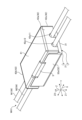
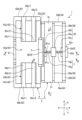
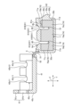
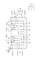
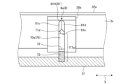
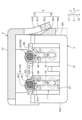
図1は、第1実施形態に係る電線圧接コネクタ1において、ハウジング本体部3に対してハウジング蓋部4を開いた状態を示す斜視図である。図2は、第1実施形態に係る電線圧接コネクタ1において、ハウジング本体部3に対してハウジング蓋部4を閉じた状態を示す斜視図である。図3は、ハウジング本体部3に対してハウジング蓋部4を開いた状態における平面図である。図4は、図3の矢視A-Aにおける断面図である。図5は、図3の矢視B-Bにおける断面図である。図6は、接続端子7の斜視図である。図7は、図3の矢視B-Bにおける断面の斜視図である。図8は、第1実施形態に係る電線圧接コネクタ1を使用して、電線Wの被覆部W2に切れ込みを入れる際の説明図である。各図のX方向は、一対の刃部81A、81Bの厚さ方向である。各図のY方向は、一対の刃部81A、81Bが対向する方向である。各図のZ1方向は、電線Wを端子スロット70に挿入する方向である。各図のZ2方向は、挿入方向Z1の反対方向である。各図の第3方向Zは、挿入方向Z1及び反対方向Z2を含む方向である。 FIG. 1 is a perspective view showing a state in which a housing lid portion 4 is opened with respect to a housing main body portion 3 in a wire pressure welding connector 1 according to a first embodiment. FIG. 2 is a perspective view showing a state in which the housing lid portion 4 is closed with respect to the housing body portion 3 in the wire pressure welding connector 1 according to the first embodiment. FIG. 3 is a plan view of the housing body 3 with the housing cover 4 opened. FIG. 4 is a cross-sectional view taken along arrow AA in FIG. FIG. 5 is a cross-sectional view taken along arrow BB in FIG. FIG. 6 is a perspective view of the connection terminal 7. FIG. 7 is a perspective view of a cross section taken along arrow BB in FIG. FIG. 8 is an explanatory diagram when making a slit in the covering portion W2 of the electric wire W using the electric wire press-connecting connector 1 according to the first embodiment. The X direction in each figure is the thickness direction of the pair of blade parts 81A and 81B. The Y direction in each figure is the direction in which the pair of blade parts 81A and 81B face each other. The Z1 direction in each figure is the direction in which the electric wire W is inserted into the terminal slot 70. The Z2 direction in each figure is the opposite direction to the insertion direction Z1. The third direction Z in each figure is a direction including the insertion direction Z1 and the opposite direction Z2.

[第1実施形態]
図1、図2に示す本実施形態の第1実施形態に係る電線圧接コネクタ1は、自動車等の車両に搭載されるワイヤハーネスWH1に組み込まれ、複数の電線Wにおける導電性を有する芯線W1どうしを電気的に接続するものである。ワイヤハーネスWH1は、例えば、車両に搭載される各機器間の接続のために、電源供給や信号通信に用いられる複数の電線Wを束にして集合部品とし、コネクタ等で複数の電線Wを各機器に接続するようにしたものである。ワイヤハーネスWH1は、複数の電線Wと、複数の電線Wにおける導電性を有する芯線W1どうしを電気的に接続する電線圧接コネクタ1とを備える。本実施形態の電線圧接コネクタ1は、例えば、一方の電線W11と、他方の電線W12とを備える。各電線Wは、図7に示すように、複数の導電性を有する金属素線からなる芯線W1の外側を、絶縁性を有する被覆部W2によって覆ったものである。本実施形態の芯線W1は、複数の金属素線によって略円柱状に形成され、かつ、横断面における芯線W1の直径R1が、後述する端子スロット70の対向方向Yの幅D1よりも大きい(図7参照)。以下、各図を参照して電線圧接コネクタ1の構成について詳細に説明する。なお、ワイヤハーネスWH1は、この他、さらに、電気接続箱、プロテクタ、グロメット、固定具、他のコネクタ等を含んで構成されてもよい。
[First embodiment]
An electric wire press-connecting connector 1 according to a first embodiment of the present embodiment shown in FIGS. 1 and 2 is incorporated into a wire harness WH1 mounted on a vehicle such as an automobile, and is used to connect conductive core wires W1 in a plurality of electric wires W. It electrically connects the The wire harness WH1 is, for example, a bundle of a plurality of electric wires W used for power supply and signal communication for connection between various devices mounted on a vehicle, and a collective part, and a connector or the like is used to connect the plurality of electric wires W to each other. It is designed to be connected to equipment. The wire harness WH1 includes a plurality of electric wires W and a wire press-connecting connector 1 that electrically connects the conductive core wires W1 of the plurality of electric wires W. The wire press-connecting connector 1 of this embodiment includes, for example, one electric wire W11 and the other electric wire W12. As shown in FIG. 7, each electric wire W has a core wire W1 made of a plurality of conductive metal wires, the outside of which is covered with an insulating coating W2. The core wire W1 of this embodiment is formed into a substantially cylindrical shape by a plurality of metal wires, and the diameter R1 of the core wire W1 in the cross section is larger than the width D1 in the opposing direction Y of the terminal slot 70, which will be described later (Fig. (see 7). Hereinafter, the configuration of the electric wire press-connecting connector 1 will be described in detail with reference to each figure. In addition, the wire harness WH1 may further include an electrical connection box, a protector, a grommet, a fixture, another connector, and the like.

電線圧接コネクタ1は、複数の電線Wの芯線W1どうしを電気的に接続するものであり、例えば中空の略直方体状に形成され、ハウジング2と、接続端子7と、切り込み部8とを備え、例えば各電線Wにおける延在方向の途中に設けられる。 The wire pressure welding connector 1 electrically connects the core wires W1 of a plurality of wires W, and is formed, for example, in the shape of a hollow rectangular parallelepiped, and includes a housing 2, a connecting terminal 7, a notch 8, For example, it is provided in the middle of each electric wire W in the extending direction.

ハウジング2は、開閉開口(開口)33を有するハウジング本体部3と、開閉開口33を閉塞するハウジング蓋部4とを備える。本実施形態のハウジング2は、ハウジング本体部3と、ハウジング蓋部4との間に、ハウジング本体部3とハウジング蓋部4とを連結するヒンジ5と、ハウジング蓋部4によって、ハウジング本体部3の開閉開口33が閉塞された状態を維持する係止機構6とを備える。 The housing 2 includes a housing main body portion 3 having an opening/closing opening (opening) 33, and a housing lid portion 4 that closes the opening/closing opening 33. The housing 2 of this embodiment has a hinge 5 that connects the housing body 3 and the housing lid 4, and a hinge 5 that connects the housing body 3 and the housing lid 4. A locking mechanism 6 is provided to maintain the opening/closing opening 33 in a closed state.

ハウジング本体部3は、開閉開口33をハウジング蓋部4によって閉塞された状態において、内部に複数の電線Wが挿通、配索される。本実施形態に係るハウジング本体部3は、厚さ方向Xの両端部が開口した樋形状に形成される。ハウジング本体部3は、厚さ方向Xに沿って電線Wが挿通される。 A plurality of electric wires W are inserted and routed inside the housing main body 3 in a state in which the opening/closing opening 33 is closed by the housing cover 4 . The housing main body 3 according to the present embodiment is formed in a gutter shape with both ends in the thickness direction X open. The electric wire W is inserted through the housing main body portion 3 along the thickness direction X.

より詳細には、ハウジング本体部3は、底部31、本体側壁部32、端子配置部35、ガイド凸部36を有する。そして、ハウジング本体部3は、底部31、及び、本体側壁部32によって形成される収容空間3s、開閉開口33、及び、挿通開口34を含んで構成される。また、ハウジング本体部3は、底部31、及び、本体側壁部32が一体となって上述したように略直線状の桶形状に形成される。 More specifically, the housing body part 3 has a bottom part 31, a body side wall part 32, a terminal placement part 35, and a guide convex part 36. The housing main body 3 includes a bottom 31, a housing space 3s formed by a main body side wall 32, an opening/closing opening 33, and an insertion opening 34. Furthermore, the housing main body 3 is integrally formed with the bottom 31 and the main body side wall 32 into a substantially linear tub shape as described above.

底部31は、ハウジング本体部3の内部空間部として収容空間3sを形成するための底壁である。底部31は、第3方向Zが板厚方向となる略矩形板状に形成される。底部31は、厚さ方向Xに延在し、対向方向Yにおいて、例えば2本の電線Wを収容可能な所定の幅を有する。 The bottom portion 31 is a bottom wall for forming a housing space 3s as an internal space portion of the housing body portion 3. The bottom portion 31 is formed into a substantially rectangular plate shape with the third direction Z being the thickness direction. The bottom portion 31 extends in the thickness direction X, and has a predetermined width that can accommodate, for example, two electric wires W in the opposing direction Y.

本体側壁部32は、ハウジング本体部3の内部に位置する収容空間3sを形成するための側壁である。本体側壁部32は、底部31から反対方向Z2に沿って突出して形成され、互いに対向する一対の対向壁部32a、32bを有する。 The main body side wall portion 32 is a side wall for forming a housing space 3s located inside the housing main body portion 3. The main body side wall portion 32 is formed to protrude from the bottom portion 31 along the opposite direction Z2, and has a pair of opposing wall portions 32a and 32b facing each other.

一対の対向壁部32a、32bは、共に対向方向Yが板厚方向となる略矩形板状にそれぞれ形成される。各対向壁部32a、32bは、厚さ方向Xに沿って延在する。一対の対向壁部32a、32bは、対向方向Yに対して底部31を挟んで両側に設けられ、対向方向Yに間隔をあけて対向して位置する。本実施形態のハウジング2において、一対の対向壁部32a、32bは、底部31の対向方向Yの両縁にそれぞれ設けられ、厚さ方向Xに沿って底部31の一方の端部から他方の端部まで延在する。言い換えれば、底部31は、対向方向Yにおいて、一対の対向壁部32a、32bの間に位置し、対向方向Yの両端部がそれぞれ各対向壁部32a、32bと接続される。一対の対向壁部32a、32bは、底部31において、第3方向Zに対して同じ側に立設される。一対の対向壁部32a、32bにおいて、一方の対向壁部32aと他方の対向壁部32bとは、第3方向Zに沿った長さがそれぞれほぼ同じであり、一方の対向壁部32aと他方の対向壁部32bとは、厚さ方向Xに沿った長さがほぼ同じである。 The pair of opposing wall portions 32a and 32b are each formed into a substantially rectangular plate shape with the opposing direction Y being the thickness direction. Each opposing wall portion 32a, 32b extends along the thickness direction X. The pair of opposing wall portions 32a and 32b are provided on both sides with the bottom portion 31 in between in the opposing direction Y, and are located facing each other with an interval in the opposing direction Y. In the housing 2 of this embodiment, the pair of opposing wall portions 32a and 32b are provided at both edges of the bottom portion 31 in the opposing direction Y, and extend from one end of the bottom portion 31 to the other end along the thickness direction X. Extends to the end. In other words, the bottom portion 31 is located between the pair of opposing walls 32a, 32b in the opposing direction Y, and both ends in the opposing direction Y are connected to the opposing walls 32a, 32b, respectively. The pair of opposing walls 32a and 32b are erected on the same side in the third direction Z at the bottom 31. In the pair of opposing wall sections 32a and 32b, one opposing wall section 32a and the other opposing wall section 32b have substantially the same length along the third direction Z, and one opposing wall section 32a and the other opposing wall section 32b have substantially the same length along the third direction Z. The length along the thickness direction X is almost the same as that of the opposing wall portion 32b.

上記のように構成されるハウジング本体部3は、底部31と本体側壁部32とによって、収容空間3s、開閉開口33、及び、複数の挿通開口34が形成される。収容空間3sは、厚さ方向Xに沿い、かつ、対向方向Yに沿って電線Wが配索される空間部である。収容空間3sは、底部31と本体側壁部32とによって囲われた内部空間部として形成される。開閉開口33は、図3に示すように、収容空間3sを外部に対して開放させる開口であり、ハウジング蓋部4によって閉塞される開口である。開閉開口33は、例えば、後述する一対の刃部81A、81Bに電線Wを接触させる際に開放され、一対の刃部81A、81Bに電線Wを接触させた後にハウジング蓋部4によって閉塞される。開閉開口33は、第3方向Zにおいて、各対向壁部32a、32bの底部31側とは反対側の端部によって形成される。開閉開口33は、各対向壁部32a、32bに対して第3方向Zに沿って一方側、すなわち、底部31側とは反対側に開口する。より具体的に説明すると、開閉開口33は、厚さ方向X、及び対向方向Yに沿って開口する。挿通開口34は、収容空間3sに電線Wを挿通させる開口である。挿通開口34は、一対の対向壁部32a、32b、及び、底部31によって厚さ方向Xの両端部に形成された第1挿通開口34a及び第2挿通開口34bを含む。第1挿通開口34a及び第2挿通開口34bは、図1に示すように、対向方向Y、及び、第3方向Zに沿って開口する。 In the housing main body 3 configured as described above, the bottom 31 and the main body side wall 32 form an accommodation space 3s, an opening/closing opening 33, and a plurality of insertion openings 34. The accommodation space 3s is a space in which the electric wires W are routed along the thickness direction X and the opposing direction Y. The accommodation space 3s is formed as an internal space surrounded by the bottom portion 31 and the main body side wall portion 32. The opening/closing opening 33 is an opening that opens the housing space 3s to the outside, as shown in FIG. 3, and is an opening that is closed by the housing lid portion 4. The opening/closing opening 33 is opened, for example, when the electric wire W is brought into contact with a pair of blade parts 81A and 81B, which will be described later, and is closed by the housing lid part 4 after the electric wire W is brought into contact with the pair of blade parts 81A and 81B. . The opening/closing opening 33 is formed, in the third direction Z, by the end portions of the opposing wall portions 32a, 32b on the opposite side to the bottom portion 31 side. The opening/closing opening 33 opens on one side along the third direction Z with respect to each of the opposing walls 32a and 32b, that is, on the side opposite to the bottom 31 side. More specifically, the opening/closing opening 33 opens along the thickness direction X and the opposing direction Y. The insertion opening 34 is an opening through which the electric wire W is inserted into the accommodation space 3s. The insertion opening 34 includes a first insertion opening 34a and a second insertion opening 34b formed at both ends in the thickness direction X by the pair of opposing walls 32a, 32b and the bottom 31. The first insertion opening 34a and the second insertion opening 34b open along the opposing direction Y and the third direction Z, as shown in FIG.

端子配置部35は、後述する接続端子7を、ハウジング本体部3にインサート成型によって配置するための部分である。より具体的に説明すると、端子配置部35は、厚さ方向Xにおいて、ハウジング本体部3の中央に配置してあり、中央端子配置部35aと、一対の側方端子配置部35b、35cとを有する。中央端子配置部35aは、対向方向Yにおいて、ハウジング本体部3の中央に配置してあり、底部31に対して一体的であって略直方体状に形成される。一対の側方端子配置部35b、35cのうち、一方の側方端子配置部35bは、対向方向Yにおいて、ハウジング本体部3の一方の端部に配置してあり、一方の対向壁部32aに対して一体的であって略矩形平板状に形成される。一対の側方端子配置部35b、35cのうち、他方の側方端子配置部35cは、対向方向Yにおいて、ハウジング本体部3の他方の端部に配置してあり、他方の対向壁部32bに対して一体的であって略矩形平板状に形成される。 The terminal arrangement portion 35 is a portion for arranging a connection terminal 7, which will be described later, in the housing main body portion 3 by insert molding. To explain more specifically, the terminal arrangement section 35 is arranged at the center of the housing body section 3 in the thickness direction X, and includes a central terminal arrangement section 35a and a pair of side terminal arrangement sections 35b and 35c. have The central terminal arrangement part 35a is arranged at the center of the housing main body part 3 in the facing direction Y, is integral with the bottom part 31, and is formed in a substantially rectangular parallelepiped shape. Among the pair of side terminal placement portions 35b and 35c, one side terminal placement portion 35b is placed at one end of the housing body portion 3 in the opposing direction Y, and is located at one opposing wall portion 32a. On the other hand, it is integral and formed into a substantially rectangular flat plate shape. Of the pair of side terminal placement portions 35b and 35c, the other side terminal placement portion 35c is placed at the other end of the housing body portion 3 in the opposing direction Y, and is located at the other opposing wall portion 32b. On the other hand, it is integral and formed into a substantially rectangular flat plate shape.

ガイド凸部36は、個々の電線Wを厚さ方向Xに沿った直線状にガイドする部分であり、第1ガイド凸部36aと、第2ガイド凸部36bとを有する。第1ガイド凸部36aは、厚さ方向Xに延在する直線状に形成してあって、中央部と第1挿通開口34aとの間において、底部31に対して一体的であって厚さ方向Xに延在する直線状に形成される。第2ガイド凸部36bは、厚さ方向Xに延在する直線状に形成してあって、中央部と第2挿通開口34bとの間において、底部31に対して一体的であって厚さ方向Xに延在する直線状に形成される。 The guide convex portion 36 is a portion that guides each electric wire W linearly along the thickness direction X, and includes a first guide convex portion 36a and a second guide convex portion 36b. The first guide convex portion 36a is formed in a straight line extending in the thickness direction X, and is integral with the bottom portion 31 between the center portion and the first insertion opening 34a. It is formed in a straight line extending in the direction X. The second guide convex portion 36b is formed in a linear shape extending in the thickness direction X, and is integral with the bottom portion 31 between the center portion and the second insertion opening 34b. It is formed in a straight line extending in the direction X.

ハウジング蓋部4は、ハウジング本体部3に組み付けられ、当該ハウジング本体部3に形成された開閉開口33を閉塞するものである。ハウジング蓋部4は、図1、図2に示すように、天部41、蓋側壁部42、及び、押圧部4343を有する。ハウジング蓋部4は、天部41、蓋側壁部42及び、押圧部4343が一体となって、ハウジング本体部3の形状に対応した略直線状の樋形状に形成される。 The housing lid portion 4 is assembled to the housing body portion 3 and closes an opening/closing opening 33 formed in the housing body portion 3. The housing lid part 4 has a top part 41, a lid side wall part 42, and a pressing part 4343, as shown in FIGS. 1 and 2. The housing lid portion 4 is formed into a substantially linear gutter shape corresponding to the shape of the housing body portion 3 by integrating the top portion 41, the lid side wall portion 42, and the pressing portion 4343.

天部41は、ハウジング本体部3の開閉開口33を塞ぎ、収容空間3sを形成するための天壁である。天部41は、第3方向Zが板厚方向となる略板状に形成される。また、天部41は、厚さ方向Xに延在するとともに、収容空間3sを閉塞可能とするために対向方向Yに所定の幅を有する。本実施形態の天部41は、ハウジング2本体の開閉開口33を閉塞した状態において、第3方向Zにおいて底部31に対向する。 The top portion 41 is a top wall for closing the opening/closing opening 33 of the housing main body portion 3 and forming the accommodation space 3s. The top portion 41 is formed into a substantially plate shape with the third direction Z being the thickness direction. Further, the top portion 41 extends in the thickness direction X and has a predetermined width in the opposing direction Y so as to be able to close the accommodation space 3s. The top portion 41 of this embodiment faces the bottom portion 31 in the third direction Z when the opening/closing opening 33 of the main body of the housing 2 is closed.

蓋側壁部42は、厚さ方向Xにおいて、互いに対向する一対の対向蓋側壁部42a、42b、及び、一方の対向蓋側壁部42aにおける対向方向Yの一方の端部と、他方の対向蓋側壁部42bにおける対向方向Yの一方の端部とを連結する連結蓋側壁部42cを有する。連結蓋側壁部42cは、ハウジング本体部3の開閉開口33をハウジング蓋部4が閉塞した状態において、対向方向Yにおいて、ハウジング本体部3の他方の対向壁部32bに対向する。一方の対向蓋側壁部42a、他方の対向蓋側壁部42b、及び、連結蓋側壁部42cは、天部41から第3方向Zに沿って突出して形成される。一方の対向蓋側壁部42a、他方の対向蓋側壁部42b、及び、連結蓋側壁部42cは、天部41に対して第3方向Zに対して同じ側に立設される。一方の対向蓋側壁部42a、他方の対向蓋側壁部42b、及び連結蓋側壁部42cは、ハウジング本体部3の開閉開口33をハウジング蓋部4が閉塞した状態において、天部41から第3方向Zに沿ってハウジング本体部3側に向けて突出して形成される。一方の対向蓋側壁部42a、他方の対向蓋側壁部42b、及び連結蓋側壁部42cは、第3方向Zに沿った長さがそれぞれほぼ同一である。 The lid side wall 42 includes a pair of opposing lid side walls 42a and 42b that face each other in the thickness direction It has a connecting lid side wall portion 42c that connects one end of the portion 42b in the opposing direction Y. The connecting lid side wall portion 42c faces the other opposing wall portion 32b of the housing body portion 3 in the opposing direction Y when the housing lid portion 4 closes the opening/closing opening 33 of the housing body portion 3. One opposing lid side wall portion 42a, the other opposing lid side wall portion 42b, and the connecting lid side wall portion 42c are formed to protrude from the top portion 41 along the third direction Z. One opposing lid side wall portion 42a, the other opposing lid side wall portion 42b, and the connecting lid side wall portion 42c are erected on the same side with respect to the third direction Z with respect to the top portion 41. One opposing lid side wall portion 42a, the other opposing lid side wall portion 42b, and the connecting lid side wall portion 42c are arranged in a third direction from the top portion 41 when the housing lid portion 4 closes the opening/closing opening 33 of the housing body portion 3. It is formed to protrude toward the housing main body portion 3 side along the Z direction. One opposing lid side wall portion 42a, the other opposing lid side wall portion 42b, and the connecting lid side wall portion 42c have substantially the same length along the third direction Z, respectively.

一方の対向蓋側壁部42a、及び、他方の対向蓋側壁部42bは、共に厚さ方向Xが板厚方向となる略矩形板状に形成され、対向方向Yに沿って延在する。一方の対向蓋側壁部42a、及び、他方の対向蓋側壁部42bは、対向方向Yにおいて、天部41を挟んで両側に設けられ、厚さ方向Xにおいて、間隔をあけて対向して位置する。本実施形態では、一方の対向蓋側壁部42a、及び、他方の対向蓋側壁部42bは、天部41の厚さ方向Xの両縁にそれぞれ設けられ、対向方向Yに沿って天部41の一方の端部から他方の端部まで延在する。言い換えれば、天部41は、対向方向Yにおいて、一方の対向蓋側壁部42a、及び、他方の対向蓋側壁部42bの間に位置し、対向方向Yの両端部がそれぞれ一方の対向蓋側壁部42a、及び、他方の対向蓋側壁部42bと接続される。一方の対向蓋側壁部42a、及び、他方の対向蓋側壁部42bは、対向方向Yに沿った長さがそれぞれほぼ同一である。 One opposing lid side wall portion 42a and the other opposing lid side wall portion 42b are both formed into a substantially rectangular plate shape with the thickness direction X being the plate thickness direction, and extend along the opposing direction Y. One opposing lid side wall portion 42a and the other opposing lid side wall portion 42b are provided on both sides with the top portion 41 in between in the opposing direction Y, and are located facing each other with an interval in the thickness direction X. . In this embodiment, one opposing lid side wall portion 42a and the other opposing lid side wall portion 42b are provided at both edges of the top portion 41 in the thickness direction X, and extend along the opposing lid side Y. Extending from one end to the other end. In other words, the top portion 41 is located between one opposing lid side wall portion 42a and the other opposing lid side wall portion 42b in the opposing direction Y, and both ends in the opposing direction Y are located at one opposing lid side wall portion. 42a and the other opposing lid side wall portion 42b. One opposing lid side wall portion 42a and the other opposing lid side wall portion 42b have substantially the same length along the opposing direction Y, respectively.

連結蓋側壁部42cは、対向方向Yが板厚方向となる略板状に形成され、厚さ方向Xに沿って延在する。また、連結蓋側壁部42cは、天部41の対向方向Yの一方の側縁に設けられ、厚さ方向Xに沿って延在する。本実施形態におけるハウジング蓋部4は、連結蓋側壁部42cにおける厚さ方向Xの中央に係止機構6の係止孔部61を設け、当該係止孔部61が配置された部分には連結蓋側壁部42cを設けていない。このような連結蓋側壁部42cは、対向方向Yにおいて、天部41を挟んでヒンジ5の反対側に設けられる。言い換えれば、天部41は、対向方向Yにおいて、連結蓋側壁部42cとヒンジ5との間に位置し、対向方向Yの一方の端部が連結蓋側壁部42cと接続される一方、対向方向Yの他方の端部がヒンジ5を介してハウジング本体部3と接続される。 The connecting lid side wall portion 42c is formed in a substantially plate shape with the facing direction Y being the thickness direction, and extends along the thickness direction X. Further, the connecting lid side wall portion 42c is provided on one side edge of the top portion 41 in the opposing direction Y, and extends along the thickness direction X. The housing lid 4 in this embodiment has a locking hole 61 of the locking mechanism 6 in the center of the connecting lid side wall 42c in the thickness direction X, and a portion where the locking hole 61 is arranged is connected No lid side wall portion 42c is provided. Such a connecting lid side wall portion 42c is provided on the opposite side of the hinge 5 with the top portion 41 in between in the opposing direction Y. In other words, the top part 41 is located between the connecting lid side wall part 42c and the hinge 5 in the facing direction Y, and one end in the facing direction Y is connected to the connecting lid side wall part 42c, while in the facing direction The other end of the Y is connected to the housing body 3 via the hinge 5.

一対の対向蓋側壁部42a、42bのうち、一方の対向蓋側壁部42aは、電線Wが挿入され、かつ、挿入された電線Wの被覆部W2が接触する対向第1蓋挿入溝42a1を複数有する。対向第1蓋挿入溝42a1は、一方の電線W11を挿入する第1対向蓋挿入溝42a11と、他方の電線W12を挿入する第2対向蓋挿入溝42a12とを含む。つまり、一方の対向蓋側壁部42aには、後述する端子スロット70に対応して2つの対向蓋挿入溝42a11、42a12が形成される。各対向蓋挿入溝42a11、42a12は、ハウジング本体部3の開閉開口33をハウジング蓋部4によって閉塞した状態において、一方の対向蓋側壁部42aの挿入方向Z1側の端部から反対方向Z2へ向けて凹み、第3方向Zに沿って直線状に延在する。 Among the pair of opposing lid side walls 42a and 42b, one opposing lid side wall 42a has a plurality of opposing first lid insertion grooves 42a1 into which the electric wire W is inserted and with which the covering portion W2 of the inserted electric wire W contacts. have The first opposing lid insertion groove 42a1 includes a first opposing lid insertion groove 42a11 into which one electric wire W11 is inserted, and a second opposing lid insertion groove 42a12 into which the other electric wire W12 is inserted. That is, two opposing lid insertion grooves 42a11 and 42a12 are formed in one opposing lid side wall portion 42a, corresponding to the terminal slots 70, which will be described later. Each of the opposing lid insertion grooves 42a11 and 42a12 extends from the end of one opposing lid side wall 42a on the insertion direction Z1 side toward the opposite direction Z2 when the opening/closing opening 33 of the housing main body 3 is closed by the housing lid 4. It is recessed and extends linearly along the third direction Z.

一対の対向蓋側壁部42a、42bのうち、他方の対向蓋側壁部42bは、電線Wが挿入され、かつ、挿入された電線Wの被覆部W2が接触する対向第2蓋挿入溝42b1を複数有する。対向第2蓋挿入溝42b1は、一方の電線W11を挿入する第3対向蓋挿入溝42b11と、他方の電線W12を挿入する第4対向蓋挿入溝42b12とを含む。つまり、他方の対向蓋側壁部42bには、端子スロット70に対応して2つの対向蓋挿入溝42b11、42b12が形成される。各対向蓋挿入溝42b11、42b12は、ハウジング本体部3の開閉開口33をハウジング蓋部4によって閉塞した状態において、他方の対向蓋側壁部42bの挿入方向Z1側の端部から反対方向Z2へ向けて凹み、第3方向Zに沿って直線状に延在する。 Of the pair of opposing lid side walls 42a and 42b, the other opposing lid side wall 42b has a plurality of opposing second lid insertion grooves 42b1 into which the electric wire W is inserted and in which the covering portion W2 of the inserted electric wire W contacts. have The second opposing lid insertion groove 42b1 includes a third opposing lid insertion groove 42b11 into which one electric wire W11 is inserted, and a fourth opposing lid insertion groove 42b12 into which the other electric wire W12 is inserted. That is, two opposing lid insertion grooves 42b11 and 42b12 corresponding to the terminal slots 70 are formed in the other opposing lid side wall portion 42b. Each of the opposing lid insertion grooves 42b11 and 42b12 extends from the end of the other opposing lid side wall 42b on the insertion direction Z1 side in the opposite direction Z2 when the opening/closing opening 33 of the housing main body 3 is closed by the housing lid 4. It is recessed and extends linearly along the third direction Z.

押圧部43は、開閉開口33をハウジング蓋部4によって閉塞する際に複数の電線W(本実施形態では2本の電線W)を押圧することによって、電線Wの芯線W1を各切り込みスロット80を介して各端子スロット70に挿入するものである。言い換えると、押圧部43は、開閉開口33をハウジング蓋部4によって閉塞する際に複数の電線を一括して押圧することによって芯線W1を各端子スロット70に挿入するものである。このような押圧部43は、天部41と一体的に形成してある。より具体的に説明すると、押圧部43は、ハウジング本体部3の開閉開口33を蓋部によって閉塞した状態において、収容空間3sの内部に位置する一方、天部41は収容空間3sの外部に位置する。このような押圧部43は、押圧中央部43a、及び、一対の押圧側部43b、43cを有する。 The pressing part 43 cuts the core wire W1 of the electric wire W into each slot 80 by pressing the plurality of electric wires W (two electric wires W in this embodiment) when closing the opening/closing opening 33 with the housing lid part 4. It is inserted into each terminal slot 70 through the terminal slot 70. In other words, the pressing part 43 inserts the core wire W1 into each terminal slot 70 by pressing the plurality of electric wires at once when closing the opening/closing opening 33 with the housing lid part 4. Such a pressing portion 43 is formed integrally with the top portion 41. More specifically, when the opening/closing opening 33 of the housing main body 3 is closed by the lid, the pressing part 43 is located inside the housing space 3s, while the top part 41 is located outside the housing space 3s. do. The pressing portion 43 has a pressing center portion 43a and a pair of pressing side portions 43b and 43c.

押圧中央部43aは、ハウジング蓋部4の厚さ方向Xにおける中央に位置する一方、一対の押圧側部43b、43cは、厚さ方向Xにおける両側に位置する。つまり、一対の押圧側部43b、43cは、厚さ方向Xにおいて、押圧中央部43aを挟んで位置する。ハウジング本体部3の開閉開口33をハウジング蓋部4が閉塞した状態において、押圧中央部43aは、切り込み部8の反対方向Z2側に対向する一方、押圧側部43b、43cは、切り込み部8から外れた底部31の反対方向Z2側に対向する。押圧中央部43aは、略矩形平板状に形成してある一方、一対の押圧側部43b、43cは、略直方体状に形成してある。また、一対の押圧側部43b、43cの第3方向Zの厚さは、押圧中央部43aの第3方向Zの厚さよりも厚く、一対の押圧側部43b、43cの挿入方向Z1側の端部は、押圧中央部43aの挿入方向Z1側の端部よりも挿入方向Z1側に突出する。 The pressing center portion 43a is located at the center of the housing lid portion 4 in the thickness direction X, while the pair of pressing side portions 43b and 43c are located on both sides in the thickness direction X. In other words, the pair of pressing side portions 43b and 43c are positioned with the pressing center portion 43a in between in the thickness direction X. When the housing cover 4 closes the opening/closing opening 33 of the housing main body 3, the pressing central portion 43a faces the opposite direction Z2 side of the notch 8, while the pressing side portions 43b, 43c are separated from the notch 8. It faces the opposite direction Z2 side of the bottom part 31 that came off. The pressing center portion 43a is formed into a substantially rectangular flat plate shape, while the pair of pressing side portions 43b and 43c are formed into a substantially rectangular parallelepiped shape. Moreover, the thickness of the pair of pressing side parts 43b, 43c in the third direction Z is thicker than the thickness of the pressing center part 43a in the third direction Z, and the end of the pair of pressing side parts 43b, 43c on the insertion direction Z1 side The portion protrudes toward the insertion direction Z1 side from the end portion of the pressing central portion 43a on the insertion direction Z1 side.

一対の押圧側部43b、43cのうち、一方の押圧側部43bは、電線Wの被覆部W2が嵌る押圧第1凹部43b1を複数有する。押圧第1凹部43b1は、一方の電線W11が嵌る第1押圧凹部43b11と、他方の電線W12が嵌る第2押圧凹部43b12と含む。つまり、一方の押圧側部43bには、後述する端子スロット70に対応して2つの押圧凹部43b11、43b12が形成される。各押圧凹部43b11、43b12は、ハウジング本体部3の開閉開口33をハウジング蓋部4によって閉塞した状態において、押圧側部43bの挿入方向Z1側の端部から反対方向Z2側へ向けて凹む。第1押圧凹部43b11の周面と、第1対向蓋挿入溝42a11における第3方向Zの他方側の端部に位置する周面は、厚さ方向Xに沿って同一の曲面を構成する。第2押圧凹部43b12の周面と、第2対向蓋挿入溝42a12における第3方向Zの他方側の端部に位置する周面は、厚さ方向Xに沿って同一の曲面を構成する。 Among the pair of pressing side parts 43b and 43c, one pressing side part 43b has a plurality of pressing first recesses 43b1 into which the covering part W2 of the electric wire W fits. The first pressing recess 43b1 includes a first pressing recess 43b11 into which one electric wire W11 fits, and a second pressing recess 43b12 into which the other electric wire W12 fits. That is, two pressing recesses 43b11 and 43b12 are formed in one pressing side portion 43b, corresponding to terminal slots 70, which will be described later. Each of the pressing recesses 43b11 and 43b12 is recessed from the end of the pressing side portion 43b on the insertion direction Z1 side toward the opposite direction Z2 side when the opening/closing opening 33 of the housing main body portion 3 is closed by the housing lid portion 4. The circumferential surface of the first pressing recess 43b11 and the circumferential surface located at the other end of the first opposing lid insertion groove 42a11 in the third direction Z form the same curved surface along the thickness direction X. The circumferential surface of the second pressing recess 43b12 and the circumferential surface located at the other end of the second opposing lid insertion groove 42a12 in the third direction Z constitute the same curved surface along the thickness direction X.

一対の押圧側部43b、43cのうち、他方の押圧側部43cは、電線Wの被覆部W2が嵌る押圧第2凹部43c1を複数有する。押圧第2凹部43c1は、一方の電線W11が嵌る第3押圧凹部43c11と、他方の電線W12が嵌る第4押圧凹部43c12と含む。つまり、他方の押圧側部43cには、後述する端子スロット70に対応して2つの押圧凹部43c11、43c12が形成される。各押圧凹部43c11、43c12は、ハウジング本体部3の開閉開口33をハウジング蓋部4によって閉塞した状態において、押圧側部43cの挿入方向Z1側の端部から反対方向Z2側へ向けて凹む。第3押圧凹部43c11の周面と、第3対向蓋挿入溝42b11における第3方向Zの他方側の端部に位置する周面は、厚さ方向Xに沿って同一の曲面を構成する。第4押圧凹部43c12の周面と、第4対向蓋挿入溝42b12における第3方向Zの他方側の端部に位置する周面は、厚さ方向Xに沿って同一の曲面を構成する。 Among the pair of pressing side portions 43b and 43c, the other pressing side portion 43c has a plurality of pressing second recesses 43c1 into which the covering portion W2 of the electric wire W is fitted. The second pressing recess 43c1 includes a third pressing recess 43c11 into which one electric wire W11 fits, and a fourth pressing recess 43c12 into which the other electric wire W12 fits. That is, two pressing recesses 43c11 and 43c12 are formed in the other pressing side portion 43c, corresponding to the terminal slots 70, which will be described later. Each of the pressing recesses 43c11 and 43c12 is recessed from the end of the pressing side portion 43c on the insertion direction Z1 side toward the opposite direction Z2 side when the opening/closing opening 33 of the housing main body 3 is closed by the housing lid portion 4. The circumferential surface of the third pressing recess 43c11 and the circumferential surface located at the other end of the third opposing lid insertion groove 42b11 in the third direction Z constitute the same curved surface along the thickness direction X. The circumferential surface of the fourth pressing recess 43c12 and the circumferential surface located at the other end of the fourth opposing lid insertion groove 42b12 in the third direction Z constitute the same curved surface along the thickness direction X.

また、本実施形態に係る電線圧接コネクタ1は、図2に示すように、一対の押圧側部43b、43cの第3方向Zにおける一方側の端部は、押圧中央部43aの第3方向Zにおける一方側の端部よりも突出するように形成される。このため、一対の押圧側部43b、43cは、後述するように、押圧部43により電線Wを押圧する初期において、押圧中央部43aが電線Wに接触するよりも早く電線Wに接触し、その後、押圧中央部43aは、電線Wに接触することによって、電線Wを後述する一対の刃部81A、81Bに押圧し、一対の刃部81A、81Bによって電線Wの被覆部W2に切れ込みを入れる。 Further, in the wire press-connecting connector 1 according to the present embodiment, as shown in FIG. 2, one end of the pair of pressing side portions 43b and 43c in the third direction Z is It is formed so as to protrude from one end of the . Therefore, as will be described later, the pair of pressing side parts 43b and 43c come into contact with the electric wire W earlier than the pressing center part 43a contacts the electric wire W at the initial stage of pressing the electric wire W by the pressing part 43, and then By contacting the electric wire W, the pressing central portion 43a presses the electric wire W against a pair of blade portions 81A and 81B, which will be described later, and makes a cut in the covering portion W2 of the electric wire W by the pair of blade portions 81A and 81B.

ヒンジ5は、図1、図4に示すように、ハウジング本体部3とハウジング蓋部4との間に設けられ、ハウジング本体部3とハウジング蓋部4とを連結するものである。つまり、図4に示すように、ヒンジ5の一方の端部51は、ハウジング本体部3に連結される一方、ヒンジ5の他方の端部52は、ハウジング蓋部4に連結される。より具体的に説明すると、ヒンジ5は、ハウジング本体部3の一方の対向壁部32aと、ハウジング蓋部4の天部41との間に設けられる。ヒンジ5は、例えば、絶縁性の合成樹脂によって、ハウジング本体部3及びハウジング蓋部4と一体的に設けられる。 As shown in FIGS. 1 and 4, the hinge 5 is provided between the housing body 3 and the housing lid 4, and connects the housing body 3 and the housing lid 4. That is, as shown in FIG. 4, one end 51 of the hinge 5 is connected to the housing body 3, while the other end 52 of the hinge 5 is connected to the housing cover 4. More specifically, the hinge 5 is provided between one opposing wall portion 32a of the housing body portion 3 and the top portion 41 of the housing lid portion 4. The hinge 5 is made of, for example, insulating synthetic resin and is integrally provided with the housing body 3 and the housing cover 4.

係止機構6は、図1に示すように、ハウジング蓋部4が開閉開口33を塞ぐ(閉塞する)正規位置でハウジング本体部3とハウジング蓋部4とを係止する機構である。係止機構6は、図7に示すように、係止孔部61と、係止爪部62とを備える。本実施形態の係止機構6は、ハウジング蓋部4に係止孔部61を設ける一方、ハウジング本体部3に係止爪部62を設ける。また、電線圧接コネクタ1は、例えば、1つの係止機構6を有する。 As shown in FIG. 1, the locking mechanism 6 is a mechanism that locks the housing body 3 and the housing lid 4 at a normal position where the housing lid 4 closes (closes) the opening/closing opening 33. The locking mechanism 6 includes a locking hole 61 and a locking claw 62, as shown in FIG. The locking mechanism 6 of this embodiment includes a locking hole 61 in the housing cover 4 and a locking claw 62 in the housing main body 3 . Further, the wire pressure welding connector 1 includes, for example, one locking mechanism 6.

係止孔部61は、ハウジング本体部3に対してハウジング蓋部4が正規位置にある状態で、係止爪部62と係止するものであり、弾性変形可能にハウジング蓋部4と一体的に形成される。係止孔部61は、図2に示すように、厚さ方向Xにおいて間隔をあけて配置される一対の棒状部61a、61bと、各棒状部61a、61bにおける第3方向Zの端部を連結する連結部61cとを有する。そして、係止孔部61は、一対の棒状部61a、61bと、連結部61cとによって、対向方向Yの両側に開口する。 The locking hole portion 61 locks with the locking claw portion 62 when the housing lid portion 4 is in a normal position with respect to the housing body portion 3, and is integrally formed with the housing lid portion 4 so as to be elastically deformable. is formed. As shown in FIG. 2, the locking hole portion 61 includes a pair of rod-shaped portions 61a and 61b arranged at intervals in the thickness direction X, and an end portion of each rod-shaped portion 61a and 61b in the third direction Z. It has a connecting part 61c to connect. The locking hole portion 61 is opened on both sides in the opposing direction Y by the pair of rod-shaped portions 61a and 61b and the connecting portion 61c.

係止爪部62は、ハウジング本体部3とハウジング蓋部4とが正規位置にある閉塞状態で、係止孔部61に係止されるものであり、ハウジング本体部3と一体的に形成される。係止爪部62は、図4、図5に示すように、ハウジング本体部3における収容空間3sの外部に位置するように、一方の対向壁部32bと一体的に設けられる。より具体的に説明すると、係止爪部62は、ハウジング本体部3に対してハウジング蓋部4が正規位置に配置された状態で、連結蓋側壁部42cにおける対向壁部32bに対向する面に設けられる。係止爪部62は、対向壁部32bにおける厚さ方向Xの中央に位置する。本実施形態の係止爪部62は、図4に示すように、対向方向Yにおいて、対向壁部32bから突出するように形成される。より具体的に説明すると、係止爪部62は、対向方向Yと第3方向Zとを含む平面における断面形状が台形であり、対向壁部32bの外面と平行な平行面62aを有するとともに、第3方向Zにおいて対向する直交面62b及び傾斜面62cとを有する。直交面62bは、平行面62aに対して直交する。傾斜面62cは、平行面62aに対して対向方向Y及び第3方向Zにおいて傾斜して交差する。より具体的に説明すると、傾斜面62cは、ハウジング本体部3の開閉開口33をハウジング蓋部4によって閉塞した状態において、対向壁部32bに対する反対方向Z2側への突出量が小さく、挿入方向Z1側へ行くに従って、対向壁部32bに対する反対方向Z2側への突出量が大きくなる。傾斜面62cは、ハウジング本体部3の開閉開口33をハウジング蓋部4によって閉塞した状態において、平行面62aに対して反対方向Z2側に位置する。直交面62bは、ハウジング本体部3の開閉開口33をハウジング蓋部4によって閉塞した状態において、平行面62aに対して挿入方向Z1側に位置する。 The locking claw portion 62 is locked in the locking hole portion 61 in a closed state in which the housing body portion 3 and the housing lid portion 4 are in their normal positions, and is formed integrally with the housing body portion 3. Ru. As shown in FIGS. 4 and 5, the locking claw portion 62 is provided integrally with one opposing wall portion 32b so as to be located outside the accommodation space 3s in the housing body portion 3. To explain more specifically, the locking claw portion 62 is attached to the surface of the connecting lid side wall portion 42c facing the opposing wall portion 32b when the housing lid portion 4 is placed in the normal position with respect to the housing body portion 3. provided. The locking claw portion 62 is located at the center of the opposing wall portion 32b in the thickness direction X. The locking claw portion 62 of this embodiment is formed to protrude from the opposing wall portion 32b in the opposing direction Y, as shown in FIG. More specifically, the locking claw portion 62 has a trapezoidal cross-sectional shape in a plane including the opposing direction Y and the third direction Z, and has a parallel surface 62a parallel to the outer surface of the opposing wall portion 32b. It has an orthogonal surface 62b and an inclined surface 62c that face each other in the third direction Z. The orthogonal surface 62b is perpendicular to the parallel surface 62a. The inclined surface 62c intersects the parallel surface 62a with an inclination in the opposing direction Y and the third direction Z. More specifically, when the opening/closing opening 33 of the housing main body part 3 is closed by the housing cover part 4, the inclined surface 62c projects a small amount in the opposite direction Z2 with respect to the opposing wall part 32b, and has a small protrusion in the insertion direction Z1. As it goes to the side, the amount of protrusion toward the opposite direction Z2 side with respect to the opposing wall portion 32b increases. The inclined surface 62c is located on the opposite direction Z2 side with respect to the parallel surface 62a when the opening/closing opening 33 of the housing body 3 is closed by the housing cover 4. The orthogonal surface 62b is located on the insertion direction Z1 side with respect to the parallel surface 62a when the opening/closing opening 33 of the housing body 3 is closed by the housing cover 4.

ハウジング蓋部4が正規位置に配置された状態では、ハウジング蓋部4における天部41がハウジング本体部3の開閉開口33を塞ぎ、一方の対向壁部32bと連結蓋側壁部42cとが対向方向Yにおいて対向して重なる。より詳細に説明すると、ハウジング蓋部4が正規位置に配置された状態では、連結蓋側壁部42cは、対向壁部32bの外側、すなわち、収容空間3s側とは反対側において一方の対向壁部32bと対向して位置する。また、図7において仮想線で示すハウジング蓋部4が正規位置に配置された状態では、接続端子7によって、一方の電線W11の芯線W1と他方の電線W12の芯線W1とが電気的に接続される。 When the housing lid part 4 is placed in the normal position, the top part 41 of the housing lid part 4 closes the opening/closing opening 33 of the housing main body part 3, and one opposing wall part 32b and the connecting lid side wall part 42c are in opposite directions. They face each other at Y and overlap. To explain in more detail, when the housing lid part 4 is placed in the normal position, the connecting lid side wall part 42c is connected to one of the facing wall parts on the outside of the facing wall part 32b, that is, on the side opposite to the housing space 3s side. 32b. In addition, when the housing lid portion 4 shown by the imaginary line in FIG. 7 is placed in the normal position, the core wire W1 of one electric wire W11 and the core wire W1 of the other electric wire W12 are electrically connected by the connecting terminal 7. Ru.

接続端子7は、導電性を有する金属材料によって、厚さ方向Xが板厚方向となる矩形板状に形成される。また、接続端子7は、厚さ方向Xにおいて収容空間3sを2つに区画する面積を有する。本実施形態の接続端子7は、例えば、インサート成形によって、ハウジング本体部3と一体的に形成される。接続端子7は、第1端面(端面)71aと、第2端面71bと、第3端面71cと、第4端面71dと、複数の端子スロット70とを有する。第1端面71a及び第2端面71bは、第3方向Zにおいて対向する。そして、第1端面71aは、反対方向Z2側に位置する一方、第2端面71bは、挿入方向Z1側に位置する。第3端面71c及び第4端面71dは、対向方向Yにおいて対向する。そして、第3端面71cは、対向方向Yにおける一方側(対向壁部32a及びヒンジ5が配置される側)に位置する一方、第4端面71dは、対向方向Yにおける他方側(対向壁部32bが配置される側)に位置する。各端子スロット70は、導電性の芯線W1を有する電線Wを挿入方向Z1に沿って挿入可能である。接続端子7は、各端子スロット70内で芯線W1と接触することで電線Wと電気的に接続される。本実施形態の接続端子7は、例えば、2つの端子スロット70を備える。端子スロット70は、例えば、第1端子スロット70aと第2端子スロット70bとを有する。本実施形態の接続端子7は、第1端子スロット70aの構成と、第2端子スロット70bの構成とが同一であり、説明の便宜のため、第1端子スロット70aの構成について以下に説明し、第2端子スロット70bの構成についての説明を省略する。第1端子スロット70aは、対向方向Yにおける幅が、第3方向Zにおいて一定である。また、第1端子スロット70aは、第3方向Zにおいて、第1端面71aから、第1端面71aと第2端面71bとの間に位置するスロット端部72まで挿入方向Z1へ延在する。さらに、接続端子7は、端子スロット70を配置したスロット配置部73と、端子スロット70を配置していないスロット非配置部74とを有する。本実施形態の接続端子7は、2つのスロット配置部73と、3つのスロット非配置部74とを有する。スロット配置部73における第3方向Zの幅は、スロット非配置部74における第3方向Zの幅よりも狭い。換言すれば、スロット非配置部74における第3方向Zの幅は、スロット配置部73における第3方向Zの幅よりも広い。また、3つのスロット非配置部74のうち、対向方向Yにおいて、2つのスロット配置部73の間に位置する中央スロット非配置部74aが、複数の電線Wの芯線W1どうしを電気的に接続する。中央スロット非配置部74aの一部は、中央端子配置部35aの内部に埋設される。また、3つのスロット非配置部74のうち、対向方向Yの両側に位置する側方スロット非配置部74b、74cの一部は、側方端子配置部35b、35cの内部にそれぞれ埋設される。 The connection terminal 7 is formed of a conductive metal material into a rectangular plate shape with the thickness direction X being the thickness direction. Further, the connection terminal 7 has an area that divides the accommodation space 3s into two in the thickness direction X. The connection terminal 7 of this embodiment is formed integrally with the housing main body part 3, for example, by insert molding. The connection terminal 7 has a first end surface (end surface) 71a, a second end surface 71b, a third end surface 71c, a fourth end surface 71d, and a plurality of terminal slots 70. The first end surface 71a and the second end surface 71b face each other in the third direction Z. The first end surface 71a is located on the opposite direction Z2 side, while the second end surface 71b is located on the insertion direction Z1 side. The third end surface 71c and the fourth end surface 71d face each other in the opposing direction Y. The third end surface 71c is located on one side in the opposing direction Y (the side on which the opposing wall 32a and the hinge 5 are arranged), while the fourth end surface 71d is located on the other side in the opposing direction Y (the opposing wall 32b located on the side where the Each terminal slot 70 can insert an electric wire W having a conductive core wire W1 along the insertion direction Z1. The connection terminal 7 is electrically connected to the electric wire W by coming into contact with the core wire W1 within each terminal slot 70. The connection terminal 7 of this embodiment includes, for example, two terminal slots 70. The terminal slot 70 has, for example, a first terminal slot 70a and a second terminal slot 70b. In the connection terminal 7 of this embodiment, the configuration of the first terminal slot 70a and the configuration of the second terminal slot 70b are the same, and for convenience of explanation, the configuration of the first terminal slot 70a will be described below. A description of the configuration of the second terminal slot 70b will be omitted. The width of the first terminal slot 70a in the opposing direction Y is constant in the third direction Z. Further, the first terminal slot 70a extends in the insertion direction Z1 from the first end surface 71a in the third direction Z to the slot end 72 located between the first end surface 71a and the second end surface 71b. Furthermore, the connection terminal 7 has a slot arrangement part 73 in which the terminal slot 70 is arranged, and a slot non-arrangement part 74 in which the terminal slot 70 is not arranged. The connection terminal 7 of this embodiment has two slot arrangement parts 73 and three slot non-arrangement parts 74. The width of the slot arrangement portion 73 in the third direction Z is narrower than the width of the slot non-arrangement portion 74 in the third direction Z. In other words, the width of the slot non-arranged portion 74 in the third direction Z is wider than the width of the slot arranged portion 73 in the third direction Z. Moreover, among the three slot non-arrangement parts 74, the central slot non-arrangement part 74a located between the two slot arrangement parts 73 in the opposing direction Y electrically connects the core wires W1 of the plurality of electric wires W. . A portion of the central slot non-arrangement portion 74a is buried inside the central terminal arrangement portion 35a. Moreover, among the three slot non-arrangement parts 74, a part of the side slot non-arrangement parts 74b and 74c located on both sides in the opposing direction Y are buried inside the side terminal arrangement parts 35b and 35c, respectively.

切り込み部8は、ハウジング2と一体的に形成される。例えば、本実施形態の切り込み部8は、二色成形によってハウジング2と一体的に形成される。二色成形によって切り込み部8をハウジング2と一体的に形成する場合には、ハウジング2は、絶縁性の合成樹脂によって形成され、切り込み部8は、ガラス入りの絶縁性の合成樹脂によって形成され、切り込み部8は、ハウジング2の剛性よりも高い剛性を有する。つまり、切り込み部8を形成する合成樹脂は、ハウジング2を形成する合成樹脂の剛性よりも高い剛性を有する。また、切り込み部8は、各端子スロット70に対応して形成される。すなわち、本実施形態の切り込み部8は、第1端子スロット70aに対応する第1切り込み部8aと、第2端子スロット70bに対応する第2切り込み部8bとがハウジング本体部3に形成される。より具体的に説明すると、第1切り込み部8aは、対向方向Yにおいて、中央端子配置部35aと、一方の側方端子配置部35bとの間に配置され、第2切り込み部8bは、対向方向Yにおいて、中央端子配置部35aと、他方の側方端子配置部35cとの間に配置される。本実施形態の電線圧接コネクタ1は、第1切り込み部8aの構成と、第2切り込み部8bの構成とが同一であり、説明の便宜のため、第1切り込み部8aの構成について以下に説明し、第2切り込み部8bの構成についての説明を省略する。第1切り込み部8aは、切り込みスロット80を有し、厚さ方向Xが板厚方向となる板状に形成される。本実施形態の第1切り込み部8aは、挿入方向Z1側における厚さ方向Xの厚さが、接続端子7における厚さ方向Xの厚さと同一である。そして、第1切り込み部8の厚さ方向Xにおける一方の平面と、接続端子7の厚さ方向Xにおける一方の平面とが、同一の平坦面を構成し、かつ、第1切り込み部8の厚さ方向Xにおける他方の平面と、接続端子7の厚さ方向Xにおける他方の平面とが、同一の平坦面を構成する。各切り込みスロット80は、挿入方向Z1側が端子スロット70に連通する一方、反対方向Z2側が外部に連通する。各切り込みスロット80は、対向方向Yにおける幅が、第3方向Zにおいて一定である。第1切り込み部8aは、厚さ方向Xにおける厚さが、反対方向Z2側へ向けて先細りとなり、対向方向Yにおいて、切り込みスロット80を挟んで形成される一対の刃部81A、81Bを有する。一対の刃部81A、81Bは、切り込みスロット80に電線Wを挿入する際に電線Wの被覆部W2に切れ込みを入れて芯線W1を外部に露出するものであって、対向方向Yにおいて互いの間隔が挿入方向Z1に沿って徐々に小さくなるように絶縁性の合成樹脂によって形成される。一対の刃部81A、81Bを構成する刃部構成部81の反対方向Z2側は、図6に示すように、厚さ方向Xにおける一方側に第1刃面81cを有する一方、厚さ方向Xにおける他方側に第2刃面81dをそれぞれ有する。第1刃面81c及び第2刃面81dは、それぞれ第3方向Z及び厚さ方向Xに対して傾斜し、かつ、厚さ方向Xにおいて対向し、刃部構成部81の厚さ方向Xの中央に位置する仮想中心線に対して線対称である。一対の刃部81A、81Bにおける第1刃面81c及び第2刃面81dの挿入方向Z1側の部分は、厚さ方向Xにおける厚さが一定である。刃部構成部81は、挿入方向Z1側の端面81eが接続端子7の反対方向Z2側の第1端面(端面)71aに接触する。 The notch 8 is formed integrally with the housing 2. For example, the cut portion 8 of this embodiment is formed integrally with the housing 2 by two-color molding. When the notch 8 is formed integrally with the housing 2 by two-color molding, the housing 2 is formed of an insulating synthetic resin, the notch 8 is formed of an insulating synthetic resin containing glass, The cut portion 8 has a rigidity higher than that of the housing 2. In other words, the synthetic resin forming the notch 8 has higher rigidity than the synthetic resin forming the housing 2. Further, the cut portion 8 is formed corresponding to each terminal slot 70. That is, in the notch portion 8 of this embodiment, a first notch portion 8a corresponding to the first terminal slot 70a and a second notch portion 8b corresponding to the second terminal slot 70b are formed in the housing body portion 3. More specifically, the first notch 8a is disposed between the central terminal arranging part 35a and one side terminal arranging part 35b in the opposing direction Y, and the second notch 8b is arranged in the opposing direction Y. In Y, it is arranged between the central terminal arrangement part 35a and the other side terminal arrangement part 35c. In the wire pressure welding connector 1 of this embodiment, the configuration of the first notch 8a and the configuration of the second notch 8b are the same, and for convenience of explanation, the configuration of the first notch 8a will be described below. , a description of the configuration of the second notch portion 8b will be omitted. The first cut portion 8a has a cut slot 80 and is formed in a plate shape with the thickness direction X being the thickness direction. The thickness of the first notch 8a of this embodiment in the thickness direction X on the insertion direction Z1 side is the same as the thickness of the connection terminal 7 in the thickness direction X. One plane in the thickness direction X of the first notch 8 and one plane in the thickness direction X of the connecting terminal 7 constitute the same flat surface, and The other plane in the width direction X and the other plane in the thickness direction X of the connection terminal 7 constitute the same flat surface. Each cut slot 80 communicates with the terminal slot 70 on the insertion direction Z1 side, and communicates with the outside on the opposite direction Z2 side. The width of each cut slot 80 in the opposing direction Y is constant in the third direction Z. The first cut portion 8a has a thickness in the thickness direction X that tapers toward the opposite direction Z2 side, and has a pair of blade portions 81A and 81B formed with the cut slot 80 in between in the opposing direction Y. The pair of blade parts 81A and 81B make a cut in the sheathing part W2 of the wire W to expose the core wire W1 to the outside when the wire W is inserted into the cut slot 80, and are spaced apart from each other in the opposing direction Y. It is formed of an insulating synthetic resin so that it gradually becomes smaller along the insertion direction Z1. As shown in FIG. 6, the opposite direction Z2 side of the blade part forming part 81 constituting the pair of blade parts 81A, 81B has a first blade surface 81c on one side in the thickness direction Each has a second blade surface 81d on the other side. The first blade surface 81c and the second blade surface 81d are inclined with respect to the third direction Z and the thickness direction It is line symmetrical with respect to a virtual center line located at the center. The portions of the first blade surface 81c and second blade surface 81d of the pair of blade portions 81A and 81B on the insertion direction Z1 side have a constant thickness in the thickness direction X. The end surface 81e of the blade component 81 on the insertion direction Z1 side contacts the first end surface (end surface) 71a of the connection terminal 7 on the opposite direction Z2 side.

上記のように構成される電線圧接コネクタ1は、以下、図4、図7に示すように、作業員がハウジング本体部3に対してハウジング蓋部4を組み付け、一対の刃部81A、81Bによって電線Wの被覆部W2に切れ込みを入れて芯線W1を外部に露出させ、かつ、接続端子7を介して、一方の電線W11の芯線W1と他方の電線W12の芯線W1とを電気的に接続する。 As shown in FIGS. 4 and 7, the electric wire pressure welding connector 1 configured as described above is constructed by an operator assembling the housing lid part 4 onto the housing body part 3 and using the pair of blade parts 81A and 81B. A slit is made in the covering part W2 of the electric wire W to expose the core wire W1 to the outside, and the core wire W1 of one electric wire W11 and the core wire W1 of the other electric wire W12 are electrically connected via the connection terminal 7. .

先ず、作業者は、図4に示すように、ハウジング本体部3に対してハウジング蓋部4を開き、その後、各切れ込み部の一対の刃部81A、81Bの上に、一方の電線W11と他方の電線W12をそれぞれ載せる。 First, as shown in FIG. 4, the operator opens the housing lid part 4 to the housing body part 3, and then inserts one electric wire W11 and the other electric wire onto the pair of blade parts 81A and 81B of each notch. Place the electric wires W12 on each.

次に、作業者は、図7に示すように、ハウジング本体部3に対してヒンジ5を中心としてハウジング蓋部4を旋回させる。作業員の旋回動作によって、ハウジング本体部3に対してハウジング蓋部4が挿入方向Z1側へ移動すると、一方の電線W11が、第1対向蓋挿入溝42a11、及び、第3対向蓋挿入溝42b11に挿入され、一方の電線W11の被覆部W2の周面が、第1対向蓋挿入溝42a11における第3方向Zの他方側の端部に位置する周面に接触するとともに、第3対向蓋挿入溝42b11における第3方向Zの他方側の端部に位置する周面に接触する。また、これと同時に、他方の電線W12が、第2対向蓋挿入溝42a12、及び、第4対向蓋挿入溝42b12に挿入され、他方の電線W12の被覆部W2の周面が、第2対向蓋挿入溝42a12における第3方向Zの他方側の端部に位置する周面に接触するとともに、第4対向蓋挿入溝42b12における第3方向Zの他方側の端部に位置する周面に接触する。 Next, as shown in FIG. 7, the operator pivots the housing lid part 4 about the hinge 5 with respect to the housing main body part 3. When the housing lid part 4 moves toward the insertion direction Z1 side with respect to the housing body part 3 due to the turning action of the worker, one electric wire W11 is inserted into the first opposing lid insertion groove 42a11 and the third opposing lid insertion groove 42b11. , the circumferential surface of the covering portion W2 of one electric wire W11 comes into contact with the circumferential surface located at the other end in the third direction Z in the first opposing lid insertion groove 42a11, and the third opposing lid is inserted. It contacts the peripheral surface located at the other end of the groove 42b11 in the third direction Z. At the same time, the other electric wire W12 is inserted into the second opposing lid insertion groove 42a12 and the fourth opposing lid insertion groove 42b12, and the circumferential surface of the covering portion W2 of the other electric wire W12 is inserted into the second opposing lid insertion groove 42a12. It contacts the peripheral surface located at the other end of the insertion groove 42a12 in the third direction Z, and also contacts the peripheral surface located at the other end of the fourth opposing lid insertion groove 42b12 in the third direction Z. .

その後、作業員が旋回動作を継続すると、一方の電線W11が、第1押圧凹部43b11に嵌るとともに、第3押圧凹部43c11に嵌り、かつ、一方の電線W11の被覆部W2の周面が、第1押圧凹部43b11の周面に接触するとともに、第3押圧凹部43c11の周面に接触する。また、これと同時に、他方の電線W12が、第2押圧凹部43b12に嵌るとともに、第4押圧凹部43c12に嵌り、かつ、他方の電線W12の被覆部W2の周面が、第2押圧凹部43b12の周面に接触するとともに、第4押圧凹部43c12の周面に接触する。 Thereafter, when the worker continues the turning operation, one of the electric wires W11 fits into the first pressing recess 43b11 and the third pressing recess 43c11, and the circumferential surface of the sheathing part W2 of the one electric wire W11 It contacts the peripheral surface of the first pressing recess 43b11 and also contacts the peripheral surface of the third pressing recess 43c11. At the same time, the other electric wire W12 is fitted into the second pressing recess 43b12 and the fourth pressing recess 43c12, and the peripheral surface of the covering portion W2 of the other electric wire W12 is in the second pressing recess 43b12. It contacts the peripheral surface and also contacts the peripheral surface of the fourth pressing recess 43c12.

一対の刃部81A、81Bは、図7に示すように、対向方向Yにおいて互いの間隔が挿入方向Z1に沿って徐々に小さくなるように形成されている。このため、一対の刃部81A、81Bのうちいずれか一方に電線Wの被覆部W2が接触した状態でハウジング蓋部4が挿入方向Z1側へ移動すると、一対の刃部81A、81Bにおける反対方向Z2側の先端部のいずれにも接触するように電線Wが移動する。 As shown in FIG. 7, the pair of blade portions 81A and 81B are formed such that the distance between them in the opposing direction Y gradually decreases along the insertion direction Z1. Therefore, when the housing lid part 4 moves toward the insertion direction Z1 with the sheath W2 of the electric wire W in contact with either one of the pair of blade parts 81A, 81B, the pair of blade parts 81A, 81B move in the opposite direction. The electric wire W moves so as to contact any of the tips on the Z2 side.

この状態において、ハウジング蓋部4がさらに挿入方向Z1側へ移動すると、切り込みスロット80に電線Wが挿入されるとともに、一対の刃部81A、81Bによって被覆部W2に切れ込みを入れて芯線W1が外部に露出される。 In this state, when the housing lid part 4 further moves in the insertion direction Z1 side, the electric wire W is inserted into the cut slot 80, and the pair of blade parts 81A and 81B make a cut in the sheathing part W2, so that the core wire W1 is removed from the outside. be exposed to.

その後、ハウジング蓋部4がさらに挿入方向Z1側へ移動すると、電線Wは、切り込みスロット80を介して端子スロット70に移動する。 Thereafter, when the housing lid part 4 further moves in the insertion direction Z1, the electric wire W moves to the terminal slot 70 via the cut slot 80.

また、上述したハウジング本体部3に対するハウジング蓋部4の移動によって、図7に示すように、係止孔部61が係止爪部62の傾斜面62cに接触することによって、係止孔部61が弾性変形する。そして、ハウジング蓋部4の移動によって、係止孔部61の連結部61cが、係止爪部62の平行面62aを乗り越えると、係止爪部62と係止孔部61とが係止し、ハウジング本体部3に対してハウジング蓋部4が正規位置で組み付けられ、ハウジング本体部3に対してハウジング蓋部4が反対方向Z2側へ移動することが規制される。 Furthermore, as the housing cover 4 moves relative to the housing main body 3 described above, the locking hole 61 comes into contact with the inclined surface 62c of the locking claw 62, as shown in FIG. deforms elastically. When the connecting portion 61c of the locking hole 61 overcomes the parallel surface 62a of the locking claw portion 62 due to the movement of the housing lid portion 4, the locking claw portion 62 and the locking hole portion 61 are locked. , the housing lid part 4 is assembled to the housing body part 3 at a proper position, and movement of the housing lid part 4 to the opposite direction Z2 side with respect to the housing body part 3 is restricted.

以上で説明した本実施形態に係る電線圧接コネクタ1は、以下の構成を有する。本実施形態に係る電線圧接コネクタ1の一対の刃部81A、81Bは、対向方向Yにおいて互いの間隔が挿入方向Z1に沿って徐々に小さくなるように絶縁性の合成樹脂によって形成される。そのため、本発明に係る電線圧接コネクタ1は、絶縁性の合成樹脂によって形成された一対の刃部81A、81Bを有するため、金属材料によって形成する接続端子7に一対の刃部81A、81Bを設ける必要がない。この結果、本実施形態に係る電線圧接コネクタ1は、2度の打ち抜き加工を行って接続端子7を形成する必要がなく、1度の打ち抜き加工によって接続端子7を形成することができるから、製造時間を短縮することができる。 The wire pressure welding connector 1 according to the present embodiment described above has the following configuration. The pair of blade parts 81A and 81B of the wire pressure welding connector 1 according to the present embodiment are formed of an insulating synthetic resin so that the distance between them in the opposing direction Y gradually decreases along the insertion direction Z1. Therefore, since the wire pressure welding connector 1 according to the present invention has a pair of blade parts 81A and 81B made of insulating synthetic resin, the pair of blade parts 81A and 81B are provided in the connecting terminal 7 made of a metal material. There's no need. As a result, the wire pressure welding connector 1 according to the present embodiment does not need to be punched out twice to form the connection terminals 7, and can be formed in a single punching process. It can save time.

本実施形態に係る電線圧接コネクタ1は以下の構成を有する。切り込み部8は、ハウジング2と一体的に形成する。このため、本実施形態に係る電線圧接コネクタ1は、ハウジング2に切り込み部8を取り付ける必要がない。従って、本実施形態の電線圧接コネクタ1は、切り込み部8とハウジング2とを個別に形成する場合と比較して容易に製造することができる。 The wire pressure welding connector 1 according to this embodiment has the following configuration. The notch 8 is formed integrally with the housing 2. Therefore, in the electric wire pressure welding connector 1 according to the present embodiment, there is no need to attach the notch 8 to the housing 2. Therefore, the wire pressure welding connector 1 of this embodiment can be manufactured more easily than when the notch 8 and the housing 2 are formed separately.

本実施形態に係る電線圧接コネクタ1は以下の構成を有する。切り込み部8は、ハウジング2の剛性よりも高い剛性を有する。そのため、本実施形態に係る電線圧接コネクタ1は、ハウジング2と切り込み部8とを同一の合成樹脂によって形成した電線圧接コネクタ1と比較して、電線Wの被覆部W2に一対の刃部81A、81Bによって確実に切れ込みを入れることができる。 The wire pressure welding connector 1 according to this embodiment has the following configuration. The cut portion 8 has a rigidity higher than that of the housing 2. Therefore, the wire pressure welding connector 1 according to the present embodiment has a pair of blade portions 81A on the covering portion W2 of the wire W, compared to the wire pressure welding connector 1 in which the housing 2 and the notch portion 8 are formed of the same synthetic resin. 81B allows the cut to be made reliably.

本実施形態に係る電線圧接コネクタ1は以下の構成を有する。ハウジング蓋部4は、開口を閉塞する際に複数の電線Wを押圧することによって、電線Wの芯線W1を各切り込みスロット80を介して各端子スロット70に挿入する押圧部43を有する。従って、本実施形態の電線圧接コネクタ1は、複数の電線Wの芯線W1を個別に端子スロット70に挿入する場合と比較して、端子スロット70に芯線W1を挿入する挿入作業を容易にすることができる。 The wire pressure welding connector 1 according to this embodiment has the following configuration. The housing lid part 4 has a pressing part 43 that inserts the core wire W1 of the electric wire W into each terminal slot 70 through each cut slot 80 by pressing the plurality of electric wires W when closing the opening. Therefore, the wire pressure welding connector 1 of this embodiment facilitates the insertion work of inserting the core wires W1 into the terminal slots 70, compared to the case where the core wires W1 of the plurality of wires W are inserted into the terminal slots 70 individually. I can do it.

[第2実施形態]
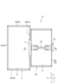
次に、第2実施形態に係る電線圧接コネクタ1Aについて説明する。図9は、第2実施形態に係る電線圧接コネクタ1Aの平面図であり、図10は、図9におけるD-D線断面図である。上述したように、第1実施形態に係る電線圧接コネクタ1の接続端子7は、インサート成形によって、ハウジング本体部3と一体的に形成されるものを説明した。一方、第2実施形態に係る電線圧接コネクタ1Aは、ハウジング本体部103と、接続端子107と、を別々に形成した後、ハウジング本体部103に接続端子107を組み付ける。このため、第2実施形態に係る電線圧接コネクタ1Aのハウジング本体部103の構成は、第1実施形態に係る電線圧接コネクタ1のハウジング本体部3の構成と異なる。一方、第2実施形態に係る電線圧接コネクタ1Aの他の構成は、第1実施形態に係る電線圧接コネクタ1の他の構成と同一である。そこで、第2実施形態に係る電線圧接コネクタ1Aの構成において、第1実施形態に係る電線圧接コネクタ1の構成と同一である部分には、同一の符号を付して説明を省略する。また、第1実施形態に係る電線圧接コネクタ1の構成に対して、第2実施形態に係る電線圧接コネクタ1Aの異なる構成について以下に説明する。
[Second embodiment]
Next, a wire insulation displacement connector 1A according to a second embodiment will be described. FIG. 9 is a plan view of a wire pressure welding connector 1A according to the second embodiment, and FIG. 10 is a sectional view taken along the line DD in FIG. As described above, the connection terminal 7 of the wire press-connecting connector 1 according to the first embodiment is formed integrally with the housing main body 3 by insert molding. On the other hand, in the wire pressure welding connector 1A according to the second embodiment, the housing body 103 and the connection terminal 107 are separately formed, and then the connection terminal 107 is assembled to the housing body 103. Therefore, the configuration of the housing body 103 of the wire pressure welding connector 1A according to the second embodiment is different from the configuration of the housing body 3 of the wire pressure welding connector 1 according to the first embodiment. On the other hand, the other configurations of the wire insulation displacement connector 1A according to the second embodiment are the same as the other configurations of the electric wire insulation displacement connector 1 according to the first embodiment. Therefore, in the configuration of the wire insulation displacement connector 1A according to the second embodiment, the same parts as the configuration of the electric wire insulation displacement connector 1 according to the first embodiment are given the same reference numerals, and the description thereof will be omitted. Further, a different configuration of the wire insulation displacement connector 1A according to the second embodiment from the configuration of the electric wire insulation displacement connector 1 according to the first embodiment will be described below.

ハウジング本体部103は、厚さ方向Xの中央に、端子挿入孔137と、一対の端子係止爪部138a、138bと、一対の弾性変形許容空間139a、139bとを有する。本実施形態のハウジング本体部103は、端子挿入孔137と、一対の端子係止爪部138a、138bと、一対の弾性変形許容空間139a、139bとを、絶縁性の合成樹脂によって一体的に形成する。 The housing main body portion 103 has a terminal insertion hole 137, a pair of terminal locking claw portions 138a, 138b, and a pair of elastic deformation allowing spaces 139a, 139b at the center in the thickness direction X. The housing main body 103 of this embodiment has a terminal insertion hole 137, a pair of terminal locking claws 138a, 138b, and a pair of elastic deformation allowable spaces 139a, 139b, which are integrally formed from an insulating synthetic resin. do.

端子挿入孔137は、対向方向Yの中央に形成された孔であり、第3方向Zにおいてハウジング本体部103を貫通し、接続端子107を挿入可能である。 The terminal insertion hole 137 is a hole formed at the center in the opposing direction Y, penetrates the housing body portion 103 in the third direction Z, and allows the connection terminal 107 to be inserted therein.

一対の端子係止爪部138a、138bは、対向方向Yにおいて、端子挿入孔137の両側に位置する。つまり、端子挿入孔137は、対向方向Yにおいて、一対の端子係止爪部138a、138bの間に位置する。一対の端子係止爪部138a、138bのそれぞれは、反対方向Z2側に爪基端部138c、138dを有し、挿入方向Z1側に爪先端部138e、138fを有し、爪基端部138c、138dと爪先端部138e、138fとの間に爪先中間部138g、138hを有する。一対の端子係止爪部138a、138bにおける各爪先端部138e、138fには、対向方向Yにおいて、互いに近接するように突出する爪部138i、138jを有する。また、一対の端子係止爪部138a、138bは、対向方向Yにおいて、爪部138i、138jが互いに離隔する方向へ弾性変形可能に形成される。さらに、爪基端部138c、138d及び爪先中間部138g、138hは、第3方向Zに延在するように形成される。 The pair of terminal locking claws 138a and 138b are located on both sides of the terminal insertion hole 137 in the opposing direction Y. That is, the terminal insertion hole 137 is located between the pair of terminal locking claws 138a and 138b in the opposing direction Y. Each of the pair of terminal locking claws 138a, 138b has claw base end portions 138c, 138d on the opposite direction Z2 side, claw tip portions 138e, 138f on the insertion direction Z1 side, and a claw base end portion 138c. , 138d and the claw tip portions 138e, 138f have intermediate toe portions 138g, 138h. The claw tips 138e, 138f of the pair of terminal locking claws 138a, 138b have claws 138i, 138j that protrude close to each other in the opposing direction Y. Further, the pair of terminal locking claws 138a and 138b are formed to be elastically deformable in the opposing direction Y in a direction in which the claws 138i and 138j are separated from each other. Further, the claw base end portions 138c, 138d and the toe intermediate portions 138g, 138h are formed to extend in the third direction Z.

一対の弾性変形許容空間139a、139bは、対向方向Yにおいて、一対の端子係止爪部138a、138bの外側(収容空間3sに対する外側)にそれぞれ位置する。一対の弾性変形許容空間139a、139bは、一対の端子係止爪部138a、138bにおける爪部138i、138jが互いに離隔する方向へ変形することを許容する空間である。 The pair of elastic deformation allowable spaces 139a and 139b are respectively located outside the pair of terminal locking claws 138a and 138b (outside with respect to the housing space 3s) in the opposing direction Y. The pair of elastic deformation allowing spaces 139a and 139b are spaces that allow the claw portions 138i and 138j of the pair of terminal locking claw portions 138a and 138b to deform in a direction away from each other.

ハウジング本体部103に接続端子107を組み付ける場合、先ず、作業者は、爪部138i、138jが互いに離隔するように、一対の端子係止爪部138a、138bに力を加えて弾性変形させる。 When assembling the connection terminal 107 to the housing body 103, the operator first applies force to the pair of terminal locking claws 138a, 138b to elastically deform them so that the claws 138i, 138j are separated from each other.

次に、作業者は、ハウジング本体部103の端子挿入孔137に接続端子107を挿入し、接続端子107の第1端面71aを、刃部構成部81の挿入方向Z1側の端面81eに接触させ、その状態で、一対の端子係止爪部138a、138bに加えた力を取り除く。 Next, the operator inserts the connection terminal 107 into the terminal insertion hole 137 of the housing body 103, and brings the first end surface 71a of the connection terminal 107 into contact with the end surface 81e of the blade component 81 on the insertion direction Z1 side. In this state, the force applied to the pair of terminal locking claws 138a and 138b is removed.

すると、一対の端子係止爪部138a、138bは、弾性復元力によって、爪部138i、138jが互いに近接するように復帰し、一方の爪先中間部138g、138hが接続端子107の第3端面71cに接触し、他方の爪先中間部138g、138hが接続端子107の第4端面71dに接触し、かつ、各爪部138i、138jが接続端子107の第2端面71bにそれぞれ接触して、接続端子107がハウジング本体部103に組み付けられる。 Then, the pair of terminal locking claws 138a, 138b returns to a position where the claws 138i, 138j approach each other due to the elastic restoring force, and one of the intermediate claws 138g, 138h engages the third end surface 71c of the connecting terminal 107. , the other toe intermediate portions 138g and 138h are in contact with the fourth end surface 71d of the connecting terminal 107, and each claw portion 138i and 138j is in contact with the second end surface 71b of the connecting terminal 107, so that the connecting terminal 107 is assembled to the housing body part 103.

第2実施形態に係る電線圧接コネクタ1Aによれば、ハウジング本体部103と接続端子107とを別体で形成し、ハウジング本体部103に設けた一対の端子係止爪部138a、138bによって接続端子107を保持する。このため、本実施形態に係る電線圧接コネクタ1Aは、接続端子107をハウジング本体部103にインサート成形する必要がない。このため、ハウジング本体部103を形成する金型が複雑になることを抑制することができ、電線圧接コネクタ1Aが高価になりことを抑制することができる。 According to the wire pressure welding connector 1A according to the second embodiment, the housing body 103 and the connection terminal 107 are formed separately, and the connection terminal is held by the pair of terminal locking claws 138a and 138b provided on the housing body 103. Hold 107. Therefore, in the electric wire press-connecting connector 1A according to the present embodiment, there is no need to insert-mold the connection terminal 107 into the housing body portion 103. Therefore, it is possible to prevent the mold for forming the housing body portion 103 from becoming complicated, and it is possible to prevent the wire pressure welding connector 1A from becoming expensive.

[第2実施形態の第1変形例]
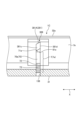
次に、第2実施形態に係る電線圧接コネクタ1Aに対する第1変形例の電線圧接コネクタ1Bについて説明する。図11は、第1変形例の電線圧接コネクタ1Bを示す図7と同様の斜視図である。第1変形例に係る電線圧接コネクタ1Bの切り込み部208の構成は、第2実施形態に係る電線圧接コネクタ1Aの切り込み部108の構成と異なる。一方、第1変形例に係る電線圧接コネクタ1Bの他の構成は、第2実施形態に係る電線圧接コネクタ1Aの他の構成と同一である。そこで、第1変形例に係る電線圧接コネクタ1Bの構成において、第2実施形態に係る電線圧接コネクタ1Aの構成と同一である部分には、同一の符号を付して説明を省略する。そして、以下に第1変形例に係る電線圧接コネクタ1Bの切り込み部208について説明する。
[First modification of second embodiment]
Next, a wire pressure welding connector 1B that is a first modification of the wire pressure welding connector 1A according to the second embodiment will be described. FIG. 11 is a perspective view similar to FIG. 7 showing a wire press-connecting connector 1B of a first modification. The structure of the notch 208 of the wire pressure welding connector 1B according to the first modification is different from the structure of the notch 108 of the wire pressure welding connector 1A according to the second embodiment. On the other hand, the other configurations of the wire insulation displacement connector 1B according to the first modification are the same as the other configurations of the electric wire insulation displacement connector 1A according to the second embodiment. Therefore, in the configuration of the wire insulation displacement connector 1B according to the first modification, the parts that are the same as the configuration of the electric wire insulation displacement connector 1A according to the second embodiment are given the same reference numerals, and the description thereof will be omitted. The notch portion 208 of the wire press-connecting connector 1B according to the first modification will be described below.

切り込み部208は、厚さ方向Xにおける厚さが、反対方向Z2側へ向けて先細りとなり、対向方向Yにおいて、切り込みスロット80を挟んで形成される一対の刃部281A、281Bを有する。 The cut portion 208 has a thickness in the thickness direction X that tapers toward the opposite direction Z2, and has a pair of blade portions 281A and 281B formed with the cut slot 80 in between in the opposing direction Y.

一対の刃部281A、281Bは、刃部構成部281によってそれぞれ構成される。刃部構成部281の反対方向Z2側は、厚さ方向Xにおける一方側に第1刃面281cを有する一方、厚さ方向Xにおける他方側に第2刃面281dを有する。第1刃面281cは、第3方向Z及び厚さ方向Xを含む平面に対して平行である。第2刃面281dは、第3方向Z及び厚さ方向Xに対して傾斜する平面である。 The pair of blade parts 281A and 281B are each constituted by the blade part forming part 281. The opposite direction Z2 side of the blade component 281 has a first blade surface 281c on one side in the thickness direction X, and has a second blade surface 281d on the other side in the thickness direction X. The first blade surface 281c is parallel to a plane including the third direction Z and the thickness direction X. The second blade surface 281d is a plane inclined with respect to the third direction Z and the thickness direction X.

本変形例の切り込み部208は、挿入方向Z1側における厚さ方向Xの厚さが、接続端子207における厚さ方向Xの厚さと同一である。そして、切り込み部208の厚さ方向Xにおける一方の平面と、接続端子207の厚さ方向Xにおける一方の平面とが、同一の平坦面を構成し、これらの平面は、第3方向Z及び厚さ方向Xを含む平面に対して平行である。つまり、本変形例の切り込み部208及び接続端子207は、厚さ方向Xの一方側において、第3方向Z及び厚さ方向Xを含む平面に対して平行である。 The thickness of the cut portion 208 in the present modification in the thickness direction X on the insertion direction Z1 side is the same as the thickness of the connection terminal 207 in the thickness direction X. One plane of the notch 208 in the thickness direction X and one plane of the connection terminal 207 in the thickness direction It is parallel to the plane containing the direction X. That is, the cut portion 208 and the connection terminal 207 of this modification are parallel to the plane including the third direction Z and the thickness direction X on one side of the thickness direction X.

[第2実施形態の第2変形例]
次に、第2実施形態に係る電線圧接コネクタ1Aに対する第2変形例の電線圧接コネクタ1Cについて説明する。図11は、第2変形例の電線圧接コネクタ1Cを示す図7と同様の斜視図である。第2変形例に係る電線圧接コネクタ1Cの切り込み部308の構成は、第2実施形態に係る電線圧接コネクタ1Aの切り込み部108の構成と異なる。一方、第2変形例に係る電線圧接コネクタ1Cの他の構成は、第2実施形態に係る電線圧接コネクタ1Aの他の構成と同一である。そこで、第2変形例に係る電線圧接コネクタ1Cの構成において、第2実施形態に係る電線圧接コネクタ1Aの構成と同一である部分には、同一の符号を付して説明を省略する。そして、以下に第2変形例に係る電線圧接コネクタ1Cの切り込み部308について説明する。
[Second modification of second embodiment]
Next, a second modification of the wire pressure welding connector 1C with respect to the wire pressure welding connector 1A according to the second embodiment will be described. FIG. 11 is a perspective view similar to FIG. 7 illustrating a second modified example of the wire pressure welding connector 1C. The structure of the notch 308 of the wire pressure welding connector 1C according to the second modification is different from the structure of the notch 108 of the wire pressure welding connector 1A according to the second embodiment. On the other hand, the other configurations of the wire insulation displacement connector 1C according to the second modification are the same as the other configurations of the electric wire insulation displacement connector 1A according to the second embodiment. Therefore, in the configuration of the wire insulation displacement connector 1C according to the second modification, the same parts as the configuration of the electric wire insulation displacement connector 1A according to the second embodiment are given the same reference numerals, and the description thereof will be omitted. The notch portion 308 of the wire press-connecting connector 1C according to the second modification will be described below.

切り込み部308は、厚さ方向Xにおける厚さが、反対方向Z2側へ向けて先細りとなり、対向方向Yにおいて、切り込みスロット80を挟んで形成される一対の刃部381A、381Bを有する。 The cut portion 308 has a thickness in the thickness direction X that tapers toward the opposite direction Z2 side, and has a pair of blade portions 381A and 381B formed with the cut slot 80 in between in the opposing direction Y.

一対の刃部381A、381Bは、刃部構成部381によってそれぞれ構成される。刃部構成部381の反対方向Z2側は、厚さ方向Xにおける一方側に第1刃面381cを有する一方、厚さ方向Xにおける他方側に第2刃面381dを有する。第1刃面381cは、第3方向Z及び厚さ方向Xに対して傾斜する平面である。第2刃面381dは、第3方向Z及び厚さ方向Xを含む平面に対して平行である。 The pair of blade portions 381A and 381B are each configured by the blade component portion 381. The opposite direction Z2 side of the blade component 381 has a first blade surface 381c on one side in the thickness direction X, and has a second blade surface 381d on the other side in the thickness direction X. The first blade surface 381c is a plane inclined with respect to the third direction Z and the thickness direction X. The second blade surface 381d is parallel to a plane including the third direction Z and the thickness direction X.

本変形例の切り込み部308は、挿入方向Z1側における厚さ方向Xの厚さが、接続端子207における厚さ方向Xの厚さと同一である。そして、切り込み部208の厚さ方向Xにおける他方の平面と、接続端子207の厚さ方向Xにおける他方の平面とが、同一の平坦面を構成し、これらの平面は、第3方向Z及び厚さ方向Xを含む平面に対して平行である。つまり、本変形例の切り込み部208及び接続端子207は、厚さ方向Xの他方側において、第3方向Z及び厚さ方向Xを含む平面に対して平行である。 The cut portion 308 of this modification has the same thickness in the thickness direction X on the insertion direction Z1 side as the thickness in the thickness direction X of the connection terminal 207 . The other plane of the notch 208 in the thickness direction X and the other plane of the connection terminal 207 in the thickness direction It is parallel to the plane containing the direction X. That is, the notch 208 and the connection terminal 207 of this modification are parallel to the plane including the third direction Z and the thickness direction X on the other side of the thickness direction X.

なお、上述した実施形態に係る電線圧接コネクタ1、1A、1B、1Cは、接続端子7、107が2つの端子スロット70を有するものを説明した。しかし、本実施形態の電線圧接コネクタ1、1A、1B、1Cは、それに限られず、接続端子7、107が3つ以上の複数の端子スロット70を有してもよい。また、接続端子7、107が3つ以上の端子スロット70を有する場合には、3つの端子スロット70のそれぞれに電線Wを挿入する必要はなく、少なくとも2つの端子スロット70に電線Wを挿入すればよい。 In addition, the electric wire press-connecting connectors 1, 1A, 1B, and 1C according to the embodiments described above have been described in which the connection terminals 7 and 107 have two terminal slots 70. However, the wire press-connecting connectors 1, 1A, 1B, and 1C of this embodiment are not limited thereto, and the connection terminals 7, 107 may have three or more terminal slots 70. Further, when the connection terminals 7 and 107 have three or more terminal slots 70, it is not necessary to insert the electric wire W into each of the three terminal slots 70, but only to insert the electric wire W into at least two terminal slots 70. Bye.

また、上述した実施形態に係る電線圧接コネクタ1、1A、1B、1Cの切り込み部8、108、208、308は、ハウジング2と一体的に形成するものを説明した。しかし、本実施形態に係る電線圧接コネクタ1、1A、1B、1Cの切り込み部8、108、208、308は、それに限られず、ハウジング2と別体に形成してもよい。 Moreover, the notches 8, 108, 208, and 308 of the wire press-connecting connectors 1, 1A, 1B, and 1C according to the embodiments described above have been described as being formed integrally with the housing 2. However, the cut portions 8, 108, 208, and 308 of the wire press-connecting connectors 1, 1A, 1B, and 1C according to the present embodiment are not limited thereto, and may be formed separately from the housing 2.

さらに、上述した実施形態の電線圧接コネクタ1の切り込み部8、108、208、308は、二色成形によって、ハウジング2の剛性よりも高い剛性を有するものを説明した。しかし、本実施形態に係る電線圧接コネクタ1の切り込み部8、108、208、308は、それに限られず、ハウジング2と同一の樹脂材料によって形成してもよい。また、切り込み部8を含むハウジング本体部3を形成する合成樹脂は、ハウジング蓋部4を形成する合成樹脂の剛性よりも高い剛性を有してもよい。つまり、切り込み部8を形成する合成樹脂は、ハウジング本体部3を形成する合成樹脂と同一である。また、切り込み部8を含むハウジング本体部3は、ハウジング蓋部4の剛性よりも高い剛性を有する。 Furthermore, the cut portions 8, 108, 208, and 308 of the wire press-connecting connector 1 of the embodiment described above have been described as having a rigidity higher than that of the housing 2 due to two-color molding. However, the cut portions 8, 108, 208, and 308 of the wire pressure welding connector 1 according to the present embodiment are not limited thereto, and may be formed of the same resin material as the housing 2. Furthermore, the synthetic resin forming the housing main body 3 including the notch 8 may have higher rigidity than the synthetic resin forming the housing lid 4. That is, the synthetic resin forming the notch portion 8 is the same as the synthetic resin forming the housing main body portion 3. Furthermore, the housing main body 3 including the notch 8 has higher rigidity than the housing lid 4.

また、上述した実施形態の電線圧接コネクタ1の係止機構6は、ハウジング蓋部4に係止孔部61を設ける一方、ハウジング本体部3に係止爪部62を設けるものを説明した。しかし、この発明はそれに限られず、ハウジング蓋部4の係止爪を設ける一方、ハウジング本体部3に係止孔部61を設けてもよい。 Further, the locking mechanism 6 of the wire pressure welding connector 1 of the above-described embodiment has been described as having a locking hole 61 in the housing lid portion 4 and a locking claw portion 62 in the housing body portion 3. However, the present invention is not limited thereto, and while the housing cover portion 4 is provided with the locking claw, the housing body portion 3 may be provided with the locking hole portion 61.

さらに、上述した実施形態の電線圧接コネクタ1は、厚さ方向Xにおいて、接続端子7、107が1つの刃部構成部81を有するものを説明した。しかし、この発明は、それに限られず、接続端子7、107が厚さ方向Xにおいて2つの刃部構成を有してもよい。この場合には、1枚の板状の接続端子7、107を折り曲げることによって、厚さ方向Xにおいて2つの刃部構成部を形成することが好ましい。 Further, in the wire pressure welding connector 1 of the embodiment described above, the connection terminals 7 and 107 have one blade component 81 in the thickness direction X. However, the present invention is not limited thereto, and the connection terminals 7, 107 may have two blade configurations in the thickness direction X. In this case, it is preferable to form two blade components in the thickness direction X by bending one plate-shaped connection terminal 7, 107.

1、1A、1B、1C 電線圧接コネクタ
2 ハウジング
3 ハウジング本体部
3s 収容空間
33 開閉開口(開口)
4 ハウジング蓋部
43 押圧部
5 ヒンジ
7 接続端子
70、70a、70b 端子スロット
71a 第1端面(端面)
8 切り込み部
80 切り込みスロット
81 刃部構成部
81A、81B 一対の刃部
W 電線
W11 一方の電線
W12 他方の電線
W1 芯線
W2 被覆部
X 厚さ方向
Y 対向方向
Z1 挿入方向
Z2 反対方向
1, 1A, 1B, 1C Wire pressure welding connector 2 Housing 3 Housing main body 3s Accommodation space 33 Opening/closing opening (opening)
4 Housing cover portion 43 Pressing portion 5 Hinge 7 Connection terminals 70, 70a, 70b Terminal slot 71a First end surface (end surface)
8 Cut portion 80 Cut slot 81 Blade component portions 81A, 81B Pair of blade portions W Electric wire W11 One electric wire W12 Other electric wire W1 Core wire W2 Covering portion X Thickness direction Y Opposing direction Z1 Insertion direction Z2 Opposite direction

Claims (5)

導電性の芯線を有する電線を挿入方向に沿って挿入可能な端子スロットを複数有し、導電性の金属材料によって形成され、各前記端子スロット内で前記芯線と接触することで前記電線と電気的に接続される接続端子と、
前記挿入方向側が端子スロットに連通する一方、前記挿入方向に対する反対方向側が外部に連通する切り込みスロットを有し、前記端子スロットに対応してそれぞれ形成された切り込み部と、
絶縁性の合成樹脂によって形成され、前記接続端子及び前記切り込み部を収容する収容空間を有するハウジングと、
を備え、
各前記切り込み部は、前記挿入方向に対して直交する厚さ方向における厚さが、前記反対方向側へ向けて先細りとなり、前記挿入方向及び前記厚さ方向に対して直交する対向方向において、前記切り込みスロットを挟んで形成される一対の刃部を有し、
一対の前記刃部を構成する刃部構成部は、前記挿入方向側の端面が前記接続端子の前記反対方向側の端面に接触し、
一対の前記刃部は、前記切り込みスロットに前記電線を挿入する際に前記電線の被覆部に切れ込みを入れて前記芯線を外部に露出するものであって、前記対向方向において互いの間隔が前記挿入方向に沿って徐々に小さくなるように絶縁性の合成樹脂によって形成されることを特徴とする、
電線圧接コネクタ。
It has a plurality of terminal slots into which electric wires having conductive core wires can be inserted along the insertion direction, and is made of a conductive metal material, and is electrically connected to the electric wire by contacting the core wire in each terminal slot. A connection terminal connected to the
a cut slot that communicates with the terminal slot on the side in the insertion direction and communicates with the outside on the side in the opposite direction to the insertion direction, and cut portions formed corresponding to the terminal slots;
a housing made of insulating synthetic resin and having a housing space for housing the connection terminal and the notch;
Equipped with
The thickness of each of the notches in the thickness direction perpendicular to the insertion direction tapers toward the opposite direction, and It has a pair of blades formed with a cut slot in between,
The blade component constituting the pair of blade portions has an end surface on the insertion direction side in contact with an end surface on the opposite direction side of the connection terminal,
The pair of blade parts make a slit in the sheathing part of the electric wire to expose the core wire to the outside when the electric wire is inserted into the cut slot, and the pair of blade parts make a slit in the sheathing part of the electric wire to expose the core wire to the outside, and the distance between the two blade parts in the facing direction is set at the insertion point. It is characterized by being formed from an insulating synthetic resin so that it gradually becomes smaller along the direction.
Wire pressure welding connector.
前記切り込み部は、前記ハウジングと一体的に形成する、
請求項1に記載の電線圧接コネクタ。
The cut portion is formed integrally with the housing.
The wire insulation displacement connector according to claim 1.
前記ハウジングは、開口を有するハウジング本体部と、前記開口を閉塞するハウジング蓋部と有し、
前記切り込み部を形成する合成樹脂は、前記ハウジング本体部を形成する合成樹脂と同一であり、
前記ハウジング本体部を形成する合成樹脂は、前記ハウジング蓋部を形成する合成樹脂よりも高い剛性を有する、
請求項1又は2に記載の電線圧接コネクタ。
The housing has a housing main body portion having an opening, and a housing lid portion closing the opening,
The synthetic resin forming the notch is the same as the synthetic resin forming the housing body,
The synthetic resin forming the housing body has higher rigidity than the synthetic resin forming the housing lid.
The electric wire press-connecting connector according to claim 1 or 2.
前記切り込み部を形成する合成樹脂は、前記ハウジングを形成する合成樹脂よりも高い剛性を有する、
請求項1又は2に記載の電線圧接コネクタ。
The synthetic resin forming the notch has higher rigidity than the synthetic resin forming the housing.
The electric wire press-connecting connector according to claim 1 or 2.
前記ハウジングは、開口を有するハウジング本体部と、前記開口を閉塞するハウジング蓋部と有し、
前記ハウジング蓋部は、前記開口を閉塞する際に複数の前記電線を押圧することによって、前記電線の芯線を各前記切り込みスロットを介して各前記端子スロットに挿入する押圧部を有する、
請求項1~3のいずれか一項に記載の電線圧接コネクタ。
The housing has a housing main body portion having an opening, and a housing lid portion closing the opening,
The housing lid part has a pressing part that presses the plurality of electric wires when closing the opening, thereby inserting the core wire of the electric wire into each of the terminal slots through each of the cut slots.
The electric wire pressure connector according to any one of claims 1 to 3.
JP2020050934A 2020-03-23 2020-03-23 Wire pressure welding connector Active JP7359727B2 (en)

Priority Applications (1)

Application Number Priority Date Filing Date Title
JP2020050934A JP7359727B2 (en) 2020-03-23 2020-03-23 Wire pressure welding connector

Applications Claiming Priority (1)

Application Number Priority Date Filing Date Title
JP2020050934A JP7359727B2 (en) 2020-03-23 2020-03-23 Wire pressure welding connector

Publications (2)

Publication Number Publication Date
JP2021150234A JP2021150234A (en) 2021-09-27
JP7359727B2 true JP7359727B2 (en) 2023-10-11

Family

ID=77851335

Family Applications (1)

Application Number Title Priority Date Filing Date
JP2020050934A Active JP7359727B2 (en) 2020-03-23 2020-03-23 Wire pressure welding connector

Country Status (1)

Country Link
JP (1) JP7359727B2 (en)

Citations (2)

* Cited by examiner, † Cited by third party
Publication number Priority date Publication date Assignee Title
JP2002101524A (en) 2000-09-25 2002-04-05 Sumitomo Wiring Syst Ltd Connection box for wire
US20040102097A1 (en) 2002-11-22 2004-05-27 Clark Gordon P. Telecommunications jack assembly

Patent Citations (2)

* Cited by examiner, † Cited by third party
Publication number Priority date Publication date Assignee Title
JP2002101524A (en) 2000-09-25 2002-04-05 Sumitomo Wiring Syst Ltd Connection box for wire
US20040102097A1 (en) 2002-11-22 2004-05-27 Clark Gordon P. Telecommunications jack assembly

Also Published As

Publication number Publication date
JP2021150234A (en) 2021-09-27

Similar Documents

Publication Publication Date Title
JP6112795B2 (en) Wire connector
JP3889983B2 (en) connector
KR100987622B1 (en) Electrical connector which has a wire aligning function and which can be reduced in size
JP3998203B2 (en) connector
JP7359727B2 (en) Wire pressure welding connector
JP7311309B2 (en) connector
JP4151568B2 (en) Electrical junction box for automobile
KR101111595B1 (en) Connector housing assembly and electrical connector assembly
JP7418305B2 (en) Wire pressure welding structure
JP7451046B2 (en) Wire pressure welding structure
JP7098678B2 (en) Protector and wire harness
JP7353921B2 (en) Connection structure, connection structure with housing, and terminal
JP7353922B2 (en) Connection structure, connection structure with housing, and terminal
JPH1074551A (en) Electric connector with cable lines arranged in steps
US11784420B2 (en) Cable holding member and cable connector device including cable holding member
US20230369802A1 (en) Cable holding member and cable connector device including cable holding member
JP6147841B1 (en) Contact module manufacturing method and connector
CN212062743U (en) Connector terminal
WO2018074537A1 (en) Terminal device and wiring fixture equipped with same
US11133608B2 (en) Contact member for an IDC terminal, contact member assembly, set of contact members and housing comprising a contact member
JP3854453B2 (en) Pressure contact terminal for plate connector
US20230378664A1 (en) Cable holding member, cable holding device including cable holding member, and cable connector device including cable holding device
EP4117123B1 (en) Connector fitting structure
JP7274007B2 (en) CABLE RETAINING MEMBER AND CABLE CONNECTOR DEVICE HAVING CABLE RETAINING MEMBER
JPH1154217A (en) Electrical connector for circuit board

Legal Events

Date Code Title Description
A621 Written request for application examination

Free format text: JAPANESE INTERMEDIATE CODE: A621

Effective date: 20230216

TRDD Decision of grant or rejection written
A977 Report on retrieval

Free format text: JAPANESE INTERMEDIATE CODE: A971007

Effective date: 20230919

A01 Written decision to grant a patent or to grant a registration (utility model)

Free format text: JAPANESE INTERMEDIATE CODE: A01

Effective date: 20230926

A61 First payment of annual fees (during grant procedure)

Free format text: JAPANESE INTERMEDIATE CODE: A61

Effective date: 20230928

R150 Certificate of patent or registration of utility model

Ref document number: 7359727

Country of ref document: JP

Free format text: JAPANESE INTERMEDIATE CODE: R150