JP7358608B2 - Processed product manufacturing method - Google Patents
Processed product manufacturing method Download PDFInfo
- Publication number
- JP7358608B2 JP7358608B2 JP2022500586A JP2022500586A JP7358608B2 JP 7358608 B2 JP7358608 B2 JP 7358608B2 JP 2022500586 A JP2022500586 A JP 2022500586A JP 2022500586 A JP2022500586 A JP 2022500586A JP 7358608 B2 JP7358608 B2 JP 7358608B2
- Authority
- JP
- Japan
- Prior art keywords
- die
- cutting
- punch
- processed product
- cut
- Prior art date
- Legal status (The legal status is an assumption and is not a legal conclusion. Google has not performed a legal analysis and makes no representation as to the accuracy of the status listed.)
- Active
Links
Images


Classifications
-
- B—PERFORMING OPERATIONS; TRANSPORTING
- B21—MECHANICAL METAL-WORKING WITHOUT ESSENTIALLY REMOVING MATERIAL; PUNCHING METAL
- B21D—WORKING OR PROCESSING OF SHEET METAL OR METAL TUBES, RODS OR PROFILES WITHOUT ESSENTIALLY REMOVING MATERIAL; PUNCHING METAL
- B21D28/00—Shaping by press-cutting; Perforating
- B21D28/02—Punching blanks or articles with or without obtaining scrap; Notching
- B21D28/16—Shoulder or burr prevention, e.g. fine-blanking
-
- B—PERFORMING OPERATIONS; TRANSPORTING
- B21—MECHANICAL METAL-WORKING WITHOUT ESSENTIALLY REMOVING MATERIAL; PUNCHING METAL
- B21D—WORKING OR PROCESSING OF SHEET METAL OR METAL TUBES, RODS OR PROFILES WITHOUT ESSENTIALLY REMOVING MATERIAL; PUNCHING METAL
- B21D22/00—Shaping without cutting, by stamping, spinning, or deep-drawing
- B21D22/02—Stamping using rigid devices or tools
-
- B—PERFORMING OPERATIONS; TRANSPORTING
- B21—MECHANICAL METAL-WORKING WITHOUT ESSENTIALLY REMOVING MATERIAL; PUNCHING METAL
- B21D—WORKING OR PROCESSING OF SHEET METAL OR METAL TUBES, RODS OR PROFILES WITHOUT ESSENTIALLY REMOVING MATERIAL; PUNCHING METAL
- B21D28/00—Shaping by press-cutting; Perforating
- B21D28/02—Punching blanks or articles with or without obtaining scrap; Notching
-
- B—PERFORMING OPERATIONS; TRANSPORTING
- B23—MACHINE TOOLS; METAL-WORKING NOT OTHERWISE PROVIDED FOR
- B23D—PLANING; SLOTTING; SHEARING; BROACHING; SAWING; FILING; SCRAPING; LIKE OPERATIONS FOR WORKING METAL BY REMOVING MATERIAL, NOT OTHERWISE PROVIDED FOR
- B23D15/00—Shearing machines or shearing devices cutting by blades which move parallel to themselves
Landscapes
- Engineering & Computer Science (AREA)
- Mechanical Engineering (AREA)
- Punching Or Piercing (AREA)
- Shaping Metal By Deep-Drawing, Or The Like (AREA)
- Electroplating Methods And Accessories (AREA)
- Transition And Organic Metals Composition Catalysts For Addition Polymerization (AREA)
Description
本発明は、表面にめっき層を有するめっき鋼板を素材とし、切断端部を有する加工品を製造するための加工品製造方法及びその加工品に関する。 TECHNICAL FIELD The present invention relates to a method for manufacturing a workpiece made of a plated steel plate having a plating layer on its surface and having a cut end, and to the workpiece.
近年、自動車及び家電等の機器の部品として、表面にめっき層を有するめっき鋼板を素材とする加工品を用いることが増えている。めっき鋼板を素材として用いることにより、加工品の成形後の表面処理を省略し、製造コストを抑えることができる。また、成形後の表面処理を省略することで、成形後の表面処理による部品の寸法精度の劣化を避けることができる。成形後の表面処理を省略することは、例えばモータケース等の高い寸法精度が要求される部品において特に検討される。 BACKGROUND ART In recent years, processed products made from plated steel sheets having a plating layer on their surfaces have been increasingly used as parts for equipment such as automobiles and home appliances. By using a plated steel plate as a material, surface treatment after forming the processed product can be omitted, and manufacturing costs can be suppressed. Moreover, by omitting the surface treatment after molding, it is possible to avoid deterioration of the dimensional accuracy of the part due to the surface treatment after molding. Omitting surface treatment after molding is particularly considered for parts that require high dimensional accuracy, such as motor cases.
成形後の表面処理を省略した場合、加工品の切断端部に鋼板素地が露出する領域が現れる。加工品が置かれる環境によっては、鋼板素地が露出した領域に赤錆が発生する場合がある。赤錆は、加工品の外観を悪化させる。また、時間の経過とともに赤錆発生領域が広がるため、赤錆により加工品の強度低下も懸念される。特に家電製品の場合には、錆の欠落による電気的短絡等も懸念される。 If surface treatment after forming is omitted, an area where the steel sheet base is exposed will appear at the cut end of the processed product. Depending on the environment in which the processed product is placed, red rust may occur in areas where the base steel plate is exposed. Red rust deteriorates the appearance of processed products. Furthermore, as the area where red rust occurs spreads over time, there is a concern that the strength of processed products may decrease due to red rust. Particularly in the case of home appliances, there are concerns about electrical short circuits due to lack of rust.
また、モータケース等のような絞り加工品のフランジ部には、加工品を他の機器に固定するためのビス穴が設けられることがある。ビス穴周辺の平坦度が悪いと、締結力の低下を招くことが懸念される。ビス穴周辺の平坦度を確保するため、フランジ部を切断する場合には、切断端部のダレの寸法を考慮してフランジ部の寸法は大きく設定される。フランジ部の寸法を大きくすると、素材重量増加の要因となる。 Further, a flange portion of a drawn product such as a motor case is sometimes provided with screw holes for fixing the processed product to other equipment. If the flatness around the screw holes is poor, there is a concern that the fastening force will decrease. In order to ensure flatness around the screw holes, when cutting the flange portion, the size of the flange portion is set large considering the size of the sag at the cut end. Increasing the dimensions of the flange portion causes an increase in the weight of the material.
加工品の切断端部の防錆能力を向上させる方法として、例えば特許文献1では、板厚2mm以下のZn系めっき鋼板において、パンチ又はダイの肩部にZn系めっき鋼板の板厚の0.1~0.5倍の曲率半径を持たせた金型を用いて打抜き加工を行うことで、打抜き加工後の打抜き端面のせん断面比率を90%以上にするとともに、せん断面の亜鉛被覆率を50%以上にする方法が提案されている。
As a method for improving the rust prevention ability of the cut end of a processed product, for example, in
また、特許文献2では、Zn系めっき鋼板の板厚に関係なく、抜きクリアランスを板厚の1~20%に設定し、パンチ又はダイの肩部にZn系めっき鋼板の板厚の0.12倍以上の曲率半径を持たせた金型を用いてZn系めっき鋼板を切断し、切断端面のダレZが0.10×板厚以上、ダレXが0.45×板厚以上の加工品を得る方法が提案されている。
Furthermore, in
さらに、特許文献3では、めっき鋼板をマイナスクリアランスで板厚の60~95%の半抜きを行い、その半抜きの反対側から平押しでせん断することによって、端面の耐食性を備える製品を得る方法が提案されている。 Furthermore, Patent Document 3 discloses a method of obtaining a product with corrosion resistance on the end face by half-blanking a plated steel plate by 60 to 95% of the plate thickness with a negative clearance and shearing it by flat pressing from the opposite side of the half-blank. is proposed.
また、特許文献4には、第1のパンチ及び第1のダイを用い、金属板材の打ち抜き加工部の最終加工面にシェービング取り代を付けて、金属板材を半抜き加工する第1工程と、第2のパンチ及び第2のダイを用い、半抜き加工された部分に更に剪断加工を主体とするシェービング加工を行う第2工程とを有し、打ち抜き加工部の最終加工面に70%以上の剪断加工面を確保する、金属板材のプレス加工方法が開示されている。 Further, Patent Document 4 describes a first step of half punching a metal plate by adding a shaving allowance to the final processed surface of the punched part of the metal plate using a first punch and a first die; A second step of shaving, mainly shearing, is performed on the half-blanked part using a second punch and a second die, and the final machined surface of the punched part has a surface area of 70% or more. A method of pressing a metal plate material is disclosed, which ensures a sheared surface.
さらに、特許文献5では、マイナスクリアランスで第1工程を行った後、刃先に丸み(R)を付与していないパンチ及びダイスを使用して、プラスのクリアランスで第2工程を行う、せん断穴あけ加工方法が記載されている。 Furthermore, in Patent Document 5, after performing the first step with a negative clearance, the second step is performed with a positive clearance using a punch and die whose cutting edge is not rounded (R). The method is described.
しかし、上記特許文献1に記載の方法では、板厚2mm以下の鋼板を対象としており、板厚2mm超の鋼板を素材として用いる場合、せん断面の亜鉛被覆率が不十分となり、赤錆の発生を抑えることが難しくなる可能性がある。また、モータケース等のフランジ端部に増肉が生じる絞り加工品にも適用が難しい。
However, the method described in
上記特許文献2に記載の方法では、切断端部のダレZが板厚の0.10以上、かつダレXが板厚の0.45倍以上の加工品を得るので、大きなダレを伴うことになる。このため、ビス穴周辺の有効接地面積が減少し、固定ビスの締結力の低下を招くこととなる。一方、ビス穴周辺の平坦度を確保するためにフランジ部の寸法を大きくすると、素材重量増加の要因となる。このため、かかる方法は、フランジ部を固定するようなモータケース等の絞り加工品に適用できない場合がある。
In the method described in
上記特許文献3に記載の方法では、めっき鋼板をマイナスクリアランスで半抜きを行うとともに、半抜きの反対側から平押しでせん断している。このため、めっき鋼板の切断端部の板厚方向中間位置に破断面が生じ、また、平押しする際にヒゲ状のバリが発生して形状品質が悪化することもあり得る。 In the method described in Patent Document 3, a plated steel plate is half-blanked with a minus clearance, and sheared by flat pressing from the opposite side of the half-blank. For this reason, a fractured surface may occur at the intermediate position in the thickness direction of the cut end of the plated steel sheet, and when flat pressing, whisker-like burrs may be generated and the shape quality may deteriorate.
上記特許文献4に記載の方法は、シェービング加工に関する技術であり、剪断加工面を大きく形成することによって金属板材の最終加工面を良好にしている。特許文献4に記載の方法によって表面にめっき層を有する金属板材をシェービング加工しても、最終加工面に表面のめっき層はほとんど残存しないため、最終加工面の耐食性は低いものとなる。 The method described in Patent Document 4 is a technique related to shaving processing, and the final processed surface of the metal plate material is improved by forming a large sheared surface. Even if a metal plate material having a plating layer on the surface is shaved by the method described in Patent Document 4, almost no surface plating layer remains on the final processed surface, so the corrosion resistance of the final processed surface is low.
上記特許文献5に記載の方法では、第2工程で使用するパンチ及びダイスの刃先には丸み(R)が付与されていないため、めっき鋼板を素材として用いても、切断端面にめっき層を残す効果は期待できない。 In the method described in Patent Document 5, the cutting edges of the punch and die used in the second step are not rounded (R), so even if a plated steel plate is used as the material, a plating layer remains on the cut end surface. The effect cannot be expected.
そこで、本発明は、上記問題に鑑みてなされたものであり、本発明の目的とするところは、板厚2.0mm超のめっき鋼板を素材として用いた場合であっても、耐食性及び形状品質の良好な加工品、及び、その加工品製造方法を提供することにある。 Therefore, the present invention has been made in view of the above problems, and an object of the present invention is to improve corrosion resistance and shape quality even when a plated steel plate with a thickness of more than 2.0 mm is used as a material. An object of the present invention is to provide a good processed product and a method for manufacturing the processed product.
上記課題を解決するために、本発明のある観点によれば、表面にめっき層を有するめっき鋼板を素材とし、加工品の板厚方向に沿った切断端部を有する加工品であって、切断端部は、当該切断端部の板厚方向に、ダレ、せん断面及び破断面を順に、または、ダレ及びせん断面を順に有しており、せん断面が表面のめっき層により覆われているめっき成分残存長さLと加工品の切断端部の板厚t1との比L/t1は、0.70以上であり、切断端部の板厚方向におけるダレの長さZは、加工品の切断端部の板厚t1の0倍超かつ0.10倍未満である、加工品が提供される。切断端部の板厚方向におけるダレの長さZは、加工品の切断端部の板厚t1の0倍超かつ0.06倍未満であってもよい。
In order to solve the above problems, according to one aspect of the present invention, a processed product is made of a plated steel sheet having a plating layer on the surface and has a cut end along the thickness direction of the processed product, The end portion has a sag, a sheared surface, and a fractured surface in this order in the thickness direction of the cut end, or a sag and a sheared surface in this order, and the sheared surface is covered with a plating layer on the surface. The ratio L/t1 of the residual length L of the component to the thickness t1 of the cut end of the workpiece is 0.70 or more, and the length Z of the sag in the thickness direction of the cut end is the thickness of the cut end of the workpiece. A processed product is provided that is more than 0 times and less than 0.10 times the plate thickness t1 at the end. The length Z of the sag in the thickness direction of the cut end may be more than 0 times and less than 0.06 times the thickness t1 of the cut end of the processed product.
切断端部の板厚方向における破断面の長さW1は、0mm超かつ1.0mm以下であってもよい。 The length W1 of the fracture surface in the thickness direction of the cut end may be more than 0 mm and less than 1.0 mm.
切断端部の板厚方向における破断面の長さW1は、0.5mm以下であってもよい。 The length W1 of the fracture surface in the thickness direction of the cut end may be 0.5 mm or less.
切断端部の板厚方向に直交する平面方向におけるダレの長さXは、加工品の切断端部の板厚t1の0倍超かつ0.30倍未満であってもよい。
The length X of the sag in the plane direction perpendicular to the plate thickness direction of the cut end may be more than 0 times and less than 0.30 times the plate thickness t1 of the cut end of the processed product.
切断端部のバリの長さは0.2mm未満であってもよい。 The length of the burr at the cut end may be less than 0.2 mm.
切断端部は、当該切断端部の板厚方向に、ダレ、せん断面、破断面及びコイニング面を順に、または、ダレ、せん断面及びコイニング面を順に有しており、切断端部の板厚方向におけるせん断面とコイニング面との間の破断面の長さW2は、0mm超かつ0.5mm以下であってもよい。 The cut end has a sag, a sheared surface, a fracture surface, and a coining surface in this order in the thickness direction of the cut end, or a sag, a sheared surface, and a coining surface in this order, and the thickness of the cut end The length W2 of the fracture surface between the shear surface and the coining surface in the direction may be greater than 0 mm and less than or equal to 0.5 mm.
また、上記課題を解決するために、本発明の別の観点によれば、表面にめっき層を有するめっき鋼板を素材とし、切断端部を有する加工品を製造するための加工品製造方法であって、第1ダイと第1パンチとのクリアランスがマイナスクリアランスに設定された第1ダイ及び第1パンチを用いて、素材から形成された第1素体の切断部分を板厚方向に半切断する半切断工程と、第2ダイ及び第2パンチを用いて、半切断された第1素体を半切断と同一方向から仕上げ切断して、板厚方向に沿った切断端部を有する加工品を得る仕上げ切断工程と、を含み、加工品の外周側に切断端部が形成される場合には第2ダイの内径D32は第1ダイの内径D31以上とし、加工品の内部側に切断端部が形成される場合には第2ダイの外径d32は第1ダイの外径d31以下とし、第1素体の切断部分の板厚をt1、半切断工程後の切断部分の残存板厚をt2として、半切断工程において、第1ダイ及び第1パンチとのクリアランスC31-41は、下記式(a1)を満たし、第1ダイの刃先の曲率半径R1は、下記式(a2)を満たし、第1素体の切断部分に対する第1ダイまたは第1パンチの押込み量Dは、下記式(a3)を満たし、下死点での第1ダイと第1パンチとの間隔CP-Dは、下記式(a4)を満たし、仕上げ切断工程において、第2ダイと第2パンチとのクリアランスC32-42は、下記式(a5)を満たし、第2ダイの刃先の曲率半径R2は、下記式(a6)を満たす、加工品製造方法が提供される。
-0.25×t1≦C31-41≦-0.01 ・・・(a1)
0.10×t1≦R1≦0.50×t1 ・・・(a2)
D≧0.70×t1 ・・・(a3)
CP-D≧0.20 ・・・(a4)
0.01≦C32-42≦0.2×t2 ・・・(a5)
0.25≦R2≦1.50×t2 ・・・(a6)
ここで、C31-41、CP-D、C32-42及びR2の単位はmmとする。Moreover, in order to solve the above-mentioned problem, according to another aspect of the present invention, there is provided a method for manufacturing a processed product that uses a plated steel sheet having a plating layer on the surface as a raw material and has a cut end. Then, using a first die and a first punch in which the clearance between the first die and the first punch is set to a negative clearance, the cut portion of the first element body formed from the material is cut in half in the thickness direction. In the half-cutting process, the half-cut first element body is finished cut in the same direction as the half-cutting process using a second die and a second punch to produce a processed product having a cut end along the plate thickness direction. If the cut end is to be formed on the outer circumferential side of the workpiece, the inner diameter D32 of the second die is greater than or equal to the inner diameter D31 of the first die, and the cut end is cut on the inner side of the workpiece. When an end portion is formed, the outer diameter d32 of the second die is equal to or less than the outer diameter d31 of the first die, the thickness of the cut portion of the first element is t1, and the thickness of the cut portion after the half-cutting step is t1. Assuming that the remaining plate thickness is t2, the clearance C 31-41 between the first die and the first punch in the half-cutting process satisfies the following formula (a1), and the radius of curvature R1 of the cutting edge of the first die is calculated by the following formula ( a2) is satisfied, the pushing amount D of the first die or the first punch with respect to the cut portion of the first element satisfies the following formula (a3), and the distance C between the first die and the first punch at the bottom dead center is PD satisfies the following formula (a4), and in the finishing cutting process, the clearance C between the second die and the second punch satisfies the following formula (a5), and the radius of curvature of the cutting edge of the second die A processed product manufacturing method is provided in which R2 satisfies the following formula (a6).
-0.25×t1≦C 31-41 ≦-0.01...(a1)
0.10×t1≦R1≦0.50×t1 (a2)
D≧0.70×t1...(a3)
C PD ≧0.20 ... (a4)
0.01≦C 32-42 ≦0.2×t2...(a5)
0.25≦R2≦1.50×t2...(a6)
Here, the units of C 31-41 , C PD , C 32-42 and R2 are mm.
さらに、上記課題を解決するために、本発明の別の観点によれば、表面にめっき層を有するめっき鋼板を素材とし、切断端部を有する加工品を製造するための加工品製造方法であって、第1ダイと第1パンチとのクリアランスがマイナスクリアランスに設定された第1ダイ及び第1パンチを用いて、素材から形成された第1素体の切断部分を板厚方向に半切断する半切断工程と、第2ダイ及び第2パンチを用いて、半切断された第1素体を半切断と同一方向から仕上げ切断して、切断面が板厚方向に沿った切断端部を有する加工品を得る仕上げ切断工程と、を含み、加工品の外周側に切断端部が形成される場合には第2ダイの内径D32は第1ダイの内径D31以上とし、加工品の内部側に切断端部が形成される場合には第2ダイの外径d32は第1ダイの外径d31以下とし、第1素体の切断部分の板厚をt1、半切断工程後の切断部分の残存板厚をt2として、半切断工程において、第1ダイ及び第1パンチとのクリアランスC31-41は、下記式(b1)を満たし、第1ダイの刃先の曲率半径R11は、下記式(b2-1)を満たし、第1パンチの刃先の曲率半径R12は、下記式(b2-2)を満たし、第1素体の切断部分に対する第1ダイまたは第1パンチの押込み量Dは、下記式(b3)を満たし、下死点での第1ダイと第1パンチとの間隔CP-Dは、下記式(b4)を満たし、仕上げ切断工程において、第2ダイと第2パンチとのクリアランスC32-42は、下記式(b5)を満たし、第2ダイの刃先の曲率半径R2は、下記式(b6)を満たす、加工品製造方法が提供される。
-0.35×t1≦C31-41≦-0.10×t1 ・・・(b1)
0.10×t1≦R11≦0.65×t1 ・・・(b2-1)
0.10×t1≦R12≦0.65×t1 ・・・(b2-2)
D≧0.70×t1 ・・・(b3)
CP-D≧0.20 ・・・(b4)
0.01≦C32-42≦0.2×t2 ・・・(b5)
0.25≦R2≦1.50×t2 ・・・(b6)
ここで、C31-41、CP-D、C32-42及びR2の単位はmmとする。Furthermore, in order to solve the above problems, according to another aspect of the present invention, there is provided a method for manufacturing a processed product that uses a plated steel sheet having a plating layer on the surface as a raw material and has a cut end. Then, using a first die and a first punch in which the clearance between the first die and the first punch is set to a negative clearance, the cut portion of the first element body formed from the material is cut in half in the thickness direction. A half-cutting step, and a second die and a second punch are used to finish cut the half-cut first element from the same direction as the half-cutting, so that the cut surface has a cut end along the plate thickness direction. and a finishing cutting step to obtain a processed product, and when the cut end is formed on the outer circumferential side of the processed product, the inner diameter D 32 of the second die is greater than or equal to the inner diameter D 31 of the first die, and the inside of the processed product is When a cut end is formed on the side, the outer diameter d32 of the second die is less than the outer diameter d31 of the first die, the thickness of the cut portion of the first element is t1, and the thickness after the half-cutting process is t1. Assuming that the remaining plate thickness of the cut portion is t2, the clearance C31-41 between the first die and the first punch in the half-cutting process satisfies the following formula (b1), and the radius of curvature R11 of the cutting edge of the first die is: The following formula (b2-1) is satisfied, and the radius of curvature R12 of the cutting edge of the first punch satisfies the following formula (b2-2), and the pushing amount D of the first die or the first punch with respect to the cut portion of the first element body is satisfies the following formula (b3), the distance C PD between the first die and the first punch at the bottom dead center satisfies the following formula (b4), and in the finishing cutting process, the distance between the second die and the second punch A method for manufacturing a processed product is provided in which the clearance C32-42 with the punch satisfies the following formula (b5), and the radius of curvature R2 of the cutting edge of the second die satisfies the following formula (b6).
-0.35×t1≦C 31-41 ≦-0.10×t1...(b1)
0.10×t1≦R11≦0.65×t1 (b2-1)
0.10×t1≦R12≦0.65×t1 (b2-2)
D≧0.70×t1...(b3)
C PD ≧0.20...(b4)
0.01≦C 32-42 ≦0.2×t2...(b5)
0.25≦R2≦1.50×t2...(b6)
Here, the units of C 31-41 , C PD , C 32-42 and R2 are mm.
上記加工品製造方法は、仕上げ切断工程で得られた加工品を第2素体として、第2素体の切断端部の角部をパッドに押し当て、角部にコイニング面が形成された加工品を得るコイニング工程をさらに含んでもよい。 The above-mentioned method for manufacturing a processed product includes processing in which the processed product obtained in the finishing cutting step is used as a second element body, the corner of the cut end of the second element is pressed against a pad, and a coining surface is formed on the corner. The method may further include a coining step of obtaining a product.
加工品の外周側に切断端部が形成される場合には、第1ダイの内径D31と第2ダイの内径D32との差の絶対値|D32-D31|を1.00mm以下とし、加工品の内部側に切断端部が形成される場合には、第1ダイの外径d31と第2ダイの外径d32との差の絶対値|d32-d31|を1.00mm以下としてもよい。When a cut end is formed on the outer circumferential side of the processed product, the absolute value of the difference between the inner diameter D 31 of the first die and the inner diameter D 32 of the second die |D 32 −D 31 | should be 1.00 mm or less. If the cut end is formed inside the workpiece, the absolute value of the difference between the outer diameter d 31 of the first die and the outer diameter d 32 of the second die is |d 32 −d 31 | It may be 1.00 mm or less.
また、上記加工品製造方法は、半切断工程の前に、平板状のめっき鋼板から、中空の側壁とフランジ部とを有する第1素体を成形加工する準備工程をさらに含んでもよい。 Further, the method for manufacturing a processed product may further include, before the half-cutting step, a preparation step of forming a first element body having a hollow side wall and a flange portion from a flat plated steel plate.
以上説明したように本発明によれば、板厚2.0mm超のめっき鋼板を素材として用いた場合であっても、得られる加工品の耐食性及び形状品質の良好な加工品を得ることができる。 As explained above, according to the present invention, even when a plated steel plate with a thickness of more than 2.0 mm is used as a raw material, a processed product with good corrosion resistance and shape quality can be obtained. .
以下に添付図面を参照しながら、本発明の好適な実施の形態について詳細に説明する。なお、本明細書及び図面において、実質的に同一の機能構成を有する構成要素については、同一の符号を付することにより重複説明を省略する。 DESCRIPTION OF THE PREFERRED EMBODIMENTS Preferred embodiments of the present invention will be described in detail below with reference to the accompanying drawings. Note that, in this specification and the drawings, components having substantially the same functional configurations are designated by the same reference numerals and redundant explanation will be omitted.
[1.第1の実施形態]
[1-1.加工品]
まず、図1に基づいて、本発明の第1の実施形態に係る加工品製造方法によって製造される加工品1について説明する。図1は、本発明の第1の実施形態に係る加工品製造方法によって製造される加工品1の一例を示す斜視図である。図1に示す加工品1は、表面にめっき層を有するめっき鋼板を素材とするモータケースである。図1に示すモータケースは、平板状のめっき鋼板に対して例えば絞り加工等の成形加工を施すことにより成形することができる。[1. First embodiment]
[1-1. Processed goods]
First, based on FIG. 1, a processed
本実施形態に係る加工品1は、図1に示すように、胴部10、突部11及びフランジ部12を有している。
The processed
胴部10は、中空筒状の側壁101と、側壁101の一端を覆うように形成された頂壁103とを有する。頂壁103は、加工品1を用いる向きによっては底壁等の他の呼ばれ方をする場合もある。図1に示す加工品1の胴部10は、XY平面による断面形状は真円形であるが、本発明は係る例に限定されない。胴部10のXY平面による断面形状は、例えば楕円形や多角形等の他の形状であってもよい。
The
突部11は、頂壁103から胴部10の中心軸方向(Z方向)外部側に突出した突状体である。なお、突部11は必ずしも形成される必要はなく、頂壁103は平板状であってもよい。
The protruding
フランジ部12は、胴部10の端部(すなわち、側壁101の他端)から胴部10の径方向外部側に延在する板部である。フランジ部12の形状は任意である。本実施形態に係るフランジ部12は、胴部10の周方向全域にわたって胴部10の径方向に延在している。フランジ部12には、胴部10の周方向に互いに離間して複数のビス穴121が設けられている。ビス穴121には、ビス123が挿通される。加工品1は、ビス123を用いて例えば車体等の取付対象に締結されることにより、取付対象に固定され得る。
The
本実施形態に係るフランジ部12は、最終的に加工品1に形成されるフランジ部12の外径よりも大きい外径を有するフランジ部素体(図5のフランジ部素体20)を切断加工して形成される。すなわち、本実施形態に係る加工品1は、フランジ部12の外周に切断端部13を有している。
The
切断加工には、裁断、打抜き及び穴あけ等の加工が含まれる。裁断は、所定の直線又は曲線に沿って切断対象を切断する加工である。打抜きは、切断対象から製品を打ち抜く加工である。穴あけは、切断対象から非製品となる部分を打ち抜き、開口を有する製品を得る加工である。図1に示すフランジ部12は、フランジ部素体から打抜きにより得ることができる。
The cutting process includes processes such as cutting, punching, and drilling. Cutting is a process of cutting an object to be cut along a predetermined straight line or curve. Punching is a process in which a product is punched out from an object to be cut. Drilling is a process in which a non-product part is punched out from a cutting target to obtain a product with an opening. The
めっき鋼板としては、種々のめっき層を有するめっき鋼板を用いることが好ましい。めっき鋼板としては、種々の鋼板を使用できるが、Zn系めっき鋼板を用いることが好ましい。Zn系めっきには、Znめっき、Zn-Al系合金めっき、Zn-Al-Mg系合金めっき及びZn-Al-Mg-Si系合金めっきが含まれる。めっき鋼板として、Zn-Al-Mg系合金めっきが施された鋼板を用いることが特に好ましい。ここで、合金めっきは、めっきの全モル数に対して、Znを80質量%以上含有することが好ましく、Znを90質量%以上含有することがより好ましい。 As the plated steel plate, it is preferable to use a plated steel plate having various plating layers. Although various steel plates can be used as the plated steel plate, it is preferable to use a Zn-based plated steel plate. Zn-based plating includes Zn plating, Zn-Al-based alloy plating, Zn-Al-Mg-based alloy plating, and Zn-Al-Mg-Si based alloy plating. As the plated steel plate, it is particularly preferable to use a steel plate plated with a Zn-Al-Mg alloy. Here, the alloy plating preferably contains 80% by mass or more of Zn, and more preferably 90% by mass or more of Zn, based on the total number of moles of the plating.
めっき鋼板の素地鋼板は、任意であるが、例えば極低炭素鋼等であり得る。 The base steel plate of the plated steel plate is arbitrary, and may be, for example, ultra-low carbon steel.
めっき鋼板におけるめっき付着量は、好ましくは30g/m2を下限とし、より好ましくは45g/m2を下限としてもよい。また、めっき鋼板におけるめっき付着量は、好ましくは450g/m2を上限とし、より好ましくは190g/m2を上限としてもよい。特にめっき付着量を45g/m2以上にすることで、切断端部13のせん断面(図2のせん断面13c)にめっき金属が回り込みやすくなるため、切断加工後の耐食性を向上できる。The lower limit of the coating weight on the plated steel sheet is preferably 30 g/m 2 , more preferably 45 g/m 2 . Further, the upper limit of the coating weight on the plated steel sheet is preferably 450 g/m 2 , more preferably 190 g/m 2 . In particular, by setting the coating weight to 45 g/m 2 or more, the plated metal can easily wrap around the sheared surface of the cut end 13 (the sheared
めっき鋼板の板厚(素地鋼板の板厚+めっき層の厚み)は、任意であるが、2.0mm以下であってもよいし、2.0mm超であってもよい。めっき鋼板の板厚は、例えば0.8mm以上かつ6.0mm以下、より好ましくは2.0mm以上かつ4.5mm以下等であり得る。 The plate thickness of the plated steel plate (thickness of the base steel plate + thickness of the plating layer) is arbitrary, and may be 2.0 mm or less or more than 2.0 mm. The thickness of the plated steel plate may be, for example, 0.8 mm or more and 6.0 mm or less, more preferably 2.0 mm or more and 4.5 mm or less.
[1-2.加工品の切断端部]
次に、図2~図4に基づいて、本実施形態に係る加工品1の切断端部13について説明する。図2は、図1の加工品1の領域Aにおける切断端部13を示し、左側は加工品1の中心軸を含むZX平面での断面図、右側はX方向から側面視した図である。図3は、図2左側の断面図の詳細図である。図4は、図3のダレXとダレZとの関係を示すグラフである。なお、図2及び図3において、フランジ部12の板厚方向Tは、図1に示した加工品1の中心軸方向であるZ方向と同一方向であるとする。また、図2では、めっき層13fの記載を省略している。[1-2. Cut end of processed product]
Next, the
例えば図2及び図3に示すように、加工品1のフランジ部12の切断端部13は、フランジ部12の板厚方向Tにおいて、上面13aから順に、ダレ13b、せん断面13c、破断面13d及びバリ13eを有する。なお、加工品1にはバリ13eがない方が好ましく、本実施形態に係る加工品1はバリ13eがない加工品1であってもよい。
For example, as shown in FIGS. 2 and 3, the
上面13aは、フランジ部素体の切断加工の際に切断金型が押し込まれた表面(被押込面)である。
The
ダレ13bは、フランジ部素体に対して切断金型が押し込まれた際に、フランジ部素体(めっき鋼板)の表面に引張力が作用し、フランジ部素体の表面が変形した部分である。本明細書では、フランジ部12の板厚方向Tにおけるダレ13bの寸法を「ダレZ」と呼び、板厚方向Tに直交する平面方向におけるダレ13bの寸法を「ダレX」と呼ぶ。
The
せん断面13cは、切断金型の刃先によりフランジ部素体がせん断された面である。せん断面13cは、フランジ部12の板厚方向Tにおいてダレ13bに隣接している。
The sheared
破断面13dは、切断金型の刃先からフランジ部素体に発生したクラックが会合して破断された面である。破断面13dは、フランジ部12の板厚方向Tにおいてせん断面13cに隣接している。
The
バリ13eは、破断面13dが形成される際にフランジ部素体が引き延ばされた部分、または、引きちぎられた部分である。バリ13eは、フランジ部12の板厚方向Tにおいて破断面13dに隣接している。
The
後述するように、本実施形態に係る加工品製造方法によりフランジ部素体20を切断することにより、ダレ13b、破断面13d及びバリ13eを小さく抑えることができる。
As will be described later, by cutting the
図3に示すように、本実施形態に係る加工品製造方法では、切断端部13の上面13aからせん断面13cにめっき層13fが回り込むように切断端部13を形成する。めっき層13fは、フランジ部素体に切断金型の刃先が食い込んでいく際に、切断金型によって引き伸ばされることでせん断面13cに回り込む。このめっき層13fの回り込みにより、せん断面13cの少なくとも一部がめっき層13fにより被覆される。せん断面13cのめっき層13fによって被覆された部分では、赤錆の発生を抑えることができる。また、めっき層13fがZn系めっき層であるとき、Zn系めっき層の犠性防食作用により、めっき層13fによって被覆された部分の近傍においても、赤錆の発生も抑えることができる。
As shown in FIG. 3, in the method for manufacturing a processed product according to this embodiment, the
このとき、加工品1において、切断端部13の上面13aからダレ13b、及び、せん断面13cの少なくとも一部を覆うめっき層13fの長さLは、加工品1の切断端部13の板厚t1の0.7倍以上である。すなわち、せん断面13cがめっき層13fにより覆われているめっき成分残存長さLと、加工品1の切断端部13の板厚t1との比L/t1は、0.70以上である。めっき層13fの長さLは、フランジ部12の板厚方向Tに係る切断端部13の上面13aとめっき層13fの下端との間の距離ともいえる。また、加工品1の切断端部13の板厚t1は、図2に示すように、加工品1のフランジ部12の板厚と等しい。このため、以下では、フランジ部12の板厚を「板厚t1」として表す場合もある。
At this time, in the
破断面13dは、フランジ部素体に発生したクラックが会合した結果生成されるものであり、粗面状の新生面である。破断面13dでは、鋼素地の金属成分が露出している。せん断面13cを覆うめっき層13fは、破断面13dまでは回り込み難い。このため、破断面13dは、切断端部13の他の面よりも先行して赤錆が発生しやすい。
The
本発明者らは、切断端部13が形成されたフランジ部12の板厚t1、切断加工の条件及び表面処理条件等を種々の範囲で変化させた実験を行い、赤錆の発生状況を調査した。その結果、めっき鋼板を切断加工する際に、上面13aからせん断面13cにめっき層13fを回り込ませ、比L/t1を0.70以上とするとともに、フランジ部12の板厚方向Tにおけるダレ13bの長さ(ダレZ)をフランジ部12の板厚(すなわち、加工品1の切断端部13の板厚t1)の0倍超かつ0.10倍未満である加工品1を得ることを想到した。かかる切断加工により、加工品1を固定するために必要なビス123の周辺の平坦部を確保するためにブランク寸法を余分に大きくすることなく、切断加工後の時間経過とともに切断端部13における赤錆の発生を抑制できることがわかった。
The present inventors conducted experiments in which the plate thickness t1 of the
ここで、フランジ部12の板厚は、加工品1の切断端部13の板厚t1と等しく、フランジ部12の最も外側の板厚(ただし、ダレ13bが生じていない部分の板厚とする。)とする。フランジ部12の板厚方向Tに係る破断面13dの長さ(以下、「破断面長さ」ともいう。)W1は、0mm超かつ1.0mm以下であるとよい。破断面長さW1を1.0mm以下とすれば、破断面13dで赤錆が発生したとしても目立たないことから、実用上問題とならないと判断できる。加工品1の破断面長さW1は小さい方が好ましく、0.8mm以下または0.6mm以下としてもよい。加工品1の破断面長さW1を0.5mm以下、0.3mm以下または0.2mm以下とすればより好ましい。また、破断面長さW1と加工品1の切断端部13の板厚t1との比W1/t1を、0.15未満、0.10未満、0.08未満、0.06未満または0.04未満としてもよい。なお、加工品1の破断面長さW1は0mmであってもよい。つまり、加工品1の切断端部13に破断面13dがなくてもよい。この場合、切断端部13は、フランジ部12の板厚方向Tにおいて、上面13aから順に、ダレ13b及びせん断面13c(バリ13eが発生している場合には、さらにバリ13e)を有する。
Here, the plate thickness of the
なお、ビス123の周辺の平坦部を確保するためには、ダレXを極力小さくすることが望まれる。ダレZとダレXとは互いに相関関係を有する。そこで、測定しやすいダレZについて整理すると、ダレZがフランジ部12の板厚、すなわち加工品1の切断端部13の板厚t1の0.10倍未満とするのがよい。なお、フランジ部12の板厚t1は、フランジ部素体20の板厚とも等しい。ダレZは小さい方が好ましく、フランジ部12の板厚、すなわち加工品1の切断端部13の板厚t1の0.08倍未満、0.06倍未満または0.04倍未満としてもよい。
Note that in order to ensure a flat area around the
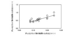
図4に、1回の工程で打抜き加工して製造された製品の切断端部のダレZとダレXとの関係の一例を示す。図4は、フランジ部素体に押し込まれる切断金型の刃先にフランジ部素体の板厚比で0.01~0.30の曲率半径を付与し、切断金型のクリアランスを板厚の0.01~0.20倍に設定して打抜き加工したときの、製品の切断端部のダレZとダレXとの関係を示している。図4に示すように、1回の工程で打抜き加工すると、板厚方向のダレZに対して、平面方向に現れるダレXは約3~4倍の大きさになる。すなわち、1回の工程で打抜き加工をすると、平面方向のダレXが大きくなってしまい、加工品1を取付対象に固定するために必要なビス123の周辺の平坦部を確保するためには、ダレXの分だけ余計にトリム寸法を大きくしなければならない。これより、ダレXは、加工品1のフランジ部12の板厚、すなわち加工品1の切断端部13の板厚t1の0倍超かつ0.30倍未満とするのがよい。ダレXは小さい方が好ましく、フランジ部12の板厚、すなわち加工品1の切断端部13の板厚t1の0.25倍未満、0.26倍未満、0.15倍未満、0.12倍未満または0.10倍未満としてもよい。
FIG. 4 shows an example of the relationship between sag Z and sag X at the cut end of a product manufactured by punching in one process. In Fig. 4, a radius of curvature of 0.01 to 0.30 is given to the cutting edge of the cutting die that is pushed into the flange element body, and the clearance of the cutting die is set to 0.0 of the plate thickness. It shows the relationship between the sag Z and the sag X at the cut end of the product when punching is performed at a setting of .01 to 0.20 times. As shown in FIG. 4, when punching is performed in one process, the sagging X appearing in the plane direction is approximately 3 to 4 times larger than the sagging Z in the thickness direction. That is, if the punching process is performed in one process, the sagging X in the plane direction will become large, and in order to secure a flat part around the
さらに、加工品1の切断端部13の破断面13dの下部側に生じるバリ13eの長さは、0.2mm未満にしてもよい。バリ13eは、打痕、電気的短絡等の原因となり得る。バリ13eの長さを0.2mm未満として、なるべく加工品1にバリを残存させないようにすることで、打痕、電気的短絡等の発生を抑制することができる。バリ13eの長さは、0.1mm未満であるのがより好ましい。バリ13eの長さが0mm、つまり加工品1にバリ13eが存在しないことが最も好ましい。
Furthermore, the length of the
そこで、本実施形態に係る加工品製造方法では、1回の工程で切断するのではなく、半切断工程と仕上げ切断工程との2回の工程によりめっき鋼板を切断する。これにより、切断端部13のダレ13bが大きくなることを抑えつつ、より多くのめっき層13fをせん断面13cに回り込ませることができる。以下、本実施形態に係る加工品製造方法について説明する。
Therefore, in the method for manufacturing a processed product according to the present embodiment, the plated steel plate is not cut in one process, but in two processes: a half-cutting process and a final cutting process. This allows
[1-3.加工品製造方法]
まず、図5に基づいて、本実施形態に係る加工品製造方法について説明する。図5は、本実施形態に係る加工品製造方法を示す説明図である。本実施形態に係る加工品製造方法は、図5に示すように、準備工程、半切断工程及び仕上げ切断工程を含む。[1-3. Processed product manufacturing method]
First, the method for manufacturing a processed product according to this embodiment will be described based on FIG. 5. FIG. 5 is an explanatory diagram showing the method for manufacturing a processed product according to this embodiment. As shown in FIG. 5, the method for manufacturing a processed product according to this embodiment includes a preparation process, a half-cutting process, and a final cutting process.
準備工程は、第1素体2を準備する工程である。第1素体2は、平板状のめっき鋼板に対して例えば絞り加工等の成形加工を施すことにより得ることができる。すなわち、第1素体2は、加工品1と同様にめっき鋼板を素材としている。第1素体2は、図1に示すフランジ部12よりも大きい外径を有するフランジ部素体20を備える。フランジ部素体20は、平面視して外形が円形であってもよく非円形であってもよい。フランジ部素体20以外の部分については、第1素体2は加工品1と同等の形状を有し得る。なお、準備工程は、本発明の実施に不可欠な部分ではない。第三者により何らかの方法によって加工された素体を入手できれば、準備工程を省略することができる。
The preparation process is a process of preparing the
半切断工程は、第1素体2を半切断する工程である。半切断工程では、フランジ部素体20の半切断が行われる。半切断とは、フランジ部素体20の板厚方向に、途中位置までフランジ部素体20を切断する加工である。第1素体2のフランジ部素体20が半切断されると、最終的に製品外となる除去部分20aがフランジ部素体20から途中まで切り離される。
The half-cutting process is a process of cutting the
仕上げ切断工程は、第1素体2を仕上げ切断する工程である。仕上げ切断工程では、フランジ部素体20の除去部分20aを切断し、フランジ部素体20から切り離す。除去部分20aが切断されることで、フランジ部12が形成される。すなわち、本実施形態に係る加工品製造方法では、準備工程にて準備された第1素体2から、半切断工程及び仕上げ切断工程を経て、加工品1を得る。図1に示した加工品1のビス穴121は、第1素体2の段階でフランジ部素体20に形成されてもよく、仕上げ切断工程の後にフランジ部12に形成されてもよい。
The finishing cutting process is a process of finishing cutting the
本実施形態に係る加工品製造方法の半切断工程及び仕上げ切断工程では、ダイ及びパンチを用いてフランジ部素体20が加工される。以下、半切断工程及び仕上げ切断工程の詳細について、半切断工程で使用されるダイ及びパンチの刃先の形状に応じた2つの形態を説明する。ダイ及びパンチの刃先を「肩部」と称する場合もある。
In the half-cutting step and the final cutting step of the method for manufacturing a processed product according to this embodiment, the
なお、以下の説明においては、加工品1を得るために用いる金型について、便宜的に、押し込み側の金型をダイ、押し込まれる側の金型をパンチと称する。押し込み側の金型は、素体に対して上方に位置する場合もあれば、下方に位置する場合もある。水平方向に移動する場合も、押し込み側の金型をダイ、押し込まれる側の金型をパンチと称する。例えば、図2に示す加工品1は、上方の金型を押し込み側の金型として切断されたものである。下方の金型を押し込み側の金型、つまり下方の金型をダイとした場合には、加工品1の切断端部13は、図2とは逆に、ダレ13bが切断端部13の最下方に位置し、その上方にせん断面13c、破断面13d、バリ13eを順に有する。したがって、バリ13eは最上方に位置することになる。つまり、フランジ部素体20の板厚方向に対向する2つの表面のうち、加工後に加工品1のダレ13bが位置する側の表面を押す金型をダイと称し、バリ13eが位置する側の表面を押す金型をパンチと称する。
In the following description, regarding the molds used to obtain the processed
上下(または左右)のどちらの金型がダイとなるかパンチとなるか不明な場合には、実際に切断を行った上で、切断端部13を観察し、ダレ13bが位置する側の表面を押す金型をダイと称し、バリ13eが位置する側の表面を押す金型をパンチと称すればよい。
If it is unclear whether the upper or lower (or left or right) mold will serve as the die or the punch, after actually cutting, observe the
図2に示すように加工品1の外周側に切断端部13が形成される場合には、ダイはパンチの外周側に位置する。加工時、ダイの内面は切断端部13と対向し、パンチの外面は切断端部13と面一となる。一方、例えば後述する図16に示す平ワッシャ900の内周面を切断する場合のように、加工品1の内周側に切断端部13が形成される場合には、ダイはパンチの内周側に位置する。加工時、ダイの外面は切断端部13に対向し、パンチの内面は切断端部13と面一となる。さらに、後述する図20及び図21に示すように、加工品1の外周側と内周側を同時に切断する場合、本実施形態では押し込み側の金型61と金型63をともにダイといい、押し込まれる側の金型65をパンチという。
As shown in FIG. 2, when the
(a.半切断工程で使用されるダイの刃先をR形状とする場合)
まず、図6及び図7に基づいて、半切断工程で使用されるダイの刃先をR形状とする場合の半切断工程及び仕上げ切断工程について説明する。図6は、半切断工程で使用されるダイの刃先をR形状とする場合の半切断工程を示す説明図である。図7は、図6の半切断工程に続いて行われる仕上げ切断工程を示す説明図である。(a. When the cutting edge of the die used in the half-cutting process is R-shaped)
First, based on FIGS. 6 and 7, a half-cutting process and a final cutting process will be described in which the cutting edge of the die used in the half-cutting process is rounded. FIG. 6 is an explanatory diagram showing a half-cutting process when the cutting edge of the die used in the half-cutting process is rounded. FIG. 7 is an explanatory diagram showing a finishing cutting process performed subsequent to the half cutting process of FIG. 6.
(半切断工程)
半切断工程では、図6に示すように、第1素体2のフランジ部素体20が、第1ダイ31及び第1パンチ41を用いて半切断される。図6では、半切断の一態様として、第1パンチ41及び第1板押さえ51によって挟持されたフランジ部素体20からフランジ部12を半抜きする態様を示している。第1ダイ31は、半切断においてフランジ部素体20に押し込まれる切断金型を構成する。本実施形態では、フランジ部素体20のうちフランジ部12となる部分を押さえる金型を第1パンチ41とし、除去部分20aを押さえる金型を第1ダイ31としている。(half cutting process)
In the half-cutting step, as shown in FIG. 6, the flange
第1ダイ31と第1パンチ41とのクリアランスC31-41は、マイナスクリアランスとされる。ここで、クリアランスC31-41は、第1ダイ31と第1パンチ41との隙間を表し、具体的には、図6に示すように、第1ダイ31の側面31aと第1パンチ41の側面41aとの距離で表される。クリアランスがない状態(すなわち、C31-41がゼロのとき)を基準として、第1ダイ31の押し込み方向(すなわち、フランジ部12の板厚方向、Z方向)から見て、第1ダイ31と第1パンチ41とが離隔している状態でのクリアランスをプラスクリアランスといい、第1ダイ31と第1パンチ41とが一部重なる状態でのクリアランスをマイナスクリアランスという。本明細書では、ダイとパンチとのクリアランスについて、プラスクリアランスを正の値、マイナスクリアランスを負の値で表す。A clearance C 31-41 between the
図6に示すように、第1素体2を半切断する第1ダイ31及び第1パンチ41は、第1ダイ31の押し込み方向から見て、第1ダイ31と第1パンチ41とが一部重なるように配置されている。仮に、クリアランスC31-41をプラスクリアランスとすると、1回で行う打抜き加工のように第1ダイ31及び第1パンチ41の刃先から発生したクラックが会合し、フランジ部素体20から除去部分20aが完全に切断されてしまう可能性がある。また、切断端部13のダレ13bが増大することとなる。クリアランスC31-41をマイナスクリアランスとすることで、半切断工程においてフランジ部素体20から除去部分20aが完全に切断されることを回避し、ダレ13bを低減することができる。As shown in FIG. 6, the
また、クリアランスC31-41をマイナスクリアランスとすることで、第1ダイ31及び第1パンチ41により挟み込まれた領域において大きな静水圧応力が発生する。このため、第1ダイ31がフランジ部素体20に押し込まれる際に発生する応力において、切断加工後にスクラップ(すなわち、除去部分20a)となる材料とフランジ部12となるフランジ材料との間に生じる引張応力が占める割合が減少する。その結果、切断加工後にスクラップとなる第1ダイ31の刃先先端に接する材料が第1ダイ31の刃先先端から第1ダイ31の側面31a側へ流動しやすくなり、せん断面13cへのめっき層13fの回り込みを大きくすることができる。また、この引張応力の割合が減少することによって圧縮応力が高まり、本来スクラップとなる側へ流れる材料がフランジ部12となる側へ押し戻される。その結果、切断加工後にダレ13bとなる部分にも材料が充填され、ダレ13bも小さくすることができる。Further, by setting the clearance C 31-41 to be a negative clearance, a large hydrostatic stress is generated in the region sandwiched between the
第1ダイ31と第1パンチ41との隣接方向(図6ではX方向)において、切断加工後にスクラップとなる材料の長さが短いほど、その材料は第1ダイ31の刃先先端から第1ダイ31の側面31a側へ流動しやすい。このため、第1ダイ31の側面31aがフランジ部素体20の端部からフランジ部素体20(すなわち、フランジ部12)の板厚の2倍以下の範囲内に位置するように第1ダイ31を配置して、半切断することが好ましい。
In the adjacent direction between the
第1ダイ31と第1パンチ41とのクリアランスC31-41[mm]は、下記式(a1)に示すように、-0.01mm以下、かつ、第1素体2のフランジ部素体20(すなわち、フランジ部12)の板厚t1[mm]の-0.25倍以上に設定される。The clearance C 31-41 [mm] between the
-0.25×t1≦C31-41≦-0.01 ・・・(a1)-0.25×t1≦C 31-41 ≦-0.01...(a1)
クリアランスC31-41が-0.01mm以下であれば、プレス機械のスライド精度や金型の芯ズレ等により部分的にプラスクリアランスとなることもなく、マイナスクリアランスを維持できる。その結果、半切断中にクラックが発生して完全な切断が生じてしまい、大きな破断面が発生することもない。一方、クリアランスC31-41がフランジ部素体20の板厚t1の-0.25倍以上であれば、半切断に必要な成形荷重は増大せず、プレス能力を超過することもない。したがって、金型への負担も小さく、金型寿命の低下を抑制することができる。クリアランスC31-41の上限は、フランジ部素体20の板厚t1の-0.05倍または-0.10倍としてもよい。クリアランスC31-41の上限は、フランジ部素体20の板厚t1の-0.20倍または-0.15倍としてもよい。If the clearance C 31-41 is -0.01 mm or less, a negative clearance can be maintained without partially becoming a positive clearance due to the slide precision of the press machine, misalignment of the mold, etc. As a result, cracks occur during half-cutting, resulting in complete cutting, and large fracture surfaces do not occur. On the other hand, if the clearance C 31-41 is -0.25 times or more the plate thickness t1 of the
第1ダイ31の刃先は、図6に示すように、曲率半径R1を有するR形状とする。図6に示すように、第1ダイ31がフランジ部素体20に押し込まれるため、第1ダイ31の刃先を、曲率半径R1を有するR形状とする。
The cutting edge of the
曲率半径R1[mm]は、下記式(a2)に示すように、第1素体2のフランジ部素体20(すなわち、フランジ部12)の板厚t1[mm]の0.10倍以上かつ0.50倍以下とする。
The radius of curvature R1 [mm] is at least 0.10 times the plate thickness t1 [mm] of the flange part element body 20 (i.e., the flange part 12) of the
0.1×t1≦R1≦0.5×t1 ・・・(a2) 0.1×t1≦R1≦0.5×t1 (a2)
曲率半径R1が板厚t1の0.10倍以上であれば、めっき層13fを削り取ることなくマイナスクリアランス下で大きな静水圧力が発生し、第1ダイ31直下のスクラップとなる第1ダイ31の刃先先端に接する材料が第1ダイ31の刃先から第1ダイ31の側面31a側へ流動させることができる。この流動により、第1ダイ31がフランジ部素体20に押し込まれる際に発生する応力において、切断加工後にスクラップ(すなわち、除去部分20a)となる材料とフランジ部12となるフランジ材料との間に生じる引張応力が占める割合が減少する。その結果、せん断面13cめっき層13fに回り込ませることができる。一方、曲率半径R1を板厚t1の0.50倍以下とすれば、半切断の際に第1ダイ31の刃先に位置する材料が少なくなり、続いて行われる仕上げ切断において破断面13dの生成を低減することができる。
If the radius of curvature R1 is 0.10 times or more the plate thickness t1, a large hydrostatic pressure will be generated under the negative clearance without scraping off the
なお、第1パンチ41の刃先は、図6に示すように丸みがない角形とする。このとき、第1パンチ41の刃先は、第1素体2のフランジ部素体20の板厚t1の0.1倍未満の曲率半径を有していてもよい。第1パンチ41の刃先の曲率半径は、必要に応じて、第1素体2のフランジ部素体20の板厚t1の0.06倍未満、0.04倍未満または0.02倍未満としてもよい。
Note that the cutting edge of the
第1素体2のフランジ部素体20への第1ダイ31の押込み量D[mm]は、下記式(a3)に示すように、第1素体2のフランジ部素体20(すなわち、フランジ部12)の板厚t1[mm]の0.70倍以上に設定される。押込み量Dは、図6に示すように、第1ダイ31が第1素体2のフランジ部素体20の上面に接触した位置から、第1ダイ31の押込みを停止する位置(以下、この位置を「下死点」ともいう。)までの、第1ダイ31の移動量である。また、下死点での第1ダイ31と第1パンチ41との間隔CP-D[mm]は、下記式(a4)に示すように、0.20mm以上に設定される。The pushing amount D [mm] of the
D≧0.70×t1 ・・・(a3)
CP-D≧0.20 ・・・(a4)D≧0.70×t1...(a3)
C PD ≧0.20 ... (a4)
半切断後にフランジ部素体20(すなわち、除去部分20a)が第1素体2に残存している残存板厚t2は、フランジ部素体20の板厚t1[mm]の0.30倍以下としてもよい。ここで、残存板厚t2とは、加工品1の切断端部13の面(この面は、第1ダイ31の内周面に対向する面である。)における残存板厚である。押込み量Dが板厚t1の0.70倍以上であれば、続いて行われる仕上げ切断において破断面13dが生成され難くなる。一方、下死点での第1ダイ31と第1パンチ41との間隔CP-Dを0.20mm以上確保することで、半切断中にクラックが発生して部分的に完全な切断が生じてしまうことを回避できる。また、金型への負担も小さく、金型寿命の低下を抑制することができる。なお、間隔CP-Dは、下死点での第1ダイ31と第1パンチ41との間隔の最小値とする。The remaining plate thickness t2 of the flange element body 20 (i.e., the removed
なお、第1素体2のフランジ部素体20(すなわち、フランジ部12)への第1ダイ31の押込み量D[mm]は、上記式(a3)に示したように、第1素体2のフランジ部素体20(すなわち、フランジ部12)の板厚t1の0.70倍以上であればよいが、0.95倍以下にしてもよい(0.70×t1≦D≦0.95×t1)。
Note that the pushing amount D [mm] of the
残存板厚t2は、フランジ部素体20(すなわち、フランジ部12)の板厚t1からフランジ部素体20への第1ダイ31の押込み量Dを減算した値に曲率半径R1を加えた値(t2=t1-D+R1)である。このため、残存板厚t2は、下死点での第1ダイ31と第1パンチ41との間隔CP-Dと異なる。押込み量Dが板厚t1の0.70倍以上であれば、続いて行われる仕上げ切断において破断面13dが生成され難くなる。一方、押込み量Dが板厚t1の0.95倍以下であれば、プレス機械のスライド精度や金型の芯ズレ等により、半切断中にクラックが発生して完全な切断が生じてしまい、大きな破断面が発生することもない。The remaining plate thickness t2 is the value obtained by adding the radius of curvature R1 to the value obtained by subtracting the pushing amount D of the
(仕上げ切断工程)
仕上げ切断工程では、図7に示すように、半切断されたフランジ部素体20が、第2ダイ32及び第2パンチ42を用いて仕上げ切断される。図7では、仕上げ切断の一態様として、第2パンチ42及び第2板押さえ52によって挟持されたフランジ部素体20からフランジ部12を仕上げ打ち抜きする態様を示している。第2ダイ32は、仕上げ切断においてフランジ部素体20に押し込まれる切断金型を構成する。本実施形態では、フランジ部素体20のうちフランジ部12となる部分を押さえる金型を第2パンチ42とし、除去部分20aを押さえる金型を第2ダイ32としている。第2ダイ32は、第1ダイ31と同一であってもよい。つまり、半切断工程で使用した第1ダイ31を、仕上げ切断工程で第2ダイ32として使用してもよい。(Final cutting process)
In the finish cutting process, as shown in FIG. 7, the half-cut
第2ダイ32と第1素体2との位置関係は、第1ダイ31と第1素体2との位置関係と同一であることが好ましい。これらの位置関係が同一でない場合、例えば第2ダイ32の径が第1ダイ31の径より大きいと、切断端部13に段差が生じる。逆に例えば第2ダイ32の径が第1ダイ31の径より小さいと、半切断工程で生成された半切断された切断端部に第2ダイ32が接触し、せん断面13cに回り込んだめっき層13fを第2ダイ32が削り落とすおそれがある。
The positional relationship between the
本実施形態に係る仕上げ切断は、半切断と同じ方向から行われる。すなわち、図6に示すように半切断においてフランジ部素体20の上面側からフランジ部素体20に第1ダイ31を押し込んだとき、図7に示すように仕上げ切断においてもフランジ部素体20の上面側からフランジ部素体20に第2ダイ32を押し込む。これにより、フランジ部素体20から除去部分20aが分離される。これにより、フランジ部素体20から除去部分20aが分離される。
The finishing cut according to this embodiment is performed from the same direction as the half cutting. That is, when the
第2ダイ32と第2パンチ42とのクリアランスC32-42[mm]は、プラスクリアランスである。クリアランスC32-42は、第2ダイ32の側面32aと第2パンチ42の側面42aとの距離で表される。ここで、半切断工程と同様に、第2ダイ32と第2パンチ42とが離隔している状態でのクリアランスをプラスクリアランスといい、第2ダイ32と第2パンチ42とが一部重なる状態でのクリアランスをマイナスクリアランスという。The clearance C 32-42 [mm] between the
第2ダイ32と第2パンチ42とのクリアランスC32-42は、下記式(5)に示すように、0.01mm以上、かつ、半切断後に除去部分20aが第1素体2のフランジ部素体20に残存している残存板厚t2の0.2倍以下に設定される。The clearance C 32-42 between the
0.01≦C32-42≦0.2×t2 ・・・(5)0.01≦C 32-42 ≦0.2×t2 (5)
クリアランスC32-42が0.01mm以上であれば、仕上げ切断の際に、プレス機械のスライド精度や金型の芯ズレ等が生じても第2ダイ32と第2パンチ42が接触して破損するおそれがない。一方、クリアランスC32-42が残存板厚t2の0.2倍以下であれば、バリ13eが生成しにくくなる。If the clearance C 32-42 is 0.01 mm or more, the
第2ダイ32の刃先は、曲率半径R2を有するR形状である。図7に示すように、第2ダイ32がフランジ部素体20の仕上げ切断が行われる部分に押し込まれるため、第2ダイ32の刃先を、曲率半径R2を有するR形状とする。なお、第2パンチ42の刃先は、図7に示すように丸みがない角形とする。このとき、第2パンチ42の刃先は、0.25mm未満、0.15mm未満、0.10mm未満または0.05mm未満の曲率半径を有していてもよい。もしくは、第2パンチ42の刃先の曲率半径は、第1素体2のフランジ部素体20の板厚t1の0.1倍未満としてもよく、必要に応じて、0.06倍未満、0.04倍未満または0.02倍未満としてもよい。
The cutting edge of the
曲率半径R2[mm]は、下記式(6)に示すように、0.25mm以上、かつ半切断が行われた部分の残存板厚t2の1.50倍以下とする。 The radius of curvature R2 [mm] is set to be 0.25 mm or more and 1.50 times or less the remaining plate thickness t2 of the half-cut portion, as shown in equation (6) below.
0.25≦R2≦1.50×t2 ・・・(6) 0.25≦R2≦1.50×t2 (6)
曲率半径R2が0.25mm以上であれば、せん断面13cに回り込んだめっき層13fを第2ダイ32が削り落とすことがない。一方、曲率半径R2が残存板厚t2の1.50倍以下であれば、バリ13eが生成しにくくなる。
If the radius of curvature R2 is 0.25 mm or more, the
なお、加工品1の外周側に切断端部が形成される場合には第2ダイ32の内径D32は第1ダイ31の内径D31以上とし、加工品1の内周側に切断端部が形成される場合には第2ダイ32の外径d32は第1ダイ31の外径d31以下とされる。具体的には、加工品1の外周側に切断端部が形成される場合には、第1ダイ31の内径D31と第2ダイ32の内径D32との差の絶対値|D32-D31|は、1.00mm以下とするのが望ましい。加工品1の内周側に切断端部が形成される場合には、第1ダイ31の外径d31と第2ダイ32の外径d32との差の絶対値|d32-d31|は、1.00mm以下とするのが望ましい。これにより、半切断工程と仕上げ切断工程との2回の工程を実施するためにダイ31、32の径差D32-D31またはd32-d31によって加工品1の切断端部13に生じる段差を小さくすることができ、良好な切断断面を得ることができる。In addition, when the cut end is formed on the outer circumference side of the
なお、加工品1の品質として、切断端部13の段差が許容される場合には、加工品1の外周側に切断端部が形成されるときの内径差の絶対値|D32-D31|、加工品1の内周側に切断端部が形成されるときの外径差の絶対値|d32-d31|は、1.00mm超であってもよい。また、これらの径差の絶対値|D32-D31|及び|d32-d31|の上限は、小さい方が好ましく、0.75mm、0.50mm、0.35mmまたは0.20mmとしてもよい。径差の絶対値|D32-D31|及び|d32-d31|の下限は0mmである。なお、加工品1の切断端部13に生じる段差は小さい方が好ましく、0.5mm以下としてもよい。加工品1の切断端部13に生じる段差の上限は、必要に応じて、0.4mm、0.3mm、0.2mmまたは0.1mmとしてもよい。Note that if the quality of the
(b.半切断工程で使用されるダイ及びパンチの刃先をR形状とする場合)
次に、図8及び図9に基づいて、半切断工程で使用されるダイ及びパンチの刃先をR形状とする場合の半切断工程及び仕上げ切断工程について説明する。図8は、半切断工程で使用されるダイ及びパンチの刃先をR形状とする場合の半切断工程を示す説明図である。図9は、図8の半切断工程に続いて行われる仕上げ切断工程を示す説明図である。(b. When the cutting edge of the die and punch used in the half-cutting process is rounded)
Next, based on FIGS. 8 and 9, a description will be given of a half-cutting process and a final cutting process when the cutting edges of the die and punch used in the half-cutting process are rounded. FIG. 8 is an explanatory diagram showing a half-cutting process in which the cutting edges of the die and punch used in the half-cutting process are rounded. FIG. 9 is an explanatory diagram showing a finishing cutting process performed subsequent to the half cutting process of FIG. 8.
(半切断工程)
半切断工程では、図8に示すように、第1素体2のフランジ部素体20が、第1ダイ31及び第1パンチ41を用いて半切断される。図8では、図6と同様、半切断の一態様として、第1パンチ41及び第1板押さえ51によって挟持されたフランジ部素体20からフランジ部12を半抜きする態様を示している。第1ダイ31は、半切断においてフランジ部素体20に押し込まれる切断金型を構成する。本実施形態では、フランジ部素体20のうちフランジ部12となる部分を押さえる金型を第1パンチ41とし、除去部分20aを押さえる金型を第1ダイ31としている。(half cutting process)
In the half-cutting process, as shown in FIG. 8, the flange
第1ダイ31と第1パンチ41とのクリアランスC31-41は、マイナスクリアランスである。したがって、図8に示すように、第1素体2を半切断する第1ダイ31及び第1パンチ41は、第1ダイ31の押し込み方向から見て、第1ダイ31と第1パンチ41とが一部重なるように配置されている。クリアランスC31-41をマイナスクリアランスとすることで、半切断工程においてフランジ部素体20から除去部分20aが完全に切断されることを回避し、ダレ13bを低減することができる。なお、本形態bにおけるクリアランスC31-41、マイナスクリアランス及びプラクリアランスの意味は、上記形態aと同一である。The clearance C 31-41 between the
また、クリアランスC31-41をマイナスクリアランスとすることで、第1ダイ31及び第1パンチ41により挟み込まれた領域において大きな静水圧応力が発生する。このため、第1ダイ31がフランジ部素体20に押し込まれる際に発生する応力において、切断加工後にスクラップ(すなわち、除去部分20a)となる材料とフランジ部12となるフランジ材料との間に生じる引張応力が占める割合が減少する。その結果、切断加工後にスクラップとなる第1ダイ31の刃先先端に接する材料が第1ダイ31の刃先先端から第1ダイ31の側面31a側へ流動しやすくなり、せん断面13cへのめっき層13fの回り込みを大きくすることができる。また、この引張応力の割合が減少することによって圧縮応力が高まり、本来スクラップとなる側へ流れる材料がフランジ部12となる側へ押し戻される。その結果、切断加工後にダレ13bとなる部分にも材料が充填され、ダレ13bも小さくすることができる。Further, by setting the clearance C 31-41 to be a negative clearance, a large hydrostatic stress is generated in the region sandwiched between the
第1ダイ31と第1パンチ41との隣接方向(図8ではX方向)において、切断加工後にスクラップとなる材料の長さが短いほど、その材料は第1ダイ31の刃先先端から第1ダイ31の側面31a側へ流動しやすい。このため、第1ダイ31の側面31aがフランジ部素体20の端部からフランジ部素体20(すなわち、フランジ部12)の板厚の2倍以下の範囲内に位置するように第1ダイ31を配置して、半切断する。
In the adjacent direction between the
第1ダイ31と第1パンチ41とのクリアランスC31-41[mm]は、下記式(b1)に示すように、第1素体2のフランジ部素体20(すなわち、フランジ部12)の板厚t1[mm]の-0.10倍以下、かつ、-0.35倍以上に設定される。The clearance C 31-41 [mm] between the
-0.35×t1≦C31-41≦-0.10×t1 ・・・(b1)-0.35×t1≦C 31-41 ≦-0.10×t1...(b1)
クリアランスC31-41がフランジ部素体20の板厚t1の-0.10倍以下であれば、第1ダイ31及び第1パンチ41により挟み込まれた領域において大きな静水圧応力が発生し、引張応力の割合が減少する。その結果、半切断中にクラックが発生して完全な切断が生じてしまい、大きな破断面が発生することがなくなり、半切断工程においてフランジ部素体20から除去部分20aが完全に切断されることを回避できる。一方、クリアランスC31-41がフランジ部素体20の板厚t1の-0.35倍以上であれば、半切断に必要な成形荷重は増大せず、プレス能力を超過することもない。したがって、金型への負担も小さく、金型寿命の低下を抑制することができる。クリアランスC31-41は、フランジ部素体20の板厚t1の-0.15倍以下または-0.20倍以下とすることが、より好ましい。クリアランスC31-41は、フランジ部素体20の板厚t1の-0.30倍以上または-0.25倍以上としてもよい。If the clearance C 31-41 is less than -0.10 times the plate thickness t1 of the
本形態においては、図8に示すように、第1ダイ31及び第1パンチ41の刃先は、R形状とする。第1ダイ31の刃先の曲率半径R11[mm]、及び、第1パンチ41の刃先の曲率半径R12[mm]は、下記式(b2-1)、式(b2-2)に示すように、第1素体2のフランジ部素体20(すなわち、フランジ部12)の板厚t1[mm]の0.10倍以上かつ0.65倍以下とする。なお、第1ダイ31の刃先の曲率半径R11と第1パンチ41の刃先の曲率半径R12とは、同一であってもよく、異なっていてもよい。
In this embodiment, as shown in FIG. 8, the cutting edges of the
0.10×t1≦R11≦0.65×t1 ・・・(b2-1)
0.10×t1≦R12≦0.65×t1 ・・・(b2-2)0.10×t1≦R11≦0.65×t1 (b2-1)
0.10×t1≦R12≦0.65×t1 (b2-2)
曲率半径R11、R12が板厚t1の0.10倍以上であれば、めっき層13fを削り取ることなくマイナスクリアランス下で大きな静水圧力が発生し、第1ダイ31直下のスクラップとなる材料が第1ダイ31の刃先から第1ダイ31の側面31a側へ流動させることができる。この流動により、第1ダイ31がフランジ部素体20に押し込まれる際に発生する応力において、切断加工後にスクラップ(すなわち、除去部分20a)となる材料とフランジ部12となるフランジ材料との間に生じる引張応力が占める割合が減少する。その結果、せん断面13cめっき層13fに回り込ませることができる。一方、曲率半径R11、R12を板厚t1の0.65倍以下とすれば、半切断の際に第1ダイ31の刃先に位置する材料が少なくなり、続いて行われる仕上げ切断において破断面13dの生成を低減することができる。
If the radii of curvature R11 and R12 are 0.10 times or more the plate thickness t1, a large hydrostatic pressure will be generated under the negative clearance without scraping off the
第1素体2のフランジ部素体20(すなわち、フランジ部12)への第1ダイ31の押込み量D[mm]は、下記式(b3)に示すように、第1素体2のフランジ部素体20(すなわち、フランジ部12)の板厚t1[mm]の0.70倍以上に設定される。押込み量Dは、第1ダイ31が第1素体2のフランジ部素体20の上面に接触した位置から、第1ダイ31の押込みを停止する位置(下死点)までの、第1ダイ31の移動量である。下死点での第1ダイ31と第1パンチ41との間隔CP-D[mm]は、下記式(b4)に示すように、0.20mm以上に設定される。The pushing amount D [mm] of the
D≧0.70×t1 ・・・(b3)
CP-D≧0.20 ・・・(b4)D≧0.70×t1...(b3)
C PD ≧0.20...(b4)
半切断後に除去部分20aが第1素体2のフランジ部素体20に残存している残存板厚t2は、フランジ部素体20の板厚t1[mm]の0.30倍以下としてもよい。押込み量Dが板厚t1の0.70倍以上であれば、続いて行われる仕上げ切断において破断面13dが生成され難くなる。一方、下死点での第1ダイ31と第1パンチ41との間隔CP-Dを0.20mm以上確保することで、半切断中にクラックが発生して部分的に完全な切断が生じてしまうことを回避できる。なお、間隔CP-Dは、下死点での第1ダイ31と第1パンチ41との間隔の最小値とする。The residual plate thickness t2 of the removed
第1ダイ31及び第1パンチ41の刃先をR形状とすることで、図6に示したように第1ダイ31または第1パンチ41の一方のみ刃先をR形状とした場合に比べ、半切断工程でのフランジ部素体20の切断量を大きくすることができる。すなわち、第1ダイ31及び第1パンチ41の刃先をR形状とすることで、図6に示したように第1ダイ31または第1パンチ41の一方のみ刃先をR形状とした場合に比べ、半切断後に除去部分20aがフランジ部素体20に残存している残存板厚t2を小さくすることができる。
By making the cutting edges of the
上記形態aのように第1ダイ31のみ刃先をR形状とした場合は、第1ダイ31の押込み量Dをフランジ部12の板厚t1以上とすると、第1ダイ31の刃先が第1パンチ41の刃先に接触してしまう。このため、上記形態aでは、第1ダイ31の押込み量Dをフランジ部12の板厚t1以上とすることはできない。しかし、第1ダイ31及び第1パンチ41の刃先をR形状とすれば、図8に示すように、第1ダイ31の刃先が第1パンチ41の刃先に接触するまでの、第1ダイ31の押込み可能な量が大きくなる。このため、形態aに比べてフランジ部素体20の切断量をより大きくすることが可能となり、切断端部13におけるせん断面13cの割合を大きくすることができる。これにより、めっき層13fをせん断面13cにより多く回り込ませることができ、めっき層13fにより覆われる切断端部13の割合を増加させることができる。また、残存板厚t2が小さくなることで仕上げ切断工程での切断量が小さくなり、仕上げ切断された部位の一部にめっき層が残存していない状態を回避することができる。
When only the
(仕上げ切断工程)
仕上げ切断工程では、図9に示すように、半切断されたフランジ部素体20が、第2ダイ32及び第2パンチ42を用いて仕上げ切断される。仕上げ切断工程は、図7に示した、第1ダイ31または第1パンチ41の一方のみ刃先をR形状として半切断を行った後に実施される仕上げ切断工程と同様に行えばよい。(Final cutting process)
In the finishing cutting step, as shown in FIG. 9, the half-cut
図9では、仕上げ切断の一態様として、第2パンチ42及び第2板押さえ52によって挟持されたフランジ部素体20からフランジ部12を仕上げ打ち抜きする態様を示している。第2ダイ32は、仕上げ切断においてフランジ部素体20に押し込まれる切断金型を構成する。本実施形態では、フランジ部素体20のうちフランジ部12となる部分を押さえる金型を第2パンチ42とし、除去部分20aを押さえる金型を第2ダイ32としている。第2ダイ32は、第1ダイ31と同一であってもよい。つまり、半切断工程で使用した第1ダイ31を、仕上げ切断工程で第2ダイ32として使用してもよい。
FIG. 9 shows a mode in which the
第2ダイ32と第1素体2との位置関係は、第1ダイ31と第1素体2との位置関係と同一であることが好ましい。これらの位置関係が同一でない場合、例えば第2ダイ32の径が第1ダイ31の径より大きいと、切断端部13に段差が生じる。逆に例えば第2ダイ32の径が第1ダイ31の径より小さいと、半切断工程で生成された半切断された切断端部に第2ダイ32が接触し、せん断面13cに回り込んだめっき層13fを第2ダイ32が削り落とすおそれがある。
The positional relationship between the
本実施形態に係る仕上げ切断は、半切断と同じ方向から行われる。すなわち、図8に示すように半切断においてフランジ部素体20の上面側からフランジ部素体20に第1ダイ31を押し込んだとき、図9に示すように仕上げ切断においてもフランジ部素体20の上面側からフランジ部素体20に第2ダイ32を押し込む。これにより、フランジ部素体20から除去部分20aが分離される。
The finishing cut according to this embodiment is performed from the same direction as the half cutting. That is, when the
第2ダイ32と第2パンチ42とのクリアランスC32-42[mm]は、プラスクリアランスとする。第2ダイ32と第2パンチ42とのクリアランスC32-42は、上記式(5)に示したように、0.01mm以上、かつ、半切断後に除去部分20aが第1素体2のフランジ部素体20に残存している残存板厚t2の0.2倍以下に設定される。クリアランスC32-42が0.01mm以上であれば、仕上げ切断の際に、プレス機械のスライド精度や金型の芯ズレ等が生じても第2ダイ32と第2パンチ42が接触して破損することもない。一方、クリアランスC32-42が残存板厚t2の0.2倍以下であれば、バリ13eが生成しにくくなる。The clearance C 32-42 [mm] between the
第2ダイ32の刃先は、曲率半径R2を有するR形状である。図9に示すように、第2ダイ32がフランジ部素体20の仕上げ切断が行われる部分に押し込まれるため、第2ダイ32の刃先を、曲率半径R2を有するR形状とする。なお、第2パンチ42の刃先は、図9に示すように丸みがない角形であってもよく、曲率半径を有していてもよい。第2パンチ42の刃先を丸みがない角形とすれば、破断面13dの先端に生じるバリをより小さくできる。第2パンチ42の刃先の曲率半径は、1.00mm未満、0.50mm未満、0.20mm未満、0.10mm未満または0.05mm未満としてもよい。もしくは、第2パンチ42の刃先の曲率半径は、第1素体2のフランジ部素体20の板厚t1の0.3倍未満としてもよく、必要に応じて、0.1倍未満、0.06倍未満、0.04倍未満または0.02倍未満としてもよい。
The cutting edge of the
曲率半径R2[mm]は、上記式(6)に示したように、0.25mm以上、かつ半切断が行われた部分の残存板厚t2の1.50倍以下とする。曲率半径R2が0.25mm以上であれば、せん断面13cに回り込んだめっき層13fを第2ダイ32が削り落とすことがない。一方、曲率半径R2が残存板厚t2の1.50倍以下であれば、バリ13eが生成しにくくなる。
The radius of curvature R2 [mm] is set to be 0.25 mm or more and 1.50 times or less of the remaining plate thickness t2 of the half-cut portion, as shown in equation (6) above. If the radius of curvature R2 is 0.25 mm or more, the
以上、本発明の第1の実施形態に係る加工品製造方法について説明した。本実施形態によれば、めっき鋼板から形成され、フランジ部12となるフランジ部素体20を有する第1素体2を切断対象として、第1ダイ31と第1パンチ41とのクリアランスがマイナスクリアランスに設定された第1ダイ31及び第1パンチ41を用いて、第1素体2のフランジ部素体20を半切断する半切断工程と、第2ダイ32及び第2パンチ42を用いて、半切断されたフランジ部素体20を半切断と同一方向から仕上げ切断して、フランジ部12に切断端部13を有する加工品1を得る仕上げ切断工程と、を含む。
The method for manufacturing a processed product according to the first embodiment of the present invention has been described above. According to the present embodiment, the clearance between the
このような2回の工程により切断された加工品1のフランジ部12の切断端部13は、当該切断端部13の板厚方向Tにダレ13b、せん断面13c及び破断面13dを順に有している。せん断面13cは、少なくとも一部が上面13aのめっき層13fにより覆われている。このとき、せん断面13cがめっき層13f1により覆われているめっき成分残存長さLと、加工品1の切断端部13の板厚t1との比L/t1は、0.70以上であり、切断端部13の板厚方向Tにおけるダレ13bの長さは、加工品1の切断端部13の板厚t1の0倍超かつ0.10倍未満である。このように、加工品1は、切断端部13のダレ13bが大きくなることが抑えられ、より多くのめっき層13fがせん断面13cに回り込んでいる。板厚2.0mm超のめっき鋼板を素材として用いた場合であっても、耐食性及び形状品質を良好とすることができる。
The
平面方向(XY平面方向)におけるダレ13bの長さ(ダレX)を小さくすることができれば、加工品1に使用する材料を少なくすることができる。例えば、図1に示したように、加工品1を固定するためのビス123が挿入されるビス穴121は、ビス123が平坦部に固定されるようにダレ13bを避けてフランジ部12に形成される。図10上側に示すように、ダレXが大きくなると、フランジ部12の端部からビス穴121までの距離が長くなり、余分な材料が必要となる。一方、図10下側に示すように、ダレXが小さければ、フランジ部12の端部からビス穴121までの距離が短くなり、フランジ部12を形成する材料を少なくすることができる。このように、本実施形態に係る加工品製造方法により、加工品1を固定するために必要なビス123の周辺の平坦部を確保するためにブランク寸法を余分に大きく必要がなくなる。
If the length of the sagging 13b (the sagging X) in the plane direction (XY plane direction) can be reduced, the amount of material used for the processed
また、本実施形態に係る加工品製造方法により、より多くのめっき層13fをせん断面13cに回り込ませることができため、切断加工後の時間経過とともに発生する切断端部13における赤錆を抑制することができる。
Furthermore, the method for manufacturing a processed product according to the present embodiment allows more of the
さらに、第2ダイ32及び第2パンチ42間のクリアランスC32-42は、0.01mm以上、かつ半切断が行われた部分の第1素体2(フランジ部素体20)の残存板厚t2の0.2倍以下に設定される。これにより、仕上げ切断の際に切断金型が接触して破損することを回避しつつ、バリ13eの生成を抑えることができる。Furthermore, the clearance C 32-42 between the
また、第1素体2の仕上げ切断の対象となる部分に押し込まれる第2ダイ32の刃先先端には、0.25mm以上、かつ、半切断が行われた部分の残存板厚t2の1.50倍以下の曲率半径R2を有する湾曲形状が設けられる。これにより、せん断面13cに回り込んだめっき層13fを切断金型が削り落とされることを回避しつつ、バリ13eの生成を抑えることができる。
Further, the cutting edge of the
[2.第2の実施形態]
次に、図11に基づいて、本発明の第2の実施形態に係る加工品製造方法について説明する。図11は、本発明の第2の実施形態に係る加工品製造方法を示す説明図である。本実施形態に係る加工品製造方法は、図11に示すように、準備工程、半切断工程、仕上げ切断工程及びコイニング工程を含む。[2. Second embodiment]
Next, a method for manufacturing a processed product according to a second embodiment of the present invention will be described based on FIG. 11. FIG. 11 is an explanatory diagram showing a method for manufacturing a processed product according to the second embodiment of the present invention. As shown in FIG. 11, the method for manufacturing a processed product according to this embodiment includes a preparation process, a half-cutting process, a finishing cutting process, and a coining process.
本実施形態に係る加工品製造方法は、図5に示した第1の実施形態に係る加工品製造方法に、コイニング工程を付加した方法である。図11に示すように、本実施形態においても、第1の実施形態と同様に、準備工程にて準備された第1素体2に対して、半切断工程及び仕上げ切断工程が行われる。したがって、準備工程、半切断工程及び仕上げ切断工程については、詳細な説明を省略する。
The processed product manufacturing method according to the present embodiment is a method in which a coining process is added to the processed product manufacturing method according to the first embodiment shown in FIG. As shown in FIG. 11, in this embodiment as well, a half-cutting process and a final cutting process are performed on the
コイニング工程は、仕上げ切断工程で得られた加工品を第2素体6として、第2素体6に対してコイニング加工を行う。コイニング工程では、仕上げ切断工程の後に、破断面13d側の切断端部13の角部13gをパッド(図12のパッド7)に押し当てて、その角部にコイニング面13hが形成された加工品1を得る。コイニング加工により、粗面状の新生面である破断面13dの領域を狭くすることができ、赤錆発生領域を抑えることができる。また、コイニング加工により、バリ13eを潰すことができ、加工品1におけるバリ13eの残存をより確実に抑えることができる。
In the coining process, a coining process is performed on the
図12~図14に基づいて、コイニング工程についてより詳細に説明する。図12は、コイニング工程を示す説明図である。図13は、コイニング工程後の加工品1の切断端部を示し、左側は加工品1の中心軸を含むZX平面での断面図、右側はX方向から側面視した図である。図14は、コイニング工程後の加工品1の切断端部の一例を示す写真である。なお、図13では、図2と同様、めっき層13fの記載を省略している。
The coining process will be explained in more detail based on FIGS. 12 to 14. FIG. 12 is an explanatory diagram showing the coining process. FIG. 13 shows the cut end of the
図12に示すように、本実施形態に係るコイニング工程では、パッド7及びコイニングブロック8により第2素体6の切断端部13を挟み込む。パッド7は、縦壁面70、底壁面71及び押当面72を有する。
As shown in FIG. 12, in the coining process according to this embodiment, the
縦壁面70は、パッド7及びコイニングブロック8により第2素体6の切断端部13を挟み込む際に、第2素体6のせん断面13cと対向し、かつ、略平行にとなるように配置される。縦壁面70は、コイニングブロック8の進退方向(図12ではZ方向)と平行となるように配置される。
The
底壁面71は、第2素体6を挟んで、フランジ部12の板厚方向にコイニングブロック8と対向するように配置される。底壁面71は、縦壁面70の下方(すなわち、コイニングブロック8と反対側)において、縦壁面70と直交する方向に延在する。
The
押当面72は、底壁面71と底壁面71を接続する面である。押当面72は、第2素体6にコイニング面(図13のコイニング面13h)を形成するために設けられ、コイニング面の形状に対応する形状に形成される。例えば、図13に示すように、コイニング面13hを平面状の面取り面(以下、「C面」と称する。)とする場合には、押当面72は、縦壁面70及び底壁面71に対して傾斜する平面とすればよい。また、例えばコイニング面13hを曲面(押圧面、圧縮面のいずれでもよい。以下、「R面」と称する。)とする場合には、押当面72は曲面とすればよい。
The
コイニング工程では、図12に示すように、第2素体6の切断端部13をパッド7の縦壁面70と対向させた状態で、コイニングブロック8とパッド7の底壁面71とにより、第2素体6を板厚方向Tに挟み込む。そして、コイニングブロック8を底壁面71に向かって押し込み、第2素体6の底面13kが底壁面71に接する位置まで、第2素体6を押し下げる。ここで、第2素体6の底面13kが底壁面71に接する前に、角部13gが押当面72に押し当てられる。角部13gが押当面72に押し当てられた後、さらにコイニングブロック8が押し込まれて、第2素体6の底面13kが底壁面71に接する。角部13gは押当面72に押し潰され、コイニング面13hとなる。コイニング工程後の加工品1の切断端部13は、例えば、図14の写真に示すような状態となる。
In the coining process, as shown in FIG. 12, with the
コイニング面13hは、押当面72の表面が転写された平滑面であり、粗面状の破断面13dと比較して赤錆が発生しにくい。面粗さが平滑となることでコイニング面13hに水分が滞留しにくいためと考えられる。また、切断端部13の底面13k側のめっき層13fがコイニング面13hに薄く伸ばされることも赤錆が発生しにくい要素であると考えられる。破断面13d側の角部13gにコイニング面13hが形成されることにより、コイニング加工後のフランジ部12における板厚方向Tにおける破断面長さW2(図13参照)は、コイニング加工前のフランジ部12における板厚方向Tに係る破断面長さW1(図2及び図3参照)よりも短くなる。すなわち、コイニング加工により、粗面状の新生面である破断面13dの領域を狭くすることができ、赤錆発生領域を抑えることができる。また、コイニング加工により、バリ13eを潰すことができ、加工品1におけるバリ13eの残存をより確実に抑えることができる。
The coining
コイニング工程では、加工品1のフランジ部12の板厚方向Tにおけるせん断面13cとコイニング面13hとの間の破断面13dの長さ(破断面長さ)W2を0mm超かつ0.5mm以下とするように、角部13gに押当面72を押し当てる。破断面長さW2を0mm超かつ0.5mm以下とすることで、仮に破断面13dで赤錆が発生したとしても、目立たないことから実用上問題とならないと判断できる。
In the coining process, the length (fracture surface length) W2 of the
なお、仕上げ切断工程では、板厚方向Tに係る破断面長さW1が1.0mm未満の第2素体6を得ることが好ましい。破断面長さW1が1.0mm未満の第2素体6を得ることで、より確実にコイニング工程において破断面長さW2を0.5mm以下とすることができる。加工品1の破断面長さW2は小さい方が好ましく、0.4mm以下または0.3mm以下としてもよい。加工品1の破断面長さW2を0.2mm以下または0.1mm以下とすればより好ましい。また、破断面長さW2と加工品1の切断端部13の板厚t1との比W2/t1を、0.15未満、0.10未満、0.08未満、0.06未満または0.04未満としてもよい。なお、加工品1の破断面長さW2は0mmであってもよい。つまり、加工品1の切断端部13に破断面13dがなくてもよい。すなわち、切断端部13は、例えば図13に示すように、切断端部13の板厚方向において、順に、ダレ13b、せん断面13c、破断面13d及びコイニング面13hを有していてもよい。または、切断端部13は、切断端部13の板厚方向において、順に、ダレ13b、せん断面13c及びコイニング面13hを有していてもよい。
In addition, in the finishing cutting process, it is preferable to obtain the
図15は、図12のパッド7の押当面72によって押し潰される角部13gの体積を示す説明図である。図12のコイニングブロック8がパッド7の底壁面71側へ押し下げられるにつれて、角部13gは押当面72に接触し、押し潰される。押し潰された角部13gの材料(素地鋼)は、押当面72に沿ってせん断面13c側に移動する。切断端部13の底面13kが底壁面71に接する位置まで切断端部13が押し下げられる際、押当面72の位置及び角度等に応じて、押当面72により押し潰されるフランジ部12の角部13gの体積V1が変化する。
FIG. 15 is an explanatory diagram showing the volume of the
コイニング工程では、図15上側に示すように、押当面72により押し潰される角部13gの体積V1を、せん断面13cの延長面13j、破断面13d及び押当面72で囲まれるコイニング空間の体積V2以下とすることが好ましい。図12に示したように、フランジ部12の切断端部13の破断面13dは、縦壁面70に対して傾斜しており、その間には隙間がある。この隙間によって生じるコイニング空間の体積V2は、押当面72により押し潰された角部13gの材料が流れ込む空間となる。コイニング空間の体積V2が押当面72により押し潰される角部13gの体積V1よりも小さいと、押当面72により押し潰された角部13gの材料は、体積V2内に収まることができず、パッド7の上部に向かって移動することになる。
In the coining process, as shown in the upper side of FIG. 15, the volume V1 of the
そこで、体積V1を体積V2以下とすることで、押当面72により押し潰された角部13gの材料がせん断面13cの延長面13jを越えて突出することを回避することができる。図15下側に示すように、体積V1が体積V2を超えると、押当面72により押し潰された角部13gの材料がせん断面13cの延長面13jを越えて突出し、パッド7の上部に向かって移動する等の事象が生じる。このような事象が生じた場合、切断端部13の寸法精度が悪化する。したがって、体積V1を体積V2以下となるように、押当面72により角部13gを押し潰すように加工するのがよい。
Therefore, by setting the volume V1 to be less than or equal to the volume V2, it is possible to prevent the material of the
以上、第2の実施形態に係る加工品製造方法について説明した。本実施形態によれば、第1の実施形態と同様、加工品1を固定するために必要なビス123の周辺の平坦部を確保するためにブランク寸法を余分に大きく必要がなくなる。また、より多くのめっき層13fをせん断面13cに回り込ませることができため、切断加工後の時間経過とともに発生する切断端部13における赤錆を抑制することができる。
The method for manufacturing a processed product according to the second embodiment has been described above. According to this embodiment, similarly to the first embodiment, there is no need to make the blank dimension extra large in order to secure a flat portion around the
さらに、仕上げ切断工程の後、コイニング工程を行うことで、粗面状の新生面である破断面13dの領域を狭くすることができ、赤錆発生領域を抑えることができる。また、コイニング加工により、バリ13eを潰すことができるため、加工品1におけるバリ13eの残存は0.2mm未満となり、バリ13eの残存をより確実に抑えることができる。バリ13eの長さは、0.1mm未満であると好ましく、0.05mm未満または0.01mm未満であることがより好ましい。バリ13eの長さが0mm、つまり加工品1にバリ13eが存在しないことが最も好ましい。
Furthermore, by performing the coining process after the finishing cutting process, the area of the
[3.加工品例]
上記実施形態では、加工品1が図1に示したようなモータケースである場合について説明したが、本実施形態に係る加工品製造方法により製造される加工品1は、めっき鋼板を素材とし、切断端部13を有する任意の物品であってよい。[3. Examples of processed products]
In the above embodiment, a case has been described in which the processed
加工品1は、例えば、図16に示すような円環状の平ワッシャ900であってもよい。また、加工品1は、例えば図17に示すような歯部911を有する平ワッシャ910A、910B、910Cであってもよい。あるいは、加工品1は、例えば図18に示すような波形の円環状の皿ばね920であってもよい。図18の皿ばね920は、例えば図16に示す平ワッシャ900を波形に加工して製造し得る。さらに、加工品は、例えば図19に示すような歯部931を有する皿ばね930であってもよい。
The processed
加工品1が図16~図19に示したような環状の各種プレート部材であるとき、その外周部及び内周部が切断端部13となる。上記実施形態に係る加工品製造方法を適用することにより、外周部及び内周部のうち少なくとも一方を、加工品1の板厚方向Tにおいて、せん断面13cがめっき層13f1により覆われているめっき成分残存長さLと、加工品1の切断端部13の板厚t1との比L/t1を、0.70以上とし、ダレ13bの長さを加工品1の切断端部13の板厚t1の0.10倍未満とすることができる。
When the processed
例えば、図16に示す平ワッシャ900の内周面及び外周面のせん断面をめっき層により覆うようにするには、図20及び図21に示すような切断金型を使用して加工すればよい。図20は、平ワッシャ900を加工するための切断金型の一例を示す模式図である。図21は、図20の切断金型により素体9を抜き加工した状態を示す模式図である。
For example, in order to cover the sheared surfaces of the inner circumferential surface and outer circumferential surface of the
図20に示す切断金型は、平ワッシャ900のような環状の加工品90を製造するための金型であり、中空円筒形状のダイ(以下、「外側ダイ」と称する。)61と、円柱形状のダイ(以下、「内側ダイ」と称する。)63と、円板状の素体9(図21参照)を支持する中空円筒形状のパンチ65とを有する。外側ダイ61及び内側ダイ63と、パンチ65とは対向して設けられ、外側ダイ61及び内側ダイ63をパンチ65に支持された素体9に押し込むことにより、素体9を切断する。外側ダイ61の内径は加工品90の外径に対応し、内側ダイ63の外径は加工品90の内径に対応する。外側ダイ61の内周面の刃先、及び、内側ダイ63の外周面の刃先は、曲率半径を有するR形状を有する。一方、パンチ65の内周面及び外周面の縁部は、R形状を有していない。
The cutting mold shown in FIG. 20 is a mold for manufacturing an annular processed
このような切断金型により素体9を仕上げ切断すると、図21に示すように、加工品90の外周面91よりも外部側となる部分9aが外側ダイ61により切断され、加工品90の内周面92よりも内部側となる部分9bが内側ダイ63により切断される。これにより、図20に示すような加工品90(平ワッシャ900)が形成される。このとき、加工品90の外周面91及び内周面92のせん断面は、めっき層により覆われているめっき成分残存長さLと、加工品90の切断端部の板厚t1との比L/t1が0.70以上となり、切断端部の板厚方向におけるダレの長さは加工品90の切断端部の板厚t1の0.10倍未満とすることができる。
When the
さらに、加工品1は、例えば、図22に示すような円板状のプレート940であってもよい。
Furthermore, the processed
(実施例a.半切断工程で使用されるダイの刃先のみをR形状とする場合)
半切断工程でのダイの肩部(すなわち、刃先)を所定の曲率半径を有するR形状として、図5及び図11に示す方法により加工品のサンプルを作成した。めっき鋼板として、板厚が1.4~3.8mmで、めっき付着量が90g/m2(片面)または190g/m2(片面)のZn-6%Al-3%Mg(質量比)合金めっき鋼板を用いた。半切断加工は、内径D31が85.00mmの丸形ダイと、ダイとパンチとのクリアランスに応じて径を変更したパンチを用い、板押さえによりめっき鋼板を保持して行った。仕上げ切断加工は、肩部(すなわち、刃先)が所定の曲率半径を有するR形状としたダイと、ダイとパンチとのクリアランスC32-42に応じて径D32を変更したパンチを用い、板押さえによりめっき鋼板を保持して行った。(Example a. When only the cutting edge of the die used in the half-cutting process is rounded)
Samples of processed products were prepared by the method shown in FIGS. 5 and 11, with the shoulder portion (ie, the cutting edge) of the die used in the half-cutting step having an R shape with a predetermined radius of curvature. As a plated steel plate, Zn-6%Al-3%Mg (mass ratio) alloy with a plate thickness of 1.4 to 3.8 mm and a coating weight of 90 g/m 2 (one side) or 190 g/m 2 (one side) A plated steel plate was used. The half-cutting process was carried out using a round die with an inner diameter D 31 of 85.00 mm and a punch whose diameter was changed depending on the clearance between the die and the punch, and the plated steel plate was held by a plate holder. The finishing cutting process was performed by using a die whose shoulder part (that is, the cutting edge) had an R shape with a predetermined radius of curvature, and a punch whose diameter D 32 was changed according to the clearance C 32-42 between the die and the punch. The plated steel plate was held by a presser.
各サンプルについて、ダレZ、ダレX、仕上げ切断後の破断面長さ(W1)と、コイニング加工を実施した場合にはコイニング加工後の破断面長さ(W2)を測定した。これらは、マイクロスコープを用いて、加工品の端面の円周上を30°間隔で測定し、計12点の測定値を平均して求めた。また、各サンプルについて、切断端部へのめっき層の回り込みについて、加工品の直辺部の中央部分の断面から、めっき鋼板の厚さ方向についてめっき層が回り込んだ長さLを測定した。切断端部におけるめっき層の長さLの測定には、電子線マイクロアナライザ(EPMA-WDS)を使用した。Zn成分の検出レベルがバックグラウンドの3倍以上である部分にめっき層が存在していると判定した。なお、測定対象は、仕上げ切断後の加工品又は第2素体及びコイニング加工後の加工品である。 For each sample, sagging Z, sagging X, the length of the fractured surface after finishing cutting (W1), and when coining was performed, the length of the fractured surface after coining (W2) were measured. These were determined by measuring the circumference of the end face of the processed product at 30° intervals using a microscope, and averaging the measured values at 12 points in total. In addition, for each sample, regarding the wrapping of the plating layer to the cut end, the length L of the wrapping of the plating layer in the thickness direction of the plated steel sheet was measured from the cross section of the central portion of the right side of the processed product. An electron beam microanalyzer (EPMA-WDS) was used to measure the length L of the plating layer at the cut end. It was determined that a plating layer existed in a portion where the detection level of the Zn component was three times or more the background. Note that the objects to be measured are the processed product after finish cutting or the second element body and the processed product after coining processing.
なお、各サンプルの切断端部において、ダレ、せん断面、破断面及びコイニング面は、図14に示した通りであり、より詳細には以下のように現れる。 In addition, at the cut end of each sample, the sag, shear surface, fracture surface, and coining surface are as shown in FIG. 14, and more specifically, they appear as follows.
ダレは、ダイが被加工材に接触した後に圧縮(加圧)力が加えられて被加工材の表面が引っ張られてできる滑らかな面として現れる。図3に示したように、切断端部を側面視すると、曲率を有する形状となっている。 Sag appears as a smooth surface created when the surface of the workpiece is stretched by compression (pressure) force applied after the die contacts the workpiece. As shown in FIG. 3, when the cut end is viewed from the side, it has a shape with curvature.
せん断面は、切断端部に平滑な面として現れる。せん断面は、ダイが被加工材に接触した後に圧縮(加圧)力が加えられて被加工材に食い込むことにより、ダイの側面と擦れて生じる。ダイと擦れて生じるため、せん断面は金属光沢を呈する。せん断面には、板厚方向に筋状の細かい摺動傷がみられる。 The sheared surface appears as a smooth surface at the cut end. The sheared surface is generated when the die rubs against the side surface of the die by applying compression (pressure) force and biting into the workpiece after the die contacts the workpiece. Because it rubs against the die, the sheared surface exhibits a metallic luster. On the sheared surface, fine streak-like sliding scratches can be seen in the thickness direction.
破断面は、せん断面側から被加工材に生じたクラックが会合して破断した面であり、光沢のない粗い面として現れる。被加工材にせん断面が生じた後、さらにダイが被加工材に食い込むと、パンチの刃先により被加工材にクラックが生じるとともに、ダイの刃先によっても被加工材にクラックが生じる。パンチ及びダイから生じたクラックは、互いに会合し、貫通する。このようにクラックが生じて形成された面が破断面となる。破断面は、パンチとダイとが接触することなく形成されるため、光沢のない粗い面となる。破断面は、パンチとダイとの隙間(クリアランス)に応じた傾斜を有する。 The fracture surface is a surface where cracks generated in the workpiece from the shear surface side join together and break, and appears as a dull, rough surface. When the die further bites into the workpiece after a sheared surface is generated in the workpiece, the punch's cutting edge causes cracks in the workpiece, and the die's cutting edge also causes cracks in the workpiece. Cracks originating from the punch and die meet and penetrate each other. The surface formed by cracking in this way becomes a fracture surface. Since the fractured surface is formed without contact between the punch and the die, it becomes a rough surface without gloss. The fracture surface has an inclination depending on the gap (clearance) between the punch and the die.
コイニング面は、破断面の凹凸が潰された滑らかな面として現れる。コイニング面は、破断面端部の下面側から斜面状または曲面状のコイニング用金型を破断面角部に押し当てることによって得られる。コイニング面は、コイニング金型の表面粗さが転写されることにより、破断面の凹凸が潰された滑らかな面となる。 The coining surface appears as a smooth surface where the irregularities of the fracture surface have been crushed. The coining surface is obtained by pressing an inclined or curved coining mold against the corner of the fractured surface from the lower surface side of the edge of the fractured surface. The surface roughness of the coining die is transferred to the coining surface, so that the unevenness of the fracture surface is flattened and becomes a smooth surface.
切断端部において、ダレ、せん断面、破断面、コイニング面を特定する方法としては、例えば上記特徴をもとに外観からマイクロスコープまたはコントレーサー等により切断端部の形状プロフィールを観察して測定する方法等がある。 A method for identifying sagging, sheared surfaces, fracture surfaces, and coining surfaces at the cut end is, for example, to observe and measure the shape profile of the cut end using a microscope or a contracer from the outside based on the above characteristics. There are methods etc.
固定ビス周辺の平坦度を確保する観点から、切断端部13のダレZが0.10倍未満のものを「A(可)」、0.10倍以上のものを「B(不可)」と評価とした。打痕や電気的短絡等の原因となるバリについて、大きさが0.2mm未満のものを「A(可)」、大きさが0.2mm以上のもの、または、ヒゲ状のバリが発生したものを「B(不可)」と評価した。また、端面の段差は、外観上及び製品寸法精度上なるべく生じさせないことが望ましい。そこで、端面の段差が0.5mm以下のものを「A(可)」、段差が0.5mm超のものを「B(不可)」と評価した。
From the perspective of ensuring flatness around the fixing screw, those with a sagging Z of the
また、サンプルを屋外にて大気曝露試験を行い、切断端部に目立った赤錆が発生するまでの日数を15日ごとに観察した。 In addition, the samples were subjected to an atmospheric exposure test outdoors, and the number of days until noticeable red rust appeared on the cut ends was observed every 15 days.
以上の結果を表1に示す。表1には、各サンプルに用いためっき鋼板、半切断工程、仕上げ切断工程の条件、及び切断端部の角部へのコイニング有無も合わせて示している。ここで、ダイの曲率半径の板厚比(R1/t1、R2/t2)は、ダイの肩部に付与された丸みを板厚で除したものである。意図的にダイの肩部(刃先)に丸みを付与していないものは、この欄に「<0.01」と記した。 The above results are shown in Table 1. Table 1 also shows the plated steel sheets used for each sample, the conditions of the half-cutting process, the final cutting process, and whether or not the corners of the cut ends were coined. Here, the plate thickness ratio of the radius of curvature of the die (R1/t1, R2/t2) is obtained by dividing the roundness given to the shoulder of the die by the plate thickness. If the die shoulder (cutting edge) was not intentionally rounded, "<0.01" was written in this column.

表1に示すように、実施例a1~a19は、切断端部の板厚t1に対するめっき成分の残存長さLが0.70倍以上であり、かつ、板厚方向に現れるダレZの大きさが加工品の切断端部の板厚t1の0.10倍未満であった。その切断端部の破断面長さW1はいずれも1.0mm以下であり、実施例a1~a19は、赤錆発生まで60日の良好な耐食性を示した。実施例a1~a13は、平面方向に現れるダレXの大きさが加工品の切断端部の板厚t1の0.30倍未満であった。切断端部の破断面長さW1が0.5mm以下である実施例a1~a16では、赤錆発生まで90日以上の良好な耐食性を示した。 As shown in Table 1, in Examples a1 to a19, the remaining length L of the plating component is 0.70 times or more with respect to the plate thickness t1 at the cut end, and the size of the sag Z appearing in the plate thickness direction is was less than 0.10 times the plate thickness t1 at the cut end of the processed product. The fracture surface length W1 of the cut end was all 1.0 mm or less, and Examples a1 to a19 exhibited good corrosion resistance for 60 days until red rust appeared. In Examples a1 to a13, the size of the sagging X appearing in the plane direction was less than 0.30 times the plate thickness t1 at the cut end of the processed product. Examples a1 to a16 in which the fracture surface length W1 of the cut end was 0.5 mm or less exhibited good corrosion resistance for 90 days or more until red rust appeared.
実施例a1~a14は、加工品の切断端部の板厚t1に対するめっき成分の残存長さLが0.80倍以上でかつ破断面長さ(W1)が0.5mm以下の範囲になった。また実施例a15は、仕上げ抜き後に、押し潰す辺の長さ(コイニング面の幅)を0.6mmとしたR面のコイニング面を形成するコイニング加工を行ったものである。実施例a16は、仕上げ抜き後に、押し潰す辺の長さ(コイニング面の幅)を1.0mmとして角度45°で面取りしたC面のコイニング面を形成するコイニング加工を行ったものである。コイニング加工後の破断面長さ(W2)、他の実施例の破断面長さW1よりも小さくなっている。切断加工のダイの径D31と仕上げ切断加工のダイの径D32との差の絶対値|D32-D31|については、実施例a1~a17では0.05mmとし、実施例a18ではゼロ(径D31と径D32とは同一)とし、実施例a19では1.00mmとしたが、いずれの場合にも、端面の段差は0.5mm以下であった。In Examples a1 to a14, the remaining length L of the plating component was 0.80 times or more with respect to the plate thickness t1 at the cut end of the processed product, and the fracture surface length (W1) was in the range of 0.5 mm or less. . Further, in Example a15, after finishing punching, a coining process was performed to form a coining surface with an R surface in which the length of the side to be crushed (width of the coining surface) was 0.6 mm. In Example a16, after finishing punching, a coining process was performed to form a C-plane coining surface chamfered at an angle of 45° with the length of the crushed side (width of the coining surface) being 1.0 mm. The fracture surface length (W2) after the coining process is smaller than the fracture surface length W1 of the other examples. The absolute value of the difference between the diameter D 31 of the die for cutting and the diameter D 32 of the die for finishing cutting |D 32 −D 31 | is set to 0.05 mm in Examples a1 to a17, and zero in Example A18. (The diameter D 31 and the diameter D 32 are the same) and in Example a19, it was 1.00 mm, but in both cases, the step difference on the end face was 0.5 mm or less.
なお、実施例a1~a14、a18、a19の切断端部は、板厚方向にダレ、せん断面及び破断面を順に有しており、実施例a15、a16の切断端部は、板厚方向にダレ、せん断面、破断面及びコイニング面を順に有していることが、上述の特徴をもとに外観から確認された。 Note that the cut ends of Examples a1 to a14, a18, and a19 have a sag, a sheared surface, and a fracture surface in order in the thickness direction, and the cut ends of Examples a15 and a16 have a sag in the thickness direction. Based on the above-mentioned characteristics, it was confirmed from the external appearance that it had a sag, a sheared surface, a fractured surface, and a coined surface in that order.
これに対して、比較例a1~a5、a8、a10~a13、a16は、加工品の切断端部の板厚t1に対するめっき層成分の残存長さLが0.70倍未満であったため、切断端部の赤錆発生までの日数は60日を下回っており、実施例と比べて耐食性が劣った。比較例a9は、半切断工程において大きなマイナスクリアランスを採用したものであるが、750kNのメカプレス機を使用した半抜き加工の工程で荷重オーバーとなり、プレス機が停止した。比較例a14、a15は、いずれも切断端部の赤錆発生まで90日以上の良好な耐食性を示したが、切断端部に0.2mm以上の大きなバリが発生した。 On the other hand, in Comparative Examples a1 to a5, a8, a10 to a13, and a16, the remaining length L of the plating layer component was less than 0.70 times the plate thickness t1 at the cut end of the processed product. The number of days until red rust appeared on the edges was less than 60 days, and the corrosion resistance was inferior compared to the examples. In Comparative Example a9, a large negative clearance was adopted in the half-cutting process, but the press machine stopped due to excessive load during the half-blanking process using a 750 kN mechanical press. Comparative Examples a14 and a15 both exhibited good corrosion resistance for 90 days or more until red rust appeared on the cut ends, but large burrs of 0.2 mm or more were generated on the cut ends.
比較例a6は、切断端部の赤錆発生までの日数は90日以上の良好な耐食性を示したが、板厚方向に現れるダレZの大きさがフランジ素材の板厚の0.10倍以上であり、かつ平面方向に現れるダレXの大きさが加工品の板厚の0.30倍以上であり、ビス止めの際にその分余計にフランジ寸法を大きくしなければならない。比較例a7は、半切断工程でのダイとパンチとのクリアランスをゼロとした場合であり、半切断工程にてめっき鋼板が完全に破断した。 Comparative Example A6 showed good corrosion resistance, with the number of days until red rust appeared on the cut end being 90 days or more, but the size of the sag Z appearing in the plate thickness direction was 0.10 times or more the plate thickness of the flange material. In addition, the size of the sagging X appearing in the plane direction is 0.30 times or more the thickness of the processed product, and the flange size must be increased accordingly when screwing. Comparative example a7 is a case in which the clearance between the die and the punch in the half-cutting process was set to zero, and the plated steel plate was completely broken in the half-cutting process.
(実施例b.半切断工程で使用されるダイ及びパンチの刃先をR形状とする場合)
次に、半切断工程でのダイ及びパンチの肩部(すなわち、刃先)を所定の曲率半径を有するR形状として、図5及び図11に示す方法により加工品のサンプルを作成した。めっき鋼板として、板厚が1.4~4.5mmで、めっき付着量が90g/m2(片面)または190g/m2(片面)のZn-6%Al-3%Mg(質量比)合金めっき鋼板を用いた。半切断加工は、内径85.00mmの丸形ダイと、ダイとパンチとのクリアランスに応じて径を変更したパンチを用い、板押さえによりめっき鋼板を保持して行った。仕上げ切断加工は、肩部(すなわち、刃先)が所定の曲率半径を有するR形状のダイと、ダイとパンチとのクリアランスに応じて径を変更したパンチを用い、板押さえによりめっき鋼板を保持して行った。(Example b. When the cutting edge of the die and punch used in the half-cutting process is rounded)
Next, samples of processed products were created by the method shown in FIGS. 5 and 11, with the shoulder portions (ie, cutting edges) of the die and punch used in the half-cutting process being formed into an R shape having a predetermined radius of curvature. Zn-6%Al-3%Mg (mass ratio) alloy with a plate thickness of 1.4 to 4.5 mm and a coating weight of 90 g/m 2 (one side) or 190 g/m 2 (one side) as a plated steel sheet. A plated steel plate was used. The half-cutting process was performed using a round die with an inner diameter of 85.00 mm and a punch whose diameter was changed depending on the clearance between the die and the punch, and the plated steel plate was held by a plate holder. The finishing cutting process uses an R-shaped die with a shoulder (i.e., cutting edge) with a predetermined radius of curvature, and a punch whose diameter is changed according to the clearance between the die and punch, and the plated steel plate is held by a plate holder. I went.
各サンプルについて、上述の実施例aと同様に、平坦度評価、バリ評価及び段差評価を行い、大気曝露試験による赤錆発生日数を調べた。実施例bの結果を表2に示す。 For each sample, flatness evaluation, burr evaluation, and step evaluation were performed in the same manner as in Example a above, and the number of days for red rust occurrence was determined by an atmospheric exposure test. The results of Example b are shown in Table 2.

表2に示すように、実施例b1~b19は、加工品の切断端部の板厚t1に対するめっき成分の残存長さLが0.70倍以上であり、かつ、板厚方向に現れるダレZの大きさが加工品の切断端部の板厚t1の0.10倍未満であった。その切断端部の破断面長さはいずれも1.0mm以下であり、実施例b1~b19は、赤錆発生まで60日の良好な耐食性を示した。実施例b1~b13、b15~b19は、平面方向に現れるダレXの大きさは加工品の切断端部の板厚t1の0.30倍未満であった。実施例b1~b14、b16、b17は、加工品の切断端部の板厚t1に対するめっき成分の残存長さLが0.80倍以上でかつ破断面長さ(W1)が0.5mm以下の範囲となり、赤錆発生まで90日以上の良好な耐食性を示した。また、実施例b16は、仕上げ抜き後に、押し潰す辺の長さ(コイニング面の幅)を0.6mmとしたR面のコイニング面を形成するコイニング加工を行ったものである。実施例b17は、仕上げ抜き後に、押し潰す辺の長さ(コイニング面の幅)を1.0mmとして角度45°で面取りしたC面のコイニング面を形成するコイニング加工を行ったものある。コイニング加工後の破断面長さ(W2)は、他の実施例よりも小さくなった。半切断加工のダイの径D31と仕上げ切断加工のダイの径D32との差の絶対値|D32-D31|については、実施例b1~b17では0.05mmとし、実施例b18ではゼロ(径D31と径D32とは同一)とし、実施例b19では1.00mmとしたが、いずれの場合にも、端面の段差は0.5mm以下であった。As shown in Table 2, in Examples b1 to b19, the residual length L of the plating component is 0.70 times or more of the plate thickness t1 at the cut end of the processed product, and the sag Z appearing in the plate thickness direction is was less than 0.10 times the plate thickness t1 of the cut end of the processed product. The length of the fractured surface of the cut end was all 1.0 mm or less, and Examples b1 to b19 exhibited good corrosion resistance for 60 days until red rust appeared. In Examples b1 to b13 and b15 to b19, the size of the sagging X appearing in the planar direction was less than 0.30 times the plate thickness t1 at the cut end of the processed product. In Examples b1 to b14, b16, and b17, the remaining length L of the plating component is 0.80 times or more of the plate thickness t1 at the cut end of the processed product, and the fracture surface length (W1) is 0.5 mm or less. It showed good corrosion resistance for 90 days or more until red rust appeared. Further, in Example b16, after finishing punching, a coining process was performed to form a coining surface with an R surface in which the length of the side to be crushed (width of the coining surface) was 0.6 mm. In Example b17, after finishing punching, coining processing was performed to form a C-plane coining surface chamfered at an angle of 45° with the length of the crushed side (width of the coining surface) being 1.0 mm. The fracture surface length (W2) after the coining process was smaller than that of the other examples. The absolute value of the difference between the die diameter D 31 for half-cutting and the die diameter D 32 for finish cutting |D 32 −D 31 | was set to 0.05 mm in Examples b1 to b17, and was set to 0.05 mm in Example b18. The diameter was zero (the diameter D 31 and the diameter D 32 were the same), and in Example b19 it was 1.00 mm, but in both cases, the step difference on the end face was 0.5 mm or less.
なお、実施例b1~b15、b18、b19の切断端部は、板厚方向にダレ、せん断面及び破断面を順に有しており、実施例b16、b17の切断端部は、板厚方向にダレ、せん断面、破断面及びコイニング面を順に有していることが、上述の特徴をもとに外観から確認された。 Note that the cut ends of Examples b1 to b15, b18, and b19 have a sag, a sheared surface, and a fracture surface in order in the thickness direction, and the cut ends of Examples b16 and b17 have a sag in the thickness direction. Based on the above-mentioned characteristics, it was confirmed from the external appearance that it had a sag, a sheared surface, a fractured surface, and a coined surface in that order.
これに対して、比較例b1、b2、b4、b6~b8、b11、b13は、加工品の切断端部の板厚t1に対するめっき層成分の残存長さLが0.70倍未満であったため、切断端部の赤錆発生までの日数は60日を下回っており、実施例と比べて耐食性が劣った。また、比較例b1、b4は、板厚方向に現れるダレZの大きさが加工品の切断端部の板厚t1の0.10倍であったため、十分な平坦度が得られなかった。比較例b5は、半切断工程において大きなマイナスクリアランスを採用したものであるが、750kNのメカプレス機を使用した半抜き加工の工程で荷重オーバーとなり、プレス機が停止した。比較例b9、b10は、いずれも切断端部の赤錆発生まで90日以上の良好な耐食性を示したが、切断端部に0.2mm以上の大きなバリが発生した。比較例b3、b12は、半切断工程でのダイとパンチとのマイナスクリアランスが十分ではなかったため、半切断工程にてめっき鋼板が完全に破断した。 On the other hand, in Comparative Examples b1, b2, b4, b6 to b8, b11, and b13, the remaining length L of the plating layer component was less than 0.70 times the plate thickness t1 at the cut end of the processed product. The number of days until red rust appeared on the cut end was less than 60 days, and the corrosion resistance was inferior compared to the examples. Further, in Comparative Examples b1 and b4, the size of the sag Z appearing in the thickness direction was 0.10 times the thickness t1 of the cut end of the processed product, and therefore sufficient flatness could not be obtained. Comparative example b5 employs a large negative clearance in the half-cutting process, but the press machine stopped due to excessive load during the half-blanking process using a 750 kN mechanical press. Comparative Examples b9 and b10 both showed good corrosion resistance for 90 days or more until red rust appeared on the cut ends, but large burrs of 0.2 mm or more were generated on the cut ends. In Comparative Examples b3 and b12, the plated steel plates were completely broken in the half-cutting process because the negative clearance between the die and the punch was not sufficient in the half-cutting process.
以上によると、半切断工程を行い続いて仕上げ切断工程を行う切断加工において、切断端部の形状に関して、加工品の切断端部の板厚t1に対するめっき成分の残存長さLが0.70倍以上とすることにより、良好な耐食性を有する切断端部が得られることが確認できた。また、切断端部の板厚方向に現れるダレZが加工品の切断端部の板厚t1の0.10倍未満とすることにより、ビス止めの際に余計にフランジ寸法を大きくすることなく製品が得られることを確認した。 According to the above, in a cutting process in which a half-cutting process is performed, followed by a finishing cutting process, regarding the shape of the cut end, the remaining length L of the plating component is 0.70 times the plate thickness t1 of the cut end of the workpiece. It was confirmed that by doing the above, a cut end having good corrosion resistance could be obtained. In addition, by making the sagging Z that appears in the thickness direction of the cut edge less than 0.10 times the plate thickness t1 of the cut edge of the processed product, the product can be manufactured without increasing the flange size unnecessarily when screwing. was confirmed to be obtained.
以上、添付図面を参照しながら本発明の好適な実施形態について詳細に説明したが、本発明はかかる例に限定されない。本発明の属する技術の分野における通常の知識を有する者であれば、特許請求の範囲に記載された技術的思想の範疇内において、各種の変更例または修正例に想到し得ることは明らかであり、これらについても、当然に本発明の技術的範囲に属するものと了解される。 Although preferred embodiments of the present invention have been described above in detail with reference to the accompanying drawings, the present invention is not limited to such examples. It is clear that a person with ordinary knowledge in the technical field to which the present invention pertains can come up with various changes or modifications within the scope of the technical idea stated in the claims. It is understood that these also naturally fall within the technical scope of the present invention.
1 加工品
2 第1素体
6 第2素体
7 パッド
8 コイニングブロック
9 素体
10 胴部
11 突部
12 フランジ部
13 切断端部
13a 上面
13b ダレ
13c せん断面
13d 破断面
13e バリ
13f めっき層
13g 角部
13h コイニング面
13j 延長面
13k 底面
20 フランジ部素体
20a 除去部分
31 第1ダイ
32 第2ダイ
41 第1パンチ
42 第2パンチ
61 外側ダイ
63 内側ダイ
65 パンチ
70 縦壁面
71 底壁面
72 押当面
101 側壁
103 頂壁
121 ビス穴
123 ビス
900、910A、910B、910C 平ワッシャ
911、931 歯部
940 プレート1
Claims (5)
第1ダイと第1パンチとのクリアランスがマイナスクリアランスに設定された前記第1ダイ及び前記第1パンチを用いて、前記素材から形成された第1素体の切断部分を板厚方向に半切断する半切断工程と、
第2ダイ及び第2パンチを用いて、半切断された前記第1素体を前記半切断と同一方向から仕上げ切断して、前記板厚方向に沿った切断端部を有する加工品を得る仕上げ切断工程と、
を含み、
前記加工品の外周側に切断端部が形成される場合には前記第2ダイの内径D32は前記第1ダイの内径D31以上とし、前記加工品の内部側に切断端部が形成される場合には前記第2ダイの外径d32は前記第1ダイの外径d31以下とし、
前記第1素体の切断部分の板厚をt1、前記半切断工程後の前記切断部分の残存板厚をt2として、
前記半切断工程において、
前記第1ダイ及び前記第1パンチとのクリアランスC31-41は、下記式(a1)を満たし、
前記第1ダイの刃先の曲率半径R1は、下記式(a2)を満たし、
前記第1素体の切断部分に対する前記第1ダイまたは前記第1パンチの押込み量Dは、下記式(a3)を満たし、
下死点での前記第1ダイと前記第1パンチとの間隔CP-Dは、下記式(a4)を満たし、
前記仕上げ切断工程において、
前記第2ダイと前記第2パンチとのクリアランスC32-42は、下記式(a5)を満たし、
前記第2ダイの刃先の曲率半径R2は、下記式(a6)を満たす、加工品製造方法。
-0.25×t1≦C31-41≦-0.01 ・・・(a1)
0.10×t1≦R1≦0.50×t1 ・・・(a2)
D≧0.70×t1 ・・・(a3)
CP-D≧0.20 ・・・(a4)
0.01≦C32-42≦0.2×t2 ・・・(a5)
0.25≦R2≦1.50×t2 ・・・(a6)
ここで、C31-41、CP-D、C32-42及びR2の単位はmmとする。 A method for manufacturing a processed product using a plated steel plate having a plating layer on the surface as a material and having a cut end, the method comprising:
Using the first die and the first punch in which the clearance between the first die and the first punch is set to a negative clearance, the cut portion of the first element body formed from the material is cut in half in the thickness direction. a half-cutting process,
Using a second die and a second punch, finish cutting the half-cut first element body from the same direction as the half-cutting to obtain a processed product having a cut end along the plate thickness direction. cutting process;
including;
When the cut end is formed on the outer circumferential side of the workpiece, the inner diameter D32 of the second die is equal to or larger than the inner diameter D31 of the first die, and the cut end is formed on the inner side of the workpiece. In the case where the outer diameter d32 of the second die is equal to or less than the outer diameter d31 of the first die,
The plate thickness of the cut portion of the first element body is t1, and the remaining plate thickness of the cut portion after the half-cutting step is t2,
In the half cutting step,
The clearance C31-41 between the first die and the first punch satisfies the following formula (a1),
The radius of curvature R1 of the cutting edge of the first die satisfies the following formula (a 2 ),
The pushing amount D of the first die or the first punch with respect to the cut portion of the first element satisfies the following formula (a3),
The distance C PD between the first die and the first punch at the bottom dead center satisfies the following formula (a4),
In the finishing cutting step,
The clearance C32-42 between the second die and the second punch satisfies the following formula (a5),
A method for manufacturing a processed product, wherein the radius of curvature R2 of the cutting edge of the second die satisfies the following formula (a6).
-0.25×t1≦C 31-41 ≦-0.01...(a1)
0.10×t1≦R1≦0.50×t1 (a2)
D≧0.70×t1...(a3)
C PD ≧0.20 ... (a4)
0.01≦C 32-42 ≦0.2×t2...(a5)
0.25≦R2≦1.50×t2...(a6)
Here, the units of C 31-41 , C PD , C 32-42 and R2 are mm.
第1ダイと第1パンチとのクリアランスがマイナスクリアランスに設定された前記第1ダイ及び前記第1パンチを用いて、前記素材から形成された第1素体の切断部分を板厚方向に半切断する半切断工程と、
第2ダイ及び第2パンチを用いて、半切断された前記第1素体を前記半切断と同一方向から仕上げ切断して、切断面が前記板厚方向に沿った切断端部を有する加工品を得る仕上げ切断工程と、
を含み、
前記加工品の外周側に切断端部が形成される場合には前記第2ダイの内径D32は前記第1ダイの内径D31以上とし、前記加工品の内部側に切断端部が形成される場合には前記第2ダイの外径d32は前記第1ダイの外径d31以下とし、
前記第1素体の切断部分の板厚をt1、前記半切断工程後の前記切断部分の残存板厚をt2として、
前記半切断工程において、
前記第1ダイ及び前記第1パンチとのクリアランスC31-41は、下記式(b1)を満たし、
前記第1ダイの刃先の曲率半径R11は、下記式(b2-1)を満たし、
前記第1パンチの刃先の曲率半径R12は、下記式(b2-2)を満たし、
前記第1素体の切断部分に対する前記第1ダイまたは前記第1パンチの押込み量Dは、下記式(b3)を満たし、
下死点での前記第1ダイと前記第1パンチとの間隔CP-Dは、下記式(b4)を満たし、
前記仕上げ切断工程において、
前記第2ダイと前記第2パンチとのクリアランスC32-42は、下記式(b5)を満たし、
前記第2ダイの刃先の曲率半径R2は、下記式(b6)を満たす、加工品製造方法。
-0.35×t1≦C31-41≦-0.10×t1・・・(b1)
0.10×t1≦R11≦0.65×t1 ・・・(b2-1)
0.10×t1≦R12≦0.65×t1 ・・・(b2-2)
D≧0.70×t1 ・・・(b3)
CP-D≧0.20 ・・・(b4)
0.01≦C32-42≦0.2×t2 ・・・(b5)
0.25≦R2≦1.50×t2 ・・・(b6)
ここで、C31-41、CP-D、C32-42及びR2の単位はmmとする。 A method for manufacturing a processed product using a plated steel plate having a plating layer on the surface as a material and having a cut end, the method comprising:
Using the first die and the first punch in which the clearance between the first die and the first punch is set to a negative clearance, the cut portion of the first element body formed from the material is cut in half in the thickness direction. a half-cutting process,
Using a second die and a second punch, the half-cut first element body is finished cut in the same direction as the half-cutting, and the processed product has a cut end whose cut surface is along the plate thickness direction. A finishing cutting process to obtain
including;
When the cut end is formed on the outer circumferential side of the workpiece, the inner diameter D32 of the second die is equal to or larger than the inner diameter D31 of the first die, and the cut end is formed on the inner side of the workpiece. In the case where the outer diameter d32 of the second die is equal to or less than the outer diameter d31 of the first die,
The plate thickness of the cut portion of the first element body is t1, and the remaining plate thickness of the cut portion after the half-cutting step is t2,
In the half cutting step,
The clearance C31-41 between the first die and the first punch satisfies the following formula (b1),
The radius of curvature R11 of the cutting edge of the first die satisfies the following formula (b2-1),
The radius of curvature R12 of the cutting edge of the first punch satisfies the following formula (b2-2),
The pushing amount D of the first die or the first punch with respect to the cut portion of the first element satisfies the following formula (b3),
The distance C PD between the first die and the first punch at the bottom dead center satisfies the following formula (b4),
In the finishing cutting step,
The clearance C32-42 between the second die and the second punch satisfies the following formula (b5),
The curvature radius R2 of the cutting edge of the second die satisfies the following formula (b6).
-0.35×t1≦C 31-41 ≦-0.10×t1...(b1)
0.10×t1≦R11≦0.65×t1 (b2-1)
0.10×t1≦R12≦0.65×t1 (b2-2)
D≧0.70×t1...(b3)
C PD ≧0.20...(b4)
0.01≦C 32-42 ≦0.2×t2...(b5)
0.25≦R2≦1.50×t2...(b6)
Here, the units of C 31-41 , C PD , C 32-42 and R2 are mm.
前記第2素体の前記切断端部の角部をパッドに押し当て、前記角部にコイニング面が形成された加工品を得るコイニング工程をさらに含む、請求項1または2に記載の加工品製造方法。 The processed product obtained in the finishing cutting step is used as a second element body,
Manufacturing a processed product according to claim 1 or 2 , further comprising a coining step of pressing a corner of the cut end of the second element against a pad to obtain a processed product in which a coining surface is formed on the corner. Method.
前記加工品の内部側に切断端部が形成される場合には、前記第1ダイの外径d31と前記第2ダイの外径d32との差の絶対値|d32-d31|を1.00mm以下とする、請求項1~3のいずれか1項に記載の加工品製造方法。 When a cut end is formed on the outer peripheral side of the processed product, the absolute value of the difference between the inner diameter D 31 of the first die and the inner diameter D 32 of the second die |D 32 −D 31 | .00mm or less,
When a cut end is formed on the inner side of the workpiece, the absolute value of the difference between the outer diameter d 31 of the first die and the outer diameter d 32 of the second die |d 32 −d 31 | The method for manufacturing a processed product according to any one of claims 1 to 3 , wherein the thickness is 1.00 mm or less.
The method for manufacturing a processed product according to any one of claims 1 to 4 , further comprising a preparation step of forming a first element from a flat plated steel plate before the half-cutting step.
Applications Claiming Priority (3)
| Application Number | Priority Date | Filing Date | Title |
|---|---|---|---|
| JP2020137515 | 2020-08-17 | ||
| JP2020137515 | 2020-08-17 | ||
| PCT/JP2021/030070 WO2022039168A1 (en) | 2020-08-17 | 2021-08-17 | Processed product and method for producing processed product |
Publications (3)
| Publication Number | Publication Date |
|---|---|
| JPWO2022039168A1 JPWO2022039168A1 (en) | 2022-02-24 |
| JPWO2022039168A5 JPWO2022039168A5 (en) | 2022-07-29 |
| JP7358608B2 true JP7358608B2 (en) | 2023-10-10 |
Family
ID=80350405
Family Applications (1)
| Application Number | Title | Priority Date | Filing Date |
|---|---|---|---|
| JP2022500586A Active JP7358608B2 (en) | 2020-08-17 | 2021-08-17 | Processed product manufacturing method |
Country Status (6)
| Country | Link |
|---|---|
| JP (1) | JP7358608B2 (en) |
| KR (1) | KR20230051772A (en) |
| CN (1) | CN115943002A (en) |
| MX (1) | MX2023002012A (en) |
| TW (1) | TWI808469B (en) |
| WO (1) | WO2022039168A1 (en) |
Citations (4)
| Publication number | Priority date | Publication date | Assignee | Title |
|---|---|---|---|---|
| JP2000117344A (en) | 1998-10-15 | 2000-04-25 | Pn:Kk | Pressing method of metallic product and progressive working method |
| JP3138030B2 (en) | 1990-11-26 | 2001-02-26 | センサーマティック エレクトロニクス コーポレーション | Jammers for electronic surveillance systems |
| JP2002321021A (en) | 2001-04-25 | 2002-11-05 | Nisshin Steel Co Ltd | Worked product excellent in fatigue characteristic and corrosion resistance at edge surface and working method therefor |
| JP2015157314A (en) | 2014-02-25 | 2015-09-03 | 日新製鋼株式会社 | PUNCHING METHOD OF Zn BASED GALVANIZED STEEL SHEET |
Family Cites Families (12)
| Publication number | Priority date | Publication date | Assignee | Title |
|---|---|---|---|---|
| JPH05228563A (en) * | 1992-02-04 | 1993-09-07 | Sankyo Seiki Mfg Co Ltd | Manufacture of case |
| JPH0657325A (en) * | 1992-08-12 | 1994-03-01 | Kobe Steel Ltd | Method for improving fatigue strength of high strength plate having sheared part |
| JP3518004B2 (en) * | 1994-12-19 | 2004-04-12 | 株式会社デンソー | End face cutting method for annular workpiece and end face forming die used for the end face cutting method |
| JPH11254055A (en) | 1998-03-12 | 1999-09-21 | Topy Ind Ltd | Method for shear-punching in two processes in same direction |
| JP2004174542A (en) | 2002-11-26 | 2004-06-24 | Fukae Kosakusho:Kk | Method for press-working metallic plate material |
| JP2008155218A (en) * | 2006-12-21 | 2008-07-10 | Nisshin Steel Co Ltd | Half blanking method of copper plated steel sheet |
| JP4999156B2 (en) * | 2006-12-21 | 2012-08-15 | 日新製鋼株式会社 | Punching method for copper-plated steel sheet |
| JP5272518B2 (en) | 2008-05-29 | 2013-08-28 | Jfeスチール株式会社 | Zinc-based galvanized steel sheet, galvanized steel sheet cutting method and die for cutting |
| JP6073025B1 (en) | 2015-11-04 | 2017-02-01 | 日新製鋼株式会社 | Surface-treated steel plate part having a cut end face and cutting method thereof |
| JPWO2017145856A1 (en) * | 2016-02-22 | 2018-03-01 | 日新製鋼株式会社 | Molded material manufacturing method and molded material |
| KR102393026B1 (en) * | 2016-12-26 | 2022-04-29 | 닛테츠 닛신 세이코 가부시키가이샤 | Parts of surface-treated steel sheet having a cut section and cutting processing method therefor |
| TWI695746B (en) * | 2016-12-28 | 2020-06-11 | 日商日新製鋼股份有限公司 | Surface-treated steel plate part with cut end face and its cut processing method |
-
2021
- 2021-08-17 KR KR1020237008926A patent/KR20230051772A/en unknown
- 2021-08-17 JP JP2022500586A patent/JP7358608B2/en active Active
- 2021-08-17 MX MX2023002012A patent/MX2023002012A/en unknown
- 2021-08-17 TW TW110130325A patent/TWI808469B/en active
- 2021-08-17 CN CN202180050731.5A patent/CN115943002A/en active Pending
- 2021-08-17 WO PCT/JP2021/030070 patent/WO2022039168A1/en active Application Filing
Patent Citations (4)
| Publication number | Priority date | Publication date | Assignee | Title |
|---|---|---|---|---|
| JP3138030B2 (en) | 1990-11-26 | 2001-02-26 | センサーマティック エレクトロニクス コーポレーション | Jammers for electronic surveillance systems |
| JP2000117344A (en) | 1998-10-15 | 2000-04-25 | Pn:Kk | Pressing method of metallic product and progressive working method |
| JP2002321021A (en) | 2001-04-25 | 2002-11-05 | Nisshin Steel Co Ltd | Worked product excellent in fatigue characteristic and corrosion resistance at edge surface and working method therefor |
| JP2015157314A (en) | 2014-02-25 | 2015-09-03 | 日新製鋼株式会社 | PUNCHING METHOD OF Zn BASED GALVANIZED STEEL SHEET |
Also Published As
| Publication number | Publication date |
|---|---|
| JPWO2022039168A1 (en) | 2022-02-24 |
| TW202212024A (en) | 2022-04-01 |
| MX2023002012A (en) | 2023-02-27 |
| WO2022039168A1 (en) | 2022-02-24 |
| TWI808469B (en) | 2023-07-11 |
| CN115943002A (en) | 2023-04-07 |
| KR20230051772A (en) | 2023-04-18 |
Similar Documents
| Publication | Publication Date | Title |
|---|---|---|
| RU2678622C1 (en) | Method for cutting, cutting device and method for manufacturing multilayer iron core | |
| JP7140298B2 (en) | Processed product and method for manufacturing processed product | |
| EP3231527B1 (en) | Blank, die assembly and method for producing a blank | |
| CN113557096B (en) | Cutting method and cut processed product | |
| JP2018075600A (en) | Constitution of end face of surface treatment steel plate, member of surface treatment steel plate and manufacturing method of member of surface treatment steel plate | |
| KR101649056B1 (en) | Commutator material, method for manufacturing same, and micromotor using same | |
| JP7358608B2 (en) | Processed product manufacturing method | |
| CN113365752A (en) | Method for manufacturing stamped member and method for manufacturing blank | |
| JP2008155219A (en) | Method of punching copper plated steel sheet | |
| JP2006224121A (en) | Steel sheet punching tool, and punching method using the same | |
| JP2008155218A (en) | Half blanking method of copper plated steel sheet | |
| KR20240127318A (en) | A rolling device for electrical contact equipped with a rounding recess rolling part and an electrical contact manufacturing apparatus including the same | |
| JP2015157314A (en) | PUNCHING METHOD OF Zn BASED GALVANIZED STEEL SHEET | |
| US20170209932A1 (en) | Sliding member and manufacturing method therefor | |
| JP2023104790A (en) | Finished article and finished article manufacturing method | |
| EP4129514A1 (en) | Method for manufacturing pressed component, method for manufacturing blank material, and steel sheet | |
| JP6066896B2 (en) | Molding material manufacturing method | |
| JPH06106226A (en) | Wire drawing method | |
| JP4510572B2 (en) | Manufacturing method for automotive parts having punched end faces with excellent fatigue characteristics | |
| JP6624765B1 (en) | Terminals and strip-shaped terminal members | |
| US11123785B2 (en) | Surface-treated steel sheet part having cut end surface, and cutting method therefor | |
| US2994570A (en) | Laminated bearing | |
| JP2022011536A (en) | Metal plate shearing method, press component manufacturing method, metal plate, and metal plate shearing metal mold | |
| JP7338573B2 (en) | Shearing blade, shearing mold, shearing method for metal plate, and method for manufacturing pressed parts | |
| EP4414111A1 (en) | Cutting device and multi-layer material |
Legal Events
| Date | Code | Title | Description |
|---|---|---|---|
| A521 | Request for written amendment filed |
Free format text: JAPANESE INTERMEDIATE CODE: A523 Effective date: 20220105 |
|
| A621 | Written request for application examination |
Free format text: JAPANESE INTERMEDIATE CODE: A621 Effective date: 20220105 |
|
| A871 | Explanation of circumstances concerning accelerated examination |
Free format text: JAPANESE INTERMEDIATE CODE: A871 Effective date: 20220105 |
|
| A131 | Notification of reasons for refusal |
Free format text: JAPANESE INTERMEDIATE CODE: A131 Effective date: 20220315 |
|
| A521 | Request for written amendment filed |
Free format text: JAPANESE INTERMEDIATE CODE: A523 Effective date: 20220427 |
|
| A02 | Decision of refusal |
Free format text: JAPANESE INTERMEDIATE CODE: A02 Effective date: 20220712 |
|
| A521 | Request for written amendment filed |
Free format text: JAPANESE INTERMEDIATE CODE: A523 Effective date: 20220905 |
|
| C60 | Trial request (containing other claim documents, opposition documents) |
Free format text: JAPANESE INTERMEDIATE CODE: C60 Effective date: 20220905 |
|
| A911 | Transfer to examiner for re-examination before appeal (zenchi) |
Free format text: JAPANESE INTERMEDIATE CODE: A911 Effective date: 20220914 |
|
| C21 | Notice of transfer of a case for reconsideration by examiners before appeal proceedings |
Free format text: JAPANESE INTERMEDIATE CODE: C21 Effective date: 20220920 |
|
| A912 | Re-examination (zenchi) completed and case transferred to appeal board |
Free format text: JAPANESE INTERMEDIATE CODE: A912 Effective date: 20221021 |
|
| C211 | Notice of termination of reconsideration by examiners before appeal proceedings |
Free format text: JAPANESE INTERMEDIATE CODE: C211 Effective date: 20221025 |
|
| A521 | Request for written amendment filed |
Free format text: JAPANESE INTERMEDIATE CODE: A523 Effective date: 20230721 |
|
| A61 | First payment of annual fees (during grant procedure) |
Free format text: JAPANESE INTERMEDIATE CODE: A61 Effective date: 20230927 |
|
| R150 | Certificate of patent or registration of utility model |
Ref document number: 7358608 Country of ref document: JP Free format text: JAPANESE INTERMEDIATE CODE: R150 |