JP7356344B2 - Boiler plant and carbon dioxide removal method - Google Patents
Boiler plant and carbon dioxide removal method Download PDFInfo
- Publication number
- JP7356344B2 JP7356344B2 JP2019238846A JP2019238846A JP7356344B2 JP 7356344 B2 JP7356344 B2 JP 7356344B2 JP 2019238846 A JP2019238846 A JP 2019238846A JP 2019238846 A JP2019238846 A JP 2019238846A JP 7356344 B2 JP7356344 B2 JP 7356344B2
- Authority
- JP
- Japan
- Prior art keywords
- absorption liquid
- carbon dioxide
- steam
- circulation line
- boiler
- Prior art date
- Legal status (The legal status is an assumption and is not a legal conclusion. Google has not performed a legal analysis and makes no representation as to the accuracy of the status listed.)
- Active
Links
Images


Classifications
-
- B—PERFORMING OPERATIONS; TRANSPORTING
- B01—PHYSICAL OR CHEMICAL PROCESSES OR APPARATUS IN GENERAL
- B01D—SEPARATION
- B01D53/00—Separation of gases or vapours; Recovering vapours of volatile solvents from gases; Chemical or biological purification of waste gases, e.g. engine exhaust gases, smoke, fumes, flue gases, aerosols
- B01D53/14—Separation of gases or vapours; Recovering vapours of volatile solvents from gases; Chemical or biological purification of waste gases, e.g. engine exhaust gases, smoke, fumes, flue gases, aerosols by absorption
- B01D53/1425—Regeneration of liquid absorbents
-
- F—MECHANICAL ENGINEERING; LIGHTING; HEATING; WEAPONS; BLASTING
- F23—COMBUSTION APPARATUS; COMBUSTION PROCESSES
- F23J—REMOVAL OR TREATMENT OF COMBUSTION PRODUCTS OR COMBUSTION RESIDUES; FLUES
- F23J15/00—Arrangements of devices for treating smoke or fumes
- F23J15/02—Arrangements of devices for treating smoke or fumes of purifiers, e.g. for removing noxious material
- F23J15/04—Arrangements of devices for treating smoke or fumes of purifiers, e.g. for removing noxious material using washing fluids
-
- B—PERFORMING OPERATIONS; TRANSPORTING
- B01—PHYSICAL OR CHEMICAL PROCESSES OR APPARATUS IN GENERAL
- B01D—SEPARATION
- B01D53/00—Separation of gases or vapours; Recovering vapours of volatile solvents from gases; Chemical or biological purification of waste gases, e.g. engine exhaust gases, smoke, fumes, flue gases, aerosols
- B01D53/14—Separation of gases or vapours; Recovering vapours of volatile solvents from gases; Chemical or biological purification of waste gases, e.g. engine exhaust gases, smoke, fumes, flue gases, aerosols by absorption
- B01D53/1412—Controlling the absorption process
-
- B—PERFORMING OPERATIONS; TRANSPORTING
- B01—PHYSICAL OR CHEMICAL PROCESSES OR APPARATUS IN GENERAL
- B01D—SEPARATION
- B01D53/00—Separation of gases or vapours; Recovering vapours of volatile solvents from gases; Chemical or biological purification of waste gases, e.g. engine exhaust gases, smoke, fumes, flue gases, aerosols
- B01D53/14—Separation of gases or vapours; Recovering vapours of volatile solvents from gases; Chemical or biological purification of waste gases, e.g. engine exhaust gases, smoke, fumes, flue gases, aerosols by absorption
- B01D53/1456—Removing acid components
- B01D53/1475—Removing carbon dioxide
-
- B—PERFORMING OPERATIONS; TRANSPORTING
- B01—PHYSICAL OR CHEMICAL PROCESSES OR APPARATUS IN GENERAL
- B01D—SEPARATION
- B01D53/00—Separation of gases or vapours; Recovering vapours of volatile solvents from gases; Chemical or biological purification of waste gases, e.g. engine exhaust gases, smoke, fumes, flue gases, aerosols
- B01D53/14—Separation of gases or vapours; Recovering vapours of volatile solvents from gases; Chemical or biological purification of waste gases, e.g. engine exhaust gases, smoke, fumes, flue gases, aerosols by absorption
- B01D53/18—Absorbing units; Liquid distributors therefor
-
- B—PERFORMING OPERATIONS; TRANSPORTING
- B01—PHYSICAL OR CHEMICAL PROCESSES OR APPARATUS IN GENERAL
- B01D—SEPARATION
- B01D53/00—Separation of gases or vapours; Recovering vapours of volatile solvents from gases; Chemical or biological purification of waste gases, e.g. engine exhaust gases, smoke, fumes, flue gases, aerosols
- B01D53/34—Chemical or biological purification of waste gases
- B01D53/343—Heat recovery
-
- B—PERFORMING OPERATIONS; TRANSPORTING
- B01—PHYSICAL OR CHEMICAL PROCESSES OR APPARATUS IN GENERAL
- B01D—SEPARATION
- B01D53/00—Separation of gases or vapours; Recovering vapours of volatile solvents from gases; Chemical or biological purification of waste gases, e.g. engine exhaust gases, smoke, fumes, flue gases, aerosols
- B01D53/34—Chemical or biological purification of waste gases
- B01D53/46—Removing components of defined structure
- B01D53/62—Carbon oxides
-
- F—MECHANICAL ENGINEERING; LIGHTING; HEATING; WEAPONS; BLASTING
- F01—MACHINES OR ENGINES IN GENERAL; ENGINE PLANTS IN GENERAL; STEAM ENGINES
- F01K—STEAM ENGINE PLANTS; STEAM ACCUMULATORS; ENGINE PLANTS NOT OTHERWISE PROVIDED FOR; ENGINES USING SPECIAL WORKING FLUIDS OR CYCLES
- F01K11/00—Plants characterised by the engines being structurally combined with boilers or condensers
- F01K11/02—Plants characterised by the engines being structurally combined with boilers or condensers the engines being turbines
-
- F—MECHANICAL ENGINEERING; LIGHTING; HEATING; WEAPONS; BLASTING
- F01—MACHINES OR ENGINES IN GENERAL; ENGINE PLANTS IN GENERAL; STEAM ENGINES
- F01K—STEAM ENGINE PLANTS; STEAM ACCUMULATORS; ENGINE PLANTS NOT OTHERWISE PROVIDED FOR; ENGINES USING SPECIAL WORKING FLUIDS OR CYCLES
- F01K23/00—Plants characterised by more than one engine delivering power external to the plant, the engines being driven by different fluids
- F01K23/02—Plants characterised by more than one engine delivering power external to the plant, the engines being driven by different fluids the engine cycles being thermally coupled
- F01K23/06—Plants characterised by more than one engine delivering power external to the plant, the engines being driven by different fluids the engine cycles being thermally coupled combustion heat from one cycle heating the fluid in another cycle
- F01K23/10—Plants characterised by more than one engine delivering power external to the plant, the engines being driven by different fluids the engine cycles being thermally coupled combustion heat from one cycle heating the fluid in another cycle with exhaust fluid of one cycle heating the fluid in another cycle
-
- B—PERFORMING OPERATIONS; TRANSPORTING
- B01—PHYSICAL OR CHEMICAL PROCESSES OR APPARATUS IN GENERAL
- B01D—SEPARATION
- B01D2252/00—Absorbents, i.e. solvents and liquid materials for gas absorption
- B01D2252/20—Organic absorbents
- B01D2252/204—Amines
- B01D2252/20478—Alkanolamines
-
- B—PERFORMING OPERATIONS; TRANSPORTING
- B01—PHYSICAL OR CHEMICAL PROCESSES OR APPARATUS IN GENERAL
- B01D—SEPARATION
- B01D2257/00—Components to be removed
- B01D2257/50—Carbon oxides
- B01D2257/504—Carbon dioxide
-
- B—PERFORMING OPERATIONS; TRANSPORTING
- B01—PHYSICAL OR CHEMICAL PROCESSES OR APPARATUS IN GENERAL
- B01D—SEPARATION
- B01D2258/00—Sources of waste gases
- B01D2258/02—Other waste gases
- B01D2258/0283—Flue gases
-
- F—MECHANICAL ENGINEERING; LIGHTING; HEATING; WEAPONS; BLASTING
- F23—COMBUSTION APPARATUS; COMBUSTION PROCESSES
- F23J—REMOVAL OR TREATMENT OF COMBUSTION PRODUCTS OR COMBUSTION RESIDUES; FLUES
- F23J2215/00—Preventing emissions
- F23J2215/50—Carbon dioxide
-
- F—MECHANICAL ENGINEERING; LIGHTING; HEATING; WEAPONS; BLASTING
- F23—COMBUSTION APPARATUS; COMBUSTION PROCESSES
- F23J—REMOVAL OR TREATMENT OF COMBUSTION PRODUCTS OR COMBUSTION RESIDUES; FLUES
- F23J2219/00—Treatment devices
- F23J2219/40—Sorption with wet devices, e.g. scrubbers
-
- F—MECHANICAL ENGINEERING; LIGHTING; HEATING; WEAPONS; BLASTING
- F24—HEATING; RANGES; VENTILATING
- F24H—FLUID HEATERS, e.g. WATER OR AIR HEATERS, HAVING HEAT-GENERATING MEANS, e.g. HEAT PUMPS, IN GENERAL
- F24H1/00—Water heaters, e.g. boilers, continuous-flow heaters or water-storage heaters
- F24H1/0018—Water heaters, e.g. boilers, continuous-flow heaters or water-storage heaters using electric energy supply
-
- Y—GENERAL TAGGING OF NEW TECHNOLOGICAL DEVELOPMENTS; GENERAL TAGGING OF CROSS-SECTIONAL TECHNOLOGIES SPANNING OVER SEVERAL SECTIONS OF THE IPC; TECHNICAL SUBJECTS COVERED BY FORMER USPC CROSS-REFERENCE ART COLLECTIONS [XRACs] AND DIGESTS
- Y02—TECHNOLOGIES OR APPLICATIONS FOR MITIGATION OR ADAPTATION AGAINST CLIMATE CHANGE
- Y02C—CAPTURE, STORAGE, SEQUESTRATION OR DISPOSAL OF GREENHOUSE GASES [GHG]
- Y02C20/00—Capture or disposal of greenhouse gases
- Y02C20/40—Capture or disposal of greenhouse gases of CO2
-
- Y—GENERAL TAGGING OF NEW TECHNOLOGICAL DEVELOPMENTS; GENERAL TAGGING OF CROSS-SECTIONAL TECHNOLOGIES SPANNING OVER SEVERAL SECTIONS OF THE IPC; TECHNICAL SUBJECTS COVERED BY FORMER USPC CROSS-REFERENCE ART COLLECTIONS [XRACs] AND DIGESTS
- Y02—TECHNOLOGIES OR APPLICATIONS FOR MITIGATION OR ADAPTATION AGAINST CLIMATE CHANGE
- Y02E—REDUCTION OF GREENHOUSE GAS [GHG] EMISSIONS, RELATED TO ENERGY GENERATION, TRANSMISSION OR DISTRIBUTION
- Y02E20/00—Combustion technologies with mitigation potential
- Y02E20/16—Combined cycle power plant [CCPP], or combined cycle gas turbine [CCGT]
-
- Y—GENERAL TAGGING OF NEW TECHNOLOGICAL DEVELOPMENTS; GENERAL TAGGING OF CROSS-SECTIONAL TECHNOLOGIES SPANNING OVER SEVERAL SECTIONS OF THE IPC; TECHNICAL SUBJECTS COVERED BY FORMER USPC CROSS-REFERENCE ART COLLECTIONS [XRACs] AND DIGESTS
- Y02—TECHNOLOGIES OR APPLICATIONS FOR MITIGATION OR ADAPTATION AGAINST CLIMATE CHANGE
- Y02E—REDUCTION OF GREENHOUSE GAS [GHG] EMISSIONS, RELATED TO ENERGY GENERATION, TRANSMISSION OR DISTRIBUTION
- Y02E20/00—Combustion technologies with mitigation potential
- Y02E20/32—Direct CO2 mitigation
-
- Y—GENERAL TAGGING OF NEW TECHNOLOGICAL DEVELOPMENTS; GENERAL TAGGING OF CROSS-SECTIONAL TECHNOLOGIES SPANNING OVER SEVERAL SECTIONS OF THE IPC; TECHNICAL SUBJECTS COVERED BY FORMER USPC CROSS-REFERENCE ART COLLECTIONS [XRACs] AND DIGESTS
- Y02—TECHNOLOGIES OR APPLICATIONS FOR MITIGATION OR ADAPTATION AGAINST CLIMATE CHANGE
- Y02T—CLIMATE CHANGE MITIGATION TECHNOLOGIES RELATED TO TRANSPORTATION
- Y02T10/00—Road transport of goods or passengers
- Y02T10/10—Internal combustion engine [ICE] based vehicles
- Y02T10/12—Improving ICE efficiencies
Description
本発明は、ボイラーと、このボイラーからの排気ガス中に含まれる二酸化炭素を除去する二酸化炭素除去設備とを備えるボイラープラント、及び排気ガス中に含まれる二酸化炭素を除去する二酸化炭素除去方法に関する。 The present invention relates to a boiler plant including a boiler and carbon dioxide removal equipment for removing carbon dioxide contained in exhaust gas from the boiler, and a carbon dioxide removal method for removing carbon dioxide contained in exhaust gas.
化石燃料の燃焼で生じた燃焼ガスの熱で蒸気を発生させるボイラーからは、二酸化炭素を含む排気ガスが排出させる。環境保全の観点から、二酸化炭素を可能な限り排気ガスから除去する技術が求められている。このような技術として、例えば、下記特許文献1に記載されたプラントが知られている。
Boilers, which generate steam using the heat of combustion gas produced by burning fossil fuels, emit exhaust gas containing carbon dioxide. From the perspective of environmental conservation, there is a need for technology that removes as much carbon dioxide as possible from exhaust gas. As such a technique, for example, a plant described in
特許文献1に記載されたプラントは、排気ガス中の二酸化炭素を吸収液中に吸収させ、二酸化炭素が除去された排気ガスを排出する吸収装置と、二酸化炭素を吸収した吸収液から二酸化炭素を乖離させる吸収液再生装置と、を有する。吸収液再生装置は、再生塔と、循環ラインと、熱交換器(又はリボイラー)と、を有する。再生塔は、吸収装置から二酸化炭素を吸収した吸収液が流入し、高温環境下で吸収液から二酸化炭素を乖離させて、二酸化炭素を排気すると共に、二酸化炭素が乖離した吸収液を吸収装置に戻す。循環ラインは、再生塔内から吸収液を取り出してから再生塔内に戻すラインである。熱交換器(又はリボイラー)は、循環ライン中に設けられ、第一循環ラインを流れる吸収液と、蒸気等とを熱交換させて吸収液を加熱する。このプラントは、さらに、熱交換器(又はリボイラー)への投入熱量を調節する熱量調節部を有する。この熱量調節部は、具体的で、吸収液との熱交換対象である蒸気の流量を調節する。
The plant described in
熱交換器(又はリボイラー)における吸収液との熱交換対象として、ボイラーで発生した蒸気を用いることがある。この場合、ボイラーからの蒸気供給がないと、熱交換器で吸収液を加熱できず、再生塔及び熱交換器内の吸収液を昇温できない。再生塔及び熱交換器内の吸収液の温度が低い場合、再生塔内で吸収液から二酸化炭素が乖離せず、吸収液が再生されない。この結果、ボイラーから蒸気が供給されないと、ボイラーからの排気ガス中に含まれる二酸化炭素を除去できない。 Steam generated in a boiler is sometimes used as a heat exchange target with an absorption liquid in a heat exchanger (or reboiler). In this case, if steam is not supplied from the boiler, the absorption liquid cannot be heated in the heat exchanger, and the temperature of the absorption liquid in the regeneration tower and the heat exchanger cannot be raised. When the temperature of the absorption liquid in the regeneration tower and the heat exchanger is low, carbon dioxide does not separate from the absorption liquid in the regeneration tower, and the absorption liquid is not regenerated. As a result, unless steam is supplied from the boiler, carbon dioxide contained in the exhaust gas from the boiler cannot be removed.
一般的なボイラーでは、このボイラーに燃料の投入を開始した際、このボイラーからは、二酸化炭素を含む排気ガスが直ちに排気され始める一方で、予め定められた温度以上で且つ予め定められた圧力以上の蒸気は直ちに発生しない。また、ガスタービンからの排気ガスの熱を利用して蒸気を発生させる排熱回収ボイラーでは、ガスタービンに燃料の投入を開始した際、この排熱回収ボイラーからは、二酸化炭素を含む排気ガスが直ちに排気され始める一方で、予め定められた温度以上で且つ予め定められた圧力以上の蒸気は直ちに発生しない。つまり、一般的なボイラーでも排熱回収ボイラーでも、排気ガスが排気され始めてから、予め定められた温度以上で且つ予め定められた圧力以上の蒸気を発生し始めるまでにはタイムラグがある。このため、ボイラーから燃焼ガスが排気され始めてから所定の時間、熱交換器で吸収液を十分に加熱することができず、ボイラーからの排気ガス中に含まれる二酸化炭素を除去できないことになる。 In a typical boiler, when fuel is started to be input into the boiler, exhaust gas containing carbon dioxide immediately begins to be exhausted from the boiler, while at the same time the temperature exceeds a predetermined temperature and the pressure exceeds a predetermined pressure. steam will not be generated immediately. In addition, in an exhaust heat recovery boiler that generates steam using the heat of exhaust gas from a gas turbine, when fuel starts to be input to the gas turbine, the exhaust heat recovery boiler releases exhaust gas containing carbon dioxide. While the exhaust begins immediately, steam having a temperature above a predetermined pressure and a pressure above a predetermined pressure is not immediately generated. In other words, in both general boilers and waste heat recovery boilers, there is a time lag between when exhaust gas begins to be exhausted and when steam begins to be generated at a predetermined temperature or higher and a predetermined pressure. For this reason, the absorption liquid cannot be sufficiently heated in the heat exchanger for a predetermined period of time after combustion gas begins to be exhausted from the boiler, and carbon dioxide contained in the exhaust gas from the boiler cannot be removed.
そこで、本発明は、ボイラーの起動過程においても、プラントから排気される排気ガス中の二酸化炭素を少なくすることができるボイラープラント、及び二酸化炭素除去方法を提供することを目的とする。 Therefore, an object of the present invention is to provide a boiler plant and a carbon dioxide removal method that can reduce carbon dioxide in exhaust gas exhausted from the plant even during the boiler startup process.
上記目的を達成するための発明に係る一態様としてのボイラープラントは、
化石燃料の燃焼で生じた燃焼ガスの熱で蒸気を発生させるボイラーと、前記ボイラーから排気された排気ガス中に含まれる二酸化炭素を除去する二酸化炭素除去設備と、を備える。前記二酸化炭素除去設備は、二酸化炭素を吸収した吸収液から二酸化炭素を乖離させる吸収液再生装置と、前記ボイラーからの排気ガスが流入し、前記排気ガス中の二酸化炭素を前記吸収液再生装置からの吸収液に吸収させ、二酸化炭素が除去された排気ガスを排出する吸収装置と、を有する。前記吸収液再生装置は、前記吸収装置で二酸化炭素を吸収した吸収液が流入し、高温環境下で吸収液から二酸化炭素を乖離させて、二酸化炭素を排出すると共に、二酸化炭素が乖離した吸収液を前記吸収装置に戻す再生塔と、前記再生塔内から吸収液を取り出してから前記再生塔内に戻す第一循環ラインと、前記再生塔内から吸収液を取り出してから前記再生塔内に戻す第二循環ラインと、前記第一循環ライン中に設けられ、前記第一循環ラインを流れる吸収液と、前記ボイラーからの蒸気とを熱交換させて吸収液を加熱する熱交換器と、前記第二循環ライン中に設けられ、前記第二循環ラインを流れる吸収液を加熱する加熱器と、前記第一循環ラインに吸収液を流す第一加熱状態と、前記第二循環ラインに吸収液を流す第二加熱状態とに切り替える切替器と、を有する。
A boiler plant as one aspect of the invention for achieving the above object is as follows:
It includes a boiler that generates steam using the heat of combustion gas generated by combustion of fossil fuels, and carbon dioxide removal equipment that removes carbon dioxide contained in the exhaust gas exhausted from the boiler. The carbon dioxide removal equipment includes an absorption liquid regeneration device that separates carbon dioxide from an absorption liquid that has absorbed carbon dioxide, and an absorption liquid regeneration device into which exhaust gas from the boiler flows and removes carbon dioxide in the exhaust gas from the absorption liquid regeneration device. and an absorption device that discharges exhaust gas from which carbon dioxide has been removed. The absorption liquid regeneration device receives the absorption liquid that has absorbed carbon dioxide in the absorption device, separates carbon dioxide from the absorption liquid in a high-temperature environment, and discharges the carbon dioxide. a regeneration tower that returns the absorbent to the absorption device; a first circulation line that takes out the absorption liquid from the regeneration tower and returns it to the regeneration tower; and a first circulation line that takes out the absorption liquid from the regeneration tower and returns it to the regeneration tower. a second circulation line; a heat exchanger that is provided in the first circulation line and heats the absorption liquid by exchanging heat between the absorption liquid flowing through the first circulation line and steam from the boiler; Two heaters installed in the circulation line to heat the absorption liquid flowing through the second circulation line; a first heating state in which the absorption liquid flows through the first circulation line; and a heater which causes the absorption liquid to flow through the second circulation line. and a switch for switching to a second heating state.
本態様では、ボイラーから熱交換器に送られる蒸気の温度が予め定められた温度以上で且つ蒸気の圧力が予め定められた圧力以上である蒸気条件を満たしているときに、吸収液再生装置を第一加熱状態にする。第一加熱状態では、熱交換器でボイラーからの蒸気により吸収液が加熱される。吸収液が加熱されることで、再生塔内が高温環境下になり、吸収液から二酸化炭素が乖離する。二酸化炭素が乖離した吸収液は、吸収装置に供給される。吸収装置では、ボイラーからの排気ガス中の二酸化炭素が吸収液に吸収され、二酸化炭素が除去された排気ガスが排出される。よって、本態様では、ボイラーからの蒸気が蒸気条件を満たしているとき、プラントから排気される排気ガス中に含まれる二酸化炭素を少なくすることができる。 In this aspect, when the temperature of the steam sent from the boiler to the heat exchanger satisfies the steam conditions that the temperature of the steam is higher than a predetermined temperature and the pressure of the steam is higher than the predetermined pressure, the absorption liquid regeneration device is activated. Bring to the first heating state. In the first heating state, the absorption liquid is heated in the heat exchanger by steam from the boiler. By heating the absorption liquid, the inside of the regeneration tower becomes a high-temperature environment, and carbon dioxide separates from the absorption liquid. The absorption liquid from which carbon dioxide has been separated is supplied to an absorption device. In the absorption device, carbon dioxide in the exhaust gas from the boiler is absorbed by an absorption liquid, and the exhaust gas from which carbon dioxide has been removed is discharged. Therefore, in this aspect, when the steam from the boiler satisfies the steam conditions, carbon dioxide contained in the exhaust gas exhausted from the plant can be reduced.
本態様では、ボイラーの停止時や起動過程など、ボイラーから熱交換器に送られる蒸気が蒸気条件(ボイラーから熱交換器に送られる蒸気の温度が予め定められた温度以上で且つ蒸気の圧力が予め定められた圧力以上である)を満たしていないときに、吸収液再生装置を第二加熱状態にする。第二加熱状態では、加熱器により吸収液が加熱される。吸収液が加熱されることで、再生塔内が高温環境下になり、吸収液から二酸化炭素が乖離する。二酸化炭素が乖離した吸収液は、吸収装置に供給される。吸収装置では、ボイラーからの排気ガス中の二酸化炭素が吸収液に吸収され、二酸化炭素が除去された排気ガスが排出される。また、本態様では、第二加熱状態から第一加熱状態に切り替わった時点も、再生塔内の吸収液の温度が所定温度以上になっているため、第二加熱状態から第一加熱状態に切り替わった直後でも、短時間のうちに、再生塔内の吸収液の温度を目的の温度にまで高めることができ、プラントから排気される排気ガス中に含まれる二酸化炭素を少なくすることができる。 In this embodiment, the steam sent from the boiler to the heat exchanger, such as when the boiler is stopped or started, is supplied under steam conditions (the temperature of the steam sent from the boiler to the heat exchanger is above a predetermined temperature, and the pressure of the steam is (which is equal to or higher than a predetermined pressure), the absorption liquid regenerating device is placed in a second heating state. In the second heating state, the absorption liquid is heated by the heater. By heating the absorption liquid, the inside of the regeneration tower becomes a high-temperature environment, and carbon dioxide separates from the absorption liquid. The absorption liquid from which carbon dioxide has been separated is supplied to an absorption device. In the absorption device, carbon dioxide in the exhaust gas from the boiler is absorbed by an absorption liquid, and the exhaust gas from which carbon dioxide has been removed is discharged. Further, in this aspect, the temperature of the absorption liquid in the regeneration tower is equal to or higher than the predetermined temperature at the time when the second heating state is switched to the first heating state, so the second heating state is switched from the second heating state to the first heating state. The temperature of the absorption liquid in the regeneration tower can be raised to the desired temperature in a short time even immediately after the regeneration process, and the amount of carbon dioxide contained in the exhaust gas exhausted from the plant can be reduced.
上記目的を達成するための発明に係る一態様としての二酸化炭素除去方法は、
二酸化炭素を吸収した吸収液から二酸化炭素を乖離させることが可能な吸収液再生工程と、ボイラーからの排気ガスが流入し、前記排気ガス中の二酸化炭素を前記吸収液再生工程で処理された吸収液に吸収させ、二酸化炭素が除去された排気ガスを排出することが可能な吸収工程と、を実行する。前記吸収液再生工程は、吸収液再生装置により実行される。前記吸収液再生装置は、前記吸収工程の実行で二酸化炭素を吸収した吸収液が流入し、高温環境下で吸収液から二酸化炭素を乖離させて、二酸化炭素を排出すると共に、二酸化炭素が乖離した吸収液を前記吸収工程で使用させる再生塔と、前記再生塔内から吸収液を取り出してから前記再生塔内に戻す第一循環ラインと、前記再生塔内から吸収液を取り出してから前記再生塔内に戻す第二循環ラインと、前記第一循環ライン中に設けられ、前記第一循環ラインを流れる吸収液と、前記ボイラーからの蒸気とを熱交換させて吸収液を加熱する熱交換器と、前記第二循環ライン中に設けられ、前記第二循環ラインを流れる吸収液を加熱する加熱器と、を有する。前記吸収液再生工程は、前記熱交換器で吸収液を加熱させることが可能に、前記第一循環ラインに吸収液を流す第一加熱工程と、前記加熱器で吸収液を加熱させることが可能に、前記第二循環ラインに吸収液を流す第二加熱工程と、を含む。
A carbon dioxide removal method as an embodiment of the invention for achieving the above object is as follows:
An absorption liquid regeneration process that can separate carbon dioxide from the absorption liquid that has absorbed carbon dioxide; and an absorption liquid regeneration process in which exhaust gas from the boiler flows in and the carbon dioxide in the exhaust gas is processed in the absorption liquid regeneration process. and an absorption step in which the exhaust gas from which carbon dioxide has been removed can be discharged. The absorption liquid regeneration step is performed by an absorption liquid regeneration device. The absorption liquid regeneration device is configured to receive an absorption liquid that has absorbed carbon dioxide in the execution of the absorption process, separate carbon dioxide from the absorption liquid in a high-temperature environment, discharge carbon dioxide, and remove carbon dioxide. a regeneration tower that uses the absorption liquid in the absorption step; a first circulation line that takes out the absorption liquid from the regeneration tower and returns it to the regeneration tower; and a first circulation line that takes out the absorption liquid from the regeneration tower and then returns it to the regeneration tower. a second circulation line that returns the liquid to the interior of the vessel, and a heat exchanger that is provided in the first circulation line and heats the absorption liquid by exchanging heat between the absorption liquid flowing through the first circulation line and the steam from the boiler. , a heater provided in the second circulation line to heat the absorption liquid flowing through the second circulation line. The absorption liquid regeneration step includes a first heating step of flowing the absorption liquid into the first circulation line so that the absorption liquid can be heated by the heat exchanger, and a first heating process in which the absorption liquid can be heated by the heater. and a second heating step of flowing the absorption liquid into the second circulation line.
本発明の一態様によれば、ボイラーの起動過程においても、プラントから排気される排気ガス中の二酸化炭素を少なくすることができる。 According to one aspect of the present invention, carbon dioxide in the exhaust gas exhausted from the plant can be reduced even during the boiler startup process.
以下、本発明に係るボイラープラントの一実施形態及び変形例について、図面を参照して以下に説明する。 EMBODIMENT OF THE INVENTION Hereinafter, one embodiment and modification of the boiler plant based on this invention are described below with reference to drawings.
「実施形態」
本実施形態のボイラープラントについて、図1~図3を参照して説明する。
"Embodiment"
The boiler plant of this embodiment will be explained with reference to FIGS. 1 to 3.
本実施形態のボイラープラントは、図1に示すように、ガスタービン設備10と、排熱回収ボイラー20と、蒸気タービン設備30と、電力系統設備40と、二酸化炭素除去設備50と、プラント制御装置100と、を備える。
As shown in FIG. 1, the boiler plant of this embodiment includes a
ガスタービン設備10は、ガスタービン11と、ガスタービン11へ燃料(化石燃料)Fを導く燃料ライン16と、燃料ライン16を流れる燃料Fの流量を調節する燃料調節弁17と、ガスタービン11の駆動で発電するGT発電機19と、を備える。ガスタービン設備10は、以上のようにGT発電機19を備えているので、ガスタービン発電設備でもある。
The
ガスタービン11は、空気Aを圧縮して圧縮空気を生成する空気圧縮機12と、圧縮空気中で燃料Fを燃焼させて燃焼ガスを生成する燃焼器13と、燃焼ガスで駆動するタービン14と、を有する。空気圧縮機12は、圧縮機ロータと、この圧縮機ロータを覆う圧縮機ケーシングと、を有する。タービン14は、タービンロータと、このタービンロータを覆うタービンケーシングと、を有する。圧縮機ロータとタービンロータとは、互いに連結されてガスタービンロータ15を成す。燃料ライン16は、燃焼器13に接続されている。この燃料ライン16に、燃料調節弁17が設けられている。
The
排熱回収ボイラー20は、ガスタービン11からの排気ガスの熱で水を加熱して、この水を蒸気にする。
The exhaust
蒸気タービン設備30は、排熱回収ボイラー20で発生した蒸気で駆動する蒸気タービン31と、排熱回収ボイラー20で発生した蒸気を蒸気タービン31に導く主蒸気ライン32と、主蒸気ライン32から蒸気タービン31に流入する蒸気の流量を調節する蒸気調節弁33と、主蒸気ライン32を流れる蒸気の温度を検知する温度計34と、主蒸気ライン32を流れる蒸気の圧力を検知する圧力計35と、蒸気タービン31から排気された蒸気を水に戻す復水器36と、復水器36内の水を排熱回収ボイラー20に導く給水ライン37と、蒸気タービン31の駆動で発電するST発電機39と、を備える。以上のように、蒸気タービン設備30は、ST発電機39を備えているので、蒸気タービン発電設備でもある。
The
電力系統設備40は、GT発電機19と外部電力系統48とを電気的に接続するGT電力系統41aと、GT電力系統41aに設けられているGT遮断器42aと、GT電力系統41aに設けられているGT変圧器43aと、ST発電機39と外部電力系統48とを電気的に接続するST電力系統41bと、ST電力系統41bに設けられているST遮断器42bと、ST電力系統41bに設けられているST変圧器43bと、GT電力系統41a及びST電力系統41bを流れる交流電力を直流電力に変換するAC/DC変換器44と、AC/DC変換器44に接続されている直流電力系統45と、直流電力系統45に接続されている太陽光発電設備46と、を備える。この太陽光発電設備46は、複数の太陽電池を備える。
The
また、外部電力系統48には、複数の発電設備が電気的に接続されている。複数の発電設備のうち、一の発電設備は、風力発電設備49である。この風力発電設備49は、風車を備える。太陽光発電設備46及び風力発電設備49は、いずれも、カーボンフリー発電設備である。カーボンフリー発電設備は、化石燃料の燃焼で生じた燃焼ガスを利用して電力を発生させる設備、例えば、本実施形態のガスタービン発電設備10からの排気ガス中の二酸化炭素濃度よりも低い濃度の二酸化炭素を排出する設備、又は発電時に二酸化炭素を排出しない設備である。また、太陽光発電設備46及び風力発電設備49は、いずれも、再生可能エネルギーを用いて発電する設備である。
Further, a plurality of power generation facilities are electrically connected to the
プラント制御装置100は、燃料調節弁17及び蒸気調節弁33の開閉等を制御する。
The
二酸化炭素除去設備50は、ガス昇圧機51と、排気ガス冷却装置60と、吸収装置70と、吸収液再生装置80と、排気ガス再循環ライン52と、を備える。
The carbon
図2に示すように、ガス昇圧機51は、排熱回収ボイラー20からの排気ガスを昇圧して、排気ガス冷却装置60に送る。排気ガス冷却装置60は、ガス昇圧機51からの排気ガスを冷却する。この排気ガス冷却装置60は、冷却塔61と、水循環ライン62と、水循環ポンプ63と、水冷却器64と、低温排気ガスライン65と、を有する。
As shown in FIG. 2, the
冷却塔61は、冷却塔容器61vと、冷却塔容器61v内の上下方向における中間部に配置されている充填物61pと、を有する。ガス昇圧機51からの排気ガスは、冷却塔容器61v中で充填物61pよりも下の位置に供給される。水循環ライン62の一端は、冷却塔容器61vの下端に接続され、水循環ライン62の他端は、冷却塔容器61v中で充填物61pよりも上の位置に接続されている。水循環ポンプ63及び水冷却器64は、この水循環ライン62に設けられている。水循環ポンプ63には、冷却塔容器61vの底部に溜まった水が水循環ライン62を介して、流入する。水循環ポンプ63は、この水を昇圧して、水循環ライン62を介して、冷却塔容器61v内の上部に送る。この結果、水は、冷却塔容器61v内の上部空間内に散布される。水冷却器64は、水循環ライン62を流れる水と冷却媒体とを熱交換させて水を冷却する熱交換器である。冷却媒体としては、例えば、冷却水が用いられる。低温排気ガスライン65の一端は、冷却塔容器61vの上端に接続されている。
The
排気ガス再循環ライン52の一端は、低温排気ガスライン65に接続されている。また、排気ガス再循環ライン52の他端は、ガスタービン設備10における空気圧縮機12の吸込口に接続されている。なお、前述のガス昇圧機51は、低温排気ガスライン65に設けてもよい。
One end of the exhaust
吸収装置70は、排気ガス冷却装置60からの排気ガス中に含まれる二酸化炭素を吸収液に吸収させ、二酸化炭素が除去された排気ガスを排出する。この吸収装置70は、吸収塔71と、排気ライン72と、リーン吸収液ライン73と、リーン-リッチ熱交換器74と、リーン吸収液ポンプ75と、リーン吸収液冷却器76と、リーン吸収液調節弁77と、水洗水循環ライン78と、水洗水循環ポンプ79pと、水洗水冷却器79rと、を有する。
The
吸収塔71は、吸収塔容器71vと、下充填物71paと、上充填物71pbと、下デミスタ71daと、上デミスタ71dbと、トレー71tと、を有する。下充填物71pa、上充填物71pb、下デミスタ71da、上デミスタ71db、及びトレー71tは、いずれも、吸収塔容器71v内に配置されている。下充填物71paは、上充填物71pbに対して下方向に間隔をあけて配置されている。下デミスタ71daは、上下方向で、下充填物71paと上充填物71pbとの間に配置されている。上デミスタ71dbは、上充填物71pbよりも上に配置されている。下デミスタ71da及び上デミスタ71dbは、いずれも、下から上へ上昇するガス中に含まれている水分を捕えて、この水分が自身よりも上に上昇するのを抑制する。トレー71tは、上下方向で、下デミスタ71daと上充填物71pbとの間に配置されている。トレー71tには、上下方向に貫通した複数の貫通孔と、水洗水が溜まる水溜まり部71sと、が形成されている。
The
前述の低温排気ガスライン65の他端は、吸収塔容器71v中で下充填物71paよりも下の位置に接続されている。排気ライン72は、吸収塔容器71vの上端に接続されている。この排気ライン72には、吸収塔容器71v内を通過した排気ガスが流れる。この排気ガスは、煙突等を経てプラント外に排気される。
The other end of the aforementioned low-temperature
水洗水循環ライン78の一端は、吸収塔容器71v内の水溜まり部71sに接続され、水洗水循環ライン78の他端は、吸収塔容器71v中、上充填物71pbよりも上で上デミスタ71dbより下の位置に接続されている。水洗水循環ポンプ79p及び水洗水冷却器79rは、いずれも、この水洗水循環ライン78に設けられている。水洗水循環ポンプ79pは、水洗水循環ライン78に流入した水洗水を昇圧する。水洗水冷却器79rは、水洗水循環ライン78に流入した水洗水を冷却する。
One end of the washing
リーン吸収液ライン73には、リーン吸収液が流れる。リーン吸収液は、二酸化炭素の吸収量が少ない吸収液である。また、リッチ吸収液は、二酸化炭素の吸収量が多い吸収液である。吸収液は、アミン系吸収液である。具体的に、この吸収液としては、例えば、モノエタノールアミン、ジエタノールアミン、トリエタノールアミン、メチルジエタノールアミン、ジイソプロパノールアミン、ジグリコールアミンなどのアルカノールアミンを採用することができる。また、ヒンダードアミン類を採用することもできる。また、これらの各単独水溶液、あるいはこれらの二以上の混合水溶液を採用することもできる。リーン吸収液ライン73の一端は、吸収塔容器71v中、下充填物71paよりも上で下デミスタ71daより下の位置に接続されている。このため、リーン吸収液ライン73を流れてきたリーン吸収液は、吸収塔容器71v内の下充填物71paと下デミスタ71daとの間の中間空間内に散布される。
A lean absorption liquid flows through the lean
リーン-リッチ熱交換器74、リーン吸収液ポンプ75、リーン吸収液冷却器76、及びリーン吸収液調節弁77は、いずれも、リーン吸収液ライン73に設けられている。リーン-リッチ熱交換器74は、リーン吸収液とリッチ吸収液とを熱交換させて、リーン吸収液を冷却する一方でリッチ吸収液を加熱する。リーン吸収液ポンプ75は、リーン吸収液ライン73を流れるリーン吸収液を昇圧する。リーン吸収液冷却器76は、リーン吸収液ポンプ75で昇圧されたリーン吸収液と冷却媒体とを熱交換させてリーン吸収液を冷却する熱交換器である。冷却媒体としては、例えば、冷却水が用いられる。リーン吸収液調節弁77は、リーン吸収液の流量を調節する。
A lean-
吸収液再生装置80は、吸収装置70からの二酸化炭素を吸収した吸収液、つまりリッチ吸収液から二酸化炭素を乖離させる。この吸収液再生装置80は、再生塔81と、二酸化炭素回収ライン82と、冷却器82rと、水分分離タンク82tと、二酸化炭素圧縮機82cと、水ポンプ82pと、水分回収ライン82wと、リッチ吸収液ライン83と、リッチ吸収液ポンプ84と、リッチ吸収液調節弁85と、第一循環ライン86と、第二循環ライン87と、リボイラー(熱交換器)89と、加熱器90と、切替器92と、切替制御器93と、温度計94と、第二加熱制御器95と、二次電池96と、充放電制御器97と、放電系統98と、を有する。
The absorption
再生塔81は、再生塔容器81vと、再生塔容器81v内の上下方向における中間部に配置されている充填物81pと、再生塔容器81v内の充填物81pの下に配置されているトレー81tと、を有する。トレー81tには、上下方向に貫通した複数の貫通孔と、吸収液が溜まる液溜まり部81sと、が形成されている。前述のリーン吸収液ライン73の他端は、再生塔容器81vの下端に接続されている。
The
二酸化炭素回収ライン82は、再生塔容器81vの上端に接続されている。この二酸化炭素回収ライン82には、再生塔容器81vから流出した二酸化炭素を含むガスが流れる。冷却器82r、水分分離タンク82t、及び二酸化炭素圧縮機82cは、この二酸化炭素回収ライン82に設けられている。冷却器82rは、再生塔容器81vから流出した二酸化炭素を含むガスを冷却する。水分分離タンク82tは、このガス中に含まれる水分を分離する。二酸化炭素圧縮機82cは、水分がほとんど除去されたガスを圧縮する。水分分離タンク82tの下端には、水分回収ライン82wの一端が接続されている。水分回収ライン82wの他端は、再生塔容器81v中、充填物81pよりも上の位置に接続されている。このため、水分分離タンク82t内に溜まった水は、再生塔容器81v内の上部空間内に散布される。水ポンプ82pは、この水分回収ライン82wに設けられている。二酸化炭素圧縮機82cで圧縮されたガスは、例えば、二酸化炭素液化設備に送られ、そこで液化される。
The carbon
リッチ吸収液ライン83の一端は、前述の吸収塔容器71vの下端に接続され、リッチ吸収液ライン83の他端は、再生塔容器81v中で充填物81pよりも上で、再生塔容器81vに対する水分回収ライン82wの接続位置よりも下の位置に接続されている。このため、リッチ吸収液ライン83からのリッチ吸収液は、再生塔容器81v内の上部空間内に散布される。リッチ吸収液ポンプ84及びリッチ吸収液調節弁85は、リッチ吸収液ライン83に設けられている。リッチ吸収液ポンプ84は、リッチ吸収液ライン83を流れるリッチ吸収液を昇圧する。リッチ吸収液調節弁85は、リッチ吸収液の流量を調節する。また、このリッチ吸収液ライン83中には、前述のリーン-リッチ熱交換器74が設けられている。よって、このリーン-リッチ熱交換器74は、リーン吸収液ライン73を流れるリーン吸収液とリッチ吸収液ライン83を流れるリッチ吸収液とを熱交換させる。
One end of the rich
第一循環ライン86の一端は、再生塔容器81v内の液溜まり部81sに接続され、第一循環ライン86の他端は、再生塔容器81v内の液溜まり部81sより下の位置に接続されている。この第一循環ライン86は、前述の一端を含む流入側共有部86aと、前述の他端を含む流出側共有部86bと、流入側共有部86aと流出側共有部86bとの間の中間部86cと、を有する。第一循環ライン86中の中間部86cには、リボイラー(熱交換器)89が設けられている。リボイラー89には、蒸気タービン設備30の主蒸気ライン32から分岐している加熱用蒸気ライン38(図1参照)が接続されている。このリボイラー89は、中間部86cを流れる吸収液と加熱用蒸気ライン38からの蒸気とを熱交換させて、吸収液を加熱する。
One end of the
第二循環ライン87は、第一循環ライン86の流入側共有部86aと、第一循環ライン86の流出側共有部86bと、流入側共有部86aと流出側供給部との間の中間部87cと、を有する。つまり、第一循環ライン86と第二循環ライン87とは、流入側の部分と流出側の部分を互いに共有している。第二循環ライン87の中間部87cは、第一循環ライン86の中間部86cから独立している。この第二循環ライン87の中間部87cには、加熱器90が設けられている。この加熱器90は、第二循環ライン87の中間部87cを流れる吸収液が流入する加熱容器90vと、この加熱容器90v内の吸収液を加熱する電気ヒータ91と、を有する。電気ヒータ91は、発熱体である電気ヒータ本体91aと、この電気ヒータ本体91aに電力を供給するヒータ駆動回路91bとを有する。
The
切替器92は、第一循環ライン86の中間部86cに設けられている第一遮断弁92aと、第二循環ライン87の中間部87cに設けられている第二遮断弁92bと、を有する。
The
切替制御器93は、蒸気タービン設備30の温度計34で検知された蒸気温度と、蒸気タービン設備30の圧力計35で検知された蒸気圧力に応じて、第一遮断弁92a及び第二遮断弁92bの開閉を制御する。切替制御器93は、第一遮断弁92a及び第二遮断弁92bの開閉を制御することで、第一循環ライン86を吸収液が流れ、リボイラー89で吸収液を加熱させることが可能な第一加熱状態と、第二循環ライン87を吸収液が流れ、加熱器90で吸収液を加熱させることが可能な第二加熱状態と、を実現させる。この切替制御器93は、排熱回収ボイラー20からリボイラー89に送られる蒸気の温度が予め定められた温度Ts以上で且つこの蒸気の圧力が予め定められた圧力以上である蒸気条件を満たしているときに、切替器92に対して第一加熱状態にするよう指示する。また、切替制御器93は、排熱回収ボイラー20からリボイラー89に送られる蒸気が蒸気条件を満たしていないときに、切替器92に対して、第二加熱状態にするよう指示する。切替制御器93は、第一加熱状態を実現させる場合、第一遮断弁92aに対して開指示を与え、第二遮断弁92bに対して閉指示を与える。また、切替制御器93は、第二加熱状態を実現させる場合、第一遮断弁92aに対して閉指示を与え、第二遮断弁92bに対して開指示を与える。なお、ここでは、切替器92を第一遮断弁92aと第二遮断弁92bとで構成しているが、切替器92を一つの三方弁で構成することも可能である。この場合、この三方弁は、第一循環ライン86の中間部86cと第二循環ライン87の中間部87cとの接続部分に設けられる。
The switching
温度計94は、再生塔容器81vの底部に設けられている。この温度計94は、再生塔容器81v内の底部に溜まった吸収液の温度を検知する。
The
第二加熱制御器95は、この温度計94で検知された吸収液温度に応じて、加熱器90での加熱を制御する。具体的には、この吸収液温度に応じて、ヒータ駆動回路91bにON指示又はOFF指示を与える。
The
放電系統98は、ヒータ駆動回路91bと充放電制御器97とを電気的に接続する。この充放電制御器97には、さらに、直流電力系統45及び二次電池96が電気的に接続されている。充放電制御器97は、プラント制御装置100からの状態信号に応じて、直流電力系統45からの直流電力を二次電池96に充電させたり、二次電池96から電力を放電させたりする。
The
次に、以上で説明したボイラープラントの動作について説明する。 Next, the operation of the boiler plant described above will be explained.
まず、ガスタービン11、蒸気タービン31、及び、排熱回収ボイラー20が定常運転しているときのボイラープラントの動作について説明する。
First, the operation of the boiler plant when the
ガスタービン11が定常運転している際、ガスタービンロータ15が定格回転数で回転している。この際、空気圧縮機12が空気を圧縮して圧縮空気を生成している。この圧縮空気は、燃焼器13に流入する。この燃焼器13には、燃料Fが供給されている。燃焼器13は、圧縮空気中で燃料Fを燃焼させて、燃焼ガスを生成する。タービン14は、この燃焼ガスにより駆動する。タービン14の駆動により、GT発電機19は、発電する。GT発電機19が発生した電力は、閉状態のGT遮断器42a、GT変圧器43aを経て、外部電力系統48に供給される。
When the
ガスタービン11から排気された排気ガスは、排熱回収ボイラー20に流入する。排熱回収ボイラー20は、この排気ガスの熱を利用して蒸気を発生させる。排熱回収ボイラー20が定常運転している際には、所定以上の温度で、所定以上の圧力の蒸気を、所定量以上発生する。
Exhaust gas exhausted from the
蒸気タービン31が定常運転している際、蒸気タービンロータが定格回転数で回転している。ST発電機39は、蒸気タービンロータの回転で発電する。ST発電機39が発生した電力は、閉状態のST遮断器42b、ST変圧器43bを経て、外部電力系統48に供給される。
When the
排熱回収ボイラー20から排気された排気ガスは、二酸化炭素除去設備50に流入する。二酸化炭素除去設備50における排気ガス冷却装置60の冷却塔61には、ガス昇圧機51で昇圧された排気ガスが流入する。冷却塔61内では、排気ガスが、例えば、40℃程度にまで冷却される。冷却塔61内で冷却された排気ガスの一部は、低温排気ガスライン65を介して、吸収塔容器71v内の下部空間に流入する。このように、排気ガスを冷却する理由は、二酸化炭素が吸収液に吸収され易くなるからである。また、冷却塔61内で冷却された排気ガスの他の一部は、低温排気ガスライン65及び排気ガス再循環ライン52を介して、ガスタービン11の空気圧縮機12内に流入する。よって、この空気圧縮機12は、外部の空気の他、冷却塔61内で冷却された排気ガスも圧縮することになる。この排気ガスは、燃焼器13及びタービン14を経て、再び、排熱回収ボイラー20内に流入する。このため、排熱回収ボイラー20から排気される排気ガス、言い換えると、二酸化炭素除去設備50に流入する排気ガス中の二酸化炭素濃度が高くなる。
Exhaust gas exhausted from the
二酸化炭素除去設備50は、以上のように、二酸化炭素濃度が高くなっている排気ガス中から二酸化炭素を除去する。このため、本実施形態では、二酸化炭素除去設備50における二酸化炭素除去効率を高めることができる。
As described above, the carbon
吸収塔容器71v内の下部空間に流入した排気ガスは、吸収塔容器71v内を上昇する。また、吸収塔容器71v内の下充填物71paと下デミスタ71daとの間の中間空間内には、例えば、40℃のリーン吸収液がリーン吸収液ライン73から散布される。このリーン吸収液は、吸収塔容器71v内を下降する。リーン吸収液は、この下降過程で、排気ガスと接触し、この排気ガス中の二酸化炭素を吸収する。リーン吸収液は、二酸化炭素を吸収することでリッチ吸収液になり、吸収塔容器71v内の底部に一時的に溜まる。一方、リーン吸収液との接触で二酸化炭素が除去された排気ガスは、上昇して、下デミスタ71daを通過する。この排気ガスは、下デミスタ71daを通過する過程で、排気ガス中に含まれている水分が除去される。この排気ガスは、トレー71tの貫通孔を通過してさらに上昇する。トレー71tの水溜まり部71sに溜まっている水は、水洗水循環ポンプ79p及び水洗水冷却器79rを経て、昇圧及び冷却された後、吸収塔容器71v中で上充填物71pbよりも上の空間内に、水洗水として散布される。トレー71tを通過した排気ガスは、上充填物71pbを通過する過程で、水洗水と接触して冷却される。水洗水の一部は、トレー71tの水溜まり部71sに溜まる。また、水洗水の残りは、トレー71tを通過して、吸収塔容器71v内の底部にリーン吸収液の一部として一時的に溜まる。水洗水で冷却された排気ガスは、上デミスタ71dbを通過する。この排気ガスは、上デミスタ71dbを通過する過程で、この排気ガス中に含まれている水分が除去される。二酸化炭素及び水分が除去された排気ガスは、排気ライン72を経て、プラント外に排気される。
The exhaust gas that has flowed into the lower space within the
吸収塔容器71v内の底部に溜まったリッチ吸収液は、リッチ吸収液ライン83に流入する。このリッチ吸収液は、このリッチ吸収液ライン83を流れる過程で、リッチ吸収液ポンプ84で昇圧され、その後、リーン-リッチ熱交換器74で、リーン吸収液との熱交換で加熱される。加熱されたリッチ吸収液は、リッチ吸収液調節弁85を介して、再生塔容器81v内の上部空間に散布される。
The rich absorption liquid accumulated at the bottom of the
再生塔容器81v内の上部空間に散布されたリッチ吸収液は、再生塔容器81v内で蒸気を接して加熱され、リッチ吸収液中の二酸化炭素が乖離する。この二酸化炭素は、二酸化炭素回収ライン82を経て、例えば、二酸化炭素液化設備に送られる。リッチ吸収液は、二酸化炭素が乖離することで、リーン吸収液になる。このリーン吸収液の一部は、トレー81tの液溜まり部81sに溜まる。また、リーン吸収液の残りは、トレー81tの貫通孔を経て、再生塔容器81v内の底部に一時的に溜まる。
The rich absorption liquid sprinkled in the upper space within the
再生塔容器81v内の液溜まり部81sに溜まったリーン吸収液は、第一循環ライン86を介して、リボイラー89に流入する。このリボイラー89には、排熱回収ボイラー20で発生した蒸気の一部が、加熱用蒸気ライン38を介して、流入する。リボイラー89では、リーン吸収液と蒸気との熱交換によりリーン吸収液が例えば120℃にまで加熱される。リボイラー89で加熱されたリーン吸収液は、開状態の第一遮断弁92aを介して、再生塔容器81v内に流入する。このリーン吸収液の一部は、再生塔容器81v内で蒸気となり、再生塔容器81v内を上昇する。また、このリーン吸収液の残りは、再生塔容器81v内を下降し、再生塔容器81v内の底部に一時的に溜まる。
The lean absorption liquid accumulated in the
再生塔容器81v内の底部に溜まったリーン吸収液は、リーン吸収液ライン73に流入する。このリーン吸収液は、リーン吸収液ライン73を流れる過程で、リーン-リッチ熱交換器74で、リッチ吸収液との熱交換で冷却されてから、リーン吸収液ポンプ75で昇圧される。その後、このリーン吸収液は、リーン吸収液冷却器76で、例えば、前述した40℃にまで冷却されてから、リーン吸収液調節弁77を介して、吸収塔容器71v内の上部空間に散布される。
The lean absorption liquid accumulated at the bottom of the
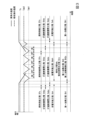
以上で説明した、ガスタービン11、蒸気タービン31、及び、排熱回収ボイラー20が定常運転しているとき、図3に示すように、燃料供給工程Sfs、GT遮断器閉工程Stbc、ST遮断器閉工程Ssbc、充電可能工程Sch、吸収工程Sab、吸収液再生工程Sre、第一加熱工程Sh1が実行されている。
When the
燃料供給工程Sfsでは、ガスタービン11の燃焼器13に燃料が供給される。このため、この燃料供給工程Sfs中、燃焼ガスが生成され、この燃焼ガスが排気ガスとして、排熱回収ボイラー20を介して、二酸化炭素除去設備50に流入する。GT遮断器閉工程Stbcでは、GT遮断器42aが閉じており、GT発電機19が発電し、このときの電力が外部電力系統48に供給される。ST遮断器閉工程Ssbcでは、ST遮断器42bが閉じており、ST発電機39が発電し、このときの電力が外部電力系統48に供給される。充電可能工程Schでは、直流電力系統45と二次電池96とが、充放電制御器97を介して電気的に接続された状態になる。このため、直流電力系統45に電気的に接続されている太陽光発電設備46、GT発電機19、ST発電機39、太陽光発電設備46、及び風力発電設備49からの電力の一部が充放電制御器97を介して二次電池96に充電可能な充電可能状態になる。この充電可能状態では、二次電池96が満充電状態でなければ、GT発電機19、ST発電機39、及び風力発電設備49からの交流電力の一部がAC/DC変換器44で、直流電力に変換された後、直流電力系統45及び充放電制御器97を介して、二次電池96に充電され得る。また、この充電可能状態では、二次電池96が満充電状態でなければ、太陽光発電設備46から直流電力の一部が、直流電力系統45及び充放電制御器97を介して、二次電池96に充電され得る。
In the fuel supply step Sfs, fuel is supplied to the
吸収工程Sabでは、二酸化炭素除去設備50が、排熱回収ボイラー20から排気された排気ガス中に含まれる二酸化炭素をリーン吸収液に吸収させ、二酸化炭素が除去された排気ガスを排出可能な状態になる。この状態では、吸収塔71に排熱回収ボイラー20から排気された排気ガスが流入すると、この排気ガス中に含まれる二酸化炭素がリーン吸収液に吸収され、二酸化炭素が除去された排気ガスを排出される。吸収液再生工程Sreでは、二酸化炭素除去設備50が、二酸化炭素を吸収した吸収液であるリッチ吸収液から二酸化炭素を乖離させることが可能な状態なる。この状態では、再生塔81に、リッチ吸収液が流入すると、このリッチ水溶液から二酸化炭素が乖離し、このリッチ吸収液がリーン吸収液になる。
In the absorption process Sab, the carbon
第一加熱工程Sh1は、吸収液再生工程Sreに含まれる。この第一加熱工程Sh1では、吸収液再生装置80が、第一循環ライン86中を吸収液が流れ、リボイラー89で吸収液を加熱することが可能な第一加熱状態になる。この第一加熱状態では、切替器92を構成する第一遮断弁92aと第二遮断弁92bとのうち、第一遮断弁92aが開いており、第二遮断弁92bが閉じている。この第一加熱状態では、再生塔容器81v内の液溜まり部81sに溜まった吸収液が第一循環ライン86を介してリボイラー89内に流入する。この吸収液は、リボイラー89内で排熱回収ボイラー20からの蒸気で加熱される。加熱された吸収液は、第一循環ライン86、開状態の第一遮断弁92aを介し再生塔81内に戻る。
The first heating step Sh1 is included in the absorption liquid regeneration step Sre. In this first heating step Sh1, the absorption
次に、ガスタービン11、蒸気タービン31、及び、排熱回収ボイラー20が定常運転している状態から、ガスタービン11、蒸気タービン31、及び、排熱回収ボイラー20が停止するまでのボイラープラントの動作について説明する。
Next, the boiler plant changes from the state where the
まず、ガスタービン11の燃焼器13への燃料供給が停止すると共に(燃料供給停止工程Sfc)、GT遮断器42aが開く(GT遮断器開工程Stbo)。この燃料供給停止工程Sfcは、プラント制御装置100が燃料調節弁17に対して閉指示を与えることで実行される。ガスタービン11の燃焼器13への燃料供給が停止すると、燃焼器13内で燃焼ガスが生成されなくなる。このため、ガスタービン11から、排熱回収ボイラー20を介して、二酸化炭素除去設備50に流入する排気ガスの流量が次第に少なくなる。GT遮断器開工程Stboは、プラント制御装置100がGT遮断器42aに対して開指示を与えることで実行される。GT遮断器閉工程Stbcが実行されると、GT発電機19から外部電力系統48に電力が供給されなくなる。
First, the fuel supply to the
排熱回収ボイラー20が発生する蒸気の流量は、燃焼器13への燃料供給が停止すると、所定時間、ガスタービン11の定常運転時の値で維持されるものの、次第に少なくなる。また、排熱回収ボイラー20が発生する蒸気の温度及び圧力も、燃焼器13への燃料供給が停止すると、所定時間、ガスタービン11の定常運転時の値で維持されるものの、次第に低下する。このため、蒸気タービン31は、定常運転ができなくなる。そこで、ガスタービン11の燃焼器13への燃料供給停止と同時に、若しくは、燃料供給停止してから所定時間後に、ST遮断器42bが開く(ST遮断器開行程Ssbo)。ST遮断器開行程Ssboは、プラント制御装置100がST遮断器42bに対して開指示を与えることで実行される。ST遮断器閉工程Ssbcが実行されると、ST発電機39から外部電力系統48に電力が供給されなくなる。
When the fuel supply to the
GT発電機19又はST発電機39から外部電力系統48に電力が供給されなくなると、つまり、GT発電機19又はST発電機39が発電しなくなると、充電可能工程Schが終了する。
When power is no longer supplied to the
GT発電機19及びST発電機39が発電しなくなり、且つ、排熱回収ボイラー20が発生する蒸気が蒸気条件を満たさなくなると、ボイラープラントが、二次電池96から電気ヒータ91へ放電可能な放電可能状態になる(放電可能工程Sdch)。充放電制御器97は、プラント制御装置100から、GT発電機19及びST発電機39が発電しなくなり、且つ、排熱回収ボイラー20が発生する蒸気が蒸気条件を満たさなくなった旨の状態信号を受信すると、ボイラープラントを放電可能状態にする。この放電可能状態では、充放電制御器97が、二次電池96と電気ヒータ91のヒータ駆動回路91bとを電気的に接続された状態にする。
When the
また、排熱回収ボイラー20が発生する蒸気が蒸気条件を満たさなくなると、吸収液再生装置80が、第二循環ライン87を吸収液が流れ、加熱器90で吸収液を加熱させられる第二加熱状態になる(第二加熱工程Sh2)。切替制御器93は、主蒸気ライン32に設けられている温度計34で検知された温度が予め定められた温度Ts未満になるか、主蒸気ライン32に設けられている圧力計35で検知された圧力が予め定められた圧力未満になると、蒸気条件を満たさなくなったとして、切替器92に対して、第二加熱状態になるよう指示する。この結果、切替器92を構成する第一遮断弁92aと第二遮断弁92bとのうち、第一遮断弁92aが閉じ、第二遮断弁92bが開き、第二加熱状態になる。第二加熱状態では、再生塔容器81v内の液溜まり部81sに溜まった吸収液が第二循環ライン87を介して加熱器90内に流入する。この吸収液は、加熱器90内で電気ヒータ91により加熱され得る。加熱された吸収液は、第二循環ライン87、開状態の第二遮断弁92bを介して、再生塔容器81v内に戻る。
Further, when the steam generated by the exhaust
第二加熱工程Sh2では、第二加熱制御工程Sh2cが実行される。この第二加熱制御工程Sh2cでは、第二加熱制御器95が、温度計94で検知された吸収液温度に応じて、加熱器90での加熱を制御する。第二加熱制御器95は、吸収液温度が予め定められた第一温度(例えば、100℃)Tab1よりも低くなると、ヒータ駆動回路91bに対してON指示を与える。また、第二加熱制御器95は、吸収液温度が第一温度Tab1よりも高い予め定められた第二温度(例えば、120℃)Tab2よりも高くなると、ヒータ駆動回路91bに対してOFF指示を与える。ヒータ駆動回路91bにON指示が入力すると、二次電池96から放電された電力が電気ヒータ本体91aに供給され、電気ヒータ本体91aが発熱し、第二循環ライン87を流れる吸収液が加熱される。また、ヒータ駆動回路91bにOFF指示が入力すると、二次電池96から電気ヒータ本体91aに電力が供給されなくなり、電気ヒータ本体91aは発熱しなくなる。よって、第二加熱工程Sh2では、再生塔81内の吸収液の温度が、第一温度Tab1と第二温度Tab2との間で上下する。
In the second heating step Sh2, a second heating control step Sh2c is performed. In this second heating control step Sh2c, the
このため、排熱回収ボイラー20が蒸気を発生しなくなっても、再生塔81内の吸収液の温度はほぼ第一温度Tab1(例えば、100℃)以上の温度に保たれる。
Therefore, even if the exhaust
ガスタービン11に燃料が供給されなくなり、ガスタービン11が停止し、排熱回収ボイラー20が蒸気を発生しなくなり、蒸気タービン31が停止した後、ガスタービン11への燃料供給が開始されると(燃料供給工程Sfs)、燃焼ガスが生成され、ガスタービンロータ15の回転数が次第に高まる。このガスタービンロータ15の回転数が定格回転数(例えば、3600rpm)になると、GT遮断器42aが閉じ(GT遮断器閉工程Stbc)、GT発電機19が発電し、このときの電力が外部電力系統48に供給される。
When fuel is no longer supplied to the
ガスタービン11から排気された燃焼ガスである排気ガスは、前述したように、排熱回収ボイラー20内に流入する。排熱回収ボイラー20は、この排気ガスの熱を利用して、水を蒸気にする。この蒸気の温度及び圧力は、次第に高まる。この過程で、排熱回収ボイラー20が発生する蒸気が蒸気条件を満たすようになると、吸収液再生装置80が、第一循環ライン86を吸収液が流れ、リボイラー89で吸収液を加熱させられる第一加熱状態になる(第一加熱工程Sh1)。切替制御器93は、主蒸気ライン32に設けられている温度計34で検知された温度が予め定められた温度Ts以上になり、且つ、主蒸気ライン32に設けられている圧力計35で検知された圧力が予め定められた圧力以上になると、蒸気条件を満たすようになったとして、切替器92に対して、第一加熱状態になるよう指示する。この結果、切替器92を構成する第一遮断弁92aと第二遮断弁92bとのうち、第一遮断弁92aが開き、第二遮断弁92bが閉じ、第一加熱状態になる。第一加熱状態では、再生塔容器81v内の液溜まり部81sに溜まった吸収液が第一循環ライン86を介してリボイラー89内に流入する。この吸収液は、リボイラー89内で排熱回収ボイラー20からの蒸気により加熱される。加熱された吸収液は、第一循環ライン86、開状態の第一遮断弁92aを介して、再生塔容器81v内に戻る。
The exhaust gas, which is the combustion gas exhausted from the
また、排熱回収ボイラー20が発生する蒸気が蒸気条件を満たすようになった時点では、GT発電機19が発電しているため、この時点から、放電可能工程Sdchから充電可能工程Schに切り替わる。また、排熱回収ボイラー20が発生する蒸気が蒸気条件を満たすようになった後、蒸気タービン31の回転数が定格回転数になると、ST遮断器42bが閉じ(ST遮断器閉行程Ssbc)、ST発電機39から外部電力系統48に電力供給できるようになる。
Furthermore, at the time when the steam generated by the exhaust
排熱回収ボイラー20の起動時では、この排熱回収ボイラー20から二酸化炭素除去設備50に排気ガスが流入する。なお、排熱回収ボイラー20の起動時とは、ガスタービン11への燃料供給が開始され、燃焼ガスが生成されて、排熱回収ボイラー20内を排気ガスが通り、この排熱回収ボイラー20が蒸気を発生し始めてから、この蒸気が蒸気条件を満たすようになるまでの間である。本実施形態では、この起動時においても、吸収工程Sab及び吸収液再生工程Sreが実行される。
When the exhaust
この起動時では、吸収液再生工程Sreで第二加熱工程Sh2が実行され、再生塔81内の吸収液の温度がほぼ第一温度Tab1(例えば、100℃)以上に保たれる。しかしながら、この起動時中のほとんどの時間帯で、再生塔81内の吸収液の温度が、吸収液から二酸化炭素を乖離させるための適切な温度(例えば、120℃)よりも低い。このため、再生塔81内で、吸収液から二酸化炭素を離脱させる能力が低下する。つまり、再生塔81から吸収塔71に送られるリーン吸収液中に二酸化炭素が含まれている量が、蒸気タービン31及び排熱回収ボイラー20が定常運転しているときよりも多くなる。従って、この起動時、吸収装置70での、排気ガス中の二酸化炭素の吸収率が、蒸気タービン31及び排熱回収ボイラー20が定常運転しているときよりも低くなる。但し、本実施形態では、起動時においても、吸収装置70で、排気ガス中の二酸化炭素の吸収液への吸収、及び二酸化炭素を吸収した吸収液の再生が実行されるため、排熱回収ボイラー20の起動時における二酸化炭素の排出量を抑えることができる。
At this time of startup, the second heating step Sh2 is executed in the absorption liquid regeneration step Sre, and the temperature of the absorption liquid in the
排熱回収ボイラー20が発生する蒸気が蒸気条件を満たすようになり、吸収液再生装置80が第一加熱状態になった時点では、再生塔81内の吸収液の温度が、二酸化炭素を乖離させるための適切な温度(例えば、120℃)よりも低い可能性が高い。しかしながら、この時点での吸収塔71内の吸収液の温度は、ほぼ第一温度Tab1(例えば、100℃)以上であるため、第一加熱状態に切り替わった後、短時間のうちに、吸収塔71内の吸収液の温度を。二酸化炭素を乖離させるための適切な温度(例えば、120℃)にすることができる。よって、本実施形態では、吸収液再生装置80が第二加熱状態から第一加熱状態に切り替わった直後における二酸化炭素の排出量を抑えることができる。
When the steam generated by the exhaust
以上のように、本実施形態では、ボイラーの起動過程においても、プラントから排気される排気ガス中の二酸化炭素を少なくすることができる。 As described above, in this embodiment, the amount of carbon dioxide in the exhaust gas exhausted from the plant can be reduced even during the boiler startup process.
本実施形態では、吸収液再生装置80が第二加熱状態の際、加熱器90で吸収液を常時加熱しないため、加熱器90での電気エネルギーの消費を抑えることができる。
In this embodiment, when the absorption
本実施形態の充填可能状態では、GT発電機19、ST発電機39、太陽光発電設備46、及び風力発電設備49からの電力の一部が、二次電池96に充電され得る。太陽光発電設備46及び風力発電設備49は、再生可能エネルギーを用いて発電するカーボンフリー発電設備である。また、本実施形態のボイラープラントは、GT発電機19を含むガスタービン発電設備10とST発電機39を含む蒸気タービン発電設備30とを備えるが、さらに二酸化炭素除去設備50を備えているので、このボイラープラントから排気される排気ガス中の二酸化炭素は少ない。よって、本実施形態では、二次電池96に充電する電力を生み出す際の二酸化炭素の排出を抑えることができる。
In the fillable state of this embodiment, part of the electric power from the
「変形例」
本実施形態のボイラーは、ガスタービン11からの排気ガスの熱で蒸気を発生させる排熱回収ボイラー20である。しかしながら、ボイラーは、化石燃料を燃焼させる燃焼室を有する一般的なボイラーでもよい。
"Variation"
The boiler of this embodiment is an exhaust
蒸気タービン31は、流入する蒸気の圧力が互いに異なる複数の蒸気タービン31を備えていてもよい。
The
本実施形態では、GT発電機19とST発電機39とが独立した発電機である。しかしながら、ガスタービンロータ15と蒸気タービンロータとが連結されている場合には、このロータに一の発電機を接続し、この発電機で、ガスタービン11用の発電機と蒸気タービン31用の発電機とを兼ねるようにしてもよい。
In this embodiment, the
本実施形態の加熱器90は、電気ヒータ91を有し、この加熱器90で吸収液を加熱するエネルギーは電気エネルギーである。しかしながら、加熱器90で吸収液を加熱するエネルギーは電気エネルギーでなくてもよく、例えば、蒸気の熱エネルギーであってもよい。但し、この場合には、排熱回収ボイラー20とは、独立して蒸気を発生するボイラー等が必要である。
The
本実施形態の第二加熱制御工程Sh2cでは、再生塔81内の吸収液の温度が第一温度Tab1と第二温度Tab2との間で上下するよう制御される。しかしながら、この第二加熱制御工程Sh2cでは、再生塔81内の吸収液の温度が、例えば、第一温度Tab1と第二温度Tab2との間の第三温度になるよう制御されてもよい。
In the second heating control step Sh2c of the present embodiment, the temperature of the absorption liquid in the
本実施形態における第一循環ライン86と第二循環ライン87とは、互に一部を共有している。しかしながら、第一循環ライン86と第二循環ライン87と、互に完全に独立していてもよい。
The
本実施形態における切替制御器93や第二加熱制御器95は、プラント制御装置100とは別個に存在する。しかしながら、切替制御器93や第二加熱制御器95は、プラント制御装置100に組み込まれていてもよい。
The switching
本実施形態では、GT発電機19又はST発電機39が発電しなくなると、充電可能工程Schが終了する。しかしながら、プラント内の他の発電設備や外部電力系統48に接続されている発電設備が稼働しており、余剰電力があれば、この充電可能工程Schを終了しなくてもよい。つまり、余剰電力がある場合には、充電可能工程Schを継続してもよい。
In this embodiment, when the
本実施形態では、GT発電機19及びST発電機39が発電しなくなり、且つ、排熱回収ボイラー20が発生する蒸気が蒸気条件を満たさなくなると、ボイラープラントが放電可能状態になる(放電可能工程Sdch)。このため、本実施形態では、充電可能工程Schと放電可能工程Sdchとが同じ時間帯で実行されない。しかしながら、二次電池96に、充電と放電とを同時に行うことが可能な機能を備えていれば、充電可能工程Schの実行時間帯と放電可能工程Sdchの実行時間帯とが一部で重複していてもよい。この場合、放電可能工程Sdchの開始タイミングは、本実施形態における充電可能工程Schの終了タイミングと一致してもよいし、本実施形態における充電可能工程Schの終了タイミングより前であってもよい。
In this embodiment, when the
「付記」
以上の実施形態におけるボイラープラントは、例えば、以下のように把握される。
(1) 第一態様におけるボイラープラントは、
化石燃料Fの燃焼で生じた燃焼ガスの熱で蒸気を発生させるボイラー20と、前記ボイラー20から排気された排気ガス中に含まれる二酸化炭素を除去する二酸化炭素除去設備50と、を備える。前記二酸化炭素除去設備50は、二酸化炭素を吸収した吸収液から二酸化炭素を乖離させる吸収液再生装置80と、前記ボイラー20からの排気ガスが流入し、前記排気ガス中の二酸化炭素を前記吸収液再生装置からの吸収液に吸収させ、二酸化炭素が除去された排気ガスを排出する吸収装置70と、を有する。前記吸収液再生装置80は、前記吸収装置70で二酸化炭素を吸収した吸収液が流入し、高温環境下で吸収液から二酸化炭素を乖離させて、二酸化炭素を排出すると共に、二酸化炭素が乖離した吸収液を前記吸収装置70に戻す再生塔81と、前記再生塔81内から吸収液を取り出してから前記再生塔81内に戻す第一循環ライン86と、前記再生塔81内から吸収液を取り出してから前記再生塔81内に戻す第二循環ライン87と、前記第一循環ライン86中に設けられ、前記第一循環ライン86を流れる吸収液と、前記ボイラー20からの蒸気とを熱交換させて吸収液を加熱する熱交換器89と、前記第二循環ライン87中に設けられ、前記第二循環ライン87を流れる吸収液を加熱する加熱器90と、前記第一循環ライン86に吸収液を流す第一加熱状態と、前記第二循環ライン87に吸収液を流す第二加熱状態とに切り替える切替器92と、を有する。
"Additional notes"
The boiler plant in the above embodiment is understood as follows, for example.
(1) The boiler plant in the first embodiment is
It includes a
本態様では、ボイラー20から熱交換器89に送られる蒸気の温度が予め定められた温度以上で且つ蒸気の圧力が予め定められた圧力以上である蒸気条件を満たしているときに、吸収液再生装置80を第一加熱状態にする。第一加熱状態では、熱交換器89で、ボイラー20からの蒸気により吸収液が加熱される。吸収液が加熱されることで、再生塔81内が高温環境下になり、吸収液から二酸化炭素が乖離する。二酸化炭素が乖離した吸収液は、吸収装置70に供給される。吸収装置70では、排熱回収ボイラー20からの排気ガス中の二酸化炭素が吸収液に吸収され、二酸化炭素が除去された排気ガスが排出される。よって、本態様では、ボイラー20からの蒸気が蒸気条件を満たしているとき、プラントから排気される排気ガス中に含まれる二酸化炭素を少なくすることができる。
In this aspect, when the temperature of the steam sent from the
本態様では、ボイラー20から熱交換器89に送られる蒸気が蒸気条件を満たしていないときに、吸収液再生装置80を第二加熱状態にする。第二加熱状態では、加熱器90で吸収液が加熱される。吸収液が加熱されることで、再生塔81内が高温環境下になり、吸収液から二酸化炭素が乖離する。二酸化炭素が乖離した吸収液は、吸収装置70に供給される。吸収装置70では、ボイラー20からの排気ガス中の二酸化炭素が吸収液に吸収され、二酸化炭素が除去された排気ガスが排出される。よって、本態様では、ボイラー20からの蒸気が蒸気条件を満たしていないときでも、プラントから排気される排気ガス中に含まれる二酸化炭素を少なくすることができる。また、本態様では、第二加熱状態から第一加熱状態に切り替わった時点も、再生塔81内の吸収液の温度が所定温度以上になっているため、第二加熱状態から第一加熱状態に切り替わった直後でも、短時間のうちに、再生塔81内の吸収液の温度を目的の温度にまで高めることができる。このため、本態様では、第二加熱状態から第一加熱状態に切り替わった直後でも、プラントから排気される排気ガス中に含まれる二酸化炭素を少なくすることができる。
In this embodiment, when the steam sent from the
(2) 第二態様におけるボイラープラントは、
前記第一態様のボイラープラントにおいて、前記吸収液再生装置80は、前記ボイラー20から前記熱交換器89に送られる蒸気の温度が予め定められた温度以上で且つ前記蒸気の圧力が予め定められた圧力以上である蒸気条件を満たしているときに、前記切替器92に対して前記第一加熱状態にするよう指示すると共に、前記蒸気条件を満たしていないときに、前記切替器92に対して、前記第二加熱状態にするよう指示する切替制御器93を有する。
(2) The boiler plant in the second embodiment is
In the boiler plant of the first aspect, the absorption
本態様では、ボイラー20から熱交換器89に送られる蒸気が蒸気条件を満たしているときに、自動的に、第一加熱状態にすることができる。また、本態様では、ボイラー20から熱交換器89に送られる蒸気が蒸気条件を満たしていないときに、自動的に、第二加熱状態にすることができる。
In this aspect, when the steam sent from the
(3) 第三態様におけるボイラープラントは、
前記第二態様のボイラープラントにおいて、前記吸収液再生装置80は、前記再生塔81内に溜まった吸収液の温度を検知する温度計94と、前記第二加熱状態のときに、前記温度計94で検知された温度が予め定められた温度よりも低くなると、前記加熱器90により吸収液を加熱させる第二加熱制御器95と、を有する。
(3) The boiler plant in the third aspect is:
In the boiler plant of the second aspect, the absorption
本態様では、第二加熱状態でも、加熱器90で吸収液を常時加熱しないため、加熱器90での加熱エネルギーの消費を抑えることができる。
In this aspect, even in the second heating state, the absorption liquid is not constantly heated by the
(4) 第四態様におけるボイラープラントは、
前記第二態様又は前記第三態様のボイラープラントにおいて、前記吸収液再生装置80は、二次電池96と、前記二次電池96の充放電を制御する充放電制御器97と、を有する。前記加熱器90は、前記二次電池96からの電力供給で発熱する電気ヒータ91を有する。
(4) The boiler plant in the fourth aspect is:
In the boiler plant of the second aspect or the third aspect, the absorption
本態様では、二次電池96に充電された電力で、電気ヒータ91を発熱させることができる。
In this aspect, the
(5) 第五態様におけるボイラープラントは、
前記第四態様のボイラープラントにおいて、前記充放電制御器97は、発電設備が発電中のときに前記発電設備から前記二次電池96に電力を充電可能に、前記発電設備と前記二次電池96とを電気的に接続させる充電可能状態にし、前記蒸気条件を満たしていないときに前記二次電池96から前記電気ヒータ91に電力を放電可能に、前記二次電池96と前記電気ヒータ91とを電気的に接続させる放電可能状態にする。
(5) The boiler plant in the fifth aspect is:
In the boiler plant of the fourth aspect, the charging/discharging
本態様では、発電設備が発電中のとき、二次電池96が満充電状態でなければ、発電設備からの電力を二次電池96に充電することができる。また、本態様では、ボイラー20から熱交換器89に送られる蒸気が蒸気条件を満たしていないときに、二次電池96に充電された電力で電気ヒータ91を発熱させることができる。
In this aspect, when the power generation equipment is generating power, if the
(6) 第六態様におけるボイラープラントは、
前記第五態様のボイラープラントにおいて、前記ボイラー20からの蒸気で駆動する蒸気タービン31と、前記蒸気タービン31の駆動で発電する発電機39と、をさらに備える。前記発電設備は、前記発電機39を含む。
(6) The boiler plant in the sixth aspect is:
The boiler plant of the fifth aspect further includes a
本態様では、蒸気タービン31の駆動する発電機39が発電中のときに、この発電機39からの電力を二次電池96に充電することができる。
In this aspect, when the
(7) 第七態様におけるボイラープラントは、
前記第五態様又は前記第六態様のボイラープラントにおいて、前記発電設備は、カーボンフリー発電設備を含み、前記カーボンフリー発電設備は、化石燃料の燃焼で生じた燃焼ガスを利用して電力を発生させる設備からの排気ガス中の二酸化炭素濃度よりも低い濃度の二酸化炭素を排出する設備、又は発電時に二酸化炭素を排出しない設備である。
(7) The boiler plant in the seventh aspect is:
In the boiler plant of the fifth aspect or the sixth aspect, the power generation equipment includes a carbon-free power generation equipment, and the carbon-free power generation equipment generates electric power using combustion gas generated by combustion of fossil fuels. Equipment that emits carbon dioxide at a concentration lower than the carbon dioxide concentration in the exhaust gas from the equipment, or equipment that does not emit carbon dioxide during power generation.
本態様では、二次電池96に充電する電力を生み出す際の二酸化炭素の排出を抑えることができる。
In this aspect, it is possible to suppress the emission of carbon dioxide when generating electric power to charge the
(8) 第八態様におけるボイラープラントは、
前記第一態様から前記第七態様のうちのいずれか一のボイラープラントにおいて、化石燃料Fの燃焼で生じた燃焼ガスで駆動するガスタービン11をさらに備える。前記ボイラー20は、前記ガスタービン11から排気された燃焼ガスの熱で蒸気を発生させる排熱回収ボイラーである。
(8) The boiler plant in the eighth aspect is:
The boiler plant according to any one of the first to seventh aspects further includes a
以上の実施形態における二酸化炭素除去方法は、例えば、以下のように把握される。
(9) 第九態様における二酸化炭素除去方法は、
二酸化炭素を吸収した吸収液から二酸化炭素を乖離させることが可能な吸収液再生工程Sreと、ボイラー20からの排気ガスが流入し、前記排気ガス中の二酸化炭素を前記吸収液再生工程Sreで処理された吸収液に吸収させ、二酸化炭素が除去された排気ガスを排出することが可能な吸収工程Sabと、を実行する。前記吸収液再生工程Sreは、吸収液再生装置80により実行される。前記吸収液再生装置80は、前記吸収工程Sabの実行で二酸化炭素を吸収した吸収液が流入し、高温環境下で吸収液から二酸化炭素を乖離させて、二酸化炭素を排出すると共に、二酸化炭素が乖離した吸収液を前記吸収工程Sabで使用させる再生塔81と、前記再生塔81内から吸収液を取り出してから前記再生塔81内に戻す第一循環ライン86と、前記再生塔81内から吸収液を取り出してから前記再生塔81内に戻す第二循環ライン87と、前記第一循環ライン86中に設けられ、前記第一循環ライン86を流れる吸収液と、前記ボイラー20からの蒸気とを熱交換させて吸収液を加熱する熱交換器89と、前記第二循環ライン87中に設けられ、前記第二循環ライン87を流れる吸収液を加熱する加熱器90と、を有する。前記吸収液再生工程Sreは、前記熱交換器89で吸収液を加熱させることが可能に、前記第一循環ライン86に吸収液を流す第一加熱工程Sh1と、前記加熱器90で吸収液を加熱させることが可能に、前記第二循環ライン87に吸収液を流す第二加熱工程Sh2と、を含む。
The carbon dioxide removal method in the above embodiment can be understood, for example, as follows.
(9) The carbon dioxide removal method in the ninth aspect includes:
An absorption liquid regeneration process Sre that can separate carbon dioxide from the absorption liquid that has absorbed carbon dioxide, and an exhaust gas from the
(10)第十態様における二酸化炭素除去方法は、
前記第九態様の二酸化炭素除去方法において、前記吸収液再生工程Sreでは、前記ボイラー20から前記熱交換器89に送られる蒸気の温度が予め定められた温度以上で且つ前記蒸気の圧力が予め定められた圧力以上である蒸気条件を満たしているときに、前記第一加熱工程Sh1を実行し、前記蒸気条件を満たしていないときに、前記第二加熱工程Sh2を実行する。
(10) The carbon dioxide removal method in the tenth aspect includes:
In the carbon dioxide removal method of the ninth aspect, in the absorption liquid regeneration step Sre, the temperature of the steam sent from the
(11)第十一態様における二酸化炭素除去方法は、
前記第十態様の二酸化炭素除去方法において、前記第二加熱工程Sh2は、前記再生塔81内に溜まった吸収液の温度が予め定められた温度よりも低くなると、前記加熱器90により吸収液を加熱させる第二加熱制御工程Sh2cを含む。
(11) The carbon dioxide removal method in the eleventh aspect is:
In the carbon dioxide removal method of the tenth aspect, in the second heating step Sh2, when the temperature of the absorption liquid accumulated in the
(12)第十二態様における二酸化炭素除去方法は、
前記第十態様又は前記第十一態様の二酸化炭素除去方法において、前記吸収液再生装置80は、二次電池96を有し、前記加熱器90は、前記二次電池96からの電力供給で発熱する電気ヒータ91を有する。前記吸収液再生工程Sreは、前記二次電池96に充電できる充電可能工程Schと、前記二次電池96から前記電気ヒータ91に放電できる放電可能工程Sdchと、を含む。
(12) The carbon dioxide removal method in the twelfth aspect includes:
In the carbon dioxide removal method of the tenth aspect or the eleventh aspect, the absorption
(13)第十三態様における二酸化炭素除去方法は、
前記第十二態様の二酸化炭素除去方法において、前記充電可能工程Schでは、発電設備が発電中のときに前記発電設備から前記二次電池96に電力を充電可能に、前記発電設備と前記二次電池96とを電気的に接続させる。また、前記放電可能工程Sdchでは、前記蒸気条件を満たしていないときに前記二次電池96から前記電気ヒータ91に電力を放電可能に、前記二次電池96と前記電気ヒータ91とを電気的に接続させる。
(13) The carbon dioxide removal method in the thirteenth aspect is:
In the carbon dioxide removal method of the twelfth aspect, in the chargeable step Sch, the power generation equipment and the secondary The
(14)第十四態様における二酸化炭素除去方法は、
前記第十三態様の二酸化炭素除去方法において、前記発電設備は、カーボンフリー発電設備を含む。前記カーボンフリー発電設備は、化石燃料の燃焼で生じた燃焼ガスを利用して電力を発生させる設備からの排気ガス中の二酸化炭素濃度よりも低い濃度の二酸化炭素を排出する設備、又は発電時に二酸化炭素を排出しない設備である。
(14) The carbon dioxide removal method in the fourteenth aspect includes:
In the carbon dioxide removal method of the thirteenth aspect, the power generation equipment includes carbon-free power generation equipment. The carbon-free power generation equipment is equipment that emits carbon dioxide at a concentration lower than the carbon dioxide concentration in the exhaust gas from equipment that generates electricity using combustion gas generated from the combustion of fossil fuels, or equipment that emits carbon dioxide at a concentration lower than that in the exhaust gas from equipment that generates electricity using combustion gas generated from the combustion of fossil fuels. The facility does not emit carbon.
(15)第十五態様における二酸化炭素除去方法は、
前記第十四態様の二酸化炭素除去方法において、前記カーボンフリー発電設備は、再生可能エネルギーを用いて発電する設備を含む。
(15) The carbon dioxide removal method in the fifteenth aspect is:
In the carbon dioxide removal method of the fourteenth aspect, the carbon-free power generation equipment includes equipment that generates power using renewable energy.
10:ガスタービン設備(又はガスタービン発電設備)
11:ガスタービン
12:空気圧縮機
13:燃焼器
14:タービン
15:ガスタービンロータ
16:燃料ライン
17:燃料調節弁
19;GT発電機
20:排熱回収ボイラー(又はボイラー)
30:蒸気タービン設備(又は蒸気タービン発電設備)
31:蒸気タービン
32:主蒸気ライン
33:蒸気調節弁
34:温度計
35:圧力計
36:復水器
37:給水ライン
38:加熱用蒸気ライン
39:ST発電機
40:電力系統設備
41a:GT電力系統
41b:ST電力系統
42a:GT遮断器
42b:ST遮断器
43a:GT変圧器
43b:ST変圧器
44:AC/DC変換器
45:直流電力系統
46:太陽光発電設備
48:外部電力系統
49:風力発電設備
50:二酸化炭素除去設備
51:ガス昇圧機
52:排気ガス再循環ライン
60:排気ガス冷却装置
61:冷却塔
61v:冷却塔容器
61p:充填物
62:水循環ライン
63:水循環ポンプ
64:水冷却器
65:低温排気ガスライン
70:吸収装置
71:吸収塔
71v:吸収塔容器
71pa:下充填物
71pb:上充填物
71da:下デミスタ
71db:上デミスタ
71t:トレー
71s:水溜まり部
72:排気ライン
73:リーン吸収液ライン
74:リーン-リッチ熱交換器
75:リーン吸収液ポンプ
76:リーン吸収液冷却器
77:リーン吸収液調節弁
78:水洗水循環ライン
79p:水洗水循環ポンプ
79r:水洗水冷却器
80:吸収液再生装置
81:再生塔
81v:再生塔容器
81p:充填物
81t:トレー
81s:液溜まり部
82:二酸化炭素回収ライン
82r:冷却器
82t:水分分離タンク
82c:二酸化炭素圧縮機
82p:水ポンプ
82w:水分回収ライン
83:リッチ吸収液ライン
84:リッチ吸収液ポンプ
85:リッチ吸収液調節弁
86:第一循環ライン
86a:流入側共有部
86b:流出側共有部
86c:中間部
87:第二循環ライン
87c:中間部
89:リボイラー(熱交換器)
90:加熱器
90v:加熱容器
91:電気ヒータ
91a:電気ヒータ本体
91b:ヒータ駆動回路
92:切替器
92a:第一遮断弁
92b:第二遮断弁
93:切替制御器
94:温度計
95:第二加熱制御器
96:二次電池
97:充放電制御器
98:放電系統
100:プラント制御装置
10: Gas turbine equipment (or gas turbine power generation equipment)
11: Gas turbine 12: Air compressor 13: Combustor 14: Turbine 15: Gas turbine rotor 16: Fuel line 17:
30: Steam turbine equipment (or steam turbine power generation equipment)
31: Steam turbine 32: Main steam line 33: Steam control valve 34: Thermometer 35: Pressure gauge 36: Condenser 37: Water supply line 38: Heating steam line 39: ST generator 40: Power system equipment 41a: GT Power system 41b: ST power system 42a: GT circuit breaker 42b: ST circuit breaker 43a: GT transformer 43b: ST transformer 44: AC/DC converter 45: DC power system 46: Solar power generation equipment 48: External power system 49: Wind power generation equipment 50: Carbon dioxide removal equipment 51: Gas booster 52: Exhaust gas recirculation line 60: Exhaust gas cooling device 61: Cooling tower 61v: Cooling tower container 61p: Filler 62: Water circulation line 63: Water circulation pump 64: Water cooler 65: Low temperature exhaust gas line 70: Absorption device 71: Absorption tower 71v: Absorption tower container 71pa: Lower filling 71pb: Upper filling 71da: Lower demister 71db: Upper demister 71t: Tray 71s: Water pool part 72 : Exhaust line 73: Lean absorption liquid line 74: Lean-rich heat exchanger 75: Lean absorption liquid pump 76: Lean absorption liquid cooler 77: Lean absorption liquid control valve 78: Washing water circulation line 79p: Washing water circulation pump 79r: Washing Water cooler 80: Absorption liquid regeneration device 81: Regeneration tower 81v: Regeneration tower container 81p: Filler 81t: Tray 81s: Liquid pool 82: Carbon dioxide recovery line 82r: Cooler 82t: Water separation tank 82c: Carbon dioxide compression Machine 82p: Water pump 82w: Moisture recovery line 83: Rich absorption liquid line 84: Rich absorption liquid pump 85: Rich absorption liquid control valve 86: First circulation line 86a: Inflow side common section 86b: Outflow side common section 86c: Intermediate Part 87: Second circulation line 87c: Intermediate part 89: Reboiler (heat exchanger)
90:
Claims (15)
前記ボイラーから排気された排気ガス中に含まれる二酸化炭素を除去する二酸化炭素除去設備と、
を備え、
前記二酸化炭素除去設備は、
二酸化炭素を吸収した吸収液から二酸化炭素を乖離させる吸収液再生装置と、
前記ボイラーからの排気ガスが流入し、前記排気ガス中の二酸化炭素を前記吸収液再生装置からの吸収液に吸収させ、二酸化炭素が除去された排気ガスを排出する吸収装置と、
を有し、
前記吸収液再生装置は、
前記吸収装置で二酸化炭素を吸収した吸収液が流入し、高温環境下で吸収液から二酸化炭素を乖離させて、二酸化炭素を排出すると共に、二酸化炭素が乖離した吸収液を前記吸収装置に戻す再生塔と、
前記再生塔内から吸収液を取り出してから前記再生塔内に戻す第一循環ラインと、
前記再生塔内から吸収液を取り出してから前記再生塔内に戻す第二循環ラインと、
前記第一循環ライン中に設けられ、前記第一循環ラインを流れる吸収液と、前記ボイラーからの蒸気とを熱交換させて吸収液を加熱する熱交換器と、
前記第二循環ライン中に設けられ、前記第二循環ラインを流れる吸収液を加熱する加熱器と、
前記第一循環ラインに吸収液を流す第一加熱状態と、前記第二循環ラインに吸収液を流す第二加熱状態との間で加熱状態を切り替える切替器と、
を有する、
ボイラープラント。 A boiler that generates steam using the heat of combustion gas generated by burning fossil fuels,
carbon dioxide removal equipment that removes carbon dioxide contained in exhaust gas exhausted from the boiler;
Equipped with
The carbon dioxide removal equipment is
an absorption liquid regeneration device that separates carbon dioxide from the absorption liquid that has absorbed carbon dioxide;
an absorption device into which exhaust gas from the boiler flows, carbon dioxide in the exhaust gas is absorbed by an absorption liquid from the absorption liquid regeneration device, and exhaust gas from which carbon dioxide has been removed is discharged;
has
The absorption liquid regeneration device includes:
The absorption liquid that has absorbed carbon dioxide in the absorption device flows in, and carbon dioxide is separated from the absorption liquid in a high-temperature environment, and the carbon dioxide is discharged, and the absorption liquid from which carbon dioxide has been separated is returned to the absorption device. tower and
a first circulation line that takes out the absorption liquid from the regeneration tower and returns it to the regeneration tower;
a second circulation line that takes out the absorption liquid from the regeneration tower and returns it to the regeneration tower;
a heat exchanger that is provided in the first circulation line and heats the absorption liquid by exchanging heat between the absorption liquid flowing through the first circulation line and steam from the boiler;
a heater provided in the second circulation line and heating the absorption liquid flowing through the second circulation line;
a switch that switches the heating state between a first heating state in which the absorption liquid flows through the first circulation line and a second heating state in which the absorption liquid flows in the second circulation line;
has,
boiler plant.
前記吸収液再生装置は、
前記ボイラーから前記熱交換器に送られる蒸気の温度が予め定められた温度以上で且つ前記蒸気の圧力が予め定められた圧力以上である蒸気条件を満たしているときに、前記切替器に対して前記第一加熱状態にするよう指示すると共に、前記蒸気条件を満たしていないときに、前記切替器に対して、前記第二加熱状態にするよう指示する切替制御器を有する、
ボイラープラント。 The boiler plant according to claim 1,
The absorption liquid regeneration device includes:
to the switching device when the temperature of the steam sent from the boiler to the heat exchanger satisfies the steam conditions that the temperature of the steam is higher than a predetermined temperature and the pressure of the steam is higher than the predetermined pressure. a switching controller that instructs the switching device to enter the first heating state and, when the steam condition is not satisfied, instructs the switching device to enter the second heating state;
boiler plant.
前記吸収液再生装置は、
前記再生塔内に溜まった吸収液の温度を検知する温度計と、
前記第二加熱状態のときに、前記温度計で検知された温度が予め定められた温度よりも低くなると、前記加熱器により吸収液を加熱させる第二加熱制御器と、
を有する、
ボイラープラント。 The boiler plant according to claim 2,
The absorption liquid regeneration device includes:
a thermometer that detects the temperature of the absorption liquid accumulated in the regeneration tower;
a second heating controller that causes the heater to heat the absorption liquid when the temperature detected by the thermometer becomes lower than a predetermined temperature in the second heating state;
has,
boiler plant.
前記吸収液再生装置は、二次電池と、前記二次電池の充放電を制御する充放電制御器と、を有し、
前記加熱器は、前記二次電池からの電力供給で発熱する電気ヒータを有する、
ボイラープラント。 In the boiler plant according to claim 2 or 3,
The absorption liquid regeneration device includes a secondary battery and a charge/discharge controller that controls charging and discharging of the secondary battery,
The heater includes an electric heater that generates heat using power supplied from the secondary battery.
boiler plant.
前記充放電制御器は、発電設備が発電中のときに前記発電設備から前記二次電池に電力を充電可能に、前記発電設備と前記二次電池とを電気的に接続させる充電可能状態にし、前記蒸気条件を満たしていないときに前記二次電池から前記電気ヒータに電力を放電可能に、前記二次電池と前記電気ヒータとを電気的に接続させる放電可能状態にする、
ボイラープラント。 The boiler plant according to claim 4,
The charge/discharge controller sets the power generation equipment and the secondary battery into a chargeable state so that the power generation equipment and the secondary battery can be electrically connected to each other so that power can be charged from the power generation equipment to the secondary battery when the power generation equipment is generating power; setting the secondary battery and the electric heater in a discharge enabled state so that power can be discharged from the secondary battery to the electric heater when the steam condition is not satisfied;
boiler plant.
前記ボイラーからの蒸気で駆動する蒸気タービンと、
前記蒸気タービンの駆動で発電する発電機と、
をさらに備え、
前記発電設備は、前記発電機を含む、
ボイラープラント。 The boiler plant according to claim 5,
a steam turbine driven by steam from the boiler;
a generator that generates electricity by driving the steam turbine;
Furthermore,
The power generation equipment includes the generator,
boiler plant.
前記発電設備は、カーボンフリー発電設備を含み、
前記カーボンフリー発電設備は、化石燃料の燃焼で生じた燃焼ガスを利用して電力を発生させる設備からの排気ガス中の二酸化炭素濃度よりも低い濃度の二酸化炭素を排出する設備、又は発電時に二酸化炭素を排出しない設備である、
ボイラープラント。 In the boiler plant according to claim 5 or 6,
The power generation equipment includes carbon-free power generation equipment,
The carbon-free power generation equipment is equipment that emits carbon dioxide at a concentration lower than the carbon dioxide concentration in the exhaust gas from equipment that generates electricity using combustion gas generated from the combustion of fossil fuels, or equipment that emits carbon dioxide at a concentration lower than that in the exhaust gas from equipment that generates electricity using combustion gas generated from the combustion of fossil fuels. It is a facility that does not emit carbon.
boiler plant.
化石燃料の燃焼で生じた燃焼ガスで駆動するガスタービンをさらに備え、
前記ボイラーは、前記ガスタービンから排気された燃焼ガスの熱で蒸気を発生させる排熱回収ボイラーである、
ボイラープラント。 The boiler plant according to any one of claims 1 to 7,
It is further equipped with a gas turbine driven by combustion gas generated from combustion of fossil fuels,
The boiler is an exhaust heat recovery boiler that generates steam using the heat of combustion gas exhausted from the gas turbine.
boiler plant.
ボイラーからの排気ガスが流入し、前記排気ガス中の二酸化炭素を前記吸収液再生工程で処理された吸収液に吸収させ、二酸化炭素が除去された排気ガスを排出することが可能な吸収工程と、
を実行し、
前記吸収液再生工程は、吸収液再生装置により実行され、
前記吸収液再生装置は、
前記吸収工程の実行で二酸化炭素を吸収した吸収液が流入し、高温環境下で吸収液から二酸化炭素を乖離させて、二酸化炭素を排出すると共に、二酸化炭素が乖離した吸収液を前記吸収工程で使用させる再生塔と、
前記再生塔内から吸収液を取り出してから前記再生塔内に戻す第一循環ラインと、
前記再生塔内から吸収液を取り出してから前記再生塔内に戻す第二循環ラインと、
前記第一循環ライン中に設けられ、前記第一循環ラインを流れる吸収液と、前記ボイラーからの蒸気とを熱交換させて吸収液を加熱する熱交換器と、
前記第二循環ライン中に設けられ、前記第二循環ラインを流れる吸収液を加熱する加熱器と、
を有し、
前記吸収液再生工程は、
前記熱交換器で吸収液を加熱させることが可能に、前記第一循環ラインに吸収液を流す第一加熱工程と、
前記加熱器で吸収液を加熱させることが可能に、前記第二循環ラインに吸収液を流す第二加熱工程と、
を含み、
前記吸収液再生工程では、前記第一循環ラインに吸収液を流す第一加熱状態と、前記第二循環ラインに吸収液を流す第二加熱状態との間で加熱状態を切り替えて、前記第一加熱工程及び前記第二加熱工程を実現する、
二酸化炭素除去方法。 an absorption liquid regeneration step capable of separating carbon dioxide from the absorption liquid that has absorbed carbon dioxide;
an absorption step in which exhaust gas from a boiler flows in, carbon dioxide in the exhaust gas is absorbed into the absorption liquid treated in the absorption liquid regeneration step, and the exhaust gas from which carbon dioxide has been removed is discharged; ,
Run
The absorption liquid regeneration step is performed by an absorption liquid regeneration device,
The absorption liquid regeneration device includes:
The absorption liquid that has absorbed carbon dioxide in the execution of the absorption process flows in, and the carbon dioxide is separated from the absorption liquid in a high-temperature environment, and the carbon dioxide is discharged, and the absorption liquid from which carbon dioxide has been separated is removed in the absorption process. A regeneration tower to be used,
a first circulation line that takes out the absorption liquid from the regeneration tower and returns it to the regeneration tower;
a second circulation line that takes out the absorption liquid from the regeneration tower and returns it to the regeneration tower;
a heat exchanger that is provided in the first circulation line and heats the absorption liquid by exchanging heat between the absorption liquid flowing through the first circulation line and steam from the boiler;
a heater provided in the second circulation line and heating the absorption liquid flowing through the second circulation line;
has
The absorption liquid regeneration step includes:
a first heating step of flowing the absorption liquid into the first circulation line so that the absorption liquid can be heated by the heat exchanger;
a second heating step of flowing the absorption liquid into the second circulation line so that the absorption liquid can be heated by the heater;
including;
In the absorption liquid regeneration step, the heating state is switched between a first heating state in which the absorption liquid flows through the first circulation line and a second heating state in which the absorption liquid flows in the second circulation line. realizing the heating step and the second heating step;
Carbon dioxide removal method.
ボイラーからの排気ガスが流入し、前記排気ガス中の二酸化炭素を前記吸収液再生工程で処理された吸収液に吸収させ、二酸化炭素が除去された排気ガスを排出することが可能な吸収工程と、
を実行し、
前記吸収液再生工程は、吸収液再生装置により実行され、
前記吸収液再生装置は、
前記吸収工程の実行で二酸化炭素を吸収した吸収液が流入し、高温環境下で吸収液から二酸化炭素を乖離させて、二酸化炭素を排出すると共に、二酸化炭素が乖離した吸収液を前記吸収工程で使用させる再生塔と、
前記再生塔内から吸収液を取り出してから前記再生塔内に戻す第一循環ラインと、
前記再生塔内から吸収液を取り出してから前記再生塔内に戻す第二循環ラインと、
前記第一循環ライン中に設けられ、前記第一循環ラインを流れる吸収液と、前記ボイラーからの蒸気とを熱交換させて吸収液を加熱する熱交換器と、
前記第二循環ライン中に設けられ、前記第二循環ラインを流れる吸収液を加熱する加熱器と、
を有し、
前記吸収液再生工程は、
前記熱交換器で吸収液を加熱させることが可能に、前記第一循環ラインに吸収液を流す第一加熱工程と、
前記加熱器で吸収液を加熱させることが可能に、前記第二循環ラインに吸収液を流す第二加熱工程と、
を含み、
前記吸収液再生工程では、
前記ボイラーから前記熱交換器に送られる蒸気の温度が予め定められた温度以上で且つ前記蒸気の圧力が予め定められた圧力以上である蒸気条件を満たしているときに、前記第一加熱工程を実行し、前記蒸気条件を満たしていないときに、前記第二加熱工程を実行する、
二酸化炭素除去方法。 an absorption liquid regeneration step capable of separating carbon dioxide from the absorption liquid that has absorbed carbon dioxide;
an absorption step in which exhaust gas from a boiler flows in, carbon dioxide in the exhaust gas is absorbed into the absorption liquid treated in the absorption liquid regeneration step, and the exhaust gas from which carbon dioxide has been removed is discharged; ,
Run
The absorption liquid regeneration step is performed by an absorption liquid regeneration device,
The absorption liquid regeneration device includes:
The absorption liquid that has absorbed carbon dioxide in the execution of the absorption process flows in, and the carbon dioxide is separated from the absorption liquid in a high-temperature environment, and the carbon dioxide is discharged, and the absorption liquid from which carbon dioxide has been separated is removed in the absorption process. A regeneration tower to be used,
a first circulation line that takes out the absorption liquid from the regeneration tower and returns it to the regeneration tower;
a second circulation line that takes out the absorption liquid from the regeneration tower and returns it to the regeneration tower;
a heat exchanger that is provided in the first circulation line and heats the absorption liquid by exchanging heat between the absorption liquid flowing through the first circulation line and steam from the boiler;
a heater provided in the second circulation line and heating the absorption liquid flowing through the second circulation line;
has
The absorption liquid regeneration step includes:
a first heating step of flowing the absorption liquid into the first circulation line so that the absorption liquid can be heated by the heat exchanger;
a second heating step of flowing the absorption liquid into the second circulation line so that the absorption liquid can be heated by the heater;
including;
In the absorption liquid regeneration step,
The first heating step is carried out when the temperature of the steam sent from the boiler to the heat exchanger satisfies the steam conditions that the temperature of the steam is higher than a predetermined temperature and the pressure of the steam is higher than the predetermined pressure. and when the steam condition is not satisfied, performing the second heating step.
Carbon dioxide removal method.
前記第二加熱工程は、前記再生塔内に溜まった吸収液の温度が予め定められた温度よりも低くなると、前記加熱器により吸収液を加熱させる第二加熱制御工程を含む、
二酸化炭素除去方法。 In the carbon dioxide removal method according to claim 10,
The second heating step includes a second heating control step in which the absorption liquid is heated by the heater when the temperature of the absorption liquid accumulated in the regeneration tower becomes lower than a predetermined temperature.
Carbon dioxide removal method.
前記吸収液再生装置は、二次電池を有し、
前記加熱器は、前記二次電池からの電力供給で発熱する電気ヒータを有し、
前記吸収液再生工程は、
前記二次電池に充電できる充電可能工程と、
前記二次電池から前記電気ヒータに放電できる放電可能工程と、
を含む、
二酸化炭素除去方法。 In the carbon dioxide removal method according to claim 10 or 11,
The absorption liquid regeneration device has a secondary battery,
The heater includes an electric heater that generates heat using power supplied from the secondary battery,
The absorption liquid regeneration step includes:
a chargeable step capable of charging the secondary battery;
a dischargeable step in which the secondary battery can be discharged to the electric heater;
including,
Carbon dioxide removal method.
前記充電可能工程では、発電設備が発電中のときに前記発電設備から前記二次電池に電力を充電可能に、前記発電設備と前記二次電池とを電気的に接続させ、
前記放電可能工程では、前記蒸気条件を満たしていないときに前記二次電池から前記電気ヒータに電力を放電可能に、前記二次電池と前記電気ヒータとを電気的に接続させる、
二酸化炭素除去方法。 In the carbon dioxide removal method according to claim 12,
In the chargeable step, the power generation equipment and the secondary battery are electrically connected so that power can be charged from the power generation equipment to the secondary battery while the power generation equipment is generating power;
In the discharging step, the secondary battery and the electric heater are electrically connected so that power can be discharged from the secondary battery to the electric heater when the steam condition is not satisfied.
Carbon dioxide removal method.
前記発電設備は、カーボンフリー発電設備を含み、
前記カーボンフリー発電設備は、化石燃料の燃焼で生じた燃焼ガスを利用して電力を発生させる設備からの排気ガス中の二酸化炭素濃度よりも低い濃度の二酸化炭素を排出する設備、又は発電時に二酸化炭素を排出しない設備である、
二酸化炭素除去方法。 In the carbon dioxide removal method according to claim 13,
The power generation equipment includes carbon-free power generation equipment,
The carbon-free power generation equipment is equipment that emits carbon dioxide at a concentration lower than the carbon dioxide concentration in the exhaust gas from equipment that generates electricity using combustion gas generated from the combustion of fossil fuels, or equipment that emits carbon dioxide at a concentration lower than that in the exhaust gas from equipment that generates electricity using combustion gas generated from the combustion of fossil fuels. It is a facility that does not emit carbon.
Carbon dioxide removal method.
前記カーボンフリー発電設備は、再生可能エネルギーを用いて発電する設備を含む、
二酸化炭素除去方法。 In the carbon dioxide removal method according to claim 14,
The carbon-free power generation equipment includes equipment that generates electricity using renewable energy.
Carbon dioxide removal method.
Priority Applications (6)
| Application Number | Priority Date | Filing Date | Title |
|---|---|---|---|
| JP2019238846A JP7356344B2 (en) | 2019-12-27 | 2019-12-27 | Boiler plant and carbon dioxide removal method |
| US17/779,430 US11833467B2 (en) | 2019-12-27 | 2020-12-07 | Boiler plant and carbon dioxide removal method |
| CA3163472A CA3163472A1 (en) | 2019-12-27 | 2020-12-07 | Boiler plant and carbon dioxide removal method |
| AU2020415622A AU2020415622B2 (en) | 2019-12-27 | 2020-12-07 | Boiler plant and carbon dioxide removal method |
| EP20905820.5A EP4083505A4 (en) | 2019-12-27 | 2020-12-07 | Boiler plant and carbon dioxide removal method |
| PCT/JP2020/045388 WO2021131629A1 (en) | 2019-12-27 | 2020-12-07 | Boiler plant and carbon dioxide removal method |
Applications Claiming Priority (1)
| Application Number | Priority Date | Filing Date | Title |
|---|---|---|---|
| JP2019238846A JP7356344B2 (en) | 2019-12-27 | 2019-12-27 | Boiler plant and carbon dioxide removal method |
Publications (3)
| Publication Number | Publication Date |
|---|---|
| JP2021107751A JP2021107751A (en) | 2021-07-29 |
| JP2021107751A5 JP2021107751A5 (en) | 2022-10-06 |
| JP7356344B2 true JP7356344B2 (en) | 2023-10-04 |
Family
ID=76573958
Family Applications (1)
| Application Number | Title | Priority Date | Filing Date |
|---|---|---|---|
| JP2019238846A Active JP7356344B2 (en) | 2019-12-27 | 2019-12-27 | Boiler plant and carbon dioxide removal method |
Country Status (6)
| Country | Link |
|---|---|
| US (1) | US11833467B2 (en) |
| EP (1) | EP4083505A4 (en) |
| JP (1) | JP7356344B2 (en) |
| AU (1) | AU2020415622B2 (en) |
| CA (1) | CA3163472A1 (en) |
| WO (1) | WO2021131629A1 (en) |
Families Citing this family (3)
| Publication number | Priority date | Publication date | Assignee | Title |
|---|---|---|---|---|
| JP2023072266A (en) * | 2021-11-12 | 2023-05-24 | 三菱重工エンジニアリング株式会社 | Carbon dioxide recovery system |
| CN116099333B (en) * | 2023-04-13 | 2023-06-23 | 清华四川能源互联网研究院 | Produced gas chemical method carbon capture system |
| CN116247827B (en) * | 2023-05-10 | 2023-08-22 | 长江三峡集团实业发展(北京)有限公司 | Industrial park comprehensive energy system and operation method thereof |
Citations (8)
| Publication number | Priority date | Publication date | Assignee | Title |
|---|---|---|---|---|
| JP2011208846A (en) | 2010-03-29 | 2011-10-20 | Hitachi Ltd | Boiler apparatus |
| JP2012516226A (en) | 2009-01-28 | 2012-07-19 | シーメンス アクチエンゲゼルシヤフト | Method and apparatus for separating carbon dioxide from exhaust gas from fossil fuel power plant equipment |
| JP2012158996A (en) | 2011-01-31 | 2012-08-23 | Hitachi Ltd | Thermal power plant with carbon dioxide capture scrubbing equipment |
| JP2014213276A (en) | 2013-04-26 | 2014-11-17 | 株式会社Ihi | Recovery method and recovery device of carbon dioxide |
| JP2015097986A (en) | 2013-11-19 | 2015-05-28 | 株式会社Ihi | Distillation column, liquid heating method, and carbon dioxide recovery apparatus and carbon dioxide recovery method using the same |
| US20160166977A1 (en) | 2014-12-10 | 2016-06-16 | Exxonmobil Research And Engineering Company | Gas-assisted stripping of liquid solvents for carbon capture |
| US20180339265A1 (en) | 2017-05-25 | 2018-11-29 | Bechtel Infrastructure and Power Corporation | System for time-shifting post-combustion co2 capture |
| JP2019076810A (en) | 2017-10-20 | 2019-05-23 | 三菱重工エンジニアリング株式会社 | Acidic gas removal device and acidic gas removal method |
Family Cites Families (8)
| Publication number | Priority date | Publication date | Assignee | Title |
|---|---|---|---|---|
| US8613794B2 (en) * | 2007-01-25 | 2013-12-24 | Shell Oil Company | Process for producing a pressurised CO2 stream in a power plant integrated with a CO2 capture unit |
| US9133407B2 (en) * | 2011-02-25 | 2015-09-15 | Alstom Technology Ltd | Systems and processes for removing volatile degradation products produced in gas purification |
| EP2719439A4 (en) * | 2011-06-09 | 2015-04-15 | Asahi Chemical Ind | Carbon-dioxide absorber and carbon-dioxide separation/recovery method using said absorber |
| JP5755047B2 (en) * | 2011-06-22 | 2015-07-29 | 三菱重工業株式会社 | Exhaust gas treatment system and exhaust gas treatment method |
| JP6158054B2 (en) | 2013-11-29 | 2017-07-05 | 株式会社東芝 | Carbon dioxide recovery system and operation method thereof |
| US9901870B2 (en) | 2013-04-09 | 2018-02-27 | Kabushiki Kaisha Toshiba | Carbon dioxide capturing system and method of operating same |
| KR101491521B1 (en) * | 2013-11-21 | 2015-02-11 | 한국에너지기술연구원 | Acidic gas Capture System and Method for Energy Saving Using Condensed Water |
| JP6392099B2 (en) * | 2014-12-01 | 2018-09-19 | 株式会社東芝 | Carbon dioxide recovery system |
-
2019
- 2019-12-27 JP JP2019238846A patent/JP7356344B2/en active Active
-
2020
- 2020-12-07 EP EP20905820.5A patent/EP4083505A4/en active Pending
- 2020-12-07 WO PCT/JP2020/045388 patent/WO2021131629A1/en unknown
- 2020-12-07 CA CA3163472A patent/CA3163472A1/en active Pending
- 2020-12-07 US US17/779,430 patent/US11833467B2/en active Active
- 2020-12-07 AU AU2020415622A patent/AU2020415622B2/en active Active
Patent Citations (8)
| Publication number | Priority date | Publication date | Assignee | Title |
|---|---|---|---|---|
| JP2012516226A (en) | 2009-01-28 | 2012-07-19 | シーメンス アクチエンゲゼルシヤフト | Method and apparatus for separating carbon dioxide from exhaust gas from fossil fuel power plant equipment |
| JP2011208846A (en) | 2010-03-29 | 2011-10-20 | Hitachi Ltd | Boiler apparatus |
| JP2012158996A (en) | 2011-01-31 | 2012-08-23 | Hitachi Ltd | Thermal power plant with carbon dioxide capture scrubbing equipment |
| JP2014213276A (en) | 2013-04-26 | 2014-11-17 | 株式会社Ihi | Recovery method and recovery device of carbon dioxide |
| JP2015097986A (en) | 2013-11-19 | 2015-05-28 | 株式会社Ihi | Distillation column, liquid heating method, and carbon dioxide recovery apparatus and carbon dioxide recovery method using the same |
| US20160166977A1 (en) | 2014-12-10 | 2016-06-16 | Exxonmobil Research And Engineering Company | Gas-assisted stripping of liquid solvents for carbon capture |
| US20180339265A1 (en) | 2017-05-25 | 2018-11-29 | Bechtel Infrastructure and Power Corporation | System for time-shifting post-combustion co2 capture |
| JP2019076810A (en) | 2017-10-20 | 2019-05-23 | 三菱重工エンジニアリング株式会社 | Acidic gas removal device and acidic gas removal method |
Also Published As
| Publication number | Publication date |
|---|---|
| WO2021131629A1 (en) | 2021-07-01 |
| CA3163472A1 (en) | 2021-07-01 |
| US11833467B2 (en) | 2023-12-05 |
| JP2021107751A (en) | 2021-07-29 |
| AU2020415622A1 (en) | 2022-06-09 |
| EP4083505A1 (en) | 2022-11-02 |
| EP4083505A4 (en) | 2024-01-10 |
| AU2020415622B2 (en) | 2023-10-05 |
| US20220410062A1 (en) | 2022-12-29 |
Similar Documents
| Publication | Publication Date | Title |
|---|---|---|
| JP7356344B2 (en) | Boiler plant and carbon dioxide removal method | |
| JP5643691B2 (en) | Carbon dioxide recovery steam power generation system and operation method thereof | |
| JP5951204B2 (en) | Fuel heating system | |
| US8752384B2 (en) | Carbon dioxide capture interface and power generation facility | |
| AU2011297732B2 (en) | Fossil fuel-fired power station having a removal apparatus for carbon dioxide and process for separating carbon dioxide from an offgas from a fossil fuel-fired power station | |
| CA2774804A1 (en) | Power plant for co2 capture | |
| CN102574049A (en) | Power plant for co2 capture | |
| WO2012045689A1 (en) | Combined cycle power plant with co2 capture and method to operate it | |
| WO2013114937A1 (en) | Carbon dioxide recovery system | |
| WO2013059236A2 (en) | Methods for using a carbon dioxide capture system as an operating reserve | |
| WO2020175012A1 (en) | Gas turbine plant and exhaust carbon dioxide recovery method therefor | |
| JP4898651B2 (en) | Combined cycle combined cycle power plant and its operation method | |
| JP4553365B2 (en) | Hot water / steam combined heat exchanger | |
| CN102341509B (en) | Method for separating and collecting carbon dioxide from blast furnace gas in blast furnace gas utilization process | |
| JP7178464B2 (en) | Plant and flue gas treatment method | |
| JP4929227B2 (en) | Gas turbine system using high humidity air | |
| JP2008078144A (en) | Fuel cell-gas turbine generator set and combined generator set | |
| CN110274218B (en) | Method for producing power from a power plant operating under varying load conditions and power plant | |
| KR20110114629A (en) | Improvements to fluidized bed combustion | |
| JP5584040B2 (en) | CO2 recovery steam turbine system and operation method thereof | |
| AU2010311336A1 (en) | Method for retrofitting a fossil-fueled power station with a carbon dioxide separation device | |
| CN116104598A (en) | Combined cycle coupling compressed air and synthesis gas afterburning peak-shaving system and method | |
| JPS6316135A (en) | Gas turbine plant |
Legal Events
| Date | Code | Title | Description |
|---|---|---|---|
| A711 | Notification of change in applicant |
Free format text: JAPANESE INTERMEDIATE CODE: A712 Effective date: 20220124 |
|
| A521 | Request for written amendment filed |
Free format text: JAPANESE INTERMEDIATE CODE: A523 Effective date: 20220928 |
|
| A621 | Written request for application examination |
Free format text: JAPANESE INTERMEDIATE CODE: A621 Effective date: 20220928 |
|
| A711 | Notification of change in applicant |
Free format text: JAPANESE INTERMEDIATE CODE: A712 Effective date: 20230623 |
|
| TRDD | Decision of grant or rejection written | ||
| A01 | Written decision to grant a patent or to grant a registration (utility model) |
Free format text: JAPANESE INTERMEDIATE CODE: A01 Effective date: 20230912 |
|
| A61 | First payment of annual fees (during grant procedure) |
Free format text: JAPANESE INTERMEDIATE CODE: A61 Effective date: 20230922 |
|
| R150 | Certificate of patent or registration of utility model |
Ref document number: 7356344 Country of ref document: JP Free format text: JAPANESE INTERMEDIATE CODE: R150 |