JP7355107B2 - electric work equipment - Google Patents
electric work equipment Download PDFInfo
- Publication number
- JP7355107B2 JP7355107B2 JP2021525996A JP2021525996A JP7355107B2 JP 7355107 B2 JP7355107 B2 JP 7355107B2 JP 2021525996 A JP2021525996 A JP 2021525996A JP 2021525996 A JP2021525996 A JP 2021525996A JP 7355107 B2 JP7355107 B2 JP 7355107B2
- Authority
- JP
- Japan
- Prior art keywords
- electric working
- working machine
- handle
- elastic body
- main body
- Prior art date
- Legal status (The legal status is an assumption and is not a legal conclusion. Google has not performed a legal analysis and makes no representation as to the accuracy of the status listed.)
- Active
Links
Images


Classifications
-
- B—PERFORMING OPERATIONS; TRANSPORTING
- B25—HAND TOOLS; PORTABLE POWER-DRIVEN TOOLS; MANIPULATORS
- B25D—PERCUSSIVE TOOLS
- B25D17/00—Details of, or accessories for, portable power-driven percussive tools
- B25D17/04—Handles; Handle mountings
- B25D17/043—Handles resiliently mounted relative to the hammer housing
-
- B—PERFORMING OPERATIONS; TRANSPORTING
- B25—HAND TOOLS; PORTABLE POWER-DRIVEN TOOLS; MANIPULATORS
- B25F—COMBINATION OR MULTI-PURPOSE TOOLS NOT OTHERWISE PROVIDED FOR; DETAILS OR COMPONENTS OF PORTABLE POWER-DRIVEN TOOLS NOT PARTICULARLY RELATED TO THE OPERATIONS PERFORMED AND NOT OTHERWISE PROVIDED FOR
- B25F5/00—Details or components of portable power-driven tools not particularly related to the operations performed and not otherwise provided for
- B25F5/02—Construction of casings, bodies or handles
-
- B—PERFORMING OPERATIONS; TRANSPORTING
- B25—HAND TOOLS; PORTABLE POWER-DRIVEN TOOLS; MANIPULATORS
- B25D—PERCUSSIVE TOOLS
- B25D11/00—Portable percussive tools with electromotor or other motor drive
- B25D11/06—Means for driving the impulse member
- B25D11/062—Means for driving the impulse member comprising a wobbling mechanism, swash plate
-
- B—PERFORMING OPERATIONS; TRANSPORTING
- B25—HAND TOOLS; PORTABLE POWER-DRIVEN TOOLS; MANIPULATORS
- B25D—PERCUSSIVE TOOLS
- B25D17/00—Details of, or accessories for, portable power-driven percussive tools
- B25D17/04—Handles; Handle mountings
-
- B—PERFORMING OPERATIONS; TRANSPORTING
- B25—HAND TOOLS; PORTABLE POWER-DRIVEN TOOLS; MANIPULATORS
- B25D—PERCUSSIVE TOOLS
- B25D17/00—Details of, or accessories for, portable power-driven percussive tools
- B25D17/24—Damping the reaction force
-
- B—PERFORMING OPERATIONS; TRANSPORTING
- B25—HAND TOOLS; PORTABLE POWER-DRIVEN TOOLS; MANIPULATORS
- B25F—COMBINATION OR MULTI-PURPOSE TOOLS NOT OTHERWISE PROVIDED FOR; DETAILS OR COMPONENTS OF PORTABLE POWER-DRIVEN TOOLS NOT PARTICULARLY RELATED TO THE OPERATIONS PERFORMED AND NOT OTHERWISE PROVIDED FOR
- B25F5/00—Details or components of portable power-driven tools not particularly related to the operations performed and not otherwise provided for
- B25F5/006—Vibration damping means
-
- B—PERFORMING OPERATIONS; TRANSPORTING
- B25—HAND TOOLS; PORTABLE POWER-DRIVEN TOOLS; MANIPULATORS
- B25D—PERCUSSIVE TOOLS
- B25D2211/00—Details of portable percussive tools with electromotor or other motor drive
- B25D2211/003—Crossed drill and motor spindles
-
- B—PERFORMING OPERATIONS; TRANSPORTING
- B25—HAND TOOLS; PORTABLE POWER-DRIVEN TOOLS; MANIPULATORS
- B25D—PERCUSSIVE TOOLS
- B25D2211/00—Details of portable percussive tools with electromotor or other motor drive
- B25D2211/06—Means for driving the impulse member
- B25D2211/061—Swash-plate actuated impulse-driving mechanisms
-
- B—PERFORMING OPERATIONS; TRANSPORTING
- B25—HAND TOOLS; PORTABLE POWER-DRIVEN TOOLS; MANIPULATORS
- B25D—PERCUSSIVE TOOLS
- B25D2222/00—Materials of the tool or the workpiece
- B25D2222/54—Plastics
- B25D2222/57—Elastomers, e.g. rubber
-
- B—PERFORMING OPERATIONS; TRANSPORTING
- B25—HAND TOOLS; PORTABLE POWER-DRIVEN TOOLS; MANIPULATORS
- B25D—PERCUSSIVE TOOLS
- B25D2250/00—General details of portable percussive tools; Components used in portable percussive tools
- B25D2250/121—Housing details
Description
本発明は電動作業機に関するものであり、特に電動作業機における防振構造に関するものである。 TECHNICAL FIELD The present invention relates to an electric working machine, and particularly to a vibration isolation structure for an electric working machine.
今日、モータを駆動源とする各種の電動作業機が知られている。それらの電動作業機が備えるモータの出力軸の回転運動は、増幅されたり、往復運動に変換されたりした上で先端工具に伝達される。 Today, various electric working machines that use motors as drive sources are known. The rotational motion of the output shaft of the motor included in these electric working machines is amplified or converted into reciprocating motion, and then transmitted to the tip tool.
特許文献1には、上記のような電動作業機の1つであるハンマドリルが記載されている。特許文献1に記載されているハンマドリルは、モータや当該モータから出力される駆動力を先端工具に伝達する伝達機構などを収容するハウジングと、作業者に把持されるハンドル部と、を備える本体部を有する。さらに、ハウジングとハンドル部との間には、ハウジングにおいて発生した振動がハンドル部へ伝達されることを防止または抑制する弾性体が設けられている。このように、振動伝達を防止または抑制するための弾性体を介して振動源を収容するハウジングと接続されているハンドル部は、「防振ハンドル」と呼ばれることがある。
特許文献1に記載されているハンマドリルでは、ハウジングとハンドル部との間に設けられた、これらハウジング及びハンドル部とは別体の弾性体によって振動伝達の防止または抑制が図られている。このため、部品点数が多くなり、組立工数も多くなるほか、構造の複雑化や製品の大型化を招いていた。
In the hammer drill described in
本発明の目的は、部品点数の削減や構造の簡略化によって組立工数の低減および小型化が図られるとともに、従来と同等或いはそれ以上に振動伝達が防止または抑制された電動作業機を実現することである。 An object of the present invention is to realize an electric working machine that reduces the number of parts and simplifies the structure to reduce assembly man-hours and downsize, and also prevents or suppresses vibration transmission to the same level or more than conventional machines. It is.
本発明の一態様では、電動作業機は、外殻の少なくとも一部を形成する第1部材及び第2部材を有し、前記第1部材と前記第2部材とは、弾性体を介して相対移動可能に接続される。前記弾性体は、前記第1部材及び前記第2部材の上に二層成形によって成形され、前記第1部材及び前記第2部材の表面を覆う一連の樹脂製カバーの一部である。 In one aspect of the present invention, the electric working machine includes a first member and a second member forming at least a part of an outer shell, and the first member and the second member are relative to each other via an elastic body. Connected in a movable manner. The elastic body is formed on the first member and the second member by two-layer molding, and is part of a series of resin covers that cover the surfaces of the first member and the second member.
本発明の他の一態様では、電動作業機は、外殻の少なくとも一部を形成する第1部材及び第2部材を有し、前記第1部材と前記第2部材とは、接続部及び弾性体を介して接続される。前記接続部は、前記第1部材に連接する第1端部と、前記第2部材に連接する第2端部と、前記第1端部と前記第2端部とを繋ぐ中間部と、を含む。前記第1端部,第2端部及び中間部は一体成形され、かつ、前記中間部は前記第1端部及び前記第2端部よりも脆弱である。前記弾性体は、前記第1部材及び前記第2部材の上に二層成形によって成形され、前記接続部を跨いで前記第1部材及び前記第2部材の表面を覆う一連の樹脂製カバーの一部である。 In another aspect of the present invention, the electric working machine includes a first member and a second member forming at least a part of an outer shell, and the first member and the second member have a connecting portion and an elastic connected through the body. The connecting portion includes a first end portion that connects to the first member, a second end portion that connects to the second member, and an intermediate portion that connects the first end portion and the second end portion. include. The first end, the second end, and the middle part are integrally molded, and the middle part is weaker than the first end and the second end. The elastic body is formed on the first member and the second member by two-layer molding, and is part of a series of resin covers covering the surfaces of the first member and the second member across the connection portion. Department.
本発明によれば、部品点数の削減や構造の簡略化によって組立工数の低減および小型化が図られるとともに、従来と同等或いはそれ以上に振動伝達が防止または抑制された電動作業機が実現される。 According to the present invention, it is possible to reduce assembly man-hours and downsize by reducing the number of parts and simplifying the structure, and to realize an electric working machine that prevents or suppresses vibration transmission to the same level or more than conventional machines. .
(第1実施形態) 以下、本発明の電動作業機の実施形態の一例について図面を参照しながら詳細に説明する。尚、以下の説明では、同一または実質的に同一の構成については同一の符号を用いるとともに、重複する説明は適宜省略する。 (First Embodiment) Hereinafter, an example of an embodiment of the electric working machine of the present invention will be described in detail with reference to the drawings. In the following description, the same or substantially the same configurations will be denoted by the same reference numerals, and redundant descriptions will be omitted as appropriate.
本実施形態に係る電動作業機は、切り替え可能な複数の動作モードを備えるハンマドリルである。本実施形態に係るハンマドリルは、少なくとも「ドリルモード」,「ハンマモード」及び「ハンマドリルモード」の3つの動作モードを備えている。ドリルモードでは、先端工具に回転力のみが付与され、ハンマモードでは、先端工具に打撃力のみが付与される。一方、ハンマドリルモードでは、先端工具に回転力及び打撃力の両方が付与される。 The electric working machine according to this embodiment is a hammer drill that has a plurality of switchable operation modes. The hammer drill according to this embodiment has at least three operation modes: "drill mode", "hammer mode", and "hammer drill mode". In drill mode, only rotational force is applied to the tip tool, and in hammer mode, only impact force is applied to the tip tool. On the other hand, in the hammer drill mode, both rotational force and impact force are applied to the tip tool.
ハンマドリルに装着される先端工具の一例としてドリルビットが挙げられる。ドリルビットは、例えば、コンクリートや石材などに穴を開けるときに用いられる。もっとも、ハンマドリルに装着される先端工具はドリルビットに限られず、複数の先端工具の中から対象物や対象物に対する作業の種類などに応じて選択される。 A drill bit is an example of a tip tool attached to a hammer drill. Drill bits are used, for example, to drill holes in concrete, stone, etc. However, the tip tool attached to the hammer drill is not limited to the drill bit, and is selected from a plurality of tip tools depending on the object, the type of work to be performed on the object, and the like.
図1に示されるように、本実施形態に係るハンマドリル1Aは、第1部材としての本体ハウジング10及び第2部材としてのハンドルハウジング20を有し、これら本体ハウジング10及びハンドルハウジング20によってハンマドリル1Aの外殻2の少なくとも一部が形成されている。本体ハウジング10とハンドルハウジング20とは弾性体30を介して相対移動可能に接続されている。本体ハウジング10とハンドルハウジング20との接続構造については後に詳述する。
As shown in FIG. 1, the hammer drill 1A according to the present embodiment has a
本体ハウジング10には、先端工具(本実施形態では、ドリルビット3)の駆動源であるモータ40と、モータ40から出力される駆動力をドリルビット3に伝達する伝達機構41と、が収容されている。一方、ハンドルハウジング20は、作業者によって把持されるハンドル21を形成している。
The
ハンドルハウジング20の上部にはトリガレバー22が設けられており、ハンドルハウジング20の下部にはバッテリ装着部23が設けられている。所定条件が満たされた状態でトリガレバー22が引かれると、バッテリ装着部23に装着されているバッテリ(電池パック24)からモータ40に電力が供給されてモータ40が作動する。つまり、モータ40から駆動力が出力される。
A
本体ハウジング10の下部に収容されているモータ40はブラシレスモータであり、その出力軸(出力シャフト)には冷却ファン42及びピニオンギヤ43が設けられている。ピニオンギヤ43は、伝達機構41の入力部であるベベルギヤ44と噛み合っている。伝達機構41は、出力シャフトと交差する方向に延びる中間シャフト45を含んでおり、ベベルギヤ44は中間シャフト45の端部に固定されている。中間シャフト45上には、当該中間シャフト45の回転運動を往復運動に変換する変換機構が設けられている。変換機構は、内輪,外輪,転動体及び連結棒を含んでおり、内輪は中間シャフト45に固定され、外輪は内輪を取り囲むように内輪の周囲に配置されている。また、転動体は内輪と外輪との間に介在しており、連結棒は外輪の外周面から当該外輪の径方向外側に向かって突出している。内輪の外周面及び外輪の内周面には、互いに交差する断面円弧状の溝がそれぞれ形成されている。転動体は、その一部が内輪に形成されている溝に嵌合し、他の一部が外輪に形成されている溝に嵌合している。つまり、内輪と外輪は、転動体を介して相対回転可能に連結されている。
The
さらに、中間シャフト45上には、当該中間シャフト45から変換機構に動力が伝達される締結状態と、当該中間シャフト45から変換機構に動力が伝達されない解放状態と、に切り替えられるクラッチが設けられている。クラッチは、中間シャフト45に対して相対回転不能であるとともに、中間シャフト45に沿って前後に移動可能である。クラッチが所定位置まで後退すると(内輪に近接すると、)、中間シャフト45と内輪とがクラッチを介して接続され、中間シャフト45から内輪に動力が伝達される。一方、クラッチが所定位置まで前進すると(内輪から離間すると、)、中間シャフト45と内輪との接続が解除され、中間シャフト45から内輪への動力伝達が遮断される。
Further, a clutch is provided on the
上記のようなクラッチの移動(切り換え)は、作業者による動作モードの切替え操作に応じて実現される。クラッチが締結状態のときに中間シャフト45が回転すると内輪が回転する。すると、内輪の表面に沿って外輪が転動し、これに伴って連結棒が前後に揺動する。
The movement (switching) of the clutch as described above is realized in response to an operation mode switching operation by an operator. When the
中間シャフト45の上方には、当該中間シャフト45と平行にシリンダ46が設けられている。シリンダ46に外周には、当該シリンダ46に沿って前後に移動可能であって、中間シャフト45の回転をシリンダ46に伝達する連結状態と、中間シャフト45の回転をシリンダ46に伝達しない非連結状態と、に切り替わるリングギヤが設けられている。リングギヤの切り換えは、作業者のモード切換え操作に応じて実現される。尚、非連結状態に切り替えられたリングギヤはシリンダ46上で空転する。
A
シリンダ46には、ピストン,打撃子及び中間子が収容されている。ピストン,打撃子及び中間子は、後方から前方に向かってこの順で一列に並んでおり、ピストンと打撃子との間には空気室が設けられている。シリンダ46の前方にはリテーナスリーブ47が設けられており、リテーナスリーブ47の後端はシリンダ46の先端に相対回転不能に固定されている。リテーナスリーブ47にはドリルビット3の根元部が挿入され、リテーナスリーブ47は、挿入されたドリルビット3の根元部を保持する。よって、リングギヤが連結状態に切り替えられ、中間シャフト45の回転がシリンダ46に伝達されると、リテーナスリーブ47及びリテーナスリーブ47に保持されているドリルビット3が回転する。
The
ピストンの背面には、変換機構の連結棒が回動可能に接続されており、連結棒が前後に揺動すると、ピストンがシリンダ46内で前後に往復動し、空気室の圧力が変動する。すると、空気室の圧力変動によって打撃子が駆動され、打撃子によって中間子が打撃され、中間子によってドリルビット3が打撃される。
A connecting rod of the conversion mechanism is rotatably connected to the back of the piston, and when the connecting rod swings back and forth, the piston reciprocates back and forth within the
本実施形態では、作業者によるモード切換え操作によってドリルモードが選択されると、クラッチが解放状態となり、リングギヤが連結状態となる。この状態で中間シャフト45が回転すると、変換機構の内輪は回転しない一方、シリンダ46は回転する。よって、リテーナスリーブ47に保持されているドリルビット3に回転力のみが付与される。
In this embodiment, when the drill mode is selected by the operator's mode switching operation, the clutch is released and the ring gear is connected. When the
一方、作業者によるモード切換え操作によってハンマモードが選択されると、クラッチが締結状態となり、リングギヤが非連結状態となる。この状態で中間シャフト45が回転すると、変換機構の内輪は回転する一方、シリンダ46は回転しない。よって、静止しているシリンダ46内でピストンが往復動し、リテーナスリーブ47に保持されているドリルビット3に打撃力のみが付与される。
On the other hand, when the hammer mode is selected by the operator's mode switching operation, the clutch is engaged and the ring gear is disengaged. When the
また、作業者によるモード切換え操作によってハンマドリルモードが選択されると、クラッチが締結状態となり、リングギヤが連結状態となる。この状態で中間シャフト45が回転すると、変換機構の内輪が回転し、かつ、シリンダ46も回転する。よって、回転するシリンダ46内でピストンが往復動し、リテーナスリーブ47に保持されているドリルビット3に回転力及び打撃力の両方が付与される。
Further, when the hammer drill mode is selected by the operator's mode switching operation, the clutch becomes engaged and the ring gear becomes connected. When the
次に、本体ハウジング10とハンドルハウジング20との接続構造について説明する。既述のとおり、本体ハウジング10とハンドルハウジング20とは、弾性体30を介して接続されている。図1に示されるように、ハンドルハウジング20は2つの端部を有しており、それぞれの端部が本体ハウジング10に弾性体30を介して接続されている。具体的には、ハンドルハウジング20は、トリガレバー22の近傍(上方)に位置する上側端部25と、バッテリ装着部23の近傍(前方)に位置する下側端部26と、を有している。一方、本体ハウジング10は、ハンドルハウジング20の上側端部25が接続される上側連結部11と、ハンドルハウジング20の下側端部26が接続される下側連結部12と、を有している。そして、ハンドルハウジング20の上側端部25と本体ハウジング10の上側連結部11、ハンドルハウジング20の下側端部26と本体ハウジング10の下側連結部12、とが弾性体30を介してそれぞれ接続されている。この結果、ハンドルハウジング20と本体ハウジング10とは相対移動可能となっている。言い換えれば、ハンドルハウジング20は、本体ハウジング10に対して所定範囲内で移動可能となっている。
Next, a connection structure between the
図1に示されるように、ハンドルハウジング20を本体ハウジング10に対して移動可能に接続している弾性体30は、ハンドルハウジング20及び本体ハウジング10の上に二層成形によって成形され、ハンドルハウジング20及び本体ハウジング10の表面を覆う一連の樹脂製カバー31の一部である。つまり、ハンドルハウジング20の上側端部25は、一連の樹脂製カバー31の一部を介して本体ハウジング10の上側連結部11に接続されており、ハンドルハウジング20の下側端部26は、一連の樹脂製カバー31の他の一部を介して本体ハウジング10の下側連結部12に接続されている。
As shown in FIG. 1, the
図1から理解できるように、ハンドルハウジング20の上側端部25と本体ハウジング10の上側連結部11との間に介在している樹脂製カバー31の一部は、当該樹脂製カバー31の端部の1つである。また、ハンドルハウジング20の下側端部26と本体ハウジング10の下側連結部12との間に介在している樹脂製カバー31の他の一部は、当該樹脂製カバー31の端部の他の1つである。以下の説明では、ハンドルハウジング20の上側端部25と本体ハウジング10の上側連結部11との間に介在している樹脂製カバー31の端部を「上方端部32」と呼び、ハンドルハウジング20の下側端部26と本体ハウジング10の下側連結部12との間に介在している樹脂製カバー31の他の端部を「下方端部33」と呼ぶ場合がある。
As can be understood from FIG. 1, a part of the
次に、樹脂製カバー31の上方端部32及び下方端部33の詳細について説明する。もっとも、上方端部32及び下方端部33は、実質的に同一の形状及び構造を有する。そこで、図2,図3を参照しながら上方端部32の形状及び構造について詳細に説明することにより、下方端部33の形状及び構造についても明らかにする。
Next, details of the
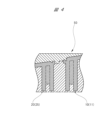
図2,図3に示されるように、上方端部32は、対向するハンドルハウジング20の端面20aと本体ハウジング10の端面10aとの間に挟まれる環状の介在部32aと、介在部32aよりもハンドルハウジング20側に位置し、当該ハンドルハウジング20の表面に形成されている係合部27に係合するハンドルハウジング側係合部32bと、介在部32aよりも本体ハウジング10側に位置し、当該本体ハウジング10の表面に形成されている係合部13に係合する本体ハウジング側係合部32cと、を含んでいる。言い換えれば、上方端部32は、環状の介在部32aと、介在部32aの一側に設けられたハンドルハウジング側係合部32bと、介在部32aの他側に設けられた本体ハウジング側係合部32cと、を含んでいる。ハンドルハウジング側係合部32bは、介在部32aの一側から当該介在部32aの径方向外側に向かって拡がった後、後方に向かって略90度屈曲してハンドルハウジング20の表面に至っている。本体ハウジング側係合部32cは、介在部32aの他側から当該介在部32aの径方向外側に向かって拡がった後、前方に向かって略90度屈曲して本体ハウジング10の表面に至っている。
As shown in FIGS. 2 and 3, the
ハンドルハウジング20の上側端部25は、上方端部32が弾性変形することによって、本体ハウジング10に対して進退する。より具体的には、ハンドルハウジング20の上側端部25は、ハンドルハウジング側係合部32bと本体ハウジング側係合部32cとが近接し、又は離間するように介在部32aが弾性変形することによって、本体ハウジング10に対して進退する。つまり、ハンドルハウジング20の上側端部25は、本体ハウジング10に対して主に前後に移動可能である。
The
既述のとおり、図1に示されている樹脂製カバー31の下方端部33は、図2,図3に示されている上方端部32と実質的に同一の形状及び構造を有している。よって、図1に示されているハンドルハウジング20の下側端部26は、樹脂製カバー31の下方端部33が上方端部32と同様に弾性変形することによって、本体ハウジング10に対して進退する。つまり、ハンドルハウジング20の下側端部26は、上側端部25と同様、本体ハウジング10に対して主に前後に移動可能である。
As mentioned above, the
以上のように、図1に示されているハンドルハウジング20と本体ハウジング10とは、これらハウジング20,10の上に二層成形によって成形された一連の樹脂製カバー31の一部を介して相対移動可能に接続されている。よって、本体ハウジング10において発生した振動が、ハンドル21を形成しているハンドルハウジング20へ伝搬することが防止または抑制される。つまり、本実施形態に係るハンマドリル1Aでは、ハンドルハウジング20及び本体ハウジング10の表面を覆っている樹脂製カバー31の一部が防振部材として機能する。そして、一部が防振部材として機能する樹脂製カバー31は、ハンドルハウジング20及び本体ハウジング10の上に二層成形によって成形された樹脂成形体である。よって、従来よりも少ない部品点数及び簡略化された構造によって組立工数の低減および小型化が図られるとともに、従来と同等或いはそれ以上の防振効果が得られる。
As described above, the
尚、本実施形態における樹脂製カバー31の素材はエラストマーであるが、樹脂製カバー31の素材は特に限定されない。もっとも、振動伝達の防止や抑制の観点からは、本体ハウジング10やハンドルハウジング20の素材よりも軟質の素材によって樹脂製カバー31を成形することが好ましい。
Although the material of the
上記のような樹脂製カバー31は、例えば次のようにして成形される。図4に示されるように、金型50内に材料樹脂を供給して本体ハウジング10及びハンドルハウジング20を同時に成形する(一次成形)。尚、図4には、ハンドルハウジング20の上側端部25及び本体ハウジング10の上側連結部11のみが図示されているが、実際には、図1に示されているハンドルハウジング20及び本体ハウジング10の全体が一次成形によって成形される。
The
その後、図5に示されるように、成形されたハンドルハウジング20及び本体ハウジング10を別の金型51に入れた後、ハンドルハウジング20及び本体ハウジング10が入れられた金型51内に材料樹脂(例えば、エラストマー)を供給し、ハンドルハウジング20及び本体ハウジング10の上に樹脂製カバー31を成形する(二次成形)。つまり、二層成形(「二色成形」と呼ばれることもある。)により、ハンドルハウジング20及び本体ハウジング10の表面の所定領域を覆うとともに、上方端部32及び下方端部33(図1)を備える樹脂製カバー31が成形される。尚、図5には、樹脂製カバー31の上方端部32とその近傍のみが図示されているが、実際には、図1に示されている樹脂製カバー31の全体が二次成形によって成形される。
Thereafter, as shown in FIG. 5, the molded
図1に示されるように、ハンドルハウジング20の上側端部25と本体ハウジング10の上側連結部11との間には規制部材60aが介在している。同じく、ハンドルハウジング20の下側端部26と本体ハウジング10の下側連結部12との間には規制部材60bが介在している。ハンドルハウジング20は、弾性体30を介して本体ハウジング10に移動可能に接続されている。よって、本体ハウジング10に対するハンドルハウジング20の移動量が大きくなり過ぎると、弾性体30が破損する恐れがある。規制部材60a,60bは、本体ハウジング10に対するハンドルハウジング20の移動量を所定範囲内に規制し、弾性体30の破損を防止する。
As shown in FIG. 1, a regulating
ここで、図1に示されている規制部材60a,60bは、実質的に同一の形状及び構造を有する。そこで、図2,図3を参照しながら、上側端部25と上側連結部11との間に介在している規制部材60aの形状及び構造について詳細に説明することにより、下側端部26と下側連結部12との間に介在している規制部材60bの形状及び構造についても明らかにする。
Here, the regulating
図2,図3に示されるように、規制部材60aは、長手方向両端が略90度折り曲げられた2枚の金属板61,62から構成されている。図2に示されるように、2枚の金属板61,62は背中合わせに重ねられた状態で上側端部25と上側連結部11とに跨って配置されている。さらに、金属板61,62の長手方向一端側に設けられている屈曲部63は、ハンドルハウジング20の端面20aに形成されたスリット20bを通してハンドルハウジング20の内側に差し入れられ、スリット20bの周囲に係止している。また、金属板61,62の長手方向他端側に設けられている屈曲部64は、本体ハウジング10の端面10aに形成されたスリット10bを通して本体ハウジング10の内側に差し入れられ、スリット10bの周囲に係止している。つまり、金属板61,62の長手方向一端側に設けられている屈曲部63は、ハンドルハウジング20の上側端部25に対する抜け止めとして機能し、金属板61,62の長手方向他端側に設けられている屈曲部64は、本体ハウジング10の上側連結部11に対する抜け止めとして機能している。この結果、本体ハウジング10に対するハンドルハウジング20の上側端部25の移動量は、金属板61,62の全長の範囲内に規制される。より厳密には、ハンドルハウジング20の上側端部25の移動量は、金属板61,62の長手方向一端側の屈曲部63と長手方向他端側の屈曲部64との間隔(D)の範囲内に規制される。
As shown in FIGS. 2 and 3, the regulating
既述のとおり、図1に示されている規制部材60bは、図2,図3に示されている規制部材60aと実質的に同一の形状及び構造を有している。よって、図1に示されているハンドルハウジング20の下側端部26の移動量も、規制部材60bを構成している2枚の金属板の全長の範囲内に規制される。
As described above, the regulating
よって、図1に示されている本体ハウジング10に対するハンドルハウジング20の移動量は、所定範囲内(=図2に示されている間隔(D)の範囲内)に規制される。さらに、金属板からなる規制部材60a,60bは、ハンドルハウジング20や本体ハウジング10と面接触することになるので、ハンドルハウジング20の不要な動きを規制する効果も得られる。例えば、ハンドルハウジング20が本体ハウジング10に対して上下方向や左右方向に過剰に動くことを規制する効果も得られる。
Therefore, the amount of movement of the
(第2実施形態) 次に、本発明の電動作業機の実施形態の他の一例について図面を参照しながら詳細に説明する。もっとも、本実施形態に係る電動作業機は、第1実施形態に係るハンマドリル1A(図1)と同一の基本構造を有するハンマドリルである。そこで、主に第1実施形態に係るハンマドリル1Aとの相違点について説明し、同一または実質的に同一の構成についての説明は適宜省略する。 (Second Embodiment) Next, another example of the embodiment of the electric working machine of the present invention will be described in detail with reference to the drawings. However, the electric working machine according to the present embodiment is a hammer drill having the same basic structure as the hammer drill 1A (FIG. 1) according to the first embodiment. Therefore, the differences from the hammer drill 1A according to the first embodiment will be mainly described, and descriptions of the same or substantially the same configurations will be omitted as appropriate.
図6に示されるように、本実施形態に係るハンマドリル1Bは、第1部材としての本体ハウジング10及び第2部材としてのハンドルハウジング20を有し、これら本体ハウジング10とハンドルハウジング20とは弾性体30を介して相対移動可能に接続されている。
As shown in FIG. 6, the
図6に示されている本体ハウジング10とハンドルハウジング20との接続構造は、図1に示されている本体ハウジング10とハンドルハウジング20との接続構造と同一である。つまり、図6に示されている本体ハウジング10とハンドルハウジング20とは、これらハウジング10,20の上に二層成形によって成形された一連の樹脂製カバー31の一部(上方端部32,下方端部33)を介して相対移動可能に接続されている。
The connection structure between the
図1と図6とを対比すると、本実施形態に係るハンマドリル1Bが備える規制部材60a,60bは、第1実施形態に係るハンマドリル1Aが備える規制部材60a,60bとは異なる。そこで、本実施形態に係るハンマドリル1Bが備える規制部材60a,60bについて詳細に説明する。
Comparing FIG. 1 and FIG. 6, the regulating
もっとも、図6に示されている規制部材60a,60bは、実質的に同一の形状及び構造を有する。そこで、図7,図8を参照しながら規制部材60aの形状及び構造について詳細に説明することにより、規制部材60bの形状及び構造についても明らかにする。
However, the regulating
図7,図8に示されるように、規制部材60aは、長手方向両端に大径部65,66がそれぞれ設けられた複数枚の金属板67から構成されている。それぞれの金属板67は同一の形状及び寸法を有しており、互いに重ね合われた状態で上側端部25と上側連結部11とに跨って配置されている。
As shown in FIGS. 7 and 8, the regulating
図7に示されるように、それぞれの金属板67の大径部65,66には長穴68が形成されている。複数枚の金属板67は、それぞれの大径部65に形成されている長穴68同士が互いに連通し、かつ、それぞれの大径部66に形成されている長穴68同士が互いに連通するように重ね合わされている。
As shown in FIG. 7,
図8に示されるように、ハンドルハウジング20の上側端部25内には、それぞれの金属板67の大径部65に形成されている長穴68(図7)を貫通する連結ピン28が設けられており、この連結ピン28の両端はハンドルハウジング20に係合されている。一方、本体ハウジング10の上側連結部11内には、それぞれの金属板67の大径部66に形成されている長穴68(図7)を貫通する連結ピン14が設けられており、この連結ピン14の両端は本体ハウジング10に係合されている。この結果、本体ハウジング10に対するハンドルハウジング20の上側端部25の移動量は、図7に示される間隔(D)の範囲内に規制される。つまり、本体ハウジング10に対するハンドルハウジング20の上側端部25の移動量は、金属板67の長手方向両端に設けられている2つの長穴68の間隔(D)の範囲内に規制される。
As shown in FIG. 8, a connecting
既述のとおり、図6に示されている規制部材60bは、図7,図8に示されている規制部材60aと実質的に同一の形状及び構造を有している。よって、図6に示されているハンドルハウジング20の下側端部26の移動量も、規制部材60bを構成している金属板の長手方向両端に設けられている2つの長穴の間隔の範囲内に規制される。
As described above, the regulating
つまり、図6に示されている本体ハウジング10に対するハンドルハウジング20の移動量は、所定範囲内(=図7に示されている間隔(D)の範囲内)に規制される。
That is, the amount of movement of the
図9,図10に、本実施形態に係るハンマドリル1Bと実質的に同一の接続構造によって本体ハウジング10とハンドルハウジング20とが接続された電動作業機の異なる例をそれぞれ示す。図9に示されている電動作業機は、セーバーソー(「レシプロソー」と呼ばれることもある。)である。図10に示されている電動作業機は、丸鋸である。
9 and 10 respectively show different examples of electric working machines in which the
図9に示されているセーバーソー1Cは、駆動源としてのモータ40を備えており、当該モータ40から出力される駆動力によって往復駆動される先端工具(鋸刃3)が装着される。図10に示されている丸鋸1Dは、駆動源としてのモータ(不図示)を備えており、当該モータから出力される駆動力によって回転駆動される先端工具(鋸刃3)が装着される。
The saver saw 1C shown in FIG. 9 includes a
図9に示されるセーバーソー1C及び図10に示される丸鋸1Dは、外殻2を形成する本体ハウジング10及びハンドルハウジング20を有している。また、本体ハウジング10とハンドルハウジング20とは、弾性体30を介して相対移動可能に接続されている。本体ハウジング10とハンドルハウジング20との接続構造の詳細についての説明は省略するが、弾性体30は、本体ハウジング10及びハンドルハウジング20の上に二層成形によって成形され、これらハウジング10,20の表面を覆う樹脂製カバー31の一部である。
The
また、本体ハウジング10とハンドルハウジング20との接続部分には、本体ハウジング10に対するハンドルハウジング20の移動量を所定範囲内に規制する規制部材60a,60bが設けられている。
Further, at the connecting portion between the
(第3実施形態) 以下、本発明の電動作業機の実施形態の他の一例について図面を参照しながら詳細に説明する。もっとも、本実施形態に係る電動作業機は、第1実施形態に係るハンマドリル1A(図1)と同一の基本構造を有するハンマドリルである。そこで、主に第1実施形態に係るハンマドリル1Aとの相違点について説明し、同一または実質的に同一の構成についての説明は適宜省略する。 (Third Embodiment) Hereinafter, another example of the embodiment of the electric working machine of the present invention will be described in detail with reference to the drawings. However, the electric working machine according to the present embodiment is a hammer drill having the same basic structure as the hammer drill 1A (FIG. 1) according to the first embodiment. Therefore, the differences from the hammer drill 1A according to the first embodiment will be mainly described, and descriptions of the same or substantially the same configurations will be omitted as appropriate.
図11は、本実施形態に係るハンマドリル1Eの部分断面図である。本実施形態に係るハンマドリル1Eは、外殻2を形成する本体ハウジング10とハンドルハウジング20とが弾性体30を介して接続されている点で第1実施形態に係るハンマドリル1Aと共通する。さらに、本実施形態に係るハンマドリル1Eは、本体ハウジング10とハンドルハウジング20とを接続している弾性体30が、ハウジング10,20の上に二層成形によって成形され、これらハウジング10,20の表面を覆う樹脂製カバー31の一部(上方端部32,下方端部33)である点においても、第1実施形態に係るハンマドリル1Aと共通する。
FIG. 11 is a partial sectional view of the
一方、本実施形態に係るハンマドリル1Eは、本体ハウジング10とハンドルハウジング20とが接続部70を介して接続されている点で、第1実施形態に係るハンマドリル1Aと相違している。つまり、本実施形態に係るハンマドリル1Eにおける本体ハウジング10とハンドルハウジング20とは、弾性体30及び接続部70の両方を介して接続されている。
On the other hand, the
図12(a)は、図11中において一点鎖線の円で囲まれているC部の拡大図である。つまり、ハンドルハウジング20の上側端部25と本体ハウジング10の上側連結部11との接続部分の拡大図である。図12(a)に示されるように、ハンドルハウジング20の上側端部25と本体ハウジング10の上側連結部11との間に介在している接続部70は、本体ハウジング10に連接する第1端部71と、ハンドルハウジング20に連接する第2端部72と、これら第1端部71と第2端部72とを繋ぐ中間部73と、を含んでいる。
FIG. 12(a) is an enlarged view of portion C surrounded by a dashed-dotted circle in FIG. That is, it is an enlarged view of the connecting portion between the
第1端部71,第2端部72及び中間部73は一体成形されているが、中間部73の肉厚は第1端部71及び第2端部72の肉厚よりも薄い。言い換えれば、本体ハウジング10からハンドルハウジング20に向かって延びる第1端部71と、ハンドルハウジング20から本体ハウジング10に向かって延びる第2端部72とは、それらよりも肉薄の中間部73を介して繋がっている。
The
第1端部71及び第2端部72よりも肉厚が薄い中間部73は、第1端部71及び第2端部72の何れよりも強度が低い脆弱部である。つまり、ハンドルハウジング20の上側端部25は、弾性体30及び脆弱部を含む接続部70を介して本体ハウジング10の上側連結部11に接続されている。尚、図11に示されるハンドルハウジング20の下側端部26と本体ハウジング10の下側連結部12との間に介在している接続部70は、図12(a)に示されている接続部70と同一の形状及び構造を備えている。つまり、ハンドルハウジング20の下側端部26は、上側端部25と同様、弾性体30及び脆弱部を含む接続部70を介して本体ハウジング10の下側連結部12に接続されている。
The
図11に示されるように、ハンドルハウジング20に、当該ハンドルハウジング20を本体ハウジング10に近接させる方向に作用する所定以上の力(F1)が加えられるか、当該ハンドルハウジング20を本体ハウジング10から離間させる方向に作用する所定以上の力(F2)が加えられると、接続部70が破壊される。具体的には、ハンドルハウジング20に力(F1)が加えられると、図12(b)に示されるように、接続部70中の脆弱部である中間部73が破断する。一方、ハンドルハウジング20に力(F2)が加えられると、図12(c)に示されるように、接続部70中の脆弱部である中間部73が破断する。
As shown in FIG. 11, a predetermined force (F1) is applied to the
ここで、図11に示されるように、本体ハウジング10及びハンドルハウジング20の表面を覆っている一連の樹脂製カバー31の一部である弾性体30は、接続部70を跨いで本体ハウジング10及びハンドルハウジング20の表面を覆っている。よって、ハンドルハウジング20に力(F1)が加えられ、中間部73が図12(b)に示されるように破断される際、弾性体30は一時的に潰れる。一方、ハンドルハウジング20に力(F2)が加えられ、中間部73が図12(c)に示されるように破断される際、弾性体30は一時的に伸びる。
Here, as shown in FIG. 11, the
図11に示されている2つの接続部70が備える中間部73(図12)が上記のようにして破断されると、それ以降、本体ハウジング10とハンドルハウジング20とは、弾性体30のみを介して接続される。言い換えれば、本体ハウジング10とハンドルハウジング20とは、相対移動可能に接続される。この結果、ハンドルハウジング20は、本体ハウジング10に対して主に前後に移動可能となり、本体ハウジング10において発生した振動が、ハンドル21を形成しているハンドルハウジング20へ伝搬することが防止または抑制される。
When the intermediate portion 73 (FIG. 12) of the two connecting
尚、中間部73の破断は、ハンマドリル1Eの出荷前に工場において行ってもよく、ハンマドリル1Eを購入したユーザが購入後に行ってもよい。
Note that the
本発明は上記実施形態に限定されるものではなく、その要旨を逸脱しない範囲で種々変更可能である。例えば、弾性体を介して相対移動可能に接続される第1部材及び第2部材は、これまでに説明した本体ハウジング10やハンドルハウジング20に限られない。図13,図14に示される実施形態では、電動作業機の外殻の少なくとも一部を形成する第1部材91と第2部材92とが弾性体30及び接続部70を介して相対移動可能に接続されている。図13,図14に示されている弾性体30は、これまでに説明した各実施形態における弾性体30と同じく、第1部材91及び第2部材92の上に二層成形によって成形され、これら第1部材91及び第2部材92の表面を覆う樹脂製カバー31の一部である。また、図13,図14に示されているそれぞれの接続部70は、図11,図12に示されている接続部70と実質的に同一の構造を有する。
The present invention is not limited to the above-described embodiments, and can be modified in various ways without departing from the gist thereof. For example, the first member and the second member that are connected so as to be relatively movable via the elastic body are not limited to the
一方、図13,図14に示されている実施形態では、第1部材91及び第2部材92の双方によってハンドル21が形成されている。具体的には、図13に示されるように、第1部材91によってハンドル21の前方部分21aが形成され、第2部材92によってハンドル21の後方部分21bが形成されている。
On the other hand, in the embodiment shown in FIGS. 13 and 14, the
図13に示される第2部材92に、当該第2部材92を第1部材91に近接させる方向に作用する所定以上の力(F1)が加えられるか、当該第2部材92を第1部材91から離間させる方向に作用する所定以上の力(F2)が加えられると、それぞれの接続部70における中間部73(「中間部73」については図12を参照)が破断される。つまり、図13,図14に示されている複数の接続部70が破壊される。
Either a predetermined force (F1) or more acting in a direction to bring the
接続部70が破壊されると、それ以降、第1部材91と第2部材92とは、弾性体30のみを介して接続される。言い換えれば、第1部材91と第2部材92とは、相対移動可能に接続される。さらに言い換えれば、ハンドル21の後方部分21bは、ハンドル21の前方部分21aを含む第1部材91に対して主に前後に移動可能となる。この結果、第1部材91において発生した振動がハンドル21の後方部分21bへ伝搬することが防止または抑制される。尚、ハンドル21の後方部分21bは、主にハンドル21を握る作業者の手のひらに当たる部分である。
When the connecting
図15に示されるように、第2部材92の上部のみを1つ又は2つ以上の接続部70を介して第1部材91に接続してもよい。この場合、図15に示されている第2部材92は、接続部70が破壊された後、その下部を支点として第1部材91に対して相対移動可能(揺動可能)となる。
As shown in FIG. 15, only the upper portion of the
本発明における接続部の形状は、これまでに参照した各図に示されている形状に限られない。本発明における接続部は、第1部材に連接する第1端部と、第2部材に連接する第2端部と、第1端部と第2端部とを繋ぐこれら第1端部及び第2端部よりも脆弱な中間部と、を含んでいればよく、その形状などは特に限定されない。そこで、図16(a)~(d)に接続部の変形例の幾つかを示す。 The shape of the connecting portion in the present invention is not limited to the shape shown in each of the figures referred to above. The connecting portion in the present invention includes a first end that connects to the first member, a second end that connects to the second member, and a first end that connects the first end and the second end. The shape of the intermediate portion is not particularly limited as long as it includes an intermediate portion that is weaker than the two end portions. Therefore, some modified examples of the connecting portion are shown in FIGS. 16(a) to 16(d).
図16(a)~(d)に示される接続部70は、第1端部71,第2端部72及び中間部73を含んでいる。また、第1端部71と第2端部72とを繋いでいる中間部73は、第1端部71及び第2端部72より肉薄であるか、少なくとも第1端部71及び第2端部72よりも肉薄な部分を含んでおり、全体として第1端部71及び第2端部72よりも脆弱である。
The connecting
図16(a)に示されている接続部70は、第2端部72から第1端部71に向かって先細りとなる中間部73を備えており、当該中間部73の頂点が第1端部71に繋がっている。図16(b)に示されている接続部70は、第2端部72から第1端部71に向かって膨出する円弧部と第1端部71から第2端部72に向かって膨出する円弧部とを含む中間部73を備えており、2つの円弧部の頂点同士が繋がっている。図16(c)に示されている接続部70は、第1端部71から第2端部72に向かって先細りとなる中間部73を備えており、当該中間部73の頂点が第2端部72に繋がっている。図16(d)に示されている接続部70は、第2端部72から第1端部71に向かって先細りとなる先鋭部と第1端部71から第2端部72に向かって先細りとなる先鋭部とを含む中間部73を備えており、2つの先鋭部の頂点同士が繋がっている。
The connecting
1A,1B,1E…ハンマドリル、1C…セーバーソー、1D…丸鋸、2…外殻、3…ドリルビット(鋸刃)、10…本体ハウジング、10a,20a…端面、10b,20b…スリット、11…上側連結部、12…下側連結部、13…係合部、14…連結ピン、20…ハンドルハウジング、21…ハンドル、21a…前方部分、21b…後方部分、22…トリガレバー、23…バッテリ装着部、24…電池パック、25…上側端部、26…下側端部、27…係合部、28…連結ピン、30…弾性体、31…樹脂製カバー、32…上方端部、32a…介在部、32b…ハンドルハウジング側係合部、32c…本体ハウジング側係合部、33…下方端部、40…モータ、41…伝達機構、42…冷却ファン、43…ピニオンギヤ、44…ベベルギヤ、45…中間シャフト、46…シリンダ、47…リテーナスリーブ、50,51…金型、60a,60b…規制部材、61,62,67…金属板、63,64…屈曲部、65,66…大径部、68…長穴、70…接続部、71…第1端部、72…第2端部、73…中間部、91…第1部材、92…第2部材 1A, 1B, 1E...Hammer drill, 1C...Saber saw, 1D...Circular saw, 2...Outer shell, 3...Drill bit (saw blade), 10...Main housing, 10a, 20a...End surface, 10b, 20b...Slit, 11 ...Upper connecting part, 12...Lower connecting part, 13...Engaging part, 14...Connecting pin, 20...Handle housing, 21...Handle, 21a...Front part, 21b...Back part, 22...Trigger lever, 23...Battery Mounting part, 24... Battery pack, 25... Upper end, 26... Lower end, 27... Engaging part, 28... Connection pin, 30... Elastic body, 31... Resin cover, 32... Upper end, 32a ... Intervening part, 32b... Handle housing side engaging part, 32c... Main body housing side engaging part, 33... Lower end part, 40... Motor, 41... Transmission mechanism, 42... Cooling fan, 43... Pinion gear, 44... Bevel gear, 45... Intermediate shaft, 46... Cylinder, 47... Retainer sleeve, 50, 51... Mold, 60a, 60b... Regulating member, 61, 62, 67... Metal plate, 63, 64... Bent part, 65, 66... Large diameter Part, 68... Elongated hole, 70... Connection part, 71... First end, 72... Second end, 73... Intermediate part, 91... First member, 92... Second member
Claims (15)
外殻の少なくとも一部を形成する第1部材及び第2部材を有し、
前記第1部材は、前記モータを収容し、
前記第2部材は、作業者によって把持されるハンドルの少なくとも一部を形成し、
前記第1と前記第2部材とは、弾性体を介して相対移動可能であり、
前記弾性体は、前記第1部材の上に二層成形によって成形された第1カバー部と、前記第2部材の上に二層成形によって成形された第2カバー部とが一体に成形されることで、前記第1部材及び前記第2部材と一体に成形された一連の樹脂製カバーの一部である、電動作業機。 An electric working machine equipped with a motor as a drive source and equipped with a tip tool driven by a driving force output from the motor,
comprising a first member and a second member forming at least a portion of the outer shell;
the first member houses the motor;
The second member forms at least a portion of a handle gripped by an operator,
The first and second members are movable relative to each other via an elastic body ,
The elastic body is integrally formed with a first cover part molded on the first member by two-layer molding and a second cover part molded on the second member by two-layer molding. In this case, the electric working machine is part of a series of resin covers integrally molded with the first member and the second member .
前記第2部材の、前記第1部材側の端部付近の表面に、前記弾性体と係合する第2係合部が設けられている、請求項1~3のいずれか1項に記載の電動作業機。 A first engaging portion that engages with the elastic body is provided on a surface of the first member near an end on the second member side,
According to any one of claims 1 to 3 , a second engaging portion that engages with the elastic body is provided on a surface of the second member near an end on the first member side. Electric work equipment.
前記第2部材は、前記第1部材に対して前後方向に移動可能である、請求項5に記載の電動作業機。 The tip tool is struck by pressure fluctuations caused by the reciprocating motion of the piston in the front-rear direction,
The electric working machine according to claim 5 , wherein the second member is movable in a front-back direction with respect to the first member .
外殻の少なくとも一部を形成する第1部材及び第2部材を有し、
前記第1部材と前記第2部材とは、接続部及び弾性体を介して接続され、
前記接続部は、前記第1部材に連接する第1端部と、前記第2部材に連接する第2端部と、前記第1端部と前記第2端部とを繋ぐ中間部と、を含み、
前記第1端部,第2端部及び中間部は一体成形され、かつ、前記中間部は前記第1端部及び前記第2端部よりも脆弱であり、
前記弾性体は、前記第1部材及び前記第2部材の上に二層成形によって成形され、前記接続部を跨いで前記第1部材及び前記第2部材の表面を覆う一連の樹脂製カバーの一部である、電動作業機。 An electric working machine equipped with a motor as a drive source and equipped with a tip tool driven by a driving force output from the motor,
comprising a first member and a second member forming at least a portion of the outer shell;
The first member and the second member are connected via a connecting portion and an elastic body,
The connecting portion includes a first end portion that connects to the first member , a second end portion that connects to the second member, and an intermediate portion that connects the first end portion and the second end portion. including,
The first end, the second end, and the middle part are integrally molded, and the middle part is weaker than the first end and the second end,
The elastic body is formed on the first member and the second member by two-layer molding, and is part of a series of resin covers covering the surfaces of the first member and the second member across the connection portion. Department of Electric Work Machines.
前記第2部材は、前記所定の方向に分割可能な一方側第2部材と他方側第2部材とが組み合わされて形成され、
前記弾性体は、前記一方側第1部材及び前記一方側第2部材の上に二層成形によって成形される一方側弾性体と、前記他方側第1部材及び前記他方側第2部材の上に二層成形によって成形される他方側弾性体と、を含む、請求項1~14のいずれか1項に記載の電動作業機。 The first member is formed by combining a first member on one side and a first member on the other side that are divisible in a predetermined direction,
The second member is formed by combining a second member on one side and a second member on the other side that are divisible in the predetermined direction,
The elastic body is formed by two-layer molding on the first member on the one side and the second member on the one side, and on the first member on the other side and the second member on the other side. The electric working machine according to any one of claims 1 to 14 , further comprising: an elastic body on the other side formed by two-layer molding.
Applications Claiming Priority (3)
| Application Number | Priority Date | Filing Date | Title |
|---|---|---|---|
| JP2019110559 | 2019-06-13 | ||
| JP2019110559 | 2019-06-13 | ||
| PCT/JP2020/021327 WO2020250715A1 (en) | 2019-06-13 | 2020-05-29 | Electric work machine |
Publications (3)
| Publication Number | Publication Date |
|---|---|
| JPWO2020250715A1 JPWO2020250715A1 (en) | 2020-12-17 |
| JPWO2020250715A5 JPWO2020250715A5 (en) | 2022-03-04 |
| JP7355107B2 true JP7355107B2 (en) | 2023-10-03 |
Family
ID=73782016
Family Applications (1)
| Application Number | Title | Priority Date | Filing Date |
|---|---|---|---|
| JP2021525996A Active JP7355107B2 (en) | 2019-06-13 | 2020-05-29 | electric work equipment |
Country Status (6)
| Country | Link |
|---|---|
| US (1) | US20220331941A1 (en) |
| EP (1) | EP3984671A4 (en) |
| JP (1) | JP7355107B2 (en) |
| CN (1) | CN113993667A (en) |
| DE (1) | DE212020000650U1 (en) |
| WO (1) | WO2020250715A1 (en) |
Citations (7)
| Publication number | Priority date | Publication date | Assignee | Title |
|---|---|---|---|---|
| JP2007331072A (en) | 2006-06-16 | 2007-12-27 | Hitachi Koki Co Ltd | Power tool |
| JP5352412B2 (en) | 2009-10-14 | 2013-11-27 | 株式会社マキタ | Electric tool |
| JP5436071B2 (en) | 2009-07-02 | 2014-03-05 | 株式会社マキタ | Work tools |
| JP5502458B2 (en) | 2009-12-25 | 2014-05-28 | 株式会社マキタ | Impact tool |
| JP2018153876A (en) | 2017-03-15 | 2018-10-04 | パナソニックIpマネジメント株式会社 | Electric tool |
| WO2019058808A1 (en) | 2017-09-19 | 2019-03-28 | 株式会社マキタ | Rotating tool |
| JP2019089139A (en) | 2017-11-10 | 2019-06-13 | パナソニックIpマネジメント株式会社 | Electric tool |
Family Cites Families (21)
| Publication number | Priority date | Publication date | Assignee | Title |
|---|---|---|---|---|
| JPS5246773A (en) * | 1975-10-11 | 1977-04-13 | Dainippon Printing Co Ltd | Process for production of lead frame for semiconductors |
| DE102005047353A1 (en) * | 2005-10-04 | 2007-04-05 | Robert Bosch Gmbh | Electric-powered machine tool e.g. hand-operated power drill, for use in pistol construction, has flange to drive train and divided into drive end and gear end bearing bracket units connected with each other by vibration damping unit |
| DE102006029630A1 (en) * | 2006-06-28 | 2008-01-03 | Robert Bosch Gmbh | Hand tool |
| DE102006050816B4 (en) * | 2006-10-27 | 2015-10-22 | Robert Bosch Gmbh | Electric hand tool |
| DE102006060652B4 (en) * | 2006-12-21 | 2019-09-05 | Robert Bosch Gmbh | Chisel or chisel hammer with a bellows |
| DE102007028382A1 (en) * | 2007-06-20 | 2008-12-24 | Robert Bosch Gmbh | Hand tool housing unit |
| DE102007030703A1 (en) * | 2007-07-02 | 2009-01-08 | Robert Bosch Gmbh | Elastic connection between housing parts of motor-driven machine tools |
| GB0801305D0 (en) * | 2008-01-24 | 2008-03-05 | Black & Decker Inc | A control mechanism for a power tool |
| US20090321101A1 (en) * | 2008-06-26 | 2009-12-31 | Makita Corporation | Power tool |
| JP5361504B2 (en) * | 2009-04-10 | 2013-12-04 | 株式会社マキタ | Impact tool |
| JP5468420B2 (en) * | 2010-03-04 | 2014-04-09 | 株式会社マキタ | Hand-held cutting tool |
| JP2012139763A (en) * | 2010-12-28 | 2012-07-26 | Hitachi Koki Co Ltd | Power tool |
| GB201112825D0 (en) * | 2011-07-26 | 2011-09-07 | Black & Decker Inc | A hammer drill |
| EP2813326A1 (en) * | 2013-06-13 | 2014-12-17 | HILTI Aktiengesellschaft | Machine tool |
| US10076833B2 (en) * | 2013-10-10 | 2018-09-18 | Makita Corporation | Electric tools |
| JP6334144B2 (en) * | 2013-11-26 | 2018-05-30 | 株式会社マキタ | Reciprocating work tool |
| JP6278830B2 (en) * | 2014-05-16 | 2018-02-14 | 株式会社マキタ | Impact tool |
| JP6441588B2 (en) * | 2014-05-16 | 2018-12-19 | 株式会社マキタ | Impact tool |
| JP6727828B2 (en) * | 2016-02-05 | 2020-07-22 | 株式会社マキタ | Power tools |
| US10233657B2 (en) * | 2016-03-25 | 2019-03-19 | Tapper Tool Co., LLC | Joiner |
| JP6399066B2 (en) * | 2016-09-27 | 2018-10-03 | オムロン株式会社 | Trigger switch |
-
2020
- 2020-05-29 EP EP20822128.3A patent/EP3984671A4/en active Pending
- 2020-05-29 CN CN202080043496.4A patent/CN113993667A/en active Pending
- 2020-05-29 DE DE212020000650.4U patent/DE212020000650U1/en active Active
- 2020-05-29 WO PCT/JP2020/021327 patent/WO2020250715A1/en active Application Filing
- 2020-05-29 JP JP2021525996A patent/JP7355107B2/en active Active
- 2020-05-29 US US17/618,299 patent/US20220331941A1/en active Pending
Patent Citations (7)
| Publication number | Priority date | Publication date | Assignee | Title |
|---|---|---|---|---|
| JP2007331072A (en) | 2006-06-16 | 2007-12-27 | Hitachi Koki Co Ltd | Power tool |
| JP5436071B2 (en) | 2009-07-02 | 2014-03-05 | 株式会社マキタ | Work tools |
| JP5352412B2 (en) | 2009-10-14 | 2013-11-27 | 株式会社マキタ | Electric tool |
| JP5502458B2 (en) | 2009-12-25 | 2014-05-28 | 株式会社マキタ | Impact tool |
| JP2018153876A (en) | 2017-03-15 | 2018-10-04 | パナソニックIpマネジメント株式会社 | Electric tool |
| WO2019058808A1 (en) | 2017-09-19 | 2019-03-28 | 株式会社マキタ | Rotating tool |
| JP2019089139A (en) | 2017-11-10 | 2019-06-13 | パナソニックIpマネジメント株式会社 | Electric tool |
Also Published As
| Publication number | Publication date |
|---|---|
| US20220331941A1 (en) | 2022-10-20 |
| CN113993667A (en) | 2022-01-28 |
| JPWO2020250715A1 (en) | 2020-12-17 |
| WO2020250715A1 (en) | 2020-12-17 |
| EP3984671A4 (en) | 2022-11-30 |
| EP3984671A1 (en) | 2022-04-20 |
| DE212020000650U1 (en) | 2022-03-23 |
Similar Documents
| Publication | Publication Date | Title |
|---|---|---|
| JP5128998B2 (en) | Hand-held work tool | |
| JP6096593B2 (en) | Reciprocating work tool | |
| JP4593387B2 (en) | Electric tool | |
| JP6334144B2 (en) | Reciprocating work tool | |
| JP2010247239A (en) | Striking tool | |
| JP6095460B2 (en) | Handle and power tool | |
| JP2016165782A (en) | Impact rotary tool | |
| JP5436071B2 (en) | Work tools | |
| WO2016076377A1 (en) | Striking device | |
| JP7001953B2 (en) | Hammer drill | |
| JP7355107B2 (en) | electric work equipment | |
| JP5356097B2 (en) | Impact tool | |
| JP6517634B2 (en) | Impact tool | |
| JP2016137559A (en) | Working tool | |
| JP4451344B2 (en) | handle | |
| JP2013063494A (en) | Power tool | |
| JP5537335B2 (en) | Dust collector | |
| JP7060098B2 (en) | Electric tool | |
| WO2023281866A1 (en) | Work machine | |
| WO2022230513A1 (en) | Work machine | |
| JP5326258B2 (en) | Impact tool | |
| JP6517633B2 (en) | Impact tool | |
| JP2016140934A (en) | Power tool | |
| JP6612496B2 (en) | Impact tool | |
| JP6385003B2 (en) | Impact tool |
Legal Events
| Date | Code | Title | Description |
|---|---|---|---|
| A521 | Request for written amendment filed |
Free format text: JAPANESE INTERMEDIATE CODE: A523 Effective date: 20211209 |
|
| A621 | Written request for application examination |
Free format text: JAPANESE INTERMEDIATE CODE: A621 Effective date: 20211209 |
|
| A131 | Notification of reasons for refusal |
Free format text: JAPANESE INTERMEDIATE CODE: A131 Effective date: 20230228 |
|
| A521 | Request for written amendment filed |
Free format text: JAPANESE INTERMEDIATE CODE: A523 Effective date: 20230426 |
|
| TRDD | Decision of grant or rejection written | ||
| A01 | Written decision to grant a patent or to grant a registration (utility model) |
Free format text: JAPANESE INTERMEDIATE CODE: A01 Effective date: 20230822 |
|
| A61 | First payment of annual fees (during grant procedure) |
Free format text: JAPANESE INTERMEDIATE CODE: A61 Effective date: 20230904 |
|
| R150 | Certificate of patent or registration of utility model |
Ref document number: 7355107 Country of ref document: JP Free format text: JAPANESE INTERMEDIATE CODE: R150 |