JP7354591B2 - Induction hardening method and induction hardening equipment - Google Patents
Induction hardening method and induction hardening equipment Download PDFInfo
- Publication number
- JP7354591B2 JP7354591B2 JP2019100544A JP2019100544A JP7354591B2 JP 7354591 B2 JP7354591 B2 JP 7354591B2 JP 2019100544 A JP2019100544 A JP 2019100544A JP 2019100544 A JP2019100544 A JP 2019100544A JP 7354591 B2 JP7354591 B2 JP 7354591B2
- Authority
- JP
- Japan
- Prior art keywords
- temperature
- shaft member
- induction hardening
- predetermined
- determination
- Prior art date
- Legal status (The legal status is an assumption and is not a legal conclusion. Google has not performed a legal analysis and makes no representation as to the accuracy of the status listed.)
- Active
Links
- 230000006698 induction Effects 0.000 title claims description 71
- 238000000034 method Methods 0.000 title claims description 68
- 238000010438 heat treatment Methods 0.000 claims description 88
- 238000001816 cooling Methods 0.000 claims description 54
- 238000010791 quenching Methods 0.000 claims description 51
- 230000002950 deficient Effects 0.000 claims description 34
- 230000000171 quenching effect Effects 0.000 claims description 32
- 238000011105 stabilization Methods 0.000 claims description 18
- 239000002826 coolant Substances 0.000 claims description 17
- 230000006641 stabilisation Effects 0.000 claims description 17
- 238000011156 evaluation Methods 0.000 claims description 11
- 229910001018 Cast iron Inorganic materials 0.000 claims description 9
- 229910001141 Ductile iron Inorganic materials 0.000 claims description 7
- 238000009529 body temperature measurement Methods 0.000 claims description 6
- 230000000087 stabilizing effect Effects 0.000 claims description 5
- 238000000275 quality assurance Methods 0.000 description 15
- 238000003860 storage Methods 0.000 description 15
- 239000000463 material Substances 0.000 description 8
- 238000005507 spraying Methods 0.000 description 5
- XEEYBQQBJWHFJM-UHFFFAOYSA-N Iron Chemical group [Fe] XEEYBQQBJWHFJM-UHFFFAOYSA-N 0.000 description 4
- 230000007547 defect Effects 0.000 description 4
- 238000002360 preparation method Methods 0.000 description 4
- 230000005855 radiation Effects 0.000 description 4
- 238000000926 separation method Methods 0.000 description 4
- 238000005336 cracking Methods 0.000 description 3
- 238000010586 diagram Methods 0.000 description 3
- 238000005259 measurement Methods 0.000 description 3
- XLYOFNOQVPJJNP-UHFFFAOYSA-N water Substances O XLYOFNOQVPJJNP-UHFFFAOYSA-N 0.000 description 3
- 229910001566 austenite Inorganic materials 0.000 description 2
- 230000007423 decrease Effects 0.000 description 2
- 238000007689 inspection Methods 0.000 description 2
- 230000007257 malfunction Effects 0.000 description 2
- 229910000734 martensite Inorganic materials 0.000 description 2
- 238000012544 monitoring process Methods 0.000 description 2
- 238000003908 quality control method Methods 0.000 description 2
- 238000005070 sampling Methods 0.000 description 2
- 229910000809 Alumel Inorganic materials 0.000 description 1
- 239000013043 chemical agent Substances 0.000 description 1
- 239000000110 cooling liquid Substances 0.000 description 1
- 230000006866 deterioration Effects 0.000 description 1
- 238000001704 evaporation Methods 0.000 description 1
- 230000008020 evaporation Effects 0.000 description 1
- 230000012447 hatching Effects 0.000 description 1
- 238000010330 laser marking Methods 0.000 description 1
- 238000004519 manufacturing process Methods 0.000 description 1
- 238000012795 verification Methods 0.000 description 1
- 238000003466 welding Methods 0.000 description 1
Images


Classifications
-
- Y—GENERAL TAGGING OF NEW TECHNOLOGICAL DEVELOPMENTS; GENERAL TAGGING OF CROSS-SECTIONAL TECHNOLOGIES SPANNING OVER SEVERAL SECTIONS OF THE IPC; TECHNICAL SUBJECTS COVERED BY FORMER USPC CROSS-REFERENCE ART COLLECTIONS [XRACs] AND DIGESTS
- Y02—TECHNOLOGIES OR APPLICATIONS FOR MITIGATION OR ADAPTATION AGAINST CLIMATE CHANGE
- Y02P—CLIMATE CHANGE MITIGATION TECHNOLOGIES IN THE PRODUCTION OR PROCESSING OF GOODS
- Y02P10/00—Technologies related to metal processing
- Y02P10/25—Process efficiency
Landscapes
- Heat Treatment Of Articles (AREA)
Description
本開示は、高周波焼入れ方法及び高周波焼入れ装置に関するものである。 The present disclosure relates to an induction hardening method and an induction hardening apparatus.
従来、高周波焼入れ製品の製造工程における品質管理は、主に、高周波加熱及び焼入れの条件系の監視と、抜き取り検査とにより行っている。しかしながら、高周波加熱装置及び/又は冷却装置の設備不良(加熱コイルの状態及び/又は冷却剤の機能低下を含む)などにより良品のヒートパターン(加熱冷却温度及び速度)から外れて不良品が発生することがある。そうすると、条件系の監視及び抜き取り検査だけでは品質保証の精度を高めることができないという問題があった。 Conventionally, quality control in the manufacturing process of induction hardened products has been carried out mainly by monitoring the conditions of induction heating and hardening, and by conducting sampling inspections. However, due to malfunctions in the high-frequency heating device and/or cooling device (including the condition of the heating coil and/or deterioration of the function of the coolant), the heat pattern (heating and cooling temperature and speed) of good products may deviate from that of good products, resulting in defective products. Sometimes. Then, there was a problem that the accuracy of quality assurance could not be improved only by monitoring the condition system and sampling inspections.
そこで、例えば、特許文献1には、被熱処理材の高周波焼入れ装置において、焼入れ品質の安定化を目的として、被熱処理材の高周波加熱温度、1次冷却温度及び2次冷却温度を検出し、これらの温度に基づいて高周波加熱装置及び冷却液制御機構の停止を行うことが開示されている。
For example,
特許文献1の技術は、900℃程度にまで上昇する高周波加熱中の被熱処理材の温度及び冷却液の吹き付けによる冷却中の被熱処理材の温度を検出することを前提としている。しかしながら、そのような高周波加熱中又は冷却中の被熱処理材について、高周波加熱部位全体の温度を精度よく検出することは困難であり現実的ではないという問題があった。
The technique of
また、特許文献1の技術において、例えば被熱処理材の一部の不安定な温度を検出することにより高周波加熱装置及び冷却液制御機構の停止が行われると、被熱処理材の他の部分は十分な高周波加熱温度又は冷却温度にまで到達していなくても次の処理に進む虞がある。そうすると、被熱処理材全体の焼入れ品質を保証することは困難であるという問題があった。
In addition, in the technique of
本開示では、品質保証の精度を向上させることができる高周波焼入れ方法及び高周波焼入れ装置を提供することを課題とする。 An object of the present disclosure is to provide an induction hardening method and an induction hardening apparatus that can improve the accuracy of quality assurance.
上記の課題を解決するために、ここに開示する第1の技術に係る高周波焼入れ方法は、鋳鉄製の軸部材の複数の所定部位を高周波加熱する高周波加熱工程と、前記高周波加熱工程後に、冷却剤により前記軸部材を冷却して該軸部材の焼入れを行う焼入れ工程と、前記焼入れ工程後に、前記軸部材を放置して該軸部材の前記複数の所定部位の焼入れ硬化部の温度を安定化させる安定化工程と、前記焼入れ工程後の前記軸部材の品質の良否を判定する判定工程と、を備え、前記安定化工程において、前記焼入れ工程終了から所定時間経過後の全ての前記複数の所定部位の焼入れ硬化部の温度を第1温度として測定し、前記安定化工程における前記所定時間は、1秒以上60秒以下であり、前記判定工程において、前記第1温度が所定範囲内にあるときに、前記軸部材の品質を良と判定し、前記第1温度の所定範囲は、150℃以上360℃以下であることを特徴とする。 In order to solve the above problems, the induction hardening method according to the first technique disclosed herein includes a high-frequency heating step of high-frequency heating a plurality of predetermined parts of a cast iron shaft member, and a cooling step after the high-frequency heating step. a quenching step of cooling the shaft member with a chemical agent to harden the shaft member; and after the quenching step, the shaft member is left to stand to stabilize the temperature of the quench-hardened portions of the plurality of predetermined portions of the shaft member. and a determination step of determining whether the quality of the shaft member after the quenching step is good or bad, and in the stabilization step, all of the plurality of predetermined values after a predetermined period of time have elapsed from the end of the quenching step. When the temperature of the quenched hardened part of the part is measured as the first temperature, the predetermined time in the stabilization step is 1 second or more and 60 seconds or less, and in the determination step, the first temperature is within a predetermined range. The quality of the shaft member is determined to be good , and the predetermined range of the first temperature is 150°C or more and 360°C or less .
高周波焼入れの処理対象部位を複数有する軸部材について高周波焼入れを行う場合、焼入れ工程後所定時間経過すると、軸部材の複数の所定部位の焼入れ硬化部の温度が均一化、すなわち安定化されてくる。本構成では、焼入れ工程後に軸部材を放置して温度を安定化させる安定化工程において、焼入れ工程終了から所定時間経過後の軸部材の全ての複数の所定部位の焼入れ硬化部の温度を第1温度して測定する。そして、その第1温度に基づいて、軸部材の品質判定を行う。本構成によれば、焼入れ工程後の軸部材の複数の所定部位の焼入れ硬化部の安定化された第1温度を測定するから、温度測定が容易であるとともに、製品の全数チェックを容易に行うことができ、高周波焼入れにおける品質保証の精度を向上させることができる。 When induction hardening is performed on a shaft member that has a plurality of induction hardening target regions, after a predetermined period of time has passed after the hardening process, the temperature of the quench hardened portions of the plurality of predetermined regions of the shaft member becomes uniform, that is, stabilized. In this configuration, in the stabilization step of leaving the shaft member after the quenching step to stabilize the temperature, the temperature of the quench hardened portion of all the plurality of predetermined portions of the shaft member after a predetermined period of time has elapsed from the end of the quenching step is determined by the first method. Measure the temperature. Then, the quality of the shaft member is determined based on the first temperature. According to this configuration, since the stabilized first temperature of the quench hardened portion of a plurality of predetermined portions of the shaft member after the quenching process is measured, it is easy to measure the temperature and also to easily check the total number of products. It is possible to improve the accuracy of quality assurance in induction hardening.
前記安定化工程における前記所定時間は、前記焼入れ工程終了から前記軸部材の前記複数の所定部位の焼入れ硬化部の温度が安定化し始めるまでの時間としてもよい。 The predetermined period of time in the stabilizing step may be a period of time from the end of the quenching step until the temperature of the quench hardened portions of the plurality of predetermined portions of the shaft member begins to stabilize.
本構成によれば、焼入れ工程後に軸部材の複数の所定部位の焼入れ硬化部の温度が安定化する初期段階で温度を測定するから、焼き割れ及び硬度不良の有無を精度よく容易に判定することができる。 According to this configuration, since the temperature is measured at the initial stage when the temperature of the quench hardened portions at a plurality of predetermined portions of the shaft member stabilizes after the quenching process, the presence or absence of quench cracks and hardness defects can be accurately and easily determined. I can do it.
前記第1温度の所定範囲は、150℃以上360℃以下である。 The predetermined range of the first temperature is 150°C or more and 360°C or less.
第1温度が150℃未満であると、軸部材の焼割れが問題となり、360℃超であると、硬度不良が問題となる。本構成によれば、第1温度が上記範囲内であるときに軸部材の品質を良と判定することにより、品質保証の精度をさらに向上させることができる。 If the first temperature is less than 150°C, quench cracking of the shaft member becomes a problem, and if it exceeds 360°C, poor hardness becomes a problem. According to this configuration, the quality of the shaft member is determined to be good when the first temperature is within the above range, thereby further improving the accuracy of quality assurance.
第2の技術は、第1の技術において、前記高周波加熱工程後であり且つ前記焼入れ工程前に、前記軸部材の全ての前記複数の所定部位の温度を第2温度として測定する第2温度測定工程と、前記第1温度及び/又は前記第2温度に基づいて、前記高周波加熱工程及び/又は前記焼入れ工程における設備状態の評価を行う設備評価工程と、を備えたことを特徴とする。 A second technique is a second technique in which the temperature of all the plurality of predetermined portions of the shaft member is measured as a second temperature after the high-frequency heating step and before the quenching step. It is characterized by comprising two temperature measuring steps, and an equipment evaluation step of evaluating the equipment condition in the high frequency heating step and/or the quenching step based on the first temperature and/or the second temperature. do.
本構成によれば、本構成によれば、第1温度及び/又は第2温度に基づいて、高周波加熱工程及び/又は冷却工程における設備状態を評価するから、これらの工程で使用される装置の設備状態をより精度よく評価することができる。 According to the present configuration, the equipment status in the high-frequency heating process and/or the cooling process is evaluated based on the first temperature and/or the second temperature, so that the equipment status used in these processes is evaluated. It is possible to evaluate the equipment condition with higher accuracy.
第3の技術は、第1又は第2の技術において、前記判定工程で良又は否と判定された前記軸部材をその判定結果に応じて分別する分別工程を備えたことを特徴とする。 A third technique is characterized in that the first or second technique includes a sorting step of sorting the shaft members judged to be good or bad in the judging step according to the judgment result.
本構成によれば、判定工程で良と判定された軸部材は、製品として出荷等の次の段階に進ませることができる。また、判定工程で否と判定された軸部材については、その原因の検証により設備状態の評価等に活用することができる。 According to this configuration, the shaft member determined to be good in the determination step can be allowed to proceed to the next stage such as shipping as a product. Furthermore, for shaft members that are determined to be rejected in the determination step, the cause thereof can be verified and used for evaluating the equipment condition.
第4の技術は、第1乃至第3の技術のいずれか一において、前記第1温度は、前記軸部材が放出する赤外線を検出する熱画像計測装置により測定されることを特徴とする。 A fourth technique is that in any one of the first to third techniques, the first temperature is measured by a thermal image measuring device that detects infrared rays emitted by the shaft member.
熱画像計測装置は、対象物から放出される赤外線を検出することによりその対象物の温度を測定するから、軸部材の複数の所定部位の焼入れ硬化部の温度を非接触且つ短時間で容易に測定できる。 A thermal image measurement device measures the temperature of an object by detecting infrared rays emitted from the object, so it can easily measure the temperature of the quenched parts of multiple predetermined parts of the shaft member without contact and in a short time. Can be measured.
第5の技術は、第1乃至第4の技術のいずれか一において、前記軸部材は、球状黒鉛鋳鉄製のカムシャフトであり、前記複数の所定部位は、複数のカム部であることを特徴とする。 A fifth technique is that in any one of the first to fourth techniques, the shaft member is a camshaft made of spheroidal graphite cast iron, and the plurality of predetermined parts are a plurality of cam parts. shall be.
本構成によれば、球状黒鉛鋳鉄製のカムシャフトの品質保証を精度よく行うことができる。 According to this configuration, quality assurance of the camshaft made of spheroidal graphite cast iron can be performed with high accuracy.
第6の技術は、鋳鉄製の軸部材の複数の所定部位を高周波加熱する高周波加熱装置と、加熱された前記軸部材を冷却剤により冷却して該軸部材の焼入れを行う冷却装置と、前記軸部材の前記複数の所定部位の温度を測定する温度測定装置と、前記軸部材の品質の良否を判定する判定装置とを備え、前記温度測定装置は、前記焼入れの終了から所定時間経過後の全ての前記複数の所定部位の焼入れ硬化部の温度を第1温度として測定し、前記所定時間は、1秒以上60秒以下であり、前記判定装置は、前記第1温度が所定範囲内にあるときに、前記軸部材の品質を良と判定し、前記第1温度の所定範囲は、150℃以上360℃以下であることを特徴とする。 A sixth technique includes a high-frequency heating device that heats a plurality of predetermined portions of a cast iron shaft member with high frequency; a cooling device that hardens the shaft member by cooling the heated shaft member with a coolant; The temperature measuring device includes a temperature measuring device that measures the temperature of the plurality of predetermined portions of the shaft member, and a determining device that determines whether the quality of the shaft member is good or bad. The temperature of the quench hardened portion of all the plurality of predetermined parts is measured as a first temperature, the predetermined time is 1 second or more and 60 seconds or less, and the determination device determines that the first temperature is within a predetermined range. In some cases, the quality of the shaft member is determined to be good , and the predetermined range of the first temperature is 150°C or more and 360°C or less .
本構成によれば、焼入れ後の軸部材の複数の所定部位の焼入れ硬化部の安定化された第1温度を測定するから、温度測定が容易であるとともに、製品の全数チェックを容易に行うことができ、高周波焼入れにおける品質保証の精度を向上させることができる。 According to this configuration, since the stabilized first temperature of the quench-hardened portion of a plurality of predetermined portions of the shaft member after quenching is measured, it is easy to measure the temperature and also easily perform a complete check of the product. This makes it possible to improve the accuracy of quality assurance in induction hardening.
前記所定時間は、前記焼入れの終了から前記軸部材の前記複数の所定部位の焼入れ硬化部の温度が安定化し始めるまでの時間としてもよい。 The predetermined time may be a time from the end of the quenching until the temperature of the quench hardened portions of the plurality of predetermined portions of the shaft member begins to stabilize.
本構成によれば、焼入れ後に軸部材の複数の所定部位の焼入れ硬化部の温度が安定化する初期段階で温度を測定するから、焼き割れ及び硬度不良の有無を精度よく容易に判定することができる。 According to this configuration, since the temperature is measured at the initial stage when the temperature of the quench-hardened portions at a plurality of predetermined portions of the shaft member stabilizes after quenching, it is possible to accurately and easily determine the presence or absence of quench cracks and hardness defects. can.
前記第1温度の所定範囲は、150℃以上360℃以下である。 The predetermined range of the first temperature is 150°C or more and 360°C or less.
本構成によれば、第1温度が上記範囲内であるときに軸部材の品質を良と判定することにより、品質保証の精度をさらに向上させることができる。 According to this configuration, the quality of the shaft member is determined to be good when the first temperature is within the above range, thereby further improving the accuracy of quality assurance.
第7の技術は、第6の技術において、前記温度測定装置は、前記軸部材の高周波加熱後焼入れ前の全ての前記複数の所定部位の温度を第2温度として測定し、前記第1温度及び/又は前記第2温度に基づいて、前記高周波加熱装置及び/又は前記冷却装置における設備状態の評価を行う設備評価装置を備えたことを特徴とする。 In a seventh technique, in the sixth technique , the temperature measuring device measures temperatures of all the plurality of predetermined portions of the shaft member after high-frequency heating and before quenching, as a second temperature, and The present invention is characterized by comprising an equipment evaluation device that evaluates equipment conditions in the high-frequency heating device and/or the cooling device based on the first temperature and/or the second temperature.
本構成によれば、第1温度及び/又は第2温度に基づいて、高周波加熱装置及び/又は冷却装置の設備状態を評価するから、これらの装置の設備状態をより精度よく評価することができる。 According to this configuration, since the equipment status of the high-frequency heating device and/or the cooling device is evaluated based on the first temperature and/or the second temperature, the equipment status of these devices can be evaluated with higher accuracy. .
第8の技術は、第6又は第7の技術において、前記判定装置の判定結果に基づいて、前記軸部材の良品と不良品とを分別する分別装置を備えたことを特徴とする。 An eighth technique is the sixth or seventh technique , characterized in that it includes a sorting device that sorts the shaft members into good and defective products based on the determination result of the determination device.
本構成によれば、判定装置により良品と判定された軸部材は製品として出荷等の次の段階に進ませることができる。また、判定装置により不良品と判定された軸部材についてはその原因の検証により設備状態の評価等に活用することができる。 According to this configuration, the shaft member determined to be a good product by the determination device can be allowed to proceed to the next stage such as shipping as a product. In addition, for shaft members determined to be defective by the determination device, the cause can be verified and used for evaluation of equipment conditions.
第9の技術は、第6乃至第8の技術のいずれか一において、前記温度測定装置は、前記軸部材が放出する赤外線を検出する熱画像計測装置であることを特徴とする。 A ninth technique is characterized in that in any one of the sixth to eighth techniques, the temperature measuring device is a thermal image measuring device that detects infrared rays emitted by the shaft member.
熱画像計測装置は、対象物から放出される赤外線を検出することによりその対象物の温度を測定するから、軸部材の複数の所定部位の焼入れ硬化部の温度を非接触且つ短時間で容易に測定できる。 A thermal image measurement device measures the temperature of an object by detecting infrared rays emitted from the object, so it can easily measure the temperature of the quenched parts of multiple predetermined parts of the shaft member without contact and in a short time. Can be measured.
第10の技術は、第6乃至第9の技術のいずれか一において、前記軸部材は、球状黒鉛鋳鉄製のカムシャフトであり、前記複数の所定部位は、複数のカム部であることを特徴とする。 A tenth technique is that in any one of the sixth to ninth techniques, the shaft member is a camshaft made of spheroidal graphite cast iron, and the plurality of predetermined parts are a plurality of cam parts. shall be.
本構成によれば、球状黒鉛鋳鉄製のカムシャフトの品質保証を精度よく行うことができる。 According to this configuration, quality assurance of the camshaft made of spheroidal graphite cast iron can be performed with high accuracy.
以上述べたように、本開示によると、焼入れ工程後の軸部材の複数の所定部位の焼入れ硬化部の安定化された第1温度を測定するから、温度測定が容易であるとともに、製品の全数チェックを容易に行うことができ、高周波焼入れにおける品質保証の精度を向上させることができる。 As described above, according to the present disclosure, since the stabilized first temperature of the quench hardened portion of a plurality of predetermined portions of the shaft member after the quenching process is measured, temperature measurement is easy, and the total number of products is Checks can be easily performed, and the accuracy of quality assurance in induction hardening can be improved.
以下、本開示の実施形態を図面に基づいて詳細に説明する。以下の好ましい実施形態の説明は、本質的に例示に過ぎず、本開示、その適用物或いはその用途を制限することを意図するものでは全くない。 Hereinafter, embodiments of the present disclosure will be described in detail based on the drawings. The following description of preferred embodiments is merely exemplary in nature and is in no way intended to limit the present disclosure, its applications, or its uses.
(実施形態1)
<カムシャフト>
図1は、本実施形態に係る高周波焼入れ方法及び装置の処理対象であるカムシャフト11(軸部材)の側面図を示している。
(Embodiment 1)
<Camshaft>
FIG. 1 shows a side view of a camshaft 11 (shaft member) that is a target of the induction hardening method and apparatus according to the present embodiment.
カムシャフト11は、球状黒鉛鋳鉄製であり、自動車の直列4気筒エンジンに搭載される。カムシャフト11は、図1に示すように、符号C1~C8及びドット状のハッチングで示す8個のカム部(所定部位)を有している。このカム部C1~C8は高強度を要することから高周波焼き入れの対象部位である。なお、カムシャフト11は、カム部C1~C8を接続する軸部Dを備える。軸部Dは、高周波加熱の対象部位ではない。また、本明細書において、カムシャフト11を「ワーク11」と称することがある。
The
なお、本実施形態に係る高周波焼入れ方法及び装置の処理対象の軸部材は、高周波焼入れを要する複数の所定部位を有するような鋳鉄製の軸部材であればよく、自動車の直列4気筒エンジン用のカムシャフトに限られない。具体的には例えば、その他の多気筒エンジン用、自動車以外の車両のエンジン用、産業用エンジン用のカムシャフト等であってもよい。また、カムシャフトに限らず、バランサシャフト等であってもよい。 The shaft member to be treated by the induction hardening method and apparatus according to the present embodiment may be a cast iron shaft member having a plurality of predetermined portions that require induction hardening, and may be a shaft member for an in-line four-cylinder automobile engine. It's not limited to camshafts. Specifically, for example, it may be used as a camshaft for other multi-cylinder engines, engines for vehicles other than automobiles, and industrial engines. Further, the shaft is not limited to a camshaft, but may be a balancer shaft or the like.
<高周波焼入れ装置>
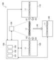
図2は、本実施形態に係る高周波焼入れ装置100の構成の概略を示す図である。
<Induction hardening equipment>
FIG. 2 is a diagram schematically showing the configuration of the
高周波焼入れ装置100は、高周波加熱装置110と、冷却装置120と、温度測定装置130と、分別装置140と、制御装置150と、図外の搬送装置と、を備える。
The
-高周波加熱装置-
高周波加熱装置110は、カムシャフト11の8個のカム部C1~C8に対し高周波加熱を行うための装置である。高周波加熱装置110としては、特に限定されるものではなく、一般的な高周波焼入れにおいて用いられる公知の装置を使用することができる。
-High frequency heating device-
The high-
-冷却装置-
冷却装置120は、高周波加熱されたカムシャフト11に対して冷却剤を吹き付ける等の方法によりカムシャフト11、特にカム部C1~C8を急激に冷却して焼入れを行うための装置である。冷却装置120としては、特に限定されるものではなく、一般的な高周波焼入れにおいて用いられる公知の装置を使用することができる。冷却剤も、高周波焼入れにおいて一般的に用いられる冷却剤を使用することができ、具体的には例えば水等の冷却剤を使用することができる。
-Cooling system-
The
-温度測定装置-
温度測定装置130は、カムシャフト11の8個のカム部C1~C8のうち複数のカム部の温度を測定するための装置であり、好ましくは全てのカム部C1~C8の温度を測定するための装置である。複数のカム部の温度を測定するから、ワーク11の品質保証の精度を高めることができる。また、全てのカム部C1~C8の温度を測定することにより、ワーク11の品質保証の精度を効果的に高めることができる。なお、複数のカム部又はカム部C1~C8の全ての温度をできる限り同一のタイミングで測定できる装置であることが望ましい。温度測定装置130としては、具体的には例えば、放射温度計、熱画像計測装置等が挙げられ、熱画像計測装置を用いることが好ましい。放射温度計を用いる場合は、例えば測定対象のカム部の個数分の放射温度計を用いて複数のカム部の各々の温度を、好ましくはできる限り同一のタイミングで、測定するようにすればよい。なお、放射温度計の数は、軸部材の構成、特に高周波焼入れ対象の所定部位の数により適宜変更され得る。熱画像計測装置は、対象物から放出される赤外線を検出することによりその対象物の温度を測定する装置である。熱画像計測装置を用いれば、カムシャフト11が放出する赤外線を検出することにより、カム部C1~C8を含むカムシャフト11全体の温度を極めて短時間、すなわちほぼ同一のタイミングで容易に測定できる。
-Temperature measuring device-
The
なお、以下の高周波焼入れ方法の説明では、理解を容易にするため、全てのカム部C1~C8の温度を測定する態様を前提とする。 In addition, in the following description of the induction hardening method, in order to facilitate understanding, it is assumed that the temperature of all the cam parts C1 to C8 is measured.
-分別装置-
分別装置140は、制御装置150の後述する判定部152により判定されたカムシャフト11の良品と不良品とを分別するための装置である。具体的には例えば、良品及び不良品に判定結果の刻印を行い、両者を別の分別箱へ分別していくような装置を採用することができる。すなわち、分別装置140は、カムシャフト11を搬送する公知の搬送機、刻印を行う公知の刻印機、刻印に基づいて分別を行う公知の分別機及び分別箱等の組合せにより構成されてもよい。具体的には例えば、搬送機は一般的なベルトコンベヤ装置等、刻印機は例えば一般的なレーザー刻印機等、分別機は刻印を読み取るセンサ等を備えた公知の分別機等を用いることができる。
-Separation device-
The
-制御装置-
制御装置150は、高周波加熱装置110、冷却装置120、温度測定装置130、及び分別装置140と通信可能に接続されており、後述する高周波焼入れ工程全体を制御・管理するための装置である。制御装置150は、記憶部151と、判定部152(判定装置)と、制御部153とを備える。制御装置150は、限定する意図ではないが、汎用のコンピュータ、ネットワークサーバ等により構成される。また、制御装置150は、図示しない表示部及び入力部等を備える。表示部及び入力部は、限定する意図ではないが、モニタ、キーボード、タッチパネル等により構成される。制御装置150及びその各部の詳細については、後述する高周波焼入れ方法の項目において説明する。
-Control device-
The
-搬送装置-
図2には図示していないが、高周波焼入れ装置100は、上述の各装置にカムシャフト11を搬入・搬出するための搬送装置を備えている。搬送装置は、限定する意図ではないが、ローダ等の公知の装置を採用することができる。
-Transport device-
Although not shown in FIG. 2, the
<高周波焼入れ方法>
本実施形態に係る高周波焼入れ方法を主に図2~図4を参照して説明する。
<Induction hardening method>
The induction hardening method according to this embodiment will be explained mainly with reference to FIGS. 2 to 4.
図4に示すように、高周波焼入れ方法は、準備工程S11と、高周波加熱工程S12と、加熱条件判定工程S21と、待機工程S13と、焼入れ工程S14と、冷却条件判定工程S23と、安定化工程S15と、第1温度判定工程S24(判定工程)と、分別工程S16とを備えている。 As shown in FIG. 4, the induction hardening method includes a preparation step S11, an induction heating step S12, a heating condition determination step S21, a standby step S13, a hardening step S14, a cooling condition determination step S23, and a stabilization step. S15, a first temperature determination step S24 (determination step), and a sorting step S16.
-準備工程-
準備工程S11において、ワーク11は高周波焼入れ装置100に搬入される。制御装置150は、ワーク11の識別コード情報、機種情報、温度条件情報等のワーク情報を取得する。ワーク情報は、記憶部151に記録される(S31)。制御部153は、読み取ったワーク情報と予め記憶部151に記録された情報とを照合して、当該ワーク11に対応する高周波加熱条件及び焼入れ条件を記憶部151より読み出し、高周波加熱装置110及び冷却装置120の各々の運転条件として設定する。なお、ワーク11に対応する各条件は、作業者が入力部から入力して設定する等の他の方法を用いてもよい。
-Preparation process-
In the preparation step S11, the
-高周波加熱工程-
高周波加熱工程S12は、高周波加熱装置110によりワーク11の8個のカム部C1~C8の高周波加熱を行う工程である。
-High frequency heating process-
The high-frequency heating step S12 is a step in which the eight cam portions C1 to C8 of the
具体的に、ワーク11は、図2の矢印A1に示すように、不図示の搬送装置により高周波加熱装置110内に搬入される。そうして、制御部153により設定された高周波加熱条件に従って、高周波加熱が行われる。高周波加熱によりカム部C1~C8の表面から一定の深さまでの鋳鉄組織がオーステナイト化される。加熱温度は、鋳鉄組織がオーステナイト化する温度であり、例えば約900℃~約1100℃である。加熱時間は、一般的な高周波焼入れで用いられる時間であり、例えば約10秒とすることができる。高周波加熱工程S12が終了すると、図2の矢印A2で示すように、ワーク11は搬送装置により高周波加熱装置110内から搬出される。
Specifically, the
なお、高周波加熱工程S12において実際に行われた高周波加熱の条件は加熱条件実績情報として記憶部151に記録される(S32)。 Note that the conditions of high-frequency heating actually performed in the high-frequency heating step S12 are recorded in the storage unit 151 as heating condition performance information (S32).
-加熱条件判定工程-
判定部152は、加熱条件実績情報のOK/NG判定を行う(加熱条件判定工程S21)。例えば、加熱条件実績情報が予め設定された高周波加熱条件と比較して妥当なものであればOKと判定される。一方、例えば、設備不良等の要因により、加熱条件実績情報が、予め設定された高周波加熱条件から大きく外れたものであればNGと判定される。OK/NG判定の基準はワーク11の仕様、装置の仕様等に応じて適宜設定される。このOK/NG判定の結果は、記憶部151に記録される(S33)。
-Heating condition determination process-
The determining unit 152 determines whether the heating condition performance information is OK or not (heating condition determining step S21). For example, if the heating condition performance information is reasonable compared with preset high frequency heating conditions, it is determined to be OK. On the other hand, if the heating condition performance information deviates significantly from the preset high-frequency heating conditions due to factors such as equipment failure, for example, it is determined to be NG. The criteria for OK/NG determination are appropriately set according to the specifications of the
-待機工程-
高周波加熱装置110内から搬出されたワーク11は、次の焼入れ工程S14に進む準備のため、例えば大気下で約数秒間、待機する(待機工程S13)。
-Standby process-
The
-焼入れ工程-
高周波加熱装置110内から搬出されたワーク11は、図2の矢印A3で示すように、冷却装置120内へ搬入される。そして、ワーク11に冷却剤が吹き付けられ、急激な冷却、すなわち焼入れが行われる(焼入れ工程S14)。焼入れが行われると、高周波加熱によりオーステナイト化した鋳鉄組織がマルテンサイト化する。なお、本明細書において、このカム部C1~C8の表面から一定の深さまでのマルテンサイト化された部分を「焼入れ硬化部」という。冷却剤の温度、吹き付け時間等の焼入れ条件は、鋳鉄組織がマルテンサイト化する温度にまでワーク11のカム部C1~C8を冷却できる条件である。焼入れ工程S14が終了すると、図2の矢印A4で示すように、ワーク11は、冷却装置120内から搬出される。
-Quenching process-
The
なお、焼入れ工程S14において実際に行われた焼入れの条件は冷却条件実績情報として記憶部151に記録される(S36)。 Note that the hardening conditions actually performed in the hardening step S14 are recorded in the storage unit 151 as cooling condition performance information (S36).
-冷却条件判定工程-
冷却条件判定工程S23において、判定部152は、冷却条件実績情報のOK/NG判定を行う。例えば、冷却条件実績情報が予め設定された焼入れ条件と比較して妥当なものであればOKと判定される。一方、例えば、設備不良等の要因により、冷却条件実績情報が、予め設定された焼入れ条件から大きく外れたものであればNGと判定される。OK/NG判定の基準はワーク11のワーク情報、装置の仕様等に応じて適宜設定される。このOK/NG判定の結果は、記憶部151に記録される(S37)。
- Cooling condition determination process -
In the cooling condition determination step S23, the determination unit 152 determines whether the cooling condition performance information is OK or NG. For example, if the cooling condition performance information is reasonable when compared with preset hardening conditions, it is determined to be OK. On the other hand, if the cooling condition performance information deviates significantly from the preset quenching conditions due to factors such as equipment failure, for example, it is determined to be NG. The criteria for OK/NG determination are appropriately set according to the work information of the
-安定化工程-
安定化工程S15は、焼入れ工程S14後、すなわち冷却装置120からの搬出後に、ワーク11を大気中で放置してその温度を安定化させる工程である。
-Stabilization process-
The stabilization step S15 is a step in which the
ここに、本実施形態に係る高周波焼入れ方法は、安定化工程S15において、温度測定装置130により、焼入れ工程S14終了から所定時間経過後の全てのカム部C1~C8の焼入れ硬化部の温度を第1温度として測定することを特徴とする。以下、安定化工程S15の詳細と第1温度の測定について説明する。
Here, in the induction hardening method according to the present embodiment, in the stabilizing step S15, the temperature of the hardened parts of all the cam parts C1 to C8 is measured by the
まず、冷却装置120から搬出されたワーク11は、そのまま大気下で一定時間放置される(安定化工程S15)。
First, the
ここで、高周波加熱工程S12から安定化工程S15までのワーク11の温度変化について図3を参照して説明する。 Here, the temperature change of the workpiece 11 from the high-frequency heating step S12 to the stabilization step S15 will be explained with reference to FIG. 3.
図3のグラフは、検証用のワーク11のカム部C8(図1参照)に市販のクロメルアルメル熱電対を溶接して高周波加熱工程S12から安定化工程S15までの温度を検出し、プロットしたものである。
The graph in FIG. 3 is a graph obtained by welding a commercially available chromel-alumel thermocouple to the cam portion C8 (see FIG. 1) of the
図3に示すように、高周波加熱工程S12において高周波加熱が行われると、カム部C8の温度は約1040℃まで徐々に増加する。そして、矢印B1の時間で加熱が終了し、ワーク11は高周波加熱装置110から搬出される(図2の矢印A2参照)。
As shown in FIG. 3, when high frequency heating is performed in the high frequency heating step S12, the temperature of the cam portion C8 gradually increases to about 1040°C. Then, the heating ends at the time indicated by arrow B1, and the
そして、図3中矢印B1の時間から矢印B2の時間までの待機工程S13において、カム部C8の温度は、約100℃低下する。 Then, in the standby step S13 from the time indicated by the arrow B1 to the time indicated by the arrow B2 in FIG. 3, the temperature of the cam portion C8 decreases by approximately 100°C.
その後、ワーク11は、冷却装置120内に搬送され(図2の矢印A3参照)、図3中矢印B2の時間から冷却剤としての水の吹き付けが始まり、カム部C8の温度は急降下する。冷却剤がワーク11に吹き付けられる間、カム部C8の温度は細かく変動する。そして、矢印B3で示すように、冷却剤の吹き付けが終了して、ワーク11が冷却装置120から搬出されると(図2の矢印A4参照)、カム部C8の焼入れ硬化部の温度は徐々に上昇し、やがて一定の温度で安定化する。この図3の符号B3の時間以降の温度の上昇及び安定化は、ワーク11を大気下で放置することにより、ワーク11のカム部C8の温度が復温、すなわちワーク11のカム部C8の焼入れ硬化部の内部と表面の温度が均一化している様子を示している。なお、図3の符号B3から約8秒程度は温度が細かく変動しているが、これは、ワーク11に付着している冷却剤の水分の蒸発等が関係していると考えられる。
Thereafter, the
本願発明者らは、図3のようなワーク11の良品のヒートパターンと、不良品のヒートパターンとを検証することにより、この復温して安定化した状態の温度、すなわち図3中矢印P1で示す時間以降の温度(本明細書において「第1温度」と称することがある。)は、良品では所定範囲内に入り、不良品ではその所定範囲から外れることを見出した。また、本願発明者らは、冷却装置120からの搬出(焼入れ工程S14終了)から第1温度に到達し始めるまでの時間(図3では矢印B3の時間から矢印P1の時間まで)は、ワーク11の仕様が同一であれば、ほぼ一定であることを見出した。
By verifying the heat pattern of a
第1温度に到達し始めるまでの時間は、ワーク11の良品のヒートパターンを予め実験的に取得しておくことにより、決定することができる。そして、安定化工程S15において、所定時間経過後のカム部C1~C8の焼入れ硬化部の温度を、第1温度として測定し、当該第1温度が所定範囲に含まれているかどうかをワーク11全てにおいて検証することにより、ワーク11の品質の良否判定を全数について行うことができる。
The time required to reach the first temperature can be determined by experimentally obtaining the heat pattern of a
従って、本実施形態に係る高周波焼入れ方法の安定化工程S15では、温度測定装置130により、焼入れ工程S14終了から所定時間経過後の全てのカム部C1~C8の焼入れ硬化部の温度を第1温度として測定する。そして、次の第1温度判定工程S24において、第1温度に基づいて、ワーク11の品質の良否判定を行う。なお、安定化工程S15において測定された第1温度は、第1温度情報として記憶部151に記録される(S38)。
Therefore, in the stabilization step S15 of the induction hardening method according to the present embodiment, the
所定時間は、ワーク11を冷却装置120から搬出してから、ワーク11のカム部C1~C8の焼入れ硬化部の温度が安定化するまでの時間(図3中矢印B3から矢印P1以降までの時間)である。そして、所定時間は、焼き割れ及び硬度不良の有無を精度よく容易に判定する観点から、好ましくは、ワーク11を冷却装置120から搬出してから、ワーク11のカム部C1~C8の焼入れ硬化部の温度が安定化し始めるまでの時間(図3中矢印B3から矢印P1までの時間)である。なお、本明細書において、図3中矢印P1で示すワーク11の温度が安定化し始める時間は、ワーク11の水分の蒸発等による細かい温度変化が終了して、滑らかに温度が上昇し始めてから、温度の時間変化率が例えば1以下、好ましくは0.7以下になり始める時間とすることができる。また、所定時間は、具体的には例えば、1秒以上60秒以下、好ましくは2秒以上20秒以下である。
The predetermined time is the time from when the
-第1温度判定工程-
第1温度判定工程S24は、制御装置150の判定部152が、上述の第1温度に基づいて、ワーク11の品質の良否を判定する工程である。
-First temperature determination process-
The first temperature determination step S24 is a step in which the determination unit 152 of the
具体的には例えば、判定部152は、第1温度が所定範囲内にあるときは、第1温度をOKと判定とする一方、第1温度が所定範囲外にあるときは、第1温度をNGと判定とする。そして、第1温度がOK判定のときは、ワーク11の品質は良品と判定される。また、第1温度がNG判定のときは、ワーク11の品質は不良品と判定される。
Specifically, for example, when the first temperature is within a predetermined range, the determination unit 152 determines that the first temperature is OK, and when the first temperature is outside the predetermined range, the determination unit 152 determines that the first temperature is OK. It is judged as NG. When the first temperature is determined to be OK, the quality of the
図3に一点鎖線で示すように、第1温度の上記所定範囲は、好ましくは150℃以上360℃以下であり、より好ましくは180℃以上330℃以下である。第1温度が150℃未満であると、焼入れ工程S14における冷却過多によるワーク11の焼割れが問題となる。また、第1温度が360℃超であると、焼入れ工程S14における冷却不足によるカム部C1~C8の硬度不良が問題となる。
As shown by the dashed line in FIG. 3, the predetermined range of the first temperature is preferably 150°C or more and 360°C or less, more preferably 180°C or more and 330°C or less. If the first temperature is less than 150° C., quench cracking of the
第1温度判定工程S24における第1温度のOK/NG判定結果は、ワーク11の品質の良否判定の結果と同一であり、このワーク11の品質の良否判定の結果は、第1温度判定情報として記憶部151に記録される(S39)。
The OK/NG determination result of the first temperature in the first temperature determination step S24 is the same as the result of determining the quality of the
-分別工程-
第1温度判定工程S24で良品又は不良品と判定されたワーク11は、上述の分別装置140により、その判定結果に応じて分別される(分別工程S16)。
-Separation process-
The
具体的には例えば、まず、安定化工程S15を終えたワーク11は、不図示の搬送装置により、分別装置140に搬入される。そして、例えばレーザー刻印機等により、記憶部151に記憶されたワーク情報の識別コード情報、加熱条件判定情報、冷却条件判定情報及び第1温度判定情報がワーク11に刻印される(S161)。そして、良品は完成パレットへ分別される一方(S162)、不良品は不良品ボックスへ分別される(S163)。こうして、ワーク11の高周波焼入れ作業は終了する。なお、刻印は良品及び不良品のいずれにも行われる。そうして、良品の品質保証の精度を高めるとともに、分別したときの不良品の良品への混入を防ぐことができる。良品は品質が保証された製品として出荷等の次の段階に進んでいく。一方、不良品は、その原因の検証用として使用され、設備状態の評価等に活用される。
Specifically, for example, first, the
<まとめ>
以上述べたように、本実施形態に係る高周波焼入れ方法及び装置は、安定化工程S15における第1温度を測定し、その第1温度に基づいてワーク11の品質の良否判定を行うから、温度測定が容易且つ高精度であるとともに、製品の全数チェックを容易に行うことができる。そうして、高周波焼入れにおける品質保証の精度を向上させることができる。
<Summary>
As described above, the induction hardening method and apparatus according to the present embodiment measure the first temperature in the stabilization step S15 and judge the quality of the
なお、記憶部151に記録されたワーク情報、加熱条件実績情報、加熱条件判定情報、冷却条件実績情報、冷却条件判定情報、第1温度情報、第1温度判定情報は、他の必要情報とともに互いに紐づけられて保存され、トレーサビリティ管理される。これにより、カムシャフト11の全数保証の品質管理の精度を向上させることができる。
Note that the workpiece information, heating condition performance information, heating condition determination information, cooling condition performance information, cooling condition determination information, first temperature information, and first temperature determination information recorded in the storage unit 151 are mutually exclusive with other necessary information. They are linked and saved, and traceability is managed. This makes it possible to improve the accuracy of quality control for guaranteeing 100% of the
(実施形態2)
以下、本開示に係る他の実施形態について詳述する。なお、これらの実施形態の説明において、実施形態1と同じ部分については同じ符号を付して詳細な説明を省略する。
(Embodiment 2)
Other embodiments according to the present disclosure will be described in detail below. In addition, in the description of these embodiments, the same parts as in
<高周波焼入れ方法>
図5は、実施形態2に係る高周波焼入れ方法の工程を示すフローである。
<Induction hardening method>
FIG. 5 is a flowchart showing the steps of the induction hardening method according to the second embodiment.
-待機工程-
実施形態1の高周波焼入れ方法では、高周波加熱工程S12後であり且つ焼入れ工程S14前に、待機工程S13を備える構成であった。本実施形態に係る高周波焼入れ方法では、待機工程S13(第2温度測定工程)において、ワーク11のカム部C1~C8の温度を測定するようにしている。
-Standby process-
The induction hardening method of
具体的には、図3の矢印P2で示すように、高周波加熱装置110内から搬出された後、冷却装置120内に搬入されるまでの間に、ワーク11の全てのカム部C1~C8の温度を、第2温度として、温度測定装置130により測定する。測定された第2温度は、第2温度情報として制御装置150の記憶部151に記録される(S34)。
Specifically, as shown by arrow P2 in FIG. The temperature is measured as a second temperature by the
-第2温度判定工程-
そして、第2温度判定工程S22(設備評価工程)において、判定部152(設備評価装置)は、第2温度が妥当な温度範囲内かどうかについて、OK/NG判定を行う。
-Second temperature determination process-
Then, in the second temperature determination step S22 (equipment evaluation step), the determination unit 152 (equipment evaluation device) performs an OK/NG determination as to whether the second temperature is within a reasonable temperature range.
図3のようなワーク11の良品のヒートパターンは、高周波加熱装置110の設備状態に問題がなければ、ワーク11の仕様、装置の仕様等により概ね決定される。従って、第2温度も、第1温度同様、良品では、ある程度の温度範囲内に収まる。従って、第2温度が予測される妥当な温度範囲に含まれる場合にはOK判定、第2温度が予測される妥当な温度範囲から外れる場合にはNG判定を行うことができる。OK判定の場合は、ワーク11は、そのまま次の焼入れ工程S14に進む。一方、NG判定の場合は、例えば、高周波加熱装置110のエラーとして、高周波焼入れ装置100全体の動作を停止させることができる。これにより、高周波加熱装置110の点検を行うことができる。このように、第2温度判定工程S22において、その判定結果に応じて、高周波加熱装置110の設備状態を評価することができる。なお、第2温度の妥当な温度範囲は例えば約850℃~約1050℃とすることができる。
The heat pattern of a
第2温度のOK/NG判定の結果についても、第2温度判定情報として記憶部151に記録される(S35)。なお、第2温度情報及び第2温度判定情報についても、上述の情報とともに互いに紐づけられて保存され、トレーサビリティ管理される。 The result of the OK/NG determination of the second temperature is also recorded in the storage unit 151 as second temperature determination information (S35). Note that the second temperature information and the second temperature determination information are also stored in a linked manner together with the above-mentioned information, and are managed for traceability.
-第1温度判定工程-
実施形態1では、第1温度判定工程S24において、判定部152により、第1温度が所定範囲に含まれるか否かによりワーク11の品質の良否判定を行う構成であった。これに対し、本実施形態に係る第1温度判定工程S24(設備評価工程)では、判定部152(設備評価装置)により、第1温度を用いたワーク11の品質の良否判定に加えて、第1温度を用いた冷却装置120の設備評価を併せて行うようにしてもよい。
-First temperature determination process-
In the first embodiment, in the first temperature determination step S24, the determination unit 152 determines whether the quality of the
具体的には、上述のごとく、判定部152は、第1温度が所定範囲内に含まれている場合はOK判定を行う。一方、第1温度が所定範囲外にある場合はNG判定を行う。そして、ワーク11は、第1温度のOK/NG判定の結果に基づき、分別工程S16で良品と不良品とに分別される。さらに、第1温度についてNG判定が出た場合、すなわち、第2温度判定工程S22において第2温度がOK判定であったにも拘わらず、第1温度がNG判定であった場合、冷却装置120の設備状態に問題が生じている可能性が高いと考えられる。従って、この場合には、例えば、高周波焼入れ装置100全体の動作を停止して、冷却装置120の設備状態の点検を行うようにすることができる。
Specifically, as described above, the determination unit 152 determines OK if the first temperature is within the predetermined range. On the other hand, if the first temperature is outside the predetermined range, an NG determination is made. Then, the
-分別工程-
分別工程S16の刻印工程S161では、上述の情報に加え、第2温度判定情報もワーク11に刻印される。そうして、第1温度がOK判定であったワーク11が良品、NG判定であったワーク11が不良品として分別される。
-Separation process-
In the marking step S161 of the sorting step S16, in addition to the above-mentioned information, second temperature determination information is also stamped on the
<まとめ>
以上述べたように、本実施形態に係る高周波焼入れ方法では、まず第2温度に基づいて高周波加熱装置110の設備状態の評価を行うことができる。そして、第2温度がOK判定であった場合には、第1温度に基づいて、冷却装置120の設備状態の評価を行うことができる。本構成によれば、高周波加熱装置110及び冷却装置120の設備状態をこまめにチェックすることができるとともに、エラー発生時にはこれらの装置の点検を速やかに行うことができる。そうして、カムシャフト11の歩留まりを高めるとともに、その品質保証の精度を効果的に高めることができる。
<Summary>
As described above, in the induction hardening method according to the present embodiment, the equipment condition of the
(その他の実施形態)
実施形態2において、第2温度がNG判定の場合、及び、第2温度がOKであるにも拘わらず第1温度がNGと判定された場合には、エラーにより高周波焼入れ装置100全体の動作を停止させる構成であったが、当該構成に限られるものではない。具体的には例えば、第1温度又は第2温度でNG判定が出た場合であっても高周波焼入れ装置100全体の動作を継続させる構成としてもよい。例えば、第2温度がOKであり、第1温度がNGの場合、高周波加熱装置110の不具合により高周波加熱が断続的に行われた結果、測定された第2温度はOKであるが、実際には高周波加熱が不十分で、第1温度がNGと判定される場合も想定され得る。このような場合には、第1温度及び第2温度の両者の判定結果に基づいて、高周波加熱装置110及び冷却装置120双方の設備状態を評価して原因を検証することが効果的である。従って、このような場合には、第1温度又は第2温度でNG判定が出た場合であっても、高周波焼入れ装置100全体の動作を停止させない構成とすることが効果的である。
(Other embodiments)
In the second embodiment, if the second temperature is determined to be NG, or if the first temperature is determined to be NG even though the second temperature is OK, the entire operation of the
実施形態2では、ワーク11の品質の良否判定は、第1温度のみに基づいて行う構成であったが、第1温度に加え、第2温度のOK/NG判定結果に基づいて、ワーク11の品質の良否判定を行うようにしてもよい。この場合、分別工程S16では、第1温度及び第2温度ともにOK判定のワーク11のみが良品、第1温度及び第2温度の少なくともいずれかがNG判定である場合は、不良品として判定、刻印及び分別される。なお、第2温度がNG判定のワーク11は、高周波加熱工程S12が終了した段階で不良品である可能性が高いから、第1温度の判定結果に拘わらず全て不良品として刻印及び分別するようにしてもよい。このように、第1温度に加えて、第2温度を用いてワーク11の品質の良否判定を行うことにより、ワーク11の熱履歴が良品のヒートパターンに沿っているかをより精度よく確認することができ、品質保証の精度をさらに高めることができる。
In the second embodiment, the quality of the
本開示は、高周波焼入れ方法及び高周波焼入れ装置の分野で、極めて有用である。 The present disclosure is extremely useful in the fields of induction hardening methods and induction hardening devices.
11 カムシャフト、ワーク(軸部材)
100 高周波焼入れ装置
110 高周波加熱装置
120 冷却装置
130 温度測定装置
140 分別装置
150 制御装置
151 記憶部
152 判定部(判定装置、設備評価装置)
153 制御部
C1~C8 カム部(所定部位)
S12 高周波加熱工程
S13 待機工程(第2温度測定工程)
S14 焼入れ工程
S15 安定化工程
S16 分別工程
S22 第2温度判定工程
S24 第1温度判定工程(判定工程)
11 Camshaft, work (shaft member)
100
153 Control part C1 to C8 Cam part (predetermined part)
S12 High frequency heating process S13 Standby process (second temperature measurement process)
S14 Quenching process S15 Stabilizing process S16 Sorting process S22 Second temperature determination process S24 First temperature determination process (determination process)
Claims (10)
前記高周波加熱工程後に、冷却剤により前記軸部材を冷却して該軸部材の焼入れを行う焼入れ工程と、
前記焼入れ工程後に、前記軸部材を放置して該軸部材の前記複数の所定部位の焼入れ硬化部の温度を安定化させる安定化工程と、
前記焼入れ工程後の前記軸部材の品質の良否を判定する判定工程と、を備え、
前記安定化工程において、前記焼入れ工程終了から所定時間経過後の全ての前記複数の所定部位の焼入れ硬化部の温度を第1温度として測定し、
前記安定化工程における前記所定時間は、1秒以上60秒以下であり、
前記判定工程において、前記第1温度が所定範囲内にあるときに、前記軸部材の品質を良と判定し、
前記第1温度の所定範囲は、150℃以上360℃以下である
ことを特徴とする高周波焼入れ方法。 a high-frequency heating step of high-frequency heating a plurality of predetermined parts of a cast iron shaft member;
After the high-frequency heating step, a quenching step of cooling the shaft member with a coolant to harden the shaft member;
After the quenching step, a stabilizing step of leaving the shaft member to stabilize the temperature of the quench hardened portions of the plurality of predetermined portions of the shaft member;
a determination step of determining whether the quality of the shaft member after the quenching step is good or bad;
In the stabilization step, the temperature of the quench hardened portion of all the plurality of predetermined portions after a predetermined time has elapsed from the end of the quenching step is measured as a first temperature,
The predetermined time in the stabilization step is 1 second or more and 60 seconds or less,
In the determination step, the quality of the shaft member is determined to be good when the first temperature is within a predetermined range ;
The predetermined range of the first temperature is 150°C or more and 360°C or less.
An induction hardening method characterized by:
前記高周波加熱工程後であり且つ前記焼入れ工程前に、前記軸部材の全ての前記複数の所定部位の温度を第2温度として測定する第2温度測定工程と、
前記第1温度及び/又は前記第2温度に基づいて、前記高周波加熱工程及び/又は前記焼入れ工程における設備状態の評価を行う設備評価工程と、を備えた
ことを特徴とする高周波焼入れ方法。 In claim 1 ,
a second temperature measurement step of measuring the temperature of all the plurality of predetermined portions of the shaft member as a second temperature after the high frequency heating step and before the quenching step;
An induction hardening method comprising: an equipment evaluation step of evaluating equipment conditions in the induction heating step and/or the hardening step based on the first temperature and/or the second temperature.
前記判定工程で良又は否と判定された前記軸部材をその判定結果に応じて分別する分別工程を備えた
ことを特徴とする高周波焼入れ方法。 In claim 1 or claim 2 ,
An induction hardening method characterized by comprising a sorting step of sorting the shaft members judged as good or bad in the judging step according to the judgment result.
前記第1温度は、前記軸部材が放出する赤外線を検出する熱画像計測装置により測定される
ことを特徴とする高周波焼入れ方法。 In any one of claims 1 to 3 ,
The induction hardening method is characterized in that the first temperature is measured by a thermal image measuring device that detects infrared rays emitted by the shaft member.
前記軸部材は、球状黒鉛鋳鉄製のカムシャフトであり、
前記複数の所定部位は、複数のカム部である
ことを特徴とする高周波焼入れ方法。 In any one of claims 1 to 4 ,
The shaft member is a camshaft made of spheroidal graphite cast iron,
An induction hardening method , wherein the plurality of predetermined portions are a plurality of cam portions.
加熱された前記軸部材を冷却剤により冷却して該軸部材の焼入れを行う冷却装置と、
前記軸部材の前記複数の所定部位の温度を測定する温度測定装置と、
前記軸部材の品質の良否を判定する判定装置とを備え、
前記温度測定装置は、前記焼入れの終了から所定時間経過後の全ての前記複数の所定部位の焼入れ硬化部の温度を第1温度として測定し、
前記所定時間は、1秒以上60秒以下であり、
前記判定装置は、前記第1温度が所定範囲内にあるときに、前記軸部材の品質を良と判定し、
前記第1温度の所定範囲は、150℃以上360℃以下である
ことを特徴とする高周波焼入れ装置。 a high-frequency heating device that heats a plurality of predetermined parts of a cast iron shaft member with high frequency;
a cooling device for cooling the heated shaft member with a coolant to harden the shaft member;
a temperature measuring device that measures the temperature of the plurality of predetermined portions of the shaft member;
and a determination device that determines whether the quality of the shaft member is good or bad,
The temperature measuring device measures the temperature of the quench hardened portion of all the plurality of predetermined portions after a predetermined time has elapsed from the end of the quenching, as a first temperature,
The predetermined time is 1 second or more and 60 seconds or less,
The determination device determines that the quality of the shaft member is good when the first temperature is within a predetermined range ;
The predetermined range of the first temperature is 150°C or more and 360°C or less.
An induction hardening device characterized by:
前記温度測定装置は、前記軸部材の高周波加熱後焼入れ前の全ての前記複数の所定部位の温度を第2温度として測定し、
前記第1温度及び/又は前記第2温度に基づいて、前記高周波加熱装置及び/又は前記冷却装置における設備状態の評価を行う設備評価装置を備えた
ことを特徴とする高周波焼入れ装置。 In claim 6 ,
The temperature measuring device measures the temperature of all the plurality of predetermined parts of the shaft member after high-frequency heating and before quenching, as a second temperature,
An induction hardening device comprising an equipment evaluation device that evaluates equipment conditions in the induction heating device and/or the cooling device based on the first temperature and/or the second temperature.
前記判定装置の判定結果に基づいて、前記軸部材の良品と不良品とを分別する分別装置を備えた
ことを特徴とする高周波焼入れ装置。 In claim 6 or claim 7 ,
An induction hardening device comprising a sorting device that sorts the shaft members into non-defective products and defective products based on the determination result of the determination device.
前記温度測定装置は、前記軸部材が放出する赤外線を検出する熱画像計測装置である
ことを特徴とする高周波焼入れ装置。 In any one of claims 6 to 8 ,
The induction hardening apparatus is characterized in that the temperature measuring device is a thermal image measuring device that detects infrared rays emitted by the shaft member.
前記軸部材は、球状黒鉛鋳鉄製のカムシャフトであり、
前記複数の所定部位は、複数のカム部である
ことを特徴とする高周波焼入れ装置。 In any one of claims 6 to 9 ,
The shaft member is a camshaft made of spheroidal graphite cast iron,
An induction hardening device characterized in that the plurality of predetermined portions are a plurality of cam portions.
Priority Applications (1)
| Application Number | Priority Date | Filing Date | Title |
|---|---|---|---|
| JP2019100544A JP7354591B2 (en) | 2019-05-29 | 2019-05-29 | Induction hardening method and induction hardening equipment |
Applications Claiming Priority (1)
| Application Number | Priority Date | Filing Date | Title |
|---|---|---|---|
| JP2019100544A JP7354591B2 (en) | 2019-05-29 | 2019-05-29 | Induction hardening method and induction hardening equipment |
Publications (2)
| Publication Number | Publication Date |
|---|---|
| JP2020193377A JP2020193377A (en) | 2020-12-03 |
| JP7354591B2 true JP7354591B2 (en) | 2023-10-03 |
Family
ID=73545696
Family Applications (1)
| Application Number | Title | Priority Date | Filing Date |
|---|---|---|---|
| JP2019100544A Active JP7354591B2 (en) | 2019-05-29 | 2019-05-29 | Induction hardening method and induction hardening equipment |
Country Status (1)
| Country | Link |
|---|---|
| JP (1) | JP7354591B2 (en) |
Families Citing this family (1)
| Publication number | Priority date | Publication date | Assignee | Title |
|---|---|---|---|---|
| CN112662859A (en) * | 2020-12-29 | 2021-04-16 | 江苏文灿压铸有限公司 | Heat treatment process for motor casing of new energy automobile |
Citations (3)
| Publication number | Priority date | Publication date | Assignee | Title |
|---|---|---|---|---|
| CN1554779A (en) | 2003-12-23 | 2004-12-15 | 东风汽车有限公司 | Method for judging tempering temperature of non-quenched and tempered steel crankshaft after medium frequency quenching |
| JP2008267786A (en) | 2007-03-29 | 2008-11-06 | Ntn Corp | Monitoring system for high frequency heat treatment facility of automobile shaft component or like |
| US20090020194A1 (en) | 2006-02-01 | 2009-01-22 | Honda Motor Co., Ltd. | Method of Induction Hardening |
Family Cites Families (3)
| Publication number | Priority date | Publication date | Assignee | Title |
|---|---|---|---|---|
| JPS566457Y2 (en) * | 1976-03-04 | 1981-02-12 | ||
| JPS6028681Y2 (en) * | 1978-05-18 | 1985-08-30 | リズム自動車部品製造株式会社 | Induction hardening monitoring device |
| JPS58147515A (en) * | 1982-02-24 | 1983-09-02 | Toyota Motor Corp | Induction hardening method for cast parts |
-
2019
- 2019-05-29 JP JP2019100544A patent/JP7354591B2/en active Active
Patent Citations (3)
| Publication number | Priority date | Publication date | Assignee | Title |
|---|---|---|---|---|
| CN1554779A (en) | 2003-12-23 | 2004-12-15 | 东风汽车有限公司 | Method for judging tempering temperature of non-quenched and tempered steel crankshaft after medium frequency quenching |
| US20090020194A1 (en) | 2006-02-01 | 2009-01-22 | Honda Motor Co., Ltd. | Method of Induction Hardening |
| JP2008267786A (en) | 2007-03-29 | 2008-11-06 | Ntn Corp | Monitoring system for high frequency heat treatment facility of automobile shaft component or like |
Also Published As
| Publication number | Publication date |
|---|---|
| JP2020193377A (en) | 2020-12-03 |
Similar Documents
| Publication | Publication Date | Title |
|---|---|---|
| US20090033008A1 (en) | Quality warranty system in induction heat treatment facilities | |
| JP7354591B2 (en) | Induction hardening method and induction hardening equipment | |
| US7591912B2 (en) | Induction heat treatment method, induction heat treatment installation and induction-heat-treated product | |
| CN117677831B (en) | Method and system for generating test specimen specifications for predicting component fatigue life | |
| US4412752A (en) | Method and apparatus for determining the cooling characteristics of a quenching medium | |
| US20060226584A1 (en) | Steel-member manufacturing facility, thin bearing-member and thrust bearing | |
| US20090323757A1 (en) | Method for Fabricating Thermal Effect Standards | |
| Veer et al. | Improving the engineering strength of heat strengthened glass | |
| KR102119981B1 (en) | Method and apparatus for controlling temperature of continuous annealing furnace | |
| JP5318354B2 (en) | Method and apparatus for quenching quality control of shaft | |
| CN117007946A (en) | Automatic test management method and related device for PCBA | |
| JP4880412B2 (en) | Induction induction tempering method and induction induction tempering program | |
| CN114965545A (en) | Quenching oil quality detection method and system | |
| US20090071954A1 (en) | Induction Tempering Method, Induction Tempering Apparatus, and Induction Tempered Product | |
| Horsch | Nondestructive Hardness Testing of Heat-Treated Parts | |
| JP5318355B2 (en) | Hardening quality control method and apparatus for constant velocity joint outer ring | |
| JP5619952B2 (en) | Manufacturing method of constant velocity joint outer ring | |
| Buschur | Automatic verification of inductive hardening using eddy current and preventive multi-frequency testing | |
| Muzyka et al. | Damage Level of the Material Structure as a Multistage Criterion of the Product Quality Control | |
| KR20190081657A (en) | Apparatus for managing quality in thermal processing, method thereof and computer recordable medium storing program to perform the method | |
| JP2000002670A (en) | Etching inspection method and specimen for etching inspection of titanium alloy products | |
| JPH102846A (en) | Age determining method for resin pellet, pellet inspecting apparatus, and method for determining deformation of resin | |
| Rydzewski | Steel Heat Treating Process Control—An Introduction | |
| KR20250045077A (en) | Method for residual stress control of stainless steel for metal masks | |
| CA2231435A1 (en) | Thermal shock testing of crystalline materials |
Legal Events
| Date | Code | Title | Description |
|---|---|---|---|
| A621 | Written request for application examination |
Free format text: JAPANESE INTERMEDIATE CODE: A621 Effective date: 20220419 |
|
| A977 | Report on retrieval |
Free format text: JAPANESE INTERMEDIATE CODE: A971007 Effective date: 20230224 |
|
| A131 | Notification of reasons for refusal |
Free format text: JAPANESE INTERMEDIATE CODE: A131 Effective date: 20230404 |
|
| A521 | Request for written amendment filed |
Free format text: JAPANESE INTERMEDIATE CODE: A523 Effective date: 20230518 |
|
| TRDD | Decision of grant or rejection written | ||
| A01 | Written decision to grant a patent or to grant a registration (utility model) |
Free format text: JAPANESE INTERMEDIATE CODE: A01 Effective date: 20230822 |
|
| A61 | First payment of annual fees (during grant procedure) |
Free format text: JAPANESE INTERMEDIATE CODE: A61 Effective date: 20230904 |
|
| R150 | Certificate of patent or registration of utility model |
Ref document number: 7354591 Country of ref document: JP Free format text: JAPANESE INTERMEDIATE CODE: R150 |