JP7353636B2 - gaming machine - Google Patents
gaming machine Download PDFInfo
- Publication number
- JP7353636B2 JP7353636B2 JP2019216395A JP2019216395A JP7353636B2 JP 7353636 B2 JP7353636 B2 JP 7353636B2 JP 2019216395 A JP2019216395 A JP 2019216395A JP 2019216395 A JP2019216395 A JP 2019216395A JP 7353636 B2 JP7353636 B2 JP 7353636B2
- Authority
- JP
- Japan
- Prior art keywords
- machine according
- gaming machine
- game
- present
- special symbol
- Prior art date
- Legal status (The legal status is an assumption and is not a legal conclusion. Google has not performed a legal analysis and makes no representation as to the accuracy of the status listed.)
- Active
Links
Images


Classifications
-
- Y—GENERAL TAGGING OF NEW TECHNOLOGICAL DEVELOPMENTS; GENERAL TAGGING OF CROSS-SECTIONAL TECHNOLOGIES SPANNING OVER SEVERAL SECTIONS OF THE IPC; TECHNICAL SUBJECTS COVERED BY FORMER USPC CROSS-REFERENCE ART COLLECTIONS [XRACs] AND DIGESTS
- Y02—TECHNOLOGIES OR APPLICATIONS FOR MITIGATION OR ADAPTATION AGAINST CLIMATE CHANGE
- Y02E—REDUCTION OF GREENHOUSE GAS [GHG] EMISSIONS, RELATED TO ENERGY GENERATION, TRANSMISSION OR DISTRIBUTION
- Y02E60/00—Enabling technologies; Technologies with a potential or indirect contribution to GHG emissions mitigation
- Y02E60/10—Energy storage using batteries
Description
本発明は、例えばパチンコ機等の遊技機に関する。 The present invention relates to a gaming machine such as a pachinko machine, for example.
従来より、所定の条件が成立すると図柄の可変表示が行われ、特別の結果が導出されると遊技者に有利な特別遊技状態に制御される遊技機が知られている。 Conventionally, gaming machines have been known in which symbols are displayed variably when a predetermined condition is met, and when a special result is derived, the game machine is controlled to a special gaming state advantageous to the player.
この種の遊技機として、例えば、始動口への入賞が容易化されるとともに抽選確率が高められる高確率時間短縮状態において、規定回数の可変表示が行われると時間短縮状態が終了し、特殊遊技が実行されやすい高確率非時間短縮状態に移行させて、出球を増加させることができるようにした遊技機が開示されている(例えば、特許文献1参照)。 As this type of gaming machine, for example, in a high probability time shortening state where it is easier to win a prize in the starting slot and the lottery probability is increased, when the variable display of the specified number of times is performed, the time shortening state ends and a special game is started. A gaming machine has been disclosed in which the number of balls to be hit can be increased by shifting to a high probability non-time saving state in which this is likely to occur (see, for example, Patent Document 1).
特許文献1に記載の遊技機は、高確率時間短縮状態から高確率非時間短縮状態に移行すると出球が増加するといった新たな遊技性を備えたものであるが、近年、さらに新たな遊技性を備えることで興趣を高めることができる遊技機が望まれている。
The gaming machine described in
本発明は、そのような点に鑑みてなされたものであり、その目的は、新たな遊技性を備える遊技機を提供することにある。 The present invention has been made in view of such points, and its purpose is to provide a gaming machine with new gaming properties.
本発明に係る遊技機は、
所定条件の成立に基づいて、特別抽選用乱数(例えば、大当り判定用乱数)を取得可能な当落乱数取得手段(例えば、メインCPU33101)と、
前記当落乱数取得手段により取得された特別抽選用乱数を用いて、遊技者に利益(例えば、遊技球や賞球データ)を付与しうる特別遊技状態(例えば、大当り遊技状態)の制御にかかる特別抽選(例えば、ステップS11475の特別図柄当り判定処理)を実行可能な特別抽選手段(例えば、メインCPU33101)と、
前記特別抽選の結果に基づいて特別図柄の可変表示を実行可能な特別図柄可変制御手段(例えば、メインCPU33101)と、
前記特別図柄の可変表示が実行されて特別結果(例えば、大当り)が導出されると、前記特別遊技状態(例えば、大当り遊技状態)に制御可能な特別遊技状態制御手段(例えば、メインCPU33101)と、
通常の遊技状態と比べて前記特別図柄の可変表示時間を短縮しうる第1特定制御と、通常の遊技状態と比べて前記所定条件が成立となる頻度を高めうる第2特定制御(例えば、電サポ制御)とのうち、少なくともいずれかの特定制御(例えば、時短制御)を実行可能な特定制御実行手段(例えば、メインCPU33101)と、
演出を実行可能な演出実行手段と、
前記演出実行手段を制御可能な演出制御手段と、
を備え、
前記特別抽選の結果は、
前記特別結果とは異なる結果として、特定結果(例えば、時短当り)と非特定結果(例えば、時短ハズレ)とを含み、
前記特定制御実行手段は、
前記特別図柄の可変表示において、前記特別抽選の結果として、前記非特定結果が導出されると前記特定制御を実行せず、前記特別結果とは異なる前記特定結果が導出されると、前記特定制御が実行される特定遊技状態に制御可能であり、
前記通常の遊技状態において前記特定結果が導出される場合と、前記特定遊技状態において前記特定結果が導出される場合とで、前記特定制御の実行期間を異ならせることが可能であり、
先の特定制御が実行されているときに前記特定結果が導出された場合、該特定結果の導出に基づいて実行可能な後の特定制御の実行期間が前記先の特定制御の実行期間よりも短い場合も含めて、前記先の特定制御に代わって前記後の特定制御を実行する切替処理を実行可能であり、
前記演出制御手段は、
前記特定結果が導出される場合には当該特定結果が導出されることを示唆する示唆演出を実行可能であり、
前記特定結果が導出される場合であっても前記示唆演出を実行しない場合があり、
第1の条件が成立する場合に、前記特別抽選の結果が前記特定結果であることを外観で把握することが可能な第1演出画像を表示可能であり、
前記第1の条件とは異なる第2の条件が成立する場合に、前記特別抽選の結果が前記特定結果であるか前記非特定結果であるかを外観で把握することが不可能または困難な第2演出画像を表示可能である、
ことを特徴とする。
The gaming machine according to the present invention includes:
Winning/losing random number acquisition means (for example, main CPU 33101) capable of acquiring special lottery random numbers (for example, random numbers for jackpot determination) based on the establishment of predetermined conditions;
A special method for controlling a special game state (for example, a jackpot game state) that can provide a profit (for example, game balls or prize ball data) to a player using the special lottery random number acquired by the winning/losing random number acquisition means. A special lottery means (for example, the main CPU 33101) capable of executing the lottery (for example, the special symbol hit determination process in step S11475);
special symbol variable control means (for example, main CPU 33101) capable of variably displaying special symbols based on the result of the special lottery;
When the variable display of the special symbols is executed and a special result (for example, a jackpot) is derived, a special game state control means (for example, the main CPU 33101) capable of controlling the special game state (for example, a jackpot game state); ,
A first specific control that can shorten the variable display time of the special symbol compared to the normal gaming state, and a second specific control that can increase the frequency with which the predetermined condition is satisfied compared to the normal gaming state (for example, a specific control execution means (e.g., main CPU 33101) capable of executing at least one of the specific controls (e.g., time saving control);
A performance execution means capable of performing the performance,
Production control means capable of controlling the production execution means;
Equipped with
The results of the special lottery are as follows:
Results different from the special results include specific results (e.g., time saving hit) and non-specific results (e.g., time saving loss);
The specific control execution means includes:
In the variable display of the special symbol, when the non-specific result is derived as a result of the special lottery, the specific control is not executed, and when the specific result different from the special result is derived, the specific control is executed. It is possible to control the specific game state in which the
It is possible to make the execution period of the specific control different between a case where the specific result is derived in the normal gaming state and a case where the specific result is derived in the specific gaming state,
If the specific result is derived while the previous specific control is being executed, the execution period of the subsequent specific control that can be executed based on the derivation of the specific result is shorter than the execution period of the previous specific control. It is possible to execute a switching process for executing the later specific control in place of the earlier specific control, including in cases where
The performance control means is
When the specific result is derived, it is possible to perform a suggestion effect that suggests that the specific result is derived,
Even if the specific result is derived, the suggesting effect may not be executed;
When the first condition is satisfied, a first effect image can be displayed that allows the user to visually understand that the result of the special lottery is the specific result;
If a second condition different from the first condition is met, it is impossible or difficult to visually determine whether the result of the special lottery is the specified result or the non-specified result . 2 production images can be displayed.
It is characterized by
本発明によれば、新たな遊技性を備える遊技機を提供することができる。 According to the present invention, it is possible to provide a gaming machine with new playability.
[第1実施形態]
以下、本発明の実施形態について、図面を参照して説明する。
[First embodiment]
Embodiments of the present invention will be described below with reference to the drawings.
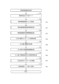
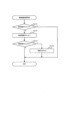
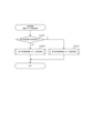
[機能フロー]
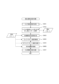
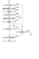
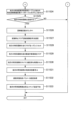
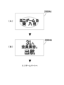
図1は、本発明の一実施形態に係るパチンコ遊技機の機能フローを示す図である。同図に示すように、パチンコゲームは、ユーザの操作により遊技球が発射され、その遊技球が各種入賞した場合に遊技球の払出制御処理が行われるゲームである。また、パチンコゲームには、特別図柄を用いる特別図柄ゲーム、普通図柄を用いる普通図柄ゲームが含まれる。なお、この明細書において、「パチンコ遊技機」と称する場合もあれば「パチンコ機」と称する場合もある。
[Function flow]
FIG. 1 is a diagram showing a functional flow of a pachinko gaming machine according to an embodiment of the present invention. As shown in the figure, the pachinko game is a game in which game balls are fired by user operations, and when the game balls win various prizes, a game ball payout control process is performed. Further, pachinko games include special symbol games using special symbols and normal symbol games using normal symbols. In addition, in this specification, it is sometimes referred to as a "pachinko gaming machine" and sometimes as a "pachinko machine."
特別図柄ゲームにおいて「大当り」となったときや、普通図柄ゲームにおいて「当り」となったときには、相対的に、遊技球が入賞する可能性が増大し、遊技球の払出制御処理が行われ易くなる。 When it becomes a "jackpot" in a special symbol game or a "hit" in a normal symbol game, the probability that the game ball will win increases relatively, and the payout control process for the game ball is more likely to be performed. Become.
また、各種入賞には、特別図柄ゲームにおいて特別図柄の可変表示が行われるための一つの条件である特別図柄始動入賞や、普通図柄ゲームにおいて普通図柄の可変表示が行われるための一つの条件である普通図柄始動入賞も含まれる。 In addition, various winnings include special symbol start winning, which is one of the conditions for variable display of special symbols in special symbol games, and one condition for variable display of normal symbols in normal symbol games. It also includes a certain normal symbol starting prize.
なお、本明細書でいう「可変表示」とは、変動可能に表示される概念であり、例えば、実際に変動して表示される「変動表示」、実際に停止して表示される「停止表示」等を可能にするものである。 Note that the term "variable display" as used herein refers to the concept of a variable display, such as a "fluctuating display" that actually changes and is displayed, and a "stop display" that actually stops and is displayed. ”, etc.
また、「可変表示」では、例えば特別図柄ゲームの結果として特別図柄(識別情報)が表示される「導出表示」を行うことができる。すなわち、本明細書では、「変動表示」の開始から「導出表示」までの動作を1回の「可変表示」と称する。 Further, in the "variable display", for example, a "derivation display" in which a special symbol (identification information) is displayed as a result of a special symbol game can be performed. That is, in this specification, the operation from the start of the "variable display" to the "derived display" is referred to as one "variable display."
以下、特別図柄ゲーム及び普通図柄ゲームの処理フローの概要を説明する。 Hereinafter, an outline of the processing flow of the special symbol game and the normal symbol game will be explained.
(1)特別図柄ゲームにおいて特別図柄始動入賞があった場合には、大当り判定用カウンタ及び図柄決定用カウンタからそれぞれ乱数値(大当り判定用乱数値及び図柄決定用乱数値)が抽出され、抽出された各乱数値が記憶される(図1に示す特別図柄ゲーム中の特別図柄始動入賞処理のフロー参照)。 (1) When a special symbol starts winning in a special symbol game, random values (random value for jackpot determination and random value for symbol determination) are extracted from the jackpot determination counter and the symbol determination counter, respectively. Each random number value is stored (see the flow of the special symbol start winning process in the special symbol game shown in FIG. 1).
また、図1に示すように、特別図柄ゲーム中の特別図柄制御処理では、最初に、特別図柄の可変表示を開始する条件が成立したか否かが判定される。この判定処理では、特別図柄始動入賞によって乱数値が記憶されているか否かを参照し、乱数値が記憶されていることを一つの条件として、特別図柄の可変表示を開始する条件が成立したと判定する。 Further, as shown in FIG. 1, in the special symbol control process during the special symbol game, it is first determined whether a condition for starting variable display of the special symbol is satisfied. In this determination process, it is determined whether or not a random number value is stored due to the special symbol starting winning, and with one condition that the random number value is stored, it is determined that the condition for starting variable display of the special symbol is satisfied. judge.
次いで、特別図柄の可変表示を開始する場合、大当り判定用カウンタから抽出された大当り判定用乱数値が参照され、「大当り」とするか否かの大当り判定が行われる。その後、停止図柄決定処理が行われる。この処理では、図柄決定用カウンタから抽出された図柄決定用乱数値と、上述した大当り判定の結果とが参照され、停止表示させる特別図柄を決定する。 Next, when starting variable display of special symbols, the jackpot determination random number value extracted from the jackpot determination counter is referred to, and a jackpot determination is made as to whether or not it is a "jackpot". After that, a stop symbol determination process is performed. In this process, the random number value for symbol determination extracted from the symbol determination counter and the result of the above-mentioned jackpot determination are referred to, and a special symbol to be stopped and displayed is determined.
次いで、変動パターン決定処理が行われる。この処理では、変動パターン決定用カウンタから乱数値が抽出され、その乱数値と、上述した大当り判定の結果と、上述した停止表示させる特別図柄とが参照され、特別図柄の変動パターンを決定する。 Next, a variation pattern determination process is performed. In this process, a random number value is extracted from a counter for determining a variation pattern, and the random number value, the result of the above-mentioned jackpot determination, and the above-mentioned special symbol to be stopped and displayed are referred to, and a variation pattern of the special symbol is determined.
次いで、演出パターン決定処理が行われる。この処理では、演出パターン決定用カウンタから乱数値が抽出され、その乱数値と、上述した大当り判定の結果と、上述した停止表示させる特別図柄と、上述した特別図柄の変動パターンとが参照され、特別図柄の可変表示に伴って実行する演出パターンを決定する。 Next, performance pattern determination processing is performed. In this process, a random value is extracted from the production pattern determining counter, and the random value, the result of the jackpot determination described above, the special symbol to be stopped and displayed, and the variation pattern of the special symbol described above are referred to, A performance pattern to be executed in conjunction with the variable display of special symbols is determined.
次いで、決定された大当り判定の結果、停止表示させる特別図柄、特別図柄の変動パターン、及び、特別図柄の可変表示に伴う演出パターンが参照され、特別図柄の可変表示の制御を行う可変表示制御処理、及び、所定の演出を行う演出制御処理が実行される。 Next, as a result of the determined jackpot determination, the special symbol to be stopped and displayed, the variation pattern of the special symbol, and the performance pattern accompanying the variable display of the special symbol are referred to, and a variable display control process is performed to control the variable display of the special symbol. , and performance control processing for performing a predetermined performance.
そして、可変表示制御処理及び演出表示制御処理が終了すると、「大当り」となるか否かが判定される。この判定処理において、「大当り」となったと判定されると、大当り遊技を行う大当り遊技制御処理が実行される。なお、大当り遊技では、上述した各種入賞の可能性が増大する。一方、「大当り」とならなかったと判定されると、大当り遊技制御処理が実行されない。 Then, when the variable display control process and the effect display control process are completed, it is determined whether or not there is a "big hit". In this determination process, if it is determined that a "jackpot" has been achieved, a jackpot game control process for performing a jackpot game is executed. In addition, in the jackpot game, the possibility of winning the various prizes mentioned above increases. On the other hand, if it is determined that the "big hit" has not occurred, the jackpot game control process is not executed.
「大当り」とならなかったと判定された場合、又は、大当り遊技制御処理が終了した場合には、遊技状態を移行させるための遊技状態移行制御処理が行われる。この遊技状態移行制御処理では、大当り遊技状態とは異なる通常時の遊技状態の管理が行われる。 If it is determined that the "big hit" has not been achieved, or if the jackpot game control process has ended, a game state transition control process is performed to shift the game state. In this gaming state transition control process, the normal gaming state, which is different from the jackpot gaming state, is managed.
通常時の遊技状態としては、例えば、上述した大当り判定において、「大当り」と判定される確率が増大する遊技状態(以下、「確変遊技状態」という)や、特別図柄始動入賞が得られやすくなる遊技状態(以下、「時短遊技状態」という)などが挙げられる。その後、再度、特別図柄の可変表示を開始させるか否かの判定処理を行い、その後は、上述した特別図柄制御処理の各種処理が繰り返される。 As a normal gaming state, for example, in the above-mentioned jackpot determination, a gaming state in which the probability of being judged as a "jackpot" increases (hereinafter referred to as "probability variable gaming state"), or a special symbol starting winning is easier to obtain. Examples include a gaming state (hereinafter referred to as a "time-saving gaming state"). After that, the process of determining whether or not to start variable display of the special symbols is performed again, and thereafter, various processes of the special symbol control process described above are repeated.
なお、本実施形態のパチンコ遊技機において、特別図柄の変動表示中に遊技球が始動入賞した場合には、該始動入賞時に取得される各種データ(大当り判定用乱数値、図柄決定用乱数値等)が保留される。 In addition, in the pachinko game machine of this embodiment, when the game ball starts winning while the special symbol is being displayed in a variable manner, various data acquired at the time of starting winning (random value for jackpot determination, random value for determining symbol, etc.) ) will be put on hold.
すなわち、特別図柄の変動表示中に遊技球が始動入賞した場合には、該始動入賞に対応する特別図柄の可変表示(変動表示)が保留され、現在実行されている特別図柄の変動表示終了後に保留されている特別図柄の可変表示が開始される。以下では、保留されている特別図柄の可変表示を「保留球」ともいう。 In other words, if a game ball starts winning while a special symbol is being displayed in a variable manner, the variable display (variable display) of the special symbol corresponding to the starting prize is suspended, and after the variable display of the currently executed special symbol ends. Variable display of the reserved special symbols is started. Hereinafter, the variable display of the reserved special symbol will also be referred to as a "reserved ball."
また、本実施形態のパチンコ遊技機では、後述するように、2種類の特別図柄始動入賞(第1始動口入賞及び第2始動口入賞)を設け、各特別図柄始動入賞に対して最大4個の保留球を取得することができる。すなわち、本実施形態では、最大8個の保留球を取得することができる。 In addition, in the pachinko game machine of this embodiment, as will be described later, two types of special symbol starting winnings are provided (first starting opening winning and second starting opening winning), and a maximum of four winnings are provided for each special symbol starting winning. It is possible to obtain a reserved ball. That is, in this embodiment, a maximum of eight reserved balls can be acquired.
なお、本実施形態のパチンコ遊技機は、図1には示さないが、上述した保留球の情報に基づいて保留球の当落(「大当り」当選の有無)や変動パターンを判定し、さらに、その判定結果に基づいて所定の演出を行う機能、すなわち先読み演出機能を備えていてもよい。 Although not shown in FIG. 1, the pachinko gaming machine of the present embodiment determines the winning or losing of the held balls (whether or not there is a "jackpot" win) and the fluctuation pattern based on the above-mentioned information on the held balls, and further determines the fluctuation pattern. It may be provided with a function of performing a predetermined effect based on the determination result, that is, a pre-read effect function.
(2)普通図柄ゲームにおいて普通図柄始動入賞があった場合には、当り判定用カウンタから乱数値が抽出され、その乱数値が記憶される(図1に示す普通図柄ゲーム中の普通図柄始動入賞処理のフロー参照)。 (2) When there is a normal symbol starting prize in the normal symbol game, a random value is extracted from the hit determination counter and the random value is stored (normal symbol starting winning in the normal symbol game shown in Figure 1). (See processing flow).
また、図1に示すように、普通図柄ゲーム中の普通図柄制御処理では、最初に、普通図柄の可変表示を開始する条件が成立したか否かが判定される。この判定処理では、普通図柄始動入賞によって乱数値が記憶されているか否かが参照され、乱数値が記憶されていることを一つの条件として、普通図柄の可変表示を開始する条件が成立したと判定する。 Further, as shown in FIG. 1, in the normal symbol control process during the normal symbol game, it is first determined whether a condition for starting variable display of the normal symbols is satisfied. In this judgment process, it is referenced whether or not a random number value is stored due to the normal symbol starting winning, and with one condition that the random number value is stored, it is assumed that the condition for starting the variable display of the normal symbol is satisfied. judge.
次いで、普通図柄の可変表示を開始する場合、当り判定用カウンタから抽出された乱数値が参照され、「当り」とするか否かの当り判定が行われる。その後、変動パターン決定処理が行われる。この処理では、当り判定の結果が参照され、普通図柄の変動パターンを決定する。 Next, when starting the variable display of the normal symbols, the random value extracted from the hit determination counter is referred to and a hit determination is made as to whether or not it is a "win". After that, a variation pattern determination process is performed. In this process, the result of the hit determination is referred to and the variation pattern of the normal symbols is determined.
次いで、決定された当り判定の結果、及び、普通図柄の変動パターンが参照され、普通図柄の可変表示の制御を行う可変表示制御処理、及び、所定の演出を行う演出制御処理が実行される。 Next, the determined result of the hit determination and the fluctuation pattern of the normal symbols are referred to, and a variable display control process for controlling the variable display of the normal symbols and an effect control process for performing a predetermined effect are executed.
可変表示制御処理及び演出表示制御処理が終了すると、「当り」となるか否かが判定される。この判定処理において、「当り」となると判定されると、当り遊技を行う当り遊技制御処理が実行される。 When the variable display control process and the effect display control process are completed, it is determined whether or not there is a "win". In this determination process, if it is determined that it is a "win", a winning game control process for performing a winning game is executed.
当り遊技制御処理では、上述した各種入賞の可能性、特に、特別図柄ゲームにおける遊技球の特別図柄始動入賞の可能性が増大する。一方、「当り」とならないと判定されると、当り遊技制御処理が実行されない。その後、再度、普通図柄の可変表示を開始させるか否かの判定処理を行い、その後は、上述した普通図柄制御処理の各種処理が繰り返される。 In the winning game control process, the possibility of winning the various prizes mentioned above increases, especially the possibility of winning a special symbol starting prize of the game ball in the special symbol game. On the other hand, if it is determined that it is not a "win", the winning game control process is not executed. After that, the process of determining whether to start the variable display of the normal symbols is performed again, and thereafter, the various processes of the normal symbol control process described above are repeated.
上述のように、パチンコゲームでは、特別図柄ゲームにおいて「大当り」となるか否か、遊技状態の移行状況、普通図柄ゲームにおいて「当り」となるか否か等の条件により、遊技球の払出制御処理の行われ易さが変化する。 As mentioned above, in a pachinko game, the payout of game balls is controlled based on conditions such as whether or not there will be a "jackpot" in the special symbol game, the transition status of the gaming state, and whether or not there will be a "win" in the normal symbol game. Ease of processing changes.
なお、本実施形態において、各種の乱数値の抽出方式としては、プログラムを実行することによって乱数値を生成するソフト乱数方式を用いる。しかしながら、本発明はこれに限定されず、例えば、パチンコ遊技機が、所定周期で乱数が更新される乱数発生器を備える場合には、その乱数発生器におけるカウンタ(いわゆる、リングカウンタ)から乱数値を抽出するハード乱数方式を、上述した各種乱数値の抽出方式として採用してもよい。 In this embodiment, as a method for extracting various random numbers, a soft random number method is used in which random numbers are generated by executing a program. However, the present invention is not limited to this, and for example, if a pachinko game machine is equipped with a random number generator whose random numbers are updated at a predetermined period, a random number is obtained from a counter (so-called ring counter) in the random number generator. A hard random number method for extracting may be adopted as the method for extracting the various random numbers described above.
なお、ハード乱数方式を用いる場合は、所定周期とは異なるタイミングで、乱数値の初期値を決定することによって、所定周期で同じ乱数値が抽出されることを防止することができる。 Note that when using the hard random number method, by determining the initial value of the random number value at a timing different from the predetermined cycle, it is possible to prevent the same random number value from being extracted at the predetermined cycle.
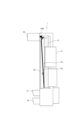
[パチンコ遊技機の構造]
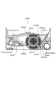
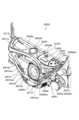
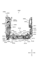
次に、図2~図4を参照して、本実施形態におけるパチンコ遊技機の構造について説明する。図2は、パチンコ遊技機の正面図、図3は、パチンコ遊技機の外観を示す斜視図、図4は、パチンコ遊技機の分解斜視図である。なお、以下の説明においては、基本的に特に断らない限り、パチンコ遊技機1の正面側を前方向、パチンコ遊技機1の背面側を後方向、パチンコ遊技機1の前方から見て左側を左方向、パチンコ遊技機1の前方から見て右側を右方向、パチンコ遊技機1の上側を上方向、パチンコ遊技機1の下側を下方向、パチンコ遊技機1を正面から見て時計回りの方向を右回りの方向、その逆に反時計回りの方向を左回りの方向として説明する。
[Structure of pachinko machine]
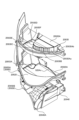
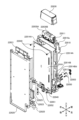
Next, the structure of the pachinko game machine in this embodiment will be explained with reference to FIGS. 2 to 4. FIG. 2 is a front view of the pachinko game machine, FIG. 3 is a perspective view showing the external appearance of the pachinko game machine, and FIG. 4 is an exploded perspective view of the pachinko game machine. In the following explanation, unless otherwise specified, the front side of the
パチンコ遊技機1は、図2及び図3に示すように、本体2と、本体2に対して開閉自在に取り付けられたベースドア3と、ベースドア3に対して開閉自在に取り付けられたガラスドア4とを備える。
As shown in FIGS. 2 and 3, the
[本体]
本体2は、長方形状の開口2aを有する枠状部材で構成される(図4参照)。この本体2は、例えば、木材等の材料により形成される。
[Body]
The
[ベースドア]
ベースドア3は、本体2の外形形状と略等しい長方形の外形形状を有する板状部材で構成される。ベースドア3は、本体2の前方(パチンコ遊技機1の正面側)に配置されており、ベースドア3を本体2の一方の側辺端部を軸にして回動させることにより、本体2の開口2aが開閉される。
[Base door]
The
ベースドア3には、図4に示すように、四角形状の開口3aが設けられる。この開口3aは、ベースドア3の略中央部から上側の領域に渡って形成され、該領域の大部分を占有する大きさで形成される。
As shown in FIG. 4, the
また、ベースドア3には、スピーカ11と、遊技盤12と、皿ユニット14と、発射装置15と、払出ユニット16と、基板ユニット17とが取り付け可能である。遊技盤12には、液晶表示装置13が取り付けられる。なお、液晶表示装置13は、遊技盤12に取り付けず、遊技盤12の背面側に、遊技盤12との間に間隔が存在する状態で配設されていてもよい。
Furthermore, a
スピーカ11は、ベースドア3の上部(上端部付近)に配置される。遊技盤12は、ベースドア3の前方(パチンコ遊技機1の正面側)に配置され、ベースドア3の開口3aを覆うように配置される。
The
遊技盤12は、光透過性を有する板形状の樹脂部材で構成される。なお、光透過性を有する樹脂としては、例えば、アクリル樹脂、ポリカーボネート樹脂、メタクリル樹脂等を用いることができる。
The
また、遊技盤12の前面(パチンコ遊技機1の正面側の表面)には、発射装置15から発射された遊技球が転動する遊技領域12aが形成される。この遊技領域12aは、ガイドレール(具体的には後述のガラスドア4の開口4aを囲む図示しない外レール41a)に囲まれた領域であり、その外周形状は略円状である。
Further, on the front surface of the game board 12 (the front surface of the pachinko game machine 1), a
さらに、遊技領域12aには、図示しない複数の遊技釘が打ちこまれている。なお、遊技盤12(遊技領域12a)の構成については、図5(a)を参照して後述する。
Furthermore, a plurality of game nails (not shown) are driven into the
液晶表示装置13は、遊技盤12の背面側(パチンコ遊技機1の正面側とは反対側)に取り付けられる。この液晶表示装置13は、画像を表示する表示領域13aを有する。表示領域13aの大きさは、遊技盤12の表面一部の領域を占めるような大きさに設定される。なお、液晶表示装置13の表示領域13aの大きさは、遊技盤12の表面全体の領域を占める大きさであってもよい。
The liquid
この液晶表示装置13の表示領域13aには、演出用の識別図柄(装飾図柄)、演出画像、装飾用画像等の各種画像が表示される。遊技者は、遊技盤12を介して、液晶表示装置13の表示領域13aに表示された各種画像を視認することができる。
In the
なお、本実施形態では、表示装置として液晶表示装置13を用いたが、本発明はこれに限定されず、液晶表示装置13に代えて、例えば、プラズマディスプレイ、リアプロジェクションディスプレイ、CRT(Cathode Ray Tube)ディスプレイ等の表示機器を適用してもよい。
In this embodiment, the liquid
また、遊技盤12の背面側(パチンコ遊技機1の正面側とは反対側)には、スペーサ19が設けられる。このスペーサ19は、遊技盤12の背面(パチンコ遊技機1の背面側の表面)と液晶表示装置13の前面(パチンコ遊技機1の正面側の表面)との間に設けられ、遊技盤12の遊技領域12aを転動する遊技球の流路となる空間を形成する。
Further, a
スペーサ19は、光透過性を有する材料で形成される。なお、本発明はこれに限定されず、スペーサ19は、例えば、一部が光透過性を有する材料で形成されていてもよいし、光透過性を有さない材料で形成されていてもよい。
The
皿ユニット14は、遊技盤12の下方に配置される。この皿ユニット14は、上皿21と、その下方に配置された下皿22とを有する。上皿21及び下皿22には、遊技球の貸出、遊技球の払出(賞球)を行うための払出口21a及び払出口22aがそれぞれ形成される。
The
所定の払出条件が成立した場合には、払出口21a又は払出口22aから遊技球が排出され、それぞれ排出された遊技球が上皿21や下皿22に貯留される。また、上皿21に貯留された遊技球は、発射装置15によって遊技領域12aに発射される。
When predetermined payout conditions are met, game balls are ejected from the
また、皿ユニット14には、演出ボタン23が設けられる。この演出ボタン23は、上皿21上に取り付けられる。また、演出ボタン23の周縁には、ジョグダイヤル24が演出ボタン23に対して回転可能に取り付けられる。
Further, the
本実施形態のパチンコ遊技機1は、演出ボタン23及びジョグダイヤル24の少なくともいずれか一方を用いて行う所定の演出機能を有し、所定の演出を行う場合には、液晶表示装置13の表示領域13aに、演出ボタン23及びジョグダイヤル24の少なくともいずれか一方の操作を促す画像が表示される。
The
発射装置15は、ベースドア3の前面において、右下の領域(右下角部付近)に配置される。この発射装置15は、遊技者によって操作可能な発射ハンドル25と、皿ユニット14の右下部に係合するパネル体26とを備える。発射ハンドル25は、パネル体26の前面側に配置され、パネル体26に回動可能に支持される。
The
なお、図2~図4には示さないが、パネル体26の背面側には、遊技球の発射動作を制御するソレノイドアクチュエータが設けられる。また、図2~図4には示さないが、発射ハンドル25の周縁部には、タッチセンサが設けられ、発射ハンドル25の内部には、発射ボリュームが設けられる。発射ボリュームは、発射ハンドル25の回動量に応じて抵抗値を変化させ、ソレノイドアクチュエータに供給する電力を変化させる。
Although not shown in FIGS. 2 to 4, a solenoid actuator for controlling the firing operation of the game ball is provided on the back side of the
本実施形態のパチンコ遊技機1では、遊技者の手が発射ハンドル25のタッチセンサに接触すると、タッチセンサは検知信号を出力する。これにより、遊技者が発射ハンドル25を握持したことが検知され、ソレノイドアクチュエータによる遊技球の発射が可能になる。
In the
そして、遊技者が発射ハンドル25を把持して時計回り(遊技者側から見て右回り)の方向へ回動操作すると、発射ハンドル25の回動角度に応じて発射ボリュームの抵抗値が変化し、その抵抗値に対応する電力がソレノイドアクチュエータに供給される。その結果、上皿21に貯留された遊技球が順次発射され、発射された遊技球は、ガイドレールに案内されて遊技盤12の遊技領域12aへ放出される。
When the player grasps the firing handle 25 and rotates it clockwise (clockwise when viewed from the player's side), the resistance value of the firing volume changes according to the rotation angle of the
また、図2~図4には示さないが、発射ハンドル25の側部には、発射停止ボタンが設けられる。発射停止ボタンは、ソレノイドアクチュエータによる遊技球の発射を停止させるために設けられたボタンである。遊技者が発射停止ボタンを押下すると、発射ハンドル25を把持して回動させた状態であっても、遊技球の発射が停止される。
Although not shown in FIGS. 2 to 4, a firing stop button is provided on the side of the
払出ユニット16及び基板ユニット17は、ベースドア3の背面側に配置される。払出ユニット16には、貯留ユニット(不図示)から遊技球が供給される。払出ユニット16は、貯留ユニットから供給された遊技球の中から、払出条件の成立に基づいて、所定個数の遊技球を上皿21又は下皿22に払い出す。
The
基板ユニット17は、各種制御基板を有する。各種制御基板には、後述する主制御回路70や副制御回路200、払出・発射制御回路300等が設けられる(後述の図8参照)。
The
[ガラスドア]
ガラスドア4は、矩形枠状に形成される。また、ガラスドア4は、遊技盤12の前面側に配置され、遊技盤12を覆う大きさを有する。このガラスドア4の前面において、スピーカ11と対向する上部領域には、上部装飾ユニット58が設けられる。上部装飾ユニット58は、パチンコ遊技機1の前方に突出するように配置されている。
[Glass door]
The
また、ガラスドア4の中央部において、遊技盤12の遊技領域12aと対向する領域には、少なくとも遊技領域12aを露出させるような大きさの開口4aが形成される。ガラスドア4の開口4aは、光透過性を有する保護ガラス28が取り付けられ、これにより、開口4aが塞がれる。
Furthermore, in the center of the
したがって、ガラスドア4をベースドア3に対して閉じると、保護ガラス28は、遊技盤12の少なくとも遊技領域12aに対面するように配置される。図2に示すように、ガラスドア4の開口4aの左右両端及び下端には、電飾カバー58A~58Cが設けられている。電飾カバー58A~58Cの後面には、LED(Light Emitting Diode)59A~59C(図8参照)が設けられている。LED59A~59Cは、液晶表示装置13に表示される演出、演出ボタン、電飾カバー58A、58Bの発光などと連動して点灯あるいは点滅するように制御される。
Therefore, when the
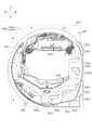
[遊技盤]
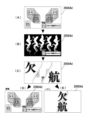
次に、遊技盤12の構成について、図5(a)を参照して説明する。図5(a)は、遊技盤12の構成を示す正面図である。
[Game board]
Next, the configuration of the
遊技盤12の前面には、図5(a)に示すように、ガイドレール41と、球通過検出器43と、第1始動口44と、第2始動口45と、普通電動役物46とが設けられる。また、遊技盤12の前面には、一般入賞口51、52と、第1大入賞口53と、第2大入賞口54と、アウト口55と、図示しない複数の遊技釘とが設けられる。
On the front side of the
また、遊技盤12の前面において第2大入賞口54付近は、膨出カバー(図示略)が設けられており、膨出カバーは、遊技盤12の前面から前方に膨れ出ている。以後、遊技盤12の前方とは、遊技盤12に対して遊技者側を表し、遊技盤12の後方とは、遊技盤12に対して遊技者側と反対側を表す。また、遊技盤12に対して右側、左側とは、遊技盤12を正面から見て右側、左側を表す。したがって、遊技盤12を後方から見た場合には、紙面において遊技盤12の右側が左側となり、遊技盤12の左側が右側となる。
Further, on the front surface of the
さらに、遊技盤12の前面において、その右下部には、特別図柄表示装置61と、普通図柄表示装置62と、普通図柄保留表示装置63と、第1特別図柄保留表示装置64と、第2特別図柄保留表示装置65とが設けられる(図5(a)において符号省略し、図8参照)。
Furthermore, on the front side of the
なお、本実施形態では、特別図柄の停止表示の結果が「大当り」である場合に点灯する報知LEDや、大当り遊技中のラウンド数を表示するラウンド数表示LED等を設けてもよい。 In addition, in this embodiment, a notification LED that lights up when the result of the stop display of the special symbol is a "jackpot", a round number display LED that displays the number of rounds during the jackpot game, etc. may be provided.
[遊技領域の各種構成部材]
ガイドレール41は、遊技領域12aを区画するように円弧状に延在し、ガラスドア4の開口4aを囲む図示しない外レール41a(図5(a)において破線で示す)と、この外レール41aの内側(内周側)に配置されて円弧状に延在する内レール41bとで構成される。
[Various components of the gaming area]
The
遊技領域12aは、外レール41aの内側に形成される。外レール41a及び内レール41bは、遊技者側から見て、遊技領域12aの左側端部付近において互いに対向するように配置され、これにより、外レール41aと内レール41bとの間に、発射装置15によって発射された遊技球を遊技領域12aの上部へと案内するガイド経路41cが形成される。
The
また、遊技領域12aの左側上部に位置する内レール41bの先端部には、該内レール41bの先端部と、それと対向する外レール41aの一部とにより、玉放出口41dが形成される。そして、内レール41bの先端部には、玉放出口41dを塞ぐようにして、玉戻り防止片42が設けられる。
Further, a
この玉戻り防止片42は、玉放出口41dから遊技領域12aに放出された遊技球が、再び玉放出口41dを通過してガイド経路41cに進入することを防止する。
This ball
玉放出口41dから放出された遊技球は、遊技領域12aの上部から下部に向かって流下する。この際、遊技球は、複数の遊技釘、第1始動口44、第2始動口45等の遊技領域12aに設けられた各種部材に衝突して、その進行方向を変えながら遊技領域12aの上部から下部に向かって流下する。
The game balls released from the
遊技領域12aの略中央には、液晶表示装置13の表示領域13aが設けられる。この表示領域13aの上端には、障害物13bが設けられる。障害物13bを設けることにより、遊技球は、遊技領域12a内の表示領域13aと重なる領域上を通過しない。
A
球通過検出器43は、遊技者側から見て、表示領域13aの右側における第1大入賞口53の上部付近に配置される。球通過検出器43には、通過する遊技球を検出するための通過球センサ43a(後述の図8参照)が設けられる。また、球通過検出器43を遊技球が通過することにより、普通図柄ゲームの「当り」か否かの抽選が行われ、該抽選の結果に基づいて普通図柄の変動表示が開始される。
The
第1始動口44は、表示領域13aの下方に配置され、第2始動口45は、第1始動口44の下方に配置される。第1始動口44及び第2始動口45は、遊技球を受け入れ可能な部材で構成される。
The
以下、遊技球が第1始動口44又は第2始動口45に入ること又は通過することを「入賞」という。そして、遊技球が第1始動口44又は第2始動口45に入賞すると、所定数(例えば3個)の遊技球が払い出される。
Hereinafter, the game ball entering or passing through the
また、第1始動口44に遊技球が入球することにより、「大当り」であるか否かの抽選及び「小当り」であるか否かの抽選が行われ、該抽選の結果に基づいて第1特別図柄の変動表示が開始される。さらに、第2始動口45に遊技球が入球することにより、「大当り」であるか否かの抽選が行われ、該抽選の結果に基づいて第2特別図柄の変動表示が開始される。第1特別図柄及び第2特別図柄は、それぞれ特図1及び特図2という場合がある。
Furthermore, when a game ball enters the
第1始動口44には、入賞した遊技球を検出するための第1始動口入賞球センサ44a(後述の図8参照)が設けられる。また、第2始動口45には、第2始動口45に入賞した遊技球を検出するための第2始動口入賞球センサ45a(後述の図8参照)が設けられる。なお、第1始動口44及び第2始動口45に入賞した遊技球は、遊技盤12に設けられた回収口(不図示)を通過して遊技球の回収部(不図示)に搬送される。
The first starting opening 44 is provided with a first starting opening winning
普通電動役物46は、第2始動口45に設けられる。普通電動役物46は、遊技盤12の前後方向に前傾姿勢・後退姿勢をなすように開閉動作する羽根状の部材であり、第2始動口45への遊技球の入賞を可能とする開放状態と、第2始動口45への遊技球の入賞を不可能又は困難とする閉鎖状態とを切り替え可能に構成されている。普通電動役物46は、普通電動役物ソレノイド46a(後述の図8参照)により開閉駆動される。
A normal
なお、本実施形態では、普通電動役物46が閉鎖状態である場合、一対の羽根部材の開口形態を、入賞不可能にする形態でなく、遊技球の入賞が困難になるような形態にしてもよい。また、普通電動役物46としては、羽根状の部材を前後方向に開閉するように動作させるものに限らず、例えば遊技盤12の左右方向に回動することで始動口を拡開するいわゆる電動チューリップ型のものや、遊技盤12の前後方向に水平移動することで始動口を開閉する舌状部材であってもよい。
In addition, in this embodiment, when the normal
一般入賞口51は、遊技者側から見て、遊技領域12aの左下部付近に配置される。また、一般入賞口52は、球通過検出器43の右方に配置され、かつ、遊技者側から見て、遊技領域12aの右下部付近に配置される。
The general winning
一般入賞口51及び一般入賞口52は、遊技球を受け入れ可能な部材で構成される。以下では、遊技球が一般入賞口51又は一般入賞口52に入ること又は通過することもまた、「入賞」という。一般入賞口51又は一般入賞口52に遊技球が入賞すると、所定数(例えば10個)の遊技球が払い出される。
The general winning
一般入賞口51には、入賞した遊技球を検出するための一般入賞球センサ51a(後述の図8参照)が設けられる。また、一般入賞口52には、一般入賞口52に入賞した遊技球を検出するための一般入賞球センサ52a(後述の図8参照)が設けられる。
The general winning
第1大入賞口53及び第2大入賞口54は、球通過検出器43の下方で、かつ、第1始動口44及び第2始動口45の右方に配置される。第1大入賞口53及び第2大入賞口54は、遊技球の流路に沿って上下方向に配置され、第1大入賞口53は、第2大入賞口54の上方に配置される。
The first big winning
第1大入賞口53及び第2大入賞口54は、ともに、いわゆるアタッカー式の開閉装置であり、開閉可能なシャッタ53a,54aと、これらのシャッタ53a,54aを駆動させるソレノイドアクチュエータ(後述の図8中の第1大入賞口ソレノイド53b及び第2大入賞口ソレノイド54b)とを有する。
The first big winning
第1大入賞口53及び第2大入賞口54のそれぞれは、対応するシャッタ53a,54aが開いている状態(開放状態)のときに遊技球を受け入れ、シャッタが閉じている状態(閉鎖状態)のときには遊技球を受け入れない。
Each of the first big winning
以下では、遊技球が第1大入賞口53又は第2大入賞口54に入ること又は通過することもまた、「入賞」という。第1大入賞口53に遊技球が入賞すると、所定数(例えば10個)の遊技球が払い出される。一方、第2大入賞口54に遊技球が入賞すると、所定数(例えば15個)の遊技球が払い出される。
Hereinafter, entering or passing the game ball into the first grand prize opening 53 or the second
また、第1大入賞口53には、入賞した遊技球を計数するためのカウントセンサ53c(後述の図8参照)が設けられる。さらに、第2大入賞口54には、入賞した遊技球を計数するためのカウントセンサ54c(図5(a)及び後述の図8参照)が設けられる。
Further, the first
本実施形態のパチンコ遊技機1において、第1大入賞口53は、遊技球が複数個同時に入賞可能となるように比較的横幅寸法が大きい開口として遊技盤12の前面に形成されている一方、第2大入賞口54は、遊技球が1個ずつ入賞し得るように比較的寸法が小さい開口として図示しない膨出カバーの上端面一部に形成されている。
In the
第1大入賞口53に対応するシャッタ53aは、遊技盤12の前後方向に前傾姿勢・後退姿勢をなすように開閉動作することにより、第1大入賞口53を開放状態あるいは閉鎖状態に切り替えるものであり、閉鎖状態において第1大入賞口53を覆うように配置されている。すなわち、シャッタ53aは、第1大入賞口53への遊技球の入賞が可能な開放状態と、遊技球の入賞が不可能又は困難な閉鎖状態とに変化するように第1大入賞口ソレノイド53b(後述の図8参照)により駆動される。
The
第2大入賞口54に対応するシャッタ54aは、遊技盤12の前後方向に水平移動することにより、第2大入賞口54を開放状態あるいは閉鎖状態に切り替えるものであり、閉鎖状態において第2大入賞口54を覆うように配置されている。すなわち、シャッタ54aは、第2大入賞口54への遊技球の入賞が可能な開放状態と、遊技球の入賞が不可能又は困難な閉鎖状態とに変化するように第2大入賞口ソレノイド54b(後述の図8参照)により駆動される。
The
また、本実施形態のパチンコ遊技機1において、膨出カバーの内側には、第2大入賞口54を通過してカウントセンサ54cにより検知された遊技球が通過可能な特定領域38A及び非特定領域38Bが設けられている。第2大入賞口54から特定領域38A及び非特定領域38Bに至る遊技球の球通路は、膨出カバーの内面に設けられた仕切り壁(図示略)により形成される。第2大入賞口54に入賞した遊技球は、特定領域38A及び非特定領域38Bのいずれか一方を通過した後、遊技盤12の背後へと導かれて回収される。第2大入賞口54から特定領域38A及び非特定領域38Bへと至るまでの球通路の途中位置には、カウントセンサ54cが配置されている。特定領域38Aには、特定領域センサ380Aが配置されており、特定領域38Aにおける遊技球の通過は、特定領域センサ380Aにより検出される。非特定領域38Bには、非特定領域センサ380Bが配置されており、非特定領域38Bへの遊技球の通過は、非特定領域センサ380Bにより検知される。また、特定領域38Aの近傍には、これを開閉するための変位部材39が設けられている。
In addition, in the
変位部材39は、遊技盤12の前後方向に水平移動することにより、特定領域38Aを開放状態あるいは閉鎖状態に切り替えるものであり、閉鎖状態では特定領域38Aを覆うように位置する。すなわち、変位部材39は、特定領域38Aへの遊技球の通過が容易な開放状態と、通過が不可能又は困難な閉鎖状態とに変化するように変位部材ソレノイド390(後述の図8参照)により駆動される。特定領域38Aが閉鎖状態にある場合、特定領域38Aを通過できない遊技球は、非特定領域38Bを通過することとなる。
The
以下では、遊技球が特定領域38Aを通過することを、「V入賞」という場合がある。また、特定領域38Aが設けられた第2大入賞口54については、「Vアタッカー」という場合がある。本実施形態のパチンコ遊技機1において、V入賞に成功した大当り遊技状態の終了後は、確変遊技状態に移行する。そのため、V入賞を「V確」という場合がある。変位部材39については、「Vベロ」という場合がある。
Hereinafter, passing the game ball through the
なお、V入賞を実現するための構成としては、図5(b)に示すような構成としてもよい。すなわち、第2大入賞口54の内部には、下方へと遊技球を導くための球通路が形成され、球通路の下端には、左右に隣接するように特定領域38Aと非特定領域38Bとを設ける。第2大入賞口54から球通路へと進入する位置には、カウントセンサ54cが配置される。特定領域38Aには、特定領域センサ380Aが配置されており、特定領域38Aへの遊技球のV入賞は、特定領域センサ380Aにより検出される。非特定領域38Bには、非特定領域センサ380Bが配置されており、非特定領域38Bへの遊技球の通過は、非特定領域センサ380Bにより検知される。そして、球通路において特定領域38A及び非特定領域38Bの近傍には、左右に回動可能な変位部材39を設ける。変位部材39は、実線で示す姿勢が変位後の開放姿勢であり、仮想線で示す位置が通常の閉鎖姿勢である。
Note that the configuration for realizing the V winning may be a configuration as shown in FIG. 5(b). That is, a ball path for guiding the game ball downward is formed inside the second
変位部材39は、特定領域38Aを開放状態あるいは閉鎖状態に切り替えるものである。変位部材39は、実線で示す開放姿勢にあるとき、特定領域38Aを開放状態とし、当該特定領域38Aへの遊技球のV入賞を容易な状態とする。このとき、変位部材39は、球通路の右側にある特定領域38Aへと遊技球を案内する。これにより、第2大入賞口54から球通路へと導かれてきた遊技球は、特定領域38Aを通過することでV入賞となる。また、変位部材39は、仮想線で示す閉鎖姿勢にあるとき、特定領域38Aを閉鎖状態とし、当該特定領域38Aへの遊技球のV入賞を不可能あるいは困難な状態とするとともに、球通路の左側にある非特定領域38Bへと遊技球を案内する。これにより、第2大入賞口54から球通路へと導かれてきた遊技球は、特定領域38Aを通過せずに非特定領域38Bを通過する。このような構成でもV入賞を実現することができる。なお、カウントセンサ54cが遊技球の通過を検出したときに賞球を払い出し、カウントセンサ54c、特定領域センサ380A、非特定領域センサ380Bからの信号に基づいて、第2大入賞口54から遊技球が排出されたか否か(第2大入賞口54内に遊技球が残留しているか否か)を判定するようにしてもよい。
The
アウト口55は、遊技領域12aの最下部に設けられる。このアウト口55は、第1始動口44、第2始動口45、一般入賞口51、52、第1大入賞口53及び第2大入賞口54のいずれにも入賞しなかった遊技球を受け入れる。
The out
本実施形態の遊技領域12aにおける各種構成部材の配置を図5(a)に示すような配置にすると、遊技者により遊技領域12aの右側の領域に遊技球が打ち込まれた場合(いわゆる右打ちの場合)、遊技釘等により遊技球が第2始動口45に誘導される。
When the various constituent members in the
この場合、第1始動口44に入賞する可能性はほとんどなくなる。なお、本実施形態では、第2始動口45に入賞した方が、第1始動口44に入賞した場合より、遊技者にとって有利な「大当り」の抽選を受け易くなる。
In this case, there is almost no possibility of winning in the
それゆえ、第2始動口45への入賞が比較的容易になるいわゆる「時短遊技状態」では、右打ちを行うことにより、第1始動口44への入賞の可能性(遊技者にとって不利な遊技状態となる可能性)を低くすることができる。
Therefore, in the so-called "time-saving gaming state" in which it is relatively easy to win a prize in the
膨出カバーは、第1大入賞口53の下方に設けられており、膨出カバーの上面は、傾斜面として形成されている。この傾斜面は、遊技者側から見て右上方から左下方に向かって左下がりに傾斜している。傾斜面は、遊技領域12aの上部から下部に向かって流下する遊技球を第2大入賞口54へと導くようになっており、傾斜面上を転動する遊技球が図示しないリブ等に衝突すると、遊技球の速度が低下してシャッタ54aが開放状態にある第2大入賞口54に遊技球が入賞し易くなる。
The bulging cover is provided below the first
また、図5(a)に示すように、遊技盤12の表示領域13aの周囲には電飾カバー58E~58Hが設けられており、電飾カバー58E~58Hの後面にはLED59e~59h(図8参照)が設けられている。電飾カバー58E~58Hは、LED59e~59hの点灯あるいは点滅によって演出表示を行う。
Further, as shown in FIG. 5(a), illumination covers 58E to 58H are provided around the
[液晶表示装置]
液晶表示装置13は、液晶で構成され、その表示領域13aにおいて各種演出表示を行う。
[Liquid crystal display device]
The liquid
具体的に、本実施形態では、後述する特別図柄表示装置61に表示される特別図柄と関連する(対応する)演出画像が表示領域13aに表示される。この際、例えば、特別図柄表示装置61において特別図柄が変動表示中であるときには、特定の場合を除いて、例えば、1~8までの数字や各種文字等からなる複数の演出用識別図柄(装飾図柄)が表示領域13aに変動表示される。
Specifically, in this embodiment, an effect image related to (corresponding to) a special symbol displayed on a special
そして、特別図柄表示装置61において特別図柄が停止表示されると、表示領域13aにも、特別図柄に対応する複数の装飾図柄が停止表示される。
When the special symbol is stopped and displayed on the special
そして、特別図柄表示装置61において停止表示された特別図柄が特定の態様である(停止表示の結果が「大当り」である)場合には、「大当り」であることを遊技者に把握させるための演出画像が表示領域13aに表示される。
Then, when the special symbol stopped and displayed on the special
「大当り」であることを遊技者に把握させるための演出としては、例えば、まず、停止表示された複数の装飾図柄が特定の態様(例えば、同一の装飾図柄が所定の方向に沿って並ぶ態様)となり、その後、「大当り」を報知する画像を表示するような演出が挙げられる。 For example, as an effect to make the player understand that it is a "jackpot", first, a plurality of decorative symbols that are stopped and displayed are arranged in a specific manner (for example, a manner in which the same decorative symbols are lined up along a predetermined direction). ), and then an image announcing a "big win" is displayed.
また、本実施形態では、液晶表示装置13の表示領域13aに、後述する第1特別図柄保留表示装置64及び第2特別図柄保留表示装置65の表示内容と関連する演出画像が表示される。例えば、表示領域13aには、特別図柄の可変表示の保留個数を報知する保留情報(例えば、保留個数と同じ数の保留用図柄)が表示される。また、例えば、本実施形態のパチンコ遊技機1では、特別図柄の保留球の情報に基づいて先読み演出を行うが、この際の予告報知も表示領域13aに表示される。
Moreover, in this embodiment, the
また、本実施形態では、後述する普通図柄表示装置62において停止表示された普通図柄が所定の態様であった場合に、その情報を遊技者に把握させる演出画像を液晶表示装置13の表示領域13aに表示させる機能をさらに設けてもよい。
In addition, in this embodiment, when the normal symbols stopped and displayed on the normal symbol display device 62 (described later) are in a predetermined manner, an effect image that allows the player to grasp the information is displayed in the
[特別図柄表示装置]
特別図柄表示装置61は、液晶表示装置13の表示領域13aの右下部に配置される。特別図柄表示装置61は、特別図柄ゲームにおいて、特別図柄を可変表示(変動表示及び停止表示)する表示装置である。本実施形態では、特別図柄を数字や記号等からなる図柄で表示する7セグ表示器により特別図柄表示装置61を構成する。
[Special symbol display device]
The special
なお、本発明はこれに限定されず、特別図柄表示装置61を、例えば、複数のLEDにより構成してもよい。この場合には、複数のLEDの点灯・消灯によって構成される表示パターンを特別図柄として表す。
Note that the present invention is not limited to this, and the special
特別図柄表示装置61は、遊技球が第1始動口44又は第2始動口45に入賞したこと(特別図柄始動入賞)を契機に、特別図柄(識別情報)の変動表示を行う。そして、特別図柄表示装置61は、所定時間、特別図柄の変動表示を行った後、特別図柄の停止表示を行う。
The special
以下では、遊技球が第1始動口44に入賞したときに、特別図柄表示装置61において変動表示される特別図柄を、第1特別図柄という。また、遊技球が第2始動口45に入賞したときに、特別図柄表示装置61において変動表示される特別図柄を、第2特別図柄という。
Hereinafter, the special symbol that is variably displayed on the special
特別図柄表示装置61において、停止表示された第1特別図柄又は第2特別図柄が特定の態様(「大当り」の態様)である場合には、遊技状態が、通常遊技状態から遊技者に有利な状態である大当り遊技状態に移行する。
In the special
すなわち、特別図柄表示装置61において、第1特別図柄又は第2特別図柄が大当り遊技状態に移行する態様で停止表示されることが、「大当り」である。
That is, in the special
大当り遊技状態では、第1大入賞口53又は第2大入賞口54が開放状態になる。具体的には、本実施形態では、遊技球が第1始動口44に入賞し、特別図柄表示装置61において第1特別図柄が特定の態様で停止表示された場合には、第1大入賞口53が開放状態となる。
In the jackpot game state, the first big winning
一方、遊技球が第2始動口45に入賞し、特別図柄表示装置61において第2特別図柄が特定の態様で停止表示された場合には、第2大入賞口54が開放状態となる。
On the other hand, when the game ball enters the second starting opening 45 and the second special symbol is stopped and displayed in a specific manner on the special
各大入賞口の開放状態は、遊技球が所定個数入賞するまで、又は、一定期間(例えば30秒)が経過するまで維持される。そして、各大入賞口の開放状態の経過期間が、このいずれかの条件を満たすと、開放状態であった大入賞口が閉鎖状態になる。 The open state of each grand prize opening is maintained until a predetermined number of game balls are won or until a certain period of time (for example, 30 seconds) has elapsed. Then, when the elapsed period of the open state of each big winning hole satisfies any of these conditions, the big winning hole that was in the open state becomes a closed state.
以下では、第1大入賞口53又は第2大入賞口54が遊技球を受け入れやすい状態(開放状態)となっている遊技をラウンドゲームという。ラウンドゲーム間は、大入賞口が閉鎖状態となる。
Hereinafter, a game in which the first grand prize opening 53 or the second
また、ラウンドゲームは、1ラウンド、2ラウンド等のラウンド数として計数される。例えば、1回目のラウンドゲームを第1ラウンド、2回目のラウンドゲームを第2ラウンドと称する。 Further, a round game is counted as the number of rounds such as 1 round, 2 rounds, etc. For example, the first round game is called the first round, and the second round game is called the second round.
なお、特別図柄表示装置61において、停止表示された特別図柄が特定の態様以外の態様(「ハズレ」の態様)である場合には、転落抽選に当選した場合を除き遊技状態は移行しない。
In addition, in the special
すなわち、特別図柄ゲームは、特別図柄表示装置61により、特別図柄が変動表示され、その後、特別図柄が停止表示され、その結果によって遊技状態が移行又は維持されるゲームである。
That is, the special symbol game is a game in which the special symbol is displayed in a variable manner by the special
また、本実施形態のパチンコ遊技機1では、第1特別図柄又は第2特別図柄の変動表示中に遊技球が第1始動口44に入賞した場合、該入賞に対応する第1特別図柄の可変表示(保留球)が保留される。
In addition, in the
そして、現在、変動表示中の第1特別図柄又は第2特別図柄が停止表示されると、保留されていた第1特別図柄の変動表示が開始される。本実施形態では、保留される第1特別図柄の可変表示の数(いわゆる、「保留個数(保留球の個数)」)を、最大4回(個)に規定する。 Then, when the first special symbol or the second special symbol currently being displayed in a variable manner is stopped and displayed, the variable display of the suspended first special symbol is started. In this embodiment, the number of variable displays of the first special symbol to be reserved (so-called "number of reserved symbols (number of reserved balls)") is defined as a maximum of four times (pieces).
さらに、本実施形態では、第1特別図柄又は第2特別図柄の変動表示中に遊技球が第2始動口45に入賞した場合、該入賞に対応する第2特別図柄の可変表示(保留球)が保留される。
Furthermore, in this embodiment, if a game ball enters the
そして、現在、変動表示中の第1特別図柄又は第2特別図柄が停止表示されると、保留されていた第2特別図柄の変動表示が開始される。本実施形態では、保留される第2特別図柄の可変表示の数(保留個数)を、最大4回(個)に規定する。したがって、本実施形態では、特別図柄の可変表示の保留個数は、合わせて最大8個となる。 Then, when the first special symbol or the second special symbol that is currently being displayed in a variable manner is stopped and displayed, the variable display of the second special symbol that has been on hold is started. In this embodiment, the number of variable displays of the second special symbols to be suspended (the number of suspended symbols) is defined as a maximum of four times (pieces). Therefore, in this embodiment, the maximum number of reserved special symbols for variable display is 8 in total.
また、本実施形態では、第1特別図柄の保留球及び第2特別図柄の保留球が混在した場合、一方の特別図柄の変動表示を、他方の特別図柄の変動表示よりも優先的に実行する。具体的には、第1特別図柄の保留球よりも第2特別図柄の保留球が優先的に消化されるようになっている。なお、本発明はこれに限定されず、第1特別図柄の保留球及び第2特別図柄の保留球が混在した場合、保留された順番に特別図柄の変動表示を実行するようにしてもよい。 In addition, in this embodiment, when the reserved balls of the first special symbol and the reserved balls of the second special symbol are mixed, the variable display of one special symbol is performed with priority over the variable display of the other special symbol. . Specifically, the reserved balls of the second special symbol are consumed preferentially than the reserved balls of the first special symbol. Note that the present invention is not limited to this, and when the reserved balls of the first special symbol and the reserved balls of the second special symbol are mixed, a variable display of the special symbols may be executed in the order in which they are reserved.
[普通図柄表示装置]
普通図柄表示装置62は、液晶表示装置13の表示領域13aの右下部に配置される。そして、本実施形態では、普通図柄表示装置62は、遊技者側から見て、特別図柄表示装置61の左側に配置される。
[Normal symbol display device]
The normal
普通図柄表示装置62は、普通図柄ゲームにおいて、普通図柄を可変表示(変動表示及び停止表示)する表示装置であり、普通図柄表示装置62は、複数のLED(普通図柄表示LED)により構成される。そして、普通図柄表示装置62では、各普通図柄表示LEDの点灯・消灯によって構成される表示パターンを普通図柄として表す。
The normal
普通図柄表示装置62は、遊技球が球通過検出器43を通過したことを契機に、2つの普通図柄表示LEDを交互に点灯・消灯して、普通図柄の変動表示を行う。そして、普通図柄表示装置62は、所定時間、普通図柄の変動表示を行った後、普通図柄の停止表示を行う。
The normal
普通図柄表示装置62において、停止表示された普通図柄が所定の態様(「当り」の態様)である場合には、普通電動役物46が所定の期間だけ閉鎖状態から開放状態になる。一方、停止表示された普通図柄が所定の態様以外の態様(「ハズレ」の態様)である場合には、普通電動役物46は閉鎖状態を維持する。
In the normal
すなわち、普通図柄ゲームは、普通図柄表示装置62により、普通図柄が変動表示されて、その後、普通図柄が停止表示され、その結果に応じて普通電動役物46が動作するゲームである。
That is, the normal symbol game is a game in which the normal symbol is displayed in a variable manner by the normal
なお、普通図柄の変動表示中に遊技球が球通過検出器43を通過した場合には、普通図柄の可変表示が保留される。そして、現在、変動表示中の普通図柄が停止表示されると、保留されていた普通図柄の変動表示が開始される。本実施形態では、保留される普通図柄の可変表示の数(すなわち、「保留個数」)を、最大4回(個)に規定する。
In addition, when the game ball passes the
[普通図柄保留表示装置]
普通図柄保留表示装置63は、液晶表示装置13の表示領域13aの右下部に配置される。
[Normal symbol retention display device]
The normal symbol holding
普通図柄保留表示装置63は、普通図柄の可変表示の保留個数を表示する装置であり、普通図柄保留表示装置63は、複数の普通図柄保留表示LEDを備えており、普通図柄保留表示装置63では、各普通図柄保留表示LEDの点灯・消灯により、普通図柄の可変表示の保留個数を表示する。
The normal symbol
具体的には、普通図柄保留表示装置63は、普通図柄の可変表示の保留個数に応じて普通図柄保留表示LEDが表示され、普通図柄保留表示LEDは、普通図柄の可変表示の保留個数に応じて最大で4個点灯される。
Specifically, in the normal symbol
[第1特別図柄保留表示装置]
第1特別図柄保留表示装置64は、液晶表示装置13の表示領域13aの右下部に配置される。
[First special symbol holding display device]
The first special symbol
第1特別図柄保留表示装置64は、保留されている第1特別図柄の可変表示(第1特別図柄の保留球)に関する情報を表示する装置である。本実施形態では、第1特別図柄保留表示装置64は、複数の第1特別図柄保留表示LEDを備えている。
The first special symbol
具体的に、第1特別図柄保留表示装置64は、第1特別図柄の可変表示の保留個数に応じて第1特別図柄保留表示LEDが表示され、第1特別図柄保留表示LEDは、第1特別図柄の可変表示の保留個数に応じて最大で4個点灯される。
Specifically, the first special symbol
[第2特別図柄保留表示装置]
第2特別図柄保留表示装置65は、液晶表示装置13の表示領域13aの右下部に配置される。
[Second special symbol holding display device]
The second special symbol retention display device 65 is arranged at the lower right portion of the
第2特別図柄保留表示装置65は、保留されている第2特別図柄の可変表示(第2特別図柄の保留球)に関する情報を表示する装置であり、第2特別図柄保留表示装置65は、複数の第2特別図柄保留表示LEDを備えている。 The second special symbol retention display device 65 is a device that displays information regarding the variable display of the reserved second special symbol (the reserved ball of the second special symbol), and the second special symbol retention display device 65 displays a plurality of It is equipped with a second special symbol pending display LED.
具体的には、第2特別図柄保留表示装置65は、第2特別図柄の可変表示の保留個数に応じて第2特別図柄保留表示LEDが表示され、第2特別図柄保留表示LEDは、第2特別図柄の可変表示の保留個数に応じて最大で4個点灯される。 Specifically, in the second special symbol retention display device 65, the second special symbol retention display LED is displayed according to the number of reservations in the variable display of the second special symbol, and the second special symbol retention display LED is the second special symbol retention display LED. A maximum of four special symbols are lit up depending on the number of special symbols on hold.
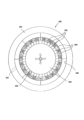
[CCDカメラ]
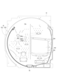
図6及び図7は、CCDカメラによって撮影される範囲を示す図である。
[CCD camera]
6 and 7 are diagrams showing the range photographed by the CCD camera.
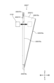
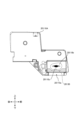
図6は、パチンコ遊技機の一部切欠き側面図(模式図)である。図6に示すように、パチンコ遊技機1において、上部装飾ユニット58の背面側には、CCDカメラ1000が配設されている。CCDカメラ1000は、ガラスドア4の後方上部に取り付けられており、ガラスドア4をベースドア3に対して閉じた際、遊技盤12の前方に位置している。これにより、CCDカメラ1000を用いて、遊技盤12の前面を撮影することができるようになっている。
FIG. 6 is a partially cutaway side view (schematic diagram) of the pachinko game machine. As shown in FIG. 6, in the
図6及び図7では、CCDカメラ1000によって撮影される範囲を太線で示している。図7では、CCDカメラ1000によって撮影される範囲をパチンコ遊技機1の正面から見た様子を示している。図7に示すように、CCDカメラ1000は、比較的広範な画角θ(視野角)で撮影可能であり、遊技盤12の大部分が撮影範囲に含まれている。特に、遊技盤12に形成された遊技領域12aは、全て撮影範囲に含まれている。そのため、CCDカメラ1000によって撮影された画像には、遊技領域12aを転動する遊技球が含まれることになる。
In FIGS. 6 and 7, the range photographed by the
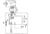
[パチンコ遊技機が備える回路の構成]
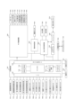
次に、図8を参照しながら、本実施形態のパチンコ遊技機1が備える各種回路の構成について説明する。なお、図8は、パチンコ遊技機1の回路構成を示すブロック図である。
[Circuit configuration of pachinko gaming machine]
Next, with reference to FIG. 8, the configurations of various circuits included in the
パチンコ遊技機1は、図8に示すように、主に遊技動作の制御を行う主制御回路70と、遊技の進行に応じた演出動作の制御を行う副制御回路200と、主に遊技球の払出や発射に関する制御を行う払出・発射制御回路300とを有する。
As shown in FIG. 8, the
[主制御回路]
主制御回路70は、メインCPU(Central Processing Unit)71と、メインROM(Read Only Memory)72と、メインRAM(Random Access Memory:Read Write Memoryを略して「RWM」ともいう)73とを備える。また、主制御回路70は、リセット用クロックパルス発生回路74と、初期リセット回路75と、シリアル通信用IC(Integrated Circuit)76とを備える。なお、上述のように、本実施形態では、第1始動口44又は第2始動口45の入賞時に特別図柄の抽選処理を行うが、この処理は、主制御回路70により制御される。すなわち、主制御回路70は、遊技状態を遊技者にとって有利な状態に移行させるか否かの抽選処理を行う手段(抽選手段)も兼ねる。
[Main control circuit]
The
メインCPU71には、メインROM72、メインRAM73、リセット用クロックパルス発生回路74、初期リセット回路75、シリアル通信用IC76等が接続される。メインROM72には、メインCPU71によりパチンコ遊技機1の動作を制御するための各種プログラムや、各種データテーブル等が記憶されている。
The
メインCPU71は、メインROM72に記憶されたプログラムに従って、各種処理を実行する。メインRAM73は、メインCPU71が各種処理を実行する際の一時記憶領域として機能し、メインCPU71が各種処理に必要となる種々のフラグや変数の値が記憶される。
The
なお、本実施形態では、メインCPU71の一時記憶領域としてメインRAM73を用いるが、本発明はこれに限定されず、読み書き可能な記憶媒体であれば任意の記録媒体を一時記憶領域として用いてもよい。
In this embodiment, the
リセット用クロックパルス発生回路74は、後述するシステムタイマ割込処理を実行するために、所定の周期(例えば2ミリ秒)でクロックパルスを発生する。初期リセット回路75は、電源投入時にリセット信号を生成する。そして、シリアル通信用IC76は、副制御回路200に対してコマンドを供給する。
The reset clock
また、主制御回路70には、図8に示すように、主制御回路70から送られた出力信号に応じて動作する各種の装置が接続される。
Furthermore, various devices that operate according to output signals sent from the
具体的には、主制御回路70には、特別図柄表示装置61、普通図柄表示装置62、普通図柄保留表示装置63、第1特別図柄保留表示装置64及び第2特別図柄保留表示装置65が接続される。
Specifically, a special
これらの各装置は、主制御回路70から送られた出力信号に基づいて所定の動作を行う。例えば、主制御回路70から特別図柄表示装置61に所定の出力信号が送信されると、特別図柄表示装置61は、その出力信号に基づいて、特別図柄ゲームにおける特別図柄の可変表示の動作制御を行う。
Each of these devices performs a predetermined operation based on an output signal sent from the
また、主制御回路70には、普通電動役物ソレノイド46a、第1大入賞口ソレノイド53b及び第2大入賞口ソレノイド54bが接続される。そして、主制御回路70は、普通電動役物ソレノイド46aを駆動制御して、普通電動役物46の一対の羽根部材を開放状態又は閉鎖状態にする。
In addition, the
また、主制御回路70は、第1大入賞口ソレノイド53b及び第2大入賞口ソレノイド54bをそれぞれ駆動制御して、第1大入賞口53及び第2大入賞口54を開放状態又は閉鎖状態にする。
In addition, the
さらに、主制御回路70には、図8に示すように、各種センサに接続され、各種センサの出力信号を受信する。具体的には、主制御回路70には、カウントセンサ53c,54c、一般入賞球センサ51a,52a、通過球センサ43a、第1始動口入賞球センサ44a及び第2始動口入賞球センサ45a、特定領域センサ380A及び非特定領域センサ380B、バックアップクリアスイッチ121等が接続される。
Furthermore, as shown in FIG. 8, the
カウントセンサ53cは、第1大入賞口53に入賞した遊技球を計数し、その結果を示す所定の出力信号を主制御回路70に出力する。カウントセンサ54cは、第2大入賞口54に入賞した遊技球を計数し、その結果を示す所定の出力信号を主制御回路70に出力する。
The
一般入賞球センサ51aは、一般入賞口51に遊技球が入賞した場合に、所定の検知信号を主制御回路70に出力する。一般入賞球センサ52aは、一般入賞口52に遊技球が入賞した場合に、所定の検知信号を主制御回路70に出力する。
The general
また、通過球センサ43aは、遊技球が球通過検出器43を通過した場合に、所定の検知信号を主制御回路70に出力する。
Further, the passing
第1始動口入賞球センサ44aは、遊技球が第1始動口44に入賞した場合に、所定の検知信号を主制御回路70に出力する。第2始動口入賞球センサ45aは、遊技球が第2始動口45に入賞した場合に、所定の検知信号を主制御回路70に出力する。
The first starting opening winning
特定領域センサ380Aは、遊技球が特定領域38Aを通過した場合に、所定の検知信号を主制御回路70に出力する。非特定領域センサ380Bは、遊技球が非特定領域38Bを通過した場合に、所定の検知信号を主制御回路70に出力する。
The
バックアップクリアスイッチ121は、電断時等にバックアップデータが遊技店の管理者等の操作に応じてクリアされた場合に、所定の検知信号を主制御回路70及び払出・発射制御回路300に出力する。
The backup clear switch 121 outputs a predetermined detection signal to the
主制御回路70には、払出・発射制御回路300が接続される。ここで、主制御回路70は、所定の払出条件が成立したことを条件に払い出される遊技球の数である賞球数を決定する。所定の払出条件は、上述した各種始動口や各種入賞口に遊技球が入賞したことである。
A payout/
また、主制御回路70は、上述のように決定された賞球数を含む情報を賞球制御コマンドとして払出・発射制御回路300に送信する。
Further, the
[払出・発射制御回路]
払出・発射制御回路300は、CPU、ROM、RAMといったマイクロコンピュータを備える。払出・発射制御回路300には、払出装置170が接続され、払出・発射制御回路300のマイクロコンピュータは、例えば払出装置170による遊技球の払出動作を制御する。
[Payout/fire control circuit]
The payout/
また、払出・発射制御回路300には、遊技球の発射を行う発射装置15、外部端子板140、及びカードユニット150が接続される。外部端子板140には、データ表示器141が接続され、カードユニット150には、貸し出し用操作部151が接続される。
Further, the payout/
ここで、カードユニット150は、所定の払出条件が成立したことを条件に払い出される遊技球の数である貸し球数を決定する。なお、所定の払出条件は、上述した貸し出し用操作部151が操作されたことである。
Here, the
払出・発射制御回路300は、発射ハンドル25が遊技者によって把持され、かつ、時計回り方向へ回動操作されたときに、その回動角度に応じて発射装置15のソレノイドアクチュエータに電力を供給する。これにより、発射装置15は、遊技球を発射させる制御を行う。
The payout/
外部端子板140は、ホール(遊技場)内の全てのパチンコ遊技機を管理するホールコンピュータにデータ送信するために用いられる。データ表示器141は、例えばパチンコ遊技機1の上部にホールの付帯設備として設置され、ホール係員を呼び出す機能や当り回数を表示する機能を有する。
The external
貸し出し用操作部151は、遊技者に操作されると、カードユニット150に遊技球の貸し出しを要求する信号を出力する。カードユニット150は、貸し出し用操作部151から遊技球の貸出を要求する信号を受信すると、決定された貸し球数の情報を含む貸し球制御信号を払出・発射制御回路300に送信する。
When operated by a player, the
このような払出・発射制御回路300は、主制御回路70から送信される賞球制御コマンド、カードユニット150から送信される貸し球制御信号を受信し、払出装置170に対して所定の信号を送信する。これにより、払出装置170は、遊技球を払い出す。
Such a payout/
[副制御回路]
副制御回路200は、主制御回路70のシリアル通信用IC76に接続される。そして、副制御回路200は、主制御回路70から送信される各種のコマンドに応じて、液晶表示装置13における表示制御、スピーカ11から発生させる音声に関する制御、LED59A~59E、59e~59hの制御、各種役物を用いた演出動作の制御等を行う。
[Sub control circuit]
The
すなわち、副制御回路200は、主制御回路70からの指令に基づいて、遊技の進行に応じた各種演出を実行する。なお、本実施形態では、副制御回路200から主制御回路70に対して信号を供給できない構成としたが、本発明はこれに限定されず、副制御回路200から主制御回路70に信号送信可能な構成を備えていてもよい。
That is, the
副制御回路200は、図8に示すように、サブCPU201と、プログラムROM202と、ワークRAM203と、表示制御回路205と、音声制御回路206と、LED制御回路207と、駆動制御回路208とを備える。サブCPU201には、プログラムROM202、ワークRAM203、表示制御回路205、音声制御回路206、LED制御回路207及び駆動制御回路208が接続される。
As shown in FIG. 8, the
プログラムROM202には、サブCPU201によりパチンコ遊技機1の演出動作を制御するための各種プログラムや、各種データテーブルが記憶される。そして、サブCPU201は、プログラムROM202に記憶されたプログラムに従って、各種の処理を実行する。特に、サブCPU201は、主制御回路70から送信される各種のコマンドに従って、副制御回路200全体の制御を行う。
The
なお、本実施形態では、プログラムや各種テーブル等を記憶する記憶手段として、メインROM72及びプログラムROM202を適用したが、本発明はこれに限定されない。このような記憶手段としては、制御手段を備えたコンピュータにより読み取り可能な記憶媒体であれば別態様の記憶媒体を用いてもよく、例えば、ハードディスク装置、CD-ROM及びDVD-ROM、ROMカートリッジ等の記憶媒体を適用してもよい。
Note that in this embodiment, the
また、プログラムの各々が別々の記憶媒体に記録されていてもよい。さらに、プログラムは、予め記録媒体に記録されていてもよいし、電源投入後に外部等からダウンロードされ、メインRAM73やワークRAM203等に記録されてもよい。
Furthermore, each of the programs may be recorded on separate storage media. Furthermore, the program may be recorded in advance on a recording medium, or may be downloaded from an external source after power is turned on, and may be recorded in the
ワークRAM203は、サブCPU201が各種処理を実行する際の一時記憶領域として機能し、サブCPU201が各種処理に必要となる種々のフラグや変数の値が記憶される。なお、本実施形態では、サブCPU201の一時記憶領域としてワークRAM203を用いるが、本発明はこれに限定されず、読み書き可能な記憶媒体であれば任意の記録媒体を一時記憶領域として用いてよい。
The
表示制御回路205は、演出に関する画像を液晶表示装置13に表示させる制御を行う。この表示制御回路205は、図示しないが、画像データプロセッサ(以下、VDP(Video Display Processor)と称する)、画像データROM、フレームバッファ、及び、D/A(Digital to Analog)コンバータ等を有する。
The
なお、画像データROMには、各種の画像データを生成するためのデータが記憶される。フレームバッファは、画像データを一時的に保存する。また、D/Aコンバータは、画像データ(デジタル電気信号)を画像信号(アナログ電気信号)に変換する。 Note that the image data ROM stores data for generating various types of image data. The frame buffer temporarily stores image data. Further, the D/A converter converts image data (digital electrical signal) into an image signal (analog electrical signal).
表示制御回路205は、サブCPU201から供給されるデータに基づいて、液晶表示装置13の表示領域13aに画像を表示させるための種々の処理を行う。また、表示制御回路205は、サブCPU201から供給される演出指定情報(メッセージ)に基づいて、装飾図柄(演出用識別図柄)を示す装飾図柄画像データ、背景画像データ、演出用画像データ等の画像データを一時的にフレームバッファに格納する。
The
そして、表示制御回路205は、フレームバッファに格納した画像データを所定のタイミングでD/Aコンバータに供給する。D/Aコンバータは、画像データを画像信号に変換し、その画像信号を所定のタイミングで液晶表示装置13に供給する。これにより、液晶表示装置13の表示領域13aに所定の演出画像が表示される。
Then, the
音声制御回路206は、音声に関する制御を行う音源IC、各種の音声データを記憶する音声データROM、及び、音声信号を増幅するための増幅器(以下、AMPと称する)等を有する。
The
なお、音源ICは、スピーカ11から発生させる音声の制御を行う。音源ICは、サブCPU201から供給される演出指定情報(メッセージ)に基づいて、音声データROMに記憶されている複数の音声データから一つの音声データを選択する。
Note that the sound source IC controls the sound generated from the
そして、音源ICは、選択した音声データを音声データROMから読み出し、読み出した音声データを所定の音声信号に変換して、AMPに供給する。また、AMPは、音声信号を増幅して、スピーカ11から音声を発生させる。
Then, the sound source IC reads the selected audio data from the audio data ROM, converts the read audio data into a predetermined audio signal, and supplies it to the AMP. Further, the AMP amplifies the audio signal and causes the
LED制御回路207は、LED制御信号を供給するためのドライブ回路、及び複数種類のLED点灯パターンが記憶されているLEDデータROM等を有する。ドライブ回路は、サブCPU201から供給される演出指定情報(メッセージ)に基づいて、LEDデータROMに記憶されている複数の点灯・点滅パターンから一つのLED点灯・点滅パターンを選択する。これにより、点灯・点滅パターンに応じてLED59(59A~59E、59e~59h)が点灯あるいは点滅する。
The
駆動制御回路208は、サブCPU201から供給される演出指定情報(メッセージ)に基づいて、各種役物を作動させるための演出用駆動モータ60を駆動する。
The
また、副制御回路200には、演出ボタン23が押下操作されたことを検出する演出ボタンスイッチ230と、ジョグダイヤル24が回転操作された際の回転方向や操作量を検出するジョグダイヤルスイッチ240とが接続される。サブCPU201は、演出ボタンスイッチ230やジョグダイヤルスイッチ240からの検出信号(入力信号)に応じて所定の演出表示が行われるように制御する。
Further, the
また、副制御回路200には、CCDカメラ1000が接続されている。サブCPU201は、CCDカメラ1000により入力された画像データに対して各種処理を行う。
Further, a
このような副制御回路200は、所定の演出画像を液晶表示装置13に表示させるとともに、スピーカ11から音声を発生させたり、LED59A~59E、59e~59hを点灯あるいは点滅させることによって演出表示を行わせる。また、副制御回路200は、CCDカメラ1000によって撮影された画像(カメラ映像)を解析し、解析結果に応じた制御を行う。
The
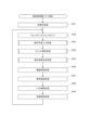
[アニメーションリクエスト構築処理の概要]
図9を参照しながら、アニメーションリクエスト構築処理の概要を説明する。なお、図9は、アニメーションリクエスト構築時の動作(各種リクエストの生成動作)概要を示す図である。
[Overview of animation request construction process]
An overview of the animation request construction process will be explained with reference to FIG. Note that FIG. 9 is a diagram showing an overview of operations when constructing an animation request (generating operations of various requests).
サブCPU201(ホスト制御回路)は、主制御回路70から各種コマンドを受信する。また、サブCPU201(ホスト制御回路)は、CCDカメラ1000によって撮影された画像(カメラ映像)のデータを受信する。そして、サブCPU201は、受信したコマンド及びデータに基づいて、演出内容の指定情報を含むアニメーションリクエストと称するリクエストを生成する(不図示)。次いで、サブCPU201は、生成されたアニメーションリクエストに基づいて、描画リクエスト、サウンドリクエスト、ランプリクエスト、役物リクエストなどの各種リクエスト(演出開始要求)を生成する。
The sub CPU 201 (host control circuit) receives various commands from the
その後、サブCPU201は、生成された各リクエストを、対応する演出装置の制御回路(コントローラ)に出力する。具体的には、サブCPU201は、サウンドリクエスト及びランプリクエストを、音声・LED制御回路206、207に出力し、描画リクエストを表示制御回路205に出力し、役物リクエストを駆動制御回路208に出力する。なお、音声制御回路206及びLED制御回路207は、別体としてもよいし、一の制御回路により構成してもよい。
Thereafter, the
音声・LED制御回路206、207は、入力されたサウンドリクエストに基づいて、スピーカ11による音声再生動作の制御を行う。また、音声・LED制御回路206、207は、入力されたランプリクエストに基づいて、ランプ(LED)群59による発光演出(LEDアニメーション)動作の制御を行う。表示制御回路205は、入力された描画リクエストに基づいて、液晶表示装置13による画像表示演出動作の制御を行う。また、駆動制御回路208は、生成された役物リクエストに基づいて、各種役物による演出動作の制御を行う。
The audio/
[スピーカの駆動制御手法]
次に、パチンコ遊技機1のホスト制御回路(サブCPU201)から音声・LED制御回路206、207にサウンドリクエストが出力された際に、音声・LED制御回路206、207が実行する、スピーカ11の駆動制御処理の内容について説明する。図10(a)は、スピーカ駆動(音声再生)時の信号フロー図である。
[Speaker drive control method]
Next, when a sound request is output from the host control circuit (sub CPU 201) of the
スピーカ11の音声再生(出力)時には、まず、副制御回路200内のホスト制御回路(サブCPU201)から音声・LED制御回路206、207にサウンドリクエストが出力される。なお、本実施形態では、サブCPU201の演出制御処理(後述の図26に示す副制御メイン処理)は、所定のFPS周期(例えば、30FPS)で行われるので、表示制御回路205への描画リクエストの送信処理や音声・LED制御回路206、207へのサウンドリクエストの送信処理も所定のFPS周期で行われる。
When reproducing (outputting) audio from the
次いで、音声・LED制御回路206、207にサウンドリクエストが入力されると、音声・LED制御回路206、207は、該サウンドリクエストに基づいて、スピーカ11からの音声出力パターンを設定するための音声信号(オーディオデータ)を内蔵中継基板に送信する。
Next, when a sound request is input to the audio/
そして、内蔵中継基板は、受信した音声信号を増幅し、スピーカ11へ出力して、スピーカ11を駆動する。これにより、スピーカ11による音声再生(演出)動作が実行される。
Then, the built-in relay board amplifies the received audio signal, outputs it to the
[ランプ(LED)の駆動制御手法]
次に、ホスト制御回路(サブCPU201)から音声・LED制御回路206、207にランプリクエストが出力された際に、音声・LED制御回路206、207が実行する、ランプ(LED)群59に含まれる複数のLEDの各種駆動制御処理の内容について説明する。なお、以下に説明する本実施形態のランプ制御手法では、発光素子としてLEDを例に挙げて説明するが、本発明はこれに限定されず、他の任意の発光素子に対しても本実施形態のランプ制御手法は同様に適用することができる。図10(b)は、LED駆動(点灯/消灯)時の信号フロー図である。
[Lamp (LED) drive control method]
Next, when a lamp request is output from the host control circuit (sub CPU 201) to the audio/
LEDの駆動(点灯/消灯)時には、まず、副制御回路200内のホスト制御回路(サブCPU201)から音声・LED制御回路206、207にランプリクエスト(LED制御リクエスト)が出力される。なお、本実施形態では、サブCPU201の演出制御処理(後述の図26に示す副制御メイン処理)は、所定のFPS周期で行われるので、音声・LED制御回路206、207へのランプリクエストの送信処理も所定のFPS周期で行われる。
When driving (turning on/off) the LED, first, a lamp request (LED control request) is output from the host control circuit (sub CPU 201) in the
次いで、音声・LED制御回路206、207にランプリクエストが入力されると、音声・LED制御回路206、207は、該ランプリクエストに基づいて、LEDの点灯パターン(LEDアニメーション)を設定するためのLEDデータ(駆動データ)をLED群59内の各LEDドライバに送信する。
Next, when a lamp request is input to the audio/
そして、LEDドライバは、受信したLEDデータに基づいて、接続されているLED59を所定のパターンで点灯/消灯する。これによりLEDアニメーションによる演出動作が実行される。例えば、LED59は、演出動作として、所定の周期(例えば、12ミリ秒間隔)で点滅するように制御される。
Then, the LED driver turns on/off the
なお、LEDデータに基づく発光態様は、LEDドライバからLED59に送信されるLEDデータに基づいて生成された信号(制御信号)より制御される。具体的には、LEDドライバからLED59に送信される信号の電気的な波形パラメータ(電圧値、電流値、パルス幅のデューティー比等)により、LED59の点灯、消灯、点滅、輝度等の発光態様が制御される。
Note that the light emission mode based on the LED data is controlled by a signal (control signal) generated based on the LED data transmitted from the LED driver to the
次に、図11~図13を参照しながら、主制御回路70のデータ構成等について説明する。
Next, the data structure of the
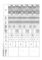
[当り乱数判定テーブル]
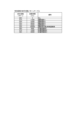
図11は、主制御回路70のメインROM72に記憶されている当り乱数判定テーブル(第1始動口、第2始動口)を示す図である。当り乱数判定テーブル(第1始動口)は、第1始動口44に遊技球が入賞した際に取得される当り判定用乱数値に基づいて、「大当り」、「小当り」、及び「ハズレ」のいずれかを抽選により決定するために参照される。当り乱数判定テーブル(第2始動口)は、第2始動口45に遊技球が入賞した際に取得される当り判定用乱数値に基づいて「大当り」及び「ハズレ」のいずれかを抽選により決定する際に参照される。
[Random number determination table]
FIG. 11 is a diagram showing a winning random number determination table (first starting port, second starting port) stored in the
当り判定用乱数値は、始動口入賞を契機に行われる抽選結果を判定するための乱数値である。より具体的にいうと、当り判定用乱数値は、特別図柄(第1特別図柄及び第2特別図柄)の抽選結果を示す値である。本実施形態において、当り判定用乱数値は、0~65535(65536種類)の中から選ばれる。 The random number value for determining a win is a random number value for determining the result of a lottery that is performed in response to a winning entry. More specifically, the random number value for hit determination is a value indicating the lottery result of the special symbols (the first special symbol and the second special symbol). In this embodiment, the random number value for hit determination is selected from 0 to 65535 (65536 types).
本実施形態では、第1始動口44に遊技球が入賞した場合、「大当り」、「小当り」及び「ハズレ」のいずれかが抽選により決定される。それゆえ、当り乱数判定テーブル(第1始動口入賞時)には、確変フラグの値(「0(=オフ)」又は「1(=オン)」)毎に、「大当り」、「小当り」及び「ハズレ」のそれぞれの当選が決定される当り判定用乱数値の範囲(幅)と、それに対応する判定値データ(「大当り判定値データ」、「小当り判定値データ」及び「ハズレ判定値データ」)との関係が規定される。確変フラグは、メインRAM73に格納される管理フラグの一つであり、遊技状態が「確変遊技状態」であるか否かを管理するためのフラグである。遊技状態が「確変遊技状態」である場合には、確変フラグは「1」となり、「非確変遊技状態」である場合には、確変フラグは「0」となる。
In this embodiment, when a game ball enters the
本実施形態では、第1始動口44入賞時に、確変フラグが「0」であり、当り判定用乱数値が「0」~「204」のいずれかである場合には、「大当り」が当選し、「大当り判定値データ」が決定される。すなわち、この場合における「大当り」の当選確率(大当り確率)は、205/65536(≒1/319)となる。 In this embodiment, when the first starting opening 44 wins, if the variable probability flag is "0" and the random number value for determining a win is between "0" and "204", a "jackpot" is won. , "jackpot determination value data" is determined. That is, the probability of winning the "jackpot" (jackpot probability) in this case is 205/65536 (≈1/319).
また、第1始動口44入賞時に、確変フラグが「0」であり、当り判定用乱数値が「205」~「409」のいずれかである場合には、「小当り」が当選し、「小当り判定値データ」が決定される。すなわち、この場合における「小当り」の当選確率は、205/65536(≒1/319)となる。 In addition, when the first starting opening 44 wins, if the variable probability flag is "0" and the random number for determining a win is one of "205" to "409", a "small win" is won and " "Small hit judgment value data" is determined. That is, the probability of winning a "small win" in this case is 205/65536 (≈1/319).
さらに、第1始動口44入賞時に、確変フラグが「0」であり、当り判定用乱数値が「0」~「409」のいずれでもない場合には、「ハズレ」が当選し、「ハズレ判定値データ」が決定される。 Furthermore, when the first starting opening 44 wins, if the probability variable flag is "0" and the random number for determining the winning is not between "0" and "409", the "loser" is won and the "loser" is determined as "loser". "value data" is determined.
一方、第1始動口44入賞時に、確変フラグが「1」であり、当り判定用乱数値が「0」~「1092」のいずれかである場合には、「大当り」が当選し、「大当り判定値データ」が決定される。すなわち、この場合における「大当り」の当選確率(大当り確率)は、1093/65536(≒1/60)となり、確変フラグが「0」である場合のそれより高くなる。 On the other hand, when the first starting opening 44 wins, if the variable probability flag is "1" and the random number for determining the hit is between "0" and "1092", the "jackpot" is won and the "jackpot" is won. "Judgement value data" is determined. That is, the probability of winning the "jackpot" in this case (jackpot probability) is 1093/65536 (≈1/60), which is higher than that when the probability variation flag is "0".
また、第1始動口44入賞時に、確変フラグが「1」であり、当り判定用乱数値が「1093」~「1297」のいずれかである場合には、「小当り」が当選し、「小当り判定値データ」が決定される。すなわち、この場合における「小当り」の当選確率は、205/65536(≒1/319)となり、確変フラグが「0」である場合と同一となる。 In addition, when the first starting opening 44 wins a prize, if the variable probability flag is "1" and the random number for determining a win is one of "1093" to "1297", a "small win" is won and " "Small hit judgment value data" is determined. That is, the probability of winning a "small win" in this case is 205/65536 (≈1/319), which is the same as when the probability variation flag is "0".
さらに、第1始動口44入賞時に、確変フラグが「1」であり、当り判定用乱数値が「0」~「1297」のいずれでもない場合には、「ハズレ」が当選し、「ハズレ判定値データ」が決定される。 Furthermore, when the first starting opening 44 wins a prize, if the probability variable flag is "1" and the random number for winning determination is neither "0" to "1297", the "loser" is won and the "loser" is determined. "value data" is determined.
上述のように、本実施形態では、第1始動口44に遊技球が入賞した場合には、入賞時の遊技状態が「確変遊技状態」であるか否かによって、大当り確率が変動する。具体的には、遊技状態が「確変遊技状態」である時に第1始動口44に遊技球が入賞した場合の大当り確率は、遊技状態が「確変遊技状態」でない時の約5倍程度高くなる。
As described above, in the present embodiment, when a game ball enters the
同様に、第2始動口45入賞時に、確変フラグが「0」であり、当り判定用乱数値が「0」~「204」のいずれかである場合には、「大当り」が当選し、「大当り判定値データ」が決定される。すなわち、この場合における「大当り」の当選確率(大当り確率)は、205/65536(≒1/319)となる。 Similarly, when the second starting opening 45 wins, if the variable probability flag is "0" and the random number for determining the hit is between "0" and "204", a "jackpot" is won and " ``Jackpot judgment value data'' is determined. That is, the probability of winning the "jackpot" (jackpot probability) in this case is 205/65536 (≈1/319).
また、第2始動口45入賞時に、確変フラグが「0」であり、当り判定用乱数値が「205」~「409」のいずれでもない場合には、「ハズレ」が当選し、「ハズレ判定値データ」が決定される。 In addition, when the second starting opening 45 wins, if the probability change flag is "0" and the random number for winning determination is not one of "205" to "409", the "loser" is won and the "loser" "value data" is determined.
一方、第2始動口45入賞時に、確変フラグが「1」であり、当り判定用乱数値が「0」~「1092」のいずれかである場合には、「大当り」が当選し、「大当り判定値データ」が決定される。すなわち、この場合における「大当り」の当選確率(大当り確率)は、1093/65536(≒1/60)となり、確変フラグが「0」である場合のそれより高くなる。 On the other hand, if the probability variable flag is "1" and the random number value for determining a hit is one of "0" to "1092" when winning the second starting opening 45, a "jackpot" is won, and a "jackpot" is won. "Judgement value data" is determined. That is, the probability of winning the "jackpot" in this case (jackpot probability) is 1093/65536 (≈1/60), which is higher than that when the probability variation flag is "0".
また、第2始動口45入賞時に、確変フラグが「1」であり、当り判定用乱数値が「0」~「1092」のいずれでもない場合には、「ハズレ」が当選し、「ハズレ判定値データ」が決定される。 In addition, when the second starting opening 45 wins, if the probability variable flag is "1" and the random number for determining a win is not between "0" and "1092", a "lose" is won and a "lose" is determined. "value data" is determined.
上述のように、本実施形態では、第2始動口45に遊技球が入賞した場合には、「小当り」に当選することなく、入賞時の遊技状態が「確変遊技状態」であるか否かによって、大当り確率が変動し、遊技状態が「確変遊技状態」である時の大当り確率は、「確変遊技状態」でない時の約5倍程度高くなる。
As described above, in the present embodiment, when a game ball enters the
[図柄判定テーブル]
図12は、主制御回路70のメインROM72に記憶されている図柄判定テーブル(第1始動口、第2始動口)を示す図である。図柄判定テーブル(第1始動口、第2始動口)は、第1始動口44あるいは第2始動口45に遊技球が入賞した際に取得される図柄乱数値と先述の判定値データとに基づいて、停止図柄を決定付ける「当り時選択図柄コマンド」及び「図柄指定コマンド」を選択するために参照される。「当り時選択図柄コマンド」は、当たり当選時の当たり種類に応じて定められる当り図柄を指定するためのコマンドであり、「図柄指定コマンド」は、特別図柄の変動停止時に表示される図柄を指定するためのコマンドである。図柄乱数値は、例えば0~99(100種類)の中から抽出される。
[Symbol judgment table]
FIG. 12 is a diagram showing a symbol determination table (first starting port, second starting port) stored in the
本実施形態の図柄判定テーブル(第1始動口)によれば、大当り判定値データが得られた場合であって図柄乱数値が「0」~「49」のいずれかである場合、50/100の確率で当り時選択図柄コマンドとして「z0」が選択され、図柄指定コマンドとして「zA1」が選択される。また、大当り判定値データが得られた場合であって図柄乱数値が「50」~「99」のいずれかである場合、50/100の確率で当り時選択図柄コマンドとして「z1」が選択され、図柄指定コマンドとして「zA1」が選択される。また、小当り判定値データが得られた場合であって図柄乱数値が「0」~「99」のいずれかである場合、当り時選択図柄コマンドとして「z2」が選択され、図柄指定コマンドとして「zA2」が選択される。一方、ハズレ判定値データが得られた場合であって図柄乱数値が「0」~「99」のいずれかである場合、当り時選択図柄コマンドが選択されず、図柄指定コマンドとして「zA3」が選択される。 According to the symbol determination table (first starting port) of this embodiment, when jackpot determination value data is obtained and the symbol random number value is one of "0" to "49", 50/100 ``z0'' is selected as the winning symbol command and ``zA1'' is selected as the symbol designation command with a probability of . In addition, when jackpot judgment value data is obtained and the symbol random number is one of "50" to "99", "z1" will be selected as the winning symbol command with a probability of 50/100. , "zA1" is selected as the symbol designation command. In addition, when small hit judgment value data is obtained and the symbol random number is one of "0" to "99", "z2" is selected as the symbol selection command at the time of hit, and "z2" is selected as the symbol designation command. "zA2" is selected. On the other hand, if loss judgment value data is obtained and the symbol random number is one of "0" to "99", the hit selection symbol command is not selected and "zA3" is used as the symbol designation command. selected.
また、本実施形態の図柄判定テーブル(第2始動口)によれば、大当り判定値データが得られた場合であって図柄乱数値が「0」~「49」のいずれかである場合、50/100の確率で当り時選択図柄コマンドとして「z3」が選択され、図柄指定コマンドとして「zA4」が選択される。また、大当り判定値データが得られた場合であって図柄乱数値が「50」~「99」のいずれかである場合、50/100の確率で当り時選択図柄コマンドとして「z4」が選択され、図柄指定コマンドとして「zA5」が選択される。一方、ハズレ判定値データが得られた場合であって図柄乱数値が「0」~「99」のいずれかである場合、当り時選択図柄コマンドが選択されず、図柄指定コマンドとして「zA6」が選択される。 Furthermore, according to the symbol determination table (second starting port) of this embodiment, when jackpot determination value data is obtained and the symbol random number value is one of "0" to "49", 50 With a probability of /100, "z3" is selected as the winning symbol command and "zA4" is selected as the symbol designating command. In addition, when jackpot judgment value data is obtained and the symbol random number is one of "50" to "99", "z4" is selected as the winning symbol command with a probability of 50/100. , "zA5" is selected as the symbol designation command. On the other hand, if loss judgment value data is obtained and the symbol random value is one of "0" to "99", the winning selection symbol command is not selected and "zA6" is selected as the symbol designation command. selected.
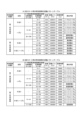
[大当り種類決定テーブル]
図13は、主制御回路70のメインROM72に記憶されている大当り種類決定テーブルを示す図である。大当り種類決定テーブルは、大当りに係る当り時選択図柄コマンドに応じて、ラウンド数やV入賞の容易性といった大当りの種類を決定するために参照される。なお、本実施形態では、大当りの種類に関係なく大当りに当選すれば、時短フラグが「1」にセットされ、時短回数が例えば100回としてセットされる。また、大当り遊技状態においてV入賞となった場合に限り、確変回数が例えば124回としてセットされる。時短フラグは、メインRAM73に格納される管理フラグの一つであり、遊技状態が「時短遊技状態」であるか否かを管理するためのフラグである。遊技状態が「時短遊技状態」である場合には、時短フラグは「1」となり、「非時短遊技状態」である場合には、時短フラグは「0」となる。時短回数は、時短遊技状態が継続可能な特別図柄ゲームの変動回数であり、確変回数は、確変遊技状態が継続可能な特別図柄ゲームの変動回数である。すなわち、時短遊技状態において大当りに当選することなく時短回数分(100回)の特別図柄変動が行われると、時短遊技状態が終了して非時短遊技状態に移行する。確変遊技状態において大当りに当選することなく確変回数分の特別図柄変動が行われると、確変遊技状態が終了して非確変遊技状態に移行する。
[Jackpot type determination table]
FIG. 13 is a diagram showing a jackpot type determination table stored in the
本実施形態の大当り種類決定テーブルによれば、当り時選択図柄コマンドが「z0」の場合、ラウンド数が「10」でV入賞が困難な大当りが決定される。当り時選択図柄コマンドが「z1」の場合、ラウンド数が「10」でV入賞が容易な大当りが決定される。当り時選択図柄コマンドが「z3」の場合、ラウンド数が「4」でV入賞が容易な大当りが決定される。当り時選択図柄コマンドが「z4」の場合、ラウンド数が「16」でV入賞が容易な大当りが決定される。 According to the jackpot type determination table of this embodiment, when the winning selection symbol command is "z0", a jackpot is determined in which the number of rounds is "10" and it is difficult to win a V prize. When the selected symbol command at the time of winning is "z1", a jackpot is determined in which the number of rounds is "10" and it is easy to win a V prize. When the selected symbol command at the time of winning is "z3", a jackpot is determined in which the number of rounds is "4" and it is easy to win a V prize. When the selected symbol command at the time of winning is "z4", a jackpot is determined in which the number of rounds is "16" and it is easy to win a V prize.
以下に、パチンコ遊技機1で実行される各種の処理を示す。
Various processes executed by the
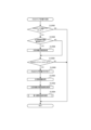
[電源投入時処理]
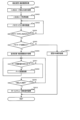
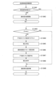
図14は、メインCPU71による電源投入時処理を示している。パチンコ遊技機1の電源が投入されると、同図に示すように、メインCPU71は、初期値をスタックポインタに設定する(ステップS11)。
[Power-on processing]
FIG. 14 shows the power-on processing by the
次に、メインCPU71は、電断検知信号がONか否かを判別する(ステップS12)。電断検知信号は、例えば所定レベルまで電圧が降下するとONとなる。電断検知信号がONの場合、メインCPU71は、電断検知状態と判別し、電断検知信号がOFFになるまでステップS12の処理を繰り返し行う。電断検知信号がOFFの場合、メインCPU71は、電断検知状態と判別し、ステップS13の処理に移る。
Next, the
ステップS13において、メインCPU71は、RWM(メインRAM)に対するアクセスを許可する。
In step S13, the
次に、メインCPU71は、副制御回路200が信号を受け付け可能になるまで待機する副制御受信受付ウェイト処理を行う(ステップS14)。
Next, the
次に、メインCPU71は、CPU内蔵の各種デバイスについて初期化処理を行う(ステップS15)。
Next, the
次に、メインCPU71は、バックアップクリア信号がONか否かを判別する(ステップS16)。バックアップクリア信号は、主制御回路70を構成するメインCPU71に備えられたメインRAM73や、払出・発射制御回路300を構成するRAM(図示せず)のバックアップ内容のクリアを指令するための信号である。バックアップクリア信号がONの場合、メインCPU71は、ステップS23の処理に移る。バックアップクリア信号がOFFの場合、メインCPU71は、ステップS17の処理に移る。
Next, the
ステップS17において、メインCPU71は、電断検知フラグが設定オンである否かを判別する。電断検知フラグは、電断発生に応じて電断処理を実行したことを示すフラグである。電断検知フラグが設定オンである場合、メインCPU71は、ステップS18の処理に移る。電断検知フラグが設定オフである場合、メインCPU71は、ステップS23の処理に移る。
In step S17, the
ステップS18において、メインCPU71は、メインRAM73について例えばチェックサムを用いて作業領域損傷チェックを行う。
In step S18, the
次に、メインCPU71は、作業領域が正常か否かを判別する(ステップS19)。作業領域が正常である場合、メインCPU71は、ステップS20の処理に移る。作業領域が正常でない場合、メインCPU71は、ステップS23の処理に移る。
Next, the
ステップS20において、メインCPU71は、電断復旧時に初期値を必要とする作業領域の初期設定を行う。
In step S20, the
次に、メインCPU71は、電断復旧時の高確率遊技状態(確変遊技状態)についての報知設定を行う(ステップS21)。
Next, the
次に、メインCPU71は、電断復帰時のコマンド(電断復帰コマンド)を副制御回路200に対して送信する処理を行う(ステップS22)。この処理を終了すると、メインCPU71は、電源投入時処理を終了する。
Next, the
ステップS23において、メインCPU71は、メインRAM73の作業領域をクリアする処理を行う。
In step S23, the
次に、メインCPU71は、RWM(メインRAM)初期化時に初期値を必要とする作業領域の初期設定を行う(ステップS24)。
Next, the
次に、メインCPU71は、RWM初期化時のコマンド(初期化コマンド)を副制御回路200に対して送信する処理を行う(ステップS25)。この処理を終了すると、メインCPU71は、電源投入時処理を終了する。
Next, the
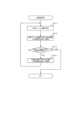
[システムタイマ割込処理]
図15は、メインCPU71によるシステムタイマ割込処理を示している。システムタイマ割込処理は、例えば2msごとに実行される。同図に示すように、メインCPU71は、各レジスタの値をメインRAM73のスタックエリアに退避する(ステップS31)。
[System timer interrupt processing]
FIG. 15 shows system timer interrupt processing by the
次に、メインCPU71は、各種の乱数値を更新する乱数更新処理を行う(ステップS32)。
Next, the
次に、メインCPU71は、各種スイッチからの入力信号を検出するためのスイッチ入力検出処理を実行する(ステップS33)。スイッチ入力検出処理については、図16を参照して後述する。
Next, the
次に、メインCPU71は、各種タイマの値を更新するタイマ更新処理を行う(ステップS34)。
Next, the
次に、メインCPU71は、副制御回路200に各種コマンドを出力(送信)するコマンド出力処理を行う(ステップS35)。
Next, the
次に、メインCPU71は、副制御回路200に各種遊技情報を出力(送信)する遊技情報出力処理を行う(ステップS36)。遊技情報は、主制御回路70、副制御回路200、払出・発射制御回路300などにおいて処理される遊技に関わる情報であり、副制御回路200や払出・発射制御回路300、ホールコンピュータに送信される。
Next, the
次に、メインCPU71は、退避した各レジスタの値を復帰させる処理を行う(ステップS37)。この処理を終了すると、メインCPU71は、システムタイマ割込処理を終了する。
Next, the
[スイッチ入力検出処理]
図16は、メインCPU71によるスイッチ入力検出処理を示している。スイッチ入力検出処理は、先述したシステムタイマ割込処理の実行中にサブルーチンとして呼び出される。同図に示すように、メインCPU71は、始動口入賞検出処理を実行する(ステップS41)。始動口入賞検出処理については、図17を参照して後述する。
[Switch input detection processing]
FIG. 16 shows switch input detection processing by the
次に、メインCPU71は、一般入賞口通過検出処理を行う(ステップS42)。一般入賞口通過検出処理では、例えば一般入賞口51、52への入賞時に払出個数等を示す払出情報をセットする。
Next, the
次に、メインCPU71は、大入賞口通過検出処理を行う(ステップS43)。大入賞口通過検出処理では、例えば第1大入賞口53又は第2大入賞口54への入賞時に払出個数等を示す払出情報をセットする。
Next, the
次に、メインCPU71は、球通過検出器通過検出処理を行う(ステップS44)。球通過検出器通過検出処理では、球通過検出器43による遊技球の通過検出に応じて普通図柄ゲームの抽選結果(乱数値)を取得する。この処理を終了すると、メインCPU71は、スイッチ入力検出処理を終了する。
Next, the
[始動口入賞検出処理]
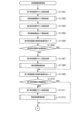
図17は、メインCPU71による始動口入賞検出処理を示している。始動口入賞検出処理は、先述したスイッチ入力検出処理の実行中にサブルーチンとして呼び出される。同図に示すように、まず、メインCPU71は、第1始動口入賞球センサ44aで遊技球を検出したか否かを判別する(ステップS51)。第1始動口入賞球センサ44aで遊技球を検出した場合、メインCPU71は、ステップS52の処理に移る。第1始動口入賞球センサ44aで遊技球を検出していない場合、メインCPU71は、ステップS59の処理に移る。
[Starting opening winning detection process]
FIG. 17 shows the starting opening winning detection process by the
ステップS52において、メインCPU71は、第1始動口入賞に応じた払出情報をセットする処理を行う。
In step S52, the
次に、メインCPU71は、第1始動口入賞の保留個数(第1特別図柄の保留個数)が4個未満であるか否かを判別する(ステップS53)。当該保留個数が4個未満の場合、メインCPU71は、ステップS54の処理に移る。当該保留個数が4個の場合、メインCPU71は、ステップS59の処理に移る。
Next, the
ステップS54において、メインCPU71は、第1始動口入賞の保留個数を1加算する処理を行う。
In step S54, the
次に、メインCPU71は、当り判定用乱数値及び図柄乱数値を取得し、これらの乱数値をメインRAM73に格納する処理を行う(ステップS55)。
Next, the
次に、メインCPU71は、第1特別停止図柄判断処理を行う(ステップS56)。第1特別停止図柄判断処理では、当り判定用乱数値及び図柄乱数値に基づいて、当り乱数判定テーブル(第1始動口)及び図柄判定テーブル(第1始動口)、大当り種類決定テーブルを参照し、停止表示される予定の第1特別図柄に係る図柄指定コマンドや当り時選択図柄コマンド等を決定する。
Next, the
次に、メインCPU71は、変動パターン決定処理を実行する(ステップS57)。変動パターン決定処理では、図柄指定コマンドや判定値データ、遊技状態等に基づいて、第1特別図柄に係る変動パターンを決定する。
Next, the
次に、メインCPU71は、第1始動口入賞の保留個数増加コマンドをセットする処理を行う(ステップS58)。第1始動口入賞の保留個数増加コマンドは、第1特別図柄の保留個数を1増加する旨を示すコマンドであり、ステップS57の処理で決定された変動パターンを示すコマンド(変動パターン指定コマンド)等とともに副制御回路200へと送信される。
Next, the
次に、メインCPU71は、第2始動口入賞球センサ45aで遊技球を検出したか否かを判別する(ステップS59)。第2始動口入賞球センサ45aで遊技球を検出した場合、メインCPU71は、ステップS60の処理に移る。第2始動口入賞球センサ45aで遊技球を検出していない場合、メインCPU71は、始動口入賞検出処理を終了する。
Next, the
ステップS60において、メインCPU71は、第2始動口入賞に応じた払出情報をセットする処理を行う。
In step S60, the
次に、メインCPU71は、第2始動口入賞の保留個数(第2特別図柄の保留個数)が4個未満であるか否かを判別する(ステップS61)。当該保留個数が4個未満の場合、メインCPU71は、ステップS62の処理に移る。当該保留個数が4個の場合、メインCPU71は、始動口入賞検出処理を終了する。
Next, the
ステップS62において、メインCPU71は、第2始動口入賞の保留個数を1加算する処理を行う。
In step S62, the
次に、メインCPU71は、当り判定用乱数値及び図柄乱数値を取得し、これらの乱数値をメインRAM73に格納する処理を行う(ステップS63)。
Next, the
次に、メインCPU71は、第2特別停止図柄判断処理を行う(ステップS64)。第2特別停止図柄判断処理も、第1特別停止図柄判断処理と同様に、当り判定用乱数値及び図柄乱数値に基づいて、当り乱数判定テーブル(第2始動口)及び図柄判定テーブル(第2始動口)、大当り種類決定テーブルを参照し、停止表示される予定の第2特別図柄に係る図柄指定コマンドや当り時選択図柄コマンド等を決定する。
Next, the
次に、メインCPU71は、変動パターン決定処理を実行する(ステップS65)。この変動パターン決定処理も、図柄指定コマンドや判定値データ、遊技状態等に基づいて、第2特別図柄に係る変動パターンを決定する。
Next, the
次に、メインCPU71は、第2始動口入賞の保留個数増加コマンドをセットする処理を行う(ステップS66)。第2始動口入賞の保留個数増加コマンドは、第2特別図柄の保留個数を1増加する旨を示すコマンドであり、ステップS65の処理で決定された変動パターンを示すコマンド(変動パターン指定コマンド)等とともに副制御回路200へと送信される。この処理を終了すると、メインCPU71は、始動口入賞検出処理を終了する。
Next, the
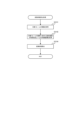
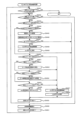
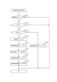
[主制御メイン処理]
図18は、メインCPU71による主制御メイン処理を示している。パチンコ遊技機1に電源が投入されると、同図に示すように、メインCPU71は、初期設定処理を行う(ステップS81)。この処理において、メインCPU71は、先述の電源投入時処理等の処理を行う。
[Main control main processing]
FIG. 18 shows main control main processing by the
次に、メインCPU71は、初期値乱数更新処理を行う(ステップS82)。この処理において、メインCPU71は、初期値乱数カウンタを更新する処理を行う。
Next, the
次に、メインCPU71は、特別図柄制御処理を行う(ステップS83)。特別図柄制御処理については、図19を参照して後述する。
Next, the
次に、メインCPU71は、普通図柄制御処理を行う(ステップS84)。普通図柄制御処理については、図25を参照して後述する。
Next, the
次に、メインCPU71は、図柄表示装置制御処理を行う(ステップS85)。この処理において、メインCPU71は、ステップS83及びステップS84でメインRAM73に記憶された特別図柄制御処理の結果及び普通図柄制御処理の結果に応じて、特別図柄表示装置61及び普通図柄表示装置62を駆動するための制御信号をメインRAM73に記憶する処理を行う。これにより、メインCPU71は、特別図柄表示装置61及び普通図柄表示装置62に制御信号を送信し、特別図柄表示装置61及び普通図柄表示装置62は、受信した制御信号に基づいて特別図柄や普通図柄を変動表示及び停止表示する。
Next, the
次に、メインCPU71は、遊技情報データ生成処理を行う(ステップS86)。この処理において、メインCPU71は、副制御回路200や払出・発射制御回路300、ホールコンピュータに送信するための遊技情報データに関する遊技状態コマンドを生成し、メインRAM73に記憶する。
Next, the
次に、メインCPU71は、記憶・遊技状態データ生成処理を行う(ステップS87)。この処理において、メインCPU71は、確変フラグの値及び時短フラグの値に基づいて、副制御回路200に送信する記憶・遊技状態データを生成し、当該記憶・遊技状態データをメインRAM73に記憶する。この処理を終了すると、メインCPU71は、ステップS82の処理に移る。
Next, the
[特別図柄制御処理]
図19は、メインCPU71による特別図柄制御処理を示している。特別図柄制御処理は、先述した主制御メイン処理の実行中にサブルーチンとして呼び出される。なお、同図に示す各処理の右方に括弧書きで記載した数値(「00」~「08」)は、制御状態フラグの値を示す。この制御状態フラグは、メインRAM73内の所定の記憶領域に格納される。メインCPU71は、制御状態フラグの数値に応じた処理を実行することにより、特別図柄ゲームを進行させる。
[Special pattern control processing]
FIG. 19 shows special symbol control processing by the
図19に示すように、メインCPU71は、制御状態フラグをロードする処理を行う(ステップS91)。この処理において、メインCPU71は、メインRAM73に記憶された制御状態フラグの値を読み出す。メインCPU71は、読み出した制御状態フラグの値に基づいて、後述のステップS92~ステップS100の各処理を実行するか否かを判定する。この制御状態フラグは、特別図柄ゲームの状態を示すものであり、ステップS92~ステップS100のいずれかの処理を実行可能にするものである。また、メインCPU71は、ステップS92~ステップS100の各処理に対して設定された待ち時間などに応じて決定された所定のタイミングで各処理を実行する。なお、この所定のタイミングに至る前は、各処理を実行せずに、他のサブルーチンに係る処理を実行する。もちろん、所定の周期で先述のシステムタイマ割込処理(図15参照)も実行する。
As shown in FIG. 19, the
次に、メインCPU71は、特別図柄記憶チェック処理を行う(ステップS92)。この処理において、メインCPU71は、制御状態フラグが特別図柄記憶チェック処理を示す値(「00」)である場合に、特別図柄の可変表示の保留個数をチェックし、保留個数が「0」でない場合(保留球がある場合)には、始動口入賞検出処理で得られた当り判定結果、特別図柄の決定結果、特別図柄の変動パターンの決定結果等を取得する。また、メインCPU71は、この処理において、制御状態フラグに、後述の特別図柄変動時間管理処理(ステップS93)を示す値(「01」)にセットし、今回の処理で取得された変動パターンに対応する特別図柄の変動時間を待ち時間タイマにセットする。すなわち、始動口入賞検出処理で決定された変動パターンに対応する特別図柄の変動時間が経過した後、後述の特別図柄表示時間管理処理が実行されるように設定される。一方、保留個数が「0」である場合(保留球がない場合)、メインCPU71は、デモ画面を表示するためのデモ表示処理を行う。この特別図柄記憶チェック処理については、図20を参照して詳述する。
Next, the
次に、メインCPU71は、特別図柄変動時間管理処理を行う(ステップS93)。この処理において、メインCPU71は、制御状態フラグが特別図柄変動時間管理処理を示す値(「01」)であり、特別図柄の変動時間が経過した場合に、制御状態フラグに、後述の特別図柄表示時間管理処理(ステップS94)を示す値(「02」)をセットし、確定後待ち時間(例えば600ms)を待ち時間タイマにセットする。すなわち、このステップS93の処理でセットされた確定後待ち時間が経過した後、後述の特別図柄表示時間管理処理が実行されるように設定される。この特別図柄変動時間管理処理については、図21を参照して詳述する。
Next, the
次に、メインCPU71は、特別図柄表示時間管理処理を行う(ステップS94)。この処理において、メインCPU71は、制御状態フラグが特別図柄表示時間管理処理を示す値(「02」)であり、ステップS93の処理でセットされた確定後待ち時間が経過した場合に、当り判定の結果が「大当り」又は「小当り」であるか否かを判断する。そして、当り判定の結果が「大当り」又は「小当り」である場合、メインCPU71は、制御状態フラグに、後述の大当り開始インターバル管理処理(ステップS95)を示す値(「03」)をセットし、大当り開始インターバルに対応する時間を待ち時間タイマにセットする。すなわち、このステップS94の処理でセットされた大当り開始インターバルに対応する時間が経過した後、後述の大当り開始インターバル管理処理が実行されるように設定される。一方、当り判定の結果が「大当り」又は「小当り」でない場合、メインCPU71は、制御状態フラグに、後述の特別図柄ゲーム終了処理(ステップS100)を示す値(「08」)をセットする。すなわち、この場合には、後述の特別図柄ゲーム終了処理が実行されるように設定される。この特別図柄表示時間管理処理については、図22を参照して後述する。
Next, the
次に、メインCPU71は、大当り開始インターバル管理処理を行う(ステップS95)。この処理において、メインCPU71は、制御状態フラグが大当り開始インターバル管理処理を示す値(「03」)であり、ステップS94の処理でセットされた大当り開始インターバルに対応する時間が経過した場合に、第1大入賞口53又は第2大入賞口54を開放させるため、メインROM72から読み出されたデータに基づいて、メインRAM73に位置付けられた変数を更新する。また、この処理において、メインCPU71は、制御状態フラグに、後述の大入賞口開放中処理(ステップS96)を示す値(「04)」をセットするとともに、大入賞口の開放上限時間(例えば30秒)を大入賞口開放時間タイマにセットする。すなわち、この処理により、後述の大入賞口開放中処理が実行されるように設定される。
Next, the
次に、メインCPU71は、大入賞口開放中処理を行う(ステップS96)。この処理において、まず、メインCPU71は、制御状態フラグが大入賞口開放中処理を示す値(「04」)である場合に、大入賞口入賞カウンタが所定数以上であるという条件、及び、開放上限時間を経過した(大入賞口開放時間タイマが「0」である)という条件の一方が満たされた(所定の閉鎖条件が成立した)か否かを判断する。一方の条件が満たされた場合、メインCPU71は、第1大入賞口53又は第2大入賞口54を閉鎖させるため、メインRAM73に位置付けられた変数を更新する。そして、メインCPU71は、制御状態フラグに、後述の大入賞口内残留球監視処理(ステップS97)を示す値(「05」)をセットするとともに、大入賞口内残留球監視時間を待ち時間タイマにセットする。すなわち、この処理により、ステップS96でセットされた大入賞口内残留球監視時間が経過した後、後述の大入賞口内残留球監視処理が実行されるように設定される。なお、この大入賞口開放中処理の終了直前には、副制御回路200に対してラウンド間表示コマンドが送信される。
Next, the
次に、メインCPU71は、大入賞口内残留球監視処理を行う(ステップS97)。この処理において、メインCPU71は、制御状態フラグが大入賞口内残留球監視処理を示す値(「05」)であり、大入賞口内残留球監視時間が経過した場合に、大入賞口開放回数カウンタの値が大入賞口開放回数の最大値以上である(最終ラウンドである)という条件が満たされたか否かを判断する。上記条件を満たさないと判別した場合、メインCPU71は、大入賞口再開放待ち時間管理処理を示す値(「06」)を制御状態フラグにセットする。また、メインCPU71は、ラウンド間インターバルに対応する時間を待ち時間タイマにセットする。すなわち、この処理により、ラウンド間インターバルに対応する時間が経過した後、後述の大入賞口再開放前待ち時間管理処理が実行されるように設定される。一方、ステップS97において、上記条件を満たしたと判別した場合、メインCPU71は、大当り終了インターバル処理を示す値(「07」)を制御状態フラグにセットし、大当り終了インターバルに対応する時間(大当り終了インターバル時間)を待ち時間タイマにセットする。すなわち、この処理でセットされた大当り終了インターバルに対応する時間が経過した後、後述の大当り終了インターバル処理が実行されるように設定される。
Next, the
次に、メインCPU71は、大入賞口開放回数カウンタの値が大入賞口開放回数の最大値以上ではないと判別した場合、大入賞口再開放前待ち時間管理処理を行う(ステップS98)。この処理において、メインCPU71は、制御状態フラグが大入賞口再開放前待ち時間管理処理を示す値(「06」)であり、ラウンド間インターバルに対応する時間が経過した場合に、大入賞口開放回数カウンタの値を「1」増加するように記憶更新する。また、メインCPU71は、大入賞口開放中処理を示す値(「04」)を制御状態フラグにセットする。そして、メインCPU71は、開放上限時間(例えば30秒)を大入賞口開放時間タイマにセットする。すなわち、この処理で上述した大入賞口開放中処理(ステップS96)が再度実行されるように設定される。なお、大入賞口再開放前待ち時間管理処理の終了直前には、副制御回路200に対して大入賞口開放中表示コマンドが送信される。
Next, when the
また、メインCPU71は、大入賞口開放回数カウンタの値が大入賞口開放回数の最大値以上であると判別した場合に、大当り終了インターバル処理を行う(ステップS99)。この処理において、メインCPU71は、制御状態フラグが大当り終了インターバル処理を示す値(「07」)であり、大当り終了インターバルに対応する時間が経過した場合に、特別図柄ゲーム終了処理を示す値(「08」)を制御状態フラグにセットする。すなわち、この処理により、ステップS99の処理後に後述の特別図柄ゲーム終了処理が実行されるように設定される。このとき、大当り中のV入賞に成功していた場合、メインCPU71は、遊技状態を確変遊技状態に移行させる制御を行い、大当り中のV入賞に失敗していた場合には、遊技状態を非確変遊技状態に移行させる制御を行う。なお、大当り図柄が「小当り」に対応する図柄である場合、メインCPU71は、遊技状態を維持するような制御を行う。
Further, when the
次に、メインCPU71は、大当り遊技状態あるいは小当り遊技状態が終了した場合、又は、「ハズレ」に当選した場合、特別図柄ゲーム終了処理を行う(ステップS100)。この処理において、メインCPU71は、制御状態フラグが特別図柄ゲーム終了処理を示す値(「08」)である場合に、保留個数を示すデータ(始動記憶情報)を「1」減少するように記憶更新する。また、メインCPU71は、次回の特別図柄の変動表示を行うために、特別図柄記憶領域の更新を行う。さらに、メインCPU71は、特別図柄記憶チェック処理を示す値(「00」)を制御状態フラグにセットする。すなわち、この処理により、ステップS100の処理後、上述した特別図柄記憶チェック処理(ステップS92)が実行されるように設定される。この特別図柄ゲーム終了処理を終了すると、メインCPU71は、特別図柄制御処理を終了する。
Next, the
上述したように、本実施形態のパチンコ遊技機1では、制御状態フラグに各種値を順次セットすることにより、特別図柄ゲームを進行させる。具体的に、遊技状態が大当り遊技状態及び小当り遊技状態のいずれでもなく、当り判定の結果が「ハズレ」である場合に、メインCPU71は、制御状態フラグを「00」、「01」、「02」、「08」の順にセットする。これにより、メインCPU71は、上述した特別図柄記憶チェック処理(ステップS92)、特別図柄変動時間管理処理(ステップS93)、特別図柄表示時間管理処理(ステップS94)及び特別図柄ゲーム終了処理(ステップS100)をこの順で所定のタイミングで実行する。
As described above, in the
また、メインCPU71は、遊技状態が大当り遊技状態及び小当り遊技状態のいずれでもなく、当り判定の結果が「大当り」又は「小当り」である場合、制御状態フラグを「00」、「01」、「02」、「03」の順でセットする。これにより、メインCPU71は、上述した特別図柄記憶チェック処理(ステップS92)、特別図柄変動時間管理処理(ステップS93)、特別図柄表示時間管理処理(ステップS94)及び大当り開始インターバル管理処理(ステップS95)をこの順で所定のタイミングで実行し、大当り遊技状態又は小当り遊技状態への移行制御を実行する。
In addition, when the gaming state is neither a jackpot gaming state nor a small winning gaming state, and the result of the winning determination is "jackpot" or "small winning", the
さらに、メインCPU71は、大当り遊技状態又は小当り遊技状態への移行制御が実行された場合、制御状態フラグを「04」、「05」、「06」の順でセットする。これにより、メインCPU71は、上述した大入賞口開放中処理(ステップS96)、大入賞口内残留球監視処理(ステップS97)及び大入賞口再開放前待ち時間管理処理(ステップS98)をこの順で所定のタイミングで実行し、大当り遊技又は小当り遊技を実行する。
Further, the
なお、大当り遊技状態中に、当該大当り遊技状態の終了条件が成立した場合、メインCPU71は、制御状態フラグを「04」、「05」、「07」、「08」の順でセットする。これにより、メインCPU71は、上述した大入賞口開放中処理(ステップS96)、大入賞口内残留球監視処理(ステップS97)、大当り終了インターバル処理(ステップS99)及び特別図柄ゲーム終了処理(ステップS100)をこの順で所定のタイミングで実行し、大当り遊技状態を終了する。
Note that when the termination condition of the jackpot gaming state is satisfied during the jackpot gaming state, the
上述したように、特別図柄制御処理では、ステータスに応じて処理フローを分岐させている。また、図18に示す主制御メイン処理中のステップS84の普通図柄制御処理(後述の図25参照)もまた、特別図柄制御処理と同様に、ステータスに応じて処理フローを分岐させる。 As mentioned above, in the special symbol control process, the process flow is branched depending on the status. In addition, the normal symbol control process (see FIG. 25 described later) in step S84 during the main control main process shown in FIG. 18 also branches the processing flow depending on the status, similar to the special symbol control process.
本実施形態の処理プログラムは、ステータスに応じて処理を分岐させて行う場合にコール命令で、小モジュールから親モジュールへの純粋な戻り処理が可能となるように、プログラミングされている。その結果、上記処理を実行するためにジャンプテーブルを配置する場合と比較して、本実施形態では、プログラムの容量を削減することができる。 The processing program of this embodiment is programmed so that pure return processing from a small module to a parent module can be performed using a call instruction when processing is branched according to the status. As a result, in this embodiment, the capacity of the program can be reduced compared to the case where a jump table is arranged to execute the above processing.
[特別図柄記憶チェック処理]
図20は、メインCPU71による特別図柄記憶チェック処理を示している。特別図柄記憶チェック処理は、先述した特別図柄制御処理の実行中にサブルーチンとして呼び出される。同図に示すように、まず、メインCPU71は、メインRAM73内の所定の記憶領域から制御状態フラグをロード処理によって読み出す(ステップS101)。
[Special symbol memory check process]
FIG. 20 shows a special symbol storage check process by the
次に、メインCPU71は、読み出した制御状態フラグが特別図柄記憶チェック処理を示す値(「00」)であるか否かを判別する(ステップS102)。制御状態フラグが「00」でないと判別した場合、メインCPU71は、特別図柄記憶チェック処理を終了する。一方、制御状態フラグが「00」であると判別した場合、メインCPU71は、ステップS103の処理に移る。
Next, the
ステップS103において、メインCPU71は、第2始動口入賞(第2特別図柄の可変表示)の保留個数(第2始動記憶数)が「0」であるか否かを判別する。第2始動口入賞の保留個数が「0」でないと判別した場合、メインCPU71は、ステップS104の処理に移る。第2始動口入賞の保留個数が「0」であると判別した場合、メインCPU71は、ステップS109の処理に移る。
In step S103, the
ステップS104において、メインCPU71は、第2始動口入賞の保留個数に対応する第2始動記憶数の値を「1」減算する。本実施形態において、メインCPU71は、メインRAM73に設けられた第2特別図柄始動記憶領域(0)~第2特別図柄始動記憶領域(4)にデータが記憶されているか否かを判別して、変動中又は保留中の第2特別図柄の可変表示に対応する特別図柄ゲームの始動記憶があるか否かを判別する。第2特別図柄始動記憶領域(0)には、変動中の第2特別図柄の可変表示に対応する特別図柄ゲームのデータ(情報)が始動記憶情報として記憶される。そして、第2特別図柄始動記憶領域(1)~第2特別図柄始動記憶領域(4)には、保留されている4回分の第2特別図柄の可変表示(保留球)に対応する特別図柄ゲームのデータ(情報)が始動記憶情報として記憶される。なお、各第2特別図柄始動記憶領域の始動記憶情報には、例えば、第2始動口45の入賞時に取得した当り判定用乱数値や図柄乱数値、決定された変動パターン等を示すデータが含まれる。
In step S104, the
次に、メインCPU71は、第2始動口入賞に基づいて特別図柄記憶転送処理を行う(ステップS105)。この処理において、メインCPU71は、第2特別図柄始動記憶領域(1)~(4)のデータを、それぞれ第2特別図柄始動記憶領域(0)~(3)にシフトする。このときまた、メインCPU71は、副制御回路200に対して保留減算コマンドを送信する。その後、メインCPU71は、ステップS106の処理に移る。
Next, the
ステップS106において、メインCPU71は、制御状態フラグに特別図柄変動時間管理処理を示す値(「01」)をセットする処理を行う。このときまた、メインCPU71は、副制御回路200に対して特別図柄演出開始コマンドを送信する。
In step S106, the
次に、メインCPU71は、大当り・小当り判定処理を行う(ステップS107)。この処理において、メインCPU71は、始動口入賞時に抽出され、かつ、第1特別図柄始動記憶領域(0)又は第2特別図柄始動記憶領域(0)において先にセットされた大当り判定用乱数値に基づき、入賞始動口の種別に対応する当り乱数判定テーブル(図11参照)を参照して、判定値データを取得する。そして、メインCPU71は、取得した判定値データに基づいて、「大当り」、「小当り」及び「ハズレ」のいずれに当選したかを判定(当り判定)する。
Next, the
次に、メインCPU71は、決定された特別図柄の変動パターンに対応する変動時間を待ち時間タイマにセットする(ステップS108)。この処理を終了すると、メインCPU71は、特別図柄記憶チェック処理を終了する。
Next, the
ステップS109において、メインCPU71は、第1始動口入賞(第1特別図柄の可変表示)の保留個数(第2始動記憶数)が「0」であるか否かを判別する。第1始動口入賞の保留個数が「0」でないと判別した場合、メインCPU71は、ステップS110の処理に移る。第1始動口入賞の保留個数が「0」であると判別した場合、メインCPU71は、ステップS112の処理に移る。
In step S109, the
ステップS110において、メインCPU71は、第1始動口入賞の保留個数に対応する第1始動記憶数の値を「1」減算する。本実施形態において、メインCPU71は、メインRAM73に設けられた第1特別図柄始動記憶領域(0)~第1特別図柄始動記憶領域(4)にデータが記憶されているか否かを判別して、変動中又は保留中の第1特別図柄の可変表示に対応する特別図柄ゲームの始動記憶があるか否かを判別する。第1特別図柄始動記憶領域(0)には、変動中の第1特別図柄の可変表示に対応する特別図柄ゲームのデータ(情報)が始動記憶情報として記憶される。そして、第1特別図柄始動記憶領域(1)~第1特別図柄始動記憶領域(4)には、保留されている4回分の第1特別図柄の可変表示(保留球)に対応する特別図柄ゲームのデータ(情報)が始動記憶情報として記憶される。なお、各第1特別図柄始動記憶領域の始動記憶情報には、例えば、第1始動口44の入賞時に取得した当り判定用乱数値や図柄乱数値、決定された変動パターン等を示すデータが含まれる。
In step S110, the
次に、第1始動口入賞に基づいて特別図柄記憶転送処理を行う(ステップS111)。この処理において、メインCPU71は、第1特別図柄始動記憶領域(1)~(4)のデータを、それぞれ第1特別図柄始動記憶領域(0)~(3)にシフトする。このときまた、メインCPU71は、副制御回路200に対して保留減算コマンドを送信する。その後、メインCPU71は、ステップS106の処理に移る。
Next, special symbol storage transfer processing is performed based on the first starting opening winning (step S111). In this process, the
ステップS112において、メインCPU71は、デモ画面を表示するためのデモ表示処理を行う。この処理において、メインCPU71は、特別図柄表示装置61において特別図柄の変動が停止してから所定時間が経過したか否かを判断し、所定時間が経過したと判断した場合に、副制御回路200に対してデモ表示コマンドを送信する。
In step S112, the
本実施形態では、特別図柄表示装置61において特別図柄の変動が停止した後、所定時間に亘って第1始動口44及び第2始動口45への入賞が発生しなかった場合に、デモ画面が表示される。
In this embodiment, after the special symbols stop changing on the special
具体的に、メインCPU71は、ステップS108でセットした待ち時間タイマ(特別図柄の変動パターンに対応する変動時間)が0になった場合(図21のステップS122参照)に、デモ移行用タイマをオンにセットする。すなわち、メインCPU71は、特別図柄の変動が停止してから経過した時間の計測を開始する。そして、メインCPU71は、ステップS112において、デモ移行用タイマの値が所定値(例えば、3分に対応する値)以上であるか否かを判断し、デモ移行用タイマの値が所定値以上であると判断した場合に、副制御回路200に対してデモ表示コマンドを送信する。デモ表示コマンドを受信すると、副制御回路200では、デモ画面の表示に係る処理が行われる。
Specifically, the
なお、デモ移行用タイマの値が所定値に達する前に、第1始動口44又は第2始動口45への入賞が発生した場合、メインCPU71は、デモ移行用タイマをオフにする。具体的に、メインCPU71は、図17のステップS51において第1始動口入賞球センサ44aで遊技球を検出したと判断した場合、デモ移行用タイマをオフにする。また、メインCPU71は、図17のステップS59において第2始動口入賞球センサ45aで遊技球を検出したと判断した場合、デモ移行用タイマをオフにする。これにより、メインCPU71は、特別図柄の変動が停止してから経過した時間の計測を終了する。
Note that if a winning occurs in the
本実施形態では、以上の処理が実行されることにより、特別図柄の変動が停止した後始動口(第1始動口44及び第2始動口45)への入賞が発生しないまま所定時間が経過した場合に、デモ画面に移行することになる。ステップS112の処理を終了すると、メインCPU71は、特別図柄記憶チェック処理を終了する。
In this embodiment, by executing the above processing, a predetermined period of time has passed without any winnings occurring in the starting openings (the first starting
[特別図柄変動時間管理処理]
図21を用いて、図19のステップS93で行われる特別図柄変動時間管理処理について説明する。図21は、メインCPU71により実行される特別図柄変動時間管理処理を示すフローチャートである。この特別図柄変動時間管理処理は、以下のステップ単位に実行される。
[Special symbol fluctuation time management process]
The special symbol variation time management process performed in step S93 of FIG. 19 will be explained using FIG. 21. FIG. 21 is a flowchart showing the special symbol variation time management process executed by the
図21に示すように、ステップS121において、メインCPU71は、制御状態フラグが特別図柄変動時間管理を示す値(「01」)であるか否かの判定を行う。メインCPU71は、特別図柄変動時間管理を示す値(「01」)であると判定した場合には、ステップS122に処理を移す。一方、メインCPU71は、特別図柄変動時間管理を示す値(「01」)でないと判定した場合には、特別図柄変動時間管理処理ルーチンを終了する。
As shown in FIG. 21, in step S121, the
ステップS122において、メインCPU71は、待ち時間タイマが「0」であるか否かの判定を行う。メインCPU71は、待ち時間タイマが「0」であると判定した場合には、ステップS123に処理を移す。待ち時間タイマが「0」でないと判定した場合には、特別図柄変動時間管理処理ルーチンを終了する。
In step S122, the
ステップS123において、メインCPU71は、特別図柄表示時間管理を示す値(「02」)を制御状態フラグにセット(記憶)する処理を行い、ステップS124に処理を移す。
In step S123, the
ステップS124において、メインCPU71は、特別図柄演出停止コマンドをセットする処理を行う。この処理において、メインCPU71は、特別図柄演出停止コマンドをメインRAM73にセット(記憶)する処理を行う。そして、特別図柄演出停止コマンドは、主制御回路70のメインCPU71から副制御回路200のサブCPU81に図柄停止コマンドとして供給されることにより、副制御回路200が図柄停止を認識するようになる。この処理を終了した場合には、ステップS125に処理を移す。
In step S124, the
ステップS125において、メインCPU71は、メインRAM73における待ち時間タイマとして機能する領域に、確定後待ち時間をセットする処理を行う。この処理を終了した場合には、特別図柄変動時間管理処理ルーチンを終了する。
In step S125, the
[特別図柄表示時間管理処理]
図22は、メインCPU71による特別図柄表示時間管理処理を示している。特別図柄表示時間管理処理は、先述した特別図柄制御処理の実行中にサブルーチンとして呼び出される。同図に示すように、メインCPU71は、制御状態フラグが特別図柄表示時間管理処理を示す値(「02」)であるか否かを判別する(ステップS131)。制御状態フラグが特別図柄表示時間管理処理を示す値(「02」)でないと判別した場合、メインCPU71は、特別図柄表示時間管理処理を終了する。一方、制御状態フラグが特別図柄表示時間管理処理を示す値(「02」)であると判別した場合、メインCPU71は、ステップS132の処理に移る。
[Special symbol display time management process]
FIG. 22 shows special symbol display time management processing by the
ステップS132において、メインCPU71は、待ち時間タイマの値(待ち時間)が「0」であるか否かを判別する。この処理において、メインCPU71は、待ち時間タイマにセットされた変動確定後の待ち時間(変動開始待ち時間)が消化されたか否かを判別する。待ち時間タイマの値が「0」でないと判別した場合、メインCPU71は、特別図柄表示時間管理処理を終了する。一方、待ち時間タイマの値が「0」であると判別した場合、メインCPU71は、ステップS133の処理に移る。
In step S132, the
ステップS133において、メインCPU71は、特別図柄ゲームが「大当り」であるか否かを判別する。特別図柄ゲームが「大当り」であると判別した場合、メインCPU71は、ステップS142の処理に移る。一方、特別図柄ゲームが「大当り」でないと判別した場合、メインCPU71は、ステップS134の処理に移る。
In step S133, the
ステップS134において、メインCPU71は、さらに特別図柄ゲームが「小当り」であるか否かを判別する。特別図柄ゲームが「小当り」であると判別した場合、メインCPU71は、ステップS137の処理に移る。一方、特別図柄ゲームが「小当り」でないと判別した場合、すなわち特別図柄ゲームが「はずれ」の場合、メインCPU71は、ステップS135の処理に移る。
In step S134, the
ステップS135において、メインCPU71は、時短・確変回数減算処理を行う。この時短・確変回数減算処理については、図23を参照して後述する。
In step S135, the
次に、メインCPU71は、制御状態フラグに特別図柄ゲーム終了処理を示す値(「08」)をセットする処理を行う(ステップS136)。この処理を終了すると、メインCPU71は、特別図柄表示時間管理処理を終了する。
Next, the
ステップS137において、メインCPU71は、小当りを示す小当りフラグをセットする処理を行う。この処理を終了すると、メインCPU71は、ステップS138の処理に移る。
In step S137, the
ステップS138において、メインCPU71は、制御状態フラグに大当り開始インターバル管理処理を示す値(「03」)をセットする処理を行う。
In step S138, the
次に、メインCPU71は、特別図柄(第1特別図柄又は第2特別図柄)に対応する大当り開始インターバル時間(例えば、5000ms)を待ち時間タイマにセットする処理を行う(ステップS139)。
Next, the
次に、メインCPU71は、特別図柄に対応する大当り開始コマンド又は小当り開始コマンドをメインRAM73にセットする処理を行う(ステップS140)。これにより、副制御回路200には、大当り開始コマンド又は小当り開始コマンドが送信される。
Next, the
次に、メインCPU71は、大当り種類決定テーブル(図13参照)を参照し、特別図柄(図柄指定コマンドの種別)に対応するラウンド数上限値(大入賞口開放回数上限値)をメインRAM73にセットし、ラウンド数表示LEDパターンフラグをセットする(ステップS141)。なお、ラウンド数表示LEDパターンフラグは、残りラウンド数を所定パターンで表示するか否かを示すフラグである。この処理を終了すると、メインCPU71は、特別図柄表示時間管理処理を終了する。
Next, the
ステップS142において、メインCPU71は、大当りを示す大当りフラグをセットする処理を行う。この処理を終了すると、メインCPU71は、S143の処理に移る。
In step S142, the
ステップS143において、メインCPU71は、時短状態変動回数カウンタ、並びに時短フラグ及び確変フラグをクリアする処理を行う。この処理を終了すると、メインCPU71は、ステップS138の処理に移る。
In step S143, the
[時短・確変回数減算処理]
図23は、メインCPU71による時短・確変回数減算処理を示している。時短・確変回数減算処理は、先述した特別図柄表示時間管理処理あるいは後述の大当り終了インターバル処理の実行中にサブルーチンとして呼び出される。同図に示すように、メインCPU71は、時短状態変動回数カウンタの値が0であるか否かを判別する(ステップS151)。時短状態変動回数カウンタは、セットされた時短回数(本実施形態では一例として100回)が0になるまで計数する減算カウンタである。時短状態変動回数カウンタの値が0である場合、メインCPU71は、ステップS155の処理に移る。時短状態変動回数カウンタの値が0でない場合、メインCPU71は、ステップS152の処理に移る。
[Time-saving/definite variable number subtraction process]
FIG. 23 shows the time saving/probability variation count subtraction process by the
ステップS152において、メインCPU71は、時短状態変動回数カウンタの値を1減算する処理を行う。
In step S152, the
次に、メインCPU71は、再び時短状態変動回数カウンタの値が0であるか否かを判別する(ステップS153)。時短状態変動回数カウンタの値が0である場合、メインCPU71は、ステップS154の処理に移る。時短状態変動回数カウンタの値が0でない場合、メインCPU71は、ステップS155の処理に移る。
Next, the
ステップS154において、メインCPU71は、時短フラグとして「0」をセットする処理を行う。この処理を終了すると、メインCPU71は、ステップS155の処理に移る。
In step S154, the
ステップS155において、メインCPU71は、確変状態変動回数カウンタの値が0であるか否かを判別する。確変状態変動回数カウンタは、セットされた確変回数(本実施形態では一例として124回)が0になるまで計数する減算カウンタである。確変状態変動回数カウンタの値が0である場合、メインCPU71は、時短・確変回数減算処理を終了する。確変状態変動回数カウンタの値が0でない場合、メインCPU71は、ステップS156の処理に移る。
In step S155, the
ステップS156において、メインCPU71は、確変状態変動回数カウンタの値を1減算する処理を行う。
In step S156, the
次に、メインCPU71は、再び確変状態変動回数カウンタの値が0であるか否かを判別する(ステップS157)。確変状態変動回数カウンタの値が0である場合、メインCPU71は、ステップS158の処理に移る。確変状態変動回数カウンタの値が0でない場合、メインCPU71は、時短・確変回数減算処理を終了する。
Next, the
ステップS158において、メインCPU71は、確変フラグとして「0」をセットする処理を行う。この処理を終了すると、メインCPU71は、時短・確変回数減算処理を終了する。
In step S158, the
[大当り終了インターバル処理]
図24は、メインCPU71による大当り終了インターバル処理を示している。大当り終了インターバル処理は、先述した特別図柄制御処理の実行中にサブルーチンとして呼び出される。同図に示すように、メインCPU71は、制御状態フラグが大当り終了インターバル処理を示す値(「07」)であるか否かを判別する(ステップS161)。制御状態フラグが大当り終了インターバル処理を示す値(「07」)でないと判別した場合(Sステップ161:NO)、メインCPU71は、大当り終了インターバル処理を終了する。一方、制御状態フラグが大当り終了インターバル処理を示す値(「07」)であると判別した場合、メインCPU71は、ステップS162の処理に移る。
[Jackpot end interval processing]
FIG. 24 shows the jackpot end interval process by the
ステップS162において、メインCPU71は、待ち時間タイマの値が「0」であるか否かを判別する。この処理において、メインCPU71は、待ち時間タイマにセットされた大当り終了インターバル時間が消化されたか否かを判別する。待ち時間タイマの値が「0」でないと判別した場合、メインCPU71は、大当り終了インターバル処理を終了する。一方、待ち時間タイマの値が「0」であると判別した場合、メインCPU71は、ステップS163の処理に移る。
In step S162, the
ステップS163において、メインCPU71は、大入賞口開放回数表示LEDパターンフラグをクリアする。大入賞口開放回数表示LEDパターンフラグは、大当り時のラウンド数をLEDの発光パターンによって表示するか否かを示す管理フラグとして用いられる。
In step S163, the
次に、メインCPU71は、ラウンド数振り分けフラグをクリアする(ステップS164)。このラウンド数振り分けフラグは、メインRAM73に格納される管理フラグの一つであり、1ラウンド中にあっても予め決められた回数だけ第1大入賞口53又は第2大入賞口54を周期的に開閉させるか否かを示すためのフラグである。1ラウンド中でも第1大入賞口53又は第2大入賞口54を周期的に開閉させる場合は、ラウンド数振り分けフラグが「1」となる。このときまた、メインCPU71は、副制御回路200に対して特別図柄当り終了表示コマンドを送信する。
Next, the
次に、メインCPU71は、制御状態フラグに特別図柄ゲーム終了処理を示す値(「08」)をセットする処理を行う(ステップS165)。
Next, the
次に、メインCPU71は、特別図柄ゲームが「大当り」であるか否かを判別する(ステップS166)。特別図柄ゲームが「大当り」であると判別した場合、メインCPU71は、ステップS167の処理に移る。一方、特別図柄ゲームが「大当り」でないと判別した場合、メインCPU71は、ステップS174の処理に移る。
Next, the
ステップS167において、メインCPU71は、大当りフラグの値をクリアする処理を行う。
In step S167, the
次に、メインCPU71は、大当り中にV入賞に成功したか否かを判別する(ステップS168)。V入賞に成功した場合、メインCPU71は、ステップS169の処理に移る。V入賞に失敗した場合、メインCPU71は、ステップS171の処理に移る。
Next, the
ステップS169において、メインCPU71は、確変フラグとして「1」をセットする処理を行う。
In step S169, the
次に、メインCPU71は、確変状態変動回数カウンタに規定の確変回数(本実施形態では一例として124回)をセットする処理を行う(ステップS170)。
Next, the
次に、メインCPU71は、時短フラグとして「1」をセットする処理を行う(ステップS171)。
Next, the
次に、メインCPU71は、時短状態変動回数カウンタに規定の時短回数(本実施形態では一例として100回)をセットする処理を行う(ステップS172)。この処理を終了すると、メインCPU71は、大当り終了インターバル処理を終了する。
Next, the
ステップS174において、メインCPU71は、小当りフラグの値をクリアする処理を行う。この処理を終了すると、メインCPU71は、大当り終了インターバル処理を終了する。
In step S174, the
[普通図柄制御処理]
図25は、メインCPU71による普通図柄制御処理を示している。普通図柄制御処理は、先述した主制御メイン処理の実行中にサブルーチンとして呼び出される。なお、図25に示すフローチャート中の各処理の右方に括弧書きで記載した数値(「00」~「04」)は、普通図柄制御状態フラグを示し、この普通図柄制御状態フラグは、メインRAM73内の所定の記憶領域に格納される。メインCPU71は、普通図柄制御状態フラグの数値に対応する各処理を実行することにより、普通図柄ゲームを進行させる。
[Normal symbol control processing]
FIG. 25 shows normal symbol control processing by the
図25に示すように、メインCPU71は、普通図柄制御状態フラグをロードする処理を行う(ステップS191)。この処理において、メインCPU71は、メインRAM73に記憶された普通図柄制御状態フラグを読み出す。メインCPU71は、読み出した普通図柄制御状態フラグの値に基づいて、後述のステップS192~ステップS196の各種の処理を実行するか否かを判定する。この普通図柄制御状態フラグは、普通図柄ゲームの遊技の状態を示すものであり、ステップS192~ステップS196のいずれかの処理を実行可能にするものである。また、メインCPU71は、ステップS192~ステップS196の各処理に対して設定された待ち時間などに応じて決定される所定のタイミングで各処理を実行する。なお、この所定のタイミングに至る前は、各処理を実行せずに他のサブルーチン処理を実行する。もちろん、所定の周期で先述のシステムタイマ割込処理(図15参照)も実行する。
As shown in FIG. 25, the
次に、メインCPU71は、普通図柄記憶チェック処理を行う(ステップS192)。この処理において、メインCPU71は、普通図柄制御状態フラグが普通図柄記憶チェック処理を示す値(「00」)である場合に、普通図柄の可変表示の保留個数をチェックし、保留個数が「0」でないときには、当り判定等の処理を行う。また、この処理において、メインCPU71は、普通図柄制御状態フラグに後述の普通図柄変動時間監視処理(ステップS193)を示す値(「01」)をセットし、今回の処理で決定された変動時間を待ち時間タイマにセットする。すなわち、ステップS192の処理により、決定された普通図柄の変動時間が経過した後、後述の普通図柄変動時間監視処理が実行されるように設定される。
Next, the
次に、メインCPU71は、普通図柄変動時間監視処理を行う(ステップS193)。この処理において、メインCPU71は、普通図柄制御状態フラグが普通図柄変動時間監視処理を示す値(「01」)であり、普通図柄の変動時間が経過した場合に、普通図柄制御状態フラグに後述の普通図柄表示時間監視処理(ステップS194)を示す値(「02」)をセットし、確定後待ち時間(例えば0.5秒)を待ち時間タイマにセットする。すなわち、ステップS193の処理により、セットされた確定後待ち時間が経過した後、後述の普通図柄表示時間監視処理が実行されるように設定される。
Next, the
次に、メインCPU71は、普通図柄表示時間監視処理を行う(ステップS194)。この処理において、メインCPU71は、普通図柄制御状態フラグが普通図柄表示時間監視処理を示す値(「02」)であり、ステップS193の処理でセットされた確定後待ち時間が経過した場合に、当り判定の結果が「当り」であるか否かを判断する。そして、当り判定の結果が「当り」である場合、メインCPU71は、普通電動役物開放設定処理を行い、普通図柄制御状態フラグに後述の普通電動役物開放処理(ステップS195)を示す値(「03」)をセットする。すなわち、この処理により、後述の普通電動役物開放処理が実行されるように設定される。一方、当り判定の結果が「当り」でない場合、メインCPU71は、普通図柄制御状態フラグに後述の普通図柄ゲーム終了処理(ステップS196)を示す値(「04」)をセットする。すなわち、この場合には、後述の普通図柄ゲーム終了処理が実行されるように設定される。
Next, the
次に、メインCPU71は、ステップS194において当り判定の結果が「当り」であると判定された場合、普通電動役物開放処理を行う(ステップS195)。この処理において、メインCPU71は、普通図柄制御状態フラグが普通電動役物開放処理を示す値(「03」)である場合に、普通電動役物46の開放中において所定数の入賞があったという条件、及び、普通電動役物46の開放上限時間を経過した(普通電役開放時間タイマが「0」である)という条件の一方が満たされたか否かを判断する。上記一方の条件が満たされた場合、メインCPU71は、普通電動役物46である羽根状の部材を閉鎖状態にするため、メインRAM73に位置付けられた変数を更新する。そして、メインCPU71は、普通図柄制御状態フラグに後述の普通図柄ゲーム終了処理(ステップS196)を示す値(「04」)をセットする。すなわち、この処理により、後述の普通図柄ゲーム終了処理が実行されるように設定される。
Next, if the result of the hit determination is determined to be a "win" in step S194, the
次に、メインCPU71は、普通図柄ゲーム終了処理を行う(ステップS196)。この処理において、メインCPU71は、普通図柄制御状態フラグが普通図柄ゲーム終了処理を示す値(「04」)である場合に、普通図柄の可変表示の保留個数を示すデータを「1」減少させるように記憶更新する。また、メインCPU71は、次回の普通図柄の変動表示を行うために、普通図柄記憶領域の更新を行う。さらに、メインCPU71は、普通図柄制御状態フラグに普通図柄記憶チェック処理を示す値(「00」)をセットする。すなわち、ステップS196の処理後、上述した普通図柄記憶チェック処理(ステップS192)が実行されるように設定される。この処理を終了すると、メインCPU71は、普通図柄制御処理を終了する。
Next, the
[副制御回路メイン処理]
一方、副制御回路200は、副制御回路メイン処理を実行することとなる。この副制御回路メイン処理について図26を用いて説明する。なお、この副制御回路メイン処理は、電源が投入されたときに開始される処理である。
[Sub control circuit main processing]
On the other hand, the
図26に示すように、サブCPU201は、RAMアクセス許可、作業領域の初期化、ハードウェア初期化、デバイス初期化、アプリケーション初期化、バックアップ復帰初期化等といった初期化処理を行う(ステップS201)。
As shown in FIG. 26, the
次に、サブCPU201は、ウォッチドッグタイマのカウンタ値をクリアする処理を行う(ステップS202)。ウォッチドッグタイマは、起動時にリセット時間(例えば2000ms)が設定され、サービスパルスの書き込みが行われなかった場合(タイムアウト時)に電断処理が実行されることとなる。
Next, the
次に、サブCPU201は、操作手段入力処理を実行する(ステップS203)。操作手段入力処理については、図28を参照して後述する。
Next, the
次に、サブCPU201は、コマンド解析処理を実行する(ステップS204)。コマンド解析処理については、図29を参照して後述する。
Next, the
次に、サブCPU201は、演出態様決定処理を実行する(ステップS205)。この処理(アニメーションリクエスト構築処理)において、サブCPU201は、演出内容の指定情報を含むアニメーションリクエストを生成し、該アニメーションリクエストに基づいて、各種演出装置を動作させるための各種リクエスト(描画リクエスト、サウンドリクエスト、ランプリクエスト、及び、役物リクエスト)を生成する。演出態様決定処理については、後に図30を用いて説明する。
Next, the
次に、サブCPU201は、描画制御処理を実行する(ステップS206)。この処理において、サブCPU201は、描画リクエストを表示制御回路205に送信する。表示制御回路205は、サブCPU201から送信されたメッセージ(描画リクエスト)に基づいて液晶表示装置13に画像を表示させるための描画制御を行う。
Next, the
次に、サブCPU201は、音声制御処理を実行する(ステップS207)。この処理において、サブCPU201は、サウンドリクエストを音声制御回路206に送信する。音声制御回路206は、サブCPU201から送信されたメッセージ(サウンドリクエスト)に基づいてスピーカ11に音声を出力させるための音声制御を行う。
Next, the
次に、サブCPU201は、LED制御処理を実行する(ステップS208)。この処理において、サブCPU201は、ランプリクエストをLED制御回路207に送信する。LED制御回路207は、サブCPU201から送信されたメッセージ(ランプリクエスト)に基づいてLED59A~59E、59e~59hを点灯あるいは点滅させるための発光制御を行う。
Next, the
次に、サブCPU201は、役物制御処理を実行する(ステップS209)。この処理において、サブCPU201は、役物リクエストを駆動制御回路208に送信する。駆動制御回路208は、サブCPU201から送信されたメッセージ(役物リクエスト)に基づいて可動役物に係る演出用駆動モータ60を動作させるための駆動制御を行う。このような副制御回路メイン処理においては、ステップS201の初期化処理が終了した後、ステップS202からステップS209の各処理が繰り返し実行される。
Next, the
[ボタン入力割込処理]
図27は、サブCPU201によるボタン入力割込処理を示している。ボタン入力割込処理は、測定用のタイマ更新により例えば1msごとに副制御回路メイン処理に並行して実行される。同図に示すように、サブCPU201は、演出ボタンスイッチ230から入力信号があるか否かを判別している(ステップS221)。演出ボタンスイッチ230から入力信号がある場合、サブCPU201は、ステップS222の処理に移る。演出ボタンスイッチ230から入力信号がない場合、サブCPU201は、ボタン入力割込処理を終了する。
[Button input interrupt processing]
FIG. 27 shows button input interruption processing by the
ステップS222において、サブCPU201は、演出ボタンスイッチ230からの入力信号に基づいて演出ボタン23の操作状態を判断し、当該操作状態を示す情報を生成する。この処理を終了すると、サブCPU201は、ボタン入力割込処理を終了する。
In step S222, the
[操作手段入力処理]
図28は、サブCPU201による操作手段入力処理を示している。操作手段入力処理は、先述した副制御回路メイン処理の実行中にサブルーチンとして呼び出される。同図に示すように、サブCPU201は、操作状態を示す情報に基づいて操作状態を取得する(ステップS231)。操作状態には、演出ボタン23であれば押下回数等が含まれ、ジョグダイヤル24であれば回転方向や回転角度、さらには回転速度等が含まれる。演出エフェクトは、操作状態に応じて決定される。この処理を終了すると、サブCPU201は、操作手段入力処理を終了する。
[Operation means input processing]
FIG. 28 shows operation means input processing by the
[コマンド解析処理]
次に、図29を参照して、副制御メイン処理(図26参照)中のステップS204で行うコマンド解析処理について説明する。図29は、本実施形態におけるコマンド解析処理の手順を示すフローチャートである。
[Command analysis processing]
Next, with reference to FIG. 29, the command analysis process performed in step S204 in the sub-control main process (see FIG. 26) will be described. FIG. 29 is a flowchart showing the procedure of command analysis processing in this embodiment.
まず、サブCPU201は、ワークRAM203に格納された受信コマンドを取得すると共に、取得した受信コマンドを解析する処理を行う(ステップS241)。なお、この際、受信コマンドに対応付けられたエラー情報がある場合には、サブCPU201は、該受信コマンドを破棄する。
First, the
また、サブCPU201は、受信したコマンドの解析において、該コマンドの種別を特定する。また、この処理では、サブCPU201は、特定したコマンド種別の情報をワークRAM203に保存する。なお、コマンド種別は、各コマンドのコマンド種別部(先頭バイト領域)に格納された情報(予め設定された値)に基づいて特定される。
Furthermore, in analyzing the received command, the
なお、サブCPU201が、コマンド種別の特定処理において受信したコマンドと対応するコマンド種別がないと判断した場合、サブCPU201は、該受信コマンドを破棄する。また、サブCPU201は、受信コマンドに含まれるパラメータ数を確認し、該パラメータ数が特定されたコマンド種別に対応するパラメータ数と異なる場合には、該受信コマンドを破棄する。
Note that if the
次いで、サブCPU201は、受信したコマンドの整合性をチェックする処理(コマンドパラメータチェック処理)を行う(ステップS242)。この処理では、サブCPU201は、コマンド毎に設定されている各種パラメータ内の情報(以下、コマンドパラメータという)の内容をチェックする。具体的には、サブCPU201は、例えば、パラメータ内の所定のビット領域に設けられた常時0領域のチェック、パラメータ内に格納されている各データの有効範囲のチェック、及び、格納データの組み合わせのチェックを行う。
Next, the
また、サブCPU201は、受信したコマンドの整合性のチェックにおいて、受信コマンドに含まれるコマンドパラメータが正常であるか否かのチェックを行う。具体的には、サブCPU201は、コマンドパラメータが正常であるか否か(コマンドの有効性の有無)を判別する。なお、サブCPU201が、受信コマンドに含まれるコマンドパラメータが正常でないと判別した場合、サブCPU201は、該受信コマンドのデータを破棄する。
Furthermore, in checking the consistency of the received command, the
一方、サブCPU201が、受信コマンドに含まれるコマンドパラメータが正常であると判別した場合、サブCPU201は、コマンドパラメータ(ゲームステータス等の情報)をゲームデータに反映(登録)させる。また、サブCPU201は、コマンドパラメータが反映されたゲームデータをワークRAM203内の所定領域に格納する。なお、「ゲームデータ」とは、コマンド内のパラメータの情報などが含まれ、サブCPU201で行われる各種抽選処理やアニメーションリクエスト構築処理などで参照されるデータの構造体(記憶領域又は変数の集合体)のことをいう。「ゲームデータ」には、後述するように、各種抽選処理の抽選結果の情報(例えば演出パターン等)も登録される。
On the other hand, if the
次いで、サブCPU201は、サブ抽選処理を行う(ステップS243)。この処理では、サブCPU201は、演出用の各種乱数値を取得し、受信したコマンドのコマンド種別に対応する演出内容の決定に係る抽選処理を行う。
Next, the
例えば、受信したコマンドが特別図柄演出開始コマンドである場合には、サブCPU201は、装飾図柄の変動パターン(サブ変動パターン)、背景画像を表示する画像演出パターンなど、各種の演出パターンを決定する。また、例えば、受信したコマンドが保留個数増加コマンドである場合には、サブCPU201は、先読み演出に係る演出パターンを決定する。
For example, when the received command is a special symbol performance start command, the
また、ステップS243の処理では、サブCPU201は、サブ抽選処理の抽選結果(例えば、上述した各種演出パターンの情報)をワークRAM203内の所定領域に格納する。
Further, in the process of step S243, the
次に、サブCPU201は、デモ移行制御処理を実行する(ステップS244)。この処理において、サブCPU201は、受信したコマンドがデモ表示コマンド(図20のステップS112参照)である場合に、描画リクエスト(液晶表示装置13にデモ画面を表示させるためのリクエスト)を生成する。
Next, the
次いで、サブCPU201は、演出パターン選択の処理を行う(ステップS245)。この処理では、サブCPU201は、ステップS243のサブ抽選処理により得られた抽選結果(演出パターン)の選択を行う。具体的には、サブCPU201は、ステップS243のサブ抽選処理により得られた演出パターン(例えば、サブ変動パターンや、先読み演出に係る演出パターン)をワークRAM203に格納されたゲームデータに反映(登録)させる。そして、ステップS245の処理後、サブCPU201は、コマンド解析処理を終了し、処理を副制御回路メイン処理(図26参照)のステップS205に移す。
Next, the
[演出態様決定処理]
次に、図30を参照して、副制御メイン処理(図26参照)中のステップS205で行う演出態様決定処理について説明する。なお、図30は、本実施形態における演出態様決定処理の手順を示すフローチャートである。
[Production mode determination process]
Next, with reference to FIG. 30, the production mode determining process performed in step S205 in the sub-control main process (see FIG. 26) will be described. Note that FIG. 30 is a flowchart showing the procedure of the production mode determination process in this embodiment.
まず、サブCPU201は、カメラ映像解析処理を実行する(ステップS261)。カメラ映像解析処理については、後に図31を用いて説明する。
First, the
次に、サブCPU201は、映像関係の選択処理を行う(ステップS262)。この処理では、サブCPU201は、ワークRAM203に格納されたゲームデータの情報を参照し、アニメーションリクエストを生成し、該アニメーションリクエストをワークRAM203の所定領域にセットする。この処理によりコマンド受信及びカメラ映像の解析結果に応じたアニメーションリクエストが生成される。次いで、サブCPU201は、アニメーションリクエストに基づいて、描画リクエスト(液晶表示装置13を制御するための制御信号)を生成する。
Next, the
次いで、サブCPU201は、ランプパターン(ランプリクエスト)選択処理を行う(ステップS263)。この処理では、サブCPU201は、ランプリクエスト(LED59を制御するための制御信号)を生成する。
Next, the
次いで、サブCPU201は、サウンドパターン(サウンドリクエスト)選択処理を行う(ステップS264)。この処理では、サブCPU201は、サウンドリクエスト(スピーカ11を制御するための制御信号)を生成する。
Next, the
次いで、サブCPU201は、その他(すなわち、映像関係、ランプリクエスト、及びサウンドリクエスト以外)の選択処理を行う(ステップS265)。なお、この処理には、例えば各種役物の演出動作を制御するための役物リクエストの選択処理が含まれる。
Next, the
そして、ステップS265の処理後、サブCPU201は、演出態様決定処理を終了し、処理を副制御回路メイン処理(図26参照)のステップS206に移す。
After the process of step S265, the
[カメラ映像解析処理]
図31を用いて、図30のステップS261で行われるカメラ映像解析処理について説明する。図31は、本発明の一実施形態に係るパチンコ遊技機において実行されるカメラ映像解析処理を示すフローチャートである。
[Camera video analysis processing]
The camera video analysis process performed in step S261 in FIG. 30 will be described using FIG. 31. FIG. 31 is a flowchart showing a camera image analysis process executed in a pachinko gaming machine according to an embodiment of the present invention.
まず、サブCPU201は、CCDカメラ1000から、撮影によって得られた画像データを受信する(ステップS281)。本実施形態において、CCDカメラ1000によって撮影された画像(カメラ映像)は、複数の静止画像(フレーム画像)から構成される動画像である。すなわち、カメラ映像は、多数の静止画像(フレーム画像)が経時的に連続することにより構成される内容となっている。CCDカメラ1000のフレームレートは、特に限定されないが、例えば、250fps(frames per second)のCCDカメラを採用することができる。ステップS281の処理において、サブCPU201は、CCDカメラ1000の備える制御LSIに対して、フレーム画像に対応するデータ(フレーム画像データ)の送信を要求する。CCDカメラ1000では、副制御回路200に送信すべきフレーム画像データが存在する場合、1フレーム分のフレーム画像データをバッファに記憶することが可能である。CCDカメラ1000の制御LSIは、フレーム画像データがバッファに記憶されている場合、当該フレーム画像データを副制御回路200に送信する。このようにして、CCDカメラ1000によって撮影された画像は、フレーム単位で副制御回路200に入力される。フレーム画像データを受信すると、サブCPU201は、受信したフレーム画像データをワークRAM203に記憶させる。
First, the
次に、サブCPU201は、受信したフレーム画像データに対して、射影変換を行う。図32(a)は、射影変換を行う前の画像を示す図である。図32(b)は、射影変換を行った後の画像を示す図である。上述したように、本実施形態において、CCDカメラ1000は、撮影対象となる遊技盤12の上側に位置しており(図6参照)、遊技盤12を上方から撮影する。このことに起因して、CCDカメラ1000によって撮影された画像には、歪みが生じ、当該画像は、下に伸びて見えることになる(図32(a)参照)。このような画像に対して4点マーカーに基づく射影変換を行うことにより、当該歪みを補正することができる(図32(b)参照)。
Next, the
また、サブCPU201は、フレーム画像データに対して、各画素における濃淡を示す値(画素値)を変換すること(画素ごとの濃淡変換)により、コントラストを強調する処理を行う(ステップS282)。この処理において、サブCPU201は、画素ごとの濃淡変換(濃度変換)前の各画素値と濃度変換後の各画素値との対応関係を示す所定の関数に基づいて、各画素値を変換する。このような濃淡変換は、例えば、ヒストグラム伸張化やヒストグラム平坦化等の方法により行うことができる。これにより、フレーム画像の濃淡にメリハリをつけることができる。
Further, the
さらに、サブCPU201は、フレーム画像データに対して、各画素の周囲の画素も含めた濃淡変換(領域に基づく濃淡変換)により、フィルタリングを行う(ステップS283)。この処理において、サブCPU201は、所定の空間フィルタを用いることにより、各画素値を変換する。空間フィルタとしては、例えば、平滑化フィルタを用いることができ、平滑化フィルタとしては、平均化フィルタ(移動平均フィルタ)や加重平均化フィルタを用いることができる。本実施形態では、例えば、加重平均化フィルタとして、ガウシアンフィルタ(ガウスフィルタ)を用いることが望ましい。ガウスフィルタでは、ガウス分布を示す関数に基づいて、フィルタによって覆われる領域内の画素に対して重み付けがなされる。
Further, the
図33は、移動平均フィルタの一例を示す図である。図33(a)では、3×3画素のフィルタを示し、図33(b)では、5×5画素のフィルタを示している。移動平均フィルタでは、フィルタによって覆われる領域内の画素値が全て同じ値(当該領域内の画素値の平均値)となっている。図34は、加重平均化フィルタの一例を示す図である。図34(a)では、3×3画素のフィルタを示し、図34(b)では、5×5画素のフィルタを示している。このような加重平均化フィルタ(ガウスフィルタ)では、移動平均フィルタと比較して、フィルタの原点(注目画素)に近い画素ほど重み付けの程度が大きくなっており、こうしたフィルタを用いることによって、より滑らかで自然な平滑化を行うことができる。以上で説明したような空間フィルタリングでは、フィルタリング後の画像(出力画像)中の一の画素の値が、フィルタリング前の画像(入力画像)における当該一の画素に対応する画素の値だけではなく、図33及び図34に示すように当該画素の周囲の画素を含む一定の範囲内の画素の値に基づいて計算される。また、移動平均フィルタ及び加重平均化フィルタでは、フレーム画像データに対して、一の値が設定された一のパラメータ(例えば、係数等)を適用することで、各画素に対する処理を実行することが可能であるが、特に、加重平均化フィルタでは、フレーム画像データの頂点部分(例えば、フレーム画像データの中心部分等)からの距離をガウス関数に適用して一の値を求めることができる。従って、ガウス関数に渡す値を変更すれば、各画素に対して設定する値を容易に変更することができる。また、ガウス関数では、二次元のみならず三次元で計算した場合にも、頂点部分からどの程度の距離にあるかによってパラメータを求めることができるため、重み付けを行う処理を各画素で共通化し、引数を変更することで各画素に対する処理を行うことが可能となり、処理の汎用性を高めることもできる。なお、一の値が記憶された一のパラメータを適用する例に限定されず、複数の値が記憶された一のパラメータ(例えば、係数、配列、構造体等)、複数の値が記憶された複数のパラメータ(例えば、係数、配列、構造体等)、一の値が記憶された複数のパラメータ(例えば、係数、配列、構造体等)などを様々に設定することが可能である。これにより、フレーム画像に含まれるノイズに起因する濃淡変動を軽減することができる。 FIG. 33 is a diagram illustrating an example of a moving average filter. FIG. 33(a) shows a 3×3 pixel filter, and FIG. 33(b) shows a 5×5 pixel filter. In the moving average filter, all the pixel values in the area covered by the filter are the same value (the average value of the pixel values in the area). FIG. 34 is a diagram illustrating an example of a weighted averaging filter. FIG. 34(a) shows a 3×3 pixel filter, and FIG. 34(b) shows a 5×5 pixel filter. In such a weighted averaging filter (Gaussian filter), compared to a moving average filter, pixels closer to the origin of the filter (the pixel of interest) are weighted to a greater degree, and by using such a filter, smoother Natural smoothing can be performed with In spatial filtering as explained above, the value of one pixel in the image after filtering (output image) is not only the value of the pixel corresponding to that one pixel in the image before filtering (input image); As shown in FIGS. 33 and 34, it is calculated based on the values of pixels within a certain range including pixels around the pixel. Furthermore, in moving average filters and weighted averaging filters, processing can be performed on each pixel by applying one parameter (for example, a coefficient, etc.) to which one value is set to frame image data. Although it is possible, in particular, in a weighted averaging filter, a value of one can be determined by applying the distance from the vertex portion of the frame image data (for example, the center portion of the frame image data, etc.) to a Gaussian function. Therefore, by changing the value passed to the Gaussian function, the value set for each pixel can be easily changed. In addition, with the Gaussian function, when calculating not only in two dimensions but also in three dimensions, parameters can be determined based on the distance from the vertex, so the weighting process is shared by each pixel, By changing the arguments, it is possible to process each pixel, and the versatility of the process can also be increased. Note that this is not limited to the example in which a single parameter with a single value stored is applied; it is also possible to apply a single parameter with multiple values stored (e.g., a coefficient, an array, a structure, etc.), or a single parameter with multiple values stored. It is possible to variously set a plurality of parameters (for example, a coefficient, an array, a structure, etc.), a plurality of parameters in which one value is stored (for example, a coefficient, an array, a structure, etc.), and the like. Thereby, it is possible to reduce density fluctuations caused by noise included in the frame image.
本実施形態では、以上で説明した射影変換、コントラストの強調、空間フィルタリング等の技術、その他の画像処理技術を用いることにより、フレーム画像データに対して処理を行って、画質の向上を図ることが可能である。以上のようにして得られるフレーム画像データは、ワークRAM203に記憶され、以降の処理に用いられる。ステップS282及びステップS283の処理は、以降の処理においてフレーム画像における遊技球の位置を抽出しやすくするための前処理として位置付けられる。
In this embodiment, by using techniques such as projective transformation, contrast enhancement, spatial filtering, etc. described above, and other image processing techniques, frame image data can be processed to improve image quality. It is possible. The frame image data obtained as described above is stored in the
次に、サブCPU201は、前後フレーム間の差分を抽出する処理を行う(ステップS284)。以下、前後フレーム間差分抽出について、図35~図40を用いて説明する。
Next, the
<前後フレーム間差分抽出>
図35は、前後フレーム間差分抽出の概念図である。図36は、遊技球が遊技領域を転動する様子を示す図である。図37は、時刻T1に撮影されたフレーム画像と時刻T2に撮影されたフレーム画像とから差分画像(1)を得る過程を示す図である。図38は、時刻T2に撮影されたフレーム画像と時刻T3に撮影されたフレーム画像とから差分画像(2)を得る過程を示す図である。図39は、差分画像(1)と差分画像(2)とから時刻T2における遊技球を抽出する過程を示す図である。図40は、マスキング領域を示す図である。
<Extraction of differences between previous and subsequent frames>
FIG. 35 is a conceptual diagram of difference extraction between the preceding and following frames. FIG. 36 is a diagram showing how the game ball rolls in the game area. FIG. 37 is a diagram showing a process of obtaining a difference image (1) from a frame image photographed at time T1 and a frame image photographed at time T2. FIG. 38 is a diagram showing a process of obtaining a difference image (2) from a frame image photographed at time T2 and a frame image photographed at time T3. FIG. 39 is a diagram showing a process of extracting game balls at time T2 from the difference image (1) and the difference image (2). FIG. 40 is a diagram showing masking areas.
図36では、複数の遊技球が遊技領域12aを転動している状態において、1個の遊技球に着目し、時刻T1における当該遊技球の位置を遊技球120aとして示し、時刻T2における当該遊技球の位置を遊技球120bとして示し、時刻T3における当該遊技球の位置を遊技球120cとして示している。なお、遊技球120a、遊技球120b、及び、遊技球120cの近傍には、LED59(演出LED)が設けられている。
In FIG. 36, in a state where a plurality of game balls are rolling in the
図35に示すように、時刻T1では演出LEDが消灯しており、時刻T1と時刻T2との間に演出LEDが点灯し、その後時刻T4にかけて演出LEDの点灯している状態が継続していると仮定する。 As shown in FIG. 35, the effect LED is off at time T1, the effect LED is turned on between time T1 and time T2, and then continues to be lit until time T4. Assume that
図37~図39では、CCDカメラ1000によって撮影される全範囲のうち、時刻T1~時刻T3の間に1個の遊技球(図36に示す遊技球)が移動する領域の近傍に着目して示している。これらの図では、説明を分かりやすくするため、撮影範囲の一部のみを示しているが、実際には、撮影範囲全体について以下の処理が一括で行われる。なお、遊技球と演出LED以外については、図示を省略している。
In FIGS. 37 to 39, out of the entire range photographed by the
前後フレーム間差分抽出においては、まず、図37に示すように、時刻T1に撮影されたフレーム画像(1フレーム目の画像)及び時刻T2に撮影されたフレーム画像(2フレーム目の画像)に対して差分処理を実行することにより、1フレーム目の画像と2フレーム目の画像との差分に対応する画像を作成する。当該画像は、1フレーム目の画像及び2フレーム目の画像における各画素値の差の絶対値を示している。このようにして得られる画像を差分画像(1)とする。なお、差分処理を行った後しきい値処理を施すことによって得られる2値画像を、差分画像(1)としてもよい。2値化により、しきい値以上の画素値を1(白画素)に、しきい値未満の画素値を0(黒画素)に変換することで(逆でも可)、1フレーム目の画像と2フレーム目の画像との間で特に変化の大きかった領域を抽出することができる。差分画像(1)は、時刻T1における遊技球(遊技球120a)、時刻T2における遊技球(遊技球120b)、及び、LED59(演出LED)の位置情報を含んでいる。
In the difference extraction between the preceding and following frames, first, as shown in FIG. By performing difference processing, an image corresponding to the difference between the first frame image and the second frame image is created. The image shows the absolute value of the difference between each pixel value between the first frame image and the second frame image. The image obtained in this way is referred to as a difference image (1). Note that a binary image obtained by performing threshold processing after performing difference processing may be used as the difference image (1). Through binarization, pixel values above the threshold are converted to 1 (white pixels) and pixel values below the threshold are converted to 0 (black pixels) (the reverse is also possible), and the image of the first frame is It is possible to extract a region where there is a particularly large change between the second frame image and the second frame image. The difference image (1) includes position information of the game ball (
次に、図38に示すように、時刻T2に撮影されたフレーム画像(2フレーム目の画像)及び時刻T3に撮影されたフレーム画像(3フレーム目の画像)に対して差分処理を実行することにより、2フレーム目の画像と3フレーム目の画像との差分に対応する画像を作成する。当該画像は、2フレーム目の画像及び3フレーム目の画像における各画素値の差の絶対値を示している。このようにして得られる画像を差分画像(2)とする。なお、差分処理を行った後しきい値処理を施すことによって得られる2値画像を、差分画像(2)としてもよい。2値化により、しきい値以上の画素値を1(白画素)に、しきい値未満の画素値を0(黒画素)に変換することで(逆でも可)、2フレーム目の画像と3フレーム目の画像との間で特に変化の大きかった領域を抽出することができる。差分画像(2)は、時刻T2における遊技球(遊技球120b)、及び、時刻T3における遊技球(遊技球120c)の位置情報を含んでいる。
Next, as shown in FIG. 38, differential processing is performed on the frame image photographed at time T2 (second frame image) and the frame image photographed at time T3 (third frame image). As a result, an image corresponding to the difference between the second frame image and the third frame image is created. The image shows the absolute value of the difference between each pixel value in the second frame image and the third frame image. The image obtained in this way is referred to as a difference image (2). Note that a binary image obtained by performing threshold processing after performing difference processing may be used as the difference image (2). By binarizing, pixel values above the threshold are converted to 1 (white pixels) and pixel values below the threshold are converted to 0 (black pixels) (the reverse is also possible), and the second frame image and It is possible to extract a region where there is a particularly large change between the third frame image and the third frame image. The difference image (2) includes position information of the game ball (
次に、図39に示すように、差分画像(1)と差分画像(2)との論理積をとる処理(AND処理)を行う。これにより、差分画像(1)と差分画像(2)との共通部分が抽出され、このようにして得られる画像(差分画像(1)と差分画像(2)とのAND画像)は、時刻T2における遊技球(遊技球120b)の位置情報を示すことになる。
Next, as shown in FIG. 39, a process (AND process) of calculating the logical product of the difference image (1) and the difference image (2) is performed. As a result, the common part between difference image (1) and difference image (2) is extracted, and the image obtained in this way (AND image of difference image (1) and difference image (2)) is obtained at time T2. This shows the position information of the game ball (
以上のようにして、本実施形態では、演出LEDの点灯及び消灯の影響を排除しつつ、時刻T2における遊技球の位置を検出することができる。同様に、2フレーム目の画像と3フレーム目の画像との差分に対応する画像(差分画像(2))と、3フレーム目の画像と4フレーム目の画像との差分に対応する画像(差分画像(3))との論理積をとることにより、時刻T3における遊技球の位置を検出することができる(図35参照)。 As described above, in this embodiment, the position of the game ball at time T2 can be detected while eliminating the influence of turning on and turning off the performance LED. Similarly, an image corresponding to the difference between the second frame image and the third frame image (difference image (2)) and an image corresponding to the difference between the third frame image and the fourth frame image (difference image By performing a logical product with image (3)), the position of the game ball at time T3 can be detected (see FIG. 35).
なお、時刻T2から時刻T3にかけて演出LEDの点灯している状態は継続しているため、差分画像(2)には、LED59(演出LED)の位置情報が含まれていない(図38参照)。従って、当該差分画像(2)と、差分画像(1)と差分画像(2)とのAND画像(図39参照)との差分をとることによっても、時刻T3における遊技球の位置を検出することができる。このようにすれば、より迅速に遊技球の位置を検出することが可能であり、遊技球の転動(位置変化)に応じて、演出等の各種制御をよりリアルタイムに実行することができる。 Note that since the effect LED continues to be lit from time T2 to time T3, the difference image (2) does not include position information of the LED 59 (effect LED) (see FIG. 38). Therefore, the position of the game ball at time T3 can also be detected by taking the difference between the difference image (2) and the AND image (see FIG. 39) of the difference image (1) and the difference image (2). I can do it. In this way, the position of the game ball can be detected more quickly, and various controls such as performances can be executed in real time in accordance with the rolling (change in position) of the game ball.
上述したように、本実施形態では、CCDカメラ1000のフレームレートが250fpsとなっている。すなわち、CCDカメラ1000によるフレーム画像の取得間隔は、1フレーム当たり4ミリ秒である。一方、LED59(演出LED)は、12ミリ秒の周期間隔で点滅する(12ミリ秒の点灯と12ミリ秒の消灯とが繰り返される)ように制御され、CCDカメラ1000による画像取得間隔が、演出LEDの点滅周期間隔の1/3となっている。本実施形態では、CCDカメラ1000による画像取得間隔を、演出LEDの点滅周期間隔の1/2以下(又は、1/3以下、1/4以下等)とすることが望ましい。あるいは、演出LEDの状態が「消灯→点灯→消灯」又は「点灯→消灯→点灯」と切り替わる場合における点灯区間又は消灯区間のうちの最短区間の長さが、CCDカメラ1000による画像取得間隔の2倍以上(又は、3倍以上、4倍以上等)となるように、演出LEDを制御することが望ましい。
As described above, in this embodiment, the frame rate of the
これにより、演出LEDの状態が「消灯→点灯→消灯」又は「点灯→消灯→点灯」と切り替わった場合であっても、連続する3つのフレーム画像(1フレーム目の画像、2フレーム目の画像、及び、3フレーム目の画像)として、下記(i)~(vi)のうちの何れかを取得することができる。「消灯状態」及び「点灯状態」は、各フレーム画像に含まれる演出LEDの状態を示している。下記(i)~(vi)の何れであっても、以上で説明した方法により、演出LEDの点灯及び消灯の影響を排除しつつ、遊技球の位置を検出することができる。
(i)1フレーム目の画像:消灯状態、2フレーム目の画像:消灯状態、3フレーム目の画像:点灯状態
(ii)1フレーム目の画像:消灯状態、2フレーム目の画像:点灯状態、3フレーム目の画像:点灯状態
(iii)1フレーム目の画像:点灯状態、2フレーム目の画像:消灯状態、3フレーム目の画像:消灯状態
(iv)1フレーム目の画像:点灯状態、2フレーム目の画像:点灯状態、3フレーム目の画像:消灯状態
(v)1フレーム目の画像:消灯状態、2フレーム目の画像:消灯状態、3フレーム目の画像:消灯状態
(vi)1フレーム目の画像:点灯状態、2フレーム目の画像:点灯状態、3フレーム目の画像:点灯状態
As a result, even if the state of the production LED changes from "off → on → off" or "on → off → on", three consecutive frame images (first frame image, second frame image) , and the third frame image), any of the following (i) to (vi) can be obtained. The "unlit state" and the "lit state" indicate the states of the effect LEDs included in each frame image. In any of the following (i) to (vi), by the method described above, the position of the game ball can be detected while eliminating the influence of turning on and turning off the performance LED.
(i) 1st frame image: light off state, 2nd frame image: light off state, 3rd frame image: light on state (ii) 1st frame image: light off state, 2nd frame image: light on state, 3rd frame image: Lighted state (iii) 1st frame image: Lighted state, 2nd frame image: Lights off state, 3rd frame image: Lights off state (iv) 1st frame image: Lighted state, 2 1st frame image: Lights off, 3rd frame image: Lights off (v) 1st frame image: Lights off, 2nd frame image: Lights off, 3rd frame image: Lights off (vi) 1st frame Eye image: lit state, 2nd frame image: lit state, 3rd frame image: lit state
なお、図36~図39の例では、遊技球の近傍にLED59(演出LED)が設けられている場合について説明したが、演出LED以外の他の物体が設けられている場合についても、同様の説明が妥当する。当該他の物体には、静止している物体だけではなく、動作可能な物体(可動部材)も含まれる。そのような可動部材としては、入賞口(始動口)への遊技球の入球を可能にする状態(開放状態)と遊技球の入球を不可能又は困難にする状態(閉鎖状態)とを切り替え可能な(開閉動作を行う)役物や、その他の演出用の可動役物等、遊技盤における所定位置に配設された各種可動部材を挙げることができる。具体的には、遊技盤の左右方向に回動する電動チューリップ型の役物、羽根状の部材を動作させる役物、遊技盤の前後方向に水平移動する舌状部材から構成される役物、遊技盤に対して垂直な方向又は鉛直方向を回転軸として回転可能な回転部材等を挙げることができる。このような可動部材は、遊技盤における所定位置を基準として(位置を変化させずに)動作を行うことにより、その外観を経時的に変化させるため、当該外観の変化がフレーム画像にも現れることになる。しかし、図36~図39を用いて説明した方法によって、当該可動部材を画像から除去することが可能であり、そうした外観変化の影響を排除しつつ、遊技球の位置を検出することができる。 In addition, in the examples of FIGS. 36 to 39, the case where the LED 59 (effect LED) is provided near the game ball has been explained, but the same applies to the case where other objects other than the effect LED are provided. The explanation is valid. The other objects include not only stationary objects but also movable objects (movable members). Such a movable member has two states: a state that allows the game ball to enter the prize opening (starting port) (open state) and a state that makes it impossible or difficult to enter the game ball (closed state). Examples include various movable members disposed at predetermined positions on the game board, such as switchable accessories (opening/closing) and other movable accessories for performance. Specifically, an electric tulip-shaped accessory that rotates in the left-right direction of the game board, an accessory that operates a wing-shaped member, an accessory that consists of a tongue-shaped member that moves horizontally in the front-rear direction of the game board, Examples include a rotating member that can rotate in a direction perpendicular or perpendicular to the game board as a rotation axis. Such a movable member changes its appearance over time by moving with respect to a predetermined position on the game board (without changing its position), so the change in appearance may also appear in the frame image. become. However, by the method described using FIGS. 36 to 39, it is possible to remove the movable member from the image, and the position of the game ball can be detected while eliminating the influence of such changes in appearance.
また、遊技球の位置情報を誤って検出する要因となる構造物(例えば、発射通路や風車等)の配置された領域や、遊技球の追跡が必要のない領域(遊技球が通過し得ない領域)に対して、予めマスキングを行って(図40参照)、当該領域を画像処理の対象から外すこととしてもよい。これにより、誤検出を防止することが可能であるとともに、画像処理にかかる負担を軽減することができる。なお、図40において、黒く塗りつぶした領域がマスキング領域である。図40では、発射通路となるガイド経路41c(遊技球が玉放出口41dから遊技領域12aに放出されるまでに通過する領域)、及び、風車125(図36参照)にマスキングが施されている様子を示している。なお、図40では、風車125の一部(上下の僅かな部分)にマスキングが施されていない様子を示しているが、風車125全体がマスキング領域に含まれることとしてもよい。
In addition, areas where there are structures (e.g. launch passageways, windmills, etc.) that can cause incorrect detection of the position information of the game ball, and areas where it is not necessary to track the game ball (where the game ball cannot pass through) The area) may be masked in advance (see FIG. 40), and the area may be excluded from the image processing target. This makes it possible to prevent erroneous detection and reduce the burden on image processing. Note that in FIG. 40, the blacked out area is the masking area. In FIG. 40, masking is applied to the
以上、図35~図40を用いて、図31のステップS284で行われる前後フレーム間差分抽出処理について説明した。図31に説明を戻す。 The difference extraction process between the preceding and following frames performed in step S284 in FIG. 31 has been described above with reference to FIGS. 35 to 40. The explanation returns to FIG. 31.
ステップS284の処理を実行した後、サブCPU201は、射出位置(射出領域)及び排出位置(排出領域)の確認を行う(ステップS285)。以下、射出領域及び排出領域について、図41及び図42を用いて説明する。
After executing the process in step S284, the
<射出領域及び排出領域>
図41は、射出領域及び排出領域を示す図である。図42は、遊技球に対するIDの割り当てについて説明するための概念図である。
<Injection area and discharge area>
FIG. 41 is a diagram showing an injection area and an ejection area. FIG. 42 is a conceptual diagram for explaining the assignment of IDs to game balls.
図41に示すように、射出領域及び排出領域は、遊技領域12a内の一定範囲として設定された領域である。図中、射出領域及び排出領域は、四角で囲まれた領域として示している。射出領域は、遊技球が玉放出口41d(図5参照)から遊技領域12aに放出される際に最初に通過する領域である。排出領域は、遊技領域12aを転動した遊技球が遊技領域12aの外部に排出される際に最後に通過する領域である。具体的に、射出領域は、玉戻り防止片42(図5参照)の近傍における所定範囲内の領域である。排出領域としては、排出領域1~5の5つの領域が設定されている。排出領域1は、第1始動口44の近傍における所定範囲内の領域であり、排出領域2は、第2始動口45の近傍における所定範囲内の領域であり、排出領域3は、第1大入賞口53の近傍における所定範囲内の領域であり、排出領域4は、第2大入賞口54の近傍における所定範囲内の領域であり、排出領域5は、アウト口55の近傍における所定範囲内の領域である。また、図41では図示していないが、一般入賞口の近傍における所定範囲内の領域も排出領域となる。
As shown in FIG. 41, the injection area and the ejection area are areas set as fixed ranges within the
本実施形態では、複数の遊技球が同時に遊技領域12aを転動し得るが、これらの複数の遊技球には、それぞれ識別情報(ID)が割り当てられている。各遊技球のIDには、当該遊技球の位置情報が対応付けられており、複数の遊技球がそれぞれ、遊技領域12a内のどこに存在するのかが、個別に管理されている。
In this embodiment, a plurality of game balls can roll in the
図42に示すように、IDとは、各遊技球に対して、それぞれ異なる数字やマークや色を割り当てるようなイメージである。IDは、遊技球が玉放出口41dから遊技領域12aに放出された直後(射出領域を通過する際)に割り当てられる。具体的に、図31のステップS285において、サブCPU201は、以下の処理を行う。
As shown in FIG. 42, the ID is an image in which different numbers, marks, and colors are assigned to each game ball. The ID is assigned immediately after the game ball is released from the
上述した前後フレーム間差分抽出処理(図31のステップS284参照)において、遊技領域12aを転動している各遊技球の位置が検出される。このようにして位置が特定された複数の遊技球(遊技領域12aを転動する複数の遊技球)のなかに、射出領域に属する遊技球があれば、当該遊技球に対して新たにIDを割り当てる。図42では、一の遊技球が射出領域内に完全に収まっている様子を示しているが、一の遊技球の少なくとも一部分が射出領域に含まれていれば、当該遊技球に対してIDを割り当てることとする。なお、一の遊技球が射出領域に属していたとしても、当該遊技球に対して既にIDが割り当てられている場合には、再度IDを割り当てる必要はないが、その場合、再度IDを割り当て直すこととしてもよい。サブCPU201は、当該新たにIDを割り当てられた遊技球の位置情報と、当該新たなIDとを対応付けて、ワークRAM203に記憶させる。
In the above-described difference extraction process between the previous and subsequent frames (see step S284 in FIG. 31), the position of each game ball rolling in the
なお、射出領域を通過した全ての遊技球に対してIDを割り当ててもよいが、割り当てることの可能なIDの数に上限を設定しておき、既に割り当てられたIDの数が上限に達している場合には、既にIDを割り当てた遊技球の追跡(図44参照)を優先し、射出領域を通過した遊技球に対してIDを割り当てないこととしてもよい。一方、新たなIDの割り当てを優先し、既にIDを割り当てた遊技球(例えば、射出領域を通過してからの経過時間が最も長い遊技球)の追跡を終了してIDを解放した上で、新たに射出領域を通過した遊技球に対して当該IDを割り当てることとしてもよい。 Note that IDs may be assigned to all game balls that have passed through the ejection area, but an upper limit is set for the number of IDs that can be assigned, and if the number of IDs that have already been assigned reaches the upper limit, If so, priority may be given to tracking game balls to which IDs have already been assigned (see FIG. 44), and IDs may not be assigned to game balls that have passed through the ejection area. On the other hand, priority is given to assigning a new ID, and after completing the tracking of the game ball to which an ID has already been assigned (for example, the game ball that has elapsed the longest time since passing through the ejection area) and releasing the ID, The ID may be assigned to a game ball that has newly passed through the ejection area.
また、追跡対象となる遊技球の数が増えすぎないように、遊技状態に応じて、射出領域を通過した遊技球に対して新たにIDを割り当てるのを一時停止することにより、新たに遊技領域に発射される遊技球を追跡対象から外すこととしてもよい。また、追跡処理の負担の大きな領域をマスキング領域として追跡対象領域から外し、単純にマスキング領域以外の遊技領域に遊技球が存在するか否かを判定するようにしてもよい。さらに、既に割り当てられたIDの数が所定数以上の場合(遊技領域12aに存在する遊技球の総数が一定以上の場合)には、射出領域を遊技球がN個(例えば、2個)通過するごとに、当該N個の遊技球のうち最初に射出領域を通過した遊技球のみが追跡対象となるように、当該遊技球にのみIDを割り当てることとしてもよい。例えば、大当り遊技状態においては、通常遊技状態よりも、遊技球が長時間に亘って遊技領域12aに保留されやすくなっている。遊技球の転動速度が遅くなるような構造を有するアタッカーも存在する。そのような場合に、遊技領域12aに存在する全ての遊技球の追跡を行うこととすれば、処理負担が増大してしまう。この点、上記のような構成を採用すれば、遊技領域12a内に通常よりも多くの遊技球が滞留する場合であっても、遊技球の追跡にかかる処理負担を一定限度に抑えることができる。一方で、そのような場合であっても、一部の遊技球に対する追跡を行うことによって、不正行為(図48参照)等への対策を講ずることができる。
In addition, in order to prevent the number of game balls to be tracked from increasing too much, depending on the game status, new IDs can be temporarily suspended for game balls that have passed through the ejection area. It is also possible to exclude game balls that are fired from the tracking target. Alternatively, an area that requires a large burden of tracking processing may be set as a masking area and removed from the tracking target area, and it may be simply determined whether or not a game ball exists in a gaming area other than the masking area. Furthermore, if the number of already assigned IDs is a predetermined number or more (if the total number of game balls existing in the
一方、前後フレーム間差分抽出処理(図31のステップS284参照)により位置が特定された複数の遊技球(遊技領域12aを転動する複数の遊技球)のなかに、排出領域1~5の何れかに属する遊技球が存在するかを確認する。一の遊技球が排出領域内に完全に収まっている場合だけでなく、一の遊技球の少なくとも一部分が排出領域に含まれていれば、当該遊技球は排出領域に属すると判定する。排出領域1~5の何れかに属する遊技球が存在する場合、サブCPU201は、当該遊技球のIDと対応付けて、当該遊技球が排出領域に属することを示す情報(排出直前フラグ)を、ワークRAM203に記憶させる。
On the other hand, among the plurality of game balls (the plurality of game balls rolling in the
このような射出領域及び排出領域は、それぞれ任意に設定することができる。例えば、遊技機のホールメニューや各種設定画面において、予め定められた複数の領域のなかから選択された一の領域を、射出領域や排出領域として設定することが可能である。また、タッチパネル等を用いて、遊技盤内における任意の領域を、射出領域や排出領域として設定することができるように構成してもよい。もちろん、機種に応じて予め自動的に設定されていてもよい。排出領域は、始動口や大入賞口の近傍の他、一般入賞口の近傍に設定してもよい。また、入賞口の近傍に排出領域を設定する場合、入賞口が大きいほど、排出領域が広い範囲で設定されるようにしてもよい。なお、マスキング領域(図40参照)についても、射出領域や排出領域と同様に設定することが可能である。 Such an injection area and an ejection area can be set arbitrarily. For example, in a hall menu or various setting screens of a gaming machine, it is possible to set one area selected from a plurality of predetermined areas as the injection area or the ejection area. Further, a touch panel or the like may be used to configure any area within the game board to be set as the injection area or the ejection area. Of course, it may be automatically set in advance depending on the model. The discharge area may be set in the vicinity of the general winning opening in addition to the vicinity of the starting opening and the big winning opening. Further, when setting the discharge area near the winning opening, the larger the winning opening, the wider the discharge area may be set. Note that the masking area (see FIG. 40) can also be set in the same way as the injection area and the ejection area.
以上、図41及び図42を用いて、図31のステップS285で行われる射出排出位置確認処理について説明した。図31に説明を戻す。 The injection and discharge position confirmation process performed in step S285 in FIG. 31 has been described above with reference to FIGS. 41 and 42. The explanation returns to FIG. 31.
ステップS285の処理を実行した後、サブCPU201は、遊技媒体追跡処理を実行する(ステップS286)。以下、遊技媒体追跡処理について、図43~図45を用いて説明する。
After executing the process of step S285, the
<遊技媒体追跡処理>
図43(a)は、時刻T2における遊技球の位置を示す図である。図43(b)は、時刻T3における遊技球の位置を示す図である。図44は、本発明の一実施形態に係るパチンコ遊技機において実行される遊技媒体追跡処理を示すフローチャートである。図45は、時刻T2における遊技球の位置を基準とした検索範囲を示す図である。
<Game media tracking process>
FIG. 43(a) is a diagram showing the position of the game ball at time T2. FIG. 43(b) is a diagram showing the position of the game ball at time T3. FIG. 44 is a flowchart showing a game medium tracking process executed in a pachinko game machine according to an embodiment of the present invention. FIG. 45 is a diagram showing a search range based on the position of the game ball at time T2.
図35~図39を用いて説明したように、時刻T1に撮影されたフレーム画像(1フレーム目の画像)と、時刻T2に撮影されたフレーム画像(2フレーム目の画像)と、時刻T3に撮影されたフレーム画像(3フレーム目の画像)とに基づいて、時刻T2における遊技球の位置が特定される。 As explained using FIGS. 35 to 39, the frame image taken at time T1 (first frame image), the frame image taken at time T2 (second frame image), and the frame image taken at time T3 Based on the photographed frame image (third frame image), the position of the game ball at time T2 is specified.
遊技領域12aには、多数の遊技球が同時に存在し得るが、説明を分かりやすくするため、図43(a)では、2個の遊技球に着目し、時刻T2におけるこれらの2個の遊技球の位置を示している。2個の遊技球には、それぞれ、ID(1)及びID(2)というIDが割り当てられている。
Although a large number of game balls may exist simultaneously in the
また、時刻T2に撮影されたフレーム画像(2フレーム目の画像)と、時刻T3に撮影されたフレーム画像(3フレーム目の画像)と、時刻T4に撮影されたフレーム画像(4フレーム目の画像)とに基づいて、時刻T3における遊技球の位置が特定される。 Also, a frame image taken at time T2 (second frame image), a frame image taken at time T3 (third frame image), and a frame image taken at time T4 (fourth frame image) ), the position of the game ball at time T3 is specified.
図43(a)と同様に、図43(b)では、2個の遊技球に着目し、時刻T3におけるこれらの2個の遊技球の位置を示している。図中、一方の遊技球の位置を遊技球120dとして示し、他方の遊技球の位置を遊技球120eとして示している。
Similar to FIG. 43(a), FIG. 43(b) focuses on two game balls and shows the positions of these two game balls at time T3. In the figure, the position of one game ball is shown as a
図43の例では、ID(1)で示される遊技球が、時刻T2から時刻T3の間に、遊技球120dとして示される位置に移動し、ID(2)で示される遊技球が、時刻T2から時刻T3の間に、遊技球120eとして示される位置に移動したと考えられる。しかし、多数の遊技球が遊技領域12aを同時に転動している状態において、遊技球120dがID(1)で示される遊技球であると同定し、遊技球120eがID(2)で示される遊技球であると同定すること(遊技球120dがID(1)で示される遊技球と同一であり、遊技球120eがID(2)で示される遊技球と同一であると正確に把握すること)は、実際には容易ではない(遊技球120eがID(1)で示される遊技球と同一であり、遊技球120dがID(2)で示される遊技球と同一である、という可能性も簡単に排除できない)。
In the example of FIG. 43, the game ball indicated by ID (1) moves to the position indicated as the
図44に示す遊技媒体追跡処理は、このような時刻T2における遊技球と時刻T3における遊技球との対応付けを行う処理である。すなわち、遊技媒体追跡処理は、時刻T2において遊技領域12aに存在する複数の遊技球と、時刻T3において遊技領域12aに存在する複数の遊技球とについて、同一の遊技球同士を結び付ける処理、換言すれば、時刻T2の時点においてある位置に存在した遊技球が時刻T2から時刻T3の間にどの位置に移動したのかを追跡する処理である。
The game medium tracking process shown in FIG. 44 is a process for associating the game ball at time T2 with the game ball at time T3. In other words, the game medium tracking process is a process of connecting the same game balls with each other with respect to a plurality of game balls existing in the
前提として、上述した前後フレーム間差分抽出処理(図31のステップS284参照)により、時刻T2における遊技球の位置、及び、時刻T3における遊技球の位置が特定されているとする。時刻T2における遊技球の位置を示す画像を球位置画像(T2)と表記し、時刻T3における遊技球の位置を示す画像を球位置画像(T3)と表記する。 It is assumed that the position of the game ball at time T2 and the position of the game ball at time T3 have been specified by the above-described inter-frame difference extraction process (see step S284 in FIG. 31). The image showing the position of the game ball at time T2 is referred to as a ball position image (T2), and the image showing the position of the game ball at time T3 is referred to as a ball position image (T3).
球位置画像(T2)は、差分画像(1)と差分画像(2)とのAND画像(図39参照)であり、球位置画像(T3)は、差分画像(2)と差分画像(3)とのAND画像である。球位置画像(T2)には、時刻T2において遊技領域12aに存在する複数の遊技球の位置情報が含まれており、各位置情報は、当該位置に存在する遊技球に割り当てられたIDと対応付けて、ワークRAM203に記憶されている。球位置画像(T3)には、時刻T3において遊技領域12aに存在する複数の遊技球の位置情報が含まれており、各位置情報は、ワークRAM203に記憶されている。遊技媒体追跡処理を行う前の時点において、球位置画像(T3)に含まれる遊技球の各位置情報は、遊技球のIDと対応付けられていない。遊技媒体追跡処理を行うことにより、球位置画像(T3)に含まれる遊技球の各位置情報と遊技球のIDとが対応付けられることになる。以下、具体的に説明する。
The sphere position image (T2) is an AND image (see FIG. 39) of the difference image (1) and the difference image (2), and the sphere position image (T3) is the AND image of the difference image (2) and the difference image (3). This is an AND image. The ball position image (T2) includes position information of a plurality of game balls existing in the
まず、サブCPU201は、対象フレームの画像を取得する(ステップS301)。対象フレームとは、球位置画像(T2)及び球位置画像(T3)を指している。サブCPU201は、球位置画像(T2)を示すデータ及び球位置画像(T3)を示すデータをワークRAM203から読み出す。
First, the
次に、サブCPU201は、現在管理対象となっている全てのIDのうちの一のID(例えば、ID(1))を処理対象に決定するとともに、前フレーム(球位置画像(T2))に含まれる複数の遊技球のうち、当該一のIDが対応付けられた遊技球の位置を基準とした検索範囲を設定する(ステップS302)。
Next, the
上記のように、球位置画像(T2)に含まれる複数の遊技球(時刻T2において遊技領域12aに存在する複数の遊技球)には、それぞれ、遊技球のIDが対応付けられている。そして、当該複数の遊技球(複数のID)には、それぞれ、検索範囲が設定されている。検索範囲とは、時刻T2(ある時点)においてある位置に存在した遊技球が時刻T3(1フレームに相当する時間が経過した後)において存在する可能性の高い領域(1フレームに相当する時間で遊技球が移動可能な範囲)であり、球位置画像内の各位置に応じて予め設定されている。
As described above, each of the plurality of game balls (the plurality of game balls existing in the
例えば、ID(1)で示される遊技球に対しては、ID(1)の遊技球の位置の近傍領域に、図45に示すような検索範囲が設定される。他のIDが割り当てられた遊技球についても同様であり、球位置画像(T2)に含まれる遊技球の個数分だけ、検索範囲が設定される。ここで、ステップS302~ステップS314の処理は、ループするようになっており、例えば、ID(1)についてステップS302~ステップS314の処理を行った後、ID(2)についてステップS302~ステップS314の処理を行い、その後ID(3)についてステップS302~ステップS314の処理を行う、といったようにして、本サブルーチンは進行する。なお、各ステップをループさせるのではなく、ステップごとに全てのIDについて一括して処理を行うようにしてもよい。 For example, for the game ball indicated by ID (1), a search range as shown in FIG. 45 is set in the vicinity of the position of the game ball with ID (1). The same applies to game balls to which other IDs are assigned, and the search range is set for the number of game balls included in the ball position image (T2). Here, the processing from step S302 to step S314 is arranged in a loop. For example, after performing the processing from step S302 to step S314 for ID (1), the processing from step S302 to step S314 is performed for ID (2). This subroutine proceeds as follows: the process is performed, and then steps S302 to S314 are performed for ID (3). Note that instead of looping each step, all IDs may be processed at once for each step.
このような検索範囲は、実験等により算出された遊技球の転動に関わる値(例えば、転動可能速度や加速度等)に基づいて予め設定されていてもよいし、カメラ映像の解析結果に基づいて遊技球の転動可能範囲を予測する処理を別途行うことにより設定されることとしてもよい。 Such a search range may be set in advance based on values related to the rolling of the game ball calculated through experiments (for example, possible rolling speed and acceleration), or may be set in advance based on values related to the rolling of the game ball (for example, possible rolling speed and acceleration), or based on the analysis results of camera images. It may be set by separately performing a process of predicting the rolling range of the game ball based on the rolling range of the game ball.
ステップS303の処理において、サブCPU201は、球位置画像(T3)に含まれる複数の遊技球それぞれの位置と、時刻T2における一の遊技球(例えば、ID(1)の遊技球)に対して設定された検索範囲とを比較して、球位置画像(T3)に含まれる複数の遊技球のなかに、当該検索範囲内に属する遊技球が存在するか否かを判断する。
In the process of step S303, the
球位置画像(T3)に含まれる複数の遊技球のなかに、当該検索範囲内に属する遊技球が存在すると判断した場合、サブCPU201は、今回検出位置に対してマークを設定する(ステップS304)。「マーク」とは、遊技球の位置情報とIDとを対応付けることである。この処理において、サブCPU201は、当該検索範囲内に属すると判断された遊技球の位置情報と、当該検索範囲の基準となる遊技球のID、すなわち、現在処理対象となっているID(例えば、ID(1))とを対応付けて、ワークRAM203に記憶させる。
If it is determined that a game ball belonging to the search range exists among the plurality of game balls included in the ball position image (T3), the
次に、サブCPU201は、再検索回数カウンタに「0」をセットする(ステップS305)。再検索回数カウンタの値は、検索範囲が再設定されるごとに加算される値であり(ステップS312参照)、一の遊技球のIDと対応付けて、ワークRAM203に記憶されている。ステップS305の処理において、サブCPU201は、現在処理対象となっているID(例えば、ID(1))と対応付けられた再検索回数カウンタに「0」をセットする。
Next, the
なお、図示しないが、サブCPU201は、当該ID(例えば、ID(1))と対応付けて、検索終了フラグをオンにセットする。検索終了フラグは、現在処理対象となっているIDに対する検索処理(ステップS303の処理)をこれ以上行わないことを示すフラグである。全てのIDと対応付けて検索終了フラグがオンにセットされたことを条件として、本サブルーチンは終了することとなる(ステップS315参照)。
Although not shown, the
次に、サブCPU201は、消失フラグをオフにセットする(ステップS306)。消失フラグは、検索処理(ステップS303の処理)において球位置画像(T3)に含まれる複数の遊技球のなかに検索範囲内に属する遊技球が存在しないと判断された場合にセットされるフラグであり(ステップS310参照)、一の遊技球のIDと対応付けて、ワークRAM203に記憶されている。ステップS306の処理において、サブCPU201は、現在処理対象となっているID(例えば、ID(1))と対応付けられた消失フラグをオフにセットする。その後、サブCPU201は、処理をステップS315に移す。
Next, the
ステップS303において、球位置画像(T3)に含まれる複数の遊技球のなかに、当該検索範囲内に属する遊技球が存在しないと判断した場合、サブCPU201は、排出領域内での消失であるか否かを判断する(ステップS307)。この処理において、サブCPU201は、現在処理対象となっているID(例えば、ID(1))の遊技球が、時刻T2において図41に示す排出領域(排出領域1~5のうちの何れか)に属していたか否かを判断する。具体的に、サブCPU201は、現在処理対象となっているID(例えば、ID(1))と対応付けて、上述した排出直前フラグがセットされているか否かを判断する。
In step S303, if it is determined that there is no game ball that belongs to the search range among the plurality of game balls included in the ball position image (T3), the
現在処理対象となっているID(例えば、ID(1))の遊技球が、時刻T2において排出領域に属していたと判断した場合、サブCPU201は、当該IDを解放する(ステップS308)。すなわち、サブCPU201は、当該IDを管理対象から外す。その後、サブCPU201は、ステップS305に処理を移す。
If it is determined that the game ball with the ID (for example, ID (1)) currently being processed belonged to the discharge area at time T2, the
ステップS307において、現在処理対象となっているID(例えば、ID(1))の遊技球が、時刻T2において排出領域に属していなかったと判断した場合、サブCPU201は、当該ID(例えば、ID(1))と対応付けられた消失フラグがオンにセットされているか否かを判断する(ステップS309)。
In step S307, if it is determined that the game ball with the ID (for example, ID (1)) currently being processed does not belong to the discharge area at time T2, the
当該ID(例えば、ID(1))と対応付けられた消失フラグがオンにセットされていないと判断した場合、サブCPU201は、当該ID(例えば、ID(1))と対応付けられた消失フラグをオンにセットする(ステップS310)。
If it is determined that the disappearance flag associated with the ID (for example, ID (1)) is not set on, the
ステップS309において当該ID(例えば、ID(1))と対応付けられた消失フラグがオンにセットされていると判断した場合、又は、ステップS310の処理を実行した後、サブCPU201は、当該ID(例えば、ID(1))に対して、前回設定した検索範囲とは異なる検索範囲を再度設定する(ステップS311)。これにより、当該再設定された検索範囲に基づいて、当該ID(例えば、ID(1))に対する検索処理(ステップS303の処理)が再度行われることとなる。
If it is determined in step S309 that the disappearance flag associated with the ID (for example, ID (1)) is set on, or after executing the process of step S310, the
次に、サブCPU201は、再検索回数カウンタの値を1加算する(ステップS312)。この処理において、サブCPU201は、ワークRAM203に記憶されている再検索回数カウンタの値に1を加えた値を、新たな再検索回数カウンタの値としてワークRAM203に記憶させる。
Next, the
次に、サブCPU201は、再検索回数カウンタの値が50よりも大きいか否かを判断する(ステップS313)。再検索回数カウンタの値が50よりも大きいと判断した場合、サブCPU201は、現在処理対象となっているID(例えば、ID(1))に対する検索を終了する(ステップS314)。この処理において、サブCPU201は、当該ID(例えば、ID(1))と対応付けて、検索終了フラグをオンにセットする。
Next, the
ステップS313において再検索回数カウンタの値が50以下であると判断した場合、又は、ステップS314若しくはステップS306の処理を実行した後、サブCPU201は、全てのIDに対する検索が終了したか否かを判断する(ステップS315)。この処理において、サブCPU201は、球位置画像(T2)に含まれる全ての遊技球のIDと対応付けて、検索終了フラグがオンにセットされているか否かを判断する。
If it is determined in step S313 that the value of the re-search count counter is 50 or less, or after executing the process in step S314 or step S306, the
少なくとも一の遊技球のIDに対して検索終了フラグがオンにセットされていないと判断した場合、サブCPU201は、処理をステップS302に戻す。これにより、検索が終了していないID(ステップS305又はステップS314の処理が完了していないID)に対してステップS302~ステップS314の処理が行われることとなる。
If it is determined that the search end flag is not set on for at least one game ball ID, the
具体的に、初めて処理対象となるIDに対しては、予め定められた検索範囲に基づいて、検索処理(ステップS303の処理)が行われる。一方、既に処理対象となったことのあるIDに対しては、ステップS311で再設定された検索範囲に基づいて、検索処理(ステップS303の処理)が行われる。 Specifically, for an ID to be processed for the first time, search processing (processing in step S303) is performed based on a predetermined search range. On the other hand, for IDs that have already been processed, search processing (processing in step S303) is performed based on the search range reset in step S311.
ステップS315において、球位置画像(T2)に含まれる全ての遊技球のIDと対応付けて、検索終了フラグがオンにセットされていると判断した場合、サブCPU201は、本サブルーチンを終了する。
In step S315, if it is determined that the search end flag is set on in association with the IDs of all game balls included in the ball position image (T2), the
以上、図43~図45を用いて、図31のステップS286で行われる遊技媒体追跡処理について説明した。図31に説明を戻す。 The game media tracking process performed in step S286 in FIG. 31 has been described above with reference to FIGS. 43 to 45. The explanation returns to FIG. 31.
ステップS286の処理を実行した後、サブCPU201は、重なり離散のID維持に係る処理を実行する(ステップS287)。以下、重なり離散のID維持について、図46及び図47を用いて説明する。
After executing the process in step S286, the
<重なり離散のID維持>
図46(a)は、時刻T2における遊技球の位置を示す図である。図46(b)は、時刻T3における遊技球の位置を示す図である。図47は、時刻T2における遊技球の位置を基準とした検索範囲を示す図である。
<Maintaining overlapping and discrete IDs>
FIG. 46(a) is a diagram showing the position of the game ball at time T2. FIG. 46(b) is a diagram showing the position of the game ball at time T3. FIG. 47 is a diagram showing a search range based on the position of the game ball at time T2.
図43(a)と同様に、図46(a)は、時刻T2における遊技球の位置を示す画像(球位置画像(T2))中の2個の遊技球に着目し、時刻T2におけるこれらの2個の遊技球の位置を示している。2個の遊技球には、それぞれ、ID(1)及びID(2)というIDが割り当てられている。 Similar to FIG. 43(a), FIG. 46(a) focuses on two game balls in the image (ball position image (T2)) showing the position of the game balls at time T2, and It shows the positions of two game balls. The two game balls are assigned IDs ID (1) and ID (2), respectively.
図43(b)と同様に、図46(b)では、時刻T3における遊技球の位置を示す画像(球位置画像(T3))中の2個の遊技球に着目し、時刻T3におけるこれらの2個の遊技球の位置を示している。図中、一方の遊技球の位置を遊技球120dとして示し、他方の遊技球の位置を遊技球120eとして示している。なお、時刻T2におけるID(1)の遊技球の位置及びID(2)の遊技球の位置も、仮想線で示している。
Similar to FIG. 43(b), in FIG. 46(b), attention is paid to two game balls in the image (ball position image (T3)) showing the position of the game balls at time T3, and these two game balls at time T3 are It shows the positions of two game balls. In the figure, the position of one game ball is shown as a
図46(b)では、遊技球120dと遊技球120eとが重なっている様子が示されている。複数の遊技球が遊技領域12aを同時に転動している状態においては、遊技球同士の位置関係や遊技球とCCDカメラ1000との位置関係次第で、このように、遊技球同士が画像上において重なり合う場合がある。
FIG. 46(b) shows how the
このような場合、図47に示すように、時刻T2における一の遊技球(この例では、ID(1)の遊技球)に対して設定された検索範囲(図44のステップS302参照)内に時刻T3において2つ以上の遊技球が属する、という状況が発生し得る。こうした状況においては、検索範囲内に属する2つ以上の遊技球のうち、何れの遊技球が当該検索範囲の基準となるIDの遊技球(図47の例では、ID(1)の遊技球)であるのか、直ちに判別することができない。 In such a case, as shown in FIG. 47, within the search range (see step S302 in FIG. 44) set for one game ball (in this example, the game ball with ID (1)) at time T2. A situation may occur where two or more game balls belong at time T3. In such a situation, which of the two or more game balls belonging to the search range is the game ball with the ID that is the reference for the search range (in the example of FIG. 47, the game ball with ID (1)) It is not possible to immediately determine whether this is the case.
このような場合においては、球位置画像(T3)における遊技球同士の重なりの態様、時刻T2よりも前の遊技球の位置(例えば、1フレーム前の球位置画像(T1))、時刻T3よりも後の遊技球の位置(例えば、1フレーム後の球位置画像(T4))等を参照する。これにより、重なり合っている各遊技球の遊技領域12a内での存在位置、移動方向や速度等を考慮して、検索範囲内に属する2つ以上の遊技球のうち、当該検索範囲の基準となるIDの遊技球(図47の例では、ID(1)の遊技球)である確率が高い遊技球に対して、当該ID(図47の例では、ID(1))を割り当てる。このようにして、検索範囲内に2つ以上の遊技球が属する場合であっても、IDを維持することができる。
In such a case, the manner in which the game balls overlap in the ball position image (T3), the position of the game balls before time T2 (for example, the ball position image (T1) one frame before), and the state of overlap between the game balls in the ball position image (T3), Also refers to the position of the game ball later (for example, the ball position image (T4) after one frame). As a result, considering the existing position, moving direction, speed, etc. of each overlapping game ball in the
また、図46(b)に示すように、時刻T3(球位置画像(T3))において2つ以上の遊技球が重なり合っている場合、時刻T3における遊技球の位置を基準に検索範囲(図示せず)を設定して、時刻T4(球位置画像(T4))における遊技球を追跡する際(図44に示す遊技媒体追跡処理を行う際)、重なり合う2つ以上の遊技球(例えば、図46(b)に示す遊技球120dと遊技球120e)に対して設定される各検索範囲が、広範囲で重複する可能性がある。そうすると、時刻T4(球位置画像(T4))においてこれらの検索範囲内に2つ以上の遊技球が属する、という状況がやはり発生し得る。こうした状況においても、上記と同様に、球位置画像(T3)における遊技球同士の重なりの態様、時刻T3よりも前の遊技球の位置(例えば、1フレーム前の球位置画像(T2))、時刻T4よりも後の遊技球の位置(例えば、1フレーム後の球位置画像(T5))等を参照することにより、IDを維持することができる。
Furthermore, as shown in FIG. 46(b), if two or more game balls overlap at time T3 (ball position image (T3)), the search range (not shown in the figure) is based on the position of the game ball at time T3. When tracking the game ball at time T4 (ball position image (T4)) (when performing the game medium tracking process shown in FIG. 44), two or more overlapping game balls (for example, FIG. There is a possibility that each search range set for the
なお、以上では、遊技球同士が画像上において重なり合う場合について説明したが、遊技球同士が近接(接触)する場合についても、基本的に同様の説明が当てはまる。 In addition, although the case where the game balls overlap each other on the image has been described above, the same explanation basically applies to the case where the game balls approach (contact) each other.
以上、図46及び図47を用いて、図31のステップS287で行われる重なり離散のID維持に係る処理について説明した。図31に説明を戻す。 The process related to maintaining overlapping and discrete IDs performed in step S287 in FIG. 31 has been described above with reference to FIGS. 46 and 47. The explanation returns to FIG. 31.
ステップS287の処理を実行した後、サブCPU201は、詰まり・消失検知に係る処理を実行する(ステップS288)。以下、詰まり・消失検知について、図48~図50を用いて説明する。
After executing the process in step S287, the
<詰まり・消失検知>
図48は、遊技盤上において複数の遊技球により球詰まりが発生している様子を示す図である。図49は、本発明の一実施形態に係るパチンコ遊技機において実行される詰まり・消失検知に係る処理を示すフローチャートである。図50(a)は、消失ポイント及び消失検知の領域について説明するための図である。図50(b)は、球詰まりが発生した様子を示す図である。図50(c)は、遊技球同士の重なり及び重なり検知の領域について説明するための図である。
<Clogging/disappearance detection>
FIG. 48 is a diagram showing how a plurality of game balls are clogging the game board. FIG. 49 is a flowchart showing processing related to clogging/disappearance detection executed in a pachinko gaming machine according to an embodiment of the present invention. FIG. 50(a) is a diagram for explaining the disappearance point and the area of disappearance detection. FIG. 50(b) is a diagram showing how ball jamming occurs. FIG. 50(c) is a diagram for explaining the overlap between game balls and the overlap detection area.
図48では、8個の遊技球120f~120mが釘の間に挟まって積もっている様子を示している。8個の遊技球120f~120mは、遊技盤12と保護ガラス28(図4参照)との間に挟まっており、これにより球詰まりが発生している。そして、これらの8個の遊技球120f~120mによって所謂「ぶどう」(ぶどうの房のような塊)が形成されている。
FIG. 48 shows eight
パチンコ遊技においては、磁石を用いることによってこのような「ぶどう」を意図的に作り出し、当該「ぶどう」を利用することによって遊技球を入賞口(始動口)へと誘導することで出玉を獲得しようとする不正行為(所謂「ぶどうゴト」)が行われることがある。本実施形態では、「ぶどう」が発生したことを検出することが可能であり、「ぶどうゴト」が行われてしまうことを未然に防止することができる。以下、「ぶどう」(球詰まり)が発生したことを検出するための方法について説明する。 In pachinko games, such "grapes" are intentionally created by using magnets, and the "grapes" are used to guide the game ball to the winning hole (starting hole) to obtain balls. In some cases, fraudulent acts (so-called ``grape goto'') are committed. In this embodiment, it is possible to detect the occurrence of "grape", and it is possible to prevent "grape" from occurring. Hereinafter, a method for detecting the occurrence of "grape" (bulb jam) will be described.
本実施形態では、下記(i)及び(ii)のうち少なくとも一方の条件が成立した場合に、球詰まりが発生した旨判定される。
(i)遊技球の位置が所定時間に亘って変化しないという現象(消失)が、所定の領域内において所定回数以上発生すること
(ii)一の遊技球の位置と他の遊技球の位置とが画像上で重なり合うこと(重なり)が、所定の領域内において所定数以上発生すること
In this embodiment, when at least one of the following conditions (i) and (ii) is satisfied, it is determined that ball clogging has occurred.
(i) The phenomenon that the position of a game ball does not change for a predetermined period of time (disappearance) occurs more than a predetermined number of times within a predetermined area (ii) The position of one game ball and the position of another game ball are different from each other. overlap on the image (overlapping) occurs a predetermined number or more within a predetermined area
以下、具体的な処理について、図49を用いて説明する。 Hereinafter, specific processing will be explained using FIG. 49.
まず、サブCPU201は、一定時間以上動いていない(同じ位置に停留している)遊技球が存在するか否かを判断する(ステップS351)。この処理において、サブCPU201は、現在管理されている全てのIDについて、ワークRAM203において対応付けられた位置情報(図44のステップS304参照)を参照し、当該位置情報が所定時間(連続する所定数のフレーム画像)に亘って同じであるか否かを判断する。
First, the
一定時間以上動いていない(同じ位置に停留している)遊技球が存在すると判断した場合、サブCPU201は、当該遊技球のIDを解放する(ステップS352)。一の遊技球が同じ位置に停留している場合、差分処理(図38参照)を実行した際に差分画像に当該遊技球の位置情報が含まれないため、当該遊技球については、それ以上追跡を行うことは困難である。そこで、その場合、サブCPU201は、当該遊技球のIDを管理対象から外す。なお、ステップS352及び次のステップS353の処理は、例えば、図44のステップS314の処理を行った後、ステップS315の処理を行う前に、実行することとしてもよい。
If it is determined that there is a game ball that has not moved (stayed at the same position) for a certain period of time or more, the
次に、サブCPU201は、消失ポイントを設定する(ステップS353)。この処理において、サブCPU201は、ステップS352において管理対象から外したIDと対応付けられた位置情報を、別途ワークRAM203に記憶させる。消失ポイントは、当該位置情報に対応しており、一定時間以上動いていない遊技球の停留位置を示す。図50(a)では、ID(1)の遊技球が一定時間以上一定の位置に停留した場合に、当該位置が消失ポイントとして設定される様子を示している。なお、消失ポイントの設定は、所定時間が経過した後解除される。
Next, the
ステップS351において一定時間以上動いていない遊技球が存在しないと判断した場合、又は、ステップS353の処理を実行した後、サブCPU201は、消失ポイントが所定数(例えば、3つ)以上設定されているか否かを判断する(ステップS354)。
If it is determined in step S351 that there are no game balls that have not moved for a certain period of time, or after executing the process in step S353, the
消失ポイントが所定数(例えば、3つ)以上設定されていると判断した場合、サブCPU201は、消失検知の領域を設定する(ステップS355)。この処理において、サブCPU201は、当該所定数以上の消失ポイントのうち一番最初に設定された消失ポイントを基準として設定される所定の範囲を、消失検知の領域として設定する。図50(a)では、ID(1)の遊技球が一定時間以上一定の位置に停留した場合に、当該位置を基準として消失検知の領域が設定される様子を示している。消失検知の領域は、基準となる消失ポイントを含む一定の範囲として設定される。
If it is determined that a predetermined number (for example, three) or more of disappearance points have been set, the
具体的に、消失検知の領域は、球位置画像内の各位置に応じて予め設定されており、球位置画像内の位置情報と消失検知の領域との対応関係を示すテーブルがプログラムROM202に記憶されている。ステップS355において、サブCPU201は、プログラムROM202に記憶されている当該テーブルを参照し、基準となる消失ポイント(一番最初に設定された消失ポイント)に対応する位置情報に基づいて、該位置情報に応じて設定された領域を、消失検知の領域として決定する。
Specifically, the disappearance detection area is set in advance according to each position in the ball position image, and a table showing the correspondence between the position information in the ball position image and the disappearance detection area is stored in the
次に、サブCPU201は、ステップS355で設定した消失検知の領域に消失ポイントが所定数(例えば、3つ)以上存在するか否かを判断する(ステップS356)。この処理において、サブCPU201は、消失ポイントの少なくとも一部が消失検知の領域に属していれば、当該消失ポイントは消失検知の領域に存在すると判断する。消失検知の領域に消失ポイントが所定数(例えば、3つ)未満しか存在しないと判断した場合、サブCPU201は、本サブルーチンを終了する。
Next, the
一方、消失検知の領域に消失ポイントが所定数(例えば、3つ)以上存在すると判断した場合、サブCPU201は、球詰まり判定を行う(ステップS357)。消失検知の領域に消失ポイントが所定数以上存在するということは、「消失検知の領域において、遊技球の位置が所定時間に亘って変化しないという現象(消失)が、所定回数以上発生したこと」(上記条件(i)参照)を意味する。図50(b)では、図50(a)に示す消失検知の領域において、ID(1)の遊技球に加え、ID(2)の遊技球とID(3)の遊技球とがそれぞれ所定時間に亘って停留したことにより、球詰まりと判定された様子を示している。球詰まりポイントは、球詰まりが発生した大凡の位置を示している。
On the other hand, if it is determined that there are a predetermined number (for example, three) or more of disappearance points in the disappearance detection area, the
ステップS357の処理において、サブCPU201は、例えば、球詰まりが発生したことを報知する画像を液晶表示装置13に表示させたり、球詰まりが発生したことを報知する音をスピーカ11から出力させたりする。また、サブCPU201は、ホール(遊技場)内のパチンコ遊技機を管理するホールコンピュータに対して、球詰まりが発生したことを示す球詰まり発生信号を送信する。球詰まり発生信号には、球詰まりポイントを示す情報が含まれることとしてもよい。ステップS357の処理を実行した後、サブCPU201は、本サブルーチンを終了する。
In the process of step S357, the
ステップS354において消失ポイントが所定数(例えば、3つ)未満しか設定されていないと判断した場合、サブCPU201は、他の遊技球と重なっている遊技球が存在するか否かを判断する(ステップS358)。なお、ステップS356において消失検知の領域に消失ポイントが所定数(例えば、3つ)未満しか存在しないと判断した場合、本サブルーチンを終了することとして説明したが、この場合にも、ステップS358の処理に移行することとしてもよい。ステップS358の処理において、サブCPU201は、上述した前後フレーム間差分抽出処理(図35~図39参照)により得られた球位置画像(例えば、図46(b)に示す球位置画像(T3))上において、遊技球同士の重なりが発生しているか否かを判断する。
If it is determined in step S354 that less than a predetermined number (for example, three) of vanishing points have been set, the
図50(c)では、時刻T3における遊技球の位置を示す画像(球位置画像(T3))中の3個の遊技球に着目し、時刻T3におけるこれらの3個の遊技球の位置を示している。上述した遊技媒体追跡処理(図44のステップS304参照)により、3個の遊技球には、それぞれ、ID(1)、ID(2)、及び、ID(3)というIDが割り当てられている。当該画像上において、ID(1)の遊技球とID(2)の遊技球とが重なっており、ID(1)の遊技球とID(3)の遊技球とが重なっている。図中、ID(1)の遊技球とID(2)の遊技球との重複部分、及び、ID(1)の遊技球とID(3)の遊技球との重複部分を、それぞれ、網掛けで示している。ステップS358の処理において、サブCPU201は、このような重なりが発生しているか否か(球位置画像上に重複部分が存在するか否か)を判断する。
In FIG. 50(c), focusing on three game balls in the image (ball position image (T3)) showing the positions of the game balls at time T3, the positions of these three game balls at time T3 are shown. ing. Through the game medium tracking process described above (see step S304 in FIG. 44), the three game balls are assigned IDs ID(1), ID(2), and ID(3), respectively. On the image, the game ball with ID (1) and the game ball with ID (2) overlap, and the game ball with ID (1) and the game ball with ID (3) overlap. In the figure, the overlapping parts between the game ball with ID (1) and the game ball with ID (2), and the overlapping parts between the game ball with ID (1) and the game ball with ID (3) are shaded. It is shown in In the process of step S358, the
重なりが発生していないと判断した場合、サブCPU201は、本サブルーチンを終了する。一方、重なりが発生していると判断した場合、サブCPU201は、重なり検知の領域を設定する(ステップS359)。この処理において、サブCPU201は、他の遊技球との重複部分(図50(c)において網掛けで示す部分)を有する遊技球のうち、一番最初にIDの割り当てられた遊技球(最初に射出領域を通過した遊技球)の位置を基準として設定される所定の範囲を、重なり検知の領域として設定する。図50(c)では、ID(1)の遊技球の位置を基準として重なり検知の領域が設定される様子を示している。重なり検知の領域は、基準となる遊技球を含む一定の範囲として設定される。
If it is determined that no overlap has occurred, the
具体的に、重なり検知の領域は、球位置画像内の各位置に応じて予め設定されており、球位置画像内の位置情報と重なり検知の領域との対応関係を示すテーブルがプログラムROM202に記憶されている。ステップS359において、サブCPU201は、プログラムROM202に記憶されている当該テーブルを参照し、基準となる遊技球(一番最初にIDの割り当てられた遊技球)の位置情報に基づいて、該位置情報に応じて設定された領域を、重なり検知の領域として決定する。
Specifically, the overlap detection area is set in advance according to each position in the ball position image, and a table showing the correspondence between the position information in the ball position image and the overlap detection area is stored in the
次に、サブCPU201は、ステップS359で設定した重なり検知の領域で所定数(例えば、5つ)以上の重なりが発生しているか否かを判断する(ステップS360)。この処理において、サブCPU201は、重なり検知の領域内に存在する重なり(上記重複部分)の個数が所定数(例えば、5つ)以上であるか否かを判断する。なお、サブCPU201は、重なり(重複部分)の少なくとも一部が重なり検知の領域に属していれば、当該重なり(重複部分)は重なり検知の領域に存在すると判断する。重なり検知の領域内に存在する重なり(重複部分)の個数が所定数(例えば、5つ)未満であると判断した場合、サブCPU201は、本サブルーチンを終了する。
Next, the
一方、重なり検知の領域内に存在する重なり(重複部分)の個数が所定数(例えば、5つ)以上であると判断した場合、サブCPU201は、球詰まり判定を行う(ステップS361)。重なり検知の領域内に存在する重複部分の個数が所定数以上であるということは、「重なり検知の領域において、一の遊技球の位置と他の遊技球の位置とが画像上で重なり合うこと(重なり)が、所定数以上発生したこと」(上記条件(ii)参照)を意味する。
On the other hand, if it is determined that the number of overlaps (overlapping parts) existing within the overlap detection area is greater than or equal to a predetermined number (for example, five), the
例えば、図50(c)に示すID(1)~ID(3)の遊技球に加え、図示しないID(4)~ID(6)の遊技球が重なり検知の領域に存在し、ID(1)の遊技球とID(4)の遊技球とが重なっており、ID(2)の遊技球とID(5)の遊技球とが重なっており、ID(5)の遊技球とID(6)の遊技球とが重なっており、これらの重なり(重複部分)が全て重なり検知の領域内に存在するような場合、重なり検知の領域内に存在する重なりは5個となる。この場合、上記「所定数」=5であれば、上記条件(ii)が成立し、球詰まりと判定されることになる。 For example, in addition to the game balls with ID (1) to ID (3) shown in FIG. 50(c), game balls with ID (4) to ID (6) (not shown) exist in the overlap detection area, and ) The game ball with ID (4) overlaps, the game ball with ID (2) overlaps with the game ball with ID (5), and the game ball with ID (5) overlaps with the game ball with ID (6). ) overlap with the game balls, and if all of these overlaps (overlapping parts) exist within the overlap detection area, the number of overlaps that exist within the overlap detection area is five. In this case, if the above-mentioned "predetermined number" = 5, the above-mentioned condition (ii) is satisfied, and it is determined that the balls are jammed.
なお、ステップS361の球詰まり判定において、サブCPU201は、ステップS357と同様の処理を行う。その後、サブCPU201は、本サブルーチンを終了する。
In addition, in the ball clogging determination in step S361, the
以上、図48~図50を用いて、図31のステップS288で行われる詰まり・消失検知に係る処理について説明した。図31に説明を戻す。 The process related to clogging/disappearance detection performed in step S288 in FIG. 31 has been described above with reference to FIGS. 48 to 50. The explanation returns to FIG. 31.
ステップS288の処理を実行した後、サブCPU201は、図31に示すカメラ映像解析処理を終了する。
After executing the process of step S288, the
以上、本発明の一実施形態として、第1実施形態に係るパチンコ遊技機1について説明した。
The
第1実施形態に係るパチンコ遊技機1によれば、時刻T1に撮影されたフレーム画像(1フレーム目の画像)と時刻T2に撮影されたフレーム画像(2フレーム目の画像)との差分に対応する差分画像(1)、及び、時刻T2に撮影されたフレーム画像(2フレーム目の画像)と時刻T3に撮影されたフレーム画像(3フレーム目の画像)との差分に対応する差分画像(2)が作成される。ここで、1フレーム目の画像の撮影タイミング(時刻T1)と2フレーム目の画像の撮影タイミング(時刻T2)との間に、遊技球の位置変化以外に、遊技領域12aにおける環境変化が発生した場合、当該環境変化が差分画像(1)に現れることとなる。同様に、2フレーム目の画像の撮影タイミング(時刻T2)と3フレーム目の画像の撮影タイミング(時刻T3)との間に、遊技球の位置変化以外に、遊技領域12aにおける環境変化が発生した場合、当該環境変化が差分画像(2)に現れることとなる。しかしながら、第1実施形態に係るパチンコ遊技機1によれば、このような環境変化の差分画像への現れは、差分画像(1)と差分画像(2)との論理積をとることによって、除去することが可能である。これにより、そのような環境変化(例えば、外来光の変化)が発生した場合であっても、当該環境変化に起因する画像への影響を排除しつつ、遊技球の位置を高い精度で把握することができる。
According to the
また、第1実施形態に係るパチンコ遊技機1では、各フレーム画像に下記(i)~(iv)の状態にある演出LEDが含まれる場合がある。
(i)1フレーム目の画像:消灯状態、2フレーム目の画像:消灯状態、3フレーム目の画像:点灯状態
(ii)1フレーム目の画像:消灯状態、2フレーム目の画像:点灯状態、3フレーム目の画像:点灯状態
(iii)1フレーム目の画像:点灯状態、2フレーム目の画像:消灯状態、3フレーム目の画像:消灯状態
(iv)1フレーム目の画像:点灯状態、2フレーム目の画像:点灯状態、3フレーム目の画像:消灯状態
Furthermore, in the
(i) 1st frame image: light off state, 2nd frame image: light off state, 3rd frame image: light on state (ii) 1st frame image: light off state, 2nd frame image: light on state, 3rd frame image: Lighted state (iii) 1st frame image: Lighted state, 2nd frame image: Lights off state, 3rd frame image: Lights off state (iv) 1st frame image: Lighted state, 2 1st frame image: On state, 3rd frame image: Off state
上記(i)及び(iv)の場合においては、差分画像(1)に演出LEDが含まれず、差分画像(2)に演出LEDの状態変化に起因する差分が含まれる。また、上記(ii)及び(iii)の場合においては、差分画像(1)に演出LEDの状態変化に起因する差分が含まれ、差分画像(2)に演出LEDが含まれない。第1実施形態に係るパチンコ遊技機1によれば、上記(i)~(iv)の何れの場合においても、差分画像(1)と差分画像(2)との論理積をとることによって、演出LEDを画像から除去することが可能である。これにより、演出LEDの状態が上記(i)~(iv)の何れの態様で変化した場合であっても、その影響を排除しつつ、遊技球の位置を高い精度で把握することができる。
In the cases (i) and (iv) above, the difference image (1) does not include the effect LED, and the difference image (2) includes a difference due to a change in the state of the effect LED. Furthermore, in the cases (ii) and (iii) above, the difference image (1) includes a difference due to a change in the state of the effect LED, and the difference image (2) does not include the effect LED. According to the
なお、演出LEDが遊技盤12における遊技領域12a以外の箇所に設けられている場合には、演出LEDの存在位置をマスキング領域として設定することによっても、演出LEDを画像から除去することが可能である。これにより、演出LEDを遊技球と誤って検出するといったことも防止することができる。
Note that if the effect LED is provided in a location other than the
以上のようにして得られた遊技球の位置情報は、適宜各種デバイスに対して送信され、演出等の各種制御に用いられることとなる。例えば、得られた遊技球の位置情報を液晶表示装置13に表示することによって、遊技球の軌跡を可視化することとしてもよい。その際、IDごとに異なる色で遊技球を表示することとすれば、遊技領域12aを転動している多数の遊技球の動きを、遊技球ごとに個別に追跡することも可能となる。
The position information of the game balls obtained as described above is transmitted to various devices as appropriate and is used for various controls such as performances. For example, the trajectory of the game ball may be visualized by displaying the obtained position information of the game ball on the liquid
このような遊技球の追跡は、図44に示す遊技媒体追跡処理により実現することができる。遊技媒体追跡処理では、時刻T2(ある時点)においてある位置に存在した遊技球が時刻T3(1フレームに相当する時間が経過した後)において、時刻T2における存在位置から距離の近い位置に移動したということを前提として説明した。本実施形態における遊技球の追跡では、距離の他、差分処理を行った際に差分画像に現れる情報(遊技球に対応する部分の輝度等)や、上述した消失や重なり等の情報を加味して、処理を行うこととしてもよい。 Such tracking of game balls can be realized by the game medium tracking process shown in FIG. 44. In the game medium tracking process, a game ball that existed at a certain position at time T2 (a certain point in time) moves to a position close to the position at time T2 at time T3 (after a time corresponding to one frame has elapsed). The explanation was based on this premise. In the tracking of the game ball in this embodiment, in addition to the distance, information that appears in the difference image when differential processing is performed (such as the brightness of the part corresponding to the game ball), and information such as the above-mentioned disappearance and overlap are taken into account. It is also possible to perform the processing.
また、第1実施形態に係るパチンコ遊技機1によれば、連続する所定数のフレーム画像に亘って、一の遊技球の位置が変化していない場合に、該一の遊技球について「消失」が発生したと認識される。そして、該一の遊技球のフレーム画像における位置を基準とした所定範囲(消失検知の領域)内で、該一の遊技球以外のN個(例えば、2個)以上の遊技球についても「消失」が発生したと認識された場合に、「球詰まり」が発生したと認識される。これにより、遊技球同士が積み重なることで「球詰まり」が発生していることを検出することが可能であり、「球詰まり」に起因する問題を除去する(例えば、「ぶどうゴト」を防止する)機会を得ることができる。
Further, according to the
また、第1実施形態に係るパチンコ遊技機1によれば、一の遊技球の位置と他の遊技球の位置とが画像上で重なっている場合に、該一の遊技球と該他の遊技球との間で「重なり」が発生していると認識される。そして、該一の遊技球のフレーム画像における位置を基準とした所定範囲(重なり検知の領域)内で、該一の遊技球と該他の遊技球との間での「重なり」以外にもM個(例えば、4個)以上の「重なり」が発生していると認識された場合に、「球詰まり」が発生したと認識される。これにより、遊技球同士が積み重なることで「球詰まり」が発生していることを検出することが可能であり、「球詰まり」に起因する問題を除去する(例えば、「ぶどうゴト」を防止する)機会を得ることができる。
Further, according to the
以上、第1実施形態では、本発明をパチンコ遊技機に適用した例について説明したが、本発明は、パチンコ遊技機以外の遊技機に適用することもできる。以下に示す第2実施形態では、本発明をパチスロ遊技機に適用した例について説明している。さらに、物体が移動可能な領域を備える装置である限り、遊技機以外の装置にも、本発明を適用することが可能である。 As mentioned above, in the first embodiment, an example in which the present invention is applied to a pachinko gaming machine has been described, but the present invention can also be applied to gaming machines other than pachinko gaming machines. In the second embodiment shown below, an example in which the present invention is applied to a pachi-slot gaming machine will be described. Furthermore, the present invention can be applied to devices other than gaming machines as long as the device includes an area in which an object can be moved.
また、第1実施形態では、パチンコ遊技機における遊技球の追跡を行う場合について説明した。パチンコ遊技機における遊技球は、本発明における対象物に相当する。本発明における対象物としては、この例に限定されず、移動可能な任意の物体を適宜採用することが可能である。第2実施形態では、パチスロ遊技機に使用されるメダルを対象物として採用した例について説明している。 Furthermore, in the first embodiment, a case has been described in which a game ball is tracked in a pachinko game machine. A game ball in a pachinko game machine corresponds to the object in the present invention. The object in the present invention is not limited to this example, and any movable object can be used as appropriate. In the second embodiment, an example is described in which medals used in a pachi-slot gaming machine are used as objects.
また、第1実施形態では、パチンコ遊技機における遊技領域を撮影対象とする場合について説明した。パチンコ遊技機における遊技領域は、本発明における撮影対象領域に相当する。本発明における撮影対象領域としては、この例に限定されず、対象物が移動可能な任意の領域を適宜採用することが可能である。第2実施形態では、パチスロ遊技機に使用されるメダルが移動可能な領域(メダルレール)を、撮影対象領域として採用した例について説明している。 Furthermore, in the first embodiment, a case has been described in which the gaming area in a pachinko gaming machine is to be photographed. The gaming area in the pachinko gaming machine corresponds to the shooting target area in the present invention. The region to be photographed in the present invention is not limited to this example, and any region in which the object can move can be appropriately adopted. In the second embodiment, an example is described in which an area (medal rail) in which medals used in a pachi-slot gaming machine are movable is adopted as an area to be photographed.
また、第1実施形態では、副制御回路200(サブCPU201)においてカメラ映像解析処理(図31参照)が行われる場合について説明した。本発明において、画像処理を行う回路は、副制御回路(演出制御回路)に限定されず、表示制御回路や音声・LED制御回路等において画像処理(カメラ映像解析処理)が行われることとしてもよい。また、撮影装置(カメラ)自体(カメラの備える制御LSI)がカメラ映像解析処理を行うこととしてもよい。演出制御回路以外の制御回路でカメラ映像解析処理を行う場合、カメラ映像解析処理の全てを当該制御回路で行うこととしてもよいし、カメラ映像解析処理の一部のみを当該制御回路で行い、残りの処理は他の制御回路で行うこととしてもよい。このように、本発明における画像処理は、複数の制御回路において分担して行うこととしてもよい。また、演出制御回路以外の制御回路でカメラ映像解析処理を行う場合、解析結果を演出制御回路に送信し、当該解析結果に基づいて演出制御回路で演出パターンの選択を行うように制御してもよい。さらに、演出制御回路を介さずに表示制御回路等でカメラ映像を解析して遊技球の追跡を行う(例えば、上述したように、遊技球の動きを液晶表示装置に表示する)ように制御し、追跡結果のみを演出制御回路にフィードバックすることとしてもよい。 Furthermore, in the first embodiment, a case has been described in which the camera image analysis process (see FIG. 31) is performed in the sub control circuit 200 (sub CPU 201). In the present invention, the circuit that performs image processing is not limited to the sub-control circuit (effect control circuit), and image processing (camera video analysis processing) may be performed in a display control circuit, audio/LED control circuit, etc. . Alternatively, the camera image analysis process may be performed by the photographing device (camera) itself (control LSI included in the camera). When camera video analysis processing is performed by a control circuit other than the production control circuit, the entire camera video analysis processing may be performed by the control circuit, or only a part of the camera video analysis processing may be performed by the control circuit, and the rest may be performed by the control circuit. The processing may be performed by another control circuit. In this way, the image processing in the present invention may be performed in a shared manner by a plurality of control circuits. In addition, when camera video analysis processing is performed in a control circuit other than the production control circuit, the analysis results may be sent to the production control circuit, and the production control circuit may be controlled to select a production pattern based on the analysis results. good. Furthermore, the camera image is analyzed using a display control circuit, etc., without going through the production control circuit, and the game ball is controlled to be tracked (for example, as described above, the movement of the game ball is displayed on the liquid crystal display device). , only the tracking results may be fed back to the production control circuit.
[第2実施形態]
上記のように、第2実施形態では、本発明をパチスロ遊技機に適用した例について説明する。より具体的には、パチスロ遊技機に使用されるメダルが移動可能な領域(メダルレール)をカメラで撮影する例について説明する。以下においては、第1実施形態における説明が第2実施形態においても当てはまる部分については、説明を省略することとする。
[Second embodiment]
As described above, in the second embodiment, an example in which the present invention is applied to a pachi-slot gaming machine will be described. More specifically, an example will be described in which an area (medal rail) in which medals used in a pachi-slot gaming machine can move is photographed with a camera. In the following, description of parts that apply to the second embodiment as well as the description of the first embodiment will be omitted.
<機能フロー>
まず、図51を参照して、パチスロの機能フローについて説明する。本実施の形態のパチスロでは、遊技を行うための遊技媒体としてメダルを用いる。遊技媒体としては、メダル以外にも、コイン、遊技球、遊技用のポイントデータまたはトークン等を対象とすることもできる。
<Functional flow>
First, the functional flow of pachi-slot will be explained with reference to FIG. In the pachi-slot machine of this embodiment, medals are used as game media for playing games. In addition to medals, the game media may include coins, game balls, point data for games, tokens, and the like.
遊技の開始時において、遊技者によりメダルが投入され、スタートレバーが操作されると、予め定められた数値の範囲(例えば、0~65535)の乱数から1つの値(以下、乱数値)が抽出される。 At the start of a game, when a player inserts a medal and operates a start lever, one value (hereinafter referred to as a random number) is extracted from a random number in a predetermined numerical range (for example, 0 to 65535). be done.
内部抽籤手段は、抽出された乱数値に基づいて抽籤を行い、内部当籤役を決定する。この内部抽籤手段は、後述する主制御回路が担う。内部当籤役の決定により、後述の入賞判定ラインに沿って表示を行うことを許可する図柄の組合せが決定される。なお、図柄の組合せの種別としては、メダルの払い出し、再遊技の作動、ボーナスの作動等といった特典が遊技者に与えられる「入賞」に係るものと、それ以外のいわゆる「ハズレ」に係るものとが設けられている。 The internal lottery means performs a lottery based on the extracted random numbers and determines an internal winning combination. This internal lottery means is handled by a main control circuit which will be described later. By determining the internal winning combination, a combination of symbols that is permitted to be displayed along a winning determination line to be described later is determined. In addition, the types of symbol combinations are those related to "winning" where the player is given benefits such as medal payout, replay activation, bonus activation, etc., and those related to other so-called "losing". is provided.
また、スタートレバーが操作されると、複数のリールの回転が行われる。その後、遊技者により所定のリールに対応するストップボタンが押されると、リール停止制御手段は、内部当籤役とストップボタンが押されたタイミングとに基づいて、該当するリールの回転を停止する制御を行う。このリール停止制御手段は、後述する主制御回路が担う。 Furthermore, when the start lever is operated, a plurality of reels are rotated. Thereafter, when the player presses the stop button corresponding to a predetermined reel, the reel stop control means controls to stop the rotation of the corresponding reel based on the internal winning combination and the timing at which the stop button is pressed. conduct. This reel stop control means is handled by a main control circuit which will be described later.
パチスロでは、基本的に、ストップボタンが押されたときから規定時間(190msecまたは75msec)内に、該当するリールの回転を停止する制御が行われる。本実施形態では、この規定時間内にリールの回転に伴って移動する図柄の数を「滑り駒数」と呼ぶ。規定期間が190msecである場合には、滑り駒数の最大数を図柄4個分に定め、規定期間が75msecである場合には、滑り駒数の最大数を図柄1個分に定める。 In pachi-slot, control is basically performed to stop the rotation of the corresponding reel within a specified time (190 msec or 75 msec) from when a stop button is pressed. In this embodiment, the number of symbols that move as the reels rotate within this specified time is referred to as the "number of sliding pieces." When the specified period is 190 msec, the maximum number of sliding pieces is set to 4 symbols, and when the specified period is 75 msec, the maximum number of sliding pieces is set to 1 symbol.
リール停止制御手段は、入賞に係る図柄の組合せ表示を許可する内部当籤役が決定されているときは、通常、190msec(図柄4コマ分)の規定時間内に、その図柄の組合せが入賞判定ラインに沿って極力表示されるようにリールの回転を停止させる。また、リール停止制御手段は、例えば、第2種特別役物であるチャレンジボーナス(CB)及びCBを連続して作動させるミドルボーナス(MB)の動作時には、1つ以上のリールに対して、規定時間75msec(図柄1コマ分)内に、その図柄の組合せが入賞判定ラインに沿って極力表示されるようにリールの回転を停止させる。さらに、リール停止制御手段は、遊技状態に対応する各種規定時間を利用して、内部当籤役によってその表示が許可されていない図柄の組合せが入賞判定ラインに沿って表示されないようにリールの回転を停止させる。 When an internal winning combination that permits the display of a combination of winning symbols is determined, the reel stop control means normally causes the symbol combination to reach the winning determination line within a specified time of 190 msec (4 symbols). The reels will stop rotating so that they are displayed as closely as possible. In addition, the reel stop control means may be configured to control one or more reels when operating a challenge bonus (CB), which is a second type special bonus, and a middle bonus (MB) that continuously operates the CB. The rotation of the reels is stopped so that the combination of symbols is displayed along the winning determination line as much as possible within a time of 75 msec (one frame of symbols). Further, the reel stop control means uses various prescribed times corresponding to the gaming state to control the rotation of the reels so that a symbol combination that is not permitted to be displayed due to an internal winning combination is not displayed along the winning determination line. make it stop.
こうして、複数のリールの回転がすべて停止されると、入賞判定手段は、入賞判定ラインに沿って表示された図柄の組合せが、入賞に係るものであるか否かの判定を行う。この入賞判定手段は、後述する主制御回路が担う。入賞判定手段により入賞に係るものであるとの判定が行われると、メダルの払い出し等の特典が遊技者に与えられる。パチスロでは、以上のような一連の流れが1回の遊技として行われる。 In this way, when the rotation of all the plurality of reels is stopped, the winning determination means determines whether or not the combination of symbols displayed along the winning determination line is related to a winning. This winning determination means is handled by a main control circuit which will be described later. When the prize determining means determines that the prize is a prize, a bonus such as a payout of medals is given to the player. In pachi-slot, the series of steps described above are performed as one game.
また、パチスロでは、前述した一連の流れの中で、液晶表示装置などの表示装置により行う映像の表示、各種ランプにより行う光の出力、スピーカにより行う音の出力、或いはこれらの組合せを利用して様々な演出が行われる。 In addition, in Pachislot, in the series of processes mentioned above, video is displayed using a display device such as a liquid crystal display, light is output from various lamps, sound is output from a speaker, or a combination of these is used. Various performances will be held.
スタートレバーが操作されると、上述した内部当籤役の決定に用いられた乱数値とは別に、演出用の乱数値(以下、演出用乱数値)が抽出される。演出用乱数値が抽出されると、演出内容決定手段は、内部当籤役に対応づけられた複数種類の演出内容の中から今回実行するものを抽籤により決定する。この演出内容決定手段は、後述する副制御回路が担う。 When the start lever is operated, a random value for performance (hereinafter referred to as random value for performance) is extracted in addition to the random value used to determine the internal winning combination described above. When the random number value for performance is extracted, the performance content determining means determines by lottery the one to be executed this time from among the plurality of types of performance contents associated with the internal winning combination. This performance content determining means is handled by a sub-control circuit which will be described later.
演出内容が決定されると、演出実行手段は、リールの回転開始時、各リールの回転停止時、入賞の有無の判定時等の各契機に連動させて対応する演出を実行する。このように、パチスロでは、内部当籤役に対応づけられた演出内容を実行することによって、決定された内部当籤役(言い換えると、狙うべき図柄の組合せ)を知る機会または予想する機会が遊技者に提供され、遊技者の興味の向上を図ることができる。 Once the content of the performance is determined, the performance execution means executes the corresponding performance in conjunction with each opportunity such as when the reels start rotating, when each reel stops rotating, and when it is determined whether or not there is a prize. In this way, in pachislot, players have the opportunity to know or predict the internal winning combination that has been determined (in other words, the combination of symbols to aim for) by executing the production content that is associated with the internal winning combination. It is possible to increase the interest of players.
<パチスロの構造>
次に、図52~図56を参照して、本実施形態におけるパチスロ2001の構造について説明する。
<Structure of Pachislot>
Next, the structure of the pachi-
[外観構造]
図52は、パチスロ2001の外部構造を示す斜視図である。
[Exterior structure]
FIG. 52 is a perspective view showing the external structure of the pachi-
図52に示すように、パチスロ2001は、外装体2002を備えている。外装体2002は、後述するホッパー装置2051やメダル補助収納庫2052等(図55参照)を収容するキャビネット2002aと、キャビネット2002aに対して開閉可能に取り付けられるフロントドア2002bとを有している。キャビネット2002aの両側面には、把手2007が設けられている(図52では一側面の把手2007のみを示す)。この把手2007は、パチスロ2001を運搬するときに手をかける凹部である。
As shown in FIG. 52, the pachi-
外装体2002の内部には、3つのリール2003L、2003C、2003Rが横並びに設けられている。以下、各リール2003L、2003C、2003Rを、それぞれ左リール2003L、中リール2003C、右リール2003Rという。各リール2003L、2003C、2003Rは、円筒状に形成されたリール本体と、リール本体の周面に装着された透光性のシート材を有している。シート材の表面には、複数(例えば20個)の図柄が周方向に沿って所定の間隔をあけて描かれている。
Inside the
フロントドア2002bは、ドア本体2009と、フロントパネル2010と、表示装置の一具体例を示す液晶表示装置2011とを備えている。
The
ドア本体2009は、ヒンジ(不図示)を用いてキャビネット2002aに取り付けられており、キャビネット2002aの開口部を開閉する。ヒンジは、パチスロ2001の前方からドア本体2009を見た場合に、ドア本体2009における左側の端部に設けられている。液晶表示装置2011は、ドア本体2009の上部に取り付けられている。この液晶表示装置2011は、表示部(表示画面)2011aを備えており、液晶表示装置2011を用いて映像の表示による演出が実行される。
The
フロントパネル2010は、液晶表示装置2011の表示部2011a側に重畳して配置され、液晶表示装置2011の表示部2011aを露出させるパネル開口2010aを有する枠状に形成されている。フロントパネル2010には、ランプ群2018が設けられている。ランプ群2018は、LED(Light Emitting Diode)等で構成され、演出内容に対応するパターンで、光を点灯及び消灯する。
The
フロントドア2002bの中央には、台座部2012が形成されている。この台座部2012には、図柄表示領域2004と、遊技者による操作の対象となる各種装置が設けられている。
A
図柄表示領域2004は、正面から見て3つのリール2003L、2003C、2003Rに重畳する手前側に配置されており、3つのリール2003L、2003C、2003Rに対応して設けられている。この図柄表示領域2004は、表示窓としての機能を果たすものであり、その背後に設けられた各リール2003L、2003C、2003Rを透過することが可能な構成になっている。以下、図柄表示領域2004を、リール表示窓2004という。
The
リール表示窓2004は、その背後に設けられたリール2003L、2003C、2003Rの回転が停止されたとき、各リール2003L、2003C、2003Rの複数種類の図柄のうち、その枠内における上段、中段及び下段の各領域にそれぞれ1個の図柄(合計で3個)を表示する。本実施の形態では、リール表示窓2004の上段、中段及び下段からなる3つの領域のうち予め定められたいずれかを組み合わせて構成される擬似的なラインを、入賞か否かの判定を行う対象となるライン(入賞判定ライン)として定義する。
When the
リール表示窓2004は、台座部2012に設けられた枠部材2013により形成されている。この枠部材2013は、リール表示窓2004と、情報表示窓2014と、ストップボタン取付部2015を有している。
The
情報表示窓2014は、リール表示窓2004の下部に連続して設けられており、上方に向かって開口している。すなわち、リール表示窓2004と情報表示窓2014は、連続する1つの開口部として形成されている。この情報表示窓2014及びリール表示窓2004は、透明の窓カバー2016によって覆われている。
The
窓カバー2016は、枠部材2013の内面側に配置されており、フロントドア2002bの前面側から取り外し不可能になっている。また、枠部材2013は、窓カバー2016を挟んで情報表示窓2014の開口に対向するシート載置部2017を有している。そして、シート載置部2017と窓カバー2016との間には、遊技に関する情報が記載されたシート部材(情報シート)が配置されている。したがって、情報シートは、凹凸や隙間の無い滑らかな表面を有する窓カバー2016により覆われている。
The
情報シートの取付部を構成する窓カバー2016は、フロントドア2002bの前面側から取り外し不可能であり、凹凸や隙間の無い滑らかな表面であるため、情報シートの取付部を利用して、パチスロ2001の内部にアクセスする不正行為を防ぐことができる。
The
ストップボタン取付部2015は、情報表示窓2014の下方に設けられており、正面を向いた平面に形成されている。このストップボタン取付部2015には、ストップボタン2019L、2019C、2019Rが貫通する貫通孔が設けられている。ストップボタン2019L、2019C、2019Rは、3つのリール2003L、2003C、2003Rのそれぞれに対応づけられ、対応するリールの回転を停止するために設けられる。以下、ストップボタン2019L、2019C、2019Rを、それぞれ左ストップボタン2019L、中ストップボタン2019C、右ストップボタン2019Rという。
The stop
ストップボタン2019L、2019C、2019Rは、遊技者による操作の対象となる各種装置の一例を示す。また、台座部2012には、遊技者による操作の対象となる各種装置として、メダル投入口2021、BETボタン2022、スタートレバー2023が設けられている。
The
メダル投入口2021は、遊技者によって外部から投下されるメダルを受け入れるために設けられる。メダル投入口2021に受け入れられたメダルは、予め定められた規定数(例えば、3枚)を上限として1回の遊技に投入されることとなり、規定数を超えた分はパチスロ2001の内部に預けることが可能となる(いわゆるクレジット機能)。
The
BETボタン2022は、パチスロ2001の内部に預けられているメダルから1回の遊技に投入する枚数を決定するために設けられる。スタートレバー2023は、全てのリール(2003L、2003C、2003R)の回転を開始するために設けられる。
The
また、フロントドア2002bを正面から見てリール表示窓2004の左側方には、7セグメントLED(Light Emitting Diode)からなる7セグ表示器2024が設けられている。この7セグ表示器2024は、特典として遊技者に対して払い出すメダルの枚数(以下、払出枚数)、パチスロ内部に預けられているメダルの枚数(以下、クレジット枚数)等の情報をデジタル表示する。
Further, a 7-
フロントドア2002bを正面から見て台座部2012の左側には、精算ボタン2027が設けられている。この精算ボタン2027は、パチスロ2001の内部に預けられているメダルを外部に引き出す(排出する)ために設けられる。台座部2012の下方には、腰部パネルユニット2031が設けられている。腰部パネルユニット2031は、任意の画像が描かれた装飾パネルと、この装飾パネルを背面側から照明するための光を出射する光源を有している。
A
腰部パネルユニット2031の下方には、メダル払出口2032と、スピーカ用孔2033L、2033Rと、メダルトレイユニット2034が設けられている。メダル払出口2032は、後述のメダルセレクタ2201から排出されるメダルや後述のホッパー装置2051の駆動により排出されるメダルを外部に導く。メダル払出口2032から排出されたメダルは、メダルトレイユニット2034に貯められる。スピーカ用孔2033L、2033Rは、演出内容に応じた効果音や楽曲等の音を出力するために設けられている。
A
[内部構造]
図53及び図54は、パチスロ2001の内部構造を示す斜視図である。この図53では、フロントドア2002bが開放され、フロントドア2002bの裏面側に設けられたミドルドア2041がフロントドア2002bに対して閉じた状態を示している。また、図54では、フロントドア2002bが開放され、ミドルドア2041がフロントドア2002bに対して開いた状態を示している。また、図55は、キャビネット2002aの内部を示す説明図である。図56は、フロントドア2002bの裏面側を示す説明図である。
[Internal structure]
53 and 54 are perspective views showing the internal structure of the pachi-
キャビネット2002aは、上面板2020aと、底面板2020bと、左右の側面板2020c、2020dと、背面板2020eを有している(図55参照)。キャビネット2002a内部の上側には、キャビネット側スピーカ2042が配設されている。このキャビネット側スピーカ2042は、取付ブラケット2043L、2043Rを介してキャビネット2002aの背面板2020eに取り付けられている。キャビネット側スピーカ2042は、例えば、効果音を出力するためのスピーカである。
The
キャビネット2002a内部を正面から見て、キャビネット側スピーカ2042の左側方には、キャビネット側中継基板2044が配設されている。このキャビネット側中継基板2044は、キャビネット2002aの左側面板2020cに取り付けられている。キャビネット側中継基板2044は、ミドルドア2041(図53及び図54参照)に取り付けられた後述する主制御基板2071(図58参照)と、ホッパー装置2051、メダル補助収納庫スイッチ(不図示)、メダル払出カウントスイッチ(不図示)とを接続する配線の中継を行う。
When looking inside the
キャビネット2002a内部の中央部には、キャビネット側スピーカ2042による音の出力を制御するアンプ基板2045が配設されている。このアンプ基板2045は、左右の側面板2020c、2020dに固定された取付棚2046に取り付けられている。
An
また、キャビネット2002a内部を正面から見て、アンプ基板2045の右側には、外部集中端子板2047が配設されている(図55参照)。この外部集中端子板2047は、キャビネット2002aの右側面板2020dに取り付けられている。外部集中端子板2047は、メダル投入信号、メダル払出信号及びセキュリティー信号などの信号をパチスロ1の外部へ出力するために設けられている。
Furthermore, when looking inside the
キャビネット2002a内部を正面から見て、アンプ基板2045の左側には、サブ電源装置2048が配設されている。このサブ電源装置2048は、キャビネット2002aの左側面板2020cに取り付けられている。サブ電源装置2048は、交流電圧100Vの電力を後述する電源装置2053に供給する。また、交流電圧100Vの電力を直流電圧の電力に変換して、アンプ基板2045に供給する。
When looking inside the
キャビネット2002aの内部の下側には、メダル払出装置(以下、ホッパー装置)2051と、メダル補助収納庫2052と、電源装置2053が配設されている。
A medal dispensing device (hereinafter referred to as a hopper device) 2051, a
ホッパー装置2051は、キャビネット2002aにおける底面板2020bの中央部に取り付けられている。このホッパー装置2051は、多量のメダルを収容可能であり、それらを1枚ずつ排出可能な構造を有する。ホッパー装置2051は、例えば、精算ボタン2027(図52参照)が押圧されてパチスロ内部に預けられているメダルの精算を行うときに、収容したメダルをクレジット枚数分排出する。ホッパー装置2051によって払い出されたメダルは、メダル払出口2032(図52参照)から排出される。
The
メダル補助収納庫2052は、ホッパー装置2051から溢れ出たメダルを収納する。このメダル補助収納庫2052は、キャビネット2002a内部を正面から見て、ホッパー装置2051の右側に配置されている。メダル補助収納庫2052は、キャビネット2002aの底面板2020bに係合されており、底面板2020bに対して着脱可能に構成されている。
The
電源装置2053は、キャビネット2002a内部を正面から見て、ホッパー装置2051の左側に配置されており、左側面板2020cに取り付けられている。この電源装置2053は、電源スイッチ2053aと、電源基板2053bを有している(図58参照)。電源装置2053は、サブ電源装置2048から供給された交流電圧100Vの電力を各部で必要な直流電圧の電力に変換して、変換した電力を各部へ供給する。
The
図53、図54及び図56に示すように、ミドルドア2041は、フロントドア2002bの裏面における中央部に配置され、リール表示窓2004(図54参照)を裏側から開閉可能に構成されている。ミドルドア2041の上部と下部には、ドアストッパ2041a、2041b、2041cが設けられている。このドアストッパ2041a、2041b、2041cは、リール表示窓2004を裏側から閉じた状態のミドルドア2041の開動作を固定(禁止)する。すなわち、ミドルドア2041を開くには、ドアストッパ2041a、2041b、2041cを回転させてミドルドア2041の固定を解除する必要がある。
As shown in FIGS. 53, 54, and 56, the
ミドルドア2041には、主制御基板2071(図58参照)を収納した主制御基板ケース2055と、3つのリール2003L、2003C、2003Rが取り付けられている。3つのリール2003L、2003C、2003Rには、所定の減速比をもったギアを介してステッピングモータが接続されている。
A main
図56に示すように、主制御基板ケース2055には、設定用鍵型スイッチ2056が設けられている。この設定用鍵型スイッチ2056は、パチスロ2001の設定を変更もしくはパチスロ2001の設定の確認を行うときに使用する。本実施の形態では、主制御基板ケース2055と、この主制御基板ケース2055に収納された主制御基板2071により、主制御基板ユニットが構成されている。
As shown in FIG. 56, the main
主制御基板ケース2055に収納された主制御基板2071は、後述する主制御回路2091(図59参照)を構成する。主制御回路2091は、内部当籤役の決定、リール2003L、2003C、2003Rの回転及び停止、入賞の有無の判定といった、パチスロ2001における遊技の主な流れを制御する回路である。主制御回路2091の具体的な構成は後述する。
The
ミドルドア2041の上方には、副制御基板2072(図58参照)を収容する副制御基板ケース2057が配設されおり、副制御基板ケース2057の上方には、センタースピーカ2058が配設されている。副制御基板ケース2057に収納された副制御基板2072は、副制御回路2101(図60参照)を構成する。この副制御回路2101は、映像の表示等による演出の実行を制御する回路である。副制御回路2101の具体的な構成は後述する。
A
フロントドア2002bを裏面側から見て、副制御基板ケース2057の右側方には、副中継基板2061が配設されている。この副中継基板2061は、副制御基板2072と主制御基板2071とを接続する配線を中継する。また、副制御基板2072と副制御基板2072の周辺に配設された基板とを接続する配線を中継する基板である。なお、副制御基板2072の周辺に配設される基板としては、後述するLED基板2062A、2062B、2062Cが挙げられる。
When looking at the
LED基板2062A、2062B、2062Cは、フロントドア2002bの裏面側から見て、副制御基板ケース2057の両側に配設されている。これらLED基板2062A、2062B、2062Cは、副制御回路2101(図60参照)の制御により実行される演出に応じて、光源の一具体例を示す複数のLED(Light Emitting Diode)2082(図58参照)を発光させて、点滅パターンを表示する。なお、本実施形態に係る遊技機では、LED基板2062A、2062B、2062C以外に複数のLED基板を備えている。
The
副中継基板2061の下方には、24hドア開閉監視ユニット2063が配設されている。この24hドア開閉監視ユニット2063は、ミドルドア2041の開閉の履歴を保存する。また、ミドルドア2041を開放したときに、液晶表示装置2011にエラー表示を行うための信号を副制御基板2072(副制御回路2101)に出力する。
A 24h door opening/
ミドルドア2041の下方には、ボードスピーカ2064と、下部スピーカ2065L、2065Rが配設されている。ボードスピーカ2064は、腰部パネルユニット2031(図52参照)に対向しており、下部スピーカ2065L、2065Rは、それぞれスピーカ用孔2033L、2033R(図52参照)に対向している。
A
下部スピーカ2065Lの上方には、メダルセレクタ2201と、メダルシュート2202と、ドア開閉監視スイッチ2067と、が配設されている。メダルセレクタ2201は、メダルの材質や形状等が適正であるか否かを判別する装置であり、メダル投入口2021に投入されたメダルを、スロープ2203を介してホッパー装置2051へ案内し、またはメダルシュート2202へ案内する。メダルセレクタ2201の具体的な構成については後述する。
A
メダルシュート2202は、略Y字状の筒状の部材であり、メダルセレクタ2201によって案内されたメダルやホッパー装置2051から排出されたメダルをメダル払出口2032(図52参照)に案内する。
The
ドア開閉監視スイッチ2067は、フロントドア2002bを裏面側から見て、メダルセレクタ2201の左側方に配置されている。このドア開閉監視スイッチ2067は、パチスロ2001の外部へ、フロントドア2002bの開閉を報知するためのセキュリティー信号を出力する。
The door opening/
また、リール表示窓4の下方であってミドルドア2041により開閉される領域には、ドア中継端子板2068が配設されている(図54参照)。このドア中継端子板2068は、主制御基板ケース2055内の主制御基板2071(図58参照)と、各種のボタンやスイッチ、副制御基板2072(図58参照)、メダルセレクタ2201及び遊技動作表示基板2081(図58参照)との配線を中継する基板である。なお、各種のボタン及びスイッチとしては、例えば、BETボタン2022、精算ボタン2027、ドア開閉監視スイッチ2067、後述するBETスイッチ2077、スタートスイッチ2079等を挙げることができる。
Furthermore, a door
<メダルの移動経路>
図57は、メダルセレクタがメダルをホッパー装置へ案内する場合のメダルの移動経路を示す図である。
<Medal movement route>
FIG. 57 is a diagram showing a movement route of medals when the medal selector guides the medals to the hopper device.
図57に示すように、メダルセレクタ2201の上端部には、メダル投入口2021(図52参照)から投入されるメダルを受け入れるメダル入口部2211が設けられている。メダル入口部2211からメダルセレクタ2201内に投入されたメダル(メダル2120a、2120b、2120c)は、メダルレール2210に沿って上方から下方へ移動する。メダルセレクタ2201の下部には、メダル出口部2204が設けられている。メダルセレクタ2201内を移動したメダル(メダル2120a、2120b、2120c)は、メダル出口部2204から排出され、スロープ2203(図54参照)を介してホッパー装置2051に収容される。
As shown in FIG. 57, a
図示しないが、メダルセレクタ2201には、カメラユニットが配設されている。カメラユニットは、メダルレール2210上を移動する物体が正規のメダルであるか否かを判別するためのユニットである。カメラユニットには、CMOSイメージセンサ、LED、及び、制御LSIが設けられている。
Although not shown, the
CMOSイメージセンサは、メダルレール2210全体を撮像可能なように配置されており、メダルレール2210上を移動するメダル(メダル2120a、2120b、2120c)を撮像し、撮像したメダルの画像データを制御LSIに出力する。LEDは、CMOSイメージセンサの周囲で面発光し、メダルレール2210上を移動するメダルに光を照射する。制御LSIは、CMOSイメージセンサから出力された画像データに基づいて、メダルレール2210上を移動する物体が正規メダルであるか否かを判別する。また、制御LSIは、当該画像データに対して、所定の処理(図31に示すカメラ映像解析処理と同様の処理)を実行することにより、メダルレール2210上をメダルが正常に流下しているか否かを判別することができる。
The CMOS image sensor is arranged so as to be able to image the
<パチスロの回路構成>
次に、パチスロ2001が備える回路の構成について、図58~図60を参照して説明する。まず、図58を参照してパチスロ2001が備える回路全体の概要について説明する。図58は、パチスロ1が備える回路全体のブロック構成図である。
<Pachislot circuit configuration>
Next, the configuration of the circuit included in Pachislot 2001 will be explained with reference to FIGS. 58 to 60. First, an overview of the entire circuit included in the pachi-
パチスロ2001は、ミドルドア2041に配設された主制御基板2071と、フロントドア2002bに配設された副制御基板2072を有している。主制御基板2071には、リール中継端子板2074と、設定用鍵型スイッチ2056と、外部集中端子板2047と、ホッパー装置2051と、メダル補助収納庫スイッチ2075と、電源装置2053の電源基板2053bが接続されている。設定用鍵型スイッチ2056、外部集中端子板2047、ホッパー装置2051及びメダル補助収納庫スイッチ2075は、キャビネット側中継基板2044を介して主制御基板2071に接続されている。外部集中端子板2047及びホッパー装置2051については、上述したため、説明を省略する。
The pachi-
リール中継端子板2074は、各リール2003L、2003C、2003Rのリール本体の内側に配設されている。このリール中継端子板2074は、各リール2003L、2003C、2003Rのステッピングモータ(不図示)に電気的に接続されており、主制御基板2071からステッピングモータに出力される信号を中継する。
The reel
メダル補助収納庫スイッチ2075は、メダル補助収納庫2052のスイッチ貫通孔(非表示)を貫通している。このメダル補助収納庫スイッチ2075は、メダル補助収納庫2052がメダルで満杯になっているか否かを検出する。
The medal
電源装置2053の電源基板2053bには、電源スイッチ2053aが接続されている。この電源スイッチ2053aは、パチスロ2001に必要な電源を供給するときにONにする。
A
また、主制御基板2071には、ドア中継端子板2068を介して、メダルセレクタ2201、ドア開閉監視スイッチ2067、BETスイッチ2077、精算スイッチ2078、スタートスイッチ2079、ストップスイッチ基板2080、遊技動作表示基板2081及び副中継基板2061が接続されている。ドア開閉監視スイッチ2067及び副中継基板2061については、上述したため、説明を省略する。
The
BETスイッチ2077は、BETボタン2022が遊技者により押されたことを検出する。精算スイッチ2078は、精算ボタン2027が遊技者により押されたことを検出する。スタートスイッチ2079は、スタートレバー2023が遊技者により操作されたこと(開始操作)を検出する。
BET switch 2077 detects that
ストップスイッチ基板2080は、回転しているリールを停止させるための回路と、停止可能なリールをLEDなどにより表示するための回路を構成する基板である。このストップスイッチ基板2080には、ストップスイッチが設けられている。ストップスイッチは、各ストップボタン2019L、2019C、2019Rが遊技者により押されたこと(停止操作)を検出する。
The
遊技動作表示基板2081は、メダルの投入を受け付けるとき、3つのリール2003L、2003C、2003Rが回動可能なとき及び再遊技を行うときに、投入されたメダルの枚数を7セグ表示器2024に表示させるための基板である。この遊技動作表示基板2081には、7セグ表示器2024とLED2082が接続されている。LED2082は、例えば、遊技の開始を表示するマークや再遊技を行うマークなどを点灯させる。
The game
副制御基板2072は、ドア中継端子板2068と副中継基板2061を介して主制御基板2071に接続されている。この副制御基板2072には、副中継基板2061を介して、サウンドI/O基板2084、LED基板2062A、2062B、2062C、24hドア開閉監視ユニット2063が接続されている。これらLED基板2062A、2062B、2062C及び24hドア開閉監視ユニット2063については、上述したため、説明を省略する。
The
サウンドI/O基板2084は、センタースピーカ2058、ボードスピーカ2064、下部スピーカ2065L、2065R及びフロントドア2002bに設けられた不図示のスピーカへの音声の出力を行う。
The sound I/
また、副制御基板2072には、ロムカートリッジ基板2086と、液晶中継基板2087が接続されている。これらロムカートリッジ基板2086及び液晶中継基板2087は、副制御基板2072と共に副制御基板ケース2057に収納されている。ロムカートリッジ基板2086は、演出用の画像(映像)、音声、LED基板2062A、2062B及びその他のLED基板(不図示)、通信のデータを管理するための基板である。液晶中継基板2087は、副制御基板2072と液晶表示装置2011とを接続する配線を中継する基板である。
Further, a
[主制御回路]
次に、主制御基板2071により構成される主制御回路2091について、図59を参照して説明する。図59は、パチスロ2001の主制御回路2091の構成例を示すブロック図である。
[Main control circuit]
Next, the
主制御回路2091は、主制御基板2071上に設置されたマイクロコンピュータ2092を主たる構成要素としている。マイクロコンピュータ2092は、メインCPU2093、メインROM2094及びメインRAM2095により構成される。
The
メインROM2094には、メインCPU2093により実行される制御プログラム(例えば、上述した内部抽籤処理の実行のためのプログラム)、データテーブル、副制御回路2101に対して各種制御指令(コマンド)を送信するためのデータ等が記憶されている。メインRAM2095には、制御プログラムの実行により決定された内部当籤役等の各種データを格納する格納領域が設けられる。
The
メインCPU2093には、クロックパルス発生回路2096、分周器2097、乱数発生器2098及びサンプリング回路2099が接続されている。クロックパルス発生回路2096及び分周器2097は、クロックパルスを発生する。メインCPU2093は、発生されたクロックパルスに基づいて、制御プログラムを実行する。乱数発生器2098は、予め定められた範囲の乱数(例えば、0~65535)を発生する。サンプリング回路2099は、発生された乱数の中から1つの値を抽出する。
A clock
メインCPU2093は、リールインデックスを検出してから各リール2003L、2003C、2003Rのステッピングモータに対してパルスを出力した回数をカウントする。これにより、メインCPU2093は、各リール2003L、2003C、2003Rの回転角度(主に、リールが図柄何個分だけ回転したか)を管理する。なお、リールインデックスとは、リールが一回転したことを示す情報である。このリールインデックスは、例えば、発光部及び受光部を有する光センサと、各リール2003L、2003C、2003Rの所定の位置に設けられ、各リール2003L、2003C、2003Rの回転により発光部と受光部との間に介在される検知片を備えたリール位置検出部(不図示)により検出する。
The
ここで、各リール2003L、2003C、2003Rの回転角度の管理について、具体的に説明する。ステッピングモータに対して出力されたパルスの数は、メインRAM2095に設けられたパルスカウンタによって計数される。そして、図柄1つ分の回転に必要な所定回数(例えば16回)のパルスの出力がパルスカウンタで計数される毎に、メインRAM2095に設けられた図柄カウンタが1ずつ加算される。図柄カウンタは、各リール2003L、2003C、2003Rに応じて設けられている。図柄カウンタの値は、リール位置検出部(不図示)によってリールインデックスが検出されるとクリアされる。
Here, management of the rotation angle of each
つまり、本実施の形態では、図柄カウンタを管理することにより、リールインデックスが検出されてから図柄何個分の回転が行われたのかを管理するようになっている。したがって、各リール2003L、2003C、2003Rの各図柄の位置は、リールインデックスが検出される位置を基準として検出される。
That is, in this embodiment, by managing the symbol counter, it is possible to manage how many symbols have been rotated since the reel index was detected. Therefore, the position of each symbol on each
上述したように、滑り駒数の最大数を図柄4個分に定めた場合は、左ストップボタン2019Lが押されたときにリール表示窓2004の中段にある左リール2003Lの図柄と、その4個先の図柄までの範囲内にある各図柄が、リール表示窓2004の中段に停止可能な図柄となる。
As mentioned above, if the maximum number of sliding pieces is set to 4 symbols, when the
[副制御回路]
次に、副制御基板2072により構成される副制御回路2101について、図60を参照して説明する。図60は、パチスロ2001の副制御回路2101の構成例を示すブロック図である。
[Sub control circuit]
Next, the
副制御回路2101は、主制御回路2091と電気的に接続されており、主制御回路2091から送信されるコマンドに基づいて演出内容の決定や実行等の処理を行う。副制御回路101は、基本的に、サブCPU2102、サブRAM2103、レンダリングプロセッサ2104、描画用RAM2105、ドライバ2106を含んで構成されている。
The
サブCPU2102は、主制御回路2091から送信されたコマンドに応じて、ロムカートリッジ基板2086に記憶されている制御プログラムに従い、映像、音、光の出力の制御を行う。ロムカートリッジ基板2086は、基本的に、プログラム記憶領域とデータ記憶領域によって構成される。
The
プログラム記憶領域には、サブCPU2102が実行する制御プログラムが記憶されている。例えば、制御プログラムには、主制御回路2091との通信を制御するための主基板通信タスクや、演出用乱数値を抽出し、演出内容(演出データ)の決定及び登録を行うための演出登録タスクが含まれる。また、決定した演出内容に基づいて液晶表示装置2011(図52参照)による映像の表示を制御する描画制御タスク、LED2082等の光源による光の出力を制御するランプ制御タスク、スピーカ2058、2064、2065L、2065R等のスピーカによる音の出力を制御する音声制御タスク等が含まれる。
A control program executed by the
データ記憶領域は、各種データテーブルを記憶する記憶領域、各演出内容を構成する演出データを記憶する記憶領域、映像の作成に関するアニメーションデータを記憶する記憶領域が含まれている。また、BGMや効果音に関するサウンドデータを記憶する記憶領域、光の点消灯のパターンに関するランプデータを記憶する記憶領域等が含まれている。 The data storage area includes a storage area for storing various data tables, a storage area for storing performance data constituting each performance content, and a storage area for storing animation data related to video creation. It also includes a storage area for storing sound data related to BGM and sound effects, a storage area for storing lamp data regarding patterns of turning on and off lights, and the like.
サブRAM2103は、決定された演出内容や演出データを登録する格納領域や、主制御回路91から送信される内部当籤役等の各種データを格納する格納領域が設けられている。
The
サブCPU2102、レンダリングプロセッサ2104、描画用RAM(フレームバッファを含む)2105及び2ドライバ106は、演出内容により指定されたアニメーションデータにしたがって映像を作成し、作成した映像を液晶表示装置11に表示させる。
The
また、サブCPU2102は、演出内容により指定されたサウンドデータにしたがってBGMなどの音をスピーカ2058、2064、2065L、2065R等のスピーカにより出力させる。また、サブCPU2102は、演出内容により指定されたランプデータにしたがってLED2082等の光源の点灯及び消灯を制御する。
Further, the
以上、本発明の一実施形態として、第2実施形態に係るパチスロ2001について説明した。
The pachi-
第2実施形態に係るパチスロ2001によれば、メダルセレクタ2201に配設されたカメラユニットの備える制御LSIによってカメラ映像解析処理(図31参照)が実行される。これにより、メダルレール2210上をメダルが正常に流下しているか否かを判別することができる。また、詰まり・消失検知に係る処理(図49参照)が実行されることにより、例えば、メダルレール2210においてメダルが詰まっている場合に、当該メダル詰まりを検出するといったことも可能となる。なお、このようなカメラ映像の解析結果は、主制御回路2091(図59参照)や副制御回路2101(図60参照)に送信されることとし、当該解析結果に基づいた処理(例えば、図49のステップS357及びステップS361参照)が実行されるように構成することが可能である。
According to the pachi-
第2実施形態では、カメラユニットの備える制御LSIによってカメラ映像解析処理(図31参照)が実行されることとして説明した。以下、変形例として、副制御回路2101においてカメラ映像解析処理(図31参照)が実行される場合について説明する。この変形例では、カメラユニットの備える制御LSIが、副制御回路2101を構成するサブCPU2102からの要求に応じて、フレーム画像データを副制御回路2101に送信する。副制御回路2101において実行される処理は、第1実施形態で説明した図26~図31の処理と略同様であるため、ここでの説明は省略する。以下では、主制御回路2091において実行される処理について説明する。
In the second embodiment, the explanation has been made assuming that the camera image analysis process (see FIG. 31) is executed by the control LSI included in the camera unit. Hereinafter, as a modified example, a case will be described in which camera image analysis processing (see FIG. 31) is executed in the
[主制御メイン処理]
まず、図61及び図62を参照して、メインCPU2093の制御による主制御メイン処理について説明する。なお、図61及び図62は、パチスロ2001の主制御メイン処理の手順を示すフローチャートである。
[Main control main processing]
First, the main control main processing controlled by the
最初に、パチスロ2001に電源が投入されると、メインCPU2093は、電源投入時処理を行う(ステップS1001)。この電源投入時処理は、バックアップが正常であるか、設定変更が適切に行われたかなどが判断され、判断結果に応じた初期化処理が実行される。
First, when the
次に、メインCPU2093は、一遊技(単位遊技)終了時の初期化処理を行う(ステップS1002)。この処理において、メインCPU2093は、例えば、一遊技終了時の初期化の格納領域を指定して初期化する。この初期化処理によって、メインRAM2095の内部当選役格納領域や表示役格納領域に格納されたデータがクリアされる。
Next, the
続いて、メインCPU2093は、メダル受付・スタートチェック処理を行う(ステップS1003)。この処理では、メインCPU2093は、投入枚数に基づいて入賞判定ラインを有効にするとともに開始操作が可能であるか否かを判別する。
Next, the
次に、メインCPU2093は、乱数値を抽出し、乱数値格納領域に格納する(ステップS1004)。この乱数値は、後述の内部抽選処理(ステップS1006)において使用される。続いて、メインCPU2093は、演出用乱数値を抽出し、演出用乱数値格納領域に格納する(ステップS1005)。この演出用乱数値は、ロック決定処理において使用される。続いて、メインCPU2093は、内部抽選処理を行う(ステップS1006)。なお、この処理では、メインCPU2093は、内部当選役を決定する。内部当選役は、遊技状態(一般遊技状態、ボーナス遊技状態、RT遊技状態等)に応じた内部抽籤テーブルに基づく抽籤が行われることにより決定される。
Next, the
続いて、メインCPU2093は、リール停止初期設定処理を行う(ステップS1007)。この処理では、メインCPU2093は、リール2003L、2003C、2003Rの回転を停止する制御に係る領域等の初期化を行う。
Next, the
次に、メインCPU2093は、スタートコマンドデータを生成し、生成されたスタートコマンドデータをメインRAM2095の通信データ格納領域に格納する(ステップS1008)。通信データ格納領域に格納されたスタートコマンドデータは、後述の通信データ送信処理(図64)において主制御回路2091から副制御回路2101へ送信されることになる。スタートコマンドには、内部当選役等、演出に必要な各種の情報(内部当選役、遊技状態等)が含まれる。これにより、副制御回路2101は、開始操作に応じて演出を行うことができる。
Next, the
次に、メインCPU2093は、遊技開始時ロック処理を行う(ステップS1009)。この処理では、メインCPU2093は、内部当選役に基づいてリール2003L、2003C、2003Rの回転を開始するタイミングを遅らせるか否かを決定する。
Next, the
続いて、メインCPU2093は、ウェイト処理を行う(ステップS1010)。この処理では、メインCPU2093は、前回の遊技開始から所定時間(例えば、4.1秒)経過するまで、又は、遊技開始時ロック処理において設定されたロック時間(例えば、5秒)経過するまで待機する。なお、遊技開始時ロック処理により設定したロック時間を、リール2003L、2003C、2003Rの回転開始後にストップボタン2019L、2019C、2019Rの停止操作を無効とすることにより消化してもよい。この場合、遊技者は、回転が開始されたにも拘わらず、停止操作が可能にならないことからロックしていることを認識できる。また、このロック中に、リールのスロー回転や逆回転などを行い(リールアクション)、ロック中であることをより認識しやすくしてもよい。
Next, the
続いて、メインCPU2093は、リール回転開始処理を行う(ステップS1011)。この処理では、メインCPU2093は、リール2003L、2003C、2003Rの回転の開始を要求するとともに、リール回転開始コマンドをメインRAM2095の通信データ格納領域に格納する(ステップS1012)。通信データ格納領域に格納されたリール回転開始コマンドデータは、通信データ送信処理(図64)において主制御回路2091から副制御回路2101へ送信されることになる。この処理により、副制御回路2101では、リール回転開始を認識することができるようになり、各種の演出を実行するタイミング等を決定することができる。
Next, the
次に、メインCPU2093は、引込優先順位格納処理を行う(ステップS1013)。続いて、メインCPU2093は、リール停止制御処理を行う(ステップS1014)。
Next, the
次に、メインCPU2093は、入賞検索処理を行う(ステップS1015)。この処理では、メインCPU2093は、リール2003L、2003C、2003Rの停止後に入賞判定ラインに沿って表示された図柄組合せと図柄組合せテーブルとを照合し、表示役を決定するとともに、メダルの払出枚数の決定を行う。
Next, the
次に、メインCPU2093は、RT制御処理を行う(ステップS1016)。この処理では、表示役に応じてRT遊技状態フラグの更新を行う。
Next, the
次に、メインCPU2093は、ステップS1015の処理において決定されたメダルの払出枚数に基づいてメダルを払い出す(ステップS1017)。続いて、メインCPU2093は、入賞作動コマンドデータをメインRAM2095の通信データ格納領域に格納する(ステップS1018)。格納された入賞作動コマンドデータは、後述する割込処理の通信データ送信処理(図64)において副制御回路2101に送信される。
Next, the
次に、メインCPU2093は、遊技終了時ロック処理を行う(ステップS1019)。この処理では、メインCPU2093は、内部当選役に基づいて遊技の進行をロックさせる否かを決定する。
Next, the
続いて、メインCPU2093は、ボーナス終了チェック処理を行う(ステップS1020)。この処理では、メインCPU2093は、ボーナスゲームを終了する条件を満たした場合にボーナスゲームの作動を終了する。具体的に、この処理において、メインCPU2093は、払い出されたメダルの数(ステップS1015参照)をボーナス終了枚数カウンタの値から減算し、ボーナス終了枚数カウンタの値が0よりも小さくなった場合に、ボーナスゲームの作動を終了する。ボーナスゲームとしては、BB遊技状態やMB遊技状態を挙げることができる。
Next, the
続いて、メインCPU2093は、ボーナス作動チェック処理を行い(ステップS1021)、次に、ステップS1002の処理を行う。なお、この処理では、メインCPU2093は、ボーナスゲームを開始する条件を満たした場合にボーナスゲームの作動を開始し、再遊技の条件を満たした場合に再遊技の作動を行う。具体的に、この処理において、メインCPU2093は、入賞判定ラインに沿って表示された図柄組合せがBB(又はMB)に対応する図柄組合せである場合、ボーナスゲームの作動を開始し、ボーナス終了枚数カウンタに所定値をセットする。
Subsequently, the
[割込処理]
本実施形態のパチスロ2001では、メインCPU2093は、メイン処理の実行中であっても、所定周期(例えば、1.1173mS毎)でメイン処理を中断し、割込処理を実行する。なお、図63は、割込処理の手順を示すフローチャートである。
[Interrupt processing]
In the pachi-
初めに、メインCPU2093は、レジスタの退避を行う(ステップS1031)。続いて、メインCPU2093は、入力ポートチェック処理を行う(ステップS1032)。この処理では、メインCPU2093は、マイクロコンピュータ2092へ送信される信号の有無を確認する。例えば、メインCPU2093は、スタートスイッチ2079、ストップスイッチ等のオンエッジ、オフエッジを割込処理毎に格納する。また、メインCPU2093は、各種スイッチのオンエッジ、オフエッジの情報を含む入力状態コマンドをメインRAM2095の通信データ格納領域に格納する。格納された入力状態コマンドは、後述する通信データ送信処理において副制御回路2101に送信される。これにより、スタートレバー2023やストップボタン2019L、2019C、2019Rといった操作手段を用いて各種演出を実行することができる。
First, the
続いて、メインCPU2093は、タイマ更新処理を行う(ステップS1033)。次に、メインCPU2093は、後述する通信データ送信処理を行う(ステップS1034)。この処理では、通信データ格納領域に格納されたコマンドを副制御回路2101へ送信する。続いて、メインCPU2093は、リール2003L、2003C、2003Rの回転を制御する処理を行う(ステップS1035)。より詳細には、メインCPU2093は、リール2003L、2003C、2003Rの回転を開始する旨の要求、すなわち、開始操作に応じて、リール2003L、2003C、2003Rの回転を開始するとともに、一定の速度でリール2003L、2003C、2003Rが回転するように制御を行う。また、停止操作に応じて、停止操作に対応するリール2003L、2003C、2003Rの回転が停止するように制御を行う。
Next, the
続いて、メインCPU2093は、ランプ・7SEG駆動処理を行う(ステップS1036)。例えば、メインCPU2093は、クレジットされているメダルの数、払出枚数等を各種表示部に表示する。続いて、メインCPU2093は、レジスタの復帰を行い(ステップS1037)、定期的に発生する割込の処理を終了する。
Next, the
[通信データ送信処理]
図64は、図63のステップS1034の処理で呼び出される通信データ送信処理のサブルーチンを示すフローチャートである。初めに、メインCPU2093は、通信データ送信タイマを1減算し(ステップS1051)、続いて、通信データ送信タイマは0であるか否かを判別する(ステップS1052)。通信データ送信タイマが0である場合(ステップS1052がYES判定の場合)、メインCPU2093は、ステップS1053へ処理を移す。これに対して、ステップS1052において、通信データ送信タイマが0でない場合(ステップS1052がNO判定の場合)、メインCPU2093は、本サブルーチンを終了する。
[Communication data transmission processing]
FIG. 64 is a flowchart showing a subroutine of the communication data transmission process called in the process of step S1034 in FIG. First, the
ステップS1053において、メインCPU2093は、通信データ格納領域に未送信データがあるか否かを判別する。未送信データがある場合(ステップS1053がYES判定の場合)、メインCPU2093は、ステップS1055へ処理を移し、未送信データがない場合(ステップS1053がNO判定の場合)、ステップS1054へ処理を移す。
In step S1053, the
ステップS1054において、メインCPU2093は、無操作コマンドデータを生成し、生成された無操作コマンドをメインRAM2095の通信データ格納領域に格納する。すなわち、通信データ格納領域に未送信データがない場合、メインCPU2093は、通信データ格納領域に無操作コマンドデータを格納する。これにより、通信データ格納領域に送信すべきコマンドデータが常に格納されている状態を生成するようになっている。具体的には、メインCPU2093は、上述した入力ポートチェック処理(ステップS1032)において、メインRAM2095に格納された操作状態を、無操作コマンドとして生成する。無操作コマンドとして生成された操作状態を表すデータは、後の通信データ送信処理(ステップS1056)において、無操作コマンドが送信される条件(入力状態コマンドが送信済となってクリアされた状態)が成立した場合に、主制御回路2091から副制御回路2101へ送信される。なお、入力状態コマンドは、演出に関連したコマンドデータであり、スイッチなどの操作に対応した演出についての操作対応コマンドを意味する。これに対して、無操作コマンドは、入力状態コマンド等の操作対応コマンドが送信されない場合に送信されるコマンド(操作非対応コマンド)である。
In step S1054, the
なお、通信データ格納領域に未送信データがない場合に無操作コマンドを副制御回路2101に送信することは必須ではなく、ステップS1053及びステップS1054の処理は行わないこととしてもよい。
Note that it is not essential to send the no-operation command to the
ステップS1055において、メインCPU2093は、通信データ送信タイマに初期値(16)をセットする。すなわち、上述のステップS1052において、通信データ送信タイマが0になっている状態であるので、メインCPU2093は、ステップS1055においてあらためて通信データ送信タイマに初期値(16)をセットする。これにより、次回の通信データ送信処理から、通信データ送信処理を行うごとに、順次、通信データ送信タイマが1ずつ減算処理されて行き、通信データを送信すべきタイミングを得ることができる。
In step S1055, the
メインCPU2093は、ステップS1055の処理の後、通信データ格納領域に格納された通信データを送信する(ステップS1056)。この場合、通信データ格納領域には、それまでの主制御回路2091における処理で通信データ格納領域に格納されたコマンドデータ(例えば、初期化コマンドデータ、メダル投入コマンドデータ、スタートコマンドデータ、リール回転開始コマンドデータ、リール停止コマンドデータ、入賞作動コマンドデータ、ボーナス開始コマンドデータ、ボーナス終了コマンドデータ、入力状態コマンドデータ、等)又は、送信すべきデータが無い場合には、上述のステップS1054において格納された無操作コマンドデータが格納されていることにより、何らかのコマンドデータが必ず送信されることになる。
After the process in step S1055, the
ステップS1056の処理の後、メインCPU2093は、通信データ格納領域を更新した後(ステップS1057)、本サブルーチンを終了する。
After the processing in step S1056, the
このように、メインCPU2093は、通信データ送信処理を実行することにより、通信データ送信タイマでカウントされる所定タイミングごとに、通信データ格納領域に格納されているコマンドデータを副制御回路2101に送信する。副制御回路2101では、受信したコマンドデータに基づいて、コマンド解析処理(図26のステップS204参照)が実行される。
In this way, by executing the communication data transmission process, the
[デモコマンド送信処理]
図65は、本発明の一実施形態に係るパチスロの主制御回路において行われるデモコマンド送信処理を示すフローチャートである。
[Demo command sending process]
FIG. 65 is a flowchart showing a demo command transmission process performed in the main control circuit of a pachi-slot machine according to an embodiment of the present invention.
図65に示すデモコマンド送信処理は、割込処理(図63参照)において行われる。例えば、ステップS1032の処理を実行した後、ステップS1033の処理を実行する前に、デモコマンド送信処理を実行するように構成することができる。 The demo command transmission process shown in FIG. 65 is performed in the interrupt process (see FIG. 63). For example, after executing the process in step S1032 and before executing the process in step S1033, the demo command sending process can be configured to be executed.
デモコマンド送信処理において、まず、メインCPU2093は、メダル投入可能状態であるか否かを判断する(ステップS1071)。この処理において、メインCPU2093は、メダル払出処理(図62のステップS1017参照)が実行されてから所定時間経過後からスタートスイッチ2079がオンになるまでの間であれば、メダル投入可能状態であると判断する。メダル投入可能状態ではないと判断した場合、メインCPU2093は、本サブルーチンを終了する。
In the demo command transmission process, first, the
一方、メダル投入可能状態であると判断した場合、メインCPU2093は、エラーフラグがオンにセットされているか否かを判断する(ステップS1072)。エラーフラグは、何らかのエラーが発生していることを示すフラグである(ステップS1082参照)。電源投入時には、エラーフラグがオフにセットされている。エラーとしては、例えば、ホッパー装置2051に収容されたメダルが少なくなったことを示すホッパエンプティエラーを挙げることができる。また、メダルレール2210でメダルが詰まったことを示すメダル詰まりエラーも挙げることができる。上述したように、メダルレール2210においてメダルが詰まっていることが検出された場合に、その旨を示す信号を主制御回路2091に送信することとすれば、メインCPU2093は、メダル詰まりエラーが発生したことを認識することができる。
On the other hand, if it is determined that the medal can be inserted, the
エラーフラグがオンにセットされていないと判断した場合、メインCPU2093は、デモコマンド送信フラグがオンにセットされているか否かを判断する(ステップS1073)。電源投入時には、デモコマンド送信フラグがオフにセットされている。デモコマンド送信フラグがオンにセットされていないと判断した場合、メインCPU2093は、デモコマンド送信タイマに初期値をセットし(ステップS1074)、デモコマンド送信フラグをオンにセットする(ステップS1075)。
If the
ステップS1073においてデモコマンド送信フラグがオンにセットされていると判断した場合、又は、ステップS1075の処理を実行した後、メインCPU2093は、デモコマンド送信タイマを1減算する(ステップS1076)。なお、メダル投入口2021からメダルが投入された場合、又は、BETボタン2022の押下によりメダルが投入された場合には、デモコマンド送信タイマの減算がキャンセルされ、再びデモコマンド送信タイマに初期値がセットされる。
If it is determined in step S1073 that the demo command transmission flag is set to on, or after executing the process in step S1075, the
次に、メインCPU2093は、デモコマンド送信タイマが0であるか否かを判断する(ステップS1077)。デモコマンド送信タイマが0ではないと判断した場合、メインCPU2093は、本サブルーチンを終了する。
Next, the
ステップS1072においてエラーフラグがオンにセットされていると判断した場合、又は、ステップS1077においてデモコマンド送信タイマが0であると判断した場合、メインCPU2093は、エラー(例えば、ホッパエンプティエラーやメダル詰まりエラー等)が発生しているか否かを判断する(ステップS1078)。
If it is determined in step S1072 that the error flag is set to ON, or if it is determined that the demo command transmission timer is 0 in step S1077, the
エラーが発生していないと判断した場合、メインCPU2093は、デモコマンドデータを生成し、生成したデモコマンドデータをメインRAM2095の通信データ格納領域に格納する(ステップS1079)。通信データ格納領域に格納されたデモコマンドデータは、通信データ送信処理(図64参照)において主制御回路2091から副制御回路2101へ送信される。デモコマンドデータを受信すると、副制御回路2101では、デモ画面の表示に係る処理が行われる(図20のステップS112参照)。
If it is determined that no error has occurred, the
そして、メインCPU2093は、デモコマンド送信フラグをオフにセットし(ステップS1080)、エラーフラグをオフにセットする(ステップS1081)。その後、メインCPU2093は、本サブルーチンを終了する。
Then, the
ステップS1078においてエラーが発生していると判断した場合、メインCPU2093は、エラーフラグをオンにセットし(ステップS1082)、その後、本サブルーチンを終了する。
If it is determined in step S1078 that an error has occurred, the
以上、図61~図65を用いて、パチスロ2001の主制御回路2091において実行される処理について説明した。
The processing executed in the
以上では説明しなかったが、パチスロ2001においては、AT遊技状態が設けられていてもよい。AT遊技状態は、内部当籤役に対応する図柄の組合せ(コンビネーション)を入賞させるための情報(例えば、押し順(ストップボタンの停止順序))が報知される状態である。AT遊技状態において、所定の押し順役(適切な順序でストップボタンが押下されることにより入賞が成立するコンビネーションを規定する内部当籤役)が内部当籤した場合、該押し順役に対応する押し順が報知されると、遊技者は、報知された押し順に従ってストップボタンを操作することにより、該押し順役によって規定されるコンビネーションを入賞させることができる。
Although not explained above, the
また、パチスロ2001においては、リプレイの当籤確率が相対的に高い状態(高RT遊技状態)が設けられていてもよい。さらに、このような高RT遊技状態であり、且つ、AT遊技状態における報知が行われる状態(ART遊技状態)が設けられていてもよい。高RT遊技状態においては、リプレイが高確率で当籤するため、遊技媒体(メダル)の消費を少なく抑えることができる。一方で、AT遊技状態において、遊技媒体(メダル)の払出枚数の多いコンビネーションを入賞させるために必要な情報(押し順)が報知されることにより、遊技者に対して、効率的に遊技媒体(メダル)を増やす機会を提供することができる。
Furthermore, in
このようなART遊技状態には、例えば、所定の内部当籤役が内部当籤した場合に行われるART抽籤に当籤したことを契機として移行するように構成することができる。また、ART遊技状態は、所定回数の単位遊技が行われた場合に終了するように構成することができる。さらに、所定の条件が成立した場合には、ART遊技状態の残りゲーム数(ARTゲーム数)を増加(上乗せ)させることとしてもよい。 Such an ART gaming state can be configured such that, for example, a transition to the ART gaming state is triggered by winning an ART lottery that is performed when a predetermined internal winning combination is internally won. Furthermore, the ART gaming state can be configured to end when a predetermined number of unit games have been played. Furthermore, if a predetermined condition is satisfied, the number of remaining games in the ART gaming state (the number of ART games) may be increased (added).
以上、本発明をパチスロ遊技機に適用した例について説明した。以下では、本発明をルーレット装置に適用した変形例について説明する。図66は、ルーレット装置の上面図である。 An example in which the present invention is applied to a pachi-slot gaming machine has been described above. Below, a modification in which the present invention is applied to a roulette machine will be described. FIG. 66 is a top view of the roulette device.
ルーレット装置2500は、筐体に固定される枠体2501と、枠体2501の内側に回転可能に収納支持されたルーレットホイール2502とを備えている。ルーレットホイール2502の上面には、凹状のナンバーポケット2503が多数(38個)形成されている。さらに、各ナンバーポケット2503の外方向におけるルーレットホイール2502の上面には、各ナンバーポケット2503と対応するように「0」、「00」、「1」~「36」の各番号が表示された番号表示板2504が形成されている。
The
枠体2501の内部には、ボール投入口2507が形成されている。ボール投入口2507には、ボール投入装置(図示せず)が連結され、ボール投入装置の駆動に伴って、ボール投入口2507からルーレットホイール2502上にボール2505が投入されるようになっている。
A
ルーレットホイール2502の下方には、ホイール駆動用モータ(図示せず)が設けられており、ホイール駆動用モータの駆動に伴ってルーレットホイール2502が回転する。
A wheel drive motor (not shown) is provided below the
また、ルーレットホイール2502の下方には、所定間隔で金属板(図示せず)が取り付けられており、この金属板を、近接センサが検出することにより、ナンバーポケット2503の位置を検出可能に構成されている。
Metal plates (not shown) are attached below the
枠体2501は、緩やかに内側に向けて傾斜しており、その中間部にはガイド壁2506が形成されている。ガイド壁2506は、投入されたボール2505を遠心力に抗するようにガイドしてボール2505を転動させるものである。ボール2505は、回転速度が弱まり遠心力を失っていくと、枠体2501の斜面を転がり落ちて内側へと向かい、回転するルーレットホイール2502に至る。そして、ルーレットホイール2502に転がって来たボール2505は、さらに回転するルーレットホイール2502の外側の番号表示板2504上を通っていずれかのナンバーポケット2503に収納される。その結果、収納されたナンバーポケット2503に対応する番号表示板2504に記載された番号がボールセンサによって判定され、当選番号となる。
The
このようなルーレット装置2500をカメラで撮影し、撮影によって得られたカメラ映像に対してカメラ映像解析処理(図31参照)と同様の処理を行う。これにより、ナンバーポケット2503に収納されるまでのボール2505の動きを追跡することができる。
Such a
なお、このようなルーレット装置は、パチスロ遊技機に設けられることとしてもよい。具体的には、パチスロ遊技機における適宜な位置(例えば、パチスロ2001におけるフロントドア2002bの台座部2012(図52参照))にルーレット装置を取り付け、遊技の状況に応じてルーレットゲームを行うようにしてもよい。その場合、ナンバーポケットの数は、もっと少なく(例えば、3~6個程度と)してもよい。このようなパチスロ遊技機においては、例えば、ルーレットゲームの結果(当選番号)に基づいて、ボーナスやARTへの当籤の有無を示唆したり、ARTゲーム数の上乗せ回数を決定したりすることが可能である。このようなパチスロ遊技機において、ナンバーポケットに収納されるまでのボールの動きを追跡して、追跡結果に基づく演出を行うようにすれば、ボールの動きに対する遊技者の関心を高めることが可能であり、遊技の興趣を向上させることができる。
Note that such a roulette device may be provided in a pachislot gaming machine. Specifically, a roulette device is attached to an appropriate position in a pachi-slot machine (for example, the
[第3実施形態]
以上、第1実施形態及び第2実施形態について説明した。以下、第3実施形態について説明する。第3実施形態に係るパチンコ遊技機1の基本的な構成は、第1実施形態に係るパチンコ遊技機1と同じである。以下においては、第1実施形態に係るパチンコ遊技機1の構成要素と同一の構成要素には、同一の符号を付して説明することとする。また、第1実施形態及び第2実施形態における説明が第3実施形態においても当てはまる部分については、説明を省略することとする。
[Third embodiment]
The first embodiment and the second embodiment have been described above. The third embodiment will be described below. The basic configuration of the
<遊技媒体追跡処理>
第1実施形態では、遊技媒体追跡処理(図31のステップS286参照)として、図44に示す処理が行われることとして説明した。これに対し、第3実施形態では、図67に示す遊技媒体追跡処理が行われる。
<Game media tracking process>
In the first embodiment, it has been explained that the process shown in FIG. 44 is performed as the game medium tracking process (see step S286 in FIG. 31). On the other hand, in the third embodiment, the game medium tracking process shown in FIG. 67 is performed.
図67は、本発明の一実施形態に係るパチンコ遊技機において実行される遊技媒体追跡処理を示すフローチャートである。図68は、球位置画像中における遊技球の大きさについて説明するための図である。図69は、球位置画像中における遊技球の大きさと検索範囲の広さとの関係について説明するための図である。図70は、検索範囲設定テーブルを示す図である。 FIG. 67 is a flowchart showing a game medium tracking process executed in a pachinko game machine according to an embodiment of the present invention. FIG. 68 is a diagram for explaining the size of the game ball in the ball position image. FIG. 69 is a diagram for explaining the relationship between the size of the game ball in the ball position image and the width of the search range. FIG. 70 is a diagram showing a search range setting table.
図44に示す遊技媒体追跡処理と同様、図67に示す遊技媒体追跡処理は、時刻T2における遊技球(図43(a)参照)と時刻T3における遊技球(図43(b)参照)との対応付けを行う処理である。第1実施形態で説明したように、時刻T2における遊技球の位置を示す画像を球位置画像(T2)と表記し、時刻T3における遊技球の位置を示す画像を球位置画像(T3)と表記する。球位置画像(T2)は、差分画像(1)と差分画像(2)とのAND画像(図39参照)であり、球位置画像(T3)は、差分画像(2)と差分画像(3)とのAND画像である。 Similar to the game media tracking process shown in FIG. 44, the game media tracking process shown in FIG. This is a process of making correspondences. As explained in the first embodiment, the image showing the position of the game ball at time T2 is referred to as a ball position image (T2), and the image showing the position of the game ball at time T3 is referred to as a ball position image (T3). do. The sphere position image (T2) is an AND image (see FIG. 39) of the difference image (1) and the difference image (2), and the sphere position image (T3) is the AND image of the difference image (2) and the difference image (3). This is an AND image.
図67に示す遊技媒体追跡処理において、まず、サブCPU201は、ステップS1301~ステップS1303の処理を実行するが、これらの処理は、図44のステップS301~ステップS303の処理と同様の処理である。
In the game medium tracking process shown in FIG. 67, first, the
ステップS1303において、サブCPU201は、図44のステップS303と同様に、球位置画像(T3)に含まれる複数の遊技球それぞれの位置と、時刻T2における一の遊技球(例えば、ID(1)の遊技球)に対して設定された検索範囲とを比較して、球位置画像(T3)に含まれる複数の遊技球のなかに、当該検索範囲内に属する遊技球が存在するか否かを判断する。
In step S1303, the
第1実施形態で説明したように、球位置画像(T2)に含まれる複数の遊技球(時刻T2において遊技領域12aに存在する複数の遊技球)には、それぞれ、遊技球のIDが対応付けられている。そして、当該複数の遊技球(複数のID)には、それぞれ、検索範囲が設定される。検索範囲は、時刻T2(ある時点)においてある位置に存在した遊技球が時刻T3(1フレームに相当する時間が経過した後)において存在する可能性の高い領域(1フレームに相当する時間で遊技球が移動可能な範囲)である。
As explained in the first embodiment, each of the plurality of game balls (the plurality of game balls existing in the
本実施形態においても、第1実施形態(図45参照)と同様に、球位置画像(T2)に含まれる各遊技球に対して、当該遊技球の位置の近傍領域に検索範囲が設定されるが、検索範囲の広さが、球位置画像(T2)における遊技球の位置によって異なっている。以下、この点について、図68及び図69を用いて説明する。 In this embodiment as well, similarly to the first embodiment (see FIG. 45), for each game ball included in the ball position image (T2), a search range is set in the vicinity of the position of the game ball. However, the width of the search range differs depending on the position of the game ball in the ball position image (T2). This point will be explained below using FIGS. 68 and 69.
ある時点(時刻T2)において、ID(1)の遊技球が、遊技盤12(遊技領域12a)上における図68(a)に示す位置にあり、ID(2)の遊技球が、遊技盤12(遊技領域12a)上における図68(b)に示す位置にあると仮定する。ID(1)の遊技球とCCDカメラ1000との鉛直方向における距離はαであり、ID(2)の遊技球とCCDカメラ1000との鉛直方向における距離はβである。ID(2)の遊技球の方がID(1)の遊技球よりも下方に位置しており、α<βとなっている。
At a certain point in time (time T2), the game ball with ID (1) is at the position shown in FIG. Assume that it is located at the position shown in FIG. 68(b) on (
ここで、パチンコ遊技機1において、遊技領域12aは、平坦な面として形成されており、遊技球は、当該平面に略拘束されて、基本的に二次元方向にのみ移動するようになっている。当該平面の方向は、鉛直方向となっているため、遊技球とCCDカメラ1000との水平方向における距離は一定(γ)である。なお、本実施形態において、CCDカメラ1000と遊技盤12との距離はかなり短く(図6参照)、γの値に対してαの値及びβの値は、かなり大きな値(例えば、5倍~50倍、あるいは、10倍~30倍程度)となっている。図68(a)及び(b)では、分かりやすくするため、γをある程度大きな値として示している。
Here, in the
図68(c)では、球位置画像(T2)におけるID(1)の遊技球及びID(2)の遊技球を示している。図68(c)は、球位置画像(T2)全体を表すものであり、実際には、ID(1)の遊技球及びID(2)の遊技球以外にも多数の遊技球が含まれるが、ID(1)の遊技球及びID(2)の遊技球以外の遊技球については図示を省略している。 FIG. 68(c) shows a game ball with ID (1) and a game ball with ID (2) in the ball position image (T2). FIG. 68(c) shows the entire ball position image (T2), and in reality, many game balls are included in addition to the game ball with ID (1) and the game ball with ID (2). , game balls other than the game ball with ID (1) and the game ball with ID (2) are omitted from illustration.
球位置画像は、長方形の形状を有しているところ、図68(c)において、球位置画像(T2)(長方形)の上辺からの距離は、ID(1)の遊技球でα′、ID(2)の遊技球でβ′となっている。α′とβ′との比率は、αとβとの比率と同じであり(α:β=α′:β′)、α′<β′となっている。 The ball position image has a rectangular shape, and in FIG. 68(c), the distance from the upper side of the ball position image (T2) (rectangle) is α' for the game ball with ID (1), and ID The game ball in (2) is β'. The ratio between α′ and β′ is the same as the ratio between α and β (α:β=α′:β′), and α′<β′.
また、ID(1)の遊技球の方がID(2)の遊技球よりもCCDカメラ1000の近くに位置していることに起因して、球位置画像中において、ID(1)の遊技球は、ID(2)の遊技球よりも大きくなっている。具体的には、ID(1)の遊技球の径が、ID(2)の遊技球の径のβ/α倍となっている。本実施形態において、球位置画像中における遊技球の大きさ(径)は、遊技領域12aにおける遊技球とCCDカメラ1000との鉛直方向における距離に反比例する。
In addition, because the game ball with ID (1) is located closer to the
図69では、このようなID(1)の遊技球及びID(2)に対して設定される検索範囲を示している。ID(1)の遊技球に対して設定される検索範囲(1)は、ID(2)の遊技球に対して設定される検索範囲(2)よりも広くなっている。本実施形態において、一の遊技球に対して設定される検索範囲の広さは、球位置画像中における当該遊技球の面積に比例する。 FIG. 69 shows the search range set for such a game ball with ID (1) and ID (2). The search range (1) set for the game ball with ID (1) is wider than the search range (2) set for the game ball with ID (2). In this embodiment, the width of the search range set for one game ball is proportional to the area of the game ball in the ball position image.
図69に示すように、球位置画像(長方形)の上辺に沿ってX軸、左辺に沿ってY軸を設定し、球位置画像中における遊技球の位置を、X軸座標の値及びY軸座標の値で表した場合、一の遊技球に対して設定される検索範囲は、当該遊技球のY軸座標の値に応じた広さとなる。具体的に、検索範囲は、矩形形状を有する領域(長方形領域)として設定され、一の遊技球に対して設定される検索範囲の大きさ(当該長方形領域におけるX軸方向の長さ及びY軸方向の長さ)は、当該遊技球のX軸座標の値にかかわらず、当該遊技球のY軸座標の値に比例する。なお、遊技球の位置は、当該遊技球の重心の位置座標によって表されるものとし、検索範囲の重心は、遊技球の重心と一致することとする。 As shown in FIG. 69, the X-axis is set along the upper side of the ball position image (rectangle), and the Y-axis is set along the left side, and the position of the game ball in the ball position image is determined by the value of the X-axis coordinate and the Y-axis. When expressed in terms of coordinate values, the search range set for one game ball has a width corresponding to the Y-axis coordinate value of the game ball. Specifically, the search range is set as an area having a rectangular shape (rectangular area), and the size of the search range set for one game ball (the length in the X-axis direction and the Y-axis in the rectangular area) The length in the direction) is proportional to the value of the Y-axis coordinate of the game ball, regardless of the value of the X-axis coordinate of the game ball. Note that the position of the game ball is expressed by the position coordinates of the center of gravity of the game ball, and the center of gravity of the search range is assumed to match the center of gravity of the game ball.
図69に示す例では、ID(1)の遊技球のY軸座標の値はα′であり、ID(2)の遊技球のY軸座標の値はβ′である(図68(c)参照)。これにより、検索範囲(1)の大きさと検索範囲(2)の大きさとを比較すると、長方形領域におけるX軸方向の長さ及びY軸方向の長さは、ともに、検索範囲(1)が検索範囲(2)のβ′/α′(=β/α)倍となる。 In the example shown in FIG. 69, the value of the Y-axis coordinate of the game ball with ID (1) is α', and the value of the Y-axis coordinate of the game ball with ID (2) is β' (FIG. 68(c) reference). As a result, when comparing the size of the search range (1) and the size of the search range (2), the length in the X-axis direction and the length in the Y-axis direction in the rectangular area are both larger than the search range (1). The range (2) is β'/α' (=β/α) times.
例えば、ID(1)の遊技球のY軸座標の値を50(α′=50)、ID(2)の遊技球のY軸座標の値を100(β′=100)と仮定し、検索範囲(1)を、X軸方向の長さ及びY軸方向の長さがそれぞれ2の正方形領域であると仮定する。この場合、検索範囲(2)は、X軸方向の長さ及びY軸方向の長さがそれぞれ1(=2×50/100)の正方形領域とすることができる。 For example, assuming that the Y-axis coordinate value of the game ball with ID (1) is 50 (α' = 50) and the value of the Y-axis coordinate of the game ball with ID (2) is 100 (β' = 100), search Assume that range (1) is a square area with a length of 2 in the X-axis direction and a length of 2 in the Y-axis direction. In this case, the search range (2) can be a square area whose length in the X-axis direction and length in the Y-axis direction are each 1 (=2×50/100).
図67のステップS1303において、サブCPU201は、時刻T2における一の遊技球(例えば、ID(1)の遊技球又はID(2)の遊技球)に対して、図68及び図69を用いて説明したように、該遊技球のY軸座標の値に基づいて検索範囲を設定する。そして、サブCPU201は、球位置画像(T3)に含まれる複数の遊技球のなかに、当該検索範囲内に属する遊技球が存在するか否かを判断する。
In step S1303 in FIG. 67, the
球位置画像(T3)に含まれる複数の遊技球のなかに、当該検索範囲内に属する遊技球が存在すると判断した場合、サブCPU201は、ステップS1304~ステップS1306の処理を実行するが、これらの処理は、図44のステップS304~ステップS306の処理と同様の処理であるため、ここでの説明は省略する。
When it is determined that there is a game ball that belongs to the search range among the plurality of game balls included in the ball position image (T3), the
一方、球位置画像(T3)に含まれる複数の遊技球のなかに、当該検索範囲内に属する遊技球が存在しないと判断した場合、サブCPU201は、ステップS1307及びステップS1308の処理を実行するが、これらの処理は、図44のステップS307及びステップS308の処理と同様の処理であるため、ここでの説明は省略する。
On the other hand, if it is determined that there is no game ball that falls within the search range among the plurality of game balls included in the ball position image (T3), the
ステップS1307において、排出領域内での消失ではないと判断した場合、すなわち、現在処理対象となっているID(例えば、ID(1))の遊技球が、時刻T2において排出領域(図41参照)に属していなかったと判断した場合、サブCPU201は、マスキングエリアに遊技球が存在するか否かを判断する(ステップS1309)。この処理において、サブCPU201は、マスキング領域(図40参照)のうちの一部を検索範囲に設定して、当該検索範囲内に遊技球が存在するか否かを判断する。
In step S1307, if it is determined that the game ball has not disappeared within the ejection area, that is, the game ball with the ID (for example, ID (1)) currently being processed is removed from the ejection area (see FIG. 41) at time T2. If it is determined that the game ball does not belong to the masking area, the
第1実施形態で説明したように、マスキング領域は、原則として、画像処理の対象から除かれているが、ここでは、マスキング領域を対象として検索が行われる。具体的に、サブCPU201は、全マスキング領域のうち、現在処理対象となっているID(例えば、ID(1))の遊技球の時刻T2における位置から一定範囲内にある領域(当該遊技球の近傍に位置するマスキング領域)に対して、前後フレーム間差分抽出処理(図31のステップS284参照)等の画像処理を実行することにより、当該領域に遊技球が存在するか否かを判断する。
As described in the first embodiment, masking areas are, in principle, excluded from image processing targets, but here, a search is performed targeting masking areas. Specifically, the
ここで、マスキング領域は、遊技球を見失いやすい領域として予め設定されている範囲である。例えば、LEDの配設位置から所定範囲内の領域(LEDの点灯が特に激しい領域等)は、LEDが遊技球として誤検出されてしまう可能性があるため、マスキング領域として設定することが望ましい。このような領域に対して前後フレーム間差分抽出処理を行うには、例えば、後述する第4実施形態で説明するような方法(図77参照)を用いればよい。なお、マスキング領域は、多数の矩形領域から構成されている。1つ1つの矩形領域の面積を小さくすることによって、検索範囲に含まれるマスキング領域の範囲を調整しやすくなる。これにより、必要最小限度のマスキング領域のみが検索範囲に含まれるようにすることが可能であり、過剰なマスキング領域が検索範囲に含まれることによって処理負担が増大してしまうことを防止することができる。 Here, the masking area is a range that is preset as an area where it is easy to lose sight of the game ball. For example, it is desirable to set an area within a predetermined range from the LED arrangement position (such as an area where the LEDs are particularly lit) as a masking area because the LED may be erroneously detected as a game ball. To perform inter-frame difference extraction processing on such a region, for example, a method as described in the fourth embodiment (see FIG. 77) to be described later may be used. Note that the masking area is composed of a large number of rectangular areas. By reducing the area of each rectangular area, it becomes easier to adjust the range of the masking area included in the search range. This makes it possible to ensure that only the minimum necessary masking area is included in the search range, and prevents the processing load from increasing due to excessive masking areas being included in the search range. can.
ステップS1309においてマスキング領域に遊技球が存在すると判断した場合、サブCPU201は、球通過領域外で遊技球が消失したとして、エラー報知を行う(ステップS1310)。この処理において、サブCPU201は、マスキング領域のうち、通常は遊技球が存在し得ない領域(例えば、役物が配設されている領域)に遊技球が存在する場合(例えば、遊技球がセンター役物を越えて跳ねた場合や、装飾役物に遊技球が引っ掛かった場合等)、必要に応じて、エラーが発生したことを示すエラー信号を表示制御回路205や音声制御回路206に送信する。これにより、エラーが発生したことを報知する画像が液晶表示装置13に表示されたり、エラーが発生したことを報知する音がスピーカ11から出力されたりする。また、サブCPU201は、ホール(遊技場)内のパチンコ遊技機を管理するホールコンピュータに対して、エラー信号を送信することとしてもよい。また、この場合、サブCPU201は、現在処理対象となっているIDを解放してもよい。なお、上述したようなLEDの点灯が特に激しい領域がマスキング領域として設定されている場合において、当該領域に遊技球が存在すると判断したような場合には、エラーが発生したわけではないため、サブCPU201は、ステップS1310の処理を行わないこととしてもよい。
If it is determined in step S1309 that the game ball exists in the masking area, the
ステップS1310の処理を実行した後、サブCPU201は、処理をステップS1305に移す。あるいは、サブCPU201は、エラー報知を行った後、本サブルーチンを終了することとしてもよい。また、ステップS1310の処理において現在処理対象となっているIDを解放しなかった場合、サブCPU201は、処理をステップS1304に移し、マスキング領域内に存在すると判断された遊技球の位置情報に、当該IDを対応付ける(マークを設定する)こととしてもよい。
After executing the process in step S1310, the
ステップS1309においてマスキング領域に遊技球が存在しないと判断した場合、サブCPU201は、ステップS1311及びステップS1312の処理を実行するが、これらの処理は、図44のステップS309及びステップS310の処理と同様の処理であるため、ここでの説明は省略する。
If it is determined in step S1309 that no game ball exists in the masking area, the
ステップS1312の処理を実行した後、サブCPU201は、消失タイマの加算を開始する。消失タイマの値は、現在処理対象となっているIDに対する検索処理(ステップS1303の処理)を行ってからの経過時間(検索処理を開始してから経過した時間、検索処理を行っている途中を起点として経過した時間、検索処理を終了してから経過した時間等)に対応している。
After executing the process of step S1312, the
ステップS1311において現在処理対象となっているID(例えば、ID(1))と対応付けて消失フラグがオンにセットされていると判断した場合、又は、ステップS1313の処理を実行した後、サブCPU201は、消失タイマの値に応じて、当該ID(例えば、ID(1))に対する検索範囲を再度設定する(ステップS1314)。
If it is determined in step S1311 that the disappearance flag is set on in association with the ID currently being processed (for example, ID (1)), or after executing the process in step S1313, the
本実施形態では、図70に示す検索範囲設定テーブルがプログラムROM202に記憶されている。検索範囲設定テーブルにおいては、消失タイマの取り得る値の範囲と初回検索範囲に対する倍率との対応関係が規定されており、消失タイマの値が大きくなるほど、初回検索範囲に対する倍率として大きな値が設定されている。初回検索範囲とは、球位置画像(T3)に対する検索を行うに当たり、各IDに対して初めて設定される検索範囲であり、図69を用いて説明したようにして設定される。ステップS1314の処理において、サブCPU201は、プログラムROM202に記憶されている検索範囲設定テーブルを参照することにより、現在の消失タイマの値に対応する倍率を取得し、当該倍率と初回検索範囲とに基づいて、新たな検索範囲を算出する。例えば、図69に示す検索範囲(1)のように、初回検索範囲がX軸方向の長さ及びY軸方向の長さがそれぞれ2の正方形領域である場合において、消失タイマの値が100である場合、新たな検索範囲は、X軸方向の長さ及びY軸方向の長さがそれぞれ3.2(=2×1.6)の正方形領域となる。
このようにして再設定された検索範囲に基づいて、当該IDに対する検索処理(ステップS1303の処理)が再度行われることとなる。なお、検索範囲の長さ(X軸方向の長さ及びY軸方向の長さ)の単位は、特に限定されず、cmやmmやμm等の任意の単位を採用することができる。
In this embodiment, a search range setting table shown in FIG. 70 is stored in the
Based on the search range reset in this way, the search process for the ID (the process in step S1303) is performed again. Note that the unit of the length of the search range (the length in the X-axis direction and the length in the Y-axis direction) is not particularly limited, and any unit such as cm, mm, or μm can be adopted.
次に、サブCPU201は、ステップS1315の処理を実行するが、この処理は、図44のステップS312の処理と同様の処理であるため、ここでの説明は省略する。
Next, the
次に、サブCPU201は、再検索回数カウンタの値が50よりも大きいか、又は、消失タイマの値が200msに相当する値よりも大きいかを判断する(ステップS1316)。
Next, the
再検索回数カウンタの値が50以下であり、消失タイマの値が200msに相当する値以下であると判断した場合、サブCPU201は、前回検出位置に対してマークを設定する(ステップS1317)。第1実施形態で説明したように、「マーク」とは、遊技球の位置情報とIDとを対応付けることである。ステップS1317の処理において、サブCPU201は、現在処理対象となっているID(例えば、ID(1))と、当該ID(例えば、ID(1))の遊技球の最新の位置情報(球位置画像(T2)に含まれる当該遊技球の位置情報)とを対応付けて、引き続きワークRAM203に記憶させる。
If it is determined that the value of the re-search count counter is 50 or less and the value of the disappearance timer is equal to or less than 200 ms, the
一方で、再検索回数カウンタの値が50よりも大きい、又は、消失タイマの値が200msに相当する値よりも大きいと判断した場合、サブCPU201は、球通過領域内で遊技球が消失したとして、エラー報知を行う(ステップS1318)。この処理において、サブCPU201は、エラーが発生したことを示すエラー信号を表示制御回路205や音声制御回路206に送信する。これにより、エラーが発生したことを報知する画像が液晶表示装置13に表示されたり、エラーが発生したことを報知する音がスピーカ11から出力されたりする。また、サブCPU201は、ホール(遊技場)内のパチンコ遊技機を管理するホールコンピュータに対して、エラー信号を送信することとしてもよい。なお、図示しないが、ステップS1318の処理において、サブCPU201は、現在処理対象となっているID(例えば、ID(1))に対する検索を終了する(図44のステップS314参照)。すなわち、サブCPU201は、当該ID(例えば、ID(1))と対応付けて、検索終了フラグをオンにセットする。
On the other hand, if it is determined that the value of the re-search count counter is greater than 50 or the value of the disappearance timer is greater than the value equivalent to 200ms, the
次に、サブCPU201は、カメラ撮影領域の角度修正に係る処理を行う(ステップS1319)。この処理において、サブCPU201は、CCDカメラ1000を制御して、レンズの向きを変更することにより、撮影範囲の調整を行う。サブCPU201は、ステップS1319の処理を実行した後、処理をステップS1320に移すが、ステップS1320の処理を行うことなく、本サブルーチンを終了することとしてもよい、また、サブCPU201は、ステップS1318の処理を実行した後、ステップS1319の処理を行うことなく、本サブルーチンを終了することとしてもよい、
Next, the
ステップS1306、ステップS1317、又は、ステップS1319の処理を実行した後、サブCPU201は、ステップS1320の処理を実行するが、この処理は、図44のステップS315の処理と同様の処理であるため、ここでの説明は省略する。その後、サブCPU201は、再度検索処理(ステップS1303の処理)を行うか、本サブルーチンを終了することになる。
After executing the process in step S1306, step S1317, or step S1319, the
以上、本発明の一実施形態として、第3実施形態に係るパチンコ遊技機1について説明した。
The
<付記1>
従来、パチンコ遊技機における遊技領域を転動する遊技球をカメラ等の撮影装置で撮影し、撮影によって得られる画像を解析することによって、遊技球の動きを追跡する技術が知られている(特開2005-237864号公報参照)。
<
Conventionally, there is a known technology for tracking the movement of game balls by photographing the game balls rolling in the playing area of a pachinko game machine using a camera or other photographing device and analyzing the images obtained from the photographing (particularly known in the art). (Refer to Publication No. 2005-237864).
しかしながら、通常、パチンコ遊技機においては、遊技球がそれなりのスピードで転動するところ、上述したような従来の技術では、画像解析に時間を要してしまう結果として、刻々と変化する遊技球の位置をリアルタイムに把握しつつ遊技球を継続的に追跡する、ということが困難になってしまうことが想定される。 However, in a pachinko game machine, the game ball usually rolls at a certain speed, but with the conventional technology described above, as a result of the time required for image analysis, the game ball is constantly changing. It is assumed that it will be difficult to continuously track game balls while grasping their positions in real time.
本発明は、上記のような問題点に鑑みてなされたものであり、遊技球の追跡を容易にすることが可能な遊技機を提供することを目的とする。 The present invention has been made in view of the above-mentioned problems, and an object of the present invention is to provide a gaming machine that allows easy tracking of game balls.
この点、第3実施形態に係るパチンコ遊技機1は、以下の特徴を備えている。
In this regard, the
(1-1) 遊技球が移動可能な遊技領域(遊技領域12a)を備える遊技盤(遊技盤12)と、
前記遊技領域を撮影可能なように配設された撮影装置(CCDカメラ1000)と、
前記遊技領域を撮影することによって得られる動画像として、連続する複数のフレーム画像を順次取得するフレーム画像取得手段(図31のステップS281の処理を実行するサブCPU201)と、
前記フレーム画像取得手段により取得される複数のフレーム画像のうち、連続する2つのフレーム画像を、それぞれ、第1フレーム画像(時刻T2に撮影されたフレーム画像)及び第2フレーム画像(時刻T3に撮影されたフレーム画像)と表記したとき、前記第1フレーム画像に含まれる一の遊技球について、前記第2フレーム画像における位置を特定する遊技球追跡手段(図67の処理を実行するサブCPU201)と、を備え、
前記遊技球追跡手段は、
フレーム画像において、互いに直交するX軸及びY軸により規定される座標系(図69に示す座標系)を設定し、前記第1フレーム画像に含まれる一の遊技球の位置を(X1,Y1)とする一方、前記第2フレーム画像における該遊技球の位置を(X2,Y2)とした場合に、X1及びY1のうち何れか一方の値に応じた検索(図67のステップS1303の処理)を行うことにより、X2及びY2の双方の値を特定することが可能である、
ことを特徴とする遊技機。
(1-1) A game board (game board 12) equipped with a game area (
a photographing device (CCD camera 1000) arranged to be able to photograph the gaming area;
Frame image acquisition means (
Among the plurality of frame images acquired by the frame image acquisition means, two consecutive frame images are respectively a first frame image (frame image photographed at time T2) and a second frame image (frame image photographed at time T3). A game ball tracking means (
The game ball tracking means includes:
In the frame image, a coordinate system (coordinate system shown in FIG. 69) defined by mutually orthogonal X and Y axes is set, and the position of one game ball included in the first frame image is set as (X 1 , Y 1 ), and when the position of the game ball in the second frame image is (X 2 , Y 2 ), search according to the value of either one of X 1 and Y 1 (see FIG. 67). By performing the process in step S1303), it is possible to specify the values of both X 2 and Y 2 .
A gaming machine characterized by:
第3実施形態に係るパチンコ遊技機1によれば、フレーム画像において、互いに直交するX軸及びY軸により規定される座標系(図69に示す座標系)を設定し、第1フレーム画像(時刻T2に撮影されたフレーム画像)に含まれる一の遊技球(例えば、図68(c)に示すID(1)の遊技球又はID(2)の遊技球)の位置を(X1,Y1)とする一方、第2フレーム画像(時刻T3に撮影されたフレーム画像)における該遊技球の位置を(X2,Y2)とした場合に、X1及びY1のうち何れか一方の値に応じた検索を行うことにより、X2及びY2の双方の値を特定することが可能である。このように、一の遊技球の動きを追跡するための検索において、X軸座標の値とY軸座標の値とのうち一方の値のみを参照すれば足りるため、追跡処理にかかる負荷を軽減することが可能となり、追跡を容易にすることができる。
According to the
(1-2) 前記(1-1)の遊技機であって、
フレーム画像中における一の遊技球は、該遊技球のY軸座標の値に応じた面積を有している、
ことを特徴とする。
(1-2) The gaming machine according to (1-1) above,
One game ball in the frame image has an area corresponding to the value of the Y-axis coordinate of the game ball,
It is characterized by
第3実施形態に係るパチンコ遊技機1によれば、フレーム画像中における一の遊技球(例えば、図68(c)に示すID(1)の遊技球又はID(2)の遊技球)は、該遊技球のY軸座標の値(例えば、α′又はβ′)に応じた面積を有している。すなわち、第1フレーム画像(時刻T2に撮影されたフレーム画像)に含まれる一の遊技球(例えば、図68(c)に示すID(1)の遊技球又はID(2)の遊技球)は、第1フレーム画像(時刻T2に撮影されたフレーム画像)における当該遊技球の位置座標を(X1,Y1)とすれば、Y1(例えば、α′又はβ′)の値に応じた大きさで第1フレーム画像(時刻T2に撮影されたフレーム画像)を占有していることになる。ここで、第1フレーム画像(時刻T2に撮影されたフレーム画像)に含まれる一の遊技球(例えば、図68(c)に示すID(1)の遊技球又はID(2)の遊技球)の面積が大きいほど、第1フレーム画像の撮影タイミング(時刻T2)における当該遊技球の位置座標(X1,Y1)と、第2フレーム画像の撮影タイミング(時刻T3)における当該遊技球の位置座標(X2,Y2)との間での位置変化(フレーム画像中での遊技球の移動スピード)も、大きくなると考えられる。そのため、第1フレーム画像(時刻T2に撮影されたフレーム画像)に含まれる一の遊技球(例えば、図68(c)に示すID(1)の遊技球又はID(2)の遊技球)の面積が大きいほど検索範囲が広くなるようにすれば(すなわち、Y1の値に応じた検索範囲を設定すれば)、第2フレーム画像(時刻T3に撮影されたフレーム画像)における当該遊技球を、検索範囲の中に効果的に含めることができるものと想定される。これにより、検索処理の効率化を図ることが可能となり、追跡処理にかかる負荷を大きく軽減することができる。
According to the
なお、第3実施形態では、図69に示すようにX軸及びY軸を設定することとして説明したが、X軸及びY軸は、任意に設定することが可能である。どのような座標系を設定したとしても、フレーム画像中における一の遊技球(例えば、図68(c)に示すID(1)の遊技球又はID(2)の遊技球)は、X軸座標の値とY軸座標の値とのうち一方の値(例えば、α′又はβ′)のみに応じた大きさとなり、当該一方の値に応じた検索範囲(例えば、図69に示す検索範囲(1)又は検索範囲(2))に基づいて検索を行うことができる。そして、このような検索範囲を用いてパターンマッチングをすれば、単純に2フレーム間での比較を行って差分の大きな領域を抽出するだけで、CPUの計算量及びメモリ使用量を抑えつつ、遊技球の追跡を行うことができる。 In the third embodiment, the X-axis and Y-axis are set as shown in FIG. 69, but the X-axis and Y-axis can be set arbitrarily. No matter what coordinate system is set, one game ball in the frame image (for example, the game ball with ID (1) or the game ball with ID (2) shown in FIG. 68(c)) has the X-axis coordinate The size corresponds to only one value (for example, α' or β') between the value of Search can be performed based on 1) or search range (2)). If you perform pattern matching using such a search range, you can simply compare two frames and extract areas with large differences, reducing the amount of CPU calculations and memory usage, and improving gameplay. You can track the ball.
<付記2>
従来、パチンコ遊技機における遊技領域を転動する遊技球をカメラ等の撮影装置で撮影し、撮影によって得られる画像を解析することによって、遊技球の動きを追跡する技術が知られている(特開2005-237864号公報参照)。
<
Conventionally, there is a known technology for tracking the movement of game balls by photographing the game balls rolling in the playing area of a pachinko game machine using a camera or other photographing device and analyzing the images obtained from the photographing (particularly known in the art). (Refer to Publication No. 2005-237864).
ところで、遊技機業界においては、従来、不正な方法により出玉を獲得しようとするゴト行為が知られている。特に、近年では、巧妙に細工された不正行為が多発しており、こうした行為を防止することが望まれている。また、遊技機に不具合が発生した場合、遊技店としては、当該不調をいち早く察知し、適切な対応をとることが求められる。 Incidentally, in the gaming machine industry, it has been known that cheating is an attempt to obtain balls by illegal means. In particular, in recent years, cleverly crafted fraudulent acts have been occurring frequently, and it is desired to prevent such acts. Furthermore, when a malfunction occurs in a gaming machine, the gaming parlor is required to detect the malfunction as soon as possible and take appropriate measures.
本発明者は、上述したような遊技球を追跡する技術について鋭意検討を行う過程において、自身の開発した技術を用いることによって遊技機に発生した異常を検出し、不正行為の防止や遊技機の不調への対応に役立てることができるのではないかという考えに想到した。 In the process of intensively studying the technology for tracking game balls as described above, the inventor discovered that by using the technology he developed, he was able to detect abnormalities occurring in gaming machines, prevent fraudulent acts, and improve the performance of gaming machines. I came up with the idea that it could be useful in dealing with poor health.
本発明は、上記のような問題点に鑑みてなされたものであり、遊技機に発生した異常を検出することを目的とする。 The present invention has been made in view of the above-mentioned problems, and an object of the present invention is to detect an abnormality occurring in a gaming machine.
この点、第3実施形態に係るパチンコ遊技機1は、以下の特徴を備えている。
In this regard, the
(2-1) 遊技球が流下可能な遊技領域(遊技領域12a)を備える遊技盤(遊技盤12)と、
前記遊技領域を流下した遊技球が入球可能であり、入球した遊技球を前記遊技領域の外部へと排出可能な排出用領域(第1始動口44、第2始動口45、第1大入賞口53、第2大入賞口54、アウト口55等)と、
前記遊技領域を撮影可能なように配設された撮影装置(CCDカメラ1000)と、
前記遊技領域を撮影することによって得られる動画像として、連続する複数のフレーム画像を順次取得するフレーム画像取得手段(図31のステップS281の処理を実行するサブCPU201)と、
前記フレーム画像取得手段により取得される複数のフレーム画像のうち、連続する2つのフレーム画像を、それぞれ、第1フレーム画像(時刻T2に撮影されたフレーム画像)及び第2フレーム画像(時刻T3に撮影されたフレーム画像)と表記したとき、前記第1フレーム画像に含まれる一の遊技球について、前記第2フレーム画像における位置を特定する遊技球追跡手段(図67の処理を実行するサブCPU201)と、を備え、
前記遊技球追跡手段は、
前記第2フレーム画像について、前記第1フレーム画像に含まれる一の遊技球の位置を基準とした範囲であって、予め定められた検索対象外領域(図40に示すマスキング領域)を含まない範囲として設定された検索範囲を対象に検索を実行する検索実行手段(図67のステップS1302及びステップS1303の処理を実行するサブCPU201)と、
前記検索実行手段による検索の結果、前記第2フレーム画像における前記検索範囲内に存在すると判定された遊技球を、前記第1フレーム画像に含まれる該一の遊技球と同一の遊技球であると判定する遊技球同定手段(図67のステップS1304の処理を実行するサブCPU201)と、を備え、
前記検索実行手段による検索の結果、前記第1フレーム画像に含まれる該一の遊技球と同一の遊技球であると判定されるべき遊技球が前記第2フレーム画像における前記検索範囲内に存在せず、前記検索対象外領域にも存在しない場合であって、且つ、前記第1フレーム画像に含まれる該一の遊技球が前記排出用領域に入球していない場合に、前記遊技球追跡手段による遊技球の追跡に失敗したことを示すエラー信号を送信するエラー信号送信手段(図67のステップS1318の処理を実行するサブCPU201)を備える、
ことを特徴とする遊技機。
(2-1) A game board (game board 12) equipped with a game area (
A discharge area (a
a photographing device (CCD camera 1000) arranged to be able to photograph the gaming area;
Frame image acquisition means (
Among the plurality of frame images acquired by the frame image acquisition means, two consecutive frame images are respectively a first frame image (frame image photographed at time T2) and a second frame image (frame image photographed at time T3). a game ball tracking means (
The game ball tracking means includes:
Regarding the second frame image, the range is based on the position of one game ball included in the first frame image, and does not include a predetermined non-search area (the masking area shown in FIG. 40). a search execution unit (
As a result of the search by the search execution means, the game ball determined to exist within the search range in the second frame image is the same game ball as the one game ball included in the first frame image. A game ball identification means for determining (
As a result of the search by the search execution means, a game ball that should be determined to be the same game ball as the one game ball included in the first frame image exists within the search range in the second frame image. First, when the game ball does not exist in the non-search target area, and the game ball included in the first frame image has not entered the ejection area, the game ball tracking means comprises an error signal transmitting means (
A gaming machine characterized by:
第3実施形態に係るパチンコ遊技機1によれば、第1フレーム画像(時刻T2に撮影されたフレーム画像)に含まれる一の遊技球(例えば、ID(1)の遊技球)の位置を基準とした範囲であって、予め定められた検索対象外領域(マスキング領域)を含まない範囲として設定された検索範囲を対象に検索が実行される。そして、検索の結果、第2フレーム画像(時刻T3に撮影されたフレーム画像)における該検索範囲内に存在すると判定された遊技球が、第1フレーム画像(時刻T2に撮影されたフレーム画像)に含まれる該一の遊技球(例えば、ID(1)の遊技球)と同一の遊技球であると判定される。一方、検索の結果、第1フレーム画像(時刻T2に撮影されたフレーム画像)に含まれる該一の遊技球(例えば、ID(1)の遊技球)と同一の遊技球であると判定されるべき遊技球が第2フレーム画像(時刻T3に撮影されたフレーム画像)における該検索範囲内に存在せず、検索対象外領域(マスキング領域)にも存在しない場合であって、且つ、第1フレーム画像(時刻T2に撮影されたフレーム画像)に含まれる該一の遊技球(例えば、ID(1)の遊技球)が排出用領域(第1始動口44、第2始動口45、第1大入賞口53、第2大入賞口54、アウト口55等)に入球していない場合に、遊技球の追跡に失敗したことを示すエラー信号が送信される。
According to the
第1フレーム画像(時刻T2に撮影されたフレーム画像)に含まれる該一の遊技球(例えば、ID(1)の遊技球)と同一の遊技球であると判定されるべき遊技球が第2フレーム画像(時刻T3に撮影されたフレーム画像)における該検索範囲内に存在しない場合(目的とする遊技球を検索範囲内に発見することができない場合)には、何らかの異常が発生しており、不正行為が行われていたり、遊技機に不具合が発生したりしている可能性がある。第3実施形態に係るパチンコ遊技機1によれば、このような場合に、エラー信号を送信することにより、不正行為を防止したり、遊技機の不調に対応したりする機会を提供することができる。なお、目的とする遊技球が排出用領域(第1始動口44、第2始動口45、第1大入賞口53、第2大入賞口54、アウト口55等)に入球したことに起因して、検索範囲内に当該遊技球を発見することができない場合には、異常が発生しているわけではないため、エラー信号は送信されないようになっている。また、検索対象外領域(マスキング領域)(遊技球を見失いやすい領域として設定されている範囲)は、予め検索範囲から除かれているところ、遊技球が正常に動いているものの、そのような見失いやすい領域に位置していることに起因して、当該遊技球を偶々発見することができない場合にも、エラー信号は送信されないようになっている。これにより、異常が発生していないにもかかわらず、異常である旨誤って検出されてしまうことを防止することができる。
The game ball that should be determined to be the same game ball as the first game ball (for example, the game ball with ID (1)) included in the first frame image (frame image taken at time T2) is the second game ball. If the frame image (frame image taken at time T3) does not exist within the search range (if the target game ball cannot be found within the search range), some abnormality has occurred. There is a possibility that fraudulent activity is being carried out or a malfunction has occurred in the gaming machine. According to the
なお、本明細書において、「排出用領域」と「排出領域」(図41参照)とは、異なる概念である。「排出用領域」は、遊技領域を流下した遊技球を入球させることを可能にする構造を有する部分(排出口)と、入球した遊技球を遊技領域の外部へと排出するための通路の形成されている部分とから構成される。「排出用領域」は、このような遊技球を入球及び排出させることが可能な構造により規定される。これに対し、「排出領域」は、図41を用いて説明したように、一の排出用領域の近傍における所定範囲内の領域である。「排出領域」は、その全体が撮影装置(カメラ)による撮影範囲に含まれるように設定される。例えば、一の時刻において撮影範囲に含まれていた遊技球が、当該一の時刻から1フレームに相当する時間(例えば、4ms)が経過した後には、排出用領域に入球したことにより撮影範囲に含まれなくなっているような状況において、当該一の時刻において遊技球の存在し得る範囲が、上記所定範囲として設定される。すなわち、所定範囲は、排出用領域の近傍のうちカメラの撮影範囲に含まれる部分と、遊技球が1フレームに相当する時間が経過する間に当該排出用領域の近傍を移動し得る距離とを考慮して設定される。遊技球が1フレームに相当する時間が経過する間に排出用領域の近傍を移動し得る距離は、遊技機(遊技盤)の構造に応じて異なるが、実験を行うことにより求めることができる。一方、「排出用領域」は、上記のようにその構造により規定され、カメラの撮影範囲とは無関係であり、その一部が撮影範囲に含まれていてもよいし、全体が撮影範囲外となっていてもよい。排出用領域の一部が撮影範囲に含まれる場合、当該部分は、排出用領域の一部であるとともに、排出領域の一部でもあることになる。すなわち、排出領域と排出用領域とは、互いの一部が重複していてもよい。また、排出用領域に入球した遊技球が比較的長い時間(例えば、1フレームに相当する時間以上)カメラの撮影範囲内に留まる場合(排出用領域の広い範囲がカメラの撮影範囲に含まれるような場合)には、排出領域全体が排出用領域に含まれていてもよい。上記のように、「排出領域」は、一の排出用領域の近傍における所定範囲内の領域であるが、「近傍」は排出用領域自体を含んでいてもよく、「排出領域」は、その一部又は全部が「排出用領域」に含まれるように設定されてもよい。 Note that in this specification, the "exhaust area" and the "exhaust area" (see FIG. 41) are different concepts. The "discharge area" includes a part (discharge port) that has a structure that allows game balls that have flown down the game area to enter, and a passageway that discharges the game balls that have entered the game area to the outside of the game area. It is made up of the parts where it is formed. The "ejection area" is defined by a structure that allows such game balls to enter and be ejected. On the other hand, the "discharge area" is an area within a predetermined range in the vicinity of one discharge area, as explained using FIG. 41. The "ejection area" is set so that the entire area is included in the photographing range of the photographing device (camera). For example, after a time period corresponding to one frame (for example, 4 ms) has elapsed since a game ball that was included in the shooting range at one time, the ball enters the ejection area and the ball falls within the shooting range. In a situation where the game ball is no longer included in the game ball, the range where the game ball can exist at that one time is set as the predetermined range. In other words, the predetermined range includes the part of the vicinity of the ejection area that is included in the photographing range of the camera, and the distance that the game ball can move in the vicinity of the ejection area during the elapse of time equivalent to one frame. It is set with consideration. The distance that a game ball can move in the vicinity of the ejection area during the elapse of time corresponding to one frame varies depending on the structure of the game machine (game board), but can be determined by conducting experiments. On the other hand, the "ejection area" is defined by its structure as described above, and is unrelated to the camera's shooting range; a part of it may be included in the shooting range, or the entire area may be outside the shooting range. It may be. When a part of the discharge area is included in the photographing range, this part is both a part of the discharge area and a part of the discharge area. That is, the discharge area and the discharge area may partially overlap each other. Also, if a game ball that enters the ejection area remains within the camera's shooting range for a relatively long time (e.g., more than the time equivalent to one frame) (a wide range of the ejection area is included in the camera's shooting range) In such a case), the entire discharge area may be included in the discharge area. As mentioned above, a "discharge area" is an area within a predetermined range in the vicinity of one discharge area, but the "neighborhood" may include the discharge area itself; Part or all of it may be set to be included in the "discharge area."
(2-2) 前記(2-1)の遊技機であって、
前記検索実行手段は、
前記第1フレーム画像に含まれる該一の遊技球と同一の遊技球であると判定されるべき遊技球が前記第2フレーム画像における検索範囲内に存在しない場合に、該検索範囲とは異なる範囲を新たな検索範囲(図67のステップS1314で再設定される検索範囲)として、前記第2フレーム画像に対する検索を繰り返し実行することが可能であり、
前記エラー信号送信手段は、 前記検索の繰り返し回数が所定回数に達した場合に、前記エラー信号を送信する、
ことを特徴とする。
(2-2) The gaming machine according to (2-1) above,
The search execution means includes:
If a game ball that should be determined to be the same game ball as the one game ball included in the first frame image does not exist within the search range in the second frame image, a range different from the search range. It is possible to repeatedly perform a search on the second frame image by setting the search range to a new search range (the search range reset in step S1314 in FIG. 67),
The error signal transmitting means transmits the error signal when the number of times the search is repeated reaches a predetermined number.
It is characterized by
第3実施形態に係るパチンコ遊技機1によれば、検索の繰り返し回数が所定回数に達した場合に、エラー信号が送信される。検索の繰り返し回数が所定回数に達したということは、所定回数に亘って検索を繰り返したにもかかわらず、目的とする遊技球を発見することができなかったことを意味しており、何らかの異常が発生している蓋然性が高いものと想定される。第3実施形態に係るパチンコ遊技機1によれば、このような場合にエラー信号を送信することにより、異常を的確に検出することができる。
According to the
<付記3>
従来、パチンコ遊技機における遊技領域を転動する遊技球をカメラ等の撮影装置で撮影し、撮影によって得られる画像を解析することによって、遊技球の動きを追跡する技術が知られている(特開2005-237864号公報参照)。
<
Conventionally, there is a known technology for tracking the movement of game balls by photographing the game balls rolling in the playing area of a pachinko game machine with a photographing device such as a camera, and analyzing the images obtained by the photographing (particularly known techniques). (Refer to Publication No. 2005-237864).
しかしながら、上述したような従来の技術では、刻々と変化する遊技球の位置を検出するための具体的な方法や、画像解析に係る処理時間等について考慮されておらず、リアルタイムに遊技球を追跡することが困難になってしまうことが想定される。 However, the conventional technology described above does not take into consideration the specific method for detecting the ever-changing position of the game ball or the processing time related to image analysis, and it is difficult to track the game ball in real time. It is expected that it will be difficult to do so.
本発明は、上記のような問題点に鑑みてなされたものであり、遊技球の追跡を高い精度で行うことが可能な遊技機を提供することを目的とする。 The present invention has been made in view of the above-mentioned problems, and an object of the present invention is to provide a gaming machine that can track gaming balls with high accuracy.
この点、第3実施形態に係るパチンコ遊技機1は、以下の特徴を備えている。
In this regard, the
(3-1) 遊技球が移動可能な遊技領域(遊技領域12a)を備える遊技盤(遊技盤12)と、
前記遊技領域を撮影可能なように配設された撮影装置(CCDカメラ1000)と、
前記遊技領域を撮影することによって得られる動画像として、連続する複数のフレーム画像を順次取得するフレーム画像取得手段(図31のステップS281の処理を実行するサブCPU201)と、
前記フレーム画像取得手段により取得される複数のフレーム画像のうち、連続する2つのフレーム画像を、それぞれ、第1フレーム画像(時刻T2に撮影されたフレーム画像)及び第2フレーム画像(時刻T3に撮影されたフレーム画像)と表記したとき、前記第1フレーム画像に含まれる一の遊技球について、前記第2フレーム画像における位置を特定する遊技球追跡手段(図67の処理を実行するサブCPU201)と、を備え、
前記遊技球追跡手段は、
前記第2フレーム画像について、前記第1フレーム画像に含まれる該一の遊技球の位置を基準とした所定範囲を対象に検索を実行する初回検索実行手段(図67のステップS1302及びステップS1303の処理を実行するサブCPU201)と、
前記初回検索実行手段による検索の結果、前記第2フレーム画像における前記所定範囲内に存在すると判定された遊技球を、前記第1フレーム画像に含まれる該一の遊技球と同一の遊技球であると判定する初回追跡手段(図67のステップS1304の処理を実行するサブCPU201)と、
前記初回検索実行手段による検索の結果、前記第1フレーム画像に含まれる該一の遊技球と同一の遊技球であると判定されるべき遊技球が前記第2フレーム画像における前記所定範囲内に存在しない場合、前記第2フレーム画像について、前記所定範囲よりも広い拡張範囲を対象に検索を実行する継続検索実行手段(図67のステップS1314、ステップS1302、及び、ステップS1303の処理を実行するサブCPU201)と、
前記継続検索実行手段による検索の結果、前記第2フレーム画像における前記拡張範囲内に存在すると判定された遊技球を、前記第1フレーム画像に含まれる該一の遊技球と同一の遊技球であると判定する継続追跡手段(図67のステップS1304の処理を実行するサブCPU201)と、を備える、
ことを特徴とする遊技機。
(3-1) A game board (game board 12) including a game area (
a photographing device (CCD camera 1000) arranged to be able to photograph the gaming area;
Frame image acquisition means (
Among the plurality of frame images acquired by the frame image acquisition means, two consecutive frame images are respectively a first frame image (frame image photographed at time T2) and a second frame image (frame image photographed at time T3). a game ball tracking means (
The game ball tracking means includes:
Regarding the second frame image, initial search execution means (processing of steps S1302 and S1303 in FIG. 67 a sub CPU 201) that executes
As a result of the search by the first search execution means, the game ball determined to exist within the predetermined range in the second frame image is the same game ball as the one game ball included in the first frame image. an initial tracking means (
As a result of the search by the first search execution means, a game ball that should be determined to be the same game ball as the one game ball included in the first frame image exists within the predetermined range in the second frame image. If not, continuous search execution means (
As a result of the search by the continuous search execution means, the game ball determined to exist within the expanded range in the second frame image is the same game ball as the one game ball included in the first frame image. continuous tracking means (
A gaming machine characterized by:
第3実施形態に係るパチンコ遊技機1によれば、初回検索では、第1フレーム画像(時刻T2に撮影されたフレーム画像)に含まれる一の遊技球(例えば、ID(1)の遊技球)の位置を基準とした所定範囲を対象に、第2フレーム画像(時刻T3に撮影されたフレーム画像)について検索が実行される。そして、初回検索の結果、第1フレーム画像(時刻T2に撮影されたフレーム画像)に含まれる該一の遊技球(例えば、ID(1)の遊技球)と同一の遊技球であると判定されるべき遊技球が第2フレーム画像(時刻T3に撮影されたフレーム画像)における所定範囲内に存在しない場合、所定範囲よりも広い拡張範囲を対象に継続検索が実行される。これにより、初回検索の対象となる所定範囲をある程度限定された範囲に設定しておき、初回検索において検索範囲内に目的とする遊技球を発見することができない場合にのみ、拡張された範囲で検索を行うことが可能となる。この点、初回検索を広い範囲で行うことにすれば、目的とする遊技球は発見しやすくなるが、初回検索にかかる処理負荷が増大する結果として、かえって遊技球の追跡を行うことが困難になってしまう。これに対し、第3実施形態に係るパチンコ遊技機1によれば、初回検索にかかる処理負荷を軽減することが可能となり、遊技球の追跡を高い精度で行うことができる。
According to the
(3-2) 前記(3-1)の遊技機であって、
前記継続検索実行手段は、
前記第2フレーム画像における前記拡張範囲を対象とした検索の結果、前記第1フレーム画像に含まれる該一の遊技球と同一の遊技球であると判定されるべき遊技球が該拡張範囲内に存在しない場合、前記第2フレーム画像について、該拡張範囲よりも広い範囲を対象とした検索を繰り返し実行することが可能であり、
前記検索の繰り返し回数が増えるのに伴って時間が経過するほど、広い範囲を前記拡張範囲として設定する、
ことを特徴とする。
(3-2) The gaming machine according to (3-1) above,
The continuous search execution means includes:
As a result of the search targeting the expanded range in the second frame image, a game ball that should be determined to be the same game ball as the one game ball included in the first frame image is within the expanded range. If it does not exist, it is possible to repeatedly perform a search for the second frame image over a wider range than the expanded range;
As time passes as the number of times the search is repeated increases, a wider range is set as the expanded range;
It is characterized by
第3実施形態に係るパチンコ遊技機1によれば、継続検索の繰り返し回数が増えるのに伴い、経過時間に応じて随時検索範囲を拡張することができる。これにより、検索処理の効率化を図ることが可能となり、追跡処理にかかる負荷を一層軽減することができる。
According to the
なお、検索範囲を無制限に拡張すると、演出LEDやマスキング領域が検索範囲内に大量に含まれて、処理負担が増大してしまうため、ある程度の広さを上限として、検索範囲を広げるのを中止し、遊技球の追跡を終了することが望ましい。そのような広さの上限は、CPUの演算速度や遊技機(遊技盤)の物理的な構造等、様々な要因によって決定される。例えば、検索範囲がある程度の広さまで拡張されると、検索処理を実行する際に必要となるワーキングメモリの容量を超えてしまうことが想定されるため、メモリの容量に応じて検索範囲の広さに上限を設定することが考えられる。また、検索範囲内に存在するマスキング領域の面積が所定値以上となった場合には、処理負担が一定限度を超えるものとして、検索範囲をそれ以上広げないこととしてもよい。本実施形態のように、検索の繰り返し回数に上限を設定すれば、それによって検索範囲の広さの上限を規定することが可能であり、検索範囲が無制限に拡張してしまうことを防止することができる。もっとも、検索範囲の広さに上限を設定せず、遊技球が発見されない限り、CCDカメラ1000による撮影範囲全体まで、検索範囲を広げることとしてもよい。あるいは、CCDカメラ1000による撮影範囲に遊技機周辺の風景が含まれる場合には、撮影範囲全体まで検索範囲を広げることはせず、撮影により得られた画像から、遊技機に対応する領域を特定し(周辺の風景を除去し)、当該遊技機に対応する領域全体まで検索範囲を広げるようにしてもよい。また、遊技機のうち遊技盤に対応する領域を特定し(遊技盤以外を除去し)、当該遊技盤に対応する領域全体まで検索範囲を広げるようにしてもよい。
Please note that if you expand the search range without limit, a large amount of performance LEDs and masking areas will be included in the search range, increasing the processing load, so we will stop expanding the search range once it reaches a certain size. However, it is desirable to end the tracking of the game ball. The upper limit of such width is determined by various factors such as the calculation speed of the CPU and the physical structure of the gaming machine (gaming board). For example, if the search range is expanded to a certain extent, it is assumed that it will exceed the working memory capacity required to execute the search process, so the width of the search range will be adjusted according to the memory capacity. It is conceivable to set an upper limit on Further, if the area of the masking region existing within the search range exceeds a predetermined value, the processing load may exceed a certain limit, and the search range may not be expanded any further. As in this embodiment, if an upper limit is set on the number of times the search is repeated, it is possible to define an upper limit on the width of the search range, thereby preventing the search range from expanding indefinitely. I can do it. However, without setting an upper limit to the width of the search range, the search range may be expanded to include the entire range photographed by the
なお、本発明における撮影装置(カメラ)は、遊技領域を撮影可能なように配設されているところ、遊技領域が全て撮影範囲に含まれていてもよいし、遊技領域の一部のみが撮影範囲に含まれていてもよい。また、遊技領域以外が撮影範囲に含まれていてもよく、例えば、遊技領域以外の遊技機の構成や遊技機周辺の風景が撮影範囲に含まれていてもよい。遊技領域以外の遊技機の構成が撮影範囲に含まれる場合には、一の遊技機が全て撮影範囲に含まれていてもよいし、一の遊技機の一部のみが撮影範囲に含まれていてもよい。 Note that the photographing device (camera) in the present invention is arranged to be able to photograph the gaming area, and the entire gaming area may be included in the photographing range, or only a part of the gaming area may be photographed. May be included in the range. Further, areas other than the gaming area may be included in the shooting range; for example, the configuration of the gaming machine other than the gaming area and the scenery around the gaming machine may be included in the shooting range. If the configuration of a gaming machine other than the gaming area is included in the shooting range, one gaming machine may be entirely included in the shooting range, or only a part of one gaming machine may be included in the shooting range. It's okay.
以上、第3実施形態について説明した。詳細な説明は省略したが、第3実施形態においても、第1実施形態と同様に、遊技媒体追跡処理(図67参照)に先立ち、遊技球の位置を検出するために、前後フレーム間差分抽出に係る処理(図35~図39参照)が行われる。しかし、第3実施形態において、遊技球の位置を検出するための方法としては、第1実施形態で説明した方法に限定されず、単純に、各フレーム画像と背景画像とに対して差分処理を実行する方法(背景差分法)を採用することとしてもよい。背景画像としては、遊技領域12aに遊技球が存在しない状態、且つ、演出LEDを点灯させない状態で遊技盤12を撮影することによって得られるLED消灯背景画像を用いることができる。この場合、各フレーム画像の撮影タイミングにおける演出LEDの状態に応じて、用いる背景画像を適宜選択することとしてもよい。すなわち、演出LED(LED59)は、サブCPU201(ホスト制御回路)からLED制御回路207に対して送信されたランプリクエスト(メッセージ)に基づいて、LED制御回路207によって制御されるため(図26のステップS208参照)、サブCPU201は、当該ランプリクエストに含まれる演出内容の指定情報(演出情報)に基づいて、演出LEDの状態を認識することができる。これにより、当該フレーム画像の撮影タイミングにおいて演出LEDが消灯していた場合には、LED消灯背景画像を選択し、演出LEDが点灯していた場合には、LED点灯背景画像(遊技領域12aに遊技球が存在しない状態、且つ、演出LEDを点灯させた状態で遊技盤12を撮影することによって得られる画像)を選択するといったことも可能である。また、1フレーム目の画像の撮影タイミング(時刻T1)から3フレーム目の画像の撮影タイミング(時刻T3)までの間に、演出LEDの状態に変化がない場合には、背景差分法を用いることとし、1フレーム目の画像の撮影タイミング(時刻T1)から3フレーム目の画像の撮影タイミング(時刻T3)までの間に、演出LEDの状態に変化があった場合にのみ、第1実施形態で説明したように、3フレーム間での比較を行うこととしてもよい。もっとも、外来光等の影響を含め、遊技盤12における環境変化に起因する画像への影響を効果的に排除するためには、常に3フレーム間での比較を行うのが望ましい。以上の点については、第3実施形態だけではなく、その他の実施形態にも妥当する。
The third embodiment has been described above. Although a detailed explanation has been omitted, in the third embodiment, as in the first embodiment, in order to detect the position of the game ball, prior to the game medium tracking process (see FIG. 67), the difference between the previous and previous frames is extracted. Processing (see FIGS. 35 to 39) is performed. However, in the third embodiment, the method for detecting the position of the game ball is not limited to the method described in the first embodiment, but simply performs differential processing on each frame image and the background image. A method (background subtraction method) may be adopted. As the background image, an LED-off background image obtained by photographing the
<変形例>
第3実施形態では、遊技媒体追跡処理(図67参照)について、時刻T2における遊技球(図43(a)参照)と時刻T3における遊技球(図43(b)参照)との対応付けを行う処理として説明した。これに対し、図71及び図72に示す変形例では、より一般的に、時刻TNにおける遊技球と時刻TN+1における遊技球との対応付けを行う場合について説明する。
<Modified example>
In the third embodiment, regarding the game medium tracking process (see FIG. 67), a game ball at time T2 (see FIG. 43(a)) is associated with a game ball at time T3 (see FIG. 43(b)). It was explained as a process. On the other hand, in the modification shown in FIGS. 71 and 72, a more general case will be described in which a game ball at time TN is associated with a game ball at time TN+1 .
また、第3実施形態では、遊技媒体追跡処理(図67参照)の処理間隔がフレーム画像の取得間隔と同じである場合について説明した。これに対し、図75及び図76に示す変形例では、遊技媒体追跡処理の処理間隔がフレーム画像の取得間隔よりも短い場合について説明する。 Furthermore, in the third embodiment, a case has been described in which the processing interval of the game medium tracking process (see FIG. 67) is the same as the frame image acquisition interval. In contrast, in the modified examples shown in FIGS. 75 and 76, a case will be described in which the processing interval of the game medium tracking process is shorter than the frame image acquisition interval.
<遊技媒体追跡処理(変形例)> 図71及び図72は、本発明の一実施形態に係るパチンコ遊技機において実行される遊技媒体追跡処理を示すフローチャートである。図73及び図74は、検索範囲が拡張される場合の一例を示す図である。 <Game Media Tracking Process (Modified Example)> FIGS. 71 and 72 are flowcharts showing the game media tracking process executed in the pachinko gaming machine according to an embodiment of the present invention. FIG. 73 and FIG. 74 are diagrams showing an example in which the search range is expanded.
図71及び図72に示す遊技媒体追跡処理は、時刻TNにおける遊技球と時刻TN+1における遊技球との対応付けを行う処理であり、時刻TN+2において行われる。時刻TNにおける遊技球の位置を示す画像を球位置画像(TN)と表記し、時刻TN+1における遊技球の位置を示す画像を球位置画像(TN+1)と表記する。 The game medium tracking process shown in FIGS. 71 and 72 is a process for associating a game ball at time TN with a game ball at time TN+1 , and is performed at time TN+2 . An image showing the position of the game ball at time TN is referred to as a ball position image (T N ), and an image showing the position of the game ball at time TN +1 is referred to as a ball position image (T N+1 ).
まず、サブCPU201は、現在管理対象となっている全てのIDのうちの一のID(例えば、ID(1))を処理対象に決定するとともに、当該一のIDについて時刻TNにおける遊技球の追跡が完了しているか否かを判断する(ステップS1401)。「一のIDについて時刻TNにおける遊技球の追跡が完了している」とは、当該IDの遊技球について、時刻TNにおける位置が特定されている(マークが設定されている)ことを意味する。一のIDについて時刻TNにおける遊技球の追跡が完了している場合には、一のIDと、当該IDの遊技球の時刻TNにおける位置情報(球位置画像(TN)に含まれる複数の遊技球のうちの何れかの遊技球の位置情報)とが、ワークRAM203において対応付けて記憶されている(ステップS1404及びステップS1413参照)。
First, the
処理対象に決定されたID(例えば、ID(1))について、時刻TNにおける遊技球の追跡が完了している(当該IDの遊技球について、時刻TNにおける位置が特定されている)と判断した場合、サブCPU201は、時刻TNにおける当該遊技球の位置を基準とした検索範囲を設定する(ステップS1402)。ここで設定される検索範囲は、第3実施形態で説明した初回検索範囲(図69参照)である。
Regarding the ID determined to be the processing target (for example, ID (1)), tracking of the game ball at time TN has been completed (the position of the game ball with the ID at time TN has been specified). If determined, the
次に、サブCPU201は、球位置画像(TN+1)に含まれる複数の遊技球それぞれの位置と、ステップS1402で設定した検索範囲とを比較して、球位置画像(TN+1)に含まれる複数の遊技球のなかに、当該検索範囲内に属する遊技球が存在するか否かを判断する(ステップS1403)。
Next, the
球位置画像(TN+1)に含まれる複数の遊技球のなかに、当該検索範囲内に属する遊技球が存在すると判断した場合、サブCPU201は、検出位置に対してマークを設定する(ステップS1404)。この処理において、サブCPU201は、当該検索範囲内に属すると判断された遊技球の位置情報と、現在処理対象となっているID(例えば、ID(1))とを対応付けて、ワークRAM203に記憶させる。
If it is determined that a game ball belonging to the search range exists among the plurality of game balls included in the ball position image (T N+1 ), the
一方、球位置画像(TN+1)に含まれる複数の遊技球のなかに、当該検索範囲内に属する遊技球が存在しないと判断した場合、サブCPU201は、ステップS1405~ステップS1408の処理を実行するが、これらの処理は、図67のステップS1307~ステップS1310の処理と同様の処理であるため、ここでの説明は省略する。ステップS1408の処理を実行した後、サブCPU201は、本サブルーチンを終了する。
On the other hand, if it is determined that there is no game ball that belongs to the search range among the plurality of game balls included in the ball position image (T N+1 ), the
なお、ステップS1408の処理を実行した後、サブCPU201は、本サブルーチンを終了するのではなく、処理をステップS1423に移すこととしてもよい。これにより、図67と同様に、エラー報知が行われた後も、当該エラー報知の要因となった遊技球以外の遊技球に対しては、本サブルーチンにおける追跡処理が継続されることになる(ステップS1424参照)。また、ステップS1408の処理を実行した後、サブCPU201は、当該エラー報知の要因となった遊技球のIDを解放してもよいが、当該IDを解放せずに、処理をステップS1409に移すこととしてもよい。これにより、当該エラー報知の要因となった遊技球について、次回以降の本サブルーチンにおいて追跡処理が継続され、例えば、エラー報知の要因が解消した場合(マスキング領域にあった遊技球がマスキング領域外に戻った場合等)には、当該遊技球を検索範囲内に発見することができる可能性がある。さらに、例えば、第1実施形態で説明したように、追跡処理の結果として得られた遊技球の位置情報(ステップS1404参照)に基づいて、液晶表示装置13において遊技球の動きを可視化するような演出を行うようにすれば、エラー報知の画面とそのような演出画面との双方が液晶表示装置13に表示されるような状況も作り出すことができる。また、プロジェクタ等の投影装置を用いて、遊技球や遊技球の近傍に対して何らかの映像(第8実施形態参照)を投影することとしてもよい。これにより、例えば、エラー報知を行いつつ、マスキング領域に存在する遊技球に対して映像を投影するといったことも可能となる。あるいは、エラー報知を行いつつ(エラー報知とは別途)遊技球に対して映像を投影するのではなく、遊技球に対して映像を投影することをエラー報知の内容(ステップS1408の処理内容)としてもよい。その上で、液晶表示装置13では、エラー報知の画面を表示するのではなく、演出画面を表示することとしてもよい。また、エラー報知の要因となった遊技球に対しては、エラー報知用の映像を投影することとし、エラー報知の要因となった遊技球以外の遊技球に対しては、演出用の映像を投影することとしてもよい。その場合には、エラー報知用の映像と演出用の映像とを異ならせるとよい。これにより、汎用性の高い遊技機を提供することができる。
Note that after executing the process in step S1408, the
ステップS1407においてマスキング領域に遊技球が存在しないと判断した場合、サブCPU201は、時刻TNにおける遊技球の位置を基準とした検索において遊技球が消失したものとして、現在処理対象となっているIDと対応付けて、消失タイマ(TN)の加算を開始する(ステップS1409)。消失タイマ(TN)の値は、現在処理対象となっているIDについて、時刻TNにおける遊技球と時刻TN+1における遊技球との対応付けを行う処理(本サブルーチン)を開始してからの経過時間(時刻TN+2からの経過時間)に対応している。
If it is determined in step S1407 that the game ball does not exist in the masking area, the
次に、サブCPU201は、現在処理対象となっているIDと対応付けて、消失回数カウンタの値を1加算する(ステップS1410)。この処理において、サブCPU201は、ワークRAM203に記憶されている消失回数カウンタの値に1を加えた値を、新たな消失回数カウンタの値としてワークRAM203に記憶させる。消失回数は、現在処理対象となっているIDについて、時刻TNにおける遊技球と時刻TN+1における遊技球との対応付けを行うために本サブルーチンを実行した回数を示しており、当該IDの遊技球を見失って以降に本サブルーチンの実行された回数に対応している。なお、ある時刻に行われる本サブルーチンにおいて一のIDの遊技球を見失った場合(ステップS1407の判断結果がNOである場合)、消失回数は、本実施形態のように当該サブルーチンを含む回数であってもよい(当該サブルーチンから消失回数のカウントを開始することとしてもよい)し、本実施形態とは異なり、当該サブルーチンの次回のサブルーチンから、消失回数のカウントを開始することとしてもよい。
Next, the
ステップS1401において、処理対象に決定されたID(例えば、ID(1))について、時刻TNにおける遊技球の追跡が完了していない(当該IDの遊技球について、時刻TNにおける位置が特定されていない)と判断した場合、サブCPU201は、当該IDについて追跡の完了している最新の球位置を基準として、消失タイマ(TK)に応じた検索範囲を設定する(ステップS1411)。ここで、「追跡の完了している最新の球位置」とは、当該IDの遊技球について、これまでに特定された(時間経過とともに随時更新された)球位置のうち、最後に特定された(最新の)球位置である。「追跡の完了している最新の球位置」を、「時刻TKにおける当該遊技球の位置」として、K<Nを満たす変数Kを定義する。ステップS1411の処理において、サブCPU201は、現在処理対象となっているIDの遊技球の時刻TKにおける位置を基準として、検索範囲を設定する。ここで設定される検索範囲は、現在処理対象となっているIDと対応付けられた消失タイマ(TK)の値(ステップS1409及びステップS1418参照)が大きいほど(時刻TK+2からの経過時間が長いほど)、その範囲が広くなる。消失タイマ(TK)の値が大きいほど検索範囲が広くなるようにするための方法は、特に限定されず、第3実施形態で説明したような検索範囲設定テーブル(図70参照)を用いることとしてもよいし、初回検索範囲に対する倍率が消失タイマ(TK)の値に比例するものとして今回の検索範囲を算出するように構成してもよい。また、初回検索範囲に対する倍率ではなく、検索範囲そのものが消失タイマ(TK)の値に対応付けられていてもよい。
In step S1401, for the ID determined to be the processing target (for example, ID (1)), tracking of the game ball at time TN has not been completed (the position of the game ball with the ID at time TN has not been specified). If the
次に、サブCPU201は、球位置画像(TK+1)に含まれる複数の遊技球のなかに、ステップS1411で設定した検索範囲内に属する遊技球が存在するか否かを判断する(ステップS1412)。
Next, the
球位置画像(TK+1)に含まれる複数の遊技球のなかに、当該検索範囲内に属する遊技球が存在すると判断した場合、サブCPU201は、検出位置に対してマークを設定する(ステップS1413)。この処理において、サブCPU201は、当該検索範囲内に属すると判断された遊技球の位置情報と、現在処理対象となっているID(例えば、ID(1))とを対応付けて、ワークRAM203に記憶させる。
If it is determined that a game ball belonging to the search range exists among the plurality of game balls included in the ball position image (T K+1 ), the
ここで、一例として、K=1である場合の例について、図73を用いて説明する。まず、前提として、図73(a)では、時刻T2における遊技球の位置(2フレーム目の球位置)が、時刻T1における遊技球の位置(1フレーム目の球位置)を基準とした初回検索範囲に含まれておらず、時刻T1における遊技球の位置(1フレーム目の球位置)を基準とした検索において遊技球が消失した状態となっている(ステップS1409参照)。初回の検索は、時刻T3(N=1)において行われている。その後、図73(b)では、時刻T1における遊技球の位置(1フレーム目の球位置)を基準とした検索範囲が拡張され(ステップS1411参照)、時刻T2における遊技球の位置(2フレーム目の球位置)は、当該拡張された検索範囲に含まれている。当該拡張された検索は、時刻T4(N=2)において行われる。これにより、時刻T1における遊技球の位置(1フレーム目の球位置)と、時刻T2における遊技球の位置(2フレーム目の球位置)との対応付けを行うことができる(ステップS1413参照)。 Here, as an example, an example where K=1 will be described using FIG. 73. First, as a premise, in FIG. 73(a), the position of the game ball at time T2 (ball position in the second frame) is based on the position of the game ball at time T1 (ball position in the first frame). It is not included in the initial search range, and the game ball has disappeared in the search based on the position of the game ball at time T1 (ball position in the first frame) (see step S1409). The first search is performed at time T 3 (N=1). Thereafter, in FIG. 73(b), the search range based on the position of the game ball at time T1 (ball position in the first frame) is expanded (see step S1411), and the position of the game ball at time T2 (ball position in the first frame) is expanded (see step S1411). The ball position in the second frame) is included in the expanded search range. The expanded search is performed at time T 4 (N=2). As a result, it is possible to associate the position of the game ball at time T1 (ball position of the first frame) with the position of the game ball at time T2 (ball position of the second frame) (see step S1413). ).
ステップS1413の処理を実行した後、サブCPU201は、現在処理対象となっているIDと対応付けられた消失タイマ(TK)の値をクリアするとともに、当該消失タイマ(TK)の加算を終了する(ステップS1414)。そして、サブCPU201は、Kの値に1を加算する(ステップS1415)。
After executing the process in step S1413, the
次に、サブCPU201は、K=Nであるか否かを判断する(ステップS1416)。K=Nではない(すなわち、K<Nである)と判断した場合、サブCPU201は、ステップS1411~ステップS1416の処理を繰り返す。なお、この場合、サブCPU201は、処理をステップS1412に戻し、ステップS1412~ステップS1416の処理を繰り返すこととしてもよい。この場合には、ステップS1416の処理を実行した後は、検索範囲を設定する処理(ステップS1411の処理)が省略され、ステップS1416の処理の実行前に行われたステップS1411の処理(前回のステップS1411の処理)において設定された検索範囲が流用されることになる。
Next, the
K=Nであると判断した場合、現在処理対象となっているIDの遊技球について、時刻TNにおける位置が特定されたことになるので、サブCPU201は、時刻TNにおける当該遊技球の位置を基準とした検索範囲を設定する(ステップS1417)。ここで、サブCPU201は、ステップS1402のように初回検索範囲を設定してもよいが、拡張された検索範囲(例えば、ステップS1411で設定した検索範囲のうち、最新の検索範囲)を採用することとしてもよい。
If it is determined that K=N, it means that the position of the game ball with the ID currently being processed at time TN has been specified, so the
図74では、図73(b)において、拡張された検索範囲を用いることにより、時刻T1における遊技球の位置(1フレーム目の球位置)と、時刻T2における遊技球の位置(2フレーム目の球位置)との対応付けが行われた後、当該拡張された検索範囲を用いることにより、時刻T2における遊技球の位置(2フレーム目の球位置)と、時刻T3における遊技球の位置(3フレーム目の球位置)との対応付けが行われている様子を示している。なお、図74では、時刻T2における遊技球の位置(2フレーム目の球位置)を基準として、拡張された検索範囲が設定されているが、時刻T1における遊技球の位置(1フレーム目の球位置)を基準として、当該検索範囲を設定することとしてもよい。時刻T1における遊技球の位置(1フレーム目の球位置)を基準とした検索範囲に、時刻T3における遊技球の位置(3フレーム目の球位置)が含まれれば、時刻T1における遊技球の位置(1フレーム目の球位置)と時刻T2における遊技球の位置(2フレーム目の球位置)との対応付けをスキップして、時刻T1における遊技球の位置(1フレーム目の球位置)と時刻T3における遊技球の位置(3フレーム目の球位置)との対応付けを行うことも可能となる。 In FIG. 74, by using the expanded search range in FIG . By using the expanded search range, the position of the game ball at time T2 (ball position of the second frame) and the game ball at time T3 are determined. It shows how the correspondence with the position (the ball position in the third frame) is being made. In addition, in FIG. 74, the expanded search range is set based on the position of the game ball at time T 2 (the ball position in the second frame), but the search range is set based on the position of the game ball at time T 1 (the ball position in the first frame). The search range may be set based on the ball position). If the search range based on the position of the game ball at time T1 (ball position in the first frame) includes the position of the game ball at time T3 (ball position in the third frame), the game at time T1 By skipping the association between the position of the ball (ball position in the first frame) and the position of the game ball at time T2 (ball position in the second frame), the position of the game ball at time T1 (ball position in the first frame) is skipped. It is also possible to associate the position of the game ball (ball position) with the position of the game ball at time T3 (ball position of the third frame).
何れにしても、ステップS1417の処理を実行した後、サブCPU201は、処理をステップS1403に移す。これにより、現在処理対象となっているIDに対する検索処理が進行する。
In any case, after executing the process in step S1417, the
ステップS1412において、球位置画像(TK+1)に含まれる複数の遊技球のなかに、当該検索範囲内に属する遊技球が存在しないと判断した場合、サブCPU201は、現在処理対象となっているIDと対応付けて、消失タイマ(TN)の加算を開始する(ステップS1418)。そして、サブCPU201は、現在処理対象となっているIDと対応付けて、消失回数カウンタの値を1加算する(ステップS1419)。
In step S1412, if it is determined that there is no game ball that belongs to the search range among the plurality of game balls included in the ball position image (T K+1 ), the
次に、サブCPU201は、消失回数カウンタの値が所定回数(例えば、2)よりも大きいか否かを判断する(ステップS1420)。消失回数カウンタの値が所定回数よりも大きいと判断した場合、サブCPU201は、ステップS1421及びステップS1422の処理を実行するが、これらの処理は、図67のステップS1318及びステップS1319の処理と同様の処理であるため、ここでの説明は省略する。ステップS1422の処理を実行した後、サブCPU201は、本サブルーチンを終了する。
Next, the
ステップS1420において消失回数カウンタの値が所定回数以下であると判断した場合、又は、ステップS1404、ステップS1406、若しくは、ステップS1410の処理を実行した後、サブCPU201は、現在処理対象となっているID(例えば、ID(1))に対する検索を終了する(ステップS1423)。この処理において、サブCPU201は、当該ID(例えば、ID(1))と対応付けて、検索終了フラグをオンにセットする。
If it is determined in step S1420 that the value of the disappearance counter is equal to or less than the predetermined number, or after executing the process in step S1404, step S1406, or step S1410, the
次に、サブCPU201は、ステップS1424の処理を実行するが、この処理は、図67のステップS1320の処理と同様の処理であるため、ここでの説明は省略する。その後、サブCPU201は、再度検索処理を行うか、本サブルーチンを終了することになる。
Next, the
<遊技媒体追跡処理(変形例)>
図75及び図76は、本発明の一実施形態に係るパチンコ遊技機において実行される遊技媒体追跡処理を示すフローチャートである。
<Game media tracking process (modified example)>
FIGS. 75 and 76 are flowcharts showing a game medium tracking process executed in a pachinko game machine according to an embodiment of the present invention.
図75及び図76に示す遊技媒体追跡処理は、時刻TN-1における遊技球と時刻TNにおける遊技球との対応付け、又は、時刻TNにおける遊技球と時刻TN+1における遊技球との対応付けを行う処理であり、球位置画像(TN)を取得した後、球位置画像(TN+1)を取得するまでの間に行われる処理である。時刻TN―1における遊技球の位置を示す画像を球位置画像(TN―1)と表記し、時刻TNにおける遊技球の位置を示す画像を球位置画像(TN)と表記し、時刻TN+1における遊技球の位置を示す画像を球位置画像(TN+1)と表記する。 The game medium tracking process shown in FIGS. 75 and 76 is performed by associating a game ball at time T N-1 with a game ball at time T N , or a game ball at time T N and a game ball at time T N+1 . This is a process of making a correspondence, and is a process that is performed after acquiring the sphere position image (T N ) and before acquiring the sphere position image (T N+1 ). The image showing the position of the game ball at time TN -1 is referred to as a ball position image (T N-1 ), and the image showing the position of the game ball at time TN is referred to as a ball position image (T N ), The image showing the position of the game ball at time T N+1 is referred to as a ball position image (T N+1 ).
まず、サブCPU201は、時刻TN+1における球位置が特定されたか否かを判断する(ステップS1501)。この処理において、サブCPU201は、前後フレーム間差分抽出処理(図31のステップS284参照)により球位置画像(TN+1)が得られたか否かを判断する。本変形例では、遊技媒体追跡処理の処理間隔がフレーム画像の取得間隔よりも短いため、球位置画像(TN)が作成されてから球位置画像(TN+1)が作成されるまでに、遊技媒体追跡処理が複数回(例えば、4回)行われる。例えば、遊技媒体追跡処理の処理間隔(図26に示す副制御回路メイン処理の処理間隔)がフレーム画像の取得間隔の1/4であるとする。この場合、副制御回路メイン処理(図26参照)が4回行われるごとに、前後フレーム間差分抽出処理(図31のステップS284参照)において最新の球位置画像が作成される。例えば、時刻TN+1に行われる副制御回路メイン処理(図26参照)中の前後フレーム間差分抽出処理(図31のステップS284参照)において、球位置画像(TN)が作成されたとする。そうすると、当該副制御回路メイン処理(図26参照)中の遊技媒体追跡処理(図75及び図76参照)のステップS1501では、時刻TNにおける球位置が特定されたとして、YESと判断されることになる。次回以降3回の副制御回路メイン処理(図26参照)中の前後フレーム間差分抽出処理(図31のステップS284参照)では、新たな球位置画像が作成されない。従って、これらの3回の副制御回路メイン処理(図26参照)中の遊技媒体追跡処理(図75及び図76参照)のステップS1501では、NOと判断されることになる。そして、さらに次回の(時刻TN+2に行われる)副制御回路メイン処理(図26参照)中の前後フレーム間差分抽出処理(図31のステップS284参照)では、球位置画像(TN+1)が作成される。従って、当該副制御回路メイン処理(図26参照)中の遊技媒体追跡処理(図75及び図76参照)のステップS1501では、時刻TN+1における球位置が特定されたとして、YESと判断されることになる。このように、図75及び図76に示す遊技媒体追跡処理が4回実行された場合(図26に示す副制御回路メイン処理が4回実行されるのに伴い、図75及び図76のステップS1501の処理が4回実行された場合)、ステップS1501の処理の判断結果は、1回だけYESであり、残りの3回はNOとなる。
First, the
球位置画像(TN+1)が得られたと判断した場合、サブCPU201は、現在管理対象となっている全てのIDのうちの何れかのIDと対応付けて、消失フラグがオンにセットされているか否かを判断する(ステップS1502)。消失フラグは、時刻TN+1において本サブルーチンに係る処理が行われた際に、時刻TN―1における遊技球の位置を基準とした検索(ステップS1507参照)において遊技球が消失した場合にセットされるフラグであり(ステップS1511参照)、一の遊技球のIDと対応付けて、ワークRAM203に記憶されている。
When it is determined that the ball position image (T N+1 ) has been obtained, the
現在管理対象となっている全てのIDのうちの何れかのIDと対応付けて、消失フラグがオンにセットされていると判断した場合、サブCPU201は、全てのIDに対応する消失タイマの値をクリアするとともに、消失タイマの加算を終了する(ステップS1503)。そして、サブCPU201は、全てのIDに対応する消失フラグをオフにセットする(ステップS1504)。なお、消失タイマの値は、時刻TN-1における遊技球と時刻TNにおける遊技球との対応付けを行う処理(本サブルーチン)を開始してからの経過時間(時刻TN+1からの経過時間)に対応している(ステップS1512参照)。
If the
ステップS1502において、現在管理対象となっている全てのIDに対応する消失フラグがオフにセットされていると判断した場合、又は、ステップS1504の処理を実行した後、サブCPU201は、ステップS1505~ステップS1510の処理を実行するが、これらの処理は、図69AのステップS1401~ステップS1406の処理と同様の処理であるため、ここでの説明は省略する。
In step S1502, if it is determined that the disappearance flags corresponding to all IDs currently being managed are set to OFF, or after executing the process in step S1504, the
ステップS1509において排出領域内での消失ではないと判断した場合、サブCPU201は、現在処理対象となっているIDと対応付けて、消失フラグをオンにセットする(ステップS1511)。そして、サブCPU201は、現在処理対象となっているIDと対応付けて、消失タイマの加算を開始する(ステップS1512)。
If it is determined in step S1509 that the disappearance is not within the discharge area, the
ステップS1505において、処理対象に決定されたID(例えば、ID(1))について、時刻TNにおける遊技球の追跡が完了していない(当該IDの遊技球について、時刻TNにおける位置が特定されていない)と判断した場合、サブCPU201は、連続する複数フレーム分の球位置画像(球位置画像(TN-1)、球位置画像(TN)、球位置画像(TN+1)等)における各遊技球の大きさ、消失、重なり等を加味して、当該IDの遊技球について、時刻TNにおける位置を特定する(ステップS1513)。図68を用いて説明したように、本実施形態においては、CCDカメラ1000からの距離の遠近に応じて、球位置画像に含まれる各遊技球の大きさが異なっている。また、遊技球同士の位置関係や遊技球とCCDカメラ1000との位置関係次第で、遊技球同士が球位置画像上において重なり合う場合がある(図46(b)参照)。さらに、一の遊技球と他の遊技球とが完全に重なり合うことにより、一方の遊技球が球位置画像上において消失してしまう場合もある。サブCPU201は、球位置画像における遊技球の大きさや遊技球同士の重なりに関する情報に基づいて、球位置画像(TN)に含まれる複数の遊技球のうち、現在処理対象となっているIDの遊技球である確率の高い遊技球に対して、当該IDを割り当てる(図31のステップS287参照)。
In step S1505, for the ID determined to be the processing target (for example, ID (1)), tracking of the game ball at time TN has not been completed (the position of the game ball with the ID at time TN has not been specified). If the
ステップS1501において球位置画像(TN+1)が得られていないと判断した場合、サブCPU201は、現在管理対象となっている全てのIDのうちの何れかのIDと対応付けて、消失フラグ(ステップS1511参照)がオンにセットされているか否かを判断する(ステップS1516)。現在管理対象となっている全てのIDに対応する消失フラグがオフにセットされていると判断した場合、サブCPU201は、本サブルーチンを終了する。
If it is determined in step S1501 that the ball position image (T N+1 ) has not been obtained, the
一方、現在管理対象となっている全てのIDのうちの何れかのIDと対応付けて、消失フラグがオンにセットされていると判断した場合、サブCPU201は、消失フラグがオンにセットされている全てのIDのうちの一のID(例えば、ID(1))を処理対象に決定するとともに、当該一のIDの遊技球の時刻TN-1における位置を基準として、消失タイマに応じた検索範囲を設定する(ステップS1517)。ここで設定される検索範囲は、消失タイマの値(ステップS1512参照)が大きいほど(時刻TN+1からの経過時間が長いほど)、その範囲が広くなる(図70参照)。
On the other hand, if the
次に、サブCPU201は、球位置画像(TN)に含まれる複数の遊技球のなかに、ステップS1517で設定した検索範囲内に属する遊技球が存在するか否かを判断する(ステップS1518)。
Next, the
次に、サブCPU201は、ステップS1519及びステップS1520の処理を実行するが、これらの処理は、図72のステップS1413及びステップS1414の処理と同様の処理であるため、ここでの説明は省略する。ステップS1520の処理を実行した後、サブCPU201は、現在処理対象となっているIDと対応付けられた消失フラグをオフにセットする(ステップS1521)。
Next, the
ステップS1518において、球位置画像(TN)に含まれる複数の遊技球のなかに当該検索範囲内に属する遊技球が存在しないと判断した場合、又は、ステップS1521の処理を実行した後、サブCPU201は、消失フラグがオンにセットされている全てのIDについて、ステップS1517~ステップS1521の処理が完了したか否かを判断する(ステップS1522)。
In step S1518, if it is determined that there is no game ball that belongs to the search range among the plurality of game balls included in the ball position image (T N ), or after executing the process in step S1521, the
消失フラグがオンにセットされている全てのIDのうちの何れかのIDについて、ステップS1517~ステップS1521の処理が完了していないと判断した場合、サブCPU201は、当該IDについて、ステップS1517~ステップS1521の処理を行う。一方、消失フラグがオンにセットされている全てのIDについて、ステップS1517~ステップS1521の処理が完了したと判断した場合、サブCPU201は、本サブルーチンを終了する。
If it is determined that the processing from step S1517 to step S1521 has not been completed for any ID among all the IDs for which the disappearance flag is set to on, the
[第4実施形態]
以上、第1実施形態~第3実施形態について説明した。以下、第4実施形態について説明する。第4実施形態に係るパチンコ遊技機1の基本的な構成は、第1実施形態及び第3実施形態に係るパチンコ遊技機1と同じである。以下においては、第1実施形態及び第3実施形態に係るパチンコ遊技機1の構成要素と同一の構成要素には、同一の符号を付して説明することとする。また、第1実施形態~第3実施形態における説明が第4実施形態においても当てはまる部分については、説明を省略することとする。
[Fourth embodiment]
The first to third embodiments have been described above. The fourth embodiment will be described below. The basic configuration of the
<前後フレーム間差分抽出>
第1実施形態では、前後フレーム間差分抽出(図31のステップS284参照)に関し、図35に示したように、時刻T1で演出LEDが消灯しており、時刻T1と時刻T2との間に演出LEDが点灯し、その後時刻T4にかけて演出LEDの点灯している状態が継続している場合について説明した。演出LEDの状態がこのような態様で変化する場合については、第4実施形態においても、第1実施形態における説明が妥当する。以下では、演出LEDの状態が別の態様で変化する場合について説明する。
<Extraction of differences between previous and subsequent frames>
In the first embodiment, regarding extraction of the difference between the preceding and following frames (see step S284 in FIG. 31), as shown in FIG. A case has been described in which the LED is turned on and then the effect LED continues to be turned on until time T4. In the case where the state of the effect LED changes in such a manner, the explanation in the first embodiment is also applicable in the fourth embodiment. Below, a case where the state of the effect LED changes in another manner will be described.
以下、図36に示した状況を前提として説明する。すなわち、第1実施形態と同様に、複数の遊技球が遊技領域12aを転動している状態において、1個の遊技球に着目し、時刻T1における当該遊技球の位置を遊技球120aとして示し、時刻T2における当該遊技球の位置を遊技球120bとして示し、時刻T3における当該遊技球の位置を遊技球120cとして示す(図36参照)。なお、遊技球120a、遊技球120b、及び、遊技球120cの近傍には、LED59(演出LED)が設けられている。
The following description is based on the situation shown in FIG. 36. That is, as in the first embodiment, in a state where a plurality of game balls are rolling in the
図77は、前後フレーム間差分抽出の概念図である。図78は、差分画像(1)と差分画像(2)とのAND画像を得る過程を示す図である。図79は、図78で得られたAND画像と演出LED単体画像とから時刻T2における遊技球を抽出する過程を示す図である。 FIG. 77 is a conceptual diagram of difference extraction between the preceding and following frames. FIG. 78 is a diagram showing the process of obtaining an AND image of difference image (1) and difference image (2). FIG. 79 is a diagram showing a process of extracting game balls at time T2 from the AND image obtained in FIG. 78 and the effect LED single image.
図77に示すように、時刻T1では演出LEDが消灯しており、時刻T1と時刻T2との間に演出LEDが点灯し、時刻T2と時刻T3との間に演出LEDが消灯したと仮定する。 As shown in FIG. 77, it is assumed that the effect LED is off at time T1, the effect LED is turned on between time T1 and time T2, and the effect LED is turned off between time T2 and time T3. .
この場合における前後フレーム間差分抽出では、まず、時刻T1に撮影されたフレーム画像(1フレーム目の画像)及び時刻T2に撮影されたフレーム画像(2フレーム目の画像)に対して差分処理を実行することにより、1フレーム目の画像と2フレーム目の画像との差分に対応する画像(差分画像(1))を作成する。差分画像(1)の作成方法については、図37を用いて説明した通りである。図37と同様に、差分画像(1)は、時刻T1における遊技球(遊技球120a)、時刻T2における遊技球(遊技球120b)、及び、LED59(演出LED)の位置情報を含んでいる。
In the difference extraction between the preceding and following frames in this case, first, difference processing is performed on the frame image photographed at time T1 (first frame image) and the frame image photographed at time T2 (second frame image). By doing so, an image (difference image (1)) corresponding to the difference between the first frame image and the second frame image is created. The method for creating the difference image (1) is as described using FIG. 37. Similar to FIG. 37, the difference image (1) includes position information of the game ball (
次に、時刻T2に撮影されたフレーム画像(2フレーム目の画像)及び時刻T3に撮影されたフレーム画像(3フレーム目の画像)に対して差分処理を実行することにより、2フレーム目の画像と3フレーム目の画像との差分に対応する画像(差分画像(2))を作成する。差分画像(2)の作成方法については、図38を用いて説明した通りである。ここで得られる差分画像(2)は、時刻T2における遊技球(遊技球120b)、時刻T3における遊技球(遊技球120c)、及び、LED59(演出LED)の位置情報を含んでいる。時刻T3における状態が図35と図77とで相違していることに起因して、図38に示す差分画像(2)に対して、LED59(演出LED)の位置情報が加わることになる。
Next, by performing differential processing on the frame image photographed at time T2 (second frame image) and the frame image photographed at time T3 (third frame image), the second frame image is An image (difference image (2)) corresponding to the difference between the image of the third frame and the image of the third frame is created. The method for creating the difference image (2) is as described using FIG. 38. The difference image (2) obtained here includes position information of the game ball (
次に、図78に示すように、差分画像(1)と差分画像(2)との論理積をとる処理(AND処理)を行う。これにより、差分画像(1)と差分画像(2)との共通部分が抽出される。図39では、差分画像(1)と差分画像(2)とのAND画像に、時刻T2における遊技球(遊技球120b)のみが含まれていたが、図78では、差分画像(1)と差分画像(2)とのAND画像に、時刻T2における遊技球(遊技球120b)に加え、LED59(演出LED)が含まれている。このように、LED59(演出LED)が混在しているため、当該AND画像では、時刻T2における遊技球の位置を検出することができていない。
Next, as shown in FIG. 78, a process (AND process) of calculating the logical product of the difference image (1) and the difference image (2) is performed. As a result, the common portion between the difference image (1) and the difference image (2) is extracted. In FIG. 39, only the game ball (
そこで、図79に示すように、差分画像(1)と差分画像(2)とのAND画像、及び、演出LED単体画像に対して差分処理を実行して、当該AND画像と演出LED単体画像との差分に対応する画像を作成する。これにより、当該AND画像と演出LED単体画像との差分が抽出され、このようにして得られる画像は、時刻T2における遊技球(遊技球120b)の位置情報を示すことになる。
Therefore, as shown in FIG. 79, difference processing is performed on the AND image of the difference image (1) and the difference image (2) and the effect LED single image, and the AND image and the effect LED single image are combined. Create an image corresponding to the difference. Thereby, the difference between the AND image and the performance LED single image is extracted, and the image obtained in this way indicates the position information of the game ball (
ここで、演出LED単体画像は、遊技領域12aに遊技球が存在しない状態、且つ、演出LEDを点灯させた状態で、遊技盤12を撮影することによって得られる画像に対して、しきい値処理を施した2値画像である。2値化により、しきい値以上の画素値を1(白画素)に、しきい値未満の画素値を0(黒画素)に変換することで(逆でも可)、演出LEDに対応する領域のみを抽出することができる。なお、演出LEDに対応する領域の画素値だけがしきい値以上となるように、演出LED単体画像を得るための撮影を行う際には、演出LEDを最大輝度で点灯させるとよい。これにより、演出LEDに対応する領域の画素値と、それ以外の領域の画素値との差異が大きくなり、演出LEDに対応する領域(光点)のみを抽出しやすくなる。あるいは、遊技領域12aに遊技球が存在しない状態、且つ、演出LEDを点灯させた状態で遊技盤12を撮影した場合と、遊技領域12aに遊技球が存在しない状態、且つ、演出LEDを点灯させない状態で遊技盤12を撮影した場合とで、それぞれ得られる画像の差分をとることによっても、演出LED単体画像を得ることができる。このように、撮影時(受信時、記憶時等)には、遊技盤に存在する構造物のうち演出LED以外のものも含まれる画像を得ることとし、当該画像から演出LED以外の構造物を除去したものを、演出LED単体画像とすることが可能である。また、演出LED単体画像は、演出LEDのみが含まれる画像に限定されず、少なくとも演出LEDが存在する画像であれば、演出LED以外の構造物が含まれていてもよい。例えば、演出LEDの他、マスキング領域内に存在する構造物が含まれている画像を、演出LED単体画像として用いて、図79に示すAND画像との差分をとった場合にも、演出LEDを画像から取り除くことができる。このような演出LED単体画像に対応するデータは、プログラムROM202に記憶されている。
Here, the effect LED single image is obtained by thresholding an image obtained by photographing the
以上のようにして、演出LED単体画像を利用することによって、演出LEDの状態が図77に示す態様で変化した場合であっても、演出LEDの点灯及び消灯の影響を排除しつつ、時刻T2における遊技球の位置を検出することができる。 As described above, by using the effect LED single image, even if the state of the effect LED changes in the manner shown in FIG. The position of the game ball can be detected.
以上、本発明の一実施形態として、第4実施形態に係るパチンコ遊技機1について説明した。
The
<付記4>
従来、パチンコ遊技機における遊技領域を転動する遊技球をカメラ等の撮影装置で撮影し、撮影によって得られる画像を解析することによって、遊技球の動きを追跡する技術が知られている(特開2005-237864号公報参照)。
<
Conventionally, there is a known technology for tracking the movement of game balls by photographing the game balls rolling in the playing area of a pachinko game machine using a camera or other photographing device and analyzing the images obtained from the photographing (particularly known in the art). (Refer to Publication No. 2005-237864).
ところで、刻々とその位置を変化させながら転動する遊技球を追跡するためには、その前提として、撮影によって得られる動画像を構成する各フレーム画像において、遊技球の存在位置を高い精度で把握することが必要である。しかしながら、上述したような従来の技術では、この点について充分な検討がなされていないという問題があった。 By the way, in order to track a rolling game ball that changes its position moment by moment, the prerequisite is to grasp the position of the game ball with high accuracy in each frame image that makes up the moving image obtained by shooting. It is necessary to. However, in the conventional techniques as described above, there is a problem in that this point has not been sufficiently studied.
本発明は、上記のような問題点に鑑みてなされたものであり、遊技球の追跡に当たり、フレーム画像における遊技球の存在位置を高い精度で把握することが可能な遊技機を提供することを目的とする。 The present invention has been made in view of the above-mentioned problems, and an object of the present invention is to provide a gaming machine that can grasp the position of a gaming ball in a frame image with high precision when tracking a gaming ball. purpose.
この点、第4実施形態に係るパチンコ遊技機1は、以下の特徴を備えている。
In this regard, the
(4-1) 遊技球が移動可能な遊技領域(遊技領域12a)及び照明手段(演出LED)が設けられた遊技盤(遊技盤12)と、
前記遊技盤を撮影可能なように配設された撮影装置(CCDカメラ1000)と、
前記遊技領域に遊技球が存在しない状態、且つ、前記照明手段を点灯させた状態で、前記遊技盤を撮影することによって得られる画像(図79に示す演出LED単体画像)を記憶する照明手段単体画像記憶手段(プログラムROM202)と、
前記遊技盤を撮影することによって得られる動画像として、連続する複数のフレーム画像を順次取得するフレーム画像取得手段(図31のステップS281の処理を実行するサブCPU201)と、
前記フレーム画像取得手段により取得される複数のフレーム画像のうち、連続する3つのフレーム画像を、それぞれ、第1フレーム画像(時刻T1に撮影されたフレーム画像)、第2フレーム画像(時刻T2に撮影されたフレーム画像)、及び、第3フレーム画像(時刻T3に撮影されたフレーム画像)と表記したとき、前記第1フレーム画像と前記第2フレーム画像との差分に対応する第1差分画像(図37に示す差分画像(1))を作成する第1差分手段と、
前記第2フレーム画像と前記第3フレーム画像との差分に対応する第2差分画像(図38に示す差分画像(2))を作成する第2差分手段と、
前記第1差分手段により作成された第1差分画像と前記第2差分手段により作成された第2差分画像との論理積をとることにより、前記第2フレーム画像に含まれる遊技球の位置を特定する位置特定手段と、を備え、
前記位置特定手段は、
前記第2フレーム画像に点灯状態にある前記照明手段が含まれ、前記第1フレーム画像及び前記第3フレーム画像に消灯状態にある前記照明手段が含まれる場合、又は、前記第2フレーム画像に消灯状態にある前記照明手段が含まれ、前記第1フレーム画像及び前記第3フレーム画像に点灯状態にある前記照明手段が含まれる場合には、前記第1差分手段により作成された第1差分画像と前記第2差分手段により作成された第2差分画像との論理積をとることで得られるAND画像(図78に示すAND画像)と、前記照明手段単体画像記憶手段に記憶されている画像(図79に示す演出LED単体画像)との差分に対応する画像を作成することにより、前記第2フレーム画像に含まれる遊技球の位置を特定する、
ことを特徴とする遊技機。
(4-1) A game board (game board 12) provided with a game area (
a photographing device (CCD camera 1000) arranged to be able to photograph the game board;
A single illumination means for storing an image (a performance LED single image shown in FIG. 79) obtained by photographing the game board in a state where no game balls are present in the game area and with the illumination means turned on. Image storage means (program ROM 202),
Frame image acquisition means (
Among the plurality of frame images acquired by the frame image acquisition means, three consecutive frame images are respectively divided into a first frame image (frame image photographed at time T1) and a second frame image (frame image photographed at time T2). When expressed as a third frame image (frame image taken at time T3), a first difference image corresponding to the difference between the first frame image and the second frame image (Fig. a first difference means for creating a difference image (1)) shown in 37;
a second difference means for creating a second difference image (difference image (2) shown in FIG. 38) corresponding to the difference between the second frame image and the third frame image;
Identifying the position of the game ball included in the second frame image by performing a logical product of the first difference image created by the first difference means and the second difference image created by the second difference means. locating means,
The position specifying means includes:
If the second frame image includes the illumination means in a lit state, and the first frame image and the third frame image include the illumination means in an unlit state, or the second frame image includes the illumination means in an unlit state. If the illumination means is in a lit state and the first frame image and the third frame image include the illumination means in a lit state, the first difference image created by the first difference means and The AND image (AND image shown in FIG. 78) obtained by performing a logical product with the second difference image created by the second difference means and the image stored in the illumination means single image storage means (see FIG. specifying the position of the game ball included in the second frame image by creating an image corresponding to the difference from the effect LED single image shown in 79);
A gaming machine characterized by:
第4実施形態に係るパチンコ遊技機1によれば、1フレーム目の画像(時刻T1に撮影されたフレーム画像)と2フレーム目の画像(時刻T2に撮影されたフレーム画像)との差分に対応する第1差分画像(差分画像(1))、及び、2フレーム目の画像(時刻T2に撮影されたフレーム画像)と3フレーム目の画像(時刻T3に撮影されたフレーム画像)との差分に対応する第2差分画像(差分画像(2))が作成される。ここで、1フレーム目の画像の撮影タイミング(時刻T1)と2フレーム目の画像の撮影タイミング(時刻T2)との間に、遊技球の位置変化以外に、遊技盤12における環境変化が発生した場合、当該環境変化が第1差分画像(差分画像(1))に現れることとなる。同様に、2フレーム目の画像の撮影タイミング(時刻T2)と第3フレーム目の画像の撮影タイミング(時刻T3)との間に、遊技球の位置変化以外に、遊技盤12における環境変化が発生した場合、当該環境変化が第2差分画像(差分画像(2))に現れることとなる。しかしながら、第4実施形態に係るパチンコ遊技機1によれば、このような環境変化の差分画像への現れは、第1差分画像(差分画像(1))と第2差分画像(差分画像(2))との論理積をとることによって、除去することが可能である。これにより、そのような環境変化が発生した場合であっても、当該環境変化に起因する画像への影響を排除しつつ、遊技球の位置を高い精度で把握することができる。
According to the
特に、第4実施形態に係るパチンコ遊技機1によれば、各フレーム画像に下記(i)又は(ii)の状態にある照明手段(演出LED)が含まれるような場合がある。
(i)1フレーム目の画像:消灯状態、2フレーム目の画像:点灯状態、3フレーム目の画像:消灯状態
(ii)1フレーム目の画像:点灯状態、2フレーム目の画像:消灯状態、3フレーム目の画像:点灯状態
In particular, according to the
(i) 1st frame image: Lights off, 2nd frame image: Lights off, 3rd frame image: Lights off (ii) 1st frame image: Lights off, 2nd frame image: Lights off, 3rd frame image: lighting state
すなわち、上記(i)及び(ii)の場合においては、第1差分画像(差分画像(1))及び第2差分画像(差分画像(2))に、照明手段(演出LED)の状態変化に起因する差分が含まれるため、第1差分画像(差分画像(1))と第2差分画像(差分画像(2))との論理積をとることで得られるAND画像にも照明手段(演出LED)が残ってしまう。しかしながら、第4実施形態に係るパチンコ遊技機1によれば、この場合、当該AND画像と、照明手段単体画像(演出LED単体画像)(遊技領域12aに遊技球が存在しない状態、且つ、照明手段(演出LED)を点灯させた状態で、遊技盤12を撮影することによって得られる画像)との差分に対応する画像が作成されるため、照明手段(演出LED)を画像から除去することが可能である。これにより、照明手段(演出LED)の状態が上記(i)又は(ii)の態様で変化した場合であっても、その影響を排除しつつ、遊技球の位置を高い精度で把握することができる。
That is, in the cases (i) and (ii) above, the first difference image (difference image (1)) and the second difference image (difference image (2)) are affected by the state change of the illumination means (effect LED). Since the resulting difference is included, the AND image obtained by taking the logical product of the first difference image (difference image (1)) and the second difference image (difference image (2)) also includes lighting means (effect LED). ) will remain. However, according to the
なお、演出LEDの状態が上記(i)の態様で変化した場合については、図77~図79を用いて説明した通りである。演出LEDの状態が上記(ii)の態様で変化した場合についても、同様の説明が妥当する。 Note that the case where the state of the effect LED changes in the manner (i) above is as described using FIGS. 77 to 79. The same explanation applies to the case where the state of the effect LED changes in the manner described in (ii) above.
さらに、演出LEDの状態が下記(a)又は(b)の態様で変化した場合についても、同様の説明が妥当する。
(a)1フレーム目の画像:消灯状態、2フレーム目の画像:点灯状態、3フレーム目の画像:点灯状態(時刻T2における演出LEDの輝度と、時刻T3における演出LEDの輝度とが異なる)
(b)1フレーム目の画像:点灯状態、2フレーム目の画像:点灯状態、3フレーム目の画像:消灯状態(時刻T1における演出LEDの輝度と、時刻T2における演出LEDの輝度とが異なる)
Furthermore, the same explanation is valid also when the state of the effect LED changes in the manner of (a) or (b) below.
(a) 1st frame image: off state, 2nd frame image: on state, 3rd frame image: on state (the brightness of the effect LED at time T2 is different from the brightness of the effect LED at time T3)
(b) 1st frame image: lit state, 2nd frame image: lit state, 3rd frame image: unlit state (the brightness of the effect LED at time T1 is different from the brightness of the effect LED at time T2)
上記(a)としては、例えば、時刻T2(2フレーム目の画像の撮影タイミング)においては、演出LEDが最大輝度で点灯していたところ、時刻T3(3フレーム目の画像の撮影タイミング)では、演出LEDの輝度が低下していたような場合や、逆に、時刻T2(2フレーム目の画像の撮影タイミング)においては、演出LEDが最大輝度よりも低い輝度で点灯していたところ、時刻T3(3フレーム目の画像の撮影タイミング)では、演出LEDが最大輝度で点灯していたような場合等が挙げられる。同様に、上記(b)としては、例えば、時刻T1(1フレーム目の画像の撮影タイミング)においては、演出LEDが最大輝度よりも低い輝度で点灯していたところ、時刻T2(2フレーム目の画像の撮影タイミング)では、演出LEDが最大輝度で点灯していたような場合や、逆に、時刻T1(1フレーム目の画像の撮影タイミング)においては、演出LEDが最大輝度で点灯していたところ、時刻T2(2フレーム目の画像の撮影タイミング)では、演出LEDの輝度が低下していたような場合が挙げられる。 As for (a) above, for example, at time T2 (timing for photographing the second frame image), the effect LED is lit at maximum brightness, but at time T3 (timing for photographing the third frame image), In the case where the brightness of the effect LED has decreased, or conversely, at time T2 (the timing of shooting the second frame image), the effect LED is lit at a brightness lower than the maximum brightness, and at time T3 In (timing of photographing the third frame image), there is a case where the effect LED is lit at maximum brightness. Similarly, as for (b) above, for example, at time T1 (the timing of photographing the first frame image), the effect LED was lit at a brightness lower than the maximum brightness, and at time T2 (the timing of photographing the second frame image), At time T1 (image shooting timing), the effect LED was lit at maximum brightness, and conversely, at time T1 (image shooting timing for the first frame), the effect LED was lit at maximum brightness. However, at time T2 (timing of photographing the second frame image), there is a case where the brightness of the effect LED has decreased.
このように、第4実施形態に係るパチンコ遊技機1によれば、演出LEDが点灯している状態が継続している中で、その輝度が変化した場合であっても、その影響を排除しつつ、遊技球の位置を高い精度で把握することができる。その際、各時刻における演出LEDの輝度が最大輝度に対してどの程度の比率であるのかに基づいて、画像中の演出LEDに対応する領域の画素値、及び、遊技球に対応する領域の画素値に対して、2値化処理等を行うことにより、遊技球に対応する領域を抽出することとしてもよい。
As described above, according to the
なお、差分画像(1)と差分画像(2)とのAND画像、及び、演出LED単体画像に対する差分処理(図79参照)を実行するか否かは、1フレーム目の画像の撮影タイミング(時刻T1)、2フレーム目の画像の撮影タイミング(時刻T2)、及び、第3フレーム目の画像の撮影タイミング(時刻T3)における演出LEDの状態(消灯又は点灯、及び、点灯している場合における輝度)に基づいて判断すればよい。具体的に、演出LED(LED59)は、サブCPU201(ホスト制御回路)からLED制御回路207に対して送信されたランプリクエスト(メッセージ)に基づいて、LED制御回路207によって制御されるため(図26のステップS208参照)、サブCPU201は、当該ランプリクエストに含まれる演出内容の指定情報(演出情報)に基づいて、演出LEDの状態を認識することができる。当該演出情報に基づいて、差分画像(1)と差分画像(2)とのAND画像に演出LEDが含まれるような態様(例えば、上記(i)、(ii)、(a)、(b)のような態様)で演出LEDの状態が変化したか否かを判断することとし、そのような態様で演出LEDの状態が変化したと判断される場合に、差分画像(1)と差分画像(2)とのAND画像、及び、演出LED単体画像に対する差分処理(図79参照)を実行することとすればよい。
Note that whether or not to perform the difference processing (see FIG. 79) on the AND image of the difference image (1) and the difference image (2) and the effect LED single image depends on the shooting timing (time) of the first frame image. T1), the state of the effect LED (unlit or on, and the brightness when it is on) at the shooting timing of the second frame image (time T2) and the shooting timing of the third frame image (time T3) ). Specifically, the effect LED (LED 59) is controlled by the
あるいは、前後フレーム間差分抽出(図31のステップS284参照)においては、差分画像(1)と差分画像(2)とのAND画像、及び、演出LED単体画像に対する差分処理(図79参照)は、一律実行しないこととしてもよい。この場合には、図78に示すように、差分画像(1)と差分画像(2)とのAND画像に演出LEDが含まれていたとしても、当該AND画像を、球位置画像(T2)(時刻T2における遊技球の位置を示す画像)として、処理を進めることになる。そうすると、遊技媒体追跡処理(図44参照)での検索において、一の演出LEDと当該演出LEDに近接して存在する一の遊技球とが双方とも一の検索範囲内に含まれるといった事態が発生し得る。遊技媒体追跡処理においてこのような問題が発生した時点で、差分画像(1)と差分画像(2)とのAND画像、及び、演出LED単体画像に対する差分処理(図79参照)を実行することとしてもよい。 Alternatively, in the difference extraction between the preceding and following frames (see step S284 in FIG. 31), the difference processing for the AND image of the difference image (1) and the difference image (2) and the effect LED single image (see FIG. 79) is as follows: It is also possible to not execute it all the time. In this case, as shown in FIG. 78, even if the AND image of the difference image (1) and the difference image (2) includes the effect LED, the AND image is combined with the ball position image (T2) ( The process will proceed as an image showing the position of the game ball at time T2). Then, in the search in the game media tracking process (see FIG. 44), a situation may occur in which one performance LED and one game ball that is located close to the performance LED are both included within one search range. It is possible. When such a problem occurs in the game medium tracking process, the difference process (see FIG. 79) is executed for the AND image of the difference image (1) and the difference image (2) and the effect LED single image. Good too.
なお、演出LED単体画像は、プログラムROM202等の記憶装置に予め記憶されていてもよいが、パチンコ遊技機の製造後、所定のタイミングで作成されることとしてもよい。例えば、電源を投入した際に演出LED単体画像が作成されるように構成してもよい、その場合には、演出LED単体画像を得るための撮影が完了するまで、発射ハンドルが回動操作されていても遊技球の発射が停止されるように構成してもよい。
Note that the performance LED single image may be stored in advance in a storage device such as the
(4-2) 遊技球が移動可能な遊技領域(遊技領域12a)及び照明手段(演出LED)が設けられた遊技盤(遊技盤12)と、
前記遊技盤を撮影可能なように配設された撮影装置(CCDカメラ1000)と、
前記遊技領域に遊技球が存在しない状態、且つ、前記照明手段を点灯させた状態で、前記遊技盤を撮影することによって得られる画像(図79に示す演出LED単体画像)を記憶する照明手段単体画像記憶手段(プログラムROM202)と、
前記遊技盤を撮影することによって得られる動画像として、連続する複数のフレーム画像を順次取得するフレーム画像取得手段(図31のステップS281の処理を実行するサブCPU201)と、
前記フレーム画像取得手段により取得される複数のフレーム画像のうち、連続する3つのフレーム画像を、それぞれ、第1フレーム画像(時刻T1に撮影されたフレーム画像)、第2フレーム画像(時刻T2に撮影されたフレーム画像)、及び、第3フレーム画像(時刻T3に撮影されたフレーム画像)と表記したとき、前記第1フレーム画像と前記第2フレーム画像と前記第3フレーム画像とに基づいて、前記第2フレーム画像に含まれる遊技球の位置を特定する位置特定手段(図31のステップS284の処理を実行するサブCPU201)と、を備え、
前記位置特定手段は、
前記第1フレーム画像と前記第2フレーム画像と前記第3フレーム画像とのうち、一のフレーム画像に含まれる前記照明手段の状態が、他のフレーム画像に含まれる前記照明手段の状態と異なる場合、前記照明手段単体画像記憶手段に記憶されている画像(図79に示す演出LED単体画像)に基づいて前記照明手段の状態変化の画像への現れを取り除くことにより、前記第2フレーム画像に含まれる遊技球の位置を特定する、
ことを特徴とする遊技機。
(4-2) A game board (game board 12) provided with a game area (
a photographing device (CCD camera 1000) arranged to be able to photograph the game board;
A single illumination means for storing an image (a performance LED single image shown in FIG. 79) obtained by photographing the game board in a state where no game balls are present in the game area and with the illumination means turned on. Image storage means (program ROM 202),
Frame image acquisition means (
Among the plurality of frame images acquired by the frame image acquisition means, three consecutive frame images are respectively divided into a first frame image (frame image photographed at time T1) and a second frame image (frame image photographed at time T2). When expressed as a frame image taken at time T3) and a third frame image (a frame image taken at time T3), based on the first frame image, the second frame image, and the third frame image, A position specifying means (
The position specifying means includes:
When the state of the illumination means included in one of the first frame image, the second frame image, and the third frame image is different from the state of the illumination means included in the other frame image. , by removing the appearance of the state change of the illumination means from the image based on the image stored in the illumination means single image storage means (the effect LED single image shown in FIG. 79), the image contained in the second frame image is Identify the position of the game ball that is being played,
A gaming machine characterized by:
第4実施形態に係るパチンコ遊技機1によれば、1フレーム目の画像(時刻T1に撮影されたフレーム画像)と2フレーム目の画像(時刻T2に撮影されたフレーム画像)と3フレーム目の画像(時刻T3に撮影されたフレーム画像)とのうち、一のフレーム画像に含まれる照明手段(演出LED)の状態が、他のフレーム画像に含まれる照明手段(演出LED)の状態と異なる場合、照明手段単体画像(演出LED単体画像)(遊技領域12aに遊技球が存在しない状態、且つ、照明手段(演出LED)を点灯させた状態で、遊技盤12を撮影することによって得られる画像)に基づいて、照明手段(演出LED)の状態変化の画像への現れが取り除かれる。これにより、1フレーム目の画像の撮影タイミング(時刻T1)から3フレーム目の画像の撮影タイミング(時刻T3)までの間に、照明手段(演出LED)の状態が変化した場合であっても、その影響を排除しつつ、遊技球の位置を高い精度で把握することができる。
According to the
<前後フレーム間差分抽出(変形例)>
第4実施形態では、差分画像(1)と差分画像(2)とのAND画像、及び、演出LED単体画像に対して差分処理を実行することにより、演出LEDの状態変化の画像への現れを除去する場合について説明した。本発明において、演出LEDの状態変化の画像への現れを除去する方法は、この例に限定されない。以下、変形例について説明する。
<Extraction of differences between previous and subsequent frames (modified example)>
In the fourth embodiment, by performing difference processing on the AND image of the difference image (1) and the difference image (2) and the effect LED single image, the appearance of the state change of the effect LED in the image is calculated. The case of removal has been explained. In the present invention, the method for removing the appearance of the state change of the effect LED on the image is not limited to this example. Modifications will be described below.
図80は、前後フレーム間差分抽出の概念図である。図81は、演出LED以外の2フレーム目の画像を得る過程を示す図である。図82は、演出LED以外の2フレーム目の画像と1フレーム目の画像とから差分画像(1)を得る過程を示す図である。図83は、演出LED以外の2フレーム目の画像と3フレーム目の画像とから差分画像(2)を得る過程を示す図である。 FIG. 80 is a conceptual diagram of difference extraction between the preceding and following frames. FIG. 81 is a diagram showing the process of obtaining the second frame image other than the effect LED. FIG. 82 is a diagram showing a process of obtaining a difference image (1) from the second frame image other than the effect LED and the first frame image. FIG. 83 is a diagram showing a process of obtaining a difference image (2) from the second frame image and the third frame image other than the effect LED.
図80に示すように、時刻T1では演出LEDが消灯しており、時刻T1と時刻T2との間に演出LEDが点灯し、時刻T2と時刻T3との間に演出LEDが消灯したと仮定する。この点は、図77と同様である。 As shown in FIG. 80, it is assumed that the effect LED is off at time T1, the effect LED is turned on between time T1 and time T2, and the effect LED is turned off between time T2 and time T3. . This point is similar to FIG. 77.
まず、時刻T2に撮影されたフレーム画像(2フレーム目の画像)及び演出LED単体画像に対して差分処理を実行することにより、2フレーム目の画像と演出LED単体画像との差分に対応する画像(演出LED以外の2フレーム目の画像)を作成する。時刻T2における演出LEDの輝度は、演出LED単体画像を得るための撮影を行った際の演出LEDの輝度と同じ(最大輝度)であるとする。これにより、2フレーム目の画像から点灯状態の演出LEDが除去される。 First, by performing difference processing on the frame image (second frame image) photographed at time T2 and the effect LED single image, an image corresponding to the difference between the second frame image and the effect LED single image is obtained. (2nd frame image other than the effect LED) is created. It is assumed that the brightness of the effect LED at time T2 is the same (maximum brightness) as the brightness of the effect LED at the time of photographing to obtain the effect LED single image. As a result, the lighting LED is removed from the second frame image.
次に、時刻T1に撮影されたフレーム画像(1フレーム目の画像)及び演出LED以外の2フレーム目の画像に対して差分処理を実行することにより、1フレーム目の画像と演出LED以外の2フレーム目の画像との差分に対応する画像(差分画像(1))を作成する。差分画像(1)の作成方法については、図37を用いて説明した通りである。ここで得られる差分画像(1)は、時刻T1における遊技球(遊技球120a)及び時刻T2における遊技球(遊技球120b)の位置情報を含んでいる。
Next, by performing difference processing on the frame image (first frame image) photographed at time T1 and the second frame image other than the effect LED, the first frame image and the second frame image other than the effect LED are An image (difference image (1)) corresponding to the difference from the image of the frame is created. The method for creating the difference image (1) is as described using FIG. 37. The difference image (1) obtained here includes position information of the game ball (
次に、演出LED以外の2フレーム目の画像及び時刻T3に撮影されたフレーム画像(3フレーム目の画像)に対して差分処理を実行することにより、演出LED以外の2フレーム目の画像と3フレーム目の画像との差分に対応する画像(差分画像(2))を作成する。差分画像(2)の作成方法については、図38を用いて説明した通りである。ここで得られる差分画像(2)は、時刻T2における遊技球(遊技球120b)及び時刻T3における遊技球(遊技球120c)の位置情報を含んでいる。
Next, by performing difference processing on the second frame image other than the effect LED and the frame image photographed at time T3 (third frame image), the second frame image other than the effect LED and the third frame image are An image (difference image (2)) corresponding to the difference with the image of the frame is created. The method for creating the difference image (2) is as described using FIG. 38. The difference image (2) obtained here includes position information of the game ball (
次に、差分画像(1)と差分画像(2)との論理積をとる処理(AND処理)を行う。これにより、差分画像(1)と差分画像(2)との共通部分が抽出され、このようにして得られる画像(差分画像(1)と差分画像(2)とのAND画像)は、時刻T2における遊技球(遊技球120b)の位置情報を示すことになる。
Next, a process (AND process) of calculating the logical product of the difference image (1) and the difference image (2) is performed. As a result, the common part between difference image (1) and difference image (2) is extracted, and the image obtained in this way (AND image of difference image (1) and difference image (2)) is obtained at time T2. This shows the position information of the game ball (
以上のようにして、演出LED単体画像を利用することによって、演出LEDが除去された差分画像を論理積の対象とすることが可能であり、演出LEDの状態が図80に示す態様で変化した場合であっても、演出LEDの点灯及び消灯の影響を排除しつつ、時刻T2における遊技球の位置を検出することができる。 As described above, by using the effect LED single image, it is possible to use the difference image from which the effect LED has been removed as a logical product, and the state of the effect LED changes as shown in FIG. 80. Even in this case, the position of the game ball at time T2 can be detected while eliminating the influence of lighting and turning off the performance LED.
<付記5>
以上、第4実施形態の変形例について説明した。上記変形例に係るパチンコ遊技機1は、以下の特徴を備えている。
<
The modification of the fourth embodiment has been described above. The
(5-1) 遊技球が移動可能な遊技領域(遊技領域12a)及び照明手段(演出LED)が設けられた遊技盤(遊技盤12)と、
前記遊技盤を撮影可能なように配設された撮影装置(CCDカメラ1000)と、
前記遊技領域に遊技球が存在しない状態、且つ、前記照明手段を点灯させた状態で、前記遊技盤を撮影することによって得られる画像(図81に示す演出LED単体画像)を記憶する照明手段単体画像記憶手段(プログラムROM202)と、
前記遊技盤を撮影することによって得られる動画像として、連続する複数のフレーム画像を順次取得するフレーム画像取得手段(図31のステップS281の処理を実行するサブCPU201)と、
前記フレーム画像取得手段により取得される複数のフレーム画像のうち、連続する3つのフレーム画像を、それぞれ、第1フレーム画像(時刻T1に撮影されたフレーム画像)、第2フレーム画像(時刻T2に撮影されたフレーム画像)、及び、第3フレーム画像(時刻T3に撮影されたフレーム画像)と表記したとき、前記第1フレーム画像、前記第2フレーム画像、及び、前記第3フレーム画像に対して差分処理を実行する差分手段と、
前記差分手段による差分処理に基づいて作成された差分画像同士(図82に示す差分画像(1)及び図83に示す差分画像(2))の論理積をとることにより、前記第2フレーム画像に含まれる遊技球の位置を特定する位置特定手段と、を備え、
前記差分手段は、
前記第1フレーム画像と前記第2フレーム画像と前記第3フレーム画像とのうち何れかのフレーム画像(時刻T2に撮影されたフレーム画像)に、点灯状態にある前記照明手段が含まれる場合に、前記照明手段単体画像記憶手段に記憶されている画像(図81に示す演出LED単体画像)に基づいて差分処理を実行する、
ことを特徴とする遊技機。
(5-1) A game board (game board 12) provided with a game area (
a photographing device (CCD camera 1000) arranged to be able to photograph the game board;
A single lighting unit that stores an image obtained by photographing the game board in a state where no game balls are present in the gaming area and with the lighting unit turned on (a single performance LED image shown in FIG. 81). Image storage means (program ROM 202),
Frame image acquisition means (
Among the plurality of frame images acquired by the frame image acquisition means, three consecutive frame images are respectively divided into a first frame image (frame image photographed at time T1) and a second frame image (frame image photographed at time T2). The difference between the first frame image, the second frame image, and the third frame image is expressed as a third frame image (a frame image taken at time T3) a differential means for performing processing;
By performing the logical product of the difference images created based on the difference processing by the difference means (the difference image (1) shown in FIG. 82 and the difference image (2) shown in FIG. 83), the second frame image is A position specifying means for specifying the position of the included game ball,
The difference means is
When any one of the first frame image, the second frame image, and the third frame image (the frame image photographed at time T2) includes the illumination means in a lighting state, executing a difference process based on the image stored in the illumination means single image storage means (the effect LED single image shown in FIG. 81);
A gaming machine characterized by:
上記変形例に係るパチンコ遊技機1によれば、1フレーム目の画像(時刻T1に撮影されたフレーム画像)、2フレーム目の画像(時刻T2に撮影されたフレーム画像)、及び、3フレーム目の画像(時刻T3に撮影されたフレーム画像)が順次取得される。ここで、1フレーム目の画像の撮影タイミング(時刻T1)から3フレーム目の画像の撮影タイミング(時刻T3)までの間に、遊技球の位置変化以外に遊技盤12における環境変化が発生した場合、当該環境変化がフレーム画像に現れることとなる。しかしながら、上記変形例に係るパチンコ遊技機1によれば、このような環境変化の画像への現れは、差分画像同士(差分画像(1)及び(差分画像(2)))の論理積をとることによって、除去することが可能である。これにより、そのような環境変化が発生した場合であっても、当該環境変化に起因する画像への影響を排除しつつ、遊技球の位置を高い精度で把握することができる。
According to the
また、上記変形例に係るパチンコ遊技機1によれば、1フレーム目の画像(時刻T1に撮影されたフレーム画像)と2フレーム目の画像(時刻T2に撮影されたフレーム画像)と3フレーム目の画像(時刻T3に撮影されたフレーム画像)とのうち何れかのフレーム画像(2フレーム目の画像)に、点灯状態にある照明手段(演出LED)が含まれる場合には、照明手段単体画像(演出LED単体画像)(遊技領域12aに遊技球が存在しない状態、且つ、照明手段(演出LED)を点灯させた状態で、遊技盤12を撮影することによって得られる画像)に基づいて差分処理が実行される。これにより、照明手段(演出LED)を画像から除去することが可能であるため、照明手段(演出LED)が遊技球として誤検出されてしまうことを防止することができる。その結果、遊技球の位置を高い精度で把握することができる。
Further, according to the
(5-2) 前記(5-1)の遊技機であって、
前記照明手段を用いた演出を制御する演出制御手段(図26のステップS208の処理を実行するサブCPU201)を備え、
前記照明手段単体画像記憶手段は、前記遊技領域に遊技球が存在しない状態、且つ、前記照明手段を最大輝度で点灯させた状態で、前記遊技盤を撮影することによって得られる最大輝度点灯画像(図81に示す演出LED単体画像)を記憶しており、
前記差分手段は、
前記演出制御手段による演出を制御するための演出情報に基づいて、前記第1フレーム画像と前記第2フレーム画像と前記第3フレーム画像とのうち何れかのフレーム画像(例えば、時刻T2に撮影されたフレーム画像)に含まれる前記照明手段が、所定の輝度以上で点灯していると判断される場合、該フレーム画像と前記最大輝度点灯画像との差分に対応する差分画像(図81に示す演出LED以外の2フレーム目の画像)を作成する輝度調整手段と、
前記輝度調整手段により作成された差分画像と、該フレーム画像以外のフレーム画像との差分に対応する差分画像(図82に示す差分画像(1)及び図83に示す差分画像(2))を作成する論理積対象用差分画像作成手段と、を備え、
前記位置特定手段は、
前記論理積対象用差分画像作成手段により作成された差分画像を用いて、差分画像同士の論理積をとることにより、前記第2フレーム画像に含まれる遊技球の位置を特定する、
ことを特徴とする。
(5-2) The gaming machine according to (5-1) above,
comprising a production control means (
The lighting means single image storage means stores a maximum brightness lighting image obtained by photographing the game board in a state where no game balls are present in the game area and with the lighting means turned on at maximum brightness. The effect LED single image shown in FIG. 81) is stored,
The difference means is
Based on the performance information for controlling the performance by the performance control means, any one of the first frame image, the second frame image, and the third frame image (for example, a frame image photographed at time T2) is selected. If it is determined that the illumination means included in the maximum brightness lighting image) is lit at a predetermined brightness or higher, a difference image corresponding to the difference between the frame image and the maximum brightness lighting image (the effect shown in FIG. 81) is displayed. a brightness adjustment means for creating a second frame image (other than the LED);
Create a difference image (difference image (1) shown in FIG. 82 and difference image (2) shown in FIG. 83) corresponding to the difference between the difference image created by the brightness adjustment means and a frame image other than the frame image. A means for creating a difference image for a logical product object,
The position specifying means includes:
specifying the position of the game ball included in the second frame image by performing a logical product between the difference images using the difference image created by the logical product difference image creation means;
It is characterized by
一定以上の輝度を有する照明手段(演出LED)が画像に含まれる場合には、照明手段(演出LED)が遊技球として誤検出されてしまうことが懸念される。この点、上記変形例に係るパチンコ遊技機1によれば、1フレーム目の画像(時刻T1に撮影されたフレーム画像)と2フレーム目の画像(時刻T2に撮影されたフレーム画像)と3フレーム目の画像(時刻T3に撮影されたフレーム画像)とのうち何れかのフレーム画像(2フレーム目の画像)に含まれる照明手段(演出LED)が、所定の輝度以上(最大輝度)で点灯していると判断される場合、該フレーム画像(2フレーム目の画像)と最大輝度点灯画像(演出LED単体画像)(遊技領域12aに遊技球が存在しない状態、且つ、照明手段(演出LED)を最大輝度で点灯させた状態で、遊技盤12を撮影することによって得られる画像)との差分に対応する差分画像(演出LED以外の2フレーム目の画像)が作成される。これにより、画像に含まれる照明手段(演出LED)の輝度を減殺することが可能であり、照明手段(演出LED)が遊技球として誤検出されてしまうことを防止することができる。
When an image includes an illumination means (effect LED) having a brightness above a certain level, there is a concern that the illumination means (effect LED) may be erroneously detected as a game ball. In this regard, according to the
上記変形例では、2フレーム目の画像の撮影タイミング(時刻T2)における演出LEDの輝度が最大輝度であり、当該タイミングで撮影された2フレーム目の画像と、最大輝度点灯画像(演出LED単体画像)との差分がとられる場合について説明した。しかし、最大輝度点灯画像(演出LED単体画像)との差分がとられるフレーム画像(2フレーム目の画像)の撮影タイミング(時刻T2)における演出LEDの輝度は、最大輝度でなくてもよく、所定の輝度以上(例えば、最大輝度の50%以上の輝度)であればよい。所定の輝度以上であれば、差分画像に含まれる演出LEDに対応する領域の画素値は、相対的に小さくなるため、必要に応じて2値化処理を行うことにより、演出LEDを除去することが可能となる。 In the above modification, the brightness of the effect LED at the photographing timing of the second frame image (time T2) is the maximum brightness, and the second frame image photographed at this timing and the maximum brightness lighting image (the single effect LED image) ) is explained. However, the brightness of the effect LED at the shooting timing (time T2) of the frame image (second frame image) from which the difference from the maximum brightness lighting image (effect LED single image) is taken does not have to be the maximum brightness, and is a predetermined brightness. (For example, the brightness is 50% or more of the maximum brightness). If the brightness is above a predetermined brightness, the pixel value of the area corresponding to the effect LED included in the difference image becomes relatively small, so the effect LED can be removed by performing binarization processing as necessary. becomes possible.
また、上記変形例では、2フレーム目の画像と演出LED単体画像との差分に対応する画像(演出LED以外の2フレーム目の画像)を作成した後、当該演出LED以外の2フレーム目の画像と、1フレーム目の画像及び3フレーム目の画像それぞれとの差分をとることとして説明した。図84には、さらに別の例を示している。 In addition, in the above modification, after creating an image corresponding to the difference between the second frame image and the effect LED single image (the second frame image other than the effect LED), the second frame image other than the effect LED is created. It has been explained that the differences between the first frame image and the third frame image are calculated. FIG. 84 shows yet another example.
図84は、前後フレーム間差分抽出の概念図である。この例では、図80と同じ態様で演出LEDの状態が変化している。差分画像(1)の作成方法は、図80と同様である。これに対し、差分画像(2)の作成方法は、図80と異なっており、差分画像(2)は、演出LED単体画像を用いることなく、単に2フレーム目の画像と3フレーム目の画像との差分をとることにより作成される。このような方法でも、差分画像(1)と差分画像(2)との論理積をとれば、演出LEDは除去され、演出LEDの点灯及び消灯の影響を排除しつつ、時刻T2における遊技球の位置を検出することができる。 FIG. 84 is a conceptual diagram of difference extraction between the preceding and following frames. In this example, the state of the effect LED changes in the same manner as in FIG. 80. The method for creating the difference image (1) is the same as that shown in FIG. 80. On the other hand, the method of creating the difference image (2) is different from that shown in FIG. It is created by taking the difference between . Even with this method, if the difference image (1) and the difference image (2) are logically ANDed, the effect LED can be removed, and while eliminating the influence of turning on and off the effect LED, the game ball at time T2 can be calculated. The location can be detected.
また、図示しないが、第4実施形態と同様の方法により差分画像(1)及び差分画像(2)を作成した後(図78参照)、それらのAND画像を作成する前に、差分画像(1)及び差分画像(2)の一方又は双方に対して演出LED単体画像を用いて差分処理を行うこととし、その後論理積をとることによっても、AND画像として、演出LEDの除去された画像を得ることができる。このように、本発明において、演出LED単体画像を用いて差分処理を行うタイミング(当該差分処理の対象となる画像)は、特に限定されず、当該差分処理の対象となる画像を適宜設定することにより、演出LEDを除去することが可能である。 Although not shown, after creating the difference image (1) and the difference image (2) by the same method as in the fourth embodiment (see FIG. 78), and before creating their AND image, the difference image (1) ) and difference image (2), or both, by using the effect LED single image, and then by performing a logical product, an image from which the effect LED has been removed is obtained as an AND image. be able to. As described above, in the present invention, the timing of performing the difference processing using the performance LED single image (the image to be subjected to the difference processing) is not particularly limited, and the image to be subjected to the difference processing can be set as appropriate. Therefore, it is possible to remove the effect LED.
また、以上では、演出LEDの状態変化の画像への現れを除去する場合について説明したが、本発明を適用すれば、演出LED以外の物体の状態変化を画像から取り除くことも可能である。そのような物体としては、第1実施形態で説明した可動部材(遊技盤における所定位置を基準として(位置を変化させずに)動作を行うことにより、その外観を経時的に変化させる物体)を挙げることができる。そのような可動部材には、例えば、入賞口(始動口)への遊技球の入球を可能にする状態(開放状態)と遊技球の入球を不可能又は困難にする状態(閉鎖状態)とを切り替え可能な(開閉動作を行う)役物(電動チューリップ型の役物や羽根状の役物等)が含まれる。また、そのような可動部材は、モータやソレノイド等の駆動手段によって駆動可能な装飾部材であってもよい。こうした駆動可能な装飾部材が可動役物として設けられている場合であっても、当該装飾部材の状態変化を画像から取り除くことができる。一例として、こうした可動部材の外観が、各フレームの撮影タイミングにおいて、第1の外観→第2の外観→第1の外観と変化するような場合を想定する。このような場合であっても、演出LED単体画像の代わりに、可動部材単体画像を用いて差分処理を実行することにより、可動部材を画像から取り除くことができる。可動部材単体画像は、例えば、遊技領域に遊技球が存在しない状態、且つ、可動部材が第1の外観となっている状態で遊技盤を撮影した場合と、遊技領域に遊技球が存在しない状態、且つ、可動部材が第2の外観となっている状態で遊技盤を撮影した場合とで、それぞれ得られる画像の差分をとることによって得ることができる。これにより、可動部材の外観変化に起因する画像への影響を排除しつつ、遊技球の位置を的確に把握することができる。 Moreover, although the case where the appearance of the state change of the effect LED in the image is removed has been described above, by applying the present invention, it is also possible to remove the state change of objects other than the effect LED from the image. Examples of such an object include the movable member described in the first embodiment (an object whose appearance changes over time by moving with a predetermined position on the game board as a reference (without changing the position)). can be mentioned. Such a movable member has, for example, a state that allows the game ball to enter the winning hole (starting hole) (open state) and a state that makes it impossible or difficult to enter the game ball (closed state). This includes accessories that can be switched between (opening and closing) (such as electric tulip-shaped accessories and feather-shaped accessories). Moreover, such a movable member may be a decorative member that can be driven by a driving means such as a motor or a solenoid. Even if such a movable decorative member is provided as a movable accessory, changes in the state of the decorative member can be removed from the image. As an example, assume that the appearance of such a movable member changes from the first appearance to the second appearance to the first appearance at the timing of photographing each frame. Even in such a case, the movable member can be removed from the image by performing differential processing using the movable member single image instead of the effect LED single image. The movable member single image includes, for example, a case where the game board is photographed with no game ball present in the game area and a state where the movable member has the first appearance, and a case where a game board is photographed with no game ball present in the game area. This can be obtained by taking the difference between the images obtained when the game board is photographed with the movable member in the second appearance. Thereby, the position of the game ball can be accurately grasped while eliminating the influence on the image caused by changes in the appearance of the movable member.
[第5実施形態]
以上、第1実施形態~第4実施形態について説明した。以下、第5実施形態について説明する。第5実施形態に係るパチンコ遊技機1の基本的な構成は、第1実施形態~第4実施形態に係るパチンコ遊技機1と同じである。以下においては、第1実施形態~第4実施形態に係るパチンコ遊技機1の構成要素と同一の構成要素には、同一の符号を付して説明することとする。また、第1実施形態~第4実施形態における説明が第5実施形態においても当てはまる部分については、説明を省略することとする。
[Fifth embodiment]
The first to fourth embodiments have been described above. The fifth embodiment will be described below. The basic configuration of the
<詰まり・消失検知>
第1実施形態では、詰まり・消失検知に係る処理(図31のステップS288参照)として、図49に示す処理が行われることとして説明した。これに対し、第5実施形態では、図85に示す処理が行われる。
<Clogging/disappearance detection>
In the first embodiment, the process shown in FIG. 49 is described as being performed as the process related to clogging/disappearance detection (see step S288 in FIG. 31). In contrast, in the fifth embodiment, the process shown in FIG. 85 is performed.
図85は、本発明の一実施形態に係るパチンコ遊技機において実行される詰まり・消失検知に係る処理を示すフローチャートである。図86は、球詰まりマークについて説明するための図である。図87は、球詰まり解消検知の領域について説明するための図である。 FIG. 85 is a flowchart showing a process related to clogging/disappearance detection executed in a pachinko gaming machine according to an embodiment of the present invention. FIG. 86 is a diagram for explaining the ball jam mark. FIG. 87 is a diagram for explaining the area for detecting ball jam removal.
図85に示す詰まり・消失検知に係る処理において、まず、サブCPU201は、同箇所付近で消失が複数発生したか否かを判断する(ステップS1601)。ここで、「消失」とは、IDが解放されること(図44のステップS308及び図49のステップS352参照)を指している。ステップS1601の処理において、サブCPU201は、所定範囲内の領域において所定時間以内に所定回数(例えば、3回)以上、IDの解放が行われたか否かを判断する。「所定範囲内の領域」とは、排出領域(図41参照)又は消失検知の領域(図50(b)参照)である。なお、図示しないが、前提として、図49のステップS351~ステップS355の処理と同様の処理(消失検知の領域を設定するための処理)が行われている。
In the process related to clogging/disappearance detection shown in FIG. 85, the
なお、遊技球の追跡が不可能であると判断された場合や、撮影により得られた画像(前後フレーム間差分抽出処理(図31のステップS284参照)で作成された球位置画像)において遊技球が検出されなかった場合(遊技球を見失ったことによりエラー報知が行われた場合等、例えば、図72のステップS1421等参照)にIDを解放することとし、このようなIDの解放を上記「消失」に含めることとしてもよい。また、第1実施形態では説明しなかったが、遊技球と同様に、消失ポイントも、IDを対応付けることにより管理することとしてもよい。例えば、ID(1)の遊技球が一定時間以上動いていない(同じ位置に停留している)と判断されることにより、当該停留位置が消失ポイントとして設定されるとともに、ID(1)が追跡対象のIDから解放されたとする(図49のステップS351~ステップS353参照)。そして、この場合において、当該消失ポイントにID(1)が対応付けられることにより、当該消失ポイントがIDで管理されているとする。このような状況において、ID(1)は既に追跡対象から解放されているため、新たに遊技領域12aに放出された遊技球(図41に示す射出領域を通過した遊技球)に対して、ID(1)が割り当てられることが想定される。そうすると、ID(1)により管理されている消失ポイントと、ID(1)により管理されている遊技球とが、併存することになる。そこで、このように消失ポイントをIDで管理する場合には、時間情報を対応付けることにする。すなわち、上記の例では、消失ポイントにID(1)を対応付ける際、その時点の時刻を示す時間情報を併せて対応付ける。また、その後、新たに遊技領域12aに放出された遊技球にID(1)を対応付ける際、その時点の時刻を示す時間情報を併せて対応付ける。これにより、当該時間情報(IDの新旧)に基づいて、上記のようなID(1)により管理されている消失ポイントと、ID(1)により管理されている遊技球とを、明確に区別することができる。なお、消失ポイントを一のIDにより管理している場合、当該消失ポイントが解除されるまで(ワークRAM203から削除されるまで)は、新たに遊技領域12aに放出された遊技球に対して当該IDを割り当てないこととしてもよい。
Note that if it is determined that tracking of the game ball is impossible, or if the game ball is If the ID is not detected (such as when an error notification is made due to a game ball being lost, for example, see step S1421 in FIG. 72), the ID will be released. It may also be included in "disappearance". Although not described in the first embodiment, vanishing points may also be managed by associating them with IDs, similar to game balls. For example, if it is determined that the game ball with ID (1) has not moved for a certain period of time (stays at the same position), the stopping position is set as the vanishing point, and ID (1) is tracked. Assume that the target ID is released (see steps S351 to S353 in FIG. 49). In this case, it is assumed that the vanishing point is managed by the ID by associating the vanishing point with ID (1). In this situation, ID (1) has already been released from the tracking target, so the ID (1) is not used for the game ball newly released into the
所定範囲内の領域において所定時間以内に所定回数(例えば、3回)以上、IDの解放が行われたと判断した場合、サブCPU201は、当該所定範囲内の領域が排出領域(図41参照)であるか否かを判断する(ステップS1602)。
If it is determined that the ID has been released a predetermined number of times (for example, three times) or more within a predetermined time in an area within a predetermined range, the
当該所定範囲内の領域が排出領域ではないと判断した場合、サブCPU201は、球詰まりであると判定し、該当箇所に球詰まりマークを付与する(ステップS1603)。この処理において、サブCPU201は、図49のステップS357と同様の処理を行う。また、サブCPU201は、消失検知の領域に存在する所定数以上の消失ポイントのうち、一番最初に設定された消失ポイント(例えば、ID(1)の遊技球に対応する消失ポイント)を基準として、球詰まりマークを設定する(図86(a)参照)。球詰まりマークは、当該一番最初に設定された消失ポイントを中心とする所定の大きさの円である。
If it is determined that the area within the predetermined range is not the discharge area, the
図86(a)に示すように、消失検知の領域に存在する所定数以上の消失ポイントは全て、少なくともその一部が、球詰まりマークとして設定された円の内部に属している。なお、第1実施形態で説明したように、消失ポイントの設定は、所定時間が経過した後解除されるが(図49のステップS353参照)、球詰まりマークの設定は、所定時間が経過しても解除されない。図86(b)では、ID(1)の遊技球に対応する消失ポイントの設定が解除された後も、球詰まりマークの設定が残っている様子を示している。このようにして設定された球詰まりマークを示す情報は、ワークRAM203に記憶される。なお、図86(b)に示すように、一番最初に設定された(一番古い)消失ポイント(ID(1)の遊技球に対応する消失ポイント)の設定が解除された後は、その次に古い消失ポイント(ID(2)の遊技球に対応する消失ポイント)を基準として新たに消失検知の領域が設定され、当該消失検知の領域に基づいて、球詰まり判定に係る処理(図49のステップS356及びステップS357参照)がさらに行われることになる。
As shown in FIG. 86(a), all of the predetermined number or more of the disappearance points existing in the disappearance detection area belong at least in part to the inside of the circle set as the ball jam mark. As explained in the first embodiment, the setting of the vanishing point is canceled after a predetermined time has elapsed (see step S353 in FIG. 49), but the setting of the ball jam mark is canceled after a predetermined time has elapsed. is not canceled either. FIG. 86(b) shows that even after the setting of the vanishing point corresponding to the game ball with ID (1) is canceled, the setting of the ball jam mark remains. Information indicating the ball jam mark set in this manner is stored in the
ステップS1603の処理を実行した後、サブCPU201は、本サブルーチンを終了する。
After executing the process in step S1603, the
ステップS1601において、所定範囲内の領域において所定時間以内に所定回数以上、IDの解放が行われたわけではないと判断した場合、又は、ステップS1602において、IDの解放が行われた領域が排出領域であると判断した場合、サブCPU201は、球詰まりマーク(図86参照)が設定されているか否かを判断する(ステップS1604)。球詰まりマークが設定されていないと判断した場合、サブCPU201は、本サブルーチンを終了する。
If it is determined in step S1601 that the ID has not been released more than a predetermined number of times within a predetermined time in an area within a predetermined range, or in step S1602, the area where the ID was released is an ejection area. If it is determined that there is, the
一方、球詰まりマークが設定されていると判断した場合、サブCPU201は、当該球詰まりマーク内の遊技球(消失ポイント)の直線上且つ遠方(下方)を遊技球が通過したか否かを判断する(ステップS1605)。この処理において、サブCPU201は、現在管理されている全てのIDについて、ワークRAM203において対応付けられた位置情報(図44のステップS304参照)を参照し、球詰まり解消検知の領域に遊技球が存在するか否かを判断する。
On the other hand, if it is determined that a ball jam mark has been set, the
球詰まり解消検知の領域の例を、図87に示している。図中のID(1)~ID(3)は、球詰まりマークとして設定された円(図86(a)参照)の内部に含まれている消失ポイントを示している。球詰まりマークとして設定された円の内部に含まれている消失ポイントを、球詰まり対象消失ポイントと呼ぶこととする。図87の例において、球詰まり解消検知の領域は、各球詰まり対象消失ポイントと、辺Aと、辺Bと、辺Cと、によって囲まれる領域(図中の斜線で示す領域)である。辺Aは、左端に位置する球詰まり対象消失ポイント(この例では、ID(2)に対応する消失ポイント)の左端部における接線に沿った辺である。辺Cは、右端に位置する球詰まり対象消失ポイント(この例では、ID(3)に対応する消失ポイント)の右端部における接線に沿った辺である。辺Bは、当該球詰まりマークの基準となった消失ポイント(この例では、ID(1)に対応する消失ポイント)の重心からの距離がDとなるような辺であり、各球詰まり対象消失ポイントよりも下側に位置している。距離Dは、予め定められた一定の値であるが、その値は特に限定されず、球詰まりマークの基準となった消失ポイント(例えば、ID(1)に対応する消失ポイント)と、画像の下端との距離であってもよい(すなわち、辺Bは、画像の下辺と一致してもよい)。換言すると、球詰まり解消検知の領域は、左端に位置する球詰まり対象消失ポイント(例えば、ID(2)に対応する消失ポイント)を下方に向かって真っ直ぐ移動させた場合に描かれる軌跡の範囲と、右端に位置する球詰まり対象消失ポイント(例えば、ID(3)に対応する消失ポイント)を下方に向かって真っ直ぐ移動させた場合に描かれる軌跡の範囲と、これらの軌跡によって挟まれた範囲とから構成される。 FIG. 87 shows an example of the area for ball jam elimination detection. ID(1) to ID(3) in the figure indicate vanishing points included inside the circle set as the ball jam mark (see FIG. 86(a)). The vanishing point included inside the circle set as the ball jam mark will be referred to as the ball jam target vanishing point. In the example of FIG. 87, the area for ball jam elimination detection is the area surrounded by each ball jam target disappearance point, side A, side B, and side C (area indicated by diagonal lines in the figure). Side A is a side along the tangent at the left end of the ball jamming target vanishing point located at the left end (in this example, the vanishing point corresponding to ID (2)). Side C is a side along the tangent at the right end of the ball jamming target vanishing point located at the right end (in this example, the vanishing point corresponding to ID (3)). Side B is a side such that the distance from the center of gravity of the vanishing point (in this example, the vanishing point corresponding to ID (1)) that is the reference for the ball jam mark is D, and each ball jam target disappears. It is located below the point. The distance D is a predetermined constant value, but the value is not particularly limited, and is based on the vanishing point that is the reference for the ball jam mark (for example, the vanishing point corresponding to ID (1)) and the image. It may be the distance to the bottom edge (that is, side B may coincide with the bottom side of the image). In other words, the ball jam elimination detection area is the range of the trajectory drawn when the ball jam target vanishing point located at the left end (for example, the vanishing point corresponding to ID (2)) is moved straight downward. , the range of trajectories drawn when the ball jam target vanishing point located at the right end (for example, the vanishing point corresponding to ID (3)) is moved straight downward, and the range sandwiched by these trajectories. It consists of
ステップS1605において、サブCPU201は、このようにして設定される球詰まり解消検知の領域に基づいて、当該領域に遊技球が存在するか否かを判断する。なお、図68を用いて説明したように、遊技球は、ある程度の大きさをもって、画像上の領域に位置しているところ、一の遊技球全体が球詰まり解消検知の領域に属している場合に、サブCPU201は、当該遊技球が球詰まり解消検知の領域に存在すると判断する。図87では、ID(X)の遊技球が球詰まり解消検知の領域に存在している様子を示している。
In step S1605, the
球詰まり解消検知の領域に遊技球が存在すると判断した場合、サブCPU201は、球詰まりが解消したと判定し、該当箇所の球詰まりマークを削除する(ステップS1606)。この処理において、サブCPU201は、ステップS1603で設定した球詰まりマークをクリアする。
If it is determined that there are game balls in the area where the ball jam has been detected, the
ステップS1605において球詰まり解消検知の領域に遊技球が存在しないと判断した場合、又は、ステップS1606の処理を実行した後、サブCPU201は、本サブルーチンを終了する。
If it is determined in step S1605 that there are no game balls in the ball jam clearing detection area, or after executing the process in step S1606, the
以上、本発明の一実施形態として、第5実施形態に係るパチンコ遊技機1について説明した。
The
<付記6>
従来、パチンコ遊技機における遊技領域を転動する遊技球をカメラ等の撮影装置で撮影し、撮影によって得られる画像を解析することによって、遊技球の動きを追跡する技術が知られている(特開2005-237864号公報参照)。
<
Conventionally, there is a known technology for tracking the movement of game balls by photographing the game balls rolling in the playing area of a pachinko game machine using a camera or other photographing device and analyzing the images obtained from the photographing (particularly known in the art). (Refer to Publication No. 2005-237864).
本発明者は、上述したような遊技球を追跡する技術について鋭意検討を行う過程において、遊技球の移動軌跡が異常なものである場合に、そのことを検出する技術を開発した。こうした異常を検出することは、異常の原因に対して適切に対処する上で有用である。 In the process of intensively studying the technology for tracking game balls as described above, the present inventor developed a technology for detecting when the movement trajectory of a game ball is abnormal. Detecting such abnormalities is useful in appropriately dealing with the cause of the abnormality.
そして、このような異常を検出する技術を採用する場合、いったん異常が検出されれば、それ以上、異常な軌跡を描く遊技球を追跡しても意味がないため、遊技球の追跡をいったん中断することが考えられる。しかしながら、異常が解消して、遊技球の移動軌跡が正常なものとなっているにもかかわらず、遊技球の追跡が再開されないとすれば、追跡の精度が低下してしまうことになる。 When adopting technology to detect such abnormalities, once an abnormality is detected, there is no point in further tracking a game ball that draws an abnormal trajectory, so tracking of the game ball is temporarily stopped. It is possible to do so. However, even though the abnormality has been resolved and the movement trajectory of the game ball has become normal, if tracking of the game ball is not restarted, the accuracy of tracking will decrease.
本発明は、上記のような問題点に鑑みてなされたものであり、遊技球の追跡を高い精度で行うことが可能な遊技機を提供することを目的とする。 The present invention has been made in view of the above-mentioned problems, and an object of the present invention is to provide a gaming machine that can track gaming balls with high precision.
この点、第5実施形態に係るパチンコ遊技機1は、以下の特徴を備えている。
In this regard, the
(6-1) 遊技球が移動可能な遊技領域(遊技領域12a)を備える遊技盤(遊技盤12)と、
前記遊技領域を撮影可能なように配設された撮影装置(CCDカメラ1000)と、
前記遊技領域を撮影することによって得られる動画像として、連続する複数のフレーム画像を順次取得するフレーム画像取得手段(図31のステップS281の処理を実行するサブCPU201)と、
前記フレーム画像取得手段により取得される各フレーム画像に含まれる遊技球の位置を特定する位置特定手段(図31のステップS284及びステップS286の処理を実行するサブCPU201)と、
連続する所定数のフレーム画像に亘って、一の遊技球の位置が変化していない場合に、該一の遊技球が同じ位置に留まる停留現象が発生したと認識する停留現象認識手段(図49のステップS351~ステップS353の処理を実行するサブCPU201)と、
一の遊技球について前記停留現象認識手段により前記停留現象が発生したと認識された場合において、該一の遊技球のフレーム画像における位置を基準とした所定範囲(図50(b)に示す消失検知の領域)内で、該一の遊技球以外のN個(Nは整数)以上の遊技球についても、前記停留現象認識手段により前記停留現象が発生したと認識された場合に、前記所定範囲内で前記停留現象が繰り返される詰まり現象が発生したと認識する詰まり現象認識手段(図49のステップS354~ステップS357の処理を実行するサブCPU201)と、
前記詰まり現象認識手段により前記詰まり現象が発生したと認識された後、前記位置特定手段により特定された遊技球の位置が、該詰まり現象が発生している状態においては遊技球が存在することが困難又は不可能な領域として、該詰まり現象が発生している位置に応じて設定される詰まり解消判定用領域(例えば、図87に示す球詰まり解消検知の領域)に属すると判定された場合、該詰まり現象が解消したと認識する詰まり解消認識手段(図85のステップS1605及びステップS1606の処理を実行するサブCPU201)と、
を備えることを特徴とする遊技機。
(6-1) A game board (game board 12) including a game area (
a photographing device (CCD camera 1000) arranged to be able to photograph the gaming area;
Frame image acquisition means (
a position specifying means (
Remaining phenomenon recognition means (Fig. 49 a sub-CPU 201) that executes the processing of steps S351 to S353;
When it is recognized that the stationary phenomenon has occurred with respect to one game ball by the stationary phenomenon recognition means, a predetermined range based on the position of the one game ball in the frame image (disappearance detection shown in FIG. 50(b) within the predetermined range), when the stationary phenomenon recognition means recognizes that the stationary phenomenon has occurred for N or more game balls other than the one game ball (N is an integer), clogging phenomenon recognition means (
After the clogging phenomenon recognition means recognizes that the clogging phenomenon has occurred, the position of the game ball specified by the position specifying means indicates that the game ball does not exist in the state where the clogging phenomenon occurs. If it is determined that the difficult or impossible area belongs to a clogging removal determination area (for example, a ball clogging removal detection area shown in FIG. 87) that is set according to the position where the clogging phenomenon occurs, A clogging removal recognition unit (
A gaming machine characterized by comprising:
遊技球同士が積み重なることで詰まり(球詰まり)が発生している場合、遊技店としては、そのような詰まり(異常)の原因に対して適切に対処することが必要である。ここで、こうした詰まり(球詰まり)が発生している場合には、一の遊技球が同じ位置に留まる停留現象が発生していると考えられる。この点、第5実施形態に係るパチンコ遊技機1によれば、連続する所定数のフレーム画像に亘って、一の遊技球の位置が変化していない場合に、該一の遊技球について停留現象(「消失」)が発生したと認識される。そして、該一の遊技球のフレーム画像における位置を基準とした所定範囲(消失検知の領域)内で、該一の遊技球以外のN個(例えば、2個)以上の遊技球についても停留現象(「消失」)が発生したと認識された場合に、詰まり現象(球詰まり)が発生したと認識される。これにより、遊技球同士が積み重なることで詰まり(球詰まり)が発生していることを検出することが可能であり、詰まり(球詰まり)に起因する問題を除去する機会を得ることができる。
If a jam occurs due to game balls stacking up on each other (ball jam), it is necessary for the game parlor to appropriately deal with the cause of such jam (abnormality). Here, if such a jam (ball jam) occurs, it is considered that a phenomenon in which one game ball remains in the same position is occurring. In this regard, according to the
特に、パチンコ遊技においては、「ぶどう」と呼ばれる球詰まり現象が知られている。「ぶどう」とは、複数の遊技球が釘の間に挟まって積み重なることで発生するものであり、ぶどうの房のような塊が形成されることから、このように呼ばれている。「ぶどう」は、遊技中に自然に発生することもあるが、悪意を持った遊技者が、磁石を用いることによって、意図的に「ぶどう」を作り出すこともある。後者に関しては、「ぶどう」を利用することによって遊技球を始動領域等へと誘導して出玉を獲得しようとする不正行為(所謂「ぶどうゴト」)として知られており、警戒されている。第5実施形態に係るパチンコ遊技機1によれば、このような「ぶどう」が発生したことを検出することが可能であり、「ぶどうゴト」が行われてしまうことを未然に防止することができる。
Particularly in pachinko games, a ball jamming phenomenon called "grape" is known. "Grapes" are generated when multiple game balls are stuck between nails and stacked on top of each other, forming a cluster like a bunch of grapes, so it is called this way. "Grapes" may occur naturally during a game, but a malicious player may also intentionally create "grapes" by using a magnet. Regarding the latter, it is known as a fraudulent act (so-called "grape goto") in which a game ball is guided to a starting area etc. by using "grape" to try to obtain a ball, and is therefore a cause for concern. According to the
また、第5実施形態に係るパチンコ遊技機1によれば、詰まり現象(球詰まり)が発生したと認識された後、遊技球の位置が、該詰まり現象(球詰まり)が発生している状態においては遊技球が存在することが困難又は不可能な領域として設定された詰まり解消判定用領域(球詰まり解消検知の領域)に属すると判定された場合、該詰まり現象(球詰まり)が解消したと認識される。これにより、詰まり(異常)が発生したことにより、遊技球の追跡を中断していた場合であっても、詰まり(異常)が解消した場合には、追跡を速やかに再開することが可能であり、追跡の精度が低下してしまうことを防止することができる。
Further, according to the
<詰まり・消失検知(変形例)> 第1実施形態では、下記(i)及び(ii)のうち少なくとも一方の条件が成立した場合に、球詰まりが発生した旨判定されることとして説明した。
(i)遊技球の位置が所定時間に亘って変化しないという現象(消失)が、所定の領域内において所定回数以上発生すること
(ii)一の遊技球の位置と他の遊技球の位置とが画像上で重なり合うこと(重なり)が、所定の領域内において所定数以上発生すること
<Clogged/Disappearance Detection (Modified Example)> In the first embodiment, it has been described that it is determined that a ball is clogged when at least one of the following conditions (i) and (ii) is satisfied.
(i) The phenomenon that the position of a game ball does not change for a predetermined period of time (disappearance) occurs more than a predetermined number of times within a predetermined area (ii) The position of one game ball and the position of another game ball are different from each other. overlap on the image (overlapping) occurs a predetermined number or more within a predetermined area
第5実施形態では、上記(i)の条件についてのみ説明したが、本発明においては、球詰まりが発生した旨判定するための条件として、上記(i)の条件又は上記(ii)の条件を単独で採用してもよいし、上記(i)及び上記(ii)双方の条件を併用することとしてもよい。以下、変形例として、上記(i)及び上記(ii)双方の条件を併用する場合について説明する。 In the fifth embodiment, only the condition (i) above has been explained, but in the present invention, the condition (i) or the condition (ii) above is used as the condition for determining that a ball jam has occurred. It may be used alone, or both conditions (i) and (ii) above may be used in combination. Hereinafter, as a modified example, a case where both conditions (i) and (ii) above are used together will be described.
図88は、本発明の一実施形態に係るパチンコ遊技機において実行される詰まり・消失検知に係る処理を示すフローチャートである。図89は、本発明の一実施形態に係るパチンコ遊技機において実行される詰まり解消検知に係る処理を示すフローチャートである。図90は、球詰まり解消検知の領域について説明するための図である。 FIG. 88 is a flowchart showing a process related to clogging/disappearance detection executed in a pachinko gaming machine according to an embodiment of the present invention. FIG. 89 is a flowchart showing a process related to clogging removal detection executed in a pachinko gaming machine according to an embodiment of the present invention. FIG. 90 is a diagram for explaining the area for detecting ball jam removal.
図88に示す詰まり・消失検知に係る処理において、まず、サブCPU201は、ステップS2351~ステップS2353の処理を実行するが、これらの処理は、図49のステップS351~ステップS353の処理と同様の処理であるため、ここでの説明は省略する。
In the process related to clogging/disappearance detection shown in FIG. 88, the
ステップS2351において一定時間以上動いていない遊技球が存在しないと判断した場合、又は、ステップS2353の処理を実行した後、サブCPU201は、詰まりフラグがオンにセットされているか否かを判断する(ステップS2354)。詰まりフラグは、球詰まりが発生したことを示すフラグである(ステップS2360及びステップS2366参照)。
If it is determined in step S2351 that there are no game balls that have not moved for a certain period of time or more, or after executing the process in step S2353, the
詰まりフラグがオンにセットされていないと判断した場合、サブCPU201は、ステップS2355~ステップS2357の処理を実行するが、これらの処理は、図49のステップS354~ステップS356の処理と同様の処理であるため、ここでの説明は省略する。
If it is determined that the clogging flag is not set on, the
ステップS2357において、ステップS2356で設定した消失検知の領域に消失ポイントが所定数(例えば、3つ)以上存在すると判断した場合、サブCPU201は、エラー報知を行う(ステップS2358)。この処理において、サブCPU201は、球詰まりが発生したことを示す球詰まり発生信号を表示制御回路205や音声制御回路206に送信する。これにより、球詰まりが発生したことを報知する画像が液晶表示装置13に表示されたり、球詰まりが発生したことを報知する音がスピーカ11から出力されたりする。また、サブCPU201は、ホール(遊技場)内のパチンコ遊技機を管理するホールコンピュータに対して、球詰まりが発生したことを示す球詰まり発生信号を送信する。
If it is determined in step S2357 that a predetermined number (for example, three) or more of disappearance points exist in the disappearance detection area set in step S2356, the
次に、サブCPU201は、再報知用タイマの加算を開始する(ステップS2359)。再報知用タイマの値は、球詰まりが発生した旨判定されてからの経過時間に対応しており、再度エラー報知を行う際に用いられる(図89のステップS2404参照)。その後、サブCPU201は、詰まりフラグをオンにセットし(ステップS2360)、本サブルーチンを終了する。
Next, the
ステップS2355において消失ポイントが所定数(例えば、3つ)未満しか設定されていないと判断した場合、サブCPU201は、他の遊技球と重なっている遊技球が存在するか否かを判断する(ステップS2361)。この処理において、サブCPU201は、図49のステップS358と同様に、前後フレーム間差分抽出処理(図31のステップS284参照)により得られた球位置画像上において、遊技球同士の重なり(図50(c)参照)が発生しているか否かを判断する。なお、上述したように、球位置画像中における遊技球の位置は、XY直交座標平面(図69参照)上の遊技球の重心の位置座標(X軸座標の値及びY軸座標の値)により表される。そして、球位置画像において、遊技球は一定の大きさを有する円であり、当該円の中心は上記重心と一致する。ここで、一の遊技球(例えば、ID(1)の遊技球)及び他の遊技球(例えば、ID(2)の遊技球)について、中心(重心)の位置をそれぞれ、(X1,Y1)及び(X2,Y2)とし、半径をそれぞれ、r1及びr2とする。(X1,Y1)と(X2,Y2)との距離が、これらの遊技球に対応する2つの円の半径の合計(r1+r2)よりも短ければ、これらの2つの遊技球は重なることになる。サブCPU201は、このように、2つの遊技球に対応する円の中心間の距離と半径の合計との大小関係を比較することにより、これらの2つの遊技球の間に重なりが発生しているか否かを判断することができる。
If it is determined in step S2355 that fewer than a predetermined number (for example, three) of vanishing points have been set, the
あるいは、サブCPU201は、以下のようにして、2つの遊技球の間に重なりが発生しているか否かを判断してもよい。ここでは、ID(1)の遊技球(半径r1)とID(2)の遊技球(半径r2)とが左右に並んでおり、ID(1)の遊技球の方がID(2)の遊技球よりも、左側に位置しているとする。そして、ID(1)の遊技球の左端部のX座標の値をX1、右端部のX座標の値をX2とし、ID(2)の遊技球の左端部のX座標の値をX3、右端部のX座標の値をX4とする。ID(1)の遊技球とID(2)の遊技球とが重なっている場合には、X1<X3<X2<X4という関係や、X4-X1<(r1+r2)×2という関係が成立することになる。同様に、ID(1)の遊技球(半径r1)とID(2)の遊技球(半径r2)とが上下に並んでおり、ID(1)の遊技球の方がID(2)の遊技球よりも、上側に位置しているとする。そして、ID(1)の遊技球の上端部のY座標の値をY1、下端部のY座標の値をY2とし、ID(2)の遊技球の上端部のY座標の値をY3、下端部のY座標の値をY4とする。ID(1)の遊技球とID(2)の遊技球とが重なっている場合には、Y1<Y3<Y2<Y4という関係や、Y4-Y1<(r1+r2)×2という関係が成立することになる。サブCPU201は、2つの遊技球の間に重なりが発生しているか否かを判断するに当たって、以上のような関係の成否を判断することとしてもよい。なお、以上では、遊技球の位置を二次元座標で表した場合について説明したが、上述したように、遊技球の位置を三次元座標で表すことも可能であり、その場合にも、サブCPU201は、同様にして、2つの遊技球の間に重なりが発生しているか否かを判断することができる。
Alternatively, the
ステップS2361において遊技球同士の重なりが発生していると判断した場合、サブCPU201は、ステップS2362及びステップS2363の処理を実行するが、これらの処理は、図49のステップS359及びステップS360の処理と同様の処理である。ステップS2363について、図49のステップS360で説明しなかった点について補足すると、この処理において、サブCPU201は、ステップS2361の処理結果に基づいて、各重なり(一の遊技球(例えば、ID(1)の遊技球)と他の遊技球(例えば、ID(2)の遊技球)との重複部分)について、当該重複部分の位置座標を特定し、当該位置座標がステップS2362で設定した重なり検知の領域内に存在するか否かを判断する。そして、サブCPU201は、重なり検知の領域内に存在する重なり(重複部分)の個数をカウントし、カウントされた個数が所定数以上であるか否かを判断する。
If it is determined in step S2361 that the game balls overlap, the
ステップS2363において、ステップS2362で設定した重なり検知の領域内に存在する重なり(重複部分)の個数が所定数(例えば、5つ)以上であると判断した場合、サブCPU201は、ステップS2364~ステップS2366の処理を実行するが、これらの処理は、ステップS2358~ステップS2360の処理と同様の処理であるため、ここでの説明は省略する。その後、サブCPU201は、本サブルーチンを終了する。
In step S2363, if it is determined that the number of overlaps (overlapping parts) existing in the overlap detection area set in step S2362 is a predetermined number (for example, five) or more, the
ステップS2354において詰まりフラグがオンにセットされていると判断した場合、サブCPU201は、詰まり解消検知に係る処理を実行し(ステップS2367)、本サブルーチンを終了する。以下、図89を用いて、詰まり解消検知に係る処理について説明する。
If it is determined in step S2354 that the clogging flag is set on, the
詰まり解消検知に係る処理において、まず、サブCPU201は、球詰まり解消検知の領域に遊技球が存在するか否かを判断する(ステップS2401)。球詰まり解消検知の領域としては、図87に示した領域を採用することができるが、ここでは、図90を用いて、球詰まり解消検知の領域の別の例について説明する。
In the process related to clogging removal detection, first, the
図90(a)は、「遊技球の位置が所定時間に亘って変化しないという現象(消失)が、所定の領域内において所定回数以上発生すること」(上記(i)の条件)が成立することにより、球詰まりが発生した旨判定された場合(図88のステップS2360において詰まりフラグがオンにセットされた場合)に用いられる球詰まり解消検知の領域を示している。図90(b)は、「一の遊技球の位置と他の遊技球の位置とが画像上で重なり合うこと(重なり)が、所定の領域内において所定数以上発生すること」(上記(ii)の条件)が成立することにより、球詰まりが発生した旨判定された場合(図88のステップS2366において詰まりフラグがオンにセットされた場合)に用いられる球詰まり解消検知の領域を示している。 In FIG. 90(a), "the phenomenon (disappearance) in which the position of the game ball does not change for a predetermined period of time occurs more than a predetermined number of times within a predetermined area" (condition (i) above) is satisfied. This shows an area for ball jam elimination detection that is used when it is determined that a ball jam has occurred (when the jam flag is set on in step S2360 in FIG. 88). FIG. 90(b) indicates that "the position of one game ball and the position of another game ball overlap on the image (overlapping) occurs a predetermined number or more within a predetermined area" ((ii) above) The area for ball jam elimination detection is shown, which is used when it is determined that a ball jam has occurred (when the jam flag is set on in step S2366 in FIG. 88) when the following conditions are satisfied.
図90(a)に示す球詰まり解消検知の領域は、各球詰まり対象消失ポイントと、辺Aと、辺Bと、辺Cと、によって囲まれる領域(図中の斜線及び網掛けで示す領域)である。ここでの球詰まり対象消失ポイントは、消失検知の領域(図50(b)参照)に存在する消失ポイントを指す。消失検知の領域は、長方形の形状を有しているところ、辺Aは、消失検知の領域(長方形)の左辺と同一直線上にあり、辺Cは、消失検知の領域(長方形)の右辺と同一直線上にある。辺Bは、当該消失検知の領域の基準となった消失ポイントの重心からの距離がDとなるような辺であり、各球詰まり対象消失ポイントよりも下側に位置している。辺Bについては、図87に示す球詰まり解消検知の領域と同様である。図90(a)において網掛けで示す領域は、消失検知の領域と球詰まり解消検知の領域とが重複する部分である。 The area for ball jam elimination detection shown in FIG. ). The ball clogging object disappearance point here refers to the disappearance point that exists in the disappearance detection area (see FIG. 50(b)). The disappearance detection area has a rectangular shape, and side A is on the same straight line as the left side of the disappearance detection area (rectangle), and side C is on the right side of the disappearance detection area (rectangle). are on the same straight line. Side B is a side such that the distance from the center of gravity of the disappearance point, which is the reference for the area of disappearance detection, is D, and is located below each ball-clogging target disappearance point. Regarding side B, it is the same as the area for ball jam elimination detection shown in FIG. 87. The shaded area in FIG. 90(a) is the area where the area for detection of disappearance and the area for detection of ball jamming clearing overlap.
図90(b)に示す球詰まり解消検知の領域は、各球詰まり対象遊技球と、辺Aと、辺Bと、辺Cと、によって囲まれる領域(図中の斜線及び網掛けで示す領域)である。ここでの各球詰まり対象遊技球は、重なり検知の領域(図50(c)参照)に重なり(他の遊技球との重複部分)を有している遊技球を指す。重なり検知の領域は、長方形の形状を有しているところ、辺Aは、重なり検知の領域(長方形)の左辺と同一直線上にあり、辺Cは、重なり検知の領域(長方形)の右辺と同一直線上にある。辺Bは、当該重なり検知の領域の基準となった遊技球の重心からの距離がDとなるような辺であり、各球詰まり対象遊技球よりも下側に位置している。辺Bについては、図87に示す球詰まり解消検知の領域と同様である。図90(b)において網掛けで示す領域は、重なり検知の領域と球詰まり解消検知の領域とが重複する部分である。 The area for ball jam elimination detection shown in FIG. ). Each ball jam target game ball here refers to a game ball that has an overlap (overlapping portion with another game ball) in the overlap detection area (see FIG. 50(c)). The overlap detection area has a rectangular shape, and side A is on the same straight line as the left side of the overlap detection area (rectangle), and side C is on the same straight line as the right side of the overlap detection area (rectangle). are on the same straight line. Side B is a side such that the distance from the center of gravity of the game ball that is the reference for the overlap detection area is D, and is located below each ball jam target game ball. Regarding side B, it is the same as the area for ball jam elimination detection shown in FIG. 87. The shaded area in FIG. 90(b) is a portion where the overlap detection area and the ball jam clearing detection area overlap.
図89のステップS2401の処理において、サブCPU201は、図88のステップS2360において詰まりフラグがオンにセットされた場合には、図90(a)に示す球詰まり解消検知の領域に遊技球が存在するか否かを判断し、図88のステップS2366において詰まりフラグがオンにセットされた場合には、図90(b)に示す球詰まり解消検知の領域に遊技球が存在するか否かを判断する。図90(a)及び図90(b)では、ID(X)の遊技球が球詰まり解消検知の領域に存在している様子を示している。
In the process of step S2401 in FIG. 89, the
球詰まり解消検知の領域に遊技球が存在すると判断した場合、サブCPU201は、球詰まりが解消した旨の報知を行う(ステップS2402)。この処理において、サブCPU201は、球詰まりが解消したことを示す球詰まり解消信号を表示制御回路205や音声制御回路206に送信する。これにより、球詰まりが解消したことを報知する画像が液晶表示装置13に表示されたり、球詰まりが解消したことを報知する音がスピーカ11から出力されたりする。また、サブCPU201は、ホール(遊技場)内のパチンコ遊技機を管理するホールコンピュータに対して、球詰まりが解消したことを示す球詰まり解消信号を送信する。
If it is determined that the game balls are present in the area where the ball jam has been cleared, the
その後、サブCPU201は、詰まりフラグをオフにセットする(ステップS2403)。図示しないが、遊技球の追跡に係る処理(図31のステップS284~ステップS287参照)は、詰まりフラグがオフにセットされていることを条件として実行される。従って、遊技球の追跡は、図88のステップS2360又はステップS2366において詰まりフラグがオンにセットされることにより中断され、図89のステップS2403において詰まりフラグがオフにセットされることにより再開されることになる。ステップS2403の処理を実行した後、サブCPU201は、本サブルーチンを終了する。
After that, the
ステップS2401において球詰まり解消検知の領域に遊技球が存在しないと判断した場合、サブCPU201は、再報知用タイマの値(図88のステップS2359及びステップS2365参照)が所定値以上であるか否かを判断する(ステップS2404)。
If it is determined in step S2401 that there are no game balls in the ball jam clearing detection area, the
再報知用タイマの値が所定値以上であると判断した場合、サブCPU201は、再度エラー報知を行う(ステップS2405)。上述したように、再報知用タイマの値は、球詰まりが発生した旨判定されてからの経過時間に対応しており、再報知用タイマの値が所定値以上であるということは、球詰まりが発生している状態が一定時間以上継続していることを意味する。
If it is determined that the value of the re-notification timer is equal to or greater than the predetermined value, the
ステップS2405の処理において、サブCPU201は、球詰まりが継続していることを示す球詰まり継続信号を表示制御回路205や音声制御回路206に送信する。これにより、球詰まりが継続していることを報知する画像が液晶表示装置13に表示されたり、球詰まりが継続していることを報知する音がスピーカ11から出力されたりする。また、サブCPU201は、ホール(遊技場)内のパチンコ遊技機を管理するホールコンピュータに対して、球詰まりが継続していることを示す球詰まり継続信号を送信する。これにより、ホールの店員等に対して、球詰まりが継続していることについて注意喚起をするとともに、ぶどうゴトが行われてしまう可能性のある状況となっていることについて、警告を発することができる。
In the process of step S2405, the
ステップS2404において再報知用タイマの値が所定値未満であると判断した場合、又は、ステップS2405の処理を実行した後、サブCPU201は、本サブルーチンを終了する。
If it is determined in step S2404 that the value of the re-notification timer is less than the predetermined value, or after executing the process in step S2405, the
以上、第5実施形態の変形例について説明した。上記変形例に係るパチンコ遊技機1は、以下の特徴を備えている。
The modification of the fifth embodiment has been described above. The
(6-2) 遊技球が移動可能な遊技領域(遊技領域12a)を備える遊技盤(遊技盤12)と、
前記遊技領域を撮影可能なように配設された撮影装置(CCDカメラ1000)と、
前記遊技領域を撮影することによって得られる動画像として、連続する複数のフレーム画像を順次取得するフレーム画像取得手段(図31のステップS281の処理を実行するサブCPU201)と、
前記フレーム画像取得手段により取得される各フレーム画像に含まれる複数の遊技球の位置を特定する位置特定手段(図31のステップS284及びステップS286の処理を実行するサブCPU201)と、
前記位置特定手段によりフレーム画像に含まれる複数の遊技球の位置が特定された場合において、一の遊技球の位置と他の遊技球の位置とが重なっている場合に、該一の遊技球と該他の遊技球との間で重なり現象が発生していると認識する重なり現象認識手段(図49のステップS358の処理を実行するサブCPU201)と、
前記重なり現象認識手段により一の遊技球と他の遊技球との間で前記重なり現象が発生していると認識された場合において、該一の遊技球のフレーム画像における位置を基準とした所定範囲(図50(c)に示す重なり検知の領域)内で、該一の遊技球と該他の遊技球との間での前記重なり現象以外にもM個(Mは整数)以上の前記重なり現象が発生していると、前記重なり現象認識手段により認識された場合に、前記所定範囲内で前記重なり現象が複数発生する詰まり現象が発生したと認識する詰まり現象認識手段(図49のステップS359~ステップS361の処理を実行するサブCPU201)と、
前記詰まり現象認識手段により前記詰まり現象が発生したと認識された後、前記位置特定手段により特定された遊技球の位置が、該詰まり現象が発生している状態においては遊技球が存在することが困難又は不可能な領域として、該詰まり現象が発生している位置に応じて設定される詰まり解消判定用領域(図90(b)に示す球詰まり解消検知の領域)に属すると判定された場合、該詰まり現象が解消したと認識する詰まり解消認識手段(図89の処理を実行するサブCPU201)と、
を備えることを特徴とする遊技機。
(6-2) A game board (game board 12) equipped with a game area (
a photographing device (CCD camera 1000) arranged to be able to photograph the gaming area;
Frame image acquisition means (
a position specifying means (
When the positions of a plurality of game balls included in the frame image are specified by the position specifying means, if the position of one game ball overlaps the position of another game ball, An overlapping phenomenon recognition means (
When the overlapping phenomenon recognition means recognizes that the overlapping phenomenon has occurred between one game ball and another game ball, a predetermined range based on the position of the one game ball in the frame image. (The overlap detection area shown in FIG. 50(c)) In addition to the overlapping phenomenon between the one game ball and the other game ball, there are M (M is an integer) or more overlapping phenomena. clogging phenomenon recognition means (from step S359 in FIG. 49) which recognizes that a clogging phenomenon in which a plurality of overlapping phenomena occur within the predetermined range occurs when the overlapping phenomenon recognition means recognizes that a sub CPU 201) that executes the process of step S361;
After the clogging phenomenon recognition means recognizes that the clogging phenomenon has occurred, the position of the game ball specified by the position specifying means indicates that the game ball does not exist in the state where the clogging phenomenon occurs. When it is determined that the difficult or impossible area belongs to the clogging removal determination area (the ball clogging removal detection area shown in FIG. 90(b)), which is set according to the position where the clogging phenomenon occurs. , a blockage clearing recognition unit (
A gaming machine characterized by comprising:
遊技球同士が積み重なることで詰まり(球詰まり)が発生している場合、遊技店としては、そのような詰まり(異常)の原因に対して適切に対処することが必要である。ここで、こうした詰まり(球詰まり)が発生している場合には、一の遊技球と他の遊技球とが画像上で重なり合う重なり現象が発生していると考えられる。この点、上記変形例に係るパチンコ遊技機1によれば、一の遊技球の位置と他の遊技球の位置とが画像上で重なっている場合に、該一の遊技球と該他の遊技球との間で重なり現象(「重なり」)が発生していると認識される。そして、該一の遊技球のフレーム画像における位置を基準とした所定範囲(重なり検知の領域)内で、該一の遊技球と該他の遊技球との間での重なり現象(「重なり」)以外にもM個(例えば、4個)以上の重なり現象(「重なり」)が発生していると認識された場合に、詰まり現象(球詰まり)が発生したと認識される。これにより、遊技球同士が積み重なることで詰まり(球詰まり)が発生していることを検出することが可能であり、詰まり(球詰まり)に起因する問題を除去する機会を得ることができる。
If a jam occurs due to game balls stacking up on each other (ball jam), it is necessary for the game parlor to appropriately deal with the cause of such jam (abnormality). Here, if such a jam (ball jam) occurs, it is considered that an overlapping phenomenon occurs in which one game ball and another game ball overlap on the image. In this regard, according to the
また、上記変形例に係るパチンコ遊技機1によれば、詰まり現象(球詰まり)が発生したと認識された後、遊技球の位置が、該詰まり現象(球詰まり)が発生している状態においては遊技球が存在することが困難又は不可能な領域として設定された詰まり解消判定用領域(球詰まり解消検知の領域)に属すると判定された場合、該詰まり現象(球詰まり)が解消したと認識される。これにより、詰まり(異常)が発生したことにより、遊技球の追跡を中断していた場合であっても、詰まり(異常)が解消した場合には、追跡を速やかに再開することが可能であり、追跡の精度が低下してしまうことを防止することができる。
Further, according to the
[第6実施形態]
以上、第1実施形態~第5実施形態について説明した。以下、第6実施形態について説明する。第6実施形態に係るパチンコ遊技機1の基本的な構成は、第1実施形態~第5実施形態に係るパチンコ遊技機1と同じである。以下においては、第1実施形態~第5実施形態に係るパチンコ遊技機1の構成要素と同一の構成要素には、同一の符号を付して説明することとする。また、第1実施形態~第5実施形態における説明が第6実施形態においても当てはまる部分については、説明を省略することとする。
[Sixth embodiment]
The first to fifth embodiments have been described above. The sixth embodiment will be described below. The basic configuration of the
<カメラ映像解析処理>
第1実施形態では、カメラ映像解析処理(図30のステップS261参照)として、図31に示す処理が行われることとして説明した。これに対し、第6実施形態では、図91に示す処理が行われる。
<Camera video analysis processing>
In the first embodiment, the process shown in FIG. 31 is described as being performed as the camera image analysis process (see step S261 in FIG. 30). In contrast, in the sixth embodiment, the process shown in FIG. 91 is performed.
図91は、本発明の一実施形態に係るパチンコ遊技機において実行されるカメラ映像解析処理を示すフローチャートである。 FIG. 91 is a flowchart showing camera video analysis processing executed in a pachinko gaming machine according to an embodiment of the present invention.
図91に示すカメラ映像解析処理において、まず、サブCPU201は、ステップS3001~ステップS3006の処理を実行するが、これらの処理は、図31のステップS281~ステップS286の処理と同様の処理であるため、ここでの説明は省略する。
In the camera video analysis process shown in FIG. 91, the
次に、サブCPU201は、玉移動に関するエラー判定に係る処理を実行する(ステップS3007)。玉移動に関するエラー判定に係る処理については、後に図92を用いて説明する。
Next, the
次に、サブCPU201は、ステップS3008及びステップS3009の処理を実行するが、これらの処理は、図31のステップS287及びステップS288の処理と同様の処理であるため、ここでの説明は省略する。その後、サブCPU201は、本サブルーチンを終了する。
Next, the
<玉移動に関するエラー判定>
図92は、本発明の一実施形態に係るパチンコ遊技機において実行される玉移動に関するエラー判定に係る処理を示すフローチャートである。図93は、遊技球の移動距離について説明するための図である。
<Error determination regarding ball movement>
FIG. 92 is a flowchart showing processing related to error determination regarding ball movement, which is executed in the pachinko gaming machine according to an embodiment of the present invention. FIG. 93 is a diagram for explaining the moving distance of the game ball.
図92に示す玉移動に関するエラー判定に係る処理において、まず、サブCPU201は、各遊技球の移動距離を検出する(ステップS3101)。ここで、第3実施形態で説明したように、現在の時刻を時刻TN+2であるとし、各IDの遊技球について、時刻TN+1における位置情報(最新の位置情報)がワークRAM203に記憶されているとする(図71のステップS1404参照)。また、最新の位置情報だけではなく、直近の所定数フレーム分の位置情報がワークRAM203に保持されているとする。ステップS3101の処理において、サブCPU201は、現在管理されている全てのIDについて、ワークRAM203において対応付けられた位置情報を参照し、最新の位置情報(時刻TN+1における遊技球の位置)と、所定数(=K、例えば、1)フレームに相当する時間だけ前の位置情報(時刻TN+1―Kにおける遊技球の位置)とに基づいて、K(例えば、1)フレームに相当する時間が経過する間に遊技球が移動した距離を算出する。
In the process related to error determination regarding ball movement shown in FIG. 92, first, the
第3実施形態で説明したように、球位置画像においてX軸及びY軸により規定される座標系(図69参照)を設定すると、遊技球の位置情報は、X軸座標の値及びY軸座標の値で表される。ここでは、ID(1)の遊技球について、時刻TN+1―Kにおける位置を(X1,Y1)と表し、時刻TN+1における遊技球の位置を(X2,Y2)と表すこととする。一方で、第3実施形態で説明したように、球位置画像に含まれる遊技球の大きさは、遊技球の位置(CCDカメラ1000からの距離の遠近、すなわち、Y軸座標の値)に応じて異なっている(図68参照)。従って、球位置画像における(X1,Y1)と(X2,Y2)との距離は、遊技盤12(遊技領域12a)上で遊技球が実際に移動した距離とは一致しないことになる。
As explained in the third embodiment, when a coordinate system defined by the X-axis and Y-axis (see FIG. 69) is set in the ball position image, the position information of the game ball is determined by the value of the X-axis coordinate and the Y-axis coordinate. It is expressed as the value of Here, regarding the game ball with ID (1), the position at time T N+1-K is expressed as (X 1 , Y 1 ), and the position of the game ball at time T N+1 is expressed as (X 2 , Y 2 ). do. On the other hand, as explained in the third embodiment, the size of the game ball included in the ball position image depends on the position of the game ball (the distance from the
そこで、ステップS3101の処理において、サブCPU201は、球位置画像における位置座標(X1,Y1)及び(X2,Y2)を、遊技領域12aにおける位置座標に変換する。第3実施形態で説明したように、遊技領域12aは、二次元平面上に形成されるため、当該二次元平面においてx軸及びy軸により規定される座標系(図93参照)を設定すると、遊技領域12aにおける遊技球の位置は、x軸座標の値及びy軸座標の値で表される。球位置画像における位置座標と遊技領域12aにおける位置座標とは、一対一に対応しており、球位置画像における位置座標(X1,Y1)に対応する遊技領域12aにおける位置座標を(x1,y1)とし、球位置画像における位置座標(X2,Y2)に対応する遊技領域12aにおける位置座標を(x2,y2)とする。サブCPU201は、所定の関数に基づいて、球位置画像における位置座標(X1,Y1)及び(X2,Y2)を、それぞれ、遊技領域12aにおける位置座標(x1,y1)及び(x2,y2)に変換する。そして、サブCPU201は、変換後の位置座標に基づいて、(x1,y1)と(x2,y2)との距離を算出する。(x1,y1)は、時刻TN+1―Kの時点で遊技領域12aにおいて実際に遊技球が存在する位置を示しており、(x2,y2)は、時刻TN+1の時点で遊技領域12aにおいて実際に遊技球が存在する位置を示している。従って、(x1,y1)と(x2,y2)との距離は、時刻TN+1―Kから時刻TN+1までの間に(K(例えば、1)フレームに相当する時間が経過する間に)遊技球が実際に移動した距離を示している。サブCPU201は、このような移動距離を、現在管理されている全てのIDの遊技球について算出する。
Therefore, in the process of step S3101, the
図93では、K=1の場合の例として、遊技領域12aの形成される二次元平面においてx軸及びy軸により規定される座標系を設定した場合において、ID(1)の遊技球が時刻TN(1フレーム目の画像の撮影タイミング)から時刻TN+1(2フレーム目の画像の撮影タイミング)までの間に(1フレームに相当する時間が経過する間に)、(x1,y1)から(x2,y2)まで移動した様子を示している。この場合における遊技球の移動距離も併せて示している。
In FIG. 93, as an example in the case of K=1, when a coordinate system defined by the x-axis and the y-axis is set in the two-dimensional plane in which the
ステップS3101の処理を実行した後、サブCPU201は、各IDの遊技球について算出した移動距離のうち、所定の距離を超えているものが存在するか否かを判断する(ステップS3102)。所定の距離は、K(例えば、1)フレームに相当する時間に遊技球が移動可能な距離であり、パチンコ遊技機1における遊技盤12の構造等に応じて予め設定されている。当該パチンコ遊技機1において実験を行うことにより、所定の距離を決定することとしてもよい。
After executing the process of step S3101, the
移動距離が所定の距離を超えている遊技球が存在すると判断した場合、サブCPU201は、エラー報知を行う(ステップS3103)。この処理において、サブCPU201は、遊技球の移動距離が所定の距離を超えたことを示す長距離移動発生信号を表示制御回路205や音声制御回路206に送信する。これにより、遊技球の移動距離が所定の距離を超えたことを報知する画像が液晶表示装置13に表示されたり、遊技球の移動距離が所定の距離を超えたことを報知する音がスピーカ11から出力されたりする。また、サブCPU201は、ホール(遊技場)内のパチンコ遊技機を管理するホールコンピュータに対して、遊技球の移動距離が所定の距離を超えたことを示す長距離移動発生信号を送信する。
If it is determined that there is a game ball whose moving distance exceeds a predetermined distance, the
ステップS3102において移動距離が所定の距離を超えている遊技球が存在しないと判断した場合、又は、ステップS3103の処理を実行した後、サブCPU201は、各遊技球の移動速度を検出する(ステップS3104)。この処理において、サブCPU201は、ステップS3101で変換した位置座標(遊技領域12aにおける位置座標)に基づいて、時刻TN+1―Kから時刻TN+1までの間の各IDの遊技球の移動速度を算出する。当該速度は、x軸方向の成分及びy軸方向の成分を有している。x軸方向の成分は、x軸方向の変位(x1→x2)を、当該変位に要した時間(K(例えば、1)フレームに相当する時間)で除することによって得られる。y軸方向の成分は、y軸方向の変位(y1→y2)を、当該変位に要した時間(K(例えば、1)フレームに相当する時間)で除することによって得られる。
If it is determined in step S3102 that there is no game ball whose moving distance exceeds a predetermined distance, or after executing the process of step S3103, the
次に、サブCPU201は、各IDの遊技球について算出した移動速度のうち、所定の速度を超えているものが存在するか否かを判断する(ステップS3105)。この処理において、サブCPU201は、各IDについて、ステップS3104で算出した速度のx軸方向の成分及びy軸方向の成分が、それぞれ、所定範囲外であるか否かを判断する。本実施形態において、x軸方向の成分に対する所定範囲と、y軸方向の成分に対する所定範囲とは、それぞれ別個に設定されている。x軸方向の成分に対する所定範囲をx軸方向速度許容範囲と呼び、y軸方向の成分に対する所定範囲をy軸方向速度許容範囲と呼ぶこととする。x軸方向速度許容範囲は、速度のx軸方向の成分のとり得る値の範囲(下限値~上限値の範囲)であり、y軸方向速度許容範囲は、速度のy軸方向の成分のとり得る値の範囲(下限値~上限値の範囲)である。これらの範囲は、パチンコ遊技機1における遊技盤12の構造等に応じて予め設定されている。当該パチンコ遊技機1において実験を行うことにより、これらの範囲を決定することとしてもよい。ステップS3105の処理において、サブCPU201は、少なくとも何れか一のIDについて、ステップS3104で算出した速度のx軸方向の成分とy軸方向の成分とのうちの少なくとも何れかが許容範囲外にあれば、移動速度が所定の速度を超えている遊技球が存在すると判断する。
Next, the
移動速度が所定の速度を超えている遊技球が存在すると判断した場合、サブCPU201は、エラー報知を行う(ステップS3106)。この処理において、サブCPU201は、遊技球の移動速度が所定の速度を超えたことを示す高速移動発生信号を表示制御回路205や音声制御回路206に送信する。これにより、遊技球の移動速度が所定の速度を超えたことを報知する画像が液晶表示装置13に表示されたり、遊技球の移動速度が所定の速度を超えたことを報知する音がスピーカ11から出力されたりする。また、サブCPU201は、ホール(遊技場)内のパチンコ遊技機を管理するホールコンピュータに対して、遊技球の移動速度が所定の速度を超えたことを示す高速移動発生信号を送信する。
If it is determined that there is a game ball whose moving speed exceeds the predetermined speed, the
ステップS3105において移動速度が所定の速度を超えている遊技球が存在しないと判断した場合、又は、ステップS3106の処理を実行した後、サブCPU201は、各遊技球の加速度を検出する(ステップS3107)。本サブルーチンが1回実行されるごとに、サブCPU201は、ステップS3104の処理において、直近のK(例えば、1)フレームに相当する時間における遊技球の移動速度を算出する。そして、本サブルーチンが実行されるごとに算出された遊技球の移動速度は、当該遊技球のIDと対応付けて、ワークRAM203に累積的に記憶されている。従って、ワークRAM203に累積的に記憶された速度は、各遊技球の速度の変遷を示すものであり、サブCPU201は、時間の経過と速度の変化との関係を認識することができる。これにより、サブCPU201は、単位時間当たりの速度の変化量を求めることにより、各遊技球の加速度を算出することができる。なお、速度と同様、加速度も、x軸方向の成分及びy軸方向の成分を有している。
If it is determined in step S3105 that there is no game ball whose moving speed exceeds the predetermined speed, or after executing the process in step S3106, the
次に、サブCPU201は、各IDの遊技球について算出した加速度のうち、所定の加速度を超えているものが存在するか否かを判断する(ステップS3108)。この処理において、サブCPU201は、各IDについて、ステップS3107で算出した加速度のx軸方向の成分及びy軸方向の成分が、それぞれ、所定範囲外であるか否かを判断する。本実施形態において、x軸方向の成分に対する所定範囲と、y軸方向の成分に対する所定範囲とは、それぞれ別個に設定されている。x軸方向の成分に対する所定範囲をx軸方向加速度許容範囲と呼び、y軸方向の成分に対する所定範囲をy軸方向加速度許容範囲と呼ぶこととする。x軸方向加速度許容範囲は、加速度のx軸方向の成分のとり得る値の範囲(下限値~上限値の範囲)であり、y軸方向加速度許容範囲は、加速度のy軸方向の成分のとり得る値の範囲(下限値~上限値の範囲)である。これらの範囲は、パチンコ遊技機1において実験を行うことにより決定することができるが、y軸方向は鉛直方向(下向き)と一致するため、y軸方向加速度許容範囲には、重力が大きく影響することになる。ステップS3108の処理において、サブCPU201は、少なくとも何れか一のIDについて、ステップS3107で算出した加速度のx軸方向の成分とy軸方向の成分とのうちの少なくとも何れかが許容範囲外にあれば、所定の加速度を超えている遊技球が存在すると判断する。なお、遊技球は、遊技盤12に設けられた各種構造物(釘等)に衝突しながら転動するところ、これらの構造物と衝突した直後のy軸方向加速度は、大きなマイナス(鉛直方向上向き)の値(許容範囲外の値)となり得る。そこで、このようなy軸方向加速度は、判断対象から外すことが望ましい。遊技球がこのような構造物と衝突する際には、速度のy軸方向の成分がプラスの値からマイナスの値へと変化するため、サブCPU201は、速度のy軸方向の成分に基づいて、遊技球が構造物と衝突したことを認識することが可能であり、それに伴うy軸方向加速度の変化を判断対象外とすることができる。
Next, the
所定の加速度を超えている遊技球が存在すると判断した場合、サブCPU201は、エラー報知を行う(ステップS3109)。この処理において、サブCPU201は、加速度が異常となったことを示す異常加速度発生信号を表示制御回路205や音声制御回路206に送信する。これにより、加速度が異常となったことを報知する画像が液晶表示装置13に表示されたり、加速度が異常となったことを報知する音がスピーカ11から出力されたりする。また、サブCPU201は、ホール(遊技場)内のパチンコ遊技機を管理するホールコンピュータに対して、加速度が異常となったことを示す異常加速度発生信号を送信する。
If it is determined that there is a game ball whose acceleration exceeds a predetermined value, the
ステップS3108において所定の加速度を超えている遊技球が存在しないと判断した場合、又は、ステップS3109の処理を実行した後、サブCPU201は、各遊技球の移動方向を検出する(ステップS3110)。この処理において、サブCPU201は、各遊技球の移動方向が鉛直方向下向きと鉛直方向上向きの何れであるかを判定する。具体的に、サブCPU201は、ステップS3101で変換した位置座標(遊技領域12aにおける位置座標)に基づいて、各IDの遊技球について、時刻TN+1―Kにおける位置のy軸座標の値(図93に示す例では、y1)と、時刻TN+1における位置のy軸座標の値(図93に示す例では、y2)とを比較する。時刻TN+1における位置のy軸座標の値(図93に示す例では、y2)の方が時刻TN+1―Kにおける位置のy軸座標の値(図93に示す例では、y1)よりも大きければ、当該IDの遊技球の移動方向は、鉛直方向下向きであると判定する。逆に、時刻TN+1における位置のy軸座標の値(図93に示す例では、y2)の方が時刻TN+1―Kにおける位置のy軸座標の値(図93に示す例では、y1)よりも小さければ、当該IDの遊技球の移動方向は、鉛直方向上向きであると判定する。遊技球の移動方向が鉛直方向下向きと鉛直方向上向きの何れであるかを判定するための方法としては、この方法に限定されず、例えば、ステップS3101で変換した位置座標(遊技領域12aにおける位置座標)ではなく、変換前の位置座標(球位置画像における位置座標)をそのまま用いて、時刻TN+1―Kにおける遊技球の位置のY軸座標の値と、時刻TN+1における遊技球の位置のY軸座標の値とを比較することとしてもよい。また、ステップS3104で算出した速度のy軸方向の成分がプラスの値であれば、遊技球の移動方向が鉛直方向下向きであると判定し、当該速度のy軸方向の成分がマイナスの値であれば、遊技球の移動方向が鉛直方向上向きであると判定することとしてもよい。
If it is determined in step S3108 that there is no game ball whose acceleration exceeds the predetermined value, or after executing the process in step S3109, the
次に、サブCPU201は、移動方向が異常な遊技球が存在するか否かを判断する(ステップS3111)。この処理において、サブCPU201は、何れかの遊技球の移動方向が鉛直方向上向きであれば、移動方向が異常な遊技球が存在すると判断する。なお、遊技球が玉放出口41dから遊技領域12aに放出された直後(図41に示す射出領域を通過した直後)は、当該遊技球は、鉛直方向上向きの速度成分を有しているのが正常であり、当該遊技球の移動方向が鉛直方向上向きになるというのは異常ではない。そこで、射出領域を通過してから(新たにIDを割り当てられてから)所定時間が経過していない遊技球については、本処理の対象外とすることが望ましい。
Next, the
移動方向が異常な(移動方向が鉛直方向上向きである)遊技球が存在すると判断した場合、サブCPU201は、エラー報知を行う(ステップS3112)。この処理において、サブCPU201は、遊技球の移動方向が鉛直方向上向きであることを示す逆流発生信号を表示制御回路205や音声制御回路206に送信する。これにより、遊技球の移動方向が鉛直方向上向きであることを報知する画像が液晶表示装置13に表示されたり、遊技球の移動方向が鉛直方向上向きであることを報知する音がスピーカ11から出力されたりする。また、サブCPU201は、ホール(遊技場)内のパチンコ遊技機を管理するホールコンピュータに対して、遊技球の移動方向が鉛直方向上向きであることを示す逆流発生信号を送信する。なお、遊技球が構造物(釘等)と衝突した際には、遊技球の移動方向が一時的に鉛直方向上向きとなり得るため、遊技球の移動方向が1回鉛直方向上向きとなっただけではエラー報知を行わず、遊技球の移動方向が鉛直方向上向きとなった回数(逆流回数)が特定回数に達した場合(ステップS3114参照)に初めてエラー報知を行うこととしてもよい。
If it is determined that there is a game ball whose movement direction is abnormal (the movement direction is vertically upward), the
次に、サブCPU201は、移動方向が異常な(移動方向が鉛直方向上向きである)遊技球のIDと対応付けて、逆流回数カウンタの値を1加算する(ステップS3113)。この処理において、サブCPU201は、ワークRAM203に記憶されている逆流回数カウンタの値に1を加えた値を、新たな逆流回数カウンタの値としてワークRAM203に記憶させる。逆流回数は、当該IDの遊技球について、移動方向が鉛直方向上向きとなった回数を示している。なお、ステップS3111において移動方向が鉛直方向下向きであると判断された遊技球については、当該遊技球のIDに対応する逆流回数カウンタの値をクリアすることとしてもよい。このようにすれば、逆流回数は、当該IDの遊技球について、移動方向が鉛直方向上向きとなった連続回数を示すこととなる。
Next, the
次に、サブCPU201は、遊技球の移動方向が異常であった(鉛直方向上向きとなった)回数が特定回数を超えたか否かを判断する(ステップS3114)。この処理において、サブCPU201は、各遊技球のIDについて、逆流回数カウンタの値が特定回数よりも大きいか否かを判断し、少なくとも一のIDに対応する逆流回数カウンタの値が特定回数よりも大きいと判断した場合、遊技球の移動方向が異常であった(鉛直方向上向きとなった)回数が特定回数を超えたと判断する。
Next, the
遊技球の移動方向が異常であった(鉛直方向上向きとなった)回数が特定回数を超えたと判断した場合、サブCPU201は、電源断絶が起こるまでエラー報知を継続する(ステップS3115)。この処理において、サブCPU201は、遊技球の移動方向が連続的又は断続的に鉛直方向上向きとなっていることを示す逆流継続信号を表示制御回路205や音声制御回路206に送信する。これにより、遊技球の移動方向が連続的又は断続的に鉛直方向上向きとなっていることを報知する画像が液晶表示装置13に表示されたり、遊技球の移動方向が連続的又は断続的に鉛直方向上向きとなっていることを報知する音がスピーカ11から出力されたりする。また、サブCPU201は、ホール(遊技場)内のパチンコ遊技機を管理するホールコンピュータに対して、遊技球の移動方向が連続的又は断続的に鉛直方向上向きとなっていることを示す逆流継続信号を送信する。
If it is determined that the number of times that the moving direction of the game ball is abnormal (upwards in the vertical direction) has exceeded the specific number of times, the
ステップS3111において移動方向が異常な(移動方向が鉛直方向上向きである)遊技球が存在しないと判断した場合、ステップS3114において遊技球の移動方向が異常であった(鉛直方向上向きとなった)回数が特定回数を超えていないと判断した場合、又は、ステップS3115の処理を実行した後、サブCPU201は、本サブルーチンを終了する。
If it is determined in step S3111 that there is no game ball whose movement direction is abnormal (the movement direction is upward in the vertical direction), in step S3114 the number of times the movement direction of the game ball is abnormal (it is upward in the vertical direction) If the
以上、本発明の一実施形態として、第6実施形態に係るパチンコ遊技機1について説明した。
The
<付記7>
従来、パチンコ遊技機における遊技領域を転動する遊技球をカメラ等の撮影装置で撮影し、撮影によって得られる画像を解析することによって、遊技球の動きを追跡する技術が知られている(特開2005-237864号公報参照)。
<
Conventionally, there is a known technology for tracking the movement of game balls by photographing the game balls rolling in the playing area of a pachinko game machine with a photographing device such as a camera, and analyzing the images obtained by the photographing (particularly known techniques). (Refer to Publication No. 2005-237864).
ところで、遊技機業界においては、従来、不正な方法により出玉を獲得しようとするゴト行為が知られている。特に、近年では、巧妙に細工された不正行為が多発しており、こうした行為を防止することが望まれている。また、遊技機に不具合が発生した場合、遊技店としては、当該不調をいち早く察知し、適切な対応をとることが求められる。 Incidentally, in the gaming machine industry, it has been known that cheating is an attempt to obtain balls by illegal means. In particular, in recent years, cleverly crafted fraudulent acts have been occurring frequently, and it is desired to prevent such acts. Furthermore, when a malfunction occurs in a gaming machine, the gaming parlor is required to detect the malfunction as soon as possible and take appropriate measures.
本発明者は、上述したような遊技球を追跡する技術について鋭意検討を行う過程において、自身の開発した技術を用いることによって遊技機に発生した異常を検出し、不正行為の防止や遊技機の不調への対応に役立てることができるのではないかという考えに想到した。 In the process of intensively studying the technology for tracking game balls as described above, the inventor discovered that by using the technology he developed, he was able to detect abnormalities occurring in gaming machines, prevent fraudulent acts, and improve the performance of gaming machines. I came up with the idea that it could be useful in dealing with poor health.
本発明は、上記のような問題点に鑑みてなされたものであり、遊技機に発生した異常を検出することを目的とする。 The present invention has been made in view of the above-mentioned problems, and an object of the present invention is to detect an abnormality occurring in a gaming machine.
この点、第6実施形態に係るパチンコ遊技機1は、以下の特徴を備えている。
In this regard, the
(7-1) 遊技球が移動可能な遊技領域(遊技領域12a)を備える遊技盤(遊技盤12)と、
前記遊技領域を撮影可能なように配設された撮影装置(CCDカメラ1000)と、
前記遊技領域を撮影することによって得られる動画像として、連続する複数のフレーム画像を順次取得するフレーム画像取得手段(図91のステップS3001の処理を実行するサブCPU201)と、
前記フレーム画像取得手段により取得される各フレーム画像に含まれる遊技球の位置を特定する位置特定手段(図91のステップS3004~ステップS3006の処理を実行するサブCPU201)と、
前記位置特定手段により特定される各フレーム画像に含まれる遊技球の位置に基づいて、所定時間における一の遊技球の移動距離が所定の距離以上であると判定される場合に、遊技球の動きが異常であることを検知する異常検知手段(図92のステップS3101~ステップS3103の処理を実行するサブCPU201)と、
を備えることを特徴とする遊技機。
(7-1) A game board (game board 12) equipped with a game area (
a photographing device (CCD camera 1000) arranged to be able to photograph the gaming area;
Frame image acquisition means (
a position specifying means (
Based on the position of the game ball included in each frame image specified by the position specifying means, the movement of the game ball when it is determined that the moving distance of one game ball in a predetermined time is equal to or more than a predetermined distance. an abnormality detection means (
A gaming machine characterized by comprising:
一定の時間における遊技球の移動距離は、通常、遊技盤の構造や遊技球の発射速度等に応じて一定の上限値を超えることはないと考えられるところ、一定の時間における遊技球の移動距離がこのような上限値を超える場合には、何らかの異常が発生しており、不正行為が行われていたり、遊技機に不具合が発生したりしている可能性がある。この点、第6実施形態に係るパチンコ遊技機1によれば、所定時間(所定数(K)フレームに相当する時間)における一の遊技球の移動距離(図92のステップS3101で算出される移動距離)が所定の距離以上であると判定される場合に、遊技球の動きが異常であることが検知される(エラー報知が行われる)ように構成されているため、不正行為を防止したり、遊技機の不調に対応したりする機会を提供することができる。
The distance a game ball moves in a certain amount of time is normally considered not to exceed a certain upper limit depending on the structure of the game board, the firing speed of the game ball, etc. If the value exceeds this upper limit, there is a possibility that some kind of abnormality has occurred, such as fraudulent activity or a malfunction in the gaming machine. In this regard, according to the
(7-2) 遊技球が移動可能な遊技領域(遊技領域12a)を備える遊技盤(遊技盤12)と、
前記遊技領域を撮影可能なように配設された撮影装置(CCDカメラ1000)と、
前記遊技領域を撮影することによって得られる動画像として、連続する複数のフレーム画像を順次取得するフレーム画像取得手段(図91のステップS3001の処理を実行するサブCPU201)と、
前記フレーム画像取得手段により取得される各フレーム画像に含まれる遊技球の位置を特定する位置特定手段(図91のステップS3004~ステップS3006の処理を実行するサブCPU201)と、
前記位置特定手段により特定される各フレーム画像に含まれる遊技球の位置に基づいて、所定時間における一の遊技球の移動速度が所定範囲外であると判定される場合に、遊技球の動きが異常であることを検知する異常検知手段(図92のステップS3104~ステップS3106の処理を実行するサブCPU201)と、
を備えることを特徴とする遊技機。
(7-2) A game board (game board 12) including a game area (
a photographing device (CCD camera 1000) arranged to be able to photograph the gaming area;
Frame image acquisition means (
a position specifying means (
Based on the position of the game ball included in each frame image specified by the position specifying means, if it is determined that the moving speed of one game ball in a predetermined time is outside a predetermined range, the movement of the game ball is An abnormality detection means (
A gaming machine characterized by comprising:
一定の時間における遊技球の移動速度は、通常、遊技盤の構造や遊技球の発射速度等に応じて一定の範囲内に収まると考えられるところ、一定の時間における遊技球の移動速度がこのような範囲内に収まらない場合には、何らかの異常が発生しており、不正行為が行われていたり、遊技機に不具合が発生したりしている可能性がある。この点、第6実施形態に係るパチンコ遊技機1によれば、所定時間(所定数(K)フレームに相当する時間)における一の遊技球の移動速度(図92のステップS3104で算出される速度のx軸方向の成分及びy軸方向の成分)が所定範囲(x軸方向速度許容範囲及びy軸方向速度許容範囲)外であると判定される場合に、遊技球の動きが異常であることが検知される(エラー報知が行われる)ように構成されているため、不正行為を防止したり、遊技機の不調に対応したりする機会を提供することができる。
The moving speed of the game ball in a certain period of time is normally considered to fall within a certain range depending on the structure of the game board, the firing speed of the game ball, etc., but the moving speed of the game ball in a certain period of time is If it does not fall within this range, there is a possibility that some kind of abnormality has occurred, such as fraudulent activity or a malfunction in the gaming machine. In this regard, according to the
特に、第6実施形態に係るパチンコ遊技機1によれば、油等が塗られた不正な遊技球(「油玉」)を用いることにより出玉を獲得しようとするゴト行為(所謂「油玉ゴト」)を防止することが可能である。例えば、従来、遊技球にラードを塗って遊技球の移動速度を遅くすることにより、アタッカへの入賞を狙うゴト行為が知られている。また、近年では、油玉を用いて遊技球の移動速度を上げることにより、所謂電チューやアタッカへの入賞頻度を高めようとするゴト行為も登場している。このような「油玉」を用いたゴト行為では、遊技球の移動速度が通常よりも速かったり遅かったりするところ、所定時間(所定数(K)フレームに相当する時間)における遊技球の移動速度が所定範囲(x軸方向速度許容範囲及びy軸方向速度許容範囲)外となる可能性があり、また、移動距離も所定の距離以上又は所定の距離以下となる可能性がある。この点、第6実施形態に係るパチンコ遊技機1によれば、遊技球の移動速度が上がっていること又は下がっていることを検出することが可能であるため、「油玉」が用いられていることをいち早く察知することができる。例えば、アタッカ付近で極端に移動速度の遅い遊技球が発見された場合には、遊技球にラードが塗られており、当該遊技球は、アタッカに向けて不正に誘導されている可能性がある。また、通常よりも速いスピードで移動している遊技球が散見される場合には、電チューやアタッカへの入賞頻度が不正に高められている可能性がある。このように、通常とは異なるスピードで移動する遊技球が存在することを検出することにより、「油玉ゴト」が行われてしまうことを未然に防止することができる。
Particularly, according to the
第6実施形態では、図92に示すサブルーチンが1回実行されるごとに、直近のKフレームに相当する時間における遊技球の移動距離が算出され、当該サブルーチンが繰り返し実行されるのに伴い、当該移動距離が繰り返し算出される。そして、このようにして得られる移動距離のうち最新の移動距離が所定の距離を超えた場合に、エラー報知が行われる(ステップS3101~ステップS3103参照)。本発明においては、このようにして繰り返し得られる移動距離のうち、最新の移動距離(最新の1回のサブルーチン実行から得られた移動距離)だけではなく、直近の複数回分の移動距離(例えば、直近の10回のサブルーチン実行から得られた10回分の移動距離)に基づいてエラー報知を行うこととしてもよい。例えば、直近の複数回分の移動距離(例えば、直近の10回のサブルーチン実行から得られた10回分の移動距離)の平均が所定の距離を超えた場合に、エラー報知を行うこととしてもよいし、直近の複数回(例えば、10回)のうち所定の距離を超えている回数が所定割合(例えば、50%)以上である場合に、エラー報知を行うこととしてもよいし、直近の所定回数分の移動距離(例えば、直近の5回のサブルーチン実行から得られた5回分の移動距離)が全て所定の距離を超えている場合に(すなわち、所定回数連続して移動距離が所定の距離を超えた場合に)、エラー報知を行うこととしてもよい。 In the sixth embodiment, each time the subroutine shown in FIG. 92 is executed, the moving distance of the game ball in the time corresponding to the most recent K frame is calculated, and as the subroutine is repeatedly executed, the moving distance of the game ball is calculated. The distance traveled is calculated repeatedly. Then, when the latest movement distance among the movement distances obtained in this manner exceeds a predetermined distance, an error notification is performed (see steps S3101 to S3103). In the present invention, among the movement distances repeatedly obtained in this way, not only the latest movement distance (the movement distance obtained from the latest single execution of the subroutine) but also the movement distance of the most recent movements (for example, The error notification may be performed based on the 10 movement distances obtained from the most recent 10 subroutine executions. For example, if the average of the most recent multiple movement distances (for example, the 10 movement distances obtained from the most recent 10 subroutine executions) exceeds a predetermined distance, an error notification may be issued. , an error notification may be performed when the number of times that a predetermined distance is exceeded among the most recent multiple times (for example, 10 times) is a predetermined percentage (for example, 50%) or more, or the most recent predetermined number of times. If all of the movement distances for the last 5 minutes (for example, the movement distances for 5 times obtained from the last 5 subroutine executions) exceed the predetermined distance (i.e., the movement distances exceed the predetermined distance for a predetermined number of consecutive times), If the limit is exceeded), an error notification may be issued.
同様に、第6実施形態では、図92に示すサブルーチンが1回実行されるごとに、直近のKフレームに相当する時間における遊技球の移動速度が算出され、当該サブルーチンが繰り返し実行されるのに伴い、当該移動速度が繰り返し算出される。そして、このようにして得られる移動速度のうち最新の移動速度が所定の速度を超えた場合に、エラー報知が行われる(ステップS3104~ステップS3106参照)。本発明においては、このようにして繰り返し得られる移動速度のうち、最新の移動速度(最新の1回のサブルーチン実行から得られた移動速度)だけではなく、直近の複数回分の移動速度(例えば、直近の10回のサブルーチン実行から得られた10回分の移動速度)に基づいてエラー報知を行うこととしてもよい。例えば、直近の複数回分の移動速度(例えば、直近の10回のサブルーチン実行から得られた10回分の移動速度)の平均が所定の速度を超えた場合に、エラー報知を行うこととしてもよいし、直近の複数回(例えば、10回)のうち所定の速度を超えている回数が所定割合(例えば、50%)以上である場合に、エラー報知を行うこととしてもよいし、直近の所定回数分の移動速度(例えば、直近の5回のサブルーチン実行から得られた5回分の移動速度)が全て所定の速度を超えている場合に(すなわち、所定回数連続して移動速度が所定の速度を超えた場合に)、エラー報知を行うこととしてもよい。 Similarly, in the sixth embodiment, each time the subroutine shown in FIG. 92 is executed, the moving speed of the game ball in the time corresponding to the most recent K frame is calculated, and the subroutine is repeatedly executed. Accordingly, the moving speed is repeatedly calculated. Then, when the latest moving speed among the moving speeds obtained in this manner exceeds a predetermined speed, an error notification is performed (see steps S3104 to S3106). In the present invention, among the movement speeds repeatedly obtained in this way, not only the latest movement speed (the movement speed obtained from the latest single execution of the subroutine) but also the movement speeds of the most recent movements (for example, The error notification may be performed based on the 10 movement speeds obtained from the most recent 10 subroutine executions. For example, if the average of the most recent multiple movement speeds (for example, the 10 movement speeds obtained from the most recent 10 subroutine executions) exceeds a predetermined speed, an error notification may be issued. , if the number of times the speed exceeds a predetermined speed is a predetermined percentage (e.g. 50%) or more among the most recent times (for example, 10 times), an error notification may be performed, or the most recent predetermined number of times If all of the movement speeds for 5 minutes (for example, the movement speeds for 5 times obtained from the last 5 subroutine executions) exceed the predetermined speed (i.e., the movement speed exceeds the predetermined speed for a predetermined number of consecutive times) ), an error notification may be issued.
同様に、第6実施形態では、図92に示すサブルーチンが1回実行されるごとに、直近のKフレームに相当する時間における遊技球の加速度が算出され、当該サブルーチンが繰り返し実行されるのに伴い、当該加速度が繰り返し算出される。そして、このようにして得られる加速度のうち最新の加速度が所定の加速度を超えた場合に、エラー報知が行われる(ステップS3107~ステップS3109参照)。本発明においては、このようにして繰り返し得られる加速度のうち、最新の加速度(最新の1回のサブルーチン実行から得られた加速度)だけではなく、直近の複数回分の加速度(例えば、直近の10回のサブルーチン実行から得られた10回分の加速度)に基づいてエラー報知を行うこととしてもよい。例えば、直近の複数回分の加速度(例えば、直近の10回のサブルーチン実行から得られた10回分の加速度)の平均が所定の加速度を超えた場合に、エラー報知を行うこととしてもよいし、直近の複数回(例えば、10回)のうち所定の加速度を超えている回数が所定割合(例えば、50%)以上である場合に、エラー報知を行うこととしてもよいし、直近の所定回数分の加速度(例えば、直近の5回のサブルーチン実行から得られた5回分の加速度)が全て加速度を超えている場合に(すなわち、所定回数連続して加速度が所定の加速度を超えた場合に)、エラー報知を行うこととしてもよい。
Similarly, in the sixth embodiment, each time the subroutine shown in FIG. 92 is executed, the acceleration of the game ball at the time corresponding to the most recent K frame is calculated, and as the subroutine is repeatedly executed, , the acceleration is repeatedly calculated. Then, if the latest acceleration among the accelerations obtained in this way exceeds a predetermined acceleration, an error notification is performed (see steps S3107 to S3109). In the present invention, among the accelerations repeatedly obtained in this way, not only the latest acceleration (the acceleration obtained from the latest single subroutine execution) but also the acceleration of the most recent multiple times (for example, the most recent 10 times) The error notification may be performed based on the acceleration obtained from the execution of the
また、第6実施形態では、遊技球の移動距離が所定の距離を超えること、遊技球の速度が所定の速度を超えること、及び、遊技球の加速度が所定の加速度を超えること、という3つの条件のうちの1つの条件さえ成立すれば、エラー報知が行われることとして説明した。しかし、本発明においては、移動距離に関する条件、速度に関する条件、及び、加速度に関する条件のうちの2つ又は3つ全ての条件が成立した場合にエラー報知を行うように構成してもよい。 Furthermore, in the sixth embodiment, three conditions are established: the moving distance of the game ball exceeds a predetermined distance, the speed of the game ball exceeds a predetermined speed, and the acceleration of the game ball exceeds a predetermined acceleration. It has been explained that an error notification is performed if only one of the conditions is satisfied. However, the present invention may be configured to issue an error notification when two or all three of the conditions related to moving distance, the conditions related to speed, and the conditions related to acceleration are satisfied.
また、本発明において、「所定の速度」(速度の許容範囲、図92のステップS3105参照)は、遊技領域における遊技球の存在位置に応じて(遊技球の描く軌道に対応させて)、異ならせてもよい。例えば、遊技球が玉放出口41dから遊技領域12aに放出された直後(図41に示す射出領域を通過した直後)には、当該遊技球は、鉛直方向上向きの速度成分を有して移動するのに対し、落下を開始した遊技球は、基本的には鉛直方向下向きの速度成分を有して移動することになる。すなわち、遊技球が玉放出口41dから遊技領域12aに放出された直後は、遊技球が重力に抗して上方向に進む勢いがあるため、遊技球は、遊技領域12aの上部に滞留する(釘やその他の構造物に当たって跳ね返り、下に落ちてくるまでに時間がかかる)と考えられる。一方、その後は時間の経過に伴って、重力の作用により下向きの速度が増し、遊技球は自由落下するものと想定される。このことに対応させて、遊技球が射出領域から一定の範囲内にある場合(あるいは、射出領域でIDを割り当てられてからの経過時間が所定時間未満の場合)と、遊技球が当該範囲外にある場合(あるいは、射出領域でIDを割り当てられてからの経過時間が所定時間以上の場合)とで、速度のy軸方向の成分のとり得る値の範囲(下限値及び上限値)を異ならせてもよい。具体的には、図93に示すようなxy座標系を設定したと仮定して、遊技球が射出領域を基準とした一定の範囲外にある場合(射出領域でIDを割り当てられてからの経過時間が所定時間以上の場合)、遊技球が当該範囲内にある場合(射出領域でIDを割り当てられてからの経過時間が所定時間未満の場合)よりも、速度のy軸方向の成分のとり得る値の上限値(下限値)が大きくなるように、y軸方向速度許容範囲を設定することが可能である。これにより、上記のような遊技領域に放出されてから自由落下するまでの遊技球の動きを適切に管理することができる。
In addition, in the present invention, the "predetermined speed" (permissible range of speed, see step S3105 in FIG. 92) may vary depending on the position of the game ball in the game area (corresponding to the trajectory drawn by the game ball). You can also let For example, immediately after the game ball is released from the
また、一の遊技球に対する速度の許容範囲は、前回のサブルーチンにおいて算出した当該遊技球の速度(図92のステップS3104参照)と、前回のサブルーチンにおいて算出した当該遊技球の加速度(図92のステップS3107)とによって随時決定されるように構成してもよい。すなわち、一の遊技球について、前回のサブルーチンにおいて算出した速度のx軸方向の成分をvx、加速度のx軸方向の成分をax、前回のサブルーチンから今回のサブルーチンまでの時間間隔(図92の処理が実行される時間間隔)をt(例えば、4ms)とすると、今回のサブルーチンにおいて算出されるであろう速度のx軸方向の成分は、その間における加速度が一定である(遊技球の運動が等加速度運動である)と仮定して、概ね、vx+ax×t程度であると予想される。このような予想値(vx+ax×t)を基準として、今回のサブルーチンにおいて算出される速度の許容範囲を算出することとしてもよい。例えば、下限値が(vx+ax×t-αx)であり、上限値が(vx+ax×t+βx)であるような範囲を、x軸方向速度許容範囲として設定することができる。同様に、一の遊技球について、前回のサブルーチンにおいて算出した速度のy軸方向の成分をvy、加速度のy軸方向の成分をay、前回のサブルーチンから今回のサブルーチンまでの時間間隔(図92の処理が実行される時間間隔)をt(例えば、4ms)として、下限値が(vy+ay×t-αy)であり、上限値が(vy+ay×t+βy)であるような範囲を、y軸方向速度許容範囲として設定することができる。αx、βx、αy、及び、βyは、それぞれ、予め定められる値であり、実験等により算出することが可能である。特に、x軸方向への遊技球の運動は、遊技球と遊技盤12等との摩擦を無視すると、等速度運動であると仮定することができ、そうすると、速度のx軸方向の成分の上記予想値は、前回と同じ値(vx)になる。そこで、x軸方向速度許容範囲として、下限値が(vx-αy)であり上限値が(vx+βy)であるような範囲を設定することも可能である。
Furthermore, the allowable range of speed for one game ball is the speed of the game ball calculated in the previous subroutine (see step S3104 in FIG. 92) and the acceleration of the game ball calculated in the previous subroutine (step S3104 in FIG. 92). S3107) may be determined at any time. That is, for one game ball, the component of the velocity in the x-axis direction calculated in the previous subroutine is v x , the component of the acceleration in the x-axis direction is a x , and the time interval from the previous subroutine to the current subroutine (Fig. 92 Assuming that the time interval during which this process is executed is t (for example, 4 ms), the x-axis component of the velocity that will be calculated in this subroutine has a constant acceleration during that time (the motion of the game ball). is a uniformly accelerated motion), it is expected to be approximately v x + a x ×t. The allowable range of the speed calculated in the current subroutine may be calculated based on such an expected value (v x +a x ×t). For example, a range in which the lower limit is (v x + a x × t - α x ) and the upper limit is (v x + a x × t + β x ) can be set as the x-axis direction speed tolerance range. . Similarly, for one game ball, the component of the velocity in the y-axis direction calculated in the previous subroutine is v y , the component of the acceleration in the y-axis direction is a y , and the time interval from the previous subroutine to the current subroutine (Fig. The lower limit value is (v y +a y ×t-α y ), and the upper limit value is (v y +a y ×t+β y ), where the time interval at which the processing of 92 is executed is t (for example, 4 ms). Such a range can be set as the allowable range of speed in the y-axis direction. α x , β x , α y , and β y are each predetermined values, and can be calculated through experiments or the like. In particular, the motion of the game ball in the x-axis direction can be assumed to be a uniform motion if the friction between the game ball and the
また、第6実施形態では、球位置画像における位置座標が遊技領域12aにおける位置座標に変換されることとして説明した(図92のステップS3101参照)。しかし、本発明において、このような座標変換は必ずしも行われなくてもよい。座標変換を行わない場合には、移動距離の上限値(ステップS3102参照)や速度の許容範囲(ステップS3105参照)や加速度の許容範囲(ステップS3108参照)を、球位置画像における座標系(図69に示すXY座標系)に対応させて設定すればよい。例えば、移動距離が上限値を超えているか否かを判断するためには、前回フレーム画像(時刻TN+1―K)における遊技球の位置を基準として、当該位置からの距離が当該上限値以下となるような範囲(図69に示すような範囲)を設定し、今回フレーム画像(時刻TN+1)における遊技球の位置が当該範囲内か否かを判断することとしてもよい。その場合には、図69と同様に、当該範囲は、前回フレーム画像(時刻TN+1―K)における遊技球の位置のY軸座標の値に応じた大きさにするとよい。
Furthermore, in the sixth embodiment, it has been explained that the position coordinates in the ball position image are converted to the position coordinates in the
<付記8>
従来、パチンコ遊技機における遊技領域を転動する遊技球をカメラ等の撮影装置で撮影し、撮影によって得られる画像を解析することによって、遊技球の動きを追跡する技術が知られている(特開2005-237864号公報参照)。
<
Conventionally, there is a known technology for tracking the movement of game balls by photographing the game balls rolling in the playing area of a pachinko game machine using a camera or other photographing device and analyzing the images obtained from the photographing (particularly known in the art). (Refer to Publication No. 2005-237864).
ところで、遊技機業界においては、従来、不正な方法により出玉を獲得しようとするゴト行為が知られている。特に、近年では、巧妙に細工された不正行為が多発しており、こうした行為を防止することが望まれている。また、遊技機に不具合が発生した場合、遊技店としては、当該不調をいち早く察知し、適切な対応をとることが求められる。 Incidentally, in the gaming machine industry, it has been known that cheating is an attempt to obtain balls by illegal means. In particular, in recent years, cleverly crafted fraudulent acts have been occurring frequently, and it is desired to prevent such acts. Furthermore, when a malfunction occurs in a gaming machine, the gaming parlor is required to detect the malfunction as soon as possible and take appropriate measures.
本発明者は、上述したような遊技球を追跡する技術について鋭意検討を行う過程において、自身の開発した技術を用いることによって遊技機に発生した異常を検出し、不正行為の防止や遊技機の不調への対応に役立てることができるのではないかという考えに想到した。 In the process of conducting intensive studies on the technology for tracking game balls as described above, the inventor discovered that by using the technology he developed, he was able to detect abnormalities occurring in gaming machines, prevent fraudulent acts, and improve the performance of gaming machines. I came up with the idea that it could be useful in dealing with poor health.
本発明は、上記のような問題点に鑑みてなされたものであり、遊技機に発生した異常を検出することを目的とする。 The present invention has been made in view of the above-mentioned problems, and an object of the present invention is to detect an abnormality occurring in a gaming machine.
この点、第6実施形態に係るパチンコ遊技機1は、以下の特徴を備えている。
In this regard, the
(8-1) 遊技球が流下可能な遊技領域(遊技領域12a)を備える遊技盤(遊技盤12)と、
前記遊技領域を撮影可能なように配設された撮影装置(CCDカメラ1000)と、
前記遊技領域を撮影することによって得られる動画像として、連続する複数のフレーム画像を順次取得するフレーム画像取得手段(図91のステップS3001の処理を実行するサブCPU201)と、
前記フレーム画像取得手段により取得される各フレーム画像に含まれる遊技球の位置を特定する位置特定手段(図91のステップS3004~ステップS3006の処理を実行するサブCPU201)と、
一の遊技球について、一の時刻に対応するフレーム画像に含まれる該一の遊技球の位置と、該一の時刻よりも後の時刻に対応するフレーム画像に含まれる該一の遊技球の位置とを比較して、該一の時刻から該一の時刻よりも後の時刻までの間における該一の遊技球の位置変化が、通常の遊技球の流下では起こり得ない逆流に相当するか否かを判断する逆流検知手段(図92のステップS3107、ステップS3108、ステップS3110、ステップS3111、ステップS3113、及び、ステップS3114の処理を実行するサブCPU201)と、
前記逆流検知手段による判断結果に基づいて、遊技球の動きが異常であることを検知することが可能な異常検知手段と、
を備えることを特徴とする遊技機。
(8-1) A game board (game board 12) equipped with a game area (
a photographing device (CCD camera 1000) arranged to be able to photograph the gaming area;
Frame image acquisition means (
a position specifying means (
Regarding one game ball, the position of the one game ball included in the frame image corresponding to the one time, and the position of the one game ball included in the frame image corresponding to the time after the one time. , whether the change in the position of the game ball between the time of the game and the time after the time of the game corresponds to a backflow that cannot occur under the normal flow of a game ball. backflow detection means (
Abnormality detection means capable of detecting that the movement of the game ball is abnormal based on the determination result by the backflow detection means;
A gaming machine characterized by comprising:
遊技球が遊技領域を移動する際、遊技球には重力が作用するところ、遊技球が重力に逆らって移動している場合には、何らかの異常が発生しており、不正行為が行われていたり、遊技機に不具合が発生したりしている可能性がある。そして、遊技球が通常に流下している際には起こり得ない態様で逆流(遊技球の鉛直方向上向きへの移動)が発生していれば、遊技球は、重力に逆らって移動している可能性がある。この点、第6実施形態に係るパチンコ遊技機1によれば、一の時刻(時刻TN+1―K)に対応するフレーム画像に含まれる一の遊技球の位置(例えば、図93に示す(x1,y1)に対応する位置)と、該一の時刻よりも後の時刻(時刻TN+1)に対応するフレーム画像に含まれる該一の遊技球の位置(例えば、図93に示す(x2,y2)に対応する位置)とを比較して、該一の時刻(時刻TN+1―K)から該一の時刻よりも後の時刻(時刻TN+1)までの間における該一の遊技球の位置変化が、通常の遊技球の流下では起こり得ない逆流に相当するか否かが判断される。これにより、遊技球が重力に逆らって移動していることを検出することが可能であり、当該検出結果に基づいて遊技球の動きが異常であることを検知することができる。これにより、不正行為を防止したり、遊技機の不調に対応したりする機会を提供することができる。
When the game ball moves in the game area, gravity acts on the game ball, and if the game ball is moving against gravity, some kind of abnormality has occurred, indicating that fraudulent activity is being carried out. , there may be a problem with the gaming machine. If backflow occurs (the game ball moves upward in the vertical direction) in a manner that would not occur when the game ball is normally flowing down, then the game ball is moving against gravity. there is a possibility. In this regard, according to the
第6実施形態では、移動方向が異常な(移動方向が鉛直方向上向きである)遊技球が存在すれば、遊技球の動きが異常であることが検知される(エラー報知が行われる)こととして説明した(図92のステップS3111及びステップS3112参照)。しかし、本発明において、エラー報知が行われるための条件としては、単に移動方向が鉛直方向上向きであるような遊技球が存在することだけでは足りず、より限定的な条件が成立した場合に、エラー報知を行うこととしてもよい。例えば、鉛直方向上向きの移動距離が所定の距離以上であるような遊技球が存在することを条件として、エラー報知を行うこととしてもよい。一の遊技球の鉛直方向上向きの移動距離は、時刻TN+1―Kにおける当該遊技球の位置のy軸座標の値(図93に示す例では、y1)と、時刻TN+1における当該遊技球の位置のy軸座標の値(図93に示す例では、y2)との差として、算出することが可能である(図92のステップS3110参照)。また、鉛直方向上向きへの移動時間が所定時間以上であるような遊技球が存在することを条件として、エラー報知を行うこととしてもよい。鉛直方向上向きへの移動時間が所定時間以上であることは、移動方向が鉛直方向上向きとなることが所定回数連続することと同義であり、図92のステップS3113で説明した方法により判定することが可能である。このような鉛直方向上向きの移動距離に関する条件と、鉛直方向上向きへの移動回数に関する条件とは、それぞれ単独で用いてもよいし、双方の条件を組み合わせることとしてもよい。例えば、鉛直方向上向きの移動距離が所定の距離以上となることが所定回数連続するような遊技球が存在することを条件として、エラー報知を行うといったことも可能である。 In the sixth embodiment, if there is a game ball whose movement direction is abnormal (the movement direction is vertically upward), it is detected that the movement of the game ball is abnormal (an error notification is performed). (See step S3111 and step S3112 in FIG. 92). However, in the present invention, the mere presence of a game ball whose moving direction is vertically upward is not sufficient as a condition for error notification to be performed, but when more restrictive conditions are met, It is also possible to issue an error notification. For example, an error notification may be provided on the condition that there is a game ball whose upward movement distance in the vertical direction is equal to or greater than a predetermined distance. The upward movement distance in the vertical direction of one game ball is determined by the value of the y-axis coordinate of the position of the game ball at time T N+1-K (y 1 in the example shown in FIG. 93) and the value of the y-axis coordinate of the position of the game ball at time T N+1. It is possible to calculate the difference from the value of the y-axis coordinate of the position (y 2 in the example shown in FIG. 93) (see step S3110 in FIG. 92). Further, an error notification may be provided on the condition that there is a game ball whose movement time in the vertical direction upward is longer than a predetermined time. The fact that the vertical upward movement time is longer than the predetermined time is equivalent to the movement direction being vertically upward a predetermined number of times in a row, and can be determined by the method described in step S3113 in FIG. 92. It is possible. The conditions regarding the distance of upward movement in the vertical direction and the conditions regarding the number of times of upward movement in the vertical direction may be used alone, or may be a combination of both conditions. For example, it is possible to issue an error notification on the condition that there is a game ball whose upward movement distance in the vertical direction is equal to or greater than a predetermined distance for a predetermined number of consecutive times.
このように、鉛直方向上向きの移動距離に関する条件や、鉛直方向上向きへの移動回数に関する条件を適宜設定することにより、「通常の遊技球の流下では起こり得ない逆流」を検出することができる。ここで、「通常の遊技球の流下では起こり得ない逆流」とは、「逆流」のうち、「通常の遊技球の流下で起こり得る逆流」を除外したものを指す。「逆流」とは、遊技球が鉛直方向上向きに移動することである。遊技球が通常に流下している際に逆流が生じる場合としては、上述したように、遊技球が何らかの構造物(釘等)と衝突した際に遊技球の移動方向が一時的に鉛直方向上向きとなる場合や、上下方向に傾斜し高低差を有する面(例えば、遊技球を始動口へと誘導するための所謂ステージ)上を遊技球が上向きに転動する場合等を挙げることができる。このような「通常の遊技球の流下で起こり得る逆流」においては、鉛直方向上向きの移動距離や鉛直方向上向きへの移動回数が、遊技機(遊技盤)の構造に応じて一定の範囲内に収まると考えられるところ、当該範囲は、実験を行うことにより求めることができる。本発明においては、このようにして求められる範囲を予め設定しておき、当該範囲内に収まらない「逆流」を「通常の遊技球の流下では起こり得ない逆流」として検出するように構成することが可能である。 In this way, by appropriately setting the conditions regarding the distance of upward movement in the vertical direction and the conditions regarding the number of times of upward movement in the vertical direction, it is possible to detect ``backflow that cannot occur when a normal game ball flows down''. Here, "backflow that cannot occur under normal flow of game balls" refers to "backflow" excluding "backflow that can occur under normal flow of game balls". "Backflow" means that the game ball moves upward in the vertical direction. Backflow occurs when the game ball is normally flowing down, as mentioned above, when the game ball collides with some kind of structure (such as a nail) and the direction of movement of the game ball temporarily turns upward in the vertical direction. There are cases where the game ball rolls upward on a surface that is inclined in the vertical direction and has a difference in height (for example, a so-called stage for guiding the game ball to the starting hole). In such "backflow that can occur due to the flow of a normal game ball", the vertical upward movement distance and the number of vertical movement upwards must be within a certain range depending on the structure of the gaming machine (gaming board). The range that is considered to be within the range can be determined by conducting experiments. In the present invention, the range to be determined in this way is set in advance, and the configuration is such that "backflow" that does not fall within the range is detected as "backflow that cannot occur under the flow of normal game balls." is possible.
あるいは、遊技球が遊技領域を流下する際、遊技球には重力が作用するところ、加速度のy軸方向の成分は、基本的に重力加速度(又はそれに近い値)に一致し、遊技球が遊技領域を流下している間略一定であると考えられる。厳密には、遊技盤や遊技盤に設けられた構造物と遊技球との間に発生する摩擦や空気抵抗に起因して、加速度のy軸方向の成分の値は重力加速度に一致しない可能性があるが、当該値は、遊技機(遊技盤)の構造に応じて一定の範囲内に収まると考えられ、このような加速度のy軸方向の成分がとり得る値の範囲(y軸方向加速度許容範囲)は、実験を行うことにより求めることができる。本発明においては、このようにして求められるy軸方向加速度許容範囲を予め設定しておき、加速度のy軸方向の成分が当該許容範囲外となる場合に、「通常の遊技球の流下では起こり得ない逆流」が発生した旨判定するように構成することとしてもよい。 Alternatively, when the game ball flows down the game area, gravity acts on the game ball, and the component of the acceleration in the y-axis direction basically matches the gravitational acceleration (or a value close to it), and the game ball It is considered to be approximately constant while flowing down the area. Strictly speaking, the value of the y-axis component of acceleration may not match the gravitational acceleration due to friction and air resistance that occur between the game board or the structures installed on the game board and the game ball. However, this value is considered to fall within a certain range depending on the structure of the gaming machine (gaming board), and the range of values that the y-axis component of such acceleration can take (y-axis direction acceleration (tolerable range) can be determined by conducting experiments. In the present invention, the allowable range of acceleration in the y-axis direction obtained in this manner is set in advance, and when the component of the acceleration in the y-axis direction is outside the allowable range, the "normal It may be configured to determine that "unacceptable backflow" has occurred.
(8-2) 遊技球が移動可能な遊技領域(遊技領域12a)を備える遊技盤(例えば、遊技盤12)と、
前記遊技領域を撮影可能なように配設された撮影装置(CCDカメラ1000)と、
前記遊技領域を撮影することによって得られる動画像として、連続する複数のフレーム画像を順次取得するフレーム画像取得手段(図91のステップS3001の処理を実行するサブCPU201)と、
前記フレーム画像取得手段により取得される各フレーム画像に含まれる遊技球の位置を特定する位置特定手段(図91のステップS3004~ステップS3006の処理を実行するサブCPU201)と、
一の時刻に対応するフレーム画像に含まれる一の遊技球の位置と、該一の時刻よりも後の時刻に対応するフレーム画像に含まれる該一の遊技球の位置とに基づいて、該一の時刻から該一の時刻よりも後の時刻までにおける該一の遊技球の移動方向を検出する移動方向検出手段(図92のステップS3110の処理を実行するサブCPU201)と、
前記移動方向検出手段により検出された遊技球の移動方向に基づいて、遊技球の動きが異常であることを検知することが可能な異常検知手段(図92のステップS3111~ステップS3115の処理を実行するサブCPU201)と、
を備えることを特徴とする遊技機。
(8-2) A game board (for example, game board 12) including a game area (
a photographing device (CCD camera 1000) arranged to be able to photograph the gaming area;
Frame image acquisition means (
a position specifying means (
Based on the position of the one game ball included in the frame image corresponding to the one time and the position of the one game ball included in the frame image corresponding to the time after the one time, a moving direction detection means (
Abnormality detection means capable of detecting that the movement of the game ball is abnormal based on the movement direction of the game ball detected by the movement direction detection means (executes the processing of steps S3111 to S3115 in FIG. 92) sub CPU 201),
A gaming machine characterized by comprising:
遊技球が遊技領域を移動する際、遊技球が通常辿り得るルートは概ね決まっており、遊技球がこのルートから外れて移動している場合には、何らかの異常が発生しており、不正行為が行われていたり、遊技機に不具合が発生したりしている可能性がある。この点、第6実施形態に係るパチンコ遊技機1によれば、一の時刻(時刻TN+1―K)に対応するフレーム画像に含まれる一の遊技球の位置(例えば、図93に示す(x1,y1)に対応する位置)と、該一の時刻よりも後の時刻(時刻TN+1)に対応するフレーム画像に含まれる該一の遊技球の位置(例えば、図93に示す(x2,y2)に対応する位置)とに基づいて、該一の時刻(時刻TN+1―K)から該一の時刻よりも後の時刻(時刻TN+1)までにおける該一の遊技球の移動方向(鉛直方向下向き又は鉛直方向上向き)が検出される。これにより、当該遊技球の移動方向が通常と異なる(鉛直方向上向きである)場合に、遊技球の動きが異常であることを検知することが可能であるため、不正行為を防止したり、遊技機の不調に対応したりする機会を提供することができる。
When a game ball moves in the game area, the route that the game ball normally follows is generally determined, and if the game ball moves deviating from this route, some kind of abnormality has occurred, and fraudulent activity may have occurred. There is a possibility that the gaming machine is being played or there is a problem with the gaming machine. In this regard, according to the
特に、第6実施形態に係るパチンコ遊技機1によれば、所謂「糸付き玉ゴト」を防止することが可能である。すなわち、糸が付けられた不正な遊技球(「糸付き玉」)が用いられている場合には、遊技球の移動方向が通常と異なる(特に、重力に逆らって遊技球の位置が上昇する)可能性がある。第6実施形態に係るパチンコ遊技機1によれば、遊技球の移動方向が鉛直方向上向きとなっていることを検出することが可能であるため、「糸付き玉」が用いられていることをいち早く察知することができる。例えば、糸付き玉を用いたゴト行為では、糸の付けられた遊技球を上皿から入れ、当該遊技球を発射装置で発射させて、当該遊技球が入賞装置を通った後に糸を引っ張ることにより、当該遊技球が入賞検知用のセンサの設置箇所を行ったり来たりするように操作される(遊技球を発射しなくても、入賞検知がなされる)。遊技球が当該センサの設置箇所を行ったり来たりする際には、遊技球が下向きに移動した後上向きに移動するという動作が繰り返されるところ、第6実施形態に係るパチンコ遊技機1によれば、このような遊技球の不自然な動作(上向きの移動)を検知することができる。これにより、「糸付き玉ゴト」が行われてしまうことを未然に防止することができる。
In particular, according to the
また、上述した「ぶどうゴト」においては、複数の遊技球が、一定の時間を隔てて、同様の軌跡を描きながら、「ぶどう」から始動領域等へと、繰り返し移動する可能性がある。この点、一の遊技球の移動軌跡を基準とした所定範囲内に、他の複数の遊技球の移動軌跡が含まれる場合には、これらの遊技球の移動軌跡が全て当該所定範囲に属することになり、これらの遊技球の移動軌跡が類似していると見なすことが可能である。ここで、遊技球の移動軌跡は、微小時間における移動に細分化することができる。こうした「微小時間における移動」は、所定数フレーム(図92では、Kフレーム)間における遊技球の移動方向を示すベクトル(図93の例では、(x1,y1)を始点とし(x2,y2)を終点とするベクトル)として表される。遊技球の移動軌跡は、このような移動方向(ベクトル)を多数連結したものとなる。従って、一の遊技球の移動軌跡を基準とした所定範囲内に、他の複数の遊技球の移動方向(ベクトル)が含まれていれば、これらの遊技球は、同様の軌跡を描いて移動していることになる。以上より、各遊技球の移動方向(ベクトル)を検出し、当該移動方向(ベクトル)が当該所定範囲に含まれるか否かの判断を行うようにすれば、これらの遊技球が同様の軌跡を描いていることを検出することが可能である。これにより、「ぶどうゴト」が行われようとしている状況を発見し、ゴト行為が完遂してしまうことを防止する機会を得ることができる。 In addition, in the above-mentioned "Grape Goto", there is a possibility that a plurality of game balls repeatedly move from the "Grape" to the starting area etc. while drawing the same trajectory at regular intervals. In this regard, if the movement trajectories of multiple other game balls are included within a predetermined range based on the movement trajectory of one game ball, all of the movement trajectories of these game balls belong to the predetermined range. Therefore, it is possible to consider that the movement trajectories of these game balls are similar. Here, the movement trajectory of the game ball can be subdivided into movements in minute periods of time. Such "movement in minute time" is a vector indicating the moving direction of the game ball between a predetermined number of frames (K frames in FIG. 92) (in the example in FIG. 93, (x 1 , y 1 ) is the starting point, and (x 2 , y 2 ). The movement trajectory of the game ball is a combination of many such movement directions (vectors). Therefore, if the moving directions (vectors) of multiple other game balls are included within a predetermined range based on the movement trajectory of one game ball, these game balls will move drawing similar trajectories. That means you are doing it. From the above, by detecting the moving direction (vector) of each game ball and determining whether or not the moving direction (vector) is included in the predetermined range, these game balls can follow similar trajectories. It is possible to detect what is being drawn. This provides an opportunity to discover a situation where a "grape goto" is about to be performed and prevent the act from being completed.
[第7実施形態]
以上、第1実施形態~第6実施形態について説明した。以下、第7実施形態について説明する。第7実施形態に係るパチンコ遊技機1の基本的な構成は、第1実施形態~第6実施形態に係るパチンコ遊技機1と同じである。以下においては、第1実施形態~第6実施形態に係るパチンコ遊技機1の構成要素と同一の構成要素には、同一の符号を付して説明することとする。また、第1実施形態~第6実施形態における説明が第7実施形態においても当てはまる部分については、説明を省略することとする。
[Seventh embodiment]
The first to sixth embodiments have been described above. The seventh embodiment will be described below. The basic configuration of the
第1実施形態では、V入賞を実現するための構成について、第2大入賞口54の内部に特定領域38Aと非特定領域38Bとが設けられており(図5参照)、変位部材39の姿勢を変化させることによって、特定領域38Aへの遊技球のV入賞が容易な状態と当該V入賞が不可能又は困難な状態との間で切り替えることとして説明した。第7実施形態では、V入賞を実現するための構成として、別の構成が採用されている。
In the first embodiment, regarding the configuration for realizing the V winning, a
<クルーン>
図94は、V入賞を実現するための構成について説明するための図である。図95は、CCDカメラによって撮影された画像に含まれるクルーン及びステージの近傍領域を示す図である。
<Clune>
FIG. 94 is a diagram for explaining the configuration for realizing V winning. FIG. 95 is a diagram showing a region near the croon and stage included in an image taken by a CCD camera.
本実施形態では、図94に示す構成により、V入賞が実現される。具体的には、クルーン3001に孔が4つ設けられており、4つの孔のうち1つが特定領域3038Aを構成している。残りの3つの孔は、非特定領域3038B、3038C、3038Dを構成している。遊技球が特定領域3038Aを通過することにより、「V入賞」となる。
In this embodiment, the configuration shown in FIG. 94 realizes V winning. Specifically, four holes are provided in the
より詳細に説明すると、第2大入賞口54に入賞した遊技球は、図示しない誘導路によって誘導されて、傾斜面3002に到達する。傾斜面3002は、正面視において左から右にかけて下方に傾斜するように形成されている。傾斜面3002に到達した遊技球は、傾斜面3002と連続して形成されたステージ3003へと流下する。
To explain in more detail, the game ball that has entered the second
ステージ3003には、遊技球の直径よりも僅かに大きな直径を有する孔が3つ設けられており、3つの孔は、ステージ3003を上下方向に貫通している。これにより、遊技球を下方へと案内する球通路3004(3004a、3004b、3004c)が形成されている。3つの球通路3004のうち、傾斜面3002に最も近いのが球通路3004aであり、傾斜面3002から最も遠いのが球通路3004cであり、球通路3004aと球通路3004cとの間に球通路3004bが設けられている。
The
ステージ3003の上面は、略平坦であるが、左右方向及び前後方向において若干の傾斜を有するように形成されている。左右方向においては、中央付近(球通路3004bの形成位置)が最も高く、球通路3004aの形成位置及び球通路3004cの形成位置が最も低くなっている。すなわち、ステージ3003の上面は、傾斜面3002から球通路3004aの形成位置までは、右に向かうにつれて下方に傾斜し、球通路3004aの形成位置から球通路3004bの形成位置までは、右に向かうにつれて上方に傾斜し、球通路3004bの形成位置から球通路3004cの形成位置までは、右に向かうにつれて下方に傾斜している。また、前後方向においては、球通路3004bよりも左側では球通路3004aの形成位置が最も低く、球通路3004bよりも右側では球通路3004cの形成位置が最も低くなっている。
The upper surface of the
これにより、傾斜面3002と連続して形成されたステージ3003へと流下した遊技球は、ステージ3003を転動した後、球通路3004a、3004b、3004cに対応する3つの孔のうちの何れかに必ず入り、ステージ3003の上面に遊技球が停止することのないようになっている。また、球通路3004aの形成位置及び球通路3004cの形成位置よりも球通路3004bの形成位置の方が上方にあることに起因して、球通路3004a及び球通路3004cに対応する2つの孔と比較して、球通路3004bに対応する孔には、遊技球が入りにくくなっている。
As a result, the game balls flowing down to the
球通路3004(3004a、3004b、3004c)は、クルーン3001と連続しており、球通路3004a、3004b、3004cの何れかを通過した遊技球は、クルーン3001へと運ばれる。クルーン3001は、皿状の形状を有しており、周縁から中央にかけて下方に傾斜する構造を備えている。特定領域3038A、及び、非特定領域3038B、3038C、3038Dは、クルーン3001の中央付近に設けられており、球通路3004からクルーン3001へと運ばれた遊技球は、特定領域3038A、及び、非特定領域3038B、3038C、3038Dに対応する4つの孔のうちの何れかに必ず入り、クルーン3001上に遊技球が停止することのないようになっている。
The ball passages 3004 (3004a, 3004b, 3004c) are continuous with the
特定領域3038A及び非特定領域3038Cは、正面視において、左右方向における位置が、球通路3004bと略一致しており、非特定領域3038Cよりも特定領域3038Aの方が、球通路3004bに近くなっている。非特定領域3038Bは、特定領域3038A及び非特定領域3038Cよりも右側に形成されており、球通路3004cよりも若干左側となっている。非特定領域3038Dは、特定領域3038A及び非特定領域3038Cよりも左側に形成されており、球通路3004aよりも若干右側となっている。また、特定領域3038A、及び、非特定領域3038B、3038C、3038Dに対応する4つの孔は、遊技球の直径よりも僅かに大きな直径を有しており、4つの孔の大きさは、略等しくなっている。
When viewed from the front, the
以上より、遊技球が球通路3004bを通過した場合には、遊技球が球通路3004a又は球通路3004cを通過した場合と比較して、遊技球が特定領域3038Aに入球する確率(V入賞となる確率)が高くなっている。遊技球が球通路3004aを通過した場合と遊技球が球通路3004cを通過した場合とでは、遊技球が特定領域3038Aに入球する確率(V入賞となる確率)は略等しくなっている。また、遊技球が球通路3004bを通過した場合には、遊技球が特定領域3038Aに入球する確率(V入賞となる確率)が、非特定領域3038B、3038C、3038Dに入球する確率よりも高くなっている。
From the above, when the game ball passes through the
また、遊技球が球通路3004aを通過した場合には、遊技球が球通路3004b又は球通路3004cを通過した場合と比較して、遊技球が非特定領域3038Dに入球する確率が高くなっている。また、遊技球が球通路3004aを通過した場合には、遊技球が非特定領域3038Dに入球する確率が、特定領域3038A、又は、非特定領域3038B、3038Cに入球する確率よりも高くなっている。
Furthermore, when the game ball passes through the
また、遊技球が球通路3004cを通過した場合には、遊技球が球通路3004a又は球通路3004bを通過した場合と比較して、遊技球が非特定領域3038Bに入球する確率が高くなっている。また、遊技球が球通路3004cを通過した場合には、遊技球が非特定領域3038Bに入球する確率が、特定領域3038A、又は、非特定領域3038C、3038Dに入球する確率よりも高くなっている。
Furthermore, when the game ball passes through the
本実施形態において、第2大入賞口54に入賞してステージ3003に到達した遊技球は、非特定領域3038B又は非特定領域3038Dに最も高い確率(例えば、それぞれ1/3の確率)で入球し、特定領域3038Aに次に高い確率(例えば、1/4の確率)で入球し、非特定領域3038Cに最も低い確率(例えば、1/12の確率)で入球する。各領域への入球確率は、特に限定されず、それぞれ同じ確率(1/4)であってもよい。
In this embodiment, the game ball that enters the second
なお、図示しないが、特定領域3038Aには、特定領域センサ3380Aが配置されており、特定領域3038Aにおける遊技球の通過(V入賞)は、特定領域センサ3380Aにより検出される。同様に、非特定領域3038B、3038C、3038Dには、それぞれ、非特定領域センサ3380B、3380C、3380Dが配置されており、非特定領域3038B、3038C、3038Dにおける遊技球の通過は、非特定領域センサ3380B、3380C、3380Dにより検知される。
Although not shown, a specific area sensor 3380A is arranged in the
図94に示すように、クルーン3001、球通路3004、及び、ステージ3003は、全て、CCDカメラ1000による撮影範囲に含まれている。クルーン3001、球通路3004、及び、ステージ3003は、透明な部材で構成されたガラス板等で覆われていてもよいが、この場合にも、これらを移動する遊技球は、遊技者から視認可能であり、CCDカメラ1000による撮影から得られた画像にも、遊技球が含まれることになる(図95参照)。
As shown in FIG. 94, the
<コマンド解析処理>
第1実施形態では、コマンド解析処理(図26のステップS204参照)として、図29に示す処理が行われることとして説明した。これに対し、第7実施形態では、図96に示す処理が行われる。
<Command analysis processing>
In the first embodiment, the process shown in FIG. 29 is described as being performed as the command analysis process (see step S204 in FIG. 26). In contrast, in the seventh embodiment, the process shown in FIG. 96 is performed.
図96は、本発明の一実施形態に係るパチンコ遊技機において実行されるコマンド解析処理を示すフローチャートである。 FIG. 96 is a flowchart showing a command analysis process executed in a pachinko gaming machine according to an embodiment of the present invention.
図96に示すコマンド解析処理は、図29に示すコマンド解析処理と基本的に同じである。概要を説明すると、サブCPU201は、主制御回路70から受信した各種コマンドを解析する(ステップS3501)。第1実施形態では説明しなかったが、主制御回路70から受信するコマンドには、V入賞成功コマンド及びV入賞失敗コマンドが含まれる。V入賞成功コマンドは、V入賞に成功した場合に、主制御回路70から副制御回路200に送信されるコマンドである。V入賞失敗コマンドは、V入賞に失敗した場合に、主制御回路70から副制御回路200に送信されるコマンドである。
The command analysis process shown in FIG. 96 is basically the same as the command analysis process shown in FIG. To summarize, the
具体的に、V入賞に成功した場合(遊技球が特定領域3038Aに入球した場合)には、特定領域3038Aに配置された特定領域センサ3380Aから、主制御回路70へと検知信号が出力される。当該検知信号を受信することにより、主制御回路70のメインCPU71は、V入賞に成功したことを認識する。そして、メインCPU71は、V入賞成功コマンドを生成し、生成したV入賞成功コマンドをメインRAM73の通信データ格納領域に格納する。V入賞成功コマンドには、V入賞に成功したこと(遊技球が特定領域3038Aに入球したこと)を示す情報(V入賞成功情報)が含まれる。
Specifically, when the V winning is successful (when the game ball enters the
同様に、V入賞に失敗した場合(遊技球が非特定領域3038B、3038C、3038Dの何れかに入球した場合)には、非特定領域3038B、3038C、3038Dにそれぞれ配置された非特定領域センサ3380B、3380C、3380Dの何れかから、主制御回路70へと検知信号が出力される。当該検知信号を受信することにより、主制御回路70のメインCPU71は、V入賞に失敗したことを認識する。そして、メインCPU71は、V入賞失敗コマンドを生成し、生成したV入賞失敗コマンドをメインRAM73の通信データ格納領域に格納する。V入賞失敗コマンドには、V入賞に失敗したこと(遊技球が非特定領域3038B、3038C、3038Dの何れかに入球したこと)を示す情報(V入賞失敗情報)、及び、非特定領域3038B、3038C、3038Dののうちの何れに遊技球が入球したのかを示す情報が含まれる。
Similarly, if the game ball fails to win a prize (if the game ball enters any of the
通信データ格納領域に格納されたV入賞成功コマンド又はV入賞失敗コマンドは、コマンド出力処理(図15のステップS35参照)により、副制御回路200に送信される。ここで、コマンド出力処理としては、図64に示す通信データ送信処理と同様の処理が行われる。すなわち、システムタイマ割込処理(図15参照)が所定回数(図64の例では、16回)行われるごとに、メインRAM73の通信データ格納領域に格納されているコマンドが副制御回路200へと送信されることになる。
The V winning success command or the V winning failure command stored in the communication data storage area is transmitted to the
V入賞成功コマンド及びV入賞失敗コマンドは、以上のようにして、主制御回路70から副制御回路200に送信される。副制御回路200で受信したコマンドは、ワークRAM203に格納される。受信したコマンドがV入賞成功コマンドである場合、サブCPU201は、V入賞に成功したことに対応する演出パターン(図99参照)を決定し、受信したコマンドがV入賞失敗コマンドである場合、サブCPU201は、V入賞に失敗したことに対応する演出パターン(図99参照)を決定する(ステップS3503)。そして、サブCPU201は、決定した演出パターンを登録し(ステップS3505)、本サブルーチンを終了する。
The V winning success command and the V winning failure command are transmitted from the
<演出態様決定処理>
第1実施形態では、演出態様決定処理(図26のステップS205参照)として、図30に示す処理が行われることとして説明した。これに対し、第7実施形態では、図97に示す処理が行われる。
<Production mode determination process>
In the first embodiment, the process shown in FIG. 30 is described as the production mode determination process (see step S205 in FIG. 26). In contrast, in the seventh embodiment, the process shown in FIG. 97 is performed.
図97は、本発明の一実施形態に係るパチンコ遊技機において実行される演出態様決定処理を示すフローチャートである。図98は、特定領域及び非特定領域に対して排出領域が設定されている様子を示す図である。図99は、演出パターン決定テーブルを示す図である。 FIG. 97 is a flowchart showing performance mode determination processing executed in the pachinko gaming machine according to an embodiment of the present invention. FIG. 98 is a diagram showing how discharge areas are set for specific areas and non-specific areas. FIG. 99 is a diagram showing a production pattern determination table.
図97に示す演出態様決定処理において、まず、サブCPU201は、カメラ映像解析処理を実行する(ステップS3601)。カメラ映像解析処理については、第1実施形態~第6実施形態で詳細に説明した通りであるため、ここでの説明は省略する。
In the performance mode determination process shown in FIG. 97, first, the
次に、サブCPU201は、V入賞に成功している場合(遊技球が特定領域3038Aに入球した場合)又はV入賞に失敗している場合(遊技球が非特定領域3038B、3038C、3038Dに入球した場合)に、V入賞の成功又は失敗に応じた演出パターンを選択し、選択した演出パターンをワークRAM203に格納されたゲームデータに反映(登録)させる(ステップS3602)。
Next, the
この処理において、サブCPU201は、ステップS3601の処理結果に基づいて、遊技球が何れかのV入賞用領域(特定領域3038A、及び、非特定領域3038B、3038C、3038D)に入球したか否かを判断する。本実施形態においては、各V入賞用領域に対して、当該V入賞用領域の近傍における所定範囲内の領域が排出領域(図41参照)として設定されている(図98参照)。従って、遊技球が何れかのV入賞用領域に入球した場合、サブCPU201は、図44のステップS307において「YES」の判断を行う(すなわち、遊技球が排出領域に属することを示す情報(排出直前フラグ)がセットされていると判断する)ことになる。ここで、遊技球がV入賞用領域に対して設定された排出領域に属する場合にセットされる排出直前フラグには、遊技球が何れのV入賞用領域に対して設定された排出領域に属するのかを示す情報(V入賞用領域情報)が対応付けられている。当該V入賞用領域情報に基づいて、サブCPU201は、遊技球が何れかのV入賞用領域に入球したか否かを判断することができるとともに、遊技球が何れかのV入賞用領域に入球したと判断した場合には、遊技球の入球したV入賞用領域が特定領域3038A、及び、非特定領域3038B、3038C、3038Dのうちの何れの領域であるのかを認識することができる。
In this process, the
そして、遊技球が何れかのV入賞用領域に入球したと判断した場合、サブCPU201は、プログラムROM202に記憶されている演出パターン決定テーブル(図99参照)に基づいて、入球したV入賞用領域に応じた演出パターンを選択する。図99に示す演出パターン決定テーブルにおいては、V入賞用領域ごとに、乱数値の範囲と演出パターンとが対応付けて規定されている。演出パターンには、V入賞の成功又は失敗に応じた演出内容を示す情報が含まれている。V入賞の成功に応じた演出(V入賞の成功を示唆する演出)としては、4種類のV入賞成功演出(V入賞成功演出1~4)が設けられ、V入賞の失敗に応じた演出(V入賞の失敗を示唆する演出)としては、4種類のV入賞失敗演出(V入賞失敗演出1~4)が設けられている。
Then, when it is determined that the game ball has entered any of the V winning areas, the
例えば、特定領域3038Aに入球した場合において、取得された乱数値が100である場合には、演出パターンとして「EN1」が選択される。演出パターン「EN1」は、V入賞成功演出1に対応している。また、例えば、非特定領域3038Cに入球した場合において、取得された乱数値が500である場合には、演出パターンとして「EN10」が選択される。演出パターン「EN10」は、V入賞失敗演出1に対応している。
For example, when the ball enters the
図99に示すように、遊技球が特定領域3038Aに入球した場合には、V入賞成功演出(V入賞成功演出1~4の何れか)に対応する演出パターンが必ず選択される。また、遊技球が非特定領域3038B、3038C、3038Dのうちの何れかに入球した場合には、V入賞失敗演出(V入賞失敗演出1~4の何れか)に対応する演出パターンが必ず選択される。
As shown in FIG. 99, when the game ball enters the
図97のステップS3602において、遊技球が何れのV入賞用領域にも入球していないと判断した場合、又は、遊技球が何れかのV入賞用領域に入球したと判断した場合において選択した演出パターン(図99参照)を登録した後、サブCPU201は、ステップS3603~ステップS3606の処理を実行する。これらの処理は、図30のステップS262~ステップS265の処理と同様の処理であるため、詳細な説明は省略するが、サブCPU201は、ステップS3602で登録した演出パターン及び図96のステップS3505で登録した演出パターンに応じて、各種演出装置(液晶表示装置13、スピーカ11、LED59、及び、各種可動役物等)を制御するためのリクエスト(描画リクエスト、サウンドリクエスト、ランプリクエスト、及び、役物リクエスト)を生成する。これらのリクエストに基づいて、各種演出装置が制御され、V入賞の成否に応じた演出等、各種演出が行われることになる(図26のステップS206~ステップS209参照)。
Selected in step S3602 of FIG. 97 when it is determined that the game ball has not entered any V winning area, or when it has been determined that the game ball has entered any V winning area. After registering the effect pattern (see FIG. 99), the
なお、以上で説明したように、V入賞用領域(特定領域3038A、及び、非特定領域3038B、3038C、3038D)への入球に応じた演出パターンとしては、受信したコマンド(V入賞成功コマンド又はV入賞失敗コマンド)に基づいて演出パターンを登録する場合(図96のステップS3505参照)と、カメラ映像解析処理の結果に基づいて演出パターンを登録する場合(図97のステップS3602参照)とがある。ここで、遊技球がV入賞用領域に入球してから当該入球に応じた演出パターンが登録されるまでの時間は、受信したコマンドに基づいて演出パターンを登録する場合(図96のステップS3505参照)よりも、カメラ映像解析処理の結果に基づいて演出パターンを登録する場合(図97のステップS3602参照)の方が短くなる。
As explained above, the production pattern corresponding to the ball entering the V winning area (
具体的に説明すると、上述したように、本実施形態では、主制御回路70においてシステムタイマ割込処理(図15参照)が所定回数行われるごとに、副制御回路200にコマンドが送信される。例えば、システムタイマ割込処理が2ms間隔で行われ、上記所定回数=16回(図64のステップS1055参照)とすると、コマンドは、32ms間隔で送信されることになる。従って、遊技球が何れかのV入賞用領域(特定領域3038A、及び、非特定領域3038B、3038C、3038D)に入球してから、V入賞成功コマンド又はV入賞失敗コマンドに応じた演出パターン(図96のステップS3505参照)が登録されるまで、最大で32ms程度の遅延が発生することとなる。
Specifically, as described above, in this embodiment, a command is transmitted to the
これに対し、副制御回路200における副制御メイン処理(図26参照)の時間間隔を4msとすると、カメラ映像解析処理(図97のステップS3601参照)の時間間隔も4msである。ここで、CCDカメラ1000のフレームレートを250fps(CCDカメラ1000によるフレーム画像の取得間隔=4ms)とすると、サブCPU201は、カメラ映像解析処理を1回行うごとに、CCDカメラ1000から最新のフレーム画像を1つ取得する(図31のステップS281参照)。その後の前後フレーム間差分抽出(図31のステップS284参照)に基づく遊技球の追跡(図44のステップS304参照)では、1フレームに相当する時間(4ms)だけ前の遊技球の位置を特定することになるため(図35参照)、遊技球がV入賞用領域に対して設定された排出領域を通過してから、サブCPU201がそのことを認識する(排出直前フラグをセットする)まで4msの時間がかかる。さらに、サブCPU201は、次回(1フレームに相当する時間=4ms経過後)の遊技媒体追跡処理(図44参照)のステップS307において「YES」の判断を行うことにより、遊技球がV入賞用領域に入球したことを認識することになるため、遊技球が何れかのV入賞用領域(特定領域3038A、及び、非特定領域3038B、3038C、3038D)に入球してから、演出パターン決定テーブル(図99参照)に基づいて、入球したV入賞用領域に応じた演出パターン(図97のステップS3602参照)を登録するまでの遅延時間は、最大で8ms程度である。
On the other hand, if the time interval of the sub-control main processing (see FIG. 26) in the
以上で説明したように、遊技球がV入賞用領域に入球してから当該入球に応じた演出パターンが登録されるまでの時間は、受信したコマンド(V入賞成功コマンド又はV入賞失敗コマンド)に基づいて演出パターンを登録する場合(図96のステップS3505参照)よりも、カメラ映像解析処理の結果に基づいて演出パターンを登録する場合(図97のステップS3602参照)の方が短くなる。ステップS3603~ステップS3606の処理において、サブCPU201は、これらの演出パターンを双方とも参照してもよいし、カメラ映像解析処理の結果に基づいて登録した演出パターンの方が最新の情報を反映したものである点に鑑み、当該演出パターンのみを参照することとしてもよい。その場合には、コマンド(V入賞成功コマンド又はV入賞失敗コマンド)に基づいて演出パターンを登録する処理(図96のステップS3503及びステップS3505参照)は、行わないこととしてもよい。
As explained above, the time from when a game ball enters the V-winning area until the performance pattern corresponding to the ball is registered is determined by the received command (V-winning success command or V-winning failure command). ) is shorter in the case where the effect pattern is registered based on the result of the camera video analysis process (see step S3602 in FIG. 97) than in the case where the effect pattern is registered based on the result of the camera video analysis process (see step S3505 in FIG. 96). In the processing from step S3603 to step S3606, the
ステップS3606の処理を実行した後、サブCPU201は、入賞情報判定処理を実行する(ステップS3607)。入賞情報判定処理については、後に図100を用いて説明する。ステップS3607の処理を実行した後、サブCPU201は、本サブルーチンを終了する。
After executing the process of step S3606, the
<入賞情報判定処理>
図100は、本発明の一実施形態に係るパチンコ遊技機において実行される入賞情報判定処理を示すフローチャートである。
<Winning information determination process>
FIG. 100 is a flowchart showing winning information determination processing executed in a pachinko gaming machine according to an embodiment of the present invention.
図100に示す入賞情報判定処理において、まず、サブCPU201は、主制御回路70から受信したコマンド(図96のステップS3501参照)に基づく入賞情報(1)を特定する(ステップS3701)。
In the winning information determination process shown in FIG. 100, first, the
この処理において、サブCPU201は、V入賞成功コマンドを受信した場合、V入賞成功コマンドに含まれる情報を特定する。上述したように、V入賞成功コマンドには、遊技球が特定領域3038Aに入球したことを示す情報(V入賞成功情報)が含まれる。サブCPU201は、V入賞成功情報を入賞情報(1)として特定し、ワークRAM203に記憶させる。
In this process, when the
また、サブCPU201は、V入賞失敗コマンドを受信した場合、V入賞失敗コマンドに含まれる情報を特定する。上述したように、V入賞失敗コマンドには、遊技球が非特定領域3038B、3038C、3038Dの何れかに入球したことを示す情報(V入賞失敗情報)が含まれる。サブCPU201は、V入賞失敗情報を入賞情報(1)として特定し、ワークRAM203に記憶させる。
Furthermore, when receiving the V winning failure command, the
また、サブCPU201は、V入賞成功コマンドもV入賞失敗コマンドも受信していない場合、遊技球が何れのV入賞用領域(特定領域3038A、及び、非特定領域3038B、3038C、3038D)にも入球していないことを示す情報(非入球情報)を、入賞情報(1)として特定し、ワークRAM203に記憶させる。
Furthermore, if the
次に、サブCPU201は、カメラ映像解析処理(図97のステップS3601参照)に基づく入賞情報(2)を特定する(ステップS3702)。
Next, the
この処理において、サブCPU201は、図97のステップS3602で遊技球が何れのV入賞用領域(特定領域3038A、及び、非特定領域3038B、3038C、3038D)にも入球していないと判断した場合には、遊技球が何れのV入賞用領域にも入球していないことを示す情報(非入球情報)を、入賞情報(2)として特定し、ワークRAM203に記憶させる。
In this process, if the
また、サブCPU201は、図97のステップS3602で遊技球が何れかのV入賞用領域(特定領域3038A、及び、非特定領域3038B、3038C、3038D)に入球したと判断した場合であって、遊技球の入球したV入賞用領域が特定領域3038Aであると判定した場合には、遊技球が特定領域3038Aに入球したことを示す情報(V入賞成功情報)を、入賞情報(2)として特定し、ワークRAM203に記憶させる。
Further, when the
また、サブCPU201は、図97のステップS3602で遊技球が何れかのV入賞用領域(特定領域3038A、及び、非特定領域3038B、3038C、3038D)に入球したと判断した場合であって、遊技球の入球したV入賞用領域が非特定領域3038B、3038C、3038Dの何れかであると判定した場合には、遊技球が非特定領域3038B、3038C、3038Dの何れかに入球したことを示す情報(V入賞失敗情報)を、入賞情報(2)として特定し、ワークRAM203に記憶させる。
Further, when the
次に、サブCPU201は、ステップS3701で特定した入賞情報(1)とステップS3702で特定した入賞情報(2)とを比較する(ステップS3703)。
Next, the
次に、サブCPU201は、ステップS3703において入賞情報(1)と入賞情報(2)とを比較した結果、入賞情報(1)と入賞情報(2)との間に齟齬があれば、エラー報知を行う(ステップS3704)。この処理において、サブCPU201は、入賞情報(1)と入賞情報(2)とが異なっている場合に、入賞情報(1)と入賞情報(2)との間に齟齬があると判定する。そして、特に、サブCPU201は、入賞情報(1)がV入賞成功情報である一方、入賞情報(2)がV入賞失敗情報又は非入球情報である場合に、主制御回路70から受信したコマンドとカメラ映像の解析結果との間に齟齬があることを示すエラー信号を表示制御回路205や音声制御回路206に送信する。これにより、主制御回路70から受信したコマンドとカメラ映像の解析結果との間に齟齬があることを報知する画像が液晶表示装置13に表示されたり、主制御回路70から受信したコマンドとカメラ映像の解析結果との間に齟齬があることを報知する音がスピーカ11から出力されたりする。また、サブCPU201は、ホール(遊技場)内のパチンコ遊技機を管理するホールコンピュータに対して、主制御回路70から受信したコマンドとカメラ映像の解析結果との間に齟齬があることを示すエラー信号を送信する。ステップS3704の処理を実行した後、サブCPU201は、本サブルーチンを終了する。
Next, as a result of comparing winning information (1) and winning information (2) in step S3703, if there is a discrepancy between winning information (1) and winning information (2), the
なお、上述したように、遊技球がV入賞用領域に入球してから当該入球に応じた演出パターンが登録されるまでの時間は、受信したコマンド(V入賞成功コマンド又はV入賞失敗コマンド)に基づいて演出パターンを登録する場合(図96のステップS3505参照)よりも、カメラ映像解析処理の結果に基づいて演出パターンを登録する場合(図97のステップS3602参照)の方が短くなる。これと同様に、遊技球がV入賞用領域に入球してから、そのことを示す情報(V入賞成功情報又はV入賞失敗情報)が入賞情報(1)として特定されるまでの時間は、入賞情報(2)として特定されるまでの時間よりも長くなる。従って、遊技球がV入賞用領域に入球した後、入賞情報(2)がV入賞成功情報又はV入賞失敗情報である一方、入賞情報(1)が非入球情報であるという状況が発生し得る。そこで、そのような場合には、入賞情報(1)と入賞情報(2)との間に齟齬があると即断せず、入賞情報(2)を保持しつつ所定時間が経過するのを待ってから、改めて入賞情報(1)と入賞情報(2)とを比較するようにしてもよい。 As mentioned above, the time from when the game ball enters the V-winning area until the performance pattern corresponding to the ball is registered is determined by the received command (V-winning success command or V-winning failure command). ) is shorter in the case where the effect pattern is registered based on the result of the camera video analysis process (see step S3602 in FIG. 97) than in the case where the effect pattern is registered based on the result of the camera video analysis process (see step S3505 in FIG. 96). Similarly, the time from when the game ball enters the V-winning area until the information indicating this (V-winning success information or V-winning failure information) is specified as winning information (1) is: This will be longer than the time it takes to be specified as winning information (2). Therefore, after the game ball enters the V winning area, a situation occurs in which winning information (2) is V winning success information or V winning failure information, while winning information (1) is ball non-winning information. It is possible. Therefore, in such a case, rather than immediately determining that there is a discrepancy between winning information (1) and winning information (2), the player should wait for a predetermined period of time to pass while holding winning information (2). From then on, winning information (1) and winning information (2) may be compared again.
以上、本発明の一実施形態として、第7実施形態に係るパチンコ遊技機1について説明した。
The
<付記9>
従来、パチンコ遊技機における遊技領域を転動する遊技球をカメラ等の撮影装置で撮影し、撮影によって得られる画像を解析することによって、遊技球の動きを追跡する技術が知られている(特開2005-237864号公報)。
<
Conventionally, there is a known technology for tracking the movement of game balls by photographing the game balls rolling in the playing area of a pachinko game machine using a camera or other photographing device and analyzing the images obtained from the photographing (particularly known in the art). Publication No. 2005-237864).
ところで、遊技機業界においては、従来、不正な方法により出玉を獲得しようとするゴト行為が知られている。特に、近年では、巧妙に細工された不正行為が多発しており、こうした行為を防止することが望まれている。また、遊技機に不具合が発生した場合、遊技店としては、当該不調をいち早く察知し、適切な対応をとることが求められる。 Incidentally, in the gaming machine industry, it has been known that cheating is an attempt to obtain balls by illegal means. In particular, in recent years, cleverly crafted fraudulent acts have been occurring frequently, and it is desired to prevent such acts. Furthermore, when a malfunction occurs in a gaming machine, the gaming parlor is required to detect the malfunction as soon as possible and take appropriate measures.
本発明者は、上述したような遊技球を追跡する技術について鋭意検討を行う過程において、自身の開発した技術を用いることによって遊技機に発生した異常を検出し、不正行為の防止や遊技機の不調への対応に役立てることができるのではないかという考えに想到した。 In the process of intensively studying the technology for tracking game balls as described above, the inventor discovered that by using the technology he developed, he was able to detect abnormalities occurring in gaming machines, prevent fraudulent acts, and improve the performance of gaming machines. I came up with the idea that it could be useful in dealing with poor health.
本発明は、上記のような問題点に鑑みてなされたものであり、遊技機に発生した異常を検出することを目的とする。 The present invention has been made in view of the above-mentioned problems, and an object of the present invention is to detect an abnormality occurring in a gaming machine.
この点、第7実施形態に係るパチンコ遊技機1は、以下の特徴を備えている。
In this regard, the
(9-1) 遊技球が流下可能な遊技領域(遊技領域12a)を備える遊技盤(遊技盤12)と、
前記遊技領域を流下した遊技球が入球可能な入賞領域と、
特定の前記入賞領域(特定領域3038A)に遊技球が入球したことを示す特定入賞信号(V入賞成功コマンド)を受信する入賞信号受信手段と、
前記遊技領域を撮影可能なように配設された撮影装置(CCDカメラ1000)と、
前記遊技領域を撮影することによって得られる動画像として、連続する複数のフレーム画像を順次取得するフレーム画像取得手段(図31のステップS281の処理を実行するサブCPU201)と、
前記フレーム画像取得手段により取得される各フレーム画像に含まれる遊技球の位置を特定する位置特定手段(図31のステップS284~ステップS286の処理を実行するサブCPU201)と、
前記位置特定手段により特定される各フレーム画像に含まれる遊技球の位置に基づいて、前記特定の入賞領域に遊技球が入球したことを検知する入賞検知手段(図97のステップS3602の処理を実行するサブCPU201)と、
前記入賞信号受信手段による前記特定入賞信号の受信の有無と、前記入賞検知手段による前記特定の入賞領域への遊技球の入球の検知の有無とに基づいて、異常を検知することが可能な異常検知手段(図100の処理を実行するサブCPU201)と、
を備えることを特徴とする遊技機。
(9-1) A game board (game board 12) equipped with a game area (
a winning area into which game balls that have flown down the gaming area can enter;
Winning signal receiving means for receiving a specific winning signal (V winning success command) indicating that a game ball has entered a specific winning area (
a photographing device (CCD camera 1000) arranged to be able to photograph the gaming area;
Frame image acquisition means (
a position specifying means (
Winning detection means (processing of step S3602 in FIG. 97 A sub CPU 201) that executes
It is possible to detect an abnormality based on whether or not the specific winning signal is received by the winning winning signal receiving means and whether or not the entering of a game ball into the specific winning area is detected by the winning winning detecting means. Anomaly detection means (
A gaming machine characterized by comprising:
ある入賞領域(特定領域3038A)に遊技球が入球していないにもかかわらず入賞信号(V入賞成功コマンド)が受信されたり、ある入賞領域(特定領域3038A)に遊技球が入球したにもかかわらず入賞信号(V入賞成功コマンド)が受信されなかったりする場合には、何らかの異常が発生しており、不正行為が行われていたり、遊技機に不具合が発生したりしている可能性がある。この点、第7実施形態に係るパチンコ遊技機1によれば、遊技領域を撮影装置(CCDカメラ1000)で撮影することによって得られるフレーム画像に含まれる遊技球の位置に基づいて、特定の入賞領域(特定領域3038A)に遊技球が入球した場合、当該入球が検知されるように構成されている。従って、当該検知の有無と入賞信号(V入賞成功コマンド)の受信の有無との間に齟齬がないか否かを判断することが可能であり、当該判断結果に基づいて齟齬がある場合には、当該齟齬を異常として検知することができる。これにより、不正行為を防止したり、遊技機の不調に対応したりする機会を提供することができる。
A winning signal (V winning success command) may be received even though no game ball has entered a certain winning area (
(9-2) 遊技球が流下可能な遊技領域(遊技領域12a)を備える遊技盤(遊技盤12)と、
前記遊技領域を流下した遊技球が入球可能な入賞領域と、
前記遊技領域を撮影可能なように配設された撮影装置(CCDカメラ1000)と、
遊技に関する制御を行う第1の制御手段(主制御回路70)と、
前記第1の制御手段とは異なる第2の制御手段(副制御回路200)と、を備え、
前記第1の制御手段は、
特定の前記入賞領域に遊技球が入球したことを示す特定入賞信号(V入賞成功コマンド)を前記第2の制御手段に送信する入賞信号送信手段(図64と同様の処理を実行するメインCPU71)を備え、
前記第2の制御手段は、
前記入賞信号送信手段により送信された前記特定入賞信号を受信する入賞信号受信手段と、
前記遊技領域を撮影することによって得られる動画像として、連続する複数のフレーム画像を順次取得するフレーム画像取得手段(図31のステップS281の処理を実行するサブCPU201)と、
前記フレーム画像取得手段により取得される各フレーム画像に含まれる遊技球の位置を特定する位置特定手段(図31のステップS284~ステップS286の処理を実行するサブCPU201)と、
前記位置特定手段により特定される各フレーム画像に含まれる遊技球の位置に基づいて、前記特定の入賞領域に遊技球が入球したことを検知する入賞検知手段(図97のステップS3602の処理を実行するサブCPU201)と、
前記入賞信号受信手段による前記特定入賞信号の受信の有無と、前記入賞検知手段による前記特定の入賞領域への遊技球の入球の検知の有無とに基づいて、異常を検知することが可能な異常検知手段(図100の処理を実行するサブCPU201)と、
を備えることを特徴とする遊技機。
(9-2) A game board (game board 12) equipped with a game area (
a winning area into which game balls that have flown down the gaming area can enter;
a photographing device (CCD camera 1000) arranged to be able to photograph the gaming area;
A first control means (main control circuit 70) that controls the game;
A second control means (sub control circuit 200) different from the first control means,
The first control means includes:
Winning signal transmitting means (
The second control means includes:
winning signal receiving means for receiving the specific winning signal transmitted by the winning signal transmitting means;
Frame image acquisition means (
a position specifying means (
Winning detection means (processing of step S3602 in FIG. 97 A sub CPU 201) that executes
It is possible to detect an abnormality based on whether or not the specific winning signal is received by the winning winning signal receiving means and whether or not the entering of a game ball into the specific winning area is detected by the winning winning detecting means. Anomaly detection means (
A gaming machine characterized by comprising:
ある入賞領域(特定領域3038A)に遊技球が入球していないにもかかわらず入賞信号(V入賞成功コマンド)が受信されたり、ある入賞領域(特定領域3038A)に遊技球が入球したにもかかわらず入賞信号(V入賞成功コマンド)が受信されなかったりする場合には、何らかの異常が発生しており、不正行為が行われていたり、遊技機に不具合が発生したりしている可能性がある。この点、第7実施形態に係るパチンコ遊技機1によれば、第2の制御手段(副制御回路200)は、特定の入賞領域(特定領域3038A)に遊技球が入球した場合、遊技領域を撮影装置(CCDカメラ1000)で撮影することによって得られるフレーム画像に含まれる遊技球の位置に基づいて、当該入球を検知するように構成されている。従って、第2の制御手段(副制御回路200)は、当該検知の有無と第1の制御手段(主制御回路70)からの入賞信号(V入賞成功コマンド)の受信の有無との間に齟齬がないか否かを判断することが可能であり、当該判断結果に基づいて齟齬がある場合には、当該齟齬を異常として検知することができる。このように、第7実施形態に係るパチンコ遊技機1によれば、第1の制御手段(主制御回路70)と第2の制御手段(副制御回路200)とが協働することにより取得し得る情報(図100に示す入賞情報(1))と、第2の制御手段(副制御回路200)が単独で取得し得る情報(図96に示す入賞情報(2))とを比較したダブルチェックを行うことが可能であり、これにより、不正行為を防止したり、遊技機の不調に対応したりする機会を提供することができる。
A winning signal (V winning success command) may be received even though no game ball has entered a certain winning area (
(9-3) 前記(9-1)又は(9-2)の遊技機であって、
前記異常検知手段は、
前記入賞信号受信手段により前記特定入賞信号が受信された一方で、前記入賞検知手段により遊技球が前記特定の入賞領域に入球したことが検知されていない場合に、異常を検知する、
ことを特徴とする。
(9-3) The gaming machine according to (9-1) or (9-2) above,
The abnormality detection means includes:
detecting an abnormality when the specific winning signal is received by the winning winning signal receiving means but the entering of the game ball into the specific winning area is not detected by the winning winning detecting means;
It is characterized by
特定の入賞領域(特定領域3038A)に遊技球が入球していないにもかかわらず入賞信号(V入賞成功コマンド)が受信される場合には、不正行為が行われている可能性がある。この点、第7実施形態に係るパチンコ遊技機1によれば、特定の入賞領域(特定領域3038A)に遊技球が入球したことを示す特定入賞信号(V入賞成功コマンド)が受信された一方で、遊技球が特定の入賞領域(特定領域3038A)に入球したことが検知されていない場合に、異常が検知されるように構成されている。これにより、入賞信号を不正に操作することによって所謂「電波ゴト」が行われようとしている状況を察知し、ゴト行為が完遂してしまうことを防止する機会を得ることができる。
If the winning signal (V winning success command) is received even though no game balls have entered the specific winning area (
また、上述したように、第7実施形態に係るパチンコ遊技機1によれば、遊技球がV入賞用領域(特定領域3038A、及び、非特定領域3038B、3038C、3038D)に入球してから当該入球に応じた演出パターンが登録されるまでの時間は、受信したコマンドに基づいて演出パターンを登録する場合(図96のステップS3505参照)よりも、カメラ映像解析処理の結果に基づいて演出パターンを登録する場合(図97のステップS3602参照)の方が短くなる。これにより、遊技球がV入賞用領域に入球した状況において、仮に、主制御回路70から副制御回路200へのコマンド(V入賞成功コマンド又はV入賞失敗コマンド)の送信に比較的長い時間がかかる場合であっても、当該コマンド送信を待つことなく、カメラ映像解析処理の結果に基づいてV入賞の成否に応じた演出(図99参照)を行うことが可能であるため、遊技球がV入賞用領域に入球したことが演出内容に反映されるまでの遅延時間を短縮することができる。また、V入賞の成否に応じた演出(図99参照)を行うに当たって、コマンド(V入賞成功コマンド及びV入賞失敗コマンド)は必須ではないため、V入賞成功コマンド及びV入賞失敗コマンドは、主制御回路70において作成されないこととしてもよい。その場合、V入賞に失敗したこと(遊技球が非特定領域3038B、3038C、3038Dの何れかに入球したこと)は、そもそも検出されなくてもよく、遊技球が非特定領域3038B、3038C、3038Dに入球したことを検知するための非特定領域センサ3380B、3380C、3380Dも、設けないこととしてもよい。このように、第7実施形態に係るパチンコ遊技機1は、カメラ映像解析処理の結果に基づいて遊技球が所定の領域に入球したことを検知し、当該検知に応じて演出を行うように構成されており、このような特徴は、センサの設けられていない入賞口や、一発台等の各種機種に対しても、幅広く適用することが可能である。
Further, as described above, according to the
<変形例>
第7実施形態では、遊技球がV入賞用領域(特定領域3038A、及び、非特定領域3038B、3038C、3038D)に入球したことを、カメラ映像解析処理(図97のステップS3602参照)の結果に基づいて検知し、当該検知に応じて、V入賞の成否に応じた演出(V入賞の成功又は失敗を示唆する演出)が行われる場合について説明した。以下の変形例では、遊技球がV入賞用領域(特定領域3038A、及び、非特定領域3038B、3038C、3038D)に入球する前の遊技球の動きを、カメラ映像解析処理の結果に基づいて検出し、当該検出結果に応じて、V入賞用領域への入球前にV入賞の成否に応じた演出(V入賞の成功又は失敗を示唆する演出)が行われる場合について説明する。
<Modified example>
In the seventh embodiment, it is determined as a result of camera video analysis processing (see step S3602 in FIG. 97) that the game ball has entered the V winning area (
以下、図101~図103を用いて、変形例について説明する。図101(a)は、クルーン上を遊技球が移動する様子を示す図である。図101(b)は、ステージ上を遊技球が転動する様子を示す図である。図102は、演出パターン決定テーブルを示す図である。図103は、球通路に対して排出領域が設定されている様子を示す図である。 Modifications will be described below with reference to FIGS. 101 to 103. FIG. 101(a) is a diagram showing how the game ball moves on the croon. FIG. 101(b) is a diagram showing how the game ball rolls on the stage. FIG. 102 is a diagram showing a production pattern determination table. FIG. 103 is a diagram showing how the discharge area is set for the ball passage.
まず、前提として、本変形例において、図97のステップS3602でサブCPU201の行う処理について説明する。遊技球は、時間の経過とともに、刻々とその位置を変化させるが、カメラ映像解析処理(図97のステップS3601参照)により、サブCPU201は、フレーム画像の撮影タイミングにおける遊技球の位置を随時特定することができる(図44のステップS304参照)。ここで、第6実施形態で説明したように、このようにして特定される遊技球の位置情報は、最新の位置情報だけではなく、直近の所定数フレーム分の位置情報がワークRAM203に保持されている(図92のステップS3101参照)。これにより、サブCPU201は、「時刻」と「遊技球の位置」との関係を把握することができる。そして、「時刻」と「遊技球の位置」との間には、「時刻の変化に伴って、遊技球の位置が変化する」という関係が成立し、また、「遊技球の位置」は、XY直交座標平面(図69参照)上のX軸座標の値及びY軸座標の値により表される。従って、「遊技球の位置のX軸座標の値」と「時刻」という2つの変数について、「遊技球の位置のX軸座標の値」は、「時刻」の関数として表すことができる。同様に、「遊技球の位置のY軸座標の値」と「時刻」という2つの変数について、「遊技球の位置のY軸座標の値」は、「時刻」の関数として表すことができる。これにより、「遊技球の位置のY軸座標の値」は、「遊技球の位置のX軸座標の値」の関数として表すことができる。サブCPU201は、ワークRAM203に記憶されている遊技球の位置情報(複数フレーム分の位置情報)に基づいて、当該関数を算出する。当該関数は、フレーム画像において遊技球の描く軌跡に対応する。このような関数を軌跡関数と呼ぶこととする。
First, as a premise, the processing performed by the
図101(a)では、1個の遊技球がクルーン3001上を移動している様子を示しており、現在の遊技球の存在位置を遊技球120pとして示している。遊技球は、クルーン3001上を様々な軌道で移動し得るが、図101(a)では、このような軌道の例を2つ示している。
In FIG. 101(a), one game ball is shown moving on the
第1の例は、1個の遊技球が(I)及び(i)の軌道で移動するというものである。当該遊技球が現在位置に到達するまでに描く軌跡(すなわち、図101(a)に示す(I)の軌道)は、上述した軌跡関数として表すことができる。そして、外力の働かない状況下において、(I)の軌道と(i)の軌道とは同一の関数として表されるため、サブCPU201は、当該軌跡関数に基づいて、(i)の軌道(遊技球がこの先どのような軌道で移動するのか)を認識することができる。現在位置を通過した遊技球は、その後、(i)の軌道(当該軌跡関数)に沿って移動するところ、サブCPU201は、当該軌跡関数上に何れかのV入賞用領域(特定領域3038A、及び、非特定領域3038B、3038C、3038D)が存在すれば、遊技球が当該V入賞用領域に入球することを認識することができる。図101(a)の例では、(i)の軌道(軌跡関数)上に非特定領域3038Dが存在しており、この場合、サブCPU201は、遊技球が非特定領域3038Dに入球する旨判定する。また、第2の例は、1個の遊技球が(II)及び(ii)の軌道で移動するというものである。上記と同様にして、この場合、サブCPU201は、遊技球が非特定領域3038Bに入球する旨判定する。
The first example is that one game ball moves on the trajectory (I) and (i). The trajectory drawn by the game ball until it reaches the current position (that is, the trajectory (I) shown in FIG. 101(a)) can be expressed as the trajectory function described above. In a situation where no external force acts, the trajectory (I) and the trajectory (i) are expressed as the same function, so the
以上のようにして、サブCPU201は、遊技球が何れのV入賞用領域に入球するのかを判定する。その後、サブCPU201は、プログラムROM202に記憶されている演出パターン決定テーブルに基づいて、入球すると判定されたV入賞用領域に応じた演出パターンを選択する。サブCPU201は、図99に示す演出パターン決定テーブルを参照してもよいが、ここでは、図102(a)に示す演出パターン決定テーブルを参照することとする。
As described above, the
図102(a)に示す演出パターン決定テーブルにおいては、V入賞用領域ごとに、乱数値の範囲と演出パターンとが対応付けて規定されている。演出パターンには、V入賞の成功又は失敗に応じた演出内容を示す情報が含まれている。V入賞の成功に応じた演出(V入賞の成功を示唆する演出)としては、3種類のV入賞成功演出(V入賞成功演出1~3)が設けられ、V入賞の失敗に応じた演出(V入賞の失敗を示唆する演出)としては、3種類のV入賞失敗演出(V入賞失敗演出1~3)が設けられている。
In the effect pattern determination table shown in FIG. 102(a), the range of random numbers and the effect pattern are defined in association with each other for each V winning area. The performance pattern includes information indicating the content of the performance depending on the success or failure of winning the V prize. There are three types of V-winning success performances (V-winning
そして、図102(a)に示すように、遊技球が特定領域3038Aに入球すると判定された場合には、V入賞成功演出に対応する演出パターン(「EN1」~「EN3」)の選択される確率がV入賞失敗演出に対応する演出パターン(「EN4」)の選択される確率よりも高くなっている。また、遊技球が特定領域3038Aに入球すると判定された場合にV入賞成功演出に対応する演出パターン(「EN1」~「EN3」)の選択される確率は、遊技球が非特定領域3038Bに入球すると判定された場合にV入賞成功演出に対応する演出パターン(「EN8」)の選択される確率、遊技球が非特定領域3038Cに入球すると判定された場合にV入賞成功演出に対応する演出パターン(「EN12」)の選択される確率、及び、遊技球が非特定領域3038Dに入球すると判定された場合にV入賞成功演出に対応する演出パターン(「EN16」)の選択される確率よりも高くなっている。また、V入賞成功演出に対応する演出パターン(「EN1」~「EN3」、「EN8」、「EN12」、「EN16」)が選択された場合において遊技球の入球するV入賞用領域が特定領域3038Aである確率は、V入賞成功演出に対応する演出パターン(「EN1」~「EN3」、「EN8」、「EN12」、「EN16」)が選択された場合において遊技球の入球するV入賞用領域が非特定領域3038B、3038C、3038Dのうちの何れかである確率よりも高くなっている。また、V入賞成功演出に対応する演出パターン(「EN1」~「EN3」、「EN8」、「EN12」、「EN16」)が選択された場合において遊技球の入球するV入賞用領域が特定領域3038Aである確率は、V入賞失敗演出に対応する演出パターン(「EN4」、「EN5」~「EN7」、「EN9」~「EN11」、「EN13」~「EN15」)が選択された場合において遊技球の入球するV入賞用領域が特定領域3038Aである確率よりも高くなっている。
Then, as shown in FIG. 102(a), when it is determined that the game ball enters the
このような演出パターン決定テーブルに基づいて演出パターンを選択することにより、第7実施形態と同様に、V入賞の成否に応じた演出(V入賞の成功又は失敗を示唆する演出)が行われる。このようにして、本変形例では、V入賞用領域(特定領域3038A、及び、非特定領域3038B、3038C、3038D)への入球前に、V入賞に成功するのか又は失敗するのかを示唆することができる。
By selecting a performance pattern based on such a performance pattern determination table, a performance corresponding to the success or failure of V winning (a performance suggesting success or failure of V winning) is performed, similarly to the seventh embodiment. In this way, in this modification, before the ball enters the V-winning area (
以上の変形例では、クルーン3001上における遊技球の移動軌跡に基づいて、V入賞の成否に応じた演出(V入賞の成功又は失敗を示唆する演出)が行われる場合について説明した。以下、別の変形例では、ステージ3003上における遊技球の移動軌跡に基づいて、V入賞の成否に応じた演出(V入賞の成功又は失敗を示唆する演出)が行われる場合について説明する。
In the above modification, a case has been described in which, based on the movement locus of the game ball on the
図101(b)では、1個の遊技球がステージ3003上を転動している様子を示しており、現在の遊技球の存在位置を遊技球120qとして示している。遊技球は、ステージ3003上を様々な軌道で転動するが、図101(b)では、このような軌道の例を2つ示している。
In FIG. 101(b), one game ball is shown rolling on the
第1の例は、1個の遊技球が(III)及び(iii)の軌道で移動するというものである。図101(a)と同様に、この場合、サブCPU201は、遊技球が球通路3004bに対応する孔に入球する旨判定する。第2の例は、1個の遊技球が(IV)及び(iv)の軌道で移動するというものである。この場合、サブCPU201は、遊技球が球通路3004aに対応する孔に入球する旨判定する。
The first example is that one game ball moves on the trajectory (III) and (iii). Similarly to FIG. 101(a), in this case, the
以上のようにして、サブCPU201は、球通路3004a、球通路3004b、及び、球通路3004cのうち、何れの球通路に対応する孔に入球するのか(遊技球が何れの球通路3004を通過するのか)を判定する。その後、サブCPU201は、プログラムROM202に記憶されている演出パターン決定テーブル(図102(b)参照)に基づいて、通過すると判定された球通路3004に応じた演出パターンを選択する。
As described above, the
図102(b)に示す演出パターン決定テーブルにおいては、球通路3004(球通路3004a、球通路3004b、及び、球通路3004c)ごとに、乱数値の範囲と演出パターンとが対応付けて規定されている。図102(a)に示す演出パターン決定テーブルと同様に、演出パターンには、V入賞の成功又は失敗に応じた演出内容を示す情報が含まれている。V入賞の成功に応じた演出(V入賞の成功を示唆する演出)としては、3種類のV入賞成功演出(V入賞成功演出1~3)が設けられ、V入賞の失敗に応じた演出(V入賞の失敗を示唆する演出)としては、3種類のV入賞失敗演出(V入賞失敗演出1~3)が設けられている。
In the performance pattern determination table shown in FIG. 102(b), the random value range and performance pattern are defined in association with each other for each ball path 3004 (
ここで、図94を用いて説明したように、球通路3004a、球通路3004b、及び、球通路3004cのうち、何れの球通路3004を遊技球が通過するのかによって、遊技球が特定領域3038Aに入球する確率(V入賞となる確率)が異なっている。具体的には、遊技球が球通路3004bを通過した場合には、遊技球が球通路3004a又は球通路3004cを通過した場合と比較して、遊技球が特定領域3038Aに入球する確率(V入賞となる確率)が高くなっている。
Here, as explained using FIG. 94, depending on which
このことに対応して、図102(b)に示す演出パターン決定テーブルでは、遊技球が球通路3004bを通過する場合には、V入賞成功演出に対応する演出パターン(「EN5」~「EN7」)の選択される確率がV入賞失敗演出に対応する演出パターン(「EN8」)の選択される確率よりも高くなっている。また、遊技球が球通路3004bを通過する場合にV入賞成功演出に対応する演出パターン(「EN5」~「EN7」)の選択される確率は、遊技球が球通路3004aを通過する場合にV入賞成功演出に対応する演出パターン(「EN4」)の選択される確率、及び、遊技球が球通路3004cを通過する場合にV入賞成功演出に対応する演出パターン(「EN12」)の選択される確率よりも高くなっている。また、V入賞成功演出に対応する演出パターン(「EN4」~「EN7」、「EN12」)が選択された場合において遊技球の通過する球通路が球通路3004bである確率は、V入賞成功演出に対応する演出パターン(「EN4」~「EN7」、「EN12」)が選択された場合において遊技球の通過する球通路が球通路3004a又は球通路3004cである確率よりも高くなっている。また、V入賞成功演出に対応する演出パターン(「EN4」~「EN7」、「EN12」)が選択された場合において遊技球の通過する球通路が球通路3004bである確率は、V入賞失敗演出に対応する演出パターン(「EN1」~「EN3」、「EN8」~「EN11」)が選択された場合において遊技球の通過する球通路が球通路3004bである確率よりも高くなっている。
Corresponding to this, in the performance pattern determination table shown in FIG. ) is selected is higher than the probability that the performance pattern (“EN8”) corresponding to the V winning failure performance is selected. In addition, when the game ball passes through the
このような演出パターン決定テーブルに基づいて演出パターンを選択することにより、第7実施形態と同様に、V入賞の成否に応じた演出(V入賞の成功又は失敗を示唆する演出)が行われる。このようにして、本変形例では、遊技球が球通路3004(3004a、3004b、3004c)を通過する前に、V入賞に成功するのか又は失敗するのかを示唆することができる。 By selecting a performance pattern based on such a performance pattern determination table, a performance corresponding to the success or failure of V winning (a performance suggesting success or failure of V winning) is performed, similarly to the seventh embodiment. In this way, in this modification, it is possible to suggest whether the game ball will succeed or fail in winning the V prize before it passes through the ball path 3004 (3004a, 3004b, 3004c).
以上の変形例では、ステージ3003上における遊技球の移動軌跡に基づいて、V入賞の成否に応じた演出(V入賞の成功又は失敗を示唆する演出)が行われる場合について説明した。以下、別の変形例では、遊技球が球通路3004(3004a、3004b、3004c)に対応する孔に入球したことを検知し、当該検知に応じて、V入賞の成否に応じた演出(V入賞の成功又は失敗を示唆する演出)が行われる場合について説明する。
In the above modification, a case has been described in which, based on the movement locus of the game ball on the
ここで、第7実施形態では、各V入賞用領域(特定領域3038A、及び、非特定領域3038B、3038C、3038D)に対して、当該V入賞用領域の近傍における所定範囲内の領域が排出領域(図41参照)として設定されていることとして説明した(図98参照)。これに対し、本変形例では、図103に示すように、各球通路3004(3004a、3004b、3004c)に対応する孔に対して、当該孔の近傍における所定範囲内の領域が排出領域(図41参照)として設定されている。これにより、サブCPU201は、第7実施形態と同様に、遊技球が何れかの球通路3004に対応する孔に入球したか否かを判断することができるとともに、遊技球が何れかの球通路3004に対応する孔に入球したと判断した場合には、遊技球の入球した球通路3004が、球通路3004a、球通路3004b、及び、球通路3004cのうちの何れの球通路であるのかを認識することができる(図97のステップS3602参照)。
Here, in the seventh embodiment, for each V winning area (
そして、遊技球が何れかの球通路3004に対応する孔に入球したと判断した場合、サブCPU201は、プログラムROM202に記憶されている演出パターン決定テーブル(図102(b)参照)に基づいて、入球した球通路3004に応じた演出パターンを選択する。これにより、上記変形例と同様に、V入賞の成否に応じた演出(V入賞の成功又は失敗を示唆する演出)が行われる。このようにして、本変形例では、V入賞用領域(特定領域3038A、及び、非特定領域3038B、3038C、3038D)への入球前に(球通路3004への入球の時点で)、V入賞に成功するのか又は失敗するのかを示唆することができる。
Then, when it is determined that the game ball has entered the hole corresponding to any of the
以上、第7実施形態に係るパチンコ遊技機1の変形例について説明した。
The modification of the
<付記10>
従来、パチンコ遊技機における遊技領域を転動する遊技球をカメラ等の撮影装置で撮影し、撮影によって得られる画像を解析することによって、遊技球の動きを追跡する技術が知られている(特開2005-237864号公報参照)。
<
Conventionally, there is a known technology for tracking the movement of game balls by photographing the game balls rolling in the playing area of a pachinko game machine with a photographing device such as a camera, and analyzing the images obtained by the photographing (particularly known techniques). (Refer to Publication No. 2005-237864).
ところで、従来のパチンコ遊技機においては、通常、始動入賞等に基づいて演出が行われるが、入賞に至るまでの遊技球の動きと演出内容とは対応しておらず、両者は乖離したものであることが一般的であった。上述したような遊技球の動きを追跡する技術においても、遊技球の追跡結果を演出に対して適切に反映させるための工夫が不充分であり、演出効果を高める上では改善の余地があった。 By the way, in conventional pachinko gaming machines, the performance is usually performed based on the winning start, etc., but the movement of the game ball up to the winning and the content of the performance do not correspond, and the two are separate. Something was common. Even with the technology for tracking the movement of game balls as described above, there is insufficient ingenuity to properly reflect the tracking results of game balls in the performance, and there is room for improvement in terms of enhancing the performance effect. .
本発明は、上記のような問題点に鑑みてなされたものであり、演出効果を高めることが可能な遊技機を提供することを目的とする。 The present invention has been made in view of the above-mentioned problems, and an object of the present invention is to provide a gaming machine that can enhance presentation effects.
この点、上記変形例に係るパチンコ遊技機1は、以下の特徴を備えている。
In this regard, the
(10-1) 遊技球が流下可能な遊技領域(遊技領域12a)を備える遊技盤(遊技盤12)と、
遊技者に有利な特定領域を含み、前記遊技領域を流下した遊技球がそれぞれ入球可能な複数の領域(特定領域3038A、及び、非特定領域3038B、3038C、3038D)と、 前記遊技領域を撮影可能なように配設された撮影装置(CCDカメラ1000)と、
前記遊技領域を撮影することによって得られる動画像として、連続する複数のフレーム画像を順次取得するフレーム画像取得手段(図31のステップS281の処理を実行するサブCPU201)と、
前記フレーム画像取得手段により取得される各フレーム画像に含まれる遊技球の位置を特定する位置特定手段(図31のステップS284~ステップS286の処理を実行するサブCPU201)と、
前記位置特定手段により特定される各フレーム画像に含まれる一の遊技球の位置に基づいて、該一の遊技球が前記複数の領域のうち前記特定領域に入球する確率を示唆する態様で演出を実行する演出実行手段(図97のステップS3602の処理を実行するサブCPU201)と、
を備えることを特徴とする遊技機。
(10-1) A game board (game board 12) equipped with a game area (
Photographing a plurality of areas (
Frame image acquisition means (
a position specifying means (
Based on the position of one game ball included in each frame image specified by the position specifying means, it is produced in a manner that suggests the probability that the one game ball will enter the specific area among the plurality of areas. (
A gaming machine characterized by comprising:
上記変形例に係るパチンコ遊技機1によれば、遊技領域を撮影することによって得られる動画像として、連続する複数のフレーム画像が順次取得され、各フレーム画像に含まれる遊技球の位置が特定される。そして、各フレーム画像に含まれる一の遊技球の位置に基づいて、該一の遊技球が特定領域(特定領域3038A)に入球する確率を示唆する態様で演出(V入賞成功演出又はV入賞失敗演出)が行われる。このように、各フレーム画像に含まれる遊技球の位置を特定することにより、遊技球の位置と遊技球が特定領域(特定領域3038A)に入球する確率とを関連付けて演出態様に反映させることが可能であるため、演出効果を高めることができる。
According to the
(10-2) 前記(10-1)の遊技機であって、
前記遊技領域を流下した遊技球が入球可能な入賞装置(第2大入賞口54)を備え、
前記複数の領域(特定領域3038A、及び、非特定領域3038B、3038C、3038D)は、前記入賞装置に入球した一の遊技球が前記複数の領域のうちの何れか一の領域に入球可能なようにそれぞれ設けられており、
前記位置特定手段は、
一の遊技球が前記入賞装置に入球した後に前記遊技領域を撮影することによって得られる複数のフレーム画像において、各フレーム画像に含まれる該一の遊技球の位置を特定し、
前記演出実行手段は、
前記位置特定手段により特定される各フレーム画像に含まれる該一の遊技球の位置に基づいて、前記入賞装置への入球後の該一の遊技球の位置変化に応じた演出を実行する、
ことを特徴とする。
(10-2) The gaming machine according to (10-1) above,
Equipped with a winning device (second big prize opening 54) into which a game ball flowing down the gaming area can enter,
The plurality of areas (
The position specifying means is
In a plurality of frame images obtained by photographing the gaming area after one gaming ball enters the winning device, specifying the position of the one gaming ball included in each frame image,
The performance execution means is
Based on the position of the one game ball included in each frame image specified by the position specifying means, perform an effect according to a change in the position of the one game ball after the ball enters the prize winning device;
It is characterized by
上記変形例に係るパチンコ遊技機1によれば、特定領域(特定領域3038A)を含む複数の領域(V入賞用領域)は、入賞装置(第2大入賞口54)に入球した一の遊技球が複数の領域(V入賞用領域)のうちの何れか一の領域に入球可能なようにそれぞれ設けられている。そして、遊技球の位置の特定は、特に、一の遊技球が入賞装置(第2大入賞口54)に入球した後に得られる複数のフレーム画像において行われ、特定された当該遊技球の位置に基づいて、当該遊技球の入賞装置(第2大入賞口54)への入球後の位置変化に応じた演出(V入賞成功演出又はV入賞失敗演出)が行われる。これにより、入賞装置(第2大入賞口54)への入球後の遊技球の動きを演出態様に反映させることが可能であるため、演出効果を一層高めることができる。
According to the
<付記11>
従来、パチンコ遊技機における遊技領域を転動する遊技球をカメラ等の撮影装置で撮影し、撮影によって得られる画像を解析することによって、遊技球の動きを追跡する技術が知られている(特開2005-237864号公報参照)。
<
Conventionally, there is a known technology for tracking the movement of game balls by photographing the game balls rolling in the playing area of a pachinko game machine using a camera or other photographing device and analyzing the images obtained from the photographing (particularly known in the art). (Refer to Publication No. 2005-237864).
ところで、従来のパチンコ遊技機においては、通常、始動入賞等に基づいて演出が行われるが、入賞に至るまでの遊技球の動きと演出内容とは対応しておらず、両者は乖離したものであることが一般的であった。上述したような遊技球の動きを追跡する技術においても、遊技球の追跡結果を演出に対して適切に反映させるための工夫が不充分であり、演出効果を高める上では改善の余地があった。 By the way, in conventional pachinko gaming machines, the performance is usually performed based on the winning start, etc., but the movement of the game ball up to the winning and the content of the performance do not correspond, and the two are separate. Something was common. Even with the technology for tracking the movement of game balls as described above, there is insufficient ingenuity to properly reflect the tracking results of game balls in the performance, and there is room for improvement in terms of enhancing the performance effect. .
本発明は、上記のような問題点に鑑みてなされたものであり、演出効果を高めることが可能な遊技機を提供することを目的とする。 The present invention has been made in view of the above-mentioned problems, and an object of the present invention is to provide a gaming machine that can enhance presentation effects.
この点、上記変形例に係るパチンコ遊技機1は、以下の特徴を備えている。
In this regard, the
(11-1) 遊技球が流下可能な遊技領域(遊技領域12a)を備える遊技盤(遊技盤12)と、
前記遊技領域を流下した遊技球がそれぞれ通過可能な複数の球通路(球通路3004a、球通路3004b、及び、球通路3004c)と、
遊技者に有利な特定領域を含み、前記球通路を通過した遊技球が入球可能な複数の領域(特定領域3038A、及び、非特定領域3038B、3038C、3038D)と、
前記遊技領域を撮影可能なように配設された撮影装置(CCDカメラ1000)と、
前記遊技領域を撮影することによって得られる動画像として、連続する複数のフレーム画像を順次取得するフレーム画像取得手段(図31のステップS281の処理を実行するサブCPU201)と、
前記フレーム画像取得手段により取得される各フレーム画像に含まれる遊技球の位置を特定する位置特定手段(図31のステップS284~ステップS286の処理を実行するサブCPU201)と、
演出を実行する演出実行手段(図97のステップS3602の処理を実行するサブCPU201)と、を備え、
前記複数の球通路及び前記複数の領域は、一の遊技球が前記複数の球通路のうちの特定の球通路(球通路3004b)を通過した場合と、該一の遊技球が前記特定の球通路以外の球通路を通過した場合とで、該一の遊技球が前記特定領域(特定領域3038A)に入球する確率が異なるように設けられており、
前記演出実行手段は、
前記位置特定手段により特定される各フレーム画像に含まれる一の遊技球の位置に基づいて、前記複数の球通路のうち、該一の遊技球が通過する球通路として判定される一の球通路に応じた演出を実行する、
ことを特徴とする遊技機。
(11-1) A game board (game board 12) equipped with a game area (
A plurality of ball paths (
A plurality of areas (
a photographing device (CCD camera 1000) arranged to be able to photograph the gaming area;
Frame image acquisition means (
a position specifying means (
A performance execution means (
The plurality of ball paths and the plurality of regions are defined as a case where one game ball passes through a specific ball path (
The performance execution means is
One ball path among the plurality of ball paths is determined as the ball path through which the one game ball passes, based on the position of the one game ball included in each frame image specified by the position specifying means. perform a performance according to the
A gaming machine characterized by:
上記変形例に係るパチンコ遊技機1によれば、遊技領域を撮影することによって得られる動画像として、連続する複数のフレーム画像が順次取得され、各フレーム画像に含まれる遊技球の位置が特定される。そして、各フレーム画像に含まれる一の遊技球の位置に基づいて、複数の球通路(球通路3004a、球通路3004b、及び、球通路3004c)のうちの一の球通路が、該一の遊技球が通過する球通路として判定され、該一の球通路に応じた演出(V入賞成功演出又はV入賞失敗演出)が実行される。ここで、一の遊技球が複数の球通路のうちの特定の球通路(球通路3004b)を通過した場合と、該一の遊技球が特定の球通路以外の球通路(球通路3004a又は球通路3004c)を通過した場合とで、該一の遊技球が特定領域(特定領域3038A)に入球する確率が異なっている。そのため、上記球通路に応じた演出(V入賞成功演出又はV入賞失敗演出)は、遊技球が特定領域(特定領域3038A)に入球する確率に応じたものとなる。このように、上記変形例に係るパチンコ遊技機1によれば、各フレーム画像に含まれる遊技球の位置を特定することにより、遊技球の位置と遊技球が特定領域(特定領域3038A)に入球する確率とを関連付けて演出態様に反映させることが可能であるため、演出効果を高めることができる。
According to the
また、上記変形例に係るパチンコ遊技機1は、以下のように構成されていてもよい。
Further, the
(11-2) 前記(11-1)の遊技機であって、
前記位置特定手段は、
一の遊技球が前記複数の球通路のうちの一の球通路を通過した後に前記遊技領域を撮影することによって得られるフレーム画像においては、該一の遊技球の位置を特定しない、
ことを特徴とする。
(11-2) The gaming machine according to (11-1) above,
The position specifying means includes:
In a frame image obtained by photographing the gaming area after one game ball passes through one of the plurality of ball paths, the position of the one game ball is not specified;
It is characterized by
例えば、遊技球が球通路3004に対応する孔に入球した後(遊技球が球通路3004を通過している途中や、遊技球がクルーン3001上を移動している際)は、遊技球の通過経路が複雑な構造を有する(例えば、遊技領域12aのような二次元平面として形成されているのではなく、三次元的な構造を有する)ことに起因して、遊技球の位置を特定する(追跡を行う)ことが困難になってしまう可能性がある。また、例えば、CCDカメラ1000とクルーン3001や球通路3004との位置関係に起因して、遊技球を撮影範囲に含めることができないことも想定される。クルーン3001や球通路3004の周囲に存在する構造物により、遊技球の撮影が妨げられてしまう可能性もある。このような場合には、例えば、球通路3004に対応する孔に対して排出領域を設定し(図103参照)、遊技球が当該孔に入球した場合には、当該遊技球のIDを解放して(図44のステップS308参照)、当該遊技球を追跡対象から外すことが考えられる。クルーン3001や球通路3004をマスキング領域(図40参照)として設定することとしてもよい。
For example, after the game ball enters the hole corresponding to the ball path 3004 (while the game ball is passing through the
このような場合には、一の遊技球が球通路(球通路3004a、球通路3004b、及び、球通路3004c)を通過した後(球通路の通過を開始した後)は、当該一の遊技球についてフレーム画像における位置が特定されないため、フレーム画像においては、遊技球が特定領域(特定領域3038A)に入球することを把握することができない。しかしながら、上記変形例に係るパチンコ遊技機1によれば、球通路3004と演出態様とを対応付けることにより、遊技球が特定領域(特定領域3038A)に入球する確率に応じた演出(V入賞成功演出又はV入賞失敗演出)を行うことができる。
In such a case, after one game ball passes through the ball paths (
なお、以上では、大当り中にV入賞した場合、大当り終了後の遊技状態が確変遊技状態になることとして説明したが(図24参照)、小当り中にV入賞することが可能であるとともに、小当り中にV入賞することで大当りが開始することとしてもよい。本発明の適用対象となるパチンコ遊技機の機種は、特に限定されず、例えば、所謂V確ST機であってもよいし、所謂1・2種混合機であってもよい。 In addition, in the above explanation, when a V prize is won during a jackpot, the gaming state after the end of the jackpot becomes a variable probability gaming state (see FIG. 24), but it is also possible to win a V prize during a small win. A jackpot may be started by winning a V prize during a small win. The model of the pachinko game machine to which the present invention is applied is not particularly limited, and may be, for example, a so-called V-ST machine or a so-called 1/2 type mixed machine.
[第8実施形態]
以上、第1実施形態~第7実施形態について説明した。以下、第8実施形態について説明する。第8実施形態に係るパチンコ遊技機1の基本的な構成は、第1実施形態~第7実施形態に係るパチンコ遊技機1と同じである。以下においては、第1実施形態~第7実施形態に係るパチンコ遊技機1の構成要素と同一の構成要素には、同一の符号を付して説明することとする。また、第1実施形態~第7実施形態における説明が第8実施形態においても当てはまる部分については、説明を省略することとする。
[Eighth embodiment]
The first to seventh embodiments have been described above. The eighth embodiment will be described below. The basic configuration of the
図104は、本発明の一実施形態に係るパチンコ遊技機の一部分解斜視図である。図105は、本発明の一実施形態に係るパチンコ遊技機におけるプロジェクタユニットを示す分解斜視図である。図106は、本発明の一実施形態に係るパチンコ遊技機の一部切欠き側面図である。 FIG. 104 is a partially exploded perspective view of a pachinko gaming machine according to an embodiment of the present invention. FIG. 105 is an exploded perspective view showing a projector unit in a pachinko gaming machine according to an embodiment of the present invention. FIG. 106 is a partially cutaway side view of a pachinko game machine according to an embodiment of the present invention.
<プロジェクタユニット>
第1実施形態で説明したように、ガラスドア4(図3参照)の前面における上部領域には、上部装飾ユニット58が設けられている。上部装飾ユニット58は、パチンコ遊技機1の前方に突出するように配置されている。上部装飾ユニット58の内部は、空洞に形成されており、この空洞には、プロジェクタユニットBが収容される(図104及び図106参照)。
<Projector unit>
As described in the first embodiment, the
図104に示すように、プロジェクタユニットBは、上部装飾ユニット58に対して着脱可能に設けられている。ガラスドア4の背面側には、フレーム部材4bが設けられており、プロジェクタユニットBは、フレーム部材4bの上部に取り付けられる。
As shown in FIG. 104, the projector unit B is removably attached to the
このようなプロジェクタユニットBは、演出として映像を投影可能な投影手段として機能し、いわゆるプロジェクションマッピングを実現するものである。プロジェクションマッピングは、一般的に、建造物や自然物などの立体物の表面に映像を投影するためのものであり、本実施形態においては、遊技盤12の前面全体のほか、装飾部材や可動役物、遊技球等を投影対象として、その位置や形状に応じた演出情報に基づき映像を投影することにより、高精細で迫力のある演出表示を実現することができる。 Such a projector unit B functions as a projection means capable of projecting an image as an effect, and realizes so-called projection mapping. Projection mapping is generally used to project images onto the surface of three-dimensional objects such as buildings and natural objects. By using a game ball or the like as a projection target and projecting an image based on performance information according to its position and shape, it is possible to realize a high-definition and powerful performance display.
特に、本実施形態では、以上の実施形態で説明したような方法(図31参照)で遊技領域12aにおける遊技球の動きを追跡し、当該追跡により得られた結果に基づいて、遊技球又は遊技球の近傍に映像を投影することにより演出を行う。このようなプロジェクタユニットBを用いた演出については、後に図107~図109を用いて説明することとし、以下では、まず、プロジェクタユニットBの構成について説明する。
In particular, in this embodiment, the movement of the game ball in the
図105に示すように、プロジェクタユニットBは、上部装飾ユニット58に着脱可能に収容されるプロジェクタカバーB1と、プロジェクタカバーB1の奥方に取り付けられ、映像を含む照射光を出射するプロジェクタ装置本体B2と、プロジェクタ装置本体B2の前方に配置されるようにプロジェクタカバーB1の前方に取り付けられ、プロジェクタ装置本体B2からの照射光を斜め下後方に配置された遊技盤12の方向に反射するミラー部材B3とを有している。
As shown in FIG. 105, the projector unit B includes a projector cover B1 that is removably housed in the
プロジェクタ装置本体B2は、プロジェクタカバーB1の上部の内側面に取り付けられる。プロジェクタ装置本体B2は、取り付け姿勢や角度を任意に調整可能に取り付けられる。図106に示すように、プロジェクタ装置本体B2は、図示しない光源から映像をなすように出射された照射光を前方のミラー部材B3に向けて出射する。 The projector device main body B2 is attached to the inner surface of the upper part of the projector cover B1. The projector device main body B2 is attached so that the attachment posture and angle can be arbitrarily adjusted. As shown in FIG. 106, the projector device main body B2 emits irradiation light emitted from a light source (not shown) so as to form an image toward a mirror member B3 in front.
ミラー部材B3は、プロジェクタカバーB1の前部の内側面に取り付けられる。ミラー部材B3は、取り付け姿勢や角度を任意に調整可能に取り付けられる。図106に示すように、ミラー部材B3は、プロジェクタ装置本体B2からの照射光を表示領域13aや遊技領域12aに向けて反射する。
The mirror member B3 is attached to the inner surface of the front part of the projector cover B1. The mirror member B3 is attached so that its attachment attitude and angle can be arbitrarily adjusted. As shown in FIG. 106, the mirror member B3 reflects the irradiated light from the projector device main body B2 toward the
図示しないが、副制御回路200(図8参照)は、プロジェクタ制御回路を有しており、プロジェクタ制御回路には、プロジェクタ装置本体B2が接続されている。副制御回路200は、プロジェクタ装置本体B2を制御するための描画リクエストをプロジェクタ制御回路に送信する。これにより、プロジェクタ装置本体B2の映像出力動作がプロジェクタ制御回路により制御される。
Although not shown, the sub-control circuit 200 (see FIG. 8) includes a projector control circuit, and the projector main body B2 is connected to the projector control circuit. The
より詳細に説明すると、プロジェクタ制御回路は、プロジェクタ装置本体B2のLED制御やフォーカス制御、画像処理等を行うためのものである。プロジェクタ装置本体B2は、電気的な構成要素として、プロジェクタ制御回路の他、光学機構や中継基板を備えている。プロジェクタ装置本体B2は、中継基板を介して副制御回路200に接続される。副制御回路200は、プロジェクタ制御回路を制御し、光学機構を介して遊技盤12の前面に向けて照射光を投影することにより、視覚的な演出として映像を表示する。
To explain in more detail, the projector control circuit is for performing LED control, focus control, image processing, etc. of the projector device main body B2. The projector device main body B2 includes an optical mechanism and a relay board as well as a projector control circuit as electrical components. The projector main body B2 is connected to the
プロジェクタ制御回路は、制御LSI、EEPROM(登録商標)、DLP(登録商標)制御回路、LEDドライバ等を備える。制御LSIは、副制御回路200の指令に基づいて、照射光を投影するようにDLP制御回路を制御する。制御LSIは、副制御回路200の指令に基づいて、フォーカス機構を制御して投射レンズ(図示略)を光軸方向に移動させることにより、照射光の投影に際してフォーカス調整を行う。EEPROMには、制御LSIによる制御プログラムやプロジェクタ装置本体B2の設定・調整に関わるデータが記憶されている。
The projector control circuit includes a control LSI, an EEPROM (registered trademark), a DLP (registered trademark) control circuit, an LED driver, and the like. The control LSI controls the DLP control circuit to project the irradiation light based on a command from the
プロジェクタ装置本体B2のDLPシステムは、主として、DLP制御回路、LEDドライバ、並びに光学機構のLED光源及びDMDにより構成される。DLP制御回路の制御により、DMDで所定方向に反射した光は、レンズユニット(図示略)へと進み、投射レンズ(図示略)を透過することでミラー機構B3に入射し、最終的にミラー機構B3で反射することによって遊技盤12の前面へと導かれる。これにより、投影対象となる遊技盤12に対して照射光が投影され、演出に応じた映像が形成される。
The DLP system of the projector main body B2 mainly includes a DLP control circuit, an LED driver, an LED light source of an optical mechanism, and a DMD. Under the control of the DLP control circuit, the light reflected in a predetermined direction by the DMD travels to a lens unit (not shown), passes through a projection lens (not shown), enters the mirror mechanism B3, and finally enters the mirror mechanism B3. The light is reflected by B3 and guided to the front of the
<演出態様決定処理>
第1実施形態では、演出態様決定処理(図26のステップS205参照)として、図30に示す処理が行われることとして説明した。これに対し、第8実施形態では、図107に示す処理が行われる。
<Production mode determination process>
In the first embodiment, it has been explained that the process shown in FIG. 30 is performed as the production mode determination process (see step S205 in FIG. 26). In contrast, in the eighth embodiment, the process shown in FIG. 107 is performed.
図107は、本発明の一実施形態に係るパチンコ遊技機において実行される演出態様決定処理を示すフローチャートである。図108は、本発明の一実施形態に係るパチンコ遊技機において実行されるプロジェクタ投影内容決定処理を示すフローチャートである。図109は、プロジェクタを用いた演出の例を示す図である。 FIG. 107 is a flowchart showing performance mode determination processing executed in the pachinko gaming machine according to an embodiment of the present invention. FIG. 108 is a flowchart showing a projector projection content determination process executed in a pachinko gaming machine according to an embodiment of the present invention. FIG. 109 is a diagram showing an example of presentation using a projector.
図107に示す演出態様決定処理において、まず、サブCPU201は、カメラ映像解析処理を実行する(ステップS4001)。カメラ映像解析処理については、第1実施形態~第7実施形態で詳細に説明した通りであるため、ここでの説明は省略する。
In the performance mode determination process shown in FIG. 107, first, the
次に、サブCPU201は、プロジェクタ投影内容決定処理を実行する(ステップS4002)。ここで、図108を用いて、プロジェクタ投影内容決定処理について説明する。
Next, the
プロジェクタ投影内容決定処理において、まず、サブCPU201は、プロジェクタにより映像を投影する演出パターン(プロジェクタ演出パターン)が選択されたか否かを判断する(ステップS4101)。この処理において、サブCPU201は、コマンド解析処理(図96参照)又は演出態様決定処理(図97参照)で選択した演出パターンがプロジェクタ演出パターンであるか否かを判断する。プロジェクタ演出パターンは、プロジェクタユニットBによって遊技球又は遊技球の近傍に映像を投影する演出に対応しており、「大当り」となった場合、「V入賞」に成功した場合、又は、「V入賞」に失敗した場合にのみ選択され得る演出パターンである。
In the projector projection content determination process, first, the
具体的に説明すると、コマンド解析処理において、サブCPU201は、受信したコマンドが大当り開始コマンドである場合、プロジェクタユニットBを用いた演出に対応する演出パターン(プロジェクタ演出パターン)及び液晶表示装置13を用いた演出に対応する演出パターン等を含む複数の演出パターンのなかから、今回の演出に採用される一の演出パターンを抽選により選択する(図96のステップS3503参照)。大当り開始コマンドは、特別図柄ゲームにおいて「大当り」となった場合に主制御回路70から副制御回路200に送信されるコマンドである(図22のステップS140参照)。
To be more specific, in the command analysis process, if the received command is a jackpot start command, the
また、演出態様決定処理において、サブCPU201は、第7実施形態で説明したように、カメラ映像解析処理(図97のステップS3601参照)で特定される遊技球の位置情報に基づいて、遊技球が何れかのV入賞用領域(特定領域3038A、及び、非特定領域3038B、3038C、3038D)に入球したと判断した場合(すなわち、「V入賞」に成功した場合、又は、「V入賞」に失敗した場合)、プロジェクタユニットBを用いた演出に対応する演出パターン(プロジェクタ演出パターン)及び液晶表示装置13を用いた演出に対応する演出パターン等を含む複数の演出パターンのなかから、今回の演出に採用される一の演出パターンを抽選により選択する(ステップS3602参照)。
In addition, in the performance mode determination process, the
なお、大当り開始コマンドを受信した場合と同様、V入賞成功コマンド又はV入賞失敗コマンドを受信した場合に演出パターンを選択することとしてもよい。第7実施形態で説明したように、V入賞成功コマンドは、「V入賞」に成功した場合(遊技球が特定領域3038A(図94参照)に入球した場合)に主制御回路70から副制御回路200に送信されるコマンドである。V入賞失敗コマンドは、「V入賞」に失敗した場合(遊技球が非特定領域3038B、3038C、3038D(図94参照)の何れかに入球した場合)に主制御回路70から副制御回路200に送信されるコマンドである。
In addition, similarly to the case where the jackpot start command is received, the production pattern may be selected when the V winning success command or the V winning failure command is received. As explained in the seventh embodiment, the V winning success command is issued by the
図108のステップS4101において、サブCPU201は、以上の処理においてプロジェクタユニットBを用いた演出に対応する演出パターン(プロジェクタ演出パターン)が選択されたか否かを判断する。
In step S4101 of FIG. 108, the
プロジェクタ演出パターンが選択されていないと判断した場合、サブCPU201は、本サブルーチンを終了する。一方、プロジェクタ演出パターンが選択されたと判断した場合、サブCPU201は、遊技球の現在位置を取得し、プロジェクタユニットBによる投影位置として決定する(ステップS4102)。
If it is determined that no projector effect pattern has been selected, the
この処理において、サブCPU201は、遊技領域12aに存在する複数の遊技球のなかから、プロジェクタユニットBによって映像を投影する対象に適した一の遊技球を特定する。具体的に、サブCPU201は、ワークRAM203に記憶されている各遊技球の位置情報(図44のステップS304参照)に基づいて、所定の位置(例えば、遊技者の視界に入りやすい位置として予め設定された位置)に最も近い位置に存在する一の遊技球を特定する。サブCPU201は、当該一の遊技球の位置を、映像の投影位置として決定する。
In this process, the
ここで、第7実施形態でも説明したように、このようにして特定される遊技球の位置は、1フレームに相当する時間(4ms)だけ前の時点での遊技球の位置であるため、現時点において、遊技球は、遊技媒体追跡処理(図44参照)において特定された位置から移動していると考えられる。ここで、サブCPU201は、1フレームに相当する時間(4ms)だけ前の時点での速度v及び加速度aを算出することが可能であり(図92のステップS3104及びステップS3107参照)、これらの値を参照すると、1フレームに相当する時間(t)での遊技球の位置の変位は、等加速度運動に関する公式から、(vt+at2/2)と予想することができる。サブCPU201は、当該計算式を用いて現時点における当該遊技球の位置を算出し、当該算出された位置を映像の投影位置として決定してもよい。あるいは、第7実施形態で説明した「遊技球の位置」と「時刻」との関係を示す関数に基づいて、現時点における当該遊技球の位置を算出することとしてもよい(図101参照)。
Here, as explained in the seventh embodiment, the position of the game ball identified in this way is the position of the game ball at the time corresponding to one frame (4 ms) before, so In this case, the game ball is considered to be moving from the position specified in the game medium tracking process (see FIG. 44). Here, the
以上のようにして映像の投影位置として決定された遊技球の位置は、フレーム画像上での位置(例えば、図69に示すXY直交座標平面上の位置)であるため、図92を用いて説明したように、フレーム画像上での位置を遊技領域12a上での位置(例えば、図93に示すxy直交座標平面上の位置)に変換することとしてもよい。
The position of the game ball determined as the image projection position as described above is the position on the frame image (for example, the position on the XY orthogonal coordinate plane shown in FIG. 69), so it will be explained using FIG. 92. As described above, the position on the frame image may be converted to the position on the
ステップS4102の処理を実行した後、サブCPU201は、大当りの種類やV入賞の成否に基づいて、投影内容を選択する(ステップS4103)。
After executing the process of step S4102, the
この処理において、サブCPU201は、「大当り」となったことに基づいてプロジェクタ演出パターンが選択された場合(図96のステップS3503参照)には、遊技球の周囲を円で囲む映像(図109(b)参照)を投影する演出パターンを、確定演出パターンとして選択する。当該円に対応する映像の色は、大当りの種類(図13参照)に応じて抽選により決定され、大当りの種類によって、決定されやすい色が異なっている。
In this process, if the projector effect pattern is selected based on a "jackpot" (see step S3503 in FIG. 96), the
また、サブCPU201は、「V入賞」に成功したことに基づいてプロジェクタ演出パターンが選択された場合(図97のステップS3602参照)には、遊技球に対して「V」という文字に対応する映像(図109(a)参照)を投影する演出パターンを、確定演出パターンとして選択する。また、サブCPU201は、「V入賞」に失敗したことに基づいてプロジェクタ演出パターンが選択された場合(図97のステップS3602参照)には、遊技球に対して「V」以外の文字や記号に対応する映像を投影する演出パターンを、確定演出パターンとして選択する。
In addition, when the projector effect pattern is selected based on a successful "V winning" (see step S3602 in FIG. 97), the
ステップS4103において、サブCPU201は、以上のようにして選択した確定演出パターンをワークRAM203に格納されたゲームデータに反映(登録)させる。その後、サブCPU201は、本サブルーチンを終了する。
In step S4103, the
以上、図108を用いて、図107のステップS4002で行われるプロジェクタ投影内容決定処理について説明した。図107に説明を戻す。 The projector projection content determination process performed in step S4002 in FIG. 107 has been described above using FIG. 108. The explanation returns to FIG. 107.
ステップS4002の処理を実行した後、サブCPU201は、ステップS4003~ステップS4006の処理を実行し、本サブルーチンを終了する。
After executing the process in step S4002, the
ステップS4003~ステップS4006の処理は、図97のステップS3603~ステップS3606の処理と同様の処理であるため、詳細な説明は省略するが、特に、サブCPU201は、図108のステップS4103で登録した確定演出パターンに応じて、プロジェクタ装置本体B2を制御するためのリクエスト(描画リクエスト)を生成する。当該リクエストに基づいて、プロジェクタ装置本体B2が制御され、遊技球又は遊技球の近傍に映像が投影される演出が行われることになる。 Since the processing from step S4003 to step S4006 is similar to the processing from step S3603 to step S3606 in FIG. 97, a detailed explanation will be omitted. A request (drawing request) for controlling the projector device main body B2 is generated according to the presentation pattern. Based on the request, the projector device main body B2 is controlled, and an effect is performed in which an image is projected onto the game ball or the vicinity of the game ball.
具体的に、大当りとなった場合には、大当りの種類に応じて決定された色(赤や青や黄等)の円(演出用の円と呼ぶ)が、遊技球の周囲の遊技盤12上に表示される結果、遊技球が当該演出用の円によって囲まれるような外観を呈する(図109(b)参照)。当該演出用の円と当該遊技球(正面視における形状が円)とは、正面視において略同心円となっており、例えば、演出用の円の半径が遊技球の半径の1.5倍(1.1倍~2倍程度)となっている。また、V入賞に成功した場合には、「V」の文字が遊技球の表面に表示される。これにより、「V」の文字と遊技球とが一体となった外観を呈する。同様に、V入賞に失敗した場合には、「V」以外の文字や記号(例えば、バツ印)が遊技球の表面に表示される。
Specifically, in the case of a jackpot, a circle (referred to as a production circle) of a color determined according to the type of jackpot (red, blue, yellow, etc.) is displayed on the
なお、映像は、僅かな時間のみ投影することとしてもよいし、ある程度の時間に亘って継続的に投影することとしてもよい。映像の投影時間は特に限定されないが、映像が投影されている間も遊技球は移動を続けるため、遊技球の移動に合わせて、映像の投影位置も経時的に変化させることが望ましい。サブCPU201は、時間の経過に伴い刻々と変化する遊技球の位置情報を随時更新することが可能であるため(図44のステップS304参照)、遊技球の最新の位置情報に基づいて、映像の投影位置を随時更新すればよい。あるいは、上述した「遊技球の位置」と「時刻」との関係を示す関数を用いれば、一の遊技球を映像の投影対象に決定した時点(図108のステップS4102参照)で、当該遊技球のその後の軌道を予測することができる(図101参照)。従って、当該投影対象となる一の遊技球が決定された時点で、そのような軌道に合わせた映像(動画像)データを予め生成してワークRAM203の所定領域にセットすれば、遊技球の移動に伴って映像の投影位置を随時計算するといった処理は不要となる。
Note that the image may be projected only for a short period of time, or may be continuously projected for a certain amount of time. The projection time of the image is not particularly limited, but since the game ball continues to move while the image is being projected, it is desirable to change the projection position of the image over time in accordance with the movement of the game ball. Since the
このように、遊技球の移動に合わせて映像の投影位置を経時的に変化させることにより、遊技球の位置が刻々と変化している間も、プロジェクタにより表示される映像(図109に示すような「V」や「円」)と遊技球との相対的な位置関係を維持することが可能であり、当該映像と遊技球との一体感を保ったまま一定時間演出を行うことができる。 In this way, by changing the projection position of the image over time in accordance with the movement of the game ball, the image displayed by the projector (as shown in FIG. It is possible to maintain the relative positional relationship between the game ball (such as a "V" or "circle") and the game ball, and it is possible to perform a performance for a certain period of time while maintaining the sense of unity between the image and the game ball.
以上、本発明の一実施形態として、第8実施形態に係るパチンコ遊技機1について説明した。
The
<付記12>
従来、パチンコ遊技機における遊技領域を転動する遊技球をカメラ等の撮影装置で撮影し、撮影によって得られる画像を解析することによって、遊技球の動きを追跡する技術が知られている(特開2005-237864号公報参照)。
<
Conventionally, there is a known technology for tracking the movement of game balls by photographing the game balls rolling in the playing area of a pachinko game machine with a photographing device such as a camera, and analyzing the images obtained by the photographing (particularly known techniques). (Refer to Publication No. 2005-237864).
しかしながら、上述したような従来の技術においては、遊技球の追跡結果を演出に反映させるための工夫が不充分であり、演出効果を高める上では改善の余地があった。 However, in the conventional technology as described above, the idea for reflecting the tracking results of game balls in the performance is insufficient, and there is room for improvement in terms of enhancing the performance effect.
本発明は、上記のような問題点に鑑みてなされたものであり、演出効果を高めることが可能な遊技機を提供することを目的とする。 The present invention has been made in view of the above-mentioned problems, and an object of the present invention is to provide a gaming machine that can enhance presentation effects.
この点、第8実施形態に係るパチンコ遊技機1は、以下の特徴を備えている。
In this regard, the
(12-1) 遊技球が移動可能な遊技領域(遊技領域12a)を備える遊技盤(遊技盤12)と、
映像を投影可能な投影装置(プロジェクタユニットB)と、
前記遊技領域を撮影可能なように配設された撮影装置(CCDカメラ1000)と、
前記遊技領域を撮影することによって得られる動画像として、連続する複数のフレーム画像を順次取得するフレーム画像取得手段(図31のステップS281の処理を実行するサブCPU201)と、
前記フレーム画像取得手段により取得される各フレーム画像に含まれる遊技球の位置を特定する位置特定手段(図31のステップS284~ステップS286の処理を実行するサブCPU201)と、
前記位置特定手段により特定される各フレーム画像に含まれる一の遊技球の位置に基づいて、該一の遊技球又は該一の遊技球から所定範囲内にある前記遊技盤に対して、前記投影装置により映像を投影する映像投影手段(図108の処理を実行するサブCPU201)と、
を備えることを特徴とする遊技機。
(12-1) A game board (game board 12) including a game area (
a projection device (projector unit B) capable of projecting an image;
a photographing device (CCD camera 1000) arranged to be able to photograph the gaming area;
Frame image acquisition means (
a position specifying means (
Based on the position of one game ball included in each frame image specified by the position specifying means, the projection is performed on the one game ball or the game board within a predetermined range from the one game ball. an image projection unit (
A gaming machine characterized by comprising:
第8実施形態に係るパチンコ遊技機1によれば、遊技領域を撮影することによって得られる動画像として、連続する複数のフレーム画像が順次取得され、各フレーム画像に含まれる遊技球の位置が特定される。そして、各フレーム画像に含まれる一の遊技球の位置に基づいて、該一の遊技球又は該一の遊技球から所定範囲内にある遊技盤に対して、映像が投影される。これにより、遊技球と映像との相乗により、従来の遊技機にはない視覚的効果を創出することが可能であり、斬新な演出を行うことができる。
According to the
ここで、「映像投影手段」は、一の遊技球又は一の遊技球から所定範囲内にある遊技盤に対して映像を投影するところ、一の遊技球に対して映像を投影する機能と、一の遊技球から所定範囲内にある遊技盤に対して映像を投影する機能とのうち、一方の機能のみを有して、他方の機能を有していなくてもよいし、双方の機能を有した上で何れか一方の機能を実行可能なように構成されていてもよい。 Here, the "image projection means" projects an image onto one game ball or a game board within a predetermined range from one game ball, and has a function of projecting an image onto one game ball; It is possible to have only one function and not the other function, or to have both functions. It may be configured such that it is possible to perform either function while having the above functions.
第8実施形態では、大当りとなった場合、プロジェクタにより投影される映像として、遊技球から所定範囲内にある遊技盤12に、演出用の円が表示されることとして説明した(図109(b)参照)。ここで、外観上において、プロジェクタにより投影された映像と遊技球との一体感を創出するためには、当該演出用の円は、遊技盤12上における遊技球の近傍領域に表示されることが望ましい。例えば、上記所定範囲を「遊技機を正面視したとき、当該一の遊技球の中心からの距離が遊技球の直径以下となるような範囲」を設定することができる。なお、遊技球の周囲に投影される映像としては、円に限らず、正方形や菱形や三角形等により遊技球が囲まれることとしてもよい。
In the eighth embodiment, it has been explained that when a jackpot is hit, a circle for production is displayed on the
また、V入賞に成功した場合には、「V」の文字が遊技球に表示されることとして説明したが(図109(a)参照)、「V」に限らず、任意の文字や記号や色等を遊技球に表示することが可能である。例えば、V入賞に成功した場合には、「当り」という文字が遊技球に表示されることとしてもよいし、赤い色が遊技球に表示されることとしてもよい。また、V入賞に失敗した場合には、何も表示しないこととしてもよい。 In addition, it has been explained that when a player wins a V prize, the letter "V" is displayed on the game ball (see Figure 109(a)). It is possible to display colors, etc. on the game balls. For example, if the player successfully wins a V prize, the word "win" may be displayed on the game ball, or a red color may be displayed on the game ball. In addition, if the player fails to win a prize, nothing may be displayed.
また、第7実施形態の変形例(図101~図103参照)で説明したように、遊技球がV入賞用領域(特定領域3038A、及び、非特定領域3038B、3038C、3038D)に入球する前に、遊技球の移動軌跡や球通路3004への入球に応じて、本実施形態のようなV入賞に係る演出(図109(a)参照)を行うようにすれば、遊技球(又は、遊技球の近傍の遊技盤)に表示される文字や記号や色等によって、V入賞に成功する確率を示唆することもできる。例えば、演出パターン決定テーブル(図99及び図102参照)における「V入賞成功演出」として、「V」の文字を表示する演出(図109(a)参照)を採用し、「V入賞失敗演出」として、「V」以外の文字を表示する(あるいは、何も表示しない)演出を採用すればよい。
Moreover, as explained in the modification of the seventh embodiment (see FIGS. 101 to 103), when the game ball enters the V winning area (
また、大当りとなった場合やV入賞に成功した場合には、遊技球(又は遊技球の近傍)に対して、プロジェクタにより映像を投影する一方で、液晶表示装置においても、大当りやV入賞に係る演出を行うように構成することが可能である。さらに、プロジェクタにより投影される映像を表示可能なスクリーンを設けることとし、当該スクリーンにおいても、大当りやV入賞に係る演出を行うこととしてもよい。このように構成することで、転動する遊技球(又は遊技球の近傍)に対する演出と、液晶表示装置における演出と、スクリーンにおける演出とを、同じタイミングで実行し、これらの演出を遊技者に同時に体感してもらうことを通じて遊技者を魅了し、これにより遊技の興趣を高めることも可能となる。 In addition, when a jackpot or a V-win is achieved, an image is projected onto the game ball (or the vicinity of the game ball) using a projector, while the liquid crystal display also shows the jackpot or V-win. It is possible to configure such a performance. Furthermore, a screen capable of displaying images projected by a projector may be provided, and effects related to jackpots and V-winnings may be performed on the screen as well. With this configuration, the effect on the rolling game ball (or the vicinity of the game ball), the effect on the liquid crystal display device, and the effect on the screen are executed at the same timing, and these effects are presented to the player. At the same time, it is possible to attract players by giving them a hands-on experience, thereby increasing the interest of the game.
(12-2) 前記(12-1)の遊技機であって、 前記映像投影手段は、
該一の遊技球の移動に合わせて、映像の投影位置を経時的に変化させる、
ことを特徴とする。
(12-2) The gaming machine according to (12-1) above, wherein the image projection means is:
changing the projection position of the image over time in accordance with the movement of the one game ball;
It is characterized by
第8実施形態に係るパチンコ遊技機1によれば、遊技球の移動に合わせて映像の投影位置が経時的に変化するため、遊技球の移動と投影される映像とを連動させることが可能であり、一層魅力的な演出を行うことができる。
According to the
なお、第8実施形態では、遊技領域12aを移動している遊技球又は当該遊技球の近傍の遊技盤12に対して、プロジェクタにより映像を投影することとして説明したが、本発明において、プロジェクタにより映像を投影する対象となる遊技球は、遊技領域を移動している遊技球に限定されない。例えば、アウト口55(図5参照)に入球した遊技球を、遊技者が視認可能な領域に一定時間とどめることとし、当該領域に存在する遊技球に対して、プロジェクタにより映像を投影することとしてもよい。
In the eighth embodiment, the projector is used to project an image onto the game ball moving in the
<変形例>
図110は、本発明の一実施形態に係るパチンコ遊技機の一部切欠き側面図である。
<Modified example>
FIG. 110 is a partially cutaway side view of a pachinko gaming machine according to an embodiment of the present invention.
図110に示すように、本変形例に係るパチンコ遊技機1は、プロジェクタユニットBにミラー部材を設けず、プロジェクタ装置本体B2から遊技盤12の前面に向けて直接、映像を含む照射光を照射するように構成されている。このような構成によっても、第8実施形態で説明したプロジェクタ演出(図109参照)を実現することが可能である。
As shown in FIG. 110, the
なお、プロジェクタ装置本体B2から出射された照射光は、上部装飾ユニット58の下端部を通過することになるところ、上部装飾ユニット58によって照射光が遮られないように、第8実施形態では、上部装飾ユニット58の下端部が光透過性を有する構造となっている。これに対し、本変形例では、上部装飾ユニット58の下端部に、プロジェクタ装置本体B2から出射された照射光を通過させるための孔が設けられている。一方で、保護ガラス28の前方には、別途保護ガラス29が設けられている。これにより、上部装飾ユニット58の下端部に設けられた孔を通じて、遊技者がプロジェクタ装置本体B2に触れてしまうことを防止することができるようになっている。
Note that the irradiated light emitted from the projector main body B2 passes through the lower end of the upper
図111は、本発明の一実施形態に係るパチンコ遊技機の外観斜視図である。図112は、本発明の一実施形態に係るパチンコ遊技機の分解斜視図である。図113は、投影手段から投影領域へ投影される状態を示す概略側面図である。 FIG. 111 is an external perspective view of a pachinko gaming machine according to an embodiment of the present invention. FIG. 112 is an exploded perspective view of a pachinko gaming machine according to an embodiment of the present invention. FIG. 113 is a schematic side view showing a state in which the image is projected onto the projection area from the projection means.
図111~図113を用いて、別の変形例について説明する。本発明において、撮影装置(カメラ)や投影装置(プロジェクタ)の配設位置は、特に限定されず、本変形例のような構成を採用することもできる。本変形例では、投影装置(投影手段)として、背面から照射光を投射するリアプロジェクタが採用されている。 Another modification will be explained using FIGS. 111 to 113. In the present invention, the arrangement positions of the photographing device (camera) and the projection device (projector) are not particularly limited, and a configuration like this modification can also be adopted. In this modification, a rear projector that projects irradiation light from the back is employed as the projection device (projection means).
図111及び図112に示すように、本変形例に係るパチンコ遊技機1は、例えば、遊技球が転動流下可能な遊技領域4095と、遊技領域4095の背面側に備えられる投影領域(第一の投影領域4121、第二の投影領域4141)と、が着脱可能に設けられる本体枠4001と、遊技領域4095を視認可能な開口部4009(以下、前枠開口部という)が設けられ、本体枠4001の前方(遊技者と対峙(対向)する側)において当該本体枠4001により回動可能に支持された前枠4007と、本体枠4001の後方(遊技機の奥行き方向で後方)に備えられ、投影手段(第一の投影手段4143、第二の投影手段4147)を所定位置に保持する保持枠4011と、を含んで構成されている。
As shown in FIGS. 111 and 112, the
前枠4007には、各種装飾部材(トップ飾り4019、右側装飾部材4021、左側装飾部材4023)、透光部材ユニット4067、貯留手段4025、遊技者が直接触れて発射装置を操作可能な発射ハンドル(操作手段)4079、などが備えられている。 The front frame 4007 includes various decorative members (top decoration 4019, right side decorative member 4021, left side decorative member 4023), a translucent member unit 4067, a storage means 4025, and a firing handle (with which the player can directly touch and operate the firing device). (operation means) 4079, etc. are provided.
本体枠4001には、上記前枠開口部4009に対向した所定位置に、当該前枠開口部4009と略同形状を成した本体枠開口部4003が設けられており、遊技領域4095と、遊技領域4095の背面側に備えられる投影領域(第一の投影領域4121、第二の投影領域4141)と、を備えて構成されている。また、図示は省略するが、所定の音声による演出を施す音声演出装置、主制御基板やサブ制御基板などの各種制御基板・中継基板なども備えられている。 The main body frame 4001 is provided with a main frame opening 4003 having approximately the same shape as the front frame opening 4009 at a predetermined position opposite to the front frame opening 4009, and has a gaming area 4095 and a gaming area. 4095 (first projection area 4121, second projection area 4141). Although not shown in the drawings, it is also equipped with an audio production device that performs predetermined audio production, and various control boards and relay boards such as a main control board and a sub-control board.
図113に示すように、貯留手段4025の側面、すなわち、貯留手段4025に向かって右側の側面(発射ハンドル4079と対峙する側の側面)の所定箇所には、CMOSカメラ4053(又はCCDカメラ)が設けられており、遊技領域4095の方向に向けて画像を撮影可能なようにカメラの向きが設定されている。 As shown in FIG. 113, a CMOS camera 4053 (or CCD camera) is installed at a predetermined location on the side surface of the storage means 4025, that is, the right side surface facing the storage means 4025 (the side surface facing the firing handle 4079). The direction of the camera is set so that an image can be taken in the direction of the game area 4095.
また、本変形例では、遊技領域4095の後方に配される投影領域(第一の投影領域4121)の他に、遊技領域4095の上方に位置するように上方の投影領域(第二の投影領域4141)が設けられている。従って、発射装置4091の上方に位置する第二の投影領域4141と発射装置4091前方の装飾部材4093及び第一の投影領域4121とによって演出を行えば、遊技者に対して迫力のある演出を提供することが可能となる。 In addition, in this modification, in addition to the projection area (first projection area 4121) located behind the gaming area 4095, there is also an upper projection area (second projection area 4121) located above the gaming area 4095. 4141) is provided. Therefore, if a performance is performed using the second projection area 4141 located above the firing device 4091, the decorative member 4093 in front of the firing device 4091, and the first projection area 4121, a powerful performance will be provided to the player. It becomes possible to do so.
投影領域は、遊技盤4097の後方に配されており、上下方向に複数の投影領域が配設されており、後述する投影手段によって所定の画像が投影される。本変形例では、所定形状のリア透過型のスクリーンタイプが想定され、遊技機の高さ方向(鉛直方向)で上下に2個備えられている。本変形例では、下方の投影領域を第一の投影領域4121、上方の投影領域を第二の投影領域4141と便宜上称する。 The projection area is arranged behind the game board 4097, and a plurality of projection areas are arranged in the vertical direction, and a predetermined image is projected by a projection means to be described later. In this modification, a rear-transmissive screen type having a predetermined shape is assumed, and two are provided above and below in the height direction (vertical direction) of the gaming machine. In this modification, the lower projection area is referred to as a first projection area 4121, and the upper projection area is referred to as a second projection area 4141 for convenience.
第一の投影領域4121は、遊技領域4095の後方に配設されるように本体枠4001に着脱可能に取り付けられており、平坦状に形成されるとともに、その略中心領域に、遊技機の前方に向けて円弧状に突設された凸状領域4123を有する略矩形状のスクリーンが想定されている。 The first projection area 4121 is removably attached to the main body frame 4001 so as to be disposed at the rear of the gaming area 4095, and is formed in a flat shape, with a projection area in front of the gaming machine approximately in the center area. A substantially rectangular screen having a convex region 4123 projecting in an arc shape toward the screen is assumed.
第一の投影領域4121は、後述する第一の投影手段4143を介して、例えば遊技者の遊技結果に関する情報を透過表示し、遊技盤4097には、遊技情報表示領域として演出表示される。例えば、遊技者の現在の持ち球数・大当たり回数・継続回数・確率変動突入回数など、所定の遊技情報が想定される。 The first projection area 4121 transparently displays, for example, information regarding the player's game results via a first projection means 4143, which will be described later, and is displayed on the game board 4097 as a game information display area. For example, predetermined game information is assumed, such as the player's current number of balls, the number of jackpot hits, the number of continuations, and the number of probability fluctuations.
すなわち、遊技者が遊技機に対峙して遊技をしているとき、第一の投影領域4121(遊技盤4097)は、少し上方から見下ろすように視認される。従って、本変形例の凸状領域4123のように、少なくとも一部が前方から見て上方に向けて斜めに傾く傾斜面4123aを有しているものであれば、上述のとおり遊技情報を投影した場合であっても、その凸状領域4123に投影された遊技情報などが遊技者から視認され易くなる。例えば、遊技者に対して第二の投影領域4141をメインの投影領域として提供し、第一の投影領域4121をサブの投影領域として提供した場合には、上方に視線が有る頻度が高いと考えられるため、サブの投影領域である第一の投影領域4121を視認する場合には、視線が上方から下方の投影領域に向けられるため、傾斜した投影領域の上側領域に遊技結果に関する情報を表示することによって遊技者が下方の投影領域に表示された情報を見やすくなる。 That is, when a player plays a game while facing the game machine, the first projection area 4121 (game board 4097) is visually recognized as if looking down from slightly above. Therefore, like the convex area 4123 of this modification, if at least a part of the area has an inclined surface 4123a that is obliquely inclined upward when viewed from the front, the game information can be projected as described above. Even in this case, the game information projected onto the convex area 4123 is easily visible to the player. For example, if the second projection area 4141 is provided to the player as the main projection area and the first projection area 4121 is provided as the sub-projection area, it is assumed that the player will have a high frequency of line of sight upward. Therefore, when viewing the first projection area 4121, which is a sub-projection area, the line of sight is directed from above to the lower projection area, so information regarding game results is displayed in the upper area of the slanted projection area. This makes it easier for the player to view the information displayed in the lower projection area.
第一の投影領域4121には、遊技盤4097の所定箇所に対応する位置に所定形状の貫通孔(導光孔)が設けられている。貫通孔は、例えば、遊技盤4097に備えられている遊技釘に対応する位置に、当該遊技釘の径よりも僅かに大径に穿設する。これにより、第一の投影手段4143から投影された光が第一の投影領域4121に設けられた貫通孔を通り、遊技盤4097に備えられている遊技釘を根元から先端にかけて発光演出させることができる。また、貫通孔は、遊技釘に対応する位置に設けるだけではなく、遊技盤4097の所定位置に対応する位置や、他の遊技部材に対応する位置に所定形状で穿設することが想定され、発光演出する箇所に応じて対応可能である。このような貫通孔を通じて、遊技球(又は遊技球の近傍)に対して映像を投影することも可能である。 In the first projection area 4121, through holes (light guide holes) of a predetermined shape are provided at positions corresponding to predetermined locations on the game board 4097. For example, the through hole is bored at a position corresponding to a game nail provided on the game board 4097, and has a diameter slightly larger than the diameter of the game nail. As a result, the light projected from the first projection means 4143 passes through the through hole provided in the first projection area 4121, and the game nails provided on the game board 4097 can be caused to emit light from the base to the tip. can. In addition, it is assumed that the through holes are not only provided at positions corresponding to game nails, but also formed in a predetermined shape at positions corresponding to predetermined positions on the game board 4097 and positions corresponding to other game members, It can be adapted depending on the location where the light is emitted. It is also possible to project an image onto the game ball (or the vicinity of the game ball) through such a through hole.
第二の投影領域4141は、第一の投影領域4121の上方で鉛直方向で上下に重なるようにして保持枠4011に着脱可能に取り付けられており、前方から見て全体的に後方(遊技機の奥行き方向)に窪んだ凹面に形成された略矩形状のスクリーンが想定され、後述する第二の投影手段4147を介して、例えば、遊技の演出に合わせた所定のキャラクター画像や装飾画像等が適宜設定されるものとする。 The second projection area 4141 is removably attached to the holding frame 4011 above the first projection area 4121 so as to overlap vertically in the vertical direction. A substantially rectangular screen formed on a concave surface recessed in the depth direction is assumed, and, for example, predetermined character images, decorative images, etc. in accordance with the presentation of the game are displayed as appropriate via a second projection means 4147, which will be described later. shall be set.
このように第二の投影領域4141を遊技機の奥行き方向に窪んだ凹面としたことにより、第二の投影手段4147を介して第二の投影手段4147に投影された画像が遊技者から奥行き方向に立体的に見えるため、遊技の演出上で投影されるキャラクター画像などの演出が効果的に行なえる。 By making the second projection area 4141 a concave surface recessed in the depth direction of the gaming machine in this way, the image projected onto the second projection means 4147 via the second projection means 4147 can be seen from the player in the depth direction. Since it looks three-dimensional, it is possible to effectively perform effects such as character images projected on game effects.
投影手段は、投影領域に所定の画像や遊技に関する情報などを投影する投影装置(リアプロジェクタ)が想定され、第一の投影領域4121と第二の投影領域4141が備えられている本体枠4001の後方に配される保持枠4011に備えられている。 The projection means is assumed to be a projection device (rear projector) that projects a predetermined image, information regarding a game, etc. onto a projection area. It is provided in a holding frame 4011 arranged at the rear.
投影手段は、第一の投影領域4121と第二の投影領域4141に合わせてそれぞれ1個ずつ備えられており、第一の投影領域4121に対応して備えられる投影装置(下方の投影装置)を第一の投影手段4143、第二の投影領域4141に対応して備えられる投影装置(上方の投影装置)を第二の投影手段4147と、便宜上称する。 The projection means is provided one each for the first projection area 4121 and the second projection area 4141, and the projection device (lower projection device) provided corresponding to the first projection area 4121 is provided. For convenience, a projection device (an upper projection device) provided corresponding to the first projection means 4143 and the second projection area 4141 is referred to as a second projection means 4147.
本変形例に用いられる投影手段は、投影領域に種々の遊技に関する画像や情報が投影可能な周知一般のリアプロジェクタ(投影装置)が想定されており、また、特に、第一の投影手段143にあっては、遊技進行に応じ、投影領域に設けた貫通孔を通過する投影光を変化させて発光態様を変化させることにより、遊技進行に係る報知を実行可能である投影装置(リアプロジェクタ)が採用可能で、それぞれ保持枠4011の所定位置に配設されている。 The projection means used in this modification is assumed to be a well-known general rear projector (projection device) capable of projecting images and information related to various games onto a projection area, and in particular, the first projection means 143 is According to the progress of the game, a projection device (rear projector) is provided that can notify the progress of the game by changing the projection light passing through a through hole provided in the projection area and changing the light emitting mode according to the progress of the game. They are each arranged at a predetermined position of the holding frame 4011.
第一の投影手段4143は、保持枠4011の横フレーム4015を介して、投影レンズ4143aが後方に向けて下がった下り傾斜状に保持される。すなわち、第一の投影領域4121の方向とは反対の方向に投影レンズ4143aを向けて保持される。そして、保持枠4011に傾斜状に取り付けた固定ベース4013を介して所定角度の傾斜をもって備えられた反射鏡4145に投影光を反射させて第一の投影領域4121に投影する形態を採用している。 The first projection means 4143 is held via the horizontal frame 4015 of the holding frame 4011 in a downwardly sloping shape with the projection lens 4143a lowered toward the rear. That is, the projection lens 4143a is held with the projection lens 4143a facing in a direction opposite to the direction of the first projection area 4121. Then, the projection light is reflected onto a reflecting mirror 4145 provided with an inclination at a predetermined angle via a fixed base 4013 attached to the holding frame 4011 in an inclined manner, and is projected onto the first projection area 4121. .
第二の投影手段4147は、保持枠4011の横フレーム4017を介して、投影レンズ4147aが真っ直ぐに第二の投影領域4141に対向するように保持されている。すなわち、第二の投影手段4147は第二の投影領域4141に直接投影する形態を採用している。図113にて、符号4200は、第一の投影手段4143と第二の投影手段4147のそれぞれの光路(理想光路)を示しており、第一の投影領域4121は第一の投影手段4143の光路4200中に備えられ、第二の投影領域4141は第二の投影手段4147の光路4200中に備えられている。 The second projection means 4147 is held via the horizontal frame 4017 of the holding frame 4011 so that the projection lens 4147a directly faces the second projection area 4141. In other words, the second projection means 4147 directly projects onto the second projection area 4141. In FIG. 113, reference numeral 4200 indicates the respective optical paths (ideal optical paths) of the first projection means 4143 and the second projection means 4147, and the first projection area 4121 indicates the optical path of the first projection means 4143. 4200 , and the second projection area 4141 is provided in the optical path 4200 of the second projection means 4147 .
上記変形例に係るパチンコ遊技機1は、遊技盤をなるべく小さくして、遊技盤外の表示領域のスペースを大きく確保するように構成されている。このような構成を採用する場合、遊技者は、主に、遊技盤(遊技領域)における遊技球の転動よりも、表示領域における演出を視認し、転動中の遊技球に対してあまり目を向けないものと考えられる。一方で、このような遊技機において、遊技球(又は遊技球の近傍)に対して映像を投影すると、そのことを契機として、当該映像に気づいた遊技者が遊技球に視線を移すことになると考えられる。これにより、(通常の遊技機(遊技盤の比較的大きな遊技機や、遊技盤の中央に表示装置が設けられているような遊技機等)において、遊技球(又は遊技球の近傍)に対して同様の演出を行う場合と比較して)遊技者が意識を払っていないところで演出が行われるという点で、遊技者に意外性を感じさせることが可能であり、演出効果を高めることができる。
The
特に、カメラ撮影により得られた映像(カメラ映像解析処理(図31参照)により特定された遊技球の動き)を表示領域に表示する演出や、カメラ映像解析処理(図31参照)の結果に基づいて実行される演出(例えば、V入賞成功演出)を表示領域において行う場合には、表示領域が大きくなった分だけ、遊技球の動きを緻密に表示したり、演出において臨場感を創出したりすることができる。また、カメラ撮影により得られた映像を用いて演出を行う場合には、演出用の映像データを予め記憶しておく必要がないため、演出にかかる処理負荷を軽減することも可能となる。カメラ撮影により得られた映像を用いた演出としては、例えば、遊技球が所定の領域(例えば、図94に示すV入賞用領域(特定領域3038A、及び、非特定領域3038B、3038C、3038D))に入球した場合に、カメラ映像解析処理(図31参照)により特定された遊技球の動きに基づいて、当該入球のリプレイ動画を流すような演出を挙げることができる。当該リプレイ動画をスローモーションで再生することとすれば、当該入球に至るまでの遊技球の動きを、遊技者にじっくりと確認してもらうことができる。その際、当該遊技球が入球した領域の近傍を拡大した態様で、動画を再生することとすれば、遊技球が入球する様子をさらに分かりやすく示すことも可能である。
In particular, there are effects that display images obtained by camera photography (movements of game balls identified by camera image analysis processing (see Figure 31)) in the display area, and based on the results of camera image analysis processing (see Figure 31). When performing a performance (for example, a successful V-winning performance) in the display area, the larger display area allows the movement of the game ball to be displayed more precisely, or to create a sense of realism in the performance. can do. Further, when performing a performance using images obtained by camera photography, there is no need to store video data for the performance in advance, so it is also possible to reduce the processing load on the performance. For example, a game ball is placed in a predetermined area (for example, the V winning area (
もっとも、上記変形例に係るパチンコ遊技機1のような構成においても、遊技盤(遊技領域)の中央付近に表示領域を設けることとしてもよい。これにより、当該表示領域において演出を行ったり、遊技の結果等の遊技情報を表示したりする一方で、遊技球(又は遊技球の近傍)に対して映像を投影する演出を別途実行すれば、表示領域における画像表示と、遊技球(又は遊技球の近傍)に対する演出とを相乗させることが可能となり、演出効果の向上を見込むことができる。
However, even in a configuration like the
<付記(その他)>
従来、発射された遊技球が転動可能な遊技領域に設けられた始動領域を遊技球が通過したことなど、所定の可変表示開始条件の成立により、可変表示装置の表示領域上に識別情報を変動表示する制御を行い、変動表示が行われている識別情報を導出表示する制御を行う可変表示制御手段が備えられ、導出表示された識別情報が所定の組合せとなった場合に遊技者に有利な大当り遊技状態(所謂「大当り」)に移行するようにしたパチンコ遊技機が知られている(例えば、特開2013-13801号公報参照)。
<Additional notes (other)>
Conventionally, identification information is displayed on the display area of a variable display device when a predetermined variable display start condition is met, such as when a game ball passes through a starting area provided in a rolling game area. A variable display control means is provided which performs control to perform variable display and control to derive and display the identification information that is being displayed in a variable manner, and provides an advantage to the player when the derived and displayed identification information is a predetermined combination. A pachinko gaming machine is known in which the player enters a jackpot gaming state (so-called "jackpot") (for example, see Japanese Patent Laid-Open No. 2013-13801).
しかしながら、従来のパチンコ遊技機では、本発明のような遊技機としての構成や機能を有さないことから、興趣の向上を図ることができなかった。本発明は、このような点に鑑みてなされたものであり、興趣の向上を図ることができる遊技機を提供することを目的とする。 However, since the conventional pachinko gaming machine does not have the structure and function of a gaming machine like the present invention, it has not been possible to improve the player's interest. The present invention has been made in view of these points, and it is an object of the present invention to provide a gaming machine that can improve the interest of players.
以上、第1実施形態~第7実施形態では、プロジェクタを備えていない遊技機について説明し、第8実施形態では、プロジェクタを備える遊技機について説明した。もちろん、第1実施形態~第7実施形態に係る遊技機も、第8実施形態で説明したようなプロジェクタを備えていてもよい。また、第2実施形態では、パチスロ遊技機について説明し、その他の実施形態では、パチンコ遊技機について説明したが、第2実施形態で説明した事項は、他の実施形態にも適用することができるし、逆に、他の実施形態で説明した事項を第2実施形態に適用することもできる。例えば、本発明は、第2実施形態で説明したようなパチスロ遊技機に適用することが可能であり、当該パチスロ遊技機は、第8実施形態で説明したようなプロジェクタを備えていてもよい。第1実施形態~第8実施形態で説明した各構成は、適宜任意に組み合わせることが可能である。 In the first to seventh embodiments, a gaming machine without a projector has been described, and in the eighth embodiment, a gaming machine including a projector has been described. Of course, the gaming machines according to the first to seventh embodiments may also be equipped with the projector as described in the eighth embodiment. Further, in the second embodiment, a pachislot game machine has been described, and in other embodiments, a pachinko game machine has been described, but the matters described in the second embodiment can also be applied to other embodiments. However, conversely, the matters described in the other embodiments can also be applied to the second embodiment. For example, the present invention can be applied to a pachi-slot gaming machine as described in the second embodiment, and the pachi-slot gaming machine may include a projector as described in the eighth embodiment. The configurations described in the first to eighth embodiments can be combined as appropriate.
上述した実施形態では、追跡処理の結果として得られた遊技球の位置情報に基づいて、液晶表示装置13において遊技球の動きを可視化する演出を行う場合について説明した。本発明においては、このように、カメラ撮影により得られた映像(カメラ映像解析処理(図31参照)により特定された遊技球の動き)をそのまま表示装置に表示するように構成されていてもよい。その際、追跡中の遊技球の動きを表示装置に表示するとともに、追跡を完了した遊技球(IDを解放した遊技球)については、表示装置上での表示を消去するように構成されていてもよい。また、上記のようにプロジェクタを備える遊技機に本発明を適用する場合には、プロジェクタにより投影される映像を表示可能なスクリーンを設けることとし、カメラ撮影により得られた映像(カメラ映像解析処理(図31参照)により特定された遊技球の動き)が当該スクリーンに表示されるようにしてもよい。
In the embodiment described above, a case has been described in which an effect is performed to visualize the movement of the game ball on the liquid
また、上述した実施形態では、パチンコ遊技機における遊技球及びパチスロ遊技機に使用されるメダルの追跡を行う場合について説明した。本発明における追跡対象物は、これらに限定されず、遊技球とは異なる擬似球、その他の役物や装飾部材であってもよい。また、物体ではなく、人物(遊技者や遊技場管理者等)を追跡対象としてもよい。なお、本明細書では、人物も含めて「対象物」と記載する。 Furthermore, in the embodiment described above, a case has been described in which game balls in a pachinko game machine and medals used in a pachislot game machine are tracked. The object to be tracked in the present invention is not limited to these, and may be a pseudo ball different from a game ball, other accessories, or decorative members. Furthermore, instead of objects, people (players, game hall managers, etc.) may be tracked. Note that in this specification, the term "object" includes people.
また、上述した実施形態では、パチンコ遊技機における遊技球を追跡する場合について、遊技球の位置を当該遊技球の重心の位置座標(例えば、図69に示すXY直交座標平面上の座標)によって表すこととして説明した。本明細書において、遊技球(又は、上記のような他の追跡対象物)は、球位置画像(二次元平面)上において一定の面積を有する存在であり、「重心」という用語は、当該二次元平面上における重心、すなわち、図形(遊技球であれば、円)が密度の一様な薄い素材で作られている(重さが面積に比例する)と仮定したときの重心(数学的な意味合いでの重心、所謂幾何的重心)のことを指している。遊技球(追跡対象物)の位置は、重心に限らず、追跡対象物における任意の点を用いて表すことが可能である。例えば、画像上において、追跡対象物に反射した光が当該追跡対象物として検出される場合には、光点の中心によって当該追跡対象物の位置を表すこととしてもよい。追跡対象物が正面視多角形である場合には、一辺(例えば、一番長い辺)の中点によって当該追跡対象物の位置を表すこととしてもよい。また、追跡対象物の上端部、下端部、左端部、右端部等の位置座標を用いることとしてもよい。また、追跡対象物を複数の角度から撮影した場合や、斜めの角度から撮影した場合等には、追跡対象物の位置を二次元座標ではなく三次元座標によって表すことも考えられる。その場合、例えば、追跡対象物を三次元で捉えた場合における各頂点から等距離にある点(中心)を基準として、追跡対象物の位置を表すこととしてもよい。 Furthermore, in the embodiment described above, when tracking a game ball in a pachinko game machine, the position of the game ball is represented by the position coordinates of the center of gravity of the game ball (for example, the coordinates on the XY orthogonal coordinate plane shown in FIG. 69). I explained it as such. In this specification, a game ball (or other tracked object as described above) has a certain area on a ball position image (two-dimensional plane), and the term "center of gravity" refers to the two objects. The center of gravity on a dimensional plane, that is, the center of gravity (mathematical It refers to the center of gravity (the so-called geometric center of gravity). The position of the game ball (tracked object) can be expressed not only by the center of gravity but also by any point on the tracked object. For example, when light reflected from a tracked object is detected as the tracked object on the image, the position of the tracked object may be represented by the center of the light spot. When the tracked object is a front-view polygon, the position of the tracked object may be expressed by the midpoint of one side (for example, the longest side). Alternatively, the position coordinates of the top end, bottom end, left end, right end, etc. of the tracked object may be used. Furthermore, in cases where the object to be tracked is photographed from multiple angles or from an oblique angle, the position of the object to be tracked may be represented by three-dimensional coordinates instead of two-dimensional coordinates. In that case, for example, the position of the tracked object may be expressed using a point (center) equidistant from each vertex when the tracked object is captured in three dimensions as a reference.
また、上述した実施形態では、消失ポイント(図50(a)参照)の位置も、重心の位置座標によって表すこととして説明したが、消失ポイントの位置も、遊技球(追跡対象物)と同様に、重心に限らず、消失ポイントにおける任意の点を用いて表すことが可能である。また、上述した実施形態では、消失ポイントが、画像上において、遊技球(当該消失ポイントを設定する契機となった遊技球)と同じ大きさを有するものであることを前提として説明したが、消失ポイントの大きさは、追跡対象物の大きさと異なっていてもよい。例えば、追跡対象物の大きさが個々で揃っておらず、対象物ごとにバラツキがあるような場合であっても、消失ポイントの大きさを統一する(追跡対象物の面積や体積に応じて、消失ポイントの大きさを増減させる)ことにより、消失検知の領域(図50(b)参照)に存在する消失ポイントを的確に把握することができる。また、上述した実施形態では、重なりの検知については、消失ポイントではなく、遊技球同士の重複部分(図50(c)参照)に基づいて判定を行うこととして説明したが、消失ポイント同士の重複部分に基づいて判定を行うこととしてもよい。この場合にも、消失ポイントの大きさを統一する(追跡対象物の面積や体積に応じて、消失ポイントの大きさを増減させる)ことにより、重なり検知の領域(図50(c)参照)に存在する重なり(重複部分)を的確に把握することができる。 Furthermore, in the embodiment described above, the position of the vanishing point (see FIG. 50(a)) was also described as being expressed by the position coordinates of the center of gravity, but the position of the vanishing point is also expressed in the same way as the game ball (tracked object). , it is possible to express using any point in the vanishing point, not only the center of gravity. Furthermore, in the embodiment described above, the explanation was given on the assumption that the vanishing point has the same size on the image as the game ball (the game ball that triggered the setting of the vanishing point); The size of the point may be different from the size of the tracked object. For example, even if the size of each tracked object is not the same and varies from object to object, the size of the vanishing point can be unified (depending on the area and volume of the tracked object). , increasing or decreasing the size of the vanishing points), it is possible to accurately grasp the vanishing points existing in the vanishing detection area (see FIG. 50(b)). Furthermore, in the above-described embodiment, the detection of overlap was explained as being determined based on the overlapping portion between game balls (see FIG. 50(c)) rather than the vanishing point, but the overlap between the vanishing points The determination may be made based on the portion. In this case as well, by unifying the size of the vanishing points (increasing or decreasing the size of the vanishing points according to the area and volume of the tracked object), the overlap detection area (see Figure 50(c)) can be adjusted. Existing overlaps (overlapping parts) can be accurately grasped.
また、上述した実施形態では、エラー信号等の各種信号(図67のステップS1310及びステップS1318、図88のステップS2358及びステップS2364、図89のステップS2402及びステップS2405、図92のステップS3103、ステップS3106、ステップS3109、ステップS3112、ステップS3115、図100のステップS3704等)をホールコンピュータに対して送信する場合について説明したが、これらの信号は、ホールコンピュータ以外の遊技用装置に送信することとしてもよい。ホールコンピュータ以外の遊技用装置としては、例えば、サンド、データ表示機、島コンピュータ、代表ランプ、アウトボックス等を挙げることができる。なお、遊技者が遊技に使用した遊技球の数(所謂アウト数)に関しては、上記アウトボックスで計数することとしてもよい。 In the embodiment described above, various signals such as error signals (steps S1310 and S1318 in FIG. 67, steps S2358 and S2364 in FIG. 88, steps S2402 and S2405 in FIG. 89, steps S3103 and S3106 in FIG. , Step S3109, Step S3112, Step S3115, Step S3704 in FIG. 100, etc.) are transmitted to the hall computer, but these signals may also be transmitted to a gaming device other than the hall computer. . Examples of gaming devices other than the hall computer include a sandbox, a data display, an island computer, a representative lamp, an outbox, and the like. Note that the number of game balls used by the player in the game (the so-called number of outs) may be counted in the out box.
以上では、本発明の実施形態として、第1実施形態~第8実施形態について説明したが、具体例を例示したに過ぎず、特に本発明を限定するものではなく、各手段等の具体的構成は、適宜設計変更可能である。また、本発明の実施形態に記載された効果は、本発明から生じる最も好適な効果を列挙したに過ぎず、本発明による効果は、本発明の実施形態に記載されたものに限定されるものではない。 Although the first to eighth embodiments have been described above as embodiments of the present invention, these are merely illustrative examples and do not particularly limit the present invention, and the specific configurations of each means etc. The design can be changed as appropriate. Furthermore, the effects described in the embodiments of the present invention are merely a list of the most preferable effects resulting from the present invention, and the effects of the present invention are limited to those described in the embodiments of the present invention. isn't it.
[第9実施形態]
以上、第1実施形態~第8実施形態について説明した。以下、第9実施形態について説明する。第9実施形態に係るパチンコ遊技機1の基本的な構成は、第1実施形態および第3実施形態~第8実施形態に係るパチンコ遊技機1と同じである。以下においては、第1実施形態および第3実施形態~第8実施形態に係るパチンコ遊技機1の構成要素と同一の構成要素には、同一の符号を付して説明することとする。また、第1実施形態および第3実施形態~第8実施形態における説明が第9実施形態においても当てはまる部分については、説明を省略することとする。
[Ninth embodiment]
The first to eighth embodiments have been described above. The ninth embodiment will be described below. The basic configuration of the
[座標変換に関連する処理]
CCDカメラ1000は、図6と同様に、パチンコ遊技機1の上部装飾ユニット58の背面側において、ガラスドア4の後方上部に取り付けられており、ガラスドア4をベースドア3に対して閉じた際、遊技盤12の前方に位置している。これにより、CCDカメラ1000を用いて、遊技盤12の前面を撮影することができるようになっている。
[Processing related to coordinate transformation]
Similarly to FIG. 6, the
図114は、遊技盤12を正面側の上方から見た場合の斜視図の一例である。図114では、CCDカメラ1000による撮影範囲1050を一点鎖線で囲っており、この撮影範囲外の遊技盤12の部分を二点鎖線で示している。なお、図114では、遊技領域12aの略全域を撮影範囲1050としているが、これに限られず、例えば遊技領域12aの一部を撮影範囲としてもよい。なお、図114は、CCDカメラ1000による撮影範囲1050、射出領域1051および排出領域1052を説明するためだけの図であり、一般的な遊技領域を簡素化して示している。したがって、遊技領域12aに配置される各種部材のうち、始動口およびアウト口のみを図示し、一般入賞口や大入賞口を含む他の各種部材については、便宜上、図示していない。
FIG. 114 is an example of a perspective view of the
図114に示すように、射出領域1051および排出領域1052は、遊技領域12a内の一定範囲として設定された領域である。射出領域1051は、発射された遊技球が遊技領域12aに放出される際に最初に通過する領域である。排出領域1052は、遊技領域12aを転動した遊技球が遊技領域12aの外部に排出される際に最後に通過する領域であり、例えば、始動口、大入賞口、アウト口等の近傍の領域である。サブCPU201は、射出領域1051に遊技球が属するとIDを付与し、排出領域1052に遊技球が属すると付与されたIDを解放するため、遊技領域12aを転動する各遊技球を識別できるようになっている。
As shown in FIG. 114, the
ところで、本実施形態のパチンコ遊技機1では、CCDカメラ1000で撮影された遊技球の位置情報に基づいてサブCPU201により軌跡処理(軌跡処理については後述する)が実行されることにより、遊技領域12aを転動する遊技球の軌跡に沿った軌跡演出(例えば、遊技球の軌跡に沿って泡の画像が表示される泡演出)が表示制御回路205の制御によって液晶表示装置13に表示されるようになっている。CCDカメラ1000で撮影された遊技球の位置情報に基づいて軌跡処理を実行するとき、CCDカメラ1000の撮影方向、CCDカメラ1000と液晶表示装置13との距離、液晶表示装置13の表示領域の大きさ等によって、実際の遊技球の位置と軌跡演出において表示される画像(例えば泡の画像)の位置との間でずれが生じるおそれがある。
By the way, in the
そこで、例えばホモグラフィ変換式を用いて、CCDカメラ1000で撮影された遊技球の位置情報(CCDカメラ1000で撮影されたフレーム画像に含まれる遊技球の物理座標)を、液晶表示装置13の表示領域上の位置である液晶座標に変換することにより、より実体に近いリアリティのある演出画像を表示することが可能となる。なお、ホモグラフィ変換式は、以下の式であらわされる。また、以下において、「CCDカメラ1000で撮影されたフレーム画像における遊技球の位置座標(物理座標)」を、単に「遊技球の位置座標」と称する。位置座標は、この明細書において、CCDカメラ1000で撮影されたフレーム画像上の位置を意味する。
u=(a×x+b×y+c)/(g×x+h×y+1)
v=(d×x+e×y+f)/(g×x+h×y+1)
x:変換前のX座標
y:変換前のY座標
u:変換後のX座標
v:変換後のY座標
a,b,c,d,e,f,g,hは変換係数
Therefore, for example, using a homography conversion formula, the position information of the game ball photographed by the CCD camera 1000 (the physical coordinates of the game ball included in the frame image photographed by the CCD camera 1000) is displayed on the liquid
u=(a×x+b×y+c)/(g×x+h×y+1)
v=(d×x+e×y+f)/(g×x+h×y+1)
x: X coordinate before conversion y: Y coordinate before conversion u: X coordinate after conversion v: Y coordinate after conversion a, b, c, d, e, f, g, h are conversion coefficients
すなわち、座標変換に関連する処理として、変換係数(a~h)を求める変換係数算出処理(後述する)を例えば電源投入時等に予め行い、求められた変換係数を上記のホモグラフィ変換式に代入して遊技中に座標変換処理(後述する)を実行すれば、遊技領域12aを転動する遊技球の位置座標を液晶座標に変換することができる。変換係数の求め方については、図115を参照して以下に説明する。
That is, as a process related to coordinate transformation, a conversion coefficient calculation process (described later) for calculating conversion coefficients (a to h) is performed in advance, for example, when the power is turned on, and the obtained conversion coefficients are applied to the above homography conversion formula. By substituting these values and executing a coordinate conversion process (described later) during the game, the position coordinates of the game ball rolling in the
図115(A)は、液晶表示装置13を正面から見た模式図の一例であって、電源投入時に、液晶表示装置13に矩形画像1300が表示されたときの態様を示す。図115(B)は、電源投入時にCCDカメラ1000で撮影されたフレーム画像内の有効領域1200に、矩形画像1300が含まれる模式図の一例である。なお、CCDカメラ1000で撮影される撮影領域は有効領域1200よりも大きい領域であるが、図115(B)では、便宜上、撮影領域を示さずに有効領域1200を示すものとする。また、有効領域1200内には、本来であれば液晶表示装置13の他に例えば遊技釘や遊技球等も含まれるが、図115(B)では、便宜上、液晶表示装置13のみを示している。
FIG. 115A is an example of a schematic diagram of the liquid
図115(A)において、液晶表示装置13に表示される矩形画像1300は、p1、p2、p3およびp4を角部の頂点とし、例えば、液晶表示装置13の左上隅画素の中心を原点O1、紙面右方向をX軸の正方向、紙面下方向をY軸の正方向、p1の液晶座標を(200,200)、p2の液晶座標を(1080,200)、p3の液晶座標を(1080,824)、p4の液晶座標を(200,824)とする画像である。この矩形画像1300は、CCDカメラ1000で認識できるように白色で表示されることが好ましいが、CCDカメラ1000で認識できれば必ずしも白色に表示されることに限られない。
In FIG. 115(A), a
また、図115(B)において、CCDカメラ1000で撮影されたフレーム画像には、例えば、有効領域1200の左上角部の頂点を原点O2、紙面右方向をX軸の正方向、紙面下方向をY軸の正方向、q1の位置座標を(357,369)、q2の位置座標を(332,122)、q3の位置座標を(462,129)、q4の位置座標を(490,337)とする矩形画像1300が含まれる。なお、q1、q2、q3およびq4は、CCDカメラ1000で撮影されたフレーム画像に含まれる矩形画像1300の角部の頂点である。すなわち、q1がp1に対応する角部頂点であり、q2がp2に対応する角部頂点であり、q3がp3に対応する角部頂点であり、q4がp4に対応する角部頂点である。
In addition, in FIG. 115(B), the frame image photographed by the
そこで、既知の値であるp1~p4の液晶座標およびCCDカメラ1000で撮影されたフレーム画像におけるq1~q4の位置座標をホモグラフィ変換式に代入すると、以下の連立方程式が得られる。
p1x=(a×q1x+b×q1y+c)/(g×q1x+h×q1y+1)
p1y=(d×q1x+e×q1y+f)/(g×q1x+h×q1y+1)
p2x=(a×q2x+b×q2y+c)/(g×q2x+h×q2y+1)
p2y=(d×q2x+e×q2y+f)/(g×q2x+h×q2y+1)
p3x=(a×q3x+b×q3y+c)/(g×q3x+h×q3y+1)
p3y=(d×q3x+e×q3y+f)/(g×q3x+h×q3y+1)
p4x=(a×q4x+b×q4y+c)/(g×q4x+h×q4y+1)
p4y=(d×q4x+e×q4y+f)/(g×q4x+h×q4y+1)
上記の連立方程式を解くと、a~hの変換係数が求められる。
Therefore, by substituting the known values of the liquid crystal coordinates of p1 to p4 and the positional coordinates of q1 to q4 in the frame image photographed by the
p1x=(a×q1x+b×q1y+c)/(g×q1x+h×q1y+1)
p1y=(d×q1x+e×q1y+f)/(g×q1x+h×q1y+1)
p2x=(a×q2x+b×q2y+c)/(g×q2x+h×q2y+1)
p2y=(d×q2x+e×q2y+f)/(g×q2x+h×q2y+1)
p3x=(a×q3x+b×q3y+c)/(g×q3x+h×q3y+1)
p3y=(d×q3x+e×q3y+f)/(g×q3x+h×q3y+1)
p4x=(a×q4x+b×q4y+c)/(g×q4x+h×q4y+1)
p4y=(d×q4x+e×q4y+f)/(g×q4x+h×q4y+1)
By solving the above simultaneous equations, the conversion coefficients a to h can be obtained.
このようにして求められた変換係数をホモグラフィ変換式に代入し、CCDカメラ1000で撮影されたフレーム画像に含まれる遊技球の位置座標を液晶座標に変換することにより、例えば遊技中にCCDカメラ1000で撮影された遊技球の位置(位置座標)に基づいて、実体に近いリアリティのある演出画像を液晶表示装置13に表示することが可能となる。
By substituting the conversion coefficient obtained in this way into the homography conversion formula and converting the position coordinates of the game ball included in the frame image taken by the
次に、上述の変換係数算出処理および座標変換処理について説明する。図116は、電源が投入されたときに、サブCPU201により実行される変換係数算出処理の一例を示すフローチャートである。図117は、遊技領域12aを流下する遊技球の位置座標を液晶座標に変換する座標変換処理の一例を示すフローチャートである。なお、サブCPU201は、上述したとおり電源が投入されたことに基づいて、p1、p2、p3およびp4を角部の頂点とする例えば白色の矩形画像1300を液晶表示装置13に表示させる制御を、表示制御回路205を介して行う。
Next, the above-described conversion coefficient calculation process and coordinate conversion process will be explained. FIG. 116 is a flowchart showing an example of a conversion coefficient calculation process executed by the
先ず、変換係数算出処理について説明する。この変換係数算出処理は、上述したとおり電源投入時に行われる処理であるが、必ずしもこれに限られず、少なくとも座標変換処理を行う必要があるタイミングよりも前に行われればよい。例えば、遊技が行われていない間、デモ演出中、電源投入してから立ち上がるまでの起動中、バックアップクリアスイッチ121を操作しつつ電源投入された場合にはRAMクリア処理(バックアップクリア処理)が終了するまでのRAMクリア準備中等の時間を利用して、変換係数算出処理を行うようにしてもよい。 First, the conversion coefficient calculation process will be explained. This conversion coefficient calculation process is a process that is performed when the power is turned on as described above, but it is not necessarily limited to this, and may be performed at least before the timing at which the coordinate conversion process needs to be performed. For example, if the power is turned on while operating the backup clear switch 121, the RAM clearing process (backup clearing process) will end while a game is not being played, during a demonstration performance, during startup after the power is turned on, or when the power is turned on while operating the backup clear switch 121. The conversion coefficient calculation process may be performed using the time spent preparing to clear the RAM.
図116に示されるように、サブCPU201は、先ず、ステップS2101において、対象フレームの画像を取得する。
As shown in FIG. 116, the
次に、サブCPU201は、ステップS2102において、対象フレームの画像に含まれる矩形画像1300の角部頂点q1~q4の位置座標を取得する。
Next, in step S2102, the
次に、サブCPU201は、ステップS2104において、取得したq1~q4の位置座標(ステップS2102参照)および既知の値であるp1~p4の液晶座標のそれぞれをホモグラフィ変換式に代入して得られた上述の連立方程式を解いて、ホモグラフィ変換式を用いて物理座標としての位置座標から液晶座標に変換するための変換係数を算出する。
Next, in step S2104, the
サブCPU201は、ステップS2104の処理を行うと、変換係数算出処理を終了する。
After performing the process of step S2104, the
次に、座標変換処理について説明する。この座標変換処理は、遊技中(遊技領域12aを遊技球が転動中)に行われる処理である。
Next, the coordinate transformation process will be explained. This coordinate conversion process is a process performed during the game (while the game ball is rolling in the
図117に示されるように、サブCPU201は、先ず、ステップS2105において、対象フレームの画像に含まれる遊技球の位置座標を取得する。
As shown in FIG. 117, the
次に、サブCPU201は、ステップS2106において、取得した位置座標(ステップS2105参照)を、ホモグラフィ変換式を用いて液晶座標に変換する。なお、このとき用いられるホモグラフィ変換式は、上述の変換係数算出処理で求められた変換係数を代入した式である。
Next, in step S2106, the
サブCPU201は、ステップS2106の処理を行うと、座標変換処理を終了する。
After performing the process of step S2106, the
このように、遊技球の位置座標を変換して液晶座標を求めることにより、軌跡処理を実行する際に、より実体に近いリアリティのある演出画像を表示することが可能となる。 In this way, by converting the positional coordinates of the game ball to obtain the liquid crystal coordinates, it becomes possible to display a realistic effect image that is closer to the real thing when executing the trajectory process.
<変換係数算出処理の変形例>
上述した変換係数算出処理では、矩形画像1300を液晶表示装置13に表示し、この矩形画像1300の4つの角部頂点p1~p4の液晶座標およびCCDカメラ1000で撮影されたフレーム画像におけるq1~q4の位置座標からホモグラフィ変換式の変換係数を求めるようにしている。以下の変形例では、これに代えて、矩形画像1300ではなく例えば三角形画像1310を液晶表示装置13に表示する場合について説明する。
<Modified example of conversion coefficient calculation process>
In the conversion coefficient calculation process described above, the
図118(A)は、電源投入時に液晶表示装置13を正面から見た模式図の一例であって、液晶表示装置13に三角形画像1310が表示されたときの態様を示す。図118(B)は、電源投入時にCCDカメラ1000で撮影されたフレーム画像内の有効領域1200に、三角形画像1310が含まれる模式図の一例である。なお、図118(A)および(B)のいずれにも、後述する仮想の矩形画像1300を、二点鎖線で示している。また、図115(B)と同様、CCDカメラ1000で撮影される撮影領域は有効領域1200よりも大きい領域であるが、図118(B)では、便宜上、撮影領域を示さずに有効領域1200を示すものとする。また、図115(B)と同様、有効領域1200内には、本来であれば液晶表示装置13の他に例えば遊技釘や遊技球等も含まれるが、図115(B)では、便宜上、液晶表示装置13のみを示している。
FIG. 118(A) is an example of a schematic diagram of the liquid
図118(A)において、液晶表示装置13に表示される三角形画像1310は、p1、p2およびp3を角部の頂点とし、例えば、液晶表示装置13の左上隅画素の中心を原点O1、紙面右方向をX軸の正方向、紙面下方向をY軸の正方向、p1の液晶座標を(200,200)、p2の液晶座標を(1080,200)、p3の液晶座標を(1080,824)とする画像である。この三角形画像1310は、CCDカメラ1000で認識できるように白色で表示されることが好ましいが、CCDカメラ1000で認識できれば必ずしも白色に表示されることに限られない。
In FIG. 118(A), a
また、図118(B)において、CCDカメラ1000で撮影されたフレーム画像には、例えば、有効領域1200の左上角部の頂点を原点O2、紙面右方向をX軸の正方向、紙面下方向をY軸の正方向、q1の位置座標を(357,369)、q2の位置座標を(332,122)、q3の位置座標を(462,129)とする三角形画像1300が含まれる。なお、q1、q2およびq3は、CCDカメラ1000で撮影されたフレーム画像に含まれる三角形画像1300の角部の頂点である。すなわち、q1がp1に対応する角部頂点であり、q2がp2に対応する角部頂点であり、q3がp3に対応する角部頂点である。
In addition, in FIG. 118(B), the frame image photographed by the
電源投入時に、液晶表示装置13に例えば三角形画像1310が表示された場合、仮想の矩形画像1300の角部頂点q4(仮想点)の位置座標を設定する。仮想の矩形画像1300は、三角形画像1310の三つの角部頂点q1~q3と仮想の角部頂点q4とを角部頂点とする画像である。そのため、CCDカメラ1000による撮影方向やCCDカメラ1000から各角部頂点q1~q3までの距離等によって調整は必要であるものの、基本的には、三角形画像1310の角部頂点q1~q3の位置座標(より詳しくは、q1の位置座標、X軸方向におけるq3の位置座標とq2の位置座標との差、および、Y軸方向におけるq3の位置座標とq2の位置座標との差)に基づいて、仮想の角部頂点q4の位置座標を設定することができる。
When, for example, a
例えば、CCDカメラ1000からp1までのX軸方向の距離とCCDカメラ1000からp2までのX軸方向の距離とが等しく且つCCDカメラ1000からp1までのY軸方向の距離とCCDカメラ1000からp2までのY軸方向の距離とが等しいと仮定した場合、q1の位置座標(357,369)、q2の位置座標(332,122)、q3の位置座標(462,129)から、q4の仮想の位置座標を例えば(487,362)と設定することができる。
For example, the distance in the X-axis direction from
なお、p1の液晶座標(200,200)、p2の液晶座標(1080,200)およびp3の液晶座標(1080,824)が既知であるから、設定された仮想の角部頂点q4に対応する仮想のp4の液晶座標を(200,824)に設定することができる。 Note that since the liquid crystal coordinates of p1 (200, 200), the liquid crystal coordinates of p2 (1080, 200), and the liquid crystal coordinates of p3 (1080, 824) are known, the virtual corner apex q4 corresponding to the set virtual corner apex q4 is The liquid crystal coordinates of p4 can be set to (200,824).
そして、既知の値であるp1~p3の液晶座標、設定されたp4(仮想点)の液晶座標、CCDカメラ1000で撮影されたフレーム画像におけるq1~q3の位置座標、および、設定されたq4(仮想点)の位置座標をホモグラフィ変換式に代入することによって、矩形画像1300が液晶表示装置13に表示された場合と同様に、a~hの変換係数を求めることができる。
Then, the liquid crystal coordinates of p1 to p3 which are known values, the liquid crystal coordinates of the set p4 (virtual point), the position coordinates of q1 to q3 in the frame image photographed by the
a~hの変換係数を求めた後、図117に示した座標変換処理を行い、CCDカメラ1000で撮影されたフレーム画像に含まれる遊技球の位置座標を液晶座標に変換することにより、CCDカメラ1000で撮影された遊技球の位置(位置座標)に基づいて、実体に近いリアリティのある演出画像を液晶表示装置13に表示することが可能となる。
After determining the conversion coefficients a to h, the coordinate conversion process shown in FIG. Based on the position (position coordinates) of the game ball photographed in
次に、変形例の変換係数算出処理について、図116に示される変換係数算出処理と異なる点について説明する。なお、座標変換処理については図117に示される処理と同様である。 Next, regarding the conversion coefficient calculation process of the modified example, differences from the conversion coefficient calculation process shown in FIG. 116 will be explained. Note that the coordinate conversion process is similar to the process shown in FIG. 117.
図119は、電源が投入されたときに、サブCPU201により実行される変換係数算出処理の変形例を示すフローチャートである。表示制御回路205は、上述したとおり、電源が投入されたことに基づいて、p1、p2およびp3を角部の頂点とする例えば白色の三角形画像1310を液晶表示装置13に表示させる制御を行う。なお、図119において、図116に示されるフローチャートと同じ処理については、同じ番号を付している。
FIG. 119 is a flowchart showing a modification of the conversion coefficient calculation process executed by the
変形例の変換係数算出処理が第9実施形態の変換係数算出処理と異なる点は、ステップS2102とステップS2104との間で、ステップS2103の処理が実行される点である。 The difference between the conversion coefficient calculation process of the modified example and the conversion coefficient calculation process of the ninth embodiment is that the process of step S2103 is executed between step S2102 and step S2104.
サブCPU201は、ステップS2102の処理を行うと、ステップS2103において、仮想の矩形画像1300の角部頂点q4の位置座標、および、p4に対応するp4の液晶座標を設定する処理を行う。
After performing the process in step S2102, the
サブCPU201は、ステップS2103の処理を行うと、ステップS2104の処理を行う。このステップS2104以降の処理は第9実施形態と同様であるため、説明を省略する。
After performing the process in step S2103, the
このように、必ずしも矩形画像1300が液晶表示装置13に表示される必要はなく、例えば三角形画像1310が液晶表示装置13に表示される場合であっても、軌跡処理を実行する際に、より実体に近いリアリティのある演出画像を表示することが可能となる。また、液晶表示装置13では矩形画像1300が表示されているものの、CCDカメラ1000で撮影された画像において3つの角部頂点しか位置座標を特定できなかったような場合であっても、変換係数を求めることができる。
In this way, the
なお、CCDカメラ1000から三角形画像の各角部頂点p1~p3までの距離は、実際にはパチンコ遊技機毎に異なる。そこで、例えば、CCDカメラ1000の撮影方向や、CCDカメラ1000と液晶表示装置13との距離等に応じて、q4(仮想点)の位置座標を微調整する等、適宜補正を行うようにするとよい。例えば、CCDカメラ1000で撮影されたフレーム画像において、q1とq2とを結ぶ線がY軸に対して成す角度や、q2とq3とを結ぶ線がX軸に対して成す角度等に基づいて、液晶表示装置13に対するCCDカメラの方向や縮尺等を特定することにより、q4の位置座標を適宜補正することができる。なお、CCDカメラ1000および液晶表示装置13の位置は固定であるため、CCDカメラ1000から三角形画像の各角部頂点p1~p3までの距離は、パチンコ遊技機固有の値として制御することもできる。
Note that the distance from the
[画像調整処理]
また、本実施形態では、例えば電源投入時に座標変換処理が行われるが、この座標変換処理の前または後に、画質調整処理を行っている。この画質調整処理は、画像調整用の特定画像を液晶表示装置13に表示し、CCDカメラ1000で撮影されたフレーム画像に含まれる特定画像の見映えや外観にかかわる要素(例えば、色相、明度、彩度、輝度等)を判別し、この判別結果に基づいて、液晶表示装置13に表示される画像の見映えや外観にかかわる要素の調整を行うようにしたものである。なお、以下において、「見映えや外観にかかわる要素」を、単に「外観要素」と称する。
[Image adjustment processing]
Furthermore, in this embodiment, coordinate transformation processing is performed, for example, when the power is turned on, and image quality adjustment processing is performed before or after this coordinate transformation processing. In this image quality adjustment process, a specific image for image adjustment is displayed on the liquid
なお、液晶表示装置13に表示される画像の外観要素の調整として、例えば、色相、明度、彩度および輝度の全部について行うことができる構成としてもよいし、色相、明度、彩度および輝度のうちいずれか一つまたは複数について行うことができる構成としてもよいし、色相、明度、彩度または/および輝度に代えてこれらとは別のものを調整できるようにしてもよい。また、特定画像が複数色からなる場合には、コントラストを調整するものであってもよい。
Note that the adjustment of the appearance elements of the image displayed on the liquid
また、画像調整用として液晶表示装置13に表示される特定画像は、例えば電源投入時に常に同じ画像が表示されるようにしてもよいし、調整対象に応じて異なる画像が表示されるようにしてもよい。後者の場合、例えば調整対象が明度である場合には明度の調整に適した画像を表示し、例えば調整対象が輝度である場合には輝度の調整に適した画像(例えば白色画像)を表示するとよい。
Further, the specific image displayed on the liquid
なお、CCDカメラ1000で撮影されたフレーム画像に含まれる特定画像の外観要素の判別結果に基づいて、液晶表示装置13に表示される画像の外観要素の調整を行うことに加え、例えば遊技者やホール関係者等が操作できる操作部を操作することによって、液晶表示装置13に表示される特定画像の外観要素の調整を行うことができるようにしてもよい。この場合、デフォルトとして、CCDカメラ1000で撮影されたフレーム画像に含まれる特定画像の外観要素の判別結果に基づいて液晶表示装置13に表示される画像の外観要素の調整が行われるものの、操作部が操作された場合には、デフォルトよりも操作部の操作を優先して、液晶表示装置13に表示される画像の外観要素の調整が行われるようにすることが好ましい。
In addition to adjusting the appearance elements of the image displayed on the liquid
次に、サブCPU201により実行される画像調整処理について、図120を参照して説明する。図120は、電源が投入されたときに、サブCPU201により実行される画像調整処理の一例を示すフローチャートである。
Next, the image adjustment processing executed by the
図120に示されるように、サブCPU201は、先ず、ステップS2111において、対象フレームの画像を取得する。
As shown in FIG. 120, the
次に、サブCPU201は、ステップS2112において、対象フレームの画像に含まれる特定画像の外観要素の度合いを識別する。この処理では、CCDカメラ1000で撮影されたフレーム画像に含まれる特定画像の外観要素の度合い(例えば、色相の度合い、明度の度合い、彩度の度合い、輝度の度合い等)を例えば数値化することによって識別する。
Next, in step S2112, the
次に、サブCPU201は、ステップS2113において、識別された特定画像の外観要素の度合いが基準値の範囲外でない場合すなわち基準値の範囲内である場合(ステップS2113におけるNO)、サブCPU201は、画像調整処理を終了する。基準値は、プログラムROM202に記憶するようにするとよい。
Next, in step S2113, if the degree of the appearance element of the identified specific image is not outside the reference value range, that is, if it is within the reference value range (NO in step S2113), the
一方、識別された特定画像の外観要素の度合いが基準値の範囲外である場合(ステップS2113におけるYES)、サブCPU201は、ステップS2114に移り、液晶表示装置13に表示される画像の外観要素の度合い調整を行う。この処理では、例えば、液晶表示装置13に表示される画像の外観要素の度合いを複数段階(例えば10段階)で調整できる場合、識別された外観要素の度合いが基準値の下限を下回っているときは、液晶表示装置13に表示される画像の外観要素の度合いを例えば1段階アップさせる処理を行う。また、識別された外観要素の度合いが基準値の上限を上回っているときは、液晶表示装置13に表示される画像の外観要素の度合いを例えば1段階ダウンさせる処理を行う。
On the other hand, if the degree of the appearance element of the identified specific image is outside the range of the reference value (YES in step S2113), the
サブCPU201は、ステップS2114の処理を行うと、ステップS2111に戻り、識別された外観用紙の度合いが基準値の範囲内となるまで(ステップS2113においてNOと判別されるまで)、ステップS2111~ステップS2114の処理を繰り返す。
After performing the process in step S2114, the
このように、画像調整処理を行うことにより、例えば電源投入時にCCDカメラ1000により撮影された画像の外観要素の度合いに基づいて、液晶表示装置13に表示される画像の外観要素の度合いが調整されるため、液晶表示装置13に表示される画像の見映えや外観を向上させて興趣の低下を抑制することが可能となる。
In this way, by performing the image adjustment processing, the degree of appearance elements of the image displayed on the liquid
なお、画像調整処理が行われるタイミングでは画像調整用の特定画像が液晶表示装置13に表示されるようにし、変換係数算出処理が行われるタイミングでは変換係数算出用の画像(例えば、矩形画像1300または三角形画像1310)が液晶表示装置13に表示されるようにしてもよいが、画像調整用の特定画像と変換係数算出用の画像とを共用画像とし、この共用画像が所定のタイミングで表示されるようにしてもよい。所定のタイミングとは、例えば電源投入時、遊技が行われていない間、デモ演出中、電源投入してから立ち上がるまでの起動中、バックアップクリアスイッチ121を操作しつつ電源投入された場合にはRAMクリア処理(バックアップクリア処理)が終了するまでのRAMクリア準備中等のタイミングが相当する。
Note that at the timing when the image adjustment process is performed, a specific image for image adjustment is displayed on the liquid
[第10実施形態]
以上、第1実施形態~第9実施形態について説明した。以下、第10実施形態について、図121~図126を参照して説明する。第10実施形態に係るパチンコ遊技機1は、基本的な構成は第1実施形態および第3実施形態~第9実施形態に係るパチンコ遊技機1と同じであるが、遊技球が転動可能な遊技領域12aの前面に設けられる始動口、大入賞口、アウト口等の配置位置等は異なる。以下においては、配置位置にかかわらず、第1実施形態および第3実施形態~第9実施形態に係るパチンコ遊技機1の構成要素と同一の構成要素には、同一の符号を付して説明することとする。また、第1実施形態および第3実施形態~第9実施形態における説明が第10実施形態においても当てはまる部分については、説明を省略することとする。なお、本実施形態において、始動口、大入賞口、アウト口55等の配置位置は限定されるものではない。また、図121~図126において、第10実施形態の説明に必要な部材については符号を付与するが、第10実施形態の説明に必要としない部材については符号を付与しないものとする。
[Tenth embodiment]
The first to ninth embodiments have been described above. The tenth embodiment will be described below with reference to FIGS. 121 to 126. The
図121は、パチンコ遊技機1の遊技盤12を示す正面図の一例であり、ガイドレール41(外レール41a、内レール41b)、始動口、大入賞口、S字状の球通路を有する球通路部材554、ステージ部材555、アウト口55、多数の遊技釘556等が前面側に設けられた図である。このパチンコ遊技機1では、遊技盤12の略全体が透明の樹脂部材で構成されており、前面側から遊技盤12を見た場合に、遊技盤12の後方を視認できるようになっている。
FIG. 121 is an example of a front view showing the
遊技盤12の後面側には、遊技盤12と略同じ大きさの表示領域を有する大型の液晶表示装置(参照符号なし)が配置されており、遊技盤12の前面側(遊技者側)から遊技盤12をとおして大型の液晶表示装置に表示される画像を視認できるように構成されている。
A large liquid crystal display device (no reference numeral) having a display area approximately the same size as the
図122は、パチンコ遊技機1の遊技盤12を示す正面図の一例であり、遊技盤12の後面側に配置された液晶表示装置に表示される画像を理解しやすいように、始動口、大入賞口、玉通路部材554およびステージ部材555等の図示を省略している。
FIG. 122 is an example of a front view showing the
図122に示されるように、液晶表示装置には、背景画像550として表示される火山、装飾図柄の演出領域として表示される図柄演出領域552の他、軌跡演出の画像として泡画像560が表示されている。
As shown in FIG. 122, the liquid crystal display device displays a volcano displayed as a
図123は、パチンコ遊技機1の遊技盤12を示す正面図の一例であり、遊技盤12の後面側に配置された液晶表示装置に画像が表示された態様を示している。このように、遊技球が転動する遊技領域12aの後方において画像を表示することができるようになっており、正面視で(遊技者側から見て)、液晶表示装置の表示領域に表示される画像を、遊技領域12aを転動する遊技球と重なるように表示することができる。
FIG. 123 is an example of a front view showing the
図123に示されるように、泡画像560は、上述した遊技媒体追跡処理を行うことにより表示される画像、すなわち遊技球580の位置情報に基づいて表示される画像であり、遊技球580の転動軌跡を示す画像として表示される。
As shown in FIG. 123, the
なお、遊技盤12の後面側に大型の液晶表示装置が配置されるようにしたが、これに代えて、例えば図100に示すように、遊技盤12の前面全体に映像を投影することが可能な第プロジェクタユニットBを設けてもよい。また、液晶表示装置により表示される画像とプロジェクタユニットBにより投影される映像との両方で、遊技盤12の前面全体を演出領域として機能させるようにしてもよい。
Although a large liquid crystal display device is arranged on the rear side of the
また、遊技盤12の前面全体を演出領域として機能させることは必須ではなく、例えば、遊技領域12aの全域を演出領域として機能させてもよいし、遊技球580の転動軌跡を演出画像に反映させることができれば、遊技領域12aの全域を演出領域として機能させることも必須ではない。
Furthermore, it is not essential that the entire front surface of the
[遊技媒体補完処理]
泡画像560のように遊技球580の位置情報に基づいて軌跡処理が実行される場合、その前提として、例えば第1実施形態において上述した遊技媒体追跡処理が行われる。上述したとおり、CCDカメラ1000で遊技領域12aが撮影されると、動画像として、連続する複数のフレーム画像が取得される(図31のステップS281参照)。遊技媒体追跡処理では、各フレーム画像に含まれる遊技球の位置情報が特定されるが、例えば、CCDカメラ1000と遊技球との間に障害物が割り込んだり、撮影上の不具合が生じたり、遊技球が突発的に大きく移動した場合等により、遊技球の位置情報を特定することが困難であったり、遊技球の位置情報を特定することはできるものの現実的でない位置情報(例えば、遊技球の位置情報に基づく画像を表示した場合に不自然な画像が表示されることとなる位置)となる場合がある。
[Game media supplement processing]
When the trajectory process is executed based on the position information of the
そこで、このパチンコ遊技機1では、CCDカメラ1000で撮影されたフレームの画像において、遊技球の位置情報を特定することが困難であったり、遊技球の位置情報が現実的でない場合、サブCPU201により実行される遊技媒体追跡処理において、遊技球の位置情報を補完する遊技媒体補完処理を行っている。
Therefore, in this
図124は、パチンコ遊技機1の遊技盤12を示す正面図の一例であって、CCDカメラ1000で遊技領域12aが撮影された複数のフレーム画像のうち、任意の連続する複数フレーム(例えば3フレーム)の画像のうちの1フレーム目の画像に含まれる遊技球580a(以下、単に「遊技球580a」と称する)、2フレーム目の画像に含まれる遊技球580b(以下、単に「遊技球580b」と称する)および3フレーム目の画像に含まれる遊技球580c(以下、単に「遊技球580c」と称する)の位置を示す図である。なお、2フレーム目の画像は1フレーム目の画像の次に撮影された画像、3フレーム目の画像は2フレーム目の画像の次に撮影された画像とする。すなわち、1フレーム目の画像~3フレーム目の画像は、CCDカメラ1000で撮影された連続する画像とする。図124では、遊技球580の軌跡を把握しやすいように、遊技盤12の後面側に配置される液晶表示装置に、背景画像550である火山や軌跡演出の画像である泡画像560を表示せずに装飾図柄演出領域552のみを表示している。
FIG. 124 is an example of a front view showing the
本実施形態において、遊技球580bが所定位置にない場合に、遊技媒体補完処理を行い、例えば遊技球580aの中心と遊技球580cの中心との略中央(以下、「特定位置」と称する)に、遊技球580bの位置情報を補完するようにしている。遊技球580bが所定位置にない場合とは、例えば以下のような場合が相当する。
・遊技球580aの位置情報と遊技球580cの位置情報との関係において、遊技球580bの位置情報が不自然である場合(ただし、後述するように、遊技球580bの位置情報が遊技球580aの位置情報よりも上方であるときは遊技媒体補完処理を行わない)。
・1フレーム目の画像に遊技球580aが含まれており且つ3フレーム目の画像にも遊技球580cが含まれているにもかかわらず、2フレーム目の画像に遊技球580bが含まれていない場合。
・遊技球580aの中心と遊技球580bの中心とを結ぶ距離が、予め定められた一定距離以上である場合。
In this embodiment, when the
- When the position information of the
- Although the first frame image includes the
- When the distance connecting the center of the
次に、図125および図126を参照し、遊技媒体補完処理の態様について説明する。図125は、遊技球580aの位置情報と遊技球580cの位置情報との関係において、遊技球580bの位置情報が不自然である場合の遊技媒体補完処理の態様を示す図であって、(A)遊技媒体補完処理を行う必要がない場合の各フレームの画像、(B)遊技球580bの位置情報が遊技球580aの位置情報から離れすぎている場合の各フレームの画像、(C)遊技球580bの位置情報が遊技球580aの位置情報から離れすぎている場合に、遊技球580bの位置情報が補完された後の各フレームの画像である。図126は、1フレーム目の画像に遊技球580aが含まれており且つ3フレーム目の画像にも遊技球580cが含まれているにもかかわらず、2フレーム目の画像に遊技球580bが含まれていない場合の遊技媒体補完処理の態様を示す図であって、(A)遊技媒体補完処理を行う必要がない場合の各フレームの画像、(B)2フレーム目の画像に遊技球580bが含まれていない場合の各フレームの画像、(C)2フレーム目の画像に遊技球580bが含まれていない場合に遊技球580bの位置情報が補完された後の各フレームの画像である。なお、CCDカメラ1000で撮影される範囲は図114において例えば一点鎖線で示される撮影範囲1050であるから、本来、図125および図126において示される各フレームの画像も、上記撮影範囲1050を撮影した画像となる。しかしここでは、図125および図126では、便宜上、遊技領域12aを正面からみた場合の図として示し、水平方向をX軸方向、鉛直方向をY軸方向として図示している。また、図126(C)の2フレーム目の画像では、理解しやすいように、遊技球580aおよび遊技球580cを二点鎖線で示している。
Next, with reference to FIG. 125 and FIG. 126, aspects of the game media complementing process will be described. FIG. 125 is a diagram showing an aspect of the game medium complementing process when the position information of the
先ず、図125を参照し、遊技球580aの位置情報と遊技球580cの位置情報との関係において、遊技球580bの位置情報が不自然である場合の遊技媒体補完処理の態様について説明する。
First, with reference to FIG. 125, a description will be given of an aspect of the game medium complementing process when the position information of the
遊技球580aの中心を基準位置として、この基準位置から遊技球580bの中心までのX軸方向の距離およびY軸方向の距離のいずれもが適正距離Aであるとき(図125(A)参照)、遊技媒体補完処理を行わない。なお、図125(A)では、便宜上、Y軸方向の距離を適正距離Aと示している。適正距離Aすなわち上述の所定位置は、特定位置(遊技球580aの中心と遊技球580cの中心とを結ぶ直線の略中央)を含む一定の領域内である。特定位置を含む一定の領域内は、軌跡処理を実行した場合に不自然な画像が表示されることとならない範囲が相当する。
When the center of the
遊技球580aの中心から遊技球580bの中心までのY向距離αが、遊技球580bの中心から遊技球580cの中心までのY軸方向の距離βと比べて一定以上に大きい場合(図125(B)参照)、すなわちY向距離αが適正距離Aの範囲を超えている(適正距離A<Y向距離α)場合、遊技媒体補完処理を行う。Y軸方向の距離αが適正距離Aの範囲を超えている場合、Y軸方向の距離βは適正距離Aよりも小さくなる(Y向距離β<適正距離A)ことが多いため、一般的には、「Y向距離β<適正距離A<Y向距離α」となる。なお、Y方向距離αが適正距離Aの範囲を超えているか否かの判断は、例えば、Y方向距離αとY方向距離βとの和が、適正距離AのN倍(例えば2倍)よりも長いか短いかによって判断するようにしてもよい。
When the distance α in the Y direction from the center of the
なお、遊技球580aの中心から遊技球580bの中心までのX軸方向の距離が、遊技球580bの中心から遊技球580cの中心までのX軸方向の距離と比べて一定以上に大きい場合にも、遊技媒体補完処理を行う。
In addition, even if the distance in the X-axis direction from the center of the
図125(B)の場合、すなわち遊技球580aの中心から遊技球580bの中心までのY向距離αが適正距離Aの範囲を超えている場合、遊技媒体補完処理は、図125(c)に示されるように行われる。具体的には、遊技球580aの中心から遊技球580bの中心までのY軸方向の距離(図125(C)ではγで図示)と、遊技球580bの中心から遊技球580cの中心までのY軸方向の距離(図125(C)ではγで図示)とが略等しくなるように、2フレーム目の遊技球580bのY軸方向の位置情報が補完される。
In the case of FIG. 125(B), that is, when the distance α in the Y direction from the center of the
また、遊技球580aの中心から遊技球580bの中心までのX軸方向の距離が適正距離Aの範囲を超えている場合には、遊技球580aの中心から遊技球580bの中心までのX軸方向の距離と、遊技球580bの中心から遊技球580cの中心までのX軸方向の距離とが略等しくなるように、2フレーム目の遊技球580bのX軸方向の位置情報が補完される。
In addition, if the distance in the X-axis direction from the center of the
そして、軌跡処理は補完後の遊技球580bの位置情報に基づいて実行されるため、液晶表示装置には、補完後の位置を遊技球580bが転動したかのような軌跡演出が表示される。
Then, since the trajectory processing is executed based on the position information of the
次に、図126を参照し、1フレーム目の画像に遊技球580aが含まれており且つ3フレーム目の画像にも遊技球580cが含まれているにもかかわらず、2フレーム目の画像に遊技球580bが含まれていない場合の遊技媒体補完処理の態様について説明する。
Next, referring to FIG. 126, even though the first frame image includes the
遊技球580aの中心から遊技球580bの中心までのX軸方向の距離およびY軸方向の距離のいずれもが適正距離であるとき、遊技媒体補完処理を行わない(図126(A)参照)。適正距離とは、軌跡処理が実行された場合に不自然な画像が表示されることとならない範囲が相当する。
When both the distance in the X-axis direction and the distance in the Y-axis direction from the center of the
また、2フレーム目の画像に遊技球580bが含まれていたとしても、この遊技球580bが1フレーム目の画像に含まれている遊技球580aよりも上方である場合には、遊技媒体補完処理を行わず、実際の遊技球580bの位置座標に基づいて軌跡演出を行うようにしている。これにより、実際の遊技球の位置と軌跡演出の画像である泡画像560の位置との間で大きな乖離が生じるような不自然な演出画像が行われることを防ぐことができ、演出効果を好適に高めて興趣の低下を抑制することが可能となる。
Further, even if the
図126(B)に示されるように、2フレーム目の画像に遊技球580bが含まれていない場合、遊技媒体補完処理を行う。
As shown in FIG. 126(B), if the
図126(B)の場合、すなわち2フレーム目の画像に遊技球580bが含まれていない場合、遊技媒体補完処理は、図126(c)に示されるように行われる。具体的には、遊技球580aの中心から遊技球580bの中心までの距離Bと、遊技球580bの中心から遊技球580cの中心までの距離Bとが略等しくなるように、2フレーム目の遊技球580bの位置情報が補完される。さらに詳述すると、遊技球580aの中心から遊技球580bの中心までのX軸方向の距離と遊技球580bの中心から遊技球580cの中心までのX軸方向の距離とが略等しくなるように、且つ、遊技球580aの中心から遊技球580bの中心までのY軸方向の距離と遊技球580bの中心から遊技球580cの中心までのY軸方向の距離とが略等しくなるように、2フレーム目の遊技球580bの位置情報が補完される。
In the case of FIG. 126(B), that is, when the
そして、液晶表示装置には、補完後の位置を遊技球580bが転動したかのような軌跡演出が表示される。
Then, on the liquid crystal display device, a locus effect is displayed as if the
なお、上記では、1フレーム目の画像~3フレーム目の画像が連続する画像として説明したが、必ずしもこれに限られない。例えば、1フレーム目の画像の複数フレーム後の画像を2フレーム目の画像とし、2フレーム後の画像の複数フレーム後の画像を3フレーム目の画像とするように、各フレーム画像は必ずしも連続する画像でなくてもよい。この場合、1フレーム目の画像と2フレーム目の画像との間のフレーム数と、2フレーム目の画像と3フレーム目の画像との間のフレーム数とが同じフレーム数であることが好ましい(すなわち、2フレーム目の画像は、1フレーム目の画像と3フレーム目の画像との中間の画像であることが好ましい)。ただし、各フレーム画像が連続しない場合には、1フレーム目の画像~3フレーム目の画像が、サブCPU201のメインループの1フレームに相当する例えば33msecの範囲内の画像であることが好ましい。また、1フレーム目の画像を取得した後、サブCPU201のメインループとしての1フレームに相当する例えば33msec後に取得されるフレーム画像を2フレーム目の画像とし、2フレーム目の画像を取得してから33msec後に取得されるフレーム画像を3フレーム目の画像としてもよい。
Note that although the above description has been made assuming that the first frame image to the third frame image are consecutive images, the present invention is not necessarily limited to this. For example, each frame image is not necessarily consecutive, such as setting the image several frames after the first frame image as the second frame image, and setting the image several frames after the image two frames later as the third frame image. It doesn't have to be an image. In this case, it is preferable that the number of frames between the first frame image and the second frame image is the same as the number of frames between the second frame image and the third frame image ( That is, the second frame image is preferably an intermediate image between the first frame image and the third frame image). However, if the frame images are not consecutive, it is preferable that the first to third frame images be within a range of, for example, 33 msec, which corresponds to one frame of the main loop of the
また、上記では、2フレーム目の画像において遊技球bについての遊技媒体補完処理を行う場合、補完先である特定位置を、2つの遊技球の位置(1フレーム目の画像に含まれる遊技球aの位置および3フレーム目の画像に含まれる遊技球cの位置)に基づいて決めているが、必ずしもこれに限られず、2つよりも多くの遊技球(すなわち、3つ以上のフレーム画像に含まれる遊技球)の位置に基づいて決めるようにしてもよいし、1つの遊技球の遊技球の位置に基づいて決めるようにしてもよい。1つの遊技球の遊技球の位置に基づいて補完先である特定位置を決める場合、遊技球aの位置に基づいて特定位置を決めてもよいし、遊技球cの位置に基づいて特定位置を決めてもよい。また、1つの遊技球の遊技球の位置に基づいて補完先である特定位置を決める場合、例えば、1フレーム目の画像に遊技球aの残像がある場合にはこの残像に基づいて遊技球の転動方向や転動速度等を推測して特定位置を決めるようにしてもよいし、重力方向に特定位置を決めるようにしてもよいし、過去の転動方向データに基づいて特定位置を決めるようにしてもよい。このように、上述した遊技媒体補完処理の態様は一例であって、遊技媒体補完処理は上述した態様に限定されるものではない。 In addition, in the above, when performing the game medium complementing process for game ball b in the second frame image, the specific position that is the complement destination is set to the position of the two game balls (game ball a included in the first frame image). and the position of game ball c included in the third frame image), but it is not necessarily limited to this. It may be determined based on the position of the game ball (game ball) that is played, or it may be determined based on the position of the game ball of one game ball. When determining a specific position to be complemented based on the position of one game ball, the specific position may be determined based on the position of game ball a, or the specific position may be determined based on the position of game ball c. You can decide. In addition, when determining a specific position to be supplemented based on the position of one game ball, for example, if there is an afterimage of game ball a in the first frame image, the position of the game ball is determined based on this afterimage. The specific position may be determined by estimating the rolling direction, rolling speed, etc., the specific position may be determined in the direction of gravity, or the specific position may be determined based on past rolling direction data. You can do it like this. As described above, the mode of the game medium complementing process described above is one example, and the game medium supplementing process is not limited to the above-mentioned mode.
[遊技媒体再補完処理]
ところで、上述の遊技媒体補完処理を行った場合、特定位置に補完された後の遊技球の位置情報が適切でない場合がある。例えば、補完後の遊技球が、遊技釘556や始動口等の各種部材と重なる場合のように、遊技球が存在しえない位置に遊技球の位置情報が補完された場合には、補完後の遊技球の位置情報が適切でない。この場合、補完された位置である特定位置からさらに別の位置に、遊技球の位置情報を移動させる遊技媒体再補完処理を行うようにしている。これにより、遊技球が存在しえない位置情報に基づいて軌跡処理が実行されること、ひいては遊技球が存在しえない位置を遊技球が転動することにより不自然な演出画像が表示されることを防止でき、演出効果を好適に高めることが可能となる。
[Game media re-complement processing]
By the way, when the above-described game medium complementing process is performed, the position information of the game ball after being complemented at a specific position may not be appropriate. For example, if the position information of the game ball is complemented in a position where the game ball cannot exist, such as when the game ball after completion overlaps with various parts such as the game nail 556 or the starting port, after completion of the completion The position information of the game ball is not appropriate. In this case, a game medium re-completion process is performed in which the position information of the game ball is moved from the specific position that has been complemented to another position. As a result, trajectory processing is executed based on position information where the game ball cannot exist, and an unnatural effect image is displayed due to the game ball rolling in a position where the game ball cannot exist. This can be prevented and the performance effect can be suitably enhanced.
なお、特定位置から別の位置に遊技球の位置情報を移動させる遊技媒体再補完処理を行ったとき、さらにその別の位置が適切でない場合(例えば、別の位置が遊技釘556や始動口等の各種部材と重なるような場合)には、上記の別の位置からさらに別の位置に遊技球の位置情報を移動させる遊技媒体再補完処理を行う。この遊技媒体再補完処理は、適切な位置に遊技球の位置情報が移動するまで繰り返し行われる。 In addition, when performing the game media re-supplementing process to move the position information of the game ball from a specific position to another position, if the other position is not appropriate (for example, if the other position is the game nail 556, starting hole, etc.) ), a game medium re-supplementing process is performed to move the position information of the game ball from the above-mentioned different position to another position. This game medium re-complement process is repeated until the position information of the game ball is moved to an appropriate position.
特定位置が「遊技球が存在しえない位置」であるか否かについては、「遊技球が存在しえない位置」の位置情報をあらかじめプログラムROM202(図8参照)に記憶し、この位置情報を参照して判別しているが、これに限られず、CCDカメラ1000により撮影されたフレーム画像に基づいてサブCPU201が判別するようにしてもよい。
As for whether or not a specific position is a "position where a game ball cannot exist", position information of "a position where a game ball cannot exist" is stored in advance in the program ROM 202 (see FIG. 8), and this position information is checked. However, the
次に、図127~図129を参照し、遊技媒体再補完処理の態様について説明する。 Next, with reference to FIGS. 127 to 129, aspects of the game medium re-complement processing will be described.
図127は、パチンコ遊技機1の遊技盤12を示す正面図の一例であって、特定位置に補完された遊技球580bの位置情報が、上下に並ぶ遊技釘556a,556bのうち下方の遊技釘556bの位置情報と重なる場合を示す図である。図128は、パチンコ遊技機1の遊技盤12を示す正面図の一例であって、遊技球580bについて遊技媒体再補完処理を行った場合を示す図である。なお、図127および図128では、遊技球580の軌跡を把握しやすいように、遊技盤12の後面側に配置される液晶表示装置に、背景画像550である火山や軌跡演出の画像である泡画像560を表示せずに装飾図柄演出領域552のみを表示している。
FIG. 127 is an example of a front view showing the
遊技媒体補完処理によって特定位置に補完された遊技球580bの位置情報が遊技釘556bの位置情報と重なる場合(図127参照)、図128に示されるように、特定位置から別の位置に遊技球580bの位置情報を移動させる遊技媒体再補完処理が行われる。
If the position information of the
図129は、(A)遊技球580bが補完される前の画像(遊技媒体補完処理前の画像)の一例、遊技球580bが特定位置に補完された画像(遊技媒体補完処理後の画像)の一例、遊技球580cが特定位置から別の位置に移動された画像(遊技媒体再補完処理後の画像)の一例、を示す図、(B)遊技球580bについて遊技媒体再補完処理が行われる場合の移動先の決め方の一例を示す図、である。なお、図129においても、便宜上、図125および図126と同様に、水平方向をX軸方向、鉛直方向をY軸方向として図示している。また、図129(A)では、理解しやすいように、遊技球580aおよび遊技球580cを二点鎖線で示している。
FIG. 129 shows (A) an example of an image before the
先ず、図129(A)の遊技媒体補完処理前の画像に示されるように、遊技球580bが、上述した所定の位置(遊技球580aの中心と遊技球580cの中心とを結ぶ直線の略中央である特定位置を含む一定の領域内)にない場合、遊技球580bについて遊技媒体補完処理が行われる。
First, as shown in the image before the game medium complementing process in FIG. (within a certain area including a certain specific position), a game medium complementing process is performed for the
遊技球580bについて遊技媒体補完処理が行われると、図129(A)の遊技媒体補完処理後の画像に示されるように、特定位置(遊技球580aの中心と遊技球580cの中心とを結ぶ直線の略中央)に遊技球580bの位置情報が補完される。ただし、特定位置に遊技球580bの位置情報が補完されたとしても、上述したように、遊技媒体補完処理が行われた後の遊技球580bの位置情報が遊技領域12aに配置された遊技釘556等の各種部材の位置情報と重複することが生じうる。そこで、この場合、遊技球580bについて遊技媒体再補完処理が行われる。
When the game medium complement process is performed on the
遊技球580bについて遊技媒体再補完処理が行われると、図129(A)の遊技媒体再補完処理後の画像に示されるように、特定位置から別の位置に、遊技球580bの位置情報が再補完される。特定位置からの移動先である上記の別の位置は、上述した一定の領域内の位置であることが好ましい。
When the game medium re-complement process is performed on the
次に、遊技球580bについて遊技媒体再補完処理が行われた場合の移動先の決め方の一例について説明する。なお、遊技媒体再補完処理は、遊技球580bの移動距離が最短となるように行われる。
Next, an example of how to determine the destination when the game medium re-complement process is performed for the
図129(B)では、特定位置にある遊技球580bを実線で示し、特定位置から別の位置に移動された遊技球580bを二点鎖線で示す。また、図129(B)に示されるように、遊技釘556bの中心をO3、特定位置における遊技球580bの中心をO4、特定位置から別の位置に移動された遊技球の中心をO5とする。
In FIG. 129(B), the
遊技球580bについて遊技媒体再補完処理を行う場合、遊技球580bを移動させる方向と、遊技球580bを移動させる距離とを決める必要がある。
When performing the game medium re-complement process for the
遊技球580bの移動距離が最短となるように遊技媒体再補完処理を行う場合、遊技球580b(具体的には遊技球580bの中心O4)を移動させる方向は、フレーム画像(二次元画像)において互いに重複する形状が遊技球580bおよび遊技釘556bのいずれも円形であるため、遊技釘556bの中心O3と遊技球580bの中心O4とを結ぶ直線Lの延長線上であって且つ遊技釘556bとは反対の方向となる。この方向は、図129(B)において、実線で示される遊技球580bの中心O4から二点鎖線で示される遊技球580bの中心O5に向けて示される矢印の方向である。
When performing the game medium re-complementation process so that the moving distance of the
また、遊技球580bを移動させる距離は、特定位置における遊技球580bの外周と直線Lとの交点P1から遊技釘556bの外周と直線Lとの交点P2までの距離mとなるため、これを測定すればよい。なお、交点P1から交点P2までの距離mは、フレーム画像(すなわち二次元画像)において遊技球580bが占める領域と遊技釘556bが占める領域とが重なる領域の面積(図129(B)において斜線で図示)に比例する。
In addition, the distance to move the
このように、特定位置にある遊技球580bの移動方向および移動距離を決定することで、移動先の位置の位置座標が決定される。そして、特定位置から移動した後の遊技球580bが他の遊技釘(例えば遊技釘556a)等の各種部材と重なる場合には、遊技球580bが各種部材と重ならなくなるまで、上述した遊技媒体再補完処理が同様の手順で繰り返される。
In this way, by determining the moving direction and moving distance of the
なお、上記では、特定位置に補完された遊技球580bの位置情報が遊技釘556の位置情報と重なる場合に行われる遊技媒体再補完処理について説明したが、例えば図130に示されるように球通路部材554を転動する遊技球について遊技媒体補完処理を行う場合には、これに付随して遊技媒体再補完処理を行う必要がある。
In addition, above, the game medium re-complement process that is performed when the position information of the
図130は、パチンコ遊技機1の遊技盤12を示す正面図の一例であって、遊技球が球通路部材554を転動する態様の一例を示す図である。なお、図130では2フレーム目の画像に含まれる遊技球580bが図示されているが、以下では、2フレーム目の画像に遊技球580bが含まれていない場合等、遊技球580bについて遊技媒体補完処理を行う必要がある場合について説明する。
FIG. 130 is an example of a front view showing the
1フレーム目の画像に含まれる遊技球580aおよび3フレーム目の画像に含まれる遊技球580cが図130に示される位置にある場合、遊技球580bについて遊技媒体補完処理が行われると、遊技球580bの位置情報は、特定位置(遊技球580aの中心と遊技球580cの中心とを結ぶ直線の略中央)に補完される。
When the
しかし、球通路部材554を転動する遊技球は、略S字状または略反S字状に方向を変えながら球通路部材554内を転動する。そのため、特定位置(遊技球580aの中心と遊技球580cの中心とを結ぶ直線の略中央)に遊技球580bの位置情報が補完されたとしても、特定位置は遊技球580bが存在しえない位置となり、遊技球580bについての遊技媒体補完処理に付随して遊技媒体再補完処理を行う必要がある。
However, the game balls rolling in the
なお、遊技球580bについて行われる遊技媒体再補完処理は、上述したとおり、球通路部材554の位置情報をあらかじめプログラムROM202(図8参照)に記憶し、この位置情報を参照して判別しているが、これに限られず、CCDカメラ1000により撮影されたフレーム画像に基づいてサブCPU201が判別するようにしてもよい。
As described above, the game medium re-complement process performed on the
以上説明したように、遊技媒体追跡処理において、必要に応じて遊技媒体補完処理を行うことにより、遊技球が存在しえない位置情報に基づいて軌跡処理が実行されること、ひいては遊技球が存在しえない位置を遊技球が転動することにより不自然な演出画像が表示されることを防止でき、演出効果を好適に高めることが可能となる。また、遊技媒体補完処理に加えて遊技媒体再補完処理を必要に応じて行うことにより、演出効果をさらに好適に高めることが可能となる。 As explained above, in the game medium tracking process, by performing the game medium supplement process as necessary, the trajectory process is executed based on position information where the game ball cannot exist, and by extension, the game ball is present. It is possible to prevent an unnatural performance image from being displayed due to the game ball rolling in an impossible position, and to suitably enhance the performance effect. Further, by performing the game medium re-complement process as necessary in addition to the game medium complement process, it is possible to further suitably enhance the presentation effect.
なお、上述した遊技媒体再補完処理の態様は一例であって、これに限定されるものではない。 Note that the aspect of the game medium re-complement process described above is an example, and is not limited thereto.
[遊技媒体補完処理・遊技媒体再補完処理が行われる場合の遊技媒体追跡処理]
次に、遊技媒体補完処理および遊技媒体再補完処理が必要に応じて行われる場合に、サブCPU201により実行される遊技媒体追跡処理について、図131を参照して説明する。図131は、サブCPU201により実行される遊技媒体追跡処理の一例を示すフローチャートである。なお、図42の遊技媒体追跡処理と重複する処理もあるが、以下では、重複する処理であるか否かにかかわらず別のステップ番号を付与して説明する。
[Game media tracking processing when gaming media supplementation processing/gaming media re-supplementation processing is performed]
Next, the game medium tracking process executed by the
サブCPU201は、先ず、対象フレームの画像を取得する(ステップS2115)。対象フレームとは、少なくとも上述する1フレーム目~3フレーム目の画像が含まれるが、それ以上のフレーム画像を取得してもよい。サブCPU201は、取得したフレーム画像に含まれる遊技球580の位置画像を示すデータをワークRAM203から読み出す。
The
次に、サブCPU201は、フレーム間の画像に含まれる遊技球の位置の比較を行う(ステップS2116)。例えば、遊技球580aの中心の位置座標と、遊技球580bの中心の位置座標と、遊技球580cの中心の位置座標とを比較する。
Next, the
次に、サブCPU201は、球位置が所定の距離より離れているか否かを判別する(ステップS2117)。例えば、遊技球580aの位置情報と遊技球580cの位置情報との関係において、遊技球580aまたは/および遊技球580cから適正距離Aの範囲内に遊技球580bがあるか否かを判別する。また、各フレームの画像に遊技球580が含まれているか否かを判別し、2フレーム目の画像に遊技球580bが含まれていなければ、球位置が所定の距離より離れていると判別してもよい。
Next, the
球位置が所定の距離より離れていない場合(ステップS2117におけるNO)、サブCPU201はステップS2123に移る。ステップS2123の処理については後述する。なお、遊技球580bの位置情報が遊技球580aの位置情報と比較して一定の基準を満たしていない場合、上述したとおり、球位置が所定の距離より離れていないと判別し(ステップS2117におけるNO)、遊技媒体補完処理を行わない。なお、一定の基準を満たしているか否かの判別は、特定の基準に基づく判別に限定されるものではなく、例えば、遊技球580bの位置情報が遊技球580aの位置情報よりも上方である場合のように遊技球580aに対する遊技球580bの方向で判別してもよいし、遊技球580aから遊技球580bまでの距離で判別してもよいし、これらを複合的に判別してもよい。また、一定の基準を満たしているか否かを判別するために、例えば、遊技球580a,580bの速度や加速度、映像の映り具合(例えば、遊技球であると判別できる程度に撮影できているか)等を要素として判別するようにしてもよい。
If the ball position is not farther away than the predetermined distance (NO in step S2117), the
球位置が所定の距離より離れている場合(ステップS2117におけるYES)、サブCPU201は、遊技媒体補完処理を行う(ステップS2118)。この遊技媒体補完処理では、補完後の位置として上述した特定位置を選択し、この特定位置に遊技球580bの位置座標を補完する。
If the ball position is farther away than the predetermined distance (YES in step S2117), the
次に、サブCPU201は、補完先として選択した特定位置に、遊技釘556や始動口等の除外対象があるか否かを判別する(ステップS2119)。除外対象とは、遊技釘556や始動口等の各種部材のように、遊技球と重ならないものが相当する。
Next, the
補完先として選択した特定位置に除外対象がある場合(ステップS2119におけるYES)、遊技媒体補完処理が行われた遊技球580bと遊技釘556等の除外対象との重複を回避するために、サブCPU201は、遊技媒体再補完処理を行う(ステップS2120)。この遊技媒体再補完処理では、再補完先の位置を選択し、この選択された再補完先の位置に遊技球580bの位置座標を移動させる。
If there is an exclusion target at the specific position selected as the complement destination (YES in step S2119), the
次に、サブCPU201は、再補完先として選択した位置に、遊技釘556や始動口等の除外対象がないかを判別する(ステップS2121)。
Next, the
再補完先として選択した位置に除外対象がある場合(ステップS2121におけるNO)、ステップS2120に戻り、除外対象がない位置が再補完先として選択されるまで、ステップS2120およびステップS2121の処理が繰り返される。 If there is an exclusion target at the position selected as the re-completion destination (NO in step S2121), the process returns to step S2120, and the processes of step S2120 and step S2121 are repeated until a position where there is no exclusion target is selected as the re-completion destination. .
再補完先として選択した位置に除外対象がない場合(ステップS2121におけるYES)、サブCPU201は、補完または再補完された遊技球580bの位置情報に基づいて軌跡処理を実行する(ステップS2122)。これにより、液晶表示装置には、補完後または再補完後の位置を遊技球580bが転動したかのような軌跡演出が表示される。サブCPU201は、ステップS2122の処理を行うと、遊技媒体追跡処理を終了する。
If there is no exclusion target at the position selected as the re-complement destination (YES in step S2121), the
また、サブCPU201は、ステップS2123では、撮影された遊技球の位置情報に基づいて軌跡処理を実行する。これにより、液晶表示装置には、撮影された遊技球の位置を転動する軌跡演出が表示される。サブCPU201は、ステップS2123の処理を行うと、遊技媒体追跡処理を終了する。
Further, in step S2123, the
なお、図131のフローチャートを用いて説明した遊技媒体追跡処理は、遊技領域12aを転動する1個の遊技球に対して行われる処理であり、遊技領域12aを転動する遊技球が複数個存在する場合には、各遊技球に対して遊技媒体追跡処理が行われる。例えば、遊技領域12aを転動する各遊技球には上述したとおりIDが付与されるが、サブCPU201は、IDを付与した遊技球のそれぞれに対して遊技媒体追跡処理を行う。したがって、1フレーム目~3フレーム目の各画像にID1が付与された遊技球AとID2が付与された遊技球Bとの両方が含まれており、2フレーム目の画像において、遊技球Aについては遊技媒体補完処理を行い、遊技球Bについては遊技媒体補完処理を行わない場合、サブCPU201は、遊技球Aについては補完後の位置情報に基づいて軌跡処理を実行し、遊技球Bについては2フレーム目の画像に含まれる遊技球の位置情報に基づいて軌跡処理を実行する。
Note that the game medium tracking process explained using the flowchart in FIG. 131 is a process performed for one game ball rolling in the
なお、遊技媒体補完処理または/および遊技媒体再補完処理が行われる場合の上述の遊技媒体追跡処理は一例であり、図131のフローチャートに示される処理に限定されるものではない。 Note that the above-described game medium tracking process when the game medium supplement process and/or the game medium re-complement process is performed is an example, and is not limited to the process shown in the flowchart of FIG. 131.
<遊技媒体追跡処理の変形例1>
上記では、遊技媒体追跡処理において、必要に応じて遊技媒体補完処理または/および遊技媒体再補完処理を行うことについて説明したが、この変形例1では、補完先である特定位置が排出位置(排出領域1052)である場合に、遊技媒体補完処理および遊技媒体再補完処理のいずれも行わないようにしたものである。この変形例1についての遊技媒体追跡処理についてはとくにフローチャートを用いて説明しないが、図131のフローチャートを用いて説明した遊技媒体追跡処理と異なる点は、球位置が所定の距離より離れている場合(ステップS2117におけるYES)、サブCPU201は、補完先である特定位置が排出位置(排出領域1052)であるか否かを判別し、特定位置が排出位置である場合には、ステップS2118~ステップS2122の処理を行わず、ステップS2123の処理を行うようにした点である。なお、特定位置が排出位置でなければ、ステップS2118~ステップS2122の処理を行う。排出位置(排出領域1052)は、図114を参照して上述したとおりである。
<Modification example 1 of game media tracking process>
In the above, it has been explained that in the game medium tracking process, the game medium complement process and/or the game medium re-supplement process are performed as necessary. However, in this modification example 1, the specific position that is the complement destination 1052), neither the game medium supplement process nor the game medium re-supplement process is performed. The game media tracking process for
図132は、遊技球580bについて遊技媒体補完処理を行った場合の補完先となる特定位置が排出位置と重複する場合には遊技媒体補完処理を行わないことを示す図の一例であり、(A)特定位置に遊技球580bの位置情報が補完された場合に遊技球580と消失領域とが重複する態様を示す図、(B)遊技球580bの位置情報が補完されない態様を示す図である。なお、図132においても、便宜上、図125、図126および図129と同様に、水平方向をX軸方向、鉛直方向をY軸方向として図示している。また、この明細書において、消失領域と排出領域とを同じ意味で用いており、これらは、例えば、始動口、大入賞口、一般入賞口、アウト口等のように、遊技球が受け入れられると遊技領域12aから排出される(消失する)領域が相当する。
FIG. 132 is an example of a diagram showing that the game medium complement process is not performed when the specific position to be complemented when the game medium complement process is performed on the
例えば、図132(A)に図示されるように、遊技球580bについて遊技媒体補完処理を行った場合の補完先となる特定位置と排出位置とが重複する場合、遊技球補完処理は行われない。特定位置と排出位置とが重複する場合とは、特定位置の全領域と排出位置の全領域とが重複する場合、特定位置の一部域と排出位置の全領域とが重複する場合、特定位置の全領域と排出位置の一部領域とが重複する場合、特定位置の一部領域と排出位置の一部領域とが重複する場合、のいずれの場合も含む。
For example, as shown in FIG. 132(A), if the specific position that is the complement destination when the game medium complement process is performed on the
図132(B)に図示されるように特定位置と排出位置とが重複する場合には、遊技球580bの位置情報の補完を行わない。この場合、サブCPU201は、CCDカメラ1000で撮影された例えば2フレーム目の画像に含まれる遊技球580bの位置情報に基づく軌跡処理を実行する。これにより、排出位置に遊技球が存在するかのような演出画像が表示されることを防止でき、演出効果を好適に高めることが可能となる。なお、特定位置が排出位置と重なるか否かについては、排出位置の位置情報をあらかじめプログラムROM202(図8参照)に記憶し、この位置情報を参照して判別しているが、これに限られず、CCDカメラ1000により撮影されたフレーム画像に基づいてサブCPU201が判別するようにしてもよい。
If the specific position and the discharge position overlap as shown in FIG. 132(B), the position information of the
<遊技媒体追跡処理の変形例2>
上記では、遊技媒体追跡処理において、必要に応じて遊技媒体補完処理または/および遊技媒体再補完処理を行うことについて説明したが、この変形例2では、CCDカメラ1000で撮影されたフレーム画像においてIDが付与された遊技球が消失した場合の遊技媒体追跡処理について説明する。
<Modified example 2 of game media tracking process>
In the above, it has been explained that in the game medium tracking process, the game medium complement process and/or the game medium re-complement process are performed as necessary. However, in this modification example 2, the ID A description will be given of a game medium tracking process when a game ball to which a ``is given'' disappears.
上述したように、サブCPU201は、射出領域1051(図114参照)に属する遊技球に対して新たにIDを割り当て、排出領域1052(図114参照)に属する遊技球に対して付与されたIDを解放するようにしている。しかし、CCDカメラ1000で撮影されたフレーム画像において、必ずしも遊技球の位置情報を常に特定できるとは限らない。例えば、CCDカメラ1000と遊技球との間が障害物によって遮られたり、遊技球周辺に光が入射したり、CCDカメラ1000で撮影されたフレーム画像が暗かったりした場合等には、CCDカメラ1000で撮影されたフレーム画像において、遊技球の位置情報を特定することが困難となる。
As described above, the
そこで、CCDカメラ1000で撮影されたフレーム画像から一のIDが付与された遊技球(以下、「特定遊技球」と称する)の位置情報が消失した場合、この特定遊技球の位置情報が消失してから、同じIDが付与された遊技球の位置情報が再び得られるまでの時間に応じて、位置情報が消失した特定遊技球と、特定遊技球と同じIDが付与された遊技球とが同一の遊技球であるか別の遊技球であるかを判別するようにしている。
Therefore, if the position information of a game ball assigned an ID (hereinafter referred to as a "specific game ball") disappears from the frame image taken by the
具体的には、射出領域1051(図114参照)に属する遊技球に対してIDを付与する場合、付与できるIDに上限を設けて、例えばID1~ID10のなかから重複しないようにIDを付与し、排出領域1052(図114参照)に属する遊技球に対して付与されたIDは解放される。そのため、CCDカメラ1000で撮影されたフレーム画像において一のIDが付与された特定遊技球の位置情報が消失した場合、原則的には、遊技領域12aから特定遊技球が排出されたものと考えることができる。しかし、上述したように、CCDカメラ1000で撮影されたフレーム画像において特定遊技球の位置情報を特定することが困難となる場合がある。このような場合が生じうることを考慮すると、CCDカメラ1000で撮影されたフレーム画像において一のIDが付与された特定遊技球の位置情報が消失した場合に、遊技領域12aから特定遊技球が排出されたのか、遊技領域12aから特定遊技球が排出されていないもののCCDカメラで撮影されたフレーム画像において特定遊技球の位置情報を特定できないだけであるのかを判別し難い。
Specifically, when assigning an ID to a game ball belonging to the ejection area 1051 (see FIG. 114), an upper limit is set on the IDs that can be assigned, and for example, IDs are assigned from among ID1 to ID10 so as not to overlap. , the ID assigned to the game ball belonging to the discharge area 1052 (see FIG. 114) is released. Therefore, if the position information of a specific game ball assigned an ID in the frame image taken by the
そこで、この変形例2では、例えばフレーム画像において一のIDが付与された特定遊技球の位置情報を特定できた場合、その後のフレーム画像において特定遊技球の位置情報が消失し、さらにその後所定時間内(例えば、サブCPU201の割込み処理としての10フレームに相当する例えば330msec以内)のフレーム画像において特定遊技球の位置座標を特定できた場合には、特定遊技球の位置情報が消失したフレーム画像において、特定遊技球について遊技媒体補完処理または/および遊技媒体再補完処理を行う。 Therefore, in this modification example 2, for example, if the position information of a specific game ball given one ID in a frame image can be specified, the position information of the specific game ball disappears in the subsequent frame image, and then for a predetermined period of time. If the position coordinates of a specific game ball can be identified in a frame image within (for example, within 330 msec, which corresponds to 10 frames as an interrupt process of the sub CPU 201), the position coordinates of the specific game ball can be identified in the frame image in which the position information of the specific game ball has disappeared. , performs game media complementation processing and/or game media re-supplementation processing for the specific game ball.
一方、例えばフレーム画像において一のIDが付与された特定遊技球の位置情報を特定できた場合、その後のフレーム画像において特定遊技球の位置情報が消失し、さらにその後所定時間内(例えば、サブCPU201の割込み処理としての10フレームに相当する例えば330msec以内)のフレーム画像において特定遊技球の位置座標を特定できなかった場合には、たとえ所定時間経過後のフレーム画像において一のID(消失した特定遊技球と同じID)が付与された特定遊技球の位置情報を特定することができたとしても、消失した特定遊技球は遊技領域12aから排出されたと判断し、所定時間経過後のフレーム画像において位置情報を特定できた特定遊技球は新たに射出領域1051(図114参照)に属した遊技球であると判断するようにしている。したがって、消失した特定遊技球については、遊技媒体補完処理および遊技媒体再補完処理のいずれも行われない。
On the other hand, if it is possible to specify the position information of a specific game ball given one ID in a frame image, for example, the position information of the specific game ball disappears in subsequent frame images, and then within a predetermined period of time (for example, when the
次に、遊技媒体追跡処理の変形例2において、サブCPU201により実行される遊技媒体追跡処理について、図133を参照して説明する。図133は、サブCPU201により実行される遊技媒体追跡処理の変形例2を示すフローチャートである。なお、図42および図131の遊技媒体追跡処理と重複する処理もあるが、以下では、重複する処理であるか否かにかかわらず別のステップ番号を付与して説明する。
Next, the game medium tracking process executed by the
サブCPU201は、先ず、対象フレームの画像を取得する(ステップS2124)。対象フレームとは、例えば上述する所定時間内に取得できるフレーム画像を指すが、それ以上のフレーム画像を取得してもよい。サブCPU201は、サブCPU201は、取得したフレーム画像に含まれる遊技球580の位置画像を示すデータをワークRAM203から読み出す。
The
次に、サブCPU201は、撮影された画像から各遊技球のIDを確認する(ステップS2125)。
Next, the
次に、サブCPU201は、IDが付与された遊技球のうち追跡できなかった遊技球すなわち位置座標を特定できなかった遊技球があるか否かを判別する(ステップS2126)。例えば、1フレーム目の画像において位置座標を特定できた遊技球(IDが付与された遊技球)のうち、2フレーム目の画像において特定できなかった遊技球があるか否かを判別する。
Next, the
IDが付与された遊技球のうち追跡できなかった遊技球がない場合(ステップS2126におけるNO)、サブCPU201は、ステップS2128に移る。
If there is no game ball that could not be tracked among the game balls given IDs (NO in step S2126), the
一方、IDが付与された遊技球のうち追跡できなかった遊技球がある場合(ステップS2126におけるYES)、サブCPU201は、追跡できなかった遊技球に付与されていたID(消失したID)と同じIDが付与された遊技球の消失時間の計測を開始又は更新し(ステップS2127)、その後、ステップS2128に移る。
On the other hand, if there is a game ball that could not be tracked among the game balls that were given IDs (YES in step S2126), the
ステップS2128において、サブCPU201は、消失したIDを再度補足したか否かを判別する。
In step S2128, the
消失したIDを再度補足していない場合(ステップS2128におけるNO)、サブCPU201は、ステップS2132に移る。
If the lost ID has not been captured again (NO in step S2128), the
一方、消失したIDを再度補足した場合(ステップS2128におけるYES)、消失時間は所定の時間内であるか否かを判別する(ステップS2129)。 On the other hand, if the lost ID is captured again (YES in step S2128), it is determined whether the lost time is within a predetermined time (step S2129).
消失時間が所定の時間内でない場合(ステップS2129におけるNO)、サブCPU201は、ステップS2132に移る。
If the disappearance time is not within the predetermined time (NO in step S2129), the
一方、消失時間が所定の時間内である場合(ステップS2129におけるYES)、サブCPU201は、ステップS2130に移り、消失した遊技球について遊技媒体補完処理を行う。
On the other hand, if the disappearance time is within the predetermined time (YES in step S2129), the
次に、サブCPU201は、補完された遊技球の位置情報に基づいて軌跡処理を実行する(ステップS2131)。これにより、液晶表示装置には、補完後の位置を遊技球が転動したかのような軌跡演出が表示される。サブCPU201は、ステップS2131の処理を行うと、遊技媒体追跡処理を終了する。
Next, the
また、サブCPU201は、ステップS2132において、撮影された遊技球の位置情報に基づいて軌跡処理を実行する。これにより、液晶表示装置には、撮影されや遊技球の位置を遊技球が転動する軌跡演出が表示される。サブCPU201は、ステップS2132の処理を行うと、遊技媒体追跡処理を終了する。
Further, in step S2132, the
このように、一のIDが付与された特定遊技球の位置情報が消失してから、同じIDが付与された遊技球の位置情報が再び得られるまでの時間に応じて、位置情報が消失した特定遊技球と、特定遊技球と同じIDが付与された遊技球とが同一の遊技球であるか別の遊技球であるかを判別することにより、例えば実際の遊技球の位置からかけ離れた位置で遊技球の軌跡演出が表示されるといった不自然な演出が表示されることを防ぐことができ、興趣の低下を抑制することが可能となる。 In this way, the position information disappears depending on the time from when the position information of the specific game ball assigned one ID disappears until the position information of the game ball assigned the same ID is obtained again. By determining whether a specific game ball and a game ball to which the same ID as the specific game ball is assigned are the same game ball or different game balls, for example, a position far away from the actual position of the game ball can be determined. It is possible to prevent an unnatural effect such as a trajectory effect of a game ball from being displayed, and it is possible to suppress a decrease in interest.
なお、図133を参照して行った説明では遊技媒体再補完処理について説明しなかったが、図133に示される遊技媒体追跡処理の変形例2においても、上述した遊技媒体再補完処理を行うようにしてもよい。 Although the game media re-complement process was not explained in the explanation with reference to FIG. 133, the above-described game media re-complement process is also performed in the second modification of the game media tracking process shown in FIG. You can also do this.
[軌跡処理]
本実施形態のパチンコ遊技機1では、上述したように、射出領域1051(図114参照)に属する遊技球に対して新たにIDを割り当て、排出領域1052(図114参照)に属する遊技球に対して付与されたIDを解放するようにしている。さらに詳述すると、ID1~ID10のID番号を用意し、射出領域1051に属する各遊技球に対して、例えば昇順でIDを付与している。例えば、射出領域1051に最初に属した遊技球に対してID1を付与し、次に射出領域1051に属した遊技球(ID1を付与した遊技球とは別の遊技球)に対してID2を付与し、さらにその次に射出領域1051に属した遊技球(ID1およびID2を付与した遊技球とは別の遊技球)に対してID3を付与し、ID10まで付与されると、ID1~ID10を付与した遊技球とは別の遊技球に対して、ID1に戻って付与している。これにより、データ量を抑制しつつ、遊技領域12aに存在する遊技球に同一のIDが付与された遊技球が極力存在しないようにすることができる。しかし、付与するIDの数に上限を設けているため、IDの数を超える数の遊技球が遊技領域12aに存在するような場合には、同一のIDが付与された複数の遊技球が遊技領域12aに存在してしまうこととなる。
[Trajectory processing]
In the
そこで、本実施形態のパチンコ遊技機1では、同一のIDが付与された複数の遊技球が遊技領域12aに存在しうることを前提として軌跡処理を行っている。
Therefore, in the
以下に、サブCPU201により実行される軌跡処理について、図134を参照して説明する。図134は、サブCPU201により実行される軌跡処理の一例を示すフローチャートである。
The trajectory processing executed by the
図134に示されるように、サブCPU201は、先ず、ステップS2140において、球IDが重複する軌跡演出があるか否かを判別する。すなわち、球IDが重複する場合に、同一のIDが付与された先着の遊技球の位置情報に基づく軌跡演出が行われているか否かを判別する。なお、球IDは、遊技球に付与されたIDを指す。
As shown in FIG. 134, the
球IDが重複する軌跡演出がなければ(ステップS2140におけるNO)、サブCPU201は、後述のステップS2144に移る。
If there is no trajectory production with duplicate ball IDs (NO in step S2140), the
一方、球IDが重複する軌跡演出があれば(ステップS2140におけるYES)、サブCPU201は、ステップS2141に移る。
On the other hand, if there is a trajectory effect with duplicate ball IDs (YES in step S2140), the
ステップS2141において、サブCPU201は、先着の球IDを解放する。上述したとおり、遊技球に付与されたIDが解放されるのは排出領域1052(図114参照)に属したときである。ただし、球IDが重複する軌跡演出がある場合には、先着の遊技球が排出領域1052に属していなかったとしてもこの先着の遊技球に対して付与されていたIDが解放される。
In step S2141, the
次に、サブCPU201は、重複する球IDの先に実行されている軌跡演出を終了する(ステップS2142)。すなわち、同一のIDが付与された複数の遊技球が遊技領域12aに存在する場合、これら複数の遊技球それぞれについて軌跡演出が行われるが、この場合、先に実行が開始された軌跡演出を終了するものである。
Next, the
次に、サブCPU201は、後着の球IDの位置情報に基づいて軌跡演出を開始する(ステップS2143)。ステップS2142およびステップS2143の処理を行うことにより、同一のIDが付与された複数の遊技球が遊技領域12aに存在する場合、先着の球IDと後着の球IDとのうち、後着の球IDの位置情報に基づく軌跡演出のみが実行されることとなる。
Next, the
次に、サブCPU201は、出現・存在する遊技球にあわせて軌跡演出をセットする(ステップS2144)。この処理では、球IDと軌跡演出とが紐付けられる。すなわち、遊技領域12aに複数の遊技球が存在する場合、複数の軌跡演出が行われることとなるため、どの軌跡演出がどの遊技球の軌跡演出であるかを紐付けるものである。
Next, the
次に、サブCPU201は、演出時間が経過した遊技球についての軌跡演出を終了する(ステップS2132)。本実施形態において、軌跡演出はサブCPU201による割込み処理の20フレームにわたって行われるため、演出時間は概ね660msecである。ただし、軌跡演出が行われる時間はこれに限定されるものではない。
Next, the
<軌跡処理の変形例>
上記では、同一のIDが付与された複数の遊技球が遊技領域12aに存在する場合、先着の球IDを解放し、先に実行が開始された軌跡演出を終了する軌跡処理について説明したが、この変形例では、同一のIDが付与された複数の遊技球が遊技領域12aに存在する場合、先着の球IDを解放するものの、先に実行が開始された軌跡演出を終了せずに継続して行うようにしたものである。
<Variation example of trajectory processing>
In the above, when a plurality of game balls given the same ID exist in the
以下に、サブCPU201により実行される軌跡処理の変形例について、図135を参照して説明する。図135は、サブCPU201により実行される軌跡処理の変形例を示すフローチャートである。なお、図134の軌跡処理と重複する処理もあるが、以下では、重複する処理であるか否かにかかわらず別のステップ番号を付与して説明する。
A modified example of trajectory processing executed by the
図135に示されるように、サブCPU201は、先ず、ステップS2150において、球IDが重複する軌跡演出があるか否かを判別する。すなわち、球IDが重複する場合に、同一のIDが付与された先着の遊技球の位置情報に基づく軌跡演出が行われているか否かを判別する。
As shown in FIG. 135, the
球IDが重複する軌跡演出がなければ(ステップS2150におけるNO)、サブCPU201は、ステップS2153に移る。
If there is no trajectory production with duplicate ball IDs (NO in step S2150), the
一方、球IDが重複する軌跡演出があれば(ステップS2150におけるYES)、サブCPU201は、ステップS2151に移る。
On the other hand, if there is a trajectory effect with duplicate ball IDs (YES in step S2150), the
ステップS2151において、サブCPU201は、先着の球IDを解放する。上述したとおり、遊技球に付与されたIDが解放されるのは排出領域1052(図114参照)に属したときであるが、この軌跡処理の変形例においても、球IDが重複する軌跡演出がある場合には、先着の遊技球が排出領域1052に属していなかったとしてもこの先着の遊技球に対して付与されていたIDが解放される。
In step S2151, the
次に、サブCPU201は、後着の球IDの位置情報に基づいて軌跡演出を開始する(ステップS2152)。なお、図134を参照して説明した軌跡処理のように先に実行が開始された軌跡演出を終了する(ステップS2142参照)のではなく、この変形例では、先着の球IDは解放されるものの、先に実行が開始された軌跡演出は、演出時間が経過するまで継続して実行される。これにより、同一のIDが付与された複数の遊技球が遊技領域12aに存在する場合、演出時間が経過するまでは、先着の球IDの位置情報に基づく軌跡演出と、後着の球IDの位置情報に基づき軌跡演出との両方が実行されることとなる。
Next, the
次に、サブCPU201は、出現・存在する遊技球にあわせて軌跡演出をセットする(ステップS2153)。この処理では、上述したように、球IDと軌跡演出とが紐付けられる。
Next, the
次に、サブCPU201は、演出時間が経過した遊技球についての軌跡演出を終了する(ステップS2154)。上述したように、軌跡演出はサブCPU201による割込み処理の20フレームにわたって行われるため、演出時間は概ね660msecである。ただし、軌跡演出が行われる時間はこれに限定されるものではない。
Next, the
このように、同一のIDが付与された複数の遊技球が遊技領域12aに存在する場合、先着の球IDは解放されるものの、先に実行が開始された軌跡演出については演出時間が経過するまで継続して実行されるため、軌跡演出が不自然な態様で終了してしまうことを回避することができ、演出効果を好適に高めることが可能となる。
In this way, when multiple game balls given the same ID exist in the
なお、「補完」とは、一般的には、足りないところをおぎなって完全にすることを意味するが、本実施形態では、必ずしもこの意味に限定して解釈されるものではなく、「補完」に代えて、例えば、「補間」、「補正」、「修正」、「移動」等を用いてもよい。すなわち、2フレーム目の画像に含まれる遊技球580bの位置を、他の位置にずらす意味を持つ用語であれば用いることができる。
Note that "complement" generally means to complete something that is missing, but in this embodiment, it is not necessarily interpreted to be limited to this meaning, and "complement" Instead, for example, "interpolation", "correction", "correction", "movement", etc. may be used. That is, any term can be used as long as it has the meaning of shifting the position of the
以上説明した実施形態のパチンコ遊技機によれば、以下のような遊技機を提供することができる。 According to the pachinko gaming machine of the embodiment described above, the following gaming machine can be provided.
<付記13>
従来より、発射された遊技球が転動可能な遊技領域に設けられた始動領域を遊技球が通過する等、所定の可変表示開始条件が成立すると識別情報の可変表示が行われ、抽選結果に基づいて導出された識別情報が所定の組合せであると、遊技者に有利な大当り遊技状態(所謂「大当り」)に移行するようにしたパチンコ遊技機が知られている。
<
Conventionally, when a predetermined variable display start condition is met, such as when a game ball passes through a starting area provided in a rolling game area where the fired game ball can roll, a variable display of identification information is performed, and the lottery result is displayed. A pachinko gaming machine is known in which, if the identification information derived based on the above matches a predetermined combination, the game enters a jackpot gaming state (so-called "jackpot") that is advantageous to the player.
また、この種のパチンコ遊技機として、遊技領域を転動する遊技球をカメラ等の撮影装置で撮影し、撮影によって得られる画像を解析することによって、遊技球の動きを追跡する技術が知られている(特開2005-237864号公報参照)。 In addition, for this type of pachinko game machine, there is a known technology for tracking the movement of game balls by photographing the game balls rolling in the game area with a camera or other photographing device and analyzing the images obtained by the photographing. (Refer to Japanese Patent Laid-Open No. 2005-237864).
しかしながら、上述したような従来の技術においては、遊技球の追跡結果を例えば演出に反映させて演出効果を高める場合には工夫が不充分であり、興趣の低下は否めず、改善の余地があった。 However, in the conventional technology as described above, the ingenuity is insufficient when it comes to reflecting the tracking results of game balls in the production to enhance the production effect, and the interest is undeniably lowered, and there is still room for improvement. Ta.
本発明は、上記のような問題点に鑑みてなされたものであり、興趣の低下を抑制することが可能な遊技機を提供することを目的とする。 The present invention has been made in view of the above-mentioned problems, and an object of the present invention is to provide a gaming machine that can suppress a decline in interest.
(1)本発明に係る遊技機は、
遊技球が移動可能な遊技領域(例えば、遊技領域12a)を有する遊技盤(例えば、遊技盤12)と、
所定の演出画像が表示される表示領域(例えば、液晶表示装置の表示領域)と、
前記遊技領域および前記表示領域を撮影可能に配設された撮影装置(例えば、CCDカメラ1000)と、
前記撮影装置による撮影によって連続する複数のフレーム画像を順次取得可能なフレーム画像取得手段(例えば、図31のステップS281、図119のステップS2101、図120のステップS2111、図131のステップS2115、図133のステップS2124等の処理を実行するサブCPU201)と、
前記表示領域に所定画像(例えば、矩形画像1300、三角形画像1310)が表示されたとき、前記フレーム画像取得手段により取得されるフレーム画像に含まれる前記所定画像の位置を、位置座標によって特定する画像位置特定手段(例えば、図119のステップS2102の処理を実行するサブCPU201)と、
前記画像位置特定手段により特定される前記所定画像の位置座標と、前記表示領域に表示される前記所定画像の画像座標とに基づいて、位置座標から画像座標に変換するときに用いられる変換係数を求める変換係数算出手段(例えば、図119のステップS2104の処理を実行するサブCPU201)と、
前記フレーム画像取得手段により取得されるフレーム画像に含まれる遊技球の位置を、位置座標によって特定する球位置特定手段(例えば、図31のステップS284~ステップS286、図117のステップS2105、図133のステップS2125等の処理を実行するサブCPU201)と、
前記球位置特定手段により特定される遊技球の位置座標を、前記変換係数算出手段により求められた変換係数を用いて画像座標に変換する球座標変換手段(例えば、図117のステップS2106の処理を実行するサブCPU201)と、
を備えることを特徴とする。
(1) The gaming machine according to the present invention is
A game board (for example, game board 12) having a game area (for example,
a display area (for example, a display area of a liquid crystal display device) in which a predetermined effect image is displayed;
a photographing device (for example, a CCD camera 1000) arranged to be able to photograph the gaming area and the display area;
Frame image acquisition means capable of sequentially acquiring a plurality of consecutive frame images by photographing with the photographing device (for example, step S281 in FIG. 31, step S2101 in FIG. 119, step S2111 in FIG. 120, step S2115 in FIG. 131, and FIG. a sub CPU 201) that executes processing such as step S2124;
When a predetermined image (for example, a
Based on the position coordinates of the predetermined image specified by the image position specifying means and the image coordinates of the predetermined image displayed in the display area, a conversion coefficient used when converting from the position coordinates to the image coordinates is determined. A conversion coefficient calculation means to be obtained (for example,
Ball position specifying means (for example, steps S284 to S286 in FIG. 31, step S2105 in FIG. 117, step S2105 in FIG. A sub CPU 201) that executes processing such as step S2125,
Sphere coordinate conversion means (for example, the process of step S2106 in FIG. 117 A sub CPU 201) that executes
It is characterized by having the following.
上記(1)の遊技機によれば、取得されるフレーム画像に含まれる所定画像(例えば、矩形画像1300、三角形画像1310)の位置を位置座標によって特定し、特定されたフレーム画像に含まれる所定画像の位置座標と、表示領域に表示される所定画像の画像座標とに基づいて、位置座標から画像座標に変換するときに用いられる変換係数を求める。また、取得されるフレーム画像に含まれる遊技領域を転動する遊技球の位置を位置座標によって特定し、求められた変換係数を用いて、遊技球の位置座標を画像座標に変換することができる。そのため、遊技球の位置座標に基づく演出画像を表示する際に、遊技球の位置座標を画像座標に変換して演出画像を表示することで好適な演出画像を表示することが可能となり、興趣の低下を抑制することが可能となる。
According to the gaming machine of (1) above, the position of a predetermined image (for example, a
(2)上記(1)に記載の遊技機において、
前記表示領域に表示される演出画像を制御する表示制御手段(例えば、サブCPU201から供給される演出指定情報に基づいて制御する表示制御回路205)をさらに備え、
前記表示制御手段は、
前記球座標変換手段により変換された前記遊技球の画像座標に基づいて、所定の演出画像が表示されるよう制御可能に構成される
ことを特徴とする。
(2) In the gaming machine described in (1) above,
Further comprising a display control means (for example, a
The display control means includes:
It is characterized in that it is configured to be controllable so that a predetermined performance image is displayed based on the image coordinates of the game ball converted by the sphere coordinate conversion means.
上記(2)の遊技機によれば、特定された遊技球の位置座標から変換された画像座標に基づいて演出画像が表示されるため、遊技領域を移動する遊技球の位置を的確に演出画像に反映させて演出効果を好適に高めることができ、興趣の低下を抑制することが可能となる。 According to the gaming machine of (2) above, since the effect image is displayed based on the image coordinates converted from the position coordinates of the specified game ball, the effect image accurately indicates the position of the game ball moving in the gaming area. It is possible to suitably enhance the production effect by reflecting the above information, and it is possible to suppress a decrease in interest.
本発明によれば、興趣の低下を抑制することが可能となる。 According to the present invention, it is possible to suppress a decline in interest.
<付記14>
従来より、発射された遊技球が転動可能な遊技領域に設けられた始動領域を遊技球が通過する等、所定の可変表示開始条件が成立すると識別情報の可変表示が行われ、抽選結果に基づいて導出された識別情報が所定の組合せであると、遊技者に有利な大当り遊技状態(所謂「大当り」)に移行するようにしたパチンコ遊技機が知られている。
<
Conventionally, when a predetermined variable display start condition is met, such as when a game ball passes through a starting area provided in a rolling game area where the fired game ball can roll, a variable display of identification information is performed, and the lottery result is displayed. A pachinko gaming machine is known in which when the identification information derived based on the above matches a predetermined combination, the game enters a jackpot gaming state (so-called "jackpot") that is advantageous to the player.
また、この種のパチンコ遊技機として、遊技領域を転動する遊技球をカメラ等の撮影装置で撮影し、撮影によって得られる画像を解析することによって、遊技球の動きを追跡する技術が知られている(特開2005-237864号公報参照)。 In addition, for this type of pachinko game machine, there is a known technology for tracking the movement of game balls by photographing the game balls rolling in the game area with a camera or other photographing device and analyzing the images obtained by the photographing. (Refer to Japanese Patent Laid-Open No. 2005-237864).
しかしながら、上述したような従来の技術においては、遊技球の追跡結果を例えば演出に反映させて演出効果を高める場合には工夫が不充分であり、興趣の低下は否めず、改善の余地があった。 However, in the conventional technology as described above, the ingenuity is insufficient when it comes to reflecting the tracking results of game balls in the production to enhance the production effect, and the interest is undeniably lowered, and there is still room for improvement. Ta.
本発明は、上記のような問題点に鑑みてなされたものであり、興趣の低下を抑制することが可能な遊技機を提供することを目的とする。 The present invention has been made in view of the above-mentioned problems, and an object of the present invention is to provide a gaming machine that can suppress a decline in interest.
(1)本発明に係る遊技機は、
遊技球が移動可能な遊技領域(例えば、遊技領域12a)を有する遊技盤(例えば、遊技盤12)と、
前記遊技領域を撮影可能に配設された撮影装置(例えば、CCDカメラ1000)と、
前記遊技領域を撮影することによって得られる動画像として、連続する複数のフレーム画像を順次取得するフレーム画像取得手段(例えば、図31のステップS281、図119のステップS2101、図120のステップS2111、図131のステップS2115、図133のステップS2124等の処理を実行するサブCPU201)と、
前記フレーム画像取得手段により取得される前記連続する複数のフレーム画像のうち、第一フレーム画像(例えば、1フレーム目の画像)および第二フレーム画像(例えば、2フレーム目の画像)それぞれに含まれる遊技球の位置を特定可能な球位置特定手段(例えば、図31のステップS284~ステップS286、図117のステップS2105、図133のステップS2125等の処理を実行するサブCPU201)と、
前記第一フレーム画像に含まれる遊技球(例えば、遊技球580a)の位置を基準位置とし、前記第二フレーム画像において、前記基準位置から所定距離離れた特定位置に遊技球が存在するか否かを判別可能な球存在判別手段(例えば、図131のステップS2117の処理を実行するサブCPU201)と、
前記第二フレーム画像において、前記特定位置に遊技球が存在しないと前記球存在判別手段により判別された場合、前記特定位置に遊技球が存在するよう補完可能な球位置補完手段(例えば、図131のステップS2118、図133のステップS2130等の処理を実行するサブCPU201)と、
を備えることを特徴とする。
(1) The gaming machine according to the present invention is
A game board (for example, game board 12) having a game area (for example,
a photographing device (for example, a CCD camera 1000) arranged to be able to photograph the gaming area;
Frame image acquisition means that sequentially acquires a plurality of consecutive frame images as moving images obtained by photographing the gaming area (for example, step S281 in FIG. 31, step S2101 in FIG. 119, step S2111 in FIG. 131, step S2124 of FIG. 133, etc.;
Included in each of the first frame image (e.g., first frame image) and second frame image (e.g., second frame image) among the plurality of consecutive frame images acquired by the frame image acquisition means. A ball position specifying means capable of specifying the position of the game ball (for example, a
The position of a game ball (for example,
In the second frame image, when the ball presence determining means determines that there is no game ball at the specific position, ball position complementing means (for example, FIG. 131 A sub CPU 201) that executes steps such as step S2118 in FIG. 133 and step S2130 in FIG.
It is characterized by having the following.
上記(1)の遊技機によれば、順次取得される連続する複数のフレーム画像のうち第一フレーム画像に含まれる遊技球の位置および第二フレーム画像に含まれる遊技球の位置が特定される。ところが、例えば、撮影装置と遊技球との間に障害物が割り込んだり、撮影上の不具合が生じたり、遊技球が突発的に大きく移動した場合等により、第二フレーム画像において遊技球の位置を特定することが困難となる場合がある。そこで、第二フレーム画像において、第一フレーム画像に含まれる遊技球の位置を基準位置として、この基準位置から所定距離離れた特定位置に遊技球が存在するか否かを判別し、特定位置に遊技球が存在しないと球存在判別手段により判別された場合、特定位置に遊技球が存在するよう補完するようにしている。これにより、遊技球の位置座標に基づいて演出画像を表示するようにした場合であっても、興趣の低下を抑制することが可能となる。 According to the gaming machine described in (1) above, the position of the game ball included in the first frame image and the position of the game ball included in the second frame image are specified among a plurality of consecutive frame images that are sequentially acquired. . However, for example, if an obstacle gets between the camera and the game ball, a problem occurs during shooting, or the game ball suddenly moves significantly, the position of the game ball may not be corrected in the second frame image. It may be difficult to identify. Therefore, in the second frame image, using the position of the game ball included in the first frame image as a reference position, it is determined whether or not the game ball exists at a specific position a predetermined distance from this reference position. When the ball existence determining means determines that no game ball exists, complementation is made so that a game ball exists at a specific position. Thereby, even if the effect image is displayed based on the position coordinates of the game balls, it is possible to suppress a decrease in interest.
なお、「前記特定位置に遊技球が存在しないと前記球存在判別手段により判別された場合」とは、第二フレーム画像に遊技球が含まれていない場合、および、第二フレーム画像に遊技球が含まれているものの特定位置に遊技球が存在しないと判別された場合の両方が含まれる。後者の場合、遊技球の中心が特定位置にないとき、および、特定位置が所定の範囲を占める領域であればこの領域内に遊技球の一部でも重なっていないときには、「特定位置に遊技球が存在しない」と判別される。ただし、特定位置が所定の範囲を占める領域である場合にこの領域内に遊技球の一部でも重なっているときには、「特定位置に遊技球が存在する」と判別してもよいし、「特定位置に遊技球が存在しない」と判別してもよい。 In addition, "the case where it is determined by the ball presence determination means that no game ball exists at the specific position" means a case where no game ball is included in the second frame image, and a case where a game ball is not included in the second frame image. This includes both cases where it is determined that there is no game ball at a specific position even though the game ball is included. In the latter case, when the center of the game ball is not at a specific position, and if the specific position occupies a predetermined range, and even a part of the game ball does not overlap within this area, "Game ball at a specific position" does not exist." However, if the specific position is an area that occupies a predetermined range and even a part of the game ball overlaps within this area, it may be determined that "the game ball exists at the specific position", or it may be determined that the game ball exists in the specific position. It may be determined that there is no game ball at the position.
また、上記(1)の遊技機では、第一フレーム画像および第二フレーム画像のうち、いずれが先に撮影されたフレーム画像であるかを特定していない。すなわち、イ)先に撮影されたフレーム画像に含まれる遊技球の位置を基準位置として、後に撮影されたフレーム画像に含まれる遊技球の位置を補完する態様、ロ)後に撮影されたフレーム画像に含まれる遊技球の位置を基準位置として、先に撮影されたフレーム画像に含まれる遊技球の位置を補完する態様、のいずれも含む趣旨である。 Further, in the gaming machine of (1) above, it is not specified which of the first frame image and the second frame image is the frame image photographed first. That is, a) a mode in which the position of the game ball included in the frame image captured earlier is used as a reference position to supplement the position of the game ball included in the frame image captured later, and b) a mode in which the position of the game ball included in the frame image captured later is supplemented. The purpose is to include any mode in which the position of the game ball included in the previously photographed frame image is complemented by using the position of the game ball included as the reference position.
また、フレーム画像取得手段により取得される複数のフレーム画像は連続するフレーム画像であるが、第一フレーム画像と第二フレーム画像とが連続することに限定されない。例えば、連続する複数のフレーム画像のうち、1フレーム目を第一フレーム画像、3フレーム目を第二フレーム画像としてもよい。 Furthermore, although the plurality of frame images acquired by the frame image acquisition means are consecutive frame images, the first frame image and the second frame image are not limited to being consecutive. For example, among a plurality of consecutive frame images, the first frame may be set as the first frame image, and the third frame may be set as the second frame image.
さらに、第二フレーム画像における遊技球の位置の補完は、第一フレーム画像に含まれる遊技球の位置を基準位置として行われるが、一つのフレーム画像に含まれる遊技球の位置のみを基準位置として行われるものに限定されず、複数のフレーム画像に含まれる遊技球の位置を基準位置として行われるようにしてもよい。 Furthermore, the position of the game ball in the second frame image is complemented using the position of the game ball included in the first frame image as the reference position, but only the position of the game ball included in one frame image is used as the reference position. It is not limited to what is carried out, and the position of the game ball included in a plurality of frame images may be used as a reference position.
なお、第一フレーム画像に含まれる遊技球の位置のみを基準位置として第二フレーム画像における遊技球の位置の補完を行う場合、基準位置から遊技球が移動する方向を推測して第二フレーム画像における遊技球の位置を補完するようにするとよい。基準位置から遊技球が移動する方向の推測は、例えば、第一フレーム画像に含まれる遊技球の残像等から推測してもよいし、遊技球が移動できる領域または遊技球が移動できない領域を予め記憶しておき、この記憶に基づいて推測してもよい。すなわち、基準位置から遊技球が移動する方向を推測する手法は特定の手法に限定されない。 In addition, when complementing the position of the game ball in the second frame image using only the position of the game ball included in the first frame image as a reference position, the direction in which the game ball moves is estimated from the reference position and the position of the game ball included in the second frame image is estimated. It is preferable to supplement the position of the game ball in . The direction in which the game ball will move from the reference position may be estimated, for example, from the afterimage of the game ball included in the first frame image, or by determining in advance the area where the game ball can move or the area where the game ball cannot move. You may memorize it and make a guess based on this memory. That is, the method of estimating the direction in which the game ball moves from the reference position is not limited to a specific method.
また、「補完」とは、一般的には、足りないところをおぎなって完全にすることを意味するが、ここでは必ずしもこの意味に限定して解釈されるものではなく、「補完」に代えて、例えば、「補間」、「補正」、「修正」、「移動」等を用いてもよい。すなわち、フレーム画像に含まれる遊技球の位置を、他の位置にずらす意味を持つ用語であれば用いることができる。 In addition, "complement" generally means to fill in the missing part to make it complete, but here it is not necessarily interpreted in this meaning, and instead of "complement" For example, "interpolation", "correction", "modification", "movement", etc. may be used. That is, any term can be used as long as it has the meaning of shifting the position of the game ball included in the frame image to another position.
(2)上記(1)に記載の遊技機において、
前記第二フレーム画像(例えば、2フレーム目の画像)は前記第一フレーム画像(例えば、1フレーム目の画像)よりも後に撮影されたものであるとともに、
前記球位置特定手段は、
前記第一フレーム画像および前記第二フレーム画像のいずれよりも後に撮影された第三フレーム画像(例えば、3フレーム目の画像)に含まれる遊技球の位置についても特定可能であり、
前記球位置補完手段は、
前記第二フレーム画像において、前記第一フレーム画像に含まれる遊技球の位置と、前記第三フレーム画像に含まれる遊技球の位置との略中間位置を前記特定位置として補完可能に構成される
ことを特徴とする。
(2) In the gaming machine described in (1) above,
The second frame image (for example, the second frame image) is photographed after the first frame image (for example, the first frame image), and
The ball position specifying means
It is also possible to specify the position of a game ball included in a third frame image (for example, a third frame image) taken after either the first frame image or the second frame image,
The ball position complementing means is
In the second frame image, a substantially intermediate position between the position of the game ball included in the first frame image and the position of the game ball included in the third frame image can be complemented as the specific position. It is characterized by
上記(2)の遊技機によれば、第一フレーム画像、第二フレーム画像、第三フレーム画像の順に撮影されたものである場合に、第二フレーム画像において、第一フレーム画像に含まれる遊技球の位置と、第三フレーム画像に含まれる遊技球の位置との略中間位置に遊技球が存在するよう補完される。すなわち、第二フレーム画像において、第一フレーム画像に含まれる遊技球の位置と、第三フレーム画像に含まれる遊技球の位置との両方を基準位置として補完される。そのため、遊技球の位置座標に基づいて演出画像を表示するようにした場合であっても、演出画像の流れの不自然さを解消し、演出効果を好適に高めて興趣の低下を抑制することが可能となる。 According to the gaming machine of (2) above, when the first frame image, the second frame image, and the third frame image are photographed in this order, the game included in the first frame image is displayed in the second frame image. The game ball is complemented so that it exists at a substantially intermediate position between the position of the ball and the position of the game ball included in the third frame image. That is, in the second frame image, both the position of the game ball included in the first frame image and the position of the game ball included in the third frame image are complemented as reference positions. Therefore, even if the effect image is displayed based on the position coordinates of the game ball, the unnatural flow of the effect image can be eliminated, the effect of the effect can be suitably enhanced, and the decrease in interest can be suppressed. becomes possible.
(3)上記(1)または(2)に記載の遊技機において、
前記第一フレーム画像(例えば、1フレーム目の画像)に含まれる遊技球の位置と、前記第二フレーム画像(例えば、2フレーム目の画像)に含まれる遊技球の位置とを比較する球位置比較手段(例えば、図131のステップS2116等の処理を実行するサブCPU201)をさらに備え、
前記球位置補完手段は、
前記第一フレーム画像よりも後に撮影された前記第二フレーム画像に含まれる遊技球(例えば、遊技球580b)の位置が、前記第一フレーム画像に含まれる遊技球(例えばば、遊技球580a)の位置よりも上方に位置する場合、前記第二フレーム画像に含まれる遊技球の位置を補完しない(例えば、図131のステップS2117においてNOと判別する)よう構成される
ことを特徴とする。
(3) In the gaming machine described in (1) or (2) above,
A ball position that compares the position of the game ball included in the first frame image (for example, the first frame image) and the position of the game ball included in the second frame image (for example, the second frame image) further comprising a comparison means (for example, a
The ball position complementing means is
The position of the game ball (for example,
上記(3)の遊技機は、第二フレーム画像において、基準位置から所定距離離れた特定位置に遊技球が存在しないと判別された場合、特定位置に遊技球が存在するよう補完されることを前提とするものである。ただし、第二フレーム画像において特定位置に遊技球が存在しなかったとしても、第二フレーム画像に含まれる遊技球の位置が、第二フレーム画像よりも先に撮影された第一フレーム画像に含まれる遊技球の位置よりも上方に位置する場合、第二フレーム画像において補完が行われない。そのため、遊技球の位置座標に基づく演出画像を表示するようにした場合に、実際の遊技球の位置と、遊技球の位置座標に基づく演出画像との間で大きな乖離が生じるような不自然な演出画像が行われることを防ぐことができ、演出効果を好適に高めて興趣の低下を抑制することが可能となる。なお、第二フレーム画像に含まれる遊技球の位置が特定位置でなく且つ第一フレーム画像に含まれる遊技球の位置よりも下方である場合や、第二フレーム画像に遊技球が含まれていない場合には、第二フレーム画像において補完が行われることが好ましい。 In the game machine (3) above, when it is determined that no game ball exists at a specific position a predetermined distance away from the reference position in the second frame image, the game ball is complemented so that the game ball exists at the specific position. This is a premise. However, even if there is no game ball at a specific position in the second frame image, the position of the game ball included in the second frame image is included in the first frame image that was photographed earlier than the second frame image. If the game ball is located above the position of the game ball, no interpolation is performed in the second frame image. Therefore, when displaying a performance image based on the position coordinates of the game ball, there may be an unnatural situation where there is a large discrepancy between the actual position of the game ball and the performance image based on the position coordinates of the game ball. It is possible to prevent the performance image from being performed, and it is possible to suitably enhance the performance effect and suppress a decrease in interest. In addition, if the position of the game ball included in the second frame image is not a specific position and is lower than the position of the game ball included in the first frame image, or if the game ball is not included in the second frame image. In this case, it is preferable that the interpolation be performed in the second frame image.
(4)上記(1)~(3)のいずれか一つに記載の遊技機において、
前記球位置特定手段により特定される遊技球の位置に基づく演出画像が所定の表示領域に表示されるよう制御可能な表示制御手段(例えば、サブCPU201から供給される演出指定情報に基づいて制御する表示制御回路205)をさらに備え、
前記表示制御手段は、
前記第二フレーム画像において、前記球位置補完手段によって前記特定位置に遊技球が存在するよう補完された場合、補完された位置である前記特定位置に基づく演出画像が表示されるよう制御可能(例えば、図131のステップS2122、図133のステップS2131等の処理を実行可能)に構成される
ことを特徴とする。
(4) In the gaming machine described in any one of (1) to (3) above,
Display control means capable of controlling such that a performance image based on the position of the game ball specified by the ball position specifying means is displayed in a predetermined display area (for example, controlling based on performance designation information supplied from the sub CPU 201) further comprising a display control circuit 205),
The display control means includes:
In the second frame image, when the ball position complementing means complements the game ball so that it exists at the specific position, it is possible to control so that an effect image based on the specific position, which is the complemented position, is displayed (for example, , step S2122 in FIG. 131, step S2131 in FIG. 133, etc.).
上記(4)の遊技機によれば、遊技領域を移動する遊技球の位置を特定し、この特定された遊技球の位置に基づく演出画像が所定の表示領域に表示されるため、遊技球と演出画像との相乗による視覚的効果の発揮により、演出効果を高めることが可能となる。しかも、遊技球の位置が補完された場合であっても、補完された位置である特定位置に基づく演出画像が表示されるため、例えば、撮影装置と遊技球との間に障害物が割り込んだり、撮影上の不具合が生じたり、遊技球が突発的に大きく移動した場合等により、第二フレーム画像において遊技球の位置を特定することが困難な場合であったとしても、特定位置に遊技球が存在するよう補完することで、遊技領域を移動する遊技球の位置を的確に演出画像に反映させて演出効果を好適に高めることができ、興趣の低下を抑制することが可能となる。 According to the gaming machine of (4) above, the position of the gaming ball moving in the gaming area is specified, and the effect image based on the specified position of the gaming ball is displayed in the predetermined display area. It is possible to enhance the presentation effect by producing a visual effect in synergy with the presentation image. Moreover, even if the position of the game ball is complemented, a production image based on the specific position that is the complemented position is displayed, so for example, if an obstacle gets between the shooting device and the game ball, Even if it is difficult to specify the position of the game ball in the second frame image due to a problem with the shooting or the game ball suddenly moves significantly, the game ball will be placed at a specific position. By complementing the game so that it exists, the position of the game ball moving in the game area can be accurately reflected in the performance image, the performance effect can be suitably enhanced, and it is possible to suppress a decrease in interest.
本発明によれば、興趣の低下を抑制することが可能となる。 According to the present invention, it is possible to suppress a decline in interest.
<付記15>
従来より、発射された遊技球が転動可能な遊技領域に設けられた始動領域を遊技球が通過する等、所定の可変表示開始条件が成立すると識別情報の可変表示が行われ、抽選結果に基づいて導出された識別情報が所定の組合せであると、遊技者に有利な大当り遊技状態(所謂「大当り」)に移行するようにしたパチンコ遊技機が知られている。
<
Conventionally, when a predetermined variable display start condition is met, such as when a game ball passes through a starting area provided in a rolling game area where the fired game ball can roll, a variable display of identification information is performed, and the lottery result is displayed. A pachinko gaming machine is known in which, if the identification information derived based on the above matches a predetermined combination, the game enters a jackpot gaming state (so-called "jackpot") that is advantageous to the player.
また、この種のパチンコ遊技機として、遊技領域を転動する遊技球をカメラ等の撮影装置で撮影し、撮影によって得られる画像を解析することによって、遊技球の動きを追跡する技術が知られている(特開2005-237864号公報参照)。 In addition, for this type of pachinko game machine, there is a known technology for tracking the movement of game balls by photographing the game balls rolling in the game area with a camera or other photographing device and analyzing the images obtained by the photographing. (Refer to Japanese Patent Laid-Open No. 2005-237864).
しかしながら、上述したような従来の技術においては、遊技球の追跡結果を例えば演出に反映させて演出効果を高める場合には工夫が不充分であり、興趣の低下は否めず、改善の余地があった。 However, in the conventional technology as described above, the ingenuity is insufficient when it comes to reflecting the tracking results of game balls in the production to enhance the production effect, and the interest is undeniably lowered, and there is still room for improvement. Ta.
本発明は、上記のような問題点に鑑みてなされたものであり、興趣の低下を抑制することが可能な遊技機を提供することを目的とする。 The present invention has been made in view of the above-mentioned problems, and an object of the present invention is to provide a gaming machine that can suppress a decline in interest.
(1)本発明に係る遊技機は、
遊技球が移動可能な遊技領域(例えば、遊技領域12a)を有する遊技盤(例えば、遊技盤12)と、
前記遊技領域を撮影可能に配設された撮影装置(例えば、CCDカメラ1000)と、
前記遊技領域を撮影することによって得られる動画像として、連続する複数のフレーム画像を順次取得するフレーム画像取得手段(例えば、図31のステップS281、図119のステップS2101、図120のステップS2111、図131のステップS2115、図133のステップS2124等の処理を実行するサブCPU201)と、
前記フレーム画像取得手段により取得される前記連続する複数のフレーム画像のうち、第一フレーム画像および第二フレーム画像それぞれに含まれる遊技球の位置を特定可能な球位置特定手段(例えば、図31のステップS284~ステップS286、図117のステップS2105、図133のステップS2125等の処理を実行するサブCPU201)と、
前記第一フレーム画像に含まれる遊技球の位置を基準位置とし、前記第二フレーム画像において、前記基準位置から所定距離離れた特定位置に遊技球が存在するか否かを判別可能な球存在判別手段(例えば、図131のステップS2117の処理を実行するサブCPU201)と、
前記第二フレーム画像において、前記特定位置に遊技球が存在しないと前記球存在判別手段により判別された場合、前記特定位置に遊技球が存在するよう補完可能な球位置補完手段(例えば、図131のステップS2118、図133のステップS2130等の処理を実行するサブCPU201)と、
を備え、
前記球位置補完手段は、
前記特定位置が遊技球の存在しえない位置である場合、前記第二フレーム画像において、遊技球が存在しうる別の位置に遊技球が存在するよう補完可能に構成される
ことを特徴とする。
(1) The gaming machine according to the present invention is
A game board (for example, game board 12) having a game area (for example,
a photographing device (for example, a CCD camera 1000) arranged to be able to photograph the gaming area;
Frame image acquisition means that sequentially acquires a plurality of consecutive frame images as moving images obtained by photographing the gaming area (for example, step S281 in FIG. 31, step S2101 in FIG. 119, step S2111 in FIG. 131, step S2124 of FIG. 133, etc.;
Among the plurality of continuous frame images acquired by the frame image acquisition means, ball position specifying means (for example, ball position specifying means shown in FIG. A sub CPU 201) that executes processes such as steps S284 to S286, step S2105 in FIG. 117, and step S2125 in FIG. 133;
A ball presence determination that can determine whether or not a game ball exists at a specific position a predetermined distance away from the reference position in the second frame image, using the position of the game ball included in the first frame image as a reference position. means (for example,
In the second frame image, when the ball presence determining means determines that there is no game ball at the specific position, ball position complementing means (for example, FIG. 131 A sub CPU 201) that executes steps such as step S2118 in FIG. 133 and step S2130 in FIG.
Equipped with
The ball position complementing means is
If the specific position is a position where a game ball cannot exist, the second frame image is configured to be able to complement the game ball so that the game ball exists at another position where the game ball can exist. .
上記(1)の遊技機によれば、順次取得される連続する複数のフレーム画像のうち第一フレーム画像に含まれる遊技球の位置および第二フレーム画像に含まれる遊技球の位置が特定される。ところが、例えば、撮影装置と遊技球との間に障害物が割り込んだり、撮影上の不具合が生じたり、遊技球が突発的に大きく移動した場合等により、第二フレーム画像において遊技球の位置を特定することが困難となる場合がある。そこで、第二フレーム画像において、第一フレーム画像に含まれる遊技球の位置を基準位置として、この基準位置から所定距離離れた特定位置に遊技球が存在するか否かを判別し、特定位置に遊技球が存在しないと球存在判別手段により判別された場合、特定位置に遊技球が存在するよう補完するようにしている。これにより、遊技球の位置座標に基づいて演出画像を表示するようにした場合であっても、興趣の低下を抑制することが可能となる。 According to the gaming machine described in (1) above, the position of the game ball included in the first frame image and the position of the game ball included in the second frame image are specified among a plurality of consecutive frame images that are sequentially acquired. . However, for example, if an obstacle gets between the camera and the game ball, a problem occurs during shooting, or the game ball suddenly moves significantly, the position of the game ball may not be corrected in the second frame image. It may be difficult to identify. Therefore, in the second frame image, using the position of the game ball included in the first frame image as a reference position, it is determined whether or not the game ball exists at a specific position a predetermined distance from this reference position. When the ball existence determining means determines that no game ball exists, complementation is made so that a game ball exists at a specific position. Thereby, even if the effect image is displayed based on the position coordinates of the game balls, it is possible to suppress a decrease in interest.
なお、「前記特定位置に遊技球が存在しないと前記球存在判別手段により判別された場合」とは、第二フレーム画像に遊技球が含まれていない場合、および、第二フレーム画像に遊技球が含まれているものの特定位置に遊技球が存在しないと判別された場合の両方が含まれる。後者の場合、遊技球の中心が特定位置にないとき、および、特定位置が所定の範囲を占める領域であればこの領域内に遊技球の一部でも重なっていないときには、「特定位置に遊技球が存在しない」と判別される。ただし、特定位置が所定の範囲を占める領域である場合にこの領域内に遊技球の一部でも重なっているときには、「特定位置に遊技球が存在する」と判別してもよいし、「特定位置に遊技球が存在しない」と判別してもよい。 In addition, "the case where it is determined by the ball presence determination means that no game ball exists at the specific position" means a case where no game ball is included in the second frame image, and a case where a game ball is not included in the second frame image. This includes both cases where it is determined that there is no game ball at a specific position even though the game ball is included. In the latter case, when the center of the game ball is not at a specific position, and if the specific position occupies a predetermined range, and even a part of the game ball does not overlap within this area, "Game ball at a specific position" does not exist." However, if the specific position is an area that occupies a predetermined range and even a part of the game ball overlaps within this area, it may be determined that "the game ball exists at the specific position", or it may be determined that the game ball exists in the specific position. It may be determined that there is no game ball at the position.
ところで、第二フレーム画像において遊技球の位置を補完した場合、補完される位置である特定位置が適切でない場合がある。例えば、遊技領域の構成上、特定位置が、遊技球が存在しえない位置である場合等である。そこで、特定位置が、遊技球が存在しえない位置である場合、第二フレーム画像において、遊技球が存在しうる別の位置に遊技球が存在するよう補完するようにしている。これにより、遊技球の位置座標に基づいて演出画像を表示するようにした場合であっても、不自然な位置に演出画像が表示されることを防止でき、演出効果を好適に高めることが可能となる。なお、特定位置が「遊技球が存在しえない位置」であるか否かについては、撮影装置により撮影されたフレーム画像に基づいて判別してもよいし、「遊技球が存在しえない位置」をあらかじめデータとして記憶し、このデータを参照して判別してもよい。 By the way, when the position of the game ball is complemented in the second frame image, the specific position that is the complemented position may not be appropriate. For example, there is a case where the specific position is a position where a game ball cannot exist due to the configuration of the game area. Therefore, when the specific position is a position where a game ball cannot exist, the second frame image is complemented so that the game ball exists at another position where the game ball can exist. As a result, even if the effect image is displayed based on the position coordinates of the game ball, it is possible to prevent the effect image from being displayed in an unnatural position, and it is possible to suitably enhance the effect of the effect. becomes. It should be noted that whether or not a specific position is a "position where a game ball cannot exist" may be determined based on a frame image taken by a photographing device, or a "position where a game ball cannot exist" may be determined based on a frame image taken by a photographing device. ” may be stored in advance as data and the determination may be made with reference to this data.
また、上記(1)の遊技機では、第一フレーム画像および第二フレーム画像のうち、いずれが先に撮影されたフレーム画像であるかを特定していない。すなわち、イ)先に撮影されたフレーム画像に含まれる遊技球の位置を基準位置として、後に撮影されたフレーム画像に含まれる遊技球の位置を補完する態様、ロ)後に撮影されたフレーム画像に含まれる遊技球の位置を基準位置として、先に撮影されたフレーム画像に含まれる遊技球の位置を補完する態様、のいずれも含む趣旨である。 Further, in the gaming machine of (1) above, it is not specified which of the first frame image and the second frame image is the frame image photographed first. That is, a) a mode in which the position of the game ball included in the frame image captured earlier is used as a reference position to supplement the position of the game ball included in the frame image captured later, and b) a mode in which the position of the game ball included in the frame image captured later is supplemented. The purpose is to include any mode in which the position of the game ball included in the previously photographed frame image is complemented by using the position of the game ball included as the reference position.
また、フレーム画像取得手段により取得される複数のフレーム画像は連続するフレーム画像であるが、第一フレーム画像と第二フレーム画像とが連続することに限定されない。例えば、連続する複数のフレーム画像のうち、1フレーム目を第一フレーム画像、3フレーム目を第二フレーム画像としてもよい。 Furthermore, although the plurality of frame images acquired by the frame image acquisition means are consecutive frame images, the first frame image and the second frame image are not limited to being consecutive. For example, among a plurality of consecutive frame images, the first frame may be set as the first frame image, and the third frame may be set as the second frame image.
さらに、第二フレーム画像における遊技球の位置の補完は、第一フレーム画像に含まれる遊技球の位置を基準位置として行われるが、一つのフレーム画像に含まれる遊技球の位置のみを基準位置として行われるものに限定されず、複数のフレーム画像に含まれる遊技球の位置を基準位置として行われるようにしてもよい。 Furthermore, the position of the game ball in the second frame image is complemented using the position of the game ball included in the first frame image as the reference position, but only the position of the game ball included in one frame image is used as the reference position. It is not limited to what is carried out, and the position of the game ball included in a plurality of frame images may be used as a reference position.
なお、第一フレーム画像に含まれる遊技球の位置のみを基準位置として第二フレーム画像における遊技球の位置の補完を行う場合、基準位置から遊技球が移動する方向を推測して第二フレーム画像における遊技球の位置を補完するようにするとよい。基準位置から遊技球が移動する方向の推測は、例えば、第一フレーム画像に含まれる遊技球の残像等から推測してもよいし、遊技球が移動できる領域または遊技球が移動できない領域を予め記憶しておき、この記憶に基づいて推測してもよい。すなわち、基準位置から遊技球が移動する方向を推測する手法は特定の手法に限定されない。 In addition, when complementing the position of the game ball in the second frame image using only the position of the game ball included in the first frame image as a reference position, the direction in which the game ball moves is estimated from the reference position and the position of the game ball included in the second frame image is estimated. It is preferable to supplement the position of the game ball in . The direction in which the game ball will move from the reference position may be estimated, for example, from the afterimage of the game ball included in the first frame image, or by determining in advance the area where the game ball can move or the area where the game ball cannot move. You may memorize it and make a guess based on this memory. That is, the method of estimating the direction in which the game ball moves from the reference position is not limited to a specific method.
また、「補完」とは、一般的には、足りないところをおぎなって完全にすることを意味するが、ここでは必ずしもこの意味に限定して解釈されるものではなく、「補完」に代えて、例えば、「補間」、「補正」、「修正」、「移動」等を用いてもよい。すなわち、フレーム画像に含まれる遊技球の位置を、他の位置にずらす意味を持つ用語であれば用いることができる。 In addition, "complement" generally means to fill in the missing part to make it complete, but here it is not necessarily interpreted in this meaning, and instead of "complement" For example, "interpolation", "correction", "modification", "movement", etc. may be used. That is, any term can be used as long as it has the meaning of shifting the position of the game ball included in the frame image to another position.
(2)上記(1)に記載の遊技機において、
前記遊技領域に存在する実体物の位置(例えば、遊技球が存在しえない位置)を記憶する実体物位置記憶手段(例えば、プログラムROM202)と、
前記第二フレーム画像において、前記実体物位置記憶手段に記憶される前記実体物の位置に基づいて、前記特定位置に遊技球が存在するよう補完することが可能であるか否かを判別する補完可否判断手段(例えば、図131のステップS2119の処理を実行するサブCPU201)と、
をさらに備える
ことを特徴とする。
(2) In the gaming machine described in (1) above,
a physical object position storage means (for example, a program ROM 202) that stores the position of a physical object existing in the gaming area (for example, a position where a game ball cannot exist);
Complement for determining whether or not it is possible to complement the second frame image so that a game ball exists at the specific position based on the position of the physical object stored in the physical object position storage means. Possibility determining means (for example,
It is characterized by further comprising:
上記(2)の遊技機によれば、第二フレーム画像において、実体物位置記憶手段に記憶される実体物の位置に基づいて補完することが可能であるか否かを判別するため、当該判別の精度を高めることができ、遊技球の位置座標に基づいて演出画像を表示するようにした場合であっても、演出効果をより一層好適に高めて興趣の低下を抑制することが可能となる。なお、「遊技領域に存在する実体物」とは、例えば、遊技領域に植設される障害釘、風車、遊技球が転動可能な球通路、センター役物、入賞口等が相当する。 According to the gaming machine of (2) above, in the second frame image, in order to determine whether or not it is possible to complement the physical object based on the position of the physical object stored in the physical object position storage means, the determination Even if the presentation image is displayed based on the position coordinates of the game ball, it is possible to further improve the presentation effect and prevent a decrease in interest. . It should be noted that the "substantive objects existing in the game area" correspond to, for example, obstacle nails planted in the game area, windmills, ball passages in which game balls can roll, center accessories, prize openings, etc.
(3)上記(1)または(2)に記載の遊技機において、
前記第二フレーム画像は前記第一フレーム画像よりも後に撮影されたものであるとともに、
前記第一フレーム画像に含まれる遊技球の位置と、前記第二フレーム画像に含まれる遊技球の位置とを比較する球位置比較手段(例えば、図131のステップS2116等の処理を実行するサブCPU201)をさらに備え、
前記球位置補完手段は、
前記第二フレーム画像に含まれる遊技球の位置が、前記第一フレーム画像に含まれる遊技球の位置よりも上方に位置する場合、前記第二フレーム画像に含まれる遊技球の位置を補完しない(例えば、図131のステップS2117においてNOと判別する)よう構成される
ことを特徴とする。
(3) In the gaming machine described in (1) or (2) above,
The second frame image is taken after the first frame image, and
A ball position comparison unit that compares the position of the game ball included in the first frame image and the position of the game ball included in the second frame image (for example, a
The ball position complementing means is
If the position of the game ball included in the second frame image is located above the position of the game ball included in the first frame image, the position of the game ball included in the second frame image is not complemented ( For example, in step S2117 of FIG. 131, NO is determined.
上記(3)の遊技機によれば、第二フレーム画像において、基準位置から所定距離離れた特定位置に遊技球が存在しないと判別された場合、特定位置に遊技球が存在するよう補完されることを前提とするものである。ただし、第二フレーム画像において特定位置に遊技球が存在しなかったとしても、第二フレーム画像に含まれる遊技球の位置が、第二フレーム画像よりも先に撮影された第一フレーム画像に含まれる遊技球の位置よりも上方に位置する場合、第二フレーム画像において補完が行われない。そのため、遊技球の位置座標に基づく演出画像を表示するようにした場合に、実際の遊技球の位置と、遊技球の位置座標に基づく演出画像との間で大きな乖離が生じるような不自然な演出画像が行われることを防ぐことができ、演出効果を好適に高めて興趣の低下を抑制することが可能となる。なお、第二フレーム画像に含まれる遊技球の位置が特定位置でなく且つ第一フレーム画像に含まれる遊技球の位置よりも下方である場合や、第二フレーム画像に遊技球が含まれていない場合には、第二フレーム画像において補完が行われることが好ましい。 According to the gaming machine of (3) above, if it is determined in the second frame image that the game ball does not exist at a specific position that is a predetermined distance away from the reference position, the game ball is complemented so that the game ball exists at the specific position. This assumes that. However, even if there is no game ball at a specific position in the second frame image, the position of the game ball included in the second frame image is included in the first frame image that was photographed earlier than the second frame image. If the game ball is located above the position of the game ball, no interpolation is performed in the second frame image. Therefore, when displaying a performance image based on the position coordinates of the game ball, there may be an unnatural situation where there is a large discrepancy between the actual position of the game ball and the performance image based on the position coordinates of the game ball. It is possible to prevent the performance image from being performed, and it is possible to suitably enhance the performance effect and suppress a decrease in interest. In addition, if the position of the game ball included in the second frame image is not a specific position and is lower than the position of the game ball included in the first frame image, or if the game ball is not included in the second frame image. In this case, it is preferable that the interpolation be performed in the second frame image.
(4)上記(1)~(3)のいずれか一つに記載の遊技機において、
前記球位置特定手段により特定される遊技球の位置に基づく演出画像が所定の表示領域に表示されるよう制御可能な表示制御手段(例えば、サブCPU201から供給される演出指定情報に基づいて制御する表示制御回路205)をさらに備え、
前記表示制御手段は、
前記第二フレーム画像において、前記球位置補完手段によって前記特定位置または該特定位置とは別の位置に遊技球が存在するよう補完された場合、補完された位置である前記特定位置または前記別の位置に基づく演出画像が表示されるよう制御可能(例えば、図131のステップS2122、図133のステップS2131等の処理を実行可能)に構成される
ことを特徴とする。
(4) In the gaming machine described in any one of (1) to (3) above,
Display control means capable of controlling such that a performance image based on the position of the game ball specified by the ball position specifying means is displayed in a predetermined display area (for example, controlling based on performance designation information supplied from the sub CPU 201) further comprising a display control circuit 205),
The display control means includes:
In the second frame image, when the game ball is complemented by the ball position complementing means so that the game ball exists at the specific position or a position different from the specific position, It is characterized in that it is configured to be able to control the display of an effect image based on the position (for example, it is possible to execute processes such as step S2122 in FIG. 131 and step S2131 in FIG. 133).
上記(4)の遊技機によれば、遊技領域を移動する遊技球の位置を特定し、この特定された遊技球の位置に基づく演出画像が所定の表示領域に表示されるため、遊技球と演出画像との相乗による視覚的効果の発揮により、演出効果を高めることが可能となる。しかも、遊技球の位置が補完された場合であっても、補完された位置である特定位置または別の位置に基づく演出画像が表示されるため、例えば、撮影装置と遊技球との間に障害物が割り込んだり、撮影上の不具合が生じたり、遊技球が突発的に大きく移動した場合等により、第二フレーム画像において遊技球の位置を特定することが困難な場合であったとしても、特定位置または別の位置に遊技球が存在するよう補完することで、遊技領域を移動する遊技球の位置を的確に演出画像に反映させて演出効果を好適に高めることができ、興趣の低下を抑制することが可能となる。 According to the gaming machine of (4) above, the position of the gaming ball moving in the gaming area is specified, and the effect image based on the specified position of the gaming ball is displayed in the predetermined display area. It is possible to enhance the presentation effect by producing a visual effect in synergy with the presentation image. Moreover, even if the position of the game ball is complemented, a production image based on a specific position that is the complemented position or another position is displayed, so for example, if there is a problem between the photographing device and the game ball. Even if it is difficult to identify the position of the game ball in the second frame image due to an object intervening, a problem with shooting, or a sudden large movement of the game ball, the position of the game ball may be difficult to identify. By complementing the presence of the game ball in one position or another position, the position of the game ball moving in the game area can be accurately reflected in the performance image, suitably enhancing the performance effect, and suppressing a decline in interest. It becomes possible to do so.
本発明によれば、興趣の低下を抑制することが可能となる。 According to the present invention, it is possible to suppress a decline in interest.
<付記16>
従来より、発射された遊技球が転動可能な遊技領域に設けられた始動領域を遊技球が通過する等、所定の可変表示開始条件が成立すると識別情報の可変表示が行われ、抽選結果に基づいて導出された識別情報が所定の組合せであると、遊技者に有利な大当り遊技状態(所謂「大当り」)に移行するようにしたパチンコ遊技機が知られている。
<
Conventionally, when a predetermined variable display start condition is met, such as when a game ball passes through a starting area provided in a rolling game area where the fired game ball can roll, a variable display of identification information is performed, and the lottery result is displayed. A pachinko gaming machine is known in which, if the identification information derived based on the above matches a predetermined combination, the game enters a jackpot gaming state (so-called "jackpot") that is advantageous to the player.
また、この種のパチンコ遊技機として、遊技領域を転動する遊技球をカメラ等の撮影装置で撮影し、撮影によって得られる画像を解析することによって、遊技球の動きを追跡する技術が知られている(特開2005-237864号公報参照)。 In addition, for this type of pachinko game machine, there is a known technology for tracking the movement of game balls by photographing the game balls rolling in the game area with a camera or other photographing device and analyzing the images obtained by the photographing. (Refer to Japanese Patent Laid-Open No. 2005-237864).
しかしながら、上述したような従来の技術においては、遊技球の追跡結果を例えば演出に反映させて演出効果を高める場合には工夫が不充分であり、興趣の低下は否めず、改善の余地があった。 However, in the conventional technology as described above, the ingenuity is insufficient when it comes to reflecting the tracking results of game balls in the production to enhance the production effect, and the interest is undeniably lowered, and there is still room for improvement. Ta.
本発明は、上記のような問題点に鑑みてなされたものであり、興趣の低下を抑制することが可能な遊技機を提供することを目的とする。 The present invention has been made in view of the above-mentioned problems, and an object of the present invention is to provide a gaming machine that can suppress a decline in interest.
(1)本発明に係る遊技機は、
入賞または排出によって遊技球が消失する消失領域を含み、遊技球が移動可能な遊技領域(例えば、遊技領域12a)を有する遊技盤(例えば、遊技盤12)と、
前記遊技領域を撮影可能に配設された撮影装置(例えば、CCDカメラ1000)と、
前記遊技領域を撮影することによって得られる動画像として、連続する複数のフレーム画像を順次取得するフレーム画像取得手段(例えば、図31のステップS281、図119のステップS2101、図120のステップS2111、図131のステップS2115、図133のステップS2124等の処理を実行するサブCPU201)と、
前記フレーム画像取得手段により取得される前記連続する複数のフレーム画像のうち、第一フレーム画像および第二フレーム画像それぞれに含まれる遊技球の位置を特定可能な球位置特定手段(例えば、図31のステップS284~ステップS286、図117のステップS2105、図133のステップS2125等の処理を実行するサブCPU201)と、
前記第一フレーム画像に含まれる遊技球の位置を基準位置とし、前記第二フレーム画像において、前記基準位置から所定距離離れた特定位置に遊技球が存在するか否かを判別可能な球存在判別手段(例えば、図131のステップS2117の処理を実行するサブCPU201)と、
前記第二フレーム画像において、前記特定位置に遊技球が存在しないと前記球存在判別手段により判別された場合、前記特定位置に遊技球が存在するよう補完可能な球位置補完手段(例えば、図131のステップS2118、図133のステップS2130等の処理を実行するサブCPU201)と、
を備え、
前記球位置補完手段は、
前記特定位置と前記消失領域とが重なる場合、前記第二フレーム画像において前記補完を行わないよう構成される
ことを特徴とする。
(1) The gaming machine according to the present invention is
A game board (e.g., game board 12) having a game area (e.g.,
a photographing device (for example, a CCD camera 1000) arranged to be able to photograph the gaming area;
Frame image acquisition means that sequentially acquires a plurality of consecutive frame images as moving images obtained by photographing the gaming area (for example, step S281 in FIG. 31, step S2101 in FIG. 119, step S2111 in FIG. 131, step S2124 of FIG. 133, etc.;
Among the plurality of continuous frame images acquired by the frame image acquisition means, ball position specifying means (for example, ball position specifying means shown in FIG. A sub CPU 201) that executes processes such as steps S284 to S286, step S2105 in FIG. 117, and step S2125 in FIG. 133;
A ball presence determination that can determine whether or not a game ball exists at a specific position a predetermined distance away from the reference position in the second frame image, using the position of the game ball included in the first frame image as a reference position. means (for example,
In the second frame image, when the ball presence determining means determines that there is no game ball at the specific position, ball position complementing means (for example, FIG. 131 A sub CPU 201) that executes steps such as step S2118 in FIG. 133 and step S2130 in FIG.
Equipped with
The ball position complementing means is
If the specific position and the disappearing area overlap, the interpolation is not performed in the second frame image.
上記(1)の遊技機によれば、順次取得される連続する複数のフレーム画像のうち第一フレーム画像に含まれる遊技球の位置および第二フレーム画像に含まれる遊技球の位置が特定される。ところが、例えば、撮影装置と遊技球との間に障害物が割り込んだり、撮影上の不具合が生じたり、遊技球が突発的に大きく移動した場合等により、第二フレーム画像において遊技球の位置を特定することが困難となる場合がある。そこで、第二フレーム画像において、第一フレーム画像に含まれる遊技球の位置を基準位置として、この基準位置から所定距離離れた特定位置に遊技球が存在するか否かを判別し、特定位置に遊技球が存在しないと球存在判別手段により判別された場合、特定位置に遊技球が存在するよう補完するようにしている。これにより、遊技球の位置座標に基づいて演出画像を表示するようにした場合であっても、興趣の低下を抑制することが可能となる。 According to the gaming machine described in (1) above, the position of the game ball included in the first frame image and the position of the game ball included in the second frame image are specified among a plurality of consecutive frame images that are sequentially acquired. . However, for example, if an obstacle gets between the camera and the game ball, a problem occurs during shooting, or the game ball suddenly moves significantly, the position of the game ball may not be corrected in the second frame image. It may be difficult to identify. Therefore, in the second frame image, using the position of the game ball included in the first frame image as a reference position, it is determined whether or not the game ball exists at a specific position a predetermined distance from this reference position. When the ball existence determining means determines that no game ball exists, complementation is made so that a game ball exists at a specific position. Thereby, even if the effect image is displayed based on the position coordinates of the game balls, it is possible to suppress a decrease in interest.
なお、「前記特定位置に遊技球が存在しないと前記球存在判別手段により判別された場合」とは、第二フレーム画像に遊技球が含まれていない場合、および、第二フレーム画像に遊技球が含まれているものの特定位置に遊技球が存在しないと判別された場合の両方が含まれる。後者の場合、遊技球の中心が特定位置にないとき、および、特定位置が所定の範囲を占める領域であればこの領域内に遊技球の一部でも重なっていないときには、「特定位置に遊技球が存在しない」と判別される。ただし、特定位置が所定の範囲を占める領域である場合にこの領域内に遊技球の一部でも重なっているときには、「特定位置に遊技球が存在する」と判別してもよいし、「特定位置に遊技球が存在しない」と判別してもよい。 In addition, "the case where it is determined by the ball presence determination means that no game ball exists at the specific position" means a case where no game ball is included in the second frame image, and a case where a game ball is not included in the second frame image. This includes both cases where it is determined that there is no game ball at a specific position even though the game ball is included. In the latter case, when the center of the game ball is not at a specific position, and if the specific position occupies a predetermined range, and even a part of the game ball does not overlap within this area, "Game ball at a specific position" does not exist." However, if the specific position is an area that occupies a predetermined range and even a part of the game ball overlaps within this area, it may be determined that "the game ball exists at the specific position", or it may be determined that the game ball exists in the specific position. It may be determined that there is no game ball at the position.
ところで、第二フレーム画像において遊技球の位置を補完した場合、補完される位置である特定位置が適切でない場合がある。例えば、特定位置と消失領域とが重なる場合等である。そこで、特定位置と消失領域とが重なる場合、第二フレーム画像において、特定位置に遊技球が存在するようにする補完を行わないようにしている。これにより、遊技球の位置座標に基づいて演出画像を表示するようにした場合であっても、消失領域に遊技球が存在することを前提とする演出画像が表示されることを防止でき、演出効果を好適に高めることが可能となる。なお、特定位置が消失領域と重なるか否かについては、撮影装置により撮影されたフレーム画像に基づいて判別してもよいし、消失領域をあらかじめデータとして記憶し、このデータを参照して判別してもよい。 By the way, when the position of the game ball is complemented in the second frame image, the specific position that is the complemented position may not be appropriate. For example, there is a case where the specific position and the disappearing area overlap. Therefore, when the specific position and the disappearing area overlap, in the second frame image, complementation is not performed to make the game ball exist at the specific position. As a result, even if the effect image is displayed based on the position coordinates of the game ball, it is possible to prevent the effect image from being displayed based on the premise that the game ball exists in the disappearing area, and It becomes possible to suitably enhance the effect. It should be noted that whether or not a specific position overlaps with the disappeared area may be determined based on a frame image photographed by a photographing device, or the disappeared area may be stored as data in advance and determined by referring to this data. It's okay.
なお、消失領域とは、例えば、遊技球が排出されたり入賞することによって遊技領域から消失される領域等が相当する。また、特定位置と消失領域とが重なる場合とは、特定位置が所定の範囲を占める領域であれば、特定位置(領域)の全部と消失領域の全部とが重なる場合、特定位置(領域)の一部と消失領域の一部とが重なる場合、特定位置(領域)の一部と消失領域の全部とが重なる場合、特定位置(領域)の全部と消失領域の一部とが重なる場合等が相当する。 Note that the disappearing area corresponds to, for example, an area that disappears from the gaming area when a game ball is ejected or won. In addition, the case where the specific position and the disappearing area overlap means that if the specific position is an area occupying a predetermined range, if the entire specific position (area) overlaps with the entire disappearing area, the case where the specific position (area) When a part of a specific position (area) overlaps with a part of the disappeared area, when a part of a specific position (area) overlaps with the whole of the disappeared area, when the entire specific position (area) overlaps with a part of the disappeared area, etc. Equivalent to.
また、上記(1)の遊技機では、第一フレーム画像および第二フレーム画像のうち、いずれが先に撮影されたフレーム画像であるかを特定していない。すなわち、イ)先に撮影されたフレーム画像に含まれる遊技球の位置を基準位置として、後に撮影されたフレーム画像に含まれる遊技球の位置を補完する態様、ロ)後に撮影されたフレーム画像に含まれる遊技球の位置を基準位置として、先に撮影されたフレーム画像に含まれる遊技球の位置を補完する態様、のいずれも含む趣旨である。 Further, in the gaming machine of (1) above, it is not specified which of the first frame image and the second frame image is the frame image photographed first. That is, a) a mode in which the position of the game ball included in the frame image captured earlier is used as a reference position to supplement the position of the game ball included in the frame image captured later, and b) a mode in which the position of the game ball included in the frame image captured later is supplemented. The purpose is to include any mode in which the position of the game ball included in the previously photographed frame image is complemented by using the position of the game ball included as the reference position.
また、フレーム画像取得手段により取得される複数のフレーム画像は連続するフレーム画像であるが、第一フレーム画像と第二フレーム画像とが連続することに限定されない。例えば、連続する複数のフレーム画像のうち、1フレーム目を第一フレーム画像、3フレーム目を第二フレーム画像としてもよい。 Furthermore, although the plurality of frame images acquired by the frame image acquisition means are consecutive frame images, the first frame image and the second frame image are not limited to being consecutive. For example, among a plurality of consecutive frame images, the first frame may be set as the first frame image, and the third frame may be set as the second frame image.
さらに、第二フレーム画像における遊技球の位置の補完は、第一フレーム画像に含まれる遊技球の位置を基準位置として行われるが、一つのフレーム画像に含まれる遊技球の位置のみを基準位置として行われるものに限定されず、複数のフレーム画像に含まれる遊技球の位置を基準位置として行われるようにしてもよい。 Furthermore, the position of the game ball in the second frame image is complemented using the position of the game ball included in the first frame image as the reference position, but only the position of the game ball included in one frame image is used as the reference position. It is not limited to what is carried out, and the position of the game ball included in a plurality of frame images may be used as a reference position.
なお、第一フレーム画像に含まれる遊技球の位置のみを基準位置として第二フレーム画像における遊技球の位置の補完を行う場合、基準位置から遊技球が移動する方向を推測して第二フレーム画像における遊技球の位置を補完するようにするとよい。基準位置から遊技球が移動する方向の推測は、例えば、第一フレーム画像に含まれる遊技球の残像等から推測してもよいし、遊技球が移動できる領域または遊技球が移動できない領域を予め記憶しておき、この記憶に基づいて推測してもよい。すなわち、基準位置から遊技球が移動する方向を推測する手法は特定の手法に限定されない。 In addition, when complementing the position of the game ball in the second frame image using only the position of the game ball included in the first frame image as a reference position, the direction in which the game ball moves is estimated from the reference position and the position of the game ball included in the second frame image is estimated. It is preferable to supplement the position of the game ball in . The direction in which the game ball will move from the reference position may be estimated, for example, from the afterimage of the game ball included in the first frame image, or by determining in advance the area where the game ball can move or the area where the game ball cannot move. You may memorize it and make a guess based on this memory. That is, the method of estimating the direction in which the game ball moves from the reference position is not limited to a specific method.
また、「補完」とは、一般的には、足りないところをおぎなって完全にすることを意味するが、ここでは必ずしもこの意味に限定して解釈されるものではなく、「補完」に代えて、例えば、「補間」、「補正」、「修正」、「移動」等を用いてもよい。すなわち、フレーム画像に含まれる遊技球の位置を、他の位置にずらす意味を持つ用語であれば用いることができる。 In addition, "complement" generally means to fill in the missing part to make it complete, but here it is not necessarily interpreted in this meaning, and instead of "complement" For example, "interpolation", "correction", "modification", "movement", etc. may be used. That is, any term can be used as long as it has the meaning of shifting the position of the game ball included in the frame image to another position.
(2)上記(1)に記載の遊技機において、
前記第二フレーム画像は前記第一フレーム画像よりも後に撮影されたものであるとともに、
前記第一フレーム画像に含まれる遊技球の位置と、前記第二フレーム画像に含まれる遊技球の位置とを比較する球位置比較手段(例えば、図131のステップS2116等の処理を実行するサブCPU201)をさらに備え、
前記球位置補完手段は、
前記第二フレーム画像に含まれる遊技球の位置が、前記第一フレーム画像に含まれる遊技球の位置よりも上方に位置する場合、前記第二フレーム画像に含まれる遊技球の位置を補完しない(例えば、図131のステップS2117においてNOと判別する)よう構成される
ことを特徴とする。
(2) In the gaming machine described in (1) above,
The second frame image is taken after the first frame image, and
A ball position comparison unit that compares the position of the game ball included in the first frame image and the position of the game ball included in the second frame image (for example, a
The ball position complementing means is
If the position of the game ball included in the second frame image is located above the position of the game ball included in the first frame image, the position of the game ball included in the second frame image is not complemented ( For example, in step S2117 of FIG. 131, NO is determined.
上記(2)の遊技機によれば、第二フレーム画像において、基準位置から所定距離離れた特定位置に遊技球が存在しないと判別された場合、特定位置に遊技球が存在するよう補完されることを前提とするものである。ただし、第二フレーム画像において特定位置に遊技球が存在しなかったとしても、第二フレーム画像に含まれる遊技球の位置が、第二フレーム画像よりも先に撮影された第一フレーム画像に含まれる遊技球の位置よりも上方に位置する場合、第二フレーム画像において補完が行われない。そのため、遊技球の位置座標に基づく演出画像を表示するようにした場合に、実際の遊技球の位置と、遊技球の位置座標に基づく演出画像との間で大きな乖離が生じるような不自然な演出画像が行われることを防ぐことができ、演出効果を好適に高めて興趣の低下を抑制することが可能となる。なお、第二フレーム画像に含まれる遊技球の位置が特定位置でなく且つ第一フレーム画像に含まれる遊技球の位置よりも下方である場合や、第二フレーム画像に遊技球が含まれていない場合には、第二フレーム画像において補完が行われることが好ましい。 According to the gaming machine of (2) above, if it is determined in the second frame image that the game ball does not exist at a specific position that is a predetermined distance away from the reference position, the game ball is complemented so that the game ball exists at the specific position. This assumes that. However, even if there is no game ball at a specific position in the second frame image, the position of the game ball included in the second frame image is included in the first frame image that was photographed earlier than the second frame image. If the game ball is located above the position of the game ball, no interpolation is performed in the second frame image. Therefore, when displaying a performance image based on the position coordinates of the game ball, there may be an unnatural situation where there is a large discrepancy between the actual position of the game ball and the performance image based on the position coordinates of the game ball. It is possible to prevent the performance image from being performed, and it is possible to suitably enhance the performance effect and suppress a decrease in interest. In addition, if the position of the game ball included in the second frame image is not a specific position and is lower than the position of the game ball included in the first frame image, or if the game ball is not included in the second frame image. In this case, it is preferable that the interpolation be performed in the second frame image.
(3)上記(1)または(2)に記載の遊技機において、
前記球位置特定手段により特定される遊技球の位置に基づく演出画像が所定の表示領域に表示されるよう制御可能な表示制御手段(例えば、サブCPU201から供給される演出指定情報に基づいて制御する表示制御回路205)をさらに備え、
前記表示制御手段は、
前記第二フレーム画像において、前記球位置補完手段によって前記特定位置に遊技球が存在するよう補完された場合、補完された位置である前記特定位置に基づく演出画像が表示されるよう制御可能(例えば、図131のステップS2122、図133のステップS2131等の処理を実行可能)であるものの、前記球位置補完手段によって前記特定位置に遊技球が存在するよう補完されなかった場合には前記特定位置に基づく演出画像が表示されないよう制御可能(例えば、図131のステップS2123、図133のステップS2132等の処理を実行可能)に構成される
ことを特徴とする。
(3) In the gaming machine described in (1) or (2) above,
Display control means capable of controlling such that a performance image based on the position of the game ball specified by the ball position specifying means is displayed in a predetermined display area (for example, controlling based on performance designation information supplied from the sub CPU 201) further comprising a display control circuit 205),
The display control means includes:
In the second frame image, when the ball position complementing means complements the game ball so that it exists at the specific position, it is possible to control so that an effect image based on the specific position, which is the complemented position, is displayed (for example, , step S2122 in FIG. 131, step S2131 in FIG. It is characterized in that it can be controlled so that the effect image based on the image is not displayed (for example, the processing of step S2123 in FIG. 131, step S2132 in FIG. 133, etc. can be executed).
上記(3)の遊技機によれば、遊技領域を移動する遊技球の位置を特定し、この特定された遊技球の位置に基づく演出画像が所定の表示領域に表示されるため、遊技球と演出画像との相乗による視覚的効果の発揮により、演出効果を高めることが可能となる。しかも、遊技球の位置が補完された場合には補完された位置である特定位置に基づく演出画像が表示される一方で、特定位置に遊技球が補完されなかった場合には特定位置に基づく演出画像が表示されないようにしている。すなわち、例えば、撮影装置と遊技球との間に障害物が割り込んだり、撮影上の不具合が生じたり、遊技球が突発的に大きく移動した場合等により、第二フレーム画像において遊技球の位置を特定することが困難な場合であったとしても、特定位置に遊技球が存在するよう補完する一方、特定位置と消失領域とが重なる場合には補完を行わないようにしている。これにより、遊技領域を移動する遊技球の位置を的確に演出画像に反映させることができるとともに、消失領域に遊技球が存在することを前提とする演出画像が表示されることを防止でき、演出効果を好適に高めることができ、興趣の低下を抑制することが可能となる。 According to the gaming machine of (3) above, the position of the gaming ball moving in the gaming area is specified, and a performance image based on the specified position of the gaming ball is displayed in a predetermined display area, so that the gaming ball and It is possible to enhance the presentation effect by producing a visual effect in synergy with the presentation image. Moreover, when the position of the game ball is complemented, a performance image based on the specific position that is the complemented position is displayed, while when the game ball is not complemented at the specific position, a performance image based on the specific position is displayed. The image is not displayed. That is, for example, if an obstacle gets between the camera and the game ball, a problem occurs during shooting, or the game ball suddenly moves significantly, the position of the game ball may be changed in the second frame image. Even if it is difficult to specify, the game ball is supplemented so that it exists at the specific position, but if the specific position and the disappearing area overlap, the supplement is not performed. As a result, the position of the game ball moving in the game area can be accurately reflected in the performance image, and it is possible to prevent the display of a performance image that assumes that the game ball exists in the disappearing area. It is possible to suitably enhance the effect and suppress a decline in interest.
なお、上述したように、特定位置に遊技球が補完されなかった場合には特定位置に基づく演出画像が表示されないようにしているが、この場合、第二フレーム画像に遊技球が含まれているときには「球位置特定手段により特定される遊技球の位置に基づく演出画像」が表示されるようにしてもよいし、第二フレーム画像において、遊技球の位置に基づく演出画像が表示されないようにしてもよい。 As mentioned above, if a game ball is not supplemented at a specific position, the effect image based on the specific position is not displayed, but in this case, the game ball is included in the second frame image. In some cases, the "effect image based on the position of the game ball specified by the ball position specifying means" may be displayed, or the effect image based on the position of the game ball may not be displayed in the second frame image. Good too.
本発明によれば、興趣の低下を抑制することが可能となる。 According to the present invention, it is possible to suppress a decline in interest.
<付記17>
従来より、発射された遊技球が転動可能な遊技領域に設けられた始動領域を遊技球が通過する等、所定の可変表示開始条件が成立すると識別情報の可変表示が行われ、抽選結果に基づいて導出された識別情報が所定の組合せであると、遊技者に有利な大当り遊技状態(所謂「大当り」)に移行するようにしたパチンコ遊技機が知られている。
<
Conventionally, when a predetermined variable display start condition is met, such as when a game ball passes through a starting area provided in a rolling game area where the fired game ball can roll, a variable display of identification information is performed, and the lottery result is displayed. A pachinko gaming machine is known in which, if the identification information derived based on the above matches a predetermined combination, the game enters a jackpot gaming state (so-called "jackpot") that is advantageous to the player.
また、この種のパチンコ遊技機として、遊技領域を転動する遊技球をカメラ等の撮影装置で撮影し、撮影によって得られる画像を解析することによって、遊技球の動きを追跡する技術が知られている(特開2005-237864号公報参照)。 In addition, for this type of pachinko game machine, there is a known technology for tracking the movement of game balls by photographing the game balls rolling in the game area with a camera or other photographing device and analyzing the images obtained by the photographing. (Refer to Japanese Patent Laid-Open No. 2005-237864).
しかしながら、上述したような従来の技術においては、遊技球の追跡結果を例えば演出に反映させて演出効果を高める場合には工夫が不充分であり、興趣の低下は否めず、改善の余地があった。 However, in the conventional technology as described above, the ingenuity is insufficient when it comes to reflecting the tracking results of game balls in the production to enhance the production effect, and the interest is undeniably lowered, and there is still room for improvement. Ta.
本発明は、上記のような問題点に鑑みてなされたものであり、興趣の低下を抑制することが可能な遊技機を提供することを目的とする。 The present invention has been made in view of the above-mentioned problems, and an object of the present invention is to provide a gaming machine that can suppress a decline in interest.
(1)本発明に係る遊技機は、
遊技球が移動可能な遊技領域(例えば、遊技領域12a)を有する遊技盤(例えば、遊技盤12)と、
前記遊技領域を撮影可能に配設された撮影装置(例えば、CCDカメラ1000)と、
前記遊技領域を撮影することによって得られる動画像として、連続する複数のフレーム画像を順次取得するフレーム画像取得手段(例えば、図31のステップS281、図119のステップS2101、図120のステップS2111、図131のステップS2115、図133のステップS2124等の処理を実行するサブCPU201)と、
前記フレーム画像取得手段により取得されるフレーム画像に含まれる複数の遊技球のそれぞれに識別符号を付与するとともに、前記遊技領域から遊技球が消失したと判別されるときには該消失した遊技球に付与された識別符号を、別の遊技球に付与可能な識別符号付与手段(サブCPU201)と、
前記フレーム画像取得手段により取得される複数のフレーム画像のうち、第一フレーム画像および第二フレーム画像それぞれに含まれる遊技球の位置を特定可能な球位置特定手段(例えば、図31のステップS284~ステップS286、図117のステップS2105、図133のステップS2125等の処理を実行するサブCPU201)と、
前記第一フレーム画像に含まれる遊技球の位置を基準位置とし、前記第二フレーム画像において、前記基準位置から所定距離離れた特定位置に、前記第一フレーム画像において前記基準位置にあった遊技球に付与された識別符号と同じ識別符号が付与された特定遊技球が存在するか否かを判別可能な球存在判別手段(例えば、図131のステップS2117の処理を実行するサブCPU201)と、
前記第二フレーム画像において、前記特定位置に前記特定遊技球が存在しないと前記球存在判別手段により判別された場合、前記特定位置に前記特定遊技球が存在するよう補完可能な球位置補完手段(例えば、図131のステップS2118、図133のステップS2130等の処理を実行するサブCPU201)と、
を備え、
前記球位置補完手段は、
前記フレーム画像取得手段により取得されるフレーム画像に含まれる複数の遊技球のうち一の遊技球に対して前記識別符号付与手段により識別符号が付与された後、所定時間経過するまでに前記一の遊技球の位置が前記球位置特定手段により特定できないとき(例えば、図133のステップS2128においてNOと判別されるとき)は前記補完を行わず、所定時間経過するまでに前記一の遊技球の位置が前記球位置特定手段により特定できるとき(例えば、図133のステップS2128においてYESと判別されるとき)は前記補完を行うよう構成される
ことを特徴とする。
(1) The gaming machine according to the present invention is
A game board (for example, game board 12) having a game area (for example,
a photographing device (for example, a CCD camera 1000) arranged to be able to photograph the gaming area;
Frame image acquisition means that sequentially acquires a plurality of consecutive frame images as moving images obtained by photographing the gaming area (for example, step S281 in FIG. 31, step S2101 in FIG. 119, step S2111 in FIG. 131, step S2124 of FIG. 133, etc.;
An identification code is attached to each of the plurality of game balls included in the frame image acquired by the frame image acquisition means, and when it is determined that the game ball has disappeared from the gaming area, an identification code is attached to the disappeared game ball. an identification code attaching means (sub CPU 201) capable of attaching an identification code to another game ball;
Among the plurality of frame images acquired by the frame image acquisition means, ball position specifying means (for example, from step S284 in FIG. 31 to A sub CPU 201) that executes the processes of step S286, step S2105 in FIG. 117, step S2125 in FIG. 133, etc.;
The position of the game ball included in the first frame image is set as a reference position, and in the second frame image, the game ball that was at the reference position in the first frame image is placed at a specific position a predetermined distance away from the reference position. Ball presence determining means (for example,
In the second frame image, when the ball presence determining means determines that the specific game ball does not exist at the specific position, ball position complementing means ( For example, a sub CPU 201) that executes steps such as step S2118 in FIG. 131 and step S2130 in FIG. 133;
Equipped with
The ball position complementing means is
After the identification code assigning means assigns an identification code to one of the plurality of game balls included in the frame image acquired by the frame image acquiring unit, the one When the position of the game ball cannot be specified by the ball position specifying means (for example, when the determination is NO in step S2128 in FIG. 133), the complementation is not performed, and the position of the one game ball is determined by the elapse of a predetermined period of time. The present invention is characterized in that it is configured to perform the complementation when it can be specified by the ball position specifying means (for example, when it is determined as YES in step S2128 of FIG. 133).
上記(1)の遊技機によれば、取得されるフレーム画像に含まれる複数の遊技球のそれぞれに識別符号が付与され、遊技領域から遊技球が消失したと判別されると、この消失したと判別された遊技球に付与された識別符号が別の遊技球に付与される。また、取得される複数のフレーム画像のうち、第一フレーム画像および第二フレーム画像それぞれに含まれる遊技球の位置が特定される。そして、順次取得される連続する複数のフレーム画像のうち第一フレーム画像に含まれる遊技球の位置を基準位置とし、第二フレーム画像において、基準位置から所定距離離れた特定位置に、特定遊技球(第一フレーム画像において基準位置にあった遊技球に付与された識別符号と同じ識別符号が付与された遊技球)が存在するか否かを判別する。ところが、例えば、撮影装置と特定遊技球との間に障害物が割り込んだり、撮影上の不具合が生じたり、特定遊技球が突発的に大きく移動した場合等により、第二フレーム画像において特定遊技球の位置を特定することが困難となる場合がある。そこで、第二フレーム画像において、特定位置に特定遊技球が存在しないと判別された場合、特定遊技球が特定位置に存在するよう補完するようにしている。しかしこの場合、遊技領域から特定遊技球が消失したにもかかわらず特定位置に特定遊技球が存在するよう補完されると、同じ識別符号が付された遊技球が遊技領域に複数存在することになるおそれがある。そこで、一の遊技球に対して識別符号が付与された後、所定時間経過するまでにこの一の遊技球の位置を特定することができないときは、遊技領域から一の遊技球が消失した可能性が高いと考えられるため補完を行わず、所定時間経過するまでに一の遊技球の位置を特定できるときは、遊技領域から一の遊技球が消失した可能性が低いと考えられるため補完を行うようにしている。これにより、例えば実際の遊技球の位置とかけ離れた位置で遊技球の位置座標に基づく演出画像が表示されるといった不自然な演出が表示されることを防ぐことができ、興趣の低下を抑制することが可能となる。 According to the gaming machine of (1) above, an identification code is given to each of the plurality of game balls included in the acquired frame image, and when it is determined that the game ball has disappeared from the gaming area, it is determined that the game ball has disappeared. The identification code given to the determined game ball is given to another game ball. Moreover, the position of the game ball included in each of the first frame image and the second frame image among the plurality of acquired frame images is specified. Then, the position of the game ball included in the first frame image among the consecutive frame images sequentially acquired is set as a reference position, and in the second frame image, a specific game ball is placed at a specific position a predetermined distance away from the reference position. It is determined whether or not (a game ball given the same identification code as the identification code given to the game ball located at the reference position in the first frame image) exists. However, for example, if an obstacle gets between the photographing device and the specified game ball, a problem occurs during shooting, or the specified game ball suddenly moves significantly, the specified game ball may not be displayed in the second frame image. It may be difficult to pinpoint the location. Therefore, in the second frame image, when it is determined that the specific game ball does not exist at the specific position, the specific game ball is complemented so that it exists at the specific position. However, in this case, if a specific game ball is complemented so that it exists at a specific position even though the specific game ball has disappeared from the gaming area, it will be determined that multiple gaming balls with the same identification code exist in the gaming area. There is a risk that Therefore, if the position of a game ball cannot be determined within a predetermined period of time after an identification code has been assigned to the game ball, it is possible that the game ball has disappeared from the gaming area. If the position of the first game ball can be identified by the elapse of a predetermined period of time, it is considered that there is a low possibility that the first game ball has disappeared from the gaming area, so no complementation is performed. I try to do it. As a result, it is possible to prevent unnatural effects from being displayed, such as displaying an effect image based on the position coordinates of the game ball at a position that is far from the actual position of the game ball, thereby suppressing a drop in interest. becomes possible.
なお、「前記特定位置に前記特定遊技球が存在しないと前記球存在判別手段により判別された場合」とは、第二フレーム画像に特定遊技球が含まれていない場合、および、第二フレーム画像に特定遊技球が含まれているものの特定位置に特定遊技球が存在しない場合の両方が含まれる。後者の場合、特定遊技球の中心が特定位置にないとき、および、特定位置が所定の範囲を占める領域であればこの領域内に特定遊技球の一部でも重なっていないときには、「特定位置に特定遊技球が存在しない」と判別される。ただし、特定位置が所定の範囲を占める領域である場合にこの領域内に特定遊技球の一部でも重なっているときには、「特定位置に特定遊技球が存在する」と判別してもよいし、「特定位置に特定遊技球が存在しない」と判別してもよい。 In addition, "the case where it is determined by the ball presence determination means that the specific game ball does not exist at the specific position" means a case where the second frame image does not include the specific game ball, and a case where the second frame image does not include the specific game ball. This includes both cases in which a specific game ball is included in a specific game ball, but the specific game ball does not exist at a specific position. In the latter case, when the center of the specific game ball is not at a specific position, and if the specific position occupies a predetermined range and even a part of the specific game ball does not overlap within this area, the It is determined that the specific game ball does not exist. However, if the specific position is an area occupying a predetermined range and even a part of the specific game ball overlaps within this area, it may be determined that "the specific game ball exists at the specific position", It may be determined that "the specific game ball does not exist at the specific position".
また、上記(1)の遊技機では、第一フレーム画像および第二フレーム画像のうち、いずれが先に撮影されたフレーム画像であるかを特定していない。すなわち、イ)先に撮影されたフレーム画像に含まれる遊技球の位置を基準位置として、後に撮影されたフレーム画像に含まれる遊技球の位置を補完する態様、ロ)後に撮影されたフレーム画像に含まれる遊技球の位置を基準位置として、先に撮影されたフレーム画像に含まれる遊技球の位置を補完する態様、のいずれも含む趣旨である。 Further, in the gaming machine of (1) above, it is not specified which of the first frame image and the second frame image is the frame image photographed first. That is, a) a mode in which the position of the game ball included in the frame image captured earlier is used as a reference position to supplement the position of the game ball included in the frame image captured later, and b) a mode in which the position of the game ball included in the frame image captured later is supplemented. The purpose is to include any mode in which the position of the game ball included in the previously photographed frame image is complemented by using the position of the game ball included as the reference position.
また、フレーム画像取得手段により取得される複数のフレーム画像は連続するフレーム画像であるが、第一フレーム画像と第二フレーム画像とが連続することに限定されない。例えば、連続する複数のフレーム画像のうち、1フレーム目を第一フレーム画像、3フレーム目を第二フレーム画像としてもよい。 Furthermore, although the plurality of frame images acquired by the frame image acquisition means are consecutive frame images, the first frame image and the second frame image are not limited to being consecutive. For example, among a plurality of consecutive frame images, the first frame may be set as the first frame image, and the third frame may be set as the second frame image.
さらに、第二フレーム画像における遊技球の位置の補完は、第一フレーム画像に含まれる遊技球の位置を基準位置として行われるが、一つのフレーム画像に含まれる遊技球の位置のみを基準位置として行われるものに限定されず、複数のフレーム画像に含まれる遊技球の位置を基準位置として行われるようにしてもよい。 Furthermore, the position of the game ball in the second frame image is complemented using the position of the game ball included in the first frame image as the reference position, but only the position of the game ball included in one frame image is used as the reference position. It is not limited to what is carried out, and the position of the game ball included in a plurality of frame images may be used as a reference position.
なお、第一フレーム画像に含まれる遊技球の位置のみを基準位置として第二フレーム画像における特定遊技球の位置の補完を行う場合、基準位置から遊技球が移動する方向を推測して第二フレーム画像における特定遊技球の位置を補完するようにするとよい。基準位置から遊技球が移動する方向の推測は、例えば、第一フレーム画像に含まれる遊技球の残像等から推測してもよいし、遊技球が移動できる領域または遊技球が移動できない領域を予め記憶しておき、この記憶に基づいて推測してもよい。すなわち、基準位置から遊技球が移動する方向を推測する手法は特定の手法に限定されない。 In addition, when complementing the position of a specific game ball in the second frame image using only the position of the game ball included in the first frame image as a reference position, the direction in which the game ball moves is estimated from the reference position and the position of the game ball included in the second frame is estimated. It is preferable to complement the position of the specific game ball in the image. The direction in which the game ball will move from the reference position may be estimated, for example, from the afterimage of the game ball included in the first frame image, or by determining in advance the area where the game ball can move or the area where the game ball cannot move. You may memorize it and make a guess based on this memory. That is, the method of estimating the direction in which the game ball moves from the reference position is not limited to a specific method.
また、「補完」とは、一般的には、足りないところをおぎなって完全にすることを意味するが、ここでは必ずしもこの意味に限定して解釈されるものではなく、「補完」に代えて、例えば、「補間」、「補正」、「修正」、「移動」等を用いてもよい。すなわち、フレーム画像に含まれる遊技球の位置を、他の位置にずらす意味を持つ用語であれば用いることができる。 In addition, "complement" generally means to fill in the missing part to make it complete, but here it is not necessarily interpreted in this meaning, and instead of "complement" For example, "interpolation", "correction", "modification", "movement", etc. may be used. That is, any term can be used as long as it has the meaning of shifting the position of the game ball included in the frame image to another position.
(2)上記(1)に記載の遊技機において、
前記第二フレーム画像は前記第一フレーム画像よりも後に撮影されたものであるとともに、
前記基準位置と、前記第二フレーム画像に含まれる前記特定遊技球の位置とを比較する球位置比較手段(例えば、図131のステップS2116等の処理を実行するサブCPU201)をさらに備え、
前記球位置補完手段は、
前記第二フレーム画像に含まれる前記特定遊技球の位置が前記基準位置よりも上方に位置する場合、前記第二フレーム画像において前記特定遊技球の位置を補完しない(例えば、図131のステップS2117においてNOと判別する)よう構成される
ことを特徴とする。
(2) In the gaming machine described in (1) above,
The second frame image is taken after the first frame image, and
Further comprising a ball position comparing means (for example, a
The ball position complementing means is
If the position of the specific game ball included in the second frame image is located above the reference position, the position of the specific game ball is not complemented in the second frame image (for example, in step S2117 of FIG. 131 It is characterized by being configured so that it is determined as NO.
上記(2)の遊技機は、第二フレーム画像において、基準位置から所定距離離れた特定位置に特定遊技球が存在しない場合、特定遊技球が特定位置に存在するよう補完されることを前提とするものである。ただし、第二フレーム画像において特定遊技球が特定位置に存在しなかったとしても、第二フレーム画像に含まれる特定遊技球の位置が、基準位置よりも上方に位置する場合、第二フレーム画像において補完が行われない。そのため、遊技球の位置座標に基づく演出画像を表示するようにした場合に、実際の遊技球の位置と、遊技球の位置座標に基づく演出画像との間で大きな乖離が生じるような不自然な演出画像が行われることを防ぐことができ、演出効果を好適に高めて興趣の低下を抑制することが可能となる。なお、第二フレーム画像において特定遊技球の位置が特定位置でなく且つ基準位置よりも下方である場合や、第二フレーム画像に特定遊技球が含まれていない場合には、第二フレーム画像において補完が行われることが好ましい。 The above gaming machine (2) is based on the premise that if a specific game ball does not exist at a specific position a predetermined distance away from the reference position in the second frame image, the specific game ball is complemented to exist at the specific position. It is something to do. However, even if the specific game ball does not exist at the specific position in the second frame image, if the position of the specific game ball included in the second frame image is located above the reference position, the second frame image Completion is not performed. Therefore, when displaying a performance image based on the position coordinates of the game ball, there may be an unnatural situation where there is a large discrepancy between the actual position of the game ball and the performance image based on the position coordinates of the game ball. It is possible to prevent the performance image from being performed, and it is possible to suitably enhance the performance effect and suppress a decrease in interest. In addition, if the position of the specific game ball in the second frame image is not a specific position and is below the reference position, or if the specific game ball is not included in the second frame image, Preferably, interpolation is performed.
(3)上記(1)または(2)に記載の遊技機において、
前記球位置特定手段により特定される遊技球の位置に基づく演出画像が所定の表示領域に表示されるよう制御可能な表示制御手段(例えば、サブCPU201から供給される演出指定情報に基づいて制御する表示制御回路205)をさらに備え、
前記表示制御手段は、
前記第二フレーム画像において、前記球位置補完手段によって前記特定位置に前記特定遊技球が存在するよう補完された場合、補完された位置である前記特定位置に基づく演出画像が表示されるよう制御可能(例えば、図131のステップS2122、図133のステップS2131等の処理を実行可能)に構成される
ことを特徴とする。
(3) In the gaming machine described in (1) or (2) above,
Display control means capable of controlling so that a performance image based on the position of the game ball specified by the ball position specifying means is displayed in a predetermined display area (for example, controlling based on performance designation information supplied from the
The display control means includes:
In the second frame image, when the ball position complementing means complements the specific game ball to exist at the specific position, control is possible to display an effect image based on the specific position that is the supplemented position. (For example, it is possible to execute processes such as step S2122 in FIG. 131 and step S2131 in FIG. 133.)
上記(3)の遊技機によれば、遊技領域を移動する遊技球の位置を特定し、この特定された遊技球の位置に基づく演出画像が所定の表示領域に表示されるため、遊技球と演出画像との相乗による視覚的効果の発揮により、演出効果を高めることが可能となる。しかも、特定遊技球の位置が補完された場合であっても、補完された位置である特定位置に基づく演出画像が表示されるため、例えば、撮影装置と特定遊技球との間に障害物が割り込んだり、撮影上の不具合が生じたり、特定遊技球が突発的に大きく移動した場合等により、第二フレーム画像において特定遊技球の位置を特定することが困難な場合であったとしても、特定位置に特定遊技球が存在するよう補完することで、遊技領域を移動する特定遊技球の位置を的確に演出画像に反映させて演出効果を好適に高めることができ、興趣の低下を抑制することが可能となる。 According to the gaming machine of (3) above, the position of the gaming ball moving in the gaming area is specified, and a performance image based on the specified position of the gaming ball is displayed in a predetermined display area, so that the gaming ball and It is possible to enhance the presentation effect by producing a visual effect in synergy with the presentation image. Furthermore, even if the position of a specific game ball is complemented, a production image based on the specific position that has been complemented is displayed, so for example, if an obstacle is detected between the photographing device and the specific game ball, Even if it is difficult to identify the position of a specific game ball in the second frame image due to interference, a problem with shooting, or a sudden large movement of the specific game ball, the By complementing the specific game ball so that it exists in the position, the position of the specific game ball moving in the game area can be accurately reflected in the performance image, and the performance effect can be suitably enhanced, and a decrease in interest can be suppressed. becomes possible.
本発明によれば、興趣の低下を抑制することが可能となる。 According to the present invention, it is possible to suppress a decline in interest.
<付記18>
従来より、発射された遊技球が転動可能な遊技領域に設けられた始動領域を遊技球が通過する等、所定の可変表示開始条件が成立すると識別情報の可変表示が行われ、抽選結果に基づいて導出された識別情報が所定の組合せであると、遊技者に有利な大当り遊技状態(所謂「大当り」)に移行するようにしたパチンコ遊技機が知られている。
<
Conventionally, when a predetermined variable display start condition is met, such as when a game ball passes through a starting area provided in a rolling game area where the fired game ball can roll, a variable display of identification information is performed, and the lottery result is displayed. A pachinko gaming machine is known in which, if the identification information derived based on the above matches a predetermined combination, the game enters a jackpot gaming state (so-called "jackpot") that is advantageous to the player.
また、この種のパチンコ遊技機として、遊技領域を転動する遊技球をカメラ等の撮影装置で撮影し、撮影によって得られる画像を解析することによって、遊技球の動きを追跡する技術が知られている(特開2005-237864号公報参照)。 In addition, for this type of pachinko game machine, there is a known technology for tracking the movement of game balls by photographing the game balls rolling in the game area with a camera or other photographing device and analyzing the images obtained by the photographing. (Refer to Japanese Patent Laid-Open No. 2005-237864).
しかしながら、上述したような従来の技術においては、遊技球の追跡結果を演出に反映させるための工夫が不充分であり、興趣の低下は否めず、演出効果を高める上では改善の余地があった。 However, in the conventional technology described above, there is insufficient ingenuity to reflect the tracking results of the game ball in the performance, and there is an undeniable drop in interest, and there is room for improvement in terms of enhancing the performance effect. .
本発明は、上記のような問題点に鑑みてなされたものであり、興趣の低下を抑制することが可能な遊技機を提供することを目的とする。 The present invention has been made in view of the above-mentioned problems, and an object of the present invention is to provide a gaming machine that can suppress a decline in interest.
(1)本発明に係る遊技機は、
遊技球が移動可能な遊技領域(例えば、遊技領域12a)を有する遊技盤(例えば、遊技盤12)と、
前記遊技領域を撮影可能に配設された撮影装置(例えば、CCDカメラ1000)と、
前記遊技領域を撮影することによって得られる動画像として、連続する複数のフレーム画像を順次取得するフレーム画像取得手段(例えば、図31のステップS281、図119のステップS2101、図120のステップS2111、図131のステップS2115、図133のステップS2124等の処理を実行するサブCPU201)と、
前記フレーム画像取得手段により取得されるフレーム画像に含まれる複数の遊技球のそれぞれに識別符号(例えば、ID)を付与するとともに、前記遊技領域から遊技球が消失したと判別されるときには該消失した遊技球に付与された識別符号を、別の遊技球に付与可能な識別符号付与手段(サブCPU201)と、
前記フレーム画像取得手段により取得される複数のフレーム画像それぞれに含まれる遊技球の位置を特定可能な球位置特定手段(例えば、図31のステップS284~ステップS286、図117のステップS2105、図133のステップS2125等の処理を実行するサブCPU201)と、
前記球位置特定手段により特定される遊技球の位置に基づく演出画像が所定の表示領域に表示されるよう制御可能な表示制御手段(例えば、サブCPU201から供給される演出指定情報に基づいて制御する表示制御回路205)と、
を備え、
前記表示制御手段は、
前記識別符号が付与された一の遊技球の位置に基づく一の演出画像を表示した後、前記遊技領域から前記一の遊技球が消失したと判別されて該一の遊技球に付与されていた識別符号が別の遊技球に付与されたとしても、所定時間が経過するまでは前記一の演出画像が継続して表示されるよう制御可能(例えば、図135の処理を実行可能)に構成される
ことを特徴とする。
(1) The gaming machine according to the present invention is
A game board (for example, game board 12) having a game area (for example,
a photographing device (for example, a CCD camera 1000) arranged to be able to photograph the gaming area;
Frame image acquisition means that sequentially acquires a plurality of consecutive frame images as moving images obtained by photographing the gaming area (for example, step S281 in FIG. 31, step S2101 in FIG. 119, step S2111 in FIG. 131, step S2124 of FIG. 133, etc.;
An identification code (for example, ID) is given to each of the plurality of game balls included in the frame image acquired by the frame image acquisition means, and when it is determined that the game ball has disappeared from the game area, the game ball has disappeared from the game area. Identification code assigning means (sub CPU 201) capable of assigning an identification code assigned to a game ball to another game ball;
Ball position specifying means that can specify the position of the game ball included in each of the plurality of frame images acquired by the frame image acquisition means (for example, steps S284 to S286 in FIG. 31, step S2105 in FIG. 117, and step S2105 in FIG. 133). A sub CPU 201) that executes processing such as step S2125,
Display control means capable of controlling so that a performance image based on the position of the game ball specified by the ball position specifying means is displayed in a predetermined display area (for example, controlling based on performance designation information supplied from the
Equipped with
The display control means includes:
After displaying a performance image based on the position of the game ball to which the identification code was attached, it was determined that the game ball had disappeared from the game area, and the identification code was attached to the game ball. Even if an identification code is given to another game ball, it is configured such that control is possible (for example, the process of FIG. 135 can be executed) so that the first effect image is continuously displayed until a predetermined time has elapsed. It is characterized by:
上記(1)の遊技機によれば、取得されるフレーム画像に含まれる複数の遊技球のそれぞれに識別符号が付与され、遊技領域から遊技球が消失したと判別されると、この消失したと判別された遊技球に付与された識別符号が別の遊技球に付与される。また、取得される複数のフレーム画像のそれぞれに含まれる遊技球の位置を特定し、特定される遊技球の位置に基づく演出画像が所定の表示領域に表示される。そのため、遊技球と演出画像との相乗による視覚的効果の発揮により、演出効果を高めることが可能となる。ところが、遊技球の位置に基づく演出画像が所定の表示領域に表示されるようにした場合、この演出画像を表示させる際に不具合が生じるおそれがある。例えば遊技領域から一の遊技球が消失したと判別されてこの一の遊技球に付与されていた識別符号が別の遊技球に付与された場合、演出画像が不自然なものとなってしまうおそれがある。そこで、一の遊技球の位置に基づく一の演出画像を表示した後、この一の遊技球が遊技領域から消失したと判別されてこの一の遊技球に付与されていた識別符号が別の遊技球に付与されたとしても、所定時間が経過するまでは一の演出画像が継続して表示されるようにすることで、演出効果を好適に高めて興趣の低下を抑制することが可能となる。 According to the gaming machine of (1) above, an identification code is given to each of the plurality of game balls included in the acquired frame image, and when it is determined that the game ball has disappeared from the gaming area, it is determined that the game ball has disappeared. The identification code given to the determined game ball is given to another game ball. Further, the position of the game ball included in each of the plurality of frame images to be acquired is specified, and an effect image based on the position of the specified game ball is displayed in a predetermined display area. Therefore, it is possible to enhance the presentation effect by producing a visual effect due to the synergy between the game ball and the presentation image. However, when an effect image based on the position of the game ball is displayed in a predetermined display area, a problem may occur when displaying this effect image. For example, if it is determined that one game ball has disappeared from the gaming area and the identification code given to this one game ball is given to another game ball, there is a risk that the effect image will become unnatural. There is. Therefore, after displaying one effect image based on the position of one game ball, it is determined that this one game ball has disappeared from the gaming area, and the identification code given to this one game ball is changed to another game ball. Even if a ball is attached, one effect image is continuously displayed until a predetermined period of time has elapsed, thereby making it possible to suitably enhance the effect and suppress a decline in interest. .
(2)上記(1)に記載の遊技機において、
前記フレーム画像取得手段により取得される前記連続する複数のフレーム画像のうち第一フレーム画像に含まれる遊技球(例えば、遊技球580a)の位置を基準位置とし、該第一フレーム画像とは別の第二フレーム画像において、前記基準位置から所定距離離れた特定位置に、前記第一フレーム画像において前記基準位置にあった遊技球に付与された識別符号と同じ識別符号が付与された特定遊技球が存在するか否かを判別可能な球存在判別手段(例えば、図134のステップS2140、図135のステップS2150等の処理を実行するサブCPU201)と、
前記第二フレーム画像において、前記特定遊技球が前記特定位置に存在しないと前記球存在判別手段により判別された場合、前記特定位置に前記特定遊技球が存在するよう補完可能な球位置補完手段(例えば、図131のステップS2118、図133のステップS2130等の処理を実行するサブCPU201)と、
をさらに備え、
前記表示制御手段は、
前記第二フレーム画像において、前記球位置補完手段によって前記特定位置に前記特定遊技球が存在するよう補完された場合、該特定位置に基づく演出画像が表示されるよう制御可能(例えば、図131のステップS2122、図133のステップS2131等の処理を実行可能)に構成される
ことを特徴とする。
(2) In the gaming machine described in (1) above,
The position of a game ball (for example,
In the second frame image, when the ball presence determining means determines that the specific game ball does not exist at the specific position, ball position complementing means ( For example, a sub CPU 201) that executes steps such as step S2118 in FIG. 131 and step S2130 in FIG. 133;
Furthermore,
The display control means includes:
In the second frame image, when the ball position complementing means complements the specific game ball to exist at the specific position, it is possible to control so that an effect image based on the specific position is displayed (for example, the control shown in FIG. 131 133).
上記(2)の遊技機によれば、順次取得される連続する複数のフレーム画像のうち第一フレーム画像に含まれる遊技球の位置を基準位置とし、第二フレーム画像において、基準位置から所定距離離れた特定位置に、特定遊技球が存在するか否かを判別する。例えば撮影装置と特定遊技球との間に障害物が割り込んだりする等の不具合により第二フレーム画像に特定遊技球が含まれていなかったり、第二フレーム画像に特定遊技球らしきものが含まれてはいるものの特定遊技球であると特定することが困難であったりする場合には、特定遊技球の位置に基づく演出画像を表示することが困難となる。また、第二フレーム画像に特定遊技球が含まれてはいるものの、基準位置から例えば離れすぎていたりする場合には、この特定遊技球の位置に基づく演出画像が不自然なものとなってしまうおそれがある。そこで、第二フレーム画像において、特定位置に特定遊技球が存在しないと判別された場合、特定遊技球が特定位置に存在するよう補完することで不自然な演出画像が行われることを抑制でき、演出効果を好適に高めて興趣の低下を抑制することが可能となる。 According to the gaming machine of (2) above, the position of the game ball included in the first frame image among a plurality of consecutive frame images sequentially acquired is set as the reference position, and in the second frame image, the position of the game ball is set at a predetermined distance from the reference position. It is determined whether a specific game ball exists at a specific remote position. For example, due to a malfunction such as an obstacle getting between the photographing device and the specified game ball, the second frame image may not include the specified game ball, or the second frame image may contain what appears to be a specified game ball. If it is difficult to specify that it is a specific game ball even though it is inserted, it becomes difficult to display an effect image based on the position of the specific game ball. Furthermore, although the second frame image includes a specific game ball, if it is, for example, too far away from the reference position, the effect image based on the position of this specific game ball will become unnatural. There is a risk. Therefore, in the second frame image, when it is determined that a specific game ball does not exist at a specific position, by supplementing the specific game ball so that it exists at a specific position, it is possible to suppress the production of an unnatural effect image. It becomes possible to suitably enhance the production effect and suppress a decline in interest.
なお、「前記特定位置に前記特定遊技球が存在しないと前記球存在判別手段により判別された場合」とは、第二フレーム画像に特定遊技球が含まれていない場合、および、第二フレーム画像に特定遊技球が含まれているものの特定位置に特定遊技球が存在しない場合の両方が含まれる。後者の場合、特定遊技球の中心が特定位置にないとき、および、特定位置が所定の範囲を占める領域であればこの領域内に特定遊技球の一部でも重なっていないときには、「特定位置に特定遊技球が存在しない」と判別される。ただし、特定位置が所定の範囲を占める領域である場合にこの領域内に特定遊技球の一部でも重なっているときには、「特定位置に特定遊技球が存在する」と判別してもよいし、「特定位置に特定遊技球が存在しない」と判別してもよい。 In addition, "the case where it is determined by the ball presence determination means that the specific game ball does not exist at the specific position" means a case where the second frame image does not include the specific game ball, and a case where the second frame image does not include the specific game ball. This includes both cases in which a specific game ball is included in a specific game ball, but the specific game ball does not exist at a specific position. In the latter case, when the center of the specific game ball is not at a specific position, and if the specific position occupies a predetermined range and even a part of the specific game ball does not overlap within this area, the It is determined that the specific game ball does not exist. However, if the specific position is an area occupying a predetermined range and even a part of the specific game ball overlaps within this area, it may be determined that "the specific game ball exists at the specific position", It may be determined that "the specific game ball does not exist at the specific position".
(3)上記(2)に記載の遊技機において、
前記第二フレーム画像は前記第一フレーム画像よりも後に撮影されたものであるとともに、
前記基準位置と、前記第二フレーム画像に含まれる前記特定遊技球の位置とを比較する球位置比較手段(例えば、図131のステップS2116等の処理を実行するサブCPU201)をさらに備え、
前記球位置補完手段は、
前記第二フレーム画像に含まれる前記特定遊技球(例えば、遊技球580b)の位置が前記基準位置よりも上方に位置する場合、前記第二フレーム画像において前記特定遊技球の位置を補完しない(例えば、図131のステップS2117においてNOと判別する)よう構成される
ことを特徴とする。
(3) In the gaming machine described in (2) above,
The second frame image is taken after the first frame image, and
Further comprising a ball position comparing means (for example, a
The ball position complementing means is
If the position of the specific game ball (for example,
上記(3)の遊技機は、第二フレーム画像において、基準位置から所定距離離れた特定位置に特定遊技球が存在しない場合、特定遊技球が特定位置に存在するよう補完されることを前提とするものである。ただし、第二フレーム画像において特定遊技球が特定位置に存在しなかったとしても、第二フレーム画像に含まれる特定遊技球の位置が、基準位置よりも上方に位置する場合、第二フレーム画像において補完が行われない。そのため、遊技球の位置座標に基づく演出画像を表示するようにした場合に、実際の遊技球の位置と、遊技球の位置座標に基づく演出画像との間で大きな乖離が生じるような不自然な演出画像が行われることを防ぐことができ、演出効果を好適に高めて興趣の低下を抑制することが可能となる。なお、第二フレーム画像において特定遊技球の位置が特定位置でなく且つ基準位置よりも下方である場合や、第二フレーム画像に特定遊技球が含まれていない場合には、第二フレーム画像において補完が行われることが好ましい。 The above gaming machine (3) is based on the premise that if a specific game ball does not exist at a specific position a predetermined distance away from the reference position in the second frame image, the specific game ball is complemented to exist at the specific position. It is something to do. However, even if the specific game ball does not exist at the specific position in the second frame image, if the position of the specific game ball included in the second frame image is located above the reference position, the second frame image Completion is not performed. Therefore, when displaying a performance image based on the position coordinates of the game ball, there may be an unnatural situation where there is a large discrepancy between the actual position of the game ball and the performance image based on the position coordinates of the game ball. It is possible to prevent the performance image from being performed, and it is possible to suitably enhance the performance effect and suppress a decrease in interest. In addition, if the position of the specific game ball in the second frame image is not a specific position and is below the reference position, or if the specific game ball is not included in the second frame image, Preferably, interpolation is performed.
本発明によれば、興趣の低下を抑制することが可能となる。 According to the present invention, it is possible to suppress a decline in interest.
<付記19>
従来より、発射された遊技球が転動可能な遊技領域に設けられた始動領域を遊技球が通過する等、所定の可変表示開始条件が成立すると識別情報の可変表示が行われ、抽選結果に基づいて導出された識別情報が所定の組合せであると、遊技者に有利な大当り遊技状態(所謂「大当り」)に移行するようにしたパチンコ遊技機が知られている。
<
Conventionally, when a predetermined variable display start condition is met, such as when a game ball passes through a starting area provided in a rolling game area where the fired game ball can roll, a variable display of identification information is performed, and the lottery result is displayed. A pachinko gaming machine is known in which, if the identification information derived based on the above matches a predetermined combination, the game enters a jackpot gaming state (so-called "jackpot") that is advantageous to the player.
また、この種のパチンコ遊技機として、遊技領域を転動する遊技球をカメラ等の撮影装置で撮影し、撮影によって得られる画像を解析することによって、遊技球の動きを追跡する技術が知られている(特開2005-237864号公報参照)。 In addition, for this type of pachinko game machine, there is a known technology for tracking the movement of game balls by photographing the game balls rolling in the game area with a camera or other photographing device and analyzing the images obtained by the photographing. (Refer to Japanese Patent Laid-Open No. 2005-237864).
しかしながら、上述したような従来の技術においては、遊技球の追跡結果を演出に反映させるための工夫が不充分であり、興趣の低下は否めず、演出効果を高める上では改善の余地があった。 However, in the conventional technology described above, there is insufficient ingenuity to reflect the tracking results of the game ball in the performance, and there is an undeniable drop in interest, and there is room for improvement in terms of enhancing the performance effect. .
本発明は、上記のような問題点に鑑みてなされたものであり、興趣の低下を抑制することが可能な遊技機を提供することを目的とする。 The present invention has been made in view of the above-mentioned problems, and an object of the present invention is to provide a gaming machine that can suppress a decline in interest.
(1)本発明に係る遊技機は、
遊技球が移動可能な遊技領域(例えば、遊技領域12a)を有する遊技盤(例えば、遊技盤12)と、
所定の表示領域に特定画像が表示されるよう制御可能な表示制御手段(例えば、サブCPU201から供給される演出指定情報に基づいて制御する表示制御回路205)と、
少なくとも前記表示領域を撮影可能に配設された撮影装置(例えば、CCDカメラ1000)と、
前記撮影装置による撮影によってフレーム画像を取得可能なフレーム画像取得手段(例えば、図31のステップS281、図119のステップS2101、図120のステップS2111、図131のステップS2115、図133のステップS2124等の処理を実行するサブCPU201)と、
前記フレーム画像取得手段により取得されるフレーム画像に含まれる前記特定画像の色相、明度、彩度および輝度のうち少なくともいずれか一つについての度合いを判別可能に構成される外観判別手段(例えば、図120のステップS2112の処理を実行するサブCPU201)と、
前記外観判別手段により判別された結果が基準レベルに達しているか否かを判別する基準到達判別手段(例えば、図120のステップS2113の処理を実行するサブCPU201)と、
前記基準到達判別手段により基準レベルに達していないと判別されたことに基づいて、前記所定の表示領域に表示される画像の色相、明度、彩度および輝度のうち少なくともいずれか一つの値を変更する外観変更手段(例えば、図120のステップS2114の処理を実行するサブCPU201)と、
を備えることを特徴とする。
(1) The gaming machine according to the present invention is
A game board (for example, game board 12) having a game area (for example,
Display control means capable of controlling display of a specific image in a predetermined display area (for example, a
a photographing device (for example, a CCD camera 1000) arranged to be able to photograph at least the display area;
Frame image acquisition means capable of acquiring frame images by photographing with the photographing device (for example, step S281 in FIG. 31, step S2101 in FIG. 119, step S2111 in FIG. 120, step S2115 in FIG. 131, step S2124 in FIG. 133, etc.) a sub CPU 201) that executes processing;
Appearance determining means (e.g., 120, a sub CPU 201) that executes the process of step S2112;
Standard attainment determination means (for example,
Changing at least one value of hue, brightness, saturation, and brightness of the image displayed in the predetermined display area based on the fact that the standard attainment determining means determines that the standard level has not been reached. Appearance changing means (for example,
It is characterized by having the following.
上記(1)の遊技機によれば、取得されるフレーム画像に含まれる特定画像の色相、明度、彩度および輝度のうち少なくともいずれか一つについての度合いを判別することが可能に構成されており、判別された度合いが基準レベルに達していない場合、基準レベルに達していないと判別された対象(色相、明度、彩度および輝度のうちの一つまたは複数)の値を変更することにより、撮影によって得られる画像を的確に演出画像に反映させることができ、演出効果を好適に高めて興趣の低下を抑制することが可能となる。 According to the gaming machine of (1) above, it is configured to be able to determine the degree of at least one of the hue, brightness, saturation, and brightness of a specific image included in the acquired frame image. If the determined degree has not reached the standard level, by changing the value of the object (one or more of hue, brightness, saturation, and brightness) that has been determined to have not reached the standard level. , it is possible to accurately reflect the image obtained by photographing in the performance image, suitably enhance the performance effect, and suppress a decrease in interest.
なお、特定画像が複数色で構成されている場合、基準レベルに達していないと判別された対象の値の変更には、コントラスト、すなわち複数色の間で明暗の差が変化するように値を変更することも含む。 In addition, when a specific image is composed of multiple colors, changing the value of the target that has been determined not to have reached the standard level requires changing the value so that the contrast, that is, the difference in brightness and darkness between the multiple colors, changes. This includes changing.
また、特定画像が表示されるタイミングは特定のタイミングに限定されないが、例えば電源投入時等に特定画像が表示されるようにすることが好ましい。 Further, the timing at which the specific image is displayed is not limited to a specific timing, but it is preferable that the specific image is displayed, for example, when the power is turned on.
(2)上記(1)に記載の遊技機において、
前記フレーム画像取得手段により取得されるフレーム画像に含まれる所定画像(例えば、矩形画像1300、三角形画像1310)の位置を、位置座標によって特定する画像位置特定手段(例えば、図119のステップS2102の処理を実行するサブCPU201)と、
前記画像位置特定手段により特定される前記所定画像の位置座標と、該所定画像の画像座標とに基づいて変換係数を求める変換係数算出手段(例えば、図119のステップS2104の処理を実行するサブCPU201)と、
前記フレーム画像取得手段により取得される各フレーム画像に含まれる遊技球の位置を、位置座標によって特定する球位置特定手段(例えば、図31のステップS284~ステップS286、図117のステップS2105、図133のステップS2125等の処理を実行するサブCPU201)と、
前記球位置特定手段により特定される遊技球の位置座標を、前記変換係数算出手段により求められた変換係数を用いて画像座標に変換する球座標変換手段(例えば、図117のステップS2106の処理を実行するサブCPU201)と、
を備え、
前記表示制御手段は、
前記球座標変換手段により変換された前記遊技球の画像座標に基づいて、所定の演出画像が前記外観変更手段により変更された値で表示されるよう制御可能に構成される
ことを特徴とする。
(2) In the gaming machine described in (1) above,
Image position specifying means (for example, the process of step S2102 in FIG. 119 a sub CPU 201) that executes
Transformation coefficient calculation means (for example,
Ball position specifying means (for example, steps S284 to S286 in FIG. 31, step S2105 in FIG. 117, and FIG. a sub CPU 201) that executes processing such as step S2125;
Sphere coordinate conversion means (for example, the process of step S2106 in FIG. 117 A sub CPU 201) that executes
Equipped with
The display control means includes:
The present invention is characterized in that it is configured to be controllable so that a predetermined effect image is displayed with a value changed by the appearance changing means based on the image coordinates of the game ball converted by the sphere coordinate converting means.
上記(2)の遊技機によれば、取得されるフレーム画像に含まれる所定画像の位置を位置座標によって特定し、特定された所定画像の位置座標と、この所定画像の画像座標とに基づいて変換係数を求める。また、取得されるフレーム画像に含まれる遊技領域を転動する遊技球の位置を位置座標によって特定し、求められた変換係数を用いて、遊技球の位置座標を画像座標に変換することができる。そして、このように変換された遊技球の画像座標に基づいて、所定の演出画像が表示される。この場合、基準レベルに達していないと判別された対象(色相、明度、彩度および輝度のうちの一つまたは複数)の値が変更されていれば、値が変更された上での演出画像が表示される。これにより、遊技領域を移動する遊技球の位置を的確に演出画像に反映させることができ、演出効果を好適に高めて興趣の低下を抑制することが可能となる。なお、「特定画像」および「所定画像」は、それぞれ別の画像としてもよいし、共用の画像としてもよい。 According to the gaming machine of (2) above, the position of the predetermined image included in the acquired frame image is specified by position coordinates, and based on the position coordinates of the specified predetermined image and the image coordinates of this predetermined image, Find the conversion coefficient. In addition, the position of the game ball rolling in the game area included in the acquired frame image can be specified by position coordinates, and the position coordinates of the game ball can be converted into image coordinates using the obtained conversion coefficient. . Then, a predetermined effect image is displayed based on the image coordinates of the game ball converted in this way. In this case, if the value of the object (one or more of hue, brightness, saturation, and brightness) determined to have not reached the standard level has been changed, the effect image with the changed value is displayed. Thereby, the position of the game ball moving in the game area can be accurately reflected in the performance image, and it becomes possible to suitably enhance the performance effect and suppress a decrease in interest. Note that the "specific image" and the "predetermined image" may be separate images, or may be a shared image.
本発明によれば、興趣の低下を抑制することが可能となる。 According to the present invention, it is possible to suppress a decline in interest.
[第11実施形態]
次に本発明の第11実施形態に係るパチンコ遊技機(遊技機)の構成及び各種動作について、図面を参照しながら説明する。なお、第1実施形態~第10実施形態に記載した発明を、以下に説明する第11実施形態に係るパチンコ遊技機に適用することができる。例えば、透明パネル172と略同じ大きさの表示領域を有する大型の液晶表示装置を透明パネル172の後面側に配置したり、透明パネル172等の遊技盤の前面全体にプロジェクタユニットB等により映像を投影することにより、遊技領域の略全域に表示または投影される画像や映像を視認できるように構成し、遊技球の位置に基づく演出(例えば軌跡演出)を行うようにしてもよい。
[Eleventh embodiment]
Next, the configuration and various operations of a pachinko gaming machine (gaming machine) according to an eleventh embodiment of the present invention will be explained with reference to the drawings. Note that the inventions described in the first to tenth embodiments can be applied to the pachinko gaming machine according to the eleventh embodiment described below. For example, a large liquid crystal display device having a display area approximately the same size as the
[1.遊技機の構成]
[1-1.外観構成]
まず、図136~図143を用いて、第11実施形態に係るパチンコ遊技機1001の外観について説明する。図136は、本発明の第11実施形態に係るパチンコ遊技機における外観を示す斜視図の一例である。図137は、本発明の第11実施形態に係るパチンコ遊技機における外観を示す分解斜視図の一例である。図138は、操作ボタン群の一例を模式的に示す図である。図139は、本発明の第11実施形態に係るパチンコ遊技機を背面側から示す斜視図の一例である。図140は、本発明の第11実施形態に係るパチンコ遊技機における遊技盤ユニットの外観を示す正面図の一例である。図141は、本発明の第11実施形態に係るパチンコ遊技機における遊技盤ユニットの外観斜視図を示す一例である。図142は、本発明の第11実施形態に係るパチンコ遊技機における遊技盤ユニットを前方右斜め上から見た分解斜視図を示す一例である。図143は、第1および第2特別図柄表示部を含むLEDユニットを示す正面図の一例である。また、図面に示されている方向は、正面視における方向である。したがって、例えば図面右方向に「左」と記載されているのは、当該図面が背面図であるため、図面上の「右」が正面視における「左」となる。同様に、図面左方向に「右」と記載されているものも、同様の理由により図面上の「左」が正面視における「右」となる。
[1. Configuration of gaming machine]
[1-1. Exterior configuration]
First, the appearance of the
なお、以下の説明では、特に説明がない限り、パチンコ遊技機1001を遊技者から見て、手前側を前側とし、奥側を後側として、前後方向を規定する。また、パチンコ遊技機1001を遊技者から見て、左手側を左側とし、右手側を右側として、左右方向を規定する。さらに、正面とは遊技者側から見た場合に視認できる側の面であり、背面とは遊技者の反対側から見た場合に視認できる側の面である。
In the following description, unless otherwise specified, the front and rear directions of the
図136、図137および図139~図142に示すように、パチンコ遊技機1001は、木枠1011、ベースドア1012、ガラスドア1013、皿ユニット1014、発射装置1015、表示装置1016、遊技盤ユニット1017、払出ユニット18、および、基板ユニット1019を具備する。
As shown in FIGS. 136, 137, and 139 to 142, the
木枠1011は、正面視略矩形状の枠体である。木枠1011には、前後方向に貫通する開口1021が設けられる。木枠1011の開口1021には、ベースドア1012が嵌め込まれる。ベースドア1012は、各種の部材を支持するものである。具体的には、ベースドア1012は、裏面側に払出ユニット18および基板ユニット1019を支持すると共に、表面側にガラスドア1013や、皿ユニット1014、発射装置1015、表示装置1016および遊技盤ユニット1017を支持する。
The
ガラスドア1013は、ベースドア1012に対して開閉自在に軸着されるものである。ガラスドア1013には、開口1022、操作ボタン群66が設けられる。ガラスドア1013の開口1022には、透過性を有する保護ガラス1023が配設される。保護ガラス1023は、ガラスドア1013がベースドア1012に対して閉鎖された状態で後述する遊技盤ユニット1017と前後方向に対向するように配置される。また、ガラスドア1013の上部には、スピーカ1024およびLED1025(以下において「ランプ群1025」と称することもある)が配設される。スピーカ1024は、例えば音声での告知や、演出、エラー報知等を行うものである。LED1025は、例えば光での告知や、演出等を行う演出用の発光手段であり、発光演出を実行できればLEDに限られず、例えばランプ等であってもよい。
The
図138に示すように、操作ボタン群66は、メインボタン662とセレクトボタン664とを有する。セレクトボタン664は、上セレクトボタン664a、下セレクトボタン664b、左セレクトボタン664cおよび右セレクトボタン664dを有する。以下において、セレクトボタン664と称するときは、上下左右セレクトボタン664a~664dの総称を意味する。
As shown in FIG. 138, the
本実施形態のパチンコ遊技機1001は、メインボタン662およびセレクトボタン664のうち少なくともいずれか一方または両方を用いて、後述するガイドメニュー画面やホールメニュー画面等で操作を行うことができる。なお、操作ボタン群66を設ける位置は、ガラスドア1013に限られず、皿ユニット1014、例えば上皿1026上等に設けてもよい。
The
皿ユニット1014は、上皿1026および下皿1028を一体化したユニット体である。皿ユニット1014は、ベースドア1012の前下部であって、ガラスドア1013の下方に配置される。
The
上皿1026は、遊技球を貯留するものであって、上皿1026に貯留される遊技球は、発射装置1015から後述する遊技領域20に向けて発射される。上皿1026には、払出口1061および演出ボタン1062が設けられる。貸し出される遊技球や賞球として払い出される遊技球は、払出口1061から上皿1026に払い出される。演出ボタン1062は、所謂「CHANCEボタン」や、「プッシュボタン」等と呼ばれるものである。演出ボタン1062は、遊技者によって操作される操作機能の他、所定の演出機能を有してもよい。所定の演出機能としては、例えば後述する特別図柄の大当り判定の結果にもとづいて上方に突出するような機能が相当する。
The
下皿1028は、主に上皿1026から溢れた遊技球を貯留するためのものである。下皿1028には、払出口1063が設けられる。上皿1026から溢れた遊技球は、払出口1063から下皿1028に払い出される。
The
発射装置1015は、上皿1026に貯留された遊技球を、遊技領域20に向けて発射するためのものである。発射装置1015は、ベースドア1012の前右下部であって、皿ユニット1014の右下方に配置される。発射装置1015は、パネル体31、駆動装置(不図示)および発射ハンドル32を具備する。
The
パネル体31は、発射装置1015において皿ユニット1014の右下部と一体化されるものである。発射ハンドル32は、パネル体31の表面側に配置される。前記駆動装置は、パネル体31の裏面側に配置され、例えば発射ソレノイド(図示せず)により構成される。こうして、発射装置1015において、遊技者によって発射ハンドル32が操作されると、操作に応じた前記駆動装置の動作により遊技球が発射される。
The
表示装置1016は、特別図柄の大当り判定(以下、特別図柄の大当り判定を単に「大当り判定」と称することもある)の結果や、遊技に関する各種の演出画像を表示するものであり、例えば液晶表示装置が用いられる。表示装置1016の表示領域に表示される前記各種の演出画像には、例えば演出用識別図柄(装飾図柄)や、大当り判定の結果に応じた演出画像、大当り中の演出画像、デモ演出画像、特別図柄の変動表示(可変表示)の保留数等が含まれる。表示装置1016(例えば、液晶表示装置の表示領域)は、遊技盤ユニット1017の略中央(後述するセンターレール1742の内周側)に配置される。
The
なお、本実施形態では、上記各種の演出画像を表示するものとして一つの表示装置1016を備えているが、二つの液晶表示装置を設けて、当該二つの液晶表示装置を用いて演出画像を表示するようにしても良い。
Note that in this embodiment, one
また、図139に示すように、本実施形態のパチンコ遊技機1001は、主制御回路100(後述する図144参照)を有する主制御基板30と、サブ制御回路270(後述する図144参照)を有するサブ制御基板40と、遊技球の払出・発射を制御する払出・発射制御回路310(後述する図144参照)を有する払出・発射制御基板50と、電源を供給する電源供給回路338(後述する図144参照)を有する電源供給ユニット1060と、電源スイッチ35と、バックアップクリアスイッチ330(後述する図144参照)とがそれぞれ設けられている。
Further, as shown in FIG. 139, the
なお、本実施形態において、サブ制御基板40は、ワンボード基板(1つの基板に1つの制御LSIまたは複数のLSIが設けられた基板)として構成されているが、これに限られず、複数の基板(例えば、ホスト制御回路2100、音声・LED制御回路2200、表示制御回路2300等)で構成されていても良い。
In this embodiment, the
本実施形態のパチンコ遊技機1001は、パチンコゲームにかかわる各種データが異なる複数の設定値(本実施形態では「1」~「6」の6段階)が設けられている。設定「6」が遊技者に最も有利であり、設定値の値が小さくなるにつれて遊技者にとっての有利度も段階的に低くなる。
The
主制御基板30を収容する主基板ケース内には、設定値を変更する際に操作される設定スイッチ332、設定値を変更したり確認したりする際に操作される設定キー328、性能表示モニタ334およびエラー報知モニタ336(いずれも後述の図144参照)が収容されている。性能表示モニタ334には、例えば後述する性能表示データや設定値が表示される。エラー報知モニタ336には、例えば後述するエラーコード等が表示される。なお、設定スイッチ332および設定キー328が主制御基板ケース内に収容されているのは、セキュリティ面を考慮して、パチンコ遊技機1001の管理責任者(以下、「遊技機管理責任者」と称する)以外の第三者(例えば遊技者)が設定スイッチ332や設定キー328に容易にアクセスできないようにするためである。尚主基板ケース内とは、正に主基板ケースを開放しないと設定スイッチ332または/および設定キー328にアクセスできないものに加え、主基板ケースの設定スイッチ332および設定キー328の対応箇所にのみ切欠きがあり、遊技機管理責任者が管理する鍵を使用してパチンコ遊技機1001を設置している島設備から当該パチンコ遊技機1001を回動させて背面を露出させたときに、遊技機管理責任者が設定スイッチ332または/および設定キー328にアクセスできるようにされているものも含む。
Inside the main board case that houses the
なお、バックアップスイッチ330(後述の図144参照)であるRAMクリアスイッチ(後述の図296中のRAMクリアスイッチ6121)が設定スイッチ(後述の図144中の設定スイッチ332、後述の図296中の設定スイッチ6081)として機能するように制御するが、このとき、遊技機が島設備に設置されていない場合には、島設備による影響が無いため、遊技機管理責任者以外の者が簡単に遊技機の背面等で露出している設定スイッチへアクセスし、その後、島設備へと設置できるような状況が想定される。一方、島設備に遊技機が設置されていてもその島設備の種類によっては、設置された状態の遊技機の背面側に遊技機管理責任者以外の者が移動可能である場合も想定される。そのため、各々の状況下においてはパチンコ遊技機に対して遊技機管理責任者が管理する鍵を使用せずに、設定スイッチに対して簡単にアクセスすることが可能であると考えられる。それゆえ、このような場合には、遊技機管理責任者が管理する鍵を使用してパチンコ遊技機を回動させる(遊技機の前扉や本体部を回動させるなど)ことで初めて、回動する前から遊技機の背面等において露出している設定スイッチを使用して設定変更や設定確認を行えるように制御して、設定変更や設定確認に対する遊技機管理責任者による管理を正確なものとするようにしてもよい。なお、設定キー(後述の図144中の設定キー328、後述の図296中の設定キー6080)と、パチンコ遊技機を回動させるための鍵(ドアキーなど)とは、異なる鍵であることが望ましく、一方の鍵を用いただけでは設定変更や設定確認を行えないように制御することができる。
Note that the RAM clear switch (RAM
遊技盤ユニット1017は、保護ガラス1023の後方に位置するように、ベースドア1012の前方に配置される。遊技盤ユニット1017の前側面には、発射された遊技球が転動流下可能な遊技領域20が形成される。
The
図140~図142に示すように、遊技盤ユニット1017は、発射された遊技球が転動流下可能な遊技領域20が形成される透明パネル172と、遊技領域20の略中央部に配置されるセンターユニット174と、普通電動役物ユニット400と、アタッカユニット500と、通過ゲート49と、裏ユニット176とを備える。センターユニット174、普通電動役物ユニット400、アタッカユニット500、および通過ゲート49は、透明パネル172の前方側に設けられる。裏ユニット176は、遊技盤ユニット1017を装飾するものであって、透明パネル172の後方側に設けられる。この裏ユニット176は、表示装置1016の表示領域の上部に配置される上部役物等(図142参照)の役物群1010を備える。これらの役物群1010のうち少なくとも一以上の役物または役物を構成する作動部材は、特別図柄抽選の結果にもとづいて動作可能な演出役物として機能するため、以下において演出役物と称することもある。
As shown in FIGS. 140 to 142, the
なお、この明細書において、大当り判定および後述する小当り判定の両方を含む総称を特別図柄抽選と称するが、「大当り判定」を「特別図柄抽選」と称したり、「特別図柄抽選」を「特別図柄判定」と称することもある。 In addition, in this specification, the general term including both the jackpot determination and the small hit determination described later is referred to as the special symbol lottery. It is also sometimes referred to as "pattern judgment".
透明パネル172には、後述する表示装置1016の表示領域が配置される部位に開口1722が形成されている。図140および図142に示すように、透明パネル172の前面には、ガイドレール1027が設けられるとともに遊技釘等が植設されている。発射装置1015から発射された遊技球は、ガイドレール1027から遊技領域20に向けて飛び出し、遊技釘等と衝突して進行方向を変えながら遊技領域20の下方に向けて流下する。
An
ガイドレール1027は、2つのレール状の部材(以下では、「外レール1027a」および「内レール1027b」と称する。)により構成される。遊技領域20は、ガイドレール1027によって区画(画定)される。内レール1027bは、外レール1027aと共に、発射された遊技球を遊技領域20の上部に案内するためのものである。内レール1027bは、透明パネル172の左側において外レール1027aの内側に配置される。
The
センターユニット174は、透明パネル172の開口1722の上方(表示装置1016の表示領域の上方)にセンターレール1742を備えており、正面視で円弧状に形成されている。センターレール1742は、遊技領域20の上部に配置されており、遊技領域20における遊技球の流下領域を、当該センターレール1742の左右に区分けするものである。
The
発射装置1015によって発射された遊技球は、センターレール1742の左右に区分けされて遊技領域20を流下し、遊技領域20を流下する遊技球は、遊技盤ユニット1017(詳しくは透明パネル172)に植設された遊技釘等との衝突により、進行方向を変えながら下方へ向けて流下する。発射された遊技球は、発射ハンドル32の操作量に応じて流下領域が振り分けられる。具体的には、発射ハンドル32の操作量が小さい場合、発射された遊技球はセンターレール1742の左側領域を流下する。一方、発射ハンドル52の操作量が大きい場合、発射された遊技球はセンターレール1742の右側領域を流下する。なお、センターレール1742の左側領域に遊技球を流下させる打ち方は所謂「左打ち」と呼ばれ、センターレール1742の右側領域に遊技球を流下させる打ち方は所謂「右打ち」と呼ばれ、遊技者によって打ち分け可能とされている。
The game balls fired by the
アタッカユニット500は、第1始動口420、大入賞口540および特別電動役物600を一体化したユニット体である。アタッカユニット500は、遊技領域20内の略右下部であって、通過ゲート49の下方に配置される。
The
大入賞口540は、遊技者に有利な遊技状態である大当り遊技状態の場合に開放可能な部分である。大入賞口540には、カウントスイッチ541が配設される(図144参照)。大入賞口540に遊技球が入賞すると、当該入賞した遊技球がカウントスイッチ541に検知される。カウントスイッチ541に遊技球が検知されると、予め設定された数の遊技球が払出口1061から上皿1026(又は、払出口1063から下皿1028)に払い出される。
The
特別電動役物600は、前後方向に進退可能なシャッタ610および当該シャッタ610を駆動する大入賞口ソレノイド620(図144参照)を具備する。特別電動役物600は、大入賞口540の上方に配置される。特別電動役物600は、大入賞口ソレノイド620によりシャッタ610が駆動されることによって、大入賞口540への遊技球の入賞を可能(又は容易)とする開放状態と、大入賞口540への遊技球の入賞を不可能(又は困難)とする閉鎖状態と、に移行(駆動)可能に構成される。特別電動役物600(シャッタ610)による開放駆動は、第1始動口420又は後述する第2始動口440に遊技球が入賞したときに行われる大当り判定の結果に基づいて、大当り遊技状態に移行された場合に行われる。なお、第1始動口420又は後述する第2始動口440に遊技球が入賞したときに行われる大当り判定の結果は、第1特別図柄表示部1073又は第2特別図柄表示部1074において、特別図柄の停止表示態様によって示される。
The special
なお、この明細書において、単に「特別図柄」と称するときは、第1特別図柄および第2特別図柄の両方を意味するものとする。ただし、本実施形態では特別図柄の数が2つ(第1特別図柄、第2特別図柄)であるが、特別図柄の数は1つであっても良い。 In addition, in this specification, when it is simply referred to as a "special symbol", it means both the first special symbol and the second special symbol. However, in this embodiment, the number of special symbols is two (first special symbol, second special symbol), but the number of special symbols may be one.
第1始動口420は、遊技球の入賞(通過)を条件に大当り判定の契機を与えると共に、大当り判定の結果を、表示装置1016や、後述する第1特別図柄表示部1073に表示させる契機を与えるものである。第1始動口420には、第1始動口スイッチ421が配設される(図144参照)。第1始動口420に遊技球が入賞すると、当該入賞した遊技球が第1始動口スイッチ421に検知される。第1始動口スイッチ421に遊技球が検知されると、パチンコ遊技機1001の内部(図144に示すメインCPU101)において大当り判定が行われると共に、予め設定された数の遊技球が払出口1061から上皿1026に又は払出口1063から下皿1028に払い出される(排出される)。なお、第1始動口420への遊技球の入賞は、左打ちによって行われる。
The
普通電動役物ユニット400は、第2始動口440、アウト口450および普通電動役物460を一体化したユニット体である。普通電動役物ユニット400は、遊技領域20の略左下部に配置される。第2始動口440とアウト口450とは互いに隣接して配置されており、第2始動口440が正面視で右側に、アウト口450が正面視で左側に配置されている。従来、普通電動役物ユニット400は例えば第1始動口420の下方に配置されるものが多かった。しかし、近年、表示装置1016をより大型化することが要求されており、第1始動口420の下方に配置することが困難となっている。そこで本実施形態のパチンコ遊技機1001では、遊技領域20の略左下部に普通電動役物ユニット400を配置するようにしている。
The normal
第2始動口440は、遊技球の入賞(通過)を条件に大当り判定の契機を与えると共に、大当り判定の結果を、表示装置1016や、後述する第2特別図柄表示部1074に表示させる契機を与えるものである。第2始動口440には、第2始動口スイッチ441が配設される(図144参照)。第2始動口440に遊技球が入賞すると、当該入賞した遊技球が第2始動口スイッチ441に検知される。第2始動口スイッチ441に遊技球が検知されると、パチンコ遊技機1001の内部(図144に示すメインCPU101)において大当り判定が行われると共に、予め設定された数の遊技球が、払出口1061から上皿1026に又は払出口1063から下皿1028に払い出される(排出される)。第2始動口440は、普通電動役物460によって入賞困難性が決定される。なお、第2始動口440への遊技球の入賞は、原則として右打ちによって行われる。
The
普通電動役物460は、右方向に回動可能な羽根部材4620、始動口ソレノイド4630(例えば、図144参照)および当該始動口ソレノイド4630の動力を羽根部材4620に伝達する動力伝達機構(不図示)を具備する。普通電動役物460は、始動口ソレノイド4630により羽根部材4620が駆動されることによって、遊技球の通過が容易な開放状態と遊技球の通過が困難な閉鎖状態との間で移行(駆動)可能に構成される。羽根部材4620が駆動されているときに当該羽根部材4620の上方を遊技球が通過すると、当該遊技球は、第2始動口440に入賞するか、アウト口450からパチンコ遊技機1001の外部に排出される。普通電動役物460(羽根部材4620)による開閉駆動は、普通図柄表示部1071において普通図柄が特定の停止表示態様となった場合に、所定の期間および回数だけ行われる。
The normal
通過ゲート49は、遊技球の入賞(通過)を条件に普通図柄判定(この明細書において「普通図柄抽選」と称することもある)の契機を与えるものである。通過ゲート49は、センターユニット174の下方右側であって、アタッカユニット500の上方右側に配置される。通過ゲート49には、通過ゲートスイッチ49aが配設される(図144参照)。通過ゲート49に遊技球が通過すると、当該通過した遊技球が通過ゲートスイッチ49aに検知される。通過ゲートスイッチ49aに遊技球が検知されると普通図柄判定用乱数が抽出され、抽出された普通図柄判定用乱数は所定数(例えば最大4個)まで保留される。メインCPU101(図137参照)は、保留された普通図柄判定用乱数を順に用いて普通図柄判定を行う。なお、通過ゲート49への遊技球の通過は、右打ちによって行われる。
The
アタッカユニット500は、第1始動口420、大入賞口540および特別電動役物600を一体化したユニット体である。アタッカユニット500は、遊技領域20の略右下部に配置される。アタッカユニット500が遊技領域20の略右下部に配置されるのは、近年、表示装置1016をより大型化することが要求されており、アタッカユニット500等の各種部材を遊技領域20に配置するには、かかる大型化された表示装置1016を回避する必要があるためである。
The
大入賞口540は、遊技者に有利な遊技状態である大当り遊技状態の場合に開放可能な部分である。大入賞口540には、カウントスイッチ541が配設される(図144参照)。大入賞口540に遊技球が入賞すると、当該入賞した遊技球がカウントスイッチ541に検知される。カウントスイッチ541に遊技球が検知されると、予め設定された数の遊技球が払出口1061から上皿1026(又は、払出口1063から下皿1028)に払い出される(排出される)。
The
特別電動役物600は、前後方向に進退可能なシャッタ610および当該シャッタ610を駆動する大入賞口ソレノイド620(図144参照)を具備する。特別電動役物600は、大入賞口540の上方に配置される。特別電動役物600は、大入賞口ソレノイド620によりシャッタ610が駆動されることによって、大入賞口540への遊技球の入賞を可能(又は容易)とする開放状態と、大入賞口540への遊技球の入賞を不可能(又は困難)とする閉鎖状態と、に移行(駆動)可能に構成される。特別電動役物600(シャッタ610)による開放駆動は、第1特別図柄表示部1073又は第2特別図柄表示部1074において特別図柄が特定の停止表示態様となって、大当り遊技状態に移行された場合に行われる。
The special
一般入賞口1053・1054・1055は遊技盤ユニット1017の左下部に配置され、一般入賞口1056は遊技盤ユニット1017の右下部に配置される。また、一般入賞口1053・1054・1055・1056には、一般入賞口スイッチ1053a・1054a・1055a・1056aが配設される(図144参照)。一般入賞口1053・1054・1055・1056に遊技球が入賞すると、当該入賞した遊技球が一般入賞口スイッチ1053a・1054a・1055a・1056aに検知される。一般入賞口スイッチ1053a・1054a・1055a・1056aに遊技球が検知されると、予め設定された数の遊技球が払出口1061から上皿1026(又は、払出口1063から下皿1028)に払い出される(排出される)。
The general winning
なお、本実施形態においては、第1始動口420および第2始動口440の賞球数は3個、一般入賞口1053・1054・1055・1056の賞球数は10個、大入賞口540の賞球数は15個にそれぞれ設定されている。この値(賞球数)は、任意に設計変更可能である。
In addition, in this embodiment, the number of prize balls for the
アウト口57は、遊技領域20の中央最下部(遊技球の流下方向における最下流位置)に配置される。アウト口57は、発射された遊技球が、いずれの始動口や入賞口にも入賞しなかった場合に、最終的に流入される。
The out
LEDユニット1070は、遊技盤ユニット1017の右下部であって、ガイドレール1027の外側に配置される(図140、図141参照)。LEDユニット1070は、各種の表示部を一体化したユニット体である。具体的には、LEDユニット1070は、前記各種の表示部として、普通図柄表示部1071、普通図柄用保留表示部1072、第1特別図柄表示部1073、第2特別図柄表示部1074、第1特別図柄用保留表示部1075および第2特別図柄用保留表示部1076を具備する。
The
普通図柄表示部1071は、普通図柄ゲームに対する判定(普通図柄判定)の結果を表示するものである。ここで、普通図柄ゲームとは、判定(普通図柄判定)の結果によって普通電動役物460を駆動して開放状態とするか否かを決定するゲームを指す。普通図柄表示部1071は、表示LED1071a・1071bを具備する。表示LED1071a・1071bは、変動表示(可変表示)の開始条件が成立すると、交互に点灯・消灯を繰り返す変動表示を開始する。表示LED1071a・1071bの点灯・消灯による組み合わせ(表示パターン)は、普通図柄として表示される。表示LED1071a・1071bは、変動表示を開始した後、所定の期間経過後に停止表示を行う。
The normal
判定(普通図柄判定)の結果が当り(以下「普通図柄当り」と称する)である場合、表示LED1071a・1071bの点灯・消灯の組み合わせ(普通図柄)が特定の停止表示態様となる。こうして、普通図柄が特定の停止表示態様で停止表示されると、普通電動役物460を開放状態とすることが決定し、普通電動役物460が所定のパターンで開閉駆動し、第2始動口440への遊技球の入賞困難性が変更される。
If the result of the determination (normal symbol determination) is a hit (hereinafter referred to as "normal symbol hit"), the combination of lighting and extinguishing of the
普通図柄用保留表示部1072は、保留されている普通図柄の変動表示の実行回数(以下、「普通図柄の変動表示の保留数」と称する)を表示するものである。普通図柄用保留表示部1072は、表示LED1072a・1072bを具備する。普通図柄用保留表示部1072は、表示LED1072a・1072bの点灯・消灯の組み合わせによって普通図柄の変動表示の保留数を表示する。例えば、普通図柄の変動表示の実行が1回分保留されている場合には、表示LED1072aが点灯すると共に、表示LED1072bが消灯する。また、普通図柄の変動表示の実行が2回分保留されている場合には、表示LED1072aが点灯すると共に、表示LED1072bが点灯する。また、普通図柄の変動表示の実行が3回分保留されている場合には、表示LED1072aが点滅すると共に、表示LED1072bが点灯する。また、普通図柄の変動表示の実行が4回分保留されている場合には、表示LED1072aが点滅すると共に、表示LED1072bが点滅する。
The normal symbol
第1特別図柄表示部1073および第2特別図柄表示部1074は、特別図柄ゲームに対する判定(大当り判定)の結果を表示するものである。ここで、特別図柄ゲームとは、判定(大当り判定)の結果によって遊技状態の移行又は維持を決定するゲームを指す。
The first special
第1特別図柄表示部1073は、8個のLEDからなる表示LED群1073aを具備する。表示LED群1073aは、第1始動口420への遊技球の入賞(始動入賞)を契機として変動表示を行うと共に、当該遊技球の入賞に基づく大当り判定の結果を表示する。表示LED群1073aは、変動表示の開始条件が成立すると、8個のLEDがそれぞれ点灯・消灯を繰り返す変動表示を開始する。表示LED群1073aにおいて、8個のLEDの点灯・消灯による組み合わせ(表示パターン)は、特別図柄として表示される。表示LED群1073aは、変動表示を開始した後、所定の期間経過後に停止表示を行う。
The first special
第1始動口420への遊技球の入賞に基づく大当り判定の結果が大当りである場合、表示LED群1073aの8個のLEDの点灯・消灯の組み合わせ(特別図柄)が特定の停止表示態様となる。こうして、特別図柄が特定の停止表示態様で停止表示されると、遊技状態の移行が決定し、シャッタ610が所定のパターンで開閉駆動し、大入賞口540に遊技球が入賞可能な遊技状態となる。なお、以下の説明では、第1始動口420への遊技球の入賞に基づいて第1特別図柄表示部1073に変動表示される特別図柄を、第1特別図柄と称する。
If the result of the jackpot determination based on the winning of the game ball to the
第2特別図柄表示部1074は、8個のLEDからなる表示LED群1074aを具備する。表示LED群1074aは、第2始動口440への遊技球の入賞(始動入賞)を契機として変動表示を行うと共に、当該遊技球の入賞に基づく大当り判定の結果を表示する。表示LED群1074aは、変動表示の開始条件が成立すると、8個のLEDがそれぞれ点灯・消灯を繰り返す変動表示を開始する。表示LED群1074aにおいて、8個のLEDの点灯・消灯による組み合わせ(表示パターン)は、特別図柄として表示される。表示LED群1074aは、変動表示を開始した後、所定の期間経過後に停止表示を行う。
The second special
第2始動口440への遊技球の入賞に基づく大当り判定の結果が大当りである場合、表示LED群1074aの8個のLEDの点灯・消灯の組み合わせ(特別図柄)が特定の停止表示態様となる。こうして、特別図柄が特定の停止表示態様で停止表示されると、遊技状態の移行が決定し、シャッタ610が所定のパターンで開閉駆動し、大入賞口540に遊技球が入賞可能な遊技状態となる。なお、以下の説明では、第2始動口440への遊技球の入賞に基づいて第2特別図柄表示部1074に変動表示される特別図柄を、第2特別図柄と称する。
If the result of the jackpot determination based on the winning of the game ball into the
このように、第1特別図柄表示部1073および第2特別図柄表示部1074の表示LED群1073a・1074aにおいて、第1又は第2特別図柄が特定の停止表示態様で停止表示されると、通常の遊技状態(通常遊技状態)から遊技者に有利な状態である大当り遊技状態への移行が決定する。なお、本実施形態において、大当り判定は、第1始動口420への遊技球の入賞に基づく大当り判定と、第2始動口440への遊技球の入賞に基づく大当り判定と、が含まれる。すなわ+ち、大当り判定の結果が大当りである場合には、大入賞口540が開放されるラウンド遊技が所定ラウンド数にわたって実行される大当り遊技状態に移行される。
In this way, in the
第1特別図柄用保留表示部1075および第2特別図柄用保留表示部1076は、保留されている特別図柄の変動表示の実行回数(以下、「特別図柄の変動表示の保留数」と称する)を表示するものである。第1特別図柄用保留表示部1075は、表示LED1075a・1075bを具備する。第2特別図柄用保留表示部1076は、表示LED1076a・1076bを具備する。第1特別図柄用保留表示部1075および第2特別図柄用保留表示部1076は、表示LED1075a・1075bおよび1076a・1076bの点灯・消灯によって特別図柄の変動表示の保留数を表示する。表示LED1075a・1075bおよび1076a・1076bの点灯・消灯の表示態様は、普通図柄用保留表示部1072の表示LED1072a・1072bと同様である。
The first special symbol
[1-2.電気的構成]
次に、図144~図154を用いて、パチンコ遊技機1001の制御回路について説明する。
[1-2. Electrical configuration]
Next, the control circuit of the
図144に示すように、パチンコ遊技機1001は、主に、遊技の制御を行う主制御回路100と、遊技の進行に応じた演出の制御を行うサブ制御回路270と、払出・発射制御回路310と、電源供給回路338と、から構成される。以下に、これらの各構成について、便宜上、主制御回路100、払出・発射制御回路310、電源供給回路338、サブ制御回路270の順に説明する。
As shown in FIG. 144, the
[1-2-1.主制御回路]
主制御回路100は、メインCPU101、メインROM102(読み出し専用メモリ)およびメインRAM103(読み書き可能メモリ)等を具備しており、主基板ケース内に収容されている。
[1-2-1. Main control circuit]
The
メインCPU101には、メインROM102や、メインRAM103等が接続される。メインCPU101は、メインROM102に記憶されたプログラムに従って、各種の処理を実行する機能を有する。
A
メインROM102には、メインCPU101によりパチンコ遊技機1001の動作を制御するためのプログラムや、各種のテーブル等が記憶されている。
The
メインRAM103は、メインCPU101の一時記憶領域として種々のフラグや変数の値を記憶する機能を有し、無通電状態であっても書き込まれた情報を記憶保持可能である。なお、本実施形態においては、メインCPU101の一時記憶領域として、無通電状態であっても書き込まれた情報を記憶保持可能なメインRAM103を用いているが、これに限らず、読み書き可能な記憶領域を有するものであればよい。
The
メインRAM103には、特別図柄ゲームの情報が始動情報として記憶される記憶領域が設けられる。具体的には、メインRAM103には、変動中の第1特別図柄に対応する特別図柄ゲームの情報が始動情報として記憶される第1特別図柄始動記憶領域(0)と、上限4回分の第1特別図柄に対応する特別図柄ゲームの情報が始動記憶として記憶される第1特別図柄始動記憶領域(1)から第1特別図柄始動記憶領域(4)と、が設けられる。また同様に、メインRAM103には、変動中の第2特別図柄に対応する特別図柄ゲームの情報が始動情報として記憶される第2特別図柄始動記憶領域(0)と、上限4回分の第2特別図柄に対応する特別図柄ゲームの情報が始動情報として記憶される第2特別図柄始動記憶領域(1)から第2特別図柄始動記憶領域(4)と、が設けられる。
The
また、主制御回路100は、電源投入時においてリセット信号を生成する初期リセット回路104や、I/Oポート105、コマンド出力ポート106、バックアップコンデンサ107等を具備する。初期リセット回路104は、メインCPU101に接続される。I/Oポート105は、各種のデバイスからの入力信号をメインCPU101に送信したり、メインCPU101からの出力信号を各種の装置に送信したりするものである。コマンド出力ポート106は、メインCPU101からのコマンドをサブ制御回路270に送信するものである。バックアップコンデンサ107は、電断(電源OFF)時において、例えばメインRAM103に対して速やかに電源を供給することにより、メインRAM103に記憶されている各種データを保持するものである。
The
また、主制御回路100には、各種の装置(部材)が接続されている。
Further, various devices (members) are connected to the
例えば、主制御回路100には、普通図柄表示部1071や、普通図柄用保留表示部1072、第1特別図柄表示部1073、第2特別図柄表示部1074、第1特別図柄用保留表示部1075、第2特別図柄用保留表示部1076、普通電動役物460の羽根部材4620を駆動する始動口ソレノイド4630、シャッタ610を駆動する大入賞口ソレノイド620等が接続されている。主制御回路100は、信号を送信することにより、これらの装置(部材)の動作を制御することができる。また、主制御回路100には、ホール係員を呼び出す機能や大当り回数を表示する機能等を有する呼出装置(不図示)や、ホール全体のパチンコ遊技機を管理するホールコンピュータ700にデータ送信するために用いる外部端子板323が接続されている。
For example, the
また、主制御回路100には、第1始動口スイッチ421や、第2始動口スイッチ441、通過ゲートスイッチ49a、カウントスイッチ541、一般入賞口スイッチ1053a・1054a・1055a・1056a、性能表示モニタ334等が接続されている。主制御回路100には、これらの部材で遊技球が検知された場合に、当該部材から所定の検知信号が供給される。また、主制御回路100には、電断時におけるバックアップデータを遊技場の管理者の操作に応じてクリアするバックアップクリアスイッチ330等が接続されている。
In addition, the
さらに、主制御回路100には、設定キー328および設定スイッチ332も接続されている。設定キー328は、後述の設定変更処理や設定確認処理を実行するための契機となる鍵または鍵に類するものである。設定スイッチ332は、押下操作可能であり、後述の設定変更処理の際に、セットされている設定値を変更するためのものである。上述したとおり、設定キー328および設定スイッチ332は、遊技機管理責任者以外の第三者(例えば遊技者)が容易にアクセスできないように主基板ケース内に収容されている。
Further, a setting
また、主制御回路100には、払出・発射制御回路310が接続されている。払出・発射制御回路310には、遊技球の払い出しを行う払出装置350や、遊技球の発射を行う発射装置1015、カードユニット360等が接続されている。払出装置350は、払出ユニット18に設けられる。カードユニット360には、球貸し操作パネル370が接続され、当該球貸し操作パネル370への遊技者の操作に応じた信号が供給される。
Further, a payout/
[1-2-2.払出・発射制御回路]
払出・発射制御回路310は、主制御回路100から供給される賞球制御コマンドや、カードユニット360から供給される貸し球制御信号を受け取ると、払出装置350に対して所定の信号を送信し、払出装置350に遊技球を払い出させる制御を行う。また、払出・発射制御回路310は、発射ハンドル32が遊技者によって握持され、かつ、時計回り方向へ回動操作されると、その回動角度(回動量)に応じて発射ソレノイド(図示せず)に電力を供給し、遊技球を発射させる制御を行う。
[1-2-2. Payout/fire control circuit]
When the payout/
さらに、コマンド出力ポート106には、サブ制御回路270(中継基板4010)が接続されている。サブ制御回路270は、主制御回路100から供給される各種のコマンドに応じて、表示装置1016における表示制御や、スピーカ1024から発生させる音声に関する制御、LED1025の光に関する制御等を行う。
Further, a sub-control circuit 270 (relay board 4010) is connected to the
なお、本実施形態においては、主制御回路100からサブ制御回路270にコマンドを供給する一方、サブ制御回路270から主制御回路100に信号を供給できないように構成したが、これに限らず、サブ制御回路270から主制御回路100に信号を送信できるように構成してもよい。
In this embodiment, the
払出・発射制御回路310は、パチンコ遊技機1001からの賞球や貸球の払い出しを制御するものであり、この払出・発射制御回路310には、遊技球を払い出すための払出装置350、遊技球を発射するための発射装置1015、電断時におけるバックアップデータを遊技場の管理者の操作に応じてクリアするバックアップクリアスイッチ330等が接続されている。
The payout/
[1-2-3.電源供給回路]
電源供給回路338は、パチンコ遊技機1001で遊技を行うために必要な電源電圧を、主制御回路100、サブ制御回路270、払出・発射制御回路310等に供給するために作成する電源回路である。
[1-2-3. Power supply circuit]
The
電源供給回路338には、電源スイッチ35等が接続されている。電源スイッチ35は、パチンコ遊技機1001に必要な電源を供給するときにON操作するものである。
The
なお、設定キー328および設定スイッチ332は、上述したように主制御回路100に接続されているが、これに代えて、電源供給回路338に接続されるようにしても良い。この場合であっても、遊技機管理責任者以外の第三者(例えば遊技者)が設定スイッチ332や設定キー328に容易にアクセスできないように、所定のケース内に収容されていることが好ましい。このような場合であっても、所定のケース内とは、正に当該ケースを開放しないと設定スイッチ332や設定キー328にアクセスできないものに加え、上記ケースの設定スイッチ332および設定キー328の対応箇所にのみ切欠きがあり、遊技機管理責任者が管理する鍵を使用してパチンコ遊技機1001を設置している島設備から当該パチンコ遊技機1001を回動させて背面を露出させたときに、遊技機管理責任者が設定スイッチ332または/および設定キー328にアクセスできるようにされているものも含む。
Although the setting
ここで、性能表示モニタ334に表示される表示内容について説明する。性能表示モニタ334には、メインCPU101の制御により性能表示データが表示される。性能表示データは、例えば、所定数(例えば60000発)の遊技球の発射に対して大当り遊技状態以外で払い出された遊技球の割合を示すデータであり、ベース値とも呼ばれる。
Here, the display contents displayed on the performance display monitor 334 will be explained. Performance display data is displayed on the performance display monitor 334 under the control of the
払出・発射制御回路310は、過去の遊技履歴に基づいてベース値を集計し、集計結果をメインRAM103の作業領域のうち後述する特定作業領域に記憶する。この特定作業領域については後述するが、後述のバックアップクリア処理が行われてもデータがクリアされない領域である。なお、ベース値の集計は、所定の操作が行われたことに基づいて行われるようにしても良いし、常に集計を行って性能表示モニタ334にベース値が常時表示されるようにしても良い。
The payout/
払出・発射制御回路310は、初期電源投入(パチンコ遊技機1001が製造されたのち初めての電源投入)から現在までの全遊技履歴に基づいて全ベース値の集計を実行する全履歴集計手段と、設定値毎の過去の遊技履歴に基づいて設定値別ベース値の集計を実行する設定値別履歴集計手段とを備える。
The payout/
例えば遊技機管理責任者等によって全ベース値の表示操作が行われると、全履歴集計手段は、上記の全ベース値の集計を実行する。全履歴集計手段により集計された全ベース値は、メインCPU101によって性能表示モニタ334に表示される。また、設定値別ベース値の表示操作が行われると、設定値別履歴集計手段は、設定値別ベース値の集計を実行する。設定値別履歴集計手段により集計された設定値別ベース値は、メインCPU101によって性能表示モニタ334に表示される。
For example, when a gaming machine manager or the like performs an operation to display all base values, the all history totaling means executes the above-mentioned totaling of all base values. The total base value totaled by the total history totaling means is displayed on the performance display monitor 334 by the
設定値別履歴集計手段は、要求(操作)に応じて、任意の設定値についてのベース値のみを集計することもできる。この場合、セットされている設定値についてのベース値だけでなく、セットされている設定値以外の他の設定値についてのベース値を集計することもできる。したがって、メインCPU101は、後述する設定変更処理を実行することなく、他の設定値についてのベース値を性能表示モニタ334に表示することができる。
The setting value-by-setting history aggregation means can also aggregate only base values for arbitrary setting values in response to a request (operation). In this case, it is possible to aggregate not only the base value of the set setting value but also the base value of other setting values other than the set setting value. Therefore, the
なお、メインCPU101は、例えば遊技機管理責任者等による操作に応じて、全履歴集計手段により集計された全ベース値と、設定値別履歴集計手段により集計された設定値別ベース値との両方を性能表示モニタ334に表示することもできるし、これらのうちいずれか一方のみを選択的に性能表示モニタ334に表示することもできる。
In addition, the
また、メインCPU101は、特定の設定値のベース値のみを性能表示モニタ334に表示しても良いし、全設定値のベース値を一覧で表示しても良い。また、全ベース値と設定値別ベース値との両方を一覧で表示しても良い。全設定値のベース値を一覧で表示する場合や、全ベース値と設定値別ベース値との両方を一覧で表示する場合には、性能表示モニタ334と他の表示手段との両方を使って表示するようにしても良い。
Further, the
また、メインCPU101は、全履歴集計手段と設定値別履歴集計手段とを備えるが、これらに加えてまたは設定値別履歴集計手段に代えて、後述する設定変更処理が実行されてから現在までの遊技履歴に基づいて設定変更後ベース値を集計する設定変更後履歴集計手段を備えるようにしても良い。この場合、メインCPU101は、設定変更後ベース値の表示操作に基づいて設定変更後の設定値別ベース値を性能表示モニタ334に表示することができる。
In addition, the
このように、全ベース値と、設定値別ベース値または/および設定変更後の設定値別ベース値とのうち全部または一部が性能表示モニタ334に表示されるようにすることで、パチンコ遊技機1001における過去の遊技履歴に基づく情報を容易に確認することが可能となる。
In this way, by displaying all or part of the total base value, the base value by setting value and/or the base value by setting value after setting change on the
なお、本実施例ではベース値を性能表示モニタ334に表示するようにしたが、遊技球の総払出数に対し、特別電動役物(大入賞口)、普通電動役物への入球により払い出された遊技球数(役物による払出)の割合を表示するようにしてもよい。また、それは総発射数に対する表示でもよく、さらに特別電動役物(大入賞口)により払い出された遊技球数の割合を表示するものでもよい。またそれらを設定別に表示してもよい。
In addition, in this embodiment, the base value is displayed on the
また、エラー報知モニタ336には、後述するエラーコードが表示される。このエラー報知モニタ336には、エラーコードの他に、後述する設定変更処理中であることを示す設定変更中コード、後述設定確認処理中であることを示す設定確認中コード等を表示することもできる。なお、設定変更中において、特別図柄表示装置において通常では表示することのない図柄(設定変更図柄)を表示するようにしてもよい。
Further, an error code, which will be described later, is displayed on the
[1-2-4.サブ制御回路]
次に、図145を参照しながら、サブ制御回路270の内部構成について、より詳細に説明する。なお、図145は、サブ制御回路270内部の回路構成、並びに、サブ制御回路270とその各種周辺装置との接続関係を示すブロック図である。
[1-2-4. Sub control circuit]
Next, the internal configuration of
サブ制御回路270は、主制御回路100からの指令に応じて遊技の進行に応じた演出等を実行するものであり、図145に示すように、中継基板4010と、サブ基板2020
(第1基板)と、制御ROM基板2030と、CGROM(Character Generator ROM)基板2040(第2基板)とを備える。そして、サブ基板2020は、中継基板4010、制御ROM基板2030及びCGROM基板2040に接続される。なお、サブ制御回路270内において、サブ基板2020と各種ROM基板(制御ROM基板2030及びCGROM基板2040)とは、ボード・トゥ・ボードコネクタ(不図示)を介して接続される。
The
(first board), a
なお、サブ制御回路270には、図144に示すように、演出ボタン1062の操作によってON/OFFされる演出ボタンスイッチ621、メインボタン662の操作によってON・OFFされるメインボタンスイッチ6621、各セレクトボタン664a~664dの操作によってON・OFFされるセレクトボタンスイッチ6641a~6641d、及び、役物群1010が初期位置にあることを検出する役物検知センサ群1002が接続されているが、図145ではこれらの図示を省略している。また、実際には、各セレクトボタン664a~664dに対応するセレクトボタンスイッチ6641a~6641dが夫々設けられているが、図144では、便宜上、これらをまとめてセレクトボタンスイッチ6641と示している。また、役物検知センサ群1002は、可動役物に対応して設けられるモータの数だけ設けられている。
As shown in FIG. 144, the
中継基板4010は、主制御回路100から送信されたコマンドを受信し、該受信したコマンドをサブ基板2020に送信するための中継基板である。
Relay board 4010 is a relay board for receiving commands transmitted from
なお、主制御回路100から送信されたコマンドを受信する受信手段として、サブ制御基板が上述したワンボード基板である場合には、サブ制御基板そのものが受信手段としての機能を有するようにしても良いし、中継基板等を介して結果的にコマンドを受信できるようにしても良い。
Note that when the sub-control board is the one-board board mentioned above, the sub-control board itself may have the function of receiving the commands transmitted from the
また、サブ制御基板が複数の基板で構成される場合には、いずれの基板が受信手段を備えていてもよく、この場合であっても、サブ制御基板が受信手段を有していると解釈することができる。また、この場合においても、複数の基板で構成されるサブ制御基板が中継基板等を介してコマンドを受信する場合にも、結果的にサブ制御基板を構成するいずれかの基板がコマンドにかかわる情報を認識していれば、サブ制御基板がコマンドを受信したと表現することも可能である。 Furthermore, if the sub-control board is composed of multiple boards, any of the boards may be equipped with the receiving means, and even in this case, it is interpreted that the sub-control board has the receiving means. can do. Also, in this case, even if a sub-control board made up of multiple boards receives a command via a relay board, etc., one of the boards that make up the sub-control board will receive information related to the command. If the command is recognized, it is possible to express that the sub-control board has received the command.
サブ基板2020には、ホスト制御回路2100、音声・LED制御回路2200、表示制御回路2300、SDRAM(Synchronous Dynamic RAM)2500及び内蔵中継基板2600が設けられる。このうち、少なくとも、ホスト制御回路2100、音声・LED制御回路2200および表示制御回路2300については1ボード基板として構成されている。
The
ホスト制御回路2100は、主制御回路100から送信される各種のコマンドに基づいて、サブ制御回路270全体の動作を制御する回路であり、CPUプロセッサ、サブワークRAM2100a、SRAM2100b、RTC(リアルタイムクロック)、ウォッチドッグタイマを含んで構成される。ホスト制御回路2100は、サブ基板2020内において、音声・LED制御回路2200、表示制御回路2300及び内蔵中継基板2600に接続される。また、ホスト制御回路2100は、制御ROM基板2030に接続される。
The
また、ホスト制御回路2100は、サブワークRAM2100a及びSRAM(Static RAM)210bを有する。サブワークRAM2100aは、ホスト制御回路2100が各種処理を実行する際の作業用一時記憶領域と作用する記憶装置であり、ホスト制御回路2100が各種処理を実行する際に必要となる種々のフラグや変数の値などを記憶する。SRAM2100bは、サブワークRAM2100a内の所定のデータをバックアップする記憶装置である。なお、本実施形態では、ホスト制御回路2100の一時記憶領域としてRAMを用いるが、本発明はこれに限定されず、読み書き可能な記憶媒体であれば任意の記録媒体を一時記憶領域として用いてよい。
Further, the
音声・LED制御回路2200は、内蔵中継基板2600を介してスピーカ1024及びランプ群1025に接続され、ホスト制御回路2100から入力される制御信号(後述のサウンドリクエスト及びLEDリクエスト)に基づいて、スピーカ1024による音声再生動作の制御及びランプ群1025による発光動作の制御を行う回路である。それゆえ、機能的には、音声・LED制御回路2200は、音声コントローラ2200aと、ランプコントローラ2200bとを有する。音声コントローラ2200a及びランプコントローラ2200bは、実質、後述のサウンド・ランプ制御モジュール2260に含まれる。音声・LED制御回路2200の内部構成については、後で図面を参照しながら詳述する。
The audio/
なお、本実施形態では、音声・LED制御回路2200から出力された制御信号及びデータ(例えば、後述のLEDデータ等)が内蔵中継基板2600を介してランプ群1025に送信される際、音声・LED制御回路2200及びランプ群1025間の通信は、SPI(Serial Periperal Interface)の通信方式(シリアル通信方式の一種)で行われる。また、本実施形態では、ランプ群1025には、1個以上のLED、及び、各LEDを制御するための1個以上のLEDドライバが含まれる。
Note that in this embodiment, when the control signal and data (for example, LED data described below) output from the audio/
表示制御回路2300は、表示装置1016に接続され、ホスト制御回路2100から入力される制御信号(描画リクエスト)に基づいて演出に関する画像(装飾図柄画像、背景画像、演出用画像等)を表示装置1016で表示させる際の各種処理動作を制御するための回路である。なお、表示制御回路2300は、ディスプレイコントローラ(後述の第1ディスプレイコントローラ2380及び第2ディスプレイコントローラ2390)と、内蔵VRAM(Video RAM)2370とを有する。
The
また、表示制御回路2300は、サブ基板2020内においてSDRAM2510に接続される。さらに、表示制御回路2300は、CGROM基板2040に接続される。また、表示制御回路2300内のディスプレイコントローラは、中継基板を介さず直接、表示装置1016に接続される。なお、表示制御回路2300の内部構成については、後で図面を参照しながら詳述する。
Further, the
SDRAM2510は、DDR2(Double-Date Rate2) SDRAMで構成される。また、SDRAM2510には、表示装置1016により表示される画像(動画及び静止画)の描画制御処理において、各種画像データを一時的に格納する各種バッファが設けられる。具体的には、例えば、SDRAM2510には、テクスチャバッファ、ムービバッファ、ブレンドバッファ、2つのフレームバッファ(第1フレームバッファ及び第2フレームバッファ)、モーションバッファ等が設けられる。
The
内蔵中継基板2600は、ホスト制御回路2100及び音声・LED制御回路2200から出力された各種信号及び各種データを受信し、該受信した各種信号及び各種データをスピーカ1024、ランプ群1025及び役物群1010に送信する中継基板である。
The built-in
また、内蔵中継基板2600は、I2C(Inter-Integrated Circuit)コントローラ2610及びデジタルオーディオパワーアンプ2620(増幅手段)を有する。なお、本実施形態では、I2Cコントローラ2610及びデジタルオーディオパワーアンプ2620が同じ中継基板に搭載された例を示すが、本発明はこれに限定されず、I2Cコントローラ2610を搭載した中継基板を、デジタルオーディオパワーアンプ2620を搭載した中継基板とは別個に設けてもよい。
Further, the built-in
I2Cコントローラ2610は、ホスト制御回路2100、及び、役物群1010のモータコントローラ2700に接続される。すなわち、ホスト制御回路2100は、I2Cコントローラ2610及びモータコントローラ2700を介して役物群1010に接続される。そして、ホスト制御回路2100から出力された制御信号及びデータ(例えば後述の励磁データ等)は、I2Cコントローラ2610及びモータコントローラ2700を介して役物群1010に入力される。
The
なお、本実施形態では、I2Cコントローラ2610及びモータコントローラ2700間の通信は、I2Cの通信方式(シリアル通信方式の一種)で行われる。また、本実施形態では、役物群1010内には、1個以上のモータが含まれ、モータコントローラ2700内には、各モータを駆動するための1個以上のモータドライバが含まれる。なお、図145には、役物群1010が1つだけ設けられた例を示すが、本発明はこれに限定されず、複数の役物群1010が設けられていてもよい。
Note that in this embodiment, communication between the
また、本実施形態の構成において、モータコントローラ2700を使用せずにホスト制御回路2100が直接、役物群1010を構成する役物のうち作動する役物や役物を構成する作動部材のモータを駆動する構成にしてもよいし、モータ制御用の制御回路を別途設けてもよい。さらに、本実施形態では、1つの制御回路で複数のモータドライバ(モータ)を制御するようにしているが、本発明はこれに限定されない。本実施形態において、1以上(1又は複数)の制御回路により1以上(1又は複数)のモータ(モータドライバ)を制御する構成にしてもよいし、1以上(1又は複数)の制御回路により1つのモータ(モータドライバ)を制御する構成にしてもよいし、1つの制御回路により1つのモータ(モータドライバ)を制御する構成にしてもよい。
In addition, in the configuration of this embodiment, the
また、デジタルオーディオパワーアンプ2620は、音声・LED制御回路2200、及び、スピーカ1024に接続される。すなわち、音声・LED制御回路2200は、デジタルオーディオパワーアンプ2620を介してスピーカ1024に接続される。それゆえ、音声・LED制御回路2200から出力された音声信号等は、デジタルオーディオパワーアンプ2620を介してスピーカ1024に入力される。
Further, the digital
制御ROM基板2030には、サブメインROM2050が設けられる。サブメインROM2050には、ホスト制御回路2100によりパチンコ遊技機1001の演出動作を制御するための各種プログラムや、各種データテーブル(後述の例えば図156~図163参照)が記憶される。そして、ホスト制御回路2100(より詳しくは、ホスト制御回路2100が備えるCPUプロセッサ)は、サブメインROM2050に記憶されたプログラムに従って、各種の処理を実行する。
The
なお、本実施形態では、ホスト制御回路2100で用いるプログラムや各種テーブル等を記憶する記憶手段として、サブメインROM2050を適用したが、本発明はこれに限定されない。このような記憶手段としては、制御手段を備えたコンピュータにより読み取り可能な記憶媒体であれば別態様の記憶媒体を用いてもよく、例えば、ハードディスク装置、CD-ROM及びDVD-ROM、ROMカートリッジ等の記憶媒体を適用してもよい。また、プログラムの各々が別々の記憶媒体に記録されていてもよい。さらに、プログラムは、予め記録媒体に記録されていてもよいし、電源投入後に外部等からダウンロードされ、サブメインROM2050に記録されてもよい。
Note that in this embodiment, the
CGROM基板2040には、CGROM2060が設けられる。CGROM2060は、NOR型又はNAND型のフラッシュメモリにより構成される。また、CGROM2060には、例えば表示装置1016で表示される画像データや、スピーカ1024により再生される音声データ(この明細書においてサウンドデータと称することもある)などが記憶される。なお、この際、各種データは圧縮(符号化)されてCGROM2060に格納されるが、本発明はこれに限定されず、各種データが圧縮されずにCGROM2060に格納されていてもよい。
A
なお、本実施形態では、サブ制御回路270内において、各種ROM基板(制御ROM基板2030及びCGROM基板2040)とサブ基板2020とがボード・トゥ・ボードコネクタで接続される構成を説明したが、本発明はこれに限定されない。例えば、各種ROMをサブ基板2020に設けられたソケット等のポートに直接挿入して、ROM機能を備えた又はROMそのものを備えた一枚の基板によりサブ基板2020を構成してもよい。すなわち、サブ基板2020と各種ROMとを一体的に構成してもよい。また、ROM機能を備えた又はROMそのものを備えた一枚の基板によりサブ基板2020が構成されている場合には、サブ制御回路270は、CGROMとして使用されるメモリの種類に応じて使用するサブ基板上の回路を物理的或いは電気的に切り替える切り替え手段、又は、メモリの種類に応じて使用するサブ基板上の回路の情報を切り替える切り替え手段を備えていてもよい。
Note that in this embodiment, a configuration in which various ROM boards (control
また、本実施形態では、各種記憶手段(サブメインROM2050、CGROM2060、内蔵VRAM2370、SDRAM2510)のそれぞれと、対応する制御回路との間におけるデータの通信速度の大小関係は、内蔵VRAM2370>SDRAM2510>サブメインROM2050≒CGROM2060となる。すなわち、本実施形態では、内蔵VRAM2370と表示制御回路2300内の各種回路との間の通信速度が最も早く、次いで、SDRAM2510と表示制御回路2300との間の通信速度が早くなる。そして、サブメインROM2050とホスト制御回路2100との間の通信速度、及び、CGROM2060と表示制御回路2300との間の通信速度が最も遅くなる。しかしながら、本発明はこれに限定されず、各種記憶手段のそれぞれと、対応する制御回路との間の通信速度の大小関係は任意に設定することができる。例えば、各種記憶手段のそれぞれと、対応する制御回路との間の通信速度の大小関係が、本実施形態と異なっていてもよいし、各記憶手段と、対応する制御回路との間の通信速度が全て同じであってもよい。
In addition, in this embodiment, the relationship in data communication speed between each of the various storage means (
ここで、上述した各種記憶手段の取り得る構成について説明する。本実施形態では、画像データに関する情報(圧縮(符号化)された画像データ)の記憶手段が、画像データに対して透明度を設定する際に使用可能な透明度データに関する情報(後述のアルファテーブル)の記憶手段と同じ(CGROM2060)である構成例を説明した。すなわち、「第1情報格納手段」が、「第2情報格納手段」と物理的に同じである構成例を説明した。しかしながら、本発明は、これに限定されない。例えば「第1情報格納手段」が、「第2情報格納手段」と物理的に異なる記憶手段(記憶媒体)で構成されていてもよい。 Here, possible configurations of the various storage means described above will be explained. In this embodiment, the storage means for information regarding image data (compressed (encoded) image data) stores information regarding transparency data (alpha table described below) that can be used when setting transparency for image data. A configuration example in which the storage means is the same (CGROM 2060) has been described. That is, a configuration example in which the "first information storage means" is physically the same as the "second information storage means" has been described. However, the present invention is not limited thereto. For example, the "first information storage means" may be configured with a physically different storage means (storage medium) from the "second information storage means".
また、本明細書でいう「情報格納手段」は、CGROM2060等の記憶手段だけでなく、該記憶手段に記憶されているテーブルや、記憶手段内のデータ記憶領域などを意味するものであってもよい。それゆえ、例えば、「第1情報格納手段」及び「第2情報格納手段」が、同じ記憶手段内における、互いに異なるデータ記憶領域であってもよいし、互いに異なるテーブルであってもよいし、また、互いに異なるレジスタアドレスに記憶されている態様であってもよい。すなわち、本明細書でいう「情報格納手段」が異なるとは、物理的に記憶手段(記憶媒体)が異なる場合だけでなく、物理的には同じ記憶手段(例えば、ROM、RAM等)であるが、該記憶手段内においてデータ領域(アドレス、レジスタ、テーブル、構造体などによって区別される記憶領域)が異なる場合も含む意味である。
Furthermore, the term "information storage means" as used herein refers not only to storage means such as the
なお、上述した本明細書における「情報格納手段」に関する意味は、上述した「第3情報格納手段」(SDRAM2510)及び「第4情報格納手段」(内蔵VRAM2370)にも適用可能である。それゆえ、例えば、「第1情報格納手段」~「第4情報格納手段」は、物理的に互いに異なる記憶手段(記憶媒体)で構成されていてもよいし、「第1情報格納手段」~「第4情報格納手段」が、一つの記憶手段内において、互いに異なるデータ領域(アドレス、レジスタ、テーブル、構造体などによって区別される記憶領域)で構成されていてもよい。 Note that the above-mentioned meaning of "information storage means" in this specification is also applicable to the above-mentioned "third information storage means" (SDRAM 2510) and "fourth information storage means" (built-in VRAM 2370). Therefore, for example, the "first information storage means" to "fourth information storage means" may be composed of physically different storage means (storage media), and the "first information storage means" to The "fourth information storage means" may be composed of mutually different data areas (storage areas distinguished by addresses, registers, tables, structures, etc.) within one storage means.
また、本実施形態では、「第1情報格納手段」及び「第2情報格納手段」を、一つの記憶手段(CGROM2060)内において、互いに異なるデータ領域で構成し、「第3情報格納手段」を、「第1情報格納手段」及び「第2情報格納手段」を含む記憶手段(CGROM2060)と物理的に異なる記憶手段(SDRAM2510)で構成し、且つ、「第4情報格納手段」を、「第1情報格納手段」及び「第2情報格納手段」を含む記憶手段(CGROM2060)、並びに、「第3情報格納手段」(SDRAM2510)と物理的に異なる記憶手段(内蔵VRAM2370)で構成する例を説明したが、本発明はこれに限定されない。「情報格納手段」をデータ領域及び記憶手段のいずれで構成するか、並びに、データ領域として定義される「情報格納手段」と、記憶手段として定義される「情報格納手段」との組み合わせをどのような態様にするかは、例えば遊技機に設けられる記憶手段の構成(個数や種別など)等に応じて適宜に設定することができる。例えば、本実施形態において、「第1情報格納手段」~「第3情報格納手段」を、一つの記憶手段内の互いに異なるデータ領域で構成し、且つ、「第4情報格納手段」を「第1情報格納手段」~「第3情報格納手段」を含む記憶手段と物理的に異なる記憶手段で構成してもよい。 Furthermore, in this embodiment, the "first information storage means" and the "second information storage means" are configured in different data areas in one storage means (CGROM 2060), and the "third information storage means" is configured as different data areas. , a storage means (CGROM 2060) including a "first information storage means" and a "second information storage means", and a physically different storage means (SDRAM 2510); An example will be explained in which a storage means (CGROM 2060) including a "first information storage means" and a "second information storage means" is used, and a storage means (built-in VRAM 2370) physically different from the "third information storage means" (SDRAM 2510). However, the present invention is not limited thereto. Whether the "information storage means" should consist of a data area or a storage means, and how the "information storage means" defined as a data area should be combined with the "information storage means" defined as a storage means. The mode can be set as appropriate depending on, for example, the configuration (number, type, etc.) of the storage means provided in the gaming machine. For example, in the present embodiment, the "first information storage means" to "third information storage means" are configured from mutually different data areas within one storage means, and the "fourth information storage means" is configured from the "third information storage means". The third information storage means may be physically different from the storage means including the first information storage means to the third information storage means.
[1-2-5.音声・LED制御回路]
次に、図146を参照しながら、音声・LED制御回路2200の内部構成について説明する。図146は、音声・LED制御回路2200の内部の回路構成、並びに、音声・LED制御回路2200とその各種周辺装置及び周辺回路部との接続関係を示すブロック図である。なお、図146では、説明を簡略化するため、音声・LED制御回路2200と各種周辺装置及び回路部との間に設けられる中継基板等の図示は省略する。
[1-2-5. Audio/LED control circuit]
Next, the internal configuration of the audio/
音声・LED制御回路2200は、図146に示すように、LSI(Large-Scale Integration)インターフェイス2210と、メモリインターフェイス2220と、デジタルオーディオインターフェイス2230と、ペリフェラルインターフェイス2240と、コマンドレジスタ2250と、サウンド・ランプ制御モジュール2260と、メインジェネレータ2270と、マルチエフェクタ2280とを備える。音声・LED制御回路2200内における各部の接続関係は、次の通りである。
As shown in FIG. 146, the audio/
音声・LED制御回路2200内において、サウンド・ランプ制御モジュール2260は、メモリインターフェイス2220、ペリフェラルインターフェイス2240、コマンドレジスタ2250、メインジェネレータ2270及びマルチエフェクタ2280に接続される。また、コマンドレジスタ2250は、サウンド・ランプ制御モジュール2260以外に、LSIインターフェイス2212に接続される。また、メインジェネレータ2270は、サウンド・ランプ制御モジュール2260以外に、メモリインターフェイス2220及びマルチエフェクタ2280に接続される。さらに、マルチエフェクタ2280は、サウンド・ランプ制御モジュール2260及びメインジェネレータ2270以外に、メモリインターフェイス2220及びデジタルオーディオインターフェイス2230に接続される。
Within the audio/
次に、音声・LED制御回路2200内の各部の構成について説明する。
Next, the configuration of each part in the audio/
LSIインターフェイス2212は、ホスト制御回路2100とコマンドレジスタ2250との間で制御信号等(例えば、サウンドリクエスト、LEDリクエスト等)の入出力動作を行う際に用いられるインターフェイス回路である。すなわち、コマンドレジスタ2250は、LSIインターフェイス2212を介してホスト制御回路2100に接続される。
The
メモリインターフェイス2220は、サブメインROM2050と、サウンド・ランプ制御モジュール2260、メインジェネレータ2270及びマルチエフェクタ2280のそれぞれとの間で音声データ等の入出力動作を行う際に用いられるインターフェイス回路である。
The
デジタルオーディオインターフェイス2230は、マルチエフェクタ2280からスピーカ1024に音声信号等を出力する際に用いられるインターフェイス回路である。また、デジタルオーディオインターフェイス2230は、オーディオ入力信号をマルチエフェクタ2280に出力する。
The
ペリフェラルインターフェイス2240は、ランプ群1025とサウンド・ランプ制御モジュール2260との間でランプ信号等(後述のLEDデータ等)の入出力動作を行う際に用いられるインターフェイス回路である。また、ペリフェラルインターフェイス2240には、ランプ群1025に含まれるLEDドライバにデータ出力を行う際の物理系統(SPIチャンネル)として、3つの物理系統が設けられている。なお、本実施形態では、後述のように、2つの物理系統(物理系統0(SPIチャンネル0)及び物理系統1(SPIチャンネル1))を用いる。
The peripheral interface 2240 is an interface circuit used for inputting/outputting lamp signals and the like (LED data, etc. to be described later) between the
コマンドレジスタ2250は、ホスト制御回路2100からアクセスされる多数のレジスタ群(例えば、多数の音声制御レジスタ)で構成される。コマンドレジスタ2250は、サウンド・ランプ制御モジュール2260、メインジェネレータ2270及びマルチエフェクタ2280の機能制御の設定を行う。また、コマンドレジスタ2250は、各インターフェイス(LSIインターフェイス2212、メモリインターフェイス2220、デジタルオーディオインターフェイス2230、ペリフェラルインターフェイス2240)の動作条件の設定も行う。
なお、コマンドレジスタ2250を構成する各レジスタには、IC(Integrated Circuit)が搭載され、メモリ・アクセス制御により動作を安定させたメモリチップにより各レジスタが構成される。このような構成のレジスタを用いた場合、各レジスタが接続された信号バスへの負担が小さくなるので、メモリ・チップ(レジスタ)を増やすことにより、容易に、メモリ・モジュール1枚当りの容量(コマンドレジスタ2250の容量)を増加させることができる。
Note that each register constituting the
サウンド・ランプ制御モジュール2260は、音声再生動作等を統括的に制御するものであり、コマンドレジスタ2250の設定内容に従い、音声・LED制御回路2200内の各構成部(各ブロック)の動作を制御する。サウンド・ランプ制御モジュール2260は、図146に示すように、シンプルアクセスコントローラ2260a、シーケンサ2260b、ランプ制御部2260c及びペリフェラル制御部2260dを有する。
The sound/
シンプルアクセスコントローラ2260aは、コマンドを一括処理する回路部である。シーケンサ2260bは、ランプ点灯や音声などの自動再生動作を制御するための各種シーケンサ(自動再生機能部)を有する。そして、各シーケンサは、タイマーやステップ条件(例えば、後述のLEDアニメーションや音声などのシーケンス再生中のステップ処理毎に設定される条件)に従って、各種動作を制御する。
The
ランプ制御部2260cは、後述のLEDデータが設定可能な全チャンネル(8つのチャンネル)において、セットされる輝度値の計算を行い、その算出結果を外部(LEDドライバ)に送信する。また、ペリフェラル制御部2260dは、ランプ制御部2260cから出力された算出結果のデータをLEDドライバに送信する際の物理的な送信制御を行う。
The lamp control unit 2260c calculates the brightness values to be set in all channels (eight channels) for which LED data, which will be described later, can be set, and transmits the calculation results to the outside (LED driver). Further, the
メインジェネレータ2270は、音声信号を生成する回路部である。具体的には、メインジェネレータ2270は、サウンド・ランプ制御モジュール2260から入力された制御信号に基づいて、CGROM2060に記憶されている所定の音声データを取得し、該取得した音声データを所定の音声信号に変換する。このメインジェネレータ2270は、再生チャンネルCH1~CH32に区分されて圧縮データを再生するデコーダ2270aと、音量を調整するチャンネルボリューム2270b(V1~V4)と、デコーダ2270aの再生音を混合するチャンネルミックス部2270cと、最終的な混合動作を実行する再ミックス部2270dと、を有して構成されている。
マルチエフェクタ2280は、メインジェネレータ2270から入力される音声信号とデジタルオーディオインターフェイス2230から入力されるオーディオ入力信号とを合成するミキサーと、音声に対して各種音響効果を与えるための各種エフェクターとを有する。そして、マルチエフェクタ2280は、ミキサーで合成された音声信号、エフェクターからの出力信号等をデジタルオーディオインターフェイス2230を介してスピーカ1024に出力する。
Multi-effector 2280 includes a mixer that synthesizes the audio signal input from
図147は、音声・LED制御回路の出力信号を説明する図面である。CGROM2060には、最高8192種類のシーケンスコード群と、最高8192種類のSACデータ群が格納されている。シーケンスコードやSACデータは、各々、13ビット長のシーケンスコード番号やSAC番号で特定されており、8192=213の関係にある。
FIG. 147 is a diagram illustrating output signals of the audio/LED control circuit. The
本実施例の場合、シーケンサ2260bとして、並列的に動作する16系列(SQ0~SQ15)が設けられ、また、シンプルアクセルコントローラ2260aとして、並列的に動作する4系列(SAC0~SAC3)が設けられている。この構成に対応して、コマンドレジスタ2250には、シーケンサ(SQ0~SQ15)制御用の音声制御レジスタRGj2と、SAC(SAC0~SAC3)制御用の音声制御レジスタRGj1とが設けられている。
In the case of this embodiment, 16 series (SQ0 to SQ15) that operate in parallel are provided as the
そして、CPUプロセッサにより構成されるホスト制御回路2100が、音声コマンドの送信動作に基づいて、SAC制御用の所定の音声制御レジスタRGj1に、SAC番号と、その付属情報を書込むと、対応するシンプルアクセスコントローラ2260aが機能を開始し、そのシンプルアクセスコントローラ2260aは、SAC番号で特定される一群の設定データを、SACデータが指示する一群の音声制御レジスタに書込むことになる。本実施形態では、煩雑な設定動作を一のSAC番号とその付属情報の送信で終えることができる。
Then, when the
一方、CPUプロセッサにより構成されるホスト制御回路2100が、音声コマンドの送信動作に基づいて、シーケンサ2260b(SQ0~SQ7)制御用の所定の音声制御レジスタRGj2に、シーケンスコード番号と、その付属情報を書込むと、対応するシーケンサSQiが機能を開始して、シーケンスコードで特定される一群の設定データを、シーケンスコードが指示する一群の音声制御レジスタに書込むことになる。
On the other hand, the
ここで、シーケンサ(SQ0~SQ7)制御用の所定の音声制御レジスタRGj2には、任意のシーケンサSQiに対して、複数(最高8個)のシーケンスコード番号と、各シーケンスコード番号の演出に対するループ情報を記入できるようになっている。したがって、例えば、シーケンサSQiに対して、n+1個のシーケンスコード番号(X0,X1,・・・,Xn)が指定された場合には、シーケンスコード番号X0の設定動作→シーケンスコード番号X1の設定動作→・・・・シーケンスコード番号Xnの設定動作が順番に実行されることになり、設定動作に対応する音声演出が実行されることになる。 Here, a predetermined audio control register RGj2 for controlling the sequencers (SQ0 to SQ7) contains multiple (up to 8) sequence code numbers and loop information for the performance of each sequence code number for any sequencer SQi. It is now possible to enter. Therefore, for example, when n+1 sequence code numbers (X0, X1, ..., Xn) are specified for sequencer SQi, the setting operation of sequence code number →...The setting operations of the sequence code number Xn will be executed in order, and the audio effects corresponding to the setting operations will be executed.
また、繰り返し回数などのループ情報は、シーケンスコード番号ごとに指定可能であるので、シーケンスコード番号で特定される音声演出を、所定回数繰り返した後に、次のシーケンスコード番号で特定される音声演出に移行することができる。 In addition, loop information such as the number of repetitions can be specified for each sequence code number, so after repeating the audio performance specified by the sequence code number a predetermined number of times, the audio performance specified by the next sequence code number can be changed. can be migrated.
このように、シーケンサSQiに設定すべきデータは多岐にわたっており、これらシーケンスコード番号及び付随データを、シーケンサ制御用の音声制御レジスタRGj2に適宜に設定する必要がある。そこで、本実施例では、シーケンスコード番号および付随データの全体を1バイト単位で分割すると共に、分割された1バイトデータと、この1バイトデータを設定すべきシーケンサ制御用レジスタRGj2のレジスタアドレスとを一組とする一群のSACデータを、CGROM2060に確保している(以下、これをシーケンサ起動用SACデータという)。 As described above, there is a wide variety of data to be set in the sequencer SQi, and it is necessary to appropriately set these sequence code numbers and accompanying data in the audio control register RGj2 for sequencer control. Therefore, in this embodiment, the entire sequence code number and accompanying data is divided into 1-byte units, and the divided 1-byte data and the register address of the sequencer control register RGj2 to which this 1-byte data is to be set are divided. A set of SAC data is secured in the CGROM 2060 (hereinafter referred to as sequencer startup SAC data).
そして、ホスト制御回路2100は、SAC制御用の音声制御レジスタRGj1に、所定のSAC番号を指定することで、シンプルアクセスコントローラ2260aを起動させている。ここで、SAC番号は、シーケンサ起動用SACデータを特定しているのは勿論である。そして、SAC(Simple Access Controller)の動作に基づいて、必要なデータを、シーケンサ制御用レジスタRGj2に展開させている。したがって、シーケンサSQ0~SQ15の起動用データの設定動作が容易である。
Then, the
ところで、図147に関して先に説明した通り、一のシーケンスコード番号で特定される一群のシーケンスコードには、ステップ終了コード(FFFEH)で区切った複数の動作単位(シーケンスステップ)が記載されているので、結局、一のシーケンスコード番号で特定される複数のシーケンスステップを全て実行した後に、次のシーケンスコード番号で特定される複数のシーケンスステップが実行されることになる。 By the way, as explained earlier with regard to FIG. 147, a group of sequence codes specified by one sequence code number includes multiple operation units (sequence steps) separated by step end codes (FFFEH). In the end, after all the sequence steps specified by one sequence code number are executed, the sequence steps specified by the next sequence code number are executed.
そして、各シーケンサには待機時間を設定することもできるので、最初のシーケンスステップ(一群の設定データの書込み動作)は、CPUプロセッサにより構成されるホスト制御回路2100から指摘された待機時間後に開始され、ステップ終了コード(FFFEH)まで実行すると、更に、待機時間の後に、次の一群の設定データが一群の音声制御レジスタに書込まれる。なお、待機時間は、シーケンサ(SQ0~SQ7)毎に、単一の時間情報が設定可能であるが、例えば、先行するシーケンスステップにおいて、これに連続する後続シーケンスステップに適用される待機時間を設定することで、シーケンスステップ毎の待機時間を任意に設定できる。
Since a standby time can be set for each sequencer, the first sequence step (writing a group of setting data) is started after the standby time specified by the
さらに、音声・LED制御回路2200の内部構成の説明を続けると、図146に示すように、チャンネルミックス部2270cの6チャンネルの出力信号(混合L0,混合R0,混合L1,混合R1,混合SUB0,混合SUB1)は、マルチエフェクタ2280において、コマンドレジスタ2250の所定の音声制御レジスタに規定された動作パラメータに基づくデジタルフィルタ処理がされた後、トータルボリューム2290(TV0~TV3)に供給され、トータルボリューム値TVに基づいて増幅される。
Furthermore, to continue the explanation of the internal configuration of the audio/
トータルボリューム値TVは、対応する音声制御レジスタに書込まれる動作パラメータで規定されるが、この動作パラメータは、先に説明した通り、本実施例では、原則として、係員が操作する設定スイッチ(ハードウェアスイッチ)に基づいて規定される。但し、遊技者が遊技動作中(但し、音声演出待機中)に、音量スイッチを操作(画面操作)した場合には、その設定値に基づいてトータルボリュームTVが規定(変更)される。なお、遊技者が音量スイッチを操作した場合に、その設定値に基づいてトータルボリュームTVが規定されることに代えてまたは加えて、チャンネルボリューム2270b(V1~V4)が規定(変更)されるようにしても良い。
The total volume value TV is defined by the operating parameters written in the corresponding audio control register, but as explained earlier, in this embodiment, in principle, these operating parameters are determined by the setting switch (hardware) operated by the staff. (ware switch). However, if the player operates the volume switch (operates the screen) during the game operation (while waiting for audio production), the total volume TV is defined (changed) based on the set value. Furthermore, when the player operates the volume switch, instead of or in addition to the total volume TV being defined based on the setting value, the
[1-2-5-1.スピーカのボリューム制御]
次に、ホスト制御回路2100により実行される各スピーカ1024のボリューム制御について、図148を参照して説明する。図148は、ホスト制御回路によるボリューム制御の一例を説明するための制御ブロック図である。
[1-2-5-1. Speaker volume control]
Next, the volume control of each
各スピーカ1024(L0/R0/L1/R1、SUB0、SUB1)から出力される遊技音等の音は、全チャンネルに出力されるトータルボリュームTV0~3の音声信号と、全チャンネルのうちそれぞれ個々のチャンネルに出力される再生チャンネル毎の音声信号とを掛け合わせることで、音声信号のボリューム値を段階的に遷移させるボリューム遷移動作により音量制御される。 Sounds such as game sounds output from each speaker 1024 (L0/R0/L1/R1, SUB0, SUB1) are audio signals of total volume TV0 to TV3 output to all channels, and audio signals of each individual volume among all channels. The volume is controlled by a volume transition operation that changes the volume value of the audio signal in stages by multiplying the audio signal of each playback channel output to the channel.
なお、「音声信号」は、音量情報(例えばワット数等の情報)を有しており、単に「音量」と呼ぶこともできる。例えば、この明細書において、「再生チャンネル毎の音声信号」を、「再生チャンネル毎の音量」と呼ぶことがある。 Note that the "audio signal" has volume information (for example, information such as wattage), and can also be simply referred to as "volume." For example, in this specification, "audio signal for each reproduction channel" may be referred to as "volume for each reproduction channel."
トータルボリュームTV0~3の音声信号は、ハードウェアスイッチによるボリューム制御2810による音声信号およびボリューム設定画面によるユーザーボリューム制御2820により出力される音声信号の総合値と、デバッグ時のデバッグボリューム制御2830により出力される音声信号とを掛け合わせて規定される。ハードウェアスイッチによるボリューム制御2810、ボリューム設定画面によるユーザーボリューム制御2820およびデバッグ時のデバッグボリューム制御2830を実行するホスト制御回路2100は、本願発明の「第1ボリューム制御手段」に相当する。
Total volume The audio signals of TV0 to TV3 are the total value of the audio signal output by the
また、再生チャンネル毎のボリュームは、一次ボリュームの音声信号と二次ボリュームの音声信号とが掛け合わされる。一次ボリュームの音声信号は、ボリューム調整の影響を受ける第1の再生チャンネル一次制御2840により出力される音声信号およびボリューム調整の影響を受けない第2の再生チャンネル一次制御2850により出力される音声信号の総合値により規定される。第1の再生チャンネル一次制御2840では、例えば遊技者等により音量を変更する操作が行われたことにもとづいて、通常の遊技音の音量(すなわち音声信号(以下同じ))を変更する制御が行われる。第2の再生チャンネル一次制御2850では、音量を変更する操作が行われたか否かにかかわらず、特定の遊技音(例えば、エラー音や違法行為時の警報音)を一定の音量で出力する制御が行われる。この一定の音量は、常に最大音量であっても良い。このように、ボリューム調整の影響を受けない第2の再生チャンネル一次制御2850では特定の遊技音が一定の音量で出力されるよう制御されることにより、全体ではなく特定の再生チャンネルにおいてのみ、特定の遊技音の音量を一定にする制御を実行することが可能となる。また、二次ボリュームの音声信号は、SAC番号で指定される音声データに組み込まれている音量であり、ボリューム制御2860,2870,2880により出力される。第1の再生チャンネル一次制御2840、第2の再生チャンネル一次制御2850、および、音声データに組み込まれているボリューム制御2860,2870,2880を実行するホスト制御回路2100は、本願発明の「第2ボリューム制御手段」に相当する。
Further, the volume of each reproduction channel is determined by multiplying the audio signal of the primary volume and the audio signal of the secondary volume. The audio signal of the primary volume is the audio signal output by the first playback channel
このように、各スピーカ1024(L0/R0/L1/R1、SUB0、SUB1)から出力される音は、トータルボリュームTV0~3の音量と、再生チャンネル毎のボリュームである一次ボリュームの音量および二次ボリュームの音量とを掛け合わせて規定されるため、遊技音のボリュームに多様性を持たせることが可能となる。とくに、トータルボリュームTV0~3の音量は、デバッグ時のデバッグボリューム制御2830により出力される音量によっても規定されるので、デバッグ時に、遊技で使用される遊技音データをそのまま用いることができ、デバッグ時の作業効率を向上させることが可能となる。
In this way, the sound output from each speaker 1024 (L0/R0/L1/R1, SUB0, SUB1) is determined by the volume of the total volume TV0 to TV3, the volume of the primary volume that is the volume of each playback channel, and the volume of the secondary volume. Since it is defined by multiplying the volume by the volume, it is possible to provide diversity in the volume of the game sound. In particular, since the volumes of the total volumes TV0 to TV3 are also determined by the volume output by the
また、通常の遊技音の音量については、遊技者等により音量を変更する操作が行われたことにもとづいて音量を変更することができるが、エラー音や違法行為時の警報音等の特定の遊技音については、音量を変更する操作が行われたか否かにかかわらず、第2の再生チャンネル一次制御2850では一定の音量が出力される。そのため、エラーの発生や違法行為があったことを隠すことができず、セキュリティを高めることが可能となる。
In addition, the volume of normal game sounds can be changed based on the operation performed by the player to change the volume, but specific sounds such as error sounds and warning sounds for illegal activities, etc. Regarding game sounds, the second playback channel
本実施形態のパチンコ遊技機1001では、ハードウェアスイッチによるボリューム制御2810は例えば大・中・小の3段階がある。また、ボリューム設定画面によるユーザーボリューム制御2820は7段階あり、ハードウェアスイッチと連動して[小]=[1]、[中]=「4]、[大]=「7]となっている。
In the
以上説明したように、本実施形態のパチンコ遊技機1001では、例えばエラー音等の特定音については、第2の再生チャンネル一次制御2850による制御だけでボリュームを維持することができるため、特定音については音量を維持しつつその他の通常音についてはボリューム調整に応じて音量を変更するといった音量制御を容易に行うことが可能となる。なお、ボリューム調整が行われた場合のホスト制御回路2100による処理については、図221~図225を参照して後述する。
As explained above, in the
[1-2-5-2.デジタルオーディオパワーアンプ及びスピーカ間の接続構成]
次に、図149を参照しながら、内蔵中継基板2600内に設けられたデジタルオーディオパワーアンプ2620及びその周辺回路と、スピーカ1024との間の接続構成について説明する。図149は、内蔵中継基板2600及びスピーカ1024間の接続構成図である。なお、図149では、接続部分の構成をより明確にするため、スピーカ1024が内蔵中継基板2600に接続されていない状態を示す。
[1-2-5-2. Connection configuration between digital audio power amplifier and speakers]
Next, with reference to FIG. 149, a connection configuration between the digital
本実施形態のパチンコ遊技機1001では、図149に示すように、スピーカ1024が設けられたスピーカボックス1024aは、ハーネス3000を介して内蔵中継基板2600に接続される。
In the
内蔵中継基板2600は、デジタルオーディオパワーアンプ2620と、LC回路2630と、4つの接続端子(第1接続端子~第4接続端子)を含む接続端子群2640と、2つの抵抗2650,2660と、コンデンサ2670と、NOT回路(論理回路)2680とを有する。
The built-in
デジタルオーディオパワーアンプ2620は、入力された音声信号(オーディオデータ)を増幅し、該増幅された音声信号をスピーカ1024に出力して、スピーカ1024を駆動する。LC回路2630は、コイル及びコンデンサを含む共振回路で構成される。また、NOT回路2680は入力された信号のレベルを反転して出力する論理回路である。
Digital
デジタルオーディオパワーアンプ2620のクロック入力端子(MCK)及びデータ入力端子(SDATA)は、音声・LED制御回路2200に接続される。そして、デジタルオーディオパワーアンプ2620のクロック入力端子(MCK)には、音声・LED制御回路2200から出力されたクロック信号(マスタークロック信号)が入力され、データ入力端子(SDATA)には、音声・LED制御回路2200から出力された音声信号(オーディオデータ)が入力される。
A clock input terminal (MCK) and a data input terminal (SDATA) of the digital
また、デジタルオーディオパワーアンプ2620の第1出力端子(OUTM1)及び第2出力端子(OUTM2)は、LC回路2630を介して、それぞれ、内蔵中継基板2600の接続端子群2640内の第1接続端子及び第2接続端子に接続される。なお、本実施形態では、デジタルオーディオパワーアンプ2620の出力端子を2つ設ける例を示すが、本発明はこれに限定されず、例えば、スピーカ1024が有する機能や仕様などに応じて適宜変更することができる。
Further, the first output terminal (OUTM1) and the second output terminal (OUTM2) of the digital
さらに、デジタルオーディオパワーアンプ2620は、ミュート端子(MUTE:音声出力制御端子)を有する。デジタルオーディオパワーアンプ2620は、ミュート端子に印加される電圧信号のレベル(振幅値)がLOWレベルである場合には、第1出力端子(OUTM1)及び第2出力端子(OUTM2)からの音声信号の出力を停止する、又は、これらの出力端子を高抵抗を介して接地した状態にする機能(以下、ミュート機能という)を有する。すなわち、デジタルオーディオパワーアンプ2620は、ミュート端子に印加される電圧信号のレベルがLOWレベルである場合に、第1出力端子(OUTM1)及び第2出力端子(OUTM2)から内蔵中継基板2600の第1接続端子及び第2接続端子への音声信号の出力が停止されるような状態を生成する機能を有する。
Furthermore, the digital
一方、ミュート端子(MUTE)に印加される電圧信号のレベル(振幅値)がHIGHレベルである場合には、デジタルオーディオパワーアンプ2620は、第1出力端子(OUTM1)及び第2出力端子(OUTM2)から音声信号を出力する。
On the other hand, when the level (amplitude value) of the voltage signal applied to the mute terminal (MUTE) is HIGH level, the digital
内蔵中継基板2600の接続端子群2640内の第3接続端子は、抵抗2660を介して、NOT回路2680の入力端子に接続される。また、NOT回路2680の出力端子は、デジタルオーディオパワーアンプ2620のミュート端子(MUTE)に接続される。なお、内蔵中継基板2600の第3接続端子及び抵抗2660間の信号配線は、抵抗2650を介して内蔵中継基板2600内に設けられた電源電圧(+5V)端子に接続される。また、NOT回路2680の入力端子及び抵抗2660間の信号配線は、コンデンサ2670を介して内蔵中継基板2600内に設けられた接地(GND)端子に接続される(接地される)。さらに、内蔵中継基板2600の第4接続端子は、接地(GND)端子に接続される。
A third connection terminal in the connection terminal group 2640 of the built-in
スピーカ1024は、図149に示すように、木枠で構成されたスピーカボックス1024aに取り付けられている。また、スピーカボックス1024aには、4つの接続端子(第1接続端子~第4接続端子)を含む接続端子群1024bが設けられる。そして、スピーカボックス1024aの第1接続端子及び第2接続端子は、信号配線を介してスピーカ1024に接続される。また、スピーカボックス1024aの第3接続端子(特定の接続端子)は、信号配線W1により、第4接続端子に電気的に接続される。
As shown in FIG. 149, the
ハーネス3000は、図149に示すように、4本の信号配線を束にして構成される。そして、4本の信号配線の一方の4つの接続端子(第1接続端子~第4接続端子)は、内蔵中継基板2600の第1接続端子~第4接続端子にそれぞれ接続される。一方、4本の信号配線の他方の4つの接続端子(第5接続端子~第8接続端子)は、スピーカボックス1024aの第1接続端子~第4接続端子にそれぞれ接続される。すなわち、内蔵中継基板2600の第1接続端子とスピーカボックス1024aの第1接続端子との間は、ハーネス3000内の第1接続端子及び第5接続端子間の信号配線により接続され、内蔵中継基板2600の第2接続端子とスピーカボックス1024aの第2接続端子との間は、ハーネス3000内の第2接続端子及び第6接続端子間の信号配線により接続される。また、内蔵中継基板2600の第3接続端子とスピーカボックス1024aの第3接続端子との間は、ハーネス3000内の第3接続端子及び第7接続端子間の信号配線により接続され、内蔵中継基板2600の第4接続端子とスピーカボックス1024aの第4接続端子との間は、ハーネス3000内の第4接続端子及び第8接続端子間の信号配線により接続される。これにより、スピーカ1024は、ハーネス3000を介して内蔵中継基板2600に接続される。
The
なお、ハーネス3000に含まれる信号配線の本数は4本に限定されず、例えば、デジタルオーディオパワーアンプ2620及びスピーカ1024の各仕様、両者間の接続構成等に応じて適宜変更される。ハーネス3000には、少なくとも、デジタルオーディオパワーアンプ2620の出力端子とスピーカ1024とを接続するための信号配線、及び、デジタルオーディオパワーアンプ2620のミュート端子をスピーカボックス1024aを介して接地するための信号配線が含まれていればよい。
Note that the number of signal wires included in the
上述のようにして、内蔵中継基板2600とスピーカ1024とをハーネス3000を介して接続すると、デジタルオーディオパワーアンプ2620の第1出力端子(OUTM1)及び第2出力端子(OUTM2)は、ハーネス3000を介して、スピーカ1024に接続される。また、デジタルオーディオパワーアンプ2620のミュート端子(MUTE)は、NOT回路2680、ハーネス3000、並びに、スピーカボックス1024aの第3接続端子及び第4接続端子間の信号配線W1を介して接地される。
When the built-in
この結果、スピーカ1024がハーネス3000を介して内蔵中継基板2600(デジタルオーディオパワーアンプ2620)に接続されている状態では、LOWレベルの電圧信号がNOT回路2680に入力されるので、デジタルオーディオパワーアンプ2620のミュート端子(MUTE)に入力される電圧信号のレベル(振幅値)はHIGHレベルとなる。この場合、デジタルオーディオパワーアンプ2620の第1出力端子(OUTM1)及び第2出力端子(OUTM2)からスピーカ1024に音声信号が出力される。
As a result, when the
一方、スピーカ1024が内蔵中継基板2600(デジタルオーディオパワーアンプ2620)に接続されていない場合には、内蔵中継基板2600の第3接続端子が開放状態となる。この場合、電源電圧(+5V)がNOT回路2680に入力されるので、デジタルオーディオパワーアンプ2620のミュート端子(MUTE)に入力される電圧信号のレベル(振幅値)はLOWレベルとなり、デジタルオーディオパワーアンプ2620の上述したミュート機能が作動する。
On the other hand, when the
すなわち、スピーカ1024が内蔵中継基板2600(デジタルオーディオパワーアンプ2620)から外れている場合には、デジタルオーディオパワーアンプ2620の第1出力端子(OUTM1)及び第2出力端子(OUTM2)から内蔵中継基板2600の第1接続端子及び第2接続端子への音声信号の出力が停止されるような状態が生成される。この結果、デジタルオーディオパワーアンプ2620(出力端子)と、内蔵中継基板2600の第1及び第2接続端子との間における共振現象の発生を抑制し、デジタルオーディオパワーアンプ2620の故障等の不具合発生を防止することができる。
That is, when the
上述のように、本実施形態では、ホスト制御回路2100及び音声・LED制御回路2200によるソフトウェア上の制御とは関係無く、デジタルオーディオパワーアンプ2620のミュート機能を作動させることができる。それゆえ、例えば、スピーカ1024が内蔵中継基板2600から外れている状況において、ホスト制御回路2100及び音声・LED制御回路2200が音声信号の出力停止制御を行っていると認識していてもプログラム上のバグ(不具合)等により誤って音声信号が出力されているような場合や、スピーカ1024をハーネス3000から外さなければ遊技盤の付け替えることができない構造のパチンコ遊技機1001において、遊技盤の付け替え終了後に誤ってスピーカ1024とハーネス3000とを接続せずに扉を閉じ、音声出力を開始した場合などの状況が発生しても、ハード的に、上述したデジタルオーディオパワーアンプ2620のミュート機能が作動する。この場合、確実に、デジタルオーディオパワーアンプ2620を保護することができ、パチンコ遊技機1001の安全性を向上させることができる。
As described above, in this embodiment, the mute function of the digital
さらに、本実施形態では、上述のように、内蔵中継基板2600の第3接続端子は、ハーネス3000、並びに、スピーカボックス1024aの第3接続端子及び第4接続端子間の信号配線W1を介して、内蔵中継基板2600内に設けられた接地(GND)端子に接続される。このような構成では、内蔵中継基板2600の第3接続端子の信号レベルがLOWになっている場合に、この要因が内蔵中継基板2600の第4接続端子が接地されていることによるものであるか否かを、内蔵中継基板2600の第4接続端子の信号レベルを計測することにより判定することができるので、デジタルオーディオパワーアンプ2620からのデジタル出力動作をより正確に管理することができる。
Further, in this embodiment, as described above, the third connection terminal of the built-in
[1-2-6.表示制御回路]
次に、図150を参照しながら、表示制御回路2300の内部構成について説明する。図150は、表示制御回路2300内部の回路構成、並びに、表示制御回路2300とその各種周辺装置及び周辺回路部との接続関係を示すブロック図である。
[1-2-6. Display control circuit]
Next, the internal configuration of
表示制御回路2300は、図150に示すように、メモリコントローラ2310と、コマンドメモリ2320と、コマンドパーサ2330と、動画デコーダ2340と、静止画デコーダ2350と、SDRAMコントローラ2360と、内蔵VRAM2370と、第1ディスプレイコントローラ2380と、第2ディスプレイコントローラ2390と、3D(Dimension)ジオメトリエンジン2400と、レンダリングエンジン2410とを備える。表示制御回路2300内における各部の接続関係、並びに、表示制御回路2300とその各種周辺装置及び周辺回路との接続関係は、次の通りである。
As shown in FIG. 150, the
表示制御回路2300内において、メモリコントローラ2310は、コマンドパーサ2330、動画デコーダ2340及び静止画デコーダ2350に接続される。コマンドパーサ2330は、メモリコントローラ2310以外に、コマンドメモリ2320、動画デコーダ2340、静止画デコーダ2350及び3Dジオメトリエンジン2400に接続される。動画デコーダ2340は、メモリコントローラ2310及びコマンドパーサ2330以外に、SDRAMコントローラ2360に接続される。静止画デコーダ2350は、メモリコントローラ2310及びコマンドパーサ2330以外に、内蔵VRAM2370に接続される。
Within the
また、表示制御回路2300内において、SDRAMコントローラ2360は、動画デコーダ2340以外に、内蔵VRAM2370、第1ディスプレイコントローラ2380及び第2ディスプレイコントローラ2390に接続される。内蔵VRAM2370は、静止画デコーダ2350及びSDRAMコントローラ2360以外に、第1ディスプレイコントローラ2380、第2ディスプレイコントローラ2390及びレンダリングエンジン2410に接続される。さらに、3Dジオメトリエンジン2400は、コマンドパーサ2330以外に、レンダリングエンジン2410に接続される。
Furthermore, in the
なお、SDRAM2510は、表示制御回路2300内のメモリコントローラ2310及びSDRAMコントローラ2360に接続される。また、CGROM基板2040は、表示制御回路2300内のメモリコントローラ2310に接続される。また、ホスト制御回路2100は、表示制御回路2300内のメモリコントローラ2310及びコマンドメモリ2320に接続される。さらに、表示装置1016は、表示制御回路2300内の第1ディスプレイコントローラ2380及び第2ディスプレイコントローラ2390に接続される。
Note that the
次に、表示制御回路2300内の各部の構成について説明する。
Next, the configuration of each part in
メモリコントローラ2310は、主に、外部の各種メモリ(CGROM基板2040及びSDRAM2510)と表示制御回路2300との間の通信制御を行う。例えば、メモリコントローラ2310は、制御対象となる外部のメモリのアドレス指定信号の送受信や、メモリのレディ、ビジー管理等の処理を行い、各種メモリに対して指定したアドレスに格納されたデータ(演出データ、コマンドデータなど)を取得する処理を行う。
The
コマンドメモリ2320は、コマンドリストを格納する内蔵メモリである。なお、コマンドリストは、コマンドメモリ2320以外に、SDRAM2510、CGROM基板2040(CGROM2060)に格納することもできる。
コマンドパーサ2330は、指定されたメモリ(コマンドメモリ2320、SDRAM2510又はCGROM2060)からコマンドリストを取得する。具体的には、本実施形態では、ホスト制御回路2100により表示制御回路2300内のシステム制御レジスタ(不図示)に、コマンドリストが配置されたメモリの種別(コマンドメモリ2320、SDRAM2510又はCGROM2060)と、その開始アドレスとが設定される。そして、コマンドパーサ2330は、システム制御レジスタ(不図示)に指定されたメモリ内の開始アドレスにアクセスしてコマンドリストを取得する。
The
また、コマンドパーサ2330は、取得したコマンドリストを解析して具体的な制御コードを生成し、該制御コードを動画デコーダ2340、静止画デコーダ2350、3Dジオメトリエンジン2400に出力する。本実施形態では、コマンドパーサ2330により出力された制御コードに基づいて、表示制御回路2300内の各画像処理モジュールが作動する。
Additionally, the
動画デコーダ2340は、CGROM基板2040又はSDRAM2510から取得された動画圧縮データを復号(デコード)する。そして、動画デコーダ2340は、復号した動画データをSDRAM2510(外付けRAM)に出力する。なお、動画デコーダ2340から出力された動画データ(デコード結果)は、SDRAM2510内に設けられたムービバッファに格納される。
The
静止画デコーダ2350は、CGROM基板2040又はSDRAM2510から取得された静止画圧縮データを復号する。そして、静止画デコーダ2350は、復号した静止画データを内蔵VRAM2370に出力する。なお、静止画デコーダ2350から出力された静止画データ(デコード結果)は、内蔵VRAM2370内に設けられた後述のスプライトバッファに一時的に格納される。
Still
SDRAMコントローラ2360は、デコードされた動画データ及び静止画データのRAMへの格納処理や、内蔵VRAM2370とCGROM基板2040又はSDRAM2510との間における画像データの転送処理などの動作を制御するコントローラである。
The
内蔵VRAM2370は、表示制御回路2300による描画制御処理において、デコード処理やレンダリング処理などの各種処理を実行する際のワークRAMとして動作する。また、後述の描画制御処理内の各処理過程において行われる、内蔵VRAM2370とCGROM基板2040又はSDRAM2510との間の画像データの転送処理において、各種画像データが内蔵VRAM2370に一時的に格納される。
The built-in
第1ディスプレイコントローラ2380及び第2ディスプレイコントローラ2390のそれぞれは、レンダリングエンジン2410により生成されたレンダリング結果(描画結果)を取得し、該レンダリング結果を表示装置1016に出力する。これにより、表示装置1016の表示画面に、所定の画像が表示される。なお、本実施形態のパチンコ遊技機1001のように、2つのディスプレイコントローラを設けた場合には、一つの表示制御回路2300(1チップ)により、2つの画面を表示装置1016に設けて各画面を独立して制御することができる。
Each of the
3Dジオメトリエンジン2400は、コマンドパーサ2330から入力された制御コードに基づいて、3次元情報を2次元情報に変換する処理(投影変換処理)や、図形の拡大、縮小、回転及び移動等のアフィン変換(図形変換)処理を行う。そして、3Dジオメトリエンジン2400は、変換処理の結果をレンダリングエンジン2410に出力する。
The
レンダリングエンジン2410は、伸張された静止画データ及び動画データが格納されたテクスチャソース(本実施形態ではSDRAM2510)を参照し、該画像データに対してレンダリング(描画)処理を施する。そして、レンダリングエンジン2410は、レンダリング結果をレンダリングターゲット(本実施形態では、内蔵VRAM2370又はSDRAM2510)に書き出す。
The
なお、本明細書でいう「レンダリング(描画)する」とは、動画の拡大縮小や回転などの指定情報(本実施形態では、3Dジオメトリエンジン2400から出力された情報)に従ってデコードされたデータを編集することである。また、ここでいう「レンダリングエンジン」には、例えば、「ラスタライザ」、「ピクセルシェーダ」なども含まれる。それゆえ、レンダリングエンジン2410では、ピクセルシェーダと同様に、画像データに対してピクセル単位で、ARGB値(A:透明度(不透明度)を示すアルファ値、R:赤色成分の輝度値、G:緑色成分の輝度値、B:青色成分の輝度値)の演算処理も行われる。
Note that "rendering (drawing)" as used herein means editing decoded data according to specified information such as scaling and rotation of a video (in this embodiment, information output from the 3D geometry engine 2400). It is to be. Furthermore, the "rendering engine" here includes, for example, a "rasterizer" and a "pixel shader". Therefore, similarly to the pixel shader, the
[1-2-6-1.表示制御回路及びCGROM間の接続構成]
本実施形態のパチンコ遊技機1001では、表示制御回路2300に接続されるCGROMの種別(NOR型又はNAND型)が異なっていても対処可能な構成を有する。ここで、図151及び図152を参照しながら、サブ基板2020内に設けられた表示制御回路2300及びその周辺回路と、CGROM基板に搭載されたCGROMとの間の接続構成について説明する。
[1-2-6-1. Connection configuration between display control circuit and CGROM]
The
図151は、CGROMがNOR型のCGROM2060a(NOR型フラッシュメモリ)である場合におけるサブ基板2020及びCGROM基板2040a間の接続構成図である。また、図152は、CGROMがNAND型のCGROM2060b(NAND型フラッシュメモリ)である場合におけるサブ基板2020及びCGROM基板2040b間の接続構成図である。なお、図151及び図152では、接続部分の構成をより明確にするため、CGROM基板がサブ基板2020から外れた状態を示すが、実際には、両基板はボード・トゥ・ボードコネクタを介して接続される。
FIG. 151 is a connection configuration diagram between the sub-board 2020 and the
(1)サブ基板の構成
まず、サブ基板2020の内部構成を説明する。なお、図151と図152との比較から明らかなように、CGROM基板2040aにNOR型のCGROM2060aを搭載した場合におけるサブ基板2020の構成は、CGROM基板2040bにNAND型のCGROM2060bを搭載した場合のそれと同様である。
(1) Configuration of sub-board First, the internal configuration of sub-board 2020 will be described. As is clear from a comparison between FIG. 151 and FIG. 152, the configuration of the sub-board 2020 when a NOR-type CGROM 2060a is mounted on the
サブ基板2020には、図151及び図152に示すように、表示制御回路2300が設けられるとともに、その周辺回路として、双方向バランストランシーバ3010及びAND回路302(ANDゲート)が設けられる。また、サブ基板2020には、各種信号配線(バス)と、各種バスを介して表示制御回路2300に直接的又は間接的に接続された複数の接続端子を含む端子群3030とが設けられる。
As shown in FIGS. 151 and 152, the sub-board 2020 is provided with a
双方向バランストランシーバ3010は、一方の4つの入出力端子(図151中の端子A0~端子A3)と、該一方の4つの入出力端子(端子A0~端子A3)にそれぞれ接続された他方の4つの入出力端子(図151中の端子B0~端子B3)とを有する。また、双方向バランストランシーバ3010は、入出力端子A0~入出力端子A3及び入出力端子B0~入出力端子B3間における信号の通信方向を切替制御するための2つの制御端子(図151中の端子OE及び端子DIR)を有する。
The bidirectional
双方向バランストランシーバ3010は、制御端子OE及び制御端子DIRにそれぞれ印加される電圧信号の信号レベルの組み合わせに応じて、入出力端子A0~入出力端子A3及び入出力端子B0~入出力端子B3間における信号の通信方向を切り替える。これにより、何らかの原因により通信方向(通信動作)に不整合が発生した場合であっても、表示制御回路2300及びCGROM間における通信動作の安全性を確保することができる。なお、双方向バランストランシーバ3010における通信方向の切替制御動作については、後で詳述する。また、本実施形態で用いる双方向バランストランシーバ3010は、3.3V及び5Vの2電源を有するシステムにも対応可能である。
The bidirectional
表示制御回路2300には、4つの入出力兼用端子(図151中の端子GMA31/GRB3~端子GMA28/GRB0)が設けられる。この入出力兼用端子GMA31/GRB3~入力出力兼用端子GMA28/GRB0は、CGROMがNOR型のCGROM2060aである場合にはアドレスバスの出力端子として作用し、CGROMがNAND型のCGROM2060bである場合にはレディ/ビジー信号の入力端子として作用する。また、表示制御回路2300には、CGROM内のデータ格納領域のアドレスに関するデータ(アドレスの指定データ等)の出力端子として作用する26個の出力端子(図151中の端子GMA27~端子GMA2)が設けられる。
The
また、表示制御回路2300には、2つのCGメモリチップイネーブル出力端子(図151中の端子GCE_0,端子GCE_1)が設けられる。なお、本実施形態では、表示制御回路2300は、2つのCGメモリチップイネーブル出力端子(GCE_0,GCE_1:特定の出力端子)に対応した2つのメモリ空間を有し、各メモリ空間には、メモリの種類、バス幅、アクセスタイミング等の情報が設定される。ただし、本実施形態では、表示制御回路2300は、同期モードのROMと非同期モードのROMとを混在した場合には対応(使用)できない構成になっている。
Furthermore, the
さらに、表示制御回路2300には、CGROMから画像データ(動画/静止画の圧縮データ)をデータバスを介して取得するための複数のデータバス入力端子が設けられる。
Furthermore, the
なお、サブ基板2020に設けられた上記構成部の電気的な接続関係は次の通りである。 Note that the electrical connection relationship of the above-mentioned components provided on the sub-board 2020 is as follows.
表示制御回路2300の入出力兼用端子GMA31/GRB3~入力出力兼用端子GMA28/GRB0は、図151及び図152に示すように、双方向バランストランシーバ3010の入出力端子B0~入出力端子B3にそれぞれ接続される。そして、双方向バランストランシーバ3010の入出力端子A0~入出力端子A3は、端子群3030の第1接続端子~第4接続端子にそれぞれ接続される。すなわち、表示制御回路2300の入出力兼用端子GMA31/GRB3~入力出力兼用端子GMA28/GRB0は、双方向バランストランシーバ3010を介して、端子群3030の第1接続端子~第4接続端子にそれぞれ接続される。
The input/output terminals GMA31/GRB3 to input/output terminals GMA28/GRB0 of the
また、表示制御回路2300の出力端子GMA27~出力端子GMA2は、端子群3030の第9接続端子~第34接続端子にそれぞれ接続され、CGメモリチップイネーブル出力端子GCE_0及びCGメモリチップイネーブル出力端子GCE_1は、端子群3030の第35接続端子及び第36接続端子にそれぞれ接続される。さらに、表示制御回路2300の複数のデータバス入力端子は、端子群3030の第37接続端子以降の対応する接続端子にそれぞれ接続される。
Furthermore, the output terminals GMA27 to GMA2 of the
双方向バランストランシーバ3010の制御端子DIRは、端子群3030の第5接続端子に接続され、制御端子OEは、AND回路302の出力端子に接続される。AND回路302の一方の入力端子は、CGメモリチップイネーブル出力端子GCE_0に接続され、AND回路302の他方の入力端子は、CGメモリチップイネーブル出力端子GCE_1に接続される。また、サブ基板2020の端子群3030の第6接続端子及び第7接続端子は、サブ基板2020に設けられた電源電圧(+3.3V)端子に接続され、第8接続端子は、サブ基板2020に設けられた接地(GND)端子に接続される。
The control terminal DIR of the bidirectional
(2)CGROM基板(NOR型)の構成
次に、NOR型のCGROM2060aを搭載したCGROM基板2040aの内部構成を、図151を参照しながら説明する。
(2) Configuration of CGROM board (NOR type) Next, the internal configuration of the
CGROM基板2040aにNOR型のCGROM2060aを搭載した場合、CGROM基板2040aには、NOR型のCGROM2060aとともに、各種信号配線(バス)と、各種バスを介してCGROM2060aに接続された複数の接続端子を含む端子群3110とが設けられる。
When a NOR-type CGROM 2060a is mounted on the
CGROM基板2040aに設けられた端子群3110中の第1接続端子~第4接続端子及び第9接続端子以降の接続端子は、CGROM2060aに接続される。
The first to fourth connection terminals and the connection terminals after the ninth connection terminal in the
なお、図151に示す例では、CGROM2060aは、NOR型フラッシュメモリ(ランダムアクセス方式のフラッシュメモリ)であるので、端子群3110中の第1接続端子~第4接続端子及び第9接続端子~第34接続端子は、CGROM2060aのアドレスバスの入力端子(不図示)に接続される。また、端子群3110中の第35接続端子及び第36接続端子は、CGROM2060aのCGメモリチップイネーブル入力端子(不図示)に接続され、第37接続端子以降の接続端子は、表示制御回路2300がCGROM2060aから画像データ(動画/静止画の圧縮データ)を取得する際に用いられるCGROM2060aのデータ出力端子に接続される。
In the example shown in FIG. 151, since the CGROM 2060a is a NOR flash memory (random access flash memory), the first to fourth connection terminals and the ninth to 34th connection terminals in the
また、CGROM基板2040aに設けられた端子群3110中の第5接続端子(所定の接続端子)は、信号配線W2を介して第8接続端子に接続され、第8接続端子は、CGROM基板2040aに設けられた接地(GND)端子に接続される。すなわち、CGROM2060aがNOR型フラッシュメモリである場合には、第5接続端子は、信号配線W2を介して接地される。さらに、端子群3110中の第6接続端子及び第7接続端子は、CGROM基板2040aに設けられた電源電圧(+3.3V)端子に接続される。
Further, the fifth connection terminal (predetermined connection terminal) in the
端子群3110に含まれる接続端子の数は、サブ基板2020に設けられたCGROM基板接続用の端子群3030の接続端子の数と同じである。そして、CGROM基板2040aをサブ基板2020に接続(装着)する際には、CGROM基板2040aの接続端子が同じ端子番号のサブ基板2020の接続端子と接続されるように、両基板が接続される。すなわち、図151に示すように、CGROM基板2040aの第1接続端子、第2接続端子、…、第37接続端子、…が、サブ基板2020の第1接続端子、第2接続端子、…、第37接続端子、…にそれぞれ接続される。
The number of connection terminals included in the
(3)CGROM基板(NAND型)の構成
次に、NAND型のCGROM2060bを搭載したCGROM基板2040bの内部構成を、図152を参照しながら説明する。なお、図152に示すCGROM基板2040bの構成において、図151に示すNOR型のCGROM2060aを搭載したCGROM基板2040aと同じ構成には同じ符号を付して示す。
(3) Configuration of CGROM board (NAND type) Next, the internal configuration of the
CGROM基板2040bにNAND型のCGROM2060bを搭載した場合、CGROM基板2040bには、NAND型のCGROM2060bとともに、その周辺回路として、トランジスタ回路312が設けられる。また、CGROM基板2040bには、各種信号配線(バス)と、各種バスを介してCGROM2060bに直接的又は間接的に接続された複数の接続端子を含む端子群3110とが設けられる。
When a
CGROM基板2040bの端子群3110中の第1接続端子~第4接続端子は、トランジスタ回路312のドレイン端子に接続される。なお、トランジスタ回路312のゲート端子はCGROM2060bに接続され、ソース端子は、CGROM基板2040bに設けられた接地(GND)端子に接続される。すなわち、第1接続端子~第4接続端子はトランジスタ回路312を介してCGROM2060bに接続される。
The first to fourth connection terminals in the
なお、図152に示す例では、CGROM2060bは、NAND型フラッシュメモリ(シーケンシャルアクセス方式のフラッシュメモリ)であるので、トランジスタ回路312のゲート端子、すなわち、端子群3110中の第1接続端子~第4接続端子は、CGROM2060bに設けられたレディ/ビジー出力端子(不図示)に接続される。
In the example shown in FIG. 152, the
また、CGROM基板2040bの端子群3110中の第5接続端子(所定の接続端子)は、信号配線W3を介して第6接続端子及び第7接続端子に接続され、第6接続端子及び第7接続端子は、CGROM基板2040bに設けられた電源電圧(+3.3V)端子に接続される。すなわち、CGROM2060bがNAND型フラッシュメモリである場合には、第5接続端子は、信号配線W3を介して電源電圧(+3.3V)端子に接続される。
Further, the fifth connection terminal (predetermined connection terminal) in the
また、CGROM基板2040bの端子群3110中の第8接続端子は、CGROM基板2040bに設けられた接地(GND)端子に接続される。
Further, the eighth connection terminal in the
さらに、CGROM基板2040bの端子群3110中の第9接続端子以降の接続端子は、CGROM2060bに接続される。この際、第9接続端子~第34接続端子は、CGROM2060bに設けられたアドレスに関するデータの入力端子(不図示)に接続され、第35接続端子及び第36接続端子は、CGROM2060bに設けられたCGメモリチップイネーブル入力端子に接続される。また、第37接続端子以降の接続端子は、表示制御回路2300がCGROM2060bから画像データ(動画/静止画の圧縮データ)を取得する際に使用されるCGROM2060bのデータ出力端子(不図示)に接続される。
Furthermore, the connection terminals after the ninth connection terminal in the
なお、CGROM基板2040bにNAND型のCGROM2060bが搭載された場合においても、CGROM基板2040bの端子群3110に含まれる接続端子の数は、サブ基板2020に設けられたCGROM基板接続用の端子群3030の接続端子の数と同じである。そして、CGROM基板2040bをサブ基板2020に接続(装着)する際には、CGROM基板2040bの接続端子が同じ端子番号のサブ基板2020の接続端子と接続されるように、両基板が接続される。すなわち、図152に示すように、CGROM基板2040bの第1接続端子、第2接続端子、…、第37接続端子、…が、サブ基板2020の第1接続端子、第2接続端子、…、第37接続端子、…にそれぞれ接続される。
Note that even when the
[1-2-6-2.表示制御回路及びCGROM間の通信動作]
次に、図151~図154を参照しながら、表示制御回路2300がCGROMから画像データ(動画/静止画の圧縮データ)を取得する際の動作を説明する。なお、図153は、サブ基板2020に設けられたAND回路302における入力信号と出力信号との対応関係を示す真理値表であり、図154は、サブ基板2020に設けられた双方向バランストランシーバ3010における、制御端子OE及び制御端子DIRに印加される信号レベルと、通信方向との対応関係を示す真理値表である。
[1-2-6-2. Communication operation between display control circuit and CGROM]
Next, the operation when the
(1)AND回路及び双方向バランストランシーバの動作
AND回路302は、図153に示すように、両方の入力端子にHIGHレベルの信号(電圧信号)が入力された場合にのみ、双方向バランストランシーバ3010の制御端子OEにHIGHレベルの信号を出力し、それ以外の入力条件では、制御端子OEにLOWレベルの信号を出力する。
(1) Operation of AND circuit and bidirectional balanced transceiver As shown in FIG. 153, the AND circuit 302 operates when the bidirectional balanced transceiver 3010 A HIGH level signal is output to the control terminal OE, and under other input conditions, a LOW level signal is output to the control terminal OE.
双方向バランストランシーバ3010は、図154に示すように、制御端子OEにLOWレベルの信号(電圧信号)が入力され、且つ、制御端子DIRにLOWレベルの信号が入力された場合、双方向バランストランシーバ3010の入出力端子A0~入出力端子A3を出力端子として作用させ、入出力端子B0~入出力端子B3を入力端子として作用させる。この場合には、表示制御回路2300及びCGROM間の通信方向は、表示制御回路2300からCGROMに向かう方向になる。
As shown in FIG. 154, the bidirectional
また、双方向バランストランシーバ3010は、制御端子OEにLOWレベルの信号が入力され、且つ、制御端子DIRにHIGHレベルの信号が入力された場合、双方向バランストランシーバ3010の入出力端子A0~入出力端子A3を入力端子として作用させ、入出力端子B0~入出力端子B3を出力端子として作用させる。この場合には、表示制御回路2300及びCGROM間の通信方向は、CGROMから表示制御回路2300に向かう方向になる。
Furthermore, when a LOW level signal is input to the control terminal OE and a HIGH level signal is input to the control terminal DIR, the bidirectional
なお、双方向バランストランシーバ3010の制御端子OEに入力される信号レベルと制御端子DIRに入力される信号レベルとの組み合わせが上記以外の組み合わせである場合(双方向バランストランシーバ3010の制御端子OEにHIGHレベルの信号が入力された場合)には、双方向バランストランシーバ3010の入出力端子A0~入出力端子A3及び入出力端子B0~入出力端子B3は、HIGHインピーダンス状態(図154中の「Z」)、すなわち、開放状態と同等の状態となり、表示制御回路2300及びCGROM間で通信は行われない。
Note that if the combination of the signal level input to the control terminal OE of the bidirectional
(2)表示制御回路及びCGROM(NOR型)間の通信動作
ここで、まず、NOR型のCGROM2060aを搭載したCGROM基板2040aをサブ基板2020に接続(装着)した場合を考える。
(2) Communication operation between display control circuit and CGROM (NOR type) First, consider a case where a
この場合、本実施形態では、表示制御回路2300の2つのCGメモリチップイネーブル出力端子GCE_0,GCE_1の少なくとも一方からLOWレベルの信号が出力されるので、双方向バランストランシーバ3010の制御端子OEにはLOWレベルの信号が入力される。なお、CGメモリチップイネーブル出力端子GCE_0,GCE_1の信号レベルは、ハードウェアの初期化処理(後述の図198参照)において設定される。
In this case, in this embodiment, since a LOW level signal is output from at least one of the two CG memory chip enable output terminals GCE_0 and GCE_1 of the
本実施形態では、CGROMの種類に応じて、サブ制御回路270により予め設定される、CGメモリチップイネーブル出力端子GCE_0,GCE_1(特定の端子)からの出力信号の振幅値が異なるので、表示制御回路2300に設けられたCGメモリチップイネーブル出力端子GCE_0,GCE_1から出力される信号の振幅値が記憶手段の種類に応じて出力される変化する。しかしながら、「CGROMの種類の応じて出力される信号の振幅値が変化する」態様は、この態様に限定されない。後述の変形例7で説明するように、表示制御回路2300が、接続された記憶手段の種類を検出し、該検出結果に基づいて、CGメモリチップイネーブル出力端子GCE_0,GCE_1(特定の端子)から出力される信号の振幅値を設定してもよい。
In this embodiment, since the amplitude values of the output signals from the CG memory chip enable output terminals GCE_0 and GCE_1 (specific terminals), which are set in advance by the
また、双方向バランストランシーバ3010の制御端子DIRが接続されたサブ基板2020の第5接続端子は、図151に示すように、CGROM基板2040aの第5接続端子及び信号配線W2を介して接地されるので、制御端子DIRにはLOWレベルの信号が入力される。
Further, the fifth connection terminal of the sub-board 2020 to which the control terminal DIR of the
それゆえ、NOR型のCGROM2060aを搭載したCGROM基板2040aをサブ基板2020に接続した場合には、図154に示すように、双方向バランストランシーバ3010の入出力端子A0~入出力端子A3は出力端子として作用し、入出力端子B0~入出力端子B3は入力端子として作用する。すなわち、双方向バランストランシーバ3010における表示制御回路2300及びCGROM2060a間の通信方向は、表示制御回路2300からCGROM2060aに向かう方向になる。
Therefore, when the
この場合、サブ基板2020の第1接続端子~第4接続端子及びCGROM基板2040aの第1接続端子~第4接続端子を介して接続された信号配線をアドレスバスとして使用することができ、表示制御回路2300は、NOR型のCGROM2060aに対して正常に、メモリのアドレス指定動作を実行することができる。その結果、表示制御回路2300は、アドレスバスを介して直接アドレス指定を行い、データの読み出し動作を行うことができる。
In this case, the signal wiring connected via the first to fourth connection terminals of the sub-board 2020 and the first to fourth connection terminals of the
(3)表示制御回路及びCGROM(NAND型)間の通信動作
次に、NAND型のCGROM2060bを搭載したCGROM基板2040bをサブ基板2020に接続(装着)した場合を考える。
(3) Communication operation between display control circuit and CGROM (NAND type) Next, consider a case where a
この場合においても、本実施形態では、表示制御回路2300の2つのCGメモリチップイネーブル出力端子CGE_0,CGE_1の少なくとも一方からLOWレベルの信号が出力されるので、双方向バランストランシーバ3010の制御端子OEにはLOWレベルの信号が入力される。すなわち、本実施形態では、CGROMの種類がNOR型及びNAND型のいずれであっても、双方向バランストランシーバ3010の制御端子OEにはLOWレベルの信号が入力される。また、双方向バランストランシーバ3010の制御端子DIRが接続されたサブ基板2020の第5接続端子は、図152に示すように、CGROM基板2040bの第5接続端子及び信号配線W3を介して電源電圧(+3.3V)端子に接続されるので、制御端子DIRにはHIGHレベルの信号が入力される。
Even in this case, in this embodiment, a LOW level signal is output from at least one of the two CG memory chip enable output terminals CGE_0 and CGE_1 of the
それゆえ、NAND型のCGROM2060bを搭載したCGROM基板2040bをサブ基板2020に接続した場合には、図154に示すように、双方向バランストランシーバ3010の入出力端子A0~入出力端子A3は入力端子として作用し、入出力端子B0~入出力端子B3は出力端子として作用する。すなわち、双方向バランストランシーバ3010における表示制御回路2300及びCGROM2060b間の通信方向は、CGROM2060bから表示制御回路2300に向かう方向になる。
Therefore, when the
この場合、サブ基板2020の第1接続端子~第4接続端子及びCGROM基板2040bの第1接続端子~第4接続端子を介して接続された信号配線をレディ/ビジー信号の通信配線として使用することができる。すなわち、この場合、NAND型のCGROM2060bからシーケンシャルアクセス方式でデータを読み出す際に表示制御回路2300が参照するレディ/ビジー信号のCGROM2060から表示制御回路2300への送信処理が実行可能になる。この結果、表示制御回路2300は、NAND型のCGROM2060bに対して正常に、メモリの状態(レディ/ビジー状態)の取得動作を実行することができる。
In this case, the signal wires connected via the first to fourth connection terminals of the
上述のように、本実施形態では、CGROMの種類が変わっても、サブ基板2020の構成を変えることなく、表示制御回路2300及びCGROM間の通信動作を正常に実行することができる。それゆえ、本実施形態では、例えば、データ容量、通信速度、価格等を考慮して、最適なCGROMを選択することができる。また、例えば、新たなパチンコ遊技機1001を作製する際に、データ容量、通信速度等の条件から過去に作製されたパチンコ遊技機で使用されたサブ基板2020を流用し、CGROMの種類だけを変更するような場合であっても、容易に対処することができる。すなわち、本実施形態のパチンコ遊技機1001では、実施態様に合わせてCGROMを選択することが可能になり、パチンコ遊技機1001の拡張性を担保することができる。
As described above, in this embodiment, even if the type of CGROM changes, the communication operation between the
さらに、本実施形態では、双方向バランストランシーバ3010を用いることにより、サブ基板2020の端子群3030中の第1接続端子~第4接続端子、並びに、CGROM基板2040の端子群3110中の第1接続端子~第4接続端子を、データの入出力兼用端子として用いることができる。この場合、サブ基板2020及びCGROM基板2040の第1接続端子~第4接続端子に対応するデータの入力用端子及び出力用端子を別個に設ける必要がなく、サブ基板2020及びCGROM基板2040の省スペース化を図ることができる。
Furthermore, in this embodiment, by using the bidirectional
なお、上述のように、本実施形態では、双方向バランストランシーバ3010により、CGROMの種類に応じて、表示制御回路2300及びCGROM間の「通信形態」を切り替えることができる。ただし、本明細書でいう表示制御回路2300及びCGROM間の「通信形態」とは、表示制御回路2300及びCGROM間における各種情報の送受信態様全般を意味する。
Note that, as described above, in this embodiment, the bidirectional
例えば、本明細書でいう表示制御回路2300及びCGROM間における「通信形態」には、表示装置1016で演出動作に関する情報を表示する際に必要となるデータ(画像データ(動画/静止画の圧縮データ))の表示制御回路2300及びCGROM間における送受信態様だけでなく、CGROM内に格納されている該データのアドレスを指定する情報を表示制御回路2300及びCGROM間で通信する際の送受信態様や、表示制御回路2300がCGROMからレディ/ビジー信号を受信する際の送受信態様なども含む意味である。なお、本発明はこれに限定されず、本明細書でいう「通信形態」が、CGROMの種類に応じて情報の送受信態様が変化する部分の通信形態のみを意味するものであってもよい。
For example, the "communication form" between the
[2.機能フロー]
次に、図155を用いて、本発明の第11実施形態に係るパチンコ遊技機の機能フローについて説明する。図155は、本発明の第11実施形態に係るパチンコ遊技機の機能フローを示す図である。
[2. Functional flow]
Next, the functional flow of the pachinko gaming machine according to the eleventh embodiment of the present invention will be explained using FIG. 155. FIG. 155 is a diagram showing a functional flow of the pachinko gaming machine according to the eleventh embodiment of the present invention.
図155に示すように、パチンコゲームは、ユーザの操作により遊技球が発射され、その遊技球が各種入賞した場合に遊技球の払出制御処理が行われるゲームである。また、パチンコゲームには、特別図柄を用いる特別図柄ゲーム、普通図柄を用いる普通図柄ゲームが含まれる。 As shown in FIG. 155, the pachinko game is a game in which a game ball is fired by a user's operation, and when the game ball wins various prizes, a game ball payout control process is performed. Further, pachinko games include special symbol games using special symbols and normal symbol games using normal symbols.
特別図柄ゲームにおいて「大当り」となったときや、普通図柄ゲームにおいて「普通図柄当り」となったときには、相対的に、遊技球が入賞する可能性が増大し、遊技球の払出制御処理が行われ易くなる。 When it becomes a "big hit" in a special symbol game or "normal symbol hit" in a normal symbol game, the probability that the game ball will win increases relatively, and the payout control process of the game ball is performed. It becomes easy to be confused.
また、各種入賞には、特別図柄ゲームにおいて特別図柄の変動表示が行われるための一つの条件である特別図柄始動入賞や、普通図柄ゲームにおいて普通図柄の変動表示が行われるための一つの条件である普通図柄始動入賞も含まれる。 In addition, various winnings include special symbol start winning, which is one of the conditions for the fluctuating display of special symbols in the special symbol game, and one condition for the fluctuating display of the normal symbols in the regular symbol game. It also includes a certain normal symbol starting prize.
以下、特別図柄ゲームおよび普通図柄ゲームの処理フローの概要を説明する。特別図柄ゲームおよび普通図柄ゲームは、メインCPU101により制御処理として実行される。
Hereinafter, an outline of the processing flow of the special symbol game and the normal symbol game will be explained. The special symbol game and the normal symbol game are executed by the
(1)特別図柄ゲームにおいて特別図柄始動入賞があった場合には、各種カウンタ(例えば大当り判定用カウンタや図柄決定用カウンタ)からそれぞれ各種乱数値(例えば大当り判定用乱数値や図柄決定用乱数値)が抽出(取得)され、抽出された各乱数値が記憶される(図155に示す特別図柄ゲーム中の特別図柄始動入賞処理のフロー参照)。 (1) When there is a special symbol starting prize in the special symbol game, various random numbers (for example, random numbers for jackpot determination and random numbers for symbol determination) are input from various counters (for example, jackpot determination counter and symbol determination counter). ) are extracted (obtained), and each extracted random number value is stored (see the flow of the special symbol start winning process during the special symbol game shown in FIG. 155).
また、図155に示すように、特別図柄ゲーム中の特別図柄制御処理では、最初に、特別図柄の変動表示を開始する条件が成立したか否かが判別される。この判別処理では、特別図柄始動入賞によって乱数値等の各種データが記憶されているか否かを参照し、乱数値等の各種データが記憶されていることを一つの条件として、特別図柄の変動表示を開始する条件が成立したと判別する。 Further, as shown in FIG. 155, in the special symbol control process during the special symbol game, it is first determined whether a condition for starting variable display of the special symbol is satisfied. In this determination process, it is checked whether various data such as random numbers are stored due to the special symbol starting winning, and one condition is that the various data such as random numbers are stored, and the fluctuation display of the special symbol is It is determined that the conditions for starting the process have been met.
次いで、特別図柄の変動表示を開始する場合、大当り判定用カウンタから抽出された大当り判定用乱数値が参照され、「大当り」とするか否かの大当り判定が行われる。その後、停止図柄決定処理が行われる。この処理では、図柄決定用カウンタから抽出された図柄決定用乱数値と、上述した大当り判定の結果とが参照され、停止表示させる特別図柄を決定する。 Next, when starting the variable display of the special symbols, the random number value for jackpot determination extracted from the jackpot determination counter is referred to, and a jackpot determination is made as to whether or not it is a "jackpot". After that, a stop symbol determination process is performed. In this process, the random number value for symbol determination extracted from the symbol determination counter and the result of the above-mentioned jackpot determination are referred to, and a special symbol to be stopped and displayed is determined.
次いで、変動パターン決定処理が行われる。この処理では、変動パターン決定用カウンタから乱数値が抽出され、その乱数値と、上述した大当り判定の結果と、上述した停止表示させる特別図柄とが参照され、特別図柄の変動パターン(可変表示パターン)を決定する。 Next, a variation pattern determination process is performed. In this process, a random number value is extracted from the counter for determining the variation pattern, and the random number value, the result of the above-mentioned jackpot determination, and the above-mentioned special symbol to be stopped and displayed are referred to, and the variation pattern of the special symbol (variable display pattern ) to determine.
次いで、演出パターン決定処理が行われる。この処理では、演出パターン決定用カウンタから乱数値が抽出され、その乱数値と、上述した大当り判定の結果と、上述した停止表示させる特別図柄と、上述した特別図柄の変動パターンとが参照され、特別図柄の変動表示に伴って実行する演出パターンを決定する。 Next, performance pattern determination processing is performed. In this process, a random value is extracted from the production pattern determining counter, and the random value, the result of the jackpot determination described above, the special symbol to be stopped and displayed, and the variation pattern of the special symbol described above are referred to, A performance pattern to be executed in conjunction with the variable display of special symbols is determined.
次いで、決定された大当り判定の結果、停止表示させる特別図柄、特別図柄の変動パターン、および、特別図柄の変動表示に伴う演出パターンが参照され、特別図柄の変動表示の制御を行う変動表示制御処理、および、所定の演出を行う演出制御処理が実行される。 Next, as a result of the determined jackpot determination, the special symbol to be stopped and displayed, the variation pattern of the special symbol, and the production pattern accompanying the variable display of the special symbol are referred to, and a variation display control process is performed to control the variable display of the special symbol. , and performance control processing for performing a predetermined performance.
そして、変動表示制御処理および演出表示制御処理が終了すると、「大当り」となるか否かが判定される。この判定処理において、「大当り」となったと判定されると、大当り遊技状態を行う大当り遊技状態制御処理が実行される。なお、大当り遊技状態では、上述した各種入賞の可能性が増大する。一方、「大当り」とならなかったと判定されると、大当り遊技状態制御処理が実行されない。 Then, when the fluctuation display control process and the performance display control process are completed, it is determined whether or not there is a "big hit". In this determination process, if it is determined that a "jackpot" has been achieved, a jackpot game state control process for performing a jackpot game state is executed. In addition, in the jackpot game state, the possibility of winning the various prizes described above increases. On the other hand, if it is determined that the "big hit" has not occurred, the jackpot game state control process is not executed.
「大当り」とならなかったと判定された場合、又は、大当り遊技状態制御処理が終了した場合には、遊技状態を移行させるための遊技状態移行制御処理が行われる。この遊技状態移行制御処理では、大当り遊技状態とは異なる通常時の遊技状態の管理が行われる。 If it is determined that a "big hit" has not been achieved, or if the jackpot game state control process is completed, a game state transition control process for shifting the game state is performed. In this gaming state transition control process, the normal gaming state, which is different from the jackpot gaming state, is managed.
通常時の遊技状態としては、例えば、上述した大当り判定において、所定の確率で「大当り」と判定される遊技状態(以下、「通常遊技状態」という)や、「大当り」と判定される確率が通常遊技状態よりも増大する遊技状態(以下、「高確率遊技状態」という)や、後述する普通図柄当り判定の結果として特別図柄始動入賞が得られやすくなる遊技状態(以下、「時短遊技状態」という)などが挙げられる。その後、再度、特別図柄の変動表示を開始させるか否かの判別処理を行い、その後は、上述した特別図柄制御処理の各種処理が繰り返される。 The normal gaming state includes, for example, a gaming state in which a "jackpot" is determined with a predetermined probability (hereinafter referred to as "normal gaming state") in the jackpot determination described above, and a gaming state in which a "jackpot" is determined with a certain probability. A gaming state that increases more than the normal gaming state (hereinafter referred to as "high probability gaming state"), and a gaming state in which it is easier to obtain a special symbol starting prize as a result of the normal symbol hit determination described later (hereinafter referred to as "time-saving gaming state") ), etc. After that, the process of determining whether or not to start the variable display of the special symbols is performed again, and thereafter, the various processes of the special symbol control process described above are repeated.
なお、本実施形態のパチンコ遊技機において、特別図柄の変動表示中に遊技球が始動入賞した場合には、該始動入賞時に抽出される各種データ(大当り判定用乱数値、図柄決定用乱数値等)が、特別図柄の変動表示を開始する条件が成立するまで記憶される。このように、特別図柄の変動表示を開始する条件が成立するまで各種データ(例えば大当り判定用乱数値等)を記憶することを「保留」といい、保留される各種データを始動情報という。 In addition, in the pachinko game machine of this embodiment, when the game ball starts winning while the special symbol is being displayed in a variable manner, various data extracted at the time of the starting winning (random value for jackpot determination, random value for symbol determination, etc.) ) is stored until the condition for starting the variable display of the special symbol is met. In this way, storing various data (for example, random numbers for jackpot determination, etc.) until the conditions for starting the variable display of special symbols are satisfied is called "suspension", and the various data that is put on hold is called starting information.
すなわち、特別図柄の変動表示中に遊技球が始動入賞した場合には、該始動入賞に対応する特別図柄の変動表示の実行が保留され、現在実行されている特別図柄の変動表示終了後に保留されている特別図柄の変動表示が順に開始される。以下では、保留されている特別図柄についての各種データを「保留球」ともいう。 That is, if the game ball starts winning during the variable display of a special symbol, the execution of the variable display of the special symbol corresponding to the starting prize is suspended, and the execution of the variable display of the special symbol currently being executed is suspended. The changing display of the special symbols that are displayed starts in order. In the following, various data regarding the reserved special symbols are also referred to as "reserved balls."
また、本実施形態のパチンコ遊技機では、後述するように、2種類の特別図柄始動入賞(第1始動口入賞および第2始動口入賞)を設け、各特別図柄始動入賞に対して最大4個まで特別図柄の変動表示の実行を保留することができる。すなわち、本実施形態では、第1特別図柄の4個と第2特別図柄の4個とで合計最大8個まで、特別図柄の変動表示の実行を保留することができる。 In addition, in the pachinko game machine of this embodiment, as will be described later, two types of special symbol starting prizes (first starting hole winning and second starting hole winning) are provided, and a maximum of four prizes are given for each special symbol starting winning. It is possible to suspend execution of the variable display of special symbols until That is, in this embodiment, execution of the variable display of special symbols can be suspended for a total of up to eight special symbols, including four first special symbols and four second special symbols.
なお、図155には示されていないが、本実施形態のパチンコ遊技機1001は、上述した保留球の情報に基づいて保留球の当落(「大当り」当選の有無)を判定し、さらに、その判定結果に基づいて所定の演出を行う機能、すなわち先読み演出機能を備えている。
Although not shown in FIG. 155, the
(2)普通図柄ゲームにおいて普通図柄始動入賞があった場合には、普通図柄当り判定用カウンタから乱数値が抽出され、その乱数値が記憶される(図155に示す普通図柄ゲーム中の普通図柄始動入賞処理のフロー参照)。 (2) When a normal symbol starts winning in a normal symbol game, a random value is extracted from the counter for determining a normal symbol hit, and the random value is stored. (Refer to the start-up prize processing flow).
また、図155に示すように、普通図柄ゲーム中の普通図柄制御処理では、最初に、普通図柄の変動表示を開始する条件が成立したか否かが判別される。この判別処理では、普通図柄始動入賞によって乱数値が記憶されているか否かが参照され、乱数値が記憶されていることを一つの条件として、普通図柄の変動表示を開始する条件が成立したと判別する。 Further, as shown in FIG. 155, in the normal symbol control process during the normal symbol game, it is first determined whether a condition for starting the variable display of the normal symbols is satisfied. In this determination process, it is referenced whether or not a random number value is stored by the normal symbol starting winning, and if the random number value is stored as one of the conditions, the condition for starting the fluctuating display of the normal symbol is satisfied. Discern.
次いで、普通図柄の変動表示を開始する場合、普通図柄当り判定用カウンタから抽出された乱数値が参照され、「普通図柄当り」とするか否かの普通図柄当り判定が行われる。その後、変動パターン決定処理が行われる。この処理では、普通図柄当り判定の結果が参照され、普通図柄の変動パターンを決定する。 Next, when starting the variable display of normal symbols, the random value extracted from the normal symbol hit determination counter is referred to, and a normal symbol hit determination is made to determine whether or not it is a "normal symbol win." After that, a variation pattern determination process is performed. In this process, the result of the normal symbol hit determination is referred to, and the fluctuation pattern of the normal symbols is determined.
次いで、決定された普通図柄当り判定の結果、および、普通図柄の変動パターンが参照され、普通図柄の変動表示の制御を行う変動表示制御処理、および、所定の演出を行う演出制御処理が実行される。 Next, the determined result of the normal symbol hit determination and the fluctuation pattern of the normal symbols are referred to, and a fluctuation display control process for controlling the fluctuating display of the normal symbols and a performance control process for performing a predetermined performance are executed. Ru.
変動表示制御処理および演出表示制御処理が終了すると、「普通図柄当り」となるか否かが判定される。この判定処理において、「普通図柄当り」となると判定されると、普通図柄当り遊技を行う普通図柄当り遊技制御処理が実行される。 When the fluctuation display control process and the effect display control process are completed, it is determined whether or not a "normal symbol hit" is achieved. In this determination process, if it is determined that it is a "normal symbol win", a normal symbol win game control process for performing a normal symbol win game is executed.
普通図柄当り遊技制御処理では、上述した各種入賞の可能性、特に、特別図柄ゲームにおける遊技球の特別図柄始動入賞の可能性が増大する。一方、「普通図柄当り」とならないと判定されると、普通図柄当り遊技制御処理が実行されない。その後、再度、普通図柄の変動表示を開始させるか否かの判別処理を行い、その後は、上述した普通図柄制御処理の各種処理が繰り返される。 In the normal symbol per game control process, the possibility of winning the various prizes mentioned above increases, especially the possibility of winning a special symbol starting prize of the game ball in the special symbol game. On the other hand, if it is determined that it is not a "normal symbol win", the normal symbol win game control process is not executed. After that, the process of determining whether or not to start the variable display of the normal symbols is performed again, and after that, the various processes of the normal symbol control process described above are repeated.
上述のように、パチンコゲームでは、特別図柄ゲームにおいて「大当り」となるか否か、遊技状態の移行状況、普通図柄ゲームにおいて「普通図柄当り」となるか否か等の条件により、遊技球の払出制御処理の行われ易さが変化する。 As mentioned above, in pachinko games, the number of game balls depends on conditions such as whether or not there will be a "jackpot" in the special symbol game, the transition status of the game state, and whether or not there will be a "normal symbol hit" in the normal symbol game. The ease with which the payout control process is performed changes.
なお、本実施形態において、各種の乱数値の抽出方式としては、メインCPU101によりプログラムを実行することによって所定の範囲(幅)内で乱数値を生成するソフト乱数方式を用いる。しかしながら、本発明はこれに限定されず、例えば、パチンコ遊技機が、所定周期で乱数が更新される乱数発生器を備える場合には、その乱数発生器におけるカウンタ(いわゆる、リングカウンタ)から乱数値を抽出するハード乱数方式を、上述した各種乱数値の抽出方式として採用してもよい。
In this embodiment, as a method for extracting various random numbers, a soft random number method is used in which random numbers are generated within a predetermined range (width) by executing a program by the
なお、ハード乱数方式を用いる場合は、所定周期とは異なるタイミングで、乱数値の初期値を決定することによって、所定周期で同じ乱数値が抽出されることを防止することができる。 Note that when using the hard random number method, by determining the initial value of the random number value at a timing different from the predetermined cycle, it is possible to prevent the same random number value from being extracted at the predetermined cycle.
[3.パチンコ遊技機の基本仕様]
次に、図156~図159を用いて、第11実施形態に係るパチンコ遊技機1001の基本仕様について説明する。図156はパチンコ遊技機1001の大当りの確率を示すテーブルの一例を示す図であり、図157は、特別図柄の大当り判定の結果が大当りであるときの当り種別(以下「メイン図柄」と称する)の選択率についての一例を示す図であり、図158はメインROM102に記憶される特別図柄の変動時間(可変表示時間)決定テーブルの一例を示す図である。図159は、サブ制御回路270のサブメインROM2050に記憶される装飾図柄決定テーブルの一例を示す図である。なお、以下の説明において、図156~図159に示されていないメインCPU101およびメインRAM103の用語を用いているが、これらは図144に示されている。
[3. Basic specifications of pachinko machines]
Next, the basic specifications of the
図156に示される大当りの確率について説明するにあたり、先ず、パチンコ遊技機1001における大当りについて簡単に説明する。
In explaining the jackpot probability shown in FIG. 156, first, the jackpot in the
メインCPU101は、第1始動口420(例えば図140参照)への遊技球の入賞を検出すると、大当り判定用カウンタから第1特別図柄の大当り判定用乱数を抽出し、メインRAM103に記憶される第1特別図柄大当り乱数判定テーブル(図示せず)を参照して、抽出された大当り判定用乱数についての大当り判定(以下、「第1特別図柄の大当り判定」と称する)を行う。なお、第1特別図柄の大当り判定用乱数の抽出は、大当り遊技状態に制御されているときであっても行われる。
When the
同様に、メインCPU101は、第2始動口440(例えば図140参照)への遊技球の入賞を検出すると、大当り判定用カウンタから第2特別図柄の大当り判定用乱数を抽出し、メインRAM103に記憶される第2特別図柄大当り乱数判定テーブル(図示せず)を参照して、抽出された大当り判定用乱数についての大当り判定(以下、「第2特別図柄の大当り判定」と称する)を行う。なお、第2特別図柄の大当り判定用乱数の抽出は、大当たり遊技状態に制御されているときであっても行われる。
Similarly, when the
第1特別図柄の大当り判定が行われると、「大当り」および「ハズレ」のいずれかに決定される。また、第2特別図柄の大当り判定が行われると、第1特別図柄の大当り判定と同様に、「大当り」および「ハズレ」のいずれかに決定される。メインRAM103に記憶される第1特別図柄の大当り乱数判定テーブルおよび第2特別図柄の大当り乱数判定テーブルには、それぞれ、確変フラグの値(「0(=オフ)」又は「1(=オン)」)毎に、「大当り」又は「ハズレ」に決定される大当り判定用乱数の範囲(幅)と、それに対応する判定値データ(「大当り判定値データ」および「ハズレ判定値データ」)との関係が規定されている。
When the jackpot determination of the first special symbol is performed, either a "jackpot" or a "loss" is determined. Moreover, when the jackpot determination for the second special symbol is performed, it is determined as either a "jackpot" or a "loss" similarly to the jackpot determination for the first special symbol. The jackpot random number determination table for the first special symbol and the jackpot random number determination table for the second special symbol stored in the
本実施形態では、第1特別図柄および第2特別図柄ともに、総乱数は65536である。すなわち、上記の大当り判定用乱数は0~65535の範囲(幅)で発生する。この範囲は固定値として設定されている。大当り確率は、大当り判定用乱数の範囲に対する大当り判定値データの数によって定められる。なお、大当り判定用乱数の範囲(幅)は、適宜変更することができる。 In this embodiment, the total random number is 65536 for both the first special symbol and the second special symbol. That is, the above-mentioned random numbers for jackpot determination are generated in the range (width) of 0 to 65535. This range is set as a fixed value. The jackpot probability is determined by the number of jackpot judgment value data for the range of jackpot judgment random numbers. Note that the range (width) of the random numbers for jackpot determination can be changed as appropriate.
なお、確変フラグは、メインRAM103に格納される管理フラグの一つであり、遊技状態が「高確率遊技状態」であるか否かを管理するためのフラグである。遊技状態が「高確率遊技状態」である場合には、確変フラグは「1」となり、「低確率遊技状態」である場合には、確変フラグは「0」となる。
Note that the probability change flag is one of the management flags stored in the
また、時短フラグは、メインRAM103に格納される管理フラグの一つであり、遊技状態が「時短遊技状態」であるか否かを管理するためのフラグである。遊技状態が「時短遊技状態」である場合には、時短フラグは「1」となり、「非時短遊技状態」である場合には、時短フラグは「0」となる。なお、時短遊技状態では、時短回数もメインCPU101によって管理されており、特別図柄が1回変動する毎に、時短回数が1減算される。
Further, the time saving flag is one of the management flags stored in the
なお、時短フラグがON設定される時短遊技状態では、非時短遊技状態と比べて、普通図柄当り判定において普通図柄当りと判別される確率(普通図柄当り確率)が高められる。そのため、時短遊技状態では、非時短遊技状態と比べて、普通電動役物460が閉鎖状態から開放状態になる頻度、すなわち第2始動口440への遊技球の入賞頻度が高められる。ただし、時短遊技状態において、非時短遊技状態と比べて普通図柄当り確率を高めることに代えて、例えば、普通図柄当り抽選の実行頻度を高める(普通図柄の変動時間が短くする)ことで、普通電動役物46が閉鎖状態から開放状態になる頻度を高めるようにしても良いし、普通電動役物460の開放態様を変えることで当該普通電動役物460に入賞しやすくしても良い。また、上記の三態様のうち二態様または三態様を組み合わせても良い。
In addition, in the time-saving gaming state where the time-saving flag is set to ON, the probability that it is determined as a normal symbol winning in the normal symbol winning determination (normal symbol winning probability) is increased compared to the non-time-saving gaming state. Therefore, in the time-saving gaming state, compared to the non-time-saving gaming state, the frequency at which the normal
本実施形態のパチンコ遊技機1001では、確変フラグおよび時短フラグのいずれもがOFFの通常遊技状態と、確変フラグON且つ時短フラグONの確変時短遊技状態と、確変フラグOFF且つ時短フラグONの時短遊技状態とのうち、いずれかの遊技状態にメインCPU101により制御されるように構成されている。
In the
メインCPU101は、第1始動口420(例えば図140参照)への遊技球の入賞を検出して第1特別図柄の大当り判定用乱数を抽出すると、当該抽出した第1特別図柄の大当り判定用乱数値を、第1特別図柄の変動表示が開始されるまで始動情報として保留する。そして、第1特別図柄の変動表示を開始するときに、第1特別図柄の大当り判定を行い、大当りであるかハズレであるかを決定する。
When the
メインCPU101は、第2始動口440(例えば図140参照)への遊技球の入賞を検出して第2特別図柄の大当り判定用乱数を抽出すると、当該抽出した第2特別図柄の大当り判定用乱数値を、第2特別図柄の変動表示が開始されるまで始動情報として保留する。そして、第2特別図柄の変動表示を開始するときに、第2特別図柄の大当り判定を行い、大当りであるかハズレであるかを決定する。
When the
[3-1.大当り確率]
図156に示されるように、第1特別図柄の大当り判定においては、セットされている設定値に応じて大当り確率が異なっている。大当り確率が相対的に低い低確率遊技状態(確変フラグOFF)であるとき、設定値毎の大当り確率は、設定1で約300分の1、設定2で約290分の1、設定3で約280分の1、設定4で約270分の1、設定5で約260分の1、設定6で約250分の1となっている。また、大当り確率が相対的に高い高確率遊技状態(確変フラグON)であるとき、設定値毎の大当り確率は、設定1で約30分の1、設定2で約29分の1、設定3で約28分の1、設定4で約27分の1、設定5で約26分の1、設定6で約25分の1となっている。
[3-1. Jackpot probability]
As shown in FIG. 156, in the jackpot determination of the first special symbol, the jackpot probability differs depending on the set value. When the jackpot probability is relatively low (probability variable flag OFF), the jackpot probability for each setting value is approximately 1/300 for setting 1, approximately 1/290 for setting 2, and approximately 1/290 for setting 3.
すなわち、上述したとおり、本実施形態では大当り判定用乱数の範囲(幅)が0~65535の範囲に固定値として設定されているため、第1特別図柄の大当り判定値データの数を設定値に応じて変えることで、設定値に応じて大当り確率を異ならせている。例えば、第1特別図柄における低確率遊技状態では、固定値である大当り判定用乱数の範囲(0~65535)に対して、大当り判定値データの数を、設定1で218個、設定2で226個、設定3で234個、設定4で243個、設定5で252個、設定6で262個とすることで、設定値に応じて大当り確率を異ならせている。また、高確率遊技状態における大当り判定値データの数は、設定1で21個、設定2で22個、設定3で23個、設定4で24個、設定5で25個、設定6で26個となっている。 That is, as mentioned above, in this embodiment, the range (width) of random numbers for jackpot determination is set as a fixed value in the range of 0 to 65535, so the number of jackpot determination value data of the first special symbol is set to the set value. By changing it accordingly, the jackpot probability is varied depending on the set value. For example, in the low probability game state with the first special symbol, the number of jackpot judgment value data is set to 218 pieces in setting 1 and 226 pieces in setting 2 for the fixed value range of jackpot judgment random numbers (0 to 65535). By setting 234 pieces for setting 3, 243 pieces for setting 4, 252 pieces for setting 5, and 262 pieces for setting 6, the jackpot probability is varied depending on the setting value. In addition, the number of jackpot judgment value data in the high probability gaming state is 21 pieces in setting 1, 22 pieces in setting 2, 23 pieces in setting 3, 24 pieces in setting 4, 25 pieces in setting 5, and 26 pieces in setting 6. It becomes.
また、第2特別図柄の大当り判定においても、セットされている設定値に応じて大当り確率が異なっている。大当り確率が相対的に低い低確率遊技状態(確変フラグOFF)であるとき、設定値毎の大当り確率は、設定1で300分の1、設定2で290分の1、設定3で280分の1、設定4で270分の1、設定5で260分の1、設定6で250分の1となっている。また、大当り確率が相対的に高い高確率遊技状態(確変フラグON)であるとき、設定値毎の大当り確率は、設定1で30分の1、設定2で29分の1、設定3で28分の1、設定4で27分の1、設定5で26分の1、設定6で25分の1となっている。
Also, in the jackpot determination of the second special symbol, the jackpot probability differs depending on the set value. When the jackpot probability is relatively low (probability variable flag OFF), the jackpot probability for each setting value is 1/300 for setting 1, 1/290 for setting 2, and 1/280 for setting 3. 1.
すなわち、第2特別図柄の大当り確率についても、大当り判定値データの数を設定値に応じて変えることで、設定値に応じて大当り確率を異ならせている。例えば、第2特別図柄における低確率遊技状態では、固定値である大当り判定用乱数の範囲(0~65535)に対して、大当り判定値データの数を、設定1で218個、設定2で226個、設定3で234個、設定4で243個、設定5で252個、設定6で262個とすることで、設定値に応じて大当り確率を異ならせている。また、高確率遊技状態における大当り判定値データの数についても、設定1で21個、設定2で22個、設定3で23個、設定4で24個、設定5で25個、設定6で26個となっている。 That is, regarding the jackpot probability of the second special symbol, the jackpot probability is varied depending on the setting value by changing the number of jackpot judgment value data according to the setting value. For example, in the low probability game state with the second special symbol, the number of jackpot judgment value data is set to 218 pieces in setting 1 and 226 pieces in setting 2 for the fixed value range of jackpot judgment random numbers (0 to 65535). By setting 234 pieces for setting 3, 243 pieces for setting 4, 252 pieces for setting 5, and 262 pieces for setting 6, the jackpot probability is varied depending on the setting value. Also, regarding the number of jackpot judgment value data in the high probability gaming state, 21 pieces for setting 1, 22 pieces for setting 2, 23 pieces for setting 3, 24 pieces for setting 4, 25 pieces for setting 5, and 26 pieces for setting 6. It is individual.
なお、第1特別図柄の大当り判定と第2特別図柄の大当り判定とでは、設定に応じて定められる大当り確率が同じである。すなわち、設定値が同じであれば、第1特別図柄の大当り判定における大当り確率と、第2特別図柄の大当り判定における大当り確率とが同じである。例えば設定3であれば、第1特別図柄の大当り判定における大当り確率は低確率遊技状態で280分の1(高確率遊技状態で28分の1)であり、この大当り確率は、第2特別図柄の大当り判定における大当り確率(低確率遊技状態で280分の1、高確率遊技状態で28分の1)と同じである。 Note that the jackpot probability determined according to the settings is the same for the jackpot determination of the first special symbol and the jackpot determination of the second special symbol. That is, if the set values are the same, the jackpot probability in the jackpot determination of the first special symbol and the jackpot probability in the jackpot determination of the second special symbol are the same. For example, in setting 3, the jackpot probability in jackpot determination for the first special symbol is 1/280 in the low probability gaming state (1/28 in the high probability gaming state), and this jackpot probability is This is the same as the jackpot probability in jackpot determination (1/280 in low probability gaming state, 1/28 in high probability gaming state).
本実施形態では、設定値が設定1~設定6の6段階であるが、必ずしも6段階である必要はなく、複数段階であれば任意に定めることができる。 In this embodiment, the setting values are set in six stages from setting 1 to setting 6, but they do not necessarily have to be six stages, and can be set arbitrarily as long as they are in multiple stages.
また、本実施形態では、設定値が異なると大当り確率も異なるように構成しているが、これに限られず、複数の設定値で共通の大当り確率となるようにしても良い。例えば、設定1と設定2とで共通の大当り確率(第1の確率)とし、設定3と設定4とで共通の大当り確率(第1の確率よりも高い第2の確率)とし、設定5と設定6とで共通の大当り確率(第2の確率よりも高い第3の確率)となるようにしても良い。
Further, in this embodiment, the jackpot probability is configured to be different depending on the set value, but the present invention is not limited to this, and a common jackpot probability may be set for a plurality of set values. For example, setting 1 and setting 2 have a common jackpot probability (first probability), setting 3 and setting 4 have a common jackpot probability (second probability higher than the first probability), and setting 5 and setting 4 have a common jackpot probability (second probability higher than the first probability).
また、本実施形態では、メインCPU101により発生される大当り判定用乱数の範囲(幅)が0~65535の範囲に固定値として設定されており、固定値であるこの大当り判定用乱数の範囲に対して、大当り判定値データの数を設定値に応じて変えることで、設定値毎に大当り確率を異ならせているが、設定値毎に大当り確率を異ならせる手法はこれに限られず、大当り判定値データの数を全設定共通とし、総乱数としての大当り判定用乱数の範囲(幅)を設定値に応じて変えることで、設定値に応じて大当り確率を異ならせるようにしても良い。例えば、大当り判定値データの数を全設定共通の218個とし、大当り判定用乱数の範囲(幅)を、設定1で0~65535の範囲(大当り確率が約300分の1)、設定2で0~63219の範囲(大当り確率が290分の1)、設定3で0~61039の範囲(大当り確率が280分の1)、設定4で0~58859の範囲(大当り確率が270分の1)、設定5で0~56679の範囲(大当り確率が260分の1)、設定6で0~54499の範囲(大当り確率が250分の1)とし、メインCPU101が設定値に応じた範囲で大当り判定用乱数を発生させることで、設定値に応じて大当り確率を変えることができる。しかも、この手法によれば、分子(大当り判定値データの数)よりも桁数が多い分母(大当り判定用乱数の範囲)を変えることで大当り確率を変えることになるため、大当り判定用乱数の範囲を固定値として大当り判定値データの数を設定値に応じて変える手法と比べて、設定値毎の大当り確率を細かく設定することが可能となる。
In addition, in this embodiment, the range (width) of random numbers for jackpot determination generated by the
なお、上記では、大当り判定値データの数を全設定共通とし、総乱数としての大当り判定用乱数の範囲(幅)を設定値に応じて変えているが、大当り判定値データの数を全設定共通とすることは必ずしも必須ではない。例えば、設定1では、大当り判定値データの数218個、大当り判定用乱数の範囲(幅)を0~65535の範囲(大当り確率が約300分の1)とし、設定2では、大当り判定値データの数219個、大当り判定用乱数の範囲(幅)を0~63509の範囲(大当り確率が約290分の1)とし、設定3では、大当り判定値データの数220個、大当り判定用乱数の範囲(幅)を0~61599の範囲(大当り確率が約280分の1)とし、設定4では、大当り判定値データの数221個、大当り判定用乱数の範囲(幅)を0~59669の範囲(大当り確率が約270分の1)とし、設定5では、大当り判定値データの数222個、大当り判定用乱数の範囲(幅)を0~57719の範囲(大当り確率が約260分の1)とし、設定6では、大当り判定値データの数223個、大当り判定用乱数の範囲(幅)を0~55749の範囲(大当り確率が約250分の1)としたように、大当り判定値データおよび大当り判定用乱数の範囲(幅)の両方を設定値に応じて変えた場合であっても、大当り判定用乱数の範囲を固定値として大当り判定値データの数を設定値に応じて変える手法と比べて、設定値毎の大当り確率を細かく設定することが可能となる。
In addition, in the above, the number of jackpot judgment value data is common to all settings, and the range (width) of random numbers for jackpot judgment as a total random number is changed according to the setting value, but the number of jackpot judgment value data is the same for all settings. It is not necessarily necessary to make them common. For example, in setting 1, the number of jackpot judgment value data is 218, the range (width) of random numbers for jackpot judgment is in the range of 0 to 65535 (jackpot probability is about 1/300), and in setting 2, jackpot judgment value data The number of jackpot judgment value data is 219, and the range (width) of random numbers for jackpot judgment is 0 to 63509 (the probability of jackpot is about 1/290). The range (width) is from 0 to 61,599 (the jackpot probability is approximately 1/280), and in setting 4, the number of jackpot judgment value data is 221 pieces, and the range (width) of random numbers for jackpot judgment is from 0 to 59,669. (Jackpot probability is about 1/270), and in setting 5, the number of jackpot judgment value data is 222, and the range (width) of random numbers for jackpot judgment is in the
なお、メインCPU101は、上記の総乱数としての大当り判定用乱数の範囲(幅)を設定値に応じて変えた場合には、後述するステップS5072やステップS5082の設定チェック処理(図177参照)において、設定値データが「0」~「5」の範囲内であるか否かの判別に加えてまたはこれに代えて、例えば、総乱数としての大当り判定用乱数の範囲(幅)が設定値に応じた範囲であるか否か、または/および、大当り判定値データの数が設定値に規定された数であるか否か等をチェックするようにしても良い。そして、当該チェックで正常でない(例えば、総乱数としての大当り判定用乱数の範囲(幅)または/および大当り判定値データの数が設定値に応じた範囲外)と判別された場合(後述するステップS5721におけるNOに相当する場合)には、メインCPU101は、遊技許可フラグをOFFにし(後述するステップS5722)、遊技を進行させることが不可能となる。
In addition, when the range (width) of the random number for jackpot determination as the total random number described above is changed according to the setting value, the
[3-2.大当り振分け]
次に、図157を参照して、特別図柄の大当り判定の結果が大当りであるときの大当り振分け、すなわち、特別図柄の停止図柄(メイン図柄)の選択率について説明する。図157に示される例では、メイン図柄の振分は全設定共通となっている。なお、図157に示されるテーブルの内容はメインROM102に記憶されている。
[3-2. Jackpot distribution]
Next, with reference to FIG. 157, a description will be given of the jackpot distribution when the result of the jackpot determination of the special symbol is a jackpot, that is, the selection rate of the stop symbol (main symbol) of the special symbol. In the example shown in FIG. 157, the distribution of the main symbols is common to all settings. Note that the contents of the table shown in FIG. 157 are stored in the
図157に示されるように、第1特別図柄の大当り判定の結果が大当りであるとき、メインCPU101は、抽出した図柄決定用乱数に基づいて、メイン図柄を、特図1-1(振分確率25.0%)、特図1-2(振分確率25.0%)、特図1-3(振分確率25.0%)、および特図1-4(振分確率25.0%)のうちいずれかに決定する。特図1-1は、ラウンド数4、確変フラグOFF、時短回数100回の大当りである。特図1-2は、ラウンド数4、確変フラグON、次回の大当り遊技状態が実行されるまで時短が継続する(時短フラグは次回の大当り遊技状態が開始されたときにOFFに設定される)大当りである。特図1-3は、ラウンド数10、確変フラグOFF、時短回数100回の大当りである。特図1-4は、ラウンド数10、確変フラグON、次回の大当り遊技状態が実行されるまで時短が継続する大当りである。第1特別図柄の大当り判定の結果が大当りであるとき、メインCPU101は、第1特別図柄を、後述する図158を参照して決定される変動時間にわたって変動表示したのち、上記決定されたメイン図柄で停止させる制御を実行する。
As shown in FIG. 157, when the result of the jackpot determination for the first special symbol is a jackpot, the
なお、本実施形態では、特別図柄の大当り判定の結果が大当りであるとき、所定の条件が成立すると(本実施形態では、特図1-2や特図1-4のように確変フラグONとなる大当りであると)、大当り遊技状態が終了したのち、次回の大当り遊技状態が開始されるまで高確率遊技状態が継続する所謂「確変ループ機」と呼ばれるものである。このような確変ループ機では、高確率遊技状態における特別図柄の大当り判定の結果が大当りであって、所定の条件が成立すると、大当り遊技状態が終了したのち、再び、次回の大当り遊技状態が開始されるまで高確率遊技状態が継続する。そして、高確率遊技状態における特別図柄の大当り判定の結果が大当りであって、所定の条件が成立しなければ(本実施形態では、特図1-1や特図1-3のように確変フラグONとならない大当りであると)、大当り遊技状態が終了したのち、高確率遊技状態に制御されずに低確率遊技状態に制御される。 In addition, in this embodiment, when the result of the jackpot determination of the special symbol is a jackpot, if a predetermined condition is met (in this embodiment, the probability variable flag is turned ON like special symbol 1-2 and special symbol 1-4). After the jackpot gaming state ends, the high probability gaming state continues until the next jackpot gaming state starts. In such variable rate loop machines, when the result of jackpot determination of the special symbol in the high probability gaming state is a jackpot and a predetermined condition is met, the next jackpot gaming state starts again after the jackpot gaming state ends. The high probability gaming state continues until the game is played. Then, if the result of the jackpot determination of the special symbol in the high probability gaming state is a jackpot, and a predetermined condition is not met (in this embodiment, the probability variable flag is If it is a jackpot that does not turn ON), after the jackpot gaming state ends, it is not controlled to a high probability gaming state but to a low probability gaming state.
第2特別図柄の大当り判定の結果が大当りであるとき、メインCPU101は、抽出した図柄決定用乱数に基づいて、メイン図柄を、特図2-1(振分確率50.0%)または特図2-2(振分確率50.0%)に決定する。特図2-1は、ラウンド数10、確変フラグOFF、時短回数100回の大当りである。特図2-2は、ラウンド数10、確変フラグON、次回の大当り遊技状態が実行されるまで時短が継続する大当りである。第2特別図柄の大当り判定の結果が大当りであるとき、メインCPU101は、第2特別図柄を、後述する図158を参照して決定される変動時間にわたって変動表示したのち、上記決定されたメイン図柄で停止させる制御を実行する。
When the result of the jackpot determination for the second special symbol is a jackpot, the
なお、特別図柄の大当り判定の結果がハズレであるとき、メインCPU101は、ハズレ図柄を決定し、当該決定されたハズレ図柄で特別図柄を停止させる制御を実行する。
Note that when the result of the jackpot determination of the special symbol is a loss, the
また、ラウンド数とは、大当り遊技状態において実行されるラウンド遊技のラウンド数である。また、確変フラグがONであれば大当り遊技状態が終了したのちの遊技状態が高確率遊技状態(確変フラグがONに設定される遊技状態)に制御され、確変フラグがOFFであれば大当り遊技状態が終了したのちの遊技状態が低確率遊技状態(確変フラグがOFFに設定される遊技状態)に制御される。以下において、ラウンド数4、確変フラグOFF、時短回数100回の大当り(例えば、特図1-1の大当り)を「4R通常大当り」と称し、ラウンド数4、確変フラグON、次回の大当たり遊技が実行されるまで時短が継続する大当り(例えば、特図1-2の大当り)を「4R確変大当り」と称し、ラウンド数10、確変フラグOFF、時短回数100回の大当り(例えば、特図1-3、特図2-1の大当り)を「10R通常大当り」と称し、ラウンド数10、確変フラグON、次回の大当たり遊技が実行されるまで時短が継続する大当り(例えば、特図1-4、特図2-2の大当り)を「10R確変大当り」と称する。 Further, the number of rounds is the number of rounds of the round game executed in the jackpot game state. In addition, if the variable probability flag is ON, the gaming state after the jackpot gaming state is controlled to be a high probability gaming state (a gaming state in which the variable probability flag is set to ON), and if the variable probability flag is OFF, the gaming state is controlled to be a jackpot gaming state. After the completion of the game, the gaming state is controlled to be a low probability gaming state (a gaming state in which the probability variable flag is set to OFF). In the following, a jackpot with 4 rounds, probability variable flag OFF, and 100 time-savings (for example, the jackpot of special map 1-1) will be referred to as a "4R normal jackpot", and a jackpot with 4 rounds, probability variable flag ON, and the next jackpot game A jackpot that continues to save time until it is executed (for example, the jackpot of special chart 1-2) is called a "4R fixed variable jackpot", and a jackpot that has 10 rounds, the fixed variable flag is OFF, and 100 times of time savings (for example, the special chart 1-2 jackpot) 3. Jackpot of special figure 2-1) is called "10R normal jackpot", and the number of rounds is 10, probability change flag is ON, and the time saving continues until the next jackpot game is executed (for example, special figure 1-4, The special figure 2-2 jackpot) is called the "10R surefire jackpot".
また、本実施形態では、大当り判定の結果が大当りであるときは、常に時短フラグがONに設定されるようになっているが、必ずしもこれに限られず、抽出した図柄決定用乱数に基づいて決定されるメイン図柄に応じて、時短フラグをONに設定するかOFFに設定するかを決定するようにしても良い。 In addition, in this embodiment, when the result of jackpot determination is a jackpot, the time saving flag is always set to ON, but this is not necessarily the case. Depending on the main symbol displayed, it may be determined whether the time saving flag is set to ON or OFF.
[3-3.特別図柄の変動時間]
次に、図158を参照して、特別図柄の変動時間が決定されるまでの流れについて説明する。特別図柄の変動時間は、特別図柄の変動パターンと対応しているため、メインCPU101は、特別図柄の変動時間と特別図柄の変動パターンとを同時に決定することとなる。また、特別図柄の変動パターンは、サブ制御回路270(ホスト制御回路2100)により表示装置1016(例えば図140参照)に表示される演出内容(例えば装飾図柄の変動パターン)とも対応している。本実施形態のパチンコ遊技機1001では、決定される特別図柄の変動パターンが(すなわち変動時間や演出内容についても)設定値に応じて異なりうるように構成されている。なお、図158に示されるテーブルの内容はメインROM102に記憶されている。また、特別図柄の保留個数に応じてリーチ演出の実行確率を変えたり、特別図柄の保留個数が多くなるにつれて通常変動における変動時間が短くなるものもあるが、図158ではこれらを省略している。
[3-3. Special symbol variation time]
Next, with reference to FIG. 158, the flow until the special symbol variation time is determined will be explained. Since the special symbol variation time corresponds to the special symbol variation pattern, the
図158に示されるように、メインCPU101は、第1特別図柄の大当り判定の結果にもとづいて第1特別図柄の変動時間を決定し、第2特別図柄の大当り判定の結果にもとづいて第2特別図柄の変動時間を決定する。
As shown in FIG. 158, the
図158に示されるように、本実施形態では、第1特別図柄と第2特別図柄とで共通のテーブルを用いて特別図柄の変動時間が決定されるようになっている。ただし、これに代えて、第1特別図柄と第2特別図柄とで別のテーブルを用いて特別図柄の変動時間が決定されるようにしても良い。 As shown in FIG. 158, in this embodiment, the variation time of the special symbol is determined using a common table for the first special symbol and the second special symbol. However, instead of this, the variation time of the special symbol may be determined using different tables for the first special symbol and the second special symbol.
また、特別図柄の変動時間決定テーブルは、特別図柄の大当り判定の結果と、遊技状態と、リーチ判定用乱数範囲と、特別図柄の大当り判定の結果が大当りであるときのメイン図柄と、演出選択用乱数範囲と、変動パターン(可変表示パターン)と、変動パターン指定コマンドと、変動時間と、演出内容との関係を規定している。ただし、特別図柄の変動時間を決定するにあたり、確変時短遊技状態と時短遊技状態とは識別されない。また、特別図柄の変動時間を決定する際のリーチ判定用乱数範囲と演出選択用乱数範囲とについては、設定値に応じて異なる乱数範囲が設定されている。 In addition, the special symbol fluctuation time determination table includes the result of the special symbol jackpot determination, the gaming state, the random number range for reach determination, the main symbol when the special symbol jackpot determination result is a jackpot, and the performance selection. The relationship among the random number range, variation pattern (variable display pattern), variation pattern designation command, variation time, and presentation content is defined. However, in determining the variation time of the special symbol, the variable time saving gaming state and the time saving gaming state are not distinguished. In addition, different random number ranges are set according to setting values for the random number range for reach determination and the random number range for production selection when determining the variation time of the special symbol.
リーチ判定用乱数範囲は、特別図柄の大当り判定の結果がハズレである場合に、設定値毎に、リーチ演出を実行するか否かの決定に供される乱数である。メインCPU101は、第1始動口420や第2始動口440(いずれも例えば図140参照)に遊技球が入賞したときに、リーチ判定用カウンタからリーチ判定用乱数を抽出し、当該抽出したリーチ判定用乱数をメインRAM103に格納する。上述したとおり、メインCPU101は、特別図柄の変動表示を開始するときに大当り判定用乱数値を用いて大当り判定を行うが、この大当り判定の結果がハズレであるときに、メインRAM103に格納されたリーチ判定用乱数を用いてリーチ演出を実行するか否かを決定する。本実施形態では、リーチ判定用カウンタから抽出されるリーチ判定用乱数値が0~249の範囲に設定されているが、この範囲は適宜変更することができる。
The random number range for reach determination is a random number that is used to determine whether or not to execute the reach effect for each set value when the result of the jackpot determination of the special symbol is a loss. When a game ball enters the
例えば、通常遊技状態(確変フラグOFF且つ時短フラグOFF)における特別図柄の大当り判定の結果がハズレの場合、リーチ演出を実行する旨が決定されるリーチ判定用乱数範囲は、設定1・2では0~25に規定されており、設定3・4では0~26に規定されており、設定5・6では0~27に規定されている。また、確変時短遊技状態(確変フラグON且つ時短フラグON)における特別図柄の大当り判定の結果がハズレの場合には、リーチ演出を実行する旨が決定されるリーチ判定用乱数範囲は、設定1・2では0~10に規定されており、設定3・4では0~11に規定されており、設定5・6では0~12に規定されている。
For example, if the result of the jackpot determination of the special symbol in the normal gaming state (the probability change flag is OFF and the time saving flag is OFF) is a loss, the random number range for reach determination in which it is determined to execute the reach effect is 0 in
このように、本実施形態のパチンコ遊技機1001における特別図柄の大当り判定の結果がハズレの場合、リーチ演出は、設定1・2よりも設定3・4の方が実行されやすく、さらに、設定3・4よりも設定5・6の方が実行されやすくなっている。すなわち、設定値に応じてリーチ演出の実行頻度が異なっており、設定値がより高いほどリーチ演出の実行頻度が高くなる。
In this way, when the result of the jackpot determination of the special symbol in the
なお、本実施形態では、リーチ演出を実行するか否かの決定に際し、リーチ判定用乱数範囲は、設定1と設定2とで共通し、設定3と設定4とで共通し、設定5と設定6とで共通しているが、これに限られず、全ての設定で異なるようにしても良い。 In addition, in this embodiment, when determining whether or not to perform a reach effect, the random number range for reach determination is common for setting 1 and setting 2, common for setting 3 and setting 4, and common for setting 5 and setting. 6, but is not limited to this, and may be different for all settings.
また、上述したリーチ演出を実行するか否かの決定は、特別図柄の大当り判定の結果がハズレである場合についての説明であるが、特別図柄の大当り判定の結果が大当りである場合、メインCPU101は、リーチ判定用カウンタから抽出されたリーチ判定用乱数の値がいずれであるかにかかわらずリーチ演出を実行する旨を決定する。
In addition, the above-mentioned decision on whether or not to execute the reach effect is explained in the case where the result of the jackpot determination of the special symbol is a loss, but if the result of the jackpot determination of the special symbol is a jackpot, the
演出選択用乱数範囲は、設定値毎に、特別図柄の変動時間の決定に供される乱数である。メインCPU101は、第1始動口420や第2始動口440(いずれも例えば図140参照)に遊技球が入賞したときに、演出選択用カウンタから演出選択用乱数を抽出し、当該抽出した演出選択用乱数をメインRAM103に格納する。メインCPU101は、遊技状態と、リーチ演出を実行するか否かの決定(特別図柄の大当り判定の結果がハズレである場合のみ)の結果とに応じて、メインRAM103に格納された演出選択用乱数を用いて特別図柄の変動時間を決定する。本実施形態では、演出選択用カウンタから抽出される演出選択用乱数値が0~99の範囲に設定されているが、この範囲は適宜変更することができる。なお、メインCPU101は、特別図柄の大当り判定の結果が大当りである場合には、遊技状態に応じて、メインRAM103に格納された演出選択用乱数を用いて特別図柄の変動時間を決定する。
The random number range for performance selection is a random number used for determining the variation time of the special symbol for each set value. When a game ball enters the
具体的には、通常遊技状態(確変フラグOFF且つ時短フラグOFF)における特別図柄の大当り判定の結果がハズレであって且つリーチ演出を実行する旨が決定された場合の特別図柄の変動時間は、次のように決定される。すなわち、特別図柄の変動時間が20000msec(通常中ノーマルリーチ)に決定される演出選択用乱数範囲は、設定1・2では0~57に規定されており、設定3・4では0~58に規定されており、設定5・6では0~59に規定されている。また、特別図柄の変動時間が30000msec(通常中スーパーリーチA)に決定される演出選択用乱数範囲は、設定1・2では58~89に規定されており、設定3・4では59~89に規定されており、設定5・6では60~89に規定されている。さらに、特別図柄の変動時間が40000msec(通常中スーパーリーチB)に決定される演出選択用乱数範囲は、設定1~6共通で90~99に規定されている。
Specifically, when the result of the jackpot determination of the special symbol in the normal gaming state (the probability change flag is OFF and the time saving flag is OFF) is a loss and it is decided to execute the reach effect, the variation time of the special symbol is as follows. It is determined as follows. In other words, the random number range for effect selection in which the variation time of the special symbol is determined to be 20,000 msec (normal reach) is defined as 0 to 57 in
また、通常遊技状態(確変フラグOFF且つ時短フラグOFF)における特別図柄の大当り判定の結果がハズレであって且つリーチ演出を実行しない旨が決定された場合の特別図柄の変動時間は、次のように決定される。すなわち、特別図柄の変動時間が10000msec(通常変動A)に決定される演出選択用乱数範囲は、設定1・2では0~51に規定されており、設定3・4では0~50に規定されており、設定5・6では0~49に規定されている。また、特別図柄の変動時間が5000msec(通常変動B)に決定される演出選択用乱数範囲は、設定1・2では52~99に規定されており、設定3・4では51~99に規定されており、設定5・6では50~99に規定されている。
In addition, when the result of the jackpot judgment of the special symbol in the normal gaming state (the probability change flag is OFF and the time saving flag is OFF) is a loss and it is decided not to execute the reach effect, the variation time of the special symbol is as follows. determined. That is, the random number range for effect selection in which the variation time of the special symbol is determined to be 10,000 msec (normal variation A) is defined as 0 to 51 in
また、確変時短遊技状態(確変フラグON且つ時短フラグON)や通常時短遊技状態(確変フラグOFF且つ時短フラグON)における特別図柄の大当り判定の結果がハズレであって且つリーチ演出を実行する旨が決定された場合の特別図柄の変動時間は、次のように決定される。すなわち、特別図柄の変動時間が25000msec(時短中ノーマルリーチ)に決定される演出選択用乱数範囲は、設定1・2では0~57に規定されており、設定3・4では0~58に規定されており、設定5・6では0~59に規定されている。また、特別図柄の変動時間が35000msec(時短中スーパーリーチA)に決定される演出選択用乱数範囲は、設定1・2では58~89に規定されており、設定3・4では59~89に規定されており、設定5・6では60~89に規定されている。さらに、特別図柄の変動時間が45000msec(時短中スーパーリーチB)に決定される演出選択用乱数範囲は、設定1~6共通で90~99に規定されている。
In addition, if the result of the jackpot determination of the special symbol in the probability variable time-saving gaming state (probability variable flag ON and time-saving flag ON) or the normal time-saving gaming state (probability variable flag OFF and time-saving flag ON) is a loss, and the reach effect is executed. When the special symbol is determined, the variation time of the special symbol is determined as follows. In other words, the random number range for effect selection in which the variation time of the special symbol is determined to be 25,000 msec (time saving medium normal reach) is defined as 0 to 57 in
また、確変時短遊技状態(確変フラグON且つ時短フラグON)や通常時短遊技状態(確変フラグOFF且つ時短フラグON)における特別図柄の大当り判定の結果がハズレであって且つリーチ演出を実行しない旨が決定された場合の特別図柄の変動時間は、次のように決定される。すなわち、特別図柄の変動時間が4000msec(短縮変動A)に決定される演出選択用乱数範囲は、設定1・2では0~51に規定されており、設定3・4では0~50に規定されており、設定5・6では0~49に規定されている。また、特別図柄の変動時間が2000msec(短縮変動B)に決定される演出選択用乱数範囲は、設定1・2では52~99に規定されており、設定3・4では51~99に規定されており、設定5・6では50~99に規定されている。
In addition, the result of the jackpot determination of the special symbol in the probability variable time-saving gaming state (probability variable flag ON and time-saving flag ON) and the normal time-saving gaming state (probability variable flag OFF and time-saving flag ON) is a loss and the reach effect is not executed. When the special symbol is determined, the variation time of the special symbol is determined as follows. That is, the random number range for effect selection in which the variation time of the special symbol is determined to be 4000 msec (shortened variation A) is defined as 0 to 51 in
なお、メイン図柄は、特別図柄の大当り判定の結果が大当りであるときに決定されるものであるため、特別図柄の大当り判定の結果がハズレであるときは、特別図柄の変動時間の決定とはかかわらない。 In addition, the main symbol is determined when the result of the jackpot determination of the special symbol is a jackpot, so if the result of the jackpot determination of the special symbol is a loss, the fluctuation time of the special symbol is determined. not involved.
通常遊技状態(確変フラグOFF且つ時短フラグOFF)における特別図柄の大当り判定の結果が大当りである場合の特別図柄の変動時間は、全てのメイン図柄について共通で、次のように決定される。すなわち、特別図柄の変動時間が20000msec(通常中ノーマルリーチ)に決定される演出選択用乱数範囲は、設定1・2では0~1に規定されており、設定3・4では0~2に規定されており、設定5・6では0~3に規定されている。また、特別図柄の変動時間が30000msec(通常中スーパーリーチA)に決定される演出選択用乱数範囲は、設定1・2では2~49に規定されており、設定3・4では3~49に規定されており、設定5・6では4~49に規定されている。さらに、特別図柄の変動時間が40000msec(通常中スーパーリーチB)に決定される演出選択用乱数範囲は、設定1~6共通で90~99に規定されている。
The fluctuation time of the special symbol when the result of the jackpot determination of the special symbol in the normal game state (probability change flag OFF and time saving flag OFF) is a jackpot is common to all main symbols and is determined as follows. In other words, the random number range for effect selection in which the variation time of the special symbol is determined to be 20,000 msec (normal reach) is defined as 0 to 1 in
また、確変時短遊技状態(確変フラグON且つ時短フラグON)や通常時短遊技状態(確変フラグOFF且つ時短フラグON)における特別図柄の大当り判定の結果が大当りである場合の特別図柄の変動時間は、全てのメイン図柄について共通で、次のように決定される。すなわち、特別図柄の変動時間が25000msec(時短中ノーマルリーチ)に決定される演出選択用乱数範囲は、設定1・2では0~1に規定されており、設定3・4では0~2に規定されており、設定5・6では0~3に規定されている。また、特別図柄の変動時間が35000msec(時短中スーパーリーチA)に決定される演出選択用乱数範囲は、設定1・2では2~49に規定されており、設定3・4では3~49に規定されており、設定5・6では4~49に規定されている。さらに、特別図柄の変動時間が45000msec(時短中スーパーリーチB)に決定される演出選択用乱数範囲は、設定1~6共通で50~99に規定されている。
In addition, the variation time of the special symbol when the result of jackpot determination of the special symbol in the probability variable time-saving gaming state (probability variable flag ON and time-saving flag ON) or normal time-saving gaming state (probability variable flag OFF and time-saving flag ON) is a jackpot, This is common to all main symbols and is determined as follows. In other words, the random number range for effect selection in which the variation time of the special symbol is determined to be 25,000 msec (time saving medium normal reach) is defined as 0 to 1 in
このように、本実施形態のパチンコ遊技機1001において、遊技状態と、特別図柄の大当り判定の結果と、リーチ演出を実行するか否かの決定の結果とが同じである限り、特別図柄の変動時間は、設定1・2よりも設定3・4の方が短い変動時間に決定されやすく、さらに、設定3・4よりも設定5・6の方が短い変動時間に決定されやすくなっている。そのため、設定値がより高いほど特別図柄の変動時間の平均が短くなり、単位時間あたりの特別図柄の変動回数(すなわち抽選回数)が多くなる。ひいては、単位時間で見たときの大当り遊技状態の実行回数が多くなる期待度が高く、また、単位時間内に大当り遊技状態が実行される確率も高くなり、設定値が高いほど、遊技者にとって有利なゲームの実行が可能となる。
In this way, in the
なお、本実施形態では、特別図柄の変動時間の決定に際し、演出選択用乱数範囲は、設定1と設定2とで共通し、設定3と設定4とで共通し、設定5と設定6とで共通しているが、これに限られず、全ての設定値で異なるようにしても良い。
In addition, in this embodiment, when determining the variation time of the special symbol, the random number range for effect selection is the same for
また、特別図柄の大当り判定の結果が大当りである場合の特別図柄の変動時間は、全てのメイン図柄について共通で決定されるようにしているが、これに限られず、メイン図柄に応じて特別図柄の変動時間が異なるように構成しても良い。 In addition, the fluctuation time of the special symbol when the result of the jackpot determination of the special symbol is a jackpot is determined in common for all main symbols, but is not limited to this, and the variation time of the special symbol is determined according to the main symbol. It may be configured such that the fluctuation times of the values are different.
変動パターンは、変動時間および演出内容を表すデータである。例えば、変動パターン「02H」は、変動時間40000msecの通常中スーパーリーチBを表す。 The fluctuation pattern is data representing the fluctuation time and the content of the performance. For example, the fluctuation pattern "02H" represents a normal medium super reach B with a fluctuation time of 40000 msec.
変動パターン指定コマンドは、変動時間および演出内容を表すデータとして、主制御回路100からサブ制御回路270へ送信される。例えば、メインCPU101により決定された変動パターンが「05H」であれば、「83H05H」の変動パターン指定コマンドが主制御回路100からサブ制御回路270へ送信される。このとき、主制御回路100(メインCPU101)により決定されたメイン図柄を特定する図柄指定コマンドもサブ制御回路270へ送信される。
The fluctuation pattern designation command is transmitted from the
[3-4.装飾図柄の停止図柄]
次に、図159を参照して、特別図柄の大当り判定の結果が大当りであるときに、図157に示される選択率でメイン図柄が決定された場合の装飾図柄の停止図柄の一例について説明する。なお、図159に示されるテーブルの内容はサブ制御回路270のサブメインROM2050に記憶されている。
[3-4. Decorative pattern stop pattern]
Next, with reference to FIG. 159, an example of the stop symbol of the decorative symbol when the main symbol is determined with the selection rate shown in FIG. 157 when the result of the jackpot determination of the special symbol is a jackpot will be explained. . Note that the contents of the table shown in FIG. 159 are stored in the
サブ制御回路270(ホスト制御回路2100)は、主制御回路100から送信された図柄指定コマンドを受信すると、設定値にかかわらず、当該図柄指定コマンドにより特定されるメイン図柄にもとづいて装飾図柄の停止図柄を決定する。例えば、主制御回路100から送信された図柄指定コマンドにより特定されるメイン図柄が特図1-2であるとき、ホスト制御回路2100は、全ての装飾図柄が同一の特定図柄(例えば「7」図柄)となる態様の振分確率が0%であるから、全ての装飾図柄(本実施形態では3つの装飾図柄)が同一の偶数図柄となる態様(振分確率30.0%)、または、全ての装飾図柄が同一の奇数図柄となる態様(振分確率70.0%)に決定する。本実施形態では、特定図柄を「7」図柄としているが、これに限られず、遊技者からみて利益度合いの高い大当りであると認識できれば他の図柄(例えば、「V」図柄)を特定図柄としても良い。
Upon receiving the symbol designation command sent from the
なお、上述したとおり、図159に示されるメイン図柄は特別図柄の大当り判定の結果が大当りであるときに決定されるものである。したがって、ホスト制御回路2100は、特別図柄の大当り判定の結果が大当りであるときに図159を参照して装飾図柄の停止図柄を決定し、特別図柄の大当り判定の結果がハズレであるときは、図159に示される図柄以外の図柄を、装飾図柄の停止図柄として決定する。図159に示される図柄以外の図柄とは、例えば、全ての装飾図柄のうち少なくとも一つの装飾図柄が他の装飾図柄と異なる図柄等が相当する。
As described above, the main symbol shown in FIG. 159 is determined when the result of the jackpot determination of the special symbol is a jackpot. Therefore, the
このように、図159によると、特別図柄の大当り判定の結果が大当りである場合、全ての装飾図柄が停止したときの態様は、第1特別図柄と第2特別図柄とのうちいずれの大当り判定の結果であるのか、大当り遊技状態が終了したのちの遊技状態が高確率遊技状態に制御される大当りであるか否か、大当り遊技状態において実行されるラウンド遊技のラウンド数が10Rであるか否か、によって異なりうる。 In this way, according to FIG. 159, when the result of the jackpot determination of the special symbol is a jackpot, the state when all the decorative symbols have stopped is the jackpot determination of either the first special symbol or the second special symbol. , whether the gaming state after the jackpot gaming state ends is a jackpot controlled to a high probability gaming state, and whether the number of rounds of the round game executed in the jackpot gaming state is 10R. It can vary depending on whether
すなわち、図157を参照して決定されたメイン図柄が特図1-1、特図1-3または特図2-1(確変フラグがON設定されない4R通常大当りまたは10R通常大当り)であるときには、設定値に関係なく、必ず、全ての装飾図柄が同一の偶数図柄となる態様(以下「第1態様」と称する)で停止する。 That is, when the main symbol determined with reference to FIG. 157 is Special Figure 1-1, Special Figure 1-3, or Special Figure 2-1 (4R normal jackpot or 10R normal jackpot where the probability change flag is not set to ON), Regardless of the setting value, it always stops in a mode in which all the decorative patterns are the same even-numbered pattern (hereinafter referred to as the "first mode").
また、メイン図柄が特図1-2(4R確変大当り)であるときには、設定値に関係なく、第1態様、または、全ての装飾図柄が同一の奇数図柄(特定図柄である「7」図柄以外の奇数図柄)となる態様(以下「第2態様」と称する)で停止する。 Also, when the main pattern is special pattern 1-2 (4R guaranteed strange jackpot), regardless of the setting value, the first mode or all the decorative patterns are the same odd-numbered pattern (other than the "7" pattern which is a specific pattern) (hereinafter referred to as the "second mode").
また、メイン図柄が特図1-4(10R確変大当り)であるときには、設定値に関係なく、全ての装飾図柄が同一の奇数図柄となる態様、または、全ての装飾図柄が同一の特定図柄となる態様(以下「特定態様」と称する)で停止する。 Also, when the main symbol is special pattern 1-4 (10R guaranteed strange jackpot), all decorative symbols are the same odd-numbered symbol, or all decorative symbols are the same specific symbol, regardless of the setting value. (hereinafter referred to as "specific mode").
さらに、メイン図柄が特図2-2(10R確変大当り)であるときには、設定値に関係なく、特定態様で停止する。特図1-4および特図2-2はいずれも10R確変大当りであるが、特図1-4は第1始動口420への遊技球の入賞に基づく大当りであるから、通常遊技状態において大当りに当選した可能性が高い。また、特図2-2は第2始動口440への遊技球の入賞に基づく大当りであるから、高確率遊技状態または時短遊技状態において大当りに当選した可能性が高い。
Furthermore, when the main symbol is special figure 2-2 (10R probability variable jackpot), it stops in a specific manner regardless of the set value. Special figure 1-4 and special figure 2-2 are both 10R guaranteed variable jackpots, but since special figure 1-4 is a jackpot based on the winning of the game ball into the
このように、特定態様で停止すると、遊技者にとっての利益度合いが最も大きい10R確変大当りが確定し、全ての装飾図柄が同一の奇数図柄となる態様で停止すると、確変大当り(4R確変大当りまたは10R確変大当り)が確定する。一方、第1態様で停止した場合には、遊技者にとっての利益度合いが最も大きい10R確変大当りでないことは確定するものの、4R確変大当りの可能性は残されている。 In this way, if it stops in a specific manner, a 10R probability variable jackpot with the highest degree of profit for the player is determined, and if it stops in a manner in which all decorative symbols are the same odd-numbered symbol, a probability variation jackpot (4R probability variation jackpot or 10R probability variation jackpot) is determined. (Probable jackpot) is confirmed. On the other hand, when the game stops in the first mode, although it is determined that it is not the 10R probability variable jackpot that provides the highest degree of profit for the player, the possibility of a 4R probability variation jackpot remains.
なお、特別図柄の大当り判定の結果が大当りであった場合、当該大当りがいずれの大当りであるかについては、装飾図柄が全て停止したときに遊技者に報知するようにしても良いし、大当り遊技状態の実行中に報知するようにしても良いし、大当り遊技状態が終了する際に報知するようにしても良い。また、本実施形態のパチンコ遊技機1001では採用されていないが、大当り遊技状態が終了したのちの遊技状態が高確率遊技状態に制御される大当りであったにもかかわらず、当該高確率遊技状態に制御されることを遊技者に明示しない所謂「潜伏確変状態」に制御するようにしても良い。
In addition, when the result of the jackpot determination of the special symbol is a jackpot, the player may be informed as to which jackpot the jackpot is when all the decorative symbols have stopped, or the jackpot game The notification may be made while the state is being executed, or may be made when the jackpot gaming state ends. In addition, although this is not adopted in the
[4.パチンコ遊技機の基本仕様の他の例]
なお、第11実施形態におけるパチンコ遊技機1001の基本仕様は上述したとおりであるが、上述の仕様に限られず、適宜変更することができる。以下に、基本仕様を適宜変更した例について説明する。ただし、以下の説明は一例であり、これに限られないことは言うまでもない。
[4. Other examples of basic specifications of pachinko gaming machines]
Although the basic specifications of the
[4-1.特別図柄の変動時間の変形例]
次に、図160を参照して、特別図柄の変動時間(すなわち特別図柄の変動パターン)の変形例について説明する。図160は、メインROM102に記憶される特別図柄の変動時間決定テーブルの他の例を示す図である。なお、上述したとおり、特別図柄の保留個数に応じてリーチ演出の実行確率を変えたり、特別図柄の保留個数が多くなるにつれて通常変動における変動時間が短くなるものもあるが、図160においてもこれらを省略している。
[4-1. Variation example of special symbol fluctuation time]
Next, with reference to FIG. 160, a modification of the special symbol variation time (that is, the special symbol variation pattern) will be described. FIG. 160 is a diagram showing another example of the special symbol variation time determination table stored in the
また、図160を参照して説明する特別図柄の変動特別図柄の変形例にかかるパチンコ遊技機のメインCPUは、特別図柄の変動回数(すなわち特別図柄の抽選回数)の実行回数をカウントする抽選回数カウント手段(図示せず)を備えている。この抽選回数カウント手段は、例えば大当り遊技状態の開始時にリセットし、大当り遊技状態が終了したときを起点として特別図柄の変動回数のカウントを開始する。 In addition, the main CPU of the pachinko gaming machine according to the variation of the special symbol fluctuation special symbol described with reference to FIG. Counting means (not shown) are provided. This lottery number counting means is reset, for example, at the start of the jackpot game state, and starts counting the number of changes in the special symbol starting from the end of the jackpot game state.
図160に示されるように、他の例では、通常遊技状態(確変フラグOFF且つ時短フラグOFF)における特別図柄の大当り判定の結果がハズレの場合、リーチ演出を実行するか否かの決定は、大当り遊技状態が終了した時点を起点としてカウントされる特別図柄の変動回数と、設定値との両方に応じて行われる。 As shown in FIG. 160, in another example, if the result of the jackpot determination of the special symbol in the normal gaming state (the probability change flag is OFF and the time saving flag is OFF) is a loss, the decision as to whether or not to execute the reach effect is as follows: This is done in accordance with both the number of changes in the special symbol, which is counted starting from the point at which the jackpot game state ends, and the set value.
具体的には、特定の時点(例えば大当り遊技状態が終了した時点)を起点とする特別図柄の変動回数が0~1000回の場合、リーチ演出を実行する旨が決定されるリーチ判定用乱数範囲は、設定1・2では0~25に規定されており、設定3・4では0~26に規定されており、設定5・6では0~27に規定されている。これらは図158と同じである。
Specifically, if the number of fluctuations of the special symbol starting from a specific point in time (for example, the time when the jackpot game state ends) is 0 to 1000, it is determined that the reach effect is executed in the random number range for reach determination. is defined as 0 to 25 in
一方、大当り遊技状態が終了した時点を起点とする特別図柄の変動回数が1001回以上になると、リーチ演出を実行する旨が決定されるリーチ判定用乱数範囲は、設定1・2では0~10に規定されており、設定3・4では0~5に規定されており、設定5・6では0~1に規定されている。すなわち、特別図柄の大当り判定の結果がハズレであれば、設定1・2では設定3・4と比べてリーチ演出の実行確率が2倍と高く、設定3・4では設定5・6と比べてリーチ演出の実行確率が5倍と高い(設定1・2では設定5・6と比べてリーチ演出の実行確率が10と高い)。
On the other hand, when the number of fluctuations of the special symbol starting from the end of the jackpot game state reaches 1001 times or more, the random number range for reach judgment is determined to execute the reach effect, and in
このように、大当り遊技状態が終了した時点を起点とする特別図柄の変動回数が1001回以上になると、大当り遊技状態が終了した時点を起点とする特別図柄の変動回数が0~1000回の場合と比べて、リーチ演出の実行確率が設定に応じて顕著に異なっている。 In this way, if the number of changes in the special symbol starting from the point at which the jackpot gaming state ends is 1001 or more, if the number of changes in the special symbol starting from the point at which the jackpot gaming state ends is 0 to 1,000 times. Compared to this, the execution probability of reach effects differs markedly depending on the settings.
また、通常遊技状態(確変フラグOFF且つ時短フラグOFF)における特別図柄の大当り判定の結果がハズレであって且つリーチ演出を実行する旨が決定された場合、特別図柄の変動時間についても、大当り遊技状態が終了した時点を起点とする特別図柄の変動回数が0~1000回の場合と1001回以上の場合とで、設定差が顕著となっている。 In addition, if the result of the jackpot determination of the special symbol in the normal gaming state (the probability change flag is OFF and the time saving flag is OFF) is a loss and it is decided to execute the reach effect, the fluctuation time of the special symbol will also be changed to the jackpot game. There is a noticeable difference in settings between when the number of variations of the special symbol starting from the point at which the state ends is 0 to 1000 times and when it is 1001 times or more.
具体的には、大当り遊技状態が終了した時点を起点とする特別図柄の変動回数が0~1000回の場合、特別図柄の変動時間が20000msec(通常中ノーマルリーチ)に決定される演出選択用乱数範囲は、設定1・2では0~57に規定されており、設定3・4では0~58に規定されており、設定5・6では0~59に規定されている。また、特別図柄の変動時間が30000msec(通常中スーパーリーチA)に決定される演出選択用乱数範囲は、設定1・2では58~89に規定されており、設定3・4では59~89に規定されており、設定5・6では60~89に規定されている。さらに、特別図柄の変動時間が40000msec(通常中スーパーリーチB)に決定される演出選択用乱数範囲は、設定1~6共通で90~99に規定されている。これらは図158と同じである。
Specifically, when the number of variations of the special symbol starting from the point when the jackpot game state ends is 0 to 1000, the random number range for performance selection is such that the variation time of the special symbol is determined to be 20,000 msec (normal reach during normal reach). is defined as 0 to 57 in
一方、大当り遊技状態が終了した時点を起点とする特別図柄の変動回数が1001回以上になると、特別図柄の変動時間が20000msec(通常中ノーマルリーチ)に決定される演出選択用乱数範囲は、設定1~4では規定されておらず、設定5・6では0~99に規定されている。また、特別図柄の変動時間が30000msec(通常中スーパーリーチA)に決定される演出選択用乱数範囲は、設定1~4では0~89に規定されており、設定5・6では規定されていない。さらに、特別図柄の変動時間が40000msec(通常中スーパーリーチB)に決定される演出選択用乱数範囲は、設定1~4共通で90~99に規定されており、設定5・6では規定されていない。したがって、大当り遊技状態が終了した時点を起点とする特別図柄の変動回数が1001回以上といった所謂大ハマリした状況下では、実行されるリーチ演出により、セットされている設定値を遊技者に示唆することが可能となる。
On the other hand, when the number of variations of the special symbol starting from the end of the jackpot game state reaches 1001 times or more, the random number range for performance selection in which the variation time of the special symbol is determined to be 20,000 msec (normal reach during normal reach) is set to 1. -4 are not specified, and
また、通常遊技状態(確変フラグOFF且つ時短フラグOFF)における特別図柄の大当り判定の結果がハズレであって且つリーチ演出を実行する旨が決定された場合、大当り遊技状態が終了した時点を起点とする特別図柄の変動回数が1001回以上では、設定値が高いほどリーチ演出の実行確率が低い。また、リーチ演出が実行されたとしても、設定値が高いほど特別図柄の変動時間が短いリーチ演出の実行確率が高い。 In addition, if the result of the jackpot determination of the special symbol in the normal gaming state (the probability change flag is OFF and the time saving flag is OFF) is a loss and it is decided to execute the reach effect, the starting point is the point at which the jackpot gaming state ends. When the number of variations of the special symbol is 1001 times or more, the higher the setting value is, the lower the execution probability of the ready-to-reach effect is. Furthermore, even if a ready-to-win effect is executed, the higher the setting value is, the higher the probability of execution of the ready-to-reach effect is, where the variation time of the special symbol is short.
このように、大当り遊技状態の終了を起点とする特別図柄の変動回数が1001回以上になると、より設定値が高いほど、1回あたりの特別図柄の変動時間の平均がより一層短くなり、単位時間あたりの特別図柄の変動回数(すなわち抽選回数)がより一層多くなる。ひいては、単位時間で見たときの大当り遊技の実行回数が多くなる期待度がより一層高く、また、単位時間内に大当り遊技が実行される確率もより一層高くなる。 In this way, when the number of fluctuations of the special symbol starting from the end of the jackpot game state reaches 1001 times or more, the higher the setting value, the shorter the average time of fluctuation of the special symbol per time, and the unit The number of changes in special symbols per hour (ie, the number of drawings) becomes even greater. As a result, the expectation that the number of times a jackpot game will be executed in a unit time becomes even higher, and the probability that a jackpot game will be executed within a unit time becomes even higher.
また、大当り遊技状態の終了を起点とする特別図柄の変動回数が1000回未満においては、リーチ演出の実行頻度から、セットされている設定値を推測することは極めて困難であるが、大当り遊技状態の終了を起点とする特別図柄の変動回数が1001回以上になると、設定値に応じてリーチ演出の実行頻度が顕著に異なってくるため、所謂大ハマリしたときには、セットされている設定値を推測できる余地が生じうる。これにより、所謂大ハマリしたときには、ホールに対して直接的な損失を与えることなく(例えば遊技球を遊技者に付与する等を行うことなく)、遊技者に対してセットされている設定値を推測しうる機会を与えることで、遊技者に楽しみを与えることが可能となる。しかも、本来であればリーチ演出になって欲しいと遊技者が考えるところ、本実施形態では、所謂大ハマリしたときにリーチ演出の実行頻度が低いほど、設定値が高いのではないかといった期待を遊技者が抱くことができるため、リーチ演出の実行頻度が低くても遊技の続行意欲の低下を軽減することができる。 In addition, if the number of changes in the special symbol starting from the end of the jackpot game state is less than 1000 times, it is extremely difficult to estimate the set value from the execution frequency of the reach effect, but the jackpot game state If the number of changes in the special symbol starting from the end of is 1001 or more, the execution frequency of the reach effect will differ markedly depending on the setting value, so when you get so-called a big hit, you can guess the set setting value. There may be room for this. As a result, when a so-called big hit occurs, the setting value set for the player can be changed without causing a direct loss to the hole (for example, without giving the game ball to the player). By providing opportunities for guessing, it is possible to give players fun. Moreover, although players would normally expect a reach effect, in this embodiment, the player expects that the setting value will be higher as the frequency of execution of the reach effect is lower when the player becomes addicted to the game. Since the player can hold the game, it is possible to reduce the decrease in the desire to continue playing the game even if the execution frequency of the reach effect is low.
なお、本実施形態では、特別図柄の変動回数がカウントされる起点を、大当り遊技状態が終了した時点としたが、これに限られず、例えば、予め決められた期間を経過すると高確率遊技状態が終了する所謂ST機と呼ばれるパチンコ機において高確率遊技状態が終了したときや、時短遊技状態が終了したときなど、任意の時点を起点とすることができる。 In addition, in this embodiment, the starting point for counting the number of changes in the special symbol is the time when the jackpot game state ends, but it is not limited to this, and for example, a high probability game state may be started after a predetermined period has passed. The starting point can be any point in time, such as when a high-probability gaming state ends in a pachinko machine called an ST machine, or when a time-saving gaming state ends.
また、本実施形態では、特定の時点を起点とする特別図柄の変動回数が1001回以上になると、リーチ演出の実行確率および特別図柄の変動時間が設定値に応じて顕著に異なるが、必ずしも1001回以上である必要はない。例えば、遊技者にとってハマリであると感じられる程度であれば、その回数は特定の回数に限られない。 In addition, in this embodiment, when the number of fluctuations of the special symbol starting from a specific point in time becomes 1001 or more, the execution probability of the reach effect and the fluctuation time of the special symbol will differ significantly depending on the setting value, but it is not necessarily 1001. It doesn't have to be more than once. For example, the number of times is not limited to a specific number of times as long as the player feels addicted to it.
また、本実施形態では、特定の時点を起点とする特別図柄の変動回数が規定回数以上になると、リーチ演出の実行確率および特別図柄の変動時間が設定値に応じて顕著に異なるが、設定値に応じて顕著に異なるのは、必ずしもリーチ演出の実行確率や特別図柄の変動時間に限られない。例えば、メインCPU101は、特別図柄の大当り抽選の結果が大当りであることが決定されてから実際に大当り遊技状態に制御するまでの間に所定の待機時間(以下「オープニング時間」と称する)を設けている。また、メインCPU101は、大当り遊技状態が終了してから特別図柄の変動表示を開始するまでの間にも所定の待機時間(以下「エンディング時間」と称する)を設けている。ホスト制御回路2100(表示制御回路2300)は、上記のオープニング時間においてオープニング演出を表示装置1016に表示し、上記のエンディング時間においてエンディング演出を表示装置1016に表示する。オープニング演出では、例えば、特別図柄抽選の結果が大当りであった旨を示す演出や、特別図柄抽選の結果が大当りであった旨を祝福する演出、大当り遊技状態での遊技手法(例えば右打ち等)を教示する演出等が行われる。エンディング演出では、大当り遊技状態において払い出された賞球量を示す演出、大当り遊技状態が継続された回数(連荘回数)を示す演出、大当り遊技状態が終了したのちの遊技状態が高確率遊技状態に制御されることを示す演出、大当り遊技状態が終了したのちの遊技状態での遊技手法(例えば左打ちに戻す等)を教示する演出、パチンコ遊技機1001の製造メーカーのロゴを表示する演出等が行われる。
In addition, in this embodiment, when the number of fluctuations of the special symbol starting from a specific time exceeds the specified number of times, the execution probability of the reach effect and the fluctuation time of the special symbol will differ significantly depending on the set value, but the set value What differs markedly depending on is not necessarily limited to the execution probability of the reach effect or the variation time of the special symbol. For example, the
具体的には、上記オープニング時間、上記インターバル時間、および、上記エンディング時間のうち、全部または少なくとも一つの時間を設定値が高くなるほど短くすることによって、設定値が高くなるほど大当り遊技状態に要する時間を短くすることができる。その結果、単位時間あたりの特別図柄の変動回数(すなわち抽選回数)の平均を多くすることが可能となり、設定値が高いほど、遊技者にとって有利なゲームの実行が可能となる。 Specifically, by decreasing all or at least one of the opening time, interval time, and ending time as the set value increases, the time required for the jackpot gaming state increases as the set value increases. Can be shortened. As a result, it becomes possible to increase the average number of changes in special symbols per unit time (namely, the number of drawings), and the higher the set value, the more advantageous the game can be executed for the player.
また、例えば、高設定値ほど出玉期待値が高い(例えば高設定値ほど大当り確率が高い等)パチンコ遊技機1001にあっては、低設定値と比べて短時間で多量の賞球が払い出される可能性があることに鑑みれば、上記オープニング時間、上記インターバル時間、および、上記エンディング時間のうち、全部または少なくとも一つの時間を設定値が高くなるほど長くなるように構成しても良い。この場合、出玉期待値が高い高設定値ほど、上記オープニング時間、上記インターバル時間、および、上記エンディング時間のうち、全部または少なくとも一つの時間が長くなるため、高設定値による遊技の面白みを担保しつつ、単位時間で払い出される賞球を抑制することが可能となる。
Furthermore, for example, in the
なお、メインCPU101は、上記のオープニング時間、エンディング時間および大当り遊技状態に制御されているときであっても、始動口(第1始動口420,第2始動口440)への遊技球の入賞を検出すると各種乱数を抽出し、後述するステップSステップS5074やステップS5082の設定チェック処理(図177参照)を実行する。そして、この設定チェック処理において設定値データが「0」~「5」の範囲外であると判別された場合(後述するステップS5721におけるNO)には、たとえ大当り遊技状態に制御されていたとしても、メインCPU101は、遊技許可フラグをOFFにし(後述するステップS5722)、遊技を進行させることが不可能となる。
In addition, the
[4-2.大当り振分けおよび装飾図柄の停止図柄の変形例]
次に、図161~図163を参照して、特別図柄の大当り判定の結果が大当りであるときの大当り振分け(メイン図柄の選択率)についての第1変形例および第2変形例と、これら第1変形例および第2変形例のときの装飾図柄の停止図柄について説明する。第1変形例および第2変形例では、メイン図柄の選択率が設定値に応じて異なっている。なお、図161は特別図柄の大当り判定の結果が大当りであるときのメイン図柄の選択率についての第1変形例を示す図であり、図162は特別図柄の大当り判定の結果が大当りであるときのメイン図柄の選択率についての第2変形例を示す図である。また、図163は、サブ制御回路270のサブメインROM2050に記憶される装飾図柄決定テーブルの変形例であり、第1変形例および第2変形例に共通で用いられる。
[4-2. Variations of jackpot distribution and stop patterns of decorative patterns]
Next, with reference to FIGS. 161 to 163, the first and second modified examples of jackpot distribution (main symbol selection rate) when the result of jackpot determination of a special symbol is a jackpot, and these modified examples The stop symbols of the decorative symbols in the first modification and the second modification will be explained. In the first modification and the second modification, the selection rate of the main symbol is different depending on the set value. In addition, FIG. 161 is a diagram showing a first modification of the selection rate of the main symbol when the result of the jackpot determination of the special symbol is a jackpot, and FIG. 162 is a diagram showing a first modification example of the selection rate of the main symbol when the result of the jackpot determination of the special symbol is a jackpot. It is a figure which shows the 2nd modification regarding the selection rate of the main symbol. Further, FIG. 163 is a modification of the decorative symbol determination table stored in the
[4-2-1.第1変形例]
先ず、図161および図163を参照して、上記第1変形例について説明する。なお、図161に示されるテーブルの内容はメインROM102に記憶されており、図163に示されるテーブルの内容はサブ制御回路270のサブメインROM2050に記憶されている。
[4-2-1. 1st modification]
First, the first modification will be described with reference to FIGS. 161 and 163. Note that the contents of the table shown in FIG. 161 are stored in the
図161に示されるように、第1変形例では、特別図柄の大当り判定の結果が大当りであるとき、メインCPU101は、抽出した図柄決定用乱数に基づいて、メイン図柄を、設定値に応じた確率で、特図1-1、特図1-2、特図1-3、特図1-4、特図1-5、特図1-6、特図1-7、および、特図1-8のうちいずれかに決定する。ただし、この第1変形例では、特図1-1と特図1-3とが「4R通常大当り」、特図1-2と特図1-4とが「4R確変大当り」、特図1-5と特図1-7と特図2-1と特図2-3とが「10R通常大当り」、特図1-6と特図1-8と特図2-2と特図2-4とが「10R確変大当り」となっている。
As shown in FIG. 161, in the first modification, when the result of the jackpot determination of the special symbol is a jackpot, the
具体的には、メインCPU101は、設定1~設定4では共通確率で、メイン図柄を、特図1-1(振分確率12.5%)、特図1-2(振分確率12.5%)、特図1-3(振分確率12.5%)、特図1-4(振分確率12.5%)、特図1-5(振分確率12.5%)、特図1-6(振分確率12.5%)、特図1-7(振分確率12.5%)、および、特図1-8(振分確率12.5%)、のうちいずれかに決定する。これに対して、設定5では、メイン図柄を、特図1-1(振分確率10.0%)、特図1-2(振分確率10.0%)、特図1-3(振分確率15.0%)、特図1-4(振分確率15.0%)、特図1-5(振分確率10.0%)、特図1-6(振分確率10.0%)、特図1-7(振分確率15.0%)、および、特図1-8(振分確率15.0%)、のうちいずれかに決定する。また、設定6では、メイン図柄を、特図1-1(振分確率5.0%)、特図1-2(振分確率5.0%)、特図1-3(振分確率20.0%)、特図1-4(振分確率20.0%)、特図1-5(振分確率5.0%)、特図1-6(振分確率5.0%)、特図1-7(振分確率20.0%)、および、特図1-8(振分確率20.0%)、のうちいずれかに決定する。
Specifically, the
すなわち、大当り種別が共通する特図1-2および特図1-4(いずれも4R確変大当り)は、両者の合成確率は設定に関係なくいずれも25.0%であるものの、高設定値(例えば設定5・6)では、特図1-2の選択率(設定5で10.0%、設定6で5.0%)よりも特図1-4の選択率(設定5で15.0%、設定6で20.0%)の方が高い(設定1~4では共通)。
In other words, for Tokuzu 1-2 and Tokuzu 1-4 (both 4R probability variable jackpot), which have the same jackpot type, the combined probability of both is 25.0% regardless of the setting, but the high setting value ( For example, with
同様に、大当り種別が共通する特図1-6および特図1-8(いずれも10R確変大当り)は、両者の合成確率は設定に関係なくいずれも25.0%であるものの、高設定値(例えば設定5・6)では、特図1-6の選択率(設定5で10.0%、設定6で5.0%)よりも特図1-8の選択率(設定5で15.0%、設定6で20.0%)の方が高い(設定1~4では共通)。
Similarly, for Tokuzu 1-6 and Tokuzu 1-8 (both 10R probability variable jackpot), which have the same jackpot type, the combined probability of both is 25.0% regardless of the setting, but the high setting value (For example, with
さらに、大当り種別が共通する特図2-2および特図2-4(いずれも10R確変大当り)についても、両者の合成確率は設定に関係なくいずれも50.0%であるものの、高設定値(例えば設定5・6)では、特図2-2の選択率(設定5で20.0%、設定6で10.0%)よりも特図2-4の選択率(設定5で30.0%、設定6で40.0%)の方が高い。
Furthermore, for Tokuzu 2-2 and Tokuzu 2-4 (both 10R probability variable jackpot), which have the same jackpot type, the combined probability of both is 50.0% regardless of the setting, but the high setting value (For example, with
ところで、特別図柄の大当り判定の結果が大当りである場合、ホスト制御回路2100は、図163に示されるように、特図1-1、特図1-3、特図1-5、特図1-7、特図2-1、特図2-3(確変フラグがON設定されない4R通常大当りまたは10R通常大当り)であるときには、設定値に関係なく、必ず、例えば表示装置1016に表示される装飾図柄が第1態様で停止するよう制御する。
By the way, when the result of the jackpot determination of the special symbol is a jackpot, the
一方、特図1-2(4R確変大当り)であるときには、ホスト制御回路2100は、設定値に関係なく、第1態様(選択率50.0%)、または、第2態様(選択率50.0%)で停止するよう制御する。また、メイン図柄が特図1-4(4R確変大当り)であるときには、ホスト制御回路2100は、設定値に関係なく、第1態様(選択率25.0%)、または、第2態様(選択率75.0%)で停止するよう制御する。ここで、高設定値(例えば設定5・6)では、特図1-2の選択率(設定5で10.0%、設定6で5.0%)よりも特図1-4の選択率(設定5で15.0%、設定6で20.0%)の方が高い。そのため、特図1-2と特図1-4とは大当り種別(いずれも4R確変大当り)が同じであるにもかかわらず、高設定値では、低設定値(例えば設定1~4)と比べて、装飾図柄が第2態様(遊技者にとって第1態様よりも高い期待度を有する態様)で停止する確率が高くなる。
On the other hand, when it is special drawing 1-2 (4R probability variable jackpot), the
同様に、特図1-6(10R確変大当り)であるときには、ホスト制御回路2100は、設定値に関係なく、必ず、第2態様で停止するよう制御する。また、メイン図柄が特図1-8(10R確変大当り)であるときには、ホスト制御回路2100は、設定値に関係なく、第2態様(選択率50.0%)、または、特定態様(選択率50.0%)で停止するよう制御する。ここで、上述したとおり、高設定値(例えば設定5・6)では、特図1-6の選択率(設定5で10.0%、設定6で5.0%)よりも特図1-8の選択率(設定5で15.0%、設定6で20.0%)の方が高い。そのため、特図1-6と特図1-8とは大当り種別(いずれも10R確変大当り)が同じであるにもかかわらず、高設定値では、低設定値(例えば設定1~4)と比べて、装飾図柄が特定態様(遊技者にとって最も高い期待度を有する態様)で停止する確率が高くなる。
Similarly, when it is special drawing 1-6 (10R probability variable jackpot), the
さらに同様に、特図2-2(10R確変大当り)であるときには、ホスト制御回路2100は、設定値に関係なく、第2態様(選択率50.0%)または特定態様(選択率50.0%)で停止するよう制御する。また、メイン図柄が特図2-4(10R確変大当り)であるときには、ホスト制御回路2100は、設定値に関係なく、必ず、特定態様で停止するよう制御する。ここで、上述したとおり、高設定値(例えば設定5・6)では、特図2-2の選択率(設定5で20.0%、設定6で10.0%)よりも特図2-4の選択率(設定5で30.0%、設定6で40.0%)の方が高い。そのため、特図2-2と特図2-4とは大当り種別(いずれも10R確変大当り)が同じであるにもかかわらず、高設定値では、低設定値(例えば設定1~4)と比べて、装飾図柄が特定態様で停止する確率が高くなる。
Furthermore, in the same way, when it is special drawing 2-2 (10R probability variable jackpot), the
このように、特別図柄の大当り判定の結果が大当りである場合には、大当り種別が同じであったとしても、設定値に応じて装飾図柄の停止態様が異なりうるようにすることが実現可能となる。とくに高設定値(例えば設定5・6)であるときには、特別図柄の大当り判定の結果が大当りであるときに特定の大当り種別(例えば10R確変大当り)に決定される合成確率が同じであったとしても、低設定値(例えば設定1~4)であるときと比べて、高い確率で、遊技者にとって相対的に高い期待度を有する態様(例えば特定態様)で装飾図柄を停止させることが可能となる。
In this way, when the result of jackpot determination for a special symbol is a jackpot, it is possible to make it possible for the decorative symbol to stop in a different manner depending on the set value even if the jackpot type is the same. Become. Especially when the setting value is high (for example, setting 5 or 6), when the result of jackpot judgment of the special symbol is a jackpot, even if the composite probability determined for a specific jackpot type (for example, 10R probability variable jackpot) is the same. Also, it is possible to stop the decorative pattern in a mode (for example, a specific mode) that has a relatively high expectation level for the player with a high probability compared to when the setting value is low (for example,
[4-2-2.第2変形例]
次に、図162および図163を参照して、上記第2変形例について説明する。なお、図162に示されるテーブルの内容はメインROM102に記憶されている。
[4-2-2. Second modification]
Next, the second modification will be described with reference to FIGS. 162 and 163. Note that the contents of the table shown in FIG. 162 are stored in the
第1変形例では、特別図柄の大当り判定の結果が大当りであるときに決定されるメイン図柄に応じて、確変フラグがON設定されるか否かが決定される。これに対して、第2変形例では、特別図柄の大当り判定の結果が大当りであるときに決定されるメイン図柄に応じて、確変フラグがON設定されるか否かがただちに決定されるわけではない。詳述すると、第2変形例では、第1変形例と異なり、確変アタッカー(図示せず)を例えば大入賞口540(例えば図140参照)の内部に備えている。そして、例えば大当り遊技状態に制御されているときに、確変アタッカーへの遊技球の進入が検出されると当該大当り遊技状態が終了したのちの遊技状態が高確率遊技状態に制御され、確変アタッカーへの遊技球の進入が検出されることなく大当り遊技状態が終了したときには当該大当り遊技状態が終了したのちの遊技状態が低確率遊技状態に制御されるようにしたものである。このように、確変アタッカーへの遊技球の進入にもとづいて高確率遊技状態に制御されるパチンコ遊技機も所謂「確変ループ機」である。 In the first modification, it is determined whether the probability change flag is set to ON or not, depending on the main symbol that is determined when the result of the jackpot determination of the special symbol is a jackpot. On the other hand, in the second modification, it is not immediately determined whether or not the probability variation flag is set to ON depending on the main symbol that is determined when the result of the jackpot determination of the special symbol is a jackpot. do not have. To be more specific, in the second modified example, unlike the first modified example, a variable probability attacker (not shown) is provided inside the big prize opening 540 (for example, see FIG. 140). For example, when the jackpot game state is being controlled, if the entry of a game ball into the probability variable attacker is detected, the game state after the jackpot game state ends is controlled to a high probability game state, and the probability variation attacker is controlled. When the jackpot game state ends without the entry of a game ball being detected, the game state after the jackpot game state ends is controlled to a low probability game state. In this way, a pachinko game machine that is controlled to a high probability gaming state based on the entry of a game ball into a variable probability attacker is also a so-called "variable loop machine."
図162に示されるように、第2変形例では、特別図柄の大当り判定の結果が大当りであるときに決定されるメイン図柄に応じて、確変アタッカーへの遊技球の進入のしやすさが異なっている。例えば、特図1-1では確変アタッカーへの遊技球の進入が困難な態様で大当り遊技状態に制御され、特図1-2では確変アタッカーへの遊技球の進入が容易な態様で大当り遊技状態に制御される。本実施形態において、「確変アタッカーへの遊技球の進入が困難な態様」での大当りであるときの時短回数は100回であり、「確変アタッカーへの遊技球の進入が容易な態様」での大当りであるときは次回の大当たり遊技が実行されるまで時短が継続する。 As shown in FIG. 162, in the second modification, the ease with which the game ball enters the probability-variable attacker differs depending on the main symbol that is determined when the result of the jackpot determination of the special symbol is a jackpot. ing. For example, in special figure 1-1, the game ball is controlled to enter the jackpot game state in a manner that makes it difficult for the game ball to enter the fixed-rate attacker, and in special figure 1-2, the jackpot game state is controlled in a manner that makes it easy for the game ball to enter the fixed-rate attacker. controlled by. In this embodiment, the number of time saving times when a jackpot is achieved in the "mode in which it is difficult for the game ball to enter the fixed-variable attacker" is 100, and the number of time-savings when the jackpot is achieved in the "mode in which it is easy for the game ball to enter the fixed-variable attacker" is 100. When it is a jackpot, the time saving continues until the next jackpot game is executed.
本実施形態において、「確変アタッカーへの遊技球の進入が困難な態様」は、大当り遊技状態に制御されている間に確変アタッカーに遊技球が進入する可能性がほぼないに等しい(ほぼ100%に近い確率で低確率遊技状態に制御される)態様である。また、「確変アタッカーへの遊技球の進入が容易な態様」は、確変アタッカーの配置部位(例えば大入賞口540(例えば図140参照))に向けて遊技球を発射する限り、大当り遊技状態に制御されている間に確変アタッカーに遊技球がほぼ進入する(ほぼ100%に近い確率で高確率遊技状態に制御される)態様である。したがって、この第2変形例では、「確変アタッカーへの遊技球の進入が困難な態様」での大当りを「通常大当り」と称し、「確変アタッカーへの遊技球の進入が容易な態様」での大当りを「確変大当り」と称する。 In this embodiment, the "mode in which it is difficult for the game ball to enter the probability-variable attacker" means that there is almost no possibility that the game ball will enter the probability-variable attacker while the jackpot game state is controlled (nearly 100%). This is a mode in which the game is controlled to a low-probability gaming state with a probability close to . In addition, the "mode in which it is easy for the game ball to enter the fixed-rate attacker" means that as long as the game ball is fired toward the placement site of the fixed-rate attacker (for example, the jackpot opening 540 (see, for example, FIG. 140)), the jackpot game state will be achieved. This is a mode in which the game ball almost enters the probability-changing attacker while being controlled (it is controlled to a high-probability game state with a probability close to 100%). Therefore, in this second modified example, a jackpot in a manner in which it is difficult for the game ball to enter the fixed-variable attacker is referred to as a "normal jackpot," and a jackpot in a manner in which it is easy for the game ball to enter the fixed-variable attacker. A jackpot is called a "probable jackpot."
ただし、「確変アタッカーへの遊技球の進入が容易な態様」であれば100%に近い確率で高確率遊技状態に制御され、「確変アタッカーへの遊技球の進入が困難な態様」であれば100%に近い確率で低確率遊技状態に制御されることに代えて、「確変アタッカーへの遊技球の進入が容易な態様」であるときに、「確変アタッカーへの遊技球の進入が困難な態様」よりも相対的に高い確率で高確率遊技状態に制御される態様であっても良い。 However, if it is "a mode in which it is easy for the game ball to enter the fixed-variable attacker", it will be controlled to a high probability gaming state with a probability close to 100%, and if it is "a mode in which it is difficult for the game ball to enter the fixed-variable attacker" Instead of being controlled to a low-probability game state with a probability close to 100%, when the game state is in a state where it is easy for the game ball to enter the fixed-variable attacker, It may be a mode in which the game is controlled to a high-probability gaming state with a relatively higher probability than the "mode".
確変アタッカーへの遊技球の進入が困難な態様と容易な態様とを作り出す方法として、例えば、確変アタッカーを内部に備える大入賞口540(例えば図140参照)とは別に、確変アタッカーを備えていない他の大入賞口(図示せず)を設けることが考えられる。そして、確変アタッカーへの遊技球の進入が容易な態様(例えば、特図1-2、特図1-4、特図1-6、特図1-8、特図2-2、特図2-4)であるときには大入賞口540を開放する大当り遊技状態に制御し、確変アタッカーへの遊技球の進入が困難な態様(例えば、特図1-1、特図1-3、特図1-5、特図1-7、特図2-1、特図2-3)であるときには大入賞口540を開放せずに他の大入賞口を開放する大当り遊技状態に制御することで、確変アタッカーへの遊技球の進入が困難な態様と容易な態様とを作り出すことができる。なお、確変アタッカーへの遊技球の進入が困難な態様と容易な態様とを作り出すことができれば、上記の態様に限定されない。
As a method of creating modes in which it is difficult and easy for the game ball to enter the fixed-variable attacker, for example, in addition to the big prize opening 540 (for example, see FIG. 140) that includes the fixed-variable attacker inside, there is no fixed-variable attacker. It is conceivable to provide another big prize opening (not shown). Then, the mode in which the game ball can easily enter the fixed attacker (for example, special figure 1-2, special figure 1-4, special figure 1-6, special figure 1-8, special figure 2-2, special figure 2 -4), the jackpot game state is controlled in which the
また、上記のように、確変アタッカーを内部に備える大入賞口540と、確変アタッカーを備えていない他の大入賞口(図示せず)とを設けた場合、大当り遊技状態において開放される大入賞口に設定差をもたせるようにしても良い。例えば、設定1などの低設定値では、大入賞口540よりも他の大入賞口が開放される大当り遊技状態が選択されやすく、設定6などの高設定値では、他の大入賞口よりも大入賞口540が開放される大当り遊技状態が選択されやすいといったように、高設定値であるほど大入賞口540が開放される大当り遊技状態が選択されやすいようにすることができる。
In addition, as described above, when the big winning
図162に示されるように、このような第2変形例では、特別図柄の大当り判定の結果が大当りであるとき、メインCPU101は、抽出した図柄決定用乱数に基づいて、メイン図柄を、設定値に応じた確率で、特図1-1、特図1-2、特図1-3、特図1-4、特図1-5、特図1-6、特図1-7、および、特図1-8のうちいずれかに決定する。ただし、この第2変形例では、特図1-1と特図1-3とが「4R通常大当り」、特図1-2と特図1-4とが「4R確変大当り」、特図1-5と特図1-7と特図2-1と特図2-3とが「10R通常大当り」、特図1-6と特図1-7と特図2-2と特図2-4とが「10R確変大当り」となっている。
As shown in FIG. 162, in such a second modification, when the result of the jackpot determination of the special symbol is a jackpot, the
具体的には、メインCPU101は、設定1~設定4では共通確率で、メイン図柄を、特図1-1(振分確率12.5%)、特図1-2(振分確率12.5%)、特図1-3(振分確率12.5%)、特図1-4(振分確率12.5%)、特図1-5(振分確率12.5%)、特図1-6(振分確率12.5%)、特図1-7(振分確率12.5%)、および、特図1-8(振分確率12.5%)、のうちいずれかに決定する。これに対して、設定5では、メイン図柄を、特図1-1(振分確率10.0%)、特図1-2(振分確率10.0%)、特図1-3(振分確率15.0%)、特図1-4(振分確率15.0%)、特図1-5(振分確率10.0%)、特図1-6(振分確率10.0%)、特図1-7(振分確率15.0%)、および、特図1-8(振分確率15.0%)、のうちいずれかに決定する。また、設定6では、メイン図柄を、特図1-1(振分確率5.0%)、特図1-2(振分確率5.0%)、特図1-3(振分確率20.0%)、特図1-4(振分確率20.0%)、特図1-5(振分確率5.0%)、特図1-6(振分確率5.0%)、特図1-7(振分確率20.0%)、および、特図1-8(振分確率20.0%)、のうちいずれかに決定する。
Specifically, the
すなわち、大当り種別が共通する特図1-2および特図1-4(いずれも4R確変大当り)は、両者の合成確率は設定に関係なくいずれも25.0%であるものの、高設定値(例えば設定5・6)では、特図1-2の選択率(設定5で10.0%、設定6で5.0%)よりも特図1-4の選択率(設定5で15.0%、設定6で20.0%)の方が高い(設定1~4では共通)。
In other words, for Tokuzu 1-2 and Tokuzu 1-4 (both 4R probability variable jackpot), which have the same jackpot type, the combined probability of both is 25.0% regardless of the setting, but the high setting value ( For example, with
同様に、大当り種別が共通する特図1-6および特図1-8(いずれも10R確変大当り)は、両者の合成確率は設定に関係なくいずれも25.0%であるものの、高設定値(例えば設定5・6)では、特図1-6の選択率(設定5で10.0%、設定6で5.0%)よりも特図1-8の選択率(設定5で15.0%、設定6で20.0%)の方が高い(設定1~4では共通)。
Similarly, for Tokuzu 1-6 and Tokuzu 1-8 (both 10R probability variable jackpot), which have the same jackpot type, the combined probability of both is 25.0% regardless of the setting, but the high setting value (For example, with
さらに、大当り種別が共通する特図2-2および特図2-4(いずれも10R確変大当り)についても、両者の合成確率は設定に関係なくいずれも50.0%であるものの、高設定値(例えば設定5・6)では、特図2-2の選択率(設定5で20.0%、設定6で10.0%)よりも特図2-4の選択率(設定5で30.0%、設定6で40.0%)の方が高い。
Furthermore, for Tokuzu 2-2 and Tokuzu 2-4 (both 10R probability variable jackpot), which have the same jackpot type, the combined probability of both is 50.0% regardless of the setting, but the high setting value (For example, with
ところで、特別図柄の大当り判定の結果が大当りである場合、ホスト制御回路2100は、図163に示されるように、特図1-1、特図1-3、特図1-5、特図1-7、特図2-1、特図2-3(確変フラグがON設定されない4R通常大当りまたは10R通常大当り)であるときには、設定値に関係なく、必ず、例えば表示装置1016に表示される装飾図柄が第1態様で停止するよう制御する。
By the way, when the result of the jackpot determination of the special symbol is a jackpot, the
一方、特図1-2(4R確変大当り)であるときには、ホスト制御回路2100は、設定値に関係なく、第1態様(選択率50.0%)、または、第2態様(選択率50.0%)で停止するよう制御する。また、メイン図柄が特図1-4(4R確変大当り)であるときには、ホスト制御回路2100は、設定値に関係なく、第1態様(選択率25.0%)、または、第2態様(選択率75.0%)で停止するよう制御する。ここで、高設定値(例えば設定5・6)では、特図1-2の選択率(設定5で10.0%、設定6で5.0%)よりも特図1-4の選択率(設定5で15.0%、設定6で20.0%)の方が高い。そのため、特図1-2と特図1-4とは大当り種別(いずれも4R確変大当り)が同じであるにもかかわらず、高設定値では、低設定値(例えば設定1~4)と比べて、装飾図柄が第2態様(遊技者にとって第1態様よりも高い期待度を有する態様)で停止する確率が高くなる。
On the other hand, when it is special drawing 1-2 (4R probability variable jackpot), the
同様に、特図1-6(10R確変大当り)であるときには、ホスト制御回路2100は、設定値に関係なく、必ず、第2態様で停止するよう制御する。また、メイン図柄が特図1-8(10R確変大当り)であるときには、ホスト制御回路2100は、設定値に関係なく、第2態様(選択率50.0%)、または、特定態様(選択率50.0%)で停止するよう制御する。ここで、上述したとおり、高設定値(例えば設定5・6)では、特図1-6の選択率(設定5で10.0%、設定6で5.0%)よりも特図1-8の選択率(設定5で15.0%、設定6で20.0%)の方が高い。そのため、特図1-6と特図1-8とは大当り種別(いずれも10R確変大当り)が同じであるにもかかわらず、高設定値では、低設定値(例えば設定1~4)と比べて、装飾図柄が特定態様(遊技者にとって最も高い期待度を有する態様)で停止する確率が高くなる。
Similarly, when it is special drawing 1-6 (10R probability variable jackpot), the
さらに同様に、特図2-2(10R確変大当り)であるときには、ホスト制御回路2100は、設定値に関係なく、第2態様(選択率50.0%)または特定態様(選択率50.0%)で停止するよう制御する。また、メイン図柄が特図2-4(10R確変大当り)であるときには、ホスト制御回路2100は、設定値に関係なく、必ず、特定態様で停止するよう制御する。ここで、上述したとおり、高設定値(例えば設定5・6)では、特図2-2の選択率(設定5で20.0%、設定6で10.0%)よりも特図2-4の選択率(設定5で30.0%、設定6で40.0%)の方が高い。そのため、特図2-2と特図2-4とは大当り種別(いずれも10R確変大当り)が同じであるにもかかわらず、高設定値では、低設定値(例えば設定1~4)と比べて、装飾図柄が特定態様で停止する確率が高くなる。
Furthermore, in the same way, when it is special drawing 2-2 (10R probability variable jackpot), the
このように、第2変形例においても、第1変形例と同様に、特別図柄の大当り判定の結果が大当りである場合には、大当り種別が同じであったとしても、設定値に応じて装飾図柄の停止態様が異なりうるようにすることが実現可能となる。とくに高設定値(例えば設定5・6)であるときには、特別図柄の大当り判定の結果が大当りであるときに特定の大当り種別(例えば10R確変大当り)に決定される合成確率が同じであったとしても、低設定値(例えば設定1~4)であるときと比べて、高い確率で、遊技者にとって相対的に高い期待度を有する態様(例えば特定態様)で装飾図柄を停止させることが可能となる。
In this way, in the second modification, as in the first modification, if the result of the jackpot determination of the special symbol is a jackpot, even if the jackpot type is the same, decorations are applied according to the set value. It becomes possible to make the patterns stop in different ways. Especially when the setting value is high (for example, setting 5 or 6), when the result of jackpot judgment of the special symbol is a jackpot, even if the composite probability determined for a specific jackpot type (for example, 10R probability variable jackpot) is the same. Also, it is possible to stop the decorative pattern in a mode (for example, a specific mode) that has a relatively high expectation level for the player with a high probability compared to when the setting value is low (for example,
なお、上述の第1変形例および第2変形例のいずれにおいても、設定値に応じてメイン図柄の選択率を異ならせることで、設定値に応じて装飾図柄の停止図柄が異なりうるように構成している。すなわち、ホスト制御回路2100は、設定値に応じて装飾図柄の停止図柄を制御しているのではなく、メイン図柄に応じて装飾図柄の停止図柄を制御し、その結果として、設定値に応じて装飾図柄の停止図柄が異なりうるようになっている。ただし、これに限られず、ホスト制御回路2100による制御によって、設定値に応じて装飾図柄の停止図柄が異なりうるように構成しても良い。
In addition, in both the above-mentioned first modification and second modification, the selection rate of the main symbol is varied according to the setting value, so that the stop symbols of the decorative symbols can be different according to the setting value. are doing. That is, the
上述の第1変形例および第2変形例によれば、設定値に応じて特別図柄の選択率に差を設けること、すなわち、ラウンド数、確変突入率、時短突入率に設定差を設けることが可能となる。 According to the first and second variations described above, it is possible to provide a difference in the selection rate of the special symbol according to the setting value, that is, to provide a setting difference in the number of rounds, the variable entry rate, and the time-saving entry rate. It becomes possible.
[5.描画制御手法の概要]
ここで、ホスト制御回路2100から表示制御回路2300に描画リクエストの制御信号が出力された際に、表示制御回路2300が実行する描画制御処理の概要を、図164を参照しながら説明する。なお、図164は、描画制御処理時における画像データ(動画データ及び静止画データ)のフローを示す図である。
[5. Overview of drawing control method]
Here, an overview of the drawing control processing executed by the
本実施形態では、表示装置1016の液晶画面に表示する画像(動画及び/又は静止画)のデータ(圧縮データ)は、CGROM基板2040内のCGROM2060に格納されている。そして、描画リクエストの制御信号が表示制御回路2300に入力されると、表示制御回路2300は、まず、CGROM2060から画像圧縮データを読み出しデコード(伸張)する。この際、動画圧縮データが読み出された場合には、表示制御回路2300内の動画デコーダ2340により動画圧縮データがデコードされ、静止画圧縮データが読み出された場合には、表示制御回路2300内の静止画デコーダ2350により静止画圧縮データがデコードされる。
In this embodiment, data (compressed data) of images (moving images and/or still images) to be displayed on the liquid crystal screen of the
次いで、表示制御回路2300は、画像データのデコード結果(画像伸張データ)をテクスチャソースに指定された所定のバッファに書き出す。なお、本実施形態では、テクスチャソースとして、SDRAM2510(外部RAM)内に設けられたムービバッファ、テクスチャバッファや、内蔵VRAM2370内のスプライトバッファが指定される。例えば、動画1枚を表示する場合には、伸張された動画データ(デコード結果)は、SDRAM2510内のムービバッファに書き出される。また、例えば、静止画1枚を表示する場合には、伸張された静止画データは、内蔵VRAM2370内のスプライトバッファに書き出される。
Next, the
次いで、表示制御回路2300は、画像データのレンダリング(描画)結果を書き出すレンダリングターゲットを指定する。なお、レンダリングターゲットとしては、例えば、SDRAM2510(外部RAM)内に設けられたフレームバッファや、内蔵VRAM2370内に設けられたフレームバッファなどを指定することができる。
Next, the
次いで、表示制御回路2300は、レンダリングエンジン2410を作動させて、テクスチャソースに書き出された画像データのデコード結果に対してレンダリング処理を施し、そのレンダリング結果をレンダリングターゲットに書き出す。なお、この処理では、動画の拡大縮小や回転などの指定情報(3Dジオメトリエンジン2400から入力される各種情報)に従ってレンダリング処理が行われる。
Next, the
次いで、表示制御回路2300は、レンダリングターゲットに書き出されたレンダリング結果(表示出力データ)を、表示装置1016の表示画面に表示する。
Next, the
なお、本実施形態では、レンダリングターゲットとして、2つのフレームバッファを用意する。そして、レンダリングエンジン2410からレンダリング結果をフレームバッファに書き出す際、レンダリング結果が書き出されるフレームバッファがフレーム毎に切り替えられる。例えば、所定のフレームにおいて、一方のフレームバッファにレンダリング結果を書き出した場合には、次フレームでは、他方のフレームバッファにレンダリング結果を書き出し、次々フレームでは、一方のフレームバッファにレンダリング結果を書き出す。すなわち、本実施形態では、一方のフレームバッファへのレンダリング結果の書き出し処理と、他方のフレームバッファへのレンダリング結果の書き出し処理とがフレーム毎に交互に切り替えて実行される。
Note that in this embodiment, two frame buffers are prepared as rendering targets. When the
また、上述したレンダリング結果の書き出し処理及び表示処理の流れの中において、所定のフレームで一方のフレームバッファに書き出されたレンダリング結果は、次フレームで表示装置1016の表示画面に表示される(一方のフレームバッファの機能が描画機能から表示機能に切り替えられる)。また、次フレームで他方のフレームバッファに書き出されたレンダリング結果は、次々フレームで表示装置1016の表示画面に表示される(他方のフレームバッファの機能が描画機能から表示機能に切り替えられる)。すなわち、本実施形態では、一方のフレームバッファにおけるレンダリング結果の表示処理と、他方のフレームバッファにおけるレンダリング結果の表示処理とがフレーム毎に交互に切り替えて実行される。
In addition, in the flow of the above-described rendering result writing process and displaying process, the rendering result written to one frame buffer in a predetermined frame is displayed on the display screen of the
[6.音声再生制御手法の概要]
次に、ホスト制御回路2100から音声・LED制御回路2200にサウンドリクエストが出力された際に、音声・LED制御回路2200が実行する音声再生処理の概要を、図147に戻って説明する。
[6. Overview of audio playback control method]
Next, referring back to FIG. 147, an outline of the audio reproduction process executed by the audio/
本実施形態では、スピーカ1024に出力する音声データは、CGROM2060に格納されている。CGROM2060に記憶された音声データは、13ビット長のフレーズ番号NUM(000H~1FFFH)で特定されるフレーズ(phrase)圧縮データであり、一連の背景音楽の一曲分(BGM)や、ひと纏まりの演出音(予告音)などが、最高8192種類(=213)、各々、フレーズ番号NUMに対応して記憶されている。そして、このフレーズ番号NUMは、ホスト制御回路2100から音声・LED制御回路2200のコマンドレジスタ2250に伝送される音声コマンドの設定値(動作パラメータ)によって特定される。
In this embodiment, audio data output to the
音声コマンドは、音声・LED制御回路2200に内蔵された多数の音声制御レジスタの何れか一の音声制御レジスタに、1バイト長の設定値を伝送するIndividual Write用途か、又は、連続する一連N個の音声制御レジスタ群に、一群N個の設定値を伝送するBlock Write 用途で使用される。
The voice command can be used for Individual Write, which transmits a 1-byte length set value to one of the many voice control registers built into the voice/
何れにしても、アクセス対象となる音声制御レジスタは、1バイト長のレジスタアドレスで特定され、各音声制御レジスタの記憶容量は1バイトである。そして、本実施例では、7個のレジスタバンクに区分して、多数の音声制御レジスタが確保されている。すなわち、レジスタバンクが7区分されていることから、音声制御レジスタの総数は、原理的には最大7×256個となる。 In any case, the audio control register to be accessed is specified by a 1-byte register address, and the storage capacity of each audio control register is 1 byte. In this embodiment, a large number of voice control registers are secured by dividing into seven register banks. That is, since the register bank is divided into seven sections, the total number of voice control registers is theoretically a maximum of 7×256.
本実施例では、全てのレジスタバンクにおいて、特定のレジスタアドレスは、レジスタバンク設定用の音声制御レジスタとなっている。そのため、7×256個の音声制御レジスタの何れか一個を特定するには、先行する音声コマンドによって、バンク設定用の音声制御レジスタにレジスタバンクを書込んだ上で、そのレジスタバンクに属する音声制御レジスタを、1バイト長のレジスタアドレスで特定することになる。 In this embodiment, in all register banks, a specific register address is an audio control register for register bank setting. Therefore, in order to specify any one of the 7 x 256 voice control registers, first write the register bank to the voice control register for bank setting using the preceding voice command, and then write the voice control register belonging to that register bank. A register is specified by a 1-byte register address.
ところで、音声制御レジスタへの設定値の設定動作は、必ずしも、設定対象となる音声制御レジスタのレジスタアドレスを直接指定する必要はなく、CGROM2060に格納されているSACデータ(Simple Access Code Data )や、シーケンスコード(Sequence Code )を指定して、一群の音声制御レジスタに対する、一連の設定動作を完了させることもできる。そして、このような動作を実現するため、音声・LED制御回路2200には、図147に示すシンプルアクセスコントローラ2260a(simple Access Controller)4個と、シーケンサ2260b(Sequencer )16個とが内蔵されている。
By the way, the operation of setting a setting value to the audio control register does not necessarily require directly specifying the register address of the audio control register to be set, but rather the SAC data (Simple Access Code Data) stored in the
シンプルアクセスコントローラ2260aを機能させるためのSAC(Simple Access Code)データから説明すると、SACデータは、音声制御レジスタのレジスタアドレス(1バイト)と、その音声制御レジスタへの設定値(1バイト)とを対応させた最大512組(=1024バイト)のデータ群であって、SAC終了コード(FFFFH)で終端される集合体を意味する(図147参照)。
To explain from the SAC (Simple Access Code) data for functioning the
本実施例の場合、このようなSACデータを、最高8192種類(=213)設けることができ、ホスト制御回路2100は、13ビット長のSAC番号を、SAC制御用の音声制御レジスタ(図147参照)に書込むことで、シンプルアクセスコントローラ2260aを機能させることができる。機能を開始したシンプルアクセスコントローラ2260aは、SAC番号で特定される一群のSACデータを、CGROM2060から順番に読出し、SACデータが示す音声制御レジスタに、SACデータが示す設定値を設定することになる。
In the case of this embodiment, a maximum of 8192 types (=213) of such SAC data can be provided, and the
そのため、ホスト制御回路2100は、SAC制御用の音声制御レジスタに、SAC番号を書込む(登録する)だけで足り、音声制御レジスタのレジスタアドレスを個々的に指定することなく、一連の設定動作を指示することができる。なお、SAC制御用の音声制御レジスタには、一連の設定動作の開始タイミングを規定する待機時間(付属データとしての待機情報)を設定することもでき、SAC制御用の音声制御レジスタへのSAC番号の書込みタイミングから、シンプルアクセスコントローラ2260aによる音声制御レジスタへの設定開始タイミングを遅延させることもできる。
Therefore, the
続いて、シーケンサ2260bを機能させるためのシーケンスコード(Sequence Code )について説明する。シーケンスコードも、SACデータと同様、音声制御レジスタのレジスタアドレス(1バイト)と、その音声制御レジスタへの設定値(1バイト)とを対応させた複数組のデータである(図147参照)。但し、SACデータとは異なり、シーケンスコードは、所定の待機時間を経て、間欠的に実行可能な複数の動作ステップ(複数のシーケンスステップ)を規定することができる。
Next, a sequence code for operating the
また、シーケンサ(Sequencer )制御用の音声制御レジスタには、各シーケンサSQ0~SQ15について、設定動作の開始タイミングを規定する待機時間(待機情報)や、繰り返し動作の有無、及びその繰り返し回数(ループ情報)を、含ませることができる。したがって、シーケンスコードは、所定時間を要して実行される一連の音声演出を特定することになる。 In addition, the audio control register for sequencer control contains, for each sequencer SQ0 to SQ15, the waiting time (standby information) that defines the start timing of the setting operation, the presence or absence of repeated operation, and the number of repetitions (loop information). ) can be included. Therefore, the sequence code specifies a series of audio effects that take a predetermined amount of time to be executed.
図147に示す通り、複数の動作ステップは、ステップ終了コード(FFFEH)で区切られており、複数の動作ステップの最後は、シーケンス終了コード(FFFFH)で終端されている。本実施例の場合、シーケンスコードも、最高8192種類(=213)設けることができ、ホスト制御回路2100は、13ビット長のシーケンスコード番号と、シーケンサの動作を規定する付属データを、シーケンサ(Sequencer )制御用の音声制御レジスタに書込むことで、一連の設定動作を、シーケンサ2260bに指示することができる。
As shown in FIG. 147, the plurality of action steps are separated by a step end code (FFFEH), and the last of the plurality of action steps is terminated with a sequence end code (FFFFH). In the case of this embodiment, a maximum of 8192 types (=213) of sequence codes can be provided, and the
本実施例では、このようなSACデータやシーケンスコードが、必要組だけ、予めCGROM2060に記憶されており、一群のSACデータや、一群のシーケンスコードは、SAC番号やシーケンスコード番号で特定される。したがって、本実施例の場合、Write 用途の音声コマンドは、音声制御レジスタへの直接的な設定動作を規定する場合だけでなく、シンプルアクセスコントローラ2260aやシーケンサ2260bを経由した間接的な設定動作を規定する場合も含まれる。
In this embodiment, necessary sets of such SAC data and sequence codes are stored in advance in the
上記の動作を実現するため、ホスト制御回路2100および音声・LED制御回路2200は、1バイトデータを送受信可能なパラレル信号線(データバス)と、動作管理データを送信可能な2ビット長の動作管理データ線(アドレスバス)と、読み書き(read/write)動作を制御可能な2ビット長の制御信号線と、音声・LED制御回路2200を選択するチップセレクト信号線とで接続されている。
In order to realize the above operation, the
パラレル信号線は、ホスト制御回路2100のデータバスで実現され、また、動作管理データ線は、ホスト制御回路2100のアドレスバスで実現されている。そして、音声・LED制御回路2200には、上位6ビットが共通し、下位2ビットが00,01,10となる3個のポート番号PORTが付与されており、ホスト制御回路2100が、これらのポート番号PORTに対するI/OREAD命令や、I/OWRITE命令を実行すると、何れの場合も、チップセレクト信号CSがアクティブレベルになるよう回路構成されている。
The parallel signal line is realized by the data bus of the
そして、I/OREAD命令や、I/OWRITE命令の実行時にアドレスバスの下位2ビットA0~A1に出力されるデータは、音声・LED制御回路2200に対する動作管理データA0~A1となり、この2ビットA0~A1に基づいて、その時のデータバスの1バイトデータが、レジスタアドレスであるか、それとも、書込みデータ又は読み出しデータであるかが特定されるようになっている。
Then, the data output to the lower two bits A0 to A1 of the address bus when executing the I/OREAD command or the I/OWRITE command becomes operation management data A0 to A1 for the audio/
すなわち、アドレスデータが[00]であれば、そのタイミングのデータバスのデータがレジスタアドレスと評価され、一方、アドレスデータが[01]であれば、そのタイミングのデータバスのデータが書込みデータ又は読み出しデータとなる。なお、I/OREAD命令を実行した場合が読み出しデータ、I/OWRITE命令を実行した場合が書込みデータである。 In other words, if the address data is [00], the data on the data bus at that timing is evaluated as a register address, while if the address data is [01], the data on the data bus at that timing is evaluated as write data or read data. It becomes data. Note that execution of an I/OREAD instruction is read data, and execution of an I/OWRITE instruction is write data.
したがって、所定の設定値を、所定の音声制御レジスタに書込む音声コマンドの送信動作は、音声・LED制御回路2200のポート番号PORTの下位2ビットA0,A1を推移させつつ、I/OWRITE命令を連続的に実行することで実現される。具体的には、アドレスデータの下位2ビットA0~A1を、[00]→[01]と推移させる一方で、データバスの1バイトデータを、[音声制御レジスタのレジスタアドレス]→[音声制御レジスタへの書込みデータ]と推移させることで、所定の音声コマンドの送信動作が実現される。
Therefore, the operation of transmitting a voice command to write a predetermined setting value into a predetermined voice control register is performed by transmitting an I/OWRITE command while changing the lower two bits A0 and A1 of the port number PORT of the voice/
SAC番号(13ビット)やシーケンスコード番号(13ビット)、及び、これに付随する制御データ(待機情報やループ情報など)を送信する場合のように、書込みデータが複数バイト長であって、制御レジタのレジスタアドレスが連続する場合には、[01]の動作管理データA0~A1を、[00]→[01]→[01]→[01]と繰り返しつつ、複数バイトの書込みデータを送信する。 If the write data is multiple bytes long and the control If the register addresses of the registers are consecutive, send multiple bytes of write data while repeating the operation management data A0 to A1 of [01] in the order of [00] → [01] → [01] → [01]. .
このようにして送信された音声コマンドは、通信異常がない限り、その後、音声・LED制御回路2200内部で実効化される。但し、複数バイト長のデータが互いに整合しないなど、通信異常が認められる場合には、その音声コマンドが実効化させることはない。そして、音声制御レジスタのエラーフラグがセットされるが、このエラーフラグ(ステイタス情報STS)は、アドレスバスの動作管理データA0~A1を、[01]から[10]に推移させたI/OREAD命令の実行によって受信することができる。
The voice commands transmitted in this manner are then implemented within the voice/
このように、この実施例では、動作管理データA0~A1を、[00]→[01]→・・・[01]→[10]と推移させる最終サイクルにおいて、複数ビット長のエラー情報(異常時はFFH)を取得することができる。そして、適正にパラレル送信できなかった音声コマンドを再送することで、音声演出を適切に進行させることができる。したがって、本実施例の構成によれば、音声演出が突然、途絶えるような不自然さを解消することができる。 In this way, in this embodiment, multiple bit length error information (abnormal FFH) can be obtained. Then, by retransmitting the voice commands that could not be properly transmitted in parallel, the voice performance can be appropriately advanced. Therefore, according to the configuration of this embodiment, it is possible to eliminate the unnaturalness in which the audio performance suddenly stops.
一方、I/OREAD動作によるデータ読み込み動作は、音声・LED制御回路2200のポート番号PORTの下位2ビットA0,A1を推移させつつ、I/OWRITE命令と、I/OREAD命令を連続的に実行することで実現される。なお、読み出しデータが複数バイト長の場合には、必要バイト数だけI/OREAD命令を連続させる。
On the other hand, in the data read operation by the I/OREAD operation, the I/OWRITE command and the I/OREAD command are executed continuously while changing the lower two bits A0 and A1 of the port number PORT of the audio/
具体的に確認すると、先ず、I/OWRITE動作として、アドレスデータの下位2ビットA0~A1が[00]となるポート番号PORTに対して、[動作ステイタスなどを記憶する音声制御レジスタのレジスタアドレス(1バイト長)]を出力する。次に、アドレスデータの下位2ビットA0~A1が[01]となるポート番号PORTに対して、I/OREAD命令を実行すれば、所定の音声制御レジスタから動作ステイタスなどの必要データを取得することができる。 To confirm this concretely, first, as an I/OWRITE operation, for the port number PORT whose lower two bits A0 to A1 of the address data are [00], [the register address of the voice control register that stores the operation status etc. 1 byte length)] is output. Next, by executing the I/OREAD command for the port number PORT whose lower two bits A0 to A1 of the address data are [01], necessary data such as the operating status can be obtained from the predetermined audio control register. I can do it.
以上のような構成を有する音声・LED制御回路2200が再生した音声は、音声・LED制御回路2200のデジタル音声信号として、5ビット信号(SCLK,LRO,SD0,SD1,SD2)の形式でデジタルオーディオパワーアンプ2620に伝送され、デジタルオーディオパワーアンプ2620でD級増幅され、アナログ音声信号として各スピーカに供給される。具体的には、デジタルオーディオパワーアンプ2620の増幅出力(アナログ音声信号)は、低音用の下方スピーカに供給されており、デジタルオーディオパワーアンプ2620の増幅出力(アナログ音声信号)は、遊技者に対して上下左右位置にほぼ整列配置された4個の通常用スピーカ(例えば図148参照(L0,R0,L1,R1)と2個の重低音用(振動用)スピーカ(例えば図148参照(SUB0,SUB1)とに供給されている。
The audio reproduced by the audio/
[7.主制御回路による処理]
次に、図165~図186を参照して、パチンコ遊技機1001のメインCPU101で実行される各種の処理について説明する。ただし、以下の説明(メインCPU101における処理の説明)において、電源スイッチ35、設定スイッチ332、設定キー328、性能表示モニタ334、エラー報知モニタ336、外部端子板323、ホールコンピュータ700の各用語を用いているが、これらは図144に示されている。
[7. Processing by main control circuit]
Next, various processes executed by the
[7-1.電源投入処理]
図165は、メインCPU101による電源投入処理の一例を示すフローチャートである。例えばホール関係者が電源スイッチ35をON操作すると、パチンコ遊技機1001の電源が投入される。パチンコ遊技機1001の電源が投入されると、同図に示すように、メインCPU101は、電源投入時処理(ステップS5010)と、設定値にかかわる設定処理(ステップS5020)と、遊技復帰処理(ステップS5030)とを、順に実行する。以下に、これらの各処理について説明する。なお、図示はしていないが、メインCPU101は、所定レベルまで電圧が降下していないかを常にチェックしており、停電発生時や電源スイッチ35のOFF操作等により電圧が所定レベルまで降下すると、後述する電源断発生時処理を行う。
[7-1. Power-on processing]
FIG. 165 is a flowchart illustrating an example of power-on processing by the
[7-1-1.電源投入時処理]
図166は、電源投入時処理の一例を示すフローチャートである。パチンコ遊技機1001の電源が投入されると、同図に示すように、メインCPU101は、初期値をスタックポインタに設定する(ステップS5011)。
[7-1-1. Power-on processing]
FIG. 166 is a flowchart illustrating an example of power-on processing. When the power of the
次に、メインCPU101は、RWM(メインRAM103)に対するアクセスを許可(ステップS5012)したのち、サブ制御回路270が信号を受け付け可能になるまで待機するサブ制御受信受付ウェイト処理を行う(ステップS5013)。そしてその後、メインCPU101は、CPU内蔵の各種デバイスについて初期化処理を行う(ステップS5014)。
Next, the
次に、メインCPU101は、設定値にかかわるスイッチを有効化する(ステップS5015)。設定値にかかわるスイッチとは、ステップS5020の設定処理を行う際に用いるスイッチであり、例えば、設定処理を開始・終了させるための設定キー328や、設定値を変更するための設定スイッチ332等が相当する。そして、メインCPU101は、設定にかかわるスイッチを有効化(ステップS5015)したのち、各スイッチの読込処理(ステップS5016)を行い、その後、遊技許可処理(ステップS5017)を行う。
Next, the
図167は、遊技許可処理の一例を示すフローチャートである。ステップS5017(図166参照)の遊技許可処理では、遊技の実行を許可するための遊技許可フラグの管理が行われる。遊技許可フラグは、遊技の実行を許可するか否かを示すフラグであり、例えば、RWM(メインRAM103)の作業領域が正常でないとき等、遊技を実行することができないときにOFFに設定される。以下に遊技許可処理(ステップS5017)について説明する。 FIG. 167 is a flowchart illustrating an example of game permission processing. In the game permission process in step S5017 (see FIG. 166), a game permission flag for permission to play a game is managed. The game permission flag is a flag indicating whether or not to permit the execution of the game, and is set to OFF when the game cannot be executed, for example, when the work area of the RWM (main RAM 103) is not normal. . The game permission process (step S5017) will be explained below.
メインCPU101は、先ず、電断時状況識別フラグがONであるか否かを判別する(ステップS6710)。電断時状況識別フラグとは、前回の電断発生時の状況を識別するフラグである。すなわち、例えば後述する設定変更処理中等に電断が発生すると、設定変更処理が適正に完了する前に電断している可能性が高いため、電源を投入したときに、そのまま遊技の実行を許可することができない。そこで、電源を投入したときに、前回の電断発生時の状況を識別できるようにしている。本実施形態では、例えば、通常遊技中や後述する設定確認処理中に電断が発生したときには、電断されるまでの間に、電断時状況識別フラグがONに設定される。一方、後述する設定変更処理中に電断が発生したときには、電断されるまでの間に、電断時状況識別フラグがOFFに設定される。また、後述するステップS5722~ステップS5727の異常状態中に電断が発生したときにも、電断時状況識別フラグがOFFに設定される。なお、未だ電源投入されたことがない初期状態、または長期間にわたって電源が投入されなかったためにメインRAM103のデータが消失したとき、電断時状況識別フラグはOFFである。上記の「通常遊技中」とは、設定変更処理および設定確認処理のいずれも行われていない遊技中を意味し、確変フラグおよび時短フラグのいずれもがOFFの通常遊技状態を意味するものではない(以下、同じ)。
The
ステップS6710において、メインCPU101は、電断時状況識別フラグがON(ステップS6710におけるYES)であるとステップS6720に移り、電断時状況識別フラグがOFF(ステップS6710におけるNO)であると遊技許可フラグをOFF(ステップS6750)にしたのちステップS6720に移る。
In step S6710, if the power outage situation identification flag is ON (YES in step S6710), the
ステップS6720において、メインCPU101は、メインRAM103の作業領域のチェックを行う。この作業領域のチェックには、セットされている設定値データが規定の範囲内(本実施形態では「0」~「5」の範囲内)であるか否かのチェックも含まれる。
In step S6720, the
なお、メインRAM103の作業領域は、後述するバックアップクリア処理が行われたときにデータがクリアされる一般作業領域と、後述するバックアップクリア処理が行われてもデータが原則クリアされずに保持される特定作業領域とに分かれている。この特定作業領域には、例えば、性能表示データやセットされている設定値データ等が記憶されている。設定値を示すデータである。本実施形態では、6段階の設定値「1」~「6」のそれぞれに、「0」~「5」の設定値データが対応している。すなわち、例えばセットされている設定値が「4」であれば、メインRAM103に記憶される設定値データは「3」である。
Note that the work area of the
ステップS6730において、メインCPU101は、メインRAM103の作業領域が正常であるか否かを判別し、正常(ステップS6730におけるYES)であるとステップS6740に移り、正常でないすなわち異常(ステップS6730におけるNO)であると遊技許可フラグをOFF(ステップS6760)にしたのちステップS6740に移る。例えば、設定値データが規定の範囲内(本実施形態では「0」~「5」の範囲内)でないとき、メインCPU101は、メインRAM103の作業領域が正常でないと判別する。
In step S6730, the
ステップS6740において、メインCPU101は、遊技許可フラグがONであるか否かを判別する。このステップS6740では、通常遊技中や後述する設定確認処理中に電断が発生し(ステップS6710におけるYES)、メインRAM103の作業領域が正常であれば(ステップS6730におけるYES)、遊技許可フラグがONであると判別される。一方、設定変更処理中や異常状態中に電断が発生したとき(ステップS6710におけるNO)、および、メインRAM103の作業領域が正常でなければ(ステップS6730におけるNO)、遊技許可フラグがOFFであると判別される。そして、遊技許可フラグがON(ステップS6740におけるYES)である場合には、遊技許可処理を終了する。遊技許可フラグがOFF(ステップS6740におけるNO)である場合には、ステップS6770に移る。
In step S6740, the
なお、この明細書において、通常遊技中に発生する電断、設定確認処理中に発生する電断および設定変更処理中に発生する電断を、正常な電断とし、後述するステップS5722~ステップS5727において発生する電断を異常な電断とする。 Note that in this specification, power outages that occur during normal gaming, power outages that occur during setting confirmation processing, and power outages that occur during setting change processing are referred to as normal power outages, and are referred to as normal power outages, and are referred to as step S5722 to step S5727, which will be described later. A power outage that occurs in this case is considered an abnormal power outage.
ステップS6770において、メインCPU101は、設定キー328がON操作された状態で電源投入された(電源スイッチ35がONとなる操作が行われた)か否か、すなわち設定キースイッチ信号がONであるか否かを判別し、設定キースイッチ信号がON(ステップS6770におけるYES)であるとステップS6780に移り、設定キースイッチ信号がOFF(ステップS6770におけるNO)であるとステップS6810に移る。
In step S6770, the
ステップS6780において、メインCPU101は、バックアップクリアスイッチ330の押下操作が行われたか否か、すなわちバックアップクリア信号がONであるか否かを判別し、バックアップクリア信号がON(ステップS6780におけるYES)であるとステップS6790に移り、バックアップクリア信号がOFFであるとステップS6810に移る。
In step S6780, the
ステップS6790において、メインCPU101は、遊技許可フラグをONに設定し、ステップS6800に移る。
In step S6790, the
このようにメインCPU101は、前回の電断発生時の状況やメインRAM103の作業領域が正常でないこと等によって遊技許可フラグがOFFであったとしても(ステップS6740におけるNO)、設定キースイッチ信号ON(ステップS6770におけるYES)且つバックアップクリア信号ON(ステップS6780におけるYES)であると、ステップS6790において遊技許可フラグをONに設定する。すなわち、設定キー328がON操作された状態で電源投入操作とバックアップクリアスイッチ330の押下操作との両方が行われた場合には、遊技許可フラグがたとえOFFであったとしても遊技許可フラグがONに設定されるが、設定キースイッチ信号とバックアップクリア信号とのうち少なくともいずれか一つでもOFFであれば、遊技許可フラグがOFFからONに設定されることがない。
In this way, the
ステップS6800において、メインCPU101は、バックアップクリアフラグをONに設定し、遊技許可処理を終了する。バックアップクリアフラグは、後述するバックアップクリア処理を行う必要があるか否かを示すフラグであり、バックアップクリア処理を行う必要があるときはバックアップクリアフラグがONに設定され、バックアップクリア処理が行われるとバックアップクリアフラグがOFFに設定される。
In step S6800,
ステップS6810において、メインCPU101は、遊技の実行が許可されない(遊技許可フラグがOFFである)ことを示すエラーコードがエラー報知モニタ336に表示されるように報知設定する。メインCPU101は、ステップS6810の処理を行うと、遊技許可処理を終了する。このように、エラーコードをエラー報知モニタ336に表示することで、ホール関係者は、エラー報知モニタ336に表示されたエラーコードを確認することで、遊技を実行できる状態でない(遊技許可フラグがOFFである)ことを把握することができる。本実施形態では、遊技許可フラグがOFFであるとき、設定キー328がON操作された状態で電源投入操作とバックアップクリアスイッチ330の押下操作との両方が行われた場合に限り、遊技許可フラグをONに設定することが可能となっている。すなわち、遊技許可フラグがOFFであるときは、電断操作を行って電力の供給を一旦停止し、後述する設定変更処理が実行されない限り、遊技許可フラグがONにならない。なお、上記ではステップS6810の処理を行うと遊技許可処理を終了するようにしているが、これに代えて、ステップS6810の処理を行った後、ステップS6740に戻り、遊技許可フラグをONにする条件が成立するまで(図167で言えば、ステップS6780においてYESと判別されるまで)、ステップS6740~ステップS6810の処理をループするようにしても良い。
In step S6810, the
[7-1-2.設定処理]
図168(a)は、ステップS5020(図165参照)の設定処理の一例を示すフローチャートであり、図168(b)は、ステップS5020の設定処理の他の例を示すフローチャートである。図168(a)と図168(b)とで異なる点は、ステップS5021において遊技許可フラグがOFFである(ステップS5021におけるNO)と判別されたときの処理が異なるだけで、その他の処理(ステップS5022~ステップS5028の処理)は両者で共通する。以下に、設定処理について説明する。
[7-1-2. Setting processing]
FIG. 168(a) is a flowchart showing an example of the setting process in step S5020 (see FIG. 165), and FIG. 168(b) is a flowchart showing another example of the setting process in step S5020. The only difference between FIG. 168(a) and FIG. 168(b) is the processing when it is determined in step S5021 that the game permission flag is OFF (NO in step S5021), and the other processing (step The processing from S5022 to S5028) is common to both. The setting process will be explained below.
図168(a)に示されるように、メインCPU101は、先ず、ステップS5021において、遊技許可フラグがONであるか否かを判別する。メインCPU101は、遊技許可フラグがON(ステップS5021におけるYES)であるとステップS5022に移り、遊技許可フラグがOFF(ステップS5021におけるNO)であると、設定変更処理(ステップS5024)および設定確認処理(ステップS5026)のいずれも実行せずに設定処理を終了する。
As shown in FIG. 168(a), the
メインCPU101は、設定キースイッチ信号ON(ステップS5022におけるYES)且つバックアップクリア信号ON(ステップS5023におけるYES)であると、設定変更処理(ステップS5024)を行い、設定キースイッチ信号ON(ステップS5022におけるYES)且つバックアップクリア信号OFF(ステップS5023におけるNO)であると、設定確認処理(ステップS5026)を行う。したがって、設定キー328がON操作された状態で電源投入されると、バックアップクリア信号がONであれば設定変更処理(ステップS5024)が実行され、バックアップクリア信号がOFFであれば設定確認処理(ステップS5026)が実行される。
When the setting key switch signal is ON (YES in step S5022) and the backup clear signal is ON (YES in step S5023), the
なお、メインCPU101は、設定キースイッチ信号OFF(ステップS5022におけるNO)且つバックアップクリア信号ON(ステップS5027におけるYES)であると、バックアップクリアフラグをONに設定し(ステップS5028)、設定変更処理(ステップS5024)および設定確認処理(ステップS5026)のいずれも実行せずに設定処理を終了する。また、メインCPU101は、設定キースイッチ信号OFF(ステップS5022におけるNO)且つバックアップクリア信号OFF(ステップS5027におけるNO)であると、ステップS5028の処理を実行せずに、設定処理を終了する(設定変更処理(ステップS5024)および設定確認処理(ステップS5026)についても実行されない)。
Note that when the setting key switch signal is OFF (NO in step S5022) and the backup clear signal is ON (YES in step S5027), the
すなわち、前回の電断が通常遊技中や後述する設定確認処理中に発生した正常な電断であって、且つ、メインRAM103の作業領域が正常であれば、ステップS5021においてYESと判別される。このとき、メインCPU101は、電源が投入されたときの設定キー328の操作状況およびバックアップクリアスイッチ330の押下操作の操作状況に応じて、設定変更処理(ステップS5024)、設定確認処理(ステップS5026)またはバックアップクリアフラグ処理(ステップS5028)を実行する。なお、設定キー328およびバックアップクリアスイッチ330のいずれも操作されずに電源が投入された場合には、設定変更処理(ステップS5024)、設定確認処理(ステップS5026)およびバックアップクリアフラグ処理(ステップS5028)のいずれも実行することなく、遊技復帰処理(ステップS5030)に移り、この遊技復帰処理(ステップS5030)が実行されたのち、遊技の実行が可能となる。
That is, if the previous power outage was a normal power outage that occurred during a normal game or during a setting confirmation process to be described later, and if the work area of the
一方、前回の電断が異常な電断であったり、前回の電断が正常な電断であったとしても設定変更処理中に発生した電断であれば、ステップS5021においてNOと判別される。このとき、メインCPU101は、電源が投入されたときの設定キー328の操作状況やバックアップクリアスイッチ330の押下操作の操作状況にかかわらず、設定変更処理(ステップS5024)、設定確認処理(ステップS5026)およびバックアップクリアフラグON(ステップS5028)のいずれも実行せずに、設定処理を終了する。したがって、設定変更処理中に電断が発生したり前回の電断が異常な電断である場合には、設定キースイッチ信号ON(ステップS6770におけるYES)且つバックアップクリア信号ON(ステップS6780におけるYES)と判別されて(すなわち、設定キー328がON操作された状態で電源投入操作とバックアップクリアスイッチ330の押下操作との両方が行われて設定変更状態に制御されて)設定値が確定されたときに限り、設定変更処理(ステップS5024)が実行されてステップS5030の遊技復帰処理に移り、この遊技復帰処理(ステップS5030)が実行されたのち、遊技の実行が可能となる。そのため、設定キー328およびバックアップクリアスイッチ330のいずれも操作されなかったり、操作されたとしてもいずれか一方のみが操作されただけであるときには、設定変更処理(ステップS5024)、設定確認処理(ステップS5026)およびバックアップクリアフラグ処理(ステップS5028)のいずれも実行されずに遊技復帰処理(ステップS5030)に移る。ただし、この遊技復帰処理(ステップS5030)では、異常時処理(後述の図172のステップS5038参照)が実行されることとなり、遊技を実行することができず、遊技停止状態となる。
On the other hand, if the previous power outage was an abnormal power outage, or even if the previous power outage was a normal power outage, it was determined to be NO in step S5021. . At this time, the
このように、図168(a)のフローチャートで示される設定処理の一例では、設定変更処理中に電断が発生したり前回の電断が異常な電断である場合には、電源が投入されたときの設定キー328の操作状況やバックアップクリアスイッチ330の押下操作の操作状況にかかわらず、設定変更処理(ステップS5024)、設定確認処理(ステップS5026)およびバックアップクリアフラグON(ステップS5028)のいずれも実行せずに、設定処理を終了している。ただし、これに限られず、図168(b)のフローチャートで示される設定処理の他の例のように、設定変更処理中に電断が発生した場合または/および前回の電断が異常な電断である場合に、メインCPU101は、電源が投入されたときの設定キー328の操作状況やバックアップクリアスイッチ330の押下操作の操作状況にかかわらず、強制的に設定変更処理(ステップS5024)を実行するようにしてもよい。設定変更処理中に電断が発生したり前回の電断が異常な電断である場合に、電源が投入されたときの設定キー328の操作状況やバックアップクリアスイッチ330の押下操作の操作状況にかかわらず強制的に設定変更処理(ステップS5024)が実行されるようにすることで、設定キー328やバックアップクリアスイッチ330の操作をし忘れた状態で電源を投入してしまったときに、再び電断を強いるような煩わしさを軽減することが可能となる。
In this way, in the example of the setting process shown in the flowchart of FIG. 168(a), if a power outage occurs during the setting change process or if the previous power outage was an abnormal power outage, the power is turned on. Regardless of the operation status of the setting key 328 or the operation status of pressing the backup
なお、図168(a)に示されるフローチャートでは、ステップS5021においてNOと判別されると、設定キー328の操作状況およびバックアップクリアスイッチ330の押下操作の操作状況のいずれも判別することなく設定処理を終了している。同様に、図168(b)に示されるフローチャートにおいても、ステップS5021においてNOと判別されると、設定キー328の操作状況およびバックアップクリアスイッチ330の押下操作の操作状況のいずれも判別することなく設定変更処理(ステップS5024)を実行している。ただし、これらに代えて、設定キー328の操作状況または/およびバックアップクリアスイッチ330の押下操作の操作状況を判別し、この判別結果にかかわらず、設定処理を終了したり設定変更処理(ステップS5024)を実行したりしてもよい。
Note that in the flowchart shown in FIG. 168(a), if NO is determined in step S5021, the setting process is performed without determining either the operating status of the setting key 328 or the operating status of the pressing operation of the backup
[7-1-2-1.設定変更処理]
図169は、設定変更処理の一例を示すフローチャートである。ステップS5024(図168参照)の設定変更処理は、セットされている設定値を変更するための処理であるが、セットされている設定値と同じ設定値にして設定変更処理を終了することもできる。また、上述したように、遊技許可フラグがOFFであるときには、電断操作を行って電力の供給を一旦停止した上で設定変更処理を実行しない限り、遊技許可フラグがONにならない。
[7-1-2-1. Setting change processing]
FIG. 169 is a flowchart illustrating an example of setting change processing. The setting change process in step S5024 (see FIG. 168) is a process for changing the set setting value, but it is also possible to end the setting change process with the same setting value as the set value. . Further, as described above, when the game permission flag is OFF, the game permission flag will not be turned ON unless a power cut operation is performed to temporarily stop the power supply and a setting change process is executed.
メインCPU101は、先ず、ステップS7410において、遊技許可フラグがONであるか否かを判別する。遊技許可フラグがOFF(ステップS7410におけるNO)であると、メインCPU101は、設定変更処理を実行することなく当該処理を終了する。なお、電源が投入された時点で遊技許可フラグがOFFであったとしても、設定キースイッチ信号ON且つバックアップクリア信号ONであるときは、ステップS6790(図167参照)において遊技許可フラグがONに設定されるため、設定変更処理が実行される。
メインCPU101は、遊技許可フラグがONであると(ステップS7410におけるYES)、ステップS7420に移り、バックアップクリア処理を実行する。このバックアップクリア処理については後述する。
If the game permission flag is ON (YES in step S7410), the
メインCPU101は、ステップS7420のバックアップクリア処理を実行したのち、ステップS7430に移り、メインRAM103に記憶されている設定値データをレジスタに格納し、ステップS7440に移る。なお、バックアップクリア処理は、設定変更処理が開始されてから終了するまでの間であれば、どのタイミングで実行しても良い。
After executing the backup clear process in step S7420, the
ステップS7440において、メインCPU101は、設定変更セキュリティ信号の出力設定を行う。この設定変更セキュリティ信号は、上述の外部端子板323を介してホールコンピュータ700に送信される。なお、設定変更セキュリティ信号は、同信号の出力期間内で一定時間以上(例えば50msec以上)出力される。
In step S7440, the
ステップS7450において、メインCPU101は、設定値情報が性能表示モニタ334に表示されるように報知設定する。この性能表示モニタ334には、レジスタに格納されている設定値データが設定値に変換されて表示される。例えば、レジスタに格納されている設定値データが「3」であるとき、性能表示モニタ334には、設定値データ「3」に対応する設定値「4」が表示される。ただし、レジスタに格納されている設定値データとセットされている設定値とが対応していれば、必ずしも、性能表示モニタには数字が表示される必要はない。例えば、設定値データ「0」~「5」をそれぞれ「A」~「F」と対応させて、レジスタに格納されている設定値データが例えば「3」であるときにはこれに対応する「D」が性能表示モニタ334に表示されるようにしても良い。なお、このステップ2450において、性能表示モニタ334には、レジスタに格納されている設定値データが設定値に変換されて表示されることとしたが、前のデータが破棄されることにより、予め定められた初期値(例えば「1」)が表示されるようにしても良い。また、このパチンコ遊技機1001に初めて電源が投入されたときには、メインCPU101は、予め定められた初期値(例えば「1」)や、通常では表示されない値(例えば「8」)などが性能表示モニタ334に表示されるように制御してもよい。メインCPU101は、通常では表示されない値を性能表示モニタ334に表示するときには、ステップS7510において設定スイッチ332が押下されたと判定されない限り、正当な設定値を設定せず、遊技許可フラグをOFFにするようにしてもよい。
In step S7450, the
ステップS7460において、メインCPU101は、設定変更中であることを示す設定変更中コードがエラー報知モニタ336に表示されるように報知設定する。これにより、ホール関係者は、エラー報知モニタ336の表示を確認することで、設定変更処理中であることを把握することができる。
In step S7460, the
ステップS7470において、メインCPU101は、設定キースイッチ信号がOFFであるか否かを判別し、設定キースイッチ信号がOFFでなければ(ステップS7470におけるNO)、ステップS7510に移る。
In step S7470, the
ステップS7510において、メインCPU101は、設定スイッチ332が押下されたか否かを判別し、設定スイッチ332が押下されていれば(ステップS5251におけるYES)、ステップS7520に移り、レジスタに格納されている設定値データを更新したのち、ステップS7440に戻る。一方、設定スイッチ332が押下されなければ(ステップS7510におけるNO)、ステップS7440に戻る。すなわち、設定変更処理では、設定キースイッチ信号がONであると判別されない限り(ステップS7470においてYESでない限り)、ステップS7510、ステップS7520、ステップS7440~ステップS7470をループする(ステップS7510、ステップS7520、ステップS7440~ステップS7470の処理が繰り返される)こととなる。
In step S7510, the
なお、メインCPU101は、設定スイッチ332が押下された(ステップS7510においてYESと判別した)とき、その後のステップS7450において、更新された設定値情報が性能表示モニタ334に表示されるように報知設定する。
Note that when the setting
また、メインCPU101は、設定キースイッチ信号がOFFである(ステップS7470におけるYES)と判別しない限り、設定スイッチ332が押下される都度、レジスタに格納されている設定値データを「0」~「5」まで循環増加させる(設定値データが「5」であるときに設定スイッチ332が押下されると「0」に戻る)。これにより、設定スイッチ332が押下される都度、性能表示モニタ334における表示も循環表示される。ただし、設定スイッチ332が押下される都度、レジスタに格納されている設定値データを「5」~「0」まで循環減少させるようにしても良いし、設定スイッチ332の押下態様によって循環増加と循環減少との両方を実行できるようにしても良い。
Further, unless the
ステップS7470において、メインCPU101は、設定キースイッチ信号がOFF(ステップS7470におけるYES)と判別すると、ステップS7480に移る。ステップS7480に移ると、メインCPU101は、ステップS7510、ステップS7520、およびステップS7440~ステップS7470のループを終了する。
In step S7470, if the
ステップS7480において、メインCPU101は、レジスタに格納されている設定値データをメインRAM103に記憶する。ステップS7480の処理が実行されると、設定値が確定する。すなわち、設定変更処理では、設定キースイッチ信号がOFFとなる操作が実行されたこと(ステップS7470においてYESと判別されたこと)にもとづいて設定値が確定し、設定キースイッチ信号がOFFとなる操作を実行せずに設定スイッチ332が押下されるだけ(ステップS7510、ステップS7520、ステップS7440~ステップS7470をループするだけ)であれば、レジスタに格納されている設定値データが更新されるだけで、メインRAM103に記憶されている設定値データの更新は行われない。
In step S7480,
なお、ステップS7470において設定キースイッチ信号がOFF(ステップS7470におけるYES)と判別された後、再び設定キー328を戻す操作を行っても、当該操作は検出されず(設定キースイッチ信号がONと検出されず)、電源断操作(電源スイッチ35のOFF操作)を行わない限り、設定値を変更することができない。なお、その際(ステップS7470において設定キースイッチ信号がOFF(ステップS7470におけるYES)と判別された後、再び設定キー328を戻す操作を行った際)、メインCPU101は、レジスタに格納されている設定値データを性能表示モニタ334に表示し、設定確認ができる(設定確認処理を行う)ようにしても良い。その際(設定確認処理を行うようにした際)、メインCPU101は、遊技許可フラグを、設定キースイッチ信号がOFFになるまでOFFとするようにしてもよい。
Note that even if the setting
ところで、設定変更処理中に電断が発生したり前回の電断が異常な電断であるときに、その後に電源が投入されたとき(電断復帰時)の設定キー328の操作状況やバックアップクリアスイッチ330の押下操作の操作状況(設定キースイッチ信号やバックアップクリア信号の状態)にかかわらず強制的に設定変更処理(図169参照)を実行するようにした場合(図168(b)参照)には、設定キー328がON操作されなくとも(設定キースイッチ信号がOFFのまま)設定変更処理が実行される。このように、設定キー328がON操作されずに設定変更処理(ステップS5024)が実行されたときには、設定キースイッチ信号がOFFのままであることがあるため、メインCPU101は、ステップS7470において設定キースイッチ信号がOFF(ステップS7470におけるYES)であるとただちに判別せずに、設定キー328が一旦ON操作された上でOFF操作されたことをもって、設定キースイッチ信号がOFFであると判別し、ステップS7480に移る(設定値を確定する)。なおこの場合、メインCPU101は、設定キースイッチ信号がONとなったことを検出し、さらに設定キースイッチ信号がOFFとなったことを検出したことをもって、ステップS7480においてYESと判別するようにしてもよいし、設定キースイッチ信号がONとなったことを検出しなくとも、設定キースイッチ信号がONからOFFとなったことを検出したことをもって、ステップS7480においてYESと判別するようにしてもよい。
By the way, if a power outage occurs during the setting change process or the previous power outage was an abnormal power outage, the operation status of the setting
なお、上記において、設定変更処理中に電断が発生したり前回の電断が異常な電断であるとき、電断復帰時の設定キースイッチ信号やバックアップクリア信号の状態にかかわらず強制的に設定変更処理を実行すると記載したが、これに限られない。例えば、メインCPU101により、電断復帰時の設定キースイッチ信号やバックアップクリア信号の状態にかかわらず状態を強制的に設定変更状態に変更することとしてもよい。また、電断復帰時の設定キースイッチ信号やバックアップクリア信号の状態にかかわらず電断が発生したときの設定変更状態で電断復帰する(すなわち、電断発生時にその状態を保持し、その後の電断復帰時に、電断復帰時の設定キースイッチ信号やバックアップクリア信号の状態にかかわらず、保持した状態に戻す処理を実行する)ようにしてもよい。
In addition, in the above, if a power outage occurs during the setting change process or the previous power outage was an abnormal power outage, the power outage will be forcibly canceled regardless of the state of the setting key switch signal or backup clear signal at the time of recovery from the power outage. Although it has been described that the setting change process is executed, the present invention is not limited to this. For example, the
ステップS7490において、メインCPU101は、性能表示データが性能表示モニタ334に表示されるように報知設定し、ステップS7500において、初期化コードがエラー報知モニタ336に表示されるように報知設定し、設定変更処理を終了する。
In step S7490, the
なお、ステップS7470において設定キースイッチ信号がOFF(ステップS7470におけるYES)と判別されることで、設定キースイッチ信号がOFFになったことを示すコマンド、すなわち設定変更処理が終了したことを示すコマンドとして初期化コマンドがホスト制御回路2100に送信されることとなる。
Note that when it is determined in step S7470 that the setting key switch signal is OFF (YES in step S7470), a command indicating that the setting key switch signal has been turned OFF, that is, a command indicating that the setting change process has been completed, is executed. An initialization command will be sent to host
ステップS5024(図168参照)の設定変更処理が終了すると、ステップS5020(図165参照)の設定処理が終了し、ステップS5030(図165参照)の遊技復帰処理に移る。 When the setting change process in step S5024 (see FIG. 168) ends, the setting process in step S5020 (see FIG. 165) ends, and the process moves to the game return process in step S5030 (see FIG. 165).
なお、ステップS5024(図168参照)の設定変更処理が実行されたのちに後述の遊技復帰処理を経て遊技の実行が可能となった場合、遊技が開始されたのちの一定期間において、または、遊技が開始されたのちの所定のタイミングにおいて、設定変更処理が実行された可能性があることを示唆する情報、設定変更処理によってより高設定値に変更された可能性があることを示唆する情報、設定変更処理によってより低設定値に変更された可能性があることを示唆する情報、設定変更処理によって設定値が複数段階以上変更された(例えば設定6から設定4といったように2段階以上変更された)可能性があることを示唆する情報等、設定変更処理にかかわる情報を、例えば表示装置1016等に表示するようにしても良い。例えば、表示装置1016等で行われる演出や装飾図柄の変動パターンを、設定変更処理が実行されたときと実行されていないときとで異なりうるようにしたり、設定変更処理によってより高設定値に変更されたときと低設定値に変更されたときとで異なりうるようにしたり、設定変更処理によって設定値が複数段階以上変更されたときと複数段階以上変更されていないときとで異なりうるようにしても良い。
In addition, if it becomes possible to play the game through the game return process described later after the setting change process in step S5024 (see FIG. 168) is executed, the Information suggesting that a setting change process may have been executed at a predetermined timing after the start of the process, information suggesting that a setting value may have been changed to a higher value by the setting change process, Information that suggests that the setting value may have been changed to a lower value by the setting change process, or information that the setting value has been changed by more than one level by the setting change process (for example, the setting value has been changed by two or more levels, such as from setting 6 to setting 4). Furthermore, information related to the setting change process, such as information suggesting that there is a possibility, may be displayed on the
また、上述した設定変更セキュリティ信号の出力期間、およびエラー報知モニタ336に設定変更中コードが表示される期間は、設定変更処理が開始されてから当該設定変更処理の終了処理が実行されるまでとなっている。ただし、これらの期間を完全に一致させる必要はない。 Furthermore, the output period of the setting change security signal described above and the period during which the setting change in progress code is displayed on the error notification monitor 336 are from the start of the setting change process until the completion process of the setting change process. It has become. However, it is not necessary that these periods match completely.
なお、上記の設定変更処理は、内部的に遊技許可フラグがONおよびOFFのいずれであったとしても実行される処理である。また、上記ステップS5024における設定変更処理が開始されたこと、ステップS7510において設定スイッチが押下されるごと、ステップS7480の処理を実行する際など、所定のタイミングにおいてサブ制御回路270に対しコマンドを送信することにより表示装置1016やスピーカ1024、LED1025などにおいて、設定変更中である旨の報知、設定値が変更されている旨の報知、設定変更が完了した旨の報知などを行うようにしてもよい。
Note that the above setting change process is a process that is executed regardless of whether the internal game permission flag is ON or OFF. Additionally, a command is sent to the
[7-1-2-1-1.バックアップクリア処理]
図170は、ステップS7420(図169参照)のバックアップクリア処理の一例を示すフローチャートである。このバックアップクリア処理は、メインRAM103の作業領域に記憶されている情報をクリアする処理である。ただし、このバックアップクリア処理では、上述したとおり、一般作業領域に記憶されている情報はクリアされるが、特定作業領域に記憶されている情報は原則としてクリアされない。
[7-1-2-1-1. Backup clear processing]
FIG. 170 is a flowchart illustrating an example of the backup clearing process in step S7420 (see FIG. 169). This backup clearing process is a process for clearing information stored in the work area of the
メインCPU101は、先ず、ステップS7421において、バックアップクリアフラグがOFFであるか否かを判別する。メインCPU101は、バックアップクリアフラグがOFF(ステップS7421におけるYES)であるときはバックアップクリア処理を実行することなく当該処理を終了し、バックアップクリアフラグがON(ステップS7421におけるNO)であるときはステップS7422に移る。
First, in step S7421, the
ステップS7422において、メインCPU101は、RWM(メインRAM103)の作業領域をクリアする。ただし、前回の電断が設定変更処理中に発生していれば、前回の電断が発生した設定変更処理中にバックアップクリア処理の全部または一部が実行されている可能性がある。そのため、前回の電断が設定変更処理中に発生した場合には、前回の電断が発生した設定変更処理中に実行されたバックアップクリア処理とあわせてメインRAM103の作業領域をクリアするようにし、今回のバックアップクリア処理では部分的にクリアするだけとしても良い。
In step S7422, the
なお、ステップS7422の処理では、上述したように、特定作業領域に記憶されている性能表示データや設定値データは原則としてクリアされない。ただし、RWM(メインRAM103)に記憶されている設定値データが異常である(例えば、セットされている設定値データが規定の範囲外である)と判別されたときは、設定値データもクリアされる。また、RWM(メインRAM103)に記憶されている性能表示データが異常であると判別されたときは、性能表示データもクリアされる。なお、設定値データが異常であるときには設定値データもクリアされるようにしているが、その際は遊技許可フラグをOFFにして、設定変更処理(例えば、図169参照)を行わない限り遊技許可フラグをONにしないようにしてもよい。 Note that in the process of step S7422, as described above, the performance display data and setting value data stored in the specific work area are not cleared in principle. However, if it is determined that the setting value data stored in RWM (main RAM 103) is abnormal (for example, the set value data is outside the specified range), the setting value data will also be cleared. Ru. Furthermore, when it is determined that the performance display data stored in the RWM (main RAM 103) is abnormal, the performance display data is also cleared. In addition, when the setting value data is abnormal, the setting value data is also cleared, but in that case, the gaming permission flag is turned OFF and unless the setting change process (for example, see FIG. 169) is performed, gaming is not permitted. The flag may not be turned on.
ステップS7423において、メインCPU101は、バックアップクリア処理が実行されたことを示す情報(メインRAM103の作業領域がクリアされたことを示す情報)が表示されるように報知設定する。その後、ステップS7424において、メインCPU101は、バックアップクリアフラグをOFFに設定し、バックアップクリア処理を終了する。なお、上記の報知設定(バックアップクリア処理が実行されたことを示す情報)は例えばサブ制御回路270へコマンド送信され、表示制御回路2300(図145参照)により、バックアップクリア処理が実行されたことを示す画像が例えば表示装置1016に表示される。
In step S7423, the
なお、設定変更処理(例えば、図169参照)に伴ってバックアップクリア処理が実行される場合、設定変更処理のステップS7450において、メインCPU101は、設定値情報が性能表示モニタ334に表示されるように報知設定する。これと同様に、設定変更処理を伴わずにバックアップクリア処理が実行される場合にも、設定値情報が性能表示モニタ334に表示されるように報知設定するようにするとよい。
Note that when the backup clearing process is executed in conjunction with the setting change process (for example, see FIG. 169), in step S7450 of the setting change process, the
[7-1-2-2.設定確認処理]
図171は、設定確認処理の一例を示すフローチャートである。ステップS5026(図168参照)の設定確認処理は、セットされている設定値を確認するための処理である。セットされている設定値はメインRAM103に格納される。
[7-1-2-2. Settings confirmation process]
FIG. 171 is a flowchart illustrating an example of setting confirmation processing. The setting confirmation process in step S5026 (see FIG. 168) is a process for confirming the set setting values. The set value is stored in the
メインCPU101は、先ず、ステップS7610において、遊技許可フラグがONであるか否かを判別する。遊技許可フラグがOFF(ステップS7610におけるNO)であると、メインCPU101は、設定確認処理を実行することなく当該処理を終了する。
メインCPU101は、遊技許可フラグがONであると(ステップS7610におけるYES)、ステップS7620に移り、設定確認セキュリティ信号の出力設定を行う。この設定確認セキュリティ信号は、上述の外部端子板323を介してホールコンピュータ700に送信される。なお、設定確認セキュリティ信号は、同信号の出力期間内で一定時間以上(例えば50msec以上)出力される。
If the game permission flag is ON (YES in step S7610), the
ステップS7630において、メインCPU101は、設定値情報が性能表示モニタ334に表示されるように報知設定する。この性能表示モニタ334に表示される設定値情報は、セットされている設定値データを示す情報である。例えば、メインRAM103に記憶されている設定値データが「3」であるとき、性能表示モニタ334には、設定値データ「3」に対応する「4」が設定値を示す情報として表示される。
In step S7630, the
ステップS7640において、メインCPU101は、設定確認中であることを示す設定確認中コードがエラー報知モニタ336に表示されるように報知設定する。これにより、ホール関係者は、エラー報知モニタ336の表示を確認することで、設定確認処理中であることを把握することができる。
In step S7640, the
ステップS7650において、メインCPU101は、設定キースイッチ信号がOFFであるか否かを判別し、設定キースイッチ信号がOFFでなければ(ステップS7650におけるNO)、ステップS7620に戻る。すなわち、設定確認処理では、設定キースイッチ信号がONであると判別されない限り(ステップS7650においてYESでない限り)、ステップS7620~ステップS7650の処理をループする(ステップS7620~ステップS7650の処理が繰り返される)こととなる。
In step S7650, the
ステップS7650において、メインCPU101は、設定キースイッチ信号がOFF(ステップS7650におけるYES)と判別すると、ステップS7660に移る。ステップS7660に移ると、メインCPU101は、ステップS7620~ステップS7650の各処理を終了する。
In step S7650, if the
なお、ステップS7650において設定キースイッチ信号がOFF(ステップS7650におけるYES)と判別されることで、後述するステップS5037において、設定確認処理が終了したことを示すコマンドとして電断復帰コマンドがホスト制御回路2100に送信されることとなる。
Note that when it is determined in step S7650 that the setting key switch signal is OFF (YES in step S7650), a power failure recovery command is sent to the
ステップS7660において、メインCPU101は、性能表示データが性能表示モニタ334に表示されるように報知設定し、ステップS7670において、エラー報知モニタ336に何らの情報も表示されないよう非報知設定し、設定確認処理を終了する。
In step S7660, the
ステップS5026(図168参照)の設定確認処理が終了すると、ステップS5020(図165参照)の設定処理が終了し、ステップS5030(図165参照)の遊技復帰処理に移る。 When the setting confirmation process in step S5026 (see FIG. 168) ends, the setting process in step S5020 (see FIG. 165) ends, and the process moves to the game return process in step S5030 (see FIG. 165).
[7-1-3.遊技復帰処理]
図172は、遊技復帰処理の一例を示すフローチャートである。ステップS5030(図165参照)の設定処理では、遊技許可フラグがONであることを前提として、遊技が実行できる状態に復帰させる処理が行われる。以下に、遊技復帰処理について説明する。
[7-1-3. Game return processing]
FIG. 172 is a flowchart showing an example of the game return process. In the setting process of step S5030 (see FIG. 165), on the premise that the game permission flag is ON, a process of returning to a state where a game can be executed is performed. The game return process will be explained below.
メインCPU101は、先ず、ステップS5031において、遊技許可フラグがONであるか否かを判別する。遊技許可フラグがOFF(ステップS5031におけるNO)であると、メインCPU101は、ステップS5038の異常時処理を実行する。この異常時処理については後述する。
First, in step S5031, the
メインCPU101は、遊技許可フラグがON(ステップS5031におけるYES)であると、ステップS5032に移り、全スイッチを有効化する処理を行う。
If the game permission flag is ON (YES in step S5031), the
ステップS5033において、メインCPU101は、バックアップクリア信号がOFFであるか否かを判別する。メインCPU101は、バックアップクリア信号がOFFであると(ステップS5033におけるYES)、ステップS5034に移る。
In step S5033, the
ステップS5034において、メインCPU101は、電断時状況識別フラグがONであるか否かを判別する。メインCPU101は、電断時状況識別フラグがONであれば(ステップS5034におけるYES)、ステップS5035に移る。上述したとおり、電断時状況識別フラグは、通常遊技中(設定変更処理および設定確認処理のいずれも行われていない遊技中)や設定確認処理中に電断が発生するとONに設定され、設定変更処理中に電断が発生するとOFFに設定される。したがって、前回の電断が通常遊技中や設定確認処理中に発生した場合に、ステップS5035の処理が行われる。
In step S5034, the
ステップS5035において、メインCPU101は、電断復旧時に初期値を必要とする作業領域の初期設定を行う。
In step S5035, the
次に、ステップS5036において、メインCPU101は、電断復旧時の遊技状態が高確率遊技状態である場合には、高確率遊技状態であることを示す報知設定を行う。
Next, in step S5036, if the gaming state at the time of recovery from the power outage is a high probability gaming state, the
次に、ステップS5037において、メインCPU101は、電断復帰時のコマンド(電断復帰コマンド)をサブ制御回路270に対して送信する処理を行う。このコマンドには、セットされている設定値についての設定値情報も含まれる。この処理を終了すると、メインCPU101は、ステップS5030(図165参照)の遊技復帰処理を終了し、一連の電源投入処理が終了する。これにより、遊技の実行が可能となる。上記の電断復帰コマンドは、電断復帰時であることを示すコマンド、または、設定確認処理が終了したことを示すコマンドとして機能する。
Next, in step S<b>5037 , the
ステップS5033において、メインCPU101は、バックアップクリア信号がON(ステップS5033におけるNO)であると判別すると、ステップS5039のバックアップクリア処理に移る。このバックアップクリア処理は、図169に示すステップS7420のバックアップクリア処理(図170に示すバックアップクリア処理)と同様であるため、説明を省略する。
In step S5033, if the
ステップS5039のバックアップクリア処理が終了すると、メインCPU101は、ステップS5040に移り、RWM(メインRAM103)の初期化時に初期値を必要とする作業領域の初期設定を行う。
When the backup clear process in step S5039 is completed, the
次に、ステップS5041において、メインCPU101は、RWM初期化時のコマンド(初期化コマンド)をサブ制御回路270に対して送信する処理を行う。この処理を終了すると、メインCPU101は、ステップS5030(図165参照)の遊技復帰処理を終了し、一連の電源投入処理が終了する。これにより、遊技の実行が可能となる。なお、上記の初期化コマンドは、設定変更処理が終了した(バックアップクリア処理も実行されている)ことを示すコマンド、または、設定変更処理を伴わないバックアップクリア処理が実行されたことを示すコマンドとして機能する。
Next, in step S5041, the
また、上記した設定確認セキュリティ信号の出力期間、およびエラー報知モニタ336に設定確認中コードが表示される期間は、設定確認処理が開始されてから当該設定確認処理の終了処理が実行されるまでとなっている。ただし、これらの期間を完全に一致させる必要はない。 Furthermore, the output period of the above-mentioned setting confirmation security signal and the period during which the setting confirmation code is displayed on the error notification monitor 336 are from the start of the setting confirmation process until the completion process of the setting confirmation process. It has become. However, it is not necessary that these periods match completely.
[7-1-3-1.異常時処理]
図173は、異常時処理の一例を示すフローチャートである。ステップS5038(図172参照)の異常時処理は、上述したとおり、ステップS5031(図172参照)の処理において、遊技許可フラグがOFF(ステップS5031におけるNO)であると判別されたときに実行される処理である。
[7-1-3-1. Abnormality processing]
FIG. 173 is a flowchart illustrating an example of abnormality processing. As described above, the abnormality process in step S5038 (see FIG. 172) is executed when it is determined in the process in step S5031 (see FIG. 172) that the game permission flag is OFF (NO in step S5031). It is processing.
先ず、ステップS5381において、メインCPU101は、遊技許可フラグがOFFであること、すなわち遊技を実行することができないことを示す異常コマンドを、サブ制御回路270に対して送信する処理を行う。ホスト制御回路2100は、異常コマンドを受信するとバックアップ不良と判断し、パチンコ遊技機1001が正常でない旨の情報をホスト制御回路2100(表示制御回路2300)の制御により表示装置1016に表示することが可能となる。
First, in step S5381, the
なお、メインCPU101は、必ずしも異常コマンドを送信しなくてもよい。例えば、ホスト制御回路2100は、サブ制御回路270(図144参照)への電源供給が開始されてから所定時間(例えば30秒)、メインCPU101からの正常なコマンドを受信できなかった場合にバックアップ不良と判断するようにしてもよい。
Note that the
ステップS5382において、メインCPU101は、異常セキュリティ信号の出力設定を行う。この異常セキュリティ信号は、上述の外部端子板323を介してホールコンピュータ700に送信される。
In step S5382, the
ステップS5383において、メインCPU101は、遊技の実行が許可されない(遊技許可フラグがOFFである)ことを示すエラーコードがエラー報知モニタ336に表示されるように報知設定する。これにより、ホール関係者は、エラー報知モニタ336の表示を確認することで、遊技を実行できる状態でない(遊技許可フラグがOFFである)ことを把握することができる。
In step S5383, the
ステップS5384において、メインCPU101は、電断検知信号がONであるか否かを判別する。電断検知信号は、電圧が所定レベルまで降下するとONとなる信号である。そして、メインCPU101は、電断検知信号がON(ステップS5384におけるYES)であると判別すると、ステップS5385に移り、電源断発生時処理が実行される。一方、電断検知信号がOFFの場合(ステップS5384におけるNO)、メインCPU101は、ステップS5382~ステップS5384をループする(ステップS5382~ステップS5384の処理が繰り返される)。
In step S5384, the
[7-1-3-1-1.電源断発生時処理]
図174は、電源断発生時処理の一例を示すフローチャートである。上述したように、メインCPU101は、所定レベルまで電圧が降下していないかを常にチェックしており、電圧が所定レベルまで降下すると、電源断発生時処理を行う。
[7-1-3-1-1. Processing when power outage occurs]
FIG. 174 is a flowchart illustrating an example of processing when a power outage occurs. As described above, the
メインCPU101は、先ず、割込処理が実行されないように割込禁止設定を行う(ステップS8851)。そして、メインRAM103の作業領域におけるチェックサムを算出し、この算出結果と各種の遊技データをメインRAM103のバックアップ領域に記憶(保存)する(ステップS8852)。このチェックサムは、復電時に、停電前のメインRAM103の内容が適正に保持されているか否かをチェックするために使用される。このようにして、電力の供給が停止されたとしても、メインRAM103に記憶されている各種の遊技データを保持することが可能となっている。
The
次いで、メインCPU101は、メインRAM103の所定領域に設けられたバックアップフラグに、電断時状況識別フラグを設定する(ステップS8853)。すなわち、上述したとおり、メインCPU101は、電断が通常遊技中(設定変更処理および設定確認処理のいずれも行われていない遊技中)や設定確認処理中に発生したのであれば電断時状況識別フラグをONに設定し、設定変更処理中に発生したのであればOFFに設定する。
Next, the
メインCPU101は、ステップS8851~ステップS8853の処理を終えると、ステップS8854に移り、RWM(メインRAM103)へのアクセスを禁止し、無限ループに入って電力供給の停止に備える。
When the
このように遊技許可フラグがOFFであるときは、上述したとおり、電断操作を行って電力の供給を一旦停止し、後述する設定変更処理が実行されない限り、遊技許可フラグがONにならないようになっている。 When the game permission flag is OFF in this way, as described above, the power supply is temporarily stopped by performing a power cut operation, and the game permission flag is not turned ON unless the setting change process described later is executed. It has become.
ところで、この処理では、ごく短時間の停電等(以下「瞬停」と称する)により電源電圧が不安定になって電源断発生時処理が開始されてしまうと、無限ループから復帰することができなくなるおそれがある。かかる弊害を回避するため、本実施例のメインCPU101には、図示しないウォッチドックタイマが設けられており、所定時間、ウォッチドックタイマが更新されないとリセットがかかるように構成されている。ウォッチドックタイマは、正常に処理が行われている間は定期的に更新されるが、電源断発生時処理に入ると、更新が行われなくなる。その結果、瞬停によって電源断発生時処理に入り、図174の無限ループに入った場合でも所定期間経過後にリセットがかかり、電源投入時と同じプロセスでメインCPU101が起動することになる。
By the way, in this process, if the power supply voltage becomes unstable due to a very short power outage (hereinafter referred to as an "instantaneous power outage") and the power outage process is started, it is not possible to recover from the infinite loop. There is a risk that it will disappear. In order to avoid such a problem, the
なお、RWM(メインRAM103)のバックアップ領域に代えて、書き換え可能な不揮発性メモリ(EEPROMなど)を備えるようにしてもよい。この場合、データをバックアップさせるために常時の電力供給を必要としないといったメリットがある。 Note that a rewritable nonvolatile memory (such as EEPROM) may be provided instead of the backup area of the RWM (main RAM 103). In this case, there is an advantage that constant power supply is not required to back up data.
若しくは、RWM(メインRAM103)の全領域を、電力の常時供給によってデータがバックアップされるバックアップ領域としてもよい。この場合、電源遮断時において、メインRAM103に記憶されているデータを他の領域に退避させる必要がなくなる。また、電源復帰時にも、退避データを処理領域に読み出す必要がなくなるため、これらの処理に要する負荷が軽減されるようになる。
Alternatively, the entire area of the RWM (main RAM 103) may be used as a backup area where data is backed up by constant power supply. In this case, there is no need to save data stored in the
[7-1-4.操作者側から見た電源投入処理の流れ]
以上がメインCPU101による電源投入処理の制御フローであるが、操作を行う者(例えばホール関係者等)から見た電源投入処理の流れについて簡単に説明する。
[7-1-4. Flow of power-on processing from the operator's perspective]
The above is the control flow of the power-on process by the
[7-1-4-1.設定変更処理の流れ]
先ず、設定変更処理、すなわちセットされている設定値を変更するための流れについて説明する。セットされている設定値を変更するためには、先ずは電源断操作(電源スイッチ35のOFF操作)を行う必要がある。そして、電源が投入されていない状態で、設定キー328をON操作し、バックアップクリアスイッチ330の押下操作および電源スイッチ35のON操作の両方を行う。
[7-1-4-1. Setting change process flow]
First, a description will be given of the setting change process, that is, the flow for changing the set setting values. In order to change the set value, it is first necessary to perform a power-off operation (turn off the power switch 35). Then, while the power is not turned on, the setting
電源スイッチ35をON操作すると、全スイッチの操作が無効化を経て、全スイッチのうち設定にかかわる操作(例えば、設定キー328の操作、設定スイッチ332の操作)のみが有効化されて、設定変更処理が開始され、設定変更を行うことが可能な状態となる。
When the
設定変更処理が開始されると、設定変更処理中であることを示す設定変更中コードがエラー報知モニタ336に表示される。さらに、性能表示モニタ334の表示は、電源スイッチ35がON操作された後、消灯状態から、セットされている設定値を示す情報に切り替わる。
When the setting change process is started, a setting change in progress code indicating that the setting change process is in progress is displayed on the
設定変更処理において、バックアップクリア処理、すなわちメインRAM103の初期化処理(メインRAM103の作業領域のクリア、メインRAM103の作業領域のクリア報知、メインRAM103の作業領域の初期設定、RWMの初期化時のコマンド送信)が実行されると、バックアップクリア処理が実行された旨の音声がスピーカ1024から出力される。なお、後述するとおり、バックアップクリア処理が実行された旨の表示は行われないが、スピーカ1024からの音声出力に代えてまたは加えて、バックアップクリア処理が実行された旨を表示装置1016の表示領域に表示するようにしてもよい。
In the setting change processing, backup clear processing, that is, initialization processing of the main RAM 103 (clearing the work area of the
設定変更処理では、設定スイッチ332を押下する毎に、性能表示モニタ334に表示されている設定値を示す情報が循環増加表示される。すなわち、設定値を示す情報は、設定値が「1」~「5」であるときは設定スイッチ332を押下する毎に1ずつ増加するが、設定値が「6」であるときは設定スイッチ332を押下すると「1」に戻って表示される。
In the setting change process, each time the setting
設定変更処理中に設定キー328をOFF操作すると設定変更状態が終了し、性能表示モニタ334に表示されている設定値がセットされる。また、エラー報知モニタ336の表示は設定変更中コードから初期化コードに変更され、性能表示モニタ334には性能表示(ベース値)が表示され、全スイッチの操作が有効化される。
If the setting
このように、設定変更処理中は、全スイッチのうち設定にかかわる操作(例えば、設定キー328の操作、設定スイッチ332の操作)のみが有効化され、その他のスイッチは全て無効化されたままである。そして、設定キー328をOFF操作すると、全スイッチが有効化される。
In this way, during the setting change process, only the settings-related operations (for example, operation of the setting
[7-1-4-2.設定確認処理の流れ]
次に、設定確認処理、すなわちセットされている設定値を確認するための流れについて説明する。設定確認処理は、内部的に遊技許可フラグがONであることを条件として実行される処理であり、内部的に遊技許可フラグがOFFであるときには実行されない。
[7-1-4-2. Flow of settings confirmation process]
Next, a description will be given of a setting confirmation process, that is, a flow for confirming the set setting values. The setting confirmation process is a process that is executed on the condition that the game permission flag is internally ON, and is not executed when the game permission flag is internally OFF.
セットされている設定値を確認するためには、内部的に遊技許可フラグがONであることを条件として、電源が投入されていない状態で、設定キー328をON操作し、バックアップクリアスイッチ330を押下操作せずに、電源スイッチ35のON操作を行う。
To check the set value, on the condition that the internal game permission flag is ON, turn on the setting
電源スイッチ35をON操作すると、全スイッチの操作が無効化を経て、全スイッチのうち設定キー328の操作のみが有効化されて、設定確認処理が開始され、セットされている設定を確認できる状態となる。
When the
設定確認処理が開始されると、設定確認処理中であることを示す設定確認中コードがエラー報知モニタ336に表示される。さらに、性能表示モニタ334の表示は、電源スイッチ35がON操作された後、消灯状態から、セットされている設定値を示す情報に切り替わる。
When the setting confirmation process is started, a setting confirmation code indicating that the setting confirmation process is in progress is displayed on the
なお、設定確認処理中は、設定スイッチ332を押下操作したとしても、性能表示モニタ334に表示されている設定値を示す情報は変化しない。
Note that during the setting confirmation process, even if the setting
設定確認処理中に設定キー328をOFF操作すると設定確認状態が終了し、エラー報知モニタ336の表示は設定確認中コードから非表示に変更され、性能表示モニタ334には性能表示(ベース値)が表示され、全スイッチの操作が有効化される。 If you turn off the setting key 328 during the setting confirmation process, the setting confirmation state ends, the display on the error notification monitor 336 changes from the setting confirmation code to non-display, and the performance display monitor 334 shows the performance display (base value). will be displayed and all switch operations will be enabled.
このように、設定確認処理中は、全スイッチのうち設定キー328のみが有効化され、その他のスイッチは全て無効化されたままである。したがって、設定スイッチ332も無効化されたままである。そして、設定キー328をOFF操作すると、全スイッチが有効化される。なお、上記の通り設定確認処理においては電源スイッチ35の操作に関係なく、通常遊技中において実行可能な処理としてもよい。
In this way, during the setting confirmation process, only the setting
[7-1-4-3.異常時処理における流れ]
上述したとおり、内部的に遊技許可フラグがOFFであるとき、設定変更処理を実行することはできるものの設定確認処理を実行することができない。そのため、内部的に遊技許可フラグがOFFであるときに、設定変更処理を実行するための操作(電源が投入されていない状態で、設定キー328をON操作し、バックアップクリアスイッチ330を押下操作し且つ電源スイッチ35のON操作)を行わずに、設定確認処理を実行するための操作を行った場合、設定変更処理を伴わないバックアップ処理(詳細は後述する)を行った場合、または、ただ単に電源を投入する操作だけを行った場合には、異常時処理が実行される。以下に、異常時処理における流れを説明する。
[7-1-4-3. Flow of abnormality processing]
As described above, when the game permission flag is internally OFF, the setting change process can be executed, but the setting confirmation process cannot be executed. Therefore, when the internal game permission flag is OFF, the operation to execute the setting change process (turning on the setting
電源スイッチ35をON操作した後、全スイッチの操作が無効化を経て、全スイッチのうち設定にかかわる操作(例えば、設定キー328の操作、設定スイッチ332の操作)のみが有効化される(内部的には異常時処理が開始される)。設定にかかわる操作が有効化される理由は、設定変更処理の実行により遊技許可フラグをONにすることができるようにするためである。
After turning on the
異常時処理が開始されると、遊技を実行できない状態であることを示すエラーコードがエラー報知モニタ336に表示される。これにより、操作者は、遊技を実行できない状態であることを確認できる。さらに、性能表示モニタ334には、エラーであることを示す情報が表示される。
When the abnormality processing is started, an error code indicating that the game cannot be played is displayed on the
さらに、異常時処理が開始されると、設定にかかわる操作についても無効化される。すなわち、全スイッチの操作が無効化される。したがって、異常時処理が開始されると、いずれの操作を実行しても反応しなくなり、電源スイッチ35をOFF操作した上で上述の設定変更処理を行わない限り、遊技を実行できる状態にパチンコ遊技機1001を復旧させることができない。なお、全スイッチの操作が無効化とは、サブ制御回路270により制御される各デバイスも一切停止する遊技が一切できない状況であるもの、一部のサブ制御回路270により制御される各デバイス(例えばLED1025)は制御可能な状態であるものも含む。
Furthermore, when abnormality processing is started, operations related to settings are also disabled. In other words, all switch operations are disabled. Therefore, once the abnormality process is started, no matter what operation is performed, the pachinko game will not respond, and unless the
[7-2.システムタイマ割込処理]
図175は、メインCPU101によるシステムタイマ割込処理を示すフローチャートである。システムタイマ割込処理は、例えば2msごとに実行される。同図に示すように、メインCPU101は、各レジスタの値をメインRAM103のスタックエリアに退避する(ステップS5051)。
[7-2. System timer interrupt processing]
FIG. 175 is a flowchart showing system timer interrupt processing by the
次に、メインCPU101は、各種の乱数値を更新する乱数更新処理を行う(ステップS5052)。
Next, the
次に、メインCPU101は、各種スイッチからの入力信号を検出するためのスイッチ入力検出処理を実行する(ステップS5353。スイッチ入力検出処理については、図176を参照して後述する。
Next, the
次に、メインCPU101は、各種タイマの値を更新するタイマ更新処理を行う(ステップS5054)。
Next, the
次に、メインCPU101は、サブ制御回路270に各種コマンドを出力(送信)するコマンド出力処理を行う(ステップS5055)。
Next, the
次に、メインCPU101は、サブ制御回路270に各種遊技情報を出力(送信)する遊技情報出力処理を行う(ステップS5056)。遊技情報は、主制御回路100、サブ制御回路270、払出・発射制御回路310などにおいて処理される遊技に関わる情報であり、サブ制御回路270や払出・発射制御回路310、ホールコンピュータ700に送信される。
Next, the
次に、メインCPU101は、退避した各レジスタの値を復帰させる処理を行う(ステップS5057)。この処理を終了すると、メインCPU101は、システムタイマ割込処理を終了する。
Next, the
[7-2-1.スイッチ入力検出処理]
図176は、メインCPU101によるスイッチ入力検出処理を示すフローチャートである。スイッチ入力検出処理は、先述したシステムタイマ割込処理の実行中にサブルーチンとして呼び出される。同図に示すように、メインCPU101は、始動口入賞検出処理を実行する(ステップS5061)。始動口入賞検出処理については、図177を参照して後述する。
[7-2-1. Switch input detection processing]
FIG. 176 is a flowchart showing switch input detection processing by the
次に、メインCPU101は、一般入賞口通過検出処理を行う(ステップS5062)。一般入賞口通過検出処理では、例えば一般入賞口1053・1054・1055・1056への入賞時に払出個数等を示す払出情報をセットする。
Next, the
次に、メインCPU101は、大入賞口通過検出処理を行う(ステップS5063)。大入賞口通過検出処理では、例えば大入賞口540への入賞時に払出個数等を示す払出情報をセットする。
Next, the
次に、メインCPU101は、球通過検出器通過検出処理を行う(ステップS5064)。球通過検出器通過検出処理では、通過ゲート49(例えば図140参照)への遊技球の通過検出を球通過検出器(図示せず)に検出されたことに基づいて普通図柄ゲームの抽選結果(乱数値)を抽出する。この処理を終了すると、メインCPU101は、スイッチ入力検出処理を終了する。
Next, the
[7-2-1-1.始動口入賞検出処理]
図177は、メインCPU101による始動口入賞検出処理を示すフローチャートである。始動口入賞検出処理は、先述したスイッチ入力検出処理の実行中にサブルーチンとして呼び出される。同図に示すように、まず、メインCPU101は、第1始動口スイッチ421で遊技球を検出したか否かを判別する(ステップS5071)。第1始動口スイッチ421で遊技球を検出した場合(ステップS5071におけるYES)、メインCPU101は、ステップS5052の処理に移る。第1始動口スイッチ421で遊技球を検出していない場合(ステップS5071におけるNO)、メインCPU101は、ステップS5081の処理に移る。
[7-2-1-1. Starting opening winning detection processing]
FIG. 177 is a flowchart showing the starting opening winning detection process by the
ステップS5072において、メインCPU101は、設定チェック処理を行う。この設定チェック処理については後述する。
In step S5072, the
ステップS5073において、メインCPU101は、第1特別図柄についての大当り判定乱数および図柄決定用乱数等の各種乱数を抽出するとともに、第1始動口入賞に応じた払出情報をセットする処理を行う。
In step S5073, the
次に、メインCPU101は、第1始動口入賞の保留個数(第1特別図柄の保留個数)が4個未満であるか否かを判別する(ステップS5074)。当該保留個数が4個未満の場合(ステップS5074におけるYES)、メインCPU101は、ステップS5075の処理に移る。当該保留個数が4個の場合(ステップS5074におけるNO)、メインCPU101は、第1始動口420への遊技球の入賞に基づいて抽出した各種乱数を破棄し、ステップS5080の処理に移る。
Next, the
ステップS5075において、メインCPU101は、第1始動口入賞の保留個数を1加算する処理を行う。
In step S5075, the
次に、メインCPU101は、第1始動口420への遊技球の入賞に基づいて抽出した各種乱数を、第1特別図柄の変動開始条件(始動条件)が成立するまでメインRAM103に格納する処理を行う(ステップS5076)。これにより、抽出した乱数についての第1特別図柄の変動表示が、始動条件が成立するまで保留される。
Next, the
次に、メインCPU101は、第1特別停止図柄判断処理を行う(ステップS5077)。第1特別停止図柄判断処理では、第1特別図柄について抽出された大当り判定用乱数値および図柄決定用乱数値に基づいて、第1特別図柄用の大当り乱数判定テーブル、図柄判定テーブルおよび大当り種類決定テーブルを参照し、メイン図柄(停止表示される予定の第1特別図柄)に係る図柄指定コマンドや当り時選択図柄コマンド等を決定する。
Next, the
次に、メインCPU101は、変動パターン決定処理を実行する(ステップS5078)。変動パターン決定処理は、先述した始動口入賞検出処理の実行中にサブルーチンとして呼び出される。また、メインCPU101は、図158(または図160)の特別図柄の変動時間決定テーブルを参照し、大当り判定の結果、リーチ判定用乱数値および演出選択用乱数値に基づいて、変動パターンを選択し、決定する処理を行う。
Next, the
なお、図158や図160に示されるように、変動パターンには、装飾図柄の変動表示時間が対応付けて記憶されているため、上記の変動パターン決定処理において決定された変動パターンに対応する変動パターン指定コマンドは、実質的に、変動時間を表すことが可能な情報となる。 Note that, as shown in FIGS. 158 and 160, since the fluctuation patterns are stored in association with the fluctuation display times of decorative symbols, the fluctuations corresponding to the fluctuation patterns determined in the above fluctuation pattern determination process are The pattern designation command essentially becomes information that can represent variation time.
次に、メインCPU101は、第1始動口入賞の保留個数増加コマンドをセットする処理を行う(ステップS5079)。第1始動口入賞の保留個数増加コマンドは、第1特別図柄の保留個数を1増加する旨を示すコマンドであり、ステップS5078の処理で決定された変動パターンを示すコマンド等とともにサブ制御回路270へと送信される。
Next, the
ステップS5080において、メインCPU101は、第1始動口入賞の保留個数オーバーフローコマンドをセットする処理を行い、ステップS5081に移る。第1始動口入賞の保留個数オーバーフローコマンドは、第1特別図柄の保留個数が上限(例えば4個)であるときに第1始動口入賞があった旨を示すコマンドであり、サブ制御回路270へと送信される。
In step S5080, the
なお、図177からも明らかであるが、第1始動口入賞の保留個数オーバーフローコマンドがサブ制御回路270に送信されるのは、後述するステップS5072の設定チェック処理において設定値データが正常で判別されることが前提である。
Note that, as is clear from FIG. 177, the overflow command for the number of pending winnings from the first starting opening is sent to the
ステップS5081において、メインCPU101は、第2始動口スイッチ441で遊技球を検出したか否かを判別する(ステップS5081)。第2始動口スイッチ441で遊技球を検出した場合(ステップS5081におけるYES)、メインCPU101は、ステップS5082の処理に移る。第2始動口スイッチ441で遊技球を検出していない場合(ステップS5081におけるNO)、メインCPU101は、始動口入賞検出処理を終了する。
In step S5081, the
ステップS5082において、メインCPU101は、設定チェック処理を行う。この設定チェック処理については後述するが、ステップS5072と同様の処理である。
In step S5082, the
ステップS5083において、メインCPU101は、第2特別図柄についての大当り判定乱数および図柄決定用乱数等の各種乱数を抽出するとともに、第2始動口入賞に応じた払出情報をセットする処理を行う。
In step S5083, the
次に、メインCPU101は、第2始動口入賞の保留個数(第2特別図柄の保留個数)が4個未満であるか否かを判別する(ステップS5084)。当該保留個数が4個未満の場合(ステップS5084におけるYES)、メインCPU101は、ステップS5085の処理に移る。当該保留個数が4個の場合(ステップS5084におけるNO)、メインCPU101は、第2始動口440への遊技球の入賞に基づいて抽出した各種乱数を破棄し、始動口入賞検出処理を終了する。
Next, the
ステップS5085において、メインCPU101は、第2始動口入賞の保留個数を1加算する処理を行う。
In step S5085, the
次に、メインCPU101は、第2始動口440への遊技球の入賞に基づいて抽出した各種乱数を、第2特別図柄の変動開始条件(始動条件)が成立するまでメインRAM103に格納する処理を行う(ステップS5086)。これにより、抽出した乱数についての第2特別図柄の変動表示が、始動条件が成立するまで保留される。
Next, the
次に、メインCPU101は、第2特別停止図柄判断処理を行う(ステップS5087)。第2特別停止図柄判断処理も、第1特別停止図柄判断処理と同様に、第2特別図柄について抽出された抽出された大当り判定用乱数値および図柄決定用乱数値に基づいて、第2特別図柄用の大当り乱数判定テーブル、図柄判定テーブルおよび大当り種類決定テーブルを参照し、メイン図柄(停止表示される予定の第2特別図柄)に係る図柄指定コマンドや大当り時選択図柄コマンド等を決定する。
Next, the
次に、メインCPU101は、変動パターン決定処理を実行する(ステップS5088)。この変動パターン決定処理は、ステップS5078と同様に、先述した始動口入賞検出処理の実行中にサブルーチンとして呼び出され、メインCPU101は、図158(または図160)の特別図柄の変動時間決定テーブルを参照し、大当り判定の結果、リーチ判定用乱数値および演出選択用乱数値に基づいて、変動パターンを選択する処理を行う。
Next, the
次に、メインCPU101は、第2始動口入賞の保留個数増加コマンドをセットする処理を行う(ステップS5089)。第2始動口入賞の保留個数増加コマンドは、第2特別図柄の保留個数を1増加する旨を示すコマンドであり、ステップS5088の処理で決定された変動パターンを示すコマンド等とともにサブ制御回路270へと送信される。この処理を終了すると、メインCPU101は、始動口入賞検出処理を終了する。
Next, the
なお、第1始動口420への遊技球入賞と第2始動口440への遊技球入賞とが同時検出された場合には、ステップS5072の設定チェック処理とステップS5082の設定チェック処理とのうちいずれか一方のみを行うようにしても良い。
In addition, if the winning of a game ball to the
また、本実施形態では、第2始動口スイッチ441で遊技球が検出された場合(ステップS5081におけるYES)に、第2始動口入賞の保留個数が4個(ステップS5084におけるNO)であったとしても、メインCPU101は、第2始動口入賞の保留個数オーバーフローコマンドをサブ制御回路270に送信せずに、第2始動口440への遊技球の入賞に基づいて抽出した各種乱数を破棄して始動口入賞検出処理を終了している。これは、後述する設定値示唆演出を効果的に行うことができるのは、非時短遊技状態のときであるからである。
Further, in this embodiment, when a game ball is detected by the second starting port switch 441 (YES in step S5081), it is assumed that the number of pending winnings in the second starting port is 4 (NO in step S5084). Also, the
[7-2-1-1-1.設定チェック処理]
図178は、メインCPU101による設定チェック処理の一例を示すフローチャートであり、この設定チェック処理はステップS5072とステップS5082(いずれも図177参照)とで同じ処理である。設定チェック処理は、セットされている設定値が正常であるか否かのチェックを行う処理である。この設定チェック処理では、例えばステップS6720(図167参照)において実行されるRWM(メインRAM103)の作業領域チェックと同様の処理を行っても良いが、本実施形態では、セットされている設定値が正常であるか否かのチェックに重点をおいている。
[7-2-1-1-1. Settings check processing]
FIG. 178 is a flowchart showing an example of a setting check process by the
同図に示すように、メインCPU101は、先ず、ステップS5721において、メインRAM103に記憶されている設定値データが適正(例えば規定の範囲内)であるか否かをチェックする。上述したとおり、本実施形態では、設定値「1」~「6」に対応する設定値データとして「0」~「5」がメインRAM103に記憶されているため、ここでは、設定値データが「0」~「5」の範囲内であるか否かが判別される。設定値データが「0」~「5」の範囲内である場合(ステップS5721におけるYES)には、設定チェック処理を終了する。設定値データが「0」~「5」の範囲外である場合(ステップS5721におけるNO)には、ステップS5722に移る。
As shown in the figure, the
ステップS5722において、メインCPU101は、遊技許可フラグをOFFに設定し、ステップS5723に移る。
In step S5722, the
ステップS5723において、メインCPU101は、特別図柄が変動表示中であるか否かを判別する。メインCPU101は、特別図柄が変動表示中であると判別すると(ステップS5723におけるYES)、ステップS5724に移り、特別図柄が変動表示中でないと判別すると(ステップS5723におけるNO)、ステップS5725に移る。
In step S5723, the
ステップS5724において、メインCPU101は、変動表示中の特別図柄の停止を禁止する。すなわち、図158(または図160)に示される特別図柄の変動時間決定テーブルを参照してステップS5078またはステップS5088(いずれも図177参照)で決定された特別図柄の変動時間が経過したとしても、特別図柄の変動表示が継続され、特別図柄が停止表示されない。そしてその後、ステップS5726に移る。
In step S5724, the
例えば、メインCPU101により特別図柄の変動表示が行われているときに始動口420,440に遊技球が入賞すると、当該特別図柄の変動表示中(当該特別図柄の変動表示が終了する前)にステップS5072(またはステップS5082)の設定チェック処理が実行される場合がある。メインCPU101は、この設定チェック処理において正常でない(ステップS5721におけるNO)と判別すると、たとえ特別図柄の変動表示中であったとしても(変動表示中の特別図柄の大当り判定の結果が表示されていなくても)、遊技許可フラグをOFFにし、異常時処理を実行する。この場合、電源を一旦落として設定変更処理を実行しない限り遊技を実行することができないため、変動表示中の特別図柄の大当り判定の結果は、保留中のデータも含めてバックアップクリア処理においてクリアされることとなる。
For example, if a game ball enters the
ステップS5726において、メインCPU101は、遊技球の発射を禁止する。すなわち、払出・発射制御回路310(図144参照)から発射ソレノイド(図示せず)に電力の供給が行われないよう制御される。したがって、遊技者が発射ハンドル32を握持して時計回り方向へ回動操作したとしても、遊技球が発射されず、遊技を行うことが不可能な状態となる。
In step S5726, the
メインCPU101は、ステップS5726において遊技球の発射を禁止すると、ステップS5727の異常時処理に移る。
When the
ステップS5725において、メインCPU101は、特別図柄の変動表示を禁止し、次の新しい変動表示が開始されないようにする。例えば、特別図柄が変動表示中でないときに特別図柄の変動表示が保留されたり、特別図柄の変動表示が停止して次の変動表示の開始待ちであったとしても、特別図柄の変動表示が開始されない。メインCPU101は、ステップS5725の処理を終了すると、ステップS5726に移る。
In step S5725, the
ステップS5727の異常時処理において、メインCPU101は、ステップS5038(図172参照)の異常時処理と同様の処理を行う。すなわち、電断検知信号ONが検出されるまで図173に示されるステップS5381~ステップS5384の処理が行われ、電断検知信号ONが検出されると、ステップS5385の電源断発生時処理、すなわち図174に示されるステップS8851~ステップS8854の処理が行われる。
In the abnormality process in step S5727, the
このように、本実施形態のパチンコ遊技機1001では、第1始動口420への遊技球の入賞時と第2始動口440への遊技球の入賞時とに設定チェック処理を行い、メインRAM103に記憶されている設定値データが正常でなければ遊技の実行が禁止されるようになっている。そのため、遊技の実行中であっても、設定値データが正常でないときは遊技を継続して行うことが不可能となり、電源を一旦落として再び電源を投入して設定変更処理を行わない限り、遊技を実行することができない。これにより、例えば設定が正常でない状態で遊技が継続して行われてしまうことを防止できる。
In this way, in the
また、メインCPU101は、ステップS5721において設定値データが適正でないと判別したときには、特別図柄の変動表示が未だ開始されずに保留されていたとしても、上述したとおり、電源を一旦落として再び電源を投入して設定変更処理を行わない限り遊技を実行することができないため、メインRAM103に記憶されている上記保留にかかる各種データ(例えば大当り判定用乱数等)は全てクリアされることとなる。すなわち、保留されている各種データが、第1始動口420への遊技球の入賞に基づくものであるか、第2始動口440への遊技球の入賞に基づくものであるかにかかわらず、全てクリアされる。これにより、上記保留にかかる各種データが正常でない設定値に基づいて処理が行われてしまうことを防止でき、セキュリティ性を高めることが可能となる。
Further, when the
また、上述したとおり、設定チェック処理は、ステップS5072とステップS5082(いずれも図177参照)とで同じ処理が行われる。したがって、第1始動口420に遊技球が入賞したときに行われた設定チェック処理(ステップS5072)において設定値データが正常でないと判別されたとき(ステップS5721におけるNO)、ステップS5724において、メインCPU101は、変動表示中の特別図柄が第1特別図柄であるときのみならず第2特別図柄であるときも、当該変動表示中の第2特別図柄の停止を禁止する。同様に、第2始動口440に遊技球が入賞したときに行われた設定チェック処理(ステップS5082)において設定値データが正常でないと判別されたとき(ステップS5721におけるNO)も、ステップS5724において、メインCPU101は、変動表示中の特別図柄が第2特別図柄であるときのみならず第1特別図柄であるときも、当該変動表示中の第1特別図柄の停止を禁止する。
Furthermore, as described above, the same setting check process is performed in step S5072 and step S5082 (both see FIG. 177). Therefore, when it is determined in the setting check process (step S5072) that the setting value data is not normal (NO in step S5721) that is performed when a game ball enters the
また、同様に、第1始動口420に遊技球が入賞したときに行われた設定チェック処理(ステップS5072)において設定値データが正常でないと判別されたとき(ステップS5721におけるNO)、ステップS5725において、メインCPU101は、変動表示が保留されている特別図柄が第1特別図柄であるときのみならず第2特別図柄であるときも、当該第2特別図柄の変動表示を禁止する。同様に、第2始動口440に遊技球が入賞したときに行われた設定チェック処理(ステップS5082)において設定値データが正常でないと判別されたとき(ステップS5721におけるNO)も、ステップS5725において、メインCPU101は、変動表示が保留されている特別図柄が第2特別図柄であるときのみならず第1特別図柄であるときも、当該第1特別図柄の変動表示を禁止する。
Similarly, when it is determined that the setting value data is not normal in the setting check process (step S5072) performed when a game ball enters the first starting port 420 (NO in step S5721), in step S5725 , the
また、本実施形態では、電源投入時(図167のステップS6730参照)の他、第1始動口420・第2始動口440への遊技球の入賞時に設定チェック処理を行っているが、これに限られず、例えば、設定確認処理時(図168のステップS5024参照)、設定変更処理時(図168のステップS5026参照)、バックアップクリア処理の実行時(図170参照)、特別図柄の変動表示が開始されるとき、特別図柄の変動停止時、通過ゲートスイッチ49a(図144参照)による通過検出時、普通図柄の変動開始時、普通図柄の変動停止時等、所定のタイミングを契機として設定チェック処理を行うようにしても良い。なお、上記の所定のタイミングは例示列挙である。また、設定チェック処理は、特定のタイミングを契機として行うだけでなく、複数のタイミング(例えば、上記の全てまたは一部のタイミング)を契機として行うようにしても良い。このような場合であっても、例えば設定が正常でない状態で遊技が継続して行われてしまうことを防止できる。
Furthermore, in this embodiment, the setting check process is performed not only when the power is turned on (see step S6730 in FIG. 167) but also when a game ball enters the
また、本実施形態では、設定チェック処理において設定値データが正常でないと判別されると、大当り遊技状態中であるか否かにかかわらずただちに遊技許可フラグをOFFにして遊技を進行させることが不可能となるようにしているが、これに限られず、設定チェック処理において設定値データが正常でないと判別したタイミングと、遊技の実行を不可能にするタイミングとをずらすようにしても良い。これにより、第1始動口420または第2始動口440に遊技球が入賞したにもかかわらず変動表示が行われないことによって生じうる遊技者の損失感を軽減することができる。ただし、設定値データが正常でない状態で各種判定処理(例えば大当り判定処理等)が行われることは好ましくないため、各種判定処理を行わず、所定時間にわたって特別図柄の変動表示を行ったのち、当該特別図柄をハズレで停止させるようにすることが好ましい。
Furthermore, in this embodiment, if it is determined in the setting check process that the setting value data is not normal, it is impossible to immediately turn off the game permission flag and proceed with the game, regardless of whether or not the jackpot game state is in progress. However, the present invention is not limited to this, and the timing at which it is determined that the setting value data is not normal in the setting check process may be shifted from the timing at which the execution of the game is made impossible. Thereby, it is possible to reduce the player's sense of loss that may occur due to the fact that the variable display is not performed even though the game ball has entered the
なお、図178では示されていないが、ステップS5722において遊技許可フラグがOFFに設定されると、普通図柄が変動表示中であれば当該普通図柄についても停止が禁止されるようにすることが好ましい。また、普通図柄が変動表示中でない場合には、普通図柄の変動表示を禁止にすることが好ましい。 Although not shown in FIG. 178, when the game permission flag is set to OFF in step S5722, it is preferable that stopping of the normal symbol is also prohibited if the normal symbol is being displayed in a variable manner. . Further, when the normal symbols are not being displayed in a variable manner, it is preferable to prohibit the variable display of the normal symbols.
[7-3.主制御メイン処理]
図179は、メインCPU101による主制御メイン処理を示すフローチャートである。パチンコ遊技機1001に電源が投入されると、同図に示すように、メインCPU101は、初期設定処理を行う(ステップS5091)。この処理において、メインCPU101は、先述の電源投入時処理等の処理を行う。
[7-3. Main control main processing]
FIG. 179 is a flowchart showing main control main processing by the
次に、メインCPU101は、初期値乱数更新処理を行う(ステップS5092)。この処理において、メインCPU101は、初期値乱数カウンタを更新する処理を行う。
Next, the
次に、メインCPU101は、特別図柄制御処理を行う(ステップS5093)。特別図柄制御処理については、図180を参照して後述する。
Next, the
次に、メインCPU101は、普通図柄制御処理を行う(ステップS5094)。普通図柄制御処理については、図186を参照して後述する。
Next, the
次に、メインCPU101は、図柄表示部制御処理を行う(ステップS5095)。この処理において、メインCPU101は、ステップS5093およびステップS5094でメインRAM103に記憶された特別図柄制御処理の結果および普通図柄制御処理の結果に応じて、特別図柄表示部(第1特別図柄表示部1073、第2特別図柄表示部1074)および普通図柄表示部1071を駆動するための制御信号をメインRAM103に記憶する処理を行う。これにより、メインCPU101は、特別図柄表示部(第1特別図柄表示部1073、第2特別図柄表示部1074)および普通図柄表示部1071に制御信号を送信し、特別図柄表示部(第1特別図柄表示部1073、第2特別図柄表示部1074)および普通図柄表示部1071は、受信した制御信号に基づいて特別図柄や普通図柄についての変動表示および停止表示を行う。
Next, the
次に、メインCPU101は、遊技情報データ生成処理を行う(ステップS5096)。この処理において、メインCPU101は、サブ制御回路270や払出・発射制御回路310、ホールコンピュータ700に送信するための遊技情報データに関する遊技状態コマンドを生成し、メインRAM103に記憶する。
Next, the
次に、メインCPU101は、記憶・遊技状態データ生成処理を行う(ステップS5097)。この処理において、メインCPU101は、確変フラグの値および時短フラグの値に基づいて、サブ制御回路270に送信する記憶・遊技状態データを生成し、当該記憶・遊技状態データをメインRAM103に記憶する。この処理を終了すると、メインCPU101は、ステップS5092の処理に戻る。
Next, the
[7-3-1.特別図柄制御処理]
図180は、メインCPU101による特別図柄制御処理を示すフローチャートである。特別図柄制御処理は、先述した主制御メイン処理の実行中にサブルーチンとして呼び出される。なお、同図に示す各処理の左方に括弧書きで記載した数値(「00」~「08」)は、制御状態フラグの値を示す。この制御状態フラグは、メインRAM103内の所定の記憶領域に格納される。メインCPU101は、制御状態フラグの数値に応じた処理を実行することにより、特別図柄ゲームを進行させる。
[7-3-1. Special symbol control processing]
FIG. 180 is a flowchart showing special symbol control processing by the
図180に示すように、メインCPU101は、制御状態フラグをロードする処理を行う(ステップS5101)。この処理において、メインCPU101は、メインRAM103に記憶された制御状態フラグの値を読み出す。メインCPU101は、読み出した制御状態フラグの値に基づいて、後述のステップS5102~S5110の各処理を実行するか否かを判定する。この制御状態フラグは、特別図柄ゲームの状態を示すものであり、ステップS5102~S5110のいずれかの処理を実行可能にするものである。また、メインCPU101は、ステップS5102~S5110の各処理に対して設定された待ち時間などに応じて決定された所定のタイミングで各処理を実行する。なお、この所定のタイミングに至る前は、各処理を実行せずに、他のサブルーチンに係る処理を実行する。もちろん、所定の周期で先述のシステムタイマ割込処理(図175参照)も実行する。
As shown in FIG. 180, the
次に、メインCPU101は、特別図柄記憶チェック処理を行う(ステップS5102)。この処理において、メインCPU101は、制御状態フラグが特別図柄記憶チェック処理を示す値(「00」)である場合に、特別図柄の変動表示の保留個数をチェックし、保留個数が「0」でない場合(保留球がある場合)には、始動口入賞検出処理で得られた大当り判定の結果、メイン図柄の決定結果、特別図柄の変動パターンの決定結果等を取得する。また、メインCPU101は、この処理において、制御状態フラグに、後述の特別図柄可変表示時間管理処理(ステップS5093)を示す値(「01」)にセットし、今回の処理で取得された変動パターンに対応する特別図柄の変動表示時間を待ち時間タイマにセットする。すなわち、始動口入賞検出処理で決定された変動パターンに対応する特別図柄の変動表示時間が経過した後、後述の特別図柄変動時間管理処理が実行されるように設定される。一方、保留個数が「0」である場合(保留球がない場合)、メインCPU101は、デモ画面を表示するためのデモ表示処理を行う。この特別図柄記憶チェック処理については、図181を参照して詳述する。
Next, the
次に、メインCPU101は、特別図柄変動時間管理処理を行う(ステップS5103)。この処理において、メインCPU101は、制御状態フラグが特別図柄変動時間管理処理を示す値(「01」)であり、特別図柄の変動表示時間が経過した場合に、制御状態フラグに、後述の特別図柄表示時間管理処理(ステップS5104)を示す値(「02」)をセットし、確定後待ち時間を待ち時間タイマにセットする。すなわち、このステップS5103の処理でセットされた確定後待ち時間が経過した後、後述の特別図柄表示時間管理処理が実行されるように設定される。
Next, the
次に、メインCPU101は、特別図柄表示時間管理処理を行う(ステップS5104)。この処理において、メインCPU101は、制御状態フラグが特別図柄表示時間管理処理を示す値(「02」)であり、ステップS5103の処理でセットされた確定後待ち時間が経過した場合に、大当り判定の結果が「大当り」であるか否かを判別する。そして、大当り判定の結果が「大当り」である場合、メインCPU101は、制御状態フラグに、後述の大当り開始インターバル管理処理(ステップS5105)を示す値(「03」)をセットし、大当り開始インターバルに対応する時間を待ち時間タイマにセットする。すなわち、このステップS5104の処理でセットされた大当り開始インターバルに対応する時間が経過した後、後述の大当り開始インターバル管理処理が実行されるように設定される。一方、大当り判定の結果が「大当り」でない場合、メインCPU101は、制御状態フラグに、後述の特別図柄ゲーム終了処理(ステップS5110)を示す値(「08」)をセットする。すなわち、この場合には、後述の特別図柄ゲーム終了処理が実行されるように設定される。この特別図柄表示時間管理処理については、図182を参照して後述する。
Next, the
次に、メインCPU101は、大当り開始インターバル管理処理を行う(ステップS5105)。この処理において、メインCPU101は、制御状態フラグが大当り開始インターバル管理処理を示す値(「03」)であり、ステップS5104の処理でセットされた大当り開始インターバルに対応する時間が経過した場合に、大入賞口540を開放させるため、メインROM102から読み出されたデータに基づいて、メインRAM103に位置付けられた変数を更新する。また、この処理において、メインCPU101は、制御状態フラグに、後述の大入賞口開放中処理(ステップS5106)を示す値(「04)」をセットするとともに、大入賞口540の開放上限時間(例えば30秒)を大入賞口開放時間タイマにセットする。すなわち、この処理により、後述の大入賞口開放中処理が実行されるように設定される。
Next, the
次に、メインCPU101は、大入賞口開放中処理を行う(ステップS5106)。この処理において、まず、メインCPU101は、制御状態フラグが大入賞口開放中処理を示す値(「04」)である場合に、大入賞口入賞カウンタが所定数以上であるという条件、および、開放上限時間を経過した(大入賞口開放時間タイマが「0」である)という条件の一方が満たされた(所定の閉鎖条件が成立した)か否かを判別する。一方の条件が満たされた場合、メインCPU101は、大入賞口540を閉鎖させるため、メインRAM103に位置付けられた変数を更新する。そして、メインCPU101は、制御状態フラグに、後述の大入賞口内残留球監視処理(ステップS5107)を示す値(「05」)をセットするとともに、大入賞口内残留球監視時間を待ち時間タイマにセットする。すなわち、この処理により、ステップS5107でセットされた大入賞口内残留球監視時間が経過した後、後述の大入賞口内残留球監視処理が実行されるように設定される。なお、この大入賞口開放中処理の終了直前には、サブ制御回路270に対してラウンド間表示コマンドが送信される。
Next, the
次に、メインCPU101は、大入賞口内残留球監視処理を行う(ステップS5107)。この処理において、メインCPU101は、制御状態フラグが大入賞口内残留球監視処理を示す値(「05」)であり、大入賞口内残留球監視時間が経過した場合に、大入賞口開放回数カウンタの値が大入賞口開放回数の最大値以上である(最終ラウンドである)という条件が満たされたか否かを判別する。上記条件を満たさないと判別した場合、メインCPU101は、大入賞口再開放待ち時間管理処理を示す値(「06」)を制御状態フラグにセットする。また、メインCPU101は、ラウンド間インターバルに対応する時間を待ち時間タイマにセットする。すなわち、この処理により、ラウンド間インターバルに対応する時間が経過した後、後述の大入賞口再開放前待ち時間管理処理が実行されるように設定される。一方、ステップS5107において、上記条件を満たしたと判別した場合、メインCPU101は、大当り終了インターバル処理を示す値(「07」)を制御状態フラグにセットし、大当り終了インターバルに対応する時間(大当り終了インターバル時間)を待ち時間タイマにセットする。すなわち、この処理でセットされた大当り終了インターバルに対応する時間が経過した後、後述の大当り終了インターバル処理が実行されるように設定される。
Next, the
次に、メインCPU101は、大入賞口開放回数カウンタの値が大入賞口開放回数の最大値以上ではないと判別した場合、大入賞口再開放前待ち時間管理処理を行う(ステップS5108)。この処理において、メインCPU101は、制御状態フラグが大入賞口再開放前待ち時間管理処理を示す値(「06」)であり、ラウンド間インターバルに対応する時間が経過した場合に、大入賞口開放回数カウンタの値を「1」増加するように記憶更新する。また、メインCPU101は、大入賞口開放中処理を示す値(「04」)を制御状態フラグにセットする。そして、メインCPU101は、開放上限時間(例えば30秒)を大入賞口開放時間タイマにセットする。すなわち、この処理で上述した大入賞口開放中処理(ステップS5106)が再度実行されるように設定される。なお、大入賞口再開放前待ち時間管理処理の終了直前には、サブ制御回路270に対して大入賞口開放中表示コマンドが送信される。
Next, if the
また、メインCPU101は、大入賞口開放回数カウンタの値が大入賞口開放回数の最大値以上であると判別した場合に、大当り終了インターバル処理を行う(ステップS5109)。この処理において、メインCPU101は、制御状態フラグが大当り終了インターバル処理を示す値(「07」)であり、大当り終了インターバルに対応する時間が経過した場合に、特別図柄ゲーム終了処理を示す値(「08」)を制御状態フラグにセットする。すなわち、この処理により、ステップS5109の処理後に後述の特別図柄ゲーム終了処理が実行されるように設定される。なお、上述したメイン図柄が特図1-2、特図1-8および特図2-2のうちのいずれかである場合、メインCPU101は、遊技状態を高確率遊技状態に移行させる制御を行い、上述したメイン図柄が特図1-1、特図1-3および特図2-1のうちのいずれかである場合には、遊技状態を低確率遊技状態(確変フラグOFF)にする制御を行う。
Further, when the
次に、メインCPU101は、大当り遊技状態が終了した場合、又は、大当り判定の結果が「ハズレ」であった場合、特別図柄ゲーム終了処理を行う(ステップS5110)。この処理において、メインCPU101は、制御状態フラグが特別図柄ゲーム終了処理を示す値(「08」)である場合に、保留個数を示すデータ数(始動情報数)を「1」減少するように記憶更新する。また、メインCPU101は、次回の特別図柄の変動表示を行うために、特別図柄記憶領域の更新を行う。さらに、メインCPU101は、特別図柄記憶チェック処理を示す値(「00」)を制御状態フラグにセットする。すなわち、この処理により、ステップS5110の処理後、上述した特別図柄記憶チェック処理(ステップS5102)が実行されるように設定される。この特別図柄ゲーム終了処理を終了すると、メインCPU101は、特別図柄制御処理を終了する。
Next, the
上述したように、本実施形態のパチンコ遊技機1001では、制御状態フラグに各種値を順次セットすることにより、特別図柄ゲームを進行させる。具体的に、遊技状態が大当り遊技状態でなく、大当り判定の結果が「ハズレ」である場合に、メインCPU101は、制御状態フラグを「00」、「01」、「02」、「08」の順にセットする。これにより、メインCPU101は、上述した特別図柄記憶チェック処理(ステップS5102)、特別図柄変動時間管理処理(ステップS5103)、特別図柄表示時間管理処理(ステップS5104)および特別図柄ゲーム終了処理(ステップS5110)をこの順で所定のタイミングで実行する。
As described above, in the
また、メインCPU101は、遊技状態が大当り遊技状態でなく、大当り判定の結果が「大当り」である場合、制御状態フラグを「00」、「01」、「02」、「03」の順でセットする。これにより、メインCPU101は、上述した特別図柄記憶チェック処理(ステップS5102)、特別図柄変動時間管理処理(ステップS5103)、特別図柄表示時間管理処理(ステップS5104)および大当り開始インターバル管理処理(ステップS5105)をこの順で所定のタイミングで実行し、大当り遊技状態への移行制御を実行する。
In addition, if the gaming state is not a jackpot gaming state and the result of jackpot determination is "jackpot", the
さらに、メインCPU101は、大当り遊技状態への移行制御が実行された場合、制御状態フラグを「04」、「05」、「06」の順でセットする。これにより、メインCPU101は、上述した大入賞口開放中処理(ステップS5106)、大入賞口内残留球監視処理(ステップS5107)および大入賞口再開放前待ち時間管理処理(ステップS5108)をこの順で所定のタイミングで実行し、大当り遊技状態を実行する。
Furthermore, when the transition control to the jackpot gaming state is executed, the
なお、大当り遊技状態中に、当該大当り遊技状態の終了条件が成立した場合、メインCPU101は、制御状態フラグを「04」、「05」、「07」、「08」の順でセットする。これにより、メインCPU101は、上述した大入賞口開放中処理(ステップS5106)、大入賞口内残留球監視処理(ステップS5107)、大当り終了インターバル処理(ステップS5109)および特別図柄ゲーム終了処理(ステップS5110)をこの順で所定のタイミングで実行し、大当り遊技状態を終了する。
Note that when the termination condition of the jackpot gaming state is satisfied during the jackpot gaming state, the
上述したように、特別図柄制御処理では、ステータスに応じて処理フローを分岐させている。また、図179に示す主制御メイン処理中のステップS5094の普通図柄制御処理(後述の図186参照)もまた、特別図柄制御処理と同様に、ステータスに応じて処理フローを分岐させる。 As mentioned above, in the special symbol control process, the process flow is branched depending on the status. In addition, the normal symbol control process (see FIG. 186 described later) in step S5094 during the main control main process shown in FIG. 179 also branches the processing flow depending on the status, similar to the special symbol control process.
本実施形態の処理プログラムは、ステータスに応じて処理を分岐させて行う場合にコール命令で、小モジュールから親モジュールへの純粋な戻り処理が可能となるように、プログラミングされている。その結果、上記処理を実行するためにジャンプテーブルを配置する場合と比較して、本実施形態では、プログラムの容量を削減することができる。 The processing program of this embodiment is programmed so that pure return processing from a small module to a parent module can be performed using a call instruction when processing is branched according to the status. As a result, in this embodiment, the capacity of the program can be reduced compared to the case where a jump table is arranged to execute the above processing.
[7-3-1-1.特別図柄記憶チェック処理]
図181は、メインCPU101による特別図柄記憶チェック処理を示すフローチャートである。特別図柄記憶チェック処理は、先述した特別図柄制御処理の実行中にサブルーチンとして呼び出される。同図に示すように、まず、メインCPU101は、メインRAM103内の所定の記憶領域から制御状態フラグをロード処理によって読み出す(ステップS5111)。
[7-3-1-1. Special symbol memory check process]
FIG. 181 is a flowchart showing special symbol memory check processing by the
次に、メインCPU101は、読み出した制御状態フラグが特別図柄記憶チェック処理を示す値(「00」)であるか否かを判別する(ステップS5112)。制御状態フラグが「00」でないと判別した場合(ステップS5112におけるNO)、メインCPU101は、特別図柄記憶チェック処理を終了する。一方、制御状態フラグが「00」であると判別した場合(ステップS5112におけるYES)、メインCPU101は、ステップS5113の処理に移る。
Next, the
ステップS5113において、メインCPU101は、第2始動口入賞(第2特別図柄の変動表示)の保留個数(第2始動情報数)が「0」であるか否かを判別する。メインCPU101は、第2始動口入賞の保留個数が「0」であると判別した場合(ステップS5113におけるYES)、ステップS5114の処理に移り、第2始動口入賞の保留個数が「0」でないと判別した場合(ステップS5113におけるNO)、ステップS5121の処理に移る。
In step S5113, the
ステップS5114において、メインCPU101は、第1始動口入賞(第1特別図柄の変動表示)の保留個数(第1始動情報数)が「0」であるか否かを判別する。メインCPU101は、第1始動口入賞の保留個数が「0」でないと判別した場合(ステップS5114におけるNO)、ステップS5115の処理に移り、第1始動口入賞の保留個数が「0」であると判別した場合(ステップS5114におけるYES)、ステップS5120の処理に移る。
In step S5114, the
ステップS5115において、メインCPU101は、第1始動口入賞の保留個数に対応する第1始動情報数の値を「1」減算する。本実施形態において、メインCPU101は、メインRAM103に設けられた第1特別図柄始動記憶領域(0)~第1特別図柄始動記憶領域(4)にデータが記憶されているか否かを判別して、変動表示中又は保留中の第1特別図柄の変動表示に対応する特別図柄ゲームの始動情報が記憶されているか否かを判別する。第1特別図柄始動記憶領域(0)には、変動表示中の第1特別図柄の変動表示に対応する特別図柄ゲームのデータ(情報)が始動情報として記憶される。そして、第1特別図柄始動記憶領域(1)~第1特別図柄始動記憶領域(4)には、保留されている4回分の第1特別図柄の変動表示(保留球)に対応する特別図柄ゲームのデータ(情報)が始動情報として記憶される。なお、各第1特別図柄始動記憶領域の始動情報には、例えば、第1始動口420の入賞時に抽出した大当り判定用乱数値や図柄決定用乱数値、決定された変動パターン等を示すデータが含まれる。
In step S5115, the
次に、ステップS5116において、メインCPU101は、第1始動口入賞に基づいて特別図柄記憶転送処理を行う。この処理において、メインCPU101は、第1特別図柄始動記憶領域(1)~(4)のデータを、それぞれ第1特別図柄始動記憶領域(0)~(3)にシフトする。このときまた、メインCPU101は、サブ制御回路270に対して保留減算コマンドを送信する。その後、メインCPU101は、ステップS5117の処理に移る。
Next, in step S5116, the
ステップS5117において、メインCPU101は、制御状態フラグに特別図柄変動時間管理処理を示す値(「01」)をセットする処理を行う。このときまた、メインCPU101は、サブ制御回路270に対して特別図柄演出開始コマンドを送信する。
In step S5117, the
ステップS5118において、メインCPU101は、大当り判定処理を行う。この処理において、メインCPU101は、始動口入賞時に抽出され、かつ、第1特別図柄始動記憶領域(0)又は第2特別図柄始動記憶領域(0)において先にセットされた大当り判定用乱数値に基づき、入賞始動口の種別に対応する大当り判定テーブル(図示せず)を参照して、判定値データを取得する。そして、メインCPU101は、取得した判定値データに基づいて、「大当り」であるか「ハズレ」であるかを判定(大当り判定)する。
In step S5118, the
次に、ステップS5119において、メインCPU101は、ステップS5078またはステップS5088(いずれも図177参照)の変動パターン決定処理で決定された特別図柄の変動パターンに対応する変動表示時間を待ち時間タイマにセットする。この処理を終了すると、メインCPU101は、特別図柄記憶チェック処理を終了する。
Next, in step S5119, the
また、ステップS5120において、メインCPU101は、デモ画面を表示するためのデモ表示処理を行う。この処理において、メインCPU101は、サブ制御回路270に対してデモ表示コマンドを送信する。この処理を終了すると、メインCPU101は、特別図柄記憶チェック処理を終了する。
Further, in step S5120, the
また、ステップS5121において、メインCPU101は、第2始動口入賞の保留個数に対応する第2始動情報の値を「1」減算する。本実施形態において、メインCPU101は、メインRAM103に設けられた第2特別図柄始動記憶領域(0)~第2特別図柄始動記憶領域(4)にデータが記憶されているか否かを判別して、変動表示中又は保留中の第2特別図柄の変動表示に対応する特別図柄ゲームの始動情報が記憶されているか否かを判別する。第2特別図柄始動記憶領域(0)には、変動表示中の第2特別図柄の変動表示に対応する特別図柄ゲームのデータ(情報)が始動情報として記憶される。そして、第2特別図柄始動記憶領域(1)~第2特別図柄始動記憶領域(4)には、保留されている4回分の第2特別図柄の変動表示(保留球)に対応する特別図柄ゲームのデータ(情報)が始動情報として記憶される。なお、各第2特別図柄始動記憶領域の始動情報には、例えば、第2始動口440の入賞時に抽出した大当り判定用乱数値や図柄決定用乱数値、決定された変動パターン等を示すデータが含まれる。
Further, in step S5121, the
次に、メインCPU101は、第2始動口入賞に基づいて特別図柄記憶転送処理を行う(ステップS5122)。この処理において、メインCPU101は、第2特別図柄始動記憶領域(1)~(4)のデータを、それぞれ第2特別図柄始動記憶領域(0)~(3)にシフトする。このときまた、メインCPU101は、サブ制御回路270に対して保留減算コマンドを送信する。その後、メインCPU101は、ステップS5117の処理に移り、ステップS5118およびステップS5119の処理を実行したのち、特別図柄記憶チェック処理を終了する。
Next, the
[7-3-2.特別図柄表示時間管理処理]
図182は、メインCPU101による特別図柄表示時間管理処理を示すフローチャートである。特別図柄表示時間管理処理は、先述した特別図柄制御処理の実行中にサブルーチンとして呼び出される。同図に示すように、メインCPU101は、制御状態フラグが特別図柄表示時間管理処理を示す値(「02」)であるか否かを判別する(ステップS5131)。制御状態フラグが特別図柄表示時間管理処理を示す値(「02」)でないと判別した場合(ステップS5131におけるNO)、メインCPU101は、特別図柄表示時間管理処理を終了する。一方、制御状態フラグが特別図柄表示時間管理処理を示す値(「02」)であると判別した場合(ステップS5131におけるYES)、メインCPU101は、ステップS5132の処理に移る。
[7-3-2. Special symbol display time management processing]
FIG. 182 is a flowchart showing special symbol display time management processing by the
ステップS5132において、メインCPU101は、待ち時間タイマの値(待ち時間)が「0」であるか否かを判別する。この処理において、メインCPU101は、待ち時間タイマにセットされた変動表示確定後の待ち時間(変動表示開始待ち時間)が消化されたか否かを判別する。待ち時間タイマの値が「0」でないと判別した場合(ステップS5132におけるNO)、メインCPU101は、特別図柄表示時間管理処理を終了する。一方、待ち時間タイマの値が「0」であると判別した場合(ステップS5132におけるYES)、メインCPU101は、ステップS5133の処理に移る。
In step S5132, the
ステップS5133において、メインCPU101は、特別図柄ゲームが「大当り」であるか否かを判別する。特別図柄ゲームが「大当り」であると判別した場合(ステップS5133におけるYES)、メインCPU101は、ステップS5134の処理に移る。一方、特別図柄ゲームが「大当り」でないと判別した場合(ステップS5133におけるNO)、メインCPU101は、ステップS5140の処理に移る。
In step S5133, the
ステップS5134において、メインCPU101は、大当りを示す大当りフラグをセットする処理を行う。この処理を終了すると、メインCPU101は、ステップS5135の処理に移る。
In step S5134, the
ステップS5135において、メインCPU101は、時短回数カウンタ、並びに時短フラグおよび確変フラグをクリアする処理を行う。この処理を終了すると、メインCPU101は、ステップS5136の処理に移る。
In step S5135, the
ステップS5136において、メインCPU101は、制御状態フラグに大当り開始インターバル管理処理を示す値(「03」)をセットする処理を行う。
In step S5136, the
次に、メインCPU101は、特別図柄(第1特別図柄又は第2特別図柄)に対応する大当り開始インターバル時間(例えば、5000ms)を待ち時間タイマにセットする処理を行う(ステップS5137)。
Next, the
次に、メインCPU101は、特別図柄に対応する大当り開始コマンドをメインRAM103にセットする処理を行う(ステップS5138)。これにより、サブ制御回路270には、大当り開始コマンドが送信される。
Next, the
次に、メインCPU101は、大当り種類決定テーブル(図157、図161または図162参照)を参照し、特別図柄(図柄指定コマンドの種別)に対応するラウンド数上限値(大入賞口開放回数上限値)をメインRAM103にセットし、ラウンド数表示LEDパターンフラグをセットする(ステップS5139)。なお、ラウンド数表示LEDパターンフラグは、残りラウンド数を所定パターンで表示するか否かを示すフラグである。この処理を終了すると、メインCPU101は、特別図柄表示時間管理処理を終了する。
Next, the
ステップS5140において、メインCPU101は、時短回数減算処理を行う。この時短回数減算処理については、図183を参照して後述する。
In step S5140, the
次に、メインCPU101は、制御状態フラグに特別図柄ゲーム終了処理を示す値(「08」)をセットする処理を行う(ステップS5141)。この処理を終了すると、メインCPU101は、特別図柄表示時間管理処理を終了する。
Next, the
[7-3-2-1.時短回数減算処理]
図183は、メインCPU101による時短回数減算処理を示すフローチャートである。時短回数減算処理は、先述した特別図柄表示時間管理処理の実行中にサブルーチンとして呼び出される。同図に示すように、メインCPU101は、時短回数カウンタの値が0であるか否かを判別する(ステップS5151)。時短回数カウンタは、セットされた時短回数が0になるまで計数する減算カウンタである。時短回数カウンタの値が0である場合(ステップS5151におけるYES)、メインCPU101は、ステップS5154の処理に移る。時短回数カウンタの値が0でない場合(ステップS5151におけるNO)、メインCPU101は、時短回数減算処理を終了する。なお、詳細は後述するが、本実施形態において時短回数カウンタとしてセットされる回数は100回または10000回である。
[7-3-2-1. Time saving number subtraction process]
FIG. 183 is a flowchart showing the time reduction count subtraction process by the
ステップS5152において、メインCPU101は、時短回数カウンタの値を1減算する処理を行う。
In step S5152, the
次に、メインCPU101は、再び時短回数カウンタの値が0であるか否かを判別する(ステップS5153)。時短回数カウンタの値が0である場合(ステップS5153におけるYES)、メインCPU101は、ステップS5154の処理に移る。時短回数カウンタの値が0でない場合(ステップS5153におけるNO)、メインCPU101は、時短回数減算処理を終了する。
Next, the
ステップS5154において、メインCPU101は、時短フラグとして「0」をセットする処理を行う。この処理を終了すると、メインCPU101は、時短回数減算処理を終了する。
In step S5154, the
[7-3-3.大当り終了インターバル処理]
図184は、メインCPU101による大当り終了インターバル処理を示すフローチャートである。大当り終了インターバル処理は、先述した特別図柄制御処理の実行中にサブルーチンとして呼び出される。同図に示すように、メインCPU101は、制御状態フラグが大当り終了インターバル処理を示す値(「07」)であるか否かを判別する(ステップS5161)。制御状態フラグが大当り終了インターバル処理を示す値(「07」)でないと判別した場合(ステップS5161におけるNO)、メインCPU101は、大当り終了インターバル処理を終了する。一方、制御状態フラグが大当り終了インターバル処理を示す値(「07」)であると判別した場合(ステップS5161におけるYES)、メインCPU101は、ステップS5162の処理に移る。
[7-3-3. Jackpot end interval processing]
FIG. 184 is a flowchart showing the jackpot end interval process by the
ステップS5162において、メインCPU101は、待ち時間タイマの値が「0」であるか否かを判別する。この処理において、メインCPU101は、待ち時間タイマにセットされた大当り終了インターバル時間が消化されたか否かを判別する。待ち時間タイマの値が「0」でないと判別した場合(ステップS5161におけるNO)、メインCPU101は、大当り終了インターバル処理を終了する。一方、待ち時間タイマの値が「0」であると判別した場合(ステップS5161におけるYES)、メインCPU101は、ステップS5163の処理に移る。
In step S5162, the
ステップS5163において、メインCPU101は、大入賞口開放回数表示LEDパターンフラグをクリアする。大入賞口開放回数表示LEDパターンフラグは、大当り時のラウンド数をLEDの発光パターンによって表示するか否かを示す管理フラグとして用いられる。
In step S5163, the
次に、メインCPU101は、ラウンド数振り分けフラグをクリアする(ステップS5164)。このラウンド数振り分けフラグは、メインRAM103に格納される管理フラグの一つであり、1ラウンド中にあっても予め決められた回数だけ大入賞口540を周期的に開閉させるか否かを示すためのフラグである。1ラウンド中でも大入賞口540を周期的に開閉させる場合は、ラウンド数振り分けフラグが「1」となる。このときまた、メインCPU101は、サブ制御回路270に対して特別図柄大当り終了表示コマンドを送信する。
Next, the
次に、メインCPU101は、制御状態フラグに特別図柄ゲーム終了処理を示す値(「08」)をセットする処理を行う(ステップS5165)。
Next, the
次に、メインCPU101は、大当たりフラグをクリアする処理、すなわち、メインRAM34の所定領域にON設定されている大当りフラグをOFFに設定する処理を行う(ステップS5166)。
Next, the
次に、メインCPU101は、大当り終了インターバル処理中の大当りが確変大当りであったか否かを判別する(ステップS5168)。確変大当りであった場合(ステップS5168におけるYES)、メインCPU101は、ステップS5169の処理に移る。確変大当りでない場合(ステップS5168におけるNO)、メインCPU101は、ステップS5171の処理に移る。
Next, the
ステップS5169において、メインCPU101は、確変フラグとして「1」をセットする処理を行う。
In step S5169, the
次に、メインCPU101は、時短フラグとして「1」をセットする処理を行う(ステップS5171)。
Next, the
次に、メインCPU101は、時短回数カウンタに規定の時短回数をセットする処理を行う(ステップS5172)。本実施形態では、大当り種類決定テーブル(図157、図161または図162)を参照して、時短回数100回の大当り(例えば、特図1-1、特図1-3、特図2-1など)であるときには時短回数カウンタに100回をセットし、次回の大当り遊技状態が実行されるまで時短が継続する大当り(例えば、特図1-2、特図1-8、特図2-2など)であるときには時短回数カウンタに10000回をセットする。ただし、次回の大当り遊技状態が実行されるまで時短が継続する大当りであるときにセットされる時短回数カウンタは10000回に限定されるものではなく、ホールの開店から閉店まで遊技を継続したとしても現実的に起こりえない回数であれば良い。このように、ホールの開店から閉店まで遊技を継続したとしても現実的に起こりえない回数を時短回数カウンタにセットすることで、実質的に、次回の大当り遊技状態が実行されるまで時短が継続することとなる。さらには、時短回数100回の大当りであるときにはカウンタ処理を行い(時短回数カウンタに100回をセットし)、次回の大当り遊技状態が実行されるまで時短が継続する大当りであるときにはフラグ処理を行う(時短フラグがONである限り時短遊技状態を継続する)ようにしても良い。
Next, the
次に、メインCPU101は、変動パターンテーブル設定処理を実行する(ステップS5173)。変動パターンテーブル設定処理については、図185を参照して後述する。この処理を終了すると、メインCPU101は、大当り終了インターバル処理を終了する。
Next, the
ステップS5174において、メインCPU101は、大当りフラグをクリアする処理、すなわち、メインRAM34の所定領域にON設定されている大当りフラグをOFFに設定する処理を行う。
In step S5174, the
ステップS5175において、メインCPU101は、上述の時短回数減算処理を実行する(ステップS5175)。この処理を終了すると、メインCPU101は、大当り終了インターバル処理を終了する。
In step S5175, the
[7-3-3-1.変動パターンテーブル設定処理]
図185は、メインCPU101による変動パターンテーブル設定処理を示すフローチャートである。変動パターンテーブル設定処理は、先述した電源投入時処理あるいは大当り終了インターバル処理の実行中にサブルーチンとして呼び出される。同図に示すように、メインCPU101は、電源投入時であるか否かを判別する(ステップS5181)。電源投入時である場合(ステップS5181におけるYES)、メインCPU101は、ステップS5182の処理に移る。電源投入時でない場合(ステップS5181におけるNO)、メインCPU101は、ステップS5183の処理に移る。
[7-3-3-1. Fluctuation pattern table setting process]
FIG. 185 is a flowchart showing the variation pattern table setting process by the
ステップS5182において、メインCPU101は、図158(または図160)に示される特別図柄の変動時間決定テーブルを参照する際のテーブルパターンとして、テーブルパターン1をセットする処理を行う。テーブルパターン1は、図158(または図160)に示される特別図柄の変動時間決定テーブルのうち、確変フラグおよび時短フラグのいずれもがONの場合(大当りおよびハズレの両方)のテーブルパターンが相当する。
In step S5182, the
次に、メインCPU101は、時短フラグがONであるか否かを判別する(ステップS5183)。時短フラグがONである場合(ステップS5183におけるYES)、メインCPU101は、ステップS5184の処理に移る。時短フラグがOFFである場合(ステップS5183におけるNO)、メインCPU101は、ステップS5185の処理に移る。
Next, the
ステップS5184において、メインCPU101は、図158(または図160)に示される特別図柄の変動時間決定テーブルを参照する際のテーブルパターンとして、テーブルパターン2をセットする処理を行う。この処理を終了すると、メインCPU101は、変動パターンテーブル設定処理を終了する。テーブルパターン2は、図158(または図160)に示される特別図柄の変動時間決定テーブルのうち、時短フラグがOFFの場合(大当りおよびハズレの両方)のテーブルパターンが相当する。
In step S5184, the
ステップS5185において、メインCPU101は、図158(または図160)に示される特別図柄の変動時間決定テーブルを参照する際のテーブルパターンとして、テーブルパターン3をセットする処理を行う。この処理を終了すると、メインCPU101は、変動パターンテーブル設定処理を終了する。テーブルパターン3は、図158(または図160)に示される特別図柄の変動時間決定テーブルのうち、時短フラグがONの場合(大当りおよびハズレの両方)のテーブルパターンが相当する。
In step S5185, the
[7-4.普通図柄制御処理]
図186は、メインCPU101による普通図柄制御処理を示すフローチャートである。普通図柄制御処理は、先述した主制御メイン処理の実行中にサブルーチンとして呼び出される。なお、図186に示すフローチャート中の各処理の右方に括弧書きで記載した数値(「00」~「04」)は、普通図柄制御状態フラグを示し、この普通図柄制御状態フラグは、メインRAM103内の所定の記憶領域に格納される。メインCPU101は、普通図柄制御状態フラグの数値に対応する各処理を実行することにより、普通図柄ゲームを進行させる。
[7-4. Normal symbol control processing]
FIG. 186 is a flowchart showing normal symbol control processing by the
図186に示すように、メインCPU101は、普通図柄制御状態フラグをロードする処理を行う(ステップS5191)。この処理において、メインCPU101は、メインRAM103に記憶された普通図柄制御状態フラグを読み出す。メインCPU101は、読み出した普通図柄制御状態フラグの値に基づいて、後述のステップS5192~S5196の各種の処理を実行するか否かを判定する。この普通図柄制御状態フラグは、普通図柄ゲームの遊技の状態を示すものであり、ステップS5162~S5166のいずれかの処理を実行可能にするものである。また、メインCPU101は、ステップS5162~S5166の各処理に対して設定された待ち時間などに応じて決定される所定のタイミングで各処理を実行する。なお、この所定のタイミングに至る前は、各処理を実行せずに他のサブルーチン処理を実行する。もちろん、所定の周期で先述のシステムタイマ割込処理(図175参照)も実行する。
As shown in FIG. 186, the
次に、メインCPU101は、普通図柄記憶チェック処理を行う(ステップS5192)。この処理において、メインCPU101は、普通図柄制御状態フラグが普通図柄記憶チェック処理を示す値(「00」)である場合に、普通図柄の変動表示の保留個数をチェックし、保留個数が「0」でないときには、大当り判定等の処理を行う。また、この処理において、メインCPU101は、普通図柄制御状態フラグに後述の普通図柄変動時間監視処理(ステップS5193)を示す値(「01」)をセットし、今回の処理で決定された変動時間を待ち時間タイマにセットする。すなわち、ステップS5192の処理により、決定された普通図柄の変動時間が経過した後、後述の普通図柄変動時間監視処理が実行されるように設定される。
Next, the
次に、メインCPU101は、普通図柄変動時間監視処理を行う(ステップS5193)。この処理において、メインCPU101は、普通図柄制御状態フラグが普通図柄変動時間監視処理を示す値(「01」)であり、普通図柄の変動時間が経過した場合に、普通図柄制御状態フラグに後述の普通図柄表示時間監視処理(ステップS5194)を示す値(「02」)をセットし、確定後待ち時間(例えば0.5秒)を待ち時間タイマにセットする。すなわち、ステップS5193の処理により、セットされた確定後待ち時間が経過した後、後述の普通図柄表示時間監視処理が実行されるように設定される。
Next, the
次に、メインCPU101は、普通図柄表示時間監視処理を行う(ステップS5194)。この処理において、メインCPU101は、普通図柄制御状態フラグが普通図柄表示時間監視処理を示す値(「02」)であり、ステップS5193の処理でセットされた確定後待ち時間が経過した場合に、大当り判定の結果が「大当り」であるか否かを判別する。そして、大当り判定の結果が「大当り」である場合、メインCPU101は、普通電動役物開放設定処理を行い、普通図柄制御状態フラグに後述の普通電動役物開放処理(ステップS5195)を示す値(「03」)をセットする。すなわち、この処理により、後述の普通電動役物開放処理が実行されるように設定される。一方、大当り判定の結果が「大当り」でない場合、メインCPU101は、普通図柄制御状態フラグに後述の普通図柄ゲーム終了処理(ステップS5195)を示す値(「04」)をセットする。すなわち、この場合には、後述の普通図柄ゲーム終了処理が実行されるように設定される。
Next, the
次に、メインCPU101は、ステップS5194において大当り判定の結果が「大当り」であると判定された場合、普通電動役物開放処理を行う(ステップS5195)。この処理において、メインCPU101は、普通図柄制御状態フラグが普通電動役物開放処理を示す値(「03」)である場合に、普通電動役物460の開放中において所定数の入賞があったという条件、および、普通電動役物460の開放上限時間を経過した(普通電役開放時間タイマが「0」である)という条件の一方が満たされたか否かを判別する。上記一方の条件が満たされた場合、メインCPU101は、普通電動役物460の羽根部材4620(例えば、図140を参照)を閉鎖状態にするため、メインRAM103に位置付けられた変数を更新する。そして、メインCPU101は、普通図柄制御状態フラグに後述の普通図柄ゲーム終了処理(ステップS5196)を示す値(「04」)をセットする。すなわち、この処理により、後述の普通図柄ゲーム終了処理が実行されるように設定される。
Next, if the result of the jackpot determination is determined to be a "jackpot" in step S5194, the
次に、メインCPU101は、普通図柄ゲーム終了処理を行う(ステップS5196)。この処理において、メインCPU101は、普通図柄制御状態フラグが普通図柄ゲーム終了処理を示す値(「04」)である場合に、普通図柄の変動表示の保留個数を示すデータを「1」減少させるように記憶更新する。また、メインCPU101は、次回の普通図柄の変動表示を行うために、普通図柄記憶領域の更新を行う。さらに、メインCPU101は、普通図柄制御状態フラグに普通図柄記憶チェック処理を示す値(「00」)をセットする。すなわち、ステップS5196の処理後、上述した普通図柄記憶チェック処理(ステップS5192)が実行されるように設定される。この処理を終了すると、メインCPU101は、普通図柄制御処理を終了する。
Next, the
[8.サブ制御メイン処理]
一方、サブCPUプロセッサを備えるサブ制御回路270(ホスト制御回路2100)は、サブ制御メイン処理を実行することとなる。このサブ制御メイン処理について図187を用いて説明する。図187は、サブ制御メインの一例を示すフローチャートであり、この処理は、電源が投入されたときに開始される。なお、後述する図196、図207、図208、図209及び図233についても、いずれも、電源が投入されたときにホスト制御回路2100により実行されるサブ制御メイン処理の一例を示すフローチャートであるが、図187は代表的な例の一つである。処理である。
[8. Sub control main processing]
On the other hand, the sub control circuit 270 (host control circuit 2100) including the sub CPU processor executes sub control main processing. This sub-control main processing will be explained using FIG. 187. FIG. 187 is a flowchart showing an example of main sub-control, and this process is started when the power is turned on. Note that FIGS. 196, 207, 208, 209, and 233, which will be described later, are also flowcharts showing examples of sub-control main processing executed by the
図187に示すように、ホスト制御回路2100は、RAMアクセス許可、作業領域の初期化、ハードウェア初期化、デバイス初期化、アプリケーション初期化、バックアップ復帰初期化等といった初期化処理を行う(ステップS5201)。
As shown in FIG. 187, the
次に、ホスト制御回路2100は、ウォッチドッグタイマのカウンタ値をクリアする処理を行う(ステップS5202)。ウォッチドッグタイマは、起動時にリセット時間(例えば2000ms)が設定され、サービスパルスの書き込みが行われなかった場合(タイムアウト時)に電断処理が実行されることとなる。
Next, the
次に、ホスト制御回路2100は、操作手段入力処理を実行する(ステップS5203)。
Next, the
次に、ホスト制御回路2100は、コマンド解析処理を実行する(ステップS5204)。コマンド解析処理については、図188を参照して後述する。
Next, the
次に、ホスト制御回路2100は、演出態様決定処理を実行する(ステップS5205)。演出態様決定処理は、主制御回路100から送信された各種コマンドに基づいて、表示装置1016に表示される演出態様を決定する処理である。
Next, the
上記の演出態様決定処理(ステップS5205)で決定される演出態様には、セットされている設定値を示唆する設定示唆演出も含まれる。この設定示唆演出について、第1の例および第2の例を挙げて説明する。 The presentation mode determined in the above presentation mode determination process (step S5205) also includes a setting suggestion presentation that suggests the set setting value. This setting suggestion effect will be explained using a first example and a second example.
(第1の例)
設定示唆演出の第1の例は、第1始動口420(例えば図140参照)への遊技球の入賞が保留上限を超えて行われたことを条件に行われる。例えば、ホスト制御回路2100は、第1始動入賞口オーバーフローポイントをカウントしており、第1始動口入賞の保留個数オーバーフローコマンドが主制御回路100から送信されると、第1始動入賞口オーバーフローポイントに1加算する。そして、この第1始動入賞口オーバーフローポイントが所定のポイント(例えば50ポイント)に達すると、メインCPU101は、上記の演出態様決定処理において、設定示唆演出を実行する旨を決定する。通常遊技状態等の時短フラグがOFFの非時短遊技状態では、第1始動口420への遊技球の入賞が容易でないため、第1始動入賞口オーバーフローが発生すると、遊技者の落胆ははかりしれない。そこで、非時短遊技状態において第1始動入賞口オーバーフローが発生したことを条件に設定示唆演出を行うようにすることで、ホールに直接的な損失を与えることなく遊技者の落胆を抑制することが可能となる。また、遊技者のなかには、第1始動口420への遊技球の入賞が保留上限であると、遊技球の発射を中断する遊技者もいる。この点、第1始動口420の遊技球の入賞が保留上限を超えたことを条件に設定示唆演出を行うようにすることで、遊技を促進させることも可能となる。
(First example)
The first example of the setting suggestion performance is performed on the condition that the winning of the game ball to the first start opening 420 (for example, see FIG. 140) exceeds the reservation upper limit. For example, the
なお、上記設定示唆演出の第1の例では、第1始動入賞口オーバーフローポイントが所定のポイントに達したときに設定示唆演出を行っているが、必ずしもこれに限られず、第1始動口入賞の保留個数オーバーフローコマンドが主制御回路100から送信されたことをもって設定示唆演出を行うようにしても良い。この場合、設定示唆演出の実行頻度が高くなるため、例えば、設定示唆演出が1回行われただけでは設定を推測することが困難な演出であることが好ましい。例えば、1回の設定示唆演出から得られる情報だけでは設定を推測することが困難であるが、複数回の設定示唆演出から得られる複数の情報を集めることで設定を推測することが可能となるようにすることが考えられる。
In addition, in the first example of the above-mentioned setting suggestion performance, the setting suggestion performance is performed when the first starting winning opening overflow point reaches a predetermined point, but this is not necessarily limited to this. The setting suggestion effect may be performed when the pending number overflow command is transmitted from the
また、上述したとおり、第1始動口入賞の保留個数オーバーフローコマンドがサブ制御回路270に送信されるのは、ステップS5072の設定チェック処理において設定値データが正常であると判別されることが前提である。そのため、設定チェック処理において設定値データが正常であると判別されなかったときには、たとえ、第1始動口420(例えば図5参照)への遊技球の入賞が保留上限を超えて行われたとしても、ホスト制御回路2100は、第1始動入賞口オーバーフローポイントへの加算を行わない。したがって、第1始動口420(例えば図140参照)への遊技球の入賞が保留上限を超えて行われると第1始動入賞口オーバーフローポイントが所定のポイントに達するような状況下(例えば所定のポイント50ポイントに対して49ポイントであるとき)において、第1始動口420(例えば図140参照)への遊技球の入賞が保留上限を超えて行われたときにステップS5072の設定チェック処理(図177参照)において正常でないと判別されると、ホスト制御回路2100による設定示唆演出が行われることなく、メインCPU101は、遊技許可フラグをOFFにし(後述するステップS5722)、遊技を進行させることが不可能となる。
Furthermore, as described above, the first starting slot prize pending number overflow command is sent to the
また、上記設定示唆演出の第1の例では、第2始動口440(例えば図140参照)への遊技球の入賞が保留上限を超えて行われたとしても設定示唆演出が行われないが(図177参照)、第2始動口440への遊技球の入賞が保留上限を超えたことを条件に、第1始動口420への遊技球の入賞が保留上限を超えたときと同様に、設定示唆演出を行うようにしても良い。
In addition, in the first example of the setting suggestion performance, even if the winning of the game ball to the second starting port 440 (for example, see FIG. 140) exceeds the reservation upper limit, the setting suggestion performance is not performed ( (See FIG. 177), on the condition that the winning of game balls to the
(第2の例)
設定示唆演出の第2の例は、リーチ演出の実行中に、特定の入賞口に遊技球が入賞したときに行われる。例えば、ホスト制御回路2100は、リーチ演出の開始時に、第1始動口420、第2始動口440および各一般入賞口1053・1054・1055(いずれも例えば図140参照)のうち特定の入賞口を、例えば抽選によりランダムに決定する。そして、リーチ演出の実行中に、上記決定された特定の入賞口への遊技球の入賞コマンドが主制御回路100から送信されると、設定示唆演出を実行する旨を決定する。例えば、遊技者のなかには、変動時間が長いリーチ演出が実行されると、遊技球の発射を中断する遊技者がいる。そこで、リーチ演出の実行中に、特定の入賞口への遊技球の入賞検出に基づいて設定示唆演出を実行することで、リーチ演出中であっても遊技球の発射を促すことが可能となる。また、リーチ演出には、リーチ演出が開始された時点で期待度が低いことがただちに分かる場合もある。このような場合、遊技者にとっては、リーチ演出が終了するまで次に変動表示が開始されず、興趣が低下する虞がある。この点、リーチ演出の実行中に、特定の入賞口への遊技球の入賞検出に基づいて設定示唆演出を実行することで、興趣の低下を抑制することが可能となる。しかも、設定値を遊技機管理責任者が設定できるようになると、遊技者は、自らが遊技を行うパチンコ遊技機の設定値が低いのではないかと疑心暗鬼になるおそれがあるが、この第2の例によれば、そのようなおそれを軽減することができ、興趣の低下を抑制することが可能となる。
(Second example)
A second example of the setting suggestion performance is performed when a game ball enters a specific winning hole during execution of the ready-to-win performance. For example, the
なお、上記特定の入賞口を、第1始動口420、第2始動口440および各一般入賞口1053・1054・1055(いずれも例えば図140参照)のなかから例えば抽選によりランダムに決定した場合、いずれが特定の入賞口であるかを開示せずに秘匿にすることが好ましい。これにより、遊技者は、いずれの入賞口を狙えばいいかといった点に面白みが生まれる。
In addition, when the above-mentioned specific winning hole is randomly determined from among the
また、上記設定示唆演出の第2の例では、上記特定の入賞口を、第1始動口420、第2始動口440および各一般入賞口1053・1054・1055(いずれも例えば図140参照)のなかから例えば抽選によりランダムに決定するようにしているが、必ずしも特定の入賞口をランダムに決定することに限られず、固定の入賞口を特定の入賞口としても良い。
In addition, in the second example of the setting suggestion effect, the specific winning opening is set to the
また、上記設定示唆演出の第1の例および第2の例では、いずれも、ホスト制御回路2100が設定示唆演出を実行する旨を決定しているが、メインCPU101が決定するようにしても良い。
Further, in both the first example and the second example of the setting suggestion effect, the
なお、リーチ演出の実行中に、特定の入賞口に遊技球が入賞した場合、当該特定の入賞口が始動口であればステップS5072またはステップS5082(いずれも図177参照)の設定チェック処理が行われる。そしてこの場合の設定示唆演出は、上記の設定チェック処理で正常であると判別されたとき(ステップS5721におけるYES)に限り行われる。メインCPU101は、上記の設定チェック処理で正常でないと判別したとき(ステップS5721におけるNO)は、設定示唆演出を行わないのみならず、ステップS5734の処理によって変動表示中の特別図柄についても停止を禁止する。また、ホスト制御回路2100についても、リーチ演出を伴う装飾図柄の変動演出中であったとしても、当該装飾図柄の変動演出を継続する。ただし、ホスト制御回路2100は、音声・LED制御回路2200による音演出の出力を停止しても良いし、出力される音量を小さくしても良い。
In addition, when a game ball enters a specific winning hole during execution of the reach effect, if the specific winning hole is the starting hole, the setting check process of step S5072 or step S5082 (see FIG. 177 for both) is performed. be exposed. The setting suggestion effect in this case is performed only when it is determined that the settings are normal in the above setting check process (YES in step S5721). When the
次に、ホスト制御回路2100は、コマンド送信処理を実行する(ステップS5206)。コマンド送信処理については、図189を参照して後述する。
Next, the
次に、表示制御回路2300は、描画制御処理を実行する(ステップS5207)。この処理において、表示制御回路2300は、ホスト制御回路2100から送信されたメッセージ(演出指定情報)に基づいて表示装置1016に画像を表示させるための描画制御を行う。
Next, the
次に、音声・LED制御回路2200は、音声制御処理を実行する(ステップS5208)。この処理において、音声・LED制御回路2200は、ホスト制御回路2100から送信されたメッセージ(演出指定情報)に基づいてスピーカ1024に音声を出力させるための音声制御を行う。
Next, the audio/
次に、音声・LED制御回路2200は、LED1025の発光態様についての制御処理を実行する(ステップS5209)。この処理において、音声・LED制御回路2200は、ホスト制御回路2100から送信されたメッセージ(演出指定情報)に基づいてLED1025を点灯あるいは点滅させるための発光制御を行う。
Next, the audio/
次に、ホスト制御回路2100は、役物制御処理を実行する(ステップS5210)。この役物制御処理は、I2Cコントローラ2610及びモータコントローラ2700を介して、演出指定情報に基づいて役物群1010を構成する役物のうち作動する役物や役物を構成する作動部材を作動させる演出用駆動モータの駆動制御を行う処理であり、詳細については後述する。このようなサブ制御メイン処理においては、ステップS5201の初期化処理が終了し後、ステップS5202~S5210の各処理が繰り返し実行される。
Next, the
[8-1.コマンド解析処理]
図188は、ホスト制御回路2100によるコマンド解析処理を示すフローチャートである。コマンド解析処理は、先述したサブ制御メイン処理の実行中にサブルーチンとして呼び出される。同図に示すように、ホスト制御回路2100は、主制御回路100(メインCPU101)から受信後、サブワークRAM2100aの受信バッファに格納されたコマンドを解析する処理を行う(ステップS5241)。
[8-1. Command analysis processing]
FIG. 188 is a flowchart showing command analysis processing by the
次に、ホスト制御回路2100は、受信したコマンドに対して整合性チェックを行う(ステップS5242)。整合性チェックは、コマンド受信に際して目的とするデータが存在し、そのデータに誤りや欠けが無いことを検証するために行われる。
Next, the
次に、ホスト制御回路2100は、サブ抽選処理を行う(ステップS5243)。この処理において、ホスト制御回路2100は、受信したコマンドが変動パターン指定コマンドである場合に、当該変動パターン指定コマンドに基づいて抽選により演出パターンを選択する。この処理を終了すると、ホスト制御回路2100は、コマンド解析処理を終了する。なお、サブ抽選処理においては、演出パターンを含む演出に係る全ての事項について抽選で選択するようにしてもよいし、演出パターンとして演出の種類(セリフ予告の有無やSU予告の有無等)のみを抽選で選択し、当該演出において実行される演出内容(エフェクトの種類やカットインの種類等)は、別途サブルーチン化された他の処理で演出情報として選択されるようにしてもよい。本実施形態では、サブ抽選処理において演出の種類を示す演出パターンが選択され、その後、当該演出パターンに基づいて実行される演出内容が演出情報として後述の演出態様決定処理により選択されるようになっている。
Next, the
ところで、本実施形態のパチンコ遊技機1001では、遊技の実行中、ステップS5072およびステップS5082(図177参照)において設定チェック処理を行い、この設定チェック処理において、設定値データが「0」~「5」の範囲内でなければ(図178のステップS5721におけるNO)、ステップS5722~ステップS5726の処理を実行した上で、ステップS5727の異常時処理を実行している。ただし、例えば、主制御基板30が不正に取り替えられたりした場合には、ステップS5072またはステップS5082の設定チェック処理が実行されない可能性が高い。また、不正信号が入力されてセットされている設定値が変更されるような場合には、設定値データが「0」~「5」の範囲内である可能性がある。そこで、本実施形態のパチンコ遊技機1001では、ステップS5072またはステップS5082において設定チェック処理が実行されない場合や、設定値が不正に変更された可能性があるにもかかわらず設定値データが「0」~「5」の範囲内である場合(例えば、ステップS5721においてYESと判別される場合)を想定し、ホスト制御回路2100により設定値情報の適否を判定する設定判定処理を実行するようにしている。この設定判定処理について、図示せずに以下に説明する。
By the way, in the
先ず、メインCPU101は、特定のタイミング(例えば、第1始動口420・第2始動口440への遊技球の入賞時、特別図柄の変動表示が保留されているとき、特別図柄の変動表示が開始されるときなど)で、メインRAM103に記憶されている設定値情報を示すコマンドを送信する。そして、このコマンドを受信したホスト制御回路2100は、今回受信したコマンドで示される設定値情報(以下「今回設定値」と称する)の適否判定を行う。この適否判定は、例えば、前回受信したコマンドで示される設定値情報(以下「前回設定値」と称する)と今回設定値とが一致しているか否かを判別する処理である。
First, the
そして、ホスト制御回路2100は、前回設定値と今回設定値とが一致していれば設定値が正常であると判定し、前回設定値と今回設定値とが一致していなければ設定値が異常であると判定する。
Then, the
また、受信した設定値情報が異常であるとき、ホスト制御回路2100は、設定値異常時処理を実行する。この異常時実行処理は、例えば、表示装置1016の表示領域に、設定値が異常である旨を報知する画像を表示したり、これに代えてまたは加えて、設定値が異常である旨を報知する音声を出力する処理である。
Furthermore, when the received setting value information is abnormal, the
なお、上述した設定値情報の適否判定は、前回設定値と今回設定値とが一致しているか否かの判定に限られず、例えば、3回以上にわたって受信した設定値情報の全てが一致しているか否かを判定するようにしてもよいし、複数回にわたって受信した設定値情報のうち一部(例えば、前々回受信したコマンドで示される設定値および今回設定値)の設定値情報が一致しているか否かを判定するようにしてもよい。ただし、設定変更処理(図168のステップS5024参照)が実行された旨を示すコマンド(例えば、設定変更開始コマンドや初期化コマンド)をホスト制御回路2100が受信したときには、今回設定値をサブワークRAM2100aに記憶するだけで、前回設定値を含む過去の設定値と今回設定値とが一致しているか否かの判定は行わない。
Note that the above-mentioned determination of the suitability of the setting value information is not limited to determining whether the previous setting value and the current setting value match. Alternatively, it may be determined whether some of the setting value information received multiple times (for example, the setting value indicated by the command received two times before and the current setting value) match. Alternatively, it may be determined whether or not there is one. However, when the
また、上述の設定判定処理(設定値情報の適否判定)は、遊技の実行中に限らず、電断後に電源投入された場合であっても、設定変更処理が実行されない限り実行することが好ましい。電断後に電源投入された場合に実行される設定判定処理については、図249を参照して後述する。 In addition, it is preferable that the above-mentioned setting determination process (determining the suitability of setting value information) is executed not only during the game, but also when the power is turned on after a power outage, as long as the setting change process is not executed. . The setting determination process executed when the power is turned on after the power is cut off will be described later with reference to FIG. 249.
上述のホスト制御回路2100により実行される設定判定処理は、コマンド解析処理(ステップS5204)において実行してもよいし、コマンド解析処理のサブルーチンを抜けた後に実行してもよい。
The setting determination process executed by the
[8-2.コマンド送信処理]
図189は、ホスト制御回路2100によるコマンド送信処理を示すフローチャートである。コマンド送信処理は、先述したサブ制御メイン処理の実行中にサブルーチンとして呼び出される。同図に示すように、ホスト制御回路2100は、各制御回路204~207に対して制御用のコマンド(メッセージ)を送信する際、メッセージ設定処理を実行する(ステップS5251)。この処理において、ホスト制御回路2100は、演出態様決定処理で得られた演出情報に基づいてメッセージ(演出指定情報)を生成し、当該メッセージを一時的にサブワークRAM2100aのディレクトバッファに格納する処理を行う。このメッセージ設定処理については、図190を参照して後述する。
[8-2. Command sending process]
FIG. 189 is a flowchart showing command transmission processing by the
次に、ホスト制御回路2100は、ディレクトテーブル登録処理を実行する(ステップS5252)。この処理において、ホスト制御回路2100は、ディレクトバッファに格納されたメッセージと演出情報とに基づいて、これらに対応するディレクトテーブルをサブワークRAM2100aの所定領域にセットする処理を行う。このディレクトテーブル登録処理については、図191を参照して後述する。
Next, the
次に、ホスト制御回路2100は、メッセージ送信処理を実行する(ステップS5253)。この処理において、ホスト制御回路2100は、ディレクトバッファに格納されたメッセージをディレクトテーブルに基づく所定のタイミングで読み出し、当該メッセージを所定の制御回路204~207に送信する処理を行う。この処理を終了すると、ホスト制御回路2100は、コマンド送信処理を終了する。このメッセージ送信処理については、図192を参照して後述する。
Next, the
[8-2-1.メッセージ設定処理]
図190は、ホスト制御回路2100によるメッセージ設定処理を示すフローチャートである。メッセージ設定処理は、先述したコマンド送信処理の実行中にサブルーチンとして呼び出される。同図に示すように、ホスト制御回路2100は、演出情報に基づいて送信するデバイス(制御回路204~207)の設定を行う(ステップS5261)。
[8-2-1. Message setting processing]
FIG. 190 is a flowchart showing message setting processing by the
次に、ホスト制御回路2100は、システム動作の有無を設定する処理を行う(ステップS5262)。
Next, the
次に、ホスト制御回路2100は、ステージ情報や各演出情報の設定を行う(ステップS5263)。
Next, the
次に、ホスト制御回路2100は、予告パターンの設定を行う(ステップS5264)。これにより、ディレクトバッファには、送信先となるデバイス(制御回路204~207)や、システム動作の有無、ステージ情報や各演出情報、予告パターンを示すメッセージが格納される。この処理を終了すると、ホスト制御回路2100は、メッセージ設定処理を終了する。
Next, the
[8-2-2.ディレクトテーブル登録処理]
図191は、ホスト制御回路2100によるディレクトテーブル登録処理を示すフローチャートである。ディレクトテーブル登録処理は、先述したコマンド送信処理の実行中にサブルーチンとして呼び出される。同図に示すように、ホスト制御回路2100は、シングルテーブルを登録する処理を行う(ステップS5271)。
[8-2-2. Director table registration process]
FIG. 191 is a flowchart showing the directory table registration process by the
次に、ホスト制御回路2100は、演出態様決定処理で決定された演出情報に基づいてマスターテーブルを登録する処理を行う(ステップS5272)。
Next, the
次に、ホスト制御回路2100は、マスターテーブルで使用するスレーブテーブルを登録する処理を行う(ステップS5273)。
Next, the
次に、ホスト制御回路2100は、ディレクトバッファにセットされたメッセージに対応するディレクトテーブルをスレーブテーブルとして登録する処理を行う(ステップS5274)。この処理を終了すると、ホスト制御回路2100は、ディレクトテーブル登録処理を終了する。
Next, the
[8-2-3.メッセージ送信処理]
図192は、ホスト制御回路2100によるメッセージ送信処理を示すフローチャートである。メッセージ送信処理は、先述したコマンド送信処理の実行中にサブルーチンとして呼び出される。同図に示すように、ホスト制御回路2100は、ディレクトテーブルに対応するディレクトバッファにメッセージが登録されていれば、当該メッセージに設定された「送信先デバイス」に従い各デバイス(制御回路204~207)にメッセージを送信する処理を行う(ステップS5281)。
[8-2-3. Message sending process]
FIG. 192 is a flowchart showing message transmission processing by the
次に、ホスト制御回路2100は、メッセージの送信完了後、不要なディレクトテーブルを破棄する処理を行う(ステップS5282)。この処理を終了すると、ホスト制御回路2100は、メッセージ送信処理を終了する。
Next, after the message transmission is completed, the
[9.本実施形態に係る遊技機の拡張性]
上述したとおり、本実施形態のパチンコ遊技機1001では、セットされている設定値に応じて、大当り確率、リーチ確率、特別図柄の変動時間、メイン図柄の選択率(ラウンド数、確変突入率、時短突入率)を変えるようにしたが、必ずしも、設定値に応じてこれらの全部を変える必要はなく、設定値に応じてこれらのうち1つだけ変えても良いし複数を変えても良い。
[9. Expandability of gaming machine according to this embodiment]
As described above, in the
また、本実施形態のパチンコ遊技機1001では、普通図柄表示部1071において、停止表示された普通図柄が所定の態様(「普通図柄当り」の態様)である場合には、普通電動役物46が所定の期間だけ閉鎖状態から開放状態になる。そこで、普通電動役物460が閉鎖状態から開放状態となるタイミングや開放状態から閉鎖状態となるタイミング(すなわち遊技球の発射タイミング)を遊技者に報知するようにしても良い。この場合、遊技球の発射タイミングの報知を行う頻度を、設定値に応じて変える(高設定値ほど発射タイミングの報知頻度を高める)ようにしても良い。
In addition, in the
また、本実施形態のパチンコ遊技機1001では、バックアップクリア処理(例えばステップS5039)を行うと、メインRAM103の作業領域のうちの一般作業領域に記憶されているデータがクリアされる。このバックアップクリア処理は、設定変更処理(ステップS5024)を実行したときにも必ず行われるため、バックアップクリア処理を行うと、必ず、メインRAM103の作業領域のうちの一般作業領域に記憶されているデータがクリアされる。ただし、これに代えて、設定変更処理を実行したときに行われるバックアップクリア処理と、設定変更処理を実行せずに行われるバックアップクリア処理とで、データがクリアされるメインRAM103のクリアアドレス範囲を異ならせるようにしても良い。例えば、大当り遊技状態が終了したのち、所定数のゲームが実行されるまで(特別図柄が所定回数変動表示されるまで)は高確率遊技状態とし、所定数のゲームの実行が終了したのちは低確率遊技状態に移行するパチンコ遊技機(所謂「ST機」と呼ばれるパチンコ遊技機)において、高確率遊技状態に制御されているとき(所定数のゲームの実行が終了する前)に、設定変更処理を伴わずにバックアップクリア処理が行われたときには確変フラグをOFF設定し、設定変更処理の実行にともなってバックアップクリア処理が行われたときには確変フラグのON設定を継続する(高確率遊技状態の残りゲーム数の記憶を保持する)ようにしても良い。さらには、設定変更処理の実行にともなってバックアップクリア処理が行われたときには、前回と同じ設定値にセットされたときは確変フラグのON設定を継続し、前回と異なる設定値にセットされたときは確変フラグをOFF設定するようにしても良い。
Furthermore, in the
また、本実施形態のパチンコ遊技機1001では、大当り遊技状態における各ラウンドゲームにおいて、大入賞口540は、当該大入賞口540に入賞した遊技球のカウントが10球に達したときと、開放状態の時間が30secに達したときとのうちいずれか一方の条件を満たすと、閉鎖状態となる。そこで、大当り遊技状態における各ラウンドゲームにおいて、大入賞口540が開放状態から閉鎖状態となる条件を、設定値に応じて変えるようにしても良い。例えば、大入賞口540が開放状態から閉鎖状態となる条件を複数用意し(例えば、1ラウンドの間に大入賞口540に遊技球を入賞させることができる遊技球数の期待値が異なる複数の条件を用意し)、設定値に応じてかかる条件を変えることで、高設定値ほど上記期待値が高い条件が選択されやすいようにしても良い。具体例としては、設定値に応じて、ラウンドゲームにおける大入賞口540の開放時間を抽選により決定することで、高設定値ほど大入賞口540の開放時間が長くなりやすいようにすることが考えられる。また、設定値に応じて、ラウンドゲームにおいて大入賞口540が開放状態から閉鎖状態となる遊技球のカウントを変えることで、高設定値ほど大入賞口540への遊技球数が多くなりやすいようにすることも考えられる。
In addition, in the
また、本実施形態のパチンコ遊技機1001では、停止表示された普通図柄が普通図柄当りの態様である場合には、普通電動役物460が所定の期間だけ閉鎖状態から開放状態になるが、普通電動役物460が開放状態となる時間(開放時間)を、設定値に応じて異ならせることで、高設定値ほど、普通電動役物460の開放時間が長くなりやすいようにしても良い。
In addition, in the
また、本実施形態のパチンコ遊技機1001では、特図1-2や特図1-4のように確変フラグONとなる大当りであるとき、大当り遊技状態が終了したのち、次回の大当り遊技が実行されるまで高確率遊技状態が継続するが、必ずしもこれに限られず、特定のタイミング(例えば、第1始動口420・第2始動口440への遊技球の入賞時、特別図柄の変動表示が保留されているとき、特別図柄の変動表示が開始されるとき)で、高確率遊技状態から低確率遊技状態に移行させるか否かの移行抽選を、実行するようにしても良い。この場合、高確率遊技状態から低確率遊技状態への移行確率を設定値に応じて異ならることで、高設定値ほど高確率遊技状態の継続確率を高める(高確率遊技状態から低確率遊技状態への移行確率を低くする)ようにしても良い。なお、本実施形態のパチンコ遊技機1001では、例えば第1始動口420・第2始動口440への遊技球の入賞時に設定チェック処理(ステップS5072、ステップS5082)を行っているが、この設定チェック処理で正常でないと判別されたとき(ステップS5721におけるNO)は、設定変更処理(ステップS5024)の実行によりバックアップクリア処理(ステップS7420)において上記移行抽選の結果もクリアされる(確変フラグもOFFに設定される)。
In addition, in the
上記のとおり、本実施形態では、セットされている設定値に応じて、大当り確率、リーチ確率、特別図柄の変動時間、メイン図柄の選択率(ラウンド数、確変突入率、時短突入率)を変えるようにしたパチンコ遊技機1001について説明したが、設定差を設けることは上述の実施形態に限られず、一部構成を変更しても良い。以下に、一部構成を変更した他の拡張例について説明する。なお、以下の他の拡張例の説明において特に言及しない構成については、本実施形態の構成と同様であるが、以下では、ステップ番号を除いて、例えばメインCPU等の各部材にあえて符号を付していない。
As mentioned above, in this embodiment, the jackpot probability, reach probability, special symbol variation time, and main symbol selection rate (number of rounds, variable entry rate, time-saving entry rate) are changed according to the set values. Although the
[9-1.拡張例1]
拡張例1のパチンコ遊技機は、特別図柄の大当り判定の結果が大当りであるとき、所定の条件が成立すると、大当り遊技状態が終了したのち、次回の大当り遊技状態が開始されるまで高確率遊技状態が継続する所謂「確変ループ機」を例に挙げて説明する。この拡張例1では、大当り遊技状態と高確率遊技状態とが繰り返し実行される回数(以下「ループ回数」と称する)に上限を設け、ループ回数がこの上限に達すると、大当り遊技状態が終了したのちの遊技状態を低確率遊技状態に制御するとともに、設定値に応じて、上記ループ回数の上限(以下「リミッタ回数」と称する)が異なりうるようにしている(このような遊技機は「リミッタ機」とも呼ばれる)。これについて、図193を参照して説明する。なお、図193は、拡張例1のパチンコ遊技機におけるリミッタ回数の選択率の一例を設定値毎に示すテーブルである。
[9-1. Expansion example 1]
In the pachinko gaming machine of expansion example 1, when the result of the jackpot determination of the special symbol is a jackpot, if a predetermined condition is met, a high probability game is played after the jackpot gaming state ends until the next jackpot gaming state starts. This will be explained by taking as an example a so-called "variable loop machine" in which the state continues. In this extended example 1, an upper limit is set on the number of times that the jackpot gaming state and the high probability gaming state are repeatedly executed (hereinafter referred to as the "loop number"), and when the loop number reaches this upper limit, the jackpot gaming state ends. In addition to controlling the subsequent gaming state to a low probability gaming state, the upper limit of the number of loops (hereinafter referred to as the "limiter number") can vary depending on the set value (such a gaming machine is called a "limiter number"). (also called machine). This will be explained with reference to FIG. 193. Note that FIG. 193 is a table showing an example of the selection rate of the limiter number of times in the Pachinko gaming machine of the expansion example 1 for each setting value.
拡張例1にかかるパチンコ遊技機のメインCPUは、特別図柄の大当り判定の結果が大当りであるとループ回数をチェックするループ回数チェック手段と、ループ回数が0であるとリミッタ回数抽選を行うリミッタ回数抽選手段と、ループ回数が規定の範囲内(本例では1~4の範囲内)であるとループ回数をインクリメントするループ回数カウント手段と、ループ回数が規定値(本例ではリミッタ上限の5)であると、大当り遊技状態が終了したのちの遊技状態を低確率状態に制御する遊技状態制御手段と、ループ回数が規定値であるとループ回数をリセットするループ回数リセット手段とを備える。なお、リミッタ回数抽選は、大当り判定の結果が大当りであると判別したとき、大当り遊技状態の開始時、大当り遊技状態中、大当り遊技状態の終了時のどのタイミングで行っても良い。 The main CPU of the pachinko gaming machine according to expansion example 1 includes a loop number checking means that checks the number of loops when the result of jackpot determination of a special symbol is a jackpot, and a limiter number of times that performs a limiter number lottery when the number of loops is 0. A lottery means, a loop number counting means that increments the number of loops when the number of loops is within a prescribed range (in the range of 1 to 4 in this example), and a loop number counting means that increments the number of loops when the number of loops is a prescribed value (in this example, the limiter upper limit is 5). This includes a game state control means for controlling the game state to a low probability state after the end of the jackpot game state, and a loop number reset means for resetting the number of loops when the number of loops is a specified value. The limiter number lottery may be performed at any timing when the result of the jackpot determination is a jackpot, at the start of the jackpot gaming state, during the jackpot gaming state, or at the end of the jackpot gaming state.
図193に示すように、設定1では、リミッタ回数が、例えば、25%の確率で1回に決定され、30%の確率で2回に決定され、25%の確率で3回に決定され、15%の確率で4回に決定され、5%の確率で5回に決定される。設定2では、リミッタ回数が、例えば、25%の確率で1回に決定され、25%の確率で2回に決定され、25%の確率で3回に決定され、20%の確率で4回に決定され、5%の確率で5回に決定される。設定3では、リミッタ回数が、例えば、15%の確率で1回に決定され、25%の確率で2回に決定され、25%の確率で3回に決定され、20%の確率で4回に決定され、15%の確率で5回に決定される。設定4では、リミッタ回数が、例えば、15%の確率で1回に決定され、20%の確率で2回に決定され、25%の確率で3回に決定され、25%の確率で4回に決定され、15%の確率で5回に決定される。設定5では、リミッタ回数が、例えば、5%の確率で1回に決定され、20%の確率で2回に決定され、25%の確率で3回に決定され、25%の確率で4回に決定され、25%の確率で5回に決定される。設定6では、リミッタ回数が、例えば、5%の確率で1回に決定され、10%の確率で2回に決定され、25%の確率で3回に決定され、30%の確率で4回に決定され、25%の確率で5回に決定される。すなわち、高設定値になるほど、より大きなリミッタ回数に決定される期待度が高くなる。 As shown in FIG. 193, in setting 1, the limiter number is determined to be once with a probability of 25%, twice with a probability of 30%, three times with a probability of 25%, There is a 15% probability that it will be determined 4 times, and a 5% probability that it will be determined 5 times. In setting 2, the limiter number of times is determined to be once with a 25% probability, twice with a 25% probability, three times with a 25% probability, and four times with a 20% probability. 5 times with a probability of 5%. In setting 3, the limiter count is determined to be once with a 15% probability, twice with a 25% probability, three times with a 25% probability, and four times with a 20% probability. 5 times with a probability of 15%. In setting 4, the limiter number of times is determined to be 1 time with a 15% probability, 2 times with a 20% probability, 3 times with a 25% probability, and 4 times with a 25% probability. 5 times with a probability of 15%. In setting 5, the limiter number of times is determined, for example, once with a 5% probability, twice with a 20% probability, three times with a 25% probability, and four times with a 25% probability. 5 times with a probability of 25%. In setting 6, the limiter number is determined to be once with a 5% probability, twice with a 10% probability, three times with a 25% probability, and four times with a 30% probability. 5 times with a probability of 25%. That is, the higher the set value is, the higher the expectation is that the limiter count will be determined to be larger.
このように、設定値に応じてリミッタ回数に対する期待度を異ならせて、高設定値ほど、大当り遊技状態と高確率遊技状態とがより多く繰り返されうるようにすることで、ワンチャンス(大当りに1回当選したときに低確率遊技状態に制御されるまでの機会)で遊技者に付与される賞球量を設定値に応じて異ならせることが可能となる。しかも、設定値に応じてリミッタ回数に対する期待値を異ならせてはいるものの、リミッタ回数を抽選により決定しているため、リミッタ回数によって設定値が遊技者に推測されてしまうといったことも防止可能となっている。 In this way, the degree of expectation for the number of limiters is varied depending on the setting value, and the higher the setting value, the more likely the jackpot gaming state and high probability gaming state will be repeated. It is possible to vary the amount of prize balls given to the player in each opportunity (until the game is controlled to a low-probability gaming state when the player wins once) in accordance with a set value. Furthermore, although the expected value for the limiter count is different depending on the set value, the limiter count is determined by lottery, so it is possible to prevent players from guessing the set value based on the limiter count. It has become.
なお、上記拡張例1では、リミッタ回数を設置値に応じて抽選により決定しているが、必ずしも抽選は必須ではなく、例えば、設定値が遊技者に推測されてしまうといった懸念はあるものの、設定1・2では3回、設定3・4では4回、設定5・6では5回といったように、設定値に応じてリミッタ回数を一義的に決定するようにしても良い。
In addition, in the above expansion example 1, the limiter count is determined by lottery according to the set value, but the lottery is not necessarily essential, and although there is a concern that the set value may be guessed by the player, The limiter number may be uniquely determined according to the set value, such as 3 times for
なお、上記のリミッタ回数は、第1特別図柄と第2特別図柄とのそれぞれに対して別に定めても良いし、第1特別図柄と第2特別図柄との両方に対してあわせて定めても良い。 In addition, the above limiter count may be set separately for each of the first special symbol and the second special symbol, or may be set for both the first special symbol and the second special symbol. good.
例えば、上記のリミッタ回数を第1特別図柄と第2特別図柄とのそれぞれに対して別に定める場合、第1特別図柄の大当り判定の結果が大当りであれば第1特別図柄についての第1リミッタ回数を決定し、ループ中に第1特別図柄の大当り判定の結果に基づく大当り遊技状態に制御されると、第1特別図柄についてのループ回数をインクリメントする。ただし、上記ループ中に第2特別図柄の大当り判定の結果に基づく大当り遊技状態に制御されたときには、第1特別図柄についてのループ回数をインクリメントせずに、第2特別図柄についての第2リミッタ回数を決定する。この場合、第1リミッタ回数と第2リミッタ回数とのうちいずれかがリミッタ回数に達したときにループを終了(低確率遊技状態に制御)しても良いし、第1リミッタ回数と第2リミッタ回数との両方がリミッタ回数に達したときにループを終了するようにしても良い。 For example, if the above limiter count is determined separately for the first special symbol and the second special symbol, if the result of the jackpot determination for the first special symbol is a jackpot, the first limiter count for the first special symbol is set. is determined, and when a jackpot game state is controlled during the loop based on the jackpot determination result of the first special symbol, the number of loops for the first special symbol is incremented. However, when the jackpot game state is controlled based on the jackpot determination result of the second special symbol during the above loop, the number of loops for the first special symbol is not incremented, and the second limiter number for the second special symbol is set. Determine. In this case, the loop may be ended (controlled to a low probability gaming state) when either the first limiter number of times or the second limiter number of times reaches the limiter number, or the first limiter number of times and the second limiter number of times The loop may be terminated when both the number of times and the number of times reach the limiter number of times.
また、例えば、上記のリミッタ回数を第1特別図柄と第2特別図柄との両方に対してあわせて定める場合、第1特別図柄であるか第2特別図柄であるかを問わず大当り判定の結果が大当りであったときにリミッタ回数を決定し、ループ中に、第1特別図柄であるか第2特別図柄であるかを問わず大当り判定の結果に基づく大当り遊技状態に制御されると、ループ回数をインクリメントする。そして、このループ回数がリミッタ回数に達するとループを終了する。 Also, for example, if the above limiter count is set for both the first special symbol and the second special symbol, the result of jackpot determination regardless of whether it is the first special symbol or the second special symbol. When it is a jackpot, the limiter number of times is determined, and during the loop, when it is controlled to a jackpot gaming state based on the result of jackpot determination regardless of whether it is the first special symbol or the second special symbol, the loop Increment the count. Then, when the number of loops reaches the limiter number, the loop ends.
さらに、上述した拡張例1のパチンコ遊技機は、所謂確変ループ機であるが、必ずしも確変ループ機である必要はなく、例えば、所謂「ST機」と呼ばれるパチンコ遊技機に上記の技術思想を適用することもできる。「ST機」とは、大当り遊技状態が終了したのちの遊技状態を必ずまたは所定の抽選結果に基づいて高確率遊技状態に制御し、当該高確率遊技状態を所定回数(以下「ST回数」と称する)の特別図柄の変動表示が行われるまで継続し、上記所定回数の特別図柄の変動表示が行われると高確率遊技状態を終了して低確率遊技状態に制御するパチンコ遊技機である。このような「ST機」であっても、設定値に応じてリミッタ回数に対する期待度を異ならせることができる。すなわち、高設定値ほど、大当り遊技状態と高確率遊技状態とがより多く繰り返されうるようにすることで、ワンチャンス(大当りに1回当選したときに低確率遊技状態に制御されるまでの機会)で遊技者に付与される賞球量を設定値に応じて異ならせることが可能である。 Further, although the pachinko game machine of expansion example 1 described above is a so-called fixed variable loop machine, it does not necessarily have to be a fixed variable loop machine. For example, the above technical idea can be applied to a pachinko gaming machine called a so-called "ST machine". You can also. "ST machine" is a machine that controls the gaming state after the end of the jackpot gaming state to a high probability gaming state without fail or based on a predetermined lottery result, and maintains the high probability gaming state a predetermined number of times (hereinafter referred to as "ST number of times"). This pachinko game machine continues until the variable display of the special symbols is performed, and when the variable display of the special symbols is performed the predetermined number of times, the high probability game state is ended and the control is controlled to the low probability game state. Even in such a "ST machine", the degree of expectation regarding the limiter number can be varied depending on the setting value. In other words, the higher the setting value, the more times the jackpot gaming state and the high probability gaming state can be repeated. ), it is possible to vary the amount of prize balls given to the player according to a set value.
なお、所謂「ST機」では、「ST回数」を予め定められた回数(例えば70回)に設定することが可能であるが、設定値に応じてST回数が異なりうるようにすることもできる。例えば、「ST機」のメインCPUは、ST回数を抽選により決定し、設定値に応じて決定されるST回数の期待値が異なるようにすることができる。具体例としては、抽選により決定されるST回数の期待値を、設定1で60回、設定2で63回、設定3で66回、設定4で69回、設定5で72回、設定6で75回とすることで、高設定値ほどST回数の期待値を高くすることができる。ただし、上記のST回数を抽選で決定することは必須ではなく、設定値に応じてST回数が一義的に決定されるようにしても良い。なお、設定値に応じてST回数が異なるようにしたときには、時短回数を全設定値で共通にすると好ましい。例えば、ST回数またはST回数の期待値が、設定1で60回、設定2で63回、設定3で66回、設定4で69回、設定5で72回、設定6で75回であるとき、全設定共通で時短回数を例えば60回にすることが考えられる。そして、サブCPUは、ST回数が一定ゲーム数(例えば60ゲーム)に達するまでは高確率遊技状態であることを把握できる演出を例えば表示装置1016で行い、ST回数が一定ゲーム数に達すると、高確率遊技状態であるか否かにかかわらず、高確率遊技状態であることを把握し難い演出を例えば液晶表示装置で行うことが好ましい。これにより、遊技者に設定値を察知されないようにしつつ、設定値に応じてST回数やST回数の期待値を異ならせることが可能となる。
In addition, in the so-called "ST machine", it is possible to set the "ST number" to a predetermined number (for example, 70 times), but it is also possible to set the ST number to vary depending on the set value. . For example, the main CPU of the "ST machine" can determine the number of STs by lottery, and the expected value of the number of STs determined according to a set value can be set to be different. As a specific example, the expected value of the number of STs determined by lottery is 60 times for setting 1, 63 times for setting 2, 66 times for setting 3, 69 times for setting 4, 72 times for setting 5, and 60 times for setting 6. By setting the number of times to 75, the higher the set value, the higher the expected value of the number of STs can be. However, it is not essential to determine the number of STs by lottery, and the number of STs may be uniquely determined according to a set value. Note that when the number of STs is set to differ depending on the setting value, it is preferable to make the number of time saving times common to all setting values. For example, when the ST number or the expected value of the ST number is 60 times for setting 1, 63 times for setting 2, 66 times for setting 3, 69 times for setting 4, 72 times for setting 5, and 75 times for setting 6. It is conceivable to set the number of time saving times to 60 times, for example, in common to all settings. Then, the sub CPU performs, for example, on the
また、拡張例1のパチンコ遊技機においても、例えば第1始動口・第2始動口への遊技球の入賞時等に設定チェック処理(ステップS5072、ステップS5082)が行われる。そして、この設定チェック処理で正常でないと判別されたとき(ステップS5721におけるNO)は、たとえループ中(すなわち、大当り遊技状態と高確率遊技状態とが繰り返し実行されているとき)であっても、ループ回数がリミッタ回数にいたることなく、設定変更処理(ステップS5024)の実行によりバックアップクリア処理(ステップS7420)において上記ループ回数もクリアされる(確変フラグもOFFに設定される)。 Also, in the pachinko game machine of the first extended example, a setting check process (step S5072, step S5082) is performed, for example, when a game ball enters the first starting hole or the second starting hole. Then, when it is determined in this setting check process that it is not normal (NO in step S5721), even if it is in a loop (that is, when the jackpot gaming state and the high probability gaming state are being repeatedly executed), Without the loop count reaching the limiter count, the loop count is also cleared in the backup clear process (step S7420) by executing the setting change process (step S5024) (the probability change flag is also set to OFF).
[9-2.拡張例2-1]
拡張例2のパチンコ遊技機は、特定口が設けられる特定領域を有している。この特定領域は、例えば役物によって遊技球の流下領域と区画形成されており、通常は特定領域内への遊技球の進入が困難(または不可能)とされている。また、特別図柄の大当り判定の結果として、大当りの他に小当りも用意されている。
[9-2. Extension example 2-1]
The pachinko game machine of expansion example 2 has a specific area in which a specific opening is provided. This specific area is separated from the downstream area of the game ball by, for example, an accessory, and it is normally difficult (or impossible) for the game ball to enter the specific area. In addition to the jackpot, a small win is also prepared as a result of the jackpot determination of the special symbol.
具体的には、メインCPUは、設定値に応じて定められた大当り確率で特別図柄の大当り判定を行い、この大当り判定の結果がハズレであるときに小当りの当落判定を行う。そして、小当りの当落判定の結果が小当りであるときに小当り遊技を実行する。すなわち、上記大当りは条件装置の作動を伴う当りであるが、上記小当りは条件装置の作動を伴う当りではない。 Specifically, the main CPU performs a jackpot determination of a special symbol with a jackpot probability determined according to a set value, and when the result of this jackpot determination is a loss, performs a small hit determination. Then, when the result of the small win determination is a small win, a small win game is executed. That is, the above-mentioned jackpot is a hit that involves the operation of a conditional device, but the above-mentioned small hit is not a hit that involves the operation of a conditional device.
また、この拡張例2において、例えば、時短フラグがOFFに設定される非時短遊技状態等の通常遊技状態では、第1始動口への遊技球の入賞に基づく第1特別図柄ゲームと、第2始動口への遊技球の入賞に基づく第2特別図柄ゲームとのうち、第1特別図柄ゲームが主として行われる。一方、時短フラグがONに設定される時短遊技状態等の例えば確変時短遊技状態では、第1特別図柄ゲームと第2特別図柄ゲームとのうち、第2特別図柄ゲームが主として行われる。また、第2特別図柄ゲームでは、大当り判定の結果がハズレであるときに、所定の確率で小当りに当選する。なお、第1特別図柄ゲームにおける大当り判定の結果がハズレであるとき、小当りの当落判定を行っても行わなくて良い。 In addition, in this expansion example 2, for example, in a normal game state such as a non-time saving game state where the time saving flag is set to OFF, the first special symbol game based on the winning of the game ball to the first starting hole, and the second The first special symbol game is mainly played among the second special symbol game based on winning of the game ball in the starting hole. On the other hand, in a probability variable time saving game state such as a time saving game state where the time saving flag is set to ON, the second special symbol game is mainly played between the first special symbol game and the second special symbol game. Furthermore, in the second special symbol game, when the result of the jackpot determination is a loss, the player wins a small hit with a predetermined probability. Note that when the result of the jackpot determination in the first special symbol game is a loss, there is no need to perform a small hit determination.
また、メインCPUは、始動口への遊技球の進入(受け入れ)に基づいて行われる特別図柄についての大当り判定の結果が小当りであると、所定の可動片を作動させて特定領域を閉鎖態様から開放態様にする小当り遊技を実行する小当り遊技実行手段と、小当り遊技の実行により開放態様となった特定領域に遊技球が入賞したことに基づいて、払出・発射制御回路を介して所定個数(例えば10球)の遊技球を賞球として払い出す払出手段とを備える。 In addition, if the result of the jackpot determination for the special symbol, which is performed based on the entry (acceptance) of the game ball into the starting hole, is a small hit, the main CPU operates a predetermined movable piece to close the specific area. A small winning game execution means that executes a small winning game that changes from the small winning game to an open mode, and a payout/launch control circuit based on a game ball winning a prize in a specific area that becomes an open mode by executing the small winning game. and a payout means for paying out a predetermined number (for example, 10 balls) of game balls as prize balls.
また、この拡張例2では、時短回数が例えば5回に設定されるとともに、特定領域内に特定口が設けられている。そして、例えば5回の時短遊技状態において普通図柄当りとなって始動口に遊技球が入賞した結果、小当りになると、所定の可動片が作動し、特定領域が開放する。このとき、特定領域内に進入した遊技球がさらに特定口に進入したことが検出されると、メインCPUは、大当り遊技を実行する。また、5回の時短遊技状態において普通図柄当りとならなかった場合には、メインCPUは時短遊技状態を終了し、非時短遊技状態に制御する。なお、時短遊技状態では、遊技領域の右側領域に向けて遊技球を発射させる右打ちで遊技が行われ、非時短遊技状態では、遊技領域の左側領域に向けて遊技球を発射させる左打ちで遊技が行われる。 In addition, in this second expansion example, the number of time saving times is set to, for example, five times, and a specific opening is provided in a specific area. For example, in the time-saving game state five times, when a normal symbol is won and the game ball enters the starting hole, resulting in a small win, a predetermined movable piece is activated and a specific area is opened. At this time, when it is detected that the game ball that has entered the specific area has further entered the specific opening, the main CPU executes the jackpot game. Further, if the normal symbol is not won in the time-saving game state five times, the main CPU ends the time-saving game state and controls the game to a non-time-saving game state. In addition, in the time-saving gaming state, the game is played by right-handed hitting, in which the game ball is fired towards the right side area of the gaming area, and in the non-time-saving gaming state, the game is played in left-handed hitting, in which the game ball is fired towards the left side area of the gaming area. A game is played.
このようなパチンコ遊技機にあって、この拡張例2では、少なくとも第2特別図柄ゲームにおける小当り確率を設定値に応じて異ならせることで、第2特別図柄ゲームが主として行われる例えば時短遊技状態において、特定領域の開放頻度ひいては出玉を設定値に応じて異ならせることが可能となる。 In such a pachinko game machine, in this second expansion example, the small hit probability in at least the second special symbol game is varied according to a set value, so that the second special symbol game is mainly played, for example, in a time-saving game state. In this case, it is possible to vary the opening frequency of a specific area and, therefore, the ball output depending on the set value.
例えば、小当りの確率を、設定1で9分の1、設定2で8分の1、設定3で7分の1、設定4で6分の1、設定5で5分の1、設定6で4分の1とする。この場合、普通図柄の変動時間が高設定であるほど長かったり、普通電動役物の開放態様が高設定ほど始動口に遊技球が入賞し難い態様であったりしない限り、高設定値であるほど始動口に遊技球が入賞しやすくなる。その結果、高設定値であるほど特定領域への遊技球の入賞頻度が高くなり、ひいては、設定値に応じて出玉スピードに差を設けることが可能となる。 For example, the probability of a small hit is 1/9 with setting 1, 1/8 with setting 2, 1/7 with setting 3, 1/6 with setting 4, 1/5 with setting 5, and 1/5 with setting 6. Make it 1/4. In this case, the higher the setting value is, the longer the fluctuation time of the normal symbol is, or the higher the setting is, the longer the normal symbol fluctuation time is, or the higher the setting is, the more difficult the opening mode of the normal electric accessory is to make it difficult for the game ball to enter the starting hole. It becomes easier for game balls to enter the starting slot. As a result, the higher the set value is, the higher the frequency of winning of game balls in the specific area becomes, and in turn, it becomes possible to provide a difference in the speed of ball delivery depending on the set value.
なお、この拡張例2では、時短遊技状態において、確変フラグをONに設定しても良いが、必ずしも確変フラグをONに設定する必要はない。 In addition, in this extended example 2, in the time-saving gaming state, the probability change flag may be set to ON, but it is not necessarily necessary to set the probability change flag to ON.
また、メインCPUにより特別図柄の変動表示が行われているときに第1始動口または第2始動口に遊技球が入賞すると、この場合も、ステップS5072またはステップS5082の設定チェック処理が実行される。メインCPUは、この設定チェック処理において正常でない(ステップS5721におけるNO)と判別すると、変動表示中の特別図柄についての大当り判定の結果がたとえ小当りであったとしても、遊技許可フラグをOFFにし、異常時処理を実行する。したがって、変動表示中の特別図柄についての大当り判定の結果が小当りであったとしても、設定チェック処理で正常でないと判別されたときには、メインCPUは、上記小当りに基づく小当り遊技を実行することなく、遊技許可フラグをOFFにし、異常時処理を実行する。したがって、変動表示中の特別図柄についての大当り判定の結果が小当りであった旨も含めて各種データがバックアップクリア処理においてクリアされない限り、遊技許可フラグがONに設定されないこととなる。 Furthermore, if a game ball enters the first starting hole or the second starting hole while the main CPU is displaying the special symbols in a variable manner, the setting check process of step S5072 or step S5082 is executed in this case as well. . If the main CPU determines that it is not normal in this setting check process (NO in step S5721), it turns off the game permission flag even if the result of the jackpot determination for the special symbol that is being displayed in a variable manner is a small hit. Execute abnormality processing. Therefore, even if the result of the jackpot determination for the special symbol being displayed as a variable is a small hit, if it is determined in the setting check process that it is not normal, the main CPU executes the small win game based on the above small win. The game permission flag is turned OFF without any problem, and abnormality processing is executed. Therefore, the game permission flag will not be set to ON unless various data, including the fact that the result of jackpot determination for the special symbol being displayed in a variable manner is a small hit, are cleared in the backup clear process.
[9-3.拡張例2-2]
拡張例2-2のパチンコ遊技機は、第1始動口および第2始動口を備えている。メインCPUは、第1始動口への遊技球の入賞に基づいて第1特別図柄の大当り判定(以下、「第1特別図柄抽選」と称する)を行い、第2始動口への遊技球の入賞に基づいて第2特別図柄の大当り判定(以下、「第2特別図柄抽選」と称する)を行う。
[9-3. Extension example 2-2]
The pachinko game machine of expansion example 2-2 includes a first starting port and a second starting port. The main CPU determines the jackpot of the first special symbol (hereinafter referred to as "first special symbol lottery") based on the winning of the game ball in the first starting hole, and the winning of the game ball in the second starting hole. Based on this, a jackpot determination of the second special symbol (hereinafter referred to as "second special symbol lottery") is performed.
また、メインCPUは、第1特別図柄抽選と第2特別図柄抽選とのうち、第1特別図柄の抽選(以下、「第1特別図柄抽選」と称する)が主として行われる第1遊技状態(例えば、確変フラグおよび時短フラグの両方がOFFに設定される通常遊技状態)と、第2特別図柄の抽選(以下、「第2特別図柄抽選」と称する)が主として行われる第2遊技状態(例えば、確変フラグがONに設定され且つ時短フラグがOFFに設定される有利遊技状態)とを含む複数の遊技状態のうちいずれかに制御可能な遊技状態制御手段を備える。このパチンコ遊技機では、第1遊技状態において特定の図柄で大当りに当選すると、大当り遊技が終了したのち、第2遊技状態に制御される。 In addition, the main CPU operates in a first game state (for example, in which a first special symbol lottery (hereinafter referred to as "first special symbol lottery") is mainly performed out of the first special symbol lottery and the second special symbol lottery. , a normal gaming state in which both the probability variable flag and the time saving flag are set to OFF), and a second gaming state in which a second special symbol lottery (hereinafter referred to as "second special symbol lottery") is mainly performed (for example, A gaming state control means capable of controlling any one of a plurality of gaming states including an advantageous gaming state in which a probability change flag is set to ON and a time saving flag is set to OFF is provided. In this pachinko game machine, when a jackpot is won with a specific symbol in the first game state, after the jackpot game ends, the machine is controlled to the second game state.
また、遊技領域の右側領域には普図ゲートが設けられており、普通ゲートに遊技球が通過すると普通図柄抽選が行われる。この普通図柄抽選の結果が特定の結果(例えば普通図柄当り)であると、メインCPUは、所定の可動部材(例えば電動チューリップ)を開放し、これによって第2始動口への遊技球の入賞が容易化される。したがって、遊技領域の右側領域に向けて遊技球を発射させて遊技を行った場合には、遊技領域の左側領域に向けて遊技球を発射させて遊技を行った場合と比べて第2始動口への遊技球の入賞頻度が高められる。 In addition, a regular symbol gate is provided in the right side area of the gaming area, and when a game ball passes through the regular gate, a regular symbol lottery is performed. If the result of this normal symbol lottery is a specific result (for example, winning a normal symbol), the main CPU releases a predetermined movable member (for example, an electric tulip), thereby causing the game ball to enter the second starting port. Facilitated. Therefore, when a game is played by firing a game ball towards the right side area of the game area, the second starting port The frequency of winning of game balls is increased.
メインCPUは、第1特別図柄抽選において、設定値に応じて定められた大当り確率で第1特別図柄の大当り判定を行い、この大当り判定の結果が大当りであるときには、所定の大入賞口が複数ラウンド数にわたって開放される大当り遊技を実行する第1大当り遊技実行手段を備える。 In the first special symbol lottery, the main CPU performs a jackpot determination for the first special symbol with a jackpot probability determined according to the set value, and when the result of this jackpot determination is a jackpot, a plurality of predetermined jackpot openings are selected. A first jackpot game execution means is provided for executing a jackpot game that is opened over a number of rounds.
また、メインCPUは、第2特別図柄抽選において、設定値に応じて定められた大当り確率で第2特別図柄の大当り判定を行い、この大当り判定の結果が大当りであるときには、所定の大入賞口が複数ラウンド数にわたって開放される大当り遊技を実行する第2大当り遊技実行手段を備える。また、メインCPUは、上記第2特別図柄抽選において、上記第2特別図柄の大当り判定の結果がハズレであるときには小当りの当落判定を行い、この小当りの当落判定の結果が小当りであるときに小当り遊技を実行する小当り遊技実行手段も備える。 In addition, in the second special symbol lottery, the main CPU determines the jackpot of the second special symbol with a jackpot probability determined according to the set value, and when the result of this jackpot determination is a jackpot, the main CPU selects a predetermined jackpot. A second jackpot game execution means is provided for executing a jackpot game in which a jackpot game is opened over a plurality of rounds. In addition, in the second special symbol lottery, if the result of the jackpot determination for the second special symbol is a loss, the main CPU determines a small hit, and the result of this small hit determination is a small hit. It also includes a small winning game execution means for occasionally executing a small winning game.
なお、第1特別図柄抽選における大当り確率と第2特別図柄抽選における大当り確率とは共通している。確変フラグがOFFに設定される第1遊技状態における大当り確率は、例えば、設定1で300分の1、設定2で290分の1、設定3で280分の1、設定4で270分の1、設定5で260分の1、設定6で250分の1とされている。また、確変フラグがONに設定される第2遊技状態における大当り確率は、例えば、設定1で30分の1、設定2で29分の1、設定3で28分の1、設定4で27分の1、設定5で26分の1、設定6で25分の1とされている。 Note that the jackpot probability in the first special symbol lottery and the jackpot probability in the second special symbol lottery are common. The jackpot probability in the first gaming state where the variable probability flag is set to OFF is, for example, 1/300 for setting 1, 1/290 for setting 2, 1/280 for setting 3, and 1/270 for setting 4. , setting 5 is 1/260, and setting 6 is 1/250. In addition, the jackpot probability in the second gaming state where the variable probability flag is set to ON is, for example, 1/30 with setting 1, 1/29 with setting 2, 1/28 with setting 3, and 27 minutes with setting 4. 1, setting 5 is 1/26, and setting 6 is 1/25.
メインCPUは、第1特別図柄抽選の結果が大当りであるときに、所定の大入賞口が複数ラウンド数にわたって開放される大当り遊技を実行する第1大当り遊技実行手段と、第2特別図柄抽選の結果が大当りであるときに、所定の大入賞口が複数ラウンド数にわたって開放される大当り遊技を実行する第2大当り遊技実行手段とを有している。第1特別図柄抽選の結果が大当りであるときに開放される大入賞口と、第2特別図柄抽選の結果が大当りであるときに開放される大入賞口とは、共通の大入賞口であっても良いし、異なる大入賞口であっても良い。 The main CPU includes a first jackpot game execution means for executing a jackpot game in which a predetermined big winning opening is opened over a plurality of rounds when the result of the first special symbol lottery is a jackpot, and a second special symbol lottery. and a second jackpot game execution means for executing a jackpot game in which a predetermined jackpot opening is opened over a plurality of rounds when the result is a jackpot. The big winning hole that is opened when the result of the first special symbol drawing is a jackpot and the big winning hole that is opened when the result of the second special symbol drawing is a jackpot are the same big winning hole. It may be a different big prize opening.
また、第1特別図柄抽選における小当り確率は、確変フラグがONおよびOFFのいずれであっても0(設定1~設定6で共通)である。また、第2特別図柄抽選における小当り確率は、確変フラグがONおよびOFFのいずれであっても、例えば、設定1で9分の1、設定2で8分の1、設定3で7分の1、設定4で6分の1、設定5で6分の1とされている。このように、第2特別図柄抽選における小当り確率は、セットされている設定値に応じて異なるものの、いずれの設定値であっても第1特別図柄抽選における小当り確率より高い。
Further, the small hit probability in the first special symbol lottery is 0 (common to
また、メインCPUは、第2特別図柄抽選の結果が小当りであるとき、小当り遊技を実行する小当り遊技実行手段を有している。小当り遊技では、第2特別図柄抽選の結果が大当りであるときに開放される大入賞口と同じ大入賞口が開放される遊技である。この大入賞口に遊技球が入賞すると、払出・発射制御回路は、払出装置を作動させて、所定数の遊技球が賞として払い出されるよう制御する。ただし、小当り遊技では、大入賞口に入賞させることができる遊技球数が大当り遊技よりも少ないため、遊技者にとっての有利度合いは、大当り遊技よりも小当り遊技の方が低い。 Further, the main CPU has a small winning game execution means for executing a small winning game when the result of the second special symbol lottery is a small winning. In the small winning game, the same big winning hole as the big winning hole that is opened when the result of the second special symbol lottery is a jackpot is opened. When a game ball enters the big prize opening, the payout/launch control circuit operates the payout device and controls so that a predetermined number of game balls are paid out as a prize. However, in the small winning game, the number of game balls that can be entered into the big winning slot is smaller than in the jackpot game, so the degree of advantage for the player is lower in the small winning game than in the jackpot game.
また、上述したとおり、第1特別図柄抽選における小当り確率は0である。すなわち、メインCPUは、第1特別図柄の大当り判定の結果がハズレであるときに、小当り確率が0の小当り判定を行っている。ただし、これに代えて、第1特別図柄の大当り判定の結果がハズレであるときに、メインCPUは、小当り判定そのものを行わないようにしても良い。 Furthermore, as described above, the small hit probability in the first special symbol lottery is 0. That is, the main CPU performs a small hit determination with a small hit probability of 0 when the result of the jackpot determination for the first special symbol is a loss. However, instead of this, when the result of the jackpot determination for the first special symbol is a loss, the main CPU may not perform the small hit determination itself.
なお、上記大当りは条件装置の作動を伴う当りであるが、上記小当りは条件装置の作動を伴う当りではない。 Note that the above-mentioned jackpot is a hit that involves the operation of a conditional device, but the above-mentioned small hit is not a hit that involves the operation of a conditional device.
また、メインCPUは、第1始動口への遊技球の入賞に基づいて第1特別図柄の変動表示を行う第1特別図柄変動表示制御手段と、第2始動口への遊技球の入賞に基づいて第2特別図柄の変動表示を行う第2特別図柄変動表示制御手段とを備える。第1特別図柄変動表示制御手段は、第1特別図柄を所定時間にわたって変動表示させた後、第1特別図柄抽選の結果が表示されるように第1特別図柄を停止させる。また、第2特別図柄変動表示制御手段は、第2特別図柄を所定時間にわたって変動表示させた後、第2特別図柄抽選の結果が表示されるように第2特別図柄を停止させる。 The main CPU also includes a first special symbol fluctuation display control means that displays a variable display of the first special symbol based on the winning of the game ball to the first starting hole, and a first special symbol fluctuation display control means that performs a fluctuating display of the first special symbol based on the winning of the game ball to the second starting hole. and a second special symbol fluctuation display control means for variably displaying the second special symbol. The first special symbol fluctuation display control means causes the first special symbol to be variably displayed for a predetermined period of time, and then stops the first special symbol so that the result of the first special symbol lottery is displayed. Further, the second special symbol fluctuation display control means causes the second special symbol to be variably displayed for a predetermined period of time, and then stops the second special symbol so that the result of the second special symbol lottery is displayed.
第1特別図柄変動表示制御手段による第1特別図柄の変動表示と、第2特別図柄変動表示制御手段による第2特別図柄の変動表示とは、同じタイミングで行うことが可能に構成されている。すなわち、第1始動口への遊技球の入賞に基づいて第1特別図柄の変動表示が行われているときに第2始動口に遊技球が入賞すると、第1特別図柄が変動表示中であっても第2特別図柄の変動表示が開始される。第2始動口への遊技球の入賞に基づいて第2特別図柄の変動表示が行われているときに第1始動口に遊技球が入賞すると、第2特別図柄が変動表示中であっても第1特別図柄の変動表示が開始される。 The variable display of the first special symbol by the first special symbol variation display control means and the variable display of the second special symbol by the second special symbol variation display control means are configured to be able to be performed at the same timing. That is, if a game ball enters the second starting port while the first special symbol is being displayed in a variable manner based on the winning of the game ball in the first starting port, the first special symbol is being displayed in a variable manner. The variable display of the second special symbol also starts. If a game ball enters the first starting port while the second special symbol is being displayed in a variable manner based on the winning of the game ball in the second starting port, even if the second special symbol is being displayed in a variable manner. The variable display of the first special symbol is started.
また、第1特別図柄変動表示制御手段により実行される第1特別図柄の変動時間の平均時間は、確変フラグがONである場合とOFFである場合とでほぼ同じであるが、第2特別図柄変動表示制御手段により実行される第2特別図柄の変動時間の平均時間は、確変フラグがONである場合とOFFである場合とで顕著に異なっている。例えば、第1特別図柄の変動時間の平均時間は、第1遊技状態で10sec、第2遊技状態で10secである一方、第2特別図柄の変動時間の平均時間は、第1遊技状態で1000sec、第2遊技状態で1secとされている。特別図柄抽選(第1特別図柄抽選、第2特別図柄抽選)は、特別図柄(第1特別図柄、第2特別図柄)の変動表示が開始されるときに行われるが、特別図柄抽選の結果が表示されるのは特別図柄の変動表示が停止したときである。したがって、第1遊技状態において第2始動口に遊技球が入賞したとき、第2特別図柄抽選はすでに行われているものの、当該第2特別図柄抽選の結果が表示されるまでに相当の時間を要することとなる。 Moreover, the average time of the variation time of the first special symbol executed by the first special symbol variation display control means is almost the same when the probability variation flag is ON and when it is OFF, but the second special symbol The average time of the variation time of the second special symbol executed by the variation display control means is significantly different between when the probability variation flag is ON and when it is OFF. For example, the average time of the fluctuation time of the first special symbol is 10 seconds in the first game state and 10 seconds in the second game state, while the average time of the fluctuation time of the second special symbol is 1000 seconds in the first game state, In the second game state, the time is 1 sec. The special symbol lottery (first special symbol lottery, second special symbol lottery) is performed when the variable display of the special symbols (first special symbol, second special symbol) starts, but the results of the special symbol lottery It is displayed when the variable display of the special symbol stops. Therefore, when a game ball enters the second starting slot in the first gaming state, although the second special symbol lottery has already been carried out, it takes a considerable amount of time before the result of the second special symbol lottery is displayed. That's what it takes.
このように、確変フラグがOFFに設定される第1遊技状態では、遊技領域の例えば右側領域に向けて遊技球を発射させて第2始動口に遊技球が入賞したとしても、第2特別図柄の変動表示が停止されるまでに時間を要してしまう。しかも、第2特別図柄は、変動時間が異なる複数のパターンのうちいずれかのパターンで変動表示されるため、仮に第2特別図柄が小当りを示す態様で停止して(小当りであることが確定して)大入賞口が所定時間(例えば1.8秒)開放したとしても、第2特別図柄が小当りであることが確定するタイミングを掴みづらくなっている。そのため、第2特別図柄が小当りであることが確定するタイミングを狙って大入賞口に遊技球を入賞させるといった、所謂狙い打ちを行うことも困難となっている。さらに、第1遊技状態では、遊技領域の例えば右側領域に向けて遊技球を発射させた場合には、例えばサブCPUの制御によってスピーカから警告音が出力される。そのため、第1遊技状態では、遊技領域の例えば左側領域に向けて遊技球を発射させて遊技が行われる。一方、第2遊技状態では、普図ゲートに遊技球を通過させることによって普通図柄抽選をつうじて第2始動口への遊技球の入賞が容易化されるだけでなく第2特別図柄の変動時間も1secと短く、しかも第2特別図柄抽選ではいずれの設定値であっても10分の1よりも高い確率で小当りに当選するため、遊技領域の例えば右側領域に向けて遊技球を発射させる遊技が行われる。 In this way, in the first game state in which the probability change flag is set to OFF, even if the game ball is launched toward the right side area of the game area and the game ball enters the second starting hole, the second special symbol It takes time for the variable display to stop. Moreover, since the second special symbol is displayed in a variable manner in one of a plurality of patterns with different variation times, even if the second special symbol stops in a manner indicating a small hit (it may not be a small hit). Even if the big winning opening is opened for a predetermined time (for example, 1.8 seconds), it is difficult to grasp the timing when the second special symbol is confirmed as a small win. For this reason, it is difficult to perform so-called targeted hitting, such as placing a game ball in the big winning hole at the timing when it is confirmed that the second special symbol is a small win. Furthermore, in the first game state, when a game ball is launched toward, for example, the right side area of the game area, a warning sound is output from the speaker under the control of, for example, the sub CPU. Therefore, in the first game state, a game is played by firing a game ball toward, for example, the left side area of the game area. On the other hand, in the second game state, by passing the game ball through the normal pattern gate, not only is it easier to enter the game ball into the second starting hole through the normal pattern lottery, but also the fluctuation time of the second special pattern is facilitated. The time is as short as 1 sec, and in the second special symbol lottery, the probability of winning a small hit is higher than 1 in 10 for any set value, so the game ball is fired towards the right side of the game area, for example. A game is played.
第1遊技状態における第2特別図柄の変動時間の平均時間(例えば、1000sec)は、第1遊技状態における第1特別図柄の変動時間の平均時間(例えば、10sec)の例えば50倍以上であることが好ましいが、少なくとも10倍以上であることが好ましい。 The average time of fluctuation of the second special symbol in the first gaming state (for example, 1000 seconds) is, for example, 50 times or more of the average time of fluctuation of the first special symbol in the first gaming state (for example, 10 seconds). is preferable, but preferably at least 10 times or more.
なお、サブCPUは、特別図柄(第1特別図柄、第2特別図柄)の変動表示と同期して、装飾図柄の変動表示が例えば液晶表示装置に表示されるよう制御する装飾図柄変動表示制御手段を備える。ただし、この装飾図柄変動表示制御手段は、第1遊技状態では、第2始動口に遊技球が入賞したとしても、第2特別図柄に同期させる装飾図柄の変動表示を目立つ態様で行わず、第1始動口に遊技球が入賞したときに第1特別図柄に同期させる装飾図柄の変動表示を目立つ態様で行う。 In addition, the sub-CPU is a decorative symbol fluctuation display control means that controls the fluctuating display of the decorative symbols to be displayed on, for example, a liquid crystal display device in synchronization with the fluctuating display of the special symbols (first special symbol, second special symbol). Equipped with However, in the first gaming state, this decorative symbol fluctuation display control means does not display the decorative symbols fluctuating in synchronization with the second special symbol in a conspicuous manner even if a game ball enters the second starting hole. When a game ball enters a first starting hole, a variable display of a decorative pattern synchronized with a first special pattern is displayed in a conspicuous manner.
上記の「目立つ態様」の例について詳述すると、液晶表示装置は、例えば、表示領域の略中央において、左図柄(第1図柄)、中図柄(第2図柄)および右図柄(第3図柄)を変動表示させて特別図柄抽選の結果を表示可能となっている。また、表示領域の四隅のうちの例えば一隅の小さな領域において、第1特別図柄および第2特別図柄それぞれに同期して変動表示(例えば点滅)させることが可能な第4図柄(例えば○や△のような形状)を表示可能となっている。第1図柄~第3図柄が表示領域を占める割合は、第4図柄が表示領域を占める割合と比べると極めて大きいため、遊技者の注視は、第4図柄よりも第1図柄~第3図柄に向くこととなる。そして、例えば、サブCPUは、第1遊技状態において、第2始動口に遊技球が入賞したときは第1図柄~第3図柄を変動表示させずに第4図柄のみ変動表示を行う一方、第1始動口に遊技球が入賞したときは第1図柄~第3図柄を変動表示させるとともに第4図柄の変動表示も行う。このようにして、第1遊技状態では、第2始動口に遊技球が入賞したとしても、第2特別図柄に同期させる装飾図柄の変動表示を目立つ態様で行わず、第1始動口に遊技球が入賞したときに第1特別図柄に同期させる装飾図柄の変動表示を目立つ態様で行うといったことを実現できる。 To explain in detail the example of the above-mentioned "conspicuous aspect," the liquid crystal display device displays, for example, a left symbol (first symbol), a middle symbol (second symbol), and a right symbol (third symbol) approximately in the center of the display area. The results of the special symbol lottery can be displayed by changing the display. In addition, in a small area, for example, one of the four corners of the display area, a fourth symbol (for example, ○ or △) that can be displayed variably (for example, blinking) in synchronization with the first special symbol and the second special symbol, respectively. shape) can be displayed. Since the proportion of the display area occupied by the first to third symbols is extremely large compared to the proportion of the display area occupied by the fourth symbol, the player's attention is more focused on the first to third symbols than on the fourth symbol. I will be heading towards it. For example, in the first gaming state, when a game ball enters the second starting hole, the sub CPU does not variably display the first to third symbols, but only variably displays the fourth symbol. When a game ball enters the first starting hole, the first to third symbols are displayed in a variable manner, and the fourth symbol is also displayed in a variable manner. In this way, in the first gaming state, even if a game ball enters the second starting hole, the decorative pattern synchronized with the second special symbol is not displayed in a conspicuous manner, and the game ball enters the first starting hole. It is possible to display a variable display of the decorative pattern synchronized with the first special pattern in a conspicuous manner when the player wins a prize.
上述した拡張例2-2のパチンコ遊技機によれば、第1遊技状態では、たとえ第2始動口に遊技球が入賞したとしても第2特別図柄抽選の結果がほとんど表示されないが、第2遊技状態では、第2始動口への遊技球の入賞が容易化されるだけでなく第2特別図柄の変動時間の平均時間が1secと短い。しかも、第2遊技状態では、第2始動口に遊技球が入賞したときに、第2特別図柄抽選の結果が小当りとなる確率(設定に応じて9分の1~4分の1)が大当りとなる確率(設定に応じて30分の1~25分の1)よりも高いため、小当り遊技による大入賞口の開放が高い頻度で行われ、時短フラグをセットすることなく(すなわち普通図柄抽選の実行頻度を高めることなく)、賞としての遊技球が払い出される機会を増加させることが可能となる。しかも、第2特別図柄抽選の結果が小当りとなる確率はセットされている設定に応じて異なるため、大当り遊技が実行されていない状態であっても、セットされている設定値に応じて出玉を異ならせることが可能となる。 According to the pachinko game machine of expansion example 2-2 described above, in the first game state, even if a game ball enters the second starting hole, the result of the second special symbol lottery is hardly displayed; In this state, not only is it easier to enter the game ball into the second starting hole, but the average time of fluctuation of the second special symbol is as short as 1 sec. Moreover, in the second game state, when the game ball enters the second starting hole, the probability that the result of the second special symbol lottery will be a small hit (1/9 to 1/4 depending on the setting) is Since the probability of winning the jackpot is higher (1/30 to 1/25 depending on the settings), the opening of the jackpot by small winning games is performed with high frequency, without setting the time saving flag (i.e. It is possible to increase the chances of game balls being paid out as prizes without increasing the frequency of symbol lottery execution. Moreover, the probability that the result of the second special symbol lottery will be a small hit differs depending on the set settings, so even if the jackpot game is not being executed, the probability that the result of the second special symbol lottery will be a small hit will be determined according to the set value. It is possible to make the balls different.
また、メインCPUにより特別図柄の変動表示が行われているときに第1始動口または第2始動口に遊技球が入賞すると、この場合も、ステップS5072またはステップS5082の設定チェック処理が実行される。したがって、メインCPUは、例えば第2遊技状態において、第2特別図柄の変動表示中に第1始動口に遊技球が入賞した場合にも、ステップS5072またはステップS5082の設定チェック処理を行う。そして、メインCPUは、この設定チェック処理において正常でない(ステップS5721におけるNO)と判別すると、遊技許可フラグをOFFにし、異常時処理を実行する。すなわち、第2遊技状態において、変動表示中の第2特別図柄についての大当り判定の結果がたとえ小当りであったとしても、設定チェック処理で正常でないと判別されたときには、メインCPUは、上記小当りに基づく小当り遊技を実行することなく、遊技許可フラグをOFFにし、異常時処理を実行する。したがって、第2遊技状態において変動表示中の第2特別図柄についての大当り判定の結果がたとえ小当りであったとしても、第2遊技状態である旨の情報および小当りである旨の情報も含めて各種データがバックアップクリア処理においてクリアされない限り、遊技許可フラグがONに設定されないこととなる。 Furthermore, if a game ball enters the first starting hole or the second starting hole while the main CPU is displaying the special symbols in a variable manner, the setting check process of step S5072 or step S5082 is executed in this case as well. . Therefore, the main CPU performs the setting check process of step S5072 or step S5082, for example, in the second gaming state, even when a game ball enters the first starting hole during the variable display of the second special symbol. If the main CPU determines in this setting check process that the setting is not normal (NO in step S5721), it turns off the game permission flag and executes the abnormality process. That is, in the second gaming state, even if the result of the jackpot determination for the second special symbol that is being fluctuated and displayed is a small hit, if it is determined that it is not normal in the setting check process, the main CPU executes the small hit described above. To turn off a game permission flag and execute abnormality processing without executing a small winning game based on a winning. Therefore, even if the result of the jackpot determination for the second special symbol that is being fluctuated and displayed in the second gaming state is a small hit, the information that it is in the second gaming state and the information that it is a small hit are also included. Unless the various data are cleared in the backup clear process, the game permission flag will not be set to ON.
[9-4.拡張例3]
拡張例3のパチンコ遊技機は、大当り遊技状態に制御されるためのルートが2つあるパチンコ遊技機であり、そのために、特定口が設けられる特定領域を有している。この特定領域は、例えば役物によって遊技球の流下領域と区画形成されており、通常は特定領域内への遊技球の進入が困難(または不可能)とされている。また、特別図柄の大当り判定の結果として、大当りの他に小当りも用意されている。
[9-4. Expansion example 3]
The pachinko game machine of expansion example 3 is a pachinko game machine that has two routes for being controlled to a jackpot game state, and therefore has a specific area where a specific opening is provided. This specific area is separated from the downstream area of the game ball by, for example, an accessory, and it is normally difficult (or impossible) for the game ball to enter the specific area. In addition to the jackpot, a small win is also prepared as a result of the jackpot determination of the special symbol.
具体的には、メインCPUは、設定値に応じて定められた大当り確率で特別図柄の大当り判定を行い、この大当り判定の結果がハズレであるときに小当りの当落判定を行う。そして、小当りの当落判定の結果が小当りであるときに小当り遊技を実行する。すなわち、上記大当りは条件装置の作動を伴う当りであるが、上記小当りは条件装置の作動を伴う当りではない。 Specifically, the main CPU performs a jackpot determination of a special symbol with a jackpot probability determined according to a set value, and when the result of this jackpot determination is a loss, performs a small hit determination. Then, when the result of the small win determination is a small win, a small win game is executed. That is, the above-mentioned jackpot is a hit that involves the operation of a conditional device, but the above-mentioned small hit is not a hit that involves the operation of a conditional device.
また、この拡張例3において、例えば、時短フラグがOFFに設定される非時短遊技状態等の通常遊技状態では、第1始動口への遊技球の入賞に基づく第1特別図柄ゲームと、第2始動口への遊技球の入賞に基づく第2特別図柄ゲームとのうち、第1特別図柄ゲームが主として行われる。一方、時短フラグがONに設定される時短遊技状態等の例えば確変時短遊技状態では、第1特別図柄ゲームと第2特別図柄ゲームとのうち、第2特別図柄ゲームが主として行われる。また、第2特別図柄ゲームでは、大当り判定の結果がハズレであるときに、所定の確率で小当りに当選する。なお、第1特別図柄ゲームにおける大当り判定の結果がハズレであるとき、小当りの当落判定を行っても行わなくて良い。 In addition, in this expansion example 3, for example, in a normal game state such as a non-time saving game state where the time saving flag is set to OFF, the first special symbol game based on the winning of the game ball to the first starting hole, and the second The first special symbol game is mainly played among the second special symbol game based on winning of the game ball in the starting hole. On the other hand, in a probability variable time saving game state such as a time saving game state where the time saving flag is set to ON, the second special symbol game is mainly played between the first special symbol game and the second special symbol game. Furthermore, in the second special symbol game, when the result of the jackpot determination is a loss, the player wins a small hit with a predetermined probability. Note that when the result of the jackpot determination in the first special symbol game is a loss, there is no need to perform a small hit determination.
また、メインCPUは、始動口への遊技球の進入(受け入れ)に基づいて行われる特別図柄についての大当り判定の結果が小当りであると、所定の可動片を作動し、上記特定領域の内部への遊技球の進入を許容する小当り遊技を実行する小当り遊技実行手段を備える。このように所定の可動片が作動したことによって上記特定領域の内部に遊技球の進入し、当該特定領域の内部に進入した遊技球が上記特定口に進入(受け入れ)が検出されると、メインCPUは、大当り遊技状態に制御する。すなわち、メインCPUは、始動口への遊技球の入賞に基づいて行われた大当り判定処理の結果が大当りであるときに、大入賞口を開放するラウンド遊技が複数ラウンドにわたって行われる第1大当り遊技状態に制御する第1大当り遊技制御手段と、上記小当り遊技が実行されたときに上記特定口に遊技球が進入したことに基づいて、上記所定の可動片を作動させるラウンド遊技が複数ラウンドにわたって行われる第2大当り遊技状態に制御する第2大当り遊技制御手段とを備える。 In addition, if the result of the jackpot determination for the special symbol, which is performed based on the entry (acceptance) of the game ball into the starting hole, is a small hit, the main CPU operates a predetermined movable piece to move the inside of the specific area. A small winning game execution means is provided for executing a small winning game that allows a game ball to enter the game ball. When the predetermined movable piece operates in this way, a game ball enters the specific area, and when the game ball that has entered the specific area is detected to have entered (accepted) into the specific opening, the main The CPU controls the jackpot game state. That is, when the result of the jackpot determination process performed based on the winning of the game ball in the starting slot is a jackpot, the main CPU executes a first jackpot game in which a round game in which the jackpot is opened is played over multiple rounds. a first jackpot game control means that controls the state, and a round game that operates the predetermined movable piece over a plurality of rounds based on the fact that a game ball enters the specific opening when the small win game is executed. and second jackpot game control means for controlling the second jackpot game state to be played.
このようなパチンコ遊技機にあって、この拡張例3では、始動口への遊技球の入賞のしやすさ(例えば、小当り遊技の実行頻度や、普通電動役物の開放パターン)を設定値に応じて異ならせている。なお、この拡張例3においても、メインCPUは、遊技者が右打ちしたときに遊技球が通過しうるゲートへの通過を検出したことに基づいて行われる普通図柄判定の結果が普通図柄当りであるときに、普通電動役物を閉鎖状態から開放状態に制御する。普通電動役物が開放状態になると始動口への遊技球の入賞が容易化される。設定値に応じて小当り遊技の実行頻度を異ならせる手法としては、例えば、普通図柄判定における普通図柄当りの確率を設定値に応じて異ならせたり、普通図柄の変動時間を設定値に応じて異ならせたりすることで実現できる。 In such a pachinko game machine, in this expansion example 3, the ease of winning a game ball into the starting hole (for example, the frequency of execution of small winning games, the release pattern of normal electric accessories) is set to a set value. It differs depending on the situation. In addition, in this extended example 3, the main CPU also determines that the result of the normal symbol judgment, which is performed based on the detection of passage of the game ball to a gate through which it can pass when the player hits the right ball, is a normal symbol hit. At a certain time, a normal electric accessory is controlled from a closed state to an open state. When the normal electric accessory is in the open state, it becomes easier to put the game ball into the starting hole. As a method of varying the execution frequency of small winning games according to the set value, for example, the probability of winning a normal symbol in normal symbol judgment is varied according to the set value, or the fluctuation time of the normal symbol is varied according to the set value. This can be achieved by making them different.
始動口への遊技球の入賞のしやすさを設定値に応じて異ならせる手法として、普通図柄判定における普通図柄当りの確率を設定値に応じて異ならせる手法を例に挙げて説明する。 As a method for varying the ease with which a game ball enters a starting hole in accordance with a set value, a method for varying the probability of winning a normal symbol in normal symbol determination according to a set value will be described as an example.
例えば、普通図柄当りの確率を、設定1で60分の1、設定2で50分の1、設定3で40分の1、設定4で30分の1、設定5で20分の1、設定6で10分の1とする。この場合、普通図柄の変動時間が高設定であるほど長かったり、普通電動役物の開放態様が高設定ほど始動口に遊技球が入賞し難い態様であったりしない限り、高設定値であるほど始動口に遊技球が入賞しやすくなる。その結果、高設定値であるほど、小当り遊技の実行頻度が高くなり、ひいては、第2大当り遊技制御手段により大当り遊技状態に制御される機会が促進される。このようにして、設定値に応じて出玉スピードに差を設けることが可能となる。 For example, setting the probability per normal symbol to 1/60 with setting 1, 1/50 with setting 2, 1/40 with setting 3, 1/30 with setting 4, and 1/20 with setting 5. 6 is 1/10. In this case, the higher the setting value is, the longer the fluctuation time of the normal symbol is, or the higher the setting is, the longer the normal symbol fluctuation time is, or the higher the setting is, the more difficult the opening mode of the normal electric accessory is to make it difficult for the game ball to enter the starting hole. It becomes easier for game balls to enter the starting slot. As a result, the higher the setting value is, the higher the frequency of execution of the small winning game becomes, and the chance of being controlled to a jackpot gaming state by the second jackpot game control means is promoted. In this way, it is possible to provide a difference in ball delivery speed depending on the set value.
なお、この拡張例3においても、インCPU101により特別図柄の変動表示が行われているときに第1始動口または第2始動口に遊技球が入賞すると、ステップS5072またはステップS5082の設定チェック処理が実行される。メインCPU101は、この設定チェック処理において正常でない(ステップS5721におけるNO)と判別すると、変動表示中の特別図柄についての大当り判定の結果がたとえ小当りであったとしても、遊技許可フラグをOFFにし、異常時処理を実行する。したがって、変動表示中の特別図柄についての大当り判定の結果が小当りであったとしても、設定チェック処理で正常でないと判別されたときには、メインCPU101は、上記小当りに基づく小当り遊技を実行することなく、遊技許可フラグをOFFにし、異常時処理を実行する。したがって、変動表示中の特別図柄についての大当り判定の結果が小当りであった旨も含めて各種データがバックアップクリア処理においてクリアされない限り、遊技許可フラグがONに設定されないこととなる。
In addition, also in this extended example 3, if a game ball enters the first starting hole or the second starting hole while the special symbol is being displayed in a variable manner by the in-
[9-5.拡張例4]
拡張例4のパチンコ遊技機は、特別図柄の大当り判定の結果が大当りであったとしても、それだけをもってただちに大当り遊技状態に制御されるのではなく、特別図柄の大当り判定の結果が大当りであることに基づいて条件装置が作動し、条件装置が作動したことを前提として遊技球が所定の領域を通過(または進入)したことに基づいて役物連続作動装置が作動するようにしたものである。以下、図194および図195を参照して説明する。図194は役物連続作動右ゲートを遊技球が通過する態様の一例を示す図であり、図195は役物連続作動左ゲートを遊技球が通過する態様の一例を示す図である。
[9-5. Expansion example 4]
In the pachinko gaming machine of expansion example 4, even if the result of the jackpot determination of the special symbol is a jackpot, the control is not immediately controlled to the jackpot gaming state just because of that, but the result of the jackpot determination of the special symbol is a jackpot. The condition device is activated based on the condition device, and the accessory continuous activation device is activated based on the game ball passing (or entering) a predetermined area on the premise that the condition device is activated. This will be explained below with reference to FIGS. 194 and 195. FIG. 194 is a diagram showing an example of a mode in which a game ball passes through the right gate of continuous action of the accessory, and FIG. 195 is a diagram showing an example of a mode of the game ball passing through the left gate of continuous action of the accessory.
図194および図195に示されるように、この拡張例4のパチンコ遊技機は、遊技領域に、役物連続作動左ゲート1100および役物連続作動右ゲート1110を備えている。また、遊技領域を流下する遊技球を、役物連続作動左ゲート1100と役物連続作動右ゲート1110とのうちいずれかに振り分けることが可能な振分装置1120が、役物連続作動ゲート1100,1110の上方に配置されている。
As shown in FIGS. 194 and 195, the pachinko game machine of this expansion example 4 is equipped with a
役物連続作動左ゲート1100および役物連続作動右ゲート1110には、それぞれ、遊技球の通過を検出可能な左ゲートセンサおよび右ゲートセンサ(いずれも図示せず)が設けられている。この左ゲートセンサおよび右ゲートセンサは、通常時は遊技球の通過検出が無効化されており、条件装置が作動したことに基づいて有効化される。また、左ゲートセンサおよび右ゲートセンサは、条件装置が作動したことに基づいて有効化されたのち、役物連続作動左ゲート1100と役物連続作動右ゲート1110とのうちいずれかを遊技球が通過したことを検出したことに基づいて無効化される。
The accessory continuous operation left
左ゲートセンサが役物連続作動左ゲート1100への遊技球の通過を検出すると、メインCPUは、例えば8ラウンドのラウンド遊技が実行される8R大当り遊技状態に制御する。また、右ゲートセンサが役物連続作動右ゲート1110への遊技球の通過を検出すると、メインCPUは、2ラウンドのラウンド遊技が実行される2R大当り遊技状態(選択率50%)と、16ラウンドのラウンド遊技が実行される16R大当り遊技状態(選択率50%)とのうちいずれを実行するかを抽選で決定し、当該抽選で決定された大当り遊技状態に制御する。
When the left gate sensor detects passage of a game ball to the accessory continuous operation left
なお、左ゲートセンサが役物連続作動左ゲート1100への遊技球の通過を検出したときと、右ゲートセンサが役物連続作動右ゲート1110への遊技球の通過を検出したときとで、大当り遊技状態において払い出される賞球量の期待値は同じとなっている。
In addition, a jackpot occurs when the left gate sensor detects the passing of the game ball to the
また、役物連続作動左ゲート1100または役物連続作動右ゲート1110を通過した遊技球は、そのまま遊技領域を流下するが、これに代えて、アウト口からパチンコ遊技機の機外に排出されるように構成しても良い。
In addition, the game balls that have passed through the
振分装置1120は、規則的な動作により、当該振分装置1120の上方に到達した遊技球を、役物連続作動左ゲート1100と役物連続作動右ゲート1110とのうちいずれかに振り分ける。振分装置1120が左側に傾いた第1姿勢では遊技球が役物連続作動右ゲート1110を通過しやすく(図194参照)、振分装置1120が右側に傾いた第2姿勢では遊技球が役物連続作動左ゲート1100を通過しやすい(図195参照)。
The
この拡張例4では、設定値に応じて、役物連続作動左ゲート1100と役物連続作動右ゲート1110とで遊技球の通過のしやすさを異ならせている。例えば、振分装置1120の動作を、設定1では第1姿勢0.5秒と第2姿勢1.5秒とを繰り返す動作、設定2では第1姿勢0.7秒と第2姿勢1.3秒とを繰り返す動作、設定3では第1姿勢0.9秒と第2姿勢1.1秒とを繰り返す動作、設定4では第1姿勢1.1秒と第2姿勢0.9秒とを繰り返す動作、設定5では第1姿勢1.3秒と第2姿勢0.7秒とを繰り返す動作、設定6では第1姿勢1.5秒と第2姿勢0.5秒とを繰り返す動作とすることで、設定値に応じて、大当り遊技状態の態様に変化をもたせることが可能となる。
In this extended example 4, the ease with which a game ball can pass is made different between the accessory continuous operation left
なお、この拡張例4では、左ゲートセンサが役物連続作動左ゲート1100への遊技球の通過を検出したときと、右ゲートセンサが役物連続作動右ゲート1110への遊技球の通過を検出したときとで、大当り遊技状態において払い出される賞球量の期待値が同じである。すなわち、設定値に応じて大当り遊技状態の態様に変化を持たせることはできるものの、設定値に応じて大当り遊技状態において払い出される賞球量に差がないが、これに限られず、左ゲートセンサが役物連続作動左ゲート1100への遊技球の通過を検出したときと、右ゲートセンサが役物連続作動右ゲート1110への遊技球の通過を検出したときとで、大当り遊技状態において払い出される賞球量の期待値を異ならせても良い。例えば、左ゲートセンサが役物連続作動左ゲート1100への遊技球の通過を検出したときは、2R大当り遊技状態(選択率70%)と16R大当り遊技状態(選択率30%)とのうちいずれを実行するかを上記の選択率で行なわれる抽選で決定し、右ゲートセンサが役物連続作動右ゲート1110への遊技球の通過を検出したときは、2R大当り遊技状態(選択率30%)と16R大当り遊技状態(選択率70%)とのうちいずれを実行するかを上記の選択率で行なわれる抽選で決定するようにしても良い。この場合、設定値に応じて大当り遊技状態において払い出される賞球量に差をもたせることができ、高設定値ほど、多量の遊技球が賞球として払い出される期待値の高い大当り遊技状態に制御される可能性を高めることが可能となる。
In addition, in this expansion example 4, when the left gate sensor detects the passing of the game ball to the
また、この拡張例4では、条件装置が作動した状況下で二つのゲート(役物連続作動左ゲート1100,役物連続作動右ゲート1110)のうちいずれかを遊技球が通過すると役物連続作動装置が作動して大当り遊技状態に制御されるように構成されている。ただし、始動口への遊技球の入賞に基づいて行われた特別図柄の大当り判定の結果が大当りであることに基づいて条件装置が作動したとしても、遊技球が上記二つのゲートのいずれをも通過する前に始動口に遊技球が入賞することがある。この場合、条件装置が作動したもものの未だ上記二つのゲートのいずれにも遊技球が通過していない状況下で、メインCPU101は、始動口への遊技球の入賞に基づいて設定チェック処理(例えば図177のステップS5072参照)を実行し、当該設定チェック処理において正常でない(例えば図178のステップS5721におけるNO)と判別されることがある。この場合、たとえ条件装置が作動したいたとしても、メインCPU101は、遊技許可フラグをOFFにし(後述するステップS5722)、遊技を進行させることが不可能となる。
In addition, in this expansion example 4, when the game ball passes through either of the two gates (accessory object continuous operation left
また、この拡張例4では、振分装置1120の下方に、条件装置が作動していることを前提として遊技球の通過を検出すると役物連続作動装置が作動する二つのゲート(役物連続作動左ゲート1100,役物連続作動右ゲート1110)が設けられているが、振分装置1120の下方に設けるのは必ずしも役物連続作動ゲートに限られず、例えば、始動口および一般入賞口であっても良い。すなわちこの場合、振分装置1120は、規則的な動作により、当該振分装置1120の上方に到達した遊技球を、特別図柄の大当り判定契機となる始動口と、当該大当り判定契機とならない一般入賞口とのうちいずれかに振り分ける。そして、振分装置1120の動作を、例えば、設定1では第1姿勢0.5秒と第2姿勢1.5秒とを繰り返す動作、設定2では第1姿勢0.7秒と第2姿勢1.3秒とを繰り返す動作、設定3では第1姿勢0.9秒と第2姿勢1.1秒とを繰り返す動作、設定4では第1姿勢1.1秒と第2姿勢0.9秒とを繰り返す動作、設定5では第1姿勢1.3秒と第2姿勢0.7秒とを繰り返す動作、設定6では第1姿勢1.5秒と第2姿勢0.5秒とを繰り返す動作とすることで、設定値に応じて、始動口への入賞率を異ならせることが可能となる。しかも、このようなパチンコ遊技機によれば、設定値に応じて始動口への入賞率を異ならせることが可能ではあるものの、いかなる設定値であったとしても遊技者による遊技球の発射タイミングで始動口への入賞を狙うことができるという面白みをもたせることが可能となる。
In addition, in this expansion example 4, below the
[9-6.拡張例5]
拡張例5のパチンコ遊技機は、パチンコ遊技機の基本仕様にかかるデータを設定値に応じて異ならせるものではなく、パチンコ遊技機のゲーム性を設定値に応じて変更できるようにしたものである。なお、この拡張例5では、設定値を設定1~設定5の5段階のうちいずれかにセットすることができるように構成されているが、必ずしも5段階である必要はなく、複数段階であれば任意に定めることができる。
[9-6. Expansion example 5]
The pachinko gaming machine of expansion example 5 does not change the data related to the basic specifications of the pachinko gaming machine depending on the setting values, but allows the game performance of the pachinko gaming machine to be changed depending on the setting values. . In addition, in this extended example 5, the configuration is such that the setting value can be set to any one of the five stages from setting 1 to setting 5, but it does not necessarily have to be five stages, and it can be set to multiple stages. It can be determined arbitrarily.
具体的には、設定値が設定1にセットされた場合、メインCPUは、例えば99分の1の確率特別図柄の大当り判定を行い、当該大当り判定の結果が大当りであると、例えば5ラウンドの大当り遊技状態に制御する。すなわち、設定値が設定1にセットされると、大当り確率が100分の1未満と比較的高い代わりに、1回の大当り遊技状態で払い出される賞球量が比較的少ない、所謂甘デジと呼ばれるゲーム性での遊技を実行することが可能となる。 Specifically, when the setting value is set to 1, the main CPU performs a jackpot judgment for a special symbol with a probability of, for example, 1/99, and if the result of the jackpot judgment is a jackpot, the main CPU executes, for example, 5 rounds. Control to a jackpot gaming state. In other words, when the setting value is set to 1, the jackpot probability is relatively high at less than 1/100, but the amount of prize balls paid out in one jackpot game state is relatively small, which is called a sweet digital game. It becomes possible to play a game-like game.
また、設定値が設定2にセットされた場合、メインCPUは、例えば300分の1の確率特別図柄の大当り判定を行い、当該大当り判定の結果が大当りであると、例えば12ラウンド(例えば出玉約1500個)の大当り遊技状態に制御する。すなわち、設定値が設定2にセットされると、大当り確率が300分の1、1回の大当り遊技状態で払い出される賞球量が約1500個といった、一般的なデジパチと呼ばれるゲーム性での遊技を実行することが可能となる。そしてこの遊技機において、メインCPUは、大当り遊技状態が終了したのちの遊技状態を高確率遊技状態に制御し、予め決められた期間を経過すると高確率遊技状態が終了して低確率遊技状態に制御する。すなわち、設定値が設定2にセットされると、所謂ST機と呼ばれるゲーム性での遊技を実行することが可能となる。 In addition, when the setting value is set to setting 2, the main CPU performs a jackpot judgment of a special symbol with a probability of, for example, 1/300, and if the result of the jackpot judgment is a jackpot, the main CPU performs a jackpot judgment, for example, for 12 rounds (e.g., The game is controlled to a jackpot game state of approximately 1,500 pieces. In other words, when the setting value is set to setting 2, the jackpot probability is 1/300, and the amount of prize balls paid out in one jackpot game state is about 1,500, which is a game with a general game style called DigiPachi. It becomes possible to execute. In this gaming machine, the main CPU controls the gaming state to a high-probability gaming state after the jackpot gaming state ends, and when a predetermined period has elapsed, the high-probability gaming state ends and changes to a low-probability gaming state. Control. That is, when the setting value is set to setting 2, it becomes possible to play a game with a so-called ST machine.
また、設定値が設定3にセットされた場合、メインCPUは、例えば300分の1の確率特別図柄の大当り判定を行い、当該大当り判定の結果が大当りであると、例えば12ラウンド(例えば出玉約1500個)の大当り遊技状態に制御する。すなわち、設定値が設定2にセットされると、大当り確率が300分の1、1回の大当り遊技状態で払い出される賞球量が約1500個といった、一般的なデジパチと呼ばれるゲーム性での遊技を実行することが可能となる。そしてこの遊技機において、メインCPUは、大当り判定の結果が大当りであるとき、例えば図柄乱数を用いて確変フラグをON設定するか否かを決定し、確変フラグがON設定されると、大当り遊技状態が終了したのちの遊技状態を、次回の大当り遊技状態が実行されるまで高確率遊技状態に制御する。すなわち、設定値が設定3にセットされると、所謂確変ループ機と呼ばれるゲーム性での遊技を実行することが可能となる。 In addition, when the setting value is set to setting 3, the main CPU performs a jackpot judgment of a special symbol with a probability of, for example, 1/300, and if the result of the jackpot judgment is a jackpot, the main CPU executes a jackpot judgment, for example, for 12 rounds (e.g., The game is controlled to a jackpot game state of approximately 1,500 pieces. In other words, when the setting value is set to setting 2, the jackpot probability is 1/300, and the amount of prize balls paid out in one jackpot game state is about 1,500, which is a game with a general game style called DigiPachi. It becomes possible to execute. In this gaming machine, when the result of the jackpot determination is a jackpot, the main CPU determines whether or not to set the probability variation flag to ON using, for example, a symbol random number, and when the probability variation flag is set to ON, the jackpot game After the state ends, the game state is controlled to a high probability game state until the next jackpot game state is executed. That is, when the setting value is set to setting 3, it becomes possible to play a game with a so-called fixed loop machine.
また、設定値が設定4にセットされた場合、メインCPUは、例えば300分の1の確率特別図柄の大当り判定を行い、当該大当り判定の結果が大当りであると、例えば12ラウンド(例えば出玉約1500個)の大当り遊技状態に制御する。すなわち、設定値が設定2にセットされると、大当り確率が300分の1、1回の大当り遊技状態で払い出される賞球量が約1500個といった、一般的なデジパチと呼ばれるゲーム性での遊技を実行することが可能となる。そしてこの遊技機において、メインCPUは、大当り判定の結果が大当りであるとき、例えば図柄乱数を用いて確変フラグをON設定するか否かを決定し、確変フラグがON設定されると、大当り遊技状態が終了したのちの遊技状態を、次回の大当り遊技状態が実行されるまで高確率遊技状態に制御する。ただし、大当り遊技状態と高確率遊技状態とが繰り返し実行される回数(上述した「ループ回数」)に上限を設け、ループ回数がこの上限に達すると、メインCPUは、大当り遊技状態が終了したのちの遊技状態を低確率遊技状態に制御する。すなわち、設定値が設定4にセットされると、所謂リミッタ機と呼ばれるゲーム性での遊技を実行することが可能となる。なお、上記のゲーム性では、大当り遊技状態が終了したのちの遊技状態が高確率遊技状態であれば、当該高確率遊技状態は次回の大当り遊技状態が実行されるまで継続するようにしているが、これに限られず、大当り遊技状態が終了したのちの高確率遊技状態を、予め決められた期間が経過すると終了して低確率遊技状態に制御される所謂ST機であっても良い。 In addition, when the setting value is set to setting 4, the main CPU performs a jackpot judgment of a special symbol with a probability of 1/300, for example, and if the result of the jackpot judgment is a jackpot, the main CPU performs a jackpot judgment for example 12 rounds (for example, The game is controlled to a jackpot game state of approximately 1,500 pieces. In other words, when the setting value is set to setting 2, the jackpot probability is 1/300, and the amount of prize balls paid out in one jackpot game state is about 1,500, which is a game with a general game style called DigiPachi. It becomes possible to execute. In this gaming machine, when the result of the jackpot determination is a jackpot, the main CPU determines whether or not to set the probability variation flag to ON using, for example, a symbol random number, and when the probability variation flag is set to ON, the jackpot game After the state ends, the game state is controlled to a high probability game state until the next jackpot game state is executed. However, an upper limit is set on the number of times that the jackpot gaming state and the high probability gaming state are repeatedly executed (the above-mentioned "loop number"), and when the loop number reaches this upper limit, the main CPU will notify that the jackpot gaming state has ended. The current gaming state is controlled to a low probability gaming state. That is, when the setting value is set to setting 4, it becomes possible to play a game with a so-called limiter game. In addition, in the above game, if the gaming state after the jackpot gaming state ends is a high probability gaming state, the high probability gaming state continues until the next jackpot gaming state is executed. However, the present invention is not limited to this, and may be a so-called ST machine in which a high probability gaming state after a jackpot gaming state ends is controlled to a low probability gaming state after a predetermined period has elapsed.
また、設定値が設定5にセットされた場合、メインCPUは、例えば300分の1の確率特別図柄の大当り判定を行い、当該大当り判定の結果が大当りであると、例えば12ラウンド(例えば出玉約1500個)の大当り遊技状態に制御する。すなわち、設定値が設定2にセットされると、大当り確率が300分の1、1回の大当り遊技状態で払い出される賞球量が約1500個といった、一般的なデジパチと呼ばれるゲーム性での遊技を実行することが可能となる。そしてこの遊技機において、メインCPUは、大当り遊技状態が終了すると、必ずまたは一定の確率で確変フラグをON設定し、確変フラグがON設定されると、大当り遊技状態が終了したのちの遊技状態を、高確率遊技状態に制御する。また、メインCPUは、高確率遊技状態において、特別図柄の大当り判定を行う際に遊技状態移行抽選を行い、当該遊技状態移行抽選において遊技状態を移行する旨を決定すると、確変フラグをOFF設定し、高確率遊技状態から低確率遊技状態に移行させる制御を実行する。すなわち、設定値が設定5にセットされると、高確率遊技状態において低確率遊技状態への移行抽選が行われるゲーム性での遊技を実行することが可能となる。 In addition, when the setting value is set to setting 5, the main CPU performs a jackpot judgment of a special symbol with a probability of, for example, 1/300, and if the result of the jackpot judgment is a jackpot, the main CPU executes, for example, 12 rounds (for example, a ball is put out). The game is controlled to a jackpot game state of approximately 1,500 pieces. In other words, when the setting value is set to setting 2, the jackpot probability is 1/300, and the amount of prize balls paid out in one jackpot game state is about 1,500, which is a game with a general game style called DigiPachi. It becomes possible to execute. In this gaming machine, when the jackpot gaming state ends, the main CPU always or with a certain probability sets the probability variation flag to ON, and when the probability variation flag is set to ON, the main CPU sets the gaming state after the jackpot gaming state ends. , control to a high probability gaming state. In addition, the main CPU performs a game state transition lottery when determining a jackpot for a special symbol in a high probability game state, and when it is determined to change the game state in the game state transition lottery, it sets the probability change flag to OFF. , executes control to shift from a high probability gaming state to a low probability gaming state. That is, when the setting value is set to setting 5, it becomes possible to play a game in which a lottery for transition to a low probability game state is performed in a high probability game state.
このように、拡張例5のパチンコ遊技機では、設定値に応じて、例えば大当り確率のようなスペックではなく、パチンコ遊技機のゲーム性を変えることができ、バリエーションに富んだゲーム性でのパチンコゲームを1台で実行することが可能となる。 In this way, the pachinko game machine of expansion example 5 can change the game play of the pachinko game machine according to the setting value, rather than the specifications such as jackpot probability, making it possible to play pachinko with a wide variety of game play. It becomes possible to run the game on one device.
なお、上記では、設定1では所謂甘デジと呼ばれるゲーム性での遊技が実行可能であり、設定2では所謂ST機と呼ばれるゲーム性での遊技を実行することが可能であり、設定3では所謂確変ループ機と呼ばれるゲーム性での遊技を実行することが可能であり、設定4では所謂リミッタ機と呼ばれるゲーム性での遊技を実行することが可能であり、設定5では高確率遊技状態において低確率遊技状態への移行抽選が行われるゲーム性での遊技を実行することが可能であるが、これらの全部のゲーム性を設定値に応じて実行できるようにすることは必須ではない。ただし、設定値に応じて、所謂ST機と呼ばれるゲーム性と、所謂確変ループ機と呼ばれるゲーム性とを切り替えて実行できる方が好ましい。所謂ST機と呼ばれるゲーム性および所謂確変ループ機と呼ばれるゲーム性は、いずれも、大当り遊技状態終了後に高確率遊技状態に制御される可能性がある点で共通するものの、当該高確率遊技状態が次回の大当り遊技状態まで継続するか中途で終了するかで大きく異なる。このように、一見は似ているものの実質的には異なる2つのゲーム性を切り替えて実行できるようにすることで、遊技機の管理責任者等によるパチンコ遊技機の活用の仕方に幅を持たせつつ興趣の向上を図ることが可能なパチンコ遊技機を提供することができる。
In addition, in the above, in setting 1, it is possible to play a game with a so-called sweet digital game, in setting 2, it is possible to play a game with a so-called ST machine game, and in setting 3, a game with a so-called ST machine can be played. It is possible to execute a game with a game characteristic called a variable loop machine, and with setting 4, it is possible to execute a game with a game characteristic called a so-called limiter machine, and with setting 5, it is possible to execute a game with a game characteristic called a limiter machine, and with a
[9-7.その他の拡張例]
本実施形態のパチンコ遊技機1001は、遊技媒体を用いて遊技を行い、その遊技の結果に基づいて特典が付与される形態全ての遊技機について、本発明を適用することができる。すなわち、物理的な遊技者の動作によって遊技媒体が発射されたり投入されたりすることで遊技を行い、その遊技の結果に基づいて遊技媒体が払い出される形態のみならず、主制御回路100自体が、遊技者が保有する遊技媒体を電磁的に管理し、封入された遊技球を循環させて行う遊技やメダルレスで行う遊技を可能とするものであってもよい。また、遊技者が保有する遊技媒体を電磁的に管理するのは、主制御回路100に装着され(接続され)、遊技媒体を管理する遊技媒体管理装置であってもよい。
[9-7. Other expansion examples]
The present invention can be applied to the
主制御回路100に接続された遊技媒体管理装置が管理する場合、遊技媒体管理装置は、ROMおよびRWM(あるいはRAM)を有して、遊技機に設けられる装置であって、図示しない外部の遊技媒体取扱い装置と所定のインターフェイスを介して双方向通信機能に接続されるものであり、遊技媒体の貸出動作(すなわち、遊技者が遊技媒体の投入操作を行う上で、必要な遊技媒体を提供する動作)若しくは遊技媒体の払出に係る役に入賞(当該役が成立)した場合の、遊技媒体の払出動作(すなわち、遊技者に対して遊技媒体の払出を行上で、必要な遊技媒体を獲得させる動作)、または遊技の用に供する遊技媒体を電磁的に記録する動作を行い得るものとすればよい。また、遊技媒体管理装置は、これら実際の遊技媒体数の管理のみならず、例えば、その遊技媒体数の管理結果に基づいて、パチンコ遊技機1001の前面に、保有する遊技媒体数を表示する保有遊技媒体数表示装置(不図示)を設けることとし、この保有遊技媒体数表示装置に表示される遊技媒体数を管理するものであってもよい。すなわち、遊技媒体管理装置は、遊技者が遊技の用に供することができる遊技媒体の総数を電磁的方法により記録し、表示することができるものとすればよい。
When managed by a gaming media management device connected to the
また、この場合、遊技媒体管理装置は、遊技者が、記録された遊技媒体数を示す信号を、外部の遊技媒体取扱装置に対して自由に送信させることができる性能を有し、また、遊技者が直接操作する場合の他、記録された遊技媒体数を減ずることができない性能を有し、また、外部の遊技媒体取扱装置との間に外部接続端子板(不図示)が設けられている場合には、その外部接続端子板を介してでなければ、遊技者が、記録された遊技媒体数を示す信号を送信できない性能を有することが望ましい。 In addition, in this case, the game media management device has the ability to allow the player to freely transmit a signal indicating the number of recorded game media to the external game media handling device, and In addition to being operated directly by a person, the number of recorded game media cannot be reduced, and an external connection terminal board (not shown) is provided between the player and an external game media handling device. In some cases, it is desirable to have the ability to allow a player to transmit a signal indicating the number of recorded game media except through the external connection terminal board.
遊技機には上記の他、遊技者が操作可能な貸出操作手段、返却(精算)操作手段、外部接続端子板が設けられ、遊技媒体取扱装置には紙幣等の有価価値の投入口、記録媒体(例えばICカード)の挿入口、携帯端末から電子マネー等の入金を行うための非接触通信アンテナ等、その他貸出操作手段、返却操作手段等各種操作手段、遊技媒体取扱装置側外部接続端子板が設けられるようにしてもよい(いずれも不図示)。 In addition to the above, the gaming machine is equipped with a lending operation means, a return (payment) operation means, and an external connection terminal board that can be operated by the player, and the gaming media handling device has an input slot for valuables such as banknotes, and a recording medium. (For example, an IC card) insertion slot, a non-contact communication antenna for depositing electronic money etc. from a mobile terminal, various operation means such as lending operation means, return operation means, external connection terminal board on the side of the gaming media handling device. (both not shown).
その際の遊技の流れとしては、例えば、遊技者が遊技媒体取扱装置に対しいずれかの方法で有価価値を入金し、上記いずれかの貸出操作手段の操作に基づいて所定数の有価価値を減算し、遊技媒体取扱装置から遊技媒体管理装置に対し減算した有価価値に対応する遊技媒体を増加させる。そして遊技者は遊技を行い、さらに遊技媒体が必要な場合には上記操作を繰り返し行う。その後遊技の結果所定数の遊技媒体を獲得し、遊技を終了する際にはいずれかの返却操作手段を操作することにより遊技媒体管理装置から遊技媒体取扱装置に対し遊技媒体数を送信し、遊技媒体取扱装置はその遊技媒体数を記録した記録媒体を排出する。遊技媒体管理装置は遊技媒体数を送信したときに自身が記憶する遊技媒体数をクリアする。遊技者は排出された記録媒体を景品交換するために景品カウンタ等に持っていくか、または他の台で記録された遊技媒体に基づいて遊技を行うために遊技台を移動する。 The flow of the game at that time is, for example, when the player deposits valuable value into the gaming media handling device using one of the methods, and subtracts a predetermined number of valuable values based on the operation of one of the lending operation means described above. Then, the amount of game media corresponding to the value subtracted from the game media handling device to the game media management device is increased. The player then plays the game and repeats the above operations if more game media are required. After that, as a result of the game, a predetermined number of game media are acquired, and when the game is finished, the number of game media is transmitted from the game media management device to the game media handling device by operating one of the return operation means, and the game The medium handling device ejects the recording medium on which the number of game media is recorded. When the game media management device transmits the number of game media, it clears the number of game media stored in itself. The player takes the ejected recording medium to a prize counter or the like to exchange it for prizes, or moves the game machine to play a game based on the game medium recorded on another machine.
なお、上記例では全遊技媒体を遊技媒体取扱装置に対して送信したが、遊技機または遊技媒体取扱装置側で遊技者が所望する遊技媒体数のみを送信し、遊技者が所持する遊技媒体を分割して処理することとしてもよい。また、記録媒体を排出するだけに限らず、現金または現金等価物を排出するようにしてもよいし、携帯端末等に記憶させるようにしてもよい。また、遊技媒体取扱装置は遊技場の会員記録媒体を挿入可能とし、会員記録媒体に貯留して後日再遊技可能とするようにしてもよい。 In the above example, all game media are sent to the game media handling device, but the game machine or game media handling device only transmits the number of game media desired by the player, and the game media owned by the player is transmitted. It is also possible to divide and process. Furthermore, instead of just ejecting the recording medium, cash or cash equivalent may be ejected, or it may be stored in a mobile terminal or the like. Further, the game media handling device may be configured to be able to insert a member recording medium of a gaming parlor, and to store the membership recording medium in the member recording medium so that it can be played again at a later date.
また、遊技機または遊技媒体取扱装置において、図示しない所定の操作手段を操作することにより遊技媒体取扱装置または遊技媒体管理装置に対し遊技媒体または有価価値のデータ通信をロックするロック操作を実行可能としてもよい。その際にはワンタイムパスワード等遊技者にしか知り得ない情報を設定することや遊技媒体取扱装置に設けられた撮像手段により遊技者を記録するようにしてもよい。 Further, in the gaming machine or the gaming media handling device, by operating a predetermined operation means (not shown), a locking operation for locking the data communication of gaming media or valuable value can be performed on the gaming media handling device or the gaming media management device. Good too. In this case, information that only the player can know, such as a one-time password, may be set, or the player may be recorded using an imaging means provided in the game medium handling device.
また、上記では、遊技媒体管理装置を、パチンコ遊技機に適用する場合について説明しているが、パチスロ機や、遊技球を用いるスロットマシンや、封入式遊技機においても同様に遊技媒体管理装置を設け、遊技者の遊技媒体が管理されるようにすることもできる。 In addition, although the above describes the case where the game media management device is applied to a pachinko game machine, the game media management device can also be applied to a pachislot machine, a slot machine that uses game balls, and an enclosed game machine. A player's gaming media can also be managed.
このように、上述した遊技媒体管理装置を設けることにより、遊技媒体が物理的に遊技に供される場合と比べて、遊技機内部の部品点数を減らすことができ、遊技機の原価および製造コストを削減できるのみならず、遊技者が直接遊技媒体に接触しないようにすることもでき、遊技環境が改善し、騒音も減らすことができるとともに、部品を減らしたことにより遊技機の消費電力を減らすことにもなる。また、遊技媒体や遊技媒体の投入口や払出口を介した不正行為を防止することができる。すなわち、遊技機をとりまく種々の環境を改善することができる遊技機を提供することが可能となる。 In this way, by providing the above-mentioned game media management device, the number of parts inside the game machine can be reduced compared to the case where game media are physically used in the game, and the cost and manufacturing cost of the game machine can be reduced. Not only can players be prevented from coming into direct contact with gaming media, the gaming environment can be improved, noise can be reduced, and the power consumption of gaming machines can also be reduced by reducing the number of parts. It also happens. In addition, it is possible to prevent fraudulent acts through the game media and the game media input and payout ports. That is, it is possible to provide a gaming machine that can improve various environments surrounding the gaming machine.
また、遊技媒体が外部に排出されずに遊技可能に構成された封入式の遊技機と、該遊技機に対して、遊技媒体の消費、貸出および払出に伴う遊技媒体の増減に関するデータを通信ケーブルを介して光信号によって送受信が可能に接続された遊技媒体管理装置と、を有する遊技システムに本発明を適用した場合には、遊技システムを以下のように構成してもよい。 In addition, communication cables are used to transmit data regarding increases and decreases in gaming media due to consumption, lending, and payout of gaming media to enclosed gaming machines that are configured to allow gaming without the gaming media being ejected to the outside. When the present invention is applied to a gaming system having a gaming media management device connected to the gaming media management device so as to be able to transmit and receive optical signals via the gaming media management device, the gaming system may be configured as follows.
以下に、封入式の遊技機の概略を説明する。封入式の遊技機において、発射装置は、遊技領域の上方に位置し、遊技領域に対して上方から遊技媒体としての遊技球を発射する。遊技者がハンドルを操作すると、払出制御回路により球送りソレノイドが駆動させられ、球送り杵が発射台の方向へと、待機状態の遊技球を押し出す。これにより、遊技球が発射台へ移動する。また、待機位置から発射台への経路には減算センサが設けられており、発射台へ移動する遊技球を検出する。減算センサによって遊技球が検出された場合には、持ち球数が1減算される。このように、遊技領域に対して上方から遊技媒体としての遊技球を発射するように構成されているため、封入式の遊技機ではいわゆる戻り球(ファール球)を回避することができる。そして、遊技領域を転動した後に遊技領域から排出された遊技球は、球磨き装置によって磨かれる。球磨き装置によって磨かれた遊技球は、揚送装置によって上方へと搬送され、発射装置に導かれる。遊技球は封入式の遊技機の外部に排出されずに、当該遊技機において一定数(例えば、50個)の遊技球が一連の経路を循環するように構成されている。 Below, an outline of the enclosed gaming machine will be explained. In the enclosed game machine, the firing device is located above the game area and fires game balls as game media from above into the game area. When the player operates the handle, the ball feed solenoid is driven by the payout control circuit, and the ball feed pestle pushes out the waiting game ball toward the launch pad. This moves the game ball to the launch pad. Further, a subtraction sensor is provided on the path from the standby position to the launch pad, and detects the game ball moving to the launch pad. When a game ball is detected by the subtraction sensor, the number of balls held is subtracted by 1. Since the game ball is thus configured to be launched from above as a game medium into the game area, so-called return balls (foul balls) can be avoided in the enclosed game machine. The game balls ejected from the game area after rolling in the game area are polished by a ball polishing device. The game balls polished by the ball polishing device are transported upward by the lifting device and guided to the firing device. The game balls are not discharged to the outside of the enclosed game machine, but are configured so that a certain number (for example, 50) of game balls circulate through a series of paths in the game machine.
封入式の遊技機では、遊技球が遊技機の外部に排出されないため、遊技球を一時的に保持するための上皿や下皿は設けられていない。封入式の遊技機では遊技球が外部に排出されないことから、遊技者の手元に遊技球が実際にあるわけではなく、遊技を行うことにより遊技球が現実に増減するわけではない。封入式の遊技機において、遊技者は遊技媒体管理装置からの貸出により持ち球を得てから遊技を開始する。ここで、持ち球を得るとは、遊技者が、データ管理上、遊技媒体を得ることをいう。そして、発射装置から遊技球が発射されることにより持ち球が消費され、持ち球数が減少する。また、遊技球が遊技領域に設けられた各入賞口等を通過することにより、入賞口に応じて設定された条件に従った数だけ払出が行われ、持ち球数が増加する。さらに、遊技媒体管理装置からの貸出によっても、持ち球数が増加する。なお、「遊技媒体の消費、貸出および払出」とは、持ち球の消費、貸出および払出が行われることを示す。また、「遊技媒体の増減」とは、消費、貸出および払出によって持ち球数が増減することを示す。また、「遊技媒体の消費、貸出および払出に伴う遊技媒体の増減に関するデータ」とは遊技球が発射されることによる持ち球の減少と、貸出および払出による持ち球の増加とに関するデータである。 In an enclosed type game machine, the game balls are not discharged to the outside of the game machine, so an upper tray or a lower tray for temporarily holding the game balls is not provided. In an enclosed game machine, the game balls are not discharged to the outside, so the game balls are not actually in the hands of the player, and the number of game balls does not actually increase or decrease as a result of playing a game. In an enclosed game machine, a player starts playing after acquiring balls lent from a game media management device. Here, obtaining a ball means that the player obtains game media in terms of data management. Then, by firing the game balls from the firing device, the balls held are consumed, and the number of balls held decreases. In addition, when the game balls pass through each winning hole provided in the gaming area, the number of balls is paid out in accordance with the conditions set according to the winning hole, and the number of balls held increases. Furthermore, the number of balls held increases by lending from the game media management device. Note that "consumption, lending, and payout of game media" indicates that the balls held are consumed, loaned, and paid out. Further, "increase/decrease in game media" indicates an increase/decrease in the number of balls held due to consumption, lending, and payout. Furthermore, "data regarding increases and decreases in game media due to consumption, lending, and payout of game media" is data regarding the decrease in the number of balls held due to game balls being fired and the increase in the number of balls held due to lending and payout.
封入式の遊技機は、払出制御回路およびタッチパネル式である液晶表示装置を有している。払出制御回路は、遊技球が各入賞口等の通過を検出する各種センサに接続されている。払出制御回路は、持ち球数を管理している。例えば、遊技球が各入賞口を通過した場合には、そのことによる遊技球の払出個数を持ち球数に加算する。また、遊技球が発射されると持ち球数を減算する。払出制御回路は、遊技者の操作により、持ち球数に関するデータを遊技媒体管理装置へ送信する。また、上記の液晶表示装置は遊技機の上部に位置し、遊技媒体管理装置で管理する遊技価値から持ち球への変換(球貸し)や、持ち球の計数(返却)の要求を受け付ける。そして、これらの要求を遊技媒体管理装置を介して払出制御回路に伝え、払出制御回路が現在の持ち球数に関するデータを遊技媒体管理装置に送信するように指示する。ここで、「遊技価値」とは、貨幣・紙幣、プリペイド媒体、トークン、電子マネーおよびチケット等であり、遊技媒体管理装置によって持ち球に変換することが可能であるものを示す。なお、本実施形態において、遊技媒体管理装置は、いわゆるCRユニットであり、紙幣およびプリペイド媒体等を受付可能に構成されている。また、計数された持ち球は、遊技システムが設置される遊技場などにおいて、景品交換等に用いることができる。 The enclosed gaming machine has a payout control circuit and a touch panel type liquid crystal display device. The payout control circuit is connected to various sensors that detect when the game ball passes through each winning hole. The payout control circuit manages the number of balls held. For example, when a game ball passes through each winning hole, the number of game balls paid out due to this is added to the number of balls held. Furthermore, when a game ball is fired, the number of balls held is subtracted. The payout control circuit transmits data regarding the number of balls held to the game media management device by the player's operation. Further, the above liquid crystal display device is located at the top of the gaming machine, and accepts requests for converting the gaming value managed by the gaming media management device into balls held (renting balls) and counting balls held (returning). Then, these requests are transmitted to the payout control circuit via the game media management device, and the payout control circuit is instructed to transmit data regarding the current number of balls held to the game media management device. Here, "gaming value" refers to money/banknotes, prepaid media, tokens, electronic money, tickets, etc., which can be converted into balls by the gaming media management device. In this embodiment, the game media management device is a so-called CR unit, and is configured to be able to accept banknotes, prepaid media, and the like. Further, the counted balls can be used for exchanging prizes, etc. at a game hall where the game system is installed.
また、封入式の遊技機は、バックアップ電源を有している。これにより、夜間等に電源をOFFにした場合であっても、OFFにする直前のデータを保持することができる。また、このバックアップ電源により、例えば、扉開放センサによる扉枠開放の検出を継続して実行させてもよい。これにより、夜間に不正行為を行われることも防止することができる。なお、この場合は、扉枠が開放された回数等の情報を記憶するものであってもよい。さらに、電源が投入された際に、扉枠が開放された回数等の情報を、遊技機の液晶表示装置等に出力するものであってもよい。 Furthermore, the enclosed gaming machine has a backup power source. As a result, even if the power is turned off at night, the data immediately before the power is turned off can be retained. Further, by using this backup power source, for example, the door opening sensor may continue to detect the opening of the door frame. This can also prevent fraudulent acts at night. In this case, information such as the number of times the door frame has been opened may be stored. Furthermore, when the power is turned on, information such as the number of times the door frame has been opened may be output to a liquid crystal display device or the like of the gaming machine.
遊技媒体管理装置は、遊技機接続基板を有している。遊技媒体管理装置は、遊技機接続基板を介して、遊技機とのデータ(送信信号)の送受信を行うように構成されている。送受信されるデータは、主制御回路に設けられたCPUの固有ID、払出制御回路に設けられたCPUの固有ID、遊技機に記憶された遊技機製造業者コード、セキュリティチップの製造業者コード、遊技機の型式コードなどの情報である。そして、遊技機および前記遊技媒体管理装置のいずれか一方を送信元とし他方を送信先として、送信元が送信信号を送信した際に、上記送信信号を受信した送信先が上記送信信号と同じ信号である確認用信号を上記送信元に送信し、上記送信元は、上記送信信号と上記確認用信号とを比較して、これらが同一か否かを判別するようにしている。 The gaming media management device has a gaming machine connection board. The game media management device is configured to transmit and receive data (transmission signals) to and from the game machine via the game machine connection board. The transmitted and received data includes the unique ID of the CPU provided in the main control circuit, the unique ID of the CPU provided in the payout control circuit, the gaming machine manufacturer code stored in the gaming machine, the security chip manufacturer code, and the gaming machine manufacturer code stored in the gaming machine. This is information such as the model code of the machine. Then, when the transmission source transmits a transmission signal with one of the gaming machine and the gaming media management device as the transmission source and the other as the transmission destination, the transmission destination that received the transmission signal receives the same signal as the transmission signal. A confirmation signal is transmitted to the transmission source, and the transmission source compares the transmission signal and the confirmation signal to determine whether or not they are the same.
このように、送信元において、送信先から送信された確認用信号を送信信号と比較して、これらが同一か否かを判別することにより、送信元から送信した信号が改ざんされることなく、送信元に送信されていることを確認することができる。これにより、遊技機と遊技媒体管理装置との間での送受信信号を改ざんする等の不正行為を抑制することができる。 In this way, by comparing the confirmation signal sent from the destination with the transmission signal at the transmission source and determining whether they are the same, the signal transmitted from the transmission source can be prevented from being tampered with. You can confirm that the message is being sent to the sender. Thereby, fraudulent acts such as tampering with transmission/reception signals between the gaming machine and the gaming media management device can be suppressed.
また、上記遊技システムにおいて、上記送信元は信号を変調する変調部を有し、該変調部により変調された信号を上記送信信号として送信し、上記送信先は上記変調部により変調された信号を復調する復調部を有することとしてもよい。 Further, in the gaming system, the transmission source has a modulation section that modulates a signal, and the transmission source transmits the signal modulated by the modulation section as the transmission signal, and the transmission destination transmits the signal modulated by the modulation section. It is also possible to include a demodulation section that performs demodulation.
これにより、仮に、遊技機と遊技媒体管理装置との間での送受信信号を読み取られたとしても、この信号の解読は困難であり、遊技機と遊技媒体管理装置との間での送受信信号を改ざんする等の不正行為を抑制することができる。 As a result, even if the transmission and reception signals between the gaming machine and the gaming media management device were read, it would be difficult to decipher the signals, and the transmission and reception signals between the gaming machine and the gaming media management device would be difficult to decipher. Fraudulent acts such as falsification can be suppressed.
また、上記遊技システムにおいて、上記送信先は、上記送信元からの上記送信信号を受信した際に、上記送信信号を受信したことを示す信号である承認信号を、上記確認用信号とは別に上記送信元に送信することとしてもよい。 In addition, in the gaming system, when the transmission destination receives the transmission signal from the transmission source, the transmission destination sends an approval signal, which is a signal indicating that the transmission signal has been received, separately from the confirmation signal. It may also be sent to the sender.
これにより、送信信号と確認用信号とを比較することにより、正規の信号の送受信が行われたことを確認するだけでなく、承認信号に基づいて正規の信号の送受信が行われたことを確認することができるので、不正行為の抑制をより強化することができる。 By comparing the transmitted signal and the confirmation signal, it is possible to not only confirm that a legitimate signal has been transmitted and received, but also to confirm that a legitimate signal has been transmitted and received based on the authorization signal. Therefore, it is possible to further strengthen the suppression of fraudulent acts.
[10.ホスト制御回路により実行される処理]
次に、サブ制御回路270のサブ基板2020(いずれも、例えば図145参照)内の各種制御回路により実行される各種処理の内容について説明する。なお、サブ制御回路270は、主制御回路100(例えば、図145参照)から送信された各種コマンドを受信し、この各種コマンドに基づいて各種処理を行う。
[10. Processing executed by host control circuit]
Next, the contents of various processes executed by various control circuits in the sub-board 2020 (see FIG. 145, for example) of the
以下において、先ず、各種デバイス等にかかわる処理について説明し、その後、ホールメニュータスクにかかわる処理について説明する。なお、ホールメニュータスクにかかわる処理及び各種デバイス等にかかわる処理のいずれもホスト制御回路2100(より詳しくは、ホスト制御回路2100が備えるCPUプロセッサ)等により実行される処理であるが、説明の便宜上、それぞれ別のフローチャートを用いて説明する。 In the following, first, processes related to various devices etc. will be explained, and then processes related to the hall menu task will be explained. Note that both the processing related to the hall menu task and the processing related to various devices are executed by the host control circuit 2100 (more specifically, the CPU processor included in the host control circuit 2100), but for convenience of explanation, Each will be explained using separate flowcharts.
[10-1.各種デバイス等にかかわる処理]
図196~図234を参照して、各種デバイス等にかかわる処理について説明する。なお、上述した図187も含めて、図196、図207、図208、図209及び図233は、いずれも、電源が投入されたときに実行されるサブ制御メイン処理(全体フロー)の一例を示すフローチャートである。これらはいずれも、ホスト制御回路2100(より詳しくは、ホスト制御回路2100が備えるCPUプロセッサ)により実行される処理であるが、説明の便宜上、各種場面に応じて処理を適宜省略している。例えば、図187及び図196では役物制御処理(ステップS5210、ステップS6213)が図示されているが、図207、図208、図209及び図233では役物制御処理の図示を省略している。また、図196、図207、図208、図209及び図233において、同じ処理であっても、説明の便宜上、異なる符号を付している。例えば、初期化処理を例に説明すると、図196の各種初期化処理(ステップS6201)、図207の初期化処理(ステップS6381)、図208の初期化処理(ステップS6391)、及び図209の初期化処理(ステップS5401)はいずれも実質的には同じ初期化処理であり、役物制御処理を例に説明すると、図187の役物制御処理(ステップS5210)及び図196の役物制御処理(ステップS6213)はいずれも実質的には同じ処理である。
[10-1. Processing related to various devices, etc.]
Processing related to various devices will be described with reference to FIGS. 196 to 234. 196, FIG. 207, FIG. 208, FIG. 209, and FIG. 233, including the above-mentioned FIG. 187, all show an example of the sub-control main processing (overall flow) executed when the power is turned on. FIG. These are all processes executed by the host control circuit 2100 (more specifically, the CPU processor included in the host control circuit 2100), but for convenience of explanation, the processes are omitted as appropriate depending on various situations. For example, in FIGS. 187 and 196, the accessory control process (step S5210, step S6213) is illustrated, but in FIGS. 207, 208, 209, and 233, the illustration of the accessory control process is omitted. Furthermore, in FIGS. 196, 207, 208, 209, and 233, even the same processing is given different numerals for convenience of explanation. For example, to explain initialization processing as an example, various initialization processing (step S6201) in FIG. 196, initialization processing (step S6381) in FIG. 207, initialization processing (step S6391) in FIG. 209, and initialization processing in FIG. The initialization process (step S5401) is essentially the same initialization process, and to explain the accessory control process as an example, the accessory control process (step S5210) in FIG. 187 and the accessory control process (step S5210) in FIG. Step S6213) is essentially the same process.
図196に示すように、ホスト制御回路2100は、各種初期化処理を行う(ステップS6201)。この処理では、ホスト制御回路2100は、例えば、ハードウェアの初期化処理、デバイスの初期化処理、各種アプリケーションの初期化処理、バックアップデータの復帰初期化処理、RTC取得処理等の各種初期設定処理を行う。なお、RAMクリア(バックアップクリア)によりゲームデータが消去されているときには乱数初期化処理も行う。また、ホスト制御回路2100は、各初期化処理が終了する都度、ウォッチドッグタイマのカウンタをクリアする。なお、起動時には、ウォッチドッグタイマのリセット時間が設定され、その後、サービスパルスの書き込みが行われなかった場合(タイムアウト時)には、電断処理が行われる。また、ウォッチドッグタイマをクリアするタイミングは、サブ制御メイン処理内のメインループにおける各処理の開始時、各初期化処理の開始時および電断処理への移行時である。
As shown in FIG. 196, the
次いで、ホスト制御回路2100は、メインループに入り、RTC時刻にもとづいてRTC取得処理、すなわち現在の時刻を取得する処理を行う(ステップS6202)。
Next, the
ホスト制御回路2100は、ステップS6203において、乱数初期化処理を行う。この乱数初期化処理については後述する。
The
ホスト制御回路2100は、ステップS6204において役物の制御コードを取得し、役物とソレノイドとの同期処理を行う(ステップS6205)。これらの処理については、後述の「役物ソレノイド制御処理」において説明する。
The
ホスト制御回路2100は、ステップS6206において、サブデバイス入力処理を行う。この処理では、ホスト制御回路2100は、操作手段等の入力状態(遊技者により例えばボタン等の操作手段に対して操作が行われたか否かの判定処理)にもとづいて、操作内容の情報取得処理等を行う。このサブデバイス入力処理(ステップS6206)には、遊技者等の操作によるLED等の輝度調整等が含まれる。
The
ホスト制御回路2100は、ステップS6207において、各種リクエスト制御処理を行う。この処理では、ホスト制御回路2100は、例えば、サウンドリクエスト制御処理、LEDリクエスト制御処理、役物リクエスト制御処理、役物制御処理等の各種リクエスト制御処理を行う。なお、サウンドリクエスト、LEDリクエストおよび役物リクエスト等は、バッファに保存され、後述するステップS6214のバンクフリップ後に各デバイスに出力される。これにより、描画との同期を図ることができる。なお、バンクフリップとは、一方のフレームバッファの機能を描画機能から表示機能に切り替えるとともに、他方のフレームバッファの機能を表示機能から描画機能に切り替える処理である。
The
ところで、役物制御処理は、各種リクエスト制御処理(S6207)において行われる他、図196では描画制御処理(ステップS6212)の後のステップS6213でも行われるように示されているが、描画制御処理(ステップS6212)の後のステップS6213で行われることは必須ではない。役物処理において、1フレーム前のアニメーション構築処理(ステップS6210)やアニメーション更新処理(ステップS6211)でバッファに格納された役物リクエストが出力されることに鑑みると、アニメーション構築処理(ステップS6210)よりも前に行われることが好ましい。ただし、バッファに格納された役物リクエストを、バッファに格納されたフレームと同じフレームで出力する場合には、描画制御処理(ステップS6212)の後のステップS6213で役物制御処理を行うようにしても良い。 By the way, in addition to being performed in various request control processes (S6207), the accessory control process is shown to be performed in step S6213 after the drawing control process (step S6212) in FIG. 196, but the drawing control process ( What is performed in step S6213 after step S6212) is not essential. In the accessory processing, considering that the accessory requests stored in the buffer in the animation construction processing (step S6210) and the animation update processing (step S6211) one frame before are output, the animation construction processing (step S6210) Preferably, this is also done before. However, if the accessory request stored in the buffer is to be output in the same frame as the frame stored in the buffer, the accessory control process is performed in step S6213 after the drawing control process (step S6212). Also good.
次いで、ホスト制御回路2100は、メインループ内のパケット受信分ループに入り、メイン・サブ間コマンド制御処理を行う(ステップS6208)。この処理では、ホスト制御回路2100は、メインCPU101からコマンドデータを受信した際のコマンドデータの読み込み処理(コマンド受信処理)及びサブワークRAM2100aへのコマンドデータの格納処理(受信データ記憶処理)を行う。
Next, the
ホスト制御回路2100は、ステップS6209において、ゲームデータバックアップ処理を行う。本実施形態のパチンコ遊技機1001では、RAMクリア判定に使用するゲームデータとして第1データ(マジックコード、プログラムバージョンおよびSUM値)および第2データ(いずれもホールメニューで設定された情報であるマジックコードおよびSUM値)を用意する。そして、ゲームデータバックアップ処理では、第1データをゲームデータ内に保存した後、SRAM2100b(図145参照)にバックアップする。また、SRAM2100bの別の領域にもゲームデータをバックアップ(ミラーリング)する。電源投入後は、SRAM2100bにバックアップされたデータからゲームデータが復帰される。このとき、第1データを使用して、バックアップされたデータに破損がないか否かをチェックする。バックアップされたデータに破損があれば、第2データに破損がないか否かをチェックする。このとき、ホールメニュー情報などの全てのSRAM2100bに保存されているデータも初期化する。
The
次いで、ホスト制御回路2100は、アニメーション構築処理を行う(ステップS6210)。この処理では、ホスト制御回路2100は、コマンド解析・状態設定・抽選の処理を行い、これらを受けて、表示装置1016を用いて演出制御を行う際に必要なアニメーションリクエストを生成し、このアニメーションリクエストに基づいて実行される表示装置1016における演出制御(表示)に対応して、各種演出装置を動作させるための各種リクエスト(描画リクエスト、サウンドリクエスト、LEDリクエスト及び役物リクエスト)を生成する。
Next, the
ホスト制御回路2100は、上記ステップS6208~ステップS6210の処理を、受信コマンド数分実行するまで実行し、受信コマンド数分実行するとパケット受信分ループを抜ける。その後、ホスト制御回路2100は、アニメーション更新処理(ステップS6211)、描画制御処理(ステップS6212)、役物制御処理(ステップS6213)およびバンクフリップ/バンクフリップ終了待ち(ステップS6214)を経て、メインループにおける各処理が繰り返される。
The
ホスト制御回路2100は、上述したステップS6202~ステップS6214の一例の処理(メインループ処理)を、所定のFPS周期で繰り返し実行する。なお、FPS周期は、例えば、約16.7msec(60FPS)、約33.3msec(30FPS)等に設定される。所定のFPS周期は、ステップS6214において時間調整される。
The
以下に、タイマ割り込み処理、サブデバイス入力処理、バックライト制御処理、バックライトおよび各種LEDの輝度調整、RTC取得処理、コンポジション再生制御、サウンドアンプ制御処理、サウンドリクエスト制御処理(同一チャンネルに対して複数のサウンドリクエストがある場合)、サウンドリクエスト制御処理(ボリューム調整が行われた場合)、LED輝度調整処理、役物ソレノイド制御処理、データロード処理及びサブ乱数処理について、この順で説明する。なお、上記各処理の説明順は、説明の便宜上、処理順とは異なる。 The following are timer interrupt processing, subdevice input processing, backlight control processing, brightness adjustment of the backlight and various LEDs, RTC acquisition processing, composition playback control, sound amplifier control processing, and sound request control processing (for the same channel). (when there are multiple sound requests), sound request control processing (when volume adjustment is performed), LED brightness adjustment processing, accessory solenoid control processing, data loading processing, and sub random number processing will be described in this order. Note that the order of explanation of each of the above-mentioned processes is different from the order of processing for convenience of explanation.
[10-2.タイマ割り込み処理]
本実施形態のパチンコ遊技機1001では、ホスト制御回路2100は、1msec周期で割り込み処理を行う。割り込み処理については、後述する各処理でも説明するが、ここでは、代表的な割り込み処理の一例について、図197を参照して簡単に説明する。図197は、ホスト制御回路(サブ制御回路)により実行されるタイマ割り込み処理の一例を示すフローチャートである。なお、図197を参照して簡単に説明するタイマ割り込み処理および後述のタイマ割り込み処理(図204および図206参照)において、同じ処理であっても、説明の便宜上、異なる符号を付している。例えば、役物モータ制御を例に説明すると、図197の役物モータ制御(ステップS6251)と、図204の役物モータ制御(ステップS6352)と、図206の役物モータ制御(ステップS6371)とは、実質的には同じ処理であるが異なる符号を付している。
[10-2. Timer interrupt processing]
In the
図197を参照して、タイマ割り込み処理において、ホスト制御回路2100は、先ず、役物モータ制御を行う(ステップS6251)。次に、ホスト制御回路2100は、サブデバイスの入力情報にもとづいて、入力状態判定処理を行う(ステップS6252)。次に、ホスト制御回路2100は、輝度値にもとづいて、例えば表示装置1016として用いられる液晶表示装置のバックライト等の制御処理を行う(ステップS6253)。次に、ホスト制御回路2100は、サウンドアンプチェック処理(ステップS6254)を行う。
Referring to FIG. 197, in the timer interrupt process,
[10-3.サブデバイス入力処理]
本実施形態において、ホスト制御回路2100は、1msec毎のタイマ割り込みで検出されたサブデバイスの入力状態にもとづいて、33.3msec毎のメイン処理でサブデバイス入力判別情報を作成し、この作成されたサブデバイス入力判別情報にもとづいてサブデバイスを制御する。
[10-3. Subdevice input processing]
In this embodiment, the
ホスト制御回路2100は、サブデバイスの入力状態を1msec毎のタイマ割り込みで検出すると、この検出結果にもとづいてメイン処理で作成される上記のサブデバイス入力判別情報として、サブデバイス入力情報と、サブデバイス入力ONエッジ情報と、サブデバイス入力ONエッジ情報(リピート機能付き)と、サブデバイス入力OFFエッジ情報とを作成する。
When the
以下に、図196に示されるサブデバイス入力処理について、図198~図201を参照して説明する。サブデバイスは、例えば、押しボタンなどのように、入力(例えば操作)情報にもとづいてホスト制御回路2100によって制御される。なお、図198は、作成されるサブデバイス入力判別情報を説明するための一例を示す図であり、(a)タイマ割り込みで検出したサブデバイスの入力状態を示す図、(b)メイン処理で作成されるサブデバイス入力情報を示す図、(c)メイン処理で作成されるサブデバイス入力ONエッジ情報を示す図、(c)メイン処理で作成されるサブデバイス入力ONエッジ情報(リピート機能付き)を示す図、(d)メイン処理で作成されるサブデバイスOFFエッジ情報を示す図である。図199は、サブデバイス入力処理の一例を示すフローチャートである。図200は、サブデバイス入力ONエッジ情報(リピート機能付き)処理の一例を示すフローチャートである。図201は、サブデバイス入力ONエッジ情報(リピート機能付き)処理の一例を示しており、図200から続くフローチャートである。
The sub device input process shown in FIG. 196 will be described below with reference to FIGS. 198 to 201. The subdevices are controlled by the
メイン処理で作成されるサブデバイス入力情報は、図198(b)に示されるように、タイマ割り込みで検出されたサブデバイス入力状態(図198(a)参照)にあわせて作成される。すなわち、タイマ割り込みで検出されたサブデバイス入力状態がONの場合、1が設定される。また、タイマ割り込みで検出されたサブデバイス入力状態がOFFの場合、0が設定される。 The subdevice input information created in the main process is created in accordance with the subdevice input state detected by the timer interrupt (see FIG. 198(a)), as shown in FIG. 198(b). That is, when the subdevice input state detected by the timer interrupt is ON, 1 is set. Furthermore, when the subdevice input state detected by a timer interrupt is OFF, 0 is set.
サブデバイス入力ONエッジ情報は、図198(c)に示されるように、タイマ割り込みで検出されたサブデバイス入力状態がOFFからONになったことが検出されると、メイン処理で1フレームのみ1が設定される。 As shown in FIG. 198(c), the sub device input ON edge information is set to 1 for only one frame in the main processing when it is detected that the sub device input state detected by the timer interrupt changes from OFF to ON. is set.
サブデバイス入力ONエッジ情報(リピート機能付き)は、例えばデバック時や操作ボタンが長押しされたときの制御に使用される情報であり、図198(d)に示されるように、タイマ割り込みで検出されたサブデバイス入力状態がOFFからONになったことが検出されると、メイン処理で1フレームについて1が設定される。そして、それ以降もサブデバイスの入力状態のON状態が続く場合には、キーリピート開始までの一定時間として例えばメイン処理で10フレーム経過後に1フレームに1が設定され、それ以降は例えばメイン処理で4フレーム毎に1が設定される。このように、最初のフレームのみ10フレームと長くしているのは、サブデバイスが長押しされたか否かを判別できるようにするためであり、最初のフレームが短ければ長押しでないと判別することができる。 Sub device input ON edge information (with repeat function) is information used for control when debugging or when an operation button is pressed for a long time, and is detected by a timer interrupt as shown in Figure 198(d). When it is detected that the sub-device input state changed from OFF to ON, 1 is set for each frame in the main processing. If the input state of the sub device continues to be ON after that, 1 is set for each frame after 10 frames elapse in the main processing as a fixed time until the start of key repeat, and after that, for example, in the main processing, 1 is set for each frame. 1 is set every 4 frames. In this way, the reason why only the first frame is made long at 10 frames is so that it can be determined whether or not the subdevice has been pressed for a long time.If the first frame is short, it can be determined that it is not a long press. I can do it.
サブデバイス入力OFFエッジ情報は、図198(e)に示されるように、タイマ割り込みで検出されたサブデバイス入力状態がONからOFFになったことが検出されると、メイン処理で1フレームのみ1が設定される。 As shown in FIG. 198(e), the sub device input OFF edge information is set to 1 for only one frame in the main processing when it is detected that the sub device input state detected by the timer interrupt changes from ON to OFF. is set.
本実施形態では、サブデバイスが複数あることを想定し、ホスト制御回路2100は、bit単位でサブデバイス入力判別情報を管理している。例えば、bit0はメインボタン、bit1は左ボタン、bit2は右ボタンといったように、最大で例えば32個のデバイスについてのサブデバイス入力判別情報を管理できるようになっている。
In this embodiment, assuming that there are a plurality of subdevices, the
次に、図199を参照して、サブデバイス入力処理(例えば、図196のステップS6206参照)について説明する。このサブデバイス入力処理は、サブデバイスの入力判別情報として、サブデバイス入力情報、サブデバイス入力ONエッジ情報、サブデバイス入力ONエッジ情報(リピート機能付き)、および、サブデバイス入力OFFエッジ情報といった例えば4種類の情報を作成する処理である。 Next, subdevice input processing (see step S6206 in FIG. 196, for example) will be described with reference to FIG. 199. This sub-device input processing uses, for example, four types of sub-device input discrimination information such as sub-device input information, sub-device input ON edge information, sub-device input ON edge information (with repeat function), and sub-device input OFF edge information. This is the process of creating type information.
ホスト制御回路2100は、先ず、現在のサブデバイスの入力状態にもとづいて、現在のサブデバイスの入力情報を作成する(ステップS6301)。具体的には、サブデバイスがON状態であれば1を設定し、サブデバイスがOFF状態であれば0を設定する。
The
次に、ホスト制御回路2100は、サブデバイスの入力情報を、現在のサブデバイス入力情報すなわちステップS6301で作成されたサブデバイスの入力情報に合わせて更新する(ステップS6302)。
Next, the
次に、ホスト制御回路2100は、前回のサブデバイス入力情報が0かつ今回のサブデバイス入力情報が1であるか否かを判別する(ステップS6303)。前回のサブデバイス入力情報が0かつ今回のサブデバイス入力情報が1であれば(ステップS6303におけるYES)、ホスト制御回路2100は、サブデバイス入力ONエッジ情報を1に設定し(ステップS6304)、ステップS6306に移る。一方、前回のサブデバイス入力情報が0かつ今回のサブデバイス入力情報が1でなければ(すなわち、前回のサブデバイス入力情報が1または/および今回のサブデバイス入力情報が0であれば)、ホスト制御回路2100は、サブデバイス入力ONエッジ情報を0に設定し(ステップS6305)、ステップS6306に移る。
Next, the
ホスト制御回路2100は、ステップS6306において、前回のサブデバイス入力情報が1かつ今回のサブデバイス入力情報が0であるか否かを判別する。前回のサブデバイス入力情報が1かつ今回のサブデバイス入力情報が0であれば(ステップS6306におけるYES)、ホスト制御回路2100は、サブデバイス入力OFFエッジ情報を1に設定し(ステップS6307)、ステップS6309に移る。一方、前回のサブデバイス入力情報が1かつ今回のサブデバイス入力情報が0でなければ(すなわち、前回のサブデバイス入力情報が0または/および今回のサブデバイス入力情報が1であれば)、ホスト制御回路2100は、サブデバイス入力OFFエッジ情報を0に設定し(ステップS6308)、ステップS6309に移る。
In step S6306, the
ホスト制御回路2100は、ステップS6309において、サブデバイス入力ONエッジ情報(リピート機能付き)処理を行う。このサブデバイス入力ONエッジ情報(リピート機能付き)処理についての詳細は後述する。
The
ステップS6309のサブデバイス入力ONエッジ情報(リピート機能付き)処理を終了すると、ホスト制御回路2100は、現在のサブデバイスの入力情報を前回のサブデバイス入力情報に設定し(ステップS6310)、サブデバイス入力処理を終了する。
After completing the subdevice input ON edge information (with repeat function) processing in step S6309, the
次に、図200および図201を参照して、サブデバイス入力ONエッジ情報(リピート機能付き)処理について説明する。 Next, subdevice input ON edge information (with repeat function) processing will be described with reference to FIGS. 200 and 201.
図200に示されるように、サブデバイス入力ONエッジ情報(リピート機能付き)処理において、ホスト制御回路2100は、先ず、前回のサブデバイス入力情報が0であるか否かを判別する(ステップS6321)。前回のサブデバイス入力情報が0であれば(ステップS6321におけるYES)、ステップS6322に移る。
As shown in FIG. 200, in the subdevice input ON edge information (with repeat function) process, the
ホスト制御回路2100は、ステップS6322において、今回のサブデバイス入力情報が1であるか否かを判別する。今回のサブデバイス入力情報が1であれば(ステップS6322におけるYES)、すなわち、前回のサブデバイス入力情報が0であってかつ今回のサブデバイス入力情報が1であれば、ステップS6323に移る。一方、今回のサブデバイス入力情報が1でなければ(ステップS6322におけるNO)、すなわち、前回のサブデバイス入力情報が0であってかつ今回のサブデバイス入力情報が0であれば、サブデバイス入力ONエッジ情報(リピート機能付き)処理を終了する。
The
次に、ホスト制御回路2100は、サブデバイス入力ONエッジ情報(リピート機能付き)を1に設定する(ステップS6323)とともに、経過フレームとして10フレームをセットし(ステップS6324)、サブデバイス入力ONエッジ情報(リピート機能付き)処理を終了する。
Next, the
ステップS6321において、前回のサブデバイス入力情報が1であれば(ステップS6321におけるNO)、ホスト制御回路2100は、図201のステップS6325に移る。
In step S6321, if the previous subdevice input information is 1 (NO in step S6321), the
図201を参照し、ホスト制御回路2100は、ステップS6325において、今回のサブデバイス入力情報が1であるか否かを判別する。今回のサブデバイス入力情報が1であれば(ステップS6325におけるYES)、すなわち、前回のサブデバイス入力情報が1であってかつ今回のサブデバイス入力情報が1であれば、経過フレームから1減算し(ステップS6326)、ステップS6327に移る。
Referring to FIG. 201,
ホスト制御回路2100は、ステップS6327において、経過フレームが0であるか否かを判別する。経過フレームが0であれば(ステップS6327におけるYES)、サブデバイス入力ONエッジ情報(リピート機能付き)を1にセットする(ステップS6328)とともに、経過フレームを4にセットし(ステップS6329)、サブデバイス入力ONエッジ情報(リピート機能付き)処理を終了する。
The
ステップS6325において、今回のサブデバイス入力情報が1でなければ(ステップS6325におけるNO)、すなわち、前回のサブデバイス入力情報が1であってかつ今回のサブデバイス入力情報が0であれば、ホスト制御回路2100は、経過フレームを0にセットし(ステップS6330)、ステップS6331に移る。
In step S6325, if the current subdevice input information is not 1 (NO in step S6325), that is, if the previous subdevice input information is 1 and the current subdevice input information is 0, the host control The
ホスト制御回路2100は、ステップS6331において、サブデバイス入力ONエッジ情報(リピート機能付き)を0にセットすると、サブデバイス入力ONエッジ情報(リピート機能付き)処理を終了する。
When the
このように、ホスト制御回路2100は、1msec毎のタイマ割り込みで検出されたサブデバイスの入力状態にもとづいて、33.3msec毎のメイン処理で上述の4種類のサブデバイス入力判別情報を作成し、これら4種類のサブデバイス入力判別情報にもとづいてサブデバイスを制御することで、サブデバイスの連打演出の制御、長押し演出の制御、時刻設定時の制御、その他の操作の制御などを容易に行うことが可能となる。
In this way, the
[10-4.バックライト制御処理]
次に、バックライト制御処理(例えば液晶表示器等のバックライトを制御するバックライト制御処理)について、図202および図203を参照して説明する。図202は、バックライト制御処理を概念的に説明するための一例を示す図である。図203は、バックライト制御処理の一例を示すフローチャートである。
[10-4. Backlight control processing]
Next, backlight control processing (for example, backlight control processing for controlling the backlight of a liquid crystal display, etc.) will be described with reference to FIGS. 202 and 203. FIG. 202 is a diagram illustrating an example for conceptually explaining backlight control processing. FIG. 203 is a flowchart illustrating an example of backlight control processing.
本実施形態のバックライト制御処理は、SPI非同期データライト(SPI+DMA)の機能を用いて例えばシリアル・ペリフェラル・インタフェース(Serial Peripheral Interface、以下「SPI」と称する)のシリアル出力端子から連続して絶え間なくパルス幅変調(pulse width modulation、以下「PWM」と称する)相当の信号を出力し、デューティ(輝度)を変更できるようにしたものである。これにより、バックライト制御用のドライバを介さずにバックライト制御を行うことが可能となる。 The backlight control process of this embodiment uses the SPI asynchronous data write (SPI+DMA) function to continuously and continuously write data from the serial output terminal of a serial peripheral interface (hereinafter referred to as "SPI"), for example. It outputs a signal equivalent to pulse width modulation (hereinafter referred to as "PWM"), and the duty (brightness) can be changed. This makes it possible to perform backlight control without using a driver for backlight control.
本実施形態では、例えば、SPIクロックの周波数100kHz、SPI1クロックが0.01msec、SPIで16ビット(輝度データの1データが16bit)のデータ送信に要する時間が0.16msec、ホスト制御回路2100の定時割り込みが1msec、ホスト制御回路2100の定時割り込み間でSPIから送信される輝度データの数が100bitである。そのため、ホスト制御回路2100の定時割り込み間で送信される輝度データの個数は6.25(100/16)個である(図202参照)。したがって、例えば16bitの輝度データを64個をセット(格納)できるFIFO(First In First Out)のデータ領域に輝度データが32個補充されるまでに実行される定時割り込み回数は5~6回であると考えられる。なお、この回数は、ホスト制御回路2100の定時割り込みの時間によって異なる。
In this embodiment, for example, the frequency of the SPI clock is 100 kHz, the SPI1 clock is 0.01 msec, the time required for data transmission of 16 bits (1 data of luminance data is 16 bits) by SPI is 0.16 msec, and the regular timing of the
例えば16bitの輝度データを64個をセット(格納)できるFIFO(First In First Out)のデータ領域にセット(記憶)されている輝度データが32個を下回るとコールバック関数が呼ばれるため、FIFOのデータ領域が常に埋められているわけではない。そのため、33.3msec周期で実行されるメイン処理における他の処理で時間を要してFIFOのデータ領域に輝度データをセットする(記憶させる)処理が回ってこないと、FIFOのデータ領域が空になる(バックライトが真っ暗になる)可能性がある。 For example, if the number of luminance data set (stored) in a FIFO (First In First Out) data area that can set (storage) 64 pieces of 16-bit luminance data falls below 32 pieces, a callback function is called, so the FIFO data The space is not always filled. Therefore, if the process of setting (storing) luminance data in the FIFO data area takes time due to other processes in the main process that is executed at a cycle of 33.3 msec, the FIFO data area becomes empty. (the backlight may become completely dark).
そこで、本実施形態では、電源投入後に、先ず、1データ16bitの輝度データを最初に64個セットしてFIFOのデータ領域を埋め、その後、FIFOのデータ領域にセットされている輝度データが32個を下回るとコールバック関数が呼ばれ、コールバック関数の中で32個のデータをセットし、FIFOのデータ領域が空にならないようにしている。 Therefore, in this embodiment, after the power is turned on, 64 pieces of brightness data of 16 bits per data are first set to fill the FIFO data area, and then 32 pieces of brightness data set in the FIFO data area are set. When the value falls below this, a callback function is called, and 32 pieces of data are set in the callback function to prevent the FIFO data area from becoming empty.
図203に示されるように、バックライト制御処理において、ホスト制御回路2100は、先ず、初期設定時の処理であるか否かを判別する(ステップS6341)。ホスト制御回路2100は、初期設定時の処理(すなわち、図196のステップ201のうちの一処理)であると判別すると(ステップS6341におけるYES)、輝度0の輝度データをFIFOのデータ領域に64個セットし(ステップS6342)、ステップS6343に移る。一方、初期設定時の処理でない(すなわち、図197のステップS6253の処理)であると判別すると(ステップS6341におけるNO)、ステップS6342の処理をスキップし、ステップS6343に移る。
As shown in FIG. 203, in the backlight control process, the
ホスト制御回路2100は、ステップS6343において、輝度値が変更されたか否かを判別する。ホスト制御回路2100は、輝度値が変更されたと判別すると(ステップS6343におけるYES)、FIFOのデータ領域にセットする輝度データを変更し(ステップS6344)、ステップS6345に移る。一方、輝度値が変更されていないと判別すると(ステップS6343におけるNO)、ステップS6344の処理をスキップし、ステップS6345に移る。
In step S6343,
ホスト制御回路2100は、ステップS6345において、FIFOのデータ領域にセットされている輝度データの数が32個より少ないか否かを判別し、FIFOのデータ領域にセットされている輝度データの数が32個より少なければ(ステップS6345におけるYES)、FIFOのデータ領域に32個の輝度データをセット、すなわち補充し(ステップS6346)、バックライト制御処理を終了する。一方、FIFOのデータ領域にセットされている輝度データの数が32個より多ければ(ステップS6345におけるNO)、ホスト制御回路2100は、バックライト処理を終了する。
In step S6345, the
このように、FIFOのデータ領域にセットされている輝度データが空にならないように処理することで、SPIのシリアルデータ出力端子から連続して絶え間なくPWM相当の信号を出力することができ、バックライト制御用のドライバを介さずにバックライト制御を行うことが可能となる。 In this way, by processing the luminance data set in the FIFO data area so that it does not become empty, it is possible to continuously output a signal equivalent to PWM from the SPI serial data output terminal, and back It becomes possible to perform backlight control without using a driver for light control.
なお、本実施形態のバックライト制御処理のステップS6343~ステップS6346の処理を、次のように代えることもできる。すなわち、輝度0のデータを64個セット(ステップS6342を参照)した後、FIFOのデータ領域にセットされている輝度データの数が32個より少ないか否かを判別する処理を行う。その後、輝度値が変更されたか否かを判別し、輝度値が変更されたと判別すると設定に応じた輝度データをFIFOのデータ領域に32個セットし、輝度値が変更されていないと判別すると前回と同じ輝度データをFIFOのデータ領域に32個セットする。このようにして輝度データをFIFOのデータ領域にセットし、バックライト制御処理を終了するようにしても良い。
Note that the processes of steps S6343 to S6346 of the backlight control process of this embodiment can be replaced as follows. That is, after setting 64 pieces of luminance data of 0 (see step S6342), a process is performed to determine whether or not the number of luminance data set in the FIFO data area is less than 32 pieces. After that, it is determined whether the brightness value has been changed, and if it is determined that the brightness value has been changed, 32 pieces of brightness data according to the settings are set in the FIFO data area, and if it is determined that the brightness value has not been changed, the
また、本実施形態では、FIFOのデータ領域にセットされている輝度データが32個(FIFOにセットできるデータ数の半分)を下回ると32個の輝度データを補充するようにしているが、輝度データを補充するタイミングおよび補充する輝度データの数はこれに限られず、FIFOのデータ領域にセットされている輝度データが所定数を下回ると当該所定数の輝度データを補充するようにすればよい。また、FIFOのデータ領域に補充される輝度データは上記の所定数である必要はなく、例えば、FIFOのデータ領域にセットされている輝度データが第1の数を下回ると、第2の数の輝度データを補充するようにしても良い。ただし、FIFOのデータ領域に輝度データをセットする頻度が多くなりすぎず且つFIFOのデータ領域にセットされている輝度データが空にならないようにする観点から言えば、上記の所定数または第1の数は、FIFOのデータ領域にセットできるデータ数の半分程度の輝度データ数であることが好ましいが、上記の通りこれに限られるものではない。なお、上記の「半分程度」とは、FIFOのデータ領域に輝度データをセットする頻度が多くなりすぎず且つFIFOのデータ領域にセットされている輝度データが空にならない範囲であればよく、FIFOのデータ領域にセットされている輝度データの消費スピード等に応じて半分以下や半分未満等、様々な判断方法がある。例えば、本実施形態におけるFIFOのデータ領域は16bitの輝度データを64個までセットできるため、FIFOのデータ領域にセットされている輝度データが1~64個であるときに新たにに1個以上の輝度データをセットするようにしても良いが、バックライトが暗くなってしまう(FIFOのデータ領域にセットされている輝度データが0になってしまう)ことを防止する観点から言えば、FIFOのデータ領域にセットされている輝度データが2個以上であるときに新たに1個以上の輝度データをセットすることが好ましい。また、FIFOのデータ領域にセットできる輝度データの数は64個に限られず、少なくとも2個以上の輝度データをセットできれば良い。このようにFIFOのデータ領域にセットできる輝度データが例えば2個以上であるとき、FIFOのデータ領域にセットされている輝度データが第1の数(例えば2個)を下回ると、第2の数(例えば1個)の輝度データを補充するようにしても良い。 Furthermore, in this embodiment, when the number of luminance data set in the data area of the FIFO falls below 32 pieces (half of the number of data that can be set in the FIFO), 32 pieces of luminance data are replenished. The timing of replenishing and the number of luminance data to be replenished are not limited to these, and it is sufficient to replenish the predetermined number of luminance data when the luminance data set in the data area of the FIFO falls below a predetermined number. Furthermore, the luminance data to be replenished in the FIFO data area does not need to be the predetermined number mentioned above; for example, if the luminance data set in the FIFO data area falls below the first number, The brightness data may be supplemented. However, from the viewpoint of not setting brightness data in the FIFO data area too frequently and preventing the brightness data set in the FIFO data area from becoming empty, the above predetermined number or the first The number of brightness data is preferably about half the number of data that can be set in the FIFO data area, but as described above, it is not limited to this. Note that the above-mentioned "about half" is sufficient as long as the frequency of setting luminance data in the FIFO data area does not become too high and the luminance data set in the FIFO data area does not become empty. There are various methods of determining whether the brightness data is less than half or less than half, depending on the consumption speed of the luminance data set in the data area. For example, in the FIFO data area in this embodiment, up to 64 pieces of 16-bit luminance data can be set, so when the number of pieces of luminance data set in the FIFO data area is 1 to 64, one or more new pieces of luminance data can be set. Although it is possible to set the brightness data, from the viewpoint of preventing the backlight from becoming dark (the brightness data set in the FIFO data area becomes 0), it is necessary to set the FIFO data. It is preferable to newly set one or more pieces of brightness data when there are two or more pieces of brightness data set in a region. Further, the number of luminance data that can be set in the FIFO data area is not limited to 64, but it is sufficient that at least two or more luminance data can be set. In this way, when the number of brightness data that can be set in the FIFO data area is, for example, two or more, if the brightness data set in the FIFO data area is less than the first number (for example, two), the second number (For example, one piece of brightness data) may be supplemented.
[10-4-1.バックライト制御処理の変形例]
次に、バックライト制御処理の変形例について、図204および図205を参照して説明する。図204は、バックライト制御処理の変形例にともなうタイマ割り込み処理の一例を示すフローチャートである。図205は、バックライト制御処理の変形例を示すフローチャートである。
[10-4-1. Modified example of backlight control processing]
Next, a modification of the backlight control process will be described with reference to FIGS. 204 and 205. FIG. 204 is a flowchart illustrating an example of timer interrupt processing according to a modified example of backlight control processing. FIG. 205 is a flowchart showing a modification of the backlight control process.
バックライト制御処理の変形例では、1msecのタイマ割り込み処理において処理に時間を要する可能性があるときに、バックライト制御処理においてFIFOのデータ領域にデータをセットしてから所定時間以上経過したか否かを判定し、所定時間以上経過した場合にFIFOのデータ領域にデータをセットするようにしたものである。 In a modified example of the backlight control processing, when there is a possibility that the processing takes time in the 1 msec timer interrupt processing, the backlight control processing determines whether a predetermined period of time or more has elapsed since data was set in the FIFO data area. If a predetermined period of time has elapsed, data is set in the FIFO data area.
図204のタイマ割り込み処理では、ホスト制御回路2100は、先ず、バックライト制御処理を行う(ステップS6351)。以下、説明の便宜上、ステップS6352以降の処理について説明する前に、ステップS6351のバックライト制御処理について、図205を参照して説明する。
In the timer interrupt processing in FIG. 204, the
図205に示されるように、バックライト制御処理において、ホスト制御回路2100は、先ず、初期設定時の処理であるか否かを判別する(ステップS6361)。ホスト制御回路2100は、初期設定時の処理(すなわち、図196のステップ201のうちの一処理)であると判別すると(ステップS6361におけるYES)、輝度0の輝度データをFIFOのデータ領域に64個セットし(ステップS6362)、その後、ステップS6366に移る。一方、初期設定時の処理でない(すなわちステップS6351の処理)であると判別すると(ステップS6361におけるNO)、ステップS6363に移る。
As shown in FIG. 205, in the backlight control process, the
ホスト制御回路2100は、ステップS6363において、FIFOのデータ領域にセットされている輝度データの数が32個より少ないか否かを判別し、FIFOのデータ領域にセットされている輝度データの数が32個より少なければ(ステップS6363におけるYES)、FIFOのデータ領域に32個の輝度データをセットすなわち補充し(ステップS6364)、ステップS6365に移る。一方、FIFOのデータ領域にセットされている輝度データの数が32個より多ければ(ステップS6363におけるNO)、ステップS6366に移る。上記の32個は、上述したとおり、FIFOにセットできるデータ数の半分である。
In step S6363, the
ホスト制御回路2100は、ステップS6365において、経過時間をリセットし(ステップS6365)、経過時間の計時を開始する(ステップS6366)。ステップS6366において経過時間の計時を開始すると、ホスト制御回路2100は、バックライト制御処理を終了する。
In step S6365, the
図204に戻り、ホスト制御回路2100は、ステップS6351のバックライト制御処理を終了したのち、役物モータ制御を行う(ステップS6352)。
Returning to FIG. 204, after completing the backlight control process in step S6351, the
この変形例において、ホスト制御回路2100は、役物モータ制御のように処理に時間を要する可能性がある処理を行ったのち、ステップS6366で計時を開始した経過時間が所定時間以上経過したか否かを判別する(ステップS6353)。所定時間以上経過していれば(ステップS6353におけるYES)、FIFOのデータ領域に32個の輝度データをセットする(ステップS6354)。一方、所定時間以上経過していなければ(ステップS6353におけるNO)、FIFOのデータ領域に輝度データを補充する必要がないため、ステップS6357に移る。
In this modification, the
なお、上述したとおり、SPIで16ビット(輝度データの1データが16bit)のデータ送信に要する時間が0.16msecであるから、32個の輝度データを送信するためには5.12msec要すると考えられる。そこで、この変形例では、ステップS6353において、所定時間として5.12msec以上経過したか否かを判別している。 As mentioned above, since the time required to transmit 16 bits (16 bits of luminance data) with SPI is 0.16 msec, it is assumed that 5.12 msec is required to transmit 32 pieces of luminance data. It will be done. Therefore, in this modification, it is determined in step S6353 whether or not a predetermined time of 5.12 msec or more has elapsed.
ホスト制御回路2100は、ステップS6354の処理を行ったのち、経過時間をリセットし(ステップS6355)、経過時間の計時を再び開始する(ステップS6356)。そして、ステップS6356において経過時間の計時を開始すると、ホスト制御回路2100は、入力状態判定処理(ステップS6357)を行い、タイマ割り込み処理を終了する。
After performing the process in step S6354, the
このように、FIFOのデータ領域に輝度データをセットしたときに計時を開始し、時間を要する可能性のある処理のあとに、上記の計時時間が所定時間以上経過していれば輝度データを補充することで、FIFOのデータ領域にある輝度データが空になることを防止することが可能となる。 In this way, time measurement is started when luminance data is set in the FIFO data area, and after processing that may require time, the luminance data is replenished if the above clock time has elapsed for a predetermined time or more. By doing so, it is possible to prevent the luminance data in the FIFO data area from becoming empty.
なお、この変形例では、ステップS6353~ステップS6357の処理を、役物モータ制御(ステップS6352)のあとに行う例について説明したが、これはあくまでも一例である。すなわち、FIFOのデータ領域にセットされている輝度データが空になることを防止する観点からいえば、ステップS6353~ステップS6357の処理を、処理に時間を要する可能性のある処理のあとに行えばよく、かかる処理は特定の処理に限定されるものではない。 In this modification, an example has been described in which the processing of steps S6353 to S6357 is performed after the accessory motor control (step S6352), but this is just an example. In other words, from the viewpoint of preventing the luminance data set in the FIFO data area from becoming empty, it is better to perform the processing from step S6353 to step S6357 after the processing that may require time. Often, such processing is not limited to any particular processing.
[10-5.バックライトおよび各種LEDの輝度調整]
次に、バックライトおよび各種LEDの輝度調整のバリエーションについて説明する。各種LEDとは、盤側LED(例えば、遊技盤ユニット1017に配されるLED)や枠側LED等が相当し、本明細書ではLEDを含むランプ群1025等(例えば、図144参照)がこれにあたる。さらに本明細書では、バックライトおよび各種LEDの輝度調整のバリエーションとして、第1実施例~第3実施例の3つのバリエーションについて、それぞれ、図206~図209を参照して説明する。図206は、バックライト制御処理を示すタイマ割り込み処理の一例を示すフローチャートである。図207は、バックライトおよび各種LEDの輝度調整の処理の第1実施例を説明するためのホスト制御回路2100により実行されるサブ制御メイン処理(全体フロー)である。図208は、バックライトおよび各種LEDの輝度調整の処理の第2実施例を説明するためのホスト制御回路2100により実行されるサブ制御メイン処理(全体フロー)である。図209は、バックライトおよび各種LEDの輝度調整の処理の第3実施例を説明するためのホスト制御回路2100により実行されるサブ制御メイン処理(全体フロー)である。ただし、図207~図209では、説明に必要な処理のみを示しており、その他の処理については省略している。なお、以下に説明する第1実施例~第3実施例においても、上述したように、ホスト制御回路2100は、FIFOのデータ領域にセットされている輝度データが半分程度になるとFIFOのデータ領域に輝度データを補充する。
[10-5. Brightness adjustment of backlight and various LEDs]
Next, variations in brightness adjustment of the backlight and various LEDs will be explained. Various LEDs correspond to board-side LEDs (for example, LEDs arranged in the game board unit 1017), frame-side LEDs, etc., and in this specification, the
なお、FIFOのデータ領域に輝度データを補充するタイミングは、FIFOのデータ領域にセットされている輝度データが半分程度になったときに限られない。本実施形態におけるFIFOのデータ領域は、例えば16bitの輝度データを64個までセットできるため、FIFOのデータ領域にセットされている輝度データが1~64個であるときに新たにに1個以上の輝度データをセットすれば良い。ただし、バックライトが暗くなってしまう(FIFOのデータ領域にセットされている輝度データが0になってしまう)ことを防止する観点から言えば、FIFOのデータ領域にセットされている輝度データが2個以上であるときに新たに1個以上の輝度データをセットすることが好ましい。また、FIFOのデータ領域にセットできる輝度データの数は64個に限られず、少なくとも2個以上の輝度データをセットできれば良い。このようにFIFOのデータ領域にセットできる輝度データが例えば2個以上であるとき、FIFOのデータ領域にセットされている輝度データが第1の数(例えば2個)を下回ると、第2の数(例えば1個)の輝度データを補充するようにしても良い。 Note that the timing for replenishing the FIFO data area with luminance data is not limited to when the luminance data set in the FIFO data area becomes about half. In the FIFO data area in this embodiment, for example, up to 64 pieces of 16-bit luminance data can be set, so when the number of pieces of luminance data set in the FIFO data area is 1 to 64, one or more new pieces of luminance data can be set. Just set the brightness data. However, from the perspective of preventing the backlight from becoming dark (the brightness data set in the FIFO data area becomes 0), the brightness data set in the FIFO data area becomes 2. It is preferable to newly set one or more pieces of brightness data when the number of pieces of brightness data is more than one. Further, the number of luminance data that can be set in the FIFO data area is not limited to 64, but it is sufficient that at least two or more luminance data can be set. In this way, when the number of brightness data that can be set in the FIFO data area is, for example, two or more, if the brightness data set in the FIFO data area is less than the first number (for example, two), the second number (For example, one piece of brightness data) may be supplemented.
(第1実施例)
例えば遊技者等の操作によってバックライト(例えば液晶表示器等のバックライト)の輝度調整が行われた場合、バックライトの輝度が変更されるが、このとき、盤側LEDや枠側LEDの制御に影響を与える場合がある。本実施形態は、このような場合において、バックライトの輝度設定と、盤側LEDおよび枠側LEDの輝度設定とを共通設定とし、当該設定に応じてバックライト、盤側LEDおよび枠側LEDの制御を行うようにしたものである。これにより、バックライト制御の更新タイミングと、盤側LEDおよび枠側LEDの制御の更新タイミングとが異なっていたとしても、処理を容易にすることが可能となる。
(First example)
For example, when the brightness of the backlight (for example, the backlight of a liquid crystal display, etc.) is adjusted by a player's operation, the brightness of the backlight is changed, but at this time, the control of the board side LED and frame side LED is may affect. In this embodiment, in such a case, the brightness settings of the backlight and the brightness settings of the panel side LEDs and the frame side LEDs are set as a common setting, and the backlight, panel side LEDs, and frame side LEDs are adjusted according to the settings. It is designed to perform control. Thereby, even if the update timing of the backlight control and the update timing of the panel side LED and frame side LED controls are different, processing can be facilitated.
図206のタイマ割り込み処理において、ホスト制御回路2100は、役物モータ制御(ステップS6371)、入力状態判定処理(ステップS6372)、およびバックライト制御処理(ステップS6373)を、この順で行う。
In the timer interrupt process of FIG. 206, the
図207に示されるように、ホスト制御回路2100は、初期化処理(ステップS6381)を行ったのち、メインループに移り、LEDリクエスト制御処理を行う(ステップS6382)。ステップS6382で行われるLEDリクエストは、1フレーム前のアニメーション構築処理(後述するステップS6386)において作成されたものである。
As shown in FIG. 207, after performing initialization processing (step S6381), the
ホスト制御回路2100は、ステップS6382の処理を行うと、サブデバイスの入力状態にもとづいて、上述したサブデバイス(ボタン)入力判別情報の生成処理(ステップS6383)を行い、ステップS6384に移る。
After performing the process of step S6382, the
ホスト制御回路2100は、ステップS6384において、サブデバイスの入力状態(例えば、表示装置1016として用いられる液晶表示装置に表示される輝度設定画面を遊技者等が操作したこと)にもとづいてバックライトの輝度を設定する。バックライトの輝度は、例えば、強・中・弱の3段階設定となっている。
In step S6384, the
ステップS6384の処理を行うと、ホスト制御回路2100は、パケット受信ループに移り、先ずは、実行される演出態様と輝度値の設定とに応じて、盤側LEDおよび枠側LEDの輝度値を設定する(ステップS6385)。盤側LEDおよび枠側LEDの輝度も、バックライトと同様に、例えば、強・中・弱の3段階設定となっている。
After performing the process in step S6384, the
ここで、盤側LEDおよび枠側LEDの輝度の設定と、バックライトの輝度の設定とを共通設定とすることで、制御負荷の増大を抑制しつつ、盤側LEDおよび枠側LEDの輝度の設定とバックライトの輝度の設定との両方を遊技者等の操作によって変更できるようになっている。例えば、表示装置1016として用いられる液晶表示装置に表示される輝度設定画面を遊技者等が操作したことにもとづいて、ホスト制御回路2100は、バックライトの輝度値を変更する(ステップS6384)とともに、盤側LEDおよび枠側LEDの輝度値も変更する(ステップS6385)。このとき、バックライトの輝度値の段階と、盤側LEDおよび枠側LEDの輝度値の段階とも共通となっている。例えば、バックライトの輝度値の段階が中であれば、盤側LEDおよび枠側LEDの輝度値の段階とも中である。なお、図207に示されるように、バックライトの輝度更新タイミングと、盤側LEDおよび枠側LEDの輝度更新タイミングが異なるため、バックライトの輝度が更新されたのち、盤側LEDおよび枠側LEDの輝度が更新されるようになっている。ただし、バックライトの輝度更新タイミングと、盤側LEDおよび枠側LEDの輝度更新タイミングとが同じとなるように制御しても良い。
Here, by setting the brightness settings of the panel side LEDs and the frame side LEDs and the brightness settings of the backlight as a common setting, the brightness of the panel side LEDs and the frame side LEDs can be adjusted while suppressing an increase in the control load. Both the settings and the backlight brightness settings can be changed by operations by the player or the like. For example, based on the player or the like operating the brightness setting screen displayed on the liquid crystal display device used as the
なお、バックライトの輝度、盤側LEDおよび枠側LEDの輝度は、表示装置1016として用いられる液晶表示装置に表示される輝度設定画面を遊技者等が操作したことにもとづいて変更されるようになっているが、これに限られず、例えば、演出用の押しボタンを操作したことにもとづいて、バックライトの輝度、盤側LEDおよび枠側LEDの輝度が変更されるようにしても良い。この場合、演出用の押しボタンとして機能する期間(押しボタン有効期間)であるか否かを判断しなければならないため、メインフローの中で盤側LEDおよび枠側LEDの輝度を調整してこれらのLEDの輝度に合わせてバックライトを制御する必要がある。
Note that the brightness of the backlight, the board side LEDs, and the frame side LEDs are changed based on the player's operation of the brightness setting screen displayed on the liquid crystal display device used as the
ホスト制御回路2100は、ステップS6386において、アニメーション構築処理を行う。ステップS6386のアニメーション構築処理では、LEDリクエストが作成される。この作成されたLEDリクエストは、バッファで待機されたのち、次のフレームのLEDリクエスト制御処理(ステップS6382参照)で出力される。
ホスト制御回路2100は、ステップS6385およびステップS6386の処理を、受信したパケットに応じて繰り返し行う。
The
ホスト制御回路2100は、パケット受信ループを抜けると、アニメーション更新処理を行い(ステップS6387)、その後、バンクフリップ/バンクフリップ終了待ちを行う(ステップS6388)。
When the
ホスト制御回路2100は、メインループにおけるステップS6382~ステップS6388の各処理を、33.3msec周期で繰り返し行う。
The
(第2実施例)
例えば遊技者等による輝度調整操作が行われた場合、上述したように、盤側LEDおよび枠側LEDの制御に影響を与える場合がある。本実施形態は、このような場合において、例えば遊技者等による輝度調整操作が行われた場合、バックライトの輝度値はただちに変更するものの、盤側LEDや枠側LEDの制御は、特別図柄の変動終了後やバンクフリップ間で実行するようにしたものである。
(Second example)
For example, when a player or the like performs a brightness adjustment operation, the control of the board-side LEDs and frame-side LEDs may be affected, as described above. In this embodiment, in such a case, for example, when a player or the like performs a brightness adjustment operation, the brightness value of the backlight is immediately changed, but the control of the board side LED and frame side LED is controlled by the special symbol. This is executed after the fluctuation ends or between bank flips.
ホスト制御回路2100は、上述したとおり、図206のタイマ割り込み処理において、役物モータ制御(ステップS6371)、入力状態判定処理(ステップS6372)、およびバックライト制御処理(ステップS6373)を、この順で行う。
As described above, in the timer interrupt process of FIG. 206, the
図208に示されるように、ホスト制御回路2100は、初期化処理(ステップS6391)を行ったのち、メインループに移り、LEDリクエスト制御処理を行う(ステップS6392)。ステップS6392で行われるLEDリクエストは、1フレーム前のアニメーション構築処理(後述するステップS6395)において作成されたものである。
As shown in FIG. 208, after performing initialization processing (step S6391), the
ホスト制御回路2100は、ステップS6392の処理を行うと、サブデバイスの入力状態(例えば、遊技者等による輝度調整操作)にもとづいて、上述したサブデバイス(ボタン)入力判別情報の生成処理(ステップS6393)を行い、ステップS6394に移る。
After performing the process in step S6392, the
ホスト制御回路2100は、ステップS6394において、サブデバイスの入力状態(例えば、遊技者等による輝度調整操作)にもとづいてバックライトの輝度を設定する。バックライトの輝度は、例えば、強・中・弱の3段階設定となっている。
In step S6394, the
ステップS6394の処理を行うと、ホスト制御回路2100は、パケット受信ループに移り、アニメーション構築処理を行う(ステップS6395)。ステップS6395のアニメーション構築処理では、LEDリクエストが作成される。この作成されたLEDリクエストは、バッファで待機されたのち、次のフレームのLEDリクエスト制御処理(ステップS6392参照)で出力される。
After performing the processing in step S6394, the
ホスト制御回路2100は、ステップS6395の処理を、受信したパケットに応じて繰り返し行う。
The
ホスト制御回路2100は、パケット受信ループを抜けると、アニメーション更新処理を行い(ステップS6396)、その後、バンクフリップ/バンクフリップ終了待ちを行い(ステップS6397)、ステップS6398に移る。
When the
ホスト制御回路2100は、ステップS6398において、表示装置1016としての液晶表示装置に表示される演出用識別の変動が終了したか否か、すなわち演出用識別図柄の変動時間が経過したか否か判別する(ステップS6398)。演出用識別図柄の変動が終了していれば(ステップS6398におけるYES)、ホスト制御回路2100は、その時の設定値に応じて盤側LEDおよび枠側LEDの輝度を変更する(ステップS6399)。一方、特別図柄の変動が終了していなければ(ステップS6398におけるNO)、33.3msec周期のメインループにおけるステップS6392~ステップS6399の処理を繰り返し行う。なお、ステップS6399の処理は、特別図柄の変動が終了したときに代えてまたは加えて、ステップS6397のバンクフリップの間に行うようにしても良い。
In step S6398, the
このように、第2実施例では、ホスト制御回路2100は、サブデバイスの入力状態(例えば、遊技者等による輝度調整操作)にもとづいて、遊技者の目に直接影響を及ぼすバックライトの輝度についてはただちに変更されるように制御するが、盤側LEDおよび枠側LEDの輝度については、バックライトの輝度が変更された後であって且つ演出用識別図柄の変動が終了してから変更されるように制御する。また、演出用識別図柄の変動中に遊技者等による輝度調整操作が行われた場合、盤側LEDおよび枠側LEDの輝度については、LEDリクエスト制御処理によって変更する必要があるが、バックライトについてはただちに変更することができる。そのため、サブデバイスの入力状態にもとづいて、バックライトの輝度についてはただちに変更されるように制御するが、盤側LEDおよび枠側LEDの輝度についてはLEDリクエスト制御処理によって変更することによって、制御負荷を最小限に抑えることが可能となる。すなわち、例えば遊技者等による輝度調整操作が1回行われるだけで、制御負荷を最小限に抑えつつ、バックライトの輝度および盤側LEDおよび枠側LEDの輝度を変更することが可能となる。
As described above, in the second embodiment, the
なお、サブデバイスの入力状態(例えば、遊技者等による輝度調整操作)にもとづいてバックライトの輝度が変更されたとき、ホスト制御回路2100は、上記変更後の輝度にかかる輝度データを、FIFOのデータ領域にセットする。
Note that when the brightness of the backlight is changed based on the input state of the subdevice (for example, a brightness adjustment operation by a player, etc.), the
(第3実施例)
例えば遊技者等による輝度調整操作が行われた場合、上述したように、盤側LEDおよび枠側LEDの制御に影響を与える場合がある。本実施形態は、このような場合において、例えば遊技者等による輝度調整操作が行われた場合、バックライトの輝度値を変更するとともに、盤側LEDおよび枠側LEDの演出については限定的に行うようにしたものである。限定的に行うとは、例えば、盤側LEDおよび枠側LEDの演出において発光するLEDの数を限定したり、盤側LEDおよび枠側LEDによって行われる演出の数を限定すること等が相当する。演出の数を限定するとは、例えば、本来、演出1~演出5を行うところ、演出1~3のみ行い、演出4および演出5については省略して行わないようにすること等が相当する。これにより、直接的に輝度値を変更しなくとも、盤側LEDおよび枠側LEDの演出が制限されるため、盤側LEDおよび枠側LEDから遊技者が受ける光の強度が抑制されることとなる。また、バックライト制御の更新タイミングと、盤側LEDおよび枠側LEDの制御の更新タイミングとが異なっていたとしても、処理を容易にすることが可能となる。
(Third example)
For example, when a player or the like performs a brightness adjustment operation, the control of the board-side LEDs and frame-side LEDs may be affected, as described above. In such a case, for example, when a player performs a brightness adjustment operation, the present embodiment changes the brightness value of the backlight and performs limited effects on the board side LEDs and frame side LEDs. This is how it was done. Performing in a limited manner means, for example, limiting the number of LEDs that emit light in the effects of the board-side LEDs and frame-side LEDs, or limiting the number of effects performed by the board-side LEDs and frame-side LEDs. . Limiting the number of performances corresponds to, for example, performing
ホスト制御回路2100は、上述したとおり、図206のタイマ割り込み処理において、役物モータ制御(ステップS6371)、入力状態判定処理(ステップS6372)、およびバックライト制御処理(ステップS6373)を、この順で行う。
As described above, in the timer interrupt process of FIG. 206, the
図209に示されるように、ホスト制御回路2100は、初期化処理(ステップS6401)を行ったのち、メインループに移り、LEDリクエスト制御処理を行う(ステップS6402)。ステップS6402で行われるLEDリクエストは、1フレーム前のアニメーション構築処理(後述するステップS6407)において作成されたものである。
As shown in FIG. 209, after performing initialization processing (step S6401), the
ホスト制御回路2100は、ステップS6402の処理を行うと、サブデバイスの入力状態にもとづいて、上述したサブデバイス(ボタン)入力判別情報の生成処理(ステップS6403)を行い、ステップS6404に移る。
After performing the process in step S6402, the
ホスト制御回路2100は、ステップS6404において、サブデバイスの入力状態(例えば、遊技者等による輝度調整操作)にもとづいてバックライトの輝度を設定する。バックライトの輝度は、例えば、強・中・弱の3段階設定となっている。
In step S6404, the
ステップS6404の処理を行うと、ホスト制御回路2100は、輝度の設定変更があったか否かを判別する(ステップS6405)。輝度の設定変更があれば(ステップS6405におけるYES)、ホスト制御回路2100は、その時に設定時に応じて盤側LEDおよび枠側LEDの輝度を限定し(ステップS6406)、パケット受信ループに移る。一方、輝度値の設定変更がなければ(ステップS6405におけるNO)、ホスト制御回路2100は、ステップS6406の処理を行わずにパケット受信ループに移る。
After performing the process in step S6404, the
パケット受信ループに移ると、ホスト制御回路2100は、アニメーション構築処理を行う(ステップS6407)。ステップS6407のアニメーション構築処理では、LEDリクエストが作成される。この作成されたLEDリクエストは、バッファで待機されたのち、次のフレームのLEDリクエスト制御処理(ステップS6402参照)で出力される。
Moving to the packet reception loop, the
ホスト制御回路2100は、ステップS6407の処理を、受信したパケットに応じて繰り返し行う。
The
ホスト制御回路2100は、パケット受信ループを抜けると、アニメーション更新処理を行い(ステップS6408)、その後、バンクフリップ/バンクフリップ終了待ちを行う(ステップS6409)。
When the
ホスト制御回路2100は、33.3msec周期のメインループにおけるステップS6402~ステップS6409の処理を繰り返し行う。
The
なお、上述したバックライトおよび各種LEDの輝度調整(第1実施例~第3実施例)について、本実施形態のバックライト制御処理は、上述したとおり、SPI非同期データライト(SPI+DMA)の機能を用いて例えばSPIのシリアル出力端子から連続して絶え間なくPWM相当の信号が出力される。これに対し、盤側LEDや枠側LEDについては、例えば図207のステップS6382に示されるように、メインループの1フレーム前に作成されたLEDリクエストにもとづいてLEDが制御される。そのため、バックライトおよび各種LEDの輝度調整が行われたとしても、バックライトの輝度が変更されるタイミングと、盤側LEDや枠側LEDの輝度が変更されるタイミングとは異なる。 Regarding the brightness adjustment of the backlight and various LEDs described above (first to third embodiments), the backlight control process of this embodiment uses the SPI asynchronous data write (SPI+DMA) function as described above. For example, a signal equivalent to PWM is continuously output from the SPI serial output terminal. On the other hand, as for the panel side LEDs and the frame side LEDs, as shown in step S6382 in FIG. 207, for example, the LEDs are controlled based on the LED request created one frame before the main loop. Therefore, even if the brightness of the backlight and various LEDs is adjusted, the timing at which the brightness of the backlight is changed is different from the timing at which the brightness of the board-side LEDs and frame-side LEDs is changed.
[10-6.RTC取得処理]
次に、RTC取得処理について、図210を参照して説明する。上述したとおり、RTC取得処理は、各種初期化処理(図196のステップS6201参照)内およびメインループ内(図196のステップS6201参照)の両方で行われる。なお、図210は、RTC取得処理の一例を示すフローチャートである。
[10-6. RTC acquisition processing]
Next, the RTC acquisition process will be explained with reference to FIG. 210. As described above, the RTC acquisition process is performed both within various initialization processes (see step S6201 in FIG. 196) and within the main loop (see step S6201 in FIG. 196). Note that FIG. 210 is a flowchart illustrating an example of RTC acquisition processing.
例えば、RTCとの通信を行うことができなかったり、RTC自体に異常が発生しているとき等、RTC異常により正確な時刻を取得できない場合、時刻が更新されずに前回時刻のままとなる。そのため、RTC時刻にもとづいてRTC演出(例えば、クリスマスの時期にクリスマスに関連する演出等)を実行する場合、RTC異常が発生すると、RTC演出を実行することができなくなってしまうおそれがある。さらには、RTC以上が発生するとRTC時刻が更新されないため、RTC演出が実行されたままであったり、予期しないときにRTC演出が実行されるといったことが発生するおそれがある。 For example, if accurate time cannot be obtained due to an abnormality in the RTC, such as when communication with the RTC cannot be performed or an abnormality has occurred in the RTC itself, the time is not updated and remains the same as the previous time. Therefore, when executing an RTC effect (for example, a Christmas-related effect during the Christmas season) based on the RTC time, if an RTC abnormality occurs, there is a risk that the RTC effect cannot be executed. Furthermore, since the RTC time is not updated when the RTC or more occurs, there is a risk that the RTC effect may continue to be executed or the RTC effect may be executed at an unexpected time.
そこで、本実施形態のRTC取得処理では、RTC異常である場合、すなわち前回のRTC時刻と現在のRTC時刻とが異なる場合に、現在の時刻にもとづいてRTC演出を実行するようにしている。なお、RTCには二次電池が設けられており、ホスト制御回路2100の電源が切断された状態でも時刻を管理することが可能となっている。また、ホスト制御回路2100は、RTCから時刻を取得し、エラー発生時刻などの管理を行っている。
Therefore, in the RTC acquisition process of this embodiment, when there is an RTC abnormality, that is, when the previous RTC time and the current RTC time are different, the RTC effect is executed based on the current time. Note that the RTC is provided with a secondary battery, so that it is possible to manage the time even when the
図210に示されるように、RTC取得処理において、ホスト制御回路2100は、先ず、RTC時刻を取得し(ステップS6412)、その後、ステップS6413に移る。
As shown in FIG. 210, in the RTC acquisition process, the
ホスト制御回路2100は、ステップS6413において、前回時刻の更新を行う。この前回時刻の更新では、後述するステップS6416で更新された現在時刻を前回時刻として更新する。その後、ホスト制御回路2100は、RTCが異常であるか否かを判別する(ステップS6414)。RTCが異常であれば(ステップS6414におけるYES)、現在時刻を維持し(ステップS6415)、ステップS6417に移る。一方、RTCが異常でなければ(ステップS6414におけるNO)、現在時刻の更新を行い(ステップS6416)、ステップS6417に移る。
The
なお、本実施形態のRTC取得処理では、前回時刻を更新(ステップS6413)した後にRTCが異常であるか否かを判別している(ステップS6414)が、これに代えて、前回時刻を更新する前にRTCが異常であるか否かを判別し、RTCが異常でなければ前回時刻を更新して現在時刻が維持されないように制御しても良い。 Note that in the RTC acquisition process of this embodiment, after updating the previous time (step S6413), it is determined whether the RTC is abnormal (step S6414), but instead of this, the previous time is updated. Control may be performed such that it is determined whether the RTC is abnormal or not, and if the RTC is not abnormal, the previous time is updated and the current time is not maintained.
ホスト制御回路2100は、ステップS6417において、現在時刻が指定時刻(例えば、RTC演出を実行する時刻)であるか否かを判別する。現在時刻が指定時刻であれば(ステップS6417におけるYES)、ステップS6418に移り、現在時刻が指定時刻でなければ(ステップS6417におけるNO)、ステップS6420に移る。
In step S6417, the
ホスト制御回路2100は、ステップS6418において、前回時刻と現在時刻とが不一致であるか否かを判別する。RTC異常である場合、前回時刻と現在時刻とが不一致(ステップS6418におけるYES)となる。前回時刻と現在時刻とが不一致であれば(ステップS6418におけるYES)、RTC演出実行フラグを1にセットする(ステップS6419)。すなわち、RTC異常である場合には、現在時刻が指定時刻となったときにRTC演出を実行することとなる。そして、ステップS6419の処理を行うと、ホスト制御回路2100は、RTC取得処理を終了する。一方、前回時刻と現在時刻とが不一致でなければ(ステップS6418におけるNO)、ステップS6420に移る。
In step S6418,
ホスト制御回路2100は、ステップS6420において、RTC演出実行フラグを0にセットする。そして、ステップS6420の処理を行うと、ホスト制御回路2100は、RTC取得処理を終了する。
The
このように、本実施形態では、RTC異常であったとしても、現在時刻が指定時刻となったときにRTC演出を実行することで、RTC演出が実行されないといった事態を回避することが可能となる。 In this way, in this embodiment, even if there is an RTC abnormality, by executing the RTC effect when the current time reaches the specified time, it is possible to avoid a situation where the RTC effect is not executed. .
[10-7.コンポジション再生制御]
次に、コンポジション再生制御について、図211および図212を参照して説明する。
[10-7. Composition playback control]
Next, composition playback control will be explained with reference to FIGS. 211 and 212.
コンポジションは、例えば表示装置1016として用いられる液晶表示装置に表示される画像(ムービー)を構成するための素材データを組み合わせたシーンデータであり、一般的には複数のレイヤーから成る。レイヤーには、アニメーションやベクトルグラフィックス、静止画、ライトなどが含まれる。
A composition is scene data that is a combination of material data for configuring an image (movie) displayed on a liquid crystal display device used as the
図211は、表示制御回路2300により実行されるアニメーション制御メイン処理の一例を示すフローチャートである。このアニメーション制御メイン処理は、ホスト制御回路2100により実行されるアニメーション構築処理(図196のステップS6211参照)において出力された描画リクエストの制御信号を入力したことに基づいて実行される。図211に示されるように、表示制御回路2300は、先ず、コンポジション再生情報をクリアする(ステップS6431)。そして、表示制御回路2300は、コンポジション再生制御処理を実行する(ステップS6432)。このコンポジション再生制御処理については後述する。その後、表示制御回路2300は、最上位直接描画関数を実行し(ステップS6433)、アニメーション制御メイン処理を終了する。
FIG. 211 is a flowchart illustrating an example of animation control main processing executed by the
図212は、表示制御回路2300により実行されるコンポジション再生制御処理の一例を示すフローチャートである。図212に示されるように、表示制御回路2300は、先ず、判定したプライオリティ数がプライオリティ数の上限未満(または上限以下)であるか否かを判別する(ステップS6441)。判定したプライオリティ数がプライオリティ数の上限未満(または上限以下)であれば(ステップS6441におけるYES)、ステップS6442に移る。プライオリティ数は同時に再生するコンポジションのレイヤーの数であり、プライオリティ数の上限は再生されるコンポジションにもとづいて予め決められている。したがって、ホスト制御回路2100による処理が正常である限り、判定したプライオリティ数がプライオリティ数の上限を超えることはない。よって、表示制御回路2300は、判定したプライオリティ数がプライオリティ数の上限を超える場合(ステップS6441におけるNO)には、コンポジション再生制御処理を終了する。
FIG. 212 is a flowchart illustrating an example of a composition playback control process executed by the
表示制御回路2300は、ステップS6442において、判定したディスプレイ数が使用可能なディスプレイ数未満(または以下)であるか否か、すなわち、判定したディスプレイ数がシステム上使用可能な(例えば搭載された)ディスプレイ数未満(または以下)であるか否かを判別する(ステップS6442)。判定したディスプレイ数が使用可能なディスプレイ数未満(または以下)であれば(ステップS6442におけるYES)、ステップS6443に移る。
In step S6442, the
表示制御回路2300は、ステップS6443において、使用したディスプレイ番号が0でないか否か、すなわち、使用可能なディスプレイ番号の存在有無を判別する。使用したディスプレイ番号が0でなければ(ステップS6443におけるYES)、すなわち、使用可能なディスプレイ番号が存在していれば、表示制御回路2300は、ステップS6444に移る。一方、使用したディスプレイ番号が0であれば(ステップS6443におけるNO)、すなわち、使用可能なディスプレイ番号が存在していなければ、表示制御回路2300は、ステップS6459に移る。
In step S6443,
ところで、本実施形態のパチンコ遊技機1001では、コンポジションが登録されるフレームバッファとして、2つのフレームバッファを備えている。これら2つのフレームバッファは、バンクフリップにより、一方のフレームバッファの機能を描画機能から表示機能に切り替えるとともに、他方のフレームバッファの機能を表示機能から描画機能に切り替えて使用される。以下、この明細書において、表示機能を有するフレームバッファを単に「フレームバッファ」と称し、描画機能を有するフレームバッファを「描画結果出力先バッファ」と称する。
By the way, the
表示制御回路2300は、ステップS6444において、描画結果出力先バッファにコンポジションが登録されているか否かを判別する。なお、このステップS6444の判別処理では、コンポジションが全部登録されているか否か(すなわち、未登録のものがないか)を判別している。描画結果出力先バッファにコンポジションが全部登録されていれば(ステップS6444におけるYES)、表示制御回路2300は、描画ターゲットを設定する(ステップS6445)。描画ターゲットを設定とは、描画を行う先のディスプレイを設定する処理である。描画結果出力先バッファにコンポジションが登録されていなければ(ステップS6444におけるNO)、すなわち未登録のコンポジションがあれば、表示制御回路2300は、ステップS6450に移る。
In step S6444, the
表示制御回路2300は、ステップS6446において、描画結果出力先バッファをフレームバッファに設定する。すなわち、このステップS6446の処理は、バンクフリップにより、描画結果出力先バッファがフレームバッファに切り替えられる処理である。このとき、フレームバッファから切り替えられた描画結果出力先バッファに登録されているコンポジションはクリアされる。その後、表示制御回路2300は、ステップS6446のバンクフリップで描画出力先バッファから切り替えられたフレームバッファに登録されているコンポジションにポーズフラグがあるか否かを判別する(ステップS6447)。ポーズフラグは画像を一時停止させるデバッグ機能のフラグであり、このポーズフラグがある場合(ステップS6447におけるYES)、表示制御回路2300は、ステップS6446のバンクフリップでフレームバッファから切り替えられた描画出力先バッファに、コンポジション再生情報を登録する(ステップS6448)とともにコンポジションの再生を行う(ステップS6449)。一方、ポーズフラグがなければ(ステップS6447におけるNO)、ステップS6459に移る。なお、コンポジションの再生情報とは、例えば、フレームバッファのサイズ、コンポジションのサイズ、再生される画像の4頂点の座標、コンポジション登録情報、再生するループコンポジション、コンポジション長さ、開始フレーム設定、ループ再生フラグ等である。また、コンポジションの再生情報の登録とは、コンポジションの再生情報を集めることであり、コンポジション再生とは、集めたコンポジションの再生情報を登録することである。コンポジションの再生情報が登録されるとき、前の再生情報はクリアされる。
In step S6446, the
表示制御回路2300は、ステップS6450において、描画結果出力先バッファに再生したフレーム数が上限以上であるか否か(すなわち、再生したフレーム数が、コンポジションが持つフレーム数を超えたか否か)を判別する。表示制御回路2300は、描画結果出力先バッファに再生したフレーム数が上限以上でなければ(ステップS6450におけるNO)、ステップS6457に移り、描画結果出力先バッファに、コンポジション再生情報を登録する(ステップS6457)とともにコンポジションの再生を行う(ステップS6458)。
In step S6450, the
表示制御回路2300は、ステップS6450において、描画結果出力先バッファに再生したフレーム数が上限以上であると判別すると(ステップS6450におけるYES)、ステップS6451に移る。
If the
表示制御回路2300は、ステップS6451において、フレームバッファに登録されているコンポジションの再生モードがループ再生であるか否かを判別する。フレームバッファに登録されているコンポジションの再生モードがループ再生であれば(ステップS6451におけるYES)、表示制御回路2300は、ループ再生時に最初から再生を行い(ステップS6452)、その後、ステップS6457に移る。フレームバッファに登録されているコンポジションの再生モードがループ再生でなければ(ステップS6451におけるNO)、表示制御回路2300は、ステップS6453に移る。
In step S6451, the
表示制御回路2300は、ステップS6453において、フレームバッファに登録されているコンポジションの再生モードがフレーム継続表示であるか否かを判別する。フレームバッファに登録されているコンポジションの再生モードがフレーム継続表示であれば(ステップS6453におけるYES)、表示制御回路2300は、フレーム継続表示時に最終フレームを再生し(ステップS6454)、その後、ステップS6457に移る。フレームバッファに登録されているコンポジションの再生モードがフレーム継続表示でなければ(ステップS6453におけるNO)、表示制御回路2300は、ステップS6455に移る。
In step S6453, the
表示制御回路2300は、ステップS6455において、フレームバッファに登録されているコンポジションの再生モードがショット再生であるか否かを判別する。再生モードがショット再生であれば(ステップS6455におけるYES)、表示制御回路2300は、ショット再生時にコンポジションをクリアし(ステップS6456)、その後、ステップS6459に移る。フレームバッファに登録されているコンポジションの再生モードがショット再生でなければ(ステップS6455におけるNO)、表示制御回路2300は、ステップS6457に移る。
In step S6455,
なお、ステップS6457のコンポジション再生情報登録は、原則として、描画結果出力先バッファにコンポジションが登録されていないとき(ステップS6444においてNOと判別された場合)に行われる処理である。ただし、表示制御回路2300は、上述したとおり、ステップS6446のバンクフリップで描画出力先バッファから切り替えられたフレームバッファにポーズフラグがある場合にも(ステップS6447におけるYES)、ステップS6446のバンクフリップでフレームバッファから切り替えられた描画出力先バッファに、コンポジション再生情報を登録する(ステップS6448)とともにコンポジションの再生を行う(ステップS6449)。このように、ステップS6446のバンクフリップで描画出力先バッファから切り替えられたフレームバッファにポーズフラグがある場合には(ステップS6447におけるYES)、ただちに描画出力先バッファにコンポジション再生情報が登録される(ステップS6448)とともにコンポジションの再生が行われる(ステップS6449)ので、迅速な処理を行うことが可能となる。
Note that the composition playback information registration in step S6457 is, in principle, a process performed when no composition is registered in the rendering result output destination buffer (if determined NO in step S6444). However, as described above, even if there is a pause flag in the frame buffer switched from the drawing output destination buffer by the bank flip in step S6446 (YES in step S6447), the
表示制御回路2300は、ステップS6459において、判定したディスプレイ数に1を加算し、ステップS6442に戻る。
なお、表示制御回路2300は、ステップS6442において、判定したディスプレイ数が使用可能なディスプレイ数の上限を超えると判別した場合(ステップS6442におけるNO)、直接描画するデータがあれば直接描画関数を実行する(ステップS6460)。その後、表示制御回路2300は、判定したプライオリティ数に1を加算し(ステップS6461)、ステップS6441に戻る。
Note that if it is determined in step S6442 that the determined number of displays exceeds the upper limit of the number of usable displays (NO in step S6442), the
このように、本実施形態のコンポジション再生制御では、描画出力先バッファにコンポジションが登録されている状態では、原則として新たなコンポジションの再生情報を登録しない。ただし、特定条件が成立しているとき(ステップS6447においてYESと判別されたとき、すなわち描画出力先バッファに登録されているコンポジションにポーズフラグがあるとき)に限り、コンポジションが登録されていないときの処理(コンポジション再生情報登録)を行うことが可能となる。つまり、描画出力先バッファにコンポジションが登録されている状態において、再度、任意のタイミングでコンポジションの登録を行うことが可能であるため、再度(新たに)登録されたコンポジションの内容によるが、演出の上書きや、演出のスキップ、演出の停止を行うことが可能となる。 In this way, in the composition playback control of this embodiment, playback information for a new composition is not registered in principle when a composition is registered in the drawing output destination buffer. However, only when a specific condition is met (YES in step S6447, that is, when the composition registered in the drawing output destination buffer has a pose flag), no composition is registered. It becomes possible to perform time processing (composition playback information registration). In other words, while a composition is registered in the drawing output destination buffer, it is possible to register the composition again at any time, so depending on the contents of the re-(newly) registered composition, , it becomes possible to overwrite the performance, skip the performance, and stop the performance.
また、ステップS6441の処理(判定したプライオリティ数がプライオリティ数の上限未満(または上限以下)であるか否かを判別する処理(判定したディスプレイ数が使用可能なディスプレイ数未満(または以下)であるか否かを判別する処理)がステップS6442の処理よりも上位の処理である。そのため、ステップS6459の処理からステップS6442に戻って処理を行うことで、ステップS6441で判定したプライオリティ数を複数のディスプレイに対して共通化することができ、処理負荷の軽減を図ることが可能となる。 In addition, the process of step S6441 (process of determining whether the determined number of priorities is less than the upper limit (or lower than the upper limit) of the number of priorities (process of determining whether the determined number of displays is less than (or less than) the number of usable displays) The process of determining whether or not the However, it is possible to share the information and reduce the processing load.
[10-8.サウンドアンプチェック処理]
次に、図197に示されるサウンドアンプチェック処理について、図213~図215を参照して説明する。このサウンドアンプチェック処理では、デジタルオーディオパワーアンプ2620(以下、「サウンドアンプ」と称する)が異常状態でないかどうか(例えば、過電流異常、高温異常、音声信号が変化しないDC検出異常等)の判定や、サウンドアンプの設定情報の確認等が行われる。図213は、サウンドアンプチェック処理の一例を示すフローチャートである。図214は、通常用アンプチェック処理の一例を示すフローチャートである。図215は、重低音用アンプチェック処理の一例を示すフローチャートである。
[10-8. Sound amplifier check processing]
Next, the sound amplifier check process shown in FIG. 197 will be explained with reference to FIGS. 213 to 215. In this sound amplifier check process, it is determined whether the digital audio power amplifier 2620 (hereinafter referred to as "sound amplifier") is in an abnormal state (for example, an overcurrent abnormality, a high temperature abnormality, a DC detection abnormality in which the audio signal does not change, etc.) and confirmation of sound amplifier setting information. FIG. 213 is a flowchart illustrating an example of sound amplifier check processing. FIG. 214 is a flowchart illustrating an example of normal amplifier check processing. FIG. 215 is a flowchart illustrating an example of deep bass amplifier check processing.
本実施形態のパチンコ遊技機1001では、サウンドアンプとして、通常の音声データを増幅する通常用アンプと、重低音の音声データを増幅する重低音用アンプとを備えている。
The
図213に示されるように、ホスト制御回路2100は、通常用アンプチェック処理(ステップS6471)と、重低音用アンプチェック処理(ステップS6472)とを行う。
As shown in FIG. 213, the
図214に示されるように、通常用アンプチェック処理では、ホスト制御回路2100は、先ず、バイナリファイルから設定が行われたか否かを判別する(ステップS6481)。初期化時にバイナリファイルがあれば、バイナリファイルから設定が行われる。なお、初期化時の処理は、電源投入時のみならず、アンプチェックで問題が発見されて再設定する際にも実行される。また、本実施形態では、バイナリファイルから設定が行われるようにしたが、これに限られず、バイナリファイルのように読み出した設定と異なる記憶領域であれば良い。
As shown in FIG. 214, in the normal amplifier check process, the
ホスト制御回路2100は、バイナリファイルから設定が行われたと判別すると(ステップS6481におけるYES)、チェックするレジスタ値の基準となるレジスタが正常であるか否かの判定処理を行い(ステップS6482)、その後、ステップS6483に移る。ステップS6482の判定処理では、番地順にレジスタの値をチェックしていくので、チェックを開始するレジスタの値が存在するか否か、またその値が正常であるか否かを判定する。
When the
ホスト制御回路2100は、ステップS6483において、バイナリファイルからの受信データの並び替え処理を行う。その後、ホスト制御回路2100は、レジスタのRAMの値と受信データとを比較し(ステップS6484)、通常用アンプの値が正常であるか否かの判定処理を行う(ステップS6485)。ホスト制御回路2100は、ステップS6485の判定処理を行うと、通常用アンプチェック処理を終了する。
In step S6483, the
一方、ステップS6481においてバイナリファイルから設定が行われていなければ(ステップS6481におけるNO)、ホスト制御回路2100は、デフォルト値と設定値とを比較する処理(ステップS6486)を行い、通常用アンプチェック処理を終了する。通常用アンプチェック処理を終了すると、ホスト制御回路2100は、重低音用アンプチェック処理を行う。
On the other hand, if the settings have not been made from the binary file in step S6481 (NO in step S6481), the
図215に示されるように、重低音用アンプチェック処理では、ホスト制御回路2100は、先ず、バイナリファイルから設定が行われたか否かを判別する(ステップS6491)。
As shown in FIG. 215, in the deep bass amplifier check process, the
ホスト制御回路2100は、バイナリファイルから設定が行われたと判別すると(ステップS6491におけるYES)、チェックするレジスタが正常であるか否かを判定する処理を行い(ステップS6492)、その後、ステップS6493に移る。
When the
ホスト制御回路2100は、ステップS6493において、ハード不具合により値が読めない場合を考慮し、レジスタ0x17-0x25を適当な値(バイナリファイル情報)でクリアする。
In step S6493, the
ホスト制御回路2100は、ステップS6494において、バイナリファイルからの受信データの並び替え処理を行う。その後、ホスト制御回路2100は、レジスタのRAMの値と受信データとを比較し(ステップS6495)、RAMアドレスの更新処理を行う(ステップS6496)。ホスト制御回路2100は、ステップS6496の更新処理を行うと、重低音用アンプチェック処理を終了する。
In step S6494, the
一方、ステップS6491においてバイナリファイルから設定が行われていなければ(ステップS6491におけるNO)、ホスト制御回路2100は、デフォルト値と設定値とを比較する処理(ステップS6497)を行い、重低音用アンプチェック処理を終了する。
On the other hand, if the settings have not been made from the binary file in step S6491 (NO in step S6491), the
このように本実施形態では、ホスト制御回路2100は、1msecの割り込み処理において、サウンドアンプチェック処理を行うようにしている。ところで、このようなサウンドアンプチェック処理は、メインループで行うことも可能である。しかし、サウンドアンプチェック処理をメインループで行う場合、サウンドアンプチェック処理に時間を要すると他の処理を圧迫するおそれがある。そこで、本実施形態のように割り込み処理においてサウンドアンプチェック処理を行うことで、メインループにおける他の処理を圧迫することなくサウンドアンプチェック処理を行うことが可能となる。
As described above, in this embodiment, the
また、タイマ割り込み処理(図197参照)に示されるサウンドアンプチェック処理は、例えば図216に示されるように、1msecの割り込み処理において、通常用アンプ/重低音用アンプ(一括)チェック処理(ステップS6498)を行うようにしても良い。この通常用アンプ/重低音用アンプ(一括)チェック処理(ステップS6498)は、通常用アンプチェック処理(図214参照)および重低音用アンプチェック処理(図215参照)を一括で行う処理である。 Further, the sound amplifier check process shown in the timer interrupt process (see FIG. 197) is performed in the 1 msec interrupt process as shown in FIG. ). This normal amplifier/deep bass amplifier (batch) check process (step S6498) is a process that performs the normal amplifier check process (see FIG. 214) and the deep bass amplifier check process (see FIG. 215) at once.
ところが、1msecの割り込み処理においてサウンドアンプチェック処理を行うと、このサウンドアンプチェック処理の全部を実行できない場合が生じうる。そこで、サウンドアンプチェック処理のより好ましい実施の形態について、図217~図219を参照して説明する。図217は、サウンドアンプチェック処理のより好ましい形態の一例を示すフローチャートである。図218は、通常用アンプ・重低音用アンプチェック処理のより好ましい形態の一例を示すフローチャートである。図219は、通常用アンプ・重低音用アンプチェック処理のより好ましい形態の一例を示しており、図218から続くすフローチャートである。 However, if the sound amplifier check process is performed during the 1 msec interrupt process, there may be a case where the sound amplifier check process cannot be executed in its entirety. Therefore, a more preferable embodiment of the sound amplifier check process will be described with reference to FIGS. 217 to 219. FIG. 217 is a flowchart showing an example of a more preferable form of sound amplifier check processing. FIG. 218 is a flowchart showing an example of a more preferable form of the normal amplifier/deep bass amplifier check process. FIG. 219 shows a more preferable example of the normal amplifier/deep bass amplifier check process, and is a flowchart continued from FIG. 218.
サウンドアンプチェック処理のより好ましい実施の形態では、図217に示されるように、ホスト制御回路2100は、通常用アンプ・重低音用アンプ(分割)チェック処理を行う(ステップS6499)。この通常用アンプ・重低音用アンプ(分割)チェック処理は、詳細は後述するが、通常用アンプの各チェック処理および重低音用アンプの各チェック処理を分割し、1msecの割り込み処理内でできる範囲内でチェック処理を行い、次回以降のフレームで続きの処理を行うようにしたものである。つまり、通常用アンプの全チェック処理および重低音用アンプの全チェック処理のうち、1回割り込み処理では一部のチェック処理しか行わないが、複数回の割り込み処理にまたがって全部のチェックを行うようにしたものである。このようにすることで、割り込み処理において、通常用アンプのチェック処理および重低音用アンプのチェック処理が途中で終了することなく全部を実行することが可能となる。
In a more preferred embodiment of the sound amplifier check process, as shown in FIG. 217, the
図218に示されるように、通常用アンプ・重低音用アンプ(分割)チェック処理では、ホスト制御回路2100は、先ず、バイナリファイルから設定が行われたか否かを判別する(ステップS6501)。
As shown in FIG. 218, in the normal amplifier/deep bass amplifier (split) check process, the
ホスト制御回路2100は、バイナリファイルから設定が行われたと判別すると(ステップS6501におけるYES)、チェックステータスが0であるか否かを判別する(ステップS6502)。チェックステータスが0であると(ステップS6502におけるYES)、ホスト制御回路2100は、通常用アンプのチェックするレジスタ値が正常であるか否かの判定処理を行う(ステップS6503)。ステップS6503の処理を行ったのち、ホスト制御回路2100は、チェックステータスを1にセットし(ステップS6504)、通常用アンプ・重低音用アンプ(分割)チェック処理を終了する。なお、ホスト制御回路2100は、ステップS6502においてチェックステータスが0でないと判別すると(ステップS6502におけるNO)、ステップS6505に移る。なお、ステップS6503の処理は、複数のレジスタのうちの各レジスタ値が正常であるか否かの判定を、レジスタ毎にさらに分割して行うようにしても良い。
When the
ホスト制御回路2100は、ステップS6505において、チェックステータスが1であるか否かを判別する。チェックステータスが1であると(ステップS6505におけるYES)、ホスト制御回路2100は、バイナリファイルからの受信データの並び替え処理を行う(ステップS6506)。その後、ホスト制御回路2100は、通常用アンプのレジスタのRAMの値と受信データとを比較し(ステップS6507)、通常用アンプの分割数分の処理を実行したか否かを判別する(ステップS6508)。通常用アンプの分割数分の処理が実行されていれば(ステップS6508におけるYES)、ホスト制御回路2100は、チェックステータスを2にセットし(ステップS6509)、通常用アンプ・重低音用アンプ(分割)チェック処理を終了する。一方、通常用アンプの分割数分の処理が実行されていなければ(ステップS6508におけるNO)、ホスト制御回路2100は、チェックステータスを更新せずに通常用アンプ・重低音用アンプ(分割)チェック処理を終了する。すなわち、チェックステータスが更新されずに1で維持されているため、ホスト制御回路2100は、次回以降のフレームにおいて、チェックステータスが1の場合の処理を再び行う。なお、ホスト制御回路2100は、ステップS6505においてチェックステータスが1でないと判別すると(ステップS6505におけるNO)、ステップS6510に移る。なお、ステップS6508の処理は、複数のレジスタのうちの各レジスタのRAMの値と受信データとを比較する処理を、レジスタ毎にさらに分割して行うようにしても良い。
The
ホスト制御回路2100は、ステップS6510において、チェックステータスが2であるか否かを判別する。チェックステータスが2であると(ステップS6510におけるYES)、ホスト制御回路2100は、通常用アンプの値が正常であるか否かの判定処理を行う(ステップS6511)。その後、ホスト制御回路2100は、通常用アンプの分割数分の処理を実行したか否かを判別する(ステップS6512)。通常用アンプの分割数分の処理が実行されていれば(ステップS6512におけるYES)、ホスト制御回路2100は、チェックステータスを3にセットし(ステップS6513)、通常用アンプ・重低音用アンプ(分割)チェック処理を終了する。一方、通常用アンプの分割数分の処理が実行されていなければ(ステップS6512におけるNO)、ホスト制御回路2100は、チェックステータスを更新せずに通常用アンプ・重低音用アンプ(分割)チェック処理を終了する。すなわち、チェックステータスが更新されずに2で維持されているため、ホスト制御回路2100は、次回以降のフレームにおいて、チェックステータスが2の場合の処理を再び行う。なお、ホスト制御回路2100は、ステップS6510においてチェックステータスが2でないと判別すると(ステップS6510におけるNO)、ステップS6514(図219参照)に移る。
図219を参照して、ホスト制御回路2100は、ステップS6514において、チェックステータスが3であるか否かを判別する。チェックステータスが3であると(ステップS6514におけるYES)、ホスト制御回路2100は、重低音用アンプのチェックするレジスタ値が正常であるか否かの判定処理を行う(ステップS6515)。その後、ホスト制御回路2100は、重低音用アンプの分割数分の処理を実行したか否かを判別する(ステップS6516)。重低音用アンプの分割数分の処理が実行されていれば(ステップS6516におけるYES)、ホスト制御回路2100は、チェックステータスを4にセットし(ステップS6517)、通常用アンプ・重低音用アンプ(分割)チェック処理を終了する。一方、重低音用アンプの分割数分の処理が実行されていなければ(ステップS6516におけるNO)、ホスト制御回路2100は、チェックステータスを更新せずに通常用アンプ・重低音用アンプ(分割)チェック処理を終了する。すなわち、チェックステータスが更新されずに3で維持されているため、ホスト制御回路2100は、次回以降のフレームにおいて、チェックステータスが3の場合の処理を再び行う。なお、ホスト制御回路2100は、ステップS6514においてチェックステータスが3でないと判別すると(ステップS6514におけるNO)、ステップS6518に移る。
Referring to FIG. 219,
ホスト制御回路2100は、ステップS6518において、チェックステータスが4であるか否かを判別する。チェックステータスが4であると(ステップS6518におけるYES)、ホスト制御回路2100は、重低音用アンプのレジスタの値を適当な値でクリアする(ステップS6519)。その後、ホスト制御回路2100は、チェックステータスを5にセットし(ステップS6520)、通常用アンプ・重低音用アンプ(分割)チェック処理を終了する。なお、ホスト制御回路2100は、ステップS6518においてチェックステータスが4でないと判別すると(ステップS6518におけるNO)、ステップS6521に移る。
ホスト制御回路2100は、ステップS6521において、チェックステータスが5であるか否かを判別する。チェックステータスが5であると(ステップS6521におけるYES)、ホスト制御回路2100は、バイナリファイルからの受信データの並び替え処理を行う(ステップS6522)。その後、ホスト制御回路2100は、重低音用アンプのレジスタのRAMの値と受信データとを比較し(ステップS6523)、RAMアドレスの更新を行う(ステップS6524)。その後、ホスト制御回路2100は、重低音用アンプの分割数分の処理を実行したか否かを判別する(ステップS6525)。重低音用アンプの分割数分の処理が実行されていれば(ステップS6525におけるYES)、ホスト制御回路2100は、RAMアドレスの更新が終了したか否かを判別し(ステップS6526)、チェックステータスを0にセットし(ステップS6527)、通常用アンプ・重低音用アンプ(分割)チェック処理を終了する。ステップS6525において重低音用アンプの分割数分の処理が実行されていない場合(ステップS6525におけるNO)、および、ステップS6526においてRAMアドレスの更新が終了していないと判別した場合(ステップS6526におけるNO)、ホスト制御回路2100は、チェックステータスを更新せずに通常用アンプ・重低音用アンプ(分割)チェック処理を終了する。すなわち、チェックステータスが更新されずに5で維持されているため、ホスト制御回路2100は、次回以降のフレームにおいて、チェックステータスが5の場合の処理を再び行う。なお、ホスト制御回路2100は、ステップS6521においてチェックステータスが5でないと判別すると(ステップS6521におけるNO)、通常用アンプ・重低音用アンプ(分割)チェック処理を終了する。
The
このように、サウンドアンプチェック処理のより好ましい実施の形態では、通常用アンプの各チェック処理および重低音用アンプの各チェック処理を分割し、1msecの割り込み処理内(すなわち、1フレーム内)でできる範囲内でチェック処理を行い、次回以降のフレームで続きの処理を行うようにしている。このように、1フレーム内で通常用アンプのチェック処理および重低音用アンプのチェック処理の一部ずつが複数フレームにわたって行われるため、各アンプのチェック処理の全部を、複数フレームにわたって実行することが可能となる。 In this way, in a more preferred embodiment of the sound amplifier check process, each check process for the normal amplifier and each check process for the deep bass amplifier are divided, and can be performed within 1 msec of interrupt processing (that is, within 1 frame). Check processing is performed within the range, and continued processing is performed in the next and subsequent frames. In this way, part of the normal amplifier check process and the heavy bass amplifier check process are performed over multiple frames within one frame, so it is not possible to execute all of the check process for each amplifier over multiple frames. It becomes possible.
なお、チェックステータスが4であるとき、ホスト制御回路2100は、分割数分の処理を実行したか否かの判定(例えば、チェックステータスが3であればステップS6516の処理が相当する)を行っていない。これは、チェックステータスが4であるときに行われるステップS6519の処理が、1msecの割り込み処理に影響を与えない程度に短いで行うことが可能だからである。言い換えると、チェックステータスが4であるときに行われる処理(ステップS6519)は、チェックステータスが0であるときに行われる処理(ステップS6503)、チェックステータスが1であるときに行われる処理(ステップS6506およびステップS6507)、チェックステータスが2であるときに行われる処理(ステップS6511)、チェックステータスが3であるときに行われる処理(ステップS6515)、チェックステータスが5であるときに行われる処理(ステップS6522~ステップS6524)と比べて処理に要する時間が短く、1msecの割り込み処理に影響を与えないからである。このように、本実施形態のパチンコ遊技機1001では、処理に要する時間(1msecの割り込み処理に影響を及ぼすか否か)を鑑みて、分割数分の処理を実行したか否かの判定を行うか否かを決めている。ただし、1msecの割り込み処理に影響を与えないような処理(例えばチェックステータスが4であるときに行われるステップS6519のような処理)であっても、分割数分の処理を実行したか否かの判定を行うようにしても良い。
Note that when the check status is 4, the
なお、ステップS6503、ステップS6511およびステップS6515の各処理は、複数のレジスタのうちの各レジスタ値が正常であるか否かの判定を、レジスタ毎にさらに分割して行うようにしても良い。この場合、さらに分割した判定の進捗を、第2のチェックステータスにより管理するようにしても良い。すなわち、図218および図219に示される大分類の処理にかかるチェックステータス(第1のチェックステータス)と、大分類の処理をさらに分割した小分類の処理にかかるチェックステータス(第2のチェックステータス)とにより、処理の進捗を管理することができる。同様に、ステップS6506~S6507およびステップS6522~S6523の各処理についても、複数のレジスタのうちの各レジスタのRAMの値と受信データとを比較する処理を、レジスタ毎にさらに分割して行うようにしても良い。この場合、さらに分割した処理の進捗を、第2のチェックステータスにより管理するようにしても良い。すなわち、図218および図219に示される大分類の処理にかかるチェックステータス(第1のチェックステータス)と、大分類の処理をさらに分割した小分類の処理にかかるチェックステータス(第2のチェックステータス)とにより、処理の進捗を管理することができる。例えば、小分類の処理や判定の途中で電断が発生した場合にも、電源復帰後に、小分類の処理や判定の進捗状況を第1のチェックステータスと第2のチェックステータスとによってチェックし、各処理や各判定を再開するように制御しても良い。 Note that the processes in steps S6503, S6511, and S6515 may be performed by further dividing the process into each register to determine whether each register value among a plurality of registers is normal. In this case, the progress of the further divided determinations may be managed by the second check status. That is, the check status (first check status) related to the processing of the major classification shown in FIGS. 218 and 219, and the check status (second check status) related to the processing of the minor classification that is further divided into the processing of the major classification. This allows the progress of processing to be managed. Similarly, in each process of steps S6506 to S6507 and steps S6522 to S6523, the process of comparing the RAM value of each register among the plurality of registers with the received data is further divided and performed for each register. It's okay. In this case, the progress of the further divided processing may be managed using the second check status. That is, the check status (first check status) related to the processing of the major classification shown in FIGS. 218 and 219, and the check status (second check status) related to the processing of the minor classification that is further divided into the processing of the major classification. This allows the progress of processing to be managed. For example, even if a power outage occurs during processing or judgment of small classification, the progress of processing or judgment of small classification is checked by the first check status and the second check status after the power is restored, Control may be performed to restart each process or each determination.
また、チェックステータスは、電源投入時は0、処理途中で電断したときは、電源復帰後に前回の電断時のチェックステータスから開始する等、様々な設定を行うことが可能である。無論、電断が発生した場合、電源が投入された場合、バックアップクリア(ラムクリア)処理が行われた場合には、電源復帰後にチェックステータスを0に設定し、全ての処理や判定を再度行う(または、初期化処理のうちの一処理として、全ての処理や判定または一部の処理や判定を再度行う)ように制御しても良い。 In addition, various settings can be made for the check status, such as 0 when the power is turned on, and when the power is cut off during processing, the check status starts from the check status at the time of the previous power cut after the power is restored. Of course, if a power outage occurs, the power is turned on, or backup clear (RAM clear) processing is performed, the check status is set to 0 after the power is restored, and all processing and judgments are performed again ( Alternatively, as part of the initialization process, all the processes and determinations or some of the processes and determinations may be performed again.
[10-9.サウンドリクエスト制御処理(同一チャンネルに対して複数のサウンドリクエストがある場合)]
次に、図196に示されるサウンドリクエスト制御処理に関し、同一チャンネルに対して複数のサウンドリクエスト(SACリクエストとも称する)がある場合のサウンドリクエスト制御処理について、図220を参照して説明する。図220は、同一チャンネルに対して複数のサウンドリクエストがある場合のサウンドリクエスト制御処理の一例を示すフローチャートである。
[10-9. Sound request control processing (when there are multiple sound requests for the same channel)]
Next, regarding the sound request control process shown in FIG. 196, the sound request control process when there are multiple sound requests (also referred to as SAC requests) for the same channel will be described with reference to FIG. 220. FIG. 220 is a flowchart illustrating an example of sound request control processing when there are multiple sound requests for the same channel.
本実施形態のパチンコ遊技機1001では、33.3msec周期で行われるメインループの同一フレームにおいて同一の再生チャンネルに複数のSACリクエストを行う場合、SACリクエストとSACリクエストとの間に例えば2msecの消音コマンドを付して登録を行っている。これにより、SACリクエストにもとづいて出力される遊技音が他の遊技音に被ってしまうことを防止でき、精度の高い遊技音を出力することが可能となっている。ただしこの場合、遊技音が上書きされないというメリットはあるものの、処理に時間を要してしまうおそれがある。そこで、本実施形態のパチンコ遊技機1001では、メインループの同一フレームにおいて同一仮想トラックに複数のSAC番号を指定(登録)する場合、先着のSACリクエストとの間に間隔をあけて後着のSACリクエストを行う場合と、先着のSAC番号との間に間隔をあけずに後着のSACリクエストを行う場合とを設けるようにしている。具体的には以下において説明する。
In the
図220に示されるように、サウンドリクエスト制御処理(同一チャンネルに対して複数のサウンドリクエストがある場合)において、ホスト制御回路2100は、先ず、SAC番号と再生チャンネルの確認を行い(ステップS6541)、その後、ステップS6542に移る。
As shown in FIG. 220, in the sound request control process (when there are multiple sound requests for the same channel), the
ホスト制御回路2100は、ステップS6542において、同一の再生チャンネルに対してSACリクエストが複数あるか否かを判別する。例えば、SHOT再生とLOOP再生とではSAC番号が異なるため、間隔をあけずに同一の再生チャンネルに複数のSAC番号が指定される場合がある。同一の再生チャンネルに対してSACリクエストが複数ある場合(ステップS6542におけるYES)、ホスト制御回路2100は、ステップS6543に移る。一方、同一の再生チャンネルに対してSACリクエストが複数なければ(ステップS6542におけるNO)、サウンドリクエスト制御処理を終了する。なお、本実施形態では、一つの再生チャンネルに対して一つの仮想トラックが対応しているので、ステップS6542の判別処理は、同一の仮想トラックに対してSACリクエストがあるか否かの判別と同義である。すなわち、「トラック」は「フレーズ」をデコード再生するためのインターフェースであり、「再生チャンネル」は「フレーズ」を再生する概念である。つまり、「再生チャンネル」を指定して「フレーズ」を再生リクエストすると、対応する「トラック」に割り当てられてフレーズが再生される。また、「仮想トラック」は「フレーズ再生制御用のインターフェイス」のことである。なお、仮想トラックは128チャンネルあり、自動的に32チャンネルのフレーズ再生チャンネルに振り分けることが出来るが、本実施形態ではこの機能を使用していないため、「仮想トラック」=「再生チャンネル」となる。
In step S6542,
ホスト制御回路2100は、ステップS6543において、SHOT再生およびLOOP再生のチェイン再生であるか否かを判別する。SHOT再生およびLOOP再生のチェイン再生である場合(ステップS6543におけるYES)、ホスト制御回路2100は、LOOP再生のSACリクエストを1フレーム後(33.3msec後)に実行し(ステップS6544)、サウンドリクエスト制御処理を終了する。SHOT再生およびLOOP再生のチェイン再生である場合に、LOOP再生のSACリクエストを1フレーム遅らせて実行することで、SHOT再生の音が上書きされないようにし、SHOT再生の音が聞き取りにくくなることを防止することが可能となる。一方、SHOT再生およびLOOP再生のチェイン再生でなければ(ステップS6543におけるNO)、ホスト制御回路2100は、ステップS6545に移る。
In step S6543, the
ホスト制御回路2100は、ステップS6545において、SAC間の消音コマンドが全ての再生チャンネルの消音設定であるか否かを判別する。例えば、特別図柄や装飾図柄の変動表示が終了するとき等には、全ての再生チャンネルに対して一律にSAC間に消音コマンドが設定されている。そして、SAC間の消音コマンドが全ての再生チャンネルの消音設定である場合(ステップS6545におけるYES)には、消音が実行されるように、ホスト制御回路2100は、先着のSACリクエストに対応するSACデータに対して消音コマンドを上書きせずに、後着のSACリクエストに対応するSACデータをセットし(ステップS6546)、サウンドリクエスト制御処理を終了する。一方、SAC間の消音コマンドが全ての再生チャンネルの消音設定でない場合(ステップS6545におけるNO)には、迅速な処理が行われるように、各再生チャンネルの消音コマンドを後着のSACリクエストに対応するSACデータで上書きしてセットし(ステップS6547)、サウンドリクエスト制御処理を終了する。
In step S6545, the
このように、本実施形態のパチンコ遊技機1001では、メインループの同一フレームにおいて同一の再生チャンネルに複数のSACリクエストを行う場合、この複数のSACリクエストがSHOT再生およびLOOP再生のチェイン再生であるときには、SHOT再生に対してLOOP再生の音が被らないようにLOOP再生のSAC番号を1フレーム(例えば33.3msec)遅らせて実行する。SHOT再生とは例えばフレーズの1回再生であり、LOOP再生とは例えばフレーズをLOOP再生(複数回再生)すること等である。
In this way, in the
また、SAC間の消音コマンドが全ての再生チャンネルの消音設定である場合には、消音が実行されるように、消音コマンドを後着のSACデータを上書きせずにSAC番号に対応するSACデータを登録する。これにより、例えば特別図柄の変動表示が終了したときに、次の特別図柄の変動表示が開始されるまでの間(ま)を確保することができる。さらに、SAC間の消音コマンドが全ての再生チャンネルの消音設定でない場合には、各再生チャンネルの消音コマンドを後着のSACリクエストに対応するSACデータで上書きして消音が実行されないようにしている。このように、状況に応じて消音を実行したり実行しないようにすることで、消音による遊技音効果を生かしつつ、処理の迅速性(消音が上書きされることによる迅速性)を担保できるようにしている。 In addition, if the mute command between SACs is to mute all playback channels, the mute command is sent to the SAC data corresponding to the SAC number without overwriting the later arriving SAC data so that the mute is executed. register. Thereby, for example, when the variable display of the special symbol ends, it is possible to secure a period of time until the variable display of the next special symbol starts. Furthermore, if the mute command between SACs does not set mute for all playback channels, the mute command for each playback channel is overwritten with SAC data corresponding to a later arriving SAC request to prevent mute from being executed. In this way, by muting or not muting depending on the situation, it is possible to take advantage of the game sound effect of muting while ensuring the speed of processing (quickness due to overwriting the muting). ing.
[10-10.サウンドリクエスト制御処理(ボリューム調整が行われた場合)]
次に、図196に示されるサウンドリクエスト制御処理に関し、ボリューム調整が行われた場合のサウンドリクエスト制御処理のバリエーションについて説明する。本明細書では、ボリューム調整が行われた場合のサウンドリクエスト制御処理のバリエーションとして、第1実施例~第5実施例の5つのバリエーションについて、それぞれ、図221~図225を参照して説明する。図221は、ボリューム調整が行われた場合のサウンドリクエスト制御処理の第1実施例を示すフローチャートである。図222は、ボリューム調整が行われた場合のサウンドリクエスト制御処理の第2実施例を示すフローチャートである。図223は、ボリューム調整が行われた場合のサウンドリクエスト制御処理の第3実施例を示すフローチャートである。図224は、ボリューム調整が行われた場合のサウンドリクエスト制御処理の第4実施例を示すフローチャートである。図225は、ボリューム調整が行われた場合のサウンドリクエスト制御処理の第5実施例を示すフローチャートである。
[10-10. Sound request control processing (when volume adjustment is performed)]
Next, regarding the sound request control process shown in FIG. 196, variations of the sound request control process when volume adjustment is performed will be described. In this specification, as variations of the sound request control process when volume adjustment is performed, five variations of the first to fifth embodiments will be described with reference to FIGS. 221 to 225, respectively. FIG. 221 is a flowchart showing a first example of sound request control processing when volume adjustment is performed. FIG. 222 is a flowchart showing a second example of sound request control processing when volume adjustment is performed. FIG. 223 is a flowchart showing a third example of sound request control processing when volume adjustment is performed. FIG. 224 is a flowchart showing a fourth example of sound request control processing when volume adjustment is performed. FIG. 225 is a flowchart showing a fifth example of sound request control processing when volume adjustment is performed.
(第1実施例)
図221に示されるように、サウンドリクエスト制御処理(ボリューム調整が行われた場合)の第1実施例において、ホスト制御回路2100は、先ず、SAC番号で指定された音声データの入力処理を行う(ステップS6551)。その後、ステップS6552に移る。なお、SAC番号は、ホスト制御回路2100により各チャンネルに登録される。
(First example)
As shown in FIG. 221, in the first embodiment of the sound request control process (when volume adjustment is performed), the
ホスト制御回路2100は、ステップS6552において、SAC番号で指定された音声データにもとづいて、出力先のスピーカを指定し、ステップS6553に移る。この第1実施例において、SAC番号で指定された音声データには、どのスピーカから出力するかの情報が組み込まれている。スピーカは、例えば、汎用的に使用される(特定の音以外の音である通常音の出力に使用される)共用スピーカと、特定音(エラー音や警告音等)の出力に使用される専用スピーカ(例えば、重低音用のスピーカ)とを有する。なお、ホスト制御回路2100は、複数のスピーカのうちいずれを専用スピーカとするかの設定を、各種初期化処理(例えば、図196の各種初期化処理(ステップS6201)参照)において行う。
In step S6552, the
ホスト制御回路2100は、ステップS6553において、ハードウェアスイッチによるボリューム制御であるか否かを判別する。ハードウェアスイッチによるボリューム制御であれば(ステップS6553におけるYES)、ハードウェアスイッチによるボリューム制御(図148の符号2810参照)を行い(ステップS6554)、ステップS6556に移る。一方、ハードウェアスイッチによるボリューム制御でなければ(ステップS6553におけるNO)、ユーザーボリューム制御(図148の符号2820参照)を行い(ステップS6555)、ステップS6556に移る。
In step S6553, the
ホスト制御回路2100は、ステップS6556において、デバッグ時のデバッグボリューム制御(図148の符号2830参照)を行い、その後、ステップS6557に移る。
In step S6556, the
ホスト制御回路2100は、ステップS6557において、特定音のボリューム制御であるか否かを判別する。特定音は、例えばエラー音等のようにボリューム調整の影響を受けたくない音が相当する。また、SAC番号で指令される音声データには、通常音の出力先が共用スピーカである旨の情報が組み込まれているとともに、特定音の出力先が専用スピーカである旨の情報が組み込まれている。
In step S6557,
ステップS6558において特定音のボリューム制御でないと判別すると(ステップS6557におけるNO)、ホスト制御回路2100は、チャンネルに設定されている通常音についてのボリューム制御(図148の符号2840参照)を行い(ステップS6558)、ステップS6560に移る。ステップS6558のボリューム制御では、ボリューム調整に応じた音量に変更する制御が行われる。
If it is determined in step S6558 that the volume control is not for a specific sound (NO in step S6557), the
一方、ステップS6557において特定音のボリューム制御であると判別すると(ステップS6557におけるYES)、ホスト制御回路2100は、チャンネルに設定されている特定音についてのボリューム制御(図148の符号2850)を行い(ステップS6559)、ステップS6560に移る。ステップS6559のボリューム制御では、ボリューム調整が行われたか否かにかかわらず、ボリューム調整の影響を受けずに一定の音量が出力される制御(すなわち、ボリューム変更操作が行われたとしても、当該操作が行われる前後において一定の音量が出力される制御)が行われる。
On the other hand, if it is determined in step S6557 that the volume control is for a specific sound (YES in step S6557), the
ホスト制御回路2100は、ステップS6560において、チャンネル数分(本実施形態では1CH~32CHの32チャンネル)のボリューム制御が行われたか否かを判別する。
In step S6560, the
ステップS6560においてチャンネル数分のボリューム設定が行われていれば(ステップS6560におけるYES)、SAC番号で指定された音声データに組み込まれているボリューム制御を行い(ステップS6561)、サウンドリクエスト制御処理を終了する。 If volume settings have been made for the number of channels in step S6560 (YES in step S6560), the volume control incorporated in the audio data specified by the SAC number is performed (step S6561), and the sound request control process ends. do.
ステップS6560においてチャンネル数分のボリューム制御が行われていなければ(ステップS6560におけるNO)、ホスト制御回路2100は、ステップS6557に戻り、チャンネル数分のボリューム制御が行われるまで(ステップS6560においてYESと判別されるまで)、ステップS6557~ステップS6560の処理が行われる。なお、図221には示されていないが、各チャンネルに対応してSAC番号の指定が行われていることに鑑みれば、ステップS6561の処理についてもチャンネル数分のボリューム制御が行われるようにすると良い。
If the volume control for the number of channels has not been performed in step S6560 (NO in step S6560), the
(第2実施例)
図222に示されるように、サウンドリクエスト制御処理(ボリューム調整が行われた場合)の第2実施例において、ホスト制御回路2100は、先ず、SAC番号で指定された音声データの入力処理を行う(ステップS6571)。その後、ステップS6572に移る。なお、SAC番号は、ホスト制御回路2100により各チャンネルに登録される。
(Second example)
As shown in FIG. 222, in the second embodiment of the sound request control process (when volume adjustment is performed), the
なお、この第2実施例では、例えば、汎用的に使用される(特定の音以外の音である通常音の出力に使用される)共用チャンネルと、特定音(エラー音や警告音等)の出力に使用される専用チャンネルとが用意されている。なお、ホスト制御回路2100は、複数のチャンネル(1~32CH)のうち特定の音の出力に使用される専用チャンネル(CH31、CH32)と、特定の音以外の音に使用される共用チャンネル(CH1~CH30)とを、各種初期化処理(例えば、図196の各種初期化処理(ステップS6201)参照)において設定する。
In addition, in this second embodiment, for example, a shared channel used for general purposes (used for outputting normal sounds that are sounds other than specific sounds) and a shared channel for specific sounds (error sounds, warning sounds, etc.) A dedicated channel is provided for output. Note that the
ホスト制御回路2100は、ステップS6572において、ハードウェアスイッチによるボリューム制御であるか否かを判別する。ハードウェアスイッチによるボリューム制御であれば(ステップS6572におけるYES)、ハードウェアスイッチによるボリューム制御(図148の符号2810参照)を行い(ステップS6573)、ステップS6575に移る。一方、ハードウェアスイッチによるボリューム制御でなければ(ステップS6572におけるNO)、ユーザーボリューム制御(図148の符号2820参照)を行い(ステップS6574)、ステップS6575に移る。
In step S6572,
ホスト制御回路2100は、ステップS6576において、デバッグ時のデバッグボリューム制御(図148の符号2830参照)を行い、その後、ステップS6576に移る。
In step S6576, the
ホスト制御回路2100は、ステップS6576において、特定音のボリューム制御であるか否かを判別する。第2実施例においても、特定音は、例えばエラー音等のようにボリューム調整の影響を受けたくない音が相当する。
In step S6576,
ステップS6576において特定音のボリューム制御でないと判別すると(ステップS6576におけるNO)、ホスト制御回路2100は、チャンネルに設定されている通常音についてのボリューム制御(図148の符号2840参照)を行い(ステップS6577)、ステップS6578に移る。ステップS6577のボリューム制御では、ボリューム調整に応じた音量に変更する制御が行われる。
If it is determined in step S6576 that the volume control is not for a specific sound (NO in step S6576), the
一方、ステップS6576において特定音のボリューム制御であると判別すると(ステップS6576におけるYES)、ホスト制御回路2100は、チャンネルに設定されている特定音についてのボリューム制御(図148の符号2850)を行い(ステップS6579)、ステップS6582に移る。ステップS6579のボリューム制御では、ボリューム調整が行われたか否かにかかわらず、ボリューム調整の影響を受けずに一定の音量が出力される制御(すなわち、ボリューム変更操作が行われたとしても、当該操作が行われる前後において一定の音量が出力される制御)が行われる。
On the other hand, if it is determined in step S6576 that the volume control is for a specific sound (YES in step S6576), the
ホスト制御回路2100は、ステップS6578において、ボリューム調整の影響を受けない再生チャンネルでの再生であるか否かを判別する。ボリューム調整の影響を受けない再生チャンネル(例えばCH31、CH32)での再生であれば(ステップS6578におけるYES)、一定の音量を指定する(ステップS6580)。ボリューム調整を受ける再生チャンネル(例えば、CH1~CH30)での再生であれば(ステップS6578におけるNO)、ユーザーボリュームに応じた音量を設定する(ステップS6581)。ステップS6580の処理が終了するとまたはステップS6581の処理が終了すると、ホスト制御回路2100は、ステップS6582に移る。
In step S6578,
ホスト制御回路2100は、ステップS6582において、チャンネル数分(本実施形態では1CH~32CHの32チャンネル)のボリューム制御が行われたか否かを判別する。
In step S6582, the
ステップS6632においてチャンネル数分のボリューム設定が行われていれば(ステップS6582におけるYES)、SAC番号で指定された音声データに組み込まれているボリューム制御を行い(ステップS6583)、サウンドリクエスト制御処理を終了する。 If the volume settings for the number of channels have been performed in step S6632 (YES in step S6582), the volume control incorporated in the audio data specified by the SAC number is performed (step S6583), and the sound request control process ends. do.
ステップS6582においてチャンネル数分のボリューム制御が行われていなければ(ステップS6582におけるNO)、ホスト制御回路2100は、ステップS6576に戻り、チャンネル数分のボリューム制御が行われるまで(ステップS6582においてYESと判別されるまで)、ステップS6576~ステップS6582の処理が行われる。なお、図222には示されていないが、ステップS6583の処理についてもチャンネル数分のボリューム制御が行われるようにすると良い。
If the volume control for the number of channels has not been performed in step S6582 (NO in step S6582), the
(第3実施例)
図223に示されるように、サウンドリクエスト制御処理(ボリューム調整が行われた場合)の第3実施例において、ホスト制御回路2100は、先ず、SAC番号で指定された音声データの入力処理を行う(ステップS6591)。その後、ステップS6592に移る。
(Third example)
As shown in FIG. 223, in the third embodiment of the sound request control process (when volume adjustment is performed), the
ホスト制御回路2100は、ステップS6592において、ハードウェアスイッチによるボリューム制御であるか否かを判別する。ハードウェアスイッチによるボリューム制御であれば(ステップS6592におけるYES)、ハードウェアスイッチによるボリューム制御(図148の符号2810参照)を行い(ステップS6593)、ステップS6595に移る。一方、ハードウェアスイッチによるボリューム制御でなければ(ステップS6592におけるNO)、ユーザーボリューム制御(図148の符号2820参照)を行い(ステップS6594)、ステップS6595に移る。
In step S6592,
ホスト制御回路2100は、ステップS6595において、デバッグ時のデバッグボリューム制御(図148の符号2830参照)を行い、その後、ステップS6596に移る。
In step S6595, the
ホスト制御回路2100は、ステップS6596において、特定音のボリューム制御であるか否かを判別する。第3実施例においても、特定音は、例えばエラー音等のようにボリューム調整の影響を受けたくない音が相当する。
In step S6596,
ステップS6596において特定音のボリューム制御でないと判別すると(ステップS6596におけるNO)、ホスト制御回路2100は、チャンネルに設定されている通常音についてのボリューム制御(図148の符号2840参照)を行い(ステップS6597)、ステップS6599に移る。ステップS6597のボリューム制御では、ボリューム調整に応じた音量に変更する制御が行われる。
If it is determined in step S6596 that the volume control is not for a specific sound (NO in step S6596), the
一方、ステップS6596において特定音のボリューム制御であると判別すると(ステップS6596におけるYES)、ホスト制御回路2100は、チャンネルに設定されている特定音についてのボリューム制御(図148の符号2850)を行い(ステップS6598)、ステップS6599に移る。ステップS6598のボリューム制御では、ボリューム調整が行われたか否かにかかわらず、ボリューム調整の影響を受けずに一定の音量が出力される制御(すなわち、ボリューム変更操作が行われたとしても、当該操作が行われる前後において一定の音量が出力される制御)が行われる。
On the other hand, if it is determined in step S6596 that the volume control is for a specific sound (YES in step S6596), the
ホスト制御回路2100は、ステップS6599において、現在、再生チャンネルにあるデータ(再生中のデータ)がボリューム調整の影響を受けないデータであるか否かを判別する。再生チャンネルにあるデータがボリューム調整の影響を受けないデータであれば(ステップS6599におけるYES)、次回、再生チャンネルに一定の音量を指定する(ステップS6600)。再生チャンネルにあるデータがボリューム調整を受けるデータであれば(ステップS6599におけるNO)、次回、再生チャンネルにボリューム調整に応じた音量を設定する(ステップS6601)。ステップS6600の処理が終了するとまたはステップS6601の処理が終了すると、ホスト制御回路2100は、ステップS6602に移る。
In step S6599,
ホスト制御回路2100は、ステップS6602において、チャンネル数分(本実施形態では1CH~32CHの32チャンネル)のボリューム制御が行われたか否かを判別する。
In step S6602, the
ステップS6602においてチャンネル数分のボリューム設定が行われていれば(ステップS6602におけるYES)、SAC番号で指定された音声データに組み込まれているボリューム制御を行い(ステップS6603)、サウンドリクエスト制御処理を終了する。 If volume settings have been made for the number of channels in step S6602 (YES in step S6602), the volume control incorporated in the audio data specified by the SAC number is performed (step S6603), and the sound request control process ends. do.
ステップS6602においてチャンネル数分のボリューム制御が行われていなければ(ステップS6602におけるNO)、ホスト制御回路2100は、ステップS6599に戻り、チャンネル数分のボリューム制御が行われるまで(ステップS6602においてYESと判別されるまで)、ステップS6599~ステップS6602の処理が行われる。なお、図223には示されていないが、ステップS6603の処理についてもチャンネル数分のボリューム制御が行われるようにすると良い。
If the volume control for the number of channels has not been performed in step S6602 (NO in step S6602), the
なお、この第3実施例では、ステップS6599において、現在、再生チャンネルにあるデータ(再生中のデータ)がボリューム調整の影響を受けないデータであるか否かを判別し、ステップS6599の判別結果がYESであれば、次回再生チャンネルに一定の音量を設定し(ステップS6600)、ステップS6599の判別結果がNOであれば、次回再生チャンネルにボリューム調整に応じた音量を設定しているが、これに代えて、以下に説明する変形例のようにしても良い。すなわち、この変形例では、ステップS6597およびステップS6598の次のステップの処理として、今回設定される音声データと、当該音声データが設定される再生チャンネルで既に再生中の音声データとが、ボリューム調整の影響を受けないデータであるか否かを確認する処理を行った後、今回の音声データのボリューム調整の設定と前回の音声データのボリューム調整の設定とが同じであるか否かを判別する処理を行う。今回の音声データのボリューム調整の設定と前回の音声データのボリューム調整の設定とが同じである場合には、ボリューム調整の影響を受けないデータであるか否かを判別する処理を行う。今回の音声データのボリューム調整の設定と前回の音声データのボリューム調整の設定とが同じない場合には、今回設定される音声データのボリューム調整の設定を行った後、ボリューム調整の影響を受けないデータであるか否かを判別する処理に移る。ボリューム調整の影響を受けないデータであるか否かを判別する処理に移る。そして、ボリューム調整の影響を受けないデータである場合には、再生チャンネルに一定の音量を設定する処理を行い、ボリューム調整の影響を受けるデータである場合には、再生チャンネルにボリューム調整に応じた音量を設定する処理を行う。その後、ステップS6602のように、チャンネル数分設定したか否かを判別する処理に移ると良い。なお、この変形例において第3実施例と異なる処理は上述した処理だけであり、その他の処理は第3実施例の処理(図223に示されるステップS6592~ステップS6598の処理、ステップS6602の処理、およびステップS6603の処理)と同じである。 In this third embodiment, in step S6599, it is determined whether the data currently in the reproduction channel (data being reproduced) is data that is not affected by volume adjustment, and the determination result in step S6599 is If YES, a constant volume is set for the next playback channel (step S6600), and if the determination result in step S6599 is NO, the next playback channel is set to a volume corresponding to the volume adjustment. Alternatively, a modified example described below may be used. That is, in this modified example, as the processing in the next step after step S6597 and step S6598, the audio data set this time and the audio data that is already being played on the playback channel to which the audio data is set are adjusted by volume adjustment. After performing the process of checking whether the data is unaffected, the process of determining whether the volume adjustment settings of the current audio data and the previous volume adjustment settings of the audio data are the same. I do. If the volume adjustment setting for the current audio data is the same as the previous volume adjustment setting for the audio data, a process is performed to determine whether the data is unaffected by the volume adjustment. If the current audio data volume adjustment settings are not the same as the previous audio data volume adjustment settings, the current audio data volume adjustment settings will not be affected by the volume adjustment. The process moves on to determining whether or not it is data. The process moves on to determining whether the data is unaffected by volume adjustment. If the data is not affected by volume adjustment, processing is performed to set a constant volume on the playback channel, and if the data is affected by volume adjustment, processing is performed to set a constant volume on the playback channel according to the volume adjustment. Performs processing to set the volume. After that, it is preferable to proceed to a process of determining whether or not the number of channels has been set as many as the number of channels, as in step S6602. Note that the only process that differs from the third embodiment in this modification is the process described above, and the other processes are the processes of the third embodiment (the processes of steps S6592 to S6598 shown in FIG. 223, the process of step S6602, and the process of step S6603).
(第4実施例)
図224に示されるように、サウンドリクエスト制御処理(ボリューム調整が行われた場合)の第4実施例において、ホスト制御回路2100は、先ず、SAC番号がボリューム調整の影響を受けるSAC番号であるかどうかを確認する(ステップS6611)。その後、ステップS6612に移る。
(Fourth example)
As shown in FIG. 224, in the fourth embodiment of the sound request control process (when volume adjustment is performed),
ホスト制御回路2100は、ステップS6612において、SAC番号がボリューム調整の影響を受けるか否かを示すフラグを更新し、SAC番号で指定された音声データの入力を行う(ステップS6613)。具体的には、SAC番号がボリューム調整の影響を受ける場合にはフラグをONに設定する(SAC番号がボリューム調整の影響を受けない場合にはフラグはOFF)。
In step S6612, the
ホスト制御回路2100は、ステップS6614において、ハードウェアスイッチによるボリューム制御であるか否かを判別する。ハードウェアスイッチによるボリューム制御であれば(ステップS6614におけるYES)、ハードウェアスイッチによるボリューム制御(図148の符号2810参照)を行い(ステップS6615)、ステップS6617に移る。一方、ハードウェアスイッチによるボリューム制御でなければ(ステップS6614におけるNO)、ユーザーボリューム制御(図148の符号2820参照)を行い(ステップS6616)、ステップS6617に移る。
In step S6614, the
ホスト制御回路2100は、ステップS6617において、デバッグ時のデバッグボリューム制御(図148の符号2830参照)を行い、その後、ステップS6618に移る。
In step S6617, the
ホスト制御回路2100は、ステップS6618において、特定音のボリューム制御であるか否かを判別する。第4実施例においても、特定音は、例えばエラー音等のようにボリューム調整の影響を受けたくない音が相当する。
In step S6618,
ステップS6618において特定音のボリューム制御でないと判別すると(ステップS6618におけるNO)、ホスト制御回路2100は、チャンネルに設定されている通常音についてのボリューム制御(図148の符号2840参照)を行い(ステップS6619)、ステップS6620に移る。ステップS6619のボリューム制御では、ボリューム調整に応じた音量に変更する制御が行われる。
If it is determined in step S6618 that the volume control is not for a specific sound (NO in step S6618), the
一方、ステップS6618において特定音のボリューム制御であると判別すると(ステップS6618におけるYES)、ホスト制御回路2100は、チャンネルに設定されている特定音についてのボリューム制御(図148の符号2850)を行い(ステップS6622)、ステップS6624に移る。ステップS6622のボリューム制御では、ボリューム調整が行われたか否かにかかわらず、ボリューム調整の影響を受けずに一定の音量が出力される制御(すなわち、ボリューム変更操作が行われたとしても、当該操作が行われる前後において一定の音量が出力される制御)が行われる。
On the other hand, if it is determined in step S6618 that the volume control is for a specific sound (YES in step S6618), the
ホスト制御回路2100は、ステップS6620において、ボリューム調整の影響を受けない再生チャンネルでの再生か否かを判別する。すなわち、ステップS6612でフラグがONに設定されているか否かを判別する。ボリューム調整の影響を受けない再生チャンネルでの再生である場合(ステップS6620におけるYES)、再生チャンネルに一定の音量を指定し(ステップS6621)、ステップS6624に移る。ボリューム調整の影響を受けない再生チャンネルでの再生でない場合(ステップS6620におけるNO)、再生チャンネルにボリューム調整に応じた音量を設定し(ステップS6623)、ステップS6624に移る。
In step S6620,
ホスト制御回路2100は、ステップS6624において、チャンネル数分(本実施形態では1CH~32CHの32チャンネル)のボリューム制御が行われたか否かを判別する。
In step S6624, the
ステップS6624においてチャンネル数分のボリューム設定が行われていれば(ステップS6624におけるYES)、SAC番号で指定された音声データに組み込まれているボリューム制御を行い(ステップS6625)、サウンドリクエスト制御処理を終了する。 If volume settings have been made for the number of channels in step S6624 (YES in step S6624), the volume control incorporated in the audio data specified by the SAC number is performed (step S6625), and the sound request control process ends. do.
ステップS6624においてチャンネル数分のボリューム制御が行われていなければ(ステップS6624におけるNO)、ホスト制御回路2100は、ステップS6618に戻り、チャンネル数分のボリューム制御が行われるまで(ステップS6624においてYESと判別されるまで)、ステップS6618~ステップS6624の処理が行われる。なお、図224には示されていないが、ステップS6625の処理についてもチャンネル数分のボリューム制御が行われるようにすると良い。
If the volume control for the number of channels has not been performed in step S6624 (NO in step S6624), the
(第5実施例)
図225に示されるように、サウンドリクエスト制御処理(ボリューム調整が行われた場合)の第5実施例において、ホスト制御回路2100は、先ず、SAC番号で指定された音声データの入力処理を行う(ステップS6631)。その後、ステップS6632に移る。
(Fifth example)
As shown in FIG. 225, in the fifth embodiment of the sound request control process (when volume adjustment is performed), the
ホスト制御回路2100は、音声データが各チャンネルがボリューム調整を受ける音声データであるかどうかを確認する(ステップS6633)。具体的には、SAC番号により指定される音声データがボリューム調整の影響を受ける音声データである場合にはフラグをONに設定する(SAC番号により指定される音声データがボリューム調整の影響を受けない音声データである場合にはフラグはOFF)。
The
ホスト制御回路2100は、ステップS6633において、ハードウェアスイッチによるボリューム制御であるか否かを判別する。ハードウェアスイッチによるボリューム制御であれば(ステップS6633におけるYES)、ハードウェアスイッチによるボリューム制御(図148の符号2810参照)を行い(ステップS6634)、ステップS6636に移る。一方、ハードウェアスイッチによるボリューム制御でなければ(ステップS6633におけるNO)、ユーザーボリューム制御(図148の符号2820参照)を行い(ステップS6635)、ステップS6636に移る。
In step S6633, the
ホスト制御回路2100は、ステップS6636において、デバッグ時のデバッグボリューム制御(図148の符号2830参照)を行い、その後、ステップS6637に移る。
In step S6636, the
ホスト制御回路2100は、ステップS6637において、特定音のボリューム制御であるか否かを判別する。第5実施例においても、特定音は、例えばエラー音等のようにボリューム調整の影響を受けたくない音が相当する。
In step S6637,
ステップS6637において特定音のボリューム制御でないと判別すると(ステップS6637におけるNO)、ホスト制御回路2100は、チャンネルに設定されている通常音についてのボリューム制御(図148の符号2840参照)を行い(ステップS6638)、ステップS6639に移る。ステップS6638のボリューム制御では、ボリューム調整に応じた音量に変更する制御が行われる。
If it is determined in step S6637 that the volume control is not for a specific sound (NO in step S6637), the
一方、ステップS6637において特定音のボリューム制御であると判別すると(ステップS6637におけるYES)、ホスト制御回路2100は、チャンネルに設定されている特定音についてのボリューム制御(図148の符号2850)を行い(ステップS6640)、ステップS6643に移る。ステップS6640のボリューム制御では、ボリューム調整が行われたか否かにかかわらず、ボリューム調整の影響を受けずに一定の音量が出力される制御(すなわち、ボリューム変更操作が行われたとしても、当該操作が行われる前後において一定の音量が出力される)が行われる。
On the other hand, if it is determined in step S6637 that the volume control is for a specific sound (YES in step S6637), the
ホスト制御回路2100は、ステップS6639において、ボリューム調整の影響を受けないチャンネルであるか否かを判別する。すなわち、ステップS6632でフラグがONに設定されているか否かを判別する。ボリューム調整の影響を受けないチャンネルであれば(ステップS6639におけるYES)、再生チャンネルに一定の音量を設定する(ステップS6641)。ボリューム調整の影響を受けるチャンネルであれば(ステップS6639におけるNO)、再生チャンネルにボリューム調整に応じた音量を設定する(ステップS6642)。ステップS6641の処理が終了するとまたはステップS6642の処理が終了すると、ホスト制御回路2100は、ステップS6643に移る。
In step S6639,
ホスト制御回路2100は、ステップS6643において、チャンネル数分(本実施形態では1CH~32CHの32チャンネル)のボリューム制御が行われたか否かを判別する。
In step S6643, the
ステップS6643においてチャンネル数分のボリューム設定が行われていれば(ステップS6643におけるYES)、SAC番号で指定された音声データに組み込まれているボリューム制御を行い(ステップS6644)、サウンドリクエスト制御処理を終了する。 If volume settings have been made for the number of channels in step S6643 (YES in step S6643), the volume control incorporated in the audio data specified by the SAC number is performed (step S6644), and the sound request control process ends. do.
ステップS6643においてチャンネル数分のボリューム制御が行われていなければ(ステップS6643におけるNO)、ホスト制御回路2100は、ステップS6637に戻り、チャンネル数分のボリューム制御が行われるまで(ステップS6643においてYESと判別されるまで)、ステップS6637~ステップS6643の処理が行われる。なお、図225には示されていないが、ステップS6644の処理についてもチャンネル数分のボリューム制御が行われるようにすると良い。
If the volume control for the number of channels is not performed in step S6643 (NO in step S6643), the
上述したボリューム調整が行われた場合のサウンドリクエスト制御処理(第1実施例~第5実施例)によれば、ボリューム調整が行われたときに、通常音についてはボリューム調整に応じた音量を出力しつつ、例えばエラー音等の重大な特定音についてはボリューム調整が行われたとしても一定の音量をスピーカから出力するといった音声制御を容易に行うことが可能となる。 According to the sound request control processing (first to fifth embodiments) when the volume adjustment is performed as described above, when the volume adjustment is performed, the volume of the normal sound is output according to the volume adjustment. At the same time, for example, it is possible to easily perform audio control such as outputting a constant volume from the speaker even if the volume is adjusted for important specific sounds such as error sounds.
[10-11.LED輝度調整処理]
次に、LEDの輝度調整について、図196および図226を参照して説明する。図226は、強・中・弱のLEDの発光強度に応じた各色(赤、緑、青)の輝度減衰値の一例を示す減衰テーブルである。この減衰テーブルは、サブメインROM2050(例えば、図145参照)に記憶されている。
[10-11. LED brightness adjustment processing]
Next, the brightness adjustment of the LED will be explained with reference to FIG. 196 and FIG. 226. FIG. 226 is an attenuation table showing an example of brightness attenuation values for each color (red, green, blue) according to the strong, medium, and weak light emission intensities of the LEDs. This attenuation table is stored in the sub-main ROM 2050 (for example, see FIG. 145).
本実施形態のパチンコ遊技機1001では、例えば遊技者等の操作によって、LEDの輝度を3段階で調整できるように構成されている。具体的には、表示装置1016として用いられる液晶表示装置に表示される輝度設定画面において輝度調整の操作が行われると、ホスト制御回路2100は、図226に示される減衰テーブルの切り替え処理を行う。例えば、3段階の輝度のうち強から中に変更する操作が行われると、ホスト制御回路2100は、参照テーブルを、図226の減衰テーブルの強から中に切り替える処理を行う。
The
なお、遊技者等の操作によって輝度を調整できるLEDは、例えばガラスドア1013(例えば図137参照)に設けられたLEDであっても良いし、例えば表示装置1016として用いられる液晶表示装置のバックライトであっても良い。なお、LEDの輝度調整は、3段階に限られず、例えばより多くの段階で調整できるように構成されていても良い。
Note that the LED whose brightness can be adjusted by the player's operation may be, for example, an LED provided in the glass door 1013 (see FIG. 137, for example), or may be, for example, a backlight of a liquid crystal display device used as the
LEDの出力値は、以下の式(1)で示される。
LEDの出力値=LEDデータによる輝度値×(100-輝度減衰値)/100・・・式(1)
上記式(1)のLEDの出力値は、LEDの再生チャンネル毎に設定することもできる。なお、遊技者の操作によって変更されるパラメータは、輝度減衰値である。例えば、輝度減衰値が0であれば輝度が最も強く、輝度減衰値が100であれば輝度が最も弱く消灯する。また、LEDの出力値の計算は、シーケンサ2260b(図146参照)の内部で行われる。
The output value of the LED is expressed by the following equation (1).
LED output value = brightness value based on LED data x (100 - brightness attenuation value) / 100...Equation (1)
The output value of the LED in the above equation (1) can also be set for each LED reproduction channel. Note that the parameter that is changed by the player's operation is the brightness attenuation value. For example, if the brightness attenuation value is 0, the brightness is the strongest, and if the brightness attenuation value is 100, the brightness is the weakest and the light is turned off. Further, calculation of the output value of the LED is performed inside the
なお、LEDデータおよび再生パターン等を定義するLEDデータテーブルは、ActiveLED(UE)およびLEDMaker(UE)といったツールを用いてBLDファイル(LEDアニメーション)を作成し、この作成されたBLDファイルに情報を付加しつつLEDリスト(Excelマクロ)(UE)で変換して作成される。 In addition, to create an LED data table that defines LED data and playback patterns, etc., create a BLD file (LED animation) using tools such as ActiveLED (UE) and LED Maker (UE), and add information to the created BLD file. It is created by converting it using an LED list (Excel macro) (UE).
ところで、3原色フルカラーLEDの場合、赤、緑および青の輝度減衰値を一律で同じとした場合、ホワイトバランスがくずれてしまい、例えば白色だったものが黄色になったりする場合がある。例えば、LEDの輝度を落とした場合、赤、緑および青のうち、青の輝度減衰値を最も大きくする必要があり、赤の輝度減衰値を最も小さくすることが好ましい。 By the way, in the case of a three-primary full-color LED, if the brightness attenuation values for red, green, and blue are uniformly the same, the white balance may be distorted, and for example, white may become yellow. For example, when reducing the brightness of an LED, it is necessary to make the brightness attenuation value of blue the largest among red, green, and blue, and it is preferable to make the brightness attenuation value of red the smallest.
そこで、本実施形態のパチンコ遊技機1001では、例えば遊技者等の操作によってLEDの輝度が変更された場合であっても、例えば1024個の各ポート毎に輝度減衰値を設定することで、ホワイトバランスを極力維持できるように構成されている。
Therefore, in the
具体的には、遊技者等の操作によってLEDの輝度が強・中・弱のうちのいずれかに調整されると、音声・LED制御回路2200は、図226の減衰テーブルを参照し、赤、緑および青のそれぞれについて設定された輝度減衰値にもとづいてLEDの輝度を制御する。なお、減衰テーブルは、例えば1024個のポート毎(LED毎)に用意されているため、各ポート毎に減衰値を設定することができる。
Specifically, when the brightness of the LED is adjusted to high, medium, or low by a player's operation, the audio/
例えば、遊技者等の操作によってLEDの輝度が強に設定されると、音声・LED制御回路2200のシーケンサ2260bは、赤の輝度減衰値0、緑の輝度減衰値5および青の輝度減衰値25を上記の式(1)に代入し、LEDの出力値を算出する。同様に、音声・LED制御回路2200のシーケンサ2260bは、遊技者等の操作によってLEDの輝度が中に設定されると、赤の輝度減衰値50、緑の輝度減衰値53および青の輝度減衰値63を上記の式(1)に代入し、遊技者等の操作によってLEDの輝度が弱に設定されると、赤の輝度減衰値80、緑の輝度減衰値81および青85の輝度減衰値を上記の式(1)に代入し、LEDの出力値を算出する。そして、音声・LED制御回路2200は、このようにして算出されたLEDの出力値にもとづいてLEDの発光を制御する。
For example, when the brightness of the LED is set to high by a player's operation, the
このように、音声・LED制御回路2200は、赤、緑および青それぞれに対応して設定された輝度減衰値にもとづいてLEDの出力値を算出し、この算出されたLEDの出力値にもとづいてLEDの発光を制御することで、例えば遊技者等の操作によってLEDの輝度が変更されたとしても、ホワイトバランスを極力維持することが可能となる。
In this way, the audio/
[10-12.役物ソレノイド制御処理]
次に、役物ソレノイド制御処理について、図196、図197および図227を参照して説明する。図227は、LEDポートと、LEDおよびソレノイドとの接続状態の一例を示すブロック図である。
[10-12. Accessory solenoid control processing]
Next, the accessory solenoid control process will be described with reference to FIGS. 196, 197, and 227. FIG. 227 is a block diagram showing an example of a connection state between an LED port, an LED, and a solenoid.
本実施形態のパチンコ遊技機1001は、例えば遊技領域に設けられた可動体(役物)の動きが多様化しており、それにともなって可動体の制御が複雑化している。そこで、可動体の多種多様な動きのなかでも簡単な動きについては、ソレノイドで役物を構成する部材を動作させたり、ロックする機構を役物に設けたりして、可動体の制御負荷の抑制を図っている。役物を作動させるモータドライバは、モータ動作のリクエスト(役物リクエスト)を受けると、モータ動作データの内容を順番に出力する。モータドライバの出力およびモータ動作終了の判定は、図197に示されるように1msecのタイマ割込処理で行われる。タイマ割込処理では、役物モータの出力判定と終了判定(すなわち、開始と終了の判定)とが行われ、複数のモータの同期制御も行われる。
In the
また、本実施形態のパチンコ遊技機1001の音声・LED制御回路2200は、図227に示されるように、ホスト制御回路2100からの指令にもとづいて、各LEDポートに接続された枠側のLEDおよび盤面側のLED(例えば、遊技盤ユニット1017に配されるLEDや表示装置1016として用いられる液晶表示装置のバックライト)等を、LEDドライバを介して発光を制御している。そして、LEDドライバにより制御されるLEDポート(Port0~Port23)のうち、Port6に上記のソレノイドを接続し、それ以外のPortにLEDを接続している。
Furthermore, as shown in FIG. 227, the audio/
音声・LED制御回路2200は、ホスト制御回路2100からの指令を受けて、枠側LEDおよび盤面側LEDの各ポートに接続されるLEDの発光を、LEDドライバを介して実行しているが、例えばポート6にソレノイドを接続することで、LEDドライバを介してソレノイドの作動も実行することができる。これにより、役物の動きの多様化によりソレノイドの数が増えたとしても、かかる役物の動きの多様性を維持しつつ、役物を作動させるための制御負荷を抑制することが可能となる。
The audio/
ところで、図227に示されるようにLEDドライバを介して上記のソレノイドの作動を実行する場合、役物を作動させるモータと上記ソレノイドの作動とを同期制御する必要がある。なお、役物の作動は、複数のモータの同期制御も含めて1msecの割り込み処理で行われている。 By the way, when operating the solenoid described above via the LED driver as shown in FIG. 227, it is necessary to synchronously control the motor that operates the accessory and the operation of the solenoid. Note that the operation of the accessory, including the synchronous control of a plurality of motors, is performed by interrupt processing of 1 msec.
そこで、本実施形態のパチンコ遊技機1001では、役物シーケンステーブルに制御コードを追加し、上記ソレノイドと役物を作動させる複数のモータとを同期制御したい場合には制御コードに0より大きな値をセットするようにしている。そして、ホスト制御回路2100は、メインループの処理において、役物デバイスで再生中の役物の制御コードを取得し(図196のステップS6204参照)、この取得した制御コードが0より大きな値をもつ場合に、制御コードに対応するLEDポート(例えば、上記のソレノイドが接続されるPort6)の制御を実行する(図196のステップS6205参照)。これにより、上記ソレノイドと役物を作動させる複数のモータとの同期制御を実行することが可能となる。
Therefore, in the
なお、制御コードに対応するLEDポートの制御をメインループで実行するのは、1msecの割り込み処理で実行される通常のLED制御に影響を及ぼさないようにするためである。 Note that the reason why the control of the LED port corresponding to the control code is executed in the main loop is to avoid affecting the normal LED control executed by 1 msec interrupt processing.
また、本実施形態のパチンコ遊技機1001では、LEDポート(Port0~Port23)のうち一部のポートにソレノイドを接続しているため、例えば遊技者等の操作によって上述したLEDの輝度調整が行われると、ソレノイドへの電圧も再設定されることになるが、ソレノイドの動作がON/OFFだけであるためソレノイドに与える影響は小さいものと考えられる。また、LEDの発光とソレノイドの動作とを同期させる同期演出を実行する場合には、かかる同期演出を容易に実行することも可能となる。
In addition, in the
[10-13.データロード処理]
本実施形態のパチンコ遊技機1001では、電源が投入されたときに実行される各種初期化処理(図196のステップS6201参照)の一つとして、データロード処理が行われる。また、遊技中にデータロード処理が行われることもある。これらのデータロード処理は、ROMからRAMやバッファへのデータ転送(例えば、サブメインROM2050からSRAM2100bへのデータ転送、CGROM2060から内蔵VRAM2370へのデータ転送など(例えば、いずれも図145参照))、すなわち、ROMに記憶されているデータをRAMやバッファにロードする処理(データロード処理)である。
[10-13. Data load processing]
In the
上記のデータロード処理は、転送されるデータ量が多いとロードに時間を要し、ウォッチドッグにリセットがかかってデータロード処理が終了してしまうおそれがある。ウォッチドッグにリセットがかかった場合、当該リセットがかかった原因が、単にデータ量が多くて時間を要したためであるのか、データロード時にエラーが発生したためであるのかを判別することが困難である。また、データロード処理が終了してしまった場合、ホスト制御回路2100は、ロード完了であるのかロード失敗であるのかを判別できずにロード完了を待ち続けることとなってしまい、自動復帰できない状態となるおそれがある。
The data load process described above takes time to load when a large amount of data is transferred, and there is a risk that the watchdog will be reset and the data load process will end. When the watchdog is reset, it is difficult to determine whether the reason for the reset is simply because the amount of data is large and takes time, or because an error occurred during data loading. Furthermore, if the data loading process ends, the
そこで本実施形態では、データロード処理に要する時間が所定の上限値を超えた場合にはエラーとしてデータロード処理を終了し、再ロードするようにしている。以下、図228を参照して、データロード処理について説明する。図228は、ホスト制御回路2100により各種初期化処理の一つとして実行されるデータロード処理の一例を示すフローチャートである。
Therefore, in this embodiment, if the time required for the data load process exceeds a predetermined upper limit value, the data load process is terminated as an error and the data is reloaded. The data load process will be described below with reference to FIG. 228. FIG. 228 is a flowchart illustrating an example of a data load process executed by the
図228に示されるように、ホスト制御回路2100は、先ず、転送時間の上限をセットする(ステップS6651)。転送時間とは、ROMからRAMへのデータロードに要する時間である。転送時間の上限は、転送されるデータ量によって変わるが、本実施形態では、以下の式(2)により決定している。
転送時間の上限値=(単位時間あたりの転送データ量)×(転送時間目安+α)・・・式(2)
上記式(2)の単位時間あたりの転送データ量および転送時間目安は、転送されるデータ量にもとづいて予め設定しておいても良いし、転送されるデータ量にもとづいて例えばホスト制御回路2100により算出するようにしても良い。なお、αは、データロードに余裕を持たせるための時間である。
As shown in FIG. 228, the
Upper limit of transfer time = (amount of data transferred per unit time) x (estimated transfer time + α)...Formula (2)
The amount of data to be transferred per unit time and the approximate transfer time in Equation (2) above may be set in advance based on the amount of data to be transferred, or may be set in advance based on the amount of data to be transferred, for example, in the
ステップS6651の処理が終了すると、ホスト制御回路2100は、ステップS6652に移り、ROMからRAMへのデータロードを開始する。
Upon completion of the process in step S6651, the
ホスト制御回路2100は、データロードを開始(ステップS6652)したのち、データロードを完了したか否かを判別する(ステップS6653)。データロードを完了していなければ(ステップS6653におけるNO)、ホスト制御回路2100は、ステップS6654に移る。一方データロードを完了していれば(ステップS6653におけるYES)、ホスト制御回路2100は、データロード処理を終了する。
After starting the data load (step S6652), the
ホスト制御回路2100は、ステップS6654において、データ転送時間が上限値を超えていないか否かを判別する。データ転送時間が上限値を超えていれば(ステップS6654におけるYES)、一定時間毎にウォッチドッグタイマのクリア処理を行う(ステップS6655)。一方、データ転送時間が上限値を超えていれば(ステップS6654におけるNO)、ホスト制御回路2100は、エラーが発生したと判定し、エラー処理を実行する。ここで実行されるエラー処理は、ウォッチドッグタイマのクリア処理を行わずにウォッチドッグリセットによりロードデータをリセットし(ステップS6656)、再ロードする処理である。その後、ホスト制御回路2100は、ステップS6654に戻る。すなわち、データ転送時間が上限値を超えた場合(ステップS6654におけるNO)には、エラー処理として再ロードされることとなる。
In step S6654,
このように、データロード処理を行う場合、正常なロード中にウォッチドッグリセットがかからないように、ホスト制御回路2100は、ロード完了待ちの間、一定時間毎にウォッチドッグタイマのクリア処理を行い続けるようにしている。ただし、データロード処理が所定の上限値を超えたときには、ホスト制御回路2100は、ロードデータをリセットして再ロードするようにしている。これにより、データロード処理に時間を要した場合であっても、再ロードにより自動復帰されることとなる。
In this way, when performing a data load process, the
[10-14.サブ乱数処理]
次に、ホスト制御回路2100によるメインループにおいて実行されるサブ乱数処理について説明する。
[10-14. Sub-random number processing]
Next, sub-random number processing executed in the main loop by the
サブ乱数処理には、電源が投入されたときに各種初期化処理(図196のステップS6201参照)の一つとして実行される乱数初期化処理と、定期的に実行される乱数定期更新処理と、乱数が使用されたときに実行される乱数取得処理とが含まれる。サブ乱数処理は、出玉にかかわるメインCPU101(例えば、図144参照)による特別図柄の抽選とは異なり、出玉に影響を及ぼさない例えば演出態様の決定等に用いられる乱数についての処理である。ただし、以下に説明するサブ乱数処理を、メインCPU101により実行される乱数処理に適用しても良い。上述のこれらのサブ乱数処理について、図229~図232を参照して説明する。図229は、ホスト制御回路2100により各種初期化処理のうちの一つとして実行される乱数初期化処理の一例を示すフローチャートである。図230は、乱数定期更新処理の一例を示すフローチャートである。図231は、(a)乱数1取得処理の一例を示すフローチャート、(b)乱数2取得処理の一例を示すフローチャート、(c)乱数3取得処理の一例を示すフローチャート、(d)乱数4取得処理の一例を示すフローチャートである。図232は、乱数が使用されたときに実行される乱数取得処理の一例を示すフローチャートである。
The sub-random number processing includes a random number initialization process that is executed as one of various initialization processes (see step S6201 in FIG. 196) when the power is turned on, and a random number periodic update process that is executed periodically. It also includes a random number acquisition process that is executed when a random number is used. The sub-random number processing is different from the lottery of special symbols by the main CPU 101 (for example, see FIG. 144), which is involved in the ball output, and is a process for random numbers that do not affect the ball output and are used, for example, to determine the performance mode. However, the sub-random number processing described below may be applied to the random number processing executed by the
本実施形態のパチンコ遊技機1001では、4つの乱数を用いられており(乱数1~乱数4)、この4つの乱数についての初期化処理は、図196に示されるように、ゲームデータRAMクリアと同じタイミングで実行される。
In the
図229に示されるように、乱数初期化処理において、ホスト制御回路2100は、先ず、RTC時刻(分・秒)を取得し(ステップS6671)、その後、乱数個数分ループに入る。
As shown in FIG. 229, in the random number initialization process, the
乱数個数分ループにおいて、ホスト制御回路2100は、先ず、乱数SEEDを作成する(ステップS6672)。乱数初期化処理における乱数SEED作成は、以下の式(3)にもとづいて実行される。
SEED(乱数1~4)=(RTC時間(秒)+(RTC時間(分)×60)+乱数番号(乱数1~4))×初期時の素数・・・式(3)
In the loop for the number of random numbers, the
SEED (
ホスト制御回路2100は、ステップS6672において乱数SEEDを作成したのち、乱数バックアップ、すなわち、SRAM2100b(例えば、図145参照)に、ステップS6672において作成した乱数SEEDを保存する(ステップS6673)。ここでバックアップされる乱数SEEDは、今回作成された乱数SEEDであるが、前回までにバックアップされた情報については消去しても良いし引き続き記憶させても良い。
After creating the random number SEED in step S6672, the
ホスト制御回路2100は、ステップS6672およびステップS6673の処理を乱数個数分(本実施形態では乱数1~乱数4の4個分)実行すると、乱数個数分ループを抜け、乱数初期化処理を終了する。
After the
このように、乱数初期化処理では、RTC時刻の分および秒が使用されている。したがって、初期化時の乱数SEEDには、電源を投入した時間が分・秒単位まで関与することとなる。 In this way, the minutes and seconds of the RTC time are used in the random number initialization process. Therefore, the random number SEED at the time of initialization is related to the time when the power is turned on, down to the minute and second level.
次に、図230を参照して、乱数定期更新処理について説明する。乱数定期更新処理はは、図196に示されるバンクフリップ終了待ちにおいて、乱数1~乱数4のいずれも使用されなかったとしても定期的に乱数1~乱数4を更新する処理である。
Next, the random number periodic update process will be described with reference to FIG. 230. The random number periodic update process is a process that periodically updates
図230に示されるように、乱数定期更新処理において、ホスト制御回路2100は、乱数1取得処理(ステップS6681)、乱数2取得処理(ステップS6682)、乱数3取得処理(ステップS6683)、乱数4取得処理(ステップS6684)をこの順に行う。なお、乱数定期更新処理は、バンクフリップ終了待ちをしている間、常に実行される。また、メインループのいずれかの処理落ちによってバンクフリップ終了待ちが発生しない場合でも、ホスト制御回路2100は、1フレームにおいて1回は乱数定期更新処理を行う。
As shown in FIG. 230, in the random number periodic update process, the
図231(a)に示されるように、乱数1取得処理は、乱数1更新(ステップS6685)、すなわち、乱数1を取得したのち乱数1の更新を行う。その後、乱数1バックアップ、すなわち、SRAM2100b(例えば、図145参照)に、取得された乱数1を保存する(ステップS6686)。同様に、図231(b)に示されるように、乱数2取得処理は、乱数2更新(ステップS6687)、および、乱数2バックアップする(ステップS6688)。また、同様に、図231(c)に示されるように、乱数3取得処理は、乱数3更新(ステップS6689)、および、乱数3バックアップする(ステップS6690)。また、同様に、図231(d)に示されるように、乱数4取得処理は、乱数4更新(ステップS6691)、および、乱数4バックアップする(ステップS6692)。なお、ステップS6686、ステップS6688、ステップS6690およびステップS6692においてバックアップされる乱数は、今回取得された乱数であるが、前回までにバックアップされた情報については消去しても良いし引き続き記憶させても良い。
As shown in FIG. 231(a), in the
なお、乱数1~乱数4は、いずれも、0~32767の範囲内で発生する乱数のなかからいずれかが取得されるが、発生する乱数の範囲はこれに限られない。
Note that each of the
図232に示されるように、乱数が使用されたときに実行される乱数取得処理において、ホスト制御回路2100は、先ず、乱数3取得処理を行う(ステップS6693)。この乱数3取得処理は、乱数1、乱数2および乱数4のうち使用する乱数の決定に供するための乱数を取得する処理である。ステップS6693の乱数3取得処理を実行すると、ホスト制御回路2100は、ステップS6694に移る。
As shown in FIG. 232, in the random number acquisition process executed when a random number is used, the
ホスト制御回路2100は、ステップS6694において、ステップS6693の乱数3取得処理で取得された乱数を4で割ったときの余り数(以下、単に「余り数」と称する)が0または1であるか否かを判別する。余り数が0または1であれば(ステップS6694におけるYES)、乱数1取得処理を行う(ステップS6695)。一方、余り数が0および1のいずれでもなければ(ステップS6694におけるNO)、ステップS6696に移る。
In step S6694, the
ホスト制御回路2100は、ステップS6696において、余り数が2であるか否かを判別する。余り数が2であれば(ステップS6696におけるYES)、乱数2取得処理を行う(ステップS6697)。一方、余り数が2でなければ(ステップS6696におけるNO)、ステップS6698に移る。
ホスト制御回路2100は、ステップS6698において、余り数が3であるか否かを判別する。余り数が3であれば(ステップS6698におけるYES)、乱数4取得処理を行う(ステップS6699)。一方、余り数が3でなければ(ステップS6698におけるNO)、これは余り数が0~3のいずれもないことを意味するから、ステップS6693から処理をやり直す。
なお、乱数1取得処理(ステップS6695)、乱数2取得処理(ステップS6697)、乱数3取得処理(ステップS6693)および乱数4取得処理(ステップS6699)は、いずれも、図231に示したとおりである。
Note that the
このように、乱数が使用されたときに実行される乱数取得処理では、乱数1、乱数2および乱数4のうち選ばれた乱数についての更新は行われるものの、選ばれなかった乱数については更新が行われない。
In this way, in the random number acquisition process that is executed when random numbers are used, the random numbers selected from
また、本実施形態のパチンコ遊技機1001では、電源が投入されたときに乱数初期化処理が行われ、乱数使用時には選ばれた乱数について乱数取得処理が行われ、バンクフリップ終了待ちまたはバンクフリップ終了待ちが発生しない場合でも乱数定期更新処理が行われる。
In addition, in the
なお、乱数更新時の計算式は以下の式(4)に示すとおりである。
今回更新値=(前回更新値×各乱数の素数)+1・・・式(4)
ここで、乱数取得処理の戻り値は、32bitから16bitに右シフト返還した0~32767の値となる。すなわち、上記の式(4)にもとづいて算出された今回更新値は、32bitであらわされ、この32bitの今回更新値は32bitから16bitに右シフト返還される。そして、16bit目についてはマスキングされ、1~15bitに示される値(0~32767のうちのいずれか)が今回更新値として決定される。
Note that the calculation formula when updating the random number is as shown in the following formula (4).
Current updated value = (previous updated value x prime number of each random number) + 1...Equation (4)
Here, the return value of the random number acquisition process is a value of 0 to 32767 that is right shifted from 32 bits to 16 bits. That is, the current updated value calculated based on the above equation (4) is expressed in 32 bits, and this 32-bit current updated value is right-shifted from 32 bits to 16 bits and returned. Then, the 16th bit is masked, and the value shown in the 1st to 15th bits (any one of 0 to 32767) is determined as the current update value.
上述したサブ乱数処理を行うことにより、取得される乱数をランダムにすることができ、取得される乱数に偏りが生じることを抑制できる。とくに、初期化時の乱数SEEDには、電源を投入した時間が分・秒単位まで関与することとなるため、初期値を都度異ならせることが可能となる。 By performing the above-described sub-random number processing, the obtained random numbers can be made random, and the occurrence of bias in the obtained random numbers can be suppressed. In particular, since the time at which the power is turned on affects the random number SEED at the time of initialization down to the minute and second level, it is possible to change the initial value each time.
[10-14-1.サブ乱数処理の変形例]
本実施形態におけるサブ乱数処理について上述したが、上述のサブ乱数処理に代えてまたは併用により、以下に説明するサブ乱数処理(変形例)を行うようにしても良い。また、以下に説明するサブ乱数処理(変形例)を、メインCPU101により実行される乱数処理に適用しても良い。このサブ乱数処理の変形例について、図233および図234を参照しつつ説明する。なお、図233は、サブ乱数処理の変形例を説明するためのホスト制御回路2100により実行されるサブ制御メイン処理(全体フロー)である。ただし、図233では、説明に必要な処理のみを示しており、その他の処理については省略している。図234は、ホスト制御回路2100により実行される受信割込処理の一例を示すフローチャートである。
[10-14-1. Modified example of sub-random number processing]
Although the sub-random number processing in this embodiment has been described above, the sub-random number processing (modified example) described below may be performed in place of or in combination with the above-described sub-random number processing. Further, the sub-random number processing (modified example) described below may be applied to the random number processing executed by the
ホスト制御回路2100は、先ず、各種初期化処理(図196のステップS6201参照)の一つとして実行される乱数初期化処理を行う(ステップS6701)。この乱数初期化処理では、例えば2のべき乗数(累乗数)の乱数シードと現在の乱数シード番号とを用意するとともに、スタックポインタに所定の初期値が設定される。
The
ステップS6701の乱数初期化処理を行うと、ホスト制御回路2100は、メインループに入り、サブデバイスの入力処理を行い(ステップS6702)、その後、各種リクエスト制御処理を行う(ステップS6703)。この各種リクエスト制御処理(ステップS6703)では、1フレーム前の後述するステップS6705で作成されたリクエストにもとづいて各種デバイスに出力される。
After performing the random number initialization process in step S6701, the
サブデバイスの入力処理(ステップS6702)および各種リクエスト制御処理(ステップS6703)を行うと、ホスト制御回路2100は、乱数テーブル作成処理を行う(ステップS6704)。このステップS6704の乱数テーブル作成処理では、描画タイミングで2のべき乗のサイズを持つ乱数テーブルに登録されている乱数が更新されることにより、新たな乱数テーブルが作成される。乱数テーブルに登録される乱数の取得には、例えば2のべき乗数の乱数シードのうち、現在の乱数シード番号にもとづいて決まる乱数シードが用いられる。例えば、23(8)の乱数シードa~hが用意されている場合、現在の乱数シード番号が4であれば、dの乱数シードが用いられる。
After performing subdevice input processing (step S6702) and various request control processing (step S6703), the
ホスト制御回路2100は、ステップS6704において、例えば25(32)のサイズを持つ乱数テーブルを作成することができ、この乱数テーブルには32個の乱数が登録される。乱数テーブルに乱数が登録されると、ホスト制御回路2100は、乱数シードの値を更新する。乱数シードの更新は、上述した式(4)と同様に、前回更新値×素数を乗じたあとに1を加算して行われる。なお、乱数テーブルのサイズは、本変形例では2のべき乗(個)であればよく、25(32)を採用しているが、2のべき乗(個)であればいずれを採用しても良い。
In step S6704, the
なお、図234に示されるように、ステップS6704における乱数テーブルの作成に用いられる乱数シードは、例えばシリアルのコマンド受信時(ステップS6801)に、ホスト制御回路2100が持つCPUプロセッサによるCPUカウンタの値を用いて更新される(ステップS6802)。このステップS6802の乱数シード更新処理では、乱数シード番号をインクリメントし、インクリメントされた乱数シード番号を現在の乱数シード番号とすることで、乱数テーブルの作成に用いられる乱数シードの更新が行われる。
Note that, as shown in FIG. 234, the random number seed used to create the random number table in step S6704 is based on the value of the CPU counter by the CPU processor of the
図233に戻って、ステップS6704の乱数テーブル作成処理を行うと、ホスト制御回路2100は、パケット受信ループに入る。
Returning to FIG. 233, after performing the random number table creation process in step S6704, the
パケット受信ループでは、ホスト制御回路2100は、動画演出用のアニメーションにかかるリクエストを作成するアニメーション構築処理(ステップS6705)を行い、乱数使用時に乱数取得処理を行う(ステップS6706)。なお、ステップS6705で作成されたリクエストは、バッファで待機後、次のフレームで出力される。
In the packet reception loop, the
ホスト制御回路2100は、ステップS6706の乱数取得処理において、ステップS6704で作成された乱数テーブルから乱数を取得する。ここで取得した乱数は、ホスト制御回路2100により実行される演出にかかわる抽選(例えば動画演出用のアニメーションを決定するための抽選)に用いられる。ホスト制御回路2100は、ステップS6706において、乱数テーブルから乱数を取得すると、乱数テーブルの参照位置を更新(インクリメント)する。なお、乱数テーブルの参照位置は、乱数テーブルから乱数を取得したときに行うだけであり、ステップS6704の乱数テーブル作成処理では行わない。
In the random number acquisition process of step S6706, the
ホスト制御回路2100は、ステップS6705およびステップS6706の処理を、パケット受信分繰り返し行う。ホスト制御回路2100は、ステップS6705およびステップS6706の処理をパケット受信分行うと、パケット受信ループを抜ける。
The
パケット受信ループを抜けると、ホスト制御回路2100は、アニメーション更新処理を行い(ステップS6707)、その後、バンクフリップ/バンクフリップ終了待ちを行う(ステップS6708)。
After exiting the packet reception loop, the
ホスト制御回路2100は、33.3msec周期のメインループにおけるステップS6702~ステップS6708の処理を繰り返し行う。
The
上述したサブ乱数処理の変形例によれば、パケット受信ループ内で乱数取得機会が複数回あったとしても、すでに作成された同じ乱数テーブルを用いて参照位置を変えて乱数を取得するだけであるから、取得される乱数に不規則性を持たせつつ、ホスト制御回路2100の制御負荷を軽くすることが可能となる。
According to the modification of the sub-random number processing described above, even if there are multiple opportunities to obtain random numbers within the packet reception loop, the same random number table that has already been created is simply used to change the reference position and obtain the random numbers. Therefore, it is possible to reduce the control load on the
[10-15.その他の拡張例]
本実施形態のパチンコ遊技機1001は、遊技媒体を用いて遊技を行い、その遊技の結果に基づいて特典が付与される形態全ての遊技機について、本発明を適用することができる。すなわち、物理的な遊技者の動作によって遊技媒体が発射されたり投入されたりすることで遊技を行い、その遊技の結果に基づいて遊技媒体が払い出される形態のみならず、主制御回路100自体が、遊技者が保有する遊技媒体を電磁的に管理し、封入された遊技球を循環させて行う遊技やメダルレスで行う遊技を可能とするものであってもよい。また、遊技者が保有する遊技媒体を電磁的に管理するのは、主制御回路100に装着され(接続され)、遊技媒体を管理する遊技媒体管理装置であってもよい。
[10-15. Other expansion examples]
The present invention can be applied to the
主制御回路100に接続された遊技媒体管理装置が管理する場合、遊技媒体管理装置は、ROMおよびRWM(あるいはRAM)を有して、遊技機に設けられる装置であって、図示しない外部の遊技媒体取扱い装置と所定のインターフェイスを介して双方向通信機能に接続されるものであり、遊技媒体の貸出動作(すなわち、遊技者が遊技媒体の投入操作を行う上で、必要な遊技媒体を提供する動作)若しくは遊技媒体の払出に係る役に入賞(当該役が成立)した場合の、遊技媒体の払出動作(すなわち、遊技者に対して遊技媒体の払出を行上で、必要な遊技媒体を獲得させる動作)、または遊技の用に供する遊技媒体を電磁的に記録する動作を行い得るものとすればよい。また、遊技媒体管理装置は、これら実際の遊技媒体数の管理のみならず、例えば、その遊技媒体数の管理結果に基づいて、パチンコ遊技機1001の前面に、保有する遊技媒体数を表示する保有遊技媒体数表示装置(不図示)を設けることとし、この保有遊技媒体数表示装置に表示される遊技媒体数を管理するものであってもよい。すなわち、遊技媒体管理装置は、遊技者が遊技の用に供することができる遊技媒体の総数を電磁的方法により記録し、表示することができるものとすればよい。
When managed by a gaming media management device connected to the
また、この場合、遊技媒体管理装置は、遊技者が、記録された遊技媒体数を示す信号を、外部の遊技媒体取扱装置に対して自由に送信させることができる性能を有し、また、遊技者が直接操作する場合の他、記録された遊技媒体数を減ずることができない性能を有し、また、外部の遊技媒体取扱装置との間に外部接続端子板(不図示)が設けられている場合には、その外部接続端子板を介してでなければ、遊技者が、記録された遊技媒体数を示す信号を送信できない性能を有することが望ましい。 In addition, in this case, the game media management device has the ability to allow the player to freely transmit a signal indicating the number of recorded game media to the external game media handling device, and In addition to being operated directly by a person, the number of recorded game media cannot be reduced, and an external connection terminal board (not shown) is provided between the player and an external game media handling device. In some cases, it is desirable to have the ability to allow a player to transmit a signal indicating the number of recorded game media except through the external connection terminal board.
遊技機には上記の他、遊技者が操作可能な貸出操作手段、返却(精算)操作手段、外部接続端子板が設けられ、遊技媒体取扱装置には紙幣等の有価価値の投入口、記録媒体(例えばICカード)の挿入口、携帯端末から電子マネー等の入金を行うための非接触通信アンテナ等、その他貸出操作手段、返却操作手段等各種操作手段、遊技媒体取扱装置側外部接続端子板が設けられるようにしてもよい(いずれも不図示)。 In addition to the above, the gaming machine is equipped with a lending operation means, a return (payment) operation means, and an external connection terminal board that can be operated by the player, and the gaming media handling device has an input slot for valuables such as banknotes, and a recording medium. (For example, an IC card) insertion slot, a non-contact communication antenna for depositing electronic money etc. from a mobile terminal, various operation means such as lending operation means, return operation means, external connection terminal board on the side of the gaming media handling device. (both not shown).
その際の遊技の流れとしては、例えば、遊技者が遊技媒体取扱装置に対しいずれかの方法で有価価値を入金し、上記いずれかの貸出操作手段の操作に基づいて所定数の有価価値を減算し、遊技媒体取扱装置から遊技媒体管理装置に対し減算した有価価値に対応する遊技媒体を増加させる。そして遊技者は遊技を行い、さらに遊技媒体が必要な場合には上記操作を繰り返し行う。その後遊技の結果所定数の遊技媒体を獲得し、遊技を終了する際にはいずれかの返却操作手段を操作することにより遊技媒体管理装置から遊技媒体取扱装置に対し遊技媒体数を送信し、遊技媒体取扱装置はその遊技媒体数を記録した記録媒体を排出する。遊技媒体管理装置は遊技媒体数を送信したときに自身が記憶する遊技媒体数をクリアする。遊技者は排出された記録媒体を景品交換するために景品カウンタ等に持っていくか、または他の台で記録された遊技媒体に基づいて遊技を行うために遊技台を移動する。 The flow of the game at that time is, for example, when the player deposits valuable value into the gaming media handling device using one of the methods, and subtracts a predetermined number of valuable values based on the operation of one of the lending operation means described above. Then, the amount of game media corresponding to the value subtracted from the game media handling device to the game media management device is increased. The player then plays the game and repeats the above operations if more game media are required. After that, as a result of the game, a predetermined number of game media are acquired, and when the game is finished, the number of game media is transmitted from the game media management device to the game media handling device by operating one of the return operation means, and the game The medium handling device ejects the recording medium on which the number of game media is recorded. When the game media management device transmits the number of game media, it clears the number of game media stored in itself. The player takes the ejected recording medium to a prize counter or the like to exchange it for prizes, or moves the game machine to play a game based on the game medium recorded on another machine.
なお、上記例では全遊技媒体を遊技媒体取扱装置に対して送信したが、遊技機または遊技媒体取扱装置側で遊技者が所望する遊技媒体数のみを送信し、遊技者が所持する遊技媒体を分割して処理することとしてもよい。また、記録媒体を排出するだけに限らず、現金または現金等価物を排出するようにしてもよいし、携帯端末等に記憶させるようにしてもよい。また、遊技媒体取扱装置は遊技場の会員記録媒体を挿入可能とし、会員記録媒体に貯留して後日再遊技可能とするようにしてもよい。 In the above example, all game media are sent to the game media handling device, but the game machine or game media handling device only transmits the number of game media desired by the player, and the game media owned by the player is transmitted. It is also possible to divide and process. Furthermore, instead of just ejecting the recording medium, cash or cash equivalent may be ejected, or it may be stored in a mobile terminal or the like. Further, the game media handling device may be configured to be able to insert a member recording medium of a gaming parlor, and to store the membership recording medium in the member recording medium so that it can be played again at a later date.
また、遊技機または遊技媒体取扱装置において、図示しない所定の操作手段を操作することにより遊技媒体取扱装置または遊技媒体管理装置に対し遊技媒体または有価価値のデータ通信をロックするロック操作を実行可能としてもよい。その際にはワンタイムパスワード等遊技者にしか知り得ない情報を設定することや遊技媒体取扱装置に設けられた撮像手段により遊技者を記録するようにしてもよい。 Further, in the gaming machine or the gaming media handling device, by operating a predetermined operation means (not shown), a locking operation for locking the data communication of gaming media or valuable value can be performed on the gaming media handling device or the gaming media management device. Good too. In this case, information that only the player can know, such as a one-time password, may be set, or the player may be recorded using an imaging means provided in the game medium handling device.
また、上記では、遊技媒体管理装置を、パチンコ遊技機に適用する場合について説明しているが、パチスロ機や、遊技球を用いるスロットマシンや、封入式遊技機においても同様に遊技媒体管理装置を設け、遊技者の遊技媒体が管理されるようにすることもできる。 In addition, although the above describes the case where the game media management device is applied to a pachinko game machine, the game media management device can also be applied to a pachislot machine, a slot machine that uses game balls, and an enclosed game machine. A player's gaming media can also be managed.
このように、上述した遊技媒体管理装置を設けることにより、遊技媒体が物理的に遊技に供される場合と比べて、遊技機内部の部品点数を減らすことができ、遊技機の原価および製造コストを削減できるのみならず、遊技者が直接遊技媒体に接触しないようにすることもでき、遊技環境が改善し、騒音も減らすことができるとともに、部品を減らしたことにより遊技機の消費電力を減らすことにもなる。また、遊技媒体や遊技媒体の投入口や払出口を介した不正行為を防止することができる。すなわち、遊技機をとりまく種々の環境を改善することができる遊技機を提供することが可能となる。 In this way, by providing the above-mentioned game media management device, the number of parts inside the game machine can be reduced compared to the case where game media are physically used in the game, and the cost and manufacturing cost of the game machine can be reduced. Not only can players be prevented from coming into direct contact with gaming media, the gaming environment can be improved, noise can be reduced, and the power consumption of gaming machines can also be reduced by reducing the number of parts. It also happens. In addition, it is possible to prevent fraudulent acts through the game media and the game media input and payout ports. That is, it is possible to provide a gaming machine that can improve various environments surrounding the gaming machine.
また、遊技媒体が外部に排出されずに遊技可能に構成された封入式の遊技機と、該遊技機に対して、遊技媒体の消費、貸出および払出に伴う遊技媒体の増減に関するデータを通信ケーブルを介して光信号によって送受信が可能に接続された遊技媒体管理装置と、を有する遊技システムに本発明を適用した場合には、遊技システムを以下のように構成してもよい。 In addition, communication cables are used to transmit data regarding increases and decreases in gaming media due to consumption, lending, and payout of gaming media to enclosed gaming machines that are configured to allow gaming without the gaming media being ejected to the outside. When the present invention is applied to a gaming system having a gaming media management device connected to the gaming media management device so as to be able to transmit and receive optical signals via the gaming media management device, the gaming system may be configured as follows.
以下に、封入式の遊技機の概略を説明する。封入式の遊技機において、発射装置は、遊技領域の上方に位置し、遊技領域に対して上方から遊技媒体としての遊技球を発射する。遊技者がハンドルを操作すると、払出制御回路により球送りソレノイドが駆動させられ、球送り杵が発射台の方向へと、待機状態の遊技球を押し出す。これにより、遊技球が発射台へ移動する。また、待機位置から発射台への経路には減算センサが設けられており、発射台へ移動する遊技球を検出する。減算センサによって遊技球が検出された場合には、持ち球数が1減算される。このように、遊技領域に対して上方から遊技媒体としての遊技球を発射するように構成されているため、封入式の遊技機ではいわゆる戻り球(ファール球)を回避することができる。そして、遊技領域を転動した後に遊技領域から排出された遊技球は、球磨き装置によって磨かれる。球磨き装置によって磨かれた遊技球は、揚送装置によって上方へと搬送され、発射装置に導かれる。遊技球は封入式の遊技機の外部に排出されずに、当該遊技機において一定数(例えば、50個)の遊技球が一連の経路を循環するように構成されている。 Below, an outline of the enclosed gaming machine will be explained. In the enclosed game machine, the firing device is located above the game area and fires game balls as game media from above into the game area. When the player operates the handle, the ball feed solenoid is driven by the payout control circuit, and the ball feed pestle pushes out the waiting game ball toward the launch pad. This moves the game ball to the launch pad. Further, a subtraction sensor is provided on the path from the standby position to the launch pad, and detects the game ball moving to the launch pad. When a game ball is detected by the subtraction sensor, the number of balls held is subtracted by 1. Since the game ball is thus configured to be launched from above as a game medium into the game area, so-called return balls (foul balls) can be avoided in the enclosed game machine. The game balls ejected from the game area after rolling in the game area are polished by a ball polishing device. The game balls polished by the ball polishing device are transported upward by the lifting device and guided to the firing device. The game balls are not discharged to the outside of the enclosed game machine, but are configured so that a certain number (for example, 50) of game balls circulate through a series of paths in the game machine.
封入式の遊技機では、遊技球が遊技機の外部に排出されないため、遊技球を一時的に保持するための上皿や下皿は設けられていない。封入式の遊技機では遊技球が外部に排出されないことから、遊技者の手元に遊技球が実際にあるわけではなく、遊技を行うことにより遊技球が現実に増減するわけではない。封入式の遊技機において、遊技者は遊技媒体管理装置からの貸出により持ち球を得てから遊技を開始する。ここで、持ち球を得るとは、遊技者が、データ管理上、遊技媒体を得ることをいう。そして、発射装置から遊技球が発射されることにより持ち球が消費され、持ち球数が減少する。また、遊技球が遊技領域に設けられた各入賞口等を通過することにより、入賞口に応じて設定された条件に従った数だけ払出が行われ、持ち球数が増加する。さらに、遊技媒体管理装置からの貸出によっても、持ち球数が増加する。なお、「遊技媒体の消費、貸出および払出」とは、持ち球の消費、貸出および払出が行われることを示す。また、「遊技媒体の増減」とは、消費、貸出および払出によって持ち球数が増減することを示す。また、「遊技媒体の消費、貸出および払出に伴う遊技媒体の増減に関するデータ」とは遊技球が発射されることによる持ち球の減少と、貸出および払出による持ち球の増加とに関するデータである。 In an enclosed type game machine, the game balls are not discharged to the outside of the game machine, so an upper tray or a lower tray for temporarily holding the game balls is not provided. In an enclosed game machine, the game balls are not discharged to the outside, so the game balls are not actually in the hands of the player, and the number of game balls does not actually increase or decrease as a result of playing a game. In an enclosed game machine, a player starts playing after acquiring balls lent from a game media management device. Here, obtaining a ball means that the player obtains game media in terms of data management. Then, by firing the game balls from the firing device, the balls held are consumed, and the number of balls held decreases. In addition, when the game balls pass through each winning hole provided in the gaming area, the number of balls is paid out in accordance with the conditions set according to the winning hole, and the number of balls held increases. Furthermore, the number of balls held increases by lending from the game media management device. Note that "consumption, lending, and payout of game media" indicates that the balls held are consumed, loaned, and paid out. Further, "increase/decrease in game media" indicates an increase/decrease in the number of balls held due to consumption, lending, and payout. Furthermore, "data regarding increases and decreases in game media due to consumption, lending, and payout of game media" is data regarding the decrease in the number of balls held due to game balls being fired and the increase in the number of balls held due to lending and payout.
封入式の遊技機は、払出制御回路およびタッチパネル式である液晶表示装置を有している。払出制御回路は、遊技球が各入賞口等の通過を検出する各種センサに接続されている。払出制御回路は、持ち球数を管理している。例えば、遊技球が各入賞口を通過した場合には、そのことによる遊技球の払出個数を持ち球数に加算する。また、遊技球が発射されると持ち球数を減算する。払出制御回路は、遊技者の操作により、持ち球数に関するデータを遊技媒体管理装置へ送信する。また、上記の液晶表示装置は遊技機の上部に位置し、遊技媒体管理装置で管理する遊技価値から持ち球への変換(球貸し)や、持ち球の計数(返却)の要求を受け付ける。そして、これらの要求を遊技媒体管理装置を介して払出制御回路に伝え、払出制御回路が現在の持ち球数に関するデータを遊技媒体管理装置に送信するように指示する。ここで、「遊技価値」とは、貨幣・紙幣、プリペイド媒体、トークン、電子マネーおよびチケット等であり、遊技媒体管理装置によって持ち球に変換することが可能であるものを示す。なお、本実施形態において、遊技媒体管理装置は、いわゆるCRユニットであり、紙幣およびプリペイド媒体等を受付可能に構成されている。また、計数された持ち球は、遊技システムが設置される遊技場などにおいて、景品交換等に用いることができる。 The enclosed gaming machine has a payout control circuit and a touch panel type liquid crystal display device. The payout control circuit is connected to various sensors that detect when the game ball passes through each winning hole. The payout control circuit manages the number of balls held. For example, when a game ball passes through each winning hole, the number of game balls paid out due to this is added to the number of balls held. Furthermore, when a game ball is fired, the number of balls held is subtracted. The payout control circuit transmits data regarding the number of balls held to the game media management device by the player's operation. Further, the above liquid crystal display device is located at the top of the gaming machine, and accepts requests for converting the gaming value managed by the gaming media management device into balls held (renting balls) and counting balls held (returning). Then, these requests are transmitted to the payout control circuit via the game media management device, and the payout control circuit is instructed to transmit data regarding the current number of balls held to the game media management device. Here, "gaming value" refers to money/banknotes, prepaid media, tokens, electronic money, tickets, etc., which can be converted into balls by the gaming media management device. In this embodiment, the game media management device is a so-called CR unit, and is configured to be able to accept banknotes, prepaid media, and the like. Further, the counted balls can be used for exchanging prizes, etc. at a game hall where the game system is installed.
また、封入式の遊技機は、バックアップ電源を有している。これにより、夜間等に電源をOFFにした場合であっても、OFFにする直前のデータを保持することができる。また、このバックアップ電源により、例えば、扉開放センサによる扉枠開放の検出を継続して実行させてもよい。これにより、夜間に不正行為を行われることも防止することができる。なお、この場合は、扉枠が開放された回数等の情報を記憶するものであってもよい。さらに、電源が投入された際に、扉枠が開放された回数等の情報を、遊技機の液晶表示装置等に出力するものであってもよい。 Furthermore, the enclosed gaming machine has a backup power source. As a result, even if the power is turned off at night, the data immediately before the power is turned off can be retained. Further, by using this backup power source, for example, the door opening sensor may continue to detect the opening of the door frame. This can also prevent fraudulent acts at night. In this case, information such as the number of times the door frame has been opened may be stored. Furthermore, when the power is turned on, information such as the number of times the door frame has been opened may be output to a liquid crystal display device or the like of the gaming machine.
遊技媒体管理装置は、遊技機接続基板を有している。遊技媒体管理装置は、遊技機接続基板を介して、遊技機とのデータ(送信信号)の送受信を行うように構成されている。送受信されるデータは、主制御回路に設けられたCPUの固有ID、払出制御回路に設けられたCPUの固有ID、遊技機に記憶された遊技機製造業者コード、セキュリティチップの製造業者コード、遊技機の型式コードなどの情報である。そして、遊技機および前記遊技媒体管理装置のいずれか一方を送信元とし他方を送信先として、送信元が送信信号を送信した際に、上記送信信号を受信した送信先が上記送信信号と同じ信号である確認用信号を上記送信元に送信し、上記送信元は、上記送信信号と上記確認用信号とを比較して、これらが同一か否かを判別するようにしている。 The gaming media management device has a gaming machine connection board. The game media management device is configured to transmit and receive data (transmission signals) to and from the game machine via the game machine connection board. The transmitted and received data includes the unique ID of the CPU provided in the main control circuit, the unique ID of the CPU provided in the payout control circuit, the gaming machine manufacturer code stored in the gaming machine, the security chip manufacturer code, and the gaming machine manufacturer code stored in the gaming machine. This is information such as the model code of the machine. Then, when the transmission source transmits a transmission signal with one of the gaming machine and the gaming media management device as the transmission source and the other as the transmission destination, the transmission destination that received the transmission signal receives the same signal as the transmission signal. A confirmation signal is transmitted to the transmission source, and the transmission source compares the transmission signal and the confirmation signal to determine whether or not they are the same.
このように、送信元において、送信先から送信された確認用信号を送信信号と比較して、これらが同一か否かを判別することにより、送信元から送信した信号が改ざんされることなく、送信元に送信されていることを確認することができる。これにより、遊技機と遊技媒体管理装置との間での送受信信号を改ざんする等の不正行為を抑制することができる。 In this way, by comparing the confirmation signal sent from the destination with the transmission signal at the transmission source and determining whether they are the same, the signal transmitted from the transmission source can be prevented from being tampered with. You can confirm that the message is being sent to the sender. Thereby, fraudulent acts such as tampering with transmission/reception signals between the gaming machine and the gaming media management device can be suppressed.
また、上記遊技システムにおいて、上記送信元は信号を変調する変調部を有し、該変調部により変調された信号を上記送信信号として送信し、上記送信先は上記変調部により変調された信号を復調する復調部を有することとしてもよい。 Further, in the gaming system, the transmission source has a modulation section that modulates a signal, and the transmission source transmits the signal modulated by the modulation section as the transmission signal, and the transmission destination transmits the signal modulated by the modulation section. It is also possible to include a demodulation section that performs demodulation.
これにより、仮に、遊技機と遊技媒体管理装置との間での送受信信号を読み取られたとしても、この信号の解読は困難であり、遊技機と遊技媒体管理装置との間での送受信信号を改ざんする等の不正行為を抑制することができる。 As a result, even if the transmission and reception signals between the gaming machine and the gaming media management device were read, it would be difficult to decipher the signals, and the transmission and reception signals between the gaming machine and the gaming media management device would be difficult to decipher. Fraudulent acts such as falsification can be suppressed.
また、上記遊技システムにおいて、上記送信先は、上記送信元からの上記送信信号を受信した際に、上記送信信号を受信したことを示す信号である承認信号を、上記確認用信号とは別に上記送信元に送信することとしてもよい。 In addition, in the gaming system, when the transmission destination receives the transmission signal from the transmission source, the transmission destination sends an approval signal, which is a signal indicating that the transmission signal has been received, separately from the confirmation signal. It may also be sent to the sender.
これにより、送信信号と確認用信号とを比較することにより、正規の信号の送受信が行われたことを確認するだけでなく、承認信号に基づいて正規の信号の送受信が行われたことを確認することができるので、不正行為の抑制をより強化することができる。 By comparing the transmitted signal and the confirmation signal, it is possible to not only confirm that a legitimate signal has been transmitted and received, but also to confirm that a legitimate signal has been transmitted and received based on the authorization signal. Therefore, it is possible to further strengthen the suppression of fraudulent acts.
[10-16.役物群内の役物の動作にかかわる処理]
役物群1010内の役物(役物群1010を構成する役物(役物を構成する作動部材を含む))の動作にかかわる処理について、図235~図242を参照して説明する。なお、ここでいう役物とは、モータやソレノイド等の各種動力源の駆動によって動作させることが可能な可動役物であり、可動しない飾り役物は含まない。なお、役物はホスト制御回路2100から出力された制御信号及びデータ(例えば後述の励磁データ等)に基づいて駆動されるが、励磁データには、ステップ数(例えば動力源がステッピングモータの場合)や励磁時間等のように動力の大きさをあらわす単位を有するデータであれば特定のデータに限定されない。
[10-16. Processing related to the movement of accessories in the accessory group]
The processing related to the operation of the accessory in the accessory group 1010 (the accessory that constitutes the accessory group 1010 (including the actuating member that constitutes the accessory) will be described with reference to FIGS. 235 to 242. Note that the accessories mentioned here are movable accessories that can be operated by driving various power sources such as motors and solenoids, and do not include decorative accessories that are not movable. Note that the accessory is driven based on the control signal and data (for example, excitation data described below) output from the
役物群1010内の役物の動作にかかわる処理は、大きくは、電源投入時にホスト制御回路2100により行われる役物初期動作処理と、ホスト制御回路2100によるサブ制御メイン処理内(またはサブ制御メイン処理における各種リクエスト制御処理内)で行われる役物制御処理とがある。以下に、役物初期動作処理及び役物制御処理について、順に説明する。
The processing related to the operation of the accessories in the
[10-16-1.役物初期動作処理]
まず、図235を参照して、ホスト制御回路2100により各種初期化処理(例えば、図196のステップS6201参照)の一つとして行われる役物初期動作処理について説明する。図235は、本実施形態において、ホスト制御回路2100により実行される役物初期動作処理の一例を示すフローチャートである。
[10-16-1. Accessory initial movement processing]
First, with reference to FIG. 235, the accessory initial operation process performed by the
まず、ホスト制御回路2100は、役物を動作させるために使用するモータの動作回数、すなわち初期位置復旧カウンタを「0」にセットする(ステップS6901)。
First, the
ホスト制御回路2100は、ステップS6901の処理後、役物群1010の役物が初期位置にあるか否かを判別する(ステップS6902)。このステップS6902の処理において、ホスト制御回路2100は、役物が初期位置に存在することを検知する役物検知センサ群1002(詳しくは、役物検知センサ群1002のうち、初期位置にあるか否かの判別対象である役物に対応して設けられる役物検知センサ)の検知状態に基づいて判別する。
After the process of step S6901, the
ホスト制御回路2100は、役物が初期位置にないと判別すると(ステップS6902におけるNO)、動作回数が規定回数(例えば10回)以上であるか否か、すなわち初期位置復旧カウンタの値が「10」以上であるか否かを判別する(ステップS6904)。
When the
ホスト制御回路2100は、動作回数が規定回数(例えば10回)未満であると判別すると(ステップS6904におけるNO)、初期位置移動動作を行う(ステップS6906)。この初期位置移動動作は、役物を初期位置に移動させるようモータを駆動させる動作である。
If the
ホスト制御回路2100は、ステップS6906の処理後、モータの動作回数、すなわち初期位置復旧カウンタの値に「1」を加算し(ステップS6907)、ステップS6902に移る。したがって、モータの動作回数が規定回数(例えば10回)にいたるまで、役物が初期位置にない(ステップS6902においてNO)と判別される限り、ホスト制御回路2100は、ステップS6902、ステップS6904、ステップS6906、ステップS6907の初期位置移動処理を繰り返し行うこととなる。
After processing in step S6906, the
ホスト制御回路2100は、ステップS6904において、動作回数が規定回数(例えば10回)以上であると判別すると(ステップS6904におけるYES)、初期位置移動処理を終了し、エラーモータ動作停止状態への移行設定処理を行う(ステップS6905)。エラーモータ動作停止状態に移行されると、全役物の動作が停止され、ホスト制御回路2100は、役物初期動作処理を終了し、処理をサブ制御メイン処理(例えば図196参照)に戻す。
If the
一方、ステップS6902において役物が初期位置にあると判別すると(ステップS6902におけるYES)、ホスト制御回路2100は、ステップS6901に移り、次の役物について、役物が初期位置にあるか否かを判別する(ステップS6902)。そして、ホスト制御回路2100は、使用される役物を動作させる全モータ分について初期位置にあると判別すると(ステップS6902におけるYES)、電源投入時処理(ステップS6903)を行い、役物初期動作処理を終了し、処理をサブ制御メイン処理(例えば図196参照)に戻す。
On the other hand, if it is determined in step S6902 that the accessory is in the initial position (YES in step S6902), the
なお、ステップS6903の電源投入時処理は、役物の動作確認のために、役物を最大可動域まで移動した後、初期位置へ移動させる動作を行う処理である。このステップS6903の電源投入時処理において、役物を最大可動域まで移動した後、初期位置へ移動させる動作を、全役物を同時に行ってもよいし、一または複数の役物を順に行うようにしてもよい。 Note that the power-on processing in step S6903 is a process of moving the accessory to its maximum range of motion and then moving it to the initial position in order to confirm the operation of the accessory. In the power-on process of step S6903, after moving the accessory objects to their maximum range of motion, the operation of moving them to the initial position may be performed on all the accessory objects at the same time, or one or more accessory objects may be moved in sequence. You can also do this.
上記のステップS6903の電源投入時処理、すなわち、役物を最大可動域まで移動した後、初期位置へ移動させる動作を行う処理では、役物の動作を確認することができれば良いので、段階的に駆動する役物(例えば、初期位置から第1段階へ移動しその後第1段階から第2段階へ移動するような役物)が存在する場合、役物の動作確認として、初期位置から第1段階まで移動する第1の動作確認と、初期位置から第1段階まで移動しその後第2段階まで移動する第2の動作確認とを実行するように制御しても良い。 In the power-on process in step S6903 above, that is, the process of moving the accessory to its initial position after moving it to its maximum range of motion, it is sufficient to be able to confirm the movement of the accessory, so If there is an accessory that moves (for example, an accessory that moves from the initial position to the first stage and then from the first stage to the second stage), to check the operation of the accessory, move it from the initial position to the first stage. Control may be performed to perform a first operation check in which the robot moves up to the initial position, and a second operation check in which the robot moves from the initial position to the first stage and then to the second stage.
また、例えば、段階的に駆動する第1の役物(例えば、初期位置から第1段階へ移動しその後第1段階から第2段階へ移動するような第1の役物)と、初期位置から所定の位置まで駆動する第2の役物とが存在する場合、役物の動作確認として、第1の役物が初期位置から第1段階まで移動する第1の動作確認を行い、その後、第2の役物が初期位置から所定の位置まで移動する第3の動作確認を行い、さらにその後、第1の役物が第1段階から第2段階へ移動する第2の動作確認を行うようにしても良い。この場合、第1の動作確認と第2の動作確認との間に第3の動作確認を行うことで、複数の役物の動作確認を効率的に行うことが可能となる。 Also, for example, a first accessory that is driven in stages (for example, a first accessory that moves from an initial position to a first stage, and then moves from the first stage to a second stage), and a first accessory that moves from an initial position to a second stage. If there is a second accessory that is driven to a predetermined position, a first operation check in which the first accessory moves from the initial position to the first stage is performed to check the operation of the accessory, and then A third operation check is performed in which the second accessory moves from the initial position to a predetermined position, and then a second operation check is performed in which the first accessory moves from the first stage to the second stage. It's okay. In this case, by performing the third operation check between the first operation check and the second operation check, it becomes possible to efficiently check the operation of the plurality of accessories.
このように、役物初期動作処理において、ホスト制御回路2100は、電源投入時に、役物が初期位置にあるか否かを役物検知センサ群1002(詳しくは、役物検知センサ群1002のうち、初期位置にあるか否かの判別対象である役物に対応して設けられる役物検知センサ)で検知し(ステップS6902)、全ての役物が初期位置にある場合には、電源投入時処理(ステップS6903)を行う。そして、初期位置にない役物がある場合には(ステップS6902におけるNO)、初期位置移動処理(ステップS6902、ステップS6904、ステップS6906、ステップS6907)を規定回数(例えば10回)繰り返し行う。初期位置移動処理(ステップS6902、ステップS6904、ステップS6906、ステップS6907)を規定回数(例えば10回)行っても初期位置に役物がなければ(ステップS6904におけるYES)、ホスト制御回路2100は、エラーモータ動作停止状態への移行設定処理を行う(ステップS6905)ようにしている。これにより、電源投入時に、役物を動作させるためのモータが正常に動作するか否かの確認と、役物が初期位置にないときに当該役物を初期位置に移動させる処理とを行なうことができる。しかも、軽微なトラブル(エラー)で役物がたまたま初期位置になかった場合には、モータエラー動作停止状態への移行を回避しつつ、役物が初期位置に復帰できない状態が継続した場合には、モータエラー動作停止状態に移行させることで深刻なエラーの発生を抑制することが可能となる。
In this way, in the accessory initial operation process, the
なお、ホスト制御回路2100は、役物初期動作処理を終了した後、バックアップクリア処理(設定変更処理を伴うバックアップクリア処理を含む)が実行されると、各種ハードウェアやデバイス等の初期化処理を行い、バックアップクリア処理が実行されていなければ、バックアップデータに基づいて各種ハードウェアやデバイス等の復帰初期化処理を行い、遊技を実行可能な状態(液晶表示装置1016を遊技画面に復帰する等)にする。ホールメニュータスクが実行される場合には、ホスト制御回路2100は、役物初期動作処理を実行した後にホールメニュータスクを実行し、その後、各種ハードウェアやデバイス等の初期化処理または復帰初期化処理を行う。
Note that when the backup clear process (including the backup clear process accompanied by the setting change process) is executed after the accessory initial operation process is finished, the
[10-16-2.役物制御処理]
次に、図236を参照して、サブ制御回路メイン処理(図187参照)中のステップS5210で行われる役物制御処理について説明する。図235は、本実施形態において、ホスト制御回路2100により実行される役物制御処理の一例を示すフローチャートである。
[10-16-2. Accessories control processing]
Next, with reference to FIG. 236, the accessory control process performed in step S5210 in the sub-control circuit main process (see FIG. 187) will be described. FIG. 235 is a flowchart showing an example of accessory control processing executed by the
まず、ホスト制御回路2100は、現在の動作状況が主制御回路100からのコマンドを受信できるコマンド受信待機動作中であるか否か(すなわち、コマンド受信待機フラグがONであるか否か)を判別する(ステップS6911)。
First, the
ホスト制御回路2100は、現在の動作状況が主制御回路100からのコマンドの受信待機動作中でない(すなわち、コマンド受信待機フラグがOFFである)と判別した場合(ステップS6911におけるNO)、役物制御処理を終了し、処理をサブ制御回路メイン処理(図187参照)に移す。
If the
ホスト制御回路2100は、現在の動作状況が主制御回路100からのコマンドの受信待機動作中であると判別した場合(ステップS6911におけるYES)、主制御回路100から演出に関するコマンドを受信したか否かを判別する(ステップS6912)。なお、この処理で判断対象となる演出に関するコマンドは、例えば、特別図柄の変動開始コマンド、特別図柄の変動停止コマンド、デモコマンド、変動確定コマンド、大当りに関する当り系コマンドであり、これらのコマンドがホスト制御回路2100で受信された際に、役物群1010内の各役物が駆動される。
If the
ホスト制御回路2100は、主制御回路100から演出に関するコマンドを受信していないと判別した場合(ステップS6912におけるNO)、役物制御処理を終了し、処理をサブ制御回路メイン処理(図187参照)に移す。
If the
一方、ホスト制御回路2100は、主制御回路100から演出に関するコマンドを受信したと判別した場合(ステップS6912におけるYES)、演出コマンド受信時処理(ステップS6913)を行う。この演出コマンド受信時処理では、後述の図237に示されるように、主制御回路100から受信した演出に関するコマンドに応じて、変動開始コマンド受信時役物処理(ステップS6933)、初期位置復旧役物動作処理(ステップS6934)、デモコマンド受信時役物処理(ステップS6936)、変動確定コマンド受信時役物処理(ステップS6938)、及び当り系コマンド受信時役物処理(ステップS6939)の各処理が行われる。これらの各処理の詳細については後述する。
On the other hand, when the
なお、本実施形態では、ステップS6933、ステップS6936、ステップS6938、ステップS6939の各処理を役物制御処理の中で行う例を説明しているが、本発明はこれに限定されず、演出に関するコマンドを受信した際に、割込処理としてこれらの各処理を行ってもよいし、上述したコマンド解析処理(図187のステップS5204参照)の直後にこれらの各処理を行ってもよい。 Although this embodiment describes an example in which each process of steps S6933, S6936, S6938, and S6939 is performed in the accessory control process, the present invention is not limited to this, and commands related to production Each of these processes may be performed as an interrupt process when the command is received, or each of these processes may be performed immediately after the above-described command analysis process (see step S5204 in FIG. 187).
演出コマンド受信時処理(ステップS6913)を実行した後、ホスト制御回路2100は、役物リクエストの受付許可がセットされているか否かを判別する(ステップS6914)。
After executing the production command reception process (step S6913), the
ホスト制御回路2100は、役物リクエストの受付許可がセットされていないと判別した場合(ステップS6914におけるNO)、役物制御処理を終了し、処理をサブ制御回路メイン処理(図187参照)に移す。
If the
一方、役物リクエストの受付許可がセットされていると判別した場合(ステップS6914におけるYES)、ホスト制御回路2100は、図196のアニメーション構築処理において役物リクエストバッファに格納された役物リクエストの取得処理を行う(ステップS6915)。
On the other hand, if it is determined that permission to accept accessory requests is set (YES in step S6914), the
また、本実施形態では、ステップS6915の処理において、ホスト制御回路2100は、役物群1010内の各役物による演出動作を表示装置1016による演出動作と同期させるために、演出制御のリクエスト生成から2フレーム経過した後、上述した役物リクエストの取得処理を実行する。
In addition, in the present embodiment, in the process of step S6915, the
次いで、ホスト制御回路2100は、取得した役物リクエストに基づいて、I2Cコントローラ2610を介して励磁データをモータドライバに送信し(ステップS6916)、その後、コマンド受信待機フラグをONにセットする(ステップS6917)。次いで、ホスト制御回路2100は、I2Cコントローラ2610から通信エラー信号が受信されたか否かを判別する(ステップS6918)。この処理では、ホスト制御回路2100は、I2Cコントローラ2610及びモータコントローラ2700間の通信エラー又はI2Cコントローラ2610のエラーを検知したか(取得したか又は入力されたか)否かを判別してよい。
Next, the
ホスト制御回路2100は、I2Cコントローラ2610から通信エラー信号を受信したと判別した場合(ステップS6918におけるYES)、通信コントローラエラーを設定する(ステップS6921)。そして、ステップS6921の処理後、ホスト制御回路2100は、役物制御処理を終了し、処理をサブ制御回路メイン処理(図187参照)に移す。
If the
一方、I2Cコントローラ261から通信エラー信号を受信していないと判別した場合(ステップS6918におけるNO)、ホスト制御回路2100は、各モータドライバのアドレスにアクセスできるか否かを判別する(ステップS6919)。
On the other hand, if it is determined that the communication error signal has not been received from the I2C controller 261 (NO in step S6918), the
ホスト制御回路2100は、各モータドライバのアドレスにアクセスできないと判別した場合(ステップS6919におけるNO)、接続エラーを設定する(ステップS6922)。そして、ステップS6922の処理後、ホスト制御回路2100は、役物制御処理を終了し、処理をサブ制御回路メイン処理(図187参照)に移す。
If the
ホスト制御回路2100は、各モータドライバのアドレスにアクセスできると判別した場合(ステップS6919におけるYES)、各役物(各モータ)の動作が正常に終了した否かを判別する(ステップS6920)。
If the
ホスト制御回路2100は、各役物(各モータ)の動作が正常に終了したと判別した場合(ステップS6920におけるYES)、役物制御処理を終了し、処理をサブ制御回路メイン処理(図187参照)に移す。一方、各役物(各モータ)の動作が正常に終了していないと判別した場合(ステップS6920におけるNO)、ホスト制御回路2100は、データエラーを設定する(ステップS6923)。そして、ステップS6923の処理後、ホスト制御回路2100は、役物制御処理を終了し、処理をサブ制御回路メイン処理(図187参照)に移す。
If the
[10-16-3.演出系コマンド受信時処理]
次に、図237を参照して、役物制御処理(図236参照)中のステップS6913で行う演出系コマンド受信時処理について説明する。図237は、演出系コマンド受信時処理の一例を示すフローチャートである。この処理は、主制御回路100から送信された演出系のコマンドを受信したことに基づいてホスト制御回路2100により実行される。
[10-16-3. Processing when receiving production commands]
Next, with reference to FIG. 237, the process performed at step S6913 in the accessory control process (see FIG. 236) when receiving a performance command will be described. FIG. 237 is a flowchart illustrating an example of processing when receiving a production command. This process is executed by the
ホスト制御回路2100は、先ず、ステップS6931において、コマンド受信待機フラグをOFFにセットする。そして、ホスト制御回路2100は、ステップS6912において受信した演出系のコマンドに応じて、各処理を実行する。具体的には、ステップS6912において受信したコマンドが変動開始コマンドである場合には(ステップS6932におけるYES)、変動開始コマンド受信時役物処理(ステップS6933)を実行する。その後、ホスト制御回路2100は、初期位置復旧役物動作処理(ステップS6934)を実行し、演出系コマンド受信時処理を終了する。
First, in step S6931,
また、ステップS6912において受信したコマンドがデモコマンドである場合には(ステップS6932におけるNO、かつ、ステップS6935におけるYES)、デモコマンド受信時役物処理(ステップS6936)を実行し、演出系コマンド受信時処理を終了する。 In addition, if the command received in step S6912 is a demo command (NO in step S6932 and YES in step S6935), the function processing when receiving a demo command (step S6936) is executed, and when receiving a production command, Finish the process.
また、ステップS6912において受信したコマンドが変動確定コマンドである場合には(ステップS6932およびステップS6935のいずれもNO、かつ、ステップS6937におけるYES)、変動開始コマンド受信時役物処理(ステップS6938)を実行し、演出系コマンド受信時処理を終了する。 Further, if the command received in step S6912 is a fluctuation confirmation command (NO in both steps S6932 and S6935, and YES in step S6937), execute the function processing upon reception of the fluctuation start command (step S6938). Then, the process when receiving a production command is ended.
さらに、ステップS6912において受信したコマンドが変動確定コマンド、デモコマンドおよび変動確定コマンドのいずれでもない場合(ステップS6932、ステップS6935およびステップS6937のいずれもNO)には、当り系コマンドを受信したと判別し、当り系コマンド受信時役物処理(ステップS6939)を実行し、演出系コマンド受信時処理を終了する。なお、ステップS6912において受信したコマンドが変動確定コマンド、デモコマンドおよび変動確定コマンドのいずれでもない場合には当り系コマンドを受信したと判別することに代えて、ステップS6912において受信したコマンドが当り系コマンドであると判別したことに基づいて当り系コマンド受信時役物処理(ステップS6939)を実行するようにしてもよい。 Furthermore, if the command received in step S6912 is neither a change confirmation command, a demo command, nor a change confirmation command (NO in steps S6932, S6935, and S6937), it is determined that a winning command has been received. , executes the accessory process (step S6939) when receiving the winning command, and ends the process when receiving the effect command. Note that if the command received in step S6912 is neither a change confirmation command, a demo command, nor a change confirmation command, instead of determining that a winning command has been received, the command received in step S6912 is determined to be a winning command. Based on the determination that the winning command is received, the accessory process (step S6939) may be executed.
上記の変動開始コマンド受信時役物処理(ステップS6933)、初期位置復旧役物動作処理(ステップS6934)、デモコマンド受信時役物処理(ステップS6936)、変動開始コマンド受信時役物処理(ステップS6938)および当り系コマンド受信時役物処理(ステップS6939)の各処理については、以下に説明する。 The above-mentioned accessory processing when receiving the fluctuation start command (step S6933), initial position restoration accessory operation processing (step S6934), accessory processing when receiving the demo command (step S6936), accessory processing when receiving the fluctuation start command (step S6938) ) and the accessory processing when receiving a winning command (step S6939) will be described below.
[10-16-4.変動開始コマンド受信時役物処理]
次に、図238を参照して、演出系コマンド受信時処理(図237参照)中のステップS6933で行う特別図柄の変動開始コマンド受信時役物処理について説明する。図238は、特別図柄の変動開始コマンド受信時役物処理の一例を示すフローチャートである。この処理は、主制御回路100から送信された特別図柄の変動開始コマンドを受信したことに基づいてホスト制御回路2100により実行される。
[10-16-4. Accessory processing when receiving fluctuation start command]
Next, with reference to FIG. 238, a description will be given of the special symbol change start command reception processing performed in step S6933 during the performance command reception processing (see FIG. 237). FIG. 238 is a flowchart showing an example of accessory processing when receiving a special symbol variation start command. This process is executed by the
まず、ホスト制御回路2100は、役物群1010の全役物(役物を構成する作動部材も含む)が初期位置にあるか否かを判別する(ステップS6941)。このステップS6941の処理において、ホスト制御回路2100は、各役物が初期位置に存在することを検知する役物検知センサ群1002の検知状態に基づいて判別する。
First, the
ホスト制御回路2100は、全役物が初期位置にあると判別した場合(ステップS6941におけるYES)、役物リクエストの受付許可をセットする(ステップS6942)。役物リクエストの受付許可がセットされると、役物群1010の各役物の制御状態が、コマンド受信待機状態から役物リクエスト受付許可状態に移行する。
If the
次いで、ホスト制御回路2100は、初期位置復旧カウンタを「0」にセットする(ステップS6943)。そして、ステップS6943の処理後、ホスト制御回路2100は、変動開始コマンド受信時役物処理を終了する。
Next, the
一方、ステップS6941において、ホスト制御回路2100は、初期位置にない役物がある、すなわち1個以上の役物が初期位置にないと判別した場合(ステップS6941におけるNO)、初期位置復旧カウンタに「1」を加算する処理を実行する(ステップS6944)。
On the other hand, in step S6941, if the
ステップS6944の処理を実行したのち、ホスト制御回路2100は、初期位置復旧カウンタが規定回数(例えば10回)以上であるか否かを判別する(ステップS6945)。
After executing the process in step S6944, the
ホスト制御回路2100は、初期位置復旧カウンタが規定回数以上であると判別すると(ステップS6945におけるYES)、エラーモータ動作停止状態への移行設定処理を行う(ステップS6946)。エラーモータ動作停止状態に移行されると、全役物の動作が停止される。ステップS6946の処理後、ホスト制御回路2100は、変動開始コマンド受信時役物処理を終了する。
If the
ホスト制御回路2100は、初期位置復旧カウンタが規定回数以上でないと判別すると(ステップS6945におけるNO)、初期位置復旧動作状態への移行設定を行う(ステップS6947)。初期位置復旧動作状態では、後述する初期位置復旧動作処理が実行される。
If the
このように、変動開始コマンド受信時役物処理において、ホスト制御回路2100は、特別図柄の変動開始コマンド受信時に、全役物が初期位置にあるか否かを役物検知センサ群1002で検知し(ステップS6941)、初期位置にない役物がある場合には、役物リクエスト受付を許可せず(禁止し)、初期位置復旧動作状態に移行させる設定(ステップS6947)を行っている。そして、ステップS6941において1個以上の役物が初期位置にないと判別される変動開始コマンド受信時役物処理の回数が連続して規定回数(例えば10回)になると、ホスト制御回路2100は、モータエラー動作停止状態に移行設定している。すなわち、特別図柄の変動開始時に初期位置にない役物があったとしても、初期位置にない役物があるという状況下での特別図柄の変動開始が連続して規定回数(例えば10回)にいたるまでは初期位置復旧動作状態に移行させる設定が行われ、規定回数にいたるとエラーモータ動作停止状態に移行させる設定が行われる。そのため、軽微なトラブル(エラー)でたまたま初期位置に復帰しなかった役物があるような場合には、モータエラー動作停止状態への移行を回避しつつ、初期位置に復帰できなくなった役物が継続してある場合には、モータエラー動作停止状態に移行させることで、深刻なエラーの発生を抑制することが可能となる。
In this way, in the accessory processing upon receiving the fluctuation start command, the
[10-16-5.初期位置復旧役物動作処理]
次に、図239を参照して、演出系コマンド受信時処理(図237参照)中のステップS6934で行う初期位置復旧役物動作処理について説明する。図239は、初期位置復旧役物動作処理の一例を示すフローチャートである。この処理は、変動開始コマンド受信時役物処理(図238参照)のステップS6947において、初期位置復旧動作状態への移行設定が行なわれたことに基づいてホスト制御回路2100により実行される。
[10-16-5. Initial position restoration accessory action processing]
Next, with reference to FIG. 239, a description will be given of the initial position restoration accessory motion process performed in step S6934 during the process when receiving a performance command (see FIG. 237). FIG. 239 is a flowchart illustrating an example of initial position restoration accessory motion processing. This process is executed by the
まず、ホスト制御回路2100は、初期位置復旧動作状態であるか否か、すなわち変動開始コマンド受信時役物処理(図238参照)のステップS6947において初期位置復旧動作状態への移行設定が行なわれたか否かを判別する(ステップS6951)。
First, the
初期位置復旧動作状態でなければ(ステップS6951におけるNO)、ホスト制御回路2100は、初期位置復旧役物動作処理を終了する。
If it is not in the initial position restoration operation state (NO in step S6951), the
ホスト制御回路2100は、初期位置復旧動作状態であると判別すると(ステップS6951におけるYES)、役物が初期位置にあるか否かを役物検知センサ群1002(詳しくは、役物検知センサ群1002のうち、初期位置にあるか否かの判別対象である役物に対応して設けられる役物検知センサ)で検知し、役物が初期位置にあるか否かを判別する(ステップS6952)。
When the
ホスト制御回路2100は、役物が初期位置にないと判別すると(ステップS6952におけるYES)、初期位置移動動作処理を実行する(ステップS6953)。この初期位置移動動作処理は、モータを駆動させて役物を初期位置に戻す処理である。
When the
ステップS6952及びステップS6953の処理は、役物を駆動させるモータの数量分行われる。 The processes in step S6952 and step S6953 are performed for the number of motors that drive the accessory.
一方、ホスト制御回路2100は、役物が初期位置にあると判別すると(ステップS6952におけるNO)、ステップS6953の処理を行わずに、次の役物が初期位置にあるか否かを判別する処理(ステップS6952)に移る。
On the other hand, if the
ホスト制御回路2100は、役物を駆動させるモータの数量分についてステップS6952又は/及びステップS6953の処理を行うと、初期位置復旧役物動作処理を終了する。
After the
[10-16-6.デモコマンド受信時役物処理]
次に、図240を参照して、演出系コマンド受信時処理(図237参照)中のステップS6936で行うデモコマンド受信時役物処理について説明する。図240は、デモコマンド受信時役物処理の一例を示すフローチャートである。この処理は、主制御回路100から送信されたデモコマンドを受信したことに基づいてホスト制御回路2100により実行される。
[10-16-6. Functional processing when receiving demo command]
Next, with reference to FIG. 240, a description will be given of the accessory processing upon reception of a demonstration command performed in step S6936 during the processing upon reception of a production-related command (see FIG. 237). FIG. 240 is a flowchart illustrating an example of accessory processing when receiving a demo command. This process is executed by the
まず、ホスト制御回路2100は、モータエラーの有無、すなわち役物を駆動させるためのモータの不具合等によるエラーが検出されているか否かを判別する(ステップS6961)。この処理において、ホスト制御回路2100は、例えば、役物制御処理(図236参照)中のステップS6918以降の処理で設定された各種エラー(通信コントローラエラー、接続エラー、データエラー)などが発生しているか否かを判別する。
First, the
ホスト制御回路2100は、モータエラーなし、すなわち役物を駆動させるためのモータの不具合等によるエラーが検出されていない(モータが正常である)と判別した場合(ステップS6961におけるYES)、役物励磁開放処理を行う(ステップS6962)。この処理では、ホスト制御回路2100は、全てのモータドライバへの励磁データの出力を停止する。
If the
次に、ホスト制御回路2100は、全役物が初期位置にあるか否かを判別する(ステップS6963)。
Next, the
全役物が初期位置にあると判別したとき(ステップS6963におけるYES)、ホスト制御回路2100は、役物リクエストの受付許可をセットする(ステップS6964)。一方、1個以上の役物が初期位置にないと判別した場合(ステップS6963におけるNO)、ホスト制御回路2100は、デモコマンド受信時役物処理を終了する。
When determining that all the accessories are in the initial position (YES in step S6963), the
一方、ステップS6961において、ホスト制御回路2100は、モータエラーあり、すなわち役物を駆動させるためのモータの不具合等によるエラーが検出されたと判別した場合(ステップS6961におけるNO)、役物リクエストの受付不許可をセットする(ステップS6965)。
On the other hand, in step S6961, if the
次いで、ホスト制御回路2100は、全モータを停止し(ステップS6966)、ステップS6966の処理後、モータドライバリセット処理(ステップS6967)を行い、デモコマンド受信時役物処理を終了する。
Next, the
このように、デモコマンド受信時役物処理において、ホスト制御回路2100は、役物を駆動させるためのモータドライバのエラーチェック(ステップS6961)を行い、エラーが検出された場合には、役物リクエストの受付を禁止し(ステップS6965)、モータドライバのリセット処理(ステップS6967)を行うようにしている。また、エラーが検出されなかった場合には、役物の励磁を全て解放する解放処理(ステップS6962)を行った後、全役物が初期位置にあるか否かを役物検知センサ群1002で検知し(ステップS6963)、全役物が初期位置にある場合には、役物リクエストの受付を許可するようにしている。
In this way, in the accessory processing upon reception of the demo command, the
[10-16-7.変動確定コマンド受信時役物処理]
次に、図241を参照して、演出系コマンド受信時処理(図237参照)中のステップS6938で行う特別図柄の変動確定コマンド受信時役物処理について説明する。図241は、特別図柄の変動確定コマンド受信時役物処理の一例を示すフローチャートである。この処理は、主制御回路100から送信された特別図柄の変動確定コマンドを受信したことに基づいてホスト制御回路2100により実行される。
[10-16-7. Processing of accessories when receiving a change confirmation command]
Next, with reference to FIG. 241, a description will be given of the special symbol change confirmation command reception processing performed in step S6938 during the performance command reception processing (see FIG. 237). FIG. 241 is a flowchart showing an example of accessory processing when receiving a special symbol change confirmation command. This process is executed by the
まず、ホスト制御回路2100は、モータエラーの有無、すなわち役物を駆動させるためのモータの不具合等によるエラーが検出されているか否かを判別する(ステップS6971)。この処理において、ホスト制御回路2100は、ステップS6961(図240参照)と同様に、例えば、役物制御処理(図236参照)中のステップS6918以降の処理で設定された各種エラー(通信コントローラエラー、接続エラー、データエラー)などが発生しているか否かを判別する。
First, the
ホスト制御回路2100は、モータエラーなし、すなわち役物を駆動させるためのモータの不具合等によるエラーが検出されていない(モータが正常である)と判別すると(ステップS6971におけるYES)、連続エラー回数を示す連続エラーカウンタを「0」にセットする(ステップS6972)。
When the
次に、ホスト制御回路2100は、全役物が初期位置にあるか否かを判別する(ステップS6973)。
Next, the
全役物が初期位置にあると判別したとき(ステップS6973におけるYES)、ホスト制御回路2100は、役物リクエストの受付許可をセットする(ステップS6974)。一方、1個以上の役物が初期位置にないと判別した場合(ステップS6973におけるNO)、ホスト制御回路2100は、変動確定コマンド受信時役物処理を終了する。
When determining that all the accessories are in the initial position (YES in step S6973), the
一方、ステップS6971において、ホスト制御回路2100は、モータエラーあり、すなわち役物を駆動させるためのモータの不具合等によるエラーが検出されたと判別した場合(ステップS6971におけるNO)、全モータを停止させる制御を実行する(ステップS6975)。
On the other hand, in step S6971, if the
ホスト制御回路2100は、ステップS6975の処理後、モータドライバリセット処理(ステップS6976)を行い、連続エラー回数に1を加算、すなわち連続エラーカウンタの値に「1」を加算する(ステップS6977)。
After the process in step S6975, the
ホスト制御回路2100は、ステップS6977の処理後、連続エラーカウンタの値が規定回数(例えば10回)以上であるか否かを判別する(ステップS6978)。
After the processing in step S6977, the
連続エラーカウンタの値が規定回数(例えば10回)以上である場合(ステップS6978におけるYES)、ホスト制御回路2100は、エラーモータ動作停止状態への移行設定処理を行う(ステップS6979)。エラーモータ動作停止状態に移行されると、全役物の動作が停止される。ステップS6979の処理後、ホスト制御回路2100は、変動確定コマンド受信時役物処理を終了する。
If the value of the continuous error counter is equal to or greater than the specified number of times (for example, 10 times) (YES in step S6978), the
一方、連続エラーカウンタの値が規定回数(例えば10回)未満である場合(ステップS6978におけるNO)、ホスト制御回路2100は、役物リクエスト受付不許可状態への移行設定処理を行う(ステップS6980)。
On the other hand, if the value of the continuous error counter is less than the specified number of times (for example, 10 times) (NO in step S6978), the
なお、連続エラー回数すなわち連続エラーカウンタの値は、モータエラーあり(ステップS6971においてNO)と判別される変動確定コマンド受信時役物処理が連続して行われた回数を示す。 Note that the number of consecutive errors, that is, the value of the continuous error counter indicates the number of times that the accessory processing is performed consecutively when receiving the fluctuation confirmation command, which is determined to have a motor error (NO in step S6971).
このように、変動確定コマンド受信時役物処理において、ホスト制御回路2100は、役物を駆動させるためのモータドライバのエラーチェックを行い(ステップS6971)、エラーが検出された場合には、モータドライバのリセット処理を行い(ステップS6976)、役物リクエストの受付を禁止している(ステップS6980)。そして、モータエラーあり(ステップS6961におけるNO)と判別される変動確定コマンド受信時役物処理の回数が連続して規定回数(例えば10回)になると、ホスト制御回路2100は、エラーモータ動作停止状態への移行設定処理を行い(ステップS6979)、全役物の動作が停止される。また、モータエラーなし(ステップS6971におけるYES)と判別されたときには、ホスト制御回路2100は、全役物が初期位置にあるか否かを役物検知センサ群1002で検知し(ステップS6973)、全役物が初期位置にある場合には、役物リクエストの受付を許可する(ステップS6974)ようにしている。そのため、軽微なトラブル(エラー)でたまたまモータエラーであると判別されたような場合には、役物リクエスト受付不許可で留めてモータエラー動作停止状態への移行を回避しつつ、モータエラーが継続する場合には、モータエラー動作停止状態に移行させることで深刻なエラーの発生を抑制することが可能となる。
In this manner, in the accessory processing upon reception of the fluctuation confirmation command, the
なお、上述したステップS6947(図238参照)の初期位置復旧動作移行設定は、本願発明の第1復旧処理に相当し、ステップS6976(図241参照)のモータドライバリセット処理は、本願発明の第2復旧処理に相当する。ただし、第1復旧処理は、初期位置復旧動作移行設定以外に、モータのエラー解除、役物を待機位置から駆動位置へと移動させるような復旧動作等、様々な動作であってもよい。同様に、第2復旧処理についても、モータドライバリセット処理以外に、サブ制御回路270内における処理を再度実行することや、モータの動作に関して再度パラメータを設定することや、第1復旧処理と同様の制御を行うこと等、様々な処理を行っても良い。
The initial position recovery operation transition setting in step S6947 (see FIG. 238) described above corresponds to the first recovery process of the present invention, and the motor driver reset process in step S6976 (see FIG. 241) corresponds to the second recovery process of the present invention. Corresponds to recovery processing. However, the first recovery process may be various operations other than the initial position recovery operation transition setting, such as a recovery operation such as canceling a motor error or moving an accessory from a standby position to a drive position. Similarly, regarding the second recovery process, in addition to the motor driver reset process, the process in the
また、上述したステップS6944の処理は、本願発明の第1計数手段に相当し、上述したステップS6977の処理は、本願発明の第2計数手段に相当する。第1計数手段および第2計数手段は、いずれも、厳密にいえば遊技回数を計数しているわけではない。しかし、上記の第1復旧処理は、変動開始コマンドを受信する都度行うことが可能であり、上記の第2復旧処理は、変動確定コマンドを受信する都度行うことが可能である。したがって、第1計数手段および第2計数手段は、上述したとおり厳密にいえば遊技回数を計数しているわけではないが、実質的に、遊技回数(変動回数)を計数しているということができる。 Further, the process of step S6944 described above corresponds to the first counting means of the present invention, and the process of step S6977 described above corresponds to the second counting means of the present invention. Strictly speaking, both the first counting means and the second counting means do not count the number of games played. However, the first restoration process described above can be performed each time a fluctuation start command is received, and the second restoration process described above can be performed each time a fluctuation confirmation command is received. Therefore, although strictly speaking the first counting means and the second counting means do not count the number of games played as described above, they actually count the number of games played (variable number of times). can.
また、上記の第1計数手段は、初期位置復旧カウンタが電源を断したときに限りリセットされる仕様でれば、連続した遊技回数(変動回数)である必要はなく、「電源投入時から電源断されるまでの間に初期位置に役物が存在しなかった遊技回数の数」と表現することが可能である。また、初期位置復旧カウンタが、例えば役物が初期位置に存在することをもってリセットされる態様であれば、役物が初期位置に存在しない変動回数が連続で発生した回数と、第1計数手段により計数された数とが同じ値になる場合もあり得る。また、上記の第2計数手段は、モータエラーが連続して発生した回数であるため、実質的には連続でモータエラーが発生した遊技回数(変動回数)と同じ値になる場合もあり得るが、特別図柄の変動開始から変動終了までの間に電源断を行い、その後、電源復帰した場合には、特別図柄の変動中に第1計数手段による計数値および第2計数手段による計数値がリセットされる。そのため、このような場合、サブ制御回路270が特別図柄の変動終了を示す変動確定コマンドを受信したときに、第1計数手段による計数値が0、第2計数手段による計数値が1に変更されるため、第1計数手段による計数値と第2計数手段による計数値とに差が生じる可能性があり得る。このように考えると、第1計数手段および第2計数手段により計数された計数値を遊技回数と表現することもできるし、第1計数手段とはあくまでも特別図柄を変動させる遊技を開始した数と同じであり、第2計数手段とは特別図柄の変動が終了した数と同じであると表現することもできる。ただし、第1計数手段による計数値および第2計数手段による計数値は、ただ単に電源をON・OFFしただけではがリセットされず、例えば、主制御基板30に設けられたリセットボタン(図示せず)や設定にかかわる操作手段(設定キー328や設定スイッチ332)等の他の操作手段を操作しつつ電源操作(電源投入操作や電源断操作)を行った場合や、設定確認処理または/および設定変更処理を行ったりした場合等に限りリセットされるようにしても良い。
Furthermore, if the initial position recovery counter is reset only when the power is turned off, the first counting means does not need to be the number of consecutive games (fluctuating number of times); It can be expressed as "the number of times the game was played without an accessory at the initial position before the game was cut off". In addition, if the initial position recovery counter is reset, for example, when the accessory exists in the initial position, the number of consecutive fluctuations in which the accessory does not exist in the initial position and the first counting means It is possible that the counted number will be the same value. In addition, since the above-mentioned second counting means is the number of consecutive motor errors, it may actually be the same value as the number of consecutive games (number of fluctuations) in which a motor error has occurred. , If the power is turned off between the start of the fluctuation of the special symbol and the end of the fluctuation, and then the power is restored, the counted value by the first counting means and the counted value by the second counting means are reset while the special symbol is fluctuating. be done. Therefore, in such a case, when the
なお、遊技回数(変動回数)について、特別図柄(第1特別図柄、第2特別図柄)の変動表示の開始時に1回の遊技(1回の図柄変動)が行われたと定義しても良いし、特別図柄の変動表示の終了時(特別図柄抽選の結果が導出された時)に1回の遊技が行われたと定義しても良いし、特別図柄の変動表示が開始されてから当該特別図柄の変動表示が終了するまでの全部を1回の遊技と定義しても良い。 In addition, regarding the number of games (number of variations), it may be defined that one game (one symbol variation) is performed at the start of the variable display of the special symbols (first special symbol, second special symbol). , it may be defined that one game is played at the end of the variable display of the special symbol (when the result of the special symbol lottery is derived), or it may be defined that one game is played after the variable display of the special symbol starts. The entire game up to the end of the variable display may be defined as one game.
[10-16-8.当り系コマンド受信時役物処理]
次に、図242を参照して、演出系コマンド受信時処理(図237参照)中のステップS6939で行う当り系コマンド受信時役物処理について説明する。図242は、当り系コマンド受信時役物処理の一例を示すフローチャートである。この処理は、主制御回路100から送信された当り系コマンドを受信したことに基づいてホスト制御回路2100により実行される。当り系コマンドは、例えば、大当り遊技状態への移行コマンド(大当り遊技の開始コマンド)、ラウンド遊技の開始コマンド、ラウンド遊技間コマンド(例えばインターバル時間等)、大当り遊技状態終了コマンド等が相当する。
[10-16-8. Processing of accessories when receiving hit commands]
Next, with reference to FIG. 242, a description will be given of the accessory processing when receiving a winning command, which is performed in step S6939 during the processing when receiving an effect command (see FIG. 237). FIG. 242 is a flowchart illustrating an example of accessory processing when receiving a winning command. This process is executed by the
まず、ホスト制御回路2100は、全役物が初期位置にあるか否かを判別する(ステップS6981)。
First, the
全役物が初期位置にあると判別したとき(ステップS6981におけるYES)、ホスト制御回路2100は、役物リクエストの受付許可をセットする(ステップS6982)。一方、1個以上の役物が初期位置にないと判別した場合(ステップS6981におけるNO)、ホスト制御回路2100は、当り系コマンド受信時役物処理を終了する。
When determining that all the accessories are in the initial position (YES in step S6981), the
このように、当り系コマンド受信時役物処理において、ホスト制御回路2100は、全役物が初期位置にあるか否かを役物検知センサ群1002で検知し(ステップS6981)、全役物が初期位置にある場合には役物リクエストの受付を許可し(ステップS6982)、1個以上の役物が初期位置にないと判別した場合には、役物リクエストの受付を許可することなく当り系コマンド受信時役物処理を終了するようにしている。
In this way, in the accessory processing when winning commands are received, the
なお、役物群内の役物の動作にかかわる処理全般をとおして、ステップS6904(図235参照)の動作回数が規定回数(例えば10回)以上であるか否かの判定、ステップS6945(図238参照)の初期位置復旧カウンタが規定回数(例えば10回)以上であるか否かの判定、ステップS6978(図241参照)の連続エラーカウンタの値が規定回数(例えば10回)以上であるか否かの判定において、いずれも規定回数を同じ回数(10回)としているが、各処理において規定回数が異なっていてもよいことは言うまでもない。 In addition, throughout the entire processing related to the movements of the accessories in the accessory group, the determination in step S6904 (see FIG. 235) as to whether the number of actions is equal to or greater than the specified number of times (for example, 10 times), and the determination in step S6945 (see FIG. 235) are performed. Determine whether the initial position recovery counter in step S6978 (see FIG. 241) is greater than or equal to a specified number of times (for example, 10 times), and whether the value of the continuous error counter in step S6978 (see FIG. 241) is greater than or equal to a specified number of times (for example, 10 times). Although the prescribed number of times is the same (10 times) in all cases in determining whether or not the process is performed, it goes without saying that the prescribed number of times may be different for each process.
また、役物初期動作処理(図236参照)、変動開始コマンド受信時役物処理(図238参照)及び変動確定コマンド受信時役物処理(図241参照)において、エラーが継続する場合にはモータエラー動作停止状態に移行させることで深刻なエラーの発生を抑制することが可能になると説明したが、深刻なエラーの発生としては以下のようなエラーを例示することができる。 In addition, if the error continues in the accessory initial movement process (see Figure 236), the accessory process when receiving the fluctuation start command (see Figure 238), and the accessory processing when receiving the fluctuation confirmation command (see Figure 241), the motor Although it has been explained that the occurrence of serious errors can be suppressed by shifting to the error operation stop state, the following errors can be exemplified as serious errors.
例えば、所定の役物(役物を構成する作動部材を含む)を、特定の位置(例えば初期位置)から規定の位置(例えば最大可動域)に向けて動作できるように設ける。所定の役物は、例えばモータによって作動する。そして、所定の役物が特定の位置に存在するとき、この所定の役物は、ロック部材(例えばソレノイド)によりロックされる。ロック部材は、通常状態(例えば通電されていないとき)では、所定の役物をロックするロック位置に位置し、通常されるとロック解除位置に作動して所定の役物のロックを解除する。ロック部材への通電は、例えばホスト制御回路2100によりI2Cコントローラ2610及びモータコントローラ2700(いずれも図145参照)を介して行われる。そして、ホスト制御回路2100は、所定の役物が特定の位置から規定の位置に向けて作動するときにロック部材を通電し、所定の役物が特定の位置から規定の位置に向けて作動を開始したのちにロック部材への通電を終了するように構成されている。すなわち、所定の役物が規定の位置に向けて動いた後、特定位置に戻るときにはロック部材がロック位置にあり、所定役物が特定の位置に押し込まれるとロックされるように構成されている。このような構成において、モータエラー(例えば、モータドライバへのモータ駆動のコマンドが通信エラーで送信できないようなエラー)が発生すると、モータを駆動することができない。一方、ロック部材には通電されるが、所定の役物が規定の位置に向けて作動を開始しない。そのため、ロック部材への通電状態が継続し(ロック部材がロック解除位置に滞在し続け)、ロック部材が過電流で断線してしまうおそれがある。そこで、このようなエラーが発生した場合に、エラーが規定回数にいたるまではエラーモータ動作停止に移行設定されないものの、このようなエラーが継続して規定回数発生した場合には、エラーモータ動作停止に移行設定することで、軽微なエラーが発生しただけではモータエラー動作停止状態に移行されず、エラーが規定回数にわたって連続して発生した場合には、モータエラー動作停止状態に移行させることで、ロック部材が過電流で断線するといったような深刻なエラーの発生を抑制することが可能となる。
For example, a predetermined accessory (including an actuating member constituting the accessory) is provided so that it can be moved from a specific position (for example, an initial position) to a prescribed position (for example, a maximum range of motion). The predetermined accessory is operated by, for example, a motor. When a predetermined accessory exists at a specific position, the predetermined accessory is locked by a locking member (for example, a solenoid). In a normal state (for example, when not energized), the locking member is located at a locking position in which a predetermined accessory is locked, and when the locking member is in a normal state, it is operated to an unlock position to unlock the predetermined accessory. The locking member is energized by, for example, the
また、本実施形態では、主制御回路100から演出系コマンドを受信したとき(ステップS6912におけるYES)、受信した演出系コマンドに応じて演出系コマンド受信時処理(ステップS6913)を実行し、その後、役物リクエストの受け渡し許可がセットされているか否かを判別する処理(ステップS6914)を実行しているが、これに限られず、ステップS6913とステップS6914との間で、コマンド受信待機動作中であるか否かを判別する処理(以下、この処理を「図外のコマンド受信待機動作判別処理」と称する)を実行するようにしてもよい。この場合の処理方法は、以下の第1処理方法~第3処理方法のいずれであっても良い。 Furthermore, in this embodiment, when a production command is received from the main control circuit 100 (YES in step S6912), a production command reception process (step S6913) is executed in accordance with the received production command, and then, Processing (step S6914) for determining whether or not permission to transfer accessory requests is set is being executed, but the present invention is not limited to this. Between step S6913 and step S6914, a command reception standby operation is in progress. A process for determining whether or not the command is received (hereinafter, this process will be referred to as "command reception standby operation determination process (not shown)") may be executed. The processing method in this case may be any of the following first to third processing methods.
第1処理方法は、コマンド受信待機動作中のステータスから、役物リクエスト受付許可、エラーモータ動作停止、初期位置復旧動作および役物リクエスト受付不許可のうちのいずれかのステータスに移行する制御である場合のホスト制御回路2100による処理方法であり、以下の手順で処理が実行される。
(A)コマンド受信待機動作中であるか否かを判別する(ステップS6911の処理に相当する)。
(B)コマンド受信待機動作中である場合(ステップS6911におけるYESに相当する場合)、変動開始コマンド、デモコマンド、変動確定コマンドおよび当り系コマンドのうちいずれかのコマンドを受信したか否かを判別する。
(C)主制御回路100から演出系コマンドを受信したとき(ステップS6912のYESに相当)、受信したコマンドに応じて、変動開始コマンド受信時役物処理、デモコマンド受信時役物処理、変動確定コマンド受信時役物処理または当り系コマンド受信時役物処理を実行し、コマンド受信待機中のステータスから、役物リクエスト受付許可、エラーモータ動作停止、初期位置復旧動作および役物リクエスト受付不許可のうちのいずれかのステータスに移行した上で、図外のコマンド受信待機動作判別処理を実行する。なお、初期位置復旧役物動作処理を行った結果、全役物が初期位置に復旧した場合には、コマンド受信待機動作中に制御される。
(D)図外のコマンド受信待機動作判別処理においてコマンド受信待機動作中であると判別された場合、全役物が初期位置にある状態でステップS6912の処理を実行することで、他のコマンドを受信しているか、次回の変動開始コマンドを受信しているか等を判定しても良いし、現在受信している変動開始コマンドに基づく場合は一変動中に(1回の変動開始コマンドで)例えば10回、ステップS6912の処理を実行するようにしても良い。
(E)図外のコマンド受信待機動作判別処理の後に実行されるステップS6914の処理
(役物リクエストの受け渡し許可がセットされているか否かを判別する処理)においてNOと判別されると、エラーモータ動作停止の状態であれば電源が断されるまでモータが停止される。なお、役物受付不許可の状態であれば役物を作動させることはないが、変動開始コマンド等を受信した場合に全役物が初期位置にあるか否かを判別し、役物リクエスト受付許可状態に制御するようにしても良い。
The first processing method is control to shift from the status of command reception standby operation to any one of accessory request acceptance permission, error motor operation stop, initial position recovery operation, and accessory request reception disallowance. This is the processing method by the
(A) Determine whether or not the command reception standby operation is in progress (corresponding to the process in step S6911).
(B) If the command reception standby operation is in progress (corresponding to YES in step S6911), determine whether any command among the fluctuation start command, demo command, fluctuation confirmation command, and winning command has been received. do.
(C) When a performance command is received from the main control circuit 100 (corresponding to YES in step S6912), depending on the received command, processing of accessories when receiving a variation start command, processing of accessories when receiving a demo command, and confirmation of variation Executes accessory processing when command is received or accessory processing when winning command is received, and from the command reception waiting status, permission to accept accessory requests, stop error motor operation, initial position recovery operation, and disallow acceptance of accessory requests. After transitioning to one of these statuses, command reception standby operation determination processing (not shown) is executed. In addition, when all the accessories are restored to their initial positions as a result of performing the initial position restoration accessory object operation process, control is performed during command reception standby operation.
(D) If it is determined in the command reception standby operation determination process (not shown) that the command reception standby operation is in progress, by executing the process of step S6912 with all the accessories in their initial positions, other commands can be executed. It is also possible to determine whether the next fluctuation start command has been received, or if it is based on the currently received fluctuation start command, during one fluctuation (with one fluctuation start command), for example. The process of step S6912 may be executed ten times.
(E) If NO is determined in the process of step S6914 (the process for determining whether or not permission to transfer accessory requests is set) executed after the command reception standby operation determination process (not shown), the error motor If the motor is in a stopped state, the motor will be stopped until the power is turned off. In addition, if the accessory is not allowed to be accepted, the accessory will not be activated, but when a fluctuation start command etc. is received, it will be determined whether all the accessories are in the initial position and the accessory request will be accepted. It may also be controlled to be in a permitted state.
第2の処理方法は、主制御回路100から送信されるコマンドとして、演出系のコマンド(変動開始コマンド、デモコマンド、変動確定コマンド、当り系コマンド)を受信していない状態をコマンド受信待機動作中とする場合の処理方法であり、以下の手順で処理が実行される。
(A)コマンド受信待機動作中であるか否かを判別する(ステップS6911の処理に相当する)。
(B)コマンド受信待機動作中である場合(ステップS6911におけるYESに相当する場合)、変動開始コマンド、デモコマンド、変動確定コマンドおよび当り系コマンドのうちいずれかのコマンドを受信したか否かを判別する。
(C)主制御回路100から演出系コマンドを受信すると(ステップS6912のYESに相当)、コマンド受信待機中のステータスから、コマンド受信非待機動作中のステータスに移行する。
(D)受信した演出系コマンドに応じて、変動開始コマンド受信時役物処理、デモコマンド受信時役物処理、変動確定コマンド受信時役物処理または当り系コマンド受信時役物処理を実行する。
(E)変動開始コマンド受信時役物処理、デモコマンド受信時役物処理、変動確定コマンド受信時役物処理および当り系コマンド受信時役物処理のいずれも実行しなかった場合には、コマンド受信待機中のステータスに戻す。変動開始コマンド受信時役物処理、デモコマンド受信時役物処理、変動確定コマンド受信時役物処理および当り系コマンド受信時役物処理のうちいずれか一つでも処理を行った場合には、コマンド受信待機中以外のステータスに移行されるので、図外のコマンド受信待機動作判別処理ではNOと判別される。
The second processing method is a command reception standby operation in which no production-related commands (variation start commands, demo commands, variation confirmation commands, winning-related commands) are received as commands sent from the
(A) Determine whether or not the command reception standby operation is in progress (corresponding to the process in step S6911).
(B) If the command reception standby operation is in progress (corresponding to YES in step S6911), determine whether any command among the fluctuation start command, demo command, fluctuation confirmation command, and winning command has been received. do.
(C) When a production command is received from the main control circuit 100 (corresponding to YES in step S6912), the status shifts from the command reception standby status to the command reception non-wait operation status.
(D) In accordance with the received effect-related command, execute the accessory processing when receiving the fluctuation start command, the accessory processing when receiving the demo command, the accessory processing when receiving the fluctuation confirmation command, or the accessory processing when receiving the winning command.
(E) If none of the processing of accessories when receiving the fluctuation start command, processing of the processing of accessories when receiving the demo command, processing of the processing of accessories when receiving the fluctuation confirmation command, and processing of the processing of the processing when winning commands are received, the command is received. Return to waiting status. Command Since the status is shifted to a status other than waiting for reception, NO is determined in the command reception waiting operation determination process (not shown).
第3処理方法は、演出系コマンドとして複数種のコマンドを受信することを前提として、例えば、受信したコマンドの種別に応じて、変動開始コマンド受信時役物処理、デモコマンド受信時役物処理、変動確定コマンド受信時役物処理および当り系コマンド受信時役物処理をループさせる処理方法である。変動開始コマンド受信時役物処理、デモコマンド受信時役物処理、変動確定コマンド受信時役物処理および当り系コマンド受信時役物処理をループさせた場合にコマンド受信待機動作中が解消されるのであれば、図外のコマンド受信待機動作判別処理においてYESと判別されたときに上記のループさせる処理を行うようにしても良い。 The third processing method is based on the premise that a plurality of types of commands are received as production commands, and for example, depending on the type of the received command, processing of accessories when receiving a fluctuation start command, processing of accessories when receiving a demo command, etc. This is a processing method that loops the accessory processing when receiving the fluctuation confirmation command and the accessory processing when receiving the winning command. If you loop the function processing when receiving a fluctuation start command, the function processing when receiving a demo command, the function processing when receiving a fluctuation confirmation command, and the function processing when receiving a winning command, the command reception waiting operation will be resolved. If so, the above-described looping process may be performed when YES is determined in the command reception standby operation determination process (not shown).
[10-17.ホールメニュータスク処理]
次に、図243~図246を参照してホールメニュータスクにかかわる処理について説明する。ホールメニュータスクはホールメニューを制御するタスクである。ホールメニュータスクは、ホスト制御回路2100によって、所定の周期、本実施形態では33msec毎に行われる。
[10-17. Hall menu task processing]
Next, processing related to the hall menu task will be described with reference to FIGS. 243 to 246. The hall menu task is a task that controls the hall menu. The hole menu task is performed by the
図243は、ホスト制御回路2100により実行されるホールメニュータスクの一例を示すフローチャートである。
FIG. 243 is a flowchart illustrating an example of a hall menu task executed by
図243に示されるように、ホスト制御回路2100は、先ず、設定変更処理中または設定確認処理中であるかを判別する(ステップS5301)。具体的には、ホスト制御回路2100は、電源投入時にメインCPU101から送信される設定操作コマンド(設定変更開始コマンド、設定確認開始コマンド)を受信したか否かを判別する。
As shown in FIG. 243, the
ホスト制御回路2100は、設定変更処理中または設定確認処理中であると判別、すなわち設定操作コマンドを受信したと判別すると(ステップS5301におけるYES)、ステップS5302のホールメニュー表示処理を実行する。このホールメニュー表示処理(ステップS5302)は、後述のホールメニュー画面を表示制御回路2300により表示装置1016の表示領域に表示する処理である。なお、ホールメニュー画面は、後述のステップS5312の処理が実行されたときも表示装置1016の表示領域に表示されるが、ステップS5302において表示されるホールメニュー画面と、ステップS5312において表示されるホールメニュー画面とでは異なる点があり、これについては後述する。
When the
ステップS5302のホールメニュー表示処理が実行されたときに表示装置1016の表示領域に表示される画像(画面)について、図244~図246を参照して説明する。図244は、ステップS5302のホールメニュー表示処理が実行されたときに、ホールメニュー画面が表示装置1016の表示領域に表示されたときの一例を示す図である。図245および図246は、ステップS5302のホールメニュー表示処理が実行されたときに、表示装置1016の表示領域に表示されるホールメニュー画面の一例を示す図である。
The image (screen) displayed in the display area of the
図244~図246に示されるように、ホールメニュー表示処理(ステップS5302)が実行されると、表示装置1016の表示領域にはホールメニュー画面が表示される。ホールメニュー画面は、図245および図246に示されるように、画面左側領域のホールメニュー項目表示領域1610と、画面下方の左右方向略中央の操作説明領域1620と、画面略中央に配置されるプレビュー表示領域1630と、を有する。
As shown in FIGS. 244 to 246, when the hall menu display process (step S5302) is executed, a hall menu screen is displayed in the display area of the
ホールメニュー項目表示領域1610には、ホールメニューの各項目が表示される。図244~図246には、便宜上、ホールメニュー項目として、時刻設定、賞球情報、設定履歴・設定確認履歴、エラー情報履歴、監視履歴、警告表示設定のみが図示されているが、これらの項目の他に、報知設定、省電力設定(省電力モード)、メンテナンス、役物動作確認、液晶輝度設定、液晶確認、音量調節設定等の項目が表示されるようにしてもよい。ただし、ステップS5302は、設定変更処理中または設定確認処理中の処理であるため、ホールメニュー画面の表示を終了して遊技画面に復帰させることができない。そのため、ホールメニューの項目の中に、ホールメニュー終了の項目はない。
Hall menu
操作説明領域1620には、操作ボタン群66(図138参照)に対応する画像、すなわちメインボタン662および上下左右の各セレクトボタン664a~664dに対応する画像が表示される。なお、ホールメニュー画面では、操作ボタン群66のうち有効化されている操作ボタンと無効化されている操作ボタンとを区別することができるように表示される。例えば図244~図246では、有効化されている操作ボタンが白塗りで表示されており(メインボタン662および上下セレクトボタン664a,664bが有効化されており)、無効化されている操作ボタンが黒塗りで表示されている(左右セレクトボタン664c,664dが無効化されている)。
In the
有効化されているセレクトボタン(上下セレクトボタン664a,664b)を操作者が操作することで、複数のホールメニューの項目のうちいずれかを選択することができる。図244および図245では、実線で囲まれたホールメニュー項目が選択されているホールメニュー項目である。例えば、図244では、実線で囲まれた「時刻設定」が選択されていることを示している。また、図246では、実線で囲まれた「設定変更・確認履歴」が選択されていることを示している。
By operating the enabled select buttons (up and down
本実施形態のパチンコ遊技機1001において、ホスト制御回路2100は、選択されている項目をハイライト表示する。ただし、選択されている項目を操作者が把握しやすい態様であれば必ずしもハイライト表示に限られない。なお、時刻設定の項目が選択されている画面(図244および図245参照)が、ホールメニュー画面の初期画面である。
In the
プレビュー表示領域1630には、複数のホールメニューの項目のうち選択されている項目についてのプレビュー画面が表示される。例えば、「時刻設定」の項目が選択されているときは、時刻設定画面がプレビュー表示され(図244および図245参照)、「設定変更・確認履歴」の項目が選択されているときは、設定変更・確認履歴画面がプレビュー表示される(図246参照)。ただし、設定変更・確認履歴画面のプレビュー画面では、設定値が表示されないようにすることが好ましい。なお、上記のプレビュー画面内では操作を行うことができない。例えば、時刻設定画面がプレビュー表示されているとき、プレビュー表示されている時刻設定画面において時刻を設定する操作を行うことができず、ホールメニュー項目として表示されている時刻設定が選択決定されたことによって表示される時刻設定画面において時刻を設定する操作を行うことができる。
The
さらに、ホスト制御回路2100は、表示装置1016の表示領域に、ホールメニュー画面とあわせて、ホールメニュー画面における操作を阻害しないように例えば右下の極小領域に、「設定変更中です」または「設定確認中です」といった文字を表示する。また同時に、ホスト制御回路2100は、音声・LED制御回路2200(図145参照)を介して「設定変更中です」または「設定確認中です」といった音声がスピーカ1024から出力されるよう制御する。さらに、ホスト制御回路2100は、音声・LED制御回路2200(図145参照)を介してLED1025(例えば、図136参照)を白色で全点灯させる制御を実行する。このようにして、設定変更中であるか設定確認中であるかを、ホールメニュー画面における操作を阻害することなく操作者に把握させるようにしている。
Furthermore, the
次に、図243に戻り、ホスト制御回路2100は、ステップS5303において、ホールメニュー処理を実行する。このホールメニュー処理(ステップS5303)についての詳細は後述する。
Next, returning to FIG. 243, the
ホスト制御回路2100は、ホールメニュー処理(ステップS5303)を実行したのち、設定変更処理または設定確認処理が終了したか否か、すなわち、設定変更処理が終了したことを示すコマンド(初期化コマンド)または設定確認処理が終了したことを示すコマンド(電断復帰コマンド)を、メインCPU101から受信したか否かを判別する(ステップS5304)。ホスト制御回路2100は、初期化コマンドおよび電断復帰コマンドのいずれをも受信していなければ(ステップS5304におけるNO)、ステップS5303のホールメニュー処理を継続して実行する。
After executing the hall menu process (step S5303), the
また、メインCPU101は、初期化コマンドを送信する場合には、当該コマンドと同じタイミングで、変更後の設定値情報についてもホスト制御回路2100に送信する。
Further, when transmitting an initialization command, the
なお、変更後の設定値情報は、初期化コマンドと必ずしも同じタイミングで送信される必要はなく、設定変更処理と対応付けることができれば異なるタイミングで送信されるようにしてもよい。 Note that the changed setting value information does not necessarily need to be transmitted at the same timing as the initialization command, and may be transmitted at different timings as long as it can be associated with the setting change process.
また、メインCPU101は、電断復帰コマンドを送信する場合には、設定値が変更されていないため設定値情報をホスト制御回路2100に送信する必要はないが、設定値情報についてもホスト制御回路2100に送信するようにしてもよい。
Furthermore, when transmitting a power failure recovery command, the
ホスト制御回路2100は、ステップS5304において、設定変更処理または設定確認処理が終了、すなわち初期化コマンドまたは電断復帰コマンドをメインCPU101から受信すると(ステップS5304におけるYES)、サブワークRAM2100aに記憶されている履歴数が所定数N以上であるか否かを判別する(ステップS5305)。これは、サブワークRAM2100aに記憶されている履歴数に応じて、データの上書きを行うか、空き領域にデータを書き込むかを適宜決定することで、極力多くの履歴データを残しつつ、履歴を記録したいときに記録できないといった事態が発生してしまうことを未然に防止するようにしたものである。なお、所定数Nは、サブワークRAM2100aに記憶できる容量に応じて適宜設定することができるが、本実施形態では例えば500に設定されている。
In step S5304, when the setting change process or setting confirmation process is completed, that is, when the
サブワークRAM2100aに記憶されている履歴情報の履歴数が所定数N以上であれば(ステップS5305におけるYES)、ステップS5306に移り、履歴情報の上書き処理(ステップS5306)を実行する。ステップS5306の履歴情報の上書き処理は、サブワークRAM2100aに記憶されている履歴のうち、最も先に記憶された履歴(最も古い履歴情報)から順に上書きされる。なお、上記の履歴情報には、エラーモータ動作停止状態の履歴情報、初期位置復旧動作移行設定の履歴情報及び役物リクエスト受付不許可の履歴情報も含まれる。エラーモータ動作停止状態の履歴情報とは、エラーモータ動作停止状態に移行設定(図238のステップS6946、図241のステップS6979)された日時情報及びエラーモータ動作停止状態が解除(図243・図249のステップS5311)された日時情報等である。初期位置復旧動作移行設定の履歴情報とは、初期位置移動動作(図235のステップS6906)や初期位置復旧動作移行設定(図238のステップS6947)された日時情報である。役物リクエスト受付不許可の履歴情報とは、役物リクエストが不許可(図240のステップS6965、図241のステップS6980)にされた日時情報等である。ただし、エラーモータ動作停止状態の解除は、厳密には後述するステップS5311で行われる。しかし、設定変更状態または設定確認状態に制御されると必ずステップS5311の処理が行われるため、エラーモータ動作停止状態が解除された日時情報として、設定変更状態または設定確認状態に制御された日時情報が上書きされるようにするとよい。
If the number of histories of history information stored in the
また、上記では、エラーモータ動作停止状態の履歴情報、初期位置復旧動作移行設定の履歴情報及び役物リクエスト受付不許可の履歴情報がステップS5306またはステップS5307においてサブワークRAM2100aに記憶されるようにしているが、ステップS5302のホールメニュー処理において「エラー情報履歴」が選択されたときに(図250のステップS8008におけるYES)、表示装置1016に表示されるエラー情報履歴画面(図251参照)に反映させる観点からいえば、ステップS5301とステップS5302との間で、エラーモータ動作停止状態の履歴情報、初期位置復旧動作移行設定の履歴情報及び役物リクエスト受付不許可の履歴情報を、サブワークRAM2100aに記憶させる処理を行った方が好ましい。
Further, in the above, the history information of the error motor operation stop state, the history information of the initial position recovery operation transition setting, and the history information of the refusal to accept the accessory request are stored in the
また、上記のように、初期位置復旧動作移行設定の履歴情報や役物リクエスト受付不許可の履歴情報を閲覧できるようにすることで、エラーモータ動作停止といった深刻なエラーにまではいたっていないものの、エラーモータ動作停止といった深刻なエラーにいたる可能性を遊技機管理者が事前に把握することができ、パチンコ遊技機1001を適切に管理することが可能となる。
In addition, as mentioned above, by making it possible to view the history information of the initial position recovery operation transition setting and the history information of the refusal to accept accessory requests, it is possible to prevent serious errors such as error motor operation stoppage. The gaming machine manager can grasp in advance the possibility of a serious error such as an error motor stopping, and can appropriately manage the
なお、ステップS5306の履歴情報の上書き処理では、サブワークRAM2100aにすでに記憶されている履歴情報に対して新たな履歴情報を上書きすることで、サブワークRAM2100aに記憶されている履歴情報が結果的に消去されるようにしているが、これに限られない。例えば、初期化コマンドまたは電断復帰コマンドを受信したときに、新たな履歴情報をサブワークRAM2100aに記憶させると所定の上限を超えるおそれがあれば、サブワークRAM2100aに記憶されている履歴情報の少なくとも一部を消去した上で、歴情報を記憶するようにしてもよい。また、初期化コマンドまたは電断復帰コマンドを受信していなくとも、これ以上の履歴情報をサブワークRAM2100aに記憶させると上限を超えるおそれがあるときに、サブワークRAM2100a記憶されている設定履歴情報の少なくとも一部を消去するようにしてもよい。
In addition, in the history information overwriting process in step S5306, by overwriting the history information already stored in the
ホスト制御回路2100は、サブワークRAM2100aに記憶されている履歴数が所定数N未満であれば(ステップS5305におけるNO)、ステップS5307に移り、サブワークRAM2100aの空き領域に履歴情報を記録する履歴情報記録処理(ステップS5307)を実行する。なお、ステップS5307で記録される履歴情報にも、エラーモータ動作停止状態についての履歴情報が含まれる。
If the number of histories stored in the
なお、本明細書において、ステップS5306の履歴情報の上書き処理およびステップS5307の履歴情報記録処理を総称して、履歴記録処理と称する場合がある。 Note that in this specification, the history information overwriting process in step S5306 and the history information recording process in step S5307 may be collectively referred to as history recording process.
なお、履歴情報とは、初期化コマンドまたは電断復帰コマンドをメインCPU101から受信したときの、RTC209により計時されている時間情報、操作種別情報(設定変更処理が実行された旨の情報または設定確認処理が実行された旨の情報)、および、設定値情報等の情報である。具体的には、初期化コマンドを受信した場合には、初期化コマンドを受信した時間情報と、設定変更処理が実行された旨の情報と、メインCPU101から送信された設定変更後の設定値情報とを対応付けた情報が履歴情報である。また、電断復帰コマンドを受信した場合には、電断復帰コマンドを受信した時間情報と、設定確認処理が実行された旨の情報と、メインCPU101から送信された現在の設定値情報とを対応付けた情報が履歴情報である。電断復帰コマンドを受信した場合に、メインCPU101から送信された現在の設定値情報を履歴情報に含むことは必須ではないが、上述した設定判定処理を実行するために、メインCPU101から送信された現在の設定値情報を履歴情報に含むことが好ましい。また、閲覧履歴も上記の履歴情報に含まれ、ホールメニュー処理(ステップS5303)において設定変更・確認履歴の閲覧が行われていれば、ステップS5306において閲覧履歴が履歴情報として上書き処理されるか、またはステップS5307においてサブワークRAM2100aの空き領域に閲覧履歴が履歴情報として記録される。
Note that history information refers to time information measured by the
なお、正常な状態では、電源が投入されると、ホスト制御回路2100が起動した後にメインCPU101からはすぐに何らかのコマンド(例えば、電断復帰コマンド、設定操作コマンドなど)が送信されることとなるが、ホスト制御回路2100は、起動してから所定時間(例えば30秒)経過してもメインCPU101からのコマンドが受信されないときには異常と判断し、サブ制御回路270側において遊技停止状態とする。サブ制御回路270側において遊技停止状態となったときの表示出力、音声出力およびLED1025の各態様については後述する。
Note that under normal conditions, when the power is turned on, the
また、サブワークRAM2100aに記憶させる履歴情報の1つである時間情報は、日時の情報のみならず、時分までの情報あるいは時分秒までの情報まで記憶させることが好ましい。
Furthermore, it is preferable that the time information, which is one of the history information stored in the
ホスト制御回路2100は、ステップS5306またはステップS5307の処理を実行したのち、ステップS5308に移る。
After executing the process of step S5306 or step S5307, the
ホスト制御回路2100は、ステップS5308において、設定変更が行われたか否か、すなわち、ステップS5304において初期化コマンドを受信したか否かを判別する(ステップS5308)。なお、ステップS5301において受信した設定操作コマンドが設定変更開始コマンドであるときは、ステップS5304において電断復帰コマンドを受信することはなく、ステップS5301において受信した設定操作コマンドが設定確認開始コマンドであるときは、ステップS5304において初期化コマンドを受信することはない。また、ステップS5308の処理では、設定変更が行われたことをホスト制御回路2100が判別できればよいため、ステップS5304において受信したコマンドが初期化コマンドであるか否かの判別に代えて、例えば変更後の設定値情報を受信したことをもって設定変更処理が行われたと判別するようにしてもよい。
The
ホスト制御回路2100は、設定変更が行われたと判別すると(ステップS5308におけるYES)、設定変更初期化処理を行い(ステップS5309)、ステップS5310に移る。
If the
ホスト制御回路2100は、ステップS5310において、エラーモータ動作停止状態であるか否かを判別する(ステップS5310)。すなわち、ステップS6905(図235参照)、ステップS6946(図238参照)、ステップS6979(図241参照)の処理が行われていれば、エラーモータ動作停止状態と判別される。
In step S5310, the
ホスト制御回路2100は、エラーモータ動作停止状態であると判別すると(ステップS5310におけるYES)、エラーモータ動作停止状態を解除する(ステップS5311)。エラーモータ動作停止状態が解除されると、全役物についての動作が可能となる。
When the
一方、エラーモータ動作停止状態でなければ(ステップS5310におけるNO)、役物リクエストが不許可であるか否かを判別し(ステップS5322)、役物リクエストが不許可であれば(ステップS5322におけるYES)、役物リクエスト不許可の解除・初期位置復旧カウンタのリセット・連続エラー回数のリセットを行い(ステップS5323)、ステップS5312に移る。役物リクエストが不許可でなければ(ステップS5322におけるNO)、ステップS5322の処理を行わずにステップS5312に移る。 On the other hand, if the error motor operation is not in the stopped state (NO in step S5310), it is determined whether the accessory request is not permitted (step S5322), and if the accessory request is not permitted (YES in step S5322). ), the access point request disallowance is canceled, the initial position recovery counter is reset, and the number of consecutive errors is reset (step S5323), and the process moves to step S5312. If the accessory request is not approved (NO in step S5322), the process moves to step S5312 without performing the process in step S5322.
なお、エラーモータ動作停止状態の解除(ステップS5311)は、設定変更処理及び設定確認処理のいずれが行われた場合であっても実行されるようにしているが、これに限られず、例えば、設定変更処理が行われたときには解除し、設定確認処理が行われたときには解除されないようにしてもよい。 Note that the cancellation of the error motor operation stop state (step S5311) is executed regardless of whether the setting change process or the setting confirmation process is performed, but the invention is not limited to this. It may be canceled when the change process is performed, but not canceled when the setting confirmation process is performed.
また、上述したとおり、設定変更処理が行われるとバックアップクリア処理も行われるが、エラーモータ動作停止状態の解除(ステップS5311)は、設定変更処理が行われた場合には実行される一方、設定変更処理を伴わないバックアップクリア処理(例えば、図168のステップS5022においてNO判定のときに実行されるバックアップクリア処理)が行われたときには実行されないようにすることが好ましい。役物群を用いた演出は、遊技興趣を高める上で重要な要素であることから、役物が正常に動作できない遊技機で遊技が行われると興趣の低下が否めない。そのため、役物が動作できなくなった遊技機を稼動させるか否かといった重要な判断については権限を有するホール関係者によって行われるようにし、権限を有しない者によってエラーモータ動作停止状態を解除できないようにしている。ただし、役物リクエスト不許可の解除・初期位置復旧カウンタのリセット・連続エラー回数のリセット(ステップS5323)のように、エラーモータ動作停止状態のような深刻なエラーにまでいたっていないときには、利便性の観点から、設定変更処理が行われた場合のみならず、設定変更処理を伴わないバックアップクリア処理が行われた場合にも実行されるようにすることが好ましい。 Further, as described above, when the setting change process is performed, the backup clear process is also performed, but the cancellation of the error motor operation stop state (step S5311) is executed when the setting change process is performed, while the It is preferable to prevent the backup clearing process from being executed when a backup clearing process that does not involve a change process (for example, the backup clearing process executed when the determination is NO in step S5022 in FIG. 168) is performed. Since performances using a group of accessories are an important element in increasing game interest, if a game is played on a gaming machine in which the accessories cannot operate normally, the interest will inevitably decrease. For this reason, important decisions such as whether or not to operate a gaming machine whose accessory has become inoperable should be made by authorized personnel at the hall, and to prevent unauthorized persons from canceling the error motor operation stop state. I have to. However, when a serious error such as an error motor operation stop state has not been reached, such as canceling the disallowance of accessory requests, resetting the initial position recovery counter, and resetting the number of consecutive errors (step S5323), it is not convenient. From this point of view, it is preferable that the process be executed not only when a setting change process is performed, but also when a backup clear process that does not involve a setting change process is performed.
ホスト制御回路2100は、ステップS5312において、ホールメニュー再表示処理を実行する。このとき、再表示されるホールメニュー画面は、設定変更中または設定確認中に表示されるホールメニュー画面(ステップS5302において表示されるホールメニュー画面)とは異なり、設定変更処理が終了して遊技の実行が可能な状態(またはステップS5030の遊技復帰処理中)に表示される画面であり、例えば図247に示されるように、ホールメニューの項目の中の一つに、ホールメニュー終了の項目が表示される。なお、図247は、ステップS5312のホールメニュー再表示処理が実行されたときに、表示装置1016の表示領域に表示されるホールメニュー画面の一例を示す図である。
すなわち、設定変更中または設定確認中に表示されるホールメニュー画面(ステップS5302において表示されるホールメニュー画面)では、操作者の意思でホールメニュー画面の表示を終了することはできないが、設定変更処理が終了したのちに再表示されるホールメニュー画面(ステップS5312において表示されるホールメニュー画面)では、操作者の意思でホールメニュー画面の表示を終了することができるように構成されている。なお、ステップS5302において表示されるホールメニュー画面(例えば、図245参照)とステップS5312において表示されるホールメニュー画面(図247参照)とは、各項目のうちのいずれかを選択決定して操作できるといった機能面(例えば、設定変更・確認履歴画面を閲覧できるといった機能面)等は共通する。 That is, on the hall menu screen displayed while changing settings or confirming settings (the hall menu screen displayed in step S5302), although the operator cannot end the display of the hall menu screen at his/her will, the setting change process The hall menu screen that is redisplayed after completion of the hall menu screen (the hall menu screen displayed in step S5312) is configured so that the operator can end the display of the hall menu screen at his or her will. Note that the hall menu screen displayed in step S5302 (for example, see FIG. 245) and the hall menu screen displayed in step S5312 (see FIG. 247) can be operated by selecting one of the items. These functional aspects (for example, the ability to view the setting change/confirmation history screen) are common.
また、ホスト制御回路2100は、ステップS5308において設定変更が行われたと判別したとき(ステップS5308におけるYES)、ステップS5312のホールメニュー再表示処理において、表示装置1016の表示領域に、ホールメニュー画面とあわせて、ホールメニュー画面における操作を阻害しないように例えば右下の極小領域に、「設定が変更されました」といった文字を表示する。選択されたホールメニュー項目の画面(例えば、設定変更・確認履歴画面)が表示されたときにも、同様に、当該画面における操作を阻害しないように例えば右下の極小領域に、「設定が変更されました」といった文字を表示する。また同時に、ホスト制御回路2100は、音声・LED制御回路2200(図145参照)を介して「設定が変更されました。RAMが初期化されました」といった音声がスピーカ1024から出力されるよう制御する。これにより、設定が変更されたこと(あわせてバックアップクリア処理が実行されたこと)を、ホールメニュー画面または選択されたホールメニュー項目の画面における操作を阻害することなく操作者に把握させることが可能となる。さらに、ホスト制御回路2100は、音声・LED制御回路2200(図145参照)を介してLED1025(例えば、図136参照)を赤色で全点灯させる制御を実行する。
Further, when the
一方、ステップS5308において設定確認が行われたと判別したとき(ステップS5308におけるNO)、すなわちステップS5304において受信したコマンドが設定確認処理の終了を示す電断復帰コマンドであるとき、ホスト制御回路2100は、ステップS5309~ステップS5316の処理を実行せずに、ステップS5317の遊技画面復帰処理を実行する。したがって、設定確認処理が終了したときは、ホールメニュー再表示処理(ステップS5312)は実行されない。また、表示装置1016の表示領域に設定確認が終了した旨を示す文字も表示しない。さらに、設定確認が終了した旨を示す音声も出力しない。ただし、音声・LED制御回路2200(図145参照)を介してLED1025(例えば、図136参照)を赤色で全点灯させる制御がホスト制御回路2100により実行される。
On the other hand, when it is determined in step S5308 that the setting confirmation has been performed (NO in step S5308), that is, when the command received in step S5304 is a power failure recovery command indicating the end of the setting confirmation process, the
ところで、ステップS5302の処理が実行されるときおよびステップS5312の処理が実行されるときは、いずれも、表示装置1016の表示領域にホールメニュー画面が表示されるが、ステップS5302の処理が実行されるときは設定確認中または設定変更中であるため遊技を実行することができないのに対し、ステップS5312の処理が実行されるときは遊技を実行することができる。しかし、上述したように、ステップS5302の処理が実行されるときとステップS5312の処理が実行されるときとで、表示装置1016の表示領域への文字表示の態様(設定確認終了時は表示されない)、スピーカ1024から出力させる音声の態様、および、LED1025の発光態様が大きく異なっている。そのため、表示装置1016の表示領域にホールメニュー画面や選択されたホールメニュー項目の画面が表示されていたとしても、ホールメニュー画面や選択されたホールメニュー項目の画面における操作(例えば、ホールメニュー項目を選択する操作やページ更新するための操作等)を阻害することなく、パチンコ遊技機1001が遊技を実行することが可能な状態であるか不可能な状態であるかを、外観で容易に把握することが可能となっている。
By the way, when the process of step S5302 is executed and when the process of step S5312 is executed, the hall menu screen is displayed in the display area of the
ホスト制御回路2100は、ステップS5312の処理を実行すると、ステップS5313に移り、ホールメニュー処理を実行する。このステップS5313のホールメニュー処理は、基本的にステップS5303と同様の処理であるが、後述する図253のステップS8072におけるYESのときの処理が異なっており、これについては後述する。
After executing the process in step S5312, the
ホスト制御回路2100は、ステップS5314において、再表示されたホールメニュー画面において、「ホールメニュー終了」が選択されたか否かを判別する。「ホールメニュー終了」が選択されたと判別すると(ステップS5314におけるYES)、ホスト制御回路2100は、遊技画面復帰表示処理(ステップS5317)を行う。この遊技画面復帰表示処理において、ホスト制御回路2100は、表示装置1016の表示領域に、遊技を行う際に表示する演出用の映像や、パチンコ遊技機1001(例えば発射ハンドル32)が所定期間操作されなかった場合に表示される初期映像を表示する。そして、ホスト制御回路2100は、ステップS5317の遊技画面復帰処理を実行した後、ステップS5318に移る。
In step S5314,
一方、ステップS5314において「ホールメニュー終了」が選択されていないと判別すると(ステップS5314におけるNO)、ホスト制御回路2100は、所定時間(例えば30秒)が経過していないか否かを判別する(ステップS5315)。図243では図示を省略しているが、設定変更処理または設定確認処理が終了したとき(ステップS5304におけるYES)、ホールメニュー再表示処理(ステップS5312)を実行したとき、ホールメニュー処理(ステップS5313)においていずれかのホールメニュー項目が選択されたとき等、操作者が何らかの操作を行ったことにもとづいて計時を開始しており、ステップS5315の処理は、この計時時間が所定時間経過していないか否かを判別する処理であり、操作者が所定時間以上にわたって何らの操作も実行しなければ、ホスト制御回路2100は、ステップS5315においてYESと判別する。
On the other hand, if it is determined in step S5314 that "end hall menu" is not selected (NO in step S5314), the
ホスト制御回路2100は、無操作のまま所定時間(例えば30秒)が経過したと判別すると(ステップS5315におけるYES)、再表示されたホールメニュー画面の表示を終了し、ステップS5317の遊技画面復帰表示処理を実行する。
When the
また、無操作のまま所定時間(例えば30秒)が経過していなければ(ステップS5315におけるNO)、ホスト制御回路2100は、演出制御オブジェクトを生成するコマンドを受信したか否かを判別する(ステップS5316)。演出制御オブジェクトを生成するコマンドは、遊技が実行されると受信可能となるコマンドであり、例えば、図柄の変動開始コマンド、図柄の変動確定(変動停止)コマンド、大当り遊技の実行開始コマンド、大当り遊技におけるラウンド数を示すコマンド、大当り遊技におけるラウンドインターバルコマンド、大当り遊技の終了コマンド、初期化コマンド、電断復帰コマンド等である。ホスト制御回路2100は、ステップS5316において、これらの演出制御オブジェクトを生成するコマンドのうちいずれかのコマンドを受信したと判別すると、再表示されたホールメニュー画面の表示を終了し、ステップS5317の遊技画面復帰表示処理を実行する。これにより、メインCPU101による遊技の進行にあわせた遊技画面が表示装置1016の表示領域に表示されることとなり、例えばメインCPU101による遊技が進行しているにもかかわらず遊技とは無関係の画像が表示される等といった、遊技の進行が阻害されることを防止することが可能となる。一方、演出制御オブジェクトを生成するコマンドを受信していないと判別すると(ステップS5316におけるNO)、ステップS5313に戻る。
Further, if a predetermined period of time (for example, 30 seconds) has not elapsed without any operation (NO in step S5315), the
ホスト制御回路2100は、遊技画面復帰表示処理(ステップS5317)を実行すると、ステップS5318に移り、ホールメニュー表示禁止処理を実行する。このホールメニュー表示禁止処理は、表示装置1016の表示領域に、ホールメニュー画面が再び表示されることを禁止する処理である。すなわち、ホールメニュー表示禁止処理(ステップS5318)が実行されると、設定キー328を再びON操作したとしてもホールメニュー画面が表示されず、電源OFF操作を行って設定変更処理または設定確認処理が実行されない限りホールメニュー表示処理(ステップS5302)を実行することができない。
After executing the game screen return display process (step S5317), the
このように、ホールメニュー画面は、原則的には設定変更処理または設定確認処理の実行中に表示装置1016の表示領域に表示される画面である。ただし、設定変更処理が実行されたときには、この設定変更処理が終了したとしても、例えば、ホールメニュー画面において操作者自身が「ホールメニュー終了」の項目を選択しないこと(ステップS5314におけるNO)、無操作時間が所定時間経過しないこと(ステップS5315におけるNO)、演出制御オブジェクトを生成するコマンドを受信していないこと(ステップS5316におけるNO)といった一定条件下では、ステップS5313~ステップS5316の処理が繰り返し実行され、ホールメニュー画面が継続して表示されることとなる。したがって、ホールメニュー画面または選択されたホールメニュー項目の画面(例えば設定変更・確認履歴画面)において操作者が何らかの操作を行っていれば、ホールメニュー画面または選択されたホールメニュー項目の画面の表示が終了することなく継続して表示されることとなる。これにより、設定変更処理または設定確認処理が終了したとしても、操作者がホームメニュー画面または選択されたホールメニュー項目の画面を操作する時間に猶予を持たせることが可能となる。しかも、操作者が「ホールメニュー終了」を選択し忘れたとしても、所定時間(例えば30秒)にわたって無操作であるとホールメニュー画面または選択されたホールメニュー項目の画面の表示が終了して遊技画面復帰処理(ステップS5317)が実行されるため、権限を有しない者(例えば遊技機管理者でないホール係員や遊技者)が設定変更履歴、設定確認履歴、閲覧履歴などの秘匿情報を容易に閲覧することができず、セキュリティ性を担保することが可能となる。
In this way, the hall menu screen is, in principle, a screen that is displayed in the display area of the
なお、ホールメニュー画面は、上述した通り、権限を有しない者(例えば遊技機管理者でないホール係員や遊技者)が設定変更履歴、設定確認履歴、閲覧履歴などの秘匿情報を容易に閲覧できないように、設定変更処理または設定確認処理の実行中に表示装置1016の表示領域に表示される画面であるが、権限を有しない者が容易に操作することができないことを担保できれば、ホールメニュー画面は、必ずしも、設定変更処理または設定確認処理の実行中に表示される画面に限定されず、また、表示される契機も特定の操作に限定されない。例えば、権限を有しない者が操作できない態様で電源ON操作をパチンコ遊技機1001に設けて、演出ボタン1062を押下しながら電源ON操作を行った場合にホールメニュー画面が表示されるようにしてもよい。また、権限を有しない者が操作できない態様で設定変更や設定確認を行う(上述とは別の態様で設定変更や設定確認を行う)ことができる操作部をパチンコ遊技機1001に設けて、この操作部が操作された場合にホールメニュー画面が表示されるようにしてもよい。さらに、権限を有しない者が操作できない態様でディップスイッチやボタン等をパチンコ遊技機1001に設けて、ディップスイッチやボタン等がデモ演出中や遊技中に操作された場合にホールメニュー画面が表示されるようにしてもよい。すなわち、ホスト制御回路2100は、所定の操作(例えば、設定キー328のON操作+電源投入操作、演出ボタン1062の押下操作+電源投入操作、電源ON中に特定操作)が行われたことに基づいてホールメニュー画面を表示するようにしてもよい。また、ホールメニュー画面の表示を終了する際にも、ホールメニュー画面において「ホールメニュー終了」が選択されたことに基づいて終了させることに限定されず、ホスト制御回路2100は、特定の操作が行われたことに基づいてホールメニュー画面を終了するようにしてもよい。この段落に記載した内容は、第11実施形態に限らず、後述する第12実施形態、第13実施形態においても同様である。
As mentioned above, the hall menu screen is designed to prevent unauthorized persons (for example, hall staff who are not gaming machine managers or players) from easily viewing confidential information such as setting change history, setting confirmation history, viewing history, etc. This screen is displayed in the display area of the
また、ホールメニュー画面には、設定変更履歴、設定確認履歴、閲覧履歴などの秘匿情報等が表示されるが、これらに加えてまたはこれらに代えて、例えば、ホールメニュー画面において、節電モードのON・OFFの設定や、音量や光量の設定等、各種設定を変更したり確認したりすることができるようにしてもよい。すなわち、例えば大当り確率のように遊技者にとっての有利度合いが異なる設定値のみならず、演出にかかわる各種設定を変更できるようにしてもよい趣旨である。この場合、1種類の(すなわち種類毎に)設定を変更したり確認したりすることができてもよいし、複数種類(例えば音量および光量)の設定を変更したり確認したりすることができてもよい。ただし、例えば大当り確率のように遊技者にとっての有利度合いが異なる設定値の変更は、メインCPU101によって設定変更状態または設定確認状態に制御されているときに行うことができるが、節電モードのON・OFFの設定や、音量や光量の設定等の各種設定は、ホスト制御回路2100によって変更または確認できる状態(例えばホールメニュー画面が表示されている状態)に制御されているときに行うことができる。この段落に記載した内容は、第11実施形態に限らず、後述する第12実施形態、第13実施形態においても同様である。
Additionally, confidential information such as setting change history, setting confirmation history, browsing history, etc. is displayed on the hall menu screen, but in addition to or in place of these, for example, on the hall menu screen, it is possible to turn on power saving mode. - You may be able to change or confirm various settings, such as OFF settings, volume settings, and light intensity settings. That is, the idea is that not only setting values with different degrees of advantage for the player, such as jackpot probability, for example, but also various settings related to performance may be changed. In this case, you may be able to change or check settings for one type (i.e., for each type), or you may be able to change or check settings for multiple types (for example, volume and light intensity). You can. However, for example, changes to setting values that have different degrees of advantage for the player, such as jackpot probability, can be made while the
また、ホールメニュー画面に秘匿情報が含まれない場合には、権限を有しない者が所定の操作を行うことによってホールメニュー画面が表示されるようにしてもよい(第11実施形態に限らず、後述する第12実施形態、第13実施形態においても同様)。 Further, if the hall menu screen does not include confidential information, the hall menu screen may be displayed by an unauthorized person performing a predetermined operation (not limited to the eleventh embodiment, The same applies to the twelfth embodiment and the thirteenth embodiment described later).
さらに、「設定値」と称呼した場合も各種設定に直接的に又は間接的に対応した値であれば特に限定されず、例えば遊技機管理者等によって設定可能なものであれば特に限定されない。「各種設定に直接的に対応した値」とは、例えば、音量レベル2に設定した場合に、音量レベル2で音声出力が行われるような場合が相当する。また、「各種設定に間接的に対応した値」とは、例えば、一の操作で音量レベルおよび光量レベルといった複数種類のレベル設定を行う場合に、複数種類のレベル設定がレベル3に設定されたときに、音量レベルが例えばレベル2に変換されて設定されるような場合が相当する。この段落に記載した内容は、第11実施形態に限らず、後述する第12実施形態、第13実施形態においても同様である。
Further, even when it is referred to as a "setting value", it is not particularly limited as long as it directly or indirectly corresponds to various settings, and is not particularly limited as long as it can be set by, for example, a gaming machine administrator. "Values that directly correspond to various settings" correspond to, for example, a case where audio is output at
なお、本実施形態では、ステップS5316において、演出制御オブジェクトを生成するコマンドを受信したと判別したときに遊技画面復帰処理(ステップS5317)およびホールメニュー表示禁止処理(ステップS5318)を行っているが、必ずしもこれに限られず、例えば、発射ハンドル32が操作されたことを示すコマンドを受信したこと等、遊技の実行が開始されると受信可能となる特定のコマンドを受信したことにもとづいて、遊技画面復帰処理(ステップS5317)およびホールメニュー表示禁止処理(ステップS5318)を行うようにしてもよい。 In addition, in this embodiment, when it is determined in step S5316 that a command to generate an effect control object has been received, the game screen return process (step S5317) and the hall menu display prohibition process (step S5318) are performed. The game screen is not necessarily limited to this, but may be displayed on the game screen based on, for example, receiving a specific command that becomes receivable once execution of the game has started, such as receiving a command indicating that the firing handle 32 has been operated. A return process (step S5317) and a hall menu display prohibition process (step S5318) may be performed.
ここで、設定変更処理を伴わないバックアップクリア処理を含めて、エラーが発生したときの報知態様について、図248を参照して説明する。図248は、表示装置1016の表示領域にエラー内容が表示された画面の一例であり、(a)設定変更処理を伴わないバックアップクリア処理が実行されたことを示す画面、(b)始動口異常入賞エラーが発生したことおよび設定変更処理を伴わないバックアップクリア処理が実行されたことを示す画面、(c)設定変更処理を伴わないバックアップクリア処理が実行されたことおよび始動口異常入賞エラーの両方が発生している状態で、バックアップクリア処理が実行されたことを示す報知期間(例えば30秒)が経過したのちの画面、を示す図である。
Here, the manner of notification when an error occurs, including backup clear processing that does not involve setting change processing, will be described with reference to FIG. 248. FIG. 248 is an example of a screen in which error details are displayed in the display area of the
図248に示されるように、複数のエラーが発生した場合、ホスト制御回路2100は、表示装置1016の表示領域に発生したエラー内容を全て表示するとともに、優先順位の高いエラー順に、音声・LED制御回路2200(図145参照)を介してスピーカ1024から音声を出力するとともに、音声・LED制御回路2200(図145参照)を介してLED1025の発光制御を実行する。
As shown in FIG. 248, when a plurality of errors occur, the
設定変更処理を伴わないバックアップクリア処理が実行されたとき、他にエラーが発生していない場合には、ホスト制御回路2100は、図248(a)に示されるように、表示装置1016の表示領域内に「RAMがクリアされました」といった文字が表示されるよう制御するとともに、「RAMがクリアされました」といった音声がスピーカ1024から出力されるよう制御し、さらに、音声・LED制御回路2200(図145参照)を介してLED1025(例えば、図136参照)を赤色で全点灯させる制御を実行する。なお、「RAMがクリアされました」といった文字は、「設定が変更されました」といった文字が表示される上述の極小領域(図247参照)よりも大きな領域を用いて表示される。
When backup clear processing without setting change processing is executed, if no other error has occurred,
すなわち、本実施形態では、設定変更処理を行うときはバックアップクリア処理も必ず実行され(図169参照)、設定変更処理終了後に実行されるステップS5312のホールメニュー再表示処理では、上述したとおり、「設定が変更されました」といった文字が表示装置1016の表示領域に表示されるものの、バックアップクリア処理が実行されたことについては表示されず、「設定が変更されました。RAMが初期化されました」といった音声がスピーカ1024から出力されるだけにとどまる。これに対し、設定変更処理を伴わずにバックアップクリア処理が実行されたとき、ホスト制御回路2100は、表示装置1016の表示領域内において、上述の極小領域(図247参照)よりも大きな領域を用いて「RAMがクリアされました」といった文字が表示されるよう制御するとともに、「RAMがクリアされました」といった音声がスピーカ1024から出力されるよう制御する(図248(a)参照)。ここで、設定変更処理を伴うバックアップクリア処理における主たる目的は設定値を変更することである(バックアップクリア処理ではない)のに対し、設定変更処理を伴わないバックアップクリア処理ではバックアップクリア処理が主たる目的であると考えられる。そのため、設定変更処理を伴うバックアップクリア処理が実行されたときは、再表示されるホールメニュー画面の操作を阻害しない態様で、バックアップクリア処理が実行されたことを控えめに報知するようにしている。これに対し、設定変更処理を伴わないバックアップクリア処理が実行されたときは、バックアップクリア処理が実行されたことを、設定変更処理を伴うバックアップクリア処理が実行されたときよりも目立つ態様で報知することで、バックアップクリア処理が不正に実行されることを抑制できるようにしている。
That is, in this embodiment, when performing the setting change process, the backup clear process is always executed (see FIG. 169), and in the hall menu redisplay process of step S5312, which is executed after the setting change process is completed, as described above, " Although the message "Settings have been changed" is displayed in the display area of the
なお、バックアップクリア処理が実行されたあと、他のエラーとして例えば始動口異常入賞エラーも発生していれば、例えば図248(b)に示されるように、始動口異常入賞エラーが発生したことと、バックアップクリア処理が実行されたこととの両方が、表示装置1016の表示領域に文字として表示される。このとき、始動口異常入賞エラーよりもバックアップクリア処理が実行されたことの方が優先順位が高いため、発生した順にかかわらず、バックアップクリア処理が実行された旨を示す文字が上位に表示される。また、優先順位が高いバックアップクリア処理が実行されたことを報知する音声がスピーカ1024から出力されるとともに、バックアップクリア処理が実行されたことを示す態様でLED1025が発光される。
In addition, after the backup clear process is executed, if another error occurs, for example, a starting opening abnormal winning error, as shown in FIG. 248(b), it is assumed that the starting opening abnormal winning error has occurred. , and that the backup clear process has been executed are displayed as characters in the display area of the
また、バックアップクリア処理が実行されたことおよび始動口異常入賞エラーの両方が発生している状態で、バックアップクリア処理が実行されたことについての報知期間(例えば30秒)が経過すると、バックアップクリア処理が実行されたことを示す文字が表示装置1016の表示領域から削除され、他のエラーが発生していなければ、始動口異常入賞エラーを示す文字のみが表示装置1016の表示領域に表示される。また、スピーカ1024から出力される音声は、バックアップクリア処理が実行されたことを報知する音声から始動口異常入賞エラーが発生したことを報知する音声に変化するとともに、LED1025の発光態様も、バックアップクリア処理が実行されたことを示す態様から始動口異常入賞エラーが発生したことを示す態様に変化する。このようにして、発生しているエラー内容を容易に把握することができるようになっている。
In addition, when the notification period (for example, 30 seconds) that the backup clear process has been executed has elapsed in a state where both the backup clear process and the starting port abnormal prize winning error have occurred, the backup clear process The characters indicating that the error has been executed are deleted from the display area of the
なお、上記では、設定変更処理中または設定確認処理中であると判別、すなわち設定操作コマンドを受信したと判別したとき(ステップS5301におけるYES)に、ホールメニュー表示処理(ステップS5302)を実行する旨を説明したが、設定変更処理を伴わないバックアップクリア処理が実行されたときにも実行するようにするとよい。設定変更処理を伴わないバックアップクリア処理は、電源が投入されていない状態で、設定キー328をON操作せずに、バックアップクリアスイッチ330の押下操作および電源スイッチ35のON操作の両方が行われると実行される(図168参照)。バックアップクリア処理が実行されると、メインCPU101は初期化コマンドをホスト制御回路2100に送信するので、設定操作コマンドを受信せずに初期化コマンドを受信したホスト制御回路2100は、設定変更処理を伴わないバックアップクリア処理が実行されたと判別することができ、ホールメニュー表示処理(ステップS5302)およびホールメニュー処理(ステップS5303)を実行することができる。
Note that in the above, when it is determined that the setting change process or the setting confirmation process is in progress, that is, when it is determined that a setting operation command has been received (YES in step S5301), the hall menu display process (step S5302) is executed. As described above, it is preferable to execute the backup clearing process that does not involve the setting change process. Backup clear processing that does not involve setting change processing is performed when both the backup
[10-17-1.ホールメニュータスクの他の例]
ところで、本実施形態のパチンコ遊技機のメインCPU101は、電源投入時処理(図166参照)の遊技許可処理(ステップS5017)において、メインRAM103の作業領域が正常であるか否かを判別しており(図167のステップS6730参照)、例えば、設定値データが規定の範囲内(本実施形態では「0」~「5」の範囲内)でないとき、メインRAM103の作業領域が正常でないと判別し(ステップS6730におけるNO)、遊技許可フラグをOFFにし(ステップS6760参照)、遊技を実行できないようにしている。ただし、例えば、主制御基板30が不正に取り替えられたりした場合には、RAM103の作業領域チェック処理(ステップS6720)が実行されない可能性が高い。また、不正信号が入力されてセットされている設定値が変更されるような場合には、設定値データが「0」~「5」の範囲内である可能性がある。そこで、遊技の実行中に実行される上述の設定判定処理と同様に、ステップS6720において作業領域チェック処理が実行されない場合や、設定値が不正に変更された可能性があるにもかかわらず設定値データが「0」~「5」の範囲内である場合(例えば、ステップS6730においてYESと判別される場合)を想定し、ホスト制御回路2100により設定値情報の適否を判定する設定判定処理(ステップS5319およびステップS5320の処理)を実行するようにしてもよい。この場合のホールメニュータスクを図249に示す。図249は、ホスト制御回路2100により実行されるホールメニュータスクの他の例であって、ホスト制御回路2100により設定値情報の適否を判定する設定判定処理を実行する場合のフローチャートである。以下において、ホールメニュータスクの他の例について説明する。ただし、図243と共通する処理についての説明は省略し、設定判定処理についてのみ説明する。
[10-17-1. Other examples of hole menu tasks]
By the way, the
先ず、メインCPU101は、設定確認処理が終了したことを示す電断復帰コマンドを送信する場合であっても、遊技の進行に用いられる現在の設定値としてメインRAM103に記憶されている設定値情報をホスト制御回路2100に送信する。
First, the
一方、電断復帰コマンドを受信したホスト制御回路2100は、設定変更が行われていないと判別し(ステップS5308におけるNO)、ステップS5319に移る。このステップS5319において、ホスト制御回路2100は、設定値チェック処理を実行する。この設定値チェック処理(ステップS5319)は、現在の設定値情報(電断前にメインCPU101から送信された、サブワークRAM2100aに記憶されている設定値情報)およびメインCPU101から送信された設定値情報(電断後にメインCPU101から送信された設定値情報)を確認する処理である。なお、ステップS5308において設定変更が行われていないと判別したとき(ステップS5308におけるNO)、ステップS5309~ステップS5316の処理は実行しない。
On the other hand, the
設定値チェック処理(ステップS5319)において現在の設定値情報およびメインCPU101から送信された設定値情報を確認した後、ホスト制御回路2100は、設定値適否判断処理すなわち設定値が適正であるか否かを判断する(ステップS5320)。このとき、現在の設定値情報とメインCPU101から送信された設定値情報とが一致していれば適正と判断し(ステップS5320におけるYES)、ステップS5317に移る。ステップS5317以降の処理は上述したとおりである。
After checking the current setting value information and the setting value information transmitted from the
一方、現在の設定値情報とメインCPU101から送信された設定値情報とが一致していなければ不適であると判断し(ステップS5320におけるNO)、ステップS5321に移り、ホスト制御回路2100は、設定値異常時処理を実行する。
On the other hand, if the current setting value information and the setting value information transmitted from the
上記の設定値異常時処理は、表示装置1016の表示領域に、設定値が異常である旨を報知する画像を表示する処理である。なお、この設定値異常時処理(ステップS5321)では、設定値が異常である旨を報知する画像を表示する処理に代えてまたは加えて、設定値が異常である旨を報知する音声を出力する処理を実行するようにしてもよい。
The setting value abnormality processing described above is a process of displaying an image in the display area of the
このように、メインCPU101から送信されたコマンドが設定確認処理の終了を示す電断復帰コマンドである場合に、ホスト制御回路2100は、設定判定処理(ステップS5319およびステップS5320の処理)を実行し、設定値が適正でないと判断したときには(ステップS5320におけるNO)設定値異常時処理(ステップS5321)を実行することで、設定値が適正でないことを遊技機管理者に報知することが可能となる。
In this way, when the command sent from the
なお、上述の設定判定処理(ステップS5319およびステップS5320の処理)は、設定確認処理が終了したときに実行しているが、設定変更処理および設定確認処理のいずれも実行せずに、設定変更処理を伴わないバックアップ処理(電源が投入されていない状態で、設定キー328をON操作せずに、バックアップクリアスイッチ330の押下操作し且つ電源スイッチ35のON操作)を実行した場合や、ただ単に電源を投入しただけの場合にも実行することが好ましい。設定変更処理が実行されない限り、電断前に受信した設定値情報と電断後に受信した設定値情報とが一致しているか否かの判定を実行することで、ホスト制御回路2100により設定値情報の適否を判定することが可能だからである。
Note that although the above-mentioned setting determination process (processing in steps S5319 and S5320) is executed when the setting confirmation process is completed, the setting change process is executed without executing either the setting change process or the setting confirmation process. If a backup process is executed that does not involve a backup operation (pressing the backup
[10-18.ホールメニュー処理]
次に、図250を参照して、ホールメニュータスク(図243、図249参照)におけるホールメニュー処理(ステップS5303)について説明する。図250は、ホスト制御回路2100により実行されるホールメニュー処理の一例を示すフローチャートである。
[10-18. Hall menu processing]
Next, with reference to FIG. 250, the hall menu processing (step S5303) in the hall menu task (see FIGS. 243 and 249) will be described. FIG. 250 is a flowchart illustrating an example of hall menu processing executed by
まず、ホスト制御回路2100は、セレクトボタン664または/およびメインボタン662が操作者に操作されたことに基づいて各種情報・設定の確認や各種設定の変更を行う対象であるホールメニュー項目を選択するホールメニュー選択処理を行う(ステップS8001)。なお、図250のホールメニュー選択処理では、ホールメニュー項目が、時刻設定、賞球情報、設定履歴・設定確認履歴、エラー情報履歴、監視履歴、警告表示設定、報知設定、省電力モード、メンテナンス、役物動作確認、液晶輝度設定、音量調節設定の場合について説明するが、ホールメニュー項目は、上述したとおりこれらに限られない。
First, the
次に、ホスト制御回路2100は、ステップS8001で選択したホールメニューは「時刻設定」であるか否かを判別する(ステップS8002)。ステップS8002において、選択したホールメニューが「時刻設定」であると判別した場合(ステップS8002におけるYES)、ホスト制御回路2100は、時刻設定処理を行う(ステップS8003)。この時刻設定処理では、ホスト制御回路2100は、表示装置1016の表示領域に時刻設定画面(不図示)を表示し、操作者が、設定されている時刻の確認および変更を行うことを可能とする。
Next, the
ホスト制御回路2100は、ステップS8001で選択したホールメニューが「時刻設定」でないと判別した場合(ステップS8002におけるNO)、ステップS8001で選択されたホールメニューが「賞球情報」であるか否かを判別する(ステップS8004)。ホスト制御回路2100は、選択したホールメニューが「賞球情報」であると判別した場合(ステップS8004におけるYES)、賞球情報処理を行う(ステップS8005)。この賞球情報処理では、ホスト制御回路2100は、表示装置1016の表示領域に賞球情報画面(不図示)を表示し、操作者によって、賞球情報の確認が行われることを可能とする。賞球情報は、例えば、本日払い出された賞球数情報、本日払い出された賞球数と発射された遊技球数との差分情報、過去数日間に払い出された日毎の賞球数情報、過去数日間に払い出された賞球数と発射された賞球数との差分情報(日毎)等である。
If the
ホスト制御回路2100は、ステップS8001で選択したホールメニューが「賞球情報」でないと判別した場合(ステップS8004におけるNO)、ステップS8001で選択したホールメニューが「設定変更・確認履歴」であるか否かを判別する(ステップS8006)。ホスト制御回路2100は、選択したホールメニューが「設定変更・確認履歴」であると判別した場合(ステップS8006におけるYES)、設定変更・確認履歴処理を行う(ステップS8007)。この設定変更・確認履歴処理では、ホスト制御回路2100は、表示装置1016の表示領域に、後述する設定変更・確認履歴画面(例えば、後述の図254参照)を表示し、操作者が、設定の確認履歴、変更履歴および閲覧履歴を確認することを可能とする。
If the
また、ホスト制御回路2100は、セレクトボタン664が操作されて「設定変更・確認履歴」が選択されている状態で、メインボタン662が操作されたことを検知すると、表示装置1016の表示領域に、設定変更・確認履歴画面(例えば、後述の図254参照)を表示し、操作者が、設定(設定値)の変更履歴、設定(設定値)の確認履歴、閲覧履歴、確認した設定(設定値)および変更後の設定(設定値)を確認することを可能とする。なお、設定変更・確認履歴処理の詳細については、図252および図253を参照して後述する。
Further, when the
ホスト制御回路2100は、ステップS8001で選択したホールメニューが「設定変更・確認履歴」でないと判別した場合(ステップS8006におけるNO)、ステップS8001で選択したホールメニューが「エラー情報履歴」であるか否かを判別する(ステップS8008)。ホスト制御回路2100は、選択したホールメニューが「エラー情報履歴」であると判別した場合(ステップS8008におけるYES)、エラー情報履歴処理を行う(ステップS8009)。このエラー情報履歴処理において、ホスト制御回路2100は、表示装置1016の表示領域にエラー情報履歴画面(例えば、図251参照)を表示し、操作者がエラー情報履歴の確認や変更を行うことを可能とする。
If the
なお、エラー情報履歴処理において表示されるエラー履歴は、例えば、ホスト制御回路2100がバックアップ不良と判断したときにエラー履歴としてサブワークRAM2100aに記憶された情報等である。ホスト制御回路2100がバックアップ不良と判断するのは、上述したとおり、メインCPU101から異常コマンドを受信したときであってもよいし、メインCPU101から異常コマンドを送信せずに、サブ制御回路270(図144参照)への電源供給が開始されてから所定時間(例えば30秒)、メインCPU101からの正常なコマンドを受信できなかったときであってもよい。
The error history displayed in the error information history process is, for example, information stored in the
図251に示すように、エラー情報履歴画面の略中央には、エラー情報履歴表が配置されている。エラー情報履歴表は、エラーコードが表示されるエラー内容列、エラーコードが記録された日時が表示される発生日時列、エラーが解除された日時が表示される解除日時列を有している。例えば、図251のエラー情報履歴画面のNo2のエラー内容には「MOTOR ERR」が示されているが、これは、例えば、ステップS6905(図235参照)、ステップS6946(図238参照)、ステップS6979(図241参照)の処理が行われた日時情報を示すものである。図251では示されていないが、エラーモータ動作停止状態の解除処理(ステップS5311)が行われた日時情報(厳密には、設定変更状態または設定確認状態に制御された日時情報)が、解除日時の欄に示される。また、エラー情報履歴画面の左下部には、エラー情報履歴画面における操作方法が表示されている。例えば、セレクトボタン664a~664d(図138参照)を操作することでカーソル(不図示)を上下左右に移動することができる旨が示されており、メインボタン662を操作することで決定することができる旨が示されている。
As shown in FIG. 251, an error information history table is arranged approximately in the center of the error information history screen. The error information history table has an error content column in which the error code is displayed, an occurrence date and time column in which the date and time when the error code was recorded is displayed, and a release date and time column in which the date and time when the error was canceled is displayed. For example, "MOTOR ERR" is shown in the No. 2 error content on the error information history screen in FIG. 251. This shows the date and time information when the process (see FIG. 241) was performed. Although not shown in FIG. 251, the date and time information when the error motor operation stop state cancellation process (step S5311) was performed (strictly speaking, the date and time information when the setting change state or setting confirmation state was controlled) is the release date and time. It is shown in the column. Furthermore, the operation method for the error information history screen is displayed at the lower left of the error information history screen. For example, it is shown that the cursor (not shown) can be moved vertically and horizontally by operating the
ホスト制御回路2100は、ステップS8001で選択したホールメニューが「エラー情報履歴」でないと判別した場合(ステップS8008におけるNO)、ステップS8001で選択したホールメニューが「監視履歴」であるか否かを判別する(ステップS8010)。選択したホールメニューが「監視履歴」であると判別した場合(ステップS8010におけるYES)、ホスト制御回路2100は、監視履歴処理を行う(ステップS8011)。この監視履歴処理では、ホスト制御回路2100は、表示装置1016の表示領域に監視履歴処理画面(不図示)を表示し、操作者が監視履歴の確認を行うことを可能とする。
If the
ホスト制御回路2100は、ステップS8001で選択したホールメニューが「監視履歴」でないと判別した場合(ステップS8010におけるNO)、ステップS8001で選択したホールメニューが「警告表示設定」であるか否かを判別する(ステップS8012)。選択したホールメニューが「警告表示設定」であると判別した場合(ステップS8012におけるYES)、ホスト制御回路2100は、警告表示設定処理を行う(ステップS8013)。この警告表示設定処理では、ホスト制御回路2100は、表示装置1016の表示領域に警告表示設定画面(不図示)を表示し、操作者が警告表示設定の確認および変更を行うことを可能とする。
If the
ホスト制御回路2100は、ステップS8001で選択したホールメニューが「警告表示設定」でないと判別した場合(ステップS8012におけるNO)、ステップS8001で選択したホールメニューが「報知設定」であるか否かを判別する(ステップS8014)。選択したホールメニューが「報知設定」であると判別した場合(ステップS8014におけるYES)、ホスト制御回路2100は、報知設定処理を行う(ステップS8015)。この報知設定処理では、ホスト制御回路2100は、表示装置1016の表示領域に報知設定画面(不図示)を表示し、操作者が報知設定の確認および変更を行うことを可能とする。
If the
ホスト制御回路2100は、ステップS8001で選択したホールメニューが「報知設定」でないと判別した場合(ステップS8014におけるNO)、ステップS8001で選択したホールメニューが「省電力モード」であるか否かを判別する(ステップS8016)。選択したホールメニューが「省電力モード」であると判別した場合(ステップS8016におけるYES)、ホスト制御回路2100は、省電力モード処理を行う(ステップS8017)。この省電力モード処理では、ホスト制御回路2100は、表示装置1016の表示領域に省電力モード画面(不図示)を表示し、操作者が省電力モードの設定の確認および変更を行うことを可能とする。
If the
ホスト制御回路2100は、ステップS8001で選択したホールメニューが「省電力モード」でないと判別した場合(ステップS8016におけるNO)、ステップS8001で選択したホールメニューが「メンテナンス」であるか否かを判別する(ステップS8018)。選択したホールメニューが「メンテナンス」であると判別した場合(ステップS8018におけるYES)、ホスト制御回路2100は、メンテナンス処理を行う(ステップS8019)。メンテナンス処理の詳細については図265を参照して後述する。
If the
ホスト制御回路2100は、ステップS8001で選択したホールメニューが「メンテナンス」でないと判別した場合(ステップS8018におけるNO)、ステップS8001で選択したホールメニューが「役物動作確認」であるか否かを判別する(ステップS8020)。選択したホールメニューが「役物動作確認」であると判別した場合(ステップS8020におけるYES)、ホスト制御回路2100は、役物動作確認処理を行う(ステップS8021)。この役物動作確認処理では、ホスト制御回路2100は、表示装置1016の表示領域に役物動作確認画面(不図示)を表示し、操作者が役物の動作の確認を行うことを可能とする。
If the
ホスト制御回路2100は、ステップS8001で選択したホールメニューが「役物動作確認」でないと判別した場合(ステップS8020におけるNO)、ステップS8001で選択したホールメニューが「液晶輝度設定」であるか否かを判別する(ステップS8022)。選択したホールメニューが「液晶輝度設定」であると判別した場合(ステップS8022におけるYES)、ホスト制御回路2100は、液晶輝度設定処理を行う(ステップS8023)。この液晶輝度設定処理では、ホスト制御回路2100は、表示装置1016の表示領域に液晶輝度設定画面(不図示)を表示し、操作者が表示装置1016の輝度の設定確認および変更を行うことを可能とする。
If the
ホスト制御回路2100は、ステップS8001で選択したホールメニューが「液晶輝度設定」でないと判別した場合(ステップS8022におけるNO)、ステップS8001で選択したホールメニューが「音量調整設定」であるか否かを判別する(ステップS8024)。選択したホールメニューが「音量調整設定」であると判別した場合(ステップS8024におけるYES)、ホスト制御回路2100は、音量調整設定処理を行う(ステップS8025)。この音量調整設定処理では、ホスト制御回路2100は、表示装置1016に音量調整設定画面(不図示)を表示し、操作者がスピーカ1024から出力される音の音量の設定確認および変更を行うことを可能とする。
If the
ステップS8003、ステップS8005、ステップS8007、ステップS8009、ステップS8011、ステップS8013、ステップS8015、ステップS8017、ステップS8019、ステップS8021、ステップS8023、ステップS8025の処理後およびステップS8001で選択したホールメニューが「音量調整設定」でないと判別した場合(ステップS8024におけるNO)、ホスト制御回路2100は、ホールメニュー処理を終了し、処理をホールメニュータスク(図243参照)のステップS5304に戻す。
After the processing in step S8003, step S8005, step S8007, step S8009, step S8011, step S8013, step S8015, step S8017, step S8019, step S8021, step S8023, step S8025 and the hall menu selected in step S8001 Setting" (NO in step S8024), the
[10-19.設定変更時・設定確認時における各種デバイスの態様等]
設定変更時・設定確認時における各種デバイス(表示装置1016、スピーカ1024、LED1025、メインRAM103、性能表示モニタ334)の態様等については上述したとおりであるが、理解しやすいように以下にまとめて説明する。
[10-19. Conditions of various devices when changing settings/confirming settings, etc.]
The aspects of various devices (
先ず、設定変更時について、各種操作が実行される順に沿って説明する。電源投入前の電源OFF状態では、電源スイッチ35はOFFとなっている。このとき、表示装置1016、スピーカ1024、LED1025および性能表示モニタ334は消灯している。設定変更処理を開始するためには、電源を投入する前に設定キー328をON操作する必要があるが、設定キー328をON操作したとしても、電源が投入されない限り、表示装置1016、スピーカ1024、LED1025および性能表示モニタ334は消灯したままである。
First, the time of changing settings will be explained in the order in which various operations are executed. In the power OFF state before the power is turned on, the
次に、設定キー328をON操作した状態でバックアップクリアスイッチ330および電源スイッチ35の両方をON操作すると、メインCPU101は、設定変更状態に制御し、設定操作コマンド(設定変更開始コマンド)を送信する。ホスト制御回路2100は、メインCPU101から送信された設定操作コマンド(設定変更開始コマンド)を受信したことに基づいて、設定変更状態に制御された(設定変更状態が開始された)と判断する。設定変更状態に制御されると、遊技を実行できない状態となり、ホスト制御回路2100は、表示制御回路2300により、表示装置1016の表示領域に、ホールメニュー画面を表示するとともに「設定変更中です」といった文字を表示する。また同時に、ホスト制御回路2100は、音声・LED制御回路2200により「設定変更中です」といった音声をスピーカ1024から出力するとともに、音声・LED制御回路2200によりLED1025を白色で全点灯する。また、メインCPU101は、設定変更セキュリティ信号を、外部端子板323を介してホールコンピュータ700に送信する。さらに、メインCPU101は、メインRAM103の作業領域がクリアされるバックアップクリア処理を実行する。なお、性能表示モニタ334には、セットされている設定値がメインCPU101により表示される。
Next, when both the backup
次に、設定変更状態において設定スイッチ332を操作すると、設定値が更新される。ただし、この段階ではまだ設定値が確定していない。性能表示モニタ334には更新された設定値が表示される。また、表示装置1016の表示領域には、ホールメニュー画面が表示されるとともに、「設定変更中です」といった文字が継続して表示されている。また同時に、「設定変更中です」といった音声がスピーカ1024から継続して出力されるとともに、LED1025が継続して白色で全点灯している。本実施形態では、設定値が更新されたとしても、確定するまではレジスタに格納されているだけでメインRAM103には記憶されていないが、設定値が確定しなくとも、更新された設定値をメインRAM103の作業領域に記憶するようにしてもよい。また、本実施形態では、設定スイッチ332を操作することによって設定値が更新されるようにしているが、他の操作手段(例えば、バックアップクリアスイッチ330)を操作することによって設定値が更新されるようにしてもよい。
Next, when the setting
次に、設定キー328をOFF操作すると、メインCPU101は、設定変更状態を終了し、初期化コマンドを送信する。ホスト制御回路2100は、メインCPU101から送信された初期化コマンドを受信したことに基づいて、設定変更状態が終了したと判断する。設定変更状態が終了すると、遊技を実行できる状態となる。ただし、設定変更状態が終了したとしても、遊技の実行が開始されない限り(例えば演出制御オブジェクトを生成するコマンドを受信しない限り)、ホスト制御回路2100は、少なくとも所定期間(例えば30秒)は、表示制御回路2300により表示装置1016の表示領域に、ホールメニュー画面または選択されたホールメニュー項目の画面(例えば、設定変更・確認履歴画面)を表示するとともに、「設定が変更されました」といった文字を表示装置1016の表示領域に表示する。ただし、バックアップクリア処理が実行されたことについは表示されない。また同時に、ホスト制御回路2100は、少なくとも所定期間(例えば30秒)は、音声・LED制御回路2200により「設定が変更されました。RAMが初期化されました。」といった音声をスピーカ1024から出力するとともに、音声・LED制御回路2200によりLED1025を赤色で全点灯する。このような、表示装置1016の表示領域における表示、スピーカ1024からの出力およびLED1025の赤色での全点灯は、ホールメニュー画面または選択されたホールメニュー項目の画面において何らかの操作が行われる限り継続され、無操作期間が所定期間継続するか、遊技の実行が開始されると終了する。なお、性能表示モニタ334には、ベース値がメインCPU101により表示される。ところで、上記ではバックアップクリア処理が実行されたことについては表示されないこととしたが、ホスト制御回路2100は、「設定が変更されました」という表示に加え、「RAMがクリアされました」という表示を併記するようにしてもよい。
Next, when the setting
このように、設定変更状態が終了したとしても、「設定が変更されました」といった文字表示、「設定が変更されました。RAMが初期化されました。」といった音声出力、LED1025の赤色全点灯を少なくとも所定期間(例えば30秒)にわたって行うことで、例えば設定変更・確認履歴画面等が閲覧される等の不正が、権限を有しない第三者によって行われることを抑制することが可能となる。また、設定変更状態中と設定変更状態が終了したときとで少なくともLED1025の発光態様が明確に異なるため、遊技を実行できる状態であるか否かを外観で容易に把握することができる。
In this way, even if the settings change state is finished, the text display saying "Settings have been changed", the voice output saying "Settings have been changed. RAM has been initialized", and the
以上が、設定変更時における各種デバイス(表示装置1016、スピーカ1024、LED1025、メインRAM103、性能表示モニタ334)の態様等である。
The above are the aspects of various devices (
次に、設定確認時について、各種操作が実行される順に沿って説明する。電源投入前の電源OFF状態では、電源スイッチ35はOFFとなっている。このとき、表示装置1016、スピーカ1024、LED1025および性能表示モニタ334は消灯している。設定確認処理を開始するためには、電源を投入する前に設定キー328をON操作する必要があるが、設定キー328をON操作したとしても、電源が投入されない限り、表示装置1016、スピーカ1024、LED1025および性能表示モニタ334は消灯したままである。
Next, the time of setting confirmation will be explained in the order in which various operations are executed. In the power OFF state before the power is turned on, the
次に、設定キー328をON操作した状態で電源スイッチ35をON操作すると(バックアップクリアスイッチ330はON操作しない)、メインCPU101は、設定確認状態に制御し、設定操作コマンド(設定確認開始コマンド)を送信する。ホスト制御回路2100は、メインCPU101から送信された設定操作コマンド(設定確認開始コマンド)を受信したことに基づいて、設定確認状態に制御された(設定確認状態が開始された)と判断する。設定確認状態に制御されると、遊技を実行できない状態となり、ホスト制御回路2100は、表示制御回路2300により、表示装置1016の表示領域に、ホールメニュー画面を表示するとともに、「設定確認中です」といった文字を表示する。また同時に、ホスト制御回路2100は、音声・LED制御回路2200により「設定確認中です」といった音声をスピーカ1024から出力するとともに、音声・LED制御回路2200によりLED1025を白色で全点灯する。また、メインCPU101は、設定確認セキュリティ信号を、外部端子板323を介してホールコンピュータ700に送信する。なお、性能表示モニタ334には、セットされている設定値がメインCPU101により表示される。
Next, when the
次に、設定キー328をOFF操作すると、メインCPU101は、設定確認状態を終了し、電断復帰コマンドを送信する。ホスト制御回路2100は、メインCPU101から送信された電断復帰コマンドを受信したことに基づいて、設定確認状態が終了したと判断する。設定確認状態が終了すると、遊技を実行できる状態となる。また、ホスト制御回路2100は、メインCPU101から送信された電断復帰コマンドを受信したことに基づいて、遊技画面復帰表示処理(ステップS5318)を実行する。このとき、ホスト制御回路2100は、設定確認が終了した旨を示す文字については表示せず、設定確認が終了した旨を示す音声も出力しない。ただし、ホスト制御回路2100は、所定期間(例えば30秒)にわたってLED1025を赤色で全点灯し、遊技の実行が開始されるとLED1025の赤色全点灯を終了する。なお、性能表示モニタ334には、メインCPU101によりベース値が表示される。
Next, when the setting
このように、設定確認状態が終了したとしても、LED1025の赤色全点灯を少なくとも所定期間(例えば30秒)にわたって行うことで、例えば設定変更・確認履歴画面等が閲覧される等の不正が、権限を有しない第三者によって行われることを抑制することが可能となる。また、設定変更状態中と設定変更状態が終了したときとで、少なくともLED1025の発光態様が明確に異なるため、遊技を実行できる状態であるか否かを外観で容易に把握することができる。
In this way, even if the setting confirmation state has ended, by keeping the
なお、上述したとおり、ホスト制御回路2100は、起動してから所定時間(例えば30秒)経過してもメインCPU101から何らコマンドが受信されずに異常と判断したときには、遊技停止状態であると判断する。ホスト制御回路2100は、遊技停止状態であると判断すると、表示制御回路2300および音声・LED制御回路2200により「設定値を決定してください」と表示出力および音声出力し、音声・LED制御回路2200によりLED1025(例えば、図1参照)を白全点滅とする。この状態は、再度メインCPU101により設定変更状態に制御され、この設定変更状態の終了に基づく初期化コマンドをホスト制御回路2100が受信するまで継続する。
As described above, when the
以上が、設定確認時における各種デバイス(表示装置1016、スピーカ1024、LED1025、メインRAM103、性能表示モニタ334)の態様等である。
The above are the aspects of various devices (
[10-20.設定変更・確認履歴処理]
次に、ホールメニュー処理(図243のステップS5303参照)における設定変更・確認履歴処理(ステップS8007)について説明する。設定変更・確認履歴処理においては、設定値の設定変更の履歴、設定値の確認の履歴、設定変更および確認を行った閲覧履歴を表示装置1016の表示領域に設定変更・確認履歴情報(後述の「設定変更履歴情報」および「設定確認履歴情報」の総称)として表示する。以下において、設定変更・確認履歴処理を説明する前に、まず、設定変更、設定確認および閲覧について説明する。
[10-20. Setting change/confirmation history processing]
Next, the setting change/confirmation history process (step S8007) in the hall menu process (see step S5303 in FIG. 243) will be explained. In the setting change/confirmation history process, setting change/confirmation history information (described later) is displayed in the display area of the
本実施形態において、設定変更操作は、上述したとおり、設定変更処理において行うことができる。この設定変更処理は、電源が投入されていない状態で、設定キー328をON操作し、バックアップクリアスイッチ330の押下操作および電源スイッチ35のON操作の両方を行うことで開始される。設定変更処理が開始されると、性能表示モニタ334に設定値が表示されることは上述したとおりである。そして、例えば設定スイッチ332を押下することにより、性能表示モニタ334に表示される設定値を「1」~「6」の範囲で増減させ、所望の設定値となったときに設定キースイッチ信号がOFFとなるように操作すると、複数の設定値のうち遊技の進行に供される一の設定値が決定され、設定変更処理が終了する。
In this embodiment, the setting change operation can be performed in the setting change process, as described above. This setting change process is started by turning on the setting
設定変更の履歴を表示可能とするため、上述したとおり、メインCPU101は、設定変更処理を実行した後、設定変更処理が終了したことを示す初期化コマンドと、変更後の設定値情報とを、ホスト制御回路2100に送信する。
In order to be able to display the history of setting changes, as described above, after executing the setting change process, the
一方、ホスト制御回路2100は、設定変更処理が終了したことを示す初期化コマンドを受信すると、操作種別情報(設定変更処理が実行された旨の情報)、設定変更後の設定値を示す設定値情報、および、RTC209により現在計時されている日時データすなわち初期化コマンドを受信した日時データを、設定変更履歴情報としてサブワークRAM2100aに記憶させる。このときに記憶される設定変更履歴情報は、例えば、後述する図254に表示される設定変更・確認履歴画面中の「No.3」および「No.4」の欄に表示される情報に相当する。
On the other hand, when the
また、本実施形態において、設定値の確認を行うときは、上述したとおり、メインCPU101によって設定確認処理が実行される必要がある。この設定確認処理は、電源が投入されていない状態で、設定キー328をON操作することで実行される。設定確認処理が開始されると、性能表示モニタ334に設定値が表示されることは上述したとおりである。そして、設定キースイッチ信号がOFFとなるように操作されると、設定確認処理が終了する。なお、設定キースイッチ信号がOFFとなるように操作された後、再び設定キースイッチ信号がONとなるように操作された場合に、再び設定確認処理が実行されるようにしてもよいことは上述したとおりである。
Furthermore, in this embodiment, when confirming the setting values, the
また、設定確認の履歴を表示可能とするため、上述したとおり、メインCPU101は、設定確認処理を実行した後、設定確認処理が終了したことを示すコマンドとして電断復帰コマンドを、ホスト制御回路2100に送信する。このとき、設定値は変更されていないが、上述の設定判定処理(ステップS5319およびステップS5320の処理、図249参照)を実行するために、設定値情報についても、メインCPU101からホスト制御回路2100に送信されることが好ましい。
In addition, in order to be able to display the setting confirmation history, as described above, after executing the setting confirmation process, the
一方、ホスト制御回路2100は、設定確認処理が終了したことを示す電断復帰コマンドを受信すると、操作種別情報(設定確認処理が実行された旨の情報)、および、RTC209により現在計時されている日時データすなわち電断復帰コマンドを受信した日時データを、設定確認履歴情報としてサブワークRAM2100aに記憶させる。このときに記憶される設定確認履歴情報は、例えば、後述する図254に表示される設定変更・確認履歴画面中の「No.1」の欄に示される情報に相当する。なお、図254に表示される設定変更・確認履歴画面中の「No.1」の欄に示されるように、設定確認処理が実行された旨の情報および時間情報と対応付けて、設定値情報についてもあわせて表示するようにしてもよい。
On the other hand, when the
なお、本実施形態に係るサブワークRAM2100aは、無通電状態であっても書き込まれた情報を記憶保持可能な記憶保持格納領域を構成している。したがって、操作者によってパチンコ遊技機1001の電源が断された場合や停電等によって電断された場合であっても、サブワークRAM2100aに記憶される例えば設定変更・確認履歴情報の記憶が保持される。
Note that the
本実施形態において、閲覧とは、ホールメニュー画面(図245、図246を参照)において、「設定変更・確認履歴」がハイライト表示されている状態でメインボタン662が押下されて、サブワークRAM2100aに記憶されている設定変更・確認履歴情報が示される設定変更・確認履歴画面(例えば、後述する図254参照)が表示されることをいう。
In this embodiment, viewing is when the
閲覧の履歴(閲覧履歴)を表示可能とするため、ホスト制御回路2100は、以下の処理を実行する。すなわち、設定変更処理中または設定確認処理中であるとき(ステップS5301におけるYES)、ホスト制御回路2100は、表示装置1016の表示領域にホールメニュー画面を表示する(ステップS5301)。そして、ホールメニュー処理(ステップS5303)において「設定変更・確認履歴」が選択決定されると(ステップS8006におけるYES)、ホスト制御回路2100は、「設定変更・確認履歴」をハイライト表示する(図246参照)。この状態で、メインボタン662が押下されると、ホスト制御回路2100は、サブワークRAM2100aに記憶されている設定変更・確認履歴情報を読み出し、設定変更・確認履歴画面(例えば、後述する図254参照)を表示装置1016の表示領域に表示するとともに、閲覧が行われたことを示す操作種別情報(閲覧されたことを示す情報)と、RTC209により現在計時されている日時データ、すなわち、閲覧されたとき(メインボタン662が押下されたとき)の日時データとを対応付けてサブワークRAM2100aに記憶させる。これが、上述の履歴記録処理(ステップS5306、ステップS5307)において閲覧履歴が記録されるときの処理である。すなわち、閲覧履歴は、設定変更処理中および設定確認処理中のいずれであっても、設定変更・確認履歴画面が表示装置1016の表示領域に表示されると、サブワークRAM2100aに記録される。ホスト制御回路2100は、閲覧履歴をサブワークRAM2100aに記憶させるとき、例えば、上記閲覧履歴を既に記憶されている設定変更・確認履歴情報に統合してサブワークRAM2100aに記憶させる。このときに記憶される閲覧履歴は、例えば、後述する図254に表示される設定変更・確認履歴画面中の「No.2」および「No.5」の欄に表示される情報に相当する。
In order to display the browsing history (browsing history), the
ここで、ステップS5306、ステップS5307の履歴記録処理についてまとめると、以下のとおりである。先ず、ホールメニュー処理(ステップS5303)において「設定変更・確認履歴」が選択決定され(ステップS8006におけるYES)、且つ、ステップS5304において受信したコマンドが設定変更処理の終了を示す初期化コマンドであるときは、ホスト制御回路2100は、設定の変更履歴および閲覧履歴の両方を行う。また、ホールメニュー処理(ステップS5303)において「設定変更・確認履歴」が選択決定され(ステップS8006におけるYES)、且つ、ステップS5304において受信したコマンドが設定確認処理の終了を示す電断復帰コマンドであるときは、ホスト制御回路2100は、設定の確認履歴および閲覧履歴の両方を行う。また、ホールメニュー処理(ステップS5303)において「設定変更・確認履歴」が選択決定されず(ステップS8006におけるNO)、且つ、ステップS5304において受信したコマンドが初期化コマンドであるときは、ホスト制御回路2100は、設定の変更履歴と閲覧履歴とのうち閲覧履歴については行わず設定の変更履歴のみを行う。さらに、ホールメニュー処理(ステップS5303)において「設定変更・確認履歴」が選択決定されず(ステップS8006におけるNO)、且つ、ステップS5304において受信したコマンドが電断復帰コマンドであるときは、ホスト制御回路2100は、設定の確認履歴と閲覧履歴とのうち閲覧履歴については行わず設定の確認履歴のみを行う。したがって、ステップS5306、ステップS5307の履歴記録処理では、ステップS5304で受信したコマンドが初期化コマンドであるか電断復帰コマンドであるかにかかわらず、ホールメニュー処理(ステップS5303)において「設定変更・確認履歴」が選択決定されると(ステップS8006におけるYES)、閲覧記録が行われる。
Here, the history recording processing in steps S5306 and S5307 is summarized as follows. First, when "setting change/confirmation history" is selected in the hall menu process (step S5303) (YES in step S8006), and the command received in step S5304 is an initialization command indicating the end of the setting change process. In this case, the
なお、設定変更処理中または設定確認処理中であるとき以外にも、上述したように設定変更処理を伴わないバックアップクリア処理が実行されたときにホールメニュー表示処理(ステップS5302)やホールメニュー処理(ステップS5303)を実行する場合には、上記の閲覧記録が行われるようにすることで、遊技店店員の不正監視にもなる。すなわち、設定変更処理または設定確認処理を行うためには専用の鍵(設定キー328の対応箇所にのみ切欠きがあり、遊技機管理責任者が管理する鍵)が必要となり、この専用の鍵を持たない例えば一般の店員では閲覧を行うことができないが、設定変更処理を伴わないバックアップクリア処理については、専用の鍵を持たない一般の遊技店店員や不正遊技者がバックアップ処理を行うことにより閲覧することが可能となる。そこで、設定変更処理を伴わないバックアップクリア処理が実行されたときにもホスト制御回路2100による閲覧記録が行われるようにすることで、その時刻に対応する防犯カメラ(通常店内に設置されている防犯カメラ)等の映像と照合し、閲覧を行った人物を特定することが可能となる。
In addition to the settings change processing or setting confirmation processing, when the backup clear processing that does not involve setting change processing is executed as described above, the hall menu display processing (step S5302) or the hall menu processing (step S5302) is performed. When step S5303) is executed, the above-mentioned viewing record is performed, which also serves to monitor fraud by the game store clerk. In other words, in order to perform setting change processing or setting confirmation processing, a dedicated key (a key that has a cutout only at the location corresponding to the
なお、ステップS5306、ステップS5307の履歴記録処理において、ステップS5304で受信したコマンドが設定変更処理の終了を示す初期化コマンドであるか設定確認処理の終了を示す電断復帰コマンドであるかにかかわらず、ホールメニュー処理(ステップS5303)において「設定変更・確認履歴」が選択決定されると(ステップS8006におけるYES)、閲覧記録が行われることは上述したとおりであるが、必ずしもこれに限られない。例えば、ホスト制御回路2100は、ホールメニュー処理(ステップS5303)において「設定変更・確認履歴」が選択決定され(ステップS8006におけるYES)、且つ、ステップS5304において受信したコマンドが電断復帰コマンドであるときは、設定の確認履歴および閲覧履歴の両方を行うが、ホールメニュー処理(ステップS5303)において「設定変更・確認履歴」が選択決定され(ステップS8006におけるYES)、且つ、ステップS5304において受信したコマンドが初期化コマンドであるときは、設定の変更履歴と閲覧履歴とのうち設定の変更履歴のみを記録し、閲覧履歴については記録しないようにしてもよい。これにより、閲覧履歴の記録回数を極力抑えることが可能となり、閲覧履歴が不必要に増えて不正を発見しづらくなってしまうことを抑制できる。これについて説明すると、設定変更を伴う不正が行われたときは、遊技機管理責任者の記憶にない設定の変更履歴をもって不正の可能性があることを察知可能であるが、設定の確認履歴を伴う不正については設定の確認履歴だけで不正の可能性があることを察知し難い。そこで、設定変更が行われたときは閲覧されたか否かにかかわらず閲覧履歴を記録せずに、設定確認が行われたときは閲覧(少なくとも設定値情報が閲覧)されていれば閲覧履歴を記録するようにしたものである。不正を行う者は、設定変更後に閲覧するよりも、設定確認後に閲覧することの方が主であると考えられるからである。すなわち、同じ時間帯において、閲覧履歴がなく設定確認履歴だけであれば不正の可能性が低いが、設定確認履歴および閲覧履歴の両方の履歴回数が多いと、不正の可能性があると考えられる。なお、ステップS5304において受信したコマンドが初期化コマンドであるか電断復帰コマンドであるかにかかわらず、ホールメニュー処理(ステップS5303)において「設定変更・確認履歴」が選択決定されていれば(ステップS8006におけるYES)、設定の変更履歴または設定の確認履歴と閲覧履歴との両方を記録するようにし、表示装置1016の表示領域に設定変更・確認履歴画面を表示する際に、設定確認処理が実行された旨の操作種別情報であるときは閲覧履歴についてもあわせて表示するようにし、設定変更処理が実行された旨の操作種別情報であるときは閲覧履歴を表示しないようにしてもよい。
Note that in the history recording process of steps S5306 and S5307, regardless of whether the command received in step S5304 is an initialization command indicating the end of the setting change process or a power failure recovery command indicating the end of the setting confirmation process. As described above, when "setting change/confirmation history" is selected in the hall menu process (step S5303) (YES in step S8006), the viewing record is performed, but this is not necessarily the case. For example, the
また、ステップS5306、ステップS5307の履歴記録処理は、ステップS5302のホールメニュー表示処理が開始されてからステップS5317の遊技画面復帰表示処理が実行されるまでの間に、複数回にわたって閲覧が行われたとしても、閲覧記録は、設定変更処理または設定確認処理が終了したときに実行されるステップS5306またはステップS5307の1回に限り実行される。例えば、ホールメニュー画面(例えば、図246参照)において「設定変更・確認履歴」を選択して決定すると(ステップS8046におけるYES)、設定変更・確認履歴画面(例えば、図254参照)が表示されるが、この設定変更・確認履歴画面において「戻る」を選択して決定すると再びホールメニュー画面に戻る。そして、このホールメニュー画面において「設定変更・確認履歴」を選択して決定すると再び設定変更・確認履歴画面が表示される。このように、ステップS5302~ステップS5317の間に複数回にわたって設定変更・確認履歴画面が閲覧されたとしても、閲覧記録は1回となる。 In addition, the history recording process in steps S5306 and S5307 is performed when viewing is performed multiple times between the start of the hall menu display process in step S5302 and the execution of the game screen return display process in step S5317. However, the viewing record is executed only once in step S5306 or step S5307, which is executed when the setting change processing or setting confirmation processing is completed. For example, if you select and confirm "setting change/confirmation history" on the hall menu screen (for example, see FIG. 246) (YES in step S8046), the setting change/confirmation history screen (for example, see FIG. 254) is displayed. However, if you select and confirm "Return" on this setting change/confirmation history screen, you will be returned to the hall menu screen again. Then, when the user selects and confirms "setting change/confirmation history" on this hall menu screen, the setting change/confirmation history screen is displayed again. In this way, even if the setting change/confirmation history screen is viewed multiple times between steps S5302 and S5317, the viewing record will be one time.
ステップS5302~ステップS5317の間に行われる閲覧記録を1回に限ることが好ましい理由は次のとおりである。すなわち、例えば不正を目的として設定変更、設定確認または閲覧を行った者は、意図的に閲覧記録を増やして履歴数を多くし、不正の発見を困難ならしめる行為を行う可能性がある。そこで、このような行為が行われたとしても、ステップS5301~ステップS5314の間に、設定変更、設定確認または閲覧が複数回にわたって行われたとしてもこれらの履歴を1回に限り記録し、電源を一旦OFFにして再投入しない限り履歴が記録されないようにすることで、これらの履歴が徒に増えることを防止することが可能となる。 The reason why it is preferable to limit the number of viewing records performed between steps S5302 and S5317 to one time is as follows. That is, for example, a person who changes settings, confirms settings, or browses for the purpose of fraud may intentionally increase the number of viewing records to increase the number of histories, thereby making it difficult to detect fraud. Therefore, even if such an action is performed, even if settings are changed, checked, or viewed multiple times between steps S5301 and S5314, the history of these changes is recorded only once, and the power is turned off. By not recording the history unless it is turned off and turned on again, it is possible to prevent these histories from increasing unnecessarily.
また、本実施形態のパチンコ遊技機1001では、設定変更処理の終了後はホールメニュー再表示処理(ステップS5312)が実行され、設定確認処理の終了後はホールメニュー再表示処理が実行されずに遊技画面復帰処理(ステップS5317)が実行されるが、例えば、設定キー328をOFF操作して設定変更処理または設定確認処理が終了した後であっても、設定キー328を再びON操作すればホールメニュー画面が表示されるような仕様である場合には、遊技画面に復帰した後、再びホールメニュー画面を表示することができる。この場合、再び表示されたホールメニュー画面において「設定変更・確認履歴」を選択決定したり、設定キー328のON・OFF操作を繰り返し実行する都度、閲覧したことになるが、このような場合であっても閲覧記録を1回にすることが好ましい。
Furthermore, in the
なお、パチンコ遊技機1001は、メインボタン662、セレクトボタン664の他に、電源スイッチ35、発射ハンドル32、ボリュームスイッチ108、設定スイッチ332、設定キー328、バックアップクリアスイッチ330等の操作手段を有している。このうち、メインボタン662、セレクトボタン664および発射ハンドル32は遊技者が操作することができる操作部であるが、電源スイッチ35、ボリュームスイッチ108、設定スイッチ332、設定キー328およびバックアップクリアスイッチ330については、遊技者が操作することができず、遊技機管理者といった特定の者のみが操作できる操作部である。
In addition to the
また、本実施形態では、設定値を確認可能な設定変更・確認履歴画面(例えば、図254参照)が表示されたことを閲覧履歴として記憶するようにしているが、設定値が表示されない設定変更・確認履歴画面(例えば、後述の図259参照)が表示されたことを閲覧履歴として記憶する構成としてもよい。 In addition, in this embodiment, the display of a setting change/confirmation history screen (for example, see FIG. 254) that allows setting values to be confirmed is stored as a viewing history, but setting changes that do not display setting values - The display of the confirmation history screen (for example, see FIG. 259 described later) may be stored as the viewing history.
次に、図252、図253および図254~図258を参照して、ホスト制御回路2100により実行される設定変更・確認履歴処理と、設定変更・確認履歴処理が実行されたときに表示装置1016の表示領域に表示される設定変更・確認履歴画面とを対比しつつ説明する。
Next, with reference to FIGS. 252, 253, and 254 to 258, the setting change/confirmation history process executed by the
なお、図252は、ホスト制御回路2100により実行される設定変更・確認履歴処理の一例を示すフローチャートである。図253は、ホスト制御回路2100により実行される設定変更・確認履歴処理の一例であって、図252から続くフローチャートである。図254は、表示装置1016の表示領域に表示される設定変更・確認履歴画面の初期画面(設定変更・確認履歴画面に移行したときの画面)の一例を示す図である。図255は、設定変更・確認履歴画面において「Page」が選択されたときの一例を示す図である。図256は、設定変更・確認履歴画面において、ページ更新を行うことができるページ更新画面の一例を示す図である。図257は、設定変更・確認履歴画面において「クリア」が選択されたときの一例を示す図である。図258は、設定変更・確認履歴画面において、各履歴データがクリアされたデータクリア画面の一例を示す図である。
Note that FIG. 252 is a flowchart showing an example of the setting change/confirmation history process executed by the
ホールメニュー処理(図250参照)において「設定変更・確認履歴」が選択されると(図250のステップS8006におけるYES)、ホスト制御回路2100は、設定変更・確認履歴画面表示処理を行う(ステップS8051)。このとき、表示装置1016の表示領域には、設定変更・確認履歴画面の初期画面(図254参照)が表示される。この設定変更・確認履歴画面の初期画面では、「戻る」がハイライト表示されている。
When “setting change/confirmation history” is selected in the hall menu process (see FIG. 250) (YES in step S8006 of FIG. 250), the
なお、表示装置1016の表示領域に表示される設定変更・確認履歴画面(例えば図254参照)は、設定変更・確認履歴表示領域1640と、操作説明領域1650と、第1選択領域1660aと、第2選択領域1660bとを有する。図254では、第1選択領域1660aには「Page」が表示され、第2選択領域1660bには「クリア」および「戻る」が表示されている例が示されている。
Note that the setting change/confirmation history screen displayed in the display area of the display device 1016 (for example, see FIG. 254) includes a setting change/confirmation
例えば図254に示されるように、設定変更・確認履歴表示領域1640には、時間情報と、操作種別情報と、設定値情報とが対応付けられて、一覧で表示される。日時の欄には、設定変更・設定確認・閲覧が行われた日時が表示される。操作種別の欄には、操作種別(設定変更、設定確認、閲覧)が表示される。設定値の欄には、設定変更が行われたときは変更後の設定値が表示され、設定確認が行われたときはそのときの設定値が表示される。なお、操作種別の欄には、設定変更の場合は単に「変更」と表示され、設定確認の場合は単に「確認」と表示される。
For example, as shown in FIG. 254, the setting change/confirmation
このように、本実施形態のパチンコ遊技機1001では、設定変更・確認履歴画面の初期画面において、時間情報と、操作種別情報(設定変更、設定確認、閲覧)とが対応付けられて表示される。さらに、操作種別が設定変更であるときには設定後の設定値が、設定確認であるときとにはそのときの設定値が、それぞれ、日時および操作種別と対応付けて表示される。
In this way, in the
ホスト制御回路2100は、設定変更・確認履歴画面表示処置(ステップS8051)を実行したのち、計時処理を実行する(ステップS8052)。この計時処理は、ホスト制御回路2100に内蔵されるタイマの計時を開始する処理である。ここで、タイマの計時を開始するのは、設定変更・確認履歴画面表示処理(ステップS8051)が実行されてから(表示装置1016の表示領域に設定変更・確認履歴画面の初期画面(図254参照)が表示されてから)、所定時間(例えば30秒)以内に何らの処理も行われなかったときに、ホールメニュー画面(例えば、図245参照)が表示されるようにするためである。
The
ホスト制御回路2100は、ステップS8053において、セレクトボタン664が操作されたか否かを判別する。セレクトボタン664が操作されなければ(ステップS8053におけるNO)、後述するステップS8071に移り、設定変更・確認履歴画面の初期画面(図254参照)において「戻る」に決定されたか否かを判別する。設定変更・確認履歴画面の初期画面では、上述したとおり「戻る」がハイライト表示(選択)されているため、セレクトボタン664が操作されずにメインボタン662を押下操作すると、「戻る」に決定される。
ホスト制御回路2100は、セレクトボタン664が操作されたと判別すると(ステップS8053におけるYES)、選択された項目をハイライト表示する(ステップS8054)。例えば、「戻る」がハイライト表示されている設定変更・確認履歴画面の初期画面(図254参照)において上セレクトボタン664aを操作すると、ハイライト表示が「戻る」から「Page」に移動する(図255参照)。
When
ホスト制御回路2100は、選択された項目をハイライト表示(ステップS8054)した後、計時処理を実行する(ステップS8055)。この計時処理は、ステップS8052で開始されたタイマの計時をクリアし、再び、ホスト制御回路2100に内蔵されるタイマの計時を開始する処理である。タイマの計時をクリアして再び計時を開始するのは、設定変更・確認履歴画面において選択された項目がハイライト表示(ステップS8054)されてから所定時間(例えば30秒)以内に何らの処理も行われなかったときに、ホールメニュー画面(例えば、図245参照)が表示されるようにするためである。
After highlighting the selected item (step S8054), the
ホスト制御回路2100は、ステップS8056において、「Page」に決定されたか否かを判別する。表示装置1016の表示領域に表示される設定変更・確認履歴画面において「Page」が選択された状態(ハイライト表示された状態)で操作者がメインボタン662を押下すると、ホスト制御回路2100は、「Page」に決定されたと判別する。
In step S8056,
ホスト制御回路2100は、「Page」に決定されたと判別すると(ステップS8056におけるYES)、ページ更新画面表示処理を実行する(ステップS8057)。ページ更新画面表示処理が実行されると、表示装置1016の表示領域には、設定変更・確認履歴画面におけるページ更新画面(図256参照)が表示される。この設定変更・確認履歴画面におけるページ更新画面では、「Page」の表記の左右に、左右セレクトボタン664c,664dを模した画像と、「次ページ」および「前ページ」とが表示される。これにより、左セレクトボタン664cを操作すると設定変更・確認履歴画面が前ページに更新され、右セレクトボタン664dを操作すると設定変更・確認履歴画面が次ページに更新されることを、操作者が把握することができる。なお、設定変更・確認履歴画面の1ページ目が表示されているときに左セレクトボタン664cを操作すると最終ページが表示され、最終ページが表示されているときに右セレクトボタン664dを操作すると1ページ目が表示されるように循環表示すると、利便性を高めることができる。
When the
一方、「Page」に決定されていなければ(ステップS8056におけるNO)、ホスト制御回路2100は、後述するステップS8065に移り、設定変更・確認履歴画面において「クリア」に決定されたか否かを判別する。
On the other hand, if "Page" has not been determined (NO in step S8056), the
ホスト制御回路2100は、ページ更新画面表示処理(ステップS8057)を実行すると、計時処理を実行する(ステップS8058)。この計時処理は、ステップS8055で開始されたタイマの計時をクリアし、再び、ホスト制御回路2100に内蔵されるタイマの計時を開始する処理である。タイマの計時をクリアして再び計時を開始するのは、ページ更新画面表示処理(ステップS8057)が実行されてから(設定変更・確認履歴画面におけるページ更新画面(図256参照)が表示されてから)、所定時間(例えば30秒)以内に何らの処理も行われなかったときに、ホールメニュー画面(例えば、図245参照)が表示されるようにするためである。
After executing the page update screen display process (step S8057), the
ホスト制御回路2100は、ステップS8059において、ページ更新操作が行われたか否かを判別する。ページ更新操作が行われていなければ(ステップS8059におけるNO)、後述するステップS8062に移る。
In step S8059,
ホスト制御回路2100は、ページ更新操作が行われたと判別すると(ステップS8059におけるYES)、ページ更新処理を実行する(ステップS8060)。表示装置1016の表示領域に表示される設定変更・確認履歴画面におけるページ更新画面(図256参照)において左右セレクトボタン664c,664dが操作されると、ホスト制御回路2100は、ページ更新処理が行われたと判別し、表示装置1016の表示領域に表示される設定変更・確認履歴画面を、次ページまたは前ページの設定変更・確認履歴画面に更新して表示する。なお、次ページまたは前ページの設定変更・確認履歴画面に更新されたときの設定変更・確認履歴画面の図示は省略している。
When
なお、本実施形態において、ホスト制御回路2100は、表示装置1016の表示領域に表示される設定変更・確認履歴画面におけるページ更新画面(図256参照)において左右セレクトボタン664c,664dが操作されるとページ更新処理を行うようにしているが、ページ更新処理を行うための操作はこれに限られない。例えば、上下セレクトボタン664a,664bを操作することによって設定変更・確認履歴画面中の「No.1」~「No.5」のうちいずれかを選択できるようにし、下セレクトボタン664bが操作され、且つ、最後の行であると判別されたときにページ更新処理を行うようにしてもよい。後述する設定変更・確認履歴処理の変形例におけるページ更新処理も同様である。
Note that in this embodiment, the
ホスト制御回路2100は、ページ更新処理(ステップS8060)を実行すると、計時処理を実行する(ステップS8061)。この計時処理は、ステップS8058で開始されたタイマの計時をクリアし、再び、ホスト制御回路2100に内蔵されるタイマの計時を開始する処理である。タイマの計時をクリアして再び計時を開始するのは、ページ更新処理(ステップS8060)が実行されてから(次ページまたは前ページの設定変更・確認履歴画面が表示されてから)、所定時間(例えば30秒)以内に何らの処理も行われなかったときに、ホールメニュー画面(例えば、図245参照)が表示されるようにするためである。
After executing the page update process (step S8060), the
ホスト制御回路2100は、ステップS8061の計時処理を実行した後、ステップS8059に戻り、ページ更新操作が行われたか否かを判別する。
After executing the time measurement process in step S8061, the
ホスト制御回路2100は、ステップS8062において、セレクトボタン664が操作されたか否かを判別する。セレクトボタン664が操作されなければ(ステップS8062におけるNO)、後述するステップS8072に移る。この場合、ステップS8071ではなくステップS8072に移るのは、設定変更・確認履歴画面のページ更新画面では、設定変更・確認履歴画面の初期画面のように「戻る」がハイライト表示(選択)されているわけではないからである。
ホスト制御回路2100は、セレクトボタン664が操作されたと判別すると(ステップS8062におけるYES)、選択された項目をハイライト表示する(ステップS8063)。例えば、設定変更・確認履歴画面(図256参照)において下セレクトボタン664bを操作すると、ハイライト表示が「Page」から「クリア」に移動する(図257参照)。
When
ホスト制御回路2100は、選択された項目をハイライト表示(ステップS8063)した後、計時処理を実行する(ステップS8064)。この計時処理は、ステップS8061で開始されたタイマの計時をクリアし、再び、ホスト制御回路2100に内蔵されるタイマの計時を開始する処理である。タイマの計時をクリアして再び計時を開始するのは、設定変更・確認履歴画面において選択された項目がハイライト表示されてから所定時間(例えば30秒)以内に何らの処理も行われなかったときに、ホールメニュー画面(例えば、図245参照)が表示されるようにするためである。
After highlighting the selected item (step S8063), the
ホスト制御回路2100は、ステップS8064の計時処理を実行した後、ステップS8065に移り、「クリア」に決定されたか否かを判別する。表示装置1016の表示領域に表示される設定変更・確認履歴画面において「クリア」が選択された状態(ハイライト表示された状態)で操作者がメインボタン662を押下すると、ホスト制御回路2100は、「クリア」に決定されたと判別する。
After executing the time measurement process in step S8064, the
ホスト制御回路2100は、「クリア」に決定されたと判別すると(ステップS8065におけるYES)、設定変更・確認履歴データクリア処理を実行する(ステップS8066)。この設定変更・確認履歴データクリア処理は、サブワークRAM2100aに記憶されている設定変更履歴、設定確認履歴および閲覧履歴の全てのデータを消去する処理である。設定変更・確認履歴データクリア処理が実行されると、表示装置1016の表示領域における設定変更・確認履歴表示領域1640に表示されていた各履歴データが全て消去される(図258参照)。ステップS8065の設定変更・確認履歴データクリア処理が実行されると、「戻る」の項目がハイライト表示される。
When the
なお、上記の設定変更・確認履歴データクリア処理(ステップS8066)では、サブワークRAM2100aに記憶されている設定変更履歴、設定確認履歴および閲覧履歴の全てのデータを消去しているが、必ずしも全てのデータを消去することに限られず、一部のデータのみを消去できるようにしてもよい。一部のデータを消去する態様としては、例えば、図257のNo.1~No.5のうちの特定のNoに対応する時間(日時)情報と操作種別情報と設定値情報とを消去する態様、設定変更・確認履歴画面をページ毎に消去する態様、複数の操作種別(設定変更、設定確認、閲覧)のうち特定の操作種別に対応する日時(時間)情報と操作種別情報と設定値情報とを消去する態様、時間(日時)情報と操作種別情報と設定値情報とのうち特定の情報(例えば設定値情報)のみを消去する態様などが考えられる。
Note that in the setting change/confirmation history data clearing process (step S8066) described above, all data of the setting change history, setting confirmation history, and viewing history stored in the
また、設定変更・確認履歴データクリア処理(ステップS8066)は、特定の条件を満たした者だけで実行されるようにすることが好ましい。例えば、設定変更・確認履歴画面において「クリア」が選択された状態(ハイライト表示された状態)では、例えばパスワードの入力を、メインボタン662の押下が有効化される条件としてもよい。この場合、パスワードを入力せずに操作者がメインボタン662を押下すると、パスワードを要求する画面が表示され、正しいパスワードが入力された場合に限り、設定変更・確認履歴データクリア処理が実行されるようにすることができる。これにより、設定変更履歴、設定確認履歴および閲覧履歴のデータを誤ってクリアしてしまうことを防止できる。また、例えば、不正を目的として設定変更処理や閲覧を行った者は、自らの不正を隠すために設定変更履歴、設定確認履歴および閲覧履歴のデータを消去するおそれがあると考えられる。そこで、例えばパスワードを知っている者等、特定の者だけが設定変更・確認履歴データクリア処理を実行できるようにすることで、不正を目的として設定変更処理や閲覧を行うことを抑制することが可能となる。
Further, it is preferable that the setting change/confirmation history data clearing process (step S8066) be executed only by those who meet specific conditions. For example, when "Clear" is selected (highlighted) on the setting change/confirmation history screen, inputting a password may be used as a condition for enabling pressing of the
ホスト制御回路2100は、設定変更・確認履歴データクリア処理(ステップS8066)を実行すると、計時処理を実行する(ステップS8067)。この計時処理は、ステップS8064で開始されたタイマの計時をクリアし、再び、ホスト制御回路2100に内蔵されるタイマの計時を開始する処理である。タイマの計時をクリアして再び計時を開始するのは、設定変更・確認履歴データクリア処理(ステップS8066)が実行されてから(設定変更・確認履歴表示領域1640に表示されていた各履歴データが全て消去されてから)、所定時間(例えば30秒)以内に何らの処理も行われなかったときに、ホールメニュー画面(例えば、図245参照)が表示されるようにするためである。
After executing the setting change/confirmation history data clearing process (step S8066), the
ホスト制御回路2100は、ステップS8068において、セレクトボタン664が操作されたか否かを判別する。セレクトボタン664が操作されなければ(ステップS8068におけるNO)、後述するステップS8072に移る。この場合、ステップS8072ではなくステップS8071に移るのは、各履歴データがクリアされたデータクリア画面では、セレクトボタン664が操作されない限り、「戻る」がハイライト表示(選択)されているからである。したがって、各履歴データがクリアされたデータクリア画面において「戻る」がハイライト表示されない仕様であれば、ステップS8072に移る。
ホスト制御回路2100は、セレクトボタン664が操作されたと判別すると(ステップS8068におけるYES)、選択された項目をハイライト表示する(ステップS8069)。
When
ホスト制御回路2100は、選択された項目をハイライト表示(ステップS8069)した後、計時処理を実行する(ステップS8070)。この計時処理は、ステップS8067で開始されたタイマの計時をクリアし、再び、ホスト制御回路2100に内蔵されるタイマの計時を開始する処理である。タイマの計時をクリアして再び計時を開始するのは、設定変更・確認履歴画面において選択された項目がハイライト表示(ステップS8069)されてから所定時間(例えば30秒)以内に何らの処理も行われなかったときに、ホールメニュー画面(例えば、図245参照)が表示されるようにするためである。
After highlighting the selected item (step S8069), the
ホスト制御回路2100は、ステップS8071において、「戻る」に決定されたか否かを判別する。表示装置1016の表示領域に表示される設定変更・確認履歴画面において「戻る」が選択された状態(ハイライト表示された状態)で操作者がメインボタン662を押下すると、ホスト制御回路2100は、「戻る」に決定されたと判別する。
In step S8071, the
ホスト制御回路2100は、「戻る」に決定されたと判別すると(ステップS8071におけるYES)、ホールメニュー画面表示処理を実行し(ステップS8073)、設定変更・確認履歴処理を終了する。このホールメニュー画面表示処理は、表示装置1016の表示領域に、設定変更・確認履歴画面に代えて、ホールメニュー画面の初期画面(図245参照)を表示する処理である。
When the
なお、ステップS8071において「戻る」に決定されなければ(ステップS8071におけるNO)、ホスト制御回路2100は、所定時間経過したか否かを判別する(ステップS8072)。
Note that if "return" is not determined in step S8071 (NO in step S8071), the
ホスト制御回路2100は、ステップS8072において所定時間経過したと判別すると(ステップS8072におけるYES)、ステップS8073に移り、表示装置1016の表示領域に表示されている設定変更・確認履歴画面を終了し、ホールメニュー画面の初期画面(図245参照)を表示する。すなわち、操作者の意思で「戻る」の項目を選択決定しなくても、無操作期間が所定期間継続すると、設定変更・確認履歴画面の表示が終了し、ホールメニュー画面の初期画面が表示されることとなる。
If the
一方、ステップS8072において所定時間経過していなければ(ステップS8072におけるNO)、ホスト制御回路2100は、ステップS8053に戻り、ステップS8053以降の処理を継続する。
On the other hand, if the predetermined time has not elapsed in step S8072 (NO in step S8072), the
このように、設定変更中または設定確認中に表示装置1016に表示される設定変更・確認履歴画面では、何らの操作も行われることなく所定時間が経過すると、設定変更・確認履歴画面が終了し、ホールメニュー画面が表示されるように構成されている。ただし、ホールメニュー画面では、たとえ無操作であったとしても設定変更中または設定確認中である限りホールメニュー画面が終了することなく、ホスト制御回路2100は、ホールメニュー画面の表示が継続するよう制御する。この場合、ホールメニュー画面には、ホールメニュー終了の項目は表示されない。
In this way, on the setting change/confirmation history screen displayed on the
なお、ステップS8072において所定時間経過した(ステップS8072におけるYES)と判別されたときにステップS8073に移る処理は、上述のステップS5303(図243、図249参照)のホールメニュー処理(すなわち設定変更中または設定確認中)における処理であり、ステップS5313(図243、図249参照)のホールメニュー処理(すなわち設定変更または設定確認が終了したのち)では異なる処理を実行する(不図示)。具体的には、ステップS5313のホールメニュー処理における設定変更・確認履歴処理(ステップS8007)において無操作のまま所定時間経過したとき(ステップS5313のホールメニュー処理におけるステップS8072において所定時間経過した(ステップS8072におけるYES)と判別されたとき)、ホスト制御回路2100は、ステップS5317(図243、図249参照)に移り、設定変更・確認履歴画面の表示を終了して遊技画面復帰表示処理(ステップS5317)およびホールメニュー表示禁止処理(ステップS5318)を実行する。すなわち、設定変更中または設定確認中における設定変更・確認履歴画面では、無操作時間が所定時間にわたって継続するとホールメニュー画面に戻るだけである(再び設定変更・確認履歴画面を閲覧することができる)が、設定変更処理が終了して再表示されたホールメニュー画面を経由して表示される設定変更・確認履歴画面では、無操作時間が所定時間にわたって継続すると、再び設定変更・確認履歴画面を閲覧することができなくなる。
Note that the process of moving to step S8073 when it is determined in step S8072 that a predetermined period of time has elapsed (YES in step S8072) is performed during the hall menu process (i.e., during the setting change or This is a process during the setting confirmation), and a different process is executed in the hall menu process (that is, after the setting change or setting confirmation is completed) in step S5313 (see FIGS. 243 and 249) (not shown). Specifically, when a predetermined time has elapsed without any operation in the setting change/confirmation history process (step S8007) in the hall menu process in step S5313 (when a predetermined time has elapsed in step S8072 in the hall menu process in step S5313 (step S8072)) (YES), the
また、ステップS8072において所定時間経過していない(ステップS8072におけるNO)と判別されたときにステップS8053に戻る処理についても、上述のステップS5303(図243、図249参照)のホールメニュー処理(すなわち設定変更中または設定確認中)における処理であり、ステップS5313(図243、図249参照)のホールメニュー処理(すなわち設定変更または設定確認が終了したのち)では異なる処理を実行する(不図示)。具体的には、ステップS5313のホールメニュー処理における設定変更・確認履歴処理(ステップS8007)において無操作期間が所定期間に至っていなくても(ステップS8072におけるNO)、例えば、演出制御オブジェクトを生成するコマンドを受信したと判別されたとき等の所定の終了条件が成立したことにもとづいて、遊技画面復帰処理(ステップS5317)およびホールメニュー表示禁止処理(ステップS5318)を実行する。すなわち、設定変更中または設定確認中における設定変更・確認履歴画面では、無操作時間が所定時間にわたって継続するとホールメニュー画面に戻るだけである(再び設定変更・確認履歴画面を閲覧することができる)が、設定変更処理が終了して再表示されたホールメニュー画面を経由して表示される設定変更・確認履歴画面では、無操作時間が所定時間にいたっていなくても、再び設定変更・確認履歴画面を閲覧することができなくなる。言い換えると、設定変更処理が終了したのちに再表示されたホールメニュー画面を経由して表示される設定変更・確認履歴画面では、所定期間にわたって無操作期間が継続されず、上記の所定の終了条件が成立しない限り、ステップS8053~ステップS8072の処理が繰り返し実行されることとなる。 Furthermore, regarding the process of returning to step S8053 when it is determined in step S8072 that the predetermined time has not elapsed (NO in step S8072), the whole menu process (i.e., the setting This process is performed during the change or confirmation of settings), and a different process is executed (not shown) in the hall menu process of step S5313 (see FIGS. 243 and 249) (that is, after the setting change or confirmation is completed). Specifically, even if the no-operation period has not reached a predetermined period in the setting change/confirmation history process (step S8007) in the hall menu process in step S5313 (NO in step S8072), for example, a production control object is generated. Based on the fulfillment of a predetermined termination condition such as when it is determined that a command has been received, a game screen return process (step S5317) and a hall menu display prohibition process (step S5318) are executed. In other words, on the setting change/confirmation history screen while changing settings or checking settings, if no operation continues for a predetermined period of time, the screen simply returns to the hall menu screen (you can view the setting change/confirmation history screen again). However, on the setting change/confirmation history screen that is displayed via the hall menu screen that is redisplayed after the setting change process is completed, the setting change/confirmation history will be displayed again even if the inactivity time has not reached the specified time. You will be unable to view the screen. In other words, on the setting change/confirmation history screen that is displayed via the hall menu screen that is redisplayed after the setting change process is completed, the period of no operation continues for a predetermined period, and the above predetermined end condition is met. Unless the following holds true, the processes from step S8053 to step S8072 will be repeatedly executed.
このように、設定変更処理が実行されたときには、この設定変更処理が終了したとしても、設定変更や設定確認の履歴といった秘匿情報を操作者が閲覧する時間に猶予を持たせつつ、所定時間(例えば30秒)にわたって無操作であると設定変更・確認履歴画面の表示が終了して遊技画面復帰処理(ステップS5317)およびホールメニュー禁止処理(ステップS5318)が実行されるため、権限を有しない者(例えば遊技機管理者でないホール係員や遊技者)が設定変更履歴、設定確認履歴、閲覧履歴などの秘匿情報を容易に閲覧することができず、セキュリティ性を担保することが可能となる。 In this way, when the setting change process is executed, even if the setting change process is completed, the operator is allowed time to view confidential information such as the history of setting changes and setting confirmations, and the process is performed for a predetermined period of time ( For example, if there is no operation for a period of 30 seconds, the display of the setting change/confirmation history screen will end and the game screen return process (step S5317) and hole menu prohibition process (step S5318) will be executed. (For example, a hall attendant who is not a game machine manager or a player) cannot easily view confidential information such as setting change history, setting confirmation history, viewing history, etc., making it possible to ensure security.
また、本実施形態のパチンコ遊技機1001では、例えば図254に示される設定変更・確認履歴画面では、操作種別(設定変更、設定確認、閲覧)にかかわらず、時間情報と操作種別情報と設定値情報との全部が示される一覧画面が表示される。すなわち、設定変更されたときの時間情報と設定値情報とが表示される第1の情報(例えば、図254のNo.3)と、設定確認されたときの時間情報と設定値情報とが表示される第2の情報(例えば、図254のNo.3、No.4)と、閲覧されたときの時間情報と設定値情報とが表示される第3の情報(例えば、図254のNo.2、No.5)とが一覧で表示される。しかし、操作者(例えば遊技機管理者)は、特定の操作種別情報にターゲットを絞り込んで表示させたい場合がある。そこで、時間情報と操作種別情報と設定値情報とが一覧で表示される画面(例えば、図254参照)と、上記の第1の情報と上記の第2の情報と上記の第3の情報とのうち特定の情報のみに絞り込まれた絞込画面とを、操作者の意思によって選択的に表示装置1016の表示領域に表示可能に構成するとよい。これにより、操作者の利便性を高めることが可能となる。とくに上記の第1の情報は、不正発見のみならず、その設定値で何日間営業を行ったか等の情報を知ることができるため、営業上における利便性も高い。上記の絞込画面は、特定の操作種別情報にターゲットを絞り込んで表示できればよいため、操作種別とは関係のない情報(例えば、現在時刻情報など)が表示されていてもよい。
In addition, in the
[10-21.設定変更・確認履歴処理において表示される表示画面の他の例]
次に、設定変更・確認履歴処理において表示装置1016の表示領域に表示される表示画面の他の例について、図259~図263を参照して説明する。ただし、ホスト制御回路2100により実行される設定変更・確認履歴処理は、図252および図253と同様であるため、この他の例では、表示装置1016の表示領域に表示される画面について説明し、ホスト制御回路2100により実行される設定変更・確認履歴処理についての説明は省略する。
[10-21. Other examples of display screens displayed during setting change/confirmation history processing]
Next, other examples of display screens displayed in the display area of the
図259は、表示装置1016の表示領域に表示される設定変更・確認履歴画面の他の例であって、初期画面の例を示す図である。図260は、表示装置1016の表示領域に表示される設定変更・確認履歴画面の他の例であって、「設定表示」が選択されたときの一例を示す図である。図261は、表示装置1016の表示領域に表示される設定変更・確認履歴画面の他の例であって、設定値が新たに加えて表示されたときの一例を示す図である。図262は、表示装置1016の表示領域に表示される設定変更・確認履歴画面の他の例であって、「Page」が選択されたときの一例を示す図である。図263は、表示装置1016の表示領域に表示される設定変更・確認履歴画面の他の例であって、ページ更新を行うことができるページ更新画面の例を示す図である。
FIG. 259 is another example of the setting change/confirmation history screen displayed in the display area of the
例えば図259に示されるように、設定変更・確認履歴画面は、設定変更・確認履歴表示領域1670と、操作説明領域1680と、第1選択領域1690aと、第2選択領域1690bとを有する。
For example, as shown in FIG. 259, the setting change/confirmation history screen has a setting change/confirmation
図259に示される設定変更・確認履歴画面の初期画面では、設定変更・確認履歴表示領域1670に、時間情報および操作種別情報は表示されるものの、設定値情報については表示されない。すなわち、図259に示される設定変更・確認履歴画面は、時間情報と操作種別情報と設定値情報とのうち時間情報および操作種別情報のみが表示される画面である。なお、時間情報が表示される日時の欄には、設定変更・設定確認・閲覧が行われた日時が表示され、操作種別情報が表示される操作種別の欄には、操作種別(設定変更、設定確認、閲覧)が表示される。
In the initial screen of the setting change/confirmation history screen shown in FIG. 259, time information and operation type information are displayed in the setting change/confirmation
また、設定変更・確認履歴画面の初期画面では、第2選択領域1690bに、「クリア」および「戻る」の他に、「設定表示」も表示される。なお、設定変更・確認履歴の初期画面では、「戻る」が選択表示(ハイライト表示)されている。この他の例においても、セレクトボタン664を操作することによって、ハイライト表示される項目を選択することができるようになっている。
Further, in the initial screen of the setting change/confirmation history screen, in addition to "clear" and "return", "setting display" is also displayed in the
セレクトボタン664を操作して「設定表示」を選択すると、「設定表示」がハイライト表示される(図260参照)。そして、「設定表示」が選択(ハイライト表示)されている状態で、メインボタン662が押下されたことをホスト制御回路2100が検知すると、時間情報および操作種別情報は表示されるものの設定値情報については表示されない設定変更・確認履歴画面の初期画面に代えて、時間情報と操作種別情報と設定値情報とが一覧で表示された設定変更・確認履歴画面(一覧画面)が表示される(図261参照)。このように、この他の例では、設定変更・確認履歴画面の初期画面では設定値が表示されていないものの、「設定表示」を選択して決定することで、日時および操作種別と対応付けて新たに設定値が一覧で表示されることとなる。なお、設定変更・確認履歴画面の初期画面に代えて、時間情報と操作種別情報と設定値情報とが表示された設定変更・確認履歴画面が表示されると、図261に示されるように「戻る」がハイライト表示される。
When "setting display" is selected by operating the
時間情報と操作種別情報と設定値情報とが表示された設定変更・確認履歴画面(図261参照)において、セレクトボタン664を操作して「Page」を選択すると、「Page」がハイライト表示される(図262参照)。そして、「Page」が選択(ハイライト表示)されている状態でメインボタン662が押下されたことをホスト制御回路2100が検知すると、ホスト制御回路2100によってページ更新処理が実行される。このページ更新処理が実行されると、表示装置1016の表示領域には、設定変更・確認履歴画面におけるページ更新画面(図263参照)が表示される。このページ更新画面では、左右セレクトボタン664c,664dを操作することで、次ページまたは前ページに更新することができる。
If you operate the
また、時間情報および操作種別情報は表示されるものの設定値情報が表示されない設定変更・確認履歴画面の初期画面(図259参照)において、「Page」を選択してメインボタン662を押下した場合にも、ホスト制御回路2100によってページ更新処理が実行される。ただし、このページ更新処理が実行されたときは、表示装置1016の表示領域に、時間情報および操作種別情報は表示されるものの、設定値情報が表示されない設定変更・確認履歴画面におけるページ更新画面が表示される。このページ更新画面では、左右セレクトボタン664c,664dを操作すると、設定値が表示されない設定変更・確認履歴画面の次ページまたは前ページに更新することができる。ただし、時間情報および操作種別情報は表示されるものの設定値情報が表示されない設定変更・確認履歴画面では、ページ更新処理を実行できないように構成してもよい。
Also, if you select "Page" and press the
なお、この他の例では、例えば図259のように時間情報と操作種別情報と設定値情報とのうち時間情報および操作種別情報のみが画面と、例えば図261のように時間情報と操作種別情報と設定値情報とが一覧で表示される画面とを選択的に表示可能となっているが、図259の画面は、時間情報と操作種別情報と設定値情報とのうちいずれか一または二の情報のみが表示される画面であればよい。 Note that in other examples, of the time information, operation type information, and setting value information, only the time information and operation type information are displayed on the screen as shown in FIG. 259, and the time information and operation type information are displayed on the screen as shown in FIG. 261, for example. Although it is possible to selectively display a screen displaying a list of information and setting value information, the screen in FIG. 259 displays one or two of the time information, operation type information, and setting value information. Any screen that displays only information will suffice.
また、時間情報と操作種別情報と設定値情報とが一覧で表示された設定変更・確認履歴画面は、特定の条件を満たした者(例えば、適正なパスワードを入力した者など)だけが閲覧できるようにしてもよいが、これについては後述する。 Additionally, the settings change/confirmation history screen, which displays a list of time information, operation type information, and setting value information, can only be viewed by those who meet certain conditions (for example, those who have entered the correct password). However, this will be described later.
図264は、本発明の第11実施形態に係るパチンコ遊技機1001の表示装置1016の表示領域に表示されるホールメニュー画面において、設定値を確認することが可能な設定変更・確認履歴画面が表示されるまでの操作手順の一例を示すフロー図である。図264に示すように、本実施形態に係るパチンコ遊技機1001は、設定変更・確認履歴情報を閲覧するための第1の手順として、設定変更処理または設定確認処理が実行されたときにホールメニュー画面を表示する。上述したとおり、設定変更処理は、電源が投入されていない状態で、設定キー328をON操作し、バックアップクリアスイッチ330の押下操作および電源スイッチ35のON操作の両方を行うことで実行できる。また、設定確認処理は、電源が投入されていない状態で、設定キー328をON操作することで実行できる。なお、設定キー328は、一方向に回す操作を行うことにより設定キースイッチ信号をオンにすることができ、逆方向に回す(元の位置に戻す)ことで設定キースイッチ信号をオフにすることができる構成となっている。
FIG. 264 shows a setting change/confirmation history screen on which setting values can be checked displayed on the hall menu screen displayed in the display area of the
なお、本実施形態のパチンコ遊技機1001において、設定キー328のON操作は、設定変更処理および設定確認処理のいずれを実行する場合であっても行われる操作であるが、これに限られず、設定変更処理および設定確認処理のうち少なくともいずれか一方の処理を実行するときに行われる操作であってもよい。後述するいずれの変形例においても同様である。
Note that in the
第2の手順として、パチンコ遊技機1001は、ホールメニュー画面(例えば、図246参照)で、ホールメニューの中の「設定変更・確認履歴」が選択決定されることにより、「設定変更・確認履歴」がハイライト表示され、かつ、日時データおよび操作種別(設定変更、確認、閲覧のうちの対応する操作種別)のみが表示された設定変更・確認履歴情報を含む設定変更・確認履歴画面のプレビュー画面(図246参照)を表示する(設定値は表示されていない)。
As a second step, the
第3の手順として、パチンコ遊技機1001は、第2の手順で表示されたホールメニュー画面
(図246参照)において、「設定変更・確認履歴」がハイライト表示されている状態でメインボタン662が押下されることにより設定変更・確認履歴画面(図254参照)を、表示装置1016の表示領域に表示する。この設定変更・確認履歴画面には、日時データと操作種別(設定変更、確認、閲覧のうちの対応する操作種別)と設定値とが対応付けられている。
As a third step, the
よって、設定キー328の使用および操作することができる者(権限を有する者)は、上記第1~第3の手順を経て表示される設定変更・確認履歴画面(図254参照)の設定変更・確認履歴を見ることで、出玉率を規定する設定値の設定変更、設定変更の確認、設定変更および確認の閲覧の各履歴と対応する設定値とを一目で確認することができるようになる。なお、権限を有する者とは、設定変更、設定変更の確認等に関する権限が与えられた者であって、ホールの店長等を意味する。以下、「権限を有する者」は、「管理権限者」と称することもある。 Therefore, a person who can use and operate the setting key 328 (person with authority) cannot change the settings or change the settings on the setting change/confirmation history screen (see FIG. 254) that is displayed after the first to third steps above. By viewing the confirmation history, you will be able to see at a glance the history of setting changes, confirmation of setting changes, and viewing of setting changes and confirmations and the corresponding setting values that define the ball payout rate. . It should be noted that the person with authority is a person who has been given authority to change settings, confirm changes in settings, etc., and means a manager of a hall or the like. Hereinafter, the "authorized person" may also be referred to as the "administrative authority person."
上述したように、本発明に係る遊技機を構成するパチンコ遊技機1001は、各種画像を表示する表示装置1016と、メインボタン662およびセレクトボタン664等の操作ボタン群66と、遊技に関わる制御を行う制御部であるメインCPU101と、表示装置1016の表示の制御を行う表示制御部であるホスト制御回路2100と、を備え、制御部は、設定値
(例えば、設定1~6)の変更又は確認を可能にする設定手段である設定スイッチ332と、ホスト制御回路2100に各種データを送信するデータ送信手段と、を備え、表示制御部は、データ送信手段からの各種データを受信する受信手段と、無通電状態であっても書き込まれた情報を記憶保持可能なバックアップメモリとして機能するサブワークRAM2100aと、日時を計時するRTC209と、を備え、メインCPU101は、データ送信手段によって、設定変更又は設定確認と設定値とをホスト制御回路2100に送信し、ホスト制御回路2100は、データ受信手段によって受信されたデータが設定変更又は設定確認の場合には、サブワークRAM2100aに設定変更又は設定確認、設定値およびRTC209からの日時データを設定変更・確認履歴情報として記憶し、サブワークRAM203に記憶された設定変更又は設定確認と日時データとを表示装置1016に表示する設定表示機能を備え、設定変更又は設定確認と日時データとが表示された状態で、メインボタン662が操作された場合にサブワークRAM2100aに記憶された設定値を表示する構成を有している。
As described above, the
この構成により、サブワークRAM2100aに設定変更又は設定確認、設定値およびRTC209からの日時データを設定変更・確認履歴情報として記憶するので、設定変更又は設定確認および日時データが表示された状態で、メインボタン662が操作された場合にサブワークRAM2100aに記憶された設定値を表示することができる。したがって、ホールメニューの「設定変更・確認履歴」が選択された場合に、設定値に関する各履歴を確認することができ、不正な設定変更又は設定確認が行われたか否かを判断することができるようになる。
With this configuration, setting changes or setting confirmations, setting values, and date and time data from the
また、本実施形態に係るパチンコ遊技機1001は、設定値を受信した日時データをRTC209から取得し、設定値と、日時データと、設定変更を表す情報と、を対応づけて記憶する構成としてもよい。
Furthermore, the
この構成により、変更後の設定値と、変更された日時データと、設定変更を表す情報と、を対応づけて記憶するので、権限を有する者が設定値の変更が行われた日時を特定することができ、設定値を変更する等の不正が行われていた場合にその不正を特定することが可能になる。 With this configuration, the changed setting value, changed date and time data, and information representing the setting change are stored in association with each other, so that an authorized person can identify the date and time when the setting value was changed. This makes it possible to identify fraud, such as changing setting values, if it has been committed.
また、本実施形態に係るパチンコ遊技機1001は、設定値を確認したこと表す情報を受信した日時をRTC209から取得し、日時データと、設定確認を表す情報と、を対応づけて記憶する構成としてもよい。
Furthermore, the
この構成により、設定値を確認した日時データと、設定確認を表す情報と、を対応づけて記憶するので、権限を有する者が設定値の確認が行われた日時を特定することができ、設定値を確認する等の不正が行われていた場合にその不正を特定することが可能になる。 With this configuration, the date and time data when setting values were confirmed and the information representing the setting confirmation are stored in association with each other, so an authorized person can specify the date and time when setting values were confirmed, and If fraud, such as checking a value, has been carried out, it becomes possible to identify the fraud.
また、本実施形態に係るパチンコ遊技機1001は、サブワークRAM2100aの設定変更・確認履歴情報のうち設定変更又は設定確認と、設定値と、日時データとが表示された場合には、表示された日時データを閲覧履歴としてサブワークRAM2100aに記憶し、表示装置1016に閲覧履歴を表示する構成としてもよい。
Furthermore, in the
この構成により、設定変更・確認履歴情報のうち設定変更又は設定確認と、設定値と、日時データとが表示された場合には、表示された日時データを閲覧履歴としてサブワークRAM2100aに記憶し、閲覧履歴を表示することができる。したがって、設定値が表示されないホールメニューの「設定変更・確認履歴」が選択された状態において、設定変更・確認履歴情報のうち設定変更又は設定確認、設定値および日時データの表示に加えて、閲覧履歴を表示することができるので、ゴト行為などの不正の目的で設定変更又は設定確認の閲覧履歴の閲覧が行われたか否かを判断することができる。
With this configuration, when setting changes or setting confirmations, setting values, and date and time data are displayed in the setting change/confirmation history information, the displayed date and time data is stored in the
上記構成によって、本実施形態では、設定変更又は設定確認と、設定値と、日時データとをそれぞれ対応づけた設定変更・確認履歴情報を保存および表示することができるので、設定値に関する各履歴を確認することができ、不正な設定変更又は設定確認が行われたか否かを判断することができるパチンコ遊技機1001を提供することができる。
With the above configuration, in this embodiment, it is possible to save and display setting change/confirmation history information that associates setting changes or setting confirmations, setting values, and date and time data, so that each history related to setting values can be saved and displayed. It is possible to provide a
また、本発明に係る遊技機を構成するパチンコ遊技機1001は、各種画像を表示する表示装置1016と、メインボタン662およびセレクトボタン664等の操作部と、遊技に関わる制御を行う制御部であるメインCPU101と、表示装置1016の表示の制御を行う表示制御部であるホスト制御回路2100と、を備え、制御部は、設定値(例えば、設定1~6)の変更又は確認を可能にする設定手段である設定スイッチ332と、ホスト制御回路2100に各種データを送信するデータ送信手段と、を備え、表示制御部は、データ送信手段からの各種データを受信する受信手段と、無通電状態であっても書き込まれた情報を記憶保持可能なサブワークRAM2100aと、日時を計時するRTC209と、を備え、メインCPU101は、データ送信手段によって、設定変更又は設定確認と設定値とをホスト制御回路2100に送信し、ホスト制御回路2100は、データ受信手段によって受信されたデータが設定変更又は設定確認の場合には、サブワークRAM2100aに設定変更又は設定確認、設定値およびRTC209からの日時データを設定変更・確認履歴情報として記憶し、サブワークRAM2100aに記憶された設定変更・確認履歴情報を表示装置1016に表示する設定表示機能を備え、サブワークRAM2100aに記憶された設定変更・確認履歴情報が表示装置1016に表示された場合には日時データを閲覧履歴としてサブワークRAM2100aに記憶し、表示装置1016に閲覧履歴を表示する構成を有している。
Further, the
この構成により、サブワークRAM2100aの設定変更・確認履歴情報が表示された場合には、表示された日時データを閲覧履歴としてサブワークRAM2100aに記憶し、表示装置1016の表示領域に閲覧履歴を表示することができる。したがって、不自然な操作がされたか否かを判断することができるばかりか、不正行為を調査する契機か否かを判断できる。
With this configuration, when setting change/confirmation history information of the
また、本実施形態に係るパチスロは、設定変更・確認履歴情報が表示装置1016に表示された日時データをRTC209から取得し、日時データと、閲覧履歴を表す情報と、を対応づけて記憶する構成としてもよい。
Furthermore, the pachislot machine according to the present embodiment acquires date and time data when setting change/confirmation history information is displayed on the
この構成により、日時データと、閲覧履歴を表す情報と、を対応づけて記憶するので、設定値に関する情報の閲覧が行われた日時を特定することができ、設定値を変更する等の不正が行われていた場合にその不正を特定することが可能になる。 With this configuration, the date and time data and information representing the viewing history are stored in association with each other, so it is possible to identify the date and time when information related to setting values was viewed, and to prevent fraud such as changing setting values. This makes it possible to identify fraud if it has been committed.
また、本実施形態に係るパチンコ遊技機1001は、サブワークRAM2100aの設定変更・確認履歴情報のうち設定変更又は設定確認と、設定値と、日時データとが表示された場合には、表示された日時データを閲覧履歴としてサブワークRAM2100aに記憶し、表示装置1016に閲覧履歴を表示する構成としてもよい。
Furthermore, in the
この構成により、設定変更・確認履歴情報のうち設定変更又は設定確認と、設定値と、日時データとが表示された場合には、表示された日時データを閲覧履歴としてサブワークRAM2100aに記憶し、表示装置1016に閲覧履歴を表示することができる。したがって、設定値が表示されないホールメニューの「設定変更・確認履歴」が選択された状態において、設定変更・確認履歴情報のうち設定変更又は設定確認、設定値および日時データの表示に加えて、閲覧履歴を表示することができるので、ゴト行為などの不正の目的で設定変更又は設定確認の閲覧履歴の閲覧が行われたか否かを判断することができる。
With this configuration, when setting changes or setting confirmations, setting values, and date and time data are displayed in the setting change/confirmation history information, the displayed date and time data is stored in the
上述した構成によって、本実施形態では、設定変更確認・履歴情報を閲覧した閲覧履歴と日時データとを対応づけた閲覧履歴情報を保存および表示することができるので、設定値に関する不自然な操作がされたか否かを判断することができるばかりか、不正行為を調査する契機か否かを判断できるパチンコ遊技機1001を提供することができる。
With the above-described configuration, in this embodiment, it is possible to save and display viewing history information that associates the viewing history of viewing setting change confirmation/history information with date and time data, thereby preventing unnatural operations regarding setting values. It is possible to provide a
[10-22.メンテナンス処理]
次に、図265~図267を参照して、ホスト制御回路2100により実行されるメンテナンス処理(ステップS8019)と、メンテナンス処理が実行されたときに表示装置1016の表示領域に表示されるメンテナンス画面とを対比しつつ説明する。なお、図265は、ホスト制御回路2100により実行されるメンテナンス処理の一例を示すフローチャートである。図266は、メンテナンス画面が表示装置1016の表示領域に表示されたときの一例を示す図である。図267は、表示装置1016の表示領域に表示されるメンテナンス画面の一例である。
[10-22. Maintenance processing]
Next, referring to FIGS. 265 to 267, the maintenance process executed by host control circuit 2100 (step S8019) and the maintenance screen displayed in the display area of
メンテナンス処理において、ホスト制御回路2100は、メンテナンス画面(図266および図267参照)を表示装置1016の表示領域に表示する。このメンテナンス処理では、例えば、演出ボタンスイッチ621、役物群1010等の演出役物といった、ホスト制御回路2100に接続されたデバイス(例えば、各種センサ、作動する各種役物等)をメンテナンス処理の対象とし、これらのデバイスが正常に作動するか否かを操作者に確認させることができる。
In the maintenance process,
図266および図267に示すように、ホスト制御回路2100は、メンテナンス画面(図266および図267参照)の略中央に、各種装置(各種センサや各種役物等)の動作状態表示表を表示する。この動作状態表示表は、例えば28個の各種装置の名称が表示されている名称列と、名称列に表示されている各種装置に付された通し番号(1~28)が表示されている番号列と、各種装置の動作状態を示す動作状態列と、を有している。動作状態列の「OFF」表示は、各種装置からの入力がない旨を表している。各種装置から入力があると、動作状態列の表示は、「OFF」表示から「ON」表示に変更される。例えば、メンテナンス画面の表示中に、演出ボタン1が操作されると、ホスト制御回路2100は、演出ボタン1の動作状態列の表示を、「OFF」表示から「ON」表示に変更する。なお、「ON」表示は赤字で表示される。上記の「各装置から入力」とは、ホスト制御回路2100による入力ポート等の検出に基づくものである。また、演出役物のそれぞれには少なくとも通常位置(例えば、初期位置)に存在することを検出する役物検知センサ群1002(図144参照)があり、通常位置を検出するセンサがONの場合に表示をOFFとして、通常位置を検出する役物検知センサ群1002がOFFの場合すなわち演出役物が移動した場合に表示をONとするものとする。
As shown in FIGS. 266 and 267, the
また、ホスト制御回路2100は、メンテナンス画面の下方に、メンテナンス画面における操作方法を表示する。具体的には、メインボタン662と上セレクトボタン664aと下セレクトボタン664bとを同時に押下すると、ホールメニュー画面の初期画面(図245参照)に戻る(再表示される)旨が表示されており、さらにその下方には、メインボタン662およびセレクトボタン664夫々に対応する画像が表示されている。図267では、全部のセレクトボタン664a~624dに対応する画像が有効であることを示す白抜きで表示されている。
Further, the
メンテナンス処理(図265参照)において、ホスト制御回路2100は、先ず、サブデバイス入力情報を取得する(ステップS8081)。サブデバイス入力情報は、図267に示す動作状態表示表の通し番号21~28が付された各種装置の作動状態の検出結果である。サブデバイス入力情報には、上記各種装置において入力がある状態であるオン状態か入力がない状態であるオフ状態かを示すサブ入力状態情報が含まれている。
In the maintenance process (see FIG. 265), the
次に、ホスト制御回路2100は、取得したサブデバイス入力情報におけるサブ入力状態情報を読み出すサブ入力状態情報編集処理を行う(ステップS8082)。
Next, the
次に、ホスト制御回路2100は、ステップS8082で読み出したサブ入力状態情報に基づいて、メンテナンス画面(図266、図267参照)を表示装置1016の表示領域に表示するメンテナンス画面表示処理を行う(ステップS8083)。この処理で、メンテナンス画面の表示および表示の更新(例えば、「OFF」表示から「ON」表示への変更)が行われる。
Next, the
次に、ホスト制御回路2100は、メインボタン662と上セレクトボタン664aと下セレクトボタン664bとが同時に操作されたか否かを判別する(ステップS8084)。メインボタン662と上セレクトボタン664aと下セレクトボタン664bとが同時に操作されたと判別した場合(ステップS8084におけるYES)、ホスト制御回路2100は、メンテナンス処理およびホールメニュー処理(図250参照)を終了し、処理をホールメニュータスク(図243参照)のステップS5304に戻す。
Next, the
一方、メインボタン662と上セレクトボタン664aと下セレクトボタン664bとが同時に操作されていないと判別した場合(ステップS8084におけるNO)、ホスト制御回路2100は、処理をステップS8081に戻す。
On the other hand, if it is determined that the
ところで、近年のパチンコ遊技機やパチスロでは、1デバイスで複数の機能を有するものもある。例えば、本実施形態のパチンコ遊技機1001でいえば、演出ボタン1062に、操作ボタンとしての機能と、演出ボタンとしての機能とを持たせたような場合である。演出ボタンの機能としては、例えば、特別図柄の抽選結果にもとづいて上方に向けて突出移動するような機能が相当する。そして、図267に示される通し番号21の「演出ボタン1」が選択決定されると、ホスト制御回路2100は、演出ボタン1062の操作機能についてのメンテナンスを実行する。また、図267に示される通し番号22の「演出ボタン2」が選択決定されると、ホスト制御回路2100は、演出ボタン1062を上方に突出移動させて、演出機能についてのメンテナンスを実行する。メンテナンス操作の結果が正常判定であれば、ホスト制御回路2100は、メンテナンス画面表示処理(ステップS8083)を実行し、メンテナンス画面の表示処理を実行する(「OFF」表示から「ON」表示に変更する)。なお、「演出ボタン2」が選択決定されたことによって上方に突出した演出ボタン1062は、例えば、正常判定された場合、セレクトボタン664を操作して図267に示される他の通し番号の項目が選択された場合、メインボタン662と上セレクトボタン664aと下セレクトボタン664bとが同時に押下されてメンテナンスモードが終了した場合に、通常状態(上方に突出する前の状態)に戻るようホスト制御回路2100により制御される。
By the way, some of the recent pachinko gaming machines and pachislot machines have multiple functions in one device. For example, in the
また、近年のパチンコ遊技機やパチスロでは、駆動手段が異なる複数の演出役物が備えられているものもあり、このような遊技機では、駆動手段が異なる複数の演出役物を同時に作動させてメンテナンスを実行してもよいし、駆動手段が異なる複数の演出役物の夫々を異なるタイミングで作動させてメンテナンスを実行してもよいし、単独で作動させてメンテナンスを実行してもよい。例えば、駆動手段が夫々異なる演出役物1~演出役物3を備える遊技機において、例えば図267に示される通し番号14の「演出役物1+2」が選択決定されると、ホスト制御回路2100は、演出役物1および演出役物2を同時に作動させてメンテナンスを実行する。また、例えば図267に示される通し番号17の「演出役物1→2」が選択決定されると、ホスト制御回路2100は、先ずは演出役物1を作動させ、その後に演出役物2を作動させてメンテナンスを実行する。さらに例えば図267に示される通し番号11の「演出役物1」が選択決定されると、ホスト制御回路2100は、演出役物1を単独で作動させてメンテナンスを実行する。なお、例えば演出1と演出3とが同時に作動すると干渉し合って作動不能となる場合には、例えば図267の通し番号15の「演出役物1+3」を選択できないか、または選択しても決定できない(メインボタン662の操作が有効化されない)ように構成されている。図267では、通し番号15の「演出役物1+3」を、選択できない項目として網掛け表示している。ただし、例えば演出1と演出3とが同時に作動した場合には干渉し合って作動不能となるものの、タイミングを異ならせて作動させた場合(例えば、先ずは演出役物1を作動させ、その後に演出役物3を作動させる場合)に干渉しなければ、例えば図267に示される通し番号18の「演出役物1→3」が選択決定できるようにするとよい。このように、複数の演出役物を、複数で作動させたり、タイミングを異ならせて作動させたり、単独で作動させたりすることを可能にするとともに、同時に作動すると干渉するような場合には同時に作動できないようにすることで、トラブルの発生を回避しつつメンテナンス性の向上を図ることが可能となる。
In addition, some recent pachinko and pachislot machines are equipped with multiple performance accessories with different drive means, and in such game machines, multiple performance accessories with different drive means can be operated at the same time. Maintenance may be performed, or maintenance may be performed by operating each of a plurality of performance accessories having different drive means at different timings, or maintenance may be performed by operating each of the performance accessories individually. For example, in a game machine including
なお、図267には示されていないが、遊技球やメダルの払出センサ、払出担保球センサ、貸出ボタン(球貸ボタンとも称される)、CRカードの返却ボタン、パチスロの精算ボタン、封入された遊技球を循環させることで遊技を可能にしたパチンコ遊技機にあっては、遊技球の発射検出センサなどについても、メンテナンスの対象にすることが好ましい。また、本実施形態のパチンコ遊技機1001では、ホスト制御回路2100に接続されるデバイス(各種センサ、各種役物等)をメンテナンス処理の対象として説明したが、これに限られず、メインCPU101に接続されるデバイス(例えば、電源スイッチ35、第1始動口スイッチ421、第2始動口スイッチ441等)をメンテナンス処理の対象としてもよい。さらには、CR機において、貸出ボタンやCRカードの返却ボタンが操作されたことにもとづいて球貸機とパチンコ遊技機との間(CRパチスロの場合は球貸機とパチスロとの間)で擬似的な信号通信を行い、この信号通信の通常状態を検出し、正常であればメンテナンス画面の表示処理を実行する(「OFF」表示から「ON」表示に変更する)ようにしてもよい。
Although not shown in FIG. 267, the enclosed sensors include a payout sensor for game balls and medals, a payout security ball sensor, a lending button (also referred to as a ball lending button), a return button for a CR card, a settlement button for pachislot machines, and In a pachinko game machine that enables games by circulating game balls, it is preferable that the game ball launch detection sensor and the like be subject to maintenance as well. Furthermore, in the
[10-23.携帯端末連携機能]
次に、図268~図270を参照してパチンコ遊技機1001の携帯端末連携機能を例に説明する。
[10-23. Mobile device linkage function]
Next, referring to FIGS. 268 to 270, the mobile terminal cooperation function of the
パチンコ遊技機1001の携帯端末連携機能は、パチンコ遊技機1001と携帯端末とを連携させる機能である。パチンコ遊技機1001の携帯端末連携機能を使用すると、遊技者が行った遊技に関する詳細な情報を記録したり、所定の条件を満たすことによりパチンコ遊技機1001の遊技結果に影響を与えない機能をカスタマイズしたりすることができる。
The mobile terminal cooperation function of the
所定の条件としては、例えば、特別図柄の大当り判定の結果が条件装置の作動を伴わない小当りに決定されることや、特定の演出が実行されたことなどを挙げることができる。また、パチンコ遊技機1001の遊技結果に影響を与えない機能をカスタマイズすることとしては、例えば、大当り遊技中や高確率遊技状態中に出力される音楽を特別な曲に変更したり、表示装置1016に表示されるキャラクターの衣装を変更したりすること等が挙げられる。
Examples of the predetermined conditions include, for example, that the result of the jackpot determination of the special symbol is determined to be a small hit that does not involve the operation of a conditional device, or that a specific performance has been executed. In addition, customizing functions that do not affect the game results of the
携帯端末連携機能を使用する場合は、まず、表示装置1016の表示領域にガイドメニュー画面(ガイド初期画像)を表示させる。表示装置1016の表示領域に表示される装飾図柄の変動表示が行われていない状態で例えばメインボタン662に対する押圧操作を行うと、表示装置1016の表示領域にガイド初期画像が表示される。
When using the mobile terminal cooperation function, first, a guide menu screen (guide initial image) is displayed in the display area of the
図268は、表示装置1016の表示領域にガイド初期画像が表示されたときの一例を示す図である。ガイド初期画像は、「ユニメモ(登録商標)」という文字と、「好きなメニューを選んで下さい」という文字と、ガイドメニューとを含む。
FIG. 268 is a diagram illustrating an example of a guide initial image displayed in the display area of the
図268に示すように、ガイドメニューの項目は、「ユニメモを始める」と、「大当り図柄・ラウンド数」と、「機種サイト」と、「遊技に戻る」とを含む。ガイド初期画像では、「ユニメモを始める」がハイライト表示されている。そして、これら複数のガイドメニューの項目のうちハイライト表示される項目を、上下セレクトボタン664a,664bを操作することによって選択できる。また、メインボタン662を操作すると、ハイライト表示されている項目に決定される。図268では、複数の各項目が実線の枠で囲まれており、ハイライト表示されている「ユニメモを始める」がより太い実線の枠で囲まれている。
As shown in FIG. 268, the items of the guide menu include "Start Unimemo", "Jackpot symbol/Number of rounds", "Model site", and "Return to game". In the initial guide image, "Start Unimemo" is highlighted. The highlighted item among the plurality of guide menu items can be selected by operating the upper and lower
ガイドメニューの「ユニメモを始める」を選択すると、表示装置1016の表示領域にユニメモ初期画像が表示される。また、「大当り図柄・ラウンド数」を選択すると、表示装置1016の表示領域に大当り図柄・ラウンド数が表示される(不図示)。そして、「機種サイト」を選択すると、表示装置1016の表示領域に機種サイト用登録コードが表示される(不図示)。
When "Start UniMemo" is selected from the guide menu, an initial UniMemo image is displayed in the display area of
「ゲームに戻る」を選択すると、表示装置1016の表示領域に表示されるガイド初期画像の表示が終了する(ガイドメニューの表示も終了する)。そして、表示装置1016の表示領域には、遊技を行う際に表示される演出用の映像や、発射ハンドル32が所定期間操作されなかったり、第1始動口420および第2始動口440のいずれにも所定期間入賞しなかったりした場合に表示されるデモ映像が表示される。また、ガイドメニューの項目の何れも選択せずに所定の時間が経過した場合も、表示装置1016の表示領域には、遊技を行う際に表示する演出用の映像や、上記のデモ映像が表示される。
When "Return to Game" is selected, the display of the initial guide image displayed in the display area of the
図269は、表示装置1016の表示領域にユニメモ初期画像が表示されたときの一例を示す図である。ユニメモ初期画像は、「ユニメモ」という文字と、「好きなキャラクターをカスタマイズしよう」という文字と、ユニメモメニューとが表示される。ユニメモメニューの項目は、「パスワード入力」と、「記録する」と、「記録して終了する」と、「会員登録」と、「遊技に戻る」と、「戻る」とを含む。ユニメモ初期画像では、「パスワード入力」がハイライト表示されている。そして、これら複数のユニメモメニューの項目のうちハイライト表示される項目を、セレクトボタン664a~664dを操作することによって選択できる。また、メインボタン662を操作すると、ハイライト表示されている項目に決定される。図269では、複数の各項目が実線の枠で囲まれており、ハイライト表示されている「パスワード入力」がより太い実線の枠で囲まれている。
FIG. 269 is a diagram illustrating an example of a UniMemo initial image displayed in the display area of the
そして、「パスワード入力」が選択されて決定されると、表示装置1016の表示領域にパスワード要求画面が表示される(図270参照)。 When "password input" is selected and determined, a password request screen is displayed in the display area of the display device 1016 (see FIG. 270).
図270は、表示装置1016の表示領域にパスワード要求画面が表示されたときの一例を示す図である。パスワード表示画像は、「パスワードを入力して下さい」という文字と、パスワード入力メニューとを含む。
FIG. 270 is a diagram illustrating an example when a password request screen is displayed in the display area of the
パスワード入力メニューには、複数のパスワード入力メニューの項目が表示される。パスワード入力メニューの項目は、「決定」と、「削除」と、「0」~「9」の数字と、「A」~「F」のアルファベットと、「遊技に戻る」と、「戻る」とを含む。パスワード表示画像では、「0」~「9」および「A」~「F」のうち、ハイライト表示される項目を、セレクトボタン664a~664dを操作することによって選択でき、メインボタン662を操作すると、ハイライト表示されている数字またはアルファベットに決定される。決定された数字またはアルファベットは、パスワード表示画像に表示される。パスワード入力メニューの「決定」が選択されて決定されると、パスワード表示画像に表示された複数の文字を、入力するパスワードとして決定する。そして、パスワード入力メニューの「削除」が選択されると、最後に入力した文字から1文字ずつ、パスワード表示画像から削除される。
A plurality of password input menu items are displayed in the password input menu. The password input menu items are "Confirm", "Delete", numbers "0" to "9", alphabets "A" to "F", "Return to game", and "Back". including. In the password display image, the highlighted item from "0" to "9" and "A" to "F" can be selected by operating the
パスワード入力メニューの「遊技に戻る」が選択されると、表示装置1016の表示領域には、遊技を行う際に表示する演出用の映像や、発射ハンドル32が所定期間操作されなかったり、第1始動口420および第2始動口440のいずれにも所定期間入賞しなかったりした場合に表示されるデモ映像が表示される。また、パスワード入力メニューの「戻る」が選択されると、表示装置1016の表示領域にユニメモ初期画像が表示される。
When "Return to Game" is selected in the password input menu, the display area of the
[10-24.設定変更・確認履歴処理の変形例]
以下に、設定変更・確認履歴処理の変形例1~3について説明する。
[10-24. Modified example of setting change/confirmation history processing]
[10-24-1.設定変更・確認履歴処理の変形例1]
先ず、設定変更・確認履歴処理の変形例1について、図271~図276を参照して、設定変更・確認履歴の変形例1について説明する。
[10-24-1. Modification example 1 of setting change/confirmation history processing]
First, modification example 1 of setting change/confirmation history processing will be described with reference to FIGS. 271 to 276.
この変形例1における設定変更・確認履歴処理は、設定値を閲覧するための認証機能を有する点以外は、図252および図253を参照して上述した設定変更・確認履歴処理と略同一である。以下においては、図252および図253を参照して上述した設定変更・確認履歴処理と異なる点について詳述する。なお、図252および図253を参照して上述した設定変更・確認履歴処理では、所定時間(例えば30秒)以内に何らの処理も行われなかったときにホールメニュー画面(例えば、図245参照)が表示されるようにするために計時処理(図252のステップS8052等を参照)を行う旨を説明した。この変形例1においても、図252および図253を参照して上述した設定変更・確認履歴処理と同様に計時処理を行い、所定時間(例えば30秒)以内に何らの処理も行われなかったときにホールメニュー画面を表示するようにしてもよいが、以下の説明では、計時処理の説明を省略する。
The setting change/confirmation history process in this
図271は、ホスト制御回路2100により実行される設定変更・確認履歴処理の変形例1を示すフローチャートである。この設定変更・確認履歴処理は、図250のステップS8006において表示中のホールメニュー画面(図245、図246参照)の中から「設定変更・確認履歴」が選択(ハイライト表示)されている状態でメインボタン662が押下されることを条件に開始される。
FIG. 271 is a flowchart showing a first modification of the setting change/confirmation history process executed by the
設定変更・確認履歴処理が開始されると、ホスト制御回路2100は、管理者権限を認証する認証処理を行う(ステップS8100)。この認証処理について、図272を参照して説明する。図272は、ホスト制御回路2100により実行される設定変更・確認履歴処理の変形例1において、認証処理の例を示すフローチャートである。
When the setting change/confirmation history process is started, the
図272に示されるように、認証処理において、ホスト制御回路2100は、先ず、ホールメニュー画面が表示されている表示装置1016の表示領域に、例えば図273および図274に示されるように、パスワードを要求するパスワード要求画面をさらに表示する(ステップS8101)。図273は、ホスト制御回路2100により実行される設定変更・確認履歴処理の変形例1において、設定変更・確認履歴処理が実行されたときに、パスワード要求画面が表示装置1016の表示領域に表示される例を示す図である。図274は、ホスト制御回路2100により実行される設定変更・確認履歴処理の変形例1において、表示装置1016の表示領域に表示されるパスワード要求画面の例である。
As shown in FIG. 272, in the authentication process, the
なお、本変形例1では、設定変更・確認履歴処理が開始されると(ホールメニュー画面において「設定変更・確認履歴」が選択(ハイライト表示)されている状態でメインボタン662が押下されると)、例えば図273および図274に示されるように、ホールメニュー画面が表示されている状態でパスワード要求画面が表示されるが、必ずしもこれに限られない。例えば、設定変更・確認履歴が開始されると、時間情報と操作種別情報と設定値情報とのうち時間情報および操作種別情報のみが表示される(設定値が表示されない)設定変更・確認履歴画面を表示し、この設定変更・確認履歴画面が表示されている状態でパスワード要求画面が表示されるようにしてもよいし、ホールメニューおよび設定変更・確認履歴画面のいずれも表示することなくパスワード要求画面のみが表示されるようにしてもよい。
In this modification example 1, when the setting change/confirmation history process is started (the
パスワードが入力されると、ホスト制御回路2100は、パスワード入力処理を実行し(ステップS8102)、ステップS8103に移る。
When the password is input, the
ホスト制御回路2100は、ステップS8103において、入力されたパスワードが適正であるか否かを判別し、入力されたパスワードが適正であれば(ステップS8103におけるYES)、認証処理を終了する。一方、入力されたパスワードが適正でないと判別すると(ステップS8103におけるNO)、ホスト制御回路2100は、認証NG表示処理を実行する(ステップS8104)。認証NG表示処理が実行されると、表示装置1016の表示領域には、例えば図275に示される画面が表示される。ここで、図275は、ホスト制御回路2100により実行される設定変更・確認履歴処理の変形例1において、入力したパスワードが不適であったときに表示装置1016の表示領域に表示される画面の例を示す図である。
In step S8103, the
ホスト制御回路2100は、ステップS8100の認証処理を実行すると、認証結果が正しい、つまり、パスワードが適正であると判別した場合(ステップS8103におけるYES)には認証OKと判別し(ステップS8110におけるYES)、ステップS8120に移る。一方、パスワードが適正でないと判別した場合(ステップS8103におけるNO)に、ホスト制御回路2100は、認証OKでないと判別し(ステップS8110におけるNO)、設定変更・確認履歴処理を終了する。
When the
なお、ホスト制御回路2100は、パスワード要求画面においてパスワードが入力された後、例えばメインボタン662が押下されると、入力されたパスワードの適否を判別する。入力されたパスワードが不適であったり、パスワードを入力せずにメインボタン662を押下した場合には、上述したステップS8103の認証NG処理が実行される。そして、正しいパスワードが入力されて例えばメインボタン662が押下されたた場合に限り、時間情報と操作種別情報と設定値情報とが表示された設定変更・確認履歴画面が表示されるようにすることができる。これにより、不正を目的として設定値の履歴情報が閲覧されてしまうことを防止することが可能となる。
Note that, for example, when the
ホスト制御回路2100は、ステップS8120において、設定変更・確認履歴画面表示処理を行う。このとき、表示装置1016の表示領域には、日時データと操作種別と設定値とが対応付けて示される設定変更・確認履歴画面(例えば、図254参照)が表示される。
The
ステップS8120の設定変更・確認履歴画面表示処理の後、ホスト制御回路2100は、ページ更新操作されたか否かを判別する(ステップS8130)。ページ更新操作が行われたと判別すると(ステップS8130におけるYES)、ページ更新処理を実行し(ステップS8140)、その後、ステップS8130に移る。一方、ページ更新操作が行われていなければ(ステップS8130におけるNO)、ステップS8150に移る。
After the setting change/confirmation history screen display process in step S8120, the
ホスト制御回路2100は、ステップS8150において、「クリア」に決定されたか否かを判別する。表示装置1016の表示領域に表示される設定変更・確認履歴画面(例えば、図257参照)において「クリア」が選択された状態(ハイライト表示された状態)で操作者がメインボタン662を押下すると、ホスト制御回路2100は、「クリア」に決定されたと判別する。
ホスト制御回路2100は、「クリア」に決定されたと判別すると(ステップS8150におけるYES)、設定変更・確認履歴データクリア処理を実行し(ステップS8180)、ステップS8180に移る。上記の設定変更・確認履歴データクリア処理は、サブワークRAM2100aに記憶されている設定変更履歴、設定確認履歴および閲覧履歴のデータを消去する処理である。設定変更・確認履歴データクリア処理が実行されると、表示装置1016の表示領域に表示されていた各履歴データが全て消去される(例えば、図258参照)。一方、「クリア」に決定されていなければ(ステップS8150におけるNO)、ステップS8170に移る。
When the
ホスト制御回路2100は、ステップS8170において、「戻る」に決定されたか否かを判別する。表示装置1016の表示領域に表示される設定変更・確認履歴画面(例えば、図254参照)において「戻る」が選択された状態(ハイライト表示された状態)で操作者がメインボタン662を押下すると、ホスト制御回路2100は、「戻る」に決定されたと判別する。
ホスト制御回路2100は、「戻る」に決定されたと判別すると(ステップS8170におけるYES)、ホールメニュー画面表示処理を実行し(ステップS8180)、設定変更・確認履歴処理を終了する。一方、「戻る」に決定されなければ(ステップS8170におけるNO)、ステップS8130に移り、ステップS8130移行の処理を継続する。
When
図276は、ホスト制御回路2100により実行される設定変更・確認履歴処理の変形例1における表示装置1016の表示領域に表示されるホールメニュー画面において、設定値を確認することが可能な設定変更・確認履歴画面が表示されるまでの操作手順の一例を示すフロー図である。図276に示すように、本実施形態に係るパチンコ遊技機1001は、設定変更・確認履歴情報を閲覧するための第1の手順として、設定変更処理または設定確認処理が実行されたときにホールメニュー画面を表示する。上述したとおり、設定変更処理は、電源が投入されていない状態で、設定キー328をON操作し、バックアップクリアスイッチ330の押下操作および電源スイッチ35のON操作の両方を行うことで実行できる。また、設定確認処理は、電源が投入されていない状態で、設定キー328をON操作することで実行できる。なお、設定キー328は、一方向に回す操作を行うことにより設定キースイッチ信号をオンにすることができ、逆方向に回す(元の位置に戻す)ことで設定キースイッチ信号をオフにすることができる構成となっている。
FIG. 276 shows a setting change/confirmation history process that allows setting values to be confirmed on the hall menu screen displayed in the display area of the
第2の手順として、パチンコ遊技機1001は、ホールメニュー画面(例えば、図246参照)で、ホールメニューの中の「設定変更・確認履歴」が選択決定されることにより、「設定変更・確認履歴」がハイライト表示され、かつ、日時データおよび操作種別(設定変更、確認、閲覧のうちの対応する操作種別)のみが表示された設定変更・確認履歴情報を含む設定変更・確認履歴画面のプレビュー画面(図246参照)を表示する(設定値は表示されていない)。
As a second step, the
第3の手順として、パチンコ遊技機1001は、パスワードの入力を要求し(図273、図274参照)、入力されたパスワードの適否判定を行う。
As a third step, the
第4の手順として、パチンコ遊技機1001は、第3の手順で入力されたパスワードが適正であれば、設定値情報、より詳しくは、日時データと操作種別(設定変更、確認、閲覧のうちの対応する操作種別)と設定値とが対応付けられている設定変更・確認履歴画面(例えば、図261参照)を、表示装置1016の表示領域に表示する。
As a fourth step, if the password input in the third step is correct, the
よって、設定キー328の使用および操作することができる者(権限を有する者)は、上記第1~第4の手順を経て表示される設定変更・確認履歴画面(図254参照)の設定変更・確認履歴を見ることで、出玉率を規定する設定値の設定変更、設定変更の確認、設定変更および確認の閲覧の各履歴と対応する設定値とを一目で確認することができるようになる。なお、権限を有する者とは、設定変更、設定変更の確認等に関する権限が与えられた者であって、ホールの店長等を意味する。以下、「権限を有する者」は、「管理権限者」と称することもある。 Therefore, a person who can use and operate the setting key 328 (person with authority) cannot change the settings or change the settings on the setting change/confirmation history screen (see FIG. 254) that is displayed after the first to fourth steps above. By viewing the confirmation history, you will be able to see at a glance the history of setting changes, confirmation of setting changes, and viewing of setting changes and confirmations and the corresponding setting values that define the ball payout rate. . It should be noted that the person with authority is a person who has been given authority to change settings, confirm changes in settings, etc., and means a manager of a hall or the like. Hereinafter, the "authorized person" may also be referred to as the "administrative authority person."
上述したように、本発明に係る遊技機を構成するパチンコ遊技機1001は、各種画像を表示する表示装置1016と、メインボタン662およびセレクトボタン664等の操作ボタン群66と、遊技に関わる制御を行う制御部であるメインCPU101と、表示装置1016の表示の制御を行う表示制御部であるホスト制御回路2100と、を備え、制御部は、設定値(例えば、設定1~6)の変更又は確認を可能にする設定手段である設定スイッチ332と、ホスト制御回路2100に各種データを送信するデータ送信手段と、を備え、表示制御部は、データ送信手段からの各種データを受信する受信手段と、無通電状態であっても書き込まれた情報を記憶保持可能なバックアップメモリとして機能するサブワークRAM2100aと、日時を計時するRTC209と、を備え、メインCPU101は、データ送信手段によって、設定変更又は設定確認と設定値とをホスト制御回路2100に送信し、ホスト制御回路2100は、データ受信手段によって受信されたデータが設定変更又は設定確認の場合には、サブワークRAM2100aに設定変更又は設定確認、設定値およびRTC209からの日時データを設定変更・確認履歴情報として記憶し、サブワークRAM203に記憶された設定変更又は設定確認と日時データとを表示装置1016に表示する設定表示機能を備え、設定変更又は設定確認と日時データとが表示された状態で、メインボタン662が操作された場合にサブワークRAM2100aに記憶された設定値を表示する構成を有している。
As described above, the
この構成により、サブワークRAM2100aに設定変更又は設定確認、設定値およびRTC209からの日時データを設定変更・確認履歴情報として記憶するので、設定変更又は設定確認および日時データが表示された状態で、メインボタン662が操作された場合にサブワークRAM2100aに記憶された設定値を表示することができる。したがって、ホールメニューの「設定変更・確認履歴」が選択された場合に、設定値に関する各履歴を確認することができ、不正な設定変更又は設定確認が行われたか否かを判断することができるようになる。
With this configuration, setting changes or setting confirmations, setting values, and date and time data from the
また、本実施形態に係るパチンコ遊技機1001は、設定値を受信した日時データをRTC209から取得し、設定値と、日時データと、設定変更を表す情報と、を対応づけて記憶する構成としてもよい。
Furthermore, the
この構成により、変更後の設定値と、変更された日時データと、設定変更を表す情報と、を対応づけて記憶するので、権限を有する者が設定値の変更が行われた日時を特定することができ、設定値を変更する等の不正が行われていた場合にその不正を特定することが可能になる。 With this configuration, the changed setting value, changed date and time data, and information representing the setting change are stored in association with each other, so that an authorized person can identify the date and time when the setting value was changed. This makes it possible to identify fraud, such as changing setting values, if it has been committed.
また、本実施形態に係るパチンコ遊技機1001は、設定値を確認したこと表す情報を受信した日時をRTC209から取得し、日時データと、設定確認を表す情報と、を対応づけて記憶する構成としてもよい。
Furthermore, the
この構成により、設定値を確認した日時データと、設定確認を表す情報と、を対応づけて記憶するので、権限を有する者が設定値の確認が行われた日時を特定することができ、設定値を確認する等の不正が行われていた場合にその不正を特定することが可能になる。 With this configuration, the date and time data when setting values were confirmed and the information representing the setting confirmation are stored in association with each other, so an authorized person can specify the date and time when setting values were confirmed, and If fraud, such as checking a value, has been carried out, it becomes possible to identify the fraud.
また、本実施形態に係るパチンコ遊技機1001は、サブワークRAM2100aの設定変更・確認履歴情報のうち設定変更又は設定確認と、設定値と、日時データとが表示された場合には、表示された日時データを閲覧履歴としてサブワークRAM2100aに記憶し、表示装置1016に閲覧履歴を表示する構成としてもよい。
Furthermore, in the
この構成により、設定変更・確認履歴情報のうち設定変更又は設定確認と、設定値と、日時データとが表示された場合には、表示された日時データを閲覧履歴としてサブワークRAM2100aに記憶し、閲覧履歴を表示することができる。したがって、設定値が表示されないホールメニューの「設定変更・確認履歴」が選択された状態において、設定変更・確認履歴情報のうち設定変更又は設定確認、設定値および日時データの表示に加えて、閲覧履歴を表示することができるので、ゴト行為などの不正の目的で設定変更又は設定確認の閲覧履歴の閲覧が行われたか否かを判断することができる。
With this configuration, when setting changes or setting confirmations, setting values, and date and time data are displayed in the setting change/confirmation history information, the displayed date and time data is stored in the
上記構成によって、本実施形態では、設定変更又は設定確認と、設定値と、日時データとをそれぞれ対応づけた設定変更・確認履歴情報を保存および表示することができるので、設定値に関する各履歴を確認することができ、不正な設定変更又は設定確認が行われたか否かを判断することができるパチンコ遊技機1001を提供することができる。
With the above configuration, in this embodiment, it is possible to save and display setting change/confirmation history information that associates setting changes or setting confirmations, setting values, and date and time data, so that each history related to setting values can be saved and displayed. It is possible to provide a
また、本発明に係る遊技機を構成するパチンコ遊技機1001は、各種画像を表示する表示装置1016と、メインボタン662およびセレクトボタン664等の操作部と、遊技に関わる制御を行う制御部であるメインCPU101と、表示装置1016の表示の制御を行う表示制御部であるホスト制御回路2100と、を備え、制御部は、設定値(例えば、設定1~6)の変更又は確認を可能にする設定手段である設定スイッチ332と、ホスト制御回路2100に各種データを送信するデータ送信手段と、を備え、表示制御部は、データ送信手段からの各種データを受信する受信手段と、無通電状態であっても書き込まれた情報を記憶保持可能なサブワークRAM2100aと、日時を計時するRTC209と、を備え、メインCPU101は、データ送信手段によって、設定変更又は設定確認と設定値とをホスト制御回路2100に送信し、ホスト制御回路2100は、データ受信手段によって受信されたデータが設定変更又は設定確認の場合には、サブワークRAM2100aに設定変更又は設定確認、設定値およびRTC209からの日時データを設定変更・確認履歴情報として記憶し、サブワークRAM2100aに記憶された設定変更・確認履歴情報を表示装置1016に表示する設定表示機能を備え、サブワークRAM2100aに記憶された設定変更・確認履歴情報が表示装置1016に表示された場合には日時データを閲覧履歴としてサブワークRAM2100aに記憶し、表示装置1016に閲覧履歴を表示する構成を有している。
Further, the
この構成により、サブワークRAM2100aの設定変更・確認履歴情報が表示された場合には、表示された日時データを閲覧履歴としてサブワークRAM2100aに記憶し、表示装置1016の表示領域に閲覧履歴を表示することができる。したがって、不自然な操作がされたか否かを判断することができるばかりか、不正行為を調査する契機か否かを判断できる。
With this configuration, when setting change/confirmation history information of the
また、本実施形態に係るパチスロは、設定変更・確認履歴情報が表示装置1016に表示された日時データをRTC209から取得し、日時データと、閲覧履歴を表す情報と、を対応づけて記憶する構成としてもよい。
Furthermore, the pachislot machine according to the present embodiment acquires date and time data when setting change/confirmation history information is displayed on the
この構成により、日時データと、閲覧履歴を表す情報と、を対応づけて記憶するので、設定値に関する情報の閲覧が行われた日時を特定することができ、設定値を変更する等の不正が行われていた場合にその不正を特定することが可能になる。 With this configuration, the date and time data and information representing the viewing history are stored in association with each other, so it is possible to identify the date and time when information related to setting values was viewed, and to prevent fraud such as changing setting values. This makes it possible to identify fraud if it has been committed.
また、本実施形態に係るパチンコ遊技機1001は、サブワークRAM2100aの設定変更・確認履歴情報のうち設定変更又は設定確認と、設定値と、日時データとが表示された場合には、表示された日時データを閲覧履歴としてサブワークRAM2100aに記憶し、表示装置1016に閲覧履歴を表示する構成としてもよい。
Furthermore, in the
この構成により、設定変更・確認履歴情報のうち設定変更又は設定確認と、設定値と、日時データとが表示された場合には、表示された日時データを閲覧履歴としてサブワークRAM2100aに記憶し、表示装置1016に閲覧履歴を表示することができる。したがって、設定値が表示されないホールメニューの「設定変更・確認履歴」が選択された状態において、設定変更・確認履歴情報のうち設定変更又は設定確認、設定値および日時データの表示に加えて、閲覧履歴を表示することができるので、ゴト行為などの不正の目的で設定変更又は設定確認の閲覧履歴の閲覧が行われたか否かを判断することができる。
With this configuration, when setting changes or setting confirmations, setting values, and date and time data are displayed in the setting change/confirmation history information, the displayed date and time data is stored in the
上述した構成によって、本実施形態では、設定変更確認・履歴情報を閲覧した閲覧履歴と日時データとを対応づけた閲覧履歴情報を保存および表示することができるので、設定値に関する不自然な操作がされたか否かを判断することができるばかりか、不正行為を調査する契機か否かを判断できるパチンコ遊技機1001を提供することができる。
With the above-described configuration, in this embodiment, it is possible to save and display viewing history information that associates the viewing history of viewing setting change confirmation/history information with date and time data, thereby preventing unnatural operations regarding setting values. It is possible to provide a
[10-24-2.設定変更・確認履歴処理の変形例2]
次に、設定変更・確認履歴処理の変形例2について、図277~図281を参照して、設定変更・確認履歴の変形例2について説明する。
[10-24-2. Modification example 2 of setting change/confirmation history processing]
Next, modification example 2 of setting change/confirmation history processing will be described with reference to FIGS. 277 to 281.
この設定変更・確認履歴処理の変形例2における設定変更・確認履歴処理は、認証機能の構成が異なる以外は変形例1のものと基本的な構成は略同一である。以下においては、特に変形例1との相違点について詳述する。 The setting change/confirmation history process in the second modification of the setting change/confirmation history process has substantially the same basic configuration as that in the first modification except for the configuration of the authentication function. In the following, differences from Modification Example 1 will be explained in detail.
設定変更・確認履歴処理の変形例2に係るパチンコ遊技機1001は、スピーカ1024の音量を調整する音量調整手段として例えばスライドスイッチを備えるようにし、複数の音量位置(ボリューム位置)、例えば音量「大」、「中」、「小」に対応する3つのボリューム位置のいずれかに切換操作するとともに、所定の操作順序で複数のボリューム位置に切り換え操作するように構成し、その切り換え操作順が予め設定した順序と一致するときに管理者権限を有するユーザとして認証するようにしている。なお、スピーカ1024の音量を調整する音量調整手段は、スライドスイッチに限られず、例えば、ジョグダイヤルを回して音量を調整し、ジョグダイヤルを押圧すると音量が確定するようにしてもよい。
The
このように、設定変更・確認履歴処理の変形例2に係るパチンコ遊技機1001は、ボリューム位置の変更順序に対応するボリュームパスワードに基づいて認証を行う認証処理機能を有する。この変形例2では、例えば音声・LED制御回路2200に上記認証処理機能が付加された制御プログラムが記憶され、ホスト制御回路2100が、その制御プログラムにしたがってボリュームパスワードに基づく認証処理を実行する。
In this way, the
図277は、ホスト制御回路2100により実行される設定変更・確認履歴処理の変形例2において、認証処理(図278参照)に適用されるボリュームパスワードを発生するボリュームスイッチ108の構成例を示す図である。ボリュームスイッチ108は、例えば、サブ制御回路270の回路基板内に配置されており、初期設定値を設定するスライド操作が可能になっている。例えば、ボリュームスイッチ108は、音量「小」、「中」、「大」に対応する3つのボリューム位置603a、603b、603c(以下、ボリューム位置1、2、3ということもある)のいずれかに切換操作されるとともに、所定の操作順序で複数のボリューム位置1、2、3に順次切り換え操作されるようになっている。具体的には、初期設定値を設定する場合、ボリュームスイッチ108を「大」→「中」→「小」→「中」のようにスライドさせることで、設定できる。すなわち、ホスト制御回路2100は、ボリュームスイッチ108のボリューム位置1、2、3を検出する位置検出部を構成する。
FIG. 277 is a diagram showing a configuration example of the
一方、管理者権限を有するユーザ(管理権限者)を設定する場合、所定の管理者設定手順に従って、ボリュームスイッチ108を初期設定時とは異なる順序で、複数のボリューム位置を経由する所定の認証操作パターンで操作し、その複数のボリューム位置および操作順序をメモリに記憶させておく。そして、設定値の変更履歴の閲覧等のために管理者権限が必要な場合に、ボリュームスイッチ108を所定の認証操作パターンで操作し、設定値の変更履歴の閲覧等を可能にする。
On the other hand, when setting a user with administrator authority (person with administrator authority), according to a prescribed administrator setting procedure, the
上記認証操作パターンとしては、例えば、図277におけるボリューム位置2(音量「中」)からボリューム位置1(音量「小」)への位置変更を表す操作パターン、またはボリューム位置2からからボリューム位置3(音量「大」)への位置変更を表す操作パターン等を予め保持しておくことができる。
The authentication operation pattern may be, for example, an operation pattern representing a change in position from volume position 2 (volume "medium") to volume position 1 (volume "low") in FIG. 277, or from
これにより、ホスト制御回路2100は、ボリュームスイッチ108の上記各ボリューム位置を示すボリューム位置情報から操作パターンを認識し、該操作パターンが予め設定されている認証操作パターンと一致するか否かによって管理権限者から否かを判定することができる。
Thereby, the
このように、設定変更・確認履歴処理の変形例2において、ボリュームスイッチ108は、ボリューム位置の操作パターンに対応したボリュームパスワードを入力する操作部として機能する。この設定変更・確認履歴処理の変形例2におけるボリュームスイッチ108は、設定スイッチ332、設定キー328、電源スイッチ35、バックアップクリアスイッチ330と同様に、遊技者が操作することができない操作部である。これに対し、例えば、メインボタン662、セレクトボタン664、発射ハンドル32等は、遊技者が操作することができる操作部である。
In this manner, in the second modification of the setting change/confirmation history process, the
図278は、ホスト制御回路2100により実行される設定変更・確認履歴処理の変形例2において、認証処理の一例を示すフローチャートである。この認証処理は、図250のステップS8006において表示中のホールメニュー(図245参照)の中から「設定変更・確認履歴」が選択され(ステップS8006におけるYES)、ホールメニュー画面で「設定変更・確認履歴」がハイライト表示されている状態(図246参照)でメインボタン662が押下されることにより開始される。
FIG. 278 is a flowchart illustrating an example of the authentication process in modification example 2 of the setting change/confirmation history process executed by the
この認証処理が開始されると、ホスト制御回路2100は、ホールメニュー画面が表示されている表示装置1016の表示領域に、ボリュームパスワードの入力を促す画面を表示するボリュームパスワード要求表示処理(ステップS8201)を実行する。
When this authentication process is started, the
図279は、ホスト制御回路2100により実行される設定変更・確認履歴処理の変形例2において、設定変更・確認履歴処理が実行されたときに、パスワード要求画面が表示装置1016の表示領域に表示される例を示す図である。図280は、ホスト制御回路2100により実行される設定変更・確認履歴処理の変形例2において、表示装置1016の表示領域に表示されるボリュームパスワード要求表示画面の例である。図279、図280に示すように、図278のステップS8201のボリュームパスワード要求表示処理において、ホスト制御回路2100は、表示装置1016の表示領域に、例えば、「※ボリュームスイッチを操作してパスワードを入力してください。パスワード入力後に設定値が表示されます。」等のメッセージを、設定変更・確認履歴情報とともに表示する。
FIG. 279 shows a password request screen displayed in the display area of the
なお、本変形例2では、設定変更・確認履歴処理が開始されると(ホールメニュー画面において「設定変更・確認履歴」が選択(ハイライト表示)されている状態でメインボタン662が押下されると)、例えば図279および図280に示されるように、ホールメニュー画面が表示されている状態でボリュームパスワード要求画面が表示されるが、必ずしもこれに限られない。例えば、設定変更・確認履歴が開始されると、時間情報と操作種別情報と設定値情報とのうち時間情報および操作種別情報のみが表示される(設定値が表示されない)設定変更・確認履歴画面を表示し、この設定変更・確認履歴画面が表示されている状態でボリュームパスワード要求画面が表示されるようにしてもよいし、ホールメニューおよび設定変更・確認履歴画面のいずれも表示することなくボリュームパスワード要求画面のみが表示されるようにしてもよい。
In this modification example 2, when the setting change/confirmation history process is started (the
上記ボリュームパスワード要求表示画面の表示後、ホスト制御回路2100は、ボリュームスイッチ108のボリューム位置情報の変更順序、すなわち操作パターンを監視する操作パターン取得処理を継続的に実行する(ステップS8202)。
After displaying the volume password request display screen, the
上記ボリューム位置情報の入力監視中にボリューム位置情報が入力されると、ホスト制御回路2100は、そのボリューム位置情報から当該ボリューム位置情報に対応する操作パターンを抽出して予め設定している認証操作パターンと照合し、両者が一致するか否かにより正しい操作がされたか否かを判定する(ステップS8203)。ここで、正しい操作が行われたことが判定された場合(ステップS8203におけるYES)、ホスト制御回路2100は、図271におけるステップS8120以降の処理を実行する。
When volume position information is input during the input monitoring of the volume position information, the
これに対し、正しい操作が行われなかったことが判定された場合(ステップS8203におけるNO)、ホスト制御回路2100は、表示装置1016の表示領域に認証がNGである旨を表示する認証NG表示処理を行う(ステップS8204)。これにより、ホスト制御回路2100は、認証処理を終了して図271におけるステップS8110の処理に移行する。なお、上記認証NG表示処理では、表示装置1016の表示領域に、例えば、「ボリュームパスワードが間違っています。最初からやり直して下さい。」等のメッセージが表示される。
On the other hand, if it is determined that the correct operation has not been performed (NO in step S8203), the
なお、図277においては、本発明に係る操作スイッチとして3つのボリューム位置を有するボリュームスイッチ108を用いる例を挙げているが、これに限らず、例えば、操作スイッチは、少なくとも3つ以上の任意の位置を取り得ることが可能なスイッチであってもよい。この場合、ホスト制御回路2100に、操作スイッチの各ボリューム位置を検出可能な位置検出機能を設け、この位置検出機能によって検出された位置情報(ボリューム位置情報を取得し、取得された順序とサブワークRAM2100aに予め記憶された所定の操作順序と一致したことを条件に、サブワークRAM2100aに記憶された設定変更・確認履歴情報を表示するように構成してもよい。
Although FIG. 277 shows an example in which the
図281は、ホスト制御回路2100により実行される設定変更・確認履歴処理の変形例2において、設定変更・確認履歴情報の設定値確認手順の一例を示すフロー図である。図281に示すように、設定変更・確認履歴処理の変形例2では、設定変更・確認履歴情報の設定値確認の第1の手順として、設定変更処理または設定確認処理が実行されたときにホールメニュー画面を表示する。上述したとおり、設定変更処理は、電源が投入されていない状態で、設定キー328をON操作し、バックアップクリアスイッチ330の押下操作および電源スイッチ35のON操作の両方を行うことで実行できる。また、設定確認処理は、電源が投入されていない状態で、設定キー328をON操作することで実行できる。なお、設定キー328は、一方向に回す操作を行うことにより設定キースイッチ信号をオンにすることができ、逆方向に回す(元の位置に戻す)ことで設定キースイッチ信号をオフにすることができる構成となっている。
FIG. 281 is a flow diagram illustrating an example of a setting value confirmation procedure for setting change/confirmation history information in modification example 2 of the setting change/confirmation history process executed by the
第2の手順として、パチンコ遊技機1001は、ホールメニュー画面(例えば、図246参照)で、ホールメニューの中の「設定変更・確認履歴」が選択決定されることにより、「設定変更・確認履歴」がハイライト表示され、かつ、日時データおよび操作種別(設定変更、確認、閲覧のうちの対応する操作種別)のみが表示された設定変更・確認履歴情報を含む設定変更・確認履歴画面のプレビュー画面(図246参照)を表示する(設定値は表示されていない)。
As a second step, the
第3の手順として、パチンコ遊技機1001は、ボリュームパスワードの入力を要求し(図279、図280参照)、入力されたボリュームパスワードを取り込み、取り込んだボリュームパスワードの適否判断を行う。ボリュームパスワードの適否判断は、取り込んだボリュームパスワードと認証操作パターン(認証用パスワード)とを照合することで行われ、両者が一致して認証OKが得られた場合に、ボリュームパスワードが適正であると判断する。
As a third step, the
第4の手順として、パチンコ遊技機1001は、第3の手順で入力されたボリュームパスワードが適正であれば、設定値情報、より詳しくは、日時データと操作種別(設定変更、確認、閲覧のうちの対応する操作種別)と設定値とが対応付けられている設定変更・確認履歴画面(例えば、図261参照)を、表示装置1016の表示領域に表示する。
As a fourth step, if the volume password input in the third step is correct, the
上述したように、本発明に係る遊技機を構成するパチンコ遊技機1001は、各種画像を表示する表示装置1016と、少なくとも遊技者の操作を受け付ける操作部であるメインボタン662およびセレクトボタン664と、遊技者が操作することのない非遊技操作部と、遊技に関わる制御を行う制御部であるメインCPU101と、表示装置1016の表示の制御を行う表示制御部であるホスト制御回路2100と、を備え、制御部は、設定値(例えば、設定1~6)の変更又は確認を可能にする設定スイッチ332と、表示制御部に各種データを送信するデータ送信手段と、を備え、表示制御部は、データ送信手段からの各種データを受信する受信手段と、無通電状態であっても書き込まれた情報を記憶保持可能なサブワークRAM2100aと、日時を計時するRTC209と、を備え、メインCPU101は、データ送信手段によって、設定変更又は設定確認と設定値をホスト制御回路2100に送信し、ホスト制御回路2100は、データ受信手段によって受信されたデータが設定変更又は設定確認の場合には、サブワークRAM2100aに設定変更又は設定確認、設定値およびRTC209からの日時データを設定変更・確認履歴情報として記憶し、サブワークRAM2100aに記憶された設定変更・確認履歴情報を表示装置1016に表示する設定表示機能を備え、非遊技操作部を所定の順序で操作されたことを条件にサブワークRAM2100aに記憶された設定変更・確認履歴情報を表示する構成を有している。
As described above, the
この構成により、非遊技操作部を所定の順序で操作されたことを条件にサブワークRAM2100aに記憶された設定変更・確認履歴情報を表示することができる。したがって、所定の操作順序を知った権限を有する者のみ、設定変更・確認履歴情報を保存および表示することができるので、設定値に関する不自然な操作がされたか否かを判断することができるばかりか、不正行為を調査する契機か否かを判断できるようになる。
With this configuration, the setting change/confirmation history information stored in the
また、本実施形態に係るパチンコ遊技機1001は、サブワークRAM2100aの設定変更・確認履歴情報が表示された場合には、表示された日時データを閲覧履歴としてサブワークRAM2100aに記憶し、表示装置1016に閲覧履歴を表示する構成としてもよい。
Furthermore, when the setting change/confirmation history information of the
この構成により、サブワークRAM2100aの設定変更・確認履歴情報が表示された場合には、表示された日時データを閲覧履歴としてサブワークRAM2100aに記憶し、表示装置1016に閲覧履歴を表示することができる。したがって、不自然な操作がされたか否かを判断することができるばかりか、不正行為を調査する契機か否かを判断できる。
With this configuration, when setting change/confirmation history information of the
また、本実施形態に係るパチンコ遊技機1001において、非遊技操作部は、音量を調整する操作スイッチ、例えば、ボリュームスイッチ108である構成としてもよい。
Furthermore, in the
この構成により、権限を有する者のみが知っている操作順序で認証することができるので、権限を有するものを識別する操作スイッチを追加することがなく、コストを低減することができる。なお、この操作順序は、パチンコ遊技機1001をホールに納品する際に示され、権限を有するもののみが設定変更や設定確認の際に用いる。
With this configuration, authentication can be performed using an operation order known only to an authorized person, so it is not necessary to add an operation switch to identify an authorized person, and costs can be reduced. Note that this order of operations is shown when the
また、本実施形態に係るパチンコ遊技機1001において、操作スイッチは、少なくとも3つ以上の任意の位置を取り得ることが可能なスイッチであって、ホスト制御回路2100が、操作スイッチの各ボリューム位置を検出可能な位置検出機能をさらに備え、設定表示機能は、位置検出機能によって検出されたボリューム位置情報を取得し、取得されたボリューム位置情報の順序と予め記憶された所定の操作順序と一致したことを条件に、サブワークRAM2100aに記憶された設定変更・確認履歴情報を表示する構成としてもよい。
Furthermore, in the
この構成により、3つ以上の任意のボリューム位置の操作順序を予め所定の操作順序として記憶しておき、当該操作順序を予め権限を有する者に知らしめておくことで、権限を有するものを識別する操作スイッチを追加することがなく、権限を有する者のみが知っている操作順序で認証することができる。 With this configuration, the operation order of three or more arbitrary volume positions is stored in advance as a predetermined operation order, and the operation order is made known to the authorized person in advance, so that the authorized person can be identified. There is no need to add any operation switches, and authentication can be performed using an operation order known only to an authorized person.
上述した構成によって、本実施形態では、権限を有する者のみ設定変更・確認履歴情報を保存および表示することができるので、設定値に関する不自然な操作がされたか否かを判断することができるばかりか、不正行為を調査する契機か否かを判断できるパチンコ遊技機1001を提供することができる。
With the above-described configuration, in this embodiment, only an authorized person can save and display the setting change/confirmation history information, so it is possible to determine whether or not an unnatural operation regarding the setting value has been performed. It is possible to provide a
本実施形態に係るパチンコ遊技機1001は、上述したように、設定変更・確認履歴情報を表示する際に、ホールにおける設定値に関する権限を有する者のみ、表示できるようボリュームスイッチ108による操作により認証する構成について説明したが、以下に説明する設定変更・確認履歴処理の変形例3に係るパチンコ遊技機1001のように、設定変更・確認履歴情報を表示する際に、パチンコ遊技機1001における入力部から入力されるパスワードを用いた認証するよう構成してもよい。
As described above, in the
[10-24-3.設定変更・確認履歴処理の変形例3]
次に、設定変更・確認履歴処理の変形例3について、図282~図289を参照して、設定変更・確認履歴の変形例3について説明する。
[10-24-3. Modification example 3 of setting change/confirmation history processing]
Next, modification example 3 of setting change/confirmation history processing will be described with reference to FIGS. 282 to 289.
図282は、ホスト制御回路2100により実行される設定変更・確認履歴処理の変形例3に係る遊技システム210の構成例を示す図である。この遊技システム210は、パチンコ遊技機1001Aと、携帯無線通信端末220と、ネットワーク1230に配置されるサーバ装置1240と、を備えて構成される。遊技システム210は、後述するように、パチンコ遊技機1001A、携帯無線通信端末220、サーバ装置1240が協働して設定変更・確認履歴情報の確認に係る認証処理を行う。
FIG. 282 is a diagram illustrating a configuration example of the
遊技システム210において、パチンコ遊技機1001Aは、上述したパチンコ遊技機1001の各機能に加えて、設定変更・確認履歴情報およびURL(Uniform Resource Locator)を含む二次元コードを生成する機能、該二次元コードを表示装置1016A(図285参照)の表示領域に表示する機能を備えている。二次元コードに含まれる設定変更・確認履歴情報は、具体的には、例えば図254に示す設定変更・確認履歴画面に表示されるような情報内容であり、設定値を含んでいる。パチンコ遊技機1001AにおけるサブCPUは、本発明に係る二次元コードを生成する生成手段を構成する。
In the
携帯無線通信端末220は、スマートホン等の移動通信端末であり、制御部221、表示操作部222、カメラ部(図示せず)等を備えて構成される。表示操作部222は、表示部および操作部の機能を備えたものであり、タッチパネル等により構成される。カメラ部は、パチンコ遊技機1001Aの表示装置1016Aの表示領域に表示された二次元コード161a等(図285参照)を読み取る(撮像する)機能部である。表示操作部222、カメラ部は、それぞれ、本発明における操作表示部、撮像手段を構成する。
The portable
制御部221は、CPU、ストレージデバイス(フラッシュメモリ、microSDメモリカード等)、RAM、通信回路等を有し、CPUが例えばストレージデバイス又はRAMに記憶されている制御プログラムに従った各種動作の制御を行う。本実施形態において、制御部221は、撮像された二次元コードを解析し、設定変更・確認履歴情報およびURLを抽出する抽出部、操作表示部222にパスワードを入力するパスワード入力画面(後述の図288参照)を表示する入力画面表示制御部、パスワード入力画面で入力された入力パスワードを上記URLに基づいてサーバ装置1240に送信し、サーバ装置1240から通知される認証結果を取得する認証結果取得部、取得した認証結果が正しい場合、設定変更・確認履歴情報を設定値を含む態様で表示操作部222に表示する履歴情報表示制御部を有する。抽出部、表示制御部、認証結果取得部、履歴情報表示制御部は、上記ストレージデバイス等に予めインストールした専用アプリケーションに従って作動するCPUにより実現可能な機能である。本実施形態に係る制御部221の構成要素である抽出部、入力画面表示制御部、認証結果取得部、履歴情報表示制御部は、それぞれ、本発明における抽出手段、入力画面表示制御手段、認証結果取得手段、履歴情報表示制御手段を構成する。
The
サーバ装置1240は、コンピュータにより実現され、上記URLで識別される認証サービスの専用サイトを管理する機能、上記URLへアクセスした携帯無線通信端末220からの入力パスワードを受信し、予め設定されているパスワードと照合してパスワードが正しいか否かを判定し、その認証結果を携帯無線通信端末220に通知する認証サービス機能等を備えている。サーバ装置1240は、本発明に認証手段を構成する。
The
図283は、変形例3に係る遊技システム210を構成するパチンコ遊技機1001Aにおける設定変更・確認履歴処理の一例を示すフローチャートである。この設定変更・確認履歴処理は、パチンコ遊技機1001Aの表示装置1016Aの表示領域に表示されたホールメニュー画面(例えば図244参照)に表示される複数のホールメニューの項目の中から「設定変更・確認履歴」が選択決定され、ホールメニュー画面において「設定変更・確認履歴」がハイライト表示されている状態(例えば図246参照)でメインボタン662が押下されることを条件に開始される。
FIG. 283 is a flowchart showing an example of a setting change/confirmation history process in the
なお、図252および図253を参照して上述した設定変更・確認履歴処理では、所定時間(例えば30秒)以内に何らの処理も行われなかったときにホールメニュー画面(例えば、図245参照)が表示されるようにするために計時処理(図252のステップS8052等を参照)を行う旨を説明した。この変形例3においても、図252および図253を参照して上述した設定変更・確認履歴処理と同様に計時処理を行い、所定時間(例えば30秒)以内に何らの処理も行われなかったときにホールメニュー画面を表示するようにしてもよいが、この変形例3における説明では、計時処理の説明を省略している。 In addition, in the setting change/confirmation history processing described above with reference to FIGS. 252 and 253, if no processing is performed within a predetermined time (for example, 30 seconds), the hall menu screen (for example, see FIG. 245) It has been explained that the timing process (see step S8052 in FIG. 252, etc.) is performed in order to display the . In this modification example 3 as well, the timing process is performed in the same way as the setting change/confirmation history process described above with reference to FIGS. 252 and 253, and when no process is performed within a predetermined time (for example, 30 seconds), Although the hall menu screen may be displayed on the screen, the description of the third modification omits the description of the timekeeping process.
この設定変更・確認履歴処理が開始されると、サブCPUは、ワークRAMから設定変更・確認履歴情報を読み出し、この設定変更・確認履歴情報と認証サービスの専用サイトのURLとを含む二次元コード161a(図285参照)を生成する二次元コード生成処理を行う(ステップS8301)。次いで、ホスト制御回路2100は、ステップS8301で読み出した設定変更・確認履歴情報と生成した二次元コード161aとを、例えば図285に示す態様で表示装置1016Aの表示領域に表示する二次元コード表示処理を実行する(ステップS8302)。
When this setting change/confirmation history process starts, the sub CPU reads the setting change/confirmation history information from the work RAM, and creates a two-dimensional code containing this setting change/confirmation history information and the URL of the dedicated site for the authentication service. 161a (see FIG. 285) is performed (step S8301). Next, the
上記ステップS8302における二次元コード表示処理の実行後、ホスト制御回路2100は、メインボタン662、セレクトボタン664の操作に基づくデータクリア要求、カーソル移動(改ページ)要求、処理戻し要求を受け付け可能な受付可能状態に移行する。メインボタン662は処理戻し要求を行うためのボタンである。セレクトボタン664は、カーソル移動(改ページ)要求を行うためのボタンである。また、メインボタン662とセレクトボタン664を一緒に操作することにより、データクリア要求を指示することができる。
After executing the two-dimensional code display process in step S8302, the
上記受付可能状態に移行後、ホスト制御回路2100は、ステップS8303~ステップS8305の処理を行う。なお、図283においては、図252に示されるステップS8056~ステップS8064の処理が省略されているが、これらの処理を行うためには、図283のステップS8302とステップS8303との間に、図252に示されるステップS8056~ステップS8064の処理を追加することになる。
After transitioning to the receivable state, the
図283において、ステップS8302の二次元コード表示処理の後、ホスト制御回路2100は、ステップS8303において、「クリア」に決定されたか否かを判別する。表示装置1016の表示領域に表示される設定変更・確認履歴画面(例えば図285参照)において「クリア」が選択された状態(ハイライト表示された状態)で操作者がメインボタン662を押下すると、ホスト制御回路2100は、「クリア」に決定されたと判別する。
In FIG. 283, after the two-dimensional code display process in step S8302, the
ホスト制御回路2100は、「クリア」に決定されたと判別すると(ステップS8303におけるYES)、設定変更・確認履歴データクリア処理を実行し(ステップS8304)、ステップS8306に移る。上記の設定変更・確認履歴データクリア処理は、サブワークRAM2100aに記憶されている設定変更履歴、設定確認履歴および閲覧履歴のデータを消去する処理である。設定変更・確認履歴データクリア処理が実行されると、表示装置1016の表示領域の設定変更・確認履歴表示領域に表示されていた各履歴データが全て消去される(図258参照)。一方、「クリア」に決定されていなければ(ステップS8303におけるNO)、ステップS8305に移る。
When the
ホスト制御回路2100は、ステップS8305において、「戻る」に決定されたか否かを判別する。表示装置1016の表示領域に表示される設定変更・確認履歴画面(例えば、図285参照)において「戻る」が選択された状態(ハイライト表示された状態)で操作者がメインボタン662を押下すると、ホスト制御回路2100は、「戻る」に決定されたと判別する。
In step S8305, the
ホスト制御回路2100は、「戻る」に決定されたと判別すると(ステップS8305におけるYES)、ホールメニュー画面表示処理を実行し(ステップS8306)、設定変更・確認履歴処理を終了する。一方、「戻る」に決定されなければ(ステップS8305におけるNO)、ステップS8303に移り、ステップS8303以降の処理を継続する。
When the
このように、本実施形態において、ホスト制御回路2100は、「クリア」に決定されたと判別すると(ステップS8303におけるYES)、二次元コード161a(図285参照)とともに表示している設定変更・確認履歴情報をクリアするようにしてもよい。この場合、パチンコ遊技機1001Aは、二次元コード161aを表示しているが、認証結果を取得していないため、認証結果がOKもしくはNGにかかわらず、設定変更・確認履歴情報をクリアすることができるようになっている。
As described above, in this embodiment, when the
図284は、変形例3に係る遊技システム210の携帯無線通信端末220およびサーバ装置1240における設定変更・確認履歴処理の一例を示すフローチャートである。この処理は、パチンコ遊技機1001Aの表示装置1016A(例えば、液晶表示装置)の表示領域に表示された二次元コード161aを携帯無線通信端末220で撮影することを条件に開始される。
FIG. 284 is a flowchart showing an example of setting change/confirmation history processing in the portable
携帯無線通信端末220で二次元コード161aの撮影が行われると、制御部221は、撮影により得られた画像データを読み込み、該画像データに基づき表示操作部222に例えば図287に示す態様で二次元コード222aを表示する二次元コード読込み表示処理を行う(ステップS8401)。
When the two-
引き続き、携帯無線通信端末220では、制御部221が、読み込んだ二次元コードを解析し、その中に含まれる設定変更・確認履歴情報とURLを抽出して例えばRAM内の所定の記憶領域に一時的に保持する二次元コード取得処理を実行する(ステップS8402)。次いで、制御部221は、上記URLに基づき認証サービスの専用サイトにアクセスしてパスワード入力画面(図288参照)を表示し、パスワードを受け付けるパスワード入力表示処理を実行する(ステップS8403)。
Subsequently, in the mobile
ステップS8403でパスワード入力表示処理を実行した後、携帯無線通信端末220の制御部221は、サーバ装置1240と連携し、以下のステップS8404およびステップS8405を経てパスワードの認証処理を行う。
After executing the password input display process in step S8403, the
パスワードの認証処理において、携帯無線通信端末220の制御部221は、まず、パスワード表示欄222c(図288参照)に対してパスワードが入力されたか否かを監視しながら(ステップS8404)、テンキー222bからのパスワードの入力を受け付ける処理を行う。ここで、パスワードが入力された場合(ステップS8404におけるYES)、制御部221は、入力されたパスワードをサーバ装置1240へ伝送する。
In the password authentication process, the
サーバ装置1240では、携帯無線通信端末220から送られてきたパスワードを予め登録されている登録パスワードと照合し、両者が一致するか否かによって認証OKか認証NGかを判定する。サーバ装置1240では、上記判定結果を携帯無線通信端末220に通知する。このように、本実施形態では、認証だけサーバ装置1240で行っている。つまり、サーバ装置1240は、認証結果のみを携帯無線通信端末220に返すようになっている。
The
これに対し、携帯無線通信端末220の制御部221は、ステップS8404で受け付けた入力パスワードを伝送した後、サーバ装置1240からの認証結果の通知を待ち、通知された認証結果が認証OKか認証NGかによってパスワードは正しいか否かを判定する(ステップS8405)。
In response, after transmitting the input password accepted in step S8404, the
ここで、パスワードは正しくないと判定された場合(ステップS8405におけるNO)、制御部221は、表示操作部222にパスワードが認証NGであることを示すメッセージ等を表示する認証NG表示処理を行い(ステップS8410)、その後、処理を終了する。認証NG表示処理では、メッセージ欄222dに例えば、「パスワードが間違っています。最初からやり直して下さい。」等のメッセージが表示される。
Here, if it is determined that the password is incorrect (NO in step S8405), the
これに対し、パスワードは正しいと判定された場合(ステップS8405におけるYES)、制御部221は、ステップS8402で一時的に保持しておいた設定変更・確認履歴情報を表示操作部222に表示する設定変更・確認履歴表示処理を行う(ステップS8406)。この設定変更・確認履歴表示処理において、制御部221は、上記ステップS8402で保持しておいた設定変更・確認履歴情報を予め設定されている表示フォーマットに従って埋め込んだ(配置した)表示用の情報を作成し、この表示用の情報に基づき設定変更・確認履歴情報を表示操作部222に表示する(図289参照)処理を行う。
On the other hand, if it is determined that the password is correct (YES in step S8405), the
図285は、変形例3に係る遊技システム210のパチンコ遊技機1001Aにおける二次元コードを含む設定変更・確認履歴画面の一例を示す図である。
FIG. 285 is a diagram showing an example of a setting change/confirmation history screen including a two-dimensional code in the
図285に示すように、パチンコ遊技機1001Aにおいて、ホスト制御回路2100は、図283の二次元コード表示処理(ステップS8302)において、パチンコ遊技機1001Aの表示装置1016Aの表示領域に設定変更・確認履歴情報と二次元コード161aとを含む設定変更・確認履歴画面を表示する。設定変更・確認履歴画面に表示される二次元コード161aは、上述したように、表示装置1016Aの表示領域に表示中の設定変更・確認履歴情報と、認証サービスの専用サイトのURLとを含んでいる。
As shown in FIG. 285, in the
なお、ステップS8302の二次元コード表示処理(図283参照)で二次元コード161aを表示する際、ホスト制御回路2100が、表示装置1016Aの表示領域に、例えば、「※二次元コードを携帯端末で読み取って認証サービスにアクセスしてください。」等、認証サービスへの移行を促すメッセージを表示する構成としてもよい。
Note that when displaying the two-
図286は、変形例3に係る遊技システム210における設定変更・確認履歴情報の設定値確認手順の一例を示すフロー図である。この設定値確認手順については、便宜上、本実施形態の最後に説明する。
FIG. 286 is a flow diagram illustrating an example of a setting value confirmation procedure for setting change/confirmation history information in the
図287は、変形例3に係る遊技システム210の携帯無線通信端末220における二次元コード表示画面の一例を示す図である。携帯無線通信端末220は、上記S6101の二次元コード読込み表示処理において、図287に示すような二次元コード222aを表示操作部222に表示する。
FIG. 287 is a diagram showing an example of a two-dimensional code display screen on the mobile
図288は、変形例3に係る遊技システム210の携帯無線通信端末220におけるパスワード入力画面の一例を示す図である。上記ステップS8403のパスワード入力表示処理(図284参照)では、携帯無線通信端末220が、上記URLへアクセスし、図288に示すパスワード入力画面を表示操作部222に表示する。
FIG. 288 is a diagram showing an example of a password input screen on the mobile
図288に示すように、パスワード入力画面には、「0」~「9」および「※」、「♯」のキーを有するテンキー222bと、テンキー222bにより入力されるパスワードを表示するパスワード表示欄222cと、メッセージ欄222dが表示される。メッセージ欄222dには、例えば、「※パスワードを入力してください。パスワード入力後に設定値が表示されます。」等、パスワードの入力を促すメッセージが表示されている。携帯無線通信端末220では、図288に示すパスワードワード入力画面において、テンキー222bを操作してパスワードを入力したパスワード表示欄222cに隠し文字「*」に変換したパスワードを表示させることができる。
As shown in FIG. 288, the password input screen includes a
図289は、変形例3に係る遊技システム210の携帯無線通信端末220における設定変更・確認履歴画面222gの一例を示す図である。図289に示すように、設定変更・確認履歴画面222gは、上記S6102で一時的に保持したおいた設定変更・確認履歴情報が、例えば、図254に示す設定変更・確認履歴画面と同等の表示フォーマットで表示されたものである。すなわち、図289において、設定変更・確認履歴情報は、設定変更・確認日時に対応して設定値が表示されている。
FIG. 289 is a diagram showing an example of a setting change/
携帯無線通信端末220において、予めインストールした専用アプリケーションは、上述した表示フォーマット、図289に示す設定変更・確認履歴画面222gの上記表示フォーマット、設定変更・確認履歴情報のスクロール、一括削除の処理機能をサポートしている。これにより、制御部221は、図284における設定変更・確認履歴処理中、S8406の設定変更・確認履歴表示処理を行った後、設定変更・確認履歴情報とともに表示操作部222に表示されている決定ボタン222e、セレクトボタン222fの操作に基づくページ更新要求を受け付け可能な受付可能状態に移行する。
In the portable
上記受付可能状態に移行後、携帯無線通信端末220の制御部221では、ページ更新操作が行われたか否かを判別する(ステップS8407)。ページ更新操作が行われたか否かの判別は、セレクトボタン222fが操作され、且つ、最後の行に至ったと判別されると、ページ更新操作が行われたと判別し(ステップS8407におけるYES)、ページ更新処理を実行する(ステップS8408)。ここで、セレクトボタン222fが操作されてページ更新操作が行われたと判別される限り(すなわち、セレクトボタン222fが操作され、且つ、最後の行に至ったと判別される限り)、ページのスクロールを続行するページ更新処理を行う(ステップS8408)。
After transitioning to the acceptable state, the
制御部222は、ページ更新操作が停止されたと判別すると(ステップS8407におけるNO)、すなわち、セレクトボタン222fの操作が停止され、決定ボタン222eが押下されていないと判別すると、ステップS8409に移る。このステップS8409において、「戻る」に決定されたと判別すると(ステップS8071におけるYES)、制御部222は、ホールメニュー画面表示処理(ステップS8410)を実行し、設定変更・確認履歴処理を終了する。一方、「戻る」に決定されていないと判別すると(ステップS8409におけるNO)、制御部222は、ステップS5340に戻る。
If the
なお、本実施形態に係る遊技システム210では、パチンコ遊技機1001A側で設定変更・確認履歴情報を所謂生データのままで二次元コードに変換して表示装置1016Aの表示領域に表示し(図283のステップS8301、ステップS8302参照)、携帯無線通信端末220側でパチンコ遊技機1001Aの表示装置1016Aの表示領域に表示された二次元コードを撮影して設定変更・確認履歴情報を生データに戻す処理を行っている(図284のステップS8401、ステップS8402参照)。
In addition, in the
一方で、近年の移動通信端末は、二次元コードを読み取って解析する機能が標準装備されているものも多い。 On the other hand, many mobile communication terminals in recent years are equipped with a function to read and analyze two-dimensional codes as standard equipment.
この点について、本実施形態に係る遊技システム210では、携帯無線通信端末220に専用のアプリケーションをインストールし、この専用アプリケーションによってパチンコ遊技機1001A側と同等の表示フォーマットで表示することを可能としている。
Regarding this point, in the
言い換えると、専用アプリケーションをインストールしていない移動通信端末では、設定変更・確認履歴情報を生データとして見ることができても、パチンコ遊技機1001A側と同等の表示フォーマットで表示された状態で見ることができず、設定変更・確認履歴情報を認識することは困難である。
In other words, on a mobile communication terminal that does not have a dedicated application installed, even if the setting change/confirmation history information can be viewed as raw data, it cannot be viewed in the same display format as on the
よって、本実施形態において、携帯無線通信端末220に専用アプリケーションをインストールして用いることで、権限のある者だけが設定値付きの設定変更・確認履歴情報をみることができるという、十分な機密性を確保することができる。
Therefore, in this embodiment, by installing and using a dedicated application on the mobile
上述したように、本実施形態では、二次元コードを読み取った段階で、それによって得られるデータはすべて携帯無線通信端末220に取り込まれるが、専用アプリケーションが有する表示フォーマットに従って上記データが図289のように表示される。したがって、当該表示フォーマットを有する専用アプリケーションを有しなければ、汎用のバーコードリーダで読み取ったとしても、二次元コードを読み取った文字列がどのような表示であるかを理解させることができないので、一定の機密性を確保できる。当該アプリケーションは、パチンコ遊技機1001Aの納品時に配布され、権限を有する者だけが取得できるようになっている。
As described above, in this embodiment, when the two-dimensional code is read, all the data obtained is imported into the mobile
本実施形態において、パスワードの認証をサーバ装置1240からの認証結果の通知を受け、通知された認証結果が認証OKか認証NGかによってパスワードは正しいか否かを判定したが、これに限定されず、サーバ装置1240からパスワードを携帯無線通信端末220が受け取り、入力したパスワードとサーバ装置1240から受け取ったパスワードとの一致を判断して入力されたパスワードが正しいか否かを判断してもよく、又、機密性をさらに確保したい場合には、パチンコ遊技機1001A側で設定変更・確認履歴情報を暗号化してから二次元コードを生成して表示し、携帯無線通信端末220にインストールする専用アプリケーションには上記暗号化に対応する設定変更・確認履歴情報の復号化機能を追加する構成としてもよい。
In the present embodiment, the password is authenticated by receiving the notification of the authentication result from the
次に、本実施形態に係る遊技システム210における設定変更・確認履歴情報の設定値確認手順について図286のフロー図を参照して説明する。
Next, a procedure for confirming the setting value of the setting change/confirmation history information in the
図286に示すように、本実施形態に係る遊技システム210における設定変更・確認履歴情報の設定値確認のための第1の手順として、パチンコ遊技機1001Aは、設定変更処理または設定確認処理が実行されたときにホールメニュー画面を表示する。上述したとおり、設定変更処理は、電源が投入されていない状態で、設定キー328をON操作し、バックアップクリアスイッチ330の押下操作および電源スイッチ35のON操作の両方を行うことで実行できる。また、設定確認処理は、電源が投入されていない状態で、設定キー328をON操作することで実行できる。なお、設定キー328は、一方向に回す操作を行うことにより設定キースイッチ信号をオンにすることができ、逆方向に回す(元の位置に戻す)ことで設定キースイッチ信号をオフにすることができる構成となっている。
As shown in FIG. 286, as a first procedure for confirming the setting value of the setting change/confirmation history information in the
第2の手順として、パチンコ遊技機1001Aは、ホールメニュー画面(例えば、図246参照)で、ホールメニューの中の「設定変更・確認履歴」が選択決定されることにより、「設定変更・確認履歴」がハイライト表示され、かつ、日時データおよび操作種別(設定変更、確認、閲覧のうちの対応する操作種別)のみが表示された設定変更・確認履歴情報を含む設定変更・確認履歴画面のプレビュー画面(図246参照)を表示する(設定値は表示されていない)。
As a second step, the
第3の手順として、パチンコ遊技機1001Aは、設定変更・確認履歴画面のプレビュー画面(図246参照)において「設定変更・確認履歴」が選択されている(ハイライト表示されている)状態でメインボタン662が押下されると、サブワークRAM2100aに保持している設定変更・確認履歴情報およびURLを含む二次元コードを生成し、該二次元コードを設定変更・確認履歴情報とともに表示させる(図285参照)。
As a third step, the
第4の手順として、携帯無線通信端末220は、パチンコ遊技機1001Aに表示された二次元コードを撮影する(図287参照)。二次元コードの撮影後、携帯無線通信端末220は、二次元コードに含まれる設定変更・確認履歴情報およびURLを抽出する。
As a fourth step, the mobile
第5の手順として、携帯無線通信端末220は、第3の手順で抽出したURLに基づき認証サービスの専用サイトにアクセスし、この専用サイトによって提供されるパスワード入力画面(図288参照)からパスワードの入力を行う。
As the fifth step, the mobile
このパスワードは、例えば、遊技システム210のメーカーから取扱い説明書等で開示され、遊技システム210、あるいは個々のパチンコ遊技機1001A等に関連付けて登録されているパスワードである。専用サイトでは、サーバ装置1240が携帯無線通信端末220からの入力パスワードを受け付け、登録パスワードと照合してパスワード認証を行う。ここで、サーバ装置1240は、認証OKの場合にその旨を携帯無線通信端末220に通知する。
This password is, for example, a password disclosed in an instruction manual or the like by the manufacturer of the
第6の手順として、携帯無線通信端末220は、第5の手順で認証OKが得られた場合に、第4の手順で抽出した設定変更・確認履歴情報を所定の表示フォーマットの画面(図289参照)として設定値を含む内容で表示操作部222に表示する。これにより、パスワードを入力した管理権限者は、携帯無線通信端末220の表示操作部222に表示された画面上でこの設定変更・確認履歴情報を設定値とともに確認することができる。
As a sixth step, if the authentication is OK in the fifth step, the mobile
上述したように、本実施形態に係るパチンコ遊技機1001Aは、各種画像を表示する表示装置1016Aと、各種操作を受け付ける操作部であるメインボタン662およびセレクトボタン664と、遊技に関わる制御を行う制御部であるメインCPU101と、表示装置1016Aの表示の制御を行う表示制御部であるホスト制御回路2100と、を備え、制御部は、設定値(例えば、設定1~6)の変更又は確認を可能にする設定スイッチ332、表示制御部に各種データを送信するデータ送信手段と、を備え、表示制御部は、データ送信手段からの各種データを受信する受信手段と、無通電状態であっても書き込まれた情報を記憶保持可能なサブワークRAM2100aと、日時を計時するRTC209と、を備え、メインCPU101は、データ送信手段によって、設定変更又は設定確認と設定値とをホスト制御回路2100に送信し、ホスト制御回路2100は、データ受信手段によって受信されたデータが設定変更又は設定確認の場合には、サブワークRAM2100aに設定変更又は設定確認、設定値およびRTC209からの日時データを設定変更・確認履歴情報として記憶し、サブワークRAM2100aに記憶された設定変更・確認履歴情報を表示装置1016Aの表示領域に表示する設定表示機能を備え、設定表示機能によって設定変更又は設定確認および日時データが表示された状態で、操作部であるメインボタン662が操作された場合に設定変更・確認履歴情報を二次元コードにより表示する構成を有している。
As described above, the
この構成により、サブワークRAM2100aに設定変更又は設定確認、設定値および日時計時手段からの日時データを設定変更・確認履歴情報として記憶するので、設定変更又は設定確認および日時データが表示された状態で、メインボタン662が操作された場合にサブワークRAM2100aに記憶された設定変更・確認履歴情報を二次元コードにより表示することができる。したがって、携帯無線通信端末220において二次元コードを読み取って、パスワード認証した後に表示を許可するようにすれば、所定のパスワードを知った権限を有する者のみ、設定変更・確認履歴情報を保存および表示することができるので、設定値に関する不自然な操作がされたか否かを判断することができるばかりか、不正行為を調査する契機か否かを判断できる。
With this configuration, setting changes or setting confirmations, setting values, and date and time data from the sundial and time means are stored in the
また、本実施形態に係るパチンコ遊技機1001Aにおいて、ホスト制御回路2100は、設定表示機能によってサブワークRAM2100aの設定変更・確認履歴情報が表示された場合には、表示された日時データを閲覧履歴としてサブワークRAM2100aに記憶し、表示装置1016Aの表示領域に閲覧履歴を表示する構成としてもよい。
In addition, in the
この構成により、サブワークRAM2100aの設定変更・確認履歴情報が表示された場合には、表示された日時データを閲覧履歴としてサブワークRAM2100aに記憶し、表示装置1016Aの表示領域に閲覧履歴を表示することができる。したがって、不自然な操作がされたか否かを判断することができるばかりか、不正行為を調査する契機か否かを判断できる。
With this configuration, when setting change/confirmation history information of the
また、本実施形態に係るパチンコ遊技機1001Aは、表示制御機能によって表示される二次元コードが携帯無線通信端末220で読み込まれることを契機として所定のサーバ装置1240からの情報に基づいて携帯無線通信端末220に設定変更・確認履歴情報を表示する構成としてもよい。
Further, the
この構成により、表示制御機能によって表示される二次元コードが携帯無線通信端末220で読み込まれることを契機として所定のサーバ装置1240からの情報、例えば予め定められたパスワードと、携帯無線通信端末220で入力されたパスワードとが一致したことを条件に、携帯無線通信端末220に設定変更・確認履歴情報を表示することができる。したがって、権限を有する者のみが知っているパスワードで認証することができるので、権限を有するものを識別する入力手段をパチンコ遊技機1001A側に追加することがなく、コストを低減することができる。なお、このパスワードは、パチンコ遊技機1001Aをホールに納品する際に示され、権限を有するもののみが設定変更や設定確認の際に用いる。
With this configuration, when the two-dimensional code displayed by the display control function is read by the mobile
また、本実施形態に係る遊技システム210は、上述したパチンコ遊技機1001Aと、ネットワーク1230に接続され、認証のためのサイトを管理するサーバ装置1240と、を有し、パチンコ遊技機1001Aは、サブワークRAM2100aに記憶された設定変更・確認履歴情報およびサイトのURLの二次元コードを生成する生成機能をさらに有し、サーバ装置1240は、携帯無線通信端末220からのパスワードを予め設定されたパスワードと比較して認証し、認証結果を携帯無線通信端末220に通知する認証サービス機を有し、携帯無線通信端末220は、表示および操作機能を備える表示操作部222と、表示装置1016Aの表示領域に表示された二次元コードを撮像するカメラ部と、撮像された二次元コードを解析し、設定変更・確認履歴情報およびURLを抽出する抽出部と、パスワードを入力するパスワード入力画面を表示する入力画面表示制御部と、パスワード入力画面での入力パスワードをURLに基づいてサーバ装置1240に送信し、サーバ装置1240から通知される認証結果を取得する認証結果取得部と、取得した認証結果が正しい場合、設定変更・確認履歴情報を表示操作部222に表示する履歴情報表示制御部と、を有する構成である。
Furthermore, the
この構成により、本実施形態に係る遊技システムは、パチンコ遊技機1001Aの表示制御機能によって表示される二次元コードを携帯無線通信端末220で読み取り、サーバ装置1240による認証を経て携帯無線通信端末220に設定変更・確認履歴情報を表示できる。したがって、所定のパスワードを知った権限を有する者のみ、設定変更確認情報を保存および表示することができるので、設定値に関する不自然な操作がされたか否かを判断することができるばかりか、不正行為を調査する契機か否かを判断できるようになる。
With this configuration, the gaming system according to the present embodiment reads a two-dimensional code displayed by the display control function of the
上述した構成により、本実施形態では、権限を有する者のみ設定変更・確認履歴情報を保存および表示することができるので、設定値に関する不自然な操作がされたか否かを判断することができるばかりか、不正行為を調査する契機か否かを判断できるパチンコ遊技機1001Aおよび遊技システム210を提供することができる。
With the above-described configuration, in this embodiment, only an authorized person can save and display the setting change/confirmation history information, so it is possible to determine whether or not an unnatural operation regarding the setting value has been performed. It is possible to provide a
以上、本発明の各実施形態に係る遊技機について、その作用効果も含めて説明した。しかし、本発明は、ここで説明した実施形態に限定されるものではなく、特許請求の範囲に記載した本発明の要旨を逸脱しない限り、種々の実施形態を含むことは言うまでもない。 The gaming machines according to each embodiment of the present invention have been described above, including their functions and effects. However, it goes without saying that the present invention is not limited to the embodiments described here, and includes various embodiments without departing from the gist of the present invention as described in the claims.
[10-25.パチスロへの適用例]
例えば、本実施形態に係る発明をパチスロに適用することもできる。本実施形態に係る発明をパチスロに適用する場合、設定変更処理および設定確認処理を実行する手順がパチンコ遊技機1001と異なる。
[10-25. Example of application to pachislot]
For example, the invention according to this embodiment can also be applied to pachi-slot. When the invention according to this embodiment is applied to a pachislot machine, the procedure for executing the setting change process and the setting confirmation process is different from that of the
パチスロでは、電源OFFの状態で設定キーをOFFからONに操作したことを条件に設定変更処理に移行し、設定値の変更が可能となる。そして、スタートレバーの操作が検知されたか、もしくは設定キーがONからOFFになったことが検知された場合に、設定変更が確定する。 In the pachislot machine, when the setting key is operated from OFF to ON while the power is OFF, the setting change process is started and the setting value can be changed. Then, when the operation of the start lever is detected or the setting key is turned from ON to OFF, the setting change is finalized.
設定変更の履歴を表示可能とするため、パチスロのメインCPUは、上述した設定変更が行われ、設定キーの操作によって設定スイッチから発生する信号を入力し、次いで、スタートレバーが操作されたことを示す信号を受信すると、設定変更が行われたことを表すデータと、現在の設定値を示すコマンドとを、サブCPUに送信する。なお、パチスロのメインCPUは、遊技の進行に関わる制御を行う制御部を構成している。メインCPUはまた表示制御部に各種データを送信するデータ送信手段を構成している。 In order to be able to display the history of setting changes, the main CPU of the pachislot machine inputs the signal generated from the setting switch by operating the setting key when the above-mentioned setting change has been made, and then inputs the signal generated by the setting switch when the start lever is operated. When the sub CPU receives a signal indicating that the setting has been changed, it transmits data indicating that the setting has been changed and a command indicating the current setting value to the sub CPU. Note that the main CPU of the pachi-slot machine constitutes a control section that performs control related to the progress of the game. The main CPU also constitutes data transmitting means for transmitting various data to the display control section.
一方、サブCPUは、メインCPUから受信されたデータが設定変更が行われたことを表す初期化コマンドである場合、設定変更であることを示す操作種別情報(設定変更を表す情報)と、RTCにより現在計時されている日時データ、すなわち、初期化コマンドを受信した日時データとを設定変更確認履歴情報としてサブワークRAM2100aに記憶する。パチスロのサブCPUは、表示部の表示の制御を行う表示制御部を構成している。また、サブCPUは、データ送信手段からの各種データを受信する受信手段を構成している。
On the other hand, if the data received from the main CPU is an initialization command indicating that a setting change has been made, the sub CPU receives operation type information indicating a setting change (information indicating a setting change) and an RTC. The date and time data that is currently being clocked, that is, the date and time data when the initialization command was received, is stored in the
パチスロにおいて、設定値の確認とは、設定キーを操作(右方向に回動)し、設定用鍵型スイッチから発生する信号に基づいて7セグ表示機に現在の設定値を表示することをいう。このように、パチスロは、電源ON状態で設定キーをOFFからONに操作したことを条件に設定確認処理に移行し、7セグ表示機に設定値が表示されるようになっている。パチスロの設定スイッチは、メインCPUとともに設定値の変更又は確認を可能にする設定手段を構成している。 In Pachislot, checking the setting value means operating the setting key (rotating it to the right) and displaying the current setting value on the 7-segment display based on the signal generated from the setting key type switch. . In this way, the pachi-slot machine moves to a setting confirmation process on the condition that the setting key is operated from OFF to ON while the power is ON, and the setting value is displayed on the 7-segment display. The pachi-slot setting switch constitutes a setting means that allows setting values to be changed or confirmed together with the main CPU.
設定値の確認の履歴を表示可能とするため、メインCPUは、上述した操作により設定値の確認が行われ、設定キーの操作によって設定スイッチから発生する信号を入力すると、設定値を確認したことを表すデータと、現在の設定値である設定確認コマンドをサブCPUに送信する。 In order to be able to display the history of confirmation of setting values, the main CPU confirms the setting values by the above-mentioned operation, and when the signal generated from the setting switch is input by operating the setting key, the main CPU confirms that the setting values have been confirmed. data representing the current setting value and a setting confirmation command that is the current setting value are sent to the sub CPU.
一方、サブCPUは、メインCPUから受信されたデータが設定値を確認したことを表す設定確認コマンドである場合、設定値の確認であることを示す操作種別情報(設定確認を表す情報)と、RTCにより現在計時されている日時データ、すなわち、設定値を確認したこと表す設定確認コマンドを受信した日時データとを設定変更確認履歴情報として、バックアップメモリとして機能するサブワークRAM2100aに記憶する。このサブワークRAM2100aは、無通電状態であっても書き込まれた情報を記憶保持可能となっている。
On the other hand, if the data received from the main CPU is a setting confirmation command indicating that the setting value has been confirmed, the sub CPU receives operation type information (information indicating setting confirmation) indicating that the setting value is confirmed; The date and time data currently measured by the RTC, that is, the date and time data at which the setting confirmation command representing confirmation of the setting value was received, is stored as setting change confirmation history information in the
設定変更開始コマンドまたは設定確認コマンドを受信したサブCPUは、設定キーがOFFからONになったと判別する。そして、サブCPUは、設定キーがOFFからONになったと判別すると、パチスロが備える液晶表示装置のメイン画面に、ホールメニュー画面を表示するホールメニュー表示処理を行う。パチスロで表示されるホールメニュー画面は、本実施形態のパチンコ遊技機1001の表示装置1016に表示されるホールメニュー画面(例えば図245参照)に表示されている「賞球情報」に代えて「トータルメダル情報」が表示されるなど細かい点で異なる箇所はあるものの、基本的には、本実施形態のパチンコ遊技機1001の表示装置1016に表示されるホールメニュー画面と同様の画面である。
The sub CPU that receives the setting change start command or the setting confirmation command determines that the setting key has changed from OFF to ON. When the sub CPU determines that the setting key has been turned from OFF to ON, the sub CPU performs a hall menu display process to display a hall menu screen on the main screen of the liquid crystal display device included in the pachislot machine. The hole menu screen displayed in the pachislot machine is replaced with the ``prize ball information'' displayed on the hole menu screen (for example, see FIG. 245) displayed on the
パチスロにおいて、閲覧とは、設定キーを操作(右方向に回動)し、液晶表示装置のメイン画面に表示されるホールメニュー画面中の「設定変更・確認履歴」が選択(ハイライト表示)されている状態でメインボタンが押下されることを条件に、サブワークRAM2100aに記憶されている設定変更確認履歴情報を、例えば、設定変更・確認履歴画面として表示する。
In Pachislot, viewing refers to operating the settings key (turning to the right) and selecting (highlighting) "Setting change/confirmation history" in the hall menu screen displayed on the main screen of the LCD device. On the condition that the main button is pressed while the main button is pressed, setting change confirmation history information stored in the
なお、パチスロのサブCPUは、ホールメニュー処理、設定変更・確認履歴処理、メンテナンス処理、認証処理など、本実施形態のパチンコ遊技機1001のホスト制御回路2100によって実行される処理と同様の処理を実行することができる。また、パチンコ遊技機1001の実施形態をパチスロに適用した場合、パチンコ遊技機1001の実施形態において説明したホールメニュー画面、設定変更・確認履歴画面、エラー情報履歴画面、ガイドメニューの画面、パスワード要求画面、入力したパスワードが不適であったときに表示される画面、携帯無線通信端末に表示される画面などと同様の画面が、パチスロの液晶表示装置のメイン画面や携帯無線通信端末に表示される。
Note that the pachislot sub CPU executes the same processes as those executed by the
なお、パチスロでは、ボーナス抽選により「ボーナス当選」が決定されると、ボーナス振り分け抽選によって「SBB」、「BB」、「RB」の何れかを決定する。しかし、本発明の遊技機としては、ボーナス振り分け抽選によって「SBB又はBB」、「RB」の何れかを決定し、前兆ゲームの終了時に「SBB」、「BB」の何れかを決定するようにしてもよい。 Note that in pachislot, when a "bonus win" is determined by a bonus lottery, one of "SBB", "BB", and "RB" is determined by a bonus distribution lottery. However, in the gaming machine of the present invention, either "SBB or BB" or "RB" is determined by a bonus allocation lottery, and either "SBB" or "BB" is determined at the end of the precursor game. It's okay.
また、パチスロでは、「SBB」又は「BB」の前兆ゲームが行われている場合に、「BB前兆フラグ」がオンになっている。つまり、「SBB」と「BB」の前兆ゲームは、「BB前兆フラグ」で管理している。しかし、本発明の遊技機としては、「SBB」用の前兆フラグと「BB」用の前兆フラグを設ける構成としてもよい。この場合は、「SBB」に対応する前兆ゲームの演出と、「BB」に対応する前兆ゲームの演出を異ならせてもよい。 Furthermore, in pachislot, when a precursor game of "SBB" or "BB" is being played, a "BB precursor flag" is turned on. In other words, the "SBB" and "BB" precursor games are managed by the "BB precursor flag." However, the gaming machine of the present invention may have a configuration in which a precursor flag for "SBB" and a precursor flag for "BB" are provided. In this case, the effect of the precursor game corresponding to "SBB" may be different from the effect of the precursor game corresponding to "BB".
また、パチスロでは、第1のART(「SBB」、「BB」、「RB」)および第2のARTが、それぞれ滞在ゲーム数の遊技を消化したことを条件に終了するが、第1のARTおよび第2のARTとしては、所定回数のナビ(表示補助情報の報知)が行われたことを条件に終了する構成にしてもよい。 In addition, in pachislot, the first ART ("SBB", "BB", "RB") and the second ART end on the condition that the number of stay games has been played, but the first ART The second ART may be configured to end on the condition that navigation (notification of display auxiliary information) has been performed a predetermined number of times.
また、パチスロでは、第1のARTにおける「SBB」の滞在ゲーム数を例えば「100」に固定してもよいし、「BB」と同様に、「SBB」中に滞在ゲーム数に上乗せゲーム数が加算(上乗せ)される構成であってもよい。 In addition, in pachislot, the number of staying games for "SBB" in the first ART may be fixed to, for example, "100", and similarly to "BB", the number of games added to the number of staying games during "SBB" may be fixed. A configuration in which the values are added (added) may also be used.
また、パチスロでは、BRで発生する可能性がある追加上乗せA,B,Cの演出を行うゲーム数を例えば「2」に固定してもよい。すなわち、追加上乗せA,B,Cの演出が決定されると、追加上乗せゲーム数カウンタに「2」をセットする構成としてもよい。しかし、追加上乗せA,B,Cの演出を行うゲーム数としては、可変にしてもよい。例えば、追加上乗せ演出の種別(追加上乗せA,B,C)に応じて、追加上乗せゲーム数カウンタにセットする値を異ならせてもよい。 Furthermore, in pachi-slot, the number of games in which additional effects A, B, and C that may occur in BR may be fixed to, for example, "2". That is, when the effects of additional add-ons A, B, and C are determined, the additional add-on game number counter may be set to "2." However, the number of games in which the additional effects A, B, and C are performed may be made variable. For example, the value set in the additional bonus game counter may be set differently depending on the type of additional bonus effect (additional bonus A, B, C).
また、パチスロでは、第2のARTの滞在ゲーム数として、例えば「50」といった固定のゲーム数に決定されるようにしてもよいし、これに代えて、所定のゲーム数を1セットとし(例えば、1セット「50」ゲーム)、第2のARTのゲーム数を、抽選によって決定した複数のセット数で設定してもよい。例えば、第2のARTの滞在ゲーム数を、1セット「50」ゲームを2セット、すなわち合計「100」ゲームに設定してもよい。また、この場合、セット間に停止順序を報知せず、且つ、遊技毎にARTゲーム数カウンタの値を減算しない所定の期間を設けてもよい。また、この所定の期間における遊技毎に上乗せゲーム数抽選を行ってもよい。そして、この所定の期間が終了する前(この所定の期間を遊技回数が所定の遊技回数に達したときに終了させる場合は、この所定の遊技回数に達する前)に、順押し以外の停止順序で停止操作(変則押し)が行われた場合は、所定の期間を強制的に終了し、変則押しが行われた遊技の次の遊技からARTゲーム数カウンタの値を遊技毎に「1」減算してもよい。 In addition, in pachislot, the number of games the second ART stays in may be determined to be a fixed number of games, such as "50", or alternatively, a predetermined number of games may be set as one set (for example, , 1 set "50 games"), the number of games of the second ART may be set as a plurality of sets determined by a lottery. For example, the number of staying games for the second ART may be set to two sets of "50" games per set, that is, a total of "100" games. Further, in this case, a predetermined period may be provided between sets in which the stop order is not notified and the value of the ART game number counter is not subtracted for each game. Further, a lottery for the number of additional games may be performed for each game in this predetermined period. Then, before this predetermined period ends (if this predetermined period is to end when the number of games reaches a predetermined number of games, before this predetermined number of games is reached), the stop order other than the order of If a stop operation (irregular press) is performed in , the predetermined period is forcibly ended, and the value of the ART game number counter is subtracted by 1 for each game from the game following the game in which the irregular press was performed. You may.
また、パチスロでは、パチンコ遊技機1001に設ける役物として、ステッピングモータの駆動によって回転する回転役物123を有する回転役物ユニット122を例に説明した。しかし、これに限らず、パチンコ遊技機1001に、例えば、ステッピングモータやソレノイドなどの駆動によって左右方向や上下方向又は前後方向に移動する役物を設けてもよい。
Furthermore, in the case of pachislot, the rotary accessory unit 122 having the
[11.付記]
以上説明した実施形態のパチンコ遊技機によれば、以下のような遊技機を提供することができる。
[11. Additional notes]
According to the pachinko gaming machine of the embodiment described above, the following gaming machine can be provided.
[11-1.付記1-1~付記1-8の各遊技機]
従来、パチンコ機等の遊技機において、所定の条件が成立すると抽選が行われ、この抽選の結果にもとづいて、例えば液晶表示器などに演出画像が表示される。抽選の結果が大当りであると、大当り遊技が開始されて、大入賞口が所定の開閉パターンで開閉する。上記の大当りが確変大当りであると、大当り遊技が終了したのち、高確率遊技状態に制御される。
[11-1. Each gaming machine from Appendix 1-1 to Appendix 1-8]
BACKGROUND ART Conventionally, in gaming machines such as pachinko machines, a lottery is held when a predetermined condition is met, and an effect image is displayed on, for example, a liquid crystal display based on the result of the lottery. If the lottery result is a jackpot, a jackpot game is started and the jackpot opens and closes in a predetermined opening and closing pattern. If the above-mentioned jackpot is a variable probability jackpot, after the jackpot game ends, the game is controlled to a high probability gaming state.
この種の遊技機として、入球口への入球率や出玉傾向を左右する遊技要素(構造的要素や制御的要素)の状態を、あらかじめ所定の設定入力手段によって入力された遊技設定値に対応する状態に設定するぱちんこ遊技機が開示されている(例えば、特開2015-065977号公報参照)。 As this type of gaming machine, game setting values are input in advance by a predetermined setting input means to determine the state of gaming elements (structural elements and control elements) that affect the rate of balls entering the entrance and the tendency of balls to come out. A pachinko game machine that is set to a state corresponding to the above has been disclosed (for example, see Japanese Patent Laid-Open No. 2015-065977).
このような特開2015-065977号公報に記載の遊技機によれば、遊技台ごとの出玉傾向を任意に設定できるため、遊技釘や役物などの遊技盤構成に対する調整や整備ができなくなったとしても、遊技店ごとまたは遊技台ごとの出玉傾向の均一化を防止できる。 According to the gaming machine described in JP-A No. 2015-065977, the ball payout tendency for each gaming machine can be arbitrarily set, making it impossible to adjust or maintain the gaming board configuration such as game nails and accessories. Even if this is the case, it is possible to prevent the ball payout tendency from becoming uniform from game to game parlor or from game to game machine to game machine.
(第1の課題)
しかし、特開2015-065977号公報に記載の遊技機によれば、遊技台ごとの出玉傾向を任意に設定できるものの、入球口への入球率や出玉傾向を左右する構造的要素または制御的要素の状態を設定値に応じて変えることができるだけで、遊技興趣の向上への貢献度合いが必ずしも大きいとは言えない。
(First issue)
However, according to the gaming machine described in JP-A-2015-065977, although it is possible to arbitrarily set the tendency of balls to come out for each gaming machine, there are structural factors that affect the rate of balls entering the ball opening and the tendency of balls to come out. Alternatively, it is only possible to change the state of a control element according to a set value, but it cannot necessarily be said that the degree of contribution to improving gaming interest is large.
本発明は、そのような点に鑑みてなされたものであり、その目的は、興趣の向上を図りつつ設定に応じて遊技要素の状態を好適に変えることが可能な遊技機を提供することにある。 The present invention has been made in view of such points, and its purpose is to provide a gaming machine that can suitably change the state of gaming elements according to settings while improving the enjoyment. be.
上記第1の課題を解決するために、以下のような構成の付記1-1の遊技機を提供する。 In order to solve the first problem described above, a gaming machine as set forth in Appendix 1-1 having the following configuration is provided.
(1)付記1-1の遊技機は、
所定の操作(例えば、電源が投入されていないときに設定キー328をON操作した状態で、バックアップクリアスイッチ330の押下操作および電源スイッチ35のON操作)にもとづいて、遊技の進行にかかわるデータが異なる複数の設定値(例えば、設定1~設定6の6段階の設定値)のうちいずれかにセット可能な設定変更制御手段(例えば、ステップS5024の処理を実行可能なメインCPU101)と、
所定条件の成立にもとづいて抽選を実行可能な抽選手段(例えば、ステップS5073、ステップS5083、ステップS5118の処理を実行可能なメインCPU101)と、
所定の変動時間にわたって所定の変動パターンで図柄(例えば、特別図柄)の変動表示が行われる表示手段(例えば、第1特別図柄表示部1073,第2特別図柄表示部1074)と、
前記表示手段において行われる変動パターンを、前記抽選の結果に基づいて決定する変動パターン決定手段(例えば、ステップS5078の処理を実行可能なメインCPU101)と、
前記変動パターンの決定に供される変動パターンテーブルを記憶する変動パターンテーブル記憶手段(例えば、メインROM102)と、
前記変動パターン決定手段により決定された変動パターンに対応する変動時間にわたって前記図柄の変動表示(例えば、特別図柄の変動表示)を行い、前記抽選の結果を示す態様で停止表示する図柄表示制御手段(例えば、ステップS5093の処理を実行可能なメインCPU101)と、
を備え、
前記変動パターンテーブル記憶手段は、
前記設定変更制御手段によりセットされた設定値が高くなるにつれて変動時間が相対的に短変動パターン(例えば通常変動B)に決定される確率が高くなるように規定された変動パターンテーブル(例えば、図158に示される特別図柄の変動時間決定テーブルテーブル)を記憶している
ことを特徴とする。
(1) The gaming machines listed in Appendix 1-1 are:
Based on a predetermined operation (for example, pressing the backup
A lottery means (for example, the
Display means (for example, first special
a fluctuation pattern determining means (for example, the
fluctuation pattern table storage means (for example, main ROM 102) for storing a fluctuation pattern table used for determining the fluctuation pattern;
A symbol display control means (for example, a fluctuating display of a special symbol) of the symbols for a varying time period corresponding to the fluctuation pattern determined by the fluctuation pattern determining means, and stopping display in a manner indicating the result of the lottery. For example, a main CPU 101) capable of executing the process of step S5093,
Equipped with
The fluctuation pattern table storage means includes:
A variation pattern table (e.g., Fig. 158) is stored.
上記(1)の遊技機によれば、設定変更制御手段によりセットされた設定値が高くなるほど変動時間が短くなるため、高設定値ほど単位時間あたりの抽選回数が多くなり、ひいては抽選の結果に対する期待度が高められ、遊技興趣を向上させることが可能となる。 According to the gaming machine of (1) above, the higher the setting value set by the setting change control means, the shorter the fluctuation time, so the higher the setting value, the more the number of drawings per unit time, and the more the result of the drawing The level of expectation is increased, and it becomes possible to improve the interest in the game.
(2)上記(1)に記載の遊技機において、
特定時からの前記抽選の実行回数をカウントする抽選回数カウント手段(例えば、メインCPU101)をさらに備えるとともに、
前記変動パターンテーブル記憶手段は、
前記設定変更制御手段によりセットされた設定値が高くなるにつれて前記短変動パターンに決定される確率が、前記変動パターンテーブルよりも高くなるように規定された他の変動パターンテーブル(例えば、図160に示される変動回数が1001以上であるときの特別図柄の変動時間決定テーブルテーブル)をさらに記憶しており、
前記変動パターン決定手段は、
前記抽選回数カウント手段によりカウントされた前記抽選の実行回数が所定の条件を満たしたとき(例えば、大当り遊技状態が終了してから1001回以上の特別図柄の大当り抽選が行われたとき)は、前記他の変動パターンテーブルを用いて前記変動パターンを決定可能に構成されている
ことを特徴とする。
(2) In the gaming machine described in (1) above,
Further comprising a lottery number counting means (for example, main CPU 101) that counts the number of times the lottery has been executed from a specific time,
The fluctuation pattern table storage means includes:
Another variation pattern table (for example, as shown in FIG. 160 It further stores a special symbol fluctuation time determination table when the number of fluctuations shown is 1001 or more,
The fluctuation pattern determining means includes:
When the number of times the lottery has been executed as counted by the number-of-lotteries counting means satisfies a predetermined condition (for example, when a special symbol jackpot lottery has been held 1001 or more times since the end of the jackpot game state), The variation pattern may be determined using the other variation pattern table.
上記(2)の遊技機によれば、抽選回数カウント手段によりカウントされた抽選の実行回数が所定の条件を満たしたときは、他の変動パターンテーブルを用いて変動パターンが決定可能とされているため、高設定値ほど単位時間あたりの抽選回数が顕著に多くなり、抽選の実行回数が特定の実行回数においては遊技者の期待度が高められ、遊技興趣を向上させることが可能となる。なお、「所定の条件」は、例えば、大当り遊技状態が終了してから所定以上(例えば1001回以上)の特別図柄の大当り抽選が行われたとき等が相当するが、これに限られない。 According to the gaming machine described in (2) above, when the number of lottery executions counted by the lottery frequency counting means satisfies a predetermined condition, a variable pattern can be determined using another variable pattern table. Therefore, the higher the setting value, the more significantly the number of drawings per unit time, and when the number of drawings is executed a certain number of times, the player's expectation level is increased, and it is possible to improve the interest in the game. Note that the "predetermined condition" corresponds to, for example, when a special symbol jackpot lottery is held a predetermined number or more (for example, 1001 or more times) after the jackpot game state ends, but is not limited to this.
(3)上記(2)に記載の遊技機において、
前記設定変更制御手段によりセットされた設定値を含む遊技の進行にかかわる遊技情報
(例えば、保留記憶手段に記憶される保留記憶の数、保留記憶や変動表示についての抽選結果、設定値)を記憶可能な遊技情報記憶手段(例えば、RWM(メインRAM103))と、
所定のタイミングで前記遊技情報記憶手段に記憶されている前記遊技情報についての適・不適を判別する適正判定手段(ステップS5072,ステップS5082の処理を行うメインCPU101)と、
前記図柄の変動表示が行われているときに、前記遊技情報記憶手段に記憶されている前記遊技情報が前記適正判定手段により不適であると判別されると、前記図柄の変動表示についての抽選の結果を示す態様で前記図柄が停止表示されていなかったとしても、遊技を進行できないよう制御する遊技制御手段(例えば、ステップS5722の処理を実行するメインCPU101)と、
を備えることを特徴とする。
(3) In the gaming machine described in (2) above,
Stores game information related to the progress of the game including the setting values set by the setting change control means (for example, the number of pending memories stored in the pending storage means, lottery results regarding pending memories and variable displays, and setting values). Possible game information storage means (for example, RWM (main RAM 103)),
Appropriateness determining means (
If the game information stored in the game information storage means is determined to be inappropriate by the suitability determination means while the symbols are being displayed in a variable manner, a lottery for the variable display of the symbols is held. A game control means (for example, the
It is characterized by having the following.
上記(3)の遊技機によれば、図柄の変動表示(例えば、特別図柄の変動表示)が行われているときに、遊技情報記憶手段に記憶されている遊技情報についての適・不適が判別されることがある。この場合、たとえ、図柄の変動表示についての抽選の結果を示す態様で図柄が停止表示されていなかったとしても、遊技情報についての適・不適の判別において不適であると判別された場合には、遊技を進行できないよう構成されている。これにより、セキュリティを担保することが可能となる。 According to the gaming machine of (3) above, when the variable display of symbols (for example, the variable display of special symbols) is performed, it is determined whether the gaming information stored in the gaming information storage means is appropriate or inappropriate. may be done. In this case, even if the symbol is not stopped and displayed in a manner that indicates the result of the lottery regarding the fluctuating symbol display, if it is determined to be inappropriate in determining whether the game information is appropriate or not, The game is configured so that the game cannot be played. This makes it possible to ensure security.
上記第1の課題を解決するために、以下のような構成の付記1-2の遊技機を提供する。 In order to solve the first problem described above, a gaming machine according to appendix 1-2 having the following configuration is provided.
(1)付記1-2の遊技機は、
所定の操作(例えば、電源が投入されていないときに設定キー328をON操作した状態で、バックアップクリアスイッチ330の押下操作および電源スイッチ35のON操作)にもとづいて、遊技の進行にかかわるデータが異なる複数の設定値(例えば、設定1~設定6の6段階の設定値)のうちいずれかにセット可能な設定変更制御手段(例えば、ステップS5024の処理を実行可能なメインCPU101)と、
所定条件の成立にもとづいて抽選を実行可能な抽選手段(例えば、ステップS5073、ステップS5083、ステップS5118の処理を実行可能なメインCPU101)と、
所定の図柄による図柄演出(例えば、装飾図柄の変動演出)が行われ、前記図柄の停止態様によって前記抽選の結果が示されうる表示手段(例えば、表示装置1016)と、
前記表示手段において示されうる前記図柄の停止態様を、前記抽選の結果に基づいて決定する停止態様決定手段(例えば、ステップS5205の処理を実行可能なホスト制御回路2100)と、
前記停止態様決定手段による前記図柄の停止態様の決定に供される停止態様テーブル(例えば、図159の装飾図柄決定テーブル)を記憶する停止態様テーブル記憶手段(例えば、サブメインROM2050)と、
前記停止態様決定手段により決定された停止態様で前記図柄が停止されるよう制御する図柄演出制御手段(例えば、ステップS5207の処理を実行可能なホスト制御回路2100)と、
前記抽選の結果が特定の結果(例えば、大当り)であることを示す態様(例えば、第1態様、第2態様、特定態様)で前記図柄が表示されると、遊技者に有利な複数の利益(例えば、4R通常大当り、4R確変大当り、10R通常大当り、10R確変大当り)のうちいずれかの利益を付与する利益付与手段(例えば、図155の大当り遊技制御を実行するメインCPU101)と、
を備え、
前記利益付与手段は、
前記抽選の結果が前記特定の結果(例えば、大当り)であることを示す停止態様で前記図柄が表示され、当該停止態様が特定停止態様(例えば、特定態様)であるとき、前記複数の利益のなかで相対的に有利度が高い特定利益(例えば、10R確変大当り)を付与可能に構成されており、
前記停止態様決定手段は、
前記抽選の結果が前記特定の結果(例えば、大当り)であるとき、前記設定変更制御手段によりセットされた設定値が高くなるにつれて、前記図柄の停止態様が前記特定停止態様で停止される確率が高められるように前記図柄の停止態様を決定可能に構成されている
ことを特徴とする。
(1) The gaming machines listed in Appendix 1-2 are:
Based on a predetermined operation (for example, pressing the backup
A lottery means (for example, the
A display means (for example, a display device 1016) that performs a pattern effect using a predetermined pattern (for example, a fluctuating effect of a decorative pattern) and can display the result of the lottery depending on the manner in which the pattern stops;
A stop mode determining means (for example, a
Stop mode table storage means (for example, sub-main ROM 2050) for storing a stop mode table (for example, the decorative pattern determination table of FIG. 159) used for determining the stop mode of the symbol by the stop mode determination means;
a symbol presentation control means (for example, a
When the symbol is displayed in a manner (for example, first aspect, second aspect, specific aspect) indicating that the result of the lottery is a specific result (for example, a jackpot), multiple benefits advantageous to the player may be generated. (For example, a profit giving means (for example, the
Equipped with
The profit giving means are:
When the symbol is displayed in a stopping mode indicating that the result of the lottery is the specific result (for example, a jackpot), and the stopping mode is a specific stopping mode (for example, a specific mode), the plurality of profits are It is configured to be able to grant specific profits that are relatively advantageous (for example, 10R guaranteed variable jackpot),
The stop mode determining means includes:
When the result of the lottery is the specific result (for example, a jackpot), as the setting value set by the setting change control means becomes higher, the probability that the pattern stops in the specific stopping pattern increases. The present invention is characterized in that it is configured such that the manner in which the symbol stops can be determined so as to increase the height of the symbol.
上記(1)の遊技機によれば、設定変更制御手段によりセットされた設定値が高くなるほど、図柄の停止態様を、複数の利益のなかで相対的に有利度が高い特定停止態様で停止される確率を高めることが可能となり、遊技興趣を向上させることが可能となる。 According to the gaming machine of (1) above, the higher the set value set by the setting change control means, the more the symbols are stopped in a specific stopping mode that is relatively more advantageous among multiple profits. It becomes possible to increase the probability that the game will occur, and it becomes possible to improve the interest in the game.
(2)上記(1)に記載の遊技機において、
前記停止態様決定手段は、
前記抽選の結果が前記特定の結果(例えば、大当り)であるとき、前記設定値によらず前記特定利益が付与される確率が同じでありながらも、前記設定変更制御手段によりセットされた設定値が高くなるにつれて、前記図柄の停止態様が前記特定停止態様で停止される確率が高められるように前記図柄の停止態様を決定可能に構成されている
ことを特徴とする。
(2) In the gaming machine described in (1) above,
The stop mode determining means includes:
When the result of the lottery is the specific result (for example, a jackpot), the setting value set by the setting change control means even though the probability of receiving the specific profit is the same regardless of the setting value. The present invention is characterized in that the stopping manner of the symbol can be determined so that the probability that the symbol will be stopped in the specific stopping manner increases as the symbol becomes higher.
上記(2)の遊技機によれば、抽選の結果が前記特定の結果(例えば、大当り)であるとき、設定がいずれであっても特定利益が付与される確率を同じとしつつも、設定変更制御手段によりセットされた設定値が高くなるにつれて特定停止態様で停止される確率が高められるため、遊技興趣を向上させることが可能となる。 According to the gaming machine of (2) above, when the result of the lottery is the specific result (for example, a jackpot), the probability of receiving a specific profit is the same regardless of the setting, but the setting is changed. As the setting value set by the control means becomes higher, the probability that the game will be stopped in a specific stopping manner increases, so that it is possible to improve the interest in the game.
(3)上記(1)または(2)に記載の遊技機において、
前記設定変更制御手段によりセットされた設定値を含む遊技の進行にかかわる遊技情報(例えば、保留記憶手段に記憶される保留記憶の数、保留記憶や変動表示についての抽選結果、設定値)を記憶可能な遊技情報記憶手段(例えば、RWM(メインRAM103))と、
所定のタイミングで前記遊技情報記憶手段に記憶されている前記遊技情報についての適・不適を判別する適正判定手段(ステップS5072,ステップS5082の処理を行うメインCPU101)と、
前記図柄演出が行われているときに、前記遊技情報記憶手段に記憶されている前記遊技情報が前記適正判定手段により不適であると判別されると、前記抽選の結果が前記特定の結果であって且つ前記図柄の停止態様が前記特定停止態様で停止される旨が前記停止態様決定手段により決定されていたとしても、遊技を進行できないよう制御する遊技制御手段(例えば、ステップS5722の処理を実行するメインCPU101)と、
を備えることを特徴とする。
(3) In the gaming machine described in (1) or (2) above,
Stores game information related to the progress of the game including the setting values set by the setting change control means (for example, the number of pending memories stored in the pending storage means, lottery results regarding pending memories and variable displays, and setting values). Possible game information storage means (for example, RWM (main RAM 103)),
Appropriateness determining means (
If the game information stored in the game information storage means is determined to be inappropriate by the suitability determination means while the symbol presentation is being performed, the result of the lottery may be determined to be the specific result. Even if the stopping mode determining means determines that the symbol is stopped in the specific stopping mode, the game control means (for example, executes the process of step S5722) controls the game so that the game cannot proceed. main CPU 101),
It is characterized by having the following.
上記(3)の遊技機によれば、図柄演出(例えば、装飾図柄の変動演出)が行われているときに、遊技情報記憶手段に記憶されている遊技情報についての適・不適が判別されることがある。この場合、たとえ、抽選の結果が特定の結果であって且つ図柄の停止態様が特定停止態様で停止される旨が決定されていたとしても、遊技情報についての適・不適の判別において不適であると判別された場合には、遊技を進行できないよう構成されている。これにより、セキュリティを担保することが可能となる。 According to the gaming machine of (3) above, when a symbol presentation (for example, a variation presentation of decorative symbols) is being performed, it is determined whether the gaming information stored in the gaming information storage means is appropriate or inappropriate. Sometimes. In this case, even if the result of the lottery is a specific result and the pattern is determined to stop in a specific stopping pattern, it is inappropriate to determine whether the game information is suitable or not. If it is determined that this is the case, the game is configured such that the game cannot proceed. This makes it possible to ensure security.
上記第1の課題を解決するために、以下のような構成の付記1-3の遊技機を提供する。 In order to solve the first problem described above, a gaming machine according to appendix 1-3 having the following configuration is provided.
(1)付記1-3の遊技機は、
所定の操作(例えば、電源が投入されていないときに設定キー328をON操作した状態で、バックアップクリアスイッチ330の押下操作および電源スイッチ35のON操作)にもとづいて、遊技の進行にかかわるデータが異なる複数の設定値(例えば、設定1~設定6の6段階の設定値)のうちいずれかにセット可能な設定変更制御手段(例えば、ステップS5024の処理を実行可能なメインCPU101)と、
所定条件の成立にもとづいて抽選を実行可能な抽選手段(例えば、ステップS5073、ステップS5083、ステップS5118の処理を実行可能なメインCPU101、大当り抽選とメイン図柄決定抽選との両方を含む)と、
前記抽選に用いられる抽選テーブル(例えば、図161または図162の特別図柄の大当り判定の結果が大当りであるときのメイン図柄の選択率を示すテーブル)を記憶する抽選テーブル記憶手段と、
少なくとも図柄の変動表示が行われる表示手段(例えば、第1特別図柄表示部1073,第2特別図柄表示部1074)と、
前記図柄の変動表示を行い、前記抽選の結果を示す態様で停止表示する図柄表示制御手段(例えば、ステップS5093の処理を実行可能なメインCPU101)と、
前記抽選の結果が特定の結果(例えば、大当り)であることを示す態様(例えば、特図1-1~特図1-8,特図2-1~特図2-4)で前記図柄が表示されると、遊技者に有利な複数の利益(例えば、4R通常大当り、4R確変大当り、10R通常大当り、10R確変大当り)のうちいずれかの利益を付与する利益付与手段(例えば、図155の大当り遊技制御を実行するメインCPU101)と、
を備え、
前記抽選テーブル記憶手段は、
前記複数の利益のうち相対的に有利度が高い特定利益(例えば、10R確変大当り)についての抽選確率が設定値に応じて異なる複数の抽選テーブルを記憶しており、
前記抽選手段は、
前記設定変更制御手段によりセットされた設定値に応じた抽選テーブルを用いて前記抽選を行いうるよう構成されている
ことを特徴とする。
(1) The gaming machines listed in Appendix 1-3 are:
Based on a predetermined operation (for example, pressing the backup
A lottery means capable of executing a lottery based on the establishment of predetermined conditions (for example, includes a
a lottery table storage means for storing a lottery table used in the lottery (for example, a table showing the selection rate of the main symbol when the result of the jackpot determination of the special symbol in FIG. 161 or 162 is a jackpot);
A display means (for example, a first special
a symbol display control means (for example, a
The above-mentioned symbols are displayed in a manner (for example, Tokuzu 1-1 to Tokuzu 1-8, Tokuzu 2-1 to Tokuzu 2-4) that indicates that the result of the lottery is a specific result (for example, a jackpot). When displayed, a benefit giving means (for example, the one shown in FIG. 155) that gives any one of a plurality of benefits advantageous to the player (for example, 4R normal jackpot, 4R probability variable jackpot, 10R normal jackpot, 10R probability variable jackpot) is displayed. A main CPU 101) that executes jackpot game control;
Equipped with
The lottery table storage means includes:
A plurality of lottery tables are stored in which lottery probabilities for relatively highly advantageous specific profits (for example, 10R variable jackpot) among the plurality of profits differ according to set values,
The lottery means is
The present invention is characterized in that it is configured such that the lottery can be performed using a lottery table according to the setting values set by the setting change control means.
上記(1)の遊技機によれば、相対的に有利度が高い特定利益についての抽選確率が設定値に応じて異なる複数の抽選テーブルを用いて抽選が行われるため、設定変更制御手段によりセットされた設定値に応じて遊技者に付与される利益度合いを異ならせることが可能となり、遊技興趣を向上させることが可能となる。 According to the gaming machine of (1) above, since the lottery is performed using a plurality of lottery tables with different lottery probabilities for specific profits that are relatively advantageous depending on the setting value, the lottery is set by the setting change control means. It becomes possible to vary the degree of profit given to the player according to the set value set, and it becomes possible to improve the interest in the game.
(2)上記(1)に記載の遊技機において、
前記利益付与手段は、
前記特定利益として、遊技者に有利な特別遊技状態と、当該特別遊技状態が終了したのちの遊技状態を相対的に高い確率で前記利益が付与される高確率遊技状態と、を少なくとも付与するものであり、
前記抽選テーブル記憶手段は、
前記高確率遊技状態に制御される確率が設定値に応じて異なる複数のテーブルを記憶している
ことを特徴とする。
(2) In the gaming machine described in (1) above,
The profit giving means are:
As the specific profit, at least a special gaming state that is advantageous to the player and a high probability gaming state in which the profit is provided with a relatively high probability in the gaming state after the special gaming state ends are provided. and
The lottery table storage means includes:
The gaming machine is characterized in that a plurality of tables are stored in which the probability of being controlled to the high probability gaming state differs depending on a set value.
上記(2)の遊技機によれば、高確率遊技状態に制御される確率が設定値に応じて異なるため、遊技興趣を向上させることが可能となる。 According to the gaming machine of (2) above, the probability of being controlled to a high probability gaming state varies depending on the set value, so it is possible to improve gaming interest.
(3)上記(1)または(2)に記載の遊技機において、
前記利益付与手段は、
前記特定利益として、前記抽選が促進される特定遊技状態(例えば、時短遊技状態)をさらに付与するものであり、
前記抽選テーブル記憶手段は、
前記特定遊技状態に制御される確率が設定値に応じて異なる複数のテーブルを記憶している
ことを特徴とする。
(3) In the gaming machine described in (1) or (2) above,
The profit giving means are:
As the specific benefit, a specific gaming state (for example, a time-saving gaming state) in which the lottery is promoted is further provided,
The lottery table storage means includes:
The gaming machine is characterized in that a plurality of tables are stored in which the probability of being controlled to the specific gaming state differs depending on a set value.
上記(2)の遊技機によれば、特定遊技状態に制御される確率が設定値に応じて異なるため、遊技興趣を向上させることが可能となる。 According to the gaming machine (2) above, since the probability of being controlled to a specific gaming state varies depending on the set value, it is possible to improve gaming interest.
(4)上記(1)~(3)のいずれか一つに記載の遊技機において、
前記設定変更制御手段によりセットされた設定値を含む遊技の進行にかかわる遊技情報(例えば、保留記憶手段に記憶される保留記憶の数、保留記憶や変動表示についての抽選結果、設定値)を記憶可能な遊技情報記憶手段(例えば、RWM(メインRAM103))と、
所定のタイミングで前記遊技情報記憶手段に記憶されている前記遊技情報についての適・不適を判別する適正判定手段(ステップS5072,ステップS5082の処理を行うメインCPU101)と、
前記図柄の変動表示が行われているときに、前記適正判定手段により前記遊技情報記憶手段に記憶されている前記遊技情報が不適であると判別されると、前記図柄の変動表示にかかる抽選の結果が前記特定利益の付与する旨の結果であったとしても、遊技を進行できないよう制御する遊技制御手段(例えば、ステップS5722の処理を実行するメインCPU101)と、
ことを特徴とする。
(4) In the gaming machine described in any one of (1) to (3) above,
Stores game information related to the progress of the game including the setting values set by the setting change control means (for example, the number of pending memories stored in the pending storage means, lottery results regarding pending memories and variable displays, and setting values). Possible game information storage means (for example, RWM (main RAM 103)),
Appropriateness determining means (
If the suitability determining means determines that the game information stored in the game information storage means is inappropriate while the symbols are being displayed in a variable manner, the lottery concerning the variable display of the symbols is determined to be inappropriate. A game control means (for example, the
It is characterized by
上記(4)の遊技機によれば、図柄の変動表示が行われているときに、遊技情報記憶手段に記憶されている遊技情報についての適・不適が判別されることがある。この場合、たとえ図柄の変動表示にかかる抽選の結果が特定利益の付与する旨の結果であったとしても、遊技を進行できないよう構成されている。これにより、セキュリティを担保することが可能となる。 According to the gaming machine of (4) above, when the symbols are displayed in a variable manner, it may be determined whether the gaming information stored in the gaming information storage means is appropriate or inappropriate. In this case, the game is configured so that the game cannot proceed even if the result of the lottery based on the variable display of symbols is that a specific profit will be awarded. This makes it possible to ensure security.
上記第1の課題を解決するために、以下のような構成の付記1-4の遊技機を提供する。 In order to solve the first problem described above, a gaming machine according to appendix 1-4 having the following configuration is provided.
(1)付記1-4の遊技機は、
所定の操作(例えば、電源が投入されていないときに設定キー328をON操作した状態で、バックアップクリアスイッチ330の押下操作および電源スイッチ35のON操作)にもとづいて、遊技の進行にかかわるデータが異なる複数の設定値(例えば、設定1~設定6の6段階の設定値)のうちいずれかにセット可能な設定変更制御手段(例えば、ステップS5024の処理を実行可能なメインCPU101)と、
遊技領域に設けられる第1の始動口および第2の始動口を含む複数の始動口と、
前記複数の始動口のそれぞれへの遊技球の進入(例えば、受け入れ)にもとづいて異なる抽選態様で特別図柄抽選を行う特別図柄抽選手段(例えば、ステップS5073、ステップS5083、ステップS5118の処理を実行可能なメインCPU101)と、
前記特別図柄抽選の結果が特別の結果(例えば、大当り)であることにもとづいて作動する特別遊技を実行可能な特別遊技実行手段(例えば、図155の大当り遊技制御を実行するメインCPU101)と、
前記特別図柄抽選の結果が特定の結果(例えば、小当り)であることにもとづいて、前記特別遊技よりも有利度合の低い特定遊技を実行可能な特定遊技実行手段(例えば、メインCPU101)と、
を備え、
前記特別図柄抽選手段は、
前記始動口への遊技球の進入(例えば、受け入れ)にもとづいて前記特別図柄抽選を行うに際し、当該特別図柄抽選を、前記特定の結果となる確率が前記設定変更制御手段によりセットされた設定値に応じて異なりうるように行うことが可能であるとともに、
前記特定遊技実行手段は、
前記設定変更制御手段によりセットされた設定値にかかわらず、前記第1の始動口に遊技球が進入したときよりも、前記第2の始動口に遊技球が進入したときの方が高い頻度で前記特定遊技を実行可能に構成されている
ことを特徴とする。
(1) The gaming machines listed in Appendix 1-4 are:
Based on a predetermined operation (for example, pressing the backup
a plurality of starting ports including a first starting port and a second starting port provided in the gaming area;
A special symbol lottery means (for example, capable of executing the processes of step S5073, step S5083, and step S5118) that performs a special symbol lottery in different lottery modes based on the entry (for example, acceptance) of game balls into each of the plurality of starting holes main CPU 101) and
A special game execution means (for example, the
A specific game execution means (for example, main CPU 101) that can execute a specific game with a lower advantage than the special game based on the result of the special symbol lottery being a specific result (for example, a small win);
Equipped with
The special symbol lottery means is
When performing the special symbol lottery based on the entry (for example, acceptance) of a game ball into the starting hole, the probability of the special symbol lottery resulting in the specific result is a set value set by the setting change control means. It is possible to do it differently depending on the
The specific game execution means is
Regardless of the set value set by the setting change control means, when a game ball enters the second starting port more frequently than when the game ball enters the first starting port. It is characterized in that it is configured to be able to execute the specific game.
上記(1)の遊技機によれば、特定の結果となる確率が設定変更制御手段によりセットされた設定値に応じて異なりうるとともに、設定変更制御手段によりセットされた設定値にかかわらず、第1始動口に遊技球が進入したときよりも、第2始動口に遊技球が進入したときの方が高い頻度で特定遊技が実行される。すなわち、第2始動口に遊技球を入賞させると、高い頻度で特定遊技が実行されることを前提とした上で、設定値に応じて特定遊技の実行頻度を異ならせることが可能となり、遊技興趣を向上させることが可能となる。 According to the gaming machine of (1) above, the probability of a particular outcome can vary depending on the setting value set by the setting change control means, and the probability of a specific result can vary depending on the setting value set by the setting change control means. A specific game is executed more frequently when a game ball enters the second starting port than when the game ball enters the first starting port. In other words, when a game ball is placed in the second starting hole, on the premise that a specific game will be executed with high frequency, it becomes possible to vary the execution frequency of the specific game according to the set value, and the game It becomes possible to improve interest.
なお、「前記第1の始動口に遊技球が進入したときよりも、前記第2の始動口に遊技球が進入したときの方が高い頻度で前記特定遊技を実行可能」とは、第1の始動口に遊技球が進入したときに、特定の結果についての当落判定(確率0を含む)を行うものの当該当落判定において特定の結果となる確率が第2の始動口に遊技球が進入したときよりも低い態様のみならず、第1の始動口に遊技球が進入したときに、特定の結果についての当落判定事態を行わない態様も含む。 In addition, "the specific game can be executed more frequently when the game ball enters the second starting port than when the game ball enters the first starting port" means that the first When the game ball enters the second starting port, a winning/losing judgment is made for a specific result (including a probability of 0), but the probability of a specific result in the winning/losing judgment is that the gaming ball enters the second starting port. This includes not only a mode in which the game ball enters the first starting port, but also a mode in which a win/loss determination situation regarding a specific result is not performed.
(2)上記(1)に記載の遊技機において、
遊技領域に設けられる普通始動口(例えば、通過ゲート49)と、
前記普通始動口への遊技球の進入(例えば、通過)にもとづいて普通図柄抽選を行う普通図柄抽選手段(例えば、図155の普通ゲームにおいて普通図柄当り判定を行うメインCPU101)と、
前記普通図柄抽選の結果が所定の結果(例えば、普通図柄当り)であることにもとづいて、前記始動口への遊技球の進入(例えば、受け入れ)を容易化させることが可能な始動可変制御手段(例えば、メインCPU101)と、
前記第1の始動口(第1始動口420)への遊技球の進入にもとづいて第1特別図柄の変動表示を行い、前記第2の始動口(第2始動口440)への遊技球の進入にもとづいて第2特別図柄の変動表示を行う特別図柄変動表示制御手段(例えば、メインCPU101)と、
前記第2特別図柄の変動表示の時間(例えば、平均時間1000sec)が遊技の進行に影響をおよぼす程度に長い第1遊技状態(例えば、確変フラグおよび時短フラグの両方がOFFに設定される通常遊技状態)、または、前記第1特別図柄の変動表示の時間(例えば、平均時間10sec)よりも前記第2特別図柄の変動表示(例えば、平均時間1sec)の方が短い第2遊技状態(例えば、確変フラグがONに設定され且つ時短フラグがOFFに設定される有利遊技状態)に制御可能な遊技状態制御手段(例えば、メインCPU101)と、
をさらに備えることを特徴とする。
(2) In the gaming machine described in (1) above,
A normal starting port (for example, passage gate 49) provided in the gaming area;
A normal symbol lottery means (for example, the
Start variable control means capable of facilitating entry (for example, acceptance) of game balls into the start opening based on the result of the normal symbol lottery being a predetermined result (for example, winning the normal symbol). (For example, main CPU 101) and
A first special symbol is displayed variably based on the entry of the game ball into the first starting port (first starting port 420), and the game ball enters the second starting port (second starting port 440). A special symbol variation display control means (for example, main CPU 101) that displays a variation of the second special symbol based on the entry;
A first game state in which the period of variable display of the second special symbol (for example, an average time of 1000 seconds) is long enough to affect the progress of the game (for example, a normal game in which both the probability change flag and the time saving flag are set to OFF) state), or a second gaming state (e.g., in which the fluctuating display time of the second special symbol (for example, an average time of 1 sec) is shorter than the fluctuating display time of the first special symbol (for example, an average time of 10 sec) A gaming state control means (for example, the main CPU 101) capable of controlling an advantageous gaming state in which the probability change flag is set to ON and the time saving flag is set to OFF;
It is characterized by further comprising:
上記(2)の遊技機によれば、第2遊技状態では、第1特別図柄の変動表示の時間よりも第2特別図柄の変動表示の方が短いため、高い頻度で特定遊技を実行しつつ、設定値に応じて特定遊技の実行頻度を異ならせることを、普通図柄抽選の実行頻度を高めることなく実現することが可能となる。 According to the gaming machine of (2) above, in the second gaming state, the variable display time of the second special symbol is shorter than the variable display time of the first special symbol, so that the specific game can be executed with high frequency. , it is possible to vary the execution frequency of a specific game according to the set value without increasing the execution frequency of the normal symbol lottery.
(3)上記(1)または(2)に記載の遊技機において、
前記設定変更制御手段によりセットされた設定値を含む遊技の進行にかかわる遊技情報(例えば、保留記憶手段に記憶される保留記憶の数、保留記憶や変動表示についての抽選結果、設定値)を記憶可能な遊技情報記憶手段(例えば、RWM(メインRAM103))と、
前記特別図柄抽選の結果を表示する表示手段(例えば、第1特別図柄表示部1073、第2特別図柄表示部1074)と、
所定のタイミングで前記遊技情報記憶手段に記憶されている前記遊技情報についての適・不適を判別する適正判定手段(ステップS5072,ステップS5082の処理を行うメインCPU101)と、
前記始動口(例えば、第2始動口)に遊技球が進入したものの前記特別図柄抽選の結果が表示される前に、前記適正判定手段により前記遊技情報記憶手段に記憶されている前記遊技情報が不適であると判別されると、前記特別図柄抽選(例えば、第2特別図柄抽選)の結果が前記特定の結果であったとしても、前記特定遊技実行手段により前記特定遊技を実行することなく遊技を進行できないよう制御する遊技制御手段(例えば、ステップS5722の処理を実行するメインCPU101)と、
を備えることを特徴とする。
(3) In the gaming machine described in (1) or (2) above,
Stores game information related to the progress of the game including the setting values set by the setting change control means (for example, the number of pending memories stored in the pending storage means, lottery results regarding pending memories and variable displays, and setting values). Possible game information storage means (for example, RWM (main RAM 103)),
Display means for displaying the results of the special symbol lottery (for example, a first special
Appropriateness determining means (
Although a game ball enters the starting hole (for example, the second starting hole), before the result of the special symbol lottery is displayed, the game information stored in the game information storage means is checked by the suitability determining means. If it is determined that the special symbol lottery is inappropriate, even if the result of the special symbol lottery (for example, the second special symbol lottery) is the specific result, the game is played without executing the specific game by the specific game execution means. A game control means (for example, the
It is characterized by having the following.
上記(3)の遊技機によれば、始動口(例えば、第2始動口)に遊技球が進入したとしても、当該始動口への遊技球の進入にもとづいて行われた特別図柄抽選(例えば、第2特別図柄抽選)の結果が示される前(例えば、特別図柄の変動表示中)に、遊技情報記憶手段に記憶されている遊技情報についての適・不適が判別されることがある。この場合、たとえ始動口(例えば、第2始動口)への遊技球の進入にもとづいて行われた特別図柄抽選(例えば、第2特別図柄抽選)の結果が特定の結果(例えば、小当り)であったとしても、遊技情報についての適・不適の判別において不適であると判別された場合には、特定遊技(例えば、小当り遊技)が実行される前に遊技を進行できないよう構成されている。これにより、セキュリティを担保することが可能となる。 According to the gaming machine of (3) above, even if a game ball enters the starting port (for example, the second starting port), the special symbol lottery (for example, , second special symbol lottery) is shown (for example, during the variable display of special symbols), it may be determined whether the game information stored in the game information storage means is suitable or not. In this case, even if the result of the special symbol lottery (for example, the second special symbol lottery) based on the entry of the game ball into the starting hole (for example, the second starting hole) is a specific result (for example, a small hit) Even if the game information is determined to be inappropriate in determining whether it is appropriate or inappropriate, the system is configured so that the game cannot proceed before a specific game (for example, a small winning game) is executed. There is. This makes it possible to ensure security.
上記第1の課題を解決するために、以下のような構成の付記1-5の遊技機を提供する。 In order to solve the above first problem, we provide a gaming machine according to appendix 1-5 having the following configuration.
(1)付記1-5の遊技機は、
所定の操作(例えば、電源が投入されていないときに設定キー328をON操作した状態で、バックアップクリアスイッチ330の押下操作および電源スイッチ35のON操作)にもとづいて、遊技の進行にかかわるデータが異なる複数の設定値(例えば、設定1~設定6の6段階の設定値)のうちいずれかにセット可能な設定変更制御手段(例えば、ステップS5024の処理を実行可能なメインCPU101)と、
遊技領域に設けられる始動口と、
前記始動口への遊技球の進入(例えば、受け入れ)にもとづいて特別図柄抽選を行う特別図柄抽選手段と、
前記特別抽選の結果が特別の結果(例えば、大当り)であることにもとづいて作動する第1特別遊技を実行可能な第1特別遊技実行手段と、
遊技領域に設けられる普通始動口(例えば、通過ゲート49)と、
前記普通始動口への遊技球の進入(例えば、通過)にもとづいて普通図柄抽選を行う普通図柄抽選手段(例えば、図155の普通ゲームにおいて普通図柄当り判定を行うメインCPU101)と、
前記普通図柄抽選の結果が所定の結果(例えば、普通図柄当り)であることにもとづいて、前記始動口への遊技球の進入(例えば、受け入れ)を容易化させることが可能な始動可変制御手段(例えば、メインCPU101)と、
前記始動口への遊技球の進入(例えば、受け入れ)にもとづいて行われた前記特別図柄抽選の結果が特定の結果(例えば、小当り)であることにもとづいて、特定口が設けられる特定領域内への遊技球の進入(例えば、受け入れ)が容易となるよう所定の可動片を作動させることが可能な特定領域可変制御手段(例えば、メインCPU101)と、
前記特定領域内に設けられた前記特定口に遊技球が受け入れられたことにもとづいて作動する第2特別遊技を実行可能な第2特別遊技実行手段と、
を備え、
前記特定領域可変制御手段は、
前記特定領域内への遊技球の進入の容易さが前記設定変更制御手段によりセットされた設定値に応じて異なりうるように前記所定の可動片を作動させることが可能に構成されている
ことを特徴とする。
(1) The gaming machines listed in Appendix 1-5 are:
Based on a predetermined operation (for example, pressing the backup
A starting port provided in the gaming area;
special symbol lottery means for performing a special symbol lottery based on the entry (for example, acceptance) of a game ball into the starting port;
a first special game execution means capable of executing a first special game that operates based on the result of the special lottery being a special result (for example, a jackpot);
A normal starting port (for example, passage gate 49) provided in the gaming area;
A normal symbol lottery means (for example, the
Start variable control means capable of facilitating entry (for example, acceptance) of game balls into the start opening based on the result of the normal symbol lottery being a predetermined result (for example, winning the normal symbol). (for example, main CPU 101),
A specific area in which a specific opening is provided based on the fact that the result of the special symbol lottery performed based on the entry (for example, acceptance) of a game ball into the starting opening is a specific result (for example, a small win). a specific area variable control means (for example, main CPU 101) capable of operating a predetermined movable piece so that the game ball can easily enter (for example, receive) the game ball;
a second special game execution means capable of executing a second special game that operates based on a game ball being received in the specific opening provided in the specific area;
Equipped with
The specific area variable control means is
The predetermined movable piece is configured to be able to be operated so that the ease of entry of the game ball into the specific area may vary depending on the setting value set by the setting change control means. Features.
上記(1)の遊技機によれば、特定の結果となる確率が設定変更制御手段によりセットされた設定値に応じて異なりうるように行われるため、当該セットされた設定値に応じて所定の可動片の作動頻度が異なり、ひいては特典が付与される機会を当該セットされた設定値に応じて異ならせることが可能となり、遊技興趣を向上させることが可能となる。 According to the gaming machine of (1) above, since the probability of a particular result can vary depending on the setting value set by the setting change control means, the predetermined result is changed according to the set setting value. It becomes possible to vary the operating frequency of the movable piece and, in turn, to vary the opportunity to receive a benefit depending on the set value, thereby making it possible to improve the interest in the game.
(2)上記(1)に記載の遊技機において、
前記特定領域可変制御手段による前記所定の可動片の作動は、
前記始動口への遊技球の進入(例えば、受け入れ)の容易化さを前記設定変更制御手段によりセットされた設定値に応じて異ならせて(例えば、普通図柄当りの確率を異ならせる、普通図柄の変動時間を短くする等)前記特別図柄抽選の実行頻度が当該セットされた設定値に応じて異なるようにすることで、前記特定領域内への遊技球の進入の容易さが当該セットされた設定値に応じて異なりうるように行われる
ことを特徴とする。
(2) In the gaming machine described in (1) above,
The operation of the predetermined movable piece by the specific area variable control means is as follows:
The ease of entry (for example, acceptance) of game balls into the starting hole is varied according to the setting value set by the setting change control means (for example, by changing the probability of each normal symbol, By making the execution frequency of the special symbol lottery different depending on the set value (such as shortening the fluctuation time of It is characterized in that it can be performed differently depending on the setting value.
上記(2)の遊技機によれば、始動口(例えば、第2始動口440)への遊技球の進入の容易さが設定変更制御手段によりセットされた設定値に応じて異なりうるように普通図柄抽選がおこなわれるので、特定領域への遊技球の進入にもとづいて付与される特典の量が当該セットされた設定値に応じて異なることとなり、遊技興趣を向上させることが可能となる According to the game machine of (2) above, the ease with which the game ball enters the starting port (for example, the second starting port 440) is normally controlled so that it can vary depending on the setting value set by the setting change control means. Since a symbol lottery is carried out, the amount of benefits given based on the entry of the game ball into a specific area will differ depending on the set value, making it possible to improve the interest in the game.
(3)上記(1)または(2)に記載の遊技機において、
前記特定領域可変制御手段による前記所定の可動片の作動は、
前記特別図柄抽選において前記特定の結果(例えば、小当り)となる確率を前記設定変更制御手段によりセットされた設定値に応じて異ならせることで、前記特定領域内への遊技球の進入の容易さが当該セットされた設定値に応じて異なりうるように行われる
ことを特徴とする。
(3) In the gaming machine described in (1) or (2) above,
The operation of the predetermined movable piece by the specific area variable control means is as follows:
By varying the probability of the specific result (for example, small win) in the special symbol lottery according to the setting value set by the setting change control means, it is easy for the game ball to enter the specific area. The method is characterized in that the settings are performed in a manner that can vary depending on the set value.
上記(3)の遊技機によれば、始動口(例えば、第2始動口440)への遊技球の進入の容易さが設定変更制御手段によりセットされた設定値に応じて異なりうるように普通図柄抽選がおこなわれるので、特定領域への遊技球の進入にもとづいて付与される特典の量が当該セットされた設定値に応じて異なることとなり、遊技興趣を向上させることが可能となる。 According to the game machine of (3) above, the ease with which the game ball enters the starting port (for example, the second starting port 440) is normally controlled so that it can vary depending on the setting value set by the setting change control means. Since a symbol lottery is carried out, the amount of benefits given based on the entry of a game ball into a specific area differs according to the set value, making it possible to improve the interest in the game.
(4)上記(1)~(3)のいずれか一に記載の遊技機において、
前記設定変更制御手段によりセットされた設定値を含む遊技の進行にかかわる遊技情報(例えば、保留記憶手段に記憶される保留記憶の数、保留記憶や変動表示についての抽選結果、設定値)を記憶可能な遊技情報記憶手段(例えば、RWM(メインRAM103))と、
前記特別図柄抽選の結果を表示する表示手段(例えば、第1特別図柄表示部1073、第2特別図柄表示部1074)と、
所定のタイミングで前記遊技情報記憶手段に記憶されている前記遊技情報についての適・不適を判別する適正判定手段(ステップS5072,ステップS5082の処理を行うメインCPU101)と、
前記始動口に遊技球が進入したものの前記特別図柄抽選の結果が表示される前に、前記適正判定手段により前記遊技情報記憶手段に記憶されている前記遊技情報が不適であると判別されると、前記特別図柄抽選の結果が特定の結果であったとしても、前記特定領域可変制御手段により前記所定の可動片を作動させることなく遊技を進行できないよう制御する遊技制御手段(例えば、ステップS5722の処理を実行するメインCPU101)と、
を備えることを特徴とする。
(4) In the gaming machine described in any one of (1) to (3) above,
Stores game information related to the progress of the game including the setting values set by the setting change control means (for example, the number of pending memories stored in the pending storage means, lottery results regarding pending memories and variable displays, and setting values). Possible game information storage means (for example, RWM (main RAM 103)),
Display means for displaying the results of the special symbol lottery (for example, a first special
Appropriateness determining means (
When a game ball enters the starting hole but before the result of the special symbol lottery is displayed, the suitability determining means determines that the game information stored in the game information storage means is inappropriate. , Even if the result of the special symbol lottery is a specific result, the specific area variable control means controls the game so that the game cannot proceed without operating the predetermined movable piece (for example, the game control means in step S5722). a main CPU 101) that executes processing;
It is characterized by having the following.
上記(4)の遊技機によれば、始動口に遊技球が進入したとしても、当該始動口への遊技球の進入にもとづいて行われた特別図柄抽選の結果が示される前(例えば、特別図柄の変動表示中)に、遊技情報記憶手段に記憶されている遊技情報についての適・不適が判別されることがある。この場合、たとえ始動口への遊技球の進入にもとづいて行われた特別図柄抽選の結果が特定の結果であったとしても、遊技情報についての適・不適の判別において不適であると判別された場合には、所定の可動片が作動する前に遊技を進行できないよう構成されている。これにより、セキュリティを担保することが可能となる。 According to the gaming machine (4) above, even if a game ball enters the starting port, the result of the special symbol lottery conducted based on the entry of the game ball into the starting port is not displayed (for example, the special During the variable display of symbols), it may be determined whether the game information stored in the game information storage means is appropriate or inappropriate. In this case, even if the result of the special symbol lottery conducted based on the entry of the game ball into the starting hole is a specific result, it is determined to be inappropriate in determining whether the game information is appropriate or inappropriate. In some cases, the game is configured such that the game cannot proceed before a predetermined movable piece is activated. This makes it possible to ensure security.
上記第1の課題を解決するために、以下のような構成の付記1-6の遊技機を提供する。 In order to solve the above first problem, we provide a gaming machine according to appendix 1-6 having the following configuration.
(1)付記1-6の遊技機は、
所定の操作(例えば、電源が投入されていないときに設定キー328をON操作した状態で、バックアップクリアスイッチ330の押下操作および電源スイッチ35のON操作)にもとづいて、遊技の進行にかかわるデータが異なる複数の設定値(例えば、設定1~設定6の6段階の設定値)のうちいずれかにセット可能な設定変更制御手段(例えば、ステップS5024の処理を実行可能なメインCPU101)と、
所定条件の成立にもとづいて抽選を実行可能な抽選手段(例えば、ステップS5073、ステップS5083、ステップS5118の処理を実行可能なメインCPU101)と、
前記抽選の結果が特別の結果(例えば、大当り)であることにもとづいて特別遊技状態(例えば、大当り遊技状態)に制御可能な特別遊技状態制御手段(例えば、図155の大当り遊技制御を実行するメインCPU101)と、
前記特別遊技状態が終了されたのちの遊技状態を、通常遊技状態よりも遊技者に有利な有利遊技状態(例えば、高確率遊技状態)に制御可能な遊技状態制御手段(例えば、ステップS5169において確変フラグをセットした上で遊技を進行するメインCPU101)と、
前記特別遊技状態に制御されたのち、前記通常遊技状態に制御されることなく前記特別遊技状態と前記有利遊技状態とが繰り返された回数(例えば、ループ回数)をカウントするカウント手段(例えば、メインCPU101)と、
を備え、
前記遊技状態制御手段は、
前記有利遊技状態における前記抽選の結果が前記特別の結果であるときにも、前記特別遊技状態に制御可能に構成されているとともに、
前記カウント手段によりカウントされた回数が規定回数となったときに、前記特別遊技状態が終了したのちの遊技状態を前記通常遊技状態に制御し、
前記規定回数は、
前記設定変更制御手段によりセットされた設定値に応じて異なりうるように構成されている
ことを特徴とする。
(1) The gaming machines listed in Appendix 1-6 are:
Based on a predetermined operation (for example, pressing the backup
A lottery means (for example, the
A special game state control means capable of controlling a special game state (for example, a jackpot game state) based on the result of the lottery being a special result (for example, a jackpot) (for example, executing the jackpot game control of FIG. 155 main CPU101) and
Game state control means (for example, probability change in step S5169) that can control the game state after the special game state is ended to an advantageous game state (for example, a high probability game state) that is more advantageous to the player than the normal game state. a main CPU 101) that proceeds with the game after setting the flag;
After being controlled to the special gaming state, the special gaming state and the advantageous gaming state are repeated (for example, the number of loops) without being controlled to the normal gaming state. CPU101) and
Equipped with
The gaming state control means includes:
Even when the result of the lottery in the advantageous gaming state is the special result, it is configured to be controllable to the special gaming state, and
When the number of times counted by the counting means reaches a specified number of times, controlling the gaming state after the special gaming state ends to the normal gaming state,
The prescribed number of times is
It is characterized in that it is configured to be able to vary depending on the setting value set by the setting change control means.
上記(1)の遊技機によれば、特別遊技状態と有利遊技状態とを規定回数まで繰り返しことが可能であり、この規定回数が設定変更制御手段によりセットされた設定値に応じて異なるため、遊技興趣を向上させることが可能となる。 According to the gaming machine of (1) above, it is possible to repeat the special gaming state and the advantageous gaming state up to a predetermined number of times, and this predetermined number of times varies depending on the setting value set by the setting change control means. It becomes possible to improve the interest in the game.
(2)上記(1)に記載の遊技機において、
前記規定回数を抽選により決定する規定回数決定手段(例えば、リミッタ回数抽選を行うメインCPU101)をさらに備え、
前記規定回数決定手段は、
前記規定回数を決定する抽選を、前記設定変更制御手段によりセットされた設定値に応じて前記規定回数に対する期待値が異なるように行うよう構成されている
ことを特徴とする。
(2) In the gaming machine described in (1) above,
Further comprising a prescribed number of times determination means (for example, a
The prescribed number of times determining means includes:
The invention is characterized in that the lottery for determining the prescribed number of times is performed such that an expected value for the prescribed number of times is different depending on a set value set by the setting change control means.
上記(2)の遊技機によれば、特別遊技状態と有利遊技状態とを繰り返すことができる規定回数が抽選により決定され、しかもこの規定回数に対する期待値が設定変更制御手段によりセットされた設定値に応じて異なるため、遊技興趣を向上させることが可能となる。 According to the gaming machine of (2) above, the prescribed number of times that the special gaming state and the advantageous gaming state can be repeated is determined by lottery, and the expected value for this prescribed number of times is a set value set by the setting change control means. Since it differs depending on the game, it is possible to improve the interest in the game.
(3)上記(1)または(2)に記載の遊技機において、
前記設定変更制御手段によりセットされた設定値を含む遊技の進行にかかわる遊技情報(例えば、保留記憶手段に記憶される保留記憶の数、保留記憶や変動表示についての抽選結果、設定値)を記憶可能な遊技情報記憶手段(例えば、RWM(メインRAM103))と、
所定のタイミングで前記遊技情報記憶手段に記憶されている前記遊技情報についての適・不適を判別する適正判定手段(ステップS5072,ステップS5082の処理を行うメインCPU101)と、
前記適正判定手段により前記遊技情報記憶手段に記憶されている前記遊技情報が不適であると判別されると、前記カウント手段によりカウントされた回数が前記規定回数未満であったとしても、前記カウント手段によりカウントされる回数が前記規定回数にいたることなく遊技を進行できないよう制御する遊技制御手段と(例えば、ステップS5722の処理を実行するメインCPU101)、
を備えることを特徴とする。
(3) In the gaming machine described in (1) or (2) above,
Stores game information related to the progress of the game including the setting values set by the setting change control means (for example, the number of pending memories stored in the pending storage means, lottery results regarding pending memories and variable displays, and setting values). Possible game information storage means (for example, RWM (main RAM 103)),
Appropriateness determining means (
When the suitability determining means determines that the game information stored in the game information storage means is inappropriate, even if the number of times counted by the counting means is less than the specified number of times, the counting means a game control means (for example, the
It is characterized by having the following.
上記(3)の遊技機によれば、通常遊技状態に制御されることなく特別遊技状態と有利遊技状態とが繰り返された回数(すなわちループ回数)が規定回数にいたっていないとき(すなわちループ中)に、遊技情報記憶手段に記憶されている遊技情報についての適・不適が判別されることがある。この場合、たとえループ中であったとしても、遊技情報についての適・不適の判別において不適であると判別された場合には、ループ回数が規定回数にいたることなく遊技を進行できないよう構成されている。これにより、セキュリティを担保することが可能となる。 According to the gaming machine of (3) above, when the number of times the special gaming state and the advantageous gaming state are repeated without being controlled to the normal gaming state (i.e., the number of loops) does not reach the specified number of times (i.e., during the loop ), it may be determined whether the gaming information stored in the gaming information storage means is appropriate or inappropriate. In this case, even if the game information is in a loop, if the game information is determined to be inappropriate, the game is configured so that the number of loops does not reach the specified number of times and the game cannot proceed. There is. This makes it possible to ensure security.
上記第1の課題を解決するために、以下のような構成の付記1-7の遊技機を提供する。 In order to solve the above first problem, we provide a gaming machine according to appendix 1-7 having the following configuration.
(1)付記1-7の遊技機は、
所定の操作(例えば、電源が投入されていないときに設定キー328をON操作した状態で、バックアップクリアスイッチ330の押下操作および電源スイッチ35のON操作)にもとづいて、遊技の進行にかかわるデータが異なる複数の設定値(例えば、設定1~設定6の6段階の設定値)のうちいずれかにセット可能な設定変更制御手段(例えば、ステップS5024の処理を実行可能なメインCPU101)と、
所定条件の成立(例えば、第1始動口420への遊技球の受け入れ)にもとづいて抽選を実行可能な抽選手段(例えば、ステップS5073、ステップS5083、ステップS5118の処理を実行可能なメインCPU101)と、
前記抽選の結果が特別の結果(例えば、大当り)であることにもとづいて特別遊技状態に制御することも含めて、遊技の進行を制御可能な遊技制御手段(例えば、図155の大当り遊技制御を実行するメインCPU101)と、
前記特別遊技状態の開始に際して行われるオープニング演出と、当該特別遊技状態の終了に際して行われるエンディング演出とを少なくとも実行可能な演出制御手段(例えば、ホスト制御回路2100(表示制御回路2300))と、
を備え、
前記抽選手段は、
前記設定変更制御手段によりセットされた設定値が高いほど有利度が高い態様で前記抽選を行うとともに、
前記演出制御手段は、
前記オープニング演出に要する時間と前記エンディング演出に要する時間とのうち少なくともいずれか一方を前記設定変更制御手段によりセットされた設定値が高いほど長くなりうるように、前記オープニング演出および前記エンディング演出を実行するよう構成されている
ことを特徴とする。
(1) The gaming machines listed in Appendix 1-7 are:
Based on a predetermined operation (for example, pressing the backup
A lottery means (for example, the
Game control means capable of controlling the progress of the game (for example, the jackpot game control shown in FIG. 155 The main CPU 101) that executes
performance control means (for example, host control circuit 2100 (display control circuit 2300)) capable of executing at least an opening performance performed at the start of the special game state and an ending performance performed at the end of the special game state;
Equipped with
The lottery means is
Performing the lottery in such a manner that the higher the setting value set by the setting change control means, the higher the advantage.
The performance control means is
The opening performance and the ending performance are executed such that at least one of the time required for the opening performance and the time required for the ending performance becomes longer as a setting value set by the setting change control means is higher. It is characterized by being configured to
上記(1)の遊技機によれば、セットされた設定値が高いほど有利度が高い態様で抽選が行われる一方で、オープニング演出に要する時間とエンディング演出に要する時間とのうち少なくともいずれか一方はセットされた設定値が高いほど長くなりうる。そのため、高設定にでは、遊技興趣の向上を図りつつ、単位時間で払い出される賞球を抑制することが可能となる。 According to the gaming machine of (1) above, the lottery is conducted in such a manner that the higher the setting value is, the higher the advantage is, and at least one of the time required for the opening performance and the time required for the ending performance. can become longer as the set value is higher. Therefore, at a high setting, it is possible to suppress the number of prize balls paid out per unit time while improving the game's interest.
(2)上記(1)に記載の遊技機において、
前記抽選の結果にもとづいて図柄の変動表示を行う図柄変動表示制御手段(例えば、ステップS5093の処理を実行可能なメインCPU101)と、
前記設定変更制御手段によりセットされた設定値を含む遊技の進行にかかわる遊技情報(例えば、保留記憶手段に記憶される保留記憶の数、保留記憶や変動表示についての抽選結果、設定値)を記憶可能な遊技情報記憶手段(例えば、RWM(メインRAM103))と、
所定のタイミングで前記遊技情報記憶手段に記憶されている前記遊技情報についての適・不適を判別する適正判定手段(ステップS5072,ステップS5082の処理を行うメインCPU101)と、
をさらに備え、
前記抽選手段は、
前記特別遊技状態に制御されているときであるか否かにかかわらず、前記始動口への遊技球の入賞にもとづいて乱数を抽出可能であるとともに、
前記適正判定手段は、
前記特別遊技状態に制御されているときであったとしても、前記遊技情報についての適・不適を判別可能に構成されており、
前記遊技制御手段は、
前記適正判定手段により前記遊技情報記憶手段に記憶されている前記遊技情報が不適であると判別されると、前記特別遊技状態に制御されていたとしても遊技を進行できないよう制御する遊技進行不許可手段(例えば、ステップS5722の処理を実行するメインCPU101)を有する
ことを特徴とする。
(2) In the gaming machine described in (1) above,
A symbol variation display control means (for example, the
Stores game information related to the progress of the game including the setting values set by the setting change control means (for example, the number of pending memories stored in the pending storage means, lottery results regarding pending memories and variable displays, and setting values). Possible game information storage means (for example, RWM (main RAM 103)),
Appropriateness determining means (
Furthermore,
The lottery means is
It is possible to extract a random number based on the winning of a game ball in the starting hole regardless of whether or not it is controlled in the special gaming state, and
The appropriateness determination means is
Even when controlled in the special gaming state, it is configured to be able to determine whether the gaming information is appropriate or inappropriate;
The game control means is
When the suitability determining means determines that the game information stored in the game information storage means is inappropriate, game progress disallowance is controlled so that the game cannot be played even if the game is controlled to the special game state. It is characterized by having a means (for example, the
上記(2)の遊技機によれば、特別遊技状態に制御されているときであったとしても遊技情報についての適・不適の判別が実行されることがある。このような場合において、遊技情報記憶手段に記憶されている遊技情報が不適であると判別されると、特別遊技状態に制御されていたとしても遊技を進行できないようになるため、セキュリティを担保しつつ、遊技興趣の向上を図ることが可能となる。 According to the gaming machine of (2) above, even when the gaming machine is controlled to be in a special gaming state, determination as to whether gaming information is appropriate or inappropriate may be executed. In such a case, if the game information stored in the game information storage means is determined to be inappropriate, the game will not be able to proceed even if it is controlled to a special game state, so security is ensured. At the same time, it is possible to improve the player's interest in the game.
上記第1の課題を解決するために、以下のような構成の付記1-8の遊技機を提供する。 In order to solve the first problem described above, a gaming machine according to appendix 1-8 is provided having the following configuration.
(1)付記1-8の遊技機は、
所定の操作(例えば、電源が投入されていないときに設定キー328をON操作した状態で、バックアップクリアスイッチ330の押下操作および電源スイッチ35のON操作)にもとづいて、遊技の進行にかかわるデータが異なる複数の設定値(例えば、設定1~設定6の6段階の設定値)のうちいずれかにセット可能な設定変更制御手段(例えば、ステップS5024の処理を実行可能なメインCPU101)と、
少なくとも第1進入口(例えば、役物連続作動左ゲート1100)および第2進入口(例えば、役物連続作動右ゲート1110)を有する複数の進入口と、
前記複数の進入口のうちいずれかに遊技球が進入可能となるように構成される進入許容手段(例えば、振分装置1120)と、
前記第1進入口に遊技球が進入したときと前記第2進入口に遊技球が進入したときとで異なる利益(例えば、ラウンド数が異なる、進入口の下方に始動口がある場合は抽選が実行されるか否か異なる等)を遊技者に付与可能な利益付与手段(例えば、図155の大当り遊技制御を実行するメインCPU101)と、
を備え、
前記進入許容手段は、
前記第1進入口と前記第2進入口とのうち前記遊技球の進入のしやすさが前記設定変更制御手段によりセットされた設定値に応じて異なりうるように構成されている
ことを特徴とする。
(1) The gaming machines listed in Appendix 1-8 are:
Based on a predetermined operation (for example, pressing the backup
a plurality of entrances having at least a first entrance (e.g., accessory continuous operation left gate 1100) and a second entrance (e.g., accessory continuous operation right gate 1110);
Entry allowing means (for example, sorting device 1120) configured to allow a game ball to enter any one of the plurality of entrances;
There are different profits depending on when the game ball enters the first entrance and when the game ball enters the second entrance (for example, if the number of rounds is different, or if there is a starting opening below the entrance, the lottery will be held) a profit granting means (for example, the
Equipped with
The entry permitting means is
The game ball is configured such that the ease with which the game ball enters the first entrance port and the second entrance port can vary depending on a setting value set by the setting change control means. do.
上記(1)の遊技機によれば、第1進入口に遊技球が進入したときと第2進入口に遊技球が進入したときとで遊技者に付与される利益が異なる可能性があるなかで、第1進入口と第2進入口とのうち遊技球の進入のしやすさが設定変更制御手段によりセットされた設定値に応じて異なりうるように構成されている。しかも、第1進入口と第2進入口とのうちいずれに遊技球が進入するかについては、遊技者が狙うことができうるため、遊技興趣の向上を図りつつ設定に応じて遊技要素の状態を好適に変えることが可能となる。 According to the gaming machine of (1) above, there is a possibility that the benefit given to the player is different when the game ball enters the first entrance and when the game ball enters the second entrance. The ease of entry of game balls into the first entry port and the second entry port is configured to be different depending on the set value set by the setting change control means. Moreover, since the player can aim at which of the first entrance and the second entrance the game ball will enter, the state of the game elements can be adjusted according to the settings while improving the enjoyment of the game. It becomes possible to suitably change.
なお、「前記第1進入口に遊技球が進入したときと前記第2進入口に遊技球が進入したときとで異なる利益を遊技者に付与可能」とは、例えば、第1進入口に遊技球が進入したときと第2進入口に遊技球が進入したときとで大当り遊技状態におけるラウンド数が異なる場合の他、一方の進入口は抽選契機となる始動口である他方の進入口は抽選契機とならない一般入賞口である場合等が相当する。 In addition, "a different profit can be given to the player when a game ball enters the first entrance port and when a game ball enters the second entrance port" means, for example, when a game ball enters the first entrance port. In addition to the case where the number of rounds in the jackpot game state is different when the ball enters and when the game ball enters the second entrance, one entrance is a starting entrance that triggers a lottery, and the other entrance is a lottery trigger. This corresponds to the case where it is a general winning opening that does not serve as an opportunity.
(2)上記(1)に記載の遊技機において、
遊技領域に設けられる始動口(例えば、第1始動口420、第2始動口440)と、
前記始動口に遊技球が受け入れられたことにもとづいて抽選を行う抽選手段(例えば、ステップS5073、ステップS5083、ステップS5118の処理を実行可能なメインCPU101)と、
前記抽選の結果にもとづいて図柄の変動表示が行われる表示手段(例えば、第1特別図柄表示部1073,第2特別図柄表示部1074)と、
前記設定変更制御手段によりセットされた設定値の情報を含む遊技の進行にかかわる遊技情報(例えば、保留記憶手段に記憶される保留記憶の数、保留記憶や変動表示についての抽選結果、設定値)を記憶可能な遊技情報記憶手段(例えば、RWM(メインRAM103))と、
所定のタイミングで前記遊技情報記憶手段に記憶されている前記遊技情報についての適・不適を判別する適正判定手段(例えば、ステップS5072,ステップS5082の処理を行うメインCPU101)と、
前記適正判定手段により前記遊技情報記憶手段に記憶されている前記遊技情報が不適であると判別されると、前記第1進入口または前記第2進入口に遊技球が進入したとしても遊技者に利益を付与することなく遊技を進行できないよう制御する遊技制御手段(例えば、ステップS5722の処理を実行するメインCPU101)と、
を備えることを特徴とする。
(2) In the gaming machine described in (1) above,
A starting port provided in the gaming area (for example, a
A lottery means (for example, a
Display means (for example, a first special
Game information related to the progress of the game, including information on the setting values set by the setting change control means (for example, the number of pending memories stored in the pending storage means, lottery results for pending memories and variable displays, and setting values) A gaming information storage means (for example, RWM (main RAM 103)) capable of storing
Appropriateness determination means (for example,
If the game information stored in the game information storage means is determined to be inappropriate by the suitability determining means, even if a game ball enters the first entrance or the second entrance, the player cannot A game control means (for example, the
It is characterized by having the following.
上記(2)の遊技機によれば、図柄の変動表示中、第1進入口または第2進入口に遊技球が進入したものの未だ利益が付与されていないとき等に、遊技情報記憶手段に記憶されている遊技情報についての適・不適が判別されることがある。この場合、遊技者に利益が付与される可能性があるにもかかわらず遊技情報についての適・不適の判別において不適であると判別されたときには、遊技者に利益を付与することなく遊技を進行できないよう構成されている。これにより、セキュリティを担保することが可能となる。 According to the gaming machine of (2) above, when the game ball enters the first entry port or the second entry port but no profit has been awarded yet while the symbols are being displayed in a variable manner, the game information is stored in the gaming information storage means. The appropriateness or inappropriateness of game information provided may be determined in some cases. In this case, even though there is a possibility that a profit may be given to the player, if the game information is determined to be inappropriate in determining whether it is suitable or not, the game is continued without giving any profit to the player. It is configured so that it is not possible. This makes it possible to ensure security.
(3)上記(2)に記載の遊技機において、
前記抽選の結果が特別の結果であることにもとづいて、少なくとも前記第1進入口と前記第2進入口とについて遊技球の進入を有効化する進入有効化手段(例えば、条件装置を作動させるメインCPU101)をさらに備え、
前記利益付与手段は、
前記第1進入口に遊技球が進入したときは所定の利益(例えば、8R大当り遊技状態)を遊技者に付与可能であるとともに、
前記第2進入口に遊技球が進入したときは前記所定の利益よりも利益度が大きい特定利益(例えば、16R大当り遊技状態)を遊技者に付与可能に構成されている
ことを特徴とする。
(3) In the gaming machine described in (2) above,
Based on the result of the lottery being a special result, entry enabling means (for example, a main unit that operates a condition device further equipped with a CPU101),
The profit giving means are:
When the game ball enters the first entrance, a predetermined profit (for example, 8R jackpot game state) can be given to the player, and
The present invention is characterized in that when a game ball enters the second entrance, a specific profit (for example, a 16R jackpot game state) with a higher profit than the predetermined profit can be given to the player.
上記(3)の遊技機によれば、遊技者は、より利益が大きい特定利益が付与される可能性がある第2進入口を狙って遊技を行うこととなり、遊技興趣を向上させることが可能となる。 According to the gaming machine described in (3) above, the player plays the game aiming at the second entrance where there is a possibility of being awarded a specific profit with a larger profit, and it is possible to improve the player's interest in the game. becomes.
上記構成の付記1-1~付記1-8の各遊技機によれば、興趣の向上を図りつつ設定に応じて遊技要素の状態を好適に変えることが可能となる。 According to each of the gaming machines of Supplementary Notes 1-1 to 1-8 having the above configuration, it is possible to suitably change the state of the gaming elements according to the settings while improving interest.
[11-2.付記2の遊技機]
従来、パチンコ機等の遊技機において、所定の条件が成立すると抽選が行われ、この抽選の結果にもとづいて、例えば液晶表示器などに演出画像が表示される。抽選の結果が大当りであると、大当り遊技が開始されて、大入賞口が所定の開閉パターンで開閉する。上記の大当りが確変大当りであると、大当り遊技が終了したのち、高確率遊技状態に制御される。
[11-2. Gaming machines in Appendix 2]
BACKGROUND ART Conventionally, in gaming machines such as pachinko machines, a lottery is held when a predetermined condition is met, and an effect image is displayed on, for example, a liquid crystal display based on the result of the lottery. If the lottery result is a jackpot, a jackpot game is started and the jackpot opens and closes in a predetermined opening and closing pattern. If the above-mentioned jackpot is a variable probability jackpot, after the jackpot game ends, the game is controlled to a high probability gaming state.
この種の遊技機として、入球口への入球率や出玉傾向を左右する遊技要素(構造的要素や制御的要素)の状態を、あらかじめ所定の設定入力手段によって入力された遊技設定値に対応する状態に設定するぱちんこ遊技機が開示されている(例えば、特開2015-065977号公報参照)。 As this type of gaming machine, game setting values are input in advance by a predetermined setting input means to determine the state of gaming elements (structural elements and control elements) that affect the rate of balls entering the entrance and the tendency of balls to come out. A pachinko game machine that is set to a state corresponding to the above has been disclosed (for example, see Japanese Patent Laid-Open No. 2015-065977).
このような特開2015-065977号公報に記載の遊技機によれば、遊技台ごとの出玉傾向を任意に設定できるため、遊技釘や役物などの遊技盤構成に対する調整や整備ができなくなったとしても、遊技店ごとまたは遊技台ごとの出玉傾向の均一化を防止できる。 According to the gaming machine described in JP-A No. 2015-065977, the ball payout tendency for each gaming machine can be arbitrarily set, making it impossible to adjust or maintain the gaming board configuration such as game nails and accessories. Even if this is the case, it is possible to prevent the ball payout tendency from becoming uniform from game to game parlor or from game to game machine to game machine.
(第2の課題)
しかし、特開2015-065977号公報に記載の遊技機によれば、遊技台ごとの出玉傾向を任意に設定できるものの、例えば遊技設定値等に異常が発生する場合があり、セキュリティが万全とは言い難い。
(Second issue)
However, according to the gaming machine described in Japanese Unexamined Patent Application Publication No. 2015-065977, although it is possible to arbitrarily set the ball payout tendency for each gaming machine, for example, an abnormality may occur in the gaming setting value, etc., and security is not completely ensured. It's hard to say.
本発明は、そのような点に鑑みてなされたものであり、その目的は、セキュリティの向上を図りつつ設定に応じて遊技要素の状態を変えることが可能な遊技機を提供することにある。 The present invention has been made in view of such points, and its purpose is to provide a gaming machine that can change the state of gaming elements according to settings while improving security.
上記第2の課題を解決するために、以下のような構成の付記2の遊技機を提供する。
In order to solve the second problem described above, a gaming machine according to
(1)付記2の遊技機は、
所定の操作(例えば、電源が投入されていないときに設定キー328をON操作した状態で、バックアップクリアスイッチ330の押下操作および電源スイッチ35のON操作)にもとづいて、遊技の進行にかかわるデータが異なる複数の設定値(例えば、設定1~設定6の6段階の設定値)のうちいずれかにセット可能な設定変更制御手段(例えば、ステップS5024の処理を実行可能なメインCPU101)と、
前記設定変更制御手段によりセットされた設定値を含む遊技の進行にかかわる遊技情報(例えば、保留記憶手段に記憶される保留記憶の数、保留記憶や変動表示についての抽選結果、設定値)を記憶する遊技情報記憶手段(例えば、RWM(メインRAM103))と、
所定条件の成立(例えば、第1始動口420への遊技球の受け入れ)にもとづいて抽選を行う抽選手段(例えば、ステップS5073、ステップS5083、ステップS5118の処理を実行可能なメインCPU101)と、
前記抽選の結果にもとづいて図柄の変動表示を行う図柄変動表示制御手段(例えば、ステップS5093の処理を実行可能なメインCPU101)と、
所定のタイミング(例えば、第1始動口420への遊技球の受け入れタイミング)で前記遊技情報についての適・不適を判別する適正判定手段(例えば、ステップS5072,ステップS5082の処理を行うメインCPU101)と、
前記図柄の変動表示が行われているときに、前記適正判定手段により前記遊技情報に記憶されている前記遊技情報が不適であると判別されると、前記図柄の変動表示が行われていたとしても遊技を進行できないよう制御する遊技制御手段(例えば、ステップS5722の処理を実行するメインCPU101)と、
を備えることを特徴とする。
(1) The gaming machines mentioned in
Based on a predetermined operation (for example, pressing the backup
Stores game information related to the progress of the game including the setting values set by the setting change control means (for example, the number of pending memories stored in the pending storage means, lottery results regarding pending memories and variable displays, and setting values). a game information storage means (for example, RWM (main RAM 103)),
A lottery means (for example, the
A symbol variation display control means (for example, the
Appropriateness determination means (for example,
If the game information stored in the game information is determined by the suitability determining means to be inappropriate while the symbols are being displayed in a variable manner, it is assumed that the symbol is being displayed in a variable manner. a game control means (for example, the
It is characterized by having the following.
上記(1)の遊技機によれば、図柄の変動表示が行われているときに遊技情報についての適・不適の判別が行われることがある。このような場合において、遊技情報記憶手段に記憶されている遊技情報が不適であると判別されると、図柄の変動表示が行われていたとしても遊技の進行を不許可とするので、セキュリティを向上することが可能となる。 According to the gaming machine of (1) above, when the symbols are being displayed in a variable manner, it may be determined whether the gaming information is appropriate or inappropriate. In such a case, if it is determined that the game information stored in the game information storage means is inappropriate, the game will not be allowed to proceed even if the symbols are displayed in a variable manner, so it is important to ensure security. It becomes possible to improve.
上記構成の付記2の遊技機によれば、セキュリティの向上を図りつつ設定に応じて遊技要素の状態を変えることが可能となる。
According to the gaming machine of
[11-3.付記3の遊技機]
従来、パチンコ機等の遊技機において、所定の条件が成立すると抽選が行われ、この抽選の結果にもとづいて、例えば液晶表示器などに演出画像が表示される。抽選の結果が大当りであると、大当り遊技が開始されて、大入賞口が所定の開閉パターンで開閉する。上記の大当りが確変大当りであると、大当り遊技が終了したのち、高確率遊技状態に制御される。
[11-3. Gaming machines in Appendix 3]
BACKGROUND ART Conventionally, in gaming machines such as pachinko machines, a lottery is held when a predetermined condition is met, and an effect image is displayed on, for example, a liquid crystal display based on the result of the lottery. If the lottery result is a jackpot, a jackpot game is started and the jackpot opens and closes in a predetermined opening and closing pattern. If the above-mentioned jackpot is a variable probability jackpot, after the jackpot game ends, the game is controlled to a high probability gaming state.
この種の遊技機として、入球口への入球率や出玉傾向を左右する遊技要素(構造的要素や制御的要素)の状態を、あらかじめ所定の設定入力手段によって入力された遊技設定値に対応する状態に設定するぱちんこ遊技機が開示されている(例えば、特開2015-065977号公報参照)。 As this type of gaming machine, game setting values are input in advance by a predetermined setting input means to determine the state of gaming elements (structural elements and control elements) that affect the rate of balls entering the entrance and the tendency of balls to come out. A pachinko game machine that is set to a state corresponding to the above has been disclosed (for example, see Japanese Patent Laid-Open No. 2015-065977).
このような特開2015-065977号公報に記載の遊技機によれば、遊技台ごとの出玉傾向を任意に設定できるため、遊技釘や役物などの遊技盤構成に対する調整や整備ができなくなったとしても、遊技店ごとまたは遊技台ごとの出玉傾向の均一化を防止できる。 According to the gaming machine described in JP-A No. 2015-065977, the ball payout tendency for each gaming machine can be arbitrarily set, making it impossible to adjust or maintain the gaming board configuration such as game nails and accessories. Even if this is the case, it is possible to prevent the ball payout tendency from becoming uniform from game to game parlor or from game to game machine to game machine.
(第3の課題)
しかし、特開2015-065977号公報に記載の遊技機によれば、遊技台ごとの出玉傾向を任意に設定できるものの、設定値に応じて出玉傾向を変えることは、必ずしも設計負荷が軽いとは言い難い。
(Third issue)
However, according to the gaming machine described in JP-A No. 2015-065977, although it is possible to arbitrarily set the ball output tendency for each game machine, changing the ball output tendency according to the set value does not necessarily require a light design load. It's hard to say.
本発明は、そのような点に鑑みてなされたものであり、その目的は、設計負荷の軽減を図りつつ設定に応じて遊技要素の状態を好適に変えることが可能な遊技機を提供することにある。 The present invention has been made in view of such points, and its purpose is to provide a game machine that can suitably change the state of game elements according to settings while reducing the design load. It is in.
上記第3の課題を解決するために、以下のような構成の付記3の遊技機を提供する。
In order to solve the third problem above, a gaming machine according to
(1)付記3の遊技機は、
所定の操作(例えば、電源が投入されていないときに設定キー328をON操作した状態で、バックアップクリアスイッチ330の押下操作および電源スイッチ35のON操作)にもとづいて、遊技の進行にかかわるデータが異なる複数の設定値(例えば、設定1~設定6の6段階の設定値)のうちいずれかにセット可能な設定変更制御手段(例えば、ステップS5024の処理を実行可能なメインCPU101)と、
所定幅で乱数を発生させる乱数発生手段(例えば、プログラムを実行することによって乱数値を生成するメインCPU101)と、
所定条件の成立にもとづいて乱数を抽出する乱数抽出手段(例えば、ステップS5073の処理を実行するメインCPU101)と、
総乱数(例えば、大当り判定用乱数の範囲)と特定乱数(例えば、大当り判定値データ)とを規定する抽選テーブル(例えば、大当り乱数判定テーブル)を記憶するテーブル記憶手段(例えば、メインRAM103)と、
前記乱数抽出手段により抽出された乱数を用いて抽選(例えば、ステップS5118の処理)を行い、前記抽出された乱数が特定乱数(例えば、大当り判定値データ)であるときに、特別遊技状態に制御可能な特別遊技状態制御手段と、
を備え、
前記テーブル記憶手段は、
前記設定変更制御手段によりセットされた設定値に応じて少なくとも前記総乱数の数が異なる抽選テーブルを記憶しており、
前記乱数発生手段は、
前記設定変更制御手段によりセットされた設定値に応じて前記抽選テーブルに規定されている数の総乱数を発生させるよう構成されている
ことを特徴とする。
(1) The gaming machines mentioned in
Based on a predetermined operation (for example, pressing the backup
Random number generation means that generates random numbers in a predetermined width (for example, the
Random number extraction means (for example,
Table storage means (for example, main RAM 103) that stores a lottery table (for example, jackpot random number determination table) that defines total random numbers (for example, range of random numbers for jackpot determination) and specific random numbers (for example, jackpot determination value data); ,
A lottery is performed using the random numbers extracted by the random number extraction means (for example, the process of step S5118), and when the extracted random numbers are specific random numbers (for example, jackpot judgment value data), control is performed to a special gaming state. possible special game state control means;
Equipped with
The table storage means includes:
storing a lottery table in which at least the total random number differs according to the setting value set by the setting change control means,
The random number generating means is
It is characterized in that it is configured to generate a total random number of the number specified in the lottery table according to the setting value set by the setting change control means.
上記(1)の遊技機によれば、分子(大当り判定値データの数)よりも桁数が多い分母(大当り判定用乱数の範囲)を変えることで、特別遊技状態に制御される確率(すなわち大当り確率)を変えることになるため、大当り判定用乱数の範囲を固定値として大当り判定値データの数を設定値に応じて変える手法と比べて、設定値毎の大当り確率を細かく設定することが可能となる。 According to the gaming machine of (1) above, by changing the denominator (range of random numbers for jackpot judgment) that has more digits than the numerator (number of jackpot judgment value data), the probability of being controlled to a special gaming state (i.e. Compared to a method where the range of random numbers for jackpot judgment is a fixed value and the number of jackpot judgment value data is changed according to the set value, it is easier to set the jackpot probability for each set value in detail. It becomes possible.
(2)上記(1)に記載の遊技機において、
前記抽選の結果にもとづいて図柄の変動表示を行う図柄変動表示制御手段(例えば、ステップS5093の処理を実行可能なメインCPU101)と、
前記設定変更制御手段によりセットされた設定値を含む遊技の進行にかかわる遊技情報(例えば、保留記憶手段に記憶される保留記憶の数、保留記憶や変動表示についての抽選結果、設定値)を記憶可能な遊技情報記憶手段(例えば、RWM(メインRAM103))と、
前記所定条件の成立にもとづいて乱数が抽出されると、前記図柄の変動表示が開始されるまでに、前記乱数発生手段により発生された総乱数についての適・不適を判別する適正判定手段(ステップS5072,ステップS5082の処理を行うメインCPU101)と、
前記乱数発生手段により発生された総乱数が前記適正判定手段により不適であると判別されると、遊技を進行できないよう制御する遊技制御手段(例えば、ステップS5722の処理を実行するメインCPU101)と、
を備えることを特徴とする。
(2) In the gaming machine described in (1) above,
A symbol variation display control means (for example, the
Stores game information related to the progress of the game including the setting values set by the setting change control means (for example, the number of pending memories stored in the pending storage means, lottery results regarding pending memories and variable display, and setting values). Possible game information storage means (for example, RWM (main RAM 103)),
When the random numbers are extracted based on the establishment of the predetermined conditions, before the fluctuating display of the symbols is started, appropriateness determining means (step A main CPU 101) that performs the processing of S5072 and S5082,
A game control means (for example, the
It is characterized by having the following.
上記(2)の遊技機によれば、乱数発生手段により発生された総乱数が不適であると判別されたときには、遊技を進行できないように構成されているため、セキュリティを担保しつつ、設定値毎の大当り確率を細かく設定することが可能となる。 According to the gaming machine described in (2) above, when it is determined that the total random number generated by the random number generating means is inappropriate, the game cannot be played, so the set value can be set while ensuring security. It becomes possible to set the jackpot probability for each game in detail.
上記構成の付記3の遊技機によれば、設計負荷の軽減を図りつつ設定に応じて遊技要素の状態を好適に変えることが可能となる。
According to the gaming machine of
[11-4.付記4-1及び付記4-2の各遊技機]
従来、パチンコ機等の遊技機において、所定の条件が成立すると抽選が行われ、この抽選の結果にもとづいて、例えば液晶表示器などに演出画像が表示される。抽選の結果が大当りであると、大当り遊技が開始されて、大入賞口が所定の開閉パターンで開閉する。上記の大当りが確変大当りであると、大当り遊技が終了したのち、高確率遊技状態に制御される。
[11-4. Each gaming machine in Appendix 4-1 and Appendix 4-2]
BACKGROUND ART Conventionally, in gaming machines such as pachinko machines, a lottery is held when a predetermined condition is met, and an effect image is displayed on, for example, a liquid crystal display based on the result of the lottery. If the lottery result is a jackpot, a jackpot game is started and the jackpot opens and closes in a predetermined opening and closing pattern. If the above-mentioned jackpot is a variable probability jackpot, after the jackpot game ends, the game is controlled to a high probability gaming state.
この種の遊技機として、入球口への入球率や出玉傾向を左右する遊技要素(構造的要素や制御的要素)の状態を、あらかじめ所定の設定入力手段によって入力された遊技設定値に対応する状態に設定するぱちんこ遊技機が開示されている(例えば、特開2015-065977号公報参照)。 As this type of gaming machine, game setting values are input in advance by a predetermined setting input means to determine the state of gaming elements (structural elements and control elements) that affect the rate of balls entering the entrance and the tendency of balls to come out. A pachinko game machine that is set to a state corresponding to the above has been disclosed (for example, see Japanese Patent Laid-Open No. 2015-065977).
このような特開2015-065977号公報に記載の遊技機によれば、遊技台ごとの出玉傾向を任意に設定できるため、遊技釘や役物などの遊技盤構成に対する調整や整備ができなくなったとしても、遊技店ごとまたは遊技台ごとの出玉傾向の均一化を防止できる。 According to the gaming machine described in JP-A No. 2015-065977, the ball payout tendency for each gaming machine can be arbitrarily set, making it impossible to adjust or maintain the gaming board configuration such as game nails and accessories. Even if this is the case, it is possible to prevent the ball payout tendency from becoming uniform from game to game parlor or from game to game machine to game machine.
(第4の課題)
しかし、特開2015-065977号公報に記載の遊技機によれば、遊技台ごとの出玉傾向を任意に設定できる一方、遊技者にとっては、出玉傾向を任意に設定できることによって疑心暗鬼になり、興趣が低下するおそれがある。
(Fourth issue)
However, according to the gaming machine described in Japanese Unexamined Patent Publication No. 2015-065977, while it is possible to arbitrarily set the ball payout tendency for each gaming machine, players may become suspicious due to the ability to arbitrarily set the ball payout tendency. , there is a risk that interest will decrease.
本発明は、そのような点に鑑みてなされたものであり、その目的は、設定に応じて遊技要素の状態を変えつつ、好適に興趣の低下を抑制することが可能な遊技機を提供することにある。 The present invention has been made in view of such points, and its purpose is to provide a gaming machine that can suitably suppress a decline in interest while changing the state of gaming elements according to settings. There is a particular thing.
上記第4の課題を解決するために、以下のような構成の付記4-1の遊技機を提供する。 In order to solve the fourth problem described above, a gaming machine according to appendix 4-1 having the following configuration is provided.
(1)付記4-1の遊技機は、
所定の操作(例えば、電源が投入されていないときに設定キー328をON操作した状態で、バックアップクリアスイッチ330の押下操作および電源スイッチ35のON操作)にもとづいて、遊技の進行にかかわるデータが異なる複数の設定値(例えば、設定1~設定6の6段階の設定値)のうちいずれかにセット可能な設定変更制御手段(例えば、ステップS5024の処理を実行可能なメインCPU101)と、
遊技領域に設けられ、始動口を含む複数の入賞口(例えば、第1始動口420、第2始動口440、一般入賞口1053~1056)と、
前記複数の入賞口のうちいずれかに遊技球が受け入れられたことにもとづいて特典(例えば、賞球)を付与する特典付与手段(例えば、払出装置350)と、
前記始動口に遊技球が受け入れられたことにもとづいて抽選を実行可能な抽選手段(例えば、ステップS5073、ステップS5083、ステップS5118の処理を実行可能なメインCPU101)と、
前記抽選の結果にもとづいて行われる図柄の変動演出が少なくとも行われる表示手段(例えば、表示装置1016)と、
前記抽選の結果が特定の結果である可能性があることを示す特定態様(例えば、リーチ演出)で前記図柄の変動演出が行われているときに、前記複数の入賞口のうち特定の入賞口に遊技球が受け入れられたことにもとづいて、前記設定変更制御手段によりセットされた設定値についての設定値情報を示唆可能な設定示唆手段(例えば、ホスト制御回路2100)と、
ことを特徴とする。
(1) The gaming machines listed in Appendix 4-1 are:
Based on a predetermined operation (for example, pressing the backup
A plurality of winning holes provided in the gaming area and including a starting hole (for example, a
A benefit granting means (for example, payout device 350) that grants a benefit (for example, a prize ball) based on a game ball being accepted into one of the plurality of winning holes;
A lottery means (for example, a
a display means (for example, display device 1016) on which at least a variation effect of symbols is performed based on the result of the lottery;
When the fluctuation effect of the symbol is performed in a specific manner (for example, reach effect) indicating that the result of the lottery may be a specific result, a specific winning hole among the plurality of winning holes a setting suggestion means (for example, host control circuit 2100) capable of suggesting setting value information regarding the setting value set by the setting change control means based on the acceptance of the game ball;
It is characterized by
上記(1)の遊技機によれば、特定態様(例えば、リーチ演出)で図柄の変動演出が行われているときに特定の入賞口に遊技球が受け入れられたことにもとづいて、設定変更制御手段によりセットされた設定値についての設定値情報が示唆される可能性があるため、遊技者が疑心暗鬼になることを軽減することができる。また、特定態様で図柄の変動演出が行われると、遊技者が遊技球の発射をやめてしまうおそれもあるが、そのようなことも抑制することが可能となる。 According to the gaming machine of (1) above, the setting change control is performed based on the fact that a game ball is received in a specific winning hole when a variation effect of symbols is performed in a specific mode (for example, reach effect). Since setting value information regarding the setting value set by the means may be suggested, it is possible to reduce doubts on the part of the player. Furthermore, if a variation effect of the symbols is performed in a specific manner, there is a risk that the player will stop shooting the game ball, but such a situation can also be suppressed.
(2)上記(1)に記載の遊技機において、
前記規定回数を抽選により決定する規定回数決定手段(例えば、リミッタ回数抽選を行うメインCPU101)をさらに備え、
前記図柄の変動演出を前記特定態様(例えば、リーチ演出)で行うか否かを決定する特定態様決定手段(例えば、ステップS5078の処理を実行するメインCPU101)と、
前記特定態様決定手段により前記図柄の変動演出を前記特定態様で行う旨が決定されたとき、前記複数の入賞口のうちのいずれかを前記特定の入賞口にランダムに決定する特定入賞口決定手段(例えば、メインCPU101)と、
をさらに備えることを特徴とする。
(2) In the gaming machine described in (1) above,
Further comprising a prescribed number of times determination means (for example, a
A specific mode determining means (for example, the
When the specific mode determining means determines that the variation effect of the symbol is to be performed in the specific mode, specific winning hole determining means randomly determines one of the plurality of winning holes to be the specific winning hole. (for example, main CPU 101),
It is characterized by further comprising:
上記(2)の遊技機によれば、特定入賞口は、固定の入賞口ではなく複数の入賞口のうちのいずれかにランダムに決定されるため、遊技興趣を高めることが可能となる。なお、ランダムに決定された特定入賞口は、開示せずに秘匿にすることが好ましい。これにより、遊技者は、いずれの入賞口を狙えばいいかといった点に面白みが生まれる。 According to the gaming machine of (2) above, the specific winning hole is not a fixed winning hole but is randomly determined to be one of a plurality of winning holes, so it is possible to increase the interest in the game. In addition, it is preferable that the randomly determined specific winning hole is kept secret without being disclosed. This makes it more interesting for the player to decide which winning opening to aim for.
(3)上記(1)または(2)に記載の遊技機において、
前記設定変更制御手段によりセットされた設定値を含む遊技の進行にかかわる遊技情報(例えば、保留記憶手段に記憶される保留記憶の数、保留記憶や変動表示についての抽選結果、設定値)を記憶可能な遊技情報記憶手段(例えば、RWM(メインRAM103))と、
所定のタイミングで前記遊技情報記憶手段に記憶されている前記遊技情報についての適・不適を判別する適正判定手段(ステップS5072,ステップS5082の処理を行うメインCPU101)と、
前記適正判定手段により前記遊技情報記憶手段に記憶されている前記遊技情報が不適であると判別されると、前記特定の入賞口に遊技球が受け入れられたとしても、前記設定変更制御手段によりセットされた設定値についての設定値情報を示唆することなく遊技を進行できないよう制御する遊技制御手段(例えば、ステップS5722の処理を実行するメインCPU101)と、
を備えることを特徴とする。
(3) In the gaming machine described in (1) or (2) above,
Stores game information related to the progress of the game including the setting values set by the setting change control means (for example, the number of pending memories stored in the pending storage means, lottery results regarding pending memories and variable displays, and setting values). Possible game information storage means (for example, RWM (main RAM 103)),
Appropriateness determining means (
When the game information stored in the game information storage means is determined to be inappropriate by the suitability determination means, even if a game ball is accepted in the specific winning hole, the setting change control means may cause the game ball to be set. A game control means (for example, the
It is characterized by having the following.
上記(3)の遊技機によれば、図柄の変動演出が行われているときや、特定の入賞口に遊技球が受け入れられたものの未だ設定値情報が示唆されていないときに、遊技情報記憶手段に記憶されている遊技情報についての適・不適が判別されることがある。この場合、設定値情報が示唆される可能性があったとしても、遊技情報についての適・不適の判別において不適であると判別された場合には、設定変更制御手段によりセットされた設定値についての設定値情報を示唆することなく遊技を進行できないよう構成されている。これにより、セキュリティを担保することが可能となる。 According to the gaming machine of (3) above, when a variation effect of symbols is being performed or when a gaming ball is accepted into a specific winning hole but no set value information has been suggested yet, the gaming information is stored. It may be determined whether game information stored in the means is appropriate or inappropriate. In this case, even if there is a possibility that setting value information may be suggested, if it is determined that the game information is inappropriate in determining whether it is appropriate or inappropriate, the setting value set by the setting change control means will be changed. The game is configured so that the game cannot proceed without suggesting setting value information. This makes it possible to ensure security.
上記第4の課題を解決するために、以下のような構成の付記4-2の遊技機を提供する。 In order to solve the fourth problem described above, a gaming machine according to appendix 4-2 having the following configuration is provided.
(1)付記4-2の遊技機は、
所定の操作(例えば、電源が投入されていないときに設定キー328をON操作した状態で、バックアップクリアスイッチ330の押下操作および電源スイッチ35のON操作)にもとづいて、遊技の進行にかかわるデータが異なる複数の設定値(例えば、設定1~設定6の6段階の設定値)のうちいずれかにセット可能な設定変更制御手段(例えば、ステップS5024の処理を実行可能なメインCPU101)と、
遊技領域に設けられる始動口(例えば、第1始動口420、第2始動口440)と、
前記始動口に遊技球が受け入れられたことにもとづいて抽選を行う抽選手段(例えば、ステップS5073、ステップS5083、ステップS5118の処理を実行可能なメインCPU101)と、
前記抽選の結果にもとづいて図柄の変動表示が行われる表示手段(例えば、第1特別図柄表示部1073,第2特別図柄表示部1074)と、
前記抽選の結果が特別の結果(例えば、大当り)であることにもとづいて特別遊技状態に制御することも含めて、遊技の進行を制御可能な遊技制御手段(例えば、図155の大当り遊技制御を実行するメインCPU101)と、
前記始動口への遊技球の受け入れにかかわる所定の条件を満たしたこと(例えば、オーバーフローポイントが所定ポイントに達したこと等)にもとづいて、前記設定変更制御手段によりセットされた設定値についての設定値情報を示唆可能な設定示唆手段(例えば、ホスト制御回路2100)と、
を備えることを特徴とする。
(1) The gaming machines listed in Appendix 4-2 are:
Based on a predetermined operation (for example, pressing the backup
A starting port provided in the gaming area (for example, a
A lottery means (for example, a
Display means (for example, a first special
Game control means capable of controlling the progress of the game (for example, the jackpot game control shown in FIG. 155 The main CPU 101) that executes
Settings for setting values set by the setting change control means based on the fulfillment of a predetermined condition related to acceptance of game balls into the starting port (for example, the overflow point has reached a predetermined point, etc.) a setting suggestion means capable of suggesting value information (for example, host control circuit 2100);
It is characterized by having the following.
上記(1)の遊技機によれば、始動口への遊技球の受け入れにかかわる所定の条件を満たしたことにもとづいて、現在の設定値(設定変更制御手段によりセットされた設定値)についての設定値情報が示唆されうるため、遊技者が疑心暗鬼になることを軽減することができる。また、始動口に遊技球が受け入れられるように遊技の実行が促される。なお、「始動口への遊技球の受け入れにかかわる所定の条件を満たしたこと」とは、例えば、始動口に遊技球が受け入れられたにもかからず保留上限であったがために保留されなかった場合や、始動口に遊技球が受け入れられたにもかからず保留上限であったがために保留されなかったときにポイントを貯めて当該ポイントが所定ポイントに達した場合等が想定されるが、これらに限られない。 According to the gaming machine of (1) above, the current setting value (the setting value set by the setting change control means) is determined based on the fulfillment of the predetermined conditions related to the acceptance of the game ball into the starting port. Since setting value information can be suggested, it is possible to reduce doubts on the part of the player. In addition, execution of the game is encouraged so that the game ball is received in the starting hole. In addition, "meeting the predetermined conditions related to the acceptance of game balls into the starting slot" means, for example, that even though the gaming balls were accepted at the starting slot, they were held because the holding limit was reached. It is assumed that there are cases where the game balls are accepted at the starting slot but are not held because the holding limit has been reached and the points are accumulated and the points reach a predetermined point. However, it is not limited to these.
(2)上記(1)に記載の遊技機において、
前記設定変更制御手段によりセットされた設定値を含む遊技の進行にかかわる遊技情報(例えば、保留記憶手段に記憶される保留記憶の数、保留記憶や変動表示についての抽選結果、設定値)を記憶可能な遊技情報記憶手段(例えば、RWM(メインRAM103))と、
所定のタイミングで前記遊技情報記憶手段に記憶されている前記遊技情報についての適・不適を判別する適正判定手段(ステップS5072,ステップS5082の処理を行うメインCPU101)と、
をさらに備え、
前記遊技制御手段は、
前記適正判定手段により前記遊技情報記憶手段に記憶されている前記遊技情報が不適であると判別されると、前記始動口に遊技球が受け入れられると前記所定の条件を満たす可能性があった(例えば、オーバーフローポイントが所定ポイントに達した等)としても、前記設定変更制御手段によりセットされた設定値についての設定値情報を示唆することなく遊技を進行できないよう制御する遊技進行不許可手段(例えば、ステップS5722の処理を実行するメインCPU101)を有する
ことを特徴とする。
(2) In the gaming machine described in (1) above,
Stores game information related to the progress of the game including the setting values set by the setting change control means (for example, the number of pending memories stored in the pending storage means, lottery results regarding pending memories and variable displays, and setting values). Possible game information storage means (for example, RWM (main RAM 103)),
Appropriateness determining means (
Furthermore,
The game control means is
If the game information stored in the game information storage means is determined to be inappropriate by the suitability determining means, there is a possibility that the predetermined condition will be satisfied when the game ball is received in the starting port ( For example, even if the overflow point reaches a predetermined point, etc.), the game progress disallowing means (for example, , a main CPU 101) that executes the process of step S5722.
上記(2)の遊技機によれば、図柄の変動表示が行われているときに、遊技情報記憶手段に記憶されている遊技情報についての適・不適が判別されることがある。この場合、始動口に遊技球が受け入れられると所定の条件を満たす可能性があったとしても、当該遊技球が始動口に受け入れられたことによって行われた遊技情報についての適・不適の判別において不適であると判別された場合には、設定変更制御手段によりセットされた設定値についての設定値情報を示唆することなく遊技を進行できないよう構成されている。これにより、セキュリティを担保することが可能となる。 According to the gaming machine of (2) above, when the symbols are displayed in a variable manner, it may be determined whether the gaming information stored in the gaming information storage means is appropriate or inappropriate. In this case, even if there is a possibility that the predetermined conditions will be met if the game ball is accepted into the starting port, in determining whether the game information is appropriate or not based on the game ball being received into the starting port, If it is determined that the setting value is inappropriate, the game is not allowed to proceed without suggesting setting value information regarding the setting value set by the setting change control means. This makes it possible to ensure security.
上記構成の付記4-1の遊技機、付記4-2の遊技機によれば、設定に応じて遊技要素の状態を変えつつ好適に興趣の低下を抑制することが可能となる。 According to the gaming machine of appendix 4-1 and the gaming machine of appendix 4-2 having the above configurations, it is possible to suitably suppress a decrease in interest while changing the state of the gaming elements according to the settings.
[11-5.付記5の遊技機]
従来、パチンコ機等の遊技機において、所定の条件が成立すると抽選が行われ、この抽選の結果にもとづいて、例えば液晶表示器などに演出画像が表示される。抽選の結果が大当りであると、大当り遊技が開始されて、大入賞口が所定の開閉パターンで開閉する。上記の大当りが確変大当りであると、大当り遊技が終了したのち、高確率遊技状態に制御される。
[11-5. Gaming machines in Appendix 5]
BACKGROUND ART Conventionally, in gaming machines such as pachinko machines, a lottery is held when a predetermined condition is met, and an effect image is displayed on, for example, a liquid crystal display based on the result of the lottery. If the lottery result is a jackpot, a jackpot game is started and the jackpot opens and closes in a predetermined opening and closing pattern. If the above-mentioned jackpot is a variable probability jackpot, after the jackpot game ends, the game is controlled to a high probability gaming state.
この種の遊技機として、入球口への入球率や出玉傾向を左右する遊技要素(構造的要素や制御的要素)の状態を、あらかじめ所定の設定入力手段によって入力された遊技設定値に対応する状態に設定するぱちんこ遊技機が開示されている(例えば、特開2015-065977号公報参照)。 As this type of gaming machine, game setting values are input in advance by a predetermined setting input means to determine the state of gaming elements (structural elements and control elements) that affect the rate of balls entering the entrance and the tendency of balls to come out. A pachinko game machine that is set to a state corresponding to the above has been disclosed (for example, see Japanese Patent Laid-Open No. 2015-065977).
このような特開2015-065977号公報に記載の遊技機によれば、遊技台ごとの出玉傾向を任意に設定できるため、遊技釘や役物などの遊技盤構成に対する調整や整備ができなくなったとしても、遊技店ごとまたは遊技台ごとの出玉傾向の均一化を防止できる。 According to the gaming machine described in JP-A No. 2015-065977, the ball payout tendency for each gaming machine can be arbitrarily set, making it impossible to adjust or maintain the gaming board configuration such as game nails and accessories. Even if this is the case, it is possible to prevent the ball payout tendency from becoming uniform from game to game parlor or from game to game machine to game machine.
(第5の課題)
しかし、特開2015-065977号公報に記載の遊技機によれば、遊技台ごとの出玉傾向を任意に設定できるものの、出玉管理が容易でなくなるおそれがある。
(Fifth issue)
However, according to the gaming machine described in Japanese Unexamined Patent Publication No. 2015-065977, although it is possible to arbitrarily set the ball payout tendency for each gaming machine, there is a risk that ball payout management will not be easy.
本発明は、そのような点に鑑みてなされたものであり、その目的は、出玉管理を容易に行うことが可能な遊技機を提供することにある。 The present invention has been made in view of such points, and its purpose is to provide a gaming machine that can easily manage ball output.
上記第5の課題を解決するために、以下のような構成の付記5の遊技機を提供する。
In order to solve the fifth problem described above, a gaming machine according to
(1)付記5の遊技機は、
所定の操作(例えば、電源が投入されていないときに設定キー328をON操作した状態で、バックアップクリアスイッチ330の押下操作および電源スイッチ35のON操作)にもとづいて、遊技の進行にかかわるデータが異なる複数の設定値(例えば、設定1~設定6の6段階の設定値)のうちいずれかにセット可能な設定変更制御手段(例えば、ステップS5024の処理を実行可能なメインCPU101)と、
前記設定変更制御手段によりセットされた設定値にもとづいて遊技の進行を制御する遊技制御手段(例えば、メインCPU101)と、
遊技の結果として入賞にもとづいて遊技媒体を払い出す払出手段(例えば、払出装置350)と、
所定条件の成立にもとづいて行われた抽選の結果が特定の結果(例えば、大当り)であったことにもとづいて、前記入賞の頻度が高められる特別遊技を実行可能な特別遊技実行手段(例えば、図155の大当り遊技制御を実行するメインCPU101)と、
前記払出手段により払い出された遊技媒体にかかわるデータを集計可能なデータ集計手段(例えば、払出・発射制御回路310)と、
前記データ集計手段により集計されたデータを所定の表示領域(性能表示モニタ334)に表示するデータ表示制御手段(メインCPU101)と、
を備え、
前記データ集計手段は、
全遊技履歴にもとづいて前記データを集計する全履歴集計手段と、
前記設定値毎の遊技履歴にもとづいて前記データを集計する設定値別履歴集計手段とを有し、
前記データ表示制御手段は、
前記全履歴集計手段により集計されたデータまたは/および前記設定値別履歴集計手段により集計されたデータを表示可能に構成されている
ことを特徴とする。
(1) The gaming machine mentioned in
Based on a predetermined operation (for example, pressing the backup
a game control means (for example, main CPU 101) that controls the progress of the game based on the setting values set by the setting change control means;
A payout means (for example, payout device 350) that pays out game media based on winnings as a result of the game;
A special game execution means (for example, a special game execution means (for example, A main CPU 101) that executes the jackpot game control in FIG. 155,
a data aggregation means (for example, a payout/launch control circuit 310) capable of aggregating data related to game media paid out by the payout means;
data display control means (main CPU 101) for displaying the data aggregated by the data aggregation means in a predetermined display area (performance display monitor 334);
Equipped with
The data aggregation means is
All history aggregation means for aggregating the data based on all gaming history;
a setting value-specific history aggregation means for aggregating the data based on the gaming history for each setting value;
The data display control means includes:
It is characterized in that it is configured to be able to display the data compiled by the total history totaling means and/or the data compiled by the setting value-by-setting history totaling means.
上記(1)の遊技機によれば、全履歴集計手段により集計されたデータと、設定値別履歴集計手段により集計されたデータとのうちいずれか一方または両方を表示することができるため、出玉管理を容易に行うことが可能となる。 According to the gaming machine of (1) above, it is possible to display either or both of the data aggregated by the total history aggregation means and the data aggregated by the setting value-specific history aggregation means. It becomes possible to manage balls easily.
上記構成の付記5の遊技機によれば、出玉管理を容易に行うことが可能な遊技機を提供することにある。
According to the gaming machine of
[11-6.付記6の遊技機]
従来、パチンコ機等の遊技機において、所定の条件が成立すると抽選が行われ、この抽選の結果にもとづいて、例えば液晶表示器などに演出画像が表示される。抽選の結果が大当りであると、大当り遊技が開始されて、大入賞口が所定の開閉パターンで開閉する。上記の大当りが確変大当りであると、大当り遊技が終了したのち、高確率遊技状態に制御される。
[11-6. Gaming machines in Appendix 6]
BACKGROUND ART Conventionally, in gaming machines such as pachinko machines, a lottery is held when a predetermined condition is met, and an effect image is displayed on, for example, a liquid crystal display based on the result of the lottery. If the lottery result is a jackpot, a jackpot game is started and the jackpot opens and closes in a predetermined opening and closing pattern. If the above-mentioned jackpot is a variable probability jackpot, after the jackpot game ends, the game is controlled to a high probability gaming state.
この種の遊技機として、スペックを変更することができる遊技機が開示されている(例えば、特開2011-010833号公報参照)。 As this type of gaming machine, a gaming machine whose specifications can be changed has been disclosed (for example, see Japanese Patent Laid-Open No. 2011-010833).
このような特開2011-010833号公報に記載の遊技機によれば、容易に遊技機のスペックを変更することができるため、演出を実行するために必要な演出データを記憶した記憶手段の交換が不要となり、無駄を排除することが可能である。 According to the gaming machine described in JP-A No. 2011-010833, the specifications of the gaming machine can be easily changed, so it is possible to easily change the storage means that stores the performance data necessary for executing the performance. is no longer necessary, and it is possible to eliminate waste.
(第6の課題)
しかし、特開2011-010833号公報に記載の遊技機によれば、無駄を排除することは可能ではあるものの、スペックを変更するだけでは面白みに欠けるおそれがある。
(6th issue)
However, although it is possible to eliminate waste according to the gaming machine described in Japanese Patent Application Laid-Open No. 2011-010833, there is a risk that the game will lack interest if only the specifications are changed.
本発明は、そのような点に鑑みてなされたものであり、その目的は、興趣の低下を抑制することが可能な遊技機を提供することにある。 The present invention has been made in view of such points, and its purpose is to provide a gaming machine that can suppress a decline in interest.
上記第6の課題を解決するために、以下のような構成の付記6の遊技機を提供する。
(1)付記6の遊技機は、
所定の操作(例えば、電源が投入されていないときに設定キー328をON操作した状態で、バックアップクリアスイッチ330の押下操作および電源スイッチ35のON操作)にもとづいて、設定値に応じてゲーム性が異なる複数の設定値(例えば、設定1~設定6の6段階の設定値)のうちいずれかにセット可能な設定変更制御手段(例えば、ステップS5024の処理を実行可能なメインCPU101)と、
前記設定変更制御手段によりセットされた設定値にもとづくゲーム性での遊技の進行を制御する遊技制御手段(例えば、メインCPU101)と、
を備え、
前記遊技制御手段は、
前記設定変更制御手段によりセットされた設定値に応じたゲーム性にもとづいて抽選(例えば、ステップS5073、ステップS5083、ステップS5118の処理)を実行可能な抽選手段と、
前記抽選の結果にもとづいて、前記設定変更制御手段によりセットされた設定値に応じた特典が付与される特別遊技(例えば、図155の大当り遊技制御)を実行可能な特別遊技実行手段と、
を少なくとも有する
ことを特徴とする。
In order to solve the above-mentioned sixth problem, a gaming machine according to
(1) The gaming machine set forth in
Based on a predetermined operation (for example, pressing the backup
a game control means (for example, main CPU 101) that controls the progress of the game based on the setting values set by the setting change control means;
Equipped with
The game control means is
a lottery means capable of executing a lottery (for example, the processes of step S5073, step S5083, and step S5118) based on the game nature according to the setting value set by the setting change control means;
A special game execution means capable of executing a special game (for example, jackpot game control in FIG. 155) in which a benefit is given according to the setting value set by the setting change control means based on the result of the lottery;
It is characterized by having at least the following.
上記(1)の遊技機によれば、設定変更制御手段によりセットされた設定値にもとづく異なるゲーム性での遊技を1台の遊技機で実行することが可能となり、遊技機管理責任者等による遊技機の活用の仕方に幅を持たせることが可能となる。 According to the gaming machine described in (1) above, it becomes possible to execute games with different game characteristics based on the setting values set by the setting change control means, and the game machine management manager etc. It becomes possible to have more flexibility in how the gaming machine is utilized.
(2)上記(1)に記載の遊技機において、
前記遊技制御手段は、
前記複数の設定値のうち第1の設定値に設定されたときは、相対的に高い確率で前記抽選が行われる高確率状態において、所定期間内に前記抽選に当選しなければ当該高確率状態を終了するゲーム性(例えば、ST仕様)のもとで遊技を実行する第1遊技制御手段(例えば、メインCPU101)と、
前記複数の設定値のうち第2の設定値に設定されたときは、相対的に高い確率で前記抽選が行われる高確率状態において、前記抽選に当選するまで当該高確率状態が終了せずに継続するゲーム性(例えば、確変ループ仕様)のもとで遊技を実行する第2遊技制御手(例えば、メインCPU101)段と、
を少なくとも有する
ことを特徴とする。
(2) In the gaming machine described in (1) above,
The game control means is
When set to the first setting value among the plurality of setting values, in a high probability state where the lottery is held with a relatively high probability, if the lottery is not won within a predetermined period, the high probability state is set. a first game control means (for example, the main CPU 101) that executes the game under a game characteristic (for example, ST specification) that ends the game;
When set to the second setting value among the plurality of setting values, in a high probability state in which the lottery is held with a relatively high probability, the high probability state does not end until the lottery is won. a second game control device (for example, the main CPU 101) that executes the game under a continuous game nature (for example, a variable loop specification);
It is characterized by having at least the following.
上記(2)の遊技機によれば、第1遊技制御手段によるゲーム性および第2遊技制御手段によるゲーム性のいずれも高確率遊技状態に制御される点で共通するものの、第1遊技制御手段によるゲーム性では高確率遊技状態が次回の大当り遊技状態まで継続することなく中途で終了することがあり、第2遊技制御手段によるゲーム性では高確率遊技状態が次の特別遊技状態に制御されるまで継続して実行される点で大きく異なる。このように、一見は似ているものの実質的には異なる2つのゲーム性を切り替えて実行できるようにすることで、遊技機の管理責任者等によるパチンコ遊技機の活用の仕方に幅をもたせつつ興趣の向上を図ることが可能な遊技機を提供することができる。 According to the gaming machine of (2) above, although both the game characteristics by the first game control means and the game characteristics by the second game control means are controlled to a high probability game state, the first game control means In the game style by the second game control means, the high probability game state may end midway without continuing until the next jackpot game state, and in the game style by the second game control means, the high probability game state is controlled to the next special game state. The major difference is that it continues to run until the end. In this way, by making it possible to switch between two seemingly similar but substantially different game features, it is possible to increase the flexibility in how pachinko machines can be used by game machine managers and others. It is possible to provide a gaming machine that can improve interest.
上記構成の付記6の遊技機によれば、興趣の低下を抑制することが可能な遊技機を提供することが可能となる。
According to the gaming machine of
[11-7.付記7-1~付記7-12の各遊技機]
従来より、所定の条件が成立すると抽選を行い、この抽選の結果にもとづいて図柄の可変表示を行う遊技機が知られている。そして、抽選の結果が特定の結果であることを示す特定の表示結果で表示されると、遊技者に有利な遊技状態に制御される。
[11-7. Each gaming machine in Appendix 7-1 to Appendix 7-12]
Conventionally, gaming machines have been known that perform a lottery when a predetermined condition is met, and display symbols variably based on the results of the lottery. Then, when a specific display result indicating that the lottery result is a specific result is displayed, the gaming state is controlled to be advantageous to the player.
この種の遊技機では、上記抽選の結果が特定の結果となる確率等、遊技において遊技者の有利不利に関わる確率を示す複数の設定値のうちいずれか1つの設定値を設定し、以後、設定された設定値にもとづいて遊技の進行が制御される遊技機が知られている(例えば、特開2011-206588号公報の段落[0063]参照)。上記の設定値は、例えばホールの遊技機管理者等、権限を有する者が設定することができる。 In this type of gaming machine, any one of a plurality of setting values indicating the probability related to the advantage or disadvantage of the player in the game, such as the probability that the result of the lottery will be a specific result, is set, and from then on, A gaming machine in which the progress of a game is controlled based on set values is known (see, for example, paragraph [0063] of Japanese Patent Laid-Open No. 2011-206588). The above setting values can be set by an authorized person, such as a gaming machine manager of a hall, for example.
(第7の課題)
しかし、設定された設定値にもとづいて遊技の進行が制御される遊技機では、例えば、権限を有しない者によって不正に設定値の変更や設定値の確認が行われたり、ノイズ等により設定値が変更されてしまう等といった様々な問題が発生することが懸念される。
(Seventh issue)
However, in gaming machines where the progress of the game is controlled based on the set values, for example, the set values may be changed or checked illegally by an unauthorized person, or the set values may be changed due to noise etc. There are concerns that various problems may occur, such as changes in the
また、上記の設定値は、ホールおよび遊技者のいずれにとっても重要な要素であるから、権限を有する者によって厳重に管理されるべきものであり、その管理には利便性も要求される。 Further, since the above setting values are important factors for both the hall and the players, they should be strictly managed by an authorized person, and convenience is also required for the management.
本発明は、そのような点に鑑みてなされたものであり、その目的は、設定値にかかわる問題に対応可能な利便性の高い遊技機を提供することにある。 The present invention has been made in view of such points, and its purpose is to provide a highly convenient gaming machine that can deal with problems related to setting values.
上記第7の課題を解決するために、以下のような構成の付記7-1の遊技機を提供する。 In order to solve the seventh problem described above, a gaming machine according to appendix 7-1 having the following configuration is provided.
(1)付記7-1の遊技機は、
複数の設定値のうちいずれか一の設定値にもとづいて遊技の進行にかかわる制御を実行可能な第1制御手段(例えば、主制御回路100)と、
所定の表示手段(例えば、表示装置1016)と、
前記表示手段に表示される画像の表示制御を少なくとも実行可能な第2制御手段(例えば、サブ制御回路270)と、
前記一の設定値にかかわる操作に用いられる設定操作手段(例えば、設定キー328)と、
電源が投入されると、前記第1制御手段および前記第2制御手段に電力を供給可能な電力供給手段(例えば、電源供給回路338)と、
を備え、
前記第1制御手段は、
少なくとも前記設定操作手段が操作された状態(例えば、設定キーがON状態)で電源が投入されると、前記一の設定値を変更または確認することが可能な設定状態に制御する設定状態制御手段(例えば、ステップS5024またはステップS5026の処理を実行可能なメインCPU101)と、
少なくとも前記一の設定値についての設定値情報を記憶可能な第1記憶手段(例えば、メインRAM103)と、
各種情報を前記第2制御手段に送信可能であり、少なくとも、前記一の設定値の変更または確認が行われたことを示す設定操作情報(例えば、設定操作コマンド)を送信可能な送信手段(例えば、コマンド出力ポート106やステップS5055の処理を実行可能なメインCPU101)と、を有し、
前記第2制御手段は、
前記送信手段から送信された情報を受信可能な受信手段(例えば、中継基板4010)と、
前記設定操作情報を前記受信手段により受信すると、少なくとも、前記受信手段により受信した設定操作情報と、当該設定操作情報にかかわる時間情報(例えば、初期化コマンドまたは電断復帰コマンドを受信した時間情報)とを、履歴情報として記憶可能な第2記憶手段(例えば、サブワークRAM2100a)と、
所定の操作にもとづいて、前記履歴情報が示される情報画面(例えば、設定変更・確認履歴画面)を表示可能な表示制御手段(例えば、表示制御回路2300)と、を有する
ことを特徴とする。
(1) The gaming machines listed in Appendix 7-1 are:
a first control means (for example, main control circuit 100) capable of executing control related to the progress of the game based on any one of the plurality of setting values;
a predetermined display means (for example, display device 1016);
a second control means (for example, sub-control circuit 270) capable of at least controlling the display of images displayed on the display means;
a setting operation means (for example, setting key 328) used for operations related to the one setting value;
a power supply means (for example, a power supply circuit 338) capable of supplying power to the first control means and the second control means when the power is turned on;
Equipped with
The first control means includes:
When the power is turned on with at least the setting operation means being operated (for example, the setting key is in the ON state), setting state control means for controlling the setting state to a setting state in which the first setting value can be changed or confirmed. (For example, the
a first storage means (for example, main RAM 103) capable of storing setting value information regarding at least the one setting value;
A transmitting means (for example, , a
The second control means
receiving means (for example, relay board 4010) capable of receiving information transmitted from the transmitting means;
When the setting operation information is received by the receiving means, at least the setting operation information received by the receiving means and time information related to the setting operation information (for example, time information when an initialization command or a power failure recovery command was received) and a second storage means (for example,
The present invention is characterized by comprising display control means (for example, display control circuit 2300) capable of displaying an information screen (for example, a setting change/confirmation history screen) on which the history information is shown based on a predetermined operation.
上記(1)の遊技機によれば、所定の操作を行うことで、設定操作情報と当該設定操作情報にかかわる時間情報とが履歴情報として示される情報画面を閲覧可能することができるため、設定値にかかわる様々な問題に対応することが可能となる。とくに、例えば権限を有しない第三者による不正を目的とした設定値の変更や設定値の確認が行われた可能性があるときには、情報画面を閲覧することで、上記不正が行われたか否かの追跡を行うことが可能となる。また、過去の履歴情報を閲覧することで、例えばホールの営業に活用できる等、利便性も高められる。 According to the gaming machine of (1) above, by performing a predetermined operation, it is possible to view the information screen in which setting operation information and time information related to the setting operation information are shown as history information. It becomes possible to deal with various problems related to values. In particular, if there is a possibility that setting values have been changed or confirmed for the purpose of fraud by an unauthorized third party, viewing the information screen will show whether or not the above fraud has occurred. This makes it possible to track the following. Furthermore, by viewing past history information, it can be used for hall sales, for example, and convenience can be improved.
なお、設定操作情報は、設定値の変更が行われたときは設定値の変更が行われた旨を示す設定値変更情報であり、設定値の確認が行われたときは設定値の確認が行われた旨を示す設定値確認情報である。また、設定操作情報が設定値変更情報であるとき、設定値情報は、変更後の一の設定値についての設定値情報である。設定操作情報が設定値確認情報であるときは、設定されている一の設定値についての設定値情報を第2制御手段に送信してもよいが、一の設定値の変更が行われていないため、設定値情報を第2制御手段に送信することは必須ではない。 Note that the setting operation information is setting value change information that indicates that the setting value has been changed when the setting value has been changed, and is setting value change information that indicates that the setting value has been changed. This is setting value confirmation information indicating that the setting value has been set. Further, when the setting operation information is setting value change information, the setting value information is setting value information regarding one setting value after the change. When the setting operation information is setting value confirmation information, setting value information regarding the first setting value that has been set may be sent to the second control means, but the first setting value has not been changed. Therefore, it is not essential to transmit the setting value information to the second control means.
また、「当該設定操作情報にかかわる時間情報」は、設定操作情報を第1制御手段から第2制御手段に送信した時間情報であってもよいし、設定操作情報を第2制御手段が受信した時間であってもよい。 Further, "time information related to the setting operation information" may be time information when the setting operation information was transmitted from the first control means to the second control means, or time information when the setting operation information was received by the second control means. It may be time.
(2)上記(1)に記載の遊技機において、
前記表示制御手段は、
前記設定操作手段が操作された状態で電源が投入されると前記情報画面を表示可能であり、遊技の実行中は前記所定の操作が行われたとしても前記情報画面の表示を制限する情報画面制限手段(例えば、ステップS5301においてNOと判別したときにホールメニュータスクを終了するホスト制御回路2100、ステップS5316においてYESと判別したときにステップS5317の処理を実行するホスト制御回路2100)を有する
ことを特徴とする。
(2) In the gaming machine described in (1) above,
The display control means includes:
an information screen that is capable of displaying the information screen when the power is turned on while the setting operation means is operated, and that restricts display of the information screen even if the predetermined operation is performed during the execution of the game; A restriction means (for example, the
上記(2)の遊技機によれば、情報画面は、設定操作手段が操作された状態で電源が投入されると表示される画面であり、遊技の実行中は所定の操作が行われたとしても表示が制限される画面である。すなわち、設定操作手段が操作された状態(例えば、設定キーがON状態)で電源が投入されないと、情報画面が表示されない。そのため、権限のない第三者が不正を目的として情報画面を容易に閲覧することが困難であり、セキュリティを担保することが可能となる。 According to the gaming machine described in (2) above, the information screen is a screen that is displayed when the power is turned on while the setting operation means is operated, and during the execution of the game, it is assumed that a predetermined operation has been performed. This is also a screen whose display is restricted. That is, unless the power is turned on while the setting operation means is being operated (for example, the setting key is in the ON state), the information screen will not be displayed. Therefore, it is difficult for an unauthorized third party to easily view the information screen for fraudulent purposes, and security can be ensured.
上記第7の課題を解決するために、以下のような構成の付記7-2の遊技機を提供する。 In order to solve the seventh problem described above, a gaming machine according to appendix 7-2 having the following configuration is provided.
(1)付記7-2の遊技機は、
複数の設定値のうちいずれか一の設定値にもとづいて遊技の進行にかかわる制御を実行可能な第1制御手段(例えば、主制御回路100)と、
所定の表示手段(例えば、表示装置1016)と、
前記表示手段に表示される画像の表示制御を少なくとも実行可能な第2制御手段(例えば、サブ制御回路270)と、
前記一の設定値にかかわる操作に用いられる設定操作手段(例えば、設定キー328)と、
電源が投入されると、前記第1制御手段および前記第2制御手段に電力を供給可能な電力供給手段(例えば、電源供給回路338)と、
を備え、
前記第1制御手段は、
少なくとも前記設定操作手段が操作された状態(例えば、設定キーがON状態)で電源が投入されると、前記一の設定値を変更または確認することが可能な設定状態に制御する設定状態制御手段(例えば、ステップS5024またはステップS5026の処理を実行可能なメインCPU101)と、
少なくとも前記一の設定値についての設定値情報を記憶可能な第1記憶手段(例えば、メインRAM103)と、
各種情報を前記第2制御手段に送信可能であり、少なくとも、前記一の設定値の変更または確認が行われたことを示す設定操作情報(例えば、設定操作コマンド)と、前記一の設定値についての設定値情報とを送信可能な送信手段(例えば、コマンド出力ポート106やステップS5055の処理を実行可能なメインCPU101)と、を有し、
前記第2制御手段は、
前記送信手段から送信された情報を受信可能な受信手段(例えば、中継基板4010)と、
前記設定操作情報を前記受信手段により受信すると、少なくとも、前記受信手段により受信した設定操作情報と、当該設定操作情報にかかわる時間情報(例えば、初期化コマンドまたは電断復帰コマンドを受信した時間情報)と、前記設定値情報とを、履歴情報として記憶可能な第2記憶手段(例えば、サブワークRAM2100a)と、
所定の操作にもとづいて、前記履歴情報が示される情報画面を表示可能な表示制御手段(例えば、表示制御回路2300)と、を有し、
前記表示制御手段は、
前記所定の操作にもとづいて、前記履歴情報のうち前記設定値情報を含まない履歴情報が示される第1画面(例えば、図259の設定変更・確認履歴画面)を表示する第1画面表示制御手段(例えば、図259の設定変更・確認履歴画面を表示するホスト制御回路2100)と、
前記第1画面が表示されたことを条件に、少なくとも前記設定値情報を含む履歴情報が示される第2画面(例えば、図261の設定変更・確認履歴画面)を表示する第2画面表示制御手段(例えば、図261の設定変更・確認履歴画面を表示するホスト制御回路2100)と、を有する
ことを特徴とする。
(1) The gaming machines listed in Appendix 7-2 are:
a first control means (for example, main control circuit 100) capable of executing control related to the progress of the game based on any one of the plurality of setting values;
a predetermined display means (for example, display device 1016);
a second control means (for example, sub-control circuit 270) capable of at least controlling the display of images displayed on the display means;
a setting operation means (for example, setting key 328) used for operations related to the one setting value;
a power supply means (for example, a power supply circuit 338) capable of supplying power to the first control means and the second control means when the power is turned on;
Equipped with
The first control means includes:
When the power is turned on with at least the setting operation means being operated (for example, the setting key is in the ON state), setting state control means for controlling the setting state to a setting state in which the first setting value can be changed or confirmed. (For example, the
a first storage means (for example, main RAM 103) capable of storing setting value information regarding at least the one setting value;
Various information can be transmitted to the second control means, and at least setting operation information (for example, a setting operation command) indicating that the one setting value has been changed or confirmed, and regarding the one setting value. and a transmitting means (for example, the
The second control means
receiving means (for example, relay board 4010) capable of receiving information transmitted from the transmitting means;
When the setting operation information is received by the receiving means, at least the setting operation information received by the receiving means and time information related to the setting operation information (for example, time information when an initialization command or a power failure recovery command was received) and the setting value information, a second storage means (for example,
a display control means (for example, display control circuit 2300) capable of displaying an information screen in which the history information is shown based on a predetermined operation;
The display control means includes:
a first screen display control means for displaying, based on the predetermined operation, a first screen (for example, the setting change/confirmation history screen of FIG. 259) showing history information that does not include the setting value information among the history information; (For example, the
a second screen display control means for displaying a second screen (for example, the setting change/confirmation history screen of FIG. 261) on which history information including at least the setting value information is shown, on the condition that the first screen is displayed; (For example, a
上記(1)の遊技機によれば、所定の操作を行うことで、設定操作情報と当該設定操作情報にかかわる時間情報と設定値情報とが履歴情報として示される情報画面を閲覧可能することができるため、設定値にかかわる様々な問題に対応することが可能となる。とくに、例えば権限を有しない第三者による不正を目的とした設定値の変更や設定値の確認が行われた可能性があるときには、情報画面を閲覧することで、上記不正が行われたか否かの追跡を行うことが可能となる。また、過去の履歴情報を閲覧することで、例えばホールの営業に活用できる等、利便性も高められる。 According to the gaming machine of (1) above, by performing a predetermined operation, it is possible to view an information screen in which setting operation information, time information related to the setting operation information, and setting value information are shown as history information. This makes it possible to deal with various problems related to setting values. In particular, if there is a possibility that setting values have been changed or confirmed for the purpose of fraud by an unauthorized third party, viewing the information screen will show whether or not the above fraud has occurred. This makes it possible to track the following. Furthermore, by viewing past history information, it can be used for hall sales, for example, and convenience can be improved.
しかも、所定の操作が行われると、先ずは、履歴情報のうち設定値情報を含まない履歴情報が示される第1画面(例えば、図259の設定変更・確認履歴画面)を表示し、第1画面が表示されたことを条件に、設定値情報を含む履歴情報が示される第2画面(例えば、図261の設定変更・確認履歴画面)が表示されるように構成されている。 Moreover, when a predetermined operation is performed, the first screen (for example, the setting change/confirmation history screen in FIG. 259) is displayed, which shows history information that does not include setting value information among the history information, and the first The configuration is such that, on the condition that the screen is displayed, a second screen (for example, the setting change/confirmation history screen in FIG. 261) showing history information including setting value information is displayed.
なお、各種情報を第2制御手段に送信可能な送信手段は、設定操作情報と設定値情報とを、ともに送信してもよいし別々に送信してもよい。設定操作情報は、設定値の変更が行われたときは設定値の変更が行われた旨を示す設定値変更情報であり、設定値の確認が行われたときは設定値の確認が行われた旨を示す設定値確認情報である。また、設定操作情報が設定値変更情報であるとき、設定値情報は、変更後の一の設定値についての設定値情報である。設定操作情報が設定値確認情報であるときは、設定されている一の設定値についての設定値情報を第2制御手段に送信してもよいが、一の設定値の変更が行われていないため、設定値情報を第2制御手段に送信することは必須ではない。 Note that the transmitting means capable of transmitting various information to the second control means may transmit the setting operation information and the setting value information together or separately. Setting operation information is setting value change information that indicates that the setting value has been changed when the setting value has been changed, and setting value change information that indicates that the setting value has been confirmed when the setting value has been confirmed. This is setting value confirmation information indicating that the Further, when the setting operation information is setting value change information, the setting value information is setting value information regarding one setting value after the change. When the setting operation information is setting value confirmation information, setting value information regarding the first setting value that has been set may be sent to the second control means, but the first setting value has not been changed. Therefore, it is not essential to transmit the setting value information to the second control means.
また、「当該設定操作情報にかかわる時間情報」は、設定操作情報を第1制御手段から第2制御手段に送信した時間情報であってもよいし、設定操作情報を第2制御手段が受信した時間であってもよい。 Further, "time information related to the setting operation information" may be time information when the setting operation information was transmitted from the first control means to the second control means, or time information when the setting operation information was received by the second control means. It may be time.
(2)上記(1)に記載の遊技機において、
前記第2画面表示制御手段は、
前記第2画面を、特定の条件を満たした場合に限り表示するよう構成されてなる
ことを特徴とする。
(2) In the gaming machine described in (1) above,
The second screen display control means includes:
The second screen is characterized in that it is configured to be displayed only when specific conditions are met.
上記(2)の遊技機によれば、特定の条件を満たした場合に限り、設定値情報を含む履歴情報が示される第2画面が表示されるので、設定値情報を容易に閲覧することができず、不正を目的として設定値情報が閲覧されることを抑制できる。なお、特定の条件とは、例えば、適正なパスワードが入力された場合等である。 According to the gaming machine described in (2) above, the second screen showing history information including setting value information is displayed only when specific conditions are met, so that setting value information can be easily viewed. This prevents setting value information from being viewed for fraudulent purposes. Note that the specific condition is, for example, a case where a proper password is input.
(3)上記(1)または(2)の遊技機において、
前記表示制御手段は、
前記設定操作手段が操作された状態で電源が投入されたときに前記情報画面を表示可能であり、遊技の実行中は前記所定の操作が行われたとしても前記情報画面の表示を制限する情報画面制限手段を有する
ことを特徴とする。
(3) In the gaming machine of (1) or (2) above,
The display control means includes:
Information that allows the information screen to be displayed when the power is turned on while the setting operation means is operated, and that restricts the display of the information screen during game execution even if the predetermined operation is performed. It is characterized by having a screen restriction means.
上記(3)の遊技機によれば、情報画面は、設定操作手段が操作された状態で電源が投入されると表示される画面であり、遊技の実行中は所定の操作が行われたとしても表示が制限される画面である。すなわち、設定操作手段が操作された状態(例えば、設定キーがON状態)で電源が投入されないと、情報画面が表示されない。そのため、権限のない第三者が不正を目的として情報画面を容易に閲覧することが困難であり、セキュリティを担保することが可能となる。 According to the gaming machine (3) above, the information screen is a screen that is displayed when the power is turned on while the setting operation means is being operated, and during the execution of the game, it is assumed that a predetermined operation has been performed. This is also a screen whose display is restricted. That is, unless the power is turned on while the setting operation means is being operated (for example, the setting key is in the ON state), the information screen will not be displayed. Therefore, it is difficult for an unauthorized third party to easily view the information screen for fraudulent purposes, and security can be ensured.
上記第7の課題を解決するために、以下のような構成の付記7-3の遊技機を提供する。 In order to solve the seventh problem described above, a gaming machine according to appendix 7-3 having the following configuration is provided.
(1)付記7-3の遊技機は、
複数の設定値のうちいずれか一の設定値にもとづいて遊技の進行にかかわる制御を実行可能な第1制御手段(例えば、主制御回路100)と、
所定の表示手段(例えば、表示装置1016)と、
前記表示手段に表示される画像の表示制御を少なくとも実行可能な第2制御手段(例えば、サブ制御回路270)と、
前記一の設定値にかかわる操作に用いられる設定操作手段(例えば、設定キー328)と、
電源が投入されると、前記第1制御手段および前記第2制御手段に電力を供給可能な電力供給手段(例えば、電源供給回路338)と、
を備え、
前記第1制御手段は、
少なくとも前記設定操作手段が操作された状態(例えば、設定キーがON状態)で電源が投入されると、前記一の設定値を変更または確認することが可能な設定状態に制御する設定状態制御手段(例えば、ステップS5024またはステップS5026の処理を実行可能なメインCPU101)と、
少なくとも前記一の設定値についての設定値情報を記憶可能な第1記憶手段(例えば、メインRAM103)と、
各種情報を前記第2制御手段に送信可能であり、少なくとも、前記一の設定値の変更または確認が行われたことを示す設定操作情報(例えば、設定操作コマンド)を送信可能な送信手段(例えば、コマンド出力ポート106やステップS5055の処理を実行可能なメインCPU101)と、を有し、
前記第2制御手段は、
前記送信手段から送信された情報を受信可能な受信手段(例えば、中継基板4010)と、
前記設定操作情報を前記受信手段により受信すると、少なくとも、前記受信手段により受信した設定操作情報と当該設定操作情報にかかわる時間情報(例えば、初期化コマンドまたは電断復帰コマンドを受信した時間情報)とを、履歴情報として記憶可能な第2記憶手段(例えば、サブワークRAM2100a)と、
所定の操作にもとづいて、前記履歴情報が示される情報画面(例えば、設定変更・確認履歴画面)を表示可能な表示制御手段と、
前記情報画面が表示されたのち、所定条件が成立するまで(例えば、演出制御オブジェクトを生成するコマンドを受信するまで)は前記情報画面を表示可能であるものの、前記所定条件が成立すると、前記情報画面の表示を制限する情報画面表示制限手段(例えば、ステップS5318のホールメニュー表示禁止処理を実行するホスト制御回路2100)と、を有する
ことを特徴とする。
(1) The gaming machines listed in Appendix 7-3 are:
a first control means (for example, main control circuit 100) capable of executing control related to the progress of the game based on any one of the plurality of setting values;
a predetermined display means (for example, display device 1016);
a second control means (for example, sub-control circuit 270) capable of at least controlling the display of images displayed on the display means;
a setting operation means (for example, setting key 328) used for operations related to the one setting value;
a power supply means (for example, a power supply circuit 338) capable of supplying power to the first control means and the second control means when the power is turned on;
Equipped with
The first control means includes:
When the power is turned on with at least the setting operation means being operated (for example, the setting key is in the ON state), setting state control means for controlling the setting state to a setting state in which the first setting value can be changed or confirmed. (For example, the
a first storage means (for example, main RAM 103) capable of storing setting value information regarding at least the one setting value;
A transmitting means (for example, , a
The second control means
receiving means (for example, relay board 4010) capable of receiving information transmitted from the transmitting means;
When the setting operation information is received by the receiving means, at least the setting operation information received by the receiving means and time information related to the setting operation information (for example, time information when an initialization command or a power failure recovery command was received) are a second storage means (for example,
a display control means capable of displaying an information screen (for example, a setting change/confirmation history screen) on which the history information is shown based on a predetermined operation;
After the information screen is displayed, it is possible to display the information screen until a predetermined condition is met (for example, until a command to generate a production control object is received); however, when the predetermined condition is met, the information The present invention is characterized in that it includes an information screen display restriction means (for example, the
上記(1)の遊技機によれば、所定の操作を行うことで、設定操作情報と当該設定操作情報にかかわる時間情報とが履歴情報として示される情報画面を閲覧可能することができるため、設定値にかかわる様々な問題に対応することが可能となる。とくに、例えば権限を有しない第三者による不正を目的とした設定値の変更や設定値の確認が行われた可能性があるときには、情報画面を閲覧することで、上記不正が行われたか否かの追跡を行うことが可能となる。また、過去の履歴情報を閲覧することで、例えばホールの営業に活用できる等、利便性も高められる。 According to the gaming machine of (1) above, by performing a predetermined operation, it is possible to view the information screen in which setting operation information and time information related to the setting operation information are shown as history information. It becomes possible to deal with various problems related to values. In particular, if there is a possibility that setting values have been changed or confirmed for the purpose of fraud by an unauthorized third party, viewing the information screen will show whether or not the above fraud has occurred. This makes it possible to track the following. Furthermore, by viewing past history information, it can be used for hall sales, for example, and convenience can be improved.
しかも、表示された情報画面は、所定条件が成立するまでは表示可能であるものの、所定条件が成立すると表示が制限されるよう構成されている。そのため、所定条件が一旦成立すると、情報画面を閲覧することができなくなるため、権限を有しない者が不正に閲覧を行おうとしても容易に閲覧することができず、セキュリティを担保することが可能となる。 Furthermore, although the displayed information screen can be displayed until a predetermined condition is met, the display is restricted when the predetermined condition is met. Therefore, once the predetermined conditions are met, the information screen cannot be viewed, so even if an unauthorized person attempts to do so, it will not be possible to do so, ensuring security. becomes.
なお、設定操作情報は、設定値の変更が行われたときは設定値の変更が行われた旨を示す設定値変更情報であり、設定値の確認が行われたときは設定値の確認が行われた旨を示す設定値確認情報である。また、設定操作情報が設定値変更情報であるとき、設定値情報は、変更後の一の設定値についての設定値情報である。設定操作情報が設定値確認情報であるときは、設定されている一の設定値についての設定値情報を第2制御手段に送信してもよいが、一の設定値の変更が行われていないため、設定値情報を第2制御手段に送信することは必須ではない。 Note that the setting operation information is setting value change information that indicates that the setting value has been changed when the setting value has been changed, and is setting value change information that indicates that the setting value has been changed. This is setting value confirmation information indicating that the setting value has been set. Further, when the setting operation information is setting value change information, the setting value information is setting value information regarding one setting value after the change. When the setting operation information is setting value confirmation information, setting value information regarding the first setting value that has been set may be sent to the second control means, but the first setting value has not been changed. Therefore, it is not essential to transmit the setting value information to the second control means.
また、「当該設定操作情報にかかわる時間情報」は、設定操作情報を第1制御手段から第2制御手段に送信した時間情報であってもよいし、設定操作情報を第2制御手段が受信した時間であってもよい。 Further, "time information related to the setting operation information" may be time information when the setting operation information was transmitted from the first control means to the second control means, or time information when the setting operation information was received by the second control means. It may be time.
上記第7の課題を解決するために、以下のような構成の付記7-4の遊技機を提供する。 In order to solve the seventh problem described above, a gaming machine according to appendix 7-4 having the following configuration is provided.
(1)付記7-4の遊技機は、
複数の設定値のうちいずれか一の設定値にもとづいて遊技の進行にかかわる制御を実行可能な第1制御手段(例えば、主制御回路100)と、
所定の表示手段(例えば、表示装置1016)と、
前記表示手段に表示される画像の表示制御を少なくとも実行可能な第2制御手段(例えば、サブ制御回路270)と、
前記一の設定値にかかわる操作に用いられる設定操作手段(例えば、設定キー328)と、
電源が投入されると、前記第1制御手段および前記第2制御手段に電力を供給可能な電力供給手段(例えば、電源供給回路338)と、
を備え、
前記第1制御手段は、
少なくとも前記設定操作手段が操作された状態(例えば、設定キーがON状態)で電源が投入されると、前記一の設定値を変更または確認することが可能な設定状態に制御する設定状態制御手段(例えば、ステップS5024またはステップS5026の処理を実行可能なメインCPU101)と、
少なくとも前記一の設定値についての設定値情報を記憶可能な第1記憶手段(例えば、メインRAM103)と、
各種情報を前記第2制御手段に送信可能であり、少なくとも、前記一の設定値の変更または確認が行われたことを示す設定操作情報(例えば、設定操作コマンド)を送信可能な送信手段(例えば、コマンド出力ポート106やステップS5055の処理を実行可能なメインCPU101)と、を有し、
前記第2制御手段は、
前記送信手段から送信された情報を受信可能な受信手段(例えば、中継基板4010)と、
前記設定操作情報を前記受信手段により受信すると、少なくとも、前記受信手段により受信した設定操作情報と、当該設定操作情報にかかわる時間情報(例えば、初期化コマンドまたは電断復帰コマンドを受信した時間情報)とを、履歴情報として記憶可能な第2記憶手段(例えば、サブワークRAM2100a)と、
不特定の者(例えば、遊技者)が閲覧することが可能な通常画面(例えば、ガイド初期画像)と、特定の者(例えば、遊技機管理者)に限り閲覧することが可能であって前記履歴情報が示される情報画面(例えば、設定変更・確認履歴画面)とを含む複数の画面のうち、いずれかの画面を前記表示手段に表示可能な表示制御手段(例えば、表示制御回路2300)と、を有し、
前記表示制御手段は、
前記通常画面については電源が投入されている限り表示可能である一方、前記情報画面については、少なくとも前記設定操作手段が操作された状態(例えば、設定キーがON状態)で電源が投入されたときに表示するよう構成されてなる
ことを特徴とする。
(1) The gaming machines listed in Appendix 7-4 are:
a first control means (for example, main control circuit 100) capable of executing control related to the progress of the game based on any one of the plurality of setting values;
a predetermined display means (for example, display device 1016);
a second control means (for example, sub-control circuit 270) capable of at least controlling the display of images displayed on the display means;
a setting operation means (for example, setting key 328) used for operations related to the one setting value;
a power supply means (for example, a power supply circuit 338) capable of supplying power to the first control means and the second control means when the power is turned on;
Equipped with
The first control means includes:
When the power is turned on with at least the setting operation means being operated (for example, the setting key is in the ON state), setting state control means for controlling the setting state to a setting state in which the first setting value can be changed or confirmed. (For example, the
a first storage means (for example, main RAM 103) capable of storing setting value information regarding at least the one setting value;
A transmitting means (for example, , a
The second control means
receiving means (for example, relay board 4010) capable of receiving information transmitted from the transmitting means;
When the setting operation information is received by the receiving means, at least the setting operation information received by the receiving means and time information related to the setting operation information (for example, time information when an initialization command or a power failure recovery command was received) and a second storage means (for example,
A normal screen (e.g., initial guide image) that can be viewed by unspecified persons (e.g., the player), and a normal screen (e.g., the initial guide image) that can be viewed by unspecified persons (e.g., the gaming machine administrator); Display control means (e.g., display control circuit 2300) capable of displaying any one of a plurality of screens including an information screen (e.g., setting change/confirmation history screen) on which history information is shown on the display means; , has
The display control means includes:
The normal screen can be displayed as long as the power is turned on, while the information screen can be displayed at least when the power is turned on while the setting operation means is being operated (for example, the setting key is in the ON state). It is characterized by being configured to be displayed on the screen.
上記(1)の遊技機によれば、所定の表示手段には、不特定の者(例えば、遊技者)が閲覧することが可能な通常画面と、特定の者(例えば、遊技機管理者)に限り閲覧することが可能な情報画面とが表示される。そして、通常画面については電源が投入されている限り表示可能である一方、情報画面については、電源が投入されているだけでは表示されず、少なくとも設定操作手段が操作された状態で電源が投入されなければ表示されないように構成されている。そのため、情報画面については、権限を有しない不特定の者が容易に閲覧することができず、不正に閲覧されることを抑制できるようになっている。 According to the gaming machine of (1) above, the predetermined display means includes a normal screen that can be viewed by an unspecified person (for example, a player) and a normal screen that can be viewed by an unspecified person (for example, a gaming machine administrator). An information screen that can only be viewed is displayed. While the normal screen can be displayed as long as the power is turned on, the information screen will not be displayed just when the power is turned on, but at least when the power is turned on while the setting operation means is being operated. It is configured so that it will not be displayed if it is not available. Therefore, the information screen cannot be easily viewed by unspecified persons without authority, and unauthorized viewing can be prevented.
ところで、上記の通常画面は、例えば会員登録を行った遊技者だけしか閲覧できないような場合には不特定の者が閲覧することが可能であると解釈できないかもしれないが、会員登録さえ行えば(すなわち、閲覧したいという意思さえあれば)誰でも閲覧することができるため、不特定の者が閲覧することが可能な通常画面であるといえる。これに対し、情報画面は、閲覧したいという意思があったとしても閲覧できるものではなく、例えば遊技機管理者のような権限を持つ者だけが閲覧できる画面である。 By the way, the above normal screen may not be interpreted as being viewable by unspecified persons if, for example, only players who have registered as members can view it, but as long as they register as members, Since anyone can view the screen (that is, as long as there is an intention to view it), it can be said that it is a normal screen that can be viewed by an unspecified person. On the other hand, the information screen cannot be viewed even if there is an intention to view it, and is a screen that can only be viewed by a person with authority, such as a gaming machine administrator, for example.
さらに、特定の者に限り閲覧できる情報画面では、設定操作情報と当該設定操作情報にかかわる時間情報とが履歴情報として示されるため、設定値にかかわる様々な問題に対応することが可能となる。とくに、例えば権限を有しない第三者による不正を目的とした設定値の変更や設定値の確認が行われた可能性があるときには、情報画面を閲覧することで、上記不正が行われたか否かの追跡を行うことが可能となる。また、過去の履歴情報を閲覧することで、例えばホールの営業に活用できる等、利便性も高められる。 Furthermore, on the information screen that can only be viewed by a specific person, setting operation information and time information related to the setting operation information are shown as history information, making it possible to deal with various problems related to setting values. In particular, if there is a possibility that setting values have been changed or confirmed for the purpose of fraud by an unauthorized third party, viewing the information screen will show whether or not the above fraud has occurred. This makes it possible to track the following. Furthermore, by viewing past history information, it can be used for hall sales, for example, and convenience can be improved.
なお、設定操作情報は、設定値の変更が行われたときは設定値の変更が行われた旨を示す設定値変更情報であり、設定値の確認が行われたときは設定値の確認が行われた旨を示す設定値確認情報である。また、設定操作情報が設定値変更情報であるとき、設定値情報は、変更後の一の設定値についての設定値情報である。設定操作情報が設定値確認情報であるときは、設定されている一の設定値についての設定値情報を第2制御手段に送信してもよいが、一の設定値の変更が行われていないため、設定値情報を第2制御手段に送信することは必須ではない。 Note that the setting operation information is setting value change information that indicates that the setting value has been changed when the setting value has been changed, and is setting value change information that indicates that the setting value has been changed. This is setting value confirmation information indicating that the setting value has been set. Further, when the setting operation information is setting value change information, the setting value information is setting value information regarding one setting value after the change. When the setting operation information is setting value confirmation information, setting value information regarding the first setting value that has been set may be sent to the second control means, but the first setting value has not been changed. Therefore, it is not essential to transmit the setting value information to the second control means.
また、「当該設定操作情報にかかわる時間情報」は、設定操作情報を第1制御手段から第2制御手段に送信した時間情報であってもよいし、設定操作情報を第2制御手段が受信した時間であってもよい。 Further, "time information related to the setting operation information" may be time information when the setting operation information was transmitted from the first control means to the second control means, or time information when the setting operation information was received by the second control means. It may be time.
(2)上記(1)に記載の遊技機において、
前記表示制御手段は、
前記設定操作手段が操作された状態で電源が投入されると前記情報画面を表示可能であり、遊技の実行中は前記情報画面の表示を制限する情報画面制限手段(例えば、ステップS5301においてNOと判別したときにホールメニュータスクを終了するホスト制御回路2100、ステップS5316においてYESと判別したときにステップS5317の処理を実行するホスト制御回路2100)を有する
ことを特徴とする。
(2) In the gaming machine described in (1) above,
The display control means includes:
When the power is turned on with the setting operation means being operated, the information screen can be displayed, and information screen restriction means (for example, if NO is selected in step S5301) that restricts the display of the information screen while the game is being played. The
上記(2)の遊技機によれば、情報画面は、設定操作手段が操作された状態で電源が投入されると表示される画面であり、遊技の実行中は所定の操作が行われたとしても表示が制限される画面である。すなわち、設定操作手段が操作された状態(例えば、設定キーがON状態)で電源が投入されないと、情報画面が表示されない。そのため、権限のない第三者が不正を目的として情報画面を容易に閲覧することが困難であり、セキュリティを担保することが可能となる。 According to the gaming machine described in (2) above, the information screen is a screen that is displayed when the power is turned on while the setting operation means is operated, and during the execution of the game, it is assumed that a predetermined operation has been performed. This is also a screen whose display is restricted. That is, unless the power is turned on while the setting operation means is being operated (for example, the setting key is in the ON state), the information screen will not be displayed. Therefore, it is difficult for an unauthorized third party to easily view the information screen for fraudulent purposes, and security can be ensured.
上記第7の課題を解決するために、以下のような構成の付記7-5の遊技機を提供する。 In order to solve the above seventh problem, a gaming machine according to appendix 7-5 having the following configuration is provided.
(1)付記7-5の遊技機は、
複数の設定値のうちいずれか一の設定値にもとづいて遊技の進行にかかわる制御を実行可能な第1制御手段(例えば、主制御回路100)と、
所定の表示手段(例えば、表示装置1016)と、
前記表示手段に表示される画像の表示制御を少なくとも実行可能な第2制御手段(例えば、サブ制御回路270)と、
前記一の設定値にかかわる操作に用いられる設定操作手段(例えば、設定キー328)と、
電源が投入されると、前記第1制御手段および前記第2制御手段に電力を供給可能な電力供給手段(例えば、電源供給回路338)と、
を備え、
前記第1制御手段は、
少なくとも前記設定操作手段が操作された状態(例えば、設定キーがON状態)で電源が投入されると、前記一の設定値を変更または確認することが可能な設定状態に制御する設定状態制御手段(例えば、ステップS5024またはステップS5026の処理を実行可能なメインCPU101)と、
少なくとも前記一の設定値についての設定値情報を記憶可能な第1記憶手段(例えば、メインRAM103)と、
各種情報を前記第2制御手段に送信可能であり、少なくとも、前記一の設定値の変更または確認が行われたことを示す設定操作情報(例えば、設定操作コマンド)を送信可能な送信手段(例えば、コマンド出力ポート106やステップS5055の処理を実行可能なメインCPU101)と、を有し、
前記第2制御手段は、
前記送信手段から送信された情報を受信可能な受信手段(例えば、中継基板4010)と、
前記設定操作情報を前記受信手段により受信すると、少なくとも、前記受信手段により受信した設定操作情報と、当該設定操作情報にかかわる時間情報(例えば、初期化コマンドまたは電断復帰コマンドを受信した時間情報)とを、履歴情報として記憶可能な第2記憶手段(例えば、サブワークRAM2100a)と、
所定の操作にもとづいて、前記履歴情報が示される情報画面(例えば、設定変更・確認履歴画面)を表示可能な表示制御手段(例えば、表示制御回路2300)と、
特定の操作を受け付けると、前記履歴情報を前記第2記憶手段から消去する情報消去手段(例えば、ステップS8066やステップS8160などの処理を実行するホスト制御回路2100)と、を有し、
前記情報消去手段は、
特定の条件を満たしたときに限り前記特定の操作を受け付けるよう構成されてなる
ことを特徴とする。
(1) The gaming machines listed in Appendix 7-5 are:
a first control means (for example, main control circuit 100) capable of executing control related to the progress of the game based on any one of the plurality of setting values;
a predetermined display means (for example, display device 1016);
a second control means (for example, sub-control circuit 270) capable of at least controlling the display of images displayed on the display means;
a setting operation means (for example, setting key 328) used for operations related to the one setting value;
a power supply means (for example, a power supply circuit 338) capable of supplying power to the first control means and the second control means when the power is turned on;
Equipped with
The first control means includes:
When the power is turned on with at least the setting operation means being operated (for example, the setting key is in the ON state), setting state control means for controlling the setting state to a setting state in which the first setting value can be changed or confirmed. (For example, the
a first storage means (for example, main RAM 103) capable of storing setting value information regarding at least the one setting value;
A transmitting means (for example, , a
The second control means
receiving means (for example, relay board 4010) capable of receiving information transmitted from the transmitting means;
When the setting operation information is received by the receiving means, at least the setting operation information received by the receiving means and time information related to the setting operation information (for example, time information when an initialization command or a power failure recovery command was received) and a second storage means (for example,
Display control means (for example, display control circuit 2300) capable of displaying an information screen (for example, a setting change/confirmation history screen) on which the history information is shown based on a predetermined operation;
information erasing means (for example, a
The information erasing means is
The device is characterized in that it is configured to accept the specific operation only when specific conditions are met.
上記(1)の遊技機によれば、所定の操作を行うことで、設定操作情報と当該設定操作情報にかかわる時間情報とが履歴情報として示される情報画面を閲覧可能することができるため、設定値にかかわる様々な問題に対応することが可能となる。とくに、例えば権限を有しない第三者による不正を目的とした設定値の変更や設定値の確認が行われた可能性があるときには、情報画面を閲覧することで、上記不正が行われたか否かの追跡を行うことが可能となる。また、過去の履歴情報を閲覧することで、例えばホールの営業に活用できる等、利便性も高められる。 According to the gaming machine of (1) above, by performing a predetermined operation, it is possible to view the information screen in which setting operation information and time information related to the setting operation information are shown as history information. It becomes possible to deal with various problems related to values. In particular, if there is a possibility that setting values have been changed or confirmed for the purpose of fraud by an unauthorized third party, viewing the information screen will show whether or not the above fraud has occurred. This makes it possible to track the following. Furthermore, by viewing past history information, it can be used for hall sales, for example, and convenience can be improved.
しかも、特定の操作(例えば、「クリア」の項目を選択した上でメインボタン662の押下操作)を受け付けると、履歴情報が消去されるよう構成されており、さらに上記特定の操作は、特定の条件を満たしたとき(例えば、入力されたパスワードが適正であったとき)に限り受け付け可能となっている。そのため、例えば権限を有しない者が不正を目的として設定値の変更や設定値の確認や閲覧が行われた履歴を消去しようとしても、特定の条件を満たさないとかかる消去を実行することができないため、不正の履歴が意図的に消去されてしまうことを防止できる。また、権限を有する者にとっては、履歴情報を消去することができるため利便性を高めることができる。
Moreover, when a specific operation (for example, pressing the
なお、設定操作情報は、設定値の変更が行われたときは設定値の変更が行われた旨を示す設定値変更情報であり、設定値の確認が行われたときは設定値の確認が行われた旨を示す設定値確認情報である。また、設定操作情報が設定値変更情報であるとき、設定値情報は、変更後の一の設定値についての設定値情報である。設定操作情報が設定値確認情報であるときは、設定されている一の設定値についての設定値情報を第2制御手段に送信してもよいが、一の設定値の変更が行われていないため、設定値情報を第2制御手段に送信することは必須ではない。 Note that the setting operation information is setting value change information that indicates that the setting value has been changed when the setting value has been changed, and is setting value change information that indicates that the setting value has been changed. This is setting value confirmation information indicating that the setting value has been set. Further, when the setting operation information is setting value change information, the setting value information is setting value information regarding one setting value after the change. When the setting operation information is setting value confirmation information, setting value information regarding the first setting value that has been set may be sent to the second control means, but the first setting value has not been changed. Therefore, it is not essential to transmit the setting value information to the second control means.
また、「当該設定操作情報にかかわる時間情報」は、設定操作情報を第1制御手段から第2制御手段に送信した時間情報であってもよいし、設定操作情報を第2制御手段が受信した時間であってもよい。 Further, "time information related to the setting operation information" may be time information when the setting operation information was transmitted from the first control means to the second control means, or time information when the setting operation information was received by the second control means. It may be time.
(2)上記(1)に記載の遊技機において、
前記送信手段は、
前記一の設定値についての設定値情報をさらに送信可能であり、
前記第2記憶手段は、
前記設定値情報についても前記履歴情報として記憶可能であるとともに、
前記表示制御手段は、
前記履歴情報に前記設定値情報が含まれる情報画面(例えば、図261の設定変更・確認履歴画面)を表示可能であり、
前記情報消去手段は、
前記設定値情報が含まれる履歴情報を、前記第2記憶手段から消去するよう構成されてなる
ことを特徴とする。
(2) In the gaming machine described in (1) above,
The transmitting means includes:
It is further possible to transmit setting value information regarding the first setting value,
The second storage means is
The setting value information can also be stored as the history information, and
The display control means includes:
It is possible to display an information screen in which the setting value information is included in the history information (for example, the setting change/confirmation history screen in FIG. 261);
The information erasing means is
It is characterized in that it is configured to delete history information including the setting value information from the second storage means.
上記(2)の遊技機によれば、情報画面が表示されると、設定値情報といったより有益な情報を閲覧することが可能となる。しかも、このような有益な情報についても、権限を有する者が消去することができるため利便性を高めることができる。 According to the gaming machine (2) above, when the information screen is displayed, it becomes possible to view more useful information such as setting value information. Moreover, since such useful information can be deleted by an authorized person, convenience can be improved.
なお、送信手段は、設定操作情報と設定値情報とを、ともに送信してもよいし別々に送信してもよい。 Note that the transmitting means may transmit the setting operation information and the setting value information together or separately.
(3)上記(1)または(2)に記載の遊技機において、
前記情報消去手段は、
前記履歴情報を前記第2記憶手段から消去するにあたり、履歴情報として前記第2記憶手段に記憶されている履歴情報のうちの一部のみを消去可能に構成されてなる
ことを特徴とする。
(3) In the gaming machine described in (1) or (2) above,
The information erasing means is
In erasing the history information from the second storage means, only a part of the history information stored in the second storage means as history information can be deleted.
上記(3)の遊技機によれば、第2記憶手段に記憶されている履歴情報のうち消去する履歴情報を、権限を有する者が取捨選択できるため、利便性が高められる。例えば、履歴情報は、一の設定操作情報と一の日時情報と一の設定値情報とが対応付けられて表示される(例えば、図261参照)。情報消去手段は、対応付けられた履歴情報(例えば、図261に示されるNo毎)に消去してもよいし、履歴情報に含まれる複数項目の情報のうち項目毎に消去してもよい(例えば、図261に示される日時の項目、操作種別の項目、設定値の項目のうちいずれかの項目の全部を消去してもよい)。 According to the gaming machine of (3) above, convenience is improved because an authorized person can select which historical information to delete from among the historical information stored in the second storage means. For example, in the history information, one setting operation information, one date and time information, and one setting value information are displayed in association with each other (for example, see FIG. 261). The information erasing means may erase the associated history information (for example, for each No. shown in FIG. 261), or may erase each item among multiple items of information included in the history information ( For example, all of the date and time items, operation type items, and setting value items shown in FIG. 261 may be deleted.
上記第7の課題を解決するために、以下のような構成の付記7-6の遊技機を提供する。 In order to solve the seventh problem described above, a gaming machine according to appendix 7-6 having the following configuration is provided.
(1)付記7-6の遊技機は、
複数の設定値のうちいずれか一の設定値にもとづいて遊技の進行にかかわる制御を実行可能な第1制御手段(例えば、主制御回路100)と、
所定の表示手段(例えば、表示装置1016)と、
前記表示手段に表示される画像の表示制御を少なくとも実行可能な第2制御手段(例えば、サブ制御回路270)と、
前記一の設定値にかかわる操作に用いられる設定操作手段(例えば、設定キー328)と、
電源が投入されると、前記第1制御手段および前記第2制御手段に電力を供給可能な電力供給手段(例えば、電源供給回路338)と、
を備え、
前記第1制御手段は、
少なくとも前記設定操作手段が操作された状態(例えば、設定キーがON状態)で電源が投入されると、前記一の設定値を変更または確認することが可能な設定状態に制御する設定状態制御手段(例えば、ステップS5024またはステップS5026の処理を実行可能なメインCPU101)と、
少なくとも前記一の設定値についての設定値情報を記憶可能な第1記憶手段(例えば、メインRAM103)と、
各種情報を前記第2制御手段に送信可能であり、少なくとも、前記一の設定値の変更または確認が行われたことを示す設定操作情報(例えば、設定操作コマンド)を送信可能な送信手段(例えば、コマンド出力ポート106やステップS5055の処理を実行可能なメインCPU101)と、を有し、
前記第2制御手段は、
前記送信手段から送信された情報を受信可能な受信手段(例えば、中継基板4010)と、
前記設定操作情報を前記受信手段により受信すると、少なくとも、前記受信手段により受信した設定操作情報と、当該設定操作情報にかかわる時間情報(例えば、初期化コマンドまたは電断復帰コマンドを受信した時間情報)とを、履歴情報として記憶可能な第2記憶手段(例えば、サブワークRAM2100a)と、
所定の操作にもとづいて、前記履歴情報が示される情報画面を表示可能な表示制御手段(例えば、表示制御回路2300)と、を有し、
前記設定操作情報は、
前記一の設定値の変更が行われたことを示す情報であるか、前記一の設定値の確認が行われたことを示す情報であるかの操作種別を区別することが可能な情報であり、
前記表示制御手段は、
前記設定操作情報の種別にかかわらず、前記設定操作情報、前記時間情報および前記設定値情報の全部が履歴情報として示される一覧の情報画面(例えば、一覧画面)と、
前記設定操作情報のうち特定の種別に対応する、前記設定操作情報、前記時間情報および前記設定値情報が履歴情報として示される特定の情報画面(例えば、絞込画面)とを選択的に表示可能に構成されてなる
ことを特徴とする。
(1) The gaming machines listed in Appendix 7-6 are:
a first control means (for example, main control circuit 100) capable of executing control related to the progress of the game based on any one of the plurality of setting values;
a predetermined display means (for example, display device 1016);
a second control means (for example, sub-control circuit 270) capable of at least controlling the display of images displayed on the display means;
a setting operation means (for example, setting key 328) used for operations related to the one setting value;
a power supply means (for example, a power supply circuit 338) capable of supplying power to the first control means and the second control means when the power is turned on;
Equipped with
The first control means includes:
When the power is turned on with at least the setting operation means being operated (for example, the setting key is in the ON state), setting state control means for controlling the setting state to a setting state in which the first setting value can be changed or confirmed. (For example, the
a first storage means (for example, main RAM 103) capable of storing setting value information regarding at least the one setting value;
A transmitting means (for example, , a
The second control means
receiving means (for example, relay board 4010) capable of receiving information transmitted from the transmitting means;
When the setting operation information is received by the receiving means, at least the setting operation information received by the receiving means and time information related to the setting operation information (for example, time information when an initialization command or a power failure recovery command was received) and a second storage means (for example,
a display control means (for example, display control circuit 2300) capable of displaying an information screen in which the history information is shown based on a predetermined operation;
The setting operation information is
The information is information that can distinguish the type of operation, such as information indicating that the first setting value has been changed or information indicating that the first setting value has been confirmed. ,
The display control means includes:
a list information screen (for example, a list screen) in which all of the setting operation information, the time information, and the setting value information are shown as history information, regardless of the type of the setting operation information;
It is possible to selectively display a specific information screen (for example, a narrowing screen) in which the setting operation information, the time information, and the setting value information corresponding to a specific type of the setting operation information are shown as history information. It is characterized by being composed of the following.
上記(1)の遊技機によれば、所定の操作を行うことで、設定操作情報と当該設定操作情報にかかわる時間情報とが履歴情報として示される情報画面を閲覧可能することができるため、設定値にかかわる様々な問題に対応することが可能となる。とくに、例えば権限を有しない第三者による不正を目的とした設定値の変更や設定値の確認が行われた可能性があるときには、情報画面を閲覧することで、上記不正が行われたか否かの追跡を行うことが可能となる。また、過去の履歴情報を閲覧することで、例えばホールの営業に活用できる等、利便性も高められる。 According to the gaming machine of (1) above, by performing a predetermined operation, it is possible to view the information screen in which setting operation information and time information related to the setting operation information are shown as history information. It becomes possible to deal with various problems related to values. In particular, if there is a possibility that setting values have been changed or confirmed for the purpose of fraud by an unauthorized third party, viewing the information screen will show whether or not the above fraud has occurred. This makes it possible to track the following. Furthermore, by viewing past history information, it can be used for hall sales, for example, and convenience can be improved.
しかも、設定操作情報の種別にかかわらず、前記設定操作情報、前記時間情報および前記設定値情報の全部が履歴情報として示される一覧の情報画面と、設定操作情報のうち特定の種別に対応する、前記設定操作情報、前記時間情報および前記設定値情報が履歴情報として示される特定の情報画面とを選択的に表示可能であるため、操作者(例えば、遊技機管理者)の利便性を高めることができる。 Moreover, regardless of the type of setting operation information, an information screen with a list showing all of the setting operation information, the time information, and the setting value information as history information, and a screen corresponding to a specific type of setting operation information, Since the setting operation information, the time information, and the setting value information can be selectively displayed on a specific information screen in which the setting value information is shown as history information, convenience for the operator (for example, a gaming machine manager) can be improved. Can be done.
なお、設定操作情報は、設定値の変更が行われたときは設定値の変更が行われた旨を示す設定値変更情報であり、設定値の確認が行われたときは設定値の確認が行われた旨を示す設定値確認情報である。また、設定操作情報が設定値変更情報であるとき、設定値情報は、変更後の一の設定値についての設定値情報である。設定操作情報が設定値確認情報であるときは、設定されている一の設定値についての設定値情報を第2制御手段に送信してもよいが、一の設定値の変更が行われていないため、設定値情報を第2制御手段に送信することは必須ではない。 Note that the setting operation information is setting value change information that indicates that the setting value has been changed when the setting value has been changed, and is setting value change information that indicates that the setting value has been changed. This is setting value confirmation information indicating that the setting value has been set. Further, when the setting operation information is setting value change information, the setting value information is setting value information regarding one setting value after the change. When the setting operation information is setting value confirmation information, setting value information regarding the first setting value that has been set may be sent to the second control means, but the first setting value has not been changed. Therefore, it is not essential to transmit the setting value information to the second control means.
また、「当該設定操作情報にかかわる時間情報」は、設定操作情報を第1制御手段から第2制御手段に送信した時間情報であってもよいし、設定操作情報を第2制御手段が受信した時間であってもよい。 Further, "time information related to the setting operation information" may be time information when the setting operation information was transmitted from the first control means to the second control means, or time information when the setting operation information was received by the second control means. It may be time.
(2)上記(1)に記載の遊技機において、
前記表示制御手段は、
特定の条件を満たした場合に限り、前記一覧の情報画面と前記特定の情報画面とを選択的に表示可能に構成されてなる
ことを特徴とする。
(2) In the gaming machine described in (1) above,
The display control means includes:
The present invention is characterized in that the information screen in the list and the specific information screen can be selectively displayed only when specific conditions are met.
上記(2)の遊技機によれば、特定の条件を満たした場合に限り、一覧の情報画面と特定の情報画面とを選択的に表示可能となるので、不正を目的として履歴情報が閲覧されることを抑制できる。なお、特定の条件とは、例えば、適正なパスワードが入力された場合等である。 According to the gaming machine described in (2) above, the list information screen and the specific information screen can be selectively displayed only when specific conditions are met, so history information cannot be viewed for fraudulent purposes. This can be suppressed. Note that the specific condition is, for example, a case where a proper password is input.
(3)上記(1)または(2)の遊技機において、
前記送信手段は、
前記一の設定値についての設定値情報をさらに送信可能であり、
前記第2記憶手段は、
前記設定値情報についても前記履歴情報として記憶可能であるとともに、
前記表示制御手段は、
前記履歴情報に前記設定値情報が含まれる情報画面を表示可能に構成されてなる
ことを特徴とする。
(3) In the gaming machine of (1) or (2) above,
The transmitting means includes:
It is further possible to transmit setting value information regarding the first setting value,
The second storage means is
The setting value information can also be stored as the history information, and
The display control means includes:
The present invention is characterized in that it is configured to be able to display an information screen in which the setting value information is included in the history information.
上記(3)の遊技機によれば、情報画面が表示されると、設定値情報といったより有益な情報を閲覧することが可能となる。しかも、このような有益な情報についても、権限を有する者が消去することができるため利便性を高めることができる。 According to the gaming machine (3) above, when the information screen is displayed, it becomes possible to view more useful information such as setting value information. Moreover, since such useful information can be deleted by an authorized person, convenience can be improved.
なお、送信手段は、設定操作情報と設定値情報とを、ともに送信してもよいし別々に送信してもよい。 Note that the transmitting means may transmit the setting operation information and the setting value information together or separately.
上記第7の課題を解決するために、以下のような構成の付記7-7の遊技機を提供する。 In order to solve the above seventh problem, a gaming machine according to appendix 7-7 having the following configuration is provided.
(1)付記7-7の遊技機は、
複数の設定値のうちいずれか一の設定値にもとづいて遊技の進行にかかわる制御を実行可能な第1制御手段(例えば、主制御回路100)と、
所定の表示手段(例えば、表示装置1016)と、
前記表示手段に表示される画像の表示制御を少なくとも実行可能な第2制御手段(例えば、サブ制御回路270)と、
前記一の設定値にかかわる操作に用いられる設定操作手段(例えば、設定キー328)と、
電源が投入されると、前記第1制御手段および前記第2制御手段に電力を供給可能な電力供給手段(例えば、電源供給回路338)と、
を備え、
前記第1制御手段は、
少なくとも前記設定操作手段が操作された状態(例えば、設定キーがON状態)で電源が投入されると、前記一の設定値を変更または確認することが可能な設定状態に制御する設定状態制御手段(例えば、ステップS5024またはステップS5026の処理を実行可能なメインCPU101)と、
少なくとも前記一の設定値についての設定値情報を記憶可能な第1記憶手段(例えば、メインRAM103)と、
各種情報を前記第2制御手段に送信可能であり、少なくとも、前記一の設定値の変更または確認が行われたことを示す設定操作情報(例えば、設定操作コマンド)を送信可能な送信手段(例えば、コマンド出力ポート106やステップS5055の処理を実行可能なメインCPU101)と、を有し、
前記第2制御手段は、
前記送信手段から送信された情報を受信可能な受信手段(例えば、中継基板4010)と、
前記設定操作情報を前記受信手段により受信すると、少なくとも、前記受信手段により受信した設定操作情報と、当該設定操作情報にかかわる時間情報(例えば、初期化コマンドまたは電断復帰コマンドを受信した時間情報)とを、履歴情報として記憶可能な第2記憶手段(例えば、サブワークRAM2100a)と、
所定の操作にもとづいて、前記履歴情報が示されない通常画面(例えば、ホールメニュー画面)を表示可能であるとともに、当該通常画面において所定の操作が行われると、前記履歴情報が示される情報画面(例えば、設定変更・確認履歴画面)を表示可能な表示制御手段(例えば、表示制御回路2300)と、
所定条件が成立するまで(例えば、ステップS5314、ステップS5315またはステップS5316においてYESと判別されるまで)は前記情報画面を表示可能であるものの、前記所定条件が成立すると、前記情報画面の表示を制限する情報画面表示制限手段(例えば、ステップS5314、ステップS5315またはステップS5316においてYESと判別されたときにステップS5317の処理を実行するホスト制御回路2100)と、を有し、
前記第2記憶手段は、
前記通常画面において前記所定の操作が行われることによって前記情報画面が表示されると、前記情報画面が閲覧されたことを示す閲覧履歴を、前記履歴情報の一つとして記憶可能であるとともに、
前記情報画面の表示が制限されるまでの間に、前記通常画面において前記所定の操作が行われることによって前記情報画面が表示される回数が複数回にわたったとしても、1回の閲覧履歴として記憶するよう構成される
ことを特徴とする。
(1) The gaming machines listed in Appendix 7-7 are:
a first control means (for example, main control circuit 100) capable of executing control related to the progress of the game based on any one of the plurality of setting values;
a predetermined display means (for example, display device 1016);
a second control means (for example, sub-control circuit 270) capable of at least controlling the display of images displayed on the display means;
a setting operation means (for example, setting key 328) used for operations related to the one setting value;
a power supply means (for example, a power supply circuit 338) capable of supplying power to the first control means and the second control means when the power is turned on;
Equipped with
The first control means includes:
When the power is turned on with at least the setting operation means being operated (for example, the setting key is in the ON state), setting state control means for controlling the setting state to a setting state in which the first setting value can be changed or confirmed. (For example, the
a first storage means (for example, main RAM 103) capable of storing setting value information regarding at least the one setting value;
A transmitting means (for example, , a
The second control means
receiving means (for example, relay board 4010) capable of receiving information transmitted from the transmitting means;
When the setting operation information is received by the receiving means, at least the setting operation information received by the receiving means and time information related to the setting operation information (for example, time information when an initialization command or a power failure recovery command was received) and a second storage means (for example,
Based on a predetermined operation, a normal screen (for example, a hall menu screen) on which the history information is not displayed can be displayed, and when a predetermined operation is performed on the normal screen, an information screen (for example, a hall menu screen) on which the history information is displayed can be displayed. For example, display control means (for example, display control circuit 2300) capable of displaying a setting change/confirmation history screen);
Although the information screen can be displayed until a predetermined condition is met (for example, until YES is determined in step S5314, step S5315, or step S5316), when the predetermined condition is met, the display of the information screen is restricted. information screen display restriction means (for example, a
The second storage means is
When the information screen is displayed by performing the predetermined operation on the normal screen, a viewing history indicating that the information screen was viewed can be stored as one of the history information,
Even if the information screen is displayed multiple times by performing the predetermined operation on the normal screen until the display of the information screen is restricted, it will be treated as one viewing history. It is characterized by being configured to memorize.
上記(1)の遊技機によれば、所定の操作を行うことで、設定操作情報と当該設定操作情報にかかわる時間情報とが履歴情報として示される情報画面を閲覧可能することができるため、設定値にかかわる様々な問題に対応することが可能となる。とくに、例えば権限を有しない第三者による不正を目的とした設定値の変更や設定値の確認が行われた可能性があるときには、情報画面を閲覧することで、上記不正が行われたか否かの追跡を行うことが可能となる。また、過去の履歴情報を閲覧することで、例えばホールの営業に活用できる等、利便性も高められる。 According to the gaming machine of (1) above, by performing a predetermined operation, it is possible to view the information screen in which setting operation information and time information related to the setting operation information are shown as history information. It becomes possible to deal with various problems related to values. In particular, if there is a possibility that setting values have been changed or confirmed for the purpose of fraud by an unauthorized third party, viewing the information screen will show whether or not the above fraud has occurred. This makes it possible to track the following. Furthermore, by viewing past history information, it can be used for hall sales, for example, and convenience can be improved.
また、情報画面は、所定条件が成立するまでは表示可能であるものの、所定条件が成立すると表示が制限される。そのため、権限のない第三者が不正を目的として情報画面を容易に閲覧することが困難であり、セキュリティを担保することが可能となる。 Further, although the information screen can be displayed until a predetermined condition is met, the display is restricted when the predetermined condition is met. Therefore, it is difficult for an unauthorized third party to easily view the information screen for fraudulent purposes, and security can be ensured.
また、情報画面は、通常画面において所定の操作が行われることによって表示される。そしてこのとき、閲覧履歴が第2記憶手段に記憶される。ただし、情報画面の表示が制限されるまでの間に、通常画面において所定の操作が行われることによって情報画面が表示される回数が複数回にわたったとしても、1回の設定履歴情報として記録される。これにより、不正を目的として設定変更、設定確認、情報画面の閲覧等を行った者が、数多くの閲覧履歴を意図的に作ることを困難ならしめることが可能となる。とくに、閲覧履歴の場合は、設定値の変更や確認と異なり、設定操作手段が操作された状態(例えば、設定キーがON状態)で電源が投入されるといった過程を経ることなく複数回にわたって閲覧することが可能であり、それ故数多くの履歴を意図的に作りやすいため、その効果は大きい。 Further, the information screen is displayed by performing a predetermined operation on the normal screen. At this time, the viewing history is stored in the second storage means. However, even if the information screen is displayed multiple times by performing certain operations on the normal screen until the information screen display is restricted, it will be recorded as one setting history information. be done. This makes it difficult for a person who has changed settings, confirmed settings, viewed information screens, etc. for fraudulent purposes to intentionally create a large number of viewing histories. In particular, in the case of viewing history, unlike changing or checking setting values, it can be viewed multiple times without going through the process of turning on the power while the setting operation means is operated (for example, the setting key is in the ON state). The effect is great because it is possible to create a large number of histories intentionally.
なお、設定操作情報は、設定値の変更が行われたときは設定値の変更が行われた旨を示す設定値変更情報であり、設定値の確認が行われたときは設定値の確認が行われた旨を示す設定値確認情報である。また、設定操作情報が設定値変更情報であるとき、設定値情報は、変更後の一の設定値についての設定値情報である。設定操作情報が設定値確認情報であるときは、設定されている一の設定値についての設定値情報を第2制御手段に送信してもよいが、一の設定値の変更が行われていないため、設定値情報を第2制御手段に送信することは必須ではない。 Note that the setting operation information is setting value change information that indicates that the setting value has been changed when the setting value has been changed, and is setting value change information that indicates that the setting value has been changed. This is setting value confirmation information indicating that the setting value has been set. Further, when the setting operation information is setting value change information, the setting value information is setting value information regarding one setting value after the change. When the setting operation information is setting value confirmation information, setting value information regarding the first setting value that has been set may be sent to the second control means, but the first setting value has not been changed. Therefore, it is not essential to transmit the setting value information to the second control means.
また、「当該設定操作情報にかかわる時間情報」は、設定操作情報を第1制御手段から第2制御手段に送信した時間情報であってもよいし、設定操作情報を第2制御手段が受信した時間であってもよい。 Further, "time information related to the setting operation information" may be time information when the setting operation information was transmitted from the first control means to the second control means, or time information when the setting operation information was received by the second control means. It may be time.
上記第7の課題を解決するために、以下のような構成の付記7-8の遊技機を提供する。 In order to solve the seventh problem described above, a gaming machine according to appendix 7-8 having the following configuration is provided.
(1)付記7-8の遊技機は、
複数の設定値のうちいずれか一の設定値にもとづいて遊技の進行にかかわる制御を実行可能な第1制御手段(例えば、主制御回路100)と、
所定の表示手段(例えば、表示装置1016)と、
前記表示手段に表示される画像の表示制御を少なくとも実行可能な第2制御手段(例えば、サブ制御回路270)と、
前記一の設定値にかかわる操作に用いられる設定操作手段(例えば、設定キー328)と、
電源が投入されると、前記第1制御手段および前記第2制御手段に電力を供給可能な電力供給手段(例えば、電源供給回路338)と、
を備え、
前記第1制御手段は、
少なくとも前記設定操作手段が操作された状態(例えば、設定キーがON状態)で電源が投入されると、前記一の設定値を変更または確認することが可能な設定状態に制御する設定状態制御手段(例えば、ステップS5024またはステップS5026の処理を実行可能なメインCPU101)と、
少なくとも前記一の設定値についての設定値情報を記憶可能な第1記憶手段(例えば、メインRAM103)と、
各種情報を前記第2制御手段に送信可能であり、少なくとも、前記一の設定値の変更が行われたのか前記一の設定値の確認が行われたのかを区別可能な設定操作情報(例えば、設定操作コマンド)を送信可能な送信手段(例えば、コマンド出力ポート106やステップS5055の処理を実行可能なメインCPU101)と、を有し、
前記第2制御手段は、
前記送信手段から送信された情報を受信可能な受信手段(例えば、中継基板4010)と、
前記設定操作情報を前記受信手段により受信すると、少なくとも、前記受信手段により受信した設定操作情報と、当該設定操作情報にかかわる時間情報(例えば、初期化コマンドまたは電断復帰コマンドを受信した時間情報)とを、設定変更履歴情報または設定確認履歴情報を含む履歴情報として記憶可能な第2記憶手段(例えば、サブワークRAM2100a)と、
所定の操作にもとづいて、前記履歴情報が示されない通常画面(例えば、ホールメニュー画面)を表示可能であるとともに、当該通常画面において所定の操作が行われると、前記履歴情報が示される情報画面(例えば、設定変更・確認履歴画面)を表示可能な表示制御手段(例えば、表示制御回路2300)と、を有し、
前記第2記憶手段は、
前記通常画面において前記所定の操作が行われることによって前記情報画面が表示されると、当該情報画面が閲覧されたことを示す閲覧履歴情報を、前記履歴情報の一つとして記憶可能であり、
さらに、前記設定操作手段が操作された状態で電源が投入された場合において、
前記一の設定値の確認と前記情報画面の閲覧とが行われたときは、前記設定確認履歴情報と前記閲覧履歴情報とのいずれもが表示される一方、
前記一の設定値の変更と前記情報画面の閲覧とが行われたときは、前記設定変更履歴情報と前記閲覧履歴情報とのうち前記閲覧履歴情報のみが表示されるよう構成されてなる
ことを特徴とする。
(1) The gaming machines listed in Appendix 7-8 are:
a first control means (for example, main control circuit 100) capable of executing control related to the progress of the game based on any one of the plurality of setting values;
a predetermined display means (for example, display device 1016);
a second control means (for example, sub-control circuit 270) capable of at least controlling the display of images displayed on the display means;
a setting operation means (for example, setting key 328) used for operations related to the one setting value;
a power supply means (for example, a power supply circuit 338) capable of supplying power to the first control means and the second control means when the power is turned on;
Equipped with
The first control means includes:
When the power is turned on with at least the setting operation means being operated (for example, the setting key is in the ON state), setting state control means for controlling the setting state to a setting state in which the first setting value can be changed or confirmed. (For example, the
a first storage means (for example, main RAM 103) capable of storing setting value information regarding at least the one setting value;
Various information can be transmitted to the second control means, and at least setting operation information (for example, a transmission means (for example, a
The second control means
receiving means (for example, relay board 4010) capable of receiving information transmitted from the transmitting means;
When the setting operation information is received by the receiving means, at least the setting operation information received by the receiving means and time information related to the setting operation information (for example, time information when an initialization command or a power failure recovery command was received) a second storage means (for example,
Based on a predetermined operation, a normal screen (for example, a hall menu screen) on which the history information is not displayed can be displayed, and when a predetermined operation is performed on the normal screen, an information screen (for example, a hall menu screen) on which the history information is displayed can be displayed. For example, a display control means (for example, a display control circuit 2300) capable of displaying a setting change/confirmation history screen);
The second storage means is
When the information screen is displayed by performing the predetermined operation on the normal screen, viewing history information indicating that the information screen has been viewed can be stored as one of the history information,
Furthermore, when the power is turned on with the setting operation means being operated,
When the first setting value is confirmed and the information screen is viewed, both the setting confirmation history information and the viewing history information are displayed;
When the first setting value is changed and the information screen is viewed, only the viewing history information of the setting change history information and the viewing history information is displayed. Features.
上記(1)の遊技機によれば、所定の操作を行うことで、設定操作情報と当該設定操作情報にかかわる時間情報とが履歴情報として示される情報画面を閲覧可能することができるため、設定値にかかわる様々な問題に対応することが可能となる。とくに、例えば権限を有しない第三者による不正を目的とした設定値の変更や設定値の確認が行われた可能性があるときには、情報画面を閲覧することで、上記不正が行われたか否かの追跡を行うことが可能となる。また、過去の履歴情報を閲覧することで、例えばホールの営業に活用できる等、利便性も高められる。 According to the gaming machine of (1) above, by performing a predetermined operation, it is possible to view the information screen in which setting operation information and time information related to the setting operation information are shown as history information. It becomes possible to deal with various problems related to values. In particular, if there is a possibility that setting values have been changed or confirmed for the purpose of fraud by an unauthorized third party, viewing the information screen will show whether or not the above fraud has occurred. This makes it possible to track the following. Furthermore, by viewing past history information, it can be used for hall sales, for example, and convenience can be improved.
ところで、設定変更を伴う不正が行われたときは、遊技機管理責任者の記憶にない設定の変更履歴をもって不正の可能性があることを察知可能であるが、設定の確認履歴を伴う不正については、設定の確認履歴だけで不正の可能性があることを察知し難い。また、不正を行う者は、設定変更後に閲覧するよりも、設定確認後に閲覧することの方が主であると考えられる。そこで、設定操作手段が操作された状態で電源が投入された場合において、一の設定値の確認と情報画面の閲覧とが行われたときは、設定確認履歴情報と閲覧履歴情報とのいずれもが表示されるようにし、一の設定値の変更と情報画面の閲覧とが行われたときは、設定変更履歴情報と閲覧履歴情報とのうち閲覧履歴情報のみが表示されるようにしている。これにより、表示手段に表示される履歴情報量を極力抑えることが可能となり、履歴総数が不必要に増えて不正を発見しづらくなってしまうことを抑制できる。 By the way, when fraud involving setting changes is committed, it is possible to detect the possibility of fraud based on the setting change history that is not remembered by the gaming machine manager. It is difficult to detect the possibility of fraud just by looking at the configuration confirmation history. Furthermore, it is thought that those who commit fraud mainly view the site after confirming the settings, rather than viewing the site after changing the settings. Therefore, when the power is turned on with the setting operation means being operated and the first setting value is confirmed and the information screen is viewed, both the setting confirmation history information and the viewing history information is displayed, and when one setting value is changed and the information screen is viewed, only the viewing history information of the setting change history information and viewing history information is displayed. This makes it possible to minimize the amount of history information displayed on the display means, and prevents the total number of histories from increasing unnecessarily and making it difficult to discover fraud.
なお、「前記一の設定値の変更と前記情報画面の閲覧とが行われたときは、前記設定変更履歴情報と前記閲覧履歴情報とのうち前記閲覧履歴情報のみが表示される」は、「設定変更履歴情報と閲覧履歴情報とのうち閲覧履歴情報のみを第2記憶手段に記憶することで、閲覧履歴情報のみが表示される態様」および「設定変更履歴情報および閲覧履歴情報のいずれもが第2記憶手段に記憶されるものの、これらの情報のうち閲覧履歴情報のみが表示制御手段による制御によって表示される態様」のいずれであってもよいが、第2記憶手段の負荷を軽減させる観点からいえば前者の方が好ましい。 Note that "When the first setting value is changed and the information screen is viewed, only the viewing history information of the setting change history information and the viewing history information is displayed" means " By storing only the browsing history information of the setting change history information and the browsing history information in the second storage means, it is possible to display a mode in which only the browsing history information is displayed and a mode in which both the setting change history information and the browsing history information are displayed. Although it is stored in the second storage means, only the viewing history information among these pieces of information is displayed under the control of the display control means. However, from the viewpoint of reducing the load on the second storage means Therefore, the former is preferable.
また、「当該設定操作情報にかかわる時間情報」は、設定操作情報を第1制御手段から第2制御手段に送信した時間情報であってもよいし、設定操作情報を第2制御手段が受信した時間であってもよい。 Further, "time information related to the setting operation information" may be time information when the setting operation information was transmitted from the first control means to the second control means, or time information when the setting operation information was received by the second control means. It may be time.
上記第7の課題を解決するために、以下のような構成の付記7-9の遊技機を提供する。 In order to solve the above seventh problem, a gaming machine according to appendix 7-9 having the following configuration is provided.
(1)付記7-9の遊技機は、
複数の設定値のうちいずれか一の設定値にもとづいて遊技の進行にかかわる制御を実行可能な第1制御手段(例えば、主制御回路100)と、
所定の表示手段(例えば、表示装置1016)と、
前記表示手段に表示される画像の表示制御を少なくとも実行可能な第2制御手段(例えば、サブ制御回路270)と、
前記一の設定値にかかわる操作に用いられる設定操作手段(例えば、設定キー328)と、
電源が投入されると、前記第1制御手段および前記第2制御手段に電力を供給可能な電力供給手段(例えば、電源供給回路338)と、
を備え、
前記第1制御手段は、
少なくとも前記設定操作手段が操作された状態(例えば、設定キーがON状態)で電源が投入されると、前記一の設定値を変更または確認することが可能な設定状態に制御する設定状態制御手段(例えば、ステップS5024またはステップS5026の処理を実行可能なメインCPU101)と、
少なくとも前記一の設定値についての設定値情報を記憶可能な第1記憶手段(例えば、メインRAM103)と、
各種情報を前記第2制御手段に送信可能であり、少なくとも、前記一の設定値の変更または確認が行われたことを示す設定操作情報(例えば、設定操作コマンド)を送信可能な送信手段(例えば、コマンド出力ポート106やステップS5055の処理を実行可能なメインCPU101)と、を有し、
前記第2制御手段は、
前記送信手段から送信された情報を受信可能な受信手段(例えば、中継基板4010)と、
前記設定操作情報を前記受信手段により受信すると、少なくとも、前記受信手段により受信した設定操作情報と、当該設定操作情報にかかわる時間情報(例えば、初期化コマンドまたは電断復帰コマンドを受信した時間情報)とを、履歴情報として記憶可能な第2記憶手段(例えば、サブワークRAM2100a)と、
所定の操作にもとづいて、前記履歴情報が示される情報画面(例えば、設定変更・確認履歴画面)を表示可能な表示制御手段(例えば、表示制御回路2300)と、
前記第2記憶手段に記憶されている履歴情報量が所定量を超えるとき、当該第2記憶手段に記憶されている履歴情報のうちの少なくとも一部を消去する制御を実行する履歴消去手段(例えば、ステップS5306の処理を実行するホスト制御回路2100)と、を有する
ことを特徴とする。
(1) The gaming machines listed in Appendix 7-9 are:
a first control means (for example, main control circuit 100) capable of executing control related to the progress of the game based on any one of the plurality of setting values;
a predetermined display means (for example, display device 1016);
a second control means (for example, sub-control circuit 270) capable of at least controlling the display of images displayed on the display means;
a setting operation means (for example, setting key 328) used for operations related to the one setting value;
a power supply means (for example, a power supply circuit 338) capable of supplying power to the first control means and the second control means when the power is turned on;
Equipped with
The first control means includes:
When the power is turned on with at least the setting operation means being operated (for example, the setting key is in the ON state), setting state control means for controlling the setting state to a setting state in which the first setting value can be changed or confirmed. (For example, the
a first storage means (for example, main RAM 103) capable of storing setting value information regarding at least the one setting value;
A transmitting means (for example, , a
The second control means
receiving means (for example, relay board 4010) capable of receiving information transmitted from the transmitting means;
When the setting operation information is received by the receiving means, at least the setting operation information received by the receiving means and time information related to the setting operation information (for example, time information when an initialization command or a power failure recovery command was received) and a second storage means (for example,
Display control means (for example, display control circuit 2300) capable of displaying an information screen (for example, a setting change/confirmation history screen) on which the history information is shown based on a predetermined operation;
When the amount of history information stored in the second storage means exceeds a predetermined amount, history deletion means (for example, , a host control circuit 2100) that executes the process of step S5306.
上記(1)の遊技機によれば、所定の操作を行うことで、設定操作情報と当該設定操作情報にかかわる時間情報とが履歴情報として示される情報画面を閲覧可能することができるため、設定値にかかわる様々な問題に対応することが可能となる。とくに、例えば権限を有しない第三者による不正を目的とした設定値の変更や設定値の確認が行われた可能性があるときには、情報画面を閲覧することで、上記不正が行われたか否かの追跡を行うことが可能となる。また、過去の履歴情報を閲覧することで、例えばホールの営業に活用できる等、利便性も高められる。 According to the gaming machine of (1) above, by performing a predetermined operation, it is possible to view the information screen in which setting operation information and time information related to the setting operation information are shown as history information. It becomes possible to deal with various problems related to values. In particular, if there is a possibility that setting values have been changed or confirmed for the purpose of fraud by an unauthorized third party, viewing the information screen will show whether or not the above fraud has occurred. This makes it possible to track the following. Furthermore, by viewing past history information, it can be used for hall sales, for example, and convenience can be improved.
ところで、上記の履歴情報は第2記憶手段(例えば、サブワークRAM2100a)に記憶されるが、第2記憶手段に記憶可能な履歴情報量には上限があるため、第2記憶手段に記憶されている履歴情報量が多くなると、履歴情報を第2記憶手段に記録したいときに記録できないといった事態が発生してしまうおそれがある。そこで、第2記憶手段に記憶されている履歴情報が所定量を超えるとき、第2記憶手段に記憶されている履歴情報のうちの少なくとも一部を消去することで、新たな履歴情報を記録することができないといった事態が生じることを防止している。
By the way, the above history information is stored in the second storage means (for example,
なお、「前記第2記憶手段に記憶されている履歴情報量が所定量を超えるとき、当該第2記憶手段に記憶されている履歴情報のうちの少なくとも一部を消去する」とは、第2記憶手段にすでに記憶されている履歴情報に対して新たな履歴情報を上書きすることで結果的に履歴情報が消去されるようにしてもよいし、新たな履歴情報を第2記憶手段に記憶させるに際して所定量を超えるおそれがあるときは、第2記憶手段に記憶されている履歴情報の少なくとも一部を消去した上で履歴情報を記憶するようにしてもよい。また、新たな履歴情報を第2記憶手段に記憶させるときでなくとも、これ以上の履歴情報を第2記憶手段に記憶させると上限を超えるおそれがあるときに、第2記憶手段に記憶されている履歴情報の少なくとも一部を消去するようにしてもよい。 Note that "when the amount of history information stored in the second storage means exceeds a predetermined amount, at least a part of the history information stored in the second storage means is erased" refers to the second storage means. The history information may be erased as a result by overwriting the history information already stored in the storage means with new history information, or the new history information may be stored in the second storage means. If there is a possibility that the predetermined amount will be exceeded, at least a part of the history information stored in the second storage means may be erased before storing the history information. Further, even if new history information is not stored in the second storage means, when there is a risk that the upper limit will be exceeded if more history information is stored in the second storage means, the new history information is stored in the second storage means. At least a portion of the historical information may be deleted.
また、設定操作情報は、設定値の変更が行われたときは設定値の変更が行われた旨を示す設定値変更情報であり、設定値の確認が行われたときは設定値の確認が行われた旨を示す設定値確認情報である。また、設定操作情報が設定値変更情報であるとき、設定値情報は、変更後の一の設定値についての設定値情報である。設定操作情報が設定値確認情報であるときは、設定されている一の設定値についての設定値情報を第2制御手段に送信してもよいが、一の設定値の変更が行われていないため、設定値情報を第2制御手段に送信することは必須ではない。 In addition, the setting operation information is setting value change information indicating that the setting value has been changed when the setting value has been changed, and setting value change information that indicates that the setting value has been changed when the setting value has been confirmed. This is setting value confirmation information indicating that the setting value has been set. Further, when the setting operation information is setting value change information, the setting value information is setting value information regarding one setting value after the change. When the setting operation information is setting value confirmation information, setting value information regarding the first setting value that has been set may be sent to the second control means, but the first setting value has not been changed. Therefore, it is not essential to transmit the setting value information to the second control means.
また、「当該設定操作情報にかかわる時間情報」は、設定操作情報を第1制御手段から第2制御手段に送信した時間情報であってもよいし、設定操作情報を第2制御手段が受信した時間であってもよい。 Further, "time information related to the setting operation information" may be time information when the setting operation information was transmitted from the first control means to the second control means, or time information when the setting operation information was received by the second control means. It may be time.
(2)上記(1)に記載の遊技機において、
前記表示制御手段は、
前記設定操作手段が操作された状態で電源が投入されたときに前記情報画面を表示可能であり、遊技の実行中は前記所定の操作が行われたとしても前記情報画面の表示を制限する情報画面制限手段(例えば、ステップS5301においてNOと判別したときにホールメニュータスクを終了するホスト制御回路2100、ステップS5316においてYESと判別したときにステップS5317の処理を実行するホスト制御回路2100)を有する
ことを特徴とする。
(2) In the gaming machine described in (1) above,
The display control means includes:
Information that allows the information screen to be displayed when the power is turned on while the setting operation means is operated, and that restricts display of the information screen during game play even if the predetermined operation is performed. It has a screen restriction means (for example, the
上記(2)の遊技機によれば、情報画面は、設定操作手段が操作された状態で電源が投入されると表示される画面であり、遊技の実行中は所定の操作が行われたとしても表示が制限される画面である。すなわち、設定操作手段が操作された状態(例えば、設定キーがON状態)で電源が投入されないと、情報画面が表示されない。そのため、権限のない第三者が不正を目的として情報画面を容易に閲覧することが困難であり、セキュリティを担保することが可能となる。 According to the gaming machine described in (2) above, the information screen is a screen that is displayed when the power is turned on while the setting operation means is operated, and during the execution of the game, it is assumed that a predetermined operation has been performed. This is also a screen whose display is restricted. That is, unless the power is turned on while the setting operation means is being operated (for example, the setting key is in the ON state), the information screen will not be displayed. Therefore, it is difficult for an unauthorized third party to easily view the information screen for fraudulent purposes, and security can be ensured.
上記第7の課題を解決するために、以下のような構成の付記7-10の遊技機を提供する。 In order to solve the seventh problem described above, a gaming machine according to appendix 7-10 having the following configuration is provided.
(1)付記7-10の遊技機は、
複数の設定値のうちいずれか一の設定値にもとづいて遊技の進行にかかわる制御を実行可能な第1制御手段(例えば、主制御回路100)と、
所定の表示手段(例えば、表示装置1016)と、
前記表示手段に表示される画像の表示制御を少なくとも実行可能な第2制御手段(例えば、サブ制御回路270)と、
前記一の設定値にかかわる操作に用いられる設定操作手段(例えば、設定キー328)と、
電源が投入されると、前記第1制御手段および前記第2制御手段に電力を供給可能な電力供給手段(例えば、電源供給回路338)と、
を備え、
前記第1制御手段は、
少なくとも前記設定操作手段が操作された状態(例えば、設定キーがON状態)で電源が投入されると、前記一の設定値を変更することが可能な設定変更状態または前記一の設定値を確認することが可能な設定確認状態に制御する設定状態制御手段(例えば、ステップS5024またはステップS5026の処理を実行可能なメインCPU101)と、
少なくとも前記一の設定値についての設定値情報を記憶可能な第1記憶手段(例えば、メインRAM103)と、
各種情報を前記第2制御手段に送信可能であり、少なくとも、前記一の設定値の変更または確認が行われることを示す設定操作情報(例えば、設定操作コマンド)を送信可能な送信手段(例えば、コマンド出力ポート106やステップS5055の処理を実行可能なメインCPU101)と、を有し、
前記第2制御手段は、
前記送信手段から送信された情報を受信可能な受信手段(例えば、中継基板4010)と、
前記設定操作情報を前記受信手段により受信すると、少なくとも、前記受信手段により受信した設定操作情報と、当該設定操作情報にかかわる時間情報(例えば、初期化コマンドまたは電断復帰コマンドを受信した時間情報)とを、履歴情報として記憶可能な第2記憶手段(例えば、サブワークRAM2100a)と、
前記設定変更状態または/および前記設定確認状態において前記履歴情報が示される情報画面(例えば、設定変更・確認履歴画面)を前記表示手段に表示可能であるとともに、前記設定変更状態または/および前記設定確認状態が終了すると前記情報画面が表示されないよう当該情報画面の表示を制限可能な表示制御手段(例えば、表示制御回路2300)と、を有し、
前記表示制御手段は、
少なくとも前記設定変更状態が終了したときには、当該設定変更状態が終了したとしても所定時間が経過するまでは前記情報画面の表示を制限せずに前記情報画面を表示可能(例えば、ステップS5312、ステップS5313の処理を実行可能)であるとともに、
前記設定変更状態が終了したとしても、当該設定変更状態が終了したのちに表示される情報画面において当該情報画面にかかる所定の操作が行われる限り、前記情報画面の表示が制限されないよう制御可能(ステップS5313~ステップS5316の処理を繰り返し可能)に構成される
ことを特徴とする。
(1) The gaming machines listed in Appendix 7-10 are:
a first control means (for example, main control circuit 100) capable of executing control related to the progress of the game based on any one of the plurality of setting values;
a predetermined display means (for example, display device 1016);
a second control means (for example, sub-control circuit 270) capable of at least controlling the display of images displayed on the display means;
a setting operation means (for example, setting key 328) used for operations related to the one setting value;
a power supply means (for example, a power supply circuit 338) capable of supplying power to the first control means and the second control means when the power is turned on;
Equipped with
The first control means includes:
When the power is turned on while at least the setting operation means is operated (for example, the setting key is in the ON state), the setting change state in which the first set value can be changed or the first set value is confirmed. a setting state control means (for example, the
a first storage means (for example, main RAM 103) capable of storing setting value information regarding at least the one setting value;
a transmitting means (e.g., It has a
The second control means
receiving means (for example, relay board 4010) capable of receiving information transmitted from the transmitting means;
When the setting operation information is received by the receiving means, at least the setting operation information received by the receiving means and time information related to the setting operation information (for example, time information when an initialization command or a power failure recovery command was received) and a second storage means (for example,
An information screen (for example, a settings change/confirmation history screen) in which the history information is shown in the settings change state and/or the settings confirmation state can be displayed on the display means, and the settings change state and/or the settings a display control means (for example, a display control circuit 2300) capable of restricting the display of the information screen so that the information screen is not displayed when the confirmation state ends;
The display control means includes:
At least when the setting change state ends, the information screen can be displayed without restricting the display of the information screen until a predetermined period of time has elapsed even if the setting change state ended (for example, step S5312, step S5313 ), and
Even if the setting change state ends, as long as a predetermined operation related to the information screen is performed on the information screen displayed after the setting change state ends, the display of the information screen can be controlled so as not to be restricted ( The process of steps S5313 to S5316 can be repeated).
上記(1)の遊技機によれば、少なくとも、設定操作情報と当該設定操作情報にかかわる時間情報とが履歴情報として示される情報画面を閲覧可能することができるため、設定値にかかわる様々な問題に対応することが可能となる。とくに、例えば権限を有しない第三者による不正を目的とした設定値の変更や設定値の確認が行われた可能性があるときには、情報画面を閲覧することで、上記不正が行われたか否かの追跡を行うことが可能となる。また、過去の履歴情報を閲覧することで、例えばホールの営業に活用できる等、利便性も高められる。 According to the gaming machine of (1) above, it is possible to view at least an information screen in which setting operation information and time information related to the setting operation information are shown as history information, so various problems related to setting values can be solved. It becomes possible to correspond to In particular, if there is a possibility that setting values have been changed or confirmed for the purpose of fraud by an unauthorized third party, viewing the information screen will show whether or not the above fraud has occurred. This makes it possible to track the following. Furthermore, by viewing past history information, it can be used for hall sales, for example, and convenience can be improved.
また、上記の情報画面は設定変更状態または/および設定確認状態において表示されるため、例えば権限を有しない第三者が容易に情報画面を閲覧することができないといったセキュリティ性が担保されている。しかも、少なくとも設定変更状態に制御されたときには、設定変更状態が終了してから所定時間が経過するまでは、情報画面にかかる所定の操作が行われる限り情報画面の表示が制限されないようにしたので、操作者の利便性を高めることも可能となる。 Further, since the above information screen is displayed in a setting change state and/or a setting confirmation state, security is ensured such that, for example, an unauthorized third party cannot easily view the information screen. Moreover, at least when controlled to change the settings state, the display of the information screen is not restricted until a predetermined period of time has elapsed after the end of the settings change state, as long as a predetermined operation on the information screen is performed. , it is also possible to improve convenience for the operator.
(2)上記(1)に記載の遊技機において、
前記送信手段は、
少なくとも前記一の設定値の変更が行われたときには、前記一の設定値についての設定値情報についても送信可能であり、
前記表示制御手段は、
前記設定変更状態または/および前記設定確認状態において、前記一の設定値についての設定値情報が前記履歴情報に含まれる情報画面を前記表示手段に表示可能に構成されてなる
ことを特徴とする。
(2) In the gaming machine described in (1) above,
The transmitting means includes:
When at least the one setting value is changed, setting value information regarding the one setting value can also be transmitted;
The display control means includes:
In the setting change state and/or the setting confirmation state, an information screen in which setting value information regarding the one setting value is included in the history information can be displayed on the display means.
上記(2)の遊技機によれば、履歴画面を表示するにあたり、一の設定値についての設定値情報も表示されるため、権限を有する者がより詳しい履歴情報を閲覧することが可能となる。とくに、一の設定値についての設定値情報は営業上にも有益な情報であるため、ホール経営に役立てることが可能となる。 According to the gaming machine described in (2) above, when displaying the history screen, setting value information regarding the first setting value is also displayed, allowing an authorized person to view more detailed history information. . In particular, since the setting value information regarding the first setting value is useful information for business, it can be useful for hall management.
(3)上記(1)または(2)に記載の遊技機において、
前記表示制御手段は、
前記設定変更状態が終了したのちに表示される情報画面において当該情報画面にかかる所定の操作が行われていたとしても、前記受信手段により遊技の進行にかかわる特定の情報を受信すると、前記情報画面の表示を終了する強制終了手段(例えば、ステップS5316においてYESとは判別したときにステップS5317の処理を実行するホスト制御回路2100)を有する
ことを特徴とする。
(3) In the gaming machine described in (1) or (2) above,
The display control means includes:
Even if a predetermined operation related to the information screen is performed on the information screen displayed after the setting change state is finished, when specific information related to the progress of the game is received by the receiving means, the information screen The present invention is characterized in that it has a forced termination means (for example, the
上記(3)の遊技機によれば、情報画面において当該情報画面に係る所定の操作が行われていたとしても、受信手段により遊技の進行にかかわる特定の情報を受信すると情報画面の表示が強制的に終了するため、遊技の実行が阻害されない。そのため、遊技が実行できる状態を担保しつつ、権限を有する者による操作の利便性を確保できたり、権限を有しない第三者による不正を抑制できたりすることが可能となる。 According to the gaming machine described in (3) above, even if a predetermined operation related to the information screen is performed on the information screen, when specific information related to the progress of the game is received by the receiving means, the information screen is forced to be displayed. Since the game ends automatically, the execution of the game is not hindered. Therefore, while ensuring the state in which games can be played, it is possible to ensure the convenience of operations by authorized persons and to suppress fraud by unauthorized third parties.
(4)上記(1)~(3)のいずれかに記載の遊技機において、
前記設定変更状態が終了したのちに表示される情報画面において、当該情報画面にかかる前記所定の操作を阻害することなく、遊技を実行可能な状態であることを把握可能に構成されてなる(例えば、設定変更中または設定確認中はLED1025が白色で全点灯されるのに対し、設定変更または設定確認が終了したときにLED1025が赤色で全点灯される)
ことを特徴とする。
(4) In the gaming machine described in any of (1) to (3) above,
The information screen displayed after the setting change state is completed is configured so that it can be recognized that the game can be executed without interfering with the predetermined operation on the information screen (e.g. , While the
It is characterized by
上記(4)の遊技機によれば、設定変更状態が終了したのちに表示される情報画面において、当該情報画面にかかる所定の操作が行われることを阻害することなく、遊技を実行可能な状態であることを把握することが可能であるため、遊技を実行できるにもかかわらずそれを把握できずに遊技が実行されないといった不具合の発生を防止することが可能となる。 According to the gaming machine of (4) above, on the information screen displayed after the setting change state is finished, the game can be executed without hindering the predetermined operation on the information screen. Since it is possible to understand that the game is executed, it is possible to prevent the occurrence of a problem in which the game is not executed because the player is unable to grasp it even though the game can be executed.
上記第7の課題を解決するために、以下のような構成の付記7-11の遊技機を提供する。 In order to solve the above seventh problem, a gaming machine according to appendix 7-11 having the following configuration is provided.
(1)付記7-11の遊技機は、
複数の設定値のうちいずれか一の設定値にもとづいて遊技の進行にかかわる制御を実行可能な第1制御手段(例えば、主制御回路100)と、
所定の表示手段(例えば、表示装置1016)と、
前記表示手段に表示される画像の表示制御を少なくとも実行可能な第2制御手段(例えば、サブ制御回路270)と、
前記一の設定値にかかわる操作に用いられる設定操作手段(例えば、設定キー328)と、
電源が投入されると、前記第1制御手段および前記第2制御手段に電力を供給可能な電力供給手段(例えば、電源供給回路338)と、
を備え、
前記第1制御手段は、
少なくとも前記設定操作手段が操作された状態(例えば、設定キーがON状態)で電源が投入されると、前記一の設定値を変更または確認することが可能な設定状態に制御する設定状態制御手段(例えば、ステップS5024またはステップS5026の処理を実行可能なメインCPU101)と、
少なくとも前記一の設定値についての設定値情報を記憶可能な第1記憶手段(例えば、メインRAM103)と、
各種情報を前記第2制御手段に送信可能であり、少なくとも、前記一の設定値の変更または確認が行われることを示す設定操作情報(例えば、設定操作コマンド)を送信可能な送信手段(例えば、コマンド出力ポート106やステップS5055の処理を実行可能なメインCPU101)と、を有し、
前記第2制御手段は、
前記送信手段から送信された情報を受信可能な受信手段(例えば、中継基板4010)と、
前記設定操作情報を前記受信手段により受信すると、少なくとも、前記受信手段により受信した設定操作情報と、当該設定操作情報にかかわる時間情報(例えば、初期化コマンドまたは電断復帰コマンドを受信した時間情報)とを、履歴情報として記憶可能な第2記憶手段(例えば、サブワークRAM2100a)と、
前記設定状態において、種々の情報が示されうる情報画面(例えば、ホールメニュー画面、ホールメニュー項目の画面)を前記表示手段に表示可能な表示制御手段(例えば、表示制御回路2300)と、を有し、
前記情報画面は、
前記履歴情報が示される履歴画面(例えば、設定変更・確認履歴画面)と、前記履歴情報は示されないものの所定の操作を行うことで前記履歴情報が示されることとなる非履歴画面(例えば、ホールメニュー画面)とを少なくとも含む複数の情報画面を有し、
前記表示制御手段は、
前記表示手段に前記複数の情報画面のうちのいずれか一の情報画面が表示されているときに所定の操作が行われると他の情報画面が表示されるよう制御する画面更新手段(例えば、ステップS8051、ステップS8057、ステップS8073等の処理を実行するホスト制御回路2100)と、
前記設定状態において、前記非履歴画面が表示されているときは前記所定の操作が行なわれなくとも当該非履歴画面を継続して表示する(例えば、ステップS5302のホールメニュー表示処理が実行されたのちのステップS5303の処理においていずれの項目も選択されなかったときはホールメニュー画面を継続して表示する)一方、前記履歴画面が表示されているときは前記所定の操作が所定時間以上にわたって行われなければ当該履歴画面の表示が終了されるよう制御する特定表示制御手段(例えば、ステップS8072においてYESと判別したときにステップS5317の処理を実行するホスト制御回路2100)と、を有する
ことを特徴とする。
(1) The gaming machines listed in Appendix 7-11 are:
a first control means (for example, main control circuit 100) capable of executing control related to the progress of the game based on any one of the plurality of setting values;
a predetermined display means (for example, display device 1016);
a second control means (for example, sub-control circuit 270) capable of at least controlling the display of images displayed on the display means;
a setting operation means (for example, setting key 328) used for operations related to the one setting value;
a power supply means (for example, a power supply circuit 338) capable of supplying power to the first control means and the second control means when the power is turned on;
Equipped with
The first control means includes:
When the power is turned on with at least the setting operation means being operated (for example, the setting key is in the ON state), setting state control means for controlling the setting state to a setting state in which the first setting value can be changed or confirmed. (For example, the
a first storage means (for example, main RAM 103) capable of storing setting value information regarding at least the one setting value;
a transmitting means (e.g., It has a
The second control means
receiving means (for example, relay board 4010) capable of receiving information transmitted from the transmitting means;
When the setting operation information is received by the receiving means, at least the setting operation information received by the receiving means and time information related to the setting operation information (for example, time information when an initialization command or a power failure recovery command was received) and a second storage means (for example,
Display control means (for example, display control circuit 2300) capable of displaying on the display means an information screen on which various information can be shown (for example, a hall menu screen, a hall menu item screen) in the setting state. death,
The information screen is
A history screen where the history information is shown (for example, a setting change/confirmation history screen), and a non-history screen where the history information is not shown but the history information is shown by performing a predetermined operation (for example, a hall screen). a plurality of information screens including at least a menu screen);
The display control means includes:
Screen updating means (for example, step A host control circuit 2100) that executes processes such as S8051, S8057, and S8073;
In the setting state, when the non-history screen is displayed, the non-history screen is continuously displayed even if the predetermined operation is not performed (for example, if the hall menu display process in step S5302 is executed), the non-history screen is displayed. (If no item is selected in the process of step S5303, the hall menu screen continues to be displayed.) On the other hand, when the history screen is displayed, the predetermined operation must be performed for a predetermined time or more. For example, the present invention is characterized by comprising a specific display control means (for example, a
上記(1)の遊技機によれば、少なくとも、設定操作情報と当該設定操作情報にかかわる時間情報とが履歴情報として示される履歴画面を閲覧可能することができるため、設定値にかかわる様々な問題に対応することが可能となる。とくに、例えば権限を有しない第三者による不正を目的とした設定値の変更や設定値の確認が行われた可能性があるときには、履歴画面を閲覧することで、上記不正が行われたか否かの追跡を行うことが可能となる。また、過去の履歴情報を閲覧することで、例えばホールの営業に活用できる等、利便性も高められる。 According to the gaming machine described in (1) above, it is possible to view at least a history screen in which setting operation information and time information related to the setting operation information are displayed as history information, so that various problems related to setting values can be solved. It becomes possible to correspond to In particular, if there is a possibility that a setting value has been changed or confirmed for the purpose of fraud by an unauthorized third party, viewing the history screen can confirm whether or not the above fraud has occurred. This makes it possible to track the following. Furthermore, by viewing past history information, it can be used for hall sales, for example, and convenience can be improved.
また、履歴情報が示されない非履歴画面については所定の操作が行われなくとも継続して表示されるが、履歴情報が示される履歴画面については所定の操作が所定時間以上にわたって行われなければ終了する。そのため、履歴情報が継続して表示され続けてしまうことによって権限のない第三者によって閲覧されてしまうということを防止できる。なお、上記の「継続して表示」には、一旦表示を終了して再表示することも含まれる。すなわち、所定の操作が所定時間以上にわたって行われなかった場合であっても表示されるのか、表示がなされなくなるのかが重要である。 Additionally, non-history screens that do not display history information will continue to be displayed even if no specific operations are performed, but history screens that display historical information will end if a specific operation is not performed for a predetermined period of time. do. Therefore, it is possible to prevent history information from being continuously displayed and being viewed by an unauthorized third party. Note that the above-mentioned "continuous display" includes temporarily terminating the display and re-displaying it. That is, it is important whether the display is displayed or not displayed even if a predetermined operation is not performed for a predetermined period of time or more.
(2)上記(1)に記載の遊技機において、
前記送信手段は、
少なくとも前記一の設定値の変更が行われたときには、前記一の設定値についての設定値情報についても送信可能であり、
前記表示制御手段は、
前記設定状態において前記履歴画面を前記表示手段に表示するにあたり、前記一の設定値についての設定値情報についても表示するよう構成されてなる
ことを特徴とする。
(2) In the gaming machine described in (1) above,
The transmitting means includes:
When at least the one setting value is changed, setting value information regarding the one setting value can also be transmitted;
The display control means includes:
When the history screen is displayed on the display means in the setting state, setting value information regarding the one setting value is also displayed.
上記(2)の遊技機によれば、履歴画面を表示するにあたり、一の設定値についての設定値情報も表示されるため、権限を有する者がより詳しい履歴情報を閲覧することが可能となる。とくに、一の設定値についての設定値情報は営業上にも有益な情報であるため、ホール経営に役立てることが可能となる。 According to the gaming machine described in (2) above, when displaying the history screen, setting value information regarding the first setting value is also displayed, allowing an authorized person to view more detailed history information. . In particular, since the setting value information regarding the first setting value is useful information for business, it can be useful for hall management.
上記第7の課題を解決するために、以下のような構成の付記7-12の遊技機を提供する。 In order to solve the seventh problem described above, a gaming machine according to appendix 7-12 having the following configuration is provided.
(1)付記7-12の遊技機は、
複数の設定値のうちいずれか一の設定値にもとづいて遊技の進行にかかわる制御を実行可能であり、前記一の設定値についての設定値情報を含む遊技の進行にかかわる情報を記憶可能な第1記憶手段を有する第1制御手段(例えば、主制御回路100)と、
所定の表示手段(例えば、表示装置1016)と、
前記表示手段に表示される画像の表示制御を少なくとも実行可能な第2制御手段(例えば、サブ制御回路270)と、
前記一の設定値にかかわる操作に用いられる設定操作手段(例えば、設定キー328)と、
前記第1記憶手段に記憶される情報を消去する操作に用いられる特定操作手段(例えば、バックアップクリアスイッチ330)と、
電源が投入されると、前記第1制御手段および前記第2制御手段に電力を供給可能な電力供給手段(例えば、電源供給回路338)と、
を備え、
前記第1制御手段は、
前記設定操作手段が操作された状態(例えば、設定キーがON状態)で前記特定操作手段が操作され且つ電源が投入されると、前記一の設定値を変更することが可能な設定変更状態に制御する設定変更状態制御手段(例えば、ステップS5024の処理を実行可能なメインCPU101)と、
各種情報を前記第2制御手段に送信可能であり、少なくとも、前記一の設定値の変更が行われることを示す設定変更情報(例えば、設定変更開始コマンド)、前記一の設定値についての設定値情報(例えば、設定値の変更が行われたときの変更後の設定値情報)、および、前記第1記憶手段に記憶される情報を消去する消去処理が実行されたときには当該消去処理が実行されたことを示す情報(例えば、初期化コマンド)を送信可能な送信手段(例えば、コマンド出力ポート106やステップS5055の処理を実行可能なメインCPU101)と、を有し、
前記第2制御手段は、
前記送信手段から送信された情報を受信可能な受信手段(例えば、中継基板4010)と、
前記設定変更情報を前記受信手段により受信すると、少なくとも、前記受信手段により受信した設定変更情報と、当該設定変更情報にかかわる時間情報(例えば、初期化コマンドまたは電断復帰コマンドを受信した時間情報)とを、履歴情報として記憶可能な第2記憶手段(例えば、サブワークRAM2100a)と、
少なくとも前記設定変更状態において前記履歴情報が示される情報画面を前記表示手段に表示可能な情報表示制御手段(例えば、表示制御回路2300)と、
前記消去処理が実行されたことを報知可能な消去実行情報報知手段(例えば、表示制御回路2300、スピーカ1024の音声出力を制御する音声・LED制御回路2200およびLED1025の点灯態様を制御する音声・LED制御回路2200)と、を有し、
前記消去実行情報報知手段は、
前記設定変更状態に制御されることなく前記消去処理(例えば、バックアップクリア処理)が実行されたとき、当該消去処理が実行されたことを把握できる第1態様(例えば、表示装置1016の表示領域内に「RAMがクリアされました」といった文字表示、「RAMがクリアされました」といった音声出力、LED1025の赤色全点灯)で報知する第1報知手段(ホスト制御回路2100)と、
前記設定変更状態に制御されたことにともなって前記消去処理が実行されたとき、前記情報画面の視認が阻害されないよう当該消去処理が実行されたことを前記第1態様よりも把握し難い第2態様(例えば、表示装置1016での表示を行わず、「設定が変更されました。RAMが初期化されました」といった音声出力およびLED1025の赤色全点灯のみ)で報知する第2報知手段(ホスト制御回路2100)と、を有する
ことを特徴とする。
(1) The gaming machines listed in Appendix 7-12 are:
A controller capable of executing control related to the progress of the game based on any one of the plurality of setting values, and capable of storing information related to the progress of the game including setting value information regarding the one setting value. a first control means (for example, main control circuit 100) having one storage means;
a predetermined display means (for example, display device 1016);
a second control means (for example, sub-control circuit 270) capable of at least controlling the display of images displayed on the display means;
a setting operation means (for example, setting key 328) used for operations related to the one setting value;
a specific operation means (for example, backup clear switch 330) used to erase information stored in the first storage means;
a power supply means (for example, a power supply circuit 338) capable of supplying power to the first control means and the second control means when the power is turned on;
Equipped with
The first control means includes:
When the specific operation means is operated and the power is turned on while the setting operation means is being operated (for example, a setting key is in the ON state), the setting change state is entered in which the first setting value can be changed. A setting change state control means to control (for example, the
Various information can be transmitted to the second control means, and at least setting change information (for example, a setting change start command) indicating that the one setting value is to be changed, and a setting value for the one setting value. When an erasing process for erasing information (for example, setting value information after changing the setting value) and information stored in the first storage means is executed, the erasing process is executed. a transmitting means (for example, the
The second control means
receiving means (for example, relay board 4010) capable of receiving information transmitted from the transmitting means;
When the setting change information is received by the receiving means, at least the setting change information received by the receiving means and time information related to the setting change information (for example, time information when an initialization command or a power failure recovery command was received) and a second storage means (for example,
information display control means (for example, display control circuit 2300) capable of displaying on the display means an information screen in which the history information is shown at least in the setting change state;
An erasure execution information notification means capable of informing that the erasure process has been executed (for example, a
The erasure execution information notification means includes:
When the erasing process (for example, backup clearing process) is executed without being controlled by the setting change state, a first aspect (for example, within the display area of the display device 1016) in which it can be recognized that the erasing process has been executed a first notification means (host control circuit 2100) that provides notification by text display such as "RAM has been cleared", audio output such as "RAM has been cleared", and all red lights of the
When the erasing process is executed as a result of being controlled to the setting change state, the second aspect makes it more difficult to recognize that the erasing process has been executed so as not to obstruct the visibility of the information screen. A second informing means (host A control circuit 2100).
上記(1)の遊技機によれば、少なくとも、設定変更情報と当該設定変更情報にかかわる時間情報とが履歴情報として示される情報画面を閲覧可能することができるため、設定値にかかわる様々な問題に対応することが可能となる。とくに、例えば権限を有しない第三者による不正を目的とした設定値の変更等が行われた可能性があるときには、情報画面を閲覧することで、上記不正が行われたか否かの追跡を行うことが可能となる。また、過去の履歴情報を閲覧することで、例えばホールの営業に活用できる等、利便性も高められる。 According to the gaming machine described in (1) above, it is possible to view at least an information screen in which setting change information and time information related to the setting change information are displayed as history information, so that various problems related to setting values can be solved. It becomes possible to correspond to In particular, if there is a possibility that settings have been changed for the purpose of fraud by an unauthorized third party, it is possible to trace whether or not the fraud has occurred by viewing the information screen. It becomes possible to do so. Furthermore, by viewing past history information, it can be used for hall sales, for example, and convenience can be improved.
また、第1記憶手段に記憶される情報を消去する消去処理(例えば、バックアップクリア処理)は、設定変更状態に制御されることなく実行される場合と、設定変更状態に制御されたことにともなって実行される場合とがある。設定変更状態に制御されることなく消去処理が実行されたときは、消去処理が実行されたことを把握できる第1態様で報知されるため、例えば権限を有しない第三者によって消去処理が実行されることを抑制することが可能となる。これに対し、設定変更状態に制御されたことにともなって消去処理が実行されたときは、一の設定値を変更することが主たる目的であり、消去処理はそれにともなって実行されただけであると考えられるため、第1態様よりも把握し難い第2態様で報知されるようにしている。さらに、設定変更状態に制御されたことにともなって消去処理が実行されたときは、履歴情報が示される情報画面が表示されるが、第2態様では、かかる情報画面の視認が阻害されないように消去処理の実行が報知されるため、利便性も担保することが可能となる。 Furthermore, erasing processing (for example, backup clearing processing) for erasing information stored in the first storage means may be executed without being controlled by the setting change state, or when it is controlled by the setting change state. There are cases where it is executed. When the erasing process is executed without being controlled by the setting change state, it is notified in the first mode that allows you to understand that the erasing process has been executed, so for example, the erasing process is executed by a third party without authority. This makes it possible to prevent this from happening. On the other hand, when the erasing process is executed in response to being controlled to change settings, the main purpose is to change the first setting value, and the erasing process is only executed in conjunction with that. Therefore, the notification is made in the second mode, which is more difficult to understand than the first mode. Furthermore, when the erasing process is executed as a result of being controlled to change settings, an information screen showing history information is displayed, but in the second aspect, the information screen is designed so that visibility of the information screen is not obstructed. Since execution of the erasing process is notified, convenience can also be ensured.
(2)上記(1)に記載の遊技機において、
所定の音声を出力可能な音声出力手段(例えば、スピーカ1024)をさらに備えるとともに、
前記第2制御手段は、
前記音声出力手段から出力される音声を制御可能な音声制御手段(例えば、音声・LED制御回路2200)をさらに有しており、
前記第1報知手段は、
前記消去処理が実行されたことを、前記表示手段と前記音声出力手段との両方を用いて報知し、
前記第2報知手段は、
前記消去処理が実行されたことを、前記表示手段と前記音声出力手段とのうち前記音声出力手段のみを用いて報知するよう構成されてなる
ことを特徴とする。
(2) In the gaming machine described in (1) above,
Further comprising an audio output means (for example, a speaker 1024) capable of outputting a predetermined audio,
The second control means
further comprising a voice control means (for example, a voice/LED control circuit 2200) capable of controlling the voice output from the voice output means,
The first notification means includes:
Notifying that the erasing process has been executed using both the display means and the audio output means;
The second notification means includes:
It is characterized in that it is configured to notify that the erasure process has been executed using only the voice output means of the display means and the voice output means.
上記(2)の遊技機によれば、設定変更状態に制御されることなく消去処理(例えば、バックアップクリア処理)が実行されたときは、表示手段と音声出力手段との両方を用いて報知するため、消去処理が実行されたことを明確に把握することが可能となる。これに対し、設定変更状態に制御されたことにともなって消去処理が実行されたときは、表示手段と音声出力手段とのうち音声出力手段のみを用いて報知するため、情報画面の視認が阻害されないようにしつつも、消去処理の実行を把握することが可能となり、利便性を高めつつ、例えば権限を有しない第三者によって消去処理が実行されることを抑制することが可能となる。 According to the gaming machine of (2) above, when the erasing process (for example, backup clearing process) is executed without being controlled by the setting change state, it is notified using both the display means and the audio output means. Therefore, it becomes possible to clearly understand that the erasing process has been executed. On the other hand, when the erasing process is executed as a result of being controlled to a setting change state, only the audio output means of the display means and audio output means is used for notification, which obstructs the visibility of the information screen. This makes it possible to understand the execution of the erasing process while preventing the user from performing the erasing process, thereby making it possible to prevent the erasing process from being executed by, for example, a third party who does not have the authority, while increasing convenience.
上記構成の付記7-1~付記7-12の各遊技機によれば、設定値にかかわる問題に対応可能な利便性の高い遊技機を提供することが可能となる。 According to each of the gaming machines of appendices 7-1 to 7-12 having the above configuration, it is possible to provide a highly convenient gaming machine that can deal with problems related to setting values.
[11-8.付記8の遊技機]
従来より、所定の条件が成立すると抽選を行い、この抽選の結果にもとづいて図柄の可変表示を行う遊技機が知られている。そして、抽選の結果が特定の結果であることを示す特定の表示結果で表示されると、遊技者に有利な遊技状態に制御される。
[11-8. Gaming machines in Appendix 8]
Conventionally, gaming machines have been known that perform a lottery when a predetermined condition is met, and display symbols variably based on the results of the lottery. Then, when a specific display result indicating that the lottery result is a specific result is displayed, the gaming state is controlled to be advantageous to the player.
この種の遊技機では、上記抽選の結果が特定の結果となる確率等、遊技において遊技者の有利不利に関わる確率を示す複数の設定値のうちいずれか1つの設定値を設定し、以後、設定された設定値にもとづいて遊技の進行が制御される遊技機が知られている(例えば、特開2011-206588号公報の段落[0063]参照)。上記の設定値は、例えばホールの遊技機管理者等、権限を有する者が設定することができる。 In this type of gaming machine, any one of a plurality of setting values indicating the probability related to the advantage or disadvantage of the player in the game, such as the probability that the result of the lottery will be a specific result, is set, and from then on, A gaming machine in which the progress of a game is controlled based on set values is known (see, for example, paragraph [0063] of Japanese Patent Laid-Open No. 2011-206588). The above setting values can be set by an authorized person, such as a gaming machine manager of a hall, for example.
(第8の課題)
しかし、設定された設定値にもとづいて遊技の進行が制御される遊技機では、例えば、権限を有しない者によって不正に設定値の変更や設定値の確認が行われたり、ノイズ等により設定値が変更されてしまったり、制御基板が不正に取り替えられる等といった様々な問題が発生することが懸念される。
(Eighth issue)
However, in gaming machines where the progress of the game is controlled based on the set values, for example, the set values may be changed or checked illegally by an unauthorized person, or the set values may be changed due to noise etc. There are concerns that various problems may occur, such as the control board being changed or the control board being illegally replaced.
また、上記の設定値は、ホールおよび遊技者のいずれにとっても重要な要素であるから、権限を有する者によって厳重に管理されるべきものである。 Furthermore, the above set values are important elements for both the hall and the players, and therefore should be strictly managed by a person with authority.
本発明は、そのような点に鑑みてなされたものであり、その目的は、設定値にかかわる問題に対応可能な遊技機を提供することにある。 The present invention has been made in view of such points, and its purpose is to provide a gaming machine that can deal with problems related to setting values.
上記第8の課題を解決するために、以下のような構成の付記8の遊技機を提供する。
In order to solve the above-mentioned eighth problem, a gaming machine according to
(1)付記8の遊技機は、
複数の設定値のうちいずれか一の設定値にもとづいて遊技の進行にかかわる制御を実行可能な第1制御手段(例えば、主制御回路100)と、
所定の表示手段(例えば、表示装置1016)と、
前記表示手段に表示される画像の表示制御を少なくとも実行可能な第2制御手段(例えば、サブ制御回路270)と、
前記一の設定値にかかわる操作に用いられる設定操作手段(例えば、設定キー328)と、
を備え、
前記第1制御手段は、
少なくとも前記設定操作手段が操作されると、前記一の設定値を変更または確認することが可能な設定状態に制御する設定状態制御手段(例えば、ステップS5024またはステップS5026の処理を実行可能なメインCPU101)と、
少なくとも前記一の設定値についての設定値情報を記憶可能な記憶手段(例えば、メインRAM103)と、
各種情報を前記第2制御手段に送信可能であり、少なくとも前記一の設定値についての設定値情報を送信可能な送信手段(例えば、コマンド出力ポート106やステップS5055の処理を実行可能なメインCPU101)と、を有し、
前記第2制御手段は、
前記送信手段から送信された前記設定値情報を受信可能な受信手段(例えば、中継基板4010)と、
前記受信手段により前記設定値情報を受信したことにもとづいて、当該受信した設定値情報と、当該設定値情報に先だって受信した設定値情報とを用いて、前記一の設定値についての適否を判定する設定判定手段(例えば、前回設定値と今回設定値とが一致しているか否かを判別するホスト制御回路2100)と、
前記設定判定手段により前記一の設定値が不適であると判定されると異常時処理を実行する異常時処理実行手段(例えば、設定値異常時処理を実行するホスト制御回路2100)と、を有する
ことを特徴とする。
(1) The gaming machine set forth in
a first control means (for example, main control circuit 100) capable of executing control related to the progress of the game based on any one of the plurality of setting values;
a predetermined display means (for example, display device 1016);
a second control means (for example, sub-control circuit 270) capable of at least controlling the display of images displayed on the display means;
a setting operation means (for example, setting key 328) used for operations related to the one setting value;
Equipped with
The first control means includes:
When at least the setting operation means is operated, the setting state control means (for example, the
a storage means (for example, main RAM 103) capable of storing setting value information regarding at least the one setting value;
Transmitting means capable of transmitting various information to the second control means, and capable of transmitting setting value information regarding at least the one setting value (for example, the
The second control means
receiving means (for example, relay board 4010) capable of receiving the setting value information transmitted from the transmitting means;
Based on the reception of the setting value information by the receiving means, determining the suitability of the one setting value using the received setting value information and the setting value information received prior to the setting value information. a setting determination means (for example, a
an abnormality processing execution means (for example, a
上記(1)の遊技機によれば、第1制御手段から複数回にわたって送信された一の設定値についての設定値情報を用いて、第2制御手段が一の設定値についての適否を判定することが可能となる。すなわち、第1制御手段において一の設定値についての適否を判定することが可能であったとしても、例えば第1制御手段が不正に交換された場合等には、一の設定値が正常であるか異常であるかにかかわらず、第1制御手段では一の設定値が正常であると判定されてしまう。そこで、第2制御手段が一の設定値についての適否を判定することができるようにすることで、例えば第1制御手段が不正に交換された場合等であっても、一の設定値についての適否をただちに発見することが可能となる。 According to the gaming machine of (1) above, the second control means determines the suitability of the one setting value using the setting value information about the one setting value transmitted multiple times from the first control means. becomes possible. That is, even if it is possible to determine the suitability of one set value in the first control means, if the first control means is illegally replaced, for example, one set value may be normal. Regardless of whether the first set value is abnormal or not, the first control means determines that the first set value is normal. Therefore, by making it possible for the second control means to determine the suitability of one set value, even if the first control means is illegally replaced, This makes it possible to immediately discover suitability.
(2)上記(1)に記載の遊技機において、
前記送信手段は、
前記一の設定値の変更または確認が行われたことを示す設定操作情報(例えば、設定操作コマンド)についても送信可能であり、
前記第2制御手段は、
前記設定操作情報を前記受信手段により受信すると、少なくとも、前記受信手段により受信した設定操作情報と、当該設定操作情報にかかわる時間情報とを、履歴情報として記憶可能な前記記憶手段とは別の記憶手段(例えば、サブワークRAM2100a)と、
所定の操作にもとづいて、前記履歴情報が示される情報画面(例えば、設定変更・確認履歴画面)を所定の表示手段に表示可能な表示制御手段(例えば、表示制御回路2300)と、を有する
ことを特徴とする。
(2) In the gaming machine described in (1) above,
The transmitting means includes:
It is also possible to transmit setting operation information (for example, a setting operation command) indicating that the first setting value has been changed or confirmed,
The second control means
When the setting operation information is received by the receiving means, a storage separate from the storage means capable of storing at least the setting operation information received by the receiving means and time information related to the setting operation information as history information. means (for example,
and display control means (e.g., display control circuit 2300) capable of displaying an information screen (e.g., setting change/confirmation history screen) on which the history information is shown on a predetermined display means based on a predetermined operation. It is characterized by
上記(2)の遊技機によれば、所定の操作を行うことで、設定操作情報と当該設定操作情報にかかわる時間情報とが履歴情報として示される情報画面を閲覧可能することができるため、設定値にかかわる様々な問題に対応することが可能となる。とくに、例えば権限を有しない第三者による不正を目的とした設定値の変更や設定値の確認が行われた可能性があるときには、情報画面を閲覧することで、上記不正が行われたか否かの追跡を行うことが可能となる。また、過去の履歴情報を閲覧することで、例えばホールの営業に活用できる等、利便性も高められる。 According to the gaming machine of (2) above, by performing a predetermined operation, it is possible to view the information screen in which setting operation information and time information related to the setting operation information are shown as history information. It becomes possible to deal with various problems related to values. In particular, if there is a possibility that setting values have been changed or confirmed for the purpose of fraud by an unauthorized third party, viewing the information screen will show whether or not the above fraud has occurred. This makes it possible to track the following. Furthermore, by viewing past history information, it can be used for hall sales, for example, and convenience can be improved.
なお、各種情報を第2制御手段に送信可能な送信手段は、設定操作情報および設定値情報の両方を送信する場合、これらの情報をともに送信してもよいし別々に送信してもよい。設定操作情報は、設定値の変更が行われたときは設定値の変更が行われた旨を示す設定値変更情報であり、設定値の確認が行われたときは設定値の確認が行われた旨を示す設定値確認情報である。また、設定操作情報が設定値変更情報であるとき、設定値情報は、変更後の一の設定値についての設定値情報である。設定操作情報が設定値確認情報であるときは、設定されている一の設定値についての設定値情報を第2制御手段に送信してもよいが、一の設定値の変更が行われていないため、設定値情報を第2制御手段に送信することは必須ではない。 In addition, when transmitting both setting operation information and setting value information, the transmitting means capable of transmitting various information to the second control means may transmit these information together or separately. Setting operation information is setting value change information that indicates that the setting value has been changed when the setting value has been changed, and setting value change information that indicates that the setting value has been confirmed when the setting value has been confirmed. This is setting value confirmation information indicating that the Further, when the setting operation information is setting value change information, the setting value information is setting value information regarding one setting value after the change. When the setting operation information is setting value confirmation information, setting value information regarding the first setting value that has been set may be sent to the second control means, but the first setting value has not been changed. Therefore, it is not essential to transmit the setting value information to the second control means.
また、「当該設定操作情報にかかわる時間情報」は、設定操作情報を第1制御手段から第2制御手段に送信した時間情報であってもよいし、設定操作情報を第2制御手段が受信した時間であってもよい。 Further, "time information related to the setting operation information" may be time information when the setting operation information was transmitted from the first control means to the second control means, or time information when the setting operation information was received by the second control means. It may be time.
上記構成の付記8の遊技機によれば、設定値にかかわる問題に対応可能な遊技機を提供することが可能となる。
According to the gaming machine of
[11-9.付記9の遊技機]
従来より、所定条件の成立にもとづいて抽選を行い、この抽選の結果にもとづいて遊技者に有利な遊技が実行される遊技機が知られている。
[11-9. Gaming machines in Appendix 9]
Conventionally, gaming machines have been known in which a lottery is drawn based on the establishment of predetermined conditions, and a game advantageous to the player is executed based on the result of the lottery.
この種の遊技機として、1つのデバイスで複数の機能を有する遊技機が提案されている。例えば、特開2012-170505号公報には、遊技者によって押下されるとともに、遊技者にインパクトを与えるために、遊技者の操作とは無関係に遊技機の本体から大きく突出した位置へ飛び出すようにした押しボタンが開示されている。 As this type of gaming machine, a gaming machine that has multiple functions in one device has been proposed. For example, Japanese Patent Laid-Open No. 2012-170505 discloses that when pressed by a player, the device jumps out to a position that greatly protrudes from the main body of the gaming machine, regardless of the player's operation, in order to give an impact to the player. A push button is disclosed.
(第9の課題) (9th issue)
ところで、役物や各種センサ等の動作確認を行う場合、例えば特開2012-170505号公報に記載された押ボタンのように1つのデバイスで複数の機能を有するものについては、メンテナンス性が低下する虞が懸念される。 By the way, when checking the operation of accessories, various sensors, etc., the maintainability of devices that have multiple functions in one device, such as the push button described in Japanese Patent Application Laid-open No. 2012-170505, decreases. There are concerns that this may occur.
本発明は、そのような点に鑑みてなされたものであり、その目的は、1つのデバイスで複数の機能を有するものについてのメンテナンス性の向上を図ることが可能な遊技機を提供することにある。 The present invention has been made in view of such points, and its purpose is to provide a gaming machine that can improve the maintainability of a device that has multiple functions in one device. be.
上記第9の課題を解決するために、以下のような構成の付記9の遊技機を提供する。
In order to solve the above-mentioned ninth problem, a gaming machine according to
(1)付記9の遊技機は、
所定条件の成立にもとづいて抽選(例えば、特別図柄抽選)を行い、当該抽選の結果にもとづいて遊技者に有利な遊技を実行可能な遊技機であって、
前記抽選の結果にもとづいて動作可能な役物(例えば、役物群1010)と、
一つで複数の機能を有する複合手段(例えば、演出ボタン1062)と、
遊技の進行に供される各種センサ(例えば、第1始動口スイッチ421等)と、
所定の表示手段(例えば、表示装置1016)と、
少なくとも、前記役物の動作確認、前記複合手段の機能確認および前記各種センサの検出確認を含む複数のメンテナンス項目のうち実行されるメンテナンス項目を決定するメンテナンス項目決定手段(例えば、ステップS8084の処理を実行可能なホスト制御回路2100)と、
前記メンテナンス項目を決定するにあたり、前記役物の動作確認、前記複合手段の機能確認および前記各種センサの検出確認を含む複数のメンテナンス項目のうちいずれかを選択可能な選択画面(例えば、図267のメンテナンス画面)を少なくとも表示するメンテナンス画面表示制御手段(例えば、ステップS8083の処理を実行可能なホスト制御回路2100)と、
を備え、
前記メンテナンス項目決定手段は、
前記メンテナンス画面表示制御手段により表示された前記選択画面において選択されたメンテナンス項目に決定可能であり、
前記メンテナンス画面表示制御手段は、
一つでありながらも複数の機能を有する前記複合手段については、前記選択画面において、機能毎に項目を選択できるよう表示可能に構成される(例えば、図267の「演出ボタン1」の項目と「演出ボタン2」の項目とのうちいずれかを選択できるように表示される)
ことを特徴とする。
(1) The gaming machine set forth in
A gaming machine that can perform a lottery (for example, a special symbol lottery) based on the establishment of predetermined conditions and execute a game advantageous to the player based on the result of the lottery,
Accessory objects that can be operated based on the result of the lottery (for example, an accessory group 1010);
A composite means having multiple functions (for example, a production button 1062);
Various sensors used for the progress of the game (for example, first starting
a predetermined display means (for example, display device 1016);
Maintenance item determining means (for example, the process of step S8084 executable host control circuit 2100);
In determining the maintenance items, a selection screen (for example, the selection screen shown in FIG. maintenance screen display control means (for example, a
Equipped with
The maintenance item determining means includes:
a maintenance item selected on the selection screen displayed by the maintenance screen display control means;
The maintenance screen display control means includes:
The composite means, which is one but has multiple functions, is configured to be displayable on the selection screen so that items can be selected for each function (for example, the item "
It is characterized by
上記(1)の遊技機によれば、一つでありながらも複数の機能を有する複合手段については、複数のメンテナンス項目のうちいずれかを選択可能な選択画面において機能毎に項目を選択できるよう表示されるため、メンテナンス性の向上を図ることが可能となる。 According to the gaming machine described in (1) above, for complex means that have one but multiple functions, items can be selected for each function on the selection screen where one of multiple maintenance items can be selected. Since the information is displayed, it is possible to improve maintainability.
(2)上記(1)に記載の遊技機において、
前記複合手段は、
少なくとも、操作機能と、前記抽選の結果にもとづいて実行されうる演出機能とを有しており、
前記メンテナンス項目決定手段は、
前記選択画面において、前記操作機能の項目(例えば、演出ボタン1)が選択されたときは当該操作機能にかかるメンテナンス項目に決定し、前記演出機能の項目(例えば、演出ボタン2)が選択されたときは当該演出機能にかかるメンテナンス項目に決定可能に構成される
ことを特徴とする。
(2) In the gaming machine described in (1) above,
The composite means is
It has at least an operation function and a performance function that can be executed based on the result of the lottery,
The maintenance item determining means includes:
On the selection screen, when the operation function item (for example, production button 1) is selected, it is determined as a maintenance item related to the operation function, and when the production function item (for example, production button 2) is selected. The present invention is characterized in that it is configured to be able to determine maintenance items related to the performance function.
上記(2)の遊技機によれば、操作機能の項目が選択されたときは当該操作機能にかかるメンテナンス項目に決定し、演出機能の項目が選択されたときは当該演出機能にかかるメンテナンス項目に決定可能に構成されるため、操作機能および演出機能のいずれについても適切にメンテナンスを行うことが可能となる。 According to the gaming machine of (2) above, when an operation function item is selected, the maintenance item related to the operation function is determined, and when the production function item is selected, the maintenance item related to the production function is determined. Since it is configured to be determinable, it is possible to appropriately maintain both the operation function and the presentation function.
上記構成の付記9の遊技機によれば、1つのデバイスで複数の機能を有するものについてのメンテナンス性の向上を図ることが可能な遊技機を提供することができる。
According to the gaming machine of
[11-10.付記10の遊技機]
従来より、所定条件の成立にもとづいて行われる抽選の結果にもとづいて遊技者に有利な遊技を実行する遊技機において、抽選の結果にもとづいて動作する可動役物を備える遊技機が知られている。
[11-10. Gaming machines in Appendix 10]
Conventionally, in gaming machines that execute games advantageous to players based on the results of a lottery conducted based on the establishment of predetermined conditions, gaming machines equipped with movable accessories that operate based on the results of the lottery have been known. There is.
この種の遊技機として、抽選の結果にもとづいて動作する可動役物として、駆動源がそれぞれ異なる第1可動役物および第2可動役物を備える遊技機が開示されている(例えば、特開2018-15273号公報参照)。 As a gaming machine of this type, a gaming machine is disclosed that includes a first movable accessory and a second movable accessory each having a different driving source as a movable accessory that operates based on the result of a lottery (for example, (Refer to Publication No. 2018-15273).
(第10の課題)
ところで、駆動源が異なる複数の可動役物を備える例えば特開2018-15273号公報に記載された遊技機では、メンテナンス作業が煩雑で煩わしい虞がある。とくに駆動源が異なる複数の可動役物が互いに干渉する可能性があるときにはそれが顕著である。
(10th issue)
By the way, in the game machine described in, for example, Japanese Patent Laid-Open No. 2018-15273, which includes a plurality of movable accessories with different drive sources, maintenance work may be complicated and troublesome. This is particularly noticeable when there is a possibility that a plurality of movable accessories having different driving sources may interfere with each other.
本発明は、そのような点に鑑みてなされたものであり、その目的は、駆動源が異なる複数の可動役物を備える場合であっても、メンテナンス作業の煩わしさを軽減することが可能な遊技機を提供することにある。 The present invention has been made in view of such points, and its purpose is to reduce the troublesomeness of maintenance work even when a plurality of movable accessories with different drive sources are provided. Our goal is to provide gaming machines.
上記第10の課題を解決するために、以下のような構成の付記10の遊技機を提供する。
In order to solve the above-mentioned tenth problem, a gaming machine according to
(1)付記10の遊技機は、
所定条件の成立にもとづいて抽選(例えば、特別図柄抽選)を行い、当該抽選の結果にもとづいて遊技者に有利な遊技を実行可能な遊技機であって、
前記抽選の結果にもとづいて動作可能であり、駆動源がそれぞれ異なる第1役物および第2役物と、
遊技の進行に供される各種センサ(例えば、第1始動口スイッチ421等)と、
所定の表示手段(例えば、表示装置1016)と、
少なくとも、前記第1役物の動作確認、前記第2役物の動作確認および前記各種センサの検出確認を含む複数のメンテナンス項目のうち実行されるメンテナンス項目を決定するメンテナンス項目決定手段(例えば、ステップS8084の処理を実行可能なホスト制御回路2100)と、
前記メンテナンス項目を決定するにあたり、前記第1役物の動作確認、前記第2役物の動作確認および前記各種センサの検出確認を含む複数のメンテナンス項目のうちいずれかを選択可能な選択画面(例えば、図267のメンテナンス画面)を少なくとも表示するメンテナンス画面表示制御手段(例えば、ステップS8083の処理を実行可能なホスト制御回路2100)と、
を備え、
前記メンテナンス項目決定手段は、
前記メンテナンス画面表示制御手段により表示された前記選択画面において選択されたメンテナンス項目に決定可能であり、
前記メンテナンス画面表示制御手段は、
前記第1役物および前記第2役物それぞれ単独での動作確認のみならず、前記第1役物および前記第2役物の両方を動作させたときの動作確認についても、前記選択画面において選択できるよう表示可能に構成されてなる(例えば、図267の「演出役物1+2」の項目等が表示されてなる)
ことを特徴とする。
(1) The gaming machine set forth in
A gaming machine that can perform a lottery (for example, a special symbol lottery) based on the establishment of predetermined conditions and execute a game advantageous to the player based on the result of the lottery,
A first accessory and a second accessory that can be operated based on the result of the lottery and have different driving sources,
Various sensors used for the progress of the game (for example, first starting
a predetermined display means (for example, display device 1016);
Maintenance item determining means (for example, step a host control circuit 2100) capable of executing the process of S8084;
In determining the maintenance items, a selection screen (for example, , a maintenance screen display control means (for example, a
Equipped with
The maintenance item determining means includes:
a maintenance item selected on the selection screen displayed by the maintenance screen display control means;
The maintenance screen display control means includes:
Not only can you check the operation of the first accessory and the second accessory, but also check the operation when both the first accessory and the second accessory are operated by selecting on the selection screen. (For example, items such as "
It is characterized by
上記(1)の遊技機によれば、第1役物および第2役物それぞれ単独での動作確認のみならず、第1役物および第2役物の両方を動作させたときの動作確認についても選択画面において選択できるため、メンテナンス作業の煩わしさを軽減することが可能となる。 According to the gaming machine of (1) above, not only can the first accessory object and the second accessory object be checked individually, but also the operation can be checked when both the first accessory object and the second accessory object are operated. can also be selected on the selection screen, making it possible to reduce the hassle of maintenance work.
(2)上記(1)に記載の遊技機において、
前記メンテナンス画面表示制御手段は、
前記第1役物を動作したのちに前記第2役物を動作させたときの動作確認を、前記選択画面において選択できるよう構成されてなる(例えば、図267の「演出役物1→2」の項目等が表示されてなる)
ことを特徴とする。
(2) In the gaming machine described in (1) above,
The maintenance screen display control means includes:
The configuration is such that an operation confirmation when the second accessory is activated after the first accessory is activated can be selected on the selection screen (for example, "
It is characterized by
上記(2)の遊技機によれば、第1役物の動作開始タイミングと第2役物の動作開始タイミングが異なりうる場合であっても、第1役物を動作したのちに第2役物を動作させたときの動作確認を選択画面において選択できるため、メンテナンス作業の煩わしさを軽減し、さらにはメンテナンス性を向上させることが可能となる。 According to the gaming machine of (2) above, even if the start timing of the operation of the first accessory and the start timing of the operation of the second accessory may be different, the second accessory is activated after the first accessory is activated. Since it is possible to select on the selection screen whether to check the operation when the system is operated, it is possible to reduce the troublesomeness of maintenance work and further improve maintainability.
(3)上記(1)または(2)に記載の遊技機において、
前記抽選の結果にもとづいて動作可能であり、前記第1役物および前記第2役物のいずれとも駆動源が異なる第3役物をさらに備え、
前記メンテナンス画面表示制御手段は、
前記第1役物または/および前記第2役物と前記第3役物とがいずれも動作したときに互いに干渉する可能性があるときは、前記第1役物または/および前記第2役物と前記第3役物とのいずれをも動作させることができない態様で前記選択画面を表示可能に構成されてなる(例えば、図267の「演出役物1+3」の項目を選択できないように表示されてなる)
ことを特徴とする。
(3) In the gaming machine described in (1) or (2) above,
further comprising a third accessory that can be operated based on the result of the lottery and has a different driving source from both the first accessory and the second accessory,
The maintenance screen display control means includes:
If there is a possibility that the first accessory object and/or the second accessory object and the third accessory object may interfere with each other when both operate, the first accessory object and/or the second accessory object may interfere with each other. The selection screen is configured to be able to display the selection screen in a manner that neither the nor the third accessory can be operated. )
It is characterized by
上記(3)の遊技機によれば、第1役物または/および第2役物と第3役物とがいずれも動作したときに互いに干渉する可能性があるときは、選択画面において、第1役物または/および第2役物と第3役物とのいずれをも動作させる態様を選択することができないため、メンテナンス性の向上を図ることが可能となる。 According to the gaming machine of (3) above, if there is a possibility that the first accessory and/or the second accessory and the third accessory may interfere with each other when they operate, the Since it is not possible to select the manner in which any of the first role object and/or the second role object and the third role object are operated, it is possible to improve maintainability.
上記構成の付記10の遊技機によれば、1つのデバイスで複数の機能を有するものについてのメンテナンス性の向上を図ることが可能な遊技機を提供することができる。
According to the gaming machine of
[11-11.付記11-1及び付記11-2の各遊技機]
従来より、所定の条件が成立すると抽選を行い、この抽選の結果にもとづいて図柄の可変表示を行う遊技機が知られている。そして、抽選の結果が特定の結果であることを示す特定の表示結果で表示されると、遊技者に有利な遊技状態に制御される。
[11-11. Gaming machines listed in Appendix 11-1 and Appendix 11-2]
Conventionally, gaming machines have been known that perform a lottery when a predetermined condition is met, and display symbols variably based on the results of the lottery. Then, when a specific display result indicating that the lottery result is a specific result is displayed, the gaming state is controlled to be advantageous to the player.
この種の遊技機では、上記抽選の結果が特定の結果となる確率等、遊技において遊技者の有利不利に関わる確率を示す複数の設定値のうちいずれか1つの設定値を設定し、以後、設定された設定値にもとづいて遊技の進行が制御される遊技機が知られている(例えば、特開2011-206588号公報の段落[0063]参照)。上記の設定値は、例えばホールの遊技機管理者等、権限を有する者が設定することができる。 In this type of gaming machine, any one of a plurality of setting values indicating the probability related to the advantage or disadvantage of the player in the game, such as the probability that the result of the lottery will be a specific result, is set, and from then on, A gaming machine in which the progress of a game is controlled based on set values is known (see, for example, paragraph [0063] of Japanese Patent Laid-Open No. 2011-206588). The above setting values can be set by an authorized person, such as a gaming machine manager of a hall, for example.
(第11の課題) (Eleventh issue)
ところで、設定された設定値にもとづいて遊技の進行が制御される遊技機において、設定値は、出玉にかかわるため、ホールおよび遊技者のいずれにとっても重要な要素である。しかし、例えば電断等の発生により設定値に異常が生じる虞がある。 By the way, in a gaming machine where the progress of the game is controlled based on the set value, the set value is an important element for both the hole and the players, since it is related to the ball output. However, there is a possibility that an abnormality may occur in the set value due to the occurrence of, for example, a power outage.
本発明は、そのような点に鑑みてなされたものであり、その目的は、設定値が適正に維持されることが可能な遊技機を提供することにある。 The present invention has been made in view of such points, and its purpose is to provide a gaming machine in which set values can be maintained appropriately.
上記第11の課題を解決するために、以下のような構成の付記11-1の遊技機を提供する。 In order to solve the above-mentioned eleventh problem, a gaming machine according to appendix 11-1 having the following configuration is provided.
(1)付記11-1の遊技機は、
複数の設定値のうちいずれか一の設定値にもとづいて遊技の進行にかかわる制御を実行可能であり、前記一の設定値についての設定値情報を含む遊技の進行にかかわる情報を記憶可能な記憶手段(例えば、メインRAM103)を有する制御手段(例えば、主制御回路100)と、
前記一の設定値にかかわる操作に用いられる設定操作手段(例えば、設定キー328)と、
前記記憶手段に記憶される情報を消去する操作に用いられる特定操作手段(例えば、バックアップクリアスイッチ330)と、
電源が投入されると前記制御手段に電力を供給可能な電力供給手段(例えば、電源供給回路338)と、
を備え、
前記制御手段は、
前記設定操作手段がON操作された状態で前記特定操作手段がON操作され且つ電源が投入されると、前記一の設定値を変更することが可能な設定変更状態に制御する状態制御手段(例えば、ステップS5024の処理を実行可能なメインCPU101)を有し、
前記状態制御手段は、
前記設定変更状態において電源の供給が停止されたとき、前記設定操作手段のON操作または/および前記特定操作手段のON操作が行われることなく電源が投入されたとしても、前記設定変更状態に制御可能又は電源の供給が停止されたときの前記設定変更状態で復電可能である(例えば、ステップS5021においてNOと判別したときにステップS5024の処理を実行する)
ことを特徴とする。
(1) The gaming machines listed in Appendix 11-1 are:
A memory capable of executing control related to the progress of the game based on any one of a plurality of setting values, and capable of storing information related to the progress of the game including setting value information regarding the one setting value. A control means (e.g., main control circuit 100) having means (e.g., main RAM 103);
a setting operation means (for example, setting key 328) used for operations related to the one setting value;
a specific operation means (for example, backup clear switch 330) used to erase information stored in the storage means;
power supply means (for example, power supply circuit 338) capable of supplying power to the control means when the power is turned on;
Equipped with
The control means includes:
When the specific operation means is turned on and the power is turned on while the setting operation means is turned on, the state control means (for example, , has a main CPU 101) capable of executing the process of step S5024,
The state control means includes:
When the supply of power is stopped in the setting change state, even if the power is turned on without performing an ON operation of the setting operation means and/or an ON operation of the specific operation means, the control remains in the setting change state. Possible or power can be restored in the setting change state when the power supply was stopped (for example, when the determination in step S5021 is NO, the process in step S5024 is executed)
It is characterized by
上記(1)の遊技機によれば、設定変更状態に制御されているときに例えば電断等が発生したとしても、その後に電源投入されると、設定変更状態に制御されるか又は電源の供給が停止されたときの設定変更状態で復電されるため、必ず設定値が設定され、設定値が適正に維持されることとなる。すなわち、例えば設定変更状態において意図しない電断等の発生により設定値が設定されていないといった事態の発生を防止することが可能となる。 According to the gaming machine of (1) above, even if, for example, a power outage occurs while the gaming machine is being controlled to the settings changing state, when the power is turned on afterwards, the gaming machine will be controlled to the settings changing state or the power supply will be turned off. Since the power is restored in the changed setting state when the supply was stopped, the set value is always set and the set value is maintained appropriately. That is, for example, it is possible to prevent the occurrence of a situation in which a setting value is not set due to an unintended power outage or the like in a setting change state.
(2)上記(1)に記載の遊技機において、
前記制御手段は、
前記設定変更状態において前記一の設定値が変更されたのち、前記設定操作手段がOFF操作されると、前記一の設定値を、変更されたのちの設定値に確定する設定値確定手段(例えば、ステップS7480の処理を実行するメインCPU101)をさらに有し、
前記設定値確定手段は、
前記設定操作手段がON操作されることなく前記設定変更状態に制御されるか又は電源の供給が停止されたときの前記設定変更状態で復電されたときは、前記設定操作手段がON操作された後さらにOFF操作されたときに、前記一の設定値を、変更されたのちの設定値に確定するよう構成されてなる
ことを特徴とする。
(2) In the gaming machine described in (1) above,
The control means includes:
When the setting operation means is turned off after the one setting value has been changed in the setting change state, setting value determining means (for example, , further comprising a main CPU 101) that executes the process of step S7480,
The set value determining means includes:
When the setting operation means is controlled to the setting change state without being turned on, or when the power is restored in the setting change state when the power supply was stopped, the setting operation means is turned on. The device is characterized in that the first set value is determined to be the changed set value when the OFF operation is performed after the first set value has been changed.
上記(2)の遊技機によれば、設定操作手段がON操作されることなく設定変更状態に制御されるか又は電源の供給が停止されたときの設定変更状態で復電された場合、設定操作手段を一旦ON操作する必要があるものの、設定操作手段をOFF操作するといった通常と変わらない操作を行うことで、一の設定値を確定させることが可能となる。これにより、設定操作手段がON操作されることなく設定変更状態に制御されるか又は電源の供給が停止されたときの設定変更状態で復電された場合であっても、煩雑な操作を行うことなく、好適に、設定値が設定されていないといった事態の発生を防止することが可能となる。 According to the gaming machine of (2) above, if the setting operation means is controlled to the setting change state without being turned on, or if the power is restored in the setting change state when the power supply was stopped, the setting Although it is necessary to turn on the operating means once, it is possible to confirm one set value by performing the same operation as usual, such as turning off the setting operating means. As a result, even if the setting operation means is controlled to the setting change state without being turned on or the power is restored in the setting change state when the power supply was stopped, complicated operations can be performed. Therefore, it is possible to suitably prevent the occurrence of a situation where a set value is not set.
上記第11の課題を解決するために、以下のような構成の付記11-2の遊技機を提供する。 In order to solve the above-mentioned eleventh problem, a gaming machine according to appendix 11-2 having the following configuration is provided.
(1)付記11-2の遊技機は、
複数の設定値のうちいずれか一の設定値にもとづいて遊技の進行にかかわる制御を実行可能であり、前記一の設定値についての設定値情報を含む遊技の進行にかかわる情報を記憶可能な記憶手段を有する制御手段(例えば、主制御回路100)と、
前記一の設定値にかかわる操作に用いられる設定操作手段(例えば、設定キー328)と、
前記記憶手段に記憶される情報を消去する操作に用いられる特定操作手段(例えば、バックアップクリアスイッチ330)と、
電源が投入されると前記制御手段に電力を供給可能な電力供給手段(例えば、電源供給回路338)と、
を備え、
前記制御手段は、
前記設定操作手段の操作状態と前記特定操作手段の操作状態とに応じて、電源が投入されたのちの状態を、前記一の設定値を変更することが可能な設定変更状態および前記一の設定値を確認することが可能な設定確認状態を含む複数の状態のうちいずれかに制御可能な状態制御手段(例えば、ステップS5024、ステップS5026、ステップS5028等の処理を実行可能なメインCPU101)を有し、
前記状態制御手段は、
前記設定確認状態において電源の供給が停止され、その後電源が投入されたとき、前記設定操作手段の操作状態と前記特定操作手段の操作状態とに応じて、前記複数の状態のうちいずれかに制御し(例えば、ステップS5022~ステップS5028の処理を実行し)、
前記設定変更状態において電源の供給が停止され、その後電源が投入されたとき、前記設定操作手段および前記特定操作手段の操作状態にかかわらず前記設定変更状態に制御可能又は電源の供給が停止されたときの設定変更状態で復電可能である(例えば、ステップS5021においてNOと判別したときにステップS5024の処理を実行する)
ことを特徴とする。
(1) The gaming machines listed in Appendix 11-2 are:
A memory capable of executing control related to the progress of the game based on any one of a plurality of setting values, and capable of storing information related to the progress of the game including setting value information regarding the one setting value. A control means (for example, main control circuit 100) having means,
a setting operation means (for example, setting key 328) used for operations related to the one setting value;
a specific operation means (for example, backup clear switch 330) used to erase information stored in the storage means;
power supply means (for example, power supply circuit 338) capable of supplying power to the control means when the power is turned on;
Equipped with
The control means includes:
A setting change state in which the first set value can be changed to a state after the power is turned on, and the first setting, depending on the operating state of the setting operating means and the operating state of the specific operating means. It has a state control means (for example, a
The state control means includes:
When the power supply is stopped in the setting confirmation state and then the power is turned on, control is performed to any one of the plurality of states depending on the operating state of the setting operating means and the operating state of the specific operating means. (for example, execute the processes from step S5022 to step S5028),
When the power supply is stopped in the setting change state and then the power is turned on, control is possible or the power supply is stopped in the setting change state regardless of the operation state of the setting operation means and the specific operation means. Power can be restored in the current setting change state (for example, when the determination in step S5021 is NO, the process in step S5024 is executed)
It is characterized by
上記(1)の遊技機によれば、操作者の利便性を確保しつつ、電断等の発生により設定値が設定されていないといった事態の発生を防止することが可能となる。すなわち、設定確認状態は、一の設定値を確認することができるだけで一の設定値の変更を行うことができない状態であるため、例えば意図しない電断等が発生したとしても、一の設定値に影響を及ぼすことは考えにくい。その一方、設定変更状態は、一の設定値を変更することができる状態であるため、例えば意図しない電断等が発生すると、一の設定値に影響を及ぼす虞がある。そこで、設定確認状態において電源の供給が停止されたときは、その後電源が投入されたときに、設定操作手段の操作状態と特定操作手段の操作状態とに応じて複数の状態のうちいずれかに制御されるようにし、設定変更状態において電源の供給が停止されたときは、その後に電源投入されると、設定変更状態に制御されるか又は電源の供給が停止されたときの設定変更状態で復電されるようにすることで、操作者の利便性を確保しつつ、意図しない電断等の発生により設定値が設定されていないといった事態の発生の防止を図るようにしたものである。 According to the gaming machine of (1) above, it is possible to prevent the occurrence of a situation where a set value is not set due to an occurrence of a power outage, etc., while ensuring operator convenience. In other words, the setting confirmation state is a state where you can only check the set value but cannot change the set value, so even if an unintended power outage occurs, the set value will not be changed. It is unlikely that this would affect the On the other hand, since the setting change state is a state in which one set value can be changed, for example, if an unintended power outage or the like occurs, there is a possibility that the one set value will be affected. Therefore, when the power supply is stopped in the setting confirmation state, when the power is turned on afterwards, it will be in one of multiple states depending on the operating state of the setting operating means and the operating state of the specific operating means. If the power supply is stopped in the setting change state, when the power is turned on afterwards, the control will be in the setting change state or in the setting change state when the power supply was stopped. By ensuring that the power is restored, the operator's convenience is ensured while preventing the occurrence of a situation in which a set value is not set due to an unintended power outage or the like.
(2)上記(1)に記載の遊技機において、
前記状態制御手段は、
前記設定操作手段がON操作された状態で前記特定操作手段がON操作され且つ電源が投入されると、前記設定変更状態に制御するものであり、
前記制御手段は、
前記設定変更状態において前記一の設定値が変更されたのち、前記設定操作手段がOFF操作されると、前記一の設定値を、変更されたのちの設定値に確定する設定値確定手段をさらに有し、
前記設定値確定手段は、
前記設定操作手段がON操作されることなく前記設定変更状態に制御されるか又は電源の供給が停止されたときの前記設定変更状態で復電されたときは、前記設定操作手段がON操作された後さらにOFF操作されたときに、前記一の設定値を、変更されたのちの設定値に確定するよう構成されてなる
ことを特徴とする。
(2) In the gaming machine described in (1) above,
The state control means includes:
When the specific operation means is turned on and the power is turned on while the setting operation means is turned on, the setting change state is controlled;
The control means includes:
further comprising set value determining means for determining the first set value to the changed set value when the setting operation means is turned off after the first set value is changed in the setting change state; have,
The set value determining means includes:
When the setting operation means is controlled to the setting change state without being turned on, or when the power is restored in the setting change state when the power supply was stopped, the setting operation means is turned on. The device is characterized in that the first set value is determined to be the changed set value when the OFF operation is performed after the first set value has been changed.
上記(2)の遊技機によれば、設定操作手段がON操作されることなく設定変更状態に制御されるか又は電源の供給が停止されたときの設定変更状態で復電された場合、設定操作手段を一旦ON操作する必要があるものの、設定操作手段をOFF操作するといった通常と変わらない操作を行うことで、一の設定値を確定させることが可能となる。これにより、設定操作手段がON操作されることなく設定変更状態に制御されるか又は電源の供給が停止されたときの設定変更状態で復電された場合であっても、煩雑な操作を行うことなく、好適に、設定値が設定されていないといった事態の発生を防止することが可能となる。 According to the gaming machine of (2) above, if the setting operation means is controlled to the setting change state without being turned on, or if the power is restored in the setting change state when the power supply was stopped, the setting Although it is necessary to turn on the operating means once, it is possible to confirm one set value by performing the same operation as usual, such as turning off the setting operating means. As a result, even if the setting operation means is controlled to the setting change state without being turned on or the power is restored in the setting change state when the power supply was stopped, complicated operations can be performed. Therefore, it is possible to suitably prevent the occurrence of a situation where a set value is not set.
上記構成の付記11-1および付記11-2の各遊技機によれば、設定値が適正に維持されることが可能な遊技機を提供することができる。 According to each of the gaming machines of appendix 11-1 and appendix 11-2 having the above configuration, it is possible to provide a gaming machine in which the set value can be maintained appropriately.
[11-12.付記12の遊技機]
従来より、所定の条件が成立すると抽選を行い、この抽選の結果にもとづいて図柄の可変表示を行う遊技機が知られている。そして、抽選の結果が特定の結果であることを示す特定の表示結果で表示されると、遊技者に有利な遊技状態に制御される。
[11-12. Gaming machines in Appendix 12]
Conventionally, gaming machines have been known that perform a lottery when a predetermined condition is met, and display symbols variably based on the results of the lottery. Then, when a specific display result indicating that the lottery result is a specific result is displayed, the gaming state is controlled to be advantageous to the player.
この種の遊技機では、上記抽選の結果が特定の結果となる確率等、遊技において遊技者の有利不利に関わる確率を示す複数の設定値のうちいずれか1つの設定値を設定し、以後、設定された設定値にもとづいて遊技の進行が制御される遊技機が知られている(例えば、特開2011-206588号公報の段落[0063]参照)。上記の設定値は、例えばホールの遊技機管理者等、権限を有する者が設定することができる。 In this type of gaming machine, any one of a plurality of setting values indicating the probability related to the advantage or disadvantage of the player in the game, such as the probability that the result of the lottery will be a specific result, is set, and from then on, A gaming machine in which the progress of a game is controlled based on set values is known (see, for example, paragraph [0063] of Japanese Patent Laid-Open No. 2011-206588). The above setting values can be set by an authorized person, such as a gaming machine manager of a hall, for example.
(第12の課題)
ところで、設定された設定値にもとづいて遊技の進行が制御される遊技機において、設定値は、出玉にかかわるため、ホールおよび遊技者のいずれにとっても重要な要素である。しかし、例えばノイズの発生や不正行為等により設定値に異常が生じる虞がある。
(Twelfth task)
By the way, in a gaming machine where the progress of the game is controlled based on the set value, the set value is an important element for both the hole and the player, since it is related to the payout of the ball. However, there is a possibility that an abnormality may occur in the set value due to, for example, noise generation or fraudulent activity.
本発明は、そのような点に鑑みてなされたものであり、その目的は、設定値が適正に維持されることが可能な遊技機を提供することにある。 The present invention has been made in view of such points, and its purpose is to provide a gaming machine in which set values can be maintained appropriately.
上記第12の課題を解決するために、以下のような構成の付記12の遊技機を提供する。
In order to solve the above-mentioned twelfth problem, a gaming machine according to
(1)付記12の遊技機は、
複数の設定値のうちいずれか一の設定値にもとづいて遊技の進行にかかわる制御を実行可能であり、前記一の設定値についての設定値情報を含む遊技の進行にかかわる情報を記憶可能な記憶手段(例えば、メインRAM103)を有する制御手段(例えば、主制御回路100)と、
前記一の設定値にかかわる操作に用いられる設定操作手段(例えば、設定キー328)と、
前記記憶手段に記憶される情報を消去する操作に用いられる特定操作手段(例えば、バックアップクリアスイッチ330)と、
電源が投入されると前記制御手段に電力を供給可能な電力供給手段(例えば、電源供給回路338)と、
を備え、
前記制御手段は、
前記設定操作手段がON操作された状態で前記特定操作手段がON操作され且つ電源が投入されると、前記一の設定値を変更することが可能な設定変更状態に制御する設定変更状態制御手段(例えば、ステップS5024の処理を実行可能なメインCPU101)と、
前記記憶手段に記憶されている情報の適・不適を判別する適正判定手段(例えば、ステップS5721の処理を実行可能なメインCPU101)と、
前記記憶手段に記憶されている情報が不適であると判別されると異常状態(例えば、ステップS5722~ステップS5727の処理が実行される状態)に制御する異常制御手段(ステップS5722~ステップS5727の処理を実行するメインCPU101)と、
前記異常状態において電源の供給が停止された場合において、電源投入後に前記設定変更状態に制御されなかったときは、前記記憶手段に記憶される情報を消去する操作が行われたとしても遊技を実行できないよう制御する(例えば、ステップS6770においてNOと判別したときにステップS6790の処理を実行しない)一方、電源投入後に前記設定変更状態に制御されたときに遊技を実行できるよう制御する(例えば、ステップS6770においてYES且つステップS6780においてYESと判別したときにステップS6790の処理を実行する)する遊技実行手段(例えば、ステップS5017の処理を実行するメインCPU101)と、を有する
ことを特徴とする。
(1) The gaming machine mentioned in
A memory capable of executing control related to the progress of the game based on any one of a plurality of setting values, and capable of storing information related to the progress of the game including setting value information regarding the one setting value. A control means (e.g., main control circuit 100) having means (e.g., main RAM 103);
a setting operation means (for example, setting key 328) used for operations related to the one setting value;
a specific operation means (for example, backup clear switch 330) used to erase information stored in the storage means;
power supply means (for example, power supply circuit 338) capable of supplying power to the control means when the power is turned on;
Equipped with
The control means includes:
Setting change state control means for controlling to a setting change state in which the one setting value can be changed when the specific operation means is turned ON and the power is turned on while the setting operation means is turned ON; (For example, the
Appropriateness determining means (for example,
If the information stored in the storage means is determined to be inappropriate, an abnormality control means (processing from step S5722 to step S5727) that controls to an abnormal state (for example, a state where the processing from step S5722 to step S5727 is executed) a main CPU 101) that executes
In the case where the power supply is stopped in the abnormal state, if the setting change state is not controlled after the power is turned on, the game is executed even if the operation to erase the information stored in the storage means is performed. Control is performed so that the game cannot be played (for example, the process in step S6790 is not executed when the determination is NO in step S6770), and control is performed so that the game can be executed when the setting change state is controlled after the power is turned on (for example, the process in step S6790 is not executed). The game execution means (for example, the
上記(1)の遊技機によれば、例えばノイズの発生や不正行為等により異常状態が発生し、かかる異常状態において電源の供給が停止された場合において、電源投入後に設定変更状態に制御されなかったときは、たとえ、記憶手段に記憶される情報を消去する操作が行われたとしても遊技を実行することができず、電源投入後に設定変更状態に制御されたときに遊技を実行可能となる。異常状態が発生したとき、記憶手段に記憶される一の設定値情報が異常である可能性が高いため、一の設定値が必ず変更されるように設定変更状態に制御されたときに限り、遊技を実行することができるようにし、設定値が適正に維持されるようにしたものである。 According to the gaming machine described in (1) above, if an abnormal state occurs due to the occurrence of noise or fraudulent activity, etc., and the power supply is stopped in such abnormal state, the machine will not be controlled to the setting change state after the power is turned on. In this case, even if an operation is performed to erase information stored in the storage means, the game cannot be played, and the game can be played only when the power is turned on and the settings are changed. . When an abnormal state occurs, there is a high possibility that the first set value information stored in the storage means is abnormal, so only when the first set value information is controlled to be changed so that the first set value is always changed. This allows games to be played and set values to be maintained appropriately.
上記構成の付記12の遊技機によれば、設定値が適正に維持されることが可能な遊技機を提供することができる。
According to the gaming machine of
[11-13.付記13の遊技機]
従来より、所定の条件が成立すると抽選を行い、この抽選の結果にもとづいて図柄の可変表示を行う遊技機が知られている。そして、抽選の結果が特定の結果であることを示す特定の表示結果で表示されると、遊技者に有利な遊技状態に制御される。
[11-13. Gaming machines in Appendix 13]
Conventionally, gaming machines have been known that perform a lottery when a predetermined condition is met, and display symbols variably based on the results of the lottery. Then, when a specific display result indicating that the lottery result is a specific result is displayed, the gaming state is controlled to be advantageous to the player.
この種の遊技機では、上記抽選の結果が特定の結果となる確率等、遊技において遊技者の有利不利に関わる確率を示す複数の設定値のうちいずれか1つの設定値を設定し、以後、設定された設定値にもとづいて遊技の進行が制御される遊技機が知られている(例えば、特開2011-206588号公報の段落[0063]参照)。上記の設定値は、例えばホールの遊技機管理者等、権限を有する者が設定することができる。 In this type of gaming machine, any one of a plurality of setting values indicating the probability related to the advantage or disadvantage of the player in the game, such as the probability that the result of the lottery will be a specific result, is set, and from then on, A gaming machine in which the progress of a game is controlled based on set values is known (see, for example, paragraph [0063] of Japanese Patent Laid-Open No. 2011-206588). The above setting values can be set by an authorized person, such as a gaming machine manager of a hall, for example.
(第13の課題)
しかし、設定された設定値にもとづいて遊技の進行が制御される遊技機では、例えば、権限を有しない者によって不正に設定値の変更や設定値の確認が行われたり、ノイズ等により設定値が変更されてしまう等といった様々な問題が発生することが懸念される。
(Thirteenth issue)
However, in gaming machines where the progress of the game is controlled based on the set values, for example, the set values may be changed or checked illegally by an unauthorized person, or the set values may be changed due to noise etc. There are concerns that various problems may occur, such as changes in the
また、上記の設定値は、ホールおよび遊技者のいずれにとっても重要な要素であるから、権限を有する者によって厳重に管理されるべきものである。 Furthermore, the above set values are important elements for both the hall and the players, and therefore should be strictly managed by a person with authority.
本発明は、そのような点に鑑みてなされたものであり、その目的は、設定値にかかわる問題に対応可能な遊技機を提供することにある。 The present invention has been made in view of such points, and its purpose is to provide a gaming machine that can deal with problems related to setting values.
上記第13の課題を解決するために、以下のような構成の付記13の遊技機を提供する。
In order to solve the thirteenth problem described above, a gaming machine according to
(1)付記13の遊技機は、
複数の設定値のうちいずれか一の設定値にもとづいて遊技の進行にかかわる制御を実行可能な第1制御手段(例えば、主制御回路100)と、
所定の表示手段(例えば、表示装置1016)と、
前記表示手段に表示される画像の表示制御を少なくとも実行可能な第2制御手段(例えば、サブ制御回路270)と、
前記一の設定値にかかわる操作に用いられる設定操作手段(例えば、設定キー328)と、
電源が投入されると、前記第1制御手段および前記第2制御手段に電力を供給可能な電力供給手段(例えば、電源供給回路338)と、
を備え、
前記第1制御手段は、
少なくとも前記設定操作手段がON操作された状態(例えば、設定キーがON状態)で電源が投入されると、前記一の設定値を変更または確認することが可能な設定状態に制御する状態制御手段(例えば、ステップS5024、ステップS5026、ステップS5028などの処理を実行可能なメインCPU101)と、
前記設定状態では遊技を実行できないものの前記設定状態が終了すると遊技を実行できるよう制御可能な遊技実行手段(例えば、ステップS5030の遊技復帰処理が未だ実行されていないステップS5020の設定処理では遊技を実行できないもののステップS5020の設定処理が終了するとステップS5030の遊技復帰処理が実行されて遊技の実行を可能とする電源投入時処理を実行するメインCPU101)と、
各種情報を前記第2制御手段に送信可能であり、少なくとも、前記一の設定値の変更または確認が行われることを示す設定操作情報(例えば、操作種別情報)を送信可能な送信手段(例えば、コマンド出力ポート106やステップS5055の処理を実行可能なメインCPU101)と、を有し、
前記第2制御手段は、
前記送信手段から送信された情報を受信可能な受信手段(例えば、中継基板4010)と、
前記受信手段により前記設定操作情報を受信したとき、前記一の設定値の変更または確認が行われたことを示す演出を、遊技を実行できない前記設定状態において実行可能な設定操作演出実行手段(例えば、音声・LED制御回路2200を介してLED1025を赤色で全点灯させる制御を実行するホスト制御回路2100)と、を有し、
前記設定操作演出実行手段は、
前記設定状態が終了して遊技を実行できる状態になったとしても、所定期間が経過するまでは、前記一の設定値の変更または確認が行われたことを示す演出を実行可能に構成される
ことを特徴とする。
(1) The gaming machine set forth in
a first control means (for example, main control circuit 100) capable of executing control related to the progress of the game based on any one of the plurality of setting values;
a predetermined display means (for example, display device 1016);
a second control means (for example, sub-control circuit 270) capable of at least controlling the display of images displayed on the display means;
a setting operation means (for example, setting key 328) used for operations related to the one setting value;
a power supply means (for example, a power supply circuit 338) capable of supplying power to the first control means and the second control means when the power is turned on;
Equipped with
The first control means includes:
When the power is turned on with at least the setting operation means being turned on (for example, the setting key is in the ON state), a state control means for controlling the setting state to a setting state in which the first setting value can be changed or confirmed. (For example, the
Although the game cannot be executed in the setting state, the game execution means is controllable so that the game can be executed when the setting state ends (for example, the game is executed in the setting process of step S5020 when the game return process of step S5030 has not been executed yet). If the setting process in step S5020 is completed even though the setting process in step S5020 is completed, the game return process in step S5030 is executed and the
A transmitting means (e.g., It has a
The second control means
receiving means (for example, relay board 4010) capable of receiving information transmitted from the transmitting means;
When the setting operation information is received by the receiving means, the setting operation effect execution means (for example, , a host control circuit 2100) that executes control to fully light up the
The setting operation performance execution means is
Even if the setting state ends and the game can be played, the game device is configured to be able to perform an effect indicating that the first setting value has been changed or confirmed until a predetermined period of time has elapsed. It is characterized by
上記(1)の遊技機によれば、受信手段により設定操作情報を受信したとき、一の設定値の変更または確認が行われることを示す演出を、遊技を実行できない設定状態において実行する。さらには、設定状態が終了して遊技を実行できる状態になったとしても、所定期間が経過するまでは、一の設定値の変更または確認が行われたことを示す演出が実行される。そのため、不正に設定値の変更や設定値の確認が行われるような場合にかかる不正を容易に発見することが可能であるとともに、不正が行われることそのものを抑制することが可能となる。 According to the gaming machine of (1) above, when the receiving means receives the setting operation information, an effect indicating that one setting value is to be changed or confirmed is executed in a setting state in which a game cannot be executed. Furthermore, even if the setting state is completed and the game can be played, an effect indicating that one setting value has been changed or confirmed is performed until a predetermined period of time has elapsed. Therefore, it is possible to easily discover fraud in cases where setting values are changed or checked in an unauthorized manner, and it is also possible to suppress the fraud itself.
(2)上記(1)に記載の遊技機において、
前記設定操作演出実行手段は、
前記設定状態が終了して遊技を実行できる状態になったのち、前記一の設定値の変更または確認が行われたことを示す演出を、遊技を実行できる状態であることを外観で把握できる態様で実行可能に構成される
ことを特徴とする。
(2) In the gaming machine described in (1) above,
The setting operation performance execution means is
After the setting state is completed and the game can be played, an effect indicating that the first set value has been changed or confirmed is displayed so that it can be visually understood that the game can be played. It is characterized by being configured to be executable.
上記(2)の遊技機によれば、遊技を実行できる状態であることを外観で把握できる態様で一の設定値の変更または確認が行われたことを示す演出が実行されるため、一の設定値の変更または確認が行われたことを示す演出が実行されつつも、遊技の進行が阻害されることを防止することが可能となる。 According to the gaming machine described in (2) above, an effect indicating that the first set value has been changed or confirmed is executed in a manner that allows the user to visually understand that the game is ready for execution. It is possible to prevent the progress of the game from being hindered even though the effect indicating that the set value has been changed or confirmed is executed.
(3)上記(1)または(2)に記載の遊技機において、
前記状態制御手段は、
前記一の設定値を変更することが可能な設定変更状態に制御する設定変更状態制御手段
(例えば、ステップS5024の処理を実行可能なメインCPU101)を有するとともに、
前記第2制御手段は、
前記設定操作情報を前記受信手段により受信すると、少なくとも、前記受信手段により受信した設定操作情報と、当該設定操作情報にかかわる時間情報(例えば、初期化コマンドまたは電断復帰コマンドを受信した時間情報)とを、履歴情報として記憶可能な記憶手段(例えば、サブワークRAM2100a)と、
前記設定状態において前記履歴情報が示される情報画面(例えば、設定変更・確認履歴画面)を前記表示手段に表示可能であるとともに、前記設定状態が終了すると前記情報画面が表示されないよう前記情報画面の表示を制限可能な表示制御手段(例えば、表示制御回路2300)と、をさらに有し、
前記表示制御手段は、
前記受信手段により前記設定変更状態が終了したことを示す設定操作情報を受信したとき、前記設定変更状態が終了したとしても、所定時間が経過するまでは前記情報画面の表示を制限せずに前記情報画面を表示可能(例えば、ステップS5312~ステップS5316の処理を実行可能)に構成される
ことを特徴とする。
(3) In the gaming machine described in (1) or (2) above,
The state control means includes:
It has a setting change state control means (for example, a
The second control means
When the setting operation information is received by the receiving means, at least the setting operation information received by the receiving means and time information related to the setting operation information (for example, time information when an initialization command or a power failure recovery command was received) and a storage means (for example,
An information screen in which the history information is shown in the setting state (for example, a setting change/confirmation history screen) can be displayed on the display means, and the information screen is arranged so that the information screen is not displayed when the setting state ends. further comprising display control means (for example, display control circuit 2300) capable of restricting display;
The display control means includes:
When the receiving means receives setting operation information indicating that the setting change state has ended, the display of the information screen is not restricted until a predetermined period of time has passed even if the setting change state has ended. It is characterized in that it is configured to be able to display an information screen (for example, to be able to execute the processes from step S5312 to step S5316).
上記(3)の遊技機によれば、設定状態では履歴情報が示される情報画面を表示手段に表示可能であるとともに、設定状態が終了すると情報画面の表示が制限される。そのため、設定状態では、履歴情報が示される情報画面を閲覧することにより、設定値にかかわる様々な問題に対応することが可能となる。とくに、例えば権限を有しない第三者による不正を目的とした設定値の変更や設定値の確認が行われた可能性があるときには、情報画面を閲覧することで、上記不正が行われたか否かの追跡を行うことが可能となる。また、過去の履歴情報を閲覧することで、例えばホールの営業に活用できる等、利便性も高められる。さらに、設定状態が終了すると情報画面の表示が制限されるなかで、設定変更状態が終了したことを示す設定操作情報を受信したときには、設定変更状態が終了したとしても、所定時間が経過するまでは情報画面を表示可能となっている。そのため、仮に不正が行われたとしてもかかる不正を容易に発見することが可能であるとともに、不正が行われることそのものを抑制することが可能となる。 According to the gaming machine (3) above, in the setting state, an information screen showing history information can be displayed on the display means, and when the setting state ends, the display of the information screen is restricted. Therefore, in the setting state, by viewing the information screen showing history information, it is possible to deal with various problems related to the setting values. In particular, if there is a possibility that setting values have been changed or confirmed for the purpose of fraud by an unauthorized third party, viewing the information screen will show whether or not the above fraud has occurred. This makes it possible to track the following. Furthermore, by viewing past history information, it can be used for hall sales, for example, and convenience can be improved. Furthermore, when the display of the information screen is restricted when the setting state ends, if setting operation information indicating that the setting change state has ended is received, even if the setting change state ends, the display of the information screen will be restricted. can display an information screen. Therefore, even if fraud is committed, it is possible to easily discover such fraud, and it is also possible to suppress the fraud itself.
上記構成の付記13の遊技機によれば、設定値にかかわる問題に対応可能な遊技機を提供することが可能となる。
According to the gaming machine of
[11-14.付記14の遊技機]
従来、パチンコ機等の遊技機において、始動口に遊技球が入賞すると抽選が行われ、この抽選の結果が大当りであると大当り遊技が行われる。
[11-14. Gaming machines in Appendix 14]
BACKGROUND ART Conventionally, in gaming machines such as pachinko machines, a lottery is held when a game ball enters a starting slot, and if the result of the lottery is a jackpot, a jackpot game is played.
この種の遊技機として、操作手段に対して、遊技者により所定の長押し操作が行われることを条件に特定遊技演出の実行態様を変化させる長押し演出を行い、長押し操作よりも短い短押し操作を複数回行う連打操作が行われることを条件に連打演出を実行することを可能にした遊技機が知られている(例えば、特開2015-065977号公報参照)。この特開2015-065977号公報の遊技機では、長押し操作が行われたか否かを判断する長押し操作受付有効期間内に長押し操作が行われた場合、長押し演出を実行する。 This type of gaming machine performs a long-press effect that changes the execution mode of a specific game effect on the condition that the player performs a predetermined long-press operation on the operating means. A gaming machine is known that makes it possible to execute a continuous hit effect on the condition that a continuous hit operation in which a push operation is performed multiple times is performed (for example, see Japanese Patent Laid-Open No. 2015-065977). In the gaming machine disclosed in JP-A-2015-065977, if a long press operation is performed within the long press operation acceptance valid period for determining whether a long press operation has been performed, a long press effect is executed.
(第14の課題)
特開2015-065977号公報に記載の遊技機のように、操作手段に対して長押し操作が行われたか連打演出が行われたかを判断して制御すると制御負荷が大きくなってしまい、好ましくない。
(14th issue)
As with the game machine described in Japanese Patent Application Laid-Open No. 2015-065977, if the control is controlled by determining whether a long press operation is performed on the operating means or a continuous hit effect is performed, the control load increases, which is not preferable. .
しかし、近年、さらなる視覚的なインパクトを与えることができる演出を行うことで、興趣を高めることが可能な遊技機が望まれている。 However, in recent years, there has been a demand for gaming machines that can increase interest by providing performances that can give an even greater visual impact.
上記第14の課題を解決するために、以下のような構成の付記14の遊技機を提供する。
In order to solve the fourteenth problem described above, a gaming machine according to
(1)付記14の遊技機は、
所定時間(例えば、33.3msec)毎に各種処理(例えば、各種リクエスト制御処理)が行われるメイン処理(例えば、メインループの処理)を実行可能な遊技機であって、
所定の操作手段(例えば、メインボタン)と、
前記所定時間よりも短い時間(例えば、1msec)毎に割り込み処理を行い、当該割り込み処理により検出された前記操作手段の入力状態にもとづいて、前記メイン処理で入力情報を生成することが可能な制御手段(例えば、ホスト制御回路2100)と、
を備え、
前記制御手段は、
前記入力情報として、前記操作手段の入力状態がOFF状態からON状態になった後、
前記入力情報として、前記操作手段の入力状態がOFF状態からON状態になった後、当該ON状態が一定時間(例えば、10フレーム)継続したと判定されてから、前記操作手段の入力状態が前記一定時間よりも短い時間(例えば、4フレーム)でON状態が続く限り、定期的にON状態が発生したと判定することが可能な情報(例えば、リピート機能付きONエッジ情報)を生成する入力情報生成手段(例えば、ステップS6309の処理を実行するホスト制御回路2100)と、
前記入力情報生成手段により生成された情報(例えば、前記リピート機能付きONエッジ情報)にもとづいて、所定のデバイスの制御を実行可能なデバイス制御手段(例えば、ホスト制御回路2100)とを有する
ことを特徴とする。
(1) The gaming machine mentioned in
A gaming machine capable of executing main processing (e.g., main loop processing) in which various processing (e.g., various request control processing) is performed every predetermined time (e.g., 33.3 msec),
a predetermined operating means (for example, a main button);
Control capable of performing interrupt processing every time shorter than the predetermined time (for example, 1 msec) and generating input information in the main processing based on the input state of the operating means detected by the interrupt processing. means (e.g., host control circuit 2100);
Equipped with
The control means includes:
As the input information, after the input state of the operating means changes from an OFF state to an ON state,
As the input information, after the input state of the operating means changes from the OFF state to the ON state, it is determined that the ON state has continued for a certain period of time (for example, 10 frames), and then the input state of the operating means changes from the OFF state to the ON state. Input information that generates information (for example, ON edge information with a repeat function) that allows it to be determined that an ON state has occurred periodically as long as the ON state continues for a period shorter than a certain period of time (for example, 4 frames) a generating means (for example, the
and device control means (e.g., host control circuit 2100) capable of controlling a predetermined device based on the information generated by the input information generation means (e.g., the ON edge information with repeat function). Features.
上記(1)の遊技機によれば、操作手段の入力状態(例えば、サブデバイスの入力情報)にもとづいて、操作手段の入力状態がOFF状態からON状態になった後、当該ON状態が一定時間継続したと判定されてから、操作手段の入力状態が一定時間よりも短い時間でON状態が続く限り、定期的にON状態が発生したと判定することが可能な情報を生成することで、サブデバイスの連打演出の制御や、長押し演出の制御等といった制御を容易に行うことが可能となる。 According to the gaming machine of (1) above, after the input state of the operating means changes from the OFF state to the ON state based on the input state of the operating means (for example, input information of a sub-device), the ON state remains constant. As long as the input state of the operating means continues to be ON for a period shorter than a certain time after it is determined that the ON state has continued for a certain period of time, information that can be periodically determined to be generated is generated. It becomes possible to easily control the sub-device's repeated hit effects, long-press effect, and the like.
また、付記14の遊技機によれば、制御負荷を軽減しつつ、操作手段の態様に応じた制御を実行することが可能となる。
Further, according to the gaming machine of
[11-15.付記15-2の各遊技機]
従来、パチンコ機等の遊技機において、始動口に遊技球が入賞すると抽選が行われ、この抽選の結果にもとづいて、例えば液晶表示器などに演出画像が表示される。
[11-15. Each gaming machine in Appendix 15-2]
BACKGROUND ART Conventionally, in gaming machines such as pachinko machines, when a game ball enters a starting slot, a lottery is held, and based on the result of the lottery, an effect image is displayed on, for example, a liquid crystal display.
この種の遊技機として、バックライトによって発光する表示装置を備える遊技機が開示されている(例えば特開2016-159026号公報参照)。 As this type of gaming machine, a gaming machine including a display device that emits light by a backlight has been disclosed (for example, see Japanese Patent Application Laid-Open No. 2016-159026).
(第15の課題)
しかし、例えばバックライトの発光手段の輝度が不安定であると、表示装置における演出画像の表示が不安定となるおそれがあり、好ましくない。
(15th issue)
However, if the luminance of the light emitting means of the backlight is unstable, for example, the display of the effect image on the display device may become unstable, which is not preferable.
上記第15の課題を解決するために、以下のような構成の付記15-1の遊技機および付記15-2の遊技機を提供する。 In order to solve the fifteenth problem described above, we provide the gaming machine of appendix 15-1 and the gaming machine of appendix 15-2 having the following configurations.
(1)付記15-1の遊技機は、
所定の態様で発光可能な発光手段(例えば、バックライト)と、
前記発光手段により発光される発光態様に対応する駆動データ(例えば、輝度データ)を所定の領域に記憶するデータ記憶手段(例えば、FIFOのデータ領域)と、
前記データ記憶手段に記憶される前記駆動データに基づく制御信号を、前記発光手段に出力する発光駆動手段(例えば、LSI)と、
前記駆動データを前記データ記憶手段の所定の領域に設定するデータ設定手段(例えば、ステップS6346の処理を実行するホスト制御回路2100)と、
を備え、
前記データ設定手段は、
前記データ記憶手段の前記所定の領域に設定されている駆動データが当該所定の領域に設定可能な駆動データ数が基準データ数になると、新たな前記駆動データを設定するよう構成される
ことを特徴とする。
(1) The gaming machine specified in Supplementary Note 15-1 is
A light emitting means (for example, a backlight) capable of emitting light in a predetermined manner;
data storage means (for example, a FIFO data area) for storing drive data (for example, luminance data) corresponding to a light emission mode emitted by the light emission means in a predetermined area;
a light emitting drive means (for example, an LSI) that outputs a control signal based on the drive data stored in the data storage means to the light emitting means;
data setting means (for example,
Equipped with
The data setting means includes:
The drive data set in the predetermined area of the data storage means is configured to set new drive data when the number of drive data that can be set in the predetermined area reaches a reference number of data. shall be.
上記(1)の付記15-1の遊技機によれば、所定のデータ領域に設定されている駆動データが当該所定の領域に記憶可能な駆動データ数が基準データ数になると、新たな駆動データが設定されるので、発光駆動手段により出力される制御信号(例えば、SPIのシリアルデータ出力端子から連続して出力されるPWM相当の信号)を出力することができ、発光手段を、ドライバを介さずに安定して発光させることが可能となる。 According to the gaming machine described in Appendix 15-1 of (1) above, when the number of drive data set in a predetermined data area that can be stored in the predetermined area reaches the reference data number, new drive data is is set, it is possible to output a control signal output by the light emitting drive means (for example, a signal equivalent to PWM that is continuously output from the SPI serial data output terminal), and the light emitting means can be controlled via the driver. This makes it possible to emit light stably without any problems.
なお、上記の「基準データ数」は、データ記憶手段の所定の領域(例えば、FIFOのデータ領域)に設定可能なデータ数が例えば64個までであれば1~64個が相当するが、データ記憶手段の所定の領域に設定されているデータ数が0にならないようにする必要があることに鑑みれば、2個以上であることが好ましい。また、FIFOのデータ領域にセットできる輝度データの数は64個に限られず、少なくとも2個以上の輝度データをセットできれば良い。このようにFIFOのデータ領域にセットできる輝度データが例えば2個以上であるとき、FIFOのデータ領域にセットされている輝度データが第1の数(例えば2個)を下回ると、第2の数(例えば1個)の輝度データを補充するようにしても良い。 Note that the above-mentioned "standard number of data" corresponds to 1 to 64 if the number of data that can be set in a predetermined area of the data storage means (for example, FIFO data area) is up to 64, but Considering that it is necessary to prevent the number of data set in a predetermined area of the storage means from becoming zero, it is preferable that the number is two or more. Further, the number of luminance data that can be set in the FIFO data area is not limited to 64, but it is sufficient that at least two or more luminance data can be set. In this way, when the number of brightness data that can be set in the FIFO data area is, for example, two or more, if the brightness data set in the FIFO data area is less than the first number (for example, two), the second number (For example, one piece of brightness data) may be supplemented.
(1)付記15-2の遊技機は、
所定の態様で発光可能な発光手段(例えば、バックライト)と、
前記発光手段により発光される発光態様に対応する駆動データ(例えば、輝度データ)を所定の領域(例えば、FIFOのデータ領域)に記憶するデータ記憶手段(例えば、FIFOのデータ領域)と、
前記データ記憶手段の所定の領域に記憶される前記駆動データに基づく制御信号を、前記発光手段に出力する発光駆動手段(例えば、LSI)と、
前記駆動データを前記データ記憶手段の所定の領域に設定するデータ設定手段(例えば、ステップS6346の処理を実行するホスト制御回路2100)と、
前記データ記憶手段の所定の領域に前記駆動データが設定されてからの経過時間を計時可能な計時手段(例えば、ステップS6356の処理を実行するホスト制御回路2100)と、
を備え、
前記データ設定手段は、
前記計時手段により計時された時間が所定時間以上経過したことにもとづいて、前記駆動データを前記データ記憶手段の所定の領域に設定可能(ステップS6354の処理を実行可能)に構成される
ことを特徴とする。
(1) The gaming machines listed in Appendix 15-2 are:
A light emitting means (for example, a backlight) capable of emitting light in a predetermined manner;
data storage means (e.g., FIFO data area) for storing drive data (e.g., brightness data) corresponding to the light emission mode emitted by the light emitting means in a predetermined area (e.g., FIFO data area);
a light emitting drive means (for example, an LSI) that outputs a control signal based on the drive data stored in a predetermined area of the data storage means to the light emitting means;
data setting means (for example,
a timer (e.g.,
Equipped with
The data setting means includes:
The drive data can be set in a predetermined area of the data storage means (the process of step S6354 can be executed) based on the elapse of a predetermined time period or more measured by the timer means. shall be.
上記(1)の付記15-2の遊技機によれば、データ記憶手段の所定の領域に前記駆動データが設定されてからの経過時間が所定時間以上経過したことにもとづいて、駆動データがデータ記憶手段の所定の領域に設定される。例えば、何らかの処理に時間を要した場合には、駆動データをデータ記憶手段の所定の領域に設定するタイミングにいたるまでの間に、データ記憶手段の所定の領域に設定されている駆動データがなくなってしまうおそれがある。この点、この遊技機によれば、駆動データをデータ記憶手段の所定の領域に設定するタイミングでなかったとしても、上記時間が所定時間以上経過したことにもとづいて駆動データがデータ記憶手段の所定の領域に設定されるので、所定のデータ領域に設定されている駆動データが空になってしまうことを防止できる。そのため、発光駆動手段により出力される制御信号(例えば、SPIのシリアルデータ出力端子から連続して出力されるPWM相当の信号)を出力することができ、発光手段をドライバを介さずに安定して発光させることが可能となる。 According to the gaming machine set forth in Supplementary note 15-2 of (1) above, the drive data is changed to It is set in a predetermined area of the storage means. For example, if some processing takes time, the drive data set in the predetermined area of the data storage means will run out by the time the drive data is set in the predetermined area of the data storage means. There is a risk that this may occur. In this respect, according to this gaming machine, even if it is not the timing to set the drive data in the predetermined area of the data storage means, the drive data is set in the predetermined area of the data storage means based on the elapse of the above-mentioned time period or more. Therefore, it is possible to prevent the drive data set in the predetermined data area from becoming empty. Therefore, it is possible to output the control signal outputted by the light emitting drive means (for example, a signal equivalent to PWM that is continuously outputted from the SPI serial data output terminal), and the light emitting means can be stably output without using a driver. It becomes possible to emit light.
また、付記15-1の遊技機、付記15-2の遊技機によれば、発光手段の発光が不安定となることを抑制することが可能となる。 Further, according to the gaming machine of appendix 15-1 and the gaming machine of appendix 15-2, it is possible to suppress the light emission of the light emitting means from becoming unstable.
[11-16.付記16-2の各遊技機]
従来、パチンコ機等の遊技機において、始動口に遊技球が入賞すると抽選が行われ、この抽選の結果にもとづいて、液晶表示器などに演出画像が表示される。
[11-16. Each gaming machine in Appendix 16-2]
BACKGROUND ART Conventionally, in gaming machines such as pachinko machines, a lottery is held when a game ball enters a starting slot, and an effect image is displayed on a liquid crystal display or the like based on the result of the lottery.
この種の遊技機として、前面側に設けられた複数のLED等の発光体からなる発光装置を所定の態様で発光させることで、演出や装飾の用に供される遊技機が知られている。また、これらの発光装置の輝度を、予め設定されている範囲内で遊技者等が調整することが可能な遊技機が開示されている(例えば、特開2008-295551号公報参照)。 As a gaming machine of this type, a gaming machine is known that is used for performances and decorations by emitting light in a predetermined manner from a light-emitting device consisting of a plurality of light-emitting bodies such as LEDs provided on the front side. . Further, a game machine has been disclosed in which a player or the like can adjust the brightness of these light emitting devices within a preset range (see, for example, Japanese Patent Laid-Open No. 2008-295551).
(第16の課題)
ところで、近年、前面側に設けられた複数のLED等の発光体からなる発光装置も含めて、演出が派手なものとなってきている。そのため、発光装置の輝度が高いと、遊技者によってはそれがストレスに感じることもある。発光装置の輝度を遊技者等が操作できれば、遊技者が所望の輝度に調整することはできるが、それだけでは不十分な場合もある。
(16th issue)
Incidentally, in recent years, displays have become more flashy, including light-emitting devices consisting of a plurality of light-emitting bodies such as LEDs provided on the front side. Therefore, if the brightness of the light emitting device is high, some players may find it stressful. If a player or the like can control the brightness of the light emitting device, the player can adjust the brightness to a desired level, but this alone may not be sufficient.
上記第16の課題を解決するために、以下のような構成の付記16-1の遊技機および付記16-2の遊技機を提供する。 In order to solve the above-mentioned 16th problem, we provide the gaming machine of appendix 16-1 and the gaming machine of appendix 16-2 having the following configurations.
(1)付記16-1の遊技機は、
所定の態様で発光可能な第1の発光手段(例えば、バックライト)と、
前記第1の発光手段の輝度を、複数段階のうちのいずれかに変更可能な操作手段(例えば、表示装置1016として用いられる液晶表示装置に表示される輝度設定画面)と、
前記操作手段が操作されたことにもとづいて、前記第1の発光手段の輝度を複数段階のうちのいずれかに変更可能な第1発光制御手段(例えば、ステップS6384の処理を実行するホスト制御回路2100)と、
前記第1の発光手段とは別に設けられる第2の発光手段(例えば、盤側LEDや枠側LED)と、
前記第2の発光手段の輝度を変更可能な第2発光制御手段(例えば、ステップS6385の処理を実行するホスト制御回路2100)と、
を備え、
前記第2発光制御手段は、
前記操作手段が操作されたことにもとづいて、前記第1の発光手段の輝度が変更されるタイミングとは異なるタイミングで、前記第2の発光手段の輝度を前記複数段階のうちのいずれかに変更可能に構成されている
ことを特徴とする。
(1) The gaming machine specified in Supplementary Note 16-1 is
a first light emitting means (for example, a backlight) capable of emitting light in a predetermined manner;
an operation device (for example, a brightness setting screen displayed on a liquid crystal display device used as the display device 1016) that can change the brightness of the first light emitting device to one of a plurality of levels;
A first light emission control means that can change the brightness of the first light emission means to one of a plurality of levels based on the operation of the operation means (for example, a host control circuit that executes the process of step S6384) 2100) and
a second light emitting means provided separately from the first light emitting means (for example, a panel side LED or a frame side LED);
a second light emission control means (for example, a
Equipped with
The second light emission control means
Based on the operating means being operated, the brightness of the second light emitting means is changed to one of the plurality of levels at a timing different from the timing at which the brightness of the first light emitting means is changed. It is characterized by being configured to allow
上記(1)の遊技機によれば、第1の発光手段の輝度を変更可能な操作手段が操作されると、第1の発光手段の輝度が変更されるタイミングとは異なるタイミングで第2の発光手段の輝度も変更されるなかで、第2の発光手段の輝度も複数段階のうちのいずれかに変更されるので、遊技者による輝度の変更にかかる自由度をより高めることが可能となる。 According to the game machine of (1) above, when the operating means capable of changing the brightness of the first light emitting means is operated, the second light emitting means is changed at a timing different from the timing at which the brightness of the first light emitting means is changed. While the brightness of the light emitting means is also changed, the brightness of the second light emitting means is also changed to one of a plurality of levels, making it possible to further increase the degree of freedom in changing the brightness by the player. .
(2)上記(1)に記載の遊技機において、
前記第1の発光手段により発光される発光態様に対応する駆動データを所定の領域に記憶するデータ記憶手段(例えば、FIFOのデータ領域)と、
前記データ記憶手段に記憶される前記駆動データに基づく制御信号を、前記第1の発光手段に出力する発光駆動手段(例えば、LSI)と、
前記駆動データを前記データ記憶手段の所定の領域に設定するデータ設定手段(例えば、ステップS6346の処理を実行するホスト制御回路2100)と、
を備え、
前記データ設定手段は、
前記データ記憶手段の前記所定の領域に設定されている駆動データが当該所定の領域に記憶可能な駆動データ数が基準データ数になると、新たな前記駆動データを設定するものであるとともに、
前記操作手段が操作されたときには、前記新たな駆動データとして、輝度が変更されたのちの駆動データを設定するよう構成される
ことを特徴とする。
(2) In the gaming machine described in (1) above,
data storage means (for example, a FIFO data area) for storing drive data corresponding to a light emission mode emitted by the first light emitting means in a predetermined area;
a light emitting drive means (for example, an LSI) that outputs a control signal based on the drive data stored in the data storage means to the first light emitting means;
data setting means (for example,
Equipped with
The data setting means includes:
When the number of drive data set in the predetermined area of the data storage means that can be stored in the predetermined area reaches a reference number of data, new drive data is set;
It is characterized in that, when the operating means is operated, drive data whose brightness has been changed is set as the new drive data.
上記(2)の遊技機によれば、所定のデータ領域に設定されている駆動データが当該所定の領域に記憶可能な駆動データ数が基準データ数になると、新たな駆動データが設定されるので、発光駆動手段により出力される制御信号(例えば、SPIのシリアルデータ出力端子から連続して出力されるPWM相当の信号)を出力することができ、発光手段をドライバを介さずに安定して発光させることが可能となる。しかも、輝度が変更されたときには、変更後の駆動データが新たな駆動データとして設定されるので、設定された輝度に応じて安定して第1の発光手段を発光させることが可能となる。 According to the gaming machine of (2) above, when the number of drive data set in a predetermined data area that can be stored in the predetermined area reaches the reference data number, new drive data is set. , it is possible to output a control signal output by the light emitting drive means (for example, a signal equivalent to PWM that is continuously output from the SPI serial data output terminal), and the light emitting means can stably emit light without using a driver. It becomes possible to do so. Moreover, when the brightness is changed, the changed drive data is set as new drive data, so it is possible to stably cause the first light emitting means to emit light according to the set brightness.
なお、上記の「基準データ数」は、データ記憶手段の所定の領域(例えば、FIFOのデータ領域)に設定可能なデータ数が例えば64個までであれば1~64個が相当するが、データ記憶手段の所定の領域に設定されているデータ数が0にならないようにする必要があることに鑑みれば、2個以上であることが好ましい。また、FIFOのデータ領域にセットできる輝度データの数は64個に限られず、少なくとも2個以上の輝度データをセットできれば良い。このようにFIFOのデータ領域にセットできる輝度データが例えば2個以上であるとき、FIFOのデータ領域にセットされている輝度データが第1の数(例えば2個)を下回ると、第2の数(例えば1個)の輝度データを補充するようにしても良い。 Note that the above-mentioned "standard number of data" corresponds to 1 to 64 if the number of data that can be set in a predetermined area of the data storage means (for example, FIFO data area) is up to 64, but Considering that it is necessary to prevent the number of data set in a predetermined area of the storage means from becoming zero, it is preferable that the number is two or more. Further, the number of luminance data that can be set in the FIFO data area is not limited to 64, but it is sufficient that at least two or more luminance data can be set. In this way, when the number of brightness data that can be set in the FIFO data area is, for example, two or more, if the brightness data set in the FIFO data area is less than the first number (for example, two), the second number (For example, one piece of brightness data) may be supplemented.
(1)付記16-2の遊技機は、
所定条件の成立のもとづいて抽選を行う抽選手段(例えば、ステップS5045の処理を実行するメインCPU101)と、
所定の演出画像が表示される表示手段(例えば、表示装置1016として用いられる液晶表示装置)と、
前記抽選の結果にもとづいて、前記表示手段において図柄(例えば、演出用識別図柄)の変動表示を行う変動表示制御手段(例えば、表示制御回路2300)と、
所定の態様で発光可能な第1の発光手段(例えば、バックライト)と、
前記第1の発光手段の輝度を、複数段階のうちのいずれかに変更可能な操作手段(例えば、表示装置1016として用いられる液晶表示装置に表示される輝度設定画面)と、
前記操作手段が操作されたことにもとづいて、前記第1の発光手段の輝度を、複数段階のうちのいずれかに変更可能な第1発光制御手段(例えば、ステップS6394の処理を実行するホスト制御回路2100)と、
前記第1の発光手段とは別に設けられる第2の発光手段(例えば、盤側LEDや枠側LED)と、
前記第2の発光手段の発光態様を、所定のリクエストにもとづいて制御する第2発光制御手段(ステップS6392の処理を実行するホスト制御回路2100)と、
を備え、
前記第2発光制御手段は、
前記操作手段が操作されたことにもとづいて、前記第2の発光手段の輝度を、前記第1の発光手段の輝度が変更されたのちであって且つ前記図柄の変動表示が終了したのちに変更(例えば、ステップS6399の処理を実行)可能に構成されている
ことを特徴とする。
(1) The gaming machines listed in Appendix 16-2 are:
A lottery means (for example, the
A display means (for example, a liquid crystal display device used as the display device 1016) on which a predetermined effect image is displayed;
a variable display control means (e.g., display control circuit 2300) that performs a variable display of symbols (e.g., performance identification symbols) on the display means based on the result of the lottery;
a first light emitting means (for example, a backlight) capable of emitting light in a predetermined manner;
an operation device (for example, a brightness setting screen displayed on a liquid crystal display device used as the display device 1016) that can change the brightness of the first light emitting device to one of a plurality of levels;
A first light emission control means that can change the brightness of the first light emission means to any one of a plurality of levels based on the operation of the operation means (for example, a host control unit that executes the process of step S6394) circuit 2100);
a second light emitting means provided separately from the first light emitting means (for example, a panel side LED or a frame side LED);
a second light emission control means (
Equipped with
The second light emission control means
Based on the operation of the operating means, the brightness of the second light emitting means is changed after the brightness of the first light emitting means is changed and after the variable display of the symbol is finished. (for example, execute the process of step S6399).
上記(1)の遊技機によれば、操作手段が操作されると第1の発光手段の輝度を変更することができる。また、第2の発光手段の輝度は、第1の発光手段の輝度が変更されたのちであって且つ図柄の変動表示が終了したのちに変更される。ここで、第2の発光手段の発光態様は、所定のリクエストにもとづいて制御されるため、図柄の変動表示が終了したのちに第2の発光手段の輝度を変更することで、制御負荷を最小限に抑えつつ、第1の発光手段および第2の発光手段の輝度を変更することが可能となる。 According to the gaming machine of (1) above, when the operating means is operated, the brightness of the first light emitting means can be changed. Further, the brightness of the second light emitting means is changed after the brightness of the first light emitting means is changed and after the variable display of the symbol is finished. Here, since the light emitting mode of the second light emitting means is controlled based on a predetermined request, the control load can be minimized by changing the brightness of the second light emitting means after the fluctuating display of the symbol is finished. It becomes possible to change the brightness of the first light emitting means and the second light emitting means while keeping the brightness to a minimum.
(2)上記(1)に記載の遊技機において、
前記第1の発光手段により発光される発光態様に対応する駆動データを所定の領域に記憶するデータ記憶手段(例えば、FIFOのデータ領域)と、
前記データ記憶手段に記憶される前記駆動データに基づく制御信号を、前記第1の発光手段に出力する発光駆動手段(例えば、LSI)と、
前記駆動データを前記データ記憶手段の所定の領域に設定するデータ設定手段(例えば、ステップS6346の処理を実行するホスト制御回路2100)と、
を備え、
前記データ設定手段は、
前記データ記憶手段の前記所定の領域に設定されている駆動データが当該所定の領域に記憶可能な駆動データ数が基準データ数になると、新たな前記駆動データを設定するものであるとともに、
前記操作手段が操作されたときには、前記新たな駆動データとして、輝度が変更されたのちの駆動データを設定するよう構成される
ことを特徴とする。
(2) In the gaming machine described in (1) above,
data storage means (for example, a FIFO data area) for storing drive data corresponding to a light emission mode emitted by the first light emitting means in a predetermined area;
a light emitting drive means (for example, an LSI) that outputs a control signal based on the drive data stored in the data storage means to the first light emitting means;
data setting means (for example,
Equipped with
The data setting means includes:
When the number of drive data set in the predetermined area of the data storage means that can be stored in the predetermined area reaches a reference number of data, new drive data is set;
It is characterized in that, when the operating means is operated, drive data whose brightness has been changed is set as the new drive data.
上記(2)の遊技機によれば、所定のデータ領域に設定されている駆動データが当該所定の領域に記憶可能な駆動データ数が基準データ数になると、新たな駆動データが設定されるので、発光駆動手段により出力される制御信号(例えば、SPIのシリアルデータ出力端子から連続して出力されるPWM相当の信号)を出力することができ、発光手段をドライバを介さずに安定して発光させることが可能となる。しかも、輝度が変更されたときには、変更後の駆動データが新たな駆動データとして設定されるので、設定された輝度に応じて安定して第1の発光手段を発光させることが可能となる。 According to the gaming machine of (2) above, when the number of drive data set in a predetermined data area that can be stored in the predetermined area reaches the reference data number, new drive data is set. , it is possible to output a control signal output by the light emitting drive means (for example, a signal equivalent to PWM that is continuously output from the SPI serial data output terminal), and the light emitting means can stably emit light without using a driver. It becomes possible to do so. Moreover, when the brightness is changed, the changed drive data is set as new drive data, so it is possible to stably cause the first light emitting means to emit light according to the set brightness.
なお、上記の「基準データ数」は、データ記憶手段の所定の領域(例えば、FIFOのデータ領域)に設定可能なデータ数が例えば64個までであれば1~64個が相当するが、データ記憶手段の所定の領域に設定されているデータ数が0にならないようにする必要があることに鑑みれば、2個以上であることが好ましい。また、FIFOのデータ領域にセットできる輝度データの数は64個に限られず、少なくとも2個以上の輝度データをセットできれば良い。このようにFIFOのデータ領域にセットできる輝度データが例えば2個以上であるとき、FIFOのデータ領域にセットされている輝度データが第1の数(例えば2個)を下回ると、第2の数(例えば1個)の輝度データを補充するようにしても良い。 Note that the above-mentioned "standard number of data" corresponds to 1 to 64 if the number of data that can be set in a predetermined area of the data storage means (for example, FIFO data area) is up to 64, but Considering that it is necessary to prevent the number of data set in a predetermined area of the storage means from becoming zero, it is preferable that the number is two or more. Further, the number of luminance data that can be set in the FIFO data area is not limited to 64, but it is sufficient that at least two or more luminance data can be set. In this way, when the number of brightness data that can be set in the FIFO data area is, for example, two or more, if the brightness data set in the FIFO data area is less than the first number (for example, two), the second number (For example, one piece of brightness data) may be supplemented.
また、付記16-1の遊技機、付記16-2の遊技機によれば、発光装置の輝度をより好適に遊技者等が調整することが可能な遊技機を提供することができる。 Further, according to the gaming machine of appendix 16-1 and the gaming machine of appendix 16-2, it is possible to provide a gaming machine that allows a player or the like to more suitably adjust the brightness of the light emitting device.
[11-17.付記17の遊技機]
従来、パチンコ機等の遊技機において、始動口に遊技球が入賞すると抽選が行われ、この抽選の結果にもとづいて、液晶表示器などに演出画像が表示される。
[11-17. Gaming machines in Appendix 17]
BACKGROUND ART Conventionally, in gaming machines such as pachinko machines, a lottery is held when a game ball enters a starting slot, and an effect image is displayed on a liquid crystal display or the like based on the result of the lottery.
この種の遊技機として、前面側に設けられた複数のLED等の発光体からなる発光装置を所定の態様で発光させることで、演出や装飾の用に供される遊技機が知られている。また、これらの発光装置の輝度を、予め設定されている範囲内で遊技者等が調整することが可能な遊技機が開示されている(例えば、特開2008-295551号公報参照)。 As a gaming machine of this type, a gaming machine is known that is used for performances and decorations by emitting light in a predetermined manner from a light-emitting device consisting of a plurality of light-emitting bodies such as LEDs provided on the front side. . Further, a game machine has been disclosed in which a player or the like can adjust the brightness of these light emitting devices within a preset range (see, for example, Japanese Patent Laid-Open No. 2008-295551).
(第17の課題)
ところで、近年、前面側に設けられた複数のLED等の発光体からなる発光装置も含めて、演出が派手なものとなってきている。そのため、発光装置から受ける光の強度が高いと、遊技者によってはそれがストレスに感じることもある。
(17th issue)
Incidentally, in recent years, displays have become more flashy, including light-emitting devices consisting of a plurality of light-emitting bodies such as LEDs provided on the front side. Therefore, if the intensity of light received from the light emitting device is high, some players may find it stressful.
上記第17の課題を解決するために、以下のような構成の付記17の遊技機を提供する。
In order to solve the seventeenth problem described above, a gaming machine according to
(1)付記17の遊技機は、
本発明に係る遊技機は、
所定の態様で発光可能な第1の発光手段(例えば、バックライト)と、
前記第1の発光手段の輝度を、複数段階のうちのいずれかに変更可能な操作手段(例えば、表示装置1016として用いられる液晶表示装置に表示される輝度設定画面)と、
前記操作手段が操作されたことにもとづいて、前記第1の発光手段の輝度を複数段階のうちのいずれかに変更可能な第1発光制御手段(例えば、ステップS6394の処理を実行するホスト制御回路2100)と、
前記第1の発光手段とは別に設けられる第2の発光手段(例えば、盤側LEDや枠側LED)と、
前記第2の発光手段の発光態様を変更可能な第2発光制御手段(例えば、ステップS6406の処理を実行するホスト制御回路2100)と、
を備え、
前記第2発光制御手段は、
前記操作手段が操作されたことにもとづいて、前記第1の発光手段の輝度が変更されるタイミングとは異なるタイミングで、前記第2の発光手段により実行される発光演出の態様を制限して実行可能に構成されている
ことを特徴とする。
(1) The gaming machine set forth in
The gaming machine according to the present invention includes:
a first light emitting means (for example, a backlight) capable of emitting light in a predetermined manner;
an operation device (for example, a brightness setting screen displayed on a liquid crystal display device used as the display device 1016) that can change the brightness of the first light emitting device to one of a plurality of levels;
A first light emission control means that can change the brightness of the first light emission means to one of a plurality of levels based on the operation of the operation means (for example, a host control circuit that executes the process of step S6394) 2100) and
a second light emitting means (for example, a panel side LED or a frame side LED) provided separately from the first light emitting means;
a second light emission control means (for example, a
Equipped with
The second light emission control means
Based on the operation of the operating means, the mode of the light emitting effect executed by the second light emitting means is limited and executed at a timing different from the timing at which the brightness of the first light emitting means is changed. It is characterized by being configured to allow
上記(1)の遊技機によれば、第1の発光手段の輝度を変更可能な操作手段が操作されると、第2の発光手段により実行される発光演出の態様が制限される。そのため、簡単な処理で、第2の発光手段から受ける光の強度を抑えることが可能となる。 According to the game machine of (1) above, when the operating means capable of changing the brightness of the first light emitting means is operated, the mode of the light emitting effect executed by the second light emitting means is limited. Therefore, with simple processing, it is possible to suppress the intensity of light received from the second light emitting means.
(2)上記(1)に記載の遊技機において、
前記第1の発光手段により発光される発光態様に対応する駆動データを所定の領域に記憶するデータ記憶手段(例えば、FIFOのデータ領域)と、
前記データ記憶手段に記憶される前記駆動データに基づく制御信号を、前記第1の発光手段に出力する発光駆動手段(例えば、LSI)と、
前記駆動データを前記データ記憶手段の所定の領域に設定するデータ設定手段(例えば、ステップS6346の処理を実行するホスト制御回路2100)と、
を備え、
前記データ設定手段は、
前記データ記憶手段の前記所定の領域に設定されている駆動データが当該所定の領域に記憶可能な駆動データ数が基準データ数になると、新たな前記駆動データを設定するものであるとともに、
前記操作手段が操作されたときには、前記新たな駆動データとして、輝度が変更されたのちの駆動データを設定するよう構成される
ことを特徴とする。
(2) In the gaming machine described in (1) above,
data storage means (for example, a FIFO data area) for storing drive data corresponding to a light emission mode emitted by the first light emitting means in a predetermined area;
a light emitting drive means (for example, an LSI) that outputs a control signal based on the drive data stored in the data storage means to the first light emitting means;
data setting means (for example,
Equipped with
The data setting means includes:
When the number of drive data set in the predetermined area of the data storage means that can be stored in the predetermined area reaches a reference number of data, new drive data is set;
It is characterized in that, when the operating means is operated, drive data whose brightness has been changed is set as the new drive data.
上記(2)の遊技機によれば、所定のデータ領域に設定されている駆動データが当該所定の領域に記憶可能な駆動データ数が基準データ数になると、新たな駆動データが設定されるので、発光駆動手段により出力される制御信号(例えば、SPIのシリアルデータ出力端子から連続して出力されるPWM相当の信号)を出力することができ、発光手段をドライバを介さずに安定して発光させることが可能となる。しかも、輝度が変更されたときには、変更後の駆動データが新たな駆動データとして設定されるので、設定された輝度に応じて安定して第1の発光手段を発光させることが可能となる。 According to the gaming machine of (2) above, when the number of drive data set in a predetermined data area that can be stored in the predetermined area reaches the reference data number, new drive data is set. , it is possible to output a control signal output by the light emitting drive means (for example, a signal equivalent to PWM that is continuously output from the SPI serial data output terminal), and the light emitting means can stably emit light without using a driver. It becomes possible to do so. Moreover, when the brightness is changed, the changed drive data is set as new drive data, so it is possible to stably cause the first light emitting means to emit light according to the set brightness.
なお、上記の「基準データ数」は、データ記憶手段の所定の領域(例えば、FIFOのデータ領域)に設定可能なデータ数が例えば64個までであれば1~64個が相当するが、データ記憶手段の所定の領域に設定されているデータ数が0にならないようにする必要があることに鑑みれば、2個以上であることが好ましい。また、FIFOのデータ領域にセットできる輝度データの数は64個に限られず、少なくとも2個以上の輝度データをセットできれば良い。このようにFIFOのデータ領域にセットできる輝度データが例えば2個以上であるとき、FIFOのデータ領域にセットされている輝度データが第1の数(例えば2個)を下回ると、第2の数(例えば1個)の輝度データを補充するようにしても良い。 Note that the above-mentioned "standard number of data" corresponds to 1 to 64 if the number of data that can be set in a predetermined area of the data storage means (for example, FIFO data area) is up to 64, but Considering that it is necessary to prevent the number of data set in a predetermined area of the storage means from becoming zero, it is preferable that the number is two or more. Further, the number of luminance data that can be set in the FIFO data area is not limited to 64, but it is sufficient that at least two or more luminance data can be set. In this way, when the number of brightness data that can be set in the FIFO data area is, for example, two or more, if the brightness data set in the FIFO data area is less than the first number (for example, two), the second number (For example, one piece of brightness data) may be supplemented.
このように、付記17の遊技機によれば、発光装置から受ける光の強度を好適に遊技者等が調整することが可能な遊技機を提供することができる。
In this way, according to the gaming machine of
[11-18.付記18の遊技機]
従来、パチンコ機等の遊技機において、例えば、RTC(リアルタイムクロック)に依存する演出が行われる遊技機が知られている。
[11-18. Gaming machines in Appendix 18]
2. Description of the Related Art Conventionally, among gaming machines such as pachinko machines, gaming machines are known in which, for example, effects are performed depending on an RTC (real-time clock).
この種の遊技機では、電源投入時等にRTCの異常判定を行い、異常があれば日時の報知を行い、RTCの異常が認められた場合に、これに素早く対処できるようにした遊技機が公知である(例えば特開2017-51853号公報(例えば段落[0094])参照)。 In this type of gaming machine, an abnormality is determined in the RTC when the power is turned on, etc., and if an abnormality is detected, the date and time are notified, and if an abnormality in the RTC is recognized, it can be quickly dealt with. It is publicly known (for example, see Japanese Patent Application Publication No. 2017-51853 (for example, paragraph [0094])).
(第18の課題)
特開2017-51853号公報に記載の遊技機によれば、RTCに異常があれば日時の報知が行われるため素早く対処できる可能性はあるものの、RTC異常により日時を取得できない場合、RTCに依存する演出を行うことができなくなるおそれがある。
(18th issue)
According to the gaming machine described in Japanese Patent Application Laid-Open No. 2017-51853, if there is an abnormality in the RTC, the date and time will be notified, so there is a possibility that it can be dealt with quickly. There is a risk that it will not be possible to perform the desired performance.
上記第18の課題を解決するために、以下のような構成の付記18の遊技機を提供する。
In order to solve the above-mentioned 18th problem, a gaming machine according to
(1)付記18の遊技機は、
時刻情報を出力可能なリアルタイムクロック(例えば、RTC)と、
前記リアルタイムクロックから時刻情報を取得し、該取得した時刻を現在時刻情報に更新可能な時刻情報管理手段(例えば、ステップS6413の処理を実行するホスト制御回路2100)と、
前記現在時刻情報が特定の時刻情報(例えば、指定時刻)であることにもとづいて特定演出(例えば、RTC演出)を実行可能な演出実行手段(例えば、ホスト制御回路2100)と、
前記リアルタイムクロックの異常を判定する異常判定手段(例えば、ステップS6414の処理を実行するホスト制御回路2100)と、
を備え、
前記時刻情報管理手段は、
前記リアルタイムクロックが異常であると判定されると、前記時刻情報管理手段により前回取得された前回時刻情報を現在時刻情報として維持(例えば、ステップS6415)し、前記リアルタイムクロックが正常であると判定されると前記前回時刻情報を現在時刻情報に更新(例えば、ステップS6416の処理)可能に構成されており、
前記演出実行手段は、
現在時刻情報が前記特定の時刻情報であって(ステップS6417におけるYES)、前記前回時刻情報と現在時刻情報とが一致しない(ステップS6418におけるYES)ことを条件に前記特定演出を実行する(ステップS6419)よう構成されている
ことを特徴とする。
(1) The gaming machine set forth in
A real-time clock (for example, RTC) that can output time information,
a time information management unit that can acquire time information from the real-time clock and update the acquired time to current time information (for example, a
Effect execution means (e.g., host control circuit 2100) capable of executing a specific effect (e.g., RTC effect) based on the current time information being specific time information (e.g., designated time);
an abnormality determining means (for example, the
Equipped with
The time information management means includes:
When it is determined that the real-time clock is abnormal, the time information management means maintains the previous time information acquired last time as current time information (for example, step S6415), and when it is determined that the real-time clock is normal. Then, the previous time information can be updated to the current time information (for example, in the process of step S6416),
The performance execution means is
The specific effect is executed on the condition that the current time information is the specific time information (YES in step S6417) and the previous time information and the current time information do not match (YES in step S6418). ) It is characterized by being configured as follows.
上記(1)の遊技機によれば、RTC異常であったとしても、RTCに依存する演出を好適に行うことが可能となる。 According to the gaming machine of (1) above, even if there is an RTC abnormality, it is possible to suitably perform effects that depend on the RTC.
[11-19.付記19-1、付記19-2の各遊技機]
従来、パチンコ機等の遊技機において、始動口に遊技球が入賞すると抽選が行われ、この抽選の結果にもとづいて、表示装置などに演出画像が表示される。抽選の結果が大当りであると、大当り遊技が開始される。
[11-19. Gaming machines listed in Appendix 19-1 and Appendix 19-2]
BACKGROUND ART Conventionally, in gaming machines such as pachinko machines, a lottery is held when a game ball enters a starting slot, and an effect image is displayed on a display device or the like based on the result of the lottery. If the result of the lottery is a jackpot, a jackpot game is started.
この種の遊技機として、圧縮された画像データをデコードし、デコード後の画像データを適宜変換処理した上でフレームバッファに格納し、表示装置に出力されるようにした遊技機が知られている(例えば特開2014-87402号公報(例えば段落[0100]参照))。 As this type of gaming machine, a gaming machine that decodes compressed image data, performs appropriate conversion processing on the decoded image data, stores it in a frame buffer, and outputs it to a display device is known. (For example, see JP-A-2014-87402 (for example, see paragraph [0100])).
(第19の課題)
近年、表示装置に表示される演出画像のバリエーションが増え、演出画像にかかる制御が複雑化する傾向にある。このような場合、演出画像にかかる制御を効率よく行うことが望まれる。
(19th issue)
In recent years, the variety of effect images displayed on display devices has increased, and control over effect images has tended to become more complex. In such cases, it is desirable to efficiently control the effect images.
上記第19の課題を解決するために、以下のような構成の付記19-1の遊技機および付記19-2の遊技機を提供する。 In order to solve the above nineteenth problem, we provide the gaming machine of appendix 19-1 and the gaming machine of appendix 19-2 having the following configurations.
(1)付記19-1の遊技機は、
描画機能を有する描画出力先バッファと表示機能を有するフレームバッファとの間で、互いの機能を切り替える処理(例えば、バンクフリップ)を実行可能な遊技機であって、
所定の表示手段に表示される演出画像にかかわる画像情報(例えば、コンポジション)を、前記描画出力先バッファに登録可能な登録手段(例えば、ステップS6449やステップS6458を実行可能な表示制御回路2300)と、
前記描画出力先バッファから前記フレームバッファに切り替えられた後(例えば、ステップS6446の処理が行われた後)、前記登録手段により登録された画像情報にもとづいて、前記所定の表示手段に演出画像が表示されるよう制御する演出画像表示制御手段(例えば、表示制御回路2300)と、
を備え、
前記登録手段は、
前記描画出力先バッファから切り替えられた前記フレームバッファに登録されている前記画像情報に、画像を一時停止させる画像情報が含まれているとき(例えば、ステップS6447においてYESと判別されるとき)、前記画像情報を前記描画出力先バッファに登録する第1登録手段(例えば、ステップS6449の処理を実行する表示制御回路2300)と、
前記描画出力先バッファに登録されている画像情報がなかったとしても(例えば、ステップS6444においてNOと判別されたとしても)、前記所定の表示手段に表示された演出画像が、前記フレームバッファに登録されている画像情報の上限に達したときに(例えば、ステップS6450においてYESと判別されたとき)、前記画像情報を前記描画出力先バッファに登録する第2登録手段(例えば、ステップS6458を実行可能な表示制御回路2300)とを有する
ことを特徴とする。
(1) The gaming machine specified in Supplementary Note 19-1 is
A gaming machine capable of executing processing (for example, bank flip) for switching functions between a drawing output destination buffer having a drawing function and a frame buffer having a display function,
Registration means (for example,
After switching from the drawing output destination buffer to the frame buffer (for example, after the process of step S6446 is performed), an effect image is displayed on the predetermined display means based on the image information registered by the registration means. Effect image display control means (for example, display control circuit 2300) that controls the display;
Equipped with
The registration means includes:
When the image information registered in the frame buffer switched from the drawing output destination buffer includes image information that causes the image to be paused (for example, when it is determined as YES in step S6447), the a first registration unit that registers image information in the drawing output destination buffer (for example, a
Even if there is no image information registered in the drawing output destination buffer (for example, even if the determination is NO in step S6444), the effect image displayed on the predetermined display means is registered in the frame buffer. a second registration means (for example, capable of executing step S6458) that registers the image information in the drawing output destination buffer when the upper limit of the image information being displayed has been reached (for example, when the determination is YES in step S6450); A display control circuit 2300).
上記(1)の遊技機によれば、画像情報が登録されていないことを条件に画像情報が登録されるなかで、画像情報が登録されていたとしても、登録されている画像情報に特定の画像情報が含まれているときに画像情報が登録されるので、演出画像にかかる制御を効率よく行うことが可能となる。 According to the gaming machine of (1) above, the image information is registered on the condition that the image information is not registered, but even if the image information is registered, there is a specific Since the image information is registered when the image information is included, it becomes possible to efficiently control the effect images.
(1)付記19-2の遊技機は、
所定の演出画像を再生可能な複数の表示手段(例えば、ディスプレイ)と、
前記複数の表示手段に再生される演出画像にかかわる画像情報を制御可能な表示制御手段(例えば、表示制御回路2300)と、
を備え、
前記表示制御手段は、
前記表示手段において同時に再生される画像情報にかかるレイヤー数の適正性を判定するレイヤー数判定手段(例えば、ステップS6441の処理を実行する表示制御回路2300)と、
前記レイヤー数が適正であるとき(例えば、ステップS6441においてYESと判定されるとき)に、前記演出画像の再生に用いられる表示手段の数の適正性を判定する表示手段数判定手段(例えば、ステップS6442の処理を実行する表示制御回路2300)と、
前記演出画像の再生に用いられる表示手段の数が適正であるとき(例えば、ステップS6442においてYESと判定されるとき)に、前記画像情報の登録対象となる表示手段の存在を判定する表示手段存在判定手段(例えば、ステップS6443の処理を実行する表示制御回路2300)と、
前記画像情報の登録対象となる表示手段が存在するとき(例えば、ステップS6443においてYESと判定されるとき)に、当該表示手段において再生される画像情報を登録する画像情報登録手段(例えば、ステップS6449やステップS6458の処理を実行する表示制御回路2300)とを有するとともに、
前記複数の表示手段のうち一の表示手段において再生される画像情報を前記画像情報登録手段により登録した後、当該画像情報が当該一の表示手段とは別の他の表示手段に登録されるように、前記表示手段数判定手段による判定および前記表示手段存在判定手段による判定を行う(ステップS6459の処理を実行したのちステップS6442に戻る処理を行う)よう構成されている
ことを特徴とする。
(1) The gaming machines listed in Appendix 19-2 are:
a plurality of display means (for example, displays) capable of reproducing predetermined performance images;
display control means (for example, display control circuit 2300) capable of controlling image information related to effect images reproduced on the plurality of display means;
Equipped with
The display control means includes:
layer number determining means (for example,
When the number of layers is appropriate (for example, when it is determined as YES in step S6441), display means number determining means (for example, step a display control circuit 2300) that executes the process of S6442;
Existence of display means for determining the existence of display means to be registered with the image information when the number of display means used to reproduce the effect image is appropriate (for example, when it is determined as YES in step S6442). A determining means (for example, the
When there is a display means to which the image information is to be registered (for example, when the determination is YES in step S6443), an image information registration means (for example, step S6449) that registers the image information to be reproduced on the display means exists. and a display control circuit 2300) that executes the process of step S6458.
After the image information to be reproduced on one of the plurality of display means is registered by the image information registration means, the image information is registered on another display means different from the one display means. The present invention is characterized in that it is configured to perform the determination by the display means number determination means and the determination by the display means presence determination means (after executing the process of step S6459, the process returns to step S6442).
上記(1)の遊技機によれば、表示手段が複数あって、画像情報にかかるレイヤー数が適正であるときに、一の表示手段に表示される演出画像にかかわる画像情報が登録されたのち、一の表示手段とは異なる他の表示手段に表示される演出画像にかかわる画像情報が登録されるので、レイヤー数が適正であると判別された画像情報を、効率よく登録することが可能となる。 According to the gaming machine of (1) above, when there are multiple display means and the number of layers related to image information is appropriate, after the image information related to the effect image displayed on one display means is registered, Since the image information related to the effect image displayed on another display means different from the first display means is registered, it is possible to efficiently register the image information for which it is determined that the number of layers is appropriate. Become.
このように、付記19-1の遊技機、付記19-2の遊技機によれば、演出画像にかかる制御を効率よく行うことが可能な遊技機を提供することができる。 In this way, according to the gaming machine of appendix 19-1 and the gaming machine of appendix 19-2, it is possible to provide a gaming machine that can efficiently control performance images.
[11-20.付記20-1、付記20-2の各遊技機]
従来、パチンコ機等の遊技機において、始動口に遊技球が入賞すると抽選が行われ、この抽選の結果にもとづいて、例えば液晶表示器などに演出画像が表示される。また、このような演出画像の他、音声演出も出力される。
[11-20. Each gaming machine in Appendix 20-1 and Appendix 20-2]
BACKGROUND ART Conventionally, in gaming machines such as pachinko machines, when a game ball enters a starting slot, a lottery is held, and based on the result of the lottery, an effect image is displayed on, for example, a liquid crystal display. In addition to such effect images, audio effects are also output.
この種の遊技機として、デジタルアンプの異常を判定するタイミングに達しているか否かを判定し、例えば、数秒程度の時間間隔で判定される動作判定タイミングに達している場合に、入力ポートPi2から異常通知信号ERRを取得して、デジタルアンプが異常レベルか否かを判定する遊技機が知られている(特開2016-209723号公報(例えば段落[0178]、[0179])参照)。 As this type of gaming machine, it is determined whether or not the timing for determining an abnormality of the digital amplifier has been reached. A gaming machine is known that acquires an abnormality notification signal ERR and determines whether the digital amplifier is at an abnormal level (see JP-A-2016-209723 (for example, paragraphs [0178] and [0179])).
(第20の課題)
近年、液晶表示器などに表示される演出画像のバリエーション増加等により、演出内容が高度化し、興趣の向上が図られている。しかし、演出内容の高度化にともなって遊技音の演出内容も高度化の傾向にあり、正常な遊技音を出力するためには、遊技音を増幅する増幅装置の判定処理が適切に行われる必要がある。
(Twentieth issue)
In recent years, the content of performances has become more sophisticated and the interest has been improved due to an increase in the variety of performance images displayed on liquid crystal displays and the like. However, as the content of the game becomes more sophisticated, the content of the game sound also tends to become more sophisticated, and in order to output normal game sounds, it is necessary for the amplification device that amplifies the game sound to perform appropriate determination processing. There is.
上記第20の課題を解決するために、以下のような構成の付記20-1の遊技機および付記20-2の遊技機を提供する。 In order to solve the above-mentioned 20th problem, we provide the gaming machine of attachment 20-1 and the gaming machine of attachment 20-2 having the following configurations.
(1)付記20-1の遊技機は、
所定時間が経過する毎に所定処理(例えば、メイン処理や割り込み処理など)を実行可能な遊技機であって、
遊技音を出力可能な出力手段(例えば、スピーカ1024)と、
前記出力手段から出力される遊技音を増幅可能な増幅手段(例えば、デジタルオーディオパワーアンプ2620)と、
前記増幅手が正常であるか否かの異常判定処理を行う異常判定手段(例えば、ステップS6503、ステップS6511、ステップS6515等の処理を実行するホスト制御回路2100)と、
を備え、
前記異常判定手段は、
前記異常判定処理を複数回の異常判定処理(例えば、ステップS6503、ステップS6511、ステップS6515等の処理)に分けて実行可能であるとともに、
前記所定時間内に実行される1回の前記所定処理(例えば、1フレーム)において前記複数回に分けられた異常判定処理(例えば、ステップS6503、ステップS6511、ステップS6515)の一部を実行し、次回以降の前記所定処理において残りの異常判定処理の一部または全部を実行可能に構成される
ことを特徴とする。
(1) The gaming machine specified in Appendix 20-1 is
A gaming machine capable of executing predetermined processing (for example, main processing, interrupt processing, etc.) every time a predetermined time elapses,
Output means (for example, speaker 1024) capable of outputting game sounds;
amplification means (for example, digital audio power amplifier 2620) capable of amplifying the game sound output from the output means;
an abnormality determination means (for example, a
Equipped with
The abnormality determination means includes:
The abnormality determination process can be divided into a plurality of abnormality determination processes (for example, steps S6503, S6511, S6515, etc.) and can be executed;
Executing a part of the abnormality determination processing divided into the plurality of times (for example, step S6503, step S6511, step S6515) in one predetermined process (for example, one frame) executed within the predetermined time, The present invention is characterized in that it is configured to be able to execute part or all of the remaining abnormality determination processing in the predetermined processing from next time onwards.
上記(1)の遊技機によれば、所定処理(例えば、1フレーム)内で増幅手段(例えば、通常用アンプや重低音用アンプ)の異常判定処理の一部ずつが複数フレームにわたって行われるため、各増幅手段の異常判定処理の全部を、複数フレームにわたって実行することが可能となる。 According to the gaming machine of (1) above, part of the abnormality determination process of the amplification means (for example, normal amplifier or heavy bass amplifier) is performed over multiple frames within a predetermined process (for example, one frame). , it becomes possible to execute all the abnormality determination processing of each amplifying means over a plurality of frames.
(2)付記20-1の遊技機の別例は、
所定時間が経過する毎に所定処理(例えば、メイン処理や割り込み処理など)を実行可能な遊技機であって、
遊技音を出力可能な出力手段(例えば、スピーカ1024)と、
前記出力手段から出力される遊技音を増幅可能な増幅手段(例えば、デジタルオーディオパワーアンプ2620)と、
前記増幅手段についての設定情報の確認処理を行う設定情報確認手段(例えば、ステップS6506~S6507、ステップS6522~S6523等の処理を実行するホスト制御回路2100)と、
を備え、
前記設定情報確認手段は、
前記確認処理を複数回の確認処理に分けて実行可能であるとともに、
前記所定時間内に実行される1回の前記所定処理において前記複数回に分けられた確認処理(例えば、ステップS6506~S6507、ステップS6522~S6523等の処理を実行するホスト制御回路2100)の一部を実行し、次回以降の前記所定処理において残りの確認処理の一部または全部を実行可能に構成される
ことを特徴とする。
(2) Another example of the gaming machine mentioned in Appendix 20-1 is:
A gaming machine capable of executing predetermined processing (for example, main processing, interrupt processing, etc.) every time a predetermined time elapses,
Output means (for example, speaker 1024) capable of outputting game sounds;
amplification means (for example, digital audio power amplifier 2620) capable of amplifying the game sound output from the output means;
a setting information confirmation unit (for example, a
Equipped with
The setting information confirmation means includes:
The confirmation process can be executed by dividing it into multiple confirmation processes, and
A part of the confirmation process divided into a plurality of times (for example, the
上記(2)の遊技機によれば、所定処理(例えば、1フレーム)内で増幅手段(例えば、通常用アンプや重低音用アンプ)の設定情報の確認処理の一部ずつが複数フレームにわたって行われるため、各増幅手段の設定情報の確認処理の全部を、複数フレームにわたって実行することが可能となる。 According to the gaming machine described in (2) above, part of the process for checking the setting information of the amplification means (for example, a normal amplifier or a heavy bass amplifier) is performed over multiple frames within a predetermined process (for example, one frame). Therefore, it becomes possible to perform the entire process of checking the setting information of each amplifying means over a plurality of frames.
(1)付記20-2の遊技機は、
所定時間が経過する毎に所定処理(例えば、メイン処理や割り込み処理など)を実行可能な遊技機であって、
遊技音を出力可能な出力手段(例えば、スピーカ1024)と、
前記出力手段から出力される遊技音を増幅可能な増幅手段(例えば、デジタルオーディオパワーアンプ2620)と、
前記増幅手段にが正常であるか否かの異常判定処理を、複数回の異常判定処理(例えば、チェックステータス=0,2,3の処理)に分けて実行可能であり、当該複数回の異常判定処理を複数回の前記所定処理にわたって行う異常判定手段(例えば、ステップS6503、ステップS6511、ステップS6515等の処理を実行するホスト制御回路2100)と、
前記異常判定処理の進捗度を管理する進捗度管理手段(例えば、チェックステータスを管理するホスト制御回路2100)と、
を備え、
前記進捗度管理手段は、
前記複数回の異常判定処理(例えば、チェックステータス=0,2,3の処理)のうち一の判定処理が一の所定処理において完了したか否かを判定可能であり、
前記異常判定手段は、
前記一の所定処理において前記一の異常判定処理(例えば、チェックステータス0の処理)が完了したときは次回以降(例えば、次フレーム以降)の所定処理において当該一の異常判定処理とは異なる他の異常判定処理(例えば、チェックステータス2の処理)を実行し、前記一の所定処理において前記一の異常判定処理(例えば、チェックステータス0の処理)が完了しなかったときは次回以降の所定処理において当該一の異常判定処理(例えば、チェックステータス0の処理)を再び実行可能に構成される
ことを特徴とする。
(1) The gaming machine described in Appendix 20-2 is
A gaming machine capable of executing predetermined processing (for example, main processing, interrupt processing, etc.) every time a predetermined time elapses,
Output means (for example, speaker 1024) capable of outputting game sounds;
amplification means (for example, digital audio power amplifier 2620) capable of amplifying the game sound output from the output means;
The abnormality determination process for determining whether or not the amplification means is normal can be executed by dividing into multiple abnormality determination processes (for example, processing for check status = 0, 2, 3), and the multiple abnormality determination processes can be executed separately. an abnormality determination means (for example, a
progress management means for managing the progress of the abnormality determination process (for example, a
Equipped with
The progress management means includes:
It is possible to determine whether one determination process among the plurality of abnormality determination processes (for example, processes for check status = 0, 2, 3) has been completed in one predetermined process,
The abnormality determining means includes:
When the first abnormality determination process (for example, check
上記(1)の遊技機によれば、所定処理(例えば、1フレーム)内で増幅手段(例えば、通常用アンプや重低音用アンプ)の異常判定処理の一部ずつが複数フレームにわたって行われるため、各増幅手段の異常判定処理の全部を、複数フレームにわたって実行することが可能となる。しかも、一の所定処理(例えば、1フレームのメイン処理や割り込み処理など)において一の異常判定処理が完了しなかったときは次回以降(例えば、次フレーム以降)の所定処理において当該一の異常判定処理が再び実行されるため、いずれの異常判定処理についても完了するまで実行されることとなる。 According to the gaming machine of (1) above, part of the abnormality determination process of the amplification means (for example, normal amplifier or heavy bass amplifier) is performed over multiple frames within a predetermined process (for example, one frame). , it becomes possible to execute all the abnormality determination processing of each amplifying means over a plurality of frames. Moreover, if one abnormality determination process is not completed in one predetermined process (for example, the main process or interrupt process for one frame), the abnormality determination process will be performed in the next and subsequent predetermined processes (for example, from the next frame onwards). Since the process is executed again, all abnormality determination processes will be executed until completion.
(2)付記20-2の遊技機の別例は、
所定時間が経過する毎に所定処理(例えば、メイン処理や割り込み処理など)を実行可能な遊技機であって、
遊技音を出力可能な出力手段(例えば、スピーカ1024)と、
前記出力手段から出力される遊技音を増幅可能な増幅手段(例えば、デジタルオーディオパワーアンプ2620)と、
前記増幅手段についての設定情報の確認処理を、複数回の確認処理(例えば、チェックステータス=1,5の処理)に分けて実行可能であり、当該複数回の確認処理を複数回の前記所定処理にわたって行う設定情報確認手段(例えば、ステップS6506~S6507、ステップS6522~S6523等の処理を実行するホスト制御回路2100)と、
前記設定情報の確認処理の進捗度を管理する進捗度管理手段(例えば、チェックステータスを管理するホスト制御回路2100)と、
を備え、
前記進捗度管理手段は、
前記複数回の確認処理(例えば、チェックステータス=1,5の処理)のうち一の確認処理が一の所定処理において完了したか否かを判定可能であり、
前記設定情報確認手段は、
前記一の所定処理において前記一の確認処理(例えば、チェックステータス=1の処理)が完了したときは次回以降の所定処理において当該一の確認処理とは異なる他の確認処理(例えば、チェックステータス=5の処理)を実行し、前記一の所定処理において前記一の確認処理が完了しなかったときは次回以降の所定処理において当該一の確認処理を再び実行可能に構成される
ことを特徴とする。
(2) Another example of the gaming machine described in Appendix 20-2 is:
A gaming machine capable of executing predetermined processing (for example, main processing, interrupt processing, etc.) every time a predetermined time elapses,
Output means (for example, speaker 1024) capable of outputting game sounds;
amplification means (for example, digital audio power amplifier 2620) capable of amplifying the game sound output from the output means;
The confirmation process of the setting information regarding the amplification means can be executed by dividing into a plurality of confirmation processes (for example, the process of check status = 1, 5), and the plurality of confirmation processes are executed as a plurality of the predetermined processes. Setting information confirmation means (for example, the
a progress management unit (for example, a
Equipped with
The progress management means includes:
It is possible to determine whether one confirmation process among the plurality of confirmation processes (for example, processes with check status = 1, 5) has been completed in one predetermined process,
The setting information confirmation means includes:
When the one confirmation process (for example, the process with check status = 1) is completed in the one predetermined process, another confirmation process different from the one confirmation process (for example, check status = 1) is completed in the next and subsequent predetermined processes. 5), and if the first confirmation process is not completed in the first predetermined process, the first confirmation process can be executed again in the next and subsequent predetermined processes. .
上記(2)の遊技機によれば、所定処理(例えば、1フレーム)内で増幅手段(例えば、通常用アンプや重低音用アンプ)の設定情報の確認処理の一部ずつが複数フレームにわたって行われるため、各増幅手段の設定情報の確認処理の全部を、複数フレームにわたって実行することが可能となる。しかも、一の所定処理(例えば、1フレームのメイン処理や割り込み処理など)において一の確認処理が完了しなかったときは次回以降(例えば、次フレーム以降)の所定処理において当該一の確認処理が再び実行されるため、いずれの確認処理についても完了するまで実行されることとなる。 According to the gaming machine described in (2) above, part of the process for checking the setting information of the amplification means (for example, a normal amplifier or a heavy bass amplifier) is performed over multiple frames within a predetermined process (for example, one frame). Therefore, it becomes possible to perform the entire process of checking the setting information of each amplifying means over a plurality of frames. Moreover, if one confirmation process is not completed in one predetermined process (for example, one frame's main process or interrupt process), that one confirmation process will be performed in the next and subsequent predetermined processes (for example, from the next frame onwards). Since it will be executed again, all confirmation processes will be executed until they are completed.
このように、付記20-1の遊技機、付記20-2の遊技機によれば、増幅装置の判定処理を適切に行うことが可能な遊技機を提供することができる。 In this way, according to the gaming machine of attachment 20-1 and the gaming machine of attachment 20-2, it is possible to provide a gaming machine that can appropriately perform the determination process of the amplification device.
[11-21.付記21-1、付記21-2の各遊技機]
従来、パチンコ機等の遊技機において、始動口に遊技球が入賞すると抽選が行われ、この抽選の結果にもとづいて、例えば液晶表示器などに演出画像が表示される。また、このような演出画像の他、遊技音もスピーカから出力される。
[11-21. Gaming machines listed in Appendix 21-1 and Appendix 21-2]
BACKGROUND ART Conventionally, in gaming machines such as pachinko machines, when a game ball enters a starting slot, a lottery is held, and based on the result of the lottery, an effect image is displayed on, for example, a liquid crystal display. In addition to such effect images, game sounds are also output from the speaker.
この種の遊技機として、SAC番号を音声制御レジスタに書込むことでシンプルアクセスコントローラを機能させて、音声メモリから遊技音等の音声データを出力する遊技機が開示されている(例えば、特開2017-79971号公報参照)。 As a game machine of this type, a game machine that operates a simple access controller by writing an SAC number into a voice control register and outputs voice data such as game sounds from a voice memory has been disclosed (for example, Japanese Patent Laid-Open No. (Refer to Publication No. 2017-79971).
(第21の課題)
近年、演出画像のバリエーション増加にともなって遊技音のバリエーションも増加しているが、例えば複数の遊技音が重なってしまうと、せっかくの遊技音による効果も半減してしまうおそれがある。
(21st issue)
In recent years, variations in game sounds have increased as variations in production images have increased, but if, for example, multiple game sounds overlap, there is a risk that the effect of the game sounds will be halved.
上記第21の課題を解決するために、以下のような構成の付記21-1の遊技機および付記21-2の遊技機を提供する。 In order to solve the above-mentioned twenty-first problem, we provide the gaming machine of attachment 21-1 and the gaming machine of attachment 21-2 having the following configurations.
(1)付記21-1の遊技機は、
遊技音データにかかわる音情報(例えば、SAC番号)をチャンネルに割り当てて設定可能な設定手段(例えば、ホスト制御回路2100)と、
前記チャンネルに割り当てられた前記音情報にもとづいて遊技音を出力可能な音出力手段(例えば、音声・LED制御回路)と、
を備え、
前記設定手段は、
一のチャンネルに音情報を割り当てるにあたり、当該一のチャンネルに複数の音情報が設定される場合(例えば、ステップS6542の処理においてYESと判別される場合)において、
前記複数の音情報が特定の音情報(例えば、SHOT再生およびLOOP再生のチェイン再生)であるとき、当該複数の音情報のうちいずれか一方の音情報(例えば、ループ再生)を、少なくとも所定時間(例えば、1フレーム)以上遅延させて設定する第1設定手段(例えば、ステップS6544の処理を実行するホスト制御回路2100)と、
前記複数の音情報が前記特定の音情報とは異なる非特定の音情報であること(例えば、ステップS6543の処理においてNOと判別されること)を条件に、前記所定時間以上遅延させることなく(例えば、当該フレームにおいて)当該複数の音情報を設定する第2設定手段(例えば、ステップS6546やステップS6547の処理を実行するホスト制御回路2100)とを有する
ことを特徴とする。
(1) The gaming machine specified in Appendix 21-1 is
Setting means (for example, host control circuit 2100) that can allocate and set sound information (for example, SAC number) related to game sound data to channels;
a sound output means (for example, a sound/LED control circuit) capable of outputting game sound based on the sound information assigned to the channel;
Equipped with
The setting means includes:
When assigning sound information to one channel, when a plurality of sound information is set to the one channel (for example, when it is determined as YES in the process of step S6542),
When the plurality of sound information is specific sound information (for example, chain playback of SHOT playback and LOOP playback), one of the plurality of sound information (for example, loop playback) is played for at least a predetermined period of time. a first setting unit (for example, the
on the condition that the plurality of sound information is non-specific sound information different from the specific sound information (for example, NO is determined in the process of step S6543), without delaying for more than the predetermined time ( For example, the second setting means (for example, the
上記(1)の遊技機によれば、一のチャンネルに複数の音情報が設定される場合に、この複数の音情報が特定の音情報であるときはいずれか一方の音情報が遅延して設定されるので、遅延させることによる音効果(例えば、消音による音効果)を享受することができる。一方、複数の音情報が非特定の音情報であれば、遅延させることなく複数の音情報が設定されるので、迅速に処理を行うことができる。すなわち、状況に応じて遅延したり遅延しないようにすることで、遅延による遊技音効果をいかしつつ、処理の迅速性を担保することが可能となる。 According to the gaming machine of (1) above, when a plurality of sound information is set in one channel and the plurality of sound information is specific sound information, one of the sound information is delayed. Since this is set, it is possible to enjoy the sound effects caused by delaying the sound (for example, the sound effects caused by muting). On the other hand, if the plurality of sound information is non-specific sound information, the plurality of sound information is set without delay, so that processing can be performed quickly. In other words, by delaying or not delaying depending on the situation, it is possible to ensure the speed of processing while making the most of the game sound effect caused by the delay.
(2)上記(1)に記載の遊技機において、
前記特定の音情報は、
1回だけ再生される第1音情報(例えば、SHOT再生)と、複数回にわたって再生される第2音情報(LOOP再生)とを少なくとも含んでおり、
前記第1設定手段は、
前記第1音情報を設定してから所定時間以上遅延させて前記第2音情報を設定可能に構成されている
ことを特徴とする。
(2) In the gaming machine described in (1) above,
The specific sound information is
It includes at least first sound information that is played only once (for example, SHOT playback) and second sound information that is played multiple times (LOOP playback),
The first setting means includes:
The apparatus is characterized in that the second sound information can be set after a predetermined time delay or more after the first sound information is set.
上記(2)の遊技機によれば、1回だけ再生される第1音情報が設定されてから所定時間以上遅延させて、複数回にわたって再生される第2音情報が設定されるので、1回だけ再生される第1音情報が聞き取りにくくなることを防止することが可能となる。 According to the gaming machine of (2) above, after the first sound information that is played only once is set, the second sound information that is played multiple times is set with a delay of more than a predetermined time. It is possible to prevent the first sound information that is reproduced only once from becoming difficult to hear.
(1)付記21-2の遊技機は、
遊技音データにかかわる音情報(例えば、SAC番号)をチャンネルに割り当てて設定可能な設定手段(例えば、音声・LED制御回路)と、
前記チャンネルに割り当てられた前記音情報にもとづいて遊技音を出力可能な音出力手段と、
を備え、
前記設定手段は、
一のチャンネルに音情報を割り当てるにあたり、当該一のチャンネルに複数の音情報が設定される場合(例えば、ステップS6542の処理においてYESと判別される場合)において、
前記複数の音情報が特定の音情報(例えば、SHOT+ループのチェイン再生)であるとき、当該複数の音情報のうちいずれか一方の音情報(例えば、ループ再生)を、少なくとも所定時間(例えば、1フレーム)以上遅延させて設定する第1設定手段(例えば、ステップS6544の処理を実行するホスト制御回路2100)と、
前記複数の音情報が前記特定の音情報とは異なる非特定の音情報であること(例えば、ステップS6543の処理においてNOと判別されること)を条件に、前記所定時間以上遅延させることなく(例えば、当該フレームにおいて)当該複数の音情報を設定する第2設定手段(例えば、ステップS6546やステップS6547の処理を実行するホスト制御回路2100)と、
を有し、
前記第2設定手段は、
全チャンネルに対して消音設定されているとき(例えば、ステップS6545の処理においてYESと判別されるとき)には当該消音設定を上書きせずに音情報を設定する(例えば、ステップS6546の処理を行う)一方、全チャンネルに対する消音設定ではなく一のチャンネルに対する消音設定であるとき(例えば、ステップS6545においてNOと判別されるとき)には当該消音設定を上書きして音情報を設定(例えば、ステップS6547の処理を行う)可能に構成される
ことを特徴とする。
(1) The gaming machine specified in Appendix 21-2 is
Setting means (e.g., audio/LED control circuit) that can assign and set sound information (e.g., SAC number) related to game sound data to channels;
a sound output means capable of outputting game sound based on the sound information assigned to the channel;
Equipped with
The setting means includes:
When assigning sound information to one channel, when a plurality of sound information is set to the one channel (for example, when it is determined as YES in the process of step S6542),
When the plurality of sound information is specific sound information (for example, chain playback of SHOT + loop), one of the sound information (for example, loop playback) among the plurality of sound information is played for at least a predetermined period of time (for example, a first setting unit (for example, the
on the condition that the plurality of sound information is non-specific sound information different from the specific sound information (for example, NO is determined in the process of step S6543), without delaying for more than the predetermined time ( a second setting unit (for example, the
has
The second setting means includes:
When all channels are set to mute (for example, when the determination is YES in the process of step S6545), the sound information is set without overwriting the mute setting (for example, the process of step S6546 is performed). ) On the other hand, when the mute setting is not for all channels but for one channel (for example, when the determination is NO in step S6545), the mute setting is overwritten and sound information is set (for example, in step S6547 It is characterized by being configured so that it can perform the following processing.
(1)上記1の遊技機によれば、一のチャンネルに複数の音情報が設定される場合に、この複数の音情報が特定の音情報であるときはいずれか一方の音情報が遅延して設定されるので、遅延させることによる音効果(例えば、消音による音効果)を享受することができる。一方、複数の音情報が非特定の音情報であれば、遅延させることなく複数の音情報が設定されるので、迅速に処理を行うことができる。すなわち、状況に応じて遅延したり遅延しないようにすることで、遅延による遊技音効果をいかしつつ、処理の迅速性を担保することが可能となる。さらに、複数の音情報が非特定の音情報であるときには、全チャンネルに対して消音設定されているときには当該消音設定を上書きせずに音情報を設定し、全チャンネルに対する消音設定ではなく一のチャンネルに対する消音設定であるときには消音設定を上書きして音情報を設定するので、必要な間(例えば、特別図柄の変動表示が終了したときに次の特別図柄の変動表示が開始されるまでの間)を確保することが可能となる。 (1) According to the game machine of 1 above, when multiple pieces of sound information are set in one channel, if the plurality of pieces of sound information are specific pieces of sound information, one of the pieces of sound information is delayed. Therefore, it is possible to enjoy sound effects caused by delaying the sound (for example, sound effects caused by muting). On the other hand, if the plurality of sound information is non-specific sound information, the plurality of sound information is set without delay, so that processing can be performed quickly. In other words, by delaying or not delaying depending on the situation, it is possible to ensure the speed of processing while making the most of the game sound effect caused by the delay. Furthermore, when multiple pieces of sound information are non-specific sound information, if the mute setting is set for all channels, the sound information is set without overwriting the mute setting, and instead of the mute setting for all channels, the sound information is set. When the mute setting is for a channel, the mute setting is overwritten and sound information is set, so it can be used for as long as necessary (for example, from when the fluctuating display of a special symbol ends until the fluctuating display of the next special symbol starts. ).
このように、付記21-1、付記21-2の遊技機によれば、遊技音の出力を好適に行うことが可能な遊技機を提供することができる。 In this way, according to the gaming machines of appendices 21-1 and 21-2, it is possible to provide a gaming machine that can suitably output gaming sounds.
[11-22.付記22の遊技機]
従来、パチンコ機等の遊技機において、始動口に遊技球が入賞すると抽選が行われ、この抽選の結果にもとづいて、例えば液晶表示器などに演出画像が表示される。また、このような演出画像の他、遊技音もスピーカから出力される。
[11-22. Gaming machines in Appendix 22]
BACKGROUND ART Conventionally, in gaming machines such as pachinko machines, when a game ball enters a starting slot, a lottery is held, and based on the result of the lottery, an effect image is displayed on, for example, a liquid crystal display. In addition to such effect images, game sounds are also output from the speaker.
この種の遊技機として、液晶表示器などに表示される演出画像に連動して、遊技を盛り上げる音声を出力する遊技機が開示されている(例えば、特開2014-144066号公報参照)。 As this type of gaming machine, a gaming machine that outputs sounds that enliven the game in conjunction with an effect image displayed on a liquid crystal display or the like has been disclosed (for example, see Japanese Patent Laid-Open No. 2014-144066).
(第22の課題)
しかし、特開2014-144066号公報に記載の遊技機では、二次ボリュームを固定値に維持し、一次ボリュームによって演出音の音量を制御しているため、演出音の音量のバリエーションを増やすには限界がある。
(22nd issue)
However, in the gaming machine described in JP-A-2014-144066, the secondary volume is maintained at a fixed value and the volume of the effect sound is controlled by the primary volume, so it is difficult to increase the variation in the volume of the effect sound. There is a limit.
上記第22の課題を解決するために、以下のような構成の付記22の遊技機を提供する。
In order to solve the above-mentioned 22nd problem, a gaming machine according to
(1)付記22の遊技機は、
所定の遊技音を出力可能な出力手段(例えば、スピーカ1024)と、
前記出力手段から出力される遊技音にかかわる音データ(例えば、音声データ)を設定可能な音データ設定手段(例えば、ホスト制御回路2100)と、
複数の再生チャンネル(例えばCH1~CH31)を有し、前記出力手段から出力される音量を制御可能な音量制御手段(例えば、サウンドリクエストを実行するホスト制御回路2100)と、
を備え、
前記音量制御手段は、
所定の操作(例えば、ハードウェアスイッチ操作やユーザによる画面操作)が行われたことにもとづいて、前記複数の再生チャンネルの全部に対して音量にかかわる情報を変更可能な第1ボリューム制御手段(例えば、ハードウェアスイッチによるボリューム制御2810、ボリューム設定画面によるユーザーボリューム制御2820およびデバッグ時のデバッグボリューム制御2830を実行するホスト制御回路2100)と、
前記複数の再生チャンネルのうちそれぞれの再生チャンネル毎に、音量にかかわる情報を変更可能な第2ボリューム制御手段(例えば、第1の再生チャンネル一次制御2840、第2の再生チャンネル一次制御2850、および、音声データに組み込まれているボリューム制御2860,2870,2880を実行するホスト制御回路2100))と、
を有し、前記第1ボリューム制御手段による音量にかかわる情報と前記第2ボリューム制御手段による音量にかかわる情報とを掛け合わせて前記出力手段から出力される音量を変更可能に構成され構成されており、
前記第2ボリューム制御手段は、
再生チャンネル毎に、前記所定の操作が行われると前記音量にかかわる情報が変更されるよう制御するボリューム制御(第1の再生チャンネル一次制御2840)と、
再生チャンネル毎に、前記所定の操作が行われたとしても、当該操作が行われる前後において一定の音量にかかわる情報(例えば、エラー音や違法行為時の警報音)が出力されるよう制御するボリューム制御(第2の再生チャンネル一次制御2850)とを実行可能に構成される
ことを特徴とする。
(1) The gaming machine mentioned in
Output means (for example, speaker 1024) capable of outputting a predetermined game sound;
sound data setting means (for example, host control circuit 2100) capable of setting sound data (for example, audio data) related to game sounds output from the output means;
a volume control means (for example, a
Equipped with
The volume control means includes:
A first volume control means (e.g., a first volume control means (e.g., , a host control circuit 2100) that executes
Second volume control means (for example, first playback channel
and configured so that the volume output from the output means can be changed by multiplying the information regarding the volume by the first volume control means and the information regarding the volume by the second volume control means. ,
The second volume control means
Volume control (first playback channel primary control 2840) for controlling each playback channel so that information related to the volume is changed when the predetermined operation is performed;
For each playback channel, even if the predetermined operation is performed, the volume is controlled so that information related to a constant volume (for example, an error sound or a warning sound in case of illegal activity) is output before and after the said operation is performed. control (second playback channel primary control 2850).
上記(1)の遊技機によれば、出力手段から出力される遊技音が、第1ボリューム制御手段による音量にかかわる情報と、第2ボリューム制御手段による音量にかかわる情報とを掛け合わせて規定されるため、遊技音の音量に多様性を持たせることが可能となる。しかも、第2ボリューム制御手段は、再生チャンネル毎に、所定の操作が行われたとしても、当該操作が行われる前後において一定の音量にかかわる情報が出力されるよう制御する。これにより、所定の操作が行われたとしても、当該操作が行われる前後において一定の音量にかかわる情報が出力される制御を、全体チャンネルではなく特定の再生チャンネルにおいてのみ実行することが可能となる。 According to the game machine of (1) above, the game sound output from the output means is defined by multiplying the information regarding the volume by the first volume control means and the information regarding the volume by the second volume control means. Therefore, it is possible to provide variety in the volume of game sounds. Furthermore, the second volume control means controls each playback channel so that even if a predetermined operation is performed, information related to a constant volume is output before and after the predetermined operation is performed. As a result, even if a predetermined operation is performed, it is possible to perform a control that outputs information related to a certain volume before and after the operation is performed only on a specific playback channel rather than on all channels. .
(2)上記(1)に記載の遊技機において、
前記第1ボリューム制御手段は、
デバッグ時のデバッグボリューム制御により音量にかかわる情報を制御可能である
ことを特徴とする。
(2) In the gaming machine described in (1) above,
The first volume control means includes:
A feature is that information related to volume can be controlled by debug volume control during debugging.
上記(2)の遊技機によれば、デバッグ時に、遊技で使用される遊技音データをそのまま用いることができ、デバッグ時の作業効率を向上させることが可能となる。 According to the game machine of (2) above, the game sound data used in the game can be used as is during debugging, and it is possible to improve work efficiency during debugging.
また、付記22の遊技機によれば、演出音の音量のバリエーションに多様性を持たせることが可能な遊技機を提供することができる。
Further, according to the gaming machine of
[11-23.付記23-1~付記23-58の各遊技機]
従来、パチンコ機等の遊技機において、始動口に遊技球が入賞すると抽選が行われ、この抽選の結果にもとづいて、例えば液晶表示器などに演出画像が表示される。また、このような演出画像の他、遊技音もスピーカから出力される。
[11-23. Each gaming machine from Appendix 23-1 to Appendix 23-58]
BACKGROUND ART Conventionally, in gaming machines such as pachinko machines, when a game ball enters a starting slot, a lottery is held, and based on the result of the lottery, an effect image is displayed on, for example, a liquid crystal display. In addition to such effect images, game sounds are also output from the speaker.
この種の遊技機として、遊技者の操作によってスピーカから出力される遊技音の音量を調整可能な遊技機が開示されている(例えば、特開2011-229766号公報参照)。 As this type of gaming machine, a gaming machine is disclosed in which the volume of gaming sound output from a speaker can be adjusted by a player's operation (for example, see Japanese Patent Laid-Open No. 2011-229766).
(第23の課題)
しかし、遊技音の操作によってスピーカから出力される遊技音の音量を調整できるようにした場合、例えばエラー音や警告音などのように音量を変更したくない音にまで影響を及ぼす可能性があり、好ましくない。
(23rd issue)
However, if it is possible to adjust the volume of the game sound output from the speakers by manipulating the game sound, this may affect sounds whose volume you do not want to change, such as error sounds and warning sounds. , undesirable.
上記第23の課題を解決するために、以下のような構成の付記23-1~付記23-5の遊技機を提供する。 In order to solve the above twenty-third problem, we provide gaming machines according to appendices 23-1 to 23-5 having the following configurations.
(1)付記23-1の遊技機は、
所定の遊技音を出力可能な複数の出力手段(例えば、スピーカ1024)と、
前記出力手段から出力される音量を操作可能な操作手段(例えば、ボリューム設定画面)と、
前記操作手段が操作されたことにもとづいて前記音量を制御可能な音制御手段(例えば、サウンドリクエスト制御処理を実行するホスト制御回路2100)と、
を備え、
前記出力手段から出力される音量は、少なくとも、前記操作手段が操作されたとしても当該操作が行われる前後において一定音量の情報を有する第1情報(例えば、第2の再生チャンネル一次制御2850により出力される音声信号)と、前記操作手段が操作されたことにもとづいて変更される音量の情報を有する第2情報(例えば、第1の再生チャンネル一次制御2840により出力される音声信号)とによって規定され、
前記複数の出力手段には、特定の音の出力に使用される専用出力手段(例えば、専用スピーカ)と、当該特定の音以外の音の出力に使用される共用出力手段(例えば、共用スピーカ)とが少なくとも含まれており、
前記音制御手段は、
前記専用出力手段については、前記操作手段が操作されたとしても当該操作が行われる前後において一定音量が出力されるよう前記第1情報を出力する制御を実行可能な特定音制御手段(例えば、ステップS6559を実行するホスト制御回路2100)と、
前記共用出力手段については、前記操作手段が操作されたことにもとづいて音量が変更されるよう前記第2情報を出力する制御を実行可能な非特定音制御手段(例えば、ステップS6558を実行するホスト制御回路2100)とを有する
ことを特徴とする。
(1) The gaming machine described in Appendix 23-1 is
a plurality of output means (for example, speaker 1024) capable of outputting predetermined game sounds;
an operating means (for example, a volume setting screen) capable of controlling the volume output from the output means;
a sound control means (for example, a
Equipped with
The volume output from the output means is determined by at least first information (for example, output by the second playback channel primary control 2850) having information on a constant volume before and after the operation is performed even if the operation means is operated. and second information (for example, an audio signal output by the first playback channel primary control 2840) having information on the volume that is changed based on the operation of the operating means. is,
The plurality of output means include a dedicated output means (e.g., a dedicated speaker) used to output a specific sound, and a shared output means (e.g., a shared speaker) used to output sounds other than the specific sound. contains at least
The sound control means includes:
The dedicated output means may include a specific sound control means (e.g., step a host control circuit 2100) that executes S6559;
The shared output means may include a non-specific sound control means (for example, a host that executes step S6558) capable of executing control to output the second information so that the volume is changed based on the operation of the operation means. control circuit 2100).
上記(1)の遊技機によれば、特定の音の出力に使用される専用出力手段については、音量を操作可能な操作手が操作されたとしても当該操作が行われる前後において一定音量が出力されるよう制御される。すなわち、音量を操作可能が操作手段の操作前後で音量が変化することなく一定音量が出力される。また、特定の音以外の音の出力に使用される共用出力手段については、音量を操作可能な操作手が操作されたことにもとづいて音量情報が変更される第2情報が出力されるため、音量の調整を好適に行うことが可能となる。 According to the gaming machine of (1) above, the dedicated output means used to output a specific sound outputs a constant volume even if an operator who can control the volume operates it, before and after the operation is performed. controlled so that That is, although the volume can be controlled, the volume does not change before and after operating the operating means, and a constant volume is output. Furthermore, regarding the shared output means used for outputting sounds other than specific sounds, second information is output in which the volume information is changed based on the operation of the operator who can operate the volume. It becomes possible to suitably adjust the volume.
(2)上記(1)に記載の遊技機において、
前記専用出力手段は振動用のスピーカである
ことを特徴とする。
(2) In the gaming machine described in (1) above,
The dedicated output means is a vibration speaker.
上記(2)の遊技機によれば、特定の音(例えば、エラー音や警告音等)を、振動用のスピーカから一定の音量で出力することが可能となる。 According to the gaming machine (2) above, it is possible to output a specific sound (for example, an error sound, a warning sound, etc.) at a constant volume from the vibration speaker.
(3)上記(1)または(2)の遊技機において、
電源投入時(例えば、ステップS6201の各種初期化処理時)に、前記複数の出力手段のうちのいずれを前記専用出力手段とするかを設定する専用出力設定手段(例えば、ステップS6201の処理を実行するホスト制御回路2100)をさらに備え、
前記特定の音にかかるデータ(例えば、SAC番号で指定された特定の音にかかる音声データ)には、当該特定の音の出力先が前記専用出力手段である旨が規定されている
ことを特徴とする。
(3) In the gaming machine of (1) or (2) above,
Dedicated output setting means (for example, executing the process of step S6201) for setting which of the plurality of output means is to be the dedicated output means when the power is turned on (for example, during various initialization processes of step S6201) further comprising a host control circuit 2100),
The data relating to the specific sound (for example, the audio data relating to the specific sound specified by the SAC number) is characterized in that it is specified that the output destination of the specific sound is the dedicated output means. shall be.
上記(3)の遊技機によれば、電源投入時に、特定の音にかかるデータの出力先が専用出力手段に規定されるので、いずれの出力手段を専用出力手段とするかを設定可能であるとともに、一定音量が出力される特定の音にかかる音声データには、専用出力手段から出力されると規定されているので、汎用性を高めることが可能となる。 According to the game machine (3) above, when the power is turned on, the output destination of data related to a specific sound is specified in the dedicated output means, so it is possible to set which output means is to be used as the dedicated output means. In addition, since it is specified that audio data relating to a specific sound that is output at a constant volume is output from a dedicated output means, it is possible to increase versatility.
(1)付記23-2の遊技機は、
所定の遊技音を出力可能な出力手段(例えば、スピーカ1024)と、
前記出力手段から出力される音量を操作可能な操作手段(例えば、ボリューム設定画面)と、
複数の再生チャンネルを有し、前記操作手段が操作されたことにもとづいて前記音量を制御可能な音制御手段(例えば、サウンドリクエスト制御処理を実行するホスト制御回路2100)と、
を備え、
前記出力手段から出力される音量は、少なくとも、前記操作手段が操作されたとしても当該操作が行われる前後において一定音量の情報を有する第1情報(例えば、第2の再生チャンネル一次制御2850により出力される音声信号)と、前記操作手段が操作されたことにもとづいて変更される音量の情報を有する第2情報(例えば、第1の再生チャンネル一次制御2840により出力される音声信号)とによって規定され、
前記複数の再生チャンネルには、特定の音の出力に使用される専用チャンネルと、当該特定の音以外の音の出力に使用される共用チャンネルとが少なくとも含まれており、
前記音制御手段は、
前記専用チャンネルについては、前記操作手段が操作されたとしても当該操作が行われる前後において一定音量が出力されるよう前記第1情報を出力する制御を実行可能な特定音制御手段(例えば、ステップS6580を実行するホスト制御回路2100)と、
前記共用チャンネルについては、前記操作手段が操作されたことにもとづいて音量が変更されるよう前記第2情報を出力する制御を実行可能な非特定音制御手段(例えば、ステップS6581を実行するホスト制御回路2100)とを有する
ことを特徴とする。
(1) The gaming machine described in Appendix 23-2 is
Output means (for example, speaker 1024) capable of outputting a predetermined game sound;
an operating means (for example, a volume setting screen) capable of controlling the volume output from the output means;
a sound control means (for example, a
Equipped with
The volume output from the output means is determined by at least first information (for example, output by the second playback channel primary control 2850) having information on a constant volume before and after the operation is performed even if the operation means is operated. and second information (for example, an audio signal output by the first playback channel primary control 2840) having information on the volume that is changed based on the operation of the operating means. is,
The plurality of playback channels include at least a dedicated channel used to output a specific sound and a shared channel used to output sounds other than the specific sound,
The sound control means includes:
Regarding the dedicated channel, a specific sound control means (for example, step S6580) capable of executing control to output the first information so that even if the operation means is operated, a constant volume is output before and after the operation is performed. a host control circuit 2100) that executes
Regarding the shared channel, non-specific sound control means capable of executing control to output the second information so that the volume is changed based on the operation of the operation means (for example, a host control unit that executes step S6581) circuit 2100).
上記(1)の遊技機によれば、特定の音の出力に使用される専用チャンネルについては操作手段が操作されたとしても、当該操作が行われる前後において一定音量が出力されるよう制御される。すなわち、音量を操作可能が操作手段の操作前後で音量が変化されずに一定の音量情報が出力される。また、特定の音以外の音の出力に使用される共用チャンネルについては、音量を操作可能な操作手が操作されたことにもとづいて音量が変更されるよう制御されるため、音量の調整を好適に行うことが可能となる。 According to the gaming machine of (1) above, even if the operating means is operated for the dedicated channel used to output a specific sound, the control is performed so that a constant volume is output before and after the operation is performed. . That is, although the volume can be controlled, the volume does not change before and after operating the operating means, and constant volume information is output. In addition, for shared channels used to output sounds other than specific sounds, the volume is controlled to change based on the operation of the operator who can control the volume, so it is recommended to adjust the volume. It becomes possible to do so.
(2)上記(1)に記載の遊技機において、
電源投入時に、前記特定の音の出力に使用される専用チャンネル(例えば、CH31、CH32)と、前記特定の音以外の音の出力に使用される共用チャンネル(例えば、CH1~CH30)とを設定するチャンネル設定手段(例えば、ステップS6201の処理を実行するホスト制御回路2100)と、
前記特定の音および前記特定の音以外の音それぞれのデータにかかる音情報(例えば、SAC番号)を、前記専用チャンネルまたは前記共用チャンネルに登録する音情報登録手段(例えば、SAC番号を登録するホスト制御回路2100)と、
をさらに備えることを特徴とする。
(2) In the gaming machine described in (1) above,
When the power is turned on, set dedicated channels (for example, CH31, CH32) used for outputting the specific sound and shared channels (for example, CH1 to CH30) used for outputting sounds other than the specific sound. channel setting means (for example,
Sound information registration means (for example, a host that registers the SAC number) for registering sound information (for example, SAC number) related to data of each of the specific sound and sounds other than the specific sound in the dedicated channel or the shared channel; control circuit 2100);
It is characterized by further comprising:
上記(2)の遊技機によれば、電源投入時に、特定の音の出力に使用される専用チャンネルと、特定の音以外の音の出力に使用される共用チャンネルとが設定されるとともに、特定の音および特定の音以外の音それぞれのデータにかかる音情報が各チャンネルに登録されるので、汎用性を高めることが可能となる。 According to the gaming machine of (2) above, when the power is turned on, a dedicated channel used for outputting a specific sound and a shared channel used for outputting sounds other than the specific sound are set, and a specific Since the sound information related to the data of each sound and sounds other than the specific sound is registered in each channel, it is possible to increase versatility.
(1)付記23-3の遊技機は、
所定の遊技音を出力可能な出力手段(例えば、スピーカ1024)と、
前記出力手段から出力される音量を操作可能な操作手段(例えば、ボリューム設定画面)と、
再生チャンネルを有し、前記操作手段が操作されたことにもとづいて前記音量を制御可能な音制御手段(例えば、サウンドリクエスト制御処理を実行するホスト制御回路2100)と、
を備え、
前記出力手段から出力される音量は、少なくとも、前記操作手段が操作されたとしても当該操作が行われる前後において一定音量の情報を有する第1情報(例えば、第2の再生チャンネル一次制御2850により出力される音声信号)と、前記操作手段が操作されたことにもとづいて変更される音量の情報を有する第2情報(例えば、第1の再生チャンネル一次制御2840により出力される音声信号)とによって規定され、
前記音制御手段は、
前記再生チャンネルで再生中の遊技音のデータが特定の音の特定データであるか否かを判別するデータ判別手段(例えば、ステップS6599を実行するホスト制御回路2100)と、
前記再生チャンネルで再生中の遊技音のデータが前記特定データであると前記データ判別手段により判別されると、前記操作手段が操作されたとしても当該操作が行われる前後において一定音量が出力されるよう前記第1情報を出力する制御を実行可能な特定音制御手段(例えば、ステップS6600を実行するホスト制御回路2100)と、
前記再生チャンネルで再生中の遊技音のデータが非特定データであると前記データ判別手段により判別されると、前記操作手段が操作されたことにもとづいて音量が変更されるよう前記第2情報を出力する制御を実行可能な非特定音制御手段(例えば、ステップS6601を実行するホスト制御回路2100)とを有する
ことを特徴とする。
(1) The gaming machines listed in Appendix 23-3 are:
Output means (for example, speaker 1024) capable of outputting a predetermined game sound;
an operating means (for example, a volume setting screen) capable of controlling the volume output from the output means;
a sound control means (for example, a
Equipped with
The volume output from the output means is determined by at least first information (for example, output by the second playback channel primary control 2850) having information on a constant volume before and after the operation is performed even if the operation means is operated. and second information (for example, an audio signal output by the first playback channel primary control 2840) having information on the volume that is changed based on the operation of the operating means. is,
The sound control means includes:
a data determining unit (for example, a
When the data determining means determines that the data of the game sound being reproduced on the reproduction channel is the specific data, even if the operating means is operated, a constant volume is output before and after the operation is performed. specific sound control means (for example,
When the data determining means determines that the data of the game sound being reproduced on the reproduction channel is non-specific data, the second information is transmitted so that the volume is changed based on the operation of the operating means. The present invention is characterized in that it includes non-specific sound control means (for example,
上記(1)の遊技機によれば、再生中の遊技音のデータが特定データであると判別されると、操作手段が操作されたとしても当該操作が行われる前後において一定音量が出力されるよう制御されるとともに、再生中の遊技音のデータが非特定データであると判別されると、操作手段が操作されたことにもとづいて音量が変更されるよう制御されるため、音量の調整を好適に行うことが可能となる。 According to the gaming machine of (1) above, if the data of the game sound being played is determined to be specific data, even if the operating means is operated, a constant volume is output before and after the operation is performed. In addition, if it is determined that the game sound data being played is non-specific data, the volume is controlled to be changed based on the operation of the operating means, so the volume cannot be adjusted. It becomes possible to perform it suitably.
(1)付記23-4の遊技機は、
所定の遊技音を出力可能な出力手段(例えば、スピーカ1024)と、
前記出力手段から出力される音量を操作可能な操作手段(例えば、ボリューム設定画面)と、
再生チャンネルを有し、前記操作手段が操作されたことにもとづいて前記音量を制御可能な音制御手段(例えば、サウンドリクエスト制御処理を実行するホスト制御回路2100)と、
を備え、
前記出力手段から出力される音量は、少なくとも、前記操作手段が操作されたとしても当該操作が行われる前後において一定音量の情報を有する第1情報(例えば、第2の再生チャンネル一次制御2850により出力される音声信号)と、前記操作手段が操作されたことにもとづいて変更される音量の情報を有する第2情報(例えば、第1の再生チャンネル一次制御2840により出力される音声信号)とによって規定され、
前記音制御手段は、
前記再生チャンネルで再生される音出力に対応する音情報(例えば、SAC番号)が特定の音情報であるとき、前記操作手段が操作されたとしてもも当該操作が行われる前後において一定音量が出力されるよう、前記再生チャンネルに前記第1情報を設定可能な特定音制御手段(例えば、ステップS6621を実行するホスト制御回路2100)と、
前記再生チャンネルで再生される遊技音に対応する音情報(例えば、SAC番号)が非特定の音情報であるとき、前記操作手段が操作されたことにもとづいて音量が変更されるよう、前記再生チャンネルに前記第2情報を設定可能な非特定音制御手段と(例えば、ステップS6623を実行するホスト制御回路2100)とを有する
ことを特徴とする。
(1) The gaming machine described in Appendix 23-4 is
Output means (for example, speaker 1024) capable of outputting a predetermined game sound;
an operating means (for example, a volume setting screen) capable of controlling the volume output from the output means;
a sound control means (for example, a
Equipped with
The volume output from the output means is determined by at least first information (for example, output by the second playback channel primary control 2850) having information on a constant volume before and after the operation is performed even if the operation means is operated. and second information (for example, an audio signal output by the first playback channel primary control 2840) having information on the volume that is changed based on the operation of the operating means. is,
The sound control means includes:
When the sound information (for example, SAC number) corresponding to the sound output played on the playback channel is specific sound information, even if the operation means is operated, a constant volume is output before and after the operation is performed. specific sound control means (for example,
When the sound information (for example, SAC number) corresponding to the game sound played on the playback channel is non-specific sound information, the playback is performed so that the volume is changed based on the operation of the operation means. The present invention is characterized in that it includes a non-specific sound control means (for example, a
上記(1)の遊技機によれば、再生チャンネルで再生される音出力に対応する音情報(例えば、SAC番号)が特定の音情報であると、操作手段が操作されたとしても一定音量が出力されるよう制御されるとともに、再生チャンネルで再生される遊技音に対応する音情報(例えば、SAC番号)が非特定の音情報であると、操作手段が操作されたことにもとづいて音量が変更されるため、音量の調整を好適に行うことが可能となる。 According to the gaming machine of (1) above, if the sound information (for example, SAC number) corresponding to the sound output played on the playback channel is specific sound information, the volume will be constant even if the operating means is operated. If the sound information (for example, SAC number) corresponding to the game sound that is controlled to be output and played on the playback channel is non-specific sound information, the volume may be adjusted based on the operation of the operating means. Therefore, the volume can be suitably adjusted.
(1)付記23-5の遊技機は、
所定の遊技音を出力可能な出力手段(例えば、スピーカ1024)と、
前記出力手段から出力される音量を操作可能な操作手段(例えば、ボリューム設定画面)と、
再生チャンネルを有し、前記操作手段が操作されたことにもとづいて前記音量を制御可能な音制御手段(例えば、サウンドリクエスト制御処理を実行するホスト制御回路2100)と、
を備え、
前記出力手段から出力される音量は、少なくとも、前記操作手段が操作されたとしても当該操作が行われる前後において一定音量の情報を有する第1情報(例えば、第2の再生チャンネル一次制御285により出力される音声信号)と、前記操作手段が操作されたことにもとづいて変更される音量の情報を有する第2情報(例えば、第1の再生チャンネル一次制御2840により出力される音声信号)と、前記再生チャンネルに登録された音情報から特定される音データに組み込まれている音量の情報を有する第3情報(例えば。音声データに組み込まれているボリューム制御2860,2870,2880により出力される音声信号)とによって規定され、
前記音制御手段は、
前記再生チャンネルに登録された音情報(例えば、SAC番号)から特定される音データが特定の音データ(例えば、ボリューム調整の影響を受けない音データ)であるときに、当該特定の音データであることを識別可能な識別情報(例えば、各チャンネルがボリューム調整の影響を受けるかどうかを示すフラグ)をあらかじめ設定する識別情報設定手段(例えば、ステップS6632の処理を実行するホスト制御回路2100)と、
前記再生チャンネルに音量を設定するにあたり、前記音情報(例えば、SAC番号)から特定される音データが前記特定の音データであると前記識別情報により識別できるとき(例えば、ステップS6637においてYESと判別されるとき)、前記操作手段が操作されたとしても、当該操作が行われる前後において一定音量が出力されるよう前記第1情報を前記再生チャンネルに設定可能な第1音量設定手段(例えば、ステップS6641の処理を実行可能なホスト制御回路2100)と、
前記再生チャンネルに音量を設定するにあたり、前記音情報から特定される音データが前記特定の音データでないと前記識別情報により識別できるとき(例えば、ステップS6637においてNOと判別されるとき)、前記操作手段が操作されたことにもとづいて音量が変更されるよう前記第2情報を前記再生チャンネルに設定可能な第2音量設定手段(例えば、ステップS6638の処理を実行可能なホスト制御回路2100)と、
前記再生チャンネルに音量を設定するにあたり、第3情報を前記再生チャンネルに設定する第3音量設定手段(例えば、ステップS6644の処理を実行可能なホスト制御回路2100)とを有する
ことを特徴とする。
(1) The gaming machine described in Appendix 23-5 is
Output means (for example, speaker 1024) capable of outputting a predetermined game sound;
an operating means (for example, a volume setting screen) capable of controlling the volume output from the output means;
a sound control means (for example, a
Equipped with
The volume output from the output means is determined by at least first information (for example, output by the second playback channel primary control 285) having information on a constant volume before and after the operation is performed even if the operation means is operated second information (for example, an audio signal output by the first playback channel primary control 2840) having information on a volume that is changed based on the operation of the operating means; Third information having information on the volume incorporated in the sound data specified from the sound information registered in the playback channel (for example, the audio signal output by the
The sound control means includes:
When the sound data specified from the sound information (for example, SAC number) registered in the playback channel is specific sound data (for example, sound data that is not affected by volume adjustment), the specific sound data an identification information setting means (for example, the
When setting the volume of the playback channel, if the sound data specified from the sound information (for example, SAC number) can be identified as the specific sound data by the identification information (for example, if YES is determined in step S6637). first volume setting means (for example, step a host control circuit 2100) capable of executing the process of S6641;
When setting the volume to the playback channel, if the sound data specified from the sound information can be identified from the identification information as not being the specific sound data (for example, when it is determined NO in step S6637), the operation a second volume setting means (for example, a
In setting the volume to the reproduction channel, the present invention is characterized by comprising a third volume setting means (for example, a
上記(1)の遊技機によれば、再生チャンネルに登録された音情報から特定される音データが特定の音データであることを識別可能な識別情報をあらかじめ設定し、音情報から特定される音情報が特定の音データであると識別情報により識別できるとき、操作手段が操作されたとしても一定音量が出力されるよう設定する。また、再生チャンネルに登録された音情報から特定される音データにもとづいて音量が変更されるよう設定する。さらに、再生チャンネルに登録された音情報から特定される音データに組み込まれている音量の情報を有する第3情報が再生チャンネルに設定される。このようにして、音量の調整を好適に行うことが可能となる。 According to the gaming machine of (1) above, identification information that can identify that the sound data specified from the sound information registered in the playback channel is specific sound data is set in advance, and the sound data specified from the sound information is set in advance. When sound information can be identified as specific sound data by identification information, a constant volume is set to be output even if an operating means is operated. Further, the volume is set to be changed based on sound data specified from the sound information registered in the playback channel. Further, third information having volume information incorporated in the sound data specified from the sound information registered in the playback channel is set in the playback channel. In this way, it becomes possible to suitably adjust the volume.
なお、上記の遊技機では、再生チャンネルに登録された音情報(例えば、SAC番号)から特定される音データが特定の音データであると識別情報により識別できるとき(例えば、ステップS6637においてYESと判別されるとき)、操作手段が操作されたとしても、当該操作が行われる前後において一定音量が出力されるようにしているが、この場合の一定音量は、常に最大音量にかかわる情報であっても良い。ただし、再生チャンネルに登録された音情報から特定される音データが特定の音データ(一定の音量にかかわる第1情報)であったとしても、再生チャンネルに登録された音情報(例えば、SAC番号)から特定される音データに組み込まれている音量と掛け合わされるため、出力される音量が一定の音量でない場合がある。 Note that in the gaming machine described above, when the sound data specified from the sound information (for example, SAC number) registered in the playback channel can be identified as specific sound data by the identification information (for example, if YES is selected in step S6637), Even if the operating means is operated, a constant volume is output before and after the operation is performed, but the constant volume in this case is always information related to the maximum volume. Also good. However, even if the sound data specified from the sound information registered in the playback channel is specific sound data (first information related to a certain volume), the sound data registered in the playback channel (for example, the SAC number ), the output volume may not be a constant volume.
このように、付記23-1~付記23-5の各遊技機によれば、音量の調整を好適に行うことが可能な遊技機を提供することができる。 In this way, according to each of the gaming machines described in Supplementary Notes 23-1 to 23-5, it is possible to provide a gaming machine in which the volume can be suitably adjusted.
[11-24.付記24の遊技機]
従来、パチンコ機等の遊技機において、例えばLED等の発光体からなる発光手段を遊技機の前面側に備え、この発光手段を所定の態様で点灯させたり点滅させる発光演出を行う遊技が知られている。
[11-24. Gaming machines in Appendix 24]
Conventionally, in a game machine such as a pachinko machine, a game is known in which a light-emitting means made of a light-emitting body such as an LED is provided on the front side of the game machine, and the light-emitting means is lit or flashed in a predetermined manner to create a light-emitting effect. ing.
この種の遊技機として、発光手段の輝度を、例えば遊技者等による操作で調整することが可能な遊技機が知られている(例えば、特開2008-295551号公報参照)。 As this type of gaming machine, a gaming machine is known in which the brightness of a light emitting device can be adjusted by, for example, an operation by a player (see, for example, Japanese Patent Laid-Open No. 2008-295551).
(第24の課題)
特開2008-295551号公報に記載の遊技機によれば、発光手段の輝度を遊技者等による操作で挑戦することができるものの、発光手段がフルカラーで発光可能である場合、輝度を変えると発光色まで著しく変わってしまうおそれがある。
(24th issue)
According to the gaming machine described in JP-A No. 2008-295551, although the brightness of the light emitting means can be controlled by the player, if the light emitting means can emit light in full color, changing the brightness will cause the light to emit less. Even the color may change significantly.
上記第24の課題を解決するために、以下のような構成の付記24の遊技機を提供する。
In order to solve the twenty-fourth problem described above, a gaming machine according to
(1)付記24の遊技機は、
所定の発光手段(例えば、ランプ(LED)群25)と、
前記発光手段の輝度を選択できるよう操作可能な操作手段(例えば、表示装置1016として用いられる液晶表示装置に表示される輝度設定画面)と、
前記発光手段の輝度にかかわる輝度情報(例えば、輝度減衰率)として、複数色(例えば、RGB)それぞれについて輝度情報が設定された輝度情報テーブル(例えば、減衰テーブル)を記憶する記憶手段(例えば、サブメインROM2050)と、
前記操作手段により輝度が選択されると、前記輝度情報テーブルにもとづいて前記発光手段の輝度を制御可能な輝度制御手段(例えば、ホスト制御回路2100)と、
を備え、
前記記憶手段は、
前記操作手段により選択可能な輝度に対応して、前記複数色それぞれに対して前記輝度情報が設定されている輝度情報テーブルを記憶しており、
前記輝度制御手段は、
前記操作手段により選択された輝度に対応する前記輝度情報テーブルにもとづいて、前記複数色のうち青の減衰率が最も大きく且つ赤の減衰率が最も小さくなるように前記発光手段の輝度を制御可能に構成されている
ことを特徴とする。
(1) The gaming machine mentioned in
Predetermined light emitting means (for example, lamp (LED) group 25),
an operation means (for example, a brightness setting screen displayed on a liquid crystal display device used as the display device 1016) that can be operated to select the brightness of the light emitting means;
Storage means (e.g., attenuation table) for storing a brightness information table (e.g., attenuation table) in which brightness information is set for each of a plurality of colors (e.g., RGB) as brightness information (e.g., brightness attenuation rate) related to the brightness of the light emitting means. sub-main ROM2050) and
brightness control means (for example, host control circuit 2100) capable of controlling the brightness of the light emitting means based on the brightness information table when the brightness is selected by the operation means;
Equipped with
The storage means is
storing a brightness information table in which the brightness information is set for each of the plurality of colors in correspondence with the brightness selectable by the operating means;
The brightness control means includes:
Based on the brightness information table corresponding to the brightness selected by the operating means, the brightness of the light emitting means can be controlled so that the attenuation rate of blue is the largest and the attenuation rate of red is the smallest among the plurality of colors. It is characterized by being configured as follows.
上記(1)の遊技機によれば、複数色それぞれに対して設定された輝度情報にもとづいて、複数色のうち青の減衰率が最も大きく且つ赤の減衰率が最も小さくなるように発光手段の発光が制御されるため、例えば遊技者等の操作によって発光手段の輝度が変更されたとしても、発光色の変化を抑制すなわちホワイトバランスを維持することが可能となる。 According to the gaming machine described in (1) above, the light emitting means controls the light emitting device so that the attenuation rate of blue is the largest and the attenuation rate of red is the smallest among the plurality of colors, based on the luminance information set for each of the plurality of colors. Since the light emission of the light emitting device is controlled, even if the brightness of the light emitting means is changed by, for example, an operation by a player or the like, it is possible to suppress a change in the emitted light color, that is, maintain the white balance.
このように、上記(1)の遊技機によれば、発光色の変化を抑制しつつ輝度を変えることが可能な遊技機を提供することができる。 In this way, according to the gaming machine (1) above, it is possible to provide a gaming machine that can change the brightness while suppressing changes in the emitted light color.
[11-25.付記25の遊技機]
従来、パチンコ機等の遊技機において、始動口に遊技球が入賞すると抽選が行われ、この抽選の結果にもとづいて、例えば液晶表示器などに演出画像が表示される。
[11-25. Gaming machines in Appendix 25]
BACKGROUND ART Conventionally, in gaming machines such as pachinko machines, when a game ball enters a starting slot, a lottery is held, and based on the result of the lottery, an effect image is displayed on, for example, a liquid crystal display.
この種の遊技機として、可動体を遊技盤に配設し、かかる可動体を作動させることによって遊技者にインパクトを与え、遊技に対する意欲を高めさせるようにした遊技機が提案されている。(例えば特開2006-288694号公報参照)。 As a game machine of this type, a game machine has been proposed in which a movable body is disposed on a game board, and by operating the movable body, it gives an impact to the player and increases his desire to play the game. (For example, see Japanese Patent Application Publication No. 2006-288694).
(第25の課題)
例えば特開2006-288694号公報のように可動体を作動させるようにした遊技機では、近年、可動体の動きが多様化しており、それにともなって可動体を作動させる制御が複雑化している。そのため、近年では、可動体の動きに多様性を持たせつつも制御負荷を抑制できる遊技機が望まれている。
(25th issue)
For example, in a gaming machine that operates a movable body as disclosed in Japanese Patent Application Laid-open No. 2006-288694, the movements of the movable body have become more diverse in recent years, and the control for operating the movable body has become more complex. Therefore, in recent years, there has been a desire for a gaming machine that can suppress the control load while providing diversity in the movement of the movable body.
上記第21の課題を解決するために、以下のような構成の付記25の遊技機を提供する。
In order to solve the above twenty-first problem, a gaming machine according to
(1)付記25の遊技機は、
所定の役物と、
前記所定の役物の作動を制御可能な制御手段(例えば、ホスト制御回路2100)と、
前記役物を構成する部材を作動させることが可能な作動部材(例えば、ソレノイド)と、
複数の発光手段(例えば、LED)と、
前記複数の発光手段のうちのいずれかと接続されることで当該接続された発光手段に対して信号を送信可能な複数の接続部(例えば、Port0~Port23)と、
前記接続部をとおして前記発光手段に信号を送信することで当該発光手段を制御可能な発光制御手段(例えば、音声・LED制御回路2200)と、
を備え、
前記作動部材は、
前記複数の接続部のうちのいずれかと接続され、前記発光制御手段からの信号により前記役物を構成する部材を作動させることが可能に構成されており、
前記制御手段は、
前記複数の接続部のうちのいずれかと接続された作動部材を、前記所定の役物と同期させて作動させることが可能に構成されている
ことを特徴とする。
(1) The gaming machine set forth in
with a prescribed role,
a control means (for example, host control circuit 2100) capable of controlling the operation of the predetermined accessory;
an actuating member (for example, a solenoid) capable of actuating a member constituting the accessory;
a plurality of light emitting means (e.g. LEDs);
a plurality of connection parts (for example, Port0 to Port23) capable of transmitting signals to the connected light-emitting means by being connected to any of the plurality of light-emitting means;
a light emission control means (for example, audio/LED control circuit 2200) capable of controlling the light emission means by transmitting a signal to the light emission means through the connection part;
Equipped with
The actuating member is
It is connected to any one of the plurality of connection parts, and is configured to be able to operate a member constituting the accessory in response to a signal from the light emission control means,
The control means includes:
The actuating member connected to any one of the plurality of connecting parts is configured to be able to be actuated in synchronization with the predetermined accessory.
上記(1)の遊技機によれば、役物の動きの多様化により作動部材の数が増えたとしても、かかる役物の動きの多様性を維持しつつ、役物を作動させるための制御負荷を抑制するとともに、役物と作動部材とを同期させることが可能となる。 According to the game machine of (1) above, even if the number of actuating members increases due to diversification of the movement of the accessory, the control for operating the accessory while maintaining the diversity of the movement of the accessory is possible. It becomes possible to suppress the load and synchronize the accessory and the operating member.
このように、上記(1)の遊技機によれば、制御負荷を抑制可能な遊技機を提供することができる。 In this way, according to the gaming machine (1) above, it is possible to provide a gaming machine that can suppress the control load.
[11-26.付記26の遊技機]
従来、パチンコ機等の遊技機において、始動口に遊技球が入賞すると抽選が行われ、この抽選の結果にもとづいて、例えば液晶表示器などに演出画像が表示される。
[11-26. Gaming machines in Appendix 26]
BACKGROUND ART Conventionally, in gaming machines such as pachinko machines, when a game ball enters a starting slot, a lottery is held, and based on the result of the lottery, an effect image is displayed on, for example, a liquid crystal display.
この種の遊技機として、液晶表示器に表示される静止画や動画の圧縮データを記憶するCGROMから圧縮データを読み出して、当該読み出した圧縮データを伸張して液晶表示器に出力すべき画像データを生成する遊技機が知られている(例えば特開2016-159026号公報参照)。 This type of gaming machine reads compressed data from a CGROM that stores compressed data of still images and moving images displayed on a liquid crystal display, decompresses the read compressed data, and outputs image data to the liquid crystal display. A gaming machine that generates a game is known (for example, see Japanese Patent Laid-Open No. 2016-159026).
(第26の課題)
しかし、特開2016-159026号公報に記載されているように、例えばCGROMから圧縮データを読み出して出力すべき画像データを生成する際に、データ量が多いとロード処理に時間を要してしまう。この場合、ロード処理が正常に進行しているにもかかわらずウォッチドッグリセットがかかってしまうことがあり、好ましくない。
(26th issue)
However, as described in Japanese Unexamined Patent Publication No. 2016-159026, for example, when reading compressed data from a CGROM and generating image data to be output, if the amount of data is large, it takes time to load the data. . In this case, the watchdog reset may occur even though the loading process is progressing normally, which is not preferable.
上記第26の課題を解決するために、以下のような構成の付記26の遊技機を提供する。
In order to solve the twenty-sixth problem described above, a gaming machine according to
(1)付記26の遊技機は、
遊技にかかわる遊技データが記憶された読込専用記憶領域(例えば、サブメインROM2050やCGROM2060)と、
遊技にかかわる遊技データを読み書き可能な揮発性記憶領域(例えば、SRAM2100bや内蔵VRAM2370)と、
前記読込専用記憶領域に記憶された前記遊技データを読み込んで前記揮発性記憶領域に書き込むロード処理を実行する転送実行手段(例えば、図228のデータロード処理を実行するホスト制御回路2100)と、
ウォッチドッグタイマと、
所定時間経過すると前記ウォッチドッグタイマの計時をクリアするクリア手段(例えば、CPUプロセッサを有するホスト制御回路2100)と、
を備え、
前記転送実行手段は、
前記ロード処理が所定時間を超えると前記ウォッチドッグタイマをリセットし、前記ロード処理を再び実行するロード再処理手段(ステップS6656の処理を実行するホスト制御回路2100)を有する
ことを特徴とする。
(1) The gaming machine set forth in
A read-only storage area (for example,
A volatile storage area (for example,
Transfer execution means (for example,
watchdog timer,
Clearing means (for example, a
Equipped with
The transfer execution means includes:
The present invention is characterized by comprising a load reprocessing means (
上記(1)の遊技機によれば、転送実行手段によるロード処理に要する時間が所定の上限値を超えた場合にロード処理を終了し、再びロード処理を実行するようにしているため、ロード処理に時間を要した場合であっても、自動復帰することが可能となる。 According to the gaming machine of (1) above, when the time required for the load process by the transfer execution means exceeds a predetermined upper limit, the load process is ended and the load process is executed again. Even if it takes time to recover, automatic recovery is possible.
このように、付記26の遊技機によれば、ロード処理に時間を要する場合であっても、好適に、ロード処理を進行させることが可能となる。
In this way, according to the gaming machine of
(2)上記(1)に記載の遊技機において、
前記クリア手段は、
前記ロード処理が前記所定時間を超えていないときは前記ウォッチドッグタイマをクリアし(例えば、ステップS6655の処理)、前記ロード処理が前記所定時間を超えたときに限り、前記ウォッチドッグタイマの計時をクリアせずにエラー処理(例えば、ステップS6656の処理)が実行されるように構成されており、
前記転送実行手段は、
前記エラー処理として前記ロード処理を再び実行するものである
ことを特徴とする。
(2) In the gaming machine described in (1) above,
The clearing means is
The watchdog timer is cleared when the load process does not exceed the predetermined time (for example, the process in step S6655), and only when the load process exceeds the predetermined time, the watchdog timer is cleared. The configuration is such that error processing (for example, the processing in step S6656) is executed without clearing,
The transfer execution means includes:
The error processing is characterized in that the load processing is executed again.
上記(2)の遊技機によれば、ロード処理が所定時間を超えていないときはウォッチドッグタイマがクリアされる一方で、ロード処理が所定時間を超えたときに限りウォッチドッグタイマをクリアせずにエラー処理が実行されるので、ロード処理がエラーの発生により完了できなかったことを把握することが可能となる。 According to the gaming machine (2) above, the watchdog timer is cleared when the loading process does not exceed the predetermined time, but the watchdog timer is not cleared only when the loading process exceeds the predetermined time. Since error processing is executed at the end of the process, it is possible to understand that the load processing could not be completed due to the occurrence of an error.
[11-27.付記27-1、付記27-2の各遊技機]
従来、パチンコ機等の遊技機において、始動口に遊技球が入賞すると抽選が行われ、抽選の結果が大当りであると大当り遊技が行われる。また、演出画像が表示される例えば液晶表示器を備えており、この液晶表示器には、抽選により決定された演出画像が表示される。
[11-27. Gaming machines listed in Appendix 27-1 and Appendix 27-2]
BACKGROUND ART Conventionally, in gaming machines such as pachinko machines, a lottery is held when a game ball enters a starting slot, and if the result of the lottery is a jackpot, a jackpot game is played. Furthermore, it is equipped with, for example, a liquid crystal display on which an effect image is displayed, and an effect image determined by a lottery is displayed on this liquid crystal display.
この種の遊技機では、さまざまな場面で抽選が行われるが、かかる抽選は、乱数を生成し、取得することによって行われる。例えば特開2017-023629号公報には、新たに取得する乱数値の桁数を決定し、基準となる乱数値から1桁の数値を決定した桁数だけ算出し、算出した値を各桁に配置して新たな数値を取得する方法が記載されている。 In this type of gaming machine, a lottery is held in various situations, and the lottery is performed by generating and obtaining random numbers. For example, in JP 2017-023629, the number of digits of a newly acquired random number is determined, one-digit numbers are calculated from the standard random number by the determined number of digits, and the calculated value is assigned to each digit. It describes how to place them and obtain new values.
(第27の課題)
乱数を取得する乱数取得処理では、取得される乱数に規則性が発生し難いことが要求される。しかし、処理を複雑にすると制御負荷が大きくなり好ましくない。そこで、制御負荷の増大を抑制しつつも規則性が発生し難い乱数取得処理を行うことが好ましい。
(27th issue)
In the random number acquisition process of acquiring random numbers, it is required that the acquired random numbers are unlikely to have any regularity. However, complicating the processing increases the control load, which is not preferable. Therefore, it is preferable to perform random number acquisition processing in which regularity is unlikely to occur while suppressing an increase in control load.
上記第27の課題を解決するために、以下のような構成の付記27-1の遊技機および付記27-2の遊技機を提供する。 In order to solve the above twenty-seventh problem, we provide the gaming machine of attachment 27-1 and the gaming machine of attachment 27-2 having the following configurations.
(1)付記27-1の遊技機は、
所定の乱数を用いて抽選を行う遊技機であって、
時刻情報を出力可能なリアルタイムクロック(例えば、RTC)と、
所定の抽選に用いられる乱数を生成する乱数生成手段(例えば、図230や図231の処理を実行するホスト制御回路2100)と、
を備え、
前記乱数生成手段は、
前記リアルタイムクロックから時刻情報を取得し、当該取得した時刻情報を用いて乱数の初期値を生成する初期化手段(例えば、乱数初期化処理を実行するホスト制御回路2100)と、
生成した乱数が前記抽選に用いられると乱数を更新する非定常更新手段(図231の処理を実行するホスト制御回路2100)と、
生成した乱数が前記抽選に用いられなくとも定期的に乱数を更新する定常更新手段(図230の処理を実行するホスト制御回路2100)と、
ことを特徴とする。
(1) The gaming machine described in Supplementary Note 27-1 is
A gaming machine that performs a lottery using predetermined random numbers,
A real-time clock (for example, RTC) that can output time information,
Random number generation means (for example,
Equipped with
The random number generation means is
initialization means (for example, a
unsteady updating means (
Constant updating means (
It is characterized by
上記(1)の遊技機によれば、リアルタイムクロックから取得された時刻情報を用いて乱数の初期値が生成されるので、取得される乱数をランダムにすることができ、取得される乱数に偏りが生じることを抑制できる。とくに、乱数の初期値は、電源を投入した時間が分・秒単位まで関与することとなるため、初期値を都度異ならせることが可能となる。 According to the gaming machine (1) above, the initial value of the random number is generated using the time information obtained from the real-time clock, so the obtained random number can be made random, and the obtained random number is biased. can be suppressed from occurring. In particular, since the initial value of the random number is affected by the time when the power is turned on down to the minute or second level, it is possible to change the initial value each time.
(1)付記27-2の遊技機は、
所定の乱数を用いて抽選を行う遊技機であって、
複数の乱数が登録される乱数テーブルを、複数の乱数シード(例えば、乱数シードa~h)のうちいずれかの乱数シードを用いて作成する乱数テーブル作成手段(例えば、ステップS6704の処理を実行するホスト制御回路2100)と、
所定の抽選に供される乱数を、前記乱数テーブル作成手段により作成された乱数テーブルを参照して取得する乱数取得手段(例えば、ステップS6706の乱数取得処理において、ステップS6704で作成された乱数テーブルから乱数を取得するホスト制御回路2100)と、
前記乱数テーブルが作成されるタイミングとは異なるタイミングで、前記乱数テーブルの参照位置を更新する参照位置更新手段(ステップS6706において、乱数テーブルから乱数を取得すると乱数テーブルの参照位置を更新するホスト制御回路2100)と、
を備え、
前記乱数取得手段は、
前記乱数テーブルを参照して乱数を取得したのち、前記乱数テーブルを作成することなく前記参照位置が更新された同じ乱数テーブルを参照して前記所定の抽選に供される乱数を取得可能(例えば、図233のパケット受信ループしてステップS6706の乱数取得処理を実行可能)に構成されている
ことを特徴とする。
(1) The gaming machine described in Supplementary Note 27-2 is
A gaming machine that performs a lottery using predetermined random numbers,
Random number table creation means that creates a random number table in which a plurality of random numbers are registered using any one of the random number seeds (for example, random number seeds a to h) (for example, executes the process of step S6704) host control circuit 2100);
Random number acquisition means that acquires random numbers to be used in a predetermined lottery by referring to the random number table created by the random number table creation means (for example, in the random number acquisition process of step S6706, from the random number table created in step S6704) a host control circuit 2100) that obtains random numbers;
Reference position updating means that updates the reference position of the random number table at a timing different from the timing at which the random number table is created (in step S6706, a host control circuit that updates the reference position of the random number table when a random number is acquired from the random number table) 2100) and
Equipped with
The random number acquisition means is
After obtaining a random number by referring to the random number table, it is possible to obtain a random number to be used in the predetermined lottery by referring to the same random number table in which the reference position has been updated without creating the random number table (for example, The random number acquisition process in step S6706 can be executed in the packet reception loop shown in FIG. 233).
上記(1)の遊技機によれば、乱数取得機会が複数回あったとしても、すでに作成された同じ乱数テーブルを用いて参照位置を更新して乱数を取得するだけであるから、取得される乱数に不規則性を持たせつつ制御負荷を軽くすることが可能となる。 According to the gaming machine described in (1) above, even if there are multiple opportunities to obtain random numbers, the random numbers are only obtained by updating the reference position using the same random number table that has already been created. It becomes possible to lighten the control load while providing irregularity to the random numbers.
このように、付記27-1の遊技機、付記27-2の遊技機によれば、制御負荷の増大を抑制しつつ規則性が発生し難い処理を実行可能な遊技機を提供することができる。 In this way, according to the gaming machine of Supplementary Note 27-1 and the gaming machine of Supplementary Note 27-2, it is possible to provide a gaming machine that can execute processing in which regularity is unlikely to occur while suppressing an increase in control load. .
[11-28.付記28の遊技機]
従来、例えばパチンコ機やパチスロ機等の遊技機では、所定条件が成立すると抽選が行われ、この抽選の結果にもとづいて図柄の変動表示が表示領域に表示される。そして、この図柄が特定の組合せで停止すると、遊技者に有利な特別遊技状態に移行する。また、図柄の変動表示が行われているときには、各種演出が行われる、
[11-28. Gaming machines in Appendix 28]
Conventionally, in gaming machines such as pachinko machines and pachi-slot machines, a lottery is held when a predetermined condition is met, and a variable display of symbols is displayed in a display area based on the result of the lottery. When the symbols stop at a specific combination, a special game state advantageous to the player is entered. Also, when the symbols are displayed in a fluctuating manner, various effects are performed.
この種の遊技機として、モータにより駆動される可動役物を用いた演出を行う遊技機が知られている。そして、このような可動役物を用いた演出を行う遊技機において、可動役物が初期位置に戻らないといった不具合が発生したときに、可動役物を初期位置に戻すための処理(再試行処理)を実行する技術が提案されている(例えば、特開2007-268038号公報参照)。 As this type of gaming machine, a gaming machine that performs performances using movable accessories driven by a motor is known. In a gaming machine that performs a performance using such movable accessories, when a problem such as the movable accessory not returning to the initial position occurs, a process (retry process) to return the movable accessory to the initial position is performed. ) has been proposed (for example, see Japanese Patent Laid-Open No. 2007-268038).
特開2007-268038号公報に記載の遊技機では、可動役物が動作基準位置(初期位置)に存在するか否かを検知する基準位置センサを設け、この基準位置センサの検知結果に基づいて再試行処理を実行している。そして、可動役物が初期位置に戻らないといった不具合が発生したときに、再試行処理を連続して行っても可動役物が初期位置に戻らなかった場合にはエラーと判定し、所定のエラー処理を実行している。 The gaming machine described in JP-A No. 2007-268038 is provided with a reference position sensor that detects whether or not a movable accessory exists at an operation reference position (initial position), and based on the detection result of this reference position sensor. Executing retry processing. When a problem occurs such as the movable accessory not returning to its initial position, if the movable accessory does not return to its initial position even after repeated retry processing, it is determined to be an error and a predetermined error is detected. Processing is being executed.
(第28の課題)
しかし、可動役物の動作にかかわる不具合としては、図柄の変動表示が複数回実行されると解消されるような軽微なエラーもある。このような軽微なエラーであった場合にまでエラーであると判定されてしまうと、不必要なエラー処理が増えてしまうという課題がある。
(28th issue)
However, as problems related to the operation of the movable accessory, there are also minor errors that are resolved when the variable display of the symbol is executed a plurality of times. If such a minor error is determined to be an error, there is a problem in that unnecessary error processing increases.
上記第28の課題を解決するために、以下のような構成の付記28の遊技機を提供する。
In order to solve the above twenty-eighth problem, a gaming machine according to
(1)付記28の遊技機は、
所定の開始条件が成立すると図柄(例えば、特別図柄)の変動表示を開始し、所定の終了条件が成立すると前記図柄の変動表示を停止することで1回の遊技を実行可能な遊技制御手段(例えば、主制御回路100のメインCPU101)と、
可動部材(例えば、役物群1010等)の動作にかかわる制御を実行可能な演出制御手段(例えば、CPUプロセッサを有するホスト制御回路2100)と、
を備え、
前記遊技制御手段は、
少なくとも、前記図柄の変動表示の開始情報および前記図柄の変動表示の停止情報を前記演出制御手段に送信可能であり(例えば、メインCPU101はステップS5055の処理を実行可能であり)、
前記演出制御手段は、
前記図柄の変動表示が開始されるタイミングで前記可動部材の動作にかかわる状態が正常であるか否かを判定する第1判定手段(例えば、ステップS6941の処理を実行するホスト制御回路2100)と、
前記第1判定手段による判定において前記可動部材の動作にかかわる状態が正常でないと判定されると、正常化されるよう第1復旧処理(例えば、ステップS6947の初期位置復旧動作移行設定)を実行可能な第1復旧制御手段(例えば、ステップS6947の処理を実行するホスト制御回路2100)と、
前記図柄の変動表示が停止されるタイミングで前記可動部材の動作にかかわる状態が正常であるか否かを判定する第2判定手段(例えば、ステップS6971の処理を実行するホスト制御回路2100)と、
前記第2判定手段による判定において前記可動部材の動作にかかわる状態が正常でないと判定されると、正常化されるよう第2復旧処理(例えば、ステップS6976のモータドライバリセット処理)を実行可能な第2復旧制御手段(例えば、ステップS6976の処理を実行するホスト制御回路2100)と、を有し、
前記第1判定手段は、
複数回の遊技において、前記図柄の変動表示が開始されるタイミングで前記所定の役物または前記可動部材の動作にかかわる状態が正常であるか否かを判定可能であるとともに、
前記第1復旧制御手段は、
前記第1判定手段により前記複数回の遊技において正常でないと判定される都度、前記第1復旧処理を実行可能に構成されており、
前記第2判定手段は、
複数回の遊技において、前記図柄の変動表示が停止されるタイミングで前記所定の役物または前記可動部材の動作にかかわる状態が正常であるか否かを判定可能であるとともに、
前記第2復旧制御手段は、
前記第2判定手段により前記複数回の遊技において正常でないと判定される都度、前記第2復旧処理を実行可能に構成されており、
前記演出制御手段は、さらに、
前記第1復旧制御手段により前記第1復旧処理が実行された回数を計数する第1計数手段(例えば、ステップS6944の処理を実行するホスト制御回路2100)と、
前記第2復旧制御手段により前記第2復旧処理が実行された回数を計数する第2計数手段(例えば、ステップS6977の処理を実行するホスト制御回路2100)と、
前記第1計数手段による計数の結果が第1の規定回数(例えば、10回)になったこと及び前記第2計数手段による計数の結果が第2の規定回数(例えば、10回)になったことのうち少なくともいずれかを満たすと、前記可動部材の動作が不可能な動作不可状態(例えば、エラーモータ動作停止状態)とする役物動作不可手段(例えば、ホスト制御回路2100)と、を有する
ことを特徴とする。
(1) The gaming machine set forth in
A game control means that can execute one game by starting the variable display of symbols (for example, special symbols) when a predetermined starting condition is met, and stopping the variable display of the symbols when a predetermined end condition is met. For example, the main CPU 101) of the
A production control means (for example, a
Equipped with
The game control means is
At least the start information of the variable display of the symbols and the stop information of the variable display of the symbols can be transmitted to the production control means (for example, the
The performance control means is
a first determination unit (for example, a
If it is determined by the first determining means that the state related to the operation of the movable member is not normal, a first restoration process (for example, initial position restoration operation transition setting in step S6947) can be executed to normalize the state. a first recovery control means (for example, the
a second determining means (for example, a
If it is determined by the second determination means that the state related to the operation of the movable member is not normal, a second determination unit capable of executing a second recovery process (for example, the motor driver reset process in step S6976) so as to restore the movable member to normality. 2 recovery control means (for example, a
The first determining means includes:
In a plurality of games, it is possible to determine whether or not a state related to the operation of the predetermined accessory or the movable member is normal at the timing when the variable display of the symbol starts.
The first recovery control means includes:
Each time the first determination means determines that the game is not normal in the plurality of games, the first recovery process is configured to be executable;
The second determining means is
In a plurality of games, it is possible to determine whether or not the state related to the operation of the predetermined accessory or the movable member is normal at the timing when the fluctuating display of the symbol is stopped;
The second recovery control means includes:
The second recovery process is configured to be able to be executed each time the second determination means determines that the game is not normal during the plurality of games;
The performance control means further includes:
a first counting unit (for example, a
a second counting unit (for example, a
The result of counting by the first counting means has reached a first prescribed number of times (for example, 10 times), and the result of counting by the second counting means has reached a second prescribed number of times (for example, 10 times). If at least one of the above conditions is satisfied, the movable member is placed in an inoperable state (for example, an error motor operation stopped state), and the movable member is set to an inoperable state (for example, an error motor operation stopped state). It is characterized by
上記(1)の遊技機によれば、第1判定手段により可動部材の動作にかかわる状態が正常でないと判定されただけでは動作不可状態とされず、第1復旧処理が行われる。同様に、第2判定手段により可動部材の動作にかかわる状態が正常でないと判定されただけでは動作不可状態とされず、第2復旧処理が行われる。そして、第1復旧処理が実行された遊技回数が第1の規定回数になったとき、または、第1復旧処理が実行された遊技回数が第1の規定回数になったときに、可動部材を動作不可状態としている。そのため、軽微なエラーが発生しただけでは動作不可状態とはならず、第1復旧処理または第2復旧処理が複数回の遊技にわたって実行されたにもかかわらず復旧できないときに動作不可状態とすることで、深刻なエラーの発生を抑制することが可能となる。 According to the gaming machine described in (1) above, just because the first determining means determines that the state related to the operation of the movable member is not normal, the movable member is not rendered inoperable, and the first recovery process is performed. Similarly, if the second determination means determines that the state related to the operation of the movable member is not normal, the movable member is not rendered inoperable, and the second recovery process is performed. Then, when the number of games in which the first recovery process has been executed reaches the first specified number of times, or when the number of games in which the first recovery process has been executed reaches the first specified number of times, the movable member is It is in an inoperable state. Therefore, the inoperable state does not occur only when a minor error occurs, but the inoperable state does not occur when recovery is not possible even though the first recovery process or the second recovery process has been executed over multiple games. This makes it possible to prevent serious errors from occurring.
しかも、可動部材の動作にかかわる状態が正常であるか否かの判定を、図柄の変動表示が開始されるタイミング及び図柄の変動表示が停止されるタイミングのそれぞれで行っている。そして、図柄の変動表示が開始されるタイミングと図柄の変動表示が停止されるタイミングとで、別々に、復旧処理及び復旧処理が実行された遊技回数の計数を行い、復旧処理が実行された回数がいずれか一方でも規定回数になったときに、動作不可状態としているため、深刻なエラーの発生をより一層抑制することが可能となる。 Furthermore, it is determined whether the state related to the operation of the movable member is normal or not at each timing when the variable display of the symbols is started and at the timing when the variable display of the symbols is stopped. Then, the recovery process and the number of games in which the recovery process was executed are counted separately at the timing when the variable display of symbols starts and the timing when the variable display of symbols is stopped, and the number of times the recovery process is executed. Since the operation is disabled when either one reaches a specified number of times, it is possible to further suppress the occurrence of serious errors.
(2)上記(1)に記載の遊技機において、
前記可動部材が特定の位置(例えば、初期位置)に存在することを検出可能な位置検出手段(例えば、役物検知センサ群1002)と、
前記可動部材を、前記特定の位置から規定の位置(例えば、最大可動域)に向けて動作させることが可能な駆動手段と、
をさらに備え、
前記第1判定手段は、
前記可動部材が少なくとも前記特定の位置に存在しないときに正常でないと判定し、
前記第2判定手段は、
前記駆動手段により前記可動部材を前記特定の位置から少なくとも前記規定の位置に向けて動作させることができないとき(例えば、モータエラーが検出されたとき)に正常でないと判定する
ことを特徴とする。
(2) In the gaming machine described in (1) above,
position detection means (for example, a group of accessory detection sensors 1002) capable of detecting that the movable member is present at a specific position (for example, an initial position);
a driving means capable of moving the movable member from the specific position to a prescribed position (for example, maximum range of motion);
Furthermore,
The first determining means includes:
determining that the movable member is not normal when it is not present at least in the specific position;
The second determining means is
It is characterized in that it is determined that the movable member is not normal when the movable member cannot be moved from the specific position toward at least the prescribed position by the driving means (for example, when a motor error is detected).
上記(2)の遊技機によれば、図柄の変動表示が開始されるタイミングで行われる可動部材の動作にかかわる状態が正常であるか否かの判定と、図柄の変動表示が停止されるタイミングで行われる可動部材の動作にかかわる状態が正常であるか否かの判定とを、互いに別観点から行っているため、エラー発生判断の精度を高めることができる。その結果、より高い精度で、軽微なエラーが発生しただけで動作不可状態となることを回避しつつ、深刻なエラーの発生を抑制することが可能となる。 According to the gaming machine of (2) above, it is determined whether or not the state related to the operation of the movable member is normal, which is performed at the timing when the variable display of symbols is started, and the timing at which the variable display of symbols is stopped. Since the determination of whether or not the state related to the operation of the movable member is normal is performed from different viewpoints, the accuracy of determining the occurrence of an error can be improved. As a result, it becomes possible to prevent the occurrence of serious errors with higher accuracy while avoiding the state of being inoperable due to the occurrence of even a minor error.
このように、付記28によれば、エラー処理を好適に行うことが可能な遊技機を提供することができる。
In this way, according to
[11-29.付記29-1~付記29-3の各遊技機]
従来、例えばパチンコ機やパチスロ機等の遊技機では、所定条件が成立すると抽選が行われ、この抽選の結果にもとづいて図柄の変動表示が表示領域に表示される。そして、この図柄が特定の組合せで停止すると、遊技者に有利な特別遊技状態に移行する。また、図柄の変動表示が行われているときには、各種演出が行われる、
[11-29. Each gaming machine listed in Appendix 29-1 to Appendix 29-3]
Conventionally, in gaming machines such as pachinko machines and pachi-slot machines, a lottery is held when a predetermined condition is met, and a variable display of symbols is displayed in a display area based on the result of the lottery. When the symbols stop at a specific combination, a special game state advantageous to the player is entered. Also, when the symbols are displayed in a fluctuating manner, various effects are performed.
この種の遊技機として、モータにより駆動される可動役物を用いた演出を行う遊技機が知られている。そして、このような可動役物を用いた演出を行う遊技機において、可動役物が初期位置に戻らないといった不具合が発生したときに、可動役物を初期位置に戻すための処理(再試行処理)を実行する技術が提案されている(例えば、特開2007-268038号公報参照)。 As this type of gaming machine, a gaming machine that performs performances using movable accessories driven by a motor is known. In a gaming machine that performs a performance using such movable accessories, when a problem such as the movable accessory not returning to the initial position occurs, a process (retry process) to return the movable accessory to the initial position is performed. ) has been proposed (for example, see Japanese Patent Laid-Open No. 2007-268038).
特開2007-268038号公報に記載の遊技機では、可動役物が動作基準位置(初期位置)に存在するか否かを検知する基準位置センサを設け、この基準位置センサの検知結果に基づいて再試行処理を実行している。そして、可動役物が初期位置に戻らないといった不具合が発生したときに、再試行処理を連続して行っても可動役物が初期位置に戻らなかった場合にはエラーと判定し、所定のエラー処理を実行している。 The gaming machine described in JP-A No. 2007-268038 is provided with a reference position sensor that detects whether or not a movable accessory exists at an operation reference position (initial position), and based on the detection result of this reference position sensor. Executing retry processing. When a problem occurs such as the movable accessory not returning to its initial position, if the movable accessory does not return to its initial position even after repeated retry processing, it is determined to be an error and a predetermined error is detected. Processing is being executed.
(第29の課題)
しかし、可動役物の動作にかかわる不具合としては、図柄の変動表示が複数回実行されると解消されるような軽微なエラーもある。このような軽微なエラーであった場合にまでエラーであると判定されてしまうと不必要なエラー処理が増えてしまい、適切でない。その一方、可動役物を用いた演出は、遊技興趣を高める上で重要な要素であるため、可動役物の動作にかかわるエラーが発生した遊技機で遊技が行われると、興趣の低下が否めない。そのため、可動役物が正常に動作できない遊技機については、稼動を継続するか停止するかの判断も含めて、権限を有するホール関係者によって管理されることが好ましい。
(29th issue)
However, as problems related to the operation of the movable accessory, there are also minor errors that are resolved when the variable display of the symbol is executed a plurality of times. If such a minor error is determined to be an error, unnecessary error processing will increase, which is not appropriate. On the other hand, performances using movable accessories are an important element in increasing game interest, so if a game is played on a gaming machine where an error related to the movement of movable accessories has occurred, the interest will inevitably decrease. do not have. Therefore, it is preferable that a gaming machine in which a movable accessory cannot operate normally be managed by an authorized person in charge of the hall, including the decision as to whether to continue or stop the operation.
上記第29の課題を解決するために、以下のような構成の付記29-1の遊技機~付記29-3の遊技機を提供する。 In order to solve the twenty-ninth problem described above, gaming machines according to attachments 29-1 to 29-3 having the following configurations are provided.
(1)付記29-1の遊技機は、
複数の設定値のうちいずれか一の設定値にもとづいて遊技の進行にかかわる制御を実行可能であり、所定の開始条件が成立すると図柄(例えば、特別図柄)の変動表示を開始し、所定の終了条件が成立すると前記図柄の変動表示を停止することで1回の遊技を実行可能な遊技制御手段(例えば、主制御回路100のメインCPU101)と、
少なくとも前記一の設定値を変更する際に操作される設定操作手段(例えば、設定キー328)と、
可動部材の動作にかかわる制御を実行可能な演出制御手段(例えば、CPUプロセッサを有するホスト制御回路2100)と、
電源の投入操作が行われると、前記遊技制御手段および前記演出制御手段に電力を供給可能な電力供給手段(例えば、電源供給回路338)と、
を備え、
前記遊技制御手段は、
少なくとも前記設定操作手段が操作された状態で前記電源の投入操作が行われると、前記一の設定値を変更することが可能な設定変更状態に制御する設定変更状態制御手段(例えば、ステップS5024の処理を実行可能なメインCPU101)を有するとともに、各種情報(例えば、遊技の進行にかかわる情報、一の設定値の変更が行われたことを示す設定変更情報)を前記演出制御手段に送信可能であり(例えば、メインCPU101はステップS5055の処理を実行可能であり)、
前記演出制御手段は、
前記1回の遊技における所定のタイミングで前記可動部材の動作にかかわる状態が正常であるか否かを判定する判定手段(例えば、ステップS6941やステップS6947の処理を実行するホスト制御回路2100)と、
前記判定手段による判定において前記可動部材の動作にかかわる状態が正常でないと判定されると、正常化されるよう復旧処理(例えば、ステップS6947の初期位置復旧動作移行設定やステップS6976のモータドライバリセット処理)を実行可能な復旧制御手段(例えば、ホスト制御回路2100)と、
を有するとともに、前記遊技制御手段から送信された各種情報を受信可能であり、
前記判定手段は、
複数回の遊技において、各遊技における所定のタイミングで前記可動部材の動作にかかわる状態が正常であるか否かを判定可能であるとともに、
前記復旧制御手段は、
前記複数回の遊技において前記判定手段により正常でないと判定される都度、前記復旧処理を実行可能に構成されており、
前記演出制御手段は、さらに、
前記復旧制御手段により前記復旧処理が実行された回数を計数する計数手段(例えば、ステップS6944やステップS6977の処理を実行するホスト制御回路2100)と、
前記計数手段による計数の結果が規定回数(例えば、10回)になると、前記可動部材の動作が不可能な動作不可状態(例えば、エラーモータ動作停止状態)とする役物動作不可手段(例えば、ステップS6946やステップS6979の処理を実行するホスト制御回路2100)と、
前記一の設定値の変更が行われたことを示す設定変更情報を受信したことに基づいて、前記役物動作不可手段による前記動作不可状態を解除する解除手段(例えば、ステップS5311の処理を実行するホスト制御回路2100)と、を有する
ことを特徴とする。
(1) The gaming machine specified in Supplementary Note 29-1 is
It is possible to execute control related to the progress of the game based on any one of a plurality of set values, and when a predetermined starting condition is met, the variable display of symbols (for example, special symbols) is started, and the predetermined A game control means (for example, the
a setting operation means (for example, setting key 328) that is operated when changing at least the one setting value;
A production control means (for example, a
When a power-on operation is performed, a power supply means (for example, a power supply circuit 338) capable of supplying power to the game control means and the performance control means;
Equipped with
The game control means is
When the power is turned on while at least the setting operation means is operated, the setting change state control means (for example, in step S5024) controls the setting change state in which the one setting value can be changed. It has a main CPU 101) capable of executing processing, and is capable of transmitting various information (for example, information related to the progress of the game, setting change information indicating that a setting value has been changed) to the effect control means. Yes (for example, the
The performance control means is
A determination means (for example, a
If the determination means determines that the state related to the operation of the movable member is not normal, a restoration process (for example, the initial position recovery operation transition setting in step S6947 or the motor driver reset process in step S6976) is performed so that the state related to the operation of the movable member is not normal. ); recovery control means (for example, host control circuit 2100) capable of executing
and is capable of receiving various information transmitted from the game control means,
The determining means is
In a plurality of games, it is possible to determine whether or not a state related to the operation of the movable member is normal at a predetermined timing in each game, and
The recovery control means includes:
The restoration process is configured to be able to be executed each time the determining means determines that the game is not normal during the plurality of games;
The performance control means further includes:
a counting unit (for example, a
When the result of counting by the counting means reaches a predetermined number of times (for example, 10 times), accessory operation disabling means (for example, a host control circuit 2100) that executes the processing in step S6946 and step S6979;
Based on the reception of setting change information indicating that the first setting value has been changed, a canceling unit for canceling the inoperable state caused by the accessory object inoperable unit (for example, executes the process of step S5311) The present invention is characterized by having a host control circuit 2100).
上記(1)の遊技機によれば、判定手段により可動部材の動作にかかわる状態が正常でないと判定されただけでは動作不可状態とされず、復旧処理が行われる。そして、復旧処理が実行された回数が規定回数になったときに、可動部材を動作不可状態としている。そのため、軽微なエラーが発生しただけでは動作不可状態とはならず、復旧処理が複数回の遊技にわたって実行されたにもかかわらず復旧できないときに動作不可状態とすることで、深刻なエラーの発生を抑制することが可能となる。 According to the gaming machine of (1) above, even if the determination means determines that the state related to the operation of the movable member is not normal, the state is not rendered inoperable, and the restoration process is performed. Then, when the number of times the recovery process has been executed reaches a predetermined number of times, the movable member is rendered inoperable. Therefore, the occurrence of a minor error will not cause the game to become inoperable; instead, it will become inoperable when recovery cannot be performed even after the recovery process has been executed multiple times, thereby preventing the occurrence of a serious error. It becomes possible to suppress the
ところで、可動部材を用いた演出は、遊技興趣を高める上で重要な要素であることから、可動部材が正常に動作できない遊技機で遊技が行われると興趣の低下が否めない。そこで、上記(1)の遊技機では、一の設定値の変更が行われたことを示す設定変更情報を受信したことに基づいて動作不可状態を解除できるようにすることで、可動部材が動作できなくなった遊技機を稼動させるか否かといった重要な判断については権限を有するホール関係者によって行われるようにし、権限を有しない者によってエラーモータ動作停止状態を解除できないようにすることができる。 By the way, performances using movable members are an important element in increasing game interest, so if a game is played on a gaming machine in which the movable members cannot operate normally, the interest will inevitably decrease. Therefore, in the gaming machine of (1) above, by making it possible to cancel the inoperable state based on the reception of setting change information indicating that one setting value has been changed, the movable member becomes inoperable. Important judgments such as whether or not to operate a gaming machine that has become inoperable can be made by authorized hall personnel, and it is possible to prevent an unauthorized person from canceling the error motor operation stop state.
(2)上記(1)に記載の遊技機において、
前記可動部材が特定の位置(例えば、初期位置)に存在することを検出可能な位置検出手段(例えば、役物検知センサ群1002)をさらに備え、
前記判定手段は、
前記可動部材が少なくとも前記特定の位置に存在しないときに正常でないと判定する位置判定手段を有し、
前記復旧制御手段は、
前記可動部材が前記特定の位置に存在しないと前記位置判定手段により判定される都度、前記可動部材を前記特定の位置に戻す位置復旧処理(例えば、ステップS6947の初期位置復旧動作移行設定)を実行する位置復旧制御手段手段(例えば、ステップS6947の処理を実行するホスト制御回路2100)を有し、
前記解除手段は、
前記一の設定値の変更が行われたことを示す設定変更情報を受信したことに基づいて、前記計数手段により計数された前記位置復旧処理が実行された回数をリセットする(例えば、ステップS5323の処理)
ことを特徴とする。
(2) In the gaming machine described in (1) above,
Further comprising a position detection means (for example, a group of accessory detection sensors 1002) capable of detecting that the movable member is present at a specific position (for example, an initial position),
The determining means is
comprising a position determining means for determining that the movable member is not normal when it is not present at least in the specific position;
The recovery control means includes:
Every time the position determining means determines that the movable member does not exist at the specific position, a position recovery process (for example, initial position recovery operation transition setting in step S6947) is executed to return the movable member to the specific position. has a position recovery control means (for example, a
The release means is
Based on the reception of setting change information indicating that the first setting value has been changed, the number of times the position recovery process has been executed, which is counted by the counting means, is reset (for example, in step S5323). process)
It is characterized by
上記(2)の遊技機によれば、たとえ動作不可状態でなかったとしても、可動部材を特定の位置に戻す位置復旧処理が実行された回数が1回以上であるときに、この位置復旧処理が実行された回数を、一の設定値の変更が行われたことを示す設定変更情報を受信したことに基づいてリセットすることができる。そのため、位置復旧処理が実行された回数のリセットについても、権限を有するホール関係者によって行われ、権限を有しない者によって行われず、遊技機を適切に管理することが可能となる。 According to the gaming machine of (2) above, even if the machine is not in an inoperable state, when the position recovery process for returning the movable member to a specific position has been executed one or more times, the position recovery process The number of times that has been executed can be reset based on receiving setting change information indicating that one setting value has been changed. Therefore, the resetting of the number of times the position recovery process has been executed is performed by an authorized person related to the hall, and not by an unauthorized person, making it possible to appropriately manage the gaming machine.
(3)上記(1)または(2)に記載の遊技機において、
前記可動部材を、特定の位置(例えば、初期位置)から規定の位置(例えば、最大稼動域)に向けて動作させることが可能な駆動手段(例えば、役物群1010を動作させるモータ)をさらに備え、
前記判定手段は、
前記駆動手段により前記可動部材を前記特定の位置から少なくとも前記規定の位置に向けて動作させることができないとき(例えば、モータエラーが検出されたとき)に正常でないと判定する動作判定手段(例えば、ステップS6971の処理を実行するホスト制御回路2100)を有し、
前記復旧制御手段は、
前記可動部材の動作にかかわる状態が正常でないと前記動作判定手段により判定される都度、前記駆動手段のドライバをリセットする動作復旧処理(例えば、ステップS6976のモータドライバリセット処理)を実行する動作復旧制御手段(例えば、ホスト制御回路2100)を有し、
前記解除手段は、
前記一の設定値の変更が行われたことを示す設定変更情報を受信したことに基づいて、前記計数手段により計数された前記動作復旧処理が実行された回数をリセットする(例えば、ステップS5323の処理)
ことを特徴とする。
(3) In the gaming machine described in (1) or (2) above,
Further comprising a driving means (for example, a motor that operates the accessory group 1010) capable of moving the movable member from a specific position (for example, the initial position) to a prescribed position (for example, the maximum operating range). Prepare,
The determining means is
Operation determining means (for example, when the movable member cannot be moved from the specific position toward at least the prescribed position by the driving means) to determine that the movable member is not normal (for example, when a motor error is detected); a host control circuit 2100) that executes the process of step S6971;
The recovery control means includes:
operation recovery control that executes operation recovery processing (for example, motor driver reset processing in step S6976) for resetting a driver of the drive means each time the operation determination means determines that a state related to the operation of the movable member is not normal; means (e.g., host control circuit 2100);
The release means is
Based on the reception of setting change information indicating that the first setting value has been changed, the number of times the operation recovery process has been executed, which is counted by the counting means, is reset (for example, in step S5323). process)
It is characterized by
上記(3)の遊技機によれば、たとえ動作不可状態でなかったとしても、駆動手段のドライバをリセットする動作復旧処理が実行された回数が1回以上であるときに、この動作復旧処理が実行された回数を、一の設定値の変更が行われたことを示す設定変更情報を受信したことに基づいてリセットすることができる。そのため、動作復旧処理が実行された回数のリセットについても、権限を有するホール関係者によって行われ、権限を有しない者によって行われず、遊技機を適切に管理することが可能となる。 According to the gaming machine of (3) above, even if the machine is not in an inoperable state, when the operation recovery process for resetting the driver of the driving means has been executed one or more times, the operation recovery process is executed. The number of executions can be reset based on receiving setting change information indicating that one setting value has been changed. Therefore, the resetting of the number of times the operation recovery process has been executed is performed by an authorized person related to the hall, and not by an unauthorized person, making it possible to properly manage the gaming machine.
(1)付記29-2の遊技機は、
複数の設定値のうちいずれか一の設定値にもとづいて遊技の進行にかかわる制御を実行可能であり、遊技の進行にかかわる遊技情報を記憶可能な記憶手段(例えば、メインROM102)を有するとともに、所定の開始条件が成立すると図柄(例えば、特別図柄)の変動表示を開始し、所定の終了条件が成立すると前記図柄の変動表示を停止することで1回の遊技を実行可能な遊技制御手段(例えば、主制御回路100のメインCPU101)と、
少なくとも前記一の設定値を変更する際に操作される設定操作手段(例えば、設定キー328)と、
少なくとも前記記憶手段に記憶される遊技情報を消去する際に操作される特定操作手段(例えば、バックアップクリアスイッチ330)と、
可動部材の動作にかかわる制御を実行可能な演出制御手段(例えば、CPUプロセッサを有するホスト制御回路2100)と、
電源の投入操作が行われると、前記遊技制御手段および前記演出制御手段に電力を供給可能な電力供給手段(例えば、電源供給回路338)と、
を備え、
前記遊技制御手段は、
前記設定操作手段が操作された状態で前記特定操作手段の操作と前記電源の投入操作とが行われると、前記一の設定値を変更することが可能な設定変更状態に制御する設定変更状態制御手段(例えば、ステップS5024の処理を実行可能なメインCPU101)と、
少なくとも前記特定操作手段の操作と前記電源の投入操作とが行われると、前記記憶手段に記憶される遊技情報を消去することが可能な遊技情報消去手段(例えば、ステップS7420の処理を実行可能なメインCPU101)と、
を有するとともに、各種情報(例えば、遊技の進行にかかわる情報、一の設定値の変更が行われたことを示す設定変更情報、遊技情報が消去されたことを示す情報)を前記演出制御手段に送信可能であり(例えば、メインCPU101はステップS5055の処理を実行可能であり)、
前記演出制御手段は、
前記1回の遊技における所定のタイミングで前記可動部材の動作にかかわる状態が正常であるか否かを判定する判定手段(例えば、ステップS6941やステップS6947の処理を実行するホスト制御回路2100)と、
前記判定手段による判定において前記可動部材の動作にかかわる状態が正常でないと判定されると、正常化されるよう復旧処理(例えば、ステップS6947の初期位置復旧動作移行設定やステップS6976のモータドライバリセット処理)を実行可能な復旧制御手段(例えば、ホスト制御回路2100)と、を有し、
前記判定手段は、
複数回の遊技において、各遊技における所定のタイミングで前記可動部材の動作にかかわる状態が正常であるか否かを判定可能であるとともに、
前記復旧制御手段は、
前記複数回の遊技において前記判定手段により正常でないと判定される都度、前記復旧処理を実行可能に構成されており、
前記演出制御手段は、さらに、
前記復旧制御手段により前記復旧処理が実行された回数を計数する計数手段(例えば、ステップS6944やステップS6977の処理を実行するホスト制御回路2100)と、
前記計数手段による計数の結果が規定回数(例えば、10回)になると、前記可動部材の動作が不可能な動作不可状態(例えば、エラーモータ動作停止状態)とする役物動作不可手段(例えば、ステップS6946やステップS6979の処理を実行するホスト制御回路2100)と、
所定条件の成立に基づいて前記役物動作不可手段による前記動作不可状態を解除する解除手段(例えば、ステップS5311の処理を実行するホスト制御回路2100)と、を有し、
前記解除手段は、
電源投入後に前記設定変更状態に制御されなかったときは、前記記憶手段に記憶される遊技情報を消去する操作が行われたとしても前記役物動作不可手段による前記動作不可状態を解除せず、電源投入後に前記設定変更状態に制御されたときに前記役物動作不可手段による前記動作不可状態を解除する(例えば、ステップS5311の処理を実行する)よう構成される
ことを特徴とする。
(1) The gaming machine specified in Supplementary Note 29-2 is
It is possible to execute control related to the progress of the game based on any one of a plurality of set values, and has a storage means (for example, main ROM 102) capable of storing game information related to the progress of the game, A game control means that can execute one game by starting the variable display of symbols (for example, special symbols) when a predetermined starting condition is met, and stopping the variable display of the symbols when a predetermined end condition is met. For example, the main CPU 101) of the
a setting operation means (for example, setting key 328) that is operated when changing at least the one setting value;
at least a specific operation means (for example, backup clear switch 330) that is operated when erasing game information stored in the storage means;
A production control means (for example, a
When a power-on operation is performed, a power supply means (for example, a power supply circuit 338) capable of supplying power to the game control means and the performance control means;
Equipped with
The game control means is
Setting change state control for controlling to a setting change state in which the one setting value can be changed when the specific operation means is operated and the power is turned on while the setting operation means is being operated. means (for example,
When at least the operation of the specific operation means and the power-on operation are performed, a game information erasing means capable of erasing the game information stored in the storage means (for example, a means capable of executing the process of step S7420) main CPU101) and
and transmits various information (for example, information related to the progress of the game, setting change information indicating that one setting value has been changed, information indicating that the game information has been deleted) to the production control means. transmission is possible (for example, the
The performance control means is
A determination means (for example, a
If the determination means determines that the state related to the operation of the movable member is not normal, a restoration process (for example, the initial position recovery operation transition setting in step S6947 or the motor driver reset process in step S6976) is performed so that the state related to the operation of the movable member is not normal. ); and a recovery control means (for example, host control circuit 2100) capable of executing
The determining means is
In a plurality of games, it is possible to determine whether or not a state related to the operation of the movable member is normal at a predetermined timing in each game, and
The recovery control means includes:
The restoration process is configured to be able to be executed each time the determining means determines that the game is not normal during the plurality of games;
The performance control means further includes:
a counting unit (for example, a
When the result of counting by the counting means reaches a predetermined number of times (for example, 10 times), accessory operation disabling means (for example, a host control circuit 2100) that executes the processing in step S6946 and step S6979;
a canceling unit (for example, a
The release means is
When the setting change state is not controlled after the power is turned on, even if an operation to delete the game information stored in the storage means is performed, the disabling state by the accessory disabling means is not released; The device is characterized in that it is configured to cancel the inoperable state by the accessory object inoperable means (for example, execute the process of step S5311) when the setting change state is controlled after the power is turned on.
上記(1)の遊技機によれば、判定手段により可動部材の動作にかかわる状態が正常でないと判定されただけでは動作不可状態とされず、復旧処理が行われる。そして、復旧処理が実行された回数が規定回数になったときに、可動部材を動作不可状態としている。そのため、軽微なエラーが発生しただけでは動作不可状態とはならず、復旧処理が複数回の遊技にわたって実行されたにもかかわらず復旧できないときに動作不可状態とすることで、深刻なエラーの発生を抑制することが可能となる。 According to the gaming machine of (1) above, even if the determination means determines that the state related to the operation of the movable member is not normal, the state is not rendered inoperable, and the restoration process is performed. Then, when the number of times the recovery process has been executed reaches a predetermined number of times, the movable member is rendered inoperable. Therefore, the occurrence of a minor error will not cause the game to become inoperable; instead, it will become inoperable when recovery cannot be performed even after the recovery process has been executed multiple times, thereby preventing the occurrence of a serious error. It becomes possible to suppress the
ところで、可動部材を用いた演出は、遊技興趣を高める上で重要な要素であることから、可動部材が正常に動作できない遊技機で遊技が行われると興趣の低下が否めない。そこで、上記(1)の遊技機では、設定変更状態に制御されなかったときは、たとえ記憶手段に記憶される遊技情報を消去する操作が行われたとしても動作不可状態が解除されず、設定変更状態に制御されたときに動作不可状態が解除されるようにしている。これにより、可動部材が動作できなくなった遊技機を稼動させるか否かといった重要な判断については権限を有するホール関係者によって行われるようにし、権限を有しない者によってエラーモータ動作停止状態を解除できないようにすることができる。 By the way, performances using movable members are an important element in increasing game interest, so if a game is played on a gaming machine in which the movable members cannot operate normally, the interest will inevitably decrease. Therefore, in the above gaming machine (1), if the setting change state is not controlled, the inoperable state will not be released even if an operation to delete the gaming information stored in the storage means is performed, and the setting change state will not be released. The inoperable state is released when the change state is controlled. As a result, important decisions such as whether or not to operate a gaming machine whose movable parts have become inoperable will be made by authorized hall personnel, and the error motor operation stop state cannot be canceled by unauthorized persons. You can do it like this.
(2)上記(1)に記載の遊技機において、
前記可動部材を、前記特定の位置から規定の位置に向けて動作させることが可能な駆動手段(例えば、役物群1010を動作させるモータ)をさらに備え、
前記判定手段は、
前記駆動手段により前記可動部材を前記特定の位置から少なくとも前記規定の位置に向けて動作させることができないとき(例えば、モータエラーが検出されたとき)に正常でないと判定する動作判定手段(例えば、ステップS6971の処理を実行するホスト制御回路2100)を有し、
前記復旧制御手段は、
前記可動部材の動作にかかわる状態が正常でないと前記判定手段により判定されたとしても、前記計数手段による計数の結果が規定回数(例えば、10回)になるまでは前記動作不可状態とせずに、前記可動部材を用いた演出を実行できないよう役物演出不許可状態とする役物演出不許可手段(例えば、ステップS6980の処理を実行するホスト制御回路2100)を有し、
前記解除手段は、
電源投入後に前記設定変更状態に制御されなかったとき、前記記憶手段に記憶される遊技情報を消去する操作が行われたとしても、前記役物動作不可手段による前記動作不可状態については解除しないものの、前記役物演出不許可手段による前記役物演出不許可状態については解除可能に構成される
ことを特徴とする。
(2) In the gaming machine described in (1) above,
Further comprising a driving means (for example, a motor that operates the accessory group 1010) that can move the movable member from the specific position to a prescribed position,
The determining means is
Operation determining means (for example, when the movable member cannot be moved from the specific position toward at least the prescribed position by the driving means) to determine that the movable member is not normal (for example, when a motor error is detected); a host control circuit 2100) that executes the process of step S6971;
The recovery control means includes:
Even if the determination means determines that the state related to the operation of the movable member is not normal, the operation is not set to the non-operational state until the result of counting by the counting means reaches a predetermined number of times (for example, 10 times). It has an accessory performance disallowing means (for example, a
The release means is
When the setting change state is not controlled after the power is turned on, even if an operation is performed to erase the game information stored in the storage means, the inoperable state by the accessory disable means will not be canceled. The apparatus is characterized in that the state in which the performance of an accessory is not permitted by the means for disallowing the performance of an accessory is configured to be cancelable.
上記(2)の遊技機によれば、可動部材の動作にかかわる状態が正常でないと判定されたとしても、復旧処理が実行された回数が規定回数(例えば、10回)になるまでは動作不可状態とせずに、可動部材を用いた演出を実行できないよう役物演出不許可状態としている。そして、電源投入後に設定変更状態に制御されなかった場合において、記憶手段に記憶される遊技情報を消去する操作が行われたとしても、動作不可状態については解除しないが、役物演出不許可状態については解除するようにしている。これにより、重要な判断については権限を有するホール関係者によって行われるようにしつつ、役物演出不許可状態のように動作不可状態にいたるほど深刻なエラーでないときには遊技情報を消去する操作をもって役物演出不許可状態を解除することで、利便性を確保することができる。 According to the gaming machine of (2) above, even if it is determined that the state related to the operation of the movable member is not normal, it cannot operate until the number of times the recovery process has been executed reaches a specified number (for example, 10 times). The accessory performance is not permitted so that the performance using movable members cannot be performed without being in the state. In the case where the setting change state is not controlled after the power is turned on, even if an operation is performed to erase the game information stored in the storage means, the inoperable state will not be canceled, but the role performance disallowed state will be canceled. We are trying to remove this. As a result, while important decisions are made by authorized hall personnel, if the error is not serious enough to make the performance unavailable, such as when the performance is not permitted, the performance information can be erased. Convenience can be ensured by canceling the performance disallowed state.
(1)付記29-3の遊技機は、
複数の設定値のうちいずれか一の設定値にもとづいて遊技の進行にかかわる制御を実行可能であり、所定の開始条件が成立すると図柄の変動表示を開始し、所定の終了条件が成立すると前記図柄の変動表示を停止することで1回の遊技を実行可能な遊技制御手段(例えば、主制御回路100のメインCPU101)と、
少なくとも前記一の設定値を変更する際に操作される設定操作手段(例えば、設定キー328)と、
所定の画像が表示される表示手段(例えば、表示装置1016)と、
可動部材の動作にかかわる制御を実行可能な演出制御手段(例えば、CPUプロセッサを有するホスト制御回路2100)と、
電源の投入操作が行われると、前記遊技制御手段および前記演出制御手段に電力を供給可能な電力供給手段(例えば、電源供給回路338)と、
を備え、
前記遊技制御手段は、
少なくとも前記設定操作手段が操作された状態で前記電源の投入操作が行われると、前記一の設定値を変更することが可能な設定変更状態に制御する設定変更状態制御手段(例えば、ステップS5024の処理を実行可能なメインCPU101)を有するとともに、各種情報(例えば、遊技の進行にかかわる情報、一の設定値の変更が行われたことを示す設定変更情報)を前記演出制御手段に送信可能であり(例えば、メインCPU101はステップS5055の処理を実行可能であり)、
前記演出制御手段は、
前記1回の遊技における所定のタイミングで前記可動部材の動作にかかわる状態が正常であるか否かを判定する判定手段(例えば、ステップS6941やステップS6947の処理を実行するホスト制御回路2100)と、
前記判定手段による判定において前記可動部材の動作にかかわる状態が正常でないと判定されると、正常化されるよう復旧処理(例えば、ステップS6947の初期位置復旧動作移行設定やステップS6976のモータドライバリセット処理)を実行可能な復旧制御手段(例えば、ホスト制御回路2100)と、
を有するとともに、前記遊技制御手段から送信された各種情報を受信可能であり、
前記判定手段は、
複数回の遊技において、各遊技における所定のタイミングで前記可動部材の動作にかかわる状態が正常であるか否かを判定可能であるとともに、
前記復旧制御手段は、
前記複数回の遊技において前記判定手段により正常でないと判定される都度、前記復旧処理を実行可能に構成されており、
前記演出制御手段は、さらに、
前記復旧制御手段により前記復旧処理が実行された回数を計数する計数手段(例えば、ステップS6944やステップS6977の処理を実行するホスト制御回路2100)と、
前記計数手段による計数の結果が規定回数(例えば、10回)になると、前記可動部材の動作が不可能な動作不可状態(例えば、エラーモータ動作停止状態)とする役物動作不可手段(例えば、ステップS6946やステップS6979の処理を実行するホスト制御回路2100)と、
前記一の設定値の変更が行われたことを示す設定変更情報を受信したことに基づいて、前記役物動作不可手段による前記動作不可状態を解除する解除手段(例えば、ステップS5311の処理を実行するホスト制御回路2100)と、
前記役物動作不可手段により前記動作不可状態とされたことに基づいて、当該動作不可状態とされた時間情報を履歴情報として記憶可能な記憶手段(例えば、ステップS5306およびステップS5307の履歴記録処理が行われたときに履歴情報を記憶するサブワークRAM2100a)と、
所定の操作に基づいて、前記履歴情報が示される情報画面を表示可能な表示制御手段(例えば、表示制御回路2300を介して図251のエラー情報履歴画面を表示するホスト制御回路2100)と、を有する
ことを特徴とする。
(1) The gaming machine specified in Supplementary Note 29-3 is
Control related to the progress of the game can be executed based on any one of a plurality of set values, and when a predetermined start condition is met, the display of symbols starts to fluctuate, and when a predetermined end condition is met, the control related to the progress of the game is executed. A game control means (for example,
a setting operation means (for example, setting key 328) that is operated when changing at least the one setting value;
Display means (for example, display device 1016) on which a predetermined image is displayed;
A production control means (for example, a
When a power-on operation is performed, a power supply means (for example, a power supply circuit 338) capable of supplying power to the game control means and the performance control means;
Equipped with
The game control means is
When the power is turned on while at least the setting operation means is operated, the setting change state control means (for example, in step S5024) controls the setting change state in which the one setting value can be changed. It has a main CPU 101) capable of executing processing, and is capable of transmitting various information (for example, information related to the progress of the game, setting change information indicating that a setting value has been changed) to the effect control means. Yes (for example, the
The performance control means is
A determination means (for example, a
If the determination means determines that the state related to the operation of the movable member is not normal, a restoration process (for example, the initial position recovery operation transition setting in step S6947 or the motor driver reset process in step S6976) is performed so that the state related to the operation of the movable member is not normal. ); recovery control means (for example, host control circuit 2100) capable of executing
and is capable of receiving various information transmitted from the game control means,
The determining means is
In a plurality of games, it is possible to determine whether or not a state related to the operation of the movable member is normal at a predetermined timing in each game, and
The recovery control means includes:
The restoration process is configured to be able to be executed each time the determining means determines that the game is not normal during the plurality of games;
The performance control means further includes:
a counting unit (for example, a
When the result of counting by the counting means reaches a predetermined number of times (for example, 10 times), accessory operation disabling means (for example, a host control circuit 2100) that executes the processing in step S6946 and step S6979;
Based on the reception of setting change information indicating that the first setting value has been changed, canceling means for canceling the inoperable state caused by the accessory object inoperable means (for example, executes the process of step S5311) a host control circuit 2100);
Based on the fact that the accessory object is set to the disabled state by the role object disabling unit, a storage unit capable of storing time information of the disabled state as history information (for example, the history recording process of step S5306 and step S5307 a
Display control means capable of displaying an information screen in which the history information is shown based on a predetermined operation (for example, a
上記(1)の遊技機によれば、判定手段により可動部材の動作にかかわる状態が正常でないと判定されただけでは動作不可状態とされず、復旧処理が行われる。そして、復旧処理が実行された回数が規定回数になったときに、可動部材を動作不可状態としている。そのため、軽微なエラーが発生しただけでは動作不可状態とはならず、復旧処理が複数回の遊技にわたって実行されたにもかかわらず復旧できないときに動作不可状態とすることで、深刻なエラーの発生を抑制することが可能となる。 According to the gaming machine of (1) above, even if the determination means determines that the state related to the operation of the movable member is not normal, the state is not rendered inoperable, and the restoration process is performed. Then, when the number of times the recovery process has been executed reaches a predetermined number of times, the movable member is rendered inoperable. Therefore, the occurrence of a minor error will not cause the game to become inoperable; instead, it will become inoperable when recovery cannot be performed even after the recovery process has been executed multiple times, thereby preventing the occurrence of a serious error. It becomes possible to suppress the
また、動作不可状態とされた時間情報が履歴情報として示される情報画面が表示されるため、深刻なエラーの履歴を管理することが可能となる。 Further, since an information screen is displayed that shows time information of the inoperable state as history information, it becomes possible to manage the history of serious errors.
(2)上記(1)に記載の遊技機において、
前記可動部材が特定の位置(例えば、初期位置)に存在することを検出可能な位置検出手段(例えば、役物検知センサ群1002)をさらに備え、
前記判定手段は、
前記可動部材が少なくとも前記特定の位置に存在しないとき(例えば、ステップS6941におけるNO)に正常でないとする位置判定手段(例えば、ホスト制御回路2100)を有し、
前記復旧制御手段は、
前記可動部材が前記特定の位置に存在しないと前記位置判定手段により判定される(例えば、ステップS6941においてNOと判定される)都度、前記可動部材を前記特定の位置に戻す位置復旧処理(例えば、ステップS6947の初期位置復旧動作移行設定)を実行する位置復旧制御手段(例えば、ホスト制御回路2100)を有し、
前記解除手段は、
前記一の設定値の変更が行われたことを示す設定変更情報を受信したことに基づいて、前記計数手段により計数された前記位置復旧処理が実行された回数をリセットし(例えば、ステップS5323の処理を実行し)、
前記記憶手段は、
前記位置復旧処理が実行された時間情報を含む位置復旧処理履歴情報と、前記位置復旧処理が実行された回数がリセットされた位置復旧処理回数リセット履歴情報とのうち少なくともいずれかを記憶可能であり、
前記表示制御手段は、
前記一の設定値の変更が行われたことを示す設定変更情報を受信したことに基づいて、前記位置復旧処理履歴情報と前記位置復旧処理回数リセット履歴情報とのうち少なくともいずれかが示される情報画面を表示可能に構成される
ことを特徴とする。
(2) In the gaming machine described in (1) above,
Further comprising a position detection means (for example, a group of accessory detection sensors 1002) capable of detecting that the movable member is present at a specific position (for example, an initial position),
The determining means is
comprising a position determining means (e.g., host control circuit 2100) that determines that the movable member is not normal when it is not present at least in the specific position (e.g., NO in step S6941);
The recovery control means includes:
Each time the position determining means determines that the movable member does not exist at the specific position (for example, NO is determined in step S6941), a position restoration process (for example, a position recovery control means (for example, host control circuit 2100) that executes the initial position recovery operation transition setting in step S6947;
The release means is
Based on the reception of setting change information indicating that the first setting value has been changed, the number of times the position recovery process has been executed, which is counted by the counting means, is reset (for example, in step S5323). process),
The storage means is
It is possible to store at least one of position recovery process history information including time information when the position recovery process was executed, and position recovery process count reset history information in which the number of times the position recovery process was executed was reset. ,
The display control means includes:
Information indicating at least one of the position recovery process history information and the position recovery process count reset history information based on reception of setting change information indicating that the first setting value has been changed. It is characterized by being configured to be able to display a screen.
上記(2)の遊技機によれば、可動部材が特定の位置に存在しないと判定される都度、可動部材を特定の位置に戻す位置復旧処理を実行するとともに、一の設定値の変更が行われたことに基づいて、位置復旧処理が実行された回数がリセットされる。そして、一の設定値の変更が行われたことに基づいて、位置復旧処理が実行された時間情報を含む位置復旧処理履歴情報と、位置復旧処理が実行された回数がリセットされた時間情報を含む位置復旧処理回数リセット履歴情報とのうち少なくともいずれかが示される情報画面が表示される。そのため、動作不可状態といった深刻なエラーにまではいたっていないものの、位置復旧処理履歴情報や位置復旧処理回数リセット履歴情報を閲覧することで、動作不可状態といった深刻なエラーにいたる可能性を事前に把握することができ、遊技機を適切に管理することが可能となる。 According to the gaming machine of (2) above, each time it is determined that the movable member does not exist at a specific position, a position restoration process is executed to return the movable member to the specific position, and the first setting value is changed. The number of times the position recovery process has been executed is reset based on the number of times the position recovery process has been executed. Based on the change in the first setting value, the location recovery process history information including the time information when the position recovery process was executed and the time information when the number of times the position recovery process was executed are reset. An information screen is displayed that shows at least one of the included location recovery processing count reset history information. Therefore, even if the error has not reached the level of a serious error such as an inoperable state, by viewing the location recovery processing history information and position recovery processing count reset history information, the possibility of a serious error such as an inoperable state can be grasped in advance. This makes it possible to appropriately manage gaming machines.
(3)上記(1)または(2)に記載の遊技機において、
前記可動部材を、特定の位置(例えば、初期位置)から規定の位置(例えば、最大稼動域)に向けて動作させることが可能な駆動手段(例えば、役物群1010を動作させるモータ)をさらに備え、
前記判定手段は、
前記駆動手段により前記可動部材を前記特定の位置から少なくとも前記規定の位置に向けて動作させることができないとき(例えば、モータエラーが検出されたとき)に正常でないと判定する動作判定手段(例えば、ステップS6971の処理を実行するホスト制御回路2100)を有し、
前記復旧制御手段は、
前記可動部材の動作にかかわる状態が正常でないと前記動作判定手段により判定される都度、前記駆動手段のドライバをリセットする動作復旧処理(例えば、ステップS6976のモータドライバリセット処理)を実行する動作復旧制御手段(例えば、ホスト制御回路2100)を有し、
前記解除手段は、
前記一の設定値の変更が行われたことを示す設定変更情報を受信したことに基づいて、前記計数手段により計数された前記動作復旧処理が実行された回数をリセットし(例えば、ステップS5323の処理を実行し)、
前記記憶手段は、
前記動作復旧処理が実行された時間情報を含む動作復旧処理履歴情報と、前記動作復旧処理が実行された回数がリセットされた動作復旧処理回数リセット履歴情報とのうち少なくともいずれかを記憶可能であり、
前記表示制御手段は、
前記一の設定値の変更が行われたことを示す設定変更情報を受信したことに基づいて、前記動作復旧処理履歴情報と前記動作復旧処理回数リセット履歴情報とのうち少なくともいずれかが示される情報画面を表示可能(例えば、ステップS5302のホールメニュー表示処理を実行可能)に構成される
ことを特徴とする。
(3) In the gaming machine described in (1) or (2) above,
Further comprising a driving means (for example, a motor that operates the accessory group 1010) capable of moving the movable member from a specific position (for example, the initial position) to a prescribed position (for example, the maximum operating range). Prepare,
The determining means is
Operation determining means (for example, when the movable member cannot be moved from the specific position toward at least the prescribed position by the driving means) to determine that the movable member is not normal (for example, when a motor error is detected); a host control circuit 2100) that executes the process of step S6971;
The recovery control means includes:
operation recovery control that executes operation recovery processing (for example, motor driver reset processing in step S6976) for resetting a driver of the drive means each time the operation determination means determines that a state related to the operation of the movable member is not normal; means (e.g., host control circuit 2100);
The release means is
Based on the reception of setting change information indicating that the first setting value has been changed, the number of times the operation recovery process has been executed, which is counted by the counting means, is reset (for example, in step S5323). process),
The storage means is
It is possible to store at least one of operation recovery process history information including time information when the operation recovery process was executed, and operation recovery process count reset history information in which the number of times the operation recovery process was executed was reset. ,
The display control means includes:
Information indicating at least one of the operation recovery process history information and the operation recovery process count reset history information based on the reception of setting change information indicating that the first setting value has been changed. It is characterized in that it is configured to be able to display a screen (for example, to be able to execute the hall menu display process in step S5302).
上記(3)の遊技機によれば、可動部材にかかわる状態が正常でないと判定される都度、駆動手段のドライバをリセットする動作復旧処理を実行するとともに、一の設定値の変更が行われたことに基づいて、動作復旧処理が実行された回数がリセットされる。そして、一の設定値の変更が行われたことに基づいて、動作復旧処理が実行された時間情報を含む動作復旧処理履歴情報と、位置復旧処理が実行された回数がリセットされた時間情報を含む動作復旧処理回数リセット履歴情報とのうち少なくともいずれかが示される情報画面が表示される。そのため、動作不可状態といった深刻なエラーにまではいたっていないものの、動作復旧処理履歴情報や動作復旧処理回数リセット履歴情報を閲覧することで、動作不可状態といった深刻なエラーにいたる可能性を事前に把握することができ、遊技機を適切に管理することが可能となる。 According to the gaming machine described in (3) above, each time it is determined that the state related to the movable member is not normal, an operation recovery process is executed to reset the driver of the driving means, and the first setting value is changed. Based on this, the number of times the operation recovery process has been executed is reset. Then, based on the change in the first setting value, the operation recovery processing history information including the time information when the operation recovery processing was executed, and the time information when the number of times the position recovery processing was executed were reset. An information screen showing at least one of the included operation recovery processing count reset history information is displayed. Therefore, even if the error has not reached the level of a serious error such as an inoperable state, by viewing the operation recovery processing history information and the operation recovery processing count reset history information, we can grasp the possibility of a serious error such as an inoperable state in advance. This makes it possible to appropriately manage gaming machines.
このように、付記29-1~付記29-3の各遊技機によれば、エラー処理および遊技機の管理を好適に行うことが可能な遊技機を提供することができる。 As described above, according to each of the gaming machines described in Supplementary Notes 29-1 to 29-3, it is possible to provide a gaming machine in which error processing and gaming machine management can be suitably performed.
[12.その他の拡張例等]
なお、本実施形態ではパチンコ遊技機に適用した場合の実施形態について説明したが、本明細書に記載された全ての発明は、その発明の趣旨を逸脱しない範囲で、パチンコ機、ゲームマシン、スロットマシンその他の全ての遊技機において適用することができる。
[12. Other expansion examples, etc.]
Although this embodiment describes an embodiment in which it is applied to a pachinko game machine, all the inventions described in this specification can be applied to a pachinko machine, a game machine, a slot machine, etc. without departing from the spirit of the invention. It can be applied to machines and all other gaming machines.
また、上記の付記を含め、上述の各実施形態、各実施例及び各変形例は例示である。各実施形態、各実施例及び各変形例で示した各構成を、他の実施形態、他の実施例及び他の変形例において部分的に置換したり組み合わせたりすることが可能であることは言うまでもない。すなわち、各実施形態、各実施例及び各変形例に記載の各構成要素は、互いに任意に組み合わせることが可能である。 In addition, each of the above-described embodiments, examples, and modifications, including the above-mentioned supplementary notes, are merely examples. It goes without saying that each configuration shown in each embodiment, each example, and each modification can be partially replaced or combined in other embodiments, other examples, and other modifications. stomach. That is, each component described in each embodiment, each example, and each modification can be arbitrarily combined with each other.
[第12実施形態]
次に、本発明の第12実施形態に係るパチンコ遊技機(遊技機)の構成及び各種動作について、図面を参照しながら説明する。なお、本実施形態のパチンコ遊技機は、複数の特別図柄(第1特別図柄及び第2特別図柄)を同時変動させることが可能な方式(同時変動タイプ)の遊技機である。また、第1実施形態~第10実施形態に記載した発明を、以下に説明する第12実施形態に係るパチンコ遊技機に適用することができる。例えば、透明な遊技盤6012と略同じ大きさの表示領域を有する大型の液晶表示装置を遊技盤6012の後面側に配置したり、遊技盤6012の前面全体にプロジェクタユニットB等により映像を投影することにより、遊技領域の略全域に表示または投影される画像や映像を視認できるように構成し、遊技球の位置に基づく演出(例えば軌跡演出)を行うようにしてもよい。
[Twelfth embodiment]
Next, the configuration and various operations of a pachinko gaming machine (gaming machine) according to a twelfth embodiment of the present invention will be explained with reference to the drawings. The pachinko gaming machine of this embodiment is a gaming machine of a type (simultaneous variation type) in which a plurality of special symbols (first special symbol and second special symbol) can be varied simultaneously. Furthermore, the inventions described in the first to tenth embodiments can be applied to the pachinko gaming machine according to the twelfth embodiment described below. For example, a large liquid crystal display device having a display area approximately the same size as the
<機能フロー>
まず、図290を参照して、本実施形態に係るパチンコ遊技機の機能について説明する。図290は、本実施形態に係るパチンコ遊技機の機能フローを示す図である。
<Functional flow>
First, with reference to FIG. 290, the functions of the pachinko gaming machine according to this embodiment will be explained. FIG. 290 is a diagram showing a functional flow of the pachinko gaming machine according to this embodiment.
パチンコゲームは、図290に示すように、ユーザの操作により遊技球が発射され、その遊技球が各種入賞した場合に遊技球の払出制御処理が行われるゲームである。また、パチンコゲームには、特別図柄を用いる特別図柄ゲーム、普通図柄を用いる普通図柄ゲームが含まれる。特別図柄ゲームにおいて「大当り」となったときや、普通図柄ゲームにおいて「当り」となったときには、相対的に、遊技球が入賞する可能性が増大し、遊技球の払出制御処理が行われ易くなる。 As shown in FIG. 290, the pachinko game is a game in which a game ball is fired by a user's operation, and when the game ball wins various prizes, a game ball payout control process is performed. Further, pachinko games include special symbol games using special symbols and normal symbol games using normal symbols. When it becomes a "jackpot" in a special symbol game or a "hit" in a normal symbol game, the probability that the game ball will win increases relatively, and the payout control process for the game ball is more likely to be performed. Become.
また、各種入賞には、特別図柄ゲームにおいて特別図柄の可変表示が行われるための一つの条件である特別図柄始動入賞や、普通図柄ゲームにおいて普通図柄の可変表示が行われるための一つの条件である普通図柄始動入賞も含まれる。 In addition, various winnings include special symbol start winning, which is one of the conditions for variable display of special symbols in special symbol games, and one condition for variable display of normal symbols in normal symbol games. It also includes a certain normal symbol starting prize.
なお、本明細書でいう「可変表示」とは、変動可能に表示される概念であり、例えば、実際に変動して表示される「変動表示」、実際に停止して表示される「停止表示」等を可能にするものである。また、「可変表示」では、例えば特別図柄ゲームの結果として特別図柄(識別情報)が表示される「導出表示」を行うことができる。すなわち、本明細書では、「変動表示」の開始から「導出表示」までの動作を1回の「可変表示」と称する。さらに、本明細書において、「識別情報」とは、特別図柄、普通図柄、装飾図柄、識別図柄等のパチンコ遊技で使用される「図柄」や、パチスロ又はスロット遊技で使用される識別図柄や装飾図柄などの、遊技者が遊技を行う上で、遊技の結果を表示又は示唆する際に使用される図柄を含み得る意味である。 Note that the term "variable display" as used herein refers to the concept of a variable display, such as a "fluctuating display" that actually changes and is displayed, and a "stop display" that actually stops and is displayed. ”, etc. Further, in the "variable display", for example, a "derivation display" in which a special symbol (identification information) is displayed as a result of a special symbol game can be performed. That is, in this specification, the operation from the start of the "variable display" to the "derived display" is referred to as one "variable display." Furthermore, in this specification, "identification information" refers to "designs" used in pachinko games such as special designs, normal designs, decorative designs, and identification designs, and identification designs and decorations used in pachislot or slot games. It is meant to include symbols used to display or suggest the results of a game when a player plays a game, such as symbols.
以下、特別図柄ゲーム及び普通図柄ゲームの処理フローの概要を説明する。 Hereinafter, an outline of the processing flow of the special symbol game and the normal symbol game will be explained.
[特別図柄ゲーム]
特別図柄ゲームにおいて特別図柄始動入賞があった場合には、大当り判定用カウンタ及び図柄決定用カウンタからそれぞれ乱数値(大当り判定用乱数値及び図柄決定用乱数値)が抽出され、抽出された各乱数値が記憶される(図290に示す特別図柄ゲーム中の特別図柄始動入賞処理のフロー参照)。
[Special design game]
When a special symbol starts winning in a special symbol game, random values (random value for jackpot determination and random value for symbol determination) are extracted from the jackpot determination counter and the symbol determination counter, and each extracted random value is The numerical value is stored (see the flow of the special symbol start winning process during the special symbol game shown in FIG. 290).
特別図柄ゲーム中の特別図柄制御処理では、図290に示すように、最初に、特別図柄の可変表示を開始する条件が成立したか否かが判定される。この判定処理では、特別図柄始動入賞によって乱数値が記憶されているか否かを参照し、乱数値が記憶されていることを一つの条件として、特別図柄の可変表示を開始する条件が成立したと判定される。 In the special symbol control process during the special symbol game, as shown in FIG. 290, it is first determined whether a condition for starting variable display of the special symbol is satisfied. In this determination process, it is determined whether or not a random number value is stored due to the special symbol starting winning, and with one condition that the random number value is stored, it is determined that the condition for starting variable display of the special symbol is satisfied. It will be judged.
次いで、特別図柄の可変表示を開始する場合、大当り判定用カウンタから抽出された大当り判定用乱数値を参照して、「大当り」とするか否かの大当り判定が行われる。その後、停止図柄決定処理が行われる。この処理では、図柄決定用カウンタから抽出された図柄決定用乱数値と、上述した大当り判定の結果とを参照して、停止表示させる特別図柄が決定される。 Next, when starting variable display of the special symbols, a jackpot determination is made to determine whether or not it is a "jackpot" by referring to the random value for jackpot determination extracted from the jackpot determination counter. After that, a stop symbol determination process is performed. In this process, a special symbol to be stopped and displayed is determined by referring to the random number value for symbol determination extracted from the symbol determination counter and the result of the jackpot determination described above.
次いで、変動パターン決定処理が行われる。この処理では、変動パターン決定用カウンタから乱数値が抽出され、その乱数値と、上述した大当り判定の結果と、上述した停止表示させる特別図柄とを参照して、特別図柄の変動パターンが決定される。 Next, a variation pattern determination process is performed. In this process, a random number value is extracted from the counter for determining the variation pattern, and a variation pattern of the special symbol is determined by referring to the random number value, the result of the above-mentioned jackpot determination, and the above-mentioned special symbol to be stopped and displayed. Ru.
次いで、演出パターン決定処理が行われる。この処理では、演出パターン決定用カウンタから乱数値が抽出され、その乱数値と、上述した大当り判定の結果と、上述した停止表示させる特別図柄と、上述した特別図柄の変動パターンとを参照し、特別図柄の可変表示に伴って実行する演出パターンが決定される。 Next, performance pattern determination processing is performed. In this process, a random value is extracted from the performance pattern determination counter, and the random value is referred to, the result of the jackpot determination described above, the special symbol to be stopped and displayed, and the variation pattern of the special symbol described above, A performance pattern to be executed in conjunction with the variable display of special symbols is determined.
次いで、決定された、大当り判定の結果、停止表示させる特別図柄、特別図柄の変動パターン及び特別図柄の可変表示に伴う演出パターンを参照し、特別図柄の可変表示の制御を行う可変表示制御処理、及び、所定の演出を行う演出制御処理が実行される。 Next, a variable display control process that controls the variable display of the special symbol by referring to the determined result of the jackpot determination, the special symbol to be stopped and displayed, the variation pattern of the special symbol, and the performance pattern accompanying the variable display of the special symbol; Then, a performance control process for performing a predetermined performance is executed.
そして、可変表示制御処理及び演出表示制御処理が終了すると、「大当り」となるか否かが判定される。この判定処理において、「大当り」となったと判定されると、大当り遊技を行う大当り遊技制御処理が実行される。なお、大当り遊技では、上述した各種入賞の可能性が増大する。一方、「大当り」とならなかったと判定されると、大当り遊技制御処理が実行されない。 Then, when the variable display control process and the effect display control process are completed, it is determined whether or not there is a "big hit". In this determination process, if it is determined that a "jackpot" has been achieved, a jackpot game control process for performing a jackpot game is executed. In addition, in the jackpot game, the possibility of winning the various prizes mentioned above increases. On the other hand, if it is determined that the "big hit" has not occurred, the jackpot game control process is not executed.
「大当り」とならなかったと判定された場合、又は、大当り遊技制御処理が終了した場合には、遊技状態を移行させるための遊技状態移行制御処理が行われる。この遊技状態移行制御処理では、大当り遊技状態とは異なる通常時の遊技状態の管理が行われる。通常時の遊技状態としては、例えば、上述した大当り判定において、「大当り」と判定される確率が増大する遊技状態(以下、「確変遊技状態」という)や、特別図柄始動入賞が得られやすくなる遊技状態(以下、「時短遊技状態」という)などが挙げられる。その後、再度、特別図柄の可変表示を開始させるか否かの判定処理を行い、その後は、上述した特別図柄制御処理の各種処理が繰り返される。 If it is determined that the "big hit" has not been achieved, or if the jackpot game control process has ended, a game state transition control process is performed to shift the game state. In this gaming state transition control process, the normal gaming state, which is different from the jackpot gaming state, is managed. As a normal gaming state, for example, in the above-mentioned jackpot determination, a gaming state in which the probability of being judged as a "jackpot" increases (hereinafter referred to as "probability variable gaming state"), or a special symbol starting winning is easier to obtain. Examples include a gaming state (hereinafter referred to as a "time-saving gaming state"). After that, the process of determining whether or not to start variable display of the special symbols is performed again, and thereafter, various processes of the special symbol control process described above are repeated.
なお、本実施形態のパチンコ遊技機において、特別図柄の変動表示中に遊技球が始動入賞した場合には、該始動入賞時に取得される各種データ(大当り判定用乱数値、図柄決定用乱数値等)が保留される。すなわち、特別図柄の変動表示中に遊技球が始動入賞した場合には、該始動入賞に対応する特別図柄の可変表示(変動表示)が保留され、現在実行されている特別図柄の変動表示終了後に保留されている特別図柄の可変表示が開始される。以下では、保留されている特別図柄の可変表示を「保留球」ともいう。 In addition, in the pachinko game machine of this embodiment, when the game ball starts winning while the special symbol is being displayed in a variable manner, various data acquired at the time of starting winning (random value for jackpot determination, random value for determining symbol, etc.) ) will be put on hold. In other words, if a game ball starts winning while a special symbol is being displayed in a variable manner, the variable display (variable display) of the special symbol corresponding to the starting prize is suspended, and after the variable display of the currently executed special symbol ends. Variable display of the reserved special symbols is started. Hereinafter, the variable display of the reserved special symbol will also be referred to as a "reserved ball."
また、本実施形態のパチンコ遊技機では、後述するように、2種類の特別図柄始動入賞(第1始動口入賞及び第2始動口入賞)を設け、各特別図柄始動入賞に対して最大4個の保留球を取得することができる。すなわち、本実施形態では、最大8個の保留球を取得することができる。 In addition, in the pachinko game machine of this embodiment, as will be described later, two types of special symbol starting winnings are provided (first starting opening winning and second starting opening winning), and a maximum of four winnings are provided for each special symbol starting winning. It is possible to obtain a reserved ball. That is, in this embodiment, a maximum of eight reserved balls can be acquired.
さらに、本実施形態のパチンコ遊技機は、図290には示さないが、上述した保留球の情報に基づいて保留球の当落(「大当り」当選の有無)を判定し、さらに、その判定結果に基づいて所定の演出を行う機能、すなわち、先読み演出機能も備える。 Furthermore, although not shown in FIG. 290, the pachinko gaming machine of this embodiment determines whether the held ball is a hit or miss (whether or not there is a "jackpot" win) based on the above-mentioned information on the held balls, and further, based on the judgment result. It also has a function to perform a predetermined effect based on the information, that is, a pre-read effect function.
なお、本実施形態のパチンコ遊技機では、以下に説明するように、特別図柄の変動パターンを前半及び後半の変動パターンに分け、各変動パターンを別個に決定する。ここで、図291を参照しながら、特別図柄の前半変動パターン及び後半変動パターンの決定手法について説明する。図291は、後述の主制御回路6100のメインROM6102に記憶されている前半変動パターン、後半変動パターン、及び、これらを組み合わせた変動パターンを規定した変動パターンテーブルを示す図である。
In addition, in the pachinko game machine of this embodiment, as explained below, the special symbol variation pattern is divided into a first half variation pattern and a second half variation pattern, and each variation pattern is determined separately. Here, with reference to FIG. 291, a method for determining the first half variation pattern and the second half variation pattern of the special symbol will be explained. FIG. 291 is a diagram showing a fluctuation pattern table that defines a first half fluctuation pattern, a second half fluctuation pattern, and a combination of these fluctuation patterns stored in the
これらのテーブルは、入賞時の当選種別や図柄指定コマンド等に基づいて、変動パターン種別、並びに、前半及び後半変動パターンを決定するために参照される。また、メインCPU6101は、前半及び後半変動パターンに対応するコマンドを組み合わせたものを変動パターン指定コマンドとして副制御回路270に送信する。なお、以下の説明では、前半及び後半変動パターンを組み合わせたものを単に「変動パターン」という。なお、副制御回路270はサブ制御回路270と同じである。
These tables are referred to in order to determine the variation pattern type and the first half and second half variation patterns based on the winning type, symbol designation command, etc. at the time of winning. Furthermore, the
まず、メインCPU6101は、入賞時の当選種別及び図柄指定コマンド等に基づいて変動パターンの種別(例えば、はずれ変動パターン9種類及び当り変動パターン9種類のうちのいずれか)を決定し、さらに、対応する前半変動パターンと後半変動パターンとを決定する。例えば、変動パターンとして、はずれ変動パターンの「通常変動」が決定されると、前半変動パターンとしてコマンド「00H」の「なし」が決定されるとともに、後半変動パターンとしてコマンド「00H」の「低確 変動1(4.0秒)」又はコマンド「01H」の「低確 変動2(8.0秒)」のいずれかが決定される。このような「通常変動」に対応する変動パターン指定コマンドは、前半及び後半変動パターンのコマンドを組み合わせた「0000H」又は「0001H」として副制御回路6200に送信される。なお、変動パターン指定コマンドは、例えば「00H00H」や「00H01H」と記す場合もある。
First, the
変動パターンの変動時間は、前半及び後半変動パターンの変動時間を合わせた時間となる。例えば、変動パターン指定コマンド「0000H」では、前半変動パターンの変動時間(0ms)と後半変動パターンの変動時間(4000ms)とを合わせた時間(4000ms)となり、変動パターン指定コマンド「0102H」では、前半変動パターンの変動時間(11000ms)と後半変動パターンの変動時間(10000ms)とを合わせた時間(21000ms)となる。このように、変動パターンについては、大まかな種別が決定された後、前半及び後半変動パターンが段階的に決定されるため、変動パターンの組み合わせとしては多様化が図られ、ひいては演出パターンのバリエーションを容易に増やすことができる。 The variation time of the variation pattern is the sum of the variation times of the first half and second half variation patterns. For example, with the fluctuation pattern specification command "0000H", the time (4000ms) is the sum of the fluctuation time of the first half fluctuation pattern (0ms) and the fluctuation time (4000ms) of the second half fluctuation pattern, and with the fluctuation pattern designation command "0102H", the first half fluctuation time This is the total time (21,000 ms) of the variation time of the variation pattern (11,000 ms) and the variation time of the latter half variation pattern (10,000 ms). In this way, after the general type of variation pattern is determined, the first half and second half variation patterns are determined in stages, which allows for diversification of the combinations of variation patterns, which in turn allows for variations in performance patterns. It can be easily increased.
なお、図291には、便宜上、はずれと当りとを合わせて18種類の変動パターンしか示されていないが、もちろん同図に示す以上であってもよい。「擬似1~4」、「特殊擬似1~3」は、いわゆる擬似連に対応する変動パターンである。「擬似1~4」は、例えば、通常の擬似連、高速擬似連などといった擬似連を実行する変動パターンとして設けられている。例えば、「擬似1~擬似4 当り」とは、例えば擬似連実行後にノーマルリーチやSPリーチを経由して大当りとなる変動パターンである。「低確」、「チャンスタイム」、「小当りラッシュ」とは、それぞれ「非確変遊技状態」、「確変かつ時短遊技状態」、「確変かつ非時短遊技状態」を意味する。本実施形態においては、「プレミア」に係る変動パターンが当り変動パターンのみ設定されているが、これに限られるものではなく、「当り」かつ「小当りラッシュ」である場合や、「当り」であることが濃厚である(当りの期待度が高い)ことを示す変動パターンとしてもよい。
For convenience, FIG. 291 shows only 18 types of variation patterns including misses and hits, but of course there may be more than shown in the figure. "
小当りラッシュは、小当りが通常の遊技状態よりも頻出する遊技状態であり、電サポ(電動チューリップによるサポート:後述の普通電動役物6046が通常時より開き易い状態)が行われないとき(普通図柄低確率)で、且つ、一方の特図(本実施形態では後述の第2特別図柄)の変動時間の短いときの遊技状態である。また、チャンスタイム(例えば、時短20回)において、時短が終了すると小当りラッシュに突入する場合があってもよい。なお、図示しないが、第2特別図柄の変動表示では、通常遊技状態(特別図柄の低確率、普通図柄の低確率)のときに10分変動(相対的に長い変動時間)が行われる場合もある。
A small hit rush is a game state in which small wins occur more frequently than in a normal game state, and when electric support (support by an electric tulip: a state in which the
[普通図柄ゲーム]
普通図柄ゲームにおいて普通図柄始動入賞があった場合には、当り判定用カウンタから乱数値が抽出され、その乱数値が記憶される(図290に示す普通図柄ゲーム中の普通図柄始動入賞処理のフロー参照)。
[Normal symbol game]
When there is a normal symbol starting win in the normal symbol game, a random value is extracted from the hit determination counter and the random value is stored (the flow of the normal symbol starting winning process in the normal symbol game shown in Fig. 290). reference).
普通図柄ゲーム中の普通図柄制御処理では、図290に示すように、最初に、普通図柄の可変表示を開始する条件が成立したか否かが判定される。この判定処理では、普通図柄始動入賞によって乱数値が記憶されているか否かを参照し、乱数値が記憶されていることを一つの条件として、普通図柄の可変表示を開始する条件が成立したと判定される。 In the normal symbol control process during the normal symbol game, as shown in FIG. 290, it is first determined whether a condition for starting variable display of the normal symbol is satisfied. In this determination process, it is determined whether or not a random number value is stored due to the normal symbol starting winning, and if the random number value is stored as one of the conditions, the condition for starting the variable display of the normal symbol is established. It will be judged.
次いで、普通図柄の可変表示を開始する場合、当り判定用カウンタから抽出された乱数値を参照して、「当り」とするか否かの当り判定が行われる。その後、変動パターン決定処理が行われる。この処理では、当り判定の結果を参照して、普通図柄の変動パターンが決定される。 Next, when starting the variable display of the normal symbols, a hit determination is made as to whether or not it is a "win" by referring to the random value extracted from the hit determination counter. After that, a variation pattern determination process is performed. In this process, the fluctuation pattern of the normal symbols is determined with reference to the result of the hit determination.
次いで、決定された当り判定の結果、及び、普通図柄の変動パターンを参照し、普通図柄の可変表示の制御を行う可変表示制御処理、及び、所定の演出を行う演出制御処理が実行される。 Next, with reference to the determined result of the hit determination and the fluctuation pattern of the normal symbols, a variable display control process for controlling the variable display of the normal symbols and an effect control process for performing a predetermined effect are executed.
可変表示制御処理及び演出表示制御処理が終了すると、「当り」となるか否かが判定される。この判定処理において、「当り」となると判定されると、当り遊技を行う当り遊技制御処理が実行される。当り遊技制御処理では、上述した各種入賞の可能性、特に、特別図柄ゲームにおける遊技球の特別図柄始動入賞の可能性が増大する。一方、「当り」とならないと判定されると、当り遊技制御処理が実行されない。その後、再度、普通図柄の可変表示を開始させるか否かの判定処理が行われ、その後は、上述した普通図柄制御処理の各種処理が繰り返される。 When the variable display control process and the effect display control process are completed, it is determined whether or not there is a "win". In this determination process, if it is determined that it is a "win", a winning game control process for performing a winning game is executed. In the winning game control process, the possibility of winning the various prizes mentioned above increases, especially the possibility of winning a special symbol starting prize of the game ball in the special symbol game. On the other hand, if it is determined that it is not a "win", the winning game control process is not executed. After that, the process of determining whether or not to start variable display of the normal symbols is performed again, and thereafter, the various processes of the normal symbol control process described above are repeated.
上述のように、パチンコゲームでは、特別図柄ゲームにおいて「大当り」となるか否か、遊技状態の移行状況、普通図柄ゲームにおいて「当り」となるか否か等の条件により、遊技球の払出制御処理の行われ易さが変化する。 As mentioned above, in a pachinko game, the payout of game balls is controlled based on conditions such as whether or not there will be a "jackpot" in the special symbol game, the transition status of the gaming state, and whether or not there will be a "win" in the normal symbol game. Ease of processing changes.
なお、本実施形態において、各種の乱数値の抽出方式としては、プログラムを実行することによって乱数値を生成するソフト乱数方式を用いる。しかしながら、本発明はこれに限定されず、例えば、パチンコ遊技機が、所定周期で乱数が更新される乱数発生器を備える場合には、その乱数発生器におけるカウンタ(いわゆる、リングカウンタ)から乱数値を抽出するハード乱数方式を、上述した各種乱数値の抽出方式として採用してもよい。なお、ハード乱数方式を用いる場合は、所定周期とは異なるタイミングで、乱数値の初期値を決定することによって、所定周期で同じ乱数値が抽出されることを防止することができる。 In this embodiment, as a method for extracting various random numbers, a soft random number method is used in which random numbers are generated by executing a program. However, the present invention is not limited to this, and for example, if a pachinko game machine is equipped with a random number generator whose random numbers are updated at a predetermined period, a random number is obtained from a counter (so-called ring counter) in the random number generator. A hard random number method for extracting may be adopted as the method for extracting the various random numbers described above. Note that when using the hard random number method, by determining the initial value of the random number value at a timing different from the predetermined cycle, it is possible to prevent the same random number value from being extracted at the predetermined cycle.
<パチンコ遊技機の構造>
次に、図292~図294を参照して、本実施形態におけるパチンコ遊技機の構造について説明する。なお、図292は、正面側から見たパチンコ遊技機の外観を示す斜視図である。図293は、パチンコ遊技機の分解斜視図である。また、図294は、背面側から見たパチンコ遊技機の外観を示す斜視図である。
<Structure of pachinko machine>
Next, the structure of the pachinko gaming machine in this embodiment will be explained with reference to FIGS. 292 to 294. Note that FIG. 292 is a perspective view showing the appearance of the pachinko gaming machine seen from the front side. FIG. 293 is an exploded perspective view of the pachinko game machine. Moreover, FIG. 294 is a perspective view showing the appearance of the pachinko gaming machine seen from the back side.
パチンコ遊技機6001は、図292~図294に示すように、本体6002と、本体6002に対して開閉自在に取り付けられたベースドア6003と、ベースドア6003に対して開閉自在に取り付けられたガラスドア6004とを備える。
As shown in FIGS. 292 to 294, the
[本体]
本体6002は、長方形状の開口6002aを有する枠状部材で構成される(図293参照)。この本体6002は、例えば、木材等の材料により形成される。
[Body]
The
[ベースドア]
ベースドア6003は、本体6002の外形形状と略等しい長方形の外形形状を有する板状部材で構成される。ベースドア6003は、本体6002の前方(パチンコ遊技機6001の正面側)に配置されており、ベースドア6003を本体6002の一方の側辺端部を軸にして回動させることにより、本体6002の開口6002aが開閉される。ベースドア6003には、図293に示すように、四角形状の開口6003aが設けられる。この開口6003aは、ベースドア6003の略中央部から上側の領域に渡って形成され、該領域の大部分を占有する大きさで形成される。
[Base door]
The
また、ベースドア6003には、スピーカ6011と、遊技盤6012と、表示装置6013と、皿ユニット6014と、発射装置6015と、払出装置6016と、基板ユニット6017とが取り付けられる。
Further, a
スピーカ6011は、ベースドア6003の上部(上端部付近)に配置される。遊技盤6012は、ベースドア6003の前方(パチンコ遊技機6001の正面側)に配置され、ベースドア6003の開口6003aを覆うように配置される。
The
遊技盤6012は、光透過性を有する板形状の樹脂部材で構成される。なお、光透過性を有する樹脂としては、例えば、アクリル樹脂、ポリカーボネート樹脂、メタクリル樹脂などを用いることができる。
The
また、遊技盤6012の前面(パチンコ遊技機6001の正面側の表面)には、発射装置6015から発射された遊技球が転動する遊技領域6012aが形成される。この遊技領域6012aは、ガイドレール6041(具体的には後述の図295に示す外レール6041a)に囲まれた領域であり、その外周形状は略円状である。さらに、遊技領域6012aには、複数の遊技釘(後述の図295参照)が打ちこまれている。なお、遊技盤6012(遊技領域6012a)の構成については、後述の図295を参照しながら後で詳述する。また、図示しないが、遊技盤6012には、異常検知用の磁気センサや振動センサなどの各種センサが設けられている。
Further, on the front surface of the game board 6012 (the front surface of the pachinko game machine 6001), a
表示装置6013は、遊技盤6012の背面側(パチンコ遊技機6001の正面側とは反対側)に取り付けられる。この表示装置6013は、画像を表示する表示領域6013aを有する。表示領域6013aの大きさは、遊技盤6012の表面の全部又は一部の領域を占めるような大きさに設定される。この表示装置6013の表示領域6013aには、演出用の識別図柄、演出画像、装飾用画像(装飾図柄)などの各種画像が表示される。遊技者は、遊技盤6012を介して、表示装置6013の表示領域6013aに表示された各種画像を視認することができる。
The
なお、本実施形態では、表示装置6013としては、液晶表示装置を用いる。しかしながら、本発明はこれに限定されず、表示装置6013として、例えば、プラズマディスプレイ、リアプロジェクションディスプレイ、CRT(Cathode Ray Tube)ディスプレイなどの表示機器を適用してもよい。
Note that in this embodiment, a liquid crystal display device is used as the
また、遊技盤6012の背面側(パチンコ遊技機6001の正面側とは反対側)には、スペーサ6019が設けられる。このスペーサ6019は、遊技盤6012の背面(パチンコ遊技機6001の背面側の表面)と表示装置6013の前面(パチンコ遊技機6001の正面側の表面)との間に設けられ、遊技盤6012の遊技領域6012aを転動する遊技球の流路となる空間を形成する。スペーサ6019は、光透過性を有する材料で形成される。なお、本発明はこれに限定されず、スペーサ6019は、例えば、一部が光透過性を有する材料で形成されていてもよいし、光透過性を有さない材料で形成されていてもよい。
Further, a
皿ユニット6014は、遊技盤6012の下方に配置される。この皿ユニット6014は、上皿6021と、その下方に配置された下皿6022とを有する。上皿6021及び下皿6022には、図292に示すように、遊技球の貸し出し、遊技球の払出し(賞球)を行うための払出口6021a及び払出口6022aがそれぞれ形成される。所定の払出条件が成立した場合には、払出口6021a及び払出口6022aから遊技球が排出されて、それぞれ、上皿6021及び下皿6022に貯留される。また、上皿6021に貯留された遊技球は、発射装置6015によって遊技領域6012aに発射される。
The
また、皿ユニット6014には、演出ボタン6023が設けられる。この演出ボタン6023は、上皿6021上に取り付けられる。また、演出ボタン6023の周縁には、ダイヤル操作部(ジョグダイヤル)6024が演出ボタン6023に対して回転可能に取り付けられる。本実施形態のパチンコ遊技機6001は、演出ボタン6023及び/又はダイヤル操作部6024を用いて行う所定の演出機能を有し、所定の演出を行う場合には、表示装置6013の表示領域6013aに、演出ボタン6023及び/又はダイヤル操作部6024の操作を促す画像が表示される。
Further, the
発射装置6015は、ベースドア6003の前面において、右下の領域(右下角部付近)に配置される。この発射装置6015は、遊技者によって操作可能な発射ハンドル6025と、皿ユニット6014の右下部に係合するパネル体6026とを備える。発射ハンドル6025は、パネル体6026の前面側に配置され、パネル体6026に回動可能に支持される。
The
なお、図292~図294には示さないが、パネル体6026の背面側には、遊技球(遊技媒体)の発射動作を制御するソレノイドアクチュエータ(駆動装置)が設けられる。また、図292~図294には示さないが、発射ハンドル6025の周縁部には、タッチセンサが設けられ、発射ハンドル6025の内部には、発射ボリュームが設けられる。発射ボリュームは、発射ハンドル6025の回動量に応じて抵抗値を変化させ、ソレノイドアクチュエータに供給する電力を変化させる。
Although not shown in FIGS. 292 to 294, a solenoid actuator (drive device) that controls the firing operation of the game ball (game medium) is provided on the back side of the
本実施形態のパチンコ遊技機6001では、遊技者の手が発射ハンドル6025のタッチセンサに接触すると、タッチセンサは検知信号を出力する。これにより、遊技者が発射ハンドル6025を握持したことが検知され、ソレノイドアクチュエータによる遊技球の発射が可能になる。そして、遊技者が発射ハンドル6025を把持して時計回り(遊技者側から見て右回り)の方向へ回動操作すると、発射ハンドル6025の回動角度に応じて発射ボリュームの抵抗値が変化し、その抵抗値に対応する電力がソレノイドアクチュエータに供給される。その結果、上皿6021に貯留された遊技球が順次発射され、発射された遊技球は、ガイドレール6041(後述の図295参照)に案内されて遊技盤6012の遊技領域6012aへ放出される。
In the
また、図292~図294には示さないが、発射ハンドル6025の側部には、発射停止ボタンが設けられる。発射停止ボタンは、ソレノイドアクチュエータによる遊技球の発射を停止させるために設けられたボタンである。遊技者が発射停止ボタンを押下すると、発射ハンドル6025を把持して回動させた状態であっても、遊技球の発射が停止される。
Although not shown in FIGS. 292 to 294, a firing stop button is provided on the side of the
払出装置6016は、ベースドア6003の背面側に配置される。払出装置6016には、貯留ユニット(不図示)から遊技球が供給される。払出装置6016は、貯留ユニットから供給された遊技球の中から、払出条件の成立に基づいて、所定個数の遊技球を上皿6021又は下皿6022に払い出す。また、払出装置6016の背面側には、図294に示すように、電源スイッチ6035が設けられる。
The
基板ユニット6017は、ベースドア6003の背面側に配置される。基板ユニット6017には、各種制御基板、各種ユニット、各種スイッチ等が配設される。具体的には、図294に示すように、主制御回路6100(後述の図296参照)が実装された主制御基板6030、副制御回路6200(後述の図296及び図297参照)が実装された副制御基板6040、遊技球の払出・発射を制御する払出・発射制御回路6300(後述の図296参照)が実装された払出・発射制御基板6050、及び、電源を供給する電源供給回路6033(後述の図296参照)を有する電源供給ユニット6060等が基板ユニット6017に設けられている。
The
なお、本実施形態では、副制御基板6040を、ワンボード基板(1つの基板に1つの制御LSIまたは複数のLSIが設けられた基板)として構成するが、本発明はこれに限られず、副制御基板6040を、複数の基板で構成(例えば、後述のホスト制御回路6210、音声・LED制御回路6220、表示制御回路6230等をそれぞれ別個の基板で構成)してもよい。
Note that in this embodiment, the
また、本実施形態のパチンコ遊技機6001では、パチンコゲームの有利度合に関わる各種データ(例えば大当り確率等)が異なる複数の設定値(本実施形態では「1」~「6」の6段階)が設けられている。設定「6」が遊技者に最も有利であり(例えば、大当り確率が最も高く)、設定値が小さくなるにつれて遊技者にとっての有利度も段階的に低くなる。
In addition, the
そして、図294には示さないが、主制御基板6030を収容する主基板ケース内には、遊技者が設定値を変更したり確認したりする際に操作される設定キー6080、設定値を変更する際に操作される設定スイッチ6081、性能表示モニタ6070及びエラー報知モニタ6071(いずれも後述の図296参照)が収容されている。性能表示モニタ6070には、例えば後述の性能表示データや設定値が表示される。エラー報知モニタ6071には、例えばエラーコード等が表示される。
Although not shown in FIG. 294, inside the main board case that houses the
なお、設定キー6080及び設定スイッチ6081が主基板ケース内に収容されている理由は、セキュリティ面を考慮して、パチンコ遊技機6001の管理責任者(以下、「遊技機管理責任者」と称する)以外の第三者(例えば遊技者)が設定キー6080及び/又は設定スイッチ6081に容易にアクセスできないようにするためである。ただし、本明細書でいう、「主基板ケース内」には、主基板ケースを開放しなければ設定キー6080及び/又は設定スイッチ6081にアクセスできない構成のものだけでなく、主基板ケースの設定キー6080及び設定スイッチ6081の対応設置箇所にのみ切欠きが設けられ、遊技機管理責任者が管理する鍵を使用してパチンコ遊技機6001を設置している島設備から当該パチンコ遊技機6001を回動させて背面を露出させたときに、遊技機管理責任者が設定キー6080及び/又は設定スイッチ6081にアクセスできるように構成されているものも含まれる。
The reason why the setting key 6080 and the
[ガラスドア]
ガラスドア6004は、表面が略四角形状の板状部材で構成される。また、ガラスドア6004は、遊技盤6012の前面側に配置され、遊技盤6012を覆う大きさを有する。このガラスドア6004の前面において、スピーカ6011と対向する上部領域には、スピーカカバー6029が設けられる。
[Glass door]
The
また、ガラスドア6004の中央部において、遊技盤6012の遊技領域6012aと対向する領域には、少なくとも遊技領域6012aを露出させるような大きさの開口6004aが形成される。そして、ガラスドア6004の開口6004aには、光透過性を有する保護ガラス6028が取り付けられ、これにより、開口6004aが塞がれる。したがって、ガラスドア6004をベースドア6003に対して閉じると、保護ガラス6028は、遊技盤6012の少なくとも遊技領域6012aに対面するように配置される。
Further, in the central portion of the
[遊技盤]
次に、遊技盤6012の構成について、図295を参照して説明する。図295は、遊技盤6012の構成を示す正面図である。
[Game board]
Next, the configuration of the
遊技盤6012の前面には、図295に示すように、ガイドレール6041と、球通過検出器6043と、第1始動口6044(始動領域)と、第2始動口6045(始動領域)と、普通電動役物6046とが設けられる。また、遊技盤6012の前面には、一般入賞口6051,6052と、第1大入賞口6053(可変入賞装置)と、第2大入賞口6054(可変入賞装置)と、アウト口6055と、複数の遊技釘6056とが設けられる。さらに、遊技盤6012の前面において、その略中央に配置された表示装置6013の表示領域6013aの上部には、第1特別図柄表示装置6061と、第2特別図柄表示装置6062と、普通図柄表示装置6063と、第1特別図柄保留表示装置6064と、第2特別図柄保留表示装置6065と、普通図柄保留表示装置6066とが設けられる。
As shown in FIG. 295, the front surface of the
なお、図295には示さないが、遊技盤6012の前面には、演出用7セグカウンタも設けられている。演出用7セグカウンタは、二桁の数字や2つの英字を表示可能な表示カウンタで構成される。また、本実施形態では、特別図柄の停止表示の結果が「大当り」である場合に点灯する報知LED(Light Emitting Diode)や、大当り遊技中のラウンド数を表示するラウンド数表示LEDなどを設けてもよい。
Although not shown in FIG. 295, a 7-segment counter for performance is also provided on the front surface of the
[遊技領域の各種構成部材]
ガイドレール6041は、遊技領域6012aを区画する円弧状に延在した外レール6041aと、この外レール6041aの内側(内周側)に配置された、円弧状に延在した内レール6041bとで構成される。遊技領域6012aは、外レール6041aの内側に形成される。外レール6041a及び内レール6041bは、遊技者側から見て、遊技領域6012aの左側端部付近において互いに対向するように配置され、これにより、外レール6041aと内レール6041bとの間に、発射装置6015によって発射された遊技球を遊技領域6012aの上部へ案内するガイド経路6041cが形成される。
[Various components of the gaming area]
The
また、遊技領域6012aの左側上部に位置する内レール6041bの先端部には、該内レール6041bの先端部と、それと対向する外レール6041aの一部とにより、玉放出口6041dが形成される。そして、内レール6041bの先端部には、玉放出口6041dを塞ぐようにして、玉戻り防止片6042が設けられる。この玉戻り防止片6042は、玉放出口6041dから遊技領域6012aに放出された遊技球が、再び玉放出口6041dを通過してガイド経路6041cに進入することを防止する。
In addition, a
玉放出口6041dから放出された遊技球は、遊技領域6012aの上部から下部に向かって流下する。この際、遊技球は、複数の遊技釘6056、第1始動口6044、第2始動口6045等の遊技領域6012aに設けられた各種部材に衝突して、その進行方向を変えながら遊技領域6012aの上部から下部に向かって流下する。
The game balls released from the
遊技領域6012aの略中央には、表示装置6013の表示領域6013aが設けられる。この表示領域6013aの上端には、障害物6013bが設けられる。障害物6013bを設けることにより、遊技球は、遊技領域6012a内の表示領域6013aと重なる領域上を通過しない。
A
球通過検出器6043は、遊技者側から見て、表示領域6013aの右側端部付近に配置される。球通過検出器6043には、球通過検出器6043を通過する遊技球を検出するための通過球スイッチ6043a(後述の図296参照)が設けられる。また、球通過検出器6043を遊技球が通過することにより、「当り」か否かの抽選が行われ、該抽選の結果に基づいて普通図柄の変動表示が開始される。
The
第1始動口6044は、表示領域6013aの下方に配置され、第2始動口6045は、第1始動口6044の下方に配置される。第1始動口6044及び第2始動口6045は、遊技球を受け入れ可能な部材で構成される。以下、遊技球が第1始動口6044又は第2始動口6045に入ること又は通過することを「入賞」という。そして、遊技球が第1始動口6044又は第2始動口6045に入賞すると、第1所定数(本実施形態では3個)の遊技球が払い出される。また、第1始動口6044に遊技球が入球することにより、「大当り」であるか否かの抽選が行われ、該抽選の結果に基づいて特別図柄の変動表示が開始される。さらに、第2始動口6045に遊技球が入球することにより、「大当り」及び「小当り」のいずれかであるか否かの抽選が行われ、該抽選の結果に基づいて特別図柄の変動表示が開始される。
The
第1始動口6044には、第1始動口6044に入賞した遊技球を検出するための第1始動口入賞球スイッチ6044a(後述の図296参照)が設けられる。また、第2始動口6045には、第2始動口6045に入賞した遊技球を検出するための第2始動口入賞球スイッチ6045a(後述の図296参照)が設けられる。なお、第1始動口6044及び第2始動口6045に入賞した遊技球は、遊技盤6012に設けられた回収口(不図示)を通過して遊技球の回収部(不図示)に搬送される。
The
普通電動役物6046は、第2始動口6045に設けられる。普通電動役物6046は、第2始動口6045の両側に回動可能に取り付けられた一対の羽根部材と、一対の羽根部材を駆動させる普通電動役物ソレノイド6046a(始動口ソレノイド、後述の図296参照)とを有する。この普通電動役物6046は、普通電動役物ソレノイド6046aにより駆動され、一対の羽根部材を拡げて第2始動口6045に遊技球を入賞し易くする開放状態、及び、一対の羽根部材を閉じて第2始動口6045に遊技球を入賞不可能にする閉鎖状態の一方の状態を発生させる。そして、時短遊技状態では、普通電動役物6046が開放状態になり易い状態となる。なお、普通電動役物6046が閉鎖状態である場合、一対の羽根部材の開口形態を、本実施形態のように、入賞不可能にする形態でなく、遊技球の入賞が困難になるような形態にしてもよい。
A
一般入賞口6051は、遊技者側から見て、遊技領域6012aの左下部付近に配置される。また、一般入賞口6052は、球通過検出器6043の下方に配置され、且つ、遊技者側から見て、遊技領域6012aの右下部付近に配置される。一般入賞口6051及び一般入賞口6052は、遊技球を受け入れ可能な部材で構成される。以下では、遊技球が一般入賞口6051又は一般入賞口6052に入ること又は通過することもまた、「入賞」という。一般入賞口6051又は一般入賞口6052に遊技球が入賞すると、第2所定数(本実施形態では10個)の遊技球が払い出される。
The
一般入賞口6051には、一般入賞口6051に入賞した遊技球を検出するための一般入賞球スイッチ6051a(後述の図296参照)が設けられる。また、一般入賞口6052には、一般入賞口6052に入賞した遊技球を検出するための一般入賞球スイッチ6052a(後述の図296参照)が設けられる。
The
第1大入賞口6053及び第2大入賞口6054(特別電動役物)は、球通過検出器6043の下方で、且つ、第1始動口6044と一般入賞口6052との間に配置される。そして、第1大入賞口6053及び第2大入賞口6054は、遊技球の流路に沿って上下方向に配置され、第1大入賞口6053は、第2大入賞口6054の上方に配置される。第1大入賞口6053及び第2大入賞口6054は、ともに、いわゆるアタッカー式の開閉装置であり、開閉可能なシャッタ6053a及び6054aと、シャッタを駆動させるソレノイドアクチュエータ(後述の図296中の第1大入賞口ソレノイド6053b及び第2大入賞口ソレノイド6054b)とを有する。
The first
第1大入賞口6053及び第2大入賞口6054のそれぞれは、対応するシャッタが開いている状態(開放状態)のときに遊技球を受け入れ、シャッタが閉じている状態(閉鎖状態)のときには遊技球を受け入れない。以下では、遊技球が第1大入賞口6053又は第2大入賞口6054に入ること又は通過することもまた、「入賞」という。第1大入賞口6053に遊技球が入賞すると、第3所定数球(本実施形態では10個)の遊技球が払い出される。一方、第2大入賞口6054に遊技球が入賞すると、第4所定数球(本実施形態では15個)の遊技球が払い出される。
Each of the first
また、第1大入賞口6053には、第1大入賞口6053に入賞した遊技球を計数するためのカウントスイッチ6053c(後述の図296参照)が設けられる。さらに、第2大入賞口6054には、第2大入賞口6054に入賞した遊技球を計数するためのカウントスイッチ6054c(後述の図296参照)が設けられる。
Further, the first
アウト口6055は、遊技領域6012aの最下部に設けられる。このアウト口6055は、第1始動口6044、第2始動口6045、一般入賞口6051、一般入賞口6052、第1大入賞口6053及び第2大入賞口6054のいずれにも入賞しなかった遊技球を受け入れる。
The out
本実施形態の遊技領域6012aにおける各種構成部材の配置を図295に示すような配置にすると、遊技者により遊技領域6012aの右側の領域に遊技球が打ち込まれた場合(右打ちされた場合)、遊技釘6056等により遊技球が第2始動口6045に誘導される。この場合、第1始動口6044に入賞する可能性はほとんどない。なお、本実施形態のパチンコ遊技機6001では、第2始動口6045に入賞した方が、第1始動口6044に入賞した場合より、遊技者にとって有利な「大当り」の抽選を受け易い遊技性となっている。それゆえ、第2始動口6045への入賞が比較的容易になる時短遊技状態では、右打ちを行うことにより、第1始動口6044への入賞の可能性(遊技者にとって不利な遊技状態となる可能性)を低くすることができる。
When the various constituent members in the
[特別図柄表示装置]
第1特別図柄表示装置6061及び第2特別図柄表示装置6062は、図295に示すように、表示装置6013の表示領域6013aの上部の略中央に配置される。
[Special symbol display device]
The first special
第1特別図柄表示装置6061及び第2特別図柄表示装置6062はそれぞれ、特別図柄ゲームにおいて、対応する特別図柄(後述の第1特別図柄又は第2特別図柄)を可変表示(変動表示及び停止表示)する表示装置である。本実施形態では、図295に示すように、特別図柄を数字や記号等からなる図柄で表示する装置により各特別図柄表示装置を構成する。なお、本発明はこれに限定されず、特別図柄表示装置を、例えば、複数のLEDにより構成してもよい。この場合には、複数のLEDの点灯・消灯によって構成される表示パターンを特別図柄として表す。
The first special
第1特別図柄表示装置6061は、遊技球が第1始動口6044に入賞したこと(特別図柄始動入賞)を契機に、特別図柄(識別情報)の変動表示を行う。そして、第1特別図柄表示装置6061は、所定時間、特別図柄の変動表示を行った後、特別図柄の停止表示を行う。なお、以下では、遊技球が第1始動口6044に入賞したときに、第1特別図柄表示装置6061において変動表示される特別図柄を、「第1特別図柄」という。
The first special
そして、第1特別図柄表示装置6061において、停止表示された第1特別図柄が特定の態様(「大当り」の態様)である場合には、遊技状態が、通常遊技状態から遊技者に有利な状態である大当り遊技状態に移行する。すなわち、第1特別図柄表示装置6061において、第1特別図柄が大当り遊技状態に移行する態様(大当り図柄)で停止表示されることが、「大当り」である。
Then, in the first special
第2特別図柄表示装置6062は、遊技球が第2始動口6045に入賞したこと(特別図柄始動入賞)を契機に、特別図柄(識別情報)の変動表示を行う。そして、第2特別図柄表示装置6062は、所定時間、特別図柄の変動表示を行った後、特別図柄の停止表示を行う。なお、以下では、遊技球が第2始動口6045に入賞したときに、第2特別図柄表示装置6062において変動表示される特別図柄を、「第2特別図柄」という。
The second special
そして、第2特別図柄表示装置6062において、停止表示された第2特別図柄が特定の態様(「大当り」の態様)である場合には、遊技状態が、通常遊技状態から遊技者に有利な状態である大当り遊技状態に移行する。すなわち、第2特別図柄表示装置6062において、第2特別図柄が大当り遊技状態に移行する態様(大当り図柄)で停止表示されることが、「大当り」である。また、第2特別図柄表示装置6062において、停止表示された第2特別図柄が規定の態様(「小当り」の態様)である場合には、遊技状態が、通常遊技状態から遊技者にとって大きな賞球が期待できない小当り遊技状態に移行する。すなわち、第2特別図柄表示装置6062において、第2特別図柄が小当り遊技状態に移行する態様(小当り図柄)で停止表示されることが、「小当り」である。
Then, in the second special
なお、本実施形態のパチンコ遊技機6001は、第1特別図柄及び第2特別図柄を同時変動させることが可能な方式(同時変動タイプ)の遊技機である。それゆえ、本実施形態のパチンコ遊技機6001では、第1特別図柄表示装置6061及び第2特別図柄表示装置6062の一方で特別図柄の変動表示が行われている最中に、他方の特別図柄表示装置で特別図柄始動入賞に基づく特別図柄の変動表示を開始させることができる。
The
大当り遊技状態では、第1大入賞口6053又は第2大入賞口6054が開放状態になる。具体的には、本実施形態では、遊技球が第1始動口6044に入賞し、第1特別図柄表示装置6061において第1特別図柄が特定の態様で停止表示された場合(大当り時)には、第1大入賞口6053が開放状態となる。一方、遊技球が第2始動口6045に入賞し、第2特別図柄表示装置6062において第2特別図柄が特定の態様又は規定の態様で停止表示された場合(大当り時又は小当り時)には、第2大入賞口6054が開放状態となる。
In the jackpot game state, the
各大入賞口の開放状態は、遊技球が所定個数入賞するまで、又は、一定期間(例えば30sec)が経過するまで維持される。そして、各大入賞口の開放状態の経過期間が、このいずれかの条件を満たすと、開放状態であった大入賞口が閉鎖状態になる。 The open state of each grand prize opening is maintained until a predetermined number of game balls are won or until a certain period of time (for example, 30 seconds) has elapsed. Then, when the elapsed period of the open state of each big winning hole satisfies any of these conditions, the big winning hole that was in the open state becomes a closed state.
以下では、第1大入賞口6053又は第2大入賞口6054が遊技球を受け入れやすい状態(開放状態)となっている遊技を「ラウンドゲーム」という。ラウンドゲーム間は、大入賞口が閉鎖状態となる。また、ラウンドゲームは、1ラウンド、2ラウンド等のラウンド数として計数される。例えば、1回目のラウンドゲームを第1ラウンド、2回目のラウンドゲームを第2ラウンドと称する。
Hereinafter, a game in which the first
なお、第1特別図柄表示装置6061において、停止表示された第1特別図柄が特定の態様以外の態様(「ハズレ」の態様)である場合、又は、第2特別図柄表示装置6062において、停止表示された第2特別図柄が特定及び規定の態様以外の態様(「ハズレ」の態様)である場合には、転落抽選(なお、本実施形態のパチンコ遊技機6001では行われない)に当選した場合を除き遊技状態は移行しない。すなわち、特別図柄ゲームは、特別図柄表示装置により、特別図柄が変動表示され、その後、特別図柄が停止表示され、その結果によって遊技状態が移行又は維持されるゲームである。
In addition, in the first special
また、本実施形態のパチンコ遊技機6001では、第1特別図柄の変動表示中に遊技球が第1始動口6044に入賞した場合、該入賞に対応する第1特別図柄の可変表示(保留球)が保留される。そして、現在、変動表示中の第1特別図柄が停止表示されると、保留されていた第1特別図柄の変動表示が開始される。本実施形態では、保留される第1特別図柄の可変表示の数(いわゆる、「保留個数(保留球の個数)」)を、最大4回(個)に規定する。
In addition, in the
さらに、本実施形態では、第2特別図柄の変動表示中に遊技球が第2始動口6045に入賞した場合、該入賞に対応する第2特別図柄の可変表示(保留球)が保留される。そして、現在、変動表示中の第2特別図柄が停止表示されると、保留されていた第2特別図柄の変動表示が開始される。本実施形態では、保留される第2特別図柄の可変表示の数(保留個数)を、最大4回(個)に規定する。したがって、本実施形態では、特別図柄の可変表示の保留個数は、合わせて最大8個となる。
Furthermore, in this embodiment, when a game ball enters the
なお、本実施形態のパチンコ遊技機6001は同時変動タイプの遊技機であるので、第1特別図柄の保留球及び第2特別図柄の保留球が混在した場合、一方の特別図柄の保留球に基づく一方の特別図柄の変動表示中に、他方の特別図柄の保留球に基づく他方の特別図柄の変動表示が開始されることもある。
In addition, since the
[普通図柄表示装置]
普通図柄表示装置6063は、図295に示すように、表示装置6013の表示領域6013aの上部の略中央に配置される。そして、本実施形態では、普通図柄表示装置6063は、遊技者側から見て、特別図柄表示装置(第1特別図柄表示装置6061及び第2特別図柄表示装置6062)の右側に配置される。
[Normal symbol display device]
The normal
普通図柄表示装置6063は、普通図柄ゲームにおいて、普通図柄を可変表示(変動表示及び停止表示)する表示装置である。本実施形態では、図295に示すように、普通図柄表示装置6063を、上下方向に配列された2つのLED(普通図柄表示LED)により構成する。そして、普通図柄表示装置6063では、各普通図柄表示LEDの点灯・消灯によって構成される表示パターンを普通図柄として表す。
The normal
普通図柄表示装置6063は、遊技球が球通過検出器6043を通過したことを契機に、2つの普通図柄表示LEDを交互に点灯・消灯して、普通図柄の変動表示を行う。そして、普通図柄表示装置6063は、所定時間、普通図柄の変動表示を行った後、普通図柄の停止表示を行う。
The normal
普通図柄表示装置6063において、停止表示された普通図柄が所定の態様(「当り」の態様)である場合には、普通電動役物6046が所定の期間だけ閉鎖状態から開放状態になる。一方、停止表示された普通図柄が所定の態様以外の態様(「ハズレ」の態様)である場合には、普通電動役物6046は閉鎖状態を維持する。すなわち、普通図柄ゲームは、普通図柄表示装置6063により、普通図柄が変動表示されて、その後、普通図柄が停止表示され、その結果に応じて普通電動役物6046が動作するゲームである。
In the normal
なお、普通図柄の変動表示中に遊技球が球通過検出器6043を通過した場合には、普通図柄の可変表示が保留される。そして、現在、変動表示中の普通図柄が停止表示されると、保留されていた普通図柄の変動表示が開始される。本実施形態では、保留される普通図柄の可変表示の数(すなわち、「保留個数」)を、最大4回(個)に規定する。
In addition, when the game ball passes the
[第1特別図柄保留表示装置]
第1特別図柄保留表示装置6064は、図295に示すように、表示装置6013の表示領域6013aの上部において、遊技者側から見て、第1特別図柄表示装置6061の左側に配置される。
[First special symbol holding display device]
As shown in FIG. 295, the first special symbol holding
第1特別図柄保留表示装置6064は、保留されている第1特別図柄の可変表示(第1特別図柄の保留球)に関する情報を表示する装置である。本実施形態では、図295に示すように、第1特別図柄保留表示装置6064は、第1特別図柄保留個数表示部6064aと、第1特別図柄保留情報表示部6064bとで構成される。そして、第1特別図柄保留情報表示部6064bは、第1特別図柄表示装置6061の左側に配置され、第1特別図柄保留個数表示部6064aは、第1特別図柄保留情報表示部6064bの左側に配置される。
The first special symbol
第1特別図柄保留個数表示部6064aは、左右方向に配列された4つのLED(第1特別図柄保留表示LED)を有する。そして、第1特別図柄保留表示装置6064では、各第1特別図柄保留表示LEDの点灯・消灯により、第1特別図柄の可変表示の保留個数を表示する。
The first special symbol reservation
具体的には、第1特別図柄の可変表示の保留個数が1個である場合、遊技者側から見て、最も左側に位置する第1特別図柄保留表示LED(左から1つ目の第1特別図柄保留表示LED)が点灯し、その他の第1特別図柄保留表示LEDが消灯する。第1特別図柄の可変表示の保留個数が2個の場合には、左から1つ目及び2つ目の第1特別図柄保留表示LEDが点灯し、その他の第1特別図柄保留表示LEDが消灯する。第1特別図柄の可変表示の保留個数が3個の場合は、左から1つ目~3つ目の第1特別図柄保留表示LEDが点灯し、その他の第1特別図柄保留表示LEDが消灯する。そして、第1特別図柄の可変表示の保留個数が4個の場合には、全ての第1特別図柄保留表示LEDが点灯する。 Specifically, when the number of pending symbols in the variable display of the first special symbol is one, the first special symbol pending display LED located on the leftmost side when viewed from the player side (the first special symbol pending display LED from the left) The special symbol pending display LED) lights up, and the other first special symbol pending display LEDs turn off. If the number of pending items in the variable display of the first special symbol is 2, the first and second 1st special symbol pending display LEDs from the left will light up, and the other 1st special symbol pending display LEDs will turn off. do. If the number of pending items in the variable display of the first special symbol is 3, the 1st to 3rd special symbol pending display LEDs from the left will light up, and the other 1st special symbol pending display LEDs will turn off. . Then, when the number of pending variable displays of the first special symbols is four, all the first special symbol pending display LEDs are lit.
第1特別図柄保留情報表示部6064bは、第1特別図柄の保留球に関する情報を表示する。例えば、第1特別図柄保留情報表示部6064bは、次に変動表示させる第1特別図柄の保留球に関する情報(識別情報)を数字や記号等からなる図柄で表示する。なお、第1特別図柄保留表示装置6064の構成は、図295に示す例に限定されず、少なくとも第1特別図柄の可変表示の保留個数を表示できる構成であれば、任意に構成することができる。
The first special symbol reservation
[第2特別図柄保留表示装置]
第2特別図柄保留表示装置6065は、図295に示すように、表示装置6013の表示領域6013aの上部において、遊技者側から見て、普通図柄表示装置6063の右側に配置される。
[Second special symbol holding display device]
As shown in FIG. 295, the second special symbol holding
第2特別図柄保留表示装置6065は、保留されている第2特別図柄の可変表示(第2特別図柄の保留球)に関する情報を表示する装置である。本実施形態では、図295に示すように、第2特別図柄保留表示装置6065は、第2特別図柄保留個数表示部6065aと、第2特別図柄保留情報表示部6065bとで構成される。そして、第2特別図柄保留情報表示部6065bは、普通図柄表示装置6063の右側に配置され、第2特別図柄保留個数表示部6065aは、第2特別図柄保留情報表示部6065bの右側に配置される。
The second special symbol
第2特別図柄保留個数表示部6065aは、左右方向に配列された4つのLED(第2特別図柄保留表示LED)を有する。なお、第2特別図柄保留個数表示部6065aの表示態様は、第1特別図柄保留個数表示部6064aの表示態様と同様である。すなわち、第2特別図柄の可変表示が保留されている場合には、遊技者側から見て、最も左側に位置する第2特別図柄保留表示LEDから保留個数目までの第2特別図柄保留表示LEDが点灯する。
The second special symbol reservation
第2特別図柄保留情報表示部6065bは、第2特別図柄の保留球に関する情報を表示する。例えば、第2特別図柄保留情報表示部6065bは、次に変動表示させる第2特別図柄の保留球に関する情報(識別情報)を数字や記号等からなる図柄で表示する。なお、第2特別図柄保留表示装置6065の構成は、図295に示す例に限定されず、少なくとも第2特別図柄の可変表示の保留個数を表示できる構成であれば、任意に構成することができる。
The second special symbol reservation
[普通図柄保留表示装置]
普通図柄保留表示装置6066は、図295に示すように、表示装置6013の表示領域6013aの上部の略中央に配置される。そして、本実施形態では、普通図柄保留表示装置6066は、第1特別図柄表示装置6061、第2特別図柄表示装置6062及び普通図柄表示装置6063の下方に配置される。
[Normal symbol retention display device]
The normal symbol
普通図柄保留表示装置6066は、普通図柄の可変表示の保留個数を表示する装置である。本実施形態では、図295に示すように、普通図柄保留表示装置6066を、左右方向に配列された4つのLED(普通図柄保留表示LED)により構成する。そして、普通図柄保留表示装置6066では、各普通図柄保留表示LEDの点灯・消灯により、普通図柄の可変表示の保留個数を表示する。
The normal symbol
なお、普通図柄保留表示装置6066の表示態様は、第1特別図柄保留個数表示部6064aの表示態様と同様である。すなわち、普通図柄の可変表示が保留されている場合には、遊技者側から見て、最も左側に位置する普通図柄保留表示LEDから保留個数目までの普通図柄保留表示LEDが点灯する。
The display mode of the normal symbol
[表示装置]
表示装置6013は、上述のように液晶表示装置で構成され、その表示領域6013aにおいて各種画像表示演出を行う。具体的には、第1特別図柄表示装置6061に表示される第1特別図柄及び第2特別図柄表示装置6062に表示される第2特別図柄と関連する演出画像が表示領域6013aに表示される。
[Display device]
The
例えば、第1特別図柄表示装置6061において第1特別図柄が変動表示中であるときには、特定の場合を除いて、例えば、1~8までの数字や各種文字などからなる複数の演出用識別図柄(装飾図柄)が表示領域6013aに変動表示される。次いで、第1特別図柄表示装置6061において第1特別図柄が停止表示されると、表示領域6013aにも、第1特別図柄に対応する複数の装飾図柄(大当り図柄等)が停止表示される。
For example, when the first special symbol is being displayed in a variable manner on the first special
そして、第1特別図柄表示装置6061において停止表示された第1特別図柄が特定の態様である(停止表示の結果が「大当り」である)場合には、「大当り」であることを遊技者に把握させるための演出画像が表示領域6013aに表示される。「大当り」であることを遊技者に把握させるための演出としては、例えば、まず、停止表示された複数の装飾図柄が特定の態様(例えば、同一の装飾図柄が所定の方向に沿って並ぶ態様)となり、その後、「大当り」を報知する画像を表示するような演出が挙げられる。
When the first special symbol stopped and displayed on the first special
また、例えば、第2特別図柄表示装置6062において第2特別図柄が変動表示中であるときには、特定の場合を除いて、複数の演出用識別図柄(装飾図柄)が表示領域6013aに変動表示される。次いで、第2特別図柄表示装置6062において第2特別図柄が停止表示されると、表示領域6013aにも、第2特別図柄に対応する複数の装飾図柄(大当り図柄等)が停止表示される。そして、第2特別図柄表示装置6062において停止表示された第2特別図柄が特定の態様である(停止表示の結果が「大当り」である)場合には、「大当り」であることを遊技者に把握させるための演出画像が表示領域6013aに表示される。
For example, when the second special symbol is being displayed in a variable manner on the second special
また、例えば、第1特別図柄及び第2特別図柄の両方が変動表示中であるときには、第1特別図柄の変動表示に対応する複数の装飾図柄の変動表示及び第2特別図柄の変動表示に対応する複数の装飾図柄の変動表示の両方が表示領域6013aで実施される。
Also, for example, when both the first special symbol and the second special symbol are being displayed in a variable manner, the variable display of a plurality of decorative symbols corresponding to the variable display of the first special symbol and the variable display of the second special symbol are supported. Both of the variable display of a plurality of decorative symbols are performed in the
また、本実施形態では、表示装置6013の表示領域6013aに、第1特別図柄保留表示装置6064及び第2特別図柄保留表示装置6065の表示内容と関連する演出画像が表示される。例えば、表示領域6013aには、特別図柄の可変表示の保留個数を報知する保留情報(例えば、保留個数と同じ数の保留用図柄)が表示される。また、例えば、本実施形態のパチンコ遊技機6001では、特別図柄の保留球の情報に基づいて先読み演出を行うが、この際の予告報知も表示領域6013aに表示される。
Moreover, in this embodiment, the
さらに、本実施形態では、遊技状態が待機状態中である場合には、待機状態であることを遊技者に把握させるための演出画像(デモ画像)が表示領域6013aに表示される。なお、本実施形態では、普通図柄表示装置6063において停止表示された普通図柄が所定の態様であった場合に、その情報を遊技者に把握させる演出画像を表示装置6013の表示領域6013aに表示させる機能をさらに設けてもよい。
Furthermore, in the present embodiment, when the gaming state is in the standby state, an effect image (demonstration image) for making the player understand that the game is in the standby state is displayed in the
<パチンコ遊技機が備える回路の構成>
次に、図296を参照しながら、本実施形態のパチンコ遊技機6001が備える各種回路の構成について説明する。なお、図296は、パチンコ遊技機6001の回路構成を示すブロック図である。
<Configuration of circuit included in pachinko gaming machine>
Next, with reference to FIG. 296, the configurations of various circuits included in the
パチンコ遊技機6001は、図296に示すように、主に、遊技動作の制御を行う主制御回路6100と、遊技の進行に応じた演出動作の制御を行う副制御回路6200と、払出・発射制御回路6300と、電源供給回路6033と、を有する。
As shown in FIG. 296, the
[主制御回路]
主制御回路6100は、メインCPU(Central Processing Unit)6101と、メインROM(Read Only Memory)6102と、メインRAM(Random Access Memory)6103と、初期リセット回路6104と、I/Oポート6105と、コマンド出力ポート6106と、バックアップコンデンサ6107と、を備える。メインROM6102、メインRAM6103及び初期リセット回路6104は、メインCPU6101に接続される。
[Main control circuit]
The
なお、本実施形態では、第1始動口6044又は第2始動口6045の入賞時に特別図柄の抽選(大当り抽選)を行うが、この抽選処理は、主制御回路6100により制御される。すなわち、主制御回路6100は、遊技状態を遊技者にとって有利な状態に移行させるか否かの抽選処理を行う手段(判定手段)も兼ねる。
In this embodiment, a special symbol lottery (jackpot lottery) is performed when the
また、本実施形態では、メインCPU6101、メインROM6102、メインRAM6103、I/Oポート6105及びコマンド出力ポート6106は、それぞれ別個に設けられていてもよい。また、本実施形態では、主制御回路6100の基板にメインROM6102が内蔵されている構成例を説明するが、本発明はこれに限定されない。例えば、主制御回路6100の基板に、メインROM6102を搭載したROM基板を接続してもよい。さらに、本実施形態では、主制御回路6100内の各種回路(各種手段)は、一体的に形成されていてもよいし、別体として形成されていてもよい。また、メインROM6102は、遊技機に設置される構成で無くてもよく、遊技機と通信可能となるような構成であってもよい。
Further, in this embodiment, the
メインCPU6101は、メインROM6102に記憶されたプログラムに従って、各種処理を実行する。メインROM6102には、メインCPU6101によりパチンコ遊技機6001の動作を制御するための各種プログラムや、各種データテーブル等が記憶されている。
The
メインRAM6103は、メインCPU6101が各種処理を実行する際の一時記憶領域として作用し、メインCPU6101が各種処理に必要となる各種乱数値、抽選結果、種々のフラグや変数の値が記憶される。メインROM6102及びメインRAM6103のメモリマップ、及び、メインRAM6103に格納される各種情報の具体例については、後述の図299、図301~図304を参照して、後で説明する。なお、本実施形態では、メインCPU6101の一時記憶領域としてメインRAM6103を用いるが、本発明はこれに限定されず、読み書き可能な記憶媒体であれば任意の記録媒体を一時記憶領域として用いることができる。
The
初期リセット回路6104は、電源投入時にリセット信号を生成する回路である。I/Oポート6105は、主制御回路6100と、それに接続された各種のデバイスとの間で入出力される信号のインターフェース(入出力ポート)である。コマンド出力ポート6106は、メインCPU6101から副制御回路6200にコマンドデータを送信する際に用いられる出力ポートである。バックアップコンデンサ6107は、電断(電源オフ)時に、例えばメインRAM6103に対して速やかに電源を供給するためのコンデンサであり、このコンデンサによる電源供給により、電断時にもメインRAM6103に記憶されている各種データを保持することができる。
The
また、主制御回路6100には、図296に示すように、主制御回路6100から出力された信号に応じて動作する各種の装置が接続される。
Furthermore, various devices that operate according to signals output from the
具体的には、主制御回路6100には、第1特別図柄表示装置6061、第2特別図柄表示装置6062、普通図柄表示装置6063、第1特別図柄保留表示装置6064、第2特別図柄保留表示装置6065及び普通図柄保留表示装置6066が接続される。これらの各装置は、主制御回路6100から出力された信号に基づいて所定の動作を行う。例えば、主制御回路6100から第1特別図柄表示装置6061に所定の出力信号が送信されると、第1特別図柄表示装置6061は、その出力信号に基づいて、特別図柄ゲームにおける第1特別図柄の可変表示の動作制御を行う。
Specifically, the
さらに、主制御回路6100は、図296に示すように、各種スイッチ(センサ)に接続され、各種スイッチの出力信号を受信する。具体的には、主制御回路6100には、カウントスイッチ6053c,6054c、一般入賞球スイッチ6051a,6052a、通過球スイッチ6043a、第1始動口入賞球スイッチ6044a、第2始動口入賞球スイッチ6045a等が接続される。
Furthermore, as shown in FIG. 296, the
カウントスイッチ6053cは、第1大入賞口6053に入賞した遊技球を計数し、その結果を示す所定の出力信号を主制御回路6100に出力する。カウントスイッチ6054cは、第2大入賞口6054に入賞した遊技球を計数し、その結果を示す所定の出力信号を主制御回路6100に出力する。一般入賞球スイッチ6051aは、一般入賞口6051に遊技球が入賞した場合に、所定の検知信号を主制御回路6100に出力し、一般入賞球スイッチ6052aは、一般入賞口6052に遊技球が入賞した場合に、所定の検知信号を主制御回路6100に出力する。
The
通過球スイッチ6043aは、遊技球が球通過検出器6043を通過した場合に、所定の検知信号を主制御回路6100に出力する。第1始動口入賞球スイッチ6044aは、遊技球が第1始動口6044に入賞した場合に、所定の検知信号を主制御回路6100に出力する。また、第2始動口入賞球スイッチ6045aは、遊技球が第2始動口6045に入賞した場合に、所定の検知信号を主制御回路6100に出力する。
Passing
また、主制御回路6100には、図296に示すように、普通電動役物ソレノイド6046a、第1大入賞口ソレノイド6053b及び第2大入賞口ソレノイド6054bが接続される。そして、主制御回路6100は、普通電動役物ソレノイド6046aを駆動制御して、普通電動役物6046の一対の羽根部材を開放状態又は閉鎖状態にする。また、主制御回路6100は、第1大入賞口ソレノイド6053b及び第2大入賞口ソレノイド6054bをそれぞれ駆動制御して、第1大入賞口6053及び第2大入賞口6054を開放状態又は閉鎖状態にする(特別電動役物(シャッタ6053a,6054a)の開閉制御を行う)。
Further, as shown in FIG. 296, the
また、主制御回路6100には、図296に示すように、性能表示モニタ6070及びエラー報知モニタ6071が接続される。
Furthermore, a
性能表示モニタ6070には、メインCPU6101の制御により性能表示データが表示される。性能表示データは、例えば、所定数(例えば60000個)の遊技球の発射に対して大当り遊技状態以外の遊技状態で払い出された遊技球の割合を示すデータであり、ベース値とも呼ばれる。なお、性能表示モニタ6070で表示される表示内容については、後で詳述する。
Performance display data is displayed on the
エラー報知モニタ6071には、エラーコードが表示される。また、エラー報知モニタ6071には、エラーコードの他に、後述の設定変更処理中であることを示す設定変更中コード、後述の設定確認処理中であることを示す設定確認中コード等を表示することもできる。なお、設定変更中コードとしては、特別図柄表示装置において通常では表示することのない図柄(設定変更図柄)を表示するようにしてもよい。
An error code is displayed on the
また、主制御回路6100には、図296に示すように、設定キー6080、設定スイッチ6081及びRAMクリアスイッチ6121が接続される。なお、RAMクリアスイッチ6121はバックアップクリアスイッチと同じである。
Further, a setting key 6080, a
設定キー6080は、後述の設定変更処理や設定確認処理を実行するための契機となる鍵又は鍵に類するものである。設定スイッチ6081は、押下操作可能であり、後述の設定変更処理の際に、セットされている設定値を変更する際に押下操作される。なお、本実施形態では、上述のように、遊技機管理責任者以外の第三者(例えば遊技者)が設定キー6080や設定スイッチ6081に容易にアクセスできないようにするため、設定キー6080及び設定スイッチ6081は、主基板ケース内に収容されている。
The setting key 6080 is a key or a key-like key that triggers the execution of setting change processing and setting confirmation processing, which will be described later. The setting
なお、本実施形態では、設定キー6080及び設定スイッチ6081が主制御回路6100に接続されているが、本発明はこれに限定されず、例えば、設定キー6080及び設定スイッチ6081が後述の電源供給回路6033に接続されるような構成にしてもよい。この場合にもまた、遊技機管理責任者以外の第三者(例えば遊技者)が設定キー6080や設定スイッチ6081に容易にアクセスできないようにするため、設定キー6080及び設定スイッチ6081が所定のケース内に収容されていることが好ましい。なお、ここでいう、「所定のケース内」には、当該ケースを開放しないと設定キー6080や設定スイッチ6081にアクセスできない構成のものだけでなく、当該ケースの設定キー6080及び設定スイッチ6081の対応箇所にのみ切欠きが設けられ、遊技機管理責任者が管理する鍵を使用してパチンコ遊技機6001を設置している島設備から当該パチンコ遊技機6001を回動させて背面を露出させたときに、遊技機管理責任者が設定キー6080及び/又は設定スイッチ6081にアクセスできるように構成されているものも含まれる。
In this embodiment, the setting key 6080 and the
RAMクリアスイッチ6121は、主制御回路6100だけでなく払出・発射制御回路6300にも接続され、メインRAM6103を初期化(クリア)する際に操作可能なスイッチである。電断時等にバックアップデータが遊技店の管理者等のRAMクリアスイッチ6121に対する操作に応じてクリアされた場合には、所定の検知信号が主制御回路6100及び払出・発射制御回路6300に出力される。
The RAM
また、主制御回路6100には、図296に示すように、払出・発射制御回路6300が接続される。なお、払出・発射制御回路6300には、遊技球を発射する発射装置6015、遊技球の払い出しを行う払出装置6016及びカードユニット6150が接続され、カードユニット6150には、貸し出し用操作部6151が接続される。
Further, a payout/
払出・発射制御回路6300は、主制御回路6100から供給される賞球制御コマンドや、カードユニット6150から供給される貸し球制御信号を受け取ると、払出装置6016に対して所定の信号を送信し、払出装置6016による遊技球の払出動作の制御を行う。
When the payout/
また、払出・発射制御回路6300は、発射ハンドル6025が遊技者によって握持され、且つ、時計回り方向へ回動操作されると、その回動角度(回動量)に応じて発射装置6015のソレノイドアクチュエータ(不図示)に電力を供給し、発射装置6015による遊技球の発射動作の制御を行う。なお、発射装置6015の駆動手段としては、ソレノイドアクチュエータの代わりにモータを用いてもよい。
Further, the payout and
貸し出し用操作部6151は、遊技者に操作されると、カードユニット6150に遊技球の貸し出しを要求する信号を出力する。カードユニット6150は、貸し出し用操作部6151から出力される遊技球の貸し出しを要求する信号に基づいて、払出される遊技球の数(貸し球数)を決定する。そして、カードユニット6150は、貸し出し用操作部6151から遊技球の貸し出しを要求する信号を受信すると、決定された貸し球数の情報を含む貸し球制御信号を払出・発射制御回路6300に送信する。
When operated by a player, the
また、主制御回路6100には、図296に示すように、電源供給回路6033が接続される。なお、電源供給回路6033は、主制御回路6100だけでなく、副制御回路6200、払出・発射制御回路6300等にも接続される。電源供給回路6033は、パチンコ遊技機6001で遊技を行うために必要な電源電圧を生成し、主制御回路6100、副制御回路6200、払出・発射制御回路6300等に生成した電源電圧を供給する。
Further, a
また、電源供給回路6033には、電源スイッチ6035(図294も参照)等が接続されている。電源スイッチ6035は、パチンコ遊技機6001に必要な電源を供給するときにオン操作される。
Further, a power switch 6035 (see also FIG. 294) and the like are connected to the
また、主制御回路6100には、図296に示すように、ホール全体のパチンコ遊技機を管理するホールコンピュータ6700にデータ送信するために用いられる外部端子板6140や、ホール係員を呼び出す機能や大当り回数を表示する機能等を有する呼出装置(不図示)が接続されている。
As shown in FIG. 296, the
[性能表示モニタ]
ここで、性能表示モニタ6070に表示されるデータの内容について説明する。払出・発射制御回路6300は、過去の遊技履歴に基づいてベース値を集計し、集計結果をメインRAM6103の作業領域内の特定作業領域に記憶する。この特定作業領域は、RAMクリア処理(バックアップクリア処理)が行われてもデータがクリアされない領域である。なお、ベース値の集計は、所定の操作が行われたことに基づいて行われるようにしてもよいし、常に集計を行って性能表示モニタ6070にベース値が常時表示されるようにしてもよい。
[Performance display monitor]
Here, the contents of the data displayed on the
払出・発射制御回路6300は、図示しないが、初期電源投入(パチンコ遊技機6001が製造された後の初めての電源投入)から現在までの全遊技履歴に基づいて全ベース値の集計を実行する全履歴集計手段と、設定値毎の過去の遊技履歴に基づいて設定値別ベース値の集計を実行する設定値別履歴集計手段とを備える。
Although not shown, the payout/
例えば遊技機管理責任者等によって全ベース値の表示操作が行われると、全履歴集計手段は、上述した全ベース値の集計を実行する。そして、全履歴集計手段により集計された全ベース値は、メインCPU6101の制御により性能表示モニタ6070に表示される。また、設定値別ベース値の表示操作が行われると、設定値別履歴集計手段は、設定値別ベース値の集計を実行する。そして、設定値別履歴集計手段により集計された設定値別ベース値は、メインCPU6101の制御により性能表示モニタ6070に表示される。
For example, when a gaming machine manager or the like performs an operation to display all base values, the all history aggregation means executes the aggregation of all base values as described above. The total base value totaled by the total history totaling means is displayed on the
設定値別履歴集計手段は、要求(操作)に応じて、任意の設定値についてのベース値のみを集計することもできる。この場合、現在セットされている設定値についてのベース値だけでなく、現在セットされていない他の設定値についてのベース値も集計することができる。したがって、メインCPU6101は、設定変更処理を実行することなく、他の設定値についてのベース値を性能表示モニタ6070に表示することができる。
The setting value-by-setting history aggregation means can also aggregate only base values for arbitrary setting values in response to a request (operation). In this case, not only the base value of the currently set setting value but also the base value of other setting values that are not currently set can be compiled. Therefore, the
また、メインCPU6101は、例えば遊技機管理責任者等による操作に応じて、全履歴集計手段により集計された全ベース値、及び、設定値別履歴集計手段により集計された設定値別ベース値の両方を性能表示モニタ6070に表示することができるだけでなく、両者の一方のみを選択的に性能表示モニタ6070に表示することもできる。
In addition, the
なお、メインCPU6101は、特定の設定値のベース値のみを性能表示モニタ6070に表示してもよいし、全ての設定値のベース値を性能表示モニタ6070に表示してもよい。また、メインCPU6101は、全ベース値及び設定値別ベース値の両方を性能表示モニタ6070に表示してもよい。さらに、メインCPU6101は、全ての設定値のベース値を表示する場合や、全ベース値及び設定値別ベース値の両方を表示する場合には、性能表示モニタ6070と他の表示手段との両方を使ってこれらのベース値を表示するようにしてもよい。
Note that the
また、払出・発射制御回路6300は、上述のように、全履歴集計手段と設定値別履歴集計手段とを備えるが、これらに加えて、又は設定値別履歴集計手段に代えて、設定変更処理が実行されてから現在までの遊技履歴に基づいて設定変更後ベース値を集計する設定変更後履歴集計手段を備えるようにしてもよい。この場合、メインCPU6101は、設定変更後ベース値の表示操作に基づいて設定変更後の設定値別ベース値を性能表示モニタ6070に表示することができる。
Further, as described above, the dispensing/
このように、全ベース値、並びに、設定値別ベース値及び/又は設定変更後の設定値別ベース値(設定変更後ベース値)のうち、全部又は一部が性能表示モニタ6070に表示されるようにすることにより、例えば、パチンコ遊技機6001における過去の遊技履歴に基づく情報を容易に確認することができる。
In this way, all or part of all base values, base values by setting value, and/or base values by setting value after setting change (base value after setting change) are displayed on the
なお、本実施形態では、ベース値を性能表示モニタ6070に表示する構成を説明したが、本発明はこれに限定されず、例えば、遊技球の総払出数に対する、特別電動役物(大入賞口)、普通電動役物への入球により払い出された遊技球数(役物による払出)の割合を表示するようにしてもよい。また、例えば、遊技球の総発射数に対する、役物により払い出された遊技球数の割合を表示してもよく、さらに、例えば、特別電動役物(大入賞口)により払い出された遊技球数の割合を表示するものでもよい。また、これらの割合を設定値毎に表示してもよい。
In addition, in this embodiment, the configuration in which the base value is displayed on the
[副制御回路]
副制御回路6200は、図296に示すように、主制御回路6100のコマンド出力ポート6106に接続される。副制御回路6200(後述のホスト制御回路6210)は、主制御回路6100から送信される各種のコマンド(遊技の進行に関する情報)に従って、副制御回路6200全体の制御を行う。
[Sub control circuit]
具体的には、副制御回路6200は、主制御回路6100から送信される各種のコマンドに基づいて、スピーカ6011による音声再生動作の制御、表示装置6013による画像表示動作の制御、LEDを含むランプ群6018によるランプ点灯/消灯動作の制御、役物6020(装飾部材)による演出動作の制御等を行う。すなわち、副制御回路6200は、主制御回路6100からの指令に基づいて、各種演出装置を制御し、遊技の進行に応じた各種演出を実行する。なお、本実施形態では、副制御回路6200から主制御回路6100に対して信号を供給できない構成とするが、本発明はこれに限定されず、副制御回路6200から主制御回路6100に信号送信可能な構成を備えていてもよい。
Specifically, the
また、副制御回路6200には、図296に示すように、役物検知センサ6090が接続されている。役物検知センサ6090は、役物6020(可動役物)が初期位置にあることを検出するセンサである。なお、役物6020が複数の可動部で構成される場合(複数のモータが含まれる場合)には、役物検知センサ6090は、モータ毎に設けられる。
Furthermore, an accessory detection sensor 6090 is connected to the
なお、図示及び説明を省略するが、本実施形態のパチンコ遊技機6001においても、上記第11実施形態と同様に、副制御回路6200には、ボリュームスイッチ108、演出ボタンスイッチ621、メインボタンスイッチ6621、セレクトボタンスイッチ6641a~6641d等の各種演出スイッチが接続されており、これらのスイッチをオン/オフ状態に基づいて作動する各種演出機能も設けられている。
Although illustrations and explanations are omitted, in the
次に、図297を参照しながら、副制御回路6200の内部構成について、より詳細に説明する。なお、図297は、副制御回路6200内部の回路構成、並びに、副制御回路6200とその各種周辺装置との接続関係を示すブロック図である。なお、図297では、説明の便宜上、役物検知センサ6090の図示を省略している。
Next, the internal configuration of
副制御回路6200は、図297に示すように、中継基板6201と、サブ基板6202と、制御ROM基板6203と、CGROM(Character Generator ROM)基板6204とを備える。そして、サブ基板6202は、中継基板6201、制御ROM基板6203及びCGROM基板6204に接続される。なお、副制御回路6200内において、サブ基板6202と各種ROM基板(制御ROM基板6203及びCGROM基板6204)とは、ボード・トゥ・ボードコネクタ(不図示)を介して接続される。
The
中継基板6201は、主制御回路6100から送信されたコマンドを受信し、該受信したコマンドをサブ基板6202に送信するための中継基板である。
サブ基板6202には、ホスト制御回路6210、音声・LED制御回路6220、表示制御回路6230、SDRAM(Synchronous Dynamic RAM)6250及び内蔵中継基板6260が設けられる。
The
ホスト制御回路6210は、主制御回路6100から送信される各種のコマンドに基づいて、副制御回路6200全体の動作を制御する回路であり、CPUプロセッサにより構成される。ホスト制御回路6210は、サブ基板6202内において、音声・LED制御回路6220、表示制御回路6230及び内蔵中継基板6260に接続される。また、ホスト制御回路6210は、制御ROM基板6203に接続される。
The
また、ホスト制御回路6210は、サブワークRAM6210a及びSRAM(Static RAM)6210bを有する。サブワークRAM6210aは、ホスト制御回路6210が各種処理を実行する際の作業用一時記憶領域と作用する記憶装置であり、ホスト制御回路6210が各種処理を実行する際に必要となる種々のフラグや変数の値などを記憶する。SRAM6210bは、サブワークRAM6210a内の所定のデータをバックアップする記憶装置である。なお、本実施形態では、ホスト制御回路6210の一時記憶領域としてRAMを用いるが、本発明はこれに限定されず、読み書き可能な記憶媒体であれば任意の記録媒体を一時記憶領域として用いてよい。
Further, the
音声・LED制御回路6220は、内蔵中継基板6260を介してスピーカ6011及びランプ群6018に接続され、ホスト制御回路6210から入力される制御信号(サウンドリクエスト及びランプリクエスト)に基づいて、スピーカ6011による音声再生動作の制御及びランプ群6018による発光動作の制御を行う回路である。それゆえ、機能的には、音声・LED制御回路6220は、音声コントローラ6220aと、ランプコントローラ6220bとを有する。音声コントローラ6220a及びランプコントローラ6220bは、実質、後述のサウンド・ランプ制御モジュール6226に含まれる。
The audio/
なお、本実施形態では、音声・LED制御回路6220から出力された制御信号及びデータ(例えば、後述のLEDデータ等)が内蔵中継基板6260を介してランプ群6018に送信される際、音声・LED制御回路6220及びランプ群6018間の通信は、SPI(Serial Periperal Interface)の通信方式(シリアル通信方式の一種)で行われる。また、本実施形態では、ランプ群6018には、1個以上のLED、及び、各LEDを制御するための1個以上のLEDドライバが含まれる。
Note that in this embodiment, when the control signal and data (for example, LED data described below) output from the audio/
表示制御回路6230は、表示装置6013に接続され、ホスト制御回路6210から入力される制御信号(描画リクエスト)に基づいて演出に関する画像(装飾図柄画像、背景画像、演出用画像等)を表示装置6013で表示させる際の各種処理動作を制御するための回路である。なお、表示制御回路6230は、ディスプレイコントローラ(第1ディスプレイコントローラ6238及び第2ディスプレイコントローラ6239)と、内蔵VRAM(Video RAM)6237とを有する。
The
また、表示制御回路6230は、サブ基板6202内においてSDRAM6250に接続される。さらに、表示制御回路6230は、CGROM基板6204に接続される。また、表示制御回路6230内のディスプレイコントローラは、中継基板を介さず直接、表示装置6013に接続される。
Further, the
SDRAM6250は、DDR2(Double-Date Rate2) SDRAMで構成される。また、SDRAM6250には、表示装置6013により表示される画像(動画及び静止画)の描画処理において、各種画像データを一時的に格納する各種バッファが設けられる。例えば、SDRAM6250には、テクスチャバッファ、ムービバッファ、ブレンドバッファ、2つのフレームバッファ(第1フレームバッファ及び第2フレームバッファ)、モーションバッファ等が設けられる。
The SDRAM 6250 is configured with a DDR2 (Double-Date Rate 2) SDRAM. Further, the SDRAM 6250 is provided with various buffers that temporarily store various image data during rendering processing of images (moving images and still images) displayed by the
内蔵中継基板6260は、ホスト制御回路6210及び音声・LED制御回路6220から出力された各種信号及び各種データを受信し、該受信した各種信号及び各種データをスピーカ6011、ランプ群6018及び役物6020に送信する中継基板である。
The built-in
また、内蔵中継基板6260は、I2C(Inter-Integrated Circuit)コントローラ6261、デジタルオーディオパワーアンプ6262(音声増幅手段)及び電圧変換回路部6269を有する。
Further, the built-in
なお、本実施形態では、I2Cコントローラ6261、デジタルオーディオパワーアンプ6262及び電圧変換回路部6269を同じ中継基板に搭載した例を示すが、本発明はこれに限定されず、I2Cコントローラ6261を搭載した中継基板、デジタルオーディオパワーアンプ6262を搭載した中継基板、及び、電圧変換回路部6269を搭載した中継基板をそれぞれ別個に設けてもよい。また、本実施形態では、I2Cコントローラ6261、デジタルオーディオパワーアンプ6262及び電圧変換回路部6269が搭載された中継基板をサブ基板6202内に設ける例を説明したが、本発明はこれに限定されない。I2Cコントローラ6261、デジタルオーディオパワーアンプ6262及び電圧変換回路部6269が搭載された中継基板をサブ基板6202とは別個に設け、両基板間を配線等で電気的に接続する構成にしてもよい。
Although this embodiment shows an example in which the
I2Cコントローラ6261は、ホスト制御回路6210、及び、役物6020のモータコントローラ6270に接続される。すなわち、ホスト制御回路6210は、I2Cコントローラ6261及びモータコントローラ6270を介して役物6020に接続される。そして、ホスト制御回路6210から出力された制御信号及びデータ(例えば励磁データ等)は、I2Cコントローラ6261及びモータコントローラ6270を介して役物6020に入力される。
The
なお、本実施形態では、I2Cコントローラ6261及びモータコントローラ6270間の通信は、I2Cの通信方式(シリアル通信方式の一種)で行われる。また、図示しないが、役物6020内には、1個以上のモータが含まれ、モータコントローラ6270内には、各モータを駆動するための1個以上のモータドライバが含まれる。また、図297には、役物6020が1つだけ設けられた例を示すが、本発明はこれに限定されず、複数の役物6020が設けられていてもよい。
Note that in this embodiment, communication between the
また、本実施形態の構成において、モータコントローラ6270を使用せずにホスト制御回路6210が直接、役物6020のモータを駆動する構成にしてもよいし、モータ制御用の制御回路を別途設けてもよい。さらに、本実施形態では、1つの制御回路で複数のモータドライバ(モータ)を制御する構成とするが、本発明はこれに限定されない。本実施形態において、1以上(1又は複数)の制御回路により1以上(1又は複数)のモータ(モータドライバ)を制御する構成にしてもよいし、1以上(1又は複数)の制御回路により1つのモータ(モータドライバ)を制御する構成にしてもよいし、1つの制御回路により1つのモータ(モータドライバ)を制御する構成にしてもよい。
Furthermore, in the configuration of this embodiment, the
また、デジタルオーディオパワーアンプ6262は、音声・LED制御回路6220、及び、スピーカ6011に接続される。すなわち、音声・LED制御回路6220は、デジタルオーディオパワーアンプ6262を介してスピーカ6011に接続される。それゆえ、音声・LED制御回路6220から出力された音声信号等は、デジタルオーディオパワーアンプ6262を介してスピーカ6011に入力される。
Further, the digital
電圧変換回路部6269は、図示しないが、電源供給回路6033、並びに、スピーカ6011、ランプ群6018及びモータコントローラ6270(役物6020)に接続される。電圧変換回路部6269は、入力された直流電圧をそれより低い直流電圧に変換して出力する回路部(DC/DC変換回路部)である。本実施形態では、電圧変換回路部6269により、電源供給回路6033から入力された+12Vの電源電圧(直流電圧)を+5Vの駆動電圧(直流電圧)に変換する。そして、電圧変換回路部6269は、変換された+5Vの駆動電圧をスピーカ6011、ランプ群6018及びモータコントローラ6270(役物6020)に供給する。
Although not shown, the voltage
制御ROM基板6203には、サブメインROM6205が設けられる。サブメインROM6205には、ホスト制御回路6210によりパチンコ遊技機6001の演出動作を制御するための各種プログラムや、各種データテーブルが記憶される。そして、ホスト制御回路6210は、サブメインROM6205に記憶されたプログラムに従って、各種の処理を実行する。
The control ROM board 6203 is provided with a
なお、本実施形態では、ホスト制御回路6210で用いるプログラムや各種テーブル等を記憶する記憶手段として、サブメインROM6205を適用したが、本発明はこれに限定されない。このような記憶手段としては、制御手段を備えたコンピュータにより読み取り可能な記憶媒体であれば別態様の記憶媒体を用いてもよく、例えば、ハードディスク装置、CD-ROM及びDVD-ROM、ROMカートリッジ等の記憶媒体を適用してもよい。また、プログラムの各々が別々の記憶媒体に記録されていてもよい。さらに、プログラムは、予め記録媒体に記録されていてもよいし、電源投入後に外部等からダウンロードされ、サブメインROM6205に記録されてもよい。
Note that in this embodiment, the
CGROM基板6204には、CGROM6206が設けられる。CGROM6206は、NOR型又はNAND型のフラッシュメモリにより構成される。また、CGROM6206には、例えば表示装置6013で表示される画像データや、スピーカ6011により再生される音声データ(アクセスデータ)などが記憶される。なお、この際、各種データは圧縮(符号化)されてCGROM6206に格納されるが、本発明はこれに限定されず、各種データが圧縮されずにCGROM6206に格納されていてもよい。
A
なお、本実施形態では、副制御回路6200内において、各種ROM基板(制御ROM基板6203及びCGROM基板6204)とサブ基板6202とがボード・トゥ・ボードコネクタで接続される構成を説明したが、本発明はこれに限定されない。例えば、各種ROMをサブ基板6202に設けられたソケット等のポートに直接挿入して、ROM機能を備えた又はROMそのものを備えた一枚の基板によりサブ基板6202を構成してもよい。すなわち、サブ基板6202と各種ROMとを一体的に構成してもよい。また、ROM機能を備えた又はROMそのものを備えた一枚の基板によりサブ基板6202が構成されている場合には、副制御回路6200は、CGROMとして使用されるメモリの種類に応じて使用するサブ基板上の回路を物理的或いは電気的に切り替える切り替え手段、又は、メモリの種類に応じて使用するサブ基板上の回路の情報を切り替える切り替え手段を備えていてもよい。
Note that in this embodiment, a configuration in which various ROM boards (control ROM board 6203 and CGROM board 6204) and sub-board 6202 are connected by a board-to-board connector in the
また、本実施形態では、各種記憶手段(サブメインROM6205、CGROM6206、内蔵VRAM6237、SDRAM6250)のそれぞれと、対応する制御回路との間におけるデータの通信速度の大小関係は、内蔵VRAM6237>SDRAM6250>サブメインROM6205≒CGROM6206となる。すなわち、本実施形態では、内蔵VRAM6237と表示制御回路6230内の各種回路との間の通信速度が最も早く、次いで、SDRAM6250と表示制御回路6230との間の通信速度が早くなる。そして、サブメインROM6205とホスト制御回路6210との間の通信速度、及び、CGROM6206と表示制御回路6230との間の通信速度が最も遅くなる。しかしながら、本発明はこれに限定されず、各種記憶手段のそれぞれと、対応する制御回路との間の通信速度の大小関係は任意に設定することができる。例えば、各種記憶手段のそれぞれと、対応する制御回路との間の通信速度の大小関係が、本実施形態と異なっていてもよいし、各記憶手段と、対応する制御回路との間の通信速度が全て同じであってもよい。
Furthermore, in this embodiment, the relationship in data communication speed between each of the various storage means (
ここで、上述した各種記憶手段(情報格納手段)の取り得る構成について説明する。本実施形態では、画像データに関する情報(圧縮(符号化)された画像データ)の記憶手段(第1の記憶手段)が、画像データに対して透明度を設定する際に使用可能な透明度データに関する情報(アルファテーブル)の記憶手段(第2の記憶手段)と物理的に同じ(CGROM6206)構成であるが、本発明はこれに限定されない。例えば、上記第1の記憶手段(第1の情報格納手段)が、上記第2の記憶手段(第2の情報格納手段)と物理的に異なる記憶手段(記憶媒体)で構成されていてもよい。 Here, possible configurations of the various storage means (information storage means) described above will be explained. In this embodiment, the storage means (first storage means) for information regarding image data (compressed (encoded) image data) stores information regarding transparency data that can be used when setting transparency for image data. Although the configuration is physically the same (CGROM6206) as the storage means (second storage means) of (alpha table), the present invention is not limited to this. For example, the first storage means (first information storage means) may be comprised of a storage means (storage medium) that is physically different from the second storage means (second information storage means). .
また、本明細書でいう「情報格納手段」は、CGROM6206等の記憶手段だけでなく、該記憶手段に記憶されているテーブルや、記憶手段内のデータ記憶領域などを意味するものであってもよい。それゆえ、例えば、上述した第1の情報格納手段及び第2の情報格納手段が、同じ記憶手段内における、互いに異なるデータ記憶領域であってもよいし、互いに異なるテーブルであってもよいし、また、互いに異なるレジスタアドレスに記憶されている態様であってもよい。すなわち、本明細書でいう「情報格納手段」が異なるとは、物理的に記憶手段(記憶媒体)が異なる場合だけでなく、物理的には同じ記憶手段(例えば、ROM、RAM等)であるが、該記憶手段内においてデータ領域(アドレス、レジスタ、テーブル、構造体などによって区別される記憶領域)が異なる場合も含む意味である。
Furthermore, the term "information storage means" as used herein refers not only to storage means such as the
なお、上述した本明細書における「情報格納手段」に関する意味は、上述したSDRAM6250(第3の情報格納手段)及び内蔵VRAM6237(第4の情報格納手段)にも適用可能である。それゆえ、例えば、上述した第1の情報格納手段~第4の情報格納手段は、物理的に互いに異なる記憶手段(記憶媒体)で構成されていてもよいし、第1の情報格納手段~第4の情報格納手段が、一つの記憶手段内において、互いに異なるデータ領域(アドレス、レジスタ、テーブル、構造体などによって区別される記憶領域)で構成されていてもよい。 Note that the above-mentioned meaning of "information storage means" in this specification is also applicable to the above-mentioned SDRAM 6250 (third information storage means) and built-in VRAM 6237 (fourth information storage means). Therefore, for example, the above-mentioned first information storage means to fourth information storage means may be configured with physically different storage means (storage media), or the first information storage means to fourth information storage means may be composed of physically different storage means (storage media). The information storage means 4 may be composed of mutually different data areas (storage areas distinguished by addresses, registers, tables, structures, etc.) within one storage means.
また、本実施形態では、上記第1の情報格納手段及び第2の情報格納手段を、一つの記憶手段(CGROM6206)内において、互いに異なるデータ領域で構成し、上記第3の情報格納手段を、第1の情報格納手段及び第2の情報格納手段を含む記憶手段(CGROM6206)と物理的に異なる記憶手段(SDRAM6250)で構成し、且つ、上記第4の情報格納手段を、上記第1の情報格納手段及び第2の情報格納手段を含む記憶手段(CGROM6206)、並びに、上記第3の情報格納手段(SDRAM6250)と物理的に異なる記憶手段(内蔵VRAM6237)で構成する例を説明したが、本発明はこれに限定されない。「情報格納手段」をデータ領域及び記憶手段のいずれで構成するか、並びに、データ領域として定義される「情報格納手段」と、記憶手段として定義される「情報格納手段」との組み合わせをどのような態様にするかは、例えば遊技機に設けられる記憶手段の構成(個数や種別など)等に応じて適宜に設定することができる。例えば、本実施形態において、上記第1の情報格納手段~上記第3の情報格納手段を、一つの記憶手段内の互いに異なるデータ領域で構成し、且つ、上記第4の情報格納手段を上記第1の情報格納手段~上記第3の情報格納手段を含む記憶手段と物理的に異なる記憶手段で構成してもよい。 Further, in this embodiment, the first information storage means and the second information storage means are configured in mutually different data areas within one storage means (CGROM 6206), and the third information storage means is configured as A storage means (CGROM6206) including a first information storage means and a second information storage means, and a physically different storage means (SDRAM6250), and the fourth information storage means is configured to store the first information. Although an example has been described in which the storage means (CGROM 6206) including the storage means and the second information storage means, and the storage means (built-in VRAM 6237) which is physically different from the third information storage means (SDRAM 6250), this The invention is not limited to this. Whether the "information storage means" should consist of a data area or a storage means, and how the "information storage means" defined as a data area should be combined with the "information storage means" defined as a storage means. The mode can be set as appropriate depending on, for example, the configuration (number, type, etc.) of the storage means provided in the gaming machine. For example, in the present embodiment, the first information storage means to the third information storage means are constituted by mutually different data areas within one storage means, and the fourth information storage means is constituted by the above-mentioned third information storage means. The storage means may be physically different from the storage means including the first information storage means to the third information storage means.
<メインCPUが有する各種レジスタ>
次に、図298を参照しながら、メインCPU6101が有する各種レジスタについて説明する。なお、図298は、メインCPU6101に含まれる各種レジスタの概略構成図である。
<Various registers possessed by the main CPU>
Next, various registers included in the
メインCPU6101は、メイン・レジスタとして、アキュームレータA(以下、「Aレジスタ」という)、フラグ・レジスタF、汎用レジスタB(以下、「Bレジスタ」という)、汎用レジスタC(以下、「Cレジスタ」という)、汎用レジスタD(以下、「Dレジスタ」という)、汎用レジスタE(以下、「Eレジスタ」という)、汎用レジスタH(以下、「Hレジスタ」という)及び汎用レジスタL(以下、「Lレジスタ」という)を有する。また、メインCPU6101は、サブ・レジスタとして、アキュームレータA′、フラグ・レジスタF′、汎用レジスタB′、汎用レジスタC′、汎用レジスタD′、汎用レジスタE′、汎用レジスタH′及び汎用レジスタL′を汎用レジスタとして有する。なお、各レジスタは、1バイトのレジスタで構成される。
The
また、本実施形態では、BレジスタとCレジスタとをペアレジスタ(以下、「BCレジスタ」という)として用い、DレジスタとEレジスタとをペアレジスタ(以下、「DEレジスタ」という)として用いる。さらに、本実施形態では、HレジスタとLレジスタとをペアレジスタ(以下、「HLレジスタ」という)として用いる。 Further, in this embodiment, the B register and C register are used as a pair register (hereinafter referred to as "BC register"), and the D register and E register are used as a pair register (hereinafter referred to as "DE register"). Furthermore, in this embodiment, an H register and an L register are used as a pair register (hereinafter referred to as "HL register").
フラグ・レジスタF,F′の各ビットには、図298に示すように、演算処理の結果等を示す所定のフラグ情報がセットされる。例えばビット6(D6)には、演算結果の判定処理において演算結果が「0」であるか否かを示すデータ(ゼロフラグ)がセットされる。具体的には、演算結果が「0」である場合、ビット6にデータ「1」がセットされ、演算結果が「0」でない場合には、ビット6にデータ「0」がセットされる。そして、演算結果の判定処理では、メインCPU6101は、ビット6のデータ「0」/「1」を参照して判定を行う。
As shown in FIG. 298, predetermined flag information indicating the result of arithmetic processing, etc. is set in each bit of the flag registers F and F'. For example, bit 6 (D6) is set with data (zero flag) indicating whether or not the calculation result is "0" in the calculation result determination process. Specifically, if the calculation result is "0", data "1" is set in
また、メインCPU6101は、拡張レジスタQ(以下、「Qレジスタ」という)を有する。Qレジスタは、1バイトのレジスタで構成される。なお、本実施形態では、後述の各種処理のソースプログラム上において、このQレジスタを用いてアドレス指定を行うことができる様々なメインCPU6101専用命令コードが設けられており、この命令コードの使用により、処理の効率化やメインROM6102の容量削減などを実現している。なお、Qレジスタを用いてアドレス指定を行う各種メインCPU6101専用命令コードでは、アドレスの上位側のアドレスデータ(アドレス値)がQレジスタに格納される。また、Qレジスタには、メインCPU6101のリセット直後に、初期値として「F0H」がセットされる。
The
さらに、メインCPU6101は、1バイトのレジスタで構成された、インタラプト・ページアドレス・レジスタI(以下、「Iレジスタ」という)及びメモリ・リフレッシュ・レジスタR、並びに、2バイトのレジスタで構成された、インデックス・レジスタIX(以下、「IXレジスタ」という)、インデックス・レジスタIY(以下、「IYレジスタ」という)、スタックポインタSP及びプログラムカウンタPCを、専用レジスタとして有する。
Furthermore, the
<メインROM及びメインRAMの内部構成(メモリマップ)>
次に、図299A~図299Cを参照しながら、主制御回路6100(マイクロプロセッサ)に含まれるメインROM6102及びメインRAM6103の内部構成(以下「メモリマップ」という)について説明する。なお、図299Aは、メモリ全体のメモリマップを示す図であり、図299Bは、メインROM6102のメモリマップを示す図であり、図299Cは、メインRAM6103のメモリマップを示す図である。
<Internal configuration of main ROM and main RAM (memory map)>
Next, the internal configurations (hereinafter referred to as "memory map") of the
主制御回路6100が備えるメモリ全体のメモリマップでは、図299Aに示すように、アドレスの先頭(0000H)側から、メインROM6102のメモリ領域、メインRAM6103のメモリ領域、内蔵レジスタエリア及びXCSデコードエリアが、不使用領域を間に挟んでこの順で、それぞれ所定のアドレスに配置される。
In the memory map of the entire memory included in the
メインROM6102のメモリマップでは、図299Bに示すように、メインROM6102のアドレスの先頭(0000H)側から、プログラムエリア、データエリア、領域外エリア、商標記録エリア、プログラム管理エリア及びセキュリティ設定エリアが、この順で、それぞれ所定のアドレスに配置される。
In the memory map of the
なお、プログラムエリアには、遊技の進行及び遊技性に関連する各種制御処理において、メインCPU6101により実行される各種処理の制御プログラムが記憶される。データエリアには、遊技の進行及び遊技性に関連する各種制御処理において、メインCPU6101により使用される各種データ(例えば、大当り抽選データテーブル等のデータテーブル、副制御回路6200に対して各種制御指令(コマンド)を送信するためのデータ等)が記憶される。すなわち、プログラムエリアとデータエリアとからなる遊技用ROM領域(遊技用記憶領域)には、遊技店で遊技者が実際に行う遊技に関連する制御処理(遊技性に関する処理)に必要な各種プログラム及び各種データが格納される。
Note that the program area stores control programs for various processes executed by the
また、領域外エリアには、遊技者により実施される遊技(遊技の進行及び遊技性)に直接関与しない各種処理(遊技性に影響を与えない処理)の制御プログラム及びデータが記憶される。例えば、パチンコ遊技機6001の検定試験(試射試験)で使用されるプログラム及びデータ、電断時のチェックサム生成処理や電断復帰時(電源復帰時)のサムチェック処理などで使用される制御プログラム及びデータ、並びに、不正対策プログラム及びそれに必要なデータ等が、領域外エリアに格納される。
Furthermore, control programs and data for various processes (processes that do not affect the gameplay) that are not directly involved in the games played by the players (game progress and gameplay) are stored in the outside area. For example, programs and data used in the certification test (sight shooting test) of the
メインRAM6103のメモリマップでは、図299Cに示すように、メインRAM6103のアドレスの先頭(F000H)側から、遊技用RAM領域(遊技用一時記憶領域)及び領域外RAM領域(領域外一時記憶領域)が、この順で、それぞれ所定のアドレスに配置される。
In the memory map of the
遊技用RAM領域には、遊技者により実施される遊技(遊技の進行及び遊技性)に関連する制御プログラムの実行により決定された例えば各種データ(各種乱数値、大当り判定結果等)を一時的に格納する作業領域及びスタックエリアが設けられる。そして、各種データのそれぞれは、遊技用RAM領域内の所定アドレスの作業領域に格納される。 The gaming RAM area temporarily stores, for example, various data (various random numbers, jackpot determination results, etc.) determined by the execution of control programs related to the games (game progress and gameplay) played by the player. A storage work area and a stack area are provided. Each of the various data is stored in a work area at a predetermined address within the gaming RAM area.
また、領域外RAM領域には、遊技者により実施される遊技(遊技の進行及び遊技性)に直接関与しない各種処理の作業領域となる領域外作業領域と、領域外スタックとが設けられる。本実施形態では、この領域外RAM領域を使用して、例えばサムチェック処理等の遊技者により実施される遊技に直接関与しない各種処理が実行される。 Further, the extra-area RAM area is provided with an extra-area work area and an extra-area stack, which are work areas for various processes that are not directly involved in the game played by the player (game progress and gameplay). In this embodiment, this extra-regional RAM area is used to execute various processes that are not directly related to the game played by the player, such as a sum check process.
上述のように、本実施形態のパチンコ遊技機6001では、メインROM6102内において、遊技者により実施される遊技に直接関与しない各種処理に使用される各種プログラム及び各種データ(テーブル)を、遊技用ROM領域とは異なるアドレスに配置された領域外ROM領域(領域外記憶領域)に格納する。また、そのような遊技者により実施される遊技に直接関与しない各種処理は、メインRAM6103内において、遊技用RAM領域とは異なるアドレスに配置された領域外RAM領域を使用して行われる。
As described above, in the
このようなメインROM6102の構成では、領域外ROM領域に遊技者が実際に行う遊技そのものには不要なプログラム及びデータを配置することができる。それゆえ、本実施形態では、遊技用ROM領域の容量の圧迫を回避することができる。
With such a configuration of the
[メインRAM内の作業領域の構成の変形例]
本実施形態では、図299に示すように、メモリマップ内のアドレス「F000H」から所定範囲の領域に配置されたメインRAM6103において、遊技用RAM領域の作業領域を一つの領域として用いる例を示したが、本発明はこれに限定されない。
[Modified example of the configuration of the work area in the main RAM]
In this embodiment, as shown in FIG. 299, an example is shown in which the work area of the gaming RAM area is used as one area in the
例えば、本実施形態のパチンコ遊技機6001のように、同時変動機能を備えている場合には、第1特別図柄の変動表示に関する各種制御処理と、第2特別図柄の変動表示に関する各種制御処理との間の切り替えを効率よく実行できるようにすることが望ましい。この課題を解決するため、例えば、メインRAM6103内の遊技用RAM領域の作業領域を、アドレス「F000H」から始まる第1作業領域と、アドレス「F100H」から始まる第2作業領域とに分割し、第1特別図柄の変動表示に関する各種制御処理を、第1作業領域を使用して実行し、第2特別図柄の変動表示に関する各種制御処理を、第2作業領域を使用して実行してもよい。
For example, when the
この場合、例えば、特別図柄の変動表示に関する各種制御処理で使用される各種データに、第1作業領域及び第2作業領域のいずれを使用するかを示す識別子を付加する。そして、処理対象のデータに付加されている識別子に基づいて、当該識別子が、第1作業領域の使用(第1特別図柄の変動表示の各種制御処理)に対応するものであれば、第1作業領域の先頭アドレスの上位(「F0H」)をロードして、第1作業領域内において処理対象のデータに対して各種制御処理を行う。一方、処理対象のデータに付加されている識別子が、第2作業領域の使用(第2特別図柄の変動表示の各種制御処理)に対応するものであれば、第2作業領域の先頭アドレスの上位(「F1H」)をロードして、第2作業領域内において処理対象のデータに対して各種制御処理所定を行う。 In this case, for example, an identifier indicating which of the first work area and the second work area is used is added to various data used in various control processes regarding the variable display of special symbols. Based on the identifier added to the data to be processed, if the identifier corresponds to the use of the first work area (various control processes for variable display of the first special symbol), the first work The upper address ("F0H") of the start address of the area is loaded, and various control processes are performed on the data to be processed in the first work area. On the other hand, if the identifier added to the data to be processed corresponds to the use of the second work area (various control processes for variable display of the second special symbol), then the upper address of the start address of the second work area ("F1H") and performs various control processing predetermined on the data to be processed in the second work area.
このような作業領域の構成を本実施形態のパチンコ遊技機6001に採用した場合には、第1特別図柄の変動表示に関する各種制御処理と、第2特別図柄の変動表示に関する各種制御処理との間の切り替えを効率よく行うことができる。すなわち、この例の遊技用RAM領域の作業領域の構成を用いた場合には、同時変動機能を備えたパチンコ遊技機6001において、主制御回路6100で行われる処理をより効率よく実行することができ、主制御回路6100の処理負荷を軽減することができる。また、本実施形態では、同時変動機能を備えたパチンコ遊技機6001を示したが、このような遊技性に限定されることはなく第1特別図柄及び第2特別図柄の変動表示に関する処理を効率良く行うことができる。
When such a work area configuration is adopted in the
なお、この例では、第1特別図柄の変動表示に関する各種制御処理を、第1作業領域を使用して実行し、第2特別図柄の変動表示に関する各種制御処理を、第2作業領域を使用して実行する例を説明したが、本発明はこれに限定されない。例えば、特別図柄の種別に関係なく、遊技の進行制御において行われる各処理単位で第1作業領域及び第2作業領域のいずれを使用するかを、処理対象のデータに付加されている識別子で規定し、当該識別子に基づいて、当該処理で使用する作業領域を選択するような構成にしてもよい。このような構成では、処理単位で処理対象のデータに付加されている識別子に応じて使用する作業領域を効率よく選択して、所定の処理を行うことが可能になる。この結果、主制御回路6100で行われる処理をより効率よく実行することができ、主制御回路6100の処理負荷を軽減することができる。
In this example, various control processes related to the variable display of the first special symbol are executed using the first work area, and various control processes related to the variable display of the second special symbol are executed using the second work area. Although an example of execution has been described, the present invention is not limited to this. For example, regardless of the type of special symbol, whether the first work area or the second work area is used in each processing unit performed in game progress control is specified by an identifier added to the data to be processed. However, a configuration may be adopted in which a work area to be used in the processing is selected based on the identifier. With such a configuration, it is possible to efficiently select a work area to be used in accordance with the identifier added to the data to be processed in units of processing, and perform predetermined processing. As a result, the processing performed by the
<遊技状態の種別>
次に、本実施形態のパチンコ遊技機6001において、メインCPU6101で制御及び管理される遊技状態の種別について説明する。
<Type of gaming state>
Next, the types of gaming states controlled and managed by the
まず、メインCPU6101で制御及び管理される遊技状態の種別としては、賞球の期待度が互いに異なる「大当り遊技状態」及び「小当り遊技状態」がある。
First, the types of gaming states controlled and managed by the
大当り遊技状態は、第1大入賞口6053のシャッタ6053a又は第2大入賞口6054のシャッタ6054aの開放期間(すなわち、1ラウンドの期間)が長い(例えば30秒等)ラウンドゲームが発生する遊技状態であり、遊技者にとって大きな賞球が期待できる遊技状態である。すなわち、大当り遊技状態では、大入賞口のシャッタの開放状態及び閉鎖状態の繰り返し態様が遊技者によって有利な状態となる。
The jackpot game state is a game state in which a round game occurs in which the opening period (i.e., one round period) of the
一方、小当り遊技状態は、アタッカー(シャッタ)が例えば1.8秒開放される遊技状態である。また、1回の小当り遊技状態におけるアタッカーの開放時間(複数回開放される場合はトータル開放時間)は、大当り遊技状態の1ラウンドにおけるアタッカーの開放時間よりも短い。すなわち、小当り遊技状態では、大入賞口のシャッタの開放状態及び閉鎖状態の繰り返し態様が大当り遊技状態に比べて遊技者によって不利な状態となる。なお、本実施形態では、小当り遊技状態は、遊技球が第2始動口6045に入賞したことを契機として行われる第2特別図柄の抽選(大当り抽選)で「小当り」に当選した場合にのみ、移行する遊技状態である。
On the other hand, the small winning game state is a game state in which the attacker (shutter) is opened for 1.8 seconds, for example. Furthermore, the attacker's opening time in one small winning game state (total opening time if the game is opened multiple times) is shorter than the attacker's opening time in one round of the jackpot gaming state. That is, in the small winning game state, the repeated manner of opening and closing the shutter of the big winning opening is disadvantageous for the player compared to the jackpot playing state. In addition, in this embodiment, the small hit game state is when a "small win" is won in the second special symbol lottery (jackpot lottery) that is triggered by the game ball entering the
なお、大当り遊技状態はラウンド遊技を行うことが可能であり、一方、小当り遊技状態は、基本的にはラウンド遊技を備えず、役物連続作動装置が作動しない大入賞口の開閉を行う。また、大当り遊技状態終了後には、遊技者にとって有利な遊技状態へ移行することが可能であるが、小当り遊技終了後には、小当り遊技状態へ移行される前よりも有利な遊技状態へ移行させないものとしてもよい。ただし、例えば1種2種混合機のように、小当り遊技状態中に特定領域を備えた大入賞口が開放し、特定領域を遊技球が通過することで条件装置が作動し、役物連続作動装置が作動する場合には、小当り遊技状態終了後に遊技者にとって有利な遊技状態である大当り遊技状態へ移行し、小当り遊技状態においてもラウンド数をカウントできる場合があってもよい。
In addition, in the jackpot game state, it is possible to play a round game, while in the small win game state, basically, a round game is not provided, and the jackpot continuous operation device opens and closes the big prize opening which does not operate. In addition, after the jackpot game state ends, it is possible to shift to a game state that is advantageous for the player, but after the small win game ends, the player shifts to a game state that is more advantageous than before the transition to the small win game state. It is also possible to not allow it. However, for example, like a 1
また、本実施形態では、第1特別図柄に対して小当りを設けず、第2特別図柄に対して小当りを設ける例を説明したが、本発明はこれに限定されない。本発明は、第1特別図柄及び第2特別図柄の両方に対して小当りを設けた場合、第1特別図柄に対して小当りを設け、第2特別図柄に対して小当りを設けない場合、並びに、第1特別図柄及び第2特別図柄の両方に対して小当りを設けない場合のいずれにも同様に適用可能である。 Further, in the present embodiment, an example has been described in which a small hit is not provided for the first special symbol and a small win is provided for the second special symbol, but the present invention is not limited to this. The present invention provides a case where a small hit is provided for both the first special symbol and a second special symbol, a case where a small win is provided for the first special symbol, and a small win is not provided for the second special symbol. , and the case where a small hit is not provided for both the first special symbol and the second special symbol.
また、メインCPU6101で制御及び管理される遊技状態の種別としては、「大当り」の当選確率が互いに異なる「確変遊技状態」(高確率遊技状態)及び「通常遊技状態」(低確率遊技状態)がある。確変遊技状態は、「大当り」の当選確率が高い遊技状態であり、通常遊技状態は、確変遊技状態に比べて「大当り」の当選確率が低い遊技状態である。
In addition, the types of gaming states controlled and managed by the
なお、本実施形態のパチンコ遊技機6001では、通常遊技状態中の「大当り」の当選確率は、例えば、設定値に応じて、1/199(設定「6」時)~1/259(設定「1」時)の範囲で変化する。一方、確変遊技状態中の「大当り」の当選確率は、例えば、1/39.9(設定「6」時)~1/51.8(設定「1」時)の範囲で変化する。
In addition, in the
さらに、メインCPU6101で制御及び管理される遊技状態の種別としては、普通図柄の当選確率(普通図柄が「当り」の態様になる確率)が互いに異なる「時短遊技状態」(高入賞遊技状態)及び「非時短遊技状態」(低入賞遊技状態)がある。
Furthermore, the types of gaming states controlled and managed by the
本明細書でいう「時短遊技状態」とは、普通図柄の当選確率が高い遊技状態のことである。すなわち、時短遊技状態は、第2始動口6045に設けられた普通電動役物6046(羽根部材)が開放状態になり易い遊技状態(第2始動口入賞が発生し易い遊技状態)であり、遊技者にとって有利な遊技状態である。なお、時短遊技状態は、「大当り」が決定された場合、又は、所定の時短回数分(例えば100回等)の特別図柄の変動表示が実行された場合に終了する。
The "time-saving gaming state" as used herein refers to a gaming state in which the winning probability of normal symbols is high. That is, the time-saving game state is a game state in which the normal electric accessory 6046 (blade member) provided in the
一方、「非時短遊技状態」とは、普通図柄の当選確率が「時短遊技状態」に比べて低い遊技状態のことである。それゆえ、非時短遊技状態は、普通電動役物6046(羽根部材)が開放状態になり難い遊技状態(第2始動口入賞が発生し難い遊技状態)であり、遊技者にとって不利な遊技状態である。 On the other hand, the "non-time-saving gaming state" is a gaming state in which the winning probability of normal symbols is lower than that of the "time-saving gaming state." Therefore, the non-time-saving gaming state is a gaming state in which the normal electric accessory 6046 (blade member) is difficult to open (a gaming state in which it is difficult for the second starting opening prize to occur), and is a gaming state that is disadvantageous for the player. be.
そして、本実施形態のパチンコ遊技機6001では、大当り遊技状態及び小当り遊技状態以外の上述した遊技状態の組合せが変化する。なお、この遊技状態の組合せは、例えば、副制御回路6200で管理及び移行制御される演出モード等に応じて変化する。
In the
具体的には、本実施形態では、確変遊技状態と時短遊技状態とが同時に発生する遊技状態(「高確時短あり」の状態)、及び、確変遊技状態と非時短遊技状態とが同時に発生する遊技状態(「高確時短なし」の状態)が設けられる。なお、「高確時短なし」の状態では、遊技状態が確変遊技状態であるか否かを遊技者が判別することが難しいので、「潜確遊技状態」とも呼ばれる。また、本実施形態では、通常遊技状態と時短遊技状態とが同時に発生する遊技状態(「低確時短あり」の状態)、及び、通常遊技状態と非時短遊技状態とが同時に発生する遊技状態(「低確時短なし」の状態)も設けられる。 Specifically, in this embodiment, there is a gaming state in which a variable probability gaming state and a time-saving gaming state occur simultaneously (a state with "high probability time saving"), and a gaming state in which a variable probability gaming state and a non-time-saving gaming state occur simultaneously. A gaming state (“no high accuracy time saving” state) is provided. In addition, in the state of "no high probability time saving", it is difficult for the player to determine whether the gaming state is a variable probability gaming state or not, so it is also called a "potential probability gaming state". In addition, in this embodiment, a gaming state in which a normal gaming state and a time-saving gaming state occur simultaneously (a state with "low probability time-saving"), and a gaming state in which a normal gaming state and a non-time-saving gaming state occur simultaneously ( A state of "low certainty no time saving") is also provided.
<特別図柄の同時変動機能>
本実施形態のパチンコ遊技機6001は、上述のように、第1特別図柄及び第2特別図柄が同時に変動可能な方式の遊技機である。そして、特別図柄の同時変動機能が作動した際には、次のような各種処理が行われる。
<Special symbol simultaneous variation function>
As described above, the
第1特別図柄及び第2特別図柄の一方の特別図柄の変動開始時に、既に、他方の特別図柄が大当りとなる変動中である場合には、一方の特別図柄の変動表示は、ハズレ又は小当りとなる変動表示になるように制御される。すなわち、一方の特別図柄の変動開始時に、既に、他方の特別図柄が大当りとなる変動中である場合には、一方の特別図柄の抽選結果は大当りとなることはなく、内部的に、一方の特別図柄の変動表示に対して、強制的にハズレ又は小当りの図柄確定処理が行われるような変動表示(ハズレ図柄又は小当り図柄)の抽選が行われる。 When one of the first special symbol and second special symbol starts to fluctuate, if the other special symbol is already fluctuating to become a jackpot, the fluctuation display of one special symbol will indicate a loss or a small hit. The display is controlled so that the display changes as follows. In other words, when one special symbol starts changing, if the other special symbol is already in the process of becoming a jackpot, the lottery result of one special symbol will not become a jackpot, and internally, one of the special symbols will be changed. In response to the variable display of the special symbol, a lottery is performed for a variable display (losing symbol or small winning symbol) such that a loss or small winning symbol confirmation process is forcibly performed.
また、第1特別図柄及び第2特別図柄の一方の特別図柄の図柄確定(停止表示)時に一方の特別図柄が大当り図柄(特定の態様)であり、且つ、他方の特別図柄が変動中である場合には、他方の特別図柄の変動表示に対して、強制的にハズレの変動表示(ハズレ図柄)となるような図柄確定処理が行われる。 Also, when one of the first special symbol and the second special symbol is determined (stop display), one of the special symbols is a jackpot symbol (specific mode), and the other special symbol is changing. In this case, symbol confirmation processing is performed such that the variable display of the other special symbol is forcibly displayed as a losing variable display (losing symbol).
また、一方の特別図柄の図柄確定時に大当り動作に移行する場合には、他方の特別図柄が変動開始しないようにするための処理が行われる。具体的には、一方の特別図柄の図柄確定時に大当り動作に移行する場合、他方の特別図柄に対して設けられた特別図柄休止フラグをオン状態にセットして、他方の特別図柄が変動開始しないようにし、一方の特別図柄の大当り確定により行われる大当り遊技の終了後に他方の特別図柄の特別図柄休止フラグをオフ状態にセットする(クリアする)。 In addition, when transitioning to a jackpot operation when one special symbol is confirmed, processing is performed to prevent the other special symbol from starting to fluctuate. Specifically, when transitioning to the jackpot operation when the symbol of one special symbol is confirmed, the special symbol suspension flag provided for the other special symbol is set to the ON state so that the other special symbol does not start fluctuating. After the jackpot game performed by confirmation of the jackpot of one special symbol ends, the special symbol suspension flag of the other special symbol is set to an OFF state (cleared).
また、一方の特別図柄(本実施形態では第2特別図柄)の図柄確定時に小当り動作に移行する場合には、他方の特別図柄が変動表示を中断させるための処理が行われる。具体的には、一方の特別図柄の図柄確定時に小当り動作に移行する場合、他方の特別図柄の特別図柄休止フラグをオン状態にセットして、他方の特別図柄の変動表示を中断し、一方の特別図柄の小当り確定により行われる小当り遊技の終了後に他方の特別図柄の特別図柄休止フラグをオフ状態にセットする(クリアする)。なお、特別図柄の変動表示の中断では、特別図柄の変動時間の計測を中断し、特別図柄を変動させたままにする。 In addition, when transitioning to a small hit operation when one special symbol (second special symbol in this embodiment) is confirmed, a process is performed to interrupt the variable display of the other special symbol. Specifically, when transitioning to a small hit operation when the symbol of one special symbol is confirmed, the special symbol pause flag of the other special symbol is set to ON state, the fluctuating display of the other special symbol is interrupted, and one After the completion of the small winning game which is performed by confirming the small winning of the special symbol, the special symbol suspension flag of the other special symbol is set to an OFF state (cleared). In addition, when the special symbol fluctuation display is interrupted, the measurement of the special symbol fluctuation time is interrupted, and the special symbol remains fluctuated.
さらに、本実施形態では、例えば、一方の特別図柄の変動表示時間(後述の特別図柄待ち時間)が経過し、一方の特別図柄の確定図柄が大当り図柄であるとき(大当り図柄確定時)に、他方の特別図柄がデモ待ち状態から変動開始に移行する(他方の特別図柄が入賞する)ような場合、すなわち、一方の特別図柄の変動表示が大当り図柄(特定の態様)で終了するときと、他方の特別図柄の変動開始時(入賞時)とが重なるような場合には、次のような処理が行われる。 Furthermore, in this embodiment, for example, when the variable display time of one special symbol (special symbol waiting time described below) has elapsed and the confirmed symbol of one of the special symbols is a jackpot symbol (when the jackpot symbol is confirmed), When the other special symbol shifts from the demonstration waiting state to the start of fluctuation (the other special symbol wins), that is, when the fluctuating display of one special symbol ends with a jackpot symbol (specific pattern), If the start of fluctuation of the other special symbol (at the time of winning) overlaps, the following process is performed.
ここで、図300Aを参照しながら、一方の特別図柄の変動表示が大当り図柄で終了するときと、他方の特別図柄の変動開始時とが重なるような場合における処理の一例を説明する。図300Aは、一方の特別図柄の変動表示が大当り図柄(特定の態様)で終了するときと、他方の特別図柄の変動開始時(入賞時)とが重なるような場合における各特別図柄に対する処理内容を説明するためのタイムチャートである。 Here, with reference to FIG. 300A, an example of processing will be described in a case where the time when the fluctuating display of one special symbol ends with a jackpot symbol and the time when the fluctuating start of the other special symbol overlaps. Figure 300A shows the processing details for each special symbol in the case where the fluctuating display of one special symbol ends with a jackpot symbol (specific mode) and the time when the fluctuation of the other special symbol starts (at the time of winning a prize) overlaps. It is a time chart for explaining.
この場合、まず、一方の特別図柄の図柄確定時(大当り確定時:図300A中のt1)に、他方の特別図柄の特別図柄休止フラグをオン状態にセットして、他方の特別図柄が変動開始しないようにする。次いで、一方の特別図柄の大当り確定により行われる大当り遊技の終了後(図300A中のt2)に他方の特別図柄の特別図柄休止フラグをオフ状態にセットする(クリアする)。これにより、他方の特別図柄の変動表示が開始される。なお、大当り遊技終了後に確変遊技状態で電サポが付く遊技性を備える場合には、当該電サポの遊技期間終了後に他方の特別図柄の特別図柄休止フラグがオフ状態にセットされ、他方の特別図柄の変動表示が開始される。また、大当り遊技終了後に電サポが付かない場合には、大当り遊技終了時に他方の特別図柄の特別図柄休止フラグがオフ状態にセットされ、他方の特別図柄の変動表示が開始される。 In this case, first, when the symbol of one special symbol is confirmed (when the jackpot is confirmed: t1 in Figure 300A), the special symbol suspension flag of the other special symbol is set to ON state, and the other special symbol starts changing. Try not to. Next, after the jackpot game that is performed by confirming the jackpot of one special symbol ends (t2 in FIG. 300A), the special symbol suspension flag of the other special symbol is set to an OFF state (cleared). As a result, the variable display of the other special symbol is started. In addition, if a game feature is provided in which an electric support is attached in a variable probability game state after the end of the jackpot game, the special symbol suspension flag of the other special symbol is set to the off state after the end of the game period of the electric support, and the special symbol of the other special symbol is The variable display of will start. Further, when the electric support is not attached after the end of the jackpot game, the special symbol suspension flag of the other special symbol is set to the off state at the end of the jackpot game, and the variable display of the other special symbol is started.
ただし、この場合には、他方の特別図柄に対して、強制的に停止図柄がハズレ又は小当りとなる変動表示を行わず、他方の特別図柄の抽選結果(大当り抽選の結果等)が維持され、他方の特別図柄の変動表示は開始されない。それゆえ、このような処理を行うことにより、他方の特別図柄の保留球1個分を無駄に消化させないようにすることができる。また、この場合、他方の特別図柄の抽選結果が大当りであるときには、一方の特別図柄の大当り遊技終了後に即座に他方の特別図柄がハズレ図柄で強制的に変動停止されることがなくなるので、同時変動機能に対する遊技の興趣の低下を抑制することができる。 However, in this case, the other special symbol will not be forced to display a variable display that causes the stop symbol to be a loss or a small hit, and the lottery results (results of a jackpot lottery, etc.) of the other special symbol will be maintained. , the variable display of the other special symbol is not started. Therefore, by performing such processing, it is possible to prevent one reserved ball of the other special symbol from being used up in vain. In addition, in this case, when the lottery result of the other special symbol is a jackpot, the other special symbol will not be forcibly stopped changing due to a losing symbol immediately after the end of the jackpot game of one special symbol, so at the same time. It is possible to suppress a decrease in interest in games with respect to variable functions.
なお、本実施形態では、一方の特別図柄の変動表示が大当り図柄で終了するときと、他方の特別図柄の変動開始時(入賞時)とが重なる場合に、他方の特別図柄が変動開始しないように制御する例を説明したが、本発明はこれに限定されない。一方の特別図柄の変動表示が大当り図柄で終了するときと、他方の特別図柄の変動開始時(入賞時)とが重なるような場合だけでなく、図300Bに示すように、他方の特別図柄の変動開始のタイミングが、一方の特別図柄の変動表示が大当り図柄で終了するとき(図300B中のt1)から所定時間前までの期間中(図300B中のΔt=t1-t0)のタイミングであれば、内部的に、他方の特別図柄の特別図柄休止フラグをオン状態にセットして、他方の特別図柄が変動開始しないようにしてもよい。この場合にも、本実施形態と同様の効果が得られる。なお、一方の特別図柄の変動表示が大当り図柄で終了するとき(t1)から所定時間前までの期間(Δt=t1-t0)は適宜設定可能である。 In addition, in this embodiment, when the fluctuating display of one special symbol ends with a jackpot symbol and the time when the fluctuation of the other special symbol starts (at the time of winning a prize) overlaps, the other special symbol does not start fluctuating. Although an example in which control is performed has been described, the present invention is not limited to this. In addition to cases where the fluctuating display of one special symbol ends with a jackpot symbol and the start of fluctuating (winning) the other special symbol, as shown in Figure 300B, Whether the timing of the fluctuation start is during the period from when the fluctuation display of one special symbol ends with the jackpot symbol (t1 in FIG. 300B) to a predetermined time (Δt=t1-t0 in FIG. 300B). For example, the special symbol suspension flag of the other special symbol may be internally set to an on state to prevent the other special symbol from starting to fluctuate. In this case as well, the same effects as in this embodiment can be obtained. Note that the period (Δt=t1-t0) from when the variable display of one special symbol ends with the jackpot symbol (t1) to a predetermined time before can be set as appropriate.
<特別図柄作業領域テーブル及び特別図柄関連定義データテーブルの構成>
次に、図301~図304を参照して、メインRAM6103に設けられる各特別図柄作業領域テーブル及び各特別図柄関連定義データテーブルの構成について説明する。なお、図301は、第1特別図柄作業領域テーブルの構成図であり、図302は、第1特別図柄関連定義データテーブルの構成図である。また、図303は、第2特別図柄作業領域テーブルの構成図であり、図304は、第2特別図柄関連定義データテーブルの構成図である。
<Configuration of special design work area table and special design related definition data table>
Next, the configuration of each special symbol work area table and each special symbol related definition data table provided in the
[第1特別図柄作業領域テーブル]
第1特別図柄作業領域テーブルには、第1特別図柄の変動表示の各種制御処理(各種モジュール)で用いられる各種情報が格納される。
[First special design work area table]
The first special symbol work area table stores various information used in various control processes (various modules) for variable display of the first special symbol.
具体的には、第1特別図柄作業領域テーブルには、図301に示すように、格納領域として、第1特別図柄制御状態番号領域、第1特別図柄当りフラグ領域、第1特別図柄保留数領域、第1特別図柄遊技状態番号領域、第1特別図柄番号領域、第1特別図柄デモ表示状態フラグ領域、第1特別図柄遊技状態移行オフセット領域、第1特別図柄待ち時間管理タイマ領域、第1特別図柄休止フラグ領域、第1特別図柄遊技状態指定パラメータ領域、第1特別図柄演出変動テーブルパラメータ領域及び第1特別図柄停止図柄管理番号パラメータ領域が設けられ、これらの格納領域が、第1特別図柄作業領域テーブルの先頭アドレス(「W_T1_YY00」)側からこの順序で配置される。なお、第1特別図柄作業領域テーブル内では、図301に示すように、各格納領域のアドレスは、第1特別図柄作業領域テーブルの先頭アドレスからのオフセット値(相対値)で規定されている。 Specifically, as shown in FIG. 301, the first special symbol work area table includes, as storage areas, a first special symbol control state number area, a first special symbol per flag area, and a first special symbol reservation number area. , 1st special symbol gaming state number area, 1st special symbol number area, 1st special symbol demo display status flag area, 1st special symbol gaming state transition offset area, 1st special symbol waiting time management timer area, 1st special A symbol pause flag area, a first special symbol game state designation parameter area, a first special symbol effect variation table parameter area, and a first special symbol stop symbol management number parameter area are provided, and these storage areas are used for the first special symbol work. They are arranged in this order from the start address ("W_T1_YY00") side of the area table. In addition, in the 1st special symbol work area table, as shown in FIG. 301, the address of each storage area is defined by the offset value (relative value) from the head address of the 1st special symbol work area table.
第1特別図柄作業領域テーブルにおいて、第1特別図柄待ち時間管理タイマ領域は、4バイトの領域で構成され、それ以外の各格納領域は1バイトの領域で構成される。 In the first special symbol working area table, the first special symbol waiting time management timer area is composed of a 4-byte area, and each other storage area is composed of a 1-byte area.
なお、第1特別図柄作業領域テーブル内の第1特別図柄当りフラグ領域には、第1始動口入賞時に行われる大当り抽選(第1特別図柄の抽選)の結果(大当り又はハズレ)を示す情報が格納される。また、第1特別図柄休止フラグ領域には、同時変動時の処理制御で用いられる第1特別図柄の特別図柄休止フラグの値(オン値/オフ値)が格納される。 In addition, in the first special symbol winning flag area in the first special symbol work area table, there is information indicating the result (jackpot or loss) of the jackpot lottery (first special symbol lottery) performed at the time of winning the first starting opening. Stored. In addition, the value (on value/off value) of the special symbol halt flag of the first special symbol used in processing control at the time of simultaneous fluctuation is stored in the first special symbol halt flag area.
また、第1特別図柄待ち時間管理タイマ領域では、アドレス上、上位側(先頭アドレス側)の2バイト領域で一つのタイマを構成し、下位側の2バイト領域で一つのタイマを構成する。本願明細書では、前者を上位2バイトタイマと称し、後者を下位2バイトタイマと称する。各2バイトタイマは、別個に管理され、各2バイトの領域には、タイマのカウント値が格納される。 In addition, in the first special symbol waiting time management timer area, on the address, the upper 2-byte area (starting address side) constitutes one timer, and the lower 2-byte area constitutes one timer. In this specification, the former is referred to as the upper 2-byte timer, and the latter is referred to as the lower 2-byte timer. Each 2-byte timer is managed separately, and each 2-byte area stores the count value of the timer.
本実施形態のパチンコ遊技機6001では、特別図柄(第1及び第2特別図柄)の変動表示時間(特別図柄待ち時間)を、前半の変動表示時間と後半の変動表示時間とに分け、各変動表示時間をそれぞれ2バイトのタイマで別個に管理する。具体的には、本実施形態では、特別図柄の前半の変動表示時間(特別図柄待ち時間)を上位2バイトタイマで管理し、特別図柄の後半の変動表示時間(特別図柄待ち時間)を下位2バイトタイマで管理する。ただし、本発明はこれに限定されず、特別図柄の前半の変動表示時間を下位2バイトタイマで管理し、特別図柄の後半の変動表示時間を上位2バイトタイマで管理してもよい。
In the
また、本実施形態では、第1特別図柄の制御処理において、第1特別図柄の上位2バイトタイマには、第1特別図柄の変動表示時間(特別図柄待ち時間)以外の各種監視時間がセットされる。例えば、後述するように、大当り遊技開始までのインターバル時間(後述の特別図柄当り開始表示時間)、大当り遊技終了までのインターバル時間(後述の特別図柄当り終了表示時間)、特定図柄の確定待ち時間、ラウンド間表示時間等が上位2バイトタイマにセットされる。なお、本発明はこれに限定されず、変動表示時間(特別図柄待ち時間)以外のこれらの監視時間を下位2バイトタイマにセットする構成にしてもよい。 In addition, in this embodiment, in the control process of the first special symbol, various monitoring times other than the variable display time (special symbol waiting time) of the first special symbol are set in the upper two byte timer of the first special symbol. Ru. For example, as described below, the interval time until the start of the jackpot game (special symbol per start display time described below), the interval time until the end of the jackpot game (the special symbol per end display time described later), the confirmation waiting time for a specific symbol, The inter-round display time, etc. are set in the upper 2 byte timer. Note that the present invention is not limited to this, and a configuration may be adopted in which these monitoring times other than the variable display time (special symbol waiting time) are set in the lower 2 byte timer.
さらに、本実施形態では、2つのタイマ(上位2バイトタイマ及び下位2バイトタイマ)をともに2バイトで構成する例を説明したが、本発明はこれに限定されず、例えば、演出の仕様、遊技性等に応じて、2つのタイマの構成を任意に設定することができる。例えば、各タイマを2バイト以外のバイト数で構成してもよいし、2つのタイマのバイト数が互いに異なる構成にしてもよい。 Furthermore, in this embodiment, an example has been described in which two timers (upper 2 byte timer and lower 2 byte timer) are both configured with 2 bytes, but the present invention is not limited to this. The configuration of the two timers can be arbitrarily set depending on the nature and the like. For example, each timer may be configured with a number of bytes other than 2 bytes, or the two timers may be configured with different numbers of bytes.
また、本実施形態では、特別図柄の変動表示時間を前半及び後半の変動表示時間に分け、それぞれの時間を上位2バイトタイマ及び下位2バイトタイマで管理する例を説明したが、本発明はこれに限定されない。上位2バイトタイマ及び下位2バイトタイマのそれぞれで管理する期間が互いに異なっていてもよい。例えば、特別図柄の変動表示時間の開始時から2バイトのタイマで計数可能な時間までの期間を上位2バイトタイマで管理し、上位2バイトタイマの計数終了後、残りの期間を下位2バイトタイマで管理してもよい。 Furthermore, in this embodiment, an example has been described in which the variable display time of the special symbol is divided into the first half and the second half, and each time is managed by the upper 2 byte timer and the lower 2 byte timer. but not limited to. The periods managed by the upper 2-byte timer and the lower 2-byte timer may be different from each other. For example, the upper 2-byte timer manages the period from the start of the variable display time of the special symbol to the time that can be counted by the 2-byte timer, and after the upper 2-byte timer finishes counting, the lower 2-byte timer manages the remaining period. It can be managed by
さらに、本実施形態では、特別図柄の変動表示時間以外の所定の監視時間に対しても、その時間が長期間(2バイトのタイマで計数し切れない期間)となる場合には、当該監視時間を2分割し、該2分割された監視時間をそれぞれ上位2バイトタイマ及び下位2バイトタイマで管理してもよい。 Furthermore, in this embodiment, even for a predetermined monitoring time other than the variable display time of the special symbol, if that time is a long period of time (a period that cannot be counted by a 2-byte timer), the monitoring time The monitoring time may be divided into two, and the divided monitoring time may be managed by an upper 2-byte timer and a lower 2-byte timer, respectively.
上述した構成のタイマを設けることにより、例えば、次のような効果が得られる。 By providing the timer with the above-described configuration, for example, the following effects can be obtained.
本実施形態では、システム周期時間(遊技制御関連の処理周期)は6msecであるので、2バイトのタイマでは監視可能な期間は、65536×6msecとなり、これ以上の長時間を監視する場合には4バイトのタイマが必要となる。例えば、特別図柄の全体の変動表示時間(特別図柄待ち時間)が10分程度の長時間となる場合には、4バイトのタイマが必要となる。しかしながら、例えば、短時間の特別図柄の全体の変動表示時間や、大当り遊技開始までのインターバル時間などのように2バイトのタイマで監視可能である時間を4バイトのタイマで監視すると、4バイト分のタイマ領域のうち、上位2バイト分のタイマ領域が未使用となり、効率的ではない。 In this embodiment, the system cycle time (gaming control related processing cycle) is 6 msec, so the period that can be monitored with a 2-byte timer is 65536 x 6 msec, and if a longer period of time is to be monitored, 4 A byte timer is required. For example, if the entire variable display time of special symbols (special symbol waiting time) is a long time of about 10 minutes, a 4-byte timer is required. However, if you use a 4-byte timer to monitor times that can be monitored with a 2-byte timer, such as the overall variable display time of short-term special symbols or the interval time until the start of a jackpot game, the 4-byte timer will Of the timer area, the upper 2 bytes of the timer area are unused, which is not efficient.
それに対して、本実施形態のように、4バイトのタイマを2つの別個の2バイトのタイマで構成し、特別図柄の前半の変動表示時間及び後半の変動表示時間をそれぞれ別個に(独立して)2バイトのタイマで管理する構成にした場合には、特別図柄の全体の変動表示時間が短時間であっても2つの2バイトのタイマの両方を使用するので、未使用となるタイマがなくなる。また、本実施形態の構成では、例えば大当り遊技開始までのインターバル時間などの短時間は、一方の2バイトのタイマを使用して監視する。それゆえ、本実施形態のタイマ構成では、効率よくタイマ領域を使用して各種監視時間を管理することができる。すなわち、本実施形態のタイマ構成では、主制御回路6100で行われる各種処理を効率よく実行することができ、主制御回路6100の処理負荷を軽減することができる。
On the other hand, as in this embodiment, the 4-byte timer is configured with two separate 2-byte timers, and the first-half variable display time and the second-half variable display time of the special symbol are separately (independently) ) If you configure the system to be managed using a 2-byte timer, both 2-byte timers will be used even if the overall variable display time of the special symbol is short, so there will be no unused timers. . Furthermore, in the configuration of this embodiment, one of the 2-byte timers is used to monitor a short period of time, such as an interval time until the start of a jackpot game. Therefore, with the timer configuration of this embodiment, various monitoring times can be managed using the timer area efficiently. That is, with the timer configuration of this embodiment, various processes performed by the
また、例えば、2バイトのタイマを2個設け、短時間の特別図柄の変動表示時間や大当り遊技開始までのインターバル時間などを監視する場合には一方の2バイトのタイマを使用し、長時間の特別図柄の変動表示時間を監視する場合には上位2バイトタイマのカウント値と下位2バイトタイマのカウント値を合算して監視する手法も考えられる。しかしながら、本実施形態のように4バイトのタイマを2つの別個の2バイトのタイマで構成し、特別図柄の前半の変動表示時間及び後半の変動表示時間をそれぞれ別個に(独立して)2バイトのタイマで管理する構成にした場合には、上位2バイトタイマのカウント値と下位2バイトタイマのカウント値を合算する必要がない。この場合、タイマのカウント値の合算処理を省略することができるので、主制御回路6100で管理する処理プログラムの容量を削減することができる。なお、本実施形態では、2つのタイマで各種時間を管理する例を説明したが、本発明はこれに限定されず、1つのタイマで各種時間を管理する構成にしてもよい。
Also, for example, if two 2-byte timers are installed to monitor the short-term fluctuating display time of special symbols or the interval time until the start of a jackpot game, one 2-byte timer is used to monitor the long-term display time. When monitoring the variable display time of the special symbol, a method of monitoring by adding up the count value of the upper 2 byte timer and the count value of the lower 2 byte timer can also be considered. However, as in this embodiment, the 4-byte timer is configured with two separate 2-byte timers, and the first half variable display time and the second half variable display time of the special symbol are each separately (independently) 2 bytes long. If the configuration is such that the timer is used for management, there is no need to add up the count value of the upper 2-byte timer and the count value of the lower 2-byte timer. In this case, since the process of adding up the count values of the timers can be omitted, the capacity of the processing program managed by the
[第1特別図柄関連定義データテーブル]
第1特別図柄関連定義データテーブル(インデックステーブル)には、第1特別図柄の変動表示の各種制御処理(各種モジュール)で用いられる情報をメインRAM6103から読み出す際に必要となる各種情報(格納領域、データ領域、定数定義値のアドレス)が格納される。それゆえ、第1特別図柄の変動表示の各種制御処理では、第1特別図柄関連定義データテーブル内に規定されている各種アドレスを参照することにより、所望の情報をメインRAM6103から直接読み出すことができる。なお、ここでいうインデックステーブルとは、参照情報が格納された情報の格納体であればよく、構造体や変数の集合体であってもよい。
[First special symbol related definition data table]
The first special symbol related definition data table (index table) contains various information (storage area, data area, constant definition value address) are stored. Therefore, in various control processes for the variable display of the first special symbol, desired information can be directly read from the
第1特別図柄関連定義データテーブルには、図302に示すように、第1特別図柄選択値(本実施形態では「0」)の格納領域、第2特別図柄作業領域テーブル内の第2特別図柄当りフラグ領域のアドレス(下位側アドレス)の格納領域、第2特別図柄作業領域テーブル内の第2特別図柄休止フラグ領域のアドレスの格納領域、第1特別図柄保留記憶領域の先頭アドレス(下位側アドレス)の格納領域、第1特別図柄保留記憶リードポインタ領域のアドレス(下位側アドレス)の格納領域、第1特別図柄保留記憶ライトポインタ領域のアドレス(下位側アドレス)の格納領域、第1特別図柄作業領域テーブル内の第1特別図柄待ち時間管理タイマ領域の先頭アドレスの格納領域、第1特別図柄作業領域テーブル内の第1特別図柄遊技状態指定パラメータ領域のアドレスの格納領域、第2特別図柄作業領域テーブルの先頭アドレスの格納領域、第1特別図柄変動開始設定データテーブルの先頭アドレスの格納領域、第1特別図柄確定設定データテーブル1の先頭アドレスの格納領域、第1特別図柄確定設定データテーブル2の先頭アドレスの格納領域、第1特別図柄遊技終了設定データテーブルの先頭アドレスの格納領域、及び、第2特別図柄関連定義データテーブルの先頭アドレスの格納領域が設けられ、これらの格納領域が、第1特別図柄関連定義データテーブルの先頭アドレス(「D_T1_XX00」)側から、この順序で配置される。また、第1特別図柄関連定義データテーブル内では、図302に示すように、各格納領域のアドレスは、第1特別図柄関連定義データテーブルの先頭アドレスからのオフセット値(相対値)で規定されている。 As shown in FIG. 302, the first special symbol related definition data table includes a storage area for the first special symbol selection value (“0” in this embodiment), and a storage area for the second special symbol in the second special symbol work area table. Storage area for the address of the hit flag area (lower address), storage area for the address of the second special symbol pause flag area in the second special symbol work area table, start address (lower address) of the first special symbol reservation storage area ) storage area, storage area for the address (lower address) of the first special symbol retention memory read pointer area, storage area for the address (lower address) of the first special symbol retention memory write pointer area, first special symbol work Storage area for the start address of the first special symbol waiting time management timer area in the area table, storage area for the address of the first special symbol gaming state specification parameter area in the first special symbol work area table, second special symbol work area Storage area for the start address of the table, storage area for the start address of the first special symbol fluctuation start setting data table, storage area for the start address of the first special symbol confirmation setting data table 1, storage area for the start address of the first special symbol confirmation setting data table 2, A storage area for the start address, a storage area for the start address of the first special symbol game end setting data table, and a storage area for the start address of the second special symbol related definition data table are provided. They are arranged in this order from the top address (“D_T1_XX00”) side of the special symbol related definition data table. In addition, in the first special symbol-related definition data table, as shown in FIG. 302, the address of each storage area is defined by an offset value (relative value) from the first address of the first special symbol-related definition data table. There is.
なお、第1特別図柄関連定義データテーブルでは、第1特別図柄選択値(0)の格納領域、第2特別図柄作業領域テーブル内の第2特別図柄当りフラグ領域のアドレス(下位側アドレス)の格納領域、第1特別図柄保留記憶領域の先頭アドレス(下位側アドレス)の格納領域、第1特別図柄保留記憶リードポインタ領域のアドレス(下位側アドレス)の格納領域、及び、第1特別図柄保留記憶ライトポインタ領域のアドレス(下位側アドレス)の格納領域は、それぞれ、1バイトの領域で構成され、それ以外の各格納領域は、2バイトの領域で構成される。 In addition, in the first special symbol related definition data table, there is a storage area for the first special symbol selection value (0), and a storage area for the address (lower side address) of the second special symbol per flag area in the second special symbol work area table. area, a storage area for the start address (lower address) of the first special symbol retention storage area, a storage area for the address (lower address) of the first special symbol retention storage read pointer area, and a first special symbol retention memory write area. Each of the storage areas for addresses (lower addresses) in the pointer area consists of a 1-byte area, and each of the other storage areas consists of a 2-byte area.
上述のように、第1特別図柄関連定義データテーブルには、第1特別図柄の変動表示の制御処理で必要な各種情報のアドレス情報がまとめて格納されている。例えば、第1特別図柄関連定義データテーブルには、図302に示すように、第1特別図柄作業領域テーブル内の第1特別図柄待ち時間管理タイマ領域及び第1特別図柄遊技状態指定パラメータ領域のアドレスが格納される。それゆえ、本実施形態では、第1特別図柄の変動表示の各種制御処理において、第1特別図柄関連定義データテーブルのアドレスを予めIXレジスタ等に設定することにより、第1特別図柄関連定義データテーブル内の各格納領域に格納された情報をメインRAM6103の作業領域から直接呼び出すことが可能になる。
As described above, the first special symbol related definition data table collectively stores address information of various types of information necessary for the control process of the variable display of the first special symbol. For example, as shown in FIG. 302, the first special symbol related definition data table includes the addresses of the first special symbol waiting time management timer area and the first special symbol gaming state specification parameter area in the first special symbol work area table. is stored. Therefore, in this embodiment, in various control processes for the variable display of the first special symbol, by setting the address of the first special symbol related definition data table in the IX register etc. in advance, the first special symbol related definition data table The information stored in each storage area in the
すなわち、上記構成の第1特別図柄関連定義データテーブルを設けることにより、メインRAM6103の作業領域から必要な情報を読み出す際に、作業領域内に格納された当該情報のアドレスデータの参照処理を省略することができる。この場合、第1特別図柄の変動表示の各種制御処理において、必要な情報を読み出す際に当該情報のアドレスデータを参照するための命令コードが不要となる。それゆえ、上記構成の第1特別図柄関連定義データテーブルを設けた場合には、主制御回路6100で管理する処理プログラムの容量を削減することができる。
That is, by providing the first special symbol-related definition data table having the above configuration, when reading necessary information from the work area of the
また、第1特別図柄関連定義データテーブルには、図302に示すように、第2特別図柄作業領域テーブルの先頭アドレス、第2特別図柄作業領域テーブル内の第2特別図柄当りフラグ領域及び第2特別図柄休止フラグ領域のアドレスが格納される。このような構成を設けた場合、第1特別図柄の変動表示の各種制御処理において、第2特別図柄作業領域テーブル内の第2特別図柄当りフラグや第2特別図柄休止フラグの情報が必要となる場合には、特別図柄関連定義データテーブルの切り替え処理(IXレジスタ等に予めセットされている第1特別図柄関連定義データテーブルのアドレスを第2特別図柄関連定義データテーブルのアドレスに切り替える処理)を行うことなく、第1特別図柄関連定義データテーブルを用いて、直接、第2特別図柄作業領域テーブルから第2特別図柄当りフラグや第2特別図柄休止フラグの情報を読み出すことができる。 In addition, as shown in FIG. 302, the first special symbol related definition data table includes the start address of the second special symbol work area table, the second special symbol per flag area in the second special symbol work area table, and the second The address of the special symbol pause flag area is stored. When such a configuration is provided, information on the second special symbol hit flag and second special symbol suspension flag in the second special symbol work area table is required in various control processes for the variable display of the first special symbol. In this case, special symbol related definition data table switching processing (processing of switching the address of the first special symbol related definition data table set in advance in the IX register etc. to the address of the second special symbol related definition data table) is performed. Information on the second special symbol hit flag and second special symbol pause flag can be directly read out from the second special symbol work area table using the first special symbol related definition data table without having to do so.
この場合、第1特別図柄の変動表示の各種制御処理において、特別図柄関連定義データテーブルの切り替え処理を実行するための命令コードが不要となる。それゆえ、上記構成の第1特別図柄関連定義データテーブルを設けた場合には、主制御回路6100で管理する処理プログラムの容量をより一層削減することができる。
In this case, in various control processes of the variable display of the first special symbol, an instruction code for executing the switching process of the special symbol related definition data table is not required. Therefore, when the first special symbol related definition data table having the above configuration is provided, the capacity of the processing program managed by the
さらに、第1特別図柄関連定義データテーブルの最後の2バイト分(最終アドレス及びその一つ前のアドレス)の格納領域(最後尾の格納領域)には、第2特別図柄関連定義データテーブルの先頭アドレスが格納される。また、後述するように、第2特別図柄関連定義データテーブルの最後の2バイト分の格納領域には、第1特別図柄関連定義データテーブルの先頭アドレスが格納される(後述の図304参照)。このような構成を設けた場合、第1特別図柄関連定義データテーブル及び第2特別図柄関連定義データテーブル間において、相互乗り入れが可能になり、同時変動時の処理をより効率よく実行することができ、主制御回路6100の処理負荷をより一層軽減することができる。
Furthermore, the storage area (the last storage area) for the last two bytes (the final address and the address immediately before it) of the first special symbol-related definition data table is stored at the beginning of the second special symbol-related definition data table. Address is stored. Furthermore, as will be described later, the first address of the first special symbol-related definition data table is stored in the last 2-byte storage area of the second special symbol-related definition data table (see FIG. 304, which will be described later). When such a configuration is provided, mutual access is possible between the first special symbol related definition data table and the second special symbol related definition data table, and processing at the time of simultaneous fluctuation can be executed more efficiently. , the processing load on the
[第2特別図柄作業領域テーブル]
第2特別図柄作業領域テーブルには、第2特別図柄の変動表示の各種制御処理(各種モジュール)で用いられる各種情報が格納される。
[Second special design work area table]
The second special symbol work area table stores various information used in various control processes (various modules) for variable display of the second special symbol.
具体的には、第2特別図柄作業領域テーブルには、図303に示すように、格納領域として、第2特別図柄制御状態番号領域、第2特別図柄当りフラグ領域、第2特別図柄保留数領域、第2特別図柄遊技状態番号領域、第2特別図柄番号領域、第2特別図柄デモ表示状態フラグ領域、第2特別図柄遊技状態移行オフセット領域、第2特別図柄待ち時間管理タイマ領域、第2特別図柄休止フラグ領域、第2特別図柄遊技状態指定パラメータ領域、第2特別図柄演出変動テーブルパラメータ領域及び第2特別図柄停止図柄管理番号パラメータ領域が設けられ、これらの格納領域が、第2特別図柄作業領域テーブルの先頭アドレス(「W_T2_YY00」)側から、この順序で配置される。なお、図303では、説明の便宜上、第2特別図柄作業領域テーブル内における各格納領域の先頭アドレスからのオフセット値の図示は省略しているが、第2特別図柄作業領域テーブル内では、各格納領域のアドレスは、第2特別図柄作業領域テーブルの先頭アドレスからのオフセット値(相対値)で規定されている。 Specifically, as shown in FIG. 303, the second special symbol work area table includes, as storage areas, a second special symbol control state number area, a second special symbol per flag area, and a second special symbol pending number area. , 2nd special symbol gaming state number area, 2nd special symbol number area, 2nd special symbol demo display status flag area, 2nd special symbol gaming state transition offset area, 2nd special symbol waiting time management timer area, 2nd special A symbol pause flag area, a second special symbol game state designation parameter area, a second special symbol effect variation table parameter area, and a second special symbol stop symbol management number parameter area are provided, and these storage areas are used for the second special symbol work. They are arranged in this order starting from the first address ("W_T2_YY00") of the area table. In addition, in FIG. 303, for convenience of explanation, the illustration of the offset value from the start address of each storage area in the second special symbol work area table is omitted, but in the second special symbol work area table, each storage area The address of the area is defined by an offset value (relative value) from the top address of the second special symbol work area table.
また、第2特別図柄作業領域テーブルにおいて、第2特別図柄待ち時間管理タイマ領域は、4バイトの領域で構成され、それ以外の各格納領域は1バイトの領域で構成される。すなわち、第2特別図柄作業領域テーブルの構成(格納される情報の種別、格納順序、各格納領域のサイズ)は、第1特別図柄作業領域テーブルのそれと同様になる。 In addition, in the second special symbol work area table, the second special symbol waiting time management timer area is composed of a 4-byte area, and each other storage area is composed of a 1-byte area. That is, the configuration of the second special symbol work area table (type of stored information, storage order, size of each storage area) is the same as that of the first special symbol work area table.
なお、第2特別図柄作業領域テーブル内の第2特別図柄当りフラグ領域には、第2始動口入賞時に行われる大当り抽選(第2特別図柄の抽選)の結果(大当り、小当り又はハズレ)を示す情報が格納される。また、第2特別図柄休止フラグ領域には、同時変動時の処理制御で用いられる第2特別図柄の特別図柄休止フラグの値(オン値/オフ値)が格納される。 In addition, the result (big hit, small hit, or loss) of the jackpot lottery (second special symbol lottery) held at the time of winning the second starting opening is shown in the second special symbol winning flag area in the second special symbol work area table. The information shown is stored. In addition, the value (on value/off value) of the special symbol halt flag of the second special symbol used in processing control at the time of simultaneous fluctuation is stored in the second special symbol halt flag area.
また、第2特別図柄待ち時間管理タイマ領域(4バイト領域)は、第1特別図柄管理タイマ領域と同様に、上位2バイトタイマと、下位2バイトタイマとで構成される。 Also, the second special symbol waiting time management timer area (4-byte area) is composed of an upper 2-byte timer and a lower 2-byte timer, similar to the first special symbol management timer area.
そして、本実施形態では、第2特別図柄の前半の変動表示時間を上位2バイトタイマで管理し、第2特別図柄の後半の変動表示時間を下位2バイトタイマで管理する。また、本実施形態では、第2特別図柄の制御処理において、第2特別図柄の変動表示時間(特別図柄待ち時間)以外の監視時間(例えば、大当り遊技開始までのインターバル時間、大当り遊技終了までのインターバル時間、特定図柄の確定待ち時間、ラウンド間表示時間等)を第2特別図柄の上位2バイトタイマで管理するが、これらの監視時間を下位2バイトタイマに管理する構成にしてもよい。 In this embodiment, the first half variable display time of the second special symbol is managed by the upper 2 byte timer, and the second half variable display time of the second special symbol is managed by the lower 2 byte timer. In addition, in the present embodiment, in the control process of the second special symbol, the monitoring time other than the variable display time (special symbol waiting time) of the second special symbol (for example, the interval time until the start of the jackpot game, the interval time until the end of the jackpot game) (interval time, specific symbol waiting time, inter-round display time, etc.) are managed by the upper 2 byte timer of the second special symbol, but the configuration may be such that these monitoring times are managed by the lower 2 byte timer.
上述のように、本実施形態では、上記第2特別図柄のタイマ構成及び監視時間の管理手法は、上記第1特別図柄のそれらと同様になる。それゆえ、上記第2特別図柄のタイマ構成及び監視時間の管理手法を採用することにより、上記第1特別図柄のタイマ構成及び監視時間の管理手法により得られる上述の各種効果と同様の効果が得られる。 As described above, in this embodiment, the timer configuration and monitoring time management method for the second special symbol are the same as those for the first special symbol. Therefore, by adopting the timer configuration and monitoring time management method of the second special symbol, the same effects as those obtained by the timer configuration and monitoring time management method of the first special symbol can be obtained. It will be done.
[第2特別図柄関連定義データテーブル]
第2特別図柄関連定義データテーブルには、第2特別図柄の変動表示の各種制御処理(各種モジュール)で用いられる情報をメインRAM6103から読み出す際に必要となる各種情報(格納領域、データ領域、定数定義値のアドレス)が格納される。それゆえ、第2特別図柄の変動表示の各種制御処理では、第2特別図柄関連定義データテーブル内に規定されている各種アドレスを参照することにより、所望の情報をメインRAM6103から直接読み出すことができる。
[Second special symbol related definition data table]
The second special symbol related definition data table contains various information (storage area, data area, constant address of the defined value) is stored. Therefore, in various control processes for the variable display of the second special symbol, desired information can be directly read from the
第2特別図柄関連定義データテーブルには、図304に示すように、第2特別図柄選択値(本実施形態では「1」)の格納領域、第1特別図柄作業領域テーブル内の第1特別図柄当りフラグ領域のアドレス(下位側アドレス)の格納領域、第1特別図柄作業領域テーブル内の第1特別図柄休止フラグ領域のアドレスの格納領域、第2特別図柄保留記憶領域の先頭アドレス(下位側アドレス)の格納領域、第2特別図柄保留記憶リードポインタ領域のアドレス(下位側アドレス)の格納領域、第2特別図柄保留記憶ライトポインタ領域のアドレス(下位側アドレス)の格納領域、第2特別図柄作業領域テーブル内の第2特別図柄待ち時間管理タイマ領域の先頭アドレスの格納領域、第2特別図柄作業領域テーブル内の第2特別図柄遊技状態指定パラメータ領域のアドレスの格納領域、第1特別図柄作業領域テーブルの先頭アドレスの格納領域、第2特別図柄変動開始設定データテーブルの先頭アドレスの格納領域、第2特別図柄確定設定データテーブル1の先頭アドレスの格納領域、第2特別図柄確定設定データテーブル2の先頭アドレスの格納領域、第2特別図柄遊技終了設定データテーブルの先頭アドレスの格納領域、及び、第1特別図柄関連定義データテーブルの先頭アドレスの格納領域が設けられ、これらの格納領域が、第2特別図柄関連定義データテーブルの先頭アドレス(「D_T2_XX00」)側から、この順序で配置される。なお、図304では、説明の便宜上、第2特別図柄関連定義データテーブル内における各格納領域の先頭アドレスからのオフセット値の図示は省略しているが、第2特別図柄関連定義データテーブル内では、各格納領域のアドレスは、第2特別図柄関連定義データテーブルの先頭アドレスからのオフセット値(相対値)で規定されている。 As shown in FIG. 304, the second special symbol related definition data table includes a storage area for the second special symbol selection value (“1” in this embodiment), and a storage area for the first special symbol in the first special symbol work area table. A storage area for the address of the hit flag area (lower address), a storage area for the address of the first special symbol suspension flag area in the first special symbol work area table, a storage area for the address of the second special symbol reservation storage area (lower address) ) storage area, storage area for the address (lower address) of the second special symbol retention memory read pointer area, storage area for the address (lower address) of the second special symbol retention memory write pointer area, second special symbol work Storage area for the start address of the second special symbol waiting time management timer area in the area table, storage area for the address of the second special symbol gaming state specification parameter area in the second special symbol work area table, first special symbol work area Storage area for the start address of the table, storage area for the start address of the second special symbol fluctuation start setting data table, storage area for the start address of the second special symbol confirmation setting data table 1, storage area for the start address of the second special symbol confirmation setting data table 2, A storage area for the start address, a storage area for the start address of the second special symbol game end setting data table, and a storage area for the start address of the first special symbol related definition data table are provided. They are arranged in this order from the top address (“D_T2_XX00”) side of the special symbol related definition data table. In addition, in FIG. 304, for convenience of explanation, the illustration of the offset value from the start address of each storage area in the second special symbol related definition data table is omitted, but in the second special symbol related definition data table, The address of each storage area is defined by an offset value (relative value) from the top address of the second special symbol related definition data table.
また、第2特別図柄関連定義データテーブルでは、第2特別図柄選択値の格納領域、第1特別図柄作業領域テーブル内の第1特別図柄当りフラグ領域のアドレス(下位側アドレス)の格納領域、第2特別図柄保留記憶領域の先頭アドレス(下位側アドレス)の格納領域、第2特別図柄保留記憶リードポインタ領域のアドレス(下位側アドレス)の格納領域、及び、第2特別図柄保留記憶ライトポインタ領域のアドレス(下位側アドレス)の格納領域は、それぞれ、1バイトの領域で構成され、それ以外の各格納領域は、2バイトの領域で構成される。すなわち、第2特別図柄関連定義データテーブルの構成(格納される情報の種別、格納順序、各格納領域のサイズ)は、第1特別図柄関連定義データテーブルのそれと同様になる。 In addition, in the second special symbol related definition data table, a storage area for the second special symbol selection value, a storage area for the address (lower side address) of the first special symbol per flag area in the first special symbol work area table, A storage area for the start address (lower address) of the 2nd special symbol retention storage area, a storage area for the address (lower address) of the 2nd special symbol retention storage read pointer area, and a storage area for the 2nd special symbol retention storage write pointer area. Each storage area for addresses (lower addresses) consists of a 1-byte area, and each other storage area consists of a 2-byte area. That is, the configuration of the second special symbol-related definition data table (type of stored information, storage order, size of each storage area) is the same as that of the first special symbol-related definition data table.
上述のように、第2特別図柄関連定義データテーブルには、第2特別図柄の変動表示の制御処理で必要な各種情報のアドレス情報がまとめて格納されている。例えば、第2特別図柄関連定義データテーブルには、図304に示すように、第2特別図柄作業領域テーブル内の第2特別図柄待ち時間管理タイマ領域及び第2特別図柄遊技状態指定パラメータ領域のアドレスが格納される。それゆえ、本実施形態では、第2特別図柄の変動表示の各種制御処理において、第2特別図柄関連定義データテーブルのアドレスを予めIXレジスタ等に設定することにより、第2特別図柄関連定義データテーブル内の各格納領域に格納された情報をメインRAM6103の作業領域から直接呼び出すことが可能になる。
As described above, the second special symbol related definition data table collectively stores the address information of various information necessary for the control process of the variable display of the second special symbol. For example, as shown in FIG. 304, the second special symbol related definition data table includes the addresses of the second special symbol waiting time management timer area and the second special symbol gaming state specification parameter area in the second special symbol work area table. is stored. Therefore, in this embodiment, in various control processes for the variable display of the second special symbol, by setting the address of the second special symbol related definition data table in the IX register etc. in advance, the second special symbol related definition data table The information stored in each storage area in the
すなわち、上記構成の第2特別図柄関連定義データテーブルを設けることにより、メインRAM6103の作業領域から必要な情報を読み出す際に、作業領域内に格納された当該情報のアドレスデータの参照処理を省略することができる。この場合、第2特別図柄の変動表示の各種制御処理において、必要な情報を読み出す際に当該情報のアドレスデータを参照するための命令コードが不要となる。それゆえ、上記構成の第2特別図柄関連定義データテーブルを設けた場合には、主制御回路6100で管理する処理プログラムの容量を削減することができる。
That is, by providing the second special symbol-related definition data table having the above configuration, when reading necessary information from the work area of the
また、第2特別図柄関連定義データテーブルには、図304に示すように、第1特別図柄作業領域テーブルの先頭アドレス、第1特別図柄作業領域テーブル内の第1特別図柄当りフラグ領域及び第1特別図柄休止フラグ領域のアドレスが格納される。このような構成を設けた場合、第2特別図柄の変動表示の各種制御処理において、第1特別図柄作業領域テーブル内の第1特別図柄当りフラグや第1特別図柄休止フラグの情報が必要となる場合には、特別図柄関連定義データテーブルの切り替え処理(IXレジスタ等に予めセットされている第2特別図柄関連定義データテーブルのアドレスを第1特別図柄関連定義データテーブルのアドレスに切り替える処理)を行うことなく、第2特別図柄関連定義データテーブルを用いて、直接、第1特別図柄作業領域テーブルから第1特別図柄当りフラグや第1特別図柄休止フラグの情報を読み出すことができる。 In addition, as shown in FIG. 304, the second special symbol related definition data table includes the start address of the first special symbol work area table, the first special symbol per flag area in the first special symbol work area table, and the first The address of the special symbol pause flag area is stored. When such a configuration is provided, information on the first special symbol hit flag and first special symbol pause flag in the first special symbol work area table is required in various control processes for the variable display of the second special symbol. In this case, special symbol related definition data table switching processing (processing of switching the address of the second special symbol related definition data table set in advance in the IX register etc. to the address of the first special symbol related definition data table) is performed. Information on the first special symbol hit flag and the first special symbol suspension flag can be directly read from the first special symbol work area table using the second special symbol related definition data table without having to do so.
この場合、第2特別図柄の変動表示の各種制御処理において、特別図柄関連定義データテーブルの切り替え処理を実行するための命令コードが不要となる。それゆえ、上記構成の第2特別図柄関連定義データテーブルを設けた場合には、主制御回路6100で管理する処理プログラムの容量をより一層削減することができる。
In this case, in various control processes of the variable display of the second special symbol, an instruction code for executing the switching process of the special symbol related definition data table is not required. Therefore, when the second special symbol related definition data table having the above configuration is provided, the capacity of the processing program managed by the
さらに、第2特別図柄関連定義データテーブルの最後の2バイト分(最終アドレス及びその一つ前のアドレス)の格納領域(最後尾の格納領域)には、第1特別図柄関連定義データテーブルの先頭アドレスが格納される。また、上述のように、第1特別図柄関連定義データテーブルの最後の2バイト分の格納領域には、第2特別図柄関連定義データテーブルの先頭アドレスが格納される(図302参照)。このような構成を設けた場合、第1特別図柄関連定義データテーブル及び第2特別図柄関連定義データテーブル間において、相互乗り入れが可能になり、同時変動時の処理をより効率よく実行することができ、主制御回路6100の処理負荷をより一層軽減することができる。
Furthermore, the storage area (the last storage area) for the last 2 bytes (the final address and the address immediately before it) of the second special symbol-related definition data table is stored at the beginning of the first special symbol-related definition data table. Address is stored. Furthermore, as described above, the first address of the second special symbol-related definition data table is stored in the last 2-byte storage area of the first special symbol-related definition data table (see FIG. 302). When such a configuration is provided, mutual access is possible between the first special symbol related definition data table and the second special symbol related definition data table, and processing at the time of simultaneous fluctuation can be executed more efficiently. , the processing load on the
[特別図柄作業領域テーブルの各種変形例]
(1)変形例1
上述のように、本実施形態では、第1特別図柄作業領域テーブルの構成(格納される情報の種別、格納順序、各格納領域のサイズ)と、第2特別図柄作業領域テーブルの構成とが互いに同じである例を説明したが、本発明はこれに限定されない。例えば、第1特別図柄作業領域テーブルの構成と、第2特別図柄作業領域テーブルの構成とが互いに異なっていてもよい。
[Various variations of special design work area table]
(1) Modification example 1
As described above, in this embodiment, the configuration of the first special symbol work area table (type of stored information, storage order, size of each storage area) and the configuration of the second special symbol work area table are different from each other. Although the same example has been described, the present invention is not limited thereto. For example, the configuration of the first special symbol work area table and the configuration of the second special symbol work area table may be different from each other.
なお、本実施形態のように、第1特別図柄作業領域テーブルの構成と、第2特別図柄作業領域テーブルの構成とが互いに同じである場合には、第1特別図柄作業領域テーブルの先頭アドレスから所定項目の情報の格納領域までのアドレスのオフセット値が、第2特別図柄作業領域テーブルの先頭アドレスから所定項目の情報の格納領域までのアドレスのオフセット値とが同じになる。この場合、各特別図柄作業テーブルから所定項目の情報を読み出す際のオフセット値の設定処理を共通化することができ、主制御回路6100で管理する処理プログラムの容量をさらに削減することができる。
In addition, as in the present embodiment, if the configuration of the first special symbol work area table and the configuration of the second special symbol work area table are the same, then The offset value of the address to the storage area of the information of the predetermined item is the same as the offset value of the address from the head address of the second special symbol work area table to the storage area of the information of the predetermined item. In this case, the offset value setting process when reading information on predetermined items from each special symbol work table can be shared, and the capacity of the processing program managed by the
しかしながら、例えば、各特別図柄作業領域テーブルに格納される情報の項目数(種別数)が互いに異なる場合には、第1特別図柄作業領域テーブルの先頭アドレスから所定項目の情報の格納領域までのアドレスのオフセット値が、第2特別図柄作業領域テーブルの先頭アドレスから所定項目の情報の格納領域までのアドレスのオフセット値と異なるような状況が発生する可能性がある。この場合には、第1特別図柄作業領域テーブルから所定項目の情報を読み出す際のオフセット値の設定処理と、第2特別図柄作業領域テーブルから所定項目の情報を読み出す際のオフセット値の設定処理とを別個に設ける必要があり、処理プログラムの容量が増大する可能性もある。 However, for example, if the number of information items (number of types) stored in each special symbol work area table is different from each other, the address from the first address of the first special symbol work area table to the storage area of the information of the predetermined item There is a possibility that a situation may occur in which the offset value is different from the offset value of the address from the top address of the second special symbol work area table to the storage area of the information of the predetermined item. In this case, an offset value setting process when reading information on a predetermined item from the first special symbol work area table, and an offset value setting process when reading information on a predetermined item from the second special symbol work area table. It is necessary to provide a separate program, which may increase the capacity of the processing program.
このような課題を解消するための特別図柄作業領域テーブルの変形例を、図305に示す。図305は、変形例1における第1特別図柄作業領域テーブルの構成を示す図である。
A modification of the special symbol work area table for solving such problems is shown in FIG. 305. FIG. 305 is a diagram showing the configuration of the first special symbol work area table in
なお、この例における第1特別図柄作業領域テーブルに設けられる格納領域の項目(種別)、配置順序、各格納領域のサイズは、図301に示す本実施形態の構成と同じである。また、図示しないが、この例では、第1特別図柄作業領域テーブル内の第1特別図柄遊技状態指定パラメータ領域以降(最終アドレス側)の構成と、第2特別図柄作業領域テーブル内の第2特別図柄遊技状態指定パラメータ領域以降の構成とは同じとし、第1特別図柄作業領域テーブル内の第1特別図柄遊技状態指定パラメータ領域より先頭アドレス側の構成は、第2特別図柄作業領域テーブル内の第2特別図柄遊技状態指定パラメータ領域より先頭アドレス側の構成と異なるものとする。 Note that the items (types) of storage areas provided in the first special symbol work area table in this example, the arrangement order, and the size of each storage area are the same as the configuration of this embodiment shown in FIG. 301. Although not shown, in this example, the configuration after the first special symbol game state specification parameter area (final address side) in the first special symbol work area table and the second special symbol in the second special symbol work area table The configuration after the symbol gaming state specification parameter area is the same, and the configuration on the first address side from the first special symbol gaming state specification parameter area in the first special symbol work area table is the same as the configuration after the symbol gaming state specification parameter area. 2. The configuration is different from that on the start address side of the special symbol gaming state designation parameter area.
この例では、第1特別図柄作業領域テーブル内において、第1特別図柄作業領域テーブルの先頭アドレス(「W_T1_YY0A」)を第1の先頭アドレス(先頭アドレスA)として規定するともに、第1特別図柄遊技状態指定パラメータ領域の一つ前(上位側)のアドレス(「W_T1_YY0B」)を第2の先頭アドレス(先頭アドレスB)として規定する。そして、図305に示すように、第1特別図柄遊技状態指定パラメータ領域、第1特別図柄演出変動テーブルパラメータ領域及び第1特別図柄停止図柄管理番号パラメータ領域に対して、それぞれのアドレスを、先頭アドレスAからのオフセット値及び先頭アドレスBからのオフセット値の2種類で規定する。 In this example, in the first special symbol work area table, the start address ("W_T1_YY0A") of the first special symbol work area table is defined as the first start address (start address A), and the first special symbol game The address immediately before (upper side) of the state specification parameter area ("W_T1_YY0B") is defined as the second start address (start address B). Then, as shown in FIG. 305, the respective addresses are assigned to the first special symbol gaming state specification parameter area, the first special symbol effect variation table parameter area, and the first special symbol stop symbol management number parameter area, and the starting address Two types of offset values are defined: an offset value from A and an offset value from the start address B.
また、図示しないが、この例では、第2特別図柄作業領域テーブル内においても、第2特別図柄作業領域テーブルの先頭アドレス(「W_T2_YY0C」)を第1の先頭アドレス(先頭アドレスC)として規定するともに、第2特別図柄遊技状態指定パラメータ領域の一つ前(上位側)のアドレス(「W_T2_YY0D」)を第2の先頭アドレス(先頭アドレスD)として規定する。そして、第2特別図柄遊技状態指定パラメータ領域、第2特別図柄演出変動テーブルパラメータ領域及び第2特別図柄停止図柄管理番号パラメータ領域に対して、それぞれのアドレスを、先頭アドレスCからのオフセット値及び先頭アドレスDからのオフセット値の2種類で規定する。 Although not shown, in this example, the first address ("W_T2_YY0C") of the second special symbol work area table is also defined as the first address (first address C) in the second special symbol work area table. In both cases, the address ("W_T2_YY0D") immediately before (upper side) of the second special symbol game state designation parameter area is defined as the second start address (start address D). Then, input the respective addresses to the second special symbol game state specification parameter area, the second special symbol effect variation table parameter area, and the second special symbol stop symbol management number parameter area, and the offset value from the start address C and the start address. It is defined by two types of offset values from address D.
第1特別図柄作業領域テーブル及び第2特別図柄作業領域テーブルの構成としてこの例の構成を採用した場合、第1特別図柄作業領域テーブル内における第1特別図柄遊技状態指定パラメータ領域以降の各項目の格納領域の先頭アドレスBからのオフセット値が、第2特別図柄作業領域テーブル内における第2特別図柄遊技状態指定パラメータ領域以降の各項目の格納領域の先頭アドレスDからのオフセット値と同じになる。この場合、先頭アドレスB及び先頭アドレスDをオフセット値の基準とすることにより、第1特別図柄作業領域テーブルから第1特別図柄遊技状態指定パラメータ領域以降の情報を読み出す際のオフセット値の設定処理と、第2特別図柄作業領域テーブルから第2特別図柄遊技状態指定パラメータ領域以降の情報を読み出す際のオフセット値の設定処理とを共通化することができる。さらに、この場合、第1特別図柄遊技状態指定パラメータ領域以降の情報の読み出し処理と、第2特別図柄遊技状態指定パラメータ領域以降の情報を読み出し処理とを共通化することができる。それゆえ、この例における第1特別図柄作業領域テーブル及び第2特別図柄作業領域テーブルの上記構成を採用した場合には、両者のテーブル構成が互いに異なっていても主制御回路6100で管理する処理プログラムの容量を削減することができる。
When the configuration of this example is adopted as the configuration of the first special symbol work area table and the second special symbol work area table, each item after the first special symbol game state specification parameter area in the first special symbol work area table The offset value from the head address B of the storage area is the same as the offset value from the head address D of the storage area of each item after the second special symbol game state designation parameter area in the second special symbol work area table. In this case, by using the start address B and the start address D as the reference for the offset value, the offset value setting process when reading the information after the first special symbol game state specification parameter area from the first special symbol work area table. , it is possible to share the offset value setting process when reading information after the second special symbol game state designation parameter area from the second special symbol work area table. Furthermore, in this case, the process of reading out the information after the first special symbol gaming state specification parameter area and the process of reading out the information after the second special symbol gaming state specification parameter area can be made common. Therefore, when the above configurations of the first special symbol work area table and the second special symbol work area table in this example are adopted, the processing program managed by the
(2)変形例2
本実施形態では、第1特別図柄作業領域テーブルには、第1特別図柄に関する情報のみを規定し、第2特別図柄作業領域テーブルには、第2特別図柄に関する情報のみを規定する構成を説明したが、本発明はこれに限定されない。一方の特別図柄作業領域テーブルに、他方の特別図柄に関する情報の少なくとも一部を規定し、一方の特別図柄作業領域テーブルに格納される他方の特別図柄に関する情報の格納位置を、同種項目の一方の特別図柄に関する情報の格納位置(格納アドレス)の1つ下位側の位置(次の格納アドレス)にしてもよい。
(2)
In this embodiment, the first special symbol working area table defines only information regarding the first special symbol, and the second special symbol working area table defines only information regarding the second special symbol. However, the present invention is not limited thereto. At least a part of the information regarding the other special symbol is defined in one special symbol work area table, and the storage position of the information regarding the other special symbol stored in one special symbol work area table is set in one of the same items. It may be a position (next storage address) one level lower than the storage position (storage address) of information regarding the special symbol.
例えば、図301に示す第1特別図柄作業領域テーブル内の第1特別図柄当りフラグ領域の次(1つ下位側)のアドレスに第2特別図柄当りフラグ領域を設け、図303に示す第2特別図柄作業領域テーブル内の第2特別図柄当りフラグ領域の次(1つ下位側)のアドレスに第1特別図柄当りフラグ領域を設けた構成にしてもよい。 For example, a second special symbol flag area is provided at the address next (one level lower) to the first special symbol flag area in the first special symbol work area table shown in FIG. It may be configured such that the first special symbol flag area is provided at the next (one level lower) address of the second special symbol flag area in the symbol work area table.
この場合、第1特別図柄の変動表示の制御処理において、第1特別図柄当りフラグ(自身の情報)を参照する際には、アドレスの補正を行わずに、第1特別図柄作業領域テーブルから第1特別図柄当りフラグを読み出し、第2特別図柄当りフラグ(相手の情報)を参照する際には、アドレスを1加算(+1)する補正をして、第1特別図柄作業領域テーブルから第2特別図柄当りフラグを読み出す。一方、第2特別図柄の変動表示の制御処理において、第2特別図柄当りフラグ(自身の情報)を参照する際には、アドレスの補正を行わずに、第2特別図柄作業領域テーブルから第2特別図柄当りフラグを読み出し、第1特別図柄当りフラグ(相手の情報)を参照する際には、アドレスを1加算(+1)する補正をして、第2特別図柄作業領域テーブルから第1特別図柄当りフラグを読み出す。 In this case, in the control process of the variable display of the first special symbol, when referring to the first special symbol per flag (its own information), the first special symbol work area table is When reading the 1 special symbol per flag and referring to the 2nd special symbol per flag (opponent's information), add 1 (+1) to the address and read the 2nd special symbol from the 1st special symbol work area table. Read out the symbol hit flag. On the other hand, in the process of controlling the variable display of the second special symbol, when referring to the second special symbol per flag (its own information), the second special symbol is displayed from the second special symbol work area table without correcting the address. When reading the special symbol per flag and referring to the first special symbol per flag (opponent's information), add 1 (+1) to the address and read the first special symbol from the second special symbol work area table. Read the hit flag.
すなわち、この例では、第1特別図柄の変動表示の制御処理において、第1特別図柄作業領域テーブルから第1特別図柄に関する情報(自身の情報)又は第2特別図柄に関する情報(相手の情報)を読み出す際の処理(アドレスのセット処理)と、第2特別図柄の変動表示の制御処理において、第2特別図柄作業領域テーブルから第2特別図柄に関する情報(自身の情報)又は第1特別図柄に関する情報(相手の情報)を読み出す際の処理(アドレスのセット処理)とが同じになるので、両処理を共通化することができる。それゆえ、この例の特別図柄作業領域テーブルの構成を採用した場合には、主制御回路6100で管理する処理プログラムの容量を削減することができる。
That is, in this example, in the control process of the variable display of the first special symbol, information regarding the first special symbol (own information) or information regarding the second special symbol (opponent's information) is obtained from the first special symbol work area table. In the reading process (address setting process) and the control process for variable display of the second special symbol, information regarding the second special symbol (own information) or information regarding the first special symbol is obtained from the second special symbol work area table. Since the process (address setting process) when reading (other party's information) is the same, both processes can be shared. Therefore, when the configuration of the special symbol work area table of this example is adopted, the capacity of the processing program managed by the
(3)変形例3
本実施形態では、第1特別図柄作業領域テーブルには、第1特別図柄に関する情報のみを規定し、第2特別図柄作業領域テーブルには、第2特別図柄に関する情報のみを規定する構成を説明したが、本発明はこれに限定されない。
(3)
In this embodiment, the first special symbol working area table defines only information regarding the first special symbol, and the second special symbol working area table defines only information regarding the second special symbol. However, the present invention is not limited thereto.
例えば、本実施形態の第1特別図柄関連定義データテーブル(図302参照)及び第2特別図柄関連定義データテーブル(図304参照)と同様に、第1特別図柄作業領域テーブルの最後の2バイト分(最終アドレス及びその一つ前のアドレス)の格納領域(最後尾の格納領域)に第2特別図柄作業領域テーブルの先頭アドレスを格納し、第2特別図柄作業領域テーブルの最後の2バイト分の格納領域に第1特別図柄作業領域テーブルの先頭アドレスを格納するような構成にしてもよい。このような構成を設けた場合には、第1特別図柄作業領域テーブル及び第2特別図柄作業領域テーブル間において、相互乗り入れが可能になり、同時変動時の処理をより効率よく実行することができ、主制御回路6100の処理負荷をより一層軽減することができる。
For example, similar to the first special symbol related definition data table (see FIG. 302) and the second special symbol related definition data table (see FIG. 304) of this embodiment, the last 2 bytes of the first special symbol work area table The start address of the second special symbol work area table is stored in the storage area (last storage area) of (the final address and the address immediately before it), and the last 2 bytes of the second special symbol work area table are stored. The configuration may be such that the first address of the first special symbol work area table is stored in the storage area. When such a configuration is provided, mutual access is possible between the first special symbol work area table and the second special symbol work area table, and processing at the time of simultaneous fluctuation can be executed more efficiently. , the processing load on the
なお、本発明では、例えば、第1特別図柄作業領域テーブル及び第2特別図柄作業領域テーブルの構成を、上記変形例2と上記変形例3とを組み合わせた構成にしてもよい。この場合にも上記変形例2及び変形例3で得られる効果と同様の効果が得られる。
In addition, in this invention, you may make the structure of the 1st special symbol work area table and the 2nd special symbol work area table into the structure which combined the said
[特別図柄関連定義データテーブルの変形例]
上述のように、本実施形態では、第1特別図柄関連定義データテーブル及び第2特別図柄関連定義データテーブルを別個に設ける例を説明したが、本発明はこれに限定されない。例えば、第1特別図柄関連定義データテーブル及び第2特別図柄関連定義データテーブルを一つの特別図柄関連定義データテーブル(インデックステーブル)で構成してもよい。なお、このような構成においても、特別図柄関連定義データテーブル内では、各格納領域のアドレスを、特別図柄関連定義データテーブルの先頭アドレスからのオフセット値(相対値)で規定することができる。
[Modified example of special design related definition data table]
As described above, in this embodiment, an example in which the first special symbol-related definition data table and the second special symbol-related definition data table are provided separately has been described, but the present invention is not limited to this. For example, the first special symbol related definition data table and the second special symbol related definition data table may be configured as one special symbol related definition data table (index table). In addition, also in such a structure, within the special symbol related definition data table, the address of each storage area can be defined by an offset value (relative value) from the top address of the special symbol related definition data table.
この場合、各特別図柄関連定義データテーブルの最後の2バイト分(最終アドレス及びその一つ前のアドレス)の格納領域(最後尾の格納領域)に格納されている相互乗り入れ用のデータ(相手側の特別図柄関連定義データテーブルの先頭アドレス)が不要となり、主制御回路6100で管理するデータの容量をより一層削減することができる。
In this case, the data for mutual access (the other party's (start address of the special symbol-related definition data table) becomes unnecessary, and the capacity of data managed by the
また、後述のように、特別図柄の変動表示の制御処理において、第1特別図柄に対する処理を行う場合には、第1特別図柄関連定義データテーブルの先頭アドレスをIXレジスタにセットし、第2特別図柄に対する処理を行う場合には、第2特別図柄関連定義データテーブルの先頭アドレスをIXレジスタにセットする。すなわち、特別図柄の変動表示の制御処理では、処理対象となる特別図柄の種別に応じて、特別図柄関連定義データテーブルの先頭アドレスのIXレジスタへのセット処理の切り替えが行われる。しかしながら、第1特別図柄関連定義データテーブル及び第2特別図柄関連定義データテーブルを一つの特別図柄関連定義データテーブルとして構成した場合には、特別図柄の変動表示の制御処理において、特別図柄関連定義データテーブルの先頭アドレスのIXレジスタへのセット処理の切り替えが不要となり、主制御回路6100で管理する処理プログラムの容量をさらに削減することができる。
In addition, as will be described later, when performing processing on the first special symbol in the control process of the variable display of special symbols, the first address of the first special symbol related definition data table is set in the IX register, and the second special symbol is When processing a symbol, the start address of the second special symbol-related definition data table is set in the IX register. That is, in the control process of the variable display of special symbols, the process of setting the start address of the special symbol-related definition data table to the IX register is switched depending on the type of special symbol to be processed. However, if the first special symbol-related definition data table and the second special symbol-related definition data table are configured as one special symbol-related definition data table, the special symbol-related definition data There is no need to switch the process of setting the start address of the table to the IX register, and the capacity of the processing program managed by the
<主制御回路の動作説明>
次に、図306~図339を参照して、主制御回路6100のメインCPU6101により実行される各種処理(各種モジュール)の内容について説明する。
<Operation explanation of main control circuit>
Next, the contents of various processes (various modules) executed by the
[外部マスカブル割込み処理]
最初に、図306を参照して、メインCPU6101の制御により実行される外部マスカブル割込み処理について説明する。この処理は、例えば電断時等に発生する外部割込み要求に応じて行われる割込み処理である。なお、図306は、外部マスカブル割込み処理の手順を示すフローチャートである。
[External maskable interrupt processing]
First, with reference to FIG. 306, the external maskable interrupt processing executed under the control of the
まず、メインCPU6101は、保護レジスタの退避処理を行う(S11001)。この処理で退避処理の対象となる保護レジスタは、アキュームレータA,A′、フラグ・レジスタF,F′、ペアレジスタBC,B′C′、ペアレジスタDE,D′E′、ペアレジスタHL,H′L′、IXレジスタ及びIYレジスタである。
First, the
次いで、メインCPU6101は、入力ポート2の状態を読み出す(S11002)。
Next, the
主制御回路6100では、入力ポート0、入力ポート1及び入力ポート2の3種類の入力ポートが設けられている。入力ポート0では、各始動口入賞球スイッチ、設定キー6080、アウト球カウントスイッチ(不図示)等のオン/オフ状態がセットされる。入力ポート1では、カウントスイッチ6053c、6054c、一般入賞球スイッチ6051a,6052a、大入賞口スイッチ、排出口スイッチ、通過球スイッチ6043a等のオン/オフ状態がセットされる。また、入力ポート2では、電断信号、RAMクリアスイッチ6121、センサ異常検知信号、枠電波センサ、開放信号、磁気センサ、振動センサ、ソレノイド監視センサ等のオン/オフ状態がセットされる。
The
次いで、メインCPU6101は、電断信号を検知中であるか否かを判定する(S11003)。
Next, the
S11003において、メインCPU6101が、電断信号を検知中でないと判定した場合(S11003がNO判定の場合)、メインCPU6101は、後述のS11005の処理を行う。一方、S11003において、メインCPU6101が、電断信号を検知中であると判定した場合(S11003がYES判定の場合)、メインCPU6101は、XINT検知フラグをオン状態(オン値)にセットする(S11004)。なお、XINT検知フラグは電断中であるか否かを示すフラグであり、その値は、メインRAM6103の作業領域内のXINT検知フラグ領域に格納される。
If the
S11004の処理後、又は、S11003がNO判定の場合、メインCPU6101は、S11001で退避させた保護レジスタの復帰処理を行う(S11005)。次いで、メインCPU6101は、割込み許可処理を行い(S11006)、外部マスカブル割込み処理を終了する。
After the process in S11004, or if the determination in S11003 is NO, the
[システムタイマ割込み処理]
次に、図307を参照して、メインCPU6101の制御により、2msecの周期(割込み周期)で実行されるシステムタイマ割込み処理について説明する。なお、図307は、システムタイマ割込み処理の手順を示すフローチャートである。
[System timer interrupt processing]
Next, with reference to FIG. 307, system timer interrupt processing executed at a 2 msec cycle (interrupt cycle) under the control of the
まず、メインCPU6101は、保護レジスタの退避処理を行う(S11011)。この処理で退避処理の対象となる保護レジスタは、アキュームレータA,A′、フラグ・レジスタF,F′、ペアレジスタBC,B′C′、ペアレジスタDE,D′E′、ペアレジスタHL,H′L′、IXレジスタ及びIYレジスタである。
First, the
次いで、メインCPU6101は、XINT検知フラグがオン状態であるか否かを判定する(S11012)。
Next, the
S11012において、メインCPU6101が、XINT検知フラグがオン状態(電断検知時)であると判定した場合(S11012がYES判定の場合)、メインCPU6101は、後述のS11026の処理を行う。一方、S11012において、メインCPU6101が、XINT検知フラグがオン状態でないと判定した場合(S11012がNO判定の場合)、メインCPU6101は、割込み許可処理を行う(S11013)。
In S11012, if the
次いで、メインCPU6101は、入力ポートの状態の読み込み処理を行う(S11014)。
Next, the
次いで、メインCPU6101は、遊技許可状態であるか否かを判定する(S11015)。この処理では、メインCPU6101は、起動制御フラグの値(起動状態)に基づいて、遊技許可状態であるか否かを判定する。
Next, the
なお、起動制御フラグは、電断復帰、設定変更、設定確認、RAMクリア等の起動状態の種別を判別するためのフラグであり、メインRAM6103内の起動制御フラグ領域に格納される。起動制御フラグの値は、電源投入時におけるRAMクリアスイッチ6121の状態情報(オン値(Low)又はオフ値(High):操作情報)、及び、設定キー6080の状態情報(オン値(High)又はオフ値(Low):操作情報)で構成される。そして、本実施形態では、両状態情報の組合せ(起動制御フラグの値)により、現在の起動状態の種別(電断復帰/設定変更/設定確認/RAMクリア)を判別する。
Note that the startup control flag is a flag for determining the type of startup state, such as power failure recovery, setting change, setting confirmation, RAM clear, etc., and is stored in the startup control flag area in the
具体的には、RAMクリアスイッチ6121がオフ値(High)であり、且つ、設定キー6080がオフ値(Low)である場合(例えば、起動制御フラグの値=「10B」)には、電断復帰時と判定される。RAMクリアスイッチ6121がオン値(Low)であり、且つ、設定キー6080がオン値(High)である場合(例えば、起動制御フラグの値=「01B」)には、設定変更中と判定され、RAMクリアスイッチ6121がオフ値(High)であり、且つ、設定キー6080がオン値(High)である場合(例えば、起動制御フラグの値=「11B」)には、設定確認中と判定される。また、RAMクリアスイッチ6121がオン値(Low)であり、且つ、設定キー6080がオフ値(Low)である場合(例えば、起動制御フラグの値=「00B」)には、RAMクリア時と判定される。そして、S11015の判定処理では、起動制御フラグの値が、設定変更及び設定確認以外を示す値であれば、YES判定(遊技許可状態)となる。なお、本実施形態では、RAMクリアスイッチ6121のオン値をLowレベルとし、オフ値をHighレベルとする例を説明したが、RAMクリアスイッチ6121のオン値をHighレベルとし、オフ値をLowレベルとしてもよい。また、本実施形態では、設定キー6080のオン値をHighレベルとし、オフ値をLowレベルとする例を説明したが、設定キー6080のオン値をLowレベルとし、オフ値をHighレベルとしてもよい。
Specifically, when the RAM
S11015において、メインCPU6101が、遊技許可状態でないと判定した場合(S11015がNO判定の場合)、メインCPU6101は、設定制御処理を行う(S11016)。この処理では、メインCPU6101は、設定変更処理又は設定確認処理を行う。すなわち、本実施形態では、設定変更処理及び設定確認処理は、2msec周期で行われるシステムタイマ割込み処理内で行われ、遊技不許可状態の場合に行われる。なお、設定制御処理の詳細については、後述の図308を参照しながら後で説明する。そして、S11016の処理後、メインCPU6101は、後述のS11026の処理を行う。
In S11015, if the
一方、S11015において、メインCPU6101が、遊技許可状態であると判定した場合(S11015がYES判定の場合)、メインCPU6101は、割込みカウンタの値を1加算する(S11017)。なお、割込みカウンタは、後述する主制御メイン処理(後述の図317~図320参照)中の割込み禁止区間を計数(管理)するためのカウンタであり、割込みカウンタの計数値は、メインRAM6103の作業領域内の割込カウンタ領域に格納される。
On the other hand, if the
次いで、メインCPU6101は、割込み周期タイマの更新処理を行う(S11018)。なお、割込み周期タイマは、割込み周期(2msec)管理用のタイマであり、割込み周期タイマの計数値は、メインRAM6103の作業領域内の割込み周期管理タイマ領域に格納される。
Next, the
次いで、メインCPU6101は、各種乱数値の更新処理を行う(S11019)。次いで、メインCPU6101は、スイッチ入力検知処理を行う(S11020)。なお、スイッチ入力検知処理の詳細については、後述の図313を参照しながら後で説明する。
Next, the
次いで、メインCPU6101は、入賞情報コマンド設定処理を行う(S11021)。この処理では、メインCPU6101は、演出制御コマンド(入賞情報コマンド)の送信予約処理を行う。
Next, the
次いで、メインCPU6101は、演出制御コマンド送信処理を行う(S11022)。この処理では、メインCPU6101は、送信予約されているコマンドを主制御回路6100から副制御回路6200に送信する。
Next, the
次いで、メインCPU6101は、レジスタの退避処理を行う(S11023)。なお、この処理で退避処理の対象となるレジスタは、アキュームレータA,A′及びフラグ・レジスタF,F′である。
Next, the
次いで、メインCPU6101は、性能表示モニタ6070の制御処理を行う(S11024)。この処理では、メインCPU6101は、遊技判定処理、賞球加算判定処理、性能表示モニタ6070の表示内容更新処理等を行う。また、この処理は、メインRAM6103内の領域外作業領域を使用して行われる。次いで、メインCPU6101は、S11023で退避させたレジスタの復帰処理を行う(S11025)。
Next, the
S11025或いはS11016の処理後、又は、S11012がYES判定の場合、メインCPU6101は、S11011で退避させた保護レジスタの復帰処理を行い(S11026)、システムタイマ割込み処理を終了する。
After the processing in S11025 or S11016, or if the determination is YES in S11012, the
上述のように、本実施形態のシステムタイマ割込み処理では、現在の起動状態が遊技不許可状態である場合(S11015がNO判定の場合)に、設定制御処理(設定変更処理又は設定確認処理)を行い、遊技許可状態時に実行される各種処理(例えば、割込み周期タイマの更新処理(S11018)、乱数値の更新処理(S11019)、性能表示モニタ6070の制御処理(S11024)等)を行わない。この場合、遊技不許可状態時に不要な処理を行わないようにすることができ、処理を簡略化することができる。それゆえ、システムタイマ割込み処理において上述した処理を行うことにより、主制御回路6100で行われる処理をより効率よく実行することができ、主制御回路6100の処理負荷を軽減することができる。
As described above, in the system timer interrupt process of this embodiment, if the current startup state is the game disallowed state (NO determination in S11015), the setting control process (setting change process or setting confirmation process) is executed. and does not perform various processes (for example, interrupt cycle timer update process (S11018), random value update process (S11019),
また、上述のように、本実施形態では、電源投入時におけるRAMクリアスイッチ6121の状態情報と設定キー6080の状態情報との組合せで構成された起動制御フラグを用いて、現在の起動状態の種別(電断復帰/設定変更/設定確認/RAMクリア)を判別することができる。すなわち、起動状態の種別(電断復帰/設定変更/設定確認/RAMクリア)を共通のフラグを用いて判別することができる(起動状態の種別毎に判別フラグを設ける必要が無くなる)ので、本実施形態では、主制御回路6100で管理するデータの容量をより削減することができる。
Further, as described above, in this embodiment, the type of the current startup state is determined using the startup control flag configured by the combination of the state information of the RAM
[設定制御処理]
次に、図308を参照して、システムタイマ割込み処理(図307参照)中のS11016で行う設定制御処理について説明する。なお、図308は、設定制御処理の手順を示すフローチャートである。
[Setting control processing]
Next, with reference to FIG. 308, the setting control process performed in S11016 during the system timer interrupt process (see FIG. 307) will be described. Note that FIG. 308 is a flowchart showing the procedure of the setting control process.
まず、メインCPU6101は、起動制御フラグの値が設定変更を示す値であるか否かを判定する(S11031)。
First, the
S11031において、メインCPU6101が、起動制御フラグの値が設定変更を示す値であると判定した場合(S11031がYES判定の場合)、メインCPU6101は、設定変更処理を行う(S11032)。なお、設定変更処理の詳細については、後述の図309を参照しながら後で説明する。
In S11031, if the
一方、S11031において、メインCPU6101が、起動制御フラグの値が設定変更を示す値でないと判定した場合(S11031がNO判定の場合)、メインCPU6101は、設定確認処理を行う(S11033)。なお、設定確認処理の詳細については、後述の図310を参照しながら後で説明する。
On the other hand, if the
S11032又はS11033の処理後、メインCPU6101は、設定操作表示処理を行う(S11034)。この処理では、現在、セットされている設定値の表示処理が行われる。
After the processing in S11032 or S11033, the
次いで、メインCPU6101は、演出制御コマンド送信処理を行う(S11035)。この処理では、メインCPU6101は、設定変更処理(S11032)又は設定確認処理(S11033)内で送信予約されているコマンド(初期化コマンド又は電断復帰コマンド)を副制御回路6200に送信する。
Next, the
次いで、メインCPU6101は、WDT(watchdog timer)の出力処理を行う(S11036)。この処理では、メインCPU6101は、WDTクリアレジスタアドレスの読み込み処理、内蔵WDTのクリア処理及び内蔵WDTのリスタート処理をこの順で行う。そして、S11036の処理後、メインCPU6101は、設定制御処理を終了し、処理を、システムタイマ割込み処理(図307)のS11026の処理に戻す。
Next, the
[設定変更処理]
次に、図309を参照して、設定制御処理(図308参照)中のS11032で行う設定変更処理について説明する。なお、図309は、設定変更処理の手順を示すフローチャートである。
[Settings change process]
Next, with reference to FIG. 309, the setting change process performed in S11032 in the setting control process (see FIG. 308) will be described. Note that FIG. 309 is a flowchart showing the procedure of the setting change process.
まず、メインCPU6101は、RAMクリアスイッチ6121が押下されたか否かを判定する(S11041)。この判定処理は、読み込まれた各種入力ポートの情報に含まれるRAMクリアスイッチ6121のオン/オフ状態の情報に基づいて行われる。
First, the
S11041において、メインCPU6101が、RAMクリアスイッチ6121が押下されていないと判定した場合(S11041がNO判定の場合)、メインCPU6101は、後述のS11043の処理を行う。一方、S11041において、メインCPU6101が、RAMクリアスイッチ6121が押下されていると判定した場合(S11041がYES判定の場合)、メインCPU6101は、設定値の範囲内更新処理を行う(S11042)。
In S11041, if the
S11042の処理後、又は、S11041がNO判定の場合、メインCPU6101は、設定キー6080がオフされたか否かを判定する(S11043)。この処理では、メインCPU6101は、今回のシステムタイマ割込み処理で読み込まれた入力ポートの情報に含まれる設定キー6080のオン/オフ情報と、前回のシステムタイマ割込み処理で読み込まれた入力ポートの情報に含まれる設定キー6080のオン/オフ情報とを比較し(排他論理和演算でマスキングし)、その比較結果に基づいて、設定キー6080の状態がオン状態からオフ状態に変化したか否か、すなわち、設定キー6080のオフエッジが検出されたか否かを判定する。
After the processing in S11042, or if the determination in S11041 is NO, the
なお、設定制御処理は、設定キー6080のオンエッジ(設定キー6080の状態がオフ状態からオン状態に変化したとき)を検出することにより実行されるが、この際にも、今回のシステムタイマ割込み処理で読み込まれた設定キー6080のオン/オフ情報と、前回のシステムタイマ割込み処理で読み込まれた設定キー6080のオン/オフ情報とを比較し(排他論理和演算でマスキングし)、その比較結果に基づいて設定キー6080のオンエッジを検出する。すなわち、本実施形態では、設定キー6080のオフエッジ及びオンエッジの検知において、今回のシステムタイマ割込み処理で読み込まれた設定キー6080のオン/オフ情報と、前回のシステムタイマ割込み処理で読み込まれた設定キー6080のオン/オフ情報との比較結果(排他論理和演算の結果)を共通のフラグとして用いることにより、設定制御処理の開始及び終了を判定する。 Note that the setting control processing is executed by detecting the on edge of the setting key 6080 (when the state of the setting key 6080 changes from the off state to the on state), but in this case also, the current system timer interrupt processing The on/off information of the setting key 6080 read in is compared with the on/off information of the setting key 6080 read in the previous system timer interrupt processing (masked by exclusive OR operation), and the comparison result is Based on this, the on-edge of the setting key 6080 is detected. That is, in this embodiment, when detecting the off edge and on edge of the setting key 6080, the on/off information of the setting key 6080 read in the current system timer interrupt processing and the setting key read in the previous system timer interrupt processing are used. By using the comparison result (result of exclusive OR operation) with the on/off information of 6080 as a common flag, the start and end of the setting control process is determined.
S11043において、メインCPU6101が、設定キー6080がオフされていないと判定した場合(S11043がNO判定の場合)、メインCPU6101は、設定変更処理を終了し、処理を、設定制御処理(図308)のS11034の処理に戻す。
In S11043, if the
一方、S11043において、メインCPU6101が、設定キー6080がオフされたと判定した場合(S11043がYES判定の場合)、メインCPU6101は、第1通常遊技前処理を行う(S11044)。この処理では、RAMクリア時の各種設定処理が行われる。なお、第1通常遊技前処理の詳細については、後述の図311を参照しながら後で説明する。そして、S11044の処理後、メインCPU6101は、設定変更処理を終了し、処理を、設定制御処理(図308)のS11034の処理に戻す。
On the other hand, in S11043, when the
[設定確認処理]
次に、図310を参照して、設定制御処理(図308参照)中のS11033で行う設定確認処理について説明する。なお、図310は、設定確認処理の手順を示すフローチャートである。
[Settings confirmation process]
Next, with reference to FIG. 310, the setting confirmation process performed in S11033 in the setting control process (see FIG. 308) will be described. Note that FIG. 310 is a flowchart showing the procedure of the setting confirmation process.
まず、メインCPU6101は、設定キー6080がオフされたか否かを判定する(S11051)。この判定処理は、上述した設定変更処理(図309参照)中のS11043の処理と同様にして行われる。
First, the
S11051において、メインCPU6101が、設定キー6080がオフされていないと判定した場合(S11051がNO判定の場合)、メインCPU6101は、設定確認処理を終了し、処理を、設定制御処理(図308)のS11034の処理に戻す。
In S11051, if the
一方、S11051において、メインCPU6101が、設定キー6080がオフされたと判定した場合(S11051がYES判定の場合)、メインCPU6101は、第2通常遊技前処理を行う(S11052)。この処理では、電断復帰時の各種設定処理が行われる。なお、第2通常遊技前処理の詳細については、後述の図312を参照しながら後で説明する。そして、S11052の処理後、メインCPU6101は、設定確認処理を終了し、処理を、設定制御処理(図308)のS11034の処理に戻す。
On the other hand, in S11051, when the
[第1通常遊技前処理]
次に、図311を参照して、設定変更処理(図309参照)中のS11044で行う第1通常遊技前処理について説明する。図311は、第1通常遊技前処理の手順を示すフローチャートである。なお、後述するように、設定変更処理(図309参照)中のS11044で行われる第1通常遊技前処理は、主制御メイン処理(後述の図317~図320参照)中の遊技制御関連の処理の前に行われる起動時初期設定処理(後述の図322参照)において、RAMクリア時の初期設定処理としても実行される。
[First normal game pre-processing]
Next, with reference to FIG. 311, the first normal game pre-processing performed in S11044 during the setting change process (see FIG. 309) will be described. FIG. 311 is a flowchart showing the procedure of the first normal game pre-processing. As described later, the first normal game pre-processing performed in S11044 during the setting change process (see FIG. 309) is the game control-related process during the main control main process (see FIGS. 317 to 320 described later). In the startup initialization process (see FIG. 322 described later) that is performed before the initialization process, this process is also executed as the initialization process when the RAM is cleared.
まず、メインCPU6101は、バックアップクリア時のRAM設定処理を行う(S11061)。この処理では、メインCPU6101は、バックアップクリア時(RAMクリアスイッチ6121の押下時)のRAM設定データテーブルをロードし、このデータテーブルのデータをメインRAM6103内の所定領域に格納する。このRAM設定処理により遊技許可状態となる。
First, the
次いで、メインCPU6101は、第1特別図柄アドレス設定処理を行う(S11062)。この処理では、メインCPU6101は、メインRAM6103内の第1特別図柄関連定義データテーブル(図302参照)のアドレスをIXレジスタにセットし、第1特別図柄作業領域テーブル(図301参照)のアドレスをIYレジスタにセットする。
Next, the
次いで、メインCPU6101は、遊技状態指定パラメータの設定処理を行う(S11063)。この処理では、メインCPU6101は、遊技状態を指定する各種データ(パラメータ)を生成し、該生成したデータを、第1特別図柄作業領域テーブル(図301参照)内の所定領域に格納する。具体的には、メインCPU6101は、第1特別図柄作業領域テーブル内の第1特別図柄遊技状態番号領域、第1特別図柄遊技状態指定パラメータ及び第1特別図柄演出変動テーブルパラメータ領域のそれぞれに格納されるデータ(パラメータ)を生成し、生成したデータを対応する領域に格納する。
Next, the
次いで、メインCPU6101は、初期化コマンドの送信予約処理を行う(S11064)。なお、当該第1通常遊技前処理が設定変更処理で呼び出されたものである場合には、S11064の処理で予約された初期化コマンドの副制御回路6200への送信は、設定制御処理(図308参照)中の演出制御コマンド送信処理(S11035)で行われる。また、当該第1通常遊技前処理が主制御メイン処理中の起動時初期設定処理(後述の図322参照)で呼び出されたものである場合には、S11064の処理で予約された初期化コマンドの副制御回路6200への送信は、次回のシステムタイマ割込み処理(図307)中の演出制御コマンド送信処理(S11022)で行われる。すなわち、本実施形態では、RAMクリア時に行われる副制御回路6200への初期化コマンドの送信処理が、設定変更処理が実行された際にも行われる。
Next, the
そして、S11064の処理後、メインCPU6101は、第1通常遊技前処理を終了するとともに設定変更処理(図309)も終了する。
After the processing in S11064, the
[第2通常遊技前処理]
次に、図312を参照して、設定確認処理(図310参照)中のS11052で行う第2通常遊技前処理について説明する。図312は、第2通常遊技前処理の手順を示すフローチャートである。なお、後述するように、設定確認処理(図310参照)中のS11052で行われる第2通常遊技前処理は、主制御メイン処理(後述の図317~図320参照)中の遊技制御関連の処理の前に行われる起動時初期設定処理(後述の図322参照)において、電断復帰時の初期設定処理としても実行される。
[Second normal game pre-processing]
Next, with reference to FIG. 312, the second normal game pre-processing performed in S11052 during the setting confirmation process (see FIG. 310) will be described. FIG. 312 is a flowchart showing the procedure of the second normal game pre-processing. In addition, as described later, the second normal game pre-processing performed in S11052 during the setting confirmation process (see FIG. 310) is the game control-related process during the main control main process (see FIGS. 317 to 320 described later). In the startup initialization process (see FIG. 322 described later) that is performed before the initialization process, this is also performed as the initialization process when the power is restored.
まず、メインCPU6101は、電断復帰時のRAM設定データテーブルを読み出す(S11071)。また、この処理では、読み出したデータをメインRAM6103内の所定領域に格納する。このRAM設定処理により遊技許可状態となる。
First, the
次いで、メインCPU6101は、遊技状態が確変遊技状態(高確率遊技状態)であるか否かを判定する(S11072)。なお、この判定処理は、メインRAM6103内に設けられた特別図柄確変状態フラグ領域に格納されたデータ(特別図柄確変状態フラグ値)に基づいて行われる。なお、特別図柄確変状態フラグは、現在の遊技状態が確変遊技状態であるか否かを示すフラグであり、現在の遊技状態が確変遊技状態である場合にオン状態にセットされる。
Next, the
S11072において、メインCPU6101が、遊技状態が確変遊技状態でない(低確率遊技状態である)と判定した場合(S11072がNO判定の場合)、メインCPU6101は、後述のS11074の処理を行う。一方、S11072において、メインCPU6101が、遊技状態が確変遊技状態であると判定した場合(S11072がYES判定の場合)、メインCPU6101は、特別図柄確変状態報知フラグ値をオン状態(オン値)にセットする(S11073)。
In S11072, if the
なお、特別図柄確変状態報知フラグは、現在の遊技状態が確変遊技状態であることを報知するか否かを示すフラグであり、現在の遊技状態が確変遊技状態である場合にオン状態にセットされる。また、特別図柄確変状態報知フラグ値は、メインRAM6103内に設けられた特別図柄確変状態報知フラグ領域に格納される。なお、本実施形態では、遊技状態が確変遊技状態であることを報知する確変ランプと呼ばれるものが設けられているが、この確変ランプは、電断時に確変遊技状態であり、その電断からの復帰時に特別図柄確変状態報知フラグがオン状態になれば点灯するが、それ以外の場合には、特別図柄確変状態報知フラグがオン状態であっても確変ランプが点灯しない構成になっている。なお、本実施形態では、遊技状態が時短遊技状態であることを報知する時短ランプと呼ばれるものも設けられており、時短遊技状態中には、時短ランプが点灯する。
The special symbol probability variable state notification flag is a flag indicating whether or not to notify that the current gaming state is a variable probability gaming state, and is set to the on state when the current gaming state is a variable probability gaming state. Ru. Further, the special symbol probability change state notification flag value is stored in the special symbol probability change state notification flag area provided in the
S11073の処理後、又は、S11072がNO判定の場合、メインCPU6101は、電断復帰コマンドの送信予約処理を行う(S11074)。なお、当該第2通常遊技前処理が設定変更処理で呼び出されたものである場合には、S11074の処理で予約された電断復帰コマンドの副制御回路6200への送信は、設定制御処理(図308参照)中の演出制御コマンド送信処理(S11035)で行われる。また、当該第2通常遊技前処理が主制御メイン処理中の起動時初期設定処理(後述の図322参照)で呼び出されたものである場合には、S11074の処理で予約された電断復帰コマンドの副制御回路6200への送信は、次回のシステムタイマ割込み処理(図307)中の演出制御コマンド送信処理(S11022)で行われる。すなわち、本実施形態では、電断復帰時に行われる副制御回路6200への電断復帰コマンドの送信処理が、設定変更処理が実行された際にも行われる。
After the processing in S11073, or if the determination is NO in S11072, the
そして、S11074の処理後、メインCPU6101は、第2通常遊技前処理を終了するとともに設定確認処理(図310)も終了する。
After the processing in S11074, the
上述のように、本実施形態のパチンコ遊技機6001では、設定制御処理(設定変更処理及び設定確認処理)は、2msec周期で行われるシステムタイマ割込み処理内で行われる。また、設定制御処理が行われた際には、上述のように、その制御種別(設定変更又は設定確認)に応じた通常遊技前処理(第1又は第2通常遊技前処理)が行われる。そして、この設定制御処理内で行われる通常遊技前処理(第1及び第2通常遊技前処理)は、主制御メイン処理(後述の図317~図320参照)内において遊技制御関連の処理の前に行われる通常遊技前処理(初期設定処理)と同様の処理となる。それゆえ、本実施形態では、設定制御処理内で行われる通常遊技前処理(第1及び第2通常遊技前処理)と、主制御メイン処理中の遊技制御関連の処理の前に行われる通常遊技前処理(初期設定処理)とを共通化することでき、主制御回路6100で管理する処理プログラムの容量を削減することができる。
As described above, in the
[スイッチ入力検知処理]
次に、図313を参照して、システムタイマ割込み処理(図307参照)中のS11020で行うスイッチ入力検知処理について説明する。なお、図313は、スイッチ入力検知処理の手順を示すフローチャートである。
[Switch input detection processing]
Next, with reference to FIG. 313, the switch input detection process performed in S11020 during the system timer interrupt process (see FIG. 307) will be described. Note that FIG. 313 is a flowchart showing the procedure of switch input detection processing.
まず、メインCPU6101は、異常状態監視処理を行う(S11081)。なお、異常状態監視処理の詳細については、後述の図314を参照しながら後で説明する。
First, the
次いで、メインCPU6101は、普通図柄関連チェック処理を行う(S11082)。この処理では、メインCPU6101は、第1始動口入賞球スイッチ6044a、通過球スイッチ6043a、第2始動口入賞球スイッチ6045a(普通電動役物6046)のチェック処理を行う。このチェック処理において、第1始動口入賞球スイッチ6044aのオンエッジ又は通過球スイッチ6043aのオンエッジが検知された場合には、乱数取得処理、乱数転送処理等が行われる。また、このチェック処理において、第2始動口入賞球スイッチ6045aのオンエッジが検知された場合には、状況に応じて、普通電動役物入賞カウンタの更新処理、入賞無効化処理等が行われる。
Next, the
次いで、メインCPU6101は、特別図柄関連チェック処理を行う(S11083)。この処理では、メインCPU6101は、カウントスイッチ6053c,6054c、第1始動口入賞球スイッチ6044a、第2始動口入賞球スイッチ6045aのチェック処理を行う。このチェック処理において、カウントスイッチ6053c,6054cのオンエッジが検知された場合には、状況に応じて、特別電動役物入賞カウンタの更新処理、入賞無効化処理等が行われる。また、このチェック処理において、各始動口入賞球スイッチのオンエッジが検出され(特別図柄の保留個数が更新され)、且つ、先読み演出が実施される場合には、特定保留加算コマンドの送信予約処理が行われる。一方、このチェック処理において、各始動口入賞球スイッチのオンエッジが検出され(特別図柄の保留個数が更新され)、且つ、先読み演出が実施されない場合には、保留加算コマンドの送信予約処理が行われる。
Next, the
次いで、メインCPU6101は、賞球関連スイッチチェック処理を行う(S11084)。この処理では、メインCPU6101は、賞球時に、払出管理テーブルに格納されたデータ(賞球管理ポインタ値)の更新処理を行う。そして、S11084の処理後、メインCPU6101は、スイッチ入力検知処理を終了し、処理を、システムタイマ割込み処理(図307)のS11021の処理に戻す。
Next, the
[異常状態監視処理]
次に、図314を参照して、スイッチ入力検知処理(図313参照)中のS11081で行う異常状態監視処理について説明する。なお、図314は、異常状態監視処理の手順を示すフローチャートである。
[Abnormal state monitoring processing]
Next, with reference to FIG. 314, the abnormal state monitoring process performed in S11081 during the switch input detection process (see FIG. 313) will be described. Note that FIG. 314 is a flowchart showing the procedure of abnormal state monitoring processing.
まず、メインCPU6101は、異常状態監視前処理を行う(S11091)。この処理では、メインCPU6101は、異常検知情報(入力ポート2の各種センサビットの情報)の更新処理を行う。なお、異常状態監視前処理の詳細については、後述の図315を参照しながら後で説明する。
First, the
次いで、メインCPU6101は、汎用異常検知判定処理を行う(S11092)。この処理では、メインCPU6101は、監視対象毎(異常項目毎)に異常があるか否かの判定処理を行う。なお、汎用異常検知判定処理の詳細については、後述の図316を参照しながら後で説明する。
Next, the
次いで、メインCPU6101は、誘導磁界監視処理を行う(S11093)。この処理では、メインCPU6101は、誘導磁界検知中であるか否かの判定し、誘導磁界検知中でなければ、誘導磁界検知情報ビットをオン状態(オン値)にセットする。そして、S11093の処理後、メインCPU6101は、異常状態監視処理を終了し、処理を、スイッチ入力検知処理(図313)のS11082の処理に戻す。
Next, the
[異常状態監視前処理]
次に、図315を参照して、異常状態監視処理(図314参照)中のS11091で行う異常状態監視前処理について説明する。なお、図315は、異常状態監視前処理の手順を示すフローチャートである。
[Abnormal condition monitoring preprocessing]
Next, with reference to FIG. 315, the abnormal state monitoring preprocessing performed in S11091 during the abnormal state monitoring process (see FIG. 314) will be described. Note that FIG. 315 is a flowchart showing the procedure of abnormal state monitoring pre-processing.
まず、メインCPU6101は、異常検知情報(入力ポート2の各種センサビットの情報)の読み込み処理を行う(S11101)。次いで、メインCPU6101は、扉・枠開放中であるか否か(ベースドア6003及び/又はガラスドア6004が開放されているか否か)を判定する(S11102)。
First, the
S11102において、メインCPU6101が、扉・枠開放中でないと判定した場合(S11102がNO判定の場合)、メインCPU6101は、後述のS11104の処理を行う。一方、S11102において、メインCPU6101が、扉・枠開放中であると判定した場合(S11102がYES判定の場合)、メインCPU6101は、入力ポート2の磁気センサビットをクリアする(S11103)。これにより、磁気センサの検知レベルがオフ状態となり、磁気センサによる異常検知が行われなくなる。
If the
S11103の処理後、又は、S11102がNO判定の場合、メインCPU6101は、異常検知情報の更新処理を行う(S11104)。そして、S11104の処理後、メインCPU6101は、異常状態監視前処理を終了し、処理を、異常状態監視処理(図314)のS11092の処理に戻す。
After the process in S11103, or if the determination in S11102 is NO, the
なお、本実施形態の異常状態監視前処理では、上述のように、扉・枠開放中(S11102がYES判定の場合)には、入力ポート2の磁気センサビットをクリア(S11103)して、磁気センサの検知レベルをオフ状態(非検知レベル)にする例を説明したが、本発明はこれに限定されない。例えば、扉・枠開放中には、磁気センサの検知レベルを下げる構成にしてもよい。この際、システムタイマ割込み処理毎(2msec周期)に、徐々に磁気センサの検知レベルを下げて、最終的に磁気センサの検知レベルをオフ状態にするような制御を行ってもよいし、検知レベルを扉・枠開放時の磁気の乱れの影響を受けない程度の低レベルに低下させて、その後、当該検知レベルを維持するような制御を行ってもよい。また、本実施形態では、扉・枠開放中(S11102がYES判定の場合)には、入力ポート2の磁気センサビットをクリア(S11103)する例を説明したが、本発明はこれに限定されない。振動センサが設けられている場合には、扉・枠開放中、入力ポート2の磁気センサビットだけでなく、振動センサビットもクリアしてもよい。
In addition, in the abnormal state monitoring preprocessing of this embodiment, as described above, when the door/frame is open (when S11102 is YES), the magnetic sensor bit of
上述のように、本実施形態では、扉・枠開放中には、異常状態監視前処理において、異常検知用の各種センサ(例えば、磁気センサ、振動センサ等)の検知レベルを下げる又はオフ状態にする。それゆえ、このような構成を設けた場合には、パチンコ遊技機6001の扉・枠(ベースドア6003及び/又はガラスドア6004)の開放時に磁気の乱れや振動が発生しても、遊技機に設けられた各種センサ(例えば、磁気センサ、振動センサ等)への悪影響を抑制することができる。
As described above, in this embodiment, while the door/frame is open, the detection level of various sensors for abnormality detection (e.g. magnetic sensor, vibration sensor, etc.) is lowered or turned off in the abnormal state monitoring pre-processing. do. Therefore, when such a configuration is provided, even if magnetic disturbance or vibration occurs when the door/frame (
[汎用異常検知判定処理]
次に、図316を参照して、異常状態監視処理(図314参照)中のS11092で行う汎用異常検知判定処理について説明する。なお、図316は、汎用異常検知判定処理の手順を示すフローチャートである。
[General-purpose abnormality detection judgment processing]
Next, with reference to FIG. 316, the general-purpose abnormality detection determination process performed in S11092 in the abnormal state monitoring process (see FIG. 314) will be described. Note that FIG. 316 is a flowchart showing the procedure of general-purpose abnormality detection and determination processing.
まず、メインCPU6101は、異常の監視対象数(監視対象となる異常項目数)を取得する(S11111)。この処理では、メインCPU6101は、異常監視テーブルの先頭アドレスの一つ前のアドレスを参照して、当該アドレスに格納されている監視対象数(監視チェック数)を読み出す。なお、本実施形態では、監視対象(異常項目)は、例えば、センサ異常監視、磁気監視、扉・枠開閉監視、受け皿満タン監視、払出異常監視、タッチ状態監視等である。
First, the
次いで、メインCPU6101は、現在、処理対象となっている監視対象(異常項目)に異常があるか否かを判定する(S11112)。
Next, the
ここで、S11112の判定処理の内容を詳述する。この処理では、メインCPU6101は、現在、処理対象となっている監視対象の監視対象領域に格納されている情報と、異常状態検知用マスク値(監視特定情報)との論理積演算を行う。なお、監視対象の監視対象領域に格納されている情報は当該監視対象の異常の有無を示す情報であり、異常状態検知用マスク値は当該監視対象が異常検知のチェック対象であるか否かを示す情報である。
Here, the details of the determination process in S11112 will be explained in detail. In this process, the
異常状態検知用マスク値は、例えば、1バイトのデータで構成され、各ビットのデータ(「0」又は「1」)には、対応する監視対象の異常検知チェック処理を行うか否かが規定される。そして、異常検知チェック処理を行う監視対象に対応するビットには「1」が格納され、異常検知チェック処理を行わない監視対象に対応するビットには「0」が格納される。 The abnormal state detection mask value is composed of, for example, 1 byte of data, and each bit of data (“0” or “1”) specifies whether or not to perform abnormality detection check processing for the corresponding monitoring target. be done. Then, "1" is stored in the bit corresponding to the monitoring target for which the abnormality detection check process is performed, and "0" is stored in the bit corresponding to the monitoring target for which the abnormality detection check process is not performed.
それゆえ、現在、処理対象となっている監視対象がチェック対象であり且つ当該監視対象に異常が発生している場合には、当該監視対象の監視対象領域に格納されている情報と異常状態検知用マスク値との論理積演算の結果は「1」となり、S11112では異常有りと判定され、それ以外の場合には、論理積演算の結果は「0」となり、S11112では異常無しと判定される。すなわち、現在、処理対象となっている監視対象が異常検知チェック処理の対象で無い場合には、当該監視対象に異常が発生していても、異常無しと判定される。この場合、後述の異常状態フラグに関する各種処理(異常検知時処理)は行われない。 Therefore, if the monitoring target that is currently being processed is a check target and an abnormality has occurred in the monitoring target, the information stored in the monitoring target area of the monitoring target and the abnormal state detection The result of the logical product operation with the mask value is "1", and it is determined that there is an abnormality in S11112. In other cases, the result of the logical product operation is "0", and it is determined that there is no abnormality in S11112. . That is, if the monitoring target currently being processed is not the target of the abnormality detection check process, it is determined that there is no abnormality even if an abnormality has occurred in the monitoring target. In this case, various processes related to the abnormal state flag (processing at the time of abnormality detection), which will be described later, are not performed.
例えば、監視対象数が「8」であり、異常状態検知用マスク値が「00111100B」である場合には、図316に示す汎用異常検知判定処理において、S11112~S11119の処理(異常検知チェック処理)が8回繰り返され、そのうち、汎用異常検知判定処理の開始から3回目~6回目までの処理で対象となる監視対象に対してのみ、実質、異常検知チェック処理が行われ、1回目、2回目、7回目及び8回目の処理で対象となる監視対象に対しては、全て異常無しと判定され、異常検知チェック処理は行われない。 For example, if the number of monitoring targets is "8" and the abnormal state detection mask value is "00111100B", in the general-purpose abnormality detection determination process shown in FIG. 316, the processes of S11112 to S11119 (abnormality detection check process) is repeated 8 times, and the anomaly detection check process is actually performed only on the target monitoring target in the 3rd to 6th processes from the start of the general-purpose anomaly detection judgment process. , the monitoring targets targeted in the seventh and eighth processes are all determined to have no abnormality, and the abnormality detection check process is not performed.
ここで、再度、図316の説明に戻って、S11112において、メインCPU6101が、監視対象に異常がないと判定した場合(S11112がNO判定の場合)、メインCPU6101は、後述のS11114の処理を行う。一方、S11112において、メインCPU6101が、監視対象に異常があると判定した場合(S11112がYES判定の場合)、メインCPU6101は、監視対象の異常状態フラグを設定する(S11113)。
Here, returning to the explanation of FIG. 316 again, if the
S11113の処理後、又は、S11112がNO判定の場合、メインCPU6101は、監視対象の異常状態フラグに変化があるか否かを判定する(S11114)。
After the processing in S11113, or if the determination in S11112 is NO, the
S11114において、メインCPU6101が、異常状態フラグに変化がないと判定した場合(S11114がNO判定の場合)、メインCPU6101は、後述のS11116の処理を行う。一方、S11114において、メインCPU6101が、異常状態フラグに変化があると判定した場合(S11114がYES判定の場合)、メインCPU6101は、監視タイマをセットする(S11115)。
In S11114, if the
S11115の処理後、又は、S11114がNO判定の場合、メインCPU6101は、監視タイマが経過したか否かを判定する(S11116)。
After the processing in S11115, or if the determination in S11114 is NO, the
S11116において、メインCPU6101が、監視タイマが経過していないと判定した場合(S11116がNO判定の場合)、メインCPU6101は、後述のS11119の処理を行う。一方、S11116において、メインCPU6101が、監視タイマが経過したと判定した場合(S11116がYES判定の場合)、メインCPU6101は、異常状態フラグに変化があるか否かを判定する(S11117)。
In S11116, if the
S11117において、メインCPU6101が、異常状態フラグに変化がないと判定した場合(S11117がNO判定の場合)、メインCPU6101は、後述のS11119の処理を行う。一方、S11117において、メインCPU6101が、異常状態フラグに変化があると判定した場合(S11117がYES判定の場合)、メインCPU6101は、異常状態フラグを更新する(S11118)。
In S11117, if the
S11118の処理後、又は、S11116或いはS11117がNO判定の場合、メインCPU6101は、監視対象数を1減算して更新し、更新後の監視対象数が「0」であるか否かを判定する(S11119)。
After the processing in S11118, or if the determination in S11116 or S11117 is NO, the
S11119において、メインCPU6101が、更新後の監視対象数が「0」でないと判定した場合(S11119がNO判定の場合)、メインCPU6101は、監視対象を更新後の監視対象数に対応する監視対象に変えて、S11112以降の処理を行う。一方、S11119において、メインCPU6101が、更新後の監視対象数が「0」であると判定した場合(S11119がYES判定の場合)、メインCPU6101は、汎用異常検知判定処理を終了し、処理を、異常状態監視処理(図314)のS11093の処理に戻す。
In S11119, if the
上述のように、本実施形態の汎用異常検知判定処理では、異常状態検知用マスク値によりチェック対象(「1」)であると規定されている監視対象に対してのみ異常検知チェック処理を行い、異常状態検知用マスク値により非チェック対象(「0」)であると規定されている監視対象に対しては、異常無しと判定して、実質、異常検知チェック処理を行わない。このような処理を行った場合、汎用異常検知判定処理をより簡便化することができる。それゆえ、この場合、主制御回路6100で行われる処理をより効率よく実行することができ、主制御回路6100の処理負荷を軽減することができる。
As described above, in the general-purpose abnormality detection determination process of this embodiment, the abnormality detection check process is performed only on the monitoring targets that are specified as check targets ("1") by the abnormal state detection mask value, For a monitoring target that is defined as a non-check target (“0”) by the abnormal state detection mask value, it is determined that there is no abnormality, and the abnormality detection check process is not actually performed. When such processing is performed, the general-purpose abnormality detection and determination processing can be further simplified. Therefore, in this case, the processing performed by
[主制御メイン処理]
次に、図317~図320を参照して、メインCPU6101の制御によるメイン処理(主制御メイン処理)について説明する。なお、図317~図320は、主制御メイン処理の手順を示すフローチャートである。
[Main control main processing]
Next, main processing (main control main processing) controlled by the
まず、メインCPU6101は、スタックポインタの設定処理を行う(S11201)。次いで、メインCPU6101は、割込みベクタテーブルのアドレスの設定処理を行う(S11202)。この処理では、割込みベクタテーブルのアドレスがIレジスタに格納される。
First, the
次いで、メインCPU6101は、電断信号がHighレベルであるか否かを判定する(S11203)。S11203において、メインCPU6101が、電断信号がHighレベルでないと判定した場合(S11203がNO判定の場合)、メインCPU6101は、S11203の判定処理を繰り返す。
Next, the
一方、S11203において、メインCPU6101が、電断信号がHighレベルであると判定した場合(S11203がYES判定の場合)、メインCPU6101は、RAMクリアスイッチ6121、及び、設定キー6080のフラグ管理処理を行う(S11204)。この処理では、メインCPU6101は、RAMクリアスイッチ6121の状態情報、及び、設定キー6080の状態情報の退避処理を行う。
On the other hand, if the
次いで、メインCPU6101は、ウェイト処理を行う(S11205)。この処理では、メインCPU6101は、副制御回路6200側の起動待ち処理を行う。起動待ち時間(ウェイト期間)は12000.07msecである。また、この起動待ち時間において、メインCPU6101は、割込み要求信号のチェック処理、割込み要求信号発生時のWDTの出力処理、所定のタイミングでの磁気センサ初期化信号の出力処理を行う。なお、ウェイト処理の詳細については、後述の図321を参照しながら後で説明する。
Next, the
次いで、メインCPU6101は、当該起動前の電断が正常電断であったか否かを判定する(S11206)。この処理では、メインRAM6103は、メインRAM6103内の電断検知フラグ領域に格納された値と予め定められた電断検知フラグの値(「0A5H」)とを比較し、両者が同じであれば、正常電断であったと判定する(YES判定)が、両者が異なれば、異常電断であったと判定する(NO判定)。
Next, the
S11206において、メインCPU6101が、正常電断でなかったと判定した場合(S11206がNO判定の場合)、メインCPU6101は、後述のS11210の処理を行う。
If the
一方、S11206において、メインCPU6101が、正常電断であったと判定した場合(S11206がYES判定の場合)、メインCPU6101は、メインRAM6103内に格納された作業領域のチェックサム値を算出する(S11207)。次いで、メインCPU6101は、作業領域のチェックサム値の照合処理を行う(S11208)。
On the other hand, if the
次いで、メインCPU6101は、照合結果が正常であるか否かを判定する(S11209)。
Next, the
S11209において、メインCPU6101が、照合結果が正常であると判定した場合(S11209がYES判定の場合)、メインCPU6101は、後述のS11217の処理を行う。一方、S11209において、メインCPU6101が、照合結果が正常でないと判定した場合(S11209がNO判定の場合)、メインCPU6101は、後述のS11210の処理を行う。
In S11209, if the
S11206又はS11209がNO判定の場合、メインCPU6101は、設定キー6080及びRAMクリアスイッチ6121がオン状態であるか否かを判定する(S11210)。この判定処理は、入力ポート0の設定キースイッチビットの値(オン/オフ値)及び入力ポート2のRAMクリアビットの値を参照して行われる。
If the determination is NO in S11206 or S11209, the
S11210において、メインCPU6101が、設定キー6080及びRAMクリアスイッチ6121がオン状態であると判定した場合(S11210がYES判定の場合)、メインCPU6101は、後述のS11216の処理を行う。一方、S11210において、メインCPU6101が、設定キー6080及びRAMクリアスイッチ6121がオン状態でないと判定した場合(S11210がNO判定の場合)、メインCPU6101は、外部端子のセキュリティ信号(出力ポートのセキュリティビット)をオン状態にセットする(S11211)。
In S11210, if the
次いで、メインCPU6101は、性能表示モニタ6070によりエラー表示を行う(S11212)。この処理では、メインCPU6101は、性能表示モニタ6070への出力ポートにエラー表示用のビットデータをセットする。これにより、性能表示モニタ6070内の所定のLEDが点灯し、エラー発生が表示される。
Next, the
次いで、メインCPU6101は、WDTクリアレジスタアドレスの設定処理を行う(S11213)。次いで、メインCPU6101は、内蔵WDTのクリア処理を行う(S11214)。この処理では、メインCPU6101は、内蔵WDTクリア値をセットする。次いで、メインCPU6101は、内蔵WDTのリスタート処理を行う(S11215)。この処理では、メインCPU6101は、内蔵WDTリスタート値をセットする。そして、S11215の処理後、メインCPU6101は、S11213~S11215の処理(WDTの出力処理)を電源断となるまで繰り返す(永久ループ処理を行う)。
Next, the
ここで、再度、S11210の処理に戻って、S11210がYES判定の場合、メインCPU6101は、設定変更状態値をメインRAM6103内の起動制御フラグ領域に格納する(S11216)。この処理により、設定変更状態値が起動制御フラグの値として格納される。
Here, returning to the process of S11210 again, if the determination is YES in S11210, the
S11216の処理後、又は、S11209がYES判定の場合、メインCPU6101は、メインRAM6103内のXINT検知フラグ領域及び電断検知フラグ領域のクリア処理を行う(S11217)。
After the processing in S11216, or when the determination in S11209 is YES, the
次いで、メインCPU6101は、起動状態判定処理を行う(S11218)。この処理では、メインCPU6101は、起動制御フラグ領域に格納された値(起動制御フラグの値)に基づいて、現在の起動状態(電断復帰/設定変更/設定確認/RAMクリア)を判定する。
Next, the
次いで、メインCPU6101は、起動時のRAMクリア処理を行う(S11219)。この処理では、メインCPU6101は、メインRAM6103内の起動時の指定エリアのクリア処理を行う。
Next, the
次いで、メインCPU6101は、起動時初期設定処理を行う(S11220)。この処理では、メインCPU6101は、現在の起動状態(電断復帰/設定変更/設定確認/RAMクリア)に応じた初期設定処理を行う。なお、起動時初期設定処理の詳細については、後述の図322を参照しながら後で説明する。
Next, the
次いで、メインCPU6101は、割込み禁止処理を行う(S11221)。次いで、メインCPU6101は、電断処理を行う(S11222)。なお、電断処理の詳細については、後述の図324を参照しながら後で説明する。
Next, the
次いで、メインCPU6101は、初期値乱数の更新処理を行う(S11223)。この処理では、メインCPU6101は、特別図柄抽選用初期値乱数の更新処理を行う。
Next, the
次いで、メインCPU6101は、遊技可能状態であるか否かを判定する(S11224)。なお、この判定処理は、起動制御フラグの値に基づいて行われ、起動制御フラグの値(現在の起動状態)が電断復帰に対応する値である場合には、S11224はYES判定となり、起動制御フラグの値が電断復帰に対応する値以外の値である場合には、S11224はNO判定となる。
Next, the
S11224において、メインCPU6101が、遊技可能状態でないと判定した場合(S11224がNO判定の場合)、メインCPU6101は、割込み許可処理を行う(S11225)。そして、S11225の処理後、メインCPU6101は、処理をS11221の処理に戻し、S11221以降の処理を行う。
In S11224, if the
一方、S11224において、メインCPU6101が、遊技可能状態であると判定した場合(S11224がYES判定の場合)、メインCPU6101は、レジスタの退避処理を行う(S11226)。なお、この処理では、メインCPU6101は、アキュームレータA及びフラグ・レジスタFの退避処理を行う。
On the other hand, if the
次いで、メインCPU6101は、性能表示モニタ集計減算処理を行う(S11227)。この処理では、メインCPU6101は、各種ベース値を算出し、更新する。また、この処理は、メインRAM6103内の領域外作業領域を使用して行われる。
Next, the
次いで、メインCPU6101は、S11226で退避させたレジスタの復帰処理を行う(S11228)。次いで、メインCPU6101は、割込み許可処理を行う(S11229)。
Next, the
次いで、メインCPU6101は、システム周期時間(6msec:割込み周期(2mses)の3倍)が経過したか否かを判定する(S11230)。具体的には、メインCPU6101は、メインRAM6103内の割込みカウンタ領域に格納された値(現在の割込みカウンタの計数値)から3減算した値が「0」であるか否かを判定する。なお、割込みカウンタの値は、システムタイマ割込み処理毎に1加算され(図307中のS11017参照)、システム周期時間経過時には「3」となる。それゆえ、割込みカウンタの値から3減算した値が「0」である場合には、S11230はYES判定となり、割込みカウンタの値から3減算した値が「0」でない場合には、S11230はNO判定となる。
Next, the
S11230において、メインCPU6101が、システム周期時間が経過していないと判定した場合(S11230がNO判定の場合)、メインCPU6101は、処理をS11221の処理に戻し、S11221以降の処理を行う。
In S11230, if the
一方、S11230において、メインCPU6101が、システム周期時間が経過したと判定した場合(S11230がYES判定の場合)、メインCPU6101は、割込みカウンタ領域に格納された値(割込みカウンタの値)から1減算する処理を3回行う(S11231)。この処理により、主制御メイン処理内の割込み禁止区間を管理する割込みカウンタの値がリセットされる(「0」になる)。
On the other hand, if the
上述のように、本実施形態では、主制御メイン処理内において、後述する遊技制御に関する各種処理の実行前に、6msecの割込み禁止区間(S11221~S11230の処理区間)が設けられる。それゆえ、本実施形態では、後述する遊技制御に関する各種処理は、6msec毎(システム周期毎)に実行されることになる。なお、本実施形態では、割込み禁止区間を割込み周期の3倍とする例を説明したが、本発明はこれに限定されず、例えば、割込み禁止区間を割込み周期の2倍以上で且つ3倍以外の値にしてもよい。 As described above, in this embodiment, in the main control main process, a 6 msec interrupt prohibition period (processing period of S11221 to S11230) is provided before execution of various processes related to game control to be described later. Therefore, in this embodiment, various processes related to game control, which will be described later, are executed every 6 msec (every system cycle). In addition, in this embodiment, an example in which the interrupt prohibition period is three times the interrupt period has been described, but the present invention is not limited to this. The value may be set to .
次いで、メインCPU6101は、システムタイマの更新処理を行う(S11232)。なお、システムタイマは、システム周期(6msec)管理用のタイマであり、システムタイマの値は、メインRAM6103の作業領域内のシステム周期管理タイマ領域に格納される。
Next, the
次いで、メインCPU6101は、主制御コマンド送受信処理を行う(S11233)。この処理では、メインCPU6101は、主に、払出制御のコマンド送受信処理を行う。
Next, the
次いで、メインCPU6101は、特別図柄制御処理を行う(S11234)。この処理では、メインCPU6101は、特別図柄ゲームの制御処理を行う。なお、特別図柄制御処理の詳細については、後述の図325及び図326を参照しながら後で説明する。
Next, the
次いで、メインCPU6101は、普通図柄制御処理を行う(S11235)。この処理では、メインCPU6101は、普通図柄ゲームの制御処理を行う。なお、普通図柄制御処理の詳細については、後述の図339を参照しながら後で説明する。
Next, the
次いで、メインCPU6101は、遊技動作表示ユニット制御処理を行う(S11236)。この処理では、メインCPU6101は、第1特別図柄表示LED、第2特別図柄表示LED、普通図柄表示LED、保留表示LED等に出力する表示データの設定処理を行う。
Next, the
次いで、メインCPU6101は、遊技情報データ生成処理を行う(S11237)。この処理では、メインCPU6101は、外部端子板パルス信号の制御処理、出力データの設定処理、試射試験信号の生成処理等を行う。なお、試射試験信号の生成処理は、メインRAM6103内の領域外作業領域を使用して行われる。
Next, the
次いで、メインCPU6101は、ポート出力処理を行う(S11238)。この処理では、メインCPU6101は、出力ポートへの出力データのセット(転送)処理、WDTの出力処理を行う。
Next, the
次いで、メインCPU6101は、状態監視処理を行う(S11239)。この処理では、メインCPU6101は、発射位置判定処理(発射位置に変化があれば、発射位置コマンドの送信予約処理を行う)、遊技異常検知判定処理(異常があれば、遊技異常検知コマンドの送信予約処理を行う)、払出異常検知判定処理(異常があれば、払出異常検知コマンドの送信予約処理を行う)を行う。
Next, the
そして、S11239の処理後、メインCPU6101は、処理をS11221の処理に戻し、S11221以降の処理を行う。
After the process in S11239, the
上述のように、本実施形態の主制御メイン処理では、起動後、ウェイト処理(S11205)の実行前(チェックサムの照合が終わる前)に、RAMクリアスイッチ6121の状態情報、及び、設定キー6080の状態情報の退避処理(S11204のフラグ管理処理)を行う。このような処理を設けた場合、例えばウェイト期間中に設定キー6080に対して操作が行われても(オン/オフされても)、電源投入時における起動制御フラグの値(起動時の状態情報)を確保することができる。それゆえ、本実施形態では、起動時の設定キー6080の操作状況及びRAMクリアスイッチ6121の操作状況をより確実に把握して、パチンコ遊技機6001の起動状態を正確に識別することができる。
As described above, in the main control main processing of this embodiment, after startup and before executing the wait processing (S11205) (before checking the checksum is completed), the state information of the RAM
また、上述のように、本実施形態では、主制御メイン処理内において、遊技制御に関する各種処理(S11231以降の処理)の実行前に、6msecの割込み禁止区間(S11221~S11230の処理区間)を設け、割込み禁止区間内で電断処理(S11222)、初期値乱数更新処理(S11223)、性能表示モニタ集計減算処理(S11227)等が行われる。すなわち、本実施形態では、遊技の出玉性能等に影響を与える値や遊技全体を通じて集計される値の管理処理を割込み禁止区間で行う。それゆえ、このような割込み禁止区間を設けることにより、遊技の管理が簡便になり、主制御回路6100で行われる処理をより効率よく実行することができ、主制御回路6100の処理負荷を軽減することができる。
In addition, as described above, in this embodiment, in the main control main processing, an interrupt prohibition period of 6 msec (processing period from S11221 to S11230) is provided before executing various processing related to game control (processing from S11231 onward). , power interruption processing (S11222), initial value random number updating processing (S11223), performance display monitor total subtraction processing (S11227), etc. are performed within the interrupt prohibited section. That is, in this embodiment, management processing of values that affect the ball payout performance of the game and values that are totaled throughout the game is performed in the interrupt-prohibited section. Therefore, by providing such an interrupt-prohibited section, game management becomes easier, the processing performed by the
さらに、本実施形態では、主制御メイン処理内の割込み禁止区間において、遊技可能な状態である場合にのみ性能表示モニタ集計減算処理(S11227)が行われる。すなわち、本実施形態では、遊技可能な場合にのみ、性能表示モニタ6070の更新が行われるので、処理がより簡便になる。それゆえ、このような処理の構成では、主制御回路6100で行われる処理をより一層効率よく実行することができ、主制御回路6100の処理負荷をさらに軽減することができる。
Furthermore, in this embodiment, the performance display monitor total subtraction process (S11227) is performed only when the game is in a playable state during the interrupt-prohibited section in the main control main process. That is, in this embodiment, the
[ウェイト処理]
次に、図321を参照して、主制御メイン処理(図317~図320参照)中のS11205で行うウェイト処理について説明する。なお、図321は、ウェイト処理の手順を示すフローチャートである。
[Wait processing]
Next, with reference to FIG. 321, the wait process performed in S11205 in the main control main process (see FIGS. 317 to 320) will be described. Note that FIG. 321 is a flowchart showing the procedure of wait processing.
まず、メインCPU6101は、第1ループ回数に例えば「60」をセットする(S11301)。次いで、メインCPU6101は、第2ループ回数に例えば「47761」をセットする(S11302)。なお、第1ループ回数及び第2ループ回数は、ウェイト期間の経過を管理するためのパラメータであり、第1ループ回数はBレジスタにセットされ、第2ループ回数はDEレジスタにセットされる。
First, the
次いで、メインCPU6101は、現タイミングが磁気センサ初期化信号の出力タイミング以外のタイミングであるか否かを判定する(S11303)。なお、本実施形態では、第1ループ回数が例えば10回である場合に磁気センサ初期化信号のビットデータを対応する出力ポート(出力ポート1)に出力する。それゆえ、S11303の判定処理では、メインCPU6101は、第1ループ回数が例えば10回以外の回数であるか否かを判定し、第1ループ回数が例えば10回以外の回数である場合には、S11303の判定結果はYES判定となり、第1ループ回数が例えば10回である場合には、S11303の判定結果はNO判定となる。
Next, the
S11303において、メインCPU6101が、現タイミングが磁気センサ初期化信号の出力タイミング以外のタイミングであると判定した場合(S11303がYES判定の場合)、メインCPU6101は、後述のS11305の処理を行う。一方、S11303において、メインCPU6101が、現タイミングが磁気センサ初期化信号の出力タイミング以外のタイミングでないと判定した場合(S11303がNO判定の場合)、メインCPU6101は、磁気センサ初期化信号のビットデータを対応する出力ポート(出力ポート1)のアドレスに出力する(S11304)。
In S11303, if the
S11304の処理後、又は、S11303がYES判定の場合、メインCPU6101は、割込み待ちモニタレジスタのアドレス情報を取得する(S11305)。次いで、メインCPU6101は、割込み待ちモニタレジスタに格納されているデータをチェックする(S11306)。
After the processing in S11304, or if the determination is YES in S11303, the
次いで、メインCPU6101は、割込み要求信号が発生しているか否かを判定する(S11307)。この判定処理では、メインCPU6101は、割込み待ちモニタレジスタ内の特定ビットのオン/オフ情報に応じて割込み要求信号が発生しているか否かを判定し、特定ビットがオン状態であれば、S11307の判定結果はYES判定となり、特定ビットがオフ状態であれば、S11307の判定結果はNO判定となる。
Next, the
S11307において、メインCPU6101が、割込み要求信号が発生していないと判定した場合(S11307がNO判定の場合)、メインCPU6101は、処理をS11306の処理に戻し、S11306以降の処理を行う。
In S11307, if the
一方、S11307において、メインCPU6101が、割込み要求信号が発生していると判定した場合(S11307がYES判定の場合)、メインCPU6101は、WDTクリアレジスタアドレスの設定処理を行う(S11308)。次いで、メインCPU6101は、内蔵WDTのクリア処理を行う(S11309)。次いで、メインCPU6101は、内蔵WDTのリスタート処理を行う(S11310)。
On the other hand, if the
次いで、メインCPU6101は、第2ループ回数を1減算し、減算結果を新たな第2ループ回数としてセット(更新)する(S11311)。次いで、メインCPU6101は、第2ループ回数が「0」でないか否かを判定する(S11312)。
Next, the
S11312において、メインCPU6101が、第2ループ回数が「0」でないと判定した場合(S11312がYES判定の場合)、メインCPU6101は、処理をS11305の処理に戻し、S11305以降の処理を行う。
In S11312, if the
一方、S11312において、メインCPU6101が、第2ループ回数が「0」であると判定した場合(S11312がNO判定の場合)、メインCPU6101は、第1ループ回数を1減算し、減算結果を新たな第1ループ回数としてセット(更新)し、減算結果(更新後の第1ループ回数)が「0」でないか否かを判定する(S11313)。
On the other hand, if the
S11313において、メインCPU6101が、更新後の第1ループ回数が「0」でないと判定した場合(S11313がYES判定の場合)、メインCPU6101は、処理をS11302の処理に戻し、S11302以降の処理を行う。
In S11313, if the
一方、S11313において、メインCPU6101が、更新後の第1ループ回数が「0」であると判定した場合(S11313がNO判定の場合)、メインCPU6101は、ウェイト処理を終了し、処理を、主制御メイン処理(図317~図320)のS11206の処理に戻す。
On the other hand, if the
上述のように、本実施形態のパチンコ遊技機6001では、ウェイト処理中の所定のタイミング(第1ループ回数が例えば10回)で、磁気センサ初期化信号の出力処理(S11304)が行われ、磁気センサが初期化される。それゆえ、本実施形態では、パチンコ遊技機6001の扉・枠(ベースドア6003及び/又はガラスドア6004)の開放時に磁気の乱れが発生しても、この処理により、磁気センサがリセットされるので、磁気の乱れによる磁気センサへの悪影響を抑制することができる。
As described above, in the
なお、ここでいう「磁気センサを初期化(クリア)する」とは「磁気センサが初期化される」ことを含み得るものであり、「磁気センサそのものの設定(ドライバ等)を初期化すること」、「磁気センサの検出状態を初期化する(例えば、強制的に検出をOFFにする、又は、検出信号=0のとき、磁気を検出したものとするならば検出信号を0以外の値とする)こと」が可能である。また、磁気センサ初期化信号としては、磁気センサの検出状態を変更するべく検出信号=0のとき、磁気を検出したものとするならば、磁気センサ初期化信号として0以外の値を送信することも可能であり、又は、磁気センサそのものの設定(ドライバ等)を初期化することを可能とするべく、磁気センサの所定の入力端子(ポート等)に所定の信号(1や0等)を送信することも可能である。 Note that "to initialize (clear) the magnetic sensor" here may include "the magnetic sensor is initialized", and may include "to initialize the settings (driver, etc.) of the magnetic sensor itself". ”, “Initialize the detection state of the magnetic sensor (for example, forcefully turn off detection, or set the detection signal to a value other than 0 if magnetism is detected when the detection signal = 0). ) is possible. In addition, as a magnetic sensor initialization signal, if it is assumed that magnetism has been detected when the detection signal = 0 to change the detection state of the magnetic sensor, a value other than 0 should be transmitted as the magnetic sensor initialization signal. Alternatively, a predetermined signal (1, 0, etc.) can be sent to a predetermined input terminal (port, etc.) of the magnetic sensor in order to make it possible to initialize the settings (driver, etc.) of the magnetic sensor itself. It is also possible to do so.
[起動時初期設定処理]
次に、図322を参照して、主制御メイン処理(図317~図320参照)中のS11220で行う起動時初期設定処理について説明する。なお、図322は、起動時初期設定処理の手順を示すフローチャートである。
[Initial setting processing at startup]
Next, with reference to FIG. 322, the startup initial setting process performed in S11220 in the main control main process (see FIGS. 317 to 320) will be described. Note that FIG. 322 is a flowchart showing the procedure of initial setting processing at startup.
まず、メインCPU6101は、起動制御フラグの読み出し処理を行う(S11321)。
First, the
次いで、メインCPU6101は、起動状態が電断復帰であるか否かを判定する(S11322)。なお、この判定処理は、起動制御フラグの値に基づいて行われる。
Next, the
S11322において、メインCPU6101が、起動状態が電断復帰であると判定した場合(S11322がYES判定の場合)、メインCPU6101は、図312を参照して説明した第2通常遊技前処理(電断復帰時の各種初期設定処理)を行う(S11323)。そして、S11323の処理後、メインCPU6101は、起動時初期設定処理を終了し、処理を、主制御メイン処理(図317~図320)のS11221の処理に戻す。
In S11322, if the
一方、S11322において、メインCPU6101が、起動状態が電断復帰でないと判定した場合(S11322がNO判定の場合)、メインCPU6101は、起動状態が設定変更又は設定確認であるか否かを判定する(S11324)。なお、この判定処理は、起動制御フラグの値に基づいて行われる。
On the other hand, if the
S11324において、メインCPU6101が、起動状態が設定変更又は設定確認であると判定した場合(S11324がYES判定の場合)、メインCPU6101は、設定操作前処理を行う(S11325)。なお、設定操作前処理の詳細については、後述の図323を参照しながら後で説明する。そして、S11325の処理後、メインCPU6101は、起動時初期設定処理を終了し、処理を、主制御メイン処理(図317~図320)のS11221の処理に戻す。
In S11324, if the
一方、S11324において、メインCPU6101が、起動状態が設定変更及び設定確認のいずれでもないと判定した場合(S11324がNO判定の場合)、メインCPU6101は、図311を参照して説明した第1通常遊技前処理(RAMクリア時の各種設定処理)を行う(S11326)。そして、S11326の処理後、メインCPU6101は、起動時初期設定処理を終了し、処理を、主制御メイン処理(図317~図320)のS11221の処理に戻す。
On the other hand, in S11324, if the
[設定操作前処理]
次に、図323を参照して、起動時初期設定処理(図322参照)中のS11325で行う設定操作前処理について説明する。なお、図323は、設定操作前処理の手順を示すフローチャートである。
[Setting operation preprocessing]
Next, with reference to FIG. 323, the setting operation preprocessing performed in S11325 during the startup initial setting process (see FIG. 322) will be described. Note that FIG. 323 is a flowchart showing the procedure of setting operation pre-processing.
設定操作前処理では、メインCPU6101は、設定操作コマンドの送信予約処理を行う(S11331)。なお、この処理で予約された設定操作コマンドの副制御回路6200への送信は、次回のシステムタイマ割込み処理(図307)中の演出制御コマンド送信処理(S11022)で行われる。
In the setting operation preprocessing, the
そして、S11331の処理後、メインCPU6101は、設定操作前処理を終了するとともに、起動時初期設定処理(図322)も終了する。
After the processing in S11331, the
上述のように、本実施形態では、設定変更処理(図309参照)又は設定確認処理(図310参照)は、システムタイマ割込み処理(図307参照)内で行われるが、設定変更又は設定確認が行われた際に主制御回路6100から副制御回路6200に送信される設定操作コマンドの送信予約処理は、主制御メイン処理内で行われる。
As described above, in this embodiment, the setting change processing (see FIG. 309) or setting confirmation processing (see FIG. 310) is performed within the system timer interrupt processing (see FIG. 307); The transmission reservation processing of the setting operation command, which is transmitted from the
設定操作コマンドの送信予約処理をシステムタイマ割込み処理内で行うと、実行された設定操作に対して割込み処理毎に設定操作コマンドの送信予約処理が行われるので、設定操作コマンドの送信予約処理が複数回実行される可能性がある。一方、本実施形態のように、主制御メイン処理内で設定操作コマンドの送信予約処理を行った場合には、実行された設定操作に対して設定操作コマンドの送信予約処理を1回実行するだけ済む。それゆえ、本実施形態では、余分な設定操作コマンドの送信予約処理を実行することが無くなる。その結果、本実施形態では、主制御回路6100で行われる処理をより効率よく実行することができ、主制御回路6100の処理負荷を軽減することができる。
When the setting operation command transmission reservation processing is performed within the system timer interrupt processing, the setting operation command transmission reservation processing is performed for each interrupt processing for the executed setting operation, so the transmission reservation processing of the setting operation command can be performed multiple times. May be executed twice. On the other hand, when the setting operation command transmission reservation process is performed in the main control main process as in this embodiment, the setting operation command transmission reservation process is executed only once for the executed setting operation. It's over. Therefore, in this embodiment, there is no need to execute the transmission reservation process for an extra setting operation command. As a result, in this embodiment, the processing performed by the
[電断処理]
次に、図324を参照して、主制御メイン処理(図317~図320参照)中のS11222で行う電断処理について説明する。なお、図324は、電断処理の手順を示すフローチャートである。
[Power outage processing]
Next, with reference to FIG. 324, the power interruption process performed in S11222 in the main control main process (see FIGS. 317 to 320) will be described. Note that FIG. 324 is a flowchart showing the procedure of power cutoff processing.
まず、メインCPU6101は、XINT検知フラグがオン状態であるか否かを判定する(S11341)。
First, the
S11341において、メインCPU6101が、XINT検知フラグがオン状態でないと判定した場合(S11341がNO判定の場合)、メインCPU6101は、電断処理を終了し、処理を、主制御メイン処理(図317~図320)のS11223の処理に戻す。一方、S11341において、メインCPU6101が、XINT検知フラグがオン状態であると判定した場合(S11341がYES判定の場合)、メインCPU6101は、チェックサム値の算出処理を行う(S11342)。
If the
次いで、メインCPU6101は、チェックサム値の算出処理が完了したか否かを判定する(S11343)。
Next, the
S11343において、メインCPU6101が、チェックサム値の算出処理が完了していないと判定した場合(S11343がNO判定の場合)、メインCPU6101は、処理をS11342に戻し、S11342以降の処理を行う。一方、S11343において、メインCPU6101が、チェックサム値の算出処理が完了したと判定した場合(S11343がYES判定の場合)、メインCPU6101は、チェックサム値及び電断検知フラグ値(「0A5H」)をメインRAM6103内の対応する所定の格納領域にそれぞれ格納する(S11344)。
In S11343, if the
次いで、メインCPU6101は、XINT検知フラグのクリア処理を行う(S11345)。次いで、メインCPU6101は、RAMアクセス禁止値の設定処理を行う(S11346)。そして、S11346の処理後、メインCPU6101は、CPUリセット待ち処理(S11347)を繰り返す。
Next, the
[特別図柄制御処理]
次に、図325及び図326を参照して、主制御メイン処理(図317~図320参照)中のS11234で行う特別図柄制御処理について説明する。なお、図325及び図326は、特別図柄制御処理の手順を示すフローチャートである。
[Special pattern control processing]
Next, with reference to FIGS. 325 and 326, the special symbol control process performed in S11234 in the main control main process (see FIGS. 317 to 320) will be described. Note that FIGS. 325 and 326 are flowcharts showing the procedure of special symbol control processing.
まず、メインCPU6101は、第1特別図柄アドレス設定処理を行う(S11401)。この処理では、メインCPU6101は、メインRAM6103内の第1特別図柄関連定義データテーブル(図302参照)のアドレスをIXレジスタにセットし、第1特別図柄作業領域テーブル(図301参照)のアドレスをIYレジスタにセットする。
First, the
次いで、メインCPU6101は、特別図柄関連タイマ更新処理を行う(S11402)。この処理では、メインCPU6101は、主に、第1特別図柄の変動表示時間(第1特別図柄待ち時間)の更新(減算)処理、第1特別図柄の変動表示時間が経過したか否かの判定処理等を行う。特別図柄関連タイマ更新処理の詳細については、後述の図327を参照しながら後で説明する。なお、本実施形態の特別図柄(第1及び第2特別図柄)の変動表示時間の管理処理では、上述のように、前半の変動表示時間及び後半の変動表示時間は、それぞれ上位2バイトタイマ及び下位2バイトタイマで別個に管理される。
Next, the
次いで、メインCPU6101は、第2特別図柄アドレス設定処理を行う(S11403)。この処理では、メインCPU6101は、メインRAM6103内の第2特別図柄関連定義データテーブル(図304参照)のアドレスをIXレジスタにセットし、第2特別図柄作業領域テーブル(図303参照)のアドレスをIYレジスタにセットする。
Next, the
次いで、メインCPU6101は、特別図柄関連タイマ更新処理を行う(S11404)。この処理では、メインCPU6101は、主に、第2特別図柄の変動表示時間(第2特別図柄待ち時間)の更新(減算)処理、第2特別図柄の変動表示時間が経過したか否かの判定処理等を行う。なお、特別図柄関連タイマ更新処理の詳細については、後述の図327を参照しながら後で説明する。また、本実施形態では、S11404で呼び出される特別図柄関連タイマ更新処理は、S11402で呼び出されるそれと同じであり、両処理では、共通の処理が呼び出されて実行される。
Next, the
次いで、メインCPU6101は、メインRAM6103内の第2特別図柄作業領域テーブル(図303参照)を参照して、第2特別図柄制御状態番号領域に格納されている第2特別図柄の制御状態番号を読み出す(S11405)。なお、特別図柄の制御状態番号は、特別図柄の変動表示(特別図柄ゲーム)に関する制御処理の状態(制御状態)の移行先(遷移先)を示す番号(本実施形態では、後述のように「0」~「6」のいずれか)である。
Next, the
次いで、メインCPU6101は、第2特別図柄の制御状態が第2特別図柄の変動開始であるか否かを判定する(S11406)。この判定処理では、S11405で読み出された第2特別図柄の制御状態番号が特別図柄変動開始値(「0」)であるか否かが判定される。
Next, the
S11406において、メインCPU6101が、第2特別図柄の制御状態が第2特別図柄の変動開始であると判定した場合(S11406がYES判定の場合)、メインCPU6101は、後述のS11409の処理を行う。
In S11406, if the
一方、S11406において、メインCPU6101が、第2特別図柄の制御状態が第2特別図柄の変動開始でないと判定した場合(S11406がNO判定の場合)、メインCPU6101は、第2特別図柄アドレス設定処理を行う(S11407)。なお、この処理では、S11403で行われた処理と同様の処理が行われる。
On the other hand, in S11406, if the
次いで、メインCPU6101は、特別図柄管理処理を行う(S11408)。この処理では、メインCPU6101は、主に、S11405で読み出された第2特別図柄の制御状態番号に対応する制御処理を行う。なお、特別図柄管理処理の詳細については、後述の図328を参照しながら後で説明する。
Next, the
S11408の処理後、又は、S11406がYES判定の場合、メインCPU6101は、メインRAM6103内の第1特別図柄作業領域テーブル(図301参照)を参照して、第1特別図柄制御状態番号領域に格納されている第1特別図柄の制御状態番号を読み出す(S11409)。
After the process of S11408, or if S11406 is YES, the
次いで、メインCPU6101は、第1特別図柄の制御状態が第1特別図柄の変動開始であるか否かを判定する(S11410)。この判定処理では、S11409で読み出された第1特別図柄の制御状態番号が特別図柄変動開始値(「0」)であるか否かが判定される。
Next, the
S11410において、メインCPU6101が、第1特別図柄の制御状態が第1特別図柄の変動開始であると判定した場合(S11410がYES判定の場合)、メインCPU6101は、後述のS11413の処理を行う。
In S11410, if the
一方、S11410において、メインCPU6101が、第1特別図柄の制御状態が第1特別図柄の変動開始でないと判定した場合(S11410がNO判定の場合)、メインCPU6101は、第1特別図柄アドレス設定処理を行う(S11411)。なお、この処理では、S11401で行われた処理と同様の処理が行われる。
On the other hand, in S11410, if the
次いで、メインCPU6101は、特別図柄管理処理を行う(S11412)。この処理では、メインCPU6101は、主に、S11409で読み出された第1特別図柄の制御状態番号に対応する制御処理を行う。なお、特別図柄管理処理の詳細については、後述の図328を参照しながら後で説明する。また、本実施形態では、S11412で呼び出される特別図柄管理処理は、S11408で呼び出されるそれと同じであり、両処理では、共通の処理が呼び出されて実行される。
Next, the
S11412の処理後、又は、S11410がYES判定の場合、メインCPU6101は、メインRAM6103内の第2特別図柄作業領域テーブル(図303参照)を参照して、第2特別図柄制御状態番号領域に格納されている第2特別図柄の制御状態番号を読み出す(S11413)。
After the process of S11412, or if S11410 is YES, the
次いで、メインCPU6101は、第2特別図柄の制御状態が第2特別図柄の変動開始であるか否かを判定する(S11414)。なお、この処理では、S11406で行われた判定処理と同様の処理が行われる。
Next, the
S11414において、メインCPU6101が、第2特別図柄の制御状態が第2特別図柄の変動開始でないと判定した場合(S11414がNO判定の場合)、メインCPU6101は、後述のS11417の処理を行う。
In S11414, if the
一方、S11414において、メインCPU6101が、第2特別図柄の制御状態が第2特別図柄の変動開始であると判定した場合(S11414がYES判定の場合)、メインCPU6101は、第2特別図柄アドレス設定処理を行う(S11415)。なお、この処理では、S11403で行われた処理と同様の処理が行われる。
On the other hand, in S11414, if the
次いで、メインCPU6101は、特別図柄管理処理を行う(S11416)。この処理では、メインCPU6101は、主に、S11413で読み出された第2特別図柄の制御状態番号に対応する制御処理を行う。なお、特別図柄管理処理の詳細については、後述の図328を参照しながら後で説明する。また、本実施形態では、S11416で呼び出される特別図柄管理処理は、S11408及びS11412のそれぞれで呼び出されるそれと同じであり、これらの処理では、共通の処理が呼び出されて実行される。
Next, the
S11416の処理後、又は、S11414がNO判定の場合、メインCPU6101は、メインRAM6103内の第1特別図柄作業領域テーブル(図301参照)を参照して、第1特別図柄制御状態番号領域に格納されている第1特別図柄の制御状態番号を読み出す(S11417)。
After the process of S11416, or if the determination is NO in S11414, the
次いで、メインCPU6101は、第1特別図柄の制御状態が第1特別図柄の変動開始であるか否かを判定する(S11418)。なお、この処理では、S11410で行われた判定処理と同様の処理が行われる。
Next, the
S11418において、メインCPU6101が、第1特別図柄の制御状態が第1特別図柄の変動開始でないと判定した場合(S11418がNO判定の場合)、メインCPU6101は、特別図柄制御処理を終了し、処理を、主制御メイン処理(図317~図320)のS11235の処理に戻す。
In S11418, if the
一方、S11418において、メインCPU6101が、第1特別図柄の制御状態が第1特別図柄の変動開始であると判定した場合(S11418がYES判定の場合)、メインCPU6101は、第1特別図柄アドレス設定処理を行う(S11419)。なお、この処理では、S11401で行われた処理と同様の処理が行われる。
On the other hand, in S11418, if the
次いで、メインCPU6101は、特別図柄管理処理を行う(S11420)。この処理では、メインCPU6101は、主に、S11417で読み出された第1特別図柄の制御状態番号に対応する制御処理を行う。なお、特別図柄管理処理の詳細については、後述の図328を参照しながら後で説明する。また、本実施形態では、S11420で呼び出される特別図柄管理処理は、S11408、S11412及びS11416のそれぞれで呼び出されるそれと同じであり、これらの処理では、共通の処理が呼び出されて実行される。そして、S11420の処理後、メインCPU6101は、特別図柄制御処理を終了し、処理を、主制御メイン処理(図317~図320)のS11235の処理に戻す。
Next, the
上述のように、本実施形態では、特別図柄関連タイマ処理及び特別図柄管理処理のそれぞれが実行される前に、特別図柄アドレス設定処理を行い、処理対象となる特別図柄(第1特別図柄又は第2特別図柄)の特別図柄作業領域テーブルのアドレスをIYレジスタにセットする。この場合、特別図柄関連タイマ処理及び特別図柄管理処理で使用される各種データを作業領域テーブルから読み出す(取得する)際に、IYレジスタにセットされたアドレスに基づいて、特別図柄作業領域テーブルから直接、必要なデータを読み出す(取得する)ことができる。すなわち、本実施形態では、特別図柄関連タイマ処理及び特別図柄管理処理で使用される各種データを作業領域テーブルから読み出す(取得する)際に、特別図柄作業領域テーブルのアドレスの参照処理を行う必要がなくなる。それゆえ、このような特別図柄アドレス設定処理を設けた場合には、特別図柄作業領域テーブルのアドレスの参照処理を省略することができるので、主制御回路6100で管理する処理プログラムの容量を削減することができる。
As described above, in this embodiment, before each of the special symbol related timer process and the special symbol management process are executed, the special symbol address setting process is performed, and the special symbol to be processed (the first special symbol or the first special symbol) is set. 2) Set the address of the special symbol work area table in the IY register. In this case, when reading (obtaining) various data used in special symbol related timer processing and special symbol management processing from the work area table, the data is directly read from the special symbol work area table based on the address set in the IY register. , the necessary data can be read (obtained). That is, in this embodiment, when reading (obtaining) various data used in special symbol related timer processing and special symbol management processing from the working area table, it is necessary to perform reference processing of the address of the special symbol working area table. It disappears. Therefore, when such a special symbol address setting process is provided, the process of referring to the address of the special symbol work area table can be omitted, thereby reducing the capacity of the processing program managed by the
[特別図柄関連タイマ更新処理]
次に、図327を参照して、特別図柄制御処理(図325及び図326参照)中のS11402及びS11404で行う特別図柄関連タイマ更新処理について説明する。図327は、特別図柄関連タイマ更新処理の手順を示すフローチャートである。
[Special symbol related timer update process]
Next, with reference to FIG. 327, the special symbol-related timer update process performed in S11402 and S11404 in the special symbol control process (see FIGS. 325 and 326) will be described. FIG. 327 is a flowchart showing the procedure of special symbol related timer update processing.
なお、以下に説明する特別図柄関連タイマ更新処理において、処理対象となる「特別図柄」は、当該特別図柄関連タイマ更新処理の開始時にIYレジスタにセットされている特別図柄作業領域テーブルのアドレスに対応する特別図柄である。例えば、特別図柄関連タイマ更新処理が特別図柄制御処理中のS11402において呼び出されて実行される場合には、以下の説明で処理対象となる「特別図柄」は第1特別図柄となる。一方、例えば、特別図柄関連タイマ更新処理が特別図柄制御処理中のS11404において呼び出されて実行される場合には、以下の説明で処理対象となる「特別図柄」は第2特別図柄となる。 In addition, in the special symbol-related timer update process described below, the "special symbol" to be processed corresponds to the address of the special symbol work area table that is set in the IY register at the start of the special symbol-related timer update process. It is a special design. For example, when the special symbol related timer update process is called and executed in S11402 during the special symbol control process, the "special symbol" to be processed in the following explanation becomes the first special symbol. On the other hand, for example, when the special symbol related timer update process is called and executed in S11404 during the special symbol control process, the "special symbol" to be processed in the following explanation becomes the second special symbol.
まず、メインCPU6101は、特別図柄の制御状態番号(本実施形態では、後述のように「0」~「6」のいずれか)を読み出す(S11431)。この処理では、メインCPU6101は、IYレジスタにセットされている特別図柄作業領域テーブルのアドレスを用いて、特別図柄作業領域テーブル内の特別図柄制御状態番号領域(図301中の第1特別図柄制御状態番号領域又は図303中の第2特別図柄制御状態番号領域)から特別図柄の制御状態番号を読み出す。この場合、メインCPU6101は、当該特別図柄作業領域テーブルのアドレス参照処理を行うことなく、メインRAM6103内の作業領域から特別図柄の制御状態番号を直接読み出すことができる。
First, the
次いで、メインCPU6101は、特別図柄が変動中であるか否かを判定する(S11432)。この判定処理では、S11431で読み出された特別図柄の制御状態番号が特別図柄変動終了値(「1」)であるか否かが判定され、特別図柄の制御状態番号が特別図柄変動終了値(「1」)でなければ、特別図柄が変動中であると判定(YES判定)される。
Next, the
S11432において、メインCPU6101が、特別図柄が変動中でないと判定した場合(S11432がNO判定の場合)、メインCPU6101は、後述のS11435の処理を行う。
In S11432, if the
一方、S11432において、メインCPU6101が、特別図柄が変動中であると判定した場合(S11432がYES判定の場合)、メインCPU6101は、当該特別図柄の特別図柄休止フラグの値を読み出す(S11433)。この処理では、上記S11431の処理と同様に、メインCPU6101は、IYレジスタにセットされている特別図柄作業領域テーブルのアドレスを用いて、特別図柄作業領域テーブル内の特別図柄休止フラグ領域(図301中の第1特別図柄休止フラグ領域又は図303中の第2特別図柄休止フラグ領域)から特別図柄休止フラグの値を読み出す。この場合、メインCPU6101は、当該特別図柄作業領域テーブルのアドレス参照処理を行うことなく、メインRAM6103内の作業領域から特別図柄休止フラグの値を直接読み出すことができる。なお、特別図柄休止フラグは、第1特別図柄及び第2特別図柄の同時変動時に、後発の特別図柄の変動開始の停止又は変動中断を設定するためのフラグ、すなわち、後発の特別図柄の変動表示の制御態様を決定するためのフラグであり、第1特別図柄及び第2特別図柄に対してそれぞれ別個に設けられている。
On the other hand, in S11432, when the
次いで、メインCPU6101は、処理対象の特別図柄に対して特別図柄休止フラグがセットされているか否かを判定する(S11434)。この処理では、メインCPU6101は、特別図柄休止フラグがオン状態であるか否か(当該特別図柄の変動開始の停止又は変動中断が設定されているか否か)を判定し、特別図柄休止フラグがオン状態であれば、S11434はYES判定となり、特別図柄休止フラグがオフ状態であれば、S11434はNO判定となる。
Next, the
S11434において、メインCPU6101が、処理対象の特別図柄に対して特別図柄休止フラグがセットされていると判定した場合(S11434がYES判定の場合)、メインCPU6101は、特別図柄関連タイマ更新処理を終了し、処理を、特別図柄制御処理(図325及び図326参照)に戻す。この際、特別図柄関連タイマ更新処理が特別図柄制御処理中のS11402で呼び出されている場合には処理をS11403の処理に戻し、特別図柄関連タイマ更新処理が特別図柄制御処理中のS11404で呼び出されている場合には処理をS11405の処理に戻す。
In S11434, if the
一方、S11434において、メインCPU6101が、処理対象の特別図柄に対して特別図柄休止フラグがセットされていないと判定した場合(S11434がNO判定の場合)、又は、S11432がNO判定の場合、メインCPU6101は、当該特別図柄の特別図柄待ち時間管理タイマ領域のアドレスに格納された値(上位2バイトタイマの値)を読み出す(S11435)。この処理では、メインCPU6101は、IYレジスタにセットされている特別図柄作業領域テーブルのアドレスを用いて、特別図柄作業領域テーブル内の特別図柄待ち時間管理タイマ領域(図301中の第1特別図柄待ち時間管理タイマ領域又は図303中の第2特別図柄待ち時間管理タイマ領域)に格納された上位2バイトタイマの値を読み出す。この場合、メインCPU6101は、当該特別図柄作業領域テーブルのアドレス参照処理を行うことなく、メインRAM6103内の作業領域から特別図柄の上位2バイトタイマの値を直接読み出すことができる。
On the other hand, if the
次いで、メインCPU6101は、ワードカウンタ減算処理を行う(S11436)。この処理では、メインCPU6101は、S11435で読み出された上位2バイトタイマ(特別図柄の前半の特別図柄待ち時間)の減算処理(更新処理)を行う。
Next, the
次いで、メインCPU6101は、減算後の上位2バイトタイマの値に基づいて、特別図柄の前半の特別図柄待ち時間が経過したか否かを判定する(S11437)。
Next, the
S11437において、メインCPU6101が、特別図柄の前半の特別図柄待ち時間が経過していないと判定した場合(S11437がNO判定の場合)、メインCPU6101は、特別図柄関連タイマ更新処理を終了し、処理を、特別図柄制御処理(図325及び図326参照)に戻す。この際、特別図柄関連タイマ更新処理が特別図柄制御処理中のS11402で呼び出されている場合には処理をS11403の処理に戻し、特別図柄関連タイマ更新処理が特別図柄制御処理中のS11404で呼び出されている場合には処理をS11405の処理に戻す。
In S11437, if the
一方、S11437において、メインCPU6101が、特別図柄の前半の特別図柄待ち時間が経過したと判定した場合(S11437がYES判定の場合)、メインCPU6101は、現タイミングが特別図柄の前半の特別図柄待ち時間(上位2バイトタイマの値)が「0」になったタイミングであるか否かを判定する(S11438)。具体的には、メインCPU6101は、今回のS11436の減算処理により、特別図柄の前半の特別図柄待ち時間(上位2バイトタイマの値)が丁度「0」になったか否かを判定する。
On the other hand, in S11437, if the
なお、このような上位2バイトタイマの値が丁度「0」になったか否かの判定処理を行わない場合、すなわち、上位2バイトタイマの経過判定処理をS11437の処理のみとした場合には、上位2バイトタイマの値が丁度「0」になったタイミング(前半の特別図柄待ち時間の計数終了時)においても後述のS11440の処理(下位2バイトタイマ(特別図柄の後半の特別図柄待ち時間)の減算処理)が行われることになる。この場合には、下位2バイトタイマの減算(更新)処理を行うべきときではないタイミング(後半の特別図柄待ち時間の最初の減算処理よりも前のタイミング)で下位2バイトタイマの減算処理が1回行われることになるので、特別図柄の後半の特別図柄待ち時間を正確に計数することができなくなる。しかしながら、本実施形態のように、上記S11438の処理を設けた場合、上位2バイトタイマの値が丁度「0」になったタイミングでは下位2バイトタイマの減算処理が行われないので、このような下位2バイトタイマのカウント処理の不具合を防止し、特別図柄の後半の特別図柄待ち時間を正確に計数することできる。 Note that if the process of determining whether the value of the upper 2 byte timer has exactly reached "0" is not performed, that is, if the process of determining the progress of the upper 2 byte timer is limited to the process of S11437, Even at the timing when the value of the upper 2 byte timer becomes exactly "0" (at the end of counting of the first half of the special symbol waiting time), the process of S11440 (described later) (the lower 2 byte timer (the second half of the special symbol waiting time of the special symbol)) is executed. (subtraction processing) will be performed. In this case, the subtraction process of the low-order 2-byte timer is performed by 1 at a timing that is not the time to perform the subtraction (update) process of the low-order 2-byte timer (timing before the first subtraction process of the special symbol waiting time in the second half). Since the waiting time for the special symbol in the second half of the special symbol cannot be counted accurately. However, when the process of S11438 is provided as in this embodiment, the subtraction process of the lower 2-byte timer is not performed at the timing when the value of the upper 2-byte timer just becomes "0", so such a process is not performed. It is possible to prevent malfunctions in the counting process of the lower 2-byte timer and accurately count the special symbol waiting time in the latter half of the special symbol.
S11438において、メインCPU6101が、特別図柄の前半の特別図柄待ち時間が「0」になったタイミングであると判定した場合(S11438がYES判定の場合)、メインCPU6101は、特別図柄関連タイマ更新処理を終了し、処理を、特別図柄制御処理(図325及び図326参照)に戻す。この際、特別図柄関連タイマ更新処理が特別図柄制御処理中のS11402で呼び出されている場合には処理をS11403の処理に戻し、特別図柄関連タイマ更新処理が特別図柄制御処理中のS11404で呼び出されている場合には処理をS11405の処理に戻す。
In S11438, if the
一方、S11438において、メインCPU6101が、特別図柄の前半の特別図柄待ち時間が「0」になったタイミングでない(今回のS11436の減算処理以前に前半の特別図柄待ち時間がすでに「0」になっている場合)と判定した場合、メインCPU6101は、特別図柄の特別図柄待ち時間管理タイマ領域の先頭アドレスに2加算したアドレス(2バイト分先のアドレス)に格納された下位2バイトタイマの値(特別図柄の後半の特別図柄待ち時間)を読み出す(S11439)。
On the other hand, in S11438, the
次いで、メインCPU6101は、ワードカウンタ減算処理を行う(S11440)。この処理では、メインCPU6101は、S11439で読み出された下位2バイトタイマ(特別図柄の後半の特別図柄待ち時間)の減算処理(更新処理)を行う。
Next, the
そして、S11440の処理後、メインCPU6101は、特別図柄関連タイマ更新処理を終了し、処理を、特別図柄制御処理(図325及び図326参照)に戻す。この際、特別図柄関連タイマ更新処理が特別図柄制御処理中のS11402で呼び出されている場合には処理をS11403の処理に戻し、特別図柄関連タイマ更新処理が特別図柄制御処理中のS11404で呼び出されている場合には処理をS11405の処理に戻す。
After the process of S11440, the
[特別図柄管理処理]
次に、図328を参照して、特別図柄制御処理(図325及び図326参照)中のS11408、S11412、S11416及びS11420で行う特別図柄管理処理について説明する。図328は、特別図柄管理処理の手順を示すフローチャートである。
[Special design management processing]
Next, with reference to FIG. 328, the special symbol management process performed in S11408, S11412, S11416, and S11420 in the special symbol control process (see FIGS. 325 and 326) will be described. FIG. 328 is a flowchart showing the procedure of special symbol management processing.
なお、以下に説明する特別図柄管理処理において、処理対象となる「特別図柄」は、当該特別図柄管理処理の開始時にIYレジスタにセットされている特別図柄作業領域テーブルのアドレスに対応する特別図柄である。例えば、特別図柄管理処理が特別図柄制御処理中のS11408又はS11416で呼び出されて実行される場合には、以下の説明で処理対象となる「特別図柄」は第2特別図柄となり、特別図柄管理処理が特別図柄制御処理中のS11412又はS11420で呼び出されて実行される場合には、以下の説明で処理対象となる「特別図柄」は第1特別図柄となる。 In addition, in the special symbol management process described below, the "special symbol" to be processed is the special symbol that corresponds to the address of the special symbol work area table set in the IY register at the start of the special symbol management process. be. For example, when the special symbol management process is called and executed in S11408 or S11416 during the special symbol control process, the "special symbol" to be processed in the following explanation becomes the second special symbol, and the special symbol management process When is called and executed in S11412 or S11420 during the special symbol control process, the "special symbol" to be processed in the following explanation becomes the first special symbol.
また、図328に示す各処理ステップの符号に並記した括弧書きの数値(「0」~「6」)は、処理対象となる特別図柄の制御状態番号であり、特別図柄作業領域テーブル内の特別図柄制御状態番号領域(図301中の第1特別図柄制御状態番号領域又は図303中の第2特別図柄制御状態番号領域)に格納される。そして、メインCPU6101は、制御状態番号に対応する各処理ステップを実行することにより、特別図柄ゲームを進行させる。
In addition, the numerical values in parentheses (“0” to “6”) written alongside the symbols of each processing step shown in FIG. 328 are the control state numbers of the special symbols to be processed, and are in the special symbol work area table. It is stored in the special symbol control state number area (the first special symbol control state number area in FIG. 301 or the second special symbol control state number area in FIG. 303). Then, the
まず、メインCPU6101は、上位2バイトタイマの値を読み出し、特別図柄の前半の特別図柄待ち時間がある(前半の特別図柄待ち時間管理タイマ値≠0である)か否かを判定する(S11451)。この処理では、メインCPU6101は、IYレジスタにセットされている特別図柄作業領域テーブルのアドレスを用いて、当該特別図柄作業領域テーブル内の特別図柄待ち時間管理タイマ領域(図301中の第1特別図柄待ち時間管理タイマ領域又は図303中の第2特別図柄待ち時間管理タイマ領域)に格納された上位2バイトタイマの値を読み出す。この場合、メインCPU6101は、当該特別図柄作業領域テーブルのアドレス参照処理を行うことなく、メインRAM6103内の作業領域から特別図柄の上位2バイトタイマの値を直接読み出すことができる。
First, the
S11451において、メインCPU6101が、特別図柄の前半の特別図柄待ち時間があると判定した場合(S11451がYES判定の場合)、メインCPU6101は、特別図柄管理処理を終了し、処理を、特別図柄制御処理(図325及び図326参照)に戻す。この際、特別図柄管理処理が特別図柄制御処理中のS11408で呼び出されている場合には処理をS11409の処理に戻し、特別図柄管理処理が特別図柄制御処理中のS11412で呼び出されている場合には処理をS11413の処理に戻す。また、特別図柄管理処理が特別図柄制御処理中のS11416で呼び出されている場合には処理をS11417の処理に戻し、特別図柄管理処理が特別図柄制御処理中のS11420で呼び出されている場合には、特別図柄制御処理も終了する。
In S11451, if the
一方、S11451において、メインCPU6101が、特別図柄の前半の特別図柄待ち時間がないと判定した場合(S11451がNO判定の場合)、メインCPU6101は、下位2バイトタイマの値を読み出し、特別図柄の後半の特別図柄待ち時間がある(後半の特別図柄待ち時間管理タイマ値≠0である)か否かを判定する(S11452)。この処理では、メインCPU6101は、IYレジスタにセットされている特別図柄作業領域テーブルのアドレスを用いて、当該特別図柄作業領域テーブル内の特別図柄待ち時間管理タイマ領域(図301中の第1特別図柄待ち時間管理タイマ領域又は図303中の第2特別図柄待ち時間管理タイマ領域)に格納された下位2バイトタイマの値を読み出す。この場合、メインCPU6101は、当該特別図柄作業領域テーブルのアドレス参照処理を行うことなく、メインRAM6103内の作業領域から特別図柄の下位2バイトタイマの値を直接読み出すことができる。
On the other hand, in S11451, if the
S11452において、メインCPU6101が、特別図柄の後半の特別図柄待ち時間があると判定した場合(S11452がYES判定の場合)、メインCPU6101は、特別図柄管理処理を終了し、処理を、特別図柄制御処理(図325及び図326参照)に戻す。この際、特別図柄管理処理が特別図柄制御処理中のS11408で呼び出されている場合には処理をS11409の処理に戻し、特別図柄管理処理が特別図柄制御処理中のS11412で呼び出されている場合には処理をS11413の処理に戻す。また、特別図柄管理処理が特別図柄制御処理中のS11416で呼び出されている場合には処理をS11417の処理に戻し、特別図柄管理処理が特別図柄制御処理中のS11420で呼び出されている場合には、特別図柄制御処理も終了する。
In S11452, if the
一方、S11452において、メインCPU6101が、特別図柄の後半の特別図柄待ち時間がないと判定した場合(S11452がNO判定の場合)、メインCPU6101は、特別図柄の制御状態番号を読み出す(S11453)。この処理では、メインCPU6101は、IYレジスタにセットされている特別図柄作業領域テーブルのアドレスを用いて、当該特別図柄作業領域テーブル内の特別図柄制御状態番号領域(図301中の第1特別図柄制御状態番号領域又は図303中の第2特別図柄制御状態番号領域)に格納された特別図柄の制御状態番号を読み出す。この場合、メインCPU6101は、当該特別図柄作業領域テーブルのアドレス参照処理を行うことなく、メインRAM6103内の作業領域から特別図柄の制御状態番号を直接読み出すことができる。
On the other hand, in S11452, when the
次いで、メインCPU6101は、特別図柄制御分岐テーブルの参照処理を行う(S11454)。なお、特別図柄制御分岐テーブルでは、特別図柄の各制御状態番号(「0」~「6」)と、対応する処理プログラムの格納アドレスとの対応関係が規定されている。
Next, the
そして、メインCPU6101は、S11453で読み出した特別図柄の制御状態番号に応じてS11455以降の処理を行う。なお、S11455以降の処理内容は、例えば、S11453で読み出された特別図柄の制御状態番号(「0」~「6」のいずれか)、各処理ステップ内での特別図柄の制御状態番号の更新の有無等、すなわち、特別図柄ゲームの遊技状況等に応じて変化する。
Then, the
まず、メインCPU6101は、特別図柄変動開始処理を行う(S11455)。ただし、S11455の処理は、該処理の開始時点において、特別図柄の制御状態番号が「0」(特別図柄変動開始値)である場合に行われる。この処理では、メインCPU6101は、特別図柄の変動表示(特別図柄ゲーム)を開始するための各種処理を行う。なお、特別図柄変動開始処理の詳細については、後述の図329を参照しながら後で説明する。一方、S11455の処理の開始時点において、特別図柄の制御状態番号が「0」以外である場合には、内部的には、S11455の処理は行われず、次の処理ステップに移行する。
First, the
次いで、メインCPU6101は、特別図柄変動終了処理を行う(S11456)。ただし、S11456の処理は、該処理の開始時点において、特別図柄の制御状態番号が「1」(特別図柄変動終了値)である場合に行われる。この処理では、メインCPU6101は、特別図柄の変動表示を終了する際の各種処理を行う。なお、特別図柄変動終了処理の詳細については、後述の図331及び図332を参照しながら後で説明する。一方、S11456の処理の開始時点において、特別図柄の制御状態番号が「1」以外である場合には、内部的には、S11456の処理は行われず、次の処理ステップに移行する。
Next, the
次いで、メインCPU6101は、特別図柄遊技判定処理を行う(S11457)。ただし、S11457の処理は、該処理の開始時点において、特別図柄の制御状態番号が「2」(特別図柄遊技判定値)である場合に行われる。この処理では、メインCPU6101は、特別図柄の導出結果(大当り/小当り/ハズレ)の判定処理を行う。なお、特別図柄遊技判定処理の詳細については、後述の図333及び図334を参照しながら後で説明する。一方、S11457の処理の開始時点において、特別図柄の制御状態番号が「2」以外である場合には、内部的には、S11457の処理は行われず、次の処理ステップに移行する。
Next, the
次いで、メインCPU6101は、大入賞口開放準備処理を行う(S11458)。ただし、S11458の処理は、該処理の開始時点において、特別図柄の制御状態番号が「3」(大入賞口開放開始値)である場合に行われる。この処理では、メインCPU6101は、例えば、大入賞口(特別電動役物)の種別、大入賞口の開放パターン等の選択処理、特別電動役物の開閉制御データの生成処理等を行う。なお、大入賞口開放準備処理の詳細については、後述の図336を参照しながら後で説明する。一方、S11458の処理の開始時点において、特別図柄の制御状態番号が「3」以外である場合には、内部的には、S11458の処理は行われず、次の処理ステップに移行する。
Next, the
次いで、メインCPU6101は、大入賞口開放制御処理を行う(S11459)。ただし、S11459の処理は、該処理の開始時点において、特別図柄の制御状態番号が「4」(大入賞口開放制御値)である場合に行われる。この処理では、メインCPU6101は、例えば、特別電動役物(大入賞口)の開閉制御処理等を行う。なお、大入賞口開放制御処理の詳細については、後述の図337を参照しながら後で説明する。一方、S11459の処理の開始時点において、特別図柄の制御状態番号が「4」以外である場合には、内部的には、S11459の処理は行われず、次の処理ステップに移行する。
Next, the
次いで、メインCPU6101は、大入賞口開放準備処理を行う(S11460)。ただし、S11460の処理は、該処理の開始時点において、特別図柄の制御状態番号が「5」(大入賞口開放準備値)である場合に行われる。この処理では、メインCPU6101は、例えば、大入賞口の種別、大入賞口の開放パターン等の選択処理、特別電動役物の開閉制御データの生成処理等を行う。なお、大入賞口開放準備処理の詳細については、後述の図336を参照しながら後で説明する。一方、S11460の処理の開始時点において、特別図柄の制御状態番号が「5」以外である場合には、内部的には、S11460の処理は行われず、次の処理ステップに移行する。
Next, the
次いで、メインCPU6101は、特別図柄当り終了処理を行う(S11461)。ただし、S11461の処理は、該処理の開始時点において、特別図柄の制御状態番号が「6」(特別図柄当り終了値)である場合に行われる。この処理では、メインCPU6101は、特別図柄当り時の遊技(特別図柄ゲーム)を終了する際の各種処理を行う。なお、特別図柄当り終了処理の詳細については、後述の図338を参照しながら後で説明する。一方、S11461の処理の開始時点において、特別図柄の制御状態番号が「6」以外である場合には、内部的には、S11461の処理は行われず、次の処理ステップに移行する。
Next, the
そして、S11461の処理後、メインCPU6101は、特別図柄管理処理を終了し、処理を、特別図柄制御処理(図325及び図326参照)に戻す。この際、特別図柄管理処理が特別図柄制御処理中のS11408で呼び出されている場合には処理をS11409の処理に戻し、特別図柄管理処理が特別図柄制御処理中のS11412で呼び出されている場合には処理をS11413の処理に戻す。また、特別図柄管理処理が特別図柄制御処理中のS11416で呼び出されている場合には処理をS11417の処理に戻し、特別図柄管理処理が特別図柄制御処理中のS11420で呼び出されている場合には、特別図柄制御処理も終了する。
After the process of S11461, the
[特別図柄変動開始処理]
次に、図329を参照して、特別図柄管理処理(図328参照)中のS11455で行う特別図柄変動開始処理について説明する。図329は、特別図柄変動開始処理の手順を示すフローチャートである。なお、以下に説明する特別図柄変動開始処理において、処理対象となる「特別図柄」は、特別図柄変動開始処理の開始時にIYレジスタにセットされている特別図柄作業領域テーブルのアドレスに対応する特別図柄である。
[Special symbol fluctuation start processing]
Next, with reference to FIG. 329, the special symbol variation start process performed in S11455 in the special symbol management process (see FIG. 328) will be described. FIG. 329 is a flowchart showing the procedure of special symbol variation start processing. In addition, in the special symbol variation start process described below, the "special symbol" to be processed is the special symbol corresponding to the address of the special symbol work area table set in the IY register at the start of the special symbol variation start process. It is.
まず、メインCPU6101は、特別図柄の制御状態番号が「0」であるか否かを判定する(S11471)。
First, the
S11471において、メインCPU6101が、特別図柄の制御状態番号が「0」でないと判定した場合(S11471がNO判定の場合)、メインCPU6101は、特別図柄変動開始処理を終了し、処理を、特別図柄管理処理(図328)のS11456の処理に戻す。
In S11471, if the
一方、S11471において、メインCPU6101が、特別図柄の制御状態番号が「0」であると判定した場合(S11471がYES判定の場合)、メインCPU6101は、特別図柄遊技待機処理を行う(S11472)。この処理では、メインCPU6101は、主に、遊技状態(「遊技開始」又は「遊技待機」)のチェック処理を行う。なお、特別図柄遊技待機処理の詳細については、後述の図330を参照しながら後で説明する。
On the other hand, in S11471, when the
次いで、メインCPU6101は、遊技状態が「遊技待機」であるか否かを判定する(S11473)。
Next, the
S11473において、メインCPU6101が、遊技状態が「遊技待機」であると判定した場合(S11473がYES判定の場合)、メインCPU6101は、特別図柄変動開始処理を終了し、処理を、特別図柄管理処理(図328)のS11456の処理に戻す。
In S11473, if the
一方、S11473において、メインCPU6101が、遊技状態が「遊技待機」でない(「遊技開始」である)と判定した場合(S11473がNO判定の場合)、メインCPU6101は、特別図柄記憶転送処理を行う(S11474)。この処理では、メインCPU6101は、特別図柄保留数の減算処理、乱数値(抽選結果)の転送処理、保留減算コマンドの送信予約処理等を行う。なお、乱数値(抽選結果)の転送処理では、変動開始する特別図柄の入賞時に乱数格納領域に格納された乱数値が特別図柄の乱数作業領域に転送される。また、この際、次変動の特別図柄の入賞時に取得された乱数値を乱数記憶領域に移動させる処理(保留球をずらす処理)も行われる。
On the other hand, in S11473, if the
次いで、メインCPU6101は、特別図柄当り判定処理を行う(S11475)。この処理では、メインCPU6101は、抽選結果(大当り/小当り/ハズレ)の判定処理を行う。なお、特別図柄当り判定処理では、まず、大当りであるか否かの判定処理を行い、この処理で大当りでないと判定された場合には、小当りであるか否かの判定処理を行い、この処理で小当りでないと判定された場合には、判定結果はハズレであると判定される。特別図柄当り判定処理(S11475)の内容については後で詳述する。
Next, the
次いで、メインCPU6101は、特別図柄決定処理を行う(S11476)。この処理では、メインCPU6101は、抽選判定結果(大当り/小当り/ハズレ)に対応する特別図柄の停止図柄の決定処理を行う。
Next, the
次いで、メインCPU6101は、特別図柄変動パターン設定処理を行う(S11477)。この処理では、メインCPU6101は、抽選判定結果(大当り/小当り/ハズレ)に対応する、特別図柄の前半の変動表示パターン及び後半の変動表示パターンの抽選処理を行い、各変動表示パターンを設定する。次いで、メインCPU6101は、特別図柄変動表示時間の設定処理を行う(S11478)。この処理では、メインCPU6101は、特別図柄の前半の変動表示時間(前半の特別図柄待ち時間)及び後半の変動表示時間(後半の特別図柄待ち時間)をそれぞれ上位2バイトタイマ及び下位2バイトタイマにセットする。
Next, the
次いで、メインCPU6101は、指定記憶領域のクリア処理を行う(S11479)。この処理では、メインRAM6103内の特別図柄の乱数作業領域のクリア処理が行われ、当該変動開始される特別図柄の入賞時に取得された乱数値がクリアされる。
Next, the
次いで、メインCPU6101は、特別図柄の制御状態番号に「1」をセットする(S11480)。この特別図柄の制御状態番号の更新処理により、当該特別図柄変動開始処理の終了後に、特別図柄変動終了処理(S11456)が行われる。
Next, the
次いで、メインCPU6101は、遊技状態指定パラメータ設定処理を行う(S11481)。この処理では、メインCPU6101は、特別図柄作業領域テーブル(図301又は図303参照)内の遊技状態番号領域、遊技状態指定パラメータ領域及び演出変動テーブルパラメータ領域の設定(更新)処理、遊技状態指定パラメータの転送処理を行う。
Next, the
次いで、メインCPU6101は、割込み禁止処理を行う(S11482)。
Next, the
次いで、メインCPU6101は、遊技状態管理処理を行う(S11483)。この処理では、メインCPU6101は、主に、遊技状態の管理に関する各種フラグの更新処理を行う。なお、それ以外の処理としては、メインCPU6101は、例えば、遊技状態オフセット値生成処理、特別図柄演出モード管理処理等を行う。
Next, the
次いで、メインCPU6101は、特別図柄演出開始コマンドの送信予約処理を行う(S11484)。なお、この処理で予約された特別図柄演出開始コマンドの副制御回路6200への送信は、次回のシステムタイマ割込み処理(図307)中の演出制御コマンド送信処理(S11022)で行われる。
Next, the
次いで、メインCPU6101は、割込み許可処理を行う(S11485)。そして、S11485の処理後、メインCPU6101は、特別図柄変動開始処理を終了し、処理を、特別図柄管理処理(図328)のS11456の処理に戻す。
Next, the
(特別図柄当り判定処理の内容)
ここで、S11475で行われる特別図柄当り判定処理の内容をより詳細に説明する。まず、同時変動機能が作動中である場合における特別図柄当り判定処理の内容を説明する。
(Contents of special symbol hit determination process)
Here, the contents of the special symbol hit determination process performed in S11475 will be explained in more detail. First, the contents of the special symbol hit determination process when the simultaneous fluctuation function is in operation will be explained.
特別図柄当り判定処理では、処理対象となっていない特別図柄(他方の特別図柄)が既に変動中である場合には、処理対象となっている特別図柄(一方の特別図柄)に対して、大当りか否かの判定処理を行わず、小当り又はハズレの判定処理を行う。この際、一方の特別図柄の乱数値(抽選結果)が小当り又はハズレに対応する乱数値である場合には、判定結果は、それぞれ小当り又はハズレとなるが、一方の特別図柄の乱数値が大当りに対応する乱数値である場合には、当該乱数値は小当り以外の乱数値(ハズレに対応する乱数値)である判定され、強制的に判定結果がハズレとなる。すなわち、特別図柄当り判定処理で処理対象となっている一方の特別図柄の変動開始時に、処理対象となっていない他方の特別図柄が既に変動中である場合には、一方の特別図柄の乱数値が大当りに対応する乱数値であっても(抽選結果が大当りであっても)、一方の特別図柄の変動表示がハズレ対応の変動表示になるように制御される。 In the special symbol hit determination process, if the special symbol that is not the target of processing (the other special symbol) is already changing, a jackpot will be determined for the special symbol that is the target of processing (the other special symbol). A small hit or a loss determination process is performed without performing a process of determining whether or not the result is a small hit. At this time, if the random number (lottery result) of one special symbol is a random number corresponding to a small hit or loss, the judgment result will be a small hit or a loss, respectively, but the random number of one special symbol If is a random number value corresponding to a jackpot, the random number is determined to be a random number other than a small hit (a random number corresponding to a loss), and the determination result is forced to be a loss. In other words, when one special symbol that is being processed in the special symbol hit determination process starts to fluctuate, if the other special symbol that is not being processed is already fluctuating, the random value of one special symbol Even if is a random number value corresponding to a jackpot (even if the lottery result is a jackpot), the variable display of one of the special symbols is controlled to be a variable display corresponding to a loss.
次に、特別図柄当り判定処理(S11475)内で行われる大当り/小当り/ハズレの抽選判定処理の具体的な内容を、より詳細に説明する。 Next, the specific contents of the jackpot/small hit/loss lottery determination process performed in the special symbol hit determination process (S11475) will be explained in more detail.
まず、メインCPU6101は、処理対象となっている特別図柄の大当り判定値データテーブル(不図示)のアドレスを読み出す。なお、特別図柄の大当り判定値データテーブルでは、設定値(「1」~「6」)毎に設定された大当りとなる乱数値の範囲(抽選値)が規定されている。また、特別図柄の大当り判定値データテーブルでは、各設定値に対して通常遊技状態(低確率遊技状態)時及び確変遊技状態(高確率遊技状態)時の大当りとなる乱数値の範囲が規定されている。そして、特別図柄の大当り判定値データテーブルでは、先頭アドレス側から、設定値の小さい順で大当りとなる乱数値の範囲が規定されている。具体的には、特別図柄の大当り判定値データテーブルでは、先頭アドレス側から、設定「1」で且つ通常遊技状態である場合に大当りとなる乱数値の範囲、設定「1」で且つ確変遊技状態である場合に大当りとなる乱数値の範囲、設定「2」で且つ通常遊技状態である場合に大当りとなる乱数値の範囲、設定「2」で且つ確変遊技状態である場合に大当りとなる乱数値の範囲、…、設定「6」で且つ通常遊技状態である場合に大当りとなる乱数値の範囲、設定「6」で且つ確変遊技状態である場合に大当りとなる乱数値の範囲が、この順で格納されている。
First, the
次いで、メインCPU6101は、設定値を読み出す(メインRAM6103内の設定値領域の内容をロードする)。次いで、メインCPU6101は、読み出した設定値を2倍し、さらに当該2倍した値に特別図柄確変状態フラグ値(通常遊技状態であれば「0」、確変遊技状態であれば「1」)を加算する。これにより、特別図柄の大当り判定値データテーブル内で参照する乱数値の範囲(抽選値)が格納された格納領域のアドレスオフセット値(先頭アドレスからのオフセット値)が算出される。そして、特別図柄の大当り判定値データテーブルの先頭アドレスにアドレスオフセット値を加算することにより、大当り判定値データテーブル内の参照する乱数値の範囲(抽選値)の格納領域を指定して、当該乱数値の範囲(抽選値)を得ることができる。
Next, the
次いで、メインCPU6101は、抽選判定処理を呼び出し、乱数値と抽選値とを参照して抽選判定処理を実行し、大当りの抽選判定結果を取得する。この際、特別図柄が大当りである場合には抽選判定結果は「0(00H)」以外の値(例えば「FFH」)となり、特別図柄が大当りでない場合には抽選判定結果は「0」となる。次いで、メインCPU6101は、抽選判定結果と、予め設定された大当りフラグ値(例えば「001H」等の「0」以外の値)との論理積演算を行う。そして、メインCPU6101は、論理積演算の結果が「1」であれば、処理対象となっている特別図柄が大当りであると判定し、論理積演算の結果が「0」であれば、特別図柄が大当りでないと判定する。
Next, the
次いで、上述した論理積演算の結果が「0」であり、特別図柄が大当りでないと判定された場合には、メインCPU6101は、特別図柄選択値を読み出す。なお、この処理では、メインCPU6101は、IXレジスタにセットされている特別図柄関連定義データテーブルのアドレスを用いて、処理対象となっている特別図柄関連定義データテーブル内の特別図柄選択値の格納領域に格納されている特別図柄選択値(図302中の第1特別図柄選択値の格納領域又は図304中の第2特別図柄選択値の格納領域)を読み出す。特別図柄選択値は、特別図柄の種別(第1特別図柄又は第2特別図柄)を示す値であり、処理対象の特別図柄が第1特別図柄である場合には「0」であり、処理対象の特別図柄が第2特別図柄である場合には「1」である。
Next, if the result of the above-mentioned AND operation is "0" and it is determined that the special symbol is not a jackpot, the
次いで、メインCPU6101は、特別図柄小当り判定値データ選択テーブル(不図示)のアドレスを読み出す。なお、特別図柄小当り判定値データ選択テーブルには、特別図柄の種別毎に特別図柄の小当り判定値データテーブル(不図示)のアドレスが規定される。ただし、特別図柄の抽選結果として小当りが設けられていない特別図柄の種別に対しては、特別図柄小当り判定値データ選択テーブルにおいて、特別図柄の小当り判定値データテーブルのアドレスは規定されていない。すなわち、本実施形態では、第1特別図柄に対する小当り判定値データテーブルのアドレスは、特別図柄小当り判定値データ選択テーブルに規定されていない。
Next, the
次いで、メインCPU6101は、特別図柄選択値(特別図柄の種別)と、特別図柄小当り判定値データ選択テーブルとを参照して、処理対象となっている特別図柄の抽選結果に小当りが設けられているか否か(特別図柄小当り判定値データ選択テーブルに特別図柄の小当り判定値データテーブルのアドレスが規定さているか否か)を判定する。
Next, the
この判定処理で、処理対象となっている特別図柄の抽選結果に小当りが設けられていると判定された場合には、メインCPU6101は、特別図柄の小当り判定値データテーブル内で参照する乱数値の範囲(抽選値)のアドレスを算出する。なお、この判定処理で、処理対象となっている特別図柄の抽選結果に小当りが設けられていないと判定された場合には、メインCPU6101は、特別図柄がハズレであると判定する。
In this determination process, if it is determined that a small hit is provided in the lottery result of the special symbol to be processed, the
次いで、特別図柄の抽選結果に小当りが設けられている場合には、メインCPU6101は、抽選判定処理を呼び出し、乱数値と抽選値とを参照して抽選判定処理を実行し、小当りの抽選判定結果を取得する。この際、特別図柄が小当りである場合には抽選判定結果は「0」以外の値となり、特別図柄が小当りでない場合には抽選判定結果は「0」となる。なお、この小当りの判定処理で読み出される抽選判定処理は、上述した大当りの判定処理で読み出される抽選判定処理と同じである。すなわち、本実施形態では、大当り/小当り/ハズレの抽選判定処理には共通の処理(モジュール)が用いられる。
Next, if the special symbol lottery results include a small win, the
次いで、メインCPU6101は、小当りの抽選判定結果と、予め設定された小当りフラグ値(例えば「002H」等の「0」以外の値)との論理積演算を行う。そして、メインCPU6101は、論理積演算の結果が「1」であれば、処理対象となっている特別図柄が小当りであると判定し、論理積演算の結果が「0」であれば、特別図柄がハズレであると判定する。
Next, the
上述のように、本実施形態では、特別図柄当り判定処理(S11475)内で行われる大当り/小当り/ハズレの抽選判定処理には共通の処理(モジュール)が用いられる。それゆえ、本実施形態では、主制御回路6100で管理する処理プログラムの容量を削減することができる。
As described above, in this embodiment, a common process (module) is used for the jackpot/small win/loss lottery judgment process performed in the special symbol hit judgment process (S11475). Therefore, in this embodiment, the capacity of the processing program managed by the
なお、本実施形態では、上述のように、特別図柄の小当り判定値データ選択テーブルを参照し、処理対象となっている特別図柄の抽選結果に小当りが設けられている場合にのみ、小当りの抽選判定処理を行う例を説明したが、本発明はこれに限定されない。 In addition, in this embodiment, as mentioned above, the small hit determination value data selection table of the special symbol is referred to, and only when a small hit is provided in the lottery result of the special symbol to be processed, the small hit is determined. Although an example has been described in which a winning lottery determination process is performed, the present invention is not limited to this.
例えば、読み出された特別図柄選択値を抽選判定処理の引数(特別図柄の種別を示す識別子)として用い、この引数に対応する乱数値及び抽選値を参照して抽選判定処理を実行し、小当りの抽選判定結果を取得するようにしてもよい。この場合には、上述した特別図柄小当り判定値データ選択テーブルを設ける必要が無くなり、主制御回路6100で管理するデータの容量をより一層削減することができる。また、この場合には、特別図柄小当り判定値データ選択テーブルを参照して実行される各種処理を省略することができるので、主制御回路6100で管理する処理プログラムの容量も削減することができる。
For example, the read special symbol selection value is used as an argument for lottery determination processing (an identifier indicating the type of special symbol), and the lottery determination processing is executed by referring to the random number value and lottery value corresponding to this argument. A winning lottery determination result may be obtained. In this case, there is no need to provide the above-mentioned special symbol small hit determination value data selection table, and the capacity of data managed by the
[特別図柄遊技待機処理]
次に、図330を参照して、特別図柄変動開始処理(図329参照)中のS11472で行う特別図柄遊技待機処理について説明する。図330は、特別図柄遊技待機処理の手順を示すフローチャートである。なお、以下に説明する特別図柄遊技待機処理において、処理対象となる「特別図柄」は、特別図柄遊技待機処理の開始時にIYレジスタにセットされている特別図柄作業領域テーブルのアドレスに対応する特別図柄である。
[Special symbol game standby processing]
Next, with reference to FIG. 330, the special symbol game standby process performed in S11472 during the special symbol variation start process (see FIG. 329) will be described. FIG. 330 is a flowchart showing the procedure of special symbol game standby processing. In addition, in the special symbol game standby process described below, the "special symbol" to be processed is the special symbol corresponding to the address of the special symbol work area table set in the IY register at the start of the special symbol game standby process. It is.
まず、メインCPU6101は、特別図柄休止フラグの値を読み出す(S11491)。この処理では、メインCPU6101は、IYレジスタにセットされている特別図柄作業領域テーブルのアドレスを用いて、特別図柄作業領域テーブル内の特別図柄休止フラグ領域(図301中の第1特別図柄休止フラグ領域又は図303中の第2特別図柄休止フラグ領域)に格納された特別図柄休止フラグの値を読み出す。この場合、メインCPU6101は、当該特別図柄作業領域テーブルのアドレス参照処理を行うことなく、メインRAM6103内の作業領域から特別図柄休止フラグの値を直接読み出すことができる。
First, the
次いで、メインCPU6101は、特別図柄休止フラグがセットされているか(オン状態であるか)否かを判定する(S11492)。
Next, the
S11492において、メインCPU6101が、特別図柄休止フラグがセットされていると判定した場合(S11492がYES判定の場合)、メインCPU6101は、後述のS11503の処理を行う。
In S11492, when the
一方、S11492において、メインCPU6101が、特別図柄休止フラグがセットされていないと判定した場合(S11492がNO判定の場合)、メインCPU6101は、特別図柄の保留数を読み出す(S11493)。この処理では、メインCPU6101は、IYレジスタにセットされている特別図柄作業領域テーブルのアドレスを用いて、特別図柄作業領域テーブル内の特別図柄保留数領域(図301中の第1特別図柄保留数領域又は図303中の第2特別図柄保留数領域)に格納された特別図柄の保留数を読み出す。この場合、メインCPU6101は、当該特別図柄作業領域テーブルのアドレス参照処理を行うことなく、メインRAM6103内の作業領域から特別図柄の保留数を直接読み出すことができる。
On the other hand, in S11492, when the
次いで、メインCPU6101は、特別図柄の保留数が「0」であるか否かを判定する(S11494)。
Next, the
S11494において、メインCPU6101が、特別図柄の保留数が「0」でないと判定した場合(S11494がNO判定の場合)、メインCPU6101は、遊技状態に「遊技開始」をセットする(S11495)。そして、S11495の処理後、メインCPU6101は、特別図柄遊技待機処理を終了し、処理を、特別図柄変動開始処理(図329)のS11473の処理に戻す。
In S11494, if the
一方、S11494において、メインCPU6101が、特別図柄の保留数が「0」であると判定した場合(S11494がYES判定の場合)、メインCPU6101は、特別図柄デモフラグ値を読み出す(S11496)。特別図柄デモフラグは、現在の遊技状態がデモ中(待機中)であるか否かを示すフラグであり、現在の遊技状態が待機状態であれば、特別図柄デモフラグがオン状態となる。この処理では、メインCPU6101は、IYレジスタにセットされている特別図柄作業領域テーブルのアドレスを用いて、特別図柄作業領域テーブル内の特別図柄デモ表示状態フラグ領域(図301中の第1特別図柄デモ表示状態フラグ領域又は図303中の第2特別図柄デモ表示状態フラグ領域)に格納された特別図柄デモフラグ値を読み出す。この場合、メインCPU6101は、当該特別図柄作業領域テーブルのアドレス参照処理を行うことなく、メインRAM6103内の作業領域から特別図柄デモフラグ値を直接読み出すことができる。
On the other hand, in S11494, when the
次いで、メインCPU6101は、S11496で読み出した特別図柄デモフラグの値に基づいて、現在の遊技状態がデモ中であるか否かを判定する(S11497)。
Next, the
S11497おいて、メインCPU6101が、現在の遊技状態がデモ中であると判定した場合(S11497がYES判定の場合)、メインCPU6101は、後述のS11503の処理を行う。
If the
一方、S11497おいて、メインCPU6101が、現在の遊技状態がデモ中でないと判定した場合(S11497がNO判定の場合)、メインCPU6101は、デモ表示コマンド送信済フラグをセットする(S11498)。この処理では、メインCPU6101は、IYレジスタにセットされているデータ(特別図柄作業領域テーブルのアドレス)を用いて、特別図柄作業領域テーブル内の特別図柄デモ表示状態フラグ領域の値を1減算する。
On the other hand, if the
次いで、メインCPU6101は、割込み禁止処理を行う(S11499)。次いで、メインCPU6101は、遊技状態指定パラメータ設定処理を行う(S11500)。この処理では、メインCPU6101は、特別図柄作業領域テーブル(図301又は図303参照)内の遊技状態番号領域、遊技状態指定パラメータ領域及び演出変動テーブルパラメータ領域の設定(更新)処理、遊技状態指定パラメータの転送処理を行う。
Next, the
次いで、メインCPU6101は、デモ表示コマンドの送信予約処理を行う(S11501)。なお、この処理で予約されたデモ表示コマンドの副制御回路6200への送信は、次回のシステムタイマ割込み処理(図307)中の演出制御コマンド送信処理(S11022)で行われる。次いで、メインCPU6101は、割込み許可処理を行う(S11502)。
Next, the
S11502の処理後、又は、S11492或いはS11497がYES判定の場合、メインCPU6101は、遊技状態に「遊技待機」をセットする(S11503)。そして、S11503の処理後、メインCPU6101は、特別図柄遊技待機処理を終了し、処理を、特別図柄変動開始処理(図329)のS11473の処理に戻す。
After the process of S11502, or if the determination is YES in S11492 or S11497, the
上述のように、本実施形態の特別図柄遊技待機処理では、処理対象となっている特別図柄に対して特別図柄休止フラグがセットされている(オン状態である)場合には、特別図柄の保留数に係る各種処理、デモ表示に係る各種処理等を含むS11493~S11502の一連の処理が実行されない。それゆえ、本実施形態のパチンコ遊技機6001では、特別図柄遊技待機処理を簡略化することができる。この場合、主制御回路6100で管理する処理プログラムの容量を削減することができるとともに、主制御回路6100で行われる処理をより効率よく実行し、主制御回路6100の処理負荷を軽減することができる。
As mentioned above, in the special symbol game standby process of this embodiment, if the special symbol suspension flag is set (on state) for the special symbol to be processed, the special symbol is suspended. A series of processes from S11493 to S11502, including various processes related to numbers, various processes related to demo display, etc., are not executed. Therefore, in the
[特別図柄変動終了処理]
次に、図331及び図332を参照して、特別図柄管理処理(図328参照)中のS11456で行う特別図柄変動終了処理について説明する。図331及び図332は、特別図柄変動終了処理の手順を示すフローチャートである。なお、以下に説明する特別図柄変動終了処理において、処理対象となる「一方の特別図柄」は、特別図柄変動終了処理の開始時にIYレジスタにセットされている特別図柄作業領域テーブルのアドレスに対応する特別図柄であり、「他方の特別図柄」は、特別図柄変動終了処理の開始時にIYレジスタにセットされていない特別図柄作業領域テーブルのアドレスに対応する特別図柄である。
[Special symbol variation end processing]
Next, with reference to FIGS. 331 and 332, the special symbol variation end process performed in S11456 in the special symbol management process (see FIG. 328) will be described. FIG. 331 and FIG. 332 are flowcharts showing the procedure of special symbol variation end processing. In addition, in the special symbol fluctuation end processing described below, "one special symbol" to be processed corresponds to the address of the special symbol work area table set in the IY register at the start of the special symbol fluctuation end processing. It is a special symbol, and the "other special symbol" is a special symbol corresponding to the address of the special symbol work area table that is not set in the IY register at the start of the special symbol variation end process.
まず、メインCPU6101は、一方の特別図柄の制御状態番号が「1」であるか否かを判定する(S11511)。
First, the
S11511において、メインCPU6101が、一方の特別図柄の制御状態番号が「1」でないと判定した場合(S11511がNO判定の場合)、メインCPU6101は、特別図柄変動終了処理を終了し、処理を、特別図柄管理処理(図328)のS11457の処理に戻す。
In S11511, if the
一方、S11511において、メインCPU6101が、一方の特別図柄の制御状態番号が「1」であると判定した場合(S11511がYES判定の場合)、メインCPU6101は、一方の特別図柄の特別図柄休止フラグ値を読み出す(S11512)。この処理では、メインCPU6101は、IYレジスタにセットされている一方の特別図柄作業領域テーブルのアドレスを用いて、一方の特別図柄作業領域テーブル内の特別図柄休止フラグ領域(図301中の第1特別図柄休止フラグ領域又は図303中の第2特別図柄休止フラグ領域)に格納された特別図柄休止フラグ値を読み出す。この場合、メインCPU6101は、当該一方の特別図柄作業領域テーブルのアドレス参照処理を行うことなく、メインRAM6103内の作業領域から一方の特別図柄の特別図柄休止フラグ値を直接読み出すことができる。
On the other hand, in S11511, if the
次いで、メインCPU6101は、一方の特別図柄の特別図柄休止フラグがセットされているか(オン状態であるか)否かを判定する(S11513)。
Next, the
S11513において、メインCPU6101が、一方の特別図柄の特別図柄休止フラグがセットされていると判定した場合(S11513がYES判定の場合)、メインCPU6101は、特別図柄変動終了処理を終了し、処理を、特別図柄管理処理(図328)のS11457の処理に戻す。
In S11513, if the
一方、S11513において、メインCPU6101が、一方の特別図柄の特別図柄休止フラグがセットされていないと判定した場合(S11513がNO判定の場合)、メインCPU6101は、一方の特別図柄の制御状態番号に「2」をセットする(S11514)。この一方の特別図柄の制御状態番号の更新処理により、一方の特別図柄に対して、当該特別図柄変動終了処理の終了後に、特別図柄遊技判定処理(S11457)が行われる。
On the other hand, in S11513, if the
次いで、メインCPU6101は、一方の特別図柄の特別図柄演出停止コマンドの送信予約処理を行う(S11515)。なお、この処理で予約された一方の特別図柄の特別図柄演出停止コマンドの副制御回路6200への送信は、次回のシステムタイマ割込み処理(図307)中の演出制御コマンド送信処理(S11022)で行われる。
Next, the
次いで、メインCPU6101は、図柄確定数カウンタの値を1加算する(S11516)。図柄確定数カウンタは、特別図柄の確定回数(特別図柄の変動表示の回数)を計数するためのカウンタであり、その計数値は、メインRAM6103内の図柄確定数カウンタ領域に格納される。
Next, the
次いで、メインCPU6101は、他方の特別図柄の特別図柄休止フラグ値の格納領域のアドレスを読み出す(S11517)。この処理では、メインCPU6101は、IXレジスタにセットされている一方の特別図柄関連定義データテーブルのアドレスを用いて、一方の特別図柄関連定義データテーブル内に格納されている他方の特別図柄の特別図柄休止フラグ格納領域のアドレス(図302中の第2特別図柄休止フラグ領域のアドレスの格納領域又は図304中の第1特別図柄休止フラグ領域のアドレスの格納領域)を読み出す。この場合、メインCPU6101は、他方の特別図柄関連定義データテーブルのアドレス参照処理(読み出し処理)、及び、IXレジスタにセットされる特別図柄関連定義データテーブルのアドレスの切り替え処理を行うことなく、メインRAM6103内の作業領域(一方の特別図柄関連定義データテーブル)から他方の特別図柄の特別図柄休止フラグ値の格納領域のアドレスを直接読み出すことができる。
Next, the
次いで、メインCPU6101は、小当り確認処理を行う(S11518)。この処理では、メインCPU6101は、一方の特別図柄作業領域テーブル内の特別図柄当りフラグ領域(図301中の第1特別図柄当りフラグ領域又は図303中の第2特別図柄当りフラグ領域)に格納されている値に基づいて、一方の特別図柄の変動表示が小当りに対応するものである否かの確認処理を行う。
Next, the
次いで、メインCPU6101は、一方の特別図柄の変動表示が小当りであるか否かを判定する(S11519)。
Next, the
S11519において、メインCPU6101が、一方の特別図柄の変動表示が小当りでないと判定した場合(S11519がNO判定の場合)、メインCPU6101は、後述のS11521の処理を行う。一方、S11519において、メインCPU6101が、一方の特別図柄の変動表示が小当りであると判定した場合(S11519がYES判定の場合)、メインCPU6101は、他方の特別図柄休止フラグ領域に特別図柄休止フラグ値(オン値)をセットする(S11520)。
In S11519, if the
S11520の処理後、又は、S11519がNO判定の場合、メインCPU6101は、大当り確認処理を行う(S11521)。この処理では、メインCPU6101は、一方の特別図柄作業領域テーブル内の特別図柄当りフラグ領域(図301中の第1特別図柄当りフラグ領域又は図303中の第2特別図柄当りフラグ領域)に格納されている値に基づいて、一方の特別図柄の変動表示が大当りに対応するものである否かの確認処理を行う。
After the process of S11520, or if the determination is NO in S11519, the
次いで、メインCPU6101は、一方の特別図柄の変動表示が大当りであるか否かを判定する(S11522)。
Next, the
S11522において、メインCPU6101が、一方の特別図柄の変動表示が大当りでないと判定した場合(S11522がNO判定の場合)、メインCPU6101は、特別図柄変動終了処理を終了し、処理を、特別図柄管理処理(図328)のS11457の処理に戻す。
In S11522, if the
一方、S11522において、メインCPU6101が、一方の特別図柄の変動表示が大当りであると判定した場合(S11522がYES判定の場合)、メインCPU6101は、他方の特別図柄休止フラグ領域に特別図柄休止フラグ値(オン値)をセットする(S11523)。
On the other hand, in S11522, if the
次いで、メインCPU6101は、メインRAM6103内の他方の特別図柄関連定義データテーブルのアドレスをIXレジスタにセットし、他方の特別図柄作業領域テーブルのアドレスをIYレジスタにセットする(S11524)。
Next, the
次いで、メインCPU6101は、他方の特別図柄が変動表示中であるか否かを判定する(S11525)。この処理では、メインCPU6101は、他方の特別図柄作業領域テーブル内の特別図柄制御状態番号領域(図301中の第1特別図柄制御状態番号領域又は図303中の第2特別図柄制御状態番号領域)に格納されている他方の特別図柄の制御状態番号が「1」であるか否かを判定し、他方の特別図柄の制御状態番号が「1」である場合にはS11525の判定処理はYES判定となり、他方の特別図柄の制御状態番号が「1」でない場合にはS11525の判定処理はNO判定となる。
Next, the
S11525において、メインCPU6101が、他方の特別図柄が変動表示中でないと判定した場合(S11525がNO判定の場合)、メインCPU6101は、特別図柄変動終了処理を終了し、処理を、特別図柄管理処理(図328)のS11457の処理に戻す。
In S11525, if the
一方、S11525において、メインCPU6101が、他方の特別図柄が変動表示中であると判定した場合(S11525がYES判定の場合)、メインCPU6101は、図柄確定数カウンタの値を1加算する(S11526)。
On the other hand, in S11525, when the
次いで、メインCPU6101は、変動停止フラグの設定処理を行う(S11527)。この処理により試射試験信号が外部に出力されるようになる。
Next, the
次いで、メインCPU6101は、他方の特別図柄の当りフラグにハズレをセットする(S11528)。具体的には、メインCPU6101は、他方の特別図柄作業領域テーブル内の特別図柄当りフラグ領域(図301中の第1特別図柄当りフラグ領域又は図303中の第2特別図柄当りフラグ領域)にハズレに対応する値をセットする。
Next, the
次いで、メインCPU6101は、他方の特別図柄の変動表示に関連する作業領域のクリア処理を行う(S11529)。次いで、メインCPU6101は、他方の特別図柄の特別図柄待ち時間管理用の上位2バイトタイマに所定の確定待ち時間をセットする(S11530)。
Next, the
次いで、メインCPU6101は、他方の特別図柄の制御状態番号に「2」をセットする(S11531)。この他方の特別図柄の制御状態番号の更新処理により、他方の特別図柄に対して、特別図柄変動終了処理が行われなくなる。
Next, the
次いで、メインCPU6101は、他方の特別図柄の遊技状態指定パラメータ設定処理を行う(S11532)。この処理では、メインCPU6101は、他方の特別図柄作業領域テーブル(図301又は図303参照)内の遊技状態番号領域、遊技状態指定パラメータ領域及び演出変動テーブルパラメータ領域の設定(更新)処理、遊技状態指定パラメータの転送処理を行う。
Next, the
次いで、メインCPU6101は、他方の特別図柄の特別図柄演出停止コマンドの送信予約処理を行う(S11533)。なお、この処理で予約された他方の特別図柄の特別図柄演出停止コマンドの副制御回路6200への送信は、次回のシステムタイマ割込み処理(図307)中の演出制御コマンド送信処理(S11022)で行われる。そして、S11533の処理後、メインCPU6101は、特別図柄変動終了処理を終了し、処理を、特別図柄管理処理(図328)のS11457の処理に戻す。
Next, the
上述のように、本実施形態の特別図柄変動終了処理では、一方の特別図柄に対して特別図柄休止フラグがセットされている(オン状態である)場合には、一方の特別図柄の小当り確認処理や大当り確認処理などを含むS11514以降の処理を行わない。それゆえ、本実施形態のパチンコ遊技機6001では、特別図柄変動終了処理を簡略化することができる。この場合、主制御回路6100で管理する処理プログラムの容量を削減することができるとともに、主制御回路6100で行われる処理をより効率よく実行し、主制御回路6100の処理負荷を軽減することができる。
As mentioned above, in the special symbol variation end process of this embodiment, if the special symbol suspension flag is set (on state) for one special symbol, small hit confirmation for one special symbol is performed. Processing after S11514, including processing and jackpot confirmation processing, is not performed. Therefore, in the
また、上述のように、本実施形態の特別図柄変動終了処理では、S11518~S11524の一連の処理において、一方の特別図柄の抽選結果が大当り又は小当りである場合には、いずれの場合においても、他方の特別図柄に対して特別図柄休止フラグをセットする(オン状態にする)。すなわち、一方の特別図柄の抽選結果が大当り又は小当りである場合には、他方の特別図柄の変動開始の中止又は中断を共通のフラグ(特別図柄休止フラグ)で制御することができる。それゆえ、本実施形態のパチンコ遊技機6001では、特別図柄変動終了処理を簡略化することができ、主制御回路6100で管理する処理プログラムの容量を削減することができる。
In addition, as described above, in the special symbol variation end process of this embodiment, in the series of processes from S11518 to S11524, if the lottery result of one special symbol is a jackpot or a small win, in either case, , sets the special symbol pause flag for the other special symbol (turns it on). That is, when the lottery result of one special symbol is a jackpot or a small prize, the stop or interruption of the start of fluctuation of the other special symbol can be controlled using a common flag (special symbol suspension flag). Therefore, in the
さらに、上述のように、本実施形態の特別図柄変動終了処理では、一方の特別図柄に対して特別図柄休止フラグがセットされておらず、一方の特別図柄の抽選結果が大当りであり、且つ、他方の特別図柄が変動表示中である場合には、他方の特別図柄の変動表示をハズレ確定にする制御処理(ハズレ確定処理)を強制的に行う。具体的には、ハズレ確定処理では、他方の特別図柄の特別図柄当りフラグをハズレにセットする(S11528)、他方の特別図柄の制御状態番号を「2」にセットする(S11531:他方の特別図柄の特別図柄変動終了処理が行われないようにする)等の処理が行われる。このようなハズレ確定処理を設けた場合、一方の特別図柄に対して特別図柄休止フラグがセットされておらず、一方の特別図柄の抽選結果が大当りであり、且つ、他方の特別図柄が変動表示中であるときには、他方の特別図柄の変動表示を強制的にハズレにして、他方の特別図柄の制御状態番号を進行させるので、他方の特別図柄に対する大当りや小当りの確認処理等の不要な処理(特別図柄変動終了処理)を省略することができる。すなわち、本実施形態のように同時変動機能を備えたパチンコ遊技機において、S11531の上記処理を設けた場合、通常は特別図柄の変動表示時間が経過した時に特別図柄の変動終了時処理を行うが、本実施形態では、一方の識別情報の変動表示の停止態様が特別遊技状態に移行させるものである場合には、他方の特別図柄の変動終了時処理を簡略化することができる。それゆえ、本実施形態では、上述したハズレ確定処理を設けることにより、特別図柄変動終了処理を簡略化することができる。この結果、主制御回路6100で行われる処理をより効率よく実行することができ、主制御回路6100の処理負荷を軽減することができる。
Furthermore, as described above, in the special symbol variation end process of this embodiment, the special symbol suspension flag is not set for one of the special symbols, and the lottery result of one of the special symbols is a jackpot, and When the other special symbol is being displayed in a variable manner, a control process (loss confirmation process) is forcibly performed to confirm the loss in the variable display of the other special symbol. Specifically, in the loss confirmation process, the special symbol hit flag of the other special symbol is set to loss (S11528), and the control state number of the other special symbol is set to "2" (S11531: Processing such as preventing the special symbol variation end processing from being performed is performed. If such a loss confirmation process is provided, the special symbol suspension flag is not set for one special symbol, the lottery result of one special symbol is a jackpot, and the other special symbol is displayed in a variable manner. When it is inside, the fluctuation display of the other special symbol is forcibly changed to a loss, and the control status number of the other special symbol is advanced, so unnecessary processing such as confirmation processing of jackpot or small hit for the other special symbol is unnecessary. (Special symbol variation end processing) can be omitted. That is, when the above process of S11531 is provided in a pachinko game machine equipped with a simultaneous variation function as in this embodiment, normally the special symbol variation end process is performed when the special symbol variation display time has elapsed. In this embodiment, when the stop mode of the fluctuation display of one identification information is to shift to a special gaming state, the processing at the end of fluctuation of the other special symbol can be simplified. Therefore, in this embodiment, by providing the above-mentioned loss confirmation process, the special symbol variation end process can be simplified. As a result, the processing performed by the
[特別図柄遊技判定処理]
次に、図333及び図334を参照して、特別図柄管理処理(図328参照)中のS11457で行う特別図柄遊技判定処理について説明する。図333及び図334は、特別図柄遊技判定処理の手順を示すフローチャートである。なお、以下に説明する特別図柄遊技判定処理において、処理対象となる「特別図柄」は、特別図柄遊技判定処理の開始時にIYレジスタにセットされている特別図柄作業領域テーブルのアドレスに対応する特別図柄である。
[Special symbol game judgment processing]
Next, with reference to FIGS. 333 and 334, the special symbol game determination process performed in S11457 in the special symbol management process (see FIG. 328) will be described. 333 and 334 are flowcharts showing the procedure of special symbol game determination processing. In addition, in the special symbol game determination process described below, the "special symbol" to be processed is the special symbol corresponding to the address of the special symbol work area table set in the IY register at the start of the special symbol game determination process. It is.
まず、メインCPU6101は、特別図柄の制御状態番号が「2」であるか否かを判定する(S11541)。
First, the
S11541において、メインCPU6101が、特別図柄の制御状態番号が「2」でないと判定した場合(S11541がNO判定の場合)、メインCPU6101は、特別図柄遊技判定処理を終了し、処理を、特別図柄管理処理(図328)のS11458の処理に戻す。一方、S11541において、メインCPU6101が、特別図柄の制御状態番号が「2」であると判定した場合(S11541がYES判定の場合)、メインCPU6101は、割込み禁止処理を行う(S11542)。
In S11541, if the
次いで、メインCPU6101は、大当り確認処理を行う(S11543)。この処理では、メインCPU6101は、IYレジスタにセットされているデータ(特別図柄作業領域テーブルのアドレス)を用いて、特別図柄作業領域テーブル内の特別図柄当りフラグ領域(図301中の第1特別図柄当りフラグ領域又は図303中の第2特別図柄当りフラグ領域)から特別図柄の当りフラグ値を直接読み出し、この当りフラグ値に基づいて、特別図柄の抽選結果が大当りである否かの確認処理を行う。
Next, the
次いで、メインCPU6101は、大当り時であるか否かを判定する(S11544)。
Next, the
S11544において、メインCPU6101が、大当り時であると判定した場合(S11544がYES判定の場合)、メインCPU6101は、後述のS11549の処理を行う。
In S11544, when the
一方、S11544において、メインCPU6101が、大当り時でないと判定した場合(S11544がNO判定の場合)、メインCPU6101は、小当り確認処理を行う(S11545)。この処理では、メインCPU6101は、IYレジスタにセットされているデータ(特別図柄作業領域テーブルのアドレス)を用いて、特別図柄作業領域テーブル内の特別図柄当りフラグ領域(図301中の第1特別図柄当りフラグ領域又は図303中の第2特別図柄当りフラグ領域)から特別図柄の当りフラグ値を直接読み出し、この当りフラグ値に基づいて、特別図柄の抽選結果が小当りである否かの確認処理を行う。
On the other hand, if the
次いで、メインCPU6101は、小当り時であるか否かを判定する(S11546)。
Next, the
S11546において、メインCPU6101が、小当り時であると判定した場合(S11546がYES判定の場合)、メインCPU6101は、後述のS11549の処理を行う。
In S11546, when the
一方、S11546において、メインCPU6101が、小当り時でないと判定した場合(S11546がNO判定の場合)、メインCPU6101は、特別図柄遊技終了処理を行う(S11547)。なお、特別図柄遊技終了処理の詳細については、後述の図335を参照しながら後で説明する。
On the other hand, in S11546, when the
次いで、メインCPU6101は、割込み許可処理を行う(S11548)。そして、S11548の処理後、メインCPU6101は、特別図柄遊技判定処理を終了し、処理を、特別図柄管理処理(図328)のS11458の処理に戻す。
Next, the
ここで、再度、S11544及びS11546の処理に戻って、S11544又はS11546がYES判定の場合、メインCPU6101は、大当り時又は小当り時の特別図柄の変動表示の開始設定処理を行う(S11549)。この処理では、メインCPU6101は、指定された特別図柄(特別図柄選択値)に応じた、外部端子板6140を介して出力される特別図柄当り信号(大当り信号又は小当り信号)の生成及び更新処理を行う。
Here, returning to the processing of S11544 and S11546 again, if the determination is YES in S11544 or S11546, the
次いで、メインCPU6101は、指定された特別図柄に応じたラウンド表示LEDデータのセット処理を行う(S11550)。次いで、メインCPU6101は、指定された特別図柄に応じた大入賞口開放回数の上限値のセット処理を行う(S11551)。
Next, the
次いで、メインCPU6101は、指定された特別図柄に応じた大入賞口動作選択オフセット値のセット処理を行う(S11552)。なお、大入賞口動作選択オフセット値は、大入賞口開閉動作パターンを選択テーブルから決定する際の当該選択テーブルの先頭アドレスからの相対アドレス値である。次いで、メインCPU6101は、指定された特別図柄に応じた大当り信号のセット処理を行う(S11553)。
Next, the
次いで、メインCPU6101は、特別図柄当り開始表示時間をセットする(S11554)。この処理では、メインCPU6101は、特別図柄当り開始表示時間を、特別図柄作業領域テーブル内の特別図柄待ち時間管理タイマ領域(図301中の第1特別図柄待ち時間管理タイマ領域又は図303中の第2特別図柄待ち時間管理タイマ領域)の上位2バイトタイマにセットする。
Next, the
次いで、メインCPU6101は、特別図柄の制御状態番号に「3」をセットする(S11555)。この特別図柄の制御状態番号の更新処理により、当該特別図柄遊技判定処理の終了後に、大入賞口開放準備処理(S11458)が行われる。
Next, the
次いで、メインCPU6101は、特別図柄の遊技状態指定パラメータ設定処理を行う(S11556)。この処理では、メインCPU6101は、特別図柄作業領域テーブル(図301又は図303参照)内の遊技状態番号領域、遊技状態指定パラメータ領域及び演出変動テーブルパラメータ領域の設定(更新)処理、遊技状態指定パラメータの転送処理を行う。
Next, the
次いで、メインCPU6101は、特別図柄当り開始表示コマンドの送信予約処理を行う(S11557)。なお、この処理で予約された特別図柄当り開始表示コマンドの副制御回路6200への送信は、次回のシステムタイマ割込み処理(図307)中の演出制御コマンド送信処理(S11022)で行われる。
Next, the
次いで、メインCPU6101は、割込み許可処理を行う(S11558)。そして、S11558の処理後、メインCPU6101は、特別図柄遊技判定処理を終了し、処理を、特別図柄管理処理(図328)のS11458の処理に戻す。
Next, the
[特別図柄遊技終了処理]
次に、図335を参照して、特別図柄遊技判定処理(図333及び図334参照)中のS11547で行う特別図柄遊技終了処理について説明する。図335は、特別図柄遊技終了処理の手順を示すフローチャートである。なお、以下に説明する特別図柄遊技終了処理において、処理対象となる「特別図柄」は、特別図柄遊技終了処理の開始時にIYレジスタにセットされている特別図柄作業領域テーブルのアドレスに対応する特別図柄である。
[Special symbol game end processing]
Next, with reference to FIG. 335, the special symbol game end process performed in S11547 in the special symbol game determination process (see FIGS. 333 and 334) will be described. FIG. 335 is a flowchart showing the procedure of special symbol game end processing. In addition, in the special symbol game end process described below, the "special symbol" to be processed is the special symbol corresponding to the address of the special symbol work area table set in the IY register at the start of the special symbol game end process. It is.
まず、メインCPU6101は、特別図柄の制御状態番号に「0」をセットする(S11561)。次いで、メインCPU6101は、特別図柄の遊技状態指定パラメータ設定処理を行う(S11562)。この処理では、メインCPU6101は、特別図柄作業領域テーブル(図301又は図303参照)内の遊技状態番号領域、遊技状態指定パラメータ領域及び演出変動テーブルパラメータ領域の設定(更新)処理、遊技状態指定パラメータの転送処理を行う。
First, the
次いで、メインCPU6101は、特別図柄遊技終了コマンドの送信予約処理を行う(S11563)。なお、この処理で予約された特別図柄遊技終了コマンドの副制御回路6200への送信は、次回のシステムタイマ割込み処理(図307)中の演出制御コマンド送信処理(S11022)で行われる。そして、S11563の処理後、メインCPU6101は、特別図柄遊技終了処理を終了し、処理を、特別図柄遊技判定処理(図333及び図334)のS11548の処理に戻す。
Next, the
[大入賞口開放準備処理]
次に、図336を参照して、特別図柄管理処理(図328参照)中のS11458及びS11460で行う大入賞口開放準備処理について説明する。図336は、大入賞口開放準備処理の手順を示すフローチャートである。なお、以下に説明する大入賞口開放準備処理において、処理対象となる「特別図柄」は、大入賞口開放準備処理の開始時にIYレジスタにセットされている特別図柄作業領域テーブルのアドレスに対応する特別図柄である。
[Big prize opening preparation process]
Next, with reference to FIG. 336, the grand prize opening preparation process performed in S11458 and S11460 in the special symbol management process (see FIG. 328) will be described. FIG. 336 is a flowchart showing the procedure of the grand prize opening preparation process. In addition, in the grand prize opening preparation process described below, the "special symbol" to be processed corresponds to the address of the special symbol work area table that is set in the IY register at the start of the grand prize opening preparation process. It is a special design.
まず、メインCPU6101は、特別図柄の制御状態番号が「3」又は「5」であるか否かを判定する(S11571)。
First, the
S11571において、メインCPU6101が、特別図柄の制御状態番号が「3」及び「5」のいずれでもないと判定した場合(S11571がNO判定の場合)、メインCPU6101は、大入賞口開放準備処理を終了し、処理を、特別図柄管理処理(図328)に戻す。この際、大入賞口開放準備処理が特別図柄管理処理中のS11458で呼び出された場合には処理をS11459の処理に戻し、大入賞口開放準備処理が特別図柄管理処理中のS11460で呼び出された場合には処理をS11461の処理に戻す。
In S11571, if the
一方、S11571において、メインCPU6101が、特別図柄の制御状態番号が「3」又は「5」であると判定した場合(S11571がYES判定の場合)、メインCPU6101は、大入賞口開放回数カウンタ値を読み出す(S11572)。大入賞口開放回数カウンタは、大入賞口の開放回数を計数するカウンタであり、その計数値(大入賞口開放回数カウンタ値)は、メインRAM6103内の大入賞口開放回数カウンタ領域に格納される。
On the other hand, in S11571, if the
次いで、メインCPU6101は、大入賞口開放回数カウンタ値が大入賞口開放回数の上限値であるか否かを判定する(S11573)。
Next, the
S11573において、メインCPU6101が、大入賞口開放回数カウンタ値が大入賞口開放回数の上限値でないと判定した場合(S11573がNO判定の場合)、メインCPU6101は、後述のS11578の処理を行う。
In S11573, when the
一方、S11573において、メインCPU6101が、大入賞口開放回数カウンタ値が大入賞口開放回数の上限値であると判定した場合(S11573がYES判定の場合)、メインCPU6101は、特別図柄当り終了表示時間をセットする(S11574)。この処理では、メインCPU6101は、特別図柄当り終了表示時間を、特別図柄作業領域テーブル内の特別図柄待ち時間管理タイマ領域(図301中の第1特別図柄待ち時間管理タイマ領域又は図303中の第2特別図柄待ち時間管理タイマ領域)の上位2バイトタイマにセットする。
On the other hand, in S11573, if the
次いで、メインCPU6101は、特別図柄の制御状態番号に「6」をセットする(S11575)。この特別図柄の制御状態番号の更新処理により、当該大入賞口開放準備処理の終了後に、特別図柄当り終了処理(S11461)が行われる。
Next, the
次いで、メインCPU6101は、特別図柄の遊技状態指定パラメータ設定処理を行う(S11576)。この処理では、メインCPU6101は、特別図柄作業領域テーブル(図301又は図303参照)内の遊技状態番号領域、遊技状態指定パラメータ領域及び演出変動テーブルパラメータ領域の設定(更新)処理、遊技状態指定パラメータの転送処理を行う。
Next, the
次いで、メインCPU6101は、特別図柄当り終了表示コマンドの送信予約処理を行う(S11577)。なお、この処理で予約された特別図柄当り終了表示コマンドの副制御回路6200への送信は、次回のシステムタイマ割込み処理(図307)中の演出制御コマンド送信処理(S11022)で行われる。そして、S11577の処理後、メインCPU6101は、大入賞口開放準備処理を終了し、処理を、特別図柄管理処理(図328)に戻す。なお、この際、大入賞口開放準備処理が特別図柄管理処理中のS11458で呼び出された場合には処理をS11459の処理に戻し、大入賞口開放準備処理が特別図柄管理処理中のS11460で呼び出された場合には処理をS11461の処理に戻す。
Next, the
ここで、再度、S11573の処理に戻って、S11573がNO判定の場合、メインCPU6101は、大入賞口開放回数カウンタ値を1加算する(S11578)。次いで、メインCPU6101は、大入賞口の開放パターンの選択処理を行う(S11579)。次いで、メインCPU6101は、大入賞口の選択処理を行う(S11580)。
Here, returning to the process of S11573 again, if the determination is NO in S11573, the
次いで、メインCPU6101は、選択された大入賞口のラウンド内の開放パターンの選択処理を行う(S11581)。次いで、メインCPU6101は、選択された大入賞口の開放制御用の設定データ(テーブル)の選択処理を行う(S11582)。
Next, the
次いで、メインCPU6101は、特別電動役物の開閉制御処理を行う(S11583)。この処理では、メインCPU6101は、特別電動役物(シャッタ6053a,6054a)の開閉制御データの生成処理を行う。
Next, the
次いで、メインCPU6101は、特別図柄の制御状態番号に「4」をセットする(S11584)。この特別図柄の制御状態番号の更新処理により、当該大入賞口開放準備処理の終了後に、大入賞口開放制御処理(S11459)が行われる。
Next, the
次いで、メインCPU6101は、特別図柄の遊技状態指定パラメータ設定処理を行う(S11585)。この処理では、メインCPU6101は、特別図柄作業領域テーブル(図301又は図303参照)内の遊技状態番号領域、遊技状態指定パラメータ領域及び演出変動テーブルパラメータ領域の設定(更新)処理、遊技状態指定パラメータの転送処理を行う。
Next, the
次いで、メインCPU6101は、大入賞口開放中表示コマンドの送信予約処理を行う(S11586)。なお、この処理で予約された大入賞口開放中表示コマンドの副制御回路6200への送信は、次回のシステムタイマ割込み処理(図307)中の演出制御コマンド送信処理(S11022)で行われる。そして、S11586の処理後、メインCPU6101は、大入賞口開放準備処理を終了し、処理を、特別図柄管理処理(図328)に戻す。なお、この際、大入賞口開放準備処理が特別図柄管理処理中のS11458で呼び出された場合には処理をS11459の処理に戻し、大入賞口開放準備処理が特別図柄管理処理中のS11460で呼び出された場合には処理をS11461の処理に戻す。
Next, the
[大入賞口開放制御処理]
次に、図337を参照して、特別図柄管理処理(図328参照)中のS11459で行う大入賞口開放制御処理について説明する。図337は、大入賞口開放制御処理の手順を示すフローチャートである。なお、以下に説明する大入賞口開放制御処理において、処理対象となる「特別図柄」は、大入賞口開放制御処理の開始時にIYレジスタにセットされている特別図柄作業領域テーブルのアドレスに対応する特別図柄である。
[Big prize opening control process]
Next, with reference to FIG. 337, the big winning opening control process performed in S11459 during the special symbol management process (see FIG. 328) will be described. FIG. 337 is a flowchart showing the procedure of the big winning opening control process. In addition, in the big winning opening control process described below, the "special symbol" to be processed corresponds to the address of the special symbol work area table that is set in the IY register at the start of the big winning opening opening control process. It is a special design.
まず、メインCPU6101は、特別図柄の制御状態番号が「4」であるか否かを判定する(S11591)。
First, the
S11591において、メインCPU6101が、特別図柄の制御状態番号が「4」でないと判定した場合(S11591がNO判定の場合)、メインCPU6101は、大入賞口開放制御処理を終了し、処理を、特別図柄管理処理(図328)のS11460の処理に戻す。
In S11591, if the
一方、S11591において、メインCPU6101が、特別図柄の制御状態番号が「4」であると判定した場合(S11591がYES判定の場合)、メインCPU6101は、大入賞口入賞カウンタ値を読み出す(S11592)。大入賞口入賞カウンタは、大入賞口の入賞回数(ラウンド数)を計数するカウンタであり、その計数値(大入賞口入賞カウンタ値)は、メインRAM6103内の大入賞口入賞カウンタ領域に格納される。
On the other hand, in S11591, when the
次いで、メインCPU6101は、大入賞口に規定数入賞済みであるか否かを判定する(S11593)。S11593において、メインCPU6101が、大入賞口に規定数入賞済みであると判定した場合(S11593がYES判定の場合)、メインCPU6101は、後述のS11597の処理を行う。
Next, the
一方、S11593において、メインCPU6101が、大入賞口に規定数入賞済みでないと判定した場合(S11593がNO判定の場合)、メインCPU6101は、特別電動役物動作管理タイマの時間が経過したか否かを判定する(S11594)。
On the other hand, in S11593, if the
S11594において、メインCPU6101が、特別電動役物動作管理タイマの時間が経過していないと判定した場合(S11594がNO判定の場合)、メインCPU6101は、大入賞口開放制御処理を終了し、処理を、特別図柄管理処理(図328)のS11460の処理に戻す。
In S11594, if the
一方、S11594において、メインCPU6101が、特別電動役物動作管理タイマの時間が経過したと判定した場合(S11594がYES判定の場合)、メインCPU6101は、特別電動役物(シャッタ6053a,6054a)の開閉制御処理を行う(S11595)。この処理では、メインCPU6101は、特別電動役物の作動状態の継続又は終了を設定するとともに、継続時には特別電動役物の開閉制御データの生成処理を行う。なお、S11595で呼び出される特別電動役物の開閉制御処理は、大入賞口開放準備処理(図336参照)中のS11583で呼び出される特別電動役物の開閉制御処理と同じ処理であり、両処理間では、共通の処理が用いられる。
On the other hand, in S11594, if the
次いで、メインCPU6101は、特別電動役物(シャッタ6053a,6054a)の作動状態を継続するか否かを判定する(S11596)。
Next, the
S11596において、メインCPU6101が、特別電動役物の作動状態を継続すると判定した場合(S11596がYES判定の場合)、メインCPU6101は、大入賞口開放制御処理を終了し、処理を、特別図柄管理処理(図328)のS11460の処理に戻す。一方、S11596において、メインCPU6101が、特別電動役物の作動状態を継続しないと判定した場合(S11596がNO判定の場合)、又は、S11593がYES判定の場合、メインCPU6101は、大入賞口の閉鎖設定処理を行う(S11597)。
In S11596, if the
次いで、メインCPU6101は、ラウンド間表示時間を設定する(S11598)。この処理では、メインCPU6101は、ラウンド間表示時間を、特別図柄作業領域テーブル内の特別図柄待ち時間管理タイマ領域(図301中の第1特別図柄待ち時間管理タイマ領域又は図303中の第2特別図柄待ち時間管理タイマ領域)の上位2バイトタイマにセットする。
Next, the
次いで、メインCPU6101は、特別図柄の制御状態番号に「5」をセットする(S11599)。この特別図柄の制御状態番号の更新処理により、当該大入賞口開放制御処理の終了後に、大入賞口開放準備処理(S11460)が行われる。
Next, the
次いで、メインCPU6101は、特別図柄の遊技状態指定パラメータ設定処理を行う(S11600)。この処理では、メインCPU6101は、特別図柄作業領域テーブル(図301又は図303参照)内の遊技状態番号領域、遊技状態指定パラメータ領域及び演出変動テーブルパラメータ領域の設定(更新)処理、遊技状態指定パラメータの転送処理を行う。
Next, the
次いで、メインCPU6101は、ラウンド間表示コマンドの送信予約処理を行う(S11601)。なお、この処理で予約されたラウンド間表示コマンドの副制御回路6200への送信は、次回のシステムタイマ割込み処理(図307)中の演出制御コマンド送信処理(S11022)で行われる。そして、S11601の処理後、メインCPU6101は、大入賞口開放制御処理を終了し、処理を、特別図柄管理処理(図328)のS11460の処理に戻す。
Next, the
[特別図柄当り終了処理]
次に、図338を参照して、特別図柄管理処理(図328参照)中のS11461で行う特別図柄当り終了処理について説明する。図338は、特別図柄当り終了処理の手順を示すフローチャートである。なお、以下に説明する特別図柄当り終了処理において、処理対象となる「特別図柄」は、特別図柄当り終了処理の開始時にIYレジスタにセットされている特別図柄作業領域テーブルのアドレスに対応する特別図柄である。
[Special symbol per end processing]
Next, with reference to FIG. 338, the special symbol per end process performed in S11461 in the special symbol management process (see FIG. 328) will be described. FIG. 338 is a flowchart showing the procedure of special symbol per end processing. In addition, in the special symbol per end processing explained below, the "special symbol" to be processed is the special symbol corresponding to the address of the special symbol work area table set in the IY register at the start of the special symbol per end processing. It is.
まず、メインCPU6101は、特別図柄の制御状態番号が「6」であるか否かを判定する(S11611)。
First, the
S11611において、メインCPU6101が、特別図柄の制御状態番号が「6」でないと判定した場合(S11611がNO判定の場合)、メインCPU6101は、特別図柄当り終了処理を終了するとともに、特別図柄管理処理(図328)も終了する。一方、S11611において、メインCPU6101が、特別図柄の制御状態番号が「6」であると判定した場合(S11611がYES判定の場合)、メインCPU6101は、割込み禁止処理を行う(S11612)。
In S11611, if the
次いで、メインCPU6101は、特別図柄当り終了共通データのセット処理を行う(S11613)。次いで、メインCPU6101は、特別図柄の特別図柄休止フラグをリセット(オフ)する(S11614)。この処理では、メインCPU6101は、特別図柄作業領域テーブル内の特別図柄休止フラグ領域(図301中の第1特別図柄休止フラグ領域又は図303中の第2特別図柄休止フラグ領域)に格納されている特別図柄休止フラグ値をオフ値にセットする。
Next, the
次いで、メインCPU6101は、特別図柄当り終了設定データの選択処理を行う(S11615)。次いで、メインCPU6101は、特別図柄遊技の終了設定処理を行う(S11616)。
Next, the
次いで、メインCPU6101は、図335で説明した特別図柄遊技終了処理を行う(S11617)。なお、この処理により、特別図柄の制御状態番号が「0」に更新される。
Next, the
次いで、メインCPU6101は、割込み許可処理を行う(S11618)。そして、S11618の処理後、メインCPU6101は、特別図柄当り終了処理を終了するとともに、特別図柄管理処理(図328)も終了する。
Next, the
[普通図柄制御処理]
次に、図339を参照して、主制御メイン処理(図317~図320参照)中のS11235で行う普通図柄制御処理について説明する。図339は、普通図柄制御処理の手順を示すフローチャートである。
[Normal symbol control processing]
Next, with reference to FIG. 339, the normal symbol control process performed in S11235 in the main control main process (see FIGS. 317 to 320) will be described. FIG. 339 is a flowchart showing the procedure of normal symbol control processing.
なお、図339に示す各処理ステップの処理名に並記した括弧書きの数値(「0」~「4」)は普通図柄の制御状態番号であり、この制御状態番号は、メインRAM6103内の普通図柄制御状態番号領域に格納される。メインCPU6101は、普通図柄の制御状態番号に対応する各処理ステップを実行することにより、普通図柄ゲームを進行させる。
In addition, the numerical values in parentheses (“0” to “4”) written alongside the process name of each process step shown in FIG. Stored in the symbol control state number area. The
まず、メインCPU6101は、普通図柄待ち時間(普通図柄の残りの変動表示時間)があるか否か(普通図柄待ち時間管理タイマ値≠0であるか否か)を判定する(S11701)。
First, the
S11701において、メインCPU6101が、普通図柄待ち時間があると判定した場合(S11701がYES判定の場合)、メインCPU6101は、普通図柄制御処理を終了し、処理を、主制御メイン処理(図317~図320)のS11236の処理に戻す。なお、S11701において、メインCPU6101が、普通図柄待ち時間がないと判定した場合(S11701がNO判定の場合)、メインCPU6101は、普通図柄の制御状態番号を読み出す(S11702)。
In S11701, if the
そして、メインCPU6101は、読み出した普通図柄の制御状態番号に応じてS11703以降の処理を行う。なお、S11703以降の処理内容は、例えば、S11702で読み出された普通図柄の制御状態番号(「0」~「4」のいずれか)、各処理ステップ内での普通図柄の制御状態番号の更新の有無、すなわち、普通図柄ゲームの遊技状況等に応じて変化する。
Then, the
まず、メインCPU6101は、普通図柄変動開始処理を行う(S11703)。ただし、S11703の処理は、この処理の開始時点において、普通図柄の制御状態番号が「0」である場合に行われる。この処理では、メインCPU6101は、例えば、普通図柄情報の転送処理、普通図柄の当り判定処理、普通図柄決定処理、普通図柄の変動時間の設定処理、普通図柄の制御状態番号を「1」に更新する処理等の各種処理を適宜行う。なお、S11703の処理の開始時点において、普通図柄の制御状態番号が「0」以外である場合には、内部的には、S11703の処理は行われず、次の処理ステップに移行する。
First, the
次いで、メインCPU6101は、普通図柄変動終了処理を行う(S11704)。ただし、S11704の処理は、この処理の開始時点において、普通図柄の制御状態番号が「1」である場合に行われる。この処理では、メインCPU6101は、例えば、普通図柄確定後待ち時間の選択処理、普通図柄の制御状態番号を「2」に更新する処理等の普通図柄の変動表示を終了する際の各種処理を適宜行う。なお、S11704の処理の開始時点において、普通図柄の制御状態番号が「1」以外である場合には、内部的には、S11704の処理は行われず、次の処理ステップに移行する。
Next, the
次いで、メインCPU6101は、普通図柄遊技判定処理を行う(S11705)。ただし、S11705の処理は、この処理の開始時点において、普通図柄の制御状態番号が「2」である場合に行われる。この処理では、メインCPU6101は、例えば、普通図柄の抽選結果が当りであれば、普通図柄の制御状態番号を「3」に更新する処理を行い、普通図柄の抽選結果がハズレであれば、普通図柄の制御状態番号を「0」に更新する処理を行う。なお、S11705の処理の開始時点において、普通図柄の制御状態番号が「2」以外である場合には、内部的には、S11705の処理は行われず、次の処理ステップに移行する。
Next, the
次いで、メインCPU6101は、普通電動役物開放処理を行う(S11706)。ただし、S11706の処理は、この処理の開始時点において、普通図柄の制御状態番号が「3」である場合に行われる。この処理では、メインCPU6101は、例えば、普通電動役物6046の入賞回数が入賞規定数に達していれば、普通図柄の制御状態番号を「4」に更新する処理等を行う。また、この処理では、メインCPU6101は、例えば、普通電動役物6046の動作時間が所定時間経過していなければ、普通図柄の制御状態番号を更新することなく、S11706の処理を終了する。さらに、この処理では、メインCPU6101は、例えば、普通電動役物6046の動作時間が所定時間経過し、普通図柄の作動状態を継続しない場合には、普通図柄の制御状態番号を「4」に更新する処理を行う。なお、S11706の処理の開始時点において、普通図柄の制御状態番号が「3」以外である場合には、内部的には、S11706の処理は行われず、次の処理ステップに移行する。
Next, the
次いで、メインCPU6101は、普通図柄当り終了処理を行う(S11707)。ただし、S11707の処理は、この処理の開始時点において、普通図柄の制御状態番号が「4」である場合に行われる。この処理では、メインCPU6101は、普通図柄ゲームを終了させるための各種処理(例えば、普通図柄の制御状態番号を「0」に更新する処理等を含む)を行う。なお、S11707の処理の開始時点において、普通図柄の制御状態番号が「4」以外である場合には、内部的には、S11707の処理は行われない。
Next, the
そして、S11707の処理後、メインCPU6101は、普通図柄制御処理を終了し、処理を、主制御メイン処理(図317~図320)のS11236の処理に戻す。
After the process of S11707, the
[第13実施形態]
次に、本発明の第13実施形態に係るパチンコ遊技機(遊技機)の構成及び各種動作について、図面を参照しながら説明する。なお、本実施形態のパチンコ遊技機において、以下に説明する構成及び各種処理動作以外の構成及び各種処理動作は、上記第12実施形態のパチンコ遊技機6001のそれらと同様である。それゆえ、以下の説明において、上記第12実施形態のパチンコ遊技機6001の構成(処理)と同じ構成(処理)には、同じ符号(ステップ番号)を付して説明する。また、以下では説明を省略するが、本実施形態では、上記第12実施形態のパチンコ遊技機6001と同様の構成及び各種処理動作を設けることにより、上記第12実施形態で説明した各種効果と同様の効果が得られる。また、第1実施形態~第10実施形態に記載した発明を、以下に説明する第13実施形態に係るパチンコ遊技機に適用することができる。例えば、透明な遊技盤6012と略同じ大きさの表示領域を有する大型の液晶表示装置を遊技盤6012の後面側に配置したり、遊技盤6012の前面全体にプロジェクタユニットB等により映像を投影することにより、遊技領域の略全域に表示または投影される画像や映像を視認できるように構成し、遊技球の位置に基づく演出(例えば軌跡演出)を行うようにしてもよい。
[13th embodiment]
Next, the configuration and various operations of a pachinko gaming machine (gaming machine) according to a thirteenth embodiment of the present invention will be explained with reference to the drawings. In the pachinko game machine of this embodiment, the configuration and various processing operations other than the configuration and various processing operations described below are the same as those of the
<パチンコ遊技機の構成、遊技性、制御等の概要>
本実施形態のパチンコ遊技機では、メインCPU6101で制御及び管理される遊技状態の種別としては、大当り遊技状態を設けるが、小当り遊技状態を設けない。それゆえ、本実施形態では、第1特別図柄及び第2特別図柄のいずれの抽選(大当り抽選)においても、当選種別として「小当り」が設けられていない。
<Overview of Pachinko machine configuration, gameplay, control, etc.>
In the pachinko game machine of this embodiment, as the types of gaming states controlled and managed by the
また、本実施形態では、メインCPU6101で制御及び管理される遊技状態の種別として、上記第12実施形態と同様に、確変遊技状態(高確率遊技状態)、通常遊技状態(低確率遊技状態)、時短遊技状態(高入賞遊技状態)及び非時短遊技状態(低入賞遊技状態)が設けられる。なお、確変遊技状態及び通常遊技状態のそれぞれでは、上記第12実施形態と同様に、設定値に応じて「大当り」の当選確率が変化する。
Furthermore, in this embodiment, the types of gaming states controlled and managed by the
さらに、本実施形態では、メインCPU6101で制御及び管理される遊技状態の種別として、上記第12実施形態と同様に、「高確時短あり」の状態(確変遊技状態と時短遊技状態とが同時に発生)、「低確時短あり」の状態(通常遊技状態と時短遊技状態とが同時に発生)及び「低確時短なし」の状態(通常遊技状態と非時短遊技状態とが同時に発生)が設けられているが、「高確時短なし」の状態(確変遊技状態と非時短遊技状態とが同時に発生)、すなわち、潜確遊技状態は設けられていない。ただし、「高確時短なし」の状態を設けるようにしてもよい。
Furthermore, in this embodiment, as the type of gaming state controlled and managed by the
また、本実施形態のパチンコ遊技機では、特別図柄の同時変動機能を設けない。それゆえ、本実施形態では、第1特別図柄及び第2特別図柄の一方の変動表示中に他方の特別図柄の入賞が発生しても、当該他方の特別図柄の変動表示は開始されず、保留球として取り扱われる。また、本実施形態では、第1特別図柄の保留球及び第2特別図柄の保留球が混在した場合には、一方の特別図柄の変動表示を、他方の特別図柄の変動表示よりも優先的に実行するが、本発明はこれに限定されず、第1特別図柄の保留球及び第2特別図柄の保留球が混在した場合には、保留された順番に特別図柄の変動表示を実行するようにしてもよい。 Furthermore, the pachinko game machine of this embodiment does not provide a special symbol simultaneous variation function. Therefore, in this embodiment, even if a winning of the other special symbol occurs during the variable display of one of the first special symbol and the second special symbol, the variable display of the other special symbol is not started and is put on hold. treated as a ball. In addition, in this embodiment, when the reserved balls of the first special symbol and the reserved balls of the second special symbol are mixed, the variable display of one special symbol is given priority over the variable display of the other special symbol. However, the present invention is not limited to this, and when the reserved balls of the first special symbol and the reserved balls of the second special symbol are mixed, the variable display of the special symbols is executed in the order in which they are reserved. It's okay.
また、本実施形態のパチンコ遊技機では、確変遊技状態から通常遊技状態への転落抽選機能が設けられる。その転落抽選及びその判定処理は、確変遊技状態において特別図柄の変動開始前に行われ、転落抽選に当選すると(転落が確定すると)、その時点で遊技状態が確変遊技状態から通常遊技状態に移行(転落)する。 In addition, the pachinko gaming machine of this embodiment is provided with a lottery function for changing from the variable probability gaming state to the normal gaming state. The falling lottery and its judgment process are performed before the special symbols start changing in the variable probability gaming state, and when the falling lottery is won (when the fall is confirmed), the gaming state changes from the variable probability gaming state to the normal gaming state at that point. (fall).
また、本実施形態のパチンコ遊技機では、時短遊技状態中又は大当り遊技状態中に、外部端子板6140を介して所定の外部信号(以下、「第1大当り信号」という:大当り遊技の連荘中に出力される信号)を出力し続ける出力ポートが設けられている。この信号は、外部に設けられたデータ表示機等に出力される。 In addition, in the pachinko game machine of this embodiment, during the time-saving game state or the jackpot game state, a predetermined external signal (hereinafter referred to as "first jackpot signal") is transmitted via the external terminal board 6140 during a series of jackpot games. An output port is provided that continues to output the signal output to the This signal is output to an externally provided data display or the like.
しかしながら、本実施形態のように確変遊技状態からの転落抽選機能が設けられている場合、確変遊技状態において特別図柄の変動開始前に転落抽選及びその判定が行われ、転落が確定し、その際に時短遊技状態も終了すると、その時点で、第1大当り信号が途絶し、それが変動開始前にデータ表示機等を介して報知され、遊技者が確変遊技状態から転落したことを認識してしまう可能性がある。 However, when the falling lottery function from the variable probability gaming state is provided as in this embodiment, the falling lottery and its determination are performed before the special symbols start changing in the variable probability gaming state, and the fall is confirmed. When the time-saving gaming state ends, at that point, the first jackpot signal is interrupted, and this is notified via a data display etc. before the fluctuation starts, and the player recognizes that he has fallen from the variable probability gaming state. There is a possibility that it will be stored away.
このような問題を解消するため、本実施形態のパチンコ遊技機では、特別図柄の変動開始前に行われた転落抽選により転落が確定したときには、第1大当り信号が途絶しないようにするため、第1大当り信号の出力を転落確定時の遊技終了(当該特別図柄の変動表示終了)まで延長する処理が行われる。 In order to solve this problem, in the pachinko gaming machine of this embodiment, when a fall is confirmed by the fall lottery conducted before the start of the change of special symbols, the first jackpot signal is not interrupted. Processing is performed to extend the output of the one jackpot signal until the end of the game when the fall is confirmed (the end of the variable display of the special symbol).
本実施形態では、この第1大当り信号の出力延長処理を実現するための制御フラグ(以下、「第1大当り信号延長フラグ」という)を設け、この第1大当り信号延長フラグをオン/オフ制御して、転落確定時に第1大当り信号が途絶しないように、第1大当り信号の出力の延長制御を行う。具体的には、特別図柄の変動開始前に行われた転落抽選により確変遊技状態からの転落が確定し、その際、時短遊技状態も終了するときには、第1大当り信号延長フラグをオン状態にセットして第1大当り信号の出力を延長し、その後、当該転落確定時の遊技終了時に第1大当り信号延長フラグをオフ状態にセットして第1大当り信号の出力延長処理を終了する。 In this embodiment, a control flag (hereinafter referred to as "first jackpot signal extension flag") for realizing the output extension process of this first jackpot signal is provided, and this first jackpot signal extension flag is controlled to turn on/off. Then, the output of the first jackpot signal is extended and controlled so that the first jackpot signal is not interrupted when the fall is confirmed. Specifically, when the fall from the variable probability gaming state is confirmed by the falling lottery held before the start of the variation of the special symbols, and at that time, when the time saving gaming state also ends, the first jackpot signal extension flag is set to the on state. Then, at the end of the game when the fall is determined, the first jackpot signal extension flag is set to an OFF state to complete the output extension process of the first jackpot signal.
それゆえ、本実施形態のパチンコ遊技機では、時短遊技状態中及び大当り遊技状態中だけでなく、第1大当り信号延長フラグがオン状態であるときにも、第1大当り信号が、外部端子板6140を介して出力し続けられる。その結果、データ表示機等を介して転落確定を遊技者が認識し難くなる(上述した転落抽選当選時の問題を解消することができる)。したがって、上述した第1大当り信号の出力延長処理を設けた場合には、転落抽選当選時における遊技の興趣の低下を抑制することができる。 Therefore, in the pachinko game machine of this embodiment, the first jackpot signal is transmitted to the external terminal board 6140 not only during the time-saving gaming state and the jackpot gaming state, but also when the first jackpot signal extension flag is in the on state. You can continue outputting via . As a result, it becomes difficult for the player to recognize that the fall has been confirmed through the data display device or the like (the above-mentioned problem at the time of winning the fall lottery can be solved). Therefore, when the output extension process of the first jackpot signal described above is provided, it is possible to suppress the decrease in interest in the game when the player wins the lottery by falling.
また、本実施形態のパチンコ遊技機では、時短遊技状態中に点灯する時短ランプ(報知ランプ)が設けられており、特別図柄の変動開始前に確変遊技状態からの転落が確定し、その際に時短遊技状態も終了すると、変動開始時に時短ランプが消灯するので、遊技者が転落したことを認識してしまう可能性がある。 In addition, the pachinko gaming machine of this embodiment is provided with a time-saving lamp (notification lamp) that lights up during the time-saving gaming state, and a fall from the fixed-variable gaming state is confirmed before the special symbols start changing. When the time-saving game state ends, the time-saving lamp goes out when the fluctuation starts, so there is a possibility that the player will realize that he has fallen.
そこで、このような問題を解消するため、本実施形態のパチンコ遊技機では、確変遊技状態中に「大当り」が決定され(確変中大当り時)、その際に時短遊技状態が終了する場合にも上述した第1大当り信号の出力延長処理を実行し、当該確変中大当り時の遊技終了まで第1大当り信号の出力を延長する構成を設ける。このような構成を設けた場合、確変中大当り時であり且つ時短遊技状態が終了するときにも時短ランプが消灯するが、第1大当り信号が出力し続けるので、時短ランプの消灯が転落確定によるものであるのか、大当りによるものであるのかをデータ表示機等を介して認識することが難しくなる。 Therefore, in order to solve such a problem, in the pachinko gaming machine of this embodiment, even if a "jackpot" is determined during a variable probability gaming state (at the time of a jackpot during variable probability) and the time-saving gaming state ends at that time, A configuration is provided in which the output extension process of the first jackpot signal described above is executed and the output of the first jackpot signal is extended until the end of the game at the time of the jackpot during the probability change. If such a configuration is provided, the time-saving lamp will go out even when there is a jackpot during the probability change and the time-saving gaming state ends, but since the first jackpot signal continues to be output, the time-saving lamp will not turn off due to the confirmed fall. It becomes difficult to recognize through a data display or the like whether it is a real thing or a jackpot.
それゆえ、本実施形態では、上述した第1大当り信号の出力延長処理を設けることにより、転落抽選当選時における遊技の興趣の低下を抑制できるとともに、時短ランプの消灯時における遊技の興趣も向上させることができる。 Therefore, in this embodiment, by providing the above-described output extension process of the first jackpot signal, it is possible to suppress the decrease in the interest in the game when winning the lottery by falling, and also improve the interest in the game when the time-saving lamp is turned off. be able to.
また、本実施形態のパチンコ遊技機では、上記図301~図304(上記第12実施形態)で示した各特別図柄の特別図柄作業領域テーブル及び特別図柄関連定義データテーブルと同様のテーブルがメインRAM6103内に設けられる。なお、本実施形態では、同時変動機能が設けられていないので、同時変動に関する情報の格納領域(例えば、各特別図柄の特別図柄休止フラグに関する格納領域等)は、本実施形態の各特別図柄の特別図柄作業領域テーブル及び特別図柄関連定義データテーブルでは設けられていない。
In addition, in the pachinko game machine of this embodiment, a table similar to the special symbol work area table and special symbol related definition data table for each special symbol shown in FIGS. 301 to 304 (the twelfth embodiment) is stored in the
<主制御回路の動作説明>
次に、図340~図352を参照して、主制御回路6100のメインCPU6101により実行される各種処理の内容について説明する。なお、本実施形態においてメインCPU6101により実行される各種処理では、特別図柄管理処理の処理内容が、上記第12実施形態においてメインCPU6101により実行されるそれと異なり、それ以外の処理内容は、上記第12実施形態で説明した処理内容と同様である。それゆえ、以下では、本実施形態における特別図柄管理処理の処理内容についてのみ説明し、その他の各種処理の説明は省略する。
<Operation explanation of main control circuit>
Next, the contents of various processes executed by the
[特別図柄管理処理]
まず、図340を参照して、本実施形態で行う特別図柄管理処理について説明する。図340は、特別図柄管理処理の手順を示すフローチャートである。なお、本実施形態の特別図柄管理処理は、上記第12実施形態で説明した特別図柄制御処理(図325及び図326参照)中のS11408、S11412、S11416及びS11420で行われる。
[Special design management processing]
First, with reference to FIG. 340, the special symbol management process performed in this embodiment will be explained. FIG. 340 is a flowchart showing the procedure of special symbol management processing. The special symbol management process of this embodiment is performed in S11408, S11412, S11416, and S11420 in the special symbol control process (see FIGS. 325 and 326) described in the twelfth embodiment.
また、以下に説明する特別図柄管理処理において、処理対象となる「特別図柄」は、特別図柄管理処理の開始時にIYレジスタにセットされている特別図柄作業領域テーブルのアドレスに対応する特別図柄である。それゆえ、特別図柄管理処理の開始時に、IYレジスタにセットされているデータが第1特別図柄作業領域テーブルのアドレスである場合には、処理対象の「特別図柄」は第1特別図柄となり、IYレジスタにセットされているデータが第2特別図柄作業領域テーブルのアドレスである場合には、処理対象の「特別図柄」は第2特別図柄となる。 In addition, in the special symbol management process described below, the "special symbol" to be processed is a special symbol that corresponds to the address of the special symbol work area table that is set in the IY register at the start of the special symbol management process. . Therefore, at the start of the special symbol management process, if the data set in the IY register is the address of the first special symbol work area table, the "special symbol" to be processed becomes the first special symbol, and the IY When the data set in the register is the address of the second special symbol work area table, the "special symbol" to be processed becomes the second special symbol.
また、図340に示す各処理ステップの符号に並記した括弧書きの数値(「0」~「6」)は、処理対象となる特別図柄の制御状態番号であり、特別図柄作業領域テーブル内の特別図柄制御状態番号領域(図301中の第1特別図柄制御状態番号領域又は図303中の第2特別図柄制御状態番号領域)に格納される。そして、メインCPU6101は、制御状態番号に対応する各処理ステップを実行することにより、特別図柄ゲームを進行させる。
In addition, the numerical values in parentheses (“0” to “6”) written alongside the symbols of each processing step shown in FIG. 340 are the control state numbers of the special symbols to be processed, and are in the special symbol work area table. It is stored in the special symbol control state number area (the first special symbol control state number area in FIG. 301 or the second special symbol control state number area in FIG. 303). Then, the
なお、図328に示す上記第12実施形態の特別図柄管理処理のフローチャートと、図340に示す本実施形態の特別図柄管理処理のフローチャートとを比較すると明らかなように、本実施形態の特別図柄管理処理の処理フローは、上記第12実施形態のそれと同じになる。しかしながら、本実施形態では、後述するように、特別図柄変動開始処理(S11805)、特別図柄変動終了処理(S11806)、特別図柄遊技判定処理(S11807)及び特別図柄当り終了処理(S11811)のそれぞれの処理内容が、上記第12実施形態の対応する処理内容と異なる。 In addition, as is clear from the comparison between the flowchart of the special symbol management process of the twelfth embodiment shown in FIG. 328 and the flowchart of the special symbol management process of the present embodiment shown in FIG. The processing flow is the same as that of the twelfth embodiment. However, in this embodiment, as will be described later, each of the special symbol variation start processing (S11805), special symbol variation end processing (S11806), special symbol game determination processing (S11807), and special symbol per end processing (S11811) The processing content is different from the corresponding processing content of the twelfth embodiment.
まず、メインCPU6101は、上位2バイトタイマの値を読み出して、特別図柄の前半の特別図柄待ち時間(変動表示時間)がある(前半の特別図柄待ち時間管理タイマ値≠0である)か否かを判定する(S11801)。この処理では、メインCPU6101は、IYレジスタにセットされている特別図柄作業領域テーブルのアドレスを用いて、当該特別図柄作業領域テーブル内の特別図柄待ち時間管理タイマ領域(図301中の第1特別図柄待ち時間管理タイマ領域又は図303中の第2特別図柄待ち時間管理タイマ領域)に格納された上位2バイトタイマの値を読み出す。この場合、メインCPU6101は、当該特別図柄作業領域テーブルのアドレス参照処理を行うことなく、メインRAM6103内の作業領域から上位2バイトタイマの値を直接読み出すことができる。
First, the
S11801において、メインCPU6101が、特別図柄の前半の特別図柄待ち時間があると判定した場合(S11801がYES判定の場合)、メインCPU6101は、特別図柄管理処理を終了し、処理を、特別図柄制御処理(図325及び図326参照)に戻す。この際、特別図柄管理処理が特別図柄制御処理中のS11408で呼び出された場合には処理をS11409の処理に戻し、特別図柄管理処理が特別図柄制御処理中のS11412で呼び出された場合には処理をS11413の処理に戻す。また、特別図柄管理処理が特別図柄制御処理中のS11416で呼び出された場合には処理をS11417の処理に戻し、特別図柄管理処理が特別図柄制御処理中のS11420で呼び出された場合には、特別図柄制御処理も終了する。
In S11801, if the
一方、S11801において、メインCPU6101が、特別図柄の前半の特別図柄待ち時間がないと判定した場合(S11801がNO判定の場合)、メインCPU6101は、下位2バイトタイマの値を読み出して、特別図柄の後半の特別図柄待ち時間がある(後半の特別図柄待ち時間管理タイマ値≠0である)か否かを判定する(S11802)。この処理では、メインCPU6101は、IYレジスタにセットされている特別図柄作業領域テーブルのアドレスを用いて、当該特別図柄作業領域テーブル内の特別図柄待ち時間管理タイマ領域(図301中の第1特別図柄待ち時間管理タイマ領域又は図303中の第2特別図柄待ち時間管理タイマ領域)に格納された下位2バイトタイマの値を読み出す。この場合、メインCPU6101は、当該特別図柄作業領域テーブルのアドレス参照処理を行うことなく、メインRAM6103内の作業領域から下位2バイトタイマの値を直接読み出すことができる。
On the other hand, in S11801, if the
S11802において、メインCPU6101が、特別図柄の後半の特別図柄待ち時間があると判定した場合(S11802がYES判定の場合)、メインCPU6101は、特別図柄管理処理を終了し、処理を、特別図柄制御処理(図325及び図326参照)に戻す。この際、特別図柄管理処理が特別図柄制御処理中のS11408で呼び出された場合には処理をS11409の処理に戻し、特別図柄管理処理が特別図柄制御処理中のS11412で呼び出された場合には処理をS11413の処理に戻す。また、特別図柄管理処理が特別図柄制御処理中のS11416で呼び出された場合には処理をS11417の処理に戻し、特別図柄管理処理が特別図柄制御処理中のS11420で呼び出された場合には、特別図柄制御処理も終了する。
In S11802, if the
一方、S11802において、メインCPU6101が、特別図柄の後半の特別図柄待ち時間がないと判定した場合(S11802がNO判定の場合)、メインCPU6101は、特別図柄の制御状態番号を読み出す(S11803)。この処理では、メインCPU6101は、IYレジスタにセットされている特別図柄作業領域テーブルのアドレスを用いて、当該特別図柄作業領域テーブル内の特別図柄制御状態番号領域(図301中の第1特別図柄制御状態番号領域又は図303中の第2特別図柄制御状態番号領域)に格納された特別図柄の制御状態番号を読み出す。この場合、メインCPU6101は、当該特別図柄作業領域テーブルのアドレス参照処理を行うことなく、メインRAM6103内の作業領域から特別図柄の制御状態番号を直接読み出すことができる。
On the other hand, in S11802, when the
次いで、メインCPU6101は、特別図柄制御分岐テーブルの参照処理を行う(S11804)。なお、本実施形態においても、特別図柄制御分岐テーブルでは、特別図柄の各制御状態番号(「0」~「6」)と、対応する処理プログラムの格納アドレスとの対応関係が規定されている。
Next, the
そして、メインCPU6101は、読み出した特別図柄の制御状態番号に応じてS11805以降の処理を行う。なお、S11805以降の処理内容は、例えば、S11803で読み出された特別図柄の制御状態番号(「0」~「6」のいずれか)、各処理ステップ内での特別図柄の制御状態番号の更新の有無等、すなわち、特別図柄ゲームの遊技状況等に応じて変化する。
Then, the
まず、メインCPU6101は、特別図柄変動開始処理を行う(S11805)。ただし、S11805の処理は、この処理の開始時点において、特別図柄の制御状態番号が「0」である場合に行われる。この処理では、メインCPU6101は、特別図柄ゲームを開始するための各種処理を行う。なお、特別図柄変動開始処理の詳細については、後述の図341を参照しながら後で説明する。一方、S11805の処理の開始時点において、特別図柄の制御状態番号が「0」以外である場合には、内部的には、S11805の処理は行われず、次の処理ステップに移行する。
First, the
次いで、メインCPU6101は、特別図柄変動終了処理を行う(S11806)。ただし、S11806の処理は、この処理の開始時点において、特別図柄の制御状態番号が「1」である場合に行われる。この処理では、メインCPU6101は、特別図柄の変動表示を終了する際の各種処理を行う。なお、特別図柄変動終了処理の詳細については、後述の図347を参照しながら後で説明する。一方、S11806の処理の開始時点において、特別図柄の制御状態番号が「1」以外である場合には、内部的には、S11806の処理は行われず、次の処理ステップに移行する。
Next, the
次いで、メインCPU6101は、特別図柄遊技判定処理を行う(S11807)。ただし、S11807の処理は、この処理の開始時点において、特別図柄の制御状態番号が「2」である場合に行われる。この処理では、メインCPU6101は、主に、特別図柄の抽選結果(大当り/ハズレ)の判定処理、及び、判定結果に応じた各種処理を行う。なお、特別図柄遊技判定処理の詳細については、後述の図348及び図349を参照しながら後で説明する。一方、S11807の処理の開始時点において、特別図柄の制御状態番号が「2」以外である場合には、内部的には、S11807の処理は行われず、次の処理ステップに移行する。
Next, the
次いで、メインCPU6101は、上記図336を参照して説明した大入賞口開放準備処理を行う(S11808)。ただし、S11808の処理は、この処理の開始時点において、特別図柄の制御状態番号が「3」である場合に行われる。一方、S11808の処理の開始時点において、特別図柄の制御状態番号が「3」以外である場合には、内部的には、S11808の処理は行われず、次の処理ステップに移行する。
Next, the
次いで、メインCPU6101は、上記図337を参照して説明した大入賞口開放制御処理を行う(S11809)。ただし、S11809の処理は、この処理の開始時点において、特別図柄の制御状態番号が「4」である場合に行われる。一方、S11809の処理の開始時点において、特別図柄の制御状態番号が「4」以外である場合には、内部的には、S11809の処理は行われず、次の処理ステップに移行する。
Next, the
次いで、メインCPU6101は、上記図336を参照して説明した大入賞口開放準備処理を行う(S11810)。ただし、S11810の処理は、この処理の開始時点において、特別図柄の制御状態番号が「5」である場合に行われる。一方、S11810の処理の開始時点において、特別図柄の制御状態番号が「5」以外である場合には、内部的には、S11810の処理は行われず、次の処理ステップに移行する。
Next, the
次いで、メインCPU6101は、特別図柄当り終了処理を行う(S11811)。ただし、S11811の処理は、この処理の開始時点において、特別図柄の制御状態番号が「6」である場合に行われる。この処理では、メインCPU6101は、特別図柄当り時の遊技を終了する際の各種処理を行う。なお、特別図柄当り終了処理の詳細については、後述の図352を参照しながら後で説明する。一方、S11811の処理の開始時点において、特別図柄の制御状態番号が「6」以外である場合には、内部的には、S11811の処理は行われず、次の処理ステップに移行する。
Next, the
そして、S11811の処理後、メインCPU6101は、特別図柄管理処理を終了し、処理を、特別図柄制御処理(図325及び図326参照)に戻す。この際、特別図柄管理処理が特別図柄制御処理中のS11408で呼び出された場合には処理をS11409の処理に戻し、特別図柄管理処理が特別図柄制御処理中のS11412で呼び出された場合には処理をS11413の処理に戻す。また、特別図柄管理処理が特別図柄制御処理中のS11416で呼び出された場合には処理をS11417の処理に戻し、特別図柄管理処理が特別図柄制御処理中のS11420で呼び出された場合には、特別図柄制御処理も終了する。
After the process of S11811, the
[特別図柄変動開始処理]
次に、図341を参照して、特別図柄管理処理(図340参照)中のS11805で行う特別図柄変動開始処理について説明する。図341は、特別図柄変動開始処理の手順を示すフローチャートである。
[Special symbol variation start processing]
Next, with reference to FIG. 341, the special symbol variation start process performed in S11805 during the special symbol management process (see FIG. 340) will be described. FIG. 341 is a flowchart showing the procedure of special symbol variation start processing.
まず、メインCPU6101は、特別図柄の制御状態番号が「0」であるか否かを判定する(S11821)。
First, the
S11821において、メインCPU6101が、特別図柄の制御状態番号が「0」でないと判定した場合(S11821がNO判定の場合)、メインCPU6101は、特別図柄変動開始処理を終了し、処理を、特別図柄管理処理(図340)のS11806の処理に戻す。
In S11821, if the
一方、S11821において、メインCPU6101が、特別図柄の制御状態番号が「0」であると判定した場合(S11821がYES判定の場合)、メインCPU6101は、特別図柄遊技待機処理を行う(S11822)。この処理では、メインCPU6101は、主に、遊技状態(「遊技開始」又は「遊技待機」)のチェック処理を行う。なお、特別図柄遊技待機処理の詳細については、後述の図342を参照しながら後で説明する。
On the other hand, in S11821, when the
次いで、メインCPU6101は、遊技状態が「遊技待機」であるか否かを判定する(S11823)。
Next, the
S11823において、メインCPU6101が、遊技状態が「遊技待機」であると判定した場合(S11823がYES判定の場合)、メインCPU6101は、特別図柄変動開始処理を終了し、処理を、特別図柄管理処理(図340)のS11806の処理に戻す。
In S11823, if the
一方、S11823において、メインCPU6101が、遊技状態が「遊技待機」でない(「遊技開始」である)と判定した場合(S11823がNO判定の場合)、メインCPU6101は、特別図柄記憶転送処理を行う(S11824)。この処理では、メインCPU6101は、特別図柄保留数の減算処理、抽選結果の転送処理、保留減算コマンドの送信予約処理等を行う。
On the other hand, in S11823, if the
次いで、メインCPU6101は、特別図柄転落判定処理を行う(S11825)。この処理では、メインCPU6101は、確変遊技状態であれば転落抽選処理を行い、転落抽選に当選すれば、遊技状態を転落させるための各種フラグの設定処理等を行う。なお、特別図柄転落判定処理の詳細については、後述の図343を参照しながら後で説明する。
Next, the
次いで、メインCPU6101は、特別図柄当り判定処理を行う(S11826)。この処理では、メインCPU6101は、特別図柄の抽選結果(大当り/ハズレ)の判定処理を行う。この処理では、上記第12実施形態で説明した特別図柄当り判定処理(S11475)と同様の処理が行われる。次いで、メインCPU6101は、特別図柄決定処理を行う(S11827)。この処理では、メインCPU6101は、特別図柄の抽選結果(大当り/ハズレ)に対応する停止図柄の決定処理を行う。
Next, the
次いで、メインCPU6101は、特別図柄変動パターン設定処理を行う(S11828)。この処理では、メインCPU6101は、特別図柄の抽選結果(大当り/ハズレ)に対応する、前半の変動表示パターン及び後半の変動表示パターンの抽選処理を行い、各変動表示パターンを設定する。次いで、メインCPU6101は、特別図柄変動表示時間の設定処理を行う(S11829)。この処理では、メインCPU6101は、特別図柄の前半の変動表示時間(前半の特別図柄待ち時間)及び後半の変動表示時間(後半の特別図柄待ち時間)をそれぞれ上位2バイトタイマ及び下位2バイトタイマにセットする。
Next, the
次いで、メインCPU6101は、特別図柄遊技状態設定処理を行う(S11830)。この処理では、メインCPU6101は、大当り時における遊技状態(各種遊技状態フラグ)の設定処理等を行う。なお、特別図柄遊技状態設定処理の詳細については、後述の図346を参照しながら後で説明する。
Next, the
次いで、メインCPU6101は、指定記憶領域のクリア処理を行う(S11831)。具体的には、メインCPU6101は、メインRAM6103内の特別図柄の乱数作業領域のクリア処理を行う。
Next, the
次いで、メインCPU6101は、特別図柄の制御状態番号に「1」をセットする(S11832)。この特別図柄の制御状態番号の更新処理により、当該特別図柄変動開始処理の終了後に、特別図柄変動終了処理(S11806)が行われる。
Next, the
次いで、メインCPU6101は、遊技状態指定パラメータ設定処理を行う(S11833)。この処理では、メインCPU6101は、特別図柄作業領域テーブル内の制御番号領域、遊技状態指定パラメータ領域及び演出変動テーブルパラメータ領域の設定(更新)処理、遊技状態指定パラメータの転送処理を行う。また、この処理では、メインCPU6101は、外部出力用のコマンドパラメータの設定処理等も行う。
Next, the
次いで、メインCPU6101は、割込み禁止処理を行う(S11834)。
Next, the
次いで、メインCPU6101は、特別図柄演出開始コマンドの送信予約処理を行う(S11835)。なお、この処理で予約された特別図柄演出開始コマンドの副制御回路6200への送信は、次回のシステムタイマ割込み処理(図307)中の演出制御コマンド送信処理(S11022)で行われる。
Next, the
次いで、メインCPU6101は、割込み許可処理を行う(S11836)。そして、S11836の処理後、メインCPU6101は、特別図柄変動開始処理を終了し、処理を、特別図柄管理処理(図340)のS11806の処理に戻す。
Next, the
[特別図柄遊技待機処理]
次に、図342を参照して、特別図柄変動開始処理(図341参照)中のS11822で行う特別図柄遊技待機処理について説明する。図342は、特別図柄遊技待機処理の手順を示すフローチャートである。
[Special symbol game standby processing]
Next, with reference to FIG. 342, the special symbol game standby process performed in S11822 during the special symbol variation start process (see FIG. 341) will be described. FIG. 342 is a flowchart showing the procedure of special symbol game standby processing.
まず、メインCPU6101は、特別図柄の保留数が「0」であるか否かを判定する(S11841)。この処理では、メインCPU6101は、IYレジスタにセットされている特別図柄作業領域テーブルのアドレスを用いて、特別図柄作業領域テーブル内の特別図柄保留数領域(図301中の第1特別図柄保留数領域又は図303中の第2特別図柄保留数領域)に格納された特別図柄の保留数を読み出す。この場合、メインCPU6101は、当該特別図柄作業領域テーブルのアドレス参照処理を行うことなく、メインRAM6103内の作業領域から特別図柄の保留数を直接読み出すことができる。
First, the
S11841において、メインCPU6101が、特別図柄の保留数が「0」でないと判定した場合(S11841がNO判定の場合)、メインCPU6101は、遊技状態に「遊技開始」をセットする(S11842)。そして、S11842の処理後、メインCPU6101は、特別図柄遊技待機処理を終了し、処理を、特別図柄変動開始処理(図341)のS11823の処理に戻す。
In S11841, if the
一方、S11841において、メインCPU6101が、特別図柄の保留数が「0」であると判定した場合(S11841がYES判定の場合)、メインCPU6101は、現在の遊技状態がデモ中(待機状態中)であるか否かを判定する(S11843)。この判定処理では、メインCPU6101は、デモ表示コマンドが送信済みであるか否か(デモ表示コマンド送信済フラグがオン状態であるか否か)を判定する。そして、デモ表示コマンドが送信済みである場合には、S11843の判定結果はYES判定となり、デモ表示コマンドが送信済みでない場合には、S11843の判定結果はNO判定となる。
On the other hand, in S11841, if the
S11843おいて、メインCPU6101が、現在の遊技状態がデモ中であると判定した場合(S11843がYES判定の場合)、メインCPU6101は、後述のS11849の処理を行う。
In S11843, if the
一方、S11843おいて、メインCPU6101が、現在の遊技状態がデモ中でないと判定した場合(S11843がNO判定の場合)、メインCPU6101は、デモ表示コマンド送信済フラグをオン状態にセットする(S11844)。なお、デモ表示コマンド送信済フラグの値は、上記第12実施形態と同様に、メインRAM6103に設けられた特別図柄作業領域テーブル内の特別図柄デモ表示状態フラグ領域(図301中の第1特別図柄デモ表示状態フラグ領域又は図303中の第2特別図柄デモ表示状態フラグ領域)に格納される。
On the other hand, if the
次いで、メインCPU6101は、割込み禁止処理を行う(S11845)。次いで、メインCPU6101は、遊技状態指定パラメータ設定処理を行う(S11846)。この処理では、メインCPU6101は、特別図柄作業領域テーブル内の制御番号領域、遊技状態指定パラメータ領域及び演出変動テーブルパラメータ領域の設定(更新)処理、遊技状態指定パラメータの転送処理を行う。
Next, the
次いで、メインCPU6101は、デモ表示コマンドの送信予約処理を行う(S11847)。なお、この処理で予約されたデモ表示コマンドの副制御回路6200への送信は、次回のシステムタイマ割込み処理(図307)中の演出制御コマンド送信処理(S11022)で行われる。次いで、メインCPU6101は、割込み許可処理を行う(S11848)。
Next, the
S11848の処理後、又は、S11843がYES判定の場合、メインCPU6101は、遊技状態に「遊技待機」をセットする(S11849)。そして、S11849の処理後、メインCPU6101は、特別図柄遊技待機処理を終了し、処理を、特別図柄変動開始処理(図341)のS11823の処理に戻す。
After the process of S11848, or if the determination is YES in S11843, the
[特別図柄転落判定処理]
次に、図343を参照して、特別図柄変動開始処理(図341参照)中のS11825で行う特別図柄転落判定処理について説明する。図343は、特別図柄転落判定処理の手順を示すフローチャートである。
[Special symbol falling judgment process]
Next, with reference to FIG. 343, the special symbol fall determination process performed in S11825 during the special symbol variation start process (see FIG. 341) will be described. FIG. 343 is a flowchart showing the procedure of special symbol fall determination processing.
まず、メインCPU6101は、確変遊技状態であるか否かを判定する(S11851)。
First, the
S11851において、メインCPU6101が、確変遊技状態でない(通常遊技状態である)と判定した場合(S11851がNO判定の場合)、メインCPU6101は、特別図柄転落判定処理を終了し、処理を、特別図柄変動開始処理(図341)のS11826の処理に戻す。
In S11851, if the
一方、S11851において、メインCPU6101が、確変遊技状態であると判定した場合(S11851がYES判定の場合)、メインCPU6101は、転落抽選処理を行う(S11852)。
On the other hand, in S11851, when the
次いで、メインCPU6101は、転落抽選に当選したか否かを判定する(S11853)。
Next, the
S11853において、メインCPU6101が、転落抽選に当選していないと判定した場合(S11853がNO判定の場合)、メインCPU6101は、特別図柄転落判定処理を終了し、処理を、特別図柄変動開始処理(図341)のS11826の処理に戻す。
In S11853, if the
一方、S11853において、メインCPU6101が、転落抽選に当選したと判定した場合(S11853がYES判定の場合)、メインCPU6101は、特別図柄確変状態フラグをクリア(オフ)する(S11854)。この処理により、遊技状態が確変遊技状態から通常遊技状態に転落(移行)する。
On the other hand, in S11853, when the
次いで、メインCPU6101は、特別図柄確変状態報知フラグをクリア(オフ)する(S11855)。
Next, the
次いで、メインCPU6101は、残りの時短回数が「0」である(時短回数=0)か否かを判定する(S11856)。
Next, the
S11856において、メインCPU6101が、残りの時短回数が「0」でないと判定した場合(S11856がNO判定の場合)、メインCPU6101は、後述のS11860の処理を行う。
In S11856, if the
一方、S11856において、メインCPU6101が、残りの時短回数が「0」であると判定した場合(S11856がYES判定の場合)、メインCPU6101は、特別図柄時短状態フラグをクリア(オフ)する(S11857)。この処理により、時短遊技状態が終了する。なお、特別図柄時短状態フラグは、現在の遊技状態が時短遊技状態であるか否かを示すフラグであり、現在の遊技状態が時短遊技状態である場合にオン状態にセットされる。特別図柄時短状態フラグの値は、メインRAM6103内に設けられた特別図柄時短状態フラグ領域に格納される。
On the other hand, in S11856, if the
次いで、メインCPU6101は、特別図柄時短状態報知フラグをクリア(オフ)する(S11858)。なお、特別図柄時短状態報知フラグは、現在の遊技状態が時短遊技状態であることを報知するか否かを示すフラグであり、現在の遊技状態が時短遊技状態であることを報知する場合にオン状態にセットされる。すなわち、特別図柄時短状態報知フラグは、時短ランプを点灯させるか否かを示すフラグであり、特別図柄時短状態フラグがオン状態であれば時短ランプが点灯し、オフ状態であれば時短ランプは消灯する。それゆえ、S11858の処理により、時短ランプが消灯する。なお、特別図柄時短状態報知フラグの値は、メインRAM6103内に設けられた特別図柄時短状態報知フラグ領域に格納される。
Next, the
次いで、メインCPU6101は、第1大当り信号延長フラグのセット処理を行う(S11859)。この処理により、第1大当り信号延長フラグがオン状態にセットされ、第1大当り信号(外部信号)の出力が延長される。すなわち、特別図柄の変動開始前に行われる転落抽選で転落が確定し、その際に時短遊技状態も終了する場合には、第1大当り信号延長の出力が延長される。なお、第1大当り信号延長フラグは、転落確定時の特別図柄の変動終了時にリセット(オフ)されるので、第1大当り信号の出力は、当該変動表示の終了時まで延長される。
Next, the
S11859の処理後、又は、S11856がNO判定の場合、メインCPU6101は、データ選択オフセット加算値にオフセット加算値「2」をセットする(S11860)。次いで、メインCPU6101は、特別図柄演出モード管理処理を行う(S11861)。この処理では、メインCPU6101は、セットされたデータ選択オフセット加算値に基づいて、特別図柄の変動パターンテーブル(演出変動パターン)の選択処理を行う。なお、特別図柄演出モード管理処理の詳細については、後述の図344を参照しながら後で説明する。
After the processing in S11859, or if the determination in S11856 is NO, the
そして、S11861の処理後、メインCPU6101は、特別図柄転落判定処理を終了し、処理を、特別図柄変動開始処理(図341)のS11826の処理に戻す。
After the process of S11861, the
[特別図柄演出モード管理処理]
次に、図344を参照して、特別図柄転落判定処理(図343参照)中のS11861で行う特別図柄演出モード管理処理について説明する。図343は、特別図柄演出モード管理処理の手順を示すフローチャートである。
[Special design production mode management processing]
Next, with reference to FIG. 344, the special symbol production mode management process performed in S11861 during the special symbol fall determination process (see FIG. 343) will be described. FIG. 343 is a flowchart showing the procedure of special symbol production mode management processing.
まず、メインCPU6101は、特別図柄変動パターン選択テーブルの組み合わせ(後述の変動パターンテーブル)の決定処理を行う(S11871)。この処理では、メインCPU6101は、セットされているデータ選択オフセット加算値に基づいて、特別図柄変動パターン選択テーブル選択データテーブル(不図示)から特別図柄変動パターン選択テーブルの組み合わせ(不図示)を決定する。
First, the
次いで、メインCPU6101は、決定された図柄変動パターン選択テーブルの組み合わせを演出変動テーブルとしてセットする(S11872)。そして、S11872の処理後、メインCPU6101は、特別図柄演出モード管理処理を終了するとともに、特別図柄転落判定処理(図343)も終了する。
Next, the
本実施形態のパチンコ遊技機では、大当り遊技終了後の特別図柄の変動パターンを決定する際に使用される変動パターンテーブルのグループが複数種設けられている。また、各グループには、確変遊技状態中において特別図柄の変動パターンを決定する際に使用される変動パターンテーブル(以下、「確変中変動パターンテーブル」という)、転落時において特別図柄の変動パターンを決定する際に使用される変動パターンテーブル(以下、「転落時変動パターンテーブル」という)、及び、転落後(通常遊技状態中)において特別図柄の変動パターンを決定する際に使用される変動パターンテーブル(以下、「通常中変動パターンテーブル」という)が設けられている。 In the pachinko game machine of this embodiment, a plurality of groups of variation pattern tables are provided to be used when determining the variation pattern of special symbols after the end of the jackpot game. In addition, each group includes a variation pattern table (hereinafter referred to as a "variation pattern table") used to determine the variation pattern of special symbols during a variable probability gaming state, and a variation pattern table used to determine the variation pattern of special symbols during a fall. A fluctuation pattern table used when determining the fluctuation pattern table (hereinafter referred to as the "falling fluctuation pattern table"), and a fluctuation pattern table used when determining the fluctuation pattern of the special symbol after the fall (during normal gaming state). (hereinafter referred to as "normal medium fluctuation pattern table") is provided.
そして、転落時以外(通常時)では、特定図柄の変動表示終了時に、変動パターンテーブルとして確変中変動パターンテーブル又は通常中変動パターンテーブルが遊技状況に応じて選択され、該選択された変動パターンテーブルから次の特別図柄の変動パターンが決定される。また、本実施形態では、確変遊技状態において特別図柄の変動開始前(遊技開始時)に行われる転落抽選で転落が決定された場合には、当該転落決定時に、変動パターンテーブルとして転落時変動パターンテーブルが選択され、該選択された転落時変動パターンテーブルから当該変動表示の変動パターンが決定される。 Then, in cases other than falling (normal time), when the fluctuation display of a specific symbol ends, a variable pattern table during probability variation or a variation pattern table during normal variation is selected as a variation pattern table according to the gaming situation, and the selected variation pattern table From this, the next special symbol variation pattern is determined. In addition, in this embodiment, if a fall is determined in the fall lottery performed before the start of the change of special symbols (at the start of the game) in the variable probability game state, at the time of the fall determination, the change pattern at the time of fall is set as a change pattern table. A table is selected, and a variation pattern of the variation display is determined from the selected falling variation pattern table.
なお、各変動パターンテーブルは、S11872で演出変動テーブルとしてセットされる、複数の特別図柄変動パターン選択テーブルの組み合わせで構成される。また、変動パターンテーブルを構成する各特別図柄変動パターン選択テーブルには当該特別図柄変動パターン選択テーブルが使用される特別図柄の変動回数(変動回数期間)が対応付けられている。このような構成の変動パターンテーブルがセットされると、特別図柄の変動回数(変動回数期間)に応じて使用される特別図柄変動パターン選択テーブルが変化する。 In addition, each variation pattern table is composed of a combination of a plurality of special symbol variation pattern selection tables that are set as a performance variation table in S11872. Further, each special symbol variation pattern selection table constituting the variation pattern table is associated with the number of variations (variation number period) of the special symbol for which the special symbol variation pattern selection table is used. When the variation pattern table with such a configuration is set, the special symbol variation pattern selection table used changes according to the number of variations (variation number period) of the special symbol.
例えば、いま、一つの変動パターンテールが3つの特別図柄変動パターン選択テーブル(特別図柄変動パターン選択テーブルA、B、C)の組み合わせで構成され、特別図柄変動パターン選択テーブルAが1回目~100回目までの変動回数(変動回数期間)が対応付けられ、特別図柄変動パターン選択テーブルBが101回目~300回目までの変動回数(変動回数期間)が対応付けられ、特別図柄変動パターン選択テーブルCが301回目以降の変動回数(変動回数期間)が対応付けられている場合を考える。この場合、当該変動パターンテールが演出変動テーブルとしてセットされると、1回目~100回目までの変動回数の期間では、特別図柄の変動パターンは特別図柄変動パターン選択テーブルAを使用して決定され、101回目~300回目までの変動回数の期間では、特別図柄の変動パターンは特別図柄変動パターン選択テーブルBを使用して決定され、301回目以降の変動回数の期間では、特別図柄の変動パターンは特別図柄変動パターン選択テーブルCを使用して決定される。 For example, now, one fluctuation pattern tail is composed of a combination of three special symbol fluctuation pattern selection tables (special symbol fluctuation pattern selection tables A, B, and C), and special symbol fluctuation pattern selection table A is used for the 1st to 100th times. The number of fluctuations (variation number period) up to 100 is associated, the special symbol fluctuation pattern selection table B is associated with the number of fluctuations (variation number period) from the 101st to 300th, and the special symbol fluctuation pattern selection table C is associated with 301. Consider a case where the number of fluctuations after the first time (variation number period) is associated. In this case, when the fluctuation pattern tail is set as the performance fluctuation table, during the period of the number of fluctuations from the 1st to the 100th, the fluctuation pattern of the special symbol is determined using the special symbol fluctuation pattern selection table A, In the period of the number of fluctuations from the 101st to the 300th, the fluctuation pattern of the special symbol is determined using the special symbol fluctuation pattern selection table B, and in the period of the number of fluctuations after the 301st, the fluctuation pattern of the special symbol is It is determined using the symbol variation pattern selection table C.
本実施形態では、変動パターンテーブル(特別図柄変動パターン選択テーブルの組み合わせ(演出グループ))の選択及び変更処理は、上述のように、データ選択オフセット加算値に基づいて行われ、データ選択オフセット加算値が「0」である場合には、通常中変動パターンテーブルが選択され、データ選択オフセット加算値が「1」である場合には、確変中変動パターンテーブルが選択され、データ選択オフセット加算値が「2」である場合には、転落時変動パターンテーブルが選択される。なお、データ選択オフセット加算値が「2」にセットされるのは、確変遊技状態の遊技開始時に転落抽選に当選した場合であるので、この場合には、転落抽選前にセットされているデータ選択オフセット加算値「1」が「2」に変更され、この変更後のデータ選択オフセット加算値「2」に基づいて、変動パターンテーブルが、転落時変動パターンテーブルに変更される。 In this embodiment, the selection and change processing of the variation pattern table (combination (effect group) of special symbol variation pattern selection tables) is performed based on the data selection offset addition value, as described above, and the data selection offset addition value is "0", the normal medium variation pattern table is selected, and when the data selection offset addition value is "1", the probability variation medium variation pattern table is selected, and the data selection offset addition value is "1", the probability variation pattern table is selected. 2'', the falling variation pattern table is selected. In addition, the data selection offset addition value is set to "2" when the falling lottery is won at the start of the game in the variable probability game state, so in this case, the data selection offset value set before the falling lottery is set to "2". The offset addition value "1" is changed to "2", and the fluctuation pattern table is changed to the fall fluctuation pattern table based on the changed data selection offset addition value "2".
このようなデータ選択オフセット加算値と変動パターンテーブル(特別図柄変動パターン選択テーブルの組み合わせ)との対応構成を設けた場合、特別図柄の変動パターンテーブル(演出変動テーブル)の決定処理では、使用する変動パターンテーブルのグループ(上述の特別図柄変動パターン選択テーブル選択データテーブル)を設定した後、当該グループ内において遊技状況に応じたオフセット値(データ選択オフセット加算値)分だけアドレスを移動させるだけで、遊技状況に応じた変動パターンテーブルを選択することができる。この場合、変動パターンテーブルの選択処理を簡略化することができる(各変動パターンテーブルのアドレス取得処理が不要になる)。この結果、本実施形態では、主制御回路6100で管理する処理プログラムの容量を削減することができるとともに、主制御回路6100で行われる処理をより効率よく実行し、主制御回路6100の処理負荷を軽減することができる。
When such a correspondence configuration is provided between the data selection offset addition value and the variation pattern table (combination of special symbol variation pattern selection table), in the process of determining the variation pattern table (effect variation table) of the special symbol, the variation to be used is After setting a pattern table group (the above-mentioned special symbol variation pattern selection table selection data table), simply move the address by the offset value (data selection offset addition value) according to the gaming situation within the group. A variation pattern table can be selected depending on the situation. In this case, the process of selecting a variable pattern table can be simplified (the process of acquiring the address of each variable pattern table becomes unnecessary). As a result, in this embodiment, the capacity of the processing program managed by the
(演出変動テーブルの選択手法の変形例)
なお、大当り遊技終了後の遊技状況に応じた変動パターンテーブル(特別図柄変動パターン選択テーブルの組み合わせ)の選択手法(以下、「演出変動テーブルの選択手法」という)は、本実施形態の例に限定されない。ここで、図345を参照しながら、遊技状況に応じた演出変動テーブル(変動パターンテーブル)の選択手法の別例を説明する。図345は、この例の演出変動テーブルの選択処理で用いられる特別図柄変動パターン選択テーブル選択データテーブル、特別図柄変動パターン選択テーブル群、及び、特別図柄変動パターン選択オフセットテーブルの概略構成を示す図である。
(Modified example of selection method of production variation table)
In addition, the selection method of the variation pattern table (combination of special symbol variation pattern selection tables) according to the gaming situation after the end of the jackpot game (hereinafter referred to as "effect variation table selection method") is limited to the example of this embodiment. Not done. Here, with reference to FIG. 345, another example of the selection method of the effect variation table (variation pattern table) according to the gaming situation will be explained. FIG. 345 is a diagram showing a schematic structure of the special symbol variation pattern selection table selection data table, special symbol variation pattern selection table group, and special symbol variation pattern selection offset table used in the production variation table selection process of this example. be.
なお、特別図柄変動パターン選択テーブル選択データテーブルには、選択可能な複数種の特別図柄変動パターン選択テーブル群(図345の例では、特別図柄変動パターン選択テーブル群0~3)の格納アドレスに関するデータ(特別図柄変動パターン選択テーブル選択データテーブルの先頭アドレスからの相対アドレス)が規定される。特別図柄変動パターン選択テーブル群には、詳細な説明は省略するが、主に、変動回数と、特別図柄変動パターン選択オフセットテーブルから演出変動テーブルを選択する際に参照する特別図柄変動パターン選択オフセットテーブル内の基準(先頭)アドレスとの関係が規定される。また、特別図柄変動パターン選択オフセットテーブルには、複数種の演出変動テーブルの格納アドレスに関するデータ(オフセット値:図345の例では、演出変動テーブル0値~12値)が規定される。
The special symbol variation pattern selection table selection data table includes data regarding the storage addresses of multiple types of selectable special symbol variation pattern selection table groups (in the example of FIG. 345, special symbol variation pattern
この例では、まず、特別図柄変動パターン選択テーブル選択データパターンを参照して、大当り遊技終了後に使用する特別図柄変動パターン選択テーブル群を選択する。なお、この選択処理では、特別図柄変動パターン選択テーブル群は、例えば、大当り図柄、遊技状態、大当りに当選した際の乱数値などに応じて決定されるようにしてもよい。また、特別図柄変動パターン選択テーブル群を選択する際に、新たに抽選を行って選択するようにしてもよい。この場合には、特別図柄変動パターン選択テーブル群をランダムに決定することができる。 In this example, first, the special symbol variation pattern selection table group to be used after the end of the jackpot game is selected by referring to the special symbol variation pattern selection table selection data pattern. In addition, in this selection process, the special symbol variation pattern selection table group may be determined according to, for example, the jackpot symbol, the gaming state, the random number value when winning the jackpot, etc. Further, when selecting the special symbol variation pattern selection table group, a new lottery may be performed to select the special symbol variation pattern selection table group. In this case, the special symbol variation pattern selection table group can be randomly determined.
次いで、選択された特別図柄変動パターン選択テーブル群と現在の変動回数とに応じて、特別図柄変動パターン選択オフセットテーブルに規定している複数種の演出変動テーブルの格納アドレスに関するデータ(オフセット値)から、使用候補となる演出変動テーブルの基準(先頭)となる演出変動テーブルの格納アドレスに関するデータ(基準アドレス、基準オフセット値)を決定する。この決定処理は、大当り遊技終了後からの変動回数に応じて、特別図柄変動パターン選択オフセットテーブルの先頭アドレスから何番目のアドレスに格納されているデータを基準とするかを決定する処理である。例えば、変動回数が20回目である場合には、特別図柄変動パターン選択オフセットテーブルの先頭アドレスから6番目のアドレスに格納されているデータを基準とし、変動回数が30回目である場合には、特別図柄変動パターン選択オフセットテーブルの先頭アドレスから9番目のアドレスに格納されているデータを基準とすることなどが、この決定処理で決定される。 Next, according to the selected special symbol variation pattern selection table group and the current number of variations, data (offset values) regarding the storage addresses of multiple types of effect variation tables specified in the special symbol variation pattern selection offset table are used. , determine the data (reference address, reference offset value) regarding the storage address of the effect variation table that becomes the reference (head) of the effect variation table that is a candidate for use. This determination process is a process for determining which address from the head address of the special symbol variation pattern selection offset table the data stored in is to be used as a reference, according to the number of variations since the end of the jackpot game. For example, when the number of fluctuations is the 20th, the data stored in the 6th address from the start address of the special symbol fluctuation pattern selection offset table is used as the standard, and when the number of fluctuations is the 30th, the data stored in the special symbol fluctuation pattern selection offset table is set as the standard. This determination process determines that the data stored in the ninth address from the top address of the symbol variation pattern selection offset table is to be used as a reference.
そして、上記決定処理で決定された基準となる演出変動テーブルの格納アドレスに関するデータ(基準アドレス)に、遊技状態に応じたデータ選択オフセット加算値(「0」~「2」のいずれか)を加算し、使用する演出変動テーブルの格納アドレスが決定される。 Then, a data selection offset addition value (any one of "0" to "2") according to the gaming state is added to the data regarding the storage address of the performance variation table that is the standard determined in the above determination process (standard address). Then, the storage address of the effect variation table to be used is determined.
例えば、いま、大当り遊技終了後からの変動回数が20回目である場合において、第2の選択処理により特別図柄変動パターン選択オフセットテーブルの先頭アドレスから6番目のアドレスに格納されているデータを基準とすることが決定された場合を考える。 For example, if the number of fluctuations after the end of the jackpot game is the 20th, the data stored in the 6th address from the top address of the special symbol fluctuation pattern selection offset table is used as the standard by the second selection process. Consider the case where it is decided to
この場合、例えば、大当り遊技終了後の遊技状態が通常遊技状態中(転落後)であるときには、データ選択オフセット加算値が「0」であるので、基準となる演出変動テーブルの格納アドレスに関するデータ(基準アドレス=6)にデータ選択オフセット加算値「0」を加算したオフセット値は「6」となり、特別図柄変動パターン選択オフセットテーブルの先頭アドレスから6番目のアドレスに格納されているデータ(相対アドレス値:図345に示す例では「演出変動テーブル10値」)に格納された演出変動テーブルが通常中変動パターンテーブルとして使用(選択)される。 In this case, for example, when the gaming state after the end of the jackpot game is the normal gaming state (after a fall), the data selection offset addition value is "0", so the data regarding the storage address of the standard production variation table ( The offset value obtained by adding the data selection offset addition value "0" to the reference address = 6) is "6", and the data stored at the 6th address from the start address of the special symbol variation pattern selection offset table (relative address value : In the example shown in FIG. 345, the performance variation table stored in the "performance variation table 10 values") is used (selected) as the normal medium variation pattern table.
また、この場合、例えば、大当り遊技終了後の遊技状態が確変遊技状態であるときには、データ選択オフセット加算値が「1」であるので、基準となる演出変動テーブルの格納アドレスに関するデータ(基準アドレス=6)にデータ選択オフセット加算値「1」を加算したオフセット値は「7」となり、特別図柄変動パターン選択オフセットテーブルの先頭アドレスから7番目のアドレスに格納されているデータ(相対アドレス値:図345に示す例では「演出変動テーブル7値」)に格納された演出変動テーブルが確変中変動パターンテーブルとして使用(選択)される。 In addition, in this case, for example, when the gaming state after the end of the jackpot game is the variable probability gaming state, the data selection offset addition value is "1", so the data regarding the storage address of the standard production variation table (standard address = The offset value obtained by adding the data selection offset addition value "1" to 6) is "7", and the data stored in the seventh address from the top address of the special symbol variation pattern selection offset table (relative address value: Figure 345 In the example shown in , the performance variation table stored in the "performance variation table 7 values") is used (selected) as the probability variation variation pattern table.
また、この場合、例えば、大当り遊技終了後の遊技状態が転落確定時であるときには、データ選択オフセット加算値が「2」であるので、基準となる演出変動テーブルの格納アドレスに関するデータ(基準アドレス=6)にデータ選択オフセット加算値「2」を加算したオフセット値は「8」となり、特別図柄変動パターン選択オフセットテーブルの先頭アドレスから8番目のアドレスに格納されているデータ(相対アドレス値:図345に示す例では「演出変動テーブル2値」)に格納された演出変動テーブルが転落時変動パターンテーブルとして使用(選択)される。 In addition, in this case, for example, when the game state after the end of the jackpot game is a confirmed fall, the data selection offset addition value is "2", so the data regarding the storage address of the standard production variation table (standard address = The offset value obtained by adding the data selection offset addition value "2" to 6) is "8", and the data stored in the 8th address from the start address of the special symbol variation pattern selection offset table (relative address value: Figure 345 In the example shown in , the performance variation table stored in the "performance variation table binary") is used (selected) as the falling variation pattern table.
上述のように、演出変動テーブルの選択手法の上記変形例では、選択された特別図柄変動パターン選択テーブル群の種別及び現在の変動回数に応じて、大当り遊技終了後の使用候補となる複数種の演出変動テーブル群の選択基準(先頭アドレス)を決定し、当該選択基準と、大当り遊技終了後の遊技状態(データ選択オフセット加算値)とに応じて、大当り遊技終了後に使用する演出変動テーブルが複数種の演出変動テーブル群の中から決定される。 As described above, in the above modification of the selection method of the production variation table, multiple types of candidates for use after the end of the jackpot game are selected according to the type of the selected special symbol variation pattern selection table group and the current number of variations. The selection criteria (starting address) of the performance variation table group is determined, and multiple performance variation tables are used after the jackpot game ends according to the selection criteria and the gaming state (data selection offset added value) after the jackpot game ends. It is determined from among the species performance variation table group.
なお、特別図柄変動パターン選択オフセットテーブルでは、上述のように、変動回数に応じて使用候補となる複数の演出変動テーブルの格納アドレスに関するデータ(オフセット値)がアドレス上、連続して配置された構成となっているので、特別図柄変動パターン選択オフセットテーブルは、変動回数に応じて何れの範囲(特別図柄変動パターン選択オフセットテーブル内のアドレス範囲)の演出変動テーブルを使用するかが規定されたテーブル群であると表現することもできる。 In addition, in the special symbol variation pattern selection offset table, as described above, data (offset values) regarding the storage addresses of a plurality of effect variation tables that are candidates for use depending on the number of variations are arranged consecutively on the address. Therefore, the special symbol variation pattern selection offset table is a table group that specifies which range (address range in the special symbol variation pattern selection offset table) of the production variation table to use depending on the number of variations. It can also be expressed as
[特別図柄遊技状態設定処理]
次に、図346を参照して、特別図柄変動開始処理(図341参照)中のS11830で行う特別図柄遊技状態設定処理について説明する。図346は、特別図柄遊技状態設定処理の手順を示すフローチャートである。
[Special symbol game state setting process]
Next, with reference to FIG. 346, the special symbol game state setting process performed in S11830 during the special symbol variation start process (see FIG. 341) will be described. FIG. 346 is a flowchart showing the procedure of special symbol game state setting processing.
まず、メインCPU6101は、大当り確認処理を行う(S11881)。この処理では、メインCPU6101は、特別図柄作業領域テーブル内の特別図柄当りフラグ領域(図301中の第1特別図柄当りフラグ領域又は図303中の第2特別図柄当りフラグ領域)に格納されている値(特別図柄当りフラグ値)を読み出し、当該特別図柄当りフラグ値に基づいて、特別図柄の抽選結果が大当りに対応するものである否かの確認処理を行う。
First, the
次いで、メインCPU6101は、大当りであるか否かを判定する(S11882)。
Next, the
S11882において、メインCPU6101が、大当りでないと判定した場合(S11882がNO判定の場合)、メインCPU6101は、特別図柄遊技状態設定処理を終了し、処理を、特別図柄変動開始処理(図341)のS11831の処理に戻す。一方、メインCPU6101が、大当りであると判定した場合(S11882がYES判定の場合)、メインCPU6101は、確変遊技状態であるか否かを判定する(S11883)。
In S11882, if the
S11883において、メインCPU6101が、確変遊技状態でないと判定した場合(S11883がNO判定の場合)、メインCPU6101は、特別図柄遊技状態設定処理を終了し、処理を、特別図柄変動開始処理(図341)のS11831の処理に戻す。
In S11883, if the
一方、S11883において、メインCPU6101が、確変遊技状態であると判定した場合(S11883がYES判定の場合)、メインCPU6101は、特別図柄確変状態フラグをクリア(オフ)する(S11884)。次いで、メインCPU6101は、特別図柄確変状態報知フラグをクリア(オフ)する(S11885)。
On the other hand, in S11883, when the
次いで、メインCPU6101は、残りの時短回数が「0」でない(時短回数≠0)か否かを判定する(S11886)。
Next, the
S11886において、メインCPU6101が、残りの時短回数が「0」でないと判定した場合(S11886がYES判定の場合)、メインCPU6101は、特別図柄遊技状態設定処理を終了し、処理を、特別図柄変動開始処理(図341)のS11831の処理に戻す。
In S11886, if the
一方、S11886において、メインCPU6101が、残りの時短回数が「0」であると判定した場合(S11886がNO判定の場合)、メインCPU6101は、特別図柄時短状態フラグをクリア(オフ)する(S11887)。次いで、メインCPU6101は、特別図柄時短状態報知フラグをクリア(オフ)する(S11888)。この処理により、時短ランプが消灯する。
On the other hand, in S11886, if the
次いで、メインCPU6101は、第1大当り信号延長フラグをセット(オン)する(S11889)。この処理により、第1大当り信号(外部信号)の出力ポートがオン状態にセットされ、第1大当り信号の出力処理が延長される。そして、S11889の処理後、メインCPU6101は、特別図柄遊技状態設定処理を終了し、処理を、特別図柄変動開始処理(図341)のS11831の処理に戻す。
Next, the
上述のように、本実施形態では、特別図柄遊技状態設定処理において確変中大当り時に行われる処理(S11884~S11889)は、特別図柄転落判定処理(図343参照)において転落確定時に行われる処理(S11854~S11859)と同じ処理となる。それゆえ、両処理において、時短遊技状態終了時(時短回数=0)にはともに、時短ランプが消灯されるが、それが転落確定によるものであるのか、大当りによるものであるのかを認識できないようにすることができる。また、この場合、両処理ではともに、第1大当り信号の出力が延長されるので、データ表示機等を介しても、時短ランプの消灯が転落確定によるものであるのか、大当りによるものであるのかを認識することができない。それゆえ、本実施形態では、時短ランプの消灯時における遊技の興趣を向上させることができる。 As described above, in this embodiment, the process (S11884 to S11889) performed at the time of a jackpot during probability change in the special symbol game state setting process is the process (S11854) performed when a fall is confirmed in the special symbol fall determination process (see FIG. 343). ~S11859) is the same process. Therefore, in both processes, the time-saving lamp is turned off at the end of the time-saving gaming state (number of time-saving games = 0), but it is difficult to recognize whether this is due to a confirmed fall or a jackpot. It can be done. In addition, in this case, since the output of the first jackpot signal is extended in both processes, it is possible to determine whether the time-saving lamp goes out due to a confirmed fall or a jackpot, even through a data display etc. cannot be recognized. Therefore, in this embodiment, it is possible to improve the interest of the game when the time saving lamp is turned off.
[特別図柄変動終了処理]
次に、図347を参照して、特別図柄管理処理(図340参照)中のS11806で行う特別図柄変動終了処理について説明する。図347は、特別図柄変動終了処理の手順を示すフローチャートである。
[Special symbol variation end processing]
Next, with reference to FIG. 347, the special symbol variation end process performed in S11806 during the special symbol management process (see FIG. 340) will be described. FIG. 347 is a flowchart showing the procedure of special symbol variation end processing.
まず、メインCPU6101は、特別図柄の制御状態番号が「1」であるか否かを判定する(S11891)。
First, the
S11891において、メインCPU6101が、特別図柄の制御状態番号が「1」でないと判定した場合(S11891がNO判定の場合)、メインCPU6101は、特別図柄変動終了処理を終了し、処理を、特別図柄管理処理(図340)のS11807の処理に戻す。
In S11891, if the
一方、S11891において、メインCPU6101が、特別図柄の制御状態番号が「1」であると判定した場合(S11891がYES判定の場合)、メインCPU6101は、特別図柄の確定待ち時間をセットする(S11892)。この処理では、メインCPU6101は、特別図柄作業領域テーブル内の特別図柄待ち時間管理タイマ領域(4バイト)中の上位2バイトタイマに特別図柄の確定待ち時間をセットする。
On the other hand, in S11891, if the
次いで、メインCPU6101は、特別図柄の制御状態番号に「2」をセットする(S11893)。この特別図柄の制御状態番号の更新処理により、当該特別図柄変動終了処理の終了後に、特別図柄遊技判定処理(S11807)が行われる。
Next, the
次いで、メインCPU6101は、特別図柄の特別図柄演出停止コマンドの送信予約処理を行う(S11894)。なお、この処理で予約された特別図柄の特別図柄演出停止コマンドの副制御回路6200への送信は、次回のシステムタイマ割込み処理(図307)中の演出制御コマンド送信処理(S11022)で行われる。そして、S11894の処理後、メインCPU6101は、特別図柄変動終了処理を終了し、処理を、特別図柄管理処理(図340)のS11807の処理に戻す。
Next, the
[特別図柄遊技判定処理]
次に、図348及び図349を参照して、特別図柄管理処理(図340参照)中のS11807で行う特別図柄遊技判定処理について説明する。図348及び図349は、特別図柄遊技判定処理の手順を示すフローチャートである。
[Special symbol game judgment processing]
Next, with reference to FIGS. 348 and 349, the special symbol game determination process performed in S11807 in the special symbol management process (see FIG. 340) will be described. 348 and 349 are flowcharts showing the procedure of special symbol game determination processing.
まず、メインCPU6101は、特別図柄の制御状態番号が「2」であるか否かを判定する(S11901)。
First, the
S11901において、メインCPU6101が、特別図柄の制御状態番号が「2」でないと判定した場合(S11901がNO判定の場合)、メインCPU6101は、特別図柄遊技判定処理を終了し、処理を、特別図柄管理処理(図340)のS11808の処理に戻す。
In S11901, if the
一方、S11901において、メインCPU6101が、特別図柄の制御状態番号が「2」であると判定した場合(S11901がYES判定の場合)、メインCPU6101は、割込み禁止処理を行う(S11902)。
On the other hand, in S11901, when the
次いで、メインCPU6101は、大当り確認処理を行う(S11903)。この処理では、メインCPU6101は、特別図柄作業領域テーブル内の特別図柄当りフラグ領域(図301中の第1特別図柄当りフラグ領域又は図303中の第2特別図柄当りフラグ領域)に格納されている値(特別図柄当りフラグ値)を読み出し、当該特別図柄当りフラグ値に基づいて、特別図柄の抽選結果が大当りに対応するものである否かの確認処理を行う。
Next, the
次いで、メインCPU6101は、大当り時であるか否かを判定する(S11904)。
Next, the
S11904において、メインCPU6101が、大当り時であると判定した場合(S11904がYES判定の場合)、メインCPU6101は、後述のS11908の処理を行う。
In S11904, if the
一方、S11904において、メインCPU6101が、大当り時でないと判定した場合(S11904がNO判定の場合)、メインCPU6101は、遊技状態管理処理を行う(S11905)。この処理では、メインCPU6101は、主に、遊技状態の管理に係る各種フラグ及び各種カウンタの更新処理を行う。なお、遊技状態管理処理の詳細については、後述の図350を参照しながら後で説明する。
On the other hand, if the
次いで、メインCPU6101は、特別図柄遊技終了処理を行う(S11906)。なお、特別図柄遊技終了処理の詳細については、後述の図351を参照しながら後で説明する。
Next, the
次いで、メインCPU6101は、割込み許可処理を行う(S11907)。そして、S11907の処理後、メインCPU6101は、特別図柄遊技判定処理を終了し、処理を、特別図柄管理処理(図340)のS11808の処理に戻す。
Next, the
ここで、再度、S11904の処理に戻って、S11904がYES判定の場合、メインCPU6101は、第1大当り信号延長フラグをクリア(オフ)する(S11908)。この処理により、第1大当り信号の出力が停止する。次いで、メインCPU6101は、大当り時の変動表示の開始設定を行う(S11909)。この処理では、メインCPU6101は、外部端子板を介して出力される特別図柄当り信号(大当り信号)のセット処理を行う。
Here, returning to the process of S11904 again, if the determination is YES in S11904, the
次いで、メインCPU6101は、指定された特別図柄に応じたラウンド表示LEDデータのセット処理を行う(S11910)。次いで、メインCPU6101は、指定された特別図柄に応じた大入賞口開放回数の上限値のセット処理を行う(S11911)。
Next, the
次いで、メインCPU6101は、指定された特別図柄に応じた大入賞口動作選択オフセット値のセット処理を行う(S11912)。なお、大入賞口動作選択オフセット値は、大入賞口開閉動作パターンを選択テーブルから決定する際の当該選択テーブルの先頭アドレスからの相対アドレスである。次いで、メインCPU6101は、指定された特別図柄に応じた大当り信号(外部信号)のセット処理を行う(S11913)。
Next, the
次いで、メインCPU6101は、特別図柄当り開始表示時間をセットする(S11914)。この処理では、メインCPU6101は、特別図柄作業領域テーブル内の特別図柄待ち時間管理タイマ領域(4バイト)中の上位2バイトタイマに特別図柄当り開始表示時間をセットする。
Next, the
次いで、メインCPU6101は、特別図柄の制御状態番号に「3」をセットする(S11915)。この特別図柄の制御状態番号の更新処理により、当該特別図柄遊技判定処理の終了後に、大入賞口開放準備処理(S11808)が行われる。
Next, the
次いで、メインCPU6101は、特別図柄の遊技状態指定パラメータ設定処理を行う(S11916)。この処理では、メインCPU6101は、特別図柄作業領域テーブル内の制御番号領域、遊技状態指定パラメータ領域及び演出変動テーブルパラメータ領域の設定(更新)処理、遊技状態指定パラメータの転送処理を行う。
Next, the
次いで、メインCPU6101は、特別図柄当り開始表示コマンドの送信予約処理を行う(S11917)。なお、この処理で予約された特別図柄当り開始表示コマンドの副制御回路6200への送信は、次回のシステムタイマ割込み処理(図307)中の演出制御コマンド送信処理(S11022)で行われる。
Next, the
次いで、メインCPU6101は、割込み許可処理を行う(S11918)。そして、S11918の処理後、メインCPU6101は、特別図柄遊技判定処理を終了し、処理を、特別図柄管理処理(図340)のS11808の処理に戻す。
Next, the
[遊技状態管理処理]
次に、図350を参照して、特別図柄遊技判定処理(図348及び図349参照)中のS11905で行う遊技状態管理処理について説明する。図350は、遊技状態管理処理の手順を示すフローチャートである。
[Game state management processing]
Next, with reference to FIG. 350, the game state management process performed in S11905 in the special symbol game determination process (see FIGS. 348 and 349) will be described. FIG. 350 is a flowchart showing the procedure of gaming state management processing.
まず、メインCPU6101は、時短状態変動回数カウンタの値を1減算する(S11921)。なお、時短状態変動回数カウンタは、残りの時短回数を計数するためのカウンタであり、その計数値は、メインRAM6103内の時短状態変動回数カウンタ領域に格納される。
First, the
次いで、メインCPU6101は、残りの時短回数が「0」でない(時短回数≠0)か否かを判定する(S11922)。S11922において、メインCPU6101が、残りの時短回数が「0」でないと判定した場合(S11922がYES判定の場合)、メインCPU6101は、後述のS11926の処理を行う。
Next, the
一方、S11922において、メインCPU6101が、残りの時短回数が「0」であると判定した場合(S11922がNO判定の場合)、メインCPU6101は、特別図柄確変状態フラグの値が「0」でないか否かを判定する(S11923)。S11923において、メインCPU6101が、特別図柄確変状態フラグの値が「0」でないと判定した場合(S11923がYES判定の場合)、メインCPU6101は、後述のS11926の処理を行う。
On the other hand, in S11922, if the
一方、S11923において、メインCPU6101が、特別図柄確変状態フラグの値が「0」であると判定した場合(S11923がNO判定の場合)、メインCPU6101は、特別図柄時短状態フラグをクリア(オフ)する(S11924)。次いで、メインCPU6101は、特別図柄時短状態報知フラグをクリア(オフ)する(S11925)。この処理により、時短ランプが消灯する。
On the other hand, in S11923, if the
S11925の処理後、又は、S11922或いはS11923がYES判定の場合、メインCPU6101は、演出変動回数カウンタの値を1減算する(S11926)。なお、演出変動回数カウンタは、現在セットされている特別図柄変動パターン選択テーブルが使用される残りの変動回数を計数するためのカウンタであり、その計数値は、メインRAM6103内の演出変動回数カウンタに格納される。なお、本実施形態のように、特別図柄の変動パターンを決定するための変動パターンテーブルが特別図柄変動パターン選択テーブルの組み合わせで構成され、各特別図柄変動パターン選択テーブルに当該特別図柄変動パターン選択テーブルが使用される特別図柄の変動回数(変動回数期間)が対応付けられている場合には、変動回数に応じて、使用する特別図柄変動パターン選択テーブルが切り替わる度に、演出変動回数カウンタにセットされる残変動回数(初期値)もセットし直される。
After the process of S11925, or if the determination is YES in S11922 or S11923, the
そして、S11926の処理後、メインCPU6101は、遊技状態管理処理を終了し、処理を、特別図柄遊技判定処理(図348及び図349)のS11906の処理に戻す。
After the process of S11926, the
[特別図柄遊技終了処理]
次に、図351を参照して、特別図柄遊技判定処理(図348及び図349参照)中のS11906で行う特別図柄遊技終了処理について説明する。図351は、特別図柄遊技終了処理の手順を示すフローチャートである。
[Special symbol game end processing]
Next, with reference to FIG. 351, the special symbol game end process performed in S11906 during the special symbol game determination process (see FIGS. 348 and 349) will be described. FIG. 351 is a flowchart showing the procedure of special symbol game end processing.
まず、メインCPU6101は、第1大当り信号延長フラグをクリア(オフ)する(S11931)。これにより、第1大当り信号の出力が停止される。次いで、メインCPU6101は、特別図柄の制御状態番号に「0」をセットする(S11932)。
First, the
次いで、メインCPU6101は、メインRAM6103内の特別図柄確変状態フラグ領域に格納されている値(通常遊技状態では「0」であり、確変遊技状態では「1」である)を入力レジスタのデータ選択オフセット加算値としてセットする(S11933)。
Next, the
次いで、メインCPU6101は、図344で説明した特別図柄演出モード管理処理を行う(S11934)。この処理では、S11933でセットされたデータ選択オフセット加算値が「0」である場合には、特別図柄の変動パターンを決定するための変動パターンテーブルとして通常中変動パターンテーブルが選択され、S11933でセットされたデータ選択オフセット加算値が「1」である場合には、特別図柄の変動パターンを決定するための変動パターンテーブルとして確変中変動パターンテーブルが選択される。
Next, the
次いで、メインCPU6101は、特別図柄の遊技状態指定パラメータ設定処理を行う(S11935)。この処理では、メインCPU6101は、特別図柄作業領域テーブル内の遊技状態番号領域、遊技状態指定パラメータ領域及び演出変動テーブルパラメータ領域の設定(更新)処理、遊技状態指定パラメータの転送処理を行う。
Next, the
次いで、メインCPU6101は、特別図柄遊技終了コマンドの送信予約処理を行う(S11936)。なお、この処理で予約された特別図柄遊技終了コマンドの副制御側への送信は、次回のシステムタイマ割込み処理(図307)中の演出制御コマンド送信処理(S11022)で行われる。そして、S11936の処理後、メインCPU6101は、特別図柄遊技終了処理を終了し、処理を、特別図柄遊技判定処理(図348及び図349)のS11907の処理に戻す。
Next, the
[特別図柄当り終了処理]
次に、図352を参照して、特別図柄管理処理(図340参照)中のS11811で行う特別図柄当り終了処理について説明する。図352は、特別図柄当り終了処理の手順を示すフローチャートである。
[Special symbol per end processing]
Next, with reference to FIG. 352, the special symbol per end process performed in S11811 in the special symbol management process (see FIG. 340) will be described. FIG. 352 is a flowchart showing the procedure of special symbol per end processing.
まず、メインCPU6101は、特別図柄の制御状態番号が「6」であるか否かを判定する(S11941)。
First, the
S11941において、メインCPU6101が、特別図柄の制御状態番号が「6」でないと判定した場合(S11941がNO判定の場合)、メインCPU6101は、特別図柄当り終了処理を終了するとともに、特別図柄管理処理(図340)も終了する。
In S11941, if the
一方、S11941において、メインCPU6101が、特別図柄の制御状態番号が「6」であると判定した場合(S11941がYES判定の場合)、メインCPU6101は、割込み禁止処理を行う(S11942)。
On the other hand, in S11941, when the
次いで、メインCPU6101は、特別図柄当り終了共通データのセット処理を行う(S11943)。次いで、メインCPU6101は、特別図柄当り終了設定データの選択処理を行う(S11944)。
Next, the
次いで、メインCPU6101は、特別図柄遊技の終了設定処理を行う(S11945)。次いで、メインCPU6101は、図351で説明した特別図柄遊技終了処理を行う(S11946)。なお、この処理により、特別図柄の制御状態番号が「0」に更新される。
Next, the
次いで、メインCPU6101は、割込み許可処理を行う(S11947)。そして、S11947の処理後、メインCPU6101は、特別図柄当り終了処理を終了するとともに、特別図柄管理処理(図340)も終了する。
Next, the
<応用例>
上記第2及び第13実施形態では、主に、主制御回路6100で制御される動作、機能について説明したが、これらの動作及び機能は、上記第11実施形態のパチンコ遊技機にも適用可能である。すなわち、上記第11実施形態で説明したサブ制御回路270側で制御される各種機能(演出機能)は、上記第2及び第13実施形態のパチンコ遊技機にも適用可能であり、この場合には、上記第11実施形態で説明した各種機能に基づく各種効果も同様に得られる。
<Application example>
In the second and thirteenth embodiments described above, the operations and functions controlled by the
また、上記各種実施形態の説明では、様々な変形例の構成について説明したが、本発明では、特段の不整合が発生しない限り、これらの各種実施形態及び各種変形例の構成を適宜組み合わせて用いることができる。さらに、上記各種実施形態及び上記各種変形例では、遊技機としてパチンコ遊技機を例に挙げ説明したが、本発明はこれに限定されない。上述した本発明の各種技術は、他の遊技機にも、適宜、適用可能であり、例えば、弾球遊技機、ゲーミングマシン、封入式遊技機、スロットマシン及びパチスロ遊技機等の各種遊技機に適用することもできる。 Further, in the description of the various embodiments above, the configurations of various modified examples have been described, but in the present invention, the configurations of these various embodiments and various modified examples are used in appropriate combinations unless a particular inconsistency occurs. be able to. Further, in the various embodiments and the various modifications described above, a pachinko game machine has been described as an example of the game machine, but the present invention is not limited thereto. The various techniques of the present invention described above can be applied to other gaming machines as appropriate, for example, to various gaming machines such as pinball gaming machines, gaming machines, enclosed gaming machines, slot machines, and pachislot gaming machines. It can also be applied.
<その他の上記実施形態に係る遊技機の拡張性>
次に、上記各種実施形態及び上記各種変形例に係る遊技機の各種拡張性について説明する。
<Other expandability of the gaming machine according to the above embodiment>
Next, various extensibility of the gaming machines according to the various embodiments and the various modified examples described above will be explained.
(1)拡張性1
上記実施形態の遊技機は、例えば、「1」~「6」の6段階の設定値を、例えばホール関係者によりセットできるように構成されていてもよい。設定値を変更すると、例えば内部抽選における大当り確率(内部当選確率)が変更される。
(1)
The gaming machine of the above embodiment may be configured such that, for example, six levels of setting values from "1" to "6" can be set by, for example, a person involved in the hall. When the set value is changed, for example, the jackpot probability (internal winning probability) in the internal lottery is changed.
上記実施形態の遊技機は、遊技媒体を用いて遊技を行い、その遊技の結果に基づいて特典が付与される形態全ての遊技機について、本発明を適用することができる。すなわち、上記実施形態の遊技機は、物理的な遊技者の動作によって遊技媒体が発射されたり投入されたりすることで遊技を行い、その遊技の結果に基づいて遊技媒体が払い出される形態のみならず、主制御回路自体が、遊技者が保有する遊技媒体を電磁的に管理し、封入された遊技機を循環させて行う遊技やメダルレスで行う遊技を可能とするものであってもよい。また、遊技者が保有する遊技媒体を電磁的に管理するのは、主制御回路に装着され(接続され)、遊技媒体を管理する遊技媒体管理装置であってもよい。 The present invention can be applied to all types of gaming machines of the above embodiments in which players play games using gaming media and receive benefits based on the results of the games. In other words, the gaming machine of the above embodiment is not limited to a mode in which a game is played by ejecting or inserting a game medium by the physical movement of a player, and the game medium is paid out based on the result of the game. The main control circuit itself may electromagnetically manage the game media held by the player and enable games played by circulating the enclosed gaming machine or games played without medals. Furthermore, the device that electromagnetically manages the game media held by the player may be a game media management device that is attached to (connected to) the main control circuit and manages the game media.
主制御回路に接続された遊技媒体管理装置が管理する場合、遊技媒体管理装置は、ROM及びRWM(あるいはRAM)を有して、遊技機に設けられる装置であって、図示しない外部の遊技媒体取扱装置と所定のインターフェイスを介して双方向通信機能に接続されるものであり、遊技媒体の貸出動作(すなわち、遊技者が遊技媒体の投入操作を行う上で、必要な遊技媒体を提供する動作)若しくは遊技媒体の払出に係る役に入賞(当該役が成立)した場合の、遊技媒体の払出動作(すなわち、遊技者に対して遊技媒体の払出を行う上で、必要な遊技媒体を獲得させる動作)、または遊技の用に供する遊技媒体を電磁的に記録する動作を行い得るものとすればよい。また、遊技媒体管理装置は、これら実際の遊技媒体数の管理のみならず、例えば、その遊技媒体数の管理結果に基づいて、遊技機の前面に、保有する遊技媒体数を表示する保有遊技媒体数表示装置(不図示)を設けることとし、この保有遊技媒体数表示装置に表示される遊技媒体数を管理するものであってもよい。すなわち、遊技媒体管理装置は、遊技者が遊技の用に供することができる遊技媒体の総数を電磁的方法により記録し、表示することができるものとすればよい。 When managed by a gaming media management device connected to the main control circuit, the gaming media management device is a device that has ROM and RWM (or RAM) and is installed in the gaming machine, and external gaming media (not shown) It is connected to the handling device and the two-way communication function via a predetermined interface, and performs the lending operation of gaming media (i.e., the operation of providing the necessary gaming media when the player inserts the gaming media). ) or the payout operation of game media in the event of winning a winning role related to the payout of game media (the role is established) (i.e., making the player acquire the necessary game media to pay out the game media) (operation), or an operation of electromagnetically recording game media used for games. In addition, the game media management device not only manages the actual number of game media, but also displays the number of game media held on the front of the gaming machine based on the management result of the number of game media. A number display device (not shown) may be provided to manage the number of game media displayed on the owned game media number display device. In other words, the game media management device may be capable of recording and displaying the total number of game media that can be used by a player in a game using an electromagnetic method.
また、この場合、遊技媒体管理装置は、遊技者が、記録された遊技媒体数を示す信号を、外部の遊技媒体取扱装置に対して自由に送信させることができる性能を有し、また、遊技者が直接操作する場合の他、記録された遊技媒体数を減ずることができない性能を有し、また、外部の遊技媒体取扱装置との間に外部接続端子板(不図示)が設けられている場合には、その外部接続端子板を介してでなければ、遊技者が、記録された遊技媒体数を示す信号を送信できない性能を有することが望ましいが、遊技媒体管理装置が専用のユニット等を介して遊技機と信号の送受信を行う場合には、信号の送受信を行う専用のユニット又は基板等を介して遊技情報等を受信することも可能である。 In addition, in this case, the game media management device has the ability to allow the player to freely transmit a signal indicating the number of recorded game media to the external game media handling device, and In addition to being operated directly by a person, the number of recorded game media cannot be reduced, and an external connection terminal board (not shown) is provided between the player and an external game media handling device. In some cases, it is desirable that the player has the ability to transmit a signal indicating the number of recorded game media except through the external connection terminal board. When transmitting and receiving signals to and from the game machine via a dedicated unit or board for transmitting and receiving signals, it is also possible to receive gaming information and the like via a dedicated unit or board for transmitting and receiving signals.
遊技機には上記の他、遊技者が操作可能な貸出操作手段、返却(精算)操作手段、外部接続端子板が設けられ、遊技媒体取扱装置には紙幣等の有価価値の投入口、記録媒体(例えばICカード)の挿入口、携帯端末から電子マネー等の入金を行うための非接触通信アンテナ等、その他貸出操作手段、返却操作手段等の各種操作手段、遊技媒体取扱装置側外部接続端子板が設けられるようにしてもよい(いずれも不図示)。 In addition to the above, the gaming machine is equipped with a lending operation means, a return (payment) operation means, and an external connection terminal board that can be operated by the player, and the gaming media handling device has an input slot for valuables such as banknotes, and a recording medium. (e.g. IC card) insertion slot, non-contact communication antenna for depositing electronic money etc. from a mobile terminal, various operation means such as lending operation means, return operation means, external connection terminal board on the side of the game media handling device may also be provided (both not shown).
その際の遊技の流れとしては、例えば、遊技者が遊技媒体取扱装置に対しいずれかの方法で有価価値を入金し、上記いずれかの貸出操作手段の操作に基づいて所定数の有価価値を減算し、遊技媒体取扱装置から遊技媒体管理装置に対し減算した有価価値に対応する遊技媒体を増加させる。そして遊技者は遊技を行い、さらに遊技媒体が必要な場合には上記操作を繰り返し行う。その後遊技の結果所定数の遊技媒体を獲得し、遊技を終了する際にはいずれかの返却操作手段を操作することにより遊技媒体管理装置から遊技媒体取扱装置に対し遊技媒体数を送信し、遊技媒体取扱装置はその遊技媒体数を記録した記録媒体を排出する。遊技媒体管理装置は遊技媒体数を送信したときに自身が記憶する遊技媒体数をクリアする。遊技者は排出された記録媒体を景品交換するために景品カウンタ等に持っていくか、または他の台で記録された遊技媒体に基づいて遊技を行うために遊技台を移動する。 The flow of the game at that time is, for example, when the player deposits valuable value into the gaming media handling device using one of the methods, and subtracts a predetermined number of valuable values based on the operation of one of the lending operation means described above. Then, the amount of game media corresponding to the value subtracted from the game media handling device to the game media management device is increased. The player then plays the game and repeats the above operations if more game media are required. After that, as a result of the game, a predetermined number of game media are acquired, and when the game is finished, the number of game media is transmitted from the game media management device to the game media handling device by operating one of the return operation means, and the game The medium handling device ejects the recording medium on which the number of game media is recorded. When the game media management device transmits the number of game media, it clears the number of game media stored in itself. The player takes the ejected recording medium to a prize counter or the like to exchange it for prizes, or moves the game machine to play a game based on the game medium recorded on another machine.
なお、上記例では全遊技媒体を遊技媒体取扱装置に対して送信したが、遊技機または遊技媒体取扱装置側で遊技者が所望する遊技媒体数のみを送信し、遊技者が所持する遊技媒体を分割して処理することとしてもよい。また、記録媒体を排出するだけに限らず、現金または現金等価物を排出するようにしてもよいし、携帯端末等に記憶させるようにしてもよい。また、遊技媒体取扱装置は遊技場の会員記録媒体を挿入可能とし、会員記録媒体に貯留して後日再遊技可能とするようにしてもよい。 In the above example, all game media are sent to the game media handling device, but the game machine or game media handling device only transmits the number of game media desired by the player, and the game media owned by the player is transmitted. It is also possible to divide and process. Furthermore, instead of just ejecting the recording medium, cash or cash equivalent may be ejected, or it may be stored in a mobile terminal or the like. Further, the game media handling device may be configured to be able to insert a member recording medium of a gaming parlor, and to store the membership recording medium in the member recording medium so that it can be played again at a later date.
また、遊技機または遊技媒体取扱装置において、図示しない所定の操作手段を操作することにより遊技媒体取扱装置または遊技媒体管理装置に対し遊技媒体または有価価値のデータ通信をロックするロック操作を実行可能としてもよい。その際にはワンタイムパスワード等遊技者にしか知り得ない情報を設定することや遊技媒体取扱装置に設けられた撮像手段により遊技者を記録するようにしてもよい。 Further, in the gaming machine or the gaming media handling device, by operating a predetermined operation means (not shown), a locking operation for locking the data communication of gaming media or valuable value can be performed on the gaming media handling device or the gaming media management device. Good too. In this case, information that only the player can know, such as a one-time password, may be set, or the player may be recorded using an imaging means provided in the game medium handling device.
また、上記では、遊技媒体管理装置を、パチンコ遊技機に適用する場合について説明しているが、パチスロ機や、遊技球を用いるスロットマシンや、封入式遊技機においても同様に遊技媒体管理装置を設け、遊技者の遊技媒体が管理されるようにすることもできる。 In addition, although the above describes the case where the game media management device is applied to a pachinko game machine, the game media management device can also be applied to a pachislot machine, a slot machine that uses game balls, and an enclosed game machine. A player's gaming media can also be managed.
このように、上述した遊技媒体管理装置を設けることにより、遊技媒体が物理的に遊技に供される場合と比べて、遊技機内部の内部点数を減らすことができ、遊技機の原価および製造コストを削減できるのみならず、遊技者が直接遊技媒体に接触しないようにすることもでき、遊技環境が改善され、騒音も減らすことができるとともに、部品を減らしたことにより遊技機の消費電力を減らすことにもなる。また、遊技媒体や遊技媒体の投入口や排出口を介した不正行為を防止することができる。すなわち、遊技機をとりまく種々の環境を改善することができる遊技機を提供することが可能となる。 In this way, by providing the above-mentioned game media management device, the number of internal points inside the game machine can be reduced compared to the case where game media are physically used in games, and the cost and manufacturing cost of the game machine can be reduced. Not only can players avoid direct contact with gaming media, the gaming environment can be improved, noise can be reduced, and the power consumption of gaming machines can also be reduced by reducing the number of parts. It also happens. In addition, it is possible to prevent fraudulent acts through the game media and the game media input and output ports. That is, it is possible to provide a gaming machine that can improve various environments surrounding the gaming machine.
また、遊技媒体が外部に排出されずに遊技可能に構成された封入式の遊技機と、該遊技機に対して、遊技媒体の消費、貸出及び払出に伴う遊技媒体の増減に関するデータを、通信ケーブルを介して光信号によって送受信が可能に接続された遊技媒体管理装置と、を有する遊技システムに本発明を適用した場合には、遊技システムを以下のように構成してもよい。 In addition, data regarding the increase and decrease in gaming media due to consumption, lending, and payout of gaming media is transmitted to enclosed gaming machines configured to allow gaming without the gaming media being ejected to the outside. When the present invention is applied to a gaming system having a gaming media management device connected to enable transmission and reception of optical signals via a cable, the gaming system may be configured as follows.
以下に、封入式の遊技機の概略を説明する。封入式の遊技機において、発射装置は、遊技領域の上方に位置し、遊技領域に対して上方から遊技媒体としての遊技球を発射する。遊技者がハンドルを操作すると、払出制御回路により球送りソレノイドが駆動させられ、球送り杵が発射台の方向へと、待機状態の遊技球を押し出す。これにより、遊技球が発射台へ移動する。また、待機位置から発射台への経路には減算センサが設けられており、発射台へ移動する遊技球を検出する。減算センサによって遊技球が検出された場合には、持ち球数が1減算される。このように、遊技領域に対して上方から遊技媒体としての遊技球を発射するように構成されているため、封入式の遊技機では、いわゆる戻り球(ファール球)を回避することができる。そして、遊技領域を転動した後に遊技領域から排出された遊技球は、球磨き装置によって磨かれる。球磨き装置によって磨かれた遊技球は、揚送装置によって上方へと搬送され、発射装置に導かれる。遊技球は封入式の遊技機の外部に排出されずに、当該遊技機において一定数(例えば、50個)の遊技球が一連の経路を循環するように構成されている。 Below, an outline of the enclosed gaming machine will be explained. In the enclosed game machine, the firing device is located above the game area and fires game balls as game media from above into the game area. When the player operates the handle, the ball feed solenoid is driven by the payout control circuit, and the ball feed pestle pushes out the waiting game ball toward the launch pad. This moves the game ball to the launch pad. Further, a subtraction sensor is provided on the path from the standby position to the launch pad, and detects the game ball moving to the launch pad. When a game ball is detected by the subtraction sensor, the number of balls held is subtracted by 1. Since the game ball is thus configured to be shot as a game medium from above into the game area, the enclosed game machine can avoid so-called return balls (foul balls). The game balls ejected from the game area after rolling in the game area are polished by a ball polishing device. The game balls polished by the ball polishing device are transported upward by the lifting device and guided to the firing device. The game balls are not discharged to the outside of the enclosed game machine, but are configured so that a certain number (for example, 50) of game balls circulate through a series of paths in the game machine.
封入式の遊技機では、遊技球が遊技機の外部に排出されないため、遊技球を一時的に保持するための上皿や下皿は設けられていない。封入式の遊技機では遊技球が外部に排出されないことから、遊技者の手元に遊技球があるわけではなく、遊技を行うことにより遊技球が現実に増減するわけではない。封入式の遊技機において、遊技者は遊技媒体管理装置からの貸出により持ち球を得てから遊技を開始する。ここで、持ち球を得るとは、遊技者が、データ管理上、遊技媒体を得ることをいう。そして、発射装置から遊技球から発射されることにより持ち球が消費され、持ち球が減少する。また、遊技球が遊技領域に設けられた各入賞口等を通過することにより、入賞口に応じて設定された条件に従った数だけ払出が行われ、持ち球が増加する。さらに、遊技媒体管理装置からの貸出によっても、持ち球が増加する。なお、「遊技媒体の消費、貸出および払出」とは、持ち球の消費、貸出および払出が行われることを示す。また、「遊技媒体の増減」とは、消費、貸出および払出によって持ち球が増減することを示す。また、「遊技媒体の消費、貸出および払出に伴う遊技媒体の増減に関するデータ」とは遊技球が発射されることによる持ち球の減少と、貸出および払出による持ち球の増加とに関するデータである。 In an enclosed type game machine, the game balls are not discharged to the outside of the game machine, so an upper tray or a lower tray for temporarily holding the game balls is not provided. In an enclosed game machine, the game balls are not discharged to the outside, so the game balls are not in the hands of the player, and the number of game balls does not actually increase or decrease as the player plays the game. In an enclosed game machine, a player starts playing after acquiring balls lent from a game media management device. Here, obtaining a ball means that the player obtains game media in terms of data management. Then, by firing the game balls from the firing device, the balls held are consumed, and the number of balls held decreases. In addition, by passing the game balls through each winning hole provided in the gaming area, the number of balls that are paid out is increased according to the conditions set according to the winning hole, and the number of balls is increased. Furthermore, the number of balls held increases by lending from the game media management device. Note that "consumption, lending, and payout of game media" indicates that the balls held are consumed, loaned, and paid out. Further, "increase/decrease in game media" indicates an increase/decrease in the number of balls held due to consumption, lending, and payout. Furthermore, "data regarding increases and decreases in game media due to consumption, lending, and payout of game media" is data regarding the decrease in the number of balls held due to game balls being fired and the increase in the number of balls held due to lending and payout.
封入式の遊技機は、払出制御回路および操作手段(例えば、タッチパネル式である液晶表示装置であって、遊技機と別体又は一体的に備えられていてもよい)を有していても良いし、遊技媒体管理装置が操作手段(例えば、タッチパネル式である液晶表示装置であって、遊技機と別体又は一体的に備えられていてもよい)を有していても良い。払出制御回路は、遊技球の各入賞口等の通過を検出する各種センサに接続されている。払出制御回路は、持ち球数を管理している。例えば、遊技球が各入賞口を通過した場合には、そのことによる遊技球の払出個数を持ち球数に加算する。また、遊技球が発射されると持ち球数を減算する。払出制御回路は、遊技者の操作により持ち球数に関するデータを遊技媒体管理装置へ送信する。また、上記液晶表示装置(又はタッチパネルなど)は、その設置位置が特に限定されることはないが主に遊技機の下部に位置し、遊技媒体管理装置で管理する遊技価値から持ち球への変換(球貸し)や、持ち球の計数(返却)の要求を受け付ける。そして、これらの要求を、遊技媒体管理装置を介して払出制御回路に伝え、払出制御回路が現在の持ち球数に関するデータを遊技媒体管理装置に送信するように指示する。ここで、「遊技価値」とは、貨幣・紙幣、プリペイド媒体、トークン、電子マネーおよびチケット等であり、遊技媒体管理装置によって持ち球に変換することが可能であるものを示す。なお、上記実施形態において、遊技媒体管理装置は、いわゆるCRユニットであり、紙幣およびプリペイド媒体等を受付可能に構成されている。また、計数された持ち球は、遊技システムが設置される遊技場などにおいて、景品交換等に用いることができる。 The enclosed gaming machine may have a payout control circuit and an operation means (for example, a touch panel liquid crystal display device, which may be provided separately or integrally with the gaming machine). However, the game media management device may have an operation means (for example, a touch panel type liquid crystal display device, which may be provided separately or integrally with the game machine). The payout control circuit is connected to various sensors that detect the passage of game balls through each winning hole, etc. The payout control circuit manages the number of balls held. For example, when a game ball passes through each winning hole, the number of game balls paid out due to this is added to the number of balls held. Furthermore, when a game ball is fired, the number of balls held is subtracted. The payout control circuit transmits data regarding the number of balls held by the player to the game media management device. In addition, the above-mentioned liquid crystal display device (or touch panel, etc.) is mainly located at the bottom of the gaming machine, although its installation position is not particularly limited, and is used to convert the gaming value managed by the gaming media management device to balls held. We accept requests for (rental of balls) and for counting (returning) balls. Then, these requests are transmitted to the payout control circuit via the game media management device, and the payout control circuit is instructed to transmit data regarding the current number of balls held to the game media management device. Here, "gaming value" refers to money/banknotes, prepaid media, tokens, electronic money, tickets, etc., which can be converted into balls by the gaming media management device. In the above embodiment, the game media management device is a so-called CR unit, and is configured to be able to accept banknotes, prepaid media, and the like. Further, the counted balls can be used for exchanging prizes, etc. at a game hall where the game system is installed.
また、封入式の遊技機は、バックアップ電源を有している。これにより、夜間等に電源をOFFにした場合であっても、OFFにする直前のデータを保持することができる。また、このバックアップ電源により、例えば、扉開放センサによる扉枠開放の検出を継続して実行させてもよい。これにより、夜間に不正行為を行われることも防止することができる。なお、この場合は、扉枠が開放された回数等の情報を記憶するものであってもよい。さらに、電源が投入された際に、扉枠が開放された回数等の情報を、遊技機の液晶表示装置等に出力するものであってもよい。 Furthermore, the enclosed gaming machine has a backup power source. As a result, even if the power is turned off at night, the data immediately before the power is turned off can be retained. Further, by using this backup power source, for example, the door opening sensor may continue to detect the opening of the door frame. This can also prevent fraudulent acts at night. In this case, information such as the number of times the door frame has been opened may be stored. Furthermore, when the power is turned on, information such as the number of times the door frame has been opened may be output to a liquid crystal display device or the like of the gaming machine.
遊技媒体管理装置は、遊技機接続基板を有している。遊技媒体管理装置は、遊技機接続基板を介して、遊技機とのデータ(送信信号)の送受信を行うように構成されている。送受信されるデータは、主制御回路に設けられたCPUの固有ID、払出制御回路に設けられたCPUの固有ID、遊技機に記憶された遊技機製造業者コード、セキュリティチップの製造業者コード、遊技機の型式コードなどの情報である。そして、遊技機および前記遊技媒体管理装置のいずれか一方を送信元とし他方を送信先として、送信元が送信信号を送信した際に、上記送信信号を受信した送信先が上記送信信号と同じ信号である確認用信号を上記送信元に送信し、上記送信元は、上記送信信号と上記確認用信号とを比較して、これらが同一か否かを判別するようにしている。 The gaming media management device has a gaming machine connection board. The game media management device is configured to transmit and receive data (transmission signals) to and from the game machine via the game machine connection board. The transmitted and received data includes the unique ID of the CPU provided in the main control circuit, the unique ID of the CPU provided in the payout control circuit, the gaming machine manufacturer code stored in the gaming machine, the security chip manufacturer code, and the gaming machine manufacturer code stored in the gaming machine. This is information such as the model code of the machine. Then, when the transmission source transmits a transmission signal with one of the gaming machine and the gaming media management device as the transmission source and the other as the transmission destination, the transmission destination that received the transmission signal receives the same signal as the transmission signal. A confirmation signal is transmitted to the transmission source, and the transmission source compares the transmission signal and the confirmation signal to determine whether or not they are the same.
このように、送信元において、送信先から送信された確認用信号を送信信号と比較して、これらが同一か否かを判別することにより、送信元から送信した信号が改ざんされることなく、送信元に送信されていることを確認することができる。これにより、遊技機と遊技媒体管理装置との間での送受信信号を改ざんする等の不正行為を抑制することができる。 In this way, by comparing the confirmation signal sent from the destination with the transmission signal at the transmission source and determining whether they are the same, the signal transmitted from the transmission source can be prevented from being tampered with. You can confirm that the message is being sent to the sender. Thereby, fraudulent acts such as tampering with transmission/reception signals between the gaming machine and the gaming media management device can be suppressed.
また、上記遊技システムにおいて、上記送信元は信号を変調する変調部を有し、該変調部により変調された信号を上記送信信号として送信し、上記送信先は上記変調部により変調された信号を復調する復調部を有することとしてもよい。 Further, in the gaming system, the transmission source has a modulation section that modulates a signal, and the transmission source transmits the signal modulated by the modulation section as the transmission signal, and the transmission destination transmits the signal modulated by the modulation section. It is also possible to include a demodulation section that performs demodulation.
これにより、仮に、遊技機と遊技媒体管理装置との間での送受信信号を読み取られたとしても、この信号の解読は困難であり、遊技機と遊技媒体管理装置との間での送受信信号を改ざんする等の不正行為を抑制することができる。 As a result, even if the transmission and reception signals between the gaming machine and the gaming media management device were read, it would be difficult to decipher the signals, and the transmission and reception signals between the gaming machine and the gaming media management device would be difficult to decipher. Fraudulent acts such as falsification can be suppressed.
また、上記遊技システムにおいて、上記送信先は、上記送信元からの上記送信信号を受信した際に、上記送信信号を受信したことを示す信号である承認信号を、上記確認用信号とは別に上記送信元に送信することとしてもよい。 In addition, in the gaming system, when the transmission destination receives the transmission signal from the transmission source, the transmission destination sends an approval signal, which is a signal indicating that the transmission signal has been received, separately from the confirmation signal. It may also be sent to the sender.
これにより、送信信号と確認用信号とを比較することにより、正規の信号の送受信が行われたことを確認するだけでなく、承認信号に基づいて正規の信号の送受信が行われたことを確認することができるので、不正行為の抑制をより強化することができる。 By comparing the transmitted signal and the confirmation signal, it is possible to not only confirm that a legitimate signal has been transmitted and received, but also to confirm that a legitimate signal has been transmitted and received based on the authorization signal. Therefore, it is possible to further strengthen the suppression of fraudulent acts.
(2)拡張性2
本発明の遊技機では、ソフトウェア上において、ドア開放が設定変更の条件となる。電源投入時に設定キーON+RWM(RAM)クリアスイッチONでさらにドア開放を監視(検知)して初めて設定変更が可能となる。設定値がセットされていない状態では性能表示モニタの4桁には全て「E」が表示される。なお、この際、所定音も発生するが、所定音だけでなく「RWM異常エラーです。」という音声を発生させても良い。設定変更時には、特定音が発生し(「設定変更中です。」という音声も発生させてもよい)、ランプも全点灯する。遊技機の裏面ではRWMクリアスイッチを押す度に設定値が変わり、設定キーを戻す(抜く)と通常の状態に戻る。鍵を回した状態で扉を開けて電源を入れると設定確認状態で裏面では設定値を確認することができ、画面では「設定変更中です。」という文言が表示される。
(2)
In the gaming machine of the present invention, opening the door is a condition for changing the settings on the software. Settings can only be changed when the setting key is turned on and the RWM (RAM) clear switch is turned on when the power is turned on to further monitor (detect) the opening of the door. When no set value is set, "E" is displayed in all four digits of the performance display monitor. Note that at this time, a predetermined sound is also generated, but in addition to the predetermined sound, a voice saying "RWM abnormal error." may be generated. When changing settings, a specific sound is generated (a voice saying "Settings are being changed" may also be generated), and all lamps are turned on. On the back of the gaming machine, the set value changes each time the RWM clear switch is pressed, and returns to the normal state when the setting key is returned (unplugged). When you open the door and turn on the power while turning the key, you can check the settings on the back and the words ``Settings are being changed.'' will be displayed on the screen.
また、メンテナンスモードが搭載されていてもよい。メンテナンス履歴では、電源ONした時間、設定確認を行った時間、RWM(RAM)異常が発生した時間、設定に係るエラー等が記録される。この場合、例えば、最大200件程度のメンテナンス履歴を記録可能としてもよい。設定履歴では、設定変更及び設定確認の履歴と、設定値とを確認することができる。なお、この履歴は、設定キーが無ければ見ることができない構成となっている。 Furthermore, a maintenance mode may be installed. In the maintenance history, the time when the power was turned on, the time when settings were checked, the time when an RWM (RAM) abnormality occurred, errors related to settings, etc. are recorded. In this case, for example, it may be possible to record up to about 200 maintenance histories. In the setting history, you can check the history of setting changes and setting confirmations, and setting values. Note that this history is configured so that it cannot be viewed without the setting key.
また、設定変更の表示は、サブ側の制御のみで行っても良いが、メイン側の制御により特図関連表示を全点灯にして表示してもよい。なお、設定変更の表示を特図関連表示を全点灯により行う場合、特別図柄の表示パターンでは、全点灯のパターンは設けられない。また、設定変更履歴は、例えば、最大100件程度まで記録可能であり、メンテナンスモードは、設定確認中にしか作動させることができない。また、履歴はホール(遊技場)では消去することができない。 Further, the display of the setting change may be performed only by the control on the sub side, but it may also be displayed with all the special figure related displays turned on under the control on the main side. In addition, when displaying the setting change by displaying the special figure related display by all lighting, the pattern of all lighting is not provided in the display pattern of the special symbol. Further, the setting change history can be recorded, for example, up to about 100 items at most, and the maintenance mode can only be activated while checking the settings. Furthermore, the history cannot be deleted at the hall (gaming hall).
また、電源基板にはバックアップ機能が設けられているため、盤の切り替え時には、RWM異常となり、性能表示モニタもクリアされる。なお、設定値をセットする最後の確定時にはディレイは入らない。ディレイ中は設定変更状態になる。 In addition, since the power supply board is provided with a backup function, when switching panels, an RWM error occurs and the performance display monitor is also cleared. Note that there is no delay at the final confirmation of setting the set value. During the delay, the settings will be changed.
(3)拡張性3
パチンコ遊技機においては、前扉の開放検知を行う第1のセンサと、外枠(機枠など)から本体部(盤の保持枠)が移動(開放動作など)したことを検知する第2のセンサとが設けられている。
(3)
In a pachinko game machine, a first sensor detects the opening of the front door, and a second sensor detects movement (opening operation, etc.) of the main body (board holding frame) from the outer frame (machine frame, etc.). A sensor is provided.
第1のセンサにより開放検知されているときには設定変更を行えないようにし、第2のセンサにより開放検知されているときには設定変更を行えるようにしても良い。この場合、設定変更を行うために押下されるスイッチは、遊技機背面側にある基板等に設けられており、遊技場の作業員が本体部を動かして、遊技機前方(遊技機の外枠前方)から作業することが保証された状態で設定変更可能になる。なお、本発明はこれに限定されず、第1のセンサ及び第2のセンサの両方により開放検知されているときに設定変更を可能にする構成にしても良いし、第1のセンサにより開放検知されているときに設定変更を可能にする構成にしても良い。 The settings may not be changed when the first sensor detects the opening, and the settings may be changed when the second sensor detects the opening. In this case, the switch that is pressed to change the settings is provided on the board, etc. on the back side of the gaming machine, and the operator at the gaming center moves the main unit to change the settings at the front of the gaming machine (the outer frame of the gaming machine). Settings can be changed while being guaranteed to work from the front). Note that the present invention is not limited to this, and a configuration may be adopted in which the setting can be changed when the opening is detected by both the first sensor and the second sensor, or the setting can be changed when the opening is detected by the first sensor. The configuration may be such that the settings can be changed when the
<付記>
[第30及び第31の遊技機]
従来、複数の図柄表示装置(表示領域)を備え、複数の図柄表示装置において同時に識別情報を変動表示可能な機能が設けられたパチンコ遊技機が知られている(例えば、特開2015-150303号公報参照)。
<Additional notes>
[30th and 31st gaming machines]
Conventionally, pachinko gaming machines are known that are equipped with a plurality of symbol display devices (display areas) and are provided with a function that allows the plurality of symbol display devices to simultaneously display identification information in a variable manner (for example, Japanese Patent Laid-Open No. 2015-150303 (see official bulletin).
ところで、近年、複数の図柄表示装置で同時に識別情報を変動表示可能な機能を備えたパチンコ遊技機では、このような機能に対する遊技の興趣を高めることが求められている。 Incidentally, in recent years, there has been a demand for pachinko gaming machines equipped with a function that can display identification information in a variable manner on a plurality of symbol display devices at the same time to increase the interest of the game with such a function.
本発明は上記第30の課題を解決するためになされたものであり、本発明の第30の目的は、複数の図柄表示装置で同時に識別情報を変動表示可能な機能を備えた遊技機において、このような機能に対する遊技の興趣を高めることが可能な技術を提供することである。 The present invention has been made in order to solve the above-mentioned 30th problem, and the 30th object of the present invention is to provide a gaming machine having a function that allows a plurality of symbol display devices to simultaneously display identification information in a variable manner. It is an object of the present invention to provide a technology that can increase the interest in playing games with such functions.
上記第30の目的を達成するために、本発明は、以下のような第30の遊技機を提供する。 In order to achieve the above 30th object, the present invention provides the following 30th gaming machine.
第1の開始条件(例えば、第1始動口6044の入賞)の成立を契機として、遊技者に有利な特別遊技状態(例えば、大当り遊技状態)に移行させるか否かを判定する第1の判定手段(例えば、メインCPU6101)と、
前記第1の判定手段による判定結果に基づいて、第1の識別情報(例えば、第1特別図柄)を変動表示する第1の識別情報表示手段(例えば、第1特別図柄表示装置6061)と、
第2の開始条件(例えば、第2始動口6045の入賞)の成立を契機として、遊技者に前記有利な特別遊技状態に移行させるか否かを判定する第2の判定手段(例えば、メインCPU6101)と、
前記第2の判定手段による判定結果に基づいて、第2の識別情報(例えば、第2特別図柄)を変動表示する第2の識別情報表示手段(例えば、第2特別図柄表示装置6062)と、を備え、
前記第1の識別情報表示手段及び前記第2の識別情報表示手段の一方の識別情報表示手段による一方の識別情報の変動表示中に、他方の識別情報表示手段による他方の識別情報の変動表示を開始可能であり、
前記一方の識別情報表示手段による前記一方の識別情報の変動表示を終了するタイミングと、前記他方の識別情報表示手段による前記他方の識別情報の変動表示を開始するタイミングとが重なり、且つ、前記一方の識別情報表示手段に対応する一方の判定結果が前記特別遊技状態に移行させるものである特定の場合には、前記他方の識別情報表示手段に対応する他方の判定結果に基づく前記他方の識別情報の変動表示を開始させない
ことを特徴とする遊技機。
A first determination for determining whether to transition to a special gaming state advantageous to the player (for example, a jackpot gaming state) based on the establishment of a first starting condition (for example, winning of the first starting opening 6044). means (for example, main CPU 6101);
a first identification information display means (for example, a first special symbol display device 6061) that variably displays first identification information (for example, a first special symbol) based on a determination result by the first determination means;
A second determining means (for example, the main CPU 6101 )and,
a second identification information display means (for example, a second special symbol display device 6062) that variably displays second identification information (for example, a second special symbol) based on the determination result by the second determination means; Equipped with
While one of the first identification information display means and the second identification information display means is displaying one of the identification information in a fluctuating manner, the other identification information display means may display the other identification information in a fluctuating manner. can be started and
The timing at which the one identification information display means ends the fluctuating display of the one identification information overlaps with the timing at which the other identification information display means starts fluctuating display of the other identification information, and In a specific case where one determination result corresponding to the identification information display means causes the transition to the special gaming state, the other identification information is based on the other determination result corresponding to the other identification information display means. A gaming machine characterized by not starting a variable display of.
また、前記本発明の第30の遊技機では、前記特定の場合には、所定の制御フラグ(例えば、特別図柄休止フラグ)をオンして、前記他方の識別情報の変動表示を開始させないようにし、前記一方の判定結果に基づいて実行される前記特別遊技状態が終了したときに、前記所定の制御フラグをオフして、前記他方の判定結果に基づく前記他方の識別情報の変動表示を開始させるようにしてもよい。 Further, in the 30th gaming machine of the present invention, in the specific case, a predetermined control flag (for example, a special symbol suspension flag) is turned on to prevent the start of the variable display of the other identification information. , when the special game state executed based on the one determination result ends, the predetermined control flag is turned off and a variable display of the other identification information is started based on the other determination result. You can do it like this.
さらに、前記本発明の第30の遊技機では、前記一方の識別情報が変動表示中であり且つ前記一方の識別情報の変動表示の態様が前記特別遊技状態に移行させるに移行させる態様である場合には、前記他方の識別情報の開始条件が成立しても、前記他方の識別情報に対して前記特別遊技状態に移行させる判定結果を決定しないように制御されるようにしてもよい。 Furthermore, in the 30th gaming machine of the present invention, when the one identification information is being displayed in a variable manner, and the manner in which the one identification information is displayed in a variable manner is a mode in which the transition is made to the special gaming state. In this case, even if the start condition for the other identification information is met, the control may be such that a determination result for shifting the other identification information to the special gaming state is not determined.
上記第30の目的を達成するために、本発明は、以下のような第31の遊技機を提供する。 In order to achieve the above 30th object, the present invention provides the following 31st gaming machine.
第1の開始条件(例えば、第1始動口6044の入賞)の成立を契機として、遊技者に有利な特別遊技状態(例えば、大当り遊技状態)に移行させるか否かを判定する第1の判定手段(例えば、メインCPU6101)と、
前記第1の判定手段による判定結果に基づいて、第1の識別情報(例えば、第1特別図柄)を変動表示する第1の識別情報表示手段(例えば、第1特別図柄表示装置6061)と、
第2の開始条件(例えば、第2始動口6045の入賞)の成立を契機として、遊技者に前記有利な特別遊技状態に移行させるか否かを判定する第2の判定手段(例えば、メインCPU6101)と、
前記第2の判定手段による判定結果に基づいて、第2の識別情報(例えば、第2特別図柄)を変動表示する第2の識別情報表示手段(例えば、第2特別図柄表示装置6062)と、を備え、
前記第1の識別情報表示手段及び前記第2の識別情報表示手段の一方の識別情報表示手段による一方の識別情報の変動表示中に、他方の識別情報表示手段による他方の識別情報の変動表示を開始可能であり、
前記一方の識別情報表示手段による前記一方の識別情報の変動表示を終了するタイミング及び当該タイミングから所定時間前までの期間に、前記他方の識別情報表示手段による前記他方の識別情報の変動表示を開始するタイミングが含まれ、且つ、前記一方の識別情報表示手段に対応する一方の判定結果が前記特別遊技状態に移行させるものである特定の場合には、前記他方の識別情報表示手段に対応する他方の判定結果に基づく前記他方の識別情報の変動表示を開始させない
ことを特徴とする遊技機。
A first determination for determining whether or not to transition to a special gaming state advantageous to the player (for example, a jackpot gaming state) based on the establishment of a first starting condition (for example, winning of the first starting opening 6044). means (for example, main CPU 6101);
a first identification information display means (for example, a first special symbol display device 6061) that variably displays first identification information (for example, a first special symbol) based on a determination result by the first determination means;
A second determination means (for example, the main CPU 6101 )and,
a second identification information display means (for example, a second special symbol display device 6062) that variably displays second identification information (for example, a second special symbol) based on the determination result by the second determination means; Equipped with
While one of the first identification information display means and the second identification information display means is displaying one of the identification information in a fluctuating manner, the other identification information display means may display the other identification information in a fluctuating manner. can be started and
Starting the variable display of the other identification information by the other identification information display means at the timing when the one identification information display means ends the variable display of the one identification information, and a period from the said timing to a predetermined time period before. In a specific case in which the timing of one judgment corresponding to the one identification information display means causes the transition to the special gaming state, the other judgment result corresponding to the other identification information display means A gaming machine characterized by not starting a variable display of the other identification information based on the determination result.
また、前記本発明の第31の遊技機では、前記特定の場合には、前記一方の判定結果に基づいて実行される前記特別遊技状態が終了したときに、前記他方の判定結果に基づく前記他方の識別情報の変動表示を開始させるようにしてもよい。 Further, in the thirty-first gaming machine of the present invention, in the specific case, when the special gaming state executed based on the one determination result ends, the other one based on the other determination result is It is also possible to start displaying the identification information in a variable manner.
さらに、前記本発明の第31の遊技機では、前記一方の識別情報が変動表示中であり且つ前記一方の識別情報の変動表示の態様が前記特別遊技状態に移行させるに移行させる態様である場合には、前記他方の識別情報の開始条件が成立しても、前記他方の識別情報に対して前記特別遊技状態に移行させる判定結果を決定しないように制御されるようにしてもよい。 Furthermore, in the thirty-first gaming machine of the present invention, when the one identification information is being displayed in a variable manner, and the manner in which the one identification information is displayed in a variable manner is a mode in which the transition is made to the special gaming state. In this case, even if the start condition for the other identification information is met, the control may be such that a determination result for shifting the other identification information to the special gaming state is not determined.
上記構成の本発明の第30及び第31の遊技機によれば、複数の図柄表示装置で同時に識別情報を変動表示可能な機能を備えた遊技機において、このような機能に対する遊技の興趣を高めることができる。 According to the 30th and 31st gaming machines of the present invention having the above-mentioned configurations, in a gaming machine equipped with a function of being able to display identification information in a variable manner simultaneously on a plurality of symbol display devices, it is possible to increase the interest of the game with respect to such a function. be able to.
[第32~第45の遊技機]
従来、複数の図柄表示装置(表示領域)を備え、複数の図柄表示装置において同時に識別情報を変動表示可能な機能が設けられたパチンコ遊技機が知られている(例えば、特開2015-150303号公報参照)。
[32nd to 45th gaming machines]
Conventionally, pachinko gaming machines are known that are equipped with a plurality of symbol display devices (display areas) and are provided with a function that allows the plurality of symbol display devices to simultaneously display identification information in a variable manner (for example, Japanese Patent Laid-Open No. 2015-150303 (see official bulletin).
ところで、上述した遊技機は、通常、識別情報の判定等の主な遊技動作を制御する回路(主制御回路)が実装された主制御基板と、映像の表示等による演出動作を制御する回路(副制御回路)が実装された副制御基板とを備える。遊技動作は、主制御回路に搭載されたCPU(Central Processing Unit)により制御される。この際、CPUの制御により、主制御回路のROM(Read Only Memory)に記憶されたプログラム及び各種テーブルデータ等が主制御回路のRAM(Random Access Memory)に展開され、各種遊技動作に関する処理が実行される。そして、近年、このような遊技機では、主制御回路で行われる処理をより効率よく実行し、主制御回路の処理負荷を軽減できる技術の開発が求められている。 By the way, the gaming machine described above usually has a main control board on which a circuit (main control circuit) for controlling main gaming operations such as determination of identification information is mounted, and a circuit (main control circuit) for controlling performance operations such as displaying images. and a sub-control board on which a sub-control circuit (sub-control circuit) is mounted. The gaming operation is controlled by a CPU (Central Processing Unit) installed in the main control circuit. At this time, under the control of the CPU, programs and various table data stored in the ROM (Read Only Memory) of the main control circuit are expanded to the RAM (Random Access Memory) of the main control circuit, and processing related to various gaming operations is executed. be done. In recent years, in such gaming machines, there has been a demand for the development of technology that can more efficiently execute the processing performed by the main control circuit and reduce the processing load on the main control circuit.
本発明は上記第31の課題を解決するためになされたものであり、本発明の第31の目的は、主制御回路で行われる処理をより効率よく実行し、主制御回路の処理負荷を軽減することが可能な遊技機を提供することである。 The present invention has been made to solve the above thirty-first problem, and the thirty-first object of the present invention is to more efficiently execute the processing performed in the main control circuit and reduce the processing load on the main control circuit. The purpose of the present invention is to provide a gaming machine that can
上記第31の目的を達成するために、本発明は、以下のような第32の遊技機を提供する。 In order to achieve the above thirty-first object, the present invention provides the following thirty-second gaming machine.
遊技の動作を制御するための演算処理を行う演算処理手段(例えば、メインCPU6101)と、
前記演算処理手段による前記演算処理の実行に必要な情報が記憶される記憶手段(例えば、メインRAM6103)と、を備え、
前記記憶手段には、2つの作業領域が設けられ、
各作業領域を使用して処理が実施される情報には、使用する作業領域に対応付けられた特定情報(例えば、識別子)が付加されており、
前記演算処理手段は、前記2つの作業領域うちの一方の作業領域を使用して情報の処理を行う場合には、処理対象となる情報に付加された前記特定情報に基づいて、使用する作業領域を選択する
ことを特徴とする遊技機。
Arithmetic processing means (for example, main CPU 6101) that performs arithmetic processing for controlling game operations;
comprising a storage means (for example, main RAM 6103) in which information necessary for the execution of the arithmetic processing by the arithmetic processing means is stored;
The storage means is provided with two work areas,
Information that is processed using each work area is attached with specific information (for example, an identifier) that is associated with the work area used.
When processing information using one of the two work areas, the arithmetic processing means selects the work area to be used based on the specific information added to the information to be processed. A gaming machine characterized by selecting.
また、前記本発明の第32の遊技機では、前記特定情報は、対応する作業領域のアドレスを構成する上位側のアドレスデータであり、
前記演算処理手段による作業領域の選択処理では、前記演算処理手段は、前記特定情報に基づいて、使用する作業領域のアドレスを指定するようにしてもよい。
Further, in the thirty-second gaming machine of the present invention, the specific information is upper address data that constitutes the address of the corresponding work area;
In the work area selection process by the arithmetic processing means, the arithmetic processing means may specify an address of the work area to be used based on the specific information.
上記第31の目的を達成するために、本発明は、以下のような第33の遊技機を提供する。 In order to achieve the above thirty-first object, the present invention provides the following thirty-third gaming machine.
第1の開始条件(例えば、第1始動口6044の入賞)の成立を契機として、第1の識別情報(例えば、第1特別図柄)を変動表示する第1の識別情報表示手段(例えば、第1特別図柄表示装置6061)と、
第2の開始条件(例えば、第2始動口6045の入賞)の成立を契機として、第2の識別情報(例えば、第2特別図柄)を変動表示する第2の識別情報表示手段(例えば、第2特別図柄表示装置6062)と、
前記識別情報の変動表示の動作を制御するための演算処理を行う演算処理手段(例えば、メインCPU6101)と、
前記演算処理手段による前記演算処理の実行に必要な情報が記憶される記憶手段(例えば、メインRAM6103)と、を備え、
前記記憶手段には、第1の作業領域及び第2の作業領域が設けられ、
前記演算処理手段による前記第1の識別情報の変動表示に係る処理は、前記第1の作業領域を使用して行われ、
前記演算処理手段による前記第2の識別情報の変動表示に係る処理は、前記第2の作業領域を使用して行われ、
前記第1の識別情報の変動表示に係る処理で処理対象となる情報には、前記第1の作業領域に対応付けられた第1の特定情報(例えば、識別子)が付加され、
前記第2の識別情報の変動表示に係る処理で処理対象となる情報には、前記第2の作業領域に対応付けられた第2の特定情報が付加され、
前記演算処理手段は、
前記第1の識別情報の変動表示に係る処理を行う際には、処理対象となる情報に付加された前記第1の特定情報に基づいて、前記第1の作業領域を選択し、
前記第2の識別情報の変動表示に係る処理を行う際には、処理対象となる情報に付加された前記第2の特定情報に基づいて、前記第2の作業領域を選択する
ことを特徴とする遊技機。
A first identification information display means (for example, a first special symbol) that variably displays first identification information (for example, a first special symbol) triggered by the establishment of a first start condition (for example, a winning of the first starting hole 6044). 1 special symbol display device 6061),
A second identification information display means (for example, a second special symbol) that variably displays second identification information (for example, a second special symbol) is triggered by the establishment of a second start condition (for example, a winning of the second starting hole 6045). 2 special symbol display device 6062),
arithmetic processing means (for example, main CPU 6101) that performs arithmetic processing for controlling the operation of changing the display of the identification information;
comprising a storage means (for example, main RAM 6103) in which information necessary for the execution of the arithmetic processing by the arithmetic processing means is stored;
The storage means is provided with a first work area and a second work area,
The processing related to the variable display of the first identification information by the arithmetic processing means is performed using the first work area,
The processing related to the variable display of the second identification information by the arithmetic processing means is performed using the second work area,
First specific information (for example, an identifier) associated with the first work area is added to the information to be processed in the process related to the variable display of the first identification information,
Second specific information associated with the second work area is added to the information to be processed in the process related to the variable display of the second identification information,
The arithmetic processing means is
When performing a process related to a variable display of the first identification information, the first work area is selected based on the first specific information added to the information to be processed;
When performing the process related to the variable display of the second identification information, the second work area is selected based on the second specific information added to the information to be processed. A gaming machine.
また、前記本発明の第33の遊技機では、前記第1の特定情報は、前記第1の作業領域のアドレスを構成する上位側のアドレスデータであり、前記第2の特定情報は、前記第2の作業領域のアドレスを構成する上位側のアドレスデータであり、
前記演算処理手段による作業領域の選択処理では、前記演算処理手段は、特定情報に基づいて、使用する作業領域のアドレスを指定するようにしてもよい。
Further, in the thirty-third gaming machine of the present invention, the first specific information is upper address data that constitutes the address of the first work area, and the second specific information is This is the upper address data that constitutes the address of the work area No. 2,
In the work area selection process by the arithmetic processing means, the arithmetic processing means may specify an address of the work area to be used based on specific information.
上記第31の目的を達成するために、本発明は、以下のような第34の遊技機を提供する。 In order to achieve the above thirty-first object, the present invention provides the following thirty-fourth gaming machine.
第1の開始条件(例えば、第1始動口6044の入賞)の成立を契機として、第1の識別情報(例えば、第1特別図柄)を変動表示する第1の識別情報表示手段(例えば、第1特別図柄表示装置6061)と、
第2の開始条件(例えば、第2始動口6045の入賞)の成立を契機として、第2の識別情報(例えば、第2特別図柄)を変動表示する第2の識別情報表示手段(例えば、第2特別図柄表示装置6062)と、
前記識別情報の変動表示の動作を制御するための演算処理を行う演算処理手段(例えば、メインCPU6101)と、
前記演算処理手段による前記第1の識別情報の変動表示に係る処理の実行時に使用される情報が格納された第1のデータテーブル(例えば、第1特別図柄作業領域テーブル)と、
前記演算処理手段による前記第2の識別情報の変動表示に係る処理の実行時に使用される情報が格納された第2のデータテーブル(例えば、第2特別図柄作業領域テーブル)と、を備え、
前記第1のデータテーブルには、前記第1の識別情報に関する所定の情報の格納領域のアドレスから所定のオフセット値分離れたアドレスの格納領域に、前記所定の情報と同種の前記第2の識別情報に関する情報が格納されるとともに、最後尾の格納領域に前記第2のデータテーブルのアドレスが格納され、
前記第2のデータテーブルには、前記第2の識別情報に関する特定の情報の格納領域のアドレスから前記所定のオフセット値分離れたアドレスの格納領域に、前記特定の情報と同種の前記第1の識別情報に関する情報が格納されるとともに、最後尾の格納領域に前記第1のデータテーブルのアドレスが格納され、
前記第1の識別情報の変動表示に係る処理において、前記第1のデータテーブル内に格納されている前記所定の情報と同種の前記第2の識別情報に関する情報を読み出す際には、前記演算処理手段は、前記所定の情報の格納領域のアドレスを基準アドレスとし、当該基準アドレスに対して前記所定のオフセット値分、アドレスを補正し、補正後のアドレスに基づいて前記所定の情報と同種の前記第2の識別情報に関する情報を読み出し、
前記第2の識別情報の変動表示に係る処理において、前記第2のデータテーブル内に格納されている前記特定の情報と同種の前記第1の識別情報に関する情報を読み出す際には、前記演算処理手段は、前記特定の情報の格納領域のアドレスを基準アドレスとし、当該基準アドレスに対して前記所定のオフセット値分、アドレスを補正し、補正後のアドレスに基づいて前記特定の情報と同種の前記第1の識別情報に関する情報を読み出す
ことを特徴とする遊技機。
A first identification information display means (for example, a first special symbol) that variably displays first identification information (for example, a first special symbol) triggered by the establishment of a first start condition (for example, a winning of the first starting hole 6044). 1 special symbol display device 6061),
A second identification information display means (for example, a second special symbol) that variably displays second identification information (for example, a second special symbol) is triggered by the establishment of a second start condition (for example, a winning of the second starting hole 6045). 2 special symbol display device 6062),
arithmetic processing means (for example, main CPU 6101) that performs arithmetic processing for controlling the operation of changing the display of the identification information;
a first data table (for example, a first special symbol work area table) storing information used when executing processing related to the variable display of the first identification information by the arithmetic processing means;
a second data table (for example, a second special symbol work area table) in which information used when executing processing related to the variable display of the second identification information by the arithmetic processing means;
In the first data table, the second identification of the same type as the predetermined information is stored in a storage area at an address separated by a predetermined offset value from the address of the storage area of predetermined information regarding the first identification information. Information related to the information is stored, and the address of the second data table is stored in the last storage area,
In the second data table, the first information of the same type as the specific information is stored in a storage area at an address separated by the predetermined offset value from the address of the storage area of specific information related to the second identification information. Information related to identification information is stored, and an address of the first data table is stored in the last storage area,
In the process related to the variable display of the first identification information, when reading information related to the second identification information of the same type as the predetermined information stored in the first data table, the calculation process The means sets the address of the storage area of the predetermined information as a reference address, corrects the address by the predetermined offset value with respect to the reference address, and selects the same type of information as the predetermined information based on the corrected address. reading information regarding the second identification information;
In the process related to the variable display of the second identification information, when reading information related to the first identification information of the same type as the specific information stored in the second data table, the calculation process The means sets the address of the storage area of the specific information as a reference address, corrects the address by the predetermined offset value with respect to the reference address, and selects the same type of information as the specific information based on the corrected address. A gaming machine characterized by reading out information related to first identification information.
また、前記本発明の第34の遊技機では、前記第1の識別情報表示手段及び前記第2の識別情報表示手段の一方の識別情報表示手段による一方の識別情報の変動表示中に、他方の識別情報表示手段による他方の識別情報の変動表示を開始可能であるようにしてもよい。 Further, in the thirty-fourth gaming machine of the present invention, while one of the first identification information display means and the second identification information display means is displaying one of the identification information in a fluctuating manner, the other identification information is displayed. The identification information display means may be able to start displaying the other identification information in a variable manner.
上記第31の目的を達成するために、本発明は、以下のような第35の遊技機を提供する。 In order to achieve the above thirty-first object, the present invention provides the following thirty-fifth gaming machine.
遊技の動作を制御する遊技制御手段(例えば、主制御メイン処理)と、
前記遊技制御手段による制御処理中に、所定周期で割込み処理を実行可能な割込み処理実行手段(例えば、システムタイマ割込み処理)と、
遊技者に対して付与された遊技価値の履歴に関する所定の情報(例えば、ベース値)を表示する表示手段(例えば、性能表示モニタ6070)と、備え、
前記割込み処理実行手段は、
前記遊技制御手段による遊技制御で使用される乱数値の更新処理を行う乱数更新手段(例えば、システムタイマ割込み処理中のS11019)と、
前記表示手段による前記所定の情報の表示処理を制御する表示制御手段(例えば、システムタイマ割込み処理中のS11024)と、
遊技の有利度合を示す設定値の変更処理又は確認処理を制御する設定制御手段(例えば、システムタイマ割込み処理中のS11016)と、を有し、
前記設定制御手段による前記設定値の変更処理又は確認処理は、遊技不許可の状態である場合に実行され、この場合には、前記乱数更新手段による前記乱数値の更新処理、及び、前記表示制御手段による前記所定の情報の表示処理は実行されない
ことを特徴とする遊技機。
A game control means (for example, main control main processing) that controls the operation of the game;
Interrupt processing execution means (for example, system timer interrupt processing) capable of executing interrupt processing at a predetermined period during the control processing by the game control means;
Display means (e.g., performance display monitor 6070) for displaying predetermined information (e.g., base value) regarding the history of gaming values given to players;
The interrupt processing execution means includes:
Random number updating means (for example, S11019 during system timer interrupt processing) for updating random number values used in game control by the game control means;
Display control means for controlling display processing of the predetermined information by the display means (for example, S11024 during system timer interrupt processing);
a setting control means (for example, S11016 during system timer interrupt processing) for controlling a setting value change process or confirmation process indicating the advantageous degree of the game;
The setting value changing process or confirmation process by the setting control means is executed when the game is not permitted, and in this case, the random number updating process by the random number updating means and the display control A gaming machine characterized in that display processing of the predetermined information by the means is not executed.
また、前記本発明の第35の遊技機では、前記表示手段は、前記設定値も表示可能であるようにしてもよい。 Furthermore, in the thirty-fifth gaming machine of the present invention, the display means may also be capable of displaying the set value.
上記第31の目的を達成するために、本発明は、以下のような第36-1の遊技機を提供する。 In order to achieve the above thirty-first object, the present invention provides the following thirty-sixth-first gaming machine.
遊技の動作を制御する遊技制御手段(例えば、主制御メイン処理)と、
前記遊技制御手段による制御処理中に、所定周期で割込み処理を実行可能な割込み処理実行手段(例えば、システムタイマ割込み処理)と、備え、
前記割込み処理実行手段は、遊技の有利度合を示す設定値の変更処理又は確認処理を制御する設定制御手段(例えば、システムタイマ割込み処理中のS11016)を有し、
前記設定制御手段による前記設定値の変更処理又は確認処理は、遊技不許可の状態である場合に実行され、この場合には、遊技許可の状態時に前記割込み処理実行手段により実行される処理が行われない
ことを特徴とする遊技機。
A game control means (for example, main control main processing) that controls the operation of the game,
an interrupt processing execution means (for example, system timer interrupt processing) capable of executing interrupt processing at a predetermined period during the control processing by the game control means;
The interrupt processing execution means has a setting control means (for example, S11016 during system timer interrupt processing) that controls a change processing or confirmation processing of a setting value indicating the advantageous degree of the game,
The setting value changing process or confirmation process by the setting control means is executed when the game is not permitted, and in this case, the process executed by the interrupt processing execution means when the game is permitted is executed. A gaming machine that is characterized by the fact that it does not play.
また、上記第31の目的を達成するために、本発明は、以下のような第36-2の遊技機を提供する。 Furthermore, in order to achieve the above thirty-first object, the present invention provides the following thirty-sixth-second gaming machine.
遊技の動作を制御する遊技制御手段(例えば、主制御メイン処理)と、
前記遊技制御手段による制御処理中に、所定周期で割込み処理を実行可能な割込み処理実行手段(例えば、システムタイマ割込み処理)と、備え、
前記割込み処理実行手段は、
起動状態に関する情報を取得する起動情報取得手段(例えば、システムタイマ割込み処理中のS11014)と、
遊技の有利度合を示す設定値の変更処理又は確認処理を制御する設定制御手段(例えば、システムタイマ割込み処理中のS11016)と、を有し、
前記設定制御手段による前記設定値の変更処理又は確認処理は、遊技不許可の状態である場合に実行され、この場合には、遊技許可の状態時に前記割込み処理実行手段により実行される処理が行われず、
遊技許可又は遊技不許可の判定は、前記起動情報取得手段に取得された前記起動状態に関する情報に基づいて行われる
ことを特徴とする遊技機。
A game control means (for example, main control main processing) that controls the operation of the game,
an interrupt processing execution means (for example, system timer interrupt processing) capable of executing interrupt processing at a predetermined period during the control processing by the game control means;
The interrupt processing execution means includes:
startup information acquisition means for acquiring information regarding the startup state (for example, S11014 during system timer interrupt processing);
a setting control means (for example, S11016 during system timer interrupt processing) for controlling a setting value change process or confirmation process indicating the advantageous degree of the game;
The setting value changing process or confirmation process by the setting control means is executed when the game is not permitted, and in this case, the process executed by the interrupt processing execution means when the game is permitted is performed. No,
A gaming machine characterized in that a determination as to whether a game is permitted or not is made based on information regarding the activation state acquired by the activation information acquisition means.
上記第31の目的を達成するために、本発明は、以下のような第37の遊技機を提供する。 In order to achieve the above thirty-first object, the present invention provides the following thirty-seventh gaming machine.
遊技の動作を制御する遊技制御手段(例えば、主制御メイン処理)と、
前記遊技制御手段による制御処理中に、所定周期で割込み処理を実行可能な割込み処理実行手段(例えば、システムタイマ割込み処理)と、
遊技者に対して付与された遊技価値の履歴に関する所定の情報(例えば、ベース値)を表示する表示手段(例えば、性能表示モニタ6070)と、備え、
前記割込み処理実行手段は、
前記遊技制御手段による遊技制御で使用される乱数値の更新処理を行う乱数更新手段(例えば、システムタイマ割込み処理中のS11019)と、
前記表示手段による前記所定の情報の表示処理を制御する表示制御手段(例えば、システムタイマ割込み処理中のS11024)と、
遊技の有利度合を示す設定値の変更処理又は確認処理を制御する設定制御手段(例えば、システムタイマ割込み処理中のS11016)と、
前記所定周期を管理するタイマの更新処理を行うタイマ更新手段(例えば、システムタイマ割込み処理中のS11018)と、を有し、
前記設定制御手段による前記設定値の変更処理又は確認処理は、遊技不許可の状態である場合に実行され、この場合には、前記乱数更新手段による前記乱数値の更新処理、前記表示制御手段による前記所定の情報の表示処理、及び、前記タイマ更新手段による前記タイマの更新処理は実行されない
ことを特徴とする遊技機。
A game control means (for example, main control main processing) that controls the operation of the game,
Interrupt processing execution means (for example, system timer interrupt processing) capable of executing interrupt processing at a predetermined period during the control processing by the game control means;
Display means (e.g. performance display monitor 6070) for displaying predetermined information (e.g. base value) regarding the history of gaming values given to players;
The interrupt processing execution means includes:
Random number updating means (for example, S11019 during system timer interrupt processing) for updating random number values used in game control by the game control means;
Display control means for controlling display processing of the predetermined information by the display means (for example, S11024 during system timer interrupt processing);
A setting control means (for example, S11016 during system timer interrupt processing) that controls a process of changing or confirming a setting value indicating the degree of advantage of the game;
a timer update unit (for example, S11018 during system timer interrupt processing) that performs update processing of a timer that manages the predetermined cycle;
The setting value changing process or confirmation process by the setting control means is executed when the game is not permitted, and in this case, the random number updating process by the random number updating means and the process by the display control means A gaming machine characterized in that display processing of the predetermined information and updating processing of the timer by the timer updating means are not executed.
また、前記本発明の第37の遊技機では、さらに、前記遊技制御手段による遊技制御に必要な情報が記憶される記憶手段(例えば、メインRAM6103)を備え、
前記記憶手段は、遊技の進行に関係する処理の実行に必要な情報が記憶される第1作業領域(例えば、遊技用RAM領域)、及び、遊技の進行に関係しない処理の実行に必要な情報が記憶される第2作業領域(例えば、領域外RAM領域)を有し、
前記表示制御手段による前記所定の情報の表示処理は、前記第2作業領域を用いて実行されるようにしてもよい。
Further, the 37th gaming machine of the present invention further includes a storage means (for example, main RAM 6103) in which information necessary for game control by the game control means is stored,
The storage means includes a first work area (for example, a gaming RAM area) in which information necessary for executing processes related to the progress of the game is stored, and information necessary for executing processes not related to the proceeding of the game. has a second work area (for example, an extra-area RAM area) in which is stored;
Display processing of the predetermined information by the display control means may be performed using the second work area.
上記第31の目的を達成するために、本発明は、以下のような第38-1の遊技機を提供する。 In order to achieve the above thirty-first object, the present invention provides the following thirty-eighth-first gaming machine.
遊技の動作を制御する遊技制御手段(例えば、主制御メイン処理)と、
演出の動作を制御する演出制御手段(例えば、副制御回路6200)と、
前記遊技制御手段による制御処理中に、所定周期で割込み処理を実行可能な割込み処理実行手段(例えば、システムタイマ割込み処理)と、を備え、
前記割込み処理実行手段は、
遊技の有利度合を示す設定値の変更処理又は確認処理を制御する設定制御手段(例えば、システムタイマ割込み処理中のS11016)と、
遊技状況に応じてデータを前記遊技制御手段から前記演出制御手段に送信するデータ送信手段(例えば、システムタイマ割込み処理中のS11022)と、を有し、
前記遊技制御手段は、前記設定値の変更処理又は確認処理が行われたことを示す設定操作データを生成する設定操作データ生成手段(例えば、設定操作前処理)を有し、
前記設定操作データ生成手段により生成された前記設定操作データは、当該設定操作データの生成処理後に行われる最初の前記割込み処理において、前記データ送信手段により前記遊技制御手段から前記演出制御手段に送信される
ことを特徴とする遊技機。
A game control means (for example, main control main processing) that controls the operation of the game;
Production control means (for example, sub-control circuit 6200) that controls production operations;
and an interrupt processing execution means (for example, system timer interrupt processing) capable of executing interrupt processing at a predetermined period during the control processing by the game control means,
The interrupt processing execution means includes:
A setting control means (for example, S11016 during system timer interrupt processing) that controls a process of changing or confirming a setting value indicating the degree of advantage of the game;
a data transmission means (for example, S11022 during system timer interrupt processing) for transmitting data from the game control means to the performance control means according to the game situation;
The game control means includes a setting operation data generation means (for example, setting operation pre-processing) that generates setting operation data indicating that the setting value changing process or confirmation process has been performed,
The setting operation data generated by the setting operation data generation means is transmitted from the game control means to the performance control means by the data transmission means in the first interrupt processing performed after the generation processing of the setting operation data. A gaming machine characterized by:
また、上記第31の目的を達成するために、本発明は、以下のような第38-2の遊技機を提供する。 Furthermore, in order to achieve the above thirty-first object, the present invention provides the following thirty-eighth-second gaming machine.
遊技の動作を制御する遊技制御手段(例えば、主制御メイン処理)と、
演出の動作を制御する演出制御手段(例えば、副制御回路6200)と、
前記遊技制御手段による制御処理中に、所定周期で割込み処理を実行可能な割込み処理実行手段(例えば、システムタイマ割込み処理)と、を備え、
前記割込み処理実行手段は、
遊技の有利度合を示す設定値の変更処理又は確認処理を制御する設定制御手段(例えば、システムタイマ割込み処理中のS11016)と、
遊技状況に応じてデータを前記遊技制御手段から前記演出制御手段に送信するデータ送信手段(例えば、システムタイマ割込み処理中のS11022)と、を有し、
前記遊技制御手段は、前記設定値の変更処理又は確認処理が行われたことを示す設定操作データを生成する設定操作データ生成手段(例えば、設定操作前処理)を有し、
前記設定操作データ生成手段により生成された前記設定操作データは、当該設定操作データの生成処理後に行われる最初の前記割込み処理において、前記データ送信手段により前記遊技制御手段から前記演出制御手段に送信され、
前記設定操作データの送信の予約処理は、前記遊技制御手段による制御処理中に行われるが、前記割込み処理実行手段による前記割込み処理中では行われない
ことを特徴とする遊技機。
A game control means (for example, main control main processing) that controls the operation of the game,
Production control means (for example, sub-control circuit 6200) that controls production operations;
and an interrupt processing execution means (for example, system timer interrupt processing) capable of executing interrupt processing at a predetermined period during the control processing by the game control means,
The interrupt processing execution means includes:
A setting control means (for example, S11016 during system timer interrupt processing) that controls a process of changing or confirming a setting value indicating the degree of advantage of the game;
a data transmission means (for example, S11022 during system timer interrupt processing) for transmitting data from the game control means to the production control means according to the game situation;
The game control means includes a setting operation data generation means (for example, setting operation preprocessing) that generates setting operation data indicating that the setting value changing process or confirmation process has been performed,
The setting operation data generated by the setting operation data generation means is transmitted from the game control means to the performance control means by the data transmission means in the first interrupt processing performed after the generation processing of the setting operation data. ,
A game machine characterized in that the reservation process for transmitting the setting operation data is performed during the control process by the game control means, but not during the interrupt process by the interrupt process execution means.
上記第31の目的を達成するために、本発明は、以下のような第39の遊技機を提供する。 In order to achieve the thirty-first object, the present invention provides the following thirty-ninth gaming machine.
遊技の動作を制御する遊技制御手段(例えば、主制御メイン処理)と、
演出の動作を制御する演出制御手段(例えば、副制御回路6200)と、
前記遊技制御手段による制御処理の実行に必要な情報が記憶される記憶手段(例えば、メインRAM6103)と、
前記遊技制御手段による制御処理中に、所定周期で割込み処理を実行可能な割込み処理実行手段(例えば、システムタイマ割込み処理)と、を備え、
前記割込み処理実行手段は、
遊技の有利度合を示す設定値の変更処理又は確認処理を制御する設定制御手段(例えば、システムタイマ割込み処理中のS11016)と、
遊技状況に応じてデータを前記遊技制御手段から前記演出制御手段に送信するデータ送信手段(例えば、システムタイマ割込み処理中のS11022)と、を有し、
前記遊技制御手段は、前記設定値の変更処理又は確認処理が行われたことを示す設定操作データを生成する設定操作データ生成手段(例えば、設定操作前処理)を有し、
前記設定操作データ生成手段により生成された前記設定操作データは、当該設定操作データの生成処理後に行われる最初の前記割込み処理において、前記データ送信手段により前記遊技制御手段から前記演出制御手段に送信され、
前記設定制御手段による前記設定値の変更処理が行われた割込み処理では、前記データ送信手段は、前記記憶手段がクリアされた場合に送信される特定のデータ(例えば、初期化コマンド)と同じデータを前記遊技制御手段から前記演出制御手段に送信し、
前記設定制御手段による前記設定値の確認処理が行われた割込み処理では、前記データ送信手段は、電源が復帰した場合に送信される所定のデータ(例えば、電断復帰コマンド)と同じデータを前記遊技制御手段から前記演出制御手段に送信する
ことを特徴とする遊技機。
A game control means (for example, main control main processing) that controls the operation of the game;
Production control means (for example, sub-control circuit 6200) that controls production operations;
Storage means (for example, main RAM 6103) in which information necessary for execution of control processing by the game control means is stored;
and an interrupt processing execution means (for example, system timer interrupt processing) capable of executing interrupt processing at a predetermined period during the control processing by the game control means,
The interrupt processing execution means includes:
A setting control means (for example, S11016 during system timer interrupt processing) that controls a process of changing or confirming a setting value indicating the degree of advantage of the game;
a data transmission means (for example, S11022 during system timer interrupt processing) for transmitting data from the game control means to the performance control means according to the game situation;
The game control means includes a setting operation data generation means (for example, setting operation pre-processing) that generates setting operation data indicating that the setting value changing process or confirmation process has been performed,
The setting operation data generated by the setting operation data generation means is transmitted from the game control means to the performance control means by the data transmission means in the first interrupt processing performed after the generation processing of the setting operation data. ,
In the interrupt processing in which the setting value is changed by the setting control means, the data transmission means transmits data that is the same as specific data (for example, an initialization command) that would be transmitted when the storage means was cleared. is transmitted from the game control means to the performance control means,
In the interrupt processing in which the setting value confirmation process is performed by the setting control means, the data transmission means transmits the same data as predetermined data (for example, a power failure recovery command) to be transmitted when the power is restored. A gaming machine characterized by transmitting information from a gaming control means to the performance control means.
上記第31の目的を達成するために、本発明は、以下のような第40の遊技機を提供する。 In order to achieve the above thirty-first object, the present invention provides the following fortieth gaming machine.
遊技の動作を制御する遊技制御手段(例えば、主制御メイン処理)と、
前記遊技制御手段による制御処理中に、所定周期で割込み処理を実行可能な割込み処理実行手段(例えば、システムタイマ割込み処理)と、
前記遊技制御手段による制御処理の実行に必要な情報が記憶される記憶手段(例えば、メインRAM6103)と、を備え、
前記遊技制御手段による制御処理では、処理の進行上、前記割込み処理実行手段による前記割込み処理の実行の禁止期間(例えば、主制御メイン処理中のS11221~S11230)が設けられ、
前記禁止期間中、前記遊技制御手段は、電断発生時の対応処理、遊技制御で使用される初期乱数値の更新処理、及び、遊技者に対して付与された遊技価値の履歴に関する所定の情報(例えば、ベース値)の更新処理を行い、
前記記憶手段は、遊技の進行に関係する処理の実行に必要な情報が記憶される第1作業領域(例えば、遊技用RAM領域)、及び、遊技の進行に関係しない処理の実行に必要な情報が記憶される第2作業領域(例えば、領域外RAM領域)を有し、
遊技者に対して付与された遊技価値の履歴に関する前記所定の情報の更新処理は、前記第2作業領域を使用して実行される
ことを特徴とする遊技機。
A game control means (for example, main control main processing) that controls the operation of the game,
Interrupt processing execution means (for example, system timer interrupt processing) capable of executing interrupt processing at a predetermined period during the control processing by the game control means;
A storage means (for example, main RAM 6103) in which information necessary for execution of control processing by the game control means is stored,
In the control process by the game control means, a prohibition period (for example, S11221 to S11230 during the main control main process) for the execution of the interrupt process by the interrupt process execution unit is provided during the progress of the process,
During the prohibition period, the game control means performs processing in response to the occurrence of a power outage, processing for updating initial random numbers used in game control, and predetermined information regarding the history of gaming values given to players. (e.g. base value),
The storage means includes a first work area (for example, a gaming RAM area) in which information necessary for executing processes related to the progress of the game is stored, and information necessary for executing processes not related to the proceeding of the game. has a second work area (for example, an extra-area RAM area) in which is stored;
A gaming machine characterized in that the process of updating the predetermined information regarding the history of gaming values given to the player is executed using the second work area.
また、前記本発明の第40の遊技機では、遊技者に対して付与された遊技価値の履歴に関する前記所定の情報の更新処理は、遊技可能な場合にのみ実行されるようにしてもよい。 Further, in the fortieth gaming machine of the present invention, the updating process of the predetermined information regarding the history of gaming values given to the player may be executed only when it is possible to play.
上記第31の目的を達成するために、本発明は、以下のような第41の遊技機を提供する。 In order to achieve the above thirty-first object, the present invention provides the following forty-first gaming machine.
遊技の動作を制御する遊技制御手段(例えば、主制御メイン処理)と、
前記遊技制御手段による制御処理中に、所定周期(例えば、2msec)で割込み処理を実行可能な割込み処理実行手段(例えば、システムタイマ割込み処理)と、を備え、
前記遊技制御手段による制御処理では、処理の進行上、前記割込み処理実行手段による前記割込み処理の実行の禁止期間(例えば、主制御メイン処理中のS11221~S11230:6msec)が設けられ、
前記禁止期間中、前記遊技制御手段は、電断発生時の対応処理、遊技の制御処理で使用される初期乱数値の更新処理、及び、遊技者に対して付与された遊技価値の履歴に関する所定の情報(例えば、ベース値)の更新処理を行い、
前記禁止期間は、前記所定周期の2倍以上の所定数倍である
ことを特徴とする遊技機。
A game control means (for example, main control main processing) that controls the operation of the game;
and an interrupt processing execution means (for example, system timer interrupt processing) capable of executing interrupt processing at a predetermined period (for example, 2 msec) during the control processing by the game control means,
In the control processing by the game control means, a prohibition period (for example, S11221 to S11230 during main control main processing: 6 msec) is provided for the execution of the interrupt processing by the interrupt processing execution means during the progress of the processing,
During the prohibition period, the game control means performs processing in response to the occurrence of a power outage, processing for updating initial random numbers used in game control processing, and predetermined processing regarding the history of gaming values given to players. Update the information (e.g. base value),
The gaming machine characterized in that the prohibited period is a predetermined number of times greater than or equal to twice the predetermined period.
また、前記本発明の第41の遊技機では、前記遊技制御手段による前記禁止期間の処理は、前記遊技制御手段による遊技の進行に関係する制御処理の実行前に行われるようにしてもよい。 Further, in the forty-first gaming machine of the present invention, the processing of the prohibition period by the game control means may be performed before the execution of control processing related to the progress of the game by the game control means.
上記第31の目的を達成するために、本発明は、以下のような第42-1の遊技機を提供する。 In order to achieve the above thirty-first object, the present invention provides a forty-second gaming machine as described below.
第1の開始条件(例えば、第1始動口6044の入賞)の成立を契機として、遊技者に有利な特別遊技状態(例えば、大当り遊技状態)に移行させるか否かを判定する第1の判定手段(例えば、メインCPU6101)と、
前記第1の判定手段による判定結果に基づいて、第1の識別情報(例えば、第1特別図柄)を変動表示する第1の識別情報表示手段(例えば、第1特別図柄表示装置6061)と、
第2の開始条件(例えば、第2始動口6045の入賞)の成立を契機として、前記特別遊技状態に移行させるか否かを判定する第2の判定手段(例えば、メインCPU6101)と、
前記第2の判定手段による判定結果に基づいて、第2の識別情報(例えば、第2特別図柄)を変動表示する第2の識別情報表示手段(例えば、第2特別図柄表示装置6062)と、を備え、
前記第1の識別情報表示手段及び前記第2の識別情報表示手段の一方の識別情報表示手段による一方の識別情報の変動表示中に、他方の識別情報表示手段による他方の識別情報の変動表示を開始可能であり、
前記他方の識別情報の変動表示時間が経過すると、前記他方の識別情報の変動表示に対する終了時処理を行うことが可能であり、
前記一方の識別情報の変動表示が終了する際に、前記一方の識別情報の変動表示の制御態様を決定するための所定の制御フラグ(例えば、特別図柄休止フラグ)がオン状態にセットされていない場合には、前記一方の識別情報の変動表示の制御処理を、前記一方の識別情報の変動表示の停止態様の結果を判定する処理に移行させることが決定され(例えば、特別図柄変動終了処理中のS11514)、
前記一方の識別情報の変動表示が終了する際に、前記所定の制御フラグがオン状態にセットされておらず、且つ、前記一方の識別情報の変動表示の停止態様の結果が前記特別遊技状態に移行させるものである場合には、前記他方の識別情報の変動表示に対する終了時処理を行わず、前記他方の識別情報の変動表示の制御処理を、前記他方の識別情報の変動表示の停止態様の結果を判定する処理に移行させることが決定可能である(例えば、特別図柄変動終了処理中のS11531)
ことを特徴とする遊技機。
A first determination for determining whether to transition to a special gaming state advantageous to the player (for example, a jackpot gaming state) based on the establishment of a first starting condition (for example, winning of the first starting opening 6044). means (for example, main CPU 6101);
a first identification information display means (for example, a first special symbol display device 6061) that variably displays first identification information (for example, a first special symbol) based on a determination result by the first determination means;
a second determination means (for example, the main CPU 6101) that determines whether or not to transition to the special gaming state in response to the establishment of a second start condition (for example, winning of the second starting port 6045);
a second identification information display means (for example, a second special symbol display device 6062) that variably displays second identification information (for example, a second special symbol) based on the determination result by the second determination means; Equipped with
While one of the first identification information display means and the second identification information display means is displaying one of the identification information in a fluctuating manner, the other identification information display means may display the other identification information in a fluctuating manner. can be started and
When the variable display time of the other identification information has elapsed, it is possible to perform an end process for the variable display of the other identification information,
When the fluctuating display of the one identification information ends, a predetermined control flag (for example, a special symbol pause flag) for determining the control mode of the fluctuating display of the one identification information is not set to an on state. In this case, it is decided to shift the control process of the fluctuating display of the one identification information to the process of determining the result of the stop mode of the fluctuating display of the one identification information (for example, during special symbol fluctuation end processing). S11514),
When the fluctuating display of the one identification information ends, the predetermined control flag is not set to the on state, and the result of the stop mode of the fluctuating display of the one identification information is the special gaming state. In the case where the change display of the other identification information is to be migrated, the termination process for the fluctuation display of the other identification information is not performed, and the control processing of the fluctuation display of the other identification information is changed to the stop mode of the fluctuation display of the other identification information. It is possible to decide to proceed to the process of determining the result (for example, S11531 during the special symbol variation end process)
A gaming machine characterized by:
また、上記第31の目的を達成するために、本発明は、以下のような第42-2の遊技機を提供する。 Furthermore, in order to achieve the thirty-first object, the present invention provides a forty-second gaming machine as described below.
第1の開始条件(例えば、第1始動口6044の入賞)の成立を契機として、遊技者に有利な特別遊技状態(例えば、大当り遊技状態)に移行させるか否かを判定する第1の判定手段(例えば、メインCPU6101)と、
前記第1の判定手段による判定結果に基づいて、第1の識別情報(例えば、第1特別図柄)を変動表示する第1の識別情報表示手段(例えば、第1特別図柄表示装置6061)と、
第2の開始条件(例えば、第2始動口6045の入賞)の成立を契機として、前記特別遊技状態に移行させるか否かを判定する第2の判定手段(例えば、メインCPU6101)と、
前記第2の判定手段による判定結果に基づいて、第2の識別情報(例えば、第2特別図柄)を変動表示する第2の識別情報表示手段(例えば、第2特別図柄表示装置6062)と、を備え、
前記第1の識別情報表示手段及び前記第2の識別情報表示手段の一方の識別情報表示手段による一方の識別情報の変動表示中に、他方の識別情報表示手段による他方の識別情報の変動表示を開始可能であり、
前記他方の識別情報の変動表示時間が経過すると、前記他方の識別情報の変動表示に対する終了時処理を行うことが可能であり、
前記識別情報の変動表示の制御態様を決定するための所定の制御フラグ(例えば、特別図柄休止フラグ)が設けられ、
前記識別情報の変動表示の制御処理の遷移を制御するための制御パラメータ(例えば、特別図柄制御状態番号)が設けられ、
前記一方の識別情報の変動表示が終了する際に、前記一方の識別情報の前記所定の制御フラグがオン状態にセットされていない場合には、前記一方の識別情報の変動表示の制御処理の制御パラメータは、変動表示の終了処理の次の変動表示の制御処理に遷移させるための所定値(例えば、「2」)に更新され(例えば、特別図柄変動終了処理中のS11514)、当該場合において、前記一方の識別情報の変動表示の停止態様の結果が前記特別遊技状態に移行させるものであるときには、前記他方の識別情報の変動表示の制御処理の制御パラメータも前記所定値に更新される(例えば、特別図柄変動終了処理中のS11531)
ことを特徴とする遊技機。
A first determination for determining whether to transition to a special gaming state advantageous to the player (for example, a jackpot gaming state) based on the establishment of a first starting condition (for example, winning of the first starting opening 6044). means (for example, main CPU 6101);
a first identification information display means (for example, a first special symbol display device 6061) that variably displays first identification information (for example, a first special symbol) based on a determination result by the first determination means;
a second determination means (for example, the main CPU 6101) that determines whether or not to transition to the special gaming state in response to the establishment of a second start condition (for example, winning of the second starting port 6045);
a second identification information display means (for example, a second special symbol display device 6062) that variably displays second identification information (for example, a second special symbol) based on the determination result by the second determination means; Equipped with
While one of the first identification information display means and the second identification information display means is displaying one of the identification information in a fluctuating manner, the other identification information display means may display the other identification information in a fluctuating manner. can be started and
When the variable display time of the other identification information has elapsed, it is possible to perform an end process for the variable display of the other identification information,
A predetermined control flag (for example, a special symbol suspension flag) is provided for determining a control mode of the fluctuating display of the identification information,
A control parameter (for example, a special symbol control state number) is provided for controlling the transition of the control process of the variable display of the identification information,
When the predetermined control flag of the one identification information is not set to an on state when the fluctuating display of the one identification information ends, controlling the control process of the fluctuating display of the one identification information; The parameter is updated to a predetermined value (for example, "2") for transitioning from the fluctuating display end process to the next fluctuating display control process (for example, S11514 during the special symbol fluctuating end process), and in this case, When the result of the stop mode of the fluctuating display of the one identification information is to shift to the special gaming state, the control parameter of the control process of the fluctuating display of the other identification information is also updated to the predetermined value (e.g. , S11531 during special symbol variation end processing)
A gaming machine characterized by:
上記第31の目的を達成するために、本発明は、以下のような第43-1の遊技機を提供する。 In order to achieve the above-mentioned 31st object, the present invention provides the following 43rd-1st gaming machine.
第1の開始条件(例えば、第1始動口6044の入賞)の成立を契機として、遊技者に有利な特別遊技状態(例えば、大当り遊技状態)に移行させるか否かを判定する第1の判定手段(例えば、メインCPU6101)と、
前記第1の判定手段による判定結果に基づいて、第1の識別情報(例えば、第1特別図柄)を変動表示する第1の識別情報表示手段(例えば、第1特別図柄表示装置6061)と、
第2の開始条件(例えば、第2始動口6045の入賞)の成立を契機として、前記特別遊技状態に移行させるか否かを判定する第2の判定手段(例えば、メインCPU6101)と、
前記第2の判定手段による判定結果に基づいて、第2の識別情報(例えば、第2特別図柄)を変動表示する第2の識別情報表示手段(例えば、第2特別図柄表示装置6062)と、を備え、
前記第1の識別情報表示手段及び前記第2の識別情報表示手段の一方の識別情報表示手段による一方の識別情報の変動表示中に、他方の識別情報表示手段による他方の識別情報の変動表示を開始可能であり、
前記他方の識別情報の変動表示時間が経過すると、前記他方の識別情報の変動表示に対する終了時処理を行うことが可能であり、
前記一方の識別情報の変動表示が終了する際に、前記一方の識別情報の変動表示の制御態様を決定するための所定の制御フラグ(例えば、特別図柄休止フラグ)がオン状態にセットされていない場合には、前記一方の識別情報の変動表示の制御処理を、前記一方の識別情報の変動表示の停止態様の結果を判定する処理に移行させることが決定され(例えば、特別図柄変動終了処理中のS11514)、
前記一方の識別情報の変動表示が終了する際に、前記所定の制御フラグがオン状態にセットされておらず、前記一方の識別情報の変動表示の停止態様の結果が前記特別遊技状態に移行させるものであり、且つ、前記他方の識別情報が変動表示中である場合には、前記他方の識別情報の変動表示に対する終了時処理を行わず、前記他方の識別情報の変動表示の制御処理を、前記他方の識別情報の変動表示の停止態様の結果を判定する処理に移行させることが決定される(例えば、特別図柄変動終了処理中のS11531)
ことを特徴とする遊技機。
A first determination for determining whether to transition to a special gaming state advantageous to the player (for example, a jackpot gaming state) based on the establishment of a first starting condition (for example, winning of the first starting opening 6044). means (for example, main CPU 6101);
a first identification information display means (for example, a first special symbol display device 6061) that variably displays first identification information (for example, a first special symbol) based on a determination result by the first determination means;
a second determination means (for example, the main CPU 6101) that determines whether or not to transition to the special gaming state in response to the establishment of a second start condition (for example, winning of the second starting port 6045);
a second identification information display means (for example, a second special symbol display device 6062) that variably displays second identification information (for example, a second special symbol) based on the determination result by the second determination means; Equipped with
While one of the first identification information display means and the second identification information display means is displaying one of the identification information in a fluctuating manner, the other identification information display means may display the other identification information in a fluctuating manner. can be started and
When the variable display time of the other identification information has elapsed, it is possible to perform an end process for the variable display of the other identification information,
When the fluctuating display of the one identification information ends, a predetermined control flag (for example, a special symbol pause flag) for determining the control mode of the fluctuating display of the one identification information is not set to an on state. In this case, it is decided to shift the control process of the fluctuating display of the one identification information to the process of determining the result of the stop mode of the fluctuating display of the one identification information (for example, during special symbol fluctuation end processing). S11514),
When the fluctuating display of the one identification information ends, the predetermined control flag is not set to an on state, and the result of the stop mode of the fluctuating display of the one identification information causes the transition to the special gaming state. and when the other identification information is being displayed in a fluctuating manner, the end processing for the fluctuating display of the other identification information is not performed, and the control processing for the fluctuating display of the other identification information is performed. It is decided to proceed to the process of determining the result of the stop mode of the variation display of the other identification information (for example, S11531 during the special symbol variation end process)
A gaming machine characterized by:
また、上記第31の目的を達成するために、本発明は、以下のような第43-2の遊技機を提供する。 Furthermore, in order to achieve the thirty-first object, the present invention provides a forty-third-second gaming machine as described below.
第1の開始条件(例えば、第1始動口6044の入賞)の成立を契機として、遊技者に有利な特別遊技状態(例えば、大当り遊技状態)に移行させるか否かを判定する第1の判定手段(例えば、メインCPU6101)と、
前記第1の判定手段による判定結果に基づいて、第1の識別情報(例えば、第1特別図柄)を変動表示する第1の識別情報表示手段(例えば、第1特別図柄表示装置6061)と、
第2の開始条件(例えば、第2始動口6045の入賞)の成立を契機として、前記特別遊技状態に移行させるか否かを判定する第2の判定手段(例えば、メインCPU6101)と、
前記第2の判定手段による判定結果に基づいて、第2の識別情報(例えば、第2特別図柄)を変動表示する第2の識別情報表示手段(例えば、第2特別図柄表示装置6062)と、を備え、
前記第1の識別情報表示手段及び前記第2の識別情報表示手段の一方の識別情報表示手段による一方の識別情報の変動表示中に、他方の識別情報表示手段による他方の識別情報の変動表示を開始可能であり、
前記他方の識別情報の変動表示時間が経過すると、前記他方の識別情報の変動表示に対する終了時処理を行うことが可能であり、
前記識別情報の変動表示の制御態様を決定するための所定の制御フラグ(例えば、特別図柄休止フラグ)が設けられ、
前記識別情報の変動表示の制御処理の遷移を制御するための制御パラメータ(例えば、特別図柄制御状態番号)が設けられ、
前記一方の識別情報の変動表示が終了する際に、前記一方の識別情報の前記所定の制御フラグがオン状態にセットされていない場合には、前記一方の識別情報の変動表示の制御処理の制御パラメータは、変動表示の終了処理の次の変動表示の制御処理に遷移させるための所定値に更新され(例えば、特別図柄変動終了処理中のS11514)、当該場合において、前記一方の識別情報の変動表示の停止態様の結果が前記特別遊技状態に移行させるものであり、且つ、前記他方の識別情報が変動表示中であるときには、前記他方の識別情報の変動表示の制御処理の制御パラメータも前記所定値に更新される(例えば、特別図柄変動終了処理中のS11531)
ことを特徴とする遊技機。
A first determination for determining whether to transition to a special gaming state advantageous to the player (for example, a jackpot gaming state) based on the establishment of a first starting condition (for example, winning of the first starting opening 6044). means (for example, main CPU 6101);
a first identification information display means (for example, a first special symbol display device 6061) that variably displays first identification information (for example, a first special symbol) based on a determination result by the first determination means;
a second determination means (for example, the main CPU 6101) that determines whether or not to transition to the special gaming state in response to the establishment of a second start condition (for example, winning of the second starting port 6045);
a second identification information display means (for example, a second special symbol display device 6062) that variably displays second identification information (for example, a second special symbol) based on the determination result by the second determination means; Equipped with
While one of the first identification information display means and the second identification information display means is displaying one of the identification information in a fluctuating manner, the other identification information display means may display the other identification information in a fluctuating manner. can be started and
When the variable display time of the other identification information has elapsed, it is possible to perform an end process for the variable display of the other identification information,
A predetermined control flag (for example, a special symbol suspension flag) is provided for determining a control mode of the fluctuating display of the identification information,
A control parameter (for example, a special symbol control state number) is provided for controlling the transition of the control process of the variable display of the identification information,
When the predetermined control flag of the one identification information is not set to an on state when the fluctuating display of the one identification information ends, controlling the control process of the fluctuating display of the one identification information; The parameter is updated to a predetermined value for transitioning to the next variable display control process after the variable display end process (for example, S11514 during the special symbol change end process), and in this case, the change in one of the identification information When the result of the display stop mode is to shift to the special gaming state, and when the other identification information is being displayed in a variable manner, the control parameter for the control process for the variable display of the other identification information is also set to the predetermined value. is updated to the value (for example, S11531 during special symbol fluctuation end processing)
A gaming machine characterized by:
上記第31の目的を達成するために、本発明は、以下のような第44-1の遊技機を提供する。 In order to achieve the above thirty-first object, the present invention provides a forty-fourth-first gaming machine as described below.
所定の開始条件(例えば、第1始動口6044の入賞)の成立を契機として、識別情報(例えば、第1特別図柄)を変動表示する識別情報表示手段(例えば、第1特別図柄表示装置6061)と、
前記識別情報の変動表示の動作を制御するための演算処理を行う演算処理手段(例えば、メインCPU6101)と、
前記演算処理手段による前記演算処理において特定期間の管理を行う時間計数手段(例えば、特別図柄待ち時間管理タイマ領域)と、を備え、
前記時間計数手段は、第1の時間計数手段(例えば、上位2バイトタイマ)と、第2の時間計数手段(例えば、下位2バイトタイマ)とで構成され、
前記特定期間が前記第1の時間計数手段及び前記第2の時間計数手段の一方の時間計数手段で計数可能な時間である場合には、前記一方の時間計数手段で前記特定期間の管理を行い(例えば、特別図柄遊技判定処理中のS11554等)、
前記特定期間が前記第1の時間計数手段及び前記第2の時間計数手段の一方の時間計数手段で計数不可能である場合には、まず、前記一方の時間計数手段で前記特定期間の一部の期間の管理し、前記一方の時間計数手段による管理終了後に、他方の時間計数手段で前記特定期間の残り期間を管理する(例えば、特別図柄関連タイマ更新処理)
ことを特徴とする遊技機。
Identification information display means (e.g., first special symbol display device 6061) that variably displays identification information (e.g., first special symbol) in response to establishment of a predetermined starting condition (e.g., winning of the first starting hole 6044). and,
arithmetic processing means (for example, main CPU 6101) that performs arithmetic processing for controlling the operation of changing the display of the identification information;
a time counting means (for example, a special symbol waiting time management timer area) for managing a specific period in the arithmetic processing by the arithmetic processing means;
The time counting means includes a first time counting means (for example, an upper 2 byte timer) and a second time counting means (for example, a lower 2 byte timer),
When the specific period is a time that can be counted by one of the first time counting device and the second time counting device, the specific period is managed by the one time counting device. (For example, S11554 during special symbol game determination processing),
If the specific period cannot be counted by one of the first time counting device and the second time counting device, first, a part of the specific period can be counted by one of the first time counting device and the second time counting device. After the management by one time counting means is completed, the remaining period of the specific period is managed by the other time counting means (for example, special symbol related timer update processing).
A gaming machine characterized by:
また、前記本発明の第44-1の遊技機では、前記第1の時間計数手段及び前記第2の時間計数手段は、それぞれ、2バイトのタイマで構成されるようにしてもよい。 Further, in the 44-1 gaming machine of the present invention, the first time counting means and the second time counting means may each be configured with a 2-byte timer.
また、上記第31の目的を達成するために、本発明は、以下のような第44-2の遊技機を提供する。 Furthermore, in order to achieve the thirty-first object, the present invention provides a forty-fourth-second gaming machine as described below.
所定の開始条件(例えば、第1始動口6044の入賞)の成立を契機として、識別情報(例えば、第1特別図柄)を変動表示する識別情報表示手段(例えば、第1特別図柄表示装置6061)と、
前記識別情報の変動表示の動作を制御するための演算処理を行う演算処理手段(例えば、メインCPU6101)と、
前記演算処理手段による前記演算処理において特定期間の管理を行う時間計数手段(例えば、特別図柄待ち時間管理タイマ領域)と、を備え、
前記時間計数手段は、第1の時間計数手段(例えば、上位2バイトタイマ)と、第2の時間計数手段(例えば、下位2バイトタイマ)とで構成され、
前記特定期間が前記第1の時間計数手段及び前記第2の時間計数手段の一方の時間計数手段で計数可能な時間である場合には、前記一方の時間計数手段で前記特定期間の管理を行い(例えば、特別図柄遊技判定処理中のS11554等)、
前記特定期間が前記第1の時間計数手段及び前記第2の時間計数手段の一方の時間計数手段で計数不可能である場合には、まず、前記一方の時間計数手段で前記特定期間の一部の期間の管理し、前記一方の時間計数手段による管理終了後に、他方の時間計数手段で前記特定期間の残り期間を管理し(例えば、特別図柄関連タイマ更新処理)、
前記一方の時間計数手段で計数可能な時間と前記他方の時間計数手段で計数可能な時間とは互いに同じであるが、前記一方の時間計数手段で管理する前記特定期間の一部の期間と前記他方の時間計数手段で管理する前記特定期間の残り期間とは互いに異なる期間である
ことを特徴とする遊技機。
Identification information display means (e.g., first special symbol display device 6061) that variably displays identification information (e.g., first special symbol) in response to establishment of a predetermined starting condition (e.g., winning of the first starting hole 6044). and,
arithmetic processing means (for example, main CPU 6101) that performs arithmetic processing for controlling the operation of changing the display of the identification information;
a time counting means (for example, a special symbol waiting time management timer area) for managing a specific period in the arithmetic processing by the arithmetic processing means;
The time counting means includes a first time counting means (for example, an upper 2 byte timer) and a second time counting means (for example, a lower 2 byte timer),
When the specific period is a time that can be counted by one of the first time counting device and the second time counting device, the specific period is managed by the one time counting device. (For example, S11554 during special symbol game determination processing),
If the specific period cannot be counted by one of the first time counting device and the second time counting device, first, a part of the specific period can be counted by one of the first time counting device and the second time counting device. After the management by one time counting means is completed, the remaining period of the specific period is managed by the other time counting means (for example, special symbol related timer update processing);
The time that can be counted by the one time counting means and the time that can be counted by the other time counting means are the same, but a part of the specific period managed by the one time counting means and the A gaming machine characterized in that the remaining period of the specific period managed by the other time counting means is a period different from each other.
上記第31の目的を達成するために、本発明は、以下のような第45-1の遊技機を提供する。 In order to achieve the above thirty-first object, the present invention provides the following gaming machine No. 45-1.
所定の開始条件(例えば、第1始動口6044の入賞)の成立を契機として、識別情報(例えば、第1特別図柄)を変動表示する識別情報表示手段(例えば、第1特別図柄表示装置6061)と、
前記識別情報の変動表示の動作を制御するための演算処理を行う演算処理手段(例えば、メインCPU6101)と、
前記演算処理手段による前記演算処理において特定期間の管理を行う時間計数手段(例えば、特別図柄待ち時間管理タイマ領域)と、を備え、
前記時間計数手段は、第1の時間計数手段(例えば、上位2バイトタイマ)と、第2の時間計数手段(例えば、下位2バイトタイマ)とで構成され、
前記特定期間が前記識別情報の変動表示期間である場合には、まず、前記第1の時間計数手段及び前記第2の時間計数手段の一方の時間計数手段で前記変動表示期間の一部の期間の管理し、前記一方の時間計数手段による管理終了後に、他方の時間計数手段で前記変動表示期間の残り期間を管理する(例えば、特別図柄関連タイマ更新処理)
ことを特徴とする遊技機。
Identification information display means (e.g., first special symbol display device 6061) that variably displays identification information (e.g., first special symbol) in response to establishment of a predetermined starting condition (e.g., winning of the first starting hole 6044). and,
arithmetic processing means (for example, main CPU 6101) that performs arithmetic processing for controlling the operation of changing the display of the identification information;
A time counting means (for example, a special symbol waiting time management timer area) for managing a specific period in the arithmetic processing by the arithmetic processing means,
The time counting means includes a first time counting means (for example, an upper 2 byte timer) and a second time counting means (for example, a lower 2 byte timer),
When the specific period is a variable display period of the identification information, first, one of the first time counting means and the second time counting means measures a part of the variable display period. After the management by one of the time counting means is completed, the remaining period of the variable display period is managed by the other time counting means (for example, special symbol related timer update processing).
A gaming machine characterized by:
また、前記本発明の第45-1の遊技機では、前記変動表示期間の一部の期間が前記変動表示期間の前半の期間であり、前記変動表示期間の残りの期間が前記変動表示期間の後半の期間であるようにしてもよい。 Further, in the 45-1 gaming machine of the present invention, a part of the variable display period is the first half of the variable display period, and the remaining period of the variable display period is the first half of the variable display period. The period may be in the latter half.
また、上記d第31の目的を達成するために、本発明は、以下のような第45-2の遊技機を提供する。 Furthermore, in order to achieve the d-31st object, the present invention provides the following 45-2 gaming machine.
所定の開始条件(例えば、第1始動口6044の入賞)の成立を契機として、識別情報(例えば、第1特別図柄)を変動表示する識別情報表示手段(例えば、第1特別図柄表示装置6061)と、
前記識別情報の変動表示の動作を制御するための演算処理を行う演算処理手段(例えば、メインCPU6101)と、
前記演算処理手段による前記演算処理において特定期間の管理を行う時間計数手段(例えば、特別図柄待ち時間管理タイマ領域)と、を備え、
前記時間計数手段は、第1の時間計数手段(例えば、上位2バイトタイマ)と、第2の時間計数手段(例えば、下位2バイトタイマ)とで構成され、
前記特定期間が前記識別情報の変動表示期間である場合には、まず、前記第1の時間計数手段及び前記第2の時間計数手段の一方の時間計数手段で前記変動表示期間の一部の期間の管理し、前記一方の時間計数手段による管理終了後に、他方の時間計数手段で前記変動表示期間の残り期間を管理し(例えば、特別図柄関連タイマ更新処理)、
前記一方の時間計数手段で管理する前記変動表示期間の一部の期間と前記他方の時間計数手段で管理する前記変動表示期間の残り期間とは互いに異なる期間であり、前記変動表示期間の一部の期間が0となる場合もある
ことを特徴とする遊技機。
Identification information display means (e.g., first special symbol display device 6061) that variably displays identification information (e.g., first special symbol) in response to establishment of a predetermined starting condition (e.g., winning of the first starting hole 6044). and,
arithmetic processing means (for example, main CPU 6101) that performs arithmetic processing for controlling the operation of changing the display of the identification information;
a time counting means (for example, a special symbol waiting time management timer area) for managing a specific period in the arithmetic processing by the arithmetic processing means;
The time counting means includes a first time counting means (for example, an upper 2 byte timer) and a second time counting means (for example, a lower 2 byte timer),
When the specific period is a variable display period of the identification information, first, one of the first time counting means and the second time counting means is used to display a part of the variable display period. and after the management by the one time counting means is completed, the remaining period of the variable display period is managed by the other time counting means (for example, special symbol related timer update processing),
A part of the variable display period managed by the one time counting means and a remaining period of the variable display period managed by the other time counting means are mutually different periods, and a part of the variable display period is managed by the other time counting means. A gaming machine characterized in that the period of may be 0.
上記構成の本発明の第32~第45の遊技機によれば、主制御回路で行われる処理をより効率よく実行し、主制御回路の処理負荷を軽減することができる。 According to the thirty-second to forty-fifth gaming machines of the present invention having the above-mentioned configurations, the processing performed by the main control circuit can be executed more efficiently, and the processing load on the main control circuit can be reduced.
[第46~第56の遊技機]
従来、複数の図柄表示装置(表示領域)を備え、複数の図柄表示装置において同時に識別情報を変動表示可能な機能が設けられたパチンコ遊技機が知られている(例えば、特開2015-150303号公報参照)。
[46th to 56th gaming machines]
Conventionally, pachinko gaming machines are known that are equipped with a plurality of symbol display devices (display areas) and are provided with a function that allows the plurality of symbol display devices to simultaneously display identification information in a variable manner (for example, Japanese Patent Laid-Open No. 2015-150303 (see official bulletin).
ところで、上述した遊技機は、通常、識別情報の判定等の主な遊技動作を制御する回路(主制御回路)が実装された主制御基板と、映像の表示等による演出動作を制御する回路(副制御回路)が実装された副制御基板とを備える。遊技動作は、主制御回路に搭載されたCPU(Central Processing Unit)により制御される。この際、CPUの制御により、主制御回路のROM(Read Only Memory)に記憶されたプログラム及び各種テーブルデータ等が主制御回路のRAM(Random Access Memory)に展開され、各種遊技動作に関する処理が実行される。そして、近年、このような遊技機では、主制御回路で管理する処理プログラムの容量削減が求められている。 By the way, the gaming machine described above usually has a main control board on which a circuit (main control circuit) for controlling main gaming operations such as determination of identification information is mounted, and a circuit (main control circuit) for controlling performance operations such as displaying images. and a sub-control board on which a sub-control circuit (sub-control circuit) is mounted. The gaming operation is controlled by a CPU (Central Processing Unit) installed in the main control circuit. At this time, under the control of the CPU, programs and various table data stored in the ROM (Read Only Memory) of the main control circuit are expanded to the RAM (Random Access Memory) of the main control circuit, and processing related to various gaming operations is executed. be done. In recent years, in such gaming machines, there has been a demand for reducing the capacity of processing programs managed by the main control circuit.
本発明は上記第32の課題を解決するためになされたものであり、本発明の第32の目的は、主制御回路で管理する処理プログラムの容量を削減することが可能な遊技機を提供することである。 The present invention has been made to solve the above thirty-second problem, and the thirty-second object of the present invention is to provide a gaming machine that can reduce the capacity of processing programs managed by the main control circuit. That's true.
上記第32の目的を達成するために、本発明は、以下のような第46の遊技機を提供する。 In order to achieve the above thirty-second object, the present invention provides the following forty-sixth gaming machine.
第1の開始条件(例えば、第1始動口6044の入賞)の成立を契機として、第1の識別情報(例えば、第1特別図柄)を変動表示する第1の識別情報表示手段(例えば、第1特別図柄表示装置6061)と、
第2の開始条件(例えば、第2始動口6045の入賞)の成立を契機として、第2の識別情報(例えば、第2特別図柄)を変動表示する第2の識別情報表示手段(例えば、第2特別図柄表示装置6062)と、
前記識別情報の変動表示の動作を制御するための演算処理を行う演算処理手段(例えば、メインCPU6101)と、
前記演算処理手段による前記第1の識別情報の変動表示に係る処理の実行時に使用される情報を呼び出すための参照情報が格納された第1のインデックステーブル(例えば、第1特別図柄関連定義データテーブル)と、
前記演算処理手段による前記第2の識別情報の変動表示に係る処理の実行時に使用される情報を呼び出すための参照情報が格納された第2のインデックステーブル(例えば、第2特別図柄関連定義データテーブル)と、
を備える遊技機。
A first identification information display means (e.g., a first special symbol) that variably displays first identification information (e.g., a first special symbol) triggered by the establishment of a first start condition (e.g., winning in the first starting hole 6044). 1 special symbol display device 6061),
A second identification information display means (for example, a second special symbol) that variably displays second identification information (for example, a second special symbol) is triggered by the establishment of a second start condition (for example, winning a prize in the second starting hole 6045). 2 special symbol display device 6062),
arithmetic processing means (for example, main CPU 6101) that performs arithmetic processing for controlling the operation of changing the display of the identification information;
a first index table (for example, a first special symbol-related definition data table) storing reference information for calling information used when executing processing related to the variable display of the first identification information by the arithmetic processing means; )and,
a second index table (for example, a second special symbol-related definition data table) storing reference information for calling information used when executing processing related to the variable display of the second identification information by the arithmetic processing means; )and,
A gaming machine equipped with.
また、前記本発明の第46の遊技機では、前記第1のインデックステーブル内の最後尾の格納領域には前記第2のインデックステーブルのアドレスが格納され、前記第2のインデックステーブル内の最後尾の格納領域には前記第1のインデックステーブルのアドレスが格納されるようにしてもよい。 Further, in the forty-sixth gaming machine of the present invention, the address of the second index table is stored in the last storage area in the first index table, and the last storage area in the second index table The address of the first index table may be stored in the storage area.
上記第32の目的を達成するために、本発明は、以下のような第47-1の遊技機を提供する。 In order to achieve the above 32nd object, the present invention provides a 47th-1 gaming machine as described below.
第1の開始条件(例えば、第1始動口6044の入賞)の成立を契機として、第1の識別情報(例えば、第1特別図柄)を変動表示する第1の識別情報表示手段(例えば、第1特別図柄表示装置6061)と、
第2の開始条件(例えば、第2始動口6045の入賞)の成立を契機として、第2の識別情報(例えば、第2特別図柄)を変動表示する第2の識別情報表示手段(例えば、第2特別図柄表示装置6062)と、
前記識別情報の変動表示の動作を制御するための演算処理を行う演算処理手段(例えば、メインCPU6101)と、
前記演算処理手段による前記第1の識別情報の変動表示に係る処理の実行時に使用される情報、及び、前記演算処理手段による前記第2の識別情報の変動表示に係る処理の実行時に使用される情報を呼び出すための参照情報が格納されたインデックステーブルと、
を備える遊技機。
A first identification information display means (for example, a first special symbol) that variably displays first identification information (for example, a first special symbol) triggered by the establishment of a first start condition (for example, a winning of the first starting hole 6044). 1 special symbol display device 6061),
A second identification information display means (for example, a second special symbol) that variably displays second identification information (for example, a second special symbol) is triggered by the establishment of a second start condition (for example, a winning of the second starting hole 6045). 2 special symbol display device 6062),
arithmetic processing means (for example, main CPU 6101) that performs arithmetic processing for controlling the operation of changing the display of the identification information;
Information used when executing a process related to a variable display of the first identification information by the arithmetic processing means, and information used when executing a process related to a variable display of the second identification information by the arithmetic processing means. An index table that stores reference information for calling information,
A gaming machine equipped with.
また、前記本発明の第47-1の遊技機では、前記第1の識別情報表示手段及び前記第2の識別情報表示手段の一方の識別情報表示手段による一方の識別情報の変動表示中に、他方の識別情報表示手段による他方の識別情報の変動表示を開始可能であるようにしてもよい。 Further, in the 47-1 gaming machine of the present invention, during the variable display of one of the identification information by one of the first identification information display means and the second identification information display means, The other identification information display means may be configured to start displaying the other identification information in a variable manner.
また、上記第32の目的を達成するために、本発明は、以下のような第47-2の遊技機を提供する。 Moreover, in order to achieve the above-mentioned 32nd object, the present invention provides the following 47th-2nd gaming machine.
第1の開始条件(例えば、第1始動口6044の入賞)の成立を契機として、第1の識別情報(例えば、第1特別図柄)を変動表示する第1の識別情報表示手段(例えば、第1特別図柄表示装置6061)と、
第2の開始条件(例えば、第2始動口6045の入賞)の成立を契機として、第2の識別情報(例えば、第2特別図柄)を変動表示する第2の識別情報表示手段(例えば、第2特別図柄表示装置6062)と、
前記識別情報の変動表示の動作を制御するための演算処理を行う演算処理手段(例えば、メインCPU6101)と、
前記演算処理手段による前記第1の識別情報の変動表示に係る処理の実行時に使用される情報、及び、前記演算処理手段による前記第2の識別情報の変動表示に係る処理の実行時に使用される情報を呼び出すための参照情報が格納されたインデックステーブルと、を備え、
前記インデックステーブル内において、前記第1の識別情報の変動表示に係る処理の実行時に使用される情報、及び、前記第2の識別情報の変動表示に係る処理の実行時に使用される情報を呼び出すための参照情報のそれぞれの格納領域のアドレスは、前記インデックステーブルの先頭アドレスからの相対値(例えば、オフセット値)で規定されている
ことを特徴とする遊技機。
A first identification information display means (for example, a first special symbol) that variably displays first identification information (for example, a first special symbol) triggered by the establishment of a first start condition (for example, a winning of the first starting hole 6044). 1 special symbol display device 6061),
A second identification information display means (for example, a second special symbol) that variably displays second identification information (for example, a second special symbol) is triggered by the establishment of a second start condition (for example, a winning of the second starting hole 6045). 2 special symbol display device 6062),
arithmetic processing means (for example, main CPU 6101) that performs arithmetic processing for controlling the operation of changing the display of the identification information;
Information used when executing a process related to a variable display of the first identification information by the arithmetic processing means, and information used when executing a process related to a variable display of the second identification information by the arithmetic processing means. Equipped with an index table storing reference information for recalling information,
In order to call, in the index table, information used when executing a process related to a variable display of the first identification information and information used when executing a process related to a variable display of the second identification information. The address of each storage area of the reference information is defined by a relative value (for example, an offset value) from the top address of the index table.
上記第32の目的を達成するために、本発明は、以下のような第48の遊技機を提供する。 In order to achieve the above thirty-second object, the present invention provides the following forty-eighth gaming machine.
第1の開始条件(例えば、第1始動口6044の入賞)の成立を契機として、第1の識別情報(例えば、第1特別図柄)を変動表示する第1の識別情報表示手段(例えば、第1特別図柄表示装置6061)と、
第2の開始条件(例えば、第2始動口6045の入賞)の成立を契機として、第2の識別情報(例えば、第2特別図柄)を変動表示する第2の識別情報表示手段(例えば、第2特別図柄表示装置6062)と、
前記識別情報の変動表示の動作を制御するための演算処理を行う演算処理手段(例えば、メインCPU6101)と、
前記演算処理手段による前記第1の識別情報の変動表示に係る処理の実行時に使用される情報が格納された第1のデータテーブル(例えば、第1特別図柄作業領域テーブル)と、
前記演算処理手段による前記第2の識別情報の変動表示に係る処理の実行時に使用される情報が格納された第2のデータテーブル(例えば、第2特別図柄作業領域テーブル)と、を備え、
前記第1のデータテーブルには、前記第1の識別情報に関する所定の情報の格納領域のアドレスから所定のオフセット値分離れたアドレスの格納領域に、前記所定の情報と同種の前記第2の識別情報に関する情報が格納され、
前記第2のデータテーブルには、前記第2の識別情報に関する特定の情報の格納領域のアドレスから前記所定のオフセット値分離れたアドレスの格納領域に、前記特定の情報と同種の前記第1の識別情報に関する情報が格納され、
前記第1の識別情報の変動表示に係る処理において、前記第1のデータテーブル内に格納されている前記所定の情報と同種の前記第2の識別情報に関する情報を読み出す際には、前記演算処理手段は、前記所定の情報の格納領域のアドレスを基準アドレスとし、当該基準アドレスに対して前記所定のオフセット値分、アドレスを補正し、補正後のアドレスに基づいて前記所定の情報と同種の前記第2の識別情報に関する情報を読み出し、
前記第2の識別情報の変動表示に係る処理において、前記第2のデータテーブル内に格納されている前記特定の情報と同種の前記第1の識別情報に関する情報を読み出す際には、前記演算処理手段は、前記特定の情報の格納領域のアドレスを基準アドレスとし、当該基準アドレスに対して前記所定のオフセット値分、アドレスを補正し、補正後のアドレスに基づいて前記特定の情報と同種の前記第1の識別情報に関する情報を読み出す
ことを特徴とする遊技機。
A first identification information display means (for example, a first special symbol) that variably displays first identification information (for example, a first special symbol) triggered by the establishment of a first start condition (for example, a winning of the first starting hole 6044). 1 special symbol display device 6061),
A second identification information display means (for example, a second special symbol) that variably displays second identification information (for example, a second special symbol) is triggered by the establishment of a second start condition (for example, a winning of the second starting hole 6045). 2 special symbol display device 6062),
arithmetic processing means (for example, main CPU 6101) that performs arithmetic processing for controlling the operation of changing the display of the identification information;
a first data table (for example, a first special symbol work area table) storing information used when executing processing related to the variable display of the first identification information by the arithmetic processing means;
a second data table (for example, a second special symbol work area table) in which information used when executing processing related to the variable display of the second identification information by the arithmetic processing means;
In the first data table, the second identification of the same type as the predetermined information is stored in a storage area at an address separated by a predetermined offset value from the address of the storage area of predetermined information regarding the first identification information. Information about information is stored;
In the second data table, the first information of the same type as the specific information is stored in a storage area at an address separated by the predetermined offset value from the address of the storage area of specific information related to the second identification information. Information regarding identification information is stored,
In the process related to the variable display of the first identification information, when reading information related to the second identification information of the same type as the predetermined information stored in the first data table, the calculation process The means sets the address of the storage area of the predetermined information as a reference address, corrects the address by the predetermined offset value with respect to the reference address, and selects the same type of information as the predetermined information based on the corrected address. reading information regarding the second identification information;
In the process related to the variable display of the second identification information, when reading information related to the first identification information of the same type as the specific information stored in the second data table, the calculation process The means sets the address of the storage area of the specific information as a reference address, corrects the address by the predetermined offset value with respect to the reference address, and selects the same type of information as the specific information based on the corrected address. A gaming machine characterized by reading out information related to first identification information.
また、前記本発明の第48の遊技機では、前記演算処理手段によるアドレスの補正処理では、前記基準アドレスに前記所定のオフセット値が加算されるようにしてもよい。 Further, in the forty-eighth gaming machine of the present invention, the predetermined offset value may be added to the reference address in the address correction process by the arithmetic processing means.
上記第32の目的を達成するために、本発明は、以下のような第49の遊技機を提供する。 In order to achieve the above thirty-second object, the present invention provides the following forty-ninth gaming machine.
所定の開始条件(例えば、第2始動口6045の入賞)の成立を契機として、遊技者に有利な特別遊技状態(例えば、大当り遊技状態)及び特定遊技状態(例えば、小当り遊技状態)のいずれかに移行させるか否かを決定する遊技状態移行決定手段(例えば、メインCPU6101)と、
前記遊技状態移行決定手段による決定結果に基づいて、識別情報(例えば、第2特別図柄)を変動表示する識別情報表示手段(例えば、第2特別図柄表示装置6062)と、
前記遊技状態移行決定手段による決定結果が前記特別遊技状態に移行させるものであるか否かを判定する第1の判定手段と、
前記遊技状態移行決定手段による決定結果が前記特定遊技状態に移行させるものであるか否かを判定する第2の判定手段と、を備え、
前記第1の判定手段による判定処理と、前記第2の判定手段による判定処理とでは、共通の処理(例えば、特別図柄当り判定処理)が用いられ、
前記遊技状態移行決定手段により前記特別遊技状態に移行させることが決定される確率が互いに異なる複数種の設定値が設けられ、
前記遊技状態移行決定手段は、前記設定値に応じて決定されたパラメータ(アドレスオフセット値)に基づいて指定された所定の記憶領域に格納されたデータを用いて、前記特別遊技状態及び前記特定遊技状態のいずれかに移行させるか否かを決定する
ことを特徴とする遊技機。
Triggered by the establishment of a predetermined starting condition (for example, winning of the second starting opening 6045), either a special game state (for example, a jackpot game state) or a specific game state (for example, a small win game state) that is advantageous to the player is activated. A gaming state transition determining means (for example, main CPU 6101) that determines whether to transition to a certain state or not;
Identification information display means (for example, second special symbol display device 6062) that variably displays identification information (for example, second special symbol) based on the determination result by the gaming state transition determination means;
a first determining means for determining whether or not the determination result by the gaming state transition determining means is to transition to the special gaming state;
a second determining means for determining whether or not the determination result by the gaming state transition determining means is to transition to the specific gaming state;
Common processing (for example, special symbol hit determination processing) is used in the determination processing by the first determination means and the determination processing by the second determination means,
A plurality of types of setting values are provided with mutually different probabilities that the gaming state transition determining means determines to transition to the special gaming state,
The game state transition determining means changes the special game state and the specific game using data stored in a predetermined storage area designated based on a parameter (address offset value) determined according to the setting value. A gaming machine characterized by determining whether or not to shift to any of the states.
上記第32の目的を達成するために、本発明は、以下のような第50の遊技機を提供する。 In order to achieve the above-mentioned 32nd object, the present invention provides the following 50th gaming machine.
所定の開始条件(例えば、第1始動口6044の入賞)の成立を契機として、識別情報(例えば、第1特別図柄)を変動表示する識別情報表示手段(例えば、第1特別図柄表示装置6061)と、
前記識別情報の変動表示の動作を制御するための演算処理を行う演算処理手段(例えば、メインCPU6101)と、
前記演算処理手段による前記演算処理の実行に必要な情報が記憶される記憶手段(例えば、メインRAM6103)と、
前記演算処理手段による前記演算処理の実行時に特定の情報を格納可能な格納手段(例えば、IYレジスタ)と、を備え、
前記演算処理手段は、前記識別情報の変動表示の動作を制御するための演算処理を行う際、当該演算処理に使用される情報が格納されている前記記憶手段内の領域(例えば、特別図柄作業領域テーブル)のアドレス情報を前記格納手段に格納し、前記格納手段に格納された前記アドレス情報に用いて、当該演算処理に必要な情報を前記記憶手段から読み出す
ことを特徴とする遊技機。
Identification information display means (e.g., first special symbol display device 6061) that variably displays identification information (e.g., first special symbol) in response to establishment of a predetermined starting condition (e.g., winning of the first starting hole 6044). and,
arithmetic processing means (for example, main CPU 6101) that performs arithmetic processing for controlling the operation of changing the display of the identification information;
storage means (for example, main RAM 6103) in which information necessary for the execution of the arithmetic processing by the arithmetic processing means is stored;
a storage means (for example, an IY register) capable of storing specific information when the arithmetic processing is executed by the arithmetic processing means;
When the arithmetic processing means performs arithmetic processing for controlling the operation of changing display of the identification information, the arithmetic processing means stores an area (for example, a special symbol work) in the storage means in which information used for the arithmetic processing is stored. A gaming machine characterized in that address information of an area table) is stored in the storage means, and information necessary for the arithmetic processing is read from the storage means using the address information stored in the storage means.
また、前記本発明の第50の遊技機では、前記識別情報表示手段は、
第1の開始条件(例えば、第1始動口6044の入賞)の成立を契機として、第1の識別情報(例えば、第1特別図柄)を変動表示する第1の識別情報表示手段(例えば、第1特別図柄表示装置6061)と、
第2の開始条件(例えば、第2始動口6045の入賞)の成立を契機として、第2の識別情報(例えば、第2特別図柄)を変動表示する第2の識別情報表示手段(例えば、第2特別図柄表示装置6062)と、を有し、
前記第1の識別情報表示手段及び前記第2の識別情報表示手段の一方の識別情報表示手段による一方の識別情報の変動表示中に、他方の識別情報表示手段による他方の識別情報の変動表示を開始可能であり、
前記演算処理手段は、
前記第1の識別情報の変動表示の動作を制御するための演算処理を行う場合には、当該演算処理に使用される情報が格納されている前記記憶手段内の第1の領域のアドレス情報を前記格納手段に格納し、前記格納手段に格納された前記第1の領域のアドレス情報に用いて、当該演算処理に必要な情報を前記記憶手段から読み出し、
前記第2の識別情報の変動表示の動作を制御するための演算処理を行う場合には、当該演算処理に使用される情報が格納されている前記記憶手段内の第2の領域のアドレス情報を前記格納手段に格納し、前記格納手段に格納された前記第2の領域のアドレス情報に用いて、当該演算処理に必要な情報を前記記憶手段から読み出すようにしてもよい。
Further, in the fiftieth gaming machine of the present invention, the identification information display means:
A first identification information display means (for example, a first special symbol) that variably displays first identification information (for example, a first special symbol) triggered by the establishment of a first start condition (for example, a winning of the first starting hole 6044). 1 special symbol display device 6061),
A second identification information display means (for example, a second special symbol) that variably displays second identification information (for example, a second special symbol) is triggered by the establishment of a second start condition (for example, a winning of the second starting hole 6045). 2 special symbol display device 6062),
While one of the first identification information display means and the second identification information display means is displaying one of the identification information in a fluctuating manner, the other identification information display means may display the other identification information in a fluctuating manner. can be started and
The arithmetic processing means is
When performing arithmetic processing to control the operation of changing display of the first identification information, address information of a first area in the storage means in which information used for the arithmetic processing is stored is stored. reading information necessary for the arithmetic processing from the storage means, stored in the storage means, and using the address information of the first area stored in the storage means;
When performing arithmetic processing to control the operation of fluctuating display of the second identification information, address information of a second area in the storage means in which information used for the arithmetic processing is stored is stored. The information may be stored in the storage means and used for address information of the second area stored in the storage means to read information necessary for the arithmetic processing from the storage means.
上記第32の目的を達成するために、本発明は、以下のような第51-1の遊技機を提供する。 In order to achieve the above thirty-second object, the present invention provides the following fifty-first gaming machine.
所定の開始条件(例えば、第1始動口6044の入賞)の成立を契機として、識別情報(例えば、第1特別図柄)を変動表示する識別情報表示手段(例えば、第1特別図柄表示装置6061)と、
前記識別情報の変動表示の動作を制御するための演算処理を行う演算処理手段(例えば、メインCPU6101)と、
前記演算処理手段による前記演算処理の実行に必要な情報が記憶される記憶手段(例えば、メインRAM6103)と、
前記演算処理手段による前記演算処理の実行時に特定の情報を格納可能なレジスタ(例えば、IYレジスタ)と、を備え、
前記演算処理手段は、前記識別情報の変動表示の動作を制御するための演算処理を行う際、当該演算処理に使用される情報が格納されている前記記憶手段内の領域(例えば、特別図柄作業領域テーブル)のアドレス情報を前記レジスタに格納し、前記レジスタに格納された前記アドレス情報に用いて、当該演算処理に必要な情報を前記記憶手段から読み出す
ことを特徴とする遊技機。
Identification information display means (e.g., first special symbol display device 6061) that variably displays identification information (e.g., first special symbol) in response to establishment of a predetermined starting condition (e.g., winning of the first starting hole 6044). and,
arithmetic processing means (for example, main CPU 6101) that performs arithmetic processing for controlling the operation of changing the display of the identification information;
storage means (for example, main RAM 6103) in which information necessary for the execution of the arithmetic processing by the arithmetic processing means is stored;
a register (for example, an IY register) capable of storing specific information when the arithmetic processing is executed by the arithmetic processing means;
When the arithmetic processing means performs arithmetic processing for controlling the operation of changing display of the identification information, the arithmetic processing means stores an area (for example, a special symbol work) in the storage means in which information used for the arithmetic processing is stored. A gaming machine characterized in that address information of an area table) is stored in the register, and information necessary for the arithmetic processing is read from the storage means using the address information stored in the register.
また、上記第32の目的を達成するために、本発明は、以下のような第51-2の遊技機を提供する。 Furthermore, in order to achieve the above thirty-second object, the present invention provides a fifty-first-second gaming machine as described below.
所定の開始条件(例えば、第1始動口6044の入賞)の成立を契機として、識別情報(例えば、第1特別図柄)を変動表示する識別情報表示手段(例えば、第1特別図柄表示装置6061)と、
前記識別情報の変動表示の動作を制御するための演算処理を行う演算処理手段(例えば、メインCPU6101)と、
前記演算処理手段による前記演算処理の実行に必要な情報が記憶される記憶手段(例えば、メインRAM6103)と、
前記演算処理手段による前記演算処理の実行時に特定の情報を格納可能な第1のレジスタ(例えば、IYレジスタ)と、
前記演算処理手段による前記演算処理の実行時に所定の情報を格納可能な第2のレジスタ(例えば、IXレジスタ)と、を備え、
前記演算処理手段は、
前記識別情報の変動表示の動作を制御するための演算処理を行う際、
当該演算処理に使用される情報が格納されている前記記憶手段内の第1の領域(例えば、特別図柄作業領域テーブル)のアドレス情報を前記第1のレジスタに格納し、前記第1のレジスタに格納された前記アドレス情報に用いて、当該演算処理に必要な情報を前記記憶手段から読み出し、
当該演算処理の実行時に使用される情報を呼び出すための参照情報が格納されている前記記憶手段内の第2の領域(例えば、特別図柄関連定義データテーブル)のアドレス情報を前記第2のレジスタに格納し、前記第2のレジスタに格納された前記アドレス情報に用いて、当該演算処理に必要な前記参照情報を前記記憶手段から読み出す
ことを特徴とする遊技機。
Identification information display means (e.g., first special symbol display device 6061) that variably displays identification information (e.g., first special symbol) in response to establishment of a predetermined starting condition (e.g., winning of the first starting hole 6044). and,
arithmetic processing means (for example, main CPU 6101) that performs arithmetic processing for controlling the operation of changing the display of the identification information;
storage means (for example, main RAM 6103) in which information necessary for the execution of the arithmetic processing by the arithmetic processing means is stored;
a first register (for example, an IY register) capable of storing specific information when the arithmetic processing is executed by the arithmetic processing means;
a second register (for example, an IX register) capable of storing predetermined information when the arithmetic processing is executed by the arithmetic processing means;
The arithmetic processing means is
When performing arithmetic processing for controlling the operation of changing display of the identification information,
Address information of a first area (for example, a special symbol work area table) in the storage means in which information used for the arithmetic processing is stored is stored in the first register; using the stored address information to read information necessary for the arithmetic processing from the storage means;
Address information of a second area (for example, a special symbol related definition data table) in the storage means in which reference information for calling information used when executing the arithmetic processing is stored in the second register. and reading out the reference information necessary for the arithmetic processing from the storage means using the address information stored in the second register.
上記第32の目的を達成するために、本発明は、以下のような第52の遊技機を提供する。 In order to achieve the above thirty-second object, the present invention provides the following fifty-second gaming machine.
遊技の動作を制御する遊技制御手段(例えば、主制御メイン処理)と、
前記遊技制御手段による制御処理の実行に必要な情報が記憶される記憶手段(例えば、メインRAM6103)と、
前記遊技制御手段による制御処理中に、所定周期で割込み処理を実行可能な割込み処理実行手段(例えば、システムタイマ割込み処理)と、
前記記憶手段がクリアされた場合に第1初期設定処理を行う第1初期設定手段(例えば、第1通常遊技前処理)と、
電源が復帰した場合に第2初期設定処理を行う第2初期設定手段(例えば、第2通常遊技前処理)と、を備え、
前記割込み処理実行手段は、遊技の有利度合を示す設定値の変更処理又は確認処理を制御する設定制御手段(例えば、システムタイマ割込み処理中のS11016)を有し、
前記設定制御手段により前記設定値の変更処理が行われたときには前記第1初期設定手段による前記第1初期設定処理が実行可能であり、前記設定制御手段により前記設定値の確認処理が行われたときには前記第2初期設定手段による前記第2初期設定処理が実行可能である
ことを特徴とする遊技機。
A game control means (for example, main control main processing) that controls the operation of the game;
Storage means (for example, main RAM 6103) in which information necessary for execution of control processing by the game control means is stored;
Interrupt processing execution means (for example, system timer interrupt processing) capable of executing interrupt processing at a predetermined period during the control processing by the game control means;
a first initial setting means (for example, a first normal game pre-processing) that performs a first initial setting process when the storage means is cleared;
a second initial setting means (for example, a second normal game pre-processing) that performs a second initial setting process when the power is restored;
The interrupt processing execution means has a setting control means (for example, S11016 during system timer interrupt processing) that controls a change processing or confirmation processing of a setting value indicating the degree of advantage of the game,
When the setting control means performs the setting value change processing, the first initial setting means can execute the first initial setting processing, and the setting control means performs the setting value confirmation processing. A gaming machine characterized in that, at times, the second initial setting process can be executed by the second initial setting means.
また、前記本発明の第52の遊技機では、前記割込み処理実行手段は、さらに、前記設定制御手段による前記設定値の変更処理又は確認処理の実行契機となる設定操作手段(例えば、設定キー6080)の操作状況を判定する設定操作判定手段(例えば、システムタイマ割込み処理中のS11015)を有し、
前記設定制御手段により前記設定値の変更処理が行われ且つ前記設定操作判定手段により前記設定操作手段がオフ状態であると判定されたときには前記第1初期設定手段による前記第1初期設定処理が実行され、前記設定制御手段により前記設定値の確認処理が行われ且つ前記設定操作判定手段により前記設定操作手段がオフ状態であると判定されたときには前記第2初期設定手段による前記第2初期設定処理が実行されるようにしてもよい。
Further, in the fifty-second gaming machine of the present invention, the interrupt processing execution means further includes a setting operation means (for example, a setting key 6080) that triggers the setting value change processing or confirmation processing by the setting control means. ) has a setting operation determination means (for example, S11015 during system timer interrupt processing) for determining the operation status of
When the setting control means performs a process of changing the set value and the setting operation determining means determines that the setting operation means is in an off state, the first initial setting process is executed by the first initial setting means. and when the setting control means performs the setting value confirmation process and the setting operation determining means determines that the setting operation means is in the off state, the second initial setting process is performed by the second initial setting means. may be executed.
上記第32の目的を達成するために、本発明は、以下のような第53-1の遊技機を提供する。 In order to achieve the above-mentioned 32nd object, the present invention provides the following 53rd-1st gaming machine.
遊技の動作を制御する遊技制御手段(例えば、主制御メイン処理)と、
前記遊技制御手段による制御処理の実行に必要な情報が記憶される記憶手段(例えば、メインRAM6103)と、
前記遊技制御手段による制御処理中に、所定周期で割込み処理を実行可能な割込み処理実行手段(例えば、システムタイマ割込み処理)と、
電源が復帰した場合又は前記記憶手段がクリアされた場合に初期設定処理を行う初期設定手段(例えば、第1通常遊技前処理又は第2通常遊技前処理)と、を備え、
前記割込み処理実行手段は、遊技の有利度合を示す設定値の変更処理又は確認処理を制御する設定制御手段(例えば、システムタイマ割込み処理中のS11016)を有し、
前記設定制御手段により前記設定値の確認処理又は変更処理が行われたときには前記初期設定手段による前記初期設定処理が実行可能である
ことを特徴とする遊技機。
A game control means (for example, main control main processing) that controls the operation of the game;
Storage means (for example, main RAM 6103) in which information necessary for execution of control processing by the game control means is stored;
Interrupt processing execution means (for example, system timer interrupt processing) capable of executing interrupt processing at a predetermined period during the control processing by the game control means;
Initial setting means (for example, first normal game pre-processing or second normal game pre-processing) that performs initial setting processing when the power is restored or when the storage means is cleared,
The interrupt processing execution means has a setting control means (for example, S11016 during system timer interrupt processing) that controls a change processing or confirmation processing of a setting value indicating the degree of advantage of the game,
A gaming machine characterized in that when the setting control means performs confirmation processing or changing processing of the setting value, the initial setting processing can be executed by the initial setting means.
また、上記第32の目的を達成するために、本発明は、以下のような第53-2の遊技機を提供する。 Moreover, in order to achieve the above-mentioned 32nd object, the present invention provides the following 53rd-2nd gaming machine.
遊技の動作を制御する遊技制御手段(例えば、主制御メイン処理)と、
前記遊技制御手段による制御処理の実行に必要な情報が記憶される記憶手段(例えば、メインRAM6103)と、
前記遊技制御手段による制御処理中に、所定周期で割込み処理を実行可能な割込み処理実行手段(例えば、システムタイマ割込み処理)と、
電源が復帰した場合又は前記記憶手段がクリアされた場合に初期設定処理を行う初期設定手段(例えば、第1通常遊技前処理又は第2通常遊技前処理)と、を備え、
前記割込み処理実行手段は、遊技の有利度合を示す設定値の変更処理又は確認処理を制御する設定制御手段(例えば、システムタイマ割込み処理中のS11016)を有し、
前記設定制御手段により前記設定値の確認処理又は変更処理が行われたときには前記初期設定手段による前記初期設定処理が実行可能であり、
前記設定制御手段により前記設定値の確認処理が行われた場合に前記初期設定手段により実行される前記初期設定処理の内容は、前記設定制御手段により前記設定値の変更処理が行われた場合に前記初期設定手段により実行される前記初期設定処理の内容と異なる
ことを特徴とする遊技機。
A game control means (for example, main control main processing) that controls the operation of the game;
Storage means (for example, main RAM 6103) in which information necessary for execution of control processing by the game control means is stored;
Interrupt processing execution means (for example, system timer interrupt processing) capable of executing interrupt processing at a predetermined period during the control processing by the game control means;
Initial setting means (for example, first normal game pre-processing or second normal game pre-processing) that performs initial setting processing when the power is restored or when the storage means is cleared,
The interrupt processing execution means has a setting control means (for example, S11016 during system timer interrupt processing) that controls a change processing or confirmation processing of a setting value indicating the degree of advantage of the game,
When the setting control means performs a confirmation process or a change process of the set value, the initial setting process is executable by the initial setting means,
The contents of the initial setting process executed by the initial setting means when the setting value confirmation process is performed by the setting control means are as follows: A gaming machine characterized in that the content of the initial setting process is different from the content of the initial setting process executed by the initial setting means.
上記第32の目的を達成するために、本発明は、以下のような第54の遊技機を提供する。 In order to achieve the above thirty-second object, the present invention provides the following fifty-fourth gaming machine.
第1の開始条件(例えば、第1始動口6044の入賞)の成立を契機として、遊技者に有利な第1の遊技状態に移行させるか否かを判定する第1の判定手段(例えば、メインCPU6101)と、
前記第1の判定手段による判定結果に基づいて、第1の識別情報(例えば、第1特別図柄)を変動表示する第1の識別情報表示手段(例えば、第1特別図柄表示装置6061)と、
第2の開始条件(例えば、第2始動口6045の入賞)の成立を契機として、遊技者に有利な第2の遊技状態に移行させるか否かを判定する第2の判定手段(例えば、メインCPU6101)と、
前記第2の判定手段による判定結果に基づいて、第2の識別情報(例えば、第2特別図柄)を変動表示する第2の識別情報表示手段(例えば、第2特別図柄表示装置6062)と、を備え、
前記第1の遊技状態及び前記第2の遊技状態には、特別遊技状態(例えば、大当り遊技状態)が含まれ、
前記第1の遊技状態及び前記第2の遊技状態の少なくとも一方には、さらに、前記特別遊技状態とは異なる特定遊技状態(例えば、小当り遊技状態)が含まれ、
前記第1の識別情報表示手段及び前記第2の識別情報表示手段の一方の識別情報表示手段による一方の識別情報の変動表示中に、他方の識別情報表示手段による他方の識別情報の変動表示を開始可能であり、
前記一方の識別情報の変動表示が終了する際に、一方の識別情報の変動表示の停止態様が前記特別遊技状態又は前記特定遊技状態へ移行させる態様である特定の場合には、他方の識別情報の変動表示の制御態様を決定するための所定の制御フラグ(例えば、特別図柄休止フラグ)をオン状態にセットし、
前記一方の識別情報の変動表示の停止態様が前記特別遊技状態へ移行させる態様である場合において、
前記他方の識別情報が変動表示中でないときには、前記他方の識別情報の変動表示が開始されないように制御され、
前記他方の識別情報が変動表示中であるときには、前記他方の識別情報の変動表示の停止態様が前記特別遊技状態又は前記特定遊技状態へ移行させる態様とならないように制御される
ことを特徴とする遊技機。
A first determining means (for example, the main CPU6101) and
a first identification information display means (for example, a first special symbol display device 6061) that variably displays first identification information (for example, a first special symbol) based on a determination result by the first determination means;
A second determining means (for example, the main CPU6101) and
a second identification information display means (for example, a second special symbol display device 6062) that variably displays second identification information (for example, a second special symbol) based on the determination result by the second determination means; Equipped with
The first gaming state and the second gaming state include a special gaming state (for example, a jackpot gaming state),
At least one of the first gaming state and the second gaming state further includes a specific gaming state (for example, a small winning gaming state) different from the special gaming state,
While one of the first identification information display means and the second identification information display means is displaying one of the identification information in a fluctuating manner, the other identification information display means may display the other identification information in a fluctuating manner. can be started and
When the fluctuating display of one of the identification information ends, in a specific case where the manner in which the fluctuating display of one of the identification information is stopped is a mode of transitioning to the special gaming state or the specific gaming state, the other identification information A predetermined control flag (for example, a special symbol suspension flag) for determining the control mode of the fluctuation display of is set to the on state,
In the case where the mode of stopping the fluctuating display of one of the identification information is a mode of transitioning to the special gaming state,
When the other identification information is not being displayed in a variable manner, the variable display of the other identification information is controlled not to start;
When the other identification information is being displayed in a fluctuating manner, the manner in which the fluctuating display of the other identification information is stopped is controlled such that it does not cause the player to shift to the special gaming state or the specific gaming state. Game machine.
また、前記本発明の第54の遊技機では、前記識別情報の変動表示の動作を制御するための演算処理を行う演算処理手段(例えば、メインCPU6101)と、
前記演算処理手段による前記第1の識別情報の変動表示に係る処理の実行時に使用される情報を呼び出すための参照情報が格納された第1のインデックステーブル(例えば、第1特別図柄関連定義データテーブル)と、
前記演算処理手段による前記第2の識別情報の変動表示に係る処理の実行時に使用される情報を呼び出すための参照情報が格納された第2のインデックステーブル(例えば、第2特別図柄関連定義データテーブル)と、をさらに備えるようにしてもよい。
Further, in the 54th gaming machine of the present invention, arithmetic processing means (for example, main CPU 6101) that performs arithmetic processing for controlling the operation of changing the display of the identification information;
a first index table (for example, a first special symbol-related definition data table) storing reference information for calling information used when executing processing related to the variable display of the first identification information by the arithmetic processing means; )and,
a second index table (for example, a second special symbol-related definition data table) storing reference information for calling information used when executing processing related to the variable display of the second identification information by the arithmetic processing means; ) and may further be provided.
上記第32の目的を達成するために、本発明は、以下のような第55の遊技機を提供する。 In order to achieve the above thirty-second object, the present invention provides the following fifty-fifth gaming machine.
第1の開始条件(例えば、第1始動口6044の入賞)の成立を契機として、遊技者に有利な特別遊技状態(例えば、大当り遊技状態)に移行させるか否かを判定する第1の判定手段(例えば、メインCPU6101)と、
前記第1の判定手段による判定結果に基づいて、第1の識別情報(例えば、第1特別図柄)を変動表示する第1の識別情報表示手段(例えば、第1特別図柄表示装置6061)と、
第2の開始条件(例えば、第2始動口6045の入賞)の成立を契機として、遊技者に有利な前記特別遊技状態に移行させるか否かを判定する第2の判定手段(例えば、メインCPU6101)と、
前記第2の判定手段による判定結果に基づいて、第2の識別情報(例えば、第2特別図柄)を変動表示する第2の識別情報表示手段(例えば、第2特別図柄表示装置6062)と、を備え、
前記第1の識別情報表示手段及び前記第2の識別情報表示手段の一方の識別情報表示手段による一方の識別情報の変動表示中に、他方の識別情報表示手段による他方の識別情報の変動表示を開始可能であり、
前記第1又は第2の識別情報の変動表示の制御態様を決定するための所定の制御フラグ(例えば、特別図柄休止フラグ)が設けられ、
前記第1又は第2の識別情報の変動表示が開始可能な状態において、第1の識別情報に対する前記所定の制御フラグがオン状態にセットされている場合には、第1の識別情報の変動表示を開始せず、第1の識別情報の変動表示の状態を待機状態に設定する
ことを特徴とする遊技機。
A first determination for determining whether to transition to a special gaming state advantageous to the player (for example, a jackpot gaming state) based on the establishment of a first starting condition (for example, winning of the first starting opening 6044). means (for example, main CPU 6101);
a first identification information display means (for example, a first special symbol display device 6061) that variably displays first identification information (for example, a first special symbol) based on a determination result by the first determination means;
A second determination means (for example, the main CPU 6101 )and,
a second identification information display means (for example, a second special symbol display device 6062) that variably displays second identification information (for example, a second special symbol) based on the determination result by the second determination means; Equipped with
While one of the first identification information display means and the second identification information display means is displaying one of the identification information in a fluctuating manner, the other identification information display means may display the other identification information in a fluctuating manner. can be started and
A predetermined control flag (for example, a special symbol suspension flag) is provided for determining a control mode of the fluctuating display of the first or second identification information,
When the predetermined control flag for the first identification information is set to the on state in a state where the variable display of the first or second identification information can be started, the variable display of the first identification information A game machine characterized in that the state of the variable display of the first identification information is set to a standby state without starting the game.
また、前記本発明の第55の遊技機では、さらに、前記第1の識別情報及び第2の識別情報の一方の識別情報の変動表示中に、一方の識別情報に対して開始条件が成立した場合に、当該成立時における前記一方の識別情報に対応する一方の判定手段による判定結果を、所定の上限数以内で記憶する判定結果記憶手段(例えば、特別図柄保留数領域)を備え、
前記一方の識別情報の変動表示が開始可能な状態において、当該一方の識別情報に対する前記所定の制御フラグがオン状態にセットされている場合には、前記判定結果記憶手段に記憶されている前記判定結果の数を判定する処理(例えば、特別図柄待機処理中のS11494)が行われないようにしてもよい。
Further, in the fifty-fifth gaming machine of the present invention, further, during the variable display of one of the first identification information and the second identification information, a start condition is satisfied for one of the identification information. In this case, a judgment result storage means (for example, a special symbol reservation number area) is provided for storing the judgment result by the one judgment means corresponding to the one identification information at the time of establishment, within a predetermined upper limit number,
When the predetermined control flag for the one identification information is set to an on state in a state where the fluctuation display of the one identification information can be started, the judgment stored in the judgment result storage means The process of determining the number of results (for example, S11494 during the special symbol standby process) may not be performed.
上記第32の目的を達成するために、本発明は、以下のような第56-1の遊技機を提供する。 In order to achieve the above thirty-second object, the present invention provides the following fifty-sixth gaming machine.
第1の開始条件(例えば、第1始動口6044の入賞)の成立を契機として、遊技者に有利な第1の遊技状態に移行させるか否かを判定する第1の判定手段(例えば、メインCPU6101)と、
前記第1の判定手段による判定結果に基づいて、第1の識別情報(例えば、第1特別図柄)を変動表示する第1の識別情報表示手段(例えば、第1特別図柄表示装置6061)と、
第2の開始条件(例えば、第2始動口6045の入賞)の成立を契機として、遊技者に有利な第2の遊技状態に移行させるか否かを判定する第2の判定手段(例えば、メインCPU6101)と、
前記第2の判定手段による判定結果に基づいて、第2の識別情報(例えば、第2特別図柄)を変動表示する第2の識別情報表示手段(例えば、第2特別図柄表示装置6062)と、を備え、
前記第1の遊技状態及び前記第2の遊技状態には、特別遊技状態(例えば、大当り遊技状態)が含まれ、
前記第1の遊技状態及び前記第2の遊技状態の少なくとも一方には、特別遊技状態とは異なる特定遊技状態(例えば、小当り遊技状態)が含まれ、
前記第1の識別情報表示手段及び前記第2の識別情報表示手段の一方の識別情報表示手段による一方の識別情報の変動表示中に、他方の識別情報表示手段による他方の識別情報の変動表示を開始可能であり、
前記一方の識別情報の変動表示が終了する際に、前記一方の識別情報の変動表示の制御態様を決定するための所定の制御フラグ(例えば、特別図柄休止フラグ)がオン状態にセットされている場合には、少なくとも前記所定の制御フラグがオフ状態にセットされるまで一方の識別情報の変動表示の停止態様が前記特別遊技状態又は前記特定遊技状態へ移行させる態様であるか否かの判定処理が行われない(例えば、特別図柄変動終了処理中のS11513)
ことを特徴とする遊技機。
A first determining means (for example, the main CPU6101) and
a first identification information display means (for example, a first special symbol display device 6061) that variably displays first identification information (for example, a first special symbol) based on a determination result by the first determination means;
A second determining means (for example, the main CPU6101) and
a second identification information display means (for example, a second special symbol display device 6062) that variably displays second identification information (for example, a second special symbol) based on the determination result by the second determination means; Equipped with
The first gaming state and the second gaming state include a special gaming state (for example, a jackpot gaming state),
At least one of the first gaming state and the second gaming state includes a specific gaming state (for example, a small winning gaming state) different from the special gaming state,
While one of the first identification information display means and the second identification information display means is displaying one of the identification information in a fluctuating manner, the other identification information display means may display the other identification information in a fluctuating manner. can be started and
When the fluctuating display of the one identification information ends, a predetermined control flag (for example, a special symbol pause flag) for determining a control mode of the fluctuating display of the one identification information is set to an on state. In this case, a process of determining whether or not the manner in which the fluctuating display of one of the pieces of identification information is stopped until at least the predetermined control flag is set to an off state is a manner in which the change is made to the special gaming state or the specific gaming state. is not performed (for example, S11513 during special symbol variation end processing)
A gaming machine characterized by:
また、上記第32の目的を達成するために、本発明は、以下のような第56-2の遊技機を提供する。 Furthermore, in order to achieve the above thirty-second object, the present invention provides a fifty-sixth-second gaming machine as described below.
第1の開始条件(例えば、第1始動口6044の入賞)の成立を契機として、遊技者に有利な第1の遊技状態に移行させるか否かを判定する第1の判定手段(例えば、メインCPU6101)と、
前記第1の判定手段による判定結果に基づいて、第1の識別情報(例えば、第1特別図柄)を変動表示する第1の識別情報表示手段(例えば、第1特別図柄表示装置6061)と、
第2の開始条件(例えば、第2始動口6045の入賞)の成立を契機として、遊技者に有利な第2の遊技状態に移行させるか否かを判定する第2の判定手段(例えば、メインCPU6101)と、
前記第2の判定手段による判定結果に基づいて、第2の識別情報(例えば、第2特別図柄)を変動表示する第2の識別情報表示手段(例えば、第2特別図柄表示装置6062)と、を備え、
前記第1の遊技状態及び前記第2の遊技状態には、特別遊技状態(例えば、大当り遊技状態)が含まれ、
前記第1の遊技状態及び前記第2の遊技状態の少なくとも一方には、特別遊技状態とは異なる特定遊技状態(例えば、小当り遊技状態)が含まれ、
前記第1の識別情報表示手段及び前記第2の識別情報表示手段の一方の識別情報表示手段による一方の識別情報の変動表示中に、他方の識別情報表示手段による他方の識別情報の変動表示を開始可能であり、
前記一方の識別情報の変動表示が終了する際に、前記一方の識別情報の変動表示の制御態様を決定するための所定の制御フラグ(例えば、特別図柄休止フラグ)がオン状態にセットされている場合には、少なくとも前記所定の制御フラグがオフ状態にセットされるまで一方の識別情報の変動表示の停止態様が前記特別遊技状態又は前記特定遊技状態へ移行させる態様であるか否かの判定処理が行われず(例えば、特別図柄変動終了処理中のS11513)、
前記一方の識別情報の変動表示が終了する際に、前記所定の制御フラグがオン状態にセットされており、一方の識別情報の変動表示の停止態様が前記特別遊技状態へ移行させる態様であり、且つ、他方の識別情報が変動表示中である場合には、当該他方の識別情報の変動表示の態様を前記特別遊技状態又は前記特定遊技状態に移行させない態様にする
ことを特徴とする遊技機。
A first determining means (for example, the main CPU6101) and
a first identification information display means (for example, a first special symbol display device 6061) that variably displays first identification information (for example, a first special symbol) based on a determination result by the first determination means;
A second determining means (for example, the main CPU6101) and
a second identification information display means (for example, a second special symbol display device 6062) that variably displays second identification information (for example, a second special symbol) based on the determination result by the second determination means; Equipped with
The first gaming state and the second gaming state include a special gaming state (for example, a jackpot gaming state),
At least one of the first gaming state and the second gaming state includes a specific gaming state (for example, a small winning gaming state) different from the special gaming state,
While one of the first identification information display means and the second identification information display means is displaying one of the identification information in a fluctuating manner, the other identification information display means may display the other identification information in a fluctuating manner. can be started and
When the fluctuating display of the one identification information ends, a predetermined control flag (for example, a special symbol pause flag) for determining a control mode of the fluctuating display of the one identification information is set to an on state. In this case, a process of determining whether or not the manner in which the fluctuating display of one of the pieces of identification information is stopped until at least the predetermined control flag is set to an off state is a manner in which the change is made to the special gaming state or the specific gaming state. is not performed (for example, S11513 during special symbol variation end processing),
When the fluctuating display of the one identification information ends, the predetermined control flag is set to an on state, and the mode of stopping the fluctuating display of the one identification information is a mode of transitioning to the special gaming state, A gaming machine characterized in that, when the other identification information is being displayed in a variable manner, the manner in which the other identification information is displayed in a variable manner is such that it does not shift to the special gaming state or the specific gaming state.
上記構成の本発明の第46~第56の遊技機によれば、主制御回路で管理する処理プログラムの容量を削減することができる。 According to the forty-sixth to fifty-sixth gaming machines of the present invention having the above configurations, it is possible to reduce the capacity of the processing program managed by the main control circuit.
[第57~第59の遊技機]
従来、複数の図柄表示装置(表示領域)を備え、複数の図柄表示装置において同時に識別情報を変動表示可能な機能が設けられたパチンコ遊技機が知られている(例えば、特開2015-150303号公報参照)。
[57th to 59th gaming machines]
Conventionally, pachinko gaming machines are known that are equipped with a plurality of symbol display devices (display areas) and are provided with a function that allows the plurality of symbol display devices to simultaneously display identification information in a variable manner (for example, Japanese Patent Laid-Open No. 2015-150303 (see official bulletin).
ところで、上述した遊技機は、通常、識別情報の判定等の主な遊技動作を制御する回路(主制御回路)が実装された主制御基板と、映像の表示等による演出動作を制御する回路(副制御回路)が実装された副制御基板とを備える。遊技動作は、主制御回路に搭載されたCPU(Central Processing Unit)により制御される。この際、CPUの制御により、主制御回路のROM(Read Only Memory)に記憶されたプログラム及び各種テーブルデータ等が主制御回路のRAM(Random Access Memory)に展開され、各種遊技動作に関する処理が実行される。そして、近年、このような遊技機では、主制御回路で管理するテーブル等のデータの容量削減が求められている。 By the way, the gaming machine described above usually has a main control board on which a circuit (main control circuit) for controlling main gaming operations such as determination of identification information is mounted, and a circuit (main control circuit) for controlling performance operations such as displaying images. and a sub-control board on which a sub-control circuit (sub-control circuit) is mounted. The gaming operation is controlled by a CPU (Central Processing Unit) installed in the main control circuit. At this time, under the control of the CPU, programs and various table data stored in the ROM (Read Only Memory) of the main control circuit are expanded to the RAM (Random Access Memory) of the main control circuit, and processing related to various gaming operations is executed. be done. In recent years, such gaming machines have been required to reduce the amount of data such as tables managed by the main control circuit.
本発明は上記第33の課題を解決するためになされたものであり、本発明の第33の目的は、主制御回路で管理するデータの容量を削減することが可能な遊技機を提供することである。 The present invention has been made to solve the above thirty-third problem, and the thirty-third object of the present invention is to provide a gaming machine that can reduce the amount of data managed by the main control circuit. It is.
上記第33の目的を達成するために、本発明は、以下のような第57の遊技機を提供する。 In order to achieve the above thirty-third object, the present invention provides the following fifty-seventh gaming machine.
第1の開始条件(例えば、第1始動口6044の入賞)の成立を契機として、遊技者に有利な特別遊技状態(例えば、大当り遊技状態)に移行させるか否かを決定する第1の遊技状態移行決定手段(例えば、メインCPU6101)と、
前記第1の遊技状態移行決定手段による決定結果に基づいて、第1の識別情報(例えば、第1特別図柄)を変動表示する第1の識別情報表示手段(例えば、第1特別図柄表示装置6061)と、
第2の開始条件(例えば、第2始動口6045の入賞)の成立を契機として、遊技者に有利な前記特別遊技状態及び特定遊技状態(例えば、小当り遊技状態)のいずれかに移行させるか否かを決定する第2の遊技状態移行決定手段(例えば、メインCPU6101)と、
前記第2の遊技状態移行決定手段による決定結果に基づいて、第2の識別情報(例えば、第2特別図柄)を変動表示する第2の識別情報表示手段(例えば、第2特別図柄表示装置6062)と、
前記第1の遊技状態移行決定手段による決定結果が前記特別遊技状態に移行させるものであるか否か、又は、前記第2の遊技状態移行決定手段による決定結果が前記特別遊技状態及び前記特定遊技状態のいずれかに移行させるものであるか否かを判定する判定手段(例えば、特別図柄当り判定処理)と、を備え、
前記判定手段による判定処理の実行時には、判定対象となる識別情報の種別に関する情報が引数として用いられ、
前記引数が前記第1の識別情報に関する情報である場合には、当該判定処理において、前記決定結果が前記特別遊技状態に移行させるものであるか否かの判定のみが行われ、
前記引数が前記第2の識別情報に関する情報である場合には、当該判定処理において、前記決定結果が前記特別遊技状態及び前記特定遊技状態のいずれかに移行させるものであるか否かの判定が行われ、
前記第1及び第2の遊技状態移行決定手段のそれぞれにより前記特別遊技状態に移行させることが決定される確率が互いに異なる複数種の設定値が設けられ、
前記第1の遊技状態移行決定手段は、前記設定値に応じて決定されたパラメータ(アドレスオフセット値)に基づいて指定された所定の記憶領域に格納されたデータを用いて、前記特別遊技状態に移行させるか否かを決定し、
前記第2の遊技状態移行決定手段は、前記設定値に応じて決定されたパラメータに基づいて指定された特定の記憶領域に格納されたデータを用いて、前記特別遊技状態及び前記特定遊技状態のいずれかに移行させるか否かを決定する
ことを特徴とする遊技機。
A first game in which it is determined whether or not to shift to a special game state advantageous to the player (for example, a jackpot game state) based on the establishment of a first starting condition (for example, winning of the first starting opening 6044). A state transition determining means (for example, main CPU 6101),
A first identification information display means (for example, a first special symbol display device 6061) that variably displays first identification information (for example, a first special symbol) based on the determination result by the first gaming state transition determination means. )and,
Is the establishment of the second starting condition (e.g., winning of the second starting opening 6045) triggered by the transition to either the special gaming state or the specific gaming state (e.g., small winning gaming state) advantageous to the player? A second game state transition determining means (for example, main CPU 6101) that determines whether
a second identification information display means (for example, a second special symbol display device 6062) that variably displays second identification information (for example, a second special symbol) based on the determination result by the second gaming state transition determination means; )and,
Whether or not the determination result by the first gaming state transition determining means is to transition to the special gaming state, or whether the determination result by the second gaming state transition determining means is to cause the transition to the special gaming state and the specific game. a determination means (for example, special symbol hit determination processing) for determining whether or not the state is to be shifted to one of the states;
When executing the determination process by the determination means, information regarding the type of identification information to be determined is used as an argument;
When the argument is information regarding the first identification information, in the determination process, only a determination is made as to whether or not the determination result is to cause a transition to the special gaming state;
When the argument is information regarding the second identification information, in the determination process, it is determined whether the determination result is to cause the transition to either the special gaming state or the specific gaming state. carried out,
A plurality of types of setting values are provided, each of which has a different probability that the first and second gaming state transition determining means will determine the transition to the special gaming state,
The first game state transition determining means transitions to the special game state using data stored in a predetermined storage area designated based on a parameter (address offset value) determined according to the setting value. Decide whether to migrate or not,
The second gaming state transition determining means determines the special gaming state and the specific gaming state using data stored in a specific storage area designated based on parameters determined according to the set values. A gaming machine characterized by determining whether or not to shift to either one.
また、前記本発明の第57の遊技機では、前記第1の識別情報表示手段及び前記第2の識別情報表示手段の一方の識別情報表示手段による一方の識別情報の変動表示中に、他方の識別情報表示手段による他方の識別情報の変動表示を開始可能であるようにしてもよい。 Further, in the 57th gaming machine of the present invention, while one of the identification information display means of the first identification information display means and the second identification information display means is displaying a variation of the identification information, the other identification information is displayed. The identification information display means may be able to start displaying the other identification information in a variable manner.
上記第33の目的を達成するために、本発明は、以下のような第58の遊技機を提供する。 In order to achieve the thirty-third object, the present invention provides the following fifty-eighth gaming machine.
遊技の動作を制御する遊技制御手段(例えば、主制御メイン処理)と、
前記遊技制御手段による制御処理中に、所定周期で割込み処理を実行可能な割込み処理実行手段(例えば、システムタイマ割込み処理)と、
遊技の有利度合を示す設定値の変更処理又は確認処理を実行する際に操作される設定操作手段(例えば、設定キー6080)と、を備え、
前記割込み処理実行手段は、前記設定値の変更処理又は確認処理を制御する設定制御手段(例えば、システムタイマ割込み処理中のS11016)を有し、
前記設定制御手段による制御処理の実行開始の判定は、前記設定操作手段に対する当該実行開始を示す所定操作の検知(例えば、ONエッジ)に基づいて行われ、前記設定制御手段による制御処理の実行終了の判定は、前記設定操作手段に対する当該実行終了を示す特定操作の検知(例えば、OFFエッジ)に基づいて行われ、
前記所定操作の検知の有無、及び、前記特定操作の検知の有無の判定は、前回の割込み処理における前記設定操作手段の操作状況を示す操作情報(例えば、起動制御フラグ)と、今回の割込み処理における前記設定操作手段の操作状況を示す操作情報と比較することにより行われる
ことを特徴とする遊技機。
A game control means (for example, main control main processing) that controls the operation of the game;
Interrupt processing execution means (for example, system timer interrupt processing) capable of executing interrupt processing at a predetermined period during the control processing by the game control means;
A setting operation means (for example, a setting key 6080) that is operated when executing a process of changing or confirming a setting value indicating the degree of advantage of the game,
The interrupt processing execution means has a setting control means (for example, S11016 during system timer interrupt processing) that controls the setting value change processing or confirmation processing,
The determination of the start of execution of the control process by the setting control means is made based on the detection of a predetermined operation on the setting operation means (for example, an ON edge) indicating the start of the execution of the control process, and the determination of the start of execution of the control process by the setting control means is performed. The determination is made based on the detection of a specific operation (for example, an OFF edge) indicating the end of the execution on the setting operation means,
The determination of whether or not the predetermined operation is detected and whether or not the specific operation is detected is determined based on operation information (for example, activation control flag) indicating the operation status of the setting operation means in the previous interrupt process and the current interrupt process. A game machine characterized in that the determination is made by comparing operation information indicating the operation status of the setting operation means in .
上記第33の目的を達成するために、本発明は、以下のような第59-1の遊技機を提供する。 In order to achieve the above thirty-third object, the present invention provides the following gaming machine No. 59-1.
遊技の動作を制御する遊技制御手段(例えば、主制御メイン処理)と、
前記遊技制御手段による制御処理の実行に必要な情報が記憶される記憶手段(例えば、メインRAM6103)と、
前記遊技制御手段による制御処理中に、所定周期で割込み処理を実行可能な割込み処理実行手段(例えば、システムタイマ割込み処理)と、
遊技の有利度合を示す設定値の変更処理又は確認処理を実行する際に操作される第1操作手段(例えば、設定キー6080)と、
前記記憶手段をクリアする際に操作される第2操作手段(例えば、RAMクリアスイッチ6121)と、を備え、
前記割込み処理実行手段は、前記設定値の変更処理又は確認処理を制御する設定制御手段(例えば、システムタイマ割込み処理中のS11016)を有し、
前記設定制御手段による制御処理の実行の有無は、前記第1操作手段の操作状況を示す第1操作情報と、前記第2操作手段の操作状況を示す第2操作情報との組み合わせ(例えば、起動制御フラグ)に基づいて決定される
ことを特徴とする遊技機。
A game control means (for example, main control main processing) that controls the operation of the game;
Storage means (for example, main RAM 6103) in which information necessary for execution of control processing by the game control means is stored;
Interrupt processing execution means (for example, system timer interrupt processing) capable of executing interrupt processing at a predetermined period during the control processing by the game control means;
a first operation means (for example, a setting key 6080) that is operated when executing a process for changing or confirming a setting value indicating the degree of advantage of the game;
a second operation means (for example, a RAM clear switch 6121) that is operated when clearing the storage means,
The interrupt processing execution means has a setting control means (for example, S11016 during system timer interrupt processing) that controls the setting value change processing or confirmation processing,
Whether or not the control process is executed by the setting control means is determined by a combination of first operation information indicating the operation status of the first operation means and second operation information indicating the operation status of the second operation means (for example, activation). A gaming machine characterized in that the determination is made based on a control flag).
また、上記第33の目的を達成するために、本発明は、以下のような第59-2の遊技機を提供する。 Furthermore, in order to achieve the above thirty-third object, the present invention provides the following gaming machine No. 59-2.
遊技の動作を制御する遊技制御手段(例えば、主制御メイン処理)と、
前記遊技制御手段による制御処理の実行に必要な情報が記憶される記憶手段(例えば、メインRAM6103)と、
前記遊技制御手段による制御処理中に、所定周期で割込み処理を実行可能な割込み処理実行手段(例えば、システムタイマ割込み処理)と、
遊技の有利度合を示す設定値の変更処理又は確認処理を実行する際に操作される第1操作手段(例えば、設定キー6080)と、
前記記憶手段をクリアする際に操作される第2操作手段(例えば、RAMクリアスイッチ6121)と、を備え、
前記割込み処理実行手段は、前記設定値の変更処理又は確認処理を制御する設定制御手段(例えば、システムタイマ割込み処理中のS11016)を有し、
前記設定制御手段による制御処理の実行の有無は、前記第1操作手段の操作状況を示す第1操作情報と、前記第2操作手段の操作状況を示す第2操作情報との組み合わせ(例えば、起動制御フラグ)に基づいて決定され、
前記設定制御手段により前記設定値の変更処理が行われる場合の前記第1操作情報と前記第2操作情報との組み合わせは、前記設定制御手段により前記設定値の確認処理が行われる場合の前記第1操作情報と前記第2操作情報との組み合わせと異なる
ことを特徴とする遊技機。
A game control means (for example, main control main processing) that controls the operation of the game;
Storage means (for example, main RAM 6103) in which information necessary for execution of control processing by the game control means is stored;
Interrupt processing execution means (for example, system timer interrupt processing) capable of executing interrupt processing at a predetermined period during the control processing by the game control means;
a first operation means (for example, a setting key 6080) that is operated when executing a process for changing or confirming a setting value indicating the degree of advantage of the game;
a second operation means (for example, a RAM clear switch 6121) that is operated when clearing the storage means,
The interrupt processing execution means has a setting control means (for example, S11016 during system timer interrupt processing) that controls the setting value change processing or confirmation processing,
Whether or not the control process is executed by the setting control means is determined by a combination of first operation information indicating the operation status of the first operation means and second operation information indicating the operation status of the second operation means (for example, activation). control flag)
The combination of the first operation information and the second operation information when the setting value change process is performed by the setting control means is the same as the combination of the first operation information and the second operation information when the setting value confirmation process is performed by the setting control means. A gaming machine characterized in that the combination of the first operation information and the second operation information is different.
上記構成の本発明の第57~第59の遊技機によれば、主制御回路で管理するデータの容量を削減することができる。 According to the 57th to 59th gaming machines of the present invention having the above configurations, it is possible to reduce the amount of data managed by the main control circuit.
[第60及び第61の遊技機]
従来、複数の図柄表示装置(表示領域)を備え、複数の図柄表示装置において同時に識別情報を変動表示可能な機能が設けられたパチンコ遊技機が知られている(例えば、特開2015-150303号公報参照)。
[60th and 61st gaming machines]
Conventionally, pachinko gaming machines are known that are equipped with a plurality of symbol display devices (display areas) and are provided with a function that allows the plurality of symbol display devices to simultaneously display identification information in a variable manner (for example, Japanese Patent Laid-Open No. 2015-150303 (see official bulletin).
ところで、上述した遊技機では、遊技機の扉・枠の開放時に磁気が不安定になり(乱れ)、遊技機に設けられ磁気センサに対して悪影響(誤動作等)を及ぼす場合がある。 By the way, in the gaming machine described above, when the door/frame of the gaming machine is opened, the magnetic field becomes unstable (disturbed), which may have an adverse effect (malfunction, etc.) on the magnetic sensor provided in the gaming machine.
本発明は上記第34の課題を解決するためになされたものであり、本発明の第34の目的は、遊技機の扉・枠の開放時に磁気の乱れが発生しても、遊技機に設けられた磁気センサへの悪影響を抑制することが可能な遊技機を提供することである。 The present invention has been made in order to solve the above-mentioned thirty-fourth problem, and the thirty-fourth object of the present invention is that even if magnetic disturbance occurs when the door/frame of the game machine is opened, It is an object of the present invention to provide a game machine that can suppress the negative influence on a magnetic sensor.
上記第34の目的を達成するために、本発明は、以下のような第60の遊技機を提供する。 In order to achieve the thirty-fourth object, the present invention provides the following sixtieth gaming machine.
遊技機本体(例えば、本体6002)と、
前記遊技機本体に対して開閉可能に取り付けられた扉部材(例えば、ベースドア6003及び/又はガラスドア6004)と、
遊技媒体が転動する遊技盤と、
磁気センサと、
遊技の動作を制御するための演算処理を行う演算処理手段(例えば、メインCPU6101)と、を備え、
前記扉部材が開放されている場合には、前記演算処理手段は、前記磁気センサによる検出をクリアする
ことを特徴とする遊技機。
A game machine main body (for example, main body 6002),
a door member (for example, a
A game board on which game media rolls,
magnetic sensor;
Comprising arithmetic processing means (for example, main CPU 6101) that performs arithmetic processing for controlling game operations,
A gaming machine characterized in that when the door member is open, the arithmetic processing means clears the detection by the magnetic sensor.
また、前記本発明の第60の遊技機では、電断復帰後、前記演算処理手段により行われる所定の待機処理(例えば、ウェイト処理)内において前記磁気センサの初期化信号が所定の出力ポートに出力されるようにしてもよい。 Further, in the 60th gaming machine of the present invention, the initialization signal of the magnetic sensor is sent to a predetermined output port during a predetermined standby process (for example, wait process) performed by the arithmetic processing means after the power is restored. It may also be output.
さらに、前記本発明の第60の遊技機では、遊技の有利度合を示す設定値の変更処理又は確認処理を制御する、前記遊技機本体の背面に露出した設定制御手段を備え、
前記扉部材が開放されている場合に、前記設定制御手段により設定変更が可能であるようにしてもよい。
Furthermore, the 60th gaming machine of the present invention includes a setting control means exposed on the back side of the gaming machine main body, which controls changing processing or confirmation processing of a setting value indicating the degree of advantage of a game,
When the door member is open, the settings may be changed by the setting control means.
上記第34の目的を達成するために、本発明は、以下のような第61-1の遊技機を提供する。 In order to achieve the above thirty-fourth object, the present invention provides the following sixty-first gaming machine.
遊技機本体(例えば、本体6002)と、
前記遊技機本体に対して開閉可能に取り付けられた扉部材(例えば、ベースドア6003及び/又はガラスドア6004)と、
遊技媒体が転動する遊技盤と、
磁気センサと、
遊技の動作を制御するための演算処理を行う演算処理手段(例えば、メインCPU6101)と、を備え、
電断復帰後、前記演算処理手段により行われる所定の待機処理(例えば、ウェイト処理)内において前記磁気センサの初期化信号が所定の出力ポートに出力される
ことを特徴とする遊技機。
A game machine main body (for example, main body 6002),
a door member (for example, a
A game board on which game media rolls,
magnetic sensor;
Comprising arithmetic processing means (for example, main CPU 6101) that performs arithmetic processing for controlling game operations,
A gaming machine characterized in that, after power is restored, an initialization signal of the magnetic sensor is output to a predetermined output port during a predetermined standby process (for example, wait process) performed by the arithmetic processing means.
また、上記第34の目的を達成するために、本発明は、以下のような第61-2の遊技機を提供する。 Furthermore, in order to achieve the thirty-fourth object, the present invention provides the following sixty-first-second gaming machine.
遊技機本体(例えば、本体6002)と、
前記遊技機本体に対して開閉可能に取り付けられた扉部材(例えば、ベースドア6003及び/又はガラスドア6004)と、
遊技媒体が転動する遊技盤と、
磁気センサと、
遊技の動作を制御するための演算処理を行う演算処理手段(例えば、メインCPU6101)と、
遊技の進行に応じた演出の動作を制御する演出制御手段(例えば、副制御回路6200)と、を備え、
前記演算処理手段は、電源復帰後の前記演出制御手段側の起動待ち時間内において、所定のタイミング(例えば、第1ループ回数が例えば10回のとき)で前記磁気センサによる検出をクリアする
ことを特徴とする遊技機。
A game machine main body (for example, main body 6002),
a door member (for example, a
A game board on which game media rolls,
magnetic sensor;
Arithmetic processing means (for example, main CPU 6101) that performs arithmetic processing for controlling game operations;
A performance control means (for example, a sub-control circuit 6200) that controls the operation of the performance according to the progress of the game,
The arithmetic processing means clears the detection by the magnetic sensor at a predetermined timing (for example, when the first loop number is 10 times) within a startup waiting time on the production control means side after the power is restored. A gaming machine with special features.
また、上記第34の目的を達成するために、本発明は、以下のような第61-3の遊技機を提供する。 Furthermore, in order to achieve the thirty-fourth object, the present invention provides the following sixty-first-third gaming machine.
遊技機本体(例えば、本体6002)と、
前記遊技機本体に対して開閉可能に取り付けられた扉部材(例えば、ベースドア6003及び/又はガラスドア6004)と、
遊技媒体が転動する遊技盤と、
磁気センサと、
遊技の動作を制御するための演算処理を行う演算処理手段(例えば、メインCPU6101)と、
遊技の進行に応じた演出の動作を制御する演出制御手段(例えば、副制御回路6200)と、を備え、
前記演算処理手段は、電源復帰後の前記演出制御手段側の起動待ち時間内において更新される、当該起動待ち時間を計数するための所定のパラメータが所定値に到達したとき(例えば、第1ループ回数が例えば10回のとき)に前記磁気センサによる検出をクリアする
ことを特徴とする遊技機。
A game machine main body (for example, main body 6002),
a door member (for example, a
A game board on which game media rolls,
magnetic sensor;
Arithmetic processing means (for example, main CPU 6101) that performs arithmetic processing for controlling game operations;
A performance control means (for example, a sub-control circuit 6200) that controls the operation of the performance according to the progress of the game,
The arithmetic processing means is updated during the start-up wait time of the production control means after the power is restored, when a predetermined parameter for counting the start-up wait time reaches a predetermined value (for example, in the first loop). A gaming machine characterized in that the detection by the magnetic sensor is cleared when the number of times is 10, for example.
上記構成の本発明の第60及び第61の遊技機によれば、遊技機の扉・枠の開放時に磁気の乱れが発生しても、遊技機に設けられた磁気センサへの悪影響を抑制することができる。 According to the 60th and 61st gaming machines of the present invention having the above configurations, even if magnetic disturbance occurs when the door/frame of the gaming machine is opened, the adverse effect on the magnetic sensor provided in the gaming machine is suppressed. be able to.
[第62及び第63の遊技機]
従来、複数の図柄表示装置(表示領域)を備え、複数の図柄表示装置において同時に識別情報を変動表示可能な機能が設けられたパチンコ遊技機が知られている(例えば、特開2015-150303号公報参照)。
[62nd and 63rd gaming machines]
Conventionally, pachinko gaming machines are known that are equipped with a plurality of symbol display devices (display areas) and are provided with a function that allows the plurality of symbol display devices to simultaneously display identification information in a variable manner (for example, Japanese Patent Laid-Open No. 2015-150303 (see official bulletin).
ところで、上述した遊技機では、遊技機の扉・枠の開放時に磁気が不安定になったり(乱れたり)、振動が発生したりして、遊技機に設けられ各種センサ(例えば、磁気センサ、振動センサ等)に対して悪影響(誤動作等)を及ぼす場合がある。 By the way, in the gaming machine described above, when the door/frame of the gaming machine is opened, the magnetic field becomes unstable (disturbed) or vibrations are generated, and various sensors installed in the gaming machine (for example, magnetic sensor, vibration sensors, etc.) may have an adverse effect (malfunction, etc.).
本発明は上記第35の課題を解決するためになされたものであり、本発明の第35の目的は、遊技機の扉・枠の開放時に磁気の乱れや振動が発生しても、遊技機に設けられた各種センサ(例えば、磁気センサ、振動センサ等)への悪影響を抑制することが可能な遊技機を提供することである。 The present invention has been made in order to solve the above thirty-fifth problem, and the thirty-fifth object of the present invention is that even if magnetic disturbance or vibration occurs when opening the door/frame of the gaming machine, the gaming machine An object of the present invention is to provide a game machine that can suppress adverse effects on various sensors (for example, magnetic sensors, vibration sensors, etc.) provided in the game machine.
上記第35の目的を達成するために、本発明は、以下のような第62-1の遊技機を提供する。 In order to achieve the above thirty-fifth object, the present invention provides the following sixty-second gaming machine.
遊技機本体(例えば、本体6002)と、
前記遊技機本体に対して開閉可能に取り付けられた扉部材(例えば、ベースドア6003及び/又はガラスドア6004)と、
遊技媒体が転動する遊技盤と、
異常を検知する異常検知センサと、
遊技の動作を制御するための演算処理を行う演算処理手段(例えば、メインCPU6101)と、を備え、
前記扉部材が開放されている場合には、前記演算処理手段は、前記異常検知センサの異常検知レベルを下げる
ことを特徴とする遊技機。
A game machine main body (for example, main body 6002),
a door member (for example, a
A game board on which game media rolls,
An anomaly detection sensor that detects an anomaly;
Comprising arithmetic processing means (for example, main CPU 6101) that performs arithmetic processing for controlling game operations,
The gaming machine characterized in that when the door member is open, the arithmetic processing means lowers the abnormality detection level of the abnormality detection sensor.
また、前記本発明の第62-1の遊技機では、前記扉部材が開放されている場合には、前記演算処理手段は、前記異常検知センサの異常検知レベルを非検知レベルにするようにしてもよい。 Further, in the 62-1 gaming machine of the present invention, when the door member is open, the arithmetic processing means sets the abnormality detection level of the abnormality detection sensor to a non-detection level. Good too.
また、上記第35の目的を達成するために、本発明は、以下のような第62-2の遊技機を提供する。 Furthermore, in order to achieve the above thirty-fifth object, the present invention provides a sixty-second gaming machine as described below.
遊技機本体(例えば、本体6002)と、
前記遊技機本体に対して開閉可能に取り付けられた扉部材(例えば、ベースドア6003及び/又はガラスドア6004)と、
遊技媒体が転動する遊技盤と、
異常を検知する異常検知センサと、
遊技の動作を制御するための演算処理を行う演算処理手段(例えば、メインCPU6101)と、
前記演算制御手段による演算処理中に、所定周期で割込み処理を実行可能な割込み処理実行手段(例えば、システムタイマ割込み処理)と、を備え、
前記扉部材が開放されている場合には、前記割込み処理実行手段による前記割込み処理の実行毎に、前記異常検知センサの異常検知レベルを下げる又は維持する処理が行われる
ことを特徴とする遊技機。
A game machine main body (for example, main body 6002),
a door member (for example, a
A game board on which game media rolls,
An anomaly detection sensor that detects an anomaly;
Arithmetic processing means (for example, main CPU 6101) that performs arithmetic processing for controlling game operations;
an interrupt processing execution means (for example, system timer interrupt processing) capable of executing interrupt processing at a predetermined period during the calculation processing by the calculation control means;
When the door member is open, a process for lowering or maintaining the abnormality detection level of the abnormality detection sensor is performed each time the interruption process is executed by the interruption process execution means. .
上記第35の目的を達成するために、本発明は、以下のような第63-1の遊技機を提供する。 In order to achieve the above thirty-fifth object, the present invention provides the following sixty-third-first gaming machine.
遊技機本体(例えば、本体6002)と、
前記遊技機本体に対して開閉可能に取り付けられた扉部材(例えば、ベースドア6003及び/又はガラスドア6004)と、
遊技媒体が転動する遊技盤と、
異常を検知する異常検知センサと、
遊技の動作を制御するための演算処理を行う演算処理手段(例えば、メインCPU6101)と、を備え、
前記扉部材が開放されている場合には、前記演算処理手段は、前記異常検知センサによる異常検知を異常検知対象から外す
ことを特徴とする遊技機。
A game machine main body (for example, main body 6002),
a door member (for example, a
A game board on which game media rolls,
An anomaly detection sensor that detects an anomaly;
Comprising arithmetic processing means (for example, main CPU 6101) that performs arithmetic processing for controlling game operations,
When the door member is open, the arithmetic processing means excludes abnormality detection by the abnormality detection sensor from the abnormality detection target.
また、前記本発明の第63-1の遊技機では、異常検知対象を規定する情報(例えば、入力ポート2の情報)が設けられ、
前記扉部材が開放されている場合には、前記演算処理手段は、前記情報内に含まれる前記異常検知センサを異常検知対象とするデータ(例えば、磁気センサビット)をクリアするようにしてもよい。
Further, in the gaming machine No. 63-1 of the present invention, information defining an abnormality detection target (for example, information on input port 2) is provided,
When the door member is open, the arithmetic processing means may clear data included in the information that makes the abnormality detection sensor an abnormality detection target (for example, a magnetic sensor bit). .
また、上記第35の目的を達成するために、本発明は、以下のような第63-2の遊技機を提供する。 Furthermore, in order to achieve the thirty-fifth object, the present invention provides the following sixty-third-second gaming machine.
遊技機本体(例えば、本体6002)と、
前記遊技機本体に対して開閉可能に取り付けられた扉部材(例えば、ベースドア6003及び/又はガラスドア6004)と、
遊技媒体が転動する遊技盤と、
異常を検知する異常検知センサと、
遊技の動作を制御するための演算処理を行う演算処理手段(例えば、メインCPU6101)と、
前記演算制御手段による演算処理中に、所定周期で割込み処理を実行可能な割込み処理実行手段(例えば、システムタイマ割込み処理)と、を備え、
前記扉部材が開放されている場合には、前記割込み処理実行手段による前記割込み処理内において、異常検知の有無の判定処理を行う前に、前記異常検知センサによる異常検知を異常検知対象から外す処理が行われる
ことを特徴とする遊技機。
A game machine main body (for example, main body 6002),
a door member (for example, a
A game board on which game media rolls,
An anomaly detection sensor that detects an anomaly;
Arithmetic processing means (for example, main CPU 6101) that performs arithmetic processing for controlling game operations;
an interrupt processing execution means (for example, system timer interrupt processing) capable of executing interrupt processing at a predetermined period during the calculation processing by the calculation control means;
When the door member is open, in the interrupt processing by the interrupt processing execution means, before performing the processing to determine whether or not an abnormality is detected, processing to remove the abnormality detected by the abnormality detection sensor from the abnormality detection target. A gaming machine characterized by:
上記構成の本発明の第62及び第63の遊技機によれば、遊技機の扉・枠の開放時に磁気の乱れや振動が発生しても、遊技機に設けられた各種センサ(例えば、磁気センサ、振動センサ等)への悪影響を抑制することができる。 According to the sixty-second and sixty-third gaming machines of the present invention having the above configuration, even if magnetic disturbance or vibration occurs when the door/frame of the gaming machine is opened, various sensors provided in the gaming machine (for example, magnetic (vibration sensors, vibration sensors, etc.) can be suppressed.
[第64及び第65の遊技機]
従来、複数の図柄表示装置(表示領域)を備え、複数の図柄表示装置において同時に識別情報を変動表示可能な機能が設けられたパチンコ遊技機が知られている(例えば、特開2015-150303号公報参照)。
[64th and 65th gaming machines]
Conventionally, pachinko gaming machines are known that are equipped with a plurality of symbol display devices (display areas) and are provided with a function that allows the plurality of symbol display devices to simultaneously display identification information in a variable manner (for example, Japanese Patent Laid-Open No. 2015-150303 (see official bulletin).
ところで、近年のパチンコ遊技機では、遊技の有利度合(例えば、大当りの当選確率等)が異なる複数の設定値(「1」~「6」)が設けられ、この設定値の変更操作又は確認操作を可能にするための設定キーが設けられている。そして、このような遊技機では、起動時の設定キーの操作状況(オン/オフ)をより確実に把握して、遊技機の起動状態を正確に識別することが可能な技術が求められている。 By the way, recent pachinko gaming machines are provided with a plurality of setting values ("1" to "6") that differ in the degree of advantage of the game (for example, probability of winning the jackpot, etc.), and these setting values can be changed or confirmed. A setting key is provided to enable this. For such gaming machines, there is a need for technology that can more reliably grasp the operation status (on/off) of the setting keys at startup and accurately identify the startup state of the gaming machine. .
本発明は上記第36の課題を解決するためになされたものであり、本発明の第36の目的は、起動時の設定キーの操作状況をより確実に把握して、遊技機の起動状態を正確に識別することが可能な遊技機を提供することである。 The present invention has been made to solve the thirty-sixth problem described above, and the thirty-sixth object of the present invention is to more reliably grasp the operation status of the setting keys at the time of startup, and to check the startup state of the gaming machine. To provide a gaming machine that can be accurately identified.
上記第36の目的を達成するために、本発明は、以下のような第64-1の遊技機を提供する。 In order to achieve the above thirty-sixth object, the present invention provides the following sixty-fourth gaming machine.
遊技の動作を制御する遊技制御手段(例えば、主制御メイン処理)と、
遊技の進行に応じた演出の動作を制御する演出制御手段(例えば、副制御回路6200)と、
遊技の有利度合を示す設定値の変更処理又は確認処理を実行する際に操作される設定操作手段(例えば、設定キー6080)と、を備え、
前記遊技制御手段は、電源復帰時には、前記演出制御手段側の起動待ち処理(例えば、主制御メイン処理中のS11205)を行う前に、前記設定操作手段の操作状況を示す操作情報を退避させる処理(例えば、主制御メイン処理中のS11204)を行う
ことを特徴とする遊技機。
A game control means (for example, main control main processing) that controls the operation of the game;
A performance control means (for example, a sub-control circuit 6200) that controls the operation of the performance according to the progress of the game;
A setting operation means (for example, a setting key 6080) that is operated when executing a process of changing or confirming a setting value indicating the degree of advantage of the game,
When the power is restored, the game control means saves operation information indicating the operation status of the setting operation means before performing a startup wait process on the production control means side (for example, S11205 during main control main processing). (For example, S11204 during main control main processing).
また、前記本発明の第64-1の遊技機では、さらに、前記遊技制御手段による制御処理の実行に必要な情報が記憶される記憶手段(例えば、メインRAM6103)を備え、
前記遊技制御手段は、前記演出制御手段側の起動待ち処理の後に、前記記憶手段のサム値のチェック処理を行うようにしてもよい。
Furthermore, the 64-1 game machine of the present invention further includes a storage means (for example, main RAM 6103) in which information necessary for execution of control processing by the game control means is stored,
The game control means may perform a process of checking the sum value of the storage means after the activation waiting process on the side of the performance control means.
また、上記第36の目的を達成するために、本発明は、以下のような第64-2の遊技機を提供する。 Furthermore, in order to achieve the thirty-sixth object, the present invention provides a sixty-fourth-second gaming machine as follows.
遊技の動作を制御する遊技制御手段(例えば、主制御メイン処理)と、
遊技の進行に応じた演出の動作を制御する演出制御手段(例えば、副制御回路6200)と、
遊技の有利度合を示す設定値の変更処理又は確認処理を実行する際に操作される設定操作手段(例えば、設定キー6080)と、を備え、
前記遊技制御手段は、
電源復帰時には、前記演出制御手段側の起動待ち処理(例えば、主制御メイン処理中のS11205)を行う前に、前記設定操作手段の操作状況を示す操作情報を退避させる処理(例えば、主制御メイン処理中のS11204)を行い、
前記演出制御手段側の起動待ち処理の後に、前記設定操作手段の操作状況を示す操作情報に基づいて、起動状態の判定処理を行う(例えば、主制御メイン処理中のS11218)
ことを特徴とする遊技機。
A game control means (for example, main control main processing) that controls the operation of the game;
A performance control means (for example, a sub-control circuit 6200) that controls the operation of the performance according to the progress of the game;
A setting operation means (for example, a setting key 6080) that is operated when executing a process of changing or confirming a setting value indicating the degree of advantage of the game,
The game control means is
When the power is restored, before performing a startup wait process (for example, S11205 during the main control main process) on the side of the production control means, a process for saving operation information indicating the operation status of the setting operation means (for example, the main control main process) is performed. Perform S11204) during processing,
After the activation waiting process on the side of the production control means, the activation state determination process is performed based on the operation information indicating the operation status of the setting operation means (for example, S11218 during the main control main process).
A gaming machine characterized by:
上記第36の目的を達成するために、本発明は、以下のような第65-1の遊技機を提供する。 In order to achieve the above thirty-sixth object, the present invention provides the following sixty-fifth-first gaming machine.
遊技の動作を制御する遊技制御手段(例えば、主制御メイン処理)と、
遊技の進行に応じた演出の動作を制御する演出制御手段(例えば、副制御回路6200)と、
前記遊技制御手段による制御処理の実行に必要な情報が記憶される記憶手段(例えば、メインRAM6103)と、
遊技の有利度合を示す設定値の変更処理又は確認処理を実行する際に操作される第1操作手段(例えば、設定キー6080)と、
前記記憶手段をクリアする際に操作される第2操作手段(例えば、RAMクリアスイッチ6121)と、を備え、
前記遊技制御手段は、電源復帰時には、前記演出制御手段側の起動待ち処理(例えば、主制御メイン処理中のS11205)を行う前に、前記第1操作手段の操作状況を示す第1操作情報、及び、前記第2操作手段の操作状況を示す第2操作情報を退避させる処理(例えば、主制御メイン処理中のS11204)を行う
ことを特徴とする遊技機。
A game control means (for example, main control main processing) that controls the operation of the game,
A performance control means (for example, a sub-control circuit 6200) that controls the operation of the performance according to the progress of the game;
Storage means (for example, main RAM 6103) in which information necessary for execution of control processing by the game control means is stored;
a first operation means (for example, a setting key 6080) that is operated when executing a process for changing or confirming a setting value indicating the degree of advantage of the game;
a second operation means (for example, a RAM clear switch 6121) that is operated when clearing the storage means;
When the power is restored, the game control means generates first operation information indicating the operation status of the first operation means, before performing a startup wait process on the production control means side (for example, S11205 during the main control main process). A gaming machine characterized in that a process (for example, S11204 during main control main processing) is performed to save second operation information indicating the operation status of the second operation means.
また、上記第36の目的を達成するために、本発明は、以下のような第65-2の遊技機を提供する。 Furthermore, in order to achieve the thirty-sixth object, the present invention provides the following sixty-fifth-second gaming machine.
遊技の動作を制御する遊技制御手段(例えば、主制御メイン処理)と、
遊技の進行に応じた演出の動作を制御する演出制御手段(例えば、副制御回路6200)と、
前記遊技制御手段による制御処理の実行に必要な情報が記憶される記憶手段(例えば、メインRAM6103)と、
遊技の有利度合を示す設定値の変更処理又は確認処理を実行する際に操作される第1操作手段(例えば、設定キー6080)と、
前記記憶手段をクリアする際に操作される第2操作手段(例えば、RAMクリアスイッチ6121)と、を備え、
前記遊技制御手段は、
電源復帰時には、前記演出制御手段側の起動待ち処理(例えば、主制御メイン処理中のS11205)を行う前に、前記第1操作手段の操作状況を示す第1操作情報、及び、前記第2操作手段の操作状況を示す第2操作情報を退避させる処理(例えば、主制御メイン処理中のS11204)を行い、
前記演出制御手段側の起動待ち処理の後に、前記第1操作情報及び前記第2操作情報に基づいて、起動状態の判定処理を行う(例えば、主制御メイン処理中のS11218)
ことを特徴とする遊技機。
A game control means (for example, main control main processing) that controls the operation of the game;
A performance control means (for example, a sub-control circuit 6200) that controls the operation of the performance according to the progress of the game;
Storage means (for example, main RAM 6103) in which information necessary for execution of control processing by the game control means is stored;
a first operation means (for example, a setting key 6080) that is operated when executing a process for changing or confirming a setting value indicating the degree of advantage of the game;
a second operation means (for example, a RAM clear switch 6121) that is operated when clearing the storage means,
The game control means is
When the power is restored, before performing the activation waiting process on the side of the production control means (for example, S11205 during main control main processing), first operation information indicating the operation status of the first operation means and the second operation Performing a process (for example, S11204 during main control main processing) to save second operation information indicating the operation status of the means,
After the activation waiting process on the side of the production control means, a process of determining the activation state is performed based on the first operation information and the second operation information (for example, S11218 during the main control main process).
A gaming machine characterized by:
上記構成の本発明の第64及び第65の遊技機によれば、起動時の設定キーの操作状況をより確実に把握して、遊技機の起動状態を正確に識別することができる。 According to the sixty-fourth and sixty-fifth gaming machines of the present invention having the above configurations, it is possible to more reliably grasp the operation status of the setting key at the time of startup, and to accurately identify the startup state of the gaming machine.
[第66及び第67の遊技機]
従来、大当り遊技状態が終了した後に確率変動遊技状態(以下、「確変遊技状態」という)に移行するパチンコ遊技機が知られている(例えば、特開2014-103996号公報参照)。確変遊技状態では、所定の組合せの識別情報が通常時よりも高い確率で導出表示される。また、特開2014-103996号公報で開示されているパチンコ遊技機では、確変遊技状態中に遊技状態の転落の当選又は非当選を決定する抽選(転落抽選)を行う機能が設けられ、転落に当選すると、確変遊技状態が終了して、所定の組合せの識別情報が通常時の確率で導出表示される遊技状態に移行する。
[66th and 67th gaming machines]
Conventionally, a pachinko gaming machine that shifts to a probability variable gaming state (hereinafter referred to as a "probability variable gaming state") after a jackpot gaming state ends is known (for example, see Japanese Patent Application Laid-Open No. 2014-103996). In the variable probability gaming state, identification information of a predetermined combination is derived and displayed with a higher probability than in normal times. In addition, the pachinko gaming machine disclosed in Japanese Patent Application Laid-open No. 2014-103996 is provided with a function to perform a lottery (fall lottery) to determine whether a fall in the game state is won or not during a variable game state. If the player wins, the variable probability gaming state ends and the game enters a gaming state in which identification information of a predetermined combination is derived and displayed with a normal probability.
ところで、上述した遊技機は、通常、識別情報の判定等の主な遊技動作を制御する回路(主制御回路)が実装された主制御基板と、映像の表示等による演出動作を制御する回路(副制御回路)が実装された副制御基板とを備える。遊技動作は、主制御回路に搭載されたCPU(Central Processing Unit)により制御される。この際、CPUの制御により、主制御回路のROM(Read Only Memory)に記憶されたプログラム及び各種テーブルデータ等が主制御回路のRAM(Random Access Memory)に展開され、各種遊技動作に関する処理が実行される。そして、近年、このような遊技機では、主制御回路で管理する処理プログラムの容量削減が求められている。 By the way, the gaming machine described above usually has a main control board on which a circuit (main control circuit) for controlling main gaming operations such as determination of identification information is mounted, and a circuit (main control circuit) for controlling performance operations such as displaying images. and a sub-control board on which a sub-control circuit (sub-control circuit) is mounted. The gaming operation is controlled by a CPU (Central Processing Unit) installed in the main control circuit. At this time, under the control of the CPU, programs and various table data stored in the ROM (Read Only Memory) of the main control circuit are expanded to the RAM (Random Access Memory) of the main control circuit, and processing related to various gaming operations is executed. be done. In recent years, in such gaming machines, there has been a demand for reducing the capacity of processing programs managed by the main control circuit.
本発明は上記第37の課題を解決するためになられたものであり、本発明の第37の目的は、主制御回路で管理する処理プログラムの容量を削減することが可能な遊技機を提供することである。 The present invention has been made to solve the thirty-seventh problem, and the thirty-seventh object of the present invention is to provide a gaming machine that can reduce the capacity of processing programs managed by the main control circuit. It is to be.
上記第37の目的を達成するために、本発明は、以下のような第66-1の遊技機を提供する。 In order to achieve the above thirty-seventh object, the present invention provides the following sixty-sixth gaming machine.
所定の開始条件(例えば、第1始動口6044の入賞)の成立を契機として、遊技者に有利な特別遊技状態(例えば、大当り遊技状態)に移行させるか否かを判定する判定手段(例えば、メインCPU6101)と、
前記判定手段による判定結果に基づいて、識別情報(例えば、第1特別図柄)を変動表示する識別情報表示手段(例えば、第1特別図柄表示装置6061)と、
前記識別情報の変動表示の動作を制御するための演算処理を行う演算処理手段(例えば、メインCPU6101)と、
前記判定手段により前記特別遊技状態に移行すると判定される確率が遊技者に不利な通常遊技状態より高くなる高確遊技状態(例えば、確変遊技状態)において、前記識別情報の変動表示の開始前に、遊技状態を前記通常遊技状態に移行させるか否かを決定する転落決定手段(例えば、特別図柄転落判定処理)と、
遊技状態が前記通常遊技状態である第1の場合において前記識別情報の変動表示パターンを決定する際に使用される第1のデータテーブル(例えば、通常中変動パターンテーブル)と、
遊技状態が前記高確遊技状態である第2の場合において前記識別情報の変動表示パターンを決定する際に使用される第2のデータテーブル(例えば、確変中変動パターンテーブル)と、
前記転落決定手段により遊技状態を前記通常遊技状態に移行させることが決定された第3の場合において前記識別情報の変動表示パターンを決定する際に使用される第3のデータテーブル(例えば、転落時変動パターンテーブル)と、を備え、
前記演算処理手段は、
前記第1、第2及び第3の場合のいずれかを示すパラメータの値(例えば、データ選択オフセット加算値)を、現在の遊技状況に応じてセットし、
前記第3の場合には、前記第3の場合に対応する前記パラメータの値に基づいて、前記識別情報の変動表示パターンを決定するためのデータテーブルとして前記第3のデータテーブルに選択する
ことを特徴とする遊技機。
Determining means (for example, determining whether or not to shift to a special gaming state advantageous to the player (for example, jackpot gaming state) upon fulfillment of a predetermined starting condition (for example, winning of the first starting opening 6044) main CPU6101) and
Identification information display means (for example, first special symbol display device 6061) that variably displays identification information (for example, first special symbol) based on the determination result by the determination means;
arithmetic processing means (for example, main CPU 6101) that performs arithmetic processing for controlling the operation of changing the display of the identification information;
In a high probability gaming state (for example, a variable probability gaming state) in which the probability of transition to the special gaming state is determined by the determining means to be higher than the normal gaming state which is disadvantageous to the player, before the start of the variable display of the identification information. , a fall determining means (for example, a special symbol fall determination process) for determining whether or not to shift the gaming state to the normal gaming state;
a first data table (for example, a normal medium variation pattern table) used when determining a variation display pattern of the identification information in a first case where the gaming state is the normal gaming state;
a second data table (for example, a probability variation fluctuation pattern table) used when determining a variation display pattern of the identification information in a second case where the gaming state is the high probability gaming state;
A third data table (for example, when a fall (variable pattern table);
The arithmetic processing means is
Setting a parameter value (for example, a data selection offset addition value) indicating one of the first, second, and third cases according to the current gaming situation;
In the third case, the third data table is selected as the data table for determining the variation display pattern of the identification information based on the value of the parameter corresponding to the third case. A gaming machine with special features.
また、上記第37の目的を達成するために、本発明は、以下のような第66-2の遊技機を提供する。 Furthermore, in order to achieve the thirty-seventh object, the present invention provides the following sixty-sixth-second gaming machine.
所定の開始条件(例えば、第1始動口6044の入賞)の成立を契機として、遊技者に有利な特別遊技状態(例えば、大当り遊技状態)に移行させるか否かを判定する判定手段(例えば、メインCPU6101)と、
前記判定手段による判定結果に基づいて、識別情報(例えば、第1特別図柄)を変動表示する識別情報表示手段(例えば、第1特別図柄表示装置6061)と、
前記識別情報の変動表示の動作を制御するための演算処理を行う演算処理手段(例えば、メインCPU6101)と、
前記判定手段により前記特別遊技状態に移行すると判定される確率が遊技者に不利な通常遊技状態より高くなる高確遊技状態(例えば、確変遊技状態)において、前記識別情報の変動表示の開始前に、遊技状態を前記通常遊技状態に移行させるか否かを決定する転落決定手段(例えば、特別図柄転落判定処理)と、
選択可能な複数種の前記識別情報の変動表示パターンに関するデータ(例えば、演出変動テーブル値)が規定された第1の選択テーブル(例えば、特別図柄変動パターン選択オフセットテーブル)と、
前記第1の選択テーブルから所定の識別情報の変動表示パターンに関するデータを選択する際に基準となる前記第1の選択テーブル内の基準アドレスが規定された複数種の第2の選択テーブル(例えば、特別図柄変動パターン選択テーブル群)と、
前記複数種の第2の選択テーブルに関するデータが規定された第3の選択テーブル(例えば、特別図柄変動パターン選択テーブル選択データテーブル)と、を備え、
前記演算処理手段は、
遊技状況を示すパラメータの値(例えば、データ選択オフセット加算値)を、現在の遊技状況に対応する値にセットし、
所定の情報(例えば、大当り図柄、遊技状態等)に基づいて、前記第3の選択テーブルから所定の第2の選択テーブルに関するデータを選択し、当該選択された前記所定の第2の選択テーブルに関するデータに基づいて、前記所定の第2の選択テーブルに規定された前記第1の選択テーブル内の基準アドレスを取得し、
前記パラメータの値が、前記転落決定手段により遊技状態を前記通常遊技状態に移行させることが決定されたときに対応する特定値(例えば、「2」)である場合には、前記第1の選択テーブル内において前記基準アドレスに前記特定値に対応するオフセット値を加算したアドレスに規定されたデータに対応する前記識別情報の変動表示パターンを選択する
ことを特徴とする遊技機。
Determining means (for example, determining whether or not to shift to a special gaming state advantageous to the player (for example, jackpot gaming state) upon fulfillment of a predetermined starting condition (for example, winning of the first starting opening 6044) main CPU6101) and
Identification information display means (for example, first special symbol display device 6061) that variably displays identification information (for example, first special symbol) based on the determination result by the determination means;
arithmetic processing means (for example, main CPU 6101) that performs arithmetic processing for controlling the operation of changing the display of the identification information;
In a high probability gaming state (for example, a variable probability gaming state) in which the probability of transition to the special gaming state is determined by the determining means to be higher than the normal gaming state which is disadvantageous to the player, before the start of the variable display of the identification information. , a fall determining means (for example, a special symbol fall determination process) for determining whether or not to shift the gaming state to the normal gaming state;
a first selection table (e.g., a special symbol variation pattern selection offset table) in which data (e.g., production variation table values) regarding a plurality of selectable types of variation display patterns of the identification information are defined;
A plurality of types of second selection tables (for example, special symbol variation pattern selection table group),
a third selection table (for example, a special symbol variation pattern selection table selection data table) in which data regarding the plurality of types of second selection tables are defined;
The arithmetic processing means is
Set the value of a parameter indicating the gaming situation (for example, data selection offset addition value) to a value corresponding to the current gaming situation,
Data regarding a predetermined second selection table is selected from the third selection table based on predetermined information (for example, jackpot symbols, gaming status, etc.), and data regarding the selected second selection table is selected. obtaining a reference address in the first selection table defined in the predetermined second selection table based on the data;
When the value of the parameter is a specific value (for example, "2") corresponding to when the fall determining means decides to shift the gaming state to the normal gaming state, the first selection A gaming machine characterized in that a variation display pattern of the identification information corresponding to data specified in an address obtained by adding an offset value corresponding to the specific value to the reference address in a table is selected.
上記第37の目的を達成するために、本発明は、以下のような第67-1の遊技機を提供する。 In order to achieve the above thirty-seventh object, the present invention provides the following sixty-seventh gaming machine.
所定の開始条件(例えば、第1始動口6044の入賞)の成立を契機として、遊技者に有利な特別遊技状態(例えば大当り遊技状態)に移行させるか否かを判定する判定手段(例えば、メインCPU6101)と、
前記判定手段による判定結果に基づいて、識別情報(例えば、第1特別図柄)を変動表示する識別情報表示手段(例えば、第1特別図柄表示装置6061)と、
前記識別情報の変動表示の動作を制御するための演算処理を行う演算処理手段(例えば、メインCPU6101)と、
前記判定手段により前記特別遊技状態に移行すると判定される確率が遊技者に不利な通常遊技状態より高くなる高確遊技状態(例えば、確変遊技状態)において、前記識別情報の変動表示の開始前に、遊技状態を前記通常遊技状態に移行させるか否かを決定する転落決定手段(例えば、特別図柄転落判定処理)と、
前記識別情報の変動表示の終了後の遊技状態が前記通常遊技状態である第1の場合において前記識別情報の変動表示パターンを決定する際に使用される第1のデータテーブル(例えば、通常中変動パターンテーブル)と、
前記識別情報の変動表示の終了後の遊技状態が前記高確遊技状態である第2の場合において前記識別情報の変動表示パターンを決定する際に使用される第2のデータテーブル(例えば、確変中変動パターンテーブル)と、
前記転落決定手段により遊技状態を前記通常遊技状態に移行させることが決定された第3の場合において前記識別情報の変動表示パターンを決定する際に使用される第3のデータテーブル(例えば、転落時変動パターンテーブル)と、を備え、
前記演算処理手段は、
前記第1、第2及び第3の場合のいずれかを示すパラメータの値(例えば、データ選択オフセット加算値)を、現在の遊技状況に応じてセットし、
前記第1の場合には、前記第1の場合に対応する前記パラメータの値に基づいて、前記識別情報の変動表示パターンを決定するためのデータテーブルとして前記第1のデータテーブルに選択し、
前記第2の場合には、前記第2の場合に対応する前記パラメータの値に基づいて、前記識別情報の変動表示パターンを決定するためのデータテーブルとして前記第2のデータテーブルに選択し、
前記第3の場合には、前記第3の場合に対応する前記パラメータの値に基づいて、前記識別情報の変動表示パターンを決定するためのデータテーブルとして前記第3のデータテーブルに選択する
ことを特徴とする遊技機。
Determining means (for example, the main CPU6101) and
Identification information display means (for example, first special symbol display device 6061) that variably displays identification information (for example, first special symbol) based on the determination result by the determination means;
arithmetic processing means (for example, main CPU 6101) that performs arithmetic processing for controlling the operation of changing the display of the identification information;
In a high probability gaming state (for example, a variable probability gaming state) in which the probability of transition to the special gaming state is determined by the determining means to be higher than the normal gaming state which is disadvantageous to the player, before the start of the variable display of the identification information. , a fall determining means (for example, a special symbol fall determination process) for determining whether or not to shift the gaming state to the normal gaming state;
A first data table (for example, a first data table (for example, a normal medium variation pattern table) and
In a second case where the gaming state after the end of the variable display of the identification information is the high-probability gaming state, a second data table (for example, a second data table (for example, fluctuation pattern table) and
A third data table (for example, when a fall (variable pattern table);
The arithmetic processing means is
Setting a parameter value (for example, a data selection offset addition value) indicating one of the first, second, and third cases according to the current gaming situation;
In the first case, the first data table is selected as a data table for determining a variation display pattern of the identification information based on the value of the parameter corresponding to the first case;
In the second case, the second data table is selected as a data table for determining a variation display pattern of the identification information based on the value of the parameter corresponding to the second case;
In the third case, the third data table is selected as the data table for determining the variation display pattern of the identification information based on the value of the parameter corresponding to the third case. A gaming machine with special features.
また、前記本発明の第67-1の遊技機では、前記第2の場合に対応する前記パラメータの値、及び、第3の場合に対応する前記パラメータの値は、前記第1の場合に対応する前記パラメータの値を基準値とするオフセット値であるようにしてもよい。 Further, in the gaming machine No. 67-1 of the present invention, the value of the parameter corresponding to the second case and the value of the parameter corresponding to the third case correspond to the first case. The reference value may be an offset value using the value of the parameter as the reference value.
また、上記第37の目的を達成するために、本発明は、以下のような第67-2の遊技機を提供する。 Furthermore, in order to achieve the thirty-seventh object, the present invention provides a sixty-seventh-second gaming machine as described below.
所定の開始条件(例えば、第1始動口6044の入賞)の成立を契機として、遊技者に有利な特別遊技状態(例えば、大当り遊技状態)に移行させるか否かを判定する判定手段(例えば、メインCPU6101)と、
前記判定手段による判定結果に基づいて、識別情報(例えば、第1特別図柄)を変動表示する識別情報表示手段(例えば、第1特別図柄表示装置6061)と、
前記識別情報の変動表示の動作を制御するための演算処理を行う演算処理手段(例えば、メインCPU6101)と、
前記判定手段により前記特別遊技状態に移行すると判定される確率が遊技者に不利な通常遊技状態より高くなる高確遊技状態(例えば、確変遊技状態)において、前記識別情報の変動表示の開始前に、遊技状態を前記通常遊技状態に移行させるか否かを決定する転落決定手段(例えば、特別図柄転落判定処理)と、
選択可能な複数種の前記識別情報の変動表示パターンに関するデータ(例えば、演出変動テーブル値)が規定された第1の選択テーブル(例えば、特別図柄変動パターン選択オフセットテーブル)と、
前記第1の選択テーブルから所定の識別情報の変動表示パターンに関するデータを選択する際に基準となる前記第1の選択テーブル内の基準アドレスが規定された複数種の第2の選択テーブル(例えば、特別図柄変動パターン選択テーブル群)と、
前記複数種の第2の選択テーブルに関するデータが規定された第3の選択テーブル(例えば、特別図柄変動パターン選択テーブル選択データテーブル)と、を備え、
前記演算処理手段は、
遊技状況を示すパラメータの値(例えば、データ選択オフセット加算値)を、現在の遊技状況に対応する値にセットし、
所定の情報(例えば、大当り図柄、遊技状態等)に基づいて、前記第3の選択テーブルから所定の第2の選択テーブルに関するデータを選択し、当該選択された前記所定の第2の選択テーブルに関するデータに基づいて、前記所定の第2の選択テーブルに規定された前記第1の選択テーブル内の基準アドレスを取得し、
前記パラメータの値が、前記識別情報の変動表示の終了後の遊技状態が前記通常遊技状態であるときに対応する第1の特定値(例えば、「0」)である場合には、前記第1の選択テーブル内の基準アドレスに規定されたデータに対応する前記識別情報の変動表示パターンを選択し、
前記パラメータの値が、前記識別情報の変動表示の終了後の遊技状態が前記高確遊技状態であるときに対応する第2の特定値(例えば、「1」)である場合には、前記第1の選択テーブル内において前記基準アドレスに前記第2の特定値に対応するオフセット値を加算したアドレスに規定されたデータに対応する前記識別情報の変動表示パターンを選択し、
前記パラメータの値が、前記転落決定手段により遊技状態を前記通常遊技状態に移行させることが決定されたときに対応する第3の特定値(例えば、「2」)である場合には、前記第1の選択テーブル内において前記基準アドレスに前記第3の特定値に対応するオフセット値を加算したアドレスに規定されたデータに対応する前記識別情報の変動表示パターンを選択する
ことを特徴とする遊技機。
Determining means (for example, determining whether or not to shift to a special gaming state advantageous to the player (for example, jackpot gaming state) upon fulfillment of a predetermined starting condition (for example, winning of the first starting opening 6044) main CPU6101) and
Identification information display means (for example, first special symbol display device 6061) that variably displays identification information (for example, first special symbol) based on the determination result by the determination means;
arithmetic processing means (for example, main CPU 6101) that performs arithmetic processing for controlling the operation of changing the display of the identification information;
In a high probability gaming state (for example, a variable probability gaming state) in which the probability of transition to the special gaming state is determined by the determining means to be higher than the normal gaming state which is disadvantageous to the player, before the start of the variable display of the identification information. , a fall determining means (for example, a special symbol fall determination process) for determining whether or not to shift the gaming state to the normal gaming state;
a first selection table (e.g., a special symbol variation pattern selection offset table) in which data (e.g., production variation table values) regarding a plurality of selectable types of variation display patterns of the identification information are defined;
A plurality of types of second selection tables (for example, special symbol variation pattern selection table group),
a third selection table (for example, a special symbol variation pattern selection table selection data table) in which data regarding the plurality of types of second selection tables are defined;
The arithmetic processing means is
Set the value of a parameter indicating the gaming situation (for example, data selection offset addition value) to a value corresponding to the current gaming situation,
Data regarding a predetermined second selection table is selected from the third selection table based on predetermined information (for example, jackpot symbols, gaming status, etc.), and data regarding the selected second selection table is selected. obtaining a reference address in the first selection table defined in the predetermined second selection table based on the data;
When the value of the parameter is a first specific value (for example, "0") corresponding to the gaming state after the end of the variable display of the identification information is the normal gaming state, the first select a variation display pattern of the identification information corresponding to the data specified in the reference address in the selection table;
When the value of the parameter is a second specific value (for example, "1") corresponding to when the gaming state after the end of the variable display of the identification information is the high-probability gaming state, the second specific value (for example, "1") selecting a variation display pattern of the identification information corresponding to data specified in an address obtained by adding an offset value corresponding to the second specific value to the reference address in the selection table No. 1;
When the value of the parameter is a third specific value (for example, "2") corresponding to when the fall determining means determines to shift the gaming state to the normal gaming state, The gaming machine is characterized in that a variation display pattern of the identification information corresponding to data specified in an address obtained by adding an offset value corresponding to the third specific value to the reference address is selected in the selection table No. 1. .
上記構成の本発明の第66及び第67の遊技機によれば、主制御回路で管理する処理プログラムの容量を削減することができる。 According to the sixty-sixth and sixty-seventh gaming machines of the present invention having the above configuration, it is possible to reduce the capacity of the processing program managed by the main control circuit.
[第68及び第69の遊技機]
従来、大当り遊技状態が終了した後に確率変動遊技状態(以下、「確変遊技状態」という)に移行するパチンコ遊技機が知られている(例えば、特開2014-103996号公報参照)。確変遊技状態では、所定の組合せの識別情報が通常時よりも高い確率で導出表示される。また、特開2014-103996号公報で開示されているパチンコ遊技機では、確変遊技状態中に遊技状態の転落の当選又は非当選を決定する抽選(転落抽選)を行う機能が設けられ、転落に当選すると、確変遊技状態が終了して、所定の組合せの識別情報が通常時の確率で導出表示される遊技状態に移行する。
[68th and 69th gaming machines]
Conventionally, a pachinko gaming machine that shifts to a probability variable gaming state (hereinafter referred to as a "probability variable gaming state") after a jackpot gaming state ends is known (for example, see Japanese Patent Application Laid-Open No. 2014-103996). In the variable probability gaming state, identification information of a predetermined combination is derived and displayed with a higher probability than in normal times. In addition, the pachinko gaming machine disclosed in Japanese Patent Application Laid-open No. 2014-103996 is provided with a function to perform a lottery (fall lottery) to determine whether a fall in the game state is won or not during a variable game state. If the player wins, the variable probability gaming state ends and the game enters a gaming state in which identification information of a predetermined combination is derived and displayed with a normal probability.
ところで、上述した遊技機は、通常、識別情報の判定等の主な遊技動作を制御する回路(主制御回路)が実装された主制御基板と、映像の表示等による演出動作を制御する回路(副制御回路)が実装された副制御基板とを備える。遊技動作は、主制御回路に搭載されたCPU(Central Processing Unit)により制御される。この際、CPUの制御により、主制御回路のROM(Read Only Memory)に記憶されたプログラム及び各種テーブルデータ等が主制御回路のRAM(Random Access Memory)に展開され、各種遊技動作に関する処理が実行される。そして、近年、このような遊技機では、主制御回路で行われる処理をより効率よく実行し、主制御回路の処理負荷を軽減できる技術の開発が求められている。 By the way, the gaming machine described above usually has a main control board on which a circuit (main control circuit) for controlling main gaming operations such as determination of identification information is mounted, and a circuit (main control circuit) for controlling performance operations such as displaying images. and a sub-control board on which a sub-control circuit (sub-control circuit) is mounted. The gaming operation is controlled by a CPU (Central Processing Unit) installed in the main control circuit. At this time, under the control of the CPU, programs and various table data stored in the ROM (Read Only Memory) of the main control circuit are expanded to the RAM (Random Access Memory) of the main control circuit, and processing related to various gaming operations is executed. be done. In recent years, in such gaming machines, there has been a demand for the development of technology that can more efficiently execute the processing performed by the main control circuit and reduce the processing load on the main control circuit.
本発明は上記第38の課題を解決するためになされたものであり、本発明の第38の目的は、主制御回路で行われる処理をより効率よく実行し、主制御回路の処理負荷を軽減することが可能な遊技機を提供することである。 The present invention has been made to solve the above-mentioned thirty-eighth problem, and the thirty-eighth object of the present invention is to more efficiently execute the processing performed in the main control circuit and reduce the processing load on the main control circuit. The purpose of the present invention is to provide a gaming machine that can
上記第38の目的を達成するために、本発明は、以下のような第68-1の遊技機を提供する。 In order to achieve the above thirty-eighth object, the present invention provides the following sixty-eighth-first gaming machine.
遊技の動作を制御する遊技制御手段(例えば、主制御メイン処理)と、
前記遊技制御手段による制御処理中に、所定周期で割込み処理を実行可能な割込み処理実行手段(例えば、システムタイマ割込み処理)と、を備え、
前記割込み処理実行手段は、複数種の異常項目を監視可能な異常監視手段(例えば、汎用異常検知判定処理)を有し、
前記異常監視手段は、監視対象とならない異常項目に対しては、当該異常項目の異常の有無に関係なく、異常の有無の判定結果を異常無しとする
ことを特徴とする遊技機。
A game control means (for example, main control main processing) that controls the operation of the game;
and an interrupt processing execution means (for example, system timer interrupt processing) capable of executing interrupt processing at a predetermined period during the control processing by the game control means,
The interrupt processing execution means has an abnormality monitoring means (for example, general-purpose abnormality detection determination processing) capable of monitoring a plurality of types of abnormality items,
The gaming machine characterized in that the abnormality monitoring means determines that there is no abnormality with respect to an abnormal item that is not a monitoring target, regardless of whether or not there is an abnormality in the abnormal item.
また、前記本発明の第68-1の遊技機では、前記複数種の異常項目のそれぞれに対して監視対象とするか否かを規定した監視特定情報が設けられ、
前記異常監視手段は、異常項目の異常の有無を示す情報及び前記監視特定情報に基づいて、異常項目に対して異常の有無の判定を行うようにしてもよい。
Further, in the 68-1 gaming machine of the present invention, monitoring specific information is provided that specifies whether or not each of the plurality of abnormal items is to be monitored,
The abnormality monitoring means may determine whether or not there is an abnormality with respect to the abnormal item based on information indicating whether or not there is an abnormality in the abnormal item and the monitoring specific information.
また、上記第38の目的を達成するために、本発明は、以下のような第68-2の遊技機を提供する。 Furthermore, in order to achieve the thirty-eighth object, the present invention provides the following sixty-eighth-second gaming machine.
遊技の動作を制御する遊技制御手段(例えば、主制御メイン処理)と、
前記遊技制御手段による制御処理中に、所定周期で割込み処理を実行可能な割込み処理実行手段(例えば、システムタイマ割込み処理)と、を備え、
前記割込み処理実行手段は、複数種の異常項目を監視可能な異常監視手段(例えば、汎用異常検知判定処理)を有し、
前記異常監視手段は、監視対象とならない異常項目に対しては、当該異常項目の異常の有無に関係なく、異常の有無の判定結果を異常無しとし、
前記異常監視手段による監視処理は、遊技不許可の状態である場合には実行されない
ことを特徴とする遊技機。
A game control means (for example, main control main processing) that controls the operation of the game,
and an interrupt processing execution means (for example, system timer interrupt processing) capable of executing interrupt processing at a predetermined period during the control processing by the game control means,
The interrupt processing execution means has an abnormality monitoring means (for example, general-purpose abnormality detection determination processing) capable of monitoring a plurality of types of abnormality items,
The abnormality monitoring means determines that there is no abnormality in an abnormality item that is not a monitoring target, regardless of whether or not there is an abnormality in the abnormality item;
A gaming machine characterized in that the monitoring process by the abnormality monitoring means is not executed when the game is not permitted.
上記第38の目的を達成するために、本発明は、以下のような第69-1の遊技機を提供する。 In order to achieve the above thirty-eighth object, the present invention provides the following sixty-ninth gaming machine.
遊技の動作を制御する遊技制御手段(例えば、主制御メイン処理)と、
前記遊技制御手段による制御処理中に、所定周期で割込み処理を実行可能な割込み処理実行手段(例えば、システムタイマ割込み処理)と、を備え、
前記割込み処理実行手段は、複数種の異常項目を監視可能な異常監視手段(例えば、汎用異常検知判定処理)を有し、
前記複数種の異常項目のそれぞれに対して監視対象とするか否かを規定した監視特定情報が設けられ、
前記異常監視手段は、
異常項目の異常の有無を示す情報及び前記監視特定情報に基づいて、異常項目に対して異常の有無の判定を行い、当該判定を全ての異常項目に対して繰り返し行い、
監視対象とならない異常項目に対する判定では、当該異常項目の異常の有無に関係なく、異常の有無の判定結果を異常無しとする
ことを特徴とする遊技機。
A game control means (for example, main control main processing) that controls the operation of the game;
and an interrupt processing execution means (for example, system timer interrupt processing) capable of executing interrupt processing at a predetermined period during the control processing by the game control means,
The interrupt processing execution means has an abnormality monitoring means (for example, general-purpose abnormality detection and determination processing) capable of monitoring a plurality of types of abnormality items,
Monitoring specific information is provided that specifies whether or not each of the plurality of abnormal items is to be monitored,
The abnormality monitoring means includes:
Based on the information indicating the presence or absence of an abnormality in the abnormal item and the monitoring specific information, a determination is made as to the presence or absence of an abnormality for the abnormal item, and the determination is repeated for all abnormal items,
A gaming machine characterized in that, in determining an abnormal item that is not a monitoring target, the determination result of the presence or absence of an abnormality is determined to be no abnormality, regardless of whether or not there is an abnormality in the abnormal item.
また、前記本発明の第69-1の遊技機では、前記異常監視手段は、異常項目の異常の有無を示す情報と、前記監視特定情報で規定されている当該異常項目を監視対象とするか否かの情報との論理積演算を行い、該論理積演算の結果に基づいて当該異常項目の異常の有無を判定するようにしてもよい。 Further, in the gaming machine according to the 69-1 aspect of the present invention, the abnormality monitoring means includes information indicating whether or not an abnormality exists in the abnormality item, and whether the abnormality item specified by the monitoring specific information is to be monitored. A logical AND operation may be performed with information indicating whether or not the abnormality item is abnormal, and based on the result of the logical AND operation, it may be determined whether or not there is an abnormality in the abnormal item.
また、上記第38の目的を達成するために、本発明は、以下のような第69-2の遊技機を提供する。 Furthermore, in order to achieve the thirty-eighth object, the present invention provides the following sixty-nine-second gaming machine.
遊技の動作を制御する遊技制御手段(例えば、主制御メイン処理)と、
前記遊技制御手段による制御処理中に、所定周期で割込み処理を実行可能な割込み処理実行手段(例えば、システムタイマ割込み処理)と、を備え、
前記割込み処理実行手段は、複数種の異常項目を監視可能な異常監視手段(例えば、汎用異常検知判定処理)を有し、
前記複数種の異常項目のそれぞれに対して監視対象とするか否かを規定した監視特定情報が設けられ、
前記異常監視手段は、
異常項目の異常の有無を示す情報及び前記監視特定情報に基づいて、異常項目に対して異常の有無の判定を行い、当該判定を全ての異常項目に対して繰り返し行い、
監視対象とならない異常項目に対する判定では、当該異常項目の異常の有無に関係なく、異常の有無の判定結果を異常無しとし、
前記異常監視手段による監視処理は、遊技不許可の状態である場合には実行されない
ことを特徴とする遊技機。
A game control means (for example, main control main processing) that controls the operation of the game,
and an interrupt processing execution means (for example, system timer interrupt processing) capable of executing interrupt processing at a predetermined period during the control processing by the game control means,
The interrupt processing execution means has an abnormality monitoring means (for example, general-purpose abnormality detection determination processing) capable of monitoring a plurality of types of abnormality items,
Monitoring specific information is provided that specifies whether or not each of the plurality of types of abnormal items is to be monitored,
The abnormality monitoring means includes:
Based on the information indicating the presence or absence of an abnormality in the abnormal item and the monitoring specific information, the presence or absence of an abnormality is determined for the abnormal item, and the determination is repeated for all abnormal items,
When making judgments on abnormal items that are not subject to monitoring, regardless of whether or not there is an abnormality in the abnormal item, the judgment result of the presence or absence of an abnormality is treated as no abnormality.
A gaming machine characterized in that the monitoring process by the abnormality monitoring means is not executed when the game is not permitted.
上記構成の本発明の第68及び第69の遊技機によれば、主制御回路で行われる処理をより効率よく実行し、主制御回路の処理負荷を軽減することができる。 According to the sixty-eighth and sixty-ninth gaming machines of the present invention having the above-mentioned configurations, the processing performed by the main control circuit can be executed more efficiently, and the processing load on the main control circuit can be reduced.
[第70及び第71の遊技機]
従来、大当り遊技状態が終了した後に確率変動遊技状態(以下、「確変遊技状態」という)に移行するパチンコ遊技機が知られている(例えば、特開2014-103996号公報参照)。確変遊技状態では、所定の組合せの識別情報が通常時よりも高い確率で導出表示される。また、特開2014-103996号公報で開示されているパチンコ遊技機では、確変遊技状態中に遊技状態の転落の当選又は非当選を決定する抽選(転落抽選)を行う機能が設けられ、転落に当選すると、確変遊技状態が終了して、所定の組合せの識別情報が通常時の確率で導出表示される遊技状態に移行する。
[70th and 71st gaming machines]
Conventionally, a pachinko gaming machine that shifts to a probability variable gaming state (hereinafter referred to as a "probability variable gaming state") after a jackpot gaming state ends is known (for example, see Japanese Patent Application Laid-Open No. 2014-103996). In the variable probability gaming state, identification information of a predetermined combination is derived and displayed with a higher probability than in normal times. In addition, the pachinko gaming machine disclosed in Japanese Patent Application Laid-open No. 2014-103996 is provided with a function to perform a lottery (fall lottery) to determine whether a fall in the game state is won or not during a variable game state. If the player wins, the variable probability gaming state ends and the game enters a gaming state in which identification information of a predetermined combination is derived and displayed with a normal probability.
ところで、従来、上述した転落抽選の機能を備えた遊技機では、転落抽選当選時にも遊技の興趣の低下を抑制することが求められている。 By the way, conventionally, in gaming machines equipped with the above-mentioned falling lottery function, it has been required to suppress a decrease in interest in the game even when a falling lottery is won.
本発明は上記第39の課題を解決するためになられたものであり、本発明の第39の目的は、転落抽選の機能を備えた遊技機において、転落抽選当選時の遊技の興趣の低下を抑制することが可能な技術を提供することである。 The present invention has been made to solve the above-mentioned problem No. 39, and the thirty-ninth object of the present invention is to reduce the interest in playing the game when winning a lottery by falling, in a gaming machine equipped with a falling lottery function. The objective is to provide technology that can suppress this.
上記第39の目的を達成するために、本発明は、以下のような第70の遊技機を提供する。 In order to achieve the thirty-ninth object, the present invention provides the following seventieth gaming machine.
所定の開始条件(例えば、第1始動口6044の入賞)の成立を契機として、遊技者に有利な特別遊技状態(例えば、大当り遊技状態)に移行させるか否かを判定する判定手段(例えば、メインCPU6101)と、
前記判定手段による判定結果に基づいて、識別情報(例えば、第1特別図柄)を変動表示する識別情報表示手段(例えば、第1特別図柄表示装置6061)と、
前記判定手段により前記特別遊技状態に移行すると判定される確率が遊技者に不利な通常遊技状態より高くなる高確遊技状態(例えば、確変遊技状態)において、前記識別情報の変動表示の開始前に、遊技状態を前記通常遊技状態に移行させるか否かを決定する転落決定手段(例えば、特別図柄転落判定処理)と、
前記所定の開始条件が成立する確率が高くなる高入賞遊技状態(例えば、時短遊技状態)中に所定の外部信号(例えば、第1大当り信号)を出力し続ける外部信号出力手段と、を備え、
前記転落決定手段により遊技状態を前記通常遊技状態に移行させることが決定され、且つ、前記高入賞遊技状態が終了する場合には、当該識別情報の変動表示が終了するまで、前記外部信号出力手段による前記所定の外部信号の出力が延長される
ことを特徴とする遊技機。
Determining means (for example, determining whether or not to shift to a special gaming state advantageous to the player (for example, jackpot gaming state) upon fulfillment of a predetermined starting condition (for example, winning of the first starting opening 6044) main CPU6101) and
Identification information display means (for example, first special symbol display device 6061) that variably displays identification information (for example, first special symbol) based on the determination result by the determination means;
In a high probability gaming state (for example, a variable probability gaming state) in which the probability of transition to the special gaming state is determined by the determining means to be higher than the normal gaming state which is disadvantageous to the player, before the start of the variable display of the identification information. , a fall determining means (for example, a special symbol fall determination process) for determining whether or not to shift the gaming state to the normal gaming state;
an external signal output means that continues to output a predetermined external signal (for example, a first jackpot signal) during a high winning gaming state (for example, a time-saving gaming state) in which the probability that the predetermined starting condition is satisfied is high;
When the fall determining means decides to shift the gaming state to the normal gaming state and the high winning gaming state ends, the external signal outputting means A game machine characterized in that the output of the predetermined external signal is extended.
また、前記本発明の第70の遊技機では、前記所定の外部信号の出力を延長するか否かを示す延長フラグ(例えば、第1大当り信号延長フラグ)が設けられ、
前記転落決定手段により遊技状態を前記通常遊技状態に移行させることが決定され、且つ、前記高入賞遊技状態が終了する場合には、当該識別情報の変動表示の開始前に前記延長フラグがオンされ、当該識別情報の変動表示の終了時に前記延長フラグがオフされるようにしてもよい。
Further, in the 70th gaming machine of the present invention, an extension flag (for example, a first jackpot signal extension flag) indicating whether or not to extend the output of the predetermined external signal is provided,
When the fall determining means decides to shift the gaming state to the normal gaming state and the high winning gaming state ends, the extension flag is turned on before the start of the variable display of the identification information. , the extension flag may be turned off at the end of the variable display of the identification information.
上記第39の目的を達成するために、本発明は、以下のような第71の遊技機を提供する。 In order to achieve the thirty-ninth object, the present invention provides the following seventy-first gaming machine.
所定の開始条件(例えば、第1始動口6044の入賞)の成立を契機として、遊技者に有利な特別遊技状態(例えば、大当り遊技状態)に移行させるか否かを判定する判定手段(例えば、メインCPU6101)と、
前記判定手段による判定結果に基づいて、識別情報(例えば、第1特別図柄)を変動表示する識別情報表示手段(例えば、第1特別図柄表示装置6061)と、
前記判定手段により前記特別遊技状態に移行すると判定される確率が遊技者に不利な通常遊技状態より高くなる高確遊技状態(例えば、確変遊技状態)において、前記識別情報の変動表示の開始前に、遊技状態を前記通常遊技状態に移行させるか否かを決定する転落決定手段(例えば、特別図柄転落判定処理)と、
前記所定の開始条件が成立する確率が高くなる高入賞遊技状態(例えば、時短遊技状態)中、及び、前記特別遊技状態中に所定の外部信号(例えば、第1大当り信号)を出力し続ける外部信号出力手段と、を備え、
前記転落決定手段により遊技状態を前記通常遊技状態に移行させることが決定され、且つ、前記高入賞遊技状態が終了する場合、及び、前記高確遊技状態中であり、前記判定手段により前記特別遊技状態への移行が決定され、且つ、前記高入賞遊技状態が終了する場合には、当該識別情報の変動表示が終了するまで、前記外部信号出力手段による前記所定の外部信号の出力が延長される
ことを特徴とする遊技機。
Determining means (for example, determining whether or not to shift to a special gaming state advantageous to the player (for example, jackpot gaming state) upon fulfillment of a predetermined starting condition (for example, winning of the first starting opening 6044) main CPU6101) and
Identification information display means (for example, first special symbol display device 6061) that variably displays identification information (for example, first special symbol) based on the determination result by the determination means;
In a high probability gaming state (for example, a variable probability gaming state) in which the probability of transition to the special gaming state is determined by the determining means to be higher than the normal gaming state which is disadvantageous to the player, before the start of the variable display of the identification information. , a fall determining means (for example, a special symbol fall determination process) for determining whether or not to shift the gaming state to the normal gaming state;
an external device that continues to output a predetermined external signal (e.g., a first jackpot signal) during a high winning game state (for example, a time-saving game state) in which the probability that the predetermined starting condition is satisfied is high, and during the special game state; A signal output means;
If the fall determining means decides to shift the gaming state to the normal gaming state, and the high winning gaming state ends, and the high winning gaming state is in progress, the determining means determines that the special gaming state When the transition to the state is determined and the high winning game state ends, the output of the predetermined external signal by the external signal output means is extended until the fluctuating display of the identification information ends. A gaming machine characterized by:
また、前記本発明の第71の遊技機では、さらに、前記高入賞遊技状態中には点灯し、前記高入賞遊技状態が終了した場合に消灯する報知ランプ(例えば、時短ランプ)を備えるようにしてもよい。 Further, the 71st gaming machine of the present invention further includes a notification lamp (for example, a time-saving lamp) that is turned on during the high winning game state and turned off when the high winning winning game state ends. It's okay.
上記構成の本発明の第70及び第71の遊技機によれば、転落抽選当選時の遊技の興趣の低下を抑制することができる。 According to the seventieth and seventy-first gaming machines of the present invention having the above configurations, it is possible to suppress a decrease in interest in the game when a player wins a lottery by falling.
[第14実施形態]
以下、第14実施形態に係るパチンコ遊技機について説明する。この第14実施形態に係るパチンコ遊技機を説明するにあたり、第11実施形態~第13実施形態の構成と共通する構成及び制御についての記載は省略する。なお、省略された記載は、この第14実施形態のパチンコ遊技機においても適用される。ただし、第1特別図柄の変動表示と第2特別図柄の変動表示とが同時に変動することが可能な制御に限っては、第12実施形態に係るパチンコ遊技機と同様である。なお、第1実施形態~第10実施形態に記載した発明を、以下に説明する第14実施形態に係るパチンコ遊技機に適用することができる。例えば、透明パネル7172と略同じ大きさの表示領域を有する大型の液晶表示装置を透明パネル172の後面側に配置したり、透明パネル7172等の遊技盤の前面全体にプロジェクタユニットB等により映像を投影することにより、遊技領域の略全域に表示または投影される画像や映像を視認できるように構成し、遊技球の位置に基づく演出(例えば軌跡演出)を行うようにしてもよい。
[Fourteenth embodiment]
A pachinko gaming machine according to a fourteenth embodiment will be described below. In describing the pachinko game machine according to the fourteenth embodiment, descriptions of the configuration and control common to those of the eleventh to thirteenth embodiments will be omitted. Note that the omitted descriptions also apply to the pachinko gaming machine of the fourteenth embodiment. However, only the control that allows the variable display of the first special symbol and the variable display of the second special symbol to vary simultaneously is the same as that of the pachinko gaming machine according to the twelfth embodiment. Note that the inventions described in the first to tenth embodiments can be applied to the pachinko gaming machine according to the fourteenth embodiment described below. For example, a large liquid crystal display device having a display area approximately the same size as the
また、この第14実施形態に係るパチンコ遊技機では、第11実施形態~第13実施形態に係るパチンコ遊技機と形状および機能のいずれもが全く同じ部材についても、原則として異なる符号を付すものとする。 Furthermore, in the pachinko game machine according to the fourteenth embodiment, members having the same shape and function as those of the pachinko game machines according to the eleventh to thirteenth embodiments will, in principle, be given different symbols. do.
[1.遊技機の構成]
[1-1.外観構成]
図353は、第14実施形態に係るパチンコ遊技機における遊技盤ユニット7017の外観を示す正面図の一例である。同図に示すように、遊技盤ユニット7017は、発射された遊技球が転動流下可能な遊技領域7020が形成される透明パネル7172と、遊技領域7020の略中央部に配置されるセンターユニット7174と、第1始動口7420と、一般入賞口7053と、通過ゲート7049と、大入賞口7540と、特別電動役物7600と、第2始動口7440と、普通電動役物7460と、小当り入賞口7560と、小当りアタッカー7562と、裏ユニット(図示せず)と、液晶表示装置7016(後述する図354~図356参照)と、7セグ表示器7770と、第4図柄表示器7785と、ルーレットランプ7790とを備える。
[1. Configuration of gaming machine]
[1-1. Exterior configuration]
FIG. 353 is an example of a front view showing the appearance of the
センターユニット7174、第1始動口7420、一般入賞口7053、通過ゲート7049、大入賞口7540、特別電動役物7600、第2始動口7440、普通電動役物7460、小当り入賞口7560、小当りアタッカー7562、第4図柄表示器7785およびルーレットランプ7790は、透明パネル7172の前方側に設けられる。裏ユニットは、遊技盤ユニット7017を装飾するものであって、透明パネル7172の後方側に設けられる。
液晶表示装置7016(後述する図354~図356参照)は、透明パネル7172の略中央に形成された略円形の開口部7722に臨むように配置されている。7セグ表示器7770およびルーレットランプ7790は、液晶表示装置7016の前方側に設けられている。第4図柄表示器7785は、7セグ表示器7770の右下方であって且つ開口部7722の周縁部に設けられている。
The liquid crystal display device 7016 (see FIGS. 354 to 356 described later) is arranged so as to face a substantially
また、この第14実施形態では図示を省略するが、遊技盤ユニット7017の右下部には、第11実施形態のパチンコ遊技機1001と同様に、LEDユニット1070が配置されている(図140、図141参照)。このLEDユニット1070は、第11実施形態のパチンコ遊技機1001と同様に、普通図柄表示部7071、普通図柄用保留表示部7072、第1特別図柄表示部7073、第2特別図柄表示部7074、第1特別図柄用保留表示部7075および第2特別図柄用保留表示部7076を具備する。ただし、これらの符号は第11実施形態のパチンコ遊技機1001に付した符号と異なる。
Although not shown in the 14th embodiment, an
以下、上述した各部材について詳述する。 Each of the above-mentioned members will be explained in detail below.
第1始動口7420および一般入賞口7053は、左打ちされた遊技球、すなわち遊技領域7020のうちセンターユニット7174よりも左側の領域(以下「左側領域」と称する)を流下する遊技球が入賞可能となるように配置されている。ただし、右打ちされた遊技球、すなわち遊技領域7020のうちセンターユニット7174よりも右側の領域(以下「右側領域」と称する)を流下する遊技球が、例えば透明パネル7172に植設された誘導釘等によって誘導されて第1始動口7420や一般入賞口7053に入賞する場合があってもよい。
The
第1始動口7420は、遊技領域7020の左右方向の略中央であって且つ開口部7722の下方に配置されている。この第1始動口7420は、遊技球の入賞を条件に第1特別図柄抽選の契機を与えるものであり、左側領域に向けて発射された遊技球が入賞可能に構成されている。第1始動口7420に遊技球が受け入れられると、当該遊技球が第1始動口スイッチ7421(後述の図357参照)に検知される。第1始動口スイッチ7421に遊技球が検知されると第1始動口への入賞となり、メインCPU7101(後述の図357参照)は、払出・発射制御回路7300を介して所定数(例えば4個)の賞球を払い出すとともに、第1特別図柄抽選を行う。また、第1始動口スイッチ7421により遊技球が検知されると、各種乱数(第1始動情報)が抽出され、抽出された各種乱数は所定数(例えば最大4個)まで保留される。メインCPU7101は、保留された各種乱数を順に用いて特別図柄抽選の結果を第1特別図柄表示部7073(図357参照)に導出する。
The
一般入賞口7053は、第1始動口7420の左下方に配置されている。一般入賞口7053に遊技球が受け入れられると、当該遊技球が一般入賞口スイッチ7531(後述の図357参照)に検知される。一般入賞口スイッチ7531に遊技球が検知されると一般入賞口7053への入賞となり、メインCPU7101は、払出・発射制御回路7300を介して所定数(例えば4個)の賞球を払い出す。
The
左打ちされた遊技球のうち、第1始動口7420および一般入賞口7053のいずれにも入賞しなかった遊技球は、アウト口7057からパチンコ遊技機外に排出される。
Among the game balls hit to the left, game balls that do not win in either the
通過ゲート7049、大入賞口7540、特別電動役物7600、第2始動口7440、普通電動役物7460、小当り入賞口7560および小当りアタッカー7562は、右側領域に配置されている。これらのうち、通過ゲート7049が最も上流側に配置されている。
通過ゲート7049は、遊技球の入賞(通過)を条件に普通図柄判定の契機を与えるものである。通過ゲート7049を遊技球が通過すると、当該通過した遊技球が通過ゲートスイッチ7050(後述の図357参照)に検知される。通過ゲートスイッチ7050に遊技球が検知されると普通図柄判定用乱数が抽出され、抽出された普通図柄判定用乱数は所定数(例えば最大4個)まで保留される。メインCPU7101(後述の図357参照)は、保留された普通図柄判定用乱数を順に用いて普通図柄判定を行うとともに、普通図柄の変動表示を行い、その後、変動表示中の普通図柄を停止させて普通図柄判定の結果を普通図柄表示部7071(図357参照)に導出する。なお、普通図柄判定は概ね1分の1の確率で当選する(普通図柄当りとなる)ように行われる。また、普通図柄の変動時間は、時短遊技状態と非時短遊技状態とで異なっており、さらに普通図柄判定の結果によっても異なる。例えば、時短遊技状態における普通図柄の変動時間は、普通図柄当りおよび普通図柄ハズレのいずれにおいても例えば200msecである。また、非時短遊技状態における普通図柄の変動時間は、普通図柄当りのときは例えば3000msec、普通図柄ハズレのときは例えば500msecである。
The
通過ゲート7049の下流側には大入賞口7540が配置されており、大入賞口7540の上方には特別電動役物7600が配置されている。特別電動役物7600は、前後方向に進退可能なシャッタ7610および当該シャッタ7610を駆動する大入賞口ソレノイド7620(後述する図357参照)を具備する。
A
特別電動役物7600は、大入賞口ソレノイド7620によりシャッタ7610が駆動されることによって、大入賞口7540への遊技球の入賞を可能(又は容易)とする開放状態と、大入賞口7540への遊技球の入賞を不可能(又は困難)とする閉鎖状態と、に移行(駆動)可能に構成される。特別電動役物7600(シャッタ7610)による開放駆動は、第1特別図柄表示部7073又は第2特別図柄表示部7074において特別図柄が特定の停止表示態様となって、大当り遊技状態に移行された場合に行われる。
The special
シャッタ7610が駆動されて大入賞口7540が開放状態(最大開放時間は例えば最大30秒)となった後、大入賞口7540に遊技球が受け入れられると、当該遊技球が大入賞カウントスイッチ7541に検知される。大入賞カウントスイッチ7541に遊技球が検知されると大入賞口7540への入賞となり、メインCPU7101は、払出・発射制御回路7300を介して所定数(例えば13個)の賞球を払い出す。そして、大入賞カウントスイッチ7541により7個の入賞がカウントされるか、最大開放時間が経過すると、シャッタ7610が駆動されて大入賞口7540が閉鎖態様とされる。
After the
大入賞口7540の下流側には、第2始動口7440が配置されている。第2始動口7440の上方には普通電動役物7460が配置されている。普通電動役物7460は、前後方向に進退可能なシャッタ7410および当該シャッタ7410を駆動する始動口ソレノイド7630(後述する図357参照)を具備する。
A
第2始動口7440は、遊技球の入賞を条件に第2特別図柄抽選の契機を与えるものであり、右側領域に向けて発射された遊技球が入賞可能に構成されている。第2始動口7440に遊技球が受け入れられると、当該遊技球が第2始動口スイッチ7441(後述の図357参照)に検知される。第2始動口スイッチ7441に遊技球が検知されると第2始動口への入賞となり、メインCPU7101は、払出・発射制御回路7300を介して所定数(例えば1個)の賞球を払い出すとともに、第2特別図柄抽選を行う。また、第2始動口スイッチ7441により遊技球が検知されると、各種乱数(第2始動情報)が抽出され、抽出された各種乱数は所定数(例えば最大4個)まで保留される。メインCPU7101は、保留された各種乱数を順に用いて特別図柄抽選の結果を第2特別図柄表示部7074(図357参照)に導出する。
The
普通電動役物7460は、始動口ソレノイド7630によりシャッタ7410が駆動されることによって、第2始動口7440への遊技球の入賞を可能(又は容易)とする開放状態と、第2始動口7440への遊技球の入賞を不可能(又は困難)とする閉鎖状態と、に移行(駆動)可能に構成される。普通電動役物7460(シャッタ7410)による開放駆動は、普通図柄表示部7071において普通図柄が特定の停止表示態様(普通図柄当り)となった場合に、所定の期間および回数だけ行われる。なお、普通電動役物7460(シャッタ7410)による開放駆動時間(第2始動口7440が開放状態となる時間)は、時短遊技状態と非時短遊技状態とで異なっており、時短遊技状態では例えば300msec、非時短遊技状態では例えば5800msecとなっている。
The
第2始動口7440の下流側には、小当り入賞口7560が配置されている。小当り入賞口7560の上方には小当りアタッカー7562が配置されている。小当りアタッカ-7562は、前後方向に進退可能なシャッタとして機能し、小当り入賞口ソレノイド(図示せず)により駆動される。
On the downstream side of the
小当り遊技状態では、小当りアタッカー7562が駆動されて小当り入賞口7560が開放状態(最大開放時間は例えば1800msec)となった後、小当り入賞口7560に遊技球が受け入れられると、当該遊技球が小当り入賞カウントスイッチ7561(後述の図357参照)に検知される。小当り入賞カウントスイッチ7561に遊技球が検知されると小当り入賞口7560への入賞となり、メインCPU7101は、払出・発射制御回路7300を介して所定数(例えば13個)の賞球を払い出す。そして、小当り入賞カウントスイッチ7561により最大で7個までの入賞がカウントされるか、最大開放時間が経過すると、小当りアタッカー7562が駆動されて小当り入賞口7560が閉鎖態様とされる。なお、小当り遊技状態では、小当り入賞口7560に入賞した遊技球をカウントせずに、最大開放時間が経過したときに小当り入賞口7560を閉鎖するようにしてもよい。
In the small winning game state, after the
ただし、上述した通り、小当り入賞口7560は第2始動口7440の下流側に配置されているため、例えば普通図柄当りとなって第2始動口7440が開放状態となったときには、たとえ小当り入賞口7560が開放状態であったとしても右打ちされた遊技球が第2始動口7440に入賞し、小当り入賞口7560への入賞は困難となる。
However, as mentioned above, since the small
7セグ表示器7770は、正面視で、透明パネル7172に形成された開口部7722の内側、すなわち液晶表示装置7016の前方に位置できるよう設けられる。詳細は後述するが、サブCPUの機能を有するホスト制御回路7212(後述の図357参照)は、この7セグ表示器7770に、第1特別図柄または第2特別図柄に対応する装飾図柄(第1図柄、第2図柄、第3図柄)が表示されるよう制御する。例えば、確変フラグおよび時短フラグのいずれもOFFの通常遊技状態では第1特別図柄に対応する装飾図柄が7セグ表示器7770に表示され、確変フラグおよび時短フラグのうちいずれかがONの遊技状態では第2特別図柄に対応する装飾図柄が7セグ表示器7770に表示される。なお、詳細は後述するが、7セグ表示器7770は、開口部7722の下方に向けて退避できるように構成されている。
The 7-
7セグ表示器7770の周囲には、開口部7722と7セグ表示器7770との間における液晶表示装置7016の表示領域を覆う表示シャッタ7780が設けられている。したがって、7セグ表示器7770および表示シャッタ7780の両方が液晶表示装置7016の前方に位置しているときは、液晶表示装置7016の表示領域に表示される演出画像を正面視で視認できない又は視認困難となる。
A
なお、7セグ表示器7770および表示シャッタ7780は、液晶表示装置7016の前方に進出した進出位置(図353に示される位置)と、液晶表示装置7016の前方から退避した退避位置(後述する図356)との間で移動できるよう構成されている。
Note that the 7-
ここで、図354は、進出位置から退避位置に向けて表示シャッタ7780が移動中であるときの遊技盤ユニット7017の外観を示す正面図の一例である。
Here, FIG. 354 is an example of a front view showing the appearance of the
図354に示すように、表示シャッタ7780は分割構成されており、正面視でルーレットランプ7790よりも上方部分は、開口部7722の径方向外側に向けて退避できるように移動可能に構成されている。一方、分割構成された表示シャッタ7780のうち、正面視でルーレットランプ7790よりも下方部分は、移動できないよう固定されている。よって、この明細書において、「表示シャッタ7780が退避位置にある」とは、分割構成された表示シャッタ7780のうち、正面視でルーレットランプ7790よりも上方部分が液晶表示装置7016の前方から退避していることを意味する。
As shown in FIG. 354, the
また、図355は、7セグ表示器7770が進出位置且つ表示シャッタ7780の上半分が退避位置であるときの遊技盤ユニット7017の外観を示す正面図の一例である。
Further, FIG. 355 is an example of a front view showing the appearance of the
図355に示すように、7セグ表示器7770および表示シャッタ7780のうち表示シャッタ7780のみが退避位置に移動すると、液晶表示装置7016の表示領域の一部が露出する。これにより、露出した液晶表示装置7016の表示領域に表示される演出画像を視認することが可能となる。
As shown in FIG. 355, when only the
さらに、図356は、7セグ表示器7770および表示シャッタ7780のいずれもが退避位置であるときの遊技盤ユニット7017の外観を示す正面図の一例である。
Furthermore, FIG. 356 is an example of a front view showing the appearance of the
図356に示すように、7セグ表示器7770および表示シャッタ7780のいずれもが退避位置に移動すると、正面視で7セグ表示器7770を視認できないか又は困難となるものの、液晶表示装置7016の表示領域のうち、図355よりもより多くの表示領域を露出する。これにより、表示制御回路7240は、図355よりも大きな表示領域を用いて演出画像を表示することが可能となる。
As shown in FIG. 356, when both the 7-
なお、詳細は後述するが、図353~図356のうち、7セグ表示器7770および表示シャッタ7780の位置がいずれに制御されるかについては遊技状態に応じて異なる。
Although details will be described later, in FIGS. 353 to 356, which position of the 7-
第4図柄表示器7785は、開口部7722の周縁に沿う右下方に配置されている。この第4図柄表示器7785は、2組の表示器が左右方向に並んで配置されている。
The
ルーレットランプ7790は、左右方向に一列に並ぶ8個のLEDで構成されており、液晶表示装置7016(後述する図354~図356参照)の前方且つ第4図柄表示器7785の左方に配置されている。ホスト制御回路7212は、このルーレットランプ7790を、第1特別図柄抽選または第2特別図柄抽選に基づいて点灯または点滅させる演出を実行する。なお、ルーレットランプ7790は、白色、紫色、赤色、黄色、緑色、青色といった複数色を点灯可能なLEDで構成されている。
The
なお、ルーレットランプ7790を構成するLEDの数は、8個に限らず任意の数にすることができるが、複数個であることが好ましい。
Note that the number of LEDs constituting the
また、ルーレットランプ7790は、複数個のLEDを左右方向に一列に並べることに限られず、例えば、複数個のLEDを左右方向に複数列に並べてもよいし、複数個のLEDを上下方向や斜め方向に一列または複数列に並べてもよいし、複数個のLEDを環状に並べてもよく、特定の配列に限定されるものではない。
Furthermore, the
正面視で7セグ表示器7770の左方には第1保留ランプ7791および第2保留ランプ7792が配置されており、7セグ表示器7770の右方には第3保留ランプ7793および第4保留ランプ7794が配置されている。ホスト制御回路7212は、メインRAM7103に設けられた第1特別図柄始動記憶領域(1)~第1特別図柄始動記憶領域(4)へのデータ(第1始動情報)の記憶状況にかかわるコマンドをメインCPU7101から受信したことに基づいて、これらの保留ランプ7791~7794の点灯制御を行う。例えば、ホスト制御回路7212は、第1特別図柄始動記憶領域(1)に第1始動情報(例えば、第1始動口7420への遊技球の入賞に基づいて抽出された大当り判定用乱数や図柄乱数等)が記憶されていれば第1保留ランプ7791を点灯させ、第1特別図柄始動記憶領域(2)に第1始動情報が記憶されていれば第2保留ランプ7792を点灯させ、第1特別図柄始動記憶領域(3)に第1始動情報が記憶されていれば第3保留ランプ7793を点灯させ、第1特別図柄始動記憶領域(4)に第1始動情報が記憶されていれば第4保留ランプ7794を点灯させる。
When viewed from the front, a
また、保留ランプ7791~7794は、例えば、白色、紫色、赤色といった複数色を点灯可能なLEDで構成されており、ホスト制御回路7212は、第1特別図柄抽選に先だって行われる先読み判定の結果に基づく発光態様で、対応する保留ランプ7791~7794の点灯制御を行う。例えば、第1特別図柄抽選の結果が大当りである期待値は、白色、紫色および赤色のうち、赤色で発光したときが最も高く、次いで紫色で発光したときが高く、白色で発光したときは最も低い。すなわち、例えば、第4保留ランプ7794が赤色で発光し、第1保留ランプ7791~第3保留ランプ7793が白色で発光したとき、第1特別図柄始動記憶領域(4)に記憶されている第1始動情報を用いた第1特別図柄抽選に基づいて第1特別図柄の変動表示が行われたときには、第1特別図柄始動記憶領域(1)~(3)に記憶されている第1始動情報を用いた第1特別図柄抽選に基づいて第1特別図柄の変動表示が行われたときと比べて、大当りを示す図柄態様が導出される期待値が高いことを示す。
In addition, the
[1-2.電気的構成]
図357は、第14実施形態に係るパチンコ遊技機の制御回路を示すブロック図の一例である。
[1-2. Electrical configuration]
FIG. 357 is an example of a block diagram showing a control circuit of a pachinko gaming machine according to the fourteenth embodiment.
図357に示すように、第14実施形態に係るパチンコ遊技機は、第11実施形態に係るパチンコ遊技機1001と同様、主に、遊技の制御を行う主制御回路7100と、遊技の進行に応じた演出の制御を行うサブ制御回路7200と、払出・発射制御回路7300と、電源供給回路7338と、から構成される。以下、第11実施形態に係るパチンコ遊技機1001と構成を異にするサブ制御回路7200について説明する。なお、図357に示されるその他の部材(払出・発射制御回路7300、電源供給回路7338、電源スイッチ7035等)については、符号は異なるものの機能は第11実施形態に係るパチンコ遊技機1001と同様であるため、説明を省略する。また、主制御回路7100については、メインCPU7101により実行される処理が第11実施形態に係るパチンコ遊技機1001と異なるものの、構成が第11実施形態に係るパチンコ遊技機1001と同様であるため、説明を省略する。
[1-2-1.主制御回路]
主制御回路7100は、メインCPU7101、メインROM7102(読み出し専用メモリ)およびメインRAM7103(読み書き可能メモリ)等を具備しており、主基板ケース内に収容されている。
As shown in FIG. 357, the pachinko game machine according to the fourteenth embodiment, like the
[1-2-1. Main control circuit]
The
メインCPU7101には、メインROM7102や、メインRAM7103等が接続される。メインCPU7101は、メインROM7102に記憶されたプログラムに従って、各種の処理を実行する機能を有する。
A
メインROM7102には、メインCPU7101によりパチンコ遊技機の動作を制御するためのプログラムや、各種のテーブル等が記憶されている。
The
メインRAM7103は、メインCPU7101の一時記憶領域として種々のフラグや変数の値を記憶する機能を有し、無通電状態すなわち電断(電源OFF)時であっても書き込まれた情報を記憶保持可能である。なお、本実施形態においては、メインCPU7101の一時記憶領域としてメインRAM7103を用いているが、これに限らず、読み書き可能な記憶媒体であればよい。
The
メインRAM7103には、特別図柄ゲームの情報が始動情報として記憶される記憶領域が設けられる。具体的には、メインRAM7103には、変動中の第1特別図柄に対応する特別図柄ゲームの情報が始動記憶として記憶される第1特別図柄始動記憶領域(0)と、上限4回分の第1特別図柄に対応する特別図柄ゲームの情報が始動記憶として記憶される第1特別図柄始動記憶領域(1)~第1特別図柄始動記憶領域(4)と、が設けられる。また同様に、メインRAM7103には、変動中の第2特別図柄に対応する特別図柄ゲームの情報が始動記憶として記憶される第2特別図柄始動記憶領域(0)と、上限4回分の第2特別図柄に対応する特別図柄ゲームの情報が始動記憶として記憶される第2特別図柄始動記憶領域(1)から第2特別図柄始動記憶領域(4)と、が設けられる。
The
また、主制御回路7100は、電源投入時においてリセット信号を生成する初期リセット回路7104や、I/Oポート7105、コマンド出力ポート7106、バックアップコンデンサ7107等を具備する。初期リセット回路7104は、メインCPU7101に接続される。I/Oポート7105は、各種のデバイスからの入力信号をメインCPU7101に送信したり、メインCPU7101からの出力信号を各種の装置に送信したりするものである。コマンド出力ポート7106は、メインCPU7101からのコマンドをサブ制御回路7200に送信するものである。バックアップコンデンサ7107は、電断(電源OFF)時において、例えばメインRAM7103に対して速やかに電源を供給することにより、メインRAM7103に記憶されている各種データを保持するものである。
The
また、主制御回路7100には、各種の装置(部材)が接続されている。
Further, various devices (members) are connected to the
例えば、主制御回路7100には、普通図柄表示部7071や、普通図柄用保留表示部7072、第1特別図柄表示部7073、第2特別図柄表示部7074、第1特別図柄用保留表示部7075、第2特別図柄用保留表示部7076、普通電動役物7460のシャッタ7410を駆動する始動口ソレノイド7630、シャッタ7610を駆動する大入賞口ソレノイド7620等が接続されている。主制御回路7100は、信号を送信することにより、これらの装置(部材)の動作を制御することができる。また、主制御回路7100には、ホール係員を呼び出す機能や大当り回数を表示する機能等を有する呼出装置(不図示)や、ホール全体のパチンコ遊技機を管理するホールコンピュータ7700にデータ送信するために用いる外部端子板7323が接続されている。
For example, the
また、主制御回路7100には、第1始動口スイッチ7421や、第2始動口スイッチ7441、通過ゲートスイッチ7050、大入賞カウントスイッチ7541、小当り入賞カウントスイッチ7561、一般入賞口スイッチ7531、性能表示モニタ7334等が接続されている。主制御回路7100には、これらの部材で遊技球が検知された場合に、当該部材から所定の検知信号が供給される。また、主制御回路7100には、電断時におけるバックアップデータを遊技場の管理者の操作に応じてクリアするバックアップクリアスイッチ7330等が接続されている。
In addition, the
さらに、主制御回路7100には、設定キー7328および設定スイッチ7332も接続されている。設定キー7328は、後述の設定変更処理や設定確認処理を実行するための契機となる鍵または鍵に類するものである。設定スイッチ7332は、押下操作可能であり、後述の設定変更処理の際に、セットされている設定値を変更するためのものである。上述したとおり、設定キー7328および設定スイッチ7332は、遊技機管理責任者以外の第三者(例えば遊技者)が容易に操作できないように主基板ケース内に収容されている。
Further, a setting key 7328 and a
また、主制御回路7100には、払出・発射制御回路7300が接続されている。払出・発射制御回路7300には、遊技球の払い出しを行う払出装置7350や、遊技球の発射を行う発射装置7340、カードユニット7360等が接続されている。カードユニット7360には、球貸し操作パネル7370が接続され、当該球貸し操作パネル7370への遊技者の操作に応じた信号が供給される。
Further, a payout/
[1-2-2.払出・発射制御回路]
払出・発射制御回路7300は、主制御回路7100から供給される賞球制御コマンドや、カードユニット7360から供給される貸し球制御信号を受け取ると、払出装置7350に対して所定の信号を送信し、払出装置7350に遊技球を払い出させる制御を行う。また、払出・発射制御回路7300は、発射ハンドル(図示せず)が遊技者によって握持され、かつ、時計回り方向へ回動操作されると、その回動角度(回動量)に応じて発射ソレノイド(図示せず)に電力を供給し、遊技球を発射させる制御を行う。
[1-2-2. Payout/fire control circuit]
When the payout/
さらに、コマンド出力ポート7106には、サブ制御回路7200(中継基板7202)が接続されている。サブ制御回路7200は、主制御回路7100から供給される各種のコマンドに応じて、液晶表示装置7016における表示制御や、スピーカ7024から発生させる音声に関する制御、ランプ(LED)群7025の光に関する制御等を行う。
Further, a sub-control circuit 7200 (relay board 7202) is connected to the
なお、本実施形態においては、主制御回路7100からサブ制御回路7200にコマンドを供給する一方、サブ制御回路7200から主制御回路7100に信号を供給できないように構成したが、これに限らず、サブ制御回路7200から主制御回路7100に信号を送信できるように構成してもよい。
Note that in this embodiment, the
払出・発射制御回路7300は、第14実施形態に係るパチンコ遊技機からの賞球や貸球の払い出しを制御するものであり、この払出・発射制御回路7300には、遊技球を払い出すための払出装置7350、遊技球を発射するための発射装置7340、電断時におけるバックアップデータを遊技場の管理者の操作に応じてクリアするバックアップクリアスイッチ7330等が接続されている。
The payout/
[1-2-3.電源供給回路]
電源供給回路7338は、第14実施形態に係るパチンコ遊技機で遊技を行うために必要な電源電圧を、主制御回路7100、サブ制御回路7200、払出・発射制御回路7300等に供給するために作成する電源回路である。
[1-2-3. Power supply circuit]
The
電源供給回路7338には、電源スイッチ35等が接続されている。電源スイッチ35は、第14実施形態に係るパチンコ遊技機に必要な電源を供給するときにON操作するものである。
The
なお、設定キー7328および設定スイッチ7332は、上述したように主制御回路7100に接続されているが、これに代えて、電源供給回路7338に接続されるようにしても良い。この場合であっても、遊技機管理責任者以外の第三者(例えば遊技者)が設定スイッチ7332や設定キー7328を容易に操作できないように、所定のケース内に収容されていることが好ましい。このような場合であっても、所定のケース内とは、正に当該ケースを開放しないと設定スイッチ7332や設定キー7328を操作できないものに加え、上記ケースの設定スイッチ7332および設定キー7328の対応箇所にのみ切欠きがあり、遊技機管理責任者が管理する鍵を使用してパチンコ遊技機を設置している島設備から当該パチンコ遊技機を回動させて背面を露出させたときに、遊技機管理責任者が設定スイッチ7332または/および設定キー7328を操作できるようにされているものも含む。
Although the setting key 7328 and the
ここで、性能表示モニタ7334に表示される表示内容について説明する。性能表示モニタ7334には、メインCPU7101の制御により性能表示データが表示される。性能表示データは、例えば、所定数(例えば60000発)の遊技球の発射に対して大当り遊技状態以外で払い出された遊技球の割合を示すデータであり、ベース値とも呼ばれる。
Here, the display contents displayed on the
メインCPU7101は、過去の遊技履歴に基づいてベース値を集計し、集計結果をメインRAM7103の作業領域のうち後述する特定作業領域に記憶する。この特定作業領域については後述するが、後述のバックアップクリア処理が行われてもデータがクリアされない領域である。なお、ベース値の集計は、所定の操作が行われたことに基づいて行われるようにしても良いし、常に集計を行って性能表示モニタ7334にベース値が常時表示されるようにしても良い。
The
メインCPU7101は、初期電源投入(パチンコ遊技機が製造されたのち初めての電源投入)から現在までの全遊技履歴に基づいて全ベース値の集計を実行する全履歴集計手段と、設定値毎の過去の遊技履歴に基づいて設定値別ベース値の集計を実行する設定値別履歴集計手段とを備える。
The
例えば遊技機管理責任者等によって全ベース値の表示操作が行われると、全履歴集計手段は、上記の全ベース値の集計を実行する。全履歴集計手段により集計された全ベース値は、メインCPU7101によって性能表示モニタ7334に表示される。また、設定値別ベース値の表示操作が行われると、設定値別履歴集計手段は、設定値別ベース値の集計を実行する。設定値別履歴集計手段により集計された設定値別ベース値は、メインCPU7101によって性能表示モニタ7334に表示される。
For example, when a gaming machine manager or the like performs an operation to display all base values, the all history totaling means executes the above-mentioned totaling of all base values. The total base value totaled by the total history totaling means is displayed on the
設定値別履歴集計手段は、要求(操作)に応じて、任意の設定値についてのベース値のみを集計することもできる。この場合、セットされている設定値についてのベース値だけでなく、セットされている設定値以外の他の設定値についてのベース値を集計することもできる。したがって、メインCPU7101は、後述する設定変更処理を実行することなく、他の設定値についてのベース値を性能表示モニタ7334に表示することができる。
The setting value-by-setting history aggregation means can also aggregate only base values for arbitrary setting values in response to a request (operation). In this case, it is possible to aggregate not only the base value of the set setting value but also the base value of other setting values other than the set setting value. Therefore, the
なお、メインCPU7101は、例えば遊技機管理責任者等による操作に応じて、全履歴集計手段により集計された全ベース値と、設定値別履歴集計手段により集計された設定値別ベース値との両方を性能表示モニタ7334に表示することもできるし、これらのうちいずれか一方のみを選択的に性能表示モニタ7334に表示することもできる。
Note that the
また、メインCPU7101は、特定の設定値のベース値のみを性能表示モニタ7334に表示しても良いし、全設定値のベース値を一覧で表示しても良い。また、全ベース値と設定値別ベース値との両方を一覧で表示しても良い。全設定値のベース値を一覧で表示する場合や、全ベース値と設定値別ベース値との両方を一覧で表示する場合には、性能表示モニタ7334と他の表示手段との両方を使って表示するようにしても良い。
Further, the
また、メインCPU7101は、全履歴集計手段と設定値別履歴集計手段とを備えるが、これらに加えてまたは設定値別履歴集計手段に代えて、後述する設定変更処理が実行されてから現在までの遊技履歴に基づいて設定変更後ベース値を集計する設定変更後履歴集計手段を備えるようにしても良い。この場合、メインCPU7101は、設定変更後ベース値の表示操作に基づいて設定変更後の設定値別ベース値を性能表示モニタ7334に表示することができる。
Further, the
このように、全ベース値と、設定値別ベース値または/および設定変更後の設定値別ベース値とのうち全部または一部が性能表示モニタ7334に表示されるようにすることで、パチンコ遊技機における過去の遊技履歴に基づく情報を容易に確認することが可能となる。
In this way, by displaying all or part of the total base value, the base value by setting value and/or the base value by setting value after setting change on the
なお、本実施例ではベース値を性能表示モニタ7334に表示するようにしたが、遊技球の総払出数に対し、特別電動役物(大入賞口)、普通電動役物への入球により払い出された遊技球数(役物による払出)の割合を表示するようにしてもよい。また、それは総発射数に対する表示でもよく、さらに特別電動役物(大入賞口)により払い出された遊技球数の割合を表示するものでもよい。またそれらを設定別に表示してもよい。
In addition, in this embodiment, the base value is displayed on the
また、エラー報知モニタ7336には、後述するエラーコードが表示される。このエラー報知モニタ7336には、エラーコードの他に、後述する設定変更処理中であることを示す設定変更中コード、後述設定確認処理中であることを示す設定確認中コード等を表示することもできる。なお、設定変更中において、特別図柄表示装置において通常では表示することのない図柄(設定変更図柄)を表示するようにしてもよい。
Further, an error code, which will be described later, is displayed on the
[1-2-4.サブ制御回路]
次に、図358を参照しながら、サブ制御回路7200の内部構成について説明する。なお、図358は、第14実施形態に係るパチンコ遊技機のサブ制御回路7200内部の回路構成、並びに、サブ制御回路7200とその各種周辺装置との接続関係を示すブロック図である。また、サブ制御回路7200の内部構成のうち、第11実施形態のパチンコ遊技機1001と共通する構成についての説明は省略する。なお、図358では、説明を省略した構成(サブ基板7210、ホスト制御回路7212、サブワークRAM7214、SRAM7216、RTC7218、音声コントローラ7222、ランプコントローラ7224、ディスプレイコントローラ7242,7244、内蔵VRAM7246、パワーアンプ7604、I2Cコントローラ7602、SDRAM7500、制御基板ROM7030、サブメインROM7032、CGROM基板7040、CGROM7060)についても、第11実施形態のパチンコ遊技機1001と符号を変えて図示している。
[1-2-4. Sub control circuit]
Next, the internal configuration of
サブ制御回路7200には、スピーカ7024、例えばLEDからなるランプ群725、可動役物として機能する表示シャッタ7780および7セグ表示器7770、液晶表示装置7016、第4図柄表示器7785、可動役物(7セグ表示器7770、表示シャッタ7780)が初期位置にあることを検出する役物検知センサ群7002、並びに、メインCPU7101により設定された設定値との組合せにより演出の出現頻度を設定することが可能なディップスイッチ7004等が接続されている。このディップスイッチ7004は、左・中・右の三段階のうちいずれか一つに切り替え可能に構成されているが、必ずしも三段階であることに限られず、例えば左・右の二段階のうちいずれか一つに切り替え可能であってもよいし、さらに他段階のうちいずれか一つに切り替え可能であってもよく、少なくとも複数段階のうちいずれか一つに切り替えることができる操作手段であれば、ディップスイッチにも限られない。
The
また、図357に示される役物検知センサ群7002は、可動役物に対応して設けられるモータの数だけ設けられており、ディップスイッチ7004は、遊技機管理責任者以外の第三者(例えば遊技者)が容易に操作できないように、例えば主基板ケース内に収用されている。ただし、ディップスイッチ7004は、必ずしも主基板ケース内に収用されている必要はなく、遊技機管理責任者以外の第三者(例えば遊技者)が容易に操作できない場所に設けられていればよいが、設定スイッチ7332や設定キー7328とともに操作される頻度が高いため、操作性を考慮すると、これらと同様に主基板ケース内に収容されていることが好ましい。なお、ディップスイッチ7004の数は1つである。
Furthermore, the accessory object
なお、音声・LED制御回路7220から出力された制御信号及びデータ(例えば、後述のLEDデータ等)が内蔵中継基板7601を介してランプ群7025に送信される際、音声・LED制御回路7220及びランプ群7025間の通信は、第11実施形態に係るパチンコ遊技機1001と同様、SPI(Serial Periperal Interface)の通信方式(シリアル通信方式の一種)で行われる。また、この第14実施形態では、ランプ群7025には、1個以上のLED、及び、各LEDを制御するための1個以上のLEDドライバの他に、ルーレットランプ7790も含まれる。したがって、ルーレットランプ7790は、内蔵中継基板7601を介して音声・LED制御回路7220に接続され、ホスト制御回路7212から入力される制御信号に基づいて発光動作が制御されることとなる。
Note that when the control signal and data (for example, LED data described below) output from the audio/
表示制御回路7240は、液晶表示装置7016、7セグ表示器7770および第4図柄表示器7785に接続され、ホスト制御回路7212から入力される制御信号(描画リクエスト等)に基づいて、演出に関する画像(装飾図柄画像、背景画像、演出用画像等)を液晶表示装置7016に表示させたり、特別図柄に対応させた第4図柄を第4図柄表示器7785に表示させたり、特別図柄に対応する装飾図柄を7セグ表示器7770に表示させたりする際の各種処理動作を制御するための回路である。
The
内蔵中継基板7601は、ホスト制御回路7212及び音声・LED制御回路7220から出力された各種信号及び各種データを受信し、該受信した各種信号及び各種データをスピーカ7024、ランプ群7025、および、可動役物として機能する表示シャッタ7780や7セグ表示器7770に送信する中継基板である。
The built-in
[2.基本仕様]
次に、図359~図364を参照して、第14実施形態に係るパチンコ遊技機の基本仕様について説明する。なお、図359~図364の各テーブルは、メインCPU7101により実行される各種の処理に用いられるものであり、いずれもメインROM7102に記憶される。
[2. basic specifications]
Next, the basic specifications of the pachinko gaming machine according to the fourteenth embodiment will be explained with reference to FIGS. 359 to 364. Note that the tables shown in FIGS. 359 to 364 are used for various processes executed by the
[2-1.特別図柄抽選確率]
第14実施形態に係るパチンコ遊技機では、第1特別図柄抽選が行われると「大当り」または「ハズレ」に決定される。また、第2特別図柄抽選が行われた場合には、「大当り」、「小当り」および「ハズレ」のうちいずれかに決定される。メインROM7102に記憶される当り乱数判定テーブル(図示せず)には、第1始動口7420への入賞に基づいて実行される第1特別図柄抽選に用いられるデータとして、設定値および確変フラグの値(「0(=オフ)」又は「1(=オン)」)毎に、「大当り」又は「ハズレ」に決定される大当り判定用乱数の範囲(幅)と、それに対応する判定値データ(「大当り判定値データ」、「ハズレ判定値データ」)との関係が規定されている。また、第2始動口7440への入賞に基づいて実行される第2特別図柄抽選に用いられるデータとして、設定値および確変フラグの値(「0(=オフ)」又は「1(=オン)」)毎に、「大当り」、「小当り」又は「ハズレ」に決定される大当り判定用乱数の範囲(幅)と、それに対応する判定値データ(「大当り判定値データ」、「小当り判定値データ」、「ハズレ判定値データ」)との関係が規定されている。
[2-1. Special symbol lottery probability]
In the pachinko game machine according to the fourteenth embodiment, when the first special symbol lottery is performed, a "jackpot" or "loss" is determined. Further, when the second special symbol lottery is performed, one of "big hit", "small hit", and "loss" is determined. A winning random number determination table (not shown) stored in the
なお、第14実施形態に係るパチンコ遊技機では、第1特別図柄および第2特別図柄ともに、大当り判定用乱数の総乱数は65536である。すなわち、上記の大当り判定用乱数は0~65535の範囲(幅)で発生する。この範囲は固定値として設定されている。大当り確率は、大当り判定用乱数の総乱数に対する大当り判定値データの数によって定められ、小当り確率は、大当り判定用乱数の総乱数に対する小当り判定値データの数によって定められる。なお、大当り判定用乱数の範囲(幅)は、適宜変更しても良い。 In addition, in the pachinko game machine according to the fourteenth embodiment, the total random number of the random numbers for jackpot determination is 65,536 for both the first special symbol and the second special symbol. That is, the above-mentioned random numbers for jackpot determination are generated in the range (width) of 0 to 65535. This range is set as a fixed value. The jackpot probability is determined by the number of jackpot determination value data relative to the total random number of jackpot determination random numbers, and the small hit probability is determined by the number of small hit determination value data relative to the total random number of jackpot determination random numbers. Note that the range (width) of random numbers for jackpot determination may be changed as appropriate.
図359は、第14実施形態に係るパチンコ遊技機の特別図柄抽選における大当りおよび小当りの確率を設定毎に示すテーブルの一例である。 FIG. 359 is an example of a table showing the probabilities of jackpot and small win in the special symbol lottery of the pachinko gaming machine according to the fourteenth embodiment for each setting.
図359に示されるように、第1特別図柄抽選においては、セットされている設定値に応じて大当り確率が異なっている。確変フラグがOFFであるときの遊技状態(通常遊技状態、低確時短遊技状態)において、設定値毎の大当り確率は、設定1で230分の1、設定2で220分の1、設定3で210分の1、設定4で200分の1、設定5で190分の1、設定6で180分の1となっている。また、確変フラグがONであるときの遊技状態(高確時短遊技状態、高確非時短遊技状態)において、設定値毎の大当り確率は、設定1で80分の1、設定2で76分の1、設定3で72分の1、設定4で68分の1、設定5で64分の1、設定6で60分の1となっている。
As shown in FIG. 359, in the first special symbol lottery, the jackpot probability differs depending on the set value. In the gaming state when the probability change flag is OFF (normal gaming state, low probability time-saving gaming state), the jackpot probability for each setting value is 1/230 for setting 1, 1/220 for setting 2, and 1/220 for setting 3.
また、第2特別図柄抽選においても、セットされている設定値に応じて大当り確率が異なっている。確変フラグがOFFであるときの遊技状態(通常遊技状態、低確時短遊技状態)において、設定値毎の大当り確率は、第1特別図柄抽選と同様に、設定1で230分の1、設定2で220分の1、設定3で210分の1、設定4で200分の1、設定5で190分の1、設定6で180分の1となっている。また、確変フラグがONであるときの遊技状態(高確時短遊技状態、高確非時短遊技状態)において、設定値毎の大当り確率は、設定1で80分の1、設定2で76分の1、設定3で72分の1、設定4で68分の1、設定5で64分の1、設定6で60分の1となっている。
Also, in the second special symbol lottery, the jackpot probability differs depending on the set value. In the gaming state when the probability change flag is OFF (normal gaming state, low probability time-saving gaming state), the jackpot probability for each set value is 1/230 for setting 1 and 1/230 for setting 2, as in the first special symbol lottery. setting is 1/220, setting 3 is 1/210, setting 4 is 1/200, setting 5 is 1/190, and setting 6 is 1/180. In addition, in the gaming state when the probability change flag is ON (high probability time-saving gaming state, high probability non-time saving gaming state), the jackpot probability for each setting value is 1/80 with setting 1 and 76% with setting 2. 1.
このように、第1特別図柄抽選と第2特別図柄抽選とでは、セットされている設定値に応じて定められる大当り確率が同じである。すなわち、設定値が同じであれば、第1特別図柄抽選における大当り確率と、第2特別図柄抽選における大当り確率とが同じである。 In this way, the first special symbol lottery and the second special symbol lottery have the same jackpot probability determined according to the set value. That is, if the set values are the same, the jackpot probability in the first special symbol lottery is the same as the jackpot probability in the second special symbol lottery.
一方、小当り確率は、第1特別図柄抽選と第2特別図柄抽選とで異なっている。具体的には、第1特別図柄抽選では小当り判定が行われないため、小当り確率は設定されていない。これに対し、第2特別図柄抽選における小当り確率は、確変フラグがONであるかOFFであるかにかかわらず、全設定値で共通の確率(例えば1.2分の1)となっている。 On the other hand, the small hit probability is different between the first special symbol lottery and the second special symbol lottery. Specifically, since a small hit determination is not performed in the first special symbol lottery, a small hit probability is not set. On the other hand, the small hit probability in the second special symbol lottery is the same probability (for example, 1/1/2) for all setting values, regardless of whether the variable probability flag is ON or OFF. .
ただし、小当り確率は、全設定値で共通する確率とすることは必須ではなく、低設定値における小当り確率よりも高設定値における小当り確率の方が高くなるように、設定値毎に異なる確率にしても良い。 However, it is not necessary to set the small hit probability to be a common probability for all setting values, but to set it for each setting value so that the small hit probability at a high setting value is higher than the small winning probability at a low setting value. Different probabilities may be used.
また、第1特別図柄抽選において小当り判定を行わないことは必須ではなく、例えば、小当り確率を0に設定した上で小当り判定を行うようにしてもよい。また、第1特別図柄抽選において小当りに当選しないようにすることも必須ではなく、第2特別図柄抽選において小当りに当選する確率よりも極めて低い確率(例えば250分の1)で、第1特別図柄抽選において小当りに当選するようにしてもよい。 In addition, it is not essential to not perform the small hit determination in the first special symbol lottery, and for example, the small hit probability may be set to 0 and then the small hit determination may be performed. Also, it is not essential to avoid winning the small hit in the first special symbol lottery, and the probability of winning the small hit in the second special symbol lottery is extremely lower (for example, 1 in 250). A small winning may be won in the special symbol lottery.
さらに、必ずしも複数の設定値を設ける必要はなく一つであってもよく、複数の設定値を設ける場合は必ずしも設定1~設定6の6段階である必要はなく、例えば設定1~4等のように任意に定めることができる。例えば設定1~4等とした場合、設定1と設定2とで大当り確率が共通し、設定3と設定4とで大当り確率が共通するようにしてもよいし、全ての設定値に応じて大当りが異なるようにしてもよい。
Furthermore, it is not necessarily necessary to provide multiple setting values; it may be one, and when providing multiple setting values, it is not necessarily necessary to have six levels from setting 1 to setting 6, but for example,
[2-2.特別図柄抽選テーブル]
図360は、第14実施形態に係るパチンコ遊技機の特別図柄抽選テーブルの一例である。
[2-2. Special design lottery table]
FIG. 360 is an example of a special symbol lottery table of the pachinko gaming machine according to the fourteenth embodiment.
図360に示すように、特別図柄抽選テーブル(第1特別図柄、第2特別図柄)は、第1始動口7420あるいは第2始動口7440に遊技球が入賞した際に取得される図柄乱数値と先述の判定値データとに基づいて、「当り時選択図柄コマンド」及び「図柄指定コマンド」を決定するために参照されるテーブルである。例えば、第1始動口7420に遊技球が入賞し、判定値データが「大当り判定値データ」であって図柄乱数値が「33」である場合には、当り時選択図柄コマンドが「z1」、「図柄指定コマンド」が「zA2」に決定される。「当り時選択図柄コマンド」は当り図柄を指定するためのコマンドであり、大当り種類はこの「当り時選択図柄コマンド」に応じて定められる。また、「図柄指定コマンド」は、特別図柄の変動停止時に表示される図柄を指定するためのコマンドである。図柄乱数値は、例えば0~99の中から抽出される。
As shown in FIG. 360, the special symbol lottery table (first special symbol, second special symbol) is based on the symbol random number value obtained when a game ball enters the
[2-3.大当り種類決定テーブル]
図361は、第14実施形態に係るパチンコ遊技機の大当り種類決定テーブルの一例である。なお、図361に示されるラウンド数、確変フラグ、時短回数はこれに限られず、任意に設定することができる。
[2-3. Jackpot type determination table]
FIG. 361 is an example of a jackpot type determination table of the pachinko gaming machine according to the fourteenth embodiment. Note that the number of rounds, probability change flag, and number of time reductions shown in FIG. 361 are not limited to these, and can be set arbitrarily.
図361に示されるように、大当り種類決定テーブルは、先述の当り時選択図柄コマンドに基づいて、大当りの種類(ラウンド数、確変フラグ、時短回数)を決定するために参照されるテーブルである。なお、時短回数は、大当りに当選したときの遊技状態に応じて決定される。 As shown in FIG. 361, the jackpot type determination table is a table that is referred to in order to determine the jackpot type (number of rounds, probability variable flag, time saving number) based on the above-mentioned winning selection symbol command. Note that the number of time reductions is determined according to the gaming state at the time of winning the jackpot.
図361に示される「低確非時短」、「低確時短」、「高確時短」および「高確非時短」は、それぞれ、確変フラグOFF且つ時短フラグOFFの通常遊技状態、確変フラグOFF且つ時短フラグONの時短遊技状態、確変フラグON且つ時短フラグONの高確時短遊技状態、確変フラグON且つ時短フラグOFFの高確非時短遊技状態を意味する。 “Low-accurate non-time saving”, “Low-accurate time-saving”, “High-accurate time-saving” and “High-accurate non-time saving” shown in FIG. It means a time-saving gaming state where the time-saving flag is ON, a highly accurate time-saving gaming state where the probability variable flag is ON and the time-saving flag is ON, and a highly-certain non-time-saving gaming state where the probability variable flag is ON and the time-saving flag is OFF.
例えば、通常遊技状態において、第1特別図柄抽選の結果が大当りであって且つ当り時選択図柄コマンドが「z1」であるとき、ラウンド数が「5」、確変フラグがON、時短回数が「100 or 20」に決定される。また、高確時短遊技状態において、第2特別図柄抽選の結果が大当りであって且つ当り時選択図柄コマンドが「z5」であるとき、ラウンド数が「5」、確変フラグがON、時短回数が「0」に決定される。 For example, in the normal gaming state, when the result of the first special symbol lottery is a jackpot and the winning symbol command is "z1", the number of rounds is "5", the probability change flag is ON, and the time saving number is "100". or 20”. In addition, in the high-accuracy time-saving gaming state, when the result of the second special symbol lottery is a jackpot and the selection symbol command at the time of winning is "z5", the number of rounds is "5", the probability change flag is ON, and the number of time-savings is It is determined to be "0".
なお、図361の時短回数の欄に示される「100 or 20」は、時短回数が、第1特別図柄および第2特別図柄の変動回数の合計が100回、または、第2特別図柄の変動回数が20回であることを意味する。すなわち、第1特別図柄および第2特別図柄の変動が合計で100回実行されたとき、または、第2特別図柄の変動が20回実行されたときに、時短フラグがOFFにセットされることを意味する。 In addition, "100 or 20" shown in the column of the number of time saving times in Figure 361 means that the number of time saving times is 100 times in total of the number of fluctuations of the first special symbol and the second special symbol, or the number of fluctuations of the second special symbol. is 20 times. That is, when the variation of the first special symbol and the second special symbol is executed 100 times in total, or when the variation of the second special symbol is executed 20 times, the time saving flag is set to OFF. means.
時短フラグONの遊技状態(時短遊技状態、高確時短遊技状態)では、普電機能が促進作動する。普電機能は、普通電動役物7460(より詳しくはシャッタ7410)を促進作動させて第2始動口7440への遊技球の入賞を可能(又は容易)にする機能である。普電機能が促進作動すると、メインCPU7101は、例えば、普通電動役物7460によるシャッタ7410の作動時間(第2始動口7440の開放時間)、普通電動役物7460によるシャッタ7410の作動回数(第2始動口7440が開放される回数)、普通図柄の変動時間及び普通図柄判定確率(「普通図柄当り」の確率)のうち少なくとも一つ以上を、第2始動口7440への入賞が可能(又は容易)となるように変更する。
In a gaming state where the time saving flag is ON (time saving gaming state, highly accurate time saving gaming state), the general electricity function is promoted. The general power function is a function that activates the normal electric accessory 7460 (more specifically, the shutter 7410) to enable (or facilitate) the winning of the game ball into the
また、以下、この明細書(第14実施形態に係るパチンコ遊技機の説明)において、図361の当り時選択図柄コマンドが「z0」であるときの大当り種類を「特1:10R確変大当り」と称し、当り時選択図柄コマンドが「z1」および「z2」であるときの大当り種類を「特1:5R確変大当り」と称し、当り時選択図柄コマンドが「z3」であるときの大当り種類を「特1:5R通常大当り」と称する。また、当り時選択図柄コマンドが「z4」であるときの大当り種類を「特2:10R確変大当り」と称し、当り時選択図柄コマンドが「z5」および「z6」であるときの大当り種類を「特2:5R確変大当り」と称し、当り時選択図柄コマンドが「z7」であるときの大当り種類を「特2:5R通常大当り」と称する。 In addition, hereinafter, in this specification (description of the pachinko gaming machine according to the fourteenth embodiment), the type of jackpot when the winning selection symbol command in FIG. The type of jackpot when the selected symbol command at the time of winning is "z1" and "z2" is called "Special 1:5R Probable Variable Jackpot", and the type of jackpot when the selected symbol command at the time of winning is "z3" is " Special 1: 5R regular jackpot". In addition, the type of jackpot when the selected symbol command at the time of winning is "z4" is called "Special 2: 10R Probable Variable Jackpot", and the type of jackpot when the selected symbol command at the time of winning is "z5" and "z6" is called " Special 2: 5R Probable Variable Jackpot", and the type of jackpot when the winning symbol command is "z7" is referred to as "Special 2: 5R Normal Jackpot".
なお、第1特別図柄抽選の結果が大当りである場合、当り時選択図柄コマンドが「z1」であるときと「z2」であるときとで、セットされるラウンド数、確変フラグのセット状況、および、セットされる時短回数がいずれも同じである。ただし、当り時選択図柄コマンドが「z1」であるときと「z2」であるときとで、大当り遊技状態が終了したのちの遊技状態において、ホスト制御回路7212により実行される演出態様が異なる。具体的には、当り時選択図柄コマンドが「z1」および「z2」のいずれであっても、大当り遊技状態終了後の遊技状態において、ホスト制御回路7212は、後述する準備演出モードに制御する。ただし、当り時選択図柄コマンドが「z1」であるときと「z2」であるときとでは、ホスト制御回路7212に送信される図柄指定コマンドが異なっており、とくに当り時選択図柄コマンドが「z2」であるときの図柄指定コマンドは当り時選択図柄コマンド「z3」のときと同様(この第14実施形態では「zA3」(図360参照))である。これにより、ホスト制御回路7212により液晶表示装置7016に表示される演出画像を、当り時選択図柄コマンドが「z2」であるときと「z3」であるときとで同様の演出画像とすることができ、通常大当りと確変大当りとのうちいずれであるのかを外観で把握し難くすることができる。
In addition, if the result of the first special symbol lottery is a jackpot, the number of rounds to be set, the setting status of the variable probability flag, and , the number of time saving times set is the same. However, the performance mode executed by the
同様に、第2特別図柄抽選の結果が大当りである場合、当り時選択図柄コマンドが「z5」であるときと「z6」であるときとで、セットされるラウンド数、確変フラグのセット状況、および、セットされる時短回数がいずれも同じである。この場合も、ホスト制御回路7212は、当り時選択図柄コマンドが「z5」であるときは大当り遊技状態終了後の遊技状態において準備演出モードに制御し、当り時選択図柄コマンドが「z2」であるときは大当り遊技状態終了後の遊技状態においてチャンス演出モードに制御する。ただしこの場合も、当り時選択図柄コマンドが「z5」であるときと「z6」であるときとでは、ホスト制御回路7212に送信される図柄指定コマンドが異なっており、とくに当り時選択図柄コマンドが「z6」であるときの図柄指定コマンドは当り時選択図柄コマンド「z7」のときと同様である。これにより、ホスト制御回路7212により液晶表示装置7016に表示される演出画像を、当り時選択図柄コマンドが「z6」であるときと「z7」であるときとで同様の演出画像とすることができ、通常大当りと確変大当りとのうちいずれであるのかを外観で把握し難くすることができる。
Similarly, when the result of the second special symbol lottery is a jackpot, the number of rounds to be set, the setting status of the variable probability flag, And, the number of time reductions set is the same in both cases. In this case as well, the
なお、上記の当り時選択図柄コマンド「z3」を設けずに、第1特別図柄抽選の結果が大当りであるときは、大当り遊技状態終了後、高確時短遊技状態または高確非時短遊技状態に制御されるようにし、低確時短遊技状態に制御されないようにしてもよい。すなわち、左打ち遊技により所謂初当りしたとき(通常遊技状態において第1特別図柄抽選の結果が大当りとなったとき)は、大当り遊技状態終了後、低確時短遊技状態に制御されず、右打ち遊技により大当りとなったとき(第2特別図柄抽選の結果が大当りとなったとき)に、大当り遊技状態終了後、低確時短遊技状態に制御されるようにしてもよい。 In addition, if the above-mentioned hit selection symbol command "z3" is not provided and the result of the first special symbol lottery is a jackpot, after the jackpot game state ends, the game will enter the high-accuracy time-saving gaming state or the high-accuracy non-time-saving gaming state. It may be controlled so that it is not controlled to a low-accuracy time-saving gaming state. In other words, when you hit the so-called first hit with a left-handed game (when the result of the first special symbol lottery in the normal gaming state is a jackpot), after the jackpot game state ends, it is not controlled to the low-probability time-saving game state, and the right-handed game is played. When the game results in a jackpot (when the result of the second special symbol lottery is a jackpot), the control may be performed to a low probability time-saving gaming state after the jackpot gaming state ends.
[2-4.特別図柄の変動パターンテーブル]
次に、第14実施形態に係るパチンコ遊技機の特別図柄の変動パターンを決定する際に用いられるテーブルについて、図362~図364を参照して説明する。図362は、特別図柄の前半変動パターンと後半変動パターンとの組み合わせを規定したテーブルの一例である。図363は、特別図柄の前半変動パターンテーブルの一例である。図364は、特別図柄の後半変動パターンテーブルの一例である。
[2-4. Special pattern variation pattern table]
Next, a table used for determining the variation pattern of special symbols of the pachinko gaming machine according to the fourteenth embodiment will be explained with reference to FIGS. 362 to 364. FIG. 362 is an example of a table that defines the combination of the first half variation pattern and the second half variation pattern of the special symbol. FIG. 363 is an example of a first half variation pattern table of special symbols. FIG. 364 is an example of a second half variation pattern table of special symbols.
第14実施形態のパチンコ遊技機では、以下に説明するように、特別図柄の変動パターンを前半及び後半の変動パターンに分け、各変動パターンを別個に決定する。なお、以下において、前半変動パターンと後半変動パターンとを組み合わせたものを、単に「変動パターン」と称する。 In the pachinko game machine of the fourteenth embodiment, as described below, the special symbol variation pattern is divided into first half and second half variation patterns, and each variation pattern is determined separately. Note that hereinafter, a combination of the first half variation pattern and the second half variation pattern will be simply referred to as a "variation pattern."
これらのテーブルは、特別図柄の種別、特別図柄抽選の結果(当落)、遊技状態(確変フラグのON・OFF状況、時短フラグのON・OFF状況)等に基づいて、前半変動パターン、後半変動パターンおよび変動パターンを決定するために参照される。また、メインCPU7101は、前半及び後半変動パターンに対応するコマンドを組み合わせたものを変動パターン指定コマンドとしてサブ制御回路7200に送信する。
These tables display the first half fluctuation pattern and the second half fluctuation pattern based on the type of special symbol, the result of the special symbol lottery (win or loss), the gaming state (ON/OFF status of the variable probability flag, ON/OFF status of the time saving flag), etc. and referenced to determine fluctuation patterns. Further, the
まず、メインCPU7101は、特別図柄の種別、特別図柄抽選の結果(当落)、遊技状態(確変フラグのON・OFF状況、時短フラグのON・OFF状況)に基づいて、前半変動パターンと後半変動パターンとの組合せを決定する。そして、この決定に基づいて、対応する前半変動パターンおよび後半変動パターンを決定する。例えば、通常遊技状態(確変フラグOFF且つ時短フラグOFF)において、特別図柄抽選の結果がハズレであって且つリーチでないとき、前半変動パターンはコマンド「00H(例えば0msec)」に決定され、後半変動パターンはコマンド「04H(例えば7000msec)」または「05H(例えば4000msec)」に決定される。このように決定された変動パターン(例えば特1通常中ノーマルハズレ)に対応する変動パターン指定コマンドは、前半変動パターンおよび後半変動パターンのそれぞれのコマンドを組み合わせた「0004H」または「0005H」としてサブ制御回路7200に送信される。なお、変動パターン指定コマンドは、「0004H」や「0005H」に代えて、例えば「00H04H」や「00H05H」と記す場合もある。そして、変動パターンの変動時間は、前半変動パターンおよび後半変動パターンのそれぞれの変動時間を合わせた時間となる。
First, the
なお、通常遊技状態(確変フラグOFF且つ時短フラグOFF)において、第2特別図柄抽選の結果が小当りであるときおよびハズレであるときは、前半変動パターンはコマンド「05H(例えば390000msec)」に決定され、後半変動パターンは、通常遊技状態において第1特別図柄の変動時間が最も長い変動パターン(特1通常中擬似3リーチハズレ)のコマンド「07H(例えば110000msec)」を流用し、これに決定される。すなわち、通常遊技状態では、本来左打ちされるため第2特別図柄の変動表示は実行されないはずであるが、仮に第2特別図柄抽選の変動表示が実行されたときは、第1特別図柄抽選の結果がハズレであるときの第1特別図柄の変動時間(特1通常ノーマルハズレであれば例えば7000msec)と比べて極めて長時間(例えば500000msec)にわたって第2特別図柄の変動表示が実行されることとなる。
In addition, in the normal gaming state (the probability change flag is OFF and the time saving flag is OFF), when the result of the second special symbol lottery is a small hit or a loss, the first half fluctuation pattern is determined to be the command "05H (for example, 390000 msec)". The second half fluctuation pattern is determined by reusing the command "07H (for example, 110000 msec)" of the fluctuation pattern with the longest fluctuation time of the first special symbol in the normal gaming state (special 1
また、通常遊技状態(確変フラグOFF且つ時短フラグOFF)では、第2特別図柄抽選の結果がたとえ大当りであったとしても、第2特別図柄の変動時間(前半変動パターンのコマンド「05H」の変動時間と後半変動パターンのコマンド「0AH」の変動時間の和が極めて長時間(例えば490000msec)に決定される。 In addition, in the normal gaming state (the probability change flag is OFF and the time saving flag is OFF), even if the result of the second special symbol lottery is a jackpot, the variation time of the second special symbol (the variation of the command "05H" of the first half variation pattern) The sum of the time and the fluctuation time of the command "0AH" of the second half fluctuation pattern is determined to be an extremely long time (for example, 490000 msec).
一方、例えば高確非時短遊技状態(確変フラグON且つ時短フラグOFF)において、第2特別図柄抽選の結果が小当りであるときは、前半変動パターンはコマンド「00H(例えば0msec)」に決定され、後半変動パターンはコマンド「15H(例えば2000msec)」に決定される。すなわち、この場合の第2特別図柄の変動時間(例えば2000msec)は、通常遊技状態(確変フラグOFF且つ時短フラグOFF)における第1特別図柄の変動時間(例えば特1通常ノーマルハズレ)と比べて極めて短く、遊技の進行が早められ、遊技者にとって有利な状態となる。なお、高確非時短遊技状態では、小当り遊技状態の頻度が高められ、第2始動口7440の開放頻度も時短遊技状態(高確時短遊技状態、低確時短遊技状態)よりも低いため、右打ちされた遊技球が小当り入賞口7560に入賞する頻度が高められる。その結果、単位時間あたりの発射球数に対する賞球数の期待値が1を超えうる所謂小当りラッシュ状態となる。
On the other hand, for example, in a high-precision non-time-saving gaming state (probability change flag ON and time-saving flag OFF), when the result of the second special symbol lottery is a small hit, the first half fluctuation pattern is determined to be the command "00H (for example, 0 msec)". , the second half fluctuation pattern is determined to be the command "15H (for example, 2000 msec)". That is, the fluctuation time of the second special symbol in this case (for example, 2000 msec) is extremely compared to the fluctuation time of the first special symbol (for example, special 1 normal normal loss) in the normal gaming state (probability change flag OFF and time saving flag OFF). It is short, the progress of the game is accelerated, and the situation is advantageous for the player. In addition, in the high-accuracy non-time-saving gaming state, the frequency of the small winning gaming state is increased, and the opening frequency of the
このように、変動パターンについては、大まかな種別が決定された後、前半及び後半変動パターンが段階的に決定されるため、変動パターンの組み合わせとしては多様化が図られ、ひいては演出パターンのバリエーションを容易に増やすことができる。 In this way, after the general type of variation pattern is determined, the first half and second half variation patterns are determined in stages, which allows for diversification of the combinations of variation patterns, which in turn allows for variations in performance patterns. It can be easily increased.
なお、図362~図364に示すテーブルは一例であって、変動パターンの種類はこれ以上にあってもよいことは勿論である。また、図363の備考欄に示される「通常擬似1~4」および「非通常擬似1~3」は、いわゆる擬似連に対応する変動パターンである。「擬似1~4」は、例えば大当りの期待値に応じた回数の擬似連を実行する変動パターンとして設けられている。
Note that the tables shown in FIGS. 362 to 364 are just examples, and it goes without saying that there may be more types of variation patterns. Further, “
なお、高確非時短遊技状態(確変フラグON且つ時短フラグOFF)では、上述した通り、小当りが通常の遊技状態よりも頻出し、しかも小当り入賞口7560への入賞頻度も高められる所謂小当りラッシュ状態となる。
In addition, in the high-probability non-time-saving gaming state (the probability change flag is ON and the time-saving flag is OFF), small wins occur more frequently than in the normal gaming state, and moreover, the so-called small winnings occur more frequently in the small-
小当りラッシュは、小当りが通常の遊技状態よりも頻出する遊技状態であり、電サポ(普通電動役物7460によるサポート:後述の普通電動役物7460が通常時より開き易い状態)が行われないとき(普通図柄低確率)で、且つ、一方の特図(この実施形態では第2特別図柄)の変動時間の短いときの遊技状態である。また、この実施形態では、高確時短遊技状態において規定回数の時短遊技が消化されると小当りラッシュに移行するが、低確時短遊技状態において規定回数の時短遊技が消化されると通常遊技状態に移行し、小当りラッシュには移行しない。ただし、これに代えて、低確遊技状態において時短遊技が消化されたときにも、単位時間あたりの発射球数に対する賞球数の期待値が1を超えない範囲で、小当りラッシュに移行するようしてもよい。
The small hit rush is a game state in which small wins occur more frequently than in the normal game state, and electric support (support by the normal electric accessory 7460: a state in which the
[2-5.主制御回路による処理]
次に、第14実施形態に係るパチンコ遊技機のメインCPU7101により実行される各種の処理について説明する。
[2-5. Processing by main control circuit]
Next, various processes executed by the
第14実施形態に係るパチンコ遊技機のメインCPU7101により実行される各種の処理は、第12実施形態に係るパチンコ遊技機のメインCPU6101により実行される各種処理と同様である。
Various processes executed by the
すなわち、外部マスカブル割込み処理(図304参照)、システムタイマ割込み処理(図305参照)、設定制御処理(図306参照)、設定変更処理(図307参照)、設定確認処理(図308参照)、第1通常遊技前処理(図309参照)、第2通常遊技前処理(図310参照)、スイッチ入力検知処理(図311参照)、異常状態監視処理(図312参照)、異常状態監視前処理(図313参照)、汎用異常検知判定処理(図314参照)、主制御メイン処理(図315~図318参照)、ウェイト処理(図319参照)、起動時初期設定処理(図320参照)、設定操作前処理(図321参照)、電断処理(図322参照)、特別図柄制御処理(図323および図324参照)、特別図柄関連タイマ更新処理(図325参照)、特別図柄管理処理(図326参照)、特別図柄変動開始処理[0](図327参照)、特別図柄遊技待機処理(図328参照)、特別図柄変動終了処理[1](図329および図330参照)、特別図柄遊技判定処理[2](図331および図332参照)、特別図柄遊技終了処理(図333参照)、大入賞口開放準備処理[3]or[5](図334参照)、大入賞口開放制御処理[4](図335参照)、特別図柄当り終了処理[6](図336参照)、普通図柄制御処理(図337参照)、特別図柄管理処理(図338参照)、特別図柄変動開始処理[0](図339参照)、特別図柄遊技待機処理(図340参照)、特別図柄転落判定処理(図341参照)、特別図柄演出モード管理処理(図342参照)、特別図柄遊技状態設定処理(図343参照)、特別図柄変動終了処理[1](図344参照)、特別図柄遊技判定処理[2](図345および図346参照)、遊技状態管理処理(図347参照)、特別図柄遊技終了処理(図348参照)および特別図柄当り終了処理[6](図349参照)については、第14実施形態に係るパチンコ遊技機のメインCPU7101によっても実行される。 That is, external maskable interrupt processing (see Fig. 304), system timer interrupt processing (see Fig. 305), setting control processing (see Fig. 306), setting change processing (see Fig. 307), setting confirmation processing (see Fig. 308), 1 normal game pre-processing (see Fig. 309), 2nd normal game pre-processing (see Fig. 310), switch input detection processing (see Fig. 311), abnormal state monitoring processing (see Fig. 312), abnormal state monitoring pre-processing (see Fig. 312). 313), general-purpose abnormality detection and determination processing (see Figure 314), main control main processing (see Figures 315 to 318), wait processing (see Figure 319), startup initial setting processing (see Figure 320), before setting operation Processing (see Fig. 321), Power cutoff processing (see Fig. 322), Special symbol control processing (see Fig. 323 and Fig. 324), Special symbol related timer update processing (see Fig. 325), Special symbol management processing (see Fig. 326) , Special symbol variation start process [0] (see Figure 327), Special symbol game standby process (see Figure 328), Special symbol variation end process [1] (see Figures 329 and 330), Special symbol game determination process [2 ] (See Figures 331 and 332), Special symbol game end process (See Figure 333), Big winning opening preparation process [3] or [5] (See Figure 334), Big winning opening control process [4] ( (See Figure 335), Special symbol per end process [6] (See Figure 336), Normal symbol control process (See Figure 337), Special symbol management process (See Figure 338), Special symbol variation start process [0] (See Figure 339) ), special symbol game standby processing (see Fig. 340), special symbol fall judgment processing (see Fig. 341), special symbol production mode management processing (see Fig. 342), special symbol game state setting processing (see Fig. 343), special Symbol variation end process [1] (see Figure 344), special symbol game determination process [2] (see Figures 345 and 346), game state management process (see Figure 347), special symbol game end process (see Figure 348) And the special symbol winning end process [6] (see FIG. 349) is also executed by the main CPU 7101 of the pachinko gaming machine according to the fourteenth embodiment.
なお、各種の処理の具体的な内容については、第12実施形態で説明したとおりであるから、ここでは説明を省略する。 Note that the specific contents of the various processes are the same as described in the twelfth embodiment, so the description will be omitted here.
[3.遊技の流れ]
次に、上述した各テーブルを用いて上記の各制御処理が実行されたときの遊技の流れとして、確変フラグOFF且つ時短フラグOFFの通常遊技状態において遊技を開始した場合のその後の遊技の流れについて説明する。なお、通常遊技状態では、上述した通り、第2始動口7440に遊技球が入賞したとしても、第2特別図柄の変動パターンは、変動時間が極めて長い変動パターン(例えば変動時間が500000msecの変動パターン)に決定される。そのため、通常遊技状態では、一般的な遊技者は左打ちで遊技を行う。左打ちで遊技が行われると、遊技領域7020に向けて発射された遊技球は、第1始動口7420に遊技球が入賞しうる。
[3. Game flow]
Next, as a game flow when each of the above-mentioned control processes is executed using each of the above-mentioned tables, we will explain the subsequent game flow when the game is started in the normal game state with the variable probability flag OFF and the time saving flag OFF. explain. In addition, in the normal gaming state, as described above, even if a game ball enters the
通常遊技状態において第1始動口7420に遊技球が入賞すると、メインCPU7101は、第1特別図柄抽選を行う。通常遊技状態において第1特別図柄抽選の結果が「大当り」となる確率は、当り乱数判定テーブル(図359参照)に示されるように、例えば設定1であれば概ね230分の1である。
When a game ball enters the
なお、通常遊技状態において遊技者が右打ちを行った場合で、右打ちされた遊技球が通過ゲート7049を通過して普通図柄判定の結果が当りであると、普通電動役物7460(より詳しくはシャッタ7410)が作動し、第2始動口7440に遊技球が入賞する可能性がある。ただし、第2始動口7440への遊技球の入賞によって払い出される賞球は1個である。また、第2始動口7440に遊技球が入賞すると、変動時間が極めて長い変動パターンで第2特別図柄の変動表示が行われるため、小当り入賞口7560が開放される頻度は極めて小さい。一方、第1始動口7420に遊技球が入賞したときは、第2始動口7440に遊技球が入賞したときよりも多くの賞球(例えば4個)が払い出される。また、通常遊技状態において、第1始動口7420に遊技球が入賞したとき(リーチにならずに第1特別図柄抽選の結果としてハズレが導出されるとき)の第1特別図柄の変動時間(例えば、4000msec、7000msec)は、第2始動口7440に遊技球が入賞したとき(第2特別図柄抽選の結果として小当りまたはハズレが導出されるとき)の第2特別図柄の変動時間(例えば、500000msec)と比べて短い。そのため、通常遊技状態において遊技者が右打ちを行う実益はない。
In addition, in the case where the player hits right in the normal game state, if the game ball hit right passes through the
通常遊技状態において行われた第1特別図柄抽選の結果が「大当り」であったとき、メインCPU7101は、特別図柄抽選テーブル(図360参照)を参照して当り時選択図柄コマンドを決定する。その後、メインCPU7101は、大当り種類決定テーブル(図361参照)を参照し、決定された当り時選択図柄コマンドに基づいて大当りの種類(ラウンド数、確変フラグ、時短回数)を決定し、大当り遊技状態に制御する。
When the result of the first special symbol lottery conducted in the normal gaming state is a "jackpot", the
例えば図353に示されるように、大入賞口7540は右側領域に配置されているため、大当り遊技状態では右打ちで遊技が行われる。
For example, as shown in FIG. 353, since the
次に、大当り遊技状態が終了したのちの遊技状態について説明する。 Next, the gaming state after the jackpot gaming state ends will be explained.
大当り種類決定テーブル(図361参照)に示されるように、通常遊技状態において、第1特別図柄抽選または第2特別図柄抽選の結果が「特1:10R確変大当り」または「特2:10R確変大当り」であるとき、メインCPU7101は、10Rの大当り遊技状態が終了したのちの遊技状態を、確変フラグON且つ時短フラグOFFの高確非時短遊技状態に制御する。この高確非時短遊技状態では、右打ちされた遊技球が第2始動口7440に入賞すると極めて高い確率(例えば1.2分の1の確率)で小当り当選し、小当り入賞口7560への入賞頻度が高められる。小当り入賞口7560に遊技球が入賞すると、上述したとおり、メインCPU7101は、払出・発射制御回路7300を介して例えば13個の賞球を払い出す。また、第2始動口7440に遊技球が入賞すると、メインCPU7101は、第2特別図柄の変動パターンを、変動時間が例えば2000msecと極めて短時間の変動時間に決定する。そのため、高確非時短遊技状態では、右打ちで遊技が行われ、単位時間あたりの発射球数に対する賞球数の期待値が1を超えうる。
As shown in the jackpot type determination table (see Fig. 361), in the normal gaming state, the result of the first special symbol lottery or the second special symbol lottery is "Special 1: 10R probability strange jackpot" or "Special 2: 10R probability strange jackpot". ”, the
また、通常遊技状態において、第1特別図柄抽選または第2特別図柄抽選の結果が「特1:5R確変大当り」または「特2:5R確変大当り」であるとき、メインCPU7101は、5Rの大当り遊技状態が終了したのちの遊技状態を、確変フラグON且つ時短フラグONの高確時短遊技状態に制御する。この高確時短遊技状態では、右打ちされた遊技球が第2始動口7440に入賞すると極めて高い確率(例えば1.2分の1の確率)で小当り当選する。また、第2始動口7440に遊技球が入賞すると、メインCPU7101は、第2特別図柄の変動パターンを、変動時間が例えば2000msecと極めて短時間の変動時間に決定する。そのため、高確時短遊技状態では、右打ちで遊技が行われる。しかし、高確時短遊技状態では、時短フラグがOFFの遊技状態(通常遊技状態、高確非時短遊技状態)と比べて高い頻度で普通電動役物7460(シャッタ7410)が作動する。そのため、右打ちされた遊技球は、小当り入賞口7560に到達する前に第2始動口7440に入賞してしまう頻度が高くなり、高確非時短遊技状態と比べて小当り入賞口7560に入賞し難い。その結果、単位時間あたりの発射球数に対する賞球数の期待値は1以下となる。なお、高確時短遊技状態において時短遊技が消化されると、メインCPU7101は、時短フラグをOFFにセットし、高確非時短遊技状態に制御する。
In addition, in the normal game state, when the result of the first special symbol lottery or the second special symbol lottery is "Special 1: 5R probability strange jackpot" or "Special 2: 5R probability strange jackpot", the
さらに、通常遊技状態において、第1特別図柄抽選または第2特別図柄抽選の結果が「特1:5R通常大当り」または「特2:5R通常大当り」であるとき、メインCPU7101は、5Rの大当り遊技状態が終了したのちの遊技状態を、確変フラグOFF且つ時短フラグOFFの低確時短遊技状態に制御する。この低確時短遊技状態においても、右打ちされた遊技球が第2始動口7440に入賞すると極めて高い確率(例えば1.2分の1の確率)で小当り当選する。また、第2始動口7440に遊技球が入賞すると、メインCPU7101は、第2特別図柄の変動パターンを、変動時間が例え2000msecと極めて短時間の変動時間に決定する。そのため、低確時短遊技状態では、右打ちで遊技が行われる。しかし、低確時短遊技状態では、時短フラグがOFFの遊技状態(通常遊技状態、高確非時短遊技状態)と比べて高い頻度で普通電動役物7460(シャッタ7410)が作動するため、高確時短遊技状態と同様に、高確非時短遊技状態と比べて小当り入賞口7560に入賞し難く、単位時間あたりの発射球数に対する賞球数の期待値は1以下となる。なお、低確時短遊技状態において時短遊技が消化されると、メインCPU7101は、時短フラグをOFFにセットし、通常遊技状態に制御する。通常遊技状態に移行されたのちは、上述した通り、第2始動口7440に遊技球が入賞したとしても、第2特別図柄の変動パターンは、変動時間が極めて長い変動パターン(例えば、変動時間500000msecの変動時間)に決定されるため、左打ちで遊技が行われる。
Furthermore, in the normal game state, when the result of the first special symbol lottery or the second special symbol lottery is "Special 1: 5R normal jackpot" or "Special 2: 5R normal jackpot", the
[4.ホスト制御回路により実行される演出]
次に、第14実施形態に係るパチンコ遊技機のホスト制御回路7212により実行される演出について説明する。
[4. Performance executed by host control circuit]
Next, the effects executed by the
ホスト制御回路7212は、遊技状態に応じて、通常演出モード、チャンス演出モード、準備演出モード、ラッシュ演出モードまたは大当り演出モードに制御する。また、ホスト制御回路7212は、遊技状態とは別に、特定の条件を満たすと、上記の各演出モードに代えてまたは加えて、保留連演出またはデモ演出を実行する。
The
ホスト制御回路7212は、通常遊技状態(低確時短遊技状態終了後の通常遊技状態において第1特別図柄の変動表示が20回実行されるまでの間は除く)において、通常演出モードに制御する。ホスト制御回路7212により通常演出モードに制御されているとき、遊技者は、メインCPU7101により通常遊技状態に制御されていることを演出態様から把握することができる。
The
また、ホスト制御回路7212は、以下の遊技状態において、チャンス演出モードに制御する。ホスト制御回路7212によりチャンス演出モードに制御されているとき、遊技者は、メインCPU7101により高確時短遊技状態に制御されているのか低確時短遊技状態に制御されているのかを演出態様から把握することが困難となっている。
・通常遊技状態または低確時短遊技状態において、当り時選択図柄コマンドが「z2」の「特1:5R確変大当り」に当選し、この大当り遊技状態が終了した後の高確時短遊技状態。
・通常遊技状態、低確時短遊技状態、高確時短遊技状態または高確非時短遊技状態において、当り時選択図柄コマンドが「z3」の「特1:5R通常大当り」に当選し、この大当り遊技状態が終了した後の低確時短遊技状態。
・通常遊技状態において、当り時選択図柄コマンドが「z6」の「特2:5R確変大当り」に当選し、この大当り遊技状態が終了した後の高確時短遊技状態。
・通常遊技状態、低確時短遊技状態、高確時短遊技状態または高確非時短遊技状態において、当り時選択図柄コマンドが「z7」の「特2:5R通常大当り」に当選し、この大当り遊技状態が終了した後の低確時短遊技状態。
・低確時短遊技状態終了後の通常遊技状態(第1特別図柄の変動表示が20回実行されるまで)。
Further, the
・In the normal gaming state or the low-accuracy time-saving gaming state, the winning selection symbol command is "z2" and the "special 1:5R probability strange jackpot" is won, and the high-accuracy time-saving gaming state after this jackpot gaming state ends.
・In the normal gaming state, low-accuracy time-saving gaming state, high-accuracy time-saving gaming state, or high-accuracy non-time-saving gaming state, the selected symbol command at the time of winning is "z3" and "Special 1:5R normal jackpot" is won, and this jackpot game A low-accuracy time-saving gaming state after the state ends.
- In the normal game state, the winning selection symbol command is "z6" and the "special 2:5R probability variable jackpot" is won, and the high probability time-saving gaming state after this jackpot gaming state ends.
・In the normal gaming state, low-accuracy time-saving gaming state, high-accuracy time-saving gaming state, or high-accuracy non-time-saving gaming state, the selected symbol command at the time of winning is "z7" and "Special 2: 5R normal jackpot" is won, and this jackpot game A low-accuracy time-saving gaming state after the state ends.
- Normal game state after the end of the low-accuracy time-saving game state (until the variable display of the first special symbol is executed 20 times).
なお、上記では、高確時短遊技状態および低確時短遊技状態のいずれにおいてもチャンス演出モードに制御されうるが、これに代えて、低確時短遊技状態においてのみチャンス演出モードに制御されるようにしてもよい。 In addition, in the above, the chance production mode can be controlled in both the high probability time saving game state and the low probability time saving gaming state, but instead of this, the chance production mode can be controlled only in the low probability time saving gaming state. It's okay.
また、上記では、通常遊技状態において、当り時選択図柄コマンドが「z2」、「z3」、「z6」または「z7」の大当りに当選した場合にも、大当り遊技状態終了後、チャンス演出モードに制御されるようにしている。すなわち、左打ち遊技により所謂初当りしたとき(第1特別図柄抽選の結果が大当りとなったとき)にも、大当り遊技状態終了後に低確時短遊技状態に制御されうる。ただし、当り時選択図柄コマンド「z3」を設けない場合には、左打ち遊技により大当りとなったとき(第1特別図柄抽選の結果が大当りとなったとき)は、大当り遊技状態の終了後にチャンス演出モードに制御されないようにし、右打ち遊技により大当りとなったとき(第2特別図柄抽選の結果が大当りとなったとき)に、大当り遊技状態終了後にチャンス演出モードに制御されるようにしてもよい。 In addition, in the above, even if the selected symbol command at the time of winning is "z2", "z3", "z6" or "z7" and wins a jackpot in the normal gaming state, after the jackpot gaming state ends, the game will enter the chance presentation mode. I'm trying to be controlled. That is, even when a so-called first hit is made in a left-handed game (when the result of the first special symbol lottery is a jackpot), the game can be controlled to a low-probability time-saving gaming state after the jackpot gaming state ends. However, if the hit selection symbol command "z3" is not provided, when a jackpot is achieved by a left-handed game (when the result of the first special symbol lottery is a jackpot), the chance will be returned after the jackpot game state ends. Even if it is not controlled by the production mode, and when a jackpot is achieved by a right-handed game (when the result of the second special symbol lottery is a jackpot), it is controlled by the chance production mode after the jackpot game state ends. good.
また、ホスト制御回路7212は、以下の遊技状態において、ラッシュ演出モードの前段階の演出モードとして、準備演出モードに制御する。ホスト制御回路7212により準備演出モードに制御されているとき、遊技者は、メインCPU7101により高確時短遊技状態に制御されていることを演出態様から把握することができる。
・通常遊技状態または低確時短遊技状態において当り時選択図柄コマンドが「z1」の「特1:5R確変大当り」に当選し、この大当り遊技状態が終了した後の高確時短遊技状態。
・通常遊技状態において、当り時選択図柄コマンドが「z5」の「特2:5R確変大当り」に当選し、この大当り遊技状態が終了した後の高確時短遊技状態。
In addition, the
- In the normal game state or the low-probability time-saving game state, the winning selection symbol command is "z1" and the "Special 1:5R Probability Variable Jackpot" is won, and the high-probability time-saving game state after this jackpot game state ends.
- In the normal game state, the winning selection symbol command is "z5" and the "Special 2:5R Probability Variable Jackpot" is won, and the high probability time-saving game state after this jackpot game state ends.
また、ホスト制御回路7212は、以下の遊技状態において、ラッシュ演出モードに制御する。すなわち、ホスト制御回路7212によりラッシュ演出モードに制御されているとき、小当りラッシュ状態で遊技が進行される。また、遊技者は、ラッシュ演出モードに制御されることによって、高確非時短遊技状態すなわち小当りラッシュ状態であることを把握することができる。
・通常遊技状態、低確時短遊技状態、高確時短遊技状態または高確非時短遊技状態において、当り時選択図柄コマンドが「z0」の「特1:10R確変大当り」に当選し、この大当り遊技状態が終了した後の高確非時短遊技状態。
・高確時短遊技状態または高確非時短遊技状態において、当り時選択図柄コマンドが「z1」または「z2」の「特1:5R確変大当り」に当選し、この大当り遊技状態が終了した後の高確非時短遊技状態。
・通常遊技状態、低確時短遊技状態、高確時短遊技状態または高確非時短遊技状態において、当り時選択図柄コマンドが「z4」の「特2:10R確変大当り」に当選し、この大当り遊技状態が終了した後の高確非時短遊技状態。
・低確時短遊技状態、高確時短遊技状態または高確非時短遊技状態において、当り時選択図柄コマンドが「z5」または「z6」の「特2:5R確変大当り」に当選し、この大当り遊技状態が終了した後の高確非時短遊技状態。
Further, the
・In the normal gaming state, low-accuracy time-saving gaming state, high-accuracy time-saving gaming state, or high-accuracy non-time-saving gaming state, the winning selection symbol command is "z0" and the "Special 1: 10R Probable Variable Jackpot" is won, and this jackpot game High-precision non-time-saving gaming state after the state ends.
・In the high-accuracy time-saving gaming state or the high-accuracy non-time-saving gaming state, after winning the "Special 1:5R Probable Variable Jackpot" where the winning selection symbol command is "z1" or "z2" and this jackpot gaming state ends. Highly accurate non-time saving gaming state.
・In the normal gaming state, low-accuracy time-saving gaming state, high-accuracy time-saving gaming state, or high-accuracy non-time-saving gaming state, the selected symbol command at the time of winning is "z4" and "special 2: 10R probability variable jackpot" is won, and this jackpot game High-precision non-time-saving gaming state after the state ends.
・In the low-accuracy time-saving gaming state, the high-accuracy time-saving gaming state, or the high-accuracy non-time-saving gaming state, the winning selection symbol command is “z5” or “z6” and the “Special 2:5R Probable Variable Jackpot” is won, and this jackpot game High-precision non-time-saving gaming state after the state ends.
また、ホスト制御回路7212は、大当り遊技状態においては、大当り演出モードに制御する。
Further, the
さらに、ホスト制御回路7212は、第1特別図柄始動記憶領域(0)~第1特別図柄始動記憶領域(4)または第2特別図柄始動記憶領域(0)~第2特別図柄始動記憶領域(4)に始動情報が記憶されていない状態が一定時間(例えば30秒)継続すると、デモ演出を実行する。
Furthermore, the
以下に、各演出モードにおいて実行される演出、保留連演出およびデモ演出について説明する。 Below, the performances executed in each performance mode, the held continuous performances, and the demonstration performances will be explained.
[4-1.通常演出モード]
ホスト制御回路7212は、通常演出モードにおいて、7セグ表示器7770および表示シャッタ7780の両方が進出位置(図353参照)となるよう制御する。
[4-1. Normal production mode]
The
通常演出モードにおいて、ホスト制御回路7212は、7セグ表示器7770に、第1特別図柄に対応する装飾図柄を表示し、第2特別図柄に対応する装飾図柄は表示しない。また、ホスト制御回路7212は、第4図柄表示器7785に、第1特別図柄に対応する第4図柄を左側の表示器により表示し、第2特別図柄に対応する第4図柄を右側の表示器により表示する。
In the normal production mode, the
また、第1特別図柄抽選の結果が「ハズレ」であるとき、ホスト制御回路7212は、第1特別図柄に対応する装飾図柄の組合せとして、例えば「778」または「77P」を7セグ表示器7770に表示する。ただし、第1特別図柄抽選の結果が「大当り」であるときにも、第1始動口7420への入賞に基づいて抽出された図柄乱数にもとづいて、「77P」が表示される場合がある。そこで、第1特別図柄に対応する装飾図柄の組合せが「77P」で停止すると、ホスト制御回路7212は、演出ボタンを操作できるボタンチャンス演出を実行する。ボタンチャンス演出が実行されたときに遊技者が演出ボタンを操作すると、第1特別図柄抽選の結果が「大当り」であれば、「ハズレ」からの復活大当りとなる復活当り演出を実行する。
Further, when the result of the first special symbol lottery is a “lose”, the
また、通常演出モード中は、第1特別図柄の変動時間と比べて第2特別図柄の変動時間が例えば500000msecと極めて長い。これは、第2特別図柄抽選の結果が大当りであったとしても同様である。また、7セグ表示器7770には、第1特別図柄に対応する装飾図柄が表示される一方、第2特別図柄に対応する装飾図柄は第4図柄表示器7785に表示されるだけであるため、変動表示中の第2特別図柄が、停止したときに大当りが導出される変動表示であったとしても、遊技者にはそれを把握し難い。そのため、第2特別図柄の変動表示が停止すると、突然、大当り遊技状態が開始されることとなる。そこで、この通常演出モードにおいて、大当りが導出される第2特別図柄の変動表示が行われている間、例えば「激熱変動中」であることを示す演出を行い、変動表示中の第2特別図柄の変動表示が停止すると、大当りが導出されることを示唆するようにしてもよい。
Further, during the normal production mode, the variation time of the second special symbol is extremely long, for example, 500000 msec, compared to the variation time of the first special symbol. This is the same even if the result of the second special symbol lottery is a jackpot. In addition, while the decorative pattern corresponding to the first special symbol is displayed on the 7-
なお、この通常演出モードでは、7セグ表示器7770および表示シャッタ7780が液晶表示装置7016の表示領域の前方に進出しているため、正面視で液晶表示装置7016の表示領域を視認できないまたは困難である。この場合、ホスト制御回路7212は、7セグ表示器7770および表示シャッタ7780の背後において第1特別図柄または/および第2特別図柄に対応するミニ図柄を表示してもよいし、表示しなくてもよい。
In addition, in this normal production mode, the 7-
また、通常演出モードにおいて、ホスト制御回路7212は、メインCPU7101からコマンド送信された第1始動情報についての先読み判定の結果に基づく先読み演出を実行する。以下に、先読み演出について説明する。
Further, in the normal performance mode, the
[4-1-1.先読み演出]
通常演出モードにおいて、ホスト制御回路7212は、メインCPU7101からコマンド送信された第1始動情報についての先読み判定の結果に基づいて、第1保留ランプ7791~第4保留ランプ7794の発光態様を制御する先読み演出を実行する。例えば、第1保留ランプ7791の発光態様により、第1特別図柄始動記憶領域(1)に記憶されている第1始動情報についての特別図柄抽選に対する期待値が示される。同様に、第2保留ランプ7792~第4保留ランプ7794の発光態様により、それぞれ、第1特別図柄始動記憶領域(2)~第1特別図柄始動記憶領域(4)に記憶されている第1始動情報についての特別図柄抽選に対する期待値が示される。
[4-1-1. Pre-reading performance]
In the normal production mode, the
ホスト制御回路7212は、メインCPU7101から送信された第1始動口7420への入賞コマンドを受信したことに基づいて、第1保留ランプ7791~第4保留ランプ7794を発光させる制御を実行する。このとき、ホスト制御回路7212は、メインCPU7101からコマンド送信された第1始動情報についての先読み判定の結果に基づいて、第1保留ランプ7791~第4保留ランプ7794の発光態様を制御する。
The
また、ホスト制御回路7212は、保留されている第1始動情報の記憶領域がシフトされたとき(第1特別図柄始動記憶領域(1)~(4)に記憶されている第1始動情報が特別図柄始動記憶領域(0)~(3)にシフトされたとき)にも、メインCPU7101からコマンド送信された第1始動情報についての先読み判定の結果に基づいて、第1保留ランプ7791~第4保留ランプ7794の発光態様を制御する。
In addition, when the storage area of the suspended first starting information is shifted (the first starting information stored in the first special symbol starting storage areas (1) to (4) (When shifted to the symbol start storage area (0) to (3)), the
第1保留ランプ7791~第4保留ランプ7794は、発光態様の一態様として例えば発光色により、第1特別図柄抽選の結果に対する期待値が示される。例えば、白色、紫色および赤色のうち、白色が最も期待値が小さく、赤色が最も期待値が大きい。したがって、第1保留ランプ7791~第4保留ランプ7794が白色で発光したときは第1特別図柄抽選に対する期待値は小さく、第1保留ランプ7791~第4保留ランプ7794のうちのいずれかが赤色で発光したときは、赤色で発光した保留ランプに対応する第1特別図柄抽選に対する期待値が大きい。
The
例えば、ホスト制御回路7212は、第1始動口7420への入賞コマンドを受信したことに基づいて、第1保留ランプ7791~第4保留ランプ7794を、先読み判定の結果に基づいて、白色、紫色または赤色で発光させる。ただし、発光色はあくまでも期待値を示すものであるから、第1特別図柄抽選において大当りとなる期待値が大きい場合であっても白色で発光させる場合があり、第1特別図柄抽選において大当りとなる期待値が小さい場合であっても白色以外(例えば紫色)で発光させる場合がある。
For example, based on receiving the winning command to the
また、ホスト制御回路7212は、保留されている第1始動情報の記憶領域がシフトされたとき、先読み判定の結果に基づいて、白色から紫色または赤色に変化させたり、紫色から赤色に変化させたりする制御を実行する。ただし、この場合も、発光色はあくまでも期待値を示すものであるから、第1特別図柄抽選において大当りとなる期待値が大きい場合であっても発光色を変化させない場合(例えば白色のまま)があり、第1特別図柄抽選において大当りとなる期待値が小さい場合であっても発光色を変化(例えば白色から紫色に変化)させる場合がある。
In addition, when the storage area of the suspended first start information is shifted, the
なお、第1特別図柄抽選に対する期待値は、必ずしも第1保留ランプ7791~第4保留ランプ7794の発光色により示すことに限られず、例えば点灯や点滅等の発光パターンにより示す等、第1特別図柄抽選に対する期待値を示すことができれば特定の態様に限定されない。
Note that the expected value for the first special symbol lottery is not necessarily limited to being indicated by the emitted light color of the
また、第14実施形態に係るパチンコ遊技機では、第1特別図柄始動記憶領域(1)~第1特別図柄始動記憶領域(4)に記憶されている第1始動情報に対応させて第1保留ランプ7791~第4保留ランプ7794を発光させているが、これに限られず、第2特別図柄始動記憶領域(1)~第2特別図柄始動記憶領域(4)に記憶されている第2始動情報(例えば、第2始動口7440への遊技球の入賞に基づいて抽出された大当り判定用乱数や図柄乱数等)に対応させて第1保留ランプ7791~第4保留ランプ7794を発光させるようにしてもよい。
Further, in the pachinko game machine according to the fourteenth embodiment, the first hold is made in correspondence with the first start information stored in the first special symbol start storage area (1) to the first special symbol start storage area (4). Although the
さらには、第1保留ランプ7791~第4保留ランプ7794を、遊技状態に応じて、第1特別図柄始動記憶領域(1)~第1特別図柄始動記憶領域(4)に記憶されている第1始動情報に対応させて発光させてもよいし、第2特別図柄始動記憶領域(1)~第2特別図柄始動記憶領域(4)に記憶されている第2始動情報に対応させて発光させるようにしてもよい。例えば、第1保留ランプ7791~第4保留ランプ7794を、左打ちされる遊技状態(例えば、通常遊技状態)では第1特別図柄始動記憶領域(1)~第1特別図柄始動記憶領域(4)に記憶されている第1始動情報に対応させて発光し、右打ちされる遊技状態(例えば、低確時短遊技状態、高確時短遊技状態、高確非時短遊技状態)では第2特別図柄始動記憶領域(1)~第2特別図柄始動記憶領域(4)に記憶されている第2始動情報に対応させて発光するようにしてもよい。
Furthermore, the
ところで、ホスト制御回路7212は、第1特別図柄始動記憶領域(2)~(4)に記憶されている第1始動情報が第1特別図柄始動記憶領域(1)~(3)にシフトされたときは、第1保留ランプ7791~第3保留ランプ7793の発光態様を変化させる先読み演出を実行することができるが、第1特別図柄始動記憶領域(1)に記憶されている第1始動情報が第1特別図柄始動記憶領域(0)にシフトされたときは、発光態様を変化させる先読み演出を実行することができない。
By the way, the
上述した通り、ルーレットランプ7790は、第1保留ランプ7791~第4保留ランプ7794の色(白色、紫色、赤色)と同じ色で発光可能なLEDで構成されている。そこで、ホスト制御回路7212は、第1特別図柄始動記憶領域(1)に記憶されている第1始動情報が第1特別図柄始動記憶領域(0)にシフトされたときに先読み演出を実行する場合、ルーレットランプ7790を用いて行う。なお、「同じ色」とは、色相、彩度、明度といった色の三属性等が全く同一であることを意味するのではなく、遊技者が見て同じ色と把握できる程度に同じであればよい。
As described above, the
具体的には、ホスト制御回路7212は、特別図柄始動記憶領域(1)に記憶されている第1始動情報が特別図柄始動記憶領域(0)にシフトされたとき、第1特別図柄始動記憶領域(2)~(4)に記憶されている第1始動情報が特別図柄始動記憶領域(1)~(3)にシフトされたときの発光態様と同様の発光態様で、例えば2~3秒にわたってルーレットランプ7790の発光態様を制御する。例えば、第1保留ランプ7791が紫色で発光されている状態で、特別図柄始動記憶領域(1)に記憶されている第1始動情報が特別図柄始動記憶領域(0)にシフトされたときに発光色を紫色から赤色に変化させる先読み演出を実行する場合、ホスト制御回路7212は、ルーレットランプ7790を構成する8個のLEDを例えば2~3秒にわたって赤色で発光させる制御を実行する。これにより、第1保留ランプ7791~第4保留ランプ7794で発光できないときであっても、共通の制御処理によってルーレットランプ7790を発光させることができるだけでなく、特別図柄始動記憶領域(1)から特別図柄始動記憶領域(0)にシフトされた第1始動情報や、変動表示中の第1始動情報についても先読み演出を行うことが可能となる。
Specifically, when the first start information stored in the special symbol start storage area (1) is shifted to the special symbol start storage area (0), the
なお、ルーレットランプ7790を用いた先読み演出が行われた場合、ルーレットランプ7790の発光色は、変動中の第1特別図柄に係る第1特別図柄抽選に対する期待値を示すものであるが、ホスト制御回路7212は、当該第1特別図柄の変動中においてルーレットランプ7790の発光色を変化させる先読み演出は実行しないようにしている。すなわち、ルーレットランプ7790を用いた先読み演出は、特別図柄始動記憶領域(1)に記憶されている第1始動情報が特別図柄始動記憶領域(0)にシフトされたタイミングにおいてのみ行われる。
In addition, when a look-ahead effect using the
また、第14実施形態に係るパチンコ遊技機では、ルーレットランプ7790を用いた先読み演出を行う場合、ルーレットランプ7790を構成する全部(8個)のLEDを用いて行っているが、必ずしも全部のLEDを用いて先読み演出を行う必要はなく、例えば、1個または複数の特定のLEDのみを用いて行うようにしてもよい。
Furthermore, in the pachinko game machine according to the fourteenth embodiment, when performing a look-ahead effect using the
また、ルーレットランプ7790を用いた先読み演出が行われた場合、ルーレットランプ7790の発光色は変動中の第1特別図柄に係る第1特別図柄抽選に対する期待値を示すものであることを遊技者が把握しやすいように、第1特別図柄の変動表示が実行されている間、ルーレットランプ7790を点滅させる等、第1保留ランプ7791~第4保留ランプ7794と比べて強調されるような演出を実行するようにしてもよい。
In addition, when a look-ahead effect using the
[4-2.チャンス演出モード]
ホスト制御回路7212は、チャンス演出モードにおいて、7セグ表示器7770が進出位置且つ表示シャッタ7780が退避位置(図355参照)となるよう制御する。
[4-2. Chance production mode]
In the chance production mode, the
チャンス演出モードにおいて、ホスト制御回路7212は、7セグ表示器7770に、第2特別図柄に対応する装飾図柄を表示し、第1特別図柄に対応する装飾図柄は表示しない。また、ホスト制御回路7212は、第4図柄表示器7785に、第1特別図柄に対応する第4図柄を左側の表示器により表示し、第2特別図柄に対応する第4図柄を右側の表示器により表示する。さらに、ホスト制御回路7212は、液晶表示装置7016の表示領域に、第2特別図柄に対応するミニ図柄を表示する。
In the chance production mode, the
また、チャンス演出モードにおいて、ホスト制御回路7212は、メインCPU7101からコマンド送信された第1特別図柄抽選の結果に基づいて、ルーレットランプ7790を用いたルーレット移動演出を実行する。以下に、ルーレット移動演出について説明する。
In addition, in the chance performance mode, the
[4-2-1.ルーレット移動演出]
ルーレットランプ7790を用いたルーレット移動演出は、変動中の第1特別図柄についての第1特別図柄抽選の結果に対する期待値(以下「変動中の第1特別図柄の期待値」と称する)を示す演出であり、具体的には、左右方向に一列に並ぶ8個のLEDを、左右に流れるように1個ずつ点灯させる演出である。この8個のLEDの点灯バリエーションは、左右に流れる速度が最も遅い低速態様と、左右に流れる速度が低速態様よりも速い高速態様と、左右に流れる速度が高速態様よりも速い超高速態様とがあり、ホスト制御回路7212は、変動中の第1特別図柄の期待値に応じた点灯バリエーションで、ルーレットランプ7790を用いたルーレット移動演出を実行する。
[4-2-1. Roulette moving performance]
The roulette moving performance using the
なお、ホスト制御回路7212は、第1特別図柄始動記憶領域(0)~第1特別図柄始動記憶領域(4)に第1始動情報が記憶されていない場合であっても、低速態様でルーレット移動演出を実行する。すなわち、第1特別図柄が変動表示されていない場合にも、低速態様でルーレットランプ7790を用いたルーレット移動演出が実行される。そして、ホスト制御回路7212は、メインCPU7101からコマンド送信された第1特別図柄抽選の結果に基づいて、低速態様でのルーレット移動演出を継続するか、または、高速態様若しくは超高速態様でのルーレット移動演出を開始する。したがって、第1特別図柄の変動表示が複数回実行された場合であっても、当該複数回の第1特別図柄の変動表示を跨って低速態様が実行されうる。また、第1特別図柄の変動表示の開始時に、低速態様が継続すれば当該変動中の第1特別図柄の期待値が小さく、低速態様から高速態様または超高速態様に変化したときは当該変動中の第1特別図柄の期待値が大きい。
Note that the
また、ホスト制御回路7212は、ルーレットランプ7790を構成する8個のLEDを、低速態様では黄色、高速態様では緑色、超高速態様では赤色で発光させるため、変動中の第1特別図柄の期待値をより把握しやすくなる。
In addition, the
また、上述した通り、通常遊技状態のうち、低確時短遊技状態終了後、第1特別図柄の変動表示が20回実行されるまでの間はチャンス演出モードに制御される。そのため、低確時短遊技状態終了後、第1特別図柄の変動表示が20回実行されるまでの間は、ルーレット移動演出が実行され、上述の先読み演出は実行されない。低確時短遊技状態終了後、第1特別図柄の変動表示が20回実行されるまでの間、第1特別図柄抽選の結果が「大当り」の可能性が高いときに、ルーレットランプ7790を特定の発光態様(例えば高速点滅等)で発光させるようにしてもよい。そして、低確時短遊技状態終了後、第1特別図柄の変動表示が20回実行された後は、ルーレットランプ7790を用いた上述の先読み演出の実行が可能となる。
Further, as described above, in the normal game state, after the end of the low-accuracy time-saving game state, until the variable display of the first special symbol is executed 20 times, the chance performance mode is controlled. Therefore, after the end of the low-accuracy time-saving game state, until the variable display of the first special symbol is executed 20 times, the roulette moving effect is executed, and the above-mentioned pre-reading effect is not executed. After the end of the low-accuracy time-saving game state and until the variable display of the first special symbol is executed 20 times, when the result of the first special symbol lottery is likely to be a "jackpot", the
なお、ホスト制御回路7212は、チャンス演出モードにおいて、左右方向に一列に並ぶ8個のLEDを左右に流れるように1個ずつ点灯させるルーレット移動演出を実行しているが、これに限られず、これに代えてまたは加えて、他の態様による演出を実行するようにしてもよい。
In addition, in the chance effect mode, the
また、上記では、第1特別図柄抽選の結果に基づいてルーレットランプ7790を用いたルーレット移動演出を実行するようにしたが、第2特別図柄抽選の結果に基づいてルーレットランプ7790を用いた演出(ルーレット移動演出に限られない)を実行するようにしてもよい。
In addition, in the above, the roulette movement effect using the
[4-3.準備演出モード]
ホスト制御回路7212は、準備演出モードにおいて、7セグ表示器7770が進出位置且つ表示シャッタ7780が退避位置(図355参照)となるよう制御する。
[4-3. Preparation production mode]
In the preparation production mode, the
準備演出モードにおいて、ホスト制御回路7212は、7セグ表示器7770に、後述するカウントダウン演出または第2特別図柄に対応する装飾図柄を表示する。なお、第1特別図柄に対応する装飾図柄は表示しない。また、ホスト制御回路7212は、第4図柄表示器7785に、第1特別図柄に対応する第4図柄を左側の表示器により表示し、第2特別図柄に対応する第4図柄を右側の表示器により表示する。さらに、ホスト制御回路7212は、液晶表示装置7016の表示領域に、第2特別図柄に対応するミニ図柄を表示する。
In the preparation presentation mode, the
また、準備演出モードにおいて、ホスト制御回路7212は、メインCPU7101からコマンド送信された特別図柄(第1特別図柄、第2特別図柄)の変動開始コマンドおよび特別図柄抽選(第1特別図柄抽選、第2特別図柄抽選)の結果に基づくカウントダウン演出、および、ルーレットランプ点滅演出を実行する。この準備演出モードにおいて、ホスト制御回路7212は、特別図柄に対応する装飾図柄を、7セグ表示器7770に代えて液晶表示装置7016の表示領域に表示する。以下に、カウントダウン演出およびルーレットランプ点滅演出について説明する。
In addition, in the preparation production mode, the
[4-3-1.カウントダウン演出]
カウントダウン演出は、準備演出モードすなわち高確時短遊技状態において、ラッシュ演出モードすなわち高確非時短遊技状態に移行するまでに必要な第2特別図柄の変動回数(残回数)を示す演出であり、具体的には、ホスト制御回路7212により7セグ表示器7770を用いて時短回数(残回数)がカウントダウン表示される演出である。これにより、遊技者は、準備演出モードにおいて、ラッシュ演出モードに移行するまでに消化すべき時短遊技の残回数を把握することができる。このカウントダウン演出が行われている間、7セグ表示器7770に、第2特別図柄に対応する装飾図柄は表示されない。
[4-3-1. Countdown performance]
The countdown performance is a performance that indicates the number of fluctuations (remaining number of times) of the second special symbol required before transitioning from the preparation performance mode, that is, the high-accuracy time-saving gaming state, to the rush performance mode, that is, the high-accuracy non-time-saving gaming state, Specifically, the
ホスト制御回路7212により実行されるカウントダウン演出について、例えば、通常遊技状態において当り時選択図柄コマンド「z1」の「特1:5R確変大当り」に当選し、当該当選に基づく大当り遊技状態が終了した後の高確時短遊技状態(準備演出モード)において実行されるカウントダウン演出を例に説明する。
Regarding the countdown performance executed by the
なお、通常遊技状態において当り時選択図柄コマンド「z1」の「特1:5R確変大当り」に当選し、当該当選に基づく大当り遊技状態が終了した後の高確時短遊技状態において、高確非時短遊技状態に移行するための条件(時短遊技の終了条件)は、以下の3つのうちいずれかが成立することである。
・第1特別図柄抽選または第2特別図柄抽選の結果が大当りであること(時短終了第1条件)。
・第1特別図柄および第2特別図柄の変動回数の合計が100回になること(時短終了第2条件)。
・第2特別図柄の変動回数が20回になること(時短終了第3条件)。
In addition, in the normal game state, if you win the "Special 1: 5R Probable Variable Jackpot" of the hit selection symbol command "z1", and after the jackpot game state based on the winning ends, in the high-probability time-saving game state, the high-probability non-time-saving The condition for transitioning to the gaming state (condition for ending the time-saving game) is that one of the following three conditions be met.
・The result of the first special symbol lottery or the second special symbol lottery is a jackpot (time-saving end first condition).
・The total number of fluctuations of the first special symbol and the second special symbol must be 100 times (second condition for time saving completion).
・The number of fluctuations of the second special symbol becomes 20 (third condition for time saving completion).
ホスト制御回路7212は、通常遊技状態において当り時選択図柄コマンド「z1」の「特1:5R確変大当り」の当選に基づく大当り遊技状態の終了コマンドをメインCPU7101から受信すると、第2特図カウンタを例えば20にセットするとともに、総特図カウンタを例えば75にセットする。第2特図カウンタは、第2特別図柄の変動表示が実行される都度、減算されるカウンタである。総特図カウンタは、第1特別図柄または第2特別図柄の変動表示が実行される都度、減算されるカウンタである。すなわち、第2特別図柄の変動表示が実行されると、第2特図カウンタおよび総特図カウンタのいずれもが減算される。総特図カウンタを75にセットする理由については後述する。
When the
ホスト制御回路7212は、第2特図カウンタが20にセットされた後、第2特別図柄の1回目の変動表示が開始されたことに基づいてカウントダウン演出を開始し、第2特図カウンタにセットされている値を、カウントダウン演出として7セグ表示器7770に表示する。そして、第2特別図柄の変動表示が実行される都度、時短終了第3条件が成立するまでの第2特別図柄の変動回数(残回数)が減算表示される。例えば図355には、第2特別図柄の変動回数の残回数として、7セグ表示器7770に「_ 1 8」が表示されている。第2特別図柄が1回変動表示されると、7セグ表示器7770の表示が例えば「_ 1 8」から「_ 1 7」に更新される。
After the second special symbol counter is set to 20, the
なお、カウントダウン演出を開始するタイミングは、第2特別図柄の1回目の変動表示が開始されたときに限らず、例えば、第2特別図柄の1回目の変動表示が開始されていなくとも、第2特図カウンタがセットされたときにカウントダウン演出を開始するようにしてもよい。 Note that the timing to start the countdown effect is not limited to when the first variable display of the second special symbol has started. For example, even if the first variable display of the second special symbol has not started, A countdown effect may be started when the special figure counter is set.
[4-3-1-1.特別図柄の抽選結果がハズレまたは小当りの場合のカウントダウン演出]
ホスト制御回路7212は、メインCPU7101から第2特別図柄の変動開始コマンド(第2特別図柄抽選の結果が「ハズレ」または「小当り」のコマンド)を受信したことに基づいて、第2特図カウンタの値および総特図カウンタの値をそれぞれ1減算するとともに、7セグ表示器7770に表示されるカウントダウン演出についても1減算表示する。
[4-3-1-1. Countdown performance in case the special symbol lottery result is a loss or a small hit]
The
また、ホスト制御回路7212は、メインCPU7101から第1特別図柄の変動開始コマンドを受信したことに基づいて、総特図カウンタの値を1減算する。このとき、ホスト制御回路7212は、第2特図カウンタの値を減算せず、7セグ表示器7770の表示されるカウントダウン演出については減算表示を行わずにそれまでの値を継続して表示する。
Further, the
ホスト制御回路7212は、特別図柄抽選において大当りに当選することなく第2特図カウンタの値が0になると、7セグ表示器7770に、カウントダウンが達成したことを示すカウントダウン達成演出を表示する。その後、ホスト制御回路7212は、準備演出モードを終了し、ラッシュ演出モードに制御する。なお、カウントダウン達成演出が表示されることにより、遊技者は、大当り遊技状態の終了後にラッシュ演出モードに制御されることを把握できる。
When the value of the second special symbol counter becomes 0 without winning a jackpot in the special symbol lottery, the
ところで、時短終了条件が複数ある場合には、高確時短遊技状態から高確非時短遊技状態への移行タイミングが把握し難い。とくに、この第14実施形態に係るパチンコ遊技機のように、時短終了条件に、第1特別図柄の変動回数および第2特別図柄の変動回数のうちいずれか一方のみがかかわる条件(時短終了第3条件)と、第1特別図柄の変動回数および第2特別図柄の変動回数の両方がかかわる条件(時短終了第2条件)とがある場合には尚更である。そこで、カウントダウン演出が実行される高確時短遊技状態では、右打ちで遊技が実行されることに鑑み、第1特別図柄の変動表示が実行されたとしてもカウントダウン表示される回数を減算する更新を行わず、第2特別図柄の変動表示が実行されたときに回数を減算する更新を行うことにより、高確時短遊技状態から高確非時短遊技状態への移行タイミングを容易に把握できるようにしている。また、第2特別図柄の変動表示が実行されたときは7セグ表示器7770に表示される時短回数(残回数)の更新表示(減算表示)を実行する一方、第1特別図柄の変動表示が実行されたときは7セグ表示器7770に表示される時短回数(残回数)の更新表示を実行しないようにすることで、高確時短遊技状態から高確非時短遊技状態への移行タイミングと、7セグ表示器7770に表示される時短回数(残回数)の表示との整合を図ることもできる。
By the way, when there are multiple time-saving termination conditions, it is difficult to grasp the transition timing from the high-accuracy time-saving gaming state to the high-accuracy non-time-saving gaming state. In particular, as in the pachinko game machine according to the fourteenth embodiment, the time-saving end condition involves only one of the number of changes in the first special symbol and the number of changes in the second special symbol (the third time-saving end condition). This is especially true when there is a condition (time-saving end second condition) that involves both the number of fluctuations of the first special symbol and the number of fluctuations of the second special symbol. Therefore, in a high-accuracy time-saving gaming state where a countdown effect is executed, in consideration of the fact that the game is executed by hitting right, an update is made to subtract the number of times the countdown is displayed even if the variable display of the first special symbol is executed. By not performing an update and subtracting the number of times when the variable display of the second special symbol is executed, it is possible to easily grasp the transition timing from a high-accuracy time-saving gaming state to a high-accuracy non-time-saving gaming state. There is. In addition, when the variable display of the second special symbol is executed, the time saving number (remaining number) displayed on the 7-
また、時短終了条件は、上述した3つの条件(時短終了第1条件、時短終了第2条件、時短終了第3条件)に限られず、他の条件が加わってもよいし、上記の時短終了第1条件、時短終了第2条件および時短終了第3条件のうち一部または全部が他の条件であってもよい。例えば後者であれば、上記の時短終了第2条件を、第1特別図柄の変動回数が80回になること等とすることができる。 Furthermore, the time-saving termination conditions are not limited to the three conditions described above (the first time-saving termination condition, the second time-saving termination condition, and the third time-saving termination condition), other conditions may be added, or the above-mentioned time-saving termination conditions Some or all of the first condition, the second time-saving termination condition, and the third time-saving termination condition may be other conditions. For example, in the case of the latter, the second condition for ending the time saving can be such that the number of fluctuations of the first special symbol becomes 80 times.
ところで、第1特別図柄および第2特別図柄の変動回数の合計が100回になると、メインCPU7101は、高確時短遊技状態から高確非時短遊技状態に移行する制御を実行する。また、ホスト制御回路7212は、準備演出モードからラッシュ演出モードに移行する制御を実行する。そのため、高確時短遊技状態において、左打ちにより遊技が行われ、第2特別図柄の変動表示が実行されずに第1特別図柄の変動表示のみが実行されて遊技が進行した場合、第1特別図柄の変動表示が80回を超えた時点で、7セグ表示器7770に表示されるカウントダウン演出において0が表示されることがなくなる。
By the way, when the total number of variations of the first special symbol and the second special symbol reaches 100, the
そこで、ホスト制御回路7212は、通常遊技状態において当り時選択図柄コマンド「z1」の「特1:5R確変大当り」の当選に基づく大当り遊技状態の終了コマンドをメインCPU7101から受信したときに総特図カウンタを75にセットし、総特図カウンタが0になったことに基づいて、カウントダウン演出を中止し、7セグ表示器7770には、カウントダウン演出に代えて第2特別図柄に対応する装飾図柄を表示する(第1特別図柄に対応する装飾図柄は表示しない)。これにより、高確時短遊技状態(準備演出モード)において、高確非時短遊技状態(ラッシュ演出モード)に移行するまでの第2特別図柄の変動回数(残回数)をカウントダウン演出として表示しつつ、カウントダウン演出において0が表示される可能性が小さくなった(またはなくなった)としても、カウントダウン演出の表示が0になる前に高確非時短遊技状態(ラッシュ演出モード)に移行してしまうことを回避することができる。なお、第2特別図柄に対応する装飾図柄が7セグ表示器7770に表示される場合、第2特別図柄抽選の結果が「ハズレ」または「小当り」であるときは、例えば「_ _ -」が表示される(_は空欄)。すなわち、カウントダウン演出が中止された後は、7セグ表示器7770には「_ _ -」が継続して表示されることとなる。
Therefore, when the
また、総特図カウンタが0になるとカウントダウン演出は中止されるものの、第2特別図柄の変動回数が20回または第1特別図柄および第2特別図柄の変動回数の合計が100回になると、高確時短遊技状態から高確非時短遊技状態に移行する。しかし、カウントダウン演出が終了しているため、たとえ高確時短遊技状態から高確非時短遊技状態に移行したとしても、ホスト制御回路7212は、カウントダウン達成演出を表示せず、大当り遊技状態への移行にともなって大当り演出モードに移行させる。
Also, when the total special symbol counter reaches 0, the countdown effect will be stopped, but if the number of fluctuations of the second special symbol reaches 20 times or the total number of fluctuations of the first special symbol and the second special symbol reaches 100 times, the high A transition is made from a certain time-saving gaming state to a highly certain non-time-saving gaming state. However, since the countdown effect has ended, even if the state shifts from the high-accuracy time-saving gaming state to the high-accuracy non-time-saving gaming state, the
ただし、図361に示されるように、高確非時短遊技状態において「特1:10R確変大当り」、「特1:5R確変大当り」、「特2:10R確変大当り」または「特2:5R確変大当り」に当選したときは、大当り遊技状態終了後はラッシュ演出モードに制御される。そのため、総特図カウンタが0になるとカウントダウン演出は中止された後に確時短遊技状態から高確非時短遊技状態に移行した場合、ホスト制御回路7212は、カウントダウン演出を終了しているにもかかわらず、カウントダウン達成演出を実行するようにしてもよい。
However, as shown in FIG. 361, in the high-probability non-time-saving gaming state, "Special 1: 10R probability variable jackpot", "Special 1: 5R probability variable jackpot", "Special 2: 10R probability variable jackpot" or "Special 2: 5R probability variable jackpot" When winning a jackpot, the game is controlled to rush performance mode after the jackpot game state ends. Therefore, when the countdown effect is canceled when the total special symbol counter reaches 0, and then shifts from the guaranteed time-saving game state to the high-precision non-time-saving game state, the
また、準備演出モードにおいてカウントダウン演出が中止された後、ホスト制御回路7212は、特別図柄に対応する装飾図柄を、液晶表示装置7016の表示領域に代えてまたは加えて7セグ表示器7770に表示してもよいし、7セグ表示器7770の表示を非表示としてもよい。
Further, after the countdown performance is canceled in the preparation performance mode, the
また、第1特別図柄の変動回数が所定回数(例えば20回)を超えると、または、第1特別図柄および第2特別図柄の変動回数の合計が所定回数(例えば20回)を超えると、カウントダウン演出として負の数が表示(マイナス表示)されるようにしてもよい。 In addition, when the number of fluctuations of the first special symbol exceeds a predetermined number of times (for example, 20 times), or when the total number of fluctuations of the first special symbol and the second special symbol exceeds a predetermined number of times (for example, 20 times), a countdown occurs. A negative number may be displayed (minus display) as an effect.
[4-3-1-2.特別図柄の抽選結果が大当りの場合のカウントダウン演出]
特別図柄の抽選結果が大当りの場合のカウントダウン演出は、第2特図カウンタの値が2以上である場合と1である場合とで異なりうる。そのため、以下において、第2特図カウンタの値が2以上である場合と、第2特図カウンタの値が1である場合とに分けて、特別図柄の抽選結果が大当りの場合のカウントダウン演出について説明する。
[4-3-1-2. Countdown performance when the special symbol lottery result is a jackpot]
The countdown performance when the special symbol lottery result is a jackpot may be different depending on whether the value of the second special symbol counter is 2 or more and when it is 1. Therefore, in the following, we will explain the countdown performance when the special symbol lottery result is a jackpot, separately for cases where the value of the second special symbol counter is 2 or more and cases where the value of the second special symbol counter is 1. explain.
[4-3-1-2-1.第2特図カウンタの値が2以上である場合]
ホスト制御回路7212は、メインCPU7101から第2特別図柄の変動開始コマンド(当り時選択図柄コマンドが「z4」~「z6」の大当りの変動開始コマンド)を受信したことに基づいて、第2特図カウンタの値および総特図カウンタの値をそれぞれ1減算し、7セグ表示器7770に、高確非時短遊技状態(ラッシュ演出モード)に移行するまでの第2特別図柄の変動回数(残回数)にかかわらず第2特別図柄の1回の変動表示で0になるまで減算するカウントダウン加速演出を実行する。なお、ホスト制御回路7212は、メインCPU7101から当り時選択図柄コマンドが「z7」の第2特別図柄の変動開始コマンドを受信したときは、第2特図カウンタの値および総特図カウンタの値をそれぞれ1減算するだけで、カウントダウン加速演出は実行しない。カウントダウン演出により7セグ表示器7770に「0」が表示されることは、大当り遊技状態終了後、高確非時短遊技状態に移行することを意味するからである。
[4-3-1-2-1. When the value of the second special figure counter is 2 or more]
The
すなわち、第2特別図柄抽選の結果が「特2:10R確変大当り」または「特2:5R確変大当り」であるとき、カウントダウン加速演出は、7セグ表示器7770に、第2特別図柄の変動回数(残回数)として2~20のいずれが表示されていたとしても、所謂確変大当りが導出される第2特別図柄の変動表示が行われると、この1回の第2特別図柄の変動表示が終了するまでの間に、第2特別図柄の変動回数(残回数)が0になるまで、カウントダウン表示を複数減算する演出である。
In other words, when the result of the second special symbol lottery is "Special 2: 10R fixed variable jackpot" or "Special 2: 5R fixed variable jackpot", the countdown acceleration effect shows the number of variations of the second special symbol on the 7-
そして、カウントダウン加速演出が実行されたことによって、7セグ表示器7770に第2特別図柄の変動回数(残回数)が0であることが表示されると、ホスト制御回路7212は、カウントダウン達成演出を実行する。これにより、大当り遊技状態終了後にラッシュ演出モードに制御されることを把握することができる。
Then, when the countdown acceleration effect is executed and the 7-
また、ホスト制御回路7212は、カウントダウン演出を行うにあたり、第2特別図柄の変動表示が開始された直後は、通常のカウントダウン演出(1だけ減算表示されるカウントダウン演出)と同様の表示を行い、その後、減算表示を徐々に加速し、最後は極めて早い速度で0まで進むように減算表示する。
In addition, when performing the countdown effect, the
一方、第1特別図柄抽選の結果が「特1:10R確変大当り」または「特1:5R確変大当り」(当り時選択図柄コマンド「z0」~「z2」)であるとき、ホスト制御回路7212は、総特図カウンタの値を1減算するだけでカウントダウン加速演出を実行しない。ただし、これに代えて、第1特別図柄抽選の結果が「特1:10R確変大当り」または「特1:5R確変大当り」(当り時選択図柄コマンド「z0」~「z2」)であるときは、カウントダウン加速演出を実行するとともにカウントダウン達成演出を実行するようにしてもよい。すなわち、カウントダウン演出モードでは、大当り種類決定テーブル(図361参照)を参照すると分かるように、「特1:10R確変大当り」(当り時選択図柄コマンド「z0」)または「特1:5R確変大当り」(当り時選択図柄コマンド「z1」、「z2」)に当選すると大当り遊技状態終了後にラッシュ演出モードに制御されるため、これらの大当りに当選したときは、カウントダウン加速演出およびカウントダウン達成演出が実行されるようにしてもよい。これにより、第1特別図柄の変動表示が行われて大当りが導出された場合であっても、大当り遊技状態終了後にラッシュ演出モードに制御されることを把握することができる。
On the other hand, when the result of the first special symbol lottery is "Special 1: 10R probability strange jackpot" or "Special 1: 5R probability strange jackpot" (select symbol commands "z0" to "z2" at the time of winning), the
そして、ホスト制御回路7212は、カウントダウン加速演出を実行した後、大当り遊技状態に制御されることを示す大当り開始演出を実行する。そして、ホスト制御回路7212は、大当り遊技状態の終了後、ラッシュ演出モードに制御する。すなわち、第2特別図柄の1回の変動表示で0になるまでのカウントダウン達成演出が実行されたときは、「特1:10R確変大当り」または「特2:10R確変大当り」に当選したことすなわち大当り遊技状態終了後の遊技状態においてラッシュ演出モードに制御されることが確定する。
After executing the countdown acceleration effect, the
また、カウントダウン加速演出が実行されたことによって7セグ表示器7770に第2特別図柄の変動回数(残回数)が0であることが表示されたとき、第2特別図柄の変動回数(残回数)が0になったことを外観で把握できればよく、カウントダウン達成演出を実行することは必須ではない。
In addition, when the countdown acceleration performance is executed and the 7-
また、ホスト制御回路7212は、メインCPU7101から第2特別図柄の変動開始コマンド(当り時選択図柄コマンドが「z4」~「z7」の大当りの変動開始コマンド)を受信したことに基づいて、第2特図カウンタの値および総特図カウンタの値をそれぞれ1減算することに代えてリセットするようにしてもよい。同様に、ホスト制御回路7212は、メインCPU7101から第1特別図柄の変動開始コマンド(当り時選択図柄コマンドが「z0」の大当りの変動開始コマンド)を受信したことに基づいて、総特図カウンタの値を1減算することに代えてリセットするようにしてもよい。
In addition, the
なお、ホスト制御回路7212は、遊技者にとっての利益度合いが最も高い特定の大当り(例えば「特2:10R確変大当り」(当り時選択図柄コマンド「z4」))のときにカウントダウン演出を実行し、例えば「特2:5R確変大当り」(当り時選択図柄コマンド「z5」、「z6」)のときはカウントダウン演出を実行しないようにしてもよい。この場合、ホスト制御回路7212は、第2特別図柄抽選の結果が「特2:5R確変大当り」のとき、カウント表示を減算更新しないかまたは1だけ減算表示した上でカウントダウン演出を終了し、大当り遊技状態に制御されることを示す大当り開始演出を実行するとよい。
In addition, the
また、ホスト制御回路7212は、メインCPU7101から第2特別図柄の変動開始コマンド(当り時選択図柄コマンドが「z7」の大当りの変動開始コマンド)を受信したことに基づいて、第2特図カウンタの値および総特図カウンタの値をそれぞれ1減算するとともに、7セグ表示器7770に表示されるカウントダウン演出についても1減算表示する。そして、第2特別図柄の変動表示が終了して第2特別図柄抽選の結果が導出されると、ホスト制御回路7212は、カウントダウン演出を終了し、大当り遊技状態に制御されることを示す大当り開始演出を実行する。そして、ホスト制御回路7212は、大当り遊技状態の終了後、チャンス演出モードに制御する。
In addition, the
また、ホスト制御回路7212は、メインCPU7101から第1特別図柄の変動開始コマンド(当り時選択図柄コマンドが「z3」の大当りの変動開始コマンド)を受信したことに基づいて、総特図カウンタの値を1減算する。このとき、ホスト制御回路7212は、第2特図カウンタの値を減算せず、7セグ表示器7770の表示されるカウントダウン演出については減算表示せずにそれまでの値を継続して表示する。そして、第1特別図柄の変動表示が終了して第1特別図柄抽選の結果が導出されると、ホスト制御回路7212は、カウントダウン演出を終了し、大当り遊技状態に制御されることを示す大当り開始演出を実行する。そして、ホスト制御回路7212は、大当り遊技状態の終了後、チャンス演出モードに制御する。
In addition, the
なお、ホスト制御回路7212は、メインCPU7101から特別図柄の抽選結果が大当りであることを示すコマンドを受信すると、当該コマンドを受信してから大当り遊技状態が終了するまでの任意のタイミングで、第2特図カウンタおよび総特図カウンタをリセットしてよい。
In addition, when the
ところで、この第14実施形態に係るパチンコ遊技機では、第2特別図柄抽選の結果が例えば「特2:10R確変大当り」であるときに、当該第2特別図柄の変動表示においてカウントダウン加速演出を実行するようにしているが、必ずしも、当該変動表示においてカウントダウン加速演出を行うことに限られない。例えば、メインCPU7101が第2特別図柄始動記憶領域(1)~(4)に記憶されている第2始動情報を事前判定(先読み判定)し、特定の大当り(例えば「特2:10R確変大当り」)が導出されることとなる第2始動情報が第2特別図柄始動記憶領域(1)~(4)に記憶されている場合に、この特定の大当りが導出される変動表示に先だって、ホスト制御回路7212によりカウントダウン加速演出が実行されるようにしてもよい。例えば、現在のカウントダウン表示が「10」であって、第2特別図柄始動記憶領域(3)に特定の大当りの第2始動情報が記憶されていると判別されるとき、ホスト制御回路7212は、現在の第2特別図柄の変動表示(特定の大当りが導出される3回前の変動表示)においてカウントダウン表示を「10」から「3」まで減算更新し、その後、特定の大当りが導出されるまでの間、第2特別図柄の変動表示が実行される都度、カウントダウン表示を1ずつ減算更新することによって、特定の大当りが導出される変動表示において「0」が表示されるようにしてもよい。
By the way, in the pachinko gaming machine according to the fourteenth embodiment, when the result of the second special symbol lottery is, for example, "Special 2: 10R guaranteed strange jackpot", the countdown acceleration effect is executed in the variable display of the second special symbol. However, the countdown acceleration effect is not necessarily limited to the variable display. For example, the
[4-3-1-2-2.第2特図カウンタの値が1である場合]
ホスト制御回路7212は、メインCPU7101から第2特別図柄の変動開始コマンド(当り時選択図柄コマンドが「z4」または「z5」の大当りの変動開始コマンド)を受信したことに基づいて、第2特図カウンタの値および総特図カウンタの値をそれぞれ1減算するとともに、7セグ表示器7770に表示されるカウントダウン演出についても1減算表示する。すなわち、第2特図カウンタの値は0となり、7セグ表示器7770に表示されるカウントダウン演出についても0が表示される。その後、ホスト制御回路7212は、7セグ表示器7770に、カウントダウンが達成したことを示すカウントダウン達成演出を表示する。そして、ホスト制御回路7212は、大当り遊技状態の終了後、ラッシュ演出モードに制御する。なお、カウントダウン達成演出が表示されることにより、遊技者は、大当り遊技状態の終了後にラッシュ演出モードに制御されることを把握できる。
[4-3-1-2-2. When the value of the second special figure counter is 1]
The
また、ホスト制御回路7212は、メインCPU7101から第1特別図柄の変動開始コマンド(当り時選択図柄コマンドが「z0」~「z3」のいずれか)を受信したことに基づいて、総特図カウンタの値を1減算する。このとき、7セグ表示器7770に表示されるカウントダウン演出では1減算表示されない。すなわち、7セグ表示器7770に表示されるカウントダウン演出では1が表示されたままである。その後、ホスト制御回路7212は、カウントダウン演出を終了し、大当り遊技状態に制御されることを示す大当り開始演出を実行する。そして、ホスト制御回路7212は、大当り遊技状態の終了後、ラッシュ演出モードに制御する。
In addition, the
ただし、第1特別図柄抽選が行われた結果、大当り遊技状態終了後のラッシュ演出モードに制御される大当り(当り時選択図柄コマンドが「z0」、「z1」または「z2」の大当りの変動開始コマンド)に当選したとき、ホスト制御回路7212は、7セグ表示器7770に表示されるカウントダウン演出において1減算表示し、その後、カウントダウン達成演出を実行するようにしてもよい。
However, as a result of the first special symbol lottery, a jackpot controlled by the rush production mode after the end of the jackpot game state (the jackpot fluctuation starts when the selected symbol command is "z0", "z1" or "z2") command), the
ホスト制御回路7212は、メインCPU7101から第2特別図柄の変動開始コマンド(当り時選択図柄コマンドが「z6」または「z7」の大当りの変動開始コマンド)を受信したことに基づいて、第2特図カウンタの値および総特図カウンタの値をそれぞれ1減算するものの、7セグ表示器7770に表示されるカウントダウン演出では1減算表示する前に(すなわちカウントダウン達成演出が表示されることなく)、カウントダウン演出を終了し、大当り遊技状態に制御されることを示す大当り開始演出を実行する。このように、カウントダウン達成演出が表示されることなくカウントダウン演出が終了することにより、遊技者は、大当り遊技状態の終了後は、チャンス演出モードに制御される可能性があることを把握できる。そして、ホスト制御回路7212は、当り時選択図柄コマンドが「z6」であったときは大当り遊技状態の終了後ラッシュ演出モードに制御し、当り時選択図柄コマンドが「z7」であったときは大当り遊技状態の終了後チャンス演出モードに制御する。
The
また、ホスト制御回路7212は、メインCPU7101から第1特別図柄の変動開始コマンド(当り時選択図柄コマンドが「z2」または「z3」の大当りの変動開始コマンド)を受信したことに基づいて、総特図カウンタの値を1減算する。このとき、7セグ表示器7770に表示されるカウントダウン演出では1減算表示されない。すなわち、7セグ表示器7770に表示されるカウントダウン演出では1が表示されたままである。その後、ホスト制御回路7212は、カウントダウン演出を終了し、大当り遊技状態に制御されることを示す大当り開始演出を実行する。このように、カウントダウン達成演出が表示されることなくカウントダウン演出が終了することにより、遊技者は、大当り遊技状態の終了後は、チャンス演出モードに制御される可能性があることを把握できる。そして、ホスト制御回路7212は、当り時選択図柄コマンドが「z2」であったときは大当り遊技状態の終了後ラッシュ演出モードに制御し、当り時選択図柄コマンドが「z3」であったときは大当り遊技状態の終了後チャンス演出モードに制御する。
In addition, the
また、第2特図カウンタの値が1である場合も、ホスト制御回路7212は、メインCPU7101から特別図柄の抽選結果が大当りであることを示すコマンドを受信すると、当該コマンドを受信してから大当り遊技状態が終了するまでの任意のタイミングで、第2特図カウンタおよび総特図カウンタをリセットする。
Further, even when the value of the second special symbol counter is 1, when the
なお、この第14実施形態に係るパチンコ遊技機では、準備演出モードすなわち高確時短遊技状態において、ラッシュ演出モードすなわち高確非時短遊技状態に移行するまでに必要な時短回数(残回数)を示す演出としてカウントダウン演出が行われるが、これに代えて、第2特別図柄の変動表示の実行回数を示すカウントアップ演出であってもよいし、第1遊技状態から第2遊技状態に移行するタイミングを把握できる演出であれば他の演出であってもよい。 In addition, in the pachinko game machine according to the fourteenth embodiment, in the preparation performance mode, that is, the high-accuracy time-saving game state, the number of times required to save time (remaining number of times) before shifting to the rush performance mode, that is, the high-accuracy non-time-saving game state is indicated. A countdown effect is performed as the effect, but instead of this, a count-up effect may be used that indicates the number of times the variable display of the second special symbol is executed, or a count-up effect may be used to indicate the timing of transition from the first game state to the second game state. Other effects may be used as long as they are understandable.
また、カウントダウン演出として示される時短回数(残回数)は、第2特別図柄の変動表示の残回数または第2特別図柄の変動表示の実行回数を把握できる態様であれば、数字で表示するものに限られず、例えば、変動回数を画像の個数で表示したり、インジケータで進捗度合いを表示したりする態様であってもよい。 In addition, the number of time reductions (remaining number) shown as a countdown effect can be displayed numerically if the remaining number of variable displays of the second special symbol or the number of executions of the variable display of the second special symbol can be grasped. For example, the number of changes may be displayed as the number of images, or the degree of progress may be displayed using an indicator.
[4-3-2.ルーレット点滅演出]
ルーレット点滅演出は、カウントダウン演出中に、ホスト制御回路7212の制御によりルーレットランプ7790(8個のLED全部)を点滅させる演出であり、ラッシュ演出モードに移行するまでに必要な第2特別図柄の変動回数(残回数)に応じた発光色で点滅する演出である。
[4-3-2. Roulette flashing effect]
The roulette flashing effect is an effect that causes the roulette lamp 7790 (all 8 LEDs) to blink under the control of the
ホスト制御回路7212は、第2特図カウンタが20にセットされた後、第2特別図柄の1回目の変動表示が開始されたことに基づいてルーレット点滅演出を開始する。ホスト制御回路7212は、カウントダウン演出が行われている間ルーレット点滅演出を実行し、カウントダウン演出が終了するとルーレット点滅演出を終了する。
After the second special symbol counter is set to 20, the
なお、ホスト制御回路7212は、ルーレット点滅演出を一旦開始すると、第2特別図柄の変動表示が行われていなくとも、ルーレット点滅演出を実行する。
Note that once the
また、ホスト制御回路7212は、第2特別図柄の変動表示が行われていないときに、第1特別図柄抽選の結果が大当りに基づく変動表示(大当りが導出される第1特別図柄抽選の変動表示)が開始された場合には、この第1特別図柄の変動表示の開始時に、ルーレット点滅演出を終了する。
In addition, when the second special symbol is not displayed in a variable manner, the
さらに、ホスト制御回路7212は、総特図カウンタが0になったことに基づいて、カウントダウン演出を中止し、第2特別図柄に対応する装飾図柄を7セグ表示器7770に表示するが、次の特別図柄の変動表示の開始時に、ルーレット点滅演出を終了する。
Furthermore, the
ホスト制御回路7212は、第2特別図柄の変動表示が開始されると第2特図カウンタを1減算する。その後、ホスト制御回路7212は、第2特図カウンタが19~15(第2特別図柄の変動表示の実行回数が1~5)の間、ルーレットランプ7790を青色で点滅させる。また、ホスト制御回路7212は、第2特図カウンタが14~10(第2特別図柄の変動表示の実行回数が6~10)の間、ルーレットランプ7790を黄色で点滅させる。また、ホスト制御回路7212は、第2特図カウンタが9~5(第2特別図柄の変動表示の実行回数が11~15)の間、ルーレットランプ7790を緑色で点滅させる。さらに、ホスト制御回路7212は、第2特図カウンタが4~0(第2特別図柄の変動表示の実行回数が16~20)の間、ルーレットランプ7790を赤色で点滅させる。これにより、遊技者は、7セグ表示器7770に表示されるカウントダウン演出に加え、ルーレットランプ7790が点滅されたときの発光色により、ラッシュ演出モードに移行するまでに消化すべき時短遊技の残回数を大まかに把握することができる。
The
なお、ホスト制御回路7212は、ルーレット点滅演出においてルーレットランプ7790を構成する8個のLED全部を点滅させることは必須ではなく、例えば、特定のLEDのみを点滅させるようにしてもよい。
Note that it is not essential for the
また、ホスト制御回路7212は、カウントダウン演出が行われている間ルーレット点滅演出を実行しているが、これに限られず、ルーレットランプ7790を構成するLEDの点滅に代えてまたはこれに加えて、他の態様による演出を実行するようにしてもよい。
Further, the
また、ホスト制御回路7212は、ルーレット点滅演出を、第2特図カウンタの値(ラッシュ演出モードに移行するまでに消化すべき時短遊技の残回数)に応じて異なる発光色で点滅させて実行しているが、ラッシュ演出モードに移行するまでに消化すべき時短遊技の残回数を大まかに把握することができればこれに限られない。
In addition, the
[4-4.ラッシュ演出モード]
ホスト制御回路7212は、ラッシュ演出モードにおいて、7セグ表示器7770および表示シャッタ7780の両方が退避位置(図356参照)となるよう制御する。ホスト制御回路7212により制御されるラッシュ演出モードは、メインCPU7101により高確非時短遊技状態において制御される演出モードであるから、単位時間あたりの発射球数に対する賞球数の期待値が1を超えうる。
[4-4. Rush production mode]
The
ラッシュ演出モードにおいて、ホスト制御回路7212は、第4図柄表示器7785に、第1特別図柄に対応する第4図柄を左側の表示器により表示し、第2特別図柄に対応する第4図柄を右側の表示器により表示する。また、ホスト制御回路7212は、液晶表示装置7016の表示領域のうち、領域面積が大部分を占める主表示領域にラッシュ専用演出画像を表示し、領域面積が極めて小さい極小領域に第2特別図柄に対応するミニ図柄を表示する。なお、特別図柄(第1特別図柄、第2特別図柄)に対応する装飾図柄は表示されない。
In the rush production mode, the
また、ラッシュ演出モードにおいて、ホスト制御回路7212は、液晶表示装置7016の表示領域に、払い出された賞球数の総数(以下「総獲得玉数」と称する)および小当り遊技が実行された回数(以下「ラッシュ数」と称する)を示す演出画像を表示する。
In addition, in the rush production mode, the
また、ホスト制御回路7212は、メインCPU7101から送信された小当り入賞口7560への入賞コマンドを受信する都度、小当り入賞口7560に入賞した遊技球数を示すキャラクター画像を表示する。小当り遊技の実行時に小当り入賞口7560に遊技球が入賞するごとに、表示されるキャラクター画像が増加するが、キャラクター画像が10個貯まると、ラッシュ数を示す演出画像を更新する「ラッシュ数表示演出」を行う。
Moreover, the
ホスト制御回路7212は、ラッシュ演出モードにおいて上述の演出を行うことにより、出球増加速度が高められていることを遊技者に実感させることが可能となる。
By performing the above-described performance in the rush performance mode, the
[4-5.保留連演出]
上述した通り、メインCPU7101は、第1特別図柄始動記憶領域(1)~(4)に記憶されている第1始動情報および第2特別図柄始動記憶領域(1)~(4)に記憶されている第2始動情報についての先読み判定を行い、この先読み判定の結果をホスト制御回路7212に送信する。ラッシュ演出モードにおいて、当り時選択図柄コマンドが「z4」の「特2:10R確変大当り」または「z5」若しくは「z6」の「特2:5R確変大当り」に当選したとき、ホスト制御回路7212は、大当り遊技状態の開始時に、メインCPU7101から送信された先読み判定の結果に基づいて保留連演出抽選を行い、この抽選結果に基づいて、大当り遊技状態終了後に保留連演出を実行可能に構成される。この保留連演出には、保留連チャン演出および保留連ゾーン演出が含まれる。なお、ホスト制御回路7212は、保留連演出において、7セグ表示器7770および表示シャッタ7780の両方が退避位置(図356参照)となるよう制御する。
[4-5. Suspended performance]
As mentioned above, the
保留連チャン演出は、第2特別図柄始動記憶領域(1)に記憶されている第2始動情報に係る第2特別図柄の変動表示が実行されたときに、「特2:10R確変大当り」または「特2:5R確変大当り」の導出が確定する演出である。すなわち、保留連チャン演出が実行されると、大当り遊技状態が終了したのちの1回目の第2特別図柄の変動表示において、「特2:10R確変大当り」または「特2:5R確変大当り」が導出される。 The pending consecutive chance performance is when the variable display of the second special symbol related to the second starting information stored in the second special symbol starting storage area (1) is executed, "Special 2: 10R guaranteed strange jackpot" or This is a performance that guarantees the derivation of “Special 2: 5R Guaranteed Weird Jackpot”. That is, when the held continuous chance performance is executed, "Special 2: 10R guaranteed strange jackpot" or "Special 2: 5R sure strange jackpot" will be displayed in the first variable display of the second special symbol after the jackpot game state ends. derived.
保留連ゾーン演出は、第2特別図柄始動記憶領域(2)~第2特別図柄始動記憶領域(4)に記憶されている第2始動情報に係る第2特別図柄の変動表示が実行されたときに、「特2:10R確変大当り」または「特2:5R確変大当り」の導出が確定する演出である。すなわち、保留連ゾーン演出が実行されると、大当り遊技状態が終了したのちの2回目~4回目の第2特別図柄の変動表示において、「特2:10R確変大当り」または「特2:5R確変大当り」が導出される。 The held continuous zone performance is when the variable display of the second special symbol related to the second starting information stored in the second special symbol starting storage area (2) to the second special symbol starting storage area (4) is executed. This is an effect in which the derivation of ``Special 2: 10R Probable Variable Jackpot'' or ``Special 2: 5R Probable Variable Jackpot'' is confirmed. In other words, when the holding continuous zone effect is executed, in the variable display of the second special symbol from the second to the fourth time after the jackpot game state ends, "Special 2: 10R probability variable jackpot" or "Special 2: 5R probability variation" is displayed. "Jackpot" is derived.
以下に、ホスト制御回路7212により実行される保留連演出抽選(保留連チャン演出抽選、保留連ゾーン演出抽選)について説明する。
Below, a description will be given of the pending consecutive effect lottery (the pending continuous effect lottery, the pending continuous zone effect lottery) executed by the
[4-5-1.保留連チャン演出抽選]
ホスト制御回路7212は、大当り遊技状態の開始時に、保留連チャン演出抽選の実行条件を満たすか否かを判断し、保留連チャン演出抽選の実行条件を満たすと、保留連チャン演出抽選を実行する。具体的には、ホスト制御回路7212は、大当り遊技状態の開始時に、第2特別図柄始動記憶領域(1)に記憶されている第2始動情報の変動パターンを判定し、「特2:10R確変大当り」または「特2:5R確変大当り」の変動パターンであるか否かを判別する。「特2:10R確変大当り」または「特2:5R確変大当り」の変動パターンであるとき、ホスト制御回路7212は、保留連チャン演出抽選を実行する。
[4-5-1. Pending continuous performance lottery]
At the start of the jackpot gaming state, the
ただし、第2特別図柄始動記憶領域(1)~第2特別図柄始動記憶領域(4)に、ラッシュ演出モード以外のモードにおいて記憶された第2始動情報または不定の変動パターンと判定される第2始動情報が記憶されている場合、ホスト制御回路7212は保留連チャン演出抽選を実行しない。
However, in the second special symbol start storage area (1) to second special symbol start storage area (4), the second start information stored in a mode other than the rush effect mode or the second start information determined to be an indefinite fluctuation pattern. If the start information is stored, the
また、大当り遊技状態の開始時に、第2始動情報が第2特別図柄始動記憶領域(1)に記憶されていない場合、および、第1特別図柄始動記憶領域(1)に第1始動情報が記憶されている場合にも、ホスト制御回路7212は保留連チャン演出抽選を実行しない。
Also, at the start of the jackpot game state, if the second starting information is not stored in the second special symbol starting storage area (1), and the first starting information is stored in the first special symbol starting storage area (1). Even if it is, the
また、大当り遊技状態の開始時には第1特別図柄始動記憶領域(1)に第1始動情報が記憶されておらず、保留連チャン演出抽選に当選し、その後、保留連チャン演出が開始されるまでの間に第1特別図柄始動記憶領域(1)に第1始動情報が記憶された場合、ホスト制御回路7212は、保留連チャン演出抽選を実行する。この場合、第1特別図柄始動記憶領域(1)に記憶された第1始動情報の変動パターンが大当りの変動パターンであったとしても、大当り遊技状態の終了後に第1特別図柄と第2特別図柄とが同時に変動開始されたときに、大当りの導出は第1特別図柄よりも第2特別図柄が優先されるため、支障をきたすことなく遊技を進行することができる。
In addition, at the start of the jackpot game state, the first starting information is not stored in the first special symbol starting storage area (1), and until the held consecutive chance performance lottery is won and the suspended consecutive chance performance is started thereafter. If the first start information is stored in the first special symbol start storage area (1) during this period, the
すなわち、保留連チャン演出抽選が実行された場合、以下の7つのパターン(パターン1~パターン7)に分かれる。
・パターン1:保留連チャン演出抽選を行った結果、保留連チャン演出抽選に当選するパターン(大当り遊技状態開始時、第2特別図柄始動記憶領域(1)に記憶されている第2始動情報の先読み判定結果が「特2:10R確変大当り」または「特2:5R確変大当り」の変動パターン)。
・パターン2:保留連チャン演出抽選を行った結果、保留連チャン演出抽選に非当選のパターン(大当り遊技状態開始時、第2特別図柄始動記憶領域(1)に記憶されている第2始動情報の先読み判定結果が「特2:10R確変大当り」または「特2:5R確変大当り」の変動パターン)。
・パターン3:保留連チャン演出抽選の実行条件を満たさないパターン(大当り遊技状態開始時、第2特別図柄始動記憶領域(1)に記憶されている第2始動情報の先読み判定結果が「特2:5R通常大当り」の変動パターン)。
・パターン4:保留連チャン演出抽選の実行条件を満たさないパターン(大当り遊技状態開始時、第2特別図柄始動記憶領域(1)に記憶されている第2始動情報の先読み判定結果が「ハズレ」または「小当り」の変動パターン)。
・パターン5:保留連チャン演出抽選の実行条件を満たさないパターン(大当り遊技状態開始時、第2特別図柄始動記憶領域(1)に第2始動情報が記憶されていない)。
・パターン6:保留連チャン演出抽選の実行条件を満たさないパターン(大当り遊技状態開始時、第2特別図柄始動記憶領域(1)~第2特別図柄始動記憶領域(4)に、ラッシュ演出モード以外のモードにおいて記憶された第2始動情報または不定の変動パターンと判定される第2始動情報が記憶されている場合)。
・パターン7:保留連チャン演出抽選の実行条件を満たさないパターン(大当り遊技状態開始時、第1特別図柄始動記憶領域(1)に第1始動情報が記憶されている場合)。
That is, when the pending consecutive chance effect lottery is executed, it is divided into the following seven patterns (
・Pattern 1: As a result of holding a holding consecutive winning lottery, a pattern of winning the holding consecutive winning winning lottery (at the start of the jackpot game state, the second starting information stored in the second special symbol starting memory area (1) A variation pattern in which the look-ahead judgment result is "Special 2: 10R Probable Variable Jackpot" or "Special 2: 5R Probable Variable Jackpot").
・Pattern 2: As a result of the held consecutive winning lottery, the pattern of non-winning in the pending consecutive winning lottery (second starting information stored in the second special symbol starting storage area (1) at the start of the jackpot game state) The pre-read judgment result is a variation pattern of "Special 2: 10R Probable Variable Jackpot" or "Special 2: 5R Probable Variable Jackpot").
・Pattern 3: A pattern that does not satisfy the execution conditions of the suspended consecutive chance performance lottery (at the start of the jackpot game state, the pre-read judgment result of the second starting information stored in the second special symbol starting storage area (1) is "Special 2 :5R normal jackpot” fluctuation pattern).
・Pattern 4: A pattern that does not satisfy the execution conditions of the suspended consecutive chance performance lottery (at the start of the jackpot game state, the pre-read judgment result of the second starting information stored in the second special symbol starting storage area (1) is "lost") or “small hit” fluctuation pattern).
-Pattern 5: A pattern that does not satisfy the execution conditions for the suspended consecutive chance effect lottery (at the start of the jackpot game state, the second start information is not stored in the second special symbol start storage area (1)).
・Pattern 6: A pattern that does not meet the execution conditions for the suspended consecutive chance effect lottery (at the start of the jackpot game state, a pattern other than the rush effect mode is stored in the second special symbol start storage area (1) to the second special symbol start memory area (4)) (in the case where the second starting information stored in this mode or the second starting information determined to be an indefinite fluctuation pattern is stored).
-Pattern 7: A pattern that does not satisfy the execution conditions for the suspended consecutive chance performance lottery (when the first start information is stored in the first special symbol start storage area (1) at the start of the jackpot game state).
なお、ホスト制御回路7212は、大当り遊技状態が終了したのちの1回目の第2特別図柄の変動表示において「特2:10R確変大当り」または「特2:5R確変大当り」が導出された場合にも、大当り遊技状態の開始時に保留連演出抽選を実行する。
In addition, the
[4-5-2.保留連ゾーン演出抽選]
ホスト制御回路7212は、大当り遊技状態の開始時に、2個以上の第2始動情報が記憶されており且つ第1始動情報が記憶されていないことを前提として、第2特別図柄始動記憶領域(2)~第2特別図柄始動記憶領域(4)に記憶されている第2始動情報の変動パターンを判定し、「特2:10R確変大当り」または「特2:5R確変大当り」の変動パターンが含まれているか否かを判別する。第2特別図柄始動記憶領域(2)~第2特別図柄始動記憶領域(4)に「特2:10R確変大当り」または「特2:5R確変大当り」の変動パターンが含まれているとき、ホスト制御回路7212は、保留連ゾーン演出抽選を実行する。
[4-5-2. Holding Ren Zone Performance Lottery]
At the start of the jackpot gaming state, the
ただし、第2特別図柄始動記憶領域(1)に記憶されている第2始動情報の先読み判定結果が「大当り」の変動パターンである場合、たとえ第2特別図柄始動記憶領域(2)~第2特別図柄始動記憶領域(4)にラッシュ演出モードに制御される大当り(例えば「特1:10R確変大当り」や「特1:5R確変大当り」)が含まれていたとしても、ホスト制御回路7212は保留連ゾーン演出抽選を実行しない。
However, if the pre-read judgment result of the second starting information stored in the second special symbol starting storage area (1) is a "jackpot" fluctuation pattern, even if the second special symbol starting storage area (2) to Even if the special symbol start storage area (4) contains a jackpot controlled by the rush production mode (for example, "Special 1: 10R guaranteed strange jackpot" or "Special 1: 5R sure strange jackpot"), the
また、保留連チャン演出抽選と同様に、第2特別図柄始動記憶領域(1)~第2特別図柄始動記憶領域(4)に、ラッシュ演出モード以外のモードにおいて記憶された第2始動情報または不定の変動パターンと判定される第2始動情報が記憶されている場合、ホスト制御回路7212は保留連ゾーン演出抽選を実行しない。
In addition, similar to the held continuous chance effect lottery, second start information or indefinite information stored in a mode other than the rush effect mode is stored in the second special symbol start storage area (1) to second special symbol start storage area (4). If the second start information determined to be a variation pattern is stored, the
また、大当り遊技状態の開始時に、2個以上の第2始動情報が記憶されていない場合すなわち第2特別図柄始動記憶領域(1)および第2特別図柄始動記憶領域(2)の両方に第2始動情報が記憶されていない場合にも、ホスト制御回路7212は保留連ゾーン演出抽選を実行しない。
In addition, at the start of the jackpot game state, if two or more pieces of second starting information are not stored, that is, the second special symbol starting information is stored in both the second special symbol starting storage area (1) and the second special symbol starting storage area (2). Even when the start information is not stored, the
なお、保留連ゾーン演出抽選は、2個以上の第2始動情報が記憶されている場合に限り実行されることに限定されず、1個以上の第2始動情報が記憶されている場合に実行するようにしてもよい。 In addition, the reserved continuous zone effect lottery is not limited to being executed only when two or more pieces of second starting information are stored, but is executed when one or more pieces of second starting information are stored. You may also do so.
また、保留連チャン演出抽選と同様に、大当り遊技状態の開始時に、第1特別図柄始動記憶領域(1)に第1始動情報が記憶されている場合にも、ホスト制御回路7212は保留連ゾーン演出抽選を実行しない。これにより、保留連ゾーン演出中に第1特別図柄の変動表示が実行されて大当り遊技状態に制御されてしまい、せっかく保留連ゾーン演出が実行されたにもかかわらず中途で終了してしまうといった事態を防ぐことが可能となる。
In addition, similar to the held continuous winning lottery, when the first starting information is stored in the first special symbol starting storage area (1) at the start of the jackpot game state, the
また、大当り遊技状態の開始時には第1特別図柄始動記憶領域(1)に第1始動情報が記憶されておらず、保留連ゾーン演出抽選に当選し、その後、保留連ゾーン演出が開始されるまでの間に第1特別図柄始動記憶領域(1)に第1始動情報が記憶され、大当り遊技状態の終了後に上記の第1始動情報に基づいて第1特別図柄が「ハズレ」の変動パターンで変動表示が開始された場合、ホスト制御回路7212は、保留連ゾーン演出抽選を実行する。保留連ゾーン演出抽選に当選した後に第1特別図柄の変動表示と第2特別図柄の変動表示と同時に開始されたとしても、第2特別図柄抽選の結果が優先され、第1特別図柄は第1特別図柄抽選の結果にかかわらずハズレが導出されるため問題が生じないからである。
In addition, at the start of the jackpot game state, the first starting information is not stored in the first special symbol starting storage area (1), and until the held continuous zone effect lottery is won and the held continuous zone effect is started thereafter. During this period, the first starting information is stored in the first special symbol starting storage area (1), and after the jackpot game state ends, the first special symbol changes in a "loss" variation pattern based on the above first starting information. When the display is started, the
すなわち、ホスト制御回路7212は、以下の手順で保留連ゾーン演出抽選の実行可否を判断し、保留連ゾーン演出抽選の実行条件を満たすと、保留連ゾーン演出抽選を実行する。
・前提条件:大当り遊技状態の開始時、第2特別図柄始動記憶領域(1)および第2特別図柄始動記憶領域(2)の両方に第2始動情報が記憶されていること。
・判断1:第2特別図柄始動記憶領域(1)に記憶されている第2始動情報の先読み判定結果が「ハズレ」または「小当り」の変動パターンであるか否かを判断する。判断1の条件を満たせば判断2に進み、判断1の条件を満たさなければ保留連ゾーン演出抽選を実行しない。
・判断2:第2特別図柄始動記憶領域(2)に記憶されている第2始動情報の先読み判定結果が「特2:10R確変大当り」または「特2:5R確変大当り」の変動パターンであるか否かを判断する。判断2の条件を満たせば保留連ゾーン演出抽選を実行し、判断2の条件を満たさなければ判断3に進む。なお、判断2の条件を満たした場合、第2特別図柄始動記憶領域(3)や第2特別図柄始動記憶領域(4)に第2始動情報が記憶されていたとしても、第2特別図柄始動記憶領域(3)や第2特別図柄始動記憶領域(4)に記憶されている第2始動情報の先読み判定の結果は保留連ゾーン演出抽選の実行に影響を及ぼさない。
・判断3:第2特別図柄始動記憶領域(2)に記憶されている第2始動情報の先読み判定結果が「ハズレ」または「小当り」の変動パターンであるか否かを判断する。判断3の条件を満たせば判断4に進み、判断3の条件を満たさなければ保留連ゾーン演出抽選を実行しない。すなわち、第2特別図柄始動記憶領域(2)に記憶されている第2始動情報の先読み判定結果が「特2:5R通常大当り」の変動パターンであるときは保留連ゾーン演出抽選を実行しない。
・判断4:第2特別図柄始動記憶領域(3)に記憶されている第2始動情報の先読み判定結果が「特2:10R確変大当り」または「特2:5R確変大当り」の変動パターンであるか否かを判断する。判断4の条件を満たせば保留連ゾーン演出抽選を実行し、判断4の条件を満たさなければ判断5に進む。なお、判断4の条件を満たした場合、第2特別図柄始動記憶領域(4)に第2始動情報が記憶されていたとしても、第2特別図柄始動記憶領域(4)に記憶されている第2始動情報の先読み判定の結果は保留連ゾーン演出抽選の実行に影響を及ぼさない。また、第2特別図柄始動記憶領域(3)に第2始動情報が記憶されていなければ保留連ゾーン演出抽選を実行しない。
・判断5:第2特別図柄始動記憶領域(3)に記憶されている第2始動情報の先読み判定結果が「ハズレ」または「小当り」の変動パターンであるか否かを判断する。判断5の条件を満たせば判断6に進み、判断5の条件を満たさなければ保留連ゾーン演出抽選を実行しない。すなわち、第2特別図柄始動記憶領域(3)に記憶されている第2始動情報の先読み判定結果が「特2:5R通常大当り」の変動パターンであるときは保留連ゾーン演出抽選を実行しない。
・判断6:第2特別図柄始動記憶領域(4)に記憶されている第2始動情報の先読み判定結果が「特2:10R確変大当り」または「特2:5R確変大当り」の変動パターンであるか否かを判断する。判断6の条件を満たせば保留連ゾーン演出抽選を実行し、判断6の条件を満たさなければ保留連ゾーン演出抽選を実行しない。なお、第2特別図柄始動記憶領域(4)に第2始動情報が記憶されていなければ保留連ゾーン演出抽選を実行しない。
That is, the
- Precondition: At the start of the jackpot game state, the second start information is stored in both the second special symbol start storage area (1) and the second special symbol start storage area (2).
- Judgment 1: It is judged whether the pre-read judgment result of the second starting information stored in the second special symbol starting storage area (1) is a fluctuation pattern of "loss" or "small hit". If the conditions of
・Judgment 2: The pre-read judgment result of the second starting information stored in the second special symbol starting storage area (2) is the fluctuation pattern of "Special 2: 10R guaranteed strange jackpot" or "Special 2: 5R sure strange jackpot" Determine whether or not. If the condition of
- Judgment 3: It is judged whether the pre-read judgment result of the second starting information stored in the second special symbol starting storage area (2) is a fluctuation pattern of "loss" or "small hit". If the condition of
・Judgment 4: The pre-read judgment result of the second starting information stored in the second special symbol starting storage area (3) is the fluctuation pattern of "Special 2: 10R guaranteed strange jackpot" or "Special 2: 5R sure strange jackpot" Determine whether or not. If the condition of
- Judgment 5: It is judged whether the pre-read judgment result of the second starting information stored in the second special symbol starting storage area (3) is a fluctuation pattern of "loss" or "small hit". If the condition of
・Judgment 6: The pre-read judgment result of the second starting information stored in the second special symbol starting storage area (4) is a fluctuation pattern of "Special 2: 10R guaranteed strange jackpot" or "Special 2: 5R sure strange jackpot" Determine whether or not. If the condition of
なお、第1特別図柄抽選または第2特別図柄抽選において、大当り遊技状態の終了後にラッシュ演出モードに制御される大当りに当選した場合(例えば、高確時短遊技状態において当り時選択図柄コマンド「z5」に当選した場合等)には、ホスト制御回路7212は、保留連ゾーン演出抽選を、第2特別図柄始動記憶領域(2)に記憶されている第2始動情報の先読み判定結果に基づいてのみ実行する。したがって、上記の判断2の条件を満たさない場合は、上記判断3以降の判断には進まないため、ホスト制御回路7212は保留連ゾーン演出抽選を実行しない。
In addition, in the first special symbol lottery or the second special symbol lottery, if a jackpot controlled by the rush effect mode is won after the end of the jackpot gaming state (for example, if the winning selection symbol command "z5" is selected in the high-accuracy time-saving gaming state) ), the
すなわち、保留連ゾーン演出抽選が実行された場合、以下の4つのパターン(パターン4A~パターン4D)に分かれる。
・パターン4A:保留連ゾーン演出抽選を行った結果、保留連ゾーン演出抽選に当選するパターン。
・パターン4B:保留連ゾーン演出抽選を行った結果、保留連ゾーン演出抽選に非当選のパターン。
・パターン4C:保留連ゾーン演出抽選の実行条件を満たさないパターン(大当り遊技状態開始時、第2特別図柄始動記憶領域(2)に第2始動情報が記憶されていない)。
・パターン4D:保留連ゾーン演出抽選の実行条件を満たさないパターン(大当り遊技状態開始時、第2特別図柄始動記憶領域(2)に第2始動情報が記憶されているが、第1特別図柄始動記憶領域(1)に第1始動情報が記憶されておらず、ラッシュ演出モード以外のモードにおいて記憶された第2始動情報または不定の変動パターンと判定される第2始動情報が記憶されていない)。
That is, when the reserved continuous zone effect lottery is executed, it is divided into the following four patterns (pattern 4A to pattern 4D).
・Pattern 4A: A pattern in which as a result of holding the reserved zone zone performance lottery, you win the suspended zone zone performance lottery.
・Pattern 4B: As a result of holding the reservation zone performance lottery, a pattern in which the reservation zone performance lottery is not won.
- Pattern 4C: A pattern that does not satisfy the execution conditions for the reserved continuous zone performance lottery (when the jackpot game state starts, the second start information is not stored in the second special symbol start storage area (2)).
・Pattern 4D: A pattern that does not satisfy the execution conditions of the reserved continuous zone production lottery (at the start of the jackpot game state, the second starting information is stored in the second special symbol starting storage area (2), but the first special symbol starting The first starting information is not stored in the storage area (1), and the second starting information stored in a mode other than the rush effect mode or the second starting information determined to be an indefinite fluctuation pattern is not stored.) .
[4-5-3.保留連チャン演出]
保留連チャン演出抽選に当選した場合、ホスト制御回路7212は、1回目の大当り遊技状態中に、液晶表示装置7016の表示領域に、大当りストック画像を表示する。この大当りストック画像が液晶表示装置7016の表示領域に表示されると、遊技者は、大当り遊技状態が連チャンし、2回目の大当り遊技状態の終了後、さらに大当り遊技状態が連チャンしなければラッシュ演出モードに制御されることを把握することができる。なお、1個の大当りストック画像は、5ラウンドのラウンド遊技に相当する。
[4-5-3. Hold continuous performance]
If the player wins the held consecutive winning lottery, the
また、ホスト制御回路7212は、保留連チャン演出において、第2特別図柄の変動表示が実行されて大当りが導出されると、保留連チャン演出を終了する。
In addition, the
また、ホスト制御回路7212は、2回目の大当り遊技状態が開始されるときに、液晶表示装置7016の表示領域に表示された大当りストック画像が放出されたことを示す演出画像を表示する。ホスト制御回路7212は、大当りストック画像が放出されたことを示す演出画像を表示した後、2回目の大当り遊技状態のラウンド数を示すロゴマークを、液晶表示装置7016の表示領域に表示する。例えば、2回目の大当り遊技状態が「特2:5R確変大当り」の当選に基づく大当り遊技状態であるとき、1個の大当りストック画像が放出され、5個のロゴマークが液晶表示装置7016の表示領域に表示される。
Furthermore, when the second jackpot game state is started, the
また、ホスト制御回路7212は、保留連チャン演出抽選に当選すると、2回目の大当り遊技状態の1ラウンド目のラウンド遊技において、液晶表示装置7016の表示領域に、1回目の大当り遊技状態の最終ラウンドのラウンド遊技における背景画像と同様の背景画像を表示する。これにより、2回の大当り遊技状態が繋がっているように見せることができる。なお、2回目の大当り遊技状態の開始時に実行される保留連チャン演出抽選に当選した場合は、3回の大当り遊技状態が繋がっているように見せることができる。それ以降の保留連チャン演出抽選に当選した場合も同様であり、保留連チャン演出抽選への当選が継続する限り、大当り遊技状態が繋がっているように見せることができる。
In addition, when the
[4-5-4.保留連ゾーン演出]
保留連ゾーン演出抽選に当選した場合、ホスト制御回路7212は、1回目の大当り遊技状態中に、液晶表示装置7016の表示領域に、保留連ゾーンロゴ画像を表示する。保留連ゾーンロゴ画像が液晶表示装置7016の表示領域に表示されると、遊技者は、所謂保留内連チャンし(第2特別図柄始動記憶領域(2)~第2特別図柄始動記憶領域(4)に記憶されている第2始動情報に係る第2特別図柄の変動表示において大当りが導出され)、さらに大当り遊技状態が連チャンしなければラッシュ演出モードに制御されることを把握することができる。
[4-5-4. Hold zone production]
When winning the pending continuous zone performance lottery, the
また、ホスト制御回路7212は、保留連ゾーン演出において、第2特別図柄の変動表示が実行されて大当りが導出されると、保留連ゾーン演出を終了する。
In addition, the
ただし、大当り遊技状態の開始時には第1特別図柄始動記憶領域(1)に第1始動情報が記憶されておらず、保留連ゾーン演出抽選に当選し、その後、保留連ゾーン演出が開始されるまでの間に第1特別図柄始動記憶領域(1)に第1始動情報が記憶され、大当り遊技状態の終了後に上記の第1始動情報に基づいて第1特別図柄が「大当り」の変動パターンで変動表示が開始された場合、ホスト制御回路7212は、変動表示中の第2特別図柄が停止されたことに基づいて、保留連ゾーン演出を終了する。なお、保留連ゾーン演出では、保留連ゾーンであることを示す名称文字が液晶表示装置7016の表示領域に表示されるが、保留連ゾーン演出の終了時、ホスト制御回路7212は、例えば液晶表示装置7016の上部に配置されている役物を下降させて上記の名称文字を消す保留連ゾーン演出終了演出を実行する。
However, at the start of the jackpot game state, the first starting information is not stored in the first special symbol starting storage area (1), and until the held continuous zone effect lottery is won and the held continuous zone effect is started thereafter. During this period, the first starting information is stored in the first special symbol starting storage area (1), and after the jackpot game state ends, the first special symbol changes in a "jackpot" variation pattern based on the above first starting information. When the display has started, the
また、保留連ゾーン演出の実行中に第1特別図柄または第2特別図柄の変動表示が実行される大当りが導出された場合、大当り遊技状態の開始時に、ホスト制御回路7212は、上述した保留連チャン演出抽選の実行条件を満たす場合には保留連チャン演出抽選を実行し、保留連ゾーン演出抽選の実行条件を満たす場合には保留ゾーン演出抽選を実行する。
In addition, if a jackpot in which a variable display of the first special symbol or the second special symbol is executed during the execution of the holding series zone effect is derived, at the start of the jackpot game state, the
なお、保留連ゾーン演出は、1回目の大当り遊技状態の終了後、第2特別図柄の変動表示が4回実行されるまでに終了するはずである。しかし、通常時は生じ得ないことであるが、何らかのトラブル(例えばバグやノイズ)等によって、大当り遊技状態の終了後、第2特別図柄の変動表示が4回実行されても大当りが導出されずに5回目の第2特別図柄の変動表示が開始されてしまう場合が生じうる。そこで、ホスト制御回路7212は、5回目の第2特別図柄の変動表示が開始されるときに、保留連ゾーン演出を実行することが決定されたとしても、少なくとも5回目の第2特別図柄の変動表示が開始されるまでに、この保留連ゾーン演出を強制的に終了する処理を実行する。これにより、大当り遊技状態の終了後、開発者が意図しない不測の事態が発生したことによって5回目の第2特別図柄の変動表示が開始されたときに保留連ゾーン演出が継続してしまうことを防止できる。
It should be noted that the holding continuous zone performance should end after the end of the first jackpot game state and by the time the variable display of the second special symbol is executed four times. However, although this cannot normally occur, due to some kind of trouble (for example, bugs or noise), the jackpot is not derived even after the variable display of the second special symbol is executed four times after the jackpot gaming state ends. A case may occur in which the variable display of the second special symbol is started for the fifth time. Therefore, the
また、第2特別図柄始動記憶領域(1)~第2特別図柄始動記憶領域(4)に記憶されている第2始動情報の先読み判定結果が「特2:5R通常大当り」の変動パターンであるときも保留連ゾーン演出が実行されないはずである。しかし、これも通常時は生じ得ないことであるが、何らかのトラブル(例えばバグやノイズ)等によって、大当り遊技状態の終了後、1回目~4回目の第2特別図柄の変動表示のいずれかにおいて「特2:5R通常大当り」が導出されてしまった場合のために、ホスト制御回路7212は、「特2:5R通常大当り」の変動パターンで第2特別図柄の変動表示が開始された場合には、この第2特別図柄の変動表示が開始されるときに、保留連ゾーン演出を強制的に終了させる。これにより、大当り遊技状態の終了後、開発者が意図しない不測の事態が発生したことによって「特2:5R通常大当り」の変動パターンで第2特別図柄の変動表示が開始されてしまった場合に、保留連ゾーン演出中に「特2:5R通常大当り」が導出されてしまうことを防止でき、興趣の低下を抑制することが可能となる。また、保留連ゾーン演出は、「特2:10R確変大当り」または「特2:5R確変大当り」が確定する演出であるため、保留連ゾーン演出中に「特2:5R通常大当り」が導出されると遊技者に与える落胆ははかりしれないが、「特2:5R通常大当り」が導出されることとなる第2特別図柄の変動表示が開始されるときに保留連ゾーンを終了することにより、興趣の低下を抑制することが可能となる。
In addition, the pre-read judgment result of the second starting information stored in the second special symbol starting storage area (1) to the second special symbol starting storage area (4) is a fluctuation pattern of "Special 2: 5R normal jackpot". Even when there is a pending zone effect, it should not be executed. However, although this cannot occur under normal circumstances, due to some kind of trouble (such as bugs or noise), after the end of the jackpot game state, any of the variable displays of the second special symbol from the 1st to the 4th time. In case "Special 2: 5R normal jackpot" is derived, the
一方、保留連ゾーン演出中に、第1特別図柄抽選の結果として「特1:5R通常大当り」が導出されることが生じうる。例えば、大当り遊技状態中に行われた保留連ゾーン演出抽選に当選した後、第1特別図柄始動記憶領域(1)~第1特別図柄始動記憶領域(4)に第1始動情報が記憶された場合である。この場合、ホスト制御回路7212は、「特1:5R通常大当り」が導出されることとなる第1特別図柄の変動表示の開始時に、保留連ゾーン演出を強制的に終了する処理を実行する。
On the other hand, during the reserved continuous zone production, the "special 1:5R normal jackpot" may be derived as a result of the first special symbol lottery. For example, after winning the reserved zone performance lottery held during the jackpot game state, the first start information is stored in the first special symbol start storage area (1) to the first special symbol start storage area (4). This is the case. In this case, the
なお、ホスト制御回路7212は、上述した保留連チャン演出抽選および保留連ゾーン演出抽選を、メインCPU7101により先読み判定された変動パターンに基づいて実行している。ただし、メインCPU7101による先読み判定は、変動パターンの先読み判定に限られず、大当り判定用乱数の先読み判定であってもよい。
In addition, the
また、保留連チャン演出または保留連ゾーン演出が実行された場合、「特2:10R確変大当り」または「特2:5R確変大当り」の導出が確定する点に面白みがあるものの、必ずしも、「特2:10R確変大当り」または「特2:5R確変大当り」の導出が確定することに限定されない。例えば、保留連チャン演出または保留連ゾーン演出が実行されたとしても、「特2:10R確変大当り」および「特2:5R確変大当り」のいずれの導出も確定しない所謂ガセの保留連チャン演出または保留連ゾーン演出が行われるようにしてもよい。 In addition, when the held consecutive chance performance or the held continuous zone performance is executed, it is interesting that the derivation of "Special 2:10R guaranteed strange jackpot" or "Special 2:5R certain strange jackpot" is determined, but it is not necessarily the case that "Special It is not limited to the derivation of ``2:10R certain variable jackpot'' or ``special 2:5R certain variable jackpot''. For example, even if a pending consecutive chance performance or a pending consecutive zone performance is executed, neither the "special 2:10R guaranteed strange jackpot" nor the "special 2:5R definite strange jackpot" will be derived, so-called false pending continuous chance performance or A suspended zone effect may be performed.
また、保留連演出抽選(保留連チャン演出抽選、保留連ゾーン演出抽選)は、大当り遊技状態の開始時に実行されることに限られず、大当り遊技状態が開始されてから終了するまでの間であれば、任意のタイミングで実行するようにしてもよい。 In addition, the pending continuous effect lottery (pending continuous effect lottery, pending continuous zone effect lottery) is not limited to being executed at the start of the jackpot gaming state, but may be executed from the start of the jackpot gaming state until the end. For example, it may be executed at any timing.
なお、「第2特別図柄の変動表示が開始されるときに、保留連ゾーン演出が続いていたとしても、この保留連ゾーン演出を強制的に終了する処理を実行する。」および「第2特別図柄の変動表示が開始されるときに、保留連ゾーン演出を強制的に終了させる。」と上述したが、この場合の「第2特別図柄の変動表示が開始されるとき」とは、第2特別図柄の変動表示の開始と同時であってもよいし、前回の第2特別図柄の変動表示が終了してから次の第2特別図柄の変動表示が開始されるまでの任意のタイミングであってもよい。 In addition, "When the variable display of the second special symbol is started, even if the suspended continuous zone performance continues, a process is executed to forcibly end this suspended continuous zone performance." and "The second special As mentioned above, "When the fluctuating display of the second special symbol starts, the reserved continuous zone performance is forcibly ended." In this case, "when the fluctuating display of the second special symbol starts" means the second special symbol. It may be at the same time as the start of the variable display of the special symbol, or at any timing from the end of the previous variable display of the second special symbol until the start of the variable display of the next second special symbol. It's okay.
[4-6.大当り演出モード]
ホスト制御回路7212は、大当り演出モードにおいて、7セグ表示器7770および表示シャッタ7780の両方が退避位置(図356参照)となるよう制御する。
[4-6. Jackpot production mode]
The
大当り演出モードにおいて、ホスト制御回路7212は、液晶表示装置7016の表示領域に大当り専用演出画像を表示する。また、ホスト制御回路7212は、演出シナリオ抽選および昇格演出抽選を実行可能に構成される。なお、演出シナリオ抽選の結果に基づく演出画像および昇格演出抽選の結果に基づく演出画像は、上記の大当り専用演出画像に含まれる。
In the jackpot effect mode, the
演出シナリオ抽選は、上述した保留連チャン演出抽選または保留連ゾーン演出抽選が実行されたときのパターン1~3、パターン4A~4D、パターン5~7に応じて、ラウンド遊技中の演出シナリオを決定する抽選であり、例えば、1回目の大当り遊技状態において大当りストック画像の表示タイミングや保留連ゾーンロゴ画像の表示タイミング等を決定する抽選である。
The performance scenario lottery determines the performance scenario during the round game according to
パターン1の場合を例に挙げて説明すると、パターン1では保留連チャン演出抽選に当選しているため、ホスト制御回路7212は、シナリオ抽選により大当りストック画像の表示タイミングを決定する。パターン1の場合、1回目の大当り遊技状態の終了後、10ラウンドの大当り遊技状態に制御される場合と、5ラウンドの大当り遊技状態に制御される場合とがある。ホスト制御回路7212は、10ラウンドの大当り遊技状態に制御される場合には1個目の大当りストック画像を表示(獲得)するタイミングと2個目の大当りストック画像を表示するタイミングとを決定し、5ラウンドの大当り遊技状態に制御される場合には1個の大当りストック画像を表示するタイミングを決定する。例えば10ラウンドの大当り遊技状態に制御される場合には、第1のラウンド遊技(例えば5ラウンド目のラウンド遊技)が開始されるまでに1個目の大当りストック画像を表示し(この時点で5ラウンドの大当り遊技状態に制御されることが確定する)、第2のラウンド遊技(例えば10ラウンド目のラウンド遊技)が開始されるまでの2個目の大当りストック画像を表示する(この時点で10ラウンドの大当り遊技状態に制御されることが確定する)ように決定される。そして、このように表示された大当りストック画像は2回目の大当り遊技状態が開始されるときに放出され、大当りストック画像1個につき5個のロゴマーク(2個の大当りストック画像が放出されたときは10個のロゴマーク)が液晶表示装置7016の表示領域に表示される。これにより、遊技者は、2回目の大当り遊技状態において実行されるラウンド遊技のラウンド数を把握することができる。
To explain the case of
また、昇格演出抽選は、例えば、5ラウンドの大当り遊技状態から10ラウンドの大当り遊技状態に昇格したように見せるラウンド数昇格演出であったり、「5R通常大当り」から「5R確変大当り」に昇格したように見せる確変昇格演出等が相当する。 In addition, the promotion effect lottery is, for example, a round number promotion effect that makes it appear as if the game state has been promoted from a 5-round jackpot game state to a 10-round jackpot game state, or a promotion effect that makes it appear as if the game state has been promoted from a 5R jackpot game state to a 5R guaranteed strange jackpot. This corresponds to a promotion production that makes it look like this.
ラウンド数昇格演出であれば、例えば、「特2:10R確変大当り」の当選に基づく大当り遊技状態に制御される場合、ホスト制御回路7212は、例えば5ラウンド目のラウンド遊技が開始されるまでに、液晶表示装置7016の表示領域に大当たりストック画像を必ず表示(獲得)する。そして、5ラウンド目のラウンド遊技と6ラウンド目のラウンド遊技との間のインターバル中に、ホスト制御回路7212は、表示された大当りストック画像を放出する演出を実行するとともに5個のロゴマークを表示する。これにより、遊技者は、さらに5ラウンドのラウンド遊技が実行されることを把握することができる。
In the case of a round number promotion effect, for example, if the control is to be made into a jackpot game state based on the winning of "Special 2: 10R Probable Strange Jackpot", the
また、確変昇格演出であれば、ホスト制御回路7212は、例えば、液晶表示装置7016の表示領域に、特別図柄の変動表示が実行されて大当りが導出されたときは「5R通常大当り」であるかのような演出画像を表示し、その後(大当り遊技状態が開始される前または大当り遊技状態の開始後)、確変昇格抽選演出を実行し、「5R確変大当り」に昇格したかのような演出画像を表示する。これにより、遊技者は、大当り遊技状態の終了後に高確時短遊技状態または高確非時短遊技状態に制御されることを把握することができる。
In addition, in the case of a definite variable promotion performance, the
[4-7.デモ演出]
ホスト制御回路7212は、通常遊技状態において第1特別図柄始動記憶領域(0)~第1特別図柄始動記憶領域(4)に第1始動情報が記憶されていない状態が一定時間(例えば30秒)継続することを示すコマンドをメインCPU7101から受信すると、デモ演出を実行する。また、ホスト制御回路7212は、低確時短遊技状態、高確時短遊技状態または高確非時短遊技状態において第2特別図柄始動記憶領域(0)~第2特別図柄始動記憶領域(4)に第2始動情報が記憶されていない状態が一定時間(例えば30秒)継続することを示すコマンドをメインCPU7101から受信した場合にも、デモ演出を実行する。
[4-7. Demo production]
The
ホスト制御回路7212は、デモ演出において、音声・LED制御回路によりスピーカ7024から出力されるBGMをミュートするとともに、各種デバイス(例えば、7セグ表示器7770、第1保留ランプ7791~第4保留ランプ7794、ルーレットランプ7790等)においてデモ専用の演出を実行する。
In the demonstration performance, the
なお、通常遊技状態において、第2特別図柄始動記憶領域(0)~第2特別図柄始動記憶領域(4)に第2始動情報が記憶されていたとしても、第1特別図柄始動記憶領域(0)~第1特別図柄始動記憶領域(4)に第1始動情報が記憶されていない状態が一定時間継続すると、ホスト制御回路7212はデモ演出を実行する。したがって、通常遊技状態において第2特別図柄が変動中であってもデモ演出が実行されうる。ただし、第2特別図柄抽選の結果が大当りであって且つ当該大当りに基づいて第2特別図柄が変動中であるとき、ホスト制御回路7212は、デモ演出を行わず、特別の演出(例えば、表示シャッタ7780を液晶表示装置7016の前方から退避した退避位置に移動させて、液晶表示装置7016の表示領域に大当りの可能性が高いことを示す演出画像が表示される演出)を実行する。
In addition, in the normal gaming state, even if the second starting information is stored in the second special symbol starting storage area (0) to the second special symbol starting storage area (4), the first special symbol starting storage area (0) ) ~ When the state in which the first start information is not stored in the first special symbol start storage area (4) continues for a certain period of time, the
同様に、低確時短遊技状態、高確時短遊技状態または高確非時短遊技状態において、第1特別図柄始動記憶領域(0)~第1特別図柄始動記憶領域(4)に第1始動情報が記憶されていたとしても、第2特別図柄始動記憶領域(0)~第2特別図柄始動記憶領域(4)に第2始動情報が記憶されていない状態が一定時間継続すると、ホスト制御回路7212はデモ演出を実行する。したがって、低確時短遊技状態、高確時短遊技状態または高確非時短遊技状態において第1特別図柄が変動中であってもデモ演出が実行されうる。ただし、第1特別図柄抽選の結果が大当りであって且つ当該大当りに基づいて第1特別図柄が変動中であるとき、ホスト制御回路7212は、デモ演出を行わず、特別の演出(例えば、表示シャッタ7780を液晶表示装置7016の前方から退避した退避位置に移動させて、液晶表示装置7016の表示領域に大当りの可能性が高いことを示す演出画像が表示される演出)を実行する。
Similarly, in the low-accuracy time-saving gaming state, the high-accuracy time-saving gaming state, or the high-accuracy non-time-saving gaming state, the first starting information is stored in the first special symbol starting storage area (0) to the first special symbol starting storage area (4). Even if it is stored, if the state in which the second start information is not stored in the second special symbol start storage area (0) to second special symbol start storage area (4) continues for a certain period of time, the
[5.電源復帰時にホスト制御回路により実行される処理]
次に、第14実施形態に係るパチンコ遊技機の電源復帰時にホスト制御回路7212により実行される処理について説明する。
[5. Processing executed by the host control circuit when power is restored]
Next, a description will be given of the processing executed by the
上述した通り、ホスト制御回路7212は、例えば電源復帰時等に、例えば7セグ表示器7770や表示シャッタ7780といった役物について役物初期動作処理を実行する。また、第11実施形態において説明したように、特定の場合(例えば、設定変更や設定確認が行われる場合、演出ボタン1062を押下しながら電源ON操作を行った場合、ディップスイッチやボタン等がデモ演出中や遊技中に操作されたような場合)には、ホスト制御回路7212は、例えば電源復帰後に、液晶表示装置7016の表示領域にホールメニュー画面を表示する。また、液晶表示装置7016の表示領域に表示されるホールメニュー画面の「ホールメニュー終了」を操作後(ホールメニュー画面の終了操作後)、スムーズに遊技を開始できる状態とするには、ホールメニュー画面終了後の表示制御や役物動作制御を好適に行う必要がある。以下に、ホールメニュー画面終了後のホスト制御回路7212により実行される処理である、役物初期動作処理および表示制御処理について説明する。
As described above, the
なお、第11実施形態において上述した通り、ホールメニュー画面の表示の終了は、ホールメニュー画面の「ホールメニュー終了」を操作したときに限られず、他の特定の操作が行われたことに基づいてホールメニュー画面を終了するようにしてもよい。 As described above in the eleventh embodiment, the end of the display of the hall menu screen is not limited to when the "end hall menu" button on the hall menu screen is operated, but may also be ended based on other specific operations. The hall menu screen may also be exited.
また、以下に説明するホールメニュー画面終了後の役物初期動作処理および表示制御処理は、電源復帰後の処理を一例として説明するが、電源復帰時以外においてホールメニュー画面が表示される場合(例えば、ディップスイッチやボタン等がデモ演出中や遊技中に操作されてホールメニュー画面が表示される場合)においても、以下と同様である。 In addition, the accessory initial operation process and display control process after the end of the hall menu screen described below will be explained using the process after the power is restored as an example, but if the hall menu screen is displayed at a time other than when the power is restored (e.g. , when a dip switch, button, etc. is operated during a demonstration performance or during a game and the hole menu screen is displayed), the same applies as below.
さらに、以下では、ホールメニュー画面終了後の役物初期動作処理および表示制御処理について説明するが、例えば各種設定の確認や変更を行うための専用画面を液晶表示装置7016に表示する場合には、このような専用画面終了後の役物初期動作処理および表示制御処理についても、以下と同様である。
Further, below, the initial operation processing and display control processing of the accessory after the end of the hall menu screen will be explained, but for example, when displaying a dedicated screen on the liquid
この役物初期動作処理において、ホスト制御回路7212は、役物(7セグ表示器7770、表示シャッタ7780)を、全て一旦退避位置(図356参照)に移動させた上で、役物初期動作処理を実行する。
In this accessory initial operation process, the
電源復帰時にバックアップクリア処理(設定変更処理を伴うバックアップクリア処理を含む)が実行されると、ホスト制御回路7212は、役物初期動作処理の終了後、7セグ表示器7770、表示シャッタ7780および液晶表示装置7016を含む各種ハードウェアやデバイス等の初期化処理を行う。
When the backup clear process (including the backup clear process accompanied by the setting change process) is executed when the power is restored, the
上記の初期化処理において、ホスト制御回路7212は、7セグ表示器7770および表示シャッタ7780を初期位置に移動させる。7セグ表示器7770および表示シャッタ7780の初期位置は、液晶表示装置7016の前方に進出した進出位置(図353に示される位置)である。これにより、例えばバックアップクリア処理が実行されたとき等、通常遊技状態において遊技が開始されるときに、スムーズに遊技を開始することができる。また、ホスト制御回路7212は、7セグ表示器7770の第1図柄に「1」、第2図柄に「2」、第3図柄に「3」を表示し、第4図柄表示器7785については左右両方の表示器を消灯する。さらに、ホスト制御回路7212は、液晶表示装置7016の表示領域のうち、領域面積が大部分を占める主表示領域に通常演出モードの背景画像を表示し、領域面積が極めて小さい極小領域にミニ図柄として例えば「123」を表示する。
In the above initialization process,
一方、電源復帰時にバックアップクリア処理が実行されなければ、ホスト制御回路7212は、メインCPU7101から送信されるバックアップデータに基づいて、7セグ表示器7770および表示シャッタ7780の位置を制御するとともに、7セグ表示器7770、液晶表示装置7016および第4図柄表示器7785の表示を制御する。
On the other hand, if the backup clear process is not executed when the power is restored, the
ただし、電源復帰時にバックアップクリア処理が実行された場合およびバックアップクリア処理が実行されなかった場合のいずれにおいても、ホールメニュータスクが実行されるときには、ホスト制御回路7212は、少なくとも7セグ表示器7770および表示シャッタ7780を退避位置に位置させる。これは、7セグ表示器7770や表示シャッタ77080が進出位置にあると、液晶表示装置7016の表示領域に表示されるホールメニュー画面を視認し難くまたは視認できなくなるからである。また、液晶表示装置7016の表示領域に表示される画像としての、演出モードに対応する背景画像やミニ図柄の表示については、ホールメニュータスクの終了後に表示が開始される。
However, whether the backup clear process is executed when the power is restored or the backup clear process is not executed, when the hall menu task is executed, the
以下、電源復帰時にバックアップクリア処理が実行されなかったときのホスト制御回路7212により実行される処理(態様)を、電源復帰時の演出モード別に、図365~図381を参照して説明する。これらの図は、電源復帰時の第1特別図柄および第2特別図柄の状況に応じた各役物(7セグ表示器7770、表示シャッタ7780)および各表示の態様を示す図を含むが、電源復帰後、メインCPU7101から送信される次コマンドを受信したことに基づく処理を、これらの図の備考欄に示す。
Hereinafter, the processing (aspects) executed by the
なお、図365~図381中の第4図柄の欄に示される小文字アルファベットは、aが点滅、bが消灯、cおよびdが大当りの種類に対応する点灯パターン、eが小当りに対応する点灯パターンを意味する。また、なお、図365~図381において、第1特別図柄および第2特別図柄を、それぞれ、「特1」および「特2」と表記している箇所がある。
In addition, the lowercase alphabets shown in the fourth symbol column in Figures 365 to 381 are: a is blinking, b is off, c and d are lighting patterns corresponding to the type of jackpot, and e is lighting pattern corresponding to small hit. means a pattern. In addition, in FIGS. 365 to 381, there are places where the first special symbol and the second special symbol are expressed as "
[5-1.第1特別図柄および第2特別図柄とも通常演出モードの場合]
図365は、第14実施形態に係るパチンコ遊技機において、電源復帰時にバックアップクリア処理が実行されなかったときのホスト制御回路7212により実行される処理(態様)の一例を示す図であって、電源復帰時に、第1特別図柄および第2特別図柄のいずれも通常演出モードであった場合を示す。なお、電源復帰時の第1特別図柄の状況は、デモ演出中、変動中_ハズレ、変動中_大当り、確定中_ハズレ、確定中_大当りのうちのいずれかである。また、電源復帰時の第2特別図柄の状況は、デモ演出中、変動中_ハズレ、変動中_大当り、変動中_小当り、確定中_ハズレ、確定中_大当り、確定中_小当り、小当り中_開始、小当り中_開放および小当り中_終了のうちのいずれかである。
[5-1. When both the 1st special symbol and the 2nd special symbol are in normal production mode]
FIG. 365 is a diagram illustrating an example of a process (aspect) executed by the
上記の「変動中_ハズレ」は、演出用識別図柄(装飾図柄)や特別図柄(以下、この段落においてこれらの図柄を「図柄等」と称する)が変動表示中であって、変動終了後にハズレが導出される状況である。上記の「変動中_大当り」は、図柄等が変動表示中であって、変動終了後に大当りが導出されるものである。上記の「確定中_ハズレ」は、図柄等の変動表示が終了し、ハズレ導出中(ハズレ確定表示中)の状況である。
上記の「確定中_大当り」は、図柄等の変動表示が終了し、大当り導出中(大当り確定表示中)の状況である。上記の「変動中_小当り」は、図柄等が変動表示中であって、変動終了後に小当りが導出されるものである。上記の「確定中_小当り」は、図柄等の変動表示が終了し、小当り導出中(小当り確定表示中)の状況である。上記の「小当り中_開始」は、小当り遊技状態において、小当りアタッカー開放前(すなわち、開始インターバル中)の状況である。上記の「小当り中_開放」は、小当り遊技状態において小当りアタッカー開始中の状況である。上記の「小当り中_終了」は、小当り遊技状態において、小当りアタッカー閉鎖後(すなわち、終了インターバル中)の状況である。
The above-mentioned "Loss during fluctuation" means that the identification symbol for production (decorative symbol) or special symbol (hereinafter, in this paragraph, these symbols are referred to as "designs, etc.") is being displayed in a fluctuating manner, and the loss occurs after the fluctuation is finished. This is the situation in which the following is derived. The above-mentioned "fluctuation_jackpot" means that the symbols etc. are being displayed in a fluctuating manner and the jackpot is derived after the fluctuating ends. The above-mentioned "determined loss_loss" is a situation in which the variable display of symbols etc. has ended and the loss is being derived (the loss is being determined and displayed).
The above-mentioned "confirmed_jackpot" is a situation where the display of variations in symbols, etc. has ended, and the jackpot is being derived (the jackpot is being displayed as confirmed). The above-mentioned "fluctuation_small win" means that the symbols etc. are being displayed in a fluctuating manner and the small win is derived after the fluctuating ends. The above-mentioned "confirmed_small win" is a situation where the display of variations in symbols, etc. has ended and the small win is being derived (the small win is being displayed as confirmed). The above-mentioned "start during small win" is the situation before the small win attacker is released (that is, during the start interval) in the small win game state. The above-mentioned "small win middle_open" is a situation where the small win attacker is starting in the small win game state. The above-mentioned "small win middle_end" is the situation after the small win attacker closes (that is, during the end interval) in the small win game state.
ホスト制御回路7212は、電源復帰時の第1特別図柄および第2特別図柄の状況に応じて、役物(7セグ表示器7770、表示シャッタ7780)および各表示を制御する。この制御について図365を参照して以下に説明する。
The
先ず、役物(7セグ表示器7770、表示シャッタ7780)の制御について説明する。ホスト制御回路7212は、第1特別図柄または第2特別図柄の状況が大当りであるときは7セグ表示器7770および表示シャッタ7780の両方とも進出位置に向けて進出させずに退避位置(図356に示される位置)に位置させたままとする。また、第1特別図柄および第2特別図柄のいずれの状況も大当り以外であるときは、7セグ表示器7770を進出位置に移動させるとともに表示シャッタ7780を退避位置のままとする(図355参照)。
First, control of the accessories (7-
次に、7セグ表示器7770の表示について説明する。ホスト制御回路7212は、第2特別図柄に対応する装飾図柄を7セグ表示器7770に表示せずに、第1特別図柄の状況に応じて、7セグ表示器7770の表示を制御する。具体的には、第1特別図柄の状況が、デモ演出中(復帰)であるときは第1特別図柄に対応する装飾図柄として「123」を表示し、変動中_ハズレまたは確定中_ハズレであるときは「---」を点灯し、変動中_大当りまたは確定中_大当りであるときは非表示とする。
Next, the display on the 7-
次に、液晶表示装置7016の表示領域に表示される画像について説明する。ホスト制御回路7212は、第1特別図柄の状況がデモ演出中(復帰)且つ第2特別図柄の状況が大当り(変動中_大当り、確定中_大当り)以外であれば、液晶表示装置7016の表示領域のうち、領域面積が大部分を占める主表示領域は非表示とし、領域面積が極めて小さい極小領域に、第1特別図柄に対応するミニ図柄として例えば「123」を表示する。また、第1特別図柄または第2特別図柄の状況が大当りであれば、電源復帰中画面を表示し、ミニ図柄を非表示とする。また、第1特別図柄の状況がデモ演出中(復帰)でなく且つ第1特別図柄および第2特別図柄のいずれの状況も大当り以外であれば、電源復帰中画面およびミニ図柄の両方とも非表示とする。なお、第2特別図柄に対応するミニ図柄は非表示とする。
Next, the image displayed in the display area of the liquid
次に、第4図柄表示器7785の表示について説明する。ホスト制御回路7212は、第1特別図柄に対応する第4図柄を第4図柄表示器7785の左側の表示器に表示し、第2特別図柄に対応する第4図柄を第4図柄表示器7785の右側の表示器に表示する。具体的には、第1特別図柄の状況が、デモ演出中または確定中_ハズレであるときは左側の表示器を消灯し、変動中_ハズレまたは変動中_大当りであるときは左側の表示器を点滅させ、確定中_大当りであるときは大当りの種類に応じた態様で左側の表示器を点灯させる。また、第2特別図柄の状況が、デモ演出中または確定中_ハズレであるときは右側の表示器を消灯し、変動中_ハズレ、変動中_大当りまたは変動中_小当りであるときは右側の表示器を点滅させ、確定中_大当り、確定中_小当り、小当り中_開始、小当り中_開放または小当り中_終了であるときは小当りを含む当りの種類に応じた態様で右側の表示器を点灯させる。
Next, the display on the
[5-2.第1特別図柄および第2特別図柄ともチャンス演出モードの場合]
図366は、第14実施形態に係るパチンコ遊技機において、電源復帰時にバックアップクリア処理が実行されなかったときのホスト制御回路7212により実行される処理(態様)の一例を示す図であって、電源復帰時に、第1特別図柄および第2特別図柄のいずれもチャンス演出モードであった場合を示す。なお、電源復帰時の第1特別図柄の状況は、デモ演出中、変動中_ハズレ、変動中_大当り、確定中_ハズレ、確定中_大当りのうちのいずれかである。また、電源復帰時の第2特別図柄の状況は、デモ演出中、変動中_ハズレ、変動中_大当り、変動中_小当り、確定中_ハズレ、確定中_大当り、確定中_小当り、小当り中_開始、小当り中_開放および小当り中_終了のうちのいずれかである。
[5-2. When both the first special symbol and the second special symbol are in chance production mode]
FIG. 366 is a diagram illustrating an example of a process (aspect) executed by the
ホスト制御回路7212は、電源復帰時の第1特別図柄および第2特別図柄の状況に応じて、役物(7セグ表示器7770、表示シャッタ7780)および各表示を制御する。この制御について図366を参照して以下に説明する。
The
先ず、役物(7セグ表示器7770、表示シャッタ7780)の制御について説明する。ホスト制御回路7212は、第1特別図柄または第2特別図柄の状況が大当りであるときは7セグ表示器7770および表示シャッタ7780の両方とも進出位置に向けて進出させずに退避位置(図356に示される位置)に位置させたままとする。また、第1特別図柄および第2特別図柄のいずれの状況も大当り以外であるときは、7セグ表示器7770を進出位置に移動させるとともに表示シャッタ7780を退避位置のままとする(図355参照)。
First, control of the accessories (7-
次に、7セグ表示器7770の表示について説明する。ホスト制御回路7212は、第1特別図柄に対応する装飾図柄を7セグ表示器7770に表示せずに、第2特別図柄の状況に応じて、7セグ表示器7770の表示を制御する。具体的には、第1特別図柄または第2特別図柄の状況が大当りであるときは7セグ表示器7770を非表示とし、第2特別図柄の状況がデモ演出中(復帰)であれば第2特別図柄に対応する装飾図柄として「765」を表示し、それ以外であれば「---」を点灯させる。
Next, the display on the 7-
次に、液晶表示装置7016の表示領域に表示される画像について説明する。ホスト制御回路7212は、第2特別図柄の状況がデモ演出中(復帰)であるときは、電断復帰時の第1特別図柄の状況がいずれであったとしても、液晶表示装置7016の表示領域のうち、領域面積が大部分を占める主表示領域は非表示とし、領域面積が極めて小さい極小領域に、第2特別図柄に対応するミニ図柄として例えば「765」を表示する。また、第2特別図柄の状況がデモ演出中(復帰)以外であれば、電源復帰中画面を表示し、ミニ図柄を非表示とする。なお、第1特別図柄に対応するミニ図柄は非表示とする。
Next, the image displayed in the display area of the liquid
次に、第4図柄表示器7785の表示について説明する。ホスト制御回路7212は、第1特別図柄に対応する第4図柄を第4図柄表示器7785の左側の表示器に表示し、第2特別図柄に対応する第4図柄を第4図柄表示器7785の右側の表示器に表示する。具体的には、第1特別図柄の状況が、デモ演出中または確定中_ハズレであるときは左側の表示器を消灯し、変動中_ハズレまたは変動中_大当りであるときは左側の表示器を点滅させ、確定中_大当りであるときは大当りの種類に応じた態様で左側の表示器を点灯させる。また、第2特別図柄の状況が、デモ演出であるときは右側の表示器を消灯し、変動中_ハズレ、変動中_大当りまたは変動中_小当りであるときは右側の表示器を点滅させ、確定中_大当り、確定中_小当り、小当り中_開始、小当り中_開放または小当り中_終了であるときは小当りを含む当りの種類に応じた態様で右側の表示器を点灯させる。
Next, the display on the
[5-3.第1特別図柄および第2特別図柄ともカウントダウン演出モードの場合]
図367は、第14実施形態に係るパチンコ遊技機において、電源復帰時にバックアップクリア処理が実行されなかったときのホスト制御回路7212により実行される処理(態様)の一例を示す図であって、電源復帰時に、第1特別図柄および第2特別図柄のいずれもカウントダウン演出モードであった場合を示す。なお、電源復帰時の第1特別図柄の状況は、デモ演出中、変動中_ハズレ、変動中_大当り、確定中_ハズレ、確定中_大当りのうちのいずれかである。また、電源復帰時の第2特別図柄の状況は、デモ演出中、変動中_ハズレ、変動中_大当り、変動中_小当り、確定中_ハズレ、確定中_大当り、確定中_小当り、小当り中_開始、小当り中_開放および小当り中_終了のうちのいずれかである。
[5-3. When both the 1st special symbol and the 2nd special symbol are in countdown production mode]
FIG. 367 is a diagram illustrating an example of a process (aspect) executed by the
ホスト制御回路7212は、電源復帰時の第1特別図柄および第2特別図柄の状況に応じて、役物(7セグ表示器7770、表示シャッタ7780)および各表示を制御する。この制御について図367を参照して以下に説明する。
The
先ず、役物(7セグ表示器7770、表示シャッタ7780)の制御について説明する。ホスト制御回路7212は、第1特別図柄または第2特別図柄の状況が大当りであるときは7セグ表示器7770および表示シャッタ7780の両方とも進出位置に向けて進出させずに退避位置(図356に示される位置)に位置させたままとする。また、第1特別図柄および第2特別図柄のいずれの状況も大当り以外であるときは、7セグ表示器7770を進出位置に移動させるとともに表示シャッタ7780を退避位置のままとする(図355参照)。
First, control of the accessories (7-
次に、7セグ表示器7770の表示について説明する。ホスト制御回路7212は、第1特別図柄に対応する装飾図柄を7セグ表示器7770に表示せずに、第2特別図柄の状況に応じて、7セグ表示器7770の表示を制御する。具体的には、第1特別図柄または第2特別図柄の状況が大当りであるときは7セグ表示器7770を非表示とし、第2特別図柄の状況がデモ演出中(復帰)であればカウントダウン演出の残回数(カウントダウン演出終了後は「_ _ -」)を表示し、それ以外であれば「---」を点灯させる。
Next, the display on the 7-
なお、図367において、第1特別図柄の状況が「デモ演出中」且つ第2特別図柄の状況が「変動中_ハズレ」、第1特別図柄の状況が「デモ演出中」且つ第2特別図柄の状況が「変動中_小当り」、第1特別図柄の状況が「デモ演出中」且つ第2特別図柄の状況が「確定中_ハズレ」、第1特別図柄の状況が「デモ演出中」且つ第2特別図柄の状況が「確定中_小当り」、第1特別図柄の状況が「デモ演出中」且つ第2特別図柄の状況が「小当り中_開始」、第1特別図柄の状況が「デモ演出中」且つ第2特別図柄の状況が「小当り中_開放」、第1特別図柄の状況が「デモ演出中」且つ第2特別図柄の状況が「小当り中_終了」、第1特別図柄の状況が「変動中_ハズレ」且つ第2特別図柄の状況が「変動中_ハズレ」、第1特別図柄の状況が「確定中_ハズレ」且つ第2特別図柄の状況が「変動中_ハズレ」の場合、次コマンドの備考欄に記載された文字を把握し難いが、この欄には、いずれも、『7セグ表示器「残回数」又は「_ _ -」、ミニ図柄「321」で停止』と記載されている。 In addition, in FIG. 367, the status of the first special symbol is "Demonstrating" and the status of the second special symbol is "Fluctuating_Loss", and the status of the first special symbol is "Demonstrating" and the second special symbol The status of the 1st special symbol is "Fluctuating_Small hit", the status of the 1st special symbol is "Demonstrating", the status of the 2nd special symbol is "Confirmed_loss", and the status of the 1st special symbol is "Demonstrating". In addition, the status of the second special symbol is "Confirmed_Small hit", the status of the first special symbol is "Demonstration in progress", the status of the second special symbol is "Small hit_start", and the status of the first special symbol is is "demonstrating" and the status of the second special symbol is "open during small hit", the status of the first special symbol is "demonstrating" and the status of the second special symbol is "during small hit_end", The status of the first special symbol is "Fluctuating ___ Loss", the status of the second special symbol is "Fluctuating ___ Loss", the status of the first special symbol is "Confirmed ___ Loss", and the status of the second special symbol is " In the case of "Fluctuating ___ Loss", it is difficult to understand the characters written in the notes column of the next command, but in this column, there are "7-segment display "Remaining number of times" or "_ _ -", mini symbol. "Stop at 321".
次に、液晶表示装置7016の表示領域に表示される画像について説明する。ホスト制御回路7212は、第2特別図柄の状況がデモ演出中(復帰)であるときは、電断復帰時の第1特別図柄の状況がいずれであったとしても、液晶表示装置7016の表示領域のうち、領域面積が大部分を占める主表示領域は非表示とし、領域面積が極めて小さい極小領域に、第2特別図柄に対応するミニ図柄として例えば「321」を表示する。また、第2特別図柄の状況がデモ演出中(復帰)以外であれば、電源復帰中画面を表示し、ミニ図柄を非表示とする。なお、第1特別図柄に対応するミニ図柄は非表示とする。
Next, the image displayed in the display area of the liquid
次に、第4図柄表示器7785の表示について説明する。ホスト制御回路7212は、第1特別図柄に対応する第4図柄を第4図柄表示器7785の左側の表示器に表示し、第2特別図柄に対応する第4図柄を第4図柄表示器7785の右側の表示器に表示する。具体的には、第1特別図柄の状況が、デモ演出中または確定中_ハズレであるときは左側の表示器を消灯し、変動中_ハズレまたは変動中_大当りであるときは左側の表示器を点滅させ、確定中_大当りであるときは大当りの種類に応じた態様で左側の表示器を点灯させる。また、第2特別図柄の状況が、デモ演出であるときは右側の表示器を消灯し、変動中_ハズレ、変動中_大当りまたは変動中_小当りであるときは右側の表示器を点滅させ、確定中_大当り、確定中_小当り、小当り中_開始、小当り中_開放または小当り中_終了であるときは小当りを含む当りの種類に応じた態様で右側の表示器を点灯させる。
Next, the display on the
[5-4.第1特別図柄および第2特別図柄ともラッシュ演出モードの場合]
図368は、第14実施形態に係るパチンコ遊技機において、電源復帰時にバックアップクリア処理が実行されなかったときのホスト制御回路7212により実行される処理(態様)の一例を示す図であって、電源復帰時に、第1特別図柄および第2特別図柄のいずれもラッシュ演出モードであった場合を示す。なお、電源復帰時の第1特別図柄の状況は、デモ演出中、変動中_ハズレ、変動中_大当り、確定中_ハズレ、確定中_大当りのうちのいずれかである。また、電源復帰時の第2特別図柄の状況は、デモ演出中、変動中_ハズレ、変動中_大当り、変動中_小当り、確定中_ハズレ、確定中_大当り、確定中_小当り、小当り中_開始、小当り中_開放および小当り中_終了のうちのいずれかである。
[5-4. When both the 1st special symbol and the 2nd special symbol are in rush production mode]
FIG. 368 is a diagram illustrating an example of a process (aspect) executed by the
ホスト制御回路7212は、電源復帰時の第1特別図柄および第2特別図柄の状況に応じて、役物(7セグ表示器7770、表示シャッタ7780)および各表示を制御する。この制御について図368を参照して以下に説明する。
The
先ず、役物(7セグ表示器7770、表示シャッタ7780)の制御について説明する。ホスト制御回路7212は、第1特別図柄および第2特別図柄の状況がいずれであったとしても、7セグ表示器7770および表示シャッタ7780の両方とも進出位置に向けて進出させずに退避位置(図356に示される位置)に位置させたままとする。
First, control of the accessories (7-
次に、7セグ表示器7770の表示について説明する。ホスト制御回路7212は、第1特別図柄に対応する装飾図柄および第2特別図柄に対応する装飾図柄のいずれも7セグ表示器7770を非表示とする。
Next, the display on the 7-
次に、液晶表示装置7016の表示領域に表示される画像について説明する。ホスト制御回路7212は、第2特別図柄の状況がデモ演出中(復帰)であるときは、電断復帰時の第1特別図柄の状況がいずれであったとしても、液晶表示装置7016の表示領域のうち、領域面積が大部分を占める主表示領域にラッシュ援用演出画像を表示し、領域面積が極めて小さい極小領域に、第2特別図柄に対応するミニ図柄として例えば「246」を表示する。また、第2特別図柄の状況がデモ演出中(復帰)以外であれば、電源復帰中画面を表示し、ミニ図柄を非表示とする。なお、第1特別図柄に対応するミニ図柄は非表示とする。
Next, the image displayed in the display area of the liquid
次に、第4図柄表示器7785の表示について説明する。ホスト制御回路7212は、第1特別図柄に対応する第4図柄を第4図柄表示器7785の左側の表示器に表示し、第2特別図柄に対応する第4図柄を第4図柄表示器7785の右側の表示器に表示する。具体的には、第1特別図柄の状況が、デモ演出中または確定中_ハズレであるときは左側の表示器を消灯し、変動中_ハズレまたは変動中_大当りであるときは左側の表示器を点滅させ、確定中_大当りであるときは大当りの種類に応じた態様で左側の表示器を点灯させる。また、第2特別図柄の状況が、デモ演出であるときは右側の表示器を消灯し、変動中_ハズレ、変動中_大当りまたは変動中_小当りであるときは右側の表示器を点滅させ、確定中_大当り、確定中_小当り、小当り中_開始、小当り中_開放または小当り中_終了であるときは小当りを含む当りの種類に応じた態様で右側の表示器を点灯させる。
Next, the display on the
[5-5.第1特別図柄が通常演出モード、第2特別図柄がチャンス演出モードの場合]
図369は、第14実施形態に係るパチンコ遊技機において、電源復帰時にバックアップクリア処理が実行されなかったときのホスト制御回路7212により実行される処理(態様)の一例を示す図であって、電源復帰時に、第1特別図柄が通常演出モード、第2特別図柄がチャンス演出モードであった場合を示す。電源復帰時の第1特別図柄の状況は、デモ演出中、変動中_ハズレ、変動中_大当り、確定中_ハズレ、確定中_大当りのうちのいずれかである。また、電源復帰時の第2特別図柄の状況は、デモ演出中、変動中_ハズレ、変動中_大当り、変動中_小当り、確定中_ハズレ、確定中_大当り、確定中_小当り、小当り中_開始、小当り中_開放および小当り中_終了のうちのいずれかである。
[5-5. When the first special symbol is in normal production mode and the second special symbol is in chance production mode]
FIG. 369 is a diagram illustrating an example of a process (aspect) executed by the
なお、電源復帰時に第1特別図柄が通常演出モード且つ第2特別図柄がチャンス演出モードとなる場合は、図370に示される通りである。図370は、第14実施形態に係るパチンコ遊技機において、電源復帰時に第1特別図柄が通常演出モード且つ第2特別図柄がチャンス演出モードとなる場合の例を示す図である。 Incidentally, when the first special symbol is in the normal production mode and the second special symbol is in the chance production mode when the power is restored, the situation is as shown in FIG. 370. FIG. 370 is a diagram showing an example where the first special symbol is in the normal performance mode and the second special symbol is in the chance performance mode when the power is restored in the pachinko game machine according to the fourteenth embodiment.
図369に示す通り、ホスト制御回路7212は、電源復帰時の第1特別図柄および第2特別図柄の状況に応じて、役物(7セグ表示器7770、表示シャッタ7780)および各表示を制御する。この制御について図369を参照して以下に説明する。
As shown in FIG. 369, the
先ず、役物(7セグ表示器7770、表示シャッタ7780)の制御について説明する。ホスト制御回路7212は、第1特別図柄または第2特別図柄の状況が大当りであるときは7セグ表示器7770および表示シャッタ7780の両方とも進出位置に向けて進出させずに退避位置(図356に示される位置)に位置させたままとする。また、第1特別図柄および第2特別図柄のいずれの状況も大当り以外であるときは、7セグ表示器7770および表示シャッタ7780の両方を進出位置に移動させる(図353参照)。
First, control of the accessories (7-
次に、7セグ表示器7770の表示について説明する。ホスト制御回路7212は、第2特別図柄に対応する装飾図柄を7セグ表示器7770に表示せずに、第1特別図柄の状況に応じて、7セグ表示器7770の表示を制御する。具体的には、第1特別図柄または第2特別図柄の状況が大当りであるときは7セグ表示器7770を非表示とし、第1特別図柄の状況がデモ演出中(復帰)であれば第1特別図柄に対応する装飾図柄として「123」を表示し、それ以外であれば「---」を点灯させる。
Next, the display on the 7-
次に、液晶表示装置7016の表示領域に表示される画像について説明する。ホスト制御回路7212は、第1特別図柄の状況がデモ演出中(復帰)であるとき、電断復帰時の第2特別図柄の状況が大当りであるときを除いて、液晶表示装置7016の表示領域のうち、領域面積が大部分を占める主表示領域は非表示とし、領域面積が極めて小さい極小領域に、第2特別図柄に対応するミニ図柄として例えば「123」を表示する。また、第1特別図柄の状況がデモ演出中(復帰)以外であるとき、および、第1特別図柄の状況がデモ演出中(復帰)であって且つ第2特別図柄の状況が大当りであるとき、液晶表示装置7016の表示領域に電源復帰中画面を表示し、ミニ図柄を非表示とする。なお、第2特別図柄に対応するミニ図柄は非表示とする。
Next, the image displayed in the display area of the liquid
次に、第4図柄表示器7785の表示について説明する。ホスト制御回路7212は、第1特別図柄に対応する第4図柄を第4図柄表示器7785の左側の表示器に表示し、第2特別図柄に対応する第4図柄を第4図柄表示器7785の右側の表示器に表示する。具体的には、第1特別図柄の状況が、デモ演出中または確定中_ハズレであるときは左側の表示器を消灯し、変動中_ハズレまたは変動中_大当りであるときは左側の表示器を点滅させ、確定中_大当りであるときは大当りの種類に応じた態様で左側の表示器を点灯させる。また、第2特別図柄の状況が、デモ演出であるときは右側の表示器を消灯し、変動中_ハズレ、変動中_大当りまたは変動中_小当りであるときは右側の表示器を点滅させ、確定中_大当り、確定中_小当り、小当り中_開始、小当り中_開放または小当り中_終了であるときは小当りを含む当りの種類に応じた態様で右側の表示器を点灯させる。
Next, the display on the
[5-6.第1特別図柄がチャンス演出モード、第2特別図柄が通常演出モードの場合]
図371は、第14実施形態に係るパチンコ遊技機において、電源復帰時にバックアップクリア処理が実行されなかったときのホスト制御回路7212により実行される処理(態様)の一例を示す図であって、電源復帰時に、第1特別図柄がチャンス演出モード、第2特別図柄が通常演出モードであった場合を示す。電源復帰時の第1特別図柄の状況は、デモ演出中、変動中_ハズレ、変動中_大当り、確定中_ハズレ、確定中_大当りのうちのいずれかである。また、電源復帰時の第2特別図柄の状況は、デモ演出中、変動中_ハズレ、変動中_大当り、変動中_小当り、確定中_ハズレ、確定中_大当り、確定中_小当り、小当り中_開始、小当り中_開放および小当り中_終了のうちのいずれかである。
[5-6. When the first special symbol is in chance production mode and the second special symbol is in normal production mode]
FIG. 371 is a diagram illustrating an example of a process (aspect) executed by the
なお、電源復帰時に第1特別図柄がチャンス演出モード且つ第2特別図柄が通常演出モードとなる場合は、図372に示される通りである。図372は、第14実施形態に係るパチンコ遊技機において、電源復帰時に第1特別図柄がチャンス演出モード且つ第2特別図柄が通常演出モードとなる場合の例を示す図である。 Incidentally, when the first special symbol is in the chance presentation mode and the second special symbol is in the normal presentation mode when the power is restored, the situation is as shown in FIG. 372. FIG. 372 is a diagram showing an example of a case where the first special symbol is in the chance performance mode and the second special symbol is in the normal performance mode when the power is restored in the pachinko game machine according to the fourteenth embodiment.
図371に示す通り、ホスト制御回路7212は、電源復帰時の第1特別図柄および第2特別図柄の状況に応じて、役物(7セグ表示器7770、表示シャッタ7780)および各表示を制御する。この場合の役物および各表示の制御は、図365と同様であるため、説明を省略する。
As shown in FIG. 371, the
[5-7.第1特別図柄がカウントダウン演出モード、第2特別図柄がラッシュ演出モードの場合]
図373は、第14実施形態に係るパチンコ遊技機において、電源復帰時にバックアップクリア処理が実行されなかったときのホスト制御回路7212により実行される処理(態様)の一例を示す図であって、電源復帰時に、第1特別図柄がカウントダウン演出モード、第2特別図柄がラッシュ演出モードであった場合を示す。電源復帰時の第1特別図柄の状況は、デモ演出中、変動中_ハズレ、変動中_大当り、確定中_ハズレ、確定中_大当りのうちのいずれかである。また、電源復帰時の第2特別図柄の状況は、デモ演出中、変動中_ハズレ、変動中_大当り、変動中_小当り、確定中_ハズレ、確定中_大当り、確定中_小当り、小当り中_開始、小当り中_開放および小当り中_終了のうちのいずれかである。
[5-7. When the first special symbol is in countdown production mode and the second special symbol is in rush production mode]
FIG. 373 is a diagram illustrating an example of a process (aspect) executed by the
なお、電源復帰時に第1特別図柄がカウントダウン演出モード且つ第2特別図柄がラッシュ演出モードとなる場合は、図374に示される通りである。図374は、第14実施形態に係るパチンコ遊技機において、電源復帰時に第1特別図柄がカウントダウン演出モード且つ第2特別図柄がラッシュ演出モードとなる場合の例を示す図である。 Note that when the first special symbol is in the countdown effect mode and the second special symbol is in the rush effect mode when the power is restored, the situation is as shown in FIG. 374. FIG. 374 is a diagram showing an example where the first special symbol is in the countdown effect mode and the second special symbol is in the rush effect mode when the power is restored in the pachinko game machine according to the fourteenth embodiment.
図373に示す通り、ホスト制御回路7212は、電源復帰時の第1特別図柄および第2特別図柄の状況に応じて、役物(7セグ表示器7770、表示シャッタ7780)および各表示を制御する。この場合の役物および各表示の制御は、図368と同様であるため、説明を省略する。
As shown in FIG. 373, the
[5-8.第1特別図柄がラッシュ演出モード、第2特別図柄がカウントダウン演出モードの場合]
図375は、第14実施形態に係るパチンコ遊技機において、電源復帰時にバックアップクリア処理が実行されなかったときのホスト制御回路7212により実行される処理(態様)の一例を示す図であって、電源復帰時に、第1特別図柄がラッシュ演出モード、第2特別図柄がカウントダウン演出モードであった場合を示す。電源復帰時の第1特別図柄の状況は、デモ演出中、変動中_ハズレ、変動中_大当り、確定中_ハズレ、確定中_大当りのうちのいずれかである。また、電源復帰時の第2特別図柄の状況は、デモ演出中、変動中_ハズレ、変動中_大当り、変動中_小当り、確定中_ハズレ、確定中_大当り、確定中_小当り、小当り中_開始、小当り中_開放および小当り中_終了のうちのいずれかである。
[5-8. When the first special symbol is rush effect mode and the second special symbol is countdown effect mode]
FIG. 375 is a diagram illustrating an example of a process (aspect) executed by the
なお、電源復帰時に第1特別図柄がラッシュ演出モード且つ第2特別図柄がカウントダウン演出モードとなる場合は、図376に示される通りである。図376は、第14実施形態に係るパチンコ遊技機において、電源復帰時に第1特別図柄がラッシュ演出モード且つ第2特別図柄がカウントダウン演出モードとなる場合の例を示す図である。 Note that when the first special symbol is in the rush effect mode and the second special symbol is in the countdown effect mode when the power is restored, the situation is as shown in FIG. 376. FIG. 376 is a diagram showing an example where the first special symbol is in the rush effect mode and the second special symbol is in the countdown effect mode when the power is restored in the pachinko game machine according to the fourteenth embodiment.
図375に示す通り、ホスト制御回路7212は、電源復帰時の第1特別図柄および第2特別図柄の状況に応じて、役物(7セグ表示器7770、表示シャッタ7780)および各表示を制御する。この場合の役物および各表示の制御は、図368と同様であるため、説明を省略する。
As shown in FIG. 375, the
[5-9.第1特別図柄がラッシュ演出モード、第2特別図柄が通常演出モードの場合]
図377は、第14実施形態に係るパチンコ遊技機において、電源復帰時にバックアップクリア処理が実行されなかったときのホスト制御回路7212により実行される処理(態様)の一例を示す図であって、電源復帰時に、第1特別図柄がラッシュ演出モード、第2特別図柄が通常演出モードであった場合を示す。電源復帰時の第1特別図柄の状況は、デモ演出中、変動中_ハズレ、変動中_大当り、確定中_ハズレ、確定中_大当りのうちのいずれかである。また、電源復帰時の第2特別図柄の状況は、デモ演出中、変動中_ハズレ、変動中_大当り、変動中_小当り、確定中_ハズレ、確定中_大当り、確定中_小当り、小当り中_開始、小当り中_開放および小当り中_終了のうちのいずれかである。
[5-9. When the first special symbol is rush production mode and the second special symbol is normal production mode]
FIG. 377 is a diagram illustrating an example of a process (aspect) executed by the
なお、電源復帰時に第1特別図柄がラッシュ演出モード且つ第2特別図柄がカウントダウン演出モードとなる場合は、図378に示される通りである。図378は、第14実施形態に係るパチンコ遊技機において、電源復帰時に第1特別図柄がラッシュ演出モード且つ第2特別図柄が通常演出モードとなる場合の例を示す図である。 Note that when the first special symbol is in the rush effect mode and the second special symbol is in the countdown effect mode when the power is restored, the situation is as shown in FIG. 378. FIG. 378 is a diagram showing an example where the first special symbol is in the rush effect mode and the second special symbol is in the normal effect mode when the power is restored in the pachinko game machine according to the fourteenth embodiment.
図377に示す通り、ホスト制御回路7212は、電源復帰時の第1特別図柄および第2特別図柄の状況に応じて、役物(7セグ表示器7770、表示シャッタ7780)および各表示を制御する。この場合の役物および各表示の制御は、図365と同様であるため、説明を省略する。
As shown in FIG. 377, the
[5-10.第1特別図柄が通常演出モード、第2特別図柄がラッシュ演出モードの場合]
図379は、第14実施形態に係るパチンコ遊技機において、電源復帰時にバックアップクリア処理が実行されなかったときのホスト制御回路7212により実行される処理(態様)の一例を示す図であって、電源復帰時に、第1特別図柄が通常演出モード、第2特別図柄がラッシュ演出モードであった場合を示す。電源復帰時の第1特別図柄の状況は、デモ演出中、変動中_ハズレ、変動中_大当り、確定中_ハズレ、確定中_大当りのうちのいずれかである。また、電源復帰時の第2特別図柄の状況は、デモ演出中、変動中_ハズレ、変動中_大当り、変動中_小当り、確定中_ハズレ、確定中_大当り、確定中_小当り、小当り中_開始、小当り中_開放および小当り中_終了のうちのいずれかである。
[5-10. When the first special symbol is in normal production mode and the second special symbol is in rush production mode]
FIG. 379 is a diagram illustrating an example of a process (aspect) executed by the
なお、電源復帰時に第1特別図柄が通常演出モード且つ第2特別図柄がラッシュ演出モードとなる場合は、図380に示される通りである。図380は、第14実施形態に係るパチンコ遊技機において、電源復帰時に第1特別図柄が通常演出モード且つ第2特別図柄がラッシュ演出モードとなる場合の例を示す図である。 Note that when the first special symbol is in the normal performance mode and the second special symbol is in the rush performance mode when the power is restored, the situation is as shown in FIG. 380. FIG. 380 is a diagram showing an example where the first special symbol is in the normal performance mode and the second special symbol is in the rush performance mode when the power is restored in the pachinko game machine according to the fourteenth embodiment.
図379に示す通り、ホスト制御回路7212は、電源復帰時の第1特別図柄および第2特別図柄の状況に応じて、役物(7セグ表示器7770、表示シャッタ7780)および各表示を制御する。この場合の役物および各表示の制御は、図369と同様であるため、説明を省略する。
As shown in FIG. 379, the
[5-11.電源復帰時の状況が大当り遊技状態の場合]
図381は、第14実施形態に係るパチンコ遊技機において、電源復帰時にバックアップクリア処理が実行されず、電源復帰時の状況が大当り遊技状態であったときに、(A)大当り遊技状態開始時に電源復帰した場合、(B)通過ゲート通過時に電源復帰した場合、(C)大入賞口開放時に電源復帰した場合、(D)大入賞口閉鎖時に電源復帰した場合、(E)大当り遊技状態終了時に電源復帰した場合、にホスト制御回路7212により実行される処理の一例を示す。
[5-11. If the situation is in the jackpot game state when the power is restored]
FIG. 381 shows that in the pachinko game machine according to the 14th embodiment, when the backup clear process is not executed when the power is restored and the situation when the power is restored is a jackpot gaming state, (A) the power supply is turned off when the jackpot gaming state starts. (B) When the power is restored when passing through the passage gate; (C) When the power is restored when the grand prize opening is opened; (D) When the power is restored when the grand prize opening is closed; (E) When the jackpot gaming state ends. An example of processing executed by the
図381(A)~(D)に示されるように、ホスト制御回路7212は、大当り遊技状態終了時を除き、電源復帰時の状況(大当り遊技状態開始時、通過ゲート7049通過時、大入賞口開放時、大入賞口閉鎖時)に応じて、役物(7セグ表示器7770、表示シャッタ7780)および各表示を以下のとおり制御する。
As shown in FIGS. 381(A) to 381(D), the
すなわち、ホスト制御回路7212は、7セグ表示器7770および表示シャッタ7780の両方とも進出位置に向けて進出させずに退避位置(図356に示される位置)に位置させたままとする。
That is, the
また、ホスト制御回路7212は、7セグ表示器7770およびミニ図柄を非表示とする。
Further, the
また、ホスト制御回路7212は、第1特別図柄が大当りであったときは、第4図柄表示器7785の左側の表示器を大当りの種類に対応する点灯パターンで点灯するとともに、第4図柄表示器7785の右側の表示器を消灯する。また、第2特別図柄が大当りであったときは、第4図柄表示器7785の左側の表示器を消灯するとともに、第4図柄表示器7785の右側の表示器を大当りの種類に対応する点灯パターンで点灯する。
In addition, when the first special symbol is a jackpot, the
その後、ホスト制御回路7212は、通過ゲート7049を遊技球が通過したことを示すコマンドをメインCPU7101から受信すると、コマンド順の2の処理に移る。それ以降も同様に、メインCPU7101から送信された各コマンドを受信すると、以降の処理に移る。
After that, when the
そして、大当り遊技状態終了コマンドを受信すると、ホスト制御回路7212は、チャンス演出モード、カウントダウン演出モードまたはラッシュ演出モードに移行し、移行先に応じて役物(7セグ表示器7770、表示シャッタ7780)の位置を制御するとともに、移行先に応じた背景画像を液晶表示装置7016に表示する。なお、7セグ表示器7770は非表示とする。液晶表示装置7016の極小領域に表示されるミニ図柄についても、第1特別図柄に対応するミニ図柄は表示せず、第2特別図柄に対応するミニ図柄を、移行先に応じて表示する。
Then, upon receiving the jackpot game state end command, the
なお、図161(E)に示されるように、電源復帰時の状況が大当り遊技状態終了時であるとき、ホスト制御回路7212は、チャンス演出モード、カウントダウン演出モードまたはラッシュ演出モードに移行し、移行先に応じて役物(7セグ表示器7770、表示シャッタ7780)の位置を制御するとともに、移行先に応じた背景画像を液晶表示装置7016に表示する。また、ホスト制御回路7212は、7セグ表示器7770の表示を、移行先がチャンス演出モードであるときは「765」を表示し、移行先がカウントダウン演出モードであるときは「_20」を表示し(_は空欄)、移行先がラッシュ演出モードであるときは非表示とする。さらに、ホスト制御回路7212は、液晶表示装置7016の極小領域に、移行先がチャンス演出モードであるときは「765」を表示し、移行先がラッシュ演出モードであるときは「321」を表示し、移行先がラッシュ演出モードであるときは「246」を表示する。なお、移行先にかかわらず第1特別図柄に対応するミニ図柄は非表示とする。
In addition, as shown in FIG. 161(E), when the situation when the power is restored is at the end of the jackpot game state, the
以上により、電源復帰時の役物初期動作処理および表示制御処理を好適に行うことができるとともに、スムーズに遊技を開始できる状態とすることが可能となる。 As described above, it is possible to suitably perform accessory initial operation processing and display control processing when the power is restored, and it also becomes possible to smoothly start the game.
[6.ホスト制御回路により実行される演出態様変更処理]
さらに、この第14実施形態に係るパチンコ遊技機において、ホスト制御回路7212は、設定変更処理においてセットされた現在の設定値とディップスイッチ7004による設定との組合せに応じて、演出態様を変更する演出態様変更処理を実行可能に構成されている。この演出態様変更処理について、以下に三つの例(第1の例~第3の例)を挙げて説明する。第1の例~第3の例の遊技機によれば、遊技機管理責任者にとって利便性を高めることが可能となる。
[6. Performance mode change processing executed by host control circuit]
Furthermore, in the pachinko game machine according to the fourteenth embodiment, the
なお、演出態様とは、例えば通常演出モード中であれば7セグ表示器7770に表示される表示演出の態様、例えばラッシュ演出モードや大当り演出モードであれば遊技状態液晶表示装置7016の表示領域に表示される表示演出の態様(装飾図柄の変動態様、背景画像の態様等)、スピーカ7024から出力される演出音の態様等を含み、ホスト制御回路7212により実行可能な制御であれば特定の演出に限定されない。
Note that the presentation mode refers to, for example, the presentation mode displayed on the 7-
また、以下の第1の例~第3の例は、いずれもパチンコ遊技機を例に挙げて説明するが、パチスロにも適用できることは言うまでもない。 In addition, although the following first to third examples are all explained using a pachinko game machine as an example, it goes without saying that they can also be applied to pachislot.
[6-1.演出態様変更処理の第1の例]
図382は、設定変更処理においてセットされた現在の設定値とディップスイッチ7004による設定との組合せに応じて、ホスト制御回路7212により実行される演出態様を変更する演出態変更処理の第1の例を説明するための図であって、(A)大当りおよび小当りの確率を示すテーブルの一例、(B)設定値とディップスイッチの設定との組合せによる一致・不一致を示す図、(C)設定値とディップスイッチの設定との組合せによる一致・不一致に対応して実行される演出態様を示す図である。
[6-1. First example of production mode change processing]
FIG. 382 shows a first example of the effect mode change process in which the effect mode executed by the
この第1の例では、特別図柄抽選における大当りおよび小当りの確率を設定毎に示すテーブルを、図359のテーブルに代えて、図382(A)のテーブルを用いて説明する。 In this first example, a table showing the probabilities of jackpot and small win in special symbol lottery for each setting will be explained using the table of FIG. 382(A) instead of the table of FIG. 359.
図382(A)に示すように、この第1の例では、設定1と設定2と設定3とで大当り確率が共通し、設定4と設定5と設定6とで大当り確率が共通している。また、図示しないが、特別図柄の変動パターン選択率等のメインCPU7101により実行される各種処理における数値も、設定1と設定2と設定3とで共通するとともに、設定4と設定5と設定6とで共通している。
As shown in FIG. 382(A), in this first example, setting 1, setting 2, and setting 3 have the same jackpot probability, and setting 4, setting 5, and setting 6 have the same jackpot probability. . Although not shown, numerical values in various processes executed by the
なお、パチスロの場合、例えば設定1と設定2と設定3とで特定役(例えば所謂リアルボーナス役と呼ばれる役)の当選確率が共通していても、例えば擬似ボーナスのように遊技者にとって有利な特別遊技が実行される期待値が異なる場合がある。例えば、レア小役当選時に擬似ボーナスの抽選を行うパチスロにおいて、設定1と設定2と設定3とでレア小役の当選確率が異なる場合、たとえ特定役の当選確率が共通していたとしても、擬似ボーナスに対する期待値が設定1と設定2と設定3とで異なることとなる。このようなパチスロにこの第1の例を適用する場合には、出玉にかかわる特別遊技が実行される期待値が、設定1と設定2と設定3とで共通するようにするとよい。なお、設定4と設定5と設定6とについても同様である。
In the case of pachislot, for example, even if
また、ディップスイッチ7004は、例えば左・中・右の3段階のうちいずれか一つに設定できるように構成されており、ディップスイッチ7004による設定はホスト制御回路7212により読み込まれる。
Further, the
ホスト制御回路7212は、図382(B)のテーブルを参照し、設定変更処理においてセットされた設定値(現在の設定値)と、ディップスイッチ7004による設定との組合せに基づいて、一致であるか不一致であるかを判別する。例えば、ホスト制御回路7212は、現在の設定値が「3」であって且つディップスイッチ7004による設定が「右」であるときは一致と判別し、現在の設定値が「1」であって且つディップスイッチ7004による設定が「中」であるときは不一致と判別する。
The
以下、設定変更処理においてセットされた設定値(現在の設定値)と、ディップスイッチ7004による設定との組合せを、単に「設定組合せ」と称する(後述する第2の例および第3の例でも同様)。
Hereinafter, the combination of the setting value set in the setting change process (current setting value) and the setting by the
なお、設定変更処理はメインCPU7101により実行される処理であるが、セットされた設定値情報は、上述したように、メインCPU7101からホスト制御回路7212にコマンド送信されるため、ホスト制御回路7212側でも現在の設定値を把握できている(後述する第2の例および第3の例でも同様)。
Note that although the setting change processing is a process executed by the
ホスト制御回路7212は、設定組合せに基づいて一致であるかまたは不一致であるかを判別すると、通常演出、特殊演出Aおよび特殊演出Bのうちいずれの演出を実行するかを決定し、該決定に基づく演出を実行する。通常演出、特殊演出Aおよび特殊演出Bのうちいずれの演出を実行するかについては、図382(C)に示される通りである。
When the
図382(C)に示すように、例えば現在の設定値が「1」のとき、ホスト制御回路7212は、設定組合せが一致および不一致のいずれであったとしても通常演出を実行すると決定する。すなわち、ディップスイッチ7004を左・中・右のうちいずれに設定したとしても、ホスト制御回路7212は通常演出を実行すると決定する。
As shown in FIG. 382(C), for example, when the current setting value is "1", the
また、例えば現在の設定値が「2」であるとき、ホスト制御回路7212は、設定組合せが一致していれば特殊演出Aを実行すると決定し、不一致であれば通常演出を実行すると決定する。さらに、例えば現在の設定値が「3」であるとき、ホスト制御回路7212は、設定組合せが一致していれば特殊演出Bを実行すると決定し、不一致であれば通常演出を実行すると決定する。
Further, for example, when the current setting value is "2", the
したがって、遊技機管理責任者は、なんら特殊演出が実行されない仕様を所望するときは、設定組合せが不一致となるように設定値やディップスイッチ7004を設定することで、通常演出が実行される仕様とすることができる。しかも、大当り確率を含むメインCPU7101により実行される各種処理における数値が設定1と設定2と設定3とで共通(設定4と設定5と設定6とについても共通)するため、遊技機管理責任者は、出玉にかかわる仕様を変えることなく演出にかかわる仕様を所望の仕様に変更することができる。
Therefore, when the game machine manager desires a specification in which no special effects are executed, he/she can set the setting values and
また、演出にかかわる仕様のみならず、出玉にかかわる仕様も変更したい場合には、設定1~設定3のグループと、設定4~設定6のグループとのうち、いずれかのグループを選択するようにすればよい。例えば、出玉を抑えたい場合には、設定1~3の範囲内で、所望の設定組合せとなるように、設定値やディップスイッチ7004設定すればよい。
Also, if you want to change not only the specifications related to the production but also the specifications related to the ball output, please select one of the groups from
なお、設定変更処理において設定変更できる範囲を必ずしも6段階にする必要はなく、例えば設定1~設定3の範囲内でしか設定できないようにしてもよく、例えば設定1~設定9の範囲内で設定できるようにしてもよい。
Note that in the setting change process, the range of settings that can be changed does not necessarily have to be six levels; for example, settings may only be set within the range of
また、ディップスイッチ7004の設定についても、出玉にかかわる仕様を変えることなく演出にかかわる仕様を所望の仕様に変更できるのであれば、必ずしも3段階に設定できるものに限られない。
Further, the settings of the
また、特殊演出Aおよび特殊演出Bは、特定の演出に限定されるものではないが、例えば、特定の遊技者には強く支持されるものの万人受けしないような演出や、現在の設定値を示唆するような演出等が考えられる。 In addition, special effects A and B are not limited to specific effects, but may include effects that are strongly supported by certain players but are not popular with everyone, or effects that change the current setting value. Suggestive performances, etc. can be considered.
[6-2.演出態様変更処理の第2の例]
図383は、設定変更処理においてセットされた現在の設定値とディップスイッチ7004による設定との組合せに応じて、ホスト制御回路7212により実行される演出態様を変更する演出態変更処理の第2の例を説明するための図であって、(A)大当りおよび小当りの確率を示すテーブルの一例、(B)設定値とディップスイッチの設定との組合せによる一致・不一致を示す図、(C)設定値とディップスイッチの設定との組合せによる一致・不一致に対応して実行される演出態様を示す図である。
[6-2. Second example of production mode change processing]
FIG. 383 shows a second example of the effect mode change process in which the effect mode executed by the
この第2の例では、特別図柄抽選における大当りおよび小当りの確率を設定毎に示すテーブルを、図383(A)のテーブルを用いて説明する。 In this second example, a table showing the probability of jackpot and small win in special symbol lottery for each setting will be explained using the table of FIG. 383(A).
図383(A)に示すように、この第2の例では、設定1と設定2とで大当り確率が共通し、設定3と設定4とで大当り確率が共通し、設定5と設定6とで大当り確率が共通している。また、図示しないが、特別図柄の変動パターン選択率等のメインCPU7101により実行される各種処理における数値も、設定1と設定2とで共通し、設定3と設定4とで共通し、設定5と設定6とで共通している。
As shown in FIG. 383(A), in this second example, setting 1 and setting 2 have the same jackpot probability, setting 3 and setting 4 have the same jackpot probability, and setting 5 and setting 6 have the same jackpot probability. The jackpot probability is common. Although not shown, numerical values in various processes executed by the
なお、パチスロの場合、例えば設定1と設定2とで特定役(例えば所謂リアルボーナス役と呼ばれる役)の当選確率が共通していても、第1の例で説明した通り、例えば擬似ボーナスのように遊技者にとって有利な特別遊技が実行される期待値が異なる場合がある。このようなパチスロにこの第2の例を適用する場合には、出玉にかかわる特別遊技が実行される期待値が、設定1と設定2とで共通するようにするとよい。なお、設定3と設定4、設定5と設定6とについても同様である。
In the case of pachislot, for example, even if setting 1 and setting 2 have the same winning probability for a specific win (for example, a win called a so-called real bonus win), as explained in the first example, for example, a pseudo bonus, etc. The expected value at which a special game advantageous to the player will be executed may differ depending on the player. When applying this second example to such a pachi-slot machine, it is preferable that the expected value at which the special game related to the payout of balls is executed is the same in setting 1 and setting 2. Note that the same applies to
また、ディップスイッチ7004は、例えば左・右の2段階のうちいずれか一つに設定できるように構成されており、ディップスイッチ7004による設定はホスト制御回路7212により読み込まれる。
Further, the
ホスト制御回路7212は、図383(B)のテーブルを参照し、設定変更処理においてセットされた設定値(現在の設定値)と、ディップスイッチ7004による設定との組合せに基づいて、一致であるか不一致であるかを判別する。例えば、ホスト制御回路7212は、現在の設定値が「1」であって且つディップスイッチ7004による設定が「左」であるときは一致と判別し、現在の設定値が「2」であって且つディップスイッチ7004による設定が「左」であるときは不一致と判別する。
The
ホスト制御回路7212は、設定組合せに基づいて一致であるかまたは不一致であるかを判別すると、その判別結果に基づいて、特殊演出の実行頻度を決定する。特殊演出の実行頻度は、図383(C)に示される通りである。
When the
図383(C)に示すように、例えば現在の設定値が「1」のとき、ホスト制御回路7212は、設定組合せが一致していれば特殊演出の実行頻度を「中」に決定し、不一致であれば特殊演出の実行頻度を「0」すなわち特殊演出を実行しないと決定する。
As shown in FIG. 383(C), for example, when the current setting value is "1", the
また、例えば現在の設定値が「2」であるとき、ホスト制御回路7212は、設定組合せが一致していれば特殊演出の実行頻度を「高」に決定し、不一致であれば特殊演出の実行頻度を「低」に決定する。
Further, for example, when the current setting value is "2", the
なお、特殊演出の実行頻度の「高」、「中」および「低」は特定の確率に限定されるものではなく、相対的に「高」、「中」、「低」となるように設定されていればよいが、特に遊技者が「高」、「中」または「低」を判断できる程度の確率差があることが好ましい。 Furthermore, "high", "medium" and "low" execution frequency of special effects are not limited to specific probabilities, but are set to be relatively "high", "medium" and "low". However, it is preferable that the probability difference be such that the player can judge "high", "medium", or "low".
また、特殊演出は、特定の演出に限定されるものではないが、例えば、現在の設定値を示唆するような設定示唆演出等が考えられる。 Further, the special effect is not limited to a specific effect, but may be, for example, a setting suggestion effect that suggests the current setting value.
例えば、特殊演出が実行されない仕様を遊技機管理責任者が所望するときは、特殊演出の実行頻度が「0」となる設定組合せ(例えば、設定「1」且つディップスイッチ「右」の組合せ)を設定することで、特殊演出が実行されない仕様とすることができる。しかも、大当り確率を含むメインCPU7101により実行される各種処理における数値が設定1と設定2とで共通(設定3と設定4、および、設定5と設定6とについても共通)するため、遊技機管理責任者は、出玉にかかわる仕様を変えることなく特殊演出の実行頻度を変更することができる。
For example, if a gaming machine manager desires a specification in which special effects are not executed, a setting combination (for example, a combination of setting ``1'' and dip switch ``right'') that makes the execution frequency of special effects ``0'' is selected. By setting this, it is possible to set a specification in which special effects are not executed. Moreover, since the numerical values in various processes executed by the
また、演出にかかわる仕様のみならず、出玉にかかわる仕様も変更したい場合には、設定1・設定2のグループと、設定3・設定4のグループと、設定5・設定6のグループとのうち、いずれかのグループを選択するようにすればよい。例えば、出玉を抑えたい場合には設定1・設定2のグループを選択した上で特殊演出の実行頻度が所望の実行頻度となる設定組合せに設定すればよく、出玉を高めたい場合には設定5・設定6のグループを選択した上で特殊演出の実行頻度が所望の実行頻度となる設定組合せに設定すればよい。
In addition, if you want to change not only the specifications related to the production but also the specifications related to the ball output, you can choose between the groups of
なお、設定変更処理において設定変更できる範囲を必ずしも6段階にする必要はなく、例えば設定1・設定2の2段階にしてもよく、例えば設定1~設定4の4段階としてもよい。 Note that the range in which the settings can be changed in the setting change process does not necessarily have to be in six stages, but may be in two stages, for example, setting 1 and setting 2, or may be in four stages, for example, setting 1 to setting 4.
また、ディップスイッチ7004の設定についても、出玉にかかわる仕様を変えることなく特殊演出の実行頻度を変更できるのであれば、必ずしも2段階に設定できるものに限られない。
Furthermore, the setting of the
[6-3.演出態様変更処理の第3の例]
図384は、設定変更処理においてセットされた現在の設定値とディップスイッチ7004による設定との組合せに応じて、ホスト制御回路7212により実行される演出態様を変更する演出態変更処理の第3の例を説明するための図であって、(A)大当りおよび小当りの確率を示すテーブルの一例、(B)設定値とディップスイッチの設定との組合せによる一致・不一致を示す図、(C)設定値とディップスイッチの設定との組合せによる一致・不一致に対応して実行される演出態様を示す図である。
[6-3. Third example of production mode change processing]
FIG. 384 shows a third example of the effect mode change process in which the effect mode executed by the
この第3の例では、特別図柄抽選における大当りおよび小当りの確率を設定毎に示すテーブルを、図384(A)のテーブルを用いて説明する。 In this third example, a table showing the probability of jackpot and small win in special symbol lottery for each setting will be explained using the table of FIG. 384(A).
図384(A)に示すように、この第3の例では、設定1~設定6のいずれも大当り確率が異なっており、設定値が高くなるにつれて大当り確率も高くなる。また、図示しないが、特別図柄の変動パターン選択率等のメインCPU7101により実行される各種処理における数値も、設定値に応じて異なっている。
As shown in FIG. 384(A), in this third example,
なお、パチスロの合、例えば設定1~設定6で特定役(例えば所謂リアルボーナス役と呼ばれる役)の当選確率が共通していても、第1の例や第2の例で説明した通り、例えば擬似ボーナスのように遊技者にとって有利な特別遊技が実行される期待値が異なる場合がある。したがって、たとえ特定役の当選確率が例えば設定1~設定6で共通していたとしても、出玉にかかわる特別遊技が実行される期待値が設定1~設定6で異なるパチスロであれば、この第3の例を適用することができる。
In addition, in the case of pachislot, for example, even if the winning probability of a specific role (for example, a role called a so-called real bonus role) is the same in
また、ディップスイッチ7004は、例えば「1」~「6」の6段階のうちいずれか一つに設定できるように構成されており、ディップスイッチ7004による設定はホスト制御回路7212により読み込まれる。
Furthermore, the
ホスト制御回路7212は、図384(B)のテーブルを参照し、設定変更処理においてセットされた設定値(現在の設定値)と、ディップスイッチ7004による設定との組合せに基づいて、一致であるか不一致であるかを判別する。例えば、ホスト制御回路7212は、現在の設定値が「1」であって且つディップスイッチ7004による設定が「1」であるときは一致と判別し、現在の設定値が「6」であって且つディップスイッチ7004による設定が「3」であるときは不一致と判別する。
The
なお、この第3の例では、現在の設定値とディップスイッチ7004による設定とが同じ値であれば「一致」と判別し、異なる値であれば「不一致」と判別するようにしている。そのため、遊技機管理責任者が設定組合せを設定する際に、設定組合せのミスを誘発し難くなっている。
Note that in this third example, if the current setting value and the setting by the
ホスト制御回路7212は、設定組合せに基づいて一致であるかまたは不一致であるかを判別すると、その判別結果に基づいて、特殊演出の実行可否を決定する。特殊演出の実行可否は、図384(C)に示される通りである。
When the
図384(C)に示すように、現在の設定値が「1」~「6」のいずれであっても、ホスト制御回路7212は、設定組合せが一致していれば特殊演出の実行を「可」に決定し、不一致であれば特殊演出の実行を「否」決定する。特殊演出の実行が「可」と決定されると特殊演出が実行され、特殊演出の実行が「否」と決定されると特殊演出が実行されない。
As shown in FIG. 384(C), regardless of whether the current setting value is "1" to "6", the
また、特殊演出は、特定の演出に限定されるものではないが、例えば、現在の設定値を示唆するような設定示唆演出等が考えられる。 Further, the special effect is not limited to a specific effect, but may be, for example, a setting suggestion effect that suggests the current setting value.
例えば、特殊演出が実行されない仕様を遊技機管理責任者が所望するときは、現在の設定値とディップスイッチ7004による設定とを異なるようにするだけでよく、特殊演出が実行される仕様を遊技機管理責任者が所望するときは、現在の設定値とディップスイッチ7004による設定とを同じにするだけといった簡単な方法で、特殊演出の実行可否を変更することができる。
For example, if a gaming machine manager desires a specification in which special effects are not executed, all that is required is to make the current setting value different from the setting by the
なお、設定変更処理において設定変更できる範囲を必ずしも6段階にする必要はなく、大当り確率を含むメインCPU7101により実行される各種処理における数値が異なる複数の設定のうちいずれかに設定できればよい。
It should be noted that the range in which the settings can be changed in the setting change process does not necessarily have to be six levels, and it is only necessary that the setting can be set to any one of a plurality of settings with different numerical values in various processes executed by the
また、この第3の例において、ホスト制御回路7212は、設定組合せが一致していれば特殊演出の実行を「可」に決定し、不一致であれば特殊演出の実行を「否」に決定するようにしているが、これに代えて、設定組合せが一致していれば特殊演出の実行を「否」に決定し、不一致であれば特殊演出の実行を「可」に決定するようにしてもよい。
In addition, in this third example, the
以上説明した第14実施形態のパチンコ遊技機によれば、以下の遊技機を提供することができる。なお、以下の遊技機には、パチスロを含むことができる場合もある。 According to the pachinko gaming machine of the fourteenth embodiment described above, the following gaming machines can be provided. Note that the following gaming machines may include Pachislot.
[7.付記]
[第72~第75の遊技機]
従来より、第1始動口に遊技球が入賞すると第1特別図柄の可変表示を行い、第2始動口に遊技球が入賞すると第2特別図柄の可変表示を行う遊技機が知られている。そして、第1特別図柄または第2特別図柄が特定の図柄組合せで表示されると、遊技者に有利な特別遊技状態に制御される。
[7. Additional notes]
[72nd to 75th gaming machines]
Conventionally, gaming machines have been known that variably display a first special symbol when a game ball enters a first starting port, and display a second special symbol variably when a game ball enters a second starting port. Then, when the first special symbol or the second special symbol is displayed in a specific symbol combination, a special game state advantageous to the player is controlled.
この種の遊技機として、例えば、第2始動口への入賞が容易化されるとともに抽選確率が高められる高確率時間短縮状態において、規定回数の可変表示が行われると時間短縮状態が終了し、特殊遊技が実行されやすい高確率非時間短縮状態に移行させて、出球を増加させることができるようにした遊技機が開示されている(例えば特開2016-174800号公報参照)。 As this type of gaming machine, for example, in a high probability time shortening state in which it is easier to win a prize in the second starting slot and the lottery probability is increased, the time shortening state ends when a variable display of a specified number of times is performed; A gaming machine has been disclosed in which the number of balls to be hit can be increased by shifting to a high probability non-time saving state in which a special game is more likely to be executed (see, for example, Japanese Patent Laid-Open No. 2016-174800).
(第40の課題)
特開2016-174800号公報に記載の遊技機は、高確率時間短縮状態から高確率非時間短縮状態に移行すると出球が増加するといった新たな遊技性を備えたものであるが、近年、さらに新たな遊技性を備えることで興趣を高めることができる遊技機が望まれている。
(40th issue)
The gaming machine described in Japanese Patent Application Laid-open No. 2016-174800 has a new gaming feature in which the number of balls to be hit increases when transitioning from a high probability time reduction state to a high probability non-time reduction state, but in recent years, even more There is a desire for a gaming machine that can increase interest by providing new gameplay features.
本発明は上記第40の課題を解決するためになられたものであり、本発明の第40の目的は、新たな遊技性を備える遊技機を提供することにある。 The present invention has been developed to solve the fortieth problem described above, and the fortieth object of the present invention is to provide a gaming machine with new playability.
上記第40の目的を達成するために、本発明は、以下のような第72の遊技機を提供する。 In order to achieve the fortieth object, the present invention provides the following seventy-second gaming machine.
(1)本発明に係る遊技機は、
遊技領域に向けて発射された遊技球が第1特別始動領域(例えば、第1始動口スイッチ7421)を通過したことに基づいて、第1特別図柄の可変表示を実行可能な第1特別図柄可変制御手段(例えば、メインCPU7101)と、
遊技領域に向けて特定の態様(例えば、右打ち)で発射された遊技球が第2特別始動領域(例えば、第2始動口スイッチ7441)を通過したことに基づいて、第2特別図柄の可変表示を実行可能な第2特別図柄可変制御手段(例えば、メインCPU7101)と、
前記第1特別図柄または前記第2特別図柄の可変表示が実行されて特別結果が導出されると特別遊技状態に制御する特別遊技状態制御手段(例えば、メインCPU7101)と、
前記特別結果が導出されなかったとしても特定条件が成立した(例えば、小当りを示す図柄態様が導出された)ときには、所定の可動部材(例えば、小当りアタッカー7562)を作動させて、遊技球が通過すると遊技価値が付与される特定通過領域(例えば、小当り入賞口7560)への受け入れが容易となる特定遊技状態(例えば、小当り遊技状態)に制御する特定遊技状態制御手段(例えば、メインCPU7101)と、
単位時間あたりの発射球数に対して付与される遊技価値の期待値が相対的に小さい第1遊技状態(例えば、高確時短状態)、および単位時間あたりの発射球数に対して付与される遊技価値の期待値が前記第1遊技状態よりも大きい第2遊技状態(例えば、高確非時短状態)を少なくとも含む複数の遊技状態のうちいずれかに制御可能な遊技状態制御手段(例えば、メインCPU7101)と、
前記第1遊技状態において、少なくとも前記第2特別図柄の可変表示が規定回数(例えば、時短終了第3条件)実行されると、当該第1遊技状態から前記第2遊技状態に移行させる制御を実行可能な状態移行制御手段(例えば、メインCPU7101)と、
前記第1遊技状態において、前記第2特別図柄の可変表示が前記規定回数実行されるまでの回数情報(例えば、時短回数(残回数))を示す経過演出(例えば、例えばカウントダウン演出)を実行可能な経過演出実行手段(例えば、ホスト制御回路7212)と、
を備え、
前記経過演出実行手段は、
前記第1遊技状態において、前記第2特別図柄の可変表示が前記規定回数実行されるまでの残回数が単位回数よりも多い複数回数である場合、特定の結果(例えば、「特1:10R確変大当り」)が導出されない前記第2特別図柄の可変表示が実行されると単位回数分の更新を行うものの、特定の結果が導出される前記第2特別図柄の可変表示が実行されると、該第2特別図柄の可変表示回数が1回であるにもかかわらず複数回数分の更新を行う(例えば、加速演出を行う)よう構成される
ことを特徴とする。
(1) The gaming machine according to the present invention is
A first special symbol variable that can perform a variable display of a first special symbol based on the fact that a game ball launched toward the gaming region passes through a first special starting region (for example, first starting port switch 7421). A control means (for example, main CPU 7101),
The second special symbol is variable based on the fact that the game ball launched in a specific manner (for example, right-handed) towards the game area has passed through the second special starting area (for example, the second starting port switch 7441). A second special symbol variable control means (for example, main CPU 7101) capable of displaying;
special game state control means (for example, main CPU 7101) that controls to a special game state when the variable display of the first special symbol or the second special symbol is executed and a special result is derived;
Even if the special result is not derived, when a specific condition is satisfied (for example, a pattern indicating a small win is derived), a predetermined movable member (for example, small win attacker 7562) is actuated to release the game ball. A specific gaming state control means (for example, a specific gaming state control means (for example, main CPU7101) and
A first game state in which the expected value of the game value given for the number of balls fired per unit time is relatively small (for example, a high accuracy time saving state), and a game value given for the number of balls fired per unit time. A gaming state control means (for example, a main CPU7101) and
In the first gaming state, when the variable display of at least the second special symbol is executed a predetermined number of times (e.g., the third condition for time-saving termination), control is executed to transition from the first gaming state to the second gaming state. possible state transition control means (for example, main CPU 7101);
In the first game state, it is possible to perform a progress effect (for example, a countdown effect) indicating information on the number of times (for example, time saving number (remaining number of times)) until the variable display of the second special symbol is executed the specified number of times. a progress effect execution means (for example, host control circuit 7212),
Equipped with
The progress performance execution means is
In the first gaming state, if the remaining number of times until the variable display of the second special symbol is executed the specified number of times is more than the unit number of times, a specific result (for example, "Special 1: 10R probability change"). When the variable display of the second special symbol that does not lead to a jackpot is executed, updates are performed for the unit number of times, but when the variable display of the second special symbol that derives a specific result is executed, the corresponding The second special symbol is characterized in that it is configured to be updated for a plurality of times (for example, to perform an accelerated performance) even though the variable number of times the second special symbol is displayed is one.
上記(1)の遊技機によれば、第1遊技状態(例えば、高確時短状態)において、第2特別図柄の可変表示が規定回数実行されるまでの回数情報(例えば、時短回数(残回数))、すなわち第1遊技状態から第2遊技状態(例えば、高確非時短遊技状態)に移行されるまでの回数情報を示す経過演出(例えば、例えばカウントダウン演出)が実行されるため、第2遊技状態に移行されるタイミングを把握でき、興趣を高めることが可能となる。 According to the gaming machine of (1) above, in the first gaming state (for example, high-accuracy time-saving state), information on the number of times until the variable display of the second special symbol is executed a specified number of times (for example, the number of time-saving times (remaining number of times) )), that is, a progress effect (for example, a countdown effect) indicating the number of times until the transition from the first game state to the second game state (for example, the high-accuracy non-time-saving game state) is executed, so the second It is possible to grasp the timing of transition to the gaming state and increase interest.
しかも、経過演出では、第2特別図柄の可変表示が実行されると単位回数分(例えば、1回分)の更新が行われるところ、第2特別図柄の可変表示により特定の結果(例えば、「特1:10R確変大当り」)が導出されるときには、1回の第2特別図柄の可変表示において複数回数分の更新が行われる。すなわち、第2特別図柄の可変表示が1回しか実行されていないにもかかわらず複数回数分の更新が行われる特殊な態様で経過演出が実行されるといった、新たな遊技性を備える遊技機を提供することができる。このような特殊な態様で経過演出が実行されることにより、遊技者に視覚的なインパクトを与えることができ、興趣を高めることが可能となる。 Moreover, in the progress performance, when the variable display of the second special symbol is executed, the update is performed for the unit number of times (for example, one time), but the variable display of the second special symbol produces a specific result (for example, "Special When a ``1:10R probability variable jackpot'') is derived, the second special symbol is updated a plurality of times in one variable display of the second special symbol. In other words, the game machine has a new gameplay feature in which a progress effect is executed in a special manner in which the variable display of the second special symbol is updated multiple times even though it is executed only once. can be provided. By executing the progress effect in such a special manner, it is possible to give a visual impact to the player and increase interest.
なお、経過演出は、第1遊技状態から第2遊技状態に移行するまでの第2特別図柄の可変表示の残回数を示すカウントダウン演出であってもよいし、第2特別図柄の可変表示の実行回数を示すカウントアップ演出であってもよく、第1遊技状態から第2遊技状態に移行するタイミングを把握できる演出であれば他の演出であってもよい。 Note that the progress performance may be a countdown performance that indicates the remaining number of variable displays of the second special symbol until the transition from the first gaming state to the second gaming state, or the execution of the variable display of the second special symbol. It may be a count-up effect showing the number of times, or any other effect may be used as long as it is a effect that allows the timing of transition from the first gaming state to the second gaming state to be grasped.
また、経過演出として示される回数情報(例えば、時短回数(残回数))は、第2特別図柄の可変表示の残回数や第2特別図柄の可変表示の実行回数を把握できる態様であれば、数字で表示するものに限られず、例えば、可変表示回数を画像の個数で表示したり、インジケータで進捗度合いを表示したりする態様であってもよい。すなわち、上記(1)の遊技機の構成に記載された「回数情報を示す」とは、間接的に回数情報を示す態様と正に数字で回数情報を示す態様とのいずれをも含み得る表現であり、経過演出はこれらの情報を示し得る演出であればその態様は特に限定されない。 In addition, the number of times information (for example, time saving number (remaining number)) shown as a progress effect is in a mode where the remaining number of times of variable display of the second special symbol and the number of times of execution of variable display of the second special symbol can be grasped, The display is not limited to numbers; for example, the number of variable displays may be displayed as the number of images, or the degree of progress may be displayed using an indicator. In other words, "indicating the number of times information" described in the configuration of the gaming machine in (1) above is an expression that can include both a mode of indirectly indicating the number of times information and a mode of directly indicating the number of times information using numbers. The progress effect is not particularly limited in its form as long as it is a effect that can show these pieces of information.
また、「単位回数分の更新」は、第1遊技状態から第2遊技状態への移行に必要な回数(第2特別図柄の可変表示の実行回数)が1回減ったことを示す表示に更新されること等が相当し、経過演出が例えばカウントダウン演出であれば、「1」減算表示されることが相当する。また、1回の第2特別図柄の可変表示に対して複数個の画像が表示されるような場合であれば、この複数個の画像を例えば消すことが、単位回数分の更新となる。 In addition, "Update by unit number of times" is updated to indicate that the number of times required to transition from the first gaming state to the second gaming state (the number of times the variable display of the second special symbol is executed) has decreased by one. For example, if the progress effect is a countdown effect, it corresponds to displaying a subtraction of "1". Further, in a case where a plurality of images are displayed for one variable display of the second special symbol, erasing the plurality of images, for example, becomes an update for the unit number of times.
また、「複数回数分の更新」は、第1遊技状態から第2遊技状態への移行に必要な回数(第2特別図柄の可変表示の実行回数)が複数回減ったことを示す表示に更新されること等が相当し、経過演出が例えばカウントダウン演出であれば、「2」以上減算表示されることが相当する。 In addition, "Update for multiple times" is updated to indicate that the number of times required to transition from the first gaming state to the second gaming state (the number of times the variable display of the second special symbol is executed) has decreased multiple times. For example, if the progress effect is a countdown effect, it corresponds to the fact that "2" or more is subtracted and displayed.
なお、「遊技価値」とは、貨幣・紙幣、プリペイド媒体、トークン、電子マネーおよびチケット等であり、遊技媒体管理装置によって持ち球に変換することが可能であるものを示すが、これに限られるものではなく、遊技機における賞球や遊技者の持ち球数を示すデータ等、遊技媒体としての価値を示すものであればこれに限定されないものである。 In addition, "gaming value" refers to money/banknotes, prepaid media, tokens, electronic money, tickets, etc., and refers to things that can be converted into balls by the gaming media management device, but is limited to these. It is not limited to data that indicates the value of a game medium, such as data indicating prize balls in a game machine or the number of balls held by a player.
(2)上記(1)に記載の遊技機において、
前記経過演出実行手段は、
前記第2特別図柄の可変表示が行われて前記特定の結果(例えば、「特2:10R確変大当り」、「特2:5R確変大当り」)が導出されるとき、前記第2特別図柄の可変表示が前記規定回数実行されるまでの残回数が複数回数であったとしても、該第2特別図柄の可変表示において、前記残回数が0であることを示す表示にいたるまで複数回数分の更新を行うよう構成される
ことを特徴とする。
(2) In the gaming machine described in (1) above,
The progress performance execution means is
When the variable display of the second special symbol is performed and the specific result (for example, "Special 2: 10R probability variable jackpot", "Special 2: 5R probability variable jackpot"), the variable display of the second special symbol is performed. Even if the remaining number of times until the display is executed the specified number of times is multiple times, in the variable display of the second special symbol, the number of times remaining is updated until the display shows that the number of remaining times is 0. It is characterized by being configured to perform.
上記(2)の遊技機によれば、第2特別図柄の可変表示が行われて特定の結果(例えば、「特2:10R確変大当り」、「特2:5R確変大当り」)が導出されるとき、第2特別図柄の可変表示が規定回数実行されるまでの残回数、すなわち第2遊技状態(例えば、高確非時短遊技状態)に移行されるまでの残回数が複数回であったとしても、この1回の第2特別図柄の可変表示において、残回数が0であることが示されるまで更新される。これにより、第1遊技状態が終了することを視覚的に認識することができ、興趣を高めることが可能となる。 According to the gaming machine of (2) above, the second special symbol is displayed variably, and a specific result (for example, "Special 2: 10R guaranteed strange jackpot", "Special 2: 5R sure strange jackpot") is derived. At this time, assuming that the number of times remaining until the variable display of the second special symbol is executed a specified number of times, that is, the number of times remaining until the transition to the second gaming state (for example, high-accuracy non-time-saving gaming state) is multiple times. is updated until it is shown that the remaining number of times is 0 in this one variable display of the second special symbol. Thereby, it is possible to visually recognize that the first gaming state has ended, and it is possible to increase interest.
(3)上記(1)または(2)に記載の遊技機において、
前記回数情報(例えば、時短回数(残回数))が前記規定回数にいたったときには、前記第1遊技状態(例えば、高確時短状態)から前記第2遊技状態(例えば、高確非時短遊技状態)に移行することを示す達成演出を実行する達成演出実行手段(例えば、ホスト制御回路7212)をさらに備える
ことを特徴とする。
(3) In the gaming machine described in (1) or (2) above,
When the number of times information (e.g., time saving number of times (remaining number of times)) reaches the specified number of times, the first gaming state (e.g., high-accuracy time-saving state) is changed from the second gaming state (e.g., high-accuracy non-time-saving gaming state). ) The present invention is characterized in that it further includes an achievement effect execution means (for example, a host control circuit 7212) that executes an achievement effect indicating that the process is to proceed to ().
上記(3)の遊技機によれば、第2遊技状態(例えば、高確非時短遊技状態)に移行されることを視覚的に認識することができ、より興趣を高めることが可能となる。 According to the gaming machine (3) above, it is possible to visually recognize that the game is being shifted to the second gaming state (for example, the high-precision, non-time-saving gaming state), thereby making it possible to further increase interest.
(4)本発明に係る遊技機は、パチンコ遊技機およびパチスロに適用可能であって、
始動条件の成立(例えば、第1始動口7420への入賞)に基づいて抽選を実行し、該抽選の結果が特別結果(例えば、大当り)であるときには遊技者に有利な特別遊技状態(例えば、大当り遊技状態)に制御可能な遊技機であって、
遊技者にとっての有利度合いが相対的に小さい第1遊技状態(例えば、高確時短状態)、および前記第1遊技状態よりも遊技者にとっての有利度合いが大きい第2遊技状態(例えば、高確非時短状態)を少なくとも含む複数の遊技状態のうちいずれかに制御可能な遊技状態制御手段と、
前記第1遊技状態において、少なくとも規定回数の遊技が実行されると(例えば、時短終了第3条件が成立すると)、当該第1遊技状態から前記第2遊技状態に移行させる制御を実行可能な状態移行制御手段と、
前記第1遊技状態において、前記規定回数の遊技が実行されるまでの回数情報を示す経過演出(例えば、カウントダウン演出)を実行可能な経過演出実行手段と、
を備え、
前記経過演出実行手段は、
前記第1遊技状態において、前記規定回数の遊技が実行されるまでの残回数が単位回数よりも多い複数回数である場合、前記特別結果が導出されない遊技においては単位回数分の更新を行うものの、前記特別結果が導出される遊技においては、1回の遊技であるにもかかわらず複数回数分の更新を行うことが可能に構成される
ことを特徴とする。
(4) The gaming machine according to the present invention is applicable to pachinko gaming machines and pachislot machines, and
A lottery is executed based on the establishment of a starting condition (for example, winning in the first starting opening 7420), and when the result of the lottery is a special result (for example, a jackpot), a special gaming state advantageous to the player (for example, A gaming machine that can be controlled to a jackpot gaming state),
A first gaming state in which the degree of advantage for the player is relatively small (for example, a high probability time saving state), and a second game state in which the degree of advantage for the player is greater than the first gaming state (for example, a high probability and non-time saving state). a game state control means capable of controlling any one of a plurality of game states including at least a time saving state;
In the first gaming state, when the game is played at least a prescribed number of times (for example, when a third time-saving termination condition is satisfied), a state in which control for transitioning from the first gaming state to the second gaming state can be executed. transition control means;
In the first gaming state, a progress effect execution means capable of executing a progress effect (for example, a countdown effect) indicating information on the number of times until the specified number of games are executed;
Equipped with
The progress performance execution means is
In the first gaming state, if the remaining number of times until the specified number of games are executed is a plurality of times that is greater than the unit number of times, in the game where the special result is not derived, the game is updated by the unit number of times; The game in which the special result is derived is characterized in that it is configured to be able to be updated a plurality of times even though it is a single game.
上記(4)の遊技機によれば、第1遊技状態(例えば、高確時短状態)において、規定回数の遊技が実行されるまでの回数情報(例えば、時短回数(残回数))、すなわち第1遊技状態から第2遊技状態(例えば、高確非時短遊技状態)に移行されるまでの回数情報を示す経過演出(例えば、例えばカウントダウン演出)が実行されるため、第2遊技状態に移行されるタイミングを把握でき、興趣を高めることが可能となる。 According to the gaming machine of (4) above, in the first gaming state (e.g., high-accuracy time-saving state), information on the number of times until the specified number of games are executed (e.g., the number of time-savings (remaining number of times)), that is, the Since a progress effect (for example, a countdown effect) indicating the number of times until the transition from the first game state to the second game state (for example, the high-accuracy non-time-saving game state) is executed, the transition to the second game state is performed. This makes it possible to know when to play and increase interest.
しかも、経過演出では、遊技が実行されると単位回数分(例えば、1回分)の更新が行われるところ、特別結果(例えば、大当り)が導出される遊技においては、1回の遊技において複数回数分の更新が行われる。すなわち、遊技が1回しか実行されていないにもかかわらず複数回数分の更新が行われる特殊な態様で経過演出が実行されるといった、新たな遊技性を備える遊技機を提供することができる。このような特殊な態様で経過演出が実行されることにより、遊技者に視覚的なインパクトを与えることができ、興趣を高めることが可能となる。 Moreover, in the progress presentation, when a game is executed, updates are performed for a unit number of times (for example, one time), but in a game where a special result (for example, a jackpot) is derived, multiple times in one game. Updates will be made. In other words, it is possible to provide a gaming machine with a new gaming experience in which a progress effect is executed in a special manner in which updates are performed a plurality of times even though the game has been executed only once. By executing the progress effect in such a special manner, it is possible to give a visual impact to the player and increase interest.
なお、経過演出は、第1遊技状態から第2遊技状態に移行するまでの残遊技回数を示すカウントダウン演出であってもよいし、実行された遊技回数を示すカウントアップ演出であってもよく、第1遊技状態から第2遊技状態に移行するタイミングを把握できる演出であれば他の演出であってもよい。 Note that the progress effect may be a countdown effect indicating the number of games remaining until the transition from the first gaming state to the second gaming state, or may be a countdown effect indicating the number of games played, Any other performance may be used as long as it is possible to grasp the timing of transition from the first gaming state to the second gaming state.
また、経過演出として示される回数情報(例えば、時短回数(残回数))は、残遊技回数や実行された遊技回数を把握できる態様であれば、数字で表示するものに限られず、例えば、可変表示回数を画像の個数で表示したり、インジケータで進捗度合いを表示したりする態様であってもよい。すなわち、上記(4)の遊技機の構成に記載された「回数情報を示す」とは、間接的に回数情報を示す態様と正に数字で回数情報を示す態様とのいずれをも含み得る表現であり、経過演出はこれらの情報を示し得る演出であればその態様は特に限定されない。 In addition, the number of times information shown as a progress effect (for example, the number of shortened hours (remaining number of times)) is not limited to being displayed numerically, as long as it is possible to grasp the number of remaining games and the number of played games, for example, it is variable. It may be possible to display the number of times of display by the number of images, or to display the degree of progress by an indicator. In other words, "indicating the number of times information" described in the configuration of the gaming machine in (4) above is an expression that can include both a mode of indirectly indicating the number of times information and a mode of directly indicating the number of times information using numbers. The progress effect is not particularly limited in its form as long as it is a effect that can show these pieces of information.
また、「単位回数分の更新」は、第1遊技状態から第2遊技状態への移行に必要な遊技回数が1回減ったことを示す表示に更新されること等が相当し、経過演出が例えばカウントダウン演出であれば、「1」減算表示されることが相当する。また、1回の遊技に対して複数個の画像が表示されるような場合であれば、この複数個の画像を例えば消すことが、単位回数分の更新となる。 In addition, "updating by the unit number of times" corresponds to updating the display to show that the number of games required to transition from the first gaming state to the second gaming state has decreased by one, and the progress effect is updated. For example, in the case of a countdown effect, "1" is displayed as a subtraction. Furthermore, in a case where a plurality of images are displayed for one game, erasing the plurality of images, for example, corresponds to updating for a unit number of times.
また、「複数回数分の更新」は、第1遊技状態から第2遊技状態への移行に必要な遊技回数が複数回減ったことを示す表示に更新されること等が相当し、経過演出が例えばカウントダウン演出であれば、「2」以上減算表示されることが相当する。 In addition, "updating for multiple times" corresponds to updating the display to show that the number of games required to transition from the first gaming state to the second gaming state has decreased multiple times, and the progress effect is updated. For example, in the case of a countdown effect, it corresponds to displaying a subtraction of "2" or more.
上記第40の目的を達成するために、本発明は、以下のような第73の遊技機を提供する。 In order to achieve the fortieth object, the present invention provides the following seventy-third gaming machine.
(1)本発明に係る遊技機は、
特別図柄の可変表示を行い、該可変表示される特別図柄が停止すると遊技結果が導出される遊技機であって、
遊技領域に向けて発射された遊技球が第1特別始動領域(例えば、第1始動口スイッチ7421)を通過したことに基づいて、第1特別図柄の可変表示を実行可能な第1特別図柄可変制御手段(例えば、メインCPU7101)と、
遊技領域に向けて特定の態様(例えば、右打ち)で発射された遊技球が第2特別始動領域(例えば、第2始動口スイッチ7441)を通過したことに基づいて、第2特別図柄の可変表示を実行可能な第2特別図柄可変制御手段(例えば、メインCPU7101)と、
前記第1特別図柄または前記第2特別図柄の可変表示が実行されて特別結果が導出されると特別遊技状態に制御する特別遊技状態制御手段(例えば、メインCPU7101)と、
前記特別結果が導出されなかったとしても特定条件が成立した(例えば、小当りを示す図柄態様が導出された)ときには、所定の可動部材(例えば、小当りアタッカー7562)を作動させて、前記特定の態様で発射された遊技球が通過すると遊技価値が付与される特定通過領域(例えば、小当り入賞口7560)への受け入れが容易となる特定遊技状態(例えば、小当り遊技状態)に制御する特定遊技状態制御手段(例えば、メインCPU7101)と、
前記特定の態様で発射された単位時間あたりの発射球数に対して付与される遊技価値の期待値が相対的に小さい第1遊技状態(例えば、高確時短状態)、および前記特定の態様で発射された単位時間あたりの発射球数に対して付与される遊技価値の期待値が前記第1遊技状態よりも大きい第2遊技状態(例えば、高確非時短状態)を少なくとも含む複数の遊技状態のうちいずれかに制御可能な遊技状態制御手段(例えば、メインCPU7101)と、
前記第1遊技状態において、前記特別図柄の可変表示が規定回数実行されると(例えば、時短終了第3条件または時短終了第2条件が成立すると)、当該第1遊技状態から前記第2遊技状態に移行させる制御を実行可能な状態移行制御手段(例えば、メインCPU7101)と、
前記第1遊技状態において、前記特別図柄の可変表示が前記規定回数実行されるまでの回数情報(例えば、時短回数(残回数))を示す経過演出(例えば、カウントダウン演出)を実行可能な経過演出実行手段(例えば、ホスト制御回路7212)と、
を備え、
前記経過演出実行手段は、
前記第1遊技状態において、前記第1特別図柄の可変表示が実行されたときは前記回数情報の更新を行わず、前記第2特別図柄の可変表示が実行されたときに前記回数情報を更新可能に構成される
ことを特徴とする。
(1) The gaming machine according to the present invention is
A gaming machine that variably displays a special symbol and derives a game result when the variably displayed special symbol stops,
A first special symbol variable that can perform a variable display of a first special symbol based on the fact that a game ball launched toward the gaming region passes through a first special starting region (for example, first starting port switch 7421). A control means (for example, main CPU 7101),
The second special symbol is variable based on the fact that the game ball launched in a specific manner (for example, right-handed) towards the game area has passed through the second special starting area (for example, the second starting port switch 7441). A second special symbol variable control means (for example, main CPU 7101) capable of displaying;
special game state control means (for example, main CPU 7101) that controls to a special game state when the variable display of the first special symbol or the second special symbol is executed and a special result is derived;
Even if the special result is not derived, when the specific condition is satisfied (for example, a symbol pattern indicating a small win is derived), a predetermined movable member (for example, the small win attacker 7562) is actuated to obtain the specified condition. When a game ball fired in this manner passes through, it is controlled to a specific gaming state (for example, a small winning gaming state) in which it is easily accepted into a specific passage area (such as the small winning prize opening 7560) where a gaming value is given. Specific game state control means (for example, main CPU 7101),
A first game state (for example, a high accuracy time saving state) in which the expected value of the game value given to the number of balls fired per unit time in the specific manner is relatively small; and A plurality of game states including at least a second game state (for example, a high-accuracy non-time-saving state) in which the expected value of the game value given to the number of fired balls per unit time is greater than the first game state. A game state control means (for example, main CPU 7101) that can be controlled by any one of the above;
In the first game state, when the variable display of the special symbol is executed a specified number of times (for example, when the third time-saving end condition or the second time-saving end condition is satisfied), the first game state is changed to the second game state. A state transition control means (for example, main CPU 7101) capable of executing control for transitioning to
In the first game state, a progress performance that can execute a progress performance (for example, a countdown performance) that indicates information on the number of times until the variable display of the special symbol is executed the specified number of times (for example, the number of time reductions (remaining number of times)) an execution means (e.g., host control circuit 7212);
Equipped with
The progress performance execution means is
In the first game state, when the variable display of the first special symbol is executed, the number of times information is not updated, and when the variable display of the second special symbol is executed, the number of times information can be updated. It is characterized by being composed of.
上記(1)の遊技機によれば、第1遊技状態(例えば、高確時短状態)において、特別図柄(第1特別図柄、第2特別図柄)の可変表示が規定回数実行されるまでの回数情報、すなわち第1遊技状態から第2遊技状態(例えば、高確非時短遊技状態)に移行されるまでの回数情報を示す経過演出(例えば、例えばカウントダウン演出)が実行されるため、第2遊技状態に移行されるタイミングを把握でき、興趣を高めることが可能となる。 According to the gaming machine of (1) above, in the first gaming state (for example, high accuracy time saving state), the number of times the special symbols (first special symbol, second special symbol) are displayed variably is executed a specified number of times. Information, that is, a progress effect (for example, a countdown effect) indicating information on the number of times until the transition from the first game state to the second game state (for example, high-accuracy non-time-saving gaming state) is executed, so the second game It is possible to grasp the timing of transition to the state and increase interest.
ところで、特別図柄の可変表示が規定回数実行されると(例えば、時短終了第3条件または時短終了第2条件が成立すると)第1遊技状態から第2遊技状態に移行する場合、特別図柄が複数(第1特別図柄と第2特別図柄)あると、第1遊技状態から第2遊技状態への移行タイミングが把握し難く、遊技興趣が低下するおそれがある。経過演出が行われる第1遊技状態では特定の態様(例えば、右打ち)で遊技者が発射され、かかる遊技球が第2特別始動領域(例えば、第2始動口スイッチ7441)を通過可能であることから、第1遊技状態から第2遊技状態への移行は、第1特別図柄が可変表示されて移行するよりも第2特別図柄が可変表示されて移行することの方が高い頻度で行われる。そこで、経過演出において、第1特別図柄の可変表示が実行されたとしても回数情報(例えば、時短回数(残回数))の更新を行わず、第2特別図柄の可変表示が実行されたときに回数情報の更新を行うことにより、第1遊技状態から第2遊技状態への移行タイミングを把握しやすくするといった、新たな遊技性を備える遊技機を提供することができる。これにより、遊技興趣の低下を抑制することが可能となる。 By the way, when the variable display of special symbols is executed a specified number of times (for example, when the third time-saving end condition or the second time-saving end condition is satisfied) and the first gaming state shifts to the second gaming state, a plurality of special symbols are displayed. If there are (first special symbols and second special symbols), it will be difficult to grasp the transition timing from the first gaming state to the second gaming state, and there is a risk that the interest in the game will decrease. In the first game state in which the progress effect is performed, the player shoots the ball in a specific manner (for example, hitting right), and the game ball can pass through the second special starting area (for example, the second starting port switch 7441). Therefore, the transition from the first gaming state to the second gaming state is performed more frequently when the second special symbol is variably displayed than when the first special symbol is variably displayed. . Therefore, in the progress performance, even if the variable display of the first special symbol is executed, the number of times information (for example, time saving number (remaining number)) is not updated, and when the variable display of the second special symbol is executed. By updating the number of times information, it is possible to provide a gaming machine with new gaming features, such as making it easier to understand the timing of transition from the first gaming state to the second gaming state. This makes it possible to suppress a decline in gaming interest.
なお、経過演出は、第1遊技状態から第2遊技状態に移行するまでの第2特別図柄の可変表示の残回数を示すカウントダウン演出であってもよいし、第2特別図柄の可変表示の実行回数を示すカウントアップ演出であってもよく、第1遊技状態から第2遊技状態に移行するタイミングを把握できる演出であれば他の演出であってもよい。 Note that the progress performance may be a countdown performance that indicates the remaining number of variable displays of the second special symbol until the transition from the first gaming state to the second gaming state, or the execution of the variable display of the second special symbol. It may be a count-up effect showing the number of times, or any other effect may be used as long as it is a effect that allows the timing of transition from the first gaming state to the second gaming state to be grasped.
また、経過演出として示される回数情報(例えば、時短回数(残回数))は、第2特別図柄の可変表示の残回数や第2特別図柄の可変表示の実行回数を把握できる態様であれば、数字で表示するものに限られず、例えば、可変表示回数を画像の個数で表示したり、インジケータで進捗度合いを表示したりする態様であってもよい。すなわち、上記(1)の遊技機の構成に記載された「回数情報を示す」とは、間接的に回数情報を示す態様と正に数字で回数情報を示す態様とのいずれをも含み得る表現であり、経過演出はこれらの情報を示し得る演出であればその態様は特に限定されない。 In addition, the number of times information (for example, time saving number (remaining number)) shown as a progress effect is in a mode where the remaining number of times of variable display of the second special symbol and the number of times of execution of variable display of the second special symbol can be grasped, The display is not limited to numbers; for example, the number of variable displays may be displayed as the number of images, or the degree of progress may be displayed using an indicator. In other words, "indicating the number of times information" described in the configuration of the gaming machine in (1) above is an expression that can include both a mode of indirectly indicating the number of times information and a mode of directly indicating the number of times information using numbers. The progress effect is not particularly limited in its form as long as it is a effect that can show these pieces of information.
なお、「遊技価値」とは、貨幣・紙幣、プリペイド媒体、トークン、電子マネーおよびチケット等であり、遊技媒体管理装置によって持ち球に変換することが可能であるものを示すが、これに限られるものではなく、遊技機における賞球や遊技者の持ち球数を示すデータ等、遊技媒体としての価値を示すものであればこれに限定されないものである。 In addition, "gaming value" refers to money/banknotes, prepaid media, tokens, electronic money, tickets, etc., and refers to things that can be converted into balls by the gaming media management device, but is limited to these. It is not limited to data that indicates the value of a game medium, such as data indicating prize balls in a game machine or the number of balls held by a player.
(2)上記(1)に記載の遊技機において、
前記規定回数には、
第1の規定回数(例えば、時短終了第3条件柄)と、該第1の規定回数よりも大きい第2の規定回数(例えば、時短終了第2条件)とがあり、
前記状態移行制御手段は、
前記第1遊技状態において、前記第2特別図柄の可変表示が前記第1の規定回数実行されると前記第2遊技状態に移行させるとともに、前記第2特別図柄の可変表示が実行されなくとも前記第1特別図柄の可変表示が前記第2の規定回数実行されたときにも前記第2遊技状態に移行させるよう構成される
ことを特徴とする。
(2) In the gaming machine described in (1) above,
The prescribed number of times includes:
There is a first prescribed number of times (for example, the third condition for time-saving termination) and a second prescribed number of times that is larger than the first prescribed number of times (for example, the second condition for time-saving termination),
The state transition control means includes:
In the first gaming state, when the variable display of the second special symbol is executed the first specified number of times, the transition to the second gaming state is made, and even if the variable display of the second special symbol is not executed, the It is characterized in that it is configured to shift to the second gaming state also when the variable display of the first special symbol is executed the second specified number of times.
上記(2)の遊技機によれば、第1の規定回数(例えば、時短終了第3条件)よりも第2の規定回数(例えば、時短終了第2条件)の方が大きいため、第1遊技状態において特定の態様で遊技球が発射される限り、第2特別図柄が可変表示されて第1遊技状態から第2遊技状態に移行する可能性が高く、経過演出を好適に実行することができる。 According to the gaming machine of (2) above, since the second prescribed number of times (for example, the second condition for time-saving termination) is greater than the first prescribed number of times (for example, the third condition for termination of time-saving), the first game As long as the game ball is fired in a specific manner in the state, there is a high possibility that the second special symbol will be variably displayed and the first game state will transition to the second game state, and the progress effect can be suitably executed. .
(3)上記(2)に記載の遊技機において、
前記状態移行制御手段は、
前記第1遊技状態において、前記第1特別図柄の可変表示と前記第2特別図柄の可変表示とをあわせて前記第2の規定回数実行されたときにも前記第2遊技状態に移行させるよう構成される
ことを特徴とする。
(3) In the gaming machine described in (2) above,
The state transition control means includes:
In the first gaming state, when the variable display of the first special symbol and the variable display of the second special symbol are both executed the second specified number of times, the transition to the second gaming state is configured. It is characterized by being
上記(3)の遊技機は、第1特別図柄の可変表示が第2の規定回数実行されたときのみならず、第1特別図柄の可変表示と第2特別図柄の可変表示とをあわせて第2の規定回数実行されたときにも、第2遊技状態に移行することを明確にしたものである。 The gaming machine of (3) above is configured not only when the variable display of the first special symbol is executed a second specified number of times, but also when the variable display of the first special symbol and the variable display of the second special symbol are performed together. This clarifies that even when the game is played a specified number of times, the game will shift to the second game state.
上記第40の目的を達成するために、本発明は、以下のような第74の遊技機を提供する。 In order to achieve the fortieth object, the present invention provides the following seventy-fourth gaming machine.
(1)本発明に係る遊技機は、
特別図柄の可変表示を行い、該可変表示される特別図柄が停止すると遊技結果が導出される遊技機であって、
遊技領域に向けて発射された遊技球が第1特別始動領域(例えば、第1始動口スイッチ7421)を通過したことに基づいて、第1特別図柄の可変表示を実行可能な第1特別図柄可変制御手段(例えば、メインCPU7101)と、
遊技領域に向けて特定の態様で発射された遊技球が第2特別始動領域を通過したことに基づいて、第2特別図柄の可変表示を実行可能な第2特別図柄可変制御手段(例えば、メインCPU7101)と、
前記第1特別図柄または前記第2特別図柄の可変表示が実行されて特別結果が導出されると特別遊技状態に制御する特別遊技状態制御手段(例えば、メインCPU7101)と、
前記特別結果が導出されなかったとしても特定条件が成立した(例えば、小当りを示す図柄態様が導出された)ときには、所定の可動部材(例えば、小当りアタッカー)を作動させて、遊技球が通過すると遊技価値が付与される特定通過領域(例えば、小当り入賞口)への受け入れが容易となる特定遊技状態(例えば、小当り遊技状態)に制御する特定遊技状態制御手段(例えば、メインCPU7101)と、
単位時間あたりの発射球数に対して付与される遊技価値の期待値が相対的に小さい第1遊技状態(例えば、高確時短状態)、および単位時間あたりの発射球数に対して付与される遊技価値の期待値が前記第1遊技状態よりも大きい第2遊技状態(例えば、高確非時短状態)を少なくとも含む複数の遊技状態のうちいずれかに制御可能な遊技状態制御手段(例えば、メインCPU7101)と、
前記第1遊技状態において、少なくとも前記第2特別図柄の可変表示が第1の規定回数実行されると(例えば、時短終了第3条件が成立すると)、当該第1遊技状態から前記第2遊技状態に移行させる制御を実行可能な状態移行制御手段(例えば、メインCPU7101)と、
前記第1遊技状態において、前記第2特別図柄の可変表示が前記第1の規定回数実行されるまでの回数情報(例えば、時短回数(残回数))を示す経過演出(例えば、カウントダウン演出)を実行可能な経過演出実行手段(例えば、ホスト制御回路7212)と、
を備え、
前記状態移行制御手段は、
前記第1遊技状態において、少なくとも前記第1特別図柄の可変表示を含む前記特別図柄の可変表示が前記第1の規定回数よりも大きい第2の規定回数実行されたときにも(例えば、時短終了第2条件が成立したときにも)、前記第2遊技状態に移行させるよう構成されており、
前記経過演出実行手段は、
少なくとも前記第1特別図柄の可変表示と前記第2特別図柄の可変表示とをあわせて所定回数(例えば、75回)の可変表示が実行されたとき、前記第2特別図柄の可変表示が前記第1の規定回数実行されていなくとも、前記経過演出を終了するよう構成される
ことを特徴とする。
(1) The gaming machine according to the present invention is
A gaming machine that variably displays a special symbol and derives a game result when the variably displayed special symbol stops,
A first special symbol variable that can perform a variable display of a first special symbol based on the fact that a game ball launched toward the gaming region passes through a first special starting region (for example, first starting port switch 7421). A control means (for example, main CPU 7101),
A second special symbol variable control means (for example, a main CPU7101) and
special game state control means (for example, main CPU 7101) that controls to a special game state when the variable display of the first special symbol or the second special symbol is executed and a special result is derived;
Even if the special result is not derived, when a specific condition is satisfied (for example, a pattern indicating a small hit is derived), a predetermined movable member (for example, a small hit attacker) is actuated to cause the game ball to A specific gaming state control means (for example, the main CPU 7101) that controls a specific gaming state (for example, a small winning gaming state) that facilitates acceptance into a specific passing area (for example, a small winning opening) where gaming value is given when passing through. )and,
A first game state in which the expected value of the game value given for the number of balls fired per unit time is relatively small (for example, a high accuracy time saving state), and a game value given for the number of balls fired per unit time. A gaming state control means (for example, a main CPU7101) and
In the first gaming state, when the variable display of at least the second special symbol is executed a first specified number of times (for example, when the third time-saving termination condition is met), the first gaming state is changed to the second gaming state. a state transition control means (for example, main CPU 7101) capable of executing control for transitioning to;
In the first game state, a progress effect (e.g., countdown effect) indicating the number of times the second special symbol is variablely displayed until it is executed the first specified number of times (e.g., time saving number (remaining number of times)). executable progress effect execution means (for example, host control circuit 7212);
Equipped with
The state transition control means includes:
In the first gaming state, also when the variable display of the special symbols including at least the variable display of the first special symbol is executed a second specified number of times that is greater than the first specified number of times (for example, when the time saving ends (also when a second condition is satisfied), the game mode is configured to shift to the second gaming state,
The progress performance execution means is
When the variable display of the first special symbol and the variable display of the second special symbol are executed a predetermined number of times (for example, 75 times), the variable display of the second special symbol is changed to the variable display of the second special symbol. The present invention is characterized in that the progress rendering is configured to end even if it has not been executed the prescribed number of times.
上記(1)の遊技機によれば、第1遊技状態(例えば、高確時短状態)において、第2特別図柄の可変表示が第1の規定回数実行されるまでの回数情報(例えば、時短回数(残回数))、すなわち第1遊技状態から第2遊技状態(例えば、高確非時短遊技状態)に移行されるまでの回数情報を示す経過演出(例えば、例えばカウントダウン演出)が実行されるため、第2遊技状態に移行されるタイミングを把握でき、興趣を高めることが可能となる。 According to the gaming machine of (1) above, in the first gaming state (e.g., high-accuracy time-saving state), information on the number of times until the variable display of the second special symbol is executed the first prescribed number of times (e.g., the number of time-saving (remaining number of times)), that is, a progress effect (for example, a countdown effect) that indicates information on the number of times until the transition from the first gaming state to the second gaming state (for example, high-accuracy non-time-saving gaming state) is executed. , the timing of transition to the second gaming state can be grasped, and it becomes possible to increase interest.
ところで、第1遊技状態において、第1特別図柄の可変表示を含む特別図柄の可変表示が第1の規定回数よりも大きい第2の規定回数実行されたときにも第2遊技状態に移行するため、第2特別図柄の可変表示が第1の規定回数実行される前に第1遊技状態から第2遊技状態に移行してしまう場合が生じうる。この場合、第1遊技状態から第2遊技状態への移行と、経過演出として示される回数情報(例えば、時短回数(残回数))との整合性が図れなくなって遊技興趣が低下してしまうおそれがある。そこで、第1特別図柄の可変表示と第2特別図柄の可変表示とをあわせて所定回数(例えば、75回)の可変表示が実行されたときには、第2特別図柄の可変表示が第1の規定回数実行されていなかったとしても、さらには第1遊技状態から第2遊技状態に移行されていなくとも、経過演出を終了するといった新たな遊技性を備える遊技機を提供するようにしたものである。これにより、第1遊技状態から第2遊技状態への移行と経過演出として示される回数情報との整合性が図れなくなるといった事態を抑制することが可能となる。 By the way, in the first gaming state, when the variable display of special symbols including the variable display of the first special symbol is executed a second prescribed number of times that is greater than the first prescribed number of times, the second gaming state is also entered. , a case may occur in which the first gaming state shifts to the second gaming state before the variable display of the second special symbol is executed the first specified number of times. In this case, there is a risk that the transition from the first gaming state to the second gaming state and the number of times information shown as a progress effect (for example, the number of times saved (remaining number of times)) will not be consistent, resulting in a decrease in game interest. There is. Therefore, when the variable display of the first special symbol and the variable display of the second special symbol are executed a predetermined number of times (for example, 75 times), the variable display of the second special symbol is changed to the first regulation. To provide a gaming machine with a new gaming feature in which the progress performance is ended even if the game has not been executed a number of times or even if the game state has not been transferred from the first game state to the second game state. . Thereby, it becomes possible to suppress a situation where consistency between the transition from the first gaming state to the second gaming state and the number of times information shown as a progress effect cannot be achieved.
なお、経過演出は、第1遊技状態から第2遊技状態に移行するまでの第2特別図柄の可変表示の残回数を示すカウントダウン演出であってもよいし、第2特別図柄の可変表示の実行回数を示すカウントアップ演出であってもよく、第1遊技状態から第2遊技状態に移行するタイミングを把握できる演出であれば他の演出であってもよい。 Note that the progress performance may be a countdown performance that indicates the remaining number of variable displays of the second special symbol until the transition from the first gaming state to the second gaming state, or the execution of the variable display of the second special symbol. It may be a count-up effect showing the number of times, or any other effect may be used as long as it is a effect that allows the timing of transition from the first gaming state to the second gaming state to be grasped.
また、経過演出として示される回数情報(例えば、時短回数(残回数))は、第2特別図柄の可変表示の残回数や第2特別図柄の可変表示の実行回数を把握できる態様であれば、数字で表示するものに限られず、例えば、可変表示回数を画像の個数で表示したり、インジケータで進捗度合いを表示したりする態様であってもよい。すなわち、上記(1)の遊技機の構成に記載された「回数情報を示す」とは、間接的に回数情報を示す態様と正に数字で回数情報を示す態様とのいずれをも含み得る表現であり、経過演出はこれらの情報を示し得る演出であればその態様は特に限定されない。 In addition, the number of times information (for example, time saving number (remaining number)) shown as a progress effect is in a mode where the remaining number of times of variable display of the second special symbol and the number of times of execution of variable display of the second special symbol can be grasped, The display is not limited to numbers; for example, the number of variable displays may be displayed as the number of images, or the degree of progress may be displayed using an indicator. In other words, "indicating the number of times information" described in the configuration of the gaming machine in (1) above is an expression that can include both a mode of indirectly indicating the number of times information and a mode of directly indicating the number of times information using numbers. The progress effect is not particularly limited in its form as long as it is a effect that can show these pieces of information.
なお、「遊技価値」とは、貨幣・紙幣、プリペイド媒体、トークン、電子マネーおよびチケット等であり、遊技媒体管理装置によって持ち球に変換することが可能であるものを示すが、これに限られるものではなく、遊技機における賞球や遊技者の持ち球数を示すデータ等、遊技媒体としての価値を示すものであればこれに限定されないものである。 In addition, "gaming value" refers to money/banknotes, prepaid media, tokens, electronic money, tickets, etc., and refers to things that can be converted into balls by the gaming media management device, but is limited to these. It is not limited to data that indicates the value of a game medium, such as data indicating prize balls in a game machine or the number of balls held by a player.
(2)上記(1)に記載の遊技機において、
前記経過演出実行手段は、
前記第1特別図柄の可変表示の実行回数と前記第2特別図柄の可変表示の実行回数との合計が、少なくとも前記第2の規定回数(例えば、時短終了第2条件)と前記第1の規定回数(例えば、時短終了第3条件)との差(例えば、80回)を超える前に、前記経過演出を終了するよう構成される
ことを特徴とする。
(2) In the gaming machine described in (1) above,
The progress performance execution means is
The sum of the number of executions of the variable display of the first special symbol and the number of executions of the variable display of the second special symbol is at least the second specified number of times (for example, the second condition for time-saving termination) and the first regulation. It is characterized in that it is configured to end the progress presentation before the difference (for example, 80 times) from the number of times (for example, the third time-saving termination condition) is exceeded.
上記(2)の遊技機によれば、第1特別図柄の可変表示の実行回数と第2特別図柄の可変表示の実行回数との合計が、少なくとも第2の規定回数(例えば、時短終了第2条件)と第1の規定回数(例えば、時短終了第3条件)との差(例えば、80回)を超える前に経過演出を終了するため、第1遊技状態から第2遊技状態への移行と経過演出として示される回数情報(例えば、時短回数(残回数))との整合性を確実に図ることができ、遊技興趣の低下を抑制することが可能となる。 According to the gaming machine of (2) above, the sum of the number of executions of the variable display of the first special symbol and the number of executions of the variable display of the second special symbol is at least the second prescribed number of times (for example, the number of executions of the variable display of the second special symbol). In order to end the progress performance before the difference (e.g., 80 times) between the first specified number of times (e.g., time-saving end third condition) is exceeded, the transition from the first gaming state to the second gaming state It is possible to ensure consistency with the number of times information (for example, the number of time reductions (remaining number of times)) shown as a progress effect, and it is possible to suppress a decrease in interest in the game.
上記第40の目的を達成するために、本発明は、以下のような第75の遊技機を提供する。 In order to achieve the fortieth object, the present invention provides the following seventy-fifth gaming machine.
(1)本発明に係る遊技機は、
特別図柄の可変表示を行い、該可変表示される特別図柄が停止すると遊技結果が導出される遊技機であって、
遊技領域に向けて発射された遊技球が第1特別始動領域(例えば、第1始動口スイッチ7421)を通過したことに基づいて、第1特別図柄の可変表示を実行可能な第1特別図柄可変制御手段(例えば、メインCPU7101)と、
遊技領域に向けて特定の態様(例えば、右打ち)で発射された遊技球が第2特別始動領域(例えば、第2始動口スイッチ7441)を通過したことに基づいて、第2特別図柄の可変表示を実行可能な第2特別図柄可変制御手段(例えば、メインCPU7101)と、
前記第1特別図柄または前記第2特別図柄の可変表示が実行されて特別結果が導出されると特別遊技状態に制御する特別遊技状態制御手段(例えば、メインCPU7101)と、
前記特別結果が導出されなかったとしても特定条件が成立した(例えば、小当りを示す図柄態様が導出された)ときには、所定の可動部材(例えば、小当りアタッカー7562)を作動させて、前記特定の態様で発射された遊技球が通過すると遊技価値が付与される特定通過領域(例えば、小当り入賞口7560)への受け入れが容易となる特定遊技状態(例えば、小当り遊技状態)に制御する特定遊技状態制御手段(例えば、メインCPU7101)と、
前記特定の態様で発射された単位時間あたりの発射球数に対して付与される遊技価値の期待値が相対的に小さい第1遊技状態(例えば、高確時短状態)、および前記特定の態様で発射された単位時間あたりの発射球数に対して付与される遊技価値の期待値が前記第1遊技状態よりも大きい第2遊技状態(例えば、高確非時短状態)を少なくとも含む複数の遊技状態のうちいずれかに制御可能な遊技状態制御手段(例えば、メインCPU7101)と、
前記第1遊技状態において、前記特別図柄の可変表示が規定回数実行されると(例えば、時短終了第3条件または時短終了第2条件が成立すると)、当該第1遊技状態から前記第2遊技状態に移行させる制御を実行可能な状態移行制御手段(例えば、メインCPU7101)と、
前記第1遊技状態において、前記特別図柄の可変表示が前記規定回数実行されるまでの回数情報(例えば、時短回数(残回数))を示す経過演出(例えば、カウントダウン演出)を実行可能な経過演出実行手段(例えば、ホスト制御回路7212)と、
を備え、
前記経過演出実行手段は、
前記第1遊技状態において、前記第1特別図柄の可変表示が実行されたときは前記回数情報の更新を行わず、前記第2特別図柄の可変表示が実行されたときに前記回数情報を更新する通常演出実行手段、および
前記第1遊技状態において、前記第1特別図柄の可変表示が行われて特定の結果(例えば、「特1:10R確変大当り」)が導出されるときには、前記回数情報の更新を行う特殊経過演出実行手段を有する
ことを特徴とする。
(1) The gaming machine according to the present invention is
A gaming machine that variably displays a special symbol and derives a game result when the variably displayed special symbol stops,
A first special symbol variable that can perform a variable display of a first special symbol based on the fact that a game ball launched toward the gaming region passes through a first special starting region (for example, first starting port switch 7421). A control means (for example, main CPU 7101),
The second special symbol is variable based on the fact that the game ball launched in a specific manner (for example, right-handed) towards the game area has passed through the second special starting area (for example, the second starting port switch 7441). A second special symbol variable control means (for example, main CPU 7101) capable of displaying;
special game state control means (for example, main CPU 7101) that controls to a special game state when the variable display of the first special symbol or the second special symbol is executed and a special result is derived;
Even if the special result is not derived, when the specific condition is satisfied (for example, a symbol pattern indicating a small win is derived), a predetermined movable member (for example, the small win attacker 7562) is actuated to obtain the specified condition. When a game ball fired in this manner passes through, it is controlled to a specific gaming state (for example, a small winning gaming state) in which it is easily accepted into a specific passage area (such as the small winning prize opening 7560) where a gaming value is given. Specific game state control means (for example, main CPU 7101),
A first game state (for example, a high accuracy time saving state) in which the expected value of the game value given to the number of balls fired per unit time in the specific manner is relatively small; and A plurality of game states including at least a second game state (for example, a high-accuracy, non-time-saving state) in which the expected value of the game value given to the number of fired balls per unit time is greater than the first game state. A game state control means (for example, main CPU 7101) that can be controlled by any one of the above;
In the first game state, when the variable display of the special symbols is executed a specified number of times (for example, when the third time-saving end condition or the second time-saving end condition is satisfied), the first game state is changed to the second game state. A state transition control means (for example, main CPU 7101) capable of executing control for transitioning to
In the first game state, a progress performance that can execute a progress performance (for example, a countdown performance) indicating information on the number of times (for example, the number of time reductions (remaining number of times)) until the variable display of the special symbol is executed the specified number of times. an execution means (e.g., host control circuit 7212);
Equipped with
The progress performance execution means is
In the first game state, when the variable display of the first special symbol is executed, the number of times information is not updated, and when the variable display of the second special symbol is executed, the number of times information is updated. normal performance execution means, and when the first special symbol is variably displayed in the first gaming state and a specific result (for example, "Special 1: 10R probability strange jackpot") is derived, the number of times information is It is characterized by having a special progress effect execution means for updating.
上記(1)の遊技機によれば、第1遊技状態(例えば、高確時短状態)において、特別図柄(第1特別図柄、第2特別図柄)の可変表示が規定回数実行されるまでの回数情報(例えば、時短回数(残回数))、すなわち第1遊技状態から第2遊技状態(例えば、高確非時短遊技状態)に移行されるまでの回数情報を示す経過演出(例えば、例えばカウントダウン演出)が実行されるため、第2遊技状態に移行されるタイミングを把握でき、興趣を高めることが可能となる。 According to the gaming machine of (1) above, in the first gaming state (for example, high accuracy time saving state), the number of times the special symbols (first special symbol, second special symbol) are displayed variably is executed a specified number of times. Information (e.g., time saving number of times (remaining number of times)), that is, progress effect (e.g., countdown effect) indicating information on the number of times to move from the first gaming state to the second gaming state (e.g., high-precision non-time-saving gaming state) ) is executed, it is possible to grasp the timing of transition to the second gaming state, and it becomes possible to increase interest.
ところで、特別図柄の可変表示が規定回数実行されると(例えば、時短終了第3条件または時短終了第2条件が成立すると)第1遊技状態から第2遊技状態に移行する場合、特別図柄が複数(第1特別図柄と第2特別図柄)あると、第1遊技状態から第2遊技状態への移行タイミングが把握し難く、遊技興趣が低下するおそれがある。経過演出が行われる第1遊技状態では特定の態様(例えば、右打ち)で遊技者が発射され、かかる遊技球が第2特別始動領域(例えば、第2始動口スイッチ7441)を通過可能であることから、第1遊技状態から第2遊技状態への移行は、第1特別図柄が可変表示されて移行するよりも第2特別図柄が可変表示されて移行することの方が高い頻度で行われる。そこで、経過演出において、第1特別図柄の可変表示が実行されたとしても回数情報(例えば、時短回数(残回数))の更新を行わず、第2特別図柄の可変表示が実行されたときに回数情報の更新を行うことにより、第1遊技状態から第2遊技状態への移行タイミングを把握しやすくするといった、新たな遊技性を備える遊技機を提供することができる。これにより、遊技興趣の低下を抑制することが可能となる。 By the way, when the variable display of special symbols is executed a specified number of times (for example, when the third time-saving end condition or the second time-saving end condition is satisfied) and the first gaming state shifts to the second gaming state, a plurality of special symbols are displayed. If there are (first special symbols and second special symbols), it will be difficult to grasp the transition timing from the first gaming state to the second gaming state, and there is a risk that the interest in the game will decrease. In the first game state in which the progress effect is performed, the player shoots the ball in a specific manner (for example, hitting right), and the game ball can pass through the second special starting area (for example, the second starting port switch 7441). Therefore, the transition from the first gaming state to the second gaming state is performed more frequently when the second special symbol is variably displayed than when the first special symbol is variably displayed. . Therefore, in the progress performance, even if the variable display of the first special symbol is executed, the number of times information (for example, time saving number (remaining number)) is not updated, and when the variable display of the second special symbol is executed. By updating the number of times information, it is possible to provide a gaming machine with new gaming features, such as making it easier to understand the timing of transition from the first gaming state to the second gaming state. This makes it possible to suppress a decline in gaming interest.
ただし、第1遊技状態において、第1特別図柄の可変表示が行われて特定の結果(例えば、「特1:10R確変大当り」)が導出されるときには、回数情報(例えば、時短回数(残回数))の更新が行われる。より具体的には、上記の特定の結果が、特別遊技状態終了後に第2遊技状態に制御される結果である場合には、回数情報を、残回数が0であることを示す表示にいたるまで複数回数分の更新を行うことが好ましい。これにより、第1遊技状態が終了することを視覚的に認識することができ、興趣を高めることが可能となる。 However, in the first gaming state, when the first special symbol is variablely displayed and a specific result (for example, "Special 1: 10R guaranteed strange jackpot") is derived, the number of times information (for example, the number of time-savings (remaining number of times )) will be updated. More specifically, if the above-mentioned specific result is a result of being controlled to the second gaming state after the end of the special gaming state, the number of times information is changed to a display indicating that the remaining number of times is 0. It is preferable to update multiple times. Thereby, it is possible to visually recognize that the first gaming state has ended, and it is possible to increase interest.
なお、経過演出は、第1遊技状態から第2遊技状態に移行するまでの第2特別図柄の可変表示の残回数を示すカウントダウン演出であってもよいし、第2特別図柄の可変表示の実行回数を示すカウントアップ演出であってもよく、第1遊技状態から第2遊技状態に移行するタイミングを把握できる演出であれば他の演出であってもよい。 Note that the progress performance may be a countdown performance that indicates the remaining number of variable displays of the second special symbol until the transition from the first gaming state to the second gaming state, or the execution of the variable display of the second special symbol. It may be a count-up effect showing the number of times, or any other effect may be used as long as it is a effect that allows the timing of transition from the first gaming state to the second gaming state to be grasped.
また、経過演出として示される回数情報(例えば、時短回数(残回数))は、第2特別図柄の可変表示の残回数や第2特別図柄の可変表示の実行回数を把握できる態様であれば、数字で表示するものに限られず、例えば、可変表示回数を画像の個数で表示したり、インジケータで進捗度合いを表示したりする態様であってもよい。すなわち、上記(1)の遊技機の構成に記載された「回数情報を示す」とは、間接的に回数情報を示す態様と正に数字で回数情報を示す態様とのいずれをも含み得る表現であり、経過演出はこれらの情報を示し得る演出であればその態様は特に限定されない。 In addition, the number of times information (for example, time saving number (remaining number)) shown as a progress effect is in a mode where the remaining number of times of variable display of the second special symbol and the number of times of execution of variable display of the second special symbol can be grasped, The display is not limited to numbers; for example, the number of variable displays may be displayed as the number of images, or the degree of progress may be displayed using an indicator. In other words, "indicating the number of times information" described in the configuration of the gaming machine in (1) above is an expression that can include both a mode of indirectly indicating the number of times information and a mode of directly indicating the number of times information using numbers. The progress effect is not particularly limited in its form as long as it is a effect that can show these pieces of information.
なお、「遊技価値」とは、貨幣・紙幣、プリペイド媒体、トークン、電子マネーおよびチケット等であり、遊技媒体管理装置によって持ち球に変換することが可能であるものを示すが、これに限られるものではなく、遊技機における賞球や遊技者の持ち球数を示すデータ等、遊技媒体としての価値を示すものであればこれに限定されないものである。 In addition, "gaming value" refers to money/banknotes, prepaid media, tokens, electronic money, tickets, etc., and refers to things that can be converted into balls by the gaming media management device, but is limited to these. It is not limited to data that indicates the value of a game medium, such as data indicating prize balls in a game machine or the number of balls held by a player.
(2)上記(1)に記載の遊技機において、
前記規定回数には、
第1の規定回数(例えば、時短終了第3条件柄)と、該第1の規定回数よりも大きい第2の規定回数(例えば、時短終了第2条件)とがあり、
前記状態移行制御手段は、
前記第1遊技状態において、前記第2特別図柄の可変表示が前記第1の規定回数実行されると前記第2遊技状態に移行させるとともに、前記第2特別図柄の可変表示が実行されなくとも前記第1特別図柄の可変表示が前記第2の規定回数実行されたときにも前記第2遊技状態に移行させるよう構成される
ことを特徴とする。
(2) In the gaming machine described in (1) above,
The prescribed number of times includes:
There is a first prescribed number of times (for example, the third condition for time-saving termination) and a second prescribed number of times that is larger than the first prescribed number of times (for example, the second condition for time-saving termination),
The state transition control means includes:
In the first gaming state, when the variable display of the second special symbol is executed the first specified number of times, the transition to the second gaming state is made, and even if the variable display of the second special symbol is not executed, the It is characterized in that it is configured to shift to the second gaming state also when the variable display of the first special symbol is executed the second specified number of times.
上記(2)の遊技機によれば、第1の規定回数(例えば、時短終了第3条件)よりも第2の規定回数(例えば、時短終了第2条件)の方が大きいため、第1遊技状態において特定の態様で遊技球が発射される限り、第2特別図柄が可変表示されて第1遊技状態から第2遊技状態に移行する可能性が高く、経過演出を好適に実行することができる。 According to the gaming machine of (2) above, since the second prescribed number of times (for example, the second condition for time-saving termination) is greater than the first prescribed number of times (for example, the third condition for termination of time-saving), the first game As long as the game ball is fired in a specific manner in the state, there is a high possibility that the second special symbol will be variably displayed and the first game state will transition to the second game state, and the progress effect can be suitably executed. .
(3)上記(2)に記載の遊技機において、
前記状態移行制御手段は、
前記第1遊技状態において、前記第1特別図柄の可変表示と前記第2特別図柄の可変表示とをあわせて前記第2の規定回数実行されたときにも前記第2遊技状態に移行させるよう構成される
ことを特徴とする。
(3) In the gaming machine described in (2) above,
The state transition control means includes:
In the first gaming state, when the variable display of the first special symbol and the variable display of the second special symbol are both executed the second specified number of times, the transition to the second gaming state is configured. It is characterized by being
上記(3)の遊技機は、第1特別図柄の可変表示が第2の規定回数実行されたときのみならず、第1特別図柄の可変表示と第2特別図柄の可変表示とをあわせて第2の規定回数実行されたときにも、第2遊技状態に移行することを明確にしたものである。 The gaming machine of (3) above is configured not only when the variable display of the first special symbol is executed a second specified number of times, but also when the variable display of the first special symbol and the variable display of the second special symbol are performed together. This clarifies that even when the game is played a specified number of times, the game will shift to the second game state.
第72~第75の遊技機によれば、新たな遊技性を備える遊技機を提供することができる。 According to the 72nd to 75th gaming machines, it is possible to provide gaming machines with new gaming features.
[第76の遊技機]
従来より、始動口に遊技球が入賞すると乱数等の始動情報を抽出し、該抽出された始動情報を所定個数まで保留し、保留された始動情報を順に用いて特別図柄の可変表示を行い、特定の図柄組合せが表示されると遊技者に有利な特別遊技状態に制御される遊技機が知られている。
[76th gaming machine]
Conventionally, when a game ball enters the starting slot, starting information such as a random number is extracted, the extracted starting information is held until a predetermined number of pieces, and the held starting information is sequentially used to display a special symbol in a variable manner. A gaming machine is known that is controlled to a special gaming state advantageous to the player when a specific symbol combination is displayed.
この種の遊技機として、例えば、保留されている始動情報を事前に判定(所謂先読み)し、この判定の結果に基づいて保留ランプによる演出を実行するものが開示されている(例えば、特開2015-205057号公報参照)。 As this type of gaming machine, for example, one has been disclosed that determines in advance (so-called look-ahead) the pending starting information and executes an effect using a pending lamp based on the result of this determination (for example, (Refer to Publication No. 2015-205057).
(第41の課題)
ところで、特開2015-205057号公報に示されるような演出を例えば保留ランプ等のデバイスを用いて行う場合、例えば可変表示が終了して保留がシフトされたとき等には、可変表示を開始しようとする始動情報や可変表示中の始動情報については演出を行うことができず、興趣が低下するおそれがあった。
(41st issue)
By the way, when performing the effect shown in Japanese Patent Application Laid-open No. 2015-205057 using a device such as a hold lamp, for example, when the variable display ends and the hold is shifted, the variable display should be started. It is not possible to perform any effects on the starting information that is displayed or the starting information that is being displayed in a variable manner, and there is a risk that interest in the game may be diminished.
本発明は、そのような点に鑑みてなされたものであり、その目的は、興趣の低下を抑制することが可能な遊技機を提供することにある。 The present invention has been made in view of such points, and its purpose is to provide a gaming machine that can suppress a decline in interest.
本発明は上記第41の課題を解決するためになられたものであり、本発明の第41の目的は、新たな遊技性を備える遊技機を提供することにある。 The present invention has been developed to solve the forty-first problem, and the forty-first object of the present invention is to provide a gaming machine with new playability.
上記第41の目的を達成するために、本発明は、以下のような第76の遊技機を提供する。 In order to achieve the forty-first object, the present invention provides the following seventy-sixth gaming machine.
(1)本発明に係る遊技機は、
所定の演出に用いられ、所定の発光態様で発光可能な演出発光手段(例えば、ルーレットランプ7790)と、
前記演出発光手段の発光態様を制御する演出発光制御手段(例えば、ホスト制御回路7212)と、
遊技領域に向けて発射された遊技球が特別始動領域(例えば、第1始動口スイッチ7421,第2始動口スイッチ7441)を通過したことに基づいて始動情報を所定数(例えば、4個)まで記憶可能な始動情報記憶手段(例えば、メインCPU7101)と、
前記始動情報記憶手段に記憶される始動情報を用いて特別図柄抽選を実行可能な特別図柄抽選手段(例えば、メインCPU7101)と、
特別図柄の可変表示を実行し、前記特別図柄抽選の結果を導出可能な特別図柄可変表示制御手段(例えば、メインCPU7101)と、
前記特別図柄の可変表示が実行されて特別結果が導出されると特別遊技状態(例えば、大当り遊技状態)に制御する特別遊技状態制御手段(例えば、メインCPU7101)と、
前記始動情報記憶手段により記憶可能な前記所定数の始動情報それぞれに対応させて、前記始動情報記憶手段による記憶状態(例えば、保留されているか否か)を示しうる保留発光手段(例えば、第1保留ランプ7791~第4保留ランプ7794)と、
前記特別図柄の可変表示が未だ実行されずに前記始動情報記憶手段に記憶されている始動情報についての事前判定を行い、前記保留発光手段を、前記特別結果が導出される期待値に応じた発光態様で発光させる制御を実行可能な保留発光制御手段(例えば、メインCPU7101)と、
を備え、
前記演出発光制御手段は、
前記特別図柄の可変表示の実行が開始されたものの未だ前記特別図柄抽選の結果が導出されていない状態において、前記演出発光手段を、前記特別結果が導出される期待値に応じた発光態様で発光させる制御を実行可能であるとともに、
前記演出発光手段を、前記保留発光制御手段により実行される前記期待値に応じた発光態様と同様の発光態様で発光させるよう構成される
ことを特徴とする。
(1) The gaming machine according to the present invention is
A production light emitting means (for example, a roulette lamp 7790) that is used for a predetermined production and can emit light in a predetermined light emission mode;
Effect light emission control means (for example, host control circuit 7212) that controls the light emission mode of the effect light emission means;
Based on the fact that the game ball launched toward the game area has passed through the special starting area (for example, the first
special symbol lottery means (for example, main CPU 7101) capable of executing a special symbol lottery using the starting information stored in the starting information storage means;
A special symbol variable display control means (for example, main CPU 7101) capable of executing a variable display of special symbols and deriving the result of the special symbol lottery;
Special game state control means (for example, main CPU 7101) that controls to a special game state (for example, jackpot game state) when the variable display of the special symbols is executed and a special result is derived;
Hold light emitting means (for example, a
A preliminary judgment is made regarding the starting information stored in the starting information storage means without the variable display of the special symbol being executed yet, and the holding light emitting means is caused to emit light in accordance with the expected value from which the special result is derived. a hold light emission control means (for example, main CPU 7101) capable of executing control to cause light emission in various modes;
Equipped with
The effect light emission control means is
In a state where the execution of the variable display of the special symbol has started but the result of the special symbol lottery has not yet been derived, the effect light emitting means is caused to emit light in a light emitting manner according to the expected value from which the special result is derived. It is possible to control the
The present invention is characterized in that the effect light emitting means is configured to emit light in the same light emitting manner as the light emitting manner according to the expected value executed by the suspended light emitting control means.
上記(1)の遊技機によれば、特別図柄の可変表示が未だ実行されずに始動情報記憶手段に記憶されている始動情報(すなわち保留状態にある始動情報)について事前判定が行われ、特別結果が導出される期待値に応じた発光態様で保留発光手段(例えば、第1保留ランプ7791~第4保留ランプ7794)が発光する。その一方で、特別図柄の可変表示の実行が開始されたものの未だ特別図柄抽選の結果が導出されていない状態においては、演出発光手段(例えば、ルーレットランプ7790)といった保留発光手段とは別のデバイスを、特別結果が導出される期待値に応じた発光態様で発光させる。しかも、演出発光手段を、保留発光制御手段により実行される期待値に応じた発光態様と同様の発光態様で発光させるため、保留発光手段で発光できないときであっても、共通の制御処理によって演出発光手段を発光させることができることに加えて、可変表示を開始しようとする始動情報や可変表示中の始動情報についても演出を行うことができ、興趣の低下を抑制することが可能となる。
According to the gaming machine of (1) above, a preliminary determination is made regarding the starting information stored in the starting information storage means without the variable display of the special symbol being executed yet (that is, the starting information in a pending state), and the The holding light emitting means (for example, the
(2)上記(1)に記載の遊技機において、
前記保留発光制御手段は、
前記特別図柄の可変表示が未だ実行されずに前記始動情報記憶手段に記憶されている始動情報について、前記保留発光手段(例えば、第1保留ランプ7791~第4保留ランプ7794)を、前記特別結果が導出される期待値に応じた発光色で発光させる制御を実行可能であり、
前記演出発光制御手段は、
前記特別図柄の可変表示の実行が開始されたものの未だ前記特別図柄抽選の結果が導出されていない状態において、前記演出発光手段(例えば、ルーレットランプ7790)を、前記特別結果が導出される期待値に応じた発光色で発光させる制御を実行可能であるとともに、
前記演出発光手段を、前記保留発光制御手段により実行される前記期待値に応じた発光色と外観上区別困難な発光色で発光させるよう構成される
ことを特徴とする。
(2) In the gaming machine described in (1) above,
The hold light emission control means
Regarding the start information stored in the start information storage means without the variable display of the special symbol being executed yet, the hold light emitting means (for example, the
The effect light emission control means is
In a state where the execution of the variable display of the special symbols has started but the result of the special symbol lottery has not yet been derived, the effect light emitting means (for example, the roulette lamp 7790) is set to the expected value from which the special result is derived. It is possible to control the emission color according to the emission color, and
The present invention is characterized in that the effect light emitting means is configured to emit light in a light emitting color that is difficult to distinguish in appearance from a light emitting color corresponding to the expected value executed by the holding light emitting control means.
上記(2)の遊技機は、特別結果が導出される期待値に応じた演出発光手段(例えば、ルーレットランプ7790)の発光色を、特別結果が導出される期待値に応じた保留発光手段(例えば、第1保留ランプ7791~第4保留ランプ7794)の発光色と外観上区別困難であることに限定したものである。これにより、保留発光手段とは別のデバイスである演出発光手段で演出を行う場合であっても特別結果が導出される期待値を把握しやすく、興趣の低下を抑制することが可能となる。
The gaming machine of (2) above changes the emitting color of the effect light emitting means (for example, the roulette lamp 7790) according to the expected value from which the special result is derived, and the emitting color of the effect light emitting means (for example, the roulette lamp 7790) according to the expected value from which the special result is derived. For example, it is limited to cases where it is difficult to distinguish from the emitted light color of the
第76の遊技機によれば、興趣の低下を抑制することが可能な遊技機を提供することができる。 According to the 76th gaming machine, it is possible to provide a gaming machine that can suppress a decline in interest.
[第77~第80の遊技機]
従来より、所定の条件が成立すると抽選を行い、この抽選の結果に基づいて図柄の可変表示を行う遊技機が知られている。そして、抽選の結果が特定の結果であることを示す特定の表示結果で表示されると、遊技者に有利な遊技状態に制御される。
[77th to 80th gaming machines]
Conventionally, gaming machines have been known that perform a lottery when a predetermined condition is met, and display symbols variably based on the results of the lottery. Then, when a specific display result indicating that the lottery result is a specific result is displayed, the gaming state is controlled to be advantageous to the player.
この種の遊技機では、複数の設定値のうちいずれか1つの設定値を設定し、以後、設定された設定値に基づいて遊技の進行が制御される遊技機が知られている(例えば、特開2011-206588号公報の段落[0063]参照)。上記の設定値は、例えばホールの遊技機管理者等、権限を有する者が設定することができる。 This type of gaming machine is known in which one of a plurality of setting values is set, and the progress of the game is then controlled based on the set setting value (for example, (See paragraph [0063] of JP-A-2011-206588). The above setting values can be set by an authorized person, such as a gaming machine manager of a hall, for example.
また、近年、ホールメニュー画面が液晶表示装置の表示領域に表示される遊技機も知られている。このホールメニュー画面は、例えば設定変更を伴う電源投入時等に表示される。さらに、この種の遊技機として、可動役物を備える遊技機も知られている(例えば、特開2007-268038号公報参照)。 Furthermore, gaming machines in which a hole menu screen is displayed in the display area of a liquid crystal display device have also been known in recent years. This hall menu screen is displayed, for example, when the power is turned on accompanied by a setting change. Furthermore, as this type of gaming machine, a gaming machine equipped with movable accessories is also known (for example, see Japanese Patent Laid-Open No. 2007-268038).
(第42の課題)
ところで、可動役物を備える遊技機では、可動役物は、例えば電源投入時等の所定時に、初期位置に復帰するかまたは例えば復電時等の所定時の状況に応じた位置に移動する。その一方で、表示領域の前方に可動役物が進出すると、ホールメニュー画面等のように復電時等の所定時に表示される特定画像の視認が妨げられるおそれがある。そのため、復電時等の所定時の可動役物の動作と復電時等の所定時に表示される特定画像とを好適に行うことが要求される。
(42nd issue)
By the way, in a gaming machine including a movable accessory, the movable accessory returns to its initial position at a predetermined time, such as when the power is turned on, or moves to a position depending on the situation at a predetermined time, such as when the power is restored. On the other hand, if a movable accessory advances to the front of the display area, there is a possibility that viewing of a specific image displayed at a predetermined time such as when power is restored, such as a hall menu screen, may be obstructed. Therefore, it is required that the movement of the movable accessory at a predetermined time, such as when the power is restored, and the specific image that is displayed at a predetermined time, such as when the power is restored, be suitably performed.
本発明は上記第42の課題を解決するためになられたものであり、本発明の第42の目的は、制御を好適に行うことが可能な遊技機を提供することにある。 The present invention has been made to solve the forty-second problem described above, and the forty-second object of the present invention is to provide a gaming machine that can be suitably controlled.
上記第42の目的を達成するために、本発明は、以下のような第77の遊技機を提供する。 In order to achieve the forty-second object, the present invention provides the following seventy-seventh gaming machine.
(1)本発明に係る遊技機は、パチンコ遊技機およびパチスロに適用可能であって、
電源が投入されると電力が供給され、複数の設定値のうちいずれか一の設定値に基づいて遊技の進行にかかわる制御が実行可能となる遊技機であって、
前記電源が投入されると、前記一の設定値を変更または確認することが可能な設定状態(例えば、設定変更状態、設定確認状態)に制御可能な設定状態制御手段(例えば、メインCPU7101)と、
所定の画像が表示される表示領域を有する表示手段(例えば、液晶表示装置7016)と、
前記表示領域の前方である進出位置と、前記表示領域の前方から退避された退避位置との間を移動可能な可動部材(例えば、7セグ表示器7770、表示シャッタ7780)と、
前記進出位置または前記退避位置に前記可動部材が位置するよう制御可能な可動制御手段(例えば、ホスト制御回路7212)と、
前記電源が投入されると、前記一の設定値にかかわる情報が含まれる特定画像(例えば、ホールメニュー画面)が前記表示手段の表示領域に表示されるよう制御可能な特定画像表示制御手段(例えば、ホスト制御回路7212)と、
前記特定画像の表示の終了操作が行われると、該特定画像の表示を終了させる特定画像終了制御手段(例えば、ホスト制御回路7212)と、
を備え、
前記可動制御手段は、
前記電力の供給が停止され、その後前記電源が投入されて前記特定画像が前記表示領域に表示されるとき、前記可動部材が前記退避位置に位置するよう制御可能であり、
前記特定画像の表示の終了操作が行われると前記可動部材が前記進出位置に位置するよう制御可能に構成される
ことを特徴とする。
(1) The gaming machine according to the present invention is applicable to pachinko gaming machines and pachislot machines, and
A gaming machine to which power is supplied when the power is turned on, and control related to the progress of the game can be executed based on any one of a plurality of setting values,
When the power is turned on, a setting state control means (e.g., main CPU 7101) capable of controlling a setting state (e.g., setting change state, setting confirmation state) in which the one set value can be changed or confirmed; ,
A display means (for example, a liquid crystal display device 7016) having a display area in which a predetermined image is displayed;
a movable member (for example, a 7-
a movable control means (for example, a host control circuit 7212) capable of controlling the movable member so that it is located at the advanced position or the retracted position;
When the power is turned on, a specific image display control means (e.g. , host control circuit 7212),
specific image termination control means (for example, host control circuit 7212) for terminating the display of the specific image when an operation for terminating the display of the specific image is performed;
Equipped with
The movable control means is
When the power supply is stopped and then the power is turned on and the specific image is displayed in the display area, the movable member can be controlled to be located at the retracted position,
The movable member is configured to be controllable so that it is located at the advanced position when an operation for terminating the display of the specific image is performed.
上記(1)の遊技機によれば、電源が投入されて特定画像(例えば、ホールメニュー画面)が表示領域に表示されるにあたって可動部材(例えば、7セグ表示器7770、表示シャッタ7780)が退避位置に位置するため、特定画像の視認を確保することができる。また、特定画像の表示の終了操作が行われると可動部材が進出位置に位置するため、表示領域の前方に可動部材が位置する状態で遊技を開始することが可能となる。このように、復電時における表示制御と可動部材の制御とを好適に行うことが可能となる。
According to the gaming machine of (1) above, when the power is turned on and a specific image (for example, the hole menu screen) is displayed in the display area, the movable members (for example, the 7-
(2)上記(1)に記載の遊技機において、
遊技領域に向けて発射された遊技球が第1特別始動領域を通過したことに基づいて、第1特別図柄抽選を実行可能な第1特別図柄抽選手段(例えば、メインCPU7101)と、
第1特別図柄の可変表示を実行し、前記第1特別図柄抽選の結果を導出可能な第1特別図柄可変表示制御手段(例えば、メインCPU7101)と、
遊技領域に向けて発射された遊技球が第2特別始動領域を通過したことに基づいて、第2特別図柄抽選を実行可能な第2特別図柄抽選手段(例えば、メインCPU7101)と、
第2特別図柄の可変表示を実行し、前記第2特別図柄抽選の結果を導出可能な第2特別図柄可変表示制御手段(例えば、メインCPU7101)と、
前記第1特別図柄または前記第2特別図柄の可変表示が実行されて特別結果が導出されると特別遊技状態(例えば、大当り遊技状態)に制御する特別遊技状態制御手(例えば、メインCPU7101)段と、
をさらに備えるとともに、前記第1特別図柄の可変表示および前記第2特別図柄の可変表示のうちいずれか一方が実行中であったとしても他方を実行可能に構成されており、
前記可動制御手段(例えば、ホスト制御回路7212)は、
前記一の設定値が変更されたときは、前記特定画像(例えば、ホールメニュー画面)の表示の終了操作が行われると前記可動部材(例えば、7セグ表示器7770、表示シャッタ7780)が前記進出位置に位置するよう制御可能であるものの、
前記一の設定値が確認されたときは、前記電力が供給されたときの前記第1特別図柄の可変表示状態と前記第2特別図柄の可変表示状態とに基づいて、前記可動部材の位置を制御するよう構成される
ことを特徴とする。
(2) In the gaming machine described in (1) above,
A first special symbol lottery means (for example, main CPU 7101) capable of executing a first special symbol lottery based on the fact that the game ball fired toward the game area passes through the first special starting region;
A first special symbol variable display control means (for example, main CPU 7101) capable of executing variable display of the first special symbol and deriving the result of the first special symbol lottery;
a second special symbol lottery means (for example, main CPU 7101) capable of executing a second special symbol lottery based on the fact that the game ball fired toward the game area passes through the second special starting region;
A second special symbol variable display control means (for example, main CPU 7101) capable of executing variable display of the second special symbol and deriving the result of the second special symbol lottery;
When the variable display of the first special symbol or the second special symbol is executed and a special result is derived, a special gaming state control unit (e.g., main CPU 7101) that controls to a special gaming state (e.g., jackpot gaming state); and,
and is configured such that even if either one of the variable display of the first special symbol and the variable display of the second special symbol is being executed, the other can be executed,
The movable control means (e.g., host control circuit 7212)
When the first set value is changed, when an operation to end the display of the specific image (for example, the hall menu screen) is performed, the movable member (for example, 7-
When the first setting value is confirmed, the position of the movable member is determined based on the variable display state of the first special symbol and the variable display state of the second special symbol when the power is supplied. characterized in that it is configured to control.
上記(2)の遊技機によれば、一の設定値が変更されたときは、特定画像(例えば、ホールメニュー画面)の表示の終了操作が行われると可動部材(例えば、7セグ表示器7770、表示シャッタ7780)が進出位置に位置するよう制御可能であるものの、一の設定値が確認されたときは、電力が供給されたときの第1特別図柄の可変表示状態と第2特別図柄の可変表示状態とに基づいて可動部材の位置が制御される。これにより、一の設定値の変更有無状況や復電時の第1特別図柄の可変表示状態および第2特別図柄の可変表示状態に応じて可動部材が制御されるため、復電時における表示制御と可動部材の制御とを、より好適に行うことが可能となる。 According to the gaming machine of (2) above, when the first setting value is changed, when an operation to end the display of a specific image (for example, the hall menu screen) is performed, the movable member (for example, the 7-segment display 7770) , display shutter 7780) can be controlled to be located at the advance position, but when the first set value is confirmed, the variable display state of the first special symbol when power is supplied and the variable display state of the second special symbol The position of the movable member is controlled based on the variable display state. As a result, the movable member is controlled according to whether or not the first set value has been changed, the variable display state of the first special symbol at the time of power restoration, and the variable display state of the second special symbol at the time of power restoration, so the display control at the time of power restoration and the control of the movable member can be performed more suitably.
(3)上記(1)または(2)に記載の遊技機において、
単位時間あたりの発射球数に対する賞の期待値が相対的に小さい通常遊技状態(例えば、通常遊技状態)、および単位時間あたりの発射球数に対する賞の期待値が前記通常遊技状態よりも大きい特定遊技状態(例えば、高確非時短状態)を少なくとも含む複数の遊技状態のうちいずれかに制御可能な遊技状態制御手段をさらに備えるとともに、
前記可動部材は、
所定の画像を表示可能な前記表示手段とは別の可動表示手段(例えば、7セグ表示器7770)を有しており、
前記可動制御手段(例えば、ホスト制御回路7212)は、
前記通常遊技状態では前記可動表示手段の表示領域に表示される画像を視認できるように該可動表示手段を前記進出位置に位置させるとともに、
前記特定遊技状態では前記表示手段の表示領域に表示される画像を視認できるように前記可動表示手段を前記退避位置に位置させるよう構成される
ことを特徴とする。
(3) In the gaming machine described in (1) or (2) above,
Specification of a normal gaming state (for example, normal gaming state) in which the expected value of the prize for the number of balls fired per unit time is relatively small, and the expected value of the prize for the number of balls fired per unit time is larger than the normal gaming state. Further comprising a gaming state control means capable of controlling any one of a plurality of gaming states including at least a gaming state (for example, a highly accurate non-time saving state),
The movable member is
It has a movable display means (for example, a 7-segment display 7770) different from the display means capable of displaying a predetermined image,
The movable control means (e.g., host control circuit 7212)
In the normal gaming state, the movable display means is positioned at the advanced position so that the image displayed in the display area of the movable display means can be viewed;
In the specific gaming state, the movable display means is configured to be located at the retracted position so that the image displayed in the display area of the display means can be viewed.
上記(3)の遊技機によれば、通常遊技状態では表示手段とは別の可動表示手段(例えば、7セグ表示器7770)を用いた演出を実行し、特定遊技状態では表示手段を用いた演出を実行するような場合であっても、復電時における表示制御と可動部材の制御とが好適に行われるため、復電後の遊技をスムーズに開始させることが可能となる。 According to the gaming machine of (3) above, in the normal gaming state, an effect is executed using a movable display means (for example, a 7-segment display 7770) different from the display means, and in the specific gaming state, the display means is used. Even in the case where a performance is executed, display control and movable member control are suitably performed at the time of power restoration, so it is possible to smoothly start the game after power restoration.
(4)本発明に係る遊技機は、
所定の操作が行われると複数の設定のうちいずれか一の設定に基づいて所定の制御(例えば、大当り確率等の遊技の進行にかかわる制御、節電制御、音量や光量の制御)が可能である遊技機であって、
前記一の設定を変更または確認することが可能な設定状態(例えば、設定変更状態、設定確認状態、ホールメニュー画面が表示された状態)に制御可能な設定状態制御手段(例えば、メインCPU7101、ホスト制御回路7212)と、
所定の画像が表示される表示領域を有する表示手段(例えば、液晶表示装置7016)と、
前記表示領域の前方である進出位置と、前記表示領域の前方から退避された退避位置との間を移動可能な可動部材(例えば、7セグ表示器7770、表示シャッタ7780)と、
前記進出位置または前記退避位置に前記可動部材が位置するよう制御可能な可動制御手段(例えば、ホスト制御回路7212)と、
前記所定の操作が行われると、前記一の設定にかかわる情報が含まれる特定画像(例えば、ホールメニュー画面)が前記表示手段の表示領域に表示されるよう制御可能な特定画像表示制御手段(例えば、ホスト制御回路7212)と、
前記特定画像の表示の終了操作が行われると、該特定画像の表示を終了させる特定画像終了制御手段(例えば、ホスト制御回路7212)と、
を備え、
前記可動制御手段は、
前記所定の操作が行われ、その後前記電源が投入されて前記特定画像が前記表示領域に表示されるとき、前記可動部材が前記退避位置に位置するよう制御可能であり、
前記特定画像の表示の終了操作が行われると前記可動部材が前記進出位置に位置するよう制御可能に構成される
ことを特徴とする。
(4) The gaming machine according to the present invention is
When a predetermined operation is performed, predetermined control (for example, control related to game progress such as jackpot probability, power saving control, volume and light intensity control) is possible based on any one of a plurality of settings. A gaming machine,
Setting state control means (for example,
A display means (for example, a liquid crystal display device 7016) having a display area in which a predetermined image is displayed;
a movable member (for example, a 7-
a movable control means (for example, a host control circuit 7212) capable of controlling the movable member so that it is located at the advanced position or the retracted position;
When the predetermined operation is performed, a specific image display control means (e.g. , host control circuit 7212),
specific image termination control means (for example, host control circuit 7212) for terminating the display of the specific image when an operation for terminating the display of the specific image is performed;
Equipped with
The movable control means is
When the predetermined operation is performed and then the power is turned on and the specific image is displayed in the display area, the movable member can be controlled to be located at the retracted position,
The movable member is configured to be controllable so that it is located at the advanced position when an operation for terminating the display of the specific image is performed.
上記(4)の遊技機によれば、所定の操作が行われて特定画像(例えば、ホールメニュー画面)が表示領域に表示されるにあたって可動部材(例えば、7セグ表示器7770、表示シャッタ7780)が退避位置に位置するため、特定画像の視認を確保することができる。また、特定画像の表示の終了操作が行われると可動部材が進出位置に位置するため、表示領域の前方に可動部材が位置する状態で遊技を開始することが可能となる。このように、特定画像からの復帰時における表示制御と可動部材の制御とを好適に行うことが可能となる。
According to the gaming machine of (4) above, when a predetermined operation is performed and a specific image (for example, the hall menu screen) is displayed in the display area, the movable members (for example, the 7-
なお、「特定画像」とは、電源投入または電源投入の操作によって表示されるものに限らず、例えば演出ボタンを押下しながら電源を投入した場合に表示される画像(例えばホールメニュー画面)や、設定の変更や確認を行うための操作によって表示される画像(例えばホールメニュー画面)や、遊技機に設けられたディップスイッチやボタン等をデモ演出中や遊技中に操作することで表示される画像(例えばホールメニュー画面)であってもよい。また、「特定画像」は、例えばホールメニュー画面が相当するが、これに限られず、例えば設定の確認や変更を行うことができる専用の画面であってもよい。さらに、「特定画像」が表示される契機についても、例えば遊技機管理者等(特定画像に秘密情報が含まれない場合には遊技者も含む)が操作することができれば特定の操作に限定されず、所定の操作によって表示されるようにしてもよい。 Note that "specific images" are not limited to those that are displayed when the power is turned on or when the power is turned on; for example, images that are displayed when the power is turned on while pressing the production button (for example, the hall menu screen), Images displayed by operations to change or confirm settings (e.g. hall menu screen), or images displayed by operating dip switches or buttons on gaming machines during demonstrations or games. (For example, a hall menu screen). Further, the "specific image" corresponds to, for example, a hall menu screen, but is not limited to this, and may be a dedicated screen on which settings can be confirmed or changed, for example. Furthermore, the trigger for displaying a "specific image" is limited to a specific operation, for example, if it can be operated by a gaming machine administrator, etc. (including the player if the specific image does not contain confidential information). Alternatively, it may be displayed by a predetermined operation.
また、「設定」とは、例えば大当り確率のように遊技者にとっての有利度合いを変更可能な設定に限定されず、例えば、特定画像(例えばホールメニュー画面)において変更可能な節電モードのON、OFFの設定、音量や光量の設定などでもよい。 In addition, "settings" are not limited to settings that can change the degree of advantage for the player, such as jackpot probability, for example, but also include turning on and off a power saving mode that can be changed in a specific image (for example, the hall menu screen). settings, volume, light intensity, etc.
また、「複数の設定」とは、1種類の設定をON、OFFすることや複数種類の設定を変更することを含む。例えば、複数の設定のうちいずれか一の設定に変更したときに、例えば音量のみといった1種類の設定のみが変更されるようにしてもよいし、例えば音量および光量といった複数種類の設定が変更されるようにしてもよい。さらに、「設定値」と称呼した場合も各種設定に直接的に又は間接的に対応した値であれば特に限定されず、遊技機管理者や遊技者等によって設定可能なものであれば特に限定されない。 Furthermore, "multiple settings" includes turning one type of setting ON or OFF and changing multiple types of settings. For example, when changing one of multiple settings, only one setting, such as volume, may be changed, or multiple settings, such as volume and light intensity, may be changed. You may also do so. Furthermore, the term "setting value" is not particularly limited as long as it directly or indirectly corresponds to various settings, and is particularly limited as long as it is a value that can be set by a gaming machine administrator, player, etc. Not done.
上記第42の目的を達成するために、本発明は、以下のような第78の遊技機を提供する。 In order to achieve the forty-second object, the present invention provides the following seventy-eighth gaming machine.
(1)本発明に係る遊技機は、
電源が投入されると電力が供給され、複数の設定値のうちいずれか一の設定値に基づいて遊技の進行にかかわる制御が実行可能となる遊技機であって、
前記電源が投入されると、前記一の設定値を変更または確認することが可能な設定状態(例えば、設定変更状態、設定確認状態)に制御可能な設定状態制御手段(例えば、メインCPU7101)と、
所定の画像が表示される表示領域を有する表示手段(例えば、液晶表示装置7016)と、
前記表示領域の前方である進出位置と、前記表示領域の前方から退避された退避位置との間を移動可能な可動部材(例えば、7セグ表示器7770、表示シャッタ7780)と、
前記進出位置または前記退避位置に前記可動部材が位置するよう制御可能な可動制御手段(例えば、ホスト制御回路7212)と、
前記電源が投入されると、前記一の設定値にかかわる情報が含まれる特定画像(例えば、ホールメニュー画面)が前記表示手段の表示領域に表示されるよう制御可能な特定画像表示制御手段(例えば、ホスト制御回路7212)と、
前記特定画像の表示の終了操作が行われると、該特定画像の表示を終了させる特定画像終了制御手段(例えば、ホスト制御回路7212)と、
遊技領域に向けて発射された遊技球が第1特別始動領域を通過したことに基づいて、第1特別図柄抽選を実行可能な第1特別図柄抽選手段(例えば、メインCPU7101)と、
第1特別図柄の可変表示を実行し、前記第1特別図柄抽選の結果を導出可能な第1特別図柄可変表示制御手段(例えば、メインCPU7101)と、
遊技領域に向けて発射された遊技球が第2特別始動領域を通過したことに基づいて、第2特別図柄抽選を実行可能な第2特別図柄抽選手段(例えば、メインCPU7101)と、
第2特別図柄の可変表示を実行し、前記第2特別図柄抽選の結果を導出可能な第2特別図柄可変表示制御手段(例えば、メインCPU7101)と、
前記第1特別図柄または前記第2特別図柄の可変表示が実行されて、前記第1特別図柄抽選の結果または前記第2特別図柄抽選の結果が特別結果(例えば、大当り)であることを示す図柄態様が導出されると、特別遊技状態(例えば、大当り遊技状態)に制御する特別遊技状態制御手段(例えば、メインCPU7101)と、
を備え、
前記第1特別図柄の可変表示および前記第2特別図柄の可変表示のうちいずれか一方が実行中であったとしても他方を実行可能に構成されており、
前記可動制御手段は、
前記電力の供給が停止され、その後前記電源が投入されて前記特定画像が前記表示領域に表示されるとき、前記可動部材が前記退避位置に位置するよう制御可能であり、
前記特定画像の表示の終了操作が行われると前記可動部材が前記進出位置に位置するよう制御可能であるものの、前記一の設定値の確認により前記特定画像が表示され、前記電力が供給されたときに前記第1特別図柄抽選の結果または前記第2特別図柄抽選の結果が前記特別結果であるときには、前記特定画像の表示の終了操作が行われたとしても、前記可動部材を前記退避位置に位置させることが可能に構成される
ことを特徴とする。
(1) The gaming machine according to the present invention is
A gaming machine to which power is supplied when the power is turned on, and control related to the progress of the game can be executed based on any one of a plurality of setting values,
When the power is turned on, a setting state control means (e.g., main CPU 7101) capable of controlling a setting state (e.g., setting change state, setting confirmation state) in which the one set value can be changed or confirmed; ,
A display means (for example, a liquid crystal display device 7016) having a display area in which a predetermined image is displayed;
a movable member (for example, a 7-
a movable control means (for example, a host control circuit 7212) capable of controlling the movable member so that it is located at the advanced position or the retracted position;
When the power is turned on, a specific image display control means (e.g. , host control circuit 7212),
specific image termination control means (for example, host control circuit 7212) for terminating the display of the specific image when an operation for terminating the display of the specific image is performed;
A first special symbol lottery means (for example, main CPU 7101) capable of executing a first special symbol lottery based on the fact that the game ball fired toward the game area passes through the first special starting region;
A first special symbol variable display control means (for example, main CPU 7101) capable of executing variable display of the first special symbol and deriving the result of the first special symbol lottery;
a second special symbol lottery means (for example, main CPU 7101) capable of executing a second special symbol lottery based on the fact that the game ball fired toward the game area passes through the second special starting region;
A second special symbol variable display control means (for example, main CPU 7101) capable of executing variable display of the second special symbol and deriving the result of the second special symbol lottery;
A symbol in which a variable display of the first special symbol or the second special symbol is executed to indicate that the result of the first special symbol lottery or the result of the second special symbol lottery is a special result (for example, a jackpot) When the mode is derived, a special gaming state control means (for example, the main CPU 7101) controls to a special gaming state (for example, a jackpot gaming state);
Equipped with
It is configured such that even if either one of the variable display of the first special symbol and the variable display of the second special symbol is being executed, the other can be executed,
The movable control means is
When the power supply is stopped and then the power is turned on and the specific image is displayed in the display area, the movable member can be controlled to be located at the retracted position,
Although it is possible to control the movable member to be located at the advanced position when an operation for terminating the display of the specific image is performed, the specific image is displayed by confirming the first set value and the power is supplied. Sometimes, when the result of the first special symbol lottery or the result of the second special symbol lottery is the special result, the movable member is moved to the retracted position even if an operation to end the display of the specific image is performed. It is characterized by being configured so that it can be positioned.
上記(1)の遊技機によれば、電源が投入されて特定画像(例えば、ホールメニュー画面)が表示領域に表示されるにあたって可動部材(例えば、7セグ表示器7770、表示シャッタ7780)が退避位置に位置するため、特定画像の視認を確保することができる。また、特定画像の表示の終了操作が行われると可動部材が進出位置に位置するため、表示領域の前方に可動部材が位置する状態で遊技を開始することが可能となる。このように、復電時における表示制御と可動部材の制御とを好適に行うことが可能となる。ただし、一の設定値の確認により特定画像が表示され、電力が供給されたときに第1特別図柄抽選の結果または第2特別図柄抽選の結果が特別結果(例えば、大当り)であるときには、特定画像の表示の終了操作が行われたとしても可動部材は退避位置に位置するため、特別遊技状態では表示領域を用いた演出をスムーズに開始することが可能となる。
According to the gaming machine of (1) above, when the power is turned on and a specific image (for example, the hole menu screen) is displayed in the display area, the movable members (for example, the 7-
(2)上記(1)に記載の遊技機において、
前記可動制御手段(例えば、ホスト制御回路7212)は、
前記一の設定値の変更により前記特定画像(例えば、ホールメニュー画面)が表示され、該特定画像の表示の終了操作が行われると、前記可動部材(例えば、7セグ表示器7770、表示シャッタ7780)が前記進出位置に位置するよう制御可能に構成される
ことを特徴とする。
(2) In the gaming machine described in (1) above,
The movable control means (e.g., host control circuit 7212)
When the specific image (for example, the hall menu screen) is displayed by changing the first setting value, and an operation to end the display of the specific image is performed, the movable members (for example, the 7-
上記(2)の遊技機によれば、一の設定値の変更により特定画像が表示されたときには、特定画像の表示の終了操作が行われると、可動部材(例えば、7セグ表示器7770、表示シャッタ7780)が進出位置に位置するため、設定変更後の遊技をスムーズに開始させることが可能となる。
According to the gaming machine of (2) above, when a specific image is displayed by changing the first setting value, when an operation to end the display of the specific image is performed, the movable member (for example, the 7-
(3)上記(2)に記載の遊技機において、
単位時間あたりの発射球数に対する賞の期待値が相対的に小さい通常遊技状態(例えば、通常遊技状態)、および単位時間あたりの発射球数に対する賞の期待値が前記通常遊技状態よりも大きい特定遊技状態(例えば、高確非時短状態)を少なくとも含む複数の遊技状態のうちいずれかに制御可能な遊技状態制御手段をさらに備えるとともに、
前記可動部材は、
所定の画像を表示可能な前記表示手段(例えば、液晶表示装置7016)とは別の可動表示手段(例えば、7セグ表示器7770)を有しており、
前記可動制御手段(例えば、ホスト制御回路7212)は、
前記通常遊技状態では前記可動表示手段の表示領域に表示される画像を視認できるように該可動表示手段を前記進出位置に位置させるとともに、
前記特定遊技状態では前記表示手段の表示領域に表示される画像を視認できるように前記可動表示手段を前記退避位置に位置させるよう構成される
ことを特徴とする。
(3) In the gaming machine described in (2) above,
Specification of a normal gaming state (for example, normal gaming state) in which the expected value of the prize for the number of balls fired per unit time is relatively small, and the expected value of the prize for the number of balls fired per unit time is larger than the normal gaming state. Further comprising a gaming state control means capable of controlling any one of a plurality of gaming states including at least a gaming state (for example, a highly accurate non-time saving state),
The movable member is
It has a movable display means (for example, a 7-segment display 7770) different from the display means (for example, a liquid crystal display device 7016) capable of displaying a predetermined image,
The movable control means (e.g., host control circuit 7212)
In the normal gaming state, the movable display means is positioned at the advanced position so that the image displayed in the display area of the movable display means can be viewed;
In the specific gaming state, the movable display means is configured to be located at the retracted position so that the image displayed in the display area of the display means can be viewed.
上記(3)の遊技機によれば、通常遊技状態では表示手段とは別の可動表示手段(例えば、7セグ表示器7770)を用いた演出を実行し、特定遊技状態では表示手段を用いた演出を実行するような場合であっても、復電時における表示制御と可動部材の制御とが好適に行われるため、復電後の遊技をスムーズに開始させることが可能となる。 According to the gaming machine of (3) above, in the normal gaming state, an effect is executed using a movable display means (for example, a 7-segment display 7770) different from the display means, and in the specific gaming state, the display means is used. Even in the case where a performance is executed, display control and movable member control are suitably performed at the time of power restoration, so it is possible to smoothly start the game after power restoration.
(4)本発明に係る遊技機は、
所定の操作が行われると複数の設定のうちいずれか一の設定に基づいて所定の制御(例えば、大当り確率等の遊技の進行にかかわる制御、節電制御、音量や光量の制御)が可能である遊技機であって、
前記一の設定を変更または確認することが可能な設定状態(例えば、設定変更状態、設定確認状態、ホールメニュー画面が表示された状態)に制御可能な設定状態制御手段(例えば、メインCPU7101、ホスト制御回路7212)と、
所定の画像が表示される表示領域を有する表示手段(例えば、液晶表示装置7016)と、
前記表示領域の前方である進出位置と、前記表示領域の前方から退避された退避位置との間を移動可能な可動部材(例えば、7セグ表示器7770、表示シャッタ7780)と、
前記進出位置または前記退避位置に前記可動部材が位置するよう制御可能な可動制御手段(例えば、ホスト制御回路7212)と、
前記所定の操作が行われると、前記一の設定にかかわる情報が含まれる特定画像(例えば、ホールメニュー画面)が前記表示手段の表示領域に表示されるよう制御可能な特定画像表示制御手段(例えば、ホスト制御回路7212)と、
前記特定画像の表示の終了操作が行われると、該特定画像の表示を終了させる特定画像終了制御手段(例えば、ホスト制御回路7212)と、
遊技領域に向けて発射された遊技球が第1特別始動領域を通過したことに基づいて、第1特別図柄抽選を実行可能な第1特別図柄抽選手段(例えば、メインCPU7101)と、
第1特別図柄の可変表示を実行し、前記第1特別図柄抽選の結果を導出可能な第1特別図柄可変表示制御手段(例えば、メインCPU7101)と、
遊技領域に向けて発射された遊技球が第2特別始動領域を通過したことに基づいて、第2特別図柄抽選を実行可能な第2特別図柄抽選手段(例えば、メインCPU7101)と、
第2特別図柄の可変表示を実行し、前記第2特別図柄抽選の結果を導出可能な第2特別図柄可変表示制御手段(例えば、メインCPU7101)と、
前記第1特別図柄または前記第2特別図柄の可変表示が実行されて、前記第1特別図柄抽選の結果または前記第2特別図柄抽選の結果が特別結果(例えば、大当り)であることを示す図柄態様が導出されると、特別遊技状態(例えば、大当り遊技状態)に制御する特別遊技状態制御手段(例えば、メインCPU7101)と、
を備え、
前記第1特別図柄の可変表示および前記第2特別図柄の可変表示のうちいずれか一方が実行中であったとしても他方を実行可能に構成されており、
前記可動制御手段は、
前記所定の操作が行われて前記特定画像が前記表示領域に表示されるとき、前記可動部材が前記退避位置に位置するよう制御可能であり、
前記特定画像の表示の終了操作が行われると前記可動部材が前記進出位置に位置するよう制御可能であるものの、該特定画像の表示の終了時に前記第1特別図柄抽選の結果または前記第2特別図柄抽選の結果が前記特別結果であるときには、前記特定画像の表示の終了操作が行われたとしても、前記可動部材を前記退避位置に位置させることが可能に構成される
ことを特徴とする。
(4) The gaming machine according to the present invention is
When a predetermined operation is performed, predetermined control (for example, control related to game progress such as jackpot probability, power saving control, volume and light intensity control) is possible based on any one of a plurality of settings. A gaming machine,
Setting state control means (for example,
A display means (for example, a liquid crystal display device 7016) having a display area in which a predetermined image is displayed;
a movable member (for example, a 7-
a movable control means (for example, a host control circuit 7212) capable of controlling the movable member so that it is located at the advanced position or the retracted position;
When the predetermined operation is performed, a specific image display control means (e.g. , host control circuit 7212),
specific image termination control means (for example, host control circuit 7212) for terminating the display of the specific image when an operation for terminating the display of the specific image is performed;
A first special symbol lottery means (for example, main CPU 7101) capable of executing a first special symbol lottery based on the fact that the game ball fired toward the game area passes through the first special starting region;
A first special symbol variable display control means (for example, main CPU 7101) capable of executing variable display of the first special symbol and deriving the result of the first special symbol lottery;
a second special symbol lottery means (for example, main CPU 7101) capable of executing a second special symbol lottery based on the fact that the game ball fired toward the game area passes through the second special starting region;
A second special symbol variable display control means (for example, main CPU 7101) capable of executing variable display of the second special symbol and deriving the result of the second special symbol lottery;
A symbol in which a variable display of the first special symbol or the second special symbol is executed to indicate that the result of the first special symbol lottery or the result of the second special symbol lottery is a special result (for example, a jackpot) When the mode is derived, a special gaming state control means (for example, the main CPU 7101) controls to a special gaming state (for example, a jackpot gaming state);
Equipped with
It is configured such that even if either one of the variable display of the first special symbol and the variable display of the second special symbol is being executed, the other can be executed,
The movable control means is
When the predetermined operation is performed and the specific image is displayed in the display area, the movable member is controllable to be located at the retracted position;
Although it is possible to control the movable member to be located at the advancing position when the operation for ending the display of the specific image is performed, the result of the first special symbol lottery or the second special symbol is determined at the end of the display of the specific image. When the result of the symbol lottery is the special result, the movable member can be positioned at the retracted position even if an operation to end the display of the specific image is performed.
上記(4)の遊技機によれば、所定の操作が行われて特定画像(例えば、ホールメニュー画面)が表示領域に表示されるにあたって可動部材(例えば、7セグ表示器7770、表示シャッタ7780)が退避位置に位置するため、特定画像の視認を確保することができる。また、特定画像の表示の終了操作が行われると可動部材が進出位置に位置するため、表示領域の前方に可動部材が位置する状態で遊技を開始することが可能となる。このように、復電時における表示制御と可動部材の制御とを好適に行うことが可能となる。ただし、所定の操作が行われて特定画像が表示され、特定画像の表示の終了時に第1特別図柄抽選の結果または第2特別図柄抽選の結果が特別結果(例えば、大当り)であるときには、特定画像の表示の終了操作が行われたとしても可動部材は退避位置に位置するため、特別遊技状態では表示領域を用いた演出をスムーズに開始することが可能となる。
According to the gaming machine of (4) above, when a predetermined operation is performed and a specific image (for example, the hall menu screen) is displayed in the display area, the movable members (for example, the 7-
なお、「特定画像」とは、電源投入または電源投入の操作によって表示されるものに限らず、例えば演出ボタンを押下しながら電源を投入した場合に表示される画像(例えばホールメニュー画面)や、設定の変更や確認を行うための操作によって表示される画像(例えばホールメニュー画面)や、遊技機に設けられたディップスイッチやボタン等をデモ演出中や遊技中に操作することで表示される画像(例えばホールメニュー画面)であってもよい。また、「特定画像」は、例えばホールメニュー画面が相当するが、これに限られず、例えば設定の確認や変更を行うことができる専用の画面であってもよい。さらに、「特定画像」が表示される契機についても、例えば遊技機管理者等(特定画像に秘密情報が含まれない場合には遊技者も含む)が操作することができれば特定の操作に限定されず、所定の操作によって表示されるようにしてもよい。 Note that "specific images" are not limited to those that are displayed when the power is turned on or when the power is turned on; for example, images that are displayed when the power is turned on while pressing the production button (for example, the hall menu screen), Images displayed by operations to change or confirm settings (e.g. hall menu screen), or images displayed by operating dip switches or buttons on gaming machines during demonstrations or games. (For example, a hall menu screen). Further, the "specific image" corresponds to, for example, a hall menu screen, but is not limited to this, and may be a dedicated screen on which settings can be confirmed or changed, for example. Furthermore, the trigger for displaying a "specific image" is limited to a specific operation, for example, if it can be operated by a gaming machine administrator, etc. (including the player if the specific image does not contain confidential information). Alternatively, it may be displayed by a predetermined operation.
また、「設定」とは、例えば大当り確率のように遊技者にとっての有利度合いを変更可能な設定に限定されず、例えば、特定画像(例えばホールメニュー画面)において変更可能な節電モードのON、OFFの設定、音量や光量の設定などでもよい。 In addition, "settings" are not limited to settings that can change the degree of advantage for the player, such as jackpot probability, for example, but also include turning on and off a power saving mode that can be changed in a specific image (for example, the hall menu screen). settings, volume, light intensity, etc.
また、「複数の設定」とは、1種類の設定をON、OFFすることや複数種類の設定を変更することを含む。例えば、複数の設定のうちいずれか一の設定に変更したときに、例えば音量のみといった1種類の設定のみが変更されるようにしてもよいし、例えば音量および光量といった複数種類の設定が変更されるようにしてもよい。さらに、「設定値」と称呼した場合も各種設定に直接的に又は間接的に対応した値であれば特に限定されず、遊技機管理者や遊技者等によって設定可能なものであれば特に限定されない。 Furthermore, "multiple settings" includes turning one type of setting ON or OFF and changing multiple types of settings. For example, when changing one of multiple settings, only one setting, such as volume, may be changed, or multiple settings, such as volume and light intensity, may be changed. You may also do so. Furthermore, the term "setting value" is not particularly limited as long as it directly or indirectly corresponds to various settings, and is particularly limited as long as it is a value that can be set by a gaming machine administrator, player, etc. Not done.
上記第42の目的を達成するために、本発明は、以下のような第79の遊技機を提供する。 In order to achieve the forty-second object, the present invention provides the following seventy-ninth gaming machine.
(1)本発明に係る遊技機は、
電源が投入されると電力が供給され、複数の設定値のうちいずれか一の設定値に基づいて遊技の進行にかかわる制御が実行可能となる遊技機であって、
前記電源が投入されると、前記一の設定値を変更または確認することが可能な設定状態(例えば、設定変更状態、設定確認状態)に制御可能な設定状態制御手段と、
所定の画像が表示される表示領域を有する表示手段(例えば、液晶表示装置7016)と、
前記表示領域の前方である進出位置と、前記表示領域の前方から退避された退避位置との間を移動可能な可動部材(例えば、7セグ表示器7770、表示シャッタ7780)と、
前記進出位置または前記退避位置に前記可動部材が位置するよう制御可能な可動制御手段(例えば、ホスト制御回路7212)と、
前記電源が投入されると、前記一の設定値にかかわる情報が含まれる特定画像(例えば、ホールメニュー画面)が前記表示手段の表示領域に表示されるよう制御可能な特定画像表示制御手段(例えば、ホスト制御回路7212)と、
前記特定画像の表示の終了操作が行われると、該特定画像の表示を終了させる特定画像終了制御手段(例えば、ホスト制御回路7212)と、
遊技領域に向けて発射された遊技球が第1特別始動領域を通過したことに基づいて、第1特別図柄抽選を実行可能な第1特別図柄抽選手段(例えば、メインCPU7101)と、
第1特別図柄の可変表示を実行し、前記第1特別図柄抽選の結果を導出可能な第1特別図柄可変表示制御手段(例えば、メインCPU7101)と、
遊技領域に向けて発射された遊技球が第2特別始動領域を通過したことに基づいて、第2特別図柄抽選を実行可能な第2特別図柄抽選手段(例えば、メインCPU7101)と、
第2特別図柄の可変表示を実行し、前記第2特別図柄抽選の結果を導出可能な第2特別図柄可変表示制御手段(例えば、メインCPU7101)と、
前記第1特別図柄または前記第2特別図柄の可変表示が実行されて、前記第1特別図柄抽選の結果または前記第2特別図柄抽選の結果が特別結果(例えば、大当り)であることを示す図柄態様が導出されると、特別遊技状態(例えば、大当り遊技状態)に制御する特別遊技状態制御手段(例えば、メインCPU7101)と、
単位時間あたりの発射球数に対する賞の期待値が相対的に小さい通常遊技状態(例えば、通常遊技状態)、および単位時間あたりの発射球数に対する賞の期待値が前記通常遊技状態よりも大きい特定遊技状態(例えば、高確非時短状態)を少なくとも含む複数の遊技状態のうちいずれかに制御可能な遊技状態制御手段と、
を備え、
前記第1特別図柄の可変表示および前記第2特別図柄の可変表示のうちいずれか一方が実行中であったとしても他方を実行可能に構成されており、
前記可動制御手段は、
前記電力の供給が停止され、その後前記電源が投入されて前記特定画像が前記表示領域に表示されるとき、前記可動部材が前記退避位置に位置するよう制御可能であり、
前記特定画像の表示の終了操作が行われると前記可動部材が前記進出位置に位置するよう制御可能であるものの、前記一の設定値の確認により前記特定画像が表示され、前記電力が供給されたときに前記特定遊技状態であるときには、前記特定画像の表示の終了操作が行われたとしても、前記可動部材を前記退避位置に位置させることが可能に構成される
ことを特徴とする。
(1) The gaming machine according to the present invention is
A gaming machine to which power is supplied when the power is turned on, and control related to the progress of the game can be executed based on any one of a plurality of setting values,
a setting state control means capable of controlling a setting state (for example, a setting change state, a setting confirmation state) in which the first setting value can be changed or confirmed when the power is turned on;
A display means (for example, a liquid crystal display device 7016) having a display area in which a predetermined image is displayed;
a movable member (for example, a 7-
a movable control means (for example, a host control circuit 7212) capable of controlling the movable member so that it is located at the advanced position or the retracted position;
When the power is turned on, a specific image display control means (e.g. , host control circuit 7212),
specific image termination control means (for example, host control circuit 7212) for terminating the display of the specific image when an operation for terminating the display of the specific image is performed;
A first special symbol lottery means (for example, main CPU 7101) capable of executing a first special symbol lottery based on the fact that the game ball fired toward the game area passes through the first special starting region;
A first special symbol variable display control means (for example, main CPU 7101) capable of executing variable display of the first special symbol and deriving the result of the first special symbol lottery;
a second special symbol lottery means (for example, main CPU 7101) capable of executing a second special symbol lottery based on the fact that the game ball fired toward the game area passes through the second special starting region;
A second special symbol variable display control means (for example, main CPU 7101) capable of executing variable display of the second special symbol and deriving the result of the second special symbol lottery;
A symbol in which a variable display of the first special symbol or the second special symbol is executed to indicate that the result of the first special symbol lottery or the result of the second special symbol lottery is a special result (for example, a jackpot) When the mode is derived, a special gaming state control means (for example, the main CPU 7101) controls to a special gaming state (for example, a jackpot gaming state);
Specification of a normal gaming state (for example, normal gaming state) in which the expected value of the prize for the number of balls fired per unit time is relatively small, and the expected value of the prize for the number of balls fired per unit time is larger than the normal gaming state. A gaming state control means capable of controlling any one of a plurality of gaming states including at least a gaming state (for example, a highly accurate non-time saving state);
Equipped with
It is configured such that even if either one of the variable display of the first special symbol and the variable display of the second special symbol is being executed, the other can be executed,
The movable control means is
When the power supply is stopped and then the power is turned on and the specific image is displayed in the display area, the movable member can be controlled to be located at the retracted position,
Although the movable member can be controlled to be located at the advanced position when an operation for ending the display of the specific image is performed, the specific image is displayed and the power is supplied by confirming the first set value. When in the specific gaming state, the movable member is configured to be able to be positioned at the retracted position even if an operation for terminating the display of the specific image is performed.
上記(1)の遊技機によれば、電源が投入されて特定画像(例えば、ホールメニュー画面)が表示領域に表示されるにあたって可動部材(例えば、7セグ表示器7770、表示シャッタ7780)が退避位置に位置するため、特定画像の視認を確保することができる。また、特定画像の表示の終了操作が行われると可動部材が進出位置に位置するため、表示領域の前方に可動部材が位置する状態で遊技を開始することが可能となる。このように、復電時における表示制御と可動部材の制御とを好適に行うことが可能となる。ただし、一の設定値の確認により特定画像が表示され、電力が供給されたときに特定遊技状態(例えば、高確非時短状態)であるときには、特定画像の表示の終了操作が行われたとしても可動部材は退避位置に位置するため、特定遊技状態では表示領域を用いた演出をスムーズに開始することが可能となる。
According to the gaming machine of (1) above, when the power is turned on and a specific image (for example, the hole menu screen) is displayed in the display area, the movable members (for example, the 7-
(2)上記(1)に記載の遊技機において、
前記可動部材は、
所定の画像を表示可能な前記表示手段(例えば、液晶表示装置7016)とは別の可動表示手段(例えば、7セグ表示器7770)を有しており、
前記可動制御手段(例えば、7セグ表示器7770)は、
前記通常遊技状態では前記可動表示手段の表示領域に表示される画像を視認できるように該可動表示手段を前記進出位置に位置させるとともに、
前記特定遊技状態では前記表示手段の表示領域に表示される画像を視認できるように前記可動表示手段を前記退避位置に位置させるよう構成される
ことを特徴とする。
(2) In the gaming machine described in (1) above,
The movable member is
It has a movable display means (for example, a 7-segment display 7770) different from the display means (for example, a liquid crystal display device 7016) capable of displaying a predetermined image,
The movable control means (for example, 7-segment display 7770)
In the normal gaming state, the movable display means is positioned at the advanced position so that the image displayed in the display area of the movable display means can be viewed;
In the specific gaming state, the movable display means is configured to be located at the retracted position so that the image displayed in the display area of the display means can be viewed.
上記(2)の遊技機によれば、通常遊技状態では表示手段とは別の可動表示手段(例えば、7セグ表示器7770)を用いた演出を実行し、特定遊技状態では表示手段を用いた演出を実行するような場合であっても、復電時における表示制御と可動部材の制御とが好適に行われるため、復電後の遊技をスムーズに開始させることが可能となる。 According to the gaming machine of (2) above, in the normal gaming state, an effect is executed using a movable display means (for example, a 7-segment display 7770) different from the display means, and in the specific gaming state, the display means is used. Even in the case where a performance is executed, display control and movable member control are suitably performed at the time of power restoration, so it is possible to smoothly start the game after power restoration.
(3)本発明に係る遊技機は、
所定の操作が行われると複数の設定のうちいずれか一の設定に基づいて所定の制御(例えば、大当り確率等の遊技の進行にかかわる制御、節電制御、音量や光量の制御)が可能である遊技機であって、
前記一の設定を変更または確認することが可能な設定状態(例えば、設定変更状態、設定確認状態、ホールメニュー画面が表示された状態)に制御可能な設定状態制御手段(例えば、メインCPU7101、ホスト制御回路7212)と、
所定の画像が表示される表示領域を有する表示手段(例えば、液晶表示装置7016)と、
前記表示領域の前方である進出位置と、前記表示領域の前方から退避された退避位置との間を移動可能な可動部材(例えば、7セグ表示器7770、表示シャッタ7780)と、
前記進出位置または前記退避位置に前記可動部材が位置するよう制御可能な可動制御手段(例えば、ホスト制御回路7212)と、
前記所定の操作が行われると、前記一の設定にかかわる情報が含まれる特定画像(例えば、ホールメニュー画面)が前記表示手段の表示領域に表示されるよう制御可能な特定画像表示制御手段(例えば、ホスト制御回路7212)と、
前記特定画像の表示の終了操作が行われると、該特定画像の表示を終了させる特定画像終了制御手段(例えば、ホスト制御回路7212)と、
遊技領域に向けて発射された遊技球が第1特別始動領域を通過したことに基づいて、第1特別図柄抽選を実行可能な第1特別図柄抽選手段(例えば、メインCPU7101)と、
第1特別図柄の可変表示を実行し、前記第1特別図柄抽選の結果を導出可能な第1特別図柄可変表示制御手段(例えば、メインCPU7101)と、
遊技領域に向けて発射された遊技球が第2特別始動領域を通過したことに基づいて、第2特別図柄抽選を実行可能な第2特別図柄抽選手段(例えば、メインCPU7101)と、
第2特別図柄の可変表示を実行し、前記第2特別図柄抽選の結果を導出可能な第2特別図柄可変表示制御手段(例えば、メインCPU7101)と、
前記第1特別図柄または前記第2特別図柄の可変表示が実行されて、前記第1特別図柄抽選の結果または前記第2特別図柄抽選の結果が特別結果(例えば、大当り)であることを示す図柄態様が導出されると、特別遊技状態(例えば、大当り遊技状態)に制御する特別遊技状態制御手段(例えば、メインCPU7101)と、
単位時間あたりの発射球数に対する賞の期待値が相対的に小さい通常遊技状態(例えば、通常遊技状態)、および単位時間あたりの発射球数に対する賞の期待値が前記通常遊技状態よりも大きい特定遊技状態(例えば、高確非時短状態)を少なくとも含む複数の遊技状態のうちいずれかに制御可能な遊技状態制御手段と、
を備え、
前記第1特別図柄の可変表示および前記第2特別図柄の可変表示のうちいずれか一方が実行中であったとしても他方を実行可能に構成されており、
前記可動制御手段は、
前記所定の操作が行われて前記特定画像が前記表示領域に表示されるとき、前記可動部材が前記退避位置に位置するよう制御可能であり、
前記特定画像の表示の終了操作が行われると前記可動部材が前記進出位置に位置するよう制御可能であるものの、該特定画像の表示の終了時に前記特定遊技状態であるときには、前記特定画像の表示の終了操作が行われたとしても、前記可動部材を前記退避位置に位置させることが可能に構成される
ことを特徴とする。
(3) The gaming machine according to the present invention is
When a predetermined operation is performed, predetermined control (for example, control related to game progress such as jackpot probability, power saving control, volume and light intensity control) is possible based on any one of a plurality of settings. A gaming machine,
Setting state control means (for example,
A display means (for example, a liquid crystal display device 7016) having a display area in which a predetermined image is displayed;
a movable member (for example, a 7-
a movable control means (for example, a host control circuit 7212) capable of controlling the movable member so that it is located at the advanced position or the retracted position;
When the predetermined operation is performed, a specific image display control means (e.g. , host control circuit 7212),
specific image termination control means (for example, host control circuit 7212) for terminating the display of the specific image when an operation for terminating the display of the specific image is performed;
A first special symbol lottery means (for example, main CPU 7101) capable of executing a first special symbol lottery based on the fact that the game ball fired toward the game area passes through the first special starting region;
A first special symbol variable display control means (for example, main CPU 7101) capable of executing variable display of the first special symbol and deriving the result of the first special symbol lottery;
a second special symbol lottery means (for example, main CPU 7101) capable of executing a second special symbol lottery based on the fact that the game ball fired toward the game area passes through the second special starting region;
A second special symbol variable display control means (for example, main CPU 7101) capable of executing variable display of the second special symbol and deriving the result of the second special symbol lottery;
A symbol in which a variable display of the first special symbol or the second special symbol is executed to indicate that the result of the first special symbol lottery or the result of the second special symbol lottery is a special result (for example, a jackpot) When the mode is derived, a special gaming state control means (for example, the main CPU 7101) controls to a special gaming state (for example, a jackpot gaming state);
Specification of a normal gaming state (for example, normal gaming state) in which the expected value of the prize for the number of balls fired per unit time is relatively small, and the expected value of the prize for the number of balls fired per unit time is larger than the normal gaming state. A gaming state control means capable of controlling any one of a plurality of gaming states including at least a gaming state (for example, a highly accurate non-time saving state);
Equipped with
It is configured such that even if either one of the variable display of the first special symbol and the variable display of the second special symbol is being executed, the other can be executed,
The movable control means is
When the predetermined operation is performed and the specific image is displayed in the display area, the movable member is controllable to be located at the retracted position;
Although it is possible to control the movable member to be located at the advance position when an operation for ending the display of the specific image is performed, if the specific game state is in the state when the display of the specific image is finished, the display of the specific image is Even if the termination operation is performed, the movable member can be positioned at the retracted position.
上記(3)の遊技機によれば、所定の操作が行われて特定画像(例えば、ホールメニュー画面)が表示領域に表示されるにあたって可動部材(例えば、7セグ表示器7770、表示シャッタ7780)が退避位置に位置するため、特定画像の視認を確保することができる。また、特定画像の表示の終了操作が行われると可動部材が進出位置に位置するため、表示領域の前方に可動部材が位置する状態で遊技を開始することが可能となる。このように、復電時における表示制御と可動部材の制御とを好適に行うことが可能となる。ただし、所定の操作が行われると特定画像が表示され、この特定画像の表示の終了時に特定遊技状態(例えば、高確非時短状態)であるときには、特定画像の表示の終了操作が行われたとしても可動部材は退避位置に位置するため、特別遊技状態では表示領域を用いた演出をスムーズに開始することが可能となる。
According to the gaming machine of (3) above, when a predetermined operation is performed and a specific image (for example, the hole menu screen) is displayed in the display area, the movable members (for example, the 7-
なお、「特定画像」とは、電源投入または電源投入の操作によって表示されるものに限らず、例えば演出ボタンを押下しながら電源を投入した場合に表示される画像(例えばホールメニュー画面)や、設定の変更や確認を行うための操作によって表示される画像(例えばホールメニュー画面)や、遊技機に設けられたディップスイッチやボタン等をデモ演出中や遊技中に操作することで表示される画像(例えばホールメニュー画面)であってもよい。また、「特定画像」は、例えばホールメニュー画面が相当するが、これに限られず、例えば設定の確認や変更を行うことができる専用の画面であってもよい。さらに、「特定画像」が表示される契機についても、例えば遊技機管理者等(特定画像に秘密情報が含まれない場合には遊技者も含む)が操作することができれば特定の操作に限定されず、所定の操作によって表示されるようにしてもよい。 Note that "specific images" are not limited to those that are displayed when the power is turned on or when the power is turned on; for example, images that are displayed when the power is turned on while pressing the production button (for example, the hall menu screen), Images displayed by operations to change or confirm settings (e.g. hall menu screen), or images displayed by operating dip switches or buttons on gaming machines during demonstrations or games. (For example, a hall menu screen). Further, the "specific image" corresponds to, for example, a hall menu screen, but is not limited to this, and may be a dedicated screen on which settings can be confirmed or changed, for example. Furthermore, the trigger for displaying a "specific image" is limited to a specific operation, for example, if it can be operated by a gaming machine administrator, etc. (including the player if the specific image does not contain confidential information). Alternatively, it may be displayed by a predetermined operation.
また、「設定」とは、例えば大当り確率のように遊技者にとっての有利度合いを変更可能な設定に限定されず、例えば、特定画像(例えばホールメニュー画面)において変更可能な節電モードのON、OFFの設定、音量や光量の設定などでもよい。 In addition, "settings" are not limited to settings that can change the degree of advantage for the player, such as jackpot probability, for example, but also include turning on and off a power saving mode that can be changed in a specific image (for example, the hall menu screen). settings, volume, light intensity, etc.
また、「複数の設定」とは、1種類の設定をON、OFFすることや複数種類の設定を変更することを含む。例えば、複数の設定のうちいずれか一の設定に変更したときに、例えば音量のみといった1種類の設定のみが変更されるようにしてもよいし、例えば音量および光量といった複数種類の設定が変更されるようにしてもよい。さらに、「設定値」と称呼した場合も各種設定に直接的に又は間接的に対応した値であれば特に限定されず、遊技機管理者や遊技者等によって設定可能なものであれば特に限定されない。 Furthermore, "multiple settings" includes turning one type of setting ON or OFF and changing multiple types of settings. For example, when changing one of multiple settings, only one setting, such as volume, may be changed, or multiple settings, such as volume and light intensity, may be changed. You may also do so. Furthermore, the term "setting value" is not particularly limited as long as it directly or indirectly corresponds to various settings, and is particularly limited as long as it is a value that can be set by a gaming machine administrator, player, etc. Not done.
上記第42の目的を達成するために、本発明は、以下のような第80の遊技機を提供する。 In order to achieve the forty-second object, the present invention provides the following eightieth gaming machine.
(1)本発明に係る遊技機は、
電源が投入されると電力が供給され、複数の設定値のうちいずれか一の設定値に基づいて遊技の進行にかかわる制御が実行可能となる遊技機であって、
前記電源が投入されると、前記一の設定値を変更または確認することが可能な設定状態(例えば、設定変更状態、設定確認状態)に制御可能な設定状態制御手段と、
所定の画像が表示される表示領域を有する表示手段(例えば、液晶表示装置7016)と、
前記表示領域の前方である進出位置と、前記表示領域の前方から退避された退避位置との間を移動可能な可動部材(例えば、7セグ表示器7770、表示シャッタ7780)と、
前記進出位置または前記退避位置に前記可動部材が位置するよう制御可能な可動制御手段(例えば、ホスト制御回路7212)と、
前記電源が投入されると、前記一の設定値にかかわる情報が含まれる特定画像(例えば、ホールメニュー画面)が前記表示手段の表示領域に表示されるよう制御可能な特定画像表示制御手段(例えば、ホスト制御回路7212)と、
前記特定画像の表示の終了操作が行われると、該特定画像の表示を終了させる特定画像終了制御手段(例えば、ホスト制御回路7212)と、
遊技領域に向けて発射された遊技球が第1特別始動領域を通過したことに基づいて、第1特別図柄抽選を実行可能な第1特別図柄抽選手段(例えば、メインCPU7101)と、
第1特別図柄の可変表示を実行し、前記第1特別図柄抽選の結果を導出可能な第1特別図柄可変表示制御手段(例えば、メインCPU7101)と、
遊技領域に向けて発射された遊技球が第2特別始動領域を通過したことに基づいて、第2特別図柄抽選を実行可能な第2特別図柄抽選手段(例えば、メインCPU7101)と、
第2特別図柄の可変表示を実行し、前記第2特別図柄抽選の結果を導出可能な第2特別図柄可変表示制御手段(例えば、メインCPU7101)と、
前記第1特別図柄または前記第2特別図柄の可変表示が実行されて、前記第1特別図柄抽選の結果または前記第2特別図柄抽選の結果が特別結果であることを示す図柄態様が導出されると、特別遊技状態(例えば、大当り遊技状態)に制御する特別遊技状態制御手段(例えば、メインCPU7101)と、
単位時間あたりの発射球数に対する賞の期待値が相対的に小さい通常遊技状態、および単位時間あたりの発射球数に対する賞の期待値が前記通常遊技状態よりも大きい特定遊技状態(例えば、高確非時短状態)を少なくとも含む複数の遊技状態のうちいずれかに制御可能な遊技状態制御手段と、
を備え、
前記第1特別図柄の可変表示および前記第2特別図柄の可変表示のうちいずれか一方が実行中であったとしても他方を実行可能に構成されており、
前記可動制御手段は、
前記電力の供給が停止され、その後前記電源が投入されて前記特定画像が前記表示領域に表示されるとき、前記可動部材が前記退避位置に位置するよう制御可能であり、
前記一の設定値の確認により前記特定画像が表示され、前記電力が供給されたときに前記特定遊技状態であるときには、前記特定画像の表示の終了操作が行われたとしても、前記可動部材を前記退避位置に位置させうるとともに、
前記電力が供給されたときに、前記第1特別図柄と前記第2特別図柄とのうち、一方が前記特定遊技状態であったとしても他方が前記通常遊技状態であれば前記可動部材を前記進出位置に位置するよう制御可能に構成される
ことを特徴とする。
(1) The gaming machine according to the present invention is
A gaming machine to which power is supplied when the power is turned on, and control related to the progress of the game can be executed based on any one of a plurality of setting values,
a setting state control means capable of controlling a setting state (for example, a setting change state, a setting confirmation state) in which the first setting value can be changed or confirmed when the power is turned on;
A display means (for example, a liquid crystal display device 7016) having a display area in which a predetermined image is displayed;
a movable member (for example, a 7-
a movable control means (for example, a host control circuit 7212) capable of controlling the movable member so that it is located at the advanced position or the retracted position;
When the power is turned on, a specific image display control means (e.g. , host control circuit 7212),
specific image termination control means (for example, host control circuit 7212) for terminating the display of the specific image when an operation for terminating the display of the specific image is performed;
A first special symbol lottery means (for example, main CPU 7101) capable of executing a first special symbol lottery based on the fact that the game ball fired toward the game area passes through the first special starting region;
A first special symbol variable display control means (for example, main CPU 7101) capable of executing variable display of the first special symbol and deriving the result of the first special symbol lottery;
a second special symbol lottery means (for example, main CPU 7101) capable of executing a second special symbol lottery based on the fact that the game ball fired toward the game area passes through the second special starting region;
A second special symbol variable display control means (for example, main CPU 7101) capable of executing variable display of the second special symbol and deriving the result of the second special symbol lottery;
Variable display of the first special symbol or the second special symbol is executed, and a symbol mode indicating that the result of the first special symbol lottery or the result of the second special symbol lottery is a special result is derived. and special gaming state control means (for example, main CPU 7101) that controls the special gaming state (for example, jackpot gaming state);
A normal game state in which the expected value of the prize for the number of balls fired per unit time is relatively small, and a specific game state (for example, a high accuracy a gaming state control means capable of controlling any one of a plurality of gaming states including at least a non-time-saving state;
Equipped with
It is configured such that even if either one of the variable display of the first special symbol and the variable display of the second special symbol is being executed, the other can be executed,
The movable control means is
When the power supply is stopped and then the power is turned on and the specific image is displayed in the display area, the movable member is controllable to be located at the retracted position,
When the specific image is displayed by confirming the first set value and the specific gaming state is in effect when the power is supplied, the movable member is not moved even if the operation to end the display of the specific image is performed. The retracted position may be located at the retracted position, and
When the power is supplied, even if one of the first special symbol and the second special symbol is in the specific gaming state, if the other is in the normal gaming state, the movable member is moved into the forward direction. It is characterized in that it is configured to be controllable so as to be located at a certain position.
上記(1)の遊技機によれば、電源が投入されて特定画像(例えば、ホールメニュー画面)が表示領域に表示されるにあたって可動部材(例えば、7セグ表示器7770、表示シャッタ7780)が退避位置に位置するため、特定画像の視認を確保することができる。また、特定画像の表示の終了操作が行われると可動部材が進出位置に位置するため、表示領域の前方に可動部材が位置する状態で遊技を開始することが可能となる。このように、復電時における表示制御と可動部材の制御とを好適に行うことが可能となる。ただし、一の設定値の確認により特定画像が表示され、電力が供給されたときに特定遊技状態(例えば、高確非時短状態)であるときには、特定画像の表示の終了操作が行われたとしても可動部材は退避位置に位置するため、特定遊技状態では表示領域を用いた演出をスムーズに開始することが可能となる。ところで、復電時に、第1特別図柄の状況と第2特別図柄の状況とが異なる場合がある。例えば、いずれか一方が特定遊技状態であって他方が通常遊技状態となる場合がある。しかしこの場合は、特定遊技状態である方の特別図柄の可変表示が終了するといずれも通常遊技状態となる。そのため、第1特別図柄と第2特別図柄とのうち一方が特定遊技状態であったとしても他方が通常遊技状態であれば、可動部材を進出位置に位置させることによって、可動部材が進出位置に位置する通常遊技状態での遊技をスムーズに開始することが可能となる。
According to the gaming machine of (1) above, when the power is turned on and a specific image (for example, the hole menu screen) is displayed in the display area, the movable members (for example, the 7-
(2)上記(1)に記載の遊技機において、
前記可動部材は、
所定の画像を表示可能な前記表示手段(例えば、液晶表示装置7016)とは別の可動表示手段(例えば、7セグ表示器7770)を有しており、
前記可動制御手段(例えば、7セグ表示器7770)は、
前記通常遊技状態では前記可動表示手段の表示領域に表示される画像を視認できるように該可動表示手段を前記進出位置に位置させるとともに、
前記特定遊技状態では前記表示手段の表示領域に表示される画像を視認できるように前記可動表示手段を前記退避位置に位置させるよう構成される
ことを特徴とする。
(2) In the gaming machine described in (1) above,
The movable member is
It has a movable display means (for example, a 7-segment display 7770) different from the display means (for example, a liquid crystal display device 7016) capable of displaying a predetermined image,
The movable control means (for example, 7-segment display 7770)
In the normal gaming state, the movable display means is positioned at the advanced position so that the image displayed in the display area of the movable display means can be viewed;
In the specific gaming state, the movable display means is configured to be located at the retracted position so that the image displayed in the display area of the display means can be viewed.
上記(2)の遊技機によれば、通常遊技状態では表示手段とは別の可動表示手段(例えば、7セグ表示器7770)を用いた演出を実行し、特定遊技状態では表示手段を用いた演出を実行するような場合であっても、復電時における表示制御と可動部材の制御とが好適に行われるため、復電後の遊技をスムーズに開始させることが可能となる。 According to the gaming machine of (2) above, in the normal gaming state, an effect is executed using a movable display means (for example, a 7-segment display 7770) different from the display means, and in the specific gaming state, the display means is used. Even in the case where a performance is executed, display control and movable member control are suitably performed at the time of power restoration, so it is possible to smoothly start the game after power restoration.
(3)本発明に係る遊技機は、
所定の操作が行われると複数の設定のうちいずれか一の設定に基づいて所定の制御(例えば、大当り確率等の遊技の進行にかかわる制御、節電制御、音量や光量の制御)が可能である遊技機であって、
前記一の設定を変更または確認することが可能な設定状態(例えば、設定変更状態、設定確認状態、ホールメニュー画面が表示された状態)に制御可能な設定状態制御手段(例えば、メインCPU7101、ホスト制御回路7212)と、
所定の画像が表示される表示領域を有する表示手段(例えば、液晶表示装置7016)と、
前記表示領域の前方である進出位置と、前記表示領域の前方から退避された退避位置との間を移動可能な可動部材(例えば、7セグ表示器7770、表示シャッタ7780)と、
前記進出位置または前記退避位置に前記可動部材が位置するよう制御可能な可動制御手段(例えば、ホスト制御回路7212)と、
前記所定の操作が行われると、前記一の設定にかかわる情報が含まれる特定画像(例えば、ホールメニュー画面)が前記表示手段の表示領域に表示されるよう制御可能な特定画像表示制御手段(例えば、ホスト制御回路7212)と、
前記特定画像の表示の終了操作が行われると、該特定画像の表示を終了させる特定画像終了制御手段(例えば、ホスト制御回路7212)と、
遊技領域に向けて発射された遊技球が第1特別始動領域を通過したことに基づいて、第1特別図柄抽選を実行可能な第1特別図柄抽選手段(例えば、メインCPU7101)と、
第1特別図柄の可変表示を実行し、前記第1特別図柄抽選の結果を導出可能な第1特別図柄可変表示制御手段(例えば、メインCPU7101)と、
遊技領域に向けて発射された遊技球が第2特別始動領域を通過したことに基づいて、第2特別図柄抽選を実行可能な第2特別図柄抽選手段(例えば、メインCPU7101)と、
第2特別図柄の可変表示を実行し、前記第2特別図柄抽選の結果を導出可能な第2特別図柄可変表示制御手段(例えば、メインCPU7101)と、
前記第1特別図柄または前記第2特別図柄の可変表示が実行されて、前記第1特別図柄抽選の結果または前記第2特別図柄抽選の結果が特別結果(例えば、大当り)であることを示す図柄態様が導出されると、特別遊技状態(例えば、大当り遊技状態)に制御する特別遊技状態制御手段(例えば、メインCPU7101)と、
単位時間あたりの発射球数に対する賞の期待値が相対的に小さい通常遊技状態(例えば、通常遊技状態)、および単位時間あたりの発射球数に対する賞の期待値が前記通常遊技状態よりも大きい特定遊技状態(例えば、高確非時短状態)を少なくとも含む複数の遊技状態のうちいずれかに制御可能な遊技状態制御手段と、
を備え、
前記第1特別図柄の可変表示および前記第2特別図柄の可変表示のうちいずれか一方が実行中であったとしても他方を実行可能に構成されており、
前記可動制御手段は、
前記所定の操作が行われて前記特定画像が前記表示領域に表示されるとき、前記可動部材が前記退避位置に位置するよう制御可能であり、
前記特定画像の表示の終了時に前記特定遊技状態であるときには、前記特定画像の表示の終了操作が行われたとしても、前記可動部材を前記退避位置に位置させうるとともに、
前記特定画像の表示の終了時に、前記第1特別図柄と前記第2特別図柄とのうち、一方が前記特定遊技状態であったとしても他方が前記通常遊技状態であれば前記可動部材を前記進出位置に位置するよう制御可能に構成される
ことを特徴とする。
(3) The gaming machine according to the present invention is
When a predetermined operation is performed, predetermined control (for example, control related to game progress such as jackpot probability, power saving control, volume and light intensity control) is possible based on any one of a plurality of settings. A gaming machine,
Setting state control means (for example,
A display means (for example, a liquid crystal display device 7016) having a display area in which a predetermined image is displayed;
a movable member (for example, a 7-
a movable control means (for example, a host control circuit 7212) capable of controlling the movable member so that it is located at the advanced position or the retracted position;
When the predetermined operation is performed, a specific image display control means (e.g. , host control circuit 7212),
specific image termination control means (for example, host control circuit 7212) for terminating the display of the specific image when an operation for terminating the display of the specific image is performed;
A first special symbol lottery means (for example, main CPU 7101) capable of executing a first special symbol lottery based on the fact that the game ball fired toward the game area passes through the first special starting region;
A first special symbol variable display control means (for example, main CPU 7101) capable of executing variable display of the first special symbol and deriving the result of the first special symbol lottery;
a second special symbol lottery means (for example, main CPU 7101) capable of executing a second special symbol lottery based on the fact that the game ball fired toward the game area passes through the second special starting region;
A second special symbol variable display control means (for example, main CPU 7101) capable of executing variable display of the second special symbol and deriving the result of the second special symbol lottery;
A symbol in which a variable display of the first special symbol or the second special symbol is executed to indicate that the result of the first special symbol lottery or the result of the second special symbol lottery is a special result (for example, a jackpot) When the mode is derived, a special gaming state control means (for example, the main CPU 7101) controls to a special gaming state (for example, a jackpot gaming state);
Specification of a normal gaming state (for example, normal gaming state) in which the expected value of the prize for the number of balls fired per unit time is relatively small, and the expected value of the prize for the number of balls fired per unit time is larger than the normal gaming state. A gaming state control means capable of controlling any one of a plurality of gaming states including at least a gaming state (for example, a highly accurate non-time saving state);
Equipped with
It is configured such that even if either one of the variable display of the first special symbol and the variable display of the second special symbol is being executed, the other can be executed,
The movable control means is
When the predetermined operation is performed and the specific image is displayed in the display area, the movable member is controllable to be located at the retracted position;
When the specific game state is in the specific gaming state when the display of the specific image ends, the movable member can be positioned at the retracted position even if an operation to end the display of the specific image is performed;
At the end of displaying the specific image, even if one of the first special symbol and the second special symbol is in the specific gaming state, if the other is in the normal gaming state, the movable member is moved to the forward position. It is characterized in that it is configured to be controllable so as to be located at a certain position.
上記(3)の遊技機によれば、所定の操作が行われて特定画像(例えば、ホールメニュー画面)が表示領域に表示されるにあたって可動部材(例えば、7セグ表示器7770、表示シャッタ7780)が退避位置に位置するため、特定画像の視認を確保することができる。また、特定画像の表示の終了操作が行われると可動部材が進出位置に位置するため、表示領域の前方に可動部材が位置する状態で遊技を開始することが可能となる。このように、復電時における表示制御と可動部材の制御とを好適に行うことが可能となる。ただし、所定の操作が行われると特定画像が表示され、この特定画像の表示の終了時に特定遊技状態(例えば、高確非時短状態)であるときには、特定画像の表示の終了操作が行われたとしても可動部材は退避位置に位置するため、特別遊技状態では表示領域を用いた演出をスムーズに開始することが可能となる。ところで、特定画像の表示の終了時に、第1特別図柄の状況と第2特別図柄の状況とが異なる場合がある。例えば、いずれか一方が特定遊技状態であって他方が通常遊技状態となる場合がある。しかしこの場合は、特定遊技状態である方の特別図柄の可変表示が終了するといずれも通常遊技状態となる。そのため、第1特別図柄と第2特別図柄とのうち一方が特定遊技状態であったとしても他方が通常遊技状態であれば、可動部材を進出位置に位置させることによって、可動部材が進出位置に位置する通常遊技状態での遊技をスムーズに開始することが可能となる。
According to the gaming machine of (3) above, when a predetermined operation is performed and a specific image (for example, the hole menu screen) is displayed in the display area, the movable members (for example, the 7-
なお、「特定画像」とは、電源投入または電源投入の操作によって表示されるものに限らず、例えば演出ボタンを押下しながら電源を投入した場合に表示される画像(例えばホールメニュー画面)や、設定の変更や確認を行うための操作によって表示される画像(例えばホールメニュー画面)や、遊技機に設けられたディップスイッチやボタン等をデモ演出中や遊技中に操作することで表示される画像(例えばホールメニュー画面)であってもよい。また、「特定画像」は、例えばホールメニュー画面が相当するが、これに限られず、例えば設定の確認や変更を行うことができる専用の画面であってもよい。さらに、「特定画像」が表示される契機についても、例えば遊技機管理者等(特定画像に秘密情報が含まれない場合には遊技者も含む)が操作することができれば特定の操作に限定されず、所定の操作によって表示されるようにしてもよい。 Note that "specific images" are not limited to those that are displayed when the power is turned on or when the power is turned on; for example, images that are displayed when the power is turned on while pressing the production button (for example, the hall menu screen), Images displayed by operations to change or confirm settings (e.g. hall menu screen), or images displayed by operating dip switches or buttons on gaming machines during demonstrations or games. (For example, a hall menu screen). Further, the "specific image" corresponds to, for example, a hall menu screen, but is not limited to this, and may be a dedicated screen on which settings can be confirmed or changed, for example. Furthermore, the trigger for displaying a "specific image" is limited to a specific operation, for example, if it can be operated by a gaming machine administrator, etc. (including the player if the specific image does not contain confidential information). Alternatively, it may be displayed by a predetermined operation.
また、「設定」とは、例えば大当り確率のように遊技者にとっての有利度合いを変更可能な設定に限定されず、例えば、特定画像(例えばホールメニュー画面)において変更可能な節電モードのON、OFFの設定、音量や光量の設定などでもよい。 In addition, "settings" are not limited to settings that can change the degree of advantage for the player, such as jackpot probability, for example, but also include turning on and off a power saving mode that can be changed in a specific image (for example, the hall menu screen). settings, volume, light intensity, etc.
また、「複数の設定」とは、1種類の設定をON、OFFすることや複数種類の設定を変更することを含む。例えば、複数の設定のうちいずれか一の設定に変更したときに、例えば音量のみといった1種類の設定のみが変更されるようにしてもよいし、例えば音量および光量といった複数種類の設定が変更されるようにしてもよい。さらに、「設定値」と称呼した場合も各種設定に直接的に又は間接的に対応した値であれば特に限定されず、遊技機管理者や遊技者等によって設定可能なものであれば特に限定されない。 Furthermore, "multiple settings" includes turning one type of setting ON or OFF and changing multiple types of settings. For example, when changing one of multiple settings, only one setting, such as volume, may be changed, or multiple settings, such as volume and light intensity, may be changed. You may also do so. Furthermore, the term "setting value" is not particularly limited as long as it directly or indirectly corresponds to various settings, and is particularly limited as long as it is a value that can be set by a gaming machine administrator, player, etc. Not done.
第77~第80の遊技機によれば、制御を好適に行うことが可能な遊技機を提供することができる。 According to the 77th to 80th gaming machines, it is possible to provide gaming machines that can be suitably controlled.
[第81~第85の遊技機]
従来より、第1始動口に遊技球が入賞すると第1始動情報を抽出し、該抽出された第1始動情報を所定個数まで保留し、保留された第1始動情報を用いて第1特別図柄の可変表示を行い、第2始動口に遊技球が入賞すると第2始動情報を抽出し、該抽出された第2始動情報を所定個数まで保留し、保留された第2始動情報を用いて第2特別図柄の可変表示を行う遊技機が知られている。そして、第1特別図柄または第2特別図柄が特定の図柄組合せで表示されると、遊技者に有利な特別遊技状態に制御される。
[81st to 85th gaming machines]
Conventionally, when a game ball enters the first starting hole, first starting information is extracted, the extracted first starting information is held until a predetermined number, and the first special symbol is created using the held first starting information. When a game ball enters the second starting slot, the second starting information is extracted, the extracted second starting information is held up to a predetermined number, and the second starting information is used to display the second starting information. 2. Gaming machines that display variable special symbols are known. Then, when the first special symbol or the second special symbol is displayed in a specific symbol combination, a special game state advantageous to the player is controlled.
この種の遊技機として、第1特別図柄の可変表示と第2特別図の可変表示とを同時に行う機能を利用し、規定回数の可変表示が行われると時間短縮状態が終了し、特殊遊技が実行されやすい高確率非時間短縮状態に移行させて、出球を増加させることができるようにした遊技機が開示されている(例えば、特開2016-174800号公報参照)。 This type of gaming machine utilizes a function that simultaneously displays variable display of the first special symbol and variable display of the second special symbol, and when the variable display is performed a predetermined number of times, the time reduction state ends and the special game begins. A gaming machine has been disclosed that can increase the number of balls thrown by shifting to a high-probability non-time saving state that is easy to execute (see, for example, Japanese Patent Laid-Open No. 2016-174800).
また、従来より、特別遊技状態において保留されている始動情報の事前判定を行い、特別遊技状態に制御されると判定された始動情報が保留されている場合に、特別遊技状態に制御されることを事前に報知する報知演出(たとえば、保留連演出等)を実行可能な遊技機が開示されている(例えば、特開2018-175632号公報参照)。 In addition, conventionally, starting information that is held in the special gaming state is determined in advance, and if starting information that is determined to be controlled in the special gaming state is held, it is not possible to be controlled in the special gaming state. A gaming machine has been disclosed that can execute a notification effect (for example, a holding continuous effect) that notifies you in advance (see, for example, Japanese Patent Laid-Open No. 2018-175632).
(第43の課題)
ところで、例えば特開2016-174800号公報のように第1特別図柄の可変表示と第2特別図の可変表示とが同時に行われる遊技機において、例えば特開2018-175632号公報に開示されたような保留連演出を行うと、開発者が意図しない事態が生じるおそれがある。そのような意図しない事態が生じると、興趣が低下し、好ましくない。
(43rd issue)
By the way, in a gaming machine in which a variable display of a first special symbol and a variable display of a second special symbol are performed at the same time, as disclosed in Japanese Patent Application Publication No. 2016-174800, for example, as disclosed in Japanese Patent Application Publication No. 2018-175632, If you perform a suspension series effect, there is a risk that a situation that the developer did not intend may occur. When such an unintended situation occurs, the interest in the game decreases and it is not desirable.
本発明は上記第43の課題を解決するためになられたものであり、本発明の第43の目的は、新たな遊技性を備える遊技機を提供することにある。 The present invention has been developed to solve the forty-third problem described above, and the forty-third object of the present invention is to provide a gaming machine with new playability.
上記第43の目的を達成するために、本発明は、以下のような第81の遊技機を提供する。 In order to achieve the forty-third object, the present invention provides the following eighty-first gaming machine.
(1)本発明に係る遊技機は、
遊技領域に向けて発射された遊技球が第1特別始動領域(例えば、第1始動口スイッチ7421)を通過したことに基づいて、第1始動情報(例えば、乱数)を所定数(例えば、4個)まで記憶可能な第1始動情報記憶手段(例えば、メインRAM7103)と、
前記第1始動情報記憶手段に記憶される第1始動情報を用いて第1特別図柄抽選を実行可能な第1特別図柄抽選手段(例えば、メインCPU7101)と、
第1特別図柄の可変表示を実行し、前記第1特別図柄抽選の結果を導出可能な第1特別図柄可変表示制御手段(例えば、メインCPU7101)と、
遊技領域に向けて発射された遊技球が第2特別始動領域(例えば、第2始動口スイッチ7441)を通過したことに基づいて、第2始動情報(例えば、乱数)を所定数(例えば、4個)まで記憶可能な第2始動情報記憶手段(例えば、メインRAM7103)と、
前記第2始動情報記憶手段に記憶される第2始動情報を用いて第2特別図柄抽選を実行可能な第2特別図柄抽選手段(例えば、メインCPU7101)と、
第2特別図柄の可変表示を実行し、前記第2特別図柄抽選の結果を導出可能な第2特別図柄可変表示制御手段(例えば、メインCPU7101)と、
前記第1特別図柄または前記第2特別図柄の可変表示が実行されて特別結果が導出されると、特別遊技状態(例えば、大当り遊技状態)に制御する特別遊技状態制御手段(例えば、メインCPU7101)と、
少なくとも前記特別遊技状態において、前記第2始動情報記憶手段に記憶されている前記第2始動情報に、前記特別結果が導出される第2始動情報が含まれているか否かの事前判別を実行し、該事前判別の結果に基づいて特定演出(例えば、保留連ゾーン演出)の実行抽選を行う特定演出抽選手段(例えば、ホスト制御回路7212)と、
前記特定演出抽選手段により前記特定演出を実行すると決定されたことに基づいて、前記特別遊技状態の終了後、前記特定演出を前記第2特別図柄の可変表示において実行する特定演出実行手段(例えば、ホスト制御回路7212)と、
を備え、
前記特定演出抽選手段は、
前記特別遊技状態の終了後、前記特別結果が導出されることなく前記所定数の前記第2特別図柄の可変表示が実行され、該所定数の前記第2特別図柄の可変表示の次(例えば、5回目)の第2特別図柄の可変表示においても前記特定演出を実行することが決定された場合、少なくとも前記次の第2特別図柄の可変表示が開始されるまでに、前記特定演出を終了させる
ことを特徴とする。
(1) The gaming machine according to the present invention is
Based on the fact that the game ball launched toward the game area has passed through the first special starting area (e.g., first starting port switch 7421), the first starting information (e.g., random number) is set to a predetermined number (e.g., 4 a first start information storage means (for example, main RAM 7103) capable of storing up to
a first special symbol lottery means (for example, main CPU 7101) capable of executing a first special symbol lottery using the first start information stored in the first start information storage means;
A first special symbol variable display control means (for example, main CPU 7101) capable of executing variable display of the first special symbol and deriving the result of the first special symbol lottery;
Based on the fact that the game ball launched toward the game area has passed through the second special starting area (e.g., second starting port switch 7441), the second starting information (e.g., random number) is set to a predetermined number (e.g., 4 second starting information storage means (for example, main RAM 7103) capable of storing up to
a second special symbol lottery means (for example, main CPU 7101) capable of executing a second special symbol lottery using the second start information stored in the second start information storage means;
A second special symbol variable display control means (for example, main CPU 7101) capable of executing variable display of the second special symbol and deriving the result of the second special symbol lottery;
When the variable display of the first special symbol or the second special symbol is executed and a special result is derived, special gaming state control means (for example, main CPU 7101) controls to a special gaming state (for example, jackpot gaming state). and,
At least in the special game state, a preliminary determination is made as to whether or not the second starting information stored in the second starting information storage means includes second starting information from which the special result is derived. , specific performance lottery means (for example, host control circuit 7212) that performs a lottery for execution of a specific performance (for example, reserved zone performance) based on the result of the preliminary determination;
Based on the determination by the specific performance lottery means to execute the specific performance, after the special game state ends, a specific performance execution means (for example, host control circuit 7212);
Equipped with
The specific performance lottery means is
After the special gaming state ends, the predetermined number of the second special symbols are variably displayed without the special result being derived, and after the variably display of the predetermined number of the second special symbols (for example, If it is determined to execute the specific performance also in the variable display of the second special symbol (fifth time), the specific performance is ended at least before the variable display of the next second special symbol is started. It is characterized by
上記(1)の遊技機によれば、本来であれば第2特別図柄の可変表示が所定数を超えるまで特定演出(例えば、保留連ゾーン演出)が継続することはないものの、開発者が意図しない不測の事態が発生することがあり得る。そこで、このような不測の事態が発生したときであっても、第2特別図柄の可変表示が所定数を超えるまで特定演出が継続することがないように、特別遊技状態の終了後、所定数の第2特別図柄の可変表示が実行されたのち、少なくとも次(例えば、「所定数+1」回目としての5回目)の第2特別図柄の可変表示が開始されるまでに、特定演出を終了させるようにしている。これにより、遊技興趣の低下を抑制することが可能となる。 According to the gaming machine described in (1) above, although the specific performance (for example, the reserved continuous zone performance) would not normally continue until the variable display of the second special symbol exceeds a predetermined number, the developer intended Unforeseen circumstances may arise. Therefore, even if such an unforeseen situation occurs, in order to prevent the specific performance from continuing until the variable display of the second special symbol exceeds a predetermined number, after the end of the special game state, a predetermined number of After the variable display of the second special symbol is executed, the specific performance is ended at least before the next (for example, the fifth time as the "predetermined number + 1" time) variable display of the second special symbol is started. That's what I do. This makes it possible to suppress a decline in gaming interest.
なお、「少なくとも次の第2特別図柄の可変表示が開始されるまでに」とは、所定数回目の第2特別図柄の可変表示の結果が導出されてから次(「所定数+1」回目としての5回目)の第2特別図柄の可変表示が開始されるまでの間であればいつでもよく、次の第2特別図柄の可変表示の開始と同時に特定演出(例えば、保留連ゾーン演出)を終了させるようにしてもよい。 Note that "at least before the start of the next variable display of the second special symbol" means "at least until the next variable display of the second special symbol starts" after the result of the variable display of the second special symbol a predetermined number of times has been derived and the next ("predetermined number + 1") time. Any time is fine until the variable display of the second special symbol (fifth time) starts, and the specific performance (for example, the held continuous zone performance) ends at the same time as the start of the variable display of the next second special symbol. You may also do so.
(2)上記(1)に記載の遊技機において、
前記特定演出抽選手段(例えば、ホスト制御回路7212)は、
前記特別遊技状態(例えば、大当り遊技状態)において、前記第2始動情報記憶手段(例えば、メインRAM7103)に前記第2始動情報(例えば、乱数)が記憶されていたとしても、該記憶されている前記第2始動情報が1つであるときは前記特定演出の実行抽選を行わず、複数の第2始動情報が記憶されているときに前記特定演出の実行抽選を行いうるよう構成される
ことを特徴とする。
(2) In the gaming machine described in (1) above,
The specific effect lottery means (for example, host control circuit 7212)
In the special gaming state (for example, jackpot gaming state), even if the second starting information (for example, a random number) is stored in the second starting information storage means (for example, main RAM 7103), the stored When the number of second start information is one, the execution lottery for the specific performance is not performed, and when a plurality of second start information is stored, the execution lottery for the specific performance can be performed. Features.
上記(2)の遊技機によれば、複数の第2始動情報が記憶されていなければ特定演出(例えば、保留連ゾーン演出)の実行抽選を実行しないため、第2始動情報が1つしか記憶されていないにもかかわらず特定演出が実行されるといったことを防止でき、これにより興趣の低下を抑制することが可能となる。 According to the gaming machine of (2) above, only one piece of second starting information is stored because the lottery for executing a specific performance (for example, a reserved zone performance) is not executed unless a plurality of pieces of second starting information are stored. It is possible to prevent a specific performance from being executed even though it has not been performed, and thereby it is possible to suppress a decrease in interest.
(3)上記(1)または(2)に記載の遊技機において、
前記第1特別図柄および前記第2特別図柄のうちいずれか一方の可変表示の実行中であったとしても他方の可変表示を実行可能に構成されてなり、
前記特定演出抽選手段は、
前記第1始動情報記憶手段により前記第1始動情報が記憶されているときは前記特定演出の実行抽選を行わず、前記第1始動情報記憶手段により前記第1始動情報が記憶されていないときに前記特定演出の実行抽選を行いうるよう構成される
ことを特徴とする。
(3) In the gaming machine described in (1) or (2) above,
Even if the variable display of either one of the first special symbol and the second special symbol is in progress, the variable display of the other one can be executed,
The specific performance lottery means is
When the first starting information is stored in the first starting information storage means, the lottery for executing the specific performance is not performed, and when the first starting information is not stored in the first starting information storage means, The present invention is characterized in that it is configured to perform a lottery for executing the specific performance.
上記(3)の遊技機によれば、第1始動情報が記憶されているときは特定演出(例えば、保留連ゾーン演出)の実行抽選を行わず、第1始動情報が記憶されていないときに特定演出の実行抽選を行うため、特定演出中に第1特別図柄の可変表示が実行されて特別遊技状態に制御されるといった事態を防ぐことが可能となり、これにより興趣の低下を抑制することが可能となる。 According to the gaming machine of (3) above, when the first start information is stored, the lottery for execution of the specific performance (for example, the reserved zone performance) is not performed, and when the first start information is not stored, the lottery is not performed. Since a lottery is conducted to execute a specific performance, it is possible to prevent a situation where the variable display of the first special symbol is executed during a specific performance and the game is controlled to a special gaming state, thereby suppressing a decrease in interest. It becomes possible.
上記第43の目的を達成するために、本発明は、以下のような第82の遊技機を提供する。 In order to achieve the forty-third object, the present invention provides the following eighty-second gaming machine.
(1)本発明に係る遊技機は、
遊技領域に向けて発射された遊技球が第1特別始動領域(例えば、第1始動口スイッチ7421)を通過したことに基づいて、第1始動情報(例えば、乱数)を所定数(例えば、4個)まで記憶可能な第1始動情報記憶手段(例えば、メインRAM7103)と、
前記第1始動情報記憶手段に記憶される第1始動情報を用いて第1特別図柄抽選を実行可能な第1特別図柄抽選手段(例えば、メインCPU7101)と、
第1特別図柄の可変表示を実行し、前記第1特別図柄抽選の結果を導出可能な第1特別図柄可変表示制御手段(例えば、メインCPU7101)と、
遊技領域に向けて発射された遊技球が第2特別始動領域(例えば、第2始動口スイッチ7441)を通過したことに基づいて、第2始動情報(例えば、乱数)を所定数(例えば、4個)まで記憶可能な第2始動情報記憶手段(例えば、メインRAM7103)と、
前記第2始動情報記憶手段に記憶される第2始動情報を用いて第2特別図柄抽選を実行可能な第2特別図柄抽選手段(例えば、メインCPU7101)と、
第2特別図柄の可変表示を実行し、前記第2特別図柄抽選の結果を導出可能な第2特別図柄可変表示制御手段(例えば、メインCPU7101)と、
前記第1特別図柄または前記第2特別図柄の可変表示が実行されて特別結果(例えば、大当り)が導出されると、特別遊技状態(例えば、大当り遊技状態)に制御する特別遊技状態制御手段(例えば、メインCPU7101)と、
少なくとも前記特別遊技状態において、前記第2始動情報記憶手段に記憶されている前記第2始動情報に、前記特別結果が導出される第2始動情報が含まれているか否かの事前判別を実行し、該事前判別の結果に基づいて特定演出(例えば、保留連ゾーン演出)の実行抽選を行う特定演出抽選手段(例えば、ホスト制御回路7212)と、
前記特定演出抽選手段により前記特定演出を実行すると決定されたことに基づいて、前記特別遊技状態の終了後、前記特定演出を前記第2特別図柄の可変表示において実行する特定演出実行手段(例えば、ホスト制御回路7212)と、
を備え、
前記第1特別図柄および前記第2特別図柄のうちいずれか一方の可変表示の実行中であったとしても他方の可変表示を実行可能に構成されており、
前記特定演出抽選手段は、
前記第1始動情報記憶手段により前記第1始動情報が記憶されているときは前記特定演出の実行抽選を行わず、前記第1始動情報記憶手段により前記第1始動情報が記憶されていないときに前記特定演出の実行抽選を行うことが可能に構成される
ことを特徴とする。
(1) The gaming machine according to the present invention is
Based on the fact that the game ball launched toward the game area has passed through the first special starting area (e.g., first starting port switch 7421), the first starting information (e.g., random number) is set to a predetermined number (e.g., 4 a first start information storage means (for example, main RAM 7103) capable of storing up to
a first special symbol lottery means (for example, main CPU 7101) capable of executing a first special symbol lottery using the first start information stored in the first start information storage means;
A first special symbol variable display control means (for example, main CPU 7101) capable of executing variable display of the first special symbol and deriving the result of the first special symbol lottery;
Based on the fact that the game ball launched toward the game area has passed through the second special starting area (e.g., second starting port switch 7441), the second starting information (e.g., random number) is set to a predetermined number (e.g., 4 second starting information storage means (for example, main RAM 7103) capable of storing up to
a second special symbol lottery means (for example, main CPU 7101) capable of executing a second special symbol lottery using the second start information stored in the second start information storage means;
A second special symbol variable display control means (for example, main CPU 7101) capable of executing variable display of the second special symbol and deriving the result of the second special symbol lottery;
When the variable display of the first special symbol or the second special symbol is executed and a special result (for example, a jackpot) is derived, a special game state control means (for example, a special game state control means (for example, a jackpot game state) for controlling to a special game state (for example, a jackpot game state) For example, main CPU7101),
At least in the special game state, a preliminary determination is made as to whether or not the second starting information stored in the second starting information storage means includes second starting information from which the special result is derived. , specific performance lottery means (for example, host control circuit 7212) that performs a lottery for execution of a specific performance (for example, reserved zone performance) based on the result of the preliminary determination;
Based on the determination by the specific performance lottery means to execute the specific performance, after the special game state ends, a specific performance execution means (for example, host control circuit 7212);
Equipped with
Even if the variable display of either one of the first special symbol and the second special symbol is in progress, the variable display of the other one can be executed,
The specific performance lottery means is
When the first starting information is stored in the first starting information storage means, the lottery for executing the specific performance is not performed, and when the first starting information is not stored in the first starting information storage means, The present invention is characterized in that it is configured to be able to perform a lottery for executing the specific performance.
上記(1)の遊技機によれば、第1始動情報(例えば、乱数)が記憶されているときは特定演出(例えば、保留連ゾーン演出)の実行抽選を行わず、第1始動情報が記憶されていないときに特定演出の実行抽選を行うため、特定演出中に第1特別図柄の可変表示が実行されて特別遊技状態(例えば、大当り遊技状態)に制御されるといった事態を防ぐことが可能となり、これにより興趣の低下を抑制することが可能となる。 According to the gaming machine of (1) above, when the first starting information (for example, a random number) is stored, a lottery for execution of a specific performance (for example, a reserved continuous zone performance) is not performed, and the first starting information is stored. Since the execution lottery for the specific performance is performed when the specific performance is not being executed, it is possible to prevent a situation where the variable display of the first special symbol is executed during the specific performance and the situation is controlled to a special game state (for example, a jackpot game state). This makes it possible to suppress a decline in interest.
(2)上記(1)に記載の遊技機において、
前記特定演出抽選手段(例えば、ホスト制御回路7212)は、
前記特別遊技状態(例えば、大当り遊技状態)において、前記第2始動情報記憶手段(例えば、メインRAM7103)に前記第2始動情報(例えば、乱数)が記憶されていたとしても、該記憶されている前記第2始動情報が1つであるときは前記特定演出の実行抽選を行わず、複数の第2始動情報が記憶されているときに前記特定演出の実行抽選を行いうるよう構成される
ことを特徴とする。
(2) In the gaming machine described in (1) above,
The specific effect lottery means (for example, host control circuit 7212)
In the special gaming state (for example, jackpot gaming state), even if the second starting information (for example, a random number) is stored in the second starting information storage means (for example, main RAM 7103), the second starting information (for example, a random number) is stored. When the second start information is one, the execution lottery for the specific performance is not performed, and when a plurality of second start information is stored, the execution lottery for the specific performance can be performed. Features.
上記(2)の遊技機によれば、複数の第2始動情報が記憶されていなければ特定演出(例えば、保留連ゾーン演出)の実行抽選を実行しないため、第2始動情報が1つしか記憶されていないにもかかわらず特定演出が実行されるといったことを防止でき、これにより興趣の低下を抑制することが可能となる。 According to the gaming machine of (2) above, only one piece of second starting information is stored because the lottery for executing a specific performance (for example, a reserved zone performance) is not executed unless a plurality of pieces of second starting information are stored. It is possible to prevent a specific performance from being executed even though it has not been performed, and thereby it is possible to suppress a decrease in interest.
上記第43の目的を達成するために、本発明は、以下のような第83の遊技機を提供する。 In order to achieve the forty-third object, the present invention provides the following eighty-third gaming machine.
(1)本発明に係る遊技機は、
遊技領域に向けて発射された遊技球が第1特別始動領域(例えば、第1始動口スイッチ7421)を通過したことに基づいて、第1始動情報(例えば、乱数)を所定数(例えば、4個)まで記憶可能な第1始動情報記憶手段(例えば、メインRAM7103)と、
前記第1始動情報記憶手段に記憶される第1始動情報を用いて第1特別図柄抽選を実行可能な第1特別図柄抽選手段(例えば、メインCPU7101)と、
第1特別図柄の可変表示を実行し、前記第1特別図柄抽選の結果を導出可能な第1特別図柄可変表示制御手段(例えば、メインCPU7101)と、
遊技領域に向けて発射された遊技球が第2特別始動領域(例えば、第2始動口スイッチ7441)を通過したことに基づいて、第2始動情報(例えば、乱数)を所定数(例えば、4個)まで記憶可能な第2始動情報記憶手段(例えば、メインRAM7103)と、
前記第2始動情報記憶手段に記憶される第2始動情報を用いて第2特別図柄抽選を実行可能な第2特別図柄抽選手段(例えば、メインCPU7101)と、
第2特別図柄の可変表示を実行し、前記第2特別図柄抽選の結果を導出可能な第2特別図柄可変表示制御手段(例えば、メインCPU7101)と、
前記第1特別図柄または前記第2特別図柄の可変表示が実行されて特別結果(例えば、大当り)が導出されると、特別遊技状態(例えば、大当り遊技状態)に制御する特別遊技状態制御手段(例えば、メインCPU7101)と、
少なくとも前記特別遊技状態において、前記第2始動情報記憶手段に記憶されている前記第2始動情報に、前記特別結果が導出される第2始動情報が含まれているか否かの事前判別を実行し、該事前判別の結果に基づいて特定演出(例えば、保留連ゾーン演出)の実行抽選を行う特定演出抽選手段(例えば、ホスト制御回路7212)と、
前記特定演出抽選手段により前記特定演出を実行すると決定されたことに基づいて、前記特別遊技状態の終了後、前記特定演出を前記第2特別図柄の可変表示において実行する特定演出実行手段(例えば、ホスト制御回路7212)と、
を備え、
前記第1特別図柄および前記第2特別図柄のうちいずれか一方の可変表示の実行中であったとしても他方の可変表示を実行可能であるとともに、前記第1特別図柄抽選および前記第2特別図柄抽選の結果のいずれもが前記特別結果であって且つ前記第1特別図柄の可変表示と前記第2特別図柄の可変表示とが同時に開始されたときは、前記第2特別図柄抽選の結果が導出されるよう構成されており、
前記特定演出抽選手段は、
前記第1始動情報記憶手段により前記第1始動情報が記憶されているときは前記特定演出の実行抽選を行わず、前記第1始動情報記憶手段により前記第1始動情報が記憶されていないときに前記特定演出の実行抽選を行うことが可能に構成されており、
前記特定演出実行手段は、
前記特定演出を実行すると決定された後に前記第1始動情報記憶手段により前記第1始動情報が記憶されたとしても、前記特定演出を、複数回の前記第2特別図柄の可変表示にわたって実行可能に構成される
ことを特徴とする。
(1) The gaming machine according to the present invention is
Based on the fact that the game ball launched toward the game area has passed through the first special starting area (e.g., first starting port switch 7421), the first starting information (e.g., random number) is set to a predetermined number (e.g., 4 a first start information storage means (for example, main RAM 7103) capable of storing up to
a first special symbol lottery means (for example, main CPU 7101) capable of executing a first special symbol lottery using the first start information stored in the first start information storage means;
A first special symbol variable display control means (for example, main CPU 7101) capable of executing variable display of the first special symbol and deriving the result of the first special symbol lottery;
Based on the fact that the game ball launched toward the game area has passed through the second special starting area (e.g., second starting port switch 7441), the second starting information (e.g., random number) is set to a predetermined number (e.g., 4 second starting information storage means (for example, main RAM 7103) capable of storing up to
a second special symbol lottery means (for example, main CPU 7101) capable of executing a second special symbol lottery using the second start information stored in the second start information storage means;
A second special symbol variable display control means (for example, main CPU 7101) capable of executing variable display of the second special symbol and deriving the result of the second special symbol lottery;
When the variable display of the first special symbol or the second special symbol is executed and a special result (for example, a jackpot) is derived, a special game state control means (for example, a special game state control means (for example, a jackpot game state) for controlling to a special game state (for example, a jackpot game state) For example, main CPU7101),
At least in the special game state, a preliminary determination is made as to whether or not the second starting information stored in the second starting information storage means includes second starting information from which the special result is derived. , specific performance lottery means (for example, host control circuit 7212) that performs a lottery for execution of a specific performance (for example, reserved zone performance) based on the result of the preliminary determination;
Based on the determination by the specific performance lottery means to execute the specific performance, after the special game state ends, a specific performance execution means (for example, host control circuit 7212);
Equipped with
Even if the variable display of either one of the first special symbol and the second special symbol is in progress, the variable display of the other can be executed, and the first special symbol lottery and the second special symbol When both of the lottery results are the special results and the variable display of the first special symbol and the variable display of the second special symbol are started at the same time, the result of the second special symbol lottery is derived. is configured to
The specific performance lottery means is
When the first starting information is stored in the first starting information storage means, the lottery for executing the specific performance is not performed, and when the first starting information is not stored in the first starting information storage means, It is configured to be able to perform a lottery for executing the specific performance,
The specific performance execution means is
Even if the first starting information is stored by the first starting information storage means after it is decided to execute the specific effect, the specific effect can be executed over a plurality of variable displays of the second special symbol. It is characterized by being composed of
上記(1)の遊技機によれば、第1始動情報(例えば、乱数)が記憶されているときは特定演出(例えば、保留連ゾーン演出)の実行抽選を行わず、第1始動情報が記憶されていないときに特定演出の実行抽選を行うため、特定演出中に第1特別図柄の可変表示が実行されて特別遊技状態(例えば、大当り遊技状態)に制御されるといった事態を防ぐことが可能となる。その一方で、第1特別図柄抽選および第2特別図柄抽選の結果のいずれもが特別結果(例えば、大当り)であって且つ第1特別図柄の可変表示と第2特別図柄の可変表示とが同時に開始されたときは、第2特別図柄抽選の結果が導出されるため、特定演出を実行すると決定された後に第1始動情報が記憶されたとしても、特定演出は、複数回の第2特別図柄の可変表示にわたって実可されるようにしている。これにより興趣の低下を抑制することが可能となる。 According to the gaming machine of (1) above, when the first starting information (for example, a random number) is stored, a lottery for execution of a specific performance (for example, a reserved continuous zone performance) is not performed, and the first starting information is stored. Since the execution lottery for the specific performance is performed when the specific performance is not being executed, it is possible to prevent a situation where the variable display of the first special symbol is executed during the specific performance and the situation is controlled to a special game state (for example, a jackpot game state). becomes. On the other hand, both the results of the first special symbol lottery and the second special symbol lottery are special results (for example, a jackpot), and the variable display of the first special symbol and the variable display of the second special symbol are performed at the same time. When it is started, the result of the second special symbol lottery is derived, so even if the first starting information is stored after it is decided to execute the specific performance, the specific performance cannot be performed by drawing the second special symbol multiple times. It is designed to be implemented over a variable display of . This makes it possible to suppress a decline in interest.
(2)上記(1)に記載の遊技機において、
前記特定演出抽選手段(例えば、ホスト制御回路7212)は、
前記特別遊技状態(例えば、大当り遊技状態)において、前記第2始動情報記憶手段(例えば、メインRAM7103)に前記第2始動情報(例えば、乱数)が記憶されていたとしても、該記憶されている前記第2始動情報が1つであるときは前記特定演出の実行抽選を行わず、複数の第2始動情報が記憶されているときに前記特定演出の実行抽選を行いうるよう構成される
ことを特徴とする。
(2) In the gaming machine described in (1) above,
The specific effect lottery means (for example, host control circuit 7212)
In the special gaming state (for example, jackpot gaming state), even if the second starting information (for example, a random number) is stored in the second starting information storage means (for example, main RAM 7103), the stored When the number of second start information is one, the execution lottery for the specific performance is not performed, and when a plurality of second start information is stored, the execution lottery for the specific performance can be performed. Features.
上記(2)の遊技機によれば、複数の第2始動情報が記憶されていなければ特定演出(例えば、保留連ゾーン演出)の実行抽選を実行しないため、第2始動情報が1つしか記憶されていないにもかかわらず特定演出が実行されるといったことを防止でき、これにより興趣の低下を抑制することが可能となる。 According to the gaming machine of (2) above, only one piece of second starting information is stored because the lottery for executing a specific performance (for example, a reserved zone performance) is not executed unless a plurality of pieces of second starting information are stored. It is possible to prevent a specific performance from being executed even though it has not been performed, and thereby it is possible to suppress a decrease in interest.
上記第43の目的を達成するために、本発明は、以下のような第84の遊技機を提供する。 In order to achieve the forty-third object, the present invention provides the following eighty-fourth gaming machine.
(1)本発明に係る遊技機は、
遊技領域に向けて発射された遊技球が第1特別始動領域(例えば、第1始動口スイッチ7421)を通過したことに基づいて、第1始動情報(例えば、乱数)を所定数(例えば、4個)まで記憶可能な第1始動情報記憶手段(例えば、メインRAM7103)と、
前記第1始動情報記憶手段に記憶される第1始動情報を用いて第1特別図柄抽選を実行可能な第1特別図柄抽選手段(例えば、メインCPU7101)と、
第1特別図柄の可変表示を実行し、前記第1特別図柄抽選の結果を導出可能な第1特別図柄可変表示制御手段(例えば、メインCPU7101)と、
遊技領域に向けて発射された遊技球が第2特別始動領域(例えば、第2始動口スイッチ7441)を通過したことに基づいて、第2始動情報(例えば、乱数)を所定数(例えば、4個)まで記憶可能な第2始動情報記憶手段(例えば、メインRAM7103)と、
前記第2始動情報記憶手段に記憶される第2始動情報を用いて第2特別図柄抽選を実行可能な第2特別図柄抽選手段(例えば、メインCPU7101)と、
第2特別図柄の可変表示を実行し、前記第2特別図柄抽選の結果を導出可能な第2特別図柄可変表示制御手段(例えば、メインCPU7101)と、
前記第1特別図柄または前記第2特別図柄の可変表示が実行されて特別結果(例えば、大当り)が導出されると、特別遊技状態(例えば、大当り遊技状態)に制御する特別遊技状態制御手段(例えば、メインCPU7101)と、
少なくとも前記特別遊技状態において、前記第2始動情報記憶手段に記憶されている前記第2始動情報に、前記特別結果が導出される第2始動情報が含まれているか否かの事前判別を実行し、該事前判別の結果に基づいて特定演出(例えば、保留連ゾーン演出)の実行抽選を行う特定演出抽選手段(例えば、ホスト制御回路7212)と、
前記特定演出抽選手段により前記特定演出を実行すると決定されたことに基づいて、前記特別遊技状態の終了後、前記特定演出を前記第2特別図柄の可変表示において実行する特定演出実行手段(例えば、ホスト制御回路7212)と、
単位時間あたりの発射球数に対する賞の期待値が相対的に小さい第1遊技状態(例えば、高確時短遊技状態)、および単位時間あたりの発射球数に対する賞の期待値が前記第1遊技状態よりも大きい第2遊技状態(例えば、高確非時短状態)を少なくとも含む複数の遊技状態のうちいずれかに制御可能な遊技状態制御手段と、
を備え、
前記特別結果には、
少なくとも、前記特別遊技状態の終了後に前記第1遊技状態に制御される第1の特別結果(例えば、「特2:10R確変大当り」、「特2:5R確変大当り」)と、前記特別遊技状態の終了後に前記第2遊技状態に制御される第2の特別結果(例えば、「特2:5R通常大当り」)とが含まれており、
前記特定演出抽選手段は、
前記第2始動情報記憶手段に、前記第1の特別結果が導出されることとなる第2始動情報が記憶されているときに前記特定演出の実行抽選を行うことが可能であるとともに、
前記特定演出実行手段は、
前記特定演出中に、前記第2の特別結果が導出されることとなる前記第2特別図柄の可変表示が行われたときには、該第2特別図柄の可変表示が開始されるまでに前記特定演出を終了するよう構成される
ことを特徴とする。
(1) The gaming machine according to the present invention is
Based on the fact that the game ball launched toward the game area has passed through the first special starting area (e.g., first starting port switch 7421), the first starting information (e.g., random number) is set to a predetermined number (e.g., 4 a first start information storage means (for example, main RAM 7103) capable of storing up to
a first special symbol lottery means (for example, main CPU 7101) capable of executing a first special symbol lottery using the first start information stored in the first start information storage means;
A first special symbol variable display control means (for example, main CPU 7101) capable of executing variable display of the first special symbol and deriving the result of the first special symbol lottery;
Based on the fact that the game ball launched toward the game area has passed through the second special starting area (e.g., second starting port switch 7441), the second starting information (e.g., random number) is set to a predetermined number (e.g., 4 second starting information storage means (for example, main RAM 7103) capable of storing up to
a second special symbol lottery means (for example, main CPU 7101) capable of executing a second special symbol lottery using the second start information stored in the second start information storage means;
A second special symbol variable display control means (for example, main CPU 7101) capable of executing variable display of the second special symbol and deriving the result of the second special symbol lottery;
When the variable display of the first special symbol or the second special symbol is executed and a special result (for example, a jackpot) is derived, a special game state control means (for example, a special game state control means (for example, a jackpot game state) for controlling to a special game state (for example, a jackpot game state) For example, main CPU7101) and
At least in the special game state, a preliminary determination is made as to whether or not the second starting information stored in the second starting information storage means includes second starting information from which the special result is derived. , specific performance lottery means (for example, host control circuit 7212) that performs a lottery for execution of a specific performance (for example, reserved zone performance) based on the result of the preliminary determination;
Based on the determination by the specific performance lottery means to execute the specific performance, after the special game state ends, a specific performance execution means (for example, host control circuit 7212);
A first game state in which the expected value of the prize with respect to the number of balls fired per unit time is relatively small (for example, a high-accuracy time-saving game state), and the expected value of the prize with respect to the number of balls fired per unit time is the first game state. a gaming state control means capable of controlling to any one of a plurality of gaming states including at least a second gaming state (for example, a high probability non-time saving state) that is larger than the second gaming state;
Equipped with
The special results include:
At least, a first special result that is controlled to the first gaming state after the end of the special gaming state (for example, "special 2: 10R probability strange jackpot", "special 2: 5R probability strange jackpot"), and the special gaming state includes a second special result (for example, "special 2: 5R normal jackpot") that is controlled to the second gaming state after the end of the game,
The specific performance lottery means is
When the second starting information storage means stores second starting information from which the first special result is derived, it is possible to perform a lottery for executing the specific performance, and
The specific performance execution means is
When the second special symbol from which the second special result is derived is variably displayed during the specific production, the specific production is completed before the variable display of the second special symbol is started. characterized in that it is configured to terminate.
上記(1)の遊技機によれば、第1の特別結果(例えば、「特2:10R確変大当り」、「特2:5R確変大当り」)が導出されることとなる第2始動情報が第2始動情報記憶手段に記憶されているときに特定演出抽選が実行されるため、本来であれば、特定演出(例えば、保留連ゾーン演出)中の第2特別図柄の可変表示において第1の特別結果が導出される。そのため、特定演出中であるにもかかわらず第2の特別結果(例えば、「特2:5R通常大当り」)が導出されると、遊技者の落胆ははかりしれず、興趣が低下することは否めない。そこで、特定演出中に、第2の特別結果が導出されることとなる第2特別図柄の可変表示が行われたときには、この第2特別図柄の可変表示が開始されるまでにソーン演出を終了させるようにしている。これにより、興趣の低下を抑制することが可能となる。 According to the gaming machine of (1) above, the second starting information from which the first special result (for example, "Special 2: 10R Probable Variable Jackpot", "Special 2: 5R Probable Variable Jackpot") is derived is 2. Since the specific performance lottery is executed when stored in the starting information storage means, originally, the first special symbol is selected during the variable display of the second special symbol during the specific performance (for example, the reserved zone performance). Results are derived. Therefore, if a second special result (for example, "Special 2: 5R normal jackpot") is derived even though a specific performance is in progress, players will be extremely disappointed, and it is undeniable that their interest will decrease. do not have. Therefore, when a variable display of a second special symbol from which a second special result is derived is performed during a specific performance, the Thorn performance ends before the variable display of this second special symbol starts. I try to let them do it. This makes it possible to suppress a decline in interest.
「第2特別図柄の可変表示が開始されるまでに特定演出を終了させる」とは、第2特別図柄の可変表示が開始されると同時に特定演出(例えば、保留連ゾーン演出)を終了させるものも含む。 "To end the specific performance before the variable display of the second special symbol starts" means to end the specific performance (e.g., held continuous zone performance) at the same time as the variable display of the second special symbol begins. Also included.
(2)上記(1)に記載の遊技機において、
前記特定演出抽選手段(例えば、ホスト制御回路7212)は、
前記特別遊技状態(例えば、大当り遊技状態)において、前記第2始動情報記憶手段(例えば、メインRAM7103)に前記第2始動情報(例えば、乱数)が記憶されていたとしても、該記憶されている前記第2始動情報が1つであるときは前記特定演出の実行抽選を行わず、複数の第2始動情報が記憶されているときに前記特定演出の実行抽選を行いうるよう構成される
ことを特徴とする。
(2) In the gaming machine described in (1) above,
The specific effect lottery means (for example, host control circuit 7212)
In the special gaming state (for example, jackpot gaming state), even if the second starting information (for example, a random number) is stored in the second starting information storage means (for example, main RAM 7103), the second starting information (for example, a random number) is stored. When the second start information is one, the execution lottery for the specific performance is not performed, and when a plurality of second start information is stored, the execution lottery for the specific performance can be performed. Features.
上記(2)の遊技機によれば、複数の第2始動情報が記憶されていなければ特定演出(例えば、保留連ゾーン演出)の実行抽選を実行しないため、第2始動情報が1つしか記憶されていないにもかかわらず特定演出が実行されるといったことを防止でき、これにより興趣の低下を抑制することが可能となる。 According to the gaming machine of (2) above, only one piece of second starting information is stored because the lottery for executing a specific performance (for example, a reserved zone performance) is not executed unless a plurality of pieces of second starting information are stored. It is possible to prevent a specific performance from being executed even though it has not been performed, and thereby it is possible to suppress a decrease in interest.
(3)上記(1)または(2)に記載の遊技機において、
前記第1特別図柄および前記第2特別図柄のうちいずれか一方の可変表示の実行中であったとしても他方の可変表示を実行可能に構成されており、
前記特定演出抽選手段(例えば、ホスト制御回路7212)は、
前記第1始動情報記憶手段(例えば、メインRAM7103)により前記第1始動情報(例えば、乱数)が記憶されているときは前記特定演出(例えば、保留連ゾーン演出)の実行抽選を行わず、前記第1始動情報記憶手段により前記第1始動情報が記憶されていないときに前記特定演出の実行抽選を行うことが可能に構成される
ことを特徴とする。
(3) In the gaming machine described in (1) or (2) above,
Even if the variable display of either one of the first special symbol and the second special symbol is in progress, the variable display of the other one can be executed,
The specific effect lottery means (for example, host control circuit 7212)
When the first starting information (for example, a random number) is stored in the first starting information storage means (for example, the main RAM 7103), the execution lottery for the specific effect (for example, the reserved zone effect) is not performed, and the The present invention is characterized in that it is configured such that when the first start information is not stored by the first start information storage means, a lottery for executing the specific performance can be held.
上記(3)の遊技機によれば、第1始動情報(例えば、乱数)が記憶されているときは特定演出(例えば、保留連ゾーン演出)の実行抽選を行わず、第1始動情報が記憶されていないときに特定演出の実行抽選を行うため、特定演出中に第1特別図柄の可変表示が実行されて特別遊技状態(例えば、大当り遊技状態)に制御されるといった事態を防ぐことが可能となり、これにより興趣の低下を抑制することが可能となる。 According to the gaming machine of (3) above, when the first starting information (for example, a random number) is stored, a lottery for execution of a specific performance (for example, a reserved continuous zone performance) is not performed, and the first starting information is stored. Since the execution lottery for the specific performance is performed when the specific performance is not being executed, it is possible to prevent a situation where the variable display of the first special symbol is executed during the specific performance and the situation is controlled to a special game state (for example, a jackpot game state). This makes it possible to suppress a decline in interest.
上記第43の目的を達成するために、本発明は、以下のような第85の遊技機を提供する。 In order to achieve the forty-third object, the present invention provides the following eighty-fifth gaming machine.
(1)本発明に係る遊技機は、
遊技領域に向けて発射された遊技球が第1特別始動領域(例えば、第1始動口スイッチ7421)を通過したことに基づいて、第1始動情報(例えば、乱数)を所定数(例えば、4個)まで記憶可能な第1始動情報記憶手段(例えば、メインRAM7103)と、
前記第1始動情報記憶手段に記憶される第1始動情報を用いて第1特別図柄抽選を実行可能な第1特別図柄抽選手段(例えば、メインCPU7101)と、
第1特別図柄の可変表示を実行し、前記第1特別図柄抽選の結果を導出可能な第1特別図柄可変表示制御手段(例えば、メインCPU7101)と、
遊技領域に向けて発射された遊技球が第2特別始動領域(例えば、第2始動口スイッチ7441)を通過したことに基づいて、第2始動情報(例えば、乱数)を所定数(例えば、4個)まで記憶可能な第2始動情報記憶手段(例えば、メインRAM7103)と、
前記第2始動情報記憶手段に記憶される第2始動情報を用いて第2特別図柄抽選を実行可能な第2特別図柄抽選手段(例えば、メインCPU7101)と、
第2特別図柄の可変表示を実行し、前記第2特別図柄抽選の結果を導出可能な第2特別図柄可変表示制御手段(例えば、メインCPU7101)と、
前記第1特別図柄または前記第2特別図柄の可変表示が実行されて特別結果(例えば、大当り)が導出されると、特別遊技状態(例えば、大当り遊技状態)に制御する特別遊技状態制御手段(例えば、メインCPU7101)と、
少なくとも前記特別遊技状態において、前記第2始動情報記憶手段に記憶されている前記第2始動情報に、前記特別結果が導出される第2始動情報が含まれているか否かの事前判別を実行し、該事前判別の結果に基づいて特定演出(例えば、保留連ゾーン演出)の実行抽選を行う特定演出抽選手段(例えば、ホスト制御回路7212)と、
前記特定演出抽選手段により前記特定演出を実行すると決定されたことに基づいて、前記特別遊技状態の終了後、前記特定演出を前記第2特別図柄の可変表示において実行する特定演出実行手段(例えば、ホスト制御回路7212)と、
を備え、
前記特定演出抽選手段は、
前記特別遊技状態において、前記第2始動情報記憶手段に前記第2始動情報が記憶されていたとしても、該記憶されている前記第2始動情報が1つであるときは前記特定演出の実行抽選を実行せず、複数の第2始動情報が記憶されているときに前記特定演出の実行抽選を実行可能であるとともに、
前記第2始動情報記憶手段に記憶される前記第2始動情報のうち前記特別遊技状態の終了後に前記第2特別図柄の可変表示が最初に実行されることとなる第2始動情報が、前記事前判別の結果により前記特別結果が導出されるものであると判別されるとき、前記第2始動情報記憶手段に複数の第2始動情報が記憶されていたとしても、前記特定演出の実行抽選を不実行とするよう構成される
ことを特徴とする。
(1) The gaming machine according to the present invention is
Based on the fact that the game ball launched toward the game area has passed through the first special starting area (e.g., first starting port switch 7421), the first starting information (e.g., random number) is set to a predetermined number (e.g., 4 a first start information storage means (for example, main RAM 7103) capable of storing up to
a first special symbol lottery means (for example, main CPU 7101) capable of executing a first special symbol lottery using the first start information stored in the first start information storage means;
A first special symbol variable display control means (for example, main CPU 7101) capable of executing variable display of the first special symbol and deriving the result of the first special symbol lottery;
Based on the fact that the game ball launched toward the game area has passed through the second special starting area (e.g., second starting port switch 7441), the second starting information (e.g., random number) is set to a predetermined number (e.g., 4 second starting information storage means (for example, main RAM 7103) capable of storing up to
a second special symbol lottery means (for example, main CPU 7101) capable of executing a second special symbol lottery using the second start information stored in the second start information storage means;
A second special symbol variable display control means (for example, main CPU 7101) capable of executing variable display of the second special symbol and deriving the result of the second special symbol lottery;
When the variable display of the first special symbol or the second special symbol is executed and a special result (for example, a jackpot) is derived, a special game state control means (for example, a special game state control means (for example, a jackpot game state) for controlling to a special game state (for example, a jackpot game state) For example, main CPU7101) and
At least in the special game state, a preliminary determination is made as to whether or not the second starting information stored in the second starting information storage means includes second starting information from which the special result is derived. , specific performance lottery means (for example, host control circuit 7212) that performs a lottery for execution of a specific performance (for example, reserved zone performance) based on the result of the preliminary determination;
Based on the determination by the specific performance lottery means to execute the specific performance, after the special game state ends, a specific performance execution means (for example, host control circuit 7212);
Equipped with
The specific performance lottery means is
In the special game state, even if the second starting information is stored in the second starting information storage means, if the number of stored second starting information is one, the execution lottery of the specific performance is performed. The execution lottery of the specific effect can be executed when a plurality of pieces of second start information are stored without executing the process.
Among the second starting information stored in the second starting information storage means, the second starting information that causes the variable display of the second special symbol to be executed first after the end of the special gaming state is based on the second starting information stored in the second starting information storage means. When it is determined that the special result is derived based on the result of the previous determination, even if a plurality of pieces of second starting information are stored in the second starting information storage means, the execution lottery of the specific effect is not executed. It is characterized by being configured so that it is not executed.
上記(1)の遊技機によれば、複数の第2始動情報が記憶されていなければ特定演出(例えば、保留連ゾーン演出)の実行抽選を実行しないため、第2始動情報が1つしか記憶されていないにもかかわらず特定演出が実行されるといったことを防止でき、これにより興趣の低下を抑制することが可能となる。ただし、特別遊技状態の終了後に第2特別図柄の可変表示が最初に実行されることとなる第2始動情報が、事前判別の結果により特別結果が導出されるものであると判別されるときには、特定演出の実行抽選を実行しないようにしている。これにより、特定演出を、複数回の第2特別図柄の可変表示にわたって確実に実行することが可能となる。 According to the gaming machine of (1) above, if a plurality of pieces of second starting information are not stored, the lottery for executing a specific performance (for example, a reserved zone performance) is not executed, so only one piece of second starting information is stored. It is possible to prevent a specific performance from being executed even though it has not been performed, and thereby it is possible to suppress a decrease in interest. However, when it is determined that the second start information that causes the variable display of the second special symbol to be executed for the first time after the end of the special gaming state is one from which a special result is derived as a result of the preliminary determination, The execution lottery for specific effects is not executed. Thereby, it becomes possible to reliably execute the specific performance over a plurality of variable displays of the second special symbol.
(2)上記(1)に記載の遊技機において、
前記第1特別図柄および前記第2特別図柄のうちいずれか一方の可変表示の実行中であったとしても他方の可変表示を実行可能に構成されており、
前記特定演出抽選手段(例えば、ホスト制御回路7212)は、
前記第1始動情報記憶手段(例えば、メインRAM7103)により前記第1始動情報(例えば、乱数)が記憶されているときは前記特定演出(例えば、保留連ゾーン演出)の実行抽選を行わず、前記第1始動情報記憶手段により前記第1始動情報が記憶されていないときに前記特定演出の実行抽選を行うことが可能に構成される
ことを特徴とする。
(2) In the gaming machine described in (1) above,
Even if the variable display of either one of the first special symbol and the second special symbol is in progress, the variable display of the other one can be executed,
The specific effect lottery means (for example, host control circuit 7212)
When the first starting information (for example, a random number) is stored in the first starting information storage means (for example, the main RAM 7103), the execution lottery for the specific effect (for example, the reserved zone effect) is not performed, and the The present invention is characterized in that it is configured such that when the first start information is not stored by the first start information storage means, a lottery for executing the specific performance can be held.
上記(2)の遊技機によれば、第1始動情報(例えば、乱数)が記憶されているときは特定演出(例えば、保留連ゾーン演出)の実行抽選を行わず、第1始動情報が記憶されていないときに特定演出の実行抽選を行うため、特定演出中に第1特別図柄の可変表示が実行されて特別遊技状態(例えば、大当り遊技状態)に制御されるといった事態を防ぐことが可能となり、これにより興趣の低下を抑制することが可能となる。 According to the gaming machine of (2) above, when the first starting information (for example, a random number) is stored, the lottery for execution of a specific performance (for example, a reserved continuous zone performance) is not performed, and the first starting information is stored. Since the execution lottery for the specific performance is performed when the specific performance is not being executed, it is possible to prevent a situation where the variable display of the first special symbol is executed during the specific performance and the situation is controlled to a special game state (for example, a jackpot game state). This makes it possible to suppress a decline in interest.
第81~第85の遊技機によれば、興趣の低下を抑制可能な遊技機を提供することができる。 According to the 81st to 85th gaming machines, it is possible to provide gaming machines that can suppress a decline in interest.
[第86の遊技機]
従来より、例えば出玉率(投入または発射等された遊技媒体に対する払い出された遊技媒体の割合)の期待値等を定める複数段階の設定値(例えば、設定1~設定6)のうち、例えばホール関係者によっていずれか一の設定値にセットすることができる遊技機が知られている。
[86th gaming machine]
Conventionally, among a plurality of setting values (for example,
この種の遊技機では、所定の遊技開始条件が成立すると内部抽選を行い、可変表示される図柄が停止して特定の図柄組合せが表示されると、遊技者に有利な遊技状態に制御される。 In this type of gaming machine, an internal lottery is performed when a predetermined game start condition is met, and when the variably displayed symbols stop and a specific symbol combination is displayed, the gaming state is controlled to be advantageous to the player. .
(第44の課題)
さらに近年、例えば液晶表示装置を備え、遊技興趣を高めるために多種多用な演出が行われている。例えば、通常時は表示されない特殊演出を行うと、遊技者の興味を惹き付けることが可能となる。このような特殊演出の一例として、例えば設定値を推測可能にした演出等が挙げられる(例えば、特開2017-184794号公報参照)。
(44th issue)
Furthermore, in recent years, games have been equipped with, for example, liquid crystal display devices, and a wide variety of performances have been performed to increase the interest of the game. For example, by performing a special effect that is not normally displayed, it is possible to attract the interest of the players. An example of such a special effect is, for example, a effect in which setting values can be guessed (see, for example, Japanese Patent Laid-Open No. 2017-184794).
ところで、特殊演出を行うことによって遊技者の興味を惹き付けることは可能であるものの、特殊演出が行われる遊技機を全てのホール関係者が一様に望むわけではないため、いかなる遊技機においても特殊演出が実行されると、ホール関係者にとって利便性が悪い。 By the way, although it is possible to attract the interest of players by performing special effects, not all players involved in the hall want to use a gaming machine with special effects. When special effects are executed, it is inconvenient for hall personnel.
本発明は、そのような点に鑑みてなされたものであり、その目的は、利便性を高めることが可能な遊技機を提供することにある。 The present invention has been made in view of such points, and its purpose is to provide a gaming machine that can improve convenience.
本発明は上記第44の課題を解決するためになられたものであり、本発明の第44の目的は、新たな遊技性を備える遊技機を提供することにある。 The present invention has been made to solve the forty-fourth problem described above, and the forty-fourth object of the present invention is to provide a gaming machine with new playability.
上記第44の目的を達成するために、本発明は、以下のような第86の遊技機を提供する。 In order to achieve the forty-fourth object, the present invention provides the following eighty-sixth gaming machine.
(1)本発明に係る遊技機は、
所定条件の成立に基づいて内部抽選を実行可能であり、該内部抽選の結果が特別の結果であると遊技者に有利な特別遊技を実行可能な遊技機であって、
複数の設定値のうちいずれか一の設定値に変更することが可能な設定変更手段(例えば、設定キー7328)と、
前記一の設定値に応じた期待値で前記特別の結果となるよう遊技の進行を制御する主制御手段(例えば、メインCPU7101)と、
少なくとも前記一の設定値にかかわる情報を前記主制御手段から受信可能であり、所定の演出を実行可能な演出制御手段(例えば、ホスト制御回路7100)と、
前記所定の演出にかかわる設定を変更可能な演出設定変更手段(例えば、ディップスイッチ7004)と、
を備え、
前記演出制御手段は、
前記一の設定値と前記演出設定変更手段(例えば、ディップスイッチ7004)による設定との組合せに基づいて、実行する演出パターン(通常or特殊演出、設定示唆演出の実行頻度、設定示唆演出の実行可否)を変更可能に構成される
ことを特徴とする。
(1) The gaming machine according to the present invention is
A gaming machine capable of executing an internal lottery based on the establishment of a predetermined condition, and capable of executing a special game advantageous to a player if the result of the internal lottery is a special result,
a setting change means (for example, setting key 7328) capable of changing to any one of the plurality of setting values;
a main control means (for example, main CPU 7101) that controls the progress of the game so that the special result is achieved with the expected value according to the one set value;
Effect control means (for example, host control circuit 7100) capable of receiving information related to at least the one setting value from the main control means and capable of executing a predetermined effect;
Effect setting changing means (for example, dip switch 7004) capable of changing settings related to the predetermined effect;
Equipped with
The performance control means is
Based on the combination of the first setting value and the setting by the effect setting changing means (for example, DIP switch 7004), the effect pattern to be executed (normal or special effect, the frequency of execution of the setting suggestion effect, whether or not the setting suggestion effect can be executed) ) is configured so that it can be changed.
上記(1)の遊技機によれば、一の設定値と演出設定変更手段(例えば、ディップスイッチ7004)による設定との組合せに基づいて演出パターンが変更されるため、例えば遊技機管理責任者が所望する演出が表示されるよう設定することができ、利便性が高められる。例えば、一の設定値と演出設定変更手段による設定との組合せが特定の組合せであるときに表示される特殊演出があるとき、この特殊演出が行われることを遊技機管理責任者が所望するのか否かに応じて、一の設定値と演出設定変更手段による設定との組合せを決めればよい。 According to the gaming machine of (1) above, the production pattern is changed based on the combination of the first set value and the setting by the production setting changing means (for example, the dip switch 7004), so that, for example, the gaming machine manager It can be set to display a desired effect, increasing convenience. For example, if there is a special effect that is displayed when the combination of the first setting value and the setting by the effect setting changing means is a specific combination, does the gaming machine manager want this special effect to be performed? Depending on whether or not this is the case, a combination of the first set value and the setting by the effect setting changing means may be determined.
(2)上記(1)に記載の遊技機において、
前記複数の設定値には、
前記特別の結果となる期待値が第1の期待値である第1の設定値(例えば、設定1)と、前記特別の結果となる期待値が前記第1の期待値と同じまたは略同じであるものの前記第1の設定値とは別の第2の設定値(例えば、設定2)および第3の設定値(例えば、設定3)とが含まれており、
前記演出制御手段は、
通常演出、第1の特殊演出および第2の特殊演出を含む複数の演出のうちいずれかの演出を実行可能に構成されているとともに
前記演出設定変更手段(例えば、ディップスイッチ7004)による設定と、前記一の設定値としての、前記第1の設定値、前記第2の設定値または前記第3の設定値との組合せに応じて、前記通常演出、前記第1の特殊演出または前記第2の特殊演出を実行可能に構成される
ことを特徴とする。
(2) In the gaming machine described in (1) above,
The plurality of setting values include
a first set value (e.g., setting 1) in which the expected value resulting in the special result is a first expected value; and A second setting value (for example, setting 2) and a third setting value (for example, setting 3) different from the first setting value of a certain thing are included,
The performance control means is
It is configured to be able to execute any one of a plurality of performances including a normal performance, a first special performance, and a second special performance, and a setting by the performance setting changing means (for example, the dip switch 7004); The normal performance, the first special performance, or the second It is characterized by being configured to be able to perform special effects.
上記(2)の遊技機によれば、第1の設定値、第2の設定値および第3の設定値のうちいずれを一の設定値とするかによって、演出設定変更手段(例えば、ディップスイッチ7004)による設定との組合せにより、通常演出、第1の特殊演出および第2の特殊演出のうち実行可能となる演出を変更することができ、利便性が高められる。しかも、第1の設定値、第2の設定値および第3の設定値は、特別の結果となる期待値が同じまたは略同じであるため、例えば遊技機管理責任者は、出玉にかかわる仕様を変えることなく演出にかかわる仕様を所望の仕様に変更することができる。 According to the gaming machine of (2) above, depending on which of the first setting value, second setting value, and third setting value is to be set as one setting value, the performance setting changing means (for example, a dip switch 7004), it is possible to change the executable effects among the normal effect, the first special effect, and the second special effect, thereby increasing convenience. Furthermore, since the first setting value, second setting value, and third setting value have the same or almost the same expected value that results in a special result, for example, a gaming machine manager may Specifications related to performance can be changed to desired specifications without changing the performance.
(3)上記(1)に記載の遊技機において、
前記複数の設定値には、
前記特別の結果となる期待値が第1の期待値である第1の設定値(例えば、設定1)と、前記特別の結果となる期待値が前記第1の期待値と同じであるものの前記第1の設定値とは別の第2の設定値(例えば、設定2)とが含まれており、
前記演出制御手段は、
通常演出および特殊演出(例えば、設定示唆演出)を含む複数の演出のうちいずれかの演出を実行可能に構成されているとともに、
前記演出設定変更手段(例えば、ディップスイッチ7004)による設定と、前記一の設定値としての前記第1の設定値または前記第2の設定値との組合せに応じて、前記特殊演出の実行頻度が異なるように構成される
ことを特徴とする。
(3) In the gaming machine described in (1) above,
The plurality of setting values include
a first setting value (for example, setting 1) in which the expected value resulting in the special result is a first expected value; and a first setting value (for example, setting 1) in which the expected value resulting in the special result is the same as the first expected value. A second setting value (for example, setting 2) different from the first setting value is included,
The performance control means is
It is configured to be able to execute any one of a plurality of performances including a normal performance and a special performance (for example, a setting suggestion performance), and
The execution frequency of the special effect is determined according to the combination of the setting by the effect setting changing means (for example, the dip switch 7004) and the first setting value or the second setting value as the one setting value. It is characterized by being configured differently.
上記(3)の遊技機によれば、第1の設定値および第2の設定値のうちいずれを一の設定値とするかによって、演出設定変更手段による設定との組合せにより、特殊演出(例えば、設定示唆演出)の実行頻度を変更することができ、利便性が高められる。しかも、第1の設定値と第2の設定値とは、特別の結果となる期待値が同じまたは略同じであるため、例えば遊技機管理責任者は、出玉にかかわる仕様を変えることなく特殊演出の実行頻度を変更することができる。
実行頻度を変更することができる。
According to the gaming machine of (3) above, depending on which of the first setting value and the second setting value is set as one setting value, special effects (for example, , setting suggestion effects) can be changed, improving convenience. Moreover, since the first setting value and the second setting value have the same or almost the same expected value that will result in a special result, for example, a gaming machine manager can set a special result without changing the specifications related to the ball output. You can change the execution frequency of the performance.
You can change the execution frequency.
(4)上記(1)に記載の遊技機において、
前記設定変更手段により設定可能な前記複数の設定値には、
前記特別の結果となる期待値が異なる複数の設定値(例えば、設定1~設定6)が含まれるとともに、
前記演出設定変更手段(例えば、ディップスイッチ7004)は、
前記設定変更手段により変更可能な前記複数の設定値と同数の設定のうちいずれかに設定可能に構成されており、
前記演出制御手段は、
通常演出および特殊演出(例えば、設定示唆演出)を含む複数の演出のうちいずれかの演出を実行可能に構成されているとともに、
前記演出設定変更手段による設定と前記一の設定値とが一致したときに、前記特殊演出の実行が可能または不可能となるように構成される
ことを特徴とする。
(4) In the gaming machine described in (1) above,
The plurality of setting values that can be set by the setting changing means include:
A plurality of setting values (for example, setting 1 to setting 6) having different expected values resulting in the special result are included, and
The effect setting changing means (for example, dip switch 7004) is
configured to be settable to any one of the same number of settings as the plurality of setting values that can be changed by the setting changing means,
The performance control means is
It is configured to be able to execute any one of a plurality of performances including a normal performance and a special performance (for example, a setting suggestion performance), and
It is characterized in that it is configured such that when the setting by the effect setting changing means and the one setting value match, execution of the special effect becomes possible or impossible.
上記(4)の遊技機によれば、演出設定変更手段(例えば、ディップスイッチ7004)は、設定変更手段により変更可能な複数の設定値と同数の設定のうちいずれかに設定可能に構成されており、演出設定変更手段による設定と一の設定値(設定変更手段によりセットされた設定値)とが一致したときに、特殊演出(例えば、設定示唆演出)の実行が可能または不可能となる。そのため、現在の設定値と演出設定変更手段による設定とを同じにするだけといった簡単な方法で、特殊演出の実行可否を変更することができ、利便性が高められる。 According to the gaming machine of (4) above, the effect setting changing means (for example, the dip switch 7004) is configured to be able to set one of the same number of settings as the plurality of setting values that can be changed by the setting changing means. When the setting by the effect setting changing means matches one setting value (the setting value set by the setting changing means), the special effect (for example, setting suggestion effect) becomes possible or impossible. Therefore, it is possible to change whether or not the special performance can be executed by simply making the current setting value the same as the setting by the performance setting changing means, thereby increasing convenience.
第86の遊技機によれば、利便性を高めることが可能な遊技機を提供することができる。 According to the 86th gaming machine, it is possible to provide a gaming machine that can improve convenience.
以上では、本発明の実施形態として、第1実施形態~第14実施形態について説明したが、具体例を例示したに過ぎず、特に本発明を限定するものではなく、各手段等の具体的構成は、適宜設計変更可能である。また、本発明の実施形態に記載された効果は、本発明から生じる最も好適な効果を列挙したに過ぎず、本発明による効果は、本発明の実施形態に記載されたものに限定されるものではない。 Although the first to fourteenth embodiments have been described above as embodiments of the present invention, these are merely illustrative examples and do not particularly limit the present invention, and the specific configurations of each means etc. The design can be changed as appropriate. Furthermore, the effects described in the embodiments of the present invention are merely a list of the most preferable effects resulting from the present invention, and the effects of the present invention are limited to those described in the embodiments of the present invention. isn't it.
上述した詳細な説明では、本発明をより容易に理解できるように、特徴的部分を中心に説明した。本発明は、上述した詳細な説明に記載する実施形態に限定されず、その他の実施形態にも適用することができ、その適用範囲は多様である。また、本明細書において用いた用語及び語法は、本発明を的確に説明するために用いたものであり、本発明の解釈を制限するために用いたものではない。また、当業者であれば、本明細書に記載された発明の概念から、本発明の概念に含まれる他の構成、システム、方法等を推考することは容易であると思われる。従って、請求の範囲の記載は、本発明の技術的思想の範囲を逸脱しない範囲で均等な構成を含むものであるとみなされなければならない。また、要約書の目的は、特許庁及び一般的公共機関や、特許、法律用語又は専門用語に精通していない本技術分野に属する技術者等が本出願の技術的な内容及びその本質を簡易な調査で速やかに判定し得るようにするものである。従って、要約書は、請求の範囲の記載により評価されるべき発明の範囲を限定することを意図したものではない。また、本発明の目的及び本発明の特有の効果を十分に理解するために、すでに開示されている文献等を充分に参酌して解釈されることが望まれる。 In the above detailed description, characteristic parts have been mainly explained so that the present invention can be more easily understood. The present invention is not limited to the embodiments described in the detailed description above, but can also be applied to other embodiments, and the scope of its application is diverse. Furthermore, the terms and phrases used in this specification are used to accurately explain the present invention, and are not used to limit the interpretation of the present invention. In addition, those skilled in the art will be able to easily deduce other configurations, systems, methods, etc. included in the concept of the present invention from the concept of the invention described in this specification. Therefore, the claims should be considered to include equivalent structures within the scope of the technical idea of the present invention. In addition, the purpose of the abstract is to help the patent office, general public institutions, and engineers in the technical field who are not familiar with patents, legal terminology, or technical terminology to easily explain the technical content and essence of the application. This will enable a quick determination through a thorough investigation. Therefore, the Abstract is not intended to limit the scope of the invention, which should be evaluated by the claims. Furthermore, in order to fully understand the purpose of the present invention and the unique effects of the present invention, it is desirable that the present invention be interpreted with full consideration of previously disclosed documents.
上述した詳細な説明は、コンピュータで実行される処理を含むものである。以上での説明及び表現は、当業者が最も効率的に理解することを目的として記載している。本明細書では、1の結果を導き出すために用いられる各処理は、自己矛盾がない処理として理解されるべきである。また、各処理では、電気的又は磁気的な信号の送受信、記録等が行われる。各処理における処理では、このような信号を、ビット、値、シンボル、文字、用語、数字等で表現しているが、これらは単に説明上便利であるために用いたものであることに留意する必要がある。また、各処理における処理は、人間の行動と共通する表現で記載される場合があるが、本明細書で説明する処理は、原則的に各種の装置により実行されるものである。また、各処理を行うために要求されるその他の構成は、以上の説明から自明になるものである。 The detailed description provided above includes computer-implemented processes. The foregoing descriptions and representations are presented to be most effectively understood by those skilled in the art. In this specification, each process used to derive one result should be understood as a self-consistent process. Further, in each process, transmission/reception, recording, etc. of electrical or magnetic signals are performed. In each process, such signals are expressed as bits, values, symbols, characters, terms, numbers, etc., but it should be noted that these are used solely for convenience of explanation. There is a need. Further, although the processing in each process may be described using expressions common to human behavior, the processing described in this specification is in principle executed by various devices. Further, other configurations required to perform each process will be obvious from the above description.
[第15実施形態]
以下、第15実施形態に係る遊技機について、添付図面を参照しつつ説明する。なお、本発明に係る遊技機としては、封入式のパチンコ遊技機を含めパチンコ遊技機全般及びパチスロ遊技機全般を対象とするが、本実施形態ではそれぞれ図に示す形態のパチンコ遊技機を想定する。まず、本発明の第15実施形態に係る遊技機について以下に説明する。
[15th embodiment]
A gaming machine according to a fifteenth embodiment will be described below with reference to the accompanying drawings. Note that the gaming machine according to the present invention is intended for pachinko gaming machines in general, including enclosed type pachinko gaming machines, and pachislot gaming machines in general, but in this embodiment, pachinko gaming machines in the form shown in the figures are assumed. . First, a gaming machine according to a fifteenth embodiment of the present invention will be described below.
「第15実施形態」<遊技機の特徴的構成>
図385~図389に示すように、本実施形態に係るパチンコ遊技機は、表枠20003に特徴的な構成要素を備えている。表枠20003の構成要素としては、表枠ベース板を構成する右側ベース板20003aa、左側ベース板20003ab及び全体ベース板20003acのほか、透明板ユニット20007、皿ユニット20008、トップ飾り20014、右側装飾部材20015、左側装飾部材20016がある。皿ユニット20008は、全体ベース板20003acの下部に取り付けられる。トップ飾り20014は、右側ベース板20003aa及び左側ベース板20003abの上部に取り付けられる。右側装飾部材20015は、右側ベース板20003aaの下部に取り付けられ、左側装飾部材20016は、左側ベース板20003abの下部に取り付けられる。以下に主たる特徴的な構成要素について図面を参照して説明する。
“Fifteenth Embodiment” <Characteristic configuration of gaming machine>
As shown in FIGS. 385 to 389, the pachinko gaming machine according to this embodiment includes characteristic components in the
<皿ユニット20008について>
図390~図398に示すように、皿ユニット20008は、上皿上部カバー20008a、下皿カバー20008b、アンダーカバー20008c、支持部材20008d、第1操作ユニット20009A、第2操作ユニット20009B、スピーカユニット20010、送風機構20110、発光ユニット20012、上皿20017、下皿20018等を有する。上皿20017は、支持部材20008dの上部左寄りの位置に設けられ、第1操作ユニット20009Aは、上皿20017の右隣りとなる支持部材20008dの上部中央の位置に設けられ、第2操作ユニット20009Bは、第1操作ユニット20009Aの右隣りとなる支持部材20008dの上部右寄りの位置に設けられる。下皿20018は、上皿20017の下方となる支持部材20008dの下部左寄りの位置に設けられ、スピーカユニット20010は、下皿20018の右隣りとなる支持部材20008dの下部中央の位置に設けられ、送風機構20110は、スピーカユニット20010の右隣りとなる支持部材20008dの下部右寄りの位置に設けられ、発光ユニット20012は、送風機構20110の右隣りで発射装置20026の左隣りとなる支持部材20008dの下部右寄りの位置に設けられる。第1操作ユニット20009A、第2操作ユニット20009B、スピーカユニット20010、送風機構20110、発光ユニット20012、上皿20017、及び下皿20018は、第1操作ユニット20009A及び第2操作ユニット20009Bの後述する操作部材(操作ボタン)や上皿20017及び下皿20018の上面を露出させるように上皿上部カバー20008a、下皿カバー20008b、アンダーカバー20008cにより覆われる。上皿上部カバー20008a、下皿カバー20008bの一部、アンダーカバー20008cは、着脱自在となっている。
<About the
As shown in FIGS. 390 to 398, the
[上皿20017及び下皿20018]
上皿20017は、遊技球を貯留可能な上皿本体20017p等のほか、上皿本体20017pに遊技球を払い出すための払出口20170を有する。下皿20018は、遊技球を貯留可能な下皿本体20018p等のほか、下皿本体20018pに遊技球を排出するための排出口20180や、下皿本体20018pの下方外部に遊技球を落下させるための球抜き部20181を有する。
[
The
[第1操作ユニット20009A]
第1操作ユニット20009Aは、遊技者が操作可能な操作部材(操作ボタン)22000のほか、押下検出センサ22035(図示略)や電飾基板22183(図示略)等を有する。第1操作ユニット20009Aの操作部材22000は、上皿上部カバー20008aの中央に設けられた開口から露出し、操作部材22000の押圧操作面が円形状に形成されている。この操作部材22000は、後述する演出抽選テーブル(図406参照)から明らかなように、比較的使用頻度が高い操作演出用のボタンとして設けられている。押下検出センサ22035及び電飾基板22183は、専用の図示しないハーネス等の配線を介して後述するサブ制御基板20033(図405参照)に接続されている。これにより、操作部材22000の押下操作に際しては、押下検出センサ22035による操作信号がサブ制御基板20033に供給される。
[
The
[第2操作ユニット20009B]
第2操作ユニット20009Bは、球貸ボタン20023や返却ボタン20024とともに、遊技者が操作演出に際して操作するための押圧ボタン23000や遊技者が選択操作するための十字ボタン23100を共通基板23200に実装して構成されたものである。球貸ボタン20023、返却ボタン20024、押圧ボタン23000、及び十字ボタン23100は、それぞれに対応して共通基板23200に設けられた押下検出センサにより変位動作が検出される。共通基板23200は、図示しないハーネス等の配線を介して後述するサブ制御基板20033やカードユニット装置CU(図405参照)に接続されている。これにより、球貸ボタン20023や返却ボタン20024の押下操作に際しては、共通基板23200から押下検出センサによる球貸操作信号や返却操作信号がカードユニット装置CUに供給される一方、押圧ボタン23000や十字ボタン23100の押下操作に際しては、共通基板23200から押下検出センサによる演出操作信号や選択操作信号がサブ制御基板20033に供給される。このような第2操作ユニット20009Bの押圧ボタン23000は、上皿上部カバー20008aの右寄りの位置に設けられた開口から露出し、押圧ボタン23000の押圧操作面が四角形状に形成されている。この押圧ボタン23000は、後述する演出抽選テーブル(図406参照)から明らかなように、比較的使用頻度が低い操作演出用のボタンとして設けられている。ここで、十字ボタン23100と押圧ボタン23000とは、共に直線状の辺を備えた略四角形状で構成され、直線状の辺が互いに対向して配置されている。
[
The
[スピーカユニット20010]
スピーカユニット20010は、低音域の音を増幅するバスレフ型のものであり、スピーカ20010c及びエンクロージャ20010eを有する。スピーカ20010cは、エンクロージャ20010eの前面に設けられており、下皿カバー20008bの前面中央部に設けられたスピーカカバー20010kによってスピーカ20010cの前部が覆われる。スピーカ20010cの前部で発生した音は、スピーカカバー20010kを通って遊技者に直接伝わる一方、スピーカ20010cの後部で発生した音は、エンクロージャ20010eの内部に一旦籠る。
[Speaker unit 20010]
The
エンクロージャ20010eは、スピーカ20010cの後部から発生した音をその前部から発生した音と干渉させないように封じ込めるものであり、比較的大きな容積をもつように形成されている。図398に示すように、エンクロージャ20010eの左上部20010eaは、下皿20018の右側上方まで迫り出すように形成されている。また、エンクロージャ20010eの左上部20010eaは、上皿本体20017pの底部と接触するように配置される。さらに、エンクロージャ20010eの左下部20010ebは、下皿本体20018pの右端部と接触するように配置される。
The
図400に示すように、エンクロージャ20010eの右下端部には、内部に設けられた導管(図示略)へと通じる開口20010ecが設けられている。このような導管及び開口20010ecは、いわゆるヘルムホルツ共鳴の原理により、スピーカ20010cの後部からエンクロージャ20010eの内部に発せられた音を共振・増強しつつ外部へと伝播する。開口20010ecから外部へと伝播する音は、スピーカ20010cの前部から発せられた音と重なることにより、豊かで力強い低音として感じられる。また、スピーカ20010cから音が発生する際には、その音の発生に連動して開口20010ecから外部へと空気が流出する。スピーカ20010cから音が発生していない状態では、開口20010ecから外部へと空気が流出しない。
As shown in FIG. 400, the lower right end of the
このようなスピーカユニット20010によれば、エンクロージャ20010eの左上部20010eaが部分的に膨出した形状であるので、例えば直方体状のエンクロージャよりも容積を十分確保することができ、スピーカ20010cから十分な音圧で迫力のある低音を発生させることができる。
According to such a
また、スピーカ20010cから音を発生させる際には、それと同時にエンクロージャ20010eの開口20010ecから外部へと十分な風圧で風を送出することができる。
Furthermore, when sound is generated from the
さらに、スピーカ20010cで音を発生させる際には、エンクロージャ20010e全体が音圧に応じて振動するが、エンクロージャ20010eの左上部20010ea及び左下部20010ebが上皿本体20017p及び下皿本体20018pの一部と接触しているので、その振動が上皿本体20017pや下皿本体20018p全体にも伝わる。これにより、上皿本体20017pや下皿本体20018pに多くの遊技球が貯留されている場合にあっても、払出口20170や排出口20180から出てくる遊技球の球詰まりを振動によって効果的に防ぐことができる。
Furthermore, when the
[送風機構20110]
送風機構20110は、エンクロージャ20010eの開口20010ecから送出される風の方向を切り替えるものであり、エンクロージャ20010eの右側面に隣接して配置される。図401及び図403に示すように、送風機構20110は、左右に2分割可能なカバー部材20110A,20110B、ソレノイド20111、スライド部材20112、リンク部材20113、バネ20114、開閉部材20115、及び開閉検知センサ20116を有する。ソレノイド20111、スライド部材20112、リンク部材20113、バネ20114、開閉部材20115、及び開閉検知センサ20116は、カバー部材20110A,20110Bの内部に収容される。
[Blower mechanism 20110]
The
図403及び図404に示すように、カバー部材20110Aには、エンクロージャ20010eの開口20010ecからまっすぐ向かう方面を開閉部材20115が閉鎖・開放可能な空間部20110aが設けられている。空間部20110aの下方は、開閉部材20115の閉鎖・開放に関係なく常に開放されており、アンダーカバー20008cに設けられた通気口20008caが位置する(図400参照)。図401及び図403に示すように、カバー部材20110Bには、空間部20110aと対向する位置に開口部20110bが設けられている。開口部20110bの右側には、下皿カバー20008bの一部として着脱自在の右下側面カバー20008baに設けられた送風口20080が位置する(図396、図399、図400参照)。これにより、開閉部材20115が空間部20110aを閉鎖した状態の場合、開口20010ecから送出された風は、開閉部材20115に当って遮られ、開口部20110bを抜けることなく空間部20110aの下方へと導かれる。空間部20110aの下方へと導かれた風は、アンダーカバー20008cの通気口20008caを通って外部へと送出される。一方、開閉部材20115が空間部20110aを開放した状態の場合、開口20010ecから送出された風は、開閉部材20115に遮られることなく概ねまっすぐ流れ、空間部20110a及び開口部20110bを抜けた後、右下側面カバー20008baの送風口20080を通って外部へと送出される。送風口20080と概ねまっすぐ対向する位置には、発射装置20026の発射ハンドル20026bが配置されており、送風口20080から出た風は、発射ハンドル20026bを把持する遊技者の手に当たる。すなわち、開口20010ecから空間部20110a及び開口部20110b並びに送風口20080を経て発射ハンドル20026bへと風が流れる流路は、概ねまっすぐ形成されるので、発射ハンドル20026bを握る遊技者の手まで風圧をできる限り弱めることなく風を到達させることができ、遊技者に対して確実に風を感じさせることができる。また、開閉部材20115の閉鎖・開放状態のいずれにしても、開口20010ecから風と共に送出される音は、送風口20080あるいは通気口20008caのいずれかを通って外部に放出されるので、ヘルムホルツ共鳴による音響効果を低減させることなく重低音を十分体感させることができる。
As shown in FIGS. 403 and 404, the
図401~図404に示すように、ソレノイド20111は、オン・オフ動作に連動して突出・退避可能なプランジャ20111aを有する。プランジャ20111aの先端部は、スライド部材20112と連結されている。スライド部材20112は、水平方向に沿って移動可能にカバー部材20110Aに支持されている。スライド部材20112には、垂直方向に沿って長く伸びるように長孔20112aが形成されている。この長孔20112aには、リンク部材20113の連結部113aが移動自在に係止される。リンク部材20113の基端部20113bは、回転可能にカバー部材20110Aに支持され、リンク部材20113の先端部寄りの部位には、バネ20114の一端が係止される。バネ20114の他端は、カバー部材20110Aの適部に係止されている。リンク部材20113の先端部には、長孔20113cが形成されている。この長孔20113cには、開閉部材20115に設けられた連結ピン20115aが移動自在に係止される。開閉部材20115は、空間部20110aに留まる閉鎖位置と空間部20110aからずれた開放位置との間を移動可能にカバー部材20110Aに案内されている。開閉検知センサ20116は、例えばタッチセンサあるいは近接センサにより構成され、開閉部材20115が開放位置にあるとき、リンク部材20113の一部が当接あるいは近接することにより、空間部20110aが開放状態にあることを検知する。開閉部材20115が閉鎖位置にあるとき、リンク部材20113が開閉検知センサ20116から離間することにより、空間部20110aが閉鎖状態にあることを検知する。開閉検知センサ20116は、サブ制御基板20033と電気的に接続されている。
As shown in FIGS. 401 to 404, the
図401及び図402に示すように、ソレノイド20111がオフ状態でプランジャ20111aが突出位置にあるとき、スライド部材20112が図中左寄りに位置し、リンク部材20113の先端部側がバネ20114によって引っ張られる結果、その先端部の長孔20113cに連結ピン20115aを介して連結された開閉部材20115は、空間部20110aの閉鎖位置に留まり、空間部20110aを閉鎖状態とする。このとき、リンク部材20113は、開閉検知センサ20116から離間した位置にあるため、開閉検知センサ20116からは、閉鎖状態を示す検知信号がサブ制御基板20033に供給される。
As shown in FIGS. 401 and 402, when the
一方、図403及び図404に示すように、ソレノイド20111がオン状態となると、プランジャ20111aが突出位置から退避位置へと移動する。プランジャ20111aが退避位置へと移動すると、スライド部材20112が図中右側へと移動し、それに伴いリンク部材20113の先端部側がバネ20114の引っ張り力に抗して基端部20113bを軸に反時計回りの方向に回動する。その結果、リンク部材20113の長孔20113cに連結ピン20115aを介して連結された開閉部材20115は、空間部20110aから図中右側の退避した位置へと移動し、これにより空間部20110aが開放状態となる。このとき、リンク部材20113は、開閉検知センサ20116と当接あるいは近接するため、開閉検知センサ20116からは、開放状態を示す検知信号がサブ制御基板20033に供給される。
On the other hand, as shown in FIGS. 403 and 404, when the
このような送風機構20110によれば、開口20010ecから送風口20080を経て発射ハンドル20026bへと至る風の流路が概ね直線状となり、この開口20010ecと送風口20080との間に位置する空間部20110aが閉鎖・開放状態に制御され、空間部20110aを閉鎖状態とした場合、開口20010ecからの風の流れを空間部20110aの下方に位置する通気口20008caへと導くことができる一方、空間部20110aを開放状態とした場合、開口20010ecからの風の流れを空間部20110aから開口部20110bを通ってまっすぐ送風口20080へと直線的に導くことができる。送風口20080を出た風は、さらにまっすぐ直線的に発射ハンドル20026bの方へと流れ、発射ハンドル20026bを把持する遊技者の手に当たることとなる。これにより、重低音を聞く聴覚とともに皮膚感覚によって風を感じさせることができる。開口20010ecからの風が通気口20008caへと導かれる場合、通気口20008ca付近に遊技者の手が添えられることはないため、例えば風を感じさせずに聴覚によって重低音のみを感じさせることができる。
According to such an
[発光ユニット20012]
発光ユニット20012は、発射ハンドル20026bを把持する遊技者の手に照射光を当てるものであり、発射ハンドル20026bの左斜め上方に配置される。発光ユニット20012は、その詳細について図示説明を省略するが、発光手段としての複数のLED、複数のLEDを搭載した発光基板、複数のLEDからの光を所定方向に導くための導光板等を有して構成される。図397及び図398に示すように、発光ユニット20012からの光が導かれる所定方向には、下皿カバー20008bの一部として着脱自在の右上側面カバー20008bbに設けられた照射窓20081が設けられている。発光ユニット20012からの光は、照射窓20081を通って発射ハンドル20026bの方に照射され、発射ハンドル20026bを把持する遊技者の手にスポットライトとして映る。これにより、皮膚感覚に訴える風や聴覚に訴える重低音とは別に、照射光によっても視覚を刺激して感じさせることができる。
[Light-emitting unit 20012]
The
[遊技機の電気的構成]
次に、図405を用いて、本実施形態に係る遊技機の制御回路について説明する。なお、図405においては、「スイッチ」を「SW」と略記し、「ソレノイド」を「SOL」と略記する。
[Electrical configuration of gaming machine]
Next, the control circuit of the gaming machine according to this embodiment will be explained using FIG. 405. Note that in FIG. 405, a "switch" is abbreviated as "SW", and a "solenoid" is abbreviated as "SOL".
図405に示すように、遊技機は、遊技の制御を行う主制御手段としての主制御基板20028と、遊技の進行に応じた演出の制御を行う副制御手段としてのサブ制御基板20033とを有する。
As shown in FIG. 405, the gaming machine includes a
主制御基板20028は、メインCPU20280、読み出し専用メモリであるメインROM20281、読み書き可能メモリであるメインRAM20282、初期リセット回路20283、I/Oポート20284、コマンド送信手段としてのコマンド出カポート20285、リセット用クロックパルス発生回路20286、及び遊技情報出力回路20287を備えている。主制御基板20028は、各種のデバイス(機器やスイッチ等)と接続されている。
The
メインCPU20280は、メインROM20281及びメインRAM20282と接続されており、メインROM20281に記憶されたプログラムにしたがって、各種の処理を実行する機能を有する。
The
主制御基板20028には、遊技盤20001Aにおける第1始動口(図示略)の後方に配置された第1始動口スイッチ20311が接続されている。第1始動口スイッチ20311によって遊技球が検出されると、当り抽選が行われる。
The
主制御基板20028には、遊技盤20001Aにおける第2始動口(図示略)の後方に配置された第2始動口スイッチ20312が接続されている。第2始動口スイッチ20312によって遊技球が検出されると、当り抽選が行われる。
A second
これらの第1始動口スイッチ20311及び第2始動口スイッチ20312は、第1始動口及び第2始動口に遊技球が入球したことを検出した場合に入賞したとして、所定の検出信号を主制御基板20028に供給する。
These first
主制御基板20028には、遊技盤20001Aにおける通過ゲート(図示略)の後方に配置された通過ゲートスイッチ20314が接続されている。通過ゲートスイッチ20314によって遊技球が検出された場合、通過ゲートに遊技球が入賞したとして、普通図柄抽選が行われる。この普通図柄抽選の結果は、遊技盤20001Aに設けられた普通図柄表示部20005Aにおいて表示される。なお、普通図柄表示部20005Aにおいて特定の図柄が停止表示された場合には、普通図柄抽選の結果が当選であることを遊技者に把握させる演出画像が液晶表示装置20004の画面上に表示されるようにしてもよい。
A
通過ゲートスイッチ20314は、通過ゲートを遊技球が通過したことを検出した場合に入賞したとして、所定の検出信号を主制御基板20028に供給する。これにより、通過ゲートスイッチ20314は、第2始動口を開放する契機を与える。
When the
主制御基板20028には、遊技盤20001Aに設けられた一般入賞口(図示略)の後方に配置された一般入賞口スイッチ20310が接続されている。一般入賞口スイッチ20310によって遊技球が検出されると、払出装置20035により予め設定されている数の賞球が行われる。
The
主制御基板20028には、遊技盤20001Aにおける第1大入賞口(図示略)の奥方に配置された第1大入賞口カウントスイッチ20315が接続されている。第1大入賞口カウントスイッチ20315は、第1大入賞口への遊技球の入賞数をカウントするためのものである。第1大入賞口カウントスイッチ20315により遊技球の入賞が検出されると、払出装置20035は、予め設定されている数の遊技球を賞球として払出口20170又は排出口20180を通じて上皿20017又は下皿20018に払い出しを行う。
The
主制御基板20028には、遊技盤20001Aにおける第2大入賞口(図示略)の奥方に配置された第2大入賞口カウントスイッチ20316が接続されている。第2大入賞口カウントスイッチ20316は、第2大入賞口への遊技球の入賞数をカウントするためのものである。第2大入賞口カウントスイッチ20316により遊技球の入賞が検出されると、払出装置20035は、予め設定されている数の遊技球を賞球として払出口20170又は排出口20180を介して上皿20017又は下皿20018に払い出しを行う。
The
これらの第1大入賞口カウントスイッチ20315及び第2大入賞口カウントスイッチ20316は、第1大入賞口及び第2大入賞口を遊技球が通過した場合に、所定の検出信号を主制御基板20028に供給する。
These first big winning hole count switch 20315 and second big winning
主制御基板20028には、第2大入賞口の内部にある特定領域及び非特定領域(図示略)に配置された特定領域スイッチ20317A及び非特定領域スイッチ20317Bが接続されている。特定領域スイッチ20317Aは、大当り遊技状態において特定領域を遊技球が通過したことを検出した場合にV入賞として、所定の検出信号を主制御基板20028に供給する。非特定領域スイッチ20317Bは、大当り遊技状態において非特定領域を遊技球が通過したことを検出した場合に非V入賞として、所定の検出信号を主制御基板20028に供給する。
The
主制御基板20028は、第1大入賞口を開閉する第1大入賞口シャッタ(図示略)を駆動する第1大入賞口ソレノイド20315Aと、第2大入賞口を開閉する第2大入賞口シャッタ(図示略)を駆動する第2大入賞口ソレノイド20316Aとを排他的に制御する。これにより、第1大入賞口シャッタは、第1大入賞口への遊技球の入賞が容易な開放状態(第1態様)と、遊技球の入賞が不可能又は困難な閉鎖状態(第2態様)とに変動するように駆動され、第1大入賞口が少なくとも閉鎖状態とされる状況において、第2大入賞口シャッタは、第2大入賞口への遊技球の入賞が可能な開放状態と、遊技球の入賞が不可能又は困難な閉鎖状態とに変動するように駆動される。このような第1大入賞口シャッタ及び第2大入賞口シャッタによる第1大入賞口及び第2大入賞口の開放駆動は、遊技盤20001Aに設けられた第1特別図柄表示部20005C又は第2特別図柄表示部20005Dにおいて特別図柄が特定の停止表示態様となって、大当り遊技状態に移行された場合に行われる。
The
主制御基板20028は、第2始動口に設けられた羽根部材(図示略)を開閉する羽根部材ソレノイド20313を制御する。これにより、普通図柄表示部20005Aにおいて所定の発光態様で普通図柄が停止表示されたときに、羽根部材が所定の時間、所定の回数だけ開放状態となり、第2始動口に遊技球を入りや易くなる。
The
例えば、本実施形態の普通図柄ゲームにおいて、時短遊技状態ではない遊技状態(非確変・非時短遊技状態)における普通図柄の当り確率は、1/256であり、羽根部材が開放されることはない。一方、高確率状態(時短遊技状態)における普通図柄の当り確率は、例えば255/256であり、これに当選した場合に、羽根部材が例えば1.3秒間、3回開放される。また、普通図柄ゲームにおいて当り図柄となる普通図柄の数は1個であり、第2始動口の開放時に上限となる入賞カウント数は10カウント(10個)である。 For example, in the normal symbol game of this embodiment, the probability of winning a normal symbol in a gaming state that is not a time-saving gaming state (non-probability variable/non-time-saving gaming state) is 1/256, and the blade member is never released. . On the other hand, the winning probability of the normal symbol in the high probability state (time saving game state) is, for example, 255/256, and when the winning is achieved, the blade member is opened three times for, for example, 1.3 seconds. In addition, the number of normal symbols that become winning symbols in the normal symbol game is one, and the upper limit winning count when the second starting port is opened is 10 counts (10 pieces).
主制御基板20028は、第2大入賞口内の特定領域の変位部材(図示略)を開閉するように動作させる変位部材ソレノイド20318を制御する。これにより、大当り遊技状態のラウンドゲームを実行中にある場合に、変位部材が所定の時間、所定の回数だけ開放状態となり、特定領域に対して遊技球が通過し易くなる。一方、大当り遊技状態であっても変位部材が閉鎖状態となる場合は、特定領域を遊技球が通過不可能又は困難となり、非特定領域を遊技球が通過し易くなる。
The
第1特別図柄保留表示部20005Eは、第1特別図柄表示部20005C又は第2特別図柄表示部20005Dが変動表示しているときに、第1始動口スイッチ20311によって遊技球が検出された場合、第1特別図柄表示部20005C又は第2特別図柄表示部20005Dにおいて変動表示中の第1特別図柄又は第2特別図柄が停止表示されるまで、第1始動口への遊技球の入賞に基づく第1特別図柄の変動表示の実行(開始)が保留される数、すなわち第1特別図柄に係る保留数を表示する。変動表示していた第1特別図柄又は第2特別図柄が停止表示された場合には、第1特別図柄に係る保留数として保留されていた第1特別図柄の変動表示が開始される。
When a game ball is detected by the first
第2特別図柄保留表示部20005Fは、第1特別図柄表示部20005C又は第2特別図柄表示部20005Dが変動表示しているときに、第2始動口スイッチ20312によって遊技球が検出された場合、第1特別図柄表示部20005C又は第2特別図柄表示部20005Dにおいて変動表示中の第1特別図柄又は第2特別図柄が停止表示されるまで、第2始動口への遊技球の入賞に基づく第2特別図柄の変動表示の実行(開始)が保留される数、すなわち第2特別図柄に係る保留数を表示する。変動表示していた第1特別図柄又は第2特別図柄が停止表示された場合には、第2特別図柄に係る保留数として保留されていた第2特別図柄の変動表示が開始される。
When a game ball is detected by the second
ここで、本実施形態のパチンコ遊技機において、第1特別図柄及び第2特別図柄の変動表示の優先順位は、第2特別図柄の方が第1特別図柄よりも優先するように設定されているが、第1始動口及び第2始動口への入賞順にしたがって、対応する第1特別図柄及び第2特別図柄を入賞順通りに変動表示させるようにしてもよい。 Here, in the pachinko gaming machine of this embodiment, the priority order of the variable display of the first special symbol and the second special symbol is set such that the second special symbol has priority over the first special symbol. However, the corresponding first special symbols and second special symbols may be displayed variably in the winning order in accordance with the winning order in the first starting hole and the second starting hole.
また、特別図柄の変動表示の実行が保留される保留数には、上限数が設定されており、本実施形態において、メインCPU20280は、第1始動口及び第2始動口に遊技球が入賞して第1始動口スイッチ20311及び第2始動口スイッチ20312によって遊技球が検出されたときの第1特別図柄及び第2特別図柄の変動表示の保留数を、それぞれ最大で4個(すなわち、4検出回数)まで記憶させており、5個目以降は保留数として記憶させないようになっている。この際、特別図柄の変動表示の終了により保留数が減った時には、再び保留数が4個を上限として加算される。
In addition, an upper limit is set for the number of reservations for which the execution of the variable display of special symbols is suspended, and in this embodiment, the
第1特別図柄表示部20005Cにおける第1特別図柄ゲームの保留数が例えば4個まで保留される場合、変動中の第1特別図柄表示部20005Cに対応する特別図柄ゲームの情報は、メインRAM20282の第1特別図柄始動記憶領域(0)に始動記憶として記憶され、以降、保留数が4個分の特別図柄ゲームの情報は、メインRAM20282の第1特別図柄始動記憶領域
(1)~(4)に始動記憶として順次記憶される。
When the number of pending first special symbol games in the first special symbol display section 20005C is, for example, up to four, the information of the special symbol game corresponding to the first special symbol display section 20005C that is changing is stored in the
第2特別図柄表示部20005Dにおける第2特別図柄ゲームについても同様に、第2特別図柄ゲームの保留数が例えば4個まで保留される場合、変動中の第2特別図柄表示部20005Dに対応する第2特別図柄ゲームの情報は、メインRAM20282の第2特別図柄始動記憶領域(0)に始動記憶として記憶され、以降、保留数が4個分の第2特別図柄ゲームの情報は、メインRAM20282の第2特別図柄始動記憶領域(1)~(4)に始動記憶として順次記憶される。
Similarly, regarding the second special symbol game in the second special symbol display section 20005D, if the number of pending second special symbol games is, for example, up to four, the number corresponding to the second special symbol display section 20005D that is changing is The information on the second special symbol game is stored as a starting memory in the second special symbol starting storage area (0) of the
したがって、第1始動口及び第2始動口への入賞に伴う特別図柄ゲームに係る遊技球の保留数は、合計で最大8個となり、第1特別図柄保留表示部20005E及び第2特別図柄保留表示部20005Fによる保留表示数もそれぞれ4個となる。
Therefore, the number of reserved game balls related to the special symbol game due to winning in the first starting hole and the second starting opening is a maximum of 8 in total, and the first special symbol pending
第1大入賞口シャッタによる第1大入賞口の開放状態は、第1大入賞口カウントスイッチ20315によるカウント値(遊技球の入賞数)が所定数(例えば、入賞数10個)となるか、あるいは予め規定された後述の開放時間を経過するといったいずれか一方の条件を満たすまで維持される。遊技球の入賞数が所定数となった場合、又は第1大入賞口シャッタの開放時間が経過した場合は、第1大入賞口シャッタが第1大入賞口を閉鎖するように駆動される。 The open state of the first big winning hole by the first big winning hole shutter means whether the count value (the number of winning game balls) by the first big winning hole count switch 20315 reaches a predetermined number (for example, the number of winnings 10), Alternatively, it is maintained until either one of the conditions, such as the elapse of a predefined opening time to be described later, is met. When the number of winning game balls reaches a predetermined number, or when the opening time of the first big winning hole shutter has elapsed, the first big winning hole shutter is driven to close the first big winning hole.
第2大入賞口シャッタによる第2大入賞口の開放状態も同様に、第2大入賞口カウントスイッチ20316によるカウント値(遊技球の入賞数)が所定数(例えば、入賞数10個)となるか、あるいは予め規定された後述の開放時間を経過するといったいずれか一方の条件を満たすまで維持される。遊技球の入賞数が所定数となった場合、又は第2大入賞口シャッタの開放時間が経過した場合は、第2大入賞口シャッタが第2大入賞口を閉鎖するように駆動される。
Similarly, in the open state of the second grand prize opening by the second grand prize opening shutter, the count value (the number of winning game balls) by the second grand prize opening
大当り遊技状態では、予め設定された大入賞口開閉パターン(当り開閉パターン)に基づき、第1大入賞口及び第2大入賞口の開放状態と閉鎖状態とが繰り返される。大当り遊技状態において、第1大入賞口及び第2大入賞口のそれぞれが大入賞口開閉パターン(当り開閉パターン)に基づいて所定回数にわたり開放状態及び閉鎖状態となる遊技は、「ラウンドゲーム(ラウンド遊技)」という。ラウンドゲーム(ラウンド遊技)は、単にラウンドという場合もある。1回のラウンドゲームにより第1大入賞口又は第2大入賞口が閉鎖状態とされてから、次回のラウンドゲームとして第1大入賞口又は第2大入賞口が開放状態となるまでの状態については、「ラウンド間ゲーム」又は「ラウンド間インターバル」あるいは単に「インターバル」ともいう。1回のラウンドゲームにおいては、第1大入賞口及び第2大入賞口のそれぞれが複数回にわたり開放状態及び閉鎖状態となる場合がある。また、1回のラウンドゲームでは、第1大入賞口及び第2大入賞口の開閉状態が排他的に制御される。すなわち、1回のラウンドゲームにおいては、一方の大入賞口が所定回数繰り返し開放状態となる間、他方の大入賞口が継続して閉鎖状態とされる。 In the jackpot game state, the open state and closed state of the first jackpot and the second jackpot are repeated based on a preset jackpot opening/closing pattern (winning opening/closing pattern). In the jackpot game state, a game in which the first jackpot and the second jackpot are in the open state and closed state for a predetermined number of times based on the jackpot opening/closing pattern (winning opening/closing pattern) is called a "round game (round game)". Games). A round game (round game) is sometimes simply called a round. Regarding the state from when the first grand prize opening or the second grand prize opening is closed due to one round game until the first grand prize opening or the second grand prize opening becomes open for the next round game. is also referred to as an "inter-round game" or "inter-round interval" or simply "interval." In one round game, each of the first big winning hole and the second big winning hole may be in an open state and a closed state multiple times. Furthermore, in one round game, the opening/closing states of the first big winning hole and the second big winning hole are exclusively controlled. That is, in one round game, while one grand prize opening is repeatedly opened a predetermined number of times, the other grand prize opening is continuously kept closed.
なお、本実施形態の遊技機には、大当り遊技状態とは異なる性質の遊技状態として、いわゆる小当り遊技状態が設けられている。小当り遊技状態は、大当り遊技状態とは異なりラウンドゲームという概念によって規定されず、本実施形態の小当り遊技状態では、第2大入賞口が所定回数繰り返し開放状態とされるように規定されている。もちろん、小当り遊技状態においては、任意あるいは特定の大入賞口を1回あるいは複数回数にわたり繰り返し開放状態となるように制御してもよい。この小当り遊技状態とは、特別図柄抽選による小当りの当選を契機に移行する遊技状態である。小当り遊技状態に移行する前とその終了後においては、基本的に遊技状態が変化しない。例えば、非確変遊技状態において小当り当選となって小当り遊技状態に移行した場合、この小当り遊技状態の終了後の遊技状態は、小当り遊技状態に移行する前の非確変遊技状態のままであり、確変遊技状態に移行することはない。同様に、確変遊技状態において小当り当選となって小当り遊技状態に移行した場合、この小当り遊技状態の終了後の遊技状態は、確変遊技状態のゲーム数が残存する限り、小当り遊技状態に移行する前の確変遊技状態のままであり、非確変遊技状態に移行することもない。 Note that the gaming machine of this embodiment is provided with a so-called small winning gaming state as a gaming state that has a different nature from the jackpot gaming state. Unlike the jackpot gaming state, the small winning gaming state is not defined by the concept of a round game, and in the small winning gaming state of this embodiment, it is defined that the second big winning opening is repeatedly opened a predetermined number of times. There is. Of course, in the small winning game state, an arbitrary or specific big winning opening may be controlled to be repeatedly opened once or multiple times. This small winning game state is a gaming state that is transitioned to when a small winning is won by special symbol lottery. The gaming state basically does not change before shifting to the small winning gaming state and after it ends. For example, if you win a small win in a non-probability variable gaming state and move to the small winning gaming state, the gaming state after the small winning gaming state ends will remain the same as the non-probability variable gaming state before shifting to the small winning gaming state. Therefore, there is no transition to a variable gaming state. Similarly, if you win a small win in the variable probability gaming state and move to the small winning gaming state, the gaming state after the end of this small winning gaming state will be the small winning gaming state as long as the number of games in the variable probability gaming state remains. The game remains in the variable probability gaming state before the transition to , and does not shift to the non-probability variable gaming state.
ラウンドゲームは、1ラウンド、2ラウンドのようにラウンド数(回数)として計数される。1回のラウンドゲームにおいて、第1大入賞口又は第2大入賞口が所定回数開放状態となる前に、1ラウンドあたりの上限入賞数に到達した場合は、第1大入賞口及び第2大入賞口が閉鎖状態となり、残りの開放回数分について第1大入賞口及び第2大入賞口が開放状態とされることなく、当該ラウンドゲームが終了させられる。 A round game is counted as the number of rounds (number of times), such as 1 round and 2 rounds. In one round game, if the maximum number of prizes per round is reached before the first big prize opening or the second big prize opening is opened a predetermined number of times, the first big prize opening and the second big prize opening The winning hole is closed, and the round game is ended without opening the first big winning hole and the second big winning hole for the remaining number of openings.
また、大当り遊技状態において第2大入賞口が開放状態となる特定のラウンドゲームでは、予め設定された作動パターン(変位部材作動パターン)に基づき、変位部材が制御される。これにより、特定領域は、大当り遊技状態の特定のラウンドゲームにおいて、開放状態及び閉鎖状態となる。すなわち、特定のラウンドゲームにおいては、特定領域を遊技球が通過してV入賞となる可能がある一方、特定のラウンドゲーム以外のラウンドゲームでは、仮に第2大入賞口に遊技球が入賞したとしても、特定領域を遊技球が通過不可能又は困難な状態となる。すなわち、大当り遊技状態の種類には、特定のラウンドゲームを含む大当り遊技状態と、特定のラウンドゲームを含まない大当り遊技状態とがある。 Further, in a specific round game in which the second big prize opening is in an open state in the jackpot game state, the displacement member is controlled based on a preset operation pattern (displacement member operation pattern). As a result, the specific area becomes an open state and a closed state in a specific round game in a jackpot game state. In other words, in a specific round game, it is possible for a game ball to pass through a specific area and win a V prize, while in a round game other than a specific round game, even if a game ball were to land in the second grand prize opening, Also, it becomes impossible or difficult for the game ball to pass through the specific area. That is, the types of jackpot gaming states include jackpot gaming states that include a specific round game and jackpot gaming states that do not include a specific round game.
液晶表示装置20004の画面上には、第1特別図柄表示部20005C及び第2特別図柄表示部20005Dにおいて表示される特別図柄と関連する演出画像が表示される。例えば、第1特別図柄表示部20005C及び第2特別図柄表示部20005Dで表示される特別図柄の変動表示中において、特定の場合を除いて、液晶表示装置20004の画面上には、数字からなる図柄(装飾図柄)、例えば、「0」、「1」、「2」・・・「7」のような数字が3列変動表示される。
On the screen of the liquid
一方、第1特別図柄表示部20005C及び第2特別図柄表示部20005Dにおいて変動表示されていた特別図柄が停止表示されると、液晶表示装置20004の画面上においても装飾図柄が停止表示される。
On the other hand, when the special symbols that have been variably displayed in the first special symbol display section 20005C and the second special symbol display section 20005D are stopped and displayed, the decorative symbols are also stopped and displayed on the screen of the liquid
また、第1特別図柄表示部20005C及び第2特別図柄表示部20005Dにおいて、変動、停止された特別図柄が特定の停止表示態様である場合には、「大当り」であることを遊技者に把握させる演出画像が液晶表示装置20004の画面上に表示される。
In addition, in the first special symbol display section 20005C and the second special symbol display section 20005D, if the changed or stopped special symbol has a specific stop display mode, the player is made to understand that it is a "jackpot". The effect image is displayed on the screen of the liquid
具体的には、第1特別図柄表示部20005C及び第2特別図柄表示部20005Dのいずれか一方において特別図柄が、例えば「大当り」に対応する特定の表示態様で停止表示された場合には、液晶表示装置20004の画面上に表示される演出用の装飾図柄の組み合わせが特定の表示態様
(例えば、複数の図柄列のそれぞれに同一の図柄がすべて揃った状態で停止表示される態様)となり、さらに、大当り用の演出画像が液晶表示装置20004の画面上に表示される。
Specifically, when a special symbol is stopped and displayed in a specific display mode corresponding to a "jackpot" in either the first special symbol display section 20005C or the second special symbol display section 20005D, the liquid crystal The combination of decorative symbols for performance displayed on the screen of the
このような主制御基板20028のメインCPU20280は、遊技領域20001pにおける所定の領域
(第1始動口、第2始動口)を遊技球が通過した場合に、遊技者に有利な特別遊技(大当り遊技状態)を実行するか否かを抽選可能な抽選手段を実現している。
The
メインROM20281は、大当り抽選や図柄抽選等といった各種の処理をメインCPU20280に実行させるためのプログラムや、各種テーブルを記憶している。
The
例えば、図406に示すように、メインROM20281に記憶されたテーブルとしては、大当り抽選テーブルや図柄抽選テーブルがある。大当り抽選テーブルは、大当り抽選を乱数抽選により行う際に用いられ、例えば乱数範囲0~255のうち、0~254の乱数値が抽出されるとハズレで、255の乱数値が抽出されると大当りの当選となる旨を規定している。図柄抽選テーブルは、大当り当選の際、第1特別図柄(特図1)及び第2特別図柄
(特図2)を乱数抽選により決定付けるために用いられる。このような図柄抽選テーブルは、例えば、第1特別図柄(特図1)に関し、乱数範囲0~99のうち、0~35の乱数値が抽出されると4R通常大当りに対応する4R通常図柄を決定し、36~65の乱数値が抽出されると16R通常大当りに対応する16R通常図柄を決定し、66~85の乱数値が抽出されると4R確変大当りに対応する4R確変図柄を決定し、86~99の乱数値が抽出されると16R確変大当りに対応する16R確変図柄を決定する旨を規定している。また、図柄抽選テーブルは、例えば、第2特別図柄(特図1)に関し、乱数範囲0~99のうち、0~33の乱数値が抽出されると4R確変大当りに対応する4R確変図柄を決定し、34~99の乱数値が抽出されると16R確変大当りに対応する16R確変図柄を決定する旨を規定している。
For example, as shown in FIG. 406, the tables stored in the
メインRAM20282は、メインCPU20280の一時記憶領域として、種々のデータ(フラグ、カウンタ、タイマ、及び変数の値等)を記憶する機能を有する。メインCPU20280の一時記憶領域としては、メインRAM20282に代えて、他の読み書き可能な記憶媒体を用いることもできる。
The
初期リセット回路20283は、電源投入時においてリセット信号を生成するものであり、メインCPU20280に接続されている。
The
I/Oポート20284は、各種のデバイスからの入力信号をメインCPU20280に、メインCPU20280からの出力信号を各種のデバイスに送信するものである。
The I/
コマンド出カポート20285は、メインCPU20280からの各種コマンドをサブ制御基板20033に送信するものである。
The
リセット用クロックパルス発生回路20286は、タイマ割込処理を実行するためのクロックパルスを所定の周期(たとえば2msec)毎に発生するものである。
The reset clock
遊技情報出力回路20287は、外部接続されたホールコンピュータHPや外部情報表示装置EDに各種の情報を出力するためのものである。
The game
主制御基板20028に接続される各種のデバイスには、第1大入賞口ソレノイド20315A、第2大入賞口ソレノイド20316A、羽根部材ソレノイド20313、変位部材ソレノイド20318、及び外部端子板20320が含まれる。
The various devices connected to the
外部端子板20320は、略して外端板と称され、ホール係員を呼び出す機能や大当り回数を表示するといった機能を有する外部情報表示装置ED、あるいはホールに設置された複数の遊技機を管理するホールコンピュータHP等の外部機器との間でデータ通信するためのものである。
The external
主制御基板20028に接続される各種のスイッチには、一般入賞口スイッチ20310、第1始動口スイッチ20311、第2始動口スイッチ20312、通過ゲートスイッチ20314、第1大入賞口カウントスイッチ20315、第2大入賞口カウントスイッチ20316、特定領域スイッチ20317A、非特定領域スイッチ20317B、及びバックアップクリアスイッチ20319が含まれる。
Various switches connected to the
バックアップクリアスイッチ20319は、電断時等における主制御基板20028及び後述する払出・発射制御基板20034のバックアップデータを、ホール管理者の操作に応じてクリアするものである。
The backup clear switch 20319 is used to clear backup data of the
また、主制御基板20028には、払出・発射制御基板20034を介して、発射装置20026、払出装置20035、及びカードユニット装置CUが接続されている。
Further, a
主制御基板20028は、払出・発射制御基板20034に賞球制御コマンドを送信する。払出・発射制御基板20034は、主として発射装置20026及び払出装置20035を制御するものであり、発射装置20026、払出装置20035、及びカードユニット装置CUが接続されている。
The
カードユニット装置CUは、遊技者の操作に応じて遊技球の貸し出しを要求する信号を出力する第2操作ユニット20009Bと接続されており、この第2操作ユニット20009Bとの間で信号を送受信可能である。
The card unit device CU is connected to a
払出・発射制御基板20034は、主制御基板20028から供給される賞球制御コマンドと、カードユニット装置CUから供給される貸し球制御信号とを受け取り、払出装置20035に対して所定の信号を送信することにより、払出装置20035に遊技球を払い出させる。払出装置20035は、例えば、第1始動口又は第2始動口への入賞1個あたり賞球数として3個の遊技球を払い出し、一般入賞口や第1大入賞口又は第2大入賞口への入賞1個あたり賞球数として10個の遊技球を払い出す。
The payout/
払出・発射制御基板20034は、発射装置20026の発射ハンドル20026bが遊技者によって把持され、かつ、時計回りの方向へ回動操作された場合に、その回動量に応じて発射ソレノイド(図示略)に電力を供給し、遊技球を遊技領域20001pに向けて発射させる制御を行う。
When the
サブ制御基板20033は、主制御基板20028に接続されており、主制御基板20028から各種のコマンドが供給されるように構成されている。
The
サブ制御基板20033は、主制御基板20028から供給される各種のコマンドに応じて、各種の制御、主として演出動作に係る制御を行うものであり、サブCPU20330、プログラムROM20331、ワークRAM20332、コマンド入力ポート20333、リアルタイムクロック(以下、「RTC:Real-Time Clock」という)334、表示制御回路20335、音響制御回路20336、発光制御回路20337、及び演出装置制御回路20338を有する。表示制御回路20335には、液晶表示装置20004が接続されている。音響制御回路20336には、スピーカ20010a,20010b,20010cが接続されている。発光制御回路20337には、ランプや各種のLED(図405においては、まとめてランプ・LED20260と表記)が接続されている。演出装置制御回路20338は、各種の可動演出役物や可動部材の可動機構(図405においては、まとめて可動演出装置20270と表記)が接続されている。
The
また、サブ制御基板20033は、第1操作ユニット20009Aと接続され、当該第1操作ユニット20009Aに設けられたセンサ類(図示略)からの信号が入力可能とされる。例えば、操作部材(操作ボタン)22000が押下された状態を押下検出センサが検出すると、この押下検出センサからサブ制御基板20033に操作部材22000の操作に応じた操作信号が入力される。サブ制御基板20033はまた、第2操作ユニット20009Bと接続され、当該第2操作ユニット20009Bに設けられたセンサ類(図示略)からの信号が入力可能とされる。例えば、押圧ボタン23000が押下された状態を押下検出センサが検出すると、この押下検出センサからサブ制御基板20033に押圧ボタン23000の操作に応じた操作信号が入力される。
Further, the
サブCPU20330は、プログラムROM20331に記憶されたプログラムにしたがって、各種の処理、主として演出動作に係る処理を実行するものである。液晶表示装置20004は、表示手段として機能する。特に、サブCPU20330は、主制御基板20028から供給される各種のコマンドにしたがって、サブ制御基板20033全体の制御を行う。
The
プログラムROM20331は、サブCPU20330が主として各種演出を制御するためのプログラムや各種のテーブルを記憶している。
The
例えば、図406に示すように、プログラムROM20331に記憶されたテーブルとしては、演出抽選テーブルがある。演出抽選テーブルは、例えば、スピーカユニット20010及び送風機構20110を用いた送風に係る演出(送風演出)、発光ユニット20012を用いた光照射に係る演出(光照射演出)、操作部材22000あるいは押圧ボタン23000を用いた操作演出(第1操作演出、第2操作演出)といった各種演出の実行有無を決定するための演出抽選を乱数抽選により行う際に用いられる。なお、送風演出が実行される際は、それと同時にスピーカ20010cを用いて低音を発生させる音響演出も実行される。第1操作演出は、第1操作ユニット20009Aの操作部材22000を用いた演出であり、第2操作演出は、第2操作ユニット20009Bの押圧ボタン23000を用いた演出である。
For example, as shown in FIG. 406, the table stored in the
具体的に、演出抽選テーブルは、大当り抽選によるハズレ、4R通常大当りの当選、16R通常大当りの当選、4R確変大当りの当選、16R確変大当りの当選といった場合に、送風演出、光照射演出、操作演出の各演出を実行させるか否かを乱数抽選(乱数範囲0~99による抽選)により決定するための抽籤値を規定している。 Specifically, the production lottery table uses ventilation effects, light irradiation effects, and operation effects in the event of a loss in the jackpot lottery, a 4R regular jackpot win, a 16R regular jackpot win, a 4R sure-variable jackpot, or a 16R probability-variable jackpot. A lottery value is defined for determining whether or not to execute each performance by a random number lottery (a lottery using random numbers in the range of 0 to 99).
このような演出抽選テーブルによれば、送風演出については、大当り抽選結果がハズレの場合、必ず0~99の乱数値が抽出されることで「演出なし」が決定され、4R通常大当りの場合、0~30の乱数値が抽出されると「演出なし」が決定される一方、31~99の乱数値が抽出されると「演出あり」が決定され、16R通常大当りの場合、0~95の乱数値が抽出されると「演出なし」が決定される一方、96~99の乱数値が抽出されると「演出あり」が決定され、4R確変大当りの場合、0~50の乱数値が抽出されると「演出なし」が決定される一方、51~99の乱数値が抽出されると「演出あり」が決定され、16R確変大当りの場合、0~50の乱数値が抽出されると「演出なし」が決定される一方、51~99の乱数値が抽出されると「演出あり」が決定される。 According to such a performance lottery table, for the ventilation performance, if the jackpot lottery result is a loss, "no performance" is always determined by extracting a random number between 0 and 99, and in the case of a 4R normal jackpot, When a random number between 0 and 30 is extracted, “no effect” is determined, while when a random number between 31 and 99 is extracted, “with effect” is determined, and in the case of a 16R normal jackpot, a value between 0 and 95 is determined. When a random number is extracted, “no effect” is determined, while when a random number between 96 and 99 is extracted, “with effect” is determined, and in the case of a 4R probability variable jackpot, a random number between 0 and 50 is extracted. If a random value between 51 and 99 is extracted, “with effect” is determined. In the case of a 16R probability variable jackpot, when a random value between 0 and 50 is extracted, “with effect” is determined. "No effect" is determined, while "with effect" is determined when a random number between 51 and 99 is extracted.
光照射演出については、大当り抽選結果がハズレの場合、0~90の乱数値が抽出されると「演出なし」が決定される一方、91~99の乱数値が抽出されると「演出あり」が決定され、4R通常大当りの場合、0~90の乱数値が抽出されると「演出なし」が決定される一方、91~99の乱数値が抽出されると「演出あり」が決定され、16R通常大当りの場合、必ず0~99の乱数値が抽出されることで「演出あり」が決定され、4R確変大当りの場合、0~90の乱数値が抽出されると「演出なし」が決定される一方、91~99の乱数値が抽出されると「演出あり」が決定され、16R確変大当りの場合、必ず0~99の乱数値が抽出されることで「演出あり」が決定される。 Regarding the light irradiation effect, if the jackpot lottery result is a loss, "no effect" will be determined if a random number between 0 and 90 is extracted, while "with effect" will be determined when a random number between 91 and 99 is extracted. is determined, and in the case of a 4R normal jackpot, if a random number between 0 and 90 is extracted, "no effect" is determined, while when a random number between 91 and 99 is extracted, "with effect" is determined, In the case of a 16R regular jackpot, "with effect" is determined by always extracting a random number between 0 and 99, and in the case of a 4R guaranteed variable jackpot, "no effect" is determined when a random number between 0 and 90 is extracted. On the other hand, if a random number between 91 and 99 is extracted, it is determined that there is an effect, and in the case of a 16R probability-variable jackpot, a random number between 0 and 99 is always extracted and it is determined that there is an effect. .
第1操作演出については、大当り抽選結果がハズレの場合、0~95の乱数値が抽出されると「演出なし」が決定される一方、96~99の乱数値が抽出されると「演出あり」が決定され、4R通常大当りの場合、0~50の乱数値が抽出されると「演出なし」が決定される一方、51~99の乱数値が抽出されると「演出あり」が決定され、16R通常大当りの場合、0~50の乱数値が抽出されると「演出なし」が決定される一方、51~99の乱数値が抽出されると「演出あり」が決定され、4R確変大当りの場合、0~85の乱数値が抽出されると「演出なし」が決定される一方、86~99の乱数値が抽出されると「演出あり」が決定され、16R確変大当りの場合、0~95の乱数値が抽出されると「演出なし」が決定される一方、96~99の乱数値が抽出されると「演出あり」が決定される。 Regarding the first operation performance, if the jackpot lottery result is a loss, if a random number between 0 and 95 is extracted, "no performance" will be determined, while when a random number between 96 and 99 is extracted, "with performance" will be determined. ” is determined, and in the case of a 4R normal jackpot, if a random number between 0 and 50 is extracted, “no effect” is determined, while when a random number between 51 and 99 is extracted, “with effect” is determined. , in the case of a 16R regular jackpot, if a random number between 0 and 50 is extracted, "no effect" is determined, while when a random number between 51 and 99 is extracted, it is determined that there is an effect, resulting in a 4R probability variable jackpot. In this case, if a random number between 0 and 85 is extracted, “no effect” is determined, while when a random number between 86 and 99 is extracted, “with effect” is determined, and in the case of a 16R probability variable jackpot, 0 When a random number value between 95 and 95 is extracted, "no effect" is determined, while when a random number value between 96 and 99 is extracted, "with effect" is determined.
第2操作演出については、大当り抽選結果がハズレの場合、必ず0~99の乱数値が抽出されることで「演出なし」が決定され、4R通常大当りの場合、0~97の乱数値が抽出されると「演出なし」が決定される一方、98~99の乱数値が抽出されると「演出あり」が決定され、16R通常大当りの場合、必ず0~99の乱数値が抽出されることで「演出なし」が決定され、4R確変大当りの場合、0~90の乱数値が抽出されると「演出なし」が決定される一方、91~99の乱数値が抽出されると「演出あり」が決定され、16R確変大当りの場合、0~60の乱数値が抽出されると「演出なし」が決定される一方、61~99の乱数値が抽出されると「演出あり」が決定される。 Regarding the second operation effect, if the jackpot lottery result is a loss, "no effect" is determined by always extracting a random number between 0 and 99, and in the case of a 4R normal jackpot, a random number between 0 and 97 is extracted. If a random number between 98 and 99 is extracted, it will be determined that there is an effect, and in the case of a 16R normal jackpot, a random number between 0 and 99 will always be extracted. In the case of a 4R fixed-variable jackpot, "no effect" is determined when a random number between 0 and 90 is extracted, while when a random value between 91 and 99 is extracted, "with effect" is determined. ” is determined, and in the case of a 16R variable jackpot, if a random number between 0 and 60 is extracted, “no effect” is determined, while when a random number between 61 and 99 is extracted, “with effect” is determined. Ru.
このような演出抽選テーブルによれば、送風演出、光照射演出、第1操作演出、第2操作演出といった演出が同時に発生する組み合わせパターンが、ハズレあるいは大当りの種類に応じて確率的に異なる。すなわち、発生する演出の組み合わせパターンに応じてハズレや大当りの種類について見当をつけやすくすることができる。 According to such a performance lottery table, the combination pattern in which performances such as the air blowing performance, the light irradiation performance, the first operation performance, and the second operation performance occur simultaneously differs in probability depending on the type of loss or jackpot. In other words, it is possible to easily predict the type of loss or jackpot depending on the combination pattern of effects that occur.
また、操作演出についての規定内容からも明らかなように、第2操作ユニット20009Bの押圧ボタン23000を用いた第2操作演出よりも、第1操作ユニット20009Aの操作部材22000を用いた第1操作演出の方が出現頻度が高くなっている。すなわち、第1操作演出において用いられる操作部材22000よりも第2操作演出において用いられる押圧ボタン23000の方が使用頻度が低いので、押圧ボタン23000の近隣に配置される操作演出とは関係ない十字ボタン23100といったボタンの誤操作を未然に防ぐとともに、使用頻度の高い操作部材22000を独立した操作ユニットに備えることで配線や基板を簡易に専用設計することができる。
Furthermore, as is clear from the stipulations regarding the operation performance, the first operation performance using the
ワークRAM20332は、サブCPU20330の一時記憶領域として種々のデータ(フラグ、カウンタ、タイマ、及び変数の値等)を記憶するものである。
The work RAM 20332 serves as a temporary storage area for the
コマンド入力ポート20333は、主制御基板20028のメインCPU20280から送信された各種コマンドを受信し、サブCPU20330へと伝えるものである。
The
RTC20334は、現在の日付を示す日付信号や現在の時刻を示す時刻信号をサブCPU20330に入力する。RTC20334は、通常、遊技機本体に電源が供給されているときには遊技機本体からの電源によって動作し、遊技機本体の電源が切られているときには、電源基板(図示略)に搭載されたバックアップ電源から供給される電源によって動作する。これにより、RTC20334は、遊技機本体の電源が切られている場合であっても現在の日時を計時することができる。なお、RTCは、サブ制御基板上に設けた電池によって動作するようにしてもよい。また、RTCに代わるものとしては、バックアップRAMとしての機能を有するワークRAMに設けたカウンタを、所定時間ごと(例えば2ms毎)にカウントアップすることによって時間を計時する手段として用いてもよい。
The
表示制御回路20335は、サブCPU20330から供給されるデータに応じて、液晶表示装置20004における表示制御を行うためのものであり、例えば画像データプロセッサ(VDP)と、各種の画像データを生成するためのデータが記憶されている画像データROMと、画像データを一時記憶するフレームバッファと、画像データを画像信号として変換するD/Aコンバータとから構成されている。なお、表示制御回路20335の構成は、あくまでも一例であり、これに限定されるものではない。
The display control circuit 20335 is for controlling the display in the liquid
表示制御回路20335は、サブCPU20330から供給される画像表示命令に応じて、液晶表示装置20004の画面上に表示させるための画像データを一時的にフレームバッファに格納する。画像データとしては、例えば装飾図柄画像データ、背景画像データ、各種演出用画像データ、各種不正報知画像データ等が含まれる。
The display control circuit 20335 temporarily stores image data to be displayed on the screen of the liquid
また、表示制御回路20335は、所定のタイミングで、フレームバッファに格納された画像データをD/Aコンバータ(図示略)に供給する。D/Aコンバータは、画像データを画像信号として変換し、所定のタイミングで、この画像信号を液晶表示装置20004に供給する。液晶表示装置20004の画面上には、D/Aコンバータからの画像信号に基づいて画像が表示される。
Furthermore, the display control circuit 20335 supplies the image data stored in the frame buffer to a D/A converter (not shown) at a predetermined timing. The D/A converter converts the image data into an image signal and supplies this image signal to the liquid
音響制御回路20336は、スピーカ20010a,20010b,20010cから発生させる音楽や音声などのサウンドに関する制御を行うためのものであり、サウンド出力に関する制御を行う音源IC、各種のサウンドデータを記憶するサウンドデータROM、サウンド信号を増幅するための増幅器(AMP)を含んでいる。なお、音響制御回路20336の構成も、あくまでも一例であり、これに限定されるものではない。
The
音源ICは、スピーカ20010a,20010b,20010cから発生させるサウンドの制御を行うものであり、サブCPU20330から供給されるサウンド発生命令に応じて、サウンドデータROMに記憶されている複数のサウンドデータから一つのサウンドデータを選択することができる。
The sound source IC controls the sounds generated from the
また、音源ICは、選択されたサウンドデータをサウンドデータROMから読み出し、サウンドデータを所定のサウンド信号に変換し、そのサウンド信号を増幅器に供給する。なお、この増幅器は、サウンド信号を増幅させ、スピーカ20010a,20010b,20010cから音を発生させる。
The sound source IC also reads the selected sound data from the sound data ROM, converts the sound data into a predetermined sound signal, and supplies the sound signal to the amplifier. Note that this amplifier amplifies the sound signal and generates sound from the
発光制御回路20337は、装飾ランプ等を含むランプ・LED20260の制御を行うためのものであり、発光制御信号を供給するためのドライブ回路、複数種類のランプ装飾パターンが記憶されている装飾データROM等から構成されている。なお、発光制御回路20337の構成も、あくまでも一例であり、これに限定されるものではない。
The light
演出装置制御回路20338は、例えば、大当り遊技状態において可動演出役物等を作動させる等の演出動作を制御する。
The performance
<右側装飾部材20015及び左側装飾部材20016について>
右側装飾部材20015及び左側装飾部材20016は、互いに概ね左右対称の形状に形成されており、共に同様の部材を備えて構成される。以下の説明においては、便宜上、右側装飾部材20015について説明する。
<About the right side
The right side
右側装飾部材20015及び左側装飾部材20016は、所定の遊技条件が成立した場合に光の演出を行うものである。図407~図412に示すように、右側装飾部材20015は、支持部材20150、発光基板(図示略)、外側導光部材20151、内側導光部材20152、及び装飾カバー20153を有する。支持部材20150、発光基板、外側導光部材20151、及び内側導光部材20152は、装飾カバー20153により覆われる。装飾カバー20153の主な前面部は、半透明あるいは透明で光透過性を有する。
The right side
支持部材20150及び発光基板は、右側ベース板20003aaに取り付けられる。支持部材20150の裏面側には、発光基板が配置される。支持部材20150には、複数のスリット20150aが形成されており、これら複数のスリット20150aに臨むように発光基板に設けられた複数のLED(図示略)が位置する。支持部材20150の前部には、複数のスリット20150aに沿うように外側導光部材20151及び内側導光部材20152が取り付けられる。LEDは、光量の確保とコスト面とを考慮し、所定の間隔(例えば、20mmから30mmの間隔)で配置されている。
The
外側導光部材20151及び内側導光部材20152は、各々板状部材で構成され、外側導光部材20151よりも内側導光部材20152が大きくなるように形成されている。外側導光部材20151及び内側導光部材20152は、互いに左右に所定間隔離れるように位置する。これら外側導光部材20151及び内側導光部材20152は、大きさや配置が異なる以外は同様の構成からなるため、以下の説明においては、便宜上、内側導光部材20152について説明する。
The outer
図408~図412に示すように、内側導光部材20152は、光入射面となる入射後端面20152aと、光出射面となる出射前端面20152bとを有する。入射後端面20152aは、支持部材20150の複数のスリット20150aに臨むように配置される。これにより、複数のLEDは、入射後端面20152aの長手方向に沿って並ぶように位置する。出射前端面20152bは、装飾カバー20153の内面に沿うように配置され、全体的に湾曲状に形成されている。
As shown in FIGS. 408 to 412, the inner
図409及び図410に示すように、入射後端面20152aは、長手方向に沿って凹凸をなすように鋸歯状のレンズカットが形成されている。これにより、スリット20150aを通って入射後端面20152aに入射したLEDからの光は、内側導光部材20152の内部を概ね長手方向に拡散しながら進む。出射前端面20152bは、いわゆるダイヤカット状のレンズカットが形成されている。これにより、入射後端面20152aから内側導光部材20152の内部へと進行してきた光は、ある程度広がりをもって前方へと照射される。なお、内側導光部材20152の出射前端面20152bは、外側導光部材20151の出射前端面よりも遊技者が位置する手前側に配置されている。
As shown in FIGS. 409 and 410, the
このような右側装飾部材20015によれば、その内部を進行する光を側方に漏らすことなく出射前端面20152bから効率よく拡散することができ、視覚を効果的に刺激するように光の演出を実行することができる。左側装飾部材20016も、右側装飾部材20015と同様の構成されていることから、右側装飾部材20015による光の演出と同時に、あるいは右側装飾部材20015による光の演出とは異なるタイミングで視覚を効果的に刺激するように光の演出を実行することができる。
According to the right side
<トップ飾り20014について>
図388に示すように、トップ飾り20014は、中央装飾ユニット20014a、右側装飾ユニット20014b、左側装飾ユニット20014cを有する。右側装飾ユニット20014b及び左側装飾ユニット20014cは、互いに概ね左右対称の形状に形成されており、共に同様の部材を備えて構成される。以下の説明においては、便宜上、中央装飾ユニット20014a及び右側装飾ユニット20014bについて説明する。
<About
As shown in FIG. 388, the
[中央装飾ユニット20014a]
中央装飾ユニット20014aは、例えば大当り開始時に発光することによって光の演出を行う正面視逆三角形状のものである。図413~図417に示すように、中央装飾ユニット20014aは、本体カバー20140、前面カバー20141、上部カバー20142、支持部材20143、発光基板20144、遮光部材20145、複数の導光部材20146a~20146cを有する。支持部材20143、発光基板20144、遮光部材20145、及び複数の導光部材20146a~20146cは、本体カバー20140、前面カバー20141、及び上部カバー20142により覆われる。前面カバー20141の前面部20141aは、半透明あるいは透明で光透過性を有する。この前面部20141aは、下部より上部に至るほど前方に位置するようなせり出す面であって、鉛直方向に対して傾斜した透光面をなすように配置される。
[
The
本体カバー20140の内側には、支持部材20143が取り付けられる。支持部材20143の前部には、発光基板20144が取り付けられるとともに、発光基板20144の前方に位置するように遮光部材20145が取り付けられる。遮光部材20145の下部には、複数の導光部材20146a~20146cが互いに所定間隔離れて取り付けられる。
A
発光基板20144の前面下部には、複数の導光部材20146a~20146cに対応する複数のLED20144aが設けられており、発光基板20144の前面上部には、後述する遮光部材20145の上部に設けられた複数の開口20145cに対応する複数のLED20144bが設けられている。
A plurality of
遮光部材20145には、その上部と下部とを仕切るように隔壁20145aが形成されている。遮光部材20145の下部には、複数の導光部材20146a~20146cに対応するように複数のスリット20145ba,20145bb,20145bcが形成されている。遮光部材20145の上部には、後述する発光基板20144のLED20144bが露出するように複数の開口20145cが形成されている。遮光部材20145の隔壁20145aの上面は、LED20144bからの光を前方に向けて反射しやすい表面加工が施され、開口20145cの周縁部も、LED20144bからの光を前方に向けて反射しやすいように凹面状に形成されている。
A
複数の導光部材20146a~20146cは、各々板状部材で構成され、正面視略U字状あるいは略V字状に形成されている。複数の導光部材20146a~20146cは、下方より上方に位置するものほど小さくなるように形成されており、導光部材20146aよりも導光部材20146bの方が小さく、導光部材20146bよりも導光部材20146cの方が小さくなっている。複数の導光部材20146a~20146cは、互いに所定間隔離れるように位置する。
Each of the plurality of
図417に示すように、複数の導光部材20146a~20146cは、光入射面となる入射後端面20146aa,20146ba,20146caと、光出射面となる出射前端面20146ab,20146bb,20146cbとを有する。入射後端面20146aa,20146ba,20146caは、遮光部材20145のスリット20145ba,20145bb,20145bcに臨むように配置される。出射前端面20146ab,20146bb,20146cbは、鉛直方向に対して傾斜した前面カバー20141の前面部20141aに沿うように配置される。
As shown in FIG. 417, the plurality of
入射後端面20146aa,20146ba,20146caは、先述した右側装飾部材20015の内側導光部材20152の入射後端面20152aと同様に、長手方向に沿って凹凸をなすように鋸歯状に形成されている。これにより、入射後端面20146aa,20146ba,20146caに入射したLED20144aからの光は、導光部材20146a~20146cの内部を概ね長手方向に拡散しながら進む。出射前端面20146ab,20146bb,20146cbは、先述した右側装飾部材20015の内側導光部材20152の出射前端面15bと同様に、いわゆるダイヤカット状に形成されている。これにより、入射後端面20146aa,20146ba,20146caから導光部材20146a~20146cの内部へと進行してきた光は、ある程度広がりをもって前方へと照射される。
The rear entrance surfaces 20146aa, 20146ba, and 20146ca are formed in a sawtooth shape so as to have irregularities along the longitudinal direction, similar to the
このような中央装飾ユニット20014aによれば、複数の導光部材20146a~20146cの出射前端面20146ab,20146bb,20146cbから照射された光は、前面カバー20141の前面部20141aを通って外方に導かれるが、出射前端面20146ab,20146bb,20146cbが前面部20141aに対して比較的近くに位置し、この出射前端面20146ab,20146bb,20146cbに沿って光強度が比較的強い細長い領域が形成されるので、前面カバー20141の下部の領域においては、出射前端面20146ab,20146bb,20146cbからの光が複数のライン状に見える。一方、前面カバー20141の上部の領域においては、複数のLED20144bからの光が遮光部材20145の開口20145cの周縁部等によって乱反射しつつ前面カバー20141の前面部20141aを通って外方に放射されるが、導光部材20146a~20146cの出射前端面20146ab,20146bb,20146cbよりも前面部20141aに対して遠い奥方から反射光として前面部20141aへと導かれるので、前面カバー20141の上部の領域においては、平均的に光が広がった広配光として見える。すなわち、遊技者の目線となる前面カバー20141の斜め下方からは、上方からの万遍なくぼんやりとした光の中に下方においてライン状の光が立体的に浮かび上がるように見える。
According to such a
[右側装飾ユニット20014b]
右側装飾ユニット20014bは、例えば大当り開始時に音の発生や発光により演出を行うものである。図418~図423に示すように、右側装飾ユニット20014bは、スピーカユニット20010A、本体支持部材20147A、本体カバー20147B、前面カバー20147C、発光基板20148、導光部材20149を有する。スピーカユニット20010A及び発光基板20148は、本体支持部材20147Aの後部に取り付けられ、発光基板20148は、スピーカユニット20010Aの前部に取り付けられる。導光部材20149は、本体支持部材20147Aの前側内部に取り付けられ、前面カバー20147Cによって覆われる。前面カバー20147Cの前面20147Caは、網目状に形成されており、隙間からスピーカ20010bの振動面や導光部材20149が視認可能とされる。
[Right
The right
スピーカユニット20010Aは、スピーカ20010bの振動面(出音部)を前方に向けて露出させる開口(図示略)を有し、この開口の周縁部に沿うように発光基板20148が取り付けられる。発光基板20148には、スピーカ20010bの周縁に沿って環状に並ぶように複数のLED20148aが設けられている。
The
本体支持部材20147Aには、スピーカ20010bの振動面及び発光基板20148の複数のLED20148aを露出させて周縁に導光部材20149を取り付け可能な開口部20147Aaが形成されている。
An opening 20147Aa is formed in the main
導光部材20149は、スピーカ20010bの振動面で発生した音を前方に導くための筒部20149a、筒部20149aの周縁後側にあって光入射面となる入射後端面20149b、筒部20149aの周縁前側にあって光出射面となる出射前端面20149c、出射前端面20149cの周縁から前方へと広がりつつ延出する突出部20149dを有する。
The
筒部20149aの後部には、スピーカ20010bの振動面が配置され、振動面で発生した音は、筒部20149aを通って前方へと導かれる。入射後端面21449bは、発光基板20148のLED20148aと対向するように配置される。入射後端面20149bは、先述した右側装飾部材20015の内側導光部材20152の入射後端面20152aと同様に、周方向に沿って凹凸をなすように鋸歯状に形成されている。これにより、入射後端面20149bに入射したLED20148aからの光は、筒部20149aを概ね周方向に拡散しながら進む。
A vibrating surface of the
出射前端面20149cは、前面カバー20147Cの前面20147Caから所定距離後方に離れて位置する。この出射前端面20149cも、入射後端面20149bと同様に、周方向に沿って凹凸をなすように鋸歯状に形成されている。これにより、入射後端面20149bから筒部20149aへと進行してきた光は、正面から見て主として周方向に広がりつつリング状に見えるように前方へと照射される。
The emission
突出部20149dは、左右両側の一部が部分的に前方へと延出するように形成されており、その先端が前面カバー20147Cの前面20147Caの裏側に当接するように配置される。なお、突出部20149dは、前面20147Caの裏側に接触させることなく近接するように配置してもよい。また、突出部20149dに代えて出射前端面20149cを前面20147Caの裏側に当接するように配置したり、あるいは近接するように配置してもよい。
The protruding
このような右側装飾ユニット20014bによれば、スピーカ20010bから発生する音に合わせてスピーカ20010bの周りがリング状に光って見える演出を行うことができる。また、前面カバー20147Cの前面20147Caは、網目状に形成されているため、それだけでは外部からの衝撃や押圧によって破損しやすいが、導光部材20149の突出部20149dが当接することで補強支持された状態にあるため、外部からの衝撃や押圧による破損を効果的に防ぐことができる。すなわち、網目状(格子状)の前面カバー20147Cは、導光部材20149に沿ってスピーカ20010bからの音が前面カバー20147Cの裏面まで導かれるので、美観を損ねることなくスピーカ20010bからの音を支障なく外方に伝えることができる。また、導光部材20149が前面カバー20147Cの支持部材としての機能を果たすため、前面カバー20147Cの剛性を高めることができる。
According to the right
以上説明した第15実施形態に係る遊技機によれば、以下のような作用効果を得ることができる。 According to the gaming machine according to the fifteenth embodiment described above, the following effects can be obtained.
スピーカユニット20010やその周辺の構成によれば、スピーカ20010cから音が出力されるのに伴いエンクロージャ20010eの開口20010ecから空気流が流出する。このとき、送風機構20110の開閉部材20115が空間部20110aを開放した状態にあると、開口20010ecからの空気流が送風口20080へとまっすぐ向かう方向に導かれ、送風口20080から発射ハンドル20026bの方へと十分な風圧をもって風が流れる。その結果、遊技者は、発射ハンドル20026bを把持する手に風を感じるとともに、スピーカ20010cからの音も送風口20080から風と共に出力される音とのヘルムホルツ共鳴によって重低音に感じることができる。
According to the configuration of the
その一方、送風機構20110の開閉部材20115が空間部20110aを閉鎖した状態にあり、開口20010ecからの空気流が空間部20110aの下方へと略直角に曲がって流れるような方向に導かれると、アンダーカバー20008cの通気口20008caから風が排出されることとなり、発射ハンドル20026bへと風が導かれなくなる。これにより、遊技者は、発射ハンドル20026bを把持する手に風を感じることなく、スピーカ20010cからの音のみを通気口20008caから風と共に出力される音とのヘルムホルツ共鳴によって重低音に感じることができる。
On the other hand, when the opening/closing
すなわち、スピーカユニット20010の開口20010ecから流出する風の方向を送風機構20110により切り替えるだけで低音と風を感じさせたり、あるいは低音のみを感じさせることができるので、スピーカユニット20010の小型化及び簡素化を図りつつ音と風による演出を臨機応変に行うことができる。
That is, by simply switching the direction of the air flowing out from the opening 20010ec of the
また、スピーカユニット20010の開口20010ecから出る風の方向を送風機構20110により切り替えるだけで音と風を感じさせたり、あるいは音のみを感じさせることができ、着脱自在の右下側面カバー20008baやアンダーカバー20008cに送風口20080や通気口20008caを形成し、これらとスピーカユニット20010との間に送風機構20110配置するように各々個別に設計すればよいので、スピーカユニット20010及びその周辺の構成について、製造コストや設計自由度、メンテナンス性に優れたものとすることができる。
In addition, by simply switching the direction of the air coming out of the opening 20010ec of the
また、バスレフ型でエンクロージャ20010eの容積が比較的大きいスピーカユニット20010でも、上皿20017や下皿20018に貯留された遊技球を取り扱う遊技者の手の支障とならならないスペースに配置することができるので、スピーカユニット20010の配置スペースを確保しつつスピーカ装置を効率よくレイアウトすることができる。
In addition, even the
また、エンクロージャ20010eの左上部10eaが上皿本体20017pの底部に当接するとともに左下部20010eb下皿本体20018pに当接するので、上皿本体20017pを支持するとともに、スピーカ20010cの作動に応じてエンクロージャ20010eからの振動が上皿20017や下皿20018に伝えられ、この振動により上皿20017や下皿20018における遊技球の詰まりを効果的に解消することができる。
In addition, the upper left 10ea of the
また、押圧ボタン23000を用いた第2操作演出よりも操作部材22000を用いた第1操作演出の方が発生頻度が高くなるように設定されており、すなわち、使用頻度が高い操作部材22000が操作ユニット9Aに単独で設けられる一方、使用頻度が低い押圧ボタン23000が球貸ボタン20023や返却ボタン20024と兼用の共通基板23200に設けられるので、使用頻度に応じて使いやすい位置に操作部材22000及び押圧ボタン23000を各々配置して各基板への配線を簡素化することができ、ひいては製造コスト及び配置スペースの節減化を図ることができる。
Furthermore, the first operation effect using the
また、使用頻度が高い操作部材22000が円形状として覚えられる一方、使用頻度が低い押圧ボタン23000が円形状とは異なる四角形状として覚えやすくなるので、使用頻度に応じて操作部材22000及び押圧ボタン23000を区別しやすい外形形状として設けることができ、ひいては複数の操作手段を使いやすくすることができる。また、四角形状の押圧ボタン23000と十字状の十字ボタン23100については、互いに直線部分となる一部の端部が対向するように隣接して配置されるので、狭いスペースにあってもこれらの複数のボタンを配置することができる。
In addition, the frequently used
また、16R通常大当りあるいは16R確変大当りといった遊技者にとって有利な遊技状態に移行する条件を満たす場合には、必ず光照射演出が実行され、それと同時に送風演出が実行される場合があるので、遊技者は、発射ハンドル20026bを把持する手に視覚及び触覚のいずれかによって光照射演出あるいは送風演出が実行されていることを感知することができ、そのような演出を見逃すことなく有利な遊技状態に移行することを察知することができる。また、送風演出が実行される際は、スピーカ20010cからの重低音による音響演出も同時に実行されることとなり、重低音による振動も感じさせることができる。
In addition, when the conditions for transitioning to a gaming state advantageous to the player, such as a 16R normal jackpot or a 16R variable probability jackpot, are met, a light irradiation effect is always executed, and a ventilation effect may be executed at the same time, so the player is able to sense that a light irradiation effect or air blowing effect is being executed by the hand holding the
また、例えば右側装飾部材20015において、外側導光部材20151及び内側導光部材20152の入射後端面20152aでは、鋸歯状のレンズカットによりLEDが並ぶ長手方向へと光を拡散しながら入射することにより、導光体内を光が効率よく進行する一方、外側導光部材20151及び内側導光部材20152の出射前端面20152bでは、入射後端面20152aから導光体内へと導かれた光をダイヤカット状のレンズカットにより外方へと効率よく散乱させることができるので、色ムラを解消して光を効率よく照射することができる。
Further, for example, in the right side
また、例えば右側装飾ユニット20014bにおいて、前面カバー20147Cの網目状の前面20147Caの裏面に当接するように導光部材20149の突出部20149dが配置され、出射前端面20149cが前面20147Caから所定間隔離れつつ、スピーカ20010bの振動面を遮らないようにその周縁に沿って環状に配置されるので、入射後端面20149b側に位置するLED20148aを前面カバー20147Cの正面から見えなくすることができ、美観を損ねることなくスピーカ20010bからの音を支障なく外方に放出することができる。
For example, in the right side
また、例えば中央装飾ユニット20014aにおいて、複数の導光部材20146a~20146cの出射前端面20146ab,20146bb,20146cbは、LED20144bが露出する遮光部材20145の開口20145cの周縁部よりも発光基板20144から遠い距離にあり、前面カバー20141の前面部20141a付近に配置されるので、開口20145cの周縁部で乱反射して前方へと導かれるLED20144bの光と、導光部材20146a~20146cの体内を通って出射前端面20146ab,20146bb,20146cbから照射されるLED20144aの光とは、平均的に拡散したような光とライン状の光となり、これらの光の視認性に明瞭な差を生じせしめることができ、ひいては斬新な光の演出を実現することができる。
Further, for example, in the
なお、送風機構20110の変形例としては、図424に示すようなものを適用してもよい。図424に示す送風機構20110では、空間部20110aの下方及び開口部20110bを排他的に開閉可能な回動自在のシャッタ部材20117が設けられる。図424(a)に示すように、シャッタ部材20117は、図外の開口20010ecからの風の流れを開口部20110bへと導く場合は、水平姿勢をなすように位置する。このとき、空間部20110aの下方へと完全に風が導かれなくなる。一方、図424(b)に示すように、シャッタ部材20117は、図外の開口20010ecからの風の流れを空間部20110aの下方へと導く場合は、図424(a)に示す水平姿勢から回動して起立姿勢をなすように位置する。このとき、空間部20110aの側方へとまっすぐ進もうとする風の流れが阻害され、空間部20110aの下方へと略直角に曲がるように風が導かれる。このような送風機構20110によれば、図外の送風口20080へと風を導く際には、空間部20110aの下方へと風を漏らさずに充分な風圧をもって送風口20080へと風を導くことができる。
Note that as a modification of the
「第16実施形態」
図425~図468は、第16実施形態に係るパチンコ遊技機Yを説明する図である。
“16th embodiment”
425 to 468 are diagrams illustrating the pachinko gaming machine Y according to the 16th embodiment.
第16実施形態に係るパチンコ遊技機Yは、表枠20003(図385参照)とは異なる構成の本体枠を有し、上下方向に配列された2台のプロジェクタユニットを備える。なお、第16実施形態に係るパチンコ遊技機Yは、矛盾の無い限り、第15実施形態のパチンコ遊技機の構成を備え、同様の作用効果を得ることができる。 The pachinko gaming machine Y according to the 16th embodiment has a body frame with a different configuration from the front frame 20003 (see FIG. 385), and includes two projector units arranged in the vertical direction. Note that the pachinko game machine Y according to the 16th embodiment has the configuration of the pachinko game machine of the 15th embodiment, and can obtain the same effects as the pachinko game machine of the 15th embodiment, unless there is a contradiction.
図425は、パチンコ遊技機Yの外観斜視図、図426は、パチンコ遊技機Yの分解斜視図である。パチンコ遊技機Yは、本体枠(外枠)20002と、本体枠20002に回動自在に軸支された本体ユニット20400と、本体ユニット20400の前面側に取り付けられた遊技盤20001Aと、遊技盤20001Aの前面側において本体ユニット20400に取り付けられたガラスドア20005と、を備える。
425 is an external perspective view of the pachinko game machine Y, and FIG. 426 is an exploded perspective view of the pachinko game machine Y. Pachinko game machine Y includes a main body frame (outer frame) 20002, a
[本体及びガラスドア]
外枠としての本体枠20002は、第16実施形態と同様の構成であり、本体ユニット20400を、一方の側縁近傍において、上下方向に延びる回転軸としての本体枠ヒンジ20002bを中心に回動可能に軸支する。ガラスドア20005は、第16実施形態のガラスドア20005と同様の構成であり、下部に、後述する皿ユニット20900が設けられている。
[Main body and glass door]
The
[本体枠]
図427は、本体ユニット20400の分解斜視図である。本体ユニット20400は、前面側に配置される取付枠20410と、取付枠20410の背面側に取り付けられ、遊技機構成部品を収容可能であるカバー部材20430と、取付枠20410とカバー部材20430との間に設けられる取付ベース20420と、を備える。
[Body frame]
FIG. 427 is an exploded perspective view of the
[取付枠]
図428は、取付枠20410の分解斜視図である。取付枠20410は、1対の縦枠20411と、1対の横枠20412と、を有し、略長方形形状の外観を形成する。取付枠20410は、貯留タンク20415を有し、後述するプロジェクタユニットbによる照射光が投影されるスクリーン部b4及び遊技盤20001A、発射装置20026等が取り付けられている。また、取付枠20410は、背面側において、遊技盤20001Aのアウト口20055(図426参照)に対応する位置に、後述する球検知ユニット20800(図427参照)が設けられている。また、1対の縦枠20411は、背面側にそれぞれ取付ベース20420及びカバー部材20430を別々に固定可能な固定部20411a(図427参照)を有する。
[Mounting frame]
FIG. 428 is an exploded perspective view of the mounting
1対の縦枠20411の内側面には、遊技盤20001Aを着脱自在に固定する遊技盤可動止め具20413が、それぞれ取り付けられている。遊技盤可動止め具20413は、縦枠20411に沿って、上下方向の任意の位置で固定されている。遊技盤可動止め具20413は、遊技盤20001Aの側縁を、着脱自在に挟持する。このような遊技盤可動止め具20413により、例えば、遊技盤20001Aの下辺を、取付枠20410の下部に配置されている溝等の係止部に係止させ、上辺の両端近傍を、遊技盤可動止め具20413により挟持することで、遊技盤20001Aを、取付枠20410に固定することが可能となる。
A game board
また、1対の縦枠20411の内側面には、スクリーン部b4を着脱自在に固定するスクリーン止め具20414が、それぞれ取り付けられている。スクリーン止め具20414は、縦枠20411に沿って、上下方向の任意の位置で固定されている。取付枠20410の背面には、遊技盤可動止め具20413及びスクリーン止め具20414を覆うようにカバー部材20430が取り付けられている。なお、遊技盤可動止め具20413やスクリーン止め具20414は、縦枠20411上を移動可能なように構成し、任意の位置で固定できるように構成してもよい。縦枠20411に、遊技盤20001A等の遊技部材や、スクリーン部b4等の演出装置を、固定する治具を、上下方向に移動可能に取り付けることで、遊技部材や演出装置の大きさや種類に応じて、治具種類や位置を変更することが可能となるので、遊技機の多様なレイアウトが可能となる。
Furthermore, screen stops 20414 for removably fixing the screen portion b4 are attached to the inner surfaces of the pair of
[遊技盤]
図429は、遊技盤20001Aの上面図である。遊技盤20001Aは、一般的な遊技盤20001Aと同様の構成を備え、更に、以下の構成を有する。遊技盤20001Aは、遊技領域20001pを備え、遊技盤20001Aの裏面側(背面側)に設けられた第1大入賞口ソレノイド20053b等と、第1大入賞口ソレノイド20053b等の配線部が接続される遊技盤中継基板20101と、を有する。また、遊技盤20001Aは、透過性を有する素材で形成され、背面側にスクリーンシートが貼付され、後述するプロジェクタユニットbから照射された投影光が投影されるスクリーンとしても機能する。
[Game board]
FIG. 429 is a top view of the
遊技盤中継基板20101は、裏面側(背面側)において、遊技盤20001Aの遊技領域20001pが形成された面に対して、略直角に背面側に延びる垂直ベース20101Aに取り付けられることで、遊技盤20001Aに対し、略直角に立設する。遊技盤中継基板20101は、他の基板に電気的に接続するためのコネクタが接続されるコネクタ接続部20101aが設けられている。
The game
また、遊技盤中継基板20101は、後述する後述するカバー部材20430の開口部20432eを介して、カバー部材20430の外部からコネクタ接続部20101aに対する接続操作が可能な位置まで延設され、かつ、少なくとも遊技盤中継基板20101の外側部分がカバー部材20430で覆われている状態で、コネクタ接続部20101aは、配線差込口20101bが、後述するカバー部材20430の開口部20432eの方向に向くように配置されている。コネクタ接続部20101aは、遊技盤コネクタ接続部の一例として機能し、後述する中継基板20100(図435参照)の特定部品コネクタ接続部の一例である中継基板コネクタ接続部20100a(図435参照)と配線部材(ケーブル)により接続される。
Further, the game
図430は、遊技盤20001Aの変形例の上面図である。図430では、遊技盤20001Aの垂直ベース20101Aが設けられた部分を拡大して示している。変形例の遊技盤中継基板20101は、遊技盤20001Aに対し、略直角に立設した状態から、遊技盤20001Aと平行な状態となるように折り畳み可能である。詳細には、変形例の垂直ベース20101Aは、遊技盤20001Aに対し、略直角に立設したベース部材20101Aaと、遊技盤20001Aの遊技領域20001pと並行して延びる回転軸となるヒンジ20101Bにより回動自在に、ベース部材20101Aaに連結され、遊技盤中継基板20101が取り付けられた回動部材20101Abと、を備える。また、変形例の垂直ベース20101Aは、ベース部材20101Aaと回動部材20101Abとの接合面において、ベース部材20101Aaと回動部材20101Abとのいずれか一方に、突起20101aが形成され、他方に、突起20101aが挿入可能なボス穴20101bが形成されている。回動部材20101Abが遊技盤20001Aに対し、略直角に立設され、突起20101aがボス穴20101bに挿入されることで、遊技盤中継基板20101が、遊技盤20001Aに対し、略直角に立設した状態で固定される。また、この状態から回動部材20101Abが、ヒンジ20101Bを中心に回動されることで、突起20101aがボス穴20101bから引き抜かれ、遊技盤中継基板20101が、遊技盤20001Aと平行な状態となるように折り畳まれる。
FIG. 430 is a top view of a modification of the
[取付ベース]
図431は取付ベース20420の斜視図、図432は取付ベース20420の正面図、図433は本体ユニット20400の断面図である。取付ベース20420は、遊技に関連する制御を実行可能な遊技装置としてのプロジェクタユニットb及びミラー部材b20003が取り付けられる。取付ベース20420は、プロジェクタユニットbが取り付けられる遊技装置取付部20421と、遊技装置取付部20421の下に形成され、プロジェクタユニットbから照射された投影光が通過可能な投影光用孔20422と、投影光用孔20422の下に配置され、ミラー部材b20003が取り付けられるミラー部材ベース20423と、遊技盤20001Aの遊技盤中継基板20101(図430参照)が挿通する基板用孔20424と、を有する。取付ベース20420は、遊技装置取付部20421、投影光用孔20422及びミラー部材ベース20423から成る構成を2つ有し、これらの構成が上下方向に配列されている。このような上の構成は、プロジェクタユニットbから照射された投影光を、スクリーン部b4の背面に投影する。また、下の構成は、プロジェクタユニットbから照射された投影光を、遊技盤20001Aの背面に投影する。基板用孔20424は、遊技盤20001Aが取り付けられた取付枠20410に、取付ベース20420を取り付けた状態において、遊技盤中継基板20101の背面側に配置され、遊技盤中継基板20101(図430参照)が挿通する孔である。
[Mounting base]
431 is a perspective view of the mounting
遊技装置取付部20421は、背面側から前面側に向かって下り傾斜した板状体であり、背面側に、プロジェクタユニットbが、前面側斜め下方に向けて投影光を照射するように取り付けられる。投影光用孔20422は、プロジェクタユニットbから照射された投影光を遮らない範囲で形成された孔である。ミラー部材ベース20423は、背面側から前面側に向かって下り傾斜した板状体である。また、ミラー部材ベース20423は、プロジェクタユニットbから照射された投影光を反射するのに必要な範囲で形成されている。具体的には、ミラー部材ベース20423は、背面側から前面側に向かって下り傾斜しているため、上方に取り付けられたプロジェクタユニットbからの距離が、背面側から前面側に行くほど遠くなる。このため、プロジェクタユニットbから照射された投影光を反射するのに必要な範囲の幅は、前面側より背面側の方が狭くなる。すなわち、ミラー部材ベース20423におけるプロジェクタユニットbから照射された投影光を反射するのに必要な範囲は、上面視で、背面側の辺の幅が、前面側の辺の幅より狭い台形形状となる。このため、ミラー部材ベース20423は、図432に示すように、上面視で、背面側の辺の幅が、前面側の辺の幅より狭い台形形状に形成されている。
The gaming
また、このミラー部材ベース20423の上面に取り付けられたミラー部材b20003も、上面視で、背面側の辺の幅が、前面側の辺の幅より狭い台形形状に形成されている。また、ミラー部材ベース20423は背面側から前面側に向かって下り傾斜しているので、図432に示すように、ミラー部材ベース20423及びミラー部材b20003は、正面視で、上方の辺の幅が、下方の辺の幅より狭い台形形状に形成されている。また、ミラー部材b20003は、ミラー部材ベース20423に、台形形状の4隅近傍にそれぞれ設けられた調整部材20423aにより取り付けられている。調整部材20423aは、例えば、ミラー部材ベース20423とミラー部材b20003とを締結する締結部材と、ミラー部材ベース20423とミラー部材b20003との間に配置された弾性部材とにより構成され、締結部材を緩めることでミラー部材ベース20423とミラー部材b20003とが離間し、締結部材を締めることでミラー部材ベース20423とミラー部材b20003とが近接する。このような調整部材20423aにより、ミラー部材b20003のミラー部材ベース20423に対する取り付け角度を調整することで、プロジェクタユニットbから照射された投影光の、スクリーン部b4又は遊技盤20001Aに投影される位置や角度を調整することができる。
Further, the mirror member b20003 attached to the upper surface of the
このような遊技装置取付部20421にプロジェクタユニットbを取り付けることで、後述するプロジェクタ装置本体b2からの投影光を出射する投射レンズb20002aが設けられたプロジェクタカバーb1の一方の端部側をパチンコ遊技機Y(図426参照)の前面側に、一方の端部側の反対の端部を背面側に配置し、かつ一方の端部側を反対の端部側より低くなるように設けることが可能となる。そして、プロジェクタユニットbは、カバー部材20430に覆われる。これにより、投射レンズb20002aから出射される投影光を遮らない位置であって、カバー部材20430とプロジェクタカバーb1の下部とカバー部材20430との間に所定の空間20405が形成され、この所定の空間20405に、後述するカバー部材20430の凹部20431aを配置し、この凹部20431aに主制御基板20070Aを収容することが可能となる。
By attaching the projector unit b to such a gaming
なお、取付ベース20420には、プロジェクタユニットbに限らず、液晶表示装置等のその他の遊技装置を取付可能な形状に形成してもよい。すなわち、取付ベース20420は、取付枠20410とカバー部材20430との間に形成された空間内に収容可能な範囲で、遊技装置の種類に応じて、形状を変更可能である。
Note that the
[プロジェクタユニット]
図433に示すように、プロジェクタユニットbは、投影光を生成可能な投影画像生成装置としてのプロジェクタ装置本体b2と、プロジェクタ装置本体b2を収容可能な収容ケースとしてのプロジェクタカバーb1と、プロジェクタ装置本体b2からの投影光を出射する照射部としての投射レンズb20002aと、を含む。プロジェクタ装置本体b2は、副制御回路20200(図468参照)に接続され、副制御回路20200により、プロジェクタ制御回路20090(図468参照)が制御され、光学機構(図示略)による投射光を、投射レンズb20002aにより拡大して出射し、この照射光をミラー部材b20003に反射させ、遊技盤20001Aやスクリーン部b4の背面に向けて照射光を投影することにより、視覚的な演出として映像を表示する。このようなスクリーン部b4は、プロジェクタユニットbから照射される投影光を反射可能な反射部の一例として機能する。また、スクリーン部b4は、ミラー部材b20003により反射される投影光により所定の画像を映し出すスクリーン部の一例として機能する。また、上述した空間20405に対応する位置において、カバー部材20430の一部が凹形状に形成されており、凹部内に主基板20070Aを収容可能となっている。
[Projector unit]
As shown in FIG. 433, the projector unit b includes a projector main body b2 as a projection image generation device capable of generating projection light, a projector cover b1 as a housing case capable of accommodating the projector main body b2, and a projector main body b2. It includes a projection lens b20002a as an irradiation unit that emits the projection light from b2. The projector device main body b2 is connected to a sub-control circuit 20200 (see FIG. 468), and the
図434は、プロジェクタユニットbから出射された投影光の光軸を説明する図である。これらの照射光は、図434に示すように、上部に設けられたプロジェクタユニットbの投射レンズb20002aからの投影光L1が、点線で示すような投影範囲を形成しつつ、下方に向かって出射され、上部のミラー部材b20003により、前面側斜め上方に向かって反射してスクリーン部b4の背面側に投影される。本実施形態の投射レンズb20002aは、レンズ部材で構成され、またレンズ部材の上半分側(前面側)は遮光された状態となっており、レンズ部材の下半分側(背面側)から出射される投影光でもって投影画像を生成している。よって、投射レンズb20002aから出射される投影光はレンズ部材の下半分側から広がるように形成される。同様に、下部に設けられたプロジェクタユニットbの投射レンズb20002aからの投影光L2が、点線で示すような投影範囲を形成しつつ、下方に向かって出射され、下部のミラー部材b20003により、前面側斜め上方に向かって反射して、遊技盤20001Aの背面側に投影される。
このように、プロジェクタユニットbまたはミラ一部材b3を一定の設置角度にて配置し、それらの背後に生じるスペースにプロジェクタユニットbや基盤ケースなどを収容することで複数の遊技装置を配しつつも他の遊技機構成部品を効率よく配置でき、省スペース化を実現できる。
FIG. 434 is a diagram illustrating the optical axis of projection light emitted from projector unit b. As shown in FIG. 434, the projection light L1 from the projection lens b20002a of the projector unit b provided at the top is emitted downward while forming a projection range as shown by the dotted line. , is reflected diagonally upward on the front side by the upper mirror member b20003 and is projected onto the back side of the screen part b4. The projection lens b20002a of this embodiment is composed of a lens member, and the upper half side (front side) of the lens member is shielded from light, and the light is emitted from the lower half side (back side) of the lens member. A projected image is generated using projection light. Therefore, the projection light emitted from the projection lens b20002a is formed to spread from the lower half side of the lens member. Similarly, the projection light L2 from the projection lens b20002a of the projector unit b provided at the bottom is emitted downward while forming a projection range as shown by the dotted line, and is reflected by the mirror member b20003 at the bottom to the front side. The light is reflected diagonally upward and projected onto the back side of the
In this way, by arranging the projector unit b or the Mirai member b3 at a certain installation angle and accommodating the projector unit b, the base case, etc. in the space created behind them, it is possible to arrange multiple game machines. Other gaming machine components can be arranged efficiently and space can be saved.
[カバー部材]
図435はカバー部材20430の背面側から視た斜視図、図436はカバー部材20430の前面側から視た斜視図である。図435に示すように、カバー部材20430は、背面部20431及び互いに対向する2つの側面20432から形成され、取付ベース20420(図433参照)との間に形成される空間の内部に、遊技機構成部品の少なくとも一部を収容可能である。また、カバー部材20430は、最も背面側に設けられることにより、遊技盤の背面側に設けられ、電気部品を覆うカバー部材の一例として機能する。
[Cover member]
435 is a perspective view of the
図435に示すように、背面部20431の幅は、取付ベース20420の幅よりも狭く形成されている。背面部20431は、主制御基板20070Aを収容可能な凹部20431aと、凹部20431aを覆う蓋部20431bと、プロジェクタユニットb(図433参照)の廃熱口に対応する位置に形成された開口部20431cと、払出制御基板20123Aを収容可能な払出制御基板収容部20431dと、を有する。また、図436に示すように、背面部20431には、後述する第2誘導樋20434の受入部20434a(図440参照)が配置される第2誘導樋用開口20432fが形成されている。図433に示すように、凹部20431a及び払出制御基板収容部20431dは、カバー部材20430の表面からパチンコ遊技機Y内部側に突出するように形成され、主制御基板20070Aや払出制御基板20123Aをカバー部材20430の表面よりパチンコ遊技機Y背面側に突出しないように収容可能である。凹部20431aは、カバー部材20430が取付ベース20420(図433参照)の背面側に取り付けられた状態で、プロジェクタカバーb1の下部に形成される所定の空間20405に配置され、主制御基板20070Aが収容され、蓋部20431bで覆われる。主制御基板20070Aは、例えば、中継基板20100(図435参照)と配線部材(ケーブル)により接続される一般部品コネクタ接続部の一例である主制御基板コネクタ接続部20070Aaを備える。主制御基板コネクタ接続部20070Aaは、主制御基板20070Aの側縁近傍に設けられ、凹部20431aに蓋部20431bを取り付けた状態でも、蓋部20431bに覆われず、露出しており、配線部材(ケーブル)の着脱が可能に構成されている。これにより、背面部20431の表面が略面一の状態となる。このように、カバー部材20430は、背面部20431及び少なくとも2つの側面部20432から形成される空間の内部に、第1の遊技機構成部品の一例である主制御基板20070Aを収容可能である。また、開口部20431cは、2つのプロジェクタユニットbの廃熱口に対応する位置にそれぞれ形成されている。払出制御基板収容部20431dは、取付ベース20420の背面側に取り付けられた状態で、下のミラー部材ベース20423の下部に形成された空間に配置される。また、凹部20431aは、カバー部材20430において、後述する球通路ユニット20730(図442参照)の配置位置より中央寄りに配置されている。
As shown in FIG. 435, the width of the
図435に示すように、互いに対向する側面20432は、互いの幅が、前面側から背面側にいくにつれて狭くなっている。側面20432は、背面部20431と隣接しない端部側に取付ベース20420に装着可能な取付部20433を備えるとともに、少なくとも1つの側面20432が、取付部20433が設けられた端部から背面部20431と隣接する端部へ傾斜するように形成されている。傾斜した側面20432には、特定収容部である側面第1凹部20432aと、側面第1凹部20432aを覆う側面第1蓋部20432bと、一般収容部である側面第2凹部20432cと、側面第2凹部20432cを覆う側面第2蓋部20432dと、側面第1凹部20432aに形成された開口部20432eと、を有する。また、凹部20431a及び側面第2凹部20432cは、少なくとも2つ以上の収容部より構成される一般収容部の一例であり、特定収容部の一例である側面第1凹部20432aに隣接している。
As shown in FIG. 435, the widths of the mutually opposing side surfaces 20432 become narrower from the front side to the back side. The
側面第1凹部20432aは、カバー部材20430の外側面に設けられ、背面部20431の凹部20431aや払出制御基板収容部20431dと隣接する位置に形成され、特定の遊技機構成部品又は第2の遊技機構成部品としての中継基板20100を収容可能である。側面第2凹部20432cは、カバー部材20430の外側面に設けられ、側面第1凹部20432aに隣接する位置に形成され、その他の複数種類の遊技機構成部品としての副制御基板20080A(サブ制御基板20033に相当)を収容可能である。側面第1凹部20432a及び側面第2凹部20432cは、カバー部材20430の表面からパチンコ遊技機Y内部側に突出するように形成され、中継基板20100や副制御基板20080Aをカバー部材20430の表面よりパチンコ遊技機Y背面側に突出しないように収容可能である。中継基板20100は、例えば、主制御基板20070A(主制御基板20028に相当)、副制御基板20080A、遊技盤中継基板20101(図429参照)等と配線部材(ケーブル)により接続される特定部品コネクタ接続部の一例である中継基板コネクタ接続部20100aを備える。副制御基板20080Aは、例えば、中継基板20100等と配線部材(ケーブル)により接続される一般部品コネクタ接続部の一例である副制御基板コネクタ接続部20080Aaを備える。すなわち、中継基板コネクタ接続部20100aと、主制御基板コネクタ接続部20070Aaや副制御基板コネクタ接続部20080Aaと、は配線部材(ケーブル)により接続される。開口部20432eは、背面部20431及び2つの側面部20432から形成される空間の内部に収容された遊技盤20001Aの遊技盤中継基板20101(図429参照)からの配線をカバー部材20430の外側に設けられた中継基板20100と接続可能なように設けられ、カバー部材20430が取付枠20410に取り付けられた状態で、遊技盤20001Aの背面側から立設する遊技盤中継基板20101に対応する位置に形成されている。このような開口部20432eが形成された側面第1凹部20432aは、側面部の外側面に設けられ、開口部を介して配線と接続される特定の遊技機構成部品を収容可能な特定収容部の一例として機能する。また、側面第2凹部20432cは、カバー部材の外側の傾斜した側面部に、カバー部材の表面から遊技機内部側に突出するように形成され、第1の遊技機構成部品とは異なる第2の遊技機構成部品を収容可能な収容部の一例である。これにより、開口部20432eから、遊技盤中継基板20101のコネクタ接続部20101aに接続したコネクタを介して、遊技盤中継基板20101と、例えば、側面第1凹部20432aに隣接する凹部20431aに収容された主制御基板20070Aと、を電気的に接続することが可能となる。このように、中継基板20100が収容可能な側面第1凹部20432aは、その他の基板が収容可能な凹部の中心に配置されている。
The
図437は、遊技盤中継基板20101と、取付ベース20420の基板用孔20424及びカバー部材20430の開口部20432eとの位置関係を説明する図である。図437は、遊技盤中継基板20101が取り付けられている部分の拡大斜視図であり、(a)は取付枠20410の背面側に取付ベース20420が取り付けられた状態を示し、(b)は更に取付ベース20420の背面側にカバー部材20430が取り付けられた状態を示している。図437(a)に示すように、遊技盤20001A(図427参照)が取り付けられた取付枠20410に、取付ベース20420を取り付けた状態では、遊技盤中継基板20101のコネクタ接続部20101aが、取付ベース20420基板用孔20424から背面側に突出している。そして、図437(b)に示すように、図437(a)に示す状態から、更に取付ベース20420の背面側にカバー部材20430を取り付けることで、遊技盤中継基板20101の側面がカバー部材20430に覆われる。この状態において、コネクタ接続部20101aの配線差込口20101bは、カバー部材20430の開口部20432eの方向に向いている。なお、図437では、遊技盤中継基板20101の全体をカバー部材20430及び側面第2蓋部20432dによって覆っているが、遊技盤中継基板20101の一部分のみを覆うようにしてもよい。また、遊技盤中継基板20101の外側面や内側面等1つの面のみを覆うようにしてもよい。いずれにせよ、遊技盤中継基板20101に加わる外力の少なくとも一部を防ぐことができれば本発明の効果を奏することができる。なお、その場合、コネクタ接続部20101aをカバー部材20430に覆われていない部分に設けることが望ましい(例えば、遊技盤中継基板20101の外側面をカバー部材20430で覆うのであれば、遊技盤中継基板20101の内側面にコネクタ接続部20101aを設ける等)。
FIG. 437 is a diagram illustrating the positional relationship between the game
また、図437(a)に示すように、取付ベース20420は、ビス等で構成される固定部材20425により、取付枠20410の背面の固定部20411aにビス止めさる。その後、図437(b)に示すように、カバー部材20430は、取付ベース20420の背面側に配置され、取付部20433で固定部材20425を覆い、取付ベース20420を貫通するビス等で構成される固定部材20435により、取付枠20410の背面の固定部20411aにビス止めさる。よって、カバー部材20430のビス止めを外した後でないと取付ベース20420のビス止めを外すことができない。
Further, as shown in FIG. 437(a), the mounting
図438は、パチンコ遊技機Yの上面図である。図438は、本体枠20002から本体ユニット20400を開いた状態(本体枠20002の内側に本体ユニット20400が配置された状態から、本体枠ヒンジ20002bを中心に90度回動させた状態)を示している。カバー部材20430は、本体枠ヒンジ20002bに軸支された方と反対側の側面20432が、回転軸としての本体枠ヒンジ20002bを中心とし、本体枠20002の内側側縁を通る仮想円VCの内側に形成され、少なくとも一部が仮想円に沿った形状に形成されている。
FIG. 438 is a top view of the pachinko gaming machine Y. FIG. 438 shows a state in which the
[樋の接続部分]
図439は、本体ユニット20400の分解斜視図、図440及び図441は、第1誘導樋20416及び第2誘導樋20434の分解斜視図である。図440及び図441は、図439に示す第1誘導樋20416及び第2誘導樋20434のみを示した図である。図440は、取付枠20410から視た図であり、図441は、カバー部材20430から視た図である。図439に示すように、取付枠20410には、図示しない貯留ユニットから供給された遊技球を貯留可能な貯留タンク20415と、貯留タンク20415から遊技球を下流に導く第1誘導樋20416と、を有する。カバー部材20430は、遊技球を払出可能な払出装置20700と、払出装置20700に遊技球を導く第2誘導樋20434と、を有する。
[Gutter connection part]
FIG. 439 is an exploded perspective view of the
第1誘導樋20416と第2誘導樋20434は、取付枠20410にカバー部材20430を装着した際に、一方の開口部に他方の開口部が挿入するように接続されることで遊技球が流下可能な状態となる。第1誘導樋20416及び第2誘導樋20434のいずれか一方(図440及び図441に示す例では第2誘導樋20434)には、他方(図440及び図441に示す例では第1誘導樋20416)の開口部の開口面積より広い開口面積にて形成された受入部20434aが設けられている。受入部20434aは、受入部20434aに挿入される開口部を接続位置まで案内する接続位置案内手段としてのリブ20434bを有する。リブ20434bは、開口を中心とする放射方向に延び、受入部20434aの外縁から内縁に向かって、側縁が下り傾斜している板状体であり、開口を囲むように、複数配置されている。第1誘導樋20416及び第2誘導樋20434のいずれか他方(図440及び図441に示す例では第1誘導樋20416)には、開口の外縁に設けられ、リブ20434bにより囲まれた部分の形状と略同一形状の外形で形成され、接続位置において、リブ20434bと係合する係合手段としての係合部20416aを有する。
The
また、図427に示すように、取付枠20410は、皿ユニット20900の払出口20901(図425参照)に遊技球を導く第3誘導樋20418を有する。また、カバー部材20430は、後述する払出装置20700から遊技球を下流に導く第4誘導樋としての第4誘導樋(図443参照)を有する。
Further, as shown in FIG. 427, the mounting
第3誘導樋20418と第1誘導路20730C及び第2誘導路20730D(図444参照)は、取付枠20410にカバー部材20430を装着した際に、一方の開口部に他方の開口部が挿入するように接続されることで遊技球が流下可能な状態となる。第3誘導樋20418と、第1誘導路20730C及び第2誘導路20730Dとのいずれか一方(図427に示す例では第3誘導樋20418)には、受入部20418aが設けられている。受入部20418aは、受入部20434aと同様に、複数のリブを有する。第1誘導路20730C及び第2誘導路20730Dの排出口20730B(図443参照)は、第1誘導樋20416と同様に、受入部20418aの複数のリブと係合する係合部を有する。
The
[払出装置]
図442は、払出装置20700を示す全体斜視図、図443は、払出装置20700に含まれる球通路ユニット20730を示す斜視図である。払出装置20700は、球供給路20710、球送出機構20720、及び球通路ユニット20730を有して構成される。球供給路20710は、上部に設けられた貯留タンク20415(図439参照)から球送出機構20720へと遊技球を導く配管部品である。球送出機構20720は、入賞に応じた賞球数を計数しながら当該賞球数分の遊技球を繰り出すものである。球通路ユニット20730は、カバー部材20430(図439参照)の背面側の端部に配置され、球送出機構20720から繰り出された遊技球を後述する皿ユニット20900の払出口20901へ導くためのものである。
[Dispensing device]
FIG. 442 is an overall perspective view showing the
球供給路20710は、貯留タンク20415(図439参照)から、互いに接続された第1誘導樋20416及び第2誘導樋20434(図441参照)を介して、球送出機構20720へと遊技球を1つずつ自然に流下させることが可能に鉛直状に設けられている。球供給路20710の下端出口(図示略)は、球送出機構20720の上部入口(図示略)に連接される。
The
球送出機構20720は、球供給路20710から流下してきた遊技球を上部入口(図示略)から内部に導きつつ下部出口(図示略)から1つずつ繰り出し可能に構成されている。球送出機構20720は、遊技球を1ずつ繰り出し可能な内部機構やこれを動作させるためのソレノイド、繰り出した遊技球を計数するためのカウントセンサ(図示略)を有する。球送出機構20720は、入賞がないとき、遊技球を繰り出さないように内部機構及びソレノイドを非作動状態とする一方、入賞があると、当該入賞に応じた賞球数の遊技球を繰り出すまで内部機構及びソレノイドを作動状態としつつ遊技球をカウントセンサにより計数し、賞球数分の遊技球を繰り出すと、再び内部機構及びソレノイドを非作動状態とする。これにより、球送出機構20720は、入賞時に賞球数分の遊技球を1つずつ繰り出すことができる。球送出機構20720の下部出口は、球通路ユニット20730の上部に設けられた導入口20730Aに連接され、球送出機構20720から繰り出された遊技球が1つずつ球通路ユニット20730の導入口20730Aへと流下する。なお、球送出機構20720から繰り出された遊技球は、基本的に導入口20730Aへと導かれるが、導入口20730Aに隣接する後述の球抜き口20730aへと導かれる場合がある。
The
球通路ユニット20730は、球送出機構20720から繰り出された多数の遊技球を数珠状に並べて通過させることが可能な誘導路を有し、この誘導路を通じて後述する皿ユニット20900の払出口20901へと遊技球を導くように構成されている。図444は、球通路ユニット20730を示す分解斜視図、図445は、図444とは異なる向きで球通路ユニット20730を示す分解斜視図である。球通路ユニット20730は、通路隔壁部材20731、満タン検知レバー20732、満タン検知センサ20733、第1カバー部材20734、第2カバー部材20735、及び球抜き部材20736を有して構成される。球通路ユニット20730の誘導路としては、パチンコ遊技機Yの正面側からみて通路隔壁部材20731の左側部と第1カバー部材20734との間に第1誘導路20730Cが形成され、パチンコ遊技機Yの正面側からみて通路隔壁部材20731の右側部と第2カバー部材20735との間に第2誘導路20730Dが形成される。第1誘導路20730C及び第2誘導路20730Dは、それぞれ多数の遊技球を並べることが可能な十分な経路長を有する。
The
通路隔壁部材20731の左側部には、第1誘導路20730Cの路側壁が前後に蛇行しつつ上部の導入口20730Aから下部の排出口20730Bへと延びるように形成されている。この通路隔壁部材20731の左側部に形成された路側壁は、第1誘導路20730Cの右半分を溝状に形成している(図445参照)。通路隔壁部材20731の右側部には、第2誘導路20730Dの路側壁が上部の導入口20730Aから下部の排出口20730Bへと延びるように形成されている。この通路隔壁部材20731の右側部に形成された路側壁は、第2誘導路20730Dの左半分を溝状に形成している(図444参照)。このような第2誘導路20730Dは、第1誘導路20730Cと隔壁を挟んで隣接している。すなわち、第1誘導路20730Cと第2誘導路20730Dとは、互いに並んで同方向に遊技球を導くように並設されている。
On the left side of the
一方、通路隔壁部材20731の左側部に対向する第1カバー部材20734の対向面にも、第1誘導路20730Cの路側壁が前後に蛇行しつつ導入口20730Aから排出口20730Bへと延びるように形成されている。これら通路隔壁部材20731の左側部と第1カバー部材20734の対向面にある路側壁どうしが合わさることにより第1誘導路20730Cが形成されるとともに、導入口20730A及び排出口20730Bが形成される。また、通路隔壁部材20731の右側部に対向する第2カバー部材20735の対向面にも、第2誘導路20730Dの路側壁が排出口20730Bへと延びるように形成されている。これら通路隔壁部材20731の右側部と第2カバー部材20735の対向面にある路側壁どうしが合わさることにより第2誘導路20730Dが形成される。第1誘導路20730Cは、横方向に比較的大きな第1の幅でもって形成される一方、第2誘導路20730Dは、第1誘導路20730Cの横幅(第1の幅)よりも横方向に小さい第2の幅でもって形成され、排出口20730Bより上流側において第1誘導路20730Cと合流するようになっている。また、排出口20730Bは、横方向に第1誘導路20730Cの横幅(第1の幅)と同じ第1の幅でもって形成される。なお、導入口20730Aは、第1誘導路20730Cのみに導通しており、基本的に球送出機構20720から繰り出された遊技球は、導入口20730Aへと入るようになっている。ただし、導入口20730Aに隣接する部位には、通路隔壁部材20731の右側部と第2カバー部材20735とが合わされることによって球抜き部材20736へと通じる球抜き口20730aが形成される。これにより、第1誘導路20730Cが詰まって導入口20730Aに入りきれない遊技球は、球抜き口20730aへと導かれる。第2誘導路20730Dの下端部は、排出口20730Bの近傍で第1誘導路20730Cと合流するように形成されている。これにより、排出口20730B付近における遊技球の詰まりが解消されると、第1誘導路20730Cと第2誘導路20730Dとに貯まった遊技球がまとまって一気に排出口20730Bから排出される。
On the other hand, the opposite surface of the
図446は、球通路ユニット20730の第1誘導路20730Cを示す平面図、図447は、球通路ユニット20730の第2誘導路20730Dを示す平面図である。通路隔壁部材20731の上部には、その右側部から左側部へと遊技球を案内するための貫通口20731Aが形成されている。通路隔壁部材20731の右側部において第1誘導路20730Cの上部途中には、貫通口20731Aへと遊技球を案内可能な分岐路20730Eが形成されている。貫通口20731Aの反対側は、第2誘導路20730Dの上端部に連通している。これにより、第1誘導路20730Cの遊技球が上部まで詰まって下方へと流れない状態になると、導入口20730Aから第1誘導路20730Cの上部へと流下してきた遊技球がこの第1誘導路20730Cを迂回して分岐路20730Eへと導かれ、さらに分岐路20730Eへと導かれてきた遊技球は、貫通口20731Aを通って第2誘導路20730Dの上端部へと導かれ、第1誘導路20730Cのみならず第2誘導路20730Dまでもが遊技球で満タン状態となるまで球通路ユニット20730の内部に賞球として払い出される遊技球が一時的に貯留される。
FIG. 446 is a plan view showing the
また、通路隔壁部材20731の右側部においては、第2誘導路20730Dの途中部分に先端部が突き出た姿勢で揺動可能な満タン検知レバー20732と、満タン検知レバー20732の先端部が突き出た姿勢から奥方に変位した状態を検知する満タン検知センサ20733とが、設けられている。満タン検知レバー20732は、第2誘導路20730Dの略鉛直部分に設けられており、この部分まで詰まって流下できない遊技球に圧接されると、奥方に変位した状態となる。満タン検知センサ20733は、奥方に変位した満タン検知レバー20732が所定時間にわたり接した状態になると、第2誘導路20730Dに遊技球が詰まって満タンになった状態と検知し、それに応じた信号を払出・発射制御回路20123(図468参照)に出力する。これにより、第1誘導路20730Cにおける遊技球の流下が停滞しても第2誘導路20730Dが満タン状態となるまで球送出機構20720の遊技球繰り出し動作を継続させることができる。
In addition, on the right side of the
さらに、パチンコ遊技機Yの正面側からみて第2カバー部材20735の右側部には、球抜き部材20736が付設される。球抜き部材20736は、球抜き口20730aから導かれてきた遊技球を下端口20736Aから排出する。球抜き部材20736の下端口20736Aから排出された遊技球は、図外の球抜き管路へと導かれ、最終的にはパチンコ遊技機Yの外部に置かれたドル箱に放出される。
Further, a
[球検知ユニット]
図448は、遊技盤20001Aのアウト口20055を示す斜視図、図449は、遊技盤20001Aを取り外した状態でアウト口20055の背後に位置する球検知ユニット20800を示す斜視図である。図448に示すように、遊技盤20001Aの遊技領域20001pにおける中央下部には、入賞せずに流下してきた遊技球を背後に導くためのアウト口20055が設けられている。図449に示すように、アウト口20055の背後には、アウト口20055から導かれてきた複数の遊技球を受けるとともに、アウト口20055と対向する箇所に遊技球を集めてさらに背後へと遊技球を導くための開口20801Aを有するアウト球受け部材20801が設けられている。球検知ユニット20800は、取付枠20410において、アウト球受け部材20801の開口20801Aの直後に設けられている。
[Ball detection unit]
FIG. 448 is a perspective view showing the
図450は、球検知ユニット20800の全体を示す斜視図、図451は、球検知ユニット20800を示す分解斜視図、図452は、図451とは異なる向きで球検知ユニット20800を示す分解斜視図である。球検知ユニット20800は、左側構成部材20810、右側構成部材20820、突片部材20830、第1検知センサ20840、第2検知センサ20850を有して構成される。球検知ユニット20800は、流入口としてのアウト口20055を通過して排出される遊技球をアウト球として検知するためのものである。左側構成部材20810には、第1検知センサ20840が設けられ、右側構成部材20820には、第2検知センサ20850が設けられており、これらの第1検知センサ20840及び第2検知センサ20850と一体に突片部材20830を中央に挟み込んだ状態で左側構成部材20810と右側構成部材20820とが接合される。第1検知センサ20840及び第2検知センサ20850は、複数の遊技球が流入可能な流入口と、流入口より下流において、流入した遊技球を検知可能な複数の検知手段の一例として機能する。
450 is a perspective view showing the entire
図453は、球検知ユニット20800を構成する左側構成部材20810の内部側面図、図454は、球検知ユニット20800を構成する右側構成部材20820の内部側面図、図455は、球検知ユニット20800を構成する突片部材20830の上面図である。左側構成部材20810及び右側構成部材20820は、概ね左右対称形に形成されており、それぞれ前面開口部20810A,820A、導入空間部20810B,20820B、センサ配置部20810C,20820C、遊動空間部20810D,20820Dを有する。
453 is an internal side view of the
前面開口部20810A,20820Aは、互いに一体となってアウト球受け部材20801の開口20801Aの直ぐ背後に位置し、開口20801Aを通過した遊技球を受け入れる受入口(流入口)を形成する。前面開口部20810A,20820Aは、それぞれ1個の遊技球が余裕をもって通過可能な開口面積を有する。これにより、一体となった受入口には、少なくとも2個の遊技球が同時に進入することができる。
The
導入空間部20810B,20820Bは、基本的にそれぞれ前面開口部20810A,20820Aからセンサ配置部20810C,20820Cへと遊技球を導く通路であり、それぞれ1個の遊技球が余裕をもって通過可能である。導入空間部20810B,20820Bの底面20810Ba,20820Baは、水平面より若干傾斜しており、奥側に進むほど下降するように形成されている。
The
センサ配置部20810C,20820Cは、それぞれ第1検知センサ20840、第2検知センサ20850が配置される箇所である。センサ配置部20810C,20820Cには、導入空間部20810B,20820Bの底面20810Ba,20820Baよりも第1検知センサ20840、第2検知センサ20850それぞれの前端が若干低位となるように配置される。第1検知センサ20840、第2検知センサ20850は、それぞれ前端から後端にいくほど上位となるように傾斜姿勢で配置される。第1検知センサ20840、第2検知センサ20850には、1個の遊技球が通過可能な通過孔が設けられており、この通過孔を遊技球が通過するとアウト球として検知され、下方に排出された後に収集される。これにより、導入空間部20810B,20820Bからセンサ配置部20810C,20820Cへと導かれてきた遊技球は、第1検知センサ20840、第2検知センサ20850の通過孔へと導かれやすくなっている。
The
遊動空間部20810D,20820Dは、アウト口20055より下流において、センサ配置部20810C,20820Cより奥側上方に設けられ、センサ配置部20810C,20820Cよりも狭小な空間を形成している。遊動空間部20810D,20820Dは、互いに一体となった状態で概ね1個の遊技球が十分遊動し得るだけの広さを有する。遊動空間部20810D,20820Dの底面20810Da,20820Daは、水平面より若干傾斜しており、奥側に進むにつれて上昇(隆起)するように形成されている。底面20810Da,20820Daの前端は、第1検知センサ20840、第2検知センサ20850の後端よりも上位に位置するように形成されている。これにより、第1検知センサ20840、第2検知センサ20850を越えて奥方の遊動空間部20810D,20820Dへと1個の遊技球が導かれることがあり、この遊動空間部20810D,20820Dへと導かれた遊技球にあっても、第1検知センサ20840、第2検知センサ20850へと転落しやすくなっている。なお、遊動空間部20810D,20820Dは、互いに一体となった状態で2個以上の遊技球が遊動し得るだけの広さを有する部分としてもよい。
The floating
突片部材20830は、センサ配置部20810C,20820C(第1検知センサ20840,第2検知センサ20850)のほか、導入空間部20810B,20820Bや遊動空間部20810D,20820Dを分け隔てるように設けられる。図453及び図454に示すように、突片部材20830は、流入した遊技球の少なくとも一部が乗り上げ可能なように流入口となる前面開口部20810A,20820Aの底部から奥方へと延設するように配置され、前面開口部20810A,20820Aの底部から遊動空間部20810D,20820Dへと進むにつれて上昇(隆起)した傾斜状の上端20830Aを有する。この上端20830Aは、導入空間部20810B,20820Bや遊動空間部20810D,20820Dを完全に仕切ることなく、これらの底面20810Ba,20820Ba,20810Da,20820Daよりも若干上方に突出している。また、図455に示すように、突片部材20830の上端20830Aは、遊技球進入方向に沿って左右に波打つように形成されているとともに、流入した遊技球が乗り上げても滑りやすいように峰状に形成されている。これにより、センサ配置部20810C,20820Cの遊技球は、突片部材20830の上端20830Aを左右方向に越えて第1検知センサ20840及び第2検知センサ20850のいずれかに落下しやすい。また、センサ配置部20810C,20820Cより奥方の遊動空間部20810D,20820Dへと進んだ遊技球は、突片部材20830の上端20830Aに不安定に接した状態となり、第1検知センサ20840及び第2検知センサ20850のいずれかの方へと振り落とされる。
The projecting
[皿ユニット]
図456は、皿ユニット20900が設けられたガラスドア20005を示す全体斜視図、図457は、ガラスドア20005の正面を示す全体正面図である。ガラスドア20005の正面に向かって左下部には、皿ユニット20900が設けられる。なお、本実施形態の遊技機においては、一つの皿ユニット20900しか存在しないが、例えば上皿ユニットと下皿ユニットとを設け、いずれか一方を本実施形態の皿ユニット20900として適用してもよい。皿ユニット20900は、入賞に応じて払い出される遊技球を貯留し、貯留した遊技球を発射装置20026へと順次誘導するとともに、遊技者の球抜き操作に応じて下方に配置したいわゆるドル箱(図示略)へと遊技球を排出可能とするものである。皿ユニット20900の後方には、遊技球を払い出す払出口20901が設けられ、この払出口20901から複数の遊技球が皿ユニット20900へと払い出される。払出口20901の背後には、発射装置20026からの遊技球を受けつつ払出口20901へと送り出すための球送出受け部材20902が設けられる(図458参照)。
[Plate unit]
FIG. 456 is an overall perspective view showing the
図458は、皿ユニット20900の全体を示す拡大斜視図、図459は、皿ユニット20900の分解斜視図、図460は、皿ユニット20900の上面図、図461は、皿ユニット20900の受け皿カバー部材20930を取り外した状態の上面図である。皿ユニット20900は、装飾カバー20910、本体部20920、受け皿カバー部材20930、球抜き通路部材20940、蓋開閉部20950などを有して構成される。装飾カバー20910は、本体部20920の下部に配置される球抜き通路部材20940などを覆うように皿ユニット20900の前面及び側面に取り付けられる。図459に示すように、本体部20920には、パチンコ遊技機Y内部の発射装置20026へと複数の遊技球を順序よく列状に整列させる整列部20920Aと、遊技者による蓋開閉部20950の操作により、球抜き通路部材20940へと遊技球を導くための第1開閉蓋20920B及び第2開閉蓋20953Bが設けられる。受け皿カバー部材20930は、本体部20920の上部に配置されるものであり、払出口20901から払い出された遊技球を最初に受けて貯留するとともに、貯留した遊技球を下方の整列部20920Aへと導くものである。受け皿カバー部材20930には、本体部20920の整列部20920Aを上方から覆うカバー部20930Aと、カバー部20930Aの外側壁20930Aaとの間に遊技球が通過し得る間隔をあけて周壁を形成する外周部20930Bと、この外側壁20930Aaと外周部20930Bとの間に形成され、下方の整列部20920Aへと遊技球を導く整流部20930Cと、払出口20901から払い出された複数の遊技球を滑り落とすことが可能なスロープ部20930Dと、スロープ部20930Dから滑り落ちてきた複数の遊技球を貯留しつつ整流部20930Cへと流動させることが可能な貯留部20930Eと、貯留部20930Eの底面にあって第1開閉蓋20920Bの上方に設けられる第1開口部20930Fとが設けられる。なお、図458においては、払出口20901の図示を省略している。図459においては、装飾カバー20910の図示を省略している。
458 is an enlarged perspective view showing the
本体部20920の整列部20920Aは、皿ユニット20900の後端側において払出口20901(球送出受け部材20902)が配置される側とは反対側の右寄りの箇所において左右にまっすぐ延びるように設けられる。整列部20920Aは、複数の遊技球が一列に並んで流動するように、右側から左側へと下降傾斜しつつガイド片20920Aaにより直線的な溝状に形成されている。すなわち、整列部20920Aにおいて遊技球が整列する方向の上流側(整列方向上流側)は、払出口20901から離間した整列部20920Aの右端部に相当し、この整列部20920Aの右端部にカバー部20930Aの整流部20930Cから遊技球が流下してくる。整列部20920Aの整列下流側となる左端部には、内部の発射装置20026へと遊技球を導くための導入口20920Abが設けられ、整列部20920Aの底面にあって第2開閉蓋20953Bの上方に設けられる第2開口部20930Gが設けられる。整列部20920Aに並んだ遊技球は、1つずつ導入口20920Abへと直線的に導かれる。このような整列部20920Aは、右端部が一部露出しつつその余の部分が受け皿カバー部材20930のカバー部20930Aによって覆われる。また、本体部20920において受け皿カバー部材20930が配置される部分は、概ね受け皿カバー部材20930の外周部20930Bや整流部20930C、スロープ部20930Dや貯留部20930E、第1開口部20930Fと整合する形状に形成されている。また、整列部20920Aの整流部20930C側には、カバー部20930Aが装着されなかった場合でも整列部20920Aに整列している遊技球に流下してくる遊技球が乗り上げないような壁部20920Acが設けられている。遊技者による第1蓋開閉部20950Aの操作により、本体部20920の第1開閉蓋20920Bが開放されると、受け皿カバー部材20930の貯留部20930Eにある遊技球が第1開口部20930Fを通じて下方へと排出される。排出された遊技球は、球抜き通路部材20940を通じてドル箱の直上に位置する落下口20940Aへと導かれ、落下口20940Aからドル箱へと遊技球が排出される。一方、第1開閉蓋20920Bが閉鎖状態にある場合、貯留部20930Eの遊技球が第1開口部20930Fから落下せずにそのままとどまり、整流部20930Cへと導かれる。また、遊技者による第2蓋開閉部20950Bの操作により、本体部20920の第2開閉蓋20953Bが開放されると、整列部20920Aに並んだ遊技球が第2開口部20930Gを通じて下方へと排出される。排出された遊技球は、球抜き通路部材20940を通じてドル箱の直上に位置する落下口20940Aへと導かれ、落下口20940Aからドル箱へと遊技球が排出される。一方、第2開閉蓋20953Bが閉鎖状態にある場合、整列部20920Aに並んだ遊技球が第2開口部20930Gから落下せずに導入口20920Abから内部の発射装置20026へと導かれる。
The
受け皿カバー部材20930のカバー部20930Aは、皿ユニット20900の後端側において払出口20901(球送出受け部材20902)が配置される側とは反対側の右寄りの箇所に位置する。カバー部20930Aの外側壁20930Aaは、湾曲状に形成されており、整列部20920Aの右端部と対応する部位に開口20930Abが形成されている。また、外周部20930Bは、外側壁20930Aaとの間に整流部20930Cを形成するように、外側壁20930Aaに概ね沿うような湾曲状に形成されている。これにより、整流部20930Cは、貯留部20930Eの遊技球を開口20930Abへと湾曲状に曲げつつ導くような通路として形成される。また、貯留部20930Eの外壁部20930Eaと整流部20930Cの外周部20930Bは、払出口20901から放出された遊技球が接触しつつ転動して整流部20930Cまで辿り着けるように連続した一つの面を形成している。これにより、貯留部20930Eに遊技球が貯留されていない状態では、放出された遊技球が外壁部20930Eaまで転動し、連続面(外壁部20930Ea、外周部20930B)にて方向を変えられつつ整流部20930Cへと導かれる。ここで、遊技球を貯留部20930Eの外部に排出可能な第1開口部20930F及び遊技球を貯留可能な閉鎖状態と遊技球を外部へと排出可能な開放状態とに切替可能な第1開閉蓋20920Bは、遊技球が連続面(外壁部20930Ea、外周部20930B)に接触しつつ転動可能なように、貯留部20930Eの内部側(遊技盤20001A側)に連続面から所定の間隔をあけて設けられている。この所定の間隔としては、少なくとも遊技球の直径以上の距離となることが望ましい。これは、払出口20901から放出された遊技球が全て第1開口部20930Fから外部へと排出されてしまうことを防止するためであり、例えば、貯留している遊技球が少ない場合、払出口20901から放出された遊技球は、連続面(外壁部20930Ea、外周部20930B)に接触しながら転動し、第1開口部20930Fに至ることなく第1開口部20930Fから落下せずに整流部20930Cへと導かれるので、仮に第1開閉蓋20920Bが開放状態であっても、遊技球が第1開口部20930Fからほとんど落下してしまって発射装置20026へと供給される遊技球が途切れてしまうようなことがない。
The
整流部20930Cは、貯留部20930Eから開口20930Abの方へと若干下降傾斜するように形成されている。また、整流部20930Cは、外側壁20930Aaと外周部20930Bとにより開口20930Abの方へと進むに従って徐々に幅狭くなるように形成されている。これにより、貯留部20930Eにおいて乱雑に山積した遊技球は、整流部20930Cによって徐々に曲がった列をなして開口20930Abへと流れるようになる。また、払出口20901から勢いよく払い出されることにより、スロープ部20930D及び貯留部20930Eを越えて整流部20930Cにまで達する遊技球があっても、遊技球は、湾曲した外周部20930Bの内面に当たることで推進力が弱められつつ整流部20930Cを経て開口20930Abへと導かれる。
The
図462は、本体部20920、球抜き通路部材20940及び蓋開閉部20950を背面側から視た斜視図、図463は、図462に示す図の分解図である。本体部20920の下には、蓋開閉部20950が設けられ、蓋開閉部20950の下には、球抜き通路部材20940が設けられている。
462 is a perspective view of the
図464は、球抜き通路部材20940の斜視図、図465は、図464中のAA’断面図、図466は、図464中のBB’断面図である。図464に示すように、球抜き通路部材20940は、上面視で略L字形状に形成され、前面側から視て左右方向に延び、中空形状に形成され、内部を遊技球が流下する第1通路20941と、第1通路20941の下流側端部に接続され、第1通路20941と直交する方向(前面背面方向)に延び、中空形状に形成され、内部を遊技球が流下し、下流側端部において下方が開放した落下口20940Aが形成された第2通路20942と、を備える。第1通路20941及び第2通路20942は、上流側から下流側に向かって、底面が下り傾斜して配置されることで、内部を遊技球が上流から下流に向かって流下する。
464 is a perspective view of the ball
第1通路20941は、球抜き通路部材20940内に遊技球を導くための第1受け口20941a及び第2受け口20941bを備える。第1受け口20941aは、上流側端部において、本体部20920の第1開口部20930F(図463参照)及び第1蓋開閉部20950Aの第1開閉蓋20953A(図463参照)の下に形成され、上方が開放されている。第1受け口20941aは、第1通路20941の側面から突出し、湾曲して上方が開放されている。これにより、第1開口部20930Fから落下した遊技球をスムーズに第1通路20941の内部に導くことができる。第2受け口20941bは、上流側端部と下流側端部との間において、本体部20920の第2開口部20930G(図463参照)及び第2蓋開閉部20950Bの第2開閉蓋20953B(図463参照)の下に形成され、上方が開放されている。第2受け口20941bは、第1通路20941の側面から突出し、湾曲して上方が開放されている。これにより、第2開口部20930Gから落下した遊技球をスムーズに第1通路20941の内部に導くことができる。
The
また、図465に示すように、第1通路20941は、上流下流方向に延びる2つの側面の少なくとも一方の側面が、底面に向かって下り傾斜する傾斜壁20941cを形成している。また、傾斜壁20941cは、図466に示すように、中間から下流側端部に向かって、他方の側面側にせり出している。すなわち、傾斜壁20941cは、底面に向かって下り傾斜しつつ、他方の側面側にせり出している。これにより、第1通路20941内部の幅は、中間から下流側端部に向かって、また、底面に向かって、徐々に狭くなっている(例えば、遊技球2個分の幅から遊技球1個分の幅になっている)。これにより、例えば、第1通路20941内に多量の遊技球が流入しても、遊技球を1列に整流して、第2通路20942に流下させることが可能となる。また、第1通路20941は、上流下流方向に延びる側面において、第1受け口20941a(図464参照)と対面する部分に、第1受け口20941aが設けられた側の側面側から他方の側面側に斜めに延びるガイド壁20941dが形成されている。これにより、第1受け口20941aから流入した遊技球をスムーズに第1通路20941の内部に導くことができる。
Further, as shown in FIG. 465, in the
第2通路20942は、第1通路20941の接続部分において、外側のコーナーを形成するコーナー壁20942aを備える。コーナー壁20942aは、第1通路20941の下流側端部から第2通路20942の上流側端部に連なる部分であり、遊技球が流下する方向に膨出した湾曲形状に形成されている。
The
図467は、球抜き通路部材20940の分解斜視図である。球抜き通路部材20940は、第1部材20940aと、第2部材20940bと、が互いに組み合わされることで、内部を遊技球が流下可能な中空形状に形成される。第1部材20940aは、第1通路20941の天面、底面及び一方の側面と、第2通路20942の天面及び2つの側面を構成する。第2部材20940bは、第1通路20941の他方の側面と、第2通路20942のコーナー壁20942a及び底面を構成する。第1部材20940aには、第2通路20942の2つの側面を構成する部分の下端に、それぞれ下端から斜め上方に向かって欠き込まれた欠き込み20940a’が形成されている。第2部材20940bには、第2通路20942の底面を構成する部分の2つの側縁に、それぞれ斜め上方に向かって突出する突起20940b’が形成されている。欠き込み20940a’と突起20940b’は、第1部材20940a及び第2部材20940bが互いに組み合わされるときに、互いに係合され、図466に示す状態となる。よって、第1部材20940a及び第2部材20940bをネジ止めしなくとも、2つの部材を組み合わせた状態に維持できる。
FIG. 467 is an exploded perspective view of the ball
図463に示すように、蓋開閉部20950は、本体部20920の第1開口部20930Fを開閉するための第1蓋開閉部20950Aと、本体部20920の第2開口部20930Gを開閉するための第2蓋開閉部20950Bと、を備える。第1蓋開閉部20950Aは、本体部20920の下に配置された基端から前面側に延び、先端が本体部20920より前面方向に突出し、遊技者が操作可能な第1把持部20951Aと、第1把持部20951Aの基端側をスライド自在に保持する第1蓋開閉部本体20952Aと、第1把持部20951Aに固定され、第1蓋開閉部本体20952Aにスライド自在に取り付けられ、第1開口部20930Fを塞ぐ閉状態と、第1開口部20930Fを開放する開状態とに変位可能な第1開閉蓋20953Aと、を備える。これにより、遊技者は、第1把持部20951Aをスライド移動させることで、第1開閉蓋20953Aを開状態と開状態との間で変位させ、第1開口部20930Fを開閉させることができる。第2蓋開閉部20950Bは、本体部20920の下に配置された基端から前面側に延び、先端が本体部20920より前面方向に突出し、遊技者が操作可能な第2把持部20951Bと、第2把持部20951Bの基端側をスライド自在に保持する第2蓋開閉部本体20952Bと、第2蓋開閉部本体20952Bにスライド自在に取り付けられ、第2開口部20930Gを塞ぐ閉状態と、第2開口部20930Gを開放する開状態とに変位可能な第2開閉蓋20953Bと、第2把持部20951Bと第2開閉蓋20953Bとに連結され、第2把持部20951Bのスライド移動により、第2開閉蓋20953Bを開状態と開状態との間で変位させるリンク部20954と、を備える。これにより、遊技者は、第2把持部20951Bをスライド移動させることで、第2開閉蓋20953Bを開状態と開状態との間で変位させ、第2開口部20930Gを開閉させることができる。
As shown in FIG. 463, the lid opening/
[第16実施形態に係る遊技機の電気的構成]
図468は、本発明の第16実施形態に係る遊技機の回路構成を示すブロック図である。第16実施形態に係るパチンコ遊技機Yの電気的構成は、主制御回路20070に第1検知センサ20840及び第2検知センサ20850が接続されている点と、払出・発射制御回路20123に満タン検知センサ20733が接続されている点と、副制御回路20200に2つのプロジェクタ装置本体b2が接続されている点と、第16実施形態のパチンコ遊技機1と異なる。
[Electrical configuration of gaming machine according to 16th embodiment]
FIG. 468 is a block diagram showing the circuit configuration of a gaming machine according to the 16th embodiment of the present invention. The electrical configuration of the pachinko gaming machine Y according to the 16th embodiment is that the
第1検知センサ20840及び第2検知センサ20850は、アウト口20055(図448参照)を通過した遊技球をそれぞれアウト球として検知し、所定の出力信号を主制御回路20070に出力する。満タン検知センサ20733は、奥方に変位した満タン検知レバー20732(図447参照)が所定時間にわたり接した状態になると、第2誘導路20730D(図447参照)に遊技球が詰まって満タンになった状態と検知し、所定の出力信号を払出・発射制御回路20123に出力する。払出・発射制御回路20123は、この所定の出力信号を受信した場合、賞球ケースユニット20170による遊技球の払い出しを一旦停止する。また、満タン検知センサ20733は、満タン検知レバー20732が前面側に変位し、満タン検知センサ20733から離間した状態になると、第2誘導路20730Dに遊技球が詰まっていない状態と検知し、所定の出力信号を払出・発射制御回路20123に出力する。払出・発射制御回路20123は、この所定の出力信号を受信した場合、一旦停止していた賞球ケースユニット20170による遊技球の払い出しを再開する。
The
副制御回路20200は、第15実施形態のパチンコ遊技機と同様に、他の遊技装置等の演出動作に応じて、プロジェクタ制御回路20090を制御し、2つのプロジェクタ装置本体b2をそれぞれ又は連動させて、照射光を投影させ、遊技盤20001Aやスクリーン部b4の背面に向けて照射光を投影することにより、視覚的な演出として映像を表示する。
Similar to the pachinko game machine of the fifteenth embodiment, the
また、主制御回路20070に接続されている各種センサ、各種装置、他の回路等の遊技機構成部品は、カバー部材20430(図435参照)に収容されている中継基板20100(図435参照)や、遊技盤20001A(図429参照)の遊技盤中継基板20101(図429参照)を介して、主制御回路20070に接続されている。
In addition, gaming machine components such as various sensors, various devices, and other circuits connected to the
上記実施形態でのパチンコ遊技機では、貯留皿に貯留されている遊技球を遊技盤に発射し、入賞が発生した場合に払出装置から遊技球を貯留皿に払い出す構成であったが、これに限定されるものではない。 In the pachinko game machine in the above embodiment, the game balls stored in the storage tray are fired onto the game board, and when a winning occurs, the game balls are paid out from the payout device to the storage tray. It is not limited to.
例えば、遊技者によって遊技に必要な遊技球やメダルなどの遊技媒体が投入され、それに基づいて遊技が行われ、例えばパチスロ機やカジノマシンなど、その遊技の結果に基づいて特典が付与される形態全てについて、本発明を適用することができる。すなわち、物理的な遊技者の動作によって遊技媒体を使用し、遊技結果に応じて遊技媒体が払い出される形態のみならず、主制御回路(主制御基板)自体が、遊技者が保有する遊技媒体を電磁的に管理し、遊技媒体を遊技者が触れることなく遊技が可能とするものであってもよい。また、遊技者が保有する遊技媒体を電磁的に管理するのは、主制御回路(主制御基板)に装着され(接続され)、遊技媒体を管理する遊技媒体管理装置であってもよい。またその場合、遊技盤に発射される遊技球は遊技者が触れることのない封入式遊技機であることが望ましい。 For example, a player inserts game media such as game balls and medals necessary for a game, plays a game based on the game media, and receives benefits based on the result of the game, such as a pachi-slot machine or a casino machine. The present invention can be applied to all of them. In other words, not only is the game medium used by the player's physical actions and the game medium is paid out according to the game result, but also the main control circuit (main control board) itself controls the game medium owned by the player. It may be possible to manage the game media electromagnetically and allow the player to play the game without touching the game medium. Further, the device that electromagnetically manages the game media owned by the player may be a game media management device that is attached to (connected to) a main control circuit (main control board) and manages the game media. Further, in that case, it is desirable that the game ball shot onto the game board be an enclosed type game machine where the game ball cannot be touched by the player.
遊技媒体管理装置は、ROM及びRWM(あるいは、RAM)を有して、遊技機に設けられる装置であって、図示しない外部の遊技媒体取扱装置と所定のインターフェイスを介して双方向通信可能に接続されるものであり、遊技媒体の貸出動作や遊技媒体の払出動作によって生じる遊技の用に供する遊技媒体を電磁的に記録する動作を行い得るものとすればよい。また、遊技媒体管理装置は、これら実際の遊技媒体数の管理のみならず、例えば、その遊技媒体数の管理結果に基づいて、パチンコ機1又は1Aの前面に、保有する遊技媒体数を表示する保有遊技媒体数表示装置(不図示)を設けることとし、この保有遊技媒体数表示装置に表示される遊技媒体数を管理するものであってもよい。すなわち、遊技媒体管理装置は、遊技者が遊技の用に供することができる遊技媒体の総数を電磁的方法により記録し、表示することができるものとすればよい。
The gaming media management device is a device that is provided in the gaming machine and has a ROM and RWM (or RAM), and is connected to an external gaming media handling device (not shown) via a predetermined interface to enable bidirectional communication. It is sufficient that the device is capable of electromagnetically recording the game media used for games generated by the lending operation of the game media or the operation of paying out the game media. Furthermore, the game media management device not only manages the actual number of game media, but also displays the number of game media held on the front of the
また、この場合、遊技媒体管理装置は、遊技者が、記録された遊技媒体数を示す信号を、外部の遊技媒体取扱装置に対して自由に送信させることできる性能を有し、また、遊技者が直接操作する場合のほか、記録された遊技媒体数を減ずることができない性能を有し、また、外部の遊技媒体取扱装置との間に外部接続端子板(不図示)が設けられる場合には、その外部接続端子板を介してでなければ、遊技者が、記録された遊技媒体数を示す信号を送信できない性能を有することが望ましい。 In addition, in this case, the game media management device has the ability to allow the player to freely transmit a signal indicating the number of recorded game media to the external game media handling device, and also allows the player to In addition to cases in which the player is directly operated, the device has the ability to prevent the number of recorded game media from being reduced, and an external connection terminal board (not shown) is installed between the device and the external game media handling device. It is desirable that the player has the ability to transmit a signal indicating the number of game media recorded except through the external connection terminal board.
遊技機には上記の他、遊技者が操作可能な貸出操作手段、返却(精算)操作手段、外部接続端子板が設けられ、遊技媒体取扱装置には紙幣等の有価価値の投入口、記録媒体(例えば、ICカード)の挿入口、携帯端末から電子マネー等の入金を行うための非接触通信アンテナ等、その他貸出操作手段、返却操作手段等の各種操作手段、遊技媒体取扱装置側外部接続端子板が設けられるようにしてもよい(いずれも不図示)。 In addition to the above, the gaming machine is equipped with a lending operation means, a return (payment) operation means, and an external connection terminal board that can be operated by the player, and the gaming media handling device has an input slot for valuables such as banknotes, and a recording medium. (for example, IC card) insertion slot, non-contact communication antenna for depositing electronic money etc. from a mobile terminal, various operation means such as lending operation means, return operation means, external connection terminal on the side of the game media handling device A plate may be provided (both not shown).
その際の遊技の流れとしては、例えば、遊技者が遊技媒体取扱装置に対しいずれかの方法で有価価値を入金し、上記いずれかの貸出操作手段の操作に基づいて所定数の有価価値を減算し、遊技媒体取扱装置から遊技媒体管理装置に対し減算した有価価値に対応する遊技媒体を増加させる。そして遊技者は遊技を行い、さらに遊技媒体が必要な場合には上記操作を繰り返し行う。その後、遊技の結果、所定数の遊技媒体を獲得し、遊技を終了する際には、いずれかの返却操作手段を操作することにより、遊技媒体管理装置から遊技媒体取扱装置に対し遊技媒体数を送信し、遊技媒体取扱装置はその遊技媒体数を記録した記録媒体を排出する。遊技媒体管理装置は遊技媒体数を送信したときに自身が記憶する遊技媒体数をクリアする。遊技者は排出された記録媒体を景品交換するために景品カウンター等に持っていくか、又は他の台で記録された遊技媒体に基づいて遊技を行うために遊技台を移動する。 The flow of the game at that time is, for example, when the player deposits valuable value into the gaming media handling device using one of the methods, and subtracts a predetermined number of valuable values based on the operation of one of the lending operation means described above. Then, the amount of game media corresponding to the value subtracted from the game media handling device to the game media management device is increased. The player then plays the game and repeats the above operations if more game media are required. After that, when you obtain a predetermined number of game media as a result of the game and end the game, by operating one of the return operation means, the game media management device sends the number of game media to the game media handling device. The game media handling device ejects the recording medium on which the number of game media is recorded. When the game media management device transmits the number of game media, it clears the number of game media stored in itself. The player either takes the ejected recording medium to a prize counter or the like to exchange prizes, or moves the game machine to play a game based on the game medium recorded on another machine.
このように、上述した遊技媒体管理装置を設けることにより、遊技媒体が物理的に遊技に供される場合と比べて、遊技機内部の払出装置等を減らすことができ、遊技機の原価及び製造コストを削減できるのみならず、遊技者が直接遊技媒体に接触しないようにすることもでき、遊技環境が改善し、騒音も減らすことができるとともに、装置を減らしたことにより遊技機の消費電力を減らすことにもなる。また、遊技媒体や遊技媒体の投入口や払出口を介した不正行為を防止することができる。すなわち、遊技機をとりまく種々の環境を改善することができる遊技機を提供することが可能となる。 In this way, by providing the above-mentioned game media management device, compared to the case where game media are physically used in games, it is possible to reduce the number of payout devices, etc. inside the game machine, and reduce the cost and manufacturing of the game machine. Not only can costs be reduced, but it also prevents players from coming into direct contact with gaming media, improving the gaming environment and reducing noise, as well as reducing the power consumption of gaming machines by reducing the number of devices. It will also reduce it. In addition, it is possible to prevent fraudulent acts through the game media and the game media input and payout ports. That is, it is possible to provide a gaming machine that can improve various environments surrounding the gaming machine.
第16実施形態に係るパチンコ遊技機Yによれば、以下の作用効果を奏する。パチンコ遊技機Yによれば、プロジェクタユニットbを、前面側から背面側方向の投射レンズb20002aから出射される投影光を遮らない位置において、傾斜させた状態で配置できるので、プロジェクタユニットbの前面側から背面側方向の設置スペースを抑えることができる。さらに、このように配置したプロジェクタユニットbの下部とカバー部材との間に形成された所定の空間20405に、主制御基板20070Aを収容できるので、所定の空間20405を利用せずに、別の場所の主制御基板20070Aを設けた場合に比べ、省スペース化が可能となる。したがって、裏機構を省スペース化することが可能な遊技機を提供できる。
According to the pachinko gaming machine Y according to the 16th embodiment, the following effects are achieved. According to the pachinko game machine Y, since the projector unit b can be arranged in an inclined state in a position where it does not block the projection light emitted from the projection lens b20002a from the front side to the back side, the front side of the projector unit b Therefore, the installation space in the rear side direction can be reduced. Furthermore, since the
また、プロジェクタユニットbを、投射レンズb20002aを設けた一方の端部側をパチンコ遊技機Yの前面側に配置し、反対の端部を背面側に配置し、一方の端部側を反対の端部側より低くなるように設けたことで、プロジェクタユニットbからの廃熱を、パチンコ遊技機Yの裏機構内にこもらせることなく、斜め上方に逃がすことが可能となり、この廃熱が他の精密部品に悪影響を及ぼすことを防止可能となる。 Furthermore, one end of the projector unit b provided with the projection lens b20002a is placed on the front side of the pachinko game machine Y, the opposite end is placed on the back side, and one end side is placed on the opposite end. By arranging the projector unit so that it is lower than the projector unit side, it is possible to release the waste heat from the projector unit b diagonally upward without being trapped in the back mechanism of the pachinko machine Y, and this waste heat can be transferred to other It is possible to prevent adverse effects on precision parts.
これにより、カバー部材20430の凹部20431aに、主制御基板20070Aを収容できるので、主制御基板20070Aをプロジェクタユニットbの下部の所定の空間20405に納めつつ、プロジェクタユニットbの廃熱から主制御基板20070Aを保護し、この廃熱による主制御基板20070Aへの悪影響を防止することが可能となる。また、主制御基板20070Aを、外側に配置されているカバー部材20430に収容することで、構成部品のメンテナンスが容易になる。
As a result, the
また、取付枠20410とカバー部材20430との間に設けられた取付ベース20420に、プロジェクタユニットb及びミラー部材b20003を取り付けることができるので、取付枠20410の前方から飛び出すようにミラー部材b20003を設ける必要がないので、パチンコ遊技機Yの美観を損ねることなく、照射光を適切に、スクリーンに投影することが可能な遊技機を提供できる。
Furthermore, since the projector unit b and the mirror member b20003 can be attached to the mounting
また、取付ベース20420の幅を、前面側から背面側にいくにつれて狭くし、カバー部材20430の背面部20431に主基板20070Aを収容可能とし、カバー部材20430の側面20432に、主基板20070Aとは異なる中継基板20100を収容可能としたので、遊技機内部の限られたスペースを有効に利用することが可能となる。また、カバー部材20430が、カバー部材20430の表面からパチンコ遊技機Y内部側に突出するように形成され、主制御基板20070Aをカバー部材20430の表面よりパチンコ遊技機Y背面側に突出しないように収容可能な凹部20431aを備えた。これにより、主制御基板20070Aを、凹部20431aに収容することで、取付ベース20420とカバー部材20430の表面との間において、パチンコ遊技機Y背面側に突出しないように設けることができるので、遊技機内部の限られたスペースを有効に利用することが可能となる。
In addition, the width of the mounting
また、前面側に配置される取付枠20410に取り付けられた可動止め具により、遊技盤20001Aを着脱自在に固定し、取付枠20410の背面側に取付ベース20420及びカバー部材20430を取り付けたので、カバー部材20430を外さないと、取付枠20410に設けられた遊技盤可動止め具20413へのアクセスを困難とすることで、不正行為を防止することができる。また、遊技盤20001Aの背面側に設ける各種部品を、遊技盤20001Aの背面側に設けられた取付ベース20420やカバー部材20430に、取り付けることができるので、例えば、各種部品を変えずに、遊技盤20001Aだけ変更することも可能となり遊技機の設計が容易になる。また、遊技機の組み立てる際には、遊技盤20001Aに関連する遊技盤可動止め具20413を取付枠20410の側面に、主制御基板20070Aが収容されているカバー部材20430を取付枠20410の背面に取り付けるようにして、遊技盤20001Aに関わる部材、主制御基板20070A等の裏機構に関わる部材、というように、部材の大きなカテゴリ毎に取り付ける面を異なるように構成した。したがって、遊技機の設計変更や組み立て作業を容易にし、また組み立て作業における作業水を低減することが可能な遊技機を提供できる。
In addition, the
また、取付枠20410のどの面に、どの部材を取り付けるかを分けることで、取付枠20410に取り付ける部材の配置関係(内周か背面か)にしたがって組み立てることで、組み立て作業における誤作業を防止できる。
Furthermore, by separating which parts are to be attached to which side of the mounting
また、取付枠20410と、主制御基板20070Aを収容可能なカバー部材20430との間に取付ベース20420を設け、この取付ベース20420にプロジェクタユニットbが取り付け、カバー部材に遊技装置を制御可能な制御基板を取り付け、取付枠20410に、取付ベース20420及びカバー部材20430を別々に固定可能な固定部20411aを備えることで、遊技装置の種類に応じて、取付ベース20420の形状を変更可能とすることができる。よって、裏機構を覆う部材を、カバー部材20430と取付ベース20420との2つの部材で構成することで、共通した部材であるカバー部材20430を使用しつつ、取付ベース20420をパチンコ遊技機Yの演出特性に合わせた遊技装置の種類に応じた形状に変更することで、柔軟な機種開発を行うことが可能となる。したがって、裏機構を覆う部材の汎用性を向上可能な遊技機を提供できる。
Further, a mounting
また、カバー部材20430を外さないと、遊技装置が取り付けられた取付ベース20420を操作できないので、いたずら等で外部から遊技装置を取り外されることを防止できる。
Furthermore, unless the
また、カバー部材20430を取付枠20410に取り付けることで、遊技機全体の剛性を向上することが可能となる。また、裏機構を覆う部材を、カバー部材20430と取付ベース20420との二重構造とすることで、さらに、遊技機全体の剛性を向上することが可能となる。
Furthermore, by attaching the
パチンコ遊技機Yによれば、カバー部材20430の側面部20432の少なくとも1つを傾斜させたので、奥行き寸法が同じ場合に、側面部20432を傾斜させない場合に比べ、副制御基板20080A等の遊技機構成部品の設置可能面積が大きくなるので、より多様な遊技機構成部品を取り付けることが可能となる。また、背面部20431及び少なくとも2つの側面部20432から形成される空間の内部に収容される主制御基板20070Aとは別に、この傾斜した側面部20432に、副制御基板20080Aを収容可能としたので、副制御基板20080Aを背面部20431に集約した場合に比べ、副制御基板20080Aがパチンコ遊技機Yの背面部20431に突出するのを抑えることが可能となる。したがって、奥行き寸法を抑えることが可能な遊技機を提供できる。
According to the pachinko game machine Y, since at least one of the side surfaces 20432 of the
また、カバー部材20430の背面部20431に凹部20431aを設けることで、カバー部材20430の背面部20431の折曲がり強度を高めることが可能となる。したがって、遊技機の背面側を覆うカバー部材の強度を向上可能な遊技機を提供できる。
Furthermore, by providing the
また、例えば、主制御基板20070Aが背面部20431から突出していた場合、パチンコ遊技機Yの移動時等において、この突出した部分に外力が加わり、破損する可能性が高くなる。本発明によれば、凹部20431aに主制御基板20070Aを収容し、背面部20431の表面を略面一の状態とすることで、遊技機の移動時等において、遊技機構成部品に外力が加わり破損する可能性を低減できる。
Furthermore, for example, if the
また、カバー部材20430の側面部20432の少なくとも1つを傾斜させたので、奥行き寸法が同じ場合に、側面部20432を傾斜させない場合に比べ、副制御基板20080A等の遊技機構成部品の設置可能面積が大きくなるので、より多様な遊技機構成部品を取り付けることが可能となる。また、本体枠20002に軸支された側と反対側の側面部20432の少なくとも一部を、本体ユニット20400の本体枠ヒンジ20002bを中心とし、本体ユニット20400の内側側縁を通る仮想円VCの内側に形成したので、本体枠20002の内側を回動可能な範囲で、カバー部材20430内部の空間をより広くし、より多くの遊技機構成部品を配置することが可能となる。したがって、奥行き寸法を抑えることが可能な遊技機を提供できる。
Furthermore, since at least one of the side surfaces 20432 of the
また、カバー部材20430の側面部20432の少なくとも一部を仮想円VCに沿った形状に形成したので、本体枠20002の内側を回動可能な範囲で、カバー部材20430内部の空間を更に広くし、更に多くの遊技機構成部品を配置することが可能となる。
Moreover, since at least a part of the
また、カバー部材20430の側面部20432の少なくとも1つを傾斜させたので、奥行き寸法が同じ場合に、側面部20432を傾斜させない場合に比べ、副制御基板20080A等の遊技機構成部品の設置可能面積が大きくなるので、より多様な遊技機構成部品を取り付けることが可能となる。また、カバー部材20430において、開口部20432eを、背面部20431及び少なくとも2つの側面部20432から形成される空間の内部に収容された遊技盤20001Aの遊技盤中継基板20101からの配線をカバー部材20430の外側に設けられた中継基板20100と接続可能なように設け、側面第1凹部20432aに開口部20432eを介して配線と接続される中継基板20100を収容可能とし、この側面第1凹部20432aに、主制御基板20070Aや副制御基板20080Aをそれぞれ収容可能な凹部20431aや側面第2凹部20432cを隣接させた。これにより、より多彩な主制御基板20070Aを取り付けることが可能であっても、多様な遊技機構成部品を集約して配置可能となり、これらを接続するケーブルを短くすることが可能となる。よって、多様な遊技機構成部品の確認作業やケーブル等の取り回しが容易になる。したがって、遊技機の組み立て作業やメンテナンスを簡素にすることが可能な遊技機を提供できる。
Furthermore, since at least one of the side surfaces 20432 of the
パチンコ遊技機Yによれば、仮に貯留皿の払出口が塞がれることなどにより、払出装置20700の内部において球送出機構20720から排出口20730Bへと通じる第1誘導路20730Cで賞球となる遊技球の流れが停滞して詰まりが生じても、この第1誘導路20730Cの上部途中から分岐した分岐路20730E及び貫通口20731Aを通じて球送出機構20720からの遊技球が第2誘導路20730Dへと迂回して導かれ、第2誘導路20730Dが遊技球で満タン状態となっても、払出口(排出口20730B)付近の閉塞状態が解消されると、第1誘導路20730C及び第2誘導路20730Dにおいて満タン状態となった多数の遊技球を直ちにまとめて排出口20730Bから排出することができる。すなわち、払出装置20700の内部における遊技球の球詰まりを第2誘導路20730Dが満タン状態となるまで可及的に遅らせて防ぐことができる。
According to the pachinko game machine Y, if the payout port of the storage tray is blocked, the prize ball is won in the
また、払出装置20700の内部に第1誘導路20730C及び第2誘導路20730Dが設けられるので、遊技者の手に誘導路内の遊技球が直接触れられるおそれもなく、外的な要因によって遊技球の球詰まりが発生してしまうことを防ぐことができる。
In addition, since the
また、カバー部材20430において、球通路ユニット20730と基板の収容部を一体的なユニットとして形成でき、また、カバー部材20430の中央よりに制御基板を配置することで、配線回しに柔軟性を持たせることが可能となり、また、制御基板に不正が行われているかも確認しやすくなる。
In addition, in the
また、第2誘導路20730Dが満タン状態となって満タン検知レバー20732及び満タン検知センサ20733により遊技球の停滞が検知されるまでは、球送出機構20720により入賞に応じた賞球としての遊技球を継続して繰り出すことができる。したがって、満タン状態となっても払い出し動作をすぐに中断させずに継続することができ、払出装置20700の内部により多くの遊技球を貯留することができる。また、第1誘導路20730Cと第2誘導路20730Dとの横方向の幅を変えることで、第1誘導部と第2誘導部とにおける遊技球の貯留量や流量を変えることが可能となり、より適切な払い出し動作を行えるように調整することが可能となる。
In addition, until the
また、第2誘導路20730Dは、第1誘導路20730Cに平面的に重なるように併設されることにより、別途設けられる第2誘導路20730Dの占有スペースを大きく拡張せずとも有効にスペースを確保して利用することができる。これにより、球通路ユニット20730と共に払出装置20700全体の小型化に貢献することができる。
In addition, the
また、第2誘導路20730Dに満タン状態となって貯留された遊技球も排出口20730Bへと合流するように導くことができる。これにより、第1誘導路20730Cの遊技球もまとめて多数の遊技球を1箇所の排出口20730Bから排出することができ、払出装置20700の内部における遊技球の球詰まりを可及的かつ速やかに解消することができる。
Moreover, the game balls stored in the
パチンコ遊技機Yによれば、突片部材20830が第1検知センサ20840,第2検知センサ20850を分け隔てつつも奥方の遊動空間部20810D,20820Dまで遊技球の進入を可能としており、遊動空間部20810D,20820Dの遊技球を突片部材20830の上端20830Aに接しながら底面20810Da,20820Daに沿って第1検知センサ20840及び第2検知センサ20850のいずれか一方に振り落とすことができるので、球検知ユニット20800の内部において遊技球どうしで球噛みを生じることがなく、ひいてはアウト口20055付近における遊技球の球詰まりを効果的に防ぐことができる。
According to the pachinko game machine Y, the protruding
また、突片部材20830は、遊技球が進入する方向に沿って手前から奥方へと遊技球を左右に振り分けるように導くことができるので、遊技球どうしで球噛みを生じるおそれもなく、第1検知センサ20840及び第2検知センサ20850のいずれかへとスムーズに遊技球を導くことができる。
In addition, since the projecting
また、突片部材20830の上端20830Aは、奥側にいくほど上昇(隆起)するように形成されているので、遊動空間部20810D,20820Dへの遊技球の進入を許容しつつも可及的に第1検知センサ20840及び第2検知センサ20850のいずれかへと徐々に遊技球を落下させやすくすることができるとともに、上端20830Aの前側部分では、遊技球の進行方向を規制せずに第1検知センサ20840及び第2検知センサ20850のいずれにも誘導することができる。
In addition, the
また、突片部材20830は、第1検知センサ20840及び第2検知センサ20850を分け隔てつつも完全にこれらを仕切ることなく、上端20830Aが峰状になっているので、進入した遊技球を引っ掛かりなく第1検知センサ20840及び第2検知センサ20850のいずれかへとスムーズに誘導することができる。
In addition, although the projecting
パチンコ遊技機Yによれば、遊技盤中継基板20101を、遊技盤20001Aに対し略直角に立設させたので、遊技盤20001Aに面で取り付けた場合に比べ、遊技盤20001Aの裏面側における遊技盤中継基板20101の設置スペースを抑えことが可能となる。また、カバー部材20430により第1大入賞口ソレノイド20053bを覆うことで、第1大入賞口ソレノイド20053bと遊技盤中継基板20101との接続部分を保護することが可能となる。したがって、遊技盤の裏面側における基板の設置スペースを抑えつつ、基板を外部の衝撃から保護することが可能な遊技機を提供できる。
According to the pachinko game machine Y, since the game
また、カバー部材20430に、遊技盤中継基板20101に対応する位置に開口を設け、遊技盤中継基板20101を、この開口を介してカバー部材20430の外部からコネクタ接続部20101aに対する接続操作が可能な位置まで延設し、かつ、少なくとも遊技盤中継基板20101の外側部分をカバー部材で覆った。このため、遊技盤中継基板20101を外部の衝撃から保護しつつ、遊技盤中継基板20101に接続されたコネクタをカバー部材20430の外に引き出したり、カバー部材20430を取り付けた状態で、遊技盤中継基板20101にコネクタを着脱することが可能となるので、遊技機の組み立てや、メンテナンスの作業性を向上することが可能となる。
In addition, an opening is provided in the
また、遊技盤中継基板20101を、遊技盤20001Aに対し略直角に立設させたので、遊技盤20001Aに面で取り付けた場合に比べ、遊技盤20001Aの裏面側における遊技盤中継基板20101の設置スペースを抑えことが可能となる。また、遊技盤中継基板20101を遊技盤20001Aと平行な状態となるように折り畳み可能とすることで、必要に応じて(例えば、遊技盤中継基板20101を取り付けた遊技盤20001Aを搬送したり、重ねて保管したりする場合等)、遊技盤中継基板20101を折り畳めるので、遊技盤20001Aから垂直に突出させたままの状態にしておく場合に比べ、遊技盤中継基板20101に外力がかかる可能性が低くなり、遊技盤中継基板20101が破損してしまうリスクを低減できる。したがって、遊技盤の裏面側における基板の設置スペースを抑えつつ、基板が損傷するリスクを低減することが可能な遊技機を提供できる。
In addition, since the game
また、カバー部材20430に、遊技盤中継基板20101に対応する位置に開口部20432eを設け、遊技盤中継基板20101が、この開口部20432eを介してカバー部材20430の外部からコネクタ接続部20101aに対する接続操作が可能な位置まで延設し、かつ、少なくとも遊技盤中継基板20101の外側部分をカバー部材20430で覆った状態でコネクタ接続部20101aの配線差込口20101bが開口部20432eの方向に向くように配置した。このため、遊技盤中継基板20101を外部の衝撃から保護しつつ、遊技盤中継基板20101に接続されたコネクタをカバー部材20430の外に引き出したり、カバー部材20430を取り付けた状態で、遊技盤中継基板20101にコネクタを着脱することが可能となるので、遊技機の組み立てや、メンテナンスの作業性を向上することが可能となる。
In addition, an
また、カバー部材20430の側面部20432の少なくとも1つを傾斜させたので、奥行き寸法が同じ場合に、側面部20432を傾斜させない場合に比べ、副制御基板20080A等の遊技機構成部品の設置可能面積が大きくなるので、より多様な遊技機構成部品を取り付けることが可能となる。また、この傾斜した側面部20432に、遊技機構成部品を収容可能としたので、遊技機構成部品を背面部20431に集約した場合に比べ、遊技機構成部品が遊技機の背面部20431に突出するのを抑えることが可能となる。また、傾斜した側面部20432において、遊技盤中継基板20101に対応する位置に開口部20432eを設けることで、遊技盤20001Aの裏面側における遊技盤中継基板20101の設置スペースを抑えつつ、カバー部材20430の側面部20432における遊技機構成部品の設置可能面積をより大きくすることが可能となる。
Furthermore, since at least one of the side surfaces 20432 of the
また、遊技盤中継基板20101を、遊技盤20001Aに対し略直角に立設させたので、遊技盤20001Aに面で取り付けた場合に比べ、遊技盤20001Aの裏面側における遊技盤中継基板20101の設置スペースを抑えことが可能となる。また、カバー部材20430により第1大入賞口ソレノイド20053bを覆うことで、第1大入賞口ソレノイド20053bと遊技盤中継基板20101との接続部分を保護することが可能となる。したがって、遊技盤の裏面側における基板の設置スペースを抑えつつ、基板を外部の衝撃から保護することが可能な遊技機を提供できる。
In addition, since the game
また、中継基板20100を収容可能な側面第1凹部20432aに、主制御基板20070A、副制御基板20080Aをそれぞれ収容可能な側面第2凹部20432c、凹部20431aを隣接して配置し、かつ側面第1凹部20432aには遊技盤20001Aからの配線と接続可能な開口部20432eを設けたので、遊技盤20001Aに設けられた部品と側面第2凹部20432cや凹部20431aに収容された主制御基板20070Aや副制御基板20080Aのそれぞれとの配線長さを短くすることができる。よって、多様な遊技機構成部品の確認作業やケーブル等の取り回しが容易になる。
In addition, the
パチンコ遊技機Yによれば、パチンコ遊技機Yの組み立て作業において、取付枠20410にカバー部材20430を取り付ける場合、大まかな位置を合わせて重ねることで、取付枠20410の第1誘導樋20416及びカバー部材20430の第2誘導樋20434のいずれか他方の開口部が、一方の開口部の受入部20434aのリブ20434bに導かれ、一方の開口部に他方の開口部が挿入するように接続されることで遊技球が流下可能な状態となる。このように、取付枠20410の第1誘導樋20416及びカバー部材20430の第2誘導樋20434のいずれか一方の開口部と他方の開口部を、厳密に位置合わせしなくとも、大まかな位置を合わせ、重ねるだけで、一方の開口部に他方の開口部が挿入するように接続され、遊技球が流下可能な状態となるので、組み立ての作業効率を向上可能となる。したがって、組み立ての作業効率を向上可能な遊技機を提供できる。
According to the pachinko gaming machine Y, when attaching the
また、パチンコ遊技機Yの組み立て作業において、取付枠20410にカバー部材20430を取り付ける場合、大まかな位置を合わせて重ねることで、取付枠20410の第1誘導樋20416及びカバー部材20430の第2誘導樋20434のいずれか他方の開口部が、一方の開口部の受入部20434aのリブ20434bに導かれ、他方の開口部が一方の開口部に挿入するように接続されることで遊技球が流下可能な状態となる。また、取付枠20410の第3誘導樋20418及びカバー部材20430の第4誘導樋のいずれか一方の開口部が、一方の開口部の受入部20434aのリブ20434bに導かれ、他方の開口部が一方の開口部に挿入するように接続されることで遊技球が流下可能な状態となる。このように、取付枠20410の第1誘導樋20416及びカバー部材20430の第2誘導樋20434のいずれか一方の開口部と他方の開口部や、取付枠20410の第3誘導樋20418及びカバー部材20430の第4誘導樋のいずれか一方の開口部と他方の開口部を、厳密に位置合わせしなくとも、大まかな位置を合わせ、重ねるだけで、一方の開口部に他方の開口部が挿入するように接続され、遊技球が流下可能な状態となるので、組み立ての作業効率を向上可能となる。さらに、第1誘導樋20416及び第2誘導樋20434と、第3誘導樋20418及び第4誘導樋と、の2ヶ所の連結部分で、取付枠20410にカバー部材20430を取り付ける際の位置決めが可能となるので、大まかな位置を合わせで、より正確な位置決めが可能となる。したがって、組み立ての作業効率を向上可能な遊技機を提供できる。
In addition, when attaching the
また、パチンコ遊技機Yの組み立て作業において、取付枠20410にカバー部材20430を取り付ける場合、大まかな位置を合わせて重ねることで、取付枠20410の第1誘導樋20416及びカバー部材20430の第2誘導樋20434のいずれか他方の開口部が、一方の開口部の受入部のリブ20434bに導かれ、他方の開口部が一方の開口部に挿入するように接続されることで遊技球が流下可能な状態となる。また、取付枠20410の第3誘導樋20418及びカバー部材20430の第4誘導樋のいずれか一方の開口部が、一方の開口部の受入部のリブ20434bに導かれ、他方の開口部が一方の開口部に挿入するように接続されることで遊技球が流下可能な状態となる。このように、取付枠20410の第1誘導樋20416及びカバー部材20430の第2誘導樋20434のいずれか一方の開口部と他方の開口部や、取付枠20410の第3誘導樋20418及びカバー部材20430の第4誘導樋のいずれか一方の開口部と他方の開口部を、厳密に位置合わせしなくとも、大まかな位置を合わせ、重ねるだけで、一方の開口部に他方の開口部が挿入するように接続され、遊技球が流下可能な状態となるので、組み立ての作業効率を向上可能となる。さらに、第1誘導樋20416及び第2誘導樋20434と、第3誘導樋20418及び第4誘導樋と、の2ヶ所の連結部分で、取付枠20410にカバー部材20430を取り付ける際の位置決めが可能となるので、大まかな位置を合わせで、より正確な位置決めが可能となる。したがって、組み立ての作業効率を向上可能な遊技機を提供できる。
In addition, when attaching the
また、パチンコ遊技機Yの組み立て作業において、取付枠20410にカバー部材20430を取り付ける場合、大まかな位置を合わせて重ねる。このとき、互いの開口部の位置が多少ずれていても、カバー部材20430を押し込むことで、他方の開口部は、一方の開口部のリブ20434bの傾斜に導かれ、リブ20434bの外縁から内縁側に移動し、内縁に囲まれた部分に嵌まり、一方の開口部に他方の開口部が挿入するように接続され、遊技球が流下可能な状態となる。このように、取付枠20410の第1誘導樋20416及びカバー部材20430の第2誘導樋20434のいずれか一方の開口部と他方の開口部を、厳密に位置合わせしなくとも、大まかな位置を合わせ、重ねるだけで、一方の開口部に他方の開口部が挿入するように接続され、遊技球が流下可能な状態となるので、組み立ての作業効率を向上可能となる。したがって、組み立ての作業効率を向上可能な遊技機を提供できる。
Furthermore, when attaching the
また、パチンコ遊技機Yの組み立て作業において、取付枠20410にカバー部材20430を取り付ける場合、大まかな位置を合わせて重ねることで、取付枠20410の第1誘導樋20416及びカバー部材20430の第2誘導樋20434のいずれか他方の開口部の係合部20416aが、一方の開口部の受入部20434aのリブ20434bに導かれ、接続位置において、リブ20434bにより囲まれた部分に嵌まり、一方の開口部に他方の開口部が挿入するように接続されることで遊技球が流下可能な状態となる。このように、取付枠20410の第1誘導樋20416及びカバー部材20430の第2誘導樋20434のいずれか一方の開口部と他方の開口部を、厳密に位置合わせしなくとも、大まかな位置を合わせ、重ねるだけで、一方の開口部に他方の開口部が挿入するように接続され、遊技球が流下可能な状態となるので、組み立ての作業効率を向上可能となる。したがって、組み立ての作業効率を向上可能な遊技機を提供できる。
In addition, when attaching the
また、他方の開口部を、一方の開口部のリブ20434bで案内する場合、他方の開口部の開口の外縁が、リブ20434bに当接するが、このとき、開口の外縁に力が加わり、開口を変形させてしまい、接続後に、遊技球の流下に支障をきたすおそれがある。本発明によれば、他方の開口部の開口の外縁に係合部20416aを設けることで、係合部20416aをリブ20434bに当接させ、開口の外縁に加わる力を低減し、接続後に、遊技球の流下に支障をきたすことを防止可能となる。
Further, when the other opening is guided by the
パチンコ遊技機Yによれば、払出口20901から放出された遊技球は、外壁部20930Eaに接触しつつこれに沿って転動し、さらに連続する湾曲状の外周部20930Bに沿って転動しながら整列部20920Aの整列方向上流側へと導かれ、整列部20920Aにおいては、複数の遊技球が直線的な列をなすように整列して導入口20920Abまで誘導される。その際、第1開口部20930Fに設けられた第1開閉蓋20953Aが開放状態にあっても、払出口20901から放出された遊技球が第1開口部20930Fに落下することなく外壁部20930Eaから外周部20930Bに沿って転動しつつ整流部20930Cから整列部20920Aへと導かれる。したがって、整流部20930Cによって払出口20901から整列部20920Aに至るまでの経路長を比較的長く確保しつつも、第1開口部20930Fから落下しないように、貯留部20930Eの外壁部20930Eaや整列部20920Aの外周部20930Bが第1開口部20930Fから所定の間隔をあけて形成されるとともに、その外周部20930Bが湾曲状に形成されているので、整流部20930Cから整列部20920Aへと円滑に落下・排出させることなく遊技球を導くことができる。
According to the pachinko game machine Y, the game ball released from the
また、払出口20901から放出された遊技球は、直接整列部20920Aに達することなく整流部20930Cへと迂回するように導かれ、その後、この整流部20930Cから整列部20920Aへと導かれ、整列部においてまっすぐ整列した状態で導入口20920Abへと導かれる。これによっても、整流部20930Cから整列部20920Aへと円滑に球詰まりさせることなく遊技球を導くことができる。
In addition, the game balls released from the
また、整流部20930Cと整列部20920Aとは、カバー部20930Aの外側と内側とに形成されるので、これによっても、払出口20901から整列部20920Aに至るまでの経路長を比較的長く確保し、皿ユニット20900全体の幅寸法や設置スペースを抑えることができる。
Furthermore, since the
また、整列部20920Aに整列している遊技球に、更に放出された遊技球が乗り上げ、整列が乱れ球詰まりが発生したり、遊技球が皿ユニット20900から飛び出したりすることを防止できる。
Furthermore, it is possible to prevent further released game balls from riding on the game balls aligned in the
また、湾曲状の整流部20930Cを形成することによっても、払出口20901から整列部20920Aに至るまでの経路長を比較的長く確保することができるので、皿ユニット20900全体の幅寸法や設置スペースを抑えることができ、整流部20930Cから整列部20920Aへと円滑に遊技球を導くことができる。
Furthermore, by forming the
なお、本実施形態においては、受け皿カバー部材20930自体のカバー部20930Aの外側壁20930Aaと外周部20930Bとの間に整列部930Cが形成されるが、単に整列部を覆うだけのカバー部材を設け、このカバー部材の外側と皿ユニット本体部の湾曲した内周部との間に整列部のほか、スロープ部や貯留部を設けるようにしてもよい。
Note that in this embodiment, although the alignment part 930C is formed between the outer wall 20930Aa of the
「第17実施形態」
次に、第17実施形態に係るパチンコ遊技機について図面を参照して説明する。なお、先述した第1~第16実施形態に係るものと同一又は類似の構成要素については、同一符号を付してその説明を省略する。図469~図519は、第17実施形態に係るパチンコ遊技機を説明するための図である。
“Seventeenth Embodiment”
Next, a pachinko gaming machine according to a seventeenth embodiment will be described with reference to the drawings. It should be noted that the same or similar components as those in the first to sixteenth embodiments described above are given the same reference numerals and the explanation thereof will be omitted. 469 to 519 are diagrams for explaining the pachinko gaming machine according to the seventeenth embodiment.
第17実施形態に係るパチンコ遊技機は、主として、主制御基板20028を収容する基板ケース22800の組付け構造、当該基板ケース22800の基板ユニット20034における取付構造、前面ドア(表枠)3の形状・構造、発射ハンドル20026bの内部構造、送風機構20110の可動構造に特徴を有する。これらの特徴的な構造について図面を参照して以下に順に説明する。
The pachinko gaming machine according to the seventeenth embodiment mainly includes the assembly structure of the
[基板ケースの組付け構造]
図469及び図470は基板ユニット20034の斜視図、図471は基板ユニット20034の正面図、図472及び図473は基板ケース22800の斜視図、図474及び図475は基板ケース22800の分解斜視図、図476は基板ケース22800の正面図、図477は基板ケース22800の背面図、図478及び図479は基板ケース22800における上側部材22810の側面図、図480は上側部材22810の一部拡大側面図、図481は基板ケース22800における下側部材22820の内部正面図、図482は上側部材22810及び下側部材22820の組付け前の状態を示す斜視図、図483は上側部材22810及び下側部材22820の組付け後の状態を示す斜視図である。
[Board case assembly structure]
469 and 470 are perspective views of the
図469~図471に示すように、主制御基板20028を収容する基板ケース22800は、サブ制御基板20033を収容するサブ制御基板収容部材20033aや中継基板20032と共に基板ユニット20034のベース部材20340に取り付けられる。中継基板20032は、ベース部材20340の下側部分に取り付けられ、サブ制御基板収容部材20033aは、中継基板20032の左寄り上方に位置し、ベース部材20340の左上側部分に取り付けられ、基板ケース22800は、中継基板20032の右寄り上方に位置し、サブ制御基板収容部材20033aに近接しつつベース部材20340の右上側部分に取り付けられる。
As shown in FIGS. 469 to 471, the
図472~図475に示すように、基板ケース22800は、主たる部材要素として、上側部材22810、下側部材22820、及びカバー部材22830を有する。上側部材22810、下側部材22820、及びカバー部材22830は、内部を視認可能な透明素材で形成される。図475に示すように、上側部材22810の裏面には、ネジ22840を介して主制御基板20028が固定される。主制御基板20028は、図示されないメインCPU20280等の電子部品が実装された主面を上側部材22810の表面22810aに向けた姿勢で固定される。主制御基板20028が裏面に固定された上側部材22810は、上下方向にスライドさせることで下側部材22820に組み付けられ、さらに上側部材22810と下側部材22820とは、互いに封止されることで一体化される。図474及び図475に示すように、カバー部材22830は、互いに封止された上側部材22810及び下側部材22820の上端部22811,22821を覆うように取り付けられる。
As shown in FIGS. 472 to 475, the
図476~図480に示すように、上側部材22810は、概ね上下方向を長手方向として蓋状に形成されており、上端部22811、端子露出部22812、封止部22813、周縁部22814を有する。
As shown in FIGS. 476 to 480, the
上端部22811と下側部材22820の上端部22821には、封印シール22830Aが貼着され、その上からシールストッパ22830Bが嵌め合わされ、さらにその上からカバー部材22830が被せられる(図474~図476参照)。
A sealing
端子露出部22812は、主制御基板20028に設けられた各種の接続端子20028a~20028cを露出させるための開口22812a~22812cを有する(図476参照)。主制御基板20028の接続端子20028a~20028cは、端子露出部22812の開口22812a~22812cから外方に露出され、図示しない外部の端子と接続される。
The
封止部22813は、上側部材22810の左端部に一体形成されている。封止部22813は、下側部材22820の封止固定部22823とネジ22850等を介して結合・封止される
(図474及び図475参照)。図476及び図477に示すように、封止部22813は、ネジ22850に対応する2つのネジ孔22813aを有し、複数のブリッジ22813bを介して上側部材22810の左端部に連接されている。このような封止部22813は、一つのネジ孔22813aにネジ22850を介して下側部材22820の封止固定部22823に結合される。ネジ22850が締結された封止部22813には、封止蓋22853が嵌め合わされる。その後、封止部22813の結合を解除する際には、複数のブリッジ22813bのうち、ネジ22850が残存する方のブリッジ22813bを切断して封止部22813の半分を分離・破壊し(図476参照)、封止固定部22823にネジ22850を残存させた状態で結合が解除される。残存するネジ22850は、封止固定部22823に取り残される。さらにその後、封止部22813は、半分破壊後に残った部分のネジ孔22813aにネジ22850を介して再び封止固定部22823に固定することができる。すなわち、上側部材22810は、封止部22813を介して2回まで下側部材22820と結合・封止することができる。
The sealing
周縁部22814は、上側部材22810の周縁から後方に延出するように形成されている。図477~図479に示すように、左右両側の周縁部22814には、複数の係合爪22814A,22814Bが形成されている。複数の係合爪22814A,22814Bのうち、封止部22813に最も近接する係合爪22814Bは、他の係合爪22814Aと一部異なる。以下においては、係合爪22814Bについて説明するが、他の係合爪22814Aについて係合爪22814Bと同様の部分については、特に断らない限りその説明を省略する。
The
図480に示すように、係合爪22814Bは、L字状に形成されており、基端部22814Ba、屈曲部22814Bb、先端部22814Bcを有する。さらに、係合爪22814Bは、他の係合爪22814Aと異なる点として切り欠き部22814Bdを有する。
As shown in FIG. 480, the engaging
基端部22814Baは、周縁部22814から後方向に突出するように形成されている。屈曲部22814Bbは、基端部22814Baから先端部22814Bcへと直角に曲がってつながるように形成されている。先端部22814Bcは、屈曲部22814Bbから下方向に延びるように形成されている。特に係合爪22814Bにおいては、封止部22813の方へと延びるように形成されている。基端部22814Baから屈曲部22814Bbまでの部分は、相対的に太い幅である一方、屈曲部22814Bbから先端部22814Bcまでの部分は、相対的に細い幅になっている。これにより、基端部22814Baは、比較的堅牢であり、先端部22814Bcは、比較的脆弱である。切り欠き部22814Bdは、屈曲部22814Bbと先端部22814Bcとの間の細い幅の部分、より具体的には先端部22814Bcよりも屈曲部22814Bbの内側に近い部分に形成されている。このような切り欠き部22814Bdは、屈曲部22814Bbから先端部22814Bcまでの細い幅の部分に前後方向の力が加わると、その細い部分が欠損しやすくなるように設けられている。
The base end portion 22814Ba is formed to protrude rearward from the
図481に示すように、下側部材22820は、概ね上下方向を長手方向として上側部材22810と対応する形状に形成されており、上端部22821、封止固定部22823、周縁部22824を有するほか、後述する基板ユニット20034のベース部材20340に対して連結するための一対の軸部22825を有する。
As shown in FIG. 481, the
上端部22821は、上側部材22810の上端部22811と図示しないカシメピン等を用いて結合・封止される。結合・封止された上端部22811,22821は、封印シール22830Aが貼着され、その上からシールストッパ22830Bが嵌め合わされ、さらにその上からカバー部材22830が被せられる(図474~図476参照)。
The
封止固定部22823は、上側部材22810の封止部22813と対応するように下側部材22820の左端部に一体形成されている。封止固定部22823には、上側部材22810の封止部22813を結合・封止する際にネジ22850を固定するための封止カバー22851及び封止プレート22852が収容される(図474及び図475参照)。封止固定部22823は、封止部22813のネジ孔22813aを通じて封止カバー22851及び封止プレート22852にネジ22850が締結されることにより、封止部22813が固定される。
The
周縁部22824は、係合爪22814A,22814Bと対応する複数の箇所に係合孔22824Aを有する。係合孔22824Aは、係合爪22814A,22814Bの屈曲部22814Bbから先端部22814Bcまでの部分を挿入可能に上下方向に沿った長孔状に形成されている。このような係合孔22824Aに対して係合爪22814A,22814Bが当初挿入された状態では、図482に示すように、上側部材22810が下側部材22820に対して若干上方向にずれた姿勢で組み合う。その後、上側部材22810全体を下方向に沿ってスライドさせることにより、係合孔22824Aに対して係合爪22814A,22814Bが係合される。これにより、図483に示すように、上側部材22810は、係合爪22814A,22814Bを介して下側部材22820に完全に組み付けられる。こうして組み付けられ、封止部22813及び封止固定部22823等で封止された上側部材22810及び下側部材22820は、封止部22813付近を前後方向に無理にこじ開けようとすると、封止部22813に最も近い係合爪22814Bに対して前後方向に過度な力が作用することとなる。その結果、係合爪22814Bの切り欠き部22814Bdが形成された付近が欠損しやすくなる。
The
軸部22825は、基板ケース22800全体をベース部材20340に対して回転可能に取り付けるための部分であり、下側部材22820の左端部に一体形成されている。軸部22825には、下方向に突出するように回転軸22825Aが形成されている。このような軸部22825を介して基板ケース22800がベース部材20340に取り付けられるが、これについては後述する。
The
このような基板ケース22800の組付け構造によれば、互いに組み付けられた上側部材22810及び下側部材22820に対し、係合爪22814A,22814B及び係合孔22824Aをスライド係合させる際の上下方向に対して垂直な前後方向に外力を加えてこじ開けようとした場合には、係合爪22814Bの切り欠き部22814Bd付近が欠損しやすいので、不正な方法で基板ケース22800をこじ開けようとした場合にその痕跡として欠損した係合爪22814Bを確実に残すことができる。
According to such an assembly structure of the
また、係合爪22814Bは、屈曲部22814Bbから先端部22814Bcへと延びる細い部分に大きなせん断力が作用し、その部分の切り欠き部22814Bd付近が欠損しやすくなるので、不正な方法で基板ケースをこじ開けようとした場合にその痕跡として欠損した係合爪22814Bを確実に残すことができる。
In addition, a large shearing force acts on the thin part of the
また、封止部22813及び封止固定部22823付近を無理にこじ開けようとした場合は、その封止部22813に最も近い係合爪22814Bの細い部分に大きなせん断力が作用し、切り欠き部22814Bd付近が欠損しやすくなるので、不正な方法で基板ケースをこじ開けようとした場合にその痕跡として欠損した係合爪22814Bを確実に残すことができる。
Furthermore, if an attempt is made to forcefully open the vicinity of the sealing
[基板ケースの基板ユニットにおける取付構造]
図484及び図485は、基板ユニット20034における基板ケース22800の回転状態を示す斜視図、図486~図488は、基板ユニット20034のベース部材20340に対する基板ケース22800の取付状態を示す斜視図、図489~図491は、基板ユニット20034のベース部材20340に対する基板ケース22800の取付前の状態を示す分解斜視図、図492は、基板ユニット20034における基板ケース22800の回転状態を示す斜視図、図493は、基板ユニット20034のベース部材20340に取り付けられる封止部材23410を示す分解斜視図、図494は、基板ユニット20034における基板ケース22800の回転状態を示す上面図である。
[Mounting structure in board unit of board case]
484 and 485 are perspective views showing the rotational state of the
図484及び図485並びに図492に示すように、基板ケース22800は、基板ユニット20034のベース部材20340に対して回転可能に取り付けられる。具体的には、図490及び図491に示すように、ベース部材20340においてサブ制御基板収容部材20033aの配置箇所に近接する右側の箇所には、封止部材23410を固定・封止可能な封止固定部20340Aと、基板ケース22800の軸部22825を軸支可能な一対の軸受部20340B,20340Cとが形成されている。上側の軸受部20340Bは、封止固定部20340Aの直下に設けられている。基板ケース22800は、軸部22825の回転軸22825Aを軸受部20340B,20340Cに対して上方から挿入されることでベース部材20340に組み付けられる。また、図484及び図486に示すように、ベース部材20340の右端部には、係合フック20340aが設けられているとともに、基板ケース22800の右端部には、凹部22800aが設けられており、この凹部22800aに係合フック20340aが係止されることで基板ケース22800がベース部材20340に対して回転不能に配置される。さらに、軸部22825を介して基板ケース22800がベース部材20340に組み付けられた後、封止部材23410が封止固定部20340Aに固定される。この封止部材23410の下端部は、上側の軸受部20340Bに挿入された軸部22825に近接あるいは当接する。これにより、封止部材23410は、軸受部20340Bにおける軸部22825の上下方向の摺動を規制し、軸部22825を回転可能としつつも軸受部20340Bから抜けないようにストッパとしての役割を果たす。
As shown in FIGS. 484, 485, and 492, the
図493に示すように、封止部材23410は、ネジ23420に対応する2つのネジ孔23411を有する。2つのネジ孔23411の間には、封止部材23410を半壊しやすくするための縦溝23412が形成されている。一方、図491に示すように、封止固定部20340Aには、封止部材23410を固定・封止する際にネジ23420を固定するための封止カバー23440及び封止プレート23450が収容される。封止固定部20340Aには、封止部材23410のネジ孔23411を通じて封止カバー23440及び封止プレート23450にネジ23420が締結されることにより、封止部材23410が固定される。このような封止部材23410は、一つのネジ孔23411(具体的には上側のネジ孔23411)にネジ23420を介して封止固定部20340Aに固定される。ネジ23420が締結された封止部材23410のネジ孔23411には、封止蓋23430が嵌め合わされる(図491参照)。その後、封止部材23410の固定を解除する際には、縦溝23412に沿って封止部材23410を切断して封止部材23410の上半分を分離・破壊し、封止固定部20340Aにネジ23420を残存させた状態で固定が解除される。残存するネジ23420は、封止固定部20340Aに取り残される。さらにその後、封止部材23410は、半分破壊後に残った下半分のネジ孔23411にネジ23420を介して再び封止固定部20340Aに固定することができる。すなわち、封止部材23410は、2回まで封止固定部20340Aに対して固定・封止することができる。また、封止部材23410は、上半分が破壊されても、その下半分の下端部に対して上側の軸受部20340Bに挿入された軸部22825が近接あるいは当接するので、軸部22825の上下方向の摺動を規制することができ、軸部22825が軸受部20340Bから抜けないようにストッパとしての役割を果たすことができる。
As shown in FIG. 493, the sealing
図488に示すように、基板ケース22800がベース部材20340に取り付けられ、封止部材23410が封止固定部20340Aに固定された状態においては、上側の軸部22825が封止部材23410と軸受部20340Bとの間において上下方向の移動が規制される。これにより、基板ケース22800は、基板ユニット20034のベース部材20340から取り外し不可とされる。一方、封止部材23410が封止固定部20340Aに固定された状態を解除すれば、軸受部20340Bから上方に軸部22825を抜き出し可能となり、基板ケース22800をベース部材20340から取り外すことができる。
As shown in FIG. 488, when the
また、図492及び図494に示すように、基板ケース22800の凹部22800aに対して係合フック20340aの係合状態を解除すると、基板ケース22800は、軸部22825を回転中心としつつベース部材20340に対して回転した姿勢をとることができる。これにより、基板ケース22800の表側だけでなく裏側からも内部に収容された主制御基板20028の状態を目視で確認することができる。
Moreover, as shown in FIGS. 492 and 494, when the engagement state of the
このとき、図494に示すように、基板ケース22800をある程度の角度(例えば30度あるいは45度)まで回転させると、基板ケース22800の左端部が封止部材23410に当接する。これにより、基板ケース22800は、その左側に近接するサブ制御基板収容部材20033aと干渉させずに裏側から内部を視認可能な回転姿勢まで回転させることができる。
At this time, as shown in FIG. 494, when the
このような基板ケース22800の基板ユニット20034における取付構造によれば、基板ユニット20034のベース部材20340に対して封止部材23410で基板ケース22800の上下方向への移動を規制することができる一方、基板ケース22800を回転可能としつつもその回転角度を規制することができるので、基板ケース22800をベース部材20340から取り外すことなくある程度の回転角度まで回転させた姿勢とし、基板ケース22800の背面側からケース内の主制御基板20028を容易に確認することができる。
According to this mounting structure of the
また、基板ケース22800をサブ制御基板収容部材20033aの方へと回転させても、基板ケース22800の左端部が封止部材23410に当接するまでの回転角度、すなわちサブ制御基板収容部材20033aに当接しない回転角度まで基板ケース22800を回転させることができるので、基板ケース22800をサブ制御基板収容部材20033aとは別にベース部材20340から取り外すことなくある程度の回転角度まで回転させた姿勢とし、基板ケース22800の背面側からケース内の主制御基板20028を容易に確認することができる。
Furthermore, even if the
[前面ドアの形状・構造]
図495は、前面ドア20003を示す斜視図、図496は、前面ドア20003を示す側面図、図497は、前面ドア20003を示す分解斜視図、図498及び図499は、前面ドア20003における透明板ユニット20007’を示す分解斜視図、図500は、前面ドア20003における透明板ユニット20007’を示す正面図、図501は、前面ドア20003における透明板ユニット20007’を示す背面図、図502は、前面ドア20003における透明板ユニット20007’を示す側面図、図503及び図504は、前面ドア20003の組み付け状態を示す分解斜視図である。なお、本実施形態においては、先述した第15実施形態の表枠20003に相当するものを前面ドア20003と称する。
[Shape and structure of front door]
495 is a perspective view showing the
図495~図497に示すように、本実施形態の前面ドア20003は、図385等に示す第15実施形態の表枠20003と異なる構成要素として、透明板ユニット20007’を有する。右側ベース板20003aa及び左側ベース板20003abは、全体ベース板20003acの前面に取り付けられる。全体ベース板20003acには、開口部20003hが形成されており、透明板ユニット20007’は、主たる前面部分が開口部20003hから前方に張り出すように全体ベース板20003acの背面に取り付けられる。
As shown in FIGS. 495 to 497, the
図498及び図499に示すように、透明板ユニット20007’は、背面側に位置ずる第1透明部材20007A、前面側に位置する第2透明部材20007B、及び装飾シート20007Cを有する。第1透明部材20007A及び第2透明部材20007Bは、例えばアクリル樹脂といった透明性を有して成形容易な素材で形成される。装飾シート20007Cは、透明あるいは半透明のシート素材で形成される。
As shown in FIGS. 498 and 499, the transparent plate unit 20007' includes a first
図499及び図501に示すように、第1透明部材20007Aは、概ね平板状に形成されており、開口部20007Aa、一対の凹部20007Ab、一対の回転係止片20007Acを有する。開口部20007Aaは、遊技盤20001Aの転動領域(遊技領域20001p)以外となる中央領域(液晶表示装置20004の表示領域20004dを含む領域)を前方に露出させるように形成されている。すなわち、第1透明部材20007Aは、転動領域(遊技領域20001p)における遊技球の前方への移動を規制しつつ、転動する遊技球を前方から視認可能とする一方、例えば可動演出役物21321を開口部20007Aaより前方に移動可能としている(図503及び図504参照)。一対の凹部20007Abは、第1透明部材20007Aの下端部に設けられており、一対の回転係止片20007Acは、第1透明部材20007Aの上端部に設けられている。第1透明部材20007Aは、凹部20007Abに第2透明部材20007Bの後述する係合爪20007Bdが掛けられた後、回転係止片20007Acを回転させて第2透明部材20007Bの上端部に係止させることにより第2透明部材20007Bに組み付けられる。
As shown in FIGS. 499 and 501, the first
図498~図500及び図502に示すように、第2透明部材20007Bは、主たる部分が前方に膨出するように形成されており、前面部20007Ba、側面部20007Bb、周縁部20007Bc、一対の係合爪20007Bd、一対の凸部20007Beを有する。前面部20007Ba及び側面部20007Bbは、第2透明部材20007Bの主たる部分として形成されている。
As shown in FIGS. 498 to 500 and 502, the second
図502に示すように、前面部20007Baは、下部から上部へといくにつれて次第に前方に突き出るように傾斜面状に形成されている。このような前面部20007Baの奥方には、第1透明部材20007Aの開口部20007Aaが配置される(図498、図499、及び図501参照)。これにより、前面部20007Baは、遊技盤20001Aと対向するように配置される(図503参照)。図502~図504に示すように、前面部20007Baの上部は、その下部よりも遊技盤20001Aとの間に可動演出役物21321が動作可能な十分なスペースを形成している。図500及び図502に示すように、側面部20007Bbは、前面部20007Baの外周部から後方へと向かうにつれて若干外側に広がるように傾斜面状に形成されており、前面部20007Baから周縁部20007Bcへと連続するように形成されている。側面部20007Bbは、前後方向に垂直な面内において弧を描くように前面部20007Baの周囲に曲面状に形成されている。側面部20007Bbには、装飾シート20007Cが貼着される。図498及び図499に示すように、周縁部20007Bcは、その裏面に対して第1透明部材20007Aが当接させられる。図500及び図501に示すように、周縁部20007Bcの下端部には、後方に突出するように係合爪20007Bdが形成されているとともに、下方に突出するように凸部20007Beが形成されている。第2透明部材20007Bは、第1透明部材20007Aの凹部20007Abに係合爪20007Bdが掛けられ、その後、周縁部20007Bcの上端部に第1透明部材20007Aの回転係止片20007Acが係止されることにより、第1透明部材20007Aと一体化される。図497に示すように、第1透明部材20007A及び第2透明部材20007Bが一体的に組み付けられた透明板ユニット20007’は、全体ベース板20003acの開口部hから前面部20007Ba及び側面部20007Bbが前方に突き出る姿勢で全体ベース板20003acの裏面に凸部20007Be等を介して組み付けられる。
As shown in FIG. 502, the front portion 20007Ba is formed in an inclined surface shape so as to gradually protrude forward from the bottom to the top. An opening 20007Aa of the first
遊技者は、透明板ユニット20007’の前面部20007Ba及び開口部20007Aaを通して液晶表示装置20004の表示領域20004dや可動演出役物21321を視認することができる。また、図502~図504に示すように、可動演出役物21321は、前後方向に大きく動作可能であり、可動演出役物21321によるダイナミックな動きを遊技者に対して見せることができる。また、遊技者は、前面部20007Baや側面部20007Bbから第1透明部材20007Aの開口部20007Aaの外縁部分を通して転動領域(遊技領域20001p)にて転動する遊技球を視認することができる。なお、第1透明部材20007A及び第2透明部材20007Bは、一体成形してもよい。
The player can visually recognize the
このような透明板ユニット20007’を備えた前面ドア20003によれば、第2透明部材20007Bの前面部20007Baにおいて前方にせり出した上部や前面部20007Baと曲面状に連なって一体的に形成された側面部20007Bbが前面ドア20003の飾り部分として構成され、これら前面部20007Baや側面部20007Bbを通して境目なく電飾等が設けられた遊技盤20001Aを視認することができるので、複数の部材を用いることなく前面ドア20003を容易に組み付けることができるとともに、軽量化を図りつつ部品コストを抑えることができ、視覚的効果を高めることができる。
According to the
[発射ハンドルの内部構造]
図505は、発射ハンドル20026bを示す斜視図、図506及び図507は、発射ハンドル20026bを示す分解斜視図、図508は、発射ハンドル20026bを示す分解側面図、図509は、発射ハンドル20026bにおけるハンドルグリップ20026dを示す正面図、図510は、発射ハンドル20026bにおけるハンドルグリップ20026dを示す背面図、図511は、発射ハンドル20026bにおけるベース部材20026kを示す正面図、図512は、発射ハンドル20026bにおけるベース部材20026kを示す背面図である。
[Internal structure of firing handle]
Figure 505 is a perspective view of firing
図506~図508に示すように、本実施形態の発射ハンドル20026bは、図385等に示す第15実施形態の発射ハンドル20026bと異なる構成要素として、ベース部材20026kを有する。ベース部材20026kは、非導電性の素材で形成されており、ハンドルキャップ20026h及びハンドルグリップ20026dの背面側に位置し、収容ケース20026cの内部に収容される。
As shown in FIGS. 506 to 508, the
図506、図507、図509、及び図510に示すように、ハンドルグリップ20026dは、2つの貫通部20026daと、発射ボリューム20026mから前方に突き出たハンドル軸20026iを挿入・固定可能なボス部20026dbとを有する。貫通部20026daは、回転軸方向(前後方向)に貫通するとともに、円周方向(回転方向)に沿って半円弧状に形成されている。ハンドルグリップ20026dの周縁部は、導電性を有する素材で形成され、遊技者の手がハンドルグリップ20026dの周縁部に接触すると、タッチセンサ20026pによって接触が検知される。タッチセンサ20026pは、ハンドルグリップ20026dの背面側に設けられている(図507及び図510参照)。
As shown in FIGS. 506, 507, 509, and 510, the
図507に示すように、収容ケース20026cには、複数のネジ孔20026caが設けられている。ハンドルキャップ20026hには、収容ケース20026cのネジ孔20026caと対応する箇所にボス部20026haが設けられている。ベース部材20026kには、収容ケース20026cのネジ孔20026ca及びハンドルキャップ20026hのボス部20026haと対応する箇所にネジ孔kbが設けられている。ハンドルキャップ20026h及びベース部材20026kは、ネジ孔20026caに挿通されたネジ20026cbがボス部20026ha及びネジ孔kbに螺着されることで収容ケース20026cに固定される。一方、ハンドルグリップ20026dは、ボス部20026ha及びネジ孔kbに螺着されたネジ20026cbが貫通部20026daを貫通しつつも回転方向に相対移動可能である。これにより、ハンドルグリップ20026dは、ハンドル軸20026iを回転中心として回転可能である。
As shown in FIG. 507, the
図506、図507、図511、及び図512に示すように、ベース部材20026kは、周縁部から外方に露出するように発射停止ボタン20026eが設けられ、前面側に凹部20026kaを有するとともに、背面側に発射停止スイッチ20026g及び発射ボリューム20026mが設けられる。ハンドルグリップ20026dの背面側に設けられたタッチセンサ20026pは、凹部20026kaの内部空間に位置し、この内部空間においてハンドルグリップ20026dと一体に回転可能である。発射停止ボタン20026eは、押圧されると発射停止スイッチ20026gによって押圧が検知される。発射ボリューム20026mは、ハンドルグリップ20026dの回動角度に応じて抵抗値を変化させ、その抵抗値に応じた電力を図示しない発射装置のソレノイドアクチュエータに供給する。このようなベース部材20026kによれば、電子部品としての発射停止スイッチ20026gや発射ボリューム20026mがベース部材20026kの背面側に設けられるので、ベース部材20026kの前面側に配置される導電性のハンドルグリップ20026dからの沿面距離が比較的大きく(図508に示す点線部参照)、ハンドルグリップ20026d等との電気的絶縁が十分確保されることとなり、発射停止スイッチ20026gや発射ボリューム20026mの誤作動を効果的に防ぐことができる。また、ベース部材20026kは、外装として傷や汚れがつきやすい収容ケース20026cやハンドルキャップ20026h、ハンドルグリップ20026dとは異なり、収容ケース20026cの内部に収容されるので、リサイクル品として有効に再利用することができる。
As shown in FIG. 506, FIG. 507, FIG. 511, and FIG. A firing
このような発射ハンドル20026bによれば、発射ハンドル20026bをリサイクル品として再利用する際には、収容ケース20026cやハンドルキャップ20026h、ハンドルグリップ20026dを取り替えるだけで発射停止スイッチ20026gや発射ボリューム20026mが設けられたベース部材20026kをそのまま再利用することができるので、リサイクル品として再利用する際に電子部品の取り外しといった煩雑な作業を要することなく、リサイクル性を高めることができる。
According to such a
また、ベース部材20026kの背面側に発射停止スイッチ20026gや発射ボリューム20026mが設けられているので、ベース部材20026kの前面側に配置されたハンドルキャップ20026hの導電性を有する周縁部までの沿面距離を大きく確保することができ、発射停止スイッチ20026gや発射ボリューム20026mの誤作動を有効に防ぐことができる。
In addition, since the firing
[送風機構の可動構造]
図513は、送風機構20110を示す斜視図、図514は、送風機構20110を示す分解斜視図、図515は、送風機構20110の内部を示す内部平面図、図516は、送風機構20110の動作を説明するための内部平面図、図517は、送風機構20110の動作を説明するための左側面図、図518は、送風機構20110の動作を説明するための内部平面図、図519は、送風機構20110の動作を説明するための左側面図である。
[Movable structure of ventilation mechanism]
513 is a perspective view showing the
図514に示すように、本実施形態の送風機構20110は、図401等に示す第15実施形態の送風機構20110と異なる構成要素として、第1リンク部材20120、第2リンク部材20121、可変フラップ20130を有する。また、カバー部材20110A,20110Bには、風を導くための楕円状の開口部20110c,20110bが形成されている。
As shown in FIG. 514, the
図514及び図518に示すように、カバー部材20110Aには、先述したエンクロージャ20010eの開口20010ec(図400参照)からまっすぐ向かう方面に開口部20110cが形成されており、開口部20110cの内側に空間部20110aが設けられている。空間部20110aにおいては、可変フラップ20130が傾斜姿勢・水平姿勢に変動可能である。空間部20110aの下方は、可変フラップ20130の傾斜姿勢・水平姿勢に関係なく常に開放されており、先述した通気口20008caが位置する(図400参照)。図514に示すように、カバー部材20110Bには、カバー部材20110Aの開口部20110cから左右方向にまっすぐ向かう方面に開口部20110bが形成されている。
As shown in FIGS. 514 and 518, an
図516及び図518に示すように、ソレノイド20111は、オン・オフ動作に連動して退避・突出可能なプランジャ20111aを有し、プランジャ20111aの先端部は、第1リンク部材20120の基端部120aと連結されている。第1リンク部材20120は、中間部20120bが回転可能にカバー部材20110Aに軸支されている。第1リンク部材20120の先端部120cは、第2リンク部材20121の基端部121aに連結されている。第2リンク部材20121は、長穴状の開口20121bを有し、この開口20121bにカバー部材20110Aの裏面に突設されたピン20110dが相対的に遊動可能となるように配置される。これにより、第2リンク部材20121は、ピン20110dを介して上下動可能に支持される。第2リンク部材20121の先端部121cは、可変フラップ20130の一端部を左右移動可能としつつこの一端部に連結されている。図516に示すように、ソレノイド20111のプランジャ20111aが下方に突き出た状態では、第1リンク部材20120を介して第2リンク部材20121が相対的に上位に位置し、これに伴い可変フラップ20130が上端部を持ち上げられた姿勢(傾斜姿勢)となる。一方、図518に示すように、ソレノイド20111のプランジャ20111aが退避した状態になると、第1リンク部材20120を介して第2リンク部材20121が相対的に下位に位置し、これに伴い可変フラップ20130が上端部を引き下げられた姿勢(水平姿勢)となる。
As shown in FIGS. 516 and 518, the
図514に示すように、可変フラップ20130は、空間部20110aにおいて下端部が回転軸20131を介して回転可能に支持されており、通常時は上端部が下端部よりも開口部20110cに近づくような傾斜姿勢に保たれる(図514において実線で示す姿勢)。一方、上述したようにソレノイド20111のプランジャ20111aが退避した状態になると、可変フラップ20130は、空間部20110aの下方を塞ぐような水平姿勢になる(図514において仮想線で示す姿勢)。図515に示すように、カバー部材20110Bの内側部分において開口部20110bの上縁付近には、弾力性を有する緩衝部材20132が貼着されている。可変フラップ20130が傾斜姿勢の状態では、風の流れが可変フラップ20130を緩衝部材20132の方方向へと押し出す力として作用し、可変フラップ20130の上端部分が緩衝部材20132に密接する。これにより、開口部20110bと可変フラップ20130との隙間から風が漏れることを効果的に防ぐことができる。開口部20110bの右側には、先述した図397、図399、図400に示すような送風口20080が位置する。
As shown in FIG. 514, the lower end of the
可変フラップ20130が傾斜姿勢の場合、開口20010ec(図400参照)から送出された風は、可変フラップ20130に当って遮られ、開口部20110bを抜けることなく空間部20110aの下方へと導かれる(図517参照)。空間部20110aの下方へと導かれた風は、アンダーカバー20008cの通気口20008ca(図400参照)を通って外部へと送出される。一方、可変フラップ20130が水平姿勢の場合、開口20010ec(図400参照)から送出された風は、可変フラップ20130に遮られることなく概ねまっすぐ流れ、空間部20110aを通って開口部20110bへとまっすぐ抜ける(図519参照)。開口部20110bを抜けた風は、右下側面カバー20008baの送風口20080(図399、図400参照)を通って外部へと送出される。送風口20080と概ねまっすぐ対向する位置には、発射装置20026の発射ハンドル20026bが配置されており、送風口20080から出た風は、発射ハンドル20026bを把持する遊技者の手に当たる。このように、通常時は発射ハンドル20026bの方へと風が漏れることなく下方へと導かれる一方、演出音等に応じて発射ハンドル20026bの方へと風を導く際には、開口20010ecから空間部20110a及び開口部20110c,20110b並びに送風口20080へと至る風の流路が概ねまっすぐ形成されるので、発射ハンドル20026bを握る遊技者の手まで風圧をできる限り弱めることなく風を到達させることができる。
When the
このような送風機構20110によれば、スピーカ20010cから音が出力されるのに伴いエンクロージャ20010eの開口20010ecから流出する空気流が、可変フラップ20130の水平姿勢によって直線的に案内されると発射ハンドル20026bの方へと導かれる一方、可変フラップ20130の傾斜姿勢によって曲折して下方へと案内されると発射ハンドル20026bの方へと導かれなくなるので、送風機構20110の小型化を図りつつも発射ハンドル20026bの方には抵抗なく十分な風量をもって空気流を導くことができ、スピーカユニット20010の小型化及び簡素化を図ることができる。
According to such a
また、可変フラップ20130が傾斜姿勢にあるときでも、可変フラップ20130の上端部と相対する接触面との間から緩衝部材20132によって空気流が漏れないようにすることができるので、発射ハンドル20026bの方には抵抗なく十分な風量をもって空気流を導く一方、下方へと空気流を導く際には発射ハンドル20026bの方に風が漏れないようにすることができる。
Furthermore, even when the
「第18実施形態」
次に、第18実施形態に係るパチンコ遊技機について図面を参照して説明する。なお、先述した第15~第17実施形態に係るものと同一又は類似の構成要素については、同一符号を付してその説明を省略する。図520~図564は、第18実施形態に係るパチンコ遊技機を説明するための図である。なお、図520~図564においては、便宜上、適宜部品の図示を省略している。
"18th embodiment"
Next, a pachinko gaming machine according to an 18th embodiment will be explained with reference to the drawings. Note that the same or similar components as those in the fifteenth to seventeenth embodiments described above are given the same reference numerals, and the description thereof will be omitted. 520 to 564 are diagrams for explaining the pachinko gaming machine according to the 18th embodiment. Note that in FIGS. 520 to 564, illustrations of parts are omitted as appropriate for convenience.
第18実施形態に係るパチンコ遊技機は、主として、本体サブユニット20440における第1演出ユニット24000の動作及び構造、本体サブユニット20440における第2演出ユニット25000の動作及び構造、遊技盤20001Aの球通路構造に特徴を有する。これらの特徴的な構造について図面を参照して以下に順に説明する。
The pachinko game machine according to the 18th embodiment mainly includes the operation and structure of the
[本体サブユニットの構造]
図520及び図521は、本体サブユニット20440を示す斜視図、図522は、本体サブユニット20440を示す正面図、図523及び図524は、本体サブユニット20440を示す分解斜視図である。
[Structure of main unit subunit]
520 and 521 are perspective views showing the
本実施形態の本体サブユニット20440は、図示しない本体ユニット20400の取付枠20410(図427及び図428参照)に対して遊技盤20001Aや液晶表示装置20004等を一体的に装着するためのものである。図523及び図524に示すように、本体サブユニット20440は、本体ケース20441、遊技盤20001A、液晶表示装置20004、第1演出ユニット24000、第2演出ユニット25000、及び装飾ユニット26000を有して構成される。
The
本体ケース20441は、液晶表示装置20004の表示領域20004dを前方に露出させる開口部20442を有し、矩形箱状に形成されている。本体ケース20441の背面には、液晶表示装置20004が表示領域20004dを開口部20442に対向させるように取り付けられる。本体ケース20441の前面奥側の左右側部から下部には、第1演出ユニット24000が配置される。本体ケース20441の前方内部における左右側部から下部には、第1演出ユニット24000が配置される。本体ケース20441の前方内部における上部には、第2演出ユニット25000が取り付けられる。本体ケース20441の前方内部における下部には、第1演出ユニット24000よりも前方に位置するように装飾ユニット26000が取り付けられる。本体ケース20441の前面には、遊技盤20001Aが取り付けられる。遊技盤20001Aには、液晶表示装置20004の表示領域20004dを前方に露出させるための開口領域20001dが形成されており、この開口領域20001dの外周に遊技球が転動可能な遊技領域20001pが形成される。開口領域20001dは、液晶表示装置20004の表示領域20004dを前方に臨ませるだけでなく、表示領域20004dと重なって出現した状態の第1演出ユニット24000や第2演出ユニット25000を遊技者に対して視認可能とする。このような開口領域20001dは、第1演出ユニット24000等の出現を見ることが可能な視野面となる。装飾ユニット26000は、遊技盤20001Aの透明な下部分を通して遊技者に視認可能となるように配置される。第1演出ユニット24000及び第2演出ユニット25000については後述する。また、遊技盤20001Aに設けられた球通路カバー27000等についても後述する。
The
[第1演出ユニット]
図525は、第1演出ユニット24000を示す斜視図、図526は、第1演出ユニット24000を示す正面図、図527は、第1演出ユニット24000を示す背面図、図528は、第1演出ユニット24000を示す側面図、図529は、第1演出ユニット24000の一部を示す上面図、図530は、第1演出ユニット24000における下ユニット24100の動作を説明するための正面図、図531は、第1演出ユニット24000における下ユニット24100の動作を説明するための背面図、図532は、第1演出ユニット24000における左ユニット24200の動作を説明するための正面図、図533は、第1演出ユニット24000における左ユニット24200の動作を説明するための背面図、図534は、第1演出ユニット24000における左ユニット24200の動作を説明するための斜視図、図535は、第1演出ユニット24000における右ユニット24300の動作を説明するための正面図、図536は、第1演出ユニット24000における右ユニット24300の動作を説明するための背面図、図537は、第1演出ユニット24000における右ユニット24300の動作を説明するための側面図、図538は、第1演出ユニット24000における右ユニット24300の動作を説明するための斜視図、図539は、第1演出ユニット24000における直立ユニット24400の動作を説明するための正面図、図540は、第1演出ユニット24000における直立ユニット24400の動作を説明するための背面図、図541は、第1演出ユニット24000における直立ユニット24400の動作を説明するための側面図、図542は、第1演出ユニット24000における直立ユニット24400の動作を説明するための上面図、図543は、第1演出ユニット24000における直立ユニット24400の動作を説明するための斜視図である。
[First production unit]
525 is a perspective view showing the
図525~図529に示すように、第1演出ユニット24000は、下ユニット24100、左ユニット24200、右ユニット24300、及び直立ユニット24400を有して構成される。下ユニット24100は、第1演出ユニット24000の下方において上下方向に移動可能に設けられる。左ユニット24200は、第1演出ユニット24000の左側において開口領域20001d(視野面)に垂直な水平軸周りに回転可能に設けられる。右ユニット24300は、第1演出ユニット24000の右側において開口領域20001dに垂直な水平軸周りに回転可能に設けられる。直立ユニット24400は、右ユニット24300よりも前方に配置され、開口領域20001dに沿う鉛直軸周りに反転可能に設けられる。
As shown in FIGS. 525 to 529, the
図526及び図527に示すように、下ユニット24100は、主として、下可動体24110、ベース部材24120、一対のリンク部材24130,24140、ラック部材24150、複数の歯車24160~24162、及びモータ24170を有して構成される。左ユニット24200は、主として、左可動体24210、ベース部材24220、アーム部材24230、複数の歯車24240~24242、及びモータ24250を有して構成される。右ユニット24300は、主として、右可動体24310、ベース部材24320、アーム部材24330、複数の歯車24340~24343、及びモータ24350を有して構成される。図525~図529に示すように、直立ユニット24400は、主として、直立可動体24410、ベース部材24420、複数の歯車24430~24433、及びモータ24440を有して構成される。
As shown in FIGS. 526 and 527, the
[下ユニット]
下ユニット24100において、下可動体24110は、遊技者から見えない開口領域20001dより下方の退避位置から開口領域20001dの下縁付近の出現位置へと上下方向にスライド移動可能な部材である。下可動体24110は、内部に発光手段を有しており、出現の際に発光する。下可動体24110の構造については後述する。図527及び図531に示すように、下可動体24110の裏面には、左右一対の支持部24111,24112が設けられており、ベース部材24120に形成された上下縦長状の案内溝24121,24122に支持部24111,24112が摺動可能に支持されている。また、下可動体24110の下部は、リンク部材24130,24140の先端部24132、24142に当接しており、リンク部材24130,24140が所定方向に回転して先端部24132、24142が上方に移動すると、先端部24132、24142に持ち上げられるようにして下可動体24110が上方に移動して出現位置へと現れる。その逆に、リンク部材24130,24140が所定方向とは逆方向に回転して先端部24132、24142が下方に移動すると、先端部24132、24142に持ち下げられるようにして下可動体24110が下方に移動して退避位置へと戻る。
[Lower unit]
In the
図527、図530、及び図531に示すように、下ユニット24100において、ベース部材24120には、上記した案内溝24121,24122のほか、リンク部材24130,24140の先端部24132、24142を摺動可能に案内するための円弧状の湾曲溝24123,24124が形成されている。リンク部材24130,24140の基端部には、ピニオン24131,24141が設けられており、これらのピニオン24131,24141が回転すると、リンク部材24130,24140の先端部24132、24142が湾曲溝24123,24124に沿って回転移動する。ベース部材24120の背後には、左右方向に移動可能にラック部材24150が配置されている。ラック部材24150には、上向きのラック24151と下向きのラック24152とが形成されている。上向きのラック24151は、左側のリンク部材24130のピニオン24131と噛合されており、下向きのラック24152は、右側のリンク部材24140のピニオン24141と噛合されている。
As shown in FIGS. 527, 530, and 531, in the
図531を参照して説明すると、図中右側のピニオン24131が図中で反時計回りに回転すると、リンク部材24130の先端部24132が下方から上方へと湾曲溝24123に沿って回転移動する。その際、ピニオン24131と噛合された上向きのラック24151が図中右方向へと転移することとなり、ラック部材24150全体も図中右方向へと移動する。すると、図中左側に配置された下向きのラック24152も図中右方向へと転移する。その結果、下向きのラック24152と噛合されたピニオン24141が図中で時計回りに回転し、リンク部材24140の先端部24142が下方から上方へと湾曲溝24124に沿って回転移動する。図中右側のピニオン24131を図中で時計回りに回転させた場合は、上記とは逆の挙動となる。これにより、一方のピニオン24131を回転させるだけで左右一対のリンク部材24130,24140を連動させ、それらの先端部24132,24142を同時に上下変位させることができ、ひいては下可動体24110を上下方向に容易にスライド移動させることができる。
Referring to FIG. 531, when the
リンク部材24130,24140、ラック部材24150、複数の歯車24160~24162、及びモータ24170は、下可動体24110を上下移動させるための駆動手段としてベース部材24120に設けられている。リンク部材24130のピニオン24131は、複数の歯車24160~24162を介してモータ24170の駆動力が伝えられ、モータ24170の回転方向に応じて正逆両方向に回転可能である。
[左ユニット]
左ユニット24200において、左可動体24210は、遊技者から見えない開口領域20001dより左側の退避位置から開口領域20001dに出現した下可動体24110の上端部左側に接する開口領域20001dの左側の出現位置へと前後方向に沿う水平軸周りに回転可能な部材である。左可動体24210は、内部に発光手段を有しており、出現の際に発光する。左可動体24210の構造については、下可動体24110の構造と同様であるため省略する。図531及び図533に示すように、左可動体24210は、端部に支持部24211が設けられており、この支持部24211が同図において省略されたベース部材24220に回転可能に支持されている。支持部24211から離間した左可動体24210の端部には、アーム部材24230の一端が回動自在に連結されている。アーム部材24230の他端は、歯車24242の側部に回動自在に連結されている。
[Left unit]
In the
図533を参照して説明すると、歯車24242が図中で反時計回りに回転すると、アーム部材24230が左可動体24210の端部に回転モーメントを付与する。これにより、左可動体24210は、支持部24211を中心に下方に向けて回転し、下可動体24110の上端部左側と合体するように出現位置へと現れる。その逆に、歯車24242が図中で時計回りに回転すると、アーム部材24230が左可動体24210の端部に逆方向の回転モーメントを付与する。これにより、左可動体24210は、支持部24211を中心に上方に向けて回転し、下可動体24110の左側上端部から離れるように退避位置へと戻る。
Referring to FIG. 533, when the
アーム部材24230、複数の歯車24240~24242、及びモータ24250は、左可動体24210を回転移動させるための駆動手段としてベース部材24220に設けられている。アーム部材24230は、複数の歯車24240~24242を介してモータ24250の駆動力が伝えられ、モータ24250の回転方向に応じて正逆両方向に回転可能である。
An
[右ユニット]
右ユニット24300において、右可動体24310は、遊技者から見えない開口領域20001dより右側の退避位置から開口領域20001dに出現した下可動体24110の上端部右側に接する出現位置へと前後方向に沿う水平軸周りに回転可能な部材である。右可動体24310は、退避位置にある状態において、直立可動体24410の背後に位置する。右可動体24310は、内部に発光手段を備えておらず、出現の際には下可動体24110からの光を受けて自ら発光しているように見える。これについては、右可動体24310の構造とともに後述する。図533及び図536に示すように、右可動体24310は、図示省略するが、左可動体24210と同様に、端部に支持部が設けられており、この支持部が同図において省略されたベース部材24320に回転可能に支持されている。支持部から離間した右可動体24310の端部には、アーム部材24330の一端が回動自在に連結されている。アーム部材24330の他端は、歯車24343の側部に回動自在に連結されている。
[Right unit]
In the
図536を参照して説明すると、歯車24343が図中で時計回りに回転すると、アーム部材24330が右可動体24310の端部に回転モーメントを付与する。これにより、右可動体24310は、支持部を中心に下方に向けて回転し、下可動体24110の上端部右側と合体するように出現位置へと現れる。その逆に、歯車24343が図中で反時計回りに回転すると、アーム部材24330が右可動体24310の端部に逆方向の回転モーメントを付与する。これにより、右可動体24310は、支持部を中心に上方に向けて回転し、下可動体24110の右側上端部から離れるように退避位置へと戻る。
Referring to FIG. 536, when the
アーム部材24330、複数の歯車24340~24343、及びモータ24350は、右可動体24310を回転移動させるための駆動手段としてベース部材24320に設けられている。アーム部材24330は、複数の歯車24340~24343を介してモータ24350の駆動力が伝えられ、モータ24350の回転方向に応じて正逆両方向に回転可能である。
An
[直立ユニット]
直立ユニット24400において、直立可動体24410は、開口領域20001dの右側に一部視認し得る状態に配置されている(図522参照)。直立可動体24410は、前面部24410Aと背面部24410Bとを有し、これらのうち背面部24410Bが下可動体24110、左可動体24210、及び右可動体24310と統一したモチーフのデザインで装飾が施されている。直立可動体24410は、背面部24410Bが裏向き状態となる退避位置から開口領域20001dの右側に背面部24410Bの一部が見える出現位置へと上下方向に沿う鉛直軸(回転軸S)周りに回転可能な部材である。図537に示すように、直立可動体24410は、背面部24410Bが退避位置にある状態(裏向き状態)において、前面部24410Aが回転軸Sよりも前方に位置するように側面視略コ字状に形成されている。これにより、背面部24410Bが退避位置にある状態では、直立可動体24410の背後に大きな空間が形成され、この空間を退避スペースとして右可動体24310が退避される。図541に示すように、右可動体24310が出現位置へと回転移動すると、右可動体24310の退避スペースを占有しつつ背面部24410Bが反転可能となる。すなわち、直立可動体24410の背面部24410Bが退避位置から反転して出現位置にある状態(表向き状態)になる。直立可動体24410は、内部に発光手段を有しており、背面部24410Bが反転して表向き状態となった際に発光する。なお、直立ユニット24400の前方には、開口領域20001dに露出することなく直立可動体24410と重ならない位置において上下方向に延びるように球回収通路部材29000が設けられる。
[Upright unit]
In the
図543に示すように、直立可動体24410は、縦長フレーム状のベース部材24420に回転可能に支持されている。図529に示すように、直立可動体24410の上部には、歯車24433が設けられており、この歯車24433に連動して直立可動体24410が回転軸S周りに回転する。
As shown in FIG. 543, the upright
図529、図535~図537、図539~図541を参照して説明すると、図535~図537に示すように、直立可動体24410の前面部24410Aが表向きの状態(背面部24410Bが裏向きの状態)において、歯車24433が図529で時計回りに回転すると、図539~図541に示すように、直立可動体24410が180度反転して前面部24410Aが裏向きの状態となる。すなわち、背面部24410Bが表向きの状態となって出現位置に現れる。その逆に、図539~図541に示すように、直立可動体24410の前面部24410Aが裏向きの状態(背面部24410Bが表向きの状態)において、歯車24433が図529で反時計回りに回転すると、直立可動体24410が逆向きに反転し、図535~図537に示すように、直立可動体24410の前面部24410Aが表向きの状態となり、背面部24410Bが裏向きの状態となって退避位置に戻る。
Referring to FIGS. 529, 535 to 537, and 539 to 541, the
複数の歯車24440~24443、及びモータ24440は、直立可動体24410を回転軸S周りに反転させるための駆動手段としてベース部材24420に設けられている。直立可動体24410は、複数の歯車24440~24443を介してモータ24450の駆動力が伝えられ、モータ24450の回転方向に応じて正逆両方向に180度反転可能である。
A plurality of
[第1演出ユニットの動作]
次に、図530~図543を参照して第1演出ユニット24000の動作について説明する。
[Operation of the first production unit]
Next, the operation of the
まず、下可動体24110、左可動体24210、右可動体24310、及び直立可動体24410は、当初において退避位置にある状態とする。この状態から、図530~図531に示すように、下可動体24110が下方の退避位置から上方の出現位置へと移動する。すると、特に図示しないが、遊技盤20001Aの開口領域20001dの下縁に沿って下可動体24110が出現する。
First, the lower
次に、下可動体24110が出現位置にある状態において、図532~図534に示すように、左可動体24210が左側の退避位置から下方の出現位置へと回転移動する。これにより、左可動体24210は、下可動体24110の上端部左側に合体した状態となる。
Next, while the lower
次に、下可動体24110及び左可動体24210が出現位置にある状態において、図535~図538に示すように、右可動体24310が右側の退避位置から下方の出現位置へと回転移動する。これにより、右可動体24310は、下可動体24110の上端部左側から上端部中央にわたって合体した状態となる。
Next, with the lower
次に、最終的には、下可動体24110、左可動体24210、及び右可動体24310が出現位置にある状態において、図539~図543に示すように、直立可動体24310の背面部24410Bが裏向きとなった退避位置から表向きの出現位置へと反転する。これにより、直立可動体24310の背面部24410Bは、下可動体24110、左可動体24210、及び右可動体24310と一体になって統一したモチーフの立体的な装飾が施された演出物の全体像が完全に出現した状態となる。
Next, finally, when the lower
このような第1演出ユニット24000によれば、上下移動する下可動体24110、水平軸周りに回転移動する左可動体24210及び右可動体24310、並びに鉛直軸周りに反転する直立可動体24410を各々異なる動作態様によって遊技盤20001Aの開口領域20001dに順次出現させ、最終的に演出物の全体像を遊技者に視認させることができるので、動作態様が多様となり、多彩な演出効果として合体時のダイナミックさを高め、ひいては面白味や興趣を高めることができる。なお、下可動体24110、左可動体24210及び右可動体24310、並びに直立可動体24410の動作態様は、互いに異なっていればよく、上記した上下移動や水平軸周りの回転、鉛直軸周りの回転に限定されず、斜め方向や奥行き方向(前後方向)の動きでもよいことはいうまでもない。
According to the
また、下可動体24110、左可動体24210、及び右可動体24310を遊技盤20001Aの開口領域20001dに出現させた後、部分的に前面部24410Aが見える直立可動体24410を反転させることで背面部24410Bを出現させることにより、連続的な異なる動作によって演出物の全体像を視認させることができるので、動作態様が多彩で連動性のある演出効果として面白味や興趣を高めることができる。なお、上記実施形態では、上下移動する下可動体24110、水平軸周りに回転移動する左可動体24210及び右可動体24310、並びに鉛直軸周りに反転する直立可動体24410でもって1つの構成物を形成したが、上記実施形態よりも可動体の数を少なくしてもよいし、多くしてもよいことは言うまでもない。例えば、可動体の数を少なくして、上下移動する可動体と、水平軸周りに回転移動する可動体と、鉛直軸周りに反転する可動体の3つの可動体で1つの構成物を構成してもよい。
In addition, after the lower
[第1演出ユニットの導光構造]
図544は、下可動体24110、左可動体24210、及び右可動体24310を示す斜視図、図545は、下可動体24110、左可動体24210、及び右可動体24310を示す分解斜視図、図546は、右可動体24310を示す分解斜視図、図547は、下可動体24110及び右可動体24310の一部を示す斜視図、図548は、下可動体24110、左可動体24210、及び右可動体24310を示す一部切り欠き側面図である。なお、第1演出ユニット24000においては、下可動体24110と右可動体24310との導光構造に特徴を有するため、これらの導光構造を主として説明する。
[Light guiding structure of the first production unit]
544 is a perspective view showing the lower
図545に示すように、下可動体24110は、ベース板24113、発光基板24114、中間フレーム部材24115、複数の導光部材24116、前面装飾部材24117、及び上縁レンズ部材24118を有して構成される。左可動体24210は、上部装飾部材24212、前面装飾部材24213、及び上縁レンズ部材24214を有して構成される。右可動体24310は、上部装飾部材24311、支持部材24312、上縁レンズ部材24313、及び上縁装飾部材24314を有して構成される。
As shown in FIG. 545, the lower
下可動体24110において、ベース板24113の前面には、発光基板24114が取り付けられる。図548に示すように、発光基板24114の前面には、複数のLED24114Aが設けられており、LED24114Aの光が概ね前方に向けて照射される。発光基板24114の前面には、LED24114Aを前方に露出させるように中間フレーム部材24115が設けられる。中間フレーム部材24115の前面には、LED24114Aからの光を前方に導くように複数の導光部材24116が設けられる。導光部材24116は、LED24114Aからの光を前方だけでなく側方にも導く。また、中間フレーム部材24115の前面には、複数の導光部材24116を覆うように前面装飾部材24117が取り付けられる。前面装飾部材24117は、モチーフに応じたデザインで透光性を有する装飾レンズとして形成されている。図548に示すように、LED24114Aからの光は、導光部材24116を通って前面装飾部材24117へと導かれ、さらに前面装飾部材24117を透過して前方へと照射される。図547に示すように、前面装飾部材24117の上部中央には、右可動体24310が合体時に近接する後述の上縁レンズ部材24313を位置決めするための凹部24117Aが形成されている。また、中間フレーム部材24115の右上部分には、前面装飾部材24117の右上端部に近接するように上縁レンズ部材24118が取り付けられる。上縁レンズ部材24118は、モチーフに応じた横長波状のデザインで透光性を有する装飾レンズとして形成されている。特に図示しないが、LED24114Aからの光は、導光部材24116を通って上縁レンズ部材24118へと導かれ、さらに上縁レンズ部材24118を透過して前方へと照射される。なお、上縁レンズ部材24118は、後述する右可動体24310の上縁レンズ部材24313と同様の形状に形成されている。
In the lower
左可動体24210は、特に細部について図示しないが、下可動体24110と同様に発光基板や導光部材を内蔵しており、発光基板のLEDからの光が導光部材を通って前面装飾部材24213や上縁レンズ部材24214へと導かれ、これら前面装飾部材24213及び上縁レンズ部材24214を透過して前方へと照射される。
Although details are not particularly shown, the left
右可動体24310は、下可動体24110や左可動体24210とは異なり、発光基板を備えておらず、下可動体24110のLED24114Aからの光を利用してあたかも自ら発光して見えるように構成されている。図545に示すように、右可動体24310において、上部装飾部材24311は、モチーフ(砲台及び甲板)に応じたデザインの装飾形状に形成されている。上部装飾部材24311の左前上端部には、支持部材24312が取り付けられる。支持部材24312の前面には、合体時に下可動体24110の上縁レンズ部材24118や左可動体24210の上縁レンズ部材24214と横方向に連続するように上縁レンズ部材24313が設けられている。上縁レンズ部材24313は、下可動体24110との合体時に凹部24117Aに対応する凸部(図示略)を有し、この凸部が凹部24117Aに嵌合することで下可動体24110の上端部中央に位置決めされる。上縁レンズ部材24313は、上縁レンズ部材24118等と統一したモチーフ(甲板の端部に設けられた手摺)に基づく横長波状のデザインで透光性を有する装飾レンズとして形成されている。図548に示すように、上縁レンズ部材24313は、下方から上方へと前方にせり出すように屈曲状に形成されている。このような上縁レンズ部材24313は、合体時に下可動体24110のLED24114Aからの光を凹部24117Aに対応する凸部を含む下端部から受け、その光を内部において屈折・反射させつつ上縁レンズ部材24313において前方に突出した部分(手摺部分)のみ前方へと光が照射するようになっている。ただし、下可動体24110が出現位置にあっても右可動体24310が退避位置にある状態では、下可動体24110のLED24114Aからの光が上縁レンズ部材24313に入射することはない。上縁レンズ部材24313の下部には、上縁装飾部材24314が取り付けられる。上縁装飾部材24314は、下可動体24110の前面装飾部材24117と統一したデザインの装飾形状に形成されている。
The right
このような右可動体24310によれば、発光基板を備えずに下可動体24110と合体するように出現させても、下可動体24110のLED24114Aからの光を受け、この光が上縁レンズ部材24313を通って前方に照射されるので、発光演出による演出効果を高めつつも部品のコストダウンを図ることができる。
According to such a right
また、下可動体24110のLED24114Aからの光は、下可動体24110の上縁レンズ部材24118を通じて屈折・反射しつつ前方に照射されるだけでなく、右可動体24310の上縁レンズ部材24313によっても屈折・反射しつつ前方に照射されるので、同様の統一感のある発光演出を行い、そのような発光演出による発光効率を高めることができる。さらに、上縁レンズ部材24313は、合体時に下可動体24110の上縁レンズ部材24118や左可動体24210の上縁レンズ部材24214と横方向に連続するように設けられているので、それぞれの上縁レンズ部材の端部から入光してくる光によって光量が補填され、さらに鮮やかな発光を実現できる。
Furthermore, the light from the
なお、本実施形態においては、左可動体24210が下可動体24110と同様に発光基板を有して自ら発光するように構成されるが、左可動体24210を右可動体24310と同様に発光基板を備えないものとし、左可動体24210においても下可動体24110のLED24114Aからの光を受けて前方に導くように構成してもよい。
Note that in this embodiment, the left
[第2演出ユニット]
図549は、第2演出ユニット25000を示す斜視図、図550は、第2演出ユニット25000を示す正面図、図551は、第2演出ユニット25000を示す上面図、図552は、第2演出ユニット25000を示す背面図、図553は、第2演出ユニット25000における上下動ユニット25200の動作を説明するための斜視図、図554は、第2演出ユニット25000における上下動ユニット25200の動作を説明するための正面図、図555は、第2演出ユニット25000における上下動ユニット25200の動作を説明するための背面図である。
[Second production unit]
549 is a perspective view showing the
図549~図552に示すように、第2演出ユニット25000は、揺動ユニット25100及び上下動ユニット25200を有して構成される。揺動ユニット25100は、第2演出ユニット25000の上方の所定位置において左右方向の水平軸周りに揺動可能に設けられており、第1ロゴ役物25110と第2ロゴ役物25120とのうちいずれかのロゴ役物が前面に位置するよう構成されている。第1ロゴ役物25110と第2ロゴ役物25120とのうちいずれか一方のロゴ役物が前面に位置するとき、他方のロゴ役物は前方から視認できないよう一方のロゴ役物の後方に待機する。揺動ユニット25100は、開口領域20001dの上端側に視認し得る状態に配置されている(図522参照)。上下動ユニット25200は、第2演出ユニット25000の上方において揺動ユニット25100の背後となる遊技者から見えない退避位置から揺動ユニット25100の下方の出現位置へと移動可能に設けられる。本実施形態においては、上下動ユニット25200に主な特徴を有するため、以下においては、上下動ユニット25200について説明する。
As shown in FIGS. 549 to 552, the
[上下動ユニットの構造・動作]
図550~図552、図554、及び図555に示すように、上下動ユニット25200は、前面装飾部材25210、背面部材25211、連結支持部材25220、ガイド部材25230、ばね部材25240、滑車部材25241、左右一対のアーム部材25250,25251、歯車25260、モータ25270、揺動機構25280を有して構成される。なお、図550に示すように、ガイド部材25230、滑車部材25341、ばね部材25240の他端25240B等は、本体ケース20441の内部面(図523参照)に固定されている。
[Structure and operation of vertical movement unit]
As shown in FIGS. 550 to 552, FIG. 554, and FIG. It includes a pair of
上下動ユニット25200において、前面装飾部材25210は、モチーフに応じたデザインで透光性を有する装飾レンズとして形成されており、背面部材25211に設けられた揺動機構25280を介して背面部材25211に支持されている(図552及び図555参照)。前面装飾部材25210の背面側には、図示しない発光基板や導光部材が設けられる。前面装飾部材25210及び背面部材25211は、互いに一体となって連結支持部材25220に支持されており、遊技者から見えない揺動ユニット25100の背後の退避位置から揺動ユニット25100より下方の出現位置へと上下方向に移動可能である。
In the
図552及び図555に示すように、連結支持部材25220は、背面部材25211を片持ち支持するように背面部材25211の片側部分(左側部分)に連結されている。連結支持部材25220の先端部5221は、摺動部分としてガイド部材25230に沿って上下方向に移動可能に支持されている。ガイド部材25230は、本体ケース20441に固定されている。ばね部材25240は、その一端25240Aが連結支持部材25220の適部に係止されるとともに、他端25240Bが本体ケース20441の適部に係止される。ばね部材25240は、連結支持部材25220が下方から上方へと移動する際に弾性収縮力によって移動を補助する役割を果たす。ばね部材25240は、その中間部分の側部が本体ケース20441に固定された滑車部材25241に当接することで略直角に曲げられており、一端25240Aから滑車部材25241に接するまでの部分がガイド部材25230によって移動案内される方向、すなわち概ね上下方向に沿うように配置される一方、滑車部材25241から他端25240Aまでの部分が概ね左右方向に沿うように配置される。これにより、ばね部材25240は、弾性限界が比較的大きくて長いものが用いられる。その結果、連結支持部材25220とともに前面装飾部材25210及び背面部材25211は、上下方向に移動するストロークが相当大きくなっている。
As shown in FIGS. 552 and 555, the
図555に示すように、左右一対のアーム部材25250,25251は、それらの先端部が背面部材25211に設けられた案内溝25211A,25211Bに摺動可能に連結されている。アーム部材25250,25251の基端部は、前後方向に沿う水平軸周りに回転可能に支持されている。一方のアーム部材25250の基端部は、図示しないリンク部材を介して歯車25260と連結されており、この歯車25260に連動してアーム部材25250が回転することにより背面部材25211と一体となって前面装飾部材25210が上下方向に移動する。アーム部材25250は、歯車25260を介してモータ25270の駆動力が伝えられ、モータ25270の回転方向に応じて正逆両方向に回転可能である。歯車25260やモータ25270は、ベース部材に取り付けられている。
As shown in FIG. 555, the distal ends of the pair of left and
具体的には、図552に示すように、前面装飾部材25210及び背面部材25211が揺動ユニット25100背後の退避位置にある状態において、歯車25260が図552で反時計回りに回転すると、図555に示すように、アーム部材25250,25251が下方向に回転し、前面装飾部材25210及び背面部材25211が連結支持部材25220を介してガイド部材25230に案内されつつ下方の出現位置へと移動する。その際、ばね部材25240は、連結支持部材25220に対して下方に変位するほど上向きの弾性収縮力を強める。ただし、前面装飾部材25210及び背面部材25211が所定の出現位置にあって連結支持部材25220が最下位に位置しても、ばね部材25240のみの弾性収縮力によってはこれらを引き上げるほどの力が発生せず、あくまでも上方に移動する際の補助的な弾性収縮力が作用するにすぎない。そのため、図555に示す状態から図552に示す状態へとアーム部材25250,25251を介して前面装飾部材25210及び背面部材25211が上方へと移動させられる際には、これらを上方へと引き戻そうとする適度な弾性収縮力がばね部材25240によって補助的に付与される。このようなばね部材25240は、左右方向に沿う部分がガイド部材25230から離れて邪魔にならない上下動ユニット25200の上方の空きスペースに配置される。
Specifically, as shown in FIG. 552, when the
このような上下動ユニット25200によれば、ばね部材25240の一端25240Aから滑車部材25241までの部分については、前面装飾部材25210及び背面部材25211を上下移動させる上下方向に伸長するように配置される一方、ばね部材25240の他端25240Bから滑車部材25241までの部分については、上下移動の方向とは異なる左右方向に伸長するように配置することができる。これにより、上下移動を補助するためのばね部材25240の長さに応じて上下動ユニット25200の移動ストロークをより大きくすることができる。
According to such a
また、上下動ユニット25200において、構成部品等に邪魔されない空きスペースにばね部材25240を曲げた姿勢で配置することができるので、比較的長いばね部材25240でも支障なく上下動ユニット25200に配置することができる。
Furthermore, in the
なお、本実施形態において、ばね部材25240は、滑車部材25241によって概ね上下方向に沿う部分と左右方向に沿う部分とに屈曲変形する姿勢で配置されるが、配置スペースによっては、滑車部材25241を介してばね部材25240を例えば上下方向から前後方向に屈曲変形する姿勢で配置するようにしてもよい。また、上記したばね部材25240以外にも、ゴム等の弾性部材を用いてもよく、伸縮して付勢力が生じる部材であれば本発明に適用できることはいうまでもない。
In the present embodiment, the
[遊技盤]
図556は、遊技盤20001Aを示す正面図、図557及び図558は、遊技盤20001Aの要部を示す分解斜視図、図558は、遊技盤20001Aの要部を示す分解斜視図、図559は、遊技盤20001Aにおける球通路カバー27000を示す斜視図、図560は、遊技盤20001Aにおける球通路カバー27000を示す背面図、図561は、遊技盤20001Aにおける開閉ユニット28000を示す斜視図、図562は、遊技盤20001Aにおける開閉ユニット28000の動作を説明するための斜視図、図563は、遊技盤20001Aにおける開閉ユニット28000の動作を説明するための一部切り欠き斜視図、図564は、遊技盤20001Aにおける開閉ユニット28000の動作を説明するための一部切り欠き上面図である。
[Game board]
556 is a front view showing the
図522及び図556に示すように、遊技盤20001Aは、球発射通路20040、ステージ20041、第1始動口20042、第2始動口20043、第2始動口20043を開閉する開閉ユニット28000、通過ゲート20044、第1大入賞口20045、第1大入賞口20045を開閉する第1大入賞口シャッタ20045A、第2大入賞口20046、第2大入賞口20046を開閉する大入賞口シャッタ20046A、複数の一般入賞口20047、アウト口20048、球通路カバー27000(図556において図示略)等を備える。なお、本実施形態のパチンコ遊技機では、第1始動口20042、第2始動口20043、通過ゲート20044、第1大入賞口20045、第2大入賞口20046、及び一般入賞口20047により遊技球が通過により入賞可能な入賞領域が形成される。図556は、球通路カバー27000を取り外した状態を示している。
As shown in FIGS. 522 and 556, the
球発射通路20040は、遊技盤20001Aに向かって左側から概ね中央上部へと延びるように配設され、一対の外レールと内レールとによって形成される。外レールは、遊技領域20001p全体を囲むように配置されている。内レールは、外レールとともに遊技球を遊技盤20001Aの上部に案内するためのものであり、遊技盤20001Aの左側において外レールの内側に配設されている。
The
ステージ20041は、遊技領域20001pにおける遊技球の流化領域を振り分けるものであり、開口領域20001dの下縁部に沿って配置されている。
The
図外の発射装置20026によって発射された遊技球は、遊技盤20001Aに打ち込まれた遊技釘(符号略)やステージ20041等との衝突により、その進行方向を変えながら遊技盤20001Aの下方に向かって流下する。この過程において、遊技球は、第1始動口20042、第2始動口20043、大入賞口20046、一般入賞口20047のいずれかに入賞することで回収され、また、入賞しなかった場合や、通過ゲート20044を通過してその後入賞しなかった場合にアウト口20048から排出されることで回収される。
The game ball fired by the firing device 20026 (not shown) changes its traveling direction and heads downwards to the
第1始動口20042及び第2始動口20043は、遊技球が入賞(通過)することを条件に抽選の契機を与えるとともに、抽選の結果を図外の液晶表示装置20004等に表示させる契機を与えるものである。
The
第1始動口20042は、遊技盤20001Aの中央で概ね下方位置に設けられている。第1始動口20042に遊技球が入賞すると、予め設定されている数の遊技球が図外の上皿20017又は下皿20018に払い出される。第1始動口20042への遊技球の入賞は、第1始動口スイッチ20311(図405参照)により検出される。
The
第2始動口20043は、遊技盤20001Aの右側で第1始動口20042より上方位置に設けられている。第2始動口20043に遊技球が入賞すると、予め設定されている数の遊技球が図外の上皿20017又は下皿20018に払い出される。第2始動口20043は、普通電動役物としての後述する開閉ユニット28000の動作により開閉される。第2始動口20043への遊技球の入賞は、第2始動口スイッチ20312(図405、図556、図557参照)により検出される。
The
通過ゲート20044は、第2始動口20043を開放する契機を与えるものである。通過ゲート20044への遊技球の入賞は、通過ゲートスイッチ20314(図405、図556、図557参照)により検出される。なお、この通過ゲート20044に遊技球が入賞しても、賞球は発生しない。
The
第1大入賞口20045は、遊技者に有利な遊技状態である当り遊技状態(大当り遊技状態など)のときに開放されるものである。第1大入賞口20045は、遊技領域20001pの右側上部に設けられている。
The first
第1大入賞口20045には、これを開閉するための第1大入賞口シャッタ20045Aが設けられている。第1大入賞口シャッタ20045Aは、棒部材が前後方向に移動することで第1大入賞口20045に遊技球を導く状態と、導かない状態とに切替可能となるように構成されている。このような第1大入賞口20045は、遊技者に有利な遊技状態である大当り遊技状態のときに開放される。第1大入賞口シャッタ20045Aは、第1大入賞口ソレノイド20315A(図405参照)により開閉可能に駆動される。第1大入賞口20045への遊技球の入賞は、第1大入賞口カウントスイッチ20315(図405参照)により検出される。
The first big winning
第2大入賞口20046も、遊技者に有利な遊技状態である当り遊技状態(大当り遊技状態など)のときに開放されるものである。第2大入賞口20046は、遊技領域20001pの右側下部にあって、第1始動口20042の右側上方で第2始動口20043の概ね左側下方に設けられている。
The second
第2大入賞口20046は、複数の遊技球が同時に入賞し得るように比較的左右方向の寸法が大きい開口からなる。第2大入賞口20046は、第2大入賞口シャッタ20046A及び後述する球通路カバー27000により形成される。第2大入賞口20046は、遊技領域20001pの右側下部に設けられている。第2大入賞口20046は、第2大入賞口シャッタ20046Aが開放状態にある時、遊技盤20001Aの前面と球通路カバー27000との間に開放口として形成され、第2大入賞口シャッタ20046Aが閉鎖状態にある時に閉鎖口となる。
The second
第2大入賞口シャッタ20046Aは、第2大入賞口20046を覆うように左右方向に沿う長手方向寸法が比較的大きい板状部材である。第2大入賞口シャッタ20046Aの短手方向寸法は、遊技球の直径程度である。第2大入賞口シャッタ20046Aは、遊技盤20001Aの前後方向に突出・退避可能に設けられている。第2大入賞口シャッタ20046Aは、遊技盤20001Aの前方に突出した状態が第2大入賞口20046を閉鎖する閉鎖状態となり、遊技盤20001Aの後方へと退避した状態が第2大入賞口20046を開放する開放状態となる。第2大入賞口シャッタ20046Aの上面は、閉鎖状態において比較的緩やかな左下がり傾向の傾斜面になっている。第2大入賞口シャッタ20046Aは、第2大入賞口ソレノイド20316A(図405参照)により開閉可能に駆動される。第2大入賞口20046への遊技球の入賞は、第2大入賞口カウントスイッチ20316(図405、図556、図557参照)により検出される。
The second big
一般入賞口20047は、遊技盤20001Aの適宜位置に一つ以上設けられている。この一般入賞口20047に遊技球が入賞すると、抽選が行われないものの、所定数の賞球が払い出される。一般入賞口20047への遊技球の入賞は、一般入賞口スイッチ20310(図405参照)により検出される。
One or more general winning
[球通路カバー]
図557~図560に示すように、球通路カバー27000は、通過ゲート20044の付近から第2始動口20043を経て第2大入賞口20046へと遊技球を導く球通路T1~T5を形成するものであり、遊技領域20001pの前面に所定の間隔をあけて対向するように取り付けられる。球通路カバー27000の前面は、透明な素材で形成されており、球通路T1~T5を通る遊技球を前方から視認可能となっている。球通路カバー27000の裏面には、複数のリブ27100,27110,27120,27130,27140、複数の凸部27200、第1減速部27300、及び第2減速部27310が形成されている。
[Ball passage cover]
As shown in FIGS. 557 to 560, the
図559及び図560に示すように、球通路カバー27000において、球通路T1は、通過ゲート20044を通過した遊技球あるいは通過ゲート20044から逸れた遊技球を下方へと落下するように導く縦長状の通路(縦通路)であり、遊技盤20001Aの前面や開口領域20001dの周縁壁とリブ27100により形成される。球通路T1の下方には、リブ27110が形成されている。球通路T1を通って落下してきた遊技球は、リブ27110において略水平状に形成された当接部27110Aに突き当たる。当接部27110Aの左側は、その先の第2始動口20043へと遊技球を放出するように開放状の放出部27110Bが形成されている。また、当接部27110Aには、球通路T1を通って落下してきた遊技球を遊技領域20001pの後面に向けて一旦跳ね返らせるように、遊技領域20001pの後面に向けて傾斜した姿勢の第1減速部27300が形成され、跳ね返った遊技球は、遊技盤20001Aの壁部によって転動を阻止され、転動速度が大幅に減速される。球通路T1を通って落下してきた遊技球は、第1減速部27300に当たることにより、直ぐに放出部27110Bの方へと跳ね返ることなく放出部27110Bへと向かう転動速度が低下させられる。これにより、球通路T1を経て放出部27110Bから放出された遊技球は、比較的緩慢な転動速度でゆっくりと第2始動口20043へと向かう。なお、第1減速部27300は、当たった遊技球が遊技領域20001pの前面に跳ね返るように形成してもよい。要するに、放出部27110B以外の方向に壁部が存在し、第1減速部27300に当たった遊技球がその壁部に転動を阻止されることで遊技球の転動速度が減速されればよい。
As shown in FIGS. 559 and 560, in the ball path cover 27000, the ball path T1 is a vertically elongated structure that guides the game balls that have passed through the
次に、球通路カバー27000において、球通路T2は、後述する開閉ユニット28000が第2始動口20043を閉状態としている場合に、放出部27110Bから放出された遊技球を第2始動口20043の上から開閉ユニット28000の内部を通過させつつさらに左側へと導く若干左下がりの通路であり、主として開閉ユニット28000により形成される。この球通路T2については、開閉ユニット28000の説明とあわせて後述する。
Next, in the
次に、球通路カバー27000において、球通路T3は、球通路T2を通過してきた遊技球をさらにその左側で落下させる通路であり、遊技盤20001Aの前面とリブ27120,27130により形成される。リブ27120は、第2始動口20043の左側に近接している。リブ27130は、リブ27120より下方に形成されており、リブ27120と高低差のある段差部27130Aを有する。段差部27130Aのさらに左側には、第2大入賞口20046が位置する。球通路T3を経て落下した遊技球は、リブ27130の段差部27130Aに突き当たる。この段差部27130Aにおいても、球通路T3を経て落下してきた遊技球を遊技領域20001pの前面に向けて一旦跳ね返らせるように、遊技領域20001pの前面に向けて傾斜した姿勢の第2減速部27310が形成されている。球通路T3を経て落下してきた遊技球は、第2減速部27310に当たることにより、直ぐに第2大入賞口20046の方へと跳ね返ることなく第2大入賞口20046へと向かう転動速度が低下させられる。これにより、球通路T3を経て第2大入賞口20046へと向かう遊技球についても、比較的遅い転動速度で転動させることができる。また、球通路T3に沿う球通路カバー27000の裏面部分には、凸部27200が形成されている。球通路T3を通過する際の遊技球は、凸部27200に当たることによっても転動速度が低下させられる。したがって、第2大入賞口20046へと向かう遊技球は、比較的遅い転動速度で第2大入賞口20046へと誘導される。
Next, in the ball path cover 27000, the ball path T3 is a path through which the game ball that has passed through the ball path T2 falls further on the left side, and is formed by the front surface of the
次に、球通路カバー27000において、球通路T4は、第2大入賞口20046を図外の第2大入賞口シャッタ20046Aにより閉状態としている場合に、その第2大入賞口シャッタ20046Aの上面に沿って遊技球をさらに左側へと導く若干左下がりの通路であり、第2大入賞口シャッタ20046Aと球通路カバー27000の裏面により形成される。球通路T4に沿う球通路カバー27000の裏面部分にも、凸部27200が形成されている。これにより、球通路T4を通過する際の遊技球は、凸部27200に当たることによって転動速度が低下させられる。その結果、複数の遊技球が停滞しながら第2大入賞口シャッタ20046A上を転動することとなり、その際に第2大入賞口シャッタ20046Aが開状態となると、一度に複数の遊技球が第2大入賞口20046から同時に落下することで多くの入賞球数が期待される。
Next, in the
次に、球通路T5は、球通路T4を通過してきた遊技球をさらにその左側で落下させる通路であり、遊技盤20001Aの前面とリブ27140により形成される。リブ27140は、第2大入賞口20046の左側に近接している。球通路T5を経て落下した遊技球は、主として図外のアウト口20048へと導かれる。
Next, the ball path T5 is a path through which the game balls that have passed through the ball path T4 are further dropped on the left side, and is formed by the front surface of the
[開閉ユニット]
図561~図564に示すように、開閉ユニット28000は、基本的な構成部品として、本体部材28100、後カバー部材28200、羽根部材28300、及び羽根部材ソレノイド20313(図示略)を有して構成される。
[Opening/closing unit]
As shown in FIGS. 561 to 564, the opening/
本体部材28100及び後カバー部材28200の内部には、球通路T2がU字状に形成される(図563、図564参照)。本体部材28100の前面右側には、放出部27110B(図559、図560参照)から転動してきた遊技球を内部に誘導するための入口部28110が形成されているとともに、本体部材28100の前面左側には、内部において転動する遊技球を外部に誘導するための出口部28120が形成されている。本体部材28100の内部には、入口部28110及び出口部28120を仕切ってU字状の球通路T2を形成するための仕切り部28130が形成されている。
A U-shaped ball passage T2 is formed inside the
後カバー部材28200は、本体部材28100の後部に取り付けられ、本体部材28100の仕切り部28130との間に遊技球が通過可能な内部空間を形成している。後カバー部材28200の内壁には、U字状の球通路T2に沿って転動する遊技球をスムーズに曲げるための凹湾曲部28210,28211が設けられている。
The
羽根部材28300は、第2始動口20043から本体部材28100及び後カバー部材28200の内部にわたって球通路T2の底面を形成する可動部品である。羽根部材28300は、図示しない羽根部材ソレノイド20313(図405参照)によって遊技盤20001Aの前後方向に突出・退避するように駆動させられる。羽根部材28300は、前方に突出した状態において、第2始動口20043を閉状態とする一方、後方に退避した状態において、第2始動口20043を開状態とする。羽根部材28300は、第2始動口20043を閉状態とする前側部分が右側から左側へと低位となるように段差状に形成されている。これにより、羽根部材28300が第2始動口20043を閉状態とした場合には、後カバー部材28200の内部に遊技球をスムーズに流入させるための誘導湾曲部27115によって入口部28110から本体部材28100及び後カバー部材28200の内部に入ることで球通路T2に沿って導かれる。羽根部材28300が第2始動口20043を閉状態あるいは開状態のいずれの場合にあっても、羽根部材28300の後側部分28320は、本体部材28100及び後カバー部材28200の内部において球通路T2の底面を形成している。この後側部分28320において、入口部28110の後方に続く部分から出口部28120の後方へと続く部分にかけては、球通路T2の進行方向に沿って低位となる傾斜状の連続面となっている。これにより、羽根部材28300が第2始動口20043を閉状態としている場合には、入口部28110から出口部28120へと球通路T2に沿って複数の遊技球が比較的緩やかな速度でスムーズに導かれる。また、羽根部材28300が第2始動口20043を開状態とした場合には、羽根部材28300の後側部分28320上に滞留している複数の遊技球が出口部28120からスムーズに排出され、第2始動口20043の下方へと落下して入賞することとなる。第2始動口20043への遊技球の入賞は、第2始動口スイッチ20312(図405、図556、図557参照)により検出される。
The
図559及び図560に示すように、球通路T2に進入する直前の遊技球は、球通路T1を経て落下した後、第1減速部27300に当たることで直ぐに第2始動口20043の方へと跳ね返ることなく、第2始動口20043へと向かう転動速度が低下させられる。これにより、球通路T2に進入する直前で第2始動口20043へと向かう遊技球は、比較的遅い転動速度で転動させることができる。その結果、複数の遊技球が球通路T2に沿って停滞しながら羽根部材28300上を転動することとなり、その際に羽根部材28300が開状態となると、一度に複数の遊技球が第2始動口20043から同時に落下することで多くの入賞球数が期待される。
As shown in FIGS. 559 and 560, the game ball just before entering the ball path T2 falls through the ball path T1 and then immediately bounces back toward the
このような遊技盤20001Aによれば、縦通路となる球通路T1に沿って落下してきた遊技球が当接部27110Aに突き当たって放出部27110Bから左方向に放出される際に、第1減速部27300によって遊技球の進行速度が減速されつつ当該遊技球が左方向に位置する第2始動口20043及び羽根部材28300へと案内され。さらに、第2始動口20043及び羽根部材28300を経て段差部27130Aへと落下してきた遊技球は、第2減速部27310によって進行速度が減速されつつ第2大入賞口20046及び第2大入賞口シャッタ20046Aへと案内される。これにより、遊技球の跳ね返りを抑えてスムーズに遊技球を放出部27110Bから第2始動口20043及び羽根部材28300を経て第2大入賞口20046及び第2大入賞口シャッタ20046Aへと導くことができ、連続する複数の入賞領域に対しても複数の遊技球を十分減速させて連続的に導くことができ、また、羽根部材28300や第2大入賞口シャッタ20046Aの傾斜を緩くしても球通路T1から球通路T5までの通路全体の落下距離を十分に維持することができ、ひいては放出部27110B付近や第2始動口20043及び第2大入賞口20046の羽根部材28300上や及び第2大入賞口シャッタ20046A上における遊技球の球噛みや球詰まりを防ぎつつ多くの入賞球数を期待させることができる。
According to such a
上述した第1~第18実施形態の各構成にあっては、それぞれ他の実施形態において本発明の範囲内で適宜援用したり変更したりして、任意の構成での組合せが可能である。 Each of the configurations of the first to eighteenth embodiments described above can be appropriately used or modified in other embodiments within the scope of the present invention, and can be combined in any configuration.
なお、本発明は、上記実施形態に限定されるものではない。上記実施形態では、遊技機としてパチンコ遊技機を例に挙げ説明したが、本発明はこれに限定されない。上述した本発明の各種技術は、他の遊技機にも適用可能であり、例えば、弾球遊技機や封入式遊技機にも適用することができる。また、汎用的な技術については、上記に挙げた遊技機のほか、例えばゲーミングマシン、スロットマシン、あるいはパチスロ遊技機等といった各種遊技機にも適用することができる。 Note that the present invention is not limited to the above embodiments. In the above embodiment, a pachinko game machine was used as an example of the game machine, but the present invention is not limited thereto. The various techniques of the present invention described above can be applied to other gaming machines, for example, to pinball gaming machines and enclosed gaming machines. In addition, the general-purpose technology can be applied to various gaming machines such as gaming machines, slot machines, and pachi-slot gaming machines, in addition to the gaming machines listed above.
また、上記実施形態で示した数値や情報、構成要素などは、あくまでも一例にすぎず、本発明の範囲内において適宜変更することができるのはいうまでもない。 Furthermore, it goes without saying that the numerical values, information, constituent elements, etc. shown in the above embodiments are merely examples, and can be changed as appropriate within the scope of the present invention.
以上の実施形態に基づき、本発明の概要を以下に列挙する。 Based on the above embodiments, an outline of the present invention will be listed below.
(付記1)
[背景技術]
この種の遊技機には、演出役物として例えば第1の演出役物と第2の演出役物とを有し、これらの演出役物が合体することで一の演出を行うように構成されたものが提案されている(例えば、特開2015-23889号公報参照)。
(Additional note 1)
[Background technology]
This type of gaming machine has, for example, a first performance accessory and a second performance accessory, and is configured to perform a performance by combining these performance accessories. Some methods have been proposed (for example, see Japanese Patent Application Laid-Open No. 2015-23889).
[発明の概要]
[発明が解決しようとする課題]
しかしながら、上記従来の遊技機では、合体時の演出役物各々の動作態様が単調であるので、多彩な演出効果として面白味や興趣に欠け、これを高めるための工夫を施す余地があった。
[Summary of the invention]
[Problem to be solved by the invention]
However, in the above-mentioned conventional game machine, the operation mode of each of the performance accessories when combined is monotonous, so the variety of performance effects lacks interest and interest, and there is room for devising ways to improve this.
本発明は、上記の点に鑑みてなされたものであり、多彩な演出効果として面白味や興趣を高めることができる遊技機を提供することを目的とする。 The present invention has been made in view of the above points, and it is an object of the present invention to provide a gaming machine that can enhance fun and interest through various performance effects.
[課題を解決するための手段]
上記の目的を達成するために、本発明は、以下のような遊技機を提供する。
[Means to solve the problem]
In order to achieve the above object, the present invention provides the following gaming machine.
本発明に係る遊技機は、
複数の可動体(例えば、下可動体24110、左可動体24210、右可動体24310、直立可動体24410)と、前記複数の可動体を駆動する駆動手段(例えば、モータ24170,24250,24350,24440)と、を備えた遊技機であって、
前記複数の可動体は、
遊技者が視認困難な第1退避位置(例えば、開口領域20001dより下方の退避位置)から視野面内(例えば、開口領域20001d)の視認容易な第1出現位置(例えば、開口領域20001dの下縁付近の出現位置)へと出現するように移動可能な第1の可動体(例えば、下可動体24110)と、
遊技者が視認困難な第2退避位置(例えば、開口領域20001dより左側の退避位置)から前記視野面内の視認容易な第2出現位置(例えば、開口領域20001dの左側の出現位置)へと出現するように前記第1の可動体とは異なる動作で移動可能な第2の可動体(例えば、左可動体24210)と、
遊技者が視認困難な第3退避位置(例えば、背面部24410Bが裏向き状態となる退避位置)から前記視野面内の視認容易な第3出現位置(例えば、背面部24410Bが表向き状態となる出現位置)へと出現するように前記第1の可動体及び前記第2の可動体とは異なる動作で移動可能な第3の可動体(例えば、直立可動体24410)と、
を含み、
前記第1の可動体、前記第2の可動体、及び前記第3の可動体を含む前記複数の可動体を前記視野面内に出現させた場合に、1つの構成物を形成可能であることを特徴とする。
The gaming machine according to the present invention includes:
A plurality of movable bodies (for example, a lower
The plurality of movable bodies are
From a first retreat position that is difficult for the player to see (for example, a retreat position below the
Appears from a second retracted position that is difficult for the player to see (for example, a retracted position to the left of the
From a third retracted position that is difficult for the player to see (e.g., a retracted position where the
including;
One structure can be formed when the plurality of movable bodies including the first movable body, the second movable body, and the third movable body appear in the viewing plane. It is characterized by
このような構成によれば、第1の可動体、第2の可動体、第3の可動体を各々異なる動作態様によって視野面内に出現させ、1つの構成物の全体像を視認させることができるので、動作態様が多様となり、多彩な演出効果として面白味や興趣を高めることができる。 According to such a configuration, it is possible to make the first movable body, the second movable body, and the third movable body appear in the field of view using different operation modes, so that the entire image of one composition can be visually recognized. As a result, the operation mode can be varied, and the fun and interest can be increased through a variety of production effects.
本発明の実施形態としては、
前記第1の可動体は、前記第1退避位置から前記第1出現位置へと直線的に移動可能であり、
前記第2の可動体は、前記第2退避位置から前記第2出現位置へと前記視野面に対して垂直状の軸周りに回転可能であり、
前記第3の可動体は、前記第3退避位置から前記第3出現位置へと前記視野面に対して平行状の軸周りに回転可能であることを特徴とする。
As an embodiment of the present invention,
The first movable body is linearly movable from the first retreat position to the first appearance position,
The second movable body is rotatable around an axis perpendicular to the viewing plane from the second retracted position to the second appearance position,
The third movable body is characterized in that it is rotatable around an axis parallel to the viewing plane from the third retracted position to the third appearance position.
このような構成によれば、第1の可動体を第1退避位置から第1出現位置へと直線的に移動させ、第2の可動体を第2退避位置から第2出現位置へと視野面に対して垂直状の軸周りに回転させ、第3の可動体を第3退避位置から第3出現位置へと視野面に対して平行状の軸周りに回転させることで、各々異なる動作によって視野面内の各々異なる位置に出現させることができるので、動作態様を互いに全く異なるものとして多様で多彩な演出を実現することができる。 According to such a configuration, the first movable body is linearly moved from the first retreat position to the first appearance position, and the second movable body is moved from the second retreat position to the second appearance position on the viewing surface. By rotating the third movable body around an axis parallel to the viewing plane from the third retracted position to the third appearance position, the field of view is changed by each different operation. Since they can be made to appear at different positions within the screen, it is possible to realize a wide variety of performances by making the operation modes completely different from each other.
[発明の効果]
本発明によれば、多彩な演出効果として面白味や興趣を高めることができる遊技機を提供することができる。
[Effect of the invention]
According to the present invention, it is possible to provide a gaming machine that can enhance fun and interest through various performance effects.
(付記1-1)
[背景技術]
この種の遊技機には、演出役物として例えば第1の演出役物と第2の演出役物とを有し、これらの演出役物が合体することで一の演出を行うように構成されたものが提案されている(例えば、特開2015-23889号公報参照)。
(Appendix 1-1)
[Background technology]
This type of gaming machine has, for example, a first performance accessory and a second performance accessory as performance accessories, and is configured to perform a performance by combining these performance accessories. Some methods have been proposed (for example, see Japanese Patent Application Laid-Open No. 2015-23889).
[発明の概要]
[発明が解決しようとする課題]
しかしながら、上記従来の遊技機では、合体時の演出役物各々の動作態様が単調であるので、多彩で統一感のある演出効果として面白味や興趣に欠け、これを高めるための工夫を施す余地があった。
[Summary of the invention]
[Problem to be solved by the invention]
However, in the above-mentioned conventional game machines, the operation mode of each of the performance accessories when combined is monotonous, so it lacks interest and interest as a diverse and unified performance effect, and there is no room for ingenuity to improve this. there were.
本発明は、上記の点に鑑みてなされたものであり、多彩で統一感のある演出効果として面白味や興趣を高めることができる遊技機を提供することを目的とする。 The present invention has been made in view of the above points, and it is an object of the present invention to provide a gaming machine that can enhance fun and interest through various and unified performance effects.
[課題を解決するための手段]
上記の目的を達成するために、本発明は、以下のような遊技機を提供する。
[Means to solve the problem]
In order to achieve the above object, the present invention provides the following gaming machine.
本発明に係る遊技機は、
複数の可動体(例えば、下可動体24110、左可動体24210、右可動体24310、直立可動体24410)と、前記複数の可動体を駆動する駆動手段(例えば、モータ24170,24250,24350,24440)と、を備えた遊技機であって、
前記複数の可動体は、
遊技者が視認困難な第1退避位置(例えば、開口領域20001dより下方の退避位置)から視野面内(例えば、開口領域20001d)の視認容易な第1出現位置(例えば、開口領域20001dの下縁付近の出現位置)へと出現するように移動可能な第1の可動体(例えば、下可動体24110)と、
遊技者が視認困難な第2退避位置(例えば、開口領域20001dより左側の退避位置)から前記視野面内の視認容易な第2出現位置(例えば、開口領域20001dの左側の出現位置)へと出現するように前記第1の可動体とは異なる動作で移動可能な第2の可動体(例えば、左可動体24210)と、
遊技者が視認困難な第3退避位置(例えば、背面部24410Bが裏向き状態となる退避位置)から前記視野面内の視認容易な第3出現位置(例えば、背面部24410Bが表向き状態となる出現位置)へと出現するように前記第1の可動体及び前記第2の可動体とは異なる動作で移動可能な第3の可動体(例えば、直立可動体24410)と、
遊技者が視認困難な第4退避位置(例えば、開口領域20001dより右側の退避位置)から前記視野面内の視認容易な第4出現位置(例えば、開口領域20001dの右側の出現位置)へと出現するように前記第1の可動体及び前記第2の可動体並びに前記第3の可動体とは異なる動作で移動可能な第4の可動体(例えば、右可動体24310)と、
を含み、
第1の可動体、第2の可動体、第3の可動体、及び第4の可動体を含む前記複数の可動体を前記視野面内に出現させた場合に、1つの構成物を形成可能であることを特徴とする。
The gaming machine according to the present invention includes:
A plurality of movable bodies (for example, a lower
The plurality of movable bodies are
From a first retreat position that is difficult for the player to see (for example, a retreat position below the
Appears from a second retracted position that is difficult for the player to see (for example, a retracted position to the left of the
From a third retracted position that is difficult for the player to see (e.g., a retracted position where the
Appears from a fourth retreat position that is difficult for the player to see (for example, a retreat position to the right of the
including;
When the plurality of movable bodies including the first movable body, the second movable body, the third movable body, and the fourth movable body appear in the viewing plane, one structure can be formed. It is characterized by
このような構成によれば、第1の可動体、第2の可動体、第3の可動体、第4の可動体を各々異なる動作態様によって視野面内に出現させ、1つの構成物の全体像を視認させることができるので、動作態様が多彩で統一感のある演出効果として面白味や興趣を高めることができる。 According to such a configuration, the first movable body, the second movable body, the third movable body, and the fourth movable body are made to appear in the field of view using different operation modes, and the whole of one composition is Since the image can be visually recognized, it is possible to enhance interest and interest as a production effect with a variety of motion modes and a sense of unity.
本発明の実施形態としては、
前記第1の可動体は、前記第1退避位置から前記第1出現位置へと直線的に移動可能であり、
前記第2の可動体は、前記第2退避位置から前記第2出現位置へと前記視野面に対して垂直状の軸周り所定方向に回転可能であり、
前記第3の可動体は、前記第3退避位置から前記第3出現位置へと前記視野面に対して平行状の軸周りに回転可能であり、
前記第4の可動体は、前記第4退避位置から前記第4出現位置へと前記視野面に対して垂直状の軸周り前記所定方向とは逆方向に回転可能であることを特徴とする。
As an embodiment of the present invention,
The first movable body is linearly movable from the first retreat position to the first appearance position,
The second movable body is rotatable in a predetermined direction around an axis perpendicular to the viewing plane from the second retracted position to the second appearance position,
The third movable body is rotatable around an axis parallel to the viewing plane from the third retracted position to the third appearance position,
The fourth movable body is characterized in that it is rotatable from the fourth retracted position to the fourth appearance position about an axis perpendicular to the viewing plane in a direction opposite to the predetermined direction.
このような構成によれば、第1の可動体を第1退避位置から第1出現位置へと直線的に移動させ、第2の可動体を第2退避位置から第2出現位置へと視野面に対して垂直状の軸周り所定方向に回転させ、第3の可動体を第3退避位置から第3出現位置へと視野面に対して平行状の軸周りに回転させ、第4の可動体を第4退避位置から第4出現位置へと視野面に対して垂直状の軸周り所定方向とは逆方向に回転させることで、各々異なる動作によって視野面内の各々異なる位置に出現させることができるので、動作態様を互いに全く異なるものとして多様で多彩な演出を実現することができる。 According to such a configuration, the first movable body is linearly moved from the first retreat position to the first appearance position, and the second movable body is moved from the second retreat position to the second appearance position on the viewing surface. The fourth movable body is rotated in a predetermined direction around an axis perpendicular to By rotating the images from the fourth retracted position to the fourth appearance position around an axis perpendicular to the viewing plane in a direction opposite to the predetermined direction, the images can be made to appear at different positions in the viewing plane by different operations. Therefore, it is possible to realize a wide variety of performances by making the operation modes completely different from each other.
[発明の効果]
本発明によれば、多彩で統一感のある演出効果として面白味や興趣を高めることができる遊技機を提供することができる。
[Effect of the invention]
According to the present invention, it is possible to provide a gaming machine that can enhance fun and interest through various and unified performance effects.
(付記1-2)
[背景技術]
この種の遊技機には、演出役物として例えば第1の演出役物と第2の演出役物とを有し、これらの演出役物が合体することで一の演出を行うように構成されたものが提案されている(例えば、特開2015-23889号公報参照)。
(Appendix 1-2)
[Background technology]
This type of gaming machine has, for example, a first performance accessory and a second performance accessory as performance accessories, and is configured to perform a performance by combining these performance accessories. Some methods have been proposed (for example, see Japanese Patent Application Laid-Open No. 2015-23889).
[発明の概要]
[発明が解決しようとする課題]
しかしながら、上記従来の遊技機では、合体時の演出役物各々の動作態様が単調であるので、多彩で連動性のある演出効果として面白味や興趣に欠け、これを高めるための工夫を施す余地があった。
[Summary of the invention]
[Problem to be solved by the invention]
However, in the above-mentioned conventional game machines, the operation mode of each performance accessory when combined is monotonous, so it lacks fun and interest as a diverse and interlocking performance effect, and there is no room for ingenuity to improve this. there were.
本発明は、上記の点に鑑みてなされたものであり、多彩で連動性のある演出効果として面白味や興趣を高めることができる遊技機を提供することを目的とする。 The present invention has been made in view of the above points, and it is an object of the present invention to provide a gaming machine that can enhance fun and interest through various and interlocking performance effects.
[課題を解決するための手段]
上記の目的を達成するために、本発明は、以下のような遊技機を提供する。
[Means to solve the problem]
In order to achieve the above object, the present invention provides the following gaming machine.
本発明に係る遊技機は、
複数の可動体(例えば、下可動体24110、左可動体24210、右可動体24310、直立可動体24410)と、前記複数の可動体を駆動する駆動手段(例えば、モータ24170,24250,24350,24440)と、を備えた遊技機であって、
前記複数の可動体は、
遊技者が視認困難な第1退避位置(例えば、開口領域20001dより下方の退避位置)から視野面内(例えば、開口領域20001d)の視認容易な第1出現位置(例えば、開口領域20001dの下縁付近の出現位置)へと出現するように移動可能な第1の可動体(例えば、下可動体24110)と、
遊技者が視認困難な第2退避位置(例えば、開口領域20001dより右側の退避位置)から前記視野面内の視認容易な第2出現位置(例えば、開口領域20001dの右側の出現位置)へと出現するように前記第1の可動体とは異なる動作で移動可能な第2の可動体(例えば、右可動体24310)と、
遊技者が視認困難な第3退避位置(例えば、背面部24410Bが裏向き状態となる退避位置)から前記視野面内の視認容易な第3出現位置(例えば、背面部24410Bが表向き状態となる出現位置)へと出現するように前記第1の可動体及び前記第2の可動体とは異なる動作で移動可能な第3の可動体(例えば、直立可動体24410)と、
を含み、
前記第1の可動体及び前記第2の可動体を前記第1出現位置及び前記第2出現位置に出現させた後に、前記第3の可動体を前記第3出現位置に出現させ、前記複数の可動体を前記視野面内に出現させることで1つの構成物を形成可能であることを特徴とする。
The gaming machine according to the present invention includes:
A plurality of movable bodies (for example, a lower
The plurality of movable bodies are
From a first retreat position that is difficult for the player to see (for example, a retreat position below the
Appears from a second retreat position that is difficult for the player to see (for example, a retreat position to the right of the
From a third retracted position that is difficult for the player to see (e.g., a retracted position where the
including;
After the first movable body and the second movable body appear at the first appearance position and the second appearance position, the third movable body appears at the third appearance position, and the plurality of The present invention is characterized in that one structure can be formed by making the movable body appear within the viewing plane.
このような構成によれば、第1の可動体、第2の可動体、第3の可動体を各々異なる動作態様によって視野面内に出現させ、その際に第1の可動体及び第2の可動体を出現させた後に、第3の可動体を出現させることにより、連続的な異なる動作によって1つの構成物の全体像を視認させることができるので、動作態様が多彩で連動性のある演出効果として面白味や興趣を高めることができる。 According to such a configuration, the first movable body, the second movable body, and the third movable body are made to appear in the field of view using different operation modes, and at that time, the first movable body and the second movable body are By making a third movable body appear after a movable body has appeared, it is possible to visualize the entire image of one composition through successive different movements, so it is possible to create a performance that has a variety of movement modes and is linked. As an effect, it can increase fun and interest.
本発明の実施形態としては、
前記第1の可動体は、前記第1退避位置から前記第1出現位置へと直線的に移動可能であり、
前記第2の可動体は、前記第2退避位置から前記第2出現位置へと前記視野面に対して垂直状の軸周りに回転可能であり、
前記第3の可動体は、前記第3退避位置から前記第3出現位置へと前記視野面に対して平行状の軸周りに回転可能であることを特徴とする。
As an embodiment of the present invention,
The first movable body is linearly movable from the first retreat position to the first appearance position,
The second movable body is rotatable around an axis perpendicular to the viewing plane from the second retracted position to the second appearance position,
The third movable body is characterized in that it is rotatable around an axis parallel to the viewing plane from the third retracted position to the third appearance position.
このような構成によれば、第1の可動体を第1退避位置から第1出現位置へと直線的に移動させ、第2の可動体を第2退避位置から第2出現位置へと視野面に対して垂直状の軸周りに回転させ、第3の可動体を第3退避位置から第3出現位置へと視野面に対して平行状の軸周りに回転させることで、各々異なる動作によって視野面内の各々異なる位置に出現させることができるので、動作態様を互いに全く異なるものとして多様で多彩な演出を実現することができる。 According to such a configuration, the first movable body is linearly moved from the first retreat position to the first appearance position, and the second movable body is moved from the second retreat position to the second appearance position on the viewing surface. By rotating the third movable body around an axis parallel to the viewing plane from the third retracted position to the third appearance position, the field of view is changed by each different operation. Since they can be made to appear at different positions within the screen, it is possible to realize a wide variety of performances by making the operation modes completely different from each other.
[発明の効果]
本発明によれば、多彩で連動性のある演出効果として面白味や興趣を高めることができる遊技機を提供することができる。
[Effect of the invention]
According to the present invention, it is possible to provide a gaming machine that can enhance fun and interest through various and interlocking performance effects.
(付記1-3)
[背景技術]
この種の遊技機には、演出役物として例えば第1の演出役物と第2の演出役物とを有し、これらの演出役物が合体することで一の演出を行うように構成されたものが提案されている(例えば、特開2015-23889号公報参照)。
(Appendix 1-3)
[Background technology]
This type of gaming machine has, for example, a first performance accessory and a second performance accessory as performance accessories, and is configured to perform a performance by combining these performance accessories. Some methods have been proposed (for example, see Japanese Patent Application Laid-Open No. 2015-23889).
[発明の概要]
[発明が解決しようとする課題]
しかしながら、上記従来の遊技機では、合体時の演出役物各々の動作態様が単調であるので、多彩な演出効果として面白味や興趣、さらには合体時のダイナミックさに欠け、これを高めるための工夫を施す余地があった。
[Summary of the invention]
[Problem to be solved by the invention]
However, in the above-mentioned conventional game machines, the operation mode of each of the performance accessories when combined is monotonous, so it lacks the fun and interest as a variety of performance effects, as well as the dynamism when combined. There was room to do so.
本発明は、上記の点に鑑みてなされたものであり、多彩な演出効果として面白味や興趣とともに合体時のダイナミックさを高めることができる遊技機を提供することを目的とする。 The present invention has been made in view of the above points, and it is an object of the present invention to provide a gaming machine that can enhance the dynamicity when combining together with the fun and interest as a variety of performance effects.
[課題を解決するための手段]
上記の目的を達成するために、本発明は、以下のような遊技機を提供する。
[Means to solve the problem]
In order to achieve the above object, the present invention provides the following gaming machine.
本発明に係る遊技機は、
複数の可動体(例えば、下可動体24110、左可動体24210、右可動体24310、直立可動体24410)と、前記複数の可動体を駆動する駆動手段(例えば、モータ24170,24250,24350,24440)と、を備えた遊技機であって、
前記複数の可動体は、
遊技者が視認困難な第1退避位置(例えば、開口領域20001dより下方の退避位置)から視野面内(例えば、開口領域20001d)の視認容易な第1出現位置(例えば、開口領域20001dの下縁付近の出現位置)へと出現するように移動可能な第1の可動体(例えば、下可動体24110)と、
遊技者が視認困難な第2退避位置(例えば、開口領域20001dより左側の退避位置)から前記視野面内の視認容易な第2出現位置(例えば、開口領域20001dの左側の出現位置)へと出現するように前記第1の可動体とは異なる動作で移動可能な第2の可動体(例えば、左可動体24210)と、
遊技者が視認困難な第3退避位置(例えば、背面部24410Bが裏向き状態となる退避位置)から前記視野面内の視認容易な第3出現位置(例えば、背面部24410Bが表向き状態となる出現位置)へと出現するように前記第1の可動体及び前記第2の可動体とは異なる動作で移動可能な第3の可動体(例えば、直立可動体24410)と、
を含み、
前記第1の可動体を上昇移動させて前記第1出現位置に出現させるとともに、前記第2の可動体を起立姿勢から横向き姿勢に移動させて前記第2出現位置に出現させることで前記第1の可動体及び前記第2の可動体を合体させ、前記複数の可動体を前記視野面内に出現させることで1つの構成物を形成可能であることを特徴とする。
The gaming machine according to the present invention includes:
A plurality of movable bodies (for example, a lower
The plurality of movable bodies are
From a first retreat position that is difficult for the player to see (for example, a retreat position below the
Appears from a second retracted position that is difficult for the player to see (for example, a retracted position to the left of the
From a third retracted position that is difficult for the player to see (e.g., a retracted position where the
including;
The first movable body is moved upward to appear at the first appearance position, and the second movable body is moved from a standing posture to a sideways posture and appears at the second appearance position, thereby causing the first movable body to appear at the second appearance position. The movable body and the second movable body can be combined to form one structure by making the plurality of movable bodies appear within the viewing plane.
このような構成によれば、第1の可動体、第2の可動体、第3の可動体を各々異なる動作態様によって視野面内に出現させ、その際に第1の可動体を上昇移動により第1出現位置に出現させるとともに、第2の可動体を起立姿勢から横向き姿勢に移動させる動作で第2出現位置に出現させてこれらを合体させることにより、異なる動作で1つの構成物の全体像を大きく合体するように視認させることができるので、動作態様が多彩な演出効果として面白味や興趣とともに合体時のダイナミックさを高めることができる。 According to such a configuration, the first movable body, the second movable body, and the third movable body are made to appear in the field of view using different operation modes, and at that time, the first movable body is caused to move upward. By making it appear at the first appearance position and by moving the second movable body from a standing posture to a sideways posture to make it appear at the second appearance position and combining them, an overall image of one composition can be obtained with different movements. Since the robots can be visually recognized as if they are merging in a large scale, it is possible to enhance the dynamicity when they are merging, as well as the fun and interest as a production effect with a variety of motion modes.
本発明の実施形態としては、
前記第1の可動体は、前記第1退避位置から前記第1出現位置へと直線的に移動可能であり、
前記第2の可動体は、前記第2退避位置から前記第2出現位置へと前記視野面に対して垂直状の軸周りに回転可能であり、
前記第3の可動体は、前記第3退避位置から前記第3出現位置へと前記視野面に対して平行状の軸周りに回転可能であることを特徴とする。
As an embodiment of the present invention,
The first movable body is linearly movable from the first retreat position to the first appearance position,
The second movable body is rotatable around an axis perpendicular to the viewing plane from the second retracted position to the second appearance position,
The third movable body is characterized in that it is rotatable around an axis parallel to the viewing plane from the third retracted position to the third appearance position.
このような構成によれば、第1の可動体を第1退避位置から第1出現位置へと直線的に移動させ、第2の可動体を第2退避位置から第2出現位置へと視野面に対して垂直状の軸周りに回転させ、第3の可動体を第3退避位置から第3出現位置へと視野面に対して平行状の軸周りに回転させることで、各々異なる動作によって視野面内の各々異なる位置に出現させることができるので、動作態様を互いに全く異なるものとして多様で多彩な演出を実現することができる。 According to such a configuration, the first movable body is linearly moved from the first retreat position to the first appearance position, and the second movable body is moved from the second retreat position to the second appearance position on the viewing surface. By rotating the third movable body around an axis parallel to the viewing plane from the third retracted position to the third appearance position, the field of view is changed by each different operation. Since they can be made to appear at different positions within the screen, it is possible to realize a wide variety of performances by making the operation modes completely different from each other.
[発明の効果]
本発明によれば、多彩な演出効果として面白味や興趣とともに合体時のダイナミックさを高めることができる遊技機を提供することができる。
[Effect of the invention]
According to the present invention, it is possible to provide a gaming machine that can enhance the dynamicity when combining together with the fun and interest as a variety of performance effects.
(付記2)
[背景技術]
この種の遊技機には、演出役物として例えば各々内部に光源が設けられた第1の演出役物と第2の演出役物とを有し、これらの演出役物が合体することで一の演出を行うように構成されたものが提案されている(例えば、特開2015-23889号公報参照)。
(Additional note 2)
[Background technology]
This type of gaming machine has a first performance accessory and a second performance accessory, each of which is provided with a light source inside, as a performance accessory, and when these performance accessories are combined, a single performance accessory is created. A device configured to perform a presentation has been proposed (for example, see Japanese Patent Application Laid-Open No. 2015-23889).
[発明の概要]
[発明が解決しようとする課題]
しかしながら、上記従来の遊技機では、演出役物のそれぞれに光源が設けられるので、発光演出に係る部品のコストアップを招くという難点があった。
[Summary of the invention]
[Problem to be solved by the invention]
However, in the above-mentioned conventional gaming machine, a light source is provided for each performance accessory, which has the disadvantage of increasing the cost of parts related to the light-emitting performance.
本発明は、上記の点に鑑みてなされたものであり、発光演出に係る部品のコストダウンを図ることができる遊技機を提供することを目的とする。 The present invention has been made in view of the above points, and an object of the present invention is to provide a gaming machine that can reduce the cost of parts related to light emitting effects.
[課題を解決するための手段]
上記の目的を達成するために、本発明は、以下のような遊技機を提供する。
[Means to solve the problem]
In order to achieve the above object, the present invention provides the following gaming machine.
本発明に係る遊技機は、
複数の可動体(例えば、下可動体24110、左可動体24210、右可動体24310、直立可動体24410)と、前記複数の可動体を駆動する駆動手段(例えば、モータ24170,24250,24350,24440)と、を備えた遊技機であって、
前記複数の可動体は、
内部に発光手段(例えば、発光基板24114)を有する第1の可動体(例えば、下可動体24110)と、
内部に発光手段をもたない第2の可動体(例えば、右可動体24310)と、
を含み、
前記第1の可動体は、前記発光手段からの光を所定方向に導く第1のレンズ部材(例えば、上縁レンズ部材24118)を有し、前記駆動手段によって遊技者が視認困難な第1退避位置(例えば、開口領域20001dより下方の退避位置)から視認容易な第1出現位置(例えば、開口領域20001dの下縁付近の出現位置)に移動可能であり、
前記第2の可動体は、前記発光手段からの光が入射され、入射した光を前記所定方向に導く第2のレンズ部材(例えば、上縁レンズ部材24313)を有し、前記駆動手段によって遊技者が視認困難な第2退避位置(例えば、開口領域20001dより右側の退避位置)から視認容易な第2出現位置(例えば、開口領域20001dの右側の出現位置)に移動可能であり、
前記第2の可動体が前記第2退避位置にある場合は、前記発光手段からの光が前記第2のレンズ部材に入射せず、
前記第1の可動体が前記第1出現位置に位置し、かつ、前記第2の可動体が前記第2出現位置に移動した場合は、前記発光手段からの光が前記第2のレンズ部材に入射することを特徴とする。
The gaming machine according to the present invention includes:
A plurality of movable bodies (for example, a lower
The plurality of movable bodies are
a first movable body (e.g., lower movable body 24110) having a light emitting means (e.g., light emitting board 24114) therein;
a second movable body (for example, right movable body 24310) that does not have a light emitting means inside;
including;
The first movable body has a first lens member (for example, an upper edge lens member 24118) that guides the light from the light emitting means in a predetermined direction, and the first movable body has a first retractable part that is difficult for the player to see by the driving means. It is movable from a position (for example, a retracted position below the
The second movable body has a second lens member (for example, an upper edge lens member 24313) into which the light from the light emitting means is incident and guides the incident light in the predetermined direction, and the second movable body has a second lens member (for example, an upper edge lens member 24313) that receives the light from the light emitting means and guides the incident light in the predetermined direction. It is possible to move from a second retracted position that is difficult for a person to see (e.g., a retracted position to the right of the
When the second movable body is in the second retracted position, the light from the light emitting means does not enter the second lens member,
When the first movable body is located at the first appearance position and the second movable body moves to the second appearance position, light from the light emitting means reaches the second lens member. It is characterized by being incident.
このような構成によれば、発光手段を有する第1の可動体及び発光手段をもたない第2の可動体を第1出現位置及び第2出現位置に移動させると、第1の可動体の発光手段からの光が、第1のレンズ部材を通じて所定方向に照射されるだけでなく、第2の可動体の第2のレンズ部材によっても所定方向に照射されるので、発光演出による演出効果を高めつつも部品のコストダウンを図ることができる。 According to such a configuration, when the first movable body having the light emitting means and the second movable body having no light emitting means are moved to the first appearance position and the second appearance position, the first movable body is moved to the first appearance position and the second appearance position. The light from the light emitting means is not only irradiated in a predetermined direction through the first lens member, but also irradiated in a predetermined direction by the second lens member of the second movable body, so that the lighting effects can be produced. It is possible to reduce the cost of parts while increasing the cost.
[発明の効果]
本発明によれば、発光演出に係る部品のコストダウンを図ることができる遊技機を提供することができる。
[Effect of the invention]
According to the present invention, it is possible to provide a gaming machine that can reduce the cost of parts related to light emitting effects.
(付記2-1)
[背景技術]
この種の遊技機には、演出役物として例えば各々内部に光源が設けられた第1の演出役物と第2の演出役物とを有し、これらの演出役物が合体することで一の演出を行うように構成されたものが提案されている(例えば、特開2015-23889号公報参照)。
(Appendix 2-1)
[Background technology]
This type of gaming machine has a first performance accessory and a second performance accessory, each of which is provided with a light source inside, as a performance accessory, and when these performance accessories are combined, a single performance accessory is created. A device configured to perform a presentation has been proposed (for example, see Japanese Patent Application Laid-Open No. 2015-23889).
[発明の概要]
[発明が解決しようとする課題]
しかしながら、上記従来の遊技機では、演出役物のそれぞれに光源が設けられるので、発光演出に係る部品のコストアップを招くという難点があった。
[Summary of the invention]
[Problem to be solved by the invention]
However, in the above-mentioned conventional gaming machine, a light source is provided for each performance accessory, which has the disadvantage of increasing the cost of parts related to the light-emitting performance.
本発明は、上記の点に鑑みてなされたものであり、発光演出に係る部品のコストダウンを図ることができる遊技機を提供することを目的とする。 The present invention has been made in view of the above points, and an object of the present invention is to provide a gaming machine that can reduce the cost of parts related to light emitting effects.
[課題を解決するための手段]
上記の目的を達成するために、本発明は、以下のような遊技機を提供する。
[Means to solve the problem]
In order to achieve the above object, the present invention provides the following gaming machine.
本発明に係る遊技機は、
複数の可動体(例えば、下可動体24110、左可動体24210、右可動体24310、直立可動体24410)と、前記複数の可動体を駆動する駆動手段(例えば、モータ24170,24250,24350,24440)と、を備えた遊技機であって、
前記複数の可動体は、
内部に発光手段(例えば、発光基板24114)を有する第1の可動体(例えば、下可動体24110)と、
内部に発光手段をもたない第2の可動体(例えば、右可動体24310)と、
を含み、
前記第1の可動体は、前記発光手段からの光を所定方向に導く第1のレンズ部材(例えば、上縁レンズ部材24118)を有し、前記駆動手段によって遊技者が視認困難な第1退避位置(例えば、開口領域20001dより下方の退避位置)から視認容易な第1出現位置(例えば、開口領域20001dの下縁付近の出現位置)に移動可能であり、
前記第2の可動体は、前記発光手段からの光が入射され、入射した光を前記所定方向に導く第2のレンズ部材(例えば、上縁レンズ部材24313)を有し、前記駆動手段によって遊技者が視認困難な第2退避位置(例えば、開口領域20001dより右側の退避位置)から視認容易な第2出現位置(例えば、開口領域20001dの右側の出現位置)に移動可能であり、
前記第2の可動体が前記第2退避位置にある場合は、前記発光手段からの光が前記第2のレンズ部材に入射せず、
前記第1の可動体が前記第1出現位置に位置し、かつ、前記第2の可動体が前記第2出現位置に移動した場合は、前記発光手段からの光が前記第2のレンズ部材に入射し、
前記第1のレンズ部材及び前記第2のレンズ部材は、前記発光手段からの光を前記所定方向として前方方向に向けて導くように屈曲形成されていることを特徴とする。
The gaming machine according to the present invention includes:
A plurality of movable bodies (for example, a lower
The plurality of movable bodies are
a first movable body (e.g., lower movable body 24110) having a light emitting means (e.g., light emitting board 24114) therein;
a second movable body (for example, right movable body 24310) that does not have a light emitting means inside;
including;
The first movable body has a first lens member (for example, an upper edge lens member 24118) that guides the light from the light emitting means in a predetermined direction, and the first movable body has a first retractable part that is difficult for the player to see by the driving means. It is movable from a position (for example, a retracted position below the
The second movable body has a second lens member (for example, an upper edge lens member 24313) into which the light from the light emitting means is incident and guides the incident light in the predetermined direction, and the second movable body has a second lens member (for example, an upper edge lens member 24313) that receives the light from the light emitting means and guides the incident light in the predetermined direction. It is possible to move from a second retracted position where it is difficult for a person to see (for example, a retracted position on the right side of the
When the second movable body is in the second retracted position, the light from the light emitting means does not enter the second lens member,
When the first movable body is located at the first appearance position and the second movable body moves to the second appearance position, light from the light emitting means reaches the second lens member. incident,
The first lens member and the second lens member are preferably bent so as to guide the light from the light emitting means forward as the predetermined direction.
このような構成によれば、発光手段を有する第1の可動体及び発光手段をもたない第2の可動体を第1出現位置及び第2出現位置に移動させると、第1の可動体の発光手段からの光が、第1のレンズ部材を通じて屈折しつつ前方方向に照射されるだけでなく、第2の可動体の第2のレンズ部材によっても屈折しつつ前方方向に照射されるので、発光演出による発光効率を高めつつも部品のコストダウンを図ることができる。 According to such a configuration, when the first movable body having the light emitting means and the second movable body having no light emitting means are moved to the first appearance position and the second appearance position, the first movable body is moved to the first appearance position and the second appearance position. The light from the light emitting means is not only refracted and irradiated forward through the first lens member, but also refracted and irradiated forward through the second lens member of the second movable body. It is possible to reduce the cost of parts while increasing the luminous efficiency through the luminous effect.
[発明の効果]
本発明によれば、発光演出に係る部品のコストダウンを図ることができる遊技機を提供することができる。
[Effect of the invention]
According to the present invention, it is possible to provide a gaming machine that can reduce the cost of parts related to light emitting effects.
(付記3)
[背景技術]
この種の遊技機には、演出役物として例えば伸縮ばねの弾性力を補助的に用いて変位部材を上下往復動作可能に設けたものが提案されている(例えば、特開2017-589号公報参照)。
(Additional note 3)
[Background technology]
For this type of gaming machine, a game machine has been proposed in which a displacement member is provided so as to be able to reciprocate up and down by using the elastic force of an elastic spring as a performance accessory (for example, Japanese Patent Laid-Open No. 2017-589 reference).
[発明の概要]
[発明が解決しようとする課題]
しかしながら、上記従来の遊技機では、伸縮ばねが全長にわたり変位部材の往復動作方向(上下方向)に沿うように設けられている。そのため、伸縮ばねの長さが比較的短いと、ばねの弾性限界を超えないようにする設計条件から変位部材の往復移動距離(ストローク)が相対的に短くなってしまう一方、伸縮ばねの長さを比較的長くすると、伸縮ばねを配置するための縦長状の長大なスペースを確保しなければならないという難点があった。
[Summary of the invention]
[Problem to be solved by the invention]
However, in the conventional gaming machine described above, the telescopic spring is provided along the entire length of the reciprocating movement direction (vertical direction) of the displacement member. Therefore, if the length of the elastic spring is relatively short, the reciprocating distance (stroke) of the displacement member will be relatively short due to the design condition of not exceeding the elastic limit of the spring. If it is made relatively long, there is a problem in that it is necessary to secure a large vertically long space for arranging the elastic spring.
本発明は、上記の点に鑑みてなされたものであり、往復動作を補助するためのばねの長さに応じてストロークを拡大しつつもばねを支障なく配置することができる遊技機を提供することを目的とする。 The present invention has been made in view of the above points, and provides a game machine in which the stroke can be expanded according to the length of the spring for assisting reciprocating motion, and the spring can be arranged without any problem. The purpose is to
[課題を解決するための手段]
上記の目的を達成するために、本発明は、以下のような遊技機を提供する。
[Means to solve the problem]
In order to achieve the above object, the present invention provides the following gaming machine.
本発明に係る遊技機は、
第1の位置(例えば、上方の位置)と前記第1の位置から所定方向(例えば、上下方向)に位置する第2の位置(例えば、下方の位置)との間で往復動作可能な可動体(例えば、前面装飾部材25210、背面部材25211、連結支持部材25220)と、前記可動体を駆動する駆動手段(例えば、モータ25270)と、を備えた遊技機であって、
前記可動体を支持するためのベース部材(例えば、本体ケース20441)と、
前記可動体に一端(例えば、一端25240A)が係止されるとともに、前記ベース部材の適部に他端(例えば、他端25240B)が係止され、前記可動体の往復動作に応じて伸縮可能な伸縮部材(例えば、ばね部材25240)と、
前記伸縮部材の側部に当接する当接部材(例えば、滑車部材25241)と、を備え、
前記伸縮部材は、
前記可動体が前記第1の位置から前記第2の位置に移動した場合、当該可動体に対して前記第1の位置の方へと引き戻そうとする付勢力を作用し、
前記可動体に係止された前記一端から前記当接部材に当接した前記側部に至るまでの第1部分(例えば、一端25240Aから滑車部材25241に接するまでの部分)が前記所定方向に伸長するように配置され、
前記当接部材に当接した前記側部から前記ベース部材に係止された前記他端に至るまでの第2部分(例えば、他端25240Bから滑車部材25241に接するまでの部分)が前記所定方向とは異なる方向(例えば、左右方向)に伸長するように配置されることを特徴とする。
The gaming machine according to the present invention includes:
a movable body capable of reciprocating between a first position (e.g., an upper position) and a second position (e.g., a lower position) located in a predetermined direction (e.g., an up-down direction) from the first position; (for example, a front
a base member (for example, main body case 20441) for supporting the movable body;
One end (for example, one
an abutting member (for example, a pulley member 25241) that abuts a side part of the elastic member,
The elastic member is
When the movable body moves from the first position to the second position, applying a biasing force to the movable body to pull it back toward the first position;
A first portion (for example, a portion from one
A second portion from the side portion that abuts the contact member to the other end that is locked to the base member (for example, the portion from the
このような構成によれば、伸縮部材の第1部分については、可動体を往復動作させる所定方向に伸長するように配置し、伸縮部材の第2部分については、その所定方向とは異なる方向に伸長するように配置することができるので、往復動作を補助するための伸縮部材の長さに応じて可動体の往復移動距離を拡大しつつも伸縮部材を支障なく配置することができる。 According to such a configuration, the first part of the telescoping member is arranged to extend in a predetermined direction that causes the movable body to reciprocate, and the second part of the telescoping member is arranged to extend in a direction different from the predetermined direction. Since the movable member can be arranged to extend, the reciprocating distance of the movable body can be expanded in accordance with the length of the extendable member for assisting the reciprocating motion, and the extendable member can be arranged without any problem.
[発明の効果]
本発明によれば、往復動作を補助するためのばねの長さに応じてストロークを拡大しつつもばねを支障なく配置することができる遊技機を提供することができる。
[Effect of the invention]
According to the present invention, it is possible to provide a game machine in which the stroke can be expanded according to the length of the spring for assisting reciprocating motion, and the spring can be arranged without any problem.
(付記3-1)
[背景技術]
この種の遊技機には、演出役物として例えば伸縮ばねの弾性力を補助的に用いて変位部材を上下往復動作可能に設けたものが提案されている(例えば、特開2017-589号公報参照)。
(Appendix 3-1)
[Background technology]
For this type of gaming machine, one has been proposed in which a displacement member is provided as a performance accessory so that it can reciprocate up and down using the elastic force of an elastic spring (for example, Japanese Patent Laid-Open No. 2017-589 reference).
[発明の概要]
[発明が解決しようとする課題]
しかしながら、上記従来の遊技機では、伸縮ばねが全長にわたり変位部材の往復動作方向(上下方向)に沿うように設けられている。そのため、伸縮ばねの長さが比較的短いと、ばねの弾性限界を超えないようにする設計条件から変位部材の往復移動距離(ストローク)が相対的に短くなってしまう一方、伸縮ばねの長さを比較的長くすると、伸縮ばねを配置するための縦長状の長大なスペースを確保しなければならないという難点があった。
[Summary of the invention]
[Problem to be solved by the invention]
However, in the conventional gaming machine described above, the telescopic spring is provided along the entire length of the reciprocating movement direction (vertical direction) of the displacement member. Therefore, if the length of the elastic spring is relatively short, the reciprocating distance (stroke) of the displacement member will be relatively short due to the design condition of not exceeding the elastic limit of the spring. If it is made relatively long, there is a problem in that it is necessary to secure a large vertically long space for arranging the elastic spring.
本発明は、上記の点に鑑みてなされたものであり、往復動作を補助するためのばねの長さに応じてストロークを拡大しつつもばねを支障なく配置することができる遊技機を提供することを目的とする。 The present invention has been made in view of the above points, and provides a game machine in which the stroke can be expanded according to the length of the spring for assisting reciprocating motion, and the spring can be arranged without any problem. The purpose is to
[課題を解決するための手段]
上記の目的を達成するために、本発明は、以下のような遊技機を提供する。
[Means to solve the problem]
In order to achieve the above object, the present invention provides the following gaming machine.
本発明に係る遊技機は、
第1の位置(例えば、上方の位置)と前記第1の位置から所定方向(例えば、上下方向)に位置する第2の位置(例えば、下方の位置)との間で往復動作可能な可動体(例えば、前面装飾部材25210、背面部材25211、連結支持部材25220)と、前記可動体を駆動する駆動手段(例えば、モータ25270)と、を備えた遊技機であって、
前記可動体を支持するためのベース部材(例えば、本体ケース20441)と、
前記可動体を前記第1の位置と前記第2の位置との間で直線的に移動案内するための案内部材(例えば、ガイド部材25230)と、
前記可動体に一端(例えば、一端25240A)が係止されるとともに、前記ベース部材の適部に他端(例えば、他端25240B)が係止され、前記可動体の往復動作に応じて伸縮可能な伸縮部材(例えば、ばね部材25240)と、
前記伸縮部材の側部に当接し、当該伸縮部材を屈曲させる当接部材(例えば、滑車部材25241)と、を備え、
前記伸縮部材は、
前記可動体が前記第1の位置から前記第2の位置に移動した場合、当該可動体に対して前記第1の位置の方へと引き戻そうとする付勢力を作用し、
前記可動体に係止された前記一端から前記当接部材に当接した前記側部に至るまでの第1部分(例えば、一端25240Aから滑車部材25241に接するまでの部分)が前記案内部材に沿って伸長するように配置され、
前記当接部材に当接した前記側部から前記ベース部材に係止された前記他端に至るまでの第2部分(例えば、他端25240Bから滑車部材25241に接するまでの部分)が前記案内部材から離れて伸長するように配置されることを特徴とする。
The gaming machine according to the present invention includes:
a movable body capable of reciprocating between a first position (e.g., an upper position) and a second position (e.g., a lower position) located in a predetermined direction (e.g., an up-down direction) from the first position; (for example, a front
a base member (for example, main body case 20441) for supporting the movable body;
a guide member (for example, guide member 25230) for linearly guiding the movable body between the first position and the second position;
One end (for example, one
an abutting member (for example, a pulley member 25241) that abuts on a side of the elastic member and bends the elastic member;
The elastic member is
When the movable body moves from the first position to the second position, applying a biasing force to the movable body to pull it back toward the first position;
A first portion from the one end that is locked to the movable body to the side portion that abuts the abutting member (for example, the portion from the one
A second portion from the side portion that abuts the contact member to the other end that is locked to the base member (for example, a portion from the
このような構成によれば、伸縮部材の第1部分については、可動体を移動案内するための案内部材に沿って伸長するように配置し、伸縮部材の第2部分については、案内部材から離れて伸長するように配置することができるので、往復動作を補助するための伸縮部材の長さに応じて可動体の往復移動距離を拡大しつつも伸縮部材を支障なく配置することができる。 According to such a configuration, the first part of the telescoping member is arranged to extend along the guide member for guiding the movement of the movable body, and the second part of the telescoping member is arranged to extend away from the guide member. Since the movable body can be arranged so as to be extended, the reciprocating distance of the movable body can be expanded in accordance with the length of the extensible member for assisting the reciprocating movement, and the extensible member can be arranged without any hindrance.
[発明の効果]
本発明によれば、往復動作を補助するためのばねの長さに応じてストロークを拡大しつつもばねを支障なく配置することができる遊技機を提供することができる。
[Effect of the invention]
According to the present invention, it is possible to provide a game machine in which the stroke can be expanded according to the length of the spring for assisting reciprocating motion, and the spring can be arranged without any problem.
(付記3-2)
[背景技術]
この種の遊技機には、演出役物として例えば伸縮ばねの弾性力を補助的に用いて変位部材を上下往復動作可能に設けたものが提案されている(例えば、特開2017-589号公報参照)。
(Appendix 3-2)
[Background technology]
For this type of gaming machine, a game machine has been proposed in which a displacement member is provided so as to be able to reciprocate up and down by using the elastic force of an elastic spring as a performance accessory (for example, Japanese Patent Laid-Open No. 2017-589 reference).
[発明の概要]
[発明が解決しようとする課題]
しかしながら、上記従来の遊技機では、伸縮ばねが全長にわたり変位部材の往復動作方向(上下方向)に沿うように設けられている。そのため、伸縮ばねの長さが比較的短いと、ばねの弾性限界を超えないようにする設計条件から変位部材の往復移動距離(ストローク)が相対的に短くなってしまう一方、伸縮ばねの長さを比較的長くすると、伸縮ばねを配置するための縦長状の長大なスペースを確保しなければならないという難点があった。
[Summary of the invention]
[Problem to be solved by the invention]
However, in the conventional gaming machine described above, the telescopic spring is provided along the entire length of the reciprocating movement direction (vertical direction) of the displacement member. Therefore, if the length of the elastic spring is relatively short, the reciprocating distance (stroke) of the displacement member will be relatively short due to the design condition of not exceeding the elastic limit of the spring. If it is made relatively long, there is a problem in that it is necessary to secure a large vertically long space for arranging the elastic spring.
本発明は、上記の点に鑑みてなされたものであり、往復動作を補助するためのばねの長さに応じてストロークを拡大しつつもばねを支障なく配置することができる遊技機を提供することを目的とする。 The present invention has been made in view of the above points, and provides a game machine in which the stroke can be expanded according to the length of the spring for assisting reciprocating motion, and the spring can be arranged without any problem. The purpose is to
[課題を解決するための手段]
上記の目的を達成するために、本発明は、以下のような遊技機を提供する。
[Means to solve the problem]
In order to achieve the above object, the present invention provides the following gaming machine.
本発明に係る遊技機は、
第1の位置(例えば、上方の位置)と前記第1の位置から所定方向(例えば、上下方向)に位置する第2の位置(例えば、下方の位置)との間で往復動作可能な可動体(例えば、前面装飾部材25210、背面部材25211、連結支持部材25220)と、前記可動体を駆動する駆動手段(例えば、モータ25270)と、を備えた遊技機であって、
前記可動体を支持するためのベース部材(例えば、本体ケース20441)と、
前記可動体に一端(例えば、一端25240A)が係止されるとともに、前記ベース部材の適部に他端(例えば、他端25240B)が係止され、前記可動体の往復動作に応じて伸縮可能な伸縮部材(例えば、ばね部材25240)と、
前記伸縮部材の側部に当接する当接部材(例えば、滑車部材25241)と、を備え、
前記伸縮部材は、
前記可動体が前記第1の位置から前記第2の位置に移動した場合、当該可動体に対して前記第1の位置の方へと引き戻そうとする付勢力を作用し、
前記可動体に係止された前記一端から前記当接部材に当接した前記側部に至るまでの第1部分(例えば、一端25240Aから滑車部材25241に接するまでの部分)が前記所定方向に伸長するように配置され、
前記当接部材に当接した前記側部が屈曲変形し、当該側部から前記ベース部材に係止された前記他端に至るまでの第2部分(例えば、他端25240Bから滑車部材25241に接するまでの部分)が前記所定方向とは異なる方向(例えば、左右方向)に伸長するように配置されることを特徴とする。
The gaming machine according to the present invention includes:
a movable body capable of reciprocating between a first position (e.g., an upper position) and a second position (e.g., a lower position) located in a predetermined direction (e.g., an up-down direction) from the first position; (for example, a front
a base member (for example, main body case 20441) for supporting the movable body;
One end (for example, one
an abutting member (for example, a pulley member 25241) that abuts a side portion of the elastic member,
The elastic member is
When the movable body moves from the first position to the second position, applying a biasing force to the movable body to pull it back toward the first position;
A first portion (for example, a portion from one
The side portion that abuts the abutting member is bent and deformed, and a second portion from the side portion to the other end that is locked to the base member (for example, a second portion that contacts the
このような構成によれば、伸縮部材の側部を当接部材によって屈曲変形させることで伸縮部材に第1部分と第2部分とを形成し、第1部分については、可動体を往復動作させる所定方向に伸長するように配置し、第2部分については、その所定方向とは異なる方向に伸長するように配置することができるので、往復動作を補助するための伸縮部材の長さに応じて可動体の往復移動距離を拡大しつつも伸縮部材を支障なく配置することができる。 According to such a configuration, the first part and the second part are formed in the telescoping member by bending and deforming the side part of the telescoping member by the contact member, and for the first part, the movable body is reciprocated. The second part can be arranged to extend in a predetermined direction, and the second part can be arranged to extend in a direction different from the predetermined direction, depending on the length of the telescopic member for assisting reciprocating motion. The reciprocating distance of the movable body can be expanded while the telescopic member can be arranged without any problem.
[発明の効果]
本発明によれば、往復動作を補助するためのばねの長さに応じてストロークを拡大しつつもばねを支障なく配置することができる遊技機を提供することができる。
[Effect of the invention]
According to the present invention, it is possible to provide a game machine in which the stroke can be expanded according to the length of the spring for assisting reciprocating motion and the spring can be arranged without any problem.
(付記4)
[背景技術]
この種の遊技機には、遊技盤に設けられた縦通路を通って上方から下方へと転落してきた遊技球を横方向に沿う横通路へとスムーズに誘導するために、横通路の合流部における底面を横方向に対する傾斜角度が異なるように形成したものが提案されている(例えば、特開2012-85803号公報参照)。
(Additional note 4)
[Background technology]
This type of game machine has a merging section in the horizontal passageway in order to smoothly guide the game balls that have fallen down from above through the vertical passageway provided on the game board to the horizontal passageway along the horizontal direction. It has been proposed that the bottom surface is formed to have different inclination angles with respect to the lateral direction (for example, see Japanese Patent Application Laid-Open No. 2012-85803).
[発明の概要]
[発明が解決しようとする課題]
しかしながら、上記従来の遊技機では、縦通路から転落してきた遊技球がそれほど進行速度を減速させずに横通路の合流部における底面に当たるので、遊技球の跳ね返りによって遊技球どうしの衝突が生じやすく、球噛みや球詰まりが発生し易いという難点があった。
[Summary of the invention]
[Problem to be solved by the invention]
However, in the above-mentioned conventional gaming machine, the game balls that have fallen from the vertical passage hit the bottom surface of the confluence of the horizontal passage without slowing down the traveling speed much, so the game balls tend to bounce and collide with each other. There was a problem in that ball biting and ball clogging were likely to occur.
本発明は、上記の点に鑑みてなされたものであり、遊技球の跳ね返りを抑えてスムーズに遊技球を横方向へと導くことができ、ひいては遊技球の球噛みや球詰まりを効果的に防ぐことができる遊技機を提供することを目的とする。 The present invention has been made in view of the above points, and is capable of suppressing the bouncing of the game ball and guiding the game ball smoothly in the horizontal direction, thereby effectively preventing ball biting and ball jamming of the game ball. The purpose of the present invention is to provide a gaming machine that can prevent such problems.
[課題を解決するための手段]
上記の目的を達成するために、本発明は、以下のような遊技機を提供する。
[Means to solve the problem]
In order to achieve the above object, the present invention provides the following gaming machine.
本発明に係る遊技機は、
遊技球が転動可能な球通路(例えば、球通路T1~T5)を有する遊技盤を備えた遊技機であって、
前記球通路は、遊技球が落下可能な縦通路(例えば、球通路T1)を含み、
前記縦通路は、
落下した遊技球が当接する当接部(例えば、第1減速部27300又は当接部27110A)と、
前記当接部に達した遊技球を所定の横方向に放出するための放出部(例えば、放出部27110B)と、を含み、
前記当接部には、落下してきた遊技球の進行速度を減速しつつ当該遊技球を前記所定の横方向に案内可能な減速部(例えば、第1減速部27300)が設けられており、
前記減速部は、前記所定の横方向とは異なる方向に遊技球を当初誘導するように形成されていることを特徴とする。
The gaming machine according to the present invention includes:
A game machine equipped with a game board having a ball path (for example, ball paths T1 to T5) in which a game ball can roll,
The ball path includes a vertical path (for example, ball path T1) in which the game ball can fall,
The vertical passage is
A contact part (for example, the
A release part (for example, release
The contact part is provided with a deceleration part (for example, a first deceleration part 27300) that can guide the falling game ball in the predetermined lateral direction while decelerating the traveling speed of the game ball,
The speed reduction section is characterized in that it is formed so as to initially guide the game ball in a direction different from the predetermined lateral direction.
このような構成によれば、縦通路から落下してきた遊技球が当接部に突き当たって放出部から所定の横方向に放出される際に、当接部に設けられた減速部によって遊技球の進行速度が減速されつつ当該遊技球が所定の横方向に案内されるので、遊技球の跳ね返りを抑えてスムーズに遊技球を放出部から所定の横方向へと導くことができ、ひいては放出部付近における遊技球の球噛みや球詰まりを防ぐことができる。 According to such a configuration, when a game ball that has fallen from the vertical passage hits the abutment part and is ejected from the ejection part in a predetermined horizontal direction, the speed reduction part provided in the abutment part reduces the speed of the game ball. Since the game ball is guided in a predetermined lateral direction while the advancing speed is reduced, it is possible to suppress the bouncing of the game ball and smoothly guide the game ball from the ejection part in the predetermined lateral direction, and even in the vicinity of the ejection part. It is possible to prevent ball chewing and ball clogging of game balls.
本発明の好ましい実施の形態は、
前記縦通路の終端部には、前記減速部により遊技球を当初誘導する方向へ転動しないような壁部が設けられていることを特徴とする。
A preferred embodiment of the invention includes:
The vertical passage is characterized in that a wall portion is provided at the end thereof to prevent the game ball from rolling in the direction initially guided by the speed reducing portion.
このような構成によれば、減速用の通路などを設けることなく省スペースで遊技球を減速することができる。 According to such a configuration, the game ball can be decelerated in a space-saving manner without providing a deceleration passage or the like.
本発明の他の好ましい実施の形態は、
前記減速部は、落下した遊技球を前後方向に案内するリブ(例えば、リブ27110)で形成されていることを特徴とする請求項1又は2に記載の遊技機。
Other preferred embodiments of the invention include:
The game machine according to
このような構成によれば、横方向にスペースを必要とせずに遊技球を減速することができる。 According to such a configuration, the game ball can be decelerated without requiring any space in the lateral direction.
[発明の効果]
本発明によれば、遊技球の跳ね返りを抑えてスムーズに遊技球を横方向へと導くことができ、ひいては遊技球の球噛みや球詰まりを効果的に防ぐことができる遊技機を提供することができる。
[Effect of the invention]
According to the present invention, to provide a game machine that can suppress the bouncing of the game balls, smoothly guide the game balls in the lateral direction, and can effectively prevent the game balls from biting or clogging. Can be done.
(付記4-1)
[背景技術]
この種の遊技機には、遊技盤に設けられた縦通路を通って上方から下方へと転落してきた遊技球を横方向に沿う横通路へとスムーズに誘導するために、横通路の合流部における底面を横方向に対する傾斜角度が異なるように形成したものが提案されている(例えば、特開2012-85803号公報参照)。
(Appendix 4-1)
[Background technology]
This type of game machine has a merging section in the horizontal passageway in order to smoothly guide the game balls that have fallen down from the top to the bottom through the vertical passage provided on the game board into the horizontal passageway along the horizontal direction. It has been proposed that the bottom surface is formed to have different inclination angles with respect to the lateral direction (for example, see Japanese Patent Application Laid-Open No. 2012-85803).
[発明の概要]
[発明が解決しようとする課題]
しかしながら、上記従来の遊技機では、縦通路から転落してきた遊技球がそれほど進行速度を減速させずに横通路の合流部における底面に当たるので、遊技球の跳ね返りによって遊技球どうしの衝突が生じやすく、球噛みや球詰まりが発生し易いという難点があった。
[Summary of the invention]
[Problem to be solved by the invention]
However, in the above-mentioned conventional gaming machine, the game balls falling from the vertical passage hit the bottom surface of the confluence of the horizontal passage without slowing down the traveling speed much, so the game balls tend to bounce and collide with each other. There was a problem in that ball biting and ball clogging were likely to occur.
本発明は、上記の点に鑑みてなされたものであり、遊技球の跳ね返りを抑えてスムーズに遊技球を横方向へと導くことができ、ひいては遊技球の球噛みや球詰まりを効果的に防ぐことができる遊技機を提供することを目的とする。 The present invention has been made in view of the above points, and is capable of suppressing the bouncing of the game ball and guiding the game ball smoothly in the horizontal direction, thereby effectively preventing ball biting and ball jamming of the game ball. The purpose of the present invention is to provide a gaming machine that can prevent such problems.
[課題を解決するための手段]
上記の目的を達成するために、本発明は、以下のような遊技機を提供する。
[Means to solve the problem]
In order to achieve the above object, the present invention provides the following gaming machine.
本発明に係る遊技機は、
遊技球が転動可能な球通路(例えば、球通路T1~T5)を有する遊技盤と、
前記遊技盤において遊技球が入賞可能な入賞領域(例えば、第2始動口20043)と、
前記入賞領域へ遊技球が流入容易な第1状態(例えば、開状態)と、前記入賞領域へ遊技球が流入困難な第2状態(例えば、閉状態)に変位可能であり、前記第2状態において複数の遊技球を案内可能な変位部材(例えば、羽根部材28300)と、を備えた遊技機であって、
前記球通路は、遊技球が落下可能な縦通路(例えば、球通路T1)を含み、
前記縦通路は、
落下した遊技球が当接する当接部(例えば、第1減速部27300又は当接部27110A)と、
前記当接部に達した遊技球を所定の横方向に放出するための放出部(例えば、放出部27110B)と、を含み、
前記当接部には、落下してきた遊技球の進行速度を減速しつつ当該遊技球を前記所定の横方向に案内可能な減速部(例えば、第1減速部27300)が設けられており、
前記減速部は、前記所定の横方向とは異なる方向に遊技球を当初誘導するように形成されており、
前記入賞領域及び前記変位部材は、前記放出部よりも下流側に配設されていることを特徴とする。
The gaming machine according to the present invention includes:
A game board having a ball path (for example, ball paths T1 to T5) in which the game ball can roll;
a winning area (for example, second starting port 20043) in which a game ball can win on the game board;
The second state is movable between a first state (for example, an open state) in which a game ball easily flows into the input prize area and a second state (for example, a closed state) in which it is difficult for a game ball to flow into the input prize area. A game machine comprising: a displacement member (for example, a blade member 28300) capable of guiding a plurality of game balls;
The ball path includes a vertical path (for example, ball path T1) in which the game ball can fall,
The vertical passage is
A contact part (for example, the
A release part (for example, release
The contact part is provided with a deceleration part (for example, a first deceleration part 27300) that can guide the falling game ball in the predetermined lateral direction while decelerating the traveling speed of the game ball,
The speed reducer is formed to initially guide the game ball in a direction different from the predetermined lateral direction,
The prize entry area and the displacement member are arranged downstream of the ejection section.
このような構成によれば、縦通路から落下してきた遊技球が当接部に突き当たって放出部から所定の横方向に放出される際に、当接部に設けられた減速部によって遊技球の進行速度が減速されつつ当該遊技球が所定の横方向に案内されるので、遊技球の跳ね返りを抑えてスムーズに遊技球を放出部から所定の横方向へと導くことができ、さらにはその放出部よりも下流側に位置する入賞領域に対しても複数の遊技球を十分減速させて連続的に導くことができ、ひいては放出部付近や入賞領域の変位部材上における遊技球の球噛みや球詰まりを防ぐことができる。 According to such a configuration, when a game ball that has fallen from the vertical passage hits the abutment part and is ejected from the ejection part in a predetermined horizontal direction, the speed reduction part provided in the abutment part reduces the speed of the game ball. Since the game ball is guided in a predetermined lateral direction while the advancing speed is reduced, it is possible to suppress the bouncing of the game ball and smoothly guide the game ball from the release section in the predetermined lateral direction, and furthermore, the ball is released. Multiple game balls can be sufficiently decelerated and guided continuously to the winning area located on the downstream side of the winning area, and as a result, the ball biting and balls on the displacement member near the release area and the winning area can be guided. Can prevent clogging.
本発明の好ましい実施の形態は、
前記縦通路の終端部には、前記減速部により遊技球を当初誘導する方向へ転動しないような壁部が設けられていることを特徴とする。
A preferred embodiment of the invention includes:
The vertical passage is characterized in that a wall portion is provided at the end thereof to prevent the game ball from rolling in the direction initially guided by the speed reducing portion.
このような構成によれば、減速用の通路などを設けることなく省スペースで遊技球を減速することができる。 According to such a configuration, the game ball can be decelerated in a space-saving manner without providing a deceleration passage or the like.
本発明の他の好ましい実施の形態は、
前記減速部は、落下した遊技球を前後方向に案内するリブ(例えば、リブ27110)で形成されていることを特徴とする請求項1又は2に記載の遊技機。
Other preferred embodiments of the invention include:
The game machine according to
このような構成によれば、横方向にスペースを必要とせずに遊技球を減速することができる。 According to such a configuration, the game ball can be decelerated without requiring any space in the lateral direction.
[発明の効果]
本発明によれば、遊技球の跳ね返りを抑えてスムーズに遊技球を横方向へと導くことができ、ひいては遊技球の球噛みや球詰まりを効果的に防ぐことができる遊技機を提供することができる。
[Effect of the invention]
According to the present invention, to provide a game machine that can suppress the rebound of game balls, smoothly guide the game balls in the lateral direction, and can effectively prevent the game balls from biting or clogging. Can be done.
(付記4-2)
[背景技術]
この種の遊技機には、遊技盤に設けられた縦通路を通って上方から下方へと転落してきた遊技球を横方向に沿う横通路へとスムーズに誘導するために、横通路の合流部における底面を横方向に対する傾斜角度が異なるように形成したものが提案されている(例えば、特開2012-85803号公報参照)。
(Appendix 4-2)
[Background technology]
This type of game machine has a merging section in the horizontal passageway in order to smoothly guide the game balls that have fallen down from above through the vertical passageway provided on the game board to the horizontal passageway along the horizontal direction. It has been proposed that the bottom surface is formed to have different inclination angles with respect to the lateral direction (for example, see Japanese Patent Application Laid-Open No. 2012-85803).
[発明の概要]
[発明が解決しようとする課題]
しかしながら、上記従来の遊技機では、縦通路から転落してきた遊技球がそれほど進行速度を減速させずに横通路の合流部における底面に当たるので、遊技球の跳ね返りによって遊技球どうしの衝突が生じやすく、球噛みや球詰まりが発生し易いという難点があった。
[Summary of the invention]
[Problem to be solved by the invention]
However, in the above-mentioned conventional gaming machine, the game balls that have fallen from the vertical passage hit the bottom surface of the confluence of the horizontal passage without slowing down the traveling speed much, so the game balls tend to bounce and collide with each other. There was a problem in that ball biting and ball clogging were likely to occur.
本発明は、上記の点に鑑みてなされたものであり、遊技球の跳ね返りを抑えてスムーズに遊技球を横方向へと導くことができ、ひいては遊技球の球噛みや球詰まりを効果的に防ぐことができる遊技機を提供することを目的とする。 The present invention has been made in view of the above points, and is capable of suppressing the bouncing of the game ball and guiding the game ball smoothly in the horizontal direction, thereby effectively preventing ball biting and ball jamming of the game ball. The purpose of the present invention is to provide a gaming machine that can prevent such problems.
[課題を解決するための手段]
上記の目的を達成するために、本発明は、以下のような遊技機を提供する。
[Means to solve the problem]
In order to achieve the above object, the present invention provides the following gaming machine.
本発明に係る遊技機は、
遊技球が転動可能な球通路(例えば、球通路T1~T5)を有する遊技盤(例えば、遊技盤20001)と、
前記遊技盤において遊技球が入賞可能な入賞領域(例えば、第2始動口20043、第2大入賞口20046)と、
前記入賞領域へ遊技球が流入容易な第1状態(例えば、開状態)と、前記入賞領域へ遊技球が流入困難な第2状態(例えば、閉状態)に変位可能な変位部材(例えば、羽根部材28300、第2大入賞口シャッタ20046A)と、を備えた遊技機であって、
前記入賞領域は、第1入賞領域(例えば、第2始動口20043)と、前記第1入賞領域とは異なる第2入賞領域(例えば、第2大入賞口20046)と、を含み、
前記変位部材は、
前記第1入賞領域に対して前記第2状態となることで複数の遊技球を案内可能な第1変位部材(例えば、羽根部材28300)と、
前記第2入賞領域に対して前記第2状態となることで複数の遊技球を案内可能な第2変位部材(例えば、第2大入賞口シャッタ20046A)と、を含み、
前記球通路は、遊技球が落下可能な縦通路(例えば、球通路T1)を含み、
前記縦通路は、
落下した遊技球が当接する当接部(例えば、第1減速部27300又は当接部27110A)と、
前記当接部に達した遊技球を所定の横方向に放出するための放出部(例えば、放出部27110B)と、を含み、
前記当接部には、落下してきた遊技球の進行速度を減速しつつ当該遊技球を前記所定の横方向に案内可能な第1減速部(例えば、第1減速部27300)が設けられており、
前記第1減速部は、前記所定の横方向とは異なる方向に遊技球を当初誘導するように形成されており、
前記第1入賞領域及び前記第1変位部材は、前記放出部よりも下流側に配設されており、
前記第2入賞領域及び前記第2変位部材は、前記第1入賞領域及び前記第1開閉部材から段差部(例えば、段差部27130A)を経て下流側に設けられており、
前記段差部には、落下してきた遊技球の進行速度を減速しつつ当該遊技球を前記所定の横方向に案内可能な第2減速部(例えば、第2減速部27310又は段差部27130A)が設けられており、
前記第2入賞領域及び前記第2変位部材は、前記第2減速部よりも下流側に配設されていることを特徴とする。
The gaming machine according to the present invention includes:
A game board (for example, game board 20001) having a ball path (for example, ball paths T1 to T5) in which the game ball can roll;
A winning area (for example, a second starting opening 20043, a second big winning opening 20046) in which a game ball can win on the game board;
A displacement member (for example, a blade) that can be displaced between a first state (for example, an open state) in which a game ball easily flows into the input prize area and a second state (for example, a closed state) in which a game ball does not easily flow into the input prize area. A gaming machine comprising: a
The entry winning area includes a first winning area (for example, second starting opening 20043) and a second winning area different from the first winning area (for example, second big winning opening 20046),
The displacement member is
a first displacement member (for example, a blade member 28300) capable of guiding a plurality of game balls by being in the second state with respect to the first winning area;
a second displacement member (for example, a second big
The ball path includes a vertical path (for example, ball path T1) in which the game ball can fall,
The vertical passage is
A contact part (for example, the
A release part (for example, release
The contact portion is provided with a first deceleration portion (for example, a first deceleration portion 27300) that can guide the falling game ball in the predetermined lateral direction while decelerating the traveling speed of the game ball. ,
The first deceleration section is formed to initially guide the game ball in a direction different from the predetermined lateral direction,
The first winning area and the first displacement member are arranged downstream of the ejection part,
The second winning area and the second displacement member are provided downstream from the first winning area and the first opening/closing member via a step portion (for example,
The stepped portion is provided with a second decelerating portion (for example, the
The second winning area and the second displacement member are arranged downstream of the second speed reduction section.
このような構成によれば、縦通路から落下してきた遊技球が当接部に突き当たって放出部から所定の横方向に放出される際に、当接部に設けられた第1減速部によって遊技球の進行速度が減速されつつ当該遊技球が所定の横方向にある第1入賞領域及び第1変位部材へと案内され、さらに、第1入賞領域及び第1変位部材を経て段差部へと落下してきた遊技球が第2減速部によって進行速度が減速されつつ第2入賞領域及び第2変位部材へと案内されるので、遊技球の跳ね返りを抑えてスムーズに遊技球を放出部から第1入賞領域及び第1変位部材を経て第2入賞領域及び第2変位部材へと導くことができ、連続する複数の入賞領域に対しても複数の遊技球を十分減速させて連続的に導くことができ、ひいては放出部付近や各入賞領域の変位部材上における遊技球の球噛みや球詰まりを防ぐことができる。 According to such a configuration, when the game ball that has fallen from the vertical passage hits the abutment part and is ejected from the ejection part in a predetermined horizontal direction, the game ball is stopped by the first deceleration part provided in the abutment part. While the traveling speed of the ball is slowed down, the game ball is guided to a first winning area and a first displacement member in a predetermined horizontal direction, and further drops to a step part via the first winning area and the first displacement member. Since the traveling speed of the game ball is reduced by the second deceleration part and guided to the second winning area and the second displacement member, the bouncing of the game ball is suppressed and the game ball is smoothly transferred from the release part to the first winning prize. The ball can be guided to the second winning area and the second displacement member via the area and the first displacement member, and the plurality of game balls can be sufficiently decelerated and guided continuously to a plurality of consecutive winning areas. In addition, it is possible to prevent the game balls from biting or clogging near the ejection part or on the displacement member in each winning area.
本発明の好ましい実施の形態は、
前記縦通路の終端部には、前記第1減速部により遊技球を当初誘導する方向へ転動しないような壁部が設けられていることを特徴とする。
A preferred embodiment of the invention includes:
The vertical passage is characterized in that a wall portion is provided at the end thereof to prevent the game balls from rolling in the direction initially guided by the first deceleration portion.
このような構成によれば、減速用の通路などを設けることなく省スペースで遊技球を減速することができる。 According to such a configuration, the game ball can be decelerated in a space-saving manner without providing a deceleration passage or the like.
本発明の他の好ましい実施の形態は、
前記1減速部は、落下した遊技球を前後方向に案内するリブ(例えば、リブ27110)で形成されていることを特徴とする請求項1又は2に記載の遊技機。
Other preferred embodiments of the invention include:
The game machine according to
このような構成によれば、横方向にスペースを必要とせずに遊技球を減速することができる。 According to such a configuration, the game ball can be decelerated without requiring any space in the lateral direction.
[発明の効果]
本発明によれば、遊技球の跳ね返りを抑えてスムーズに遊技球を横方向へと導くことができ、ひいては遊技球の球噛みや球詰まりを効果的に防ぐことができる遊技機を提供することができる。
[Effect of the invention]
According to the present invention, to provide a game machine that can suppress the rebound of game balls, smoothly guide the game balls in the lateral direction, and can effectively prevent the game balls from biting or clogging. I can do it.
[第19実施形態]
以下、第19実施形態(以下「本実施形態」と称する)に係る遊技機について説明する。本実施形態に係る遊技機としては、封入式のパチンコ遊技機を含めパチンコ遊技機全般及びパチスロ遊技機全般を対象とするが、本実施形態ではパチンコ遊技機を例に挙げて説明する。なお、本実施形態に係るパチンコ遊技機の機械的構成および電気的構成は、上述の各実施形態(とくに第15~第18実施形態)のパチンコ遊技機と共通する部分が多いため説明を省略する。ただし、本実施形態のパチンコ遊技機を説明するにあたり、上述した各実施形態において記載した各種部材の機能や構成が共通する部材であったとしても異なる符号を付す場合がある。また、本実施形態に係るパチンコ遊技機において実行される制御(各種処理)についても、上述の各実施形態(とくに第12実施形態)のパチンコ遊技機と共通する部分が多いため説明を省略する。とくに、本実施形態に係るパチンコ遊技機は、第1特別図柄の変動表示と第2特別図柄の変動表示とが並行して変動することが可能であり、メインCPU20280により実行される各種処理は、例えば図306~図352等に示される各種処理と同様である。以下では、本実施形態に係るパチンコ遊技機において、上述した各実施形態に係るパチンコ遊技機と異なる制御や演出について主として説明する。
[19th embodiment]
A gaming machine according to a nineteenth embodiment (hereinafter referred to as "this embodiment") will be described below. The gaming machine according to this embodiment is intended for pachinko gaming machines in general and pachislot gaming machines in general, including enclosed type pachinko gaming machines, but in this embodiment, a pachinko gaming machine will be described as an example. Note that the mechanical configuration and electrical configuration of the pachinko gaming machine according to this embodiment have many parts in common with the pachinko gaming machines of the above-mentioned embodiments (particularly the 15th to 18th embodiments), so explanations will be omitted. . However, in explaining the pachinko game machine of this embodiment, different symbols may be given to the various members described in each of the above-described embodiments even if they have the same functions and configurations. Further, the controls (various processes) executed in the pachinko game machine according to this embodiment have many parts in common with the pachinko game machines of the above-described embodiments (especially the twelfth embodiment), so a description thereof will be omitted. In particular, in the pachinko gaming machine according to the present embodiment, the variable display of the first special symbol and the variable display of the second special symbol can vary in parallel, and various processes executed by the
[1.遊技情報提供サービス]
本実施形態のパチンコ遊技機は、遊技情報提供サービス(以下、「ユニメモ」とも称する)を享受できるように構成されている。
[1. Game information provision service]
The pachinko game machine of this embodiment is configured so that a game information providing service (hereinafter also referred to as "Unimemo") can be enjoyed.
図565に、遊技情報提供システム21000の一例を示す。遊技情報提供システム21000は遊技情報提供サービスの提供を行うもので、遊技情報提供サービスは、例えば携帯電話等とインターネット上の専用サイトとを連動させ、専用サイトにより、遊技者が遊技を開始してからある時点までの遊技内容(遊技履歴)の情報提供等、遊技者に応じたサービスを遊技者に提供するものである。
FIG. 565 shows an example of the game
図565に示すように、遊技情報提供システム21000は、例えばパチンコ遊技機と、遊技情報を管理するための遊技情報管理サーバ21110と、遊技者が所持する例えばカメラ付き携帯通信端末21120(以下、「携帯端末」と称する)とを備える。なお、図565では、説明の便宜上、一台の携帯端末21120を示しているが、複数の携帯端末21120が同時期に遊技情報管理サーバ21110にアクセスすることができる。
As shown in FIG. 565, the gaming
携帯端末21120と遊技情報管理サーバ21110とは、ネットワークNWを介して、例えば、通信プロトコルにTCP/IP等を用いて相互にデータの送受信をすることができる。なお、ネットワークNWは、例えば、インターネット、専用通信回線(例えば、CATV(Community Antenna Television)回線)、移動体通信網(基地局等を含む)、ゲートウェイ等により構築されている。また、パチンコ遊技機はネットワークNWに接続されていない。
The
遊技情報管理サーバ21110および携帯端末21120は、特に図示しないが、それぞれ、制御部、記憶部、表示部、通信部等を備えている。
Although not particularly illustrated, the game
パチンコ遊技機のサブCPU20330は、遊技者が遊技を開始してからの遊技内容をワークRAM20332のゲームデータ領域等に記録し、遊技者が遊技の途中または遊技の終了時にその遊技内容を示す遊技情報を取得しようとした場合に、2次元コード21130によって遊技者に遊技情報を提供する。
The
パチンコ遊技機のサブCPU20330は、遊技情報提供サービスを行う際、遊技者の携帯端末21120が遊技情報管理サーバ21110にアクセスできるように、ワークRAM20332のゲームデータ領域等に記録されている遊技者の遊技情報を2次元コード21130に変換してその2次元コード21130を液晶表示装置20004の表示領域20004dに表示させる。
The
具体的には、i)遊技者がユニメモを利用して初めて遊技を開始する時、ii)遊技者が遊技の途中で遊技情報を取得しようとした時、ii)遊技者が遊技の終了時に遊技情報を取得しようとした時に、それぞれ、2次元コード21130を表示させる。
Specifically, i) when a player starts playing a game for the first time using Unimemo, ii) when a player tries to obtain gaming information during a game, and ii) when a player finishes playing a game When trying to obtain information, a two-
なお、上記の2次元コード21130は、遊技者の遊技情報を変換したコード等であればよく、2次元コード21130に限定されない。
Note that the two-
上記のi)遊技者が遊技を開始する時の送信情報には遊技情報管理サーバ21110のドメインに関する情報、電源オンからのログイン回数を示すログイン回数情報、自遊技機と他の遊技機とを識別するための遊技機識別情報等が含まれているが、送信情報に含まれる情報はこれらに限られず、さらに他の情報が含まれていてもよいし、上記の複数の情報のうち少なくとも1つが含まれていてもよい。
The above i) information sent when a player starts playing includes information regarding the domain of the gaming
また、上記のii)遊技者が遊技の途中で遊技情報を取得しようとした時またはiii)遊技者が遊技の終了時に遊技情報を取得しようとした時の送信情報には、それらの情報に加え、上記のi)遊技者がユニメモを利用して初めて遊技を開始した時以降に記録した遊技内容を示す遊技情報等が含まれる。 In addition to the above information, the information sent when the player attempts to acquire gaming information during the game or iii) when the player attempts to acquire gaming information at the end of the game, , the above i) game information indicating the game contents recorded after the player started playing the game for the first time using UniMemo.
携帯端末21120の制御部は、液晶表示装置20004の表示領域20004dに表示された2次元コード21130をカメラで読み取り、2次元コード21130に含まれるドメイン等の情報に従って遊技情報管理サーバ21110にアクセスし、上記i)の時であれば、2次元コード21130に含まれるログイン回数情報、遊技機識別情報等を開始時送信データとして送信し、上記ii)又はiii)の時であれば、2次元コード21130に含まれるログイン回数情報、遊技機識別情報、遊技情報および後述するキャラクター解放情報等を出力時送信データとして送信する。
The control unit of the
遊技情報管理サーバ21110の制御部は、上記i)の時にアクセスがあった場合には、受信した開始時送信データに含まれるログイン回数情報、遊技機識別情報等を記憶部に記憶する。
The control unit of the gaming
遊技情報管理サーバ21110の制御部は、上記ii)、iii)の時にアクセスがあった場合には、受信した出力時送信データに含まれるログイン回数情報及び遊技機識別情報と、上記i)の時に記憶したログイン回数情報及び遊技機識別情報とが一致するかを判定し、一致する場合に、当該出力時送信データに含まれるログイン回数情報、遊技機識別情報、及び遊技情報等を図示しない遊技情報DB(database)に蓄積する。
If there is an access at the time of ii) or iii) above, the control unit of the gaming
また、遊技情報管理サーバ21110の制御部は、受信した遊技情報等が示す内容を携帯端末21120が表示できるような表示データ(例えば、Webページ)を生成し、アクセスしてきた携帯端末21120に対して返信する。携帯端末21120の制御部は受信した表示データに基づいて、遊技内容等を示す画像を表示部に表示させる。遊技者は、その表示された画像から遊技内容等を確認することができる。
In addition, the control unit of the gaming
次に、遊技者が遊技情報提供サービスを利用する際の遊技者から見た流れについて、図566および図567を参照して説明する。図566は、ユニメモメニュー画面が表示されるまでの流れの一例を示しており、図567は、ユニメモメニュー画面が表示された以降の流れの一例を示している。なお、ユニメモにかかわるパチンコ遊技機における制御はサブCPU20330により行われる。
Next, the flow from the player's perspective when the player uses the game information providing service will be described with reference to FIGS. 566 and 567. FIG. 566 shows an example of the flow until the UniMemo menu screen is displayed, and FIG. 567 shows an example of the flow after the UniMemo menu screen is displayed. Note that control in the pachinko gaming machine related to Unimemo is performed by the
図566において、液晶表示装置20004の表示領域20004dに例えばデモ画面が表示されているとき(ステップS12001)、遊技者が十字ボタン23100を押下操作すると(ステップS12002)、液晶表示装置20004の表示領域20004dにメインメニュー画面が表示される(ステップS12003)。
In FIG. 566, when, for example, a demo screen is displayed in the
メインメニュー画面には、「ユニメモ」、「キャラクター選択」、「演出カスタム」、「サイト」および「遊技に戻る」の項目が表示される。そして、メインメニュー画面に表示された「ユニメモ」の項目を遊技者が選択すると、ユニメモメニュー画面が液晶表示装置20004の表示領域20004dに表示される(ステップS12004)。
The main menu screen displays the following items: "Unimemo", "Character Selection", "Custom Performance", "Site", and "Return to Game". Then, when the player selects the "UniMemo" item displayed on the main menu screen, the UniMemo menu screen is displayed on the
図567において、ユニメモメニュー画面には、「ユニメモを始める」、「パスワード入力」、「記録して終了」、「データクリア」、「会員登録」および「メインメニューへ戻る」の項目が表示される。 In Figure 567, the UniMemo menu screen displays the following items: "Start UniMemo", "Enter password", "Record and exit", "Clear data", "Register as member", and "Return to main menu". Ru.
遊技者がユニメモメニュー画面において「ユニメモを始める」を選択すると(ステップS12010)、液晶表示装置20004の表示領域20004dにサイト誘導画面が表示される。サイト誘導画面では、ユニメモの遊技パスワードを発行するサイトへ誘導する二次元コードが表示される。そして、表示された二次元コードを遊技者が携帯端末21120で読み取ると、ユニメモ会員であれば、遊技者の携帯端末21120にパスワード発行画面が表示され、パスワードが発行される。ユニメモ非会員であれば会員登録画面が表示される。その後、液晶表示装置20004の表示領域20004dにはパスワード入力画面が表示され(ステップS12011)、認証成功すると、遊技者は遊技情報提供サービスを享受することができる。一方、十字ボタン23100を一定時間以上押下しなければ、ユニメモメニュー画面に戻る。
When the player selects "Start UniMemo" on the UniMemo menu screen (step S12010), a site guidance screen is displayed in the
ところで、遊技者が事前にパスワードを発行している場合もある。ユニメモメニュー画面において遊技者がパスワード入力画面を選択すると、液晶表示装置20004の表示領域20004dには、パスワード入力画面が表示される(ステップS12020)。
By the way, there are cases where the player has been issued a password in advance. When the player selects the password input screen on the UniMemo menu screen, the password input screen is displayed in the
なお、パスワード入力画面が表示される際には、必ず上書き注意表示画面が表示される(ステップS12021)。具体的には、例えば「パスワードを入力するとプレイデータがクリアされますが、よろしいですか?」の画面が表示される。遊技者が「はい」を選択するとパスワード入力画面が表示され(ステップS12022)、遊技者が「いいえ」を選択するとユニメモメニュー画面に戻る。 Note that when the password input screen is displayed, an overwrite warning display screen is always displayed (step S12021). Specifically, for example, a screen that says, "If you enter your password, the play data will be cleared. Are you sure?" is displayed. If the player selects "Yes", a password input screen is displayed (step S12022), and if the player selects "No", the screen returns to the UniMemo menu screen.
パスワード入力画面において遊技者がパスワードを入力し、認証成功すれば認証成功表示画面が表示され(ステップS12023)、その後、デモ画面が表示される(ステップS12024)。一方、認証失敗すれば認証失敗表示画面が表示され(ステップS12025)、パスワードを再入力できるようにパスワード入力画面が表示され、十字ボタン23100を一定時間以上操作しなければユニメモメニュー画面に戻る(ステップS12026)。また、パスワード入力画面において未入力エラーとなった場合(ステップS12027)にも、パスワードを再入力できるようにパスワード入力画面が表示され、十字ボタン23100を一定時間以上操作しなければ、ユニメモメニュー画面に戻る(ステップS12028)。なお、サブCPU20330は、パスワード未入力で認証が開始された場合や、一定時間の入力が行われない場合等に、パスワードの未入力エラーであると判断するようにするとよい。
The player inputs a password on the password input screen, and if authentication is successful, an authentication success display screen is displayed (step S12023), and then a demonstration screen is displayed (step S12024). On the other hand, if the authentication fails, an authentication failure display screen is displayed (step S12025), a password input screen is displayed so that the password can be re-entered, and if the
遊技者がユニメモメニュー画面において「記録して終了」を選択すると(ステップS12030)、液晶表示装置20004の表示領域20004dに、二次元コード生成確認画面が表示される(ステップS12031)。この二次元コード生成確認画面は、例えば「二次元コードを発行するとプレイデータが消えます。よろしいですか?」といった画面である。遊技者が「はい」を選択すると二次元コード発行画面が表示され(ステップS12032)、遊技者が「いいえ」を選択するか十字ボタン23100を一定時間以上操作しなければ、ユニメモメニュー画面に戻る。二次元コード発行画面が表示された後、二次元コード終了確認画面が表示される(ステップS12033)。この二次元コード終了確認画面において遊技者が終了確認するまで二次元コード発行画面が継続して表示され、デモ画面に戻る(ステップS12034)。
When the player selects "Record and exit" on the UniMemo menu screen (step S12030), a two-dimensional code generation confirmation screen is displayed in the
遊技者がユニメモメニュー画面において「データをクリアする」を選択すると(ステップS12040)、現在の遊技データを登録する二次元コードを表示する。液晶表示装置20004の表示領域20004dに、クリア時注意画面が表示される(ステップS12041)。このクリア時注意画面は、例えば「登録コードを発行しないでプレイデータをクリアします。よろしいですか?」といった画面である。遊技者が「はい」を選択すると、遊技者が操作したタイミングでまたはその後にデータ消去が開始され、データクリア表示画面が表示される(ステップS12042)。データクリア表示画面は、例えば「プレイデータをクリアしました」といった画面である。
When the player selects "Clear data" on the UniMemo menu screen (step S12040), a two-dimensional code for registering current game data is displayed. A clear warning screen is displayed in the
遊技者がユニメモメニュー画面において「会員登録」を選択すると(ステップS12050)、液晶表示装置20004の表示領域20004dに、ユニメモ登録サイトへ誘導する二次元コードが表示される。そして、表示された二次元コードを遊技者が携帯端末21120で読み取るとユニメモ登録サイトへ誘導され、会員登録を行うことができる。会員登録すると、遊技者の携帯端末21120にパスワード発行画面が表示され、このパスワードを、液晶表示装置20004の表示領域20004dに表示されたパスワード入力画面に入力することにより、遊技情報提供サービスを享受することが可能となる。
When the player selects "membership registration" on the UniMemo menu screen (step S12050), a two-dimensional code guiding to the UniMemo registration site is displayed in the
遊技者がユニメモメニュー画面において「メインメニューへ戻る」を選択すると(ステップS12060)、液晶表示装置20004の表示領域20004dにはメインメニュー画面が表示される。
When the player selects "Return to main menu" on the UniMemo menu screen (step S12060), the main menu screen is displayed in the
図566に戻り、メインメニュー画面において、「キャラクター選択」の項目を遊技者が選択すると(ステップS12100)、キャラクター選択画面が液晶表示装置20004の表示領域20004dに表示される(ステップS12101)。
Returning to FIG. 566, when the player selects the "character selection" item on the main menu screen (step S12100), a character selection screen is displayed in the
図568(A)は、キャラクター選択画面の一例を示す画面である。図568(B)は、キャラクター解放条件の一例を示す図である。 FIG. 568(A) is a screen showing an example of a character selection screen. FIG. 568(B) is a diagram illustrating an example of character release conditions.
図568(A)に示されるように、キャラクター選択画面では、例えば34人のキャラクターに対応する「1」~「34」のうち、キャラクター解放条件を満たすキャラクターのいずれかを選択できるようになっている。この「1」~「34」のキャラクターは、図568(B)のキャラクター解放条件のNoに対応するキャラクターである。図568(A)に示される「1」~「34」のうち解放条件を満たすキャラクターのいずれかを選択すると、サブCPU20330は、選択されたキャラクターを名前とともに表示する処理を行う。選択されたキャラクターは、遊技を行うときに液晶表示装置20004の表示領域20004dに表示演出として表示される。なお、「任」を選択すると、キャラクター解放条件を満たすキャラクターのなかからいずれかのキャラクターがランダムで選択される。そして、遊技者が「戻る」を選択すると、液晶表示装置20004の表示領域20004dにはメインメニュー画面が表示される(ステップS12102)。
As shown in FIG. 568(A), on the character selection screen, for example, you can select any character from "1" to "34" corresponding to 34 characters that satisfies the character release conditions. There is. These characters “1” to “34” are characters corresponding to No in the character release condition in FIG. 568(B). When one of the characters "1" to "34" shown in FIG. 568A is selected that satisfies the release condition, the
ところで、図568(B)に示される「1」~「34」のキャラクターのうち、「1」~「6」、「24」および「32」のキャラクターについてはデフォルトで解放されているため、遊技者を問わず、選択することができる。選択されたキャラクターは、遊技を行うときに、推しキャラクターとして液晶表示装置20004の表示領域20004dに表示される表示演出に用いられる。
By the way, among the characters "1" to "34" shown in FIG. 568(B), the characters "1" to "6", "24" and "32" are released by default, Anyone can choose. The selected character is used in a display effect displayed in the
しかし、図568(B)に示される「1」~「34」のキャラクターのうち、「7」~「23」、「25」~「31」、「33」および「34」のキャラクターについては、図568(B)に示されるキャラクター解放条件を満たした遊技者のみに対して選択機会が与えられ、キャラクター解放条件を満たしていない遊技者に対しては選択機会が与えられない。すなわち、解放されていないキャラクターは選択することができないため、遊技を行うときに液晶表示装置20004の表示領域20004dに表示演出として表示されない。
However, among the characters "1" to "34" shown in FIG. 568(B), for the characters "7" to "23", "25" to "31", "33" and "34", Only players who meet the character release conditions shown in FIG. 568(B) are given the selection opportunity, and players who do not meet the character release conditions are not given the selection opportunity. That is, since a character that has not been released cannot be selected, it is not displayed as a display effect in the
図568(B)に示されるように、キャラクター解放条件には複数の条件があり、キャラクターに対応して設定されている。例えば、No.7のキャラクターGのキャラクター解放条件はサイトにアクセスしてキャラクターポイントを入手することによって満たすことが可能な条件である。また、No.34のキャラクターAHのキャラクター解放条件はミッションをクリアすることによって満たすことが可能な条件である。例えば、後述のラッシュ状態において小当り入賞したときに行われるステップアップ演出によってユニメモのミッションがクリアされる場合もある。また、No.33のキャラクターAGのキャラクター解放条件は、後述の例えばラッシュ状態において称号を獲得することによって満たすことが可能な条件である。そして、キャラクター解放条件をクリアすると、図568(A)のキャラクター選択画面において選択することが可能となる。
As shown in FIG. 568(B), the character release conditions include a plurality of conditions, which are set corresponding to the characters. For example, No. The character release conditions for character G in
このように、キャラクター解放条件を満たしていないキャラクターについては推しキャラクターとして選択することができず、ユニメモ会員が所定のキャラクター解放条件を満たすことによって解放されたキャラクターを選択できるようにすることで、ユニメモ会員登録を促すことができるだけでなく、キャラクター解放条件を満たすたびに選択できるキャラクターが増えていくため、興趣を高めることが可能となる。 In this way, characters that do not meet the character release conditions cannot be selected as favorite characters, and by allowing Unimemo members to select characters that are released by meeting the predetermined character release conditions, Unimemo Not only can it encourage membership registration, but the number of characters that can be selected increases each time the character release conditions are met, making it possible to increase interest.
なお、上記では、特定のキャラクターについてはキャラクター解放条件をクリアすることによって表示演出可能としたが、これに代えて、例えば、リーチ解放条件をクリアすることによって実現できるリーチ演出を設けるようにしてもよい。例えば、大当り期待度が高い高期待リーチ演出や人気度の高いキャラクターリーチ演出については、所定のリーチ解放条件をクリアしなければ出現せず、所定のリーチ解放条件をクリアした場合に限り出現しうるようにしてもよい。また、ステップ1⇒ステップ2⇒ステップ3⇒ステップ4と大当り期待度がステップアップしていくステップアップ演出が行われる場合、所定のリーチ解放条件をクリアしなければ途中のステップ(例えばステップ3)までしかステップアップせず、所定のリーチ解放条件をクリアした場合に限り最上位のステップ4までステップアップしうるようにしてもよい。
In addition, in the above, a display effect is possible for a specific character by clearing the character release condition, but instead of this, for example, it is also possible to provide a reach effect that can be realized by clearing the reach release condition. good. For example, highly anticipated reach effects with high expectations for jackpots and character reach effects with high popularity will not appear unless certain reach release conditions are met, and may appear only when the predetermined reach release conditions are cleared. You can do it like this. In addition, if a step-up effect is performed in which the jackpot expectation level increases step by step from
また、メインメニュー画面において、「演出カスタム」の項目を遊技者が選択すると(ステップS12110)、演出カスタム画面が液晶表示装置20004の表示領域20004dに表示される(ステップS12111)。この演出カスタム画面は、演出カスタムを遊技者が決定することができる画面であって、例えば、先読み等の演出の発生頻度が高めに設定された「にぎやかカスタム」、先読み演出が一切発生しない「先読み無しカスタム」、確変大当り時のみならず通常大当りや小当りも含めて全体的にプレミア演出の出現率が高めに設定された「プレミアUPカスタム」、ガセ演出の出現率が低めに設定された「シンプルカスタム」やバランスの取れた「デフォルトカスタム」等のなかから遊技者が設定することができる。そして、遊技者が「メインメニューへ戻る」を選択すると、液晶表示装置20004の表示領域20004dにはメインメニュー画面が表示される(ステップS12112)。
Furthermore, when the player selects the item "Custom Effect" on the main menu screen (step S12110), the custom effect screen is displayed in the
また、メインメニュー画面において、「サイト」の項目を遊技者が選択すると(ステップS12120)、液晶表示装置20004の表示領域20004dにサイト表示画面が表示される(ステップS12121)。そして、遊技者が「メインメニューへ戻る」を選択すると、液晶表示装置20004の表示領域20004dにはメインメニュー画面が表示される(ステップS12122)。
Furthermore, when the player selects the "site" item on the main menu screen (step S12120), a site display screen is displayed in the
また、メインメニュー画面において、「遊技に戻る」の項目を遊技者が選択すると(ステップS12130)、液晶表示装置20004の表示領域20004dにデモ画面が表示される(ステップS12131)。
Furthermore, when the player selects the item "Return to Game" on the main menu screen (step S12130), a demo screen is displayed in the
[2.当り乱数判定テーブル]
図569は、主制御基板20028のメインROM20281に記憶されている当り乱数判定テーブルであって、(a)は第1特別図柄の当り乱数判定テーブル、(b)は第2特別図柄の当り乱数判定テーブルである。第1特別図柄の当り乱数判定テーブルは、第1始動口20042に遊技球が入賞した際に取得される当り判定用乱数値に基づいて、「大当り」及び「ハズレ」のいずれかを抽選により決定するために参照される。第2特別図柄の当り乱数判定テーブルは、第2始動口20043に遊技球が入賞した際に取得される当り判定用乱数値に基づいて「大当り」、「小当り」及び「ハズレ」のうちのいずれかを抽選により決定する際に参照される。
[2. Hit random number judgment table]
569 is a winning random number determination table stored in the
当り判定用乱数値は、始動口入賞を契機に行われる抽選結果を判定するための乱数値である。より具体的にいうと、当り判定用乱数値は、特別図柄(第1特別図柄及び第2特別図柄)の抽選結果を示す値である。本実施形態において、当り判定用乱数値は、0~65535(65536個)の中から選ばれる。 The random number value for determining a win is a random number value for determining the result of a lottery that is performed in response to a winning entry. More specifically, the random number value for hit determination is a value indicating the lottery result of the special symbols (the first special symbol and the second special symbol). In this embodiment, the random number value for hit determination is selected from 0 to 65535 (65536 pieces).
本実施形態では、第1始動口20042への遊技球の入賞に基づいて、「大当り」及び「ハズレ」のいずれかが抽選により決定される。それゆえ、第1特別図柄の当り乱数判定テーブルには、確変フラグの値(「0(=オフ)」又は「1(=オン)」)毎に、「大当り」及び「ハズレ」のいずれかに決定される当り判定用乱数値の範囲(幅)と、それに対応する判定値データ(「大当り判定値データ」及び「ハズレ判定値データ」)との関係が規定される。確変フラグは、メインRAM20282に格納される管理フラグの一つであり、遊技状態が「確変遊技状態」であるか否かを管理するためのフラグである。遊技状態が「確変遊技状態」である場合には、確変フラグは「1」となり、「非確変遊技状態」である場合には、確変フラグは「0」となる。
In this embodiment, either a "jackpot" or a "loss" is determined by lottery based on the winning of the game ball into the
本実施形態では、第1始動口20042入賞時に、確変フラグが「0」であり、当り判定用乱数値が「0」~「204」のいずれかである場合には、「大当り」が当選し、「大当り判定値データ」が決定される。すなわち、この場合における「大当り」の当選確率(大当り確率)は、205/65536(≒1/319)となる。 In this embodiment, when the first starting opening 20042 wins, if the variable probability flag is "0" and the random number for determining a win is between "0" and "204", a "jackpot" is won. , "jackpot determination value data" is determined. That is, the probability of winning the "jackpot" (jackpot probability) in this case is 205/65536 (≈1/319).
また、第1始動口20042入賞時に、確変フラグが「0」であり、当り判定用乱数値が「0」~「204」のいずれでもない場合には、「ハズレ判定値データ」が決定される。 In addition, when the first starting opening 20042 wins, if the probability change flag is "0" and the random value for winning determination is not between "0" and "204", "loss determination value data" is determined. .
一方、第1始動口20042入賞時に、確変フラグが「1」であり、当り判定用乱数値が「0」~「1310」のいずれかである場合には、「大当り」が当選し、「大当り判定値データ」が決定される。すなわち、この場合における「大当り」の当選確率(大当り確率)は、1311/65536(≒1/50)となり、確変フラグが「0」である場合の大当り確率より高くなる。 On the other hand, when the first starting opening 20042 wins, if the variable probability flag is "1" and the random number for determining the hit is between "0" and "1310", the "jackpot" is won and the "jackpot" is won. "Judgement value data" is determined. That is, the winning probability (jackpot probability) of the "jackpot" in this case is 1311/65536 (≈1/50), which is higher than the jackpot probability when the probability variation flag is "0".
さらに、第1始動口20042入賞時に、確変フラグが「1」であり、当り判定用乱数値が「0」~「1310」のいずれでもない場合には、「大当り」が落選し、「ハズレ判定値データ」が決定される。
Furthermore, when winning the
上述のように、本実施形態では、第1始動口20042に遊技球が入賞した場合には、入賞時の遊技状態が「確変遊技状態」であるか否かによって、大当り確率が変動する。具体的には、遊技状態が「確変遊技状態」である時に第1始動口20042に遊技球が入賞した場合の大当り確率は、遊技状態が「確変遊技状態」でない時の6倍以上度高くなる。
As described above, in this embodiment, when a game ball wins in the
同様に、第2始動口20043入賞時に、確変フラグが「0」であり、当り判定用乱数値が「0」~「204」のいずれかである場合には、「大当り」が当選し、「大当り判定値データ」が決定される。すなわち、この場合における「大当り」の当選確率(大当り確率)は、205/65536(≒1/319)となる。 Similarly, when the second starting opening 20043 wins, if the variable probability flag is "0" and the random number for determining the hit is between "0" and "204", a "jackpot" is won and " ``Jackpot judgment value data'' is determined. That is, the probability of winning the "jackpot" (jackpot probability) in this case is 205/65536 (≈1/319).
また、第2始動口20043入賞時に、確変フラグが「0」であり、当り判定用乱数値が「20000」~「65535」のいずれかである場合には、「小当り」が当選し、「小当り判定値データ」が決定される。すなわち、この場合における「小当り」の当選確率は、45536/65536(≒1/1.44)となる。 In addition, when the second starting opening 20043 wins, if the variable probability flag is "0" and the random number for determining a win is between "20000" and "65535", a "small win" is won and " "Small hit judgment value data" is determined. That is, the probability of winning a "small win" in this case is 45536/65536 (≈1/1.44).
また、第2始動口20043入賞時に、確変フラグが「0」であり、当り判定用乱数値が「0」~「204」および「20000~65535」のいずれでもない場合には、「大当り」および「小当り」のいずれにも落選し、「ハズレ判定値データ」が決定される。 In addition, when the second starting opening 20043 wins, if the probability change flag is "0" and the random number value for hit determination is neither "0" to "204" or "20000 to 65535", it will be a "jackpot" and If any of the "small wins" are unsuccessful, "loss determination value data" is determined.
一方、第2始動口20043入賞時に、確変フラグが「1」であり、当り判定用乱数値が「0」~「1310」のいずれかである場合には、「大当り判定値データ」が決定される。すなわち、この場合における「大当り」の当選確率(大当り確率)は、1311/65536(≒1/50)となり、確変フラグが「0」である場合の大当り確率より高くなる。 On the other hand, when the second starting opening 20043 wins, if the probability change flag is "1" and the random number value for hit determination is one of "0" to "1310", "jackpot determination value data" is determined. Ru. That is, the winning probability (jackpot probability) of the "jackpot" in this case is 1311/65536 (≈1/50), which is higher than the jackpot probability when the probability variation flag is "0".
また、第2始動口20043入賞時に、確変フラグが「1」であり、当り判定用乱数値が「20000」~「65535」のいずれかである場合には、「小当り判定値データ」が決定される。すなわち、この場合における「小当り」の当選確率は、45536/65536(≒1/1.44)となり、確変フラグが「0」である場合と同一となる。 In addition, when the second starting opening 20043 wins, if the probability change flag is "1" and the random number value for hit determination is one of "20000" to "65535", "small hit determination value data" is determined. be done. That is, the probability of winning a "small win" in this case is 45536/65536 (≈1/1.44), which is the same as when the probability variable flag is "0".
また、第2始動口20043入賞時に、確変フラグが「1」であり、当り判定用乱数値が「0」~「1310」および「20000~65535」のいずれでもない場合には、「大当り」および「小当り」のいずれにも落選し、「ハズレ判定値データ」が決定される。 In addition, when the second starting opening 20043 wins, if the probability change flag is "1" and the random number for determining the hit is neither "0" to "1310" or "20000 to 65535", it will be a "jackpot" and If any of the "small wins" are unsuccessful, "loss determination value data" is determined.
上述のように、本実施形態では、第1始動口20042に遊技球が入賞した場合には、「小当り」に当選することなく、第2始動口20043に遊技球が入賞した場合に「小当り」に当選しうる。ただし、これに限られず、第1始動口20042に遊技球が入賞した場合にも、例えば第2始動口20043に遊技球が入賞した場合よりも低い確率で「小当り」に当選しうるようにしてもよい。
As described above, in this embodiment, when a game ball enters the
また、特別図柄(第1特別図柄、第2特別図柄)の可変表示の開始時の遊技状態が「確変遊技状態」であるか否かによって、大当り確率が変動し、遊技状態が「確変遊技状態」である時の大当り確率は、「確変遊技状態」でない時の6倍以上高くなる。 In addition, the jackpot probability varies depending on whether the gaming state at the start of the variable display of the special symbols (first special symbol, second special symbol) is "probable variable gaming state", and the gaming state is "probable variable gaming state". ”, the jackpot probability is more than 6 times higher than when the game is not in a “probability-variable gaming state.”
[3.図柄判定テーブル]
図570は、主制御基板20028のメインROM20281に記憶されている図柄判定テーブルであって、(a)第1特別図柄の図柄判定テーブル、(b)第2特別図柄の図柄判定テーブルである。図柄判定テーブル(第1特別図柄、第2特別図柄)は、第1始動口20042あるいは第2始動口20043に遊技球が入賞した際に取得される図柄乱数値と先述の判定値データとに基づいて、停止図柄を決定付ける「当り時選択図柄コマンド」及び「図柄指定コマンド」を選択するために参照される。「当り時選択図柄コマンド」は、当たり当選時の当たり種類に応じて定められる当り図柄を指定するためのコマンドであり、「図柄指定コマンド」は、特別図柄の変動停止時に表示される図柄を指定するためのコマンドである。図柄乱数値は、例えば0~99(100種類)の中から抽出される。
[3. Design judgment table]
FIG. 570 shows symbol determination tables stored in the
本実施形態の図柄判定テーブル(第1始動口)によれば、大当り判定値データが得られた場合、当り時選択図柄コマンドおよび図柄指定コマンドは以下のとおり選択される。すなわち、図柄乱数値が「0」~「3」のいずれかである場合、4/100の確率で当り時選択図柄コマンドとして「z0」が選択され、図柄指定コマンドとして「zA1」が選択される。また、図柄乱数値が「4」~「25」のいずれかである場合、22/100の確率で当り時選択図柄コマンドとして「z1」が選択され、図柄指定コマンドとして「zA1」が選択される。また、図柄乱数値が「26」~「69」のいずれかである場合、44/100の確率で当り時選択図柄コマンドとして「z2」が選択され、図柄指定コマンドとして「zA1」が選択される。さらに、図柄乱数値が「70」~「99」のいずれかである場合、30/100の確率で当り時選択図柄コマンドとして「z3」が選択され、図柄指定コマンドとして「zA2」が選択される。一方、ハズレ判定値データが得られた場合であって図柄乱数値が「0」~「99」のいずれかである場合、当り時選択図柄コマンドが選択されず、図柄指定コマンドとして「zA3」が選択される。 According to the symbol determination table (first starting port) of this embodiment, when jackpot determination value data is obtained, the hit selection symbol command and symbol designation command are selected as follows. In other words, when the symbol random number is one of "0" to "3", "z0" is selected as the winning symbol command and "zA1" is selected as the symbol designation command with a probability of 4/100. . Also, if the symbol random number is between "4" and "25", "z1" will be selected as the winning symbol command and "zA1" will be selected as the symbol designation command with a probability of 22/100. . Also, if the symbol random number is between "26" and "69", "z2" will be selected as the winning symbol command and "zA1" will be selected as the symbol designation command with a probability of 44/100. . Furthermore, if the symbol random number is between "70" and "99", "z3" will be selected as the winning symbol command and "zA2" will be selected as the symbol designation command with a probability of 30/100. . On the other hand, if loss judgment value data is obtained and the symbol random number is one of "0" to "99", the hit selection symbol command is not selected and "zA3" is used as the symbol designation command. selected.
また、本実施形態の図柄判定テーブル(第2始動口)によれば、大当り判定値データが得られた場合、当り時選択図柄コマンドおよび図柄指定コマンドは以下のとおり選択される。すなわち、図柄乱数値が「0」~「25」のいずれかである場合、26/100の確率で当り時選択図柄コマンドとして「z4」が選択され、図柄指定コマンドとして「zA4」が選択される。また、図柄乱数値が「26」~「51」のいずれかである場合、26/100の確率で当り時選択図柄コマンドとして「z5」が選択され、図柄指定コマンドとして「zA4」が選択される。また、図柄乱数値が「52」~「56」のいずれかである場合、5/100の確率で当り時選択図柄コマンドとして「z6」が選択され、図柄指定コマンドとして「zA4」が選択される。また、図柄乱数値が「57」~「61」のいずれかである場合、5/100の確率で当り時選択図柄コマンドとして「z7」が選択され、図柄指定コマンドとして「zA4」が選択される。また、図柄乱数値が「62」~「69」のいずれかである場合、8/100の確率で当り時選択図柄コマンドとして「z8」が選択され、図柄指定コマンドとして「zA4」が選択される。さらに、図柄乱数値が「70」~「99」のいずれかである場合、30/100の確率で当り時選択図柄コマンドとして「z9」が選択され、図柄指定コマンドとして「zA5」が選択される。また、小当り判定値データが得られた場合であって図柄乱数値が「0」~「99」のいずれかである場合、当り時選択図柄コマンドとして「z10」が選択され、図柄指定コマンドとして「zA6」が選択される。一方、ハズレ判定値データが得られた場合であって図柄乱数値が「0」~「99」のいずれかである場合、当り時選択図柄コマンドが選択されず、図柄指定コマンドとして「zA7」が選択される。 Further, according to the symbol determination table (second starting port) of the present embodiment, when jackpot determination value data is obtained, the hit selection symbol command and symbol designation command are selected as follows. In other words, when the symbol random number is between "0" and "25", "z4" is selected as the winning symbol command and "zA4" is selected as the symbol designation command with a probability of 26/100. . In addition, if the symbol random number is one of "26" to "51", "z5" will be selected as the winning symbol command and "zA4" will be selected as the symbol designation command with a probability of 26/100. . Also, if the symbol random number is one of "52" to "56", "z6" will be selected as the winning symbol command and "zA4" will be selected as the symbol designation command with a probability of 5/100. . Additionally, if the symbol random number is one of "57" to "61", "z7" will be selected as the winning symbol command and "zA4" will be selected as the symbol designation command with a probability of 5/100. . Also, if the symbol random number is one of "62" to "69", "z8" will be selected as the winning symbol command and "zA4" will be selected as the symbol designation command with a probability of 8/100. . Furthermore, if the symbol random number is between "70" and "99", "z9" will be selected as the winning symbol command and "zA5" will be selected as the symbol designation command with a probability of 30/100. . In addition, when small hit judgment value data is obtained and the symbol random number is one of "0" to "99", "z10" is selected as the symbol selection command at the time of winning, and "z10" is selected as the symbol designation command. "zA6" is selected. On the other hand, if loss judgment value data is obtained and the symbol random value is one of "0" to "99", the winning selection symbol command is not selected and "zA7" is selected as the symbol designation command. selected.
[4.大当り種類決定テーブル]
図571は、主制御基板20028のメインROM20281に記憶されている大当り種類決定テーブルを示す図である。大当り種類決定テーブルは、大当りに係る当り時選択図柄コマンドに応じて、ラウンド数、確変回数、時短回数といった大当りの種類を決定するために参照される。
[4. Jackpot type determination table]
FIG. 571 is a diagram showing a jackpot type determination table stored in the
図571に示されるように、当り時選択図柄コマンドが「z0」の場合、ラウンド数が「10」、確変回数が「10000」にセットされる。ただし、時短回数は、大当り判定値データが得られたとき(すなわち特別図柄の可変表示の開始時)の遊技状態に応じてセットされる回数が異なる(当り時選択図柄コマンド「z1」~「z9」についても同様)。例えば、確変フラグおよび時短フラグのいずれもがOFFにセットされた通常遊技状態において大当り判定値データが得られると時短回数が「10000」にセットされ、確変フラグがOFFにセットされ且つ時短フラグがONにセットされた時短遊技状態、確変フラグおよび時短フラグのいずれもがONにセットされた高確時短遊技状態、または、確変フラグがONにセットされ且つ時短フラグがOFFにセットされた高確非時短遊技状態(以下「ラッシュ状態」と称する)において、大当り判定値データが得られると時短回数が「0」にセットされる。以下において、当り時選択図柄コマンドが「z0」の場合の大当りの種類を、「特図1_10R確変当り」と称する。 As shown in FIG. 571, when the winning selection symbol command is "z0", the number of rounds is set to "10" and the number of probability variations is set to "10000". However, the number of time saving times is set differently depending on the gaming state when the jackpot judgment value data is obtained (that is, at the start of variable display of special symbols) (select symbol commands "z1" to "z9" ”). For example, if jackpot judgment value data is obtained in a normal gaming state where both the probability change flag and the time saving flag are set to OFF, the time saving number is set to "10000", the probability variation flag is set to OFF, and the time saving flag is turned ON. A high-accuracy time-saving gaming state in which both the probability variable flag and the time-saving flag are set to ON, or a high-accuracy non-time-saving gaming state in which the probability variable flag is set to ON and the time-saving flag is set to OFF. In a gaming state (hereinafter referred to as a "rush state"), when jackpot determination value data is obtained, the time saving number is set to "0". In the following, the type of jackpot when the selected symbol command at the time of winning is "z0" will be referred to as "Special Figure 1_10R Probable Variable Hit".
また、当り時選択図柄コマンドが「z1」の場合、ラウンド数が「6」、確変回数が「10000」にセットされる。時短回数は、通常遊技状態において大当り判定値データが得られると時短回数が「10000」にセットされ、それ以外の遊技状態(時短遊技状態、高確時短遊技状態、ラッシュ状態)において大当り判定値データが得られると時短回数が「0」にセットされる。以下において、当り時選択図柄コマンドが「z1」の場合の大当りの種類を、「特図1_6R確変第1当り」と称する。 Further, when the winning selection symbol command is "z1", the number of rounds is set to "6" and the number of probability variations is set to "10000". The time saving number is set to "10000" when jackpot judgment value data is obtained in the normal gaming state, and jackpot judgment value data is set in other gaming states (time saving gaming state, high accuracy time saving gaming state, rush state). When obtained, the time saving number is set to "0". In the following, the type of jackpot when the selected symbol command at the time of winning is "z1" will be referred to as "special figure 1_6R probability variable first hit".
また、当り時選択図柄コマンドが「z2」の場合、ラウンド数が「6」、確変回数が「10000」にセットされる。時短回数は、通常遊技状態または高確時短遊技状態において大当り判定値データが得られると時短回数が「10000」にセットされ、時短遊技状態またはラッシュ状態において大当り判定値データが得られると時短回数が「0」にセットされる。以下において、当り時選択図柄コマンドが「z2」の場合の大当りの種類を、「特図1_6R確変第2当り」と称する。 Further, when the winning selection symbol command is "z2", the number of rounds is set to "6" and the number of probability variations is set to "10000". The time saving number is set to "10000" when jackpot judgment value data is obtained in the normal gaming state or high-accuracy time saving gaming state, and the time saving number is set to "10000" when jackpot judgment value data is obtained in the time saving gaming state or rush state. Set to "0". In the following, the type of jackpot when the selected symbol command at the time of winning is "z2" will be referred to as "special figure 1_6R probability variable 2nd hit".
また、当り時選択図柄コマンドが「z3」の場合、ラウンド数が「6」、確変回数が「0」にセットされる。時短回数は、通常遊技状態において大当り判定値データが得られると時短回数が「50」にセットされ、それ以外の遊技状態(時短遊技状態、高確時短遊技状態、ラッシュ状態)において大当り判定値データが得られると時短回数が「100」にセットされる。以下において、当り時選択図柄コマンドが「z3」の場合の大当りの種類を、「特図1_6R通常当り」と称する。 Moreover, when the selected symbol command at the time of winning is "z3", the number of rounds is set to "6" and the number of probability variations is set to "0". The time saving number is set to "50" when jackpot judgment value data is obtained in the normal gaming state, and jackpot judgment value data is set in other gaming states (time saving gaming state, high accuracy time saving gaming state, rush state). When obtained, the time saving number is set to "100". In the following, the type of jackpot when the selected symbol command at the time of winning is "z3" will be referred to as "special figure 1_6R normal hit".
また、当り時選択図柄コマンドが「z4」の場合、ラウンド数が「10」、確変回数が「10000」にセットされる。時短回数は、通常遊技状態において大当り判定値データが得られると時短回数が「10000」にセットされ、それ以外の遊技状態(時短遊技状態、高確時短遊技状態、ラッシュ状態)において大当り判定値データが得られると時短回数が「0」にセットされる。以下において、当り時選択図柄コマンドが「z4」の場合の大当りの種類を、「特図2_10R確変第1当り」と称する。 Further, when the winning selection symbol command is "z4", the number of rounds is set to "10" and the number of probability variations is set to "10000". The time saving number is set to "10000" when jackpot judgment value data is obtained in the normal gaming state, and jackpot judgment value data is set in other gaming states (time saving gaming state, high accuracy time saving gaming state, rush state). When obtained, the time saving number is set to "0". In the following, the type of jackpot when the selected symbol command at the time of winning is "z4" will be referred to as "special figure 2_10R probability variable first hit".
また、当り時選択図柄コマンドが「z5」の場合、ラウンド数が「10」、確変回数が「10000」にセットされる。時短回数は、通常遊技状態または高確時短遊技状態において大当り判定値データが得られると時短回数が「10000」にセットされ、時短遊技状態またはラッシュ状態において大当り判定値データが得られると時短回数が「0」にセットされる。以下において、当り時選択図柄コマンドが「z5」の場合の大当りの種類を、「特図2_10R確変第2当り」と称する。 Further, when the winning selection symbol command is "z5", the number of rounds is set to "10" and the number of probability variations is set to "10000". The time saving number is set to "10000" when jackpot judgment value data is obtained in the normal gaming state or high-accuracy time saving gaming state, and the time saving number is set to "10000" when jackpot judgment value data is obtained in the time saving gaming state or rush state. Set to "0". In the following, the type of jackpot when the selected symbol command at the time of winning is "z5" will be referred to as "special figure 2_10R probability variable second hit".
また、当り時選択図柄コマンドが「z6」の場合、ラウンド数が「8」、確変回数が「10000」にセットされる。時短回数は、通常遊技状態または高確時短遊技状態において大当り判定値データが得られると時短回数が「10000」にセットされ、時短遊技状態またはラッシュ状態において大当り判定値データが得られると時短回数が「0」にセットされる。以下において、当り時選択図柄コマンドが「z6」の場合の大当りの種類を、「特図2_8R確変当り」と称する。 Further, when the winning selection symbol command is "z6", the number of rounds is set to "8" and the number of probability variations is set to "10000". The time saving number is set to "10000" when jackpot judgment value data is obtained in the normal gaming state or high-accuracy time saving gaming state, and the time saving number is set to "10000" when jackpot judgment value data is obtained in the time saving gaming state or rush state. Set to "0". In the following, the type of jackpot when the selected symbol command at the time of winning is "z6" will be referred to as "Special Figure 2_8R Probable Variable Hit".
また、当り時選択図柄コマンドが「z7」の場合、ラウンド数が「6」、確変回数が「10000」にセットされる。時短回数は、通常遊技状態または高確時短遊技状態において大当り判定値データが得られると時短回数が「10000」にセットされ、時短遊技状態またはラッシュ状態において大当り判定値データが得られると時短回数が「0」にセットされる。以下において、当り時選択図柄コマンドが「z7」の場合の大当りの種類を、「特図2_6R確変当り」と称する。 Further, when the winning selection symbol command is "z7", the number of rounds is set to "6" and the probability variation number is set to "10000". The time saving number is set to "10000" when jackpot judgment value data is obtained in the normal gaming state or high-accuracy time saving gaming state, and the time saving number is set to "10000" when jackpot judgment value data is obtained in the time saving gaming state or rush state. Set to "0". In the following, the type of jackpot when the selected symbol command at the time of winning is "z7" will be referred to as "special figure 2_6R probability variable hit".
また、当り時選択図柄コマンドが「z8」の場合、ラウンド数が「3」、確変回数が「10000」にセットされる。時短回数は、通常遊技状態または高確時短遊技状態において大当り判定値データが得られると時短回数が「10000」にセットされ、時短遊技状態またはラッシュ状態において大当り判定値データが得られると時短回数が「0」にセットされる。以下において、当り時選択図柄コマンドが「z8」の場合の大当りの種類を、「特図2_3R確変当り」と称する。 Moreover, when the selected symbol command at the time of winning is "z8", the number of rounds is set to "3" and the number of probability variations is set to "10000". The time saving number is set to "10000" when jackpot judgment value data is obtained in the normal gaming state or high-accuracy time saving gaming state, and the time saving number is set to "10000" when jackpot judgment value data is obtained in the time saving gaming state or rush state. Set to "0". In the following, the type of jackpot when the selected symbol command at the time of winning is "z8" will be referred to as "Special Figure 2_3R Probable Variable Hit".
また、当り時選択図柄コマンドが「z9」の場合、ラウンド数が「3」、確変回数が「0」にセットされる。時短回数は、通常遊技状態において大当り判定値データが得られると時短回数が「50」にセットされ、それ以外の遊技状態(時短遊技状態、高確時短遊技状態、ラッシュ状態)において大当り判定値データが得られると時短回数が「100」にセットされる。以下において、当り時選択図柄コマンドが「z9」の場合の大当りの種類を、「特図2_3R通常当り」と称する。 Further, when the winning selection symbol command is "z9", the number of rounds is set to "3" and the number of probability variations is set to "0". The time saving number is set to "50" when jackpot judgment value data is obtained in the normal gaming state, and jackpot judgment value data is set in other gaming states (time saving gaming state, high accuracy time saving gaming state, rush state). When obtained, the time saving number is set to "100". In the following, the type of jackpot when the selected symbol command at the time of winning is "z9" will be referred to as "special figure 2_3R normal hit".
なお、確変回数が「0」にセットされると、大当り遊技状態終了後の遊技状態において確変フラグがOFFにセットされ、確変回数が「0」以外(本実施形態では10000)にセットされると、大当り遊技状態終了後の遊技状態において確変フラグがONにセットされる。 In addition, when the probability variation number is set to "0", the probability variation flag is set to OFF in the gaming state after the end of the jackpot gaming state, and when the probability variation number is set to a value other than "0" (10000 in this embodiment). , the probability change flag is set to ON in the gaming state after the end of the jackpot gaming state.
同様に、時短回数が「0」にセットされると、大当り遊技状態終了後の遊技状態において時短フラグがOFFにセットされ、時短回数が「0」以外(本実施形態では、50、100または10000)にセットされると、大当り遊技状態終了後の遊技状態において時短フラグがONにセットされる。 Similarly, when the time saving number is set to "0", the time saving flag is set to OFF in the gaming state after the end of the jackpot gaming state, and the time saving number is set to a value other than "0" (in this embodiment, 50, 100 or 10000). ), the time saving flag is set to ON in the gaming state after the end of the jackpot gaming state.
また、確変回数または時短回数が「10000」にセットされると、現実的に、次回の大当り遊技状態まで確変フラグONまたは時短フラグONが継続する。 Further, when the probability change number or the time saving number is set to "10000", realistically, the probability change flag ON or the time saving flag ON continues until the next jackpot game state.
[5.遊技状態遷移]
次に、本実施形態に係るパチンコ遊技機の遊技状態の遷移について、図572を参照して説明する。図572は、遊技状態遷移の一例を示す図である。なお、図572において、「大当」は大当り遊技状態を意味し、「終了」は大当り遊技状態の終了を意味する。また、図572の矢印内に示される「z0」~「z9」は、大当りの種類を当り時選択図柄コマンドで示したものである。例えば、高確時短遊技状態において「特図1_6R通常当り」(当り時選択図柄コマンド「z3」)または「特図2_3R通常当り」(当り時選択図柄コマンド「z9」)に当選した場合、大当り遊技状態が終了すると第1時短遊技状態に制御される。
[5. Game state transition]
Next, the transition of the gaming state of the pachinko gaming machine according to this embodiment will be explained with reference to FIG. 572. FIG. 572 is a diagram showing an example of game state transition. In addition, in FIG. 572, "jackpot" means the jackpot gaming state, and "end" means the end of the jackpot gaming state. Further, “z0” to “z9” shown within the arrows in FIG. 572 indicate the types of jackpots by the winning selection symbol commands. For example, in the high-accuracy time-saving game state, if you win "Special drawing 1_6R normal hit" (selected symbol command "z3" when winning) or "Special drawing 2_3R normal hit" (selected symbol command "z9" when winning), the jackpot game When the state ends, it is controlled to the first time saving game state.
図572に示されるように、本実施形態に係るパチンコ遊技機では、大当り遊技状態でないとき、通常遊技状態、高確時短遊技状態、ラッシュ状態、第1時短遊技状態または第2時短遊技状態に制御される。第1時短遊技状態と第2時短遊技状態とではセットされる時短回数が異なっており、第1時短遊技状態では時短回数が100回にセットされ、第2時短遊技状態では時短回数が50回にセットされる。 As shown in FIG. 572, in the pachinko gaming machine according to the present embodiment, when not in the jackpot gaming state, control is performed to the normal gaming state, the high-accuracy time-saving gaming state, the rush state, the first time-saving gaming state, or the second time-saving gaming state. be done. The number of time savings set is different between the first time saving game state and the second time saving game state, and in the first time saving game state, the number of time saving times is set to 100 times, and in the second time saving game state, the number of time saving times is set to 50 times. Set.
本実施形態のパチンコ遊技機では、時短遊技状態から通常遊技状態に移行した直後(以下「時短抜け時」と称する)であったり遊技者が変則打ちしたりしない限り、通常遊技状態では左打ちで遊技が行われ、それ以外の遊技状態(通常遊技状態、高確時短遊技状態、ラッシュ状態、第1時短遊技状態、第2時短遊技状態)では右打ちで遊技が行われる。そのため、通常遊技状態において当選する通常当りは「特図1_6R通常当り」(当り時選択図柄コマンド「z3」)となり、それ以外の遊技状態において当選する通常当りは「特図2_3R通常当り」(当り時選択図柄コマンド「z9」)となる。 In the pachinko game machine of this embodiment, unless the player makes an irregular play immediately after transitioning from the time-saving gaming state to the normal gaming state (hereinafter referred to as "time-saving exit") or the player makes an irregular play, the player can only hit left-handed in the normal gaming state. A game is played, and in other game states (normal game state, high-accuracy time-saving game state, rush state, first time-saving game state, second time-saving game state), the game is played with right-handed hitting. Therefore, the normal winning in the normal gaming state will be "Special drawing 1_6R normal winning" (select symbol command "z3" at the time of winning), and the normal winning winning in other gaming states will be "Special drawing 2_3R normal winning" (winning time selection symbol command "z9").
なお、右打ちすべきであるか左打ちすべきであるかについては、サブCPU20330によって報知することが可能であり、この報知内容の一方にしたがって遊技者が遊技を行う場合が通常遊技状態であり、報知内容の他方にしたがって遊技者が遊技を行う場合がそれ以外の遊技状態(高確時短遊技状態、ラッシュ状態、第1時短遊技状態、第2時短遊技状態)であってもよい。
Note that whether the player should play to the right or the left can be notified by the
また、図572に示される確変当りは、「特図1_10R確変当り」、「特図1_6R確変第1当り」、「特図1_6R確変第2当り」、「特図2_10R確変第1当り」、「特図2_10R確変第2当り」、「特図2_8R確変当り」、「特図2_6R確変当り」および「特図2_3R確変当り」が相当する。上述した通り、通常遊技状態では左打ちで遊技が行われ、それ以外の遊技状態(高確時短遊技状態、ラッシュ状態、第1時短遊技状態、第2時短遊技状態)では右打ちで遊技が行われるため、通常遊技状態において当選する確変当りは「特図1_10R確変当り」、「特図1_6R確変第1当り」または「特図1_6R確変第2当り」となり、それ以外の遊技状態において当選する確変当りは「特図2_10R確変第1当り」、「特図2_10R確変第2当り」、「特図2_8R確変当り」、「特図2_6R確変当り」または「特図2_3R確変当り」となる。 In addition, the winnings shown in FIG. 572 include "Special chart 1_10R fixed winning," "Special chart 1_6R winning, 1st winning," "Special drawing 1_6R winning 2nd," "Special drawing 2_10R winning winning 1st", "Special drawing 2_10R winning winning," This corresponds to "Special Figure 2_10R Guaranteed Variable 2nd Win", "Special Figure 2_8R Guaranteed Variable Win", "Special Figure 2_6R Guaranteed Variable Win", and "Special Figure 2_3R Guaranteed Variable Win". As mentioned above, in the normal gaming state, the game is played with the left hand, and in other game states (high accuracy time saving game state, rush state, first time saving game state, second time saving game state), the game is played with the right hand. Therefore, the winning chance in the normal gaming state is "Special drawing 1_10R winning winning", "Special drawing 1_6R winning winning 1st" or "Special drawing 1_6R winning winning 2nd winning", and the winning winning in other gaming states is "Special drawing 1_6R winning winning". The winnings are ``Special Figure 2_10R Guaranteed Variable 1st Win'', ``Special Figure 2_10R Guaranteed Variable 2nd Win'', ``Special Figure 2_8R Guaranteed Variable Win'', ``Special Figure 2_6R Guaranteed Variable Win'', or ``Special Figure 2_3R Guaranteed Variable Win''.
なお、変則打ちとは、通常遊技状態において右打ちしたり、それ以外の遊技状態(高確時短遊技状態、ラッシュ状態、第1時短遊技状態、第2時短遊技状態)において左打ちしたりする打ち方が相当する。 In addition, irregular hitting refers to hitting to the right in the normal game state, or hitting to the left in other game states (high-accuracy time-saving game state, rush state, first time-saving game state, second time-saving game state). is equivalent.
図572に示されるように、通常遊技状態において、当り時選択図柄コマンド「z3」の当り(特図1_6R通常当り)または当り時選択図柄コマンド「z9」の当り(特図2_3R通常当り)に当選すると大当り遊技状態に制御され、この大当り遊技状態が終了すると第2時短遊技状態に制御される。また、通常遊技状態において、当り時選択図柄コマンド「z0」~「z2」の当り(特図1_10R確変当り、特図1_6R確変第2当り、特図1_6R確変第2当り)および当り時選択図柄コマンド「z4」~「z8」の当り(特図2_10R確変第1当り、特図2_10R確変第2当り、特図2_8R確変当り、特図2_6R確変当り、特図2_3R確変当り)のうちのいずれかに当選すると大当り遊技状態に制御され、この大当り遊技状態が終了すると高確時短遊技状態に制御される。 As shown in FIG. 572, in the normal gaming state, if you win the winning selection symbol command "z3" (special pattern 1_6R normal win) or the winning pattern command "z9" (special pattern 2_3R normal win). Then, the game is controlled to a jackpot game state, and when this jackpot game state ends, it is controlled to a second time-saving game state. In addition, in the normal gaming state, the winning selection symbol commands "z0" to "z2" (special pattern 1_10R probability variation winning, special pattern 1_6R probability variation 2nd winning, special pattern 1_6R probability variation 2nd winning) and the winning selection symbol command Any one of "z4" to "z8" (Special figure 2_10R fixed variable 1st win, Special figure 2_10R fixed variable 2nd win, Special figure 2_8R fixed variable hit, Special figure 2_6R fixed variable hit, Special figure 2_3R fixed variable hit) When winning, the game is controlled to a jackpot game state, and when this jackpot game state ends, it is controlled to a highly accurate time-saving game state.
また、高確率時短遊技状態において、当り時選択図柄コマンド「z3」の当り(特図1_6R通常当り)または当り時選択図柄コマンド「z9」の当り(特図2_3R通常当り)に当選すると大当り遊技状態に制御され、この大当り遊技状態が終了すると第1時短遊技状態に制御される。また、高確率遊技状態において、当り時選択図柄コマンド「z2」の当り(特図1_6R確変第2当り)および当り時選択図柄コマンド「z5」~「z8」の当り(特図2_10R確変第2当り、特図2_8R確変当り、特図2_6R確変当り、特図2_3R確変当り)のうちのいずれかに当選すると大当り遊技状態に制御され、この大当り遊技状態が終了すると高確時短遊技状態に制御される。また、高確率遊技状態において、当り時選択図柄コマンド「z0」の当り(特図1_10R確変当り)、当り時選択図柄コマンド「z1」の当り(特図1_6R確変第1当り)または当り時選択図柄コマンド「z4」の当り(特図2_10R確変第1当り)に当選すると大当り遊技状態に制御され、この大当り遊技状態が終了するとラッシュ状態に制御される。 In addition, in the high probability time saving game state, if you win the winning selection symbol command "z3" (special pattern 1_6R normal hit) or the winning selection symbol command "z9" (special pattern 2_3R normal winning), you will enter the jackpot gaming state. When this jackpot gaming state ends, the first time saving gaming state is controlled. In addition, in the high-probability gaming state, the winning selection symbol command "z2" hits (special pattern 1_6R probability variable 2nd winning) and the winning selection symbol command "z5" to "z8" hits (special pattern 2_10R variable probability 2nd winning). , Special Figure 2_8R (probable odd win, Special Figure 2_6R (probable odd hit), Special Drawing 2_3R (probable odd hit)), the game is controlled to a jackpot gaming state, and when this jackpot gaming state ends, it is controlled to a high-accuracy time-saving gaming state. . In addition, in the high-probability gaming state, the winning selection symbol command "z0" (special pattern 1_10R probability variation winning), the winning selection symbol command "z1" (special pattern 1_6R probability variation 1st winning), or the winning selection symbol When the command "z4" is won (special figure 2_10R probability variable first win), the game is controlled to a jackpot game state, and when this jackpot game state ends, it is controlled to a rush state.
また、ラッシュ状態において、当り時選択図柄コマンド「z3」の当り(特図1_6R通常当り)または当り時選択図柄コマンド「z9」の当り(特図2_3R通常当り)に当選すると大当り遊技状態に制御され、この大当り遊技状態が終了すると第1時短遊技状態に制御される。また、ラッシュ状態において、当り時選択図柄コマンド「z0」~「z2」の当り(特図1_10R確変当り、特図1_6R確変第2当り、特図1_6R確変第2当り)および当り時選択図柄コマンド「z4」~「z8」の当り(特図2_10R確変第1当り、特図2_10R確変第2当り、特図2_8R確変当り、特図2_6R確変当り、特図2_3R確変当り)のうちのいずれかに当選すると大当り遊技状態に制御され、この大当り遊技状態が終了するとラッシュ状態に制御される。 In addition, in the rush state, if you win the winning selection symbol command "z3" (special pattern 1_6R normal win) or the winning selection symbol command "z9" (special pattern 2_3R normal win), it will be controlled to the jackpot game state. , When this jackpot game state ends, the game is controlled to the first time-saving game state. In addition, in the rush state, the winning selection symbol commands "z0" to "z2" (special pattern 1_10R probability variation winning, special pattern 1_6R probability variation 2nd winning, special pattern 1_6R probability variation 2nd winning) and the winning selection symbol command " Win any of the following winnings from z4 to z8 (Special Figure 2_10R 1st winning, Special 2_10R 2nd winning, Special 2_8R winning, Special 2_6R winning, Special 2_3R winning). Then, the game is controlled to a jackpot game state, and when this jackpot game state ends, it is controlled to a rush state.
また、第1時短遊技状態において、時短遊技が100回消化されると通常遊技状態に移行し、時短遊技100回が消化される前に大当りに当選すると、大当り遊技状態に制御される。この大当り遊技状態が終了すると、当選した大当りの種類に応じて、高確時短遊技状態、ラッシュ状態または第1時短遊技状態に制御される。具体的には、第1時短遊技状態において、当り時選択図柄コマンド「z3」の当り(特図1_6R通常当り)または当り時選択図柄コマンド「z9」の当り(特図2_3R通常当り)に当選すると大当り遊技状態に制御され、この大当り遊技状態が終了すると第1時短遊技状態に制御される。また、第1時短遊技状態において、当り時選択図柄コマンド「z0」~「z2」の当り(特図1_10R確変当り、特図1_6R確変第2当り、特図1_6R確変第2当り)および当り時選択図柄コマンド「z4」~「z8」の当り(特図2_10R確変第1当り、特図2_10R確変第2当り、特図2_8R確変当り、特図2_6R確変当り、特図2_3R確変当り)のうちのいずれかに当選すると大当り遊技状態に制御され、この大当り遊技状態が終了するとラッシュ状態に制御される。 Further, in the first time-saving game state, when the time-saving game is played 100 times, the state shifts to the normal game state, and if a jackpot is won before the time-saving game is played 100 times, the game is controlled to the jackpot game state. When this jackpot gaming state ends, the game is controlled to a high-accuracy time-saving gaming state, a rush state, or a first time-saving gaming state, depending on the type of jackpot won. Specifically, in the first time-saving game state, if you win the winning selection symbol command “z3” (special pattern 1_6R normal win) or the winning pattern command “z9” (special pattern 2_3R normal winning). It is controlled to a jackpot gaming state, and when this jackpot gaming state ends, it is controlled to a first time saving gaming state. In addition, in the first time-saving gaming state, the winning selection symbol commands "z0" to "z2" (special pattern 1_10R probability variation winning, special pattern 1_6R probability variation 2nd winning, special pattern 1_6R probability variation 2nd winning) and the selection at the time of winning. Any of the winnings of symbol commands "z4" to "z8" (special pattern 2_10R probability variation 1st winning, special pattern 2_10R probability variation 2nd winning, special pattern 2_8R probability variation winning, special pattern 2_6R probability variation winning, special pattern 2_3R probability variation winning) When a winning jackpot is won, the game is controlled into a jackpot game state, and when this jackpot game state ends, it is controlled into a rush state.
なお、メインCPU20280は、大当り遊技状態終了後の第1時短遊技状態において、第1時短遊技状態に制御されてから100回目の特別図柄の可変表示の開始時に時短フラグをOFFにセットする。そのため、第1時短遊技状態に制御されてから100回目の特別図柄の可変表示として第1特別図柄および第2特別図柄のいずれか一方の特別図柄の可変表示が開始された後、100回目の特別図柄の可変表示中に他方の特別図柄の可変表示が101回目の特別図柄の可変表示として開始されたとしても、この101回目の特別図柄の可変表示は時短遊技状態として処理されず、通常遊技状態における可変表示として処理される。これにより、第1時短遊技状態に制御されてから101回目の特別図柄の可変表示が時短遊技状態としての可変表示となってしまうことを防止できる。
In addition, the
同様に、第2通常遊技状態において、時短遊技が50回消化されると通常遊技状態に移行し、時短遊技50回が消化される前に大当りに当選すると、大当り遊技状態に制御される。この大当り遊技状態が終了すると、当選した大当りの種類に応じて、高確時短遊技状態、ラッシュ状態または第1時短遊技状態に制御される。具体的には、第2時短遊技状態において、当り時選択図柄コマンド「z3」の当り(特図1_6R通常当り)または当り時選択図柄コマンド「z9」の当り(特図2_3R通常当り)に当選すると大当り遊技状態に制御され、この大当り遊技状態が終了すると第1時短遊技状態に制御される。また、第2時短遊技状態において、当り時選択図柄コマンド「z0」~「z2」の当り(特図1_10R確変当り、特図1_6R確変第2当り、特図1_6R確変第2当り)および当り時選択図柄コマンド「z4」~「z8」の当り(特図2_10R確変第1当り、特図2_10R確変第2当り、特図2_8R確変当り、特図2_6R確変当り、特図2_3R確変当り)のうちのいずれかに当選すると大当り遊技状態に制御され、この大当り遊技状態が終了するとラッシュ状態に制御される。 Similarly, in the second normal game state, when the time-saving game is played 50 times, the state shifts to the normal game state, and if a jackpot is won before the time-saving game is played 50 times, the game is controlled to the jackpot game state. When this jackpot gaming state ends, the game is controlled to a high-accuracy time-saving gaming state, a rush state, or a first time-saving gaming state, depending on the type of jackpot won. Specifically, in the second time-saving game state, if you win the winning selection symbol command "z3" (special pattern 1_6R normal win) or the winning selection symbol command "z9" (special pattern 2_3R normal winning). It is controlled to a jackpot gaming state, and when this jackpot gaming state ends, it is controlled to a first time saving gaming state. In addition, in the second time-saving gaming state, the winning selection symbol commands "z0" to "z2" (special pattern 1_10R probability variation winning, special pattern 1_6R probability variation 2nd winning, special pattern 1_6R probability variation 2nd winning) and the selection at the time of winning. Any of the winnings of symbol commands "z4" to "z8" (special pattern 2_10R probability variation 1st winning, special pattern 2_10R probability variation 2nd winning, special pattern 2_8R probability variation winning, special pattern 2_6R probability variation winning, special pattern 2_3R probability variation winning) When a winning jackpot is won, the game is controlled into a jackpot game state, and when this jackpot game state ends, it is controlled into a rush state.
なお、メインCPU20280は、大当り遊技状態終了後の第2通常遊技状態においても、大当り遊技状態終了後50回目の特別図柄の可変表示の開始時に時短フラグをOFFにセットする。そのため、第2時短遊技状態に制御されてから50回目の特別図柄の可変表示として第1特別図柄および第2特別図柄のいずれか一方の特別図柄の可変表示が開始された後、50回目の特別図柄の可変表示中に他方の特別図柄の可変表示が51回目の特別図柄の可変表示として開始されたとしても、この51回目の特別図柄の可変表示は時短遊技状態として処理されず、通常遊技状態における可変表示として処理される。これにより、第1時短遊技状態に制御されてから51回目の特別図柄の可変表示が時短遊技状態としての可変表示となってしまうことを防止できる。
In addition, the
このように、第2時短遊技状態に制御されるのは通常遊技状態において当り時選択図柄コマンド「z3」の当り(特図1_6R通常当り)または当り時選択図柄コマンド「z9」の当り(特図2_3R通常当り)に当選したときであり、高確時短遊技状態、ラッシュ状態または第1時短遊技状態において当り時選択図柄コマンド「z3」の当り(特図1_6R通常当り)または当り時選択図柄コマンド「z9」の当り(特図2_3R通常当り)に当選したときは、第2時短遊技状態に制御されずに第1時短遊技状態に制御される。 In this way, the second time-saving gaming state is controlled when the winning selection symbol command "z3" hits in the normal gaming state (special figure 1_6R normal winning) or the winning selecting symbol command "z9" hits (special figure 1_6R normal winning). 2_3R normal win) is won, and in the high-accuracy time-saving gaming state, rush state, or first time-saving gaming state, the winning selection symbol command “z3” (special pattern 1_6R normal winning) or the winning selection symbol command “ z9" (special figure 2_3R normal win), the control is not controlled to the second time saving gaming state but to the first time saving gaming state.
また、通常遊技状態、高確時短遊技状態、ラッシュ状態、第1時短遊技状態および第2時短遊技状態のいずれであったとしても、小当りに当選した場合、小当り遊技状態が終了後、他の遊技状態に移行せず、小当りに当選したときの遊技状態が継続される。なお、当たり前のことではあるが、時短遊技状態における最後の遊技(例えば第1時短遊技状態であれば100回目の時短遊技)における特別抽選の結果が小当りである場合は、小当り遊技を経て通常遊技状態に移行する。 In addition, even if you are in the normal gaming state, high-accuracy time-saving gaming state, rush state, first time-saving gaming state, or second time-saving gaming state, if you win a small hit, after the small winning gaming state ends, The game state does not shift to the game state of , and the game state when the small win is won continues. Although it is a matter of course, if the result of the special lottery in the last game in the time-saving game state (for example, the 100th time-saving game in the first time-saving game state) is a small win, then after the small win game Shift to normal gaming state.
なお、本実施形態では、通常遊技状態から大当り遊技状態を経由して高確時短遊技状態または第2時短遊技状態へと移行する(ラッシュ状態に移行しない)遊技性について説明したが、これに限られず、通常遊技状態から大当り遊技状態を経由してラッシュ状態へと移行する遊技性であってもよい。 In addition, in this embodiment, although the gaming nature of transitioning from the normal gaming state to the jackpot gaming state to the high-accuracy time-saving gaming state or the second time-saving gaming state (does not shift to the rush state), the present invention is not limited to this. Instead, the gameplay may be such that the game progresses from a normal gaming state to a rush state via a jackpot gaming state.
また、時短遊技状態(第1時短遊技状態、第2時短遊技状態)から通常遊技状態への移行は、時短遊技状態における最後(第1時短遊技状態であれば100回目、第2時短遊技状態であれば50回目)の特別図柄の可変表示の開始時にメインCPU20280が時短フラグをOFFにセットして通常遊技状態に移行するようにしてもよいが、これに限られない。例えば、遊技状態をモード管理し、メインCPU20280は、時短遊技状態における最後の特別図柄の可変表示(以下「時短最終変動」とも称する)の開始時に時短フラグをOFFにセットするものの、時短最終変動が終了したときに通常遊技状態のモードに変更するようにしてもよい。この場合、時短最終変動中に次の可変表示として別の特別図柄の可変表示が開始されると、この別の特別図柄の可変表示は、時短遊技状態のモードにおける可変表示となるが、時短フラグがOFFにセットされている状態での可変表示となる。そのため、時短最終変動中に可変表示が開始された別の特別図柄の可変表示を、時短遊技状態のモードにおける可変表示として処理せず、通常遊技状態のモードにおける可変表示とみなして通常遊技状態と同様の処理を行うようにしてもよい。
In addition, the transition from the time-saving game state (first time-saving game state, second time-saving game state) to the normal game state is the last time in the time-saving game state (the 100th time in the first time-saving game state, and the 100th time in the second time-saving game state). The
ところで、第1特別図柄の可変表示と第2特別図柄の可変表示とを並行して行うことを可能にした場合、第1特別図柄の可変表示の開始時期と第2特別図柄の可変表示の開始時期とが同時になる場合が生じうる。すなわち、メインCPU20280は、第1特別図柄の可変表示の開始条件が成立していれば第1特別図柄の可変表示を開始し、第2特別図柄の可変表示の開始条件が成立していれば第2特別図柄の可変表示を開始するが、同一割込み処理内において第1特別図柄の可変表示の開始条件および第2特別図柄の可変表示の開始条件の両方が成立する可能性がある。
By the way, if it is possible to perform the variable display of the first special symbol and the variable display of the second special symbol in parallel, the start time of the variable display of the first special symbol and the start of the variable display of the second special symbol There may be cases where the timing is the same. That is, the
そこで、本実施形態では、少なくとも時短最終変動として第1特別図柄の可変表示の開始条件および第2特別図柄の可変表示の開始条件の両方が成立している場合、図325に示されるように、メインCPU20280は、第2特別図柄の可変表示の処理を、第1特別図柄の可変表示の処理よりも優先して先に行う。この場合、第2特別図柄の可変表示の処理を行ってから第1特別図柄の可変表示の処理を行うまでに時短フラグをOFFにセットする処理を行うことで、第1特別図柄の可変表示が時短遊技状態での処理とならないようにしている。これにより、副特別図柄(副特別図柄については後述する)である第1特別図柄の可変表示が時短最終変動として実行されてしまうことを極力抑制することが可能となる。
Therefore, in this embodiment, when both the start condition for the variable display of the first special symbol and the start condition for the variable display of the second special symbol are satisfied at least as the time saving final variation, as shown in FIG. 325, The
なお、図325では、第1特別図柄の可変表示の開始条件および第2特別図柄の可変表示の開始条件の両方が成立している場合、第1特別図柄の可変表示よりも第2特別図柄の可変表示を優先して行う処理を、時短遊技状態における特別図柄の可変表示(時短最終変動を除く)や他の遊技状態における特別図柄の可変表示においても実行されるようにしているが、少なくとも時短最終変動において実行されるようにしてもよい。 In addition, in FIG. 325, when both the start condition of the variable display of the first special symbol and the start condition of the variable display of the second special symbol are satisfied, the variable display of the second special symbol is more effective than the variable display of the first special symbol. The process of giving priority to the variable display is also executed in the variable display of special symbols in the time-saving gaming state (excluding the time-saving final variation) and the variable display of special symbols in other gaming states, but at least the time-saving It may also be executed in the final variation.
[6.特別図柄の変動パターン]
次に、上述した特別図柄変動パターン設定処理(図329のステップS11477参照)で設定される特別図柄の可変表示パターン(以下、「特別図柄の変動パターン」と称する)について説明する。特別図柄変動パターン設定処理で設定される特別図柄の変動パターンは、特別図柄の変動パターンテーブル群を参照して決定される。以下に、特別図柄の変動パターンを決定するまでの流れについて説明する。
[6. Special pattern variation pattern]
Next, the special symbol variable display pattern (hereinafter referred to as "special symbol variation pattern") set in the above-mentioned special symbol variation pattern setting process (see step S11477 in FIG. 329) will be explained. The special symbol variation pattern set in the special symbol variation pattern setting process is determined with reference to the special symbol variation pattern table group. Below, the flow up to determining the special symbol variation pattern will be explained.
メインCPU20280は、現在の遊技状態等に対応する変動パターンテーブル群を参照し、前半変動パターンおよび後半変動パターンを決定する。そして、変動パターンテーブルを参照し、前半変動パターンと後半変動パターンとを組合せて変動パターンを決定する。
The
なお、本実施形態に係るパチンコ遊技機では、メインCPU20280により制御される遊技状態等に応じて、参照される変動パターンテーブル群が異なる。
In addition, in the pachinko gaming machine according to this embodiment, the referenced variable pattern table group differs depending on the gaming state etc. controlled by the
具体的には、通常遊技状態(後述のNOR2が参照される場合を除く)において参照される変動パターンテーブル群(以下このテーブル群を「NOR1」と称する)、時短抜け時の通常遊技状態において参照される変動パターンテーブル群(以下このテーブルを「NOR2」と称する)、高確時短遊技状態において参照される変動パターンテーブル群(以下このテーブルを「HJTN」と称する)、ラッシュ状態において参照される変動パターンテーブル群(以下このテーブルを「RUSH」と称する)、第1時短遊技状態(最終の可変表示を除く)において参照される変動パターンテーブル群(以下このテーブルを「JTN1」と称する)、第2時短遊技状態(最終の可変表示を除く)において参照される変動パターンテーブル群(以下このテーブルを「JTN2」と称する)、第1時短遊技状態の最終の可変表示において参照される変動パターンテーブル群(以下このテーブルを「J1END」と称する)、第2時短遊技状態の最終の可変表示において参照される変動パターンテーブル群(以下このテーブルを「J2END」と称する)がメインROM20281に記憶されている。メインCPU20280は、遊技状態等に基づいて上記のいずれかのテーブルを参照して前半変動パターンおよび後半変動パターンを決定した後、変動パターンテーブルを参照し、特別図柄の変動パターンを決定する。なお、「時短抜け時」は、本実施形態では、時短最終変動の次の特別図柄の可変表示および時短最終変動の次の次の特別図柄の可変表示が相当する。例えば、第1時短遊技状態終了後であれば101回目および102回目が相当し、第2時短遊技状態終了後であれば51回目および52回目が相当するが、これに限られない。
Specifically, a variable pattern table group (hereinafter referred to as "NOR1") that is referenced in the normal gaming state (excluding when NOR2 described below is referred to), and a variable pattern table group (hereinafter referred to as "NOR1") that is referenced in the normal gaming state when the time is shortened. (hereinafter, this table will be referred to as "NOR2"), a fluctuation pattern table group that will be referred to in the high-accuracy time-saving gaming state (hereinafter, this table will be referred to as "HJTN"), and fluctuations that will be referred to in the rush state. A pattern table group (hereinafter this table will be referred to as "RUSH"), a variable pattern table group referred to in the first time-saving gaming state (excluding the final variable display) (hereinafter this table will be referred to as "JTN1"), a second A variable pattern table group (hereinafter referred to as "JTN2") that is referenced in the time-saving gaming state (excluding the final variable display), a variable pattern table group (hereinafter referred to as "JTN2") that is referenced in the final variable display of the first time-saving gaming state ( Hereinafter, this table will be referred to as "J1END"), and a group of variable pattern tables (hereinafter, this table will be referred to as "J2END") that will be referred to in the final variable display of the second time-saving gaming state are stored in the
特別図柄変動パターン設定処理で設定される特別図柄の変動パターンを決定するに際し、メインCPU20280は、先ず、特別図柄の変動パターンテーブル群を決定する(以下、この処理を「変動パターンテーブル決定処理」と称する)。
When determining the special symbol variation pattern set in the special symbol variation pattern setting process, the
図573は、変動パターンテーブル決定処理において参照されるテーブルの一例である。図574は、メインCPU20280により実行される変動パターンテーブル決定処理の一例を示すフローチャートである。なお、図573に示されるテーブルは、メインROM20281に記憶されている。
FIG. 573 is an example of a table referred to in the variation pattern table determination process. FIG. 574 is a flowchart illustrating an example of a variation pattern table determination process executed by the
図573に示されるように、確変フラグがONであるか否か、時短フラグがONであるか否か、時短種別、変動回数およびR変動回数に応じて、決定されるテーブル群が異なる。 As shown in FIG. 573, the table group determined differs depending on whether the probability change flag is ON, whether the time saving flag is ON, the time saving type, the number of fluctuations, and the number of R fluctuations.
なお、時短種別の「1」は第1時短遊技状態を示し、時短種別の「2」は第2時短遊技状態を示す。 In addition, "1" of the time saving type indicates the first time saving gaming state, and "2" of the time saving type indicates the second time saving gaming state.
変動回数は、時短回数がセットされたときを起点として、特別図柄の可変表示が開始される都度減算される、いわゆる時短残回数である。よって、変動回数の「1」は、時短残回数が「1」であることすなわち時短最終変動であることを示す。 The number of fluctuations is the so-called remaining number of time savings, which is subtracted each time the variable display of the special symbol starts from the time the time savings number is set. Therefore, the number of changes of "1" indicates that the remaining number of times of time saving is "1", that is, the final time saving change.
R変動回数は、時短終了時に「2」がセットされ、特別図柄の可変表示が開始される都度減算される。よって、R変動回数の「2」は、時短終了後の1回転目(第1時短遊技状態であれば第1時短遊技状態移行後101回転目、第2時短遊技状態であれば第2時短遊技状態移行後51回転目)を示す。また、R変動回数の「1」は、時短終了後の2回転目(第1時短遊技状態であれば第1時短遊技状態移行後102回転目、第2時短遊技状態であれば第2時短遊技状態移行後52回転目)を示す。 The R variation number is set to "2" when the time saving ends, and is subtracted every time the variable display of the special symbol starts. Therefore, "2" of the R fluctuation number is the 1st rotation after the end of the time saving game (101st rotation after the transition to the 1st time saving game state if it is in the 1st time saving game state, and the 2nd time saving game if it is in the 2nd time saving game state) 51st rotation after the state transition). In addition, "1" of the R fluctuation number is the 2nd rotation after the end of the time saving game (102nd rotation after the transition to the 1st time saving game state if it is in the 1st time saving game state, and the 2nd time saving game if it is in the 2nd time saving game state) 52nd rotation after the state transition).
図574に示されるように、メインCPU20280は、先ず、特別図柄抽選(第1特別図柄抽選、第2特別図柄抽選)の結果が当りであるか否かを判別する(ステップS12201)。なお、第2特別図柄抽選の結果が小当りの場合もYES判定される。
As shown in FIG. 574, the
特別図柄抽選の結果が当りである場合(ステップS12201におけるYES)、メインCPU20280は当り時テーブル決定処理(ステップS12210)に移る。一方、特別図柄抽選の結果がハズレである場合(ステップS12201におけるNO)、メインCPU20280はハズレ時テーブル決定処理(ステップS12230)に移る。
If the result of the special symbol lottery is a win (YES in step S12201), the
図575は、当り時テーブル決定処理の一例を示すフローチャートである。当り時テーブル決定処理は、上述の変動パターンテーブル決定処理の実行中にサブルーチンとして呼び出される。 FIG. 575 is a flowchart illustrating an example of a winning table determination process. The hit table determination process is called as a subroutine during execution of the above-described variation pattern table determination process.
当り時テーブル決定処理において、メインCPU20280は、先ず、確変フラグがOFFであるか否かを判別する(ステップS12211)。確変フラグがOFFである場合(ステップS12211におけるYES)、メインCPU20280はステップS12212に移る。一方、確変フラグがONである場合(ステップS12211におけるNO)、メインCPU20280はステップS12223に移る。
In the winning table determination process, the
ステップS12212において、メインCPU20280は時短フラグがOFFであるか否かを判別する(ステップS12212)。時短フラグがOFFである場合(ステップS12212におけるYES)、メインCPU20280はステップS12213に移る。一方、時短フラグがONである場合(ステップS12212におけるNO)、メインCPU20280はステップS12216に移る。
In step S12212, the
ステップS12213において、メインCPU20280はR変動回数が1以上であるか否かを判別する。R変動回数が1以上である場合(ステップS12213におけるYES)、すなわちR変動回数が1または2である場合、メインCPU20280はステップS12214に移り、特別図柄の変動パターンを決定する際に参照するテーブルをNOR2(当り時)に決定する。一方、R変動回数が1以上でない場合(ステップS12213におけるNO)、メインCPU20280はステップS12215に移り、特別図柄の変動パターンを決定する際に参照するテーブルをNOR1(当り時)に決定する。
In step S12213, the
ステップS12216において、メインCPU20280は、時短種別が1であるか否かを判別する。具体的には、現在の遊技状態が第1時短遊技状態であれば時短種別が1であると判別され、現在の遊技状態が第2時短遊技状態であれば時短種別が1でないと判別される。時短種別が1である場合(ステップS12216におけるYES)、メインCPU20280はステップS12217に移る。一方、時短種別が1でない場合(ステップS12216におけるNO)、メインCPU20280はステップS12220に移る。
In step S12216, the
ステップS12217において、メインCPU20280は変動回数が1であるか否か、すなわち時短遊技状態における最後の特別図柄の可変表示であるか否かを判別する。変動回数が1である場合(ステップS12217におけるYES)、メインCPU20280は、ステップS12218に移り、特別図柄の変動パターンを決定する際に参照するテーブルをJ1END(当り時)に決定する。一方、変動回数が1でない場合(ステップS12217におけるNO)、メインCPU20280はステップS12219に移り、特別図柄の変動パターンを決定する際に参照するテーブルをJTN1(当り時)に決定する。
In step S12217, the
ステップS12220において、メインCPU20280は変動回数が1であるか否か、すなわち時短遊技状態における最後の特別図柄の可変表示であるか否かを判別する。変動回数が1である場合(ステップS12220におけるYES)、メインCPU20280は、ステップS12221に移り、特別図柄の変動パターンを決定する際に参照するテーブルをJ2END(当り時)に決定する。一方、変動回数が1でない場合(ステップS12220におけるNO)、メインCPU20280はステップS12222に移り、特別図柄の変動パターンを決定する際に参照するテーブルをJTN2(当り時)に決定する。
In step S12220, the
ステップS12223において、メインCPU20280は時短フラグがOFFであるか否かを判別する。時短フラグがOFFである場合(ステップS12223におけるYES)、メインCPU20280は、ステップS12224に移り、特別図柄の変動パターンを決定する際に参照するテーブルをRUSH(当り時)に決定する。一方、時短フラグがOFFでない、すなわちONである場合(ステップS12223におけるNO)、メインCPU20280は、ステップS12225に移り、特別図柄の変動パターンを決定する際に参照するテーブルをHJTN(当り時)に決定する。
In step S12223, the
メインCPU20280は、当り時テーブル決定処理において特別図柄の変動パターンを決定すると、すなわち、ステップS12214、ステップS12215、ステップS12218、ステップS12219、ステップS12221、ステップS12222、ステップS12224およびステップS12225のいずれかの処理を行うと、メインCPU20280は当り時テーブル決定処理を終了する。
When the
図576は、ハズレ時テーブル決定処理の一例を示すフローチャートである。ハズレ時テーブル決定処理は、上述の変動パターンテーブル決定処理の実行中にサブルーチンとして呼び出される。 FIG. 576 is a flowchart illustrating an example of table determination processing at the time of loss. The table determination process at the time of loss is called as a subroutine during execution of the above-described variation pattern table determination process.
ハズレ時テーブル決定処理において、メインCPU20280は、先ず、確変フラグがOFFであるか否かを判別する(ステップS12231)。確変フラグがOFFである場合(ステップS12231におけるYES)、メインCPU20280はステップS12232に移る。一方、確変フラグがONである場合(ステップS12231におけるNO)、メインCPU20280はステップS12243に移る。
In the losing table determination process, the
ステップS12232において、メインCPU20280は時短フラグがOFFであるか否かを判別する(ステップS12232)。時短フラグがOFFである場合(ステップS12232におけるYES)、メインCPU20280はステップS12233に移る。一方、時短フラグがONである場合(ステップS12232におけるNO)、メインCPU20280はステップS12236に移る。
In step S12232, the
ステップS12233において、メインCPU20280はR変動回数が1以上であるか否かを判別する。R変動回数が1以上である場合(ステップS12233におけるYES)、すなわちR変動回数が1または2である場合、メインCPU20280はステップS12234に移り、特別図柄の変動パターンを決定する際に参照するテーブルをNOR2(ハズレ時)に決定する。一方、R変動回数が1以上でない場合(ステップS12233におけるNO)、メインCPU20280はステップS12235に移り、特別図柄の変動パターンを決定する際に参照するテーブルをNOR1(ハズレ時)に決定する。
In step S12233, the
ステップS12236において、メインCPU20280は、時短種別が1であるか否かを判別する。具体的には、現在の遊技状態が第1時短遊技状態であれば時短種別が1であると判別され、現在の遊技状態が第2時短遊技状態であれば時短種別が1でないと判別される。時短種別が1である場合(ステップS12236におけるYES)、メインCPU20280はステップS12237に移る。一方、時短種別が1でない場合(ステップS12236におけるNO)、メインCPU20280はステップS12240に移る。
In step S12236, the
ステップS12237において、メインCPU20280は変動回数が1であるか否か、すなわち時短遊技状態における最後の特別図柄の可変表示であるか否かを判別する。変動回数が1である場合(ステップS12237におけるYES)、メインCPU20280は、ステップS12238に移り、特別図柄の変動パターンを決定する際に参照するテーブルをJ1END(ハズレ時)に決定する。一方、変動回数が1でない場合(ステップS12237におけるNO)、メインCPU20280はステップS12239に移り、特別図柄の変動パターンを決定する際に参照するテーブルをJTN1(ハズレ時)に決定する。
In step S12237, the
ステップS12240において、メインCPU20280は変動回数が1であるか否か、すなわち時短遊技状態における最後の特別図柄の可変表示であるか否かを判別する。変動回数が1である場合(ステップS12240におけるYES)、メインCPU20280は、ステップS12241に移り、特別図柄の変動パターンを決定する際に参照するテーブルをJ2END(ハズレ時)に決定する。一方、変動回数が1でない場合(ステップS12240におけるNO)、メインCPU20280はステップS12242に移り、特別図柄の変動パターンを決定する際に参照するテーブルをJTN2(ハズレ時)に決定する。
In step S12240, the
ステップS12243において、メインCPU20280は時短フラグがOFFであるか否かを判別する。時短フラグがOFFである場合(ステップS12243におけるYES)、メインCPU20280は、ステップS12244に移り、特別図柄の変動パターンを決定する際に参照するテーブルをRUSH(ハズレ時)に決定する。一方、時短フラグがOFFでない場合(ステップS12243におけるNO)、すなわち時短フラグがONである場合、メインCPU20280は、ステップS12245に移り、特別図柄の変動パターンを決定する際に参照するテーブルをHJTN(ハズレ時)に決定する。
In step S12243, the
メインCPU20280は、ハズレ時テーブル決定処理において特別図柄の変動パターンを決定すると、すなわち、ステップS12234、ステップS12235、ステップS12238、ステップS12239、ステップS12241、ステップS12242、ステップS12244およびステップS12245のいずれかの処理を行うと、メインCPU20280はハズレ時テーブル決定処理を終了する。
When the
上述の変動パターンテーブル決定処理により決定される特別図柄の変動パターン群をまとめると、図577のとおりとなる。図577は、メインCPU20280により制御される遊技状態に応じて参照される変動パターンテーブル群の一例をまとめた図である。
The special symbol variation pattern group determined by the above-described variation pattern table determination process is summarized as shown in FIG. 577. FIG. 577 is a diagram summarizing an example of a group of variable pattern tables that are referred to depending on the gaming state controlled by the
図577に示されるように、通常遊技状態において「特図1_10R確変当り」、「特図1_6R確変第1当り」、「特図1_6R確変第2当り」、「特図2_10R確変第1当り」、「特図2_10R確変第2当り」、「特図2_8R確変当り」、「特図2_6R確変当り」および「特図2_3R確変当り」のいずれかに当選した場合、大当り遊技状態が終了した後の高確時短遊技状態において、メインCPU20280は、次回の大当りに当選するまで、HJTN(当り時)またはHJTN(ハズレ時)のテーブル群と、変動パターンテーブルとを参照して特別図柄の変動パターンを決定する。
As shown in FIG. 577, in the normal gaming state, "Special chart 1_10R probability variable win", "Special symbol 1_6R probability variable first win", "Special symbol 1_6R probability variable second win", "Special symbol 2_10R probability variable first win", If you win any of the following: "Special Figure 2_10R Guaranteed Variable 2nd Win", "Special Figure 2_8R Guaranteed Variable Win", "Special Figure 2_6R Guaranteed Variable Win", and "Special Figure 2_3R Guaranteed Variable Win", the high winnings after the jackpot gaming state ends. In the time-saving gaming state, the
また、通常遊技状態において「特図1_6R通常当り」または「特図2_3R通常当り」に当選した場合、大当り遊技状態が終了した後の第2時短遊技状態において、メインCPU20280は、1~49回目の特別図柄の可変表示ではJTN2(当り時)またはJTN2(ハズレ時)のテーブル群と、変動パターンテーブルとを参照して特別図柄の変動パターンを決定し、第2時短遊技状態における最終の可変表示である50回目の特別図柄の可変表示ではJ2END(当り時)またはJ2END(ハズレ時)のテーブル群と、変動パターンテーブルとを参照して特別図柄の変動パターンを決定する。そして、第2時短遊技状態が終了した後の通常遊技状態において、メインCPU20280は、51回目および52回目の特別図柄の可変表示ではNOR2(当り時)またはNOR2(ハズレ時)のテーブル群と、変動パターンテーブルとを参照して特別図柄の変動パターンを決定し、53回目以降の特別図柄の可変表示では次回の大当りに当選するまでNOR1(当り時)またはNOR1(ハズレ時)のテーブル群と、変動パターンテーブルとを参照して特別図柄の変動パターンを決定する。
In addition, if you win "Special Figure 1_6R Normal Win" or "Special Figure 2_3R Normal Win" in the normal gaming state, in the second time-saving gaming state after the jackpot gaming state ends, the
また、時短遊技状態(第1時短遊技状態、第2時短遊技状態)またはラッシュ状態において「特図1_10R確変当り」、「特図1_6R確変第1当り」、「特図1_6R確変第2当り」、「特図2_10R確変第1当り」、「特図2_10R確変第2当り」、「特図2_8R確変当り」、「特図2_6R確変当り」および「特図2_3R確変当り」のいずれかに当選した場合、大当り遊技状態が終了した後のラッシュ状態において、メインCPU20280は、次回の大当りに当選するまでRUSH(当り時)またはRUSH(ハズレ時)のテーブル群と、変動パターンテーブルを参照して特別図柄の変動パターンとを決定する。
In addition, in the time-saving gaming state (first time-saving gaming state, second time-saving gaming state) or rush state, "Special drawing 1_10R probability variation winning", "Special drawing 1_6R probability variation 1st winning", "Special drawing 1_6R probability variation 2nd winning", If you win any of the following: "Special Map 2_10R 1st Win", "Special 2_10R 2nd Win", "Special 2_8R Win", "Special 2_6R Win", and "Special 2_3R Win" In the rush state after the jackpot game state ends, the
また、時短遊技状態(第1時短遊技状態、第2時短遊技状態)またはラッシュ状態において「特図1_6R通常当り」または「特図2_3R通常当り」に当選した場合、大当り遊技状態が終了した後の第1通常遊技状態において、メインCPU20280は、1~99回目の特別図柄の可変表示ではJTN1(当り時)またはJTN1(ハズレ時)のテーブル群と、変動パターンテーブルとを参照して特別図柄の変動パターンを決定し、第1時短遊技状態における最終の可変表示である100回目の特別図柄の可変表示ではJ1END(当り時)またはJ1END(ハズレ時)のテーブル群と、変動パターンテーブルとを参照して特別図柄の変動パターンを決定する。そして、第1時短遊技状態が終了した後の通常遊技状態において、メインCPU20280は、101回目および102回目の特別図柄の可変表示ではNOR2(当り時)またはNOR2(ハズレ時)のテーブル群と、変動パターンテーブルとを参照して特別図柄の変動パターンを決定し、103回目以降の特別図柄の可変表示では次回の大当りに当選するまでNOR1(当り時)またはNOR1(ハズレ時)のテーブル群と、変動パターンテーブルとを参照して特別図柄の変動パターンを決定する。
In addition, if you win "Special drawing 1_6R normal win" or "Special drawing 2_3R normal winning" in the time-saving gaming state (first time-saving gaming state, second time-saving gaming state) or rush state, after the jackpot gaming state ends, In the first normal game state, in the 1st to 99th special symbol variable display, the
また、高確時短遊技状態において「特図1_10R確変当り」、「特図1_6R確変第1当り」および「特図2_10R確変第1当り」のいずれかに当選した場合、メインCPU20280は、大当り遊技状態が終了した後のラッシュ状態において、次回の大当りに当選するまでRUSH(当り時)またはRUSH(ハズレ時)のテーブル群と、変動パターンテーブルとを参照して特別図柄の変動パターンを決定する。
In addition, if you win any of "Special Figure 1_10R Guaranteed Variable Win", "Special Figure 1_6R Guaranteed Variable 1st Win", and "Special Figure 2_10R Guaranteed Variable 1st Win" in the high-accuracy time-saving gaming state, the
また、高確時短遊技状態において「特図1_6R確変第2当り」、「特図2_10R確変第2当り」、「特図2_8R確変当り」、「特図2_6R確変当り」および「特図2_3R確変当り」のいずれかに当選した場合、メインCPU20280は、大当り遊技状態が終了した後の高確時短遊技状態において、次回の大当りに当選するまでHJTN(当り時)またはHJTN(ハズレ時)のテーブル群と、変動パターンテーブルとを参照して特別図柄の変動パターンを決定する。
In addition, in the high-accuracy time-saving gaming state, "Special figure 1_6R probability variable 2nd win", "Special figure 2_10R probability variation 2nd win", "Special symbol 2_8R probability variation winning", "Special symbol 2_6R probability variation winning", and "Special symbol 2_3R probability variation winning" ”, the
また、高確時短遊技状態において「特図1_6R通常当り」または「特図2_3R通常当り」に当選した場合、大当り遊技状態が終了した後の第1時短遊技状態において、メインCPU20280は、1~99回目の特別図柄の可変表示ではJTN1(当り時)またはJTN1(ハズレ時)のテーブル群と、変動パターンテーブルとを参照して特別図柄の変動パターンを決定し、第1時短遊技状態における最終の可変表示である100回目の特別図柄の可変表示ではJ1END(当り時)またはJ1END(ハズレ時)のテーブル群と、変動パターンテーブルとを参照して特別図柄の変動パターンを決定する。そして、第1時短遊技状態が終了した後の通常遊技状態において、メインCPU20280は、101回目および102回目の特別図柄の可変表示ではNOR2(当り時)またはNOR2(ハズレ時)のテーブル群と、変動パターンテーブルとを参照して特別図柄の変動パターンを決定し、103回目以降の特別図柄の可変表示では次回の大当りに当選するまでNOR1(当り時)またはNOR1(ハズレ時)のテーブル群と、変動パターンテーブルとを参照して特別図柄の変動パターンを決定する。
In addition, if you win "Special Figure 1_6R Normal Win" or "Special Figure 2_3R Normal Win" in the high-accuracy time-saving gaming state, in the first time-saving gaming state after the jackpot gaming state ends, the
なお、工場出荷時やバックアップクリア処理が行われた後の遊技状態は原則として通常遊技状態に制御されるため、メインCPU20280は、NOR1(当り時)またはNOR1(ハズレ時)のテーブル群と、変動パターンテーブルとを参照して特別図柄の変動パターンを決定する。
In addition, since the gaming state is basically controlled to the normal gaming state at the time of factory shipment or after the backup clear processing is performed, the
次に、各変動パターンテーブル群(NOR1(当り時)、NOR1(ハズレ時)、NOR2(当り時)、NOR2(ハズレ時)、HJTN(当り時)、HJTN(ハズレ時)、RUSH(当り時)、RUSH(ハズレ時)、JTN1(当り時)、JTN1(ハズレ時)、JTN2(当り時)、JTN2(ハズレ時)、J1END(当り時)、J1END(ハズレ時)、J2END(当り時)、J2END(ハズレ時))について、図578~図606を参照して説明する。これらのテーブルは、上述した通り、特別図柄の種別、特別図柄抽選の結果(当落)、遊技状態(確変フラグのON・OFF状況、時短フラグのON・OFF状況)、時短遊技状態における遊技の進捗度(特別図柄の可変表示回数)等に基づいて、前半変動パターン、後半変動パターンおよび変動パターンを決定するために参照される。そして、前半変動パターンおよび後半変動パターンが決定されると、メインCPU20280は、前半変動パターン及び後半変動パターンのそれぞれに対応するコードを組み合わせたものを変動パターン指定コマンドとしてサブ制御回路20033に送信する。
Next, each fluctuation pattern table group (NOR1 (when you win), NOR1 (when you lose), NOR2 (when you win), NOR2 (when you lose), HJTN (when you win), HJTN (when you lose), RUSH (when you win) , RUSH (when you lose), JTN1 (when you win), JTN1 (when you lose), JTN2 (when you win), JTN2 (when you lose), J1END (when you win), J1END (when you lose), J2END (when you win), J2END (When losing)) will be explained with reference to FIGS. 578 to 606. As mentioned above, these tables include the type of special symbol, the result of the special symbol lottery (win or loss), the gaming status (ON/OFF status of the variable probability flag, ON/OFF status of the time saving flag), and the progress of the game in the time saving gaming state. It is referred to in order to determine the first half variation pattern, the second half variation pattern, and the variation pattern based on the frequency (variable number of times the special symbol is displayed) and the like. When the first half variation pattern and the second half variation pattern are determined, the
なお、NOR1(当り時)、NOR1(ハズレ時)、NOR2(当り時)、NOR2(ハズレ時)、HJTN(当り時)、HJTN(ハズレ時)、RUSH(当り時)、RUSH(ハズレ時)、JTN1(当り時)、JTN1(ハズレ時)、JTN2(当り時)、JTN2(ハズレ時)、J1END(当り時)、J1END(ハズレ時)、J2END(当り時)、J2END(ハズレ時)の各変動パターンテーブル群は、それぞれ、変動モードテーブルID決定テーブル、変動パターンテーブルNo決定テーブル、および、変動パターン番号決定テーブルで構成される。 In addition, NOR1 (when you win), NOR1 (when you lose), NOR2 (when you win), NOR2 (when you lose), HJTN (when you win), HJTN (when you lose), RUSH (when you win), RUSH (when you lose), Changes in JTN1 (when you win), JTN1 (when you lose), JTN2 (when you win), JTN2 (when you lose), J1END (when you win), J1END (when you lose), J2END (when you win), and J2END (when you lose). The pattern table group includes a variable mode table ID determination table, a variable pattern table number determination table, and a variable pattern number determination table, respectively.
ここで、図578は、NOR1(ハズレ時)の変動パターンテーブル群のうち、変動モードテーブルID決定テーブルおよび変動パターンテーブルNo決定テーブルの一例である。図579は、NOR1(ハズレ時)の変動パターンテーブル群のうち、変動パターン番号決定テーブルの一例である。 Here, FIG. 578 is an example of a variation mode table ID determination table and a variation pattern table No. determination table among the variation pattern table group of NOR1 (at the time of loss). FIG. 579 is an example of a variation pattern number determination table among the variation pattern table group of NOR1 (at the time of loss).
また、図580は、NOR1(当り時)の変動パターンテーブル群のうち、変動モードテーブルID決定テーブルおよび変動パターンテーブルNo決定テーブルの一例である。図581は、NOR1(当り時)の変動パターンテーブル群のうち、変動パターン番号決定テーブルの一例である。 Further, FIG. 580 is an example of a variation mode table ID determination table and a variation pattern table No. determination table among the variation pattern table group of NOR1 (at the time of winning). FIG. 581 is an example of a variation pattern number determination table among the variation pattern table group of NOR1 (at the time of winning).
また、図582は、NOR2(ハズレ時)の変動パターンテーブル群のうち、変動モードテーブルID決定テーブルおよび変動パターンテーブルNo決定テーブルの一例である。図583は、NOR2(ハズレ時)の変動パターンテーブル群のうち、変動パターン番号決定テーブルの一例である。 Further, FIG. 582 is an example of a variation mode table ID determination table and a variation pattern table No. determination table among the variation pattern table group of NOR2 (at the time of loss). FIG. 583 is an example of a variation pattern number determination table among the variation pattern table group of NOR2 (at the time of loss).
また、図584は、NOR2(当り時)の変動パターンテーブル群のうち、変動モードテーブルID決定テーブルおよび変動パターンテーブルNo決定テーブルの一例である。図585は、NOR2(当り時)の変動パターンテーブル群のうち、変動パターン番号決定テーブルの一例である。 Further, FIG. 584 is an example of a variation mode table ID determination table and a variation pattern table No. determination table among the variation pattern table group of NOR2 (at the time of winning). FIG. 585 is an example of a variation pattern number determination table among the variation pattern table group of NOR2 (at the time of winning).
また、図586は、HJTN(ハズレ時)の変動パターンテーブル群のうち、変動モードテーブルID決定テーブルおよび変動パターンテーブルNo決定テーブルの一例である。図587は、HJTN(ハズレ時)の変動パターンテーブル群のうち、変動パターン番号決定テーブルの一例である。 Moreover, FIG. 586 is an example of a variation mode table ID determination table and a variation pattern table No. determination table among the variation pattern table group of HJTN (at the time of loss). FIG. 587 is an example of a variation pattern number determination table among the variation pattern table group for HJTN (when losing).
また、図588は、HJTN(当り時)の変動パターンテーブル群のうち、変動モードテーブルID決定テーブルおよび変動パターンテーブルNo決定テーブルの一例である。図589は、HJTN(当り時)の変動パターンテーブル群のうち、変動パターン番号決定テーブルの一例である。 Moreover, FIG. 588 is an example of a variation mode table ID determination table and a variation pattern table No. determination table among the variation pattern table group of HJTN (at the time of winning). FIG. 589 is an example of a fluctuation pattern number determination table among the HJTN (at the time of winning) fluctuation pattern table group.
また、図590は、RUSH(ハズレ時)の変動パターンテーブル群のうち、変動モードテーブルID決定テーブルおよび変動パターンテーブルNo決定テーブルの一例である。図591は、RUSH(ハズレ時)の変動パターンテーブル群のうち、変動パターン番号決定テーブルの一例である。 Further, FIG. 590 is an example of a variation mode table ID determination table and a variation pattern table No. determination table among the RUSH (at the time of loss) variation pattern table group. FIG. 591 is an example of a variation pattern number determination table among the RUSH (at the time of loss) variation pattern table group.
また、図592は、RUSH(当り時)の変動パターンテーブル群のうち、変動モードテーブルID決定テーブルおよび変動パターンテーブルNo決定テーブルの一例である。図593は、RUSH(当り時)の変動パターンテーブル群のうち、変動パターン番号決定テーブルの一例である。 Further, FIG. 592 is an example of a variation mode table ID determination table and a variation pattern table No. determination table among the RUSH (at the time of winning) variation pattern table group. FIG. 593 is an example of a variation pattern number determination table among the RUSH (at the time of winning) variation pattern table group.
また、図594は、JTN1(ハズレ時)の変動パターンテーブル群のうち、変動モードテーブルID決定テーブルおよび変動パターンテーブルNo決定テーブルの一例である。図595は、JTN1(ハズレ時)の変動パターンテーブル群のうち、変動パターン番号決定テーブルの一例である。 Further, FIG. 594 is an example of a variation mode table ID determination table and a variation pattern table No. determination table among the variation pattern table group of JTN1 (at the time of loss). FIG. 595 is an example of a variation pattern number determination table among the variation pattern table group of JTN1 (at the time of loss).
また、図596は、JTN1(当り時)の変動パターンテーブル群のうち、変動モードテーブルID決定テーブルおよび変動パターンテーブルNo決定テーブルの一例である。図597は、JTN1(当り時)の変動パターンテーブル群のうち、変動パターン番号決定テーブルの一例である。 Further, FIG. 596 is an example of a variation mode table ID determination table and a variation pattern table No. determination table among the variation pattern table group of JTN1 (at the time of winning). FIG. 597 is an example of a variation pattern number determination table among the variation pattern table group of JTN1 (at the time of winning).
また、図598は、JTN2(ハズレ時)の変動パターンテーブル群のうち、変動モードテーブルID決定テーブルおよび変動パターンテーブルNo決定テーブルの一例である。図599は、JTN2(ハズレ時)の変動パターンテーブル群のうち、変動パターン番号決定テーブルの一例である。 Further, FIG. 598 is an example of a variation mode table ID determination table and a variation pattern table No. determination table among the variation pattern table group of JTN2 (at the time of loss). FIG. 599 is an example of a variation pattern number determination table among the variation pattern table group of JTN2 (when losing).
また、図600は、JTN2(当り時)の変動パターンテーブル群のうち、変動モードテーブルID決定テーブルおよび変動パターンテーブルNo決定テーブルの一例である。図601は、JTN2(当り時)の変動パターンテーブル群のうち、変動パターン番号決定テーブルの一例である。 Further, FIG. 600 is an example of a variation mode table ID determination table and a variation pattern table No. determination table among the variation pattern table group of JTN2 (at the time of winning). FIG. 601 is an example of a variation pattern number determination table among the variation pattern table group of JTN2 (at the time of winning).
また、図602は、J1END(ハズレ時)の変動パターンテーブル群のうち、変動モードテーブルID決定テーブルおよび変動パターンテーブルNo決定テーブルの一例である。図603は、J1END(ハズレ時)の変動パターンテーブル群のうち、変動パターン番号決定テーブルの一例である。 Moreover, FIG. 602 is an example of a variation mode table ID determination table and a variation pattern table No. determination table among the variation pattern table group for J1END (when losing). FIG. 603 is an example of a variation pattern number determination table among the variation pattern table group for J1END (at the time of loss).
また、図604は、J1END(当り時)の変動パターンテーブル群のうち、変動モードテーブルID決定テーブルおよび変動パターンテーブルNo決定テーブルの一例である。図605は、J1END(当り時)の変動パターンテーブル群のうち、変動パターン番号決定テーブルの一例である。 Moreover, FIG. 604 is an example of a variation mode table ID determination table and a variation pattern table No. determination table among the variation pattern table group of J1END (at the time of winning). FIG. 605 is an example of a variation pattern number determination table among the variation pattern table group for J1END (at the time of winning).
なお、図602および図603の各テーブルは、J2END(ハズレ時)と共通で用いられる。また、図604および図605の各テーブルについても、J2END(当り時)と共通で用いられる。 Note that the tables in FIGS. 602 and 603 are used in common with J2END (at the time of loss). Furthermore, the tables in FIGS. 604 and 605 are also used in common with J2END (at the time of winning).
また、図606は、特別図柄の変動パターンテーブルの一例である。 Further, FIG. 606 is an example of a special symbol variation pattern table.
例えば、バックアップクリア処理が行われた後の通常遊技状態において、特別抽選結果がハズレであるとき、メインCPU20280は、NOR1の変動モードテーブルID決定テーブル(図578参照)を参照し、特別図柄の種類(第1特別図柄であるか第2特別図柄であるか)および保留数に応じて変動モードテーブルIDを決定する。例えば、第1特別図柄抽選の結果がハズレであって、第1特別図柄の保留数が3である場合、変動モードテーブルIDは、10000分の8800の確率でCに決定され、10000分の1000の確率でFに決定され、10000分の100の確率でGに決定され、10000分の70の確率でHに決定され、10000分の30の確率でIに決定される。なお、変動モードテーブルIDは、ノーマル変動系、特殊変動系、ミッション変動失敗系およびミッション変動成功系のうちいずれかの変動系統に対応している。
For example, in the normal gaming state after the backup clear process has been performed, when the special lottery result is a loss, the
変動モードテーブルIDが決定されると、メインCPU20280は、NOR1の変動パターンテーブルNo決定テーブル(図578参照)を参照し、変動パターンテーブルNoを決定する。例えば、変動モードテーブルIDがCである場合、変動パターンテーブルNoは、2000分の1の確率でNo1(3Sはずれ)に決定され、2000分の1の確率でNo2(5Sはずれ)に決定され、2000分の1997の確率でNo3(8Sはずれ)に決定され、2000分の1の確率でNo5(13Sはずれ)に決定される。このようにして決定された変動パターンテーブルNoに対応する変動モードは、前半変動パターンに相当する。
When the variation mode table ID is determined, the
変動パターンテーブルNoが決定されると、メインCPU20280は、NOR1の変動パターン番号決定テーブル(図579参照)を参照し、変動パターン番号を決定する。例えば、変動パターンテーブルNoがNo3である場合、変動パターン番号は、250分の250の確率で変動パターン番号4(8S変動)に決定される。このようにして決定された変動パターン番号に対応する変動パターンは、後半変動パターンに相当する。
When the variation pattern table No. is determined, the
その後、メインCPU20280は、変動パターンテーブル(図606参照)を参照し、前半変動パターンと後半変動パターンとの組合せにより、特別図柄の変動パターン(コード)を決定する。例えば、変動パターンテーブルNoがNo3であって、変動パターン番号が番号4である場合、「00H04H」のコードに決定される。なお、変動パターンテーブル(図606参照)には図示されていないが、フレーム数が各コードに対応して設定されており、これにより、結果的に特別図柄の変動の長さが決まる。
Thereafter, the
このようにして決定されたコードは、メインCPU20280からサブCPU20330にコマンド送信される。
The code determined in this manner is transmitted as a command from the
なお、他の変動パターンテーブル群を参照して特別図柄の変動パターンを決定する際も、上述した通り、対応する変動パターンテーブル群(変動モードテーブルID決定テーブル、変動パターンテーブルNo決定テーブルおよび変動パターン番号決定テーブル)と変動パターンテーブル(図606参照)を参照して決定する。 In addition, when determining the fluctuation pattern of the special symbol by referring to other fluctuation pattern table groups, as described above, the corresponding fluctuation pattern table group (variation mode table ID determination table, fluctuation pattern table No. determination table, fluctuation pattern This is determined by referring to the number determination table) and the variation pattern table (see FIG. 606).
例えば、ラッシュ状態では、第2特別図柄抽選の結果がハズレである場合、第2特別図柄の変動パターンは「00H01H」に決定される確率が最も高い(図590、図591および図606を参照)。変動パターンテーブル(図606参照)には示されていないが、前半変動パターンの「00H」のフレーム数は0であるため、特別図柄のトータルの変動時間は概ね2Sとなる。また、ラッシュ状態において、第1特別図柄抽選の結果がハズレである場合、第1特別図柄の変動パターンは常に「13H24H」の長変動(概ね600S)に決定される。 For example, in a rush state, if the result of the second special symbol lottery is a loss, the fluctuation pattern of the second special symbol has the highest probability of being determined to be "00H01H" (see Figures 590, 591, and 606). . Although not shown in the variation pattern table (see FIG. 606), since the number of frames of "00H" in the first half variation pattern is 0, the total variation time of the special symbol is approximately 2S. Further, in the rush state, if the result of the first special symbol lottery is a loss, the variation pattern of the first special symbol is always determined to be a long variation of "13H24H" (approximately 600S).
また、第1時短遊技状態終了直後の101回目が第1特別図柄の可変表示であって、第1特別図柄抽選の結果がハズレである場合、第1特別図柄の変動パターンは常に「00H06H」に決定される(図582、図583および図606を参照)。上述した通り、前半変動パターンの「00H」のフレーム数は0であるため、第1特別図柄のトータルの変動時間は常に13Sとなる。また、第1時短遊技状態終了直後の101回目が第2特別図柄の可変表示であって、第2特別図柄抽選の結果がハズレである場合、第2特別図柄の変動パターンは常に「13H12H」に決定される(図582、図583および図606を参照)。 In addition, if the 101st time immediately after the end of the first time saving game state is the variable display of the first special symbol, and the result of the first special symbol lottery is a loss, the fluctuation pattern of the first special symbol will always be "00H06H". (See Figures 582, 583 and 606). As described above, since the number of frames of "00H" in the first half variation pattern is 0, the total variation time of the first special symbol is always 13S. In addition, if the 101st time immediately after the end of the first time saving game state is a variable display of the second special symbol, and the result of the second special symbol lottery is a loss, the fluctuation pattern of the second special symbol will always be "13H12H". (See Figures 582, 583 and 606).
また、第1時短遊技状態における最終の可変表示では、第1特別図柄および第2特別図柄の可変表示のいずれであったとしても、特別図柄抽選の結果がハズレである場合、特別図柄の変動パターンは常に「00H06H」に決定される(図602、図603および図606を参照)。上述した通り、前半変動パターンの「00H」のフレーム数は0であるため、第2特別図柄のトータルの変動時間は常に13Sとなる。 In addition, in the final variable display in the first time saving game state, regardless of whether the first special symbol or the second special symbol is variable displayed, if the result of the special symbol lottery is a loss, the special symbol fluctuation pattern is always determined to be "00H06H" (see Figures 602, 603 and 606). As described above, since the number of frames of "00H" in the first half variation pattern is 0, the total variation time of the second special symbol is always 13S.
また、第1時短遊技状態における最終の可変表示が第1特別図柄の可変表示であって、第1特別図柄抽選の結果が確変当りである場合、特別図柄の変動パターンは常に「00H3EH」に決定される(図604~図606を参照)。 In addition, if the final variable display in the first time-saving gaming state is a variable display of the first special symbol, and the result of the first special symbol lottery is a guaranteed variable win, the variation pattern of the special symbol is always determined to be "00H3EH". (See FIGS. 604 to 606).
このように、特別図柄の変動パターンについては、大まかな変動系統が決定された後、前半及び後半変動パターンが段階的に決定されるため、メインROM20281の負荷を抑制しつつ、変動パターンの組み合わせとしての多様化が図られ、ひいては演出パターンのバリエーションを容易に増やすことができる。
In this way, regarding the fluctuation pattern of the special symbol, after the general fluctuation system is determined, the first half and second half fluctuation patterns are determined in stages, so while suppressing the load on the
なお、本実施形態では、特別抽選結果が大当りである場合と小当りである場合とで同じ変動パターンテーブル群を参照して特別図柄の変動パターンを決定するようにしたが、これに限られず、特別抽選結果が大当りである場合と小当りである場合とで異なる変動パターンテーブル群を参照して特別図柄の変動パターンを決定するようにしてもよい。 In addition, in this embodiment, the variation pattern of the special symbol is determined by referring to the same variation pattern table group whether the special lottery result is a jackpot or a small win, but the variation pattern of the special symbol is not limited to this. The variation pattern of the special symbol may be determined by referring to different variation pattern table groups depending on whether the special lottery result is a jackpot or a small win.
なお、ラッシュ状態では、小当り遊技状態の頻度が高められ、第2始動口20043の開放頻度が時短遊技状態(高確時短遊技状態、低確時短遊技状態)よりも低い。すなわち、ラッシュ状態は、右打ちされた遊技球が小当り用のアタッカーとして機能する第2大入賞口20046(例えば図556参照)に入賞(第2大入賞口カウントスイッチ20316を遊技球が通過)する頻度が他の遊技状態(通常遊技状態、高確時短遊技状態、第1時短遊技状態、第2時短遊技状態)よりも高められる遊技状態であり、時短フラグがOFFであり且つ一方の特図(この実施形態では第2特別図柄)の変動時間が短いときの遊技状態である。一方、時短遊技状態(第1時短遊技状態、第2時短遊技状態、高確時短遊技状態)では、第2始動口20043への遊技球の入賞が容易化される電サポ状態となるため、第2特別図柄抽選の結果が小当りであったとしても、第2始動口20043よりも下流側に設けられる第2大入賞口20046への入賞が困難となる。また、第2始動口20043に遊技球が入賞したときの賞球数(例えば1個)よりも、第2大入賞口20046に遊技球が入賞したときの賞球数(例えば10個)の方が多い。その結果、時短遊技状態では単位時間あたりの発射球数に対する賞球数の期待値が1以下または1未満であるが、ラッシュ状態では単位時間あたりの発射球数に対する賞球数の期待値が1を超えうる。ただし、通常遊技状態では、第2始動口20043に遊技球が入賞したとしても第2特別図柄の可変表示が長変動(例えば600S)となり、単位時間あたりの特別図柄の可変表示の実行回数の期待値は、第2始動口20043に入賞した場合よりも第1始動口20042に入賞した場合の方が大きいため、右打ちする実益に乏しい。
In addition, in the rush state, the frequency of the small winning game state is increased, and the opening frequency of the
この実施形態では、高確時短遊技状態において「特図2_10R確変当り」に当選すると、大当り遊技状態が終了した後の遊技状態がラッシュ状態となる。ただし、ラッシュ状態となるのはこれに限られず、例えば、高確時短遊技状態において規定回数の時短遊技が消化されると小当りラッシュに移行するようにしてもよい。 In this embodiment, if the "Special Figure 2_10R Probable Variable Win" is won in the high probability time saving gaming state, the gaming state after the jackpot gaming state ends becomes a rush state. However, the rush state is not limited to this, and for example, when a specified number of time-saving games are completed in the high-accuracy time-saving game state, the state may shift to a small-hit rush.
また、この実施形態では、確変フラグON且つ時短フラグOFFとなるいわゆる高確非時短状態をラッシュ状態としているが、ラッシュ状態は、必ずしも「高確非時短状態」でしか実現できないわけではない。すなわち、「時短状態」では、一般的に、特別図柄の変動時間が短縮される他、第2始動口20043の遊技球の入賞が容易化される電サポ状態となる。しかし、「時短状態」であったとしても、「通常遊技状態」と比べて第2始動口20043への遊技球の入賞が容易化されていなければ電サポ状態ではない。そのため、「通常遊技状態」において、例えば、右打ちした遊技球が通過ゲートスイッチ20314により検出されたことに基づいて行われる普通図柄抽選の結果が100%又は100%に近い確率で当りとなるようにし、第2始動口20043への入賞に基づいて払い出される賞球数を1球とするとともに、第2特別図柄の変動時間を、「通常遊技状態」では長変動とし、大当り遊技状態が終了したのちの遊技状態では超速変動(例えば1800msec)とすれば、大当り遊技状態が終了したのちの遊技状態が「高確時短状態」であっても(ただし非電サポ状態)、単位時間あたりの発射球数に対する賞球数の期待値が1を超えうるラッシュ状態を実現することが可能となる。
Furthermore, in this embodiment, the rush state is a so-called high certainty non-time saving state in which the probability change flag is ON and the time saving flag is OFF, but the rush state cannot necessarily be realized only in the "high certainty non time saving state". That is, in the "time saving state", in addition to generally shortening the variation time of the special symbol, it becomes an electric support state in which winning of the game ball in the second starting opening 20043 is facilitated. However, even if it is a "time saving state", it is not an electric support state unless it is easier to enter the game ball into the
[7.液晶表示装置の表示領域で行なわれる表示演出]
本実施形態に係るパチンコ遊技機において、サブCPU20330は、遊技状態に応じて、第1特別図柄および第2特別図柄のうちいずれか一方を主特別図柄にセットするとともに他方を副特別図柄にセットする。そして、メインCPU20280による処理では第1特別図柄の可変表示と第2特別図柄の可変表示とを並行して実行可能であるものの、サブCPU20330による処理では、主特別図柄に対応する装飾図柄の変動演出と副特別図柄に対応する装飾図柄の変動演出とのうち、主特別図柄に対応する装飾図柄の変動演出のみが液晶表示装置20004の表示領域20004dに表示される。より具体的には、サブCPU20330は、原則として、通常遊技状態では主特別図柄として第1特別図柄をセットし、通常遊技状態以外の特定遊技状態(例えば、高確時短遊技状態、ラッシュ状態、第1時短遊技状態、第2時短遊技状態)では主特別図柄として第2特別図柄をセットする。そして、サブCPU20330は、セットされた主特別図柄に対応する装飾図柄の変動演出を液晶表示装置20004の表示領域20004dに表示し、副特別図柄に対応する装飾図柄の変動演出については表示しない。
[7. Display performance performed in the display area of the liquid crystal display device]
In the pachinko game machine according to this embodiment, the
なお、「主特別図柄に対応する装飾図柄の変動演出と副特別図柄に対応する装飾図柄の変動演出とのうち、主特別図柄に対応する装飾図柄の変動演出のみが液晶表示装置20004の表示領域20004dに表示される」とは、特別図柄表示部(第1特別図柄表示部20005C、第2特別図柄表示部20005D)に両特別図柄の可変表示が表示されることを排除しないことは勿論、両特別図柄の可変表示に対応する装飾図柄の変動演出を、例えば、液晶表示装置20004の表示領域20004dの片隅やミニ図柄表示器等、目立たない位置に表示することを排除する趣旨ではない。
Furthermore, among the variable presentation of the decorative symbol corresponding to the main special symbol and the variable presentation of the decorative symbol corresponding to the secondary special symbol, only the variable presentation of the decorative symbol corresponding to the main special symbol is displayed in the display area of the liquid
また、サブCPU20330は、液晶表示装置20004の表示領域20004dにおける表示演出状態を、左打ちされる通常遊技状態では通常演出状態に制御し、右打ちされる通常遊技状態以外の特定遊技状態(例えば、高確時短遊技状態、ラッシュ状態、第1時短遊技状態、第2時短遊技状態)では特定演出状態(例えば、高確時短演出状態、ラッシュ演出状態、第1時短演出状態、第2時短演出状態)に制御する。
Further, the
通常演出状態において、サブCPU20330は、液晶表示装置20004の表示領域20004dに、通常遊技状態であることを把握できる背景画像(通常背景画像)を表示するとともに、主特別図柄である第1特別図柄の可変表示が行われると、第1演出として、第1特別図柄の可変表示に対応する装飾図柄の変動演出(第1特別図柄抽選の結果期待度を示すキャラクター演出を含む)を表示する。
In the normal performance state, the
一方、特定演出状態において、サブCPU20330は、液晶表示装置20004の表示領域20004dに、特定演出状態に制御されていることを把握できる背景画像(特定背景画像)を表示するとともに、主特別図柄である第2特別図柄の可変表示が行われると、第2演出として、第2特別図柄の可変表示に対応する装飾図柄の変動演出(第2特別図柄抽選の結果期待度を示すキャラクター演出を含む)を表示する。
On the other hand, in the specific production state, the
なお、通常演出状態では第2演出は表示されない。同様に、特定演出状態では第1演出は表示されない。また、上記の特定背景画像は、高確時短遊技状態では高確時短遊技状態であることを把握できる背景画像(高確時短背景画像)とし、ラッシュ状態ではラッシュ状態であることを把握できる背景画像(ラッシュ背景画像)とし、第1時短遊技状態では第1時短遊技状態であることを把握できる背景画像(第1時短背景画像)とし、第2時短遊技状態では第2時短遊技状態であることを把握できる背景画像(第2時短背景画像)としてもよい。 Note that the second performance is not displayed in the normal performance state. Similarly, the first performance is not displayed in the specific performance state. In addition, the above specific background image is a background image (high-accuracy time-saving background image) that allows you to understand that you are in a high-accuracy time-saving gaming state in a high-accuracy time-saving gaming state, and a background image that allows you to understand that you are in a rush state in a rush state. (rush background image), a background image (first time saving background image) that allows you to understand that you are in the first time saving game state in the first time saving game state, and a background image that allows you to understand that you are in the second time saving game state in the second time saving game state. It may also be a background image (second time-saving background image) that can be understood.
また、第1特別図柄の可変表示に対応する装飾図柄の変動演出は、例えば第1特別図柄の可変表示と同期して行われる演出であり、第1特別図柄抽選の結果が第1特別図柄表示部20005Cに導出されると、これに対応して装飾図柄の停止態様によって第1特別図柄抽選の結果が表示される。同様に、第2特別図柄の可変表示に対応する装飾図柄の変動演出は、例えば第2特別図柄の可変表示と同期して行われる演出であり、第2特別図柄抽選の結果が第2特別図柄表示部20005Dに導出されると、これに対応して装飾図柄の停止態様によって第2特別図柄抽選の結果が表示される。 In addition, the variation performance of the decorative symbols corresponding to the variable display of the first special symbol is, for example, a performance performed in synchronization with the variable display of the first special symbol, and the result of the first special symbol lottery is the first special symbol displayed. 20005C, the result of the first special symbol lottery is displayed in accordance with the manner in which the decorative symbols stop. Similarly, the variation performance of the decorative pattern corresponding to the variable display of the second special symbol is, for example, a performance performed in synchronization with the variable display of the second special symbol, and the result of the second special symbol lottery is the second special symbol. When the result is derived to the display section 20005D, the result of the second special symbol lottery is correspondingly displayed depending on the stop mode of the decorative symbol.
ところで、第1特別図柄の可変表示と第2特別図柄の可変表示とを並行して行うことができるようにした場合、メインCPU20280は、上述した通り、時短最終変動の開始時に、時短フラグをOFFにセットする。そして、メインCPU20280は、第1特別図柄および第2特別図柄のうちいずれか一方の特別図柄の可変表示を時短最終変動として開始すると、この時短最終変動中に他方の特別図柄の可変表示を開始したとしても、この他方の特別図柄の可変表示を時短遊技状態における可変表示として処理せず、通常遊技状態における可変表示として処理する。これにより、第1特別図柄の可変表示と第2特別図柄の可変表示とを並行して行うことができるようにした場合であっても、セットされた時短回数より多くの時短遊技が実行されてしまうことを防止することができる。
By the way, when the variable display of the first special symbol and the variable display of the second special symbol can be performed in parallel, the
例えば、時短最終変動の終了時に時短フラグをOFFにセットすると、時短最終変動として例えば第2特別図柄の可変表示が実行され、この時短最終変動中に第1特別図柄の可変表示が開始されると、この第1特別図柄の可変表示についても時短遊技となってしまう。そこで、第1特別図柄の可変表示と第2特別図柄の可変表示とを並行して行うことができるようにした本実施形態では、時短最終変動が開始されるときに時短フラグをオフにセットするようにしている。時短最終変動の開始時に時短フラグをOFFにセットすることは、例えば、図341のS11830の特別図柄遊技状態設定処理において実現することができる。ただし、時短フラグをオフにセットする処理は、S11830で行うことに限られず、時短最終変動が開始されるときであればよい。なお、時短最終変動が開始されるときに時短フラグをオフにセットする処理を行った場合であっても、図296~図386に示されるメインCPU20280による処理を実行可能である。
For example, if the time saving flag is set to OFF at the end of the time saving final fluctuation, the variable display of the second special symbol will be executed as the time saving final fluctuation, and if the variable display of the first special symbol is started during this time saving final fluctuation. , This variable display of the first special symbol also becomes a time-saving game. Therefore, in this embodiment, in which variable display of the first special symbol and variable display of the second special symbol can be performed in parallel, the time saving flag is set to off when the final time saving variation is started. That's what I do. Setting the time saving flag to OFF at the start of the time saving final variation can be realized, for example, in the special symbol game state setting process of S11830 in FIG. 341. However, the process of setting the time saving flag to OFF is not limited to being performed in S11830, and may be performed as long as the time saving final variation is started. Note that even if the time saving flag is set to OFF when the time saving final fluctuation is started, the processing by the
なお、上述した通り、時短遊技状態から通常遊技状態への移行は、時短最終変動(第1時短遊技状態であれば100回目の可変表示、第2時短遊技状態であれば50回目の可変表示)の開始時にメインCPU20280が時短フラグをOFFにセットして通常遊技状態に移行するようにしてもよいが、これに限定されず、例えば、時短最終変動の開始時に時短フラグをOFFにセットするものの、時短最終変動が終了したときに通常遊技状態に移行するようにし、時短最終変動中に別の特別図柄の可変表示が開始された場合、この別の特別図柄の可変表示を、時短フラグがOFFにセットされていることにより時短遊技状態における可変表示として処理せず、通常遊技状態とみなして通常遊技状態における可変表示と同様の処理を行うようにしてもよい。
As mentioned above, the transition from the time-saving gaming state to the normal gaming state is based on the final time-saving variation (the 100th variable display in the first time-saving gaming state, the 50th variable display in the second time-saving gaming state). Although the
ところで、通常遊技状態では通常演出状態に制御され、通常遊技状態以外の特定遊技状態(例えば、高確時短遊技状態、ラッシュ状態、第1時短遊技状態、第2時短遊技状態)では特定演出状態に制御されるようにした本実施形態のパチンコ遊技機において、時短最終変動の開始時に時短遊技状態から通常遊技状態に移行するようにすると、種々の問題が生じうる。 By the way, in the normal game state, it is controlled to the normal performance state, and in specific game states other than the normal game state (for example, high-accuracy time-saving game state, rush state, first time-saving game state, second time-saving game state), it is controlled to the specific performance state. In the controlled Pachinko gaming machine of this embodiment, various problems may occur if the time-saving gaming state is shifted to the normal gaming state at the start of the time-saving final variation.
例えば、メインCPU20280は時短最終変動の開始時に時短遊技状態から通常遊技状態に移行させる(時短フラグをOFFにセットする)制御を実行するものの、時短最終変動は、JTN1(当り時)、JTN1(ハズレ時)、JTN2(当り時)またはJTN2(ハズレ時)の変動パターンテーブル群を参照して特別図柄の変動パターンが決定された時短遊技である。そのため、サブCPU20330は、液晶表示装置20004の表示領域20004dに、主特別図柄である第2特別図柄の可変表示に対応する装飾図柄の変動演出が表示されるよう制御する。すなわち、時短最終変動中は、時短フラグがOFFにセットされているものの、液晶表示装置20004の表示領域20004dの表示演出状態は時短演出状態となる。仮に、時短最終変動において、時短フラグがOFFにセットされたのち、サブCPU20330がただちに時短演出状態から通常演出状態に切り替える制御を行うと、例えば第1特別図柄の可変表示中に主特別図柄が第2特別図柄から第1特別図柄に切り替わったりする等、液晶表示装置20004の表示領域20004dの表示演出の切り替えがスムーズに行われず、興趣が低下するおそれがある。そこで、本実施形態のパチンコ遊技機では、時短遊技状態から通常遊技状態への移行時に、特殊演出設定処理を行うようにしている。
For example, although the
[7-1.特殊演出設定処理]
以下に、特殊演出設定処理について説明する。
[7-1. Special effect setting processing]
The special effect setting process will be explained below.
図607は、特殊演出設定処理に用いられる特殊演出テーブルの一例である。特殊演出設定処理は、演出態様決定処理(図187のステップS5205参照)で実行される一処理であり、同じく演出態様決定処理の一処理として行われる装飾図柄の変動演出パターン設定処理が行われた後、例えば時短最終フラグがONであるとき等、必要に応じて行われる処理である。なお、図607に示されるテーブルは、サブ制御基板20033のプログラムROM20331(図405参照)に記憶されている。
FIG. 607 is an example of a special effect table used in the special effect setting process. The special effect setting process is a process executed in the effect mode determination process (see step S5205 in FIG. 187), and the decorative pattern variation effect pattern setting process, which is also performed as a process in the effect mode determination process, is performed. After that, this is a process that is performed as necessary, for example, when the time saving final flag is ON. Note that the table shown in FIG. 607 is stored in the program ROM 20331 (see FIG. 405) of the
図607の特殊演出テーブルに示される特殊演出モードは、時短遊技状態から通常遊技状態への移行時(本実施形態では、時短最終変動時、時短最終変動の次の変動時、時短最終変動の次の次の変動時)に、液晶表示装置20004の表示領域20004dに表示される演出画面の設定に用いられる。特殊演出モードはデフォルトが「0」であり、特殊演出モードが「0」である場合には、時短最終変動でない限り特殊演出設定処理が実行されない。
The special performance modes shown in the special performance table in FIG. is used to set the effect screen displayed in the
また、図607の特殊演出テーブルに示される時短最終フラグは、時短最終変動であることを示すフラグであり、特殊演出設定処理において、当該変動演出が時短最終変動に対応する装飾図柄の変動演出であることを把握できるようにサブCPU20330によりセットされるフラグである。
In addition, the time saving final flag shown in the special effect table in FIG. 607 is a flag indicating that it is a time saving final variation, and in the special effect setting process, the said variation effect is a variation effect of a decorative pattern corresponding to the time saving final variation. This is a flag that is set by the
なお、特殊演出モードが「0」かつ時短最終フラグがONである場合、サブCPU20330は、第1特別図柄および第2特別図柄の可変表示状況に対応する特殊演出が実行されるように特殊演出モードをセットする。
In addition, when the special performance mode is "0" and the time saving final flag is ON, the
また、特殊演出モードが「1」、「2」、「3」および「11」のうちのいずれかである場合、サブCPU20330は、第1特別図柄および第2特別図柄の変動演出状況に応じて特殊演出モードをセットする。
Furthermore, when the special production mode is any one of "1", "2", "3", and "11", the
すなわち、特殊演出設定処理は、時短最終変動の開始時に特殊演出の開始を決定し、特殊演出の実行中における第1特別図柄および第2特別図柄の可変表示状況に応じて特殊演出の終了を決定する処理である。 That is, the special performance setting process determines the start of the special performance at the start of the final time saving variation, and determines the end of the special performance according to the variable display status of the first special symbol and the second special symbol during the execution of the special performance. This is the process of
図608は、サブCPU20330により実行される特殊演出設定処理の一例を示すフローチャートである。なお、本フローチャートは、後述する図611に示されるタイムチャートに対応して抜粋したものであり、第1特別図柄に対応する装飾図柄の変動演出開始(変動開始)、第1特別図柄に対応する装飾図柄の変動演出終了(変動停止)、第2特別図柄に対応する装飾図柄の変動演出開始および第2特別図柄に対応する装飾図柄の変動演出終了の各条件のうち、特殊演出設定処理を必要としない条件下ではこの処理(特殊演出設定処理)を行わない。
FIG. 608 is a flowchart showing an example of special effect setting processing executed by the
図608に示されるように、サブCPU20330は、先ず、特殊演出モードが「0」であるか否かを判別する(ステップS12301)。特殊演出モードが「0」であれば(ステップS12301におけるYES)、サブCPU20330は変動開始時特殊演出設定処理(ステップS12310)に移る。一方、特殊演出モードが「0」でなければ(ステップS12301におけるNO)、すなわち特殊演出モードが「1」、「2」、「3」および「11」のうちのいずれかであれば、サブCPU20330は変動終了時特殊演出設定処理(ステップS12320)に移る。
As shown in FIG. 608, the
図609は、変動開始時特殊演出設定処理の一例を示すフローチャートである。変動開始時特殊演出設定処理は、上述の特殊演出設定処理の実行中にサブルーチンとして呼び出される。 FIG. 609 is a flowchart illustrating an example of a special effect setting process at the start of variation. The special effect setting process at the start of variation is called as a subroutine during execution of the above-described special effect setting process.
変動開始時特殊演出設定処理において、サブCPU20330は、先ず、時短最終フラグがONであるか否かを判別する(ステップS12311)。時短最終フラグがONであれば(ステップS12311におけるYES)、サブCPU20330はステップS12312に移る。一方、時短最終フラグがONでなければ(ステップS12311におけるNO)、サブCPU20330は変動開始時特殊演出設定処理を終了する(すなわち特殊演出設定処理を実行しない)。
In the variation start special effect setting process, the
ステップS12312において、サブCPU20330は、第2特別図柄の可変表示が開始されたか否か、すなわち時短最終変動が第2特別図柄の可変表示であるか否かを判別する。
In step S12312, the
第2特別図柄の可変表示が開始された場合(ステップS12312におけるYES)、すなわち時短最終変動が第2特別図柄の可変表示であった場合、サブCPU20330は、特殊演出モードを「1」にセットし(ステップS12313)、変動開始時特殊演出設定処理を終了する。特殊演出モードが「1」にセットされると、サブCPU20330は、第2特別図柄に対応する装飾図柄の変動演出に代えてまたは加えて、「リザルト演出」を特殊演出として実行する。
When the variable display of the second special symbol is started (YES in step S12312), that is, when the time saving final variation is the variable display of the second special symbol, the
一方、第2特別図柄の可変表示が開始されていない場合(ステップS12312におけるNO)、すなわち時短最終変動が第1特別図柄の可変表示であった場合、サブCPU20330はステップS12314に移る。
On the other hand, if the variable display of the second special symbol has not been started (NO in step S12312), that is, if the time saving final variation is the variable display of the first special symbol, the
ステップS12314において、サブCPU20330は、メインCPU20280から送信されたコマンドに基づいて、第2特別図柄が待機中であるか否かを判別する。
In step S12314, the
第2特別図柄が待機中である場合(ステップS12314におけるYES)、主特別図柄である第2特別図柄に対応する装飾図柄が停止している状態で、時短最終変動として副特別図柄である第1特別図柄の可変表示が開始されることになる。この場合、サブCPU20330は、特殊演出モードを「2」にセットし(ステップS12315)、変動開始時特殊演出設定処理を終了する。特殊演出モードが「2」にセットされると、サブCPU20330は、「イレギュラー演出」を特殊演出として実行する。
If the second special symbol is on standby (YES in step S12314), while the decorative symbol corresponding to the second special symbol which is the main special symbol is stopped, the first special symbol which is the secondary special symbol as the time saving final variation is Variable display of special symbols will begin. In this case, the
一方、第2特別図柄が待機中でない場合(ステップS12314におけるNO)、すなわち第2特別図柄が可変表示中である場合、サブCPU20330は、第2特別図柄に対応する装飾図柄の変動演出中である。この場合、サブCPU20330は、特殊演出モードを「3」にセットし(ステップS12316)、変動開始時特殊演出設定処理を終了する。特殊演出モードが「3」にセットされると、「イレギュラー演出」の待機状態となる。すなわち、後述する処理ではあるが、時短最終変動である第1特別図柄の可変表示が終了する前に第2特別図柄に対応する装飾図柄の変動演出が終了した場合は「イレギュラー演出」が実行され、時短最終変動である第1特別図柄の可変表示が終了したときに第2特別図柄に対応する装飾図柄が変動演出中である場合は特殊演出を行うことなく終了する。
On the other hand, if the second special symbol is not on standby (NO in step S12314), that is, if the second special symbol is being displayed in a variable manner, the
図610は、変動終了時特殊演出設定処理の一例を示すフローチャートである。変動終了時特殊演出設定処理は、上述の特殊演出設定処理の実行中にサブルーチンとして呼び出される。 FIG. 610 is a flowchart illustrating an example of a special effect setting process at the end of variation. The special effect setting process at the end of variation is called as a subroutine during execution of the above-described special effect setting process.
変動終了時特殊演出設定処理において、サブCPU20330は、先ず、特殊演出モードが「1」であるか否か、すなわち「リザルト演出」を実行中であるか否かを判別する(ステップS12321)。特殊演出モードが「1」にセットされるのは、時短最終変動が第2特別図柄の可変表示であった場合である。特殊演出モードが「1」であれば(ステップS12321におけるYES)、サブCPU20330はステップS12322に移る。一方、特殊演出モードが「1」でなければ(ステップS12320におけるNO)、サブCPU20330はステップS12325に移る。
In the special effect setting process at the end of variation, the
ステップS12322において、サブCPU20330は、第2特別図柄の可変表示が終了(変動停止)したときに、第1特別図柄が待機中であるか否かを判別する。
In step S12322, the
第1特別図柄が待機中である場合(ステップS12322におけるYES)、すなわち第2特別図柄の可変表示が終了したときに第1特別図柄が待機中であると、サブCPU20330は、特殊演出モードを「0」にセットし(ステップS12323)、変動終了時特殊演出設定処理を終了する。特殊演出モードが「0」にセットされると、サブCPU20330は、特殊演出として実行中の「リザルト演出」を終了する。
If the first special symbol is on standby (YES in step S12322), that is, if the first special symbol is on standby when the variable display of the second special symbol ends, the
一方、第1特別図柄が待機中でない場合(ステップS12322におけるNO)、すなわち第2特別図柄の可変表示が終了したときに第1特別図柄が可変表示中である場合、サブCPU20330は、特殊演出モードを「11」にセットし(ステップS12324)、変動終了時特殊演出設定処理を終了する。
On the other hand, if the first special symbol is not on standby (NO in step S12322), that is, if the first special symbol is being variably displayed when the variable display of the second special symbol ends, the
特殊演出モードが「11」にセットされると、サブCPU20330は、特殊演出として実行中の「リザルト演出」の継続を決定する。すなわち、第2特別図柄の可変表示が終了したとしても「リザルト演出」が終了せずに継続される。なお、第1特別図柄の可変表示の停止時も状況的にはあり得るが、実質的に何ら特殊演出と関連する処理を行わないため処理を省略している。
When the special effect mode is set to "11", the
次に、ステップS12325において、サブCPU20330は、特殊演出モードが「2」であるか否か、すなわち「イレギュラー演出」を実行中であるか否かを判別する。特殊演出モードが「2」にセットされるのは、時短最終変動が第1特別図柄の可変表示であって、このとき第2特別図柄の可変表示が待機中であった場合である。特殊演出モードが「2」であれば(ステップS12325におけるYES)、サブCPU20330はステップS12326に移る。一方、特殊演出モードが「2」でなければ(ステップS12325におけるNO)、サブCPU20330はステップS12327に移る。
Next, in step S12325, the
ステップS12326において、サブCPU20330は、第1特別図柄の可変表示が終了すると特殊演出モードを「0」にセットし、変動終了時特殊演出設定処理を終了する。特殊演出モードが「0」にセットされると、サブCPU20330は、特殊演出として実行中の「イレギュラー演出」を終了する。
In step S12326, when the variable display of the first special symbol ends, the
次に、ステップS12327において、サブCPU20330は、特殊演出モードが「3」であるか否か、すなわち「イレギュラー演出」の待機状態であるか否かを判別する。サブCPU20330は、特殊演出モードが「3」であれば(ステップS12327におけるYES)、ステップS12328に移り、特殊演出モードが「3」でなければ(ステップS12327におけるNO)、すなわち特殊演出モードが「11」であればステップS12330に移る。
Next, in step S12327, the
なお、特殊演出モードが「3」にセットされるのは、時短最終変動が第1特別図柄の可変表示であって、このとき第2特別図柄の可変表示が可変表示中であった場合である。すなわち、時短最終変動が第1特別図柄の可変表示であったとしても、第2特別図柄の可変表示が行われているときは、この第2特別図柄の可変表示に対応する装飾図柄の変動演出が液晶表示装置20004の表示領域20004dに表示される。そのため、この第2特別図柄の可変表示に対応する装飾図柄の変動演出が終了するまで、「イレギュラー演出」の待機状態となる。
In addition, the special production mode is set to "3" when the time saving final variation is the variable display of the first special symbol, and at this time the variable display of the second special symbol is being variable displayed. . In other words, even if the time saving final variation is a variable display of the first special symbol, when a variable display of the second special symbol is being performed, a variable display of the decorative symbol corresponding to the variable display of the second special symbol is performed. is displayed in the
ステップS12328において、サブCPU20330は、第1特別図柄が可変表示中であるか否かを判別する。第1特別図柄が可変表示中である場合(ステップS12328におけるYES)、この変動終了時特殊演出設定処理は第2特別図柄の可変表示が終了したときの処理であるから、サブCPU20330は特殊演出モードを「2」にセットし(ステップS12329)、変動終了時特殊演出設定処理を終了する。特殊演出モードが「2」にセットされると、サブCPU20330は、「イレギュラー演出」を特殊演出として実行する。
In step S12328, the
一方、第1特別図柄が可変表示中でない場合、第1特別図柄の可変表示が終了した場合と、第2特別図柄の可変表示が終了した場合とがある。しかし、第1特別図柄が可変表示中でなく且つ第2特別図柄の可変表示が終了した場合は処理が行われないため、ステップS12328においてNOと判別されるのは、第1特別図柄の可変表示が終了した場合である。この場合、サブCPU20330は、特殊演出モードを「0」にセットし(ステップS12330)、変動終了時特殊演出設定処理を終了する。特殊演出モードが「0」にセットされると、サブCPU20330は、特殊演出を行うことなく「イレギュラー演出」の待機状態を解除する。
On the other hand, there are cases where the first special symbol is not being variably displayed, a case where the variable display of the first special symbol has ended, and a case where the variable display of the second special symbol has ended. However, if the first special symbol is not being displayed variably and the variable display of the second special symbol has ended, the process is not performed. This is the case when the In this case, the
また、ステップS12327において、特殊演出モードが「3」でなければ(ステップS12327におけるNO)、すなわち特殊演出モードが「11」である場合、サブCPU20330は、ステップS12330に移る。
Further, in step S12327, if the special effect mode is not "3" (NO in step S12327), that is, if the special effect mode is "11", the
ステップS12330において、サブCPU20330は、特殊演出モードを「0」にセットし(ステップS12330)、変動終了時特殊演出設定処理を終了する。特殊演出モードが「0」にセットされると、サブCPU20330は、「リザルト演出」を終了する。なお、ステップS12330の処理は、理論上、第1特別図柄の可変表示が終了した場合および第2特別図柄の可変表示が終了した場合のいずれも生じうるが、実際は、第1特別図柄の可変表示が終了した場合にのみ行われる処理である。なぜなら、本実施形態では、時短最終変動および時短最終変動の次の特別図柄の可変表示のいずれも可変表示時間が概ね13Sと同じだからである。そこで、サブCPU20330は、ステップS12330においてNO判別すると、特殊演出モードを「0」にセットするようにしたものである。
In step S12330, the
上述の特殊演出設定処理を行うことにより、第1特別図柄の可変表示と第2特別図柄の可変表示とが並行して行われる遊技機において、通常遊技状態では通常演出状態に制御し、通常遊技状態以外の特定遊技状態(例えば、高確時短遊技状態、ラッシュ状態、第1時短遊技状態、第2時短遊技状態)では特定演出状態(例えば、高確時短演出状態、ラッシュ演出状態、第1時短演出状態、第2時短演出状態)に制御するとともに、時短最終変動の開始時に時短フラグをOFFにセットすることで、液晶表示装置20004の表示領域20004dにおける表示演出状態を、時短演出状態から通常演出状態への切り替えを違和感なくスムーズに行うことが可能となる。とくに、例えば、時短最終変動が第1特別図柄の可変表示であったり、時短最終変動は第2特別図柄の可変表示であるもののこの第2特別図柄の可変表示が終了する前に第1特別図柄の可変表示が開始されたりするようなイレギュラーが発生したとしても、液晶表示装置20004の表示領域20004dにおける表示演出の切り替えをスムーズに行うことができ、興趣の低下を抑制することができる。
By performing the above-mentioned special performance setting process, in a gaming machine where variable display of the first special symbol and variable display of the second special symbol are performed in parallel, the normal game state is controlled to the normal performance state, and the normal game is controlled to the normal performance state. In a specific game state other than the state (for example, a high-accuracy time-saving game state, a rush state, a first time-saving game state, a second time-saving game state), a specific performance state (for example, a high-accuracy time-saving performance state, a rush performance state, a first time-saving game state) By controlling the display effect state in the
[7-2.時短遊技状態終了時における表示演出と特別図柄の可変表示との関係]
上述の特殊演出設定処理をまとめると、時短遊技状態終了時における液晶表示装置20004の表示領域20004dにおける表示演出状態と特別図柄の可変表示との関係は、図611に示されるとおりとなる。図611は、第1時短遊技状態終了時における液晶表示装置20004の表示領域20004dにおける表示演出状態と特別図柄の可変表示との関係の一例を示すタイムチャートである。図611では、第1時短遊技状態終了時を示す図であるが、第2時短遊技状態終了時も同様である。なお、図611に示される「待」は、装飾図柄の変動表示(特別図柄の可変表示)が待機中であること、および、デモ演出中であることの両方を含む。
[7-2. Relationship between display performance and variable display of special symbols at the end of time-saving gaming state]
To summarize the above special performance setting process, the relationship between the display performance state in the
なお、サブCPU20330は、特別図柄抽選の結果に基づいて、役物演出を実行するか否かの決定、および役物演出を実行すると決定したときには役物演出の態様を決定し、当該特別図柄の可変表示が実行されている間に、役物演出を実行する。図611に示される第1役物演出状態は、主特別図柄である第1特別図柄抽選の結果に基づいてサブCPU20330により役物演出が実行される役物演出状態である。第1役物演出状態では、第2特別図柄抽選に基づく役物演出は実行されない。同様に、第2役物演出状態は、主特別図柄である第2特別図柄抽選の結果に基づいてサブCPU20330により役物演出が実行される役物演出状態である。同じく第2役物演出状態では、第1特別図柄抽選に基づく役物演出は実行されない。
In addition, the
[7-2-1.基本動作時]
図611(A)は、主特別図柄の変更を伴う遊技状態の切り替わり時における各種動作およびその関係の一例を示す図であって、イレギュラーが発生していない基本動作時(すなわち時短遊技状態終了付近(99回目および100回目)の可変表示が第2特別図柄の可変表示であって、100回目の可変表示が終了するまで第1特別図柄の可変表示が開始されない場合)の態様を示す。
[7-2-1. During basic operation]
FIG. 611(A) is a diagram showing an example of various operations and their relationships at the time of switching the game state accompanied by a change of the main special symbol, and shows an example of the basic operation in which no irregularities occur (i.e., the end of the time-saving game state). This shows a case where the variable display in the vicinity (99th and 100th times) is the variable display of the second special symbol, and the variable display of the first special symbol does not start until the 100th variable display ends.
図611(A)に示されるように、第1時短遊技状態が開始されてから99回目および100回目の可変表示が第2特別図柄の可変表示である場合、100回目の可変表示が開始されるとき、サブCPU20330は、時短演出状態の制御を終了し、液晶表示装置20004の表示領域20004dに、特殊演出として「リザルト演出」が表示されるよう制御する。
As shown in FIG. 611(A), when the 99th and 100th variable display after the start of the first time saving game state is the variable display of the second special symbol, the 100th variable display is started. At this time, the
「リザルト演出」は、例えば、エンドカードを背景画像として、大当り遊技状態で獲得した賞球数、大当り遊技状態が所謂連チャンした場合(大当り遊技状態終了後に高確遊技状態に制御されて再び大当り遊技状態に制御された場合)には一連の大当り遊技状態で獲得した賞球数の合計、ミッションクリア(例えば称号獲得)によりキャラクター解放条件が成立した情報等が表示される演出である。 "Result production" is, for example, using the end card as a background image, the number of prize balls acquired in a jackpot gaming state, and when the jackpot playing state is so-called a consecutive chance (after the jackpot playing state ends, it is controlled to a high-probability gaming state and the jackpot occurs again. When controlled to a gaming state), the total number of prize balls obtained in a series of jackpot gaming states, information that character release conditions are satisfied by clearing a mission (for example, acquiring a title), etc. are displayed.
背景画像として表示するエンドカードは複数パターン(例えば15パターン)が用意されており、サブCPU20330は、例えば、一連の大当り遊技状態で獲得した賞球数の合計に基づいて、リザルト演出において表示するエンドカードのパターンを決定する。
A plurality of patterns (for example, 15 patterns) are prepared for the end card to be displayed as a background image, and the
ところで、本実施形態のパチンコ遊技機が、例えば、特別図柄の大当り確率が異なる複数の設定値(例えば設定1~設定6)のうちいずれかにセット可能であり、セットされた一の設定値に基づいて遊技が進行する遊技機である場合、かかる一の設定値を示唆できるようにしてもよい。例えば、複数パターンのエンドカードのうち特定のエンドカードに決定された場合、サブCPU20330は、「リザルト演出」を表示する際に、セットされている一の設定値情報またはセットされている一の設定値情報を推測しうる情報を、液晶表示装置20004の表示領域20004dに表示するようにしてもよい。また、時短状態では第2特別図柄抽選の結果が小当りであったとしても小当り入賞し難いが、サブCPU20330は、小当り入賞したことに基づいてアイテムを獲得可能とし、このアイテムを用いて例えば設定示唆抽選を行い、この設定示唆抽に当選すると、セットされている一の設定値情報またはセットされている一の設定値情報を推測しうる情報を、液晶表示装置20004の表示領域20004dに表示するようにしてもよい。
By the way, the pachinko game machine of this embodiment can be set to any one of a plurality of setting values (for example, setting 1 to setting 6) in which the jackpot probability of the special symbol differs, and the pachinko game machine of the present embodiment can be set to any one of a plurality of setting values (for example, setting 1 to setting 6) that have different jackpot probabilities. In the case of a gaming machine in which the game progresses based on the above, it may be possible to suggest such a setting value. For example, when a specific end card is determined among multiple patterns of end cards, the
第1時短遊技状態が開始されてから100回目の可変表示が開始されるとメインCPU20280は時短遊技状態を終了するものの、サブCPU20330は、この時点では通常演出状態の制御を開始せず、「リザルト演出」をLOOP待機させる制御を行い、第1時短遊技状態が開始されてから100回目の可変表示である第2特別図柄の可変表示が終了すると同時またはほぼ同時に「リザルト演出」を終了する。
When the 100th variable display starts after the start of the first time-saving game state, the
そして、この第2特別図柄の可変表示(100回目)が終了すると、サブCPU20330は、復帰処理を行い、通常演出状態の制御を開始する。
Then, when the variable display of the second special symbol (100th time) ends, the
このように、メインCPU20280による制御では時短遊技状態を終了して通常遊技状態に制御されていたとしても、サブCPU20330による制御では通常演出状態の制御を開始せずに、第2特別図柄の可変表示(100回目)が終了するまで「リザルト演出」をLOOP待機させる制御を行うことにより、液晶表示装置20004の表示領域20004dにおける表示演出状態としての時短演出状態から通常演出状態への切り替えを違和感なくスムーズに行うことが可能となる。
In this way, even if the control by the
また、100回目の可変表示である時短最終変動は、J1END&J2END共通(ハズレ時)の変動パターンテーブル群(図602、図603)を参照すると分かるように、特別図柄抽選の結果がハズレである限り、リーチ演出に発展しない通常のハズレ変動として固定時間(例えば13S)に設定される。通常のハズレ変動は、リーチ演出に発展しないため相対的に短い変動時間である。このように、時短最終変動の時間を通常のハズレ変動として固定時間とすることにより、「リザルト演出」がいたずらに長時間にわたって行われることを回避できる。 In addition, the time saving final variation, which is the 100th variable display, is as long as the result of the special symbol lottery is a loss, as can be seen by referring to the variation pattern table group (Figures 602 and 603) common to J1END & J2END (when losing). It is set to a fixed time (for example, 13S) as a normal loss fluctuation that does not develop into a reach effect. Normal loss fluctuations have a relatively short fluctuation time because they do not develop into reach effects. In this way, by setting the time of the final time saving variation as a fixed time as a normal losing variation, it is possible to avoid the "result effect" from being performed for an unnecessarily long time.
また、サブCPU20330は、特別抽選の結果に基づいて役物を作動させる可動演出を実行可能であるが、時短演出状態に制御されているときは第2特別図柄抽選に基づく可動演出(第2役物演出)を行い、通常演出状態に制御されているときは第1特別図柄に基づく可動演出(第1役物演出)を行う。ただし、サブCPU20330は、第1時短遊技状態が開始されてから100回目の特別図柄抽選に基づく可動演出を行わず、この100回目の特別図柄の可変表示中、役物を原点復帰させて収納する処理を行う。役物の終了処理を終えると、収納状態で待機する。
In addition, the
[7-2-2.イレギュラー発生時]
次に、イレギュラー発生時の、第1時短遊技状態終了時における液晶表示装置20004の表示領域20004dに表示される表示演出状態と特別図柄の可変表示との関係を、図611(B)~図611(F)を参照して説明する。
[7-2-2. When irregularity occurs]
Next, the relationship between the display effect state displayed in the
なお、イレギュラー発生時の具体例としては、例えば以下の場合が考えられる。
(イ)第1のイレギュラー:第1時短遊技状態が開始されてから100回目の可変表示として第2特別図柄の可変表示が開始され、この第2特別図柄の可変表示中(100回目)に101回目の可変表示として第1特別図柄の可変表示が開始された場合。
(ロ)第2のイレギュラー:第1時短遊技状態が開始されてから99回目の可変表示として第2特別図柄の可変表示が開始され、この第2特別図柄の可変表示中(99回目)に100回目の可変表示として第1特別図柄の可変表示が開始されるとともに、第2特別図柄の可変表示(99回目)が終了する前に第1特別図柄の可変表示(100回目)が終了した場合。
(ハ)第3のイレギュラー:第1時短遊技状態が開始されてから99回目の可変表示として第2特別図柄の可変表示が開始され、この第2特別図柄の可変表示中(99回目)に100回目の可変表示として第1特別図柄の可変表示が開始されるとともに、第2特別図柄の可変表示(99回目)の終了後に第1特別図柄の可変表示(100回目)が終了した場合。
(ニ)第4のイレギュラー:第1特別図柄および第2特別図柄の両方が未変動(保留無し)の状態で、第1時短遊技状態が開始されてから100回目の可変表示として第1特別図柄の可変表示が開始され、この第1特別図柄の可変表示(100回目)が終了するまで第2特別図柄の可変表示が開始されなかった場合。
(ホ)第5のイレギュラー:第1時短遊技状態が開始されてから99回目の可変表示として第2特別図柄の可変表示が開始され、この第2特別図柄の可変表示中(99回目)に100回目および101回目の可変表示として第1特別図柄の可変表示が開始され、第1特別図柄の可変表示(101回目)が大当りの可変表示である場合。
In addition, as a specific example when irregularity occurs, the following cases can be considered, for example.
(B) First irregular: The variable display of the second special symbol is started as the 100th variable display after the first time-saving game state is started, and during the variable display of the second special symbol (100th time) When the variable display of the first special symbol is started as the 101st variable display.
(b) Second irregularity: The variable display of the second special symbol is started as the 99th variable display after the first time-saving game state is started, and during the variable display of the second special symbol (99th time) When the variable display of the first special symbol starts as the 100th variable display, and the variable display of the first special symbol (100th time) ends before the variable display of the second special symbol (99th time) ends. .
(C) Third irregularity: The variable display of the second special symbol is started as the 99th variable display after the first time-saving game state is started, and during the variable display of the second special symbol (99th time) When the variable display of the first special symbol is started as the 100th variable display, and the variable display of the first special symbol (100th time) ends after the variable display of the second special symbol (99th time) ends.
(d) Fourth irregularity: With both the first special symbol and the second special symbol unchanged (no reservation), the first special symbol is displayed as the 100th variable display after the first time-saving gaming state is started. A case where variable display of the symbols is started and variable display of the second special symbol is not started until the variable display of the first special symbol (100th time) is finished.
(e) Fifth irregularity: The variable display of the second special symbol is started as the 99th variable display after the first time-saving game state is started, and during the variable display of the second special symbol (99th time) When the variable display of the first special symbol is started as the 100th and 101st variable display, and the variable display of the first special symbol (101st time) is the variable display of the jackpot.
[7-2-2-1.第1のイレギュラー発生時]
図611(B)は、主特別図柄の変更を伴う遊技状態の切り替わり時における各種動作およびその関係の一例を示す図であって、第1のイレギュラー発生時の態様を示す。
[7-2-2-1. When the first irregularity occurs]
FIG. 611(B) is a diagram illustrating an example of various operations and their relationships at the time of switching the gaming state accompanied by a change in the main special symbol, and shows a mode when the first irregularity occurs.
図611(B)に示されるように、第1時短遊技状態が開始されてから100回目の可変表示として第2特別図柄の可変表示が開始されるとき、サブCPU20330は、時短演出状態を終了し、液晶表示装置20004の表示領域20004dに、特殊演出として「リザルト演出」が表示されるよう制御する。なお、「リザルト演出」が表示されている期間を、時短演出状態としてもよい。
As shown in FIG. 611(B), when the variable display of the second special symbol is started as the 100th variable display after the start of the first time-saving game state, the
そして、第1時短遊技状態が開始されてから101回目の可変表示として第1特別図柄の可変表示が開始され、この第1特別図柄の可変表示中(101回目)に、第2特別図柄の可変表示(100回目)が終了したとしても、サブCPU20330は、「リザルト演出」をLOOP待機させる制御を行い(「リザルト演出」を継続表示し)、第1特別図柄の可変表示(101回目)が終了するすると同時またはほぼ同時に「リザルト演出」を終了する。
Then, the variable display of the first special symbol is started as the 101st variable display after the first time saving game state is started, and during the variable display of the first special symbol (101st time), the variable display of the second special symbol is started. Even if the display (100th time) ends, the
第1時短遊技状態が開始されてから101回目の可変表示である第1特別図柄の可変表示が終了すると、サブCPU20330は、復帰処理を行い、通常演出状態の制御を開始する。
When the variable display of the first special symbol, which is the 101st variable display after the start of the first time-saving game state, ends, the
第1時短遊技状態が開始されてから100回目の可変表示が開始されるとメインCPU20280は時短遊技状態を終了するものの、この時点では通常演出状態の制御を開始せず、上述したように、100回目の可変表示である第2特別図柄の可変表示が開始されてから101回目の可変表示である第1特別図柄の可変表示が終了するまで「リザルト演出」をLOOP待機させる制御を行うことにより、液晶表示装置20004の表示領域20004dにおける表示演出状態としての時短演出状態から通常演出状態への切り替えを違和感なくスムーズに行うことが可能となる。
When the 100th variable display starts after the start of the first time-saving game state, the
また、100回目の可変表示である時短最終変動は、J1END&J2END共通(ハズレ時)の変動パターンテーブル群(図602、図603)を参照すると分かるように、特別図柄抽選の結果がハズレである限り、リーチ演出に発展しない通常のハズレ変動として固定時間(例えば13S)に設定される。また、101回目の可変表示も、NOR2(ハズレ時)の変動パターンテーブル群(図582、図583)を参照すると分かるように、特別図柄抽選の結果がハズレである限り、リーチ演出に発展しない通常のハズレ変動として固定時間(例えば13S)に設定される。通常のハズレ変動は、リーチ演出に発展しないため相対的に短い変動時間である。 In addition, the time saving final variation, which is the 100th variable display, is as long as the result of the special symbol lottery is a loss, as can be seen by referring to the variation pattern table group (Figures 602 and 603) common to J1END & J2END (when losing). It is set to a fixed time (for example, 13S) as a normal loss fluctuation that does not develop into a reach effect. In addition, as can be seen from the variable pattern table group (Figures 582 and 583) of NOR2 (when losing), the 101st variable display does not develop into a reach effect as long as the result of the special symbol lottery is a loss. A fixed time (for example, 13S) is set as the loss fluctuation. Normal loss fluctuations have a relatively short fluctuation time because they do not develop into reach effects.
このように、第1特別図柄および第2特別図柄の可変表示状況に応じて、より具体的には、第1時短遊技状態が開始されてから101回目の特別図柄の可変表示の開始タイミングが100回目の特別図柄の可変表示中であるか可変終了後であるかに応じて、LOOP待機の時間により「リザルト演出」の実行時間を変更することができるため、区切りのよいタイミングで第1演出から第2演出にスムーズに移行させることが可能となり、興趣の低下を抑制することが可能となる。 In this way, depending on the variable display status of the first special symbol and the second special symbol, more specifically, the start timing of the variable display of the special symbol for the 101st time after the start of the first time saving game state is 100. You can change the execution time of the "result effect" depending on the LOOP standby time, depending on whether the special symbol for the first time is being displayed variable or after the variable ends, so you can start the first effect at a good timing. It becomes possible to smoothly transition to the second performance, and it becomes possible to suppress a decrease in interest.
このように、時短最終変動の時間を通常のハズレ変動として固定時間とすることにより、100回目および101回目の特別図柄の可変表示にまたがって「リザルト演出」が表示されるようにしても、必要以上に長時間にわたって「リザルト演出」が表示されることを回避できる。 In this way, by setting the time of the time saving final fluctuation as a fixed time as the normal losing fluctuation, even if the "result effect" is displayed across the variable display of the 100th and 101st special symbols, it will not be necessary. It is possible to avoid displaying the "result presentation" for an extended period of time.
このような第1のイレギュラーが発生した場合であっても、とくに上述の変動終了時特殊演出設定処理(図610参照)を行うことにより、第1特別図柄の可変表示と第2特別図柄の可変表示とが並行して行われる遊技機において、液晶表示装置20004の表示領域20004dにおける表示演出状態としての時短演出状態から通常演出状態への切り替えを違和感なくスムーズに行うことが可能となる。
Even if such a first irregularity occurs, the variable display of the first special symbol and the variable display of the second special symbol can be achieved by performing the above-mentioned special effect setting process at the end of the variation (see FIG. 610). In a game machine in which variable display is performed in parallel, it is possible to smoothly switch from a time-saving performance state as a display performance state in a
また、この場合、サブCPU20330は、第1時短遊技状態が開始されてから100回目および101回目の特別図柄抽選に基づく可動演出を行わず、100回目の特別図柄の可変表示中および101回目の特別図柄の可変表示中、役物を原点復帰させて収納する処理を行う。役物の終了処理を終えると、収納状態で待機する。
In addition, in this case, the
[7-2-2-2.第2のイレギュラー発生時]
図611(C)は、主特別図柄の変更を伴う遊技状態の切り替わり時における各種動作およびその関係の一例を示す図であって、第2のイレギュラー発生時の態様を示す。
[7-2-2-2. When second irregularity occurs]
FIG. 611(C) is a diagram illustrating an example of various operations and their relationships at the time of switching the gaming state accompanied by a change in the main special symbol, and shows a mode when a second irregularity occurs.
図611(C)に示されるように、第1時短遊技状態が開始されてから99回目の可変表示として第2特別図柄の可変表示が開始されると、サブCPU20330は、時短演出状態における演出として、第2特別図柄の可変表示(99回目)に対応する装飾図柄の変動演出を行う。
As shown in FIG. 611(C), when the variable display of the second special symbol is started as the 99th variable display after the start of the first time-saving game state, the
この第2特別図柄の可変表示中(99回目)に100回目の可変表示として第1特別図柄の可変表示が開始されると、メインCPU20280により時短遊技状態から通常遊技状態に移行されるものの、サブCPU20330は、第1特別図柄に対応する装飾図柄の変動演出を行わず、第2特別図柄の可変表示(99回目)に対応する装飾図柄の変動演出を継続して表示する。
When the variable display of the first special symbol is started as the 100th variable display during the variable display of the second special symbol (99th time), the
そして、第2特別図柄の可変表示(99回目)が終了する前に第1特別図柄の可変表示(100回目)が終了したとしても、サブCPU20330は、復帰処理を行わず、第2特別図柄の可変表示(99回目)が終了するまで時短演出状態に制御する。
Even if the variable display of the first special symbol (100th time) ends before the end of the variable display of the second special symbol (99th time), the
第2特別図柄の可変表示(99回目)が終了すると、サブCPU20330は、復帰処理を行い、通常演出状態の制御を開始する。
When the variable display of the second special symbol (99th time) ends, the
この場合、液晶表示装置20004の表示領域20004dにおける表示演出状態としての時短演出状態は第2特別図柄の可変表示(99回目)をもって終了してしまうものの、例えば装飾図柄の変動中に、第2特別図柄を主特別図柄とする時短演出状態から、第1特別図柄を主特別図柄とする通常演出状態に切り替わってしまうことを回避でき、液晶表示装置20004の表示領域20004dにおける表示演出状態としての時短演出状態から通常演出状態への切り替えを違和感なくスムーズに行うことが可能となる。
In this case, although the time-saving effect state as a display effect state in the
[7-2-2-3.第3のイレギュラー発生時]
図611(D)は、主特別図柄の変更を伴う遊技状態の切り替わり時における各種動作およびその関係の一例を示す図であって、第3のイレギュラー発生時の態様を示す。
[7-2-2-3. When the third irregularity occurs]
FIG. 611(D) is a diagram showing an example of various operations and their relationships at the time of switching the game state accompanied by a change of the main special symbol, and shows a mode when the third irregularity occurs.
図611(D)に示されるように、第1時短遊技状態が開始されてから99回目の可変表示として第2特別図柄の可変表示が開始されると、サブCPU20330は、時短演出状態における演出として、第2特別図柄の可変表示(99回目)に対応する装飾図柄の変動演出を行う。
As shown in FIG. 611(D), when the variable display of the second special symbol is started as the 99th variable display after the start of the first time-saving game state, the
この第2特別図柄の可変表示中(99回目)に100回目の可変表示として第1特別図柄の可変表示が開始されると、メインCPU20280により時短遊技状態から通常遊技状態に移行されるものの、サブCPU20330は、第1特別図柄に対応する装飾図柄の変動演出を行わず、第2特別図柄の可変表示(99回目)に対応する装飾図柄の変動演出を継続して表示する。
When the variable display of the first special symbol is started as the 100th variable display during the variable display of the second special symbol (99th time), the
そして、第2特別図柄の可変表示(99回目)が終了した時点で第1特別図柄の可変表示(100回目)が終了しておらず、第1特別図柄の可変表示中(100回目)に101回目の可変表示として第2特別図柄の可変表示が開始されると、サブCPU20330は、特殊演出として「イレギュラー演出」が表示されるよう制御する。これにより、第1時短遊技状態が開始されてから100回目の可変表示に対応する装飾図柄の変動演出が行われなくとも、時短遊技状態が終了することを遊技者に把握させることが可能となる。
Then, when the variable display of the second special symbol (99th time) ends, the variable display of the first special symbol (100th time) has not ended, and during the variable display of the first special symbol (100th time), 101 When the variable display of the second special symbol is started as the second variable display, the
そして、サブCPU20330は、第2特別図柄の可変表示(101回目)の開始時に特殊演出としての表示が開始された「イレギュラー演出」を、第1特別図柄の可変表示(100回目)が終了するすると同時またはほぼ同時に終了するよう制御する。この時点では、メインCPU20280により通常遊技状態に制御されているものの復帰処理がまだ行われていないため主特別図柄は第2特別図柄であるが、サブCPU20330は、「イレギュラー演出」の終了時に、第1特別図柄抽選(100回目)の結果を表示してもよい。
Then, the
このように、第2特別図柄が可変表示中(101回目)であったとしても、第2特別図柄が可変表示の開始時に開始された「イレギュラー演出」を第1特別図柄の可変表示(100回目)の終了時に終了することにより、「イレギュラー演出」がいたずらに長時間にわたって行われることを回避できるだけでなく、液晶表示装置20004の表示領域20004dにおける表示演出状態としての時短演出状態から通常演出状態への切り替えを違和感なくスムーズに行うことが可能となる。
In this way, even if the second special symbol is being displayed variablely (101st time), the "irregular effect" that was started when the second special symbol started the variable display will be changed to the variable display of the first special symbol (101st time). By ending the performance at the end of the third round, it is possible not only to avoid the "irregular performance" from being performed for an unnecessarily long time, but also to change the time-saving performance state from the normal performance state as the display performance state in the
[7-2-2-4.第4のイレギュラー発生時]
図611(E)は、主特別図柄の変更を伴う遊技状態の切り替わり時における各種動作およびその関係の一例を示す図であって、第4のイレギュラー発生時の態様を示す。
[7-2-2-4. When the fourth irregularity occurs]
FIG. 611(E) is a diagram illustrating an example of various operations and their relationships at the time of switching the game state accompanied by a change in the main special symbol, and shows a mode when the fourth irregularity occurs.
図611(E)に示されるように、第1特別図柄および第2特別図柄の両方が未変動(保留無し)の状態で、第1時短遊技状態が開始されてから100回目の可変表示として第1特別図柄の可変表示が開始されると、サブCPU20330は、特殊演出として「イレギュラー演出」が表示されるよう制御する。これにより、第1時短遊技状態が開始されてから100回目の可変表示に対応する装飾図柄の変動演出が行われなくとも、時短遊技状態が終了することを遊技者に把握させることが可能となる。
As shown in FIG. 611(E), with both the first special symbol and the second special symbol unchanged (no reservation), the variable display is displayed for the 100th time after the first time-saving game state is started. 1. When variable display of the special symbol starts, the
そして、サブCPU20330は、第1特別図柄の可変表示(100回目)の開始時に特殊演出としての表示が開始された「イレギュラー演出」を、第1特別図柄の可変表示(100回目)が終了するすると同時またはほぼ同時に終了するよう制御する。この時点では、メインCPU20280により通常遊技状態に制御されているものの復帰処理がまだ行われていないため主特別図柄は第2特別図柄であるが、サブCPU20330は、「イレギュラー演出」の終了時に、第1特別図柄抽選(100回目)の結果を表示するようにするとよい。
Then, the
また、第1時短遊技状態が開始されてから100回目の可変表示である時短最終変動は、J1END&J2END共通(ハズレ時)の変動パターンテーブル群(図602、図603)を参照すると分かるように、特別図柄抽選の結果がハズレである限り、リーチ演出に発展しない通常のハズレ変動として固定時間(例えば13S)に設定される。通常のハズレ変動は、リーチ演出に発展しないため相対的に短い変動時間である。これにより、「イレギュラー演出」が長時間にわたって表示されることを回避できるだけでなく、液晶表示装置20004の表示領域20004dにおける表示演出状態としての時短演出状態から通常演出状態への切り替えを違和感なくスムーズに行うことが可能となる。
In addition, the time saving final variation, which is the 100th variable display after the first time saving game state starts, is a special time saving final variation, as can be seen from the variation pattern table group common to J1END & J2END (when losing) (Fig. 602, Fig. 603). As long as the result of the symbol lottery is a loss, it is set to a fixed time (for example, 13S) as a normal loss fluctuation that does not develop into a reach effect. Normal loss fluctuations have a relatively short fluctuation time because they do not develop into reach effects. As a result, it is not only possible to avoid displaying the "irregular effect" for a long time, but also to smoothly switch from the time-saving effect state to the normal effect state as the display effect state in the
[7-2-2-5.第5のイレギュラー発生時]
図611(F)は、主特別図柄の変更を伴う遊技状態の切り替わり時における各種動作およびその関係の一例を示す図であって、第5のイレギュラー発生時の態様を示す。
[7-2-2-5. When the fifth irregularity occurs]
FIG. 611(F) is a diagram showing an example of various operations and their relationships at the time of switching the game state accompanied by a change of the main special symbol, and shows a mode when the fifth irregularity occurs.
図611(F)に示されるように、第1時短遊技状態が開始されてから99回目の可変表示として第2特別図柄の可変表示が開始されると、サブCPU20330は、第2特別図柄の可変表示に対応する装飾図柄の変動演出が表示されるよう制御する。この第2特別図柄の可変表示(99回目)に対応する装飾図柄の変動演出は、原則として、第2特別図柄の可変表示(99回目)が終了するまで継続して行われる。
As shown in FIG. 611(F), when the variable display of the second special symbol starts as the 99th variable display after the start of the first time saving game state, the
本実施形態のパチンコ遊技機では、第1特別図柄と第2特別図柄とが同系統の変動パターンテーブル群を参照して特別図柄の変動パターンが決定される限り、副特別図柄の抽選結果が大当りであるときの可変表示時間は、主特別図柄の抽選結果がハズレであるときの可変表示時間よりも長くなる。例えば、通常遊技状態において参照されるテーブル群であるNOR1とNOR2とは同系統の変動パターンテーブル群である。同様に、第1時短遊技状態において参照されるテーブル群であるJTN1とJ1ENDとは同系統の変動パターンテーブル群であり、第2時短遊技状態において参照されるテーブル群であるJTN2とJ2ENDとは同系統の変動パターンテーブル群である。 In the pachinko gaming machine of this embodiment, as long as the first special symbol and the second special symbol refer to the same family of variation pattern tables to determine the variation pattern of the special symbol, the lottery result of the secondary special symbol is a jackpot. The variable display time when this is the case is longer than the variable display time when the lottery result of the main special symbol is a loss. For example, NOR1 and NOR2, which are the table groups referred to in the normal gaming state, are the same system of variation pattern table groups. Similarly, JTN1 and J1END, which are the table groups referred to in the first time-saving gaming state, are the same type of fluctuation pattern table group, and JTN2 and J2END, which are the table groups referred to in the second time-saving gaming state, are the same. This is a group of system fluctuation pattern tables.
なお、JTN1、J1END、JTN2およびJ2ENDは全て同系統の変動パターンテーブル群であるため、例えば、時短最終変動を除く時短遊技状態ではJTN1を参照して特別図柄の変動パターンを決定し、時短最終変動ではJ2ENDを参照して特別図柄の変動パターンを決定するようにしてもよい。同様に、時短最終変動を除く時短遊技状態ではJTN2を参照して特別図柄の変動パターンを決定し、時短最終変動ではJ1ENDを参照して特別図柄の変動パターンを決定するようにしてもよい。 In addition, JTN1, J1END, JTN2, and J2END are all variation pattern table groups of the same system, so for example, in a time-saving game state excluding the time-saving final variation, the variation pattern of the special symbol is determined by referring to JTN1, and the time-saving final variation is determined. Then, the variation pattern of the special symbol may be determined with reference to J2END. Similarly, in the time-saving game state excluding the time-saving final variation, the variation pattern of the special symbol may be determined with reference to JTN2, and in the time-saving final variation, the variation pattern of the special symbol may be determined with reference to J1END.
同系統の変動パターンテーブル群とは、同じ種類の変動パターンテーブル群を意味し、具体的には、特別図柄の変動パターンを決定する際(テーブル群が参照される際)の遊技状態が同じ(例えば、NOR1およびNOR2はいずれも通常遊技状態において参照されるため遊技状態が同じであり、JTN1およびJ1ENDはいずれも第1時短遊技状態において参照されるため技状態が同じ)であって、副特別図柄の抽選結果が大当りであるときの可変表示時間を、主特別図柄の抽選結果がハズレであるときの可変表示時間よりも長くなるように設定した変動パターンテーブル群である。 A group of variation pattern tables of the same type means a group of variation pattern tables of the same type, and specifically, the gaming state when determining the variation pattern of a special symbol (when a table group is referred to) is the same ( For example, NOR1 and NOR2 are both referenced in the normal gaming state, so the gaming state is the same, and JTN1 and J1END are both referenced in the first time-saving gaming state, so the technique state is the same), and the secondary special This is a group of variable pattern tables in which the variable display time when the lottery result of a symbol is a jackpot is set to be longer than the variable display time when the lottery result of the main special symbol is a loss.
しかし、図611(F)の場合、第1特別図柄の可変表示(101回目)ではNOR2の変動パターンテーブル群を参照して特別図柄の変動パターンが決定され、第2特別図柄の可変表示(99回目)ではJTN1の変動パターンテーブル群を参照して特別図柄の変動パターンが決定される。このように、第1特別図柄と第2特別図柄とで異なる系統の変動パターンテーブル群を参照して特別図柄の変動パターンが決定される場合に、副特別図柄である第1特別図柄抽選(101回目)が大当りであるとき、サブCPU20330は、主特別図柄である第2特別図柄の可変表示(99回目)に対応する装飾図柄の変動演出に代えて、第1特別図柄抽選(101回目)の結果が大当りであることを示す特殊演出として「祝福演出」が表示されるよう制御する。このように制御することによって、イレギュラー大当りであった場合、液晶表示装置20004の表示領域20004dに表示される表示演出に対して感じうる違和感を最小限に抑えることが可能となる。
However, in the case of FIG. 611(F), in the variable display of the first special symbol (101st time), the variation pattern of the special symbol is determined by referring to the variation pattern table group of NOR2, and the variable display of the second special symbol (99 In the second round), the variation pattern of the special symbol is determined by referring to the variation pattern table group of JTN1. In this way, when the variation pattern of the special symbol is determined by referring to the variation pattern table groups of different systems for the first special symbol and the second special symbol, the first special symbol lottery (101 When the second special symbol (the 99th time) is a jackpot, the
なお、上述した「リザルト演出」および「イレギュラー演出」は、異なる演出であることを前提として説明したが、これに限られず、「リザルト演出」と「イレギュラー演出」とを同じ演出としてもよい。また、「イレギュラー演出」では、何らかの演出画像を表示することは必須ではなく、例えば、液晶表示装置20004の表示領域20004dを、イレギュラー変動中であることを示す画面(例えばブラック画面)としてもよい。この場合、「イレギュラー変動中」であることを示す情報を表示してもよいが、例えばブラック画面のように通常時は表示されることのない画面であれば、「イレギュラー変動中」であることを示す情報を表示しなくてもよい。
Although the above-mentioned "result performance" and "irregular performance" have been explained on the assumption that they are different performances, the present invention is not limited to this, and the "result performance" and "irregular performance" may be the same performance. . In addition, in the "irregular effect", it is not essential to display any effect image; for example, the
また、液晶表示装置20004の表示領域20004dに「祝福演出」が表示されると、サブCPU20330は、イレギュラー大当りに応じた役物演出が行われるよう可動役物を作動させる制御を実行する。
Furthermore, when the "blessing performance" is displayed in the
[8.役物制御]
本実施形態のパチンコ遊技機において、サブCPU20330は、主特別図柄の特別図柄抽選結果に基づいて、例えば第1ロゴ役物25110、第2ロゴ役物25120(いずれも例えば図553参照)および下可動体24110(例えば図530参照)等の可動役物の全部または一部を作動させる役物制御を実行する。以下に、サブCPU20330により実行される役物制御について説明する。
[8. Accessory control]
In the pachinko game machine of this embodiment, the
本実施形態では、可動役物を作動させるための役物動作シーケンスとして、演出シーケンス、初期動作シーケンス、エラー復帰動作シーケンスが用意されている。 In this embodiment, a performance sequence, an initial operation sequence, and an error recovery operation sequence are prepared as accessory operation sequences for activating a movable accessory.
サブCPU20330は、演出シーケンスに基づく役物制御を行う際、役物演出として可動役物を作動させた後、特別図柄の可変表示が終了するまでに可動役物が初期位置に戻るよう制御する。
When performing accessory control based on the presentation sequence, the
初期動作シーケンスは、電源投入時に可動役物の作動確認を行うための役物動作シーケンスである。サブCPU20330は、初期動作シーケンスに基づく役物制御を行う際、初期動作として、全てのモータが動作するように基本的な動きを行ってから可動役物が初期位置に戻るよう制御する。サブCPU20330は、初期作動が全て正常に終了するまで、役物リクエストを受け付けない。
The initial operation sequence is an accessory operation sequence for checking the operation of the movable accessory when the power is turned on. When the
エラー復帰動作シーケンスは、主特別図柄の可変表示の開始時に、全ての可動役物を初期位置に戻すための役物動作シーケンスである。サブCPU20330は、エラー復帰動作シーケンスに基づく役物制御を行う際、主特別図柄に対応する装飾図柄の変動開始時に、可動役物が初期位置にあるか否かを可動役物毎に判別し、初期位置にいない可動役物を初期位置へ戻すエラー復帰動作を行う。
The error recovery operation sequence is an accessory operation sequence for returning all movable accessory objects to their initial positions at the start of the variable display of the main special symbol. When performing accessory control based on the error recovery operation sequence, the
以下において、サブCPU20330により実行されるエラー復帰動作シーケンスに基づく役物制御について説明する。
The accessory control based on the error recovery operation sequence executed by the
本実施形態のパチンコ遊技機では、可能役物の態様として、例えば、役物態様A、役物態様B、役物態様Cおよび役物態様Dの4種類の役物態様が存在する。 In the pachinko game machine of this embodiment, there are four types of accessory features, for example, accessory feature A, accessory feature B, accessory feature C, and accessory feature D.
図612は、遊技盤20001の正面図であって、可動役物の態様が役物態様Aであるときの一例を示す図である。役物態様Aは、前方から視認できる前面に第1ロゴ役物25110が位置する(第2ロゴ役物25120は視認できない後方に待機している)とともに、下可動体24110(例えば後述の図614参照)が前方から視認できない位置または視認困難な位置に待機している状態である。
FIG. 612 is a front view of the
図613は、遊技盤20001の正面図であって、可動役物の態様が役物態様Bであるときの一例を示す図である。役物態様Bは、視認できる前面に第2ロゴ役物25120が位置する(この場合、第1ロゴ役物25110は視認できない位置に待機している)とともに、下可動体24110(後述の図614参照)が前方から視認できない位置に待機している状態である。
FIG. 613 is a front view of the
図614は、遊技盤20001の正面図であって、可動役物の態様が役物態様Cであるときの一例を示す図である。役物態様Cは、視認できる前面に第2ロゴ役物25120が位置する(第1ロゴ役物25110は視認できない後方に待機している)とともに、前方から視認できる液晶表示装置20004の表示領域20004dの下方領域に下可動体24110が進出している状態である。
FIG. 614 is a front view of the
図615は、遊技盤20001の正面図であって、可動役物の態様が役物態様Dであるときの一例を示す図である。役物態様Dは、前方から視認できる前面に第1ロゴ役物25110が位置する(第2ロゴ役物25120は視認できない後方に待機している)とともに、前方から視認できる液晶表示装置20004の表示領域20004dの下方領域に下可動体24110が進出している状態である。
FIG. 615 is a front view of the
本実施形態のパチンコ遊技機において、サブCPU20330は、遊技状態等に応じて、可動役物の原点位置を、役物態様A、役物態様B、役物態様Cまたは役物態様Dに決定する。そして、サブCPU20330は、遊技状態等に応じたモードに基づいてエラー復帰動作を行う。
In the pachinko game machine of this embodiment, the
図616は、サブCPU20330により実行されるエラー復帰動作を説明するための表または図であり、(A)エラー復帰状態に応じて行われるエラー復帰動作の一例を示す表、(B)遊技状態等の移行に応じてエラー復帰状態が遷移する態様の一例を示す図である。
FIG. 616 is a table or diagram for explaining the error recovery operation executed by the
図616(A)に示されるように、サブCPU20330は、モード1~モード5のいずれかでエラー復帰動作を実行する。なお、エラー復帰状態は遊技状態等に応じている。
As shown in FIG. 616(A), the
具体的には、通常遊技状態(モード1)では、サブCPU20330は、可動役物の原点位置を役物態様Aにセットし、可動役物の態様が役物態様Aとなるようにエラー復帰動作を実行する。また、時短遊技状態(第1時短遊技状態、第2時短遊技状態)およびラッシュ状態(モード2)では、サブCPU20330は、可動役物の原点位置を役物態様Bにセットし、可動役物の態様が役物態様Bとなるようにエラー復帰動作を実行する。さらに、高確時短遊技状態(モード3)では、サブCPU20330は、可動役物の原点位置を役物態様Cにセットし、可動役物の態様が役物態様Cとなるようにエラー復帰動作を実行する。
Specifically, in the normal game state (mode 1), the
また、通常遊技状態において一定時間以上にわたって第1特別図柄の可変表示(第1特別図柄の可変表示に対応する装飾図柄の変動演出)が行われなければ、サブCPU20330は、液晶表示装置20004の表示領域20004dにデモ演出が表示されるよう制御する。デモ演出が開始されてから一定時間(例えば180S)経過すると、サブCPU20330は、可動役物の原点位置を役物態様Dにセットする(モード4)。よって、可動役物の態様が役物態様Dでなければ、サブCPU20330は、役物態様Dとなるように可動役物を作動させる。
In addition, if the variable display of the first special symbol (the variable display of the decorative symbol corresponding to the variable display of the first special symbol) is not performed for a certain period of time or more in the normal gaming state, the
さらに、イレギュラー大当り(例えば、副特別図柄の特別図柄抽選の結果が大当り)が発生した場合、サブCPU20330は、イレギュラー大当り役物演出態様として、可動役物の原点位置を役物態様Aにセットする(モード5)。よって、可動役物の態様が役物態様Aでなければ、サブCPU20330は、役物態様Aとなるように可動役物を作動させる。
Furthermore, when an irregular jackpot (for example, a jackpot is the result of a special symbol drawing of a secondary special symbol), the
また、図616(B)に示されるように、サブCPU20330は、遊技状態等が移行すると、エラー復帰状態を変更または維持する。なお、図616(B)では、遊技状態の移行を実線で示し、遊技状態は移行しない通常遊技状態とデモ演出との間を破線で示している。
Further, as shown in FIG. 616(B), the
例えば、通常遊技状態から高確時短遊技状態に移行すると、サブCPU20330は、エラー復帰状態をモード1からモード3に変更した上で、エラー復帰動作を実行する。また、例えば、ラッシュ状態から第1時短遊技状態に移行すると、サブCPU20330は、エラー復帰状態をモード2に維持した上で、可動役物の態様が役物態様Bでなければエラー復帰動作を実行する。
For example, when shifting from the normal gaming state to the highly accurate time-saving gaming state, the
このように、サブCPU20330は、遊技状態の移行に応じてエラー復帰状態を変更または維持するが、遊技状態の移行上、可動役物が発生しえない作動を行った場合、エラー処理を実行する。例えば、高確時短遊技状態から通常遊技状態への移行は行われないため(モード3からモード1に変更されることがないため)、役物態様Cから役物態様Aへの可動役物の作動は発生しえない。よって、例えば可動役物が役物態様Cから役物態様Aに作動したとき、サブCPU20330はエラー処理を実行する。
In this way, the
可動役物が発生しえない作動を行った場合のエラー処理は、例えば軽微なエラーとして初期位置移動処理(例えば、ステップS6902、ステップS6904、ステップS6906、ステップS6907等を参照)を規定回数(例えば10回)繰り返し行ってもよいし、例えば深刻なエラーとしてモータエラー動作停止状態としてもよい。 Error processing when an operation in which a movable accessory is not generated is performed, for example, by performing initial position movement processing (for example, step S6902, step S6904, step S6906, step S6907, etc.) as a minor error a specified number of times (for example, This may be repeated (10 times), or the motor may be stopped due to an error, for example, as a serious error.
ところで、デモ演出中、エラー復帰状態はモード4であり、可動役物の原点位置は役物態様Dにセットされる。遊技球の発射検出または特別図柄の可変表示が開始されるとデモ演出は終了するが、デモ演出が終了すると、エラー復帰状態がモード4からモード1に変更される。そのため、デモ演出が終了すると、サブCPU20330は、可動役物を、役物態様Dから役物態様Aとなるように作動させる。このような可動役物の作動は、遊技状態の移行上、発生しえない作動であるからエラー処理の実行対象となるべきところ、モード4においては、サブCPU20330はエラー処理を実行しない。すなわち、デモ演出が終了したとき、サブCPU20330は、下可動体24110を、前方から視認できる位置(液晶表示装置20004の表示領域20004dの下方領域に進出している状態)から視認できない位置に作動させるが、このような下可動体24110の作動は、遊技状態の移行上、発生しえない。ただし、デモ演出が終了する場合には、このような遊技状態の移行上発生しえない下可動体24110の作動を非エラーとし、モード4でのエラー復帰動作後に、正常な処理として、モード1に変更するようにしている。これにより、適切な可動役物のエラー復帰動作を行うことが可能となる。
By the way, during the demonstration performance, the error recovery state is
また、イレギュラー大当りは、モード1~モード3のいずれにおいても発生する可能性がある。上述した通り、イレギュラー大当りが発生すると、サブCPU20330は、可動役物の原点位置を役物態様Aにセットする(モード5)。例えば、高確時短遊技状態においてイレギュラー大当りが発生すると、サブCPU20330は、エラー復帰状態をモード3からモード5に変更し、可動役物の原点位置を役物態様Aにセットする。しかし、遊技状態の移行上、役物態様Cから役物態様Aへの可動役物の作動は発生しえない。高確時短遊技状態から通常遊技状態への移行が行われることがないため(モード3からモード1に変更されることがないため)である。このような可動役物の作動は、遊技状態の移行上、発生しえない作動であるからエラー処理の実行対象となるべきところ、モード5においては、サブCPU20330はエラー処理を実行せずに、正常な処理として役物態様Cから役物態様Aへ可動役物を作動させる。これにより、適切な可動役物のエラー復帰動作を行うことが可能となる。
Furthermore, an irregular jackpot may occur in any of
[9.通常遊技状態における演出の流れ]
次に、サブCPU20330により実行される通常遊技状態における演出の流れについて説明する。図617は、通常遊技状態における演出の流れの一例を示す図である。
[9. Flow of performance in normal gaming state]
Next, the flow of the performance in the normal gaming state executed by the
通常遊技状態において、SPリーチや全回転リーチに発展すると、現在行われている特別図柄の可変表示についての大当り期待度が高められる。上述した通り、通常遊技状態では、主特別図柄が第1特別図柄であるため、液晶表示装置20004の表示領域20004dに、第1特別図柄の可変表示に対応する装飾図柄の変動演出が表示される。そのため、第1特別図柄の可変表示に対応する装飾図柄の変動演出がSPリーチや全回転リーチに発展した場合、第1特別図柄抽選の結果期待度が高められることとなる。
In the normal game state, when the SP reach or full rotation reach develops, the expectation level of a jackpot regarding the variable display of special symbols currently being performed is increased. As described above, in the normal game state, since the main special symbol is the first special symbol, a variable effect of decorative symbols corresponding to the variable display of the first special symbol is displayed in the
SPリーチには例えばSP1リーチとSP2リーチとがあり、SPリーチに発展する場合、SP1リーチまたはSP2リーチに発展する。さらに、SP2リーチはSP2リーチ(前半)とSP2リーチ(後半)とに分けられている。SP2リーチ(前半)からSP2リーチ(後半)に発展するとき、役物による可動演出が行われる。 SP reach includes, for example, SP1 reach and SP2 reach, and when it develops into SP reach, it develops into SP1 reach or SP2 reach. Furthermore, SP2 reach is divided into SP2 reach (first half) and SP2 reach (second half). When the SP2 reach (first half) progresses to the SP2 reach (second half), a movable performance is performed using accessories.
また、本実施形態のパチンコ遊技機では、SPリーチに発展する期待度を高める演出として、ミニゲーム演出が用意されている。このミニゲーム演出は、本実施形態ではキャラクターを集める演出であり、リーチ演出中といった限られた時間内に例えば31人といった多人数のキャラクターを全員集めることができれば、SPリーチに発展することを示すSP発展演出が表示される。SP発展演出が表示されると、SP1リーチまたはSP2リーチに発展する。SP2リーチに発展する場合、いきなりSP2リーチ(後半)に発展する場合もあれば、SP2リーチ(前半)を経由してSP2リーチ(後半)に発展する場合もある。このように、ミニゲーム演出は、大当り期待度の高いSP演出に発展することを期待させる演出として機能する。なお、ミニゲーム演出には、ミニゲーム演出Aとミニゲーム演出Bとが含まれている。 Furthermore, in the pachinko game machine of this embodiment, a mini-game performance is prepared as a performance that increases the expectation level of developing into SP reach. In this embodiment, this mini-game performance is a performance that collects characters, and indicates that if a large number of characters, such as 31 people, can all be collected within a limited time such as during a reach performance, it will develop into SP reach. SP development effect will be displayed. When the SP development effect is displayed, it will develop to SP1 reach or SP2 reach. When developing into SP2 reach, it may suddenly develop into SP2 reach (second half), or it may develop into SP2 reach (second half) via SP2 reach (first half). In this way, the mini-game performance functions as a performance that makes the player expect to develop into an SP performance with a high expectation of a jackpot. Note that the mini-game performance includes mini-game performance A and mini-game performance B.
また、本実施形態のパチンコ遊技機では、ミニゲーム演出やノーマルリーチの前段階として、各種予告演出が行われる。各種予告演出は複数種類の予告演出が用意されており、その一つとして、ミニゲーム演出にかかわる予告が行われるミニゲーム予告演出も含まれる。 Furthermore, in the pachinko gaming machine of this embodiment, various preview performances are performed as a pre-stage of the mini-game performance and the normal reach. A plurality of types of preview performances are prepared, and one of them includes a mini-game preview performance in which a preview related to a mini-game performance is given.
なお、ミニゲーム演出は、ミニゲーム予告演出からノーマルリーチを経由して行われる場合もあれば、ノーマルリーチを経由せずに行われる場合もある。 Note that the mini-game performance may be performed from the mini-game preview performance via the normal reach, or may be performed without going through the normal reach.
また、本実施形態のパチンコ遊技機では、SP発展演出が表示される期待度(すなわちSPリーチが行われる期待度)がミニゲーム演出よりも低いものの、SP発展演出が表示される可能性のあるスキット演出も用意されている。 Furthermore, in the pachinko gaming machine of this embodiment, although the expectation level for displaying the SP development effect (that is, the expectation level for SP reach) is lower than the mini-game effect, there is a possibility that the SP development effect will be displayed. Skit performances are also available.
さらに、大当り期待度の高い演出として、SPリーチや前回転リーチを経由せずに、例えばリーチ外れや停止予告等から突入する特殊リーチも容易されている。この特殊リーチは複数種類用意されている。 Furthermore, as a production with high expectations for a jackpot, a special reach that enters from a missed reach or a stop notice, for example, without going through the SP reach or the previous rotation reach, is facilitated. Multiple types of this special reach are available.
複数種類用意された特殊リーチには、本来、高確遊技状態(高確時短遊技状態、ラッシュ状態)または時短遊技状態で行われるところ、特別の条件が成立したときに限り行われる演出である分岐チャレンジ演出が含まれている。この分岐チャレンジ演出については後述する。 There are multiple types of special reaches, which are originally performed in a high-precision gaming state (high-precision time-saving gaming state, rush state) or time-saving gaming state, but there are branching effects that are performed only when special conditions are met. Contains challenge performances. This branching challenge effect will be described later.
以下、上述した演出のうち、ミニゲームに関連する演出であるミニゲーム予告演出およびミニゲーム演出(ミニゲーム演出A、ミニゲーム演出B)について説明する。ミニゲーム予告演出およびミニゲーム演出は、いずれもサブCPU20330の制御により実行される。
Hereinafter, of the above-mentioned effects, the mini-game preview effect and the mini-game effect (mini-game effect A, mini-game effect B), which are effects related to the mini-game, will be explained. Both the mini-game preview performance and the mini-game performance are executed under the control of the
[9-1.ミニゲーム予告演出]
上述した通り、ミニゲーム予告演出はミニゲーム演出の前段階として行われる演出であり、このミニゲーム予告演出においていかに多くのキャラクターをストックできるかによって、のちに行われる可能性のあるミニゲーム演出における有利度合い(SPリーチに発展するための有利度合い)が変わる。本実施形態のパチンコ遊技機では、例えば最大10人のキャラクターをストックできるようになっている。
[9-1. Mini game preview production]
As mentioned above, the mini-game preview performance is a performance that is performed as a preliminary stage of the mini-game performance, and depending on how many characters can be stocked in this mini-game preview performance, the mini-game performance that may be performed later The degree of advantage (degree of advantage for developing into SP reach) changes. In the pachinko game machine of this embodiment, for example, a maximum of 10 characters can be stocked.
なお、ミニゲーム予告演出は、メインCPU20280により保留の先読み(特別図柄抽選の結果の先読み)が行われた結果に基づいて、大当りが導出される可能性のある第1特別図柄(主特別図柄)の可変表示の実行前から複数回の特別図柄の可変表示にわたって先読み演出として行ってもよいし、大当りが導出される可能性のある当該第1特別図柄の可変表示中(リーチ表示前)の演出として行ってもよい。
In addition, the mini-game preview performance is based on the result of pending pre-reading (pre-reading of the result of special symbol lottery) performed by the
図618は、液晶表示装置20004の表示領域20004dに表示されるミニゲーム予告演出における演出画面の一例であり、ストックされたキャラクターのストック位置を示す演出画面の一例である。
FIG. 618 is an example of a presentation screen in a mini-game preview presentation displayed on the
図618に示されるように、ストックされたキャラクターは、液晶表示装置20004の表示領域20004dの周方向に沿って設けられるストック位置(1~16および特別キャラと表示される位置)に表示される。なお、ストックされたキャラクターを表示するストック位置1~16は、キャラクターと対応付けられている。
As shown in FIG. 618, the stocked characters are displayed at stock positions (
上述した通り、ストックできるキャラクター数は最大で10人としているが、ストック位置は特別キャラのストック位置を除いて16個であるため、この範囲でストックできるキャラクター数を任意に変更してもよい。 As mentioned above, the maximum number of characters that can be stocked is 10, but the stock positions are 16, excluding the stock positions of special characters, so the number of characters that can be stocked may be changed arbitrarily within this range.
図619は、ミニゲーム予告演出においてキャラクターがストックされる態様を示す演出画面の一例であって、(A)キャラクターが出現したときの演出画面、(B)出現したキャラクターがストックされたことを示す演出画面である。なお、図619では、液晶表示装置20004の表示領域20004dうち、正面視における左上領域のみを示した画面である。
FIG. 619 is an example of a production screen showing how characters are stocked in a mini-game preview production, (A) production screen when a character appears, (B) showing that the character that has appeared is stocked. This is the production screen. Note that in FIG. 619, only the upper left region of the
図619(A)では、ストック位置3に対応するキャラクターA、ストック位置16に対応するキャラクターBおよびストック位置15に対応するキャラクターCの3人のキャラクターが出現したことを示している(ストック位置については図618を参照)。
FIG. 619(A) shows that three characters have appeared: character A corresponding to stock
図619(B)では、キャラクターAがストック位置3にストックされ、キャラクターBがストック位置16にストックされ、キャラクターCがストック位置15にストックされた態様を示している(ストック位置については図618を参照)。
In FIG. 619(B), character A is stocked at
ところで、例えば10人といった多人数のキャラクターを表示する必要がある場合、キャラクターが密集して表示されるため、ストックされたキャラクターの各々の表示領域が被ってしまうおそれがある。 By the way, when it is necessary to display a large number of characters, such as 10 characters, for example, the characters are displayed so densely that there is a risk that the display areas of each of the stocked characters will overlap.
そこで、本実施形態のパチンコ遊技機では、特別キャラを除く16人のキャラクターが表示される位置(1~16)を左区分(1~3、12~16)と右区分(4~11)とに分け、左区分については「3>2>1>16>15>14>13>12」の優先順位を設定し、右区分については「4>5>6>7>8>9>10>11」の優先順位を設定している。この優先順位はプログラムROM20331に記憶されている。そして、例えば隣接し合う複数のキャラクターを液晶表示装置20004の表示領域20004dに表示する場合、サブCPU20330は、優先順位が相対的に上位にあるキャラクター(以下「上位キャラクター」と称する)を、優先順位が相対的に下位にあるキャラクター(以下「下位キャラクター」と称する)よりも手前側となるように、上位キャラクターと下位キャラクターとが重ねて表示されるよう制御を行う。これにより、多人数のキャラクターがストックされた場合であっても、多人数のキャラクターがストックされたことを遊技者が把握しやすい態様でこれらの多人数のキャラクターを密集して表示することが可能となる。
Therefore, in the pachinko game machine of this embodiment, the positions where 16 characters (excluding special characters) are displayed (1 to 16) are divided into left divisions (1 to 3, 12 to 16) and right divisions (4 to 11). For the left section, set the priority as "3>2>1>16>15>14>13>12", and for the right section, set the priority as "4>5>6>7>8>9>10>" 11" priority order is set. This priority order is stored in the
ミニゲーム予告演出が終了すると、上述した通り、ノーマルリーチを経由してミニゲーム演出に突入する場合と、ノーマルリーチを経由せずにミニゲーム演出に突入する場合とがある。以下では、ノーマルリーチを経由してミニゲーム演出に突入する場合の演出例について説明する。 When the mini-game preview effect ends, as described above, there are cases where the mini-game effect is entered via the normal reach, and cases where the mini-game effect is entered without passing through the normal reach. Below, an example of the effect when entering the mini-game effect via the normal reach will be explained.
図620は、ノーマルリーチを経由してミニゲーム演出に突入する場合に表示される演出画面の一例である。なお、図620は、ノーマルリーチになってからミニゲーム演出に突入するまでの表示演出の流れの一例を示す図である。 FIG. 620 is an example of an effect screen displayed when entering the mini-game effect via normal reach. Note that FIG. 620 is a diagram illustrating an example of the flow of display effects from reaching normal reach until entering mini-game effects.
図620に示されるように、ノーマルリーチを経由してミニゲーム演出に突入する場合、「リーチ」であることを示す演出画面(図620(A)参照)が表示された後、ストックされたキャラクターが表示領域20004dの中央に集合する演出画面(図620(B)参照)が表示される。図620では示されていないが、このとき、ストックされた人数が表示されるようにするとよい。そして、後述する「ミニゲーム突入(ミニゲームA突入またはミニゲームB突入)」が表示されるか否かを煽る演出画面(図620(C)参照)が表示される。その後、「ミニゲームA突入」が表示されるとミニゲームA演出が行われ、「ミニゲームB突入」が表示されるとミニゲームB演出が行われる(いずれの場合も第1特別図柄の可変表示に対応する変動演出は継続する)。また、「ミニゲームA突入」および「ミニゲームB突入」のいずれも表示されなかった場合、ミニゲーム演出が行われることなくミニゲーム予告演出が終了して通常画面に戻り、第1特別図柄の可変表示に対応する装飾図柄の変動演出が終了し、第1特別図柄抽選の結果がハズレであることが確定する。
As shown in Figure 620, when entering the mini game effect via normal reach, after the effect screen indicating "reach" (see Figure 620 (A)) is displayed, the stocked characters are displayed. A collection of performance screens (see FIG. 620(B)) is displayed in the center of the
また、ノーマルリーチを経由せずにミニゲーム演出に突入する場合は、「リーチ」であることを示す演出画面が表示されないだけでノーマルリーチを経由してミニゲーム演出に突入する場合と同様の演出を行ってもよいし、ノーマルリーチを経由してミニゲーム演出に突入する場合と全く異なる演出を行ってもよい。 Also, if you enter the mini-game effect without going through normal reach, the effect screen indicating that it is "reach" will not be displayed, but the same effect as when entering the mini-game effect via normal reach will be performed. Alternatively, a completely different performance may be performed from the case where the player enters the mini-game performance via the normal reach.
[9-2.ミニゲーム演出A]
上述した通り、ミニゲーム演出にはミニゲーム演出Aとミニゲーム演出Bとが用意されている。先ず、ミニゲーム演出Aについて、図621~図623を参照して説明する。ミニゲーム演出Aには、ミニゲームパートにいたるまでの導入部分である導入パートと、実際にミニゲーム演出が行われるミニゲームパートとがある。
[9-2. Mini game production A]
As described above, the mini-game effects include mini-game effects A and mini-game effects B. First, mini-game effect A will be explained with reference to FIGS. 621 to 623. The mini-game performance A includes an introduction part that is an introduction part leading up to the mini-game part, and a mini-game part in which the mini-game performance is actually performed.
ミニゲーム演出Aでは、ミニゲーム予告演出でストックされたキャラクターがそのまま引き継がれる。例えば、ミニゲーム予告演出で例えば5人のキャラクターがストックされていれば、5人のキャラクターが既に集まった状態からミニゲーム演出Aが開始される。したがって、ミニゲーム予告演出でストックされたキャラクター数が多いほど、大当り期待度が高くなる。 In mini-game presentation A, the characters stocked in the mini-game preview presentation are inherited as they are. For example, if five characters are stocked in the mini-game preview performance, mini-game performance A is started from a state where the five characters have already gathered. Therefore, the greater the number of characters stocked in the mini-game preview performance, the higher the expectation of a jackpot.
図621は、ミニゲーム演出Aの導入パートの演出画面の一例である。この図621に示されるように、導入パートでは、先ず、上述した「ミニゲームA突入」の文字が表示される(図621(A)参照)。この文字が表示されると、ミニゲーム演出Aが開始される。その後、31人のキャラクターを集めるとSP発展演出が表示されることを示す画面(図621(B)参照)が表示され、さらにその後、ミニゲーム予告演出でストックされたキャラクター数を示す画面(図621(C)参照)が表示される。図621では、5人のキャラクターがストックされたことが示されている。これにより、遊技者は、さらに26人のキャラクターを集めるとSP発展演出が表示されることを把握できる。 FIG. 621 is an example of a presentation screen of the introduction part of mini-game presentation A. As shown in FIG. 621, in the introduction part, first, the above-mentioned characters "Enter mini game A" are displayed (see FIG. 621(A)). When this character is displayed, mini-game effect A is started. After that, a screen showing that an SP development effect will be displayed when 31 characters are collected is displayed (see Figure 621(B)), and then a screen showing the number of characters stocked in a mini-game preview effect (see Figure 621(B)) is displayed. 621(C)) is displayed. Figure 621 shows that five characters have been stocked. This allows the player to understand that if he collects 26 more characters, an SP development effect will be displayed.
図622は、ミニゲーム演出Aのミニゲームパートのおおまかな流れを示す演出画面の一例である。ミニゲームパートでは、キャラクターを獲得するミニゲームが行われる(図622(A)参照。キャラクターを獲得すると、獲得済のキャラクターは乗船するとともに(図622(B)参照)、表示領域20004dの上方領域に獲得済のキャラクターが獲得順に表示されていく。本実施形態では、ミニゲーム予告演出でストックされたキャラクター数と、このミニゲームパートで獲得できたキャラクター数との合計が31人になると(図622(C)参照、SP発展演出が表示される。図622では示されていないが、例えば獲得できたキャラクター数が増えると、船の向きや背景画像が変化する。そして、31人のキャラクターを集めると、船が正面を向いて出航し、SP発展演出が表示される。
FIG. 622 is an example of a production screen showing the general flow of the mini-game part of mini-game production A. In the mini-game part, a mini-game to acquire a character is played (see FIG. 622(A)). When a character is acquired, the acquired character is boarded (see FIG. 622(B)), and the upper area of the
次に、図623を参照し、ミニゲームパートにおける演出内容を詳しく説明する。図623は、ミニゲーム演出Aのミニゲームパートにおける演出の流れを具体的に示す演出画面の一例である。なお、(A)、(B)、(C)、(D)の順で演出画面が進行する。 Next, with reference to FIG. 623, the content of the effect in the mini-game part will be explained in detail. FIG. 623 is an example of a production screen specifically showing the flow of production in the mini-game part of mini-game production A. Note that the production screens progress in the order of (A), (B), (C), and (D).
図623(A)~(D)に示されるように、液晶表示装置20004の表示領域20004dの左下側の領域には、複数のアイコン8000が表示される。これら複数のアイコン8000は、図623において左下側から表示領域20004dの中央に向けて移動する。そして、最も手前側に移動したアイコン8000a(以下、「当該アイコン8000a」と称する)は表示領域20004dの略中央に移動した後(図623(A)参照)、開放される。当該アイコン8000aが開放されると、獲得できたキャラクター数が表示される。図623(B)は、獲得できたキャラクター数が1人であることを示す画面である。なお、当該アイコン8000aの位置へ移動するアイコンは装飾ユニット26000(例えば図520または図521を参照)へ向かうように表示される。
As shown in FIGS. 623(A) to 623(D), a plurality of
アイコン8000が一つ開放されると、表示領域20004dの左下側の領域に新たなアイコンが一つ追加される。そして、複数のアイコンが1つずつ順に開放されていき、それに伴って獲得キャラクター数が増加していく。獲得できたキャラクター数が一定数以上になると、上述した通り、船の向きが変わったり背景画面が変わったりする。
When one
アイコン8000aが開放されて獲得できたキャラクター数が表示された後、獲得されたキャラクターは、図623(C)に示されるように船に乗り移るとともに、獲得済みキャラクターとして表示領域20004dの上方に表示される。
After the
このようなミニゲームパートにおける演出が行われ、最終的に31人のキャラクターを獲得できると、SP発展演出が表示されてSPリーチに発展し、第1特別図柄の可変表示に対応する変動演出が継続する。一方、31人のキャラクターを集めることができなければ、SP発展演出が表示されずに(SPリーチに発展せずに)通常画面に戻り、第1特別図柄の可変表示に対応する装飾図柄の変動演出が終了し、第1特別図柄抽選の結果がハズレであることが確定する。 When the effects in the mini-game part are performed and 31 characters are finally obtained, the SP development effect will be displayed and it will develop into SP reach, and the variable effect corresponding to the variable display of the first special symbol will be displayed. continue. On the other hand, if 31 characters cannot be collected, the SP development effect will not be displayed (without developing to SP reach) and the screen will return to the normal screen, and the decorative symbols will change in accordance with the variable display of the first special symbol. The performance ends, and it is confirmed that the result of the first special symbol lottery is a loss.
このように、ミニゲーム演出Aでは、キャラクターを集めるといった面白みを遊技者に与えることができ、興趣を高めることが可能となる。 In this way, mini-game effect A can provide the player with the fun of collecting characters, making it possible to increase interest.
なお、サブCPU20330は、液晶表示装置20004の表示領域20004dに、例えば操作部材22000(例えば、図385参照)等の操作ボタンの操作を促すアイコンや、例えばミニゲーム演出A等の演出の終了を示唆するようなアイコンを表示するようにしてもよいし、例えば最大10人を限度として複数人のキャラクターを獲得するような演出を行うようにしてもよい。また、都度、集合人数を異ならせるようにしてもよい。
Note that the
[9-3.ミニゲーム演出B]
次に、ミニゲーム演出Bについて、図624~図628を参照して説明する。
[9-3. Mini game production B]
Next, mini game performance B will be explained with reference to FIGS. 624 to 628.
ミニゲーム演出Bでは、ミニゲーム予告演出でストックされたキャラクターは引き継がれず、1人のキャラクターも集まっていない状態からミニゲーム演出Bが開始される。ミニゲーム演出Bは、ミニゲームパートにいたるまでの導入部分である導入パートと、実際にミニゲーム演出が行われるミニゲームパートとがある。 In mini-game performance B, the characters stocked in the mini-game preview performance are not carried over, and mini-game performance B is started from a state where not a single character has gathered. The mini-game production B includes an introduction part that is an introduction part leading up to the mini-game part, and a mini-game part in which the mini-game production is actually performed.
図624は、ミニゲーム演出Bの導入パートの演出画面の一例である。導入パートでは、ミニゲーム演出Aと同様に、先ず、「ミニゲーム演出B突入」の文字が表示される(図624(A)参照)。この文字が表示されると、ミニゲーム演出Bが開始される。その後、31人のキャラクターを集めるとSP発展演出が表示されることを示す画面(図624(B)参照)が表示される。 FIG. 624 is an example of a presentation screen of the introduction part of mini-game presentation B. In the introduction part, similar to mini-game performance A, first, the words "Enter mini-game performance B" are displayed (see FIG. 624(A)). When this character is displayed, mini-game effect B is started. Thereafter, a screen (see FIG. 624(B)) is displayed indicating that when 31 characters are collected, an SP development effect will be displayed.
図625は、ミニゲーム演出Bのミニゲームパートにおける演出画面の一例を示す図である。 FIG. 625 is a diagram showing an example of a presentation screen in the mini-game part of mini-game presentation B.
図625に示されるように、ミニゲームパートでは、キャラクターが描かれたカードが左右の奥側から手前側に向けて次々と高速スクロールし(以下、「高速スクロール画面」と称する)、最も手前までスクロールされるとカードが停止し、停止したカードに描かれたキャラクターを獲得することができる。獲得できたキャラクターは、表示領域20004dの左下領域に表示される。また、キャラクターを獲得すると、表示領域20004dの下方領域に示される残りキャラクター人数が減算される。
As shown in Figure 625, in the mini-game part, cards with characters drawn on them scroll at high speed one after another from the left and right rear sides to the front side (hereinafter referred to as the "high-speed scroll screen"), until they reach the frontmost side. When the card is scrolled, it will stop and you can acquire the character drawn on the stopped card. The acquired character is displayed in the lower left area of the
ミニゲーム演出Bのミニゲームパートでは、ミニゲーム演出Aのミニゲームパートと比べて高速で次々とキャラクターを獲得することができ、ミニゲーム予告演出でストックされたキャラクターは引き継がれないものの、ミニゲーム演出Aのミニゲームパートと比べてより多くのキャラクターを獲得できるような感覚を与えることができる。また、SP発展演出が表示される期待度(SPリーチが行われる期待度)は、ミニゲーム演出Aよりもミニゲーム演出Bの方が大きい。 In the mini-game part of mini-game performance B, you can acquire characters one after another at a higher speed than in the mini-game part of mini-game performance A, and although the characters stocked in the mini-game preview performance are not inherited, the mini-game Compared to the mini-game part of production A, it is possible to give the feeling that more characters can be acquired. Furthermore, the degree of expectation that the SP development effect will be displayed (the degree of expectation that SP reach will be performed) is greater for the mini-game effect B than for the mini-game effect A.
なお、ミニゲーム演出Bでは、ミニゲーム予告演出でストックされたキャラクターが引き継がれないが、ミニゲームパートにおいて、ミニゲーム予告演出でストックされたキャラクターが描かれたカードは、ミニゲーム予告演出でストックされていないキャラクターが描かれたカードよりも優先して停止する。 In addition, in mini-game performance B, the characters stocked in the mini-game preview performance are not carried over, but in the mini-game part, the cards on which the characters stocked in the mini-game preview performance are drawn are carried over in the mini-game preview performance. Characters that are not shown will stop before cards that are drawn on them.
本実施形態のパチンコ遊技機では、先ず、ミニゲーム予告演出でストックされたキャラクターの全部をミニゲームパートにおいて獲得し、その後、ミニゲーム予告演出でストックされていないキャラクターを獲得できるといった演出が行われる。 In the pachinko game machine of this embodiment, first, all of the characters stocked in the mini-game preview performance are acquired in the mini-game part, and then a performance is performed in which characters that are not stocked can be acquired in the mini-game preview performance. .
このように、ミニゲーム予告演出ではキャラクターをストックする演出を行い、ミニゲーム演出Bでは、ミニゲーム予告演出でストックされたキャラクターを獲得する演出と、ミニゲーム予告演出でストックされていないキャラクターを獲得する演出とが行われる。しかも、ミニゲーム予告演出でストックされていないキャラクターを獲得する演出よりも、ミニゲーム予告演出でストックされたキャラクターを獲得する演出が優先して行われるため、遊技興趣を高めることができる。例えばミニゲーム予告演出でストックされたキャラクターが多人数である場合には、ストックされたキャラクターの全部を遊技者が覚えておくことは困難であると考えられるため、ミニゲームパートにおいて、遊技者は、ストックされたキャラクターの記憶を辿りつつ演出を楽しむことが可能となる。とくに、ストックされた記憶が薄いキャラクターを獲得した際、遊技者は、これ以上のキャラクターを獲得できないリスクがあることに気付く。しかし、その後にストックされたことを明確に記憶しているキャラクターを獲得すると、さらにキャラクターを獲得できる可能性があることに気付くこととなる。このように、ミニゲーム予告演出でストックされていないキャラクターよりも優先してミニゲーム予告演出でストックされたキャラクターを獲得できるようにすることで興趣が高められる。 In this way, in the mini-game preview performance, characters are stocked, and in mini-game performance B, characters that are stocked in the mini-game preview performance are acquired, and characters that are not stocked are acquired in the mini-game preview performance. A performance will be held. Furthermore, since the performance for acquiring stocked characters in the mini-game preview performance is given priority over the performance for acquiring unstocked characters in the mini-game preview performance, the game enjoyment can be increased. For example, if a large number of characters are stocked in a mini-game preview, it may be difficult for the player to remember all of the stocked characters. , it becomes possible to enjoy the production while tracing the memories of the stocked characters. In particular, when a player acquires a character that has little memory of being stocked, the player realizes that there is a risk of not being able to acquire any more characters. However, if you later acquire a character that you clearly remember being stocked, you will realize that you may be able to acquire more characters. In this way, interest can be increased by making it possible to acquire characters that are stocked in the mini-game preview performance with priority over characters that are not stocked in the mini-game preview performance.
なお、本実施形態では、ミニゲーム演出Bにおいて、ミニゲーム予告演出でストックされたキャラクターを獲得する演出を、ミニゲーム予告演出でストックされなかったキャラクターを獲得する演出よりも優先して行われるようにしているが、これに代えて、例えば、ミニゲーム予告演出でストックされたキャラクターと同じ属性のキャラクターを獲得する演出を、ミニゲーム予告演出でストックされたキャラクターと属性が異なるキャラクターを獲得する演出よりも優先して行われるようにしてもよい。すなわち、ミニゲーム演出Bでは、その前提となる前提遊技(例えばミニゲーム予告演出)において行われた演出を想起させたり関連付けた演出を、前提遊技において行われた演出を想起させるものでも関連付けたものでもない演出よりも優先して行われるようにすることで、上述した作用効果を奏することができる。なお、「同じ属性」とは、例えば、キャラクターの色や性別が同じであったり、演出におけるグループ(例えば、敵グループと味方グループ等)が同じであるように、遊技者が同じカテゴリーに属すると認識できるような場合等が相当する。 In addition, in this embodiment, in mini-game performance B, the performance for acquiring characters that were stocked in the mini-game preview performance is given priority over the performance for acquiring characters that were not stocked in the mini-game preview performance. However, instead of this, for example, you can create a performance that acquires a character with the same attributes as the stocked character in the mini-game preview performance, or a performance that acquires a character with different attributes from the stocked character in the mini-game preview performance. It may be configured to be performed with priority over. That is, in mini-game performance B, a performance that is reminiscent of or associated with the performance performed in the premise game (for example, mini-game preview performance), which is the premise, is also associated with a performance that is reminiscent of the performance performed in the premise game. The above-mentioned effects can be achieved by giving priority to performances that are not suitable. Note that "same attributes" means that players belong to the same category, such as characters having the same color or gender, or the same group in the production (for example, enemy group and ally group, etc.). This corresponds to cases where it can be recognized.
図626は、ミニゲーム演出Bのミニゲームパートにおける演出画面の一例であって、ミニゲーム演出Bの終了可能性を煽る演出画面を示す図である。 FIG. 626 is an example of a performance screen in the mini-game part of mini-game performance B, and is a diagram showing a performance screen that encourages the possibility of ending mini-game performance B.
図626に示されるように、ミニゲーム演出Bのミニゲームパートにおける高速スクロール画面(図626(A)参照)においてカットイン画面(図626(B)参照)が表示されると、SPリーチに発展しないことを示す「欠航」の演出画面(図626(C))が確定するか否かを煽る演出画面が表示される。その後、「欠航」の演出画面(図626(E))が確定表示されると、SPリーチが行われないことが確定し、通常画面に戻る。すなわち、第1特別図柄の可変表示に対応する装飾図柄の変動演出が終了し、第1特別図柄抽選の結果がハズレであることが確定する。一方、「欠航」の演出画面が消えて高速スクロール画面(図626(D)に参照)に戻ると、ミニゲーム演出Bが継続する(第1特別図柄の可変表示に対応する装飾図柄の変動演出が継続する)。 As shown in FIG. 626, when the cut-in screen (see FIG. 626(B)) is displayed on the high-speed scroll screen (see FIG. 626(A)) in the mini-game part of mini-game performance B, it develops into SP reach. An effect screen that prompts whether or not the “flight cancellation” effect screen (FIG. 626(C)) indicating that the flight will not be confirmed is displayed. Thereafter, when the "flight cancellation" effect screen (FIG. 626(E)) is confirmed and displayed, it is confirmed that SP reach will not be performed, and the screen returns to the normal screen. That is, the variable presentation of the decorative symbols corresponding to the variable display of the first special symbol is completed, and it is determined that the result of the first special symbol lottery is a loss. On the other hand, when the "flight cancellation" production screen disappears and returns to the high-speed scroll screen (see Figure 626(D)), mini-game production B continues (variable display of decorative symbols corresponding to the variable display of the first special symbol). continues).
図627は、ミニゲーム演出Bのミニゲームパートにおける演出画面の一例であって、SPリーチに発展する可能性を煽る演出画面を示す図である。 FIG. 627 is an example of a performance screen in the mini-game part of mini-game performance B, and is a diagram showing a performance screen that stimulates the possibility of developing into SP reach.
図627に示されるように、ミニゲーム演出Bのミニゲームパートにおける高速スクロール画面(図627(A)参照)においてカットイン画面(図627(B)参照)が表示されると、SPリーチに発展するか否かを煽る演出画面(図627(C)参照)が表示される。その後、遊技者に押しボタンの操作を促す演出画面(図627(D)参照)が表示され、遊技者が押しボタンを操作した結果、成功すればSP発リーチに発展することが確定する演出画面(図627(E)参照)。一方、失敗すれば高速スクロール画面(図627(F)参照)に戻る(第1特別図柄の可変表示に対応する装飾図柄の変動演出が継続する)。 As shown in Figure 627, when the cut-in screen (see Figure 627 (B)) is displayed on the high-speed scroll screen (see Figure 627 (A)) in the mini game part of mini game performance B, it develops into SP reach. An effect screen (see FIG. 627(C)) is displayed that prompts whether or not to do so. After that, a production screen (see FIG. 627(D)) is displayed that prompts the player to operate the push button, and if the player successfully operates the push button, it will be confirmed that it will develop into SP reach. (See Figure 627(E)). On the other hand, if it fails, the screen returns to the high-speed scroll screen (see FIG. 627(F)) (the variable performance of the decorative pattern corresponding to the variable display of the first special pattern continues).
なお、図626に示されるカットイン画面(図626(B)参照)は例えば青色や黒色のように遊技者を消沈させるような雰囲気が醸し出された画面であり、図627に示されるカットイン画面(図627(B)参照)は例えば赤色や虹色のような明るい色で多くの星が流れて遊技者を高揚させるような雰囲気が醸し出された画面である。 Note that the cut-in screen shown in FIG. 626 (see FIG. 626(B)) is a screen that creates an atmosphere that makes the player depressed, such as blue or black, and the cut-in screen shown in FIG. 627 (See FIG. 627(B)) is a screen in which many stars appear in bright colors, such as red or rainbow colors, creating an atmosphere that uplifts the player.
図628は、ミニゲーム演出Bにおいて例えば31人のキャラクター全員を集めることに成功し、SP発展表示演出が行われる演出画面の一例を示す図である。図628(A)は、ミニゲーム演出Bのミニゲームパートにおける演出画面の一例であり、図627(A)と同様の高速スクロール画面である。図628(B)は、例えば31人のキャラクター全員を集めることに成功し、表示領域20004dに表示される演出画像の全体が例えば金色になる等、期待度が高い状態となったことを遊技者が認識できる演出画面の一例である。図628(C)は、SPリーチに発展することを示す演出画面の一例である。
FIG. 628 is a diagram illustrating an example of a production screen where, for example, all 31 characters are successfully collected in mini-game production B, and an SP development display production is performed. FIG. 628(A) is an example of a presentation screen in the mini-game part of mini-game presentation B, and is a high-speed scrolling screen similar to FIG. 627(A). FIG. 628(B) shows that the player has succeeded in gathering all 31 characters, for example, and the entire effect image displayed in the
なお、ミニゲームパートでは、キャラクターを獲得すると、例えば図627(B)に示されるように、液晶表示装置20004の表示領域20004dの下方の領域に表示される残り人数が減算表示される。この残り人数が0になると、SP発展演出が表示されてSPリーチに発展し、第1特別図柄の可変表示に対応する変動演出が継続する。一方、残り人数が0になる前にミニゲーム演出Bが終了すると、SP発展演出が表示されずに通常画面に戻り、第1特別図柄の可変表示に対応する装飾図柄の変動演出が終了し、第1特別図柄抽選の結果がハズレであることが確定する。
In the mini-game part, when a character is acquired, the remaining number of characters displayed in the lower area of the
なお、ミニゲームパートおいて残り人数が0になると、演出画面は図628(B)に移る。図628ではあらわれていないが、図628では、高速スクロール画面が例えば金色に変化し、その後、「発展」の文字が表示される。 Note that when the number of players remaining in the mini-game part becomes 0, the effect screen moves to FIG. 628(B). Although not shown in FIG. 628, in FIG. 628, the high-speed scrolling screen changes to, for example, gold color, and then the words "Development" are displayed.
このように、ミニゲーム演出Bでは、例えば1回の特別図柄の可変表示時間がミニゲーム演出Aと同じであれば、ミニゲーム演出Aのようにミニゲーム予告演出でストックされたキャラクターが引き継がれない分、ミニゲーム演出Aよりも多くのキャラクターを限られた時間内(1回の特別図柄の可変表示時間内)で集める演出を行うことから、速い展開で演出が進み、興趣を高めることが可能となる。 In this way, in mini-game performance B, for example, if the variable display time of one special symbol is the same as mini-game performance A, the characters stocked in the mini-game preview performance will be inherited as in mini-game performance A. However, since it is a production that collects more characters in a limited time (within the variable display time of one special symbol) than mini-game production A, the production progresses quickly and increases interest. It becomes possible.
なお、ミニゲーム演出Aの導入パートでは「ミニゲームA突入」が表示され、ミニゲーム演出Bの導入パートでは「ミニゲーム演出B突入」が表示されるため、導入パートの初期段階から、ミニゲーム演出Aおよびミニゲーム演出Bのいずれに突入するかを把握できるようになっている。ただし、これに代えて、ミニゲーム演出Aの導入パートおよびミニゲーム演出Bの導入パートのいずれにおいても、例えば「ミニゲーム突入」といった演出画面のように、いずれのミニゲーム演出に突入するのかを把握できない演出画面を表示するようにしてもよい。これにより、導入パートの初期段階では、ミニゲーム演出Aと、ミニゲーム演出AよりもSPリーチに発展する期待度が高いミニゲーム演出Bとのうちいずれが開始されるかを、遊技者に把握し難くし、ミニゲーム演出の進行によって把握できるようにすることで、より興趣を高めることが可能となる。 In addition, in the introduction part of mini-game effect A, "Enter mini-game A" is displayed, and in the introduction part of mini-game effect B, "Enter mini-game effect B" is displayed, so from the initial stage of the introduction part, the mini-game It is possible to know which of the effects A and mini-game effects B will be entered. However, instead of this, in both the introduction part of mini-game effect A and the introduction part of mini-game effect B, it is possible to specify which mini-game effect to enter, for example, on the effect screen "Enter mini-game". It may also be possible to display a production screen that cannot be grasped. As a result, at the initial stage of the introduction part, players can understand which one will start, mini-game performance A or mini-game performance B, which has higher expectations for developing into SP reach than mini-game performance A. By making it more difficult to play and making it easier to understand through the progress of the mini-game, it is possible to further increase interest.
また、ミニゲーム演出Aまたはミニゲーム演出Bにおいて、残り人数が0人にならなかったとしても、特別なキャラクターが描かれたレアカードが出現したりまたは所定確率でSPリーチに発展するようにしてもよい。 Also, in mini-game performance A or mini-game performance B, even if the remaining number of people does not reach 0, a rare card with a special character will appear or it will develop into SP reach with a predetermined probability. Good too.
また、ミニゲーム演出Aおよびミニゲーム演出Bのいずれにおいても、所定数(例えば31人)のキャラクターを集めることができたときにSPリーチに発展することに代えて、例えば30人のキャラクターを集めた場合は20人のキャラクターしか集めることができなかった場合と比べてSPリーチに発展する期待度が高いといったように、集めたキャラクター数の多少に応じてSPリーチに発展する期待度を変えるようにしてもよい。 In addition, in both mini-game performance A and mini-game performance B, instead of developing SP reach when a predetermined number of characters (for example, 31 characters) can be collected, for example, 30 characters can be collected. The degree of expectation for developing to SP reach will be changed depending on the number of characters collected, such as the degree of expectation for developing to SP reach is higher if you can collect only 20 characters. You can also do this.
また、ミニゲーム演出Aおよびミニゲーム演出Bのいずれにおいても、特別キャラクターを獲得した場合には、例えば31人のキャラクター全員を集めなくとも、SPリーチに発展するようにしてもよい。 Further, in both mini-game performance A and mini-game performance B, when a special character is acquired, the SP reach may be developed without collecting all 31 characters, for example.
[10.分岐チャレンジ演出]
次に、分岐チャレンジ演出について説明する。上述した通り、分岐チャレンジ演出は、原則として、高確遊技状態(高確時短遊技状態、ラッシュ状態)または時短遊技状態において行われるが、通常遊技状態において行われるようにしてもよい。上述した通り、高確遊技状態および時短遊技状態では、第2特別図柄の可変表示に対応する装飾図柄の変動演出が液晶表示装置20004の表示領域20004dに表示される。なお、分岐チャレンジ演出はサブCPU20330の制御により実行される。
[10. Branch challenge performance]
Next, the branching challenge effect will be explained. As mentioned above, the branching challenge performance is, in principle, carried out in the high probability gaming state (high probability time saving gaming state, rush state) or the time saving gaming state, but it may also be carried out in the normal gaming state. As described above, in the high-precision game state and the time-saving game state, a variable performance of decorative symbols corresponding to the variable display of the second special symbol is displayed in the
分岐チャレンジ演出は、当該変動前の複数変動(先読み時)においてまたは当該変動において分岐チャレンジ予告演出が行われる。この分岐チャレンジ予告演出において分岐チャレンジ演出に突入することが確定すると、分岐チャレンジ演出が開始される。 In the branching challenge performance, a branching challenge preview performance is performed in multiple variations (at the time of look-ahead) before the variation concerned or during the variation concerned. When it is determined in this branching challenge preview performance that the branching challenge performance will begin, the branching challenge performance is started.
図629は、分岐チャレンジ演出の流れを示す演出画面の一例である。左図柄、中図柄および右図柄はいずれも1~8の装飾図柄が用意されており、各装飾図柄は、それぞれ、大当り期待度の異なる3種類の図柄が用意されている。例えば、「1」の装飾図柄は、期待度低の「1」、期待度中の「1」、期待度高の「1」が用意されている。「2」~「8」の各装飾図柄についても同様である。
FIG. 629 is an example of a production screen showing the flow of branch challenge production.
図629に示されるように、分岐チャレンジ演出では、三つ揃い(期待度を問わず)の装飾図柄が表示されると(図629(A)参照)、左図柄、中図柄および右図柄の図柄組合せ候補が液晶表示装置20004の表示領域20004dに表示される(図629(B)参照)。図629(B)では、複数(例えば8個)の図柄組合せ候補が表示されている。液晶表示装置20004の表示領域20004dに表示される複数の図柄組合せ候補は、大当り期待度が異なることが好ましい。なお、図629(B)に示される図柄組合せ候補は、便宜上、いずれの図柄組合せについても期待度が同じ装飾図柄のゾロ目が示されているが、期待度が異なる装飾図柄のゾロ目の図柄組合せ候補も含まれるようにすることが好ましい。
As shown in Figure 629, in the branching challenge performance, when a set of three decorative symbols (regardless of the level of expectation) is displayed (see Figure 629 (A)), the left, middle, and right symbols are displayed. The combination candidates are displayed in the
液晶表示装置20004の表示領域20004dに複数の図柄組合せ候補が表示されると、その後、これらの図柄組合せを維持した状態でスクロール表示される(図629(C)参照)。そして、分岐チャレンジ演出において分岐チャレンジ図柄を獲得すると、分岐チャレンジ本編演出が開始される。分岐チャレンジ図柄は、中図柄にキャラクターが描かれた図柄組合せであり、描かれたキャラクターが異なる複数種類の分岐チャレンジ図柄が用意されている。なお、液晶表示装置20004の表示領域20004dに表示された複数の図柄組合せ候補がスクロール表示された後、分岐チャレンジ図柄で停止(特別図柄抽選の結果が確定する停止ではなく仮停止)すると、停止した分岐チャレンジ図柄を獲得することができる。
When a plurality of symbol combination candidates are displayed in the
分岐チャレンジ図柄を獲得すると、獲得した分岐チャレンジ図柄に対応するキャラクターに応じた分岐チャレンジ本編演出が開始される。すなわち、分岐チャレンジ本編演出は、分岐チャレンジ図柄の中図柄に描かれたキャラクターに対応する複数の演出が用意されており、獲得した分岐チャレンジ図柄の中図柄に描かれたキャラクターに対応する分岐チャレンジ本編演出が行われることとなる。 When a branching challenge pattern is obtained, a branching challenge main production will begin that corresponds to the character corresponding to the obtained branching challenge pattern. In other words, the main part of the branching challenge production has multiple productions that correspond to the characters drawn in the middle design of the branching challenge symbol, and the main part of the branching challenge that corresponds to the character drawn in the middle part of the branching challenge symbol obtained. A performance will be held.
[11.分岐チャレンジ本編演出]
以下に、複数の分岐チャレンジ本編演出のうち、一のキャラクターに対応する一の分岐チャレンジ本編演出を例に挙げて、図630および図631を参照して説明する。図630は、「EXTRA TIME」が発生しない場合の一の分岐チャレンジ本編演出の一例を示す演出画面である。図631は、「EXTRA TIME」が発生する場合の一の分岐チャレンジ本編演出の一例を示す演出画面である。
[11. Branch challenge main production]
Below, one branching challenge main production corresponding to one character among a plurality of branching challenge main productions will be exemplified and explained with reference to FIGS. 630 and 631. FIG. 630 is a production screen showing an example of the first branch challenge main production in the case where "EXTRA TIME" does not occur. FIG. 631 is a production screen showing an example of the first branch challenge main production in the case where "EXTRA TIME" occurs.
なお、「EXTRA TIME」は、例えば第2特別図柄抽選の結果が大当りであるときに、所定の確率で発生するようにしている。ただし、「EXTRA TIME」を発生させるか否かの決定は、これに限定されるものではない。 Note that "EXTRA TIME" is generated with a predetermined probability, for example, when the result of the second special symbol lottery is a jackpot. However, the determination of whether or not to generate "EXTRA TIME" is not limited to this.
図630に示される一の分岐チャレンジ本編演出では、第2始動口20043への入賞を促すために、液晶表示装置20004の表示領域20004dにおいて右打ちを指示する演出画面(図630(A)参照)が表示される。
In the main production of the first branch challenge shown in FIG. 630, a production screen instructing to hit right in the
具体的には、サブCPU20330は、液晶表示装置20004の表示領域20004dに例えば「右を狙え!」の文字が表示された演出画面(図630(A)参照)を表示し、その後、カウントダウン演出が表示された演出画面(図630(B)参照)の表示を行う。図630に示されるカウントダウン演出では「EXTRA TIME」が発生しないため、残り時間が10秒であることを示す「10:00」からカウントダウン演出が開始される。
Specifically, the
上記のカウントダウン演出は、第2始動口20043に入賞させると特定の演出(例えば、LED20260の発光演出や表示領域20004dに表示される演出等)が行われる時間(以下、「演出有効時間」と称する)の残り時間を示す演出として行われるが、これに代えてまたは加えて、第2始動口20043に入賞させることが可能なタイミング(開閉ユニット28000の開放タイミング)を示す演出として行われるようにしてもよい。
The above countdown effect is a time period (hereinafter referred to as "effect effective time") during which a specific effect (for example, a light emitting effect of the
なお、演出有効時間の残り時間を示す演出を、カウントダウン演出に代えてカウントアップ演出としてもよい。 Note that the performance indicating the remaining time of the effective performance time may be a count-up performance instead of the countdown performance.
また、演出有効時間内に第2始動口20043に入賞させたときに行われる特定の演出は、特別図柄抽選の結果を報知または示唆する演出とするとよい。例えば、特定の演出がLED20260の発光演出である場合、サブCPU20330は、LEDの発光態様(発光色、発光時間等)を特別図柄抽選の結果に応じた態様とすることにより、カウントダウン演出中に、第2始動口20043への入賞を促すといった面白みのある演出とすることができる。LEDの発光態様についての「特別図柄抽選の結果に応じた態様」の具体例としては、例えば、発光色が白、緑、赤、青白、レインボーの順で大当り期待度が高くなっていくようにすることができる。また、白ロング点灯であれば通常大当り、赤ロング点灯であれば確変大当り、青白ロング点灯であれば通常大当り且つ保留連、レインボーロング点灯であれば確変大当り且つ保留連といったように、大当りの種類を報知するものであってもよい。
Further, the specific performance that is performed when a prize is won in the second start opening 20043 within the effective performance time may be a performance that notifies or suggests the result of the special symbol lottery. For example, when the specific performance is a light emission performance of the
なお、サブCPU20330は、上記のカウントダウン演出を、主制御基板20028から送信されたコマンドに基づいて開閉ユニット28000の開放タイミングに合わせて行うようにしてもよいし、開閉ユニット28000の開放タイミングとは無関係に行うようにしてもよい。後者の場合であっても、遊技者が右打ちすると通過ゲート20044を遊技球が通過して開閉ユニット28000が開放されるため、カウントダウン演出が行われている間に第2始動口20043への入賞タイミングがおとずれる可能性が高く、大きな問題とはならないと考えられる。
Note that the
また、図631に示される一の分岐チャレンジ本編演出においても、第2始動口20043への入賞を促すために、液晶表示装置20004の表示領域20004dにおいて右打ちを指示する演出画面(図631(A)参照)が表示される。 In addition, in the main performance of the first branch challenge shown in FIG. ) is displayed.
具体的には、サブCPU20330は、液晶表示装置20004の表示領域20004dに例えば「右を狙え!」の文字が表示された演出画面(図631(A)参照)を表示し、その後、カウントダウン演出が表示された演出画面(図631(B)参照)の表示を行う。ただし、図631に示されるカウントダウン演出では「EXTRA TIME」が発生する。「EXTRA TIME」が発生する場合、残り時間が7秒であることを示す「7:00」秒からカウントダウン演出が開始される。
Specifically, the
また、サブCPU20330は、「EXTRA TIME」の発生を示す演出画面(図631(C)参照)を表示する。その後、サブCPU20330は、カウントダウン演出の途中にカウントアップ演出が行われた結果として、残り秒数に例えば「3.00」秒の加算が行われた演出画面(図631(D)参照)を表示する。図631(D)では、カウントアップ演出が行われた結果、残り秒数として「5.00」秒が表示されている(すなわち残り病数「2.00」秒のときに加算されたこととなる)。
Further, the
サブCPU20330は、カウントダウン演出が行われている間、第2始動口20043に遊技球が入賞する都度、発光手段としてのLED20260の発光制御を行う。また、サブCPU20330は、カウントダウン演出が行われている間、第2始動口20043に遊技球が入賞したことに基づいてミニキャラクター出現抽選を行う。このミニキャラクター出現抽選に当選すると、サブCPU20330は、液晶表示装置20004の表示領域20004dの下部領域にミニキャラクターを出現させて、当該キャラクターによる所定の演出を行う。
The
カウントダウン演出において残り秒数が0になると、サブCPU20330は、特別図柄抽選(例えば第2特別図柄)の結果として、ハズレであることを示す演出画面または大当りであることを示す演出画面を表示する。
When the remaining seconds become 0 in the countdown performance, the
サブCPU20330は、大当りであることを示す演出画面を表示した後、図632に示されるように、液晶表示装置20004の表示領域20004dにおいて再びカウントアップ演出を行う。図632は、大当りであることを示す演出画面が表示された後に行われるカウントアップ演出の演出画面の一例である。
After displaying a performance screen indicating a jackpot, the
図632に示されるカウントアップ演出は、大当り遊技状態において獲得しうる賞球数または賞球数データのカウントアップ演出である。なお、このようなカウントアップ演出とあわせて、演出有効時間の残り時間を示す演出も行われる。 The count-up performance shown in FIG. 632 is a count-up performance of the number of prize balls or prize ball number data that can be obtained in the jackpot game state. In addition to such a count-up performance, a performance indicating the remaining time of the effective performance time is also performed.
図632に示されるカウントアップ演出において、サブCPU20330は、第2始動口20043に遊技球が入賞する都度、カウントの更新が行われるカウントアップ演出を行う。図632では、カウント数0から始まり(図632(A)参照)、第2始動口20043に遊技球が入賞すると、カウント数0から20にカウントアップする演出画面(図632(B)参照)を表示する。その後、第2始動口20043に遊技球が入賞する都度、カウント数が100(図632(C)参照)⇒250(図632(D)参照)⇒400(図632(E)参照)にカウントアップする演出画面を表示する。ただし、第2始動口20043に遊技球が入賞すると必ずカウントアップ演出されるわけではなく、第2始動口20043に遊技球が入賞したとしても、例えば400⇒400といったようにカウントが維持される(以下、「カウント維持演出」と称する)場合もある。
In the count-up performance shown in FIG. 632, the
なお、サブCPU20030は、カウント維持演出を、例えば抽選によりランダムに行うようにしてもよいが、所定の上限値に達した場合に行うようにしてもよい。「所定の上限値」は、大当り遊技状態において獲得しうる賞球数または賞球数データの上限値であってもよいが、これに限られず、大当り遊技状態において獲得しうる賞球数または賞球数データよりも少ない範囲で設定された演出上の上限値であってもよい。 Note that the sub CPU 20030 may perform the count maintenance performance randomly, for example, by lottery, or may perform the count maintenance performance when a predetermined upper limit is reached. The "predetermined upper limit value" may be the upper limit of the number of prize balls or prize ball number data that can be obtained in a jackpot gaming state, but is not limited to this, and is not limited to this. It may be an upper limit value for performance that is set within a smaller range than the pitch count data.
また、図632に示されるカウントアップ演出において、サブCPU20330は、演出有効時間の残り秒数も併せて表示する。例えば、図632(B)では「4.10」秒が表示されている。
In addition, in the count-up effect shown in FIG. 632, the
このように、第2始動口20043に遊技球が入賞する都度カウントアップを行うとともに、演出有効時間の残り秒数を表示することにより、遊技興趣を高めることが可能となる。
In this way, by counting up each time a game ball enters the
なお、このようなカウントアップ演出においても、サブCPU20330は、演出有効時間の残り秒数の表示を、主制御基板20028から送信されたコマンドに基づいて開閉ユニット28000の開放タイミングに合わせて行うようにしてもよいし、開閉ユニット28000の開放タイミングとは無関係に行うようにしてもよい。
In addition, even in such a count-up performance, the
[12.ラッシュ状態における演出]
次に、ラッシュ状態においてサブCPU20330により行われる表示演出の一例について、図633~図635を参照して説明する。上述した通り、第2特別図柄の可変表示が行われて小当りが導出されると、メインCPU20280は、小当り遊技状態用のアタッカーとして機能する第2大入賞口20046(例えば図556参照)が所定回数繰り返し開放状態とされる小当り遊技状態に制御する。高確時短遊技様態、ラッシュ状態および時短遊技状態では右打ちで遊技が行われ、図569(B)に示されるように相対的に高い確率(本実施形態では1.44分の1)で小当りに当選する。しかし、高確時短遊技状態や時短遊技状態では、たとえ右打ちしたとしても普通電動役物としての開閉ユニット28000が相対的に高い頻度で開放されるため、右打ちされた遊技球が第2大入賞口20046に到達する前に第2始動口20043に入賞してしまう。一方、ラッシュ状態では、開閉ユニット28000の開放頻度が相対的に低いため、小当り遊技状態に制御されると第2大入賞口20046に入賞しうる。上述した通り、第2大入賞口20046への入賞1個あたり賞球数として10個の遊技球が払い出されるため、ラッシュ状態では、単位時間あたりの発射球数に対する賞球数の期待値が1を超えうる。
[12. Performance in rush state]
Next, an example of the display performance performed by the
図633は、小当り入賞(小当りが導出されて第2大入賞口20046(例えば図556参照)が開放状態とされた場合に第2大入賞口20046に入賞)したときにサブCPU20330により行われる小当り入賞演出の一例を示す演出画面である。
FIG. 633 shows that the process is executed by the
図633に示されるように、サブCPU20330は、小当り入賞演出として、賞球数表示演出および出玉カウントアップ演出を行う。図633において、「10」の表示が賞球数表示演出であり、「TOTAL0000↑」の表示が出玉カウントアップ演出である(↑は1ずつカウントアップしていることを示す)。
As shown in FIG. 633, the
賞球数表示演出は、小当り入賞1個あたりの賞球数を1回で表示する演出であり、小当り入賞する毎に「10」を表示する演出である(以下、この演出を「+10演出」と称する)。すなわち、サブCPU20330は、小当り入賞したことに基づいて、10球の賞球が払い出される過程である0から10までの賞球数を表示することなく、小当り入賞1個あたりに払い出される賞球数が10個であることを示す表示演出を行う。
The award pitch display performance is a display that displays the number of prize balls per small hit prize at one time, and is a display that displays "10" every time a small hit is won (hereinafter, this production will be referred to as "+10"). (referred to as "direction"). In other words, the
これに対し、出玉カウントアップ演出は、ラッシュ状態において払い出された賞球数の総数(以下、「出玉総数」と称する)に対して、払い出された賞球数を加算表示する演出である。この出玉カウントアップ演出では、小当り入賞したときに、出玉総数に対して1ずつ加算表示する演出を行っている。すなわち、サブCPU20330は、小当り入賞する都度、出玉総数に対して0から10までの賞球数を1つずつ加算していく演出を行う。
On the other hand, the ball count-up effect is a display in which the number of prize balls paid out is added to the total number of prize balls paid out in a rush state (hereinafter referred to as the "total number of balls put out"). It is. In this ball count-up performance, when a small hit is won, the total number of balls put out is incremented by 1 and displayed. That is, the
このように、賞球数表示演出および出玉カウントアップ演出は、いずれも、小当り入賞1個あたりに払い出される賞球数にかかわる演出であるにもかかわらず、両者を異なる態様で表示することにより、遊技者が両者を明確に区別できるだけでなく、バリエーションに富んだ演出を行うことができ、興趣を高めることが可能となる。 In this way, although both the prize ball number display performance and the ball count-up performance are related to the number of prize balls paid out per small winning ball, they are displayed in different ways. This not only allows the player to clearly distinguish between the two, but also allows the player to perform a variety of performances, thereby increasing interest.
なお、上述した出玉カウントアップ演出では、小当り入賞したときに、出玉総数に対して1ずつ加算表示する演出を行っているが、必ずしも1ずつ加算表示することに限定されず、例えば2ずつ加算表示する等、出玉総数に対して複数回に分けて加算表示する演出であれば、小当り入賞1個あたりの賞球数を1回で表示する賞球数表示演出との違いを出すことが可能となる。 In addition, in the above-mentioned ball count-up performance, when a small hit is won, the total number of balls put out is incremented by 1 and displayed, but it is not necessarily limited to displaying an addition of 1 each. If it is a display that adds up and displays the total number of balls in multiple times, such as adding up and displaying the total number of balls, it is different from the number of prize balls display that displays the number of prize balls per small winning ball in one time. It becomes possible to take it out.
図634は、所定条件が成立する態様で小当り入賞したときに行われるシナリオ演出の一例を示す演出画面である。 FIG. 634 is a production screen showing an example of a scenario production performed when a small hit is won in a manner in which a predetermined condition is satisfied.
図634に示されるように、このシナリオ演出では、所定条件が成立する態様で小当り入賞する都度、液晶表示装置20004の表示領域20004dに表示される演出を段階的にステップアップさせるステップアップ演出が行われる。本実施形態では、所定条件を満たせばSU1~SU4の4段階のシナリオ演出が行われる。
As shown in FIG. 634, in this scenario performance, a step-up performance is performed that steps up the performance displayed in the
具体的には、液晶表示装置20004の表示領域20004dに背景画面(図634(A)参照)が表示されている場合において、1個の小当り入賞があると、サブCPU20330は、表示領域20004dに表示される演出画面を、背景画面からSU1(図634(B)参照)にステップアップさせる。
Specifically, when the background screen (see FIG. 634(A)) is displayed in the
そして、液晶表示装置20004の表示領域20004dにSU1が表示されているときに、所定条件を満たす態様で1個の小当り入賞があると、サブCPU20330は、表示領域20004dに表示される演出画面を、SU1(図634(B)参照)からSU2(図634(C)参照)にステップアップさせる。一方、所定条件を満たす態様での小当り入賞がなければ、サブCPU20330は、表示領域20004dに表示される演出画面を、SU1(図634(B)参照)から背景画面に戻す。
Then, when SU1 is displayed in the
また、液晶表示装置20004の表示領域20004dにSU2が表示されているときに、所定条件を満たす態様で1個の小当り入賞があると、サブCPU20330は、表示領域20004dに表示される演出画面を、SU2(図634(C)参照)からSU3(図634(D)参照)にステップアップさせる。一方、所定条件を満たす態様での小当り入賞がなければ、サブCPU20330は、表示領域20004dに表示される演出画面を、SU2(図634(C)参照)から背景画面に戻す。
Further, when SU2 is displayed in the
また、液晶表示装置20004の表示領域20004dにSU3が表示されているときに、所定条件を満たす態様で1個の小当り入賞があると、サブCPU20330は、表示領域20004dに表示される演出画面を、SU3(図634(D)参照)からSU4(図634(E)参照)にステップアップさせる。一方、所定条件を満たす態様での小当り入賞がなければ、サブCPU20330は、表示領域20004dに表示される演出画面を、SU3(図634(D)参照)から背景画面に戻す。
Further, when SU3 is displayed in the
このように、ラッシュ状態において、例えば小当り連続入賞する等の所定の条件を満たす態様で小当りが入賞したときに演出画面をステップアップさせることにより、遊技興趣を高めることが可能となる。 In this way, in a rush state, when a small win is won in a manner that satisfies a predetermined condition such as consecutive small wins, for example, the effect screen is stepped up, thereby making it possible to increase the interest in the game.
なお、上記では、所定条件を満たす態様で1個の小当り入賞があると、表示領域20004dに表示される演出画面をステップアップさせているが、ステップアップの対象は表示領域20004dに表示される演出画面に限られない。例えば、可動役物の作動による役物演出に例えばSU1~SU4といった段階を持たせて、所定条件を満たす態様で1個の小当り入賞があると、役物演出をステップアップさせるようにしてもよい。
In addition, in the above, when one small win is won in a manner that satisfies the predetermined conditions, the effect screen displayed in the
また、小当り連続入賞させることによって所定レベル(例えばSU4)までステップアップした場合、例えば称号を獲得し、図568(B)を参照して上述した特定(例えばNo.33)のキャラクターについてのキャラクター解放条件が成立するようにしたり、セットされている一の設定値情報またはこの情報を推測しうる情報を、液晶表示装置20004の表示領域20004dに表示するようにしたりしてもよい。また、称号の獲得(例えばNo.33noキャラクター解放条件)は、例えば小当り入賞に基づいてサブCPU20330が称号獲得抽選を行い、この称号獲得抽選に当選したことに基づいて獲得できるようにしてもよい。なお、獲得した称号は、パチンコ遊技機から提供される遊技者の遊技情報を変換した2次元コードに含まれる。
In addition, if you step up to a predetermined level (for example, SU4) by winning small wins continuously, you will acquire a title, for example, and the character of the specific character (for example, No. 33) described above with reference to FIG. 568(B). The release condition may be satisfied, or information on one set value or information that can be inferred from this information may be displayed on the
さらに、例えば、特別図柄の大当り確率が異なる複数の設定値のうちいずれかにセット可能であり、セットされた一の設定値に基づいて遊技が進行する遊技機にあっては、遊技者が所定の条件を満たす態様で小当り入賞させることによってSU4まで発展した場合、サブCPU20330は、セットされている設定値を示唆する設定示唆演出を行うようにしてもよい。これにより、遊技興趣をより一層高めることが可能となる。
Furthermore, for example, in a gaming machine in which the jackpot probability of a special symbol can be set to one of a plurality of different setting values, and the game progresses based on the set one setting value, the player can If the sub-CPU 20330 develops to SU4 by winning a small prize in a manner that satisfies the conditions described above, the
また、上記の「所定条件を満たす態様」を例えば小当り連続入賞にすると、遊技興趣をとくに高めることができる。小当り連続入賞とは、1個の小当り入賞があったときに、この1個の小当り入賞にかかわる演出が終了するまでの間にさらに別の小当り入賞があった場合等が相当する。 Moreover, if the above-mentioned "aspect satisfying the predetermined condition" is, for example, consecutive small wins, the interest in the game can be particularly enhanced. Continuous small hit winnings corresponds to cases where, when there is one small winning prize, there is another small winning winning until the performance related to this one small winning prize ends. .
以下、図635を参照して小当り入賞したときに行われる各演出について説明する。図635は、小当り入賞時に行われる各演出の実行タイミングおよび有効期間を示すタイムチャートの一例であり、(A)小当り入賞が1回である場合のタイムチャート、(B)小当り連続入賞した場合のタイムチャートである。 Hereinafter, with reference to FIG. 635, each performance performed when a small hit is won will be explained. FIG. 635 is an example of a time chart showing the execution timing and validity period of each performance performed when winning a small hit, (A) time chart when there is one small hit winning, (B) continuous small winning winning. This is a time chart when
図635(A)に示されるように、1回の小当り入賞があると、サブCPU20330は「+10演出」を行う。その後、サブCPU20330は、液晶表示装置20004の表示領域20004dに表示される演出画面を揺らす演出(以下、「画ブレ演出」と称する)を行い、出玉総数に対して1ずつ加算表示する出玉カウントアップ演出を行う。サブCPU20330は、出玉カウントアップ演出をを行った後、加算終了演出を行う。ステップアップ演出は、小当り入賞してから出玉カウントアップ演出が行われている間実行され、出玉カウントアップ演出が終了すると終了する。サブCPU20330は、メインCPU20280からのコマンドに基づいて図635(A)に示される有効期間内に小当り入賞があると小当り連続入賞があったと判断する。ただし、これに代えて、有効期間内に小当り入賞があるとメインCPU20280が小当り連続入賞があったと判断し、小当り連続入賞した旨の情報をサブCPU20330にコマンド送信するようにしてもよい。
As shown in FIG. 635(A), when there is one small hit, the
図635(B)に示されるように、出玉カウントアップ演出の途中に小当り連続入賞があると、サブCPU20330は、出玉カウントアップ演出を継続しつつ「+10演出」を行う。この場合、2回目の小当り入賞についての「+10演出」および1回目の小当り入賞についての出玉カウントアップ演出の両方が液晶表示装置20004の表示領域20004dに表示されるが、上述したとおり両者の演出態様が異なるため遊技者は両者を明確に区別することができる。そして、1回目の小当り入賞についての出玉カウントアップ演出が終了すると、サブCPU20330は、加算終了演出をスキップして画ブレ演出を行い、その後、2回目の小当り入賞についての出玉カウントアップ演出を行う。有効期間中に3回以上にわたって小当り連続入賞があった場合、サブCPU20330は、画ブレ演出を行わずに3回目以降の小当り入賞についての出玉カウントアップ演出を、2回目の小当り入賞についての出玉カウントアップ演出に続けて行う。
As shown in FIG. 635(B), if there are consecutive small wins during the ball count-up effect, the
[13.時短遊技状態における演出]
次に、時短遊技状態においてサブCPU20330により行われる演出の一例について、図636および図637を参照して説明する。図636は、伝声管を用いてキャラクターが会話を行っている演出画面(以下、この演出を「伝声管演出」と称する)の一例を示す図である。図637は、役物ステップアップ演出の一例を説明するための図であって、(A)ボタン操作を促す演出画面の一例を示す図、(B)演出フローの一例を示す図である。
[13. Performance in time-saving gaming state]
Next, an example of the performance performed by the
先ず、伝声管演出について説明する。本実施形態のパチンコ遊技機では、多数のキャラクターが演出画面にあらわれるが、これら多数のキャラクターは、生声で会話を行うキャラクターと、伝声管を用いて会話を行うキャラクターと、無線を用いて会話を行うキャラクターとに分けられている。伝声管を用いた会話(音声)が出力される場合、サブCPU20330は、専用のサウンドチャンネルで再生を行う。
First, I will explain the speaking tube performance. In the pachinko game machine of this embodiment, a large number of characters appear on the production screen, and these many characters are characters that converse with live voices, characters that converse using speaking tubes, and characters that converse using wireless communication. It is divided into characters and characters. When a conversation (voice) using a speaking tube is output, the
例えば第1時短遊技状態では、特別図柄の回転数に応じて3つのパートに分けられている。本実施形態では、第1時短遊技状態における時短回数は100回にセットされ、この100回を、前半(例えば0~49回転)と、後半(例えば50~84回転)と、繋ぎ(例えば85~99回転)とに分けられている。そして、各パートにおいて、抽選で選択された会話が流れるようになっている。 For example, in the first time-saving game state, the game is divided into three parts depending on the number of rotations of the special symbols. In this embodiment, the number of time saving times in the first time saving game state is set to 100 times, and these 100 times are divided into the first half (for example, 0 to 49 rotations), the second half (for example, 50 to 84 rotations), and the connection (for example, 85 to 84 rotations). 99 revolutions). In each part, a dialogue selected by lottery is played.
サブCPU20330は、伝声管演出を、複数の変動に跨って(複数の装飾図柄の変動演出に跨って(複数の特別図柄の可変表示回数に跨って))行う。すなわち、伝声管演出は、特別図柄の可変表示や装飾図柄の変動演出とは関係なく行われる。ただし、伝声管演出中にリーチ演出が実行される場合、サブCPU20330は、伝声管演出を終了する。また、伝声管演出は、複数のキャラクターによって同時に行われることはなく、複数のキャラクターが同時にセリフを発声する可能性がある場合には、主要キャラクターの1人のみが行う。
The
背景画面への復帰を伴う演出が発生した場合、サブCPU20330は当該シナリオの再生を終了する。背景復帰時はデフォルト状態(伝声管演出が行われていない状態)で復帰する。なお、装飾図柄の変動演出が行われていないときにシナリオの再生が終了した場合はデモ演出等が行われていないデフォルト状態(装飾図柄の変動演出が何ら行われていない状態)で復帰(移行)するようにしてもよい。
When an effect accompanied by a return to the background screen occurs, the
また、背景復帰を伴わない場合、サブCPU20330は、消音のみを行い、シナリオは進行させる。「背景復帰を伴わない場合」とは、例えば、装飾図柄の変動演出中に電断が発生し、電断復帰時が装飾図柄の変動演出中であって、電断時に実行していた装飾図柄の変動演出を再生できない場合に背景画像を「電断復帰中」というイレギュラー表示を行う場合は通常の背景画像に復帰しないため、通常の背景画像とあわせて消音のみを行い、一方でシナリオは進行させるように制御してもよい。このとき、通常の背景画像とあわせて消音のみを行っているが、シナリオを進行することはできるため、音声やLEDの演出は背景画像と連動させずにシナリオ進行にあわせて出力したり実行することも可能である。
Furthermore, when the background is not returned, the
なお、例えば第1時短遊技状態における時短回数である100回のうち、上述した前半(例えば0~49回転)、後半(例えば50~84回転)および繋ぎ(例えば85~99回転)の各パートで本編が再生され、本編が終了すると例えば予告テーブルまたはプレミアテーブルから抽選で選択された会話が流れるようにしてもよい。 For example, out of the 100 time saving times in the first time saving game state, each of the above-mentioned first half (for example, 0 to 49 rotations), second half (for example, 50 to 84 rotations), and connection (for example, 85 to 99 rotations) The main story may be played, and when the main story ends, a conversation selected by lottery from the preview table or the premier table may be played.
また、サブCPU20330は、上記の伝声管演出を、リーチ演出にかかわらず1の演出から他の演出に移行(例えば、発展、進行等)する演出を行う際に、終了するように制御してもよい。また、リーチ演出は1の演出から他の演出に移行(例えば、発展、進行等)する演出であってもよい。
Further, the
次に、役物ステップアップ演出について説明する。 Next, the role-playing step-up performance will be explained.
図637(A)に示されるように、サブCPU20330は、リーチ発生後の中装飾図柄のスクロール開始タイミング付近で、表示領域20004dの演出画面中に、ボタン操作(例えば、操作部材22000(例えば、図385参照)の操作)を促す演出画面を表示する。サブCPU20330は、ボタン操作(例えば、操作部材22000の操作)があったことを検出すると、図637(B)に示される役物ステップアップ演出を行う。
As shown in FIG. 637(A), the
役物ステップアップ演出では、先ず、SU1として、サブCPU20330は、表示領域20004dの右方縁部に配置されている直立可動体24410をガタガタと作動させる。その後、役物ステップアップ演出が終了(SU1終了)するか、SU2にステップアップする。
In the accessory step-up performance, first, as SU1, the
次に、SU2において、サブCPU20330は、表示領域20004dの上方縁部に配置されている第1ロゴ役物25110(より詳しくは第1ロゴ役物25110(例えば図553参照)を支持する上方支持部材)をガタガタと作動させる。その後、役物ステップアップ演出が終了(SU2終了)するか、SU3にステップアップする。
Next, in SU2, the
次に、SU3において、サブCPU20330は、表示領域20004dの上方縁部に配置されている上方支持部材を回転させて第2ロゴ役物25120(例えば図553参照)が前方に来るように作動させるとともに、表示領域20004dに向けて第2ロゴ役物25120を進出させる。その後、役物ステップアップ演出が終了(SU3終了)するか、SU4にステップアップする。
Next, in SU3, the
次に、SU4において、サブCPU20330は、表示領域20004dの上方縁部に配置されている上方支持部材を上方に向けて移動させるとともに、第1ロゴ役物25110および第2ロゴ役物25120のそれぞれに設けられたLEDを発光させる。SU4までステップアップすると、SP発展演出が行われることが確定する。このように、表示領域20004dにおける表示演出のみならず、複数の役物を作動させて段階的にレベルをあげていく役物ステップアップ演出を行うことにより、興趣を高めることが可能となる。
Next, in SU4, the
なお、伝声管演出および役物ステップアップ演出は、いずれも時短遊技状態において行われる演出に限定されるものではなく、通常遊技状態、高確時短遊技状態または/およびラッシュ状態で行われるようにしてもよい。 In addition, the speaking tube performance and the accessory step-up performance are not limited to performances performed in the time-saving game state, and may be performed in the normal game state, high-accuracy time-saving game state, and/or rush state. good.
[14.演出レイヤー]
次に、演出画面における演出レイヤーの優先順位について、図638を参照して説明する。図638は、本実施形態のパチンコ遊技機において行われる装飾図柄の変動演出の一例であって、演出レイヤーの優先順位を説明するための図である。なお、図638(A)は、装飾図柄が停止しているときの演出画面の一例であり、図638(B)~図638(D)は、装飾図柄が変動演出しているときの演出画面の一例である。
[14. Production layer]
Next, the priority order of the effect layers on the effect screen will be explained with reference to FIG. 638. FIG. 638 is a diagram for explaining the priority order of the effect layers, which is an example of the variation effect of the decorative symbols performed in the pachinko game machine of this embodiment. Note that FIG. 638(A) is an example of a presentation screen when the decorative pattern is stopped, and FIGS. 638(B) to 638(D) are presentation screens when the decorative pattern is changing. This is an example.
液晶表示装置20004の表示領域20004dに表示される演出画像は、複数の演出レイヤーで構成されている。液晶表示装置20004の表示領域20004dに表示される演出画像は、大きくは、背景画像が描かれたレイヤー、装飾図柄画像が描かれたレイヤー、キャラクター画像が描かれたレイヤーおよびエフェクト画像が描かれたレイヤーを重ねて構成されており、これらの各画像について表示の優先順位が設定されている。そして、サブCPU20330は、優先順位が高い画像を、優先順位が低い画像よりも手前側に表示するよう制御を行う。
The effect image displayed in the
なお、図638において、上下方向の筋状の線が背景画像、「1」「3」および「2」の図柄が装飾図柄画像、女の子のキャラクターがキャラクター画像、オーブのような形状の画像がエフェクト画像である(図638(A)において図示)。 In Figure 638, the vertical striped lines are the background image, the symbols "1", "3", and "2" are decorative pattern images, the girl character is the character image, and the orb-shaped image is the effect. It is an image (illustrated in FIG. 638(A)).
図638(A)に示されるように、装飾図柄が停止しているとき、例えば、背景画像<キャラクター画像<エフェクト画像<装飾図柄画像、の優先順位に設定されている。すなわち、背景画像、装飾図柄画像、キャラクター画像およびエフェクト画像のうち、背景画像の優先順位が最も低く、装飾図柄の優先順位が最も高い。サブCPU20330は、このように設定された優先順位に基づいて表示演出を行う。
As shown in FIG. 638(A), when the decorative pattern is stopped, the priority order is set to, for example, background image<character image<effect image<decorative pattern image. That is, among the background image, decorative pattern image, character image, and effect image, the background image has the lowest priority, and the decorative pattern has the highest priority. The
そして、図638(B)に示されるように、特別図柄の可変表示に同期して装飾図柄の表示演出が開始されると、サブCPU20330は、各画像の優先順位を切り替えて表示演出を行う。具体的には、サブCPU20330は、各画像について表示の優先順位を、背景画像<キャラクター画像<装飾図柄画像<エフェクト画像、に切り替えて表示演出を行う。これにより、エフェクト画像が最も手前に表示され、エフェクト画像よりも優先順位が低い装飾図柄画像の一部がエフェクト画像の背後に隠れるように表示される。
Then, as shown in FIG. 638(B), when the display performance of the decorative symbols is started in synchronization with the variable display of the special symbols, the
また、装飾図柄の表示演出の進行に伴い、サブCPU20330は、図638(C)に示されるように、各画像の優先順位を、背景画像<キャラクター画像<装飾図柄画像<エフェクト画像、に維持した状態で、図638(B)と比べてエフェクト画像がより装飾図柄画像と被る(重複する)演出画面が表示されるように表示演出を行う。エフェクト画像と装飾図柄画像との重なり度合いは、これらの画像の大きさを維持しつつ重なり度合いを変更してもよいし、エフェクト画像と装飾図柄画像とのうち少なくともいずれか一方の画像の大きさを変更することによって両画像の重なり度合いを変更してもよい。このように、両画像の重なり度合いを変更することにより、図638(B)と比べてより一層、装飾図柄(とくに左図柄および右図柄)がエフェクト画像の背後に隠れるように表示することができ、興趣を高めることができる。
In addition, as the display effect of the decorative patterns progresses, the
また、装飾図柄の表示演出がさらに進行すると、サブCPU20330は、図638(D)に示されるように、各画像の優先順位を、背景画像<キャラクター画像<装飾図柄画像<エフェクト画像、に維持した状態で、図638(C)と比べてエフェクト画像がより装飾図柄画像と被る演出画面が表示されるように表示演出を行う。これにより、図638(C)と比べてより一層、装飾図柄がエフェクト画像の背後に隠れるように表示される。
Further, as the display performance of the decorative pattern further progresses, the
そして、特別図柄の可変表示に同期して装飾図柄の表示演出が終了して装飾図柄が停止すると、サブCPU20330は、各画像について表示の優先順位を、背景画像<キャラクター画像<エフェクト画像<装飾図柄画像、に切り替えて表示演出を行う。この場合、装飾図柄画像が最も手前に表示され、装飾図柄画像よりも優先順位が低いエフェクト画像が装飾図柄画像の背後に隠れるように表示される。
Then, when the display effect of the decorative pattern ends and the decorative pattern stops in synchronization with the variable display of the special pattern, the
このように、装飾図柄が表示演出中であるか停止しているかに応じて各画像の優先順位を変更することにより、装飾図柄が停止したときは装飾図柄画像が最も手前に表示されるため、視認性が阻害されずに特別図柄の抽選結果の把握のしやすさを担保しつつ、装飾図柄の変動演出中は装飾図柄の優先順位を相対的に低くすることで表示演出を楽しむことが可能となる。とくに、装飾図柄が表示演出中であるか停止しているかに応じて各画像の優先順位を変更することだけでなく、装飾図柄画像とエフェクト画像との重複程度を装飾図柄の表示演出の進行に応じて変更することにより、各画像の見え方が経時的に変化し、興趣を高めることが可能となる。 In this way, by changing the priority of each image depending on whether the decorative pattern is being displayed or stopped, the decorative pattern image is displayed closest to the front when the decorative pattern is stopped. It is possible to enjoy the display effect by lowering the priority of the decorative patterns relatively while the decorative patterns are changing, while ensuring that visibility is not obstructed and it is easy to understand the special pattern lottery results. becomes. In particular, in addition to changing the priority order of each image depending on whether the decorative pattern is being displayed or stopped, the degree of overlap between the decorative pattern image and the effect image is determined in the progress of the display of the decorative pattern. By changing accordingly, the appearance of each image changes over time, making it possible to increase interest.
なお、上記において、サブCPU20330は、装飾図柄の表示演出中、装飾図柄がエフェクト画像の背後に隠れるように表示し、装飾図柄の表示演出が終了して装飾図柄が停止するとエフェクト画像よりも装飾図柄画像が手前に表示されるようにしたが、この場合、装飾図柄が停止したときの図柄態様を、装飾図柄の表示演出中に例えばエフェクト画像で示唆する演出を行うようにすると、より興趣を高めることが可能となる。例えば、装飾図柄には赤図柄と青図柄とが含まれており、装飾図柄が赤図柄のゾロ目で停止したときは利益度合いが相対的に高い大当り(例えば確変大当り)が実行され、装飾図柄が青図柄のゾロ目で停止したときは利益度合いが相対的に低い大当り(例えば非確変大当り)が実行される場合、赤図柄でリーチ演出が行われると遊技者の期待度は大きくなる。そこで、例えばリーチ演出中に装飾図柄を例えばエフェクト画像で隠れるようにするとともに、装飾図柄に対する期待度をエフェクト画像の態様で示唆する演出を行うようにすると、隠れて視認できない装飾図柄に対する遊技者の興味を高めることが可能となる。
In the above, the
さらに、エフェクト画像と装飾図柄との関係性だけでなく、例えばエフェクト画像とキャラクター画像と装飾図柄とを関連付けると、より多彩なバリエーションの演出を行うことが可能となる。例えば、サブCPU20330は、装飾図柄の表示演出中、エフェクト画像または/およびキャラクター画像によって装飾図柄を視認できないかまたは視認困難となる演出を実行するとともに、エフェクト画像または/およびキャラクター画像による表示態様によって装飾図柄が停止したときの図柄態様に対する期待度を煽る演出を実行してもよい。例えば、装飾図柄の表示演出中、エフェクト画像により装飾図柄を視認できないかまたは視認困難となる演出を実行するとともに、キャラクター画像がエフェクト画像に対して働きかける等(例えばエフェクト画像を移動させたり消滅させる等)、装飾図柄の視認性を向上させることを可能ならしめる演出を実行してもよい。この場合、例えば装飾図柄をチラ見させる(例えば、一時的に見せる、装飾図柄の一部のみを見せる)等すると、より興趣が高められる。
Furthermore, by associating not only the relationship between the effect image and the decorative pattern, but also the effect image, character image, and decorative pattern, for example, it becomes possible to produce a more diverse range of variations. For example, during the display performance of the decorative pattern, the
また、例えば先読み演出のように、複数回の特別図柄の可変表示にわたって例えばシナリオ演出のような一連のゾーン演出が行われる場合、サブCPU20330は、装飾図柄の変動演出が複数回にわたって行われる間、例えばエフェクト画像やキャラクター画像を表示し続けることがある。このような場合であっても、各画像の優先順位を、(N-1)回目の装飾図柄の変動演出中は例えば「背景画像<キャラクター画像<装飾図柄画像<エフェクト画像」とし、この(N-1)回目の装飾図柄の変動演出が終了して装飾図柄が停止したときは「背景画像<キャラクター画像<エフェクト画像<装飾図柄画像」とし、N回目の装飾図柄の変動演出が開始されると例えば「背景画像<キャラクター画像<装飾図柄画像<エフェクト画像」といったように、遊技の進行に応じて変更するようにするとよい。これにより、先読み演出によって複数の変動演出に跨ってエフェクト画像やキャラクター画像が継続して表示される場合であっても、視認性が阻害されずに特別図柄の抽選結果の把握のしやすさを担保しつつ、装飾図柄の変動演出中は装飾図柄の優先順位を相対的に低くすることで表示演出を楽しむことが可能となる。
Furthermore, when a series of zone effects such as a scenario effect is performed over multiple variable displays of special symbols, such as a look-ahead effect, the
なお、本実施形態では、装飾図柄が停止しているときと変動演出しているときとで、装飾図柄画像とエフェクト画像との優先順位を変更し、背景画像およびキャラクター画像の優先順位については変更していないが、これに限られず、例えば、装飾図柄画像とキャラクター図柄画像との優先順位を変更するようにしてもよい。また、装飾図柄が停止しているときは装飾図柄画像の優先順位を最も高く設定し、装飾図柄が変動演出しているときは装飾図柄画像の優先順位を最も低く設定するようにしてもよい。すなわち、装飾図柄が停止したときは装飾図柄画像の停止態様(特別図柄の抽選結果)を把握することができれば、これらの優先順位を任意に変更してもよい。 In addition, in this embodiment, the priority order of the decorative pattern image and the effect image is changed depending on when the decorative pattern is stopped and when the decorative pattern is being varied, and the priority order of the background image and character image is changed. However, the present invention is not limited to this, and for example, the priority order between the decorative pattern image and the character pattern image may be changed. Further, when the decorative pattern is stationary, the priority of the decorative pattern image may be set to be the highest, and when the decorative pattern is changing, the priority of the decorative pattern image may be set to the lowest. That is, when the decorative symbols are stopped, if the manner in which the decorative symbol images are stopped (the lottery result of the special symbol) can be grasped, these priorities may be changed arbitrarily.
また、優先順位の設定対象となる画像は、背景画像、キャラクター画像、エフェクト画像および装飾図柄画像に限られず、その他の画像も優先順位の設定対象としてもよいし、背景画像、キャラクター画像およびエフェクト画像おのうちいずれかを優先順位の設定対象に必ずしも含めなくてもよい。また、優先順位の設定対象となる画像は、必ずしも特別図柄の可変表示に同期する装飾図柄の変動演出にかかわる画像である必要はなく、例えば特定の時間になったときに特別図柄抽選の結果にかかわりなく複数のパチンコ遊技機で一斉演出を行う場合に表示されるような画像(特別図柄の可変表示とはかかわりのない画像)を優先順位の設定対象に含めるようにしてもよい。 In addition, the images for which priority is set are not limited to background images, character images, effect images, and decorative pattern images; other images may also be set for priority, and background images, character images, and effect images It is not necessary to include any one of them as a priority setting target. In addition, the images for which priority is set do not necessarily have to be images related to the variable display of decorative symbols that are synchronized with the variable display of special symbols; Regardless, images that are displayed when a plurality of pachinko game machines perform simultaneous performance (images that are unrelated to variable display of special symbols) may be included in priority setting targets.
また、「装飾図柄が停止」とは、特別図柄抽選の結果を確定表示したときを意味し、例えば仮停止等のように、その後に再変動等することによって特別図柄抽選の結果が変わりうる状態は含まない。したがって、例えば装飾図柄が仮停止しているときの優先順位は、装飾図柄画像よりも例えばエフェクト画像の方が高いことがありうる。 In addition, "the decorative pattern is stopped" means the time when the result of the special pattern drawing is confirmed and displayed, and the result of the special pattern drawing may change due to subsequent fluctuations, such as a temporary stop, etc. is not included. Therefore, for example, when a decorative pattern is temporarily stopped, an effect image may have a higher priority than a decorative pattern image.
以上では、本発明の実施形態として、第1実施形態~第19実施形態について説明したが、具体例を例示したに過ぎず、特に本発明を限定するものではなく、各手段等の具体的構成は、適宜設計変更可能である。また、本発明の実施形態に記載された効果は、本発明から生じる最も好適な効果を列挙したに過ぎず、本発明による効果は、本発明の実施形態に記載されたものに限定されるものではない。 Although the first to nineteenth embodiments have been described as embodiments of the present invention, these are merely illustrative examples and do not particularly limit the present invention, and the specific configurations of each means etc. The design can be changed as appropriate. Furthermore, the effects described in the embodiments of the present invention are merely a list of the most preferable effects resulting from the present invention, and the effects of the present invention are limited to those described in the embodiments of the present invention. isn't it.
上述した詳細な説明では、本発明をより容易に理解できるように、特徴的部分を中心に説明した。本発明は、上述した詳細な説明に記載する実施形態に限定されず、その他の実施形態にも適用することができ、その適用範囲は多様である。また、本明細書において用いた用語及び語法は、本発明を的確に説明するために用いたものであり、本発明の解釈を制限するために用いたものではない。また、当業者であれば、本明細書に記載された発明の概念から、本発明の概念に含まれる他の構成、システム、方法等を推考することは容易であると思われる。従って、請求の範囲の記載は、本発明の技術的思想の範囲を逸脱しない範囲で均等な構成を含むものであるとみなされなければならない。また、要約書の目的は、特許庁及び一般的公共機関や、特許、法律用語又は専門用語に精通していない本技術分野に属する技術者等が本出願の技術的な内容及びその本質を簡易な調査で速やかに判定し得るようにするものである。従って、要約書は、請求の範囲の記載により評価されるべき発明の範囲を限定することを意図したものではない。また、本発明の目的及び本発明の特有の効果を十分に理解するために、すでに開示されている文献等を充分に参酌して解釈されることが望まれる。 In the above detailed description, characteristic parts have been mainly explained so that the present invention can be more easily understood. The present invention is not limited to the embodiments described in the detailed description above, but can also be applied to other embodiments, and the scope of its application is diverse. Furthermore, the terms and phrases used in this specification are used to accurately explain the present invention, and are not used to limit the interpretation of the present invention. In addition, those skilled in the art will be able to easily deduce other configurations, systems, methods, etc. included in the concept of the present invention from the concept of the invention described in this specification. Therefore, the claims should be considered to include equivalent structures within the scope of the technical idea of the present invention. In addition, the purpose of the abstract is to help the patent office, general public institutions, and engineers in the technical field who are not familiar with patents, legal terminology, or technical terminology to easily explain the technical content and essence of the application. This will enable a quick determination through a thorough investigation. Therefore, the Abstract is not intended to limit the scope of the invention, which should be evaluated by the claims. Furthermore, in order to fully understand the purpose of the present invention and the unique effects of the present invention, it is desirable that the present invention be interpreted with full consideration of previously disclosed documents.
上述した詳細な説明は、コンピュータで実行される処理を含むものである。以上での説明及び表現は、当業者が最も効率的に理解することを目的として記載している。本明細書では、1の結果を導き出すために用いられる各処理は、自己矛盾がない処理として理解されるべきである。また、各処理では、電気的又は磁気的な信号の送受信、記録等が行われる。各処理における処理では、このような信号を、ビット、値、シンボル、文字、用語、数字等で表現しているが、これらは単に説明上便利であるために用いたものであることに留意する必要がある。また、各処理における処理は、人間の行動と共通する表現で記載される場合があるが、本明細書で説明する処理は、原則的に各種の装置により実行されるものである。また、各処理を行うために要求されるその他の構成は、以上の説明から自明になるものである。 The detailed description provided above includes computer-implemented processes. The foregoing descriptions and representations are presented to be most effectively understood by those skilled in the art. In this specification, each process used to derive one result should be understood as a self-consistent process. Further, in each process, transmission/reception, recording, etc. of electrical or magnetic signals are performed. In each process, such signals are expressed as bits, values, symbols, characters, terms, numbers, etc., but it should be noted that these are used solely for convenience of explanation. There is a need. Further, although the processing in each process may be described using expressions common to human behavior, the processing described in this specification is in principle executed by various devices. Further, other configurations required to perform each process will be obvious from the above description.
[15.オートボタン設定]
次に、オート機能を有効化するためのオートボタン設定について説明する。ボタン設定におけるオート機能は、ボタン操作(例えば、操作部材22000(例えば図385参照)の操作)が行われなくとも、ボタン操作が行われた場合と同様の処理が行われたものとする機能である。
[15. Auto button setting]
Next, the auto button setting for enabling the auto function will be explained. The auto function in button setting is a function that assumes that the same processing as if a button operation had been performed even if no button operation (for example, operation of the operation member 22000 (see Fig. 385)) was performed. be.
本実施形態のパチンコ遊技機において、サブCPU20330は、特別図柄の可変表示中にボタン操作(例えば、操作部材22000の操作)が継続して規定時間以上(例えば3S以上)行われると、オート機能を有効化する処理を行う。なお、オート機能が有効化された状態でボタン操作が行われると、サブCPU20330は、オート機能の有効化を解除する(すなわちオート機能を無効化する)処理を行う。
In the pachinko game machine of this embodiment, the
上述したように、サブCPU20330は、例えばリーチ発生後に中装飾図柄が一旦仮停止し、その後のスクロール開始タイミング付近で、表示領域20004dの演出画面中に、予告ボタン演出として、ボタン操作(例えば、操作部材22000の操作)を促す演出画面を表示する場合がある。この場合、サブCPU20330は、予告ボタン演出に基づくボタン操作を内部的に有効化する予告ボタン有効期間を設定するともに、予告ボタン有効期間と同期して予告ボタン演出を行う期間としての予告ボタン演出有効期間を設定し、これらの期間内にボタン操作が行われると、期待度の高い特定演出を行いうる。なお、予告ボタン有効期間と予告ボタン演出有効期間とは、必ずしも同期させる必要はなく、予告ボタン有効期間のうちの一部の期間を予告ボタン演出有効期間としてもよい。また、予告ボタン有効期間および予告ボタン演出有効期間の設定は、特別図柄に対応する装飾図柄の変動演出が開始されてから停止するまでの間のいずれのタイミングで行ってもよい。
As described above, the
このように、ボタン操作には、予告ボタン演出が行われたときに特定演出の契機となる演出契機用のボタン操作と、オート機能を有効化するためのオート設定用のボタン操作とがあるため、サブCPU20330には適正な制御が求められる。
In this way, button operations include button operations for triggering a specific effect when a preview button effect is performed, and button operations for auto setting to enable the auto function. , the
そこで、サブCPU20330は、予告ボタン演出に基づく操作を内部的に有効化する予告ボタン有効期間(本実施形態では、予告ボタン有効期間と予告ボタン演出有効期間とが同期するため、予告ボタン演出有効期間と同じ)と、オート機能を有効化するための操作を有効化するオートボタン設定有効期間とを設定することにより、ボタン操作が行われたときに、かかるボタン操作を、演出契機用のボタン操作とオート設定用のボタン操作とのいずれの操作として処理するかを決定している。
Therefore, the
なお、オート機能が有効化された状態で例えば予告ボタン演出が行われた場合、サブCPU20330は、ボタン操作が行われなくとも、予告ボタン演出有効期間中に(例えば、予告ボタン演出有効期間の中間点で)、特定演出の契機となる演出契機用のボタン操作を自動操作し、特定演出を表示する処理を行う。また、オート機能が有効化されている状態で予告ボタン演出有効期間中にボタン操作が行われた場合、サブCPU20330は、特定演出を表示する処理およびオート機能の有効化を解除する処理の両方を行うようにしてもよい。
Note that, for example, if a preview button effect is performed while the auto function is enabled, the
また、オート機能が有効化された場合、サブCPU20330は、予告ボタン演出有効期間中にボタン操作を行わなくとも特定演出の契機となる演出契機用のボタン操作を自動操作することに代えて、予告ボタン有効期間を設定せずに、ボタン操作が行われなくともまたはボタン操作が行われたものとして、特定演出を表示する処理を行うようにしてもよい。
In addition, when the auto function is enabled, the
以下に、ボタン操作が行われたときのサブCPU20330による処理について説明する。なお、以下では、第1の処理例~第7の処理例について説明する。
Below, processing by the
[15-1.ボタン操作が行われたときの第1の処理例]
先ず、ボタン操作が行われたときの第1の処理例について、図639(A)を参照して説明する。図639(A)は、特別図柄の可変表示状況(変動・停止)と、予告ボタン演出有効フラグ状況(ON・OFF)と、オートボタン設定有効フラグ状況(ON・OFF)と、ボタン操作が行われるタイミングと、オート機能状況(有効・無効)との関係性の一例を示すタイムチャートである。図639(A)には、予告ボタン演出有効フラグがOFFにセットされている期間(予告ボタン演出無効期間)中にボタン操作が行われた場合の処理例(第1の処理例)が示されている。
[15-1. First processing example when button operation is performed]
First, a first processing example when a button operation is performed will be described with reference to FIG. 639(A). Figure 639(A) shows the variable display status of the special symbol (variation/stop), the status of the preview button production valid flag (ON/OFF), the status of the auto button setting valid flag (ON/OFF), and the status of the button operation. 3 is a time chart illustrating an example of the relationship between the timing when the auto function is activated and the auto function status (valid/invalid). FIG. 639(A) shows a processing example (first processing example) when a button operation is performed during a period when the preview button effect valid flag is set to OFF (notice button effect invalid period). ing.
なお、予告ボタン演出有効フラグがONであるときが予告ボタン演出有効期間であり、オートボタン設定有効フラグがONであるときがオートボタン設定有効期間である。 Note that when the preview button effect valid flag is ON, the preview button effect is valid period, and when the auto button setting valid flag is ON, it is the auto button setting valid period.
図639(A)に示されるように、サブCPU20330は、メインCPU20280からのコマンドに基づいて特別図柄(第1特別図柄、第2特別図柄)の可変表示状況を判別し、特別図柄の可変表示が開始されるとオートボタン設定有効フラグをONにセットし、特別図柄の可変表示が停止されるとオートボタン設定有効フラグをOFFにセットする。
As shown in FIG. 639(A), the
また、サブCPU20330は、予告ボタン演出を行う場合、予告ボタン演出有効フラグをONにセットし、予告ボタン演出有効フラグをONにセットしてから所定時間が経過すると、予告ボタン演出有効フラグをOFFにセットする。サブCPU20330は、予告ボタン演出有効期間内にボタン操作が行われると特定演出を行うが、予告ボタン演出有効期間外にボタン操作が行われたとしても特定演出を行わない。
Furthermore, when performing a preview button performance, the
そして、予告ボタン演出有効フラグがOFFであって且つオートボタン設定有効フラグがONである期間中(オートボタン設定有効期間中)に、ボタン操作が継続して規定時間以上行われると、サブCPU20330は、オート機能を有効化する。
Then, if the button operation continues for more than a specified time during the period when the preview button production valid flag is OFF and the auto button setting valid flag is ON (during the automatic button setting valid period), the
これにより、ボタン操作が行われたときに、このボタン操作に基づいて特定演出とオート機能の有効化とのうちいずれを実行すべきかの判別を好適に行うことができ、興趣の低下を抑制することができる。 As a result, when a button is operated, it is possible to suitably determine whether to execute a specific effect or enable an automatic function based on the button operation, thereby suppressing a decrease in interest. be able to.
[15-2.ボタン操作が行われたときの第2の処理例]
ボタン操作が行われたときの第2の処理例について、図639(B)を参照して説明する。図639(B)は、特別図柄の可変表示状況(変動・停止)と、予告ボタン演出有効フラグ状況(ON・OFF)と、オートボタン設定有効フラグ状況(ON・OFF)と、ボタン操作が行われるタイミングと、オート機能状況(有効・無効)との関係性の一例を示すタイムチャートである。図639(B)には、予告ボタン演出有効期間中(オートボタン設定無効期間中)にボタン操作が行われた場合の処理例(第2の処理例)が示されている。なお、図639(B)が図639(A)と異なる点は、ボタン操作が行われるタイミングおよびこれに伴ってオート機能が有効化されるタイミングのみである。
[15-2. Second processing example when button operation is performed]
A second processing example when a button operation is performed will be described with reference to FIG. 639(B). Figure 639(B) shows the variable display status of the special symbol (variation/stop), the status of the preview button production valid flag (ON/OFF), the status of the auto button setting valid flag (ON/OFF), and the status of the button operation. 3 is a time chart illustrating an example of the relationship between the timing when the auto function is activated and the auto function status (valid/invalid). FIG. 639(B) shows a processing example (second processing example) when a button operation is performed during the preview button performance valid period (auto button setting invalid period). Note that FIG. 639(B) differs from FIG. 639(A) only in the timing at which the button operation is performed and the timing at which the auto function is activated accordingly.
図639(B)に示されるように、予告ボタン演出有効期間中にボタン操作が行われた場合、サブCPU20330は、オート機能を有効化するための操作よりも、予告ボタン演出に基づく操作(特定演出契機用のボタン操作)を優先するため、予告ボタン演出有効期間中にボタン操作が規定時間を超えて行われたとしても、サブCPU20330は、オート設定用のボタン操作ではなく、予告ボタン演出に基づく操作が行われたものとして処理を行う。よって、オート機能を有効化する処理は行われない。
As shown in FIG. 639(B), when a button operation is performed during the validity period of the preview button effect, the
これにより、特別図柄の可変表示中にボタン操作が行われたときに、このボタン操作に基づいて特定演出とオート機能の有効化とのうちいずれを実行すべきかの判別を好適に行うことができ、興趣の低下を抑制することができる。 As a result, when a button is operated while a special symbol is being displayed in a variable manner, it is possible to suitably determine whether to execute a specific effect or enable the automatic function based on this button operation. , it is possible to suppress a decline in interest.
なお、予告ボタン演出有効期間中にボタン操作が行われたとしても、このボタン操作が予告ボタン演出有効期間終了後(予告ボタン演出有効フラグがOFFにセットされた後)も継続して行われ、予告ボタン演出無効期間(オートボタン設定有効期間)におけるボタン操作が規定時間を超えた場合がある。また、遊技者は予告ボタン演出有効期間中にボタン操作を行ったつもりでも、このボタン操作が予告ボタン演出有効期間終了後に行われたものであるとともに規定時間を超える場合もある。このような場合、サブCPU20330はオート機能を有効化する処理を行う。
Furthermore, even if a button operation is performed during the preview button performance valid period, this button operation will continue to be performed even after the preview button performance valid period ends (after the preview button performance valid flag is set to OFF). In some cases, button operations during the preview button effect invalid period (auto button setting valid period) exceeded the specified time. Further, even if the player intends to operate the button during the valid period of the preview button performance, the button operation may be performed after the valid period of the preview button performance has ended and the predetermined time may be exceeded. In such a case, the
ところで、予告ボタン演出が行われた場合、サブCPU20330は、ボタン操作が所定時間を超えて行われると、遊技者を高揚させるためにバイブレーション機能を作動させる演出を行うことがある。そのため、予告ボタン演出が行われた場合、遊技者は、例えば図639(B)に示されるように、予告ボタン演出有効期間中にボタン操作が開始されたとしても、予告ボタン演出有効期間の終了後も継続してボタン操作が行われる場合がある。そして、予告ボタン演出有効期間の終了後、規定時間を超えてボタン操作が継続すると、遊技者が意図していないにもかかわらずオート機能が有効化されてしまうことが生じうる。このように遊技者が意図していないにもかかわらずオート機能が有効化されてしまうことを防止する処理例を、以下の第3の処理例に説明する。
By the way, when a preview button performance is performed, the
[15-3.ボタン操作が行われたときの第3の処理例]
ボタン操作が行われたときの第3の処理例について、図640(A)を参照して説明する。図640(A)は、特別図柄の可変表示状況と、予告ボタン演出有効期間と、オートボタン設定有効期間と、ボタン操作が行われるタイミングと、オート機能状況(有効・無効)との関係性の一例を示すタイムチャートである。図640(A)には、遊技者が意図していないにもかかわらずオート機能が有効化されてしまうことを防止するための処理例(第3の処理例)が示されている。
[15-3. Third processing example when button operation is performed]
A third processing example when a button operation is performed will be described with reference to FIG. 640(A). Figure 640 (A) shows the relationship between the variable display status of special symbols, the effective period for advance notice button effects, the effective period for auto button settings, the timing at which button operations are performed, and the auto function status (enable/disable). It is a time chart showing an example. FIG. 640(A) shows a processing example (third processing example) for preventing the automatic function from being enabled even though the player does not intend to do so.
図640(A)に示されるように、第3の処理例において、サブCPU20330は、予告ボタン演出有効期間が終了したとしてもただちにオートボタン設定有効期間を開始せずに、予告ボタン演出有効期間が終了(予告ボタン演出有効フラグをOFFにセット)してから一定時間経過後(例えば3S後)にオートボタン設定有効期間を開始(オートボタン設定有効フラグをONにセット)する処理を行っている。
As shown in FIG. 640(A), in the third processing example, the
このように、予告ボタン演出有効期間が終了してから一定時間経過後にオートボタン設定有効期間を開始することにより、例えば、予告ボタン演出有効期間中に行われたボタン操作が予告ボタン演出有効期間終了後も継続して行われた場合や、遊技者が予告ボタン演出有効期間中にボタン操作を行ったつもりであるもののこのボタン操作が予告ボタン演出有効期間終了後に行われたものである場合であったとしても、オートボタン設定有効期間中にボタン操作が規定時間以上とならなければオート機能が有効化されない。これにより、遊技者が意図していないときにオート機能が有効化されてしまうことを抑制することが可能となる。 In this way, by starting the auto button setting valid period after a certain period of time has passed after the end of the notice button effect valid period, for example, a button operation performed during the notice button effect valid period will end the notice button effect valid period. If the player intends to operate a button during the valid period of the preview button effect, but the button operation is performed after the valid period of the preview button effect expires. Even if the automatic button setting is valid, the automatic function will not be activated unless the button is operated for a specified time or more during the valid period of the automatic button setting. This makes it possible to prevent the auto function from being activated when the player does not intend to do so.
[15-4.ボタン操作が行われたときの第4の処理例]
ボタン操作が行われたときの第4の処理例について、図640(B)を参照して説明する。図640(B)は、特別図柄の可変表示状況(変動・停止)と、予告ボタン演出有効フラグ状況(ON・OFF)と、オートボタン設定有効フラグ状況(ON・OFF)と、ボタン操作が行われるタイミングと、オート機能状況(有効・無効)との関係性の一例を示すタイムチャートである。図640(B)には、オート機能を有効化するための操作の実行中であって規定時間経過前に、予告ボタン演出有効フラグがONとなった場合の処理例(第4の処理例)が示されている。
[15-4. Fourth processing example when button operation is performed]
A fourth processing example when a button operation is performed will be described with reference to FIG. 640(B). Figure 640 (B) shows the variable display status of the special symbol (fluctuating/stopping), the status of the preview button production valid flag (ON/OFF), the status of the auto button setting valid flag (ON/OFF), and the status of the button operation. 3 is a time chart illustrating an example of the relationship between the timing when the auto function is activated and the auto function status (valid/invalid). FIG. 640(B) shows a processing example (fourth processing example) when the preview button effect enable flag is turned ON while the operation for activating the auto function is being executed and before the specified time has elapsed. It is shown.
図640(B)に示されるように、サブCPU20330は、予告ボタン演出有効フラグをONにセットすると同時またはほぼ同時にオートボタン設定有効フラグをOFFにセットする。すなわち、予告ボタン演出有効期間中、サブCPU20330は、ボタン操作が行われたとしても、このボタン操作を、予告ボタン演出に基づく操作であると判断して処理を行う。なお、予告ボタン演出有効フラグがOFFにセットされた場合、図640(A)と同様に、予告ボタン演出有効フラグをOFFにセットしてから一定時間経過後にオートボタン設定有効フラグをONにセットするようにしている。
As shown in FIG. 640(B), the
このように、ボタン操作をオートボタン設定有効期間中に行ったとしても、規定時間経過前に予告ボタン演出有効フラグがONにセットされた場合、サブCPU20330は、予告ボタン演出に基づく操作とオート機能を有効化するための操作とのうち、予告ボタン演出に基づく操作を優先するため、オート機能を有効化せず無効化を維持する。
In this way, even if the button operation is performed during the auto button setting validity period, if the preview button effect enable flag is set to ON before the specified time elapses, the
これにより、ボタン操作が行われたときに、このボタン操作に基づいて特定演出とオート機能の有効化とのうちいずれを実行すべきかの判別を好適に行うことができ、興趣の低下を抑制することができる。 As a result, when a button is operated, it is possible to suitably determine whether to execute a specific effect or enable an automatic function based on the button operation, thereby suppressing a decrease in interest. be able to.
なお、予告ボタン演出として、ボタン操作(例えば、操作部材22000の操作)を促す演出画面が表示されると、遊技者は予告ボタン演出有効フラグがONにセットされることを把握できる。 Note that when a presentation screen prompting a button operation (for example, operation of the operating member 22000) is displayed as a preview button performance, the player can understand that the preview button performance valid flag is set to ON.
しかし、サブCPU20330は、所謂隠しボタンによるボタン演出を行う場合、すなわち、ボタン操作を促す演出画面を表示することなく予告ボタン演出有効フラグをONにセットする場合がある。このような隠しボタンによるボタン演出が行われる場合であっても、サブCPU20330は、図640(B)に示されるタイムチャートと同様の処理を行う。この場合、予告ボタン演出有効期間中であることを察知していない遊技者が、オート機能を有効化するための操作を行おうとしたときに予告ボタン演出有効期間中であることを察知することができる可能性が高くなり、興趣を高めることが可能となる。
However, the
[15-5.ボタン操作が行われたときの第5の処理例]
ボタン操作が行われたときの第5の処理例について、図640(C)を参照して説明する。図640(C)は、特別図柄の可変表示状況(変動・停止)と、予告ボタン演出有効フラグ状況(ON・OFF)と、オートボタン設定有効フラグ状況(ON・OFF)と、ボタン操作が行われるタイミングと、オート機能状況(有効・無効)との関係性の一例を示すタイムチャートである。図640(C)には、特別図柄の可変表示を跨いでオート機能を有効化するための操作が行われた場合の処理例(第5の処理例)が示されている。
[15-5. Fifth processing example when button operation is performed]
A fifth processing example when a button operation is performed will be described with reference to FIG. 640(C). Figure 640 (C) shows the variable display status of the special symbol (variation/stop), the status of the preview button production valid flag (ON/OFF), the status of the auto button setting valid flag (ON/OFF), and the status of the button operation. 3 is a time chart illustrating an example of the relationship between the timing when the auto function is activated and the auto function status (valid/invalid). FIG. 640(C) shows a processing example (fifth processing example) when an operation for validating the automatic function is performed across the variable display of special symbols.
上述したとおり、サブCPU20330は、特別図柄の可変表示が開始されるとオートボタン設定有効フラグをONにセットし、特別図柄の可変表示が停止されるとオートボタン設定有効フラグをOFFにセットする。そのため、図640(C)に示されるように、オートボタン設定有効期間中にボタン操作が開始されたものの、このボタン操作中に特別図柄の可変表示が終了し、規定時間経過前に、オートボタン設定有効フラグがOFFに設定されてしまうことがある。
As described above, the
このような場合、サブCPU20330は、オートボタン設定有効期間中にボタン操作が開始されてこのボタン操作を継続したとしても、特別図柄の可変表示の終了によりオートボタン設定有効フラグをOFFにセットすると同時またはほぼ同時にボタン操作時間を計時するタイマ(以下、「ボタン操作計時タイマ」と称する)による計時を終了してリセットする。その後、サブCPU20330は、特別図柄の可変表示が開始されてオートボタン設定有効フラグをONにセットしたときにボタン操作が継続して行われていれば、オートボタン設定有効フラグをONにセットすると同時またはほぼ同時にボタン操作計時タイマによる計時を開始し、この計時が規定時間以上になるとオート機能を有効化する。この場合、ボタン操作をやめずに複数回の特別図柄の可変表示を跨って継続してボタン操作していたとしても、ボタン操作計時タイマによる計時が開始される。これにより、特別図柄の可変表示を跨いでオート機能を有効化するための操作が行われたとしても、ボタン操作を一旦やめるといった煩わしい作業が不要となるため、オート機能を有効化するための操作の利便性を高めることができる。
In such a case, even if a button operation is started and continued during the auto button setting valid period, the
なお、上記では、特別図柄の可変表示が終了するとボタン操作計時タイマによる計時を終了してリセットし、特別図柄の可変表示が開始されたときにボタン操作が継続して行われていればボタン操作計時タイマによる計時を開始するようにしているが、これに代えて、特別図柄の可変表示が終了したときにボタン操作計時タイマをリセットせずに中断し、一定時間内に特別図柄の可変表示が開始されたときにボタン操作が継続して行われていればボタン操作計時タイマによる計時を中断された時間から再開するようにしてしてもよい。 In addition, in the above, when the variable display of the special symbol ends, the button operation clock timer ends and resets the time, and if the button operation is continued when the variable display of the special symbol starts, the button operation is stopped. The clock timer starts timing, but instead of this, when the variable display of the special symbol ends, the button operation clock timer is interrupted without resetting, and the variable display of the special symbol is stopped within a certain period of time. If the button operation is continued when the button operation is started, the time measurement by the button operation clock timer may be restarted from the interrupted time.
また、上記では、ボタン操作をやめずに複数回の特別図柄の可変表示を跨って継続してボタン操作した場合、特別図柄の可変表示が開始されたときにボタン操作が継続して行われていればボタン操作計時タイマによる計時を開始するようにしているが、特別図柄の可変表示が開始されたときにボタン操作が継続していればボタン操作計時タイマによる計時を開始せず、特別図柄の可変表示の開始後にボタン操作された場合にボタン操作計時タイマによる計時を開始するようにしてもよい。すなわちこの場合、特別図柄の可変表示が終了すると、ボタン操作を一旦やめて特別図柄の可変表示の開始以降にボタン操作を行わなければ、ボタン操作計時タイマによる計時が開始されない。 In addition, in the above, if the button is operated continuously across multiple variable display of special symbols without stopping button operation, the button operation will continue when the variable display of the special symbol starts. However, if the button operation continues when the variable display of the special symbol starts, the button operation clock timer does not start the time measurement and the special symbol is not displayed. If a button is operated after the start of the variable display, the button operation timing timer may start counting time. That is, in this case, when the variable display of the special symbol ends, the button operation timer will not start counting time unless the button operation is stopped once and the button operation is performed after the start of the variable display of the special symbol.
[15-6.ボタン操作が行われたときの第6の処理例]
ボタン操作が行われたときの第6の処理例について、図641(A)を参照して説明する。図641(A)は、特別図柄の可変表示状況(変動・停止)と、予告ボタン演出有効フラグ状況(ON・OFF)と、オートボタン設定有効フラグ状況(ON・OFF)と、ボタン操作が行われるタイミングと、オート機能状況(有効・無効)との関係性の一例を示すタイムチャートである。図641(A)には、オートボタン設定有効期間中にボタン操作が開始されたものの規定時間経過前に特別図柄の可変表示が終了して待機画面になった場合の処理例(第6の処理例)が示されている。
[15-6. Sixth processing example when button operation is performed]
A sixth processing example when a button operation is performed will be described with reference to FIG. 641(A). Figure 641(A) shows the variable display status of the special symbol (variation/stop), the status of the advance notice button production valid flag (ON/OFF), the status of the auto button setting valid flag (ON/OFF), and the status of the button operation. 3 is a time chart illustrating an example of the relationship between the timing when the auto function is activated and the auto function status (valid/invalid). FIG. 641(A) shows a processing example (sixth processing Example) is shown.
この場合、サブCPU20330は、特別図柄の可変表示中すなわちオートボタン設定有効期間中にボタン操作が開始されてこのボタン操作を継続したとしても、特別図柄の可変表示の終了によりオートボタン設定有効フラグをOFFにセットすると同時またはほぼ同時にボタン操作計時タイマによる計時を終了してリセットする。そのため、特別図柄の可変表示の終了後にボタン操作を継続して行ったとしても、特別図柄の可変表示の終了後に待機画面(デモ画面)が表示された場合(すなわち、特別図柄の可変表示が終了してから一定時間内に特別図柄の可変表示が開始されなかった場合)、サブCPU20330は、オート機能を有効化せずに無効化状態を維持する。このように、ボタン操作が規定時間にいたる前に特別図柄の可変表示が終了した場合にオート機能を有効化しないようにすることで、期待度の高い特定演出の実行契機となりうる予告ボタン演出に基づくボタン操作を好適に行うことが可能となり、興趣の低下を抑制することができる。
In this case, even if the button operation is started and continued during the variable display of the special symbol, that is, during the auto button setting valid period, the
[15-7.ボタン操作が行われたときの第7の処理例]
ボタン操作が行われたときの第7の処理例について、図641(B)を参照して説明する。上記の第1の処理例~第6の処理例では、予告ボタン演出有効フラグがONにセットされると同時またはほぼ同時にオートボタン設定有効フラグがOFFにセットされるようにしたが、必ずしもこれに限られない。そこで、この第7の処理例では、例えば、予告ボタン演出有効フラグがONにセットされたとしても、ただちにオートボタン設定有効フラグをOFFにセットせずに、予告ボタン演出有効フラグがONにセットされてから一定時間経過後にオートボタン設定有効フラグをOFFにセットするようにしたものである。そして、サブCPU20330は、予告ボタン演出有効フラグおよびオートボタン設定有効フラグのいずれもがONにセットされているときにボタン操作が行われた場合、予告ボタン演出に基づく操作とオート機能を有効化するための操作とのうち、オート機能を有効化するための操作を優先する。
[15-7. Seventh processing example when button operation is performed]
A seventh processing example when a button operation is performed will be described with reference to FIG. 641(B). In the first to sixth processing examples above, the auto button setting valid flag is set to OFF at the same time or almost simultaneously when the preview button effect valid flag is set to ON, but this does not necessarily mean that the automatic button setting valid flag is set to OFF. Not limited. Therefore, in this seventh processing example, for example, even if the advance notice button effect flag is set to ON, the advance notice button effect enable flag is not immediately set to OFF, but the advance notice button effect enable flag is set to ON. The automatic button setting valid flag is set to OFF after a certain period of time has passed. Then, if a button operation is performed while both the preview button effect enable flag and the auto button setting enable flag are set to ON, the
図641(B)は、特別図柄の可変表示状況(変動・停止)と、予告ボタン演出有効フラグ状況(ON・OFF)と、オートボタン設定有効フラグ状況(ON・OFF)と、ボタン操作が行われるタイミングと、オート機能状況(有効・無効)との関係性の一例を示すタイムチャートである。図641(B)には、予告ボタン演出有効フラグがONにセットされてから一定時間経過後にオートボタン設定有効フラグがOFFにセットされる場合の処理例(第7の処理例)が示されている。 Figure 641 (B) shows the variable display status of the special symbol (fluctuating/stopping), the status of the preview button production valid flag (ON/OFF), the status of the auto button setting valid flag (ON/OFF), and the status of the button operation. 3 is a time chart illustrating an example of the relationship between the timing when the auto function is activated and the auto function status (valid/invalid). FIG. 641(B) shows a processing example (seventh processing example) in which the auto button setting effective flag is set to OFF after a certain period of time has elapsed after the preview button effect effective flag was set to ON. There is.
この第7の処理例では、図641(B)に示されるように、予告ボタン演出有効フラグがOFF(オートボタン設定有効フラグがON)にセットされているときにボタン操作が開始され、その後もボタン操作が継続し、規定時間が経過する前に予告ボタン演出有効フラグがONにセットされたとしても、サブCPU20330は、オートボタン設定有効フラグをただちにOFFにセットせず、ボタン操作計時タイマによる計時を継続する。そして、サブCPU20330は、予告ボタン演出有効フラグがONにセットされる前のボタン操作計時タイマによる計時時間と、予告ボタン演出有効フラグがONにセットされた後のボタン操作計時タイマによる計時時間(オートボタン設定有効期間中に限る)との合計が規定時間を超えると、オート機能を有効化する。ただし、サブCPU20330は、予告ボタン演出有効フラグがONにセットされる前のボタン操作計時タイマによる計時時間と、予告ボタン演出有効フラグがONにセットされた後のボタン操作計時タイマによる計時時間との合計が規定時間を超える前にボタン操作が終了すると、オート機能を有効化しない。
In this seventh processing example, as shown in FIG. 641(B), the button operation is started when the advance notice button effect flag is set to OFF (the auto button setting valid flag is ON), and the button operation is continued thereafter. Even if the button operation continues and the preview button effect enable flag is set to ON before the specified time elapses, the
すなわち、予告ボタン演出有効フラグがOFF(オートボタン設定有効フラグがON)にセットされているときにボタン操作が開始された場合、この操作を行う遊技者には、オート機能を有効化しようとする意思が存在するものと考えられる。したがって、オート機能無効状態からオート機能有効状態に変更させようとして遊技者によるボタン操作が行われたにもかかわらず、規定時間が経過する前に予告ボタン演出有効フラグがONにセットされた場合、遊技者に煩わしさを与えることとなり、興趣が低下するおそれがある。とくに、予告ボタン演出有効フラグは遊技者の意思とは無関係にONにセットされてしまうため尚更である。そこで、本実施形態のパチンコ遊技機では、予告ボタン演出有効フラグがONにセットされる前に遊技者によるボタン操作が開始され、予告ボタン演出有効フラグがONにセットされた以降もボタン操作が継続した場合、予告ボタン演出有効フラグがONにセットされる前のボタン操作と、予告ボタン演出有効フラグがONにセットされた後のボタン操作とをあわせた時間が規定時間を超えると、オート機能無効状態からオート機能有効状態に変更させるようにしたものである。これにより、興趣の低下を抑制することができる。 In other words, if a button operation is started while the preview button effect enable flag is set to OFF (the auto button setting enable flag is ON), the player who performs this operation is prompted to enable the auto function. It is thought that there is a will. Therefore, if the advance notice button effect flag is set to ON before the specified time elapses even though the player operates the button in an attempt to change the auto function from disabled state to auto function enabled state, This may cause annoyance to the players and may reduce their interest. This is particularly the case since the preview button performance enable flag is set to ON regardless of the player's intention. Therefore, in the pachinko game machine of the present embodiment, the button operation by the player is started before the advance notice button effect enable flag is set to ON, and the button operation continues even after the advance notice button effect enable flag is set to ON. In this case, if the combined time of the button operations before the preview button effect enable flag is set to ON and the button operations after the advance notice button effect enable flag is set to ON exceeds the specified time, the auto function will be disabled. The state is changed to the auto function enabled state. Thereby, it is possible to suppress a decrease in interest.
なお、予告ボタン演出有効フラグがOFF(オートボタン設定有効フラグがON)にセットされているときにボタン操作が開始され、その後もボタン操作が継続し、規定時間が経過する前に予告ボタン演出有効フラグがONにセットされた場合、予告ボタン演出有効期間中にボタン操作が行われていることになる。この場合、サブCPU20330は、予告ボタン演出有効フラグがONにセットされる前から継続してボタン操作が行われている場合、このボタン操作を、オート機能を有効化するための操作であると判別する一方、予告ボタン演出有効フラグがONにセットされた時点ではボタン操作が行われておらず、予告ボタン演出有効フラグがONにセットされた以降にボタン操作が行われた場合、このボタン操作を、予告ボタン演出に基づく操作であると判別することが好ましい。ただし、これに限定されるものではない。
Note that the button operation starts when the preview button effect enable flag is set to OFF (the auto button setting enable flag is ON), and the button operation continues after that, and the preview button effect becomes effective before the specified time elapses. If the flag is set to ON, this means that the button operation is being performed during the effective period of the preview button effect. In this case, if the button operation has been performed continuously since before the preview button effect enable flag was set to ON, the
[16.付記]
[16-1.付記1]
従来より、所定の条件が成立すると抽選を行い、この抽選結果に基づいて図柄の可変表示を行う遊技機が知られている。そして、抽選結果が特別結果であることを示す態様が導出されると、遊技者に有利な特別遊技状態に制御される。
[16. Additional notes]
[16-1. Appendix 1]
Conventionally, gaming machines have been known that perform a lottery when a predetermined condition is met, and display symbols variably based on the lottery results. Then, when an aspect indicating that the lottery result is a special result is derived, a special game state advantageous to the player is controlled.
この種の遊技機として、キャラクター画像や図柄などを用いた表示演出を行い、興趣を高めるようにした遊技機が知られている(例えば、特開2016-29956号公報参照)。 As this type of gaming machine, a gaming machine that performs display effects using character images, designs, etc. to increase interest is known (for example, see Japanese Patent Application Laid-Open No. 2016-29956).
しかしながら、表示演出をさらに向上させることにより、より一層、興趣を高めることが可能な遊技機の提供が望まれている。 However, it is desired to provide a gaming machine that can further increase interest by further improving display performance.
本発明は、そのような点に鑑みてなされたものであり、その目的は、興趣を高めることが可能な遊技機を提供することにある。 The present invention has been made in view of these points, and its purpose is to provide a gaming machine that can increase interest.
(1)本発明に係る遊技機は、
所定条件の成立に基づいて抽選を行う抽選手段(例えば、特別図柄抽選を行うメインCPU20280)と、
可変表示を行う可変制御手段(例えば、特別図柄の可変表示を行うメインCPU20280)と、
前記抽選の結果に基づいて遊技者に利益(例えば、大当り遊技状態)を付与可能な利益付与手段(例えば、大当り遊技状態に制御するメインCPU20280)と、
所定の表示領域において特定演出(例えば、ミニゲーム予告演出およびミニゲーム演出B)を行う特定演出制御手段(例えば、サブCPU20330)と、
前記特定演出から移行する演出であって、所定条件が成立すると前記利益が付与される可能性が高められる特別演出(例えば、SPリーチ)を行う特別演出制御手段(例えば、サブCPU20330)と、
を備え、
前記特定演出は、
第1演出(例えば、ミニゲーム予告演出においてキャラクターをストックする演出)と、該第1演出の演出内容に関連する第2演出(例えば、ミニゲーム予告演出でストックされたキャラクターを獲得する演出)と、該第1演出の演出内容に関連しない第3演出(例えば、ミニゲーム予告演出でストックされなかったキャラクターを獲得する演出)とを含み、前記第3演出よりも前記第2演出が優先して実行される演出であり、
前記特別演出制御手段は、
前記特定演出において、前記第1演出、前記第2演出または/および前記第3演出が行われて所定条件が成立すると(例えば、31人のキャラクター全員を集めることに成功すると)前記特別演出を実行可能に構成される
ことを特徴とする。
(1) The gaming machine according to the present invention is
A lottery means (for example, a
Variable control means that performs variable display (for example,
A profit granting means (for example, a
A specific effect control means (for example, sub CPU 20330) that performs a specific effect (for example, mini game preview effect and mini game effect B) in a predetermined display area;
A special performance control means (for example, sub CPU 20330) that performs a special performance (for example, SP reach) that is a performance that transitions from the specific performance and increases the possibility that the profit will be granted when a predetermined condition is satisfied;
Equipped with
The specific performance is
A first performance (for example, a performance that stocks characters in a mini-game preview performance), and a second performance related to the content of the first performance (for example, a performance that acquires stocked characters in a mini-game preview performance). , a third performance that is not related to the content of the first performance (for example, a performance that acquires a character that was not stocked in the mini-game preview performance), and the second performance has priority over the third performance. It is a performance that is performed,
The special performance control means is
In the specific performance, when the first performance, the second performance, and/or the third performance are performed and a predetermined condition is satisfied (for example, when all 31 characters are successfully gathered), the special performance is executed. It is characterized by being able to be configured.
上記(1)の遊技機によれば、特定演出には、第1演出の演出内容に関連する第2演出と、第1演出の演出内容に関連しない第3演出とが含まれるだけでなく、第3演出よりも第2演出が優先して実行される。しかも、第1演出、第2演出または/および第3演出が行われて所定条件が成立すると特別演出が実行されるため、興趣を高めることが可能となる。 According to the gaming machine of (1) above, the specific performance not only includes a second performance that is related to the performance content of the first performance and a third performance that is not related to the performance content of the first performance; The second performance is executed with priority over the third performance. Furthermore, when the first performance, second performance, and/or third performance is performed and a predetermined condition is satisfied, a special performance is executed, so that it is possible to increase interest.
なお、遊技者に付与可能な利益は、例えばパチンコ遊技機であれば、大当り遊技状態や小当りラッシュ等の遊技状態の他、賞球や賞球データ等が相当する。また、例えばパチスロ機であれば、ATゲーム、賞としてのメダルや電子データ、ボーナスゲーム等が相当する。すなわち、上記の利益は特定のものに限られず、遊技者にとって有利となるものであれば利益の態様は特定のものに限られない。 Note that, in the case of a pachinko game machine, for example, the profits that can be given to the player include game states such as a jackpot game state and a small win rush, as well as prize balls and prize ball data. For example, in the case of a pachi-slot machine, this includes AT games, medals and electronic data as prizes, bonus games, and the like. That is, the above-mentioned profit is not limited to a specific one, and the form of the profit is not limited to a specific one as long as it is advantageous to the player.
(2)上記(1)に記載の遊技機において、
前記特定演出制御手段(例えば、サブCPU20330)は、
前記第1演出、前記第2演出または/および前記第3演出を行うにあたり、演出の進行に応じて、所定の表示領域に表示される特定画像(例えば、キャラクター)を増加させていく演出を実行可能であるとともに、
前記所定の表示領域に表示される複数の特定画像を重ねて表示させるとともに、該複数の特定画像を重ねて表示するにあたり、前記複数の特定画像の間で予め決められた優先順位のより高い特定画像が前方側に表示されるよう制御可能に構成される
ことを特徴とする。
(2) In the gaming machine described in (1) above,
The specific effect control means (for example, sub CPU 20330)
When performing the first performance, the second performance, and/or the third performance, a performance is performed that increases the number of specific images (for example, characters) displayed in a predetermined display area according to the progress of the performance. It is possible and
A plurality of specific images displayed in the predetermined display area are displayed in an overlapping manner, and when displaying the plurality of specific images in an overlapping manner, a predetermined higher priority is identified among the plurality of specific images. It is characterized by being configured to be controllable so that the image is displayed on the front side.
上記(2)の遊技機によれば、特定画像の増加により所定の表示領域に表示される特定画像の数が多数であったとしても、複数の特定画像は、予め決められた優先順位のより高い特定画像が前方側に表示されるよう重ねて表示されるため、多数の特定画像を表示することで興趣を高める演出を実行することが可能となる。 According to the gaming machine described in (2) above, even if the number of specific images displayed in a predetermined display area is large due to an increase in the number of specific images, the plurality of specific images are displayed according to a predetermined priority order. Since the high specific images are displayed in an overlapping manner so as to be displayed on the front side, it is possible to perform an effect that increases interest by displaying a large number of specific images.
本発明によれば、興趣を高めることが可能な遊技機を提供することができる。 According to the present invention, it is possible to provide a gaming machine that can increase interest.
[16-2.付記2]
従来より、所定の条件が成立すると抽選を行い、この抽選結果に基づいて図柄の可変表示を行う遊技機が知られている。そして、抽選結果が特別結果であることを示す態様が導出されると、遊技者に有利な特別遊技状態に制御される。
[16-2. Appendix 2]
Conventionally, gaming machines have been known that perform a lottery when a predetermined condition is met, and display symbols variably based on the lottery results. Then, when an aspect indicating that the lottery result is a special result is derived, a special game state advantageous to the player is controlled.
この種の遊技機として、キャラクター画像や図柄などを用いた表示演出を行い、興趣を高めるようにした遊技機が知られている(例えば、特開2016-29956号公報参照)。 As this type of gaming machine, a gaming machine that performs display effects using character images, designs, etc. to increase interest is known (for example, see Japanese Patent Application Laid-Open No. 2016-29956).
しかしながら、表示演出をさらに向上させることにより、より一層、興趣を高めることが可能な遊技機の提供が望まれている。 However, it is desired to provide a gaming machine that can further increase interest by further improving display performance.
本発明は、そのような点に鑑みてなされたものであり、その目的は、興趣を高めることが可能な遊技機を提供することにある。 The present invention has been made in view of these points, and its purpose is to provide a gaming machine that can increase interest.
(1)本発明に係る遊技機は、
所定条件の成立に基づいて抽選を行い、該抽選の結果に基づいて遊技者に利益を付与する(例えば、大当り遊技状態に制御する)ことが可能な遊技機であって、
所定の表示領域(例えば、液晶表示装置20004の表示領域20004d)において装飾図柄の変動演出を行い、該装飾図柄を停止させて前記抽選の結果を表示可能な表示制御手段(例えば、サブCPU20330)を備え、
前記表示制御手段は、
前記装飾図柄が描かれた第1レイヤーと、前記装飾図柄とは別の他の画像(例えば、エフェクト画像)が描かれた第2レイヤーとを重ねて表示可能であるとともに、
前記装飾図柄の変動演出が行われているときと該装飾図柄が停止しているときとで、前記第1レイヤーと前記第2レイヤーとの優先順位を変えて表示可能に構成される
ことを特徴とする。
(1) The gaming machine according to the present invention is
A gaming machine capable of conducting a lottery based on the establishment of predetermined conditions and granting profits to players based on the results of the lottery (for example, controlling to a jackpot gaming state),
Display control means (for example, sub CPU 20330) capable of performing a fluctuating display of decorative symbols in a predetermined display area (for example,
The display control means includes:
A first layer on which the decorative pattern is drawn and a second layer on which another image (for example, an effect image) other than the decorative pattern is drawn can be displayed in an overlapping manner, and
The first layer and the second layer are configured to be able to be displayed with different priorities between when the decorative pattern is being varied and when the decorative pattern is stopped. shall be.
上記(1)の遊技機によれば、装飾図柄の変動演出が行われているときと装飾図柄が停止しているときとで、第1レイヤーと第2レイヤーとの優先順位を変えて演出画像が表示されるため、興趣を高めることが可能となる。 According to the gaming machine of (1) above, the priority order of the first layer and the second layer is changed between when the fluctuating effect of the decorative pattern is being performed and when the decorative pattern is stopped. is displayed, making it possible to increase interest.
(2)上記(1)に記載の遊技機において、
前記表示制御手段(例えば、サブCPU20330)は、
前記装飾図柄の変動演出が行われているとき、前記第1レイヤーよりも前記第2レイヤーの優先順位を高めることにより前記装飾図柄よりも前記他の画像(例えば、エフェクト画像)を手前側に表示可能であるとともに、
前記装飾図柄が停止しているとき、前記第2レイヤーよりも前記第1レイヤーの優先順位を高めることにより前記他の画像よりも前記装飾図柄を手前側に表示可能に構成される
ことを特徴とする。
(2) In the gaming machine described in (1) above,
The display control means (for example, sub CPU 20330)
When the variation effect of the decorative pattern is being performed, the other image (for example, an effect image) is displayed closer than the decorative pattern by giving higher priority to the second layer than the first layer. It is possible and
When the decorative pattern is stopped, the first layer is given a higher priority than the second layer, so that the decorative pattern can be displayed closer than the other images. do.
上記(2)の遊技機によれば、装飾図柄の変動演出が行われているときは装飾図柄よりも他の画像が手前側に表示され、装飾図柄が停止しているときは他の画像よりも装飾図柄が手前側に表示されるため、抽選結果の把握しやすさを担保しつつ興趣を高めることが可能となる。 According to the gaming machine of (2) above, when the decorative pattern is being fluctuated, other images are displayed closer to the decorative pattern, and when the decorative pattern is stopped, the other image is displayed closer to the user than the other image. Since the decorative patterns are displayed on the front side, it is possible to increase interest while ensuring that the lottery results are easy to understand.
(3)上記(1)または(2)に記載の遊技機において、
前記表示制御手段は、
前記装飾図柄の変動演出が行われているとき、遊技の進行に応じて前記装飾図柄と前記他の画像(例えば、エフェクト画像)との重なり度合いを変更可能に構成される
ことを特徴とする。
(3) In the gaming machine described in (1) or (2) above,
The display control means includes:
When the fluctuating performance of the decorative symbols is being performed, the degree of overlap between the decorative symbols and the other images (for example, effect images) can be changed according to the progress of the game.
上記(3)の遊技機によれば、遊技の進行に応じて装飾図柄と他の画像との重なり度合いを変えることによって、各画像の見え方が経時的に変化し、興趣を高めることが可能となる。 According to the gaming machine described in (3) above, by changing the degree of overlap between decorative patterns and other images as the game progresses, the appearance of each image changes over time, making it possible to increase interest. becomes.
(4)上記(1)~(3)のいずれか一つに記載の遊技機において、
前記表示制御手段は、
前記他の画像(例えば、エフェクト画像)を、前記装飾図柄の一の変動演出と、該一の変動演出の次の変動演出とに跨って表示可能であるとともに、
前記他の画像が前記装飾図柄の一の変動演出と前記次の変動演出とに跨って表示される場合であっても、前記一の変動演出および前記次の変動演出では前記第1レイヤーよりも前記第2レイヤーの優先順位を高めることにより前記装飾図柄よりも前記他の画像が手前側に表示されるようにし、前記装飾図柄が停止しているときは前記第2レイヤーよりも前記第1レイヤーの優先順位を高めることにより前記他の画像よりも前記装飾図柄が手前側に表示されうるよう構成される
ことを特徴とする。
(4) In the gaming machine described in any one of (1) to (3) above,
The display control means includes:
The other image (for example, an effect image) can be displayed across one variable effect of the decorative pattern and a subsequent variable effect after the one variable effect, and
Even if the other image is displayed across the first variable effect and the next variable effect of the decorative symbol, the first variable effect and the next variable effect may be displayed more than the first layer. By increasing the priority of the second layer, the other image is displayed closer than the decorative pattern, and when the decorative pattern is stopped, the first layer is prioritized more than the second layer. The present invention is characterized in that the decorative pattern is configured to be displayed closer to the viewer than the other images by increasing the priority of the decorative pattern.
上記(4)の遊技機によれば、例えば先読み演出のように他の画像が装飾図柄の一の変動演出と次の変動演出とに跨って表示される場合であっても、一の変動演出および次の変動演出では装飾図柄よりも他の画像が手前側に表示されるようにし、装飾図柄が停止しているときは他の画像よりも装飾図柄が手前側に表示されうるため、抽選結果の把握しやすさを担保しつつ興趣を高めることが可能となる。 According to the gaming machine of (4) above, even if another image is displayed across one variable effect and the next variable effect of the decorative symbol, such as in a look-ahead effect, the first variable effect In the next variable production, other images are displayed closer to the decorative pattern, and when the decorative pattern is stopped, the decorative pattern may be displayed closer to the other images, so the lottery results This makes it possible to increase interest while ensuring ease of understanding.
本発明によれば、興趣を高めることが可能な遊技機を提供することができる。 According to the present invention, it is possible to provide a gaming machine that can increase interest.
[16-3.付記3]
従来より、所定の条件が成立すると抽選を行い、この抽選結果に基づいて図柄の可変表示を行う遊技機が知られている。そして、抽選結果が特別結果であることを示す態様が導出されると、遊技者に有利な特別遊技状態に制御される。
[16-3. Appendix 3]
Conventionally, gaming machines have been known that perform a lottery when a predetermined condition is met, and display symbols variably based on the lottery results. Then, when an aspect indicating that the lottery result is a special result is derived, a special game state advantageous to the player is controlled.
この種の遊技機として、キャラクター画像や図柄などを用いた表示演出を行い、興趣を高めるようにした遊技機が知られている(例えば、特開2016-29956号公報参照)。 As this type of gaming machine, a gaming machine that performs display effects using character images, designs, etc. to increase interest is known (for example, see Japanese Patent Application Laid-Open No. 2016-29956).
しかしながら、表示演出をさらに向上させることにより、より一層、興趣を高めることが可能な遊技機の提供が望まれている。 However, it is desired to provide a gaming machine that can further increase interest by further improving display performance.
本発明は、そのような点に鑑みてなされたものであり、その目的は、興趣を高めることが可能な遊技機を提供することにある。 The present invention has been made in view of these points, and its purpose is to provide a gaming machine that can increase interest.
(1)本発明に係る遊技機は、
通常態様(例えば、左打ち)で遊技媒体が発射されて遊技が進行する通常遊技状態と、特定態様(例えば、右打ち)で遊技媒体が発射されて遊技が進行する特定遊技状態(例えば、ラッシュ状態)とを含む複数の遊技状態のうちいずれかに制御する状態制御手段(例えば、メインCPU20280)と、
所定の演出領域において演出が行われるよう制御する演出制御手段(例えば、サブCPU20330)と、
を備え、
前記特定遊技状態は、
前記特定態様で発射された遊技媒体が所定期間にわたって所定の入賞領域に入賞可能となる特定遊技状態(例えば、小当り遊技状態)に制御される頻度が相対的に(例えば、通常遊技状態よりも)高められる状態であり、
前記演出制御手段は、
前記特定態様での遊技媒体の発射を促す演出として、時間の経過に伴って残時間が少なくなる態様で更新表示(例えば、演出有効時間の残り時間を示すカウントダウン演出)を行うことが可能に構成される
ことを特徴とする。
(1) The gaming machine according to the present invention is
There is a normal game state in which the game progresses with the game media being ejected in a normal manner (e.g. left-handed play), and a specific game state (e.g. rush state control means (for example, main CPU 20280) for controlling any one of a plurality of gaming states including
Production control means (for example, sub CPU 20330) that controls production to be performed in a predetermined production area;
Equipped with
The specific gaming state is
The frequency with which game media ejected in the specific manner is controlled to be in a specific gaming state (e.g., small winning gaming state) in which it is possible to win a prize in a predetermined winning area for a predetermined period of time is relatively (e.g., more than the normal gaming state). ) is a state of being enhanced;
The performance control means is
As a performance to encourage the firing of the game medium in the specific mode, an update display can be performed in a manner in which the remaining time decreases as time passes (for example, a countdown display indicating the remaining time of the effective production time). It is characterized by being
上記(1)の遊技機によれば、特定遊技状態において、特定態様での遊技媒体の発射が促されたことによって特定態様で遊技媒体が発射されると、所定の入賞領域への遊技媒体の入賞頻度が高められるため、興趣を高めることが可能となる。 According to the gaming machine of (1) above, when the game medium is ejected in a specific manner as a result of being prompted to eject the game medium in a specific manner in a specific gaming state, the game medium is ejected in a predetermined winning area. Since the frequency of winning is increased, it is possible to increase interest.
なお、通常態様と特定態様とのうちいずれで遊技媒体を発射すべきであるかについては、遊技機(例えば、サブCPU20330)が報知することが可能であり、この報知内容の一方にしたがって遊技者が遊技を行う場合が通常遊技状態であり、報知内容の他方にしたがって遊技者が遊技を行う場合が特定遊技状態であってもよい。 Note that the gaming machine (for example, the sub CPU 20330) can notify whether the game media should be ejected in either the normal mode or the specific mode, and the player can The normal gaming state may be when the player plays a game, and the specific gaming state may be when the player plays the game according to the other notification content.
(2)上記(1)に記載の遊技機において、
所定条件の成立に基づいて抽選を行う抽選手段(例えば、メインCPU20280)と、
前記抽選の結果が特別の結果であることに基づいて、該特別の結果に応じて異なる利益が遊技者に付与される特別遊技状態に制御する特別遊技状態制御手段(例えば、メインCPU20280)と、
をさらに備え、
前記演出制御手段(例えば、サブCPU20330)は、
前記所定の入賞領域に遊技媒体が入賞したことに基づいて、前記特別遊技状態において付与される利益の大きさにかかわる情報を表示可能な利益演出制御手段(例えば、サブCPU20330)を有する
ことを特徴とする。
(2) In the gaming machine described in (1) above,
A lottery means (for example, main CPU 20280) that performs a lottery based on the establishment of predetermined conditions;
A special game state control means (for example, main CPU 20280) that controls a special game state in which, based on the fact that the result of the lottery is a special result, a different profit is given to the player according to the special result;
Furthermore,
The effect control means (for example, sub CPU 20330)
It is characterized by comprising a profit performance control means (for example, sub CPU 20330) capable of displaying information related to the size of profit given in the special gaming state based on the winning of the gaming medium in the predetermined winning area. shall be.
上記(2)の遊技機によれば、所定の入賞領域に遊技媒体が入賞すると特別遊技状態において付与される利益の大きさにかかわる情報が表示されるため、所定の入賞領域へ遊技球を入賞させようとする遊技者の意欲を高めることができ、興趣を高めることが可能となる。 According to the gaming machine described in (2) above, when a game medium wins in a predetermined winning area, information related to the size of the profit to be awarded in the special gaming state is displayed, so when the game ball enters the predetermined winning area. It is possible to increase the player's desire to play the game, and it is possible to increase interest.
(3)上記(1)または(2)に記載の遊技機において、
前記利益演出制御手段(例えば、サブCPU20330)は、
前記所定の入賞領域に遊技媒体が入賞する都度、前記特別遊技状態において付与される利益を加算表示(例えば、賞球数または賞球数データのカウントアップ演出)しうるよう構成される
ことを特徴とする。
(3) In the gaming machine described in (1) or (2) above,
The profit production control means (for example, sub CPU 20330)
Each time a game medium wins a prize in the predetermined winning area, the profit awarded in the special game state can be added and displayed (for example, count up the number of prize balls or the number of prize balls data). shall be.
上記(3)の遊技機によれば、所定の入賞領域に遊技媒体を入賞させると、特別遊技状態において付与される利益が増えるかのような感覚を遊技者に与えることができ、興趣を高めることが可能となる。 According to the gaming machine described in (3) above, when a game medium is placed in a predetermined winning area, it is possible to give the player a feeling as if the profits awarded in the special gaming state will increase, thereby increasing interest. becomes possible.
(4)本発明に係る遊技機は、
遊技者にとって不利な遊技状態である通常遊技状態と、遊技者にとって前記通常遊技状態よりも有利な特定遊技状態(例えば、ラッシュ状態)とを含む複数の遊技状態のうちいずれかに制御する状態制御手段と、
所定の演出領域において演出が行われるよう制御する演出制御手段(例えば、サブCPU20330)と、
を備え、
前記特定遊技状態は、
遊技媒体が所定期間にわたって所定の入賞領域に入賞可能となる特定遊技状態(例えば、小当り遊技状態)に制御される頻度が相対的に(例えば、通常遊技状態よりも)高められる状態であり、
前記演出制御手段は、
遊技媒体の発射を促す演出として、時間の経過に伴って残時間が少なくなる態様で更新表示(例えば、演出有効時間の残り時間を示すカウントダウン演出)を行うことが可能に構成される
ことを特徴とする。
(4) The gaming machine according to the present invention is
State control for controlling one of a plurality of gaming states including a normal gaming state that is disadvantageous for the player and a specific gaming state (for example, a rush state) that is more advantageous for the player than the normal gaming state. means and
Production control means (for example, sub CPU 20330) that controls production to be performed in a predetermined production area;
Equipped with
The specific gaming state is
A state in which the frequency in which the gaming medium is controlled to a specific gaming state (for example, a small winning gaming state) in which it is possible to win a prize in a predetermined prize area for a predetermined period of time is relatively increased (for example, compared to the normal gaming state),
The performance control means is
The present invention is characterized in that it is configured to be able to perform an update display (for example, a countdown effect indicating the remaining time of effective effect time) in such a manner that the remaining time decreases as time passes, as a effect to encourage the firing of the game medium. shall be.
上記(4)の遊技機によれば、特定遊技状態において、特定態様での遊技媒体の発射が促されたことによって特定態様で遊技媒体が発射されると、所定の入賞領域への遊技媒体の入賞頻度が高められるため、興趣を高めることが可能となる。 According to the gaming machine of (4) above, when the game medium is ejected in a specific manner as a result of being prompted to eject the game medium in a specific manner in a specific gaming state, the game medium is ejected in a predetermined winning area. Since the frequency of winning is increased, it is possible to increase interest.
なお、上記(1)および(4)に記載した「遊技媒体の発射を促す演出」は、いわゆる右打ちや左打ちを指示する演出に限られず、特定の入賞口に遊技媒体を入賞させるように報知することや、特定の領域に向かって遊技媒体を発射すること等、遊技者による遊技媒体の発射に関する指標(指示、方向、内容等)や入賞領域が開放していることを報知することで、入賞装置が開放するタイミングにあわせて遊技媒体の発射時期を結果的に遊技者に示すことができれば特定の態様に限定されるものではない。 Furthermore, the "effects that encourage the firing of game media" described in (1) and (4) above are not limited to effects that instruct so-called right-handed or left-handed strikes, but also include effects that encourage the firing of gaming media into a specific prize opening. Indicators (instructions, directions, contents, etc.) regarding the firing of gaming media by the player, such as notification or firing of gaming media toward a specific area, and notification that the winning area is open. However, the present invention is not limited to a particular embodiment as long as the timing of releasing the game media can be shown to the player in accordance with the timing when the prize-winning device is released.
本発明によれば、興趣を高めることが可能な遊技機を提供することができる。 According to the present invention, it is possible to provide a gaming machine that can increase interest.
[16-4.付記4]
従来より、所定の条件が成立すると抽選を行い、この抽選結果に基づいて図柄の可変表示が行われる可変表示手段を備え、可変表示手段において特定結果を示す態様が導出されると遊技者に利益が付与されるパチンコ遊技機やパチスロ機等の遊技機が知られている。
[16-4. Appendix 4]
Conventionally, when a predetermined condition is met, a lottery is held, and a variable display means is provided that displays symbols variably based on the result of the lottery, and when a mode indicating a specific result is derived in the variable display means, a profit is given to the player. Gaming machines, such as pachinko and pachislot machines, are known.
この種の遊技機では、例えば、高確率状態等の特定遊技状態において、小当り遊技の実行頻度が高められる小当りラッシュ状態に制御されるようにした遊技機が開示されている(例えば、特開2016-174800号公報参照)。 As a gaming machine of this type, a gaming machine has been disclosed that is controlled to a small win rush state in which the execution frequency of small win games is increased in a specific gaming state such as a high probability state (for example, a special (Refer to Publication No. 2016-174800).
ところで、上述した特定遊技状態では、小当り遊技の実行頻度を高めることができるものの、近年では、さらに興趣を高めることができる新たな遊技機の提供が望まれている。 By the way, in the above-mentioned specific gaming state, the frequency of execution of small winning games can be increased, but in recent years, it has been desired to provide a new gaming machine that can further increase interest.
本発明は、そのような点に鑑みてなされたものであり、その目的は、新たな遊技機を提供することにある。 The present invention has been made in view of such points, and its purpose is to provide a new gaming machine.
(1)本発明に係る遊技機は、
所定条件の成立に基づいて抽選を行う抽選手段(例えば、メインCPU20280)と、
可変表示を行い、前記抽選の結果を導出する可変制御手段(例えば、メインCPU20280)と、
前記可変制御手段により特定の結果が導出されると、所定の利益が付与されうる特定遊技(例えば、小当り遊技、AT遊技)の実行頻度が高められる特定遊技状態に制御可能な特定遊技状態制御手段(例えば、メインCPU20280)と、
前記特定遊技状態において利益付与条件が成立すると利益(例えば、賞球、賞メダル、賞球または賞メダルに対応する電子データ等)を付与する利益付与手段(例えば、メインCPU20280)と、
所定の演出を実行可能な演出制御手段(例えば、サブCPU20330)と、
を備え、
前記演出制御手段は、
前記特定遊技状態において、所定の条件を満たす態様で(例えば、連続入賞して)前記所定の利益が付与される都度、演出内容をステップアップさせる演出を実行可能に構成される
ことを特徴とする。
(1) The gaming machine according to the present invention is
A lottery means (for example, main CPU 20280) that performs a lottery based on the establishment of predetermined conditions;
Variable control means (for example, main CPU 20280) that performs variable display and derives the lottery result;
Specific game state control that can be controlled to a specific game state in which the frequency of execution of a specific game (for example, a small winning game, an AT game) that can give a predetermined profit is increased when a specific result is derived by the variable control means. means (for example, main CPU 20280);
A profit giving unit (for example, main CPU 20280) that gives a profit (for example, a prize ball, a prize medal, electronic data corresponding to the prize ball or the prize medal, etc.) when a profit granting condition is satisfied in the specific gaming state;
A production control means (for example, sub CPU 20330) capable of executing a predetermined production;
Equipped with
The performance control means is
In the specific gaming state, each time the predetermined profit is awarded in a manner that satisfies a predetermined condition (for example, by winning consecutively), the player is configured to be able to perform a performance that steps up the content of the performance. .
上記(1)の遊技機によれば、特定遊技状態において、所定の条件を満たす態様で所定の利益が付与される都度、演出内容がステップアップするため、興趣を高めることが可能となる。 According to the gaming machine described in (1) above, each time a predetermined profit is awarded in a manner that satisfies a predetermined condition in a specific gaming state, the performance content is stepped up, making it possible to increase interest.
(2)上記(1)に記載の遊技機において、
前記利益付与手段(例えば、メインCPU20280)は、
2以上の規定量(例えば、10個)の遊技媒体に相当する利益を付与可能であるとともに、
前記演出制御手段(例えば、サブCPU20330)は、
前記特定遊技状態において、1回の利益に相当する前記規定量を示す情報を表示する第1利益演出と、付与された利益の総量を示す情報を表示する第2利益演出とを実行可能であるとともに、
前記第1利益演出と前記第2利益演出とのうち、いずれか一方の演出として1から前記規定量までのうち前記規定量のみを示す情報を表示し、該一方の演出とは異なる他方の演出として1から前記規定量までを所定量(例えば、1個)ずつ加算表示するよう構成される
ことを特徴とする。
(2) In the gaming machine described in (1) above,
The profit giving means (for example, main CPU 20280) is
It is possible to give profits equivalent to two or more prescribed amounts (for example, 10 pieces) of game media, and
The effect control means (for example, sub CPU 20330)
In the specific gaming state, it is possible to execute a first profit presentation that displays information indicating the prescribed amount corresponding to one profit, and a second profit presentation that displays information indicating the total amount of awarded profits. With,
Displaying information indicating only the predetermined amount from 1 to the predetermined amount as one of the first profit presentation and the second profit presentation, and displaying the other presentation that is different from the one presentation. It is characterized in that it is configured to add and display a predetermined amount (for example, one) from 1 to the specified amount.
上記(2)の遊技機によれば、第1利益演出および第2利益演出は、いずれも付与される利益量を示す情報であるものの、一方の演出では1から規定量までのうち規定量のみが表示され、他方の演出では1から規定量までが所定量ずつ加算表示される。このように、いずれも付与される利益量を示す情報でありながら両者を異なる態様で表示することにより、視覚的なインパクトを遊技者に与えることができ、興趣を高めることができる。 According to the gaming machine of (2) above, the first profit performance and the second profit performance are both information indicating the amount of profit to be given, but in one performance, only the specified amount from 1 to the specified amount is provided. is displayed, and in the other effect, a predetermined amount is added and displayed from 1 to a specified amount. In this way, by displaying both pieces of information in different ways even though they both indicate the amount of profit to be awarded, it is possible to give a visual impact to the player and increase interest.
なお、「1から前記規定量までのうち前記規定量のみを示す情報を表示し」とは、例えば、1回の利益付与において、10球の遊技球(2枚の遊技メダル)に相当する量の利益が付与される場合、付与される利益が「10球(2枚)」であることを把握可能な情報を表示または付与された利益の総量に加算表示することが相当する。また、「1から前記規定量までを所定量ずつ加算表示する」とは、1回の利益付与において、10球の遊技球(2枚の遊技メダル)に相当する量の利益が付与される場合、「1」から「10(2)」まで所定量ずつ(例えば1個ずつ)加算表示することが相当する。 In addition, "displaying information indicating only the specified amount from 1 to the specified amount" means, for example, an amount equivalent to 10 game balls (2 game medals) in one profit grant. When a profit of 10 balls (2 balls) is awarded, this corresponds to displaying information that allows the user to understand that the profit to be awarded is "10 balls (2 balls)" or adding and displaying information that is added to the total amount of profits awarded. Furthermore, "Add and display a predetermined amount from 1 to the specified amount" means that in one profit award, an amount of profit equivalent to 10 game balls (2 game medals) is given. , "1" to "10(2)" are added and displayed by a predetermined amount (for example, one by one).
(3)上記(1)または(2)に記載の遊技機において、
遊技者にとっての有利度合いが異なる複数の設定値のうち、セットされたいずれか一の設定値にもとづいて遊技の進行にかかわる制御を実行可能であって、
前記演出制御手段(例えば、サブCPU20330)は、
演出内容をステップアップさせる演出において所定の条件を満たすと(例えば、最高ステップの演出まで発展すると)、セットされた前記一の設定値を示唆する設定示唆演出を実行可能に構成される
ことを特徴とする。
(3) In the gaming machine described in (1) or (2) above,
Control related to the progress of the game can be executed based on any one of a plurality of setting values having different degrees of advantage for the player,
The effect control means (for example, sub CPU 20330)
When a predetermined condition is met in a performance that steps up the content of the performance (for example, when the performance reaches the highest step), it is configured to be able to execute a setting suggestion performance that suggests the first setting value that has been set. shall be.
上記(3)の遊技機によれば、演出内容をステップアップさせる演出において所定の条件を満たすと設定示唆演出が実行されるため、より一層、特定遊技状態において興趣を高めることが可能となる。 According to the gaming machine of (3) above, since the setting suggestion performance is executed when a predetermined condition is met in the performance that steps up the content of the performance, it is possible to further increase interest in a specific game state.
(4)本発明に係る遊技機は、
所定条件の成立に基づいて抽選を行う抽選手段(例えば、メインCPU20280)と、
特別図柄の可変表示を行い、前記抽選の結果を導出する可変制御手段(例えば、メインCPU20280)と、
前記可変制御手段により特定の結果が導出されると所定の入賞領域への遊技球の通過を可能または容易にする特定遊技(例えば、小当り遊技)の実行頻度が高められる特定遊技状態に制御可能な特定遊技状態制御手段(例えば、メインCPU20280)と、
前記所定の入賞領域を遊技球が通過すると利益(例えば、賞球または賞データ)を付与する利益付与手段(例えば、メインCPU20280)と、
所定の演出を実行可能な演出制御手段(例えば、サブCPU20330)と、
を備え、
前記演出制御手段は、
前記特定遊技状態において、所定の条件を満たす態様で(例えば、連続入賞して)前記所定の入賞領域を遊技球が通過する都度、演出内容をステップアップさせる演出を実行可能に構成される
ことを特徴とする。
(4) The gaming machine according to the present invention is
A lottery means (for example, main CPU 20280) that performs a lottery based on the establishment of predetermined conditions;
Variable control means (for example, main CPU 20280) that variably displays special symbols and derives the lottery results;
When a specific result is derived by the variable control means, it is possible to control to a specific game state in which the frequency of execution of a specific game (for example, a small winning game) that enables or facilitates passage of a game ball to a predetermined winning area is increased. specific game state control means (for example, main CPU 20280),
a benefit giving unit (for example, main CPU 20280) that gives a profit (for example, prize ball or prize data) when a game ball passes through the predetermined prize winning area;
A production control means (for example, sub CPU 20330) capable of executing a predetermined production;
Equipped with
The performance control means is
In the specific gaming state, each time a game ball passes through the predetermined winning area in a manner that satisfies a predetermined condition (for example, by winning consecutively), the game ball is configured to be able to perform a performance that steps up the content of the performance. Features.
上記(4)の遊技機によれば、特定遊技状態において、所定の条件を満たす態様で所定の入賞領域を遊技球が通過する都度、演出内容がステップアップするため、興趣を高めることが可能となる。 According to the gaming machine described in (4) above, each time the game ball passes through a predetermined winning area in a manner that satisfies predetermined conditions in a specific gaming state, the content of the presentation is stepped up, so it is possible to increase interest. Become.
[16-5.付記5]
従来より、第1始動口に入賞すると第1特別図柄抽選を行って第1特別図柄の可変表示を行い、第2始動口に入賞すると第2特別図柄抽選を行って第2特別図柄の可変表示を行うパチンコ機が知られている。
[16-5. Appendix 5]
Conventionally, when a prize is won in the first starting slot, a first special symbol is drawn and a first special symbol is variably displayed, and when a prize is entered in a second starting slot, a second special symbol is drawn and a second special symbol is variably displayed. Pachinko machines that perform this are known.
この種の遊技機として、例えば、第1特別図柄と第2特別図柄とを並行して可変表示させるようにした遊技機が開示されている(例えば、特開2016-174800号公報参照)。このように第1特別図柄と第2特別図柄とを並行して可変表示させるようにしたとしても、例えば液晶表示装置では、第1特別図柄および第2特別図柄のうち、遊技状態に応じていずれか一方の可変表示に対応する演出のみが行われるようにしたものが多い。 As this type of gaming machine, for example, a gaming machine in which a first special symbol and a second special symbol are variably displayed in parallel has been disclosed (for example, see Japanese Patent Laid-Open No. 2016-174800). Even if the first special symbol and the second special symbol are variably displayed in parallel in this way, for example, in a liquid crystal display device, it is possible to display which of the first special symbol and the second special symbol depending on the gaming state. In many cases, only the effects corresponding to one variable display are performed.
ところで、第1特別図柄と第2特別図柄とを並行して可変表示させるようにした遊技機において、第1特別図柄および第2特別図柄のうち、遊技状態に応じていずれか一方の可変表示に対応する演出のみが行われるようにした場合、種々の不具合が生じ、興趣が低下するおそれがある。 By the way, in a gaming machine in which a first special symbol and a second special symbol are variably displayed in parallel, one of the first special symbol and the second special symbol may be variably displayed depending on the gaming state. If only the corresponding effects are performed, various problems may occur and interest may be reduced.
本発明は、そのような点に鑑みてなされたものであり、その目的は、興趣の低下を抑制することにある。 The present invention has been made in view of such points, and its purpose is to suppress the decline in interest.
[16-5-1.付記5-1]
(1)本発明に係る遊技機は、
第1特別図柄および第2特別図柄を含む特別図柄のうちいずれかの特別図柄が可変表示中であっても他の特別図柄を可変表示可能な遊技機であって、
遊技領域(例えば、遊技領域20001p)に向けて発射された遊技球が第1特別始動領域(例えば、第1始動口20042)を通過したことに基づいて、可変表示時間が異なる複数の可変表示パターンのうちいずれかの可変表示パターンで前記第1特別図柄の可変表示を行い、第1特別図柄抽選の結果を導出可能な第1特別図柄可変制御手段(例えば、メインCPU20280)と、
遊技領域に向けて発射された遊技球が第2特別始動領域を通過したことに基づいて、可変表示時間が異なる複数の可変表示パターンのうちいずれかの可変表示パターンで前記第2特別図柄の可変表示を行い、第2特別図柄抽選の結果を導出可能な第2特別図柄可変制御手段(例えば、メインCPU20280)と、
通常遊技状態と特定遊技状態(例えば、第1時短遊技状態、第2時短遊技状態)とを含む複数の遊技状態のうちいずれかの遊技状態に制御可能であり、前記特定遊技状態において前記特別図柄の可変表示がN回(例えば、100回)行われると、該特定遊技状態から前記通常遊技状態に移行させる制御を実行可能な遊技状態制御手段(例えば、メインCPU20280)と、
所定の演出領域(例えば、液晶表示装置20004の表示領域20004d)において、前記第1特別図柄の可変表示に対応する第1演出(例えば、第1特別図柄の可変表示に対応する装飾図柄の変動演出)と前記第2特別図柄の可変表示に対応する第2演出(例えば、第2特別図柄の可変表示に対応する装飾図柄の変動演出)とのうちいずれか一方の演出を実行可能であり、前記通常遊技状態では前記第1演出を実行し、前記特定遊技状態では前記第2演出を実行するよう構成される演出制御手段(例えば、サブCPU20330)と、
を備え、
前記演出制御手段は、
前記特定遊技状態において前記N回目の特別図柄の可変表示が開始されると、該可変表示が前記第1特別図柄および前記第2特別図柄のいずれの可変表示であったとしても、前記第1演出および前記第2演出とは異なる特殊演出(例えば、リザルト演出)を実行可能な特殊演出制御手段(例えば、ステップS12313の処理を実行するサブCPU20330)を有する
ことを特徴とする。
[16-5-1. Appendix 5-1]
(1) The gaming machine according to the present invention is
A gaming machine capable of variably displaying other special symbols even when any one of the special symbols including a first special symbol and a second special symbol is being variably displayed,
A plurality of variable display patterns with different variable display times based on the fact that a game ball launched toward a game area (for example,
Based on the fact that the game ball fired toward the game area passes through the second special starting area, the second special symbol is changed in any one of the plurality of variable display patterns with different variable display times. a second special symbol variable control means (for example, main CPU 20280) capable of displaying and deriving the result of the second special symbol lottery;
It is possible to control the game state to any one of a plurality of game states including a normal game state and a specific game state (for example, a first time-saving game state, a second time-saving game state), and in the specific game state, the special symbols are displayed. a gaming state control means (for example, main CPU 20280) capable of executing control to shift from the specific gaming state to the normal gaming state when the variable display is performed N times (for example, 100 times);
In a predetermined presentation area (for example, the
Equipped with
The performance control means is
When the variable display of the Nth special symbol is started in the specific gaming state, regardless of whether the variable display is the first special symbol or the second special symbol, the first effect and a special performance control means (for example, a
上記(1)の遊技機によれば、特定遊技状態から通常遊技状態への移行時に、演出が煩雑となることを防止でき、興趣の低下を抑制することが可能となる。すなわち、特定遊技状態では所定の演出領域において第2演出が実行されるが、例えばN回目の可変表示が第1特別図柄の可変表示であると、N回目の特別図柄の可変表示において第2演出が実行されていないにもかかわらず特定遊技状態が終了してしまうといったことが生じる。この場合、特別図柄の可変表示がN回実行されていないにもかかわらず特定遊技状態が終了してしまったという誤解を遊技者に与えかねない。そこで、N回目の特別図柄の可変表示が開始されたとき、この可変表示が第1特別図柄および第2特別図柄のいずれの可変表示であったとしても第1演出および第2演出とは異なる特殊演出を実行可能とすることで、遊技者に誤解を与えることを防止でき、興趣の低下を抑制することが可能となる。 According to the gaming machine of (1) above, it is possible to prevent the performance from becoming complicated when transitioning from the specific gaming state to the normal gaming state, and it is possible to suppress a decrease in interest. That is, in a specific game state, the second performance is executed in a predetermined performance area, but for example, if the Nth variable display is the variable display of the first special symbol, the second performance is performed in the Nth variable display of the special symbol. A specific game state may end even though the game has not been executed. In this case, the player may be given the misunderstanding that the specific game state has ended even though the variable display of the special symbols has not been executed N times. Therefore, when the Nth special symbol variable display starts, no matter which variable display is the first special symbol or the second special symbol, a special symbol that is different from the first effect and the second effect is applied. By making the performance executable, it is possible to prevent misunderstandings from being given to the players, and it is possible to suppress a decrease in interest.
なお、「可変表示中」は、特別図柄の可変表示を計時するタイマの計時が開始された後、この可変表示について設定された可変表示時間が経過するまでの間が相当する。 In addition, "during variable display" corresponds to the period after the timer for measuring the variable display of the special symbol starts counting until the variable display time set for this variable display has elapsed.
また、「第1特別図柄の可変表示に対応する第1演出」は、例えば、第1特別図柄の可変表示時間に対応する(第1特別図柄と同期する)ように装飾図柄の可変表示演出を行ったり、第1特別図柄抽選の結果に基づく演出(例えば、第1特別図柄抽選の結果期待度を示すキャラクター演出)を第1特別図柄の可変表示中に行ったりする演出等が相当する。同様に、「第2特別図柄の可変表示に対応する第2演出」は、例えば、第2特別図柄の可変表示時間に対応する(第2特別図柄と同期する)ように装飾図柄の可変表示演出を行ったり、第2特別図柄抽選の結果に基づく演出(例えば、第2特別図柄抽選の結果期待度を示すキャラクター演出)を第2特別図柄の可変表示中に行ったりする演出等が相当する。 In addition, the "first performance corresponding to the variable display of the first special symbol" is, for example, a variable display performance of the decorative symbol so as to correspond to the variable display time of the first special symbol (synchronized with the first special symbol). This corresponds to a performance in which a performance based on the result of the first special symbol lottery (for example, a character performance indicating the degree of expectation for the result of the first special symbol lottery) is performed during variable display of the first special symbol. Similarly, the "second presentation corresponding to the variable display of the second special symbol" is, for example, a variable display presentation of the decorative symbol that corresponds to the variable display time of the second special symbol (synchronized with the second special symbol). This corresponds to a performance in which a performance based on the result of the second special symbol lottery (for example, a character performance indicating the degree of expectation for the result of the second special symbol lottery) is performed during variable display of the second special symbol.
また、「前記第1演出および前記第2演出とは異なる特殊演出」とは、例えば、第1特別図柄の可変表示時間および第2特別図柄の可変表示時間のいずれとも異なる時間にわたって行われる演出等が相当する。 In addition, "a special performance different from the first performance and the second performance" refers to, for example, a performance that is performed for a time different from both the variable display time of the first special symbol and the variable display time of the second special symbol, etc. is equivalent.
(2)上記(1)に記載の遊技機において、
前記特殊演出制御手段(例えば、ステップS12313の処理を実行するサブCPU20330)は、
前記特殊演出(例えば、リザルト演出)を、前記N回目の特別図柄の可変表示の終了時に他の特別図柄が可変表示中であるときは該他の特別図柄の可変表示が終了するまで継続するよう構成される
ことを特徴とする。
(2) In the gaming machine described in (1) above,
The special effect control means (for example, the
If another special symbol is being variably displayed at the end of the variable display of the Nth special symbol, the special performance (for example, result performance) is continued until the variable display of the other special symbol is completed. It is characterized by being composed of
上記(2)の遊技機によれば、特定遊技状態が終了して通常遊技状態に移行する際に、所定の演出領域に表示される演出を第1演出にスムーズに移行させることができ、興趣の低下を抑制することが可能となる。すなわち、例えばN回目の可変表示が第2特別図柄の可変表示であって、この第2特別図柄の可変表示中に、特定遊技状態に制御されてから(N+1)回目の可変表示として第1特別図柄の可変表示が開始し、第1特別図柄の可変表示よりも第2特別図柄の可変表示が早く終了する場合、第2特別図柄の可変表示が終了したタイミングで所定の演出領域に表示される演出を第2演出から第1演出に変更すると、第1特別図柄の可変表示の中途から第1演出に変更されることとなってしまう。そこで、特殊演出を、N回目の特別図柄の可変表示の終了時に他の特別図柄が可変表示中であるときは該他の特別図柄の可変表示が終了するまで継続するようにすることで、所定の演出領域に表示される演出を第1演出から第2演出にスムーズに移行させることが可能となる。 According to the gaming machine of (2) above, when the specific game state ends and the normal game state is entered, the performance displayed in the predetermined performance area can be smoothly transitioned to the first performance, and the It becomes possible to suppress the decrease in That is, for example, the Nth variable display is the variable display of the second special symbol, and during the variable display of the second special symbol, the first special symbol is displayed as the (N+1)th variable display after being controlled to a specific gaming state. If the variable display of the symbol starts and the variable display of the second special symbol ends earlier than the variable display of the first special symbol, it will be displayed in the predetermined production area at the timing when the variable display of the second special symbol ends. If the performance is changed from the second performance to the first performance, the change will be made to the first performance halfway through the variable display of the first special symbol. Therefore, if another special symbol is being displayed variably at the end of the variable display of the Nth special symbol, the special performance is made to continue until the variable display of the other special symbol ends. It becomes possible to smoothly transition the performance displayed in the performance area from the first performance to the second performance.
(3)上記(2)に記載の遊技機において、
前記特殊演出制御手段(例えば、ステップS12313の処理を実行するサブCPU20330)は、
前記特殊演出(例えば、リザルト演出)を、前記N回目の特別図柄の可変表示の終了時に他の特別図柄が可変表示中でないときは該N回目の特別図柄の可変表示と略同時に終了するよう構成される
ことを特徴とする。
(3) In the gaming machine described in (2) above,
The special effect control means (for example, the
The special performance (for example, the result performance) is configured to end approximately at the same time as the variable display of the N-th special symbol if no other special symbol is being variably displayed at the end of the N-th variable display of the special symbol. It is characterized by being
上記(3)の遊技機によれば、N回目の特別図柄の可変表示の終了時に他の特別図柄が可変表示中であるときはこの他の特別図柄の可変表示が終了するまで特殊演出が継続する一方、N回目の特別図柄の可変表示の終了時に他の特別図柄が可変表示中でないときはN回目の特別図柄の可変表示と略同時に特殊演出が終了する。例えば、N回目の特別図柄の可変表示が第2特別図柄の可変表示であって、このN回目の可変表示の終了時に、第1特別図柄が可変表示であるときはこの第1特別図柄の可変表示が終了するまで特殊演出を継続させる一方、第1特別図柄が可変表示でないときはこの第1特別図柄の可変表示の終了と略同時に特殊演出を終了させるようにしたものである。これにより、特殊演出の実行期間を徒に長くすることなく、所定の演出領域に表示される演出を第1演出にスムーズに移行させることができ、興趣の低下を抑制することが可能となる。 According to the gaming machine of (3) above, if another special symbol is being displayed variably at the end of the variable display of the Nth special symbol, the special performance continues until the variable display of the other special symbol ends. On the other hand, if no other special symbol is being variably displayed at the end of the N-th variable display of the special symbol, the special performance ends approximately at the same time as the N-th variable display of the special symbol. For example, if the variable display of the Nth special symbol is the variable display of the second special symbol, and the first special symbol is the variable display at the end of the Nth variable display, then the variable display of the first special symbol The special performance is continued until the display ends, and when the first special symbol is not variably displayed, the special performance is ended substantially at the same time as the end of the variable display of the first special symbol. Thereby, the performance displayed in the predetermined performance area can be smoothly transferred to the first performance without unnecessarily lengthening the execution period of the special performance, and it is possible to suppress a decrease in interest.
[16-5-2.付記5-2]
(1)本発明に係る遊技機は、
第1特別図柄および第2特別図柄を含む特別図柄のうちいずれかの特別図柄が可変表示中であっても他の特別図柄を可変表示可能な遊技機であって、
遊技領域(例えば、遊技領域20001p)に向けて発射された遊技球が第1特別始動領域(例えば、第1始動口20042)を通過したことに基づいて、可変表示時間が異なる複数の可変表示パターンのうちいずれかの可変表示パターンで前記第1特別図柄の可変表示を行い、第1特別図柄抽選の結果を導出可能な第1特別図柄可変制御手段(例えば、メインCPU20280)と、
遊技領域に向けて発射された遊技球が第2特別始動領域を通過したことに基づいて、可変表示時間が異なる複数の可変表示パターンのうちいずれかの可変表示パターンで前記第2特別図柄の可変表示を行い、第2特別図柄抽選の結果を導出可能な第2特別図柄可変制御手段(例えば、メインCPU20280)と、
通常遊技状態と特定遊技状態(例えば、第1時短遊技状態、第2時短遊技状態)とを含む複数の遊技状態のうちいずれかの遊技状態に制御可能であり、前記特定遊技状態において前記特別図柄の可変表示がN回(例えば、100回)行われると、該特定遊技状態を終了して前記通常遊技状態に移行可能な遊技状態制御手段(例えば、メインCPU20280)と、
所定の演出領域(例えば、液晶表示装置20004の表示領域20004d)に表示される演出状態を、前記特定遊技状態に制御されているときは特定演出状態に制御可能であり、前記通常遊技状態に制御されているときは通常演出状態に制御可能な演出制御手段(例えば、サブCPU20330)と、
を備え、
前記遊技状態制御手段は、
前記特定遊技状態の終了にかかわる処理(例えば、時短フラグをOFFにセットする処理)を、該特定遊技状態における前記N回目の特別図柄の可変表示の開始時または開始されるまでに実行する一方、
前記演出制御手段は、
前記N回目の前記特別図柄の可変表示中は前記通常演出状態に制御せず、少なくとも前記N回目の前記特別図柄の可変表示が終了した後に前記通常演出状態に制御するよう構成される
ことを特徴とする。
[16-5-2. Appendix 5-2]
(1) The gaming machine according to the present invention is
A gaming machine capable of variably displaying other special symbols even when any one of the special symbols including a first special symbol and a second special symbol is being variably displayed,
A plurality of variable display patterns with different variable display times based on the fact that a game ball launched toward a game area (for example,
Based on the fact that the game ball fired toward the game area passes through the second special starting area, the second special symbol is changed in any one of the plurality of variable display patterns with different variable display times. a second special symbol variable control means (for example, main CPU 20280) capable of displaying and deriving the result of the second special symbol lottery;
It is possible to control the game state to any one of a plurality of game states including a normal game state and a specific game state (for example, a first time-saving game state, a second time-saving game state), and in the specific game state, the special symbols are displayed. a gaming state control means (for example, main CPU 20280) capable of ending the specific gaming state and transitioning to the normal gaming state when the variable display is performed N times (for example, 100 times);
When the performance state displayed in a predetermined performance area (for example, the
Equipped with
The gaming state control means includes:
While executing the process related to the end of the specific gaming state (for example, the process of setting the time saving flag to OFF) at or before the start of variable display of the N-th special symbol in the specific gaming state,
The performance control means is
The special symbol is not controlled to the normal presentation state during the Nth variable display of the special symbol, but is configured to be controlled to the normal presentation state at least after the Nth variable display of the special symbol ends. shall be.
上記(1)の遊技機によれば、特定遊技状態の終了にかかわる処理がN回目の特別図柄の可変表示の開始時または開始されるまでに実行されるものの、所定の演出領域に表示される演出状態は、少なくともN回目の特別図柄の可変表示が終了した後に通常演出状態に制御される。すなわち、N回目の特別図柄の可変表示中、特定遊技状態の終了にかかわる処理がすでに実行されているにもかかわらず所定の演出領域の演出状態を通常演出状態に制御しないようにすることで、特定遊技状態に制御されてから(N+1)回目の特別図柄の可変表示が特定遊技状態としての可変表示とならないようにしつつ、特定演出状態から通常演出状態への移行時の表示演出をスムーズに行うことが可能となり、興趣の低下を抑制することが可能となる。 According to the gaming machine of (1) above, although the processing related to the end of the specific gaming state is executed at or before the start of the Nth variable display of special symbols, the processing is displayed in the predetermined production area. The performance state is controlled to the normal performance state after at least the Nth variable display of the special symbol is completed. That is, during the variable display of the Nth special symbol, the performance state of the predetermined performance area is not controlled to the normal performance state even though the process related to the end of the specific game state has already been executed, To smoothly perform a display performance when transitioning from a specific performance state to a normal performance state while preventing the (N+1) variable display of a special symbol after being controlled to a specific game state from becoming a variable display as a specific game state. This makes it possible to suppress a decline in interest.
なお、「可変表示中」は、特別図柄の可変表示を計時するタイマの計時が開始された後、この可変表示について設定された可変表示時間が経過するまでの間が相当する。 In addition, "during variable display" corresponds to the period after the timer for measuring the variable display of the special symbol starts counting until the variable display time set for this variable display has elapsed.
また、「前記第1演出および前記第2演出とは異なる特殊演出」とは、例えば、第1特別図柄の可変表示時間および第2特別図柄の可変表示時間のいずれとも異なる時間にわたって行われる演出等が相当する。 In addition, "a special performance different from the first performance and the second performance" refers to, for example, a performance that is performed for a time different from both the variable display time of the first special symbol and the variable display time of the second special symbol, etc. corresponds to
また、「前記特定遊技状態の終了にかかわる処理を、該特定遊技状態における前記N回目の特別図柄の可変表示の開始時または開始されるまでに実行する」のうち、「開始されるまでに」とは、例えば、特別図柄の可変表示パターンが決定されてから特別図柄の可変表示が開始されるまでの間が相当する。実際、特別図柄の可変表示パターンは特別図柄の可変表示の開始時に決定されるが、特別図柄の可変表示パターンがセットされてから特別図柄の可変表示が開始されるまでの間に特定遊技状態の終了にかかわる処理を実行してもよい趣旨である。 In addition, among "the processing related to the end of the specific gaming state is executed at or before the start of the variable display of the N-th special symbol in the specific gaming state", "before the start" For example, this corresponds to the period after the variable display pattern of the special symbol is determined until the variable display of the special symbol is started. In fact, the variable display pattern of the special symbol is determined at the start of the variable display of the special symbol, but after the variable display pattern of the special symbol is set until the variable display of the special symbol starts, the specific game state is The intent is that processing related to termination may be executed.
また、特定遊技状態の終了にかかわる処理は、特定遊技状態におけるN回目の特別図柄の可変表示の開始時または開始されるまでに例えば特定遊技状態終了フラグをONにセット(例えば、時短フラグをOFFにセット)して通常遊技状態に移行するようにしてもよいが、これに限定されない。例えば、特定遊技状態におけるN回目の特別図柄の可変表示の開始時または開始されるまでに例えば特定遊技状態終了フラグをONにセット(例えば、時短フラグをOFFにセット)するものの、N回目の特別図柄の可変表示が終了したときに通常遊技状態に移行するようにし、N回目の特別図柄の可変表示中に別の特別図柄の可変表示が開始された場合、この別の特別図柄の可変表示を、例えば特定遊技状態終了フラグがONにセット(例えば、時短フラグがOFFにセット)されていることにより特定遊技状態における可変表示として処理せず、通常遊技状態とみなして通常遊技状態における可変表示と同様の処理を行うようにしてもよい。 In addition, processing related to the end of a specific gaming state may be performed by, for example, setting the specific gaming state end flag to ON (for example, turning the time saving flag to OFF) at the start of or before the Nth variable display of special symbols in the specific gaming state. (set to ) and transition to the normal gaming state, but the present invention is not limited to this. For example, although the specific gaming state end flag is set to ON (for example, the time saving flag is set to OFF) at the start of or before the Nth special symbol variable display in a specific gaming state, the Nth special When the variable display of a symbol is finished, the game state is changed to the normal game state, and if the variable display of another special symbol is started during the variable display of the Nth special symbol, the variable display of this other special symbol is changed. , for example, because the specific gaming state end flag is set to ON (for example, the time saving flag is set to OFF), it is not processed as a variable display in the specific gaming state, but is treated as a normal gaming state, and the variable display in the normal gaming state is Similar processing may be performed.
(2)上記(1)に記載の遊技機において、
前記演出制御手段は、
前記特定遊技状態において前記N回目の特別図柄の可変表示が開始されると、該可変表示が前記第1特別図柄および前記第2特別図柄のいずれの可変表示であったとしても、前記第1特別図柄の可変表示に対応する第1演出(例えば、第1特別図柄の可変表示に対応する装飾図柄の変動演出)および前記第2特別図柄の可変表示に対応する第2演出(例えば、第2特別図柄の可変表示に対応する装飾図柄の変動演出)とは異なる特殊演出(例えば、リザルト演出)を実行可能な特殊演出制御手段(例えば、ステップS12313の処理を実行するサブCPU20330)を有し、
前記特殊演出制御手段(例えば、ステップS12313の処理を実行するサブCPU20330)は、
前記特殊演出(例えば、リザルト演出)を、前記N回目の特別図柄の可変表示の終了時に他の特別図柄が可変表示中であるときは該他の特別図柄の可変表示が終了するまで継続するよう構成される
ことを特徴とする。
(2) In the gaming machine described in (1) above,
The performance control means is
When the variable display of the Nth special symbol is started in the specific gaming state, regardless of whether the variable display is the first special symbol or the second special symbol, the first special symbol A first effect corresponding to the variable display of the symbols (for example, a variable effect of the decorative symbol corresponding to the variable display of the first special symbol) and a second effect corresponding to the variable display of the second special symbol (for example, the second special has a special performance control means (for example, a
The special effect control means (for example, the
If another special symbol is being variably displayed at the end of the variable display of the Nth special symbol, the special performance (for example, result performance) is continued until the variable display of the other special symbol is completed. It is characterized by being composed of
上記(2)の遊技機によれば、特定遊技状態が終了して通常遊技状態に移行する際に、所定の演出領域に表示される演出を第1演出にスムーズに移行させることができ、興趣の低下を抑制することが可能となる。すなわち、例えばN回目の可変表示が第2特別図柄の可変表示であって、この第2特別図柄の可変表示中に、特定遊技状態に制御されてから(N+1)回目の第1特別図柄の可変表示が開始し、第1特別図柄の可変表示よりも第2特別図柄の可変表示が早く終了する場合、第2特別図柄の可変表示が終了したタイミングで所定の演出領域に表示される演出を第2演出から第1演出に変更すると、第1特別図柄の可変表示の中途から第1演出に変更されることとなってしまう。そこで、特殊演出を、N回目の特別図柄の可変表示の終了時に他の特別図柄が可変表示中であるときは該他の特別図柄の可変表示が終了するまで継続するようにすることで、所定の演出領域に表示される演出を第1演出から第2演出にスムーズに移行させることが可能となる。 According to the gaming machine of (2) above, when the specific game state ends and the normal game state is entered, the performance displayed in the predetermined performance area can be smoothly transitioned to the first performance, and the It becomes possible to suppress the decrease in That is, for example, the Nth variable display is the variable display of the second special symbol, and during the variable display of the second special symbol, the (N+1)th variable display of the first special symbol after being controlled to the specific game state When the display starts and the variable display of the second special symbol ends earlier than the variable display of the first special symbol, the effect displayed in the predetermined effect area is changed to the second effect at the timing when the variable display of the second special symbol ends. If the second performance is changed to the first performance, the change will be made to the first performance in the middle of the variable display of the first special symbol. Therefore, if another special symbol is being displayed variably at the end of the variable display of the Nth special symbol, the special performance is made to continue until the variable display of the other special symbol ends. It becomes possible to smoothly transition the performance displayed in the performance area from the first performance to the second performance.
なお、「第1特別図柄の可変表示に対応する第1演出」は、例えば、第1特別図柄の可変表示時間に対応する(第1特別図柄と同期する)ように装飾図柄の可変表示演出を行ったり、第1特別図柄抽選の結果に基づく演出(例えば、第1特別図柄抽選の結果期待度を示すキャラクター演出)を第1特別図柄の可変表示中に行ったりする演出等が相当する。同様に、「第2特別図柄の可変表示に対応する第2演出」は、例えば、第2特別図柄の可変表示時間に対応する(第2特別図柄と同期する)ように装飾図柄の可変表示演出を行ったり、第2特別図柄抽選の結果に基づく演出(例えば、第2特別図柄抽選の結果期待度を示すキャラクター演出)を第2特別図柄の可変表示中に行ったりする演出等が相当する。 In addition, the "first performance corresponding to the variable display of the first special symbol" is, for example, a variable display performance of the decorative symbol so as to correspond to the variable display time of the first special symbol (synchronized with the first special symbol). This corresponds to a performance in which a performance based on the result of the first special symbol lottery (for example, a character performance indicating the degree of expectation for the result of the first special symbol lottery) is performed during variable display of the first special symbol. Similarly, the "second presentation corresponding to the variable display of the second special symbol" is, for example, a variable display presentation of the decorative symbol that corresponds to the variable display time of the second special symbol (synchronized with the second special symbol). This corresponds to a performance in which a performance based on the result of the second special symbol lottery (for example, a character performance indicating the degree of expectation for the result of the second special symbol lottery) is performed during variable display of the second special symbol.
(3)上記(2)に記載の遊技機において、
前記特殊演出制御手段(例えば、ステップS12313の処理を実行するサブCPU20330)は、
前記特殊演出(例えば、リザルト演出)を、前記N回目の特別図柄の可変表示の終了時に他の特別図柄が可変表示中でないときは該N回目の特別図柄の可変表示と略同時に終了するよう構成される
ことを特徴とする。
(3) In the gaming machine described in (2) above,
The special effect control means (for example, the
The special performance (for example, the result performance) is configured to end approximately at the same time as the variable display of the N-th special symbol if no other special symbol is being variably displayed at the end of the N-th variable display of the special symbol. It is characterized by being
上記(3)の遊技機によれば、N回目の特別図柄の可変表示の終了時に他の特別図柄が可変表示中であるときはこの他の特別図柄の可変表示が終了するまで特殊演出が継続する一方、N回目の特別図柄の可変表示の終了時に他の特別図柄が可変表示中でないときはN回目の特別図柄の可変表示と略同時に特殊演出が終了する。例えば、N回目の特別図柄の可変表示が第2特別図柄の可変表示であって、このN回目の可変表示の終了時に、第1特別図柄が可変表示であるときはこの第1特別図柄の可変表示が終了するまで特殊演出を継続させる一方、第1特別図柄が可変表示でないときはこの第1特別図柄の可変表示の終了と略同時に特殊演出を終了させるようにしたものである。これにより、特殊演出の実行期間を徒に長くすることなく、所定の演出領域に表示される演出を第1演出にスムーズに移行させることができ、興趣の低下を抑制することが可能となる。 According to the gaming machine of (3) above, if another special symbol is being displayed variably at the end of the variable display of the Nth special symbol, the special performance continues until the variable display of the other special symbol ends. On the other hand, if no other special symbol is being variably displayed at the end of the N-th variable display of the special symbol, the special performance ends approximately at the same time as the N-th variable display of the special symbol. For example, if the variable display of the Nth special symbol is the variable display of the second special symbol, and the first special symbol is the variable display at the end of the Nth variable display, then the variable display of the first special symbol The special performance is continued until the display ends, and when the first special symbol is not variably displayed, the special performance is ended substantially at the same time as the end of the variable display of the first special symbol. Thereby, the performance displayed in the predetermined performance area can be smoothly transferred to the first performance without unnecessarily lengthening the execution period of the special performance, and it is possible to suppress a decrease in interest.
[16-5-3.付記5-3]
(1)本発明に係る遊技機は、
第1特別図柄および第2特別図柄を含む特別図柄のうちいずれかの特別図柄が可変表示中であっても他の特別図柄を可変表示可能な遊技機であって、
遊技領域(例えば、遊技領域20001p)に向けて発射された遊技球が第1特別始動領域(例えば、第1始動口20042)を通過したことに基づいて、可変表示時間が異なる複数の可変表示パターンのうちいずれかの可変表示パターンで前記第1特別図柄の可変表示を行い、第1特別図柄抽選の結果を導出可能な第1特別図柄可変制御手段(例えば、メインCPU20280)と、
遊技領域に向けて発射された遊技球が第2特別始動領域を通過したことに基づいて、可変表示時間が異なる複数の可変表示パターンのうちいずれかの可変表示パターンで前記第2特別図柄の可変表示を行い、第2特別図柄抽選の結果を導出可能な第2特別図柄可変制御手段(例えば、メインCPU20280)と、
通常遊技状態と特定遊技状態(例えば、第1時短遊技状態、第2時短遊技状態)とを含む複数の遊技状態のうちいずれかの遊技状態に制御可能であり、前記特定遊技状態において前記特別図柄の可変表示がN回(例えば、100回)行われると、該特定遊技状態から前記通常遊技状態に移行させる制御を実行可能な遊技状態制御手段(例えば、メインCPU20280)と、
所定の演出領域(例えば、液晶表示装置20004の表示領域20004d)において、前記第1特別図柄の可変表示に対応する第1演出(例えば、第1特別図柄の可変表示に対応する装飾図柄の変動演出)と前記第2特別図柄の可変表示に対応する第2演出(例えば、第2特別図柄の可変表示に対応する装飾図柄の変動演出)とのうちいずれか一方の演出を実行可能であり、前記通常遊技状態では前記第1演出を実行し、前記特定遊技状態では前記第2演出を実行するよう構成される演出制御手段(例えば、サブCPU20330)と、
を備え、
前記演出制御手段は、
前記特定遊技状態に制御されてから前記N回目の可変表示が前記第2特別図柄の可変表示であって、該N回目の可変表示である前記第2特別図柄の可変表示が終了する前に(N+1)回目の可変表示として前記第1特別図柄の可変表示が開始された場合、前記特別図柄の可変表示が前記N回行われると前記遊技状態制御手段により前記通常遊技状態に制御されるものの、少なくとも前記(N+1)回目の可変表示である前記第1特別図柄の可変表示が終了した後に前記第1演出を開始するよう構成される
ことを特徴とする。
[16-5-3. Appendix 5-3]
(1) The gaming machine according to the present invention is
A gaming machine capable of variably displaying other special symbols even when any one of the special symbols including a first special symbol and a second special symbol is being variably displayed,
A plurality of variable display patterns with different variable display times based on the fact that a game ball launched toward a game area (for example,
Based on the fact that the game ball fired toward the game area passes through the second special starting area, the second special symbol is changed in any one of the plurality of variable display patterns with different variable display times. a second special symbol variable control means (for example, main CPU 20280) capable of displaying and deriving the result of the second special symbol lottery;
It is possible to control the game state to any one of a plurality of game states including a normal game state and a specific game state (for example, a first time-saving game state, a second time-saving game state), and in the specific game state, the special symbols are displayed. a gaming state control means (for example, main CPU 20280) capable of executing control to shift from the specific gaming state to the normal gaming state when the variable display is performed N times (for example, 100 times);
In a predetermined presentation area (for example, the
Equipped with
The performance control means is
The Nth variable display after being controlled to the specific gaming state is the variable display of the second special symbol, and before the variable display of the second special symbol, which is the Nth variable display, ends ( When the variable display of the first special symbol is started as the N+1)th variable display, when the variable display of the special symbol is performed the N times, the gaming state control means controls the normal gaming state; The present invention is characterized in that the first effect is started after the variable display of the first special symbol, which is the (N+1)th variable display, has ended at least.
上記(1)の遊技機によれば、特定遊技状態に制御されてからN回目の可変表示である第2特別図柄の可変表示が終了する前に(N+1)回目の可変表示として第1特別図柄の可変表示が開始された場合、この(N+1)回目の可変表示は通常遊技状態における可変表示であるものの、所定の演出領域には、(N+1)回目の特別図柄の可変表示が終了した後に第1演出が表示される。これにより、(N+1)回目の特別図柄の可変表示が特定遊技状態としての可変表示とならないようにしつつ、所定の演出領域における表示演出を第2演出から第1演出にスムーズに移行させることが可能となり、興趣の低下を抑制することが可能となる。 According to the gaming machine of (1) above, the first special symbol is displayed as the (N+1)th variable display before the end of the variable display of the second special symbol that is the Nth variable display after being controlled to the specific gaming state. When the (N+1)th variable display starts, this (N+1)th variable display is a variable display in the normal gaming state, but the (N+1)th variable display of the special symbol is displayed in the predetermined production area after the (N+1)th variable display ends. 1 performance is displayed. As a result, it is possible to smoothly transition the display performance in a predetermined performance area from the second performance to the first performance while preventing the variable display of the (N+1)th special symbol from becoming a variable display as a specific game state. This makes it possible to suppress a decline in interest.
なお、上記の(N+1)回目の可変表示は、特定遊技状態に制御されてから(N+1)回目の可変表示であることを意味するが、特定遊技状態における可変表示ではなく、通常遊技状態における可変表示である。 Note that the above (N+1)th variable display means the (N+1)th variable display after being controlled to a specific gaming state, but it is not a variable display in a specific gaming state, but a variable display in a normal gaming state. It is a display.
また、「可変表示中」は、特別図柄の可変表示を計時するタイマの計時が開始された後、この可変表示について設定された可変表示時間が経過するまでの間が相当する。 Further, "during variable display" corresponds to the period after the timer for measuring the variable display of the special symbol starts counting until the variable display time set for this variable display elapses.
また、「第1特別図柄の可変表示に対応する第1演出」は、例えば、第1特別図柄の可変表示時間に対応する(第1特別図柄と同期する)ように装飾図柄の可変表示演出を行ったり、第1特別図柄抽選の結果に基づく演出(例えば、第1特別図柄抽選の結果期待度を示すキャラクタ演出)を第1特別図柄の可変表示中に行ったりする演出等が相当する。同様に、「第2特別図柄の可変表示に対応する第2演出」は、例えば、第2特別図柄の可変表示時間に対応する(第2特別図柄と同期する)ように装飾図柄の可変表示演出を行ったり、第2特別図柄抽選の結果に基づく演出(例えば、第2特別図柄抽選の結果期待度を示すキャラクタ演出)を第2特別図柄の可変表示中に行ったりする演出等が相当する。 In addition, the "first performance corresponding to the variable display of the first special symbol" is, for example, a variable display performance of the decorative symbol so as to correspond to the variable display time of the first special symbol (synchronized with the first special symbol). This corresponds to a performance in which a performance based on the result of the first special symbol lottery (for example, a character performance indicating the expected result of the first special symbol lottery) is performed during the variable display of the first special symbol. Similarly, the "second presentation corresponding to the variable display of the second special symbol" is, for example, a variable display presentation of the decorative symbol that corresponds to the variable display time of the second special symbol (synchronized with the second special symbol). This corresponds to a performance that performs a performance based on the result of the second special symbol lottery (for example, a character performance that indicates the degree of expectation for the result of the second special symbol lottery) while the second special symbol is being variably displayed.
(2)上記(1)に記載の遊技機において、
前記演出制御手段(例えば、サブCPU20330)は、
前記特定遊技状態(例えば、第1時短遊技状態、第2時短遊技状態)において、前記N回目の可変表示としての前記第2特別図柄の可変表示が開始されてから、前記(N+1)回目の可変表示としての前記第1特別図柄の可変表示が終了するまで、前記第1演出および前記第2演出とは異なる特殊演出(例えば、リザルト演出)を実行可能な特殊演出制御手段(例えば、ステップS12313の処理を実行するサブCPU20330)を有する
ことを特徴とする。
(2) In the gaming machine described in (1) above,
The effect control means (for example, sub CPU 20330)
In the specific game state (for example, the first time-saving game state, the second time-saving game state), after the start of the variable display of the second special symbol as the N-th variable display, the (N+1)th variable display starts. Until the variable display of the first special symbol as a display ends, special performance control means (for example, in step S12313) that can execute a special performance (for example, a result performance) different from the first performance and the second performance It is characterized by having a sub CPU 20330) that executes processing.
上記(2)の遊技機によれば、N回目の可変表示としての第2特別図柄の可変表示が開始されてから(N+1)回目の可変表示としての第1特別図柄の可変表示が終了するまで特殊演出が表示されるため、所定の演出領域に表示される演出を、区切りのよいタイミングで第1演出から第2演出にスムーズに移行させることが可能となり、興趣の低下を抑制することが可能となる。 According to the gaming machine of (2) above, from the start of the variable display of the second special symbol as the Nth variable display until the end of the variable display of the first special symbol as the (N+1)th variable display. Since a special effect is displayed, it is possible to smoothly transition the effect displayed in a predetermined effect area from the first effect to the second effect at a good timing, and it is possible to suppress a drop in interest. becomes.
なお、「前記第1演出および前記第2演出とは異なる特殊演出」とは、例えば、第1特別図柄の可変表示時間および第2特別図柄の可変表示時間のいずれとも異なる時間にわたって行われる演出等が相当する。 In addition, "a special performance different from the first performance and the second performance" is, for example, a performance that is performed for a time different from both the variable display time of the first special symbol and the variable display time of the second special symbol, etc. is equivalent.
[16-5-4.付記5-4]
(1)本発明に係る遊技機は、
第1特別図柄および第2特別図柄を含む特別図柄のうちいずれかの特別図柄が可変表示中であっても他の特別図柄を可変表示可能な遊技機であって、
遊技領域(例えば、遊技領域20001p)に向けて発射された遊技球が第1特別始動領域(例えば、第1始動口20042)を通過したことに基づいて、可変表示時間が異なる複数の可変表示パターンのうちいずれかの可変表示パターンで前記第1特別図柄の可変表示を行い、第1特別図柄抽選の結果を導出可能な第1特別図柄可変制御手段(例えば、メインCPU20280)と、
遊技領域に向けて発射された遊技球が第2特別始動領域を通過したことに基づいて、可変表示時間が異なる複数の可変表示パターンのうちいずれかの可変表示パターンで前記第2特別図柄の可変表示を行い、第2特別図柄抽選の結果を導出可能な第2特別図柄可変制御手段(例えば、メインCPU20280)と、
通常遊技状態と特定遊技状態(例えば、第1時短遊技状態、第2時短遊技状態)とを含む複数の遊技状態のうちいずれかの遊技状態に制御可能であり、前記特定遊技状態において前記特別図柄の可変表示がN回(例えば、100回)行われると、該特定遊技状態から前記通常遊技状態に移行させる制御を実行可能な遊技状態制御手段(例えば、メインCPU20280)と、
所定の演出領域(例えば、液晶表示装置20004の表示領域20004d)において、前記第1特別図柄の可変表示に対応する第1演出(例えば、第1特別図柄の可変表示に対応する装飾図柄の変動演出)と前記第2特別図柄の可変表示に対応する第2演出(例えば、第2特別図柄の可変表示に対応する装飾図柄の変動演出)とのうちいずれか一方の演出を実行可能であり、前記通常遊技状態では前記第1演出を実行し、前記特定遊技状態では前記第2演出を実行するよう構成される演出制御手段(例えば、サブCPU20330)と、
を備え、
前記遊技状態制御手段は、
前記特定遊技状態の終了にかかわる処理を、該特定遊技状態における前記N回目の特別図柄の可変表示の開始時または開始されるまでに実行するよう構成されており、
前記演出制御手段は、
前記特定遊技状態における(N-1)回目の可変表示が前記第2特別図柄の可変表示であって、該第2特別図柄の可変表示が終了する前に前記N回目の可変表示として前記第1特別図柄の可変表示が開始された場合、該第1特別図柄の可変表示が開始された後は前記特定遊技状態の終了にかかわる処理が実行されるものの、該第1特別図柄の可変表示中、前記第1演出を実行せずに前記(N-1)回目の可変表示に対応する第2演出を実行可能に構成される
ことを特徴とする。
[16-5-4. Appendix 5-4]
(1) The gaming machine according to the present invention is
A gaming machine capable of variably displaying other special symbols even when any one of the special symbols including a first special symbol and a second special symbol is being variably displayed,
A plurality of variable display patterns with different variable display times based on the fact that a game ball launched toward a game area (for example,
Based on the fact that the game ball fired toward the game area passes through the second special starting area, the second special symbol is changed in any one of the plurality of variable display patterns with different variable display times. a second special symbol variable control means (for example, main CPU 20280) capable of displaying and deriving the result of the second special symbol lottery;
It is possible to control the game state to any one of a plurality of game states including a normal game state and a specific game state (for example, a first time-saving game state, a second time-saving game state), and in the specific game state, the special symbols are displayed. a gaming state control means (for example, main CPU 20280) capable of executing control to shift from the specific gaming state to the normal gaming state when the variable display is performed N times (for example, 100 times);
In a predetermined presentation area (for example, the
Equipped with
The gaming state control means includes:
The processing related to the end of the specific gaming state is configured to be executed at or before the start of variable display of the N-th special symbol in the specific gaming state,
The performance control means is
The (N-1)th variable display in the specific gaming state is the variable display of the second special symbol, and before the variable display of the second special symbol ends, the first variable display is performed as the N-th variable display. When the variable display of the special symbol is started, after the variable display of the first special symbol is started, the processing related to the end of the specific gaming state is executed, but during the variable display of the first special symbol, The present invention is characterized in that it is configured to be able to execute a second effect corresponding to the (N-1)th variable display without executing the first effect.
上記(1)の遊技機によれば、特定遊技状態の終了にかかわる処理がこの特定遊技状態におけるN回目の特別図柄の可変表示の開始時または開始されるまでに実行されるものの、(N-1)回目の可変表示が第2特別図柄の可変表示であって、この第2特別図柄の可変表示が終了する前にN回目の可変表示として第1特別図柄の可変表示が開始された場合、N回目の可変表示である第1特別図柄の可変表示が開始された後も第1演出を実行せず、(N-1)回目の可変表示に対応する第2演出を実行するようにしたものである。これにより、所定の演出領域における表示演出を第2演出から第1演出にスムーズに移行させることが可能となり、興趣の低下を抑制することが可能となる。 According to the gaming machine of (1) above, although the process related to the end of a specific gaming state is executed at or before the start of the Nth variable display of special symbols in this specific gaming state, (N- 1) If the variable display of the second special symbol is the variable display of the second special symbol, and the variable display of the first special symbol is started as the N-th variable display before the variable display of the second special symbol ends, Even after the variable display of the first special symbol, which is the Nth variable display, has started, the first effect is not executed, and the second effect corresponding to the (N-1)th variable display is executed. It is. Thereby, it becomes possible to smoothly transition the display performance in a predetermined performance area from the second performance to the first performance, and it becomes possible to suppress a decrease in interest.
なお、「可変表示中」は、特別図柄の可変表示を計時するタイマの計時が開始された後、この可変表示について設定された可変表示時間が経過するまでの間が相当する。 In addition, "during variable display" corresponds to the period after the timer for measuring the variable display of the special symbol starts counting until the variable display time set for this variable display has elapsed.
また、「第1特別図柄の可変表示に対応する第1演出」は、例えば、第1特別図柄の可変表示時間に対応する(第1特別図柄と同期する)ように装飾図柄の可変表示演出を行ったり、第1特別図柄抽選の結果に基づく演出(例えば、第1特別図柄抽選の結果期待度を示すキャラクタ演出)を第1特別図柄の可変表示中に行ったりする演出等が相当する。同様に、「第2特別図柄の可変表示に対応する第2演出」は、例えば、第2特別図柄の可変表示時間に対応する(第2特別図柄と同期する)ように装飾図柄の可変表示演出を行ったり、第2特別図柄抽選の結果に基づく演出(例えば、第2特別図柄抽選の結果期待度を示すキャラクタ演出)を第2特別図柄の可変表示中に行ったりする演出等が相当する。 In addition, the "first performance corresponding to the variable display of the first special symbol" is, for example, a variable display performance of the decorative symbol so as to correspond to the variable display time of the first special symbol (synchronized with the first special symbol). This corresponds to a performance in which a performance based on the result of the first special symbol lottery (for example, a character performance indicating the expected result of the first special symbol lottery) is performed during the variable display of the first special symbol. Similarly, the "second presentation corresponding to the variable display of the second special symbol" is, for example, a variable display presentation of the decorative symbol that corresponds to the variable display time of the second special symbol (synchronized with the second special symbol). This corresponds to a performance that performs a performance based on the result of the second special symbol lottery (for example, a character performance that indicates the degree of expectation for the result of the second special symbol lottery) while the second special symbol is being variably displayed.
また、「前記特定遊技状態の終了にかかわる処理を、該特定遊技状態における前記N回目の特別図柄の可変表示の開始時または開始されるまでに実行する」のうち、「開始されるまでに」とは、例えば、特別図柄の可変表示パターンが決定されてから特別図柄の可変表示が開始されるまでの間が相当する。実際、特別図柄の可変表示パターンは特別図柄の可変表示の開始時に決定されるが、特別図柄の可変表示パターンがセットされてから特別図柄の可変表示が開始されるまでの間に特定遊技状態の終了にかかわる処理を実行してもよい趣旨である。 In addition, among "the processing related to the end of the specific gaming state is executed at or before the start of the variable display of the N-th special symbol in the specific gaming state", "before the start" For example, this corresponds to the period after the variable display pattern of the special symbol is determined until the variable display of the special symbol is started. In fact, the variable display pattern of the special symbol is determined at the start of the variable display of the special symbol, but after the variable display pattern of the special symbol is set until the variable display of the special symbol starts, the specific game state is The intent is that processing related to termination may be executed.
また、特定遊技状態の終了にかかわる処理は、特定遊技状態におけるN回目の特別図柄の可変表示の開始時または開始されるまでに例えば特定遊技状態終了フラグをONにセット(例えば、時短フラグをOFFにセット)して通常遊技状態に移行するようにしてもよいが、これに限定されない。例えば、特定遊技状態におけるN回目の特別図柄の可変表示の開始時または開始されるまでに例えば特定遊技状態終了フラグをONにセット(例えば、時短フラグをOFFにセット)するものの、N回目の特別図柄の可変表示が終了したときに通常遊技状態に移行するようにし、N回目の特別図柄の可変表示中に別の特別図柄の可変表示が開始された場合、この別の特別図柄の可変表示を、例えば特定遊技状態終了フラグがONにセット(例えば、時短フラグがOFFにセット)されていることにより特定遊技状態における可変表示として処理せず、通常遊技状態とみなして通常遊技状態における可変表示と同様の処理を行うようにしてもよい。 In addition, processing related to the end of a specific gaming state may be performed by, for example, setting the specific gaming state end flag to ON (for example, turning the time saving flag to OFF) at the start of or before the Nth variable display of special symbols in the specific gaming state. (set to ) and transition to the normal gaming state, but the present invention is not limited to this. For example, although the specific gaming state end flag is set to ON (for example, the time saving flag is set to OFF) at the start of or before the Nth special symbol variable display in a specific gaming state, the Nth special When the variable display of a symbol is finished, the game state is changed to the normal game state, and if the variable display of another special symbol is started during the variable display of the Nth special symbol, the variable display of this other special symbol is changed. , for example, because the specific gaming state end flag is set to ON (for example, the time saving flag is set to OFF), it is not processed as a variable display in the specific gaming state, but is treated as a normal gaming state, and the variable display in the normal gaming state is Similar processing may be performed.
[16-5-5.付記5-5]
(1)本発明に係る遊技機は、
第1特別図柄および第2特別図柄を含む特別図柄のうちいずれかの特別図柄が可変表示中であっても他の特別図柄を可変表示可能な遊技機であって、
遊技領域(例えば、遊技領域20001p)に向けて発射された遊技球が第1特別始動領域(例えば、第1始動口20042)を通過したことに基づいて、可変表示時間が異なる複数の可変表示パターンのうちいずれかの可変表示パターンで前記第1特別図柄の可変表示を行い、第1特別図柄抽選の結果を導出可能な第1特別図柄可変制御手段(例えば、メインCPU20280)と、
遊技領域に向けて発射された遊技球が第2特別始動領域を通過したことに基づいて、可変表示時間が異なる複数の可変表示パターンのうちいずれかの可変表示パターンで前記第2特別図柄の可変表示を行い、第2特別図柄抽選の結果を導出可能な第2特別図柄可変制御手段(例えば、メインCPU20280)と、
通常遊技状態と特定遊技状態(例えば、第1時短遊技状態、第2時短遊技状態)とを含む複数の遊技状態のうちいずれかの遊技状態に制御可能であり、前記特定遊技状態において前記特別図柄の可変表示がN回(例えば、100回)行われると、該特定遊技状態から前記通常遊技状態に移行させる制御を実行可能な遊技状態制御手段(例えば、メインCPU20280)と、
所定の演出領域(例えば、液晶表示装置20004の表示領域20004d)において、前記第1特別図柄の可変表示に対応する第1演出(例えば、第1特別図柄の可変表示に対応する装飾図柄の変動演出)と前記第2特別図柄の可変表示に対応する第2演出(例えば、第2特別図柄の可変表示に対応する装飾図柄の変動演出)とのうちいずれか一方の演出を実行可能であり、前記通常遊技状態では前記第1演出を実行し、前記特定遊技状態では前記第2演出を実行するよう構成される演出制御手段(例えば、サブCPU20330)と、
を備え、
前記遊技状態制御手段は、
前記特定遊技状態の終了にかかわる処理を、該特定遊技状態における前記N回目の特別図柄の可変表示の開始時または開始されるまでに実行するよう構成されており、
前記演出制御手段は、
前記特定遊技状態における(N-1)回目の可変表示が前記第2特別図柄の可変表示であって、該第2特別図柄の可変表示が終了する前に前記N回目の可変表示として前記第1特別図柄の可変表示が開始され、前記(N-1)回目の可変表示である第2特別図柄の可変表示が終了したときに前記N回目の可変表示である第1特別図柄が可変表示中である場合、該N回目の可変表示である第1特別図柄の可変表示が開始された後は前記特定遊技状態の終了にかかわる処理が実行されているものの、少なくとも該第1特別図柄の可変表示中は前記第1演出を実行せず、該第1特別図柄の可変表示の終了後に前記第1演出を実行するよう構成される
ことを特徴とする。
[16-5-5. Appendix 5-5]
(1) The gaming machine according to the present invention is
A gaming machine capable of variably displaying other special symbols even when any one of the special symbols including a first special symbol and a second special symbol is being variably displayed,
A plurality of variable display patterns with different variable display times based on the fact that a game ball launched toward a game area (for example,
Based on the fact that the game ball fired toward the game area passes through the second special starting area, the second special symbol is changed in any one of the plurality of variable display patterns with different variable display times. a second special symbol variable control means (for example, main CPU 20280) capable of displaying and deriving the result of the second special symbol lottery;
It is possible to control the game state to any one of a plurality of game states including a normal game state and a specific game state (for example, a first time-saving game state, a second time-saving game state), and in the specific game state, the special symbols are displayed. a gaming state control means (for example, main CPU 20280) capable of executing control to shift from the specific gaming state to the normal gaming state when the variable display is performed N times (for example, 100 times);
In a predetermined presentation area (for example, the
Equipped with
The gaming state control means includes:
The processing related to the end of the specific gaming state is configured to be executed at or before the start of variable display of the N-th special symbol in the specific gaming state,
The performance control means is
The (N-1)th variable display in the specific gaming state is the variable display of the second special symbol, and before the variable display of the second special symbol ends, the first variable display is performed as the N-th variable display. When the variable display of the special symbol is started and the variable display of the second special symbol, which is the (N-1)th variable display, is finished, the first special symbol, which is the N-th variable display, is being variably displayed. In some cases, after the start of the variable display of the first special symbol, which is the Nth variable display, processing related to the end of the specific gaming state is executed, but at least during the variable display of the first special symbol. The present invention is characterized in that the first performance is not executed, and the first performance is executed after the variable display of the first special symbol ends.
上記(1)の遊技機によれば、特定遊技状態の終了にかかわる処理がこの特定遊技状態におけるN回目の特別図柄の可変表示の開始時または開始されるまでに実行されるものの、(N-1)回目の可変表示である第2特別図柄の可変表示が終了したときにN回目の可変表示である第1特別図柄が可変表示中である場合、N回目の可変表示である第1特別図柄の可変表示が開始された後も第1演出を実行せず、第1特別図柄の可変表示の終了後に第1演出を実行するようにしたものである。これにより、第1演出が中途段階から開始されてしまうことを回避でき、所定の演出領域における表示演出を第2演出から第1演出にスムーズに移行させることが可能となり、興趣の低下を抑制することが可能となる。 According to the gaming machine of (1) above, although the process related to the end of a specific gaming state is executed at or before the start of the Nth variable display of special symbols in this specific gaming state, (N- 1) If the first special symbol, which is the N-th variable display, is being variably displayed when the variable display of the second special symbol, which is the N-th variable display, is finished, the first special symbol, which is the N-th variable display The first performance is not executed even after the variable display of the first special symbol is started, and the first performance is executed after the variable display of the first special symbol is finished. As a result, it is possible to avoid starting the first performance in the middle, and it is possible to smoothly transition the display performance in a predetermined performance area from the second performance to the first performance, thereby suppressing a drop in interest. becomes possible.
なお、「可変表示中」は、特別図柄の可変表示を計時するタイマの計時が開始された後、この可変表示について設定された可変表示時間が経過するまでの間が相当する。 In addition, "during variable display" corresponds to the period after the timer for measuring the variable display of the special symbol starts counting until the variable display time set for this variable display has elapsed.
また、「第1特別図柄の可変表示に対応する第1演出」は、例えば、第1特別図柄の可変表示時間に対応する(第1特別図柄と同期する)ように装飾図柄の可変表示演出を行ったり、第1特別図柄抽選の結果に基づく演出(例えば、第1特別図柄抽選の結果期待度を示すキャラクタ演出)を第1特別図柄の可変表示中に行ったりする演出等が相当する。同様に、「第2特別図柄の可変表示に対応する第2演出」は、例えば、第2特別図柄の可変表示時間に対応する(第2特別図柄と同期する)ように装飾図柄の可変表示演出を行ったり、第2特別図柄抽選の結果に基づく演出(例えば、第2特別図柄抽選の結果期待度を示すキャラクタ演出)を第2特別図柄の可変表示中に行ったりする演出等が相当する。 In addition, the "first performance corresponding to the variable display of the first special symbol" is, for example, a variable display performance of the decorative symbol so as to correspond to the variable display time of the first special symbol (synchronized with the first special symbol). This corresponds to a performance in which a performance based on the result of the first special symbol lottery (for example, a character performance indicating the expected result of the first special symbol lottery) is performed during the variable display of the first special symbol. Similarly, the "second presentation corresponding to the variable display of the second special symbol" is, for example, a variable display presentation of the decorative symbol that corresponds to the variable display time of the second special symbol (synchronized with the second special symbol). This corresponds to a performance that performs a performance based on the result of the second special symbol lottery (for example, a character performance that indicates the degree of expectation for the result of the second special symbol lottery) while the second special symbol is being variably displayed.
また、「前記特定遊技状態の終了にかかわる処理を、該特定遊技状態における前記N回目の特別図柄の可変表示の開始時または開始されるまでに実行する」のうち、「開始されるまでに」とは、例えば、特別図柄の可変表示パターンが決定されてから特別図柄の可変表示が開始されるまでの間が相当する。実際、特別図柄の可変表示パターンは特別図柄の可変表示の開始時に決定されるが、特別図柄の可変表示パターンがセットされてから特別図柄の可変表示が開始されるまでの間に特定遊技状態の終了にかかわる処理を実行してもよい趣旨である。 In addition, among "the processing related to the end of the specific gaming state is executed at or before the start of the variable display of the N-th special symbol in the specific gaming state", "before the start" For example, this corresponds to the period after the variable display pattern of the special symbol is determined until the variable display of the special symbol is started. In fact, the variable display pattern of the special symbol is determined at the start of the variable display of the special symbol, but after the variable display pattern of the special symbol is set until the variable display of the special symbol starts, the specific game state is The intent is that processing related to termination may be executed.
また、特定遊技状態の終了にかかわる処理は、特定遊技状態におけるN回目の特別図柄の可変表示の開始時または開始されるまでに例えば特定遊技状態終了フラグをONにセット(例えば、時短フラグをOFFにセット)して通常遊技状態に移行するようにしてもよいが、これに限定されない。例えば、特定遊技状態におけるN回目の特別図柄の可変表示の開始時または開始されるまでに例えば特定遊技状態終了フラグをONにセット(例えば、時短フラグをOFFにセット)するものの、N回目の特別図柄の可変表示が終了したときに通常遊技状態に移行するようにし、N回目の特別図柄の可変表示中に別の特別図柄の可変表示が開始された場合、この別の特別図柄の可変表示を、例えば特定遊技状態終了フラグがONにセット(例えば、時短フラグがOFFにセット)されていることにより特定遊技状態における可変表示として処理せず、通常遊技状態とみなして通常遊技状態における可変表示と同様の処理を行うようにしてもよい。 In addition, processing related to the end of a specific gaming state may be performed by, for example, setting the specific gaming state end flag to ON (for example, turning the time saving flag to OFF) at the start of or before the Nth variable display of special symbols in the specific gaming state. (set to ) and transition to the normal gaming state, but the present invention is not limited to this. For example, although the specific gaming state end flag is set to ON (for example, the time saving flag is set to OFF) at the start of or before the Nth special symbol variable display in a specific gaming state, the Nth special When the variable display of a symbol is finished, the game state is changed to the normal game state, and if the variable display of another special symbol is started during the variable display of the Nth special symbol, the variable display of this other special symbol is changed. , for example, because the specific gaming state end flag is set to ON (for example, the time saving flag is set to OFF), it is not processed as a variable display in the specific gaming state, but is treated as a normal gaming state, and the variable display in the normal gaming state is Similar processing may be performed.
(2)上記(1)に記載の遊技機において、
前記演出制御手段(例えば、サブCPU20330)は、
前記(N-1)回目の可変表示である第2特別図柄の可変表示が終了してから前記N回目の可変表示である第1特別図柄の可変表示が終了するまで、前記第1演出および前記第2演出のいずれとも異なる特定演出(例えば、イレギュラー演出)を実行可能に構成される
ことを特徴とする。
(2) In the gaming machine described in (1) above,
The effect control means (for example, sub CPU 20330)
The first performance and the above-mentioned The present invention is characterized in that it is configured to be able to execute a specific performance (for example, an irregular performance) that is different from any of the second performances.
上記(2)の遊技機によれば、特定遊技状態における最後の可変表示としての第2演出が実行されないまま、特定遊技状態が終了してしまうことによって生じうる違和感を解消することができる。すなわち、(N-1)回目の可変表示である第2特別図柄の可変表示が終了する前にN回目の可変表示として第1特別図柄の可変表示が開始され、N回目の可変表示である第1特別図柄の可変表示よりも(N-1)回目の可変表示である第2特別図柄の可変表示が先に終了した場合、(N-1)回目の可変表示である第2特別図柄の可変表示が終了してからN回目の可変表示である第1特別図柄の可変表示が終了するまで特定演出を表示するようにしたものである。これにより、第1演出が中途段階から開始されてしまうことを回避でき、所定の演出領域における表示演出を第2演出から第1演出にスムーズに移行させることが可能となり、興趣の低下を抑制することが可能となる。 According to the gaming machine of (2) above, it is possible to eliminate the sense of discomfort that may occur when the specific gaming state ends without the second performance as the last variable display in the specific gaming state being executed. That is, before the variable display of the second special symbol, which is the (N-1)th variable display, ends, the variable display of the first special symbol starts as the N-th variable display, and the variable display of the first special symbol, which is the N-th variable display, starts. If the variable display of the second special symbol, which is the (N-1)th variable display, ends earlier than the variable display of the first special symbol, the variable display of the second special symbol, which is the (N-1)th variable display, ends earlier. The specific effect is displayed until the variable display of the first special symbol, which is the Nth variable display, is finished after the display is finished. As a result, it is possible to avoid starting the first performance in the middle, and it is possible to smoothly transition the display performance in a predetermined performance area from the second performance to the first performance, thereby suppressing a drop in interest. becomes possible.
なお、特定演出はN回目の可変表示である第1特別図柄の可変表示が終了と同期して終了するため、演出制御手段は、第1特別図柄抽選の結果を表示するようにしてもよい。 In addition, since the specific performance ends in synchronization with the end of the variable display of the first special symbol, which is the Nth variable display, the performance control means may display the result of the first special symbol lottery.
[16-5-6.付記5-6]
(1)本発明に係る遊技機は、
第1特別図柄および第2特別図柄を含む特別図柄のうちいずれかの特別図柄が可変表示中であっても他の特別図柄を可変表示可能な遊技機であって、
遊技領域(例えば、遊技領域20001p)に向けて発射された遊技球が第1特別始動領域(例えば、第1始動口20042)を通過したことに基づいて、可変表示時間が異なる複数の可変表示パターンのうちいずれかの可変表示パターンで前記第1特別図柄の可変表示を行い、第1特別図柄抽選の結果を導出可能な第1特別図柄可変制御手段(例えば、メインCPU20280)と、
遊技領域に向けて発射された遊技球が第2特別始動領域を通過したことに基づいて、可変表示時間が異なる複数の可変表示パターンのうちいずれかの可変表示パターンで前記第2特別図柄の可変表示を行い、第2特別図柄抽選の結果を導出可能な第2特別図柄可変制御手段(例えば、メインCPU20280)と、
通常遊技状態と特定遊技状態(例えば、第1時短遊技状態、第2時短遊技状態)とを含む複数の遊技状態のうちいずれかの遊技状態に制御可能であり、前記特定遊技状態において前記特別図柄の可変表示がN回(例えば、100回)行われると、該特定遊技状態から前記通常遊技状態に移行させる制御を実行可能な遊技状態制御手段(例えば、メインCPU20280)と、
所定の可動役物(例えば、第1ロゴ役物25110、第2ロゴ役物25120、下可動体24110)を作動させる役物演出として、前記第1特別図柄抽選の結果に基づく第1役物演出と前記第2特別図柄抽選の結果に基づく第2役物演出とのうちいずれか一方の役物演出を実行可能であり、前記通常遊技状態では前記第1役物演出を実行可能である一方、前記特定遊技状態では前記第2役物演出を実行可能な役物制御手段(例えば、サブCPU20330)と、
を備え、
前記遊技状態制御手段は、
前記特定遊技状態の終了にかかわる処理を、該特定遊技状態における前記N回目の特別図柄の可変表示の開始時または開始されるまでに実行する一方、
前記役物制御手段は、
前記特定遊技状態に制御されてから前記N回目の前記特別図柄の可変表示中は前記特定遊技状態の終了にかかわる処理が実行されているものの前記第1役物演出を実行せず、少なくとも前記N回目の前記特別図柄の可変表示が終了した後に前記第1役物演出を実行可能に構成される
ことを特徴とする。
[16-5-6. Appendix 5-6]
(1) The gaming machine according to the present invention is
A gaming machine capable of variably displaying other special symbols even when any one of the special symbols including a first special symbol and a second special symbol is being variably displayed,
A plurality of variable display patterns with different variable display times based on the fact that a game ball launched toward a game area (for example,
Based on the fact that the game ball fired toward the game area passes through the second special starting area, the second special symbol is changed in any one of the plurality of variable display patterns with different variable display times. a second special symbol variable control means (for example, main CPU 20280) capable of displaying and deriving the result of the second special symbol lottery;
It is possible to control the game state to any one of a plurality of game states including a normal game state and a specific game state (for example, a first time-saving game state, a second time-saving game state), and in the specific game state, the special symbols are displayed. a gaming state control means (for example, main CPU 20280) capable of executing control to shift from the specific gaming state to the normal gaming state when the variable display is performed N times (for example, 100 times);
A first accessory performance based on the result of the first special symbol lottery as an accessory performance that activates a predetermined movable accessory (for example, the
Equipped with
The gaming state control means includes:
executing the process related to the end of the specific gaming state at or before the start of variable display of the N-th special symbol in the specific gaming state;
The accessory control means is
During the variable display of the special symbol for the Nth time after being controlled to the specific gaming state, although the processing related to the end of the specific gaming state is being executed, the first role-playing effect is not executed, and at least the N The present invention is characterized in that it is configured to be capable of executing the first accessory performance after the variable display of the special symbol ends for the first time.
上記(1)の遊技機によれば、特定遊技状態の終了にかかわる処理がN回目の特別図柄の可変表示の開始時または開始されるまでに実行されるものの、N回目の特別図柄の可変表示中、第1役物演出を実行せず、少なくともN回目の特別図柄の可変表示が終了した後に第1役物演出が実行されるようにしている。すなわち、N回目の特別図柄の可変表示中、特定遊技状態の終了にかかわる処理がすでに実行されているにもかかわらず第1役物演出が実行されないようにすることで、(N+1)回目の特別図柄抽選に基づく役物演出が第2役物演出とならないようにしつつ、第2役物演出から第1役物演出への移行をスムーズに行うことが可能となり、興趣の低下を抑制することが可能となる。 According to the gaming machine of (1) above, although the process related to the end of the specific gaming state is executed at or before the start of the N-th variable display of the special symbol, the N-th variable display of the special symbol is executed. In the middle, the first accessory presentation is not executed, and the first accessory presentation is executed after at least the Nth variable display of the special symbol is finished. In other words, during the variable display of the Nth special symbol, by preventing the first role performance from being executed even though the process related to the end of the specific game state has already been executed, the (N+1)th special While preventing the character performance based on the symbol lottery from becoming the second character performance, it is possible to smoothly transition from the second character performance to the first character performance, and it is possible to suppress a decline in interest. It becomes possible.
なお、「可変表示中」は、特別図柄の可変表示を計時するタイマの計時が開始された後、この可変表示について設定された可変表示時間が経過するまでの間が相当する。 In addition, "during variable display" corresponds to the period after the timer for measuring the variable display of the special symbol starts counting until the variable display time set for this variable display has elapsed.
また、「前記特定遊技状態の終了にかかわる処理を、該特定遊技状態における前記N回目の特別図柄の可変表示の開始時または開始されるまでに実行する」のうち、「開始されるまでに」とは、例えば、特別図柄の可変表示パターンが決定されてから特別図柄の可変表示が開始されるまでの間が相当する。実際、特別図柄の可変表示パターンは特別図柄の可変表示の開始時に決定されるが、特別図柄の可変表示パターンがセットされてから特別図柄の可変表示が開始されるまでの間に特定遊技状態の終了にかかわる処理を実行してもよい趣旨である。 In addition, among "the processing related to the end of the specific gaming state is executed at or before the start of the variable display of the N-th special symbol in the specific gaming state", "before the start" For example, this corresponds to the period after the variable display pattern of the special symbol is determined until the variable display of the special symbol is started. In fact, the variable display pattern of the special symbol is determined at the start of the variable display of the special symbol, but after the variable display pattern of the special symbol is set until the variable display of the special symbol starts, the specific game state is The intent is that processing related to termination may be executed.
また、特定遊技状態の終了にかかわる処理は、特定遊技状態におけるN回目の特別図柄の可変表示の開始時または開始されるまでに例えば特定遊技状態終了フラグをONにセット(例えば、時短フラグをOFFにセット)して通常遊技状態に移行するようにしてもよいが、これに限定されない。例えば、特定遊技状態におけるN回目の特別図柄の可変表示の開始時または開始されるまでに例えば特定遊技状態終了フラグをONにセット(例えば、時短フラグをOFFにセット)するものの、N回目の特別図柄の可変表示が終了したときに通常遊技状態に移行するようにし、N回目の特別図柄の可変表示中に別の特別図柄の可変表示が開始された場合、この別の特別図柄の可変表示を、例えば特定遊技状態終了フラグがONにセット(例えば、時短フラグがOFFにセット)されていることにより特定遊技状態における可変表示として処理せず、通常遊技状態とみなして通常遊技状態における可変表示と同様の処理を行うようにしてもよい。 In addition, processing related to the end of a specific gaming state may be performed by, for example, setting the specific gaming state end flag to ON (for example, turning the time saving flag to OFF) at the start of or before the Nth variable display of special symbols in the specific gaming state. (set to ) and transition to the normal gaming state, but the present invention is not limited to this. For example, although the specific gaming state end flag is set to ON (for example, the time saving flag is set to OFF) at the start of or before the Nth special symbol variable display in a specific gaming state, the Nth special When the variable display of a symbol is finished, the game state is changed to the normal game state, and if the variable display of another special symbol is started during the variable display of the Nth special symbol, the variable display of this other special symbol is changed. , for example, because the specific gaming state end flag is set to ON (for example, the time saving flag is set to OFF), it is not processed as a variable display in the specific gaming state, but is treated as a normal gaming state, and the variable display in the normal gaming state is Similar processing may be performed.
(2)上記(1)に記載の遊技機において、
前記第1特別図柄または前記第2特別図柄の可変表示が行われて特別の結果が導出されると遊技者に有利な特別遊技が実行され、
前記役物制御手段(例えば、サブCPU20330)は、
前記特定遊技状態に制御されてから(N-1)回目の可変表示が前記第2特別図柄の可変表示であって、該第2特別図柄の可変表示中にN回目および(N+1)回目の可変表示として前記第1特別図柄の可変表示が開始され、該(N+1)回目の可変表示において前記特別の結果が導出される場合、前記(N-1)回目の前記第2特別図柄抽選の結果に基づく前記第2役物演出が実行されていたとしても、前記可動役物(例えば、第1ロゴ役物25110、第2ロゴ役物25120、下可動体24110)を特別態様(例えば、イレギュラー大当り役物演出態様)となるよう作動可能に構成されてなる
ことを特徴とする。
(2) In the gaming machine described in (1) above,
When the first special symbol or the second special symbol is variably displayed and a special result is derived, a special game advantageous to the player is executed;
The accessory control means (for example, sub CPU 20330)
The (N-1)th variable display after being controlled to the specific gaming state is the variable display of the second special symbol, and the N-th and (N+1)th variable display during the variable display of the second special symbol When the variable display of the first special symbol is started as a display and the special result is derived in the (N+1)th variable display, the result of the second special symbol lottery of the (N-1)th time is Even if the second accessory effect based on The apparatus is characterized in that it is configured to be able to operate in such a manner as to perform a performance role.
上記(2)の遊技機によれば、特定遊技状態における(N-1)回目の可変表示が第2特別図柄の可変表示である場合には、この(N-1)回目の第2特別図柄抽選の結果に基づく第2役物演出が実行されている可能性がある。ところが、この(N-1)回目の第2特別図柄の可変表示中にN回目および(N+1)回目の可変表示として第1特別図柄の可変表示が開始され、この(N+1)回目の可変表示において特別の結果が導出される場合、第2役物演出が実行されていたとしても、可動役物を特別態様となるように作動させるようにしたものである。これにより、遊技者にとってサプライズとなる役物演出が実行されることとなり、興趣の低下を抑制することが可能となる。 According to the gaming machine of (2) above, when the (N-1)th variable display in the specific gaming state is the variable display of the second special symbol, the (N-1)th second special symbol There is a possibility that a second accessory presentation based on the result of the lottery is being executed. However, during this (N-1)th variable display of the second special symbol, the variable display of the first special symbol is started as the N-th and (N+1)th variable display, and in this (N+1)th variable display, When a special result is derived, the movable accessory is operated in a special mode even if the second accessory effect is being executed. As a result, an accessory performance that is a surprise for the player is executed, and it becomes possible to suppress a decrease in interest.
なお、上記の(N+1)回目の可変表示は、特定遊技状態に制御されてから(N+1)回目の可変表示であることを意味するが、特定遊技状態における可変表示ではなく、通常遊技状態における可変表示である。 Note that the above (N+1)th variable display means the (N+1)th variable display after being controlled to a specific gaming state, but it is not a variable display in a specific gaming state, but a variable display in a normal gaming state. It is a display.
(3)上記(2)に記載の遊技機において、
前記可動役物(例えば、第1ロゴ役物25110、第2ロゴ役物25120、下可動体24110)に異常が発生した場合に異常時処理を実行可能な役物異常制御手段(例えば、サブCPU20330)をさらに備え、
前記役物制御手段は、
前記可動役物を遊技状態に応じた態様となるよう作動可能であり、前記複数の遊技状態のうち一の遊技状態(例えば、第1時短遊技状態)から他の遊技状態(例えば、通常遊技状態)に移行した場合、前記一の遊技状態に応じた役物態様(例えば、役物態様B)から前記他の遊技状態に応じた役物態様(例えば、役物態様A)となるよう前記可動役物を作動可能であり、
前記役物異常制御手段は、
一の役物態様から他の役物態様への前記可動役物の作動が発生しえない遊技状態の移行に対応する作動(例えば、役物態様Cから役物態様Aへの作動)である場合に異常時処理を実行可能であるものの、前記第2役物演出を実行中の可動役物が前記特別態様となるように該可動役物を作動させる場合、この可動役物の作動が発生しえない遊技状態の移行に対応する作動であったとしても、前記異常時処理を実行せず、正常な処理として前記可動役物を作動させるよう構成される
ことを特徴とする。
(3) In the gaming machine described in (2) above,
accessory abnormality control means (for example, sub CPU 20330) capable of executing abnormality processing when an abnormality occurs in the movable accessory (for example,
The accessory control means includes:
The movable accessory is operable to take a mode depending on the game state, and the movable accessory is operable to change from one game state (for example, the first time-saving game state) to another game state (for example, the normal game state) among the plurality of game states. ), the movable mode changes from the role object mode (for example, role object mode B) corresponding to the one game state to the role object mode (for example, role object mode A) corresponding to the other game state. It is possible to operate the role,
The accessory abnormality control means includes:
This is an operation corresponding to a transition of a game state in which the operation of the movable accessory from one accessory mode to another accessory mode cannot occur (for example, an operation from accessory mode C to accessory mode A). If the abnormality processing can be executed in this case, but if the movable accessory that is performing the second accessory performance is operated so that the movable accessory becomes the special mode, the operation of this movable accessory occurs. Even if the operation corresponds to an impossible transition to a game state, the movable accessory is configured to operate as a normal process without executing the abnormal process.
上記(3)の遊技機によれば、一の遊技状態から他の遊技状態に移行した場合、一の遊技状態に応じた役物態様から他の遊技状態に応じた役物態様となるように可動役物を作動させるとともに、この可動役物作動が発生しえない遊技状態の移行に対応する作動である場合には異常時処理が実行されるようにしている。ところが、(N-1)回目の第2特別図柄の可変表示中にN回目および(N+1)回目の可変表示として第1特別図柄の可変表示が開始され、この(N+1)回目の可変表示において特別の結果が導出される場合、第2役物演出が実行されていたとしても可動役物が特別態様となるように作動する可能性があるため、この作動が、発生しえない遊技状態の移行に対応する作動となる場合が生じうる。ただし、この場合、可動役物の作動が発生しえない遊技状態の移行に対応する作動であったとしても、異常時処理を実行せず、正常な処理として可動役物を作動させることで可動役物の異常時処理を好適に行うことができ、興趣の低下を抑制できる。 According to the gaming machine of (3) above, when transitioning from one gaming state to another gaming state, the accessory object mode corresponding to the first gaming state changes to the accessory object embodiment corresponding to the other gaming state. The movable accessory is activated, and if the movable accessory is an operation corresponding to a transition to a game state that cannot occur, abnormality processing is executed. However, during the (N-1)th variable display of the second special symbol, the variable display of the first special symbol is started as the N-th and (N+1)-th variable display, and in this (N+1)th variable display, the special If the result is derived, there is a possibility that the movable accessory will operate in a special mode even if the second accessory performance is executed, so this operation may be a transition of the game state that cannot occur. There may be cases where the operation corresponds to the above. However, in this case, even if the operation of the movable accessory corresponds to a transition to a game state in which the operation of the movable accessory cannot occur, the abnormality processing is not executed and the movable accessory is operated as a normal process. It is possible to suitably handle the abnormality of the accessory, and it is possible to suppress a decrease in interest.
[16-5-7.付記5-7]
(1)本発明に係る遊技機は、
第1特別図柄および第2特別図柄を含む特別図柄のうちいずれかの特別図柄が可変表示中であっても他の特別図柄を可変表示可能な遊技機であって、
遊技領域(例えば、遊技領域20001p)に向けて発射された遊技球が第1特別始動領域(例えば、第1始動口20042)を通過したことに基づいて、可変表示時間が異なる複数の可変表示パターンのうちいずれかの可変表示パターンで前記第1特別図柄の可変表示を行い、第1特別図柄抽選の結果を導出可能な第1特別図柄可変制御手段(例えば、メインCPU20280)と、
遊技領域に向けて発射された遊技球が第2特別始動領域を通過したことに基づいて、可変表示時間が異なる複数の可変表示パターンのうちいずれかの可変表示パターンで前記第2特別図柄の可変表示を行い、第2特別図柄抽選の結果を導出可能な第2特別図柄可変制御手段(例えば、メインCPU20280)と、
通常遊技状態と特定遊技状態(例えば、第1時短遊技状態、第2時短遊技状態)とを含む複数の遊技状態のうちいずれかの遊技状態に制御可能であり、前記特定遊技状態において前記特別図柄の可変表示がN回(例えば、100回)行われると、該特定遊技状態から前記通常遊技状態に移行させる制御を実行可能な遊技状態制御手段(例えば、メインCPU20280)と、
所定の演出領域(例えば、液晶表示装置20004の表示領域20004d)において表示演出が行われるよう制御する表示演出制御手段(例えば、サブCPU20330)と、
所定の可動役物(例えば、第1ロゴ役物25110、第2ロゴ役物25120、下可動体24110)を遊技状態に応じた態様となるよう作動可能であり、前記複数の遊技状態のうち一の遊技状態から他の遊技状態に移行した場合、前記一の遊技状態に応じた役物態様から前記他の遊技状態に応じた役物態様となるよう前記可動役物を作動可能な役物制御手段(例えば、サブCPU20330)と、
前記可動役物に異常が発生した場合に異常時処理を実行可能な役物異常制御手段(例えば、サブCPU20330)と、
を備え、
前記表示演出制御手段は、
一定時間以上にわたって前記特別図柄の可変表示が行われなかった場合、前記所定の演出領域において待機演出が行われるよう制御可能であるとともに、
前記役物制御手段は、
前記待機演出においても、該待機演出に応じた態様(例えば、役物態様D)となるよう前記可動役物を作動可能に構成されており、
前記役物異常制御手段は、
一の役物態様から他の役物態様への前記可動役物の作動が発生しえない遊技状態の移行に対応する作動(例えば、役物態様Cから役物態様Aへの作動)である場合に異常時処理を実行可能であるものの、前記待機演出に応じた態様からいずれかの遊技状態に応じた態様となるように前記可動役物を作動させる場合、この可動役物の作動が発生しえない遊技状態の移行に対応する作動であったとしても、前記異常時処理を実行せず、正常な処理として前記可動役物を作動させるよう構成される
ことを特徴とする。
[16-5-7. Appendix 5-7]
(1) The gaming machine according to the present invention is
A gaming machine capable of variably displaying other special symbols even when any one of the special symbols including a first special symbol and a second special symbol is being variably displayed,
A plurality of variable display patterns with different variable display times based on the fact that a game ball launched toward a game area (for example,
Based on the fact that the game ball fired toward the game area passes through the second special starting area, the second special symbol is changed in any one of the plurality of variable display patterns with different variable display times. a second special symbol variable control means (for example, main CPU 20280) capable of displaying and deriving the result of the second special symbol lottery;
It is possible to control the game state to any one of a plurality of game states including a normal game state and a specific game state (for example, a first time-saving game state, a second time-saving game state), and in the specific game state, the special symbols are displayed. a gaming state control means (for example, main CPU 20280) capable of executing control to shift from the specific gaming state to the normal gaming state when the variable display is performed N times (for example, 100 times);
Display effect control means (for example, sub CPU 20330) that controls display effect to be performed in a predetermined effect area (for example,
Predetermined movable accessories (for example, the
Accessory object abnormality control means (for example, sub CPU 20330) capable of executing abnormality processing when an abnormality occurs in the movable accessory object;
Equipped with
The display effect control means includes:
If the variable display of the special symbol is not performed for a certain period of time or more, control is possible such that a standby performance is performed in the predetermined performance area,
The accessory control means includes:
Also in the standby performance, the movable accessory is configured to be operable in a manner corresponding to the standby performance (for example, accessory mode D),
The accessory abnormality control means includes:
This is an operation corresponding to a transition of a game state in which the operation of the movable accessory from one accessory mode to another accessory mode cannot occur (for example, an operation from accessory mode C to accessory mode A). In this case, it is possible to execute abnormality processing, but when the movable accessory is operated from the mode corresponding to the standby performance to the mode corresponding to any game state, the operation of this movable accessory occurs. Even if the operation corresponds to an impossible transition to a game state, the movable accessory is configured to operate as a normal process without executing the abnormal process.
上記(1)の遊技機によれば、一定時間以上にわたって特別図柄の可変表示が行われなかった場合、所定の演出領域において待機演出が行われるよう制御されるが、この待機演出では、待機演出に応じた態様となるよう可動役物が作動するよう構成されている。また、一の遊技状態から他の遊技状態に移行した場合、一の遊技状態に応じた役物態様から他の遊技状態に応じた役物態様となるように可動役物を作動させるとともに、この可動役物作動が発生しえない遊技状態の移行に対応する作動である場合には異常時処理が実行されるようにしている。ただし、待機演出に応じた態様からいずれかの遊技状態に応じた態様となるように可動役物を作動させる場合、この可動役物の作動が発生しえない遊技状態の移行に対応する作動であったとしても、異常時処理を実行せず、正常な処理として可動役物を作動させることで、可動役物の異常時処理を好適に行うことができ、興趣の低下を抑制できる。 According to the gaming machine of (1) above, if the variable display of special symbols is not performed for a certain period of time or more, the standby effect is controlled to be performed in a predetermined effect area, but in this standby effect, the standby effect is The movable accessory is configured to operate in a mode corresponding to the situation. In addition, when transitioning from one gaming state to another, the movable accessory is activated so that the accessory mode corresponding to one gaming state changes to the accessory mode corresponding to the other gaming state, and this If the operation corresponds to a transition to a game state in which no movable accessory operation can occur, abnormality processing is executed. However, when operating a movable accessory from the mode corresponding to the standby production to the mode corresponding to any game state, the operation of this movable accessory will not be the operation corresponding to the transition of the game state in which the operation of this movable accessory cannot occur. Even if there is an abnormality process, by operating the movable accessory as a normal process without executing the abnormality process, the abnormality process of the movable accessory can be suitably performed, and a decrease in interest can be suppressed.
[16-5-8.付記5-8]
(1)本発明に係る遊技機は、
第1特別図柄および第2特別図柄を含む特別図柄のうちいずれかの特別図柄が可変表示中であっても他の特別図柄を可変表示可能な遊技機であって、
遊技領域(例えば、遊技領域20001p)に向けて発射された遊技球が第1特別始動領域(例えば、第1始動口20042)を通過したことに基づいて、可変表示時間が異なる複数の可変表示パターンのうちいずれかの可変表示パターンで前記第1特別図柄の可変表示を行い、第1特別図柄抽選の結果を導出可能な第1特別図柄可変制御手段(例えば、メインCPU20280)と、
遊技領域に向けて発射された遊技球が第2特別始動領域を通過したことに基づいて、可変表示時間が異なる複数の可変表示パターンのうちいずれかの可変表示パターンで前記第2特別図柄の可変表示を行い、第2特別図柄抽選の結果を導出可能な第2特別図柄可変制御手段(例えば、メインCPU20280)と、
通常遊技状態と特定遊技状態(例えば、第1時短遊技状態、第2時短遊技状態)とを含む複数の遊技状態のうちいずれかの遊技状態に制御可能であり、前記特定遊技状態において前記特別図柄の可変表示がN回(例えば、100回)行われると、該特定遊技状態から前記通常遊技状態に移行させる制御を実行可能な遊技状態制御手段(例えば、メインCPU20280)と、
所定の演出領域(例えば、液晶表示装置20004の表示領域20004d)において、前記第1特別図柄の可変表示に対応する第1演出(例えば、第1特別図柄の可変表示に対応する装飾図柄の変動演出)と前記第2特別図柄の可変表示に対応する第2演出(例えば、第2特別図柄の可変表示に対応する装飾図柄の変動演出)とのうちいずれか一方の演出を実行可能であり、前記通常遊技状態では前記第1演出を実行し、前記特定遊技状態では前記第2演出を実行するよう構成される演出制御手段(例えば、サブCPU20330)と、
を備え、
前記演出制御手段は、
前記特定遊技状態において前記N回目の特別図柄の可変表示が開始されると、該可変表示が前記第1特別図柄および前記第2特別図柄のいずれの可変表示であったとしても、前記第1演出および前記第2演出とは異なる特殊演出(例えば、リザルト演出)を実行可能な特殊演出制御手段(例えば、ステップS12313の処理を実行するサブCPU20330)を有し、
前記特殊演出制御手段は、
前記特定遊技状態に制御されてから前記N回目の可変表示が前記第2特別図柄の可変表示であって、(N+1)回目の可変表示が第1特別図柄の可変表示である場合、前記特殊演出を、該(N+1)回目の可変表示である第1特別図柄の可変表示が終了するまで継続可能であり、
前記第1特別図柄可変制御手段は、
前記(N+1)回目の可変表示である前記第1特別図柄の可変表示を、予め決められた一定時間にわたってするよう構成される
ことを特徴とする。
[16-5-8. Appendix 5-8]
(1) The gaming machine according to the present invention is
A gaming machine capable of variably displaying other special symbols even when any one of the special symbols including a first special symbol and a second special symbol is being variably displayed,
A plurality of variable display patterns with different variable display times based on the fact that a game ball launched toward a game area (for example,
Based on the fact that the game ball fired toward the game area passes through the second special starting area, the second special symbol is changed in any one of the plurality of variable display patterns with different variable display times. a second special symbol variable control means (for example, main CPU 20280) capable of displaying and deriving the result of the second special symbol lottery;
It is possible to control the game state to any one of a plurality of game states including a normal game state and a specific game state (for example, a first time-saving game state, a second time-saving game state), and in the specific game state, the special symbols are displayed. a gaming state control means (for example, main CPU 20280) capable of executing control to shift from the specific gaming state to the normal gaming state when the variable display is performed N times (for example, 100 times);
In a predetermined presentation area (for example, the
Equipped with
The performance control means is
When the variable display of the Nth special symbol is started in the specific gaming state, regardless of whether the variable display is the first special symbol or the second special symbol, the first effect and a special performance control means (for example, a
The special effect control means is
When the Nth variable display after being controlled to the specific gaming state is the variable display of the second special symbol, and the (N+1)th variable display is the variable display of the first special symbol, the special performance can be continued until the variable display of the first special symbol, which is the (N+1)th variable display, ends,
The first special symbol variable control means is
The present invention is characterized in that the variable display of the first special symbol, which is the (N+1)th variable display, is performed over a predetermined fixed period of time.
上記(1)の遊技機によれば、特定遊技状態から通常遊技状態への移行時に、演出が煩雑となることを防止でき、興趣の低下を抑制することが可能となる。すなわち、特定遊技状態では所定の演出領域において第2演出が実行されるが、例えばN回目の可変表示が第1特別図柄の可変表示であると、N回目の特別図柄の可変表示において第2演出が実行されていないにもかかわらず特定遊技状態が終了してしまうといったことが生じる。この場合、特別図柄の可変表示がN回実行されていないにもかかわらず特定遊技状態が終了してしまったという誤解を遊技者に与えかねない。そこで、N回目の特別図柄の可変表示が開始されたとき、この可変表示が第1特別図柄および第2特別図柄のいずれの可変表示であったとしても第1演出および第2演出とは異なる特殊演出を実行可能とすることで、遊技者に誤解を与えることを防止でき、興趣の低下を抑制することが可能となる。 According to the gaming machine of (1) above, it is possible to prevent the performance from becoming complicated when transitioning from the specific gaming state to the normal gaming state, and it is possible to suppress a decrease in interest. That is, in a specific game state, the second performance is executed in a predetermined performance area, but for example, if the Nth variable display is the variable display of the first special symbol, the second performance is performed in the Nth variable display of the special symbol. A specific game state may end even though the game has not been executed. In this case, the player may be given the misunderstanding that the specific game state has ended even though the variable display of the special symbols has not been executed N times. Therefore, when the Nth special symbol variable display starts, no matter which variable display is the first special symbol or the second special symbol, a special symbol that is different from the first effect and the second effect is applied. By making the performance executable, it is possible to prevent misunderstandings from being given to the players, and it is possible to suppress a decrease in interest.
また、N回目の可変表示が第2特別図柄の可変表示であって、この第2特別図柄の可変表示中に(N+1)回目の特別図柄の可変表示として第1特別図柄の可変表示が開始された場合、N回目の可変表示である第2特別図柄の可変表示が終了したタイミングで所定の演出領域に表示される演出を第2演出から第1演出に変更すると、第1特別図柄の可変表示の中途から第1演出に変更されることとなってしまう。そこで、このような場合には、特殊演出を、(N+1)回目の可変表示である第1特別図柄の可変表示が終了するまで継続するようにしている。 Further, the Nth variable display is the variable display of the second special symbol, and during the variable display of the second special symbol, the variable display of the first special symbol is started as the (N+1)th variable display of the special symbol. In this case, if the performance displayed in the predetermined performance area is changed from the second performance to the first performance at the timing when the variable display of the second special symbol, which is the Nth variable display, ends, the variable display of the first special symbol It ends up being changed to the first performance halfway through. Therefore, in such a case, the special performance is continued until the variable display of the first special symbol, which is the (N+1)th variable display, ends.
ところで、上記の(N+1)回目の可変表示である第1特別図柄の可変表示が終了するまで特殊演出を継続するようにした場合、可変表示時間が異なる複数の可変表示パターンのうちいずれかの可変表示パターンで第1特別図柄の可変表示を行うようにすると、相対的に長い時間にわたって第1特別図柄の可変表示が行われる場合が生じうる。そこで、(N+1)回目の特別図柄の可変表示である第1特別図柄の可変表示を、予め決められた一定時間にわたって行うようようにすることで、いたずらに長時間にわたって(N+1)回目の可変表示である第1特別図柄の可変表示が続いてしまうことを防ぐことが可能となる。 By the way, if the special effect is continued until the variable display of the first special symbol, which is the (N+1)th variable display, is finished, any one of the variable display patterns with different variable display times If the first special symbol is variably displayed in the display pattern, there may be a case where the first special symbol is variably displayed for a relatively long period of time. Therefore, by making the variable display of the first special symbol, which is the variable display of the (N+1)th special symbol, for a predetermined period of time, the variable display of the (N+1)th special symbol may be unnecessarily extended for a long time. It is possible to prevent the variable display of the first special symbol from continuing.
なお、上記の(N+1)回目の可変表示は、特定遊技状態に制御されてから(N+1)回目の可変表示であることを意味するが、特定遊技状態における可変表示ではなく、通常遊技状態における可変表示である。 Note that the above (N+1)th variable display means the (N+1)th variable display after being controlled to a specific gaming state, but it is not a variable display in a specific gaming state, but a variable display in a normal gaming state. It is a display.
また、「可変表示中」とは、特別図柄の可変表示が開始されてから終了するまでであり、特別図柄が実際に可変表示しているときのみならず、特別図柄の可変表示を開始する前のインターバルおよび特別図柄の可変表示を終了した後のインターバルも含む。 In addition, "during variable display" refers to the period from when the variable display of the special symbol starts until it ends, and not only when the special symbol is actually variable display, but also before the variable display of the special symbol starts. It also includes the interval after the end of the variable display of the special symbol.
また、「第1特別図柄の可変表示に対応する第1演出」は、例えば、第1特別図柄の可変表示時間に対応する(第1特別図柄と同期する)ように装飾図柄の可変表示演出を行ったり、第1特別図柄抽選の結果に基づく演出(例えば、第1特別図柄抽選の結果期待度を示すキャラクタ演出)を第1特別図柄の可変表示中に行ったりする演出等が相当する。同様に、「第2特別図柄の可変表示に対応する第2演出」は、例えば、第2特別図柄の可変表示時間に対応する(第2特別図柄と同期する)ように装飾図柄の可変表示演出を行ったり、第2特別図柄抽選の結果に基づく演出(例えば、第2特別図柄抽選の結果期待度を示すキャラクタ演出)を第2特別図柄の可変表示中に行ったりする演出等が相当する。 In addition, the "first performance corresponding to the variable display of the first special symbol" is, for example, a variable display performance of the decorative symbol so as to correspond to the variable display time of the first special symbol (synchronized with the first special symbol). This corresponds to a performance in which a performance based on the result of the first special symbol lottery (for example, a character performance indicating the expected result of the first special symbol lottery) is performed during the variable display of the first special symbol. Similarly, the "second presentation corresponding to the variable display of the second special symbol" is, for example, a variable display presentation of the decorative symbol that corresponds to the variable display time of the second special symbol (synchronized with the second special symbol). This corresponds to a performance that performs a performance based on the result of the second special symbol lottery (for example, a character performance that indicates the degree of expectation for the result of the second special symbol lottery) while the second special symbol is being variably displayed.
また、「前記第1演出および前記第2演出とは異なる特殊演出」とは、例えば、第1特別図柄の可変表示時間および第2特別図柄の可変表示時間のいずれとも異なる時間にわたって行われる演出等が相当する。 In addition, "a special performance different from the first performance and the second performance" refers to, for example, a performance that is performed for a time different from both the variable display time of the first special symbol and the variable display time of the second special symbol, etc. corresponds to
(2)上記(1)に記載の遊技機において、
前記特殊演出制御手段(例えば、ステップS12313の処理を実行するサブCPU20330)は、
前記特殊演出(例えば、リザルト演出)を、前記N回目の特別図柄の可変表示である第2特別図柄の可変表示の終了時に前記(N+1)回目の特別図柄の可変表示である第1特別図柄が可変表示中でないときは前記N回目の特別図柄の可変表示である第2特別図柄の可変表示と略同時に終了するよう構成される
ことを特徴とする。
(2) In the gaming machine described in (1) above,
The special effect control means (for example, the
The special performance (for example, the result performance) is such that at the end of the variable display of the second special symbol, which is the variable display of the Nth special symbol, the first special symbol, which is the variable display of the (N+1)th special symbol, is When the variable display is not in progress, the variable display is configured to end substantially at the same time as the variable display of the second special symbol, which is the variable display of the Nth special symbol.
上記(2)の遊技機によれば、N回目の特別図柄の可変表示の終了時に他の特別図柄が可変表示中であるときはこの他の特別図柄の可変表示が終了するまで特殊演出が継続する一方、N回目の特別図柄の可変表示の終了時に他の特別図柄が可変表示中でないときはN回目の特別図柄の可変表示と略同時に特殊演出が終了する。例えば、N回目の特別図柄の可変表示が第2特別図柄の可変表示であって、このN回目の可変表示の終了時に、第1特別図柄が可変表示であるときはこの第1特別図柄の可変表示が終了するまで特殊演出を継続させる一方、第1特別図柄が可変表示でないときはこの第1特別図柄の可変表示の終了と略同時に特殊演出を終了させるようにしたものである。これにより、特殊演出の実行期間を徒に長くすることなく、所定の演出領域に表示される演出を第1演出にスムーズに移行させることができ、興趣の低下を抑制することが可能となる。 According to the gaming machine of (2) above, if another special symbol is being displayed variably at the end of the variable display of the Nth special symbol, the special performance continues until the variable display of the other special symbol ends. On the other hand, if no other special symbol is being variably displayed at the end of the N-th variable display of the special symbol, the special performance ends approximately at the same time as the N-th variable display of the special symbol. For example, if the variable display of the Nth special symbol is the variable display of the second special symbol, and the first special symbol is the variable display at the end of the Nth variable display, then the variable display of the first special symbol The special performance is continued until the display ends, and when the first special symbol is not variably displayed, the special performance is ended substantially at the same time as the end of the variable display of the first special symbol. Thereby, the performance displayed in the predetermined performance area can be smoothly transferred to the first performance without unnecessarily lengthening the execution period of the special performance, and it is possible to suppress a decrease in interest.
付記5(付記5-1~付記5-8)の遊技機によれば、興趣の低下を抑制することができる。 According to the gaming machine of Appendix 5 (Appendix 5-1 to Appendix 5-8), it is possible to suppress a decrease in interest.
[16-6.付記6]
従来より、所定の条件が成立すると抽選を行い、この抽選結果に基づいて図柄の可変表示が行われる可変表示手段を備え、可変表示手段において特別結果を示す態様が導出されると遊技者に有利な特別遊技状態に制御されるパチンコ機やパチスロ機等の遊技機が知られている。
[16-6. Appendix 6]
Conventionally, when a predetermined condition is met, a lottery is held, and a variable display means is provided that performs a variable display of symbols based on the result of the lottery, and it is advantageous to the player if a mode indicating a special result is derived in the variable display means. 2. Description of the Related Art Gaming machines such as pachinko machines and pachislot machines that are controlled to a special gaming state are known.
この種の遊技機には、図柄の可変表示が行われているときに遊技者による操作を促し、遊技者が操作を行うと、特別結果を示す態様が導出される可能性があることを示す演出を行うことで興趣を高めるようにしたものがある。 This type of gaming machine prompts the player to operate while the symbols are being displayed in a variable manner, and indicates that if the player performs the operation, a mode that indicates a special result may be derived. There are some that are made to be more interesting by staging them.
このような遊技機において、遊技者による操作が行われない場合でも、所定の条件を契機として遊技者による操作が行われた場合と同じ処理を行うオートボタン機能を備える遊技機が開示されている(例えば、特開2015-223522号公報参照)。 Among such gaming machines, there has been disclosed a gaming machine equipped with an auto button function that performs the same processing as when the player performs an operation, triggered by a predetermined condition, even when the player does not perform the operation. (For example, see Japanese Patent Application Publication No. 2015-223522).
しかし、特開2015-223522号公報に記載された遊技機は、可変表示が実行されていないときにオートボタン機能を設定するものである。そのため、オートボタン機能を設定するには遊技を一旦中断しなければならないため興趣が低下するおそれがあり、オートボタン機能を好適に設定できるようにすることが望まれている。 However, the gaming machine described in Japanese Unexamined Patent Publication No. 2015-223522 sets the auto button function when the variable display is not being executed. Therefore, in order to set the auto button function, the game must be temporarily interrupted, which may reduce the player's interest in the game.Therefore, it is desired to be able to set the auto button function appropriately.
本発明は、そのような点に鑑みてなされたものであり、好適に、興趣の低下を抑制することができる遊技機を提供することを目的とする。 The present invention has been made in view of such points, and an object of the present invention is to provide a gaming machine that can suitably suppress a decline in interest.
[16-6-1.付記6-1]
(1)本発明に係る遊技機は、
所定条件の成立に基づいて可変表示を行う可変制御手段(例えば、特別図柄の可変表示を行うメインCPU20380、装飾図柄の変動演出を行うサブCPU20330)と、
遊技者による操作が可能に設けられる操作手段(例えば、操作部材22000)と、
演出に関する設定状態を第1状態(例えば、オート機能無効状態)または第2状態(例えば、オート機能有効状態)に設定可能な設定手段(例えば、サブCPU20330)と、
所定の有効期間(例えば、予告ボタン演出有効期間)中に遊技者による操作が行われると(例えば、ボタン操作されると)特定演出を実行可能な特定演出実行手段(例えば、サブCPU20330)と、
を備え、
前記特定演出実行手段は、
前記第1状態において、前記有効期間中に遊技者による操作が行われなければ前記特定演出を実行せず、前記有効期間中に遊技者による操作が行われると前記特定演出を実行可能である一方、
前記第2状態において、遊技者による操作が行われたか否かにかかわらず前記特定演出を実行可能であり、
前記設定手段は、
前記第1状態において可変表示の実行中に遊技者による操作が所定の態様で行われると(例えば、規定時間以上にわたってボタン操作が行われると)該第1状態から前記第2状態に変更可能であるものの、該遊技者による操作が前記有効期間中に行われた場合、前記第1状態から前記第2状態に変更しないよう構成される
ことを特徴とする。
[16-6-1. Appendix 6-1]
(1) The gaming machine according to the present invention is
A variable control means that performs variable display based on the establishment of a predetermined condition (for example, a main CPU 20380 that performs variable display of special symbols, a
An operation means (for example, operation member 22000) that can be operated by a player;
Setting means (e.g., sub CPU 20330) capable of setting a setting state regarding production to a first state (e.g., auto function disabled state) or a second state (e.g., auto function enabled state);
a specific performance execution means (for example, sub CPU 20330) capable of executing a specific performance when an operation is performed by a player (for example, when a button is operated) during a predetermined validity period (for example, a notice button performance validity period);
Equipped with
The specific performance execution means is
In the first state, if the player does not perform an operation during the validity period, the specific performance is not performed, and if the player performs an operation during the validity period, the specific performance can be performed. ,
In the second state, the specific performance can be executed regardless of whether or not the player performs an operation;
The setting means includes:
If the player performs an operation in a predetermined manner while the variable display is being performed in the first state (for example, if a button operation is performed for more than a specified time), the first state can be changed to the second state. However, if an operation by the player is performed during the validity period, the first state is not changed to the second state.
上記(1)の遊技機によれば、第1状態において可変表示の実行中に遊技者の操作によって第2状態に変更可能としつつ、特定演出の実行契機となる操作を好適に行うことができ、興趣の低下を抑制することができる。 According to the gaming machine of (1) above, while the variable display is being executed in the first state, it is possible to change to the second state by the player's operation, and it is possible to suitably perform the operation that triggers the execution of the specific performance. , it is possible to suppress a decline in interest.
なお、特定演出の実行契機となる操作手段と、第1状態から第2状態への変更契機となる操作手段とは、共通する操作手段であることが好ましいが、両者が異なる操作手段であるものを排除する趣旨ではない。 It should be noted that it is preferable that the operating means that triggers the execution of the specific performance and the operating means that triggers the change from the first state to the second state are the same operating means, but they are different operating means. It is not intended to exclude.
また、「遊技者による操作が行われたか否かにかかわらず前記特定演出を実行可能」とは、遊技者による操作が検出された場合と遊技者による操作が検出されなかった場合とのいずれにおいても特定演出を実行する態様、および、遊技者による操作の検出自体を行わずに(遊技者による操作があったか否か自体を判別することなく)特定演出を実行する態様の両方を含む概念である。 Furthermore, "the specific performance can be executed regardless of whether or not the player has performed an operation" means that the specific effect can be executed regardless of whether or not the player has performed an operation. This is a concept that includes both a mode in which a specific effect is executed and a mode in which a specific effect is executed without detecting the operation by the player itself (without determining whether or not there has been an operation by the player). .
(2)上記(1)に記載の遊技機において、
前記有効期間中に遊技者による操作が所定時間を超えて行われると、さらなる演出(例えば、バイブレーション機能を作動させる演出)を実行可能な付加演出制御手段(例えば、サブCPU20330)をさらに備え、
前記設定手段は、
前記有効期間終了後の所定期間、遊技者による操作が行われたとしても前記第1状態から前記第2状態に変更しないよう構成される
ことを特徴とする。
(2) In the gaming machine described in (1) above,
Further comprising additional performance control means (for example, sub CPU 20330) capable of executing further performance (for example, a performance that activates a vibration function) when the operation by the player exceeds a predetermined time during the validity period,
The setting means is
It is characterized in that the first state is not changed to the second state for a predetermined period after the expiry of the validity period even if an operation is performed by the player.
上記(2)の遊技機によれば、有効期間中に遊技者による操作が所定時間を超えて行われるとさらなる演出が実行される可能性があるため興趣を高めることができる一方、遊技者は、さらなる演出が実行されることを期待して長時間にわたって操作を行い続ける可能性がある。この場合、遊技者の意図しないときに第1状態から第2状態に変更されてしまうことが生じうる。そこで、有効期間終了後の所定期間、遊技者による操作が行われたとしても第1状態から第2状態に変更しないようにしている。これにより、第1状態において可変表示の実行中に遊技者の操作によって第2状態に変更可能としつつ、特定演出の実行契機となる操作を好適に行うことができるとともに、遊技者の意図しないときに第1状態から第2状態に変更されてしまうことを防止することが可能となる。 According to the gaming machine described in (2) above, if the player performs an operation for more than a predetermined time during the validity period, there is a possibility that further effects will be executed, so that the player's interest can be increased. , there is a possibility that the operation may continue for a long time in the expectation that further effects will be executed. In this case, the first state may be changed to the second state when the player does not intend to do so. Therefore, the first state is not changed to the second state even if the player performs an operation for a predetermined period after the validity period ends. As a result, it is possible to change the variable display to the second state by the player's operation while the variable display is being executed in the first state, and it is possible to suitably perform the operation that triggers the execution of a specific effect, and when the player does not intend to do so. It becomes possible to prevent the first state from being changed to the second state at any time.
なお、「さらなる演出」は、例えば操作手段を振動させる等、遊技者による操作が所定時間を超えて行われたときに遊技者が容易に把握できる演出であることが好ましい。 Note that the "further effect" is preferably an effect that the player can easily understand when the player's operation exceeds a predetermined time, such as by vibrating the operating means.
[16-6-2.付記6-2]
(1)本発明に係る遊技機は、
所定条件の成立に基づいて可変表示を行う可変制御手段(例えば、特別図柄の可変表示を行うメインCPU20380、装飾図柄の変動演出を行うサブCPU20330)と、
遊技者による操作が可能に設けられる操作手段(例えば、操作部材22000)と、
演出に関する設定状態を第1状態(例えば、オート機能無効状態)または第2状態(例えば、オート機能有効状態)に設定可能な設定手段(例えば、サブCPU20330)と、
所定の有効期間(例えば、予告ボタン演出有効期間)中に遊技者による操作が行われると(例えば、ボタン操作されると)特定演出を実行可能な特定演出実行手段(例えば、サブCPU20330)と、
を備え、
前記特定演出実行手段は、
前記第1状態において、前記有効期間中に遊技者による操作が行われなければ前記特定演出を実行せず、前記有効期間中に遊技者による操作が行われると前記特定演出を実行可能である一方、
前記第2状態において、遊技者による操作が行われたか否かにかかわらず前記特定演出を実行可能であり、
前記設定手段は、
前記第1状態において可変表示の実行中に遊技者による操作が規定時間を超えて行われると該第1状態から前記第2状態に変更可能であるものの、該遊技者による操作が前記有効期間中に行われた場合、前記第1状態から前記第2状態に変更しないとともに、
前記有効期間中でないときに遊技者による操作が開始されたものの、該操作が前記規定時間を超える前に前記有効期間となった場合にも、前記第1状態から前記第2状態に変更しないよう構成される
ことを特徴とする。
[16-6-2. Appendix 6-2]
(1) The gaming machine according to the present invention is
A variable control means that performs variable display based on the establishment of a predetermined condition (for example, a main CPU 20380 that performs variable display of special symbols, a
An operation means (for example, operation member 22000) that can be operated by a player;
Setting means (e.g., sub CPU 20330) capable of setting a setting state regarding production to a first state (e.g., auto function disabled state) or a second state (e.g., auto function enabled state);
a specific performance execution means (for example, sub CPU 20330) capable of executing a specific performance when an operation is performed by a player (for example, when a button is operated) during a predetermined validity period (for example, a notice button performance validity period);
Equipped with
The specific performance execution means is
In the first state, if the player does not perform an operation during the validity period, the specific performance is not performed, and if the player performs an operation during the validity period, the specific performance can be executed. ,
In the second state, the specific performance can be executed regardless of whether or not the player performs an operation;
The setting means is
If the operation by the player exceeds the specified time while the variable display is being performed in the first state, the first state can be changed to the second state, but the operation by the player is not performed during the valid period. , the first state is not changed to the second state, and
Even if an operation by a player is started when the validity period is not within the validity period, but the validity period reaches the validity period before the operation exceeds the specified time, the first state is not changed to the second state. It is characterized by being composed of
上記(1)の遊技機によれば、第1状態において可変表示の実行中に遊技者の操作によって第2状態に変更可能としつつ、特定演出の実行契機となる操作を好適に行うことができ、興趣の低下を抑制することができる。 According to the gaming machine of (1) above, while the variable display is being executed in the first state, it is possible to change to the second state by the player's operation, and it is possible to suitably perform the operation that triggers the execution of the specific performance. , it is possible to suppress a decline in interest.
また、遊技者による操作が行われているときに有効期間中となった場合にも、遊技者による操作が規定時間を超えていなければ第1状態から第2状態に変更しないようにすることで、特定演出の実行契機となる操作を好適に行うことができ、興趣の低下を抑制することができる。 Furthermore, even if the validity period ends while the player is performing an operation, the first state is not changed to the second state unless the player's operation exceeds the specified time. , it is possible to suitably perform an operation that triggers execution of a specific performance, and it is possible to suppress a decrease in interest.
なお、特定演出の実行契機となる操作手段と、第1状態から第2状態への変更契機となる操作手段とは、共通する操作手段であることが好ましいが、両者が異なる操作手段であるものを排除する趣旨ではない。 It should be noted that it is preferable that the operating means that triggers the execution of the specific performance and the operating means that triggers the change from the first state to the second state are the same operating means, but they are different operating means. It is not intended to exclude.
また、「遊技者による操作が行われたか否かにかかわらず前記特定演出を実行可能」とは、遊技者による操作が検出された場合と遊技者による操作が検出されなかった場合とのいずれにおいても特定演出を実行する態様、および、遊技者による操作の検出自体を行わずに(遊技者による操作があったか否か自体を判別することなく)特定演出を実行する態様の両方を含む概念である。 Furthermore, "the specific performance can be executed regardless of whether or not the player has performed an operation" means that the specific effect can be executed regardless of whether or not the player has performed an operation. This is a concept that includes both a mode in which a specific effect is executed and a mode in which a specific effect is executed without detecting the operation by the player itself (without determining whether or not there has been an operation by the player). .
(2)上記(1)に記載の遊技機において、
前記有効期間中に遊技者による操作が所定時間を超えて行われると、さらなる演出(例えば、バイブレーション機能を作動させる演出)を実行可能な付加演出制御手段(例えば、サブCPU20330)をさらに備え、
前記設定手段は、
前記有効期間終了後の所定期間、遊技者による操作が行われたとしても前記第1状態から前記第2状態に変更しないよう構成される
ことを特徴とする。
(2) In the gaming machine described in (1) above,
Further comprising additional performance control means (for example, sub CPU 20330) capable of executing further performance (for example, a performance that activates a vibration function) if the operation by the player exceeds a predetermined time during the validity period,
The setting means includes:
The first state may not be changed to the second state for a predetermined period after the expiry of the validity period even if the player performs an operation.
上記(2)の遊技機によれば、有効期間中に遊技者による操作が所定時間を超えて行われるとさらなる演出が実行される可能性があるため興趣を高めることができる一方、遊技者は、さらなる演出が実行されることを期待して長時間にわたって操作を行い続ける可能性がある。この場合、遊技者の意図しないときに第1状態から第2状態に変更されてしまうことが生じうる。そこで、有効期間終了後の所定期間、遊技者による操作が行われたとしても第1状態から第2状態に変更しないようにしている。これにより、第1状態において可変表示の実行中に遊技者の操作によって第2状態に変更可能としつつ、特定演出の実行契機となる操作を好適に行うことができるとともに、遊技者の意図しないときに第1状態から第2状態に変更されてしまうことを防止することが可能となる。 According to the gaming machine described in (2) above, if the player performs an operation for more than a predetermined time during the validity period, there is a possibility that further effects will be executed, so that the player's interest can be increased. , there is a possibility that the operation may continue for a long time in the expectation that further effects will be executed. In this case, the first state may be changed to the second state when the player does not intend to do so. Therefore, the first state is not changed to the second state even if the player performs an operation for a predetermined period after the validity period ends. As a result, it is possible to change the variable display to the second state by the player's operation while the variable display is being executed in the first state, and it is possible to suitably perform the operation that triggers the execution of a specific effect, and when the player does not intend to do so. It becomes possible to prevent the first state from being changed to the second state at any time.
なお、「さらなる演出」は、例えば操作手段を振動させる等、遊技者による操作が所定時間を超えて行われたときに遊技者が容易に把握できる演出であることが好ましい。 Note that the "further effect" is preferably an effect that the player can easily understand when the player's operation exceeds a predetermined time, such as by vibrating the operating means.
[16-6-3.付記6-3]
(1)本発明に係る遊技機は、
所定条件の成立に基づいて可変表示を行う可変制御手段(例えば、特別図柄の可変表示を行うメインCPU20380、装飾図柄の変動演出を行うサブCPU20330)と、
遊技者による操作が可能に設けられる操作手段(例えば、操作部材22000)と、
演出に関する設定状態を第1状態(例えば、オート機能無効状態)または第2状態(例えば、オート機能有効状態)に設定可能な設定手段(例えば、サブCPU20330)と、
所定の有効期間(例えば、予告ボタン演出有効期間)中に遊技者による操作が行われると(例えば、ボタン操作されると)特定演出を実行可能な特定演出実行手段(例えば、サブCPU20330)と、
を備え、
前記特定演出実行手段は、
前記第1状態において、前記有効期間中に遊技者による操作が行われなければ前記特定演出を実行せず、前記有効期間中に遊技者による操作が行われると前記特定演出を実行可能である一方、
前記第2状態において、遊技者による操作が行われたか否かにかかわらず前記特定演出を実行可能であり、
前記設定手段は、
前記第1状態において可変表示の実行中に遊技者による操作が規定時間を超えて行われると該第1状態から前記第2状態に変更可能であるものの、該遊技者による操作が前記有効期間中に行われた場合、前記第1状態から前記第2状態に変更しないとともに、
可変表示の実行中に遊技者による操作が開始されたものの、該操作が前記規定時間を超える前に該可変表示が終了した場合にも、前記第1状態から前記第2状態に変更しないよう構成される
ことを特徴とする。
[16-6-3. Appendix 6-3]
(1) The gaming machine according to the present invention is
A variable control means that performs variable display based on the establishment of a predetermined condition (for example, a main CPU 20380 that performs variable display of special symbols, a
An operation means (for example, operation member 22000) that can be operated by a player;
Setting means (e.g., sub CPU 20330) capable of setting a setting state regarding production to a first state (e.g., auto function disabled state) or a second state (e.g., auto function enabled state);
a specific performance execution means (for example, sub CPU 20330) capable of executing a specific performance when an operation is performed by a player (for example, when a button is operated) during a predetermined validity period (for example, a notice button performance validity period);
Equipped with
The specific performance execution means is
In the first state, if the player does not perform an operation during the validity period, the specific performance is not performed, and if the player performs an operation during the validity period, the specific performance can be performed. ,
In the second state, the specific performance can be executed regardless of whether or not the player performs an operation;
The setting means includes:
If the operation by the player exceeds the specified time while the variable display is being performed in the first state, the first state can be changed to the second state, but the operation by the player is not performed during the valid period. , the first state is not changed to the second state, and
Even if the player starts an operation while the variable display is being executed, but the variable display ends before the operation exceeds the prescribed time, the first state is configured not to change to the second state. It is characterized by being
上記(1)の遊技機によれば、第1状態において可変表示の実行中に遊技者の操作によって第2状態に変更可能としつつ、特定演出の実行契機となる操作を好適に行うことができ、興趣の低下を抑制することができる。 According to the gaming machine of (1) above, while the variable display is being executed in the first state, it is possible to change to the second state by the player's operation, and it is possible to suitably perform the operation that triggers the execution of the specific performance. , it is possible to suppress a decline in interest.
また、可変表示の実行中に遊技者による操作が開始されたものの、この操作が規定時間を超える前に可変表示が終了した場合、すなわち、遊技者による操作が行われているものの規定時間にいたる前に可変表示が停止した場合にも、第1状態から第2状態に変更しないようにすることで、特定演出の実行契機となる操作を好適に行うことができ、興趣の低下を抑制することができる。 In addition, if the player starts an operation while the variable display is being executed, but the variable display ends before the operation exceeds the specified time, in other words, the player is performing the operation, but the variable display ends before the specified time has elapsed. By not changing from the first state to the second state even if the variable display has previously stopped, the operation that triggers the execution of a specific performance can be performed suitably, and a decrease in interest can be suppressed. I can do it.
なお、特定演出の実行契機となる操作手段と、第1状態から第2状態への変更契機となる操作手段とは、共通する操作手段であることが好ましいが、両者が異なる操作手段であるものを排除する趣旨ではない。 It should be noted that it is preferable that the operating means that triggers the execution of the specific performance and the operating means that triggers the change from the first state to the second state are the same operating means, but they are different operating means. It is not intended to exclude.
また、「遊技者による操作が行われたか否かにかかわらず前記特定演出を実行可能」とは、遊技者による操作が検出された場合と遊技者による操作が検出されなかった場合とのいずれにおいても特定演出を実行する態様、および、遊技者による操作の検出自体を行わずに(遊技者による操作があったか否か自体を判別することなく)特定演出を実行する態様の両方を含む概念である。 Furthermore, "the specific performance can be executed regardless of whether or not the player has performed an operation" means that the specific effect can be executed regardless of whether or not the player has performed an operation. This is a concept that includes both a mode in which a specific effect is executed and a mode in which a specific effect is executed without detecting the operation by the player itself (without determining whether or not there has been an operation by the player). .
(2)上記(1)に記載の遊技機において、
前記有効期間中に遊技者による操作が所定時間を超えて行われると、さらなる演出(例えば、バイブレーション機能を作動させる演出)を実行可能な付加演出制御手段(例えば、サブCPU20330)をさらに備え、
前記設定手段は、
前記有効期間終了後の所定期間、遊技者による操作が行われたとしても前記第1状態から前記第2状態に変更しないよう構成される
ことを特徴とする。
(2) In the gaming machine described in (1) above,
Further comprising additional performance control means (for example, sub CPU 20330) capable of executing further performance (for example, a performance that activates a vibration function) if the operation by the player exceeds a predetermined time during the validity period,
The setting means includes:
The first state may not be changed to the second state for a predetermined period after the expiry of the validity period even if the player performs an operation.
上記(2)の遊技機によれば、有効期間中に遊技者による操作が所定時間を超えて行われるとさらなる演出が実行される可能性があるため興趣を高めることができる一方、遊技者は、さらなる演出が実行されることを期待して長時間にわたって操作を行い続ける可能性がある。この場合、遊技者の意図しないときに第1状態から第2状態に変更されてしまうことが生じうる。そこで、有効期間終了後の所定期間、遊技者による操作が行われたとしても第1状態から第2状態に変更しないようにしている。これにより、第1状態において可変表示の実行中に遊技者の操作によって第2状態に変更可能としつつ、特定演出の実行契機となる操作を好適に行うことができるとともに、遊技者の意図しないときに第1状態から第2状態に変更されてしまうことを防止することが可能となる。 According to the gaming machine described in (2) above, if the player performs an operation for more than a predetermined time during the validity period, there is a possibility that further effects will be executed, so that the player's interest can be increased. , there is a possibility that the operation may continue for a long time in the expectation that further effects will be executed. In this case, the first state may be changed to the second state when the player does not intend to do so. Therefore, the first state is not changed to the second state even if the player performs an operation for a predetermined period after the validity period ends. As a result, it is possible to change the variable display to the second state by the player's operation while the variable display is being executed in the first state, and it is possible to suitably perform the operation that triggers the execution of a specific effect, and when the player does not intend to do so. It becomes possible to prevent the first state from being changed to the second state at any time.
なお、「さらなる演出」は、例えば操作手段を振動させる等、遊技者による操作が所定時間を超えて行われたときに遊技者が容易に把握できる演出であることが好ましい。 Note that the "further effect" is preferably an effect that the player can easily understand when the player's operation exceeds a predetermined time, such as by vibrating the operating means.
(3)上記(1)または(2)に記載の遊技機において、
前記設定手段は、
前記可変表示が実行される前に遊技者による操作が開始され、該遊技者による操作が開始された後に前記可変表示が実行されたとしても、該可変表示の実行が開始されてから前記規定時間を超えて遊技者による操作が継続する場合、前記有効期間とならない限り前記第1状態から前記第2状態に変更するよう構成される
ことを特徴とする。
(3) In the gaming machine described in (1) or (2) above,
The setting means is
Even if the operation by the player is started before the variable display is executed, and the variable display is executed after the start of the operation by the player, the specified period of time after the execution of the variable display is started. If the operation by the player continues beyond the period of time, the first state is changed to the second state unless the validity period has expired.
上記(3)の遊技機によれば、遊技者による操作が開始されたときは可変表示が実行される前であったとしても、その後に可変表示が開始された場合には、可変表示が開始されてから規定時間を超えて遊技者による操作が継続すれば、有効期間とならない限り第1状態から第2状態に変更される。これにより、第1状態において可変表示の実行中に遊技者の操作によって第2状態に変更可能としつつ、特定演出の実行契機となる操作を好適に行うことができ、興趣の低下を抑制することができる。 According to the gaming machine described in (3) above, even if the variable display is not executed when the player starts the operation, if the variable display is started after that, the variable display starts. If the operation by the player continues beyond a specified period of time, the first state will be changed to the second state unless the validity period has expired. As a result, it is possible to change to the second state by the player's operation while the variable display is being executed in the first state, and it is possible to suitably perform the operation that triggers the execution of the specific performance, thereby suppressing a decrease in interest. I can do it.
[16-6-4.付記6-4]
(1)本発明に係る遊技機は、
所定条件の成立に基づいて可変表示を行う可変制御手段と、
遊技者による操作が可能に設けられる操作手段と、
演出に関する設定状態を第1状態または第2状態に設定可能な設定手段と、
所定の有効期間中に遊技者による操作が行われると特定演出を実行可能な特定演出実行手段と、
を備え、
前記特定演出実行手段は、
前記第1状態において、前記有効期間中に遊技者による操作が行われなければ前記特定演出を実行せず、前記有効期間中に遊技者による操作が行われると前記特定演出を実行可能である一方、
前記第2状態において、遊技者による操作が行われたか否かにかかわらず前記特定演出を実行可能であり、
前記設定手段は、
前記第1状態において可変表示の実行中に遊技者による操作が規定時間を超えて行われると該第1状態から前記第2状態に変更可能であるものの、該遊技者による操作が前記有効期間中に行われた場合、前記第1状態から前記第2状態に変更しない一方、
前記有効期間でないときに遊技者による操作が開始され、該操作が前記規定時間を超える前に前記有効期間となったもののその後も遊技者による操作が継続されたことによって遊技者による操作が前記規定時間を超えた場合、前記第1状態から前記第2状態に変更可能に構成される
ことを特徴とする。
[16-6-4. Appendix 6-4]
(1) The gaming machine according to the present invention is
variable control means that performs variable display based on establishment of a predetermined condition;
an operating means that can be operated by a player;
a setting means capable of setting a setting state regarding production to a first state or a second state;
a specific performance execution means capable of executing a specific performance when an operation is performed by a player during a predetermined validity period;
Equipped with
The specific performance execution means is
In the first state, if the player does not perform an operation during the validity period, the specific performance is not performed, and if the player performs an operation during the validity period, the specific performance can be performed. ,
In the second state, the specific performance can be executed regardless of whether or not the player performs an operation;
The setting means is
If the operation by the player exceeds the specified time while the variable display is being performed in the first state, the first state can be changed to the second state, but the operation by the player is not performed during the valid period. when the first state is not changed to the second state,
An operation by the player was started when it was not within the valid period, and although the valid period reached the valid period before the operation exceeded the specified time, the operation by the player continued even after that, so that the operation by the player did not exceed the specified period. If the time period is exceeded, the first state can be changed to the second state.
上記(1)の遊技機によれば、第1状態において可変表示の実行中に遊技者の操作によって第2状態に変更可能としつつ、特定演出の実行契機となる操作を好適に行うことができ、興趣の低下を抑制することができる。 According to the gaming machine of (1) above, while the variable display is being executed in the first state, it is possible to change to the second state by the player's operation, and it is possible to suitably perform the operation that triggers the execution of the specific performance. , it is possible to suppress a decline in interest.
ところで、有効期間前に遊技者による操作が開始された場合、この操作を行う遊技者には、第1状態から第2状態に変更させようとする意思が存在するものと考えられる。したがって、第1状態から第2状態に変更させようとして遊技者による操作が行われたにもかかわらず、規定時間が経過する前に有効期間となった場合、遊技者に煩わしさを与えることとなり、興趣が低下するおそれがある。とくに、遊技者の意思とは無関係に有効期間となってしまうため尚更である。そこで、有効期間前に遊技者による操作が開始され、この操作が有効期間となった以降も継続した場合、有効期間となる前の遊技者による操作と有効期間となった後の遊技者による操作とをあわせて規定時間を超えると第1状態から第2状態に変更させることで、興趣の低下を抑制することができる。 By the way, if the player starts an operation before the validity period, it is considered that the player who performs this operation has an intention to change the first state to the second state. Therefore, even though the player performs an operation to change from the first state to the second state, if the validity period expires before the specified time elapses, this will cause trouble to the player. , there is a risk that interest will decrease. This is especially true because the validity period ends regardless of the player's intention. Therefore, if an operation by a player starts before the validity period and this operation continues after the validity period has expired, the operation by the player before the validity period has expired and the operation by the player after the validity period has expired. By changing the first state to the second state when the specified time has passed in combination, it is possible to suppress a decrease in interest.
なお、特定演出の実行契機となる操作手段と、第1状態から第2状態への変更契機となる操作手段とは、共通する操作手段であることが好ましいが、両者が異なる操作手段であるものを排除する趣旨ではない。 It should be noted that it is preferable that the operating means that triggers the execution of the specific performance and the operating means that triggers the change from the first state to the second state are the same operating means, but they are different operating means. It is not intended to exclude.
また、「遊技者による操作が行われたか否かにかかわらず前記特定演出を実行可能」とは、遊技者による操作が検出された場合と遊技者による操作が検出されなかった場合とのいずれにおいても特定演出を実行する態様、および、遊技者による操作の検出自体を行わずに(遊技者による操作があったか否か自体を判別することなく)特定演出を実行する態様の両方を含む概念である。 Furthermore, "the specific performance can be executed regardless of whether or not the player has performed an operation" means that the specific effect can be executed regardless of whether or not the player has performed an operation. This is a concept that includes both a mode in which a specific effect is executed and a mode in which a specific effect is executed without detecting the operation by the player itself (without determining whether or not there has been an operation by the player). .
(2)上記(1)に記載の遊技機において、
前記有効期間中に遊技者による操作が所定時間を超えて行われると、さらなる演出(例えば、バイブレーション機能を作動させる演出)を実行可能な付加演出制御手段(例えば、サブCPU20330)をさらに備え、
前記設定手段は、
前記有効期間終了後の所定期間、遊技者による操作が行われたとしても前記第1状態から前記第2状態に変更しないよう構成される
ことを特徴とする。
(2) In the gaming machine described in (1) above,
Further comprising additional performance control means (for example, sub CPU 20330) capable of executing further performance (for example, a performance that activates a vibration function) if the operation by the player exceeds a predetermined time during the validity period,
The setting means is
The first state may not be changed to the second state for a predetermined period after the expiry of the validity period even if the player performs an operation.
上記(2)の遊技機によれば、有効期間中に遊技者による操作が所定時間を超えて行われるとさらなる演出が実行される可能性があるため興趣を高めることができる一方、遊技者は、さらなる演出が実行されることを期待して長時間にわたって操作を行い続ける可能性がある。この場合、遊技者の意図しないときに第1状態から第2状態に変更されてしまうことが生じうる。そこで、有効期間終了後の所定期間、遊技者による操作が行われたとしても第1状態から第2状態に変更しないようにしている。これにより、第1状態において可変表示の実行中に遊技者の操作によって第2状態に変更可能としつつ、特定演出の実行契機となる操作を好適に行うことができるとともに、遊技者の意図しないときに第1状態から第2状態に変更されてしまうことを防止することが可能となる。 According to the gaming machine described in (2) above, if the player performs an operation for more than a predetermined time during the validity period, there is a possibility that further effects will be executed, so that the player's interest can be increased. , there is a possibility that the operation may continue for a long time in the expectation that further effects will be executed. In this case, the first state may be changed to the second state when the player does not intend to do so. Therefore, the first state is not changed to the second state even if the player performs an operation for a predetermined period after the validity period ends. As a result, it is possible to change the variable display to the second state by the player's operation while the variable display is being executed in the first state, and it is possible to suitably perform the operation that triggers the execution of a specific effect, and when the player does not intend to do so. It becomes possible to prevent the first state from being changed to the second state at any time.
なお、「さらなる演出」とは、例えば操作手段を振動させる等、遊技者による操作が所定時間を超えて行われたときに遊技者が容易に把握できる演出であることが好ましい。 It is preferable that the "further effect" be an effect that the player can easily understand when the player's operation exceeds a predetermined time, such as by vibrating the operating means.
(3)上記(1)または(2)に記載の遊技機において、
前記設定手段は、
前記可変表示が実行される前(例えば、前回の可変表示の実行中、可変表示が実行されていないとき)に遊技者による操作が開始され、該遊技者による操作が開始された後に前記可変表示が実行されたとしても、該可変表示の実行が開始されてから前記規定時間を超えて遊技者による操作が継続する場合、前記第1状態から前記第2状態に変更するよう構成される
ことを特徴とする。
(3) In the gaming machine described in (1) or (2) above,
The setting means is
The operation by the player is started before the variable display is executed (for example, during the execution of the previous variable display, when the variable display was not executed), and the variable display is executed after the operation by the player is started. is configured to change from the first state to the second state if the operation by the player continues beyond the specified time after execution of the variable display is started, even if the variable display is executed. Features.
上記(3)の遊技機によれば、遊技者による操作が開始されたときは可変表示が実行される前であったとしても、その後に可変表示が開始された場合には、可変表示が開始されてから規定時間を超えて遊技者による操作が継続すれば、有効期間とならない限り第1状態から第2状態に変更される。これにより、第1状態において可変表示の実行中に遊技者の操作によって第2状態に変更可能としつつ、特定演出の実行契機となる操作を好適に行うことができ、興趣の低下を抑制することができる。 According to the gaming machine described in (3) above, even if the variable display is not executed when the player starts the operation, if the variable display is started after that, the variable display starts. If the operation by the player continues beyond a specified period of time, the first state will be changed to the second state unless the validity period has expired. As a result, it is possible to change to the second state by the player's operation while the variable display is being executed in the first state, and it is possible to suitably perform the operation that triggers the execution of the specific performance, thereby suppressing a decrease in interest. I can do it.
付記6(付記6-1~付記6-4)の遊技機によれば、好適に、興趣の低下を抑制することができる遊技機を提供することができる。 According to the gaming machine of Appendix 6 (Appendix 6-1 to Appendix 6-4), it is possible to provide a gaming machine that can suitably suppress a decline in interest.
[17.拡張例]
以下に、上述した全ての実施形態に共通する拡張例について説明する。なお、実施形態に応じて各構成に付された符号が異なるため、以下の説明では符号を省略する。
[17. Expansion example]
Expansion examples common to all the embodiments described above will be described below. Note that since the reference numerals assigned to each component differ depending on the embodiment, the reference numerals will be omitted in the following description.
先ず、各実施形態に係るパチンコ遊技機は、遊技媒体を用いて遊技を行い、その遊技の結果に基づいて特典が付与される形態全ての遊技機について、本発明を適用することができる。すなわち、物理的な遊技者の動作によって遊技媒体が発射されたり投入されたりすることで遊技を行い、その遊技の結果に基づいて遊技媒体が払い出される形態のみならず、主制御回路自体が、遊技者が保有する遊技媒体を電磁的に管理し、封入された遊技球を循環させて行う遊技やメダルレスで行う遊技を可能とするものであってもよい。また、遊技者が保有する遊技媒体を電磁的に管理するのは、主制御回路に装着され(接続され)、遊技媒体を管理する遊技媒体管理装置であってもよい。 First, the present invention can be applied to all pachinko gaming machines according to the embodiments in which a game is played using game media and a benefit is awarded based on the result of the game. In other words, not only is the game played by ejecting or inserting game media through the physical actions of the player, and the game media are paid out based on the result of the game, but the main control circuit itself It may also be possible to electromagnetically manage game media owned by a person and to enable games played by circulating enclosed game balls or games played without medals. Furthermore, the device that electromagnetically manages the game media held by the player may be a game media management device that is attached to (connected to) the main control circuit and manages the game media.
封入された遊技球を循環させて遊技を行うパチンコ遊技機の場合、遊技媒体としての遊技球が外部に排出されずに遊技可能に構成されているため、入賞したとき、賞球が払い出されることに代えて遊技媒体としての賞球データが付与される。この明細書において、「付与される遊技価値」には、賞球および賞球データのいずれの意味も含まれる。例えば、賞球数が15個の入賞口に入賞した場合、封入式の遊技機であれば、15個の賞球に対応する価値の賞球データが付与される。また、遊技価値は、必ずしも賞球や賞球データに限定されず、賞球や賞球データに相当するものであればよい。 In the case of a pachinko game machine in which games are played by circulating enclosed game balls, the game balls as a game medium are configured so that the game can be played without being ejected to the outside, so when a prize is won, the prize balls are paid out. Instead, prize ball data is provided as game media. In this specification, "gaming value provided" includes both prize balls and prize ball data. For example, if a prize is entered into a winning slot with a number of prize balls of 15, if the game machine is an enclosed type game machine, prize ball data with a value corresponding to the 15 prize balls will be given. Furthermore, the gaming value is not necessarily limited to the prize ball or prize ball data, but may be anything that corresponds to the prize ball or prize ball data.
また、主制御回路に接続された遊技媒体管理装置が管理する場合、遊技媒体管理装置は、ROMおよびRWM(あるいはRAM)を有して、遊技機に設けられる装置であって、図示しない外部の遊技媒体取扱い装置と所定のインターフェイスを介して双方向通信機能に接続されるものであり、遊技媒体の貸出動作(すなわち、遊技者が遊技媒体の投入操作を行う上で、必要な遊技媒体を提供する動作)若しくは遊技媒体の払出に係る役に入賞(当該役が成立)した場合の、遊技媒体の払出動作(すなわち、遊技者に対して遊技媒体の払出を行上で、必要な遊技媒体を獲得させる動作)、または遊技の用に供する遊技媒体を電磁的に記録する動作を行い得るものとすればよい。また、遊技媒体管理装置は、これら実際の遊技媒体数の管理のみならず、例えば、その遊技媒体数の管理結果に基づいて、パチンコ遊技機の前面に、保有する遊技媒体数を表示する保有遊技媒体数表示装置(不図示)を設けることとし、この保有遊技媒体数表示装置に表示される遊技媒体数を管理するものであってもよい。すなわち、遊技媒体管理装置は、遊技者が遊技の用に供することができる遊技媒体の総数を電磁的方法により記録し、表示することができるものとすればよい。 When managed by a gaming media management device connected to the main control circuit, the gaming media management device is a device that has ROM and RWM (or RAM) and is installed in the gaming machine, and is connected to an external device (not shown). It is connected to the game media handling device and the two-way communication function via a predetermined interface, and provides the necessary game media when the player performs the game media lending operation (i.e., when the player inserts the game media). or the payout operation of game media in the event that a win is won (the winning combination is established) related to the payout of game media (i.e., payout of game media to the player on the line, and payout of the necessary game media to the player) It may be possible to perform an operation to electromagnetically record game media to be used in a game. In addition, the gaming media management device not only manages the actual number of gaming media, but also displays the number of owned gaming media on the front of the pachinko gaming machine based on the management result of the number of gaming media. A media number display device (not shown) may be provided, and the number of game media displayed on this owned game media number display device may be managed. In other words, the game media management device may be capable of recording and displaying the total number of game media that can be used by a player in a game using an electromagnetic method.
また、この場合、遊技媒体管理装置は、遊技者が、記録された遊技媒体数を示す信号を、外部の遊技媒体取扱装置に対して自由に送信させることができる性能を有し、また、遊技者が直接操作する場合の他、記録された遊技媒体数を減ずることができない性能を有し、また、外部の遊技媒体取扱装置との間に外部接続端子板(不図示)が設けられている場合には、その外部接続端子板を介してでなければ、遊技者が、記録された遊技媒体数を示す信号を送信できない性能を有することが望ましい。 In addition, in this case, the game media management device has the ability to allow the player to freely transmit a signal indicating the number of recorded game media to the external game media handling device, and In addition to being operated directly by a person, the number of recorded game media cannot be reduced, and an external connection terminal board (not shown) is provided between the player and an external game media handling device. In some cases, it is desirable to have the ability to allow a player to transmit a signal indicating the number of recorded game media except through the external connection terminal board.
遊技機には上記の他、遊技者が操作可能な貸出操作手段、返却(精算)操作手段、外部接続端子板が設けられ、遊技媒体取扱装置には紙幣等の有価価値の投入口、記録媒体(例えばICカード)の挿入口、携帯端末から電子マネー等の入金を行うための非接触通信アンテナ等、その他貸出操作手段、返却操作手段等各種操作手段、遊技媒体取扱装置側外部接続端子板が設けられるようにしてもよい(いずれも不図示)。 In addition to the above, the gaming machine is equipped with a lending operation means, a return (payment) operation means, and an external connection terminal board that can be operated by the player, and the gaming media handling device has an input slot for valuables such as banknotes, and a recording medium. (For example, an IC card) insertion slot, a non-contact communication antenna for depositing electronic money etc. from a mobile terminal, various operation means such as lending operation means, return operation means, external connection terminal board on the side of the gaming media handling device. (both not shown).
その際の遊技の流れとしては、例えば、遊技者が遊技媒体取扱装置に対しいずれかの方法で有価価値を入金し、上記いずれかの貸出操作手段の操作に基づいて所定数の有価価値を減算し、遊技媒体取扱装置から遊技媒体管理装置に対し減算した有価価値に対応する遊技媒体を増加させる。そして遊技者は遊技を行い、さらに遊技媒体が必要な場合には上記操作を繰り返し行う。その後遊技の結果所定数の遊技媒体を獲得し、遊技を終了する際にはいずれかの返却操作手段を操作することにより遊技媒体管理装置から遊技媒体取扱装置に対し遊技媒体数を送信し、遊技媒体取扱装置はその遊技媒体数を記録した記録媒体を排出する。遊技媒体管理装置は遊技媒体数を送信したときに自身が記憶する遊技媒体数をクリアする。遊技者は排出された記録媒体を景品交換するために景品カウンタ等に持っていくか、または他の台で記録された遊技媒体に基づいて遊技を行うために遊技台を移動する。 The flow of the game at that time is, for example, when the player deposits valuable value into the gaming media handling device using one of the methods, and subtracts a predetermined number of valuable values based on the operation of one of the lending operation means described above. Then, the amount of game media corresponding to the value subtracted from the game media handling device to the game media management device is increased. The player then plays the game and repeats the above operations if more game media are required. After that, as a result of the game, a predetermined number of game media are acquired, and when the game is finished, the number of game media is transmitted from the game media management device to the game media handling device by operating one of the return operation means, and the game The medium handling device ejects the recording medium on which the number of game media is recorded. When the game media management device transmits the number of game media, it clears the number of game media stored in itself. The player takes the ejected recording medium to a prize counter or the like to exchange it for prizes, or moves the game machine to play a game based on the game medium recorded on another machine.
なお、上記例では全遊技媒体を遊技媒体取扱装置に対して送信したが、遊技機または遊技媒体取扱装置側で遊技者が所望する遊技媒体数のみを送信し、遊技者が所持する遊技媒体を分割して処理することとしてもよい。また、記録媒体を排出するだけに限らず、現金または現金等価物を排出するようにしてもよいし、携帯端末等に記憶させるようにしてもよい。また、遊技媒体取扱装置は遊技場の会員記録媒体を挿入可能とし、会員記録媒体に貯留して後日再遊技可能とするようにしてもよい。 In the above example, all game media are sent to the game media handling device, but the game machine or game media handling device only transmits the number of game media desired by the player, and the game media owned by the player is transmitted. It is also possible to divide and process. Furthermore, instead of just ejecting the recording medium, cash or cash equivalent may be ejected, or it may be stored in a mobile terminal or the like. Further, the game media handling device may be configured to be able to insert a member recording medium of a gaming parlor, and to store the membership recording medium in the member recording medium so that it can be played again at a later date.
また、遊技機または遊技媒体取扱装置において、図示しない所定の操作手段を操作することにより遊技媒体取扱装置または遊技媒体管理装置に対し遊技媒体または有価価値のデータ通信をロックするロック操作を実行可能としてもよい。その際にはワンタイムパスワード等遊技者にしか知り得ない情報を設定することや遊技媒体取扱装置に設けられた撮像手段により遊技者を記録するようにしてもよい。 Further, in the gaming machine or the gaming media handling device, by operating a predetermined operation means (not shown), a locking operation for locking the data communication of gaming media or valuable value can be performed on the gaming media handling device or the gaming media management device. Good too. In this case, information that only the player can know, such as a one-time password, may be set, or the player may be recorded using an imaging means provided in the game medium handling device.
また、上記では、遊技媒体管理装置を、パチンコ遊技機に適用する場合について説明しているが、パチスロ機や、遊技球を用いるスロットマシンや、封入式遊技機においても同様に遊技媒体管理装置を設け、遊技者の遊技媒体が管理されるようにすることもできる。 In addition, although the above describes the case where the game media management device is applied to a pachinko game machine, the game media management device can also be applied to a pachislot machine, a slot machine that uses game balls, and an enclosed game machine. A player's gaming media can also be managed.
このように、上述した遊技媒体管理装置を設けることにより、遊技媒体が物理的に遊技に供される場合と比べて、遊技機内部の部品点数を減らすことができ、遊技機の原価および製造コストを削減できるのみならず、遊技者が直接遊技媒体に接触しないようにすることもでき、遊技環境が改善し、騒音も減らすことができるとともに、部品を減らしたことにより遊技機の消費電力を減らすことにもなる。また、遊技媒体や遊技媒体の投入口や払出口を介した不正行為を防止することができる。すなわち、遊技機をとりまく種々の環境を改善することができる遊技機を提供することが可能となる。 In this way, by providing the above-mentioned game media management device, the number of parts inside the game machine can be reduced compared to the case where game media are physically used in the game, and the cost and manufacturing cost of the game machine can be reduced. Not only can players be prevented from coming into direct contact with gaming media, the gaming environment can be improved, noise can be reduced, and the power consumption of gaming machines can also be reduced by reducing the number of parts. It also happens. In addition, it is possible to prevent fraudulent acts through the game media and the game media input and payout ports. That is, it is possible to provide a gaming machine that can improve various environments surrounding the gaming machine.
また、遊技媒体が外部に排出されずに遊技可能に構成された封入式の遊技機と、該遊技機に対して、遊技媒体の消費、貸出および払出に伴う遊技媒体の増減に関するデータを通信ケーブルを介して光信号によって送受信が可能に接続された遊技媒体管理装置と、を有する遊技システムに本発明を適用した場合には、遊技システムを以下のように構成してもよい。 In addition, communication cables are used to transmit data regarding increases and decreases in gaming media due to consumption, lending, and payout of gaming media to enclosed gaming machines that are configured to allow gaming without the gaming media being ejected to the outside. When the present invention is applied to a gaming system having a gaming media management device connected to the gaming media management device so as to be able to transmit and receive optical signals via the gaming media management device, the gaming system may be configured as follows.
以下に、封入式の遊技機の概略を説明する。封入式の遊技機において、発射装置は、遊技領域の上方に位置し、遊技領域に対して上方から遊技媒体としての遊技球を発射する。遊技者がハンドルを操作すると、払出制御回路により球送りソレノイドが駆動させられ、球送り杵が発射台の方向へと、待機状態の遊技球を押し出す。これにより、遊技球が発射台へ移動する。また、待機位置から発射台への経路には減算センサが設けられており、発射台へ移動する遊技球を検出する。減算センサによって遊技球が検出された場合には、持ち球数が1減算される。このように、遊技領域に対して上方から遊技媒体としての遊技球を発射するように構成されているため、封入式の遊技機ではいわゆる戻り球(ファール球)を回避することができる。そして、遊技領域を転動した後に遊技領域から排出された遊技球は、球磨き装置によって磨かれる。球磨き装置によって磨かれた遊技球は、揚送装置によって上方へと搬送され、発射装置に導かれる。遊技球は封入式の遊技機の外部に排出されずに、当該遊技機において一定数(例えば、50個)の遊技球が一連の経路を循環するように構成されている。 Below, an outline of the enclosed gaming machine will be explained. In the enclosed game machine, the firing device is located above the game area and fires game balls as game media from above into the game area. When the player operates the handle, the ball feed solenoid is driven by the payout control circuit, and the ball feed pestle pushes out the waiting game ball toward the launch pad. This moves the game ball to the launch pad. Further, a subtraction sensor is provided on the path from the standby position to the launch pad, and detects the game ball moving to the launch pad. When a game ball is detected by the subtraction sensor, the number of balls held is subtracted by 1. Since the game ball is thus configured to be launched from above as a game medium into the game area, so-called return balls (foul balls) can be avoided in the enclosed game machine. The game balls ejected from the game area after rolling in the game area are polished by a ball polishing device. The game balls polished by the ball polishing device are transported upward by the lifting device and guided to the firing device. The game balls are not discharged to the outside of the enclosed game machine, but are configured so that a certain number (for example, 50) of game balls circulate through a series of paths in the game machine.
封入式の遊技機では、遊技球が遊技機の外部に排出されないため、遊技球を一時的に保持するための上皿や下皿は設けられていない。封入式の遊技機では遊技球が外部に排出されないことから、遊技者の手元に遊技球が実際にあるわけではなく、遊技を行うことにより遊技球が現実に増減するわけではない。封入式の遊技機において、遊技者は遊技媒体管理装置からの貸出により持ち球を得てから遊技を開始する。ここで、持ち球を得るとは、遊技者が、データ管理上、遊技媒体を得ることをいう。そして、発射装置から遊技球が発射されることにより持ち球が消費され、持ち球数が減少する。また、遊技球が遊技領域に設けられた各入賞口等を通過することにより、入賞口に応じて設定された条件に従った数だけ払出が行われ、持ち球数が増加する。さらに、遊技媒体管理装置からの貸出によっても、持ち球数が増加する。なお、「遊技媒体の消費、貸出および払出」とは、持ち球の消費、貸出および払出が行われることを示す。また、「遊技媒体の増減」とは、消費、貸出および払出によって持ち球数が増減することを示す。また、「遊技媒体の消費、貸出および払出に伴う遊技媒体の増減に関するデータ」とは遊技球が発射されることによる持ち球の減少と、貸出および払出による持ち球の増加とに関するデータである。 In an enclosed type game machine, the game balls are not discharged to the outside of the game machine, so an upper tray or a lower tray for temporarily holding the game balls is not provided. In an enclosed game machine, the game balls are not discharged to the outside, so the game balls are not actually in the hands of the player, and the number of game balls does not actually increase or decrease as a result of playing a game. In an enclosed game machine, a player starts playing after acquiring balls lent from a game media management device. Here, obtaining a ball means that the player obtains game media in terms of data management. Then, by firing the game balls from the firing device, the balls held are consumed, and the number of balls held decreases. In addition, when the game balls pass through each winning hole provided in the gaming area, the number of balls is paid out in accordance with the conditions set according to the winning hole, and the number of balls held increases. Furthermore, the number of balls held increases by lending from the game media management device. Note that "consumption, lending, and payout of game media" indicates that the balls held are consumed, loaned, and paid out. Further, "increase/decrease in game media" indicates an increase/decrease in the number of balls held due to consumption, lending, and payout. Furthermore, "data regarding increases and decreases in game media due to consumption, lending, and payout of game media" is data regarding the decrease in the number of balls held due to game balls being fired and the increase in the number of balls held due to lending and payout.
封入式の遊技機は、払出制御回路およびタッチパネル式である液晶表示装置を有している。払出制御回路は、遊技球が各入賞口等の通過を検出する各種センサに接続されている。払出制御回路は、持ち球数を管理している。例えば、遊技球が各入賞口を通過した場合には、そのことによる遊技球の払出個数を持ち球数に加算する。また、遊技球が発射されると持ち球数を減算する。払出制御回路は、遊技者の操作により、持ち球数に関するデータを遊技媒体管理装置へ送信する。また、上記の液晶表示装置は遊技機の上部に位置し、遊技媒体管理装置で管理する遊技価値から持ち球への変換(球貸し)や、持ち球の計数(返却)の要求を受け付ける。そして、これらの要求を遊技媒体管理装置を介して払出制御回路に伝え、払出制御回路が現在の持ち球数に関するデータを遊技媒体管理装置に送信するように指示する。ここで、「遊技価値」とは、貨幣・紙幣、プリペイド媒体、トークン、電子マネーおよびチケット等であり、遊技媒体管理装置によって持ち球に変換することが可能であるものを示す。なお、この第2実施形態において、遊技媒体管理装置は、いわゆるCRユニットであり、紙幣およびプリペイド媒体等を受付可能に構成されている。また、計数された持ち球は、遊技システムが設置される遊技場などにおいて、景品交換等に用いることができる。 The enclosed gaming machine has a payout control circuit and a touch panel type liquid crystal display device. The payout control circuit is connected to various sensors that detect when the game ball passes through each winning hole. The payout control circuit manages the number of balls held. For example, when a game ball passes through each winning hole, the number of game balls paid out due to this is added to the number of balls held. Furthermore, when a game ball is fired, the number of balls held is subtracted. The payout control circuit transmits data regarding the number of balls held to the game media management device by the player's operation. Further, the above liquid crystal display device is located at the top of the gaming machine, and accepts requests for converting the gaming value managed by the gaming media management device into balls held (renting balls) and counting balls held (returning). Then, these requests are transmitted to the payout control circuit via the game media management device, and the payout control circuit is instructed to transmit data regarding the current number of balls held to the game media management device. Here, "gaming value" refers to money/banknotes, prepaid media, tokens, electronic money, tickets, etc., which can be converted into balls by the gaming media management device. In this second embodiment, the game media management device is a so-called CR unit, and is configured to be able to accept banknotes, prepaid media, and the like. Further, the counted balls can be used for exchanging prizes, etc. at a game hall where the game system is installed.
また、封入式の遊技機は、バックアップ電源を有している。これにより、夜間等に電源をOFFにした場合であっても、OFFにする直前のデータを保持することができる。また、このバックアップ電源により、例えば、扉開放センサによる扉枠開放の検出を継続して実行させてもよい。これにより、夜間に不正行為を行われることも防止することができる。なお、この場合は、扉枠が開放された回数等の情報を記憶するものであってもよい。さらに、電源が投入された際に、扉枠が開放された回数等の情報を、遊技機の液晶表示装置等に出力するものであってもよい。 Furthermore, the enclosed gaming machine has a backup power source. As a result, even if the power is turned off at night, the data immediately before the power is turned off can be retained. Further, by using this backup power source, for example, the door opening sensor may continue to detect the opening of the door frame. This can also prevent fraudulent acts at night. In this case, information such as the number of times the door frame has been opened may be stored. Furthermore, when the power is turned on, information such as the number of times the door frame has been opened may be output to a liquid crystal display device or the like of the gaming machine.
遊技媒体管理装置は、遊技機接続基板を有している。遊技媒体管理装置は、遊技機接続基板を介して、遊技機とのデータ(送信信号)の送受信を行うように構成されている。送受信されるデータは、主制御回路に設けられたCPUの固有ID、払出制御回路に設けられたCPUの固有ID、遊技機に記憶された遊技機製造業者コード、セキュリティチップの製造業者コード、遊技機の型式コードなどの情報である。そして、遊技機および前記遊技媒体管理装置のいずれか一方を送信元とし他方を送信先として、送信元が送信信号を送信した際に、上記送信信号を受信した送信先が上記送信信号と同じ信号である確認用信号を上記送信元に送信し、上記送信元は、上記送信信号と上記確認用信号とを比較して、これらが同一か否かを判別するようにしている。 The gaming media management device has a gaming machine connection board. The game media management device is configured to transmit and receive data (transmission signals) to and from the game machine via the game machine connection board. The transmitted and received data includes the unique ID of the CPU provided in the main control circuit, the unique ID of the CPU provided in the payout control circuit, the gaming machine manufacturer code stored in the gaming machine, the security chip manufacturer code, and the gaming machine manufacturer code stored in the gaming machine. This is information such as the model code of the machine. Then, when the transmission source transmits a transmission signal with one of the gaming machine and the gaming media management device as the transmission source and the other as the transmission destination, the transmission destination that received the transmission signal receives the same signal as the transmission signal. A confirmation signal is transmitted to the transmission source, and the transmission source compares the transmission signal and the confirmation signal to determine whether or not they are the same.
このように、送信元において、送信先から送信された確認用信号を送信信号と比較して、これらが同一か否かを判別することにより、送信元から送信した信号が改ざんされることなく、送信元に送信されていることを確認することができる。これにより、遊技機と遊技媒体管理装置との間での送受信信号を改ざんする等の不正行為を抑制することができる。 In this way, by comparing the confirmation signal sent from the destination with the transmission signal at the transmission source and determining whether they are the same, the signal transmitted from the transmission source can be prevented from being tampered with. You can confirm that the message is being sent to the sender. Thereby, fraudulent acts such as tampering with transmission/reception signals between the gaming machine and the gaming media management device can be suppressed.
また、上記遊技システムにおいて、上記送信元は信号を変調する変調部を有し、該変調部により変調された信号を上記送信信号として送信し、上記送信先は上記変調部により変調された信号を復調する復調部を有することとしてもよい。 Further, in the gaming system, the transmission source has a modulation section that modulates a signal, and the transmission source transmits the signal modulated by the modulation section as the transmission signal, and the transmission destination transmits the signal modulated by the modulation section. It is also possible to include a demodulation section that performs demodulation.
これにより、仮に、遊技機と遊技媒体管理装置との間での送受信信号を読み取られたとしても、この信号の解読は困難であり、遊技機と遊技媒体管理装置との間での送受信信号を改ざんする等の不正行為を抑制することができる。 As a result, even if the transmission and reception signals between the gaming machine and the gaming media management device were read, it would be difficult to decipher the signals, and the transmission and reception signals between the gaming machine and the gaming media management device would be difficult to decipher. Fraudulent acts such as falsification can be suppressed.
また、上記遊技システムにおいて、上記送信先は、上記送信元からの上記送信信号を受信した際に、上記送信信号を受信したことを示す信号である承認信号を、上記確認用信号とは別に上記送信元に送信することとしてもよい。 In addition, in the gaming system, when the transmission destination receives the transmission signal from the transmission source, the transmission destination sends an approval signal, which is a signal indicating that the transmission signal has been received, separately from the confirmation signal. It may also be sent to the sender.
これにより、送信信号と確認用信号とを比較することにより、正規の信号の送受信が行われたことを確認するだけでなく、承認信号に基づいて正規の信号の送受信が行われたことを確認することができるので、不正行為の抑制をより強化することができる。 By comparing the transmitted signal and the confirmation signal, it is possible to not only confirm that a legitimate signal has been transmitted and received, but also to confirm that a legitimate signal has been transmitted and received based on the authorization signal. Therefore, it is possible to further strengthen the suppression of fraudulent acts.
また、第1特別図柄の変動表示と第2特別図柄の変動表示とが並行して行われる場合、メインCPUは、第1特別図柄及び第2特別図柄の両方が大当り図柄を示す図柄組合せで停止することがないように処理を行う。 In addition, when the variable display of the first special symbol and the variable display of the second special symbol are performed in parallel, the main CPU stops at a symbol combination in which both the first special symbol and the second special symbol indicate a jackpot symbol. Take steps to ensure that you do not have to worry about it.
詳述すると、メインCPUは、第1特別図柄の変動表示及び第2特別図柄の変動表示の両方を行っているときに、一方の特別図柄が大当り図柄を示す図柄組合せで停止した場合は、他方の特別図柄を、特別抽選の結果にかかわらずハズレを示す図柄組合せで強制的に停止させる制御を行う。一方の特別図柄が大当り図柄を示す図柄組合せで停止すると、上述したとおり一般遊技状態から大当り遊技状態に移行するが、この大当り遊技状態では、第1特別図柄の始動条件及び第2特別図柄の始動条件のいずれも成立せず、メインCPUは、第1特別図柄の変動表示及び第2特別図柄の変動表示のいずれも新たに行わない。 To be more specific, when the main CPU is performing both the variable display of the first special symbol and the variable display of the second special symbol, if one special symbol stops at a symbol combination indicating a jackpot symbol, the main CPU displays the other special symbol. The special symbols are forcibly stopped at a symbol combination indicating a loss regardless of the result of the special lottery. When one special symbol stops at a symbol combination indicating a jackpot symbol, the state shifts from the general gaming state to the jackpot gaming state as described above, but in this jackpot gaming state, the starting conditions for the first special symbol and the starting condition for the second special symbol are set. None of the conditions are satisfied, and the main CPU does not newly perform either the variable display of the first special symbol or the variable display of the second special symbol.
また、メインCPUは、第1特別図柄の変動表示及び第2特別図柄の変動表示の両方を行っているときに、一方の特別図柄が小当り図柄を示す図柄組合せで停止した場合は、一般遊技状態から小当り遊技状態への移行(小当り図柄を示す図柄組合せで停止したこと)に基づいて他方の特別図柄の変動時間の計時を中断し、小当り遊技状態から一般遊技状態への移行(小当り遊技の終了)に基づいて他方の特別図柄の変動時間の計時を再開する処理を行う。一方の特別図柄が小当り図柄を示す図柄組合せで停止すると、上述したとおり一般遊技状態から小当り遊技状態に移行するが、この小当り遊技状態では、第1特別図柄の始動条件及び第2特別図柄の始動条件のいずれも成立せず、メインCPUは、第1特別図柄の変動表示及び第2特別図柄の変動表示のいずれも新たに行わない。ただし、第1特別図柄の変動表示及び第2特別図柄の変動表示の両方を行っているときに、一方の特別図柄が小当り図柄を示す図柄組合せで停止した場合、メインCPUは、変動表示中の他方の特別図柄について、見掛け上は変動表示中と同様の態様でLED群で構成される特別図柄の変動表示を行うが、上述したとおり変動時間の計時は中断する。 In addition, when the main CPU is performing both the variable display of the first special symbol and the variable display of the second special symbol, if one of the special symbols stops at a symbol combination indicating a small winning symbol, the main CPU Based on the transition from the small winning gaming state to the small winning gaming state (stopping at the symbol combination indicating the small winning symbol), the measurement of the fluctuation time of the other special symbol is interrupted, and the transition from the small winning gaming state to the general gaming state ( Based on the termination of the small winning game, the process of restarting the measurement of the variation time of the other special symbol is performed. When one of the special symbols stops at a symbol combination that indicates a small winning symbol, the state shifts from the general gaming state to the small winning gaming state as described above, but in this small winning gaming state, the starting conditions of the first special symbol and the second special None of the symbol starting conditions are satisfied, and the main CPU does not newly perform either the variable display of the first special symbol or the variable display of the second special symbol. However, when both the first special symbol and the second special symbol are displayed in a variable manner, if one of the special symbols stops at a symbol combination that indicates a small hit symbol, the main CPU Regarding the other special symbol, the special symbol composed of the LED group is displayed in a manner similar to that during the variable display, but the measurement of the variation time is interrupted as described above.
[18.第20実施形態]
次に、第20実施形態のパチンコ遊技機について説明する。なお、本実施形態に係るパチンコ遊技機の機械的構成および電気的構成は、上述の各実施形態(とくに第15~第19実施形態)のパチンコ遊技機と共通する部分についての説明を省略し、異なる部分について主に説明する。また、本実施形態に係るパチンコ遊技機において実行される制御(各種処理)についても、上述の各実施形態(とくに第12実施形態)のパチンコ遊技機と共通する部分についての説明を省略し、異なる部分について主に説明する。ただし、本実施形態のパチンコ遊技機を説明するにあたり、上述した各実施形態において記載した各種部材の機能や構成または各種処理が共通するものであったとしても、基本的に異なる符号やステップ番号を付すものとする。
[18. 20th embodiment]
Next, a pachinko gaming machine according to a 20th embodiment will be explained. Note that regarding the mechanical configuration and electrical configuration of the pachinko game machine according to this embodiment, descriptions of parts common to the pachinko game machines of the above-mentioned embodiments (particularly the 15th to 19th embodiments) will be omitted. We will mainly explain the different parts. Regarding the control (various processes) executed in the pachinko game machine according to the present embodiment, explanations of the parts common to the pachinko game machines of the above-mentioned embodiments (especially the 12th embodiment) will be omitted, and I will mainly explain the parts. However, in explaining the pachinko game machine of this embodiment, even if the functions, configurations, or various processes of various members described in each of the above-mentioned embodiments are common, fundamentally different symbols and step numbers will be used. shall be attached.
本実施形態では、遊技者にとっての有利度合い(例えば大当り確率)が異なる複数の設定値のうちいずれか一の設定値に基づいて遊技が進行するパチンコ遊技機を例に挙げて説明するが、パチスロにも適用することが可能である。 In this embodiment, a pachinko game machine in which the game progresses based on one of a plurality of setting values with different degrees of advantage for the player (for example, jackpot probability) will be explained as an example. It can also be applied to
なお、第12実施形態では、「高確時短なし」の状態(確変遊技状態と非時短遊技状態とが同時に発生)が設けられていない旨を説明したが、本実施形態のパチンコ遊技機では、大当り遊技状態の終了後、「高確時短なし」の状態に制御されうる。この「高確時短なし」の状態は、通常遊技状態と比べて遊技者に有利な遊技状態(例えば、後述するラッシュ状態)であり、大当り遊技状態に制御されるまで継続しうるが、高設定値ほど大当り確率が高いため終了しやすい。そこで、本実施形態では、低設定値よりも高設定値の方が大当りに当選しやすくしつつ、低設定値よりも高設定値の方が有利遊技状態の継続確率を高めることを可能ならしめたものである。 In addition, in the twelfth embodiment, it was explained that the state of "no high probability time saving" (the probability variable gaming state and the non-time saving gaming state occur simultaneously) is not provided, but in the pachinko gaming machine of this embodiment, After the jackpot game state ends, the state can be controlled to a "highly accurate no time saving" state. This state of "high accuracy and no time savings" is a gaming state that is advantageous to the player compared to the normal gaming state (for example, the rush state described later), and can continue until it is controlled to the jackpot gaming state, but the high setting The higher the value, the higher the jackpot probability, so it is easier to finish. Therefore, in this embodiment, it is possible to make it easier to win a jackpot with a high setting value than with a low setting value, and to increase the probability of continuation of an advantageous gaming state with a high setting value than with a low setting value. It is something that
なお、本実施形態に係るパチンコ遊技機は、第1特別図柄の変動表示と第2特別図柄の変動表示とが並行して変動することが可能であり、メインCPU30101により実行される各種処理は、例えば図306~図352等に示される各種処理と同様である。ただし、図341の特別図柄転落判定処理(S11825)はこの第20実施形態のパチンコ遊技機では実行されない。以下では、本実施形態に係るパチンコ遊技機において、上述した各実施形態に係るパチンコ遊技機と異なる制御について主として説明する。
In addition, in the pachinko gaming machine according to this embodiment, the variable display of the first special symbol and the variable display of the second special symbol can vary in parallel, and various processes executed by the
[18-1.遊技機の外観構成および電気的構成]
まず、図642および図643を用いて、第20実施形態のパチンコ遊技機の主たる外観構成および主たる電気的構成を中心に説明する。
[18-1. External configuration and electrical configuration of gaming machine]
First, using FIGS. 642 and 643, the main external configuration and main electrical configuration of the pachinko gaming machine of the 20th embodiment will be mainly explained.
図642は、第20実施形態に係るパチンコ遊技機における遊技盤ユニットの正面図の一例である。図643は、第20実施形態に係るパチンコ遊技機の制御回路を示すブロック図の一例である。 FIG. 642 is an example of a front view of the game board unit in the pachinko game machine according to the twentieth embodiment. FIG. 643 is an example of a block diagram showing a control circuit of a pachinko gaming machine according to the 20th embodiment.
図642に示すように、遊技盤ユニット30017は、発射された遊技球が転動流下可能な遊技領域30020を有する。
As shown in FIG. 642, the
遊技領域30020の略中央には液晶表示装置30016が設けられており、この液晶表示装置30016の下方には回転役物30030が設けられている。この回転役物30030は、後述する演出に用いられる回転役物であって、1個の特定口30032と4個の非特定口30034とを有し、常時一定の回転速度で回転している。
A liquid
発射ハンドルの操作量が小さい場合、遊技球は遊技領域30020の左側領域30021を流下する。左側領域30021を流下した遊技球は、第1始動口30420または一般入賞口30053に入賞可能であり、第1始動口30420および一般入賞口30053のいずれにも入賞しなかった遊技球はアウト口30057から機外に排出される。
When the amount of operation of the firing handle is small, the game ball flows down the
なお、第1始動口30420を遊技球が通過すると、かかる遊技球が第1始動口スイッチ30421(図643参照)により入賞検出される。また、一般入賞口30053を遊技球が通過すると、かかる遊技球が一般入賞口スイッチ30531(図643参照)により入賞検出される。
Note that when a game ball passes through the
発射ハンドルの操作量が大きい場合、遊技球は遊技領域30020の右側領域30022を流下する。遊技領域30020の右側領域30022には、遊技球が通過可能な役連作動ゲート30049が配置されており、役連作動ゲート30049の下流側には特別電動役物30600が設けられている。
When the amount of operation of the firing handle is large, the game ball flows down the
なお、役連作動ゲート30049を遊技球が通過すると、かかる遊技球が役連作動ゲートスイッチ30491により通過検出される。
In addition, when a game ball passes through the role-linked
特別電動役物30600は、大入賞口30540の上方に設けられており、前後方向に進退可能なシャッタ30610、当該シャッタ30610を駆動する大入賞口ソレノイド30620(図643参照)および当該大入賞口ソレノイド30620の動力をシャッタ30610に伝達する動力伝達機構(不図示)を備える。
The special
特別電動役物30600は、大入賞口ソレノイド30620(図643参照)によりシャッタ30610が駆動されることによって、大入賞口30540への遊技球の入賞を可能(又は容易)とする開放状態と、大入賞口30540への遊技球の入賞を不可能(又は困難)とする閉鎖状態と、に移行(駆動)可能に構成される。特別電動役物30600すなわちシャッタ30610による開放駆動は、第1特別図柄表示部30073又は第2特別図柄表示部30074(いずれも図643参照)において特別図柄が特定の停止表示態様となって、大当り遊技状態に移行された場合に行われる。
The special
大当り遊技状態に移行すると、所定のインターバルを経て、大入賞口30540が上述の開放状態とされるラウンド遊技が複数ラウンドにわたって実行される。
When the state shifts to the jackpot game state, after a predetermined interval, a round game in which the
また、大入賞口30540の内部には、大入賞口30540に入賞した遊技球すなわち大入賞口スイッチ30541(図643参照)に検出された遊技球を、機外に排出する排出ルート(図示せず)と、1球の遊技球のみ保持可能な保持部材30542に向かう演出ルート30550とが形成されている。また、大入賞口30540の内部には、大入賞口30540に入賞した遊技球の進行方向を、排出ルートと演出ルート30550とに切り換え可能なルート切換部材(図示せず)を備えている。ルート切換部材は、例えばメインCPU30101(図643参照)から送信されたコマンドに基づいて、サブCPU30202(図643参照)の制御により排出ルートから演出ルート30550に切り換えられ、1球の遊技球が演出ルートに向かうと、演出ルート30550から排出ルートに再び切り換えられる。なお、すでに保持部材30542に先着の遊技球が保持されているものの演出ルート30550に向かってしまった遊技球は、進行方向が排出ルートに切り換えられるように構成されている。
In addition, inside the big winning
また、保持部材30542の下流側には、回転役物30030に連通する連通口30543が形成されており、保持部材30542による保持が解除された遊技球は、連通口30543を通過するように構成されている。連通口30543を通過した遊技球は、誘導筒30544を転動し、回転役物30030に導かれる。誘導筒30544は、遊技球が転動したときにかかる遊技球を視認できるように、例えば透明樹脂で構成されている。そして、誘導筒30544を転動した遊技球は、特定口30032または非特定口30034を通過し、その後、機外に排出される。
In addition, a
なお、保持部材30542により保持されている遊技球は、例えば、遊技者が操作可能な貯留解除ボタン30040(図643参照)を操作することによって解除することができる。
Note that the game ball held by the holding
大入賞口30540に入賞しなかった遊技球の流下方向としての下流側には、第2始動口30440が設けられている。第2始動口30440を遊技球が通過すると、かかる遊技球が第2始動口スイッチ30441(図643参照)により入賞検出される。この第2始動口30440は、右側領域30022を流下し且つ大入賞口30540に入賞しなかった遊技球のうち、概ね2分の1~7分の1の程度の確率で遊技球が入賞するように構成されているが、第2始動口30440への入賞のしやすさは適宜変更してよい。
A second start opening 30440 is provided on the downstream side of the big winning
右側領域30022を流下した遊技球のうち大入賞口30540および第2始動口30440のいずれにも入賞しなかった遊技球の流下方向としての下流側には、小当り入賞口30560が設けられている。この小当り入賞口30560は、前後方向に進退可能なシャッタ30570により常には遊技球の入賞が不可能(または困難)であるものの、第2特別図柄への入賞に基づいて行なわれた第2特別図柄抽選の結果が小当りであることに基づいてシャッタ30570が作動し、遊技球の入賞が可能(または容易)となる。この小当り入賞口30560は、メインCPU30101(図643参照)の制御により作動する小当り入賞口ソレノイド30520(図643参照)の動力が伝達されることによって開閉動作される。また、小当り入賞口30560を遊技球が通過すると、かかる遊技球が小当り入賞口スイッチ30521(図643参照)により入賞検出される。
A small
本実施形態においては、第1始動口30420または第2始動口30440への入賞に基づいて払い出される賞球数は例えば3個、一般入賞口30053への入賞に基づいて払い出される賞球数は例えば10個、大入賞口30540への入賞に基づいて払い出される賞球数は例えば15個、小当り入賞口30560への入賞に基づいて払い出される賞球数は例えば10個にそれぞれ設定されている。ただし、この値(賞球数)は、任意に設計変更可能である。
In this embodiment, the number of prize balls paid out based on winning to the
また、上記では、普通図柄抽選の契機となる通過ゲートや普通電動役物について説明していないが、これらを設けるようにしてもよい。この場合、例えば、役連作動ゲートと通過ゲートとを兼用し、役連作動ゲート(通過ゲート)を遊技球が通過したことに基づいて普通図柄抽選を行い、この普通図柄抽選の結果が特定の結果(例えば、普通図柄当り)であることに基づいて、上述の第2始動口30440とは別に設けられた入賞口(例えば、賞球の払い出しが1個の第2始動口等)への入賞が容易(または可能)となるように普通電動役物を作動させるようにしてもよい。ただし、普通電動役物の作動が相対的に促進される所謂電サポ状態では、第2始動口30440への入賞に基づいて行われた第2特別図柄抽選の結果が例えば小当りであったとしても、小当り入賞口30560への遊技球の入賞が困難(または不可能)となるように、小当り入賞口30560の上流側に普通電動役物が設けられる。すなわち、所謂電サポ状態では、第2特別図柄抽選の結果が例えば小当りであったとしても、普通電動役物が作動することによって上記の入賞口に遊技球が入賞し、小当り入賞口30560まで遊技球が到達しないようになっている。そして、普通電動役物の作動が相対的に促進されない非電サポ状態(例えば、後述の確変フラグおよび後述するラッシュフラグの両方がONにセットされている状態)において、第2始動口30440への入賞に基づいて行われた第2特別図柄抽選の結果が例えば小当りである場合、小当り入賞口30560への入賞が可能となる。
Moreover, although the passage gate and the normal electrically-powered accessories that serve as triggers for the normal symbol lottery are not explained above, these may be provided. In this case, for example, the role-related operation gate and the passing gate are used together, and a normal symbol lottery is performed based on the game ball passing through the role-associated operation gate (passing gate), and the result of this normal symbol lottery is a specific Based on the result (for example, winning a normal symbol), a prize is placed in a winning opening provided separately from the second starting opening 30440 (for example, a second starting opening that pays out one prize ball, etc.) Ordinary electrically powered accessories may be operated so that it is easy (or possible) to do so. However, in the so-called electric support state where the operation of normal electric accessories is relatively promoted, if the result of the second special symbol lottery conducted based on the winning in the
なお、本実施形態の説明では、ガイドレール30028(外レール30028a、内レール30028b)およびLEDユニット30070(いずれも図642参照)については言及していない。また、第1特別図柄用保留表示部30075、第2特別図柄用保留表示部30076、性能表示モニタ30334、エラー報知モニタ30336、主制御回路30100、メインROM30102、メインRAM30103、スピーカ30024、LED30025、初期リセット回路30104、I/Oポート30105、コマンド出力ポート30106、メインRAM30102の記憶保持用としてバックアップ電源を供給可能なバックアップコンデンサ30107、サブ制御回路30200、設定キー30328、設定スイッチ30332、コマンド入力ポート30201、プログラムROM30203、ワークRAM30204、表示制御回路30205、音声制御回路30206、LED制御回路30207、役物制御回路30208、電源供給回路30338、電源スイッチ30035、払出・発射制御回路30300、払出装置30340、発射装置30015、バックアップクリアスイッチ30330、カードユニット30360、球貸し操作パネル30370、外部端子板30323およびホールコンピュータ30700(いずれも図643参照)についても言及していない。本実施形態の説明において言及していない上記各構成の機能等については、符号は異なるものの既に上述したとおりであるため、説明を省略したものである。
Note that in the description of this embodiment, the guide rail 30028 (
[18-2.第20実施形態に係るパチンコ遊技機の基本仕様]
次に、図644~図649を用いて、第20実施形態に係るパチンコ遊技機の基本仕様について説明する。なお、図644~図649に示される各テーブルは、メインROM30102に記憶される。
[18-2. Basic specifications of pachinko gaming machine according to the 20th embodiment]
Next, the basic specifications of the pachinko gaming machine according to the 20th embodiment will be explained using FIGS. 644 to 649. Note that each table shown in FIGS. 644 to 649 is stored in the
[18-2-1.当り乱数判定テーブル]
図644は、本実施形態に係るパチンコ遊技機における特別図柄の当り乱数判定テーブルの一例である。
[18-2-1. Hit random number determination table]
FIG. 644 is an example of a special symbol winning random number determination table in the pachinko gaming machine according to the present embodiment.
図644に示されるとおり、第1特別抽選が行われると、「大当り」または「ハズレ」に決定される。また、第2特別抽選が行われた場合には、「大当り」、「小当り」および「ハズレ」のうちいずれかに決定される。メインROM30102に記憶される当り乱数判定テーブルには、第1始動口30420への入賞に基づいて実行される第1特別抽選に用いられるデータとして、確変フラグの値(「0(=オフ)」又は「1(=オン)」)毎に、「大当り」又は「ハズレ」に決定される大当り判定用乱数値の範囲(幅)と、それに対応する判定値データ(「大当り判定値データ」、「ハズレ判定値データ」)との関係が規定されている。また、第2始動口30440への入賞に基づいて実行される第2特別抽選に用いられるデータとして、確変フラグの値(「0(=オフ)」又は「1(=オン)」)毎に、「大当り」、「小当り」又は「ハズレ」に決定される大当り判定用乱数の範囲(幅)と、それに対応する判定値データ(「大当り判定値データ」、「小当り判定値データ」、「ハズレ判定値データ」)との関係が規定されている。
As shown in FIG. 644, when the first special lottery is held, it is determined to be a "big hit" or a "loss". Further, when the second special lottery is held, one of "big hit", "small hit", and "loss" is determined. The winning random number determination table stored in the
本実施形態では、第1特別図柄および第2特別図柄ともに、大当り判定用乱数の総乱数は65536である。すなわち、上記の大当り判定用乱数は0~65535の範囲(幅)で発生する。大当り確率は、大当り判定用乱数の総乱数に対する大当り判定値データの数によって定められ、小当り確率は、大当り判定用乱数の総乱数に対する小当り判定値データの数によって定められる。また、ハズレ確率は、大当り判定用乱数の総乱数に対するハズレ判定値データの数によって定められる。なお、大当り判定用乱数の範囲(幅)は、適宜変更しても良い。大当り確率、小当り確率およびハズレ確率は、図644において選択率として示される。 In this embodiment, the total random number of the jackpot determination random numbers for both the first special symbol and the second special symbol is 65,536. That is, the above-mentioned random numbers for jackpot determination are generated in the range (width) of 0 to 65535. The jackpot probability is determined by the number of jackpot determination value data relative to the total random number of jackpot determination random numbers, and the small hit probability is determined by the number of small hit determination value data relative to the total random number of jackpot determination random numbers. Moreover, the loss probability is determined by the number of loss determination value data with respect to the total random number of the random numbers for jackpot determination. Note that the range (width) of random numbers for jackpot determination may be changed as appropriate. The jackpot probability, small win probability, and loss probability are shown as selection rates in FIG. 644.
図644に示されるように、大当り確率は、低設定よりも高設定の方が高くなるように、設定値毎に異なっている。小当り確率は、設定値によらず全設定値共通の確率であるが、低設定よりも高設定の方が高くなるように、設定値毎に異ならせてもよい。また、ハズレ確率は、高設定よりも低設定の方が高くなるように、設定値毎に異なっている。 As shown in FIG. 644, the jackpot probability differs for each setting value so that the high setting is higher than the low setting. The small hit probability is a probability common to all setting values regardless of the setting value, but it may be different for each setting value so that it is higher at a high setting than at a low setting. Furthermore, the probability of loss differs for each setting value so that it is higher for a low setting than for a high setting.
また、本実施形態では、大当り確率は、確変フラグがONにセットされているときとOFFにセットされているときとで大きく異ならず、設定値が異なると大きく異なる。例えば、設定1において、確変フラグがOFFにセットされているときの特別図柄(第1特別図柄、第2特別図柄)の大当り確率は319分の1、確変フラグがONにセットされているときの特別図柄の大当り確率は318分の1であり、確変フラグがONおよびOFFのいずれにセットされているかにかかわらず、遊技者が体感できるほどの確率差ではない。これは他の設定値についても同様である。ところが、設定値が異なると、大当り確率ひいてはハズレ確率が大きく異なる。例えば設定6では、確変フラグがOFFにセットされているときの特別図柄(第1特別図柄、第2特別図柄)の大当り確率は198分の1(ハズレ確率は318分の1)、確変フラグがONにセットされているときの特別図柄の大当り確率は198分の1(ハズレ確率は318分の1)であり、設定1の場合と顕著に異なる。この理由については後述する。 Furthermore, in this embodiment, the jackpot probability does not differ greatly between when the probability change flag is set to ON and when it is set to OFF, and differs greatly when the setting value is different. For example, in setting 1, when the variable probability flag is set to OFF, the probability of hitting the jackpot for the special symbols (first special symbol, second special symbol) is 1/319, and when the variable probability flag is set to ON, the probability of hitting the jackpot is 1/319. The jackpot probability of the special symbol is 1/318, and regardless of whether the probability variation flag is set to ON or OFF, the difference in probability is not large enough for the player to experience. This also applies to other setting values. However, if the setting values are different, the jackpot probability and even the loss probability will vary greatly. For example, in setting 6, when the variable probability flag is set to OFF, the jackpot probability of the special symbols (first special symbol, second special symbol) is 1/198 (probability of loss is 1/318), and the probability variable flag is set to OFF. The jackpot probability of the special symbol when it is set to ON is 1/198 (the probability of losing is 1/318), which is significantly different from the case of setting 1. The reason for this will be explained later.
[18-2-2.特別図柄判定テーブル]
図645は、第20実施形態に係るパチンコ遊技機の特別図柄判定テーブルの一例である。
[18-2-2. Special symbol judgment table]
FIG. 645 is an example of a special symbol determination table of the pachinko gaming machine according to the 20th embodiment.
図645に示されるように、特別図柄判定テーブルは、第1始動口30420あるいは第2始動口30440に遊技球が入賞した際に取得される図柄乱数値と先述の判定値データとに基づいて、停止図柄を決定付ける「当り時選択図柄コマンド」及び「図柄指定コマンド」を決定するために参照されるテーブルである。例えば、第2始動口30440に遊技球が入賞し、判定値データが「大当り判定値データ」であって図柄乱数値が「33」である場合には、当り時選択図柄コマンドが「z4」、「図柄指定コマンド」が「zA6」に決定される。「当り時選択図柄コマンド」は当り図柄を指定するためのコマンドであり、当り種類は、この「当り時選択図柄コマンド」に応じて定められる。また、「図柄指定コマンド」は、特別図柄や装飾図柄等の図柄の変動停止時に表示される図柄を指定するためのコマンドである。図柄乱数値は、例えば0~99の中から抽出される。
As shown in FIG. 645, the special symbol determination table is based on the random symbol number obtained when a game ball enters the
[18-2-3.大当り種類決定テーブル]
図646は第20実施形態に係るパチンコ遊技機の大当り種類決定テーブルの一例である。
[18-2-3. Jackpot type determination table]
FIG. 646 is an example of a jackpot type determination table of the pachinko gaming machine according to the 20th embodiment.
図646に示されるように、大当り種類決定テーブルは、先述の当り時選択図柄コマンドに基づいて、大当りの種類(ラウンド数、確変フラグのON・OFF、ラッシュフラグのON・OFF)を決定するために参照されるテーブルである。例えば、当り時選択図柄コマンドが「z2」であるとき、ラウンド数が「2」、確変フラグがON、ラッシュフラグがONに決定される。 As shown in FIG. 646, the jackpot type determination table is for determining the type of jackpot (number of rounds, ON/OFF of probability variable flag, ON/OFF of rush flag) based on the above-mentioned hit selection symbol command. This is a table referenced by For example, when the winning selection symbol command is "z2", the number of rounds is determined to be "2", the probability change flag is set to ON, and the rush flag is set to ON.
なお、ラッシュフラグは、詳細は後述するが、後述の第2特別図柄の変動パターンを設定する際に用いられるフラグである。 Note that the rush flag is a flag used when setting a variation pattern of the second special symbol, which will be described later, although the details will be described later.
この第20実施形態のパチンコ遊技機において、メインCPU30101は、遊技状態を、確変フラグおよびラッシュフラグのいずれもがOFFにセットされた通常遊技状態、確変フラグがONにセットされ且つラッシュフラグがOFFにセットされた擬似通常遊技状態、または、確変フラグおよびラッシュフラグのいずれもがONにセットされたラッシュ状態に制御する。ただし、これに限られず、例えば、確変フラグがOFFにセットされ且つラッシュフラグがONにセットされた状態や、確変フラグおよび電サポ状態となる時短フラグがONにセットされ且つラッシュフラグがOFFにセットされた状態等に制御可能としてもよい。
In the pachinko game machine of the 20th embodiment, the
なお、通常遊技状態および擬似通常遊技状態では左打ち(遊技球を遊技領域30020の左側領域30021を流下させるように発射される打ち方)で遊技が行われ、ラッシュ状態および大当り遊技状態では右打ち(遊技球を遊技領域30020の右側領域30022を流下させるように発射される打ち方)で遊技が行われる。この理由については後述する。
In addition, in the normal game state and the pseudo-normal game state, the game is played by left-handed hitting (the game ball is fired so as to flow down the
そこで、通常遊技状態および擬似通常遊技状態では、サブCPU30202は、液晶表示装置30016(例えば図642参照)に、表示制御回路30205を介して背景画像等として通常演出画像を表示するとともに、第1特別図柄の変動表示に対応する装飾図柄の変動演出を表示するよう制御する。一方、ラッシュ状態では、サブCPU30202は、表示制御回路30205を介して通常演出画像よりも遊技者にとっての有利度合いが高い印象を与えうる特別演出画像を背景画像として表示するとともに、第2特別図柄の変動表示に対応する装飾図柄の変動演出を表示するよう制御する。
Therefore, in the normal gaming state and the pseudo normal gaming state, the
また、通常遊技状態および擬似通常遊技状態では、単位時間あたりの発射球数に対する賞球数の期待値は1未満であり、ラッシュ状態では、単位時間あたりの発射球数に対する賞球数の期待値は1を超えうる。 In addition, in the normal game state and pseudo-normal game state, the expected value of the number of prize balls relative to the number of balls fired per unit time is less than 1, and in the rush state, the expected value of the number of prize balls relative to the number of balls fired per unit time. can exceed 1.
なお、本実施形態のパチンコ遊技機は、普通電動役物の作動が相対的に促進される所謂電サポ状態には制御されない仕様となっているが、これに限られず、例えば大当り遊技状態終了後に所定回数にわたって電サポ状態となる大当り種類を設けてもよい。ただし、電サポ状態では、第2特別図柄抽選の結果が小当りであったとしても、上述したとおり小当り入賞口30560への遊技球の入賞が困難(または不可能)となるように構成される。
Note that the pachinko game machine of this embodiment is designed not to be controlled to the so-called electric support state in which the operation of the normal electric accessories is relatively promoted, but the specification is not limited to this, and for example, after the jackpot game state ends. A jackpot type may be provided in which the power support state occurs for a predetermined number of times. However, in the electric support state, even if the result of the second special symbol lottery is a small hit, it is configured so that it is difficult (or impossible) to enter the game ball into the small
[18-2-4.第1特別図柄の変動パターンテーブル]
図647は、第20実施形態に係るパチンコ遊技機の第1特別図柄の変動パターンテーブルの一例である。メインCPU30101は、第1始動口30420への遊技球の入賞に基づいて第1特別図柄の変動パターンを設定する。
[18-2-4. First special symbol variation pattern table]
FIG. 647 is an example of a variation pattern table of the first special symbol of the pachinko gaming machine according to the 20th embodiment. The
図647に示されるように、第1特別抽選の結果が大当りである場合、メインCPU30101は、第1特別図柄の変動パターンを、第1始動口30420に遊技球が入賞したときに抽出された演出選択用乱数に基づいて決定する。また、第1特別抽選の結果がハズレである場合、メインCPU30101は、第1特別図柄の変動パターンを、第1始動口30420に遊技球が入賞したときに抽出されたリーチ判定用乱数および演出選択用乱数に基づいて決定する。
As shown in FIG. 647, when the result of the first special lottery is a jackpot, the
[18-2-5.第2特別図柄の変動パターンにかかわるテーブル]
図648は、第20実施形態に係るパチンコ遊技機において、第2特別図柄の変動パターンテーブル番号を設定するための第2特別図柄変動パターンテーブル番号設定テーブルの一例であり、図649は、第20実施形態に係るパチンコ遊技機における第2特別図柄の変動パターンテーブルの一例である。
[18-2-5. Table related to the variation pattern of the second special symbol]
FIG. 648 is an example of a second special symbol variation pattern table number setting table for setting the variation pattern table number of the second special symbol in the pachinko gaming machine according to the twentieth embodiment, and FIG. It is an example of the variation pattern table of the 2nd special symbol in the pachinko game machine based on embodiment.
先ず、メインCPU30101は、第2始動口30440に遊技球が入賞すると、図648の第2特別図柄変動パターンテーブル番号設定テーブルを参照し、現在の遊技状態(確変フラグのON・OFF状況、ラッシュフラグのON・OFF状況)に基づいて変動パターンテーブル番号を設定する。具体的には、第2特別図柄の変動パターンを設定する際、確変フラグがOFFにセットされている場合、および、確変フラグがONにセットされ且つラッシュフラグがOFFにセットされている場合、メインCPU30101は、変動パターンテーブル番号を0にセットする。また、第2特別図柄の変動パターンを設定する際、確変フラグがONにセットされ且つラッシュフラグがONにセットされている場合、メインCPU30101は、変動パターンテーブル番号を、第2特別図柄抽選の結果が小当りであれば1にセットし、第2特別図柄抽選結果が大当りまたはハズレであれば0にセットする。なお、第2特別図柄抽選結果が大当りである場合、変動パターンテーブル番号を1にセットするようにしてもよい。
First, when a game ball enters the
次に、メインCPU30101は、図649の第2特別図柄の変動パターンテーブルを参照し、第2特別図柄の変動パターンを設定する。具体的には、メインCPU30101は、第2特別図柄の変動パターンを、変動パターンテーブル番号、第2特別図柄抽選の結果(当落)および第2始動口30440に遊技球が入賞したときに抽出された演出選択用乱数に基づいて決定する。
Next, the
ところで、第2特別図柄の変動時間は、変動パターンテーブル番号が0であるか1であるかによって大きく影響される。例えば図649に示されるように、変動パターンテーブル番号が0である場合(すなわち確変フラグまたはラッシュフラグがOFFにセットされている場合、確変フラグおよびラッシュフラグがONにセットされているものの第2特別図柄抽選の結果がハズレである場合)、第2特別図柄の変動パターンは、単位時間あたりの第2特別図柄の変動回数の期待値が相対的に小さい(すなわち第2特別図柄の変動時間が相対的に長い)変動時間に決定される。一方、変動パターンテーブル番号が1である場合(すなわちラッシュフラグがONにセットされており且つ第2特別図柄抽選の結果が大当りまたは小当りである場合)、第2特別図柄の変動パターンは、単位時間あたりの第2特別図柄の変動回数の期待値が相対的に大きい(すなわち第2特別図柄の変動時間が相対的に短い)変動時間に決定される。とくに、変動パターンテーブル番号が1であって第2特別図柄抽選の結果が小当りである場合、第2特別図柄の変動時間は1000msecと極めて短い超速変動に決定される。 By the way, the variation time of the second special symbol is greatly influenced by whether the variation pattern table number is 0 or 1. For example, as shown in FIG. 649, when the variation pattern table number is 0 (that is, when the probability variation flag or rush flag is set to OFF, the second special When the result of the symbol lottery is a loss), the fluctuation pattern of the second special symbol has a relatively small expected value of the number of fluctuations of the second special symbol per unit time (that is, the fluctuation time of the second special symbol is relatively small). determined by a variable time period (usually long). On the other hand, when the fluctuation pattern table number is 1 (that is, when the rush flag is set to ON and the result of the second special symbol lottery is a jackpot or small hit), the fluctuation pattern of the second special symbol is in units of The expected value of the number of fluctuations of the second special symbol per time is determined to be a relatively large fluctuation time (that is, the fluctuation time of the second special symbol is relatively short). Particularly, when the variation pattern table number is 1 and the result of the second special symbol lottery is a small hit, the variation time of the second special symbol is determined to be extremely short variation of 1000 msec.
なお、図647および図649の「備考」の欄に示した内容は、分かりやすいように便宜上示したものである。 Note that the contents shown in the "Remarks" column in FIGS. 647 and 649 are shown for convenience to make it easier to understand.
また、図647および図649には示されていないが、設定値毎に、演出選択用乱数範囲を変えて、決定される特別図柄の変動パターン(変動時間)が異なりうるようにしてもよい。 Although not shown in FIGS. 647 and 649, the random number range for performance selection may be changed for each set value so that the variation pattern (variation time) of the special symbol to be determined may be different.
また、サブCPU30202により液晶表示装置30016(例えば図642参照)に表示される演出内容(例えば装飾図柄の変動演出パターン)は、通常遊技状態および擬似通常遊技状態では第1特別図柄の変動パターンに対応し、ラッシュ状態では第2特別図柄の変動パターンに対応している。
In addition, the performance contents (for example, the fluctuating performance pattern of decorative symbols) displayed on the liquid crystal display device 30016 (for example, see FIG. 642) by the
[18-3.主制御回路による処理]
次に、第20実施形態のパチンコ遊技機のメインCPU30101により実行される各種の処理のうち、特別図柄変動パターン設定処理(図329のS11477参照)について説明し、その他の説明については省略する。なお、図329に示されるS11477は、サブルーチンの処理として示されていないが、この実施形態ではサブルーチンとして以下の処理が実行される。
[18-3. Processing by main control circuit]
Next, of the various processes executed by the
[18-3-1.特別図柄変動パターン設定処理]
図650は、特別図柄変動パターン設定処理(図329のS11477参照)の一例を示すフローチャートである。この特別図柄変動パターン設定処理は、上述の特別図柄変動開始処理(図329参照)の実行中にサブルーチンとして呼び出される。
[18-3-1. Special symbol fluctuation pattern setting process]
FIG. 650 is a flowchart showing an example of the special symbol variation pattern setting process (see S11477 in FIG. 329). This special symbol variation pattern setting process is called as a subroutine during execution of the above-mentioned special symbol variation start process (see FIG. 329).
図650に示すように、メインCPU30101は、第1特別図柄の変動であるか否かを判別する(S13001)。第1特別図柄の変動である場合(S13001におけるYES)、メインCPU30101は、S13002に移る。一方、第1特別図柄の変動でない場合(S13001におけるNO)、すなわち第2特別図柄の変動である場合、メインCPU30101は、S13003に移る。
As shown in FIG. 650, the
S13002において、メインCPU30101は、第1特別図柄変動パターンテーブル(図647参照)を参照して第1特別図柄の変動パターンを設定し、特別図柄変動パターン設定処理を終了する。なお、設定された第1特別図柄の変動パターンは、主制御回路30100からサブ制御回路30200に送信される。
In S13002, the
S13003において、メインCPU30101は、第2特別図柄変動パターン設定処理を行う。
In S13003, the
[18-3-2.第2特別図柄変動パターン設定処理]
図651は、第2特別図柄変動パターン設定処理の一例を示すフローチャートである。この第2特別図柄変動パターン設定処理は、上述の特別図柄変動パターン設定処理(図650参照)の実行中にサブルーチンとして呼び出される。
[18-3-2. 2nd special symbol variation pattern setting process]
FIG. 651 is a flowchart showing an example of the second special symbol variation pattern setting process. This second special symbol variation pattern setting process is called as a subroutine during execution of the above-mentioned special symbol variation pattern setting process (see FIG. 650).
図651に示すように、メインCPU30101は、先ず、確変フラグがONにセットされているか否かを判別する(S13011)。確変フラグがONにセットされていれば(S13011におけるYES)、メインCPU30101は、S13012に移る。一方、確変フラグがONにセットされていなければ(S13011におけるNO)、すなわち確変フラグがOFFにセットされていれば、メインCPU30101は、S13015に移る。
As shown in FIG. 651, the
S13012において、メインCPU30101は、ラッシュフラグがONであるか否かを判別する。ラッシュフラグは、大当りの種類(図646参照)に応じて、特別図柄当り終了処理(図328のS11461参照)において、ONまたはOFFにセットされる。より具体的には、割込み禁止(図338のS11612参照)の処理が行われてから、割込み許可(図338のS11618参照)の処理が行われるまでの間で行われる。
In S13012, the
そして、ラッシュフラグがONにセットされていれば(S13012におけるYES)、メインCPU30101は、S13013に移る。一方、ラッシュフラグがONにセットされていなければ(S13012におけるNO)、すなわちラッシュフラグがOFFにセットされていれば、メインCPU30101は、S13015に移る。
Then, if the rush flag is set to ON (YES in S13012), the
S13013において、メインCPU30101は、第2特別図柄抽選の結果が大当り又は小当りであるか否かを判別する。第2特別図柄抽選の結果が大当り又は小当りである場合(S13013におけるYES)、メインCPU30101は、S13014に移る。一方、第2特別図柄抽選の結果が大当りおよび小当りのいずれでもない場合(S13013におけるNO)、すなわち第2特別図柄抽選の結果がハズレである場合、メインCPU30101は、S13015に移る。
In S13013, the
S13014において、メインCPU30101は、変動パターンテーブル番号を「1」にセットする。メインCPU30101は、その後、S13015に移る。
In S13014, the
なお、第2特別図柄抽選の結果が小当りでない場合(S13013におけるNO)、すなわち第2特別図柄抽選の結果が大当りであるかまたはハズレである場合、変動パターンテーブル番号が「1」にセットされないため、変動パターンテーブル番号は「0」である。 In addition, if the result of the second special symbol lottery is not a small hit (NO in S13013), that is, if the result of the second special symbol lottery is a jackpot or a loss, the variable pattern table number is not set to "1". Therefore, the variation pattern table number is "0".
なお、メインCPU30101は、第2特別図柄抽選の結果が大当りであるかまたはハズレである場合、第2特別図柄の可変表示終了時にラッシュフラグをOFFにセットするが、第2特別図柄抽選の結果が小当りである場合、ラッシュフラグをOFFにセットしない。そのため、第2特別図柄抽選の結果が小当りである限り、ラッシュフラグがONにセットされた状態が継続する。
In addition, if the result of the second special symbol lottery is a jackpot or a loss, the
S13015において、メインCPU30101は、第2特別図柄変動パターンを参照し、第2特別図柄の変動パターンを設定する。例えば、S13015の処理が、S13014の処理を経て行われる場合(変動パターンテーブル番号が1にセットされている場合)、第2特別図柄抽選結果が大当りであれば演出選択用乱数に応じて5000msec~10000msecの範囲で第2特別図柄の変動パターンが設定され、第2特別図柄抽選結果が小当りであれば1000msecといった超速変動に第2特別図柄の変動パターンが設定される。一方、S13015の処理が、S13014の処理を経ずに行われる場合(変動パターンテーブル番号が0にセットされている場合)、第2特別図柄抽選結果にかかわらず概ね600000msecといった長変動の変動パターンに、第2特別図柄の変動パターンが設定される。そして、S13015の処理を行うと、メインCPU30101は、第2特別図柄変動パターン設定処理を終了する。
In S13015, the
なお、S13014で「1」にセットされた変動パターンテーブル番号は、第2特別図柄の可変表示終了時に「0」にセットされる。すなわち、本実施形態では、変動パターンテーブル番号がデフォルトで常に「0」にセットされており、確変フラグON且つラッシュフラグONである場合に、第2特別図柄抽選の結果が小当りである都度、変動パターンテーブル番号が「1」にセットされるようにしている。ただし、これに限られず、確変フラグON且つラッシュフラグONである場合、変動パターンテーブル番号を「1」にセットし、第2特別図柄抽選の結果がハズレとなった場合に辺土パターンテーブル番号を「0」にセットするようにしてもよい。 The variable pattern table number set to "1" in S13014 is set to "0" when the variable display of the second special symbol ends. That is, in this embodiment, the fluctuation pattern table number is always set to "0" by default, and when the probability fluctuation flag is ON and the rush flag is ON, each time the result of the second special symbol lottery is a small hit, The fluctuation pattern table number is set to "1". However, this is not limited to this, and if the probability change flag is ON and the rush flag is ON, the fluctuation pattern table number is set to "1", and if the result of the second special symbol lottery is a loss, the hedo pattern table number is set to "1". It may be set to 0.
[18-4.遊技の流れ]
次に、上述した各テーブルを用いて上記の各制御処理が実行されたときの遊技の流れについて説明する。
[18-4. Flow of the game]
Next, the flow of the game when each of the above-mentioned control processes is executed using each of the above-mentioned tables will be explained.
先ず、通常遊技状態では、仮に遊技者が右打ちを行って第2始動口30440に遊技球が入賞したとしても、通常遊技状態ではラッシュフラグがOFFにセットされているため(変動パターンテーブル番号が「0」にセットされるため)、第2特別図柄の変動パターンは概ね600000msecといった長変動の変動パターンに設定される。よって、通常遊技状態では、遊技者が右打ちする実益に乏しい。そのため、通常遊技状態では、左打ちで遊技が行われることとなる。
First, in the normal gaming state, even if the player hits right and the game ball lands in the
左打ちで遊技が行われる通常遊技状態では、遊技領域30020に向けて発射された遊技球は、第2始動口30440には入賞せず、第1始動口30420に入賞しうる。
In the normal game state in which the game is played by left-handed hitting, the game ball fired toward the
そして、通常遊技状態において行われた第1特別抽選の結果が「大当り」であったとき、メインCPU30101は、特別図柄判定テーブル(図645参照)を参照して当り時選択図柄コマンドを決定する。その後、メインCPU30101は、大当り種類決定テーブル(図646参照)を参照し、決定された当り時選択図柄コマンドに基づいて大当りの種類(ラウンド数、確変フラグのON・OFF、ラッシュフラグのON・OFF)を決定し、大当り遊技状態に制御する。
Then, when the result of the first special lottery conducted in the normal gaming state is a "jackpot", the
なお、図642に示されるように、大入賞口30540が右側領域30022に配置されているため、大当り遊技状態では、右打ちで遊技が行われる。
In addition, as shown in FIG. 642, since the
大当り遊技状態では、大入賞口30540が所定の態様で開閉動作するラウンド遊技が複数ラウンドにわたって行われる。本実施形態では、大当り遊技状態に制御されると、大当り種類決定テーブル(図646参照)に示されるように、大当り種類に応じて2ラウンドまたは10ラウンドのラウンド遊技が実行される。
In the jackpot game state, a round game in which the
本実施形態では、大当り遊技状態における例えば最後のラウンド遊技(以下、「最終ラウンド遊技」と称する)において、大入賞口30540に入賞した遊技球の進行方向が、サブCPU30202の制御によってルート切換部材が作動し、排出ルートから演出ルート30550に切り換えられる。そして、1球の遊技球が演出ルートに向かうと、サブCPU30202の制御によって切換部材が作動し、演出ルート30550から排出ルートに切り換えられる。この場合、最終ラウンドにおいて大入賞口30540に遊技球が入賞すると必ず保持部材30542によって保持されるように、大入賞口30540に最初に入賞した遊技球が演出ルートに向かうようにするとよい。このようにして保持部材30542によって保持された遊技球は、最終ラウンド遊技が終了するまで保持される。
In this embodiment, for example, in the last round game (hereinafter referred to as "final round game") in the jackpot game state, the traveling direction of the game ball that won the big winning
最終ラウンド遊技が終了すると、サブCPU30202は、表示制御回路30205を介して、液晶表示装置30016に例えば「V穴を狙って操作ボタンを押して!」といった貯留解除ボタン30040の操作促す演出画像を表示するとともに、保持部材30542による遊技球の保持を解除可能な状態とする。そして、遊技者が貯留解除ボタン30040を操作すると、保持部材30542が退避するように作動し、保持部材30542による遊技球の保持が解除される。保持部材30542による遊技球の保持が解除されると、かかる遊技球は、連通口30543に受け入れられて回転役物30030に導かれる。
When the final round game ends, the
そして、回転役物30030に導かれた遊技球が回転役物の特定口30032を通過すると、特定口30032を通過した遊技球が特定センサ30033によって検出される。特定センサ30033により遊技球が検出されると、サブCPU30202は、現在の設定値にかかわる情報を遊技者に報知する演出を表示制御回路30205を介して行う。回転役物30030に導かれた遊技球が回転役物の特定口30032を通過するか否かは、保持部材30542による保持が解除されたタイミングに依存するため、遊技者の技術が向上すれば、回転役物の特定口30032を遊技球が通過することを狙って貯留解除ボタン30040を操作することが可能となる。
Then, when the game ball guided to the
このように、遊技者の技術介入に応じて現在の設定値にかかわる情報が報知されるようにすることで、ゲーム性が拡大し、遊技興趣を高めることが可能となる。 In this way, by informing the player of information related to the current set value in response to the player's technical intervention, it is possible to expand the gameplay and increase the interest in the game.
なお、上記では、大入賞口30540に入賞した遊技球を保持部材30542によって保持するようにしたが、これに代えてまたは加えて、例えば、小当り入賞口30560、始動口(第1始動口30420、第2始動口30440)、一般入賞口30053等に入賞した遊技球等、特定領域を通過した遊技球を保持部材30542によって保持するようにしてもよい。
In addition, in the above, the game ball that won the
また、上記では、例えば最終ラウンドにおいて大入賞口30540に遊技球が入賞すると必ず保持部材30542によって保持されるようにしているが、これに限られず、保持部材30542によって遊技球が保持される確率を、設定値に応じて異なるようにしてもよい。例えば、保持部材30542によって遊技球が保持される確率を、例えば設定1では25%、設定2では30%、設定3では35%、設定4では40%、設定5では55%、設定6では50%といったように、低設定値よりも高設定値の方が高くなるようにすることが好ましい。
In addition, in the above, when a game ball enters the
また、上記では、特別図柄判定テーブル(図645参照)に示されるように、特別図柄抽選結果が大当りであるときの当り時選択図柄コマンドに応じて、大当り遊技状態終了後の遊技状態において確変フラグをONにセットするかOFFにセットするかを決定したが、これに代えて、例えばV確変機であってもよい。V確変機は公知であるため詳述しないが、簡単に説明すると、大入賞口30540内にV入賞口を設けて、大当り遊技状態においてV入賞口に遊技球が入賞すると大当り遊技状態終了後の遊技状態において確変フラグをONにセットし、大当り遊技状態においてV入賞口に遊技球が入賞しなければ大当り遊技状態終了後の遊技状態において確変フラグをOFFにセットするようにしたものである。そして、このようなV確変機において、大当り遊技状態においてV入賞口に入賞した場合と入賞しなかった場合とで、保持部材30542によって遊技球が保持される確率を異ならせるようにしてもよい。例えば、大当り遊技状態においてV入賞口に入賞した場合には例えば50%の確率で保持部材30542によって遊技球が保持され、大当り遊技状態においてV入賞口に入賞しなかった場合には、V入賞口に入賞した場合よりも高い確率(例えば100%)で保持部材30542によって遊技球が保持されるようにしてもよい。この場合、大当り遊技状態においてV入賞口に入賞しなかったことによる落胆をある程度払拭することが可能となる。さらに、大当り遊技状態においてV入賞口に入賞しなかった場合には例えば50%の確率で保持部材30542によって遊技球が保持され、大当り遊技状態においてV入賞口に入賞した場合には、V入賞口に入賞しなかった場合よりも高い確率(例えば100%)で保持部材30542によって遊技球が保持されるようにしてもよい。
In addition, in the above, as shown in the special symbol determination table (see FIG. 645), in response to the winning selection symbol command when the special symbol lottery result is a jackpot, the probability change flag is flagged in the gaming state after the end of the jackpot gaming state. Although it has been decided whether to set it to ON or OFF, instead of this, for example, a V probability changer may be used. Since the V winning machine is well known, it will not be described in detail, but to briefly explain, a V winning hole is provided in the big winning
また、現在の設定値にかかわる情報を報知する演出は、セットされている現在の設定値をそのまま表示する演出であってもよいし、セットされている現在の設定値を推測させる演出であってもよいし、特定の設定値(例えば最も遊技者に有利な設定6)にセットされている可能性の有無や度合いを遊技者に報知する演出であってもよく、現在の設定値にかかわる情報であれば、報知される情報は特定の情報に限定されない。 Furthermore, the effect that notifies information regarding the current setting value may be an effect that displays the current setting value as it is, or may be an effect that makes you guess the current setting value that is set. Alternatively, it may be an effect that notifies the player of the possibility and degree of the setting being set to a specific setting value (for example, setting 6, which is most advantageous to the player), and information related to the current setting value. If so, the information to be broadcast is not limited to specific information.
また、現在の設定値にかかわる情報を報知する演出の態様としては、サブCPU30202の制御により液晶表示装置30016に表示してもよいし、サブCPU30202の制御により液晶表示装置30016とは別の表示装置に表示してもよいし、サブCPU30202の制御によりスピーカ30024から出力されるようにしてもよく、かかる演出の態様は特定の態様に限定されない。
Further, as a mode of presentation for notifying information related to the current setting value, it may be displayed on the liquid
なお、貯留解除ボタン30040の操作促す演出画像が表示されて保持部材30542による遊技球の保持を解除可能な状態となったにもかかわらず、一定時間にわたって貯留解除ボタン30040が操作されなかった場合、サブCPU30202は、保持部材30542により保持されていた遊技球が回転役物30030に導かれるように、保持部材30542を退避させる方向に作動させる。ただし、これに限られず、保持部材30542により保持されていた遊技球を、排出ルートに向かうように構成してもよい。
In addition, even though the effect image prompting the operation of the
次に、大当り遊技状態が終了したのちの遊技状態について説明する。 Next, the gaming state after the jackpot gaming state ends will be explained.
大当り種類決定テーブル(図646参照)に示されるように、当り時選択図柄コマンドが「z1」、「z3」および「z5」のうちのいずれかであるとき、メインCPU30101は、大当り遊技状態が終了したのちの遊技状態を、確変フラグおよびラッシュフラグのいずれもOFFの通常遊技状態に制御する。
As shown in the jackpot type determination table (see FIG. 646), when the winning selection symbol command is one of "z1", "z3", and "z5", the
一方、当り時選択図柄コマンドが「z0」、「z2」および「z4」のうちのいずれかであるとき、メインCPU30101は、大当り遊技状態が終了したのちの遊技状態を、確変フラグおよびラッシュフラグのいずれもONにセットされるラッシュ状態に制御する。
On the other hand, when the winning selection symbol command is one of "z0", "z2", and "z4", the
ラッシュ状態では、第2特別図柄抽選の結果が大当りまたは小当りである都度、変動パターンテーブル番号が「1」にセットされる。すなわち、変動パターンテーブル番号は原則として「0」にセットされているものの、ラッシュ状態では、第2特別図柄抽選の結果が小当りである都度、変動パターンテーブル番号が「1」にセットされ、今回の第2特別図柄の変動に限り、第2特別図柄の変動パターンが例えば1000msecといった超変動の変動パターンに設定される。また、当り乱数判定テーブル(図644参照)に示されるように、第2特別図柄抽選が行われたときの小当り確率は概ね1.01分の1である。そのため、ラッシュ状態では、よりメリットの大きい右打ちで遊技が行われることとなる。また、第2特別図柄抽選が行われたときの小当り確率が概ね1.01分の1であることから、ラッシュ状態では継続して小当りに当選しやすい。ただし、ラッシュ状態において、一旦、第2特別図柄抽選の結果がハズレであると、上述したとおりラッシュフラグがOFFにセットされ、ラッシュ状態が終了する。 In the rush state, the variable pattern table number is set to "1" every time the result of the second special symbol lottery is a jackpot or a small jackpot. In other words, although the variable pattern table number is basically set to "0", in the rush state, each time the result of the second special symbol lottery is a small hit, the variable pattern table number is set to "1", and this time As for the variation of the second special symbol, the variation pattern of the second special symbol is set to a super-fluctuation variation pattern of, for example, 1000 msec. Furthermore, as shown in the hit random number determination table (see FIG. 644), the small hit probability when the second special symbol lottery is performed is approximately 1/1.01. Therefore, in a rush state, the game is played with right-handed hitting, which has a greater advantage. Furthermore, since the probability of winning a small hit when the second special symbol lottery is performed is approximately 1/1.01, it is easy to continue winning a small winning in a rush state. However, in the rush state, once the result of the second special symbol lottery is a loss, the rush flag is set to OFF as described above, and the rush state ends.
ここで、ラッシュ状態において、第2特別図柄抽選におけるハズレ確率は、設定1で概ね198分の1であるのに対し、設定6では概ね318分の1である。このように、設定値に応じて第2特別図柄抽選におけるハズレ確率に顕著な差を設けることによって、低設定値よりも高設定値の方が大当りに当選しやすくしつつ、低設定値よりも高設定値の方がラッシュ状態の継続確率を高めることが可能になるといった、新たな遊技機を提供することが可能となる。 Here, in the rush state, the probability of losing in the second special symbol lottery is approximately 1/198 in setting 1, whereas it is approximately 1/318 in setting 6. In this way, by creating a noticeable difference in the probability of losing in the second special symbol lottery depending on the setting value, it is easier to win the jackpot with a high setting value than with a low setting value, while also making it easier to win the jackpot with a high setting value than with a low setting value. It becomes possible to provide a new gaming machine in which the higher the setting value, the higher the probability of continuation of the rush state.
ところで、ラッシュ状態において、第2特別図柄抽選の結果がハズレであると、ラッシュフラグはOFFにセットされるものの、確変フラグがONにセットされたままである。すなわち、メインCPU30101は、確変フラグがONにセットされ且つラッシュフラグがOFFにセットされた擬似通常遊技状態に制御する。確変フラグON且つラッシュフラグOFFの状態を擬似通常遊技状態としたのは、確変フラグがONにセットされていたとしても確変フラグがOFFにセットされている通常遊技状態と比べて遊技者が体感できるほどの確率差がなく、単位時間あたりの第2特別図柄の変動回数の期待値も通常遊技状態と同じであるからである。
By the way, in the rush state, if the result of the second special symbol lottery is a loss, the rush flag is set to OFF, but the probability change flag remains set to ON. That is, the
また、上述したとおり、通常遊技状態および擬似通常遊技状態において、サブCPU30202は、表示制御回路30205を介して、液晶表示装置30016(例えば図642参照)に背景画像等として通常演出画像を表示するとともに、第1特別図柄の変動表示に対応する装飾図柄の変動演出を表示するよう制御する。そのため、遊技者にとっては、通常遊技状態と擬似通常遊技状態とでほぼ同じ遊技が行われることとなる。
In addition, as described above, in the normal gaming state and the pseudo normal gaming state, the
また、擬似通常遊技状態では、仮に遊技者が右打ちを行って第2始動口30440に遊技球が入賞したとしても、通常遊技状態ではラッシュフラグがOFFにセットされているため(変動パターンテーブル番号が「0」にセットされるため)、第2特別図柄の変動パターンは概ね600000msecといった長変動の変動パターンに設定される。よって、擬似通常遊技状態では、通常遊技状態と同様に、遊技者が右打ちする実益に乏しい。そのため、擬似通常遊技状態においても、通常遊技状態と同様に、左打ちで遊技が行われることとなる。
In addition, in the pseudo normal gaming state, even if the player hits right and the game ball lands in the
そして、擬似通常遊技状態では、上述した通常遊技状態と同様の流れで遊技が進行する。 In the pseudo-normal gaming state, the game proceeds in the same manner as the normal gaming state described above.
なお、第20実施形態のパチンコ遊技機は、第1特別図柄および第2特別図柄を設ける所謂1種1種の遊技機であるが、これに代えて、例えば所謂1種2種混合機に上述した発明を適用してもよい。例えば、所謂1種抽選の結果が大当りとなる確率が低設定値よりも高設定値の方が高く、所謂1種抽選の結果が小当りとなる確率がほぼ1分の1の所謂1種2種混合機に上述した発明を適用すると、以下のとおりとなる。すなわち、バックアップクリア処理が行われた後等の通常の遊技状態における1種抽選の結果が小当りである場合、メインCPU30101は、変動パターンを、通常の変動パターンテーブルを参照して特別図柄の変動時間を設定する。そして、メインCPU30101は、1種抽選の結果が小当りであることに基づいて、1回の遊技(1回の特別図柄の変動表示)限定で、通常遊技状態から特殊遊技状態に移行する。この特殊遊技状態では、特殊変動パターンテーブルを参照して特別図柄の変動時間が設定される。特殊変動パターンテーブルを参照して特別図柄の変動時間が設定された場合、通常の変動パターンテーブルを参照して特別図柄の変動時間が設定された場合と比べて、所謂2種役物としての羽根部材の開放タイミングを狙って遊技球を発射しやすくなるように構成される。所謂1種抽選の結果がハズレであると、通常の変動パターンテーブルを参照して特別図柄の変動時間が設定される通常の遊技状態となる。このような遊技機では、一旦、特殊変動パターンテーブルを参照して特別図柄の変動時間が設定されるようになると、所謂1種抽選の結果が小当りとなる限り、特殊変動パターンテーブルを参照して特別図柄の変動時間が設定されることとなり、所謂2種役物としての羽根部材の開放タイミングを狙って遊技球を発射しやすい有利状態が継続する。ただし、このような状態において所謂1種抽選の結果が一旦ハズレになると、特殊変動パターンテーブルを参照して特別図柄の変動時間が設定されることなく、通常の変動パターンテーブルを参照して特別図柄の変動時間が設定されるようになる。このような所謂1種2種混合機に上述した発明を適用した場合であっても、低設定値よりも高設定値の方が大当りに当選しやすくしつつ、低設定値よりも高設定値の方が有利状態の継続確率を高めることが可能になるといった、新たな遊技機を提供することが可能となる。
The pachinko game machine of the 20th embodiment is a so-called 1
上記の通常の変動パターンテーブルは、例えば変動時間が1秒ずつ異なる10パターンの変動パターン(例えば、変動時間1秒の変動パターン、変動時間2秒の変動パターン、・・・、変動時間10秒の変動パターン)が記憶されたテーブルであって、通常の変動パターンテーブルを参照して特別図柄の変動時間が設定される場合、上記の例えば10パターンの変動パターンのうちいずれかに設定する。また、上記の特殊変動パターンテーブルは、例えば変動時間が2秒ずつ異なる5パターンの変動パターン(例えば、変動時間2秒の変動パターン、変動時間4秒の変動パターン、・・・、変動時間10秒の変動パターン)が記憶されたテーブルであって、特殊変動パターンを参照して特別図柄の変動時間が設定される場合、上記の例えば5パターンの変動パターンのうちいずれかに設定することによって、通常の変動パターンを参照して特別図柄の変動時間が設定される場合よりも、所謂2種役物としての羽根部材の開放タイミングを狙って遊技球を発射しやすくなる。 The normal fluctuation pattern table above includes, for example, 10 fluctuation patterns whose fluctuation times differ by 1 second (for example, a fluctuation pattern with a fluctuation time of 1 second, a fluctuation pattern with a fluctuation time of 2 seconds, ..., a fluctuation pattern with a fluctuation time of 10 seconds, etc.). When the fluctuation time of the special symbol is set by referring to the normal fluctuation pattern table, it is set to one of the above-mentioned 10 fluctuation patterns, for example. In addition, the above special fluctuation pattern table includes, for example, five fluctuation patterns whose fluctuation times differ by 2 seconds (for example, a fluctuation pattern with a fluctuation time of 2 seconds, a fluctuation pattern with a fluctuation time of 4 seconds, ..., a fluctuation pattern with a fluctuation time of 10 seconds). When the fluctuation time of the special symbol is set by referring to the special fluctuation pattern, the normal It becomes easier to shoot the game ball aiming at the opening timing of the feather member as a so-called second-class accessory than when the variation time of the special symbol is set with reference to the variation pattern.
[19.第21実施形態]
次に、第21実施形態のパチンコ遊技機について説明する。この第21実施形態のパチンコ遊技機は、特別抽選の結果が大当りであると大当り遊技状態に制御されるが、小当りによって開放するアタッカーに進入した遊技球がアタッカー内のV入賞口に入賞したときにも大当り遊技状態に制御される、所謂1種・2種混合機と呼ばれるパチンコ遊技機である。なお、本実施形態に係るパチンコ遊技機の機械的構成および電気的構成は、上述の各実施形態(とくに第15~第19実施形態)のパチンコ遊技機と共通する部分についての説明を省略し、異なる部分について主に説明する。また、本実施形態に係るパチンコ遊技機において実行される制御(各種処理)についても、上述の各実施形態のパチンコ遊技機と共通する部分についての説明を省略し、異なる部分について主に説明する。ただし、本実施形態のパチンコ遊技機を説明するにあたり、上述した各実施形態において記載した各種部材の機能や構成または各種処理が共通するものであったとしても、基本的に異なる符号やステップ番号を付すものとする。
[19. 21st embodiment]
Next, a pachinko gaming machine according to a twenty-first embodiment will be explained. The pachinko game machine of the 21st embodiment is controlled to a jackpot gaming state if the result of the special lottery is a jackpot, but if the game ball that enters the attacker who opens it due to a small win enters the V winning hole in the attacker. This is a pachinko gaming machine called a so-called 1-type/2-type mixed machine that is sometimes controlled to a jackpot gaming state. Note that regarding the mechanical configuration and electrical configuration of the pachinko game machine according to this embodiment, descriptions of parts common to the pachinko game machines of the above-mentioned embodiments (particularly the 15th to 19th embodiments) will be omitted. We will mainly explain the different parts. Also, regarding the control (various processes) executed in the pachinko game machine according to this embodiment, description of the parts common to the pachinko game machines of the above-mentioned embodiments will be omitted, and the different parts will be mainly described. However, in explaining the pachinko game machine of this embodiment, even if the functions, configurations, or various processes of various members described in each of the above-mentioned embodiments are common, fundamentally different symbols and step numbers will be used. shall be attached.
本実施形態のパチンコ遊技機では、普通図柄抽選の結果が特定の結果(例えば普通図柄当り)である場合、普通電動役物を作動させるが、この普通電動役物をこれまでにない新たな態様で作動させることによって、大当り遊技状態を継続して発生させることを可能ならしめたものである。 In the pachinko game machine of this embodiment, when the result of the normal symbol lottery is a specific result (for example, winning a normal symbol), the normal electric accessory is activated, but this normal electric accessory is operated in a new manner that has never been seen before. By operating the machine, it is possible to continuously generate a jackpot gaming state.
[19-1.遊技機の外観構成および電気的構成]
まず、図652および図653を用いて、第21実施形態のパチンコ遊技機の主たる外観構成および主たる電気的構成を中心に説明する。
[19-1. External configuration and electrical configuration of gaming machine]
First, using FIGS. 652 and 653, the main external configuration and main electrical configuration of the pachinko gaming machine of the 21st embodiment will be mainly explained.
図652は、第21実施形態に係るパチンコ遊技機における遊技盤ユニットの正面図の一例である。図653は、第21実施形態に係るパチンコ遊技機の制御回路を示すブロック図の一例である。 FIG. 652 is an example of a front view of the game board unit in the pachinko game machine according to the twenty-first embodiment. FIG. 653 is an example of a block diagram showing a control circuit of the pachinko gaming machine according to the twenty-first embodiment.
図652に示すように、遊技盤ユニット31017は、発射された遊技球が転動流下可能な遊技領域31020を有する。
As shown in FIG. 652, the
液晶表示装置31016の下方には、遊技領域31020の左側領域31021を流下する遊技球が転動可能なステージ31046が形成されており、このステージ31046には、ステージ31046を転動する遊技球を受け入れ可能な誘導口31047が設けられている。ただし、ステージ31046を転動する遊技球の大部分は、ステージ31046から落下してアウト口31057から機外に排出され、ステージ31046を転動する遊技球の一部のみが誘導口31047に受け入れ可能となっている。
A
発射ハンドルの操作量が小さい場合、遊技球は遊技領域31020の左側領域31021を流下する。左側領域31021を流下した遊技球は、誘導口31047に受け入れ可能であるとともに一般入賞口31053に入賞可能であり、誘導口31047に受け入れられずまた一般入賞口31053のも入賞しなかった遊技球はアウト口31057から機外に排出される。
When the amount of operation of the firing handle is small, the game ball flows down the
なお、一般入賞口31053を遊技球が通過すると、かかる遊技球が一般入賞口スイッチ31531により入賞検出される。
In addition, when a game ball passes through the general winning
ステージ31046のさらに下方には、遊技球を転動させた後、進路を振り分ける振分装置31050が配置されている。この振分装置31050は誘導口31047とは連通しており、誘導口31047から受け入れられた遊技球は振分装置31050に導かれるように構成されている。
Further below the
振分装置31050は、遊技球が転動可能な皿状部材を有しており、この皿状部材には、例えば、1個の特定口31052と2個の排出口31054とが形成されている。そして、皿状部材を転動した遊技球は、特定口31052または排出口31054を通過するように構成されている。
The
特定口31052を通過した遊技球は振分装置31050の下方に配置された普図ゲート31049を通過しうるが、排出口31054を通過した遊技球は機外に排出される。ただし、排出口31054を通過した遊技球は、ただちに機外に排出されるのではなく、遊技領域31020に戻した上で、アウト口31057から機外に排出されるようにしてもよい。
The game balls that have passed through the
普図ゲート31049を遊技球が通過すると、メインCPU31101(図653参照)は、普通図柄抽選を行う。メインCPU31101は、普通図柄表示部31071において普通図柄の変動表示を所定時間にわたって行い、その後、普通図柄抽選の結果を表示する。
When the game ball passes through the
なお、普図ゲート31049を遊技球が通過すると、かかる遊技球が普図ゲートスイッチ31491(図653参照)により通過検出される。
In addition, when a game ball passes through the
遊技領域31020の右側領域31022には、特図始動口31420が設けられている。この特図始動口31420の上方には、普通電動役物31460が配置されている。普通電動役物31460は、前後方向に進退させることで特図始動口31420を開閉させることが可能なシャッタ31461、当該シャッタ31461を駆動する普電用ソレノイド31462(図653参照)および当該普電用ソレノイド31462の動力をシャッタ31461に伝達する動力伝達機構(不図示)を備える。
A special
普通電動役物31460は、普電用ソレノイド31462(図653参照)によりシャッタ31461が駆動されることによって、特図始動口31420への遊技球の入賞が容易な開放状態と、特図始動口31420への遊技球の入賞が困難または不可能な閉鎖状態との間で移行(駆動)可能に構成される。メインCPU31101(図653参照)は、普通図柄が特定の停止表示態様(普通図柄当りを示す停止態様)が普通図柄表示部31071に表示されると、普通電動役物31460すなわちシャッタ31461を所定の期間及び所定の回数だけ駆動(作動)させる制御を行う。これにより、特図始動口31420が開放状態または閉鎖状態となる。
The ordinary
特図始動口31420の下流側には、V入賞装置31422が配置されている。V入賞装置31422は、V入賞装置31422の内部に遊技球が進入できるように開口された開閉入賞口31423と、開閉入賞口31423を開閉させることが可能なVアタッカー31424と、開閉入賞口31423からV入賞装置31422の内部に進入した遊技球が入賞可能なV入賞口31425と、開閉入賞口31423からV入賞装置31422の内部に進入した遊技球のうちV入賞口31425に進入しなかった遊技球を受け入れ可能なハズレ口31426と、V入賞口31425を開閉させるシャッタ31427とを備える。
Vアタッカー31424は、弧状に沿った部材からなり、常には開閉入賞口31423を閉鎖している。そして、特別図柄の変動表示が停止して「小当り」であることを示す図柄組合せが確定表示(導出)されると、特別図柄の変動表示が停止してから一定時間(例えば500msec)経過後に、Vアタッカー用ソレノイド31520(図653参照)の駆動によりVアタッカー31424が例えば1回作動する。Vアタッカー31424が1回作動すると開閉入賞口31423は例えば最大で1800msec開放する。そして、開閉入賞口31423が開放している間、V入賞装置31422の内部に遊技球が進入可能となる。
The
図653に示されるVアタッカースイッチ31521は、V入賞装置31422の内部への遊技球の進入を検出するスイッチである。Vアタッカースイッチ31521によりV入賞装置31422の内部への遊技球の進入が検出されると、メインCPU31101は、払出・発射制御回路31300(図653参照)を介して例えば10個の賞球を払い出す。また、アタッカー入賞カウンタの値が加算される。アタッカー入賞カウンタが規定値に達すると、開閉入賞口31423を開放することができる最大時間(例えば1800msec)が経過していなくても、Vアタッカー用ソレノイド31520(図653参照)によりVアタッカー31424が駆動して開閉入賞口31423が閉鎖される。
The
V入賞口31425を開閉させるシャッタ31427は、常時一定動作を行っている。本実施形態では、V入賞装置31422の内部に遊技球が進入した場合、少なくとも1球はほぼV入賞口31425に進入できる態様でシャッタ31427が動作している。なお、「常時一定動作」とは、例えばシャッタ31427等の可動物が電源投入後に動作し続ける態様、上記の可動物が一定の周期で動作が停止する態様、および、役物連続作動装置の作動中(例えば後述する特別電動役物31600の作動中)に入賞した遊技球のうち一の数を契機として上記の可動物が一定の動作を行う態様等を含むものである、
The
図653に示されるV入賞口スイッチ31428(図653参照)は、V入賞口31425への遊技球の入賞を検出するものである。メインCPU31101は、Vアタッカー31424が開放してから所定時間(例えば4000msec)内にV入賞口31425への遊技球の入賞を検出すると、大当り遊技状態に制御する。
The V winning hole switch 31428 (see FIG. 653) shown in FIG. 653 detects the winning of a game ball into the
V入賞装置31422の内部に進入しなかった遊技球の進行方向の下流側には特別電動役物31600が配置されている。特別電動役物31600は、前後方向に進退可能なシャッタ31610、当該シャッタ31610を駆動する大入賞口ソレノイド31620(図653参照)および当該大入賞口ソレノイド31620の動力をシャッタ31610に伝達する動力伝達機構(不図示)を備える。特別電動役物31600は、大入賞口31540の上方に配置される。特別電動役物31600は、大入賞口ソレノイド31620によりシャッタ31610が駆動されることによって、大入賞口31540への遊技球の入賞を可能(又は容易)とする開放状態と、大入賞口31540への遊技球の入賞を不可能(又は困難)とする閉鎖状態と、に移行(駆動)可能に構成される。特別電動役物31600すなわちシャッタ31610による開放駆動は、大当り遊技状態に移行された場合に行われる。
A special
大入賞口31540を遊技球が通過すると、かかる遊技球が大入賞口スイッチ31541(図653参照)により入賞検出される。
When a game ball passes through the big winning
なお、大当り遊技状態に移行するのは、特別図柄表示部31073(図653参照)において特別の表示態様(例えば、大当り図柄)が表示された場合、および、特別図柄表示部31073(図653参照)において特定の表示態様(例えば、小当り図柄)が表示されたことによってV入賞装置31422の内部に進入した遊技球がV入賞口31425に進入した場合である。
Note that the transition to the jackpot game state occurs when a special display mode (for example, a jackpot symbol) is displayed in the special symbol display section 31073 (see FIG. 653), and when the special symbol display section 31073 (see FIG. 653) This is a case where a game ball that has entered the inside of the
また、右打ちされた遊技球のうち、特図始動口31420、V入賞装置31422および大入賞口31540のいずれにも入賞しなかった遊技球は、アウト口31057から機外に排出される。
Further, among the game balls hit right, those that do not win in any of the special
普図ゲート31049を遊技球が通過すると、メインCPU31101は、普通図柄の始動情報(普通図柄当り判定用乱数値や普通図柄乱数値)を最大4個まで保留し、保留された順に普通図柄抽選を行う。普通図柄の始動情報の保留数は、メインCPU31101の制御によって普通図柄用保留表示部31074に表示される。
When a game ball passes through the
普通図柄抽選の結果が「普通図柄当り」となる確率は例えば概ね20分の1であるが、この確率は適宜変更可能である。なお、メインCPU31101は、普通図柄の始動情報が保留されていたとしても、普通電動役物31460の作動中は普通図柄の変動表示を開始せず、所定の動作パターン(例えば、後述する動作パターン1~4)での普通電動役物31460の作動が終了したことに基づいて、普通図柄の変動表示を開始する。
The probability that the result of the normal symbol lottery will be a "normal symbol" is approximately 1/20, for example, but this probability can be changed as appropriate. In addition, even if the starting information of the normal symbol is withheld, the
また、本実施形態のパチンコ遊技機は、特別図柄の始動情報(特別図柄判定用乱数値や特別図柄乱数値)を保留する機能は有していない。 Furthermore, the pachinko game machine of this embodiment does not have a function of holding special symbol starting information (random value for special symbol determination or special symbol random value).
なお、本実施形態の説明では、ガイドレール31028(外レール31028a、内レール31028b)およびLEDユニット31070(いずれも図652参照)については言及していない。また、性能表示モニタ31334、エラー報知モニタ31336、主制御回路31100、メインROM31102、メインRAM31103、初期リセット回路31104、I/Oポート31105、コマンド出力ポート31106、メインRAM31102の記憶保持用としてバックアップ電源を供給可能なバックアップコンデンサ31107、設定キー31328、設定スイッチ31332、サブ制御回路31200、コマンド入力ポート31201、サブCPU31202、プログラムROM31203、ワークRAM31204、表示制御回路31205、音声制御回路31206、LED制御回路31207、役物制御回路31208、スピーカ31024、LED31025、役物群31000、電源供給回路31338、電源スイッチ31035、払出装置31340、発射装置31015、バックアップクリアスイッチ31330、カードユニット31360、球貸し操作パネル31370、外部端子板31323およびホールコンピュータ31700(いずれも図653参照)についても言及していない。本実施形態の説明において言及していない上記各構成の機能等については、符号は異なるものの既に上述したとおりであるため、説明を省略したものである。
Note that in the description of this embodiment, the guide rail 31028 (
[19-2.パチンコ遊技機の基本仕様]
次に、図654~図657を用いて、パチンコ遊技機の基本仕様について説明する。図654は特別図柄の当り乱数判定テーブルの一例、図655は普通図柄の当り乱数判定テーブルの一例、図656は普通図柄判定テーブルの一例、図657は普通図柄当り種類決定テーブルの一例である。これらのテーブルはメインROM31102に記憶される。
[19-2. Basic specifications of pachinko machines]
Next, the basic specifications of the pachinko gaming machine will be explained using FIGS. 654 to 657. FIG. 654 is an example of a special symbol winning random number determination table, FIG. 655 is an example of a normal symbol winning random number determination table, FIG. 656 is an example of a normal symbol determining table, and FIG. 657 is an example of a normal symbol winning type determination table. These tables are stored in
[19-2-1.特別図柄の当り乱数判定テーブル]
図654に示されるとおり、特別図柄抽選が行われると、大当り、小当りおよびハズレのうちいずれかに決定される。なお、小当り確率(選択率(概算))は、1.01分の1と極めて高く、特図始動口31420に遊技球が入賞すると、ほとんどが小当りを示す表示態様が特別図柄表示部31073に導出される。
[19-2-1. Special symbol hit random number determination table]
As shown in FIG. 654, when the special symbol lottery is performed, one of a jackpot, a small win, and a loss is determined. In addition, the small hit probability (selection rate (approximate)) is extremely high at 1/1.01, and when a game ball enters the special symbol start opening 31420, the display mode that indicates a small win is mostly displayed in the special symbol display section 31073. is derived.
メインROM31102に記憶される特別図柄の当り乱数判定テーブルには、特図始動口31420に入賞した場合のデータとして、「大当り」、「小当り」又は「ハズレ」に決定される大当り判定用乱数値の範囲(幅)と、それに対応する判定値データ(「大当り判定値データ」、「小当り判定値データ」、「ハズレ判定値データ」)との関係が規定されている。
The special symbol winning random number determination table stored in the
本実施形態では、大当り判定用乱数の総乱数は65536である。すなわち、上記の大当り判定用乱数は0~65535の範囲(幅)で発生する。大当り確率は、大当り判定用乱数の範囲に対する大当り判定値データの数によって定められ、小当り確率は、大当り判定用乱数の範囲に対する小当り判定値データの数によって定められる。なお、大当り判定用乱数の範囲(幅)は、適宜変更しても良い。大当り確率、小当り確率およびハズレ確率は、図654において選択率として示される。 In this embodiment, the total random number of the random numbers for jackpot determination is 65,536. That is, the above-mentioned random numbers for jackpot determination are generated in the range (width) of 0 to 65535. The jackpot probability is determined by the number of jackpot determination value data for the range of jackpot determination random numbers, and the small hit probability is determined by the number of small hit determination value data for the range of jackpot determination random numbers. Note that the range (width) of random numbers for jackpot determination may be changed as appropriate. The jackpot probability, small win probability, and loss probability are shown as selection rates in FIG. 654.
なお、図654には示されていないが、大当り確率および小当り確率は、低設定よりも高設定の方が高くなるように、設定値毎に異なるようにしても良い。 Although not shown in FIG. 654, the jackpot probability and small win probability may be different for each set value so that the high setting is higher than the low setting.
[19-2-2.普通図柄の当り乱数判定テーブル]
図655は、本実施形態に係るパチンコ遊技機の普通図柄当り乱数判定テーブルの一例である。
[19-2-2. Normal symbol hit random number determination table]
FIG. 655 is an example of a random number determination table per normal symbol of the pachinko gaming machine according to this embodiment.
図655に示されるとおり、普通図柄抽選が行われると、普通図柄当りまたはハズレに決定される。メインROM31102に記憶される普通図柄当り乱数判定テーブルには、普図ゲート31049への遊技球の通過に基づいて実行される普通図柄抽選に用いられるデータとして、「普通図柄当り」又は「ハズレ」に決定される普通図柄当り判定用乱数の範囲(幅)と、それに対応する判定値データ(「普通図柄当り判定値データ」、「ハズレ判定値データ」)との関係が規定されている。
As shown in FIG. 655, when the normal symbol lottery is performed, it is determined that the symbol is a hit or a loss. The normal symbol hit random number determination table stored in the
本実施形態では、普通図柄当り判定用乱数の総乱数は256である。すなわち、上記の普通図柄当り判定用乱数は0~255の範囲(幅)で発生する。この範囲は固定値として設定されている。普通図柄当り確率は、普通図柄当り判定用乱数の範囲に対する普通図柄当り判定値データの数によって定められる。なお、普通図柄当り判定用乱数の範囲(幅)は、適宜変更してもよい。普通図柄当り確率は、図655において選択率として示される。 In this embodiment, the total random number of the random numbers for normal symbol hit determination is 256. That is, the above-mentioned normal symbol hit determination random number is generated in the range (width) of 0 to 255. This range is set as a fixed value. The normal symbol hit probability is determined by the number of normal symbol hit determination value data for the range of normal symbol hit determination random numbers. Note that the range (width) of the random number for normal symbol hit determination may be changed as appropriate. The probability of winning a normal symbol is shown as a selection rate in FIG. 655.
[19-2-3.普通図柄判定テーブル]
図656は、本実施形態に係るパチンコ遊技機の普通図柄判定テーブルの一例である。
[19-2-3. Normal symbol judgment table]
FIG. 656 is an example of a normal symbol determination table of the pachinko gaming machine according to this embodiment.
図656に示されるように、普通図柄判定テーブルは、先述の判定値データと、普図ゲート31049を遊技球が通過した際に取得される普通図柄乱数値とに基づいて、停止図柄を決定付ける「普通図柄当り時選択図柄コマンド」を決定するために参照されるテーブルである。例えば、判定値データが「普通図柄当り判定値データ」であって図柄乱数値が「777」である場合には、当り時選択図柄コマンドが「fz4」に決定される。「普通図柄当り時選択図柄コマンド」は、普通図柄当り図柄を指定するためのコマンドであり、後述する普通図柄当り種類は、この「普通図柄当り時選択図柄コマンド」に応じて定められる。普通図柄乱数値は、例えば0~1023の中から抽出される。
As shown in FIG. 656, the normal symbol determination table determines the stopping symbols based on the aforementioned determination value data and the normal symbol random value obtained when the game ball passes through the
[19-2-4.普通図柄当り種類決定テーブル]
図657は、本実施形態に係るパチンコ遊技機の普通図柄当り種類決定テーブルの一例である。
[19-2-4. Normal symbol type determination table]
FIG. 657 is an example of a normal symbol type determination table of the pachinko gaming machine according to this embodiment.
図657に示されるように、普通図柄当り種類決定テーブルは、先述の普通図柄当り時選択図柄コマンドに基づいて、普通図柄当りの種類(普通電動役物開放パターン、普通電動役物開放パターンコマンド)を決定するために参照されるテーブルである。図657の「備考」の欄は、分かりやすいように便宜上示したものであり、メインCPU31101により実行される普通電動役物31460ひいてはシャッタ31461の開閉制御の動作パターンの態様を示している。例えば、普通図柄当り時選択図柄コマンドが「fz3」であるとき、メインCPU31101は、「開放状態(例えば500ms)→閉鎖状態(例えば360000ms)」の動作が3回繰り返されるように、普通電動役物31460ひいてはシャッタ31461を作動させる。なお、開放状態(例えば500ms)は、普通電動役物31460の作動によって特図始動口31420が例えば500ms開放状態となることが相当し、閉鎖状態(例えば360000ms)は、普通電動役物31460の作動によって特図始動口31420が例えば360000ms閉鎖状態となることが相当する。
As shown in FIG. 657, the normal symbol per type determination table is based on the above-mentioned normal symbol per selection symbol command (normal electric accessory release pattern, normal electric accessory release pattern command) This is a table that is referenced to determine the The "Remarks" column in FIG. 657 is shown for convenience to make it easy to understand, and shows the operation pattern of the opening/closing control of the normal
ただし、普通図柄抽選の結果が普通図柄当りであるとき、1回の普通図柄当りに対して、普通電動役物31460が所定の動作パターンで作動する回数は1回である。ここでいう「1回」とは、「開放状態→閉鎖状態」の動作回数ではなく、普通図柄当り時選択図柄コマンドに応じて決定された動作パターンで作動する回数が1回であることを意味する。例えば、普通図柄当り時選択図柄コマンドが「fz3」であるとき、「開放状態→閉鎖状態」が3回繰り返される動作が1回である。そして、この1回の普通電動役物31460の作動において特図始動口31420に入賞可能な遊技球数は、例えば最大10個である。したがって、普通図柄当り時選択図柄コマンドが「fz3」であったとしても、例えば、「開放状態→閉鎖状態」の1回目の動作において特図始動口31420に入賞した遊技球数および2回目の動作において特図始動口31420に入賞した遊技球数の合計が10球になると、その時点で普通電動役物31460の作動が終了し、「開放状態→閉鎖状態」の3回目の動作は実行されない。
However, when the result of the normal symbol lottery is a normal symbol, the number of times that the normal
したがって、「開放状態→閉鎖状態」の動作が最大4回(普通図柄当り時選択図柄コマンドが「fz4」の場合)繰り返されることに鑑みれば、上記の開放状態(例えば500ms)は、特図始動口31420に1球または2球の遊技球が入賞しうる程度の開放状態であることが好ましい。
Therefore, considering that the operation of "open state → closed state" is repeated up to 4 times (when the selected symbol command at the time of normal symbol hit is "fz4"), the above open state (for example, 500 ms) is the special symbol start It is preferable that the
[19-3.主制御回路による処理]
次に、本実施形態のパチンコ遊技機のメインCPU31101により実行される各種の処理について、第11実施形態と異なる処理を中心に説明する。
[19-3. Processing by main control circuit]
Next, various processes executed by the
[19-3-1.始動口入賞検出処理]
図658は、メインCPU31101による始動口入賞検出処理を示すフローチャートである。以下に説明する始動口入賞検出処理は、特図始動口31420に遊技球が入賞したとしても特図始動口31420への入賞に基づいて取得された各種乱数等の始動情報を保留する機能を有しないことを前提として行われる処理として説明する。
[19-3-1. Starting opening winning detection processing]
FIG. 658 is a flowchart showing the starting opening winning detection process by the
本実施形態における始動口入賞検出処理は、スイッチ入力検出処理(例えば、図176参照)の実行中にサブルーチンとして呼び出される。図658に示すように、まず、メインCPU31101は、特図始動口スイッチ31421で遊技球を検出したか否かを判別する(S13071)。特図始動口スイッチ31421で遊技球を検出した場合(S13071におけるYES)、メインCPU31101は、S13072の処理に移る。特図始動口スイッチ31421で遊技球を検出していない場合(S13071におけるNO)、メインCPU31101は、始動口入賞検出処理を終了する。
The starting opening winning detection process in this embodiment is called as a subroutine during the execution of the switch input detection process (for example, see FIG. 176). As shown in FIG. 658, first, the
S13072において、メインCPU31101は、設定チェック処理を行う。この設定チェック処理については、図178を参照して上述したとおりである。
In S13072, the
S13073において、メインCPU31101は、特別図柄についての大当り判定乱数および図柄決定用乱数等の各種乱数を抽出するとともに、特図始動口入賞に応じた払出情報をセットする処理を行う。
In S13073, the
次に、メインCPU31101は、抽出した大当り判定乱数に基づいて、変動パターン設定処理を実行する(S13074)。この処理を終了すると、メインCPU31101は、始動口入賞検出処理を終了する。なお、設定された特別図柄の変動パターンは、主制御回路31100からサブ制御回路31200に送信される。
Next, the
[19-3-2.特別図柄制御処理]
図659は、メインCPU31101による特別図柄制御処理を示すフローチャートである。
[19-3-2. Special symbol control processing]
FIG. 659 is a flowchart showing special symbol control processing by the
特別図柄制御処理は、主制御メイン処理(例えば、図179参照)の実行中にサブルーチンとして呼び出される。なお、図658に示す各処理の右方に括弧書きで記載した数値(「00」~「11」)は、制御状態フラグの値を示す。この制御状態フラグは、メインRAM31103内の所定の記憶領域に格納される。メインCPU31101は、制御状態フラグの数値に応じた処理を実行することにより、特別図柄ゲームを進行させる。
The special symbol control process is called as a subroutine during execution of the main control main process (for example, see FIG. 179). Note that the numerical values (“00” to “11”) written in parentheses to the right of each process shown in FIG. 658 indicate the value of the control state flag. This control state flag is stored in a predetermined storage area within the
図658に示すように、メインCPU31101は、制御状態フラグをロードする処理を行う(S13111)。この処理において、メインCPU31101は、メインRAM31103に記憶された制御状態フラグの値を読み出す。メインCPU31101は、読み出した制御状態フラグの値に基づいて、後述のS13112~S13123の各処理を実行するか否かを判定する。この制御状態フラグは、特別図柄ゲームの状態を示すものであり、S13112~S13123のいずれかの処理を実行可能にするものである。また、メインCPU31101は、S13112~S13123の各処理に対して設定された待ち時間などに応じて決定された所定のタイミングで各処理を実行する。なお、この所定のタイミングに至る前は、各処理を実行せずに、他のサブルーチンに係る処理を実行する。もちろん、所定の周期で、システムタイマ割込処理(例えば、図175参照)も実行する。
As shown in FIG. 658, the
次に、メインCPU31101は、特別図柄入賞チェック処理を行う(S13112)。この処理において、メインCPU31101は、制御状態フラグが特別図柄入賞チェック処理を示す値(「00」)である場合に、特図始動口31420への遊技球の入賞の有無をチェックし、特図始動口31420への遊技球の入賞がある場合には、特図始動口31420への遊技球の入賞で得られた情報(設定された特別図柄の変動パターンの情報等)を取得する。また、メインCPU31101は、この処理において、制御状態フラグに、後述の特別図柄変動時間管理処理(S13113)を示す値(「01」)をセットし、今回の処理で取得された特別図柄の変動パターンに対応する特別図柄の変動表示時間を待ち時間タイマにセットする。すなわち、始動口入賞検出処理で決定された特別図柄の変動パターン(例えば、図658のS13074参照)に対応する変動時間が経過した後、後述の特別図柄表示時間管理処理が実行されるように設定される。
Next, the
次に、メインCPU31101は、特別図柄変動時間管理処理を行う(S13113)。この処理において、制御状態フラグが特別図柄変動時間管理処理を示す値(「01」)であり、特別図柄の変動時間が経過した場合に、メインCPU31101は、制御状態フラグに、後述の特別図柄表示時間管理処理(S13114)を示す値(「02」)をセットし、確定後待ち時間を待ち時間タイマにセットする。すなわち、このS13113の処理でセットされた確定後待ち時間が経過した後、後述の特別図柄表示時間管理処理が実行されるように設定される。
Next, the
次に、メインCPU31101は、特別図柄表示時間管理処理を行う(S13114)。この処理において、メインCPU31101は、制御状態フラグが特別図柄表示時間管理処理を示す値(「02」)であり、S13113の処理でセットされた確定後待ち時間が経過した場合に、特別抽選の結果を判別する。そして、特別抽選の結果が「小当り」である場合、メインCPU31101は、制御状態フラグに、後述のVアタッカー開放インターバル管理処理(S13115)を示す値(「03」)をセットし、Vアタッカー開放インターバル(小当り開始インターバル)に対応する時間を待ち時間タイマにセットする。
Next, the
また、特別抽選の結果が「大当り」である場合、メインCPU31101は、制御状態フラグに、後述の大当り開始インターバル管理処理(S13118)を示す値(「06」)をセットし、大当り開始インターバルに対応する時間を待ち時間タイマにセットする。このように、S13114の処理でセットされたVアタッカー開放インターバルまたは大当り開始インターバルに対応する時間が経過した後、後述のVアタッカー開放インターバル管理処理または大当り開始インターバル管理処理が実行されるように設定される。一方、特別抽選の結果が「大当り」および「小当り」のいずれでもない場合、メインCPU31101は、制御状態フラグに、後述の特別図柄ゲーム終了処理(S13123)を示す値(「11」)をセットする。すなわち、この場合には、Vアタッカー開放インターバル管理処理(S13115)および大当り開始インターバル管理処理(S13118)のいずれも実行されず、後述の特別図柄ゲーム終了処理が実行されるように設定される。この特別図柄表示時間管理処理については、図660を参照して後述する。
Furthermore, if the result of the special lottery is a "jackpot", the
制御状態フラグに、Vアタッカー開放インターバル管理処理(S13115)を示す値(「03」)がセットされている場合、メインCPU31101は、Vアタッカー開放インターバル管理処理を行う(S13115)。この処理において、メインCPU31101は、制御状態フラグがVアタッカー開放インターバル管理処理を示す値(「03」)であり、S13114の処理でセットされたVアタッカー開放インターバルに対応する時間が経過した場合に、Vアタッカー31424を作動させて開閉入賞口31423を開放し、V入賞装置31422への遊技球の入賞を可能にするため、メインROM31102から読み出されたデータに基づいて、メインRAM31103に位置付けられた変数を更新する。また、この処理において、メインCPU31101は、制御状態フラグに、後述のVアタッカー開放中処理(S13116)を示す値(「04)」をセットするとともに、Vアタッカー31424の開放上限時間(例えば1800msec)をアタッカ開放時間タイマ(図示せず)にセットする。すなわち、この処理により、後述のVアタッカー開放中処理(S13116)が実行されるように設定される。
When the control state flag is set to a value (“03”) indicating V-attacker release interval management processing (S13115), the
次に、メインCPU31101は、Vアタッカー開放中処理(小当り遊技処理)を行う(S13116)。詳細は後述するが、この処理において、まず、メインCPU31101は、制御状態フラグがVアタッカー開放中処理を示す値(「04」)である場合に、Vアタッカー入賞カウンタが所定数(例えば5個)以上であるという条件、及び、開放上限時間(例えば1800msec)を経過した(Vアタッカー開放時間タイマが「0」である)という条件の一方が満たされた(所定の閉鎖条件が成立した)か否かを判別する。一方の条件が満たされた場合、メインCPU31101は、Vアタッカー用ソレノイド31520によりVアタッカー31424を駆動させて開閉入賞口31423を閉鎖させるため、メインRAM31103に位置付けられた変数を更新する。そして、メインCPU31101は、V入賞口スイッチ31428によりV入賞口31425への遊技球の入賞の検出があったか否かを判別し、V入賞口31425への遊技球の入賞の検出がなければ、制御状態フラグに、Vアタッカー開放終了インターバル処理を示す値(「05」)をセットし、Vアタッカー開放処理終了インターバルに対応する時間(Vアタッカー開放処理終了インターバル時間)を待ち時間タイマにセットする。すなわち、この処理でセットされたVアタッカー開放処理終了インターバル時間が経過した後、後述のVアタッカー開放処理終了インターバル処理が実行されるように設定される。一方、V入賞口31425への遊技球の入賞の検出があったと判別すると、メインCPU31101は、制御状態フラグに、後述の大入賞口内残留球監視処理(S13120)を示す値(「08」)をセットし、Vアタッカー開放処理終了インターバル時間を待ち時間タイマにセットする。すなわち、この処理でセットされたVアタッカー開放処理終了インターバル時間が経過した後、後述の大入賞口内残留球監視時間が実行されるように設定される。なお、後述の大入賞口再開放前待ち時間管理処理(S13121)において大入賞口開放回数カウンタの値が「1」増加するため、上述のVアタッカー開放中処理が、大当り遊技状態における1ラウンド目のラウンド遊技となる。
Next, the
制御状態フラグに、制御状態フラグがVアタッカー開放処理終了インターバル処理を示す値(「05」)がセットされている場合、メインCPU31101は、Vアタッカー開放処理終了インターバル処理を行う(S13117)。この処理において、メインCPU31101は、Vアタッカー開放処理終了インターバル時間が経過した場合に、特別図柄ゲーム終了処理を示す値(「11」)を制御状態フラグにセットする。すなわち、この処理により、S13117の処理後に後述の特別図柄ゲーム終了処理が実行されるように設定される。
When the control state flag is set to a value (“05”) indicating the V-attacker release process end interval process, the
次に、制御状態フラグに、大当り開始インターバル管理処理(S13118)を示す値(「06」)がセットされている場合、メインCPU31101は、大当り開始インターバル管理処理を行う(S13118)。この処理において、メインCPU31101は、制御状態フラグが大当り開始インターバル管理処理を示す値(「06」)であり、S13114の処理でセットされた大当り開始インターバルに対応する時間が経過した場合に大入賞口31540を開放させるため、メインROM31102から読み出されたデータに基づいて、メインRAM31103に位置付けられた変数を更新する。また、この処理において、メインCPU31101は、制御状態フラグに、後述の大入賞口開放中処理(S13119)を示す値(「07)」をセットするとともに、大入賞口31540の開放上限時間(例えば30秒)を大入賞口開放時間タイマにセットする。すなわち、この処理により、後述の大入賞口開放中処理が実行されるように設定される。
Next, when the control state flag is set to a value (“06”) indicating the jackpot start interval management process (S13118), the
次に、メインCPU31101は、大入賞口開放中処理を行う(S13119)。この処理において、まず、メインCPU31101は、制御状態フラグが大入賞口開放中処理を示す値(「07」)である場合に、大入賞口入賞カウンタが所定数以上であるという条件、及び、開放上限時間を経過した(大入賞口開放時間タイマが「0」である)という条件の一方が満たされた(所定の閉鎖条件が成立した)か否かを判別する。一方の条件が満たされた場合、メインCPU31101は、大入賞口31540を閉鎖させるため、メインRAM31103に位置付けられた変数を更新する。そして、メインCPU31101は、制御状態フラグに、後述の大入賞口内残留球監視処理(S13120)を示す値(「08」)をセットするとともに、大入賞口内残留球監視時間を待ち時間タイマにセットする。すなわち、この処理により、S13119でセットされた大入賞口内残留球監視時間が経過した後、後述の大入賞口内残留球監視処理が実行されるように設定される。なお、この大入賞口開放中処理の終了直前には、サブ制御回路31200に対してラウンド間表示コマンドが送信される。
Next, the
次に、メインCPU31101は、大入賞口内残留球監視処理を行う(S13120)。この処理において、メインCPU31101は、制御状態フラグが大入賞口内残留球監視処理を示す値(「08」)であり、大入賞口内残留球監視時間が経過した場合に、大入賞口開放回数カウンタの値が大入賞口開放回数の最大値以上である(最終ラウンドである)という条件が満たされたか否かを判別する。上記条件を満たさないと判別した場合、メインCPU31101は、大入賞口再開放待ち時間管理処理を示す値(「09」)を制御状態フラグにセットする。また、メインCPU31101は、ラウンド間インターバルに対応する時間を待ち時間タイマにセットする。すなわち、この処理により、ラウンド間インターバルに対応する時間が経過した後、後述の大入賞口再開放前待ち時間管理処理が実行されるように設定される。一方、S13120において、上記条件を満たしたと判別した場合、メインCPU31101は、大当り終了インターバル処理を示す値(「10」)を制御状態フラグにセットし、大当り終了インターバルに対応する時間(大当り終了インターバル時間)を待ち時間タイマにセットする。すなわち、この処理でセットされた大当り終了インターバルに対応する時間が経過した後、後述の大当り終了インターバル処理が実行されるように設定される。
Next, the
次に、メインCPU31101は、大入賞口開放回数カウンタの値が大入賞口開放回数の最大値以上ではないと判別した場合、大入賞口再開放前待ち時間管理処理を行う(S13121)。この処理において、メインCPU31101は、制御状態フラグが大入賞口再開放前待ち時間管理処理を示す値(「09」)であり、ラウンド間インターバルに対応する時間が経過した場合に、大入賞口開放回数カウンタの値を「1」増加するように記憶更新する。また、メインCPU31101は、大入賞口開放中処理を示す値(「07」)を制御状態フラグにセットする。そして、メインCPU31101は、開放上限時間(例えば30秒)を大入賞口開放時間タイマにセットする。すなわち、この処理で上述した大入賞口開放中処理(S13119)が再度実行されるように設定される。なお、大入賞口再開放前待ち時間管理処理の終了直前には、サブ制御回路31200に対して大入賞口開放中表示コマンドが送信される。
Next, if the
また、メインCPU31101は、大入賞口開放回数カウンタの値が大入賞口開放回数の最大値以上であると判別した場合に、大当り終了インターバル処理を行う(S13122)。この処理において、メインCPU31101は、制御状態フラグが大当り終了インターバル処理を示す値(「10」)であり、大当り終了インターバルに対応する時間が経過した場合に、特別図柄ゲーム終了処理を示す値(「11」)を制御状態フラグにセットする。すなわち、この処理により、S13122の処理後に後述の特別図柄ゲーム終了処理が実行されるように設定される。
Further, when the
なお、Vアタッカー開放中処理(S13116)においてV入賞口31425への遊技球の入賞の検出があったと判別された場合には大当り遊技状態に制御されるが、この大当り遊技状態における2ラウンド目以降を、Vアタッカー31424を駆動させてV入賞装置31422への遊技球の入賞を可能とするラウンド遊技としてもよいし、シャッタ31610を駆動させて大入賞口31540への遊技球の入賞を可能とするラウンド遊技としてもよい。
In addition, if it is determined in the V attacker opening process (S13116) that there is a detection of winning of a game ball to the
次に、メインCPU31101は、大当り遊技状態が終了した場合、小当り遊技状態が終了した場合、又は、大当り判定の結果が「ハズレ」であった場合、特別図柄ゲーム終了処理を行う(S13123)。この特別図柄ゲーム終了処理を終了すると、メインCPU31101は、特別図柄制御処理を終了する。
Next, the
上述したように、本実施形態のパチンコ遊技機では、制御状態フラグに各種値を順次セットすることにより、特別図柄ゲームを進行させる。具体的に、遊技状態が大当り遊技状態及び小当り遊技状態のいずれでもなく、大当り判定の結果が「ハズレ」である場合に、メインCPU31101は、制御状態フラグを「00」、「01」、「02」、「11」の順にセットする。これにより、メインCPU31101は、上述した特別図柄入賞チェック処理(S13112)、特別図柄変動時間管理処理(S13113)、特別図柄表示時間管理処理(S13114)及び特別図柄ゲーム終了処理(S13123)をこの順で所定のタイミングで実行する。
As described above, in the pachinko game machine of this embodiment, the special symbol game is advanced by sequentially setting various values in the control state flag. Specifically, when the gaming state is neither a jackpot gaming state nor a small winning gaming state, and the result of the jackpot determination is "loss", the
また、メインCPU31101は、遊技状態が大当り遊技状態及び小当り遊技状態のいずれでもなく、特別抽選の結果が「小当り」である場合、制御状態フラグを「00」、「01」、「02」、「03」の順でセットする。これにより、メインCPU31101は、上述した特別図柄入賞チェック処理(S13112)、特別図柄変動時間管理処理(S13113)、特別図柄表示時間管理処理(S13114)及びVアタッカー開放インターバル管理処理(S13115)をこの順で所定のタイミングで実行し、小当り遊技状態への移行制御を実行する。
In addition, if the gaming state is neither a jackpot gaming state nor a small winning gaming state, and the result of the special lottery is "small winning", the
さらに、メインCPU31101は、小当り遊技状態への移行制御が実行された場合、制御状態フラグを「04」にセットする。これにより、メインCPU31101は、上述したVアタッカー開放中処理(S13116)、すなわち小当り遊技状態を実行することとなる。
Further, the
そして、Vアタッカー開放中処理(S13116)において、V入賞口31425への遊技球の入賞の検出があった場合、メインCPU31101は、制御フラグを「08」、「09」の順でセットする。これにより、メインCPU31101は、大入賞口内残留球監視処理(S13120)および大入賞口再開放前待ち時間管理処理(S13121)をこの順で実行し、大当り遊技状態を実行する。
Then, in the V attacker opening process (S13116), when it is detected that a game ball has entered the
一方、Vアタッカー開放中処理(S13116)において、V入賞口31425への遊技球の入賞の検出がなかった場合、メインCPU31101は、制御状態フラグを「05」にセットする。これにより、メインCPU31101は、上述したVアタッカー開放終了インターバル処理(S13117)を実行し、小当り遊技状態を終了する。
On the other hand, in the V attacker opening process (S13116), when there is no detection of winning of the game ball to the
また、メインCPU31101は、遊技状態が大当り遊技状態及び小当り遊技状態のいずれでもなく、特別抽選の結果が「大当り」である場合、制御状態フラグを「00」、「01」、「02」、「06」の順でセットする。これにより、メインCPU31101は、上述した特別図柄入賞チェック処理(S13112)、特別図柄変動時間管理処理(S13113)、特別図柄表示時間管理処理(S13114)及び大当り開始インターバル管理処理(S13118)をこの順で所定のタイミングで実行し、大当り遊技状態への移行制御を実行する。
In addition, when the gaming state is neither a jackpot gaming state nor a small winning gaming state, and the result of the special lottery is "jackpot", the
さらに、メインCPU31101は、大当り遊技状態への移行制御が実行された場合、制御状態フラグを「07」、「08」、「09」の順でセットする。これにより、メインCPU31101は、上述した大入賞口開放中処理(S13119)、大入賞口内残留球監視処理(S13120)及び大入賞口再開放前待ち時間管理処理(S13121)をこの順で所定のタイミングで実行し、大当り遊技状態を実行する。
Furthermore, when the transition control to the jackpot gaming state is executed, the
なお、大当り遊技状態中に、当該大当り遊技状態の終了条件が成立した場合、メインCPU31101は、制御状態フラグを「07」、「08」、「10」、「11」の順でセットする。これにより、メインCPU31101は、上述した大入賞口開放中処理(S13119)、大入賞口内残留球監視処理(S13120)、大当り終了インターバル処理(S13122)及び特別図柄ゲーム終了処理(S13123)をこの順で所定のタイミングで実行し、大当り遊技状態を終了する。
Note that when the termination condition of the jackpot gaming state is satisfied during the jackpot gaming state, the
[19-3-3.特別図柄表示時間管理処理]
図660は、本実施形態に係るパチンコ遊技機のメインCPU31101による特別図柄表示時間管理処理の一例を示すフローチャートである。特別図柄表示時間管理処理は、特別図柄制御処理の実行中にサブルーチンとして呼び出される。図660に示すように、メインCPU31101は、制御状態フラグが特別図柄表示時間管理処理を示す値(「02」)であるか否かを判別する(S13141)。制御状態フラグが特別図柄表示時間管理処理を示す値(「02」)でないと判別した場合(S13141におけるNO)、メインCPU31101は、特別図柄表示時間管理処理を終了する。一方、制御状態フラグが特別図柄表示時間管理処理を示す値(「02」)であると判別した場合(S13141におけるYES)、メインCPU31101は、S13142の処理に移る。
[19-3-3. Special symbol display time management processing]
FIG. 660 is a flowchart showing an example of special symbol display time management processing by the
S13142において、メインCPU31101は、待ち時間タイマの値(待ち時間)が「0」であるか否かを判別する。この処理において、メインCPU31101は、待ち時間タイマにセットされた変動表示確定後の待ち時間(変動表示開始待ち時間)が消化されたか否かを判別する。待ち時間タイマの値が「0」でないと判別した場合(S13142におけるNO)、メインCPU31101は、特別図柄表示時間管理処理を終了する。一方、待ち時間タイマの値が「0」であると判別した場合(S13142におけるYES)、メインCPU31101は、S13143の処理に移る。
In S13142, the
S13143において、メインCPU31101は、特別抽選の結果が「大当り」であるか否かを判別する。特別抽選の結果が「大当り」であると判別した場合(S13143におけるYES)、メインCPU31101は、S13145の処理に移る。一方、特別抽選の結果が「大当り」でないと判別した場合(S13143におけるNO)、メインCPU31101は、S13152の処理に移る。
In S13143, the
S13144において、メインCPU31101は、各種データの初期化処理を行う。例えば、各種カウンタ処理や各種フラグ処理が行われている場合、各カウンタ値および各フラグの初期化処理を行う。この処理を終了すると、メインCPU31101は、S13145の処理に移る。
In S13144, the
S13145において、メインCPU31101は、大当りを示す大当りフラグをセットする処理を行う。この処理を終了すると、メインCPU31101は、S13146の処理に移る。
In S13145, the
S13146において、メインCPU31101は、制御状態フラグに大当り開始インターバル管理処理を示す値(「06」)をセットする処理を行う。
In S13146, the
次に、メインCPU31101は、特別図柄(第1特別図柄又は第2特別図柄)に対応する大当り開始インターバル時間を待ち時間タイマにセットする処理を行う(S13147)。
Next, the
次に、メインCPU31101は、特別図柄に対応する大当り開始コマンドをメインRAM31103にセットする処理を行う(S13148)。これにより、サブ制御回路31200には、大当り開始コマンドが送信される。
Next, the
次に、メインCPU31101は、ラウンド数上限値(大入賞口開放回数上限値)をメインRAM31103にセットし、ラウンド数表示LEDパターンフラグをセットする(S13149)。なお、ラウンド数表示LEDパターンフラグは、残りラウンド数を所定パターンで表示するか否かを示すフラグである。この処理を終了すると、メインCPU31101は、特別図柄表示時間管理処理を終了する。
Next, the
S13152において、メインCPU31101は、特別抽選の結果が「小当り」であるか否かを判別する(S13152)。特別抽選の結果が「小当り」であると判別した場合(S13152におけるYES)、メインCPU31101は、S13153の処理に移る。一方、特別抽選の結果が「小当り」でないと判別した場合(S13152におけるNO)、メインCPU31101は、S13157の処理に移る。
In S13152, the
S13153において、メインCPU31101は、小当りであることを示す小当りフラグをセットする処理を行う。この処理を終了すると、メインCPU31101は、S13154の処理に移る。
In S13153, the
S13154において、メインCPU31101は、制御状態フラグにVアタッカー開放インターバル管理処理を示す値(「03」)をセットする処理を行う。
In S13154, the
次に、メインCPU31101は、小当り開始インターバル時間(Vアタッカー開放処理開始インターバル時間)を待ち時間タイマにセットする処理を行う(S13155)。
Next, the
次に、メインCPU31101は、小当り開始コマンドをメインRAM31103にセットする処理を行う(S13156)。これにより、サブ制御回路31200には、小当り開始コマンドが送信される。この処理を終了すると、メインCPU31101は、特別図柄表示時間管理処理を終了する。
Next, the
また、S13157において、メインCPU31101は、制御状態フラグに特別図柄ゲーム終了処理を示す値(「11」)をセットする処理を行う。この処理を終了すると、メインCPU31101は、特別図柄表示時間管理処理を終了する。
Further, in S13157, the
[19-3-4.Vアタッカー開放中処理]
図661は、本実施形態に係るパチンコ遊技機のメインCPU31101によるVアタッカー開放中処理の一例を示すフローチャートである。Vアタッカー開放中処理は、特別図柄制御処理の実行中にサブルーチンとして呼び出される。図661に示すように、メインCPU31101は、制御状態フラグがVアタッカー開放中処理を示す値(「04」)であるか否かを判別する(S13161)。制御状態フラグがVアタッカー開放中処理を示す値(「04」)でないと判別した場合(S13161におけるNO)、メインCPU31101は、Vアタッカー開放中処理を終了する。一方、制御状態フラグがVアタッカー開放中処理を示す値(「04」)であると判別した場合(S13161におけるYES)、メインCPU31101は、S13162の処理に移る。
[19-3-4. Processing while V attacker is open]
FIG. 661 is a flowchart illustrating an example of V-attacker opening processing by the
S13162において、メインCPU31101は、V入賞装置31422への遊技球の入賞数を示すVアタッカー入賞カウンタの値が上限の5個に達したか否かを判別する。Vアタッカー入賞カウンタの値が5個以上であると判別すると(S13162におけるYES)、メインCPU31101は、S13163に移る。一方、アタッカー入賞カウンタの値が5個に達していなければ(S13162におけるNO)、メインCPU31101は、S13164に移る。
In S13162, the
S13163において、メインCPU31101は、待ち時間タイマをクリアする。S13163の処理を終了すると、メインCPU31101は、S13165に移る。
In S13163, the
一方、S13164では、メインCPU31101は、待ち時間タイマの値が「0」であるか否かを判別する。待ち時間タイマの値が「0」でなければ(S13164におけるNO)、メインCPU31101は、Vアタッカー開放中処理を終了する。一方、待ち時間タイマの値が「0」であれば(S13164におけるYES)、メインCPU31101は、S13165に移る。
On the other hand, in S13164, the
S13165において、メインCPU31101は、V入賞口スイッチ31428によるV入賞口31425への遊技球の入賞検出があったか否かを判別する。V入賞口スイッチ31428によるV入賞口31425への遊技球の入賞検出があれば(S13165におけるYES)、メインCPU31101は、S13166に移る。一方、V入賞口スイッチ31428によるV入賞口31425への遊技球の入賞検出がなければ(S13165におけるNO)、メインCPU31101は、S13170に移る。
In S13165, the
S13166において、メインCPU31101は、制御状態フラグに、大入賞口内残留球監視処理(S13120参照)を示す値(「08」)をセットするとともに、大入賞口内残留球監視時間を待ち時間タイマにセットする。すなわち、この処理により、後述の大入賞口内残留球監視処理が実行されるように設定される。この処理を終了すると、メインCPU31101は、S13167に移る。
In S13166, the
S13167において、メインCPU31101は、V大当り開始インターバル時間を待ち時間タイマにセットする。この処理を終了すると、メインCPU31101は、S13168に移る。
In S13167, the
S13168において、メインCPU31101は、V大当り開始コマンドをセットする。これにより、サブ制御回路31200には、V大当り開始コマンドが送信される。この処理を終了すると、メインCPU31101は、Vアタッカー開放中処理を終了する。
In S13168, the
S13170では、メインCPU31101は、制御状態フラグに、Vアタッカー開放終了インターバル処理を示す値(「05」)をセットし、Vアタッカー開放中処理を終了する。
In S13170, the
[19-3-5.Vアタッカー開放終了インターバル処理]
図662は、本実施形態に係るパチンコ遊技機のメインCPU31101によるVアタッカー開放終了インターバル処理の一例を示すフローチャートである。Vアタッカー開放終了インターバル処理は、特別図柄制御処理の実行中にサブルーチンとして呼び出される。この処理は、Vアタッカー開放中処理(S13116参照)において、V入賞口スイッチ31428によるV入賞口31425への遊技球の入賞検出がなかった場合に実行される処理である。
[19-3-5. V-attacker release end interval processing]
FIG. 662 is a flowchart showing an example of the V attacker release end interval process by the
図662に示すように、メインCPU31101は、先ず、制御状態フラグがVアタッカー開放終了インターバル処理を示す値(「05」)であるか否かを判別する(S13171)。制御状態フラグがVアタッカー開放終了インターバル処理を示す値(「05」)でないと判別した場合(S13171におけるNO)、メインCPU31101は、Vアタッカー開放終了インターバル処理を終了する。一方、制御状態フラグがVアタッカー開放終了インターバル処理を示す値(「05」)であると判別した場合(S13171におけるYES)、メインCPU31101は、S13172の処理に移る。
As shown in FIG. 662, the
S13172において、メインCPU31101は、待ち時間タイマの値が「0」であるか否かを判別する。この処理において、メインCPU31101は、待ち時間タイマにセットされたVアタッカー開放処理終了インターバル時間が消化されたか否かを判別する。待ち時間タイマの値が「0」でないと判別した場合(S13172におけるNO)、メインCPU31101は、Vアタッカー開放終了インターバル処理を終了する。一方、待ち時間タイマの値が「0」であると判別した場合(S13172におけるYES)、メインCPU31101は、S13173の処理に移る。
In S13172, the
S13173において、メインCPU31101は、Vアタッカー開放終了コマンドをセットする。これにより、サブ制御回路31200には、Vアタッカー開放終了コマンドが送信される。この処理を終了すると、メインCPU31101は、S13174に移る。
In S13173, the
S13174において、メインCPU31101は、制御状態フラグに特別図柄ゲーム終了処理を示す値(「11」)をセットする処理を行い、S13175に移る。
In S13174, the
S13175において、メインCPU31101は、小当りフラグをクリアする処理、すなわち、メインRAM31103の所定領域にON設定されている小当りフラグをOFFに設定する処理を行い、Vアタッカー開放終了インターバル処理を終了する。
In S13175, the
[19-3-6.大当り終了インターバル処理]
図663は、本実施形態に係るパチンコ遊技機のメインCPU31101による大当り終了インターバル処理の一例を示すフローチャートである。大当り終了インターバル処理は、特別図柄制御処理の実行中にサブルーチンとして呼び出される。図663に示すように、メインCPU31101は、制御状態フラグが大当り終了インターバル処理を示す値(「10」)であるか否かを判別する(S13221)。制御状態フラグが大当り終了インターバル処理を示す値(「10」)でないと判別した場合(S13221におけるNO)、メインCPU31101は、大当り終了インターバル処理を終了する。一方、制御状態フラグが大当り終了インターバル処理を示す値(「10」)であると判別した場合(S13221におけるYES)、メインCPU31101は、S13222の処理に移る。
[19-3-6. Jackpot end interval processing]
FIG. 663 is a flowchart showing an example of the jackpot end interval process by the
S13222において、メインCPU31101は、待ち時間タイマの値が「0」であるか否かを判別する。この処理において、メインCPU31101は、待ち時間タイマにセットされた大当り終了インターバル時間が消化されたか否かを判別する。待ち時間タイマの値が「0」でないと判別した場合(S13222におけるNO)、メインCPU31101は、大当り終了インターバル処理を終了する。一方、待ち時間タイマの値が「0」であると判別した場合(S13222におけるYES)、メインCPU31101は、S13223の処理に移る。
In S13222, the
S13223において、メインCPU31101は、大入賞口開放回数表示LEDパターンフラグをクリアする。大入賞口開放回数表示LEDパターンフラグは、大当り時のラウンド数をLEDの発光パターンによって表示するか否かを示す管理フラグとして用いられる。
In S13223, the
次に、メインCPU31101は、ラウンド数振り分けフラグをクリアする(S13224)。このラウンド数振り分けフラグは、メインRAM31103に格納される管理フラグの一つであり、1ラウンド中にあっても予め決められた回数だけ大入賞口31540を周期的に開閉させるか否かを示すためのフラグである。1ラウンド中でも大入賞口31540を周期的に開閉させる場合は、ラウンド数振り分けフラグが「1」となる。このときまた、メインCPU31101は、サブ制御回路31200に対して特別図柄大当り終了表示コマンドを送信する。
Next, the
次に、メインCPU31101は、制御状態フラグに特別図柄ゲーム終了処理を示す値(「11」)をセットする処理を行う(S13225)。
Next, the
次に、メインCPU31101は、S13226において、大当りフラグをクリアする処理、すなわち、メインRAM31103の所定領域にON設定されている大当りフラグをOFFに設定する処理を行う。この処理を終了すると、メインCPU31101は、大当り終了インターバル処理を終了する。
Next, in S13226, the
[19-3-7.普通図柄制御処理]
図664は、本実施形態に係るパチンコ遊技機のメインCPU31101による普通図柄制御処理の一例を示すフローチャートである。
[19-3-7. Normal symbol control processing]
FIG. 664 is a flowchart showing an example of normal symbol control processing by the
普通図柄制御処理は、主制御メイン処理の実行中にサブルーチンとして呼び出される。なお、図664に示す各処理の右方に括弧書きで記載した数値(「00」~「05」)は、普通図柄制御状態フラグの値を示す。この普通図柄制御状態フラグは、メインRAM31103内の所定の記憶領域に格納される。メインCPU31101は、普通図柄制御状態フラグの数値に応じた処理を実行することにより、普通図柄ゲームを進行させる。
Normal symbol control processing is called as a subroutine during execution of main control main processing. Note that the numerical values (“00” to “05”) written in parentheses on the right side of each process shown in FIG. 664 indicate the value of the normal symbol control state flag. This normal symbol control state flag is stored in a predetermined storage area in the
図664に示すように、メインCPU31101は、普通図柄制御状態フラグをロードする処理を行う(S13231)。この処理において、メインCPU31101は、メインRAM31103に記憶された普通図柄制御状態フラグの値を読み出す。メインCPU31101は、読み出した普通図柄制御状態フラグの値に基づいて、後述のS13232~S13237の各処理を実行するか否かを判定する。この普通図柄制御状態フラグは、普通図柄ゲームの状態を示すものであり、S13232~S13237のいずれかの処理を実行可能にするものである。また、メインCPU31101は、S13232~S13237の各処理に対して設定された待ち時間などに応じて決定された所定のタイミングで各処理を実行する。なお、この所定のタイミングに至る前は、各処理を実行せずに、他のサブルーチンに係る処理を実行する。もちろん、所定の周期で、システムタイマ割込処理(例えば、図175参照)も実行する。
As shown in FIG. 664, the
次に、メインCPU31101は、普通図柄記憶チェック処理を行う(S13232)。この処理において、メインCPU31101は、普通図柄制御状態フラグが普通図柄記憶チェック処理を示す値(「00」)である場合に、普通図柄の変動表示の保留個数をチェックし、保留個数が「0」でない場合(保留球がある場合)には、球通過検出器通過検出処理(例えば、図176のS5064参照)で得られた情報(普通当り判定用乱数値等)を取得する。また、メインCPU31101は、この処理において、普通図柄制御状態フラグに、後述の普通図柄変動時間管理処理(S13233)を示す値(「01」)をセットし、今回の処理で取得された普通図柄の変動パターンに対応する普通図柄の変動表示時間を待ち時間タイマにセットする。すなわち、球通過検出器通過検出で決定された普通図柄の変動パターンに対応する変動時間が経過した後、後述の普通図柄表示時間管理処理が実行されるように設定される。
Next, the
次に、メインCPU31101は、普通図柄変動時間管理処理を行う(S13233)。この処理において、普通図柄制御状態フラグが普通図柄変動時間管理処理を示す値(「01」)であり、普通図柄の変動時間が経過した場合に、メインCPU31101は、普通図柄制御状態フラグに、後述の普通図柄表示時間管理処理(S13234)を示す値(「02」)をセットし、確定後待ち時間を待ち時間タイマにセットする。すなわち、このS13233の処理でセットされた確定後待ち時間が経過した後、後述の普通図柄表示時間管理処理が実行されるように設定される。
Next, the
次に、メインCPU31101は、普通図柄表示時間管理処理を行う(S13234)。この処理において、メインCPU31101は、普通図柄制御状態フラグが普通図柄表示時間管理処理を示す値(「02」)であり、S13233の処理でセットされた確定後待ち時間が経過した場合に、普通抽選の結果を判別する。そして、普通抽選の結果が「普通当り」である場合、メインCPU31101は、普通図柄制御状態フラグに、後述の普通電動役物開放処理(S13235)を示す値(「03」)をセットし、普通電動役物開放処理に対応する時間を待ち時間タイマにセットする。そして、S13234の処理でセットされた普通電動役物開放処理に対応する時間が経過した後、普通電動役物開放処理が実行されるように設定される。一方、普通抽選の結果が「ハズレ」である場合、メインCPU31101は、普通図柄制御状態フラグに、後述の普通図柄ゲーム終了処理(S13237)を示す値(「05」)をセットする。すなわち、この場合には、普通電動役物開放処理(S13235)が実行されず、後述の普通図柄ゲーム終了処理が実行されるように設定される。この普通図柄表示時間管理処理については、図666を参照して後述する。
Next, the
次に、普通図柄制御状態フラグに、普通電動役物開放処理(S13235)を示す値(「03」)がセットされている場合、メインCPU31101は、普通電動役物開放処理(S13235)を行う。この普通電動役物開放処理は、後述するS13250でセットされた普通電動役物開放パターンに基づいて、普通電動役物31460ひいてはシャッタ31461を開放させる処理である。メインCPU31101は、上記の普通電動役物開放パターンで、普通電動役物31460の開放処理を実行する。そして、普通電動役物開放終了インターバル処理を示す値(「04」)を普通図柄制御状態フラグにセットし、普通電動役物開放終了インターバルに対応する時間を待ち時間タイマにセットする。すなわち、普通電動役物開放処理を終了すると、後述の普通電動役物開放終了インターバル処理が実行されるように設定される。
Next, when the value (“03”) indicating the normal electric accessory release process (S13235) is set in the normal symbol control state flag, the
次に、普通図柄制御状態フラグに、普通電動役物開放終了インターバル処理を示す値(「04」)がセットされている場合、メインCPU31101は、普通電動役物開放終了インターバル処理を行う(S13236)。この処理において、メインCPU31101は、後述するS13264でセットされた普通図柄当りフラグをクリアし、普通図柄ゲーム終了処理を示す値(「05」)を制御状態フラグにセットする。すなわち、この処理により、S13236の処理後に後述の普通図柄ゲーム終了処理が実行されるように設定される。
Next, if the normal symbol control state flag is set to a value (“04”) indicating the normal electric accessory release end interval process, the
次に、メインCPU31101は、普通図柄制御状態フラグが普通図柄ゲーム終了処理を示す値(「05」)である場合(普通抽選の結果が「ハズレ」である場合、普通抽選の結果が「普通当り」であって普通電動役物開放処理が終了した場合)、普通図柄ゲーム終了処理を行う(S13237)。この処理において、メインCPU31101は、保留個数を示すデータ(始動記憶情報)を「1」減少するように記憶更新する。また、メインCPU31101は、次回の普通図柄の変動表示を行うために、普通図柄記憶領域の更新を行う。さらに、メインCPU31101は、普通図柄記憶チェック処理を示す値(「00」)を普通図柄制御状態フラグにセットする。すなわち、この処理により、S13237の処理後、上述した普通図柄記憶チェック処理(S13232)が実行されるように設定される。この普通図柄ゲーム終了処理を終了すると、メインCPU31101は、普通図柄制御処理を終了する。
Next, the
[19-3-8.普通図柄記憶チェック処理]
図665は、本実施形態に係るパチンコ遊技機のメインCPU31101による普通図柄記憶チェック処理の一例を示すフローチャートである。普通図柄記憶チェック処理は、普通図柄制御処理の実行中にサブルーチンとして呼び出される。
[19-3-8. Normal symbol memory check process]
FIG. 665 is a flowchart showing an example of normal symbol memory check processing by the
先ず、メインCPU31101は、普通図柄制御処理(S13231参照)で読み出した制御状態フラグが普通図柄記憶チェック処理を示す値(「00」)であるか否かを判別する(S13241)。普通図柄制御状態フラグが「00」でないと判別した場合(S13242におけるNO)、メインCPU31101は、普通図柄記憶チェック処理を終了する。一方、普通図柄制御状態フラグが「00」であると判別した場合(S13242におけるYES)、メインCPU31101は、S13243の処理に移る。
First, the
S13243において、メインCPU31101は、変動表示の実行が保留されている普通図柄の保留個数が「0」であるか否かを判別する。メインCPU31101は、普通図柄の保留個数が「0」であると判別した場合(S13243におけるNO)、普通図柄記憶チェック処理を終了する。一方、普通図柄の保留個数が「0」でないと判別した場合(S13243におけるYES)、S13244の処理に移る。
In S13243, the
S13244において、メインCPU31101は、普通図柄の保留個数に対応する普通始動情報数の値を「1」減算する。本実施形態において、メインCPU31101は、メインRAM31103に設けられた普通図柄始動記憶領域(0)~普通図柄始動記憶領域(4)にデータが記憶されているか否かを判別して、変動表示中又は保留中の普通図柄の変動表示に対応する普通図柄ゲームの始動情報があるか否かを判別する。普通図柄始動記憶領域(0)には、変動表示中の普通図柄の変動表示に対応する普通図柄ゲームのデータ(情報)が始動情報として記憶される。そして、普通図柄始動記憶領域(1)~普通図柄始動記憶領域(4)には、保留されている4回分の普通図柄の変動表示(保留球)に対応する普通図柄ゲームのデータ(情報)が始動情報として記憶される。なお、普通図柄始動記憶領域の始動情報には、例えば、普図ゲート31049への遊技球の通過時に抽出した普通当り判定用乱数値や普通演出選択用乱数値等が含まれる。
In S13244, the
次に、S13245において、メインCPU31101は、普通図柄始動情報の転送処理を行う。この処理において、メインCPU31101は、普通図柄始動記憶領域(1)~(4)のデータを、それぞれ普通図柄始動記憶領域(0)~(3)にシフトする。このときまた、メインCPU31101は、サブ制御回路31200に対して保留減算コマンドを送信する。その後、メインCPU31101は、S13247の処理に移る。
Next, in S13245, the
S13247において、メインCPU31101は、普通当り判定処理を行う。この処理において、メインCPU31101は、普図ゲート31049への遊技球の通過時に抽出され、かつ、普通図柄始動記憶領域(0)において先にセットされた普通図柄当り判定用乱数値に基づき、普通図柄当り乱数判定テーブル(図655参照)を参照して、普通図柄当り判定値データを取得する。そして、メインCPU31101は、取得した普通当り判定値データに基づいて、「普通図柄当り」であるか「ハズレ」であるかを判定(普通図柄抽選)する。
In S13247, the
次に、S13248において、メインCPU31101は、普通図柄決定処理を行う。この処理において、メインCPU31101は、普通図柄判定テーブル(図656参照)を参照し、S13247において取得した普通図柄当り判定値データに基づいて普通図柄当り時選択図柄コマンドを決定する。
Next, in S13248, the
次に、S13249において、メインCPU31101は、普通図柄変動パターン設定処理(普通図柄変動時間設定処理)を行う。この処理において、メインCPU31101は、普通図柄の変動パターンを、変動時間が異なる複数の変動パターンのうちいずれかの変動パターンに決定し、設定する。なお、設定された普通図柄の変動パターンは、主制御回路31100からサブ制御回路31200に送信される。
Next, in S13249, the
次に、S13250において、メインCPU31101は、普通電動役物開放パターン決定処理を行う。この処理において、メインCPU31101は、普通図柄当り種類決定テーブル(図657参照)を参照し、S13248において決定された普通図柄当り時選択図柄コマンドに基づいて、普通電動役物31460すなわちシャッタ31461の動作パターン(開放パターン)を決定する。
Next, in S13250, the
次に、S13251において、メインCPU31101は、S13249の普通図柄変動パターン設定処理で設定された普通図柄の変動パターンに対応する変動表示時間を待ち時間タイマにセットする。この処理を終了すると、メインCPU31101は、処理を、S13252に移す。
Next, in S13251, the
S13252において、メインCPU31101は、普通図柄制御状態フラグに普通図柄変動時間管理処理を示す値(「01」)をセットする処理を行う。また、メインCPU31101は、サブ制御回路31200に対して普通図柄演出開始コマンドを送信予約する。この処理を終了すると、メインCPU3101は、普通図柄記憶チェック処理を終了する。
In S13252, the
[19-3-9.普通図柄表示時間管理処理]
図666は、本実施形態に係るパチンコ遊技機のメインCPU31101による普通図柄表示時間管理処理の一例を示すフローチャートである。普通図柄表示時間管理処理は、普通図柄制御処理の実行中にサブルーチンとして呼び出される。図666に示すように、メインCPU31101は、普通図柄制御状態フラグが普通図柄表示時間管理処理を示す値(「02」)であるか否かを判別する(S13261)。普通図柄制御状態フラグが普通図柄表示時間管理処理を示す値(「02」)でないと判別した場合(S13261におけるNO)、メインCPU31101は、普通図柄表示時間管理処理を終了する。一方、普通図柄制御状態フラグが普通図柄表示時間管理処理を示す値(「02」)であると判別した場合(S13261におけるYES)、メインCPU31101は、S13262の処理に移る。
[19-3-9. Normal symbol display time management processing]
FIG. 666 is a flowchart showing an example of normal symbol display time management processing by the
S13262において、メインCPU31101は、待ち時間タイマの値(待ち時間)が「0」であるか否かを判別する。この処理において、メインCPU31101は、待ち時間タイマにセットされた普通図柄の変動表示確定後の待ち時間(変動表示開始待ち時間)が消化されたか否かを判別する。待ち時間タイマの値が「0」でないと判別した場合(S13262におけるNO)、メインCPU31101は、普通図柄表示時間管理処理を終了する。一方、待ち時間タイマの値が「0」であると判別した場合(S13262におけるYES)、メインCPU31101は、S13263の処理に移る。
In S13262, the
S13263において、メインCPU31101は、普通図柄ゲームが「普通当り」であるか否かを判別する。普通図柄ゲームが「普通当り」であると判別した場合(S13263におけるYES)、メインCPU31101は、S13264の処理に移る。一方、普通図柄ゲームが「普通当り」でないと判別した場合(S13263におけるNO)、メインCPU31101は、S13269の処理に移る。
In S13263, the
S13264において、メインCPU31101は、普通図柄当りを示す普通図柄当りフラグをセットする処理を行う。この処理を終了すると、メインCPU31101は、S13265の処理に移る。
In S13264, the
S13265において、メインCPU31101は、普通図柄制御状態フラグに普通電動役物開放処理を示す値(「03」)をセットする処理を行う。
In S13265, the
次に、メインCPU31101は、普通当り開始インターバル時間を待ち時間タイマにセットする処理を行う(S13266)。
Next, the
次に、メインCPU31101は、普通当り種類決定テーブル(図657参照)を参照し、普通電動役物31460すなわちシャッタ31461の動作パターン(開放パターン)をメインRAM31103にセットする処理を行う(S13267)。
Next, the
次に、メインCPU31101は、普通電動役物31460の開放パターンコマンドをメインRAM31103にセットする処理を行う(S13268)。これにより、サブ制御回路31200には、普通当り開始コマンドが送信される。この処理を終了すると、メインCPU31101は、普通図柄表示時間管理処理を終了する。
Next, the
また、S13269において、メインCPU31101は、普通図柄制御状態フラグに普通図柄ゲーム終了処理を示す値(「04」)をセットする処理を行う。この処理を終了すると、メインCPU31101は、普通図柄表示時間管理処理を終了する。
[19-4.遊技の流れ]
次に、上述した各テーブルを用いて上記の各制御処理が実行されたときの遊技の流れについて説明する。
Further, in S13269, the
[19-4. Flow of the game]
Next, the flow of the game when each of the above control processes is executed using each of the above-mentioned tables will be explained.
先ず、通常の遊技状態では、遊技球がステージ31046を転動するように例えば左打ちで遊技が行われる。遊技領域31020の左側領域31021を流下した遊技球がステージ31046を転動して誘導口31047に受け入れられると、かかる遊技球は振分装置31050に導かれる。
First, in a normal gaming state, the game is played, for example, by hitting to the left so that the game ball rolls on the
振分装置31050に導かれた遊技球は、皿状の振分装置31050内を転動し、1個の特定口31052および2個の排出口31054のうちいずれかを通過する。この排出口31054を遊技球が通過した場合、かかる遊技球は機外に排出される。一方、特定口31052を遊技球が通過した場合、かかる遊技球は普図ゲート31049を通過し、メインCPU31101により普通図柄抽選が行われる。
The game ball guided to the
なお、液晶表示装置31016には、図柄の変動演出がサブCPU31202により表示制御回路31205を介して行われる。サブCPU31202により表示制御回路31205を介して行われる図柄の変動演出は、普通図柄抽選の結果に基づいてメインCPU31101により実行される普通図柄の変動表示(普通図柄表示部31071に表示される普通図柄の変動表示)に対応する変動演出である。
Note that, on the liquid
そして、液晶表示装置31016に、大当り遊技状態への移行契機となりうる当り図柄が表示される(この場合、普通図柄表示部31071に、普通図柄抽選の結果が普通図柄当りであることを示す態様が表示される)と、S13250で決定された動作パターンで普通電動役物31460が作動し、特図始動口31420に遊技球が入賞可能な状態となる。
Then, the liquid
ところで、「開放状態→閉鎖状態」の動作を1回の動作としたとき、上述したように、普通電動役物31460の作動は、動作回数が異なる複数の動作パターンのうちいずれかの動作パターンで行われる。本実施形態では、図657に示されるように、上記の動作回数が1回の動作パターン1、上記の動作回数が2回の動作パターン2、上記の動作回数が3回の動作パターン3および上記の動作回数が4回の動作パターン4のうち、いずれかの動作パターンで普通電動役物31460が作動する。
By the way, when the operation of "open state → closed state" is considered as one operation, as mentioned above, the operation of the normal
以下に、普通電動役物31460の動作パターンと、大当り遊技状態に制御される回数との関係性について、図667および図668を参照して説明する。
Below, the relationship between the operation pattern of the normal
図667および図668は、普通図柄が普通図柄当りを示す停止態様で停止した場合に、普通電動役物31460の動作状況と、特別図柄の変動状況と、Vアタッカー31424の開放状況と、大入賞口31540の開放状況との関係性を示すタイムチャートであって、図667(A)は普通電動役物31460が動作パターン1で作動する場合、図667(B)は普通電動役物31460が動作パターン2で作動する場合、を示す図、図668(A)は普通電動役物31460が動作パターン3で作動する場合、図668(B)は普通電動役物31460が動作パターン4で作動する場合、を示す図である。
Figures 667 and 668 show the operating status of the normal
図667(A)に示されるように、普通電動役物31460が動作パターン1で作動する場合、普通図柄が普通図柄当りを示す態様で表示されると(a)、特図始動口31420が開放状態(例えば500ms)となるように普通電動役物31460が作動する。
As shown in FIG. 667(A), when the normal
そして、上記の開放状態(例えば500ms)において特図始動口31420に遊技球が入賞すると(b)、特別図柄の変動表示が開始される。このとき、上述したように極めて高い確率(例えば1.01分の1)で、小当りに当選したことを示す特定の表示態様が特別図柄表示部31073に導出される。
Then, when a game ball enters the special
特別図柄の変動表示が停止して特定の表示態様が特別図柄表示部31073に導出されると(c)、Vアタッカー31424が開放する。そして、V入賞装置31422の内部に遊技球を進入させると、上述したように少なくとも1球はほぼV入賞口31425に進入するため、極めて高い確率で大当り遊技状態に制御されることとなる。
When the variable display of the special symbols stops and a specific display mode is introduced to the special symbol display section 31073 (c), the
大当り遊技状態が開始されると(d)、大入賞口31540が開閉動作するラウンド遊技が例えば10ラウンドにわたって実行され、全てのラウンド遊技が実行されると、大当り遊技状態は終了する(e)。
When the jackpot game state is started (d), a round game in which the
また、図667に示されるように、特図始動口31420が閉鎖状態(例えば360000ms)であるときに、大当り遊技状態に制御されるように構成されている。大当り遊技状態に制御される時間は遊技の進行状況(例えば大入賞口31540への遊技球の入賞状況)に応じて異なるが、特図始動口31420が閉鎖状態となる時間(本実施形態では360000ms)は、大当り遊技状態に制御される可能性がある最大時間よりも長時間であることが好ましい。例えば、10ラウンドのラウンド遊技が実行される大当り遊技状態において、1ラウンドあたりの最大遊技時間を例えば30000ms(インターバル時間を含む)としたとき、特図始動口31420が閉鎖状態となる時間は、300000msよりも長時間であることが好ましい。
Moreover, as shown in FIG. 667, when the special
また、図667(B)に示されるように、普通電動役物31460が動作パターン2で作動する場合、普通電動役物31460は、「開放状態→閉鎖状態」の動作を2回にわたって行う。すなわち、「開放状態→閉鎖状態」の動作が2回行われるまでが、普通電動役物31460の作動期間となる。上述したように、普通電動役物31460の作動中は普通図柄の変動表示が開始されないため、普通電動役物31460が動作パターン2で作動する場合、大当り遊技状態に制御される機会(大当り遊技状態の連チャン数)は2回となる。
Further, as shown in FIG. 667(B), when the normal
同様に、図668(A)に示されるように普通電動役物31460が動作パターン3で作動する場合、大当り遊技状態に制御される機会(大当り遊技状態の連チャン数)は3回となり、図668(B)に示されるように普通電動役物31460が動作パターン4で作動する場合、大当り遊技状態に制御される機会(大当り遊技状態の連チャン数)は4回となる。
Similarly, when the normal
このように、普通電動役物31460の作動が終了するまでの一連の動作(「開放状態→閉鎖状態」の動作)を、普通図柄当りを示す表示態様で1回導出されたことに対して複数回にわたって実行可能とし、N回目の開放状態(例えば500ms)から(N+1)回目の開放状態(例えば500ms)までの間に、Vアタッカー31424の開放制御と、大当り遊技状態への制御との両方を実行可能に構成されている。これにより、N回目の開放状態(例えば500ms)が終了してから(N+1)回目の開放状態(例えば500ms)となるまでの間の閉鎖状態(例えば360000ms)において、Vアタッカー31424の開放制御と、大当り遊技状態への制御との両方を実行可能ならしめるといった、新たな遊技性を備える遊技機を提供することが可能となる。
In this way, a series of operations (operation from "open state → closed state") until the operation of the normal
なお、本実施形態では、普通図柄当りの確率が256分の13であり(図655参照)、普通図柄当りである場合に、普通電動役物31460が動作パターン1で作動する確率(普通図柄当り時選択図柄コマンド「fz1」の選択率)、動作パターン2で作動する確率(普通図柄当り時選択図柄コマンド「fz2」の選択率)、動作パターン3で作動する確率(普通図柄当り時選択図柄コマンド「fz3」の選択率)および動作パターン4で作動する確率(普通図柄当り時選択図柄コマンド「fz4」の選択率)は、それぞれ、10%、10%、40%、40%である(図656参照)が、これに限られない。例えば、普通図柄当りの確率を概ね15分の1とし、普通図柄当りである場合に、普通電動役物31460が動作パターン1で作動する確率、動作パターン2で作動する確率、動作パターン3で作動する確率および動作パターン4で作動する確率を、それぞれ、30%、25%、25%、20%としてもよい。また、普通図柄当りの確率を概ね10分の1とし、普通図柄当りである場合に、普通電動役物31460が動作パターン1で作動する確率、動作パターン2で作動する確率、動作パターン3で作動する確率および動作パターン4で作動する確率を、それぞれ、65%、20%、10%、5%としてもよい。このように各種確率を適宜変更することによって、異なるゲーム性を実現することができる。
In addition, in this embodiment, the probability per normal symbol is 13/256 (see FIG. 655), and the probability that the normal
また、本実施形態では、特別図柄の始動情報(特別図柄判定用乱数値や特別図柄乱数値)を保留する機能は有していないが、当該変動を含まずに所定数(例えば4個)を上限として特別図柄の始動情報を保留する機能を有してもよい。この場合、1回の開放状態(例えば500ms)において、特図始動口31420への遊技球の入賞数(保留数)に応じて大当り遊技状態に制御される回数を変えるようにしてもよい。例えば、1回の開放状態(例えば500ms)において、特図始動口31420への入賞数が1個(当該変動を含まない保留数が0)であれば例えば3ラウンドの大当り遊技状態を実行し、特図始動口31420への入賞数が2個(当該変動を含まない保留数が1)であれば例えば3ラウンドの大当り遊技状態を2回実行し、特図始動口31420への入賞数が3個(当該変動を含まない保留数が2)であれば例えば3ラウンドの大当り遊技状態を3回実行し、特図始動口31420への入賞数が4個(当該変動を含まない保留数が3)であれば例えば3ラウンドの大当り遊技状態を4回実行し、特図始動口31420への入賞数が5個(当該変動を含まない保留数が4)であれば例えば3ラウンドの大当り遊技状態を5回実行するようにしてもよい。この場合、特図始動口31420が閉鎖状態となる時間(本実施形態では360000ms)は、大当り遊技状態に制御される可能性がある最大時間(3ラウンドの大当り遊技状態が5回実行されるときの最大時間)よりも長時間であることが好ましい。このようにすることで、「開放状態→閉鎖状態」の動作が複数回行われる場合に、大当り遊技状態に制御される回数が都度異なりうる。例えば、1回目の閉鎖状態において制御される大当り遊技状態の回数と、2回目の閉鎖状態において制御される大当り遊技状態の回数とが異なりうる。これにより、バリエーションに富んだゲーム性を実現することができ、興趣を高めることが可能となる。
In addition, in this embodiment, although it does not have a function to withhold the starting information of special symbols (random value for special symbol determination or special symbol random value), a predetermined number (for example, 4 pieces) can be stored without including the fluctuation. It may have a function of suspending the starting information of special symbols as an upper limit. In this case, in one open state (for example, 500 ms), the number of times the jackpot game state is controlled may be changed depending on the number of winnings (retention number) of game balls into the special
なお、特図始動口31420が閉鎖状態となる時間は一定時間であるため(本実施形態では360000ms)、大当り遊技状態が終了したとしても上記の閉鎖状態が継続している場合がある。この場合、閉鎖状態の時間が経過するまで待ち状態となるため、サブCPU31202は、上記の待ち時間において、液晶表示装置31016に各種表示演出が行われるよう制御するとよい。例えば、サブCPU31202は、普通図柄当りが導出された時点では普通電動役物31460の動作パターン(すなわち、大当り遊技状態に制御される回数)を遊技者に報知する演出を行わず、上記の待ち時間において、普通電動役物31460の動作パターンを示唆したり明示したりする演出を行うようにすると、より一層興趣を高めることが可能となる。
In addition, since the time when the special
また、通常の遊技状態において、サブCPU31202は、普通図柄の変動表示に対応する変動演出を液晶表示装置31016に表示するようにしているが、例えば、通常の奇数図柄(例えば7を除く奇数図柄)の揃い目(ゾロ目)が表示されたときは大当り遊技状態の連チャン数を不明とし、特定図柄(例えばV図柄)のゾロ目が表示されたときは例えば3連チャン以上が確定し、特定の奇数図柄(例えば7)ゾロ目が表示されたときは最大連チャン数(本実施形態では4連チャン)が確定するような演出を実行することにより、興趣を高めることが可能となる。
In addition, in the normal gaming state, the
[20.第22実施形態]
次に、第22実施形態のパチンコ遊技機について説明する。この第22実施形態のパチンコ遊技機では、確変フラグおよび時短フラグのいずれもがOFFにセットされた通常遊技状態と、確変フラグおよび時短フラグのいずれもがONにセットされた高確時短遊技状態と、確変フラグがONにセットされ且つ時短フラグがOFFにセットされたラッシュ状態とが用意されている。なお、本実施形態に係るパチンコ遊技機の機械的構成および電気的構成は、上述の各実施形態(とくに第15~第19実施形態)のパチンコ遊技機と共通する部分についての説明を省略し、異なる部分について主に説明する。また、本実施形態に係るパチンコ遊技機において実行される制御(各種処理)についても、上述の各実施形態のパチンコ遊技機と共通する部分についての説明を省略し、異なる部分について主に説明する。ただし、本実施形態のパチンコ遊技機を説明するにあたり、上述した各実施形態において記載した各種部材の機能や構成または各種処理が共通するものであったとしても、基本的に異なる符号やステップ番号を付すものとする。
[20. 22nd embodiment]
Next, a pachinko gaming machine according to a twenty-second embodiment will be explained. The pachinko game machine of the 22nd embodiment has a normal gaming state in which both the probability variable flag and the time saving flag are set to OFF, and a high probability time saving gaming state in which both the probability variable flag and the time saving flag are set to ON. , and a rush state in which the probability change flag is set to ON and the time saving flag is set to OFF are prepared. In addition, regarding the mechanical configuration and electrical configuration of the pachinko game machine according to this embodiment, descriptions of parts common to the pachinko game machines of each of the above-mentioned embodiments (particularly the 15th to 19th embodiments) will be omitted. We will mainly explain the different parts. Also, regarding the control (various processes) executed in the pachinko game machine according to this embodiment, the description of the parts common to the pachinko game machines of the above-mentioned embodiments will be omitted, and the different parts will be mainly described. However, in explaining the pachinko game machine of this embodiment, even if the functions, configurations, or various processes of various members described in each of the above-mentioned embodiments are common, fundamentally different symbols and step numbers will be used. shall be attached.
第22実施形態では、本実施形態のパチンコ遊技機の外観構成および電気的構成を説明する前に、先ず、パチンコ遊技機における遊技状態の遷移について、図669を参照して説明する。図669は、本実施形態における遊技状態遷移の一例を示す図である。 In the 22nd embodiment, before explaining the external configuration and electrical configuration of the pachinko gaming machine of this embodiment, first, the transition of the gaming state in the pachinko gaming machine will be explained with reference to FIG. 669. FIG. 669 is a diagram showing an example of game state transition in this embodiment.
図669に示されるように、通常遊技状態において「特図1_10R大当り」に当選すると、相対的に多量の出玉の払い出しを期待できる10ラウンドの大当り遊技状態に制御される。そして、大当り遊技状態が終了すると、確変フラグON且つ時短フラグONの高確時短遊技状態に制御される。この高確時短遊技状態は、大当りに当選することなく規定回数の遊技が実行されると終了する回数限定の遊技状態である。本実施形態では、100回の遊技が実行されると(特別図柄の可変表示(変動表示)が100回実行されると)、高確時短遊技状態が終了する。そして、例えば100回限定の高確時短遊技状態を完走すると(大当り当選することなく例えば100回の遊技が実行されると)、確変フラグON且つ時短フラグOFFの高確非時短遊技状態(本実施形態において以下「ラッシュ状態」と称する)に移行する。このラッシュ状態は、例えば、単位時間当たりの発射球数に対する賞球数の期待値が1を超えうる遊技者に有利な遊技状態である。 As shown in FIG. 669, if the "special figure 1_10R jackpot" is won in the normal gaming state, the control is controlled to a 10-round jackpot gaming state in which a relatively large amount of balls can be expected to be paid out. Then, when the jackpot game state ends, the game is controlled to a high-probability time-saving game state in which the probability change flag is ON and the time-saving flag is ON. This high-accuracy time-saving gaming state is a limited-time gaming state that ends when the game is played a specified number of times without winning a jackpot. In this embodiment, when the game is executed 100 times (when the variable display (variable display) of the special symbol is executed 100 times), the high-accuracy time-saving game state ends. For example, if you complete the high-accuracy time-saving gaming state limited to 100 times (for example, 100 games are executed without winning a jackpot), the high-accuracy non-time-saving gaming state where the probability change flag is ON and the time-saving flag is OFF (this implementation (hereinafter referred to as a "rush state"). This rush state is, for example, a gaming state advantageous to a player in which the expected value of the number of prize balls to the number of balls fired per unit time exceeds 1.
上記のラッシュ状態において「特図2_2R大当り」に当選すると、賞球としての出玉をさほど期待できず、相対的に少量の出玉しか期待できない2ラウンドの大当り遊技状態に制御される。ただし、このラッシュ状態も、大当りに当選することなく規定回数の遊技が実行されると終了する回数限定の遊技状態である。本実施形態では、20回の遊技が実行されるとラッシュ状態が終了する。そして、例えば20回限定のラッシュ状態を完走すると(大当り当選することなく例えば20回の遊技が実行されると)、確変フラグOFF且つ時短フラグOFFの通常遊技状態に移行する。 If the "Special Figure 2_2R Jackpot" is won in the above-mentioned rush state, the game is controlled to a two-round jackpot game state in which one cannot expect much of a prize ball to come out, and only a relatively small amount of balls can be expected to come out. However, this rush state is also a limited number of game state that ends when the game is played a specified number of times without winning a jackpot. In this embodiment, the rush state ends after 20 games have been played. When the rush state, which is limited to 20 games, is completed (for example, 20 games are played without winning a jackpot), the game shifts to the normal game state where the probability change flag is OFF and the time saving flag is OFF.
なお、ラッシュ状態を完走すると通常遊技状態に移行するものの、例えば第15実施形態において説明した液晶表示装置20004(例えば、図405参照)に表示される演出画像については通常遊技状態よりも期待度が高い印象を遊技者に与えうる特殊ステージに移行し、この特殊ステージにおいて所定回数の遊技が行われた後、通常遊技状態であることを把握可能な通常ステージに移行するようにしてもよい。 Although the rush state is completed, the normal game state is entered, but the effect image displayed on the liquid crystal display device 20004 (for example, see FIG. 405) described in the fifteenth embodiment has a higher level of expectation than the normal game state. The game may be moved to a special stage that can give a high impression to the player, and after a predetermined number of games have been played on this special stage, the game may be moved to a normal stage where it can be recognized that the player is in a normal gaming state.
このように遊技状態が遷移する本実施形態のパチンコ遊技機では、ラッシュ状態を完走すると通常遊技状態に制御される。このように期間限定のラッシュ状態に制御されうるようにした場合、ラッシュ状態を完走するとラッシュ状態が終了して通常遊技状態に移行してしまう。また、ラッシュ状態中に大当り当選したとしても、ラッシュ状態が中途で終了してしまい、いずれにしても遊技者を落胆させてしまうおそれがある。そこで、本実施形態のパチンコ遊技機は、所定条件が成立した場合、ラッシュ状態を完走させつつも通常遊技状態への移行を回避可能とすることで、興趣を高めるようにしたものである。 In the pachinko game machine of the present embodiment, in which the game state changes in this way, when the rush state is completed, the game is controlled to the normal game state. If it is possible to control the rush state for a limited time in this way, when the rush state is completed, the rush state ends and the game shifts to the normal gaming state. Furthermore, even if the player wins a jackpot during the rush state, the rush state ends prematurely, and in any case, there is a risk that the player may be disappointed. Therefore, the pachinko game machine of this embodiment is designed to increase interest by making it possible to complete the rush state and avoid transition to the normal gaming state when a predetermined condition is met.
なお、本実施形態に係るパチンコ遊技機は、第1特別図柄の可変表示と第2特別図柄の可変表示とが並行して変動することが可能であり、メインCPU32101により実行される各種処理は、例えば図306~図352等に示される各種処理と基本的に同様である。ただし、図341の特別図柄転落判定処理(S11825)はこの第22実施形態のパチンコ遊技機では実行されない。以下では、本実施形態に係るパチンコ遊技機において、上述した各実施形態に係るパチンコ遊技機と異なる制御について主として説明する。
In addition, in the pachinko gaming machine according to this embodiment, the variable display of the first special symbol and the variable display of the second special symbol can be varied in parallel, and various processes executed by the
[20-1.遊技機の外観構成および電気的構成]
次に、図670および図671を用いて、第22実施形態のパチンコ遊技機の主たる外観構成および主たる電気的構成を中心に説明する。
[20-1. External configuration and electrical configuration of gaming machine]
Next, using FIGS. 670 and 671, the main external configuration and main electrical configuration of the pachinko gaming machine of the 22nd embodiment will be mainly explained.
図670は、第22実施形態に係るパチンコ遊技機における遊技盤ユニット32017の正面図の一例である。図671は、第22実施形態に係るパチンコ遊技機の制御回路を示すブロック図の一例である。
FIG. 670 is an example of a front view of the
図670に示すように、遊技盤ユニット32017は、発射された遊技球が転動流下可能な遊技領域32020を有する。
As shown in FIG. 670, the
遊技領域32020の略中央には液晶表示装置32016が設けられており、この液晶表示装置32016の下方には、第1特別図柄抽選の契機となる第1始動口32420Aが設けられている。
A liquid
発射ハンドルの操作量が小さい場合、遊技球は遊技領域32020の左側領域32021を流下する。左側領域32021を流下した遊技球は、第1始動口32420Aまたは一般入賞口32053に入賞可能であり、第1始動口32420Aおよび一般入賞口32053のいずれにも入賞しなかった遊技球はアウト口32057から機外に排出される。
When the amount of operation of the firing handle is small, the game ball flows down the
なお、第1始動口32420Aを遊技球が通過すると、かかる遊技球が第1始動口スイッチ32421A(図671参照)により入賞検出される。また、一般入賞口32053を遊技球が通過すると、かかる遊技球が一般入賞口スイッチ32531(図671参照)により入賞検出される。
In addition, when a game ball passes through the
メインCPU32101は、第1始動口スイッチ32421A(図671参照)により入賞検出があると、第1特別図柄抽選を行う。
The
発射ハンドルの操作量が大きい場合、遊技球は遊技領域32020の右側領域32022を流下する。遊技領域32020の右側領域32022には、遊技球が通過可能な通過ゲート32049が配置されている。この通過ゲート32049は、普通図柄抽選の契機となる機能および役物連続作動装置を作動させる契機を兼ね備えている。
When the amount of operation of the firing handle is large, the game ball flows down the
なお、通過ゲート32049を遊技球が通過すると、かかる遊技球が通過ゲートスイッチ32491により通過検出される。
Note that when a game ball passes through the
通過ゲートの下流側には普通電動役物32460が配置されている。普通電動役物32460は、前後方向に進退させることで第1始動口32420Bを開閉させることが可能なシャッタ32442、当該シャッタ32442を駆動する普電用ソレノイド32462(図671参照)および当該普電用ソレノイド32462の動力をシャッタ32442に伝達する動力伝達機構(不図示)を備える。
A normal
普通電動役物32460は、普電用ソレノイド32462によりシャッタ32442が駆動されることによって、第1始動口32420Bへの遊技球の入賞が容易(可能)な開放状態と、第1始動口32420Bへの遊技球の入賞が困難(不可能)な閉鎖状態との間で移行(駆動)可能に構成される。普通電動役物32460すなわちシャッタ32442は、普通図柄表示部32071(図671参照)において普通図柄が特定の停止表示態様(普通図柄当りを示す停止態様)となった場合に、所定の期間及び回数だけ作動する。
The normal
普通電動役物32460が作動すると、第1始動口32420Bへの遊技球の入賞が容易(可能)な開放状態となる頻度が高められる。第1始動口32420Bへの遊技球の入賞が容易(可能)な開放状態になると、右打ちされた遊技球のほとんどが第1始動口32420Bに入賞するため、後述する第2始動口32440や小当り入賞口32560への入賞頻度が低くなる。
When the normal
第1始動口32420Bを遊技球が通過すると、かかる遊技球が第1始動口スイッチ32421B(図671参照)により入賞検出される。
When a game ball passes through the
メインCPU32101は、第1始動口スイッチ32421B(図671参照)により入賞検出があると、第1特別図柄抽選を行う。
The
右側領域32022を流下する遊技球のうち第1始動口32420Bに入賞しなかった遊技球の進行方向である普通電動役物32460よりもさらに下流側には、第2特別図柄抽選の契機となる第2始動口32440が設けられている。この第2始動口32440は、右側領域32022を流下し且つ第1始動口32420Bに入賞しなかった遊技球のうち、概ね2分の1~7分の1の程度の確率で遊技球が入賞するように構成されているが、第2始動口32440への入賞のしやすさは適宜変更してよい。
Further downstream of the normal
なお、第2始動口32440を遊技球が通過すると、かかる遊技球が第2始動口スイッチ32441(図671参照)により入賞検出される。
In addition, when a game ball passes through the
メインCPU32101は、第2始動口スイッチ32441(図671参照)により入賞検出があると、第2特別図柄抽選を行う。
The
右側領域32022を流下する遊技球のうち第1始動口32420Bおよび第2始動口32440のいずれにも入賞しなかった遊技球の進行方向である第2始動口32440よりもさらに下流側には、特別電動役物32600が配置されている。
Further downstream of the
特別電動役物32600は、前後方向に進退可能なシャッタ32610、当該シャッタ32610を駆動する大入賞口ソレノイド32620(図671参照)および当該大入賞口ソレノイド32620の動力をシャッタ32610に伝達する動力伝達機構(不図示)を備える。特別電動役物32600は、大入賞口32540の上方に配置される。特別電動役物32600は、大入賞口ソレノイド32620によりシャッタ32610が駆動されることによって、大入賞口32540への遊技球の入賞を可能(又は容易)とする開放状態と、大入賞口32540への遊技球の入賞を不可能(又は困難)とする閉鎖状態と、に移行(駆動)可能に構成される。特別電動役物32600すなわちシャッタ32610による開放駆動は、第1特別図柄表示部32073又は第2特別図柄表示部32074(いずれも図671参照)において特別図柄が特定の停止表示態様となって、大当り遊技状態に移行された場合に行われる。
The special
なお、大入賞口32540を遊技球が通過すると、かかる遊技球が大入賞口スイッチ32541(図671参照)により入賞検出される。
In addition, when a game ball passes through the big winning
右側領域32022を流下する遊技球のうち第1始動口32420B、第2始動口32440および大入賞口32540のいずれにも入賞しなかった遊技球の進行方向であるさらに下流側には、小当り入賞口32560が配置されている。
Among the game balls flowing down the
小当り入賞口32560は、前後方向に進退させることで小当り入賞口32560を開閉させることが可能なシャッタ32562を備えており、入賞により払い出される賞球数は例えば10個である。シャッタ32562は、小当り入賞口ソレノイド32520(例えば、図671参照)により駆動される。
The small
小当り入賞口32560に至った遊技球は、シャッタ32562の作動により小当り入賞口32560が開放されていれば小当り入賞口32560に入賞し、小当り入賞口32560が開放されていなければ小当り入賞口32560に入賞せずにさらに下流側に流下する。小当り入賞口32560に入賞せずにさらに下流側に流下した遊技球は、アウト口32057から機外に排出される。
The game ball that has reached the small winning
小当り入賞口32560を遊技球が通過すると、かかる遊技球が小当り入賞口スイッチ32521(図671参照)により入賞検出される。
When a game ball passes through the small
なお、普通電動役物32460が作動した状態(第1始動口32420Bへの遊技球の入賞が容易(可能)な開放状態)においては、右側領域32022を流下する遊技球のほとんどが第1始動口32420Bに入賞するため、普通電動役物32460よりもさらに下流側の第2始動口32440や小当り入賞口32560まで流下し難くなっている。したがって、小当り入賞口32560がたとえ開放されていたとしても、第1始動口32420Bへの遊技球の入賞が容易(可能)な開放状態であれば小当り入賞口32560に遊技球が入賞し難い。一方、普通電動役物32460が作動していなければ(すなわち第1始動口32420Bへの遊技球の入賞が困難(不可能)な閉鎖状態であれば)、右側領域32022を流下する遊技球は、第1始動口32420Bに入賞せずに、第2始動口32440や小当り入賞口32560まで流下する。この場合、小当り入賞口32560が開放されていれば、右側領域32022を流下する遊技球は小当り入賞口32560に入賞可能となる。
In addition, in the state in which the normal
また、通過ゲート32049を遊技球が通過すると、メインCPU32101は、普通図柄の始動情報(普通当り判定用乱数値や普通図柄乱数値)を最大4個まで保留する。普通図柄の始動情報の保留数は、メインCPU32101により普通図柄用保留表示部32072(図671参照)に表示される。
Further, when the game ball passes through the
また、メインCPU32101は、第1始動口32420Aまたは第1始動口32420Bに遊技球が入賞した場合に第1特別図柄の始動情報(大当り判定用乱数値や図柄乱数値)を最大4個まで保留することは勿論、第2始動口32440に遊技球が入賞した場合にも、第2特別図柄の始動情報(大当り判定用乱数値や図柄乱数値)を最大4個まで保留する。第1特別図柄の始動情報の保留数および第2特別図柄の始動情報の保留数は、それぞれ、メインCPU32101により第1特別図柄用保留表示部32075および第2特別図柄用保留表示部32076(いずれも図671参照)に表示される。
In addition, the
上述したように、メインCPU32101は、第1始動口32420Aおよび第1始動口32420Bのいずれに遊技球が入賞したとしても第1特別抽選を行う。なお、第1始動口32420Aおよび第2始動口32440への入賞時に払い出される賞球数は例えば4個であるが、第1始動口32420Bへの入賞時に払い出される賞球数は例えば1個である。
As described above, the
なお、高確時短遊技状態では、通常遊技状態と比べて大当り確率が高められるとともに普通電動役物32460の作動が促進制御される電サポ状態とされる。このように電サポ状態とされることによって、非電サポ状態と比べて第1始動口32420Bへの遊技球の入賞頻度が高められる。また、電サポ状態では、第1始動口32420Bへの遊技球の入賞頻度が高められることによって、右打ちされた遊技球が第2始動口32440まで到達し難くなる。そのため、電サポ状態では、第2始動口32440よりも第1始動口32420Bの方が入賞しやすい。ただし、上述したとおり、第1始動口32420Bへの入賞時に払い出される賞球数は例えば1個であるため、高確時短遊技状態では、単位時間あたりの発射球数に対して付与されうる遊技価値の期待値は1未満となる。
In addition, in the high-accuracy time-saving game state, the jackpot probability is increased compared to the normal game state, and the operation of the normal
また、ラッシュ状態では、他の遊技状態(例えば、通常遊技状態、高確時短遊技状態)と比べて小当り入賞口32560への遊技球の入賞頻度を高めることにより、単位時間あたりの発射球数に対して付与されうる遊技価値の期待値が1を超えうるようにしている。具体的には、ラッシュ状態では、非電サポ状態となり、高確時短遊技状態と比べて第1始動口32420Bへの遊技球の入賞が困難(または不可能)となり、第1始動口32420Bよりも第2始動口32440の方が入賞しやすくなる。上述の当り乱数判定テーブル(図673参照)に示されるように、第2特別図柄抽選が行われたときの小当り確率は概ね1.01であるから、小当り入賞口32560への遊技球の入賞頻度が高められることとなる。
In addition, in the rush state, the number of balls fired per unit time is increased by increasing the frequency of game balls entering the small
なお、本実施形態では、確変フラグがONにセットされ且つ時短フラグがOFFにセットされる高確非時短遊技状態をラッシュ状態としているが、これに限られない。例えば、確変フラグおよび時短フラグのいずれもがONにセットされる「高確時短遊技状態」として、大当り確率が相対的に高められるとともに普通電動役物32460の作動が促進制御される電サポ状態とし、単位時間あたりの発射球数に対して付与されうる遊技価値の期待値が1未満の「第1の高確時短遊技状態」と、当り確率が相対的に高められるとともに非電サポ状態とし、第2特別図柄の可変表示時間(変動時間)を通常遊技状態よりも短くすることで単位時間あたりの発射球数に対して付与されうる遊技価値が1を超えるようにした「第2の高確時短遊技状態」とを設けて、この「第2の高確時短遊技状態」をラッシュ状態としてもよい。この場合、「高確非時短遊技状態」を設けなくてもよい。
In addition, in this embodiment, the high probability non-time saving gaming state in which the probability change flag is set to ON and the time saving flag is set to OFF is defined as the rush state, but it is not limited to this. For example, a "high-accuracy time-saving game state" in which both the probability change flag and the time-saving flag are set to ON, and an electric support state in which the jackpot probability is relatively increased and the operation of the normal
なお、封入された遊技球を循環させて遊技を行うパチンコ遊技機の場合、遊技媒体としての遊技球が外部に排出されずに遊技可能に構成されているため、入賞したとき、賞球が払い出されることに代えて遊技媒体としての賞球データが付与される。この明細書において、「付与される遊技価値」には、賞球および賞球データのいずれの意味も含まれる。例えば、賞球数が15個の入賞口に入賞した場合、封入式の遊技機であれば、15個の賞球に対応する価値の賞球データが付与される。また、遊技価値は、必ずしも賞球や賞球データに限定されず、賞球や賞球データに相当するものであればよい。 In addition, in the case of a pachinko game machine that circulates enclosed game balls to play the game, the game ball as a game medium is configured so that the game can be played without being ejected to the outside, so when a prize is won, the prize ball is paid out. Instead of being given prize ball data as game media. In this specification, "gaming value provided" includes both prize balls and prize ball data. For example, if a prize is entered into a winning slot with a number of prize balls of 15, if the game machine is an enclosed type game machine, prize ball data with a value corresponding to the 15 prize balls will be given. Furthermore, the gaming value is not necessarily limited to the prize ball or prize ball data, but may be anything that corresponds to the prize ball or prize ball data.
「普通電動役物32460の作動が促進制御される」とは、時短フラグがONであるときに第1始動口32420Bへの遊技球の入賞を容易化する制御であり、例えば、普通電動役物32460の開放態様(シャッタ32442が駆動されることによって第1始動口32420Bへの遊技球の入賞が容易な開放状態となる開放回数や開放時間等)、普通図柄の変動時間及び普通当り確率のうち少なくとも一つ以上を、第1始動口32420Bへの入賞が容易化されるように変更する制御である。
"The operation of the normal
すなわち、本実施形態において、時短フラグがONにセットされる時短遊技状態(例えば高確時短遊技状態)では、非時短遊技状態(例えば通常遊技状態やラッシュ状態)と比べて、普通図柄抽選において普通図柄当りであると判定される確率(普通図柄当り確率)が高められるようにしている。そのため、時短遊技状態では、非時短遊技状態と比べて、普通電動役物32460が閉鎖状態から開放状態になる頻度、すなわち第1始動口への遊技球の入賞頻度が高められる。ただし、時短遊技状態において、非時短遊技状態と比べて普通図柄当り確率を高めることに代えて、例えば、普通図柄抽選の実行頻度を高める(普通図柄の変動時間を短くする)ことで、普通電動役物32460が閉鎖状態から開放状態になる頻度を高めるようにしても良いし、普通電動役物32460の開放態様を変えることで当該普通電動役物32460に入賞しやすくしても良い。また、上記の三態様のうち二態様または三態様を組み合わせても良い。
That is, in this embodiment, in a time-saving gaming state where the time-saving flag is set to ON (for example, a high-accuracy time-saving gaming state), compared to a non-time-saving gaming state (for example, a normal gaming state or a rush state), the normal symbol lottery is The probability of determining that the symbol is a hit (normal symbol hit probability) is increased. Therefore, in the time-saving game state, compared to the non-time-saving game state, the frequency at which the normal
なお、本実施形態の説明では、ガイドレール32028(外レール32028a、内レール32028b)およびLEDユニット32070(いずれも図670参照)については言及していない。また、性能表示モニタ32334、エラー報知モニタ32336、初期リセット回路32104、I/Oポート32105、コマンド出力ポート32106、メインRAM32102の記憶保持用としてバックアップ電源を供給可能なバックアップコンデンサ32107、設定キー32328、設定スイッチ32332、コマンド入力ポート32201、プログラムROM32203、ワークRAM32204、表示制御回路32205、音声制御回路32206、LED制御回路32207、役物制御回路32208、LED32025、役物群33000、電源供給回路32338、電源スイッチ32035、払出装置32340、発射装置32015、バックアップクリアスイッチ32330、カードユニット32360、球貸し操作パネル32370、外部端子板32323およびホールコンピュータ32700(いずれも図671参照)についても言及していない。本実施形態の説明において言及していない上記各構成の機能等については、符号は異なるものの既に上述したとおりであるため、説明を省略したものである。
Note that in the description of this embodiment, the guide rail 32028 (
[20-2.パチンコ遊技機の基本仕様]
次に、図672~図675を用いて、パチンコ遊技機の基本仕様について説明する。図672はパチンコ遊技機の当り乱数判定テーブルの一例、図673はパチンコ遊技機における特別図柄判定テーブルの一例、図674はパチンコ遊技機の特別図柄の判定結果が大当りであるときの大当り種類決定テーブルの一例、図675はパチンコ遊技機の特別図柄の変動パターンテーブルの一例である。これらのテーブルはメインROM32102に記憶される。
[20-2. Basic specifications of pachinko machines]
Next, the basic specifications of the pachinko gaming machine will be explained using FIGS. 672 to 675. Figure 672 is an example of a winning random number determination table for a pachinko gaming machine, Figure 673 is an example of a special symbol determination table for a pachinko gaming machine, and Figure 674 is a jackpot type determination table when the determination result of a special symbol for a pachinko gaming machine is a jackpot. As an example, FIG. 675 is an example of a special symbol variation pattern table of a pachinko game machine. These tables are stored in
[20-2-1.当り乱数判定テーブル]
図672に示されるとおり、第1特別抽選が行われると、「大当り」または「ハズレ」に決定される。また、第2特別抽選が行われた場合には、「大当り」、「小当り」および「ハズレ」のうちいずれかに決定される。メインROM32102に記憶される当り乱数判定テーブルには、第1始動口32420Aまたは第1始動口32420Bに入賞した場合のデータとして、確変フラグの値(「0(=オフ)」又は「1(=オン)」)毎に、「大当り」又は「ハズレ」に決定される大当り判定用乱数の範囲(幅)と、それに対応する判定値データ(「大当り判定値データ」、「ハズレ判定値データ」)との関係が規定されている。また、第2始動口32440に入賞した場合のデータとして、確変フラグの値(「0(=オフ)」又は「1(=オン)」)毎に、「大当り」、「小当り」又は「ハズレ」に決定される大当り判定用乱数の範囲(幅)と、それに対応する判定値データ(「大当り判定値データ」、「小当り判定値データ」、「ハズレ判定値データ」)との関係が規定されている。
[20-2-1. Hit random number determination table]
As shown in FIG. 672, when the first special lottery is held, it is determined to be a "big hit" or a "loss". Further, when the second special lottery is held, one of "big hit", "small hit", and "loss" is determined. The winning random number determination table stored in the
本実施形態では、第1特別図柄および第2特別図柄ともに、大当り判定用乱数の総乱数は65536である。すなわち、上記の大当り判定用乱数は0~65535の範囲(幅)で発生する。この範囲は固定値として設定されている。大当り確率は、大当り判定用乱数の範囲に対する大当り判定値データの数によって定められ、小当り確率は、大当り判定用乱数の範囲に対する小当り判定値データの数によって定められる。なお、大当り判定用乱数の範囲(幅)は、適宜変更しても良い。大当り確率、小当り確率およびハズレ確率は、図672において選択率として示される。 In this embodiment, the total random number of the jackpot determination random numbers for both the first special symbol and the second special symbol is 65,536. That is, the above-mentioned random numbers for jackpot determination are generated in the range (width) of 0 to 65535. This range is set as a fixed value. The jackpot probability is determined by the number of jackpot determination value data for the range of jackpot determination random numbers, and the small hit probability is determined by the number of small hit determination value data for the range of jackpot determination random numbers. Note that the range (width) of random numbers for jackpot determination may be changed as appropriate. The jackpot probability, small win probability, and loss probability are shown as selection rates in FIG. 672.
なお、図672には示されていないが、大当り確率および小当り確率は、低設定よりも高設定の方が高くなるように、設定値毎に異なるようにしても良い。 Although not shown in FIG. 672, the jackpot probability and small win probability may be different for each set value so that the high setting is higher than the low setting.
[20-2-2.特別図柄判定テーブル]
図673に示されるように、特別図柄判定テーブル(第1特別図柄、第2特別図柄)は、第1始動口32420A,32420Bまたは第2始動口32440に遊技球が入賞した際に取得される図柄乱数値と先述の判定値データとに基づいて、停止図柄を決定付ける「当り時選択図柄コマンド」及び「図柄指定コマンド」を決定するために参照されるテーブルである。なお、本実施形態では、取得された図柄乱数値によらず判定値データに基づいて「当り時選択図柄コマンド」および「図柄指定コマンド」が決定されるが、これに限られず、判定値データが同じであったとしても取得された図柄乱数値に基づいて「当り時選択図柄コマンド」および「図柄指定コマンド」が異なるようにしてもよい。例えば、第1始動口32420Aまたは第1始動口32420Bに遊技球が入賞し、判定値データが「大当り判定値データ」である場合、図柄乱数値が例えば「0」~「49」のいずれかである場合と「50」~「99」のいずれかである場合とで、決定される当り時選択図柄コマンドおよび図柄指定コマンドが異なるようにしてもよい。
[20-2-2. Special symbol judgment table]
As shown in FIG. 673, the special symbol determination table (first special symbol, second special symbol) is a symbol obtained when a game ball enters the
[20-2-3.大当り種類決定テーブル]
図674に示されるように、大当り種類決定テーブルは、先述の当り時選択図柄コマンドに基づいて、大当りの種類(ラウンド数、確変回数、時短回数)を決定するために参照されるテーブルである。例えば、当り時選択図柄コマンドが「z0」であるとき、ラウンド数が「10」、確変回数が「120」、時短回数が「100」に決定される。なお、セットされる確変回数が「1」以上であれば、大当り遊技状態終了時に確変フラグもONにセットされ、同様に、セットされる時短回数が「1」以上であれば、大当り遊技状態終了時に時短フラグもONにセットされる。
[20-2-3. Jackpot type determination table]
As shown in FIG. 674, the jackpot type determination table is a table that is referred to to determine the type of jackpot (number of rounds, probability variable number, time saving number) based on the above-mentioned winning selection symbol command. For example, when the winning selection symbol command is "z0", the number of rounds is determined to be "10", the number of probability variations is determined to be "120", and the number of time reductions is determined to be "100". In addition, if the set probability variable number is "1" or more, the probability variation flag is also set to ON when the jackpot gaming state ends, and similarly, if the time saving number set is "1" or more, the jackpot gaming state ends. At the same time, the time saving flag is also set to ON.
なお、確変回数は、相対的に高い確率で特別図柄抽選が実行される遊技回数(特別図柄の変動回数)であり、時短回数は、普通電動役物32460の作動が促進制御される遊技回数である。
In addition, the probability variation number is the number of games in which the special symbol lottery is executed with a relatively high probability (the number of variations in the special symbol), and the time saving number is the number of games in which the operation of the normal
[20-2-4.特別図柄の変動パターンテーブル]
メインCPU32101は、第1始動口32420Aまたは第1始動口32420Bに遊技球が入賞したときは第1特別図柄の変動パターンを決定し、第2始動口32440に遊技球が入賞したときは第2特別図柄の変動パターンを決定する(例えば、図329のS11477およびS11478参照)。
[20-2-4. Special pattern variation pattern table]
The
図675に示されるように、第1特別抽選の結果が大当りである場合、第1特別図柄の変動パターン(第1特別図柄の変動時間)は、確変フラグの状況(ONであるかOFFであるか)と、時短フラグの状況(ONであるかOFFであるか)と、状態移行カウンタ(残回数)の状況または第1始動口32420A,32420Bに遊技球が入賞したときに抽出された図柄決定用乱数とに基づいて決定される。具体的には、状態移行カウンタ(残回数)が1~4のうちのいずれかであれば、変動時間が125000msの特定変動Aに決定されるが、状態移行カウンタ(残回数)が1~4のうちのいずれかでもない場合(すなわち状態移行カウンタが0の場合)、変動時間が1000msの超速変動に決定される。このように、第1特別抽選の結果が大当りであって、確変フラグON且つ時短フラグOFFである場合、状態移行カウンタ(残回数)に応じて、決定される変動時間が顕著に異なる。
As shown in FIG. 675, when the result of the first special lottery is a jackpot, the fluctuation pattern of the first special symbol (the fluctuation time of the first special symbol) is the status of the variable probability flag (ON or OFF). ), the status of the time-saving flag (ON or OFF), the status of the state transition counter (remaining number of times), or the pattern determination extracted when the game ball enters the
なお、状態移行カウンタは、高確時短遊技状態において最後(例えば100回目)の特別図柄の可変表示(以下「高確時短最終変動」と称する)の終了時点において、第1特別図柄の始動情報の保留数に応じてセットされるカウンタである。例えば、高確時短最終変動の終了時点において、第1特別図柄の始動情報の保留数が4であれば、状態移行カウンタは「4」にセットされる。 In addition, the state transition counter displays the start information of the first special symbol at the end of the last (for example, 100th) variable display of the special symbol (hereinafter referred to as "high-accuracy time-saving final variation") in the high-accuracy time-saving gaming state. This is a counter that is set according to the number of reservations. For example, if the number of pending start information of the first special symbol is 4 at the end of the high-accuracy time-saving final variation, the state transition counter is set to "4".
また、第1特別抽選の結果がハズレである場合、第1特別図柄の変動パターン(第1特別図柄の変動時間)は、確変フラグの状況(ONであるかOFFであるか)と、時短フラグの状況(ONであるかOFFであるか)と、リーチ判定用乱数と、図柄決定用乱数とに基づいて決定される。リーチ判定用乱数および図柄決定用乱数は、第1始動口32420Aまたは第1始動口32420Bに遊技球が入賞したときに抽出される乱数である。
In addition, if the result of the first special lottery is a loss, the fluctuation pattern of the first special symbol (fluctuation time of the first special symbol) will depend on the status of the probability change flag (ON or OFF) and the time saving flag. It is determined based on the situation (ON or OFF), the random number for reach determination, and the random number for symbol determination. The random number for reach determination and the random number for symbol determination are random numbers extracted when a game ball enters the
また、第2特別図柄の変動パターン(第2特別図柄の変動時間)は、第2特別抽選の結果が大当りである場合、確変フラグの状況(ONであるかOFFであるか)と、時短フラグの状況(ONであるかOFFであるか)と、第2始動口32440に遊技球が入賞したときに抽出された図柄決定用乱数とに基づいて決定される。
In addition, the fluctuation pattern of the second special symbol (fluctuation time of the second special symbol) is based on the status of the probability variable flag (ON or OFF) and the time saving flag if the result of the second special lottery is a jackpot. It is determined based on the situation (ON or OFF) and the random number for symbol determination extracted when the game ball enters the
また、第2特別図柄の変動パターン(第2特別図柄の変動時間)は、第2特別抽選の結果が小当りまたはハズレである場合、確変フラグの状況(ONであるかOFFであるか)と、時短フラグの状況(ONであるかOFFであるか)と、状態移行カウンタ(残回数)の状況または第2始動口32440に遊技球が入賞したときに抽出されたリーチ判定用乱数とに基づいて決定される。
In addition, the fluctuation pattern of the second special symbol (fluctuation time of the second special symbol) will change depending on the status of the variable flag (ON or OFF) if the result of the second special lottery is a small hit or a loss. , based on the status of the time saving flag (ON or OFF) and the status of the state transition counter (remaining number of times) or the random number for reach determination extracted when the game ball enters the
とくにラッシュ状態(確変フラグON且つ時短フラグOFF)において、第2特別抽選の結果が小当りまたはハズレである場合、状態移行カウンタ(残回数)が1~4のうちのいずれかであれば、第1特別抽選の結果がハズレである場合の第1特別図柄の変動時間(例えば1000ms)よりも変動時間が長い特定変動B(例えば10000ms)Bに決定される。これにより、状態移行カウンタ(残回数)が1~4のうちのいずれかである場合、単位時間あたりの第2特別図柄の変動回数の期待値を、高確時短遊技状態終了時に保留されている第1特別図柄の始動情報についての単位時間あたりの変動回数の期待値よりも小さくすることができ、第2特別図柄の可変表示の実行を極力抑制することが可能となる。すなわち、高確時短遊技状態終了時に保留されていた第1始動情報にかかる第1特別図柄の可変表示が実行される間、第2特別図柄の可変表示の実行を極力抑制することで第2特別図柄の可変表示が実行されて大当りが導出されてしまうことを抑制することが可能となる。さらに、高確時短遊技状態終了時に第1始動情報が上限の例えば4個まで保留されていたとしても、最後に可変表示が開始される保留4個目の第1始動情報にかかる可変表示が開始されるまでの間に、第2特別図柄の可変表示が極力実行されないようにすることが好ましい。例えば、ラッシュ状態において、状態移行カウンタが1~4の場合、第2特別図柄抽選の結果が小当りまたはハズレである場合の変動パターン(変動時間)を、第1特別図柄抽選の結果がハズレである場合の保留3回(保留上限-1)分の変動時間(インターバルを含む)の合計時間(例えば、1000ms×3)よりも長くすることによって、高確時短遊技状態終了時(ラッシュ状態開始時)に第1特別図柄の始動情報が上限の4個まで保留されていたとしても、保留されている第1特別図柄の始動情報の全部が消化されるまでの間、第2特別図柄の可変表示の開始を抑制することが可能となる。とくに、高確時短遊技状態終了時に第1始動情報が上限の例えば4個まで保留されており、最後に可変表示される4個目に保留されている第1特別図柄の始動情報が大当りであったとしても、この4個目の第1始動情報にかかる第1特別図柄の可変表示が開始されるまでに第2特別図柄の可変表示において大当りが導出されてしまうことを回避することが可能となる。 Especially in a rush state (probability change flag ON and time saving flag OFF), if the result of the second special lottery is a small hit or a loss, if the state transition counter (remaining number of times) is one of 1 to 4, the second special lottery The specific variation B (for example, 10000 ms) is determined to have a longer variation time than the variation time (for example, 1000 ms) of the first special symbol when the result of the first special lottery is a loss. As a result, when the state transition counter (remaining number of times) is one of 1 to 4, the expected value of the number of changes of the second special symbol per unit time is held at the end of the high-accuracy time-saving gaming state. The number of fluctuations per unit time for the start information of the first special symbol can be made smaller than the expected value, and it is possible to suppress execution of variable display of the second special symbol as much as possible. In other words, while the variable display of the first special symbol related to the first start information that was suspended at the end of the high-accuracy time-saving gaming state is executed, the execution of the variable display of the second special symbol is suppressed as much as possible. It is possible to prevent a jackpot from being derived due to variable display of symbols. Furthermore, even if the first starting information is suspended up to the upper limit, for example four, at the end of the high-accuracy time-saving gaming state, the variable display related to the first starting information of the fourth pending item will start variable display at the end. It is preferable to prevent the variable display of the second special symbol from being executed as much as possible until the second special symbol is displayed. For example, in a rush state, when the state transition counter is 1 to 4, the fluctuation pattern (fluctuation time) when the result of the second special symbol lottery is a small hit or a loss is changed to the fluctuation pattern (fluctuation time) when the result of the first special symbol lottery is a loss. By making it longer than the total time (for example, 1000ms x 3) of the variable time (including intervals) for 3 holds (holding upper limit - 1) in a certain case, the ), even if up to the upper limit of four starting information of the first special symbol is suspended, the second special symbol will be displayed variablely until all of the suspended starting information of the first special symbol is digested. This makes it possible to suppress the start of In particular, at the end of the high-accuracy time-saving game state, the first starting information is held up to the upper limit of, for example, four pieces, and the starting information of the first special symbol that is held as the fourth variably displayed at the end is a jackpot. Even so, it is possible to avoid a jackpot being derived in the variable display of the second special symbol before the variable display of the first special symbol related to the fourth first starting information is started. Become.
なお、上記では、ラッシュ状態(確変フラグON且つ時短フラグOFF)において状態移行カウンタ(残回数)が1~4のうちのいずれかである場合、第2特別図柄の変動パターンを、第1特別図柄の変動時間(例えば1000ms)よりも変動時間が長い特定変動B(例えば10000ms)に決定するようにしたが、これに限られない。例えば、ラッシュ状態における最初の第2特別図柄の変動パターンのみを、第1特別図柄抽選の結果がハズレである場合の保留3回(保留上限-1)分の変動時間(インターバルを含む)の合計時間(例えば、1000ms×3)よりも長くい変動パターン(例えば特定変動B)に決定するようにしてもよい。このようにすることで、ラッシュ状態における最初の第2特別図柄の変動時間の長短によって、高確時短遊技状態の終了時に保留されていた第1始動情報のなかに大当りが導出されることとなる第1始動情報が含まれているか否かをただちに遊技者に見極められることを防止できる。ただし、状態移行カウンタ(残回数)が0である場合(高確時短遊技状態の終了時に第1始動情報が保留されていない場合)は、例えば特定変動Bに決定される必要がないため、例えば超速変動に決定されるようにしてもよい。 In addition, in the above, when the state transition counter (remaining number of times) is one of 1 to 4 in the rush state (probability change flag ON and time saving flag OFF), the fluctuation pattern of the second special symbol is changed to the first special symbol. Although the specific variation B (for example, 10,000 ms) is determined to have a longer variation time than the variation time (for example, 1,000 ms) of (for example, 10,000 ms), the present invention is not limited to this. For example, only the fluctuation pattern of the first 2nd special symbol in the rush state is the total fluctuation time (including the interval) for 3 reservations (retention limit - 1) when the result of the 1st special symbol lottery is a loss. A variation pattern (for example, specific variation B) that is longer than the time (for example, 1000 ms×3) may be determined. By doing this, depending on the length of the variation time of the first second special symbol in the rush state, a jackpot will be derived from the first starting information that was held at the end of the high-accuracy time-saving gaming state. It is possible to prevent the player from immediately determining whether or not the first start information is included. However, if the state transition counter (remaining number of times) is 0 (if the first start information is not held at the end of the high-accuracy time-saving gaming state), for example, there is no need to determine specific fluctuation B. It may be determined that the fluctuation is extremely rapid.
また、第2特別図柄の変動パターンは、通常遊技状態(確変フラグおよび時短フラグのいずれもOFF)では概ね600000msと長時間の変動パターンに決定されるが、高確時短遊技状態(確変フラグおよび時短フラグのいずれもON)またはラッシュ状態(確変フラグON且つ時短フラグOFF)では、ハズレリーチ演出Dが実行される場合および状態移行カウンタが1~4のいずれかである場合を除き、例えば1000msの超速変動に決定される。したがって、高確時短遊技状態およびラッシュ状態では右打ちで遊技が行われるが、通常遊技状態では、概ね600000msと長時間の変動パターンに決定されるため右打ちする実益がなく、左打ちで遊技が行われる。 In addition, the fluctuation pattern of the second special symbol is determined to be a long fluctuation pattern of approximately 600000 ms in the normal gaming state (both the probability variable flag and the time saving flag are OFF), but in the high accuracy time saving gaming state (the probability variable flag and the time saving flag are both OFF). (all flags are ON) or in a rush state (probability change flag ON and time saving flag OFF), except when loss reach performance D is executed or when the state transition counter is one of 1 to 4, for example, a super fast speed of 1000 ms. Determined by fluctuations. Therefore, in the high-accuracy time-saving gaming state and the rush state, the game is played with the right hand, but in the normal gaming state, since the fluctuation pattern is determined for a long time of approximately 600,000 ms, there is no practical benefit to playing the right hand, and the game is played with the left hand. It will be done.
なお、ハズレリーチ演出Dの変動時間を、リーチ演出であるにもかかわらず5000msと比較的短い変動時間としたのは、ラッシュ状態中にハズレリーチ演出Dが実行される場合があったとしてもラッシュ状態を完走できるようにしたものである。 In addition, the reason why the variation time of the losing reach effect D is set to be relatively short at 5000 ms even though it is a reach effect is that even if the losing reach effect D is executed during the rush state, the rush It is designed to allow you to complete the race.
また、図675中の「備考」の欄は、分かりやすいように便宜上示したものであり、サブCPU32202により表示制御回路32205を介して液晶表示装置32016に表示される演出画像(例えば装飾図柄の変動演出パターン)の内容を示している。 In addition, the "Remarks" column in FIG. 675 is shown for convenience to make it easy to understand. The contents of the performance pattern) are shown.
なお、図675には示されていないが、設定値毎に、図柄決定用乱数範囲を変えて、決定される特別図柄の変動パターン(変動時間)が異なりうるようにしてもよい。 Although not shown in FIG. 675, the random number range for symbol determination may be changed for each set value so that the variation pattern (variation time) of the special symbol to be determined may be different.
なお、特別図柄の変動時間は特別図柄の変動パターンと対応しているため、特別図柄の変動時間が決まれば特別図柄の変動パターンも決定するようになっている。また、特別図柄の変動パターンは、サブCPU32202により液晶表示装置32016(例えば図670参照)に表示される演出内容(例えば装飾図柄の変動演出パターン)とも対応している。
In addition, since the variation time of the special symbol corresponds to the variation pattern of the special symbol, once the variation time of the special symbol is determined, the variation pattern of the special symbol is also determined. Further, the variation pattern of the special symbol also corresponds to the presentation content (for example, the variation presentation pattern of the decorative symbol) displayed on the liquid crystal display device 32016 (for example, see FIG. 670) by the
[20-3.主制御回路による処理]
次に、第22実施形態のパチンコ遊技機の主制御回路32100が有するメインCPU32101により実行される各種の処理のうち、図306~図352等に示される各種処理と異なる処理として、特別図柄変動パターン設定処理(図329のS11477参照)について、図676~図678を参照して説明する。なお、図329に示されるS11477は、サブルーチンの処理として示されていないが、この実施形態ではサブルーチンとして以下の処理が実行される。また、メインCPU32101の処理として、特別図柄変動パターン設定処理を除き、図306~図352等に示される各種処理と異なる主な点または詳述すべき主な点ついては、とくに図を参照することなく以下に説明する。
[20-3. Processing by main control circuit]
Next, among the various processes executed by the
[20-3-1.特別図柄変動パターン設定処理]
図676は、特別図柄変動パターン設定処理の一例を示すフローチャートである。図676に示すように、メインCPU32101は、先ず、第1特別図柄の可変表示であるか否かを判別する(S13271)。第1特別図柄の可変表示であれば(S13271におけるYES)、メインCPU32101は、処理をS13202に移す。一方、第1特別図柄の可変表示でなければ(S13271におけるNO)、すなわち第2特別図柄の可変表示であれば、メインCPU32101は、処理をS13273に移す。
[20-3-1. Special symbol fluctuation pattern setting process]
FIG. 676 is a flowchart showing an example of special symbol variation pattern setting processing. As shown in FIG. 676, the
S13272において、メインCPU32101は、第1特別図柄変動パターン設定処理を行う。この処理を実行した後、メインCPU32101は特別図柄変動パターン設定処理を終了する。なお、第1特別図柄変動パターン設定処理の詳細については後述する。
In S13272, the
S13273において、メインCPU32101は、第2特別図柄変動パターン設定処理を行う。この処理を実行した後、メインCPU32101は特別図柄変動パターン設定処理を終了する。なお、第2特別図柄変動パターン設定処理の詳細については後述する。
In S13273, the
図677は、第1特別図柄変動パターン設定処理の一例を示すフローチャートである。図677に示すように、メインCPU32101は、先ず、ラッシュ状態中であるか否かを判別する(S13281)。ラッシュ状態中であれば(S13281におけるYES)、メインCPU32101は処理をS13282に移し、ラッシュ状態中でなければ(S13281におけるNO)、メインCPU32101は処理をS13285に移す。
FIG. 677 is a flowchart showing an example of the first special symbol variation pattern setting process. As shown in FIG. 677, the
次に、S13282において、メインCPU32101は、状態移行カウンタが0でなく(すなわち1~4のいずれかであって)且つ第1特別図柄抽選の結果が大当りであるか否かを判別する。状態移行カウンタが0でなく且つ第1特別図柄抽選の結果が大当りであれば(S13282におけるYES)、メインCPU32101は処理をS13283に移し、状態移行カウンタが0であるかまたは/および第1特別図柄抽選の結果が大当りでなければ(S13282におけるNO)、メインCPU32101は処理をS13284に移す。
Next, in S13282, the
次に、S13283において、メインCPU32101は、第1特別図柄の可変表示パターンとして特定変動Aをセットする。この処理を実行した後、メインCPU32101は第1特別図柄変動パターン設定処理を終了する。
Next, in S13283, the
一方、S13284において、メインCPU32101は、第1特別図柄の可変表示パターンとして超速変動をセットする。この処理を実行した後、メインCPU32101は第1特別図柄変動パターン設定処理を終了する。
On the other hand, in S13284, the
また、S13285において、メインCPU32101は、通常処理を行う。この処理を実行した後、メインCPU32101は第1特別図柄変動パターン設定処理を終了する。なお、ここでいう通常処理は、特別図柄の変動パターンテーブル(図675参照)を参照し、第1特別図柄の可変表示パターンをセットする処理が相当する。
Further, in S13285, the
なお、本実施形態では、図675に示されるように、ラッシュ状態(例えば、確変フラグON且つ時短フラグOFF)において、第1特別図柄抽選の結果がハズレの場合、状態移行カウンタ(残回数)の値にかかわらず、変動時間が例えば1000msの超速変動に設定されるようにしているが、これに限られない。例えば、状態移行カウンタ(残回数)が1~4の場合は例えば1000msの超速変動に設定し、状態移行カウンタ(残回数)が0の場合は、通常遊技状態と同様の変動パターン(例えばハズレリーチ演出A~Cまたは通常変動A~通常変動C)に設定するようにしてもよい。ただし、ラッシュ状態では第1始動口32420Bに遊技球が入賞することはほとんどないため、第1特別図柄抽選の結果がハズレの場合、常に1000msの超速変動に設定されるようにしても差し支えない。
In addition, in this embodiment, as shown in FIG. 675, if the result of the first special symbol lottery is a loss in the rush state (for example, the probability change flag is ON and the time saving flag is OFF), the state transition counter (remaining number of times) is Regardless of the value, the variation time is set to ultra-fast variation of, for example, 1000 ms, but is not limited to this. For example, if the state transition counter (remaining number of times) is 1 to 4, it is set to ultra-fast fluctuation of 1000ms, and if the state transition counter (remaining number of times) is 0, the same fluctuation pattern as in the normal gaming state (for example, loss reach It may be set to effects A to C or normal variation A to normal variation C). However, in the rush state, it is rare for a game ball to enter the
図678は、第2特別図柄変動パターン設定処理の一例を示すフローチャートである。図678に示すように、メインCPU32101は、先ず、ラッシュ状態中であるか否かを判別する(S13301)。ラッシュ状態中であれば(S13301におけるYES)、メインCPU32101は処理をS13302に移し、ラッシュ状態中でなければ(S13301におけるNO)、メインCPU32101は処理をS13305に移す。
FIG. 678 is a flowchart showing an example of the second special symbol variation pattern setting process. As shown in FIG. 678, the
次に、S13302において、メインCPU32101は、状態移行カウンタが0でなく(すなわち1~4のいずれかであって)且つ2特別図柄抽選の結果が小当りまたはハズレであるか否かを判別する。状態移行カウンタが0でなく且つ第2特別図柄抽選の結果が小当りであるかまたはハズレであれば(S13302におけるYES)、メインCPU32101は処理をS13303に移し、状態移行カウンタが0であるかまたは/および第2特別図柄抽選の結果が小当りでもハズレでもなければ(S13302におけるNO)、メインCPU32101は処理をS13304に移す。
Next, in S13302, the
次に、S13303において、メインCPU32101は、第2特別図柄の可変表示パターンとして特定変動Bをセットする。この処理を実行した後、メインCPU32101は第2特別図柄変動パターン設定処理を終了する。
Next, in S13303, the
一方、S13304において、メインCPU32101は、第2特別図柄の可変表示パターンとして超速変動をセットする。この処理を実行した後、メインCPU32101は第2特別図柄変動パターン設定処理を終了する。
On the other hand, in S13304, the
また、S13305において、メインCPU32101は、通常処理を行う。この処理を実行した後、メインCPU32101は第2特別図柄変動パターン設定処理を終了する。なお、ここでいう通常処理は、特別図柄の変動パターンテーブル(図675参照)を参照し、第2特別図柄の可変表示パターンをセットする処理が相当する。
Further, in S13305, the
[20-3-2.メインCPU32101によるその他の処理]
メインCPU32101により実行される処理として、特別図柄変動パターン設定処理を除き、図306~図352等に示される各種処理と異なる主な点または詳述すべき主な点は以下のとおりである。
[20-3-2. Other processing by main CPU 32101]
As the processing executed by the
本実施形態では、特別図柄変動開始処理(図329参照)において実行される遊技状態管理処理(図350)に代えて、図679に示される遊技状態管理処理が実行される。図679は、メインCPU32101により実行される遊技状態管理処理の一例を示すフローチャートである。この遊技状態管理処理は、上述の特別図柄変動開始処理の実行中にサブルーチンとして呼び出される。
In this embodiment, the game state management process shown in FIG. 679 is executed instead of the game state management process (FIG. 350) executed in the special symbol variation start process (see FIG. 329). FIG. 679 is a flowchart showing an example of the gaming state management process executed by the
図679に示されるように、メインCPU32101は、先ず、時短フラグがONであるか否かを判別する(S13301)。時短フラグがONであれば(S13301におけるYES)、メインCPU32101はS13302に移る。一方、時短フラグがONでなければ(S13289におけるNO)、メインCPU32101はS13306に移る。
As shown in FIG. 679, the
S13302において、メインCPU32101は、時短カウンタから1を減算する。この処理を実行した後、メインCPU32101はS13303に移る。
In S13302, the
S13303において、メインCPU32101は、確変カウンタから1を減算する。この処理を実行した後、メインCPU32101はS13304に移る。なお、本実施形態では、時短フラグがONであれば必ず確変フラグがONである。
In S13303, the
S13304において、メインCPU32101は、時短カウンタが0であるか否かを判別する。時短カウンタが0であれば(S13304におけるYES)、メインCPU32101はS13305に移る。一方、時短カウンタが0でなければ(S13304におけるNO)、メインCPU32101は遊技状態管理処理を終了する。
In S13304, the
S13305において、メインCPU32101は、時短フラグをOFFにセットする。この処理を実行した後、メインCPU32101は遊技状態管理処理を終了する。
In S13305, the
また、S13306において、メインCPU32101は、確変フラグがONであるか否かを判別する。確変フラグがONであれば(S13306におけるYES)、メインCPU32101はS13307に移る。一方、確変フラグがONでなければ(S13306におけるNO)、メインCPU32101は遊技状態管理処理を終了する。
Further, in S13306, the
S13307において、メインCPU32101は、確変カウンタから1を減算する。この処理を実行した後、メインCPU32101はS13308に移る。
In S13307, the
S13308において、メインCPU32101は、確変カウンタが0であるか否かを判別する。確変カウンタが0であれば(S13308におけるYES)、メインCPU32101はS13309に移る。一方、確変カウンタが0でなければ(S13308におけるNO)、メインCPU32101は遊技状態管理処理を終了する。
In S13308, the
S13309において、メインCPU32101は、確変フラグをOFFにセットする。この処理を実行した後、メインCPU32101はS13310に移る。
In S13309, the
S13310において、メインCPU32101は、第1特別図柄の始動情報の保留数をチェックする。この処理を実行した後、メインCPU32101はS13311に移る。
In S13310, the
S13311において、メインCPU32101は、第1特別図柄の始動情報の保留数に相当する値を、状態移行カウンタにセットする。例えば、第1特別図柄の始動情報の保留数が「2」であれば、状態移行カウンタに「2」をセットする。ただし、本実施形態において、高確時短遊技状態では普通電動役物32460の作動が促進制御される電サポ状態となるため、確変カウンタが0になった(S13296においてYES)と判別されたときの第1特別図柄の始動情報の保留数は「4」または「3」である場合が多いと考えられる。この処理を実行した後、メインCPU32101は遊技状態管理処理を終了する。
In S13311, the
また、特別図柄当り終了処理の特別図柄遊技終了処理(図338のS11617参照)、より詳しくは遊技状態指定パラメータ設定処理(図335のS11562)において、メインCPU32101は、大当り種類に応じて、確変フラグ、時短フラグ、状態移行カウンタ、時短カウンタをセットする。本実施形態では、図674に示されるように、当り時選択図柄コマンドが「z0」および「z1」のいずれであったとしても、確変回数「120」、時短回数「100」にセットされる。また、確変フラグおよび時短フラグのONにセットされる。
In addition, in the special symbol game end process (see S11617 in FIG. 338) of the special symbol hit end process, more specifically in the game state designation parameter setting process (S11562 in FIG. 335), the
また、特別図柄関連チェック処理(図313のS11083参照)では、メインCPU32101は、第1始動口32420A、第1始動口32420Bまたは第2始動口32440への入賞チェックを行うが、第1始動口32420A、第1始動口32420Bまたは第2始動口32440に入賞したと判別すると、特別図柄当り判定処理(図329のS11475参照)に先だって先読み処理を行うようにしている。この先読み処理は、第1始動口32420A、第1始動口32420Bまたは第2始動口32440への入賞に基づいて取得された特別図柄の始動情報についての可変表示が開始されるまでの間に(例えば、保留状態にあるときまたは保留される前に)、当落や変動パターン等を、特別図柄当り判定処理に先だって判定する処理である。
In addition, in the special symbol related check process (see S11083 in FIG. 313), the
また、第1特別図柄の可変表示と第2特別図柄の可変表示とが並行して行われる場合、メインCPU32101は、第1特別図柄及び第2特別図柄の両方が大当り図柄を示す図柄組合せで停止することがないように処理を行う。例えば、第1特別図柄の可変表示及び第2特別図柄の可変表示の両方を行っているときに、先に可変表示が開始された一方の特別図柄が大当り図柄を示す図柄組合せで停止する場合、メインCPU32101は、後に可変表示が開始された他方の特別図柄を、特別抽選の結果にかかわらずハズレを示す図柄組合せで強制的に停止させる制御を行う。すなわち、例えば、先に可変表示が開始された一方の特別図柄抽選(例えば第1特別図柄抽選)の結果が大当りである場合、この一方の特別図柄抽選の結果が導出されるまでの間、他方の特別図柄(例えば第2特別図柄)の可変表示が行われたとしても、この他方の特別図柄が停止したときに大当りが導出されない。
In addition, when the variable display of the first special symbol and the variable display of the second special symbol are performed in parallel, the
したがって、例えばラッシュ状態において第1特別図柄抽選の結果が大当りである場合、大当りが導出される第1特別図柄の可変表示が開始されると、この第1特別図柄の可変表示が実行されて大当りが導出されるまでの間、第2特別図柄抽選の結果として小当りが導出される都度、小当り入賞口32560への遊技球の入賞に基づいて賞球の払い出しを受けることが可能となる。
Therefore, for example, if the result of the first special symbol lottery is a jackpot in a rush state, when the variable display of the first special symbol from which the jackpot is derived starts, the variable display of the first special symbol is executed and the jackpot is achieved. Each time a small hit is drawn as a result of the second special symbol lottery, it becomes possible to receive a payout of the prize ball based on the winning of the game ball to the small
本実施形態では、第1特別図柄抽選の結果が大当りであるとともに確変フラグON且つ時短フラグOFFであって、状態移行カウンタが1~4のいずれかである場合、例えば125000msにわたって第1特別図柄の可変表示が実行される。また、第2特別図柄抽選における小当り確率は概ね1.01分の1である。したがって、高確時短遊技状態終了時に第1特別図柄の始動情報が保留されており、この保留のなかに大当りが導出される第1特別図柄の始動情報が含まれている場合、この大当りが導出される第1特別図柄の可変表示中(例えば、125000msの間)、第2特別図柄抽選の結果として大当りが導出されることがないため、小当り入賞口32560への遊技球の入賞に基づいて賞球の払い出しを受け続けることが可能となる。また、ラッシュ状態(確変フラグON且つ時短フラグOFF)における第2特別図柄の変動時間は、特別図柄の変動パターンテーブル(図675参照)に示されるように、大当りでない限り1000msの超速変動であるから、インターバルや小当り遊技状態に制御される(小当り入賞口32560が開放される)ことを考慮しても、例えば20回のラッシュ状態を完走することが可能となる。さらに、第1特別図柄抽選の結果が大当りであることを担保した状態でラッシュ状態を完走するため、ラッシュ状態を完走した後は再び10ラウンドのラウンド遊技が実行される大当り遊技状態に制御され、さらにその後は再びラッシュ状態に制御されることとなる。すなわち、高確時短遊技状態終了時に保留されている第1特別図柄の始動情報に大当りが含まれている場合、最初の10ラウンドの大当り遊技状態と、完走確定のラッシュ状態と、ラッシュ状態を完走した後の2回目の大当り遊技状態と、この2回目の大当り遊技状態終了後に高確時短遊技状態を経て実行されるラッシュ状態とが必ず実行されることとなり、大量の出玉を期待できる。しかも、2回目の大当り遊技状態終了後の高確時短遊技状態終了時に保留されている第1特別図柄の始動情報に大当りが含まれている場合、さらに完走確定のラッシュ状態と、このラッシュ状態を完走した後の3回目の大当り遊技状態と、この3回目の大当り遊技状態終了後に高確時短遊技状態を経て実行されるラッシュ状態とが必ず実行されるといったループ状態となる。これにより、これまでにない新たなゲーム性を備えたパチンコ遊技機を提供することで、興趣を高めることが可能となる。
In this embodiment, if the result of the first special symbol lottery is a jackpot, the probability change flag is ON, the time saving flag is OFF, and the state transition counter is one of 1 to 4, the first special symbol is drawn for 125,000 ms, for example. A variable display is executed. Further, the probability of a small hit in the second special symbol lottery is approximately 1/1.01. Therefore, if the starting information of the first special symbol is held at the end of the high-accuracy time-saving gaming state, and the starting information of the first special symbol from which a jackpot is derived is included in this suspension, this jackpot is derived. During the variable display of the first special symbol (for example, for 125,000 ms), the jackpot is not derived as a result of the second special symbol lottery. It becomes possible to continue receiving the prize balls. In addition, the fluctuation time of the second special symbol in the rush state (probability change flag ON and time saving flag OFF) is a super fast fluctuation of 1000ms unless it is a jackpot, as shown in the special symbol fluctuation pattern table (see Figure 675). Even taking into consideration that the game is controlled to be an interval or a small winning game state (the small winning
なお、本実施形態では、ラッシュ状態(確変フラグON且つ時短フラグOFF)において、状態移行カウンタが1~4の場合、第2特別図柄の変動パターン(変動時間)を、第1特別図柄の保留3回分の変動時間(例えば1000ms×3)よりも長い時間(例えば10000ms)の変動パターンに決定するようにしてもよい旨を説明した。すなわち、ラッシュ状態において、状態移行カウンタが1~4の場合、第2特別図柄の変動パターンを、第1特別図柄の始動情報が上限(例えば4個)まで保留されているものと仮定して決定するようにしたが、これに代えて、状態移行カウンタ(残回数)の値(第1特別図柄の始動情報の保留数)に応じて、第2特別図柄の変動パターンの変動時間が異なるようにしてもよい。例えば、第2特別図柄の変動パターンを、状態移行カウンタの値が「1」であれば例えば2500ms、状態移行カウンタの値が「2」であれば例えば5000ms、状態移行カウンタの値が「3」であれば例えば7500ms、状態移行カウンタの値が「4」であれば例えば10000msに決定するようにしてもよい。 In addition, in this embodiment, in the rush state (probability change flag ON and time saving flag OFF), if the state transition counter is 1 to 4, the fluctuation pattern (fluctuation time) of the second special symbol is changed to the pending 3 of the first special symbol. It has been explained that the variation pattern may be determined to have a longer time (for example, 10000 ms) than the variation time for each batch (for example, 1000 ms x 3). That is, in the rush state, when the state transition counter is 1 to 4, the fluctuation pattern of the second special symbol is determined on the assumption that the starting information of the first special symbol is held up to the upper limit (for example, 4 pieces). However, instead of this, the fluctuation time of the fluctuation pattern of the second special symbol is made to differ depending on the value of the state transition counter (remaining number of times) (the number of pending start information of the first special symbol). It's okay. For example, if the value of the state transition counter is "1", the fluctuation pattern of the second special symbol is 2500 ms, for example, 5000 ms if the value of the state transition counter is "2", and if the value of the state transition counter is "3". If so, it may be determined to be, for example, 7,500 ms, and if the value of the state transition counter is "4", it may be determined to be, for example, 10,000 ms.
[20-4.サブ制御回路による処理]
次に、第22実施形態のパチンコ遊技機のサブ制御回路32200が有するサブCPU32202により実行される各種の処理のうち、装飾図柄の変動開始時に実行される演出態様決定処理(例えば図26のS205参照)の一処理として実行されるラッシュ状態中の演出処理であるラッシュ状態演出処理について、図680~図682を参照して説明する。
[20-4. Processing by sub control circuit]
Next, among the various processes executed by the
図680は、サブCPU32202により実行されるラッシュ状態演出処理の一例を示すフローチャートである。
FIG. 680 is a flowchart showing an example of rush state production processing executed by the
図680に示されるように、サブCPU32202は、先ず、ラッシュ状態の1遊技目であるか否かを判別する(S13401)。ラッシュ状態の1遊技目であれば(S13401におけるYES)、メインCPU32101はS13402に移る。一方、ラッシュ状態の1遊技目でなければ(S13401におけるNO)、メインCPU32101はS13403に移る。
As shown in FIG. 680, the
S13402において、メインCPU32101は、ラッシュ状態1遊技目演出処理を実行する。このラッシュ状態1遊技目演出処理は、ラッシュ状態の1遊技目に実行される処理であり、詳細については後述する。
In S13402, the
S13403において、メインCPU32101は、ラッシュ状態中演出管理処理を実行する。このラッシュ状態中演出管理処理は、ラッシュ状態の2遊技目以降に実行される処理であり、詳細については後述する。
In S13403, the
図681は、サブCPU32202により実行されるラッシュ状態1遊技目演出処理の一例を示すフローチャートである。このラッシュ状態1遊技目演出処理は、上述のラッシュ状態演出処理の実行中にサブルーチンとして呼び出される。
FIG. 681 is a flowchart showing an example of rush state first game effect processing executed by the
図681に示されるように、ラッシュ状態1遊技目演出処理において、サブCPU32202は、第1特別図柄の始動情報が保留されているか否かを判別する(S13411)。第1特別図柄の始動情報が保留されている場合(S13411におけるYES)、サブCPU32202はS13412に移る。一方、第1特別図柄の始動情報が保留されていない場合(S13411におけるNO)、サブCPU32202はS13414に移る。なお、第1特別図柄の始動情報が保留されているか否かの判別は、メインCPU32101から送信されるコマンドの解析結果に基づいて行われる。
As shown in FIG. 681, in the rush state first game production process, the
次に、S13412において、サブCPU32202は、保留されている第1特別図柄の始動情報のなかに大当りが含まれているか否かを判別する。この判別は、メインCPU32101にから送信されるコマンド(メインCPU32101により実行された先読み処理の結果を示すコマンド)の解析結果に基づいて行われる。第1特別図柄の始動情報のなかに大当りが含まれている場合(S13412におけるYES)、サブCPU32202はS13413に移る。一方、第1特別図柄の始動情報のなかに大当りが含まれていない場合(S13412におけるNO)、サブCPU32202はS13415に移る。なお、サブCPU32202による第1特別図柄の始動情報のなかに大当りが含まれているか否かの判別は、メインCPU32101から送信されるコマンドの解析結果に基づいて行われる。この第1特別図柄の始動情報のなかに大当りが含まれているか否かの判別では、メインCPU32101は、第1始動口32420Aまたは第1始動口32420Bへの入賞チェック時に先読み処理を行い、この先読み処理の結果をサブ制御回路32200にむけてコマンド送信予約する。そして、サブCPU32202は、高確時短遊技状態における最終変動の終了時に、第1特別図柄の始動情報のなかに大当りが含まれているか否かを判定するようにしてもよいし、ラッシュ状態における最初の変動開始時に、最初に変動開始される第1特別図柄の始動情報も含めて保留状態にある第1特別図柄の始動情報のなかに大当りが含まれているか否かを判定するようにしてもよい。
Next, in S13412, the
次に、S13413において、サブCPU32202は、フリーズ演出を開始させるための処理(フリーズ演出開始処理)を実行する。なお、フリーズ演出は、液晶表示装置32016に表示される表示演出、または/および、スピーカ32024から出力される音声演出を、通常時とは異なる特別な事態が発生したことを遊技者が把握できる態様で行う演出である。本実施形態において、このフリーズ演出は、複数回の遊技にわたって実行されるが、これに限られず、1遊技で終了するようにしてもよい。フリーズ演出開始処理を実行した後、サブCPU32202は、ラッシュ状態1遊技目演出処理を終了する。
Next, in S13413, the
また、S13414では、サブCPU32202は、ラッシュ通常演出を開始させるための処理(ラッシュ通常演出開始処理)を実行する。この処理を実行した後、サブCPU32202は、ラッシュ状態1遊技目演出処理を終了する。
Further, in S13414, the
図682は、サブCPU32202により実行されるラッシュ状態中演出管理処理の一例を示すフローチャートである。このラッシュ状態中演出管理処理は、例えば背景画像等の演出処理であり、上述のラッシュ状態演出処理の実行中にサブルーチンとして呼び出される。なお、サブCPU32202による装飾図柄の変動演出処理は別途実行されている。
FIG. 682 is a flowchart showing an example of the rush state performance management process executed by the
図682に示されるように、ラッシュ状態中演出管理処理において、サブCPU32202は、先ず、ラッシュ通常演出中であるか否かを判別する(S13415)。ラッシュ通常演出中であれば(S13415におけるYES)、サブCPU32202はS13416に移り、ラッシュ通常演出中でなければ(S13415におけるNO)、サブCPU32202はS13419に移る。
As shown in FIG. 682, in the rush state production management process, the
次に、S13416において、サブCPU32202は、特別図柄抽選の結果が大当りであるか否かを判別する。特別図柄抽選の結果が大当りであれば(S13416におけるYES)、サブCPU32202はS13418に移り、特別図柄抽選の結果が大当りでなければ(S13416におけるNO)、サブCPU32202はS13417に移る。なお、ラッシュ状態中は右打ちされるため、S13416の処理では、第2特別図柄抽選の結果が大当りであるか否かを判別することがほとんどであるが、ラッシュ状態中であるにもかかわらず左打ちされることによって第1特別図柄抽選が行われた場合には、第1特別図柄抽選の結果が大当りであるか否かを判別することとなる。
Next, in S13416, the
S13417において、サブCPU32202は、完走したか否か、すなわち、ラッシュ状態における最終変動であるか否か(例えばラッシュ状態における20回目の遊技であるか否か)を判別する。完走した場合(S13417におけるYES)、サブCPU32202はS13418に移り、完走していなければ(S13417におけるNO)、サブCPU32202は、ラッシュ状態中演出管理処理を終了する。
In S13417, the
次に、S13418において、サブCPU32202は、ラッシュ通常演出を終了させるための処理(ラッシュ通常演出終了処理)を実行する。この処理を実行した後、サブCPU32202は、ラッシュ状態中演出管理処理を終了する。
Next, in S13418, the
また、S13419において、サブCPU32202は、ラッシュ特別演出中であるか否かを判別する(S13419)。ラッシュ特別演出中であれば(S13419におけるYES)、サブCPU32202はS13420に移り、ラッシュ特別演出中でなければ(S13419におけるNO)、サブCPU32202はS13422に移る。なお、S13422の処理に移るのはフリーズ演出中である。
Further, in S13419, the
次に、S13420において、サブCPU32202は、完走したか否か、すなわち、ラッシュ状態における最終変動であるか否か(例えばラッシュ状態における20回目の遊技であるか否か)を判別する。完走した場合(S13420におけるYES)、サブCPU32202はS13421に移り、完走していなければ(S13420におけるNO)、サブCPU32202は、ラッシュ状態中演出管理処理を終了する。
Next, in S13420, the
次に、S13421において、サブCPU32202は、ラッシュ特別演出を終了させるための処理(ラッシュ特別演出終了処理)を実行する。この処理を実行した後、サブCPU32202は、ラッシュ状態中演出管理処理を終了する。
Next, in S13421, the
また、S13422において、サブCPU32202は、フリーズ演出終了条件として所定時間が経過したか否かを判別する。所定時間が経過(すなわちフリーズ終了条件が成立)していれば(S13422におけるYES)、サブCPU32202は処理をS13423に移し、所定時間が経過(すなわちフリーズ演出終了条件)が成立していなければ(S13422におけるNO)、サブCPU32202は、ラッシュ状態中演出管理処理を終了する。なお、フリーズ演出終了条件は、所定時間経過したことに限られず、例えば所定回数の遊技が実行されたこと等とすることができるが、特定の条件に限定されるものではない。
Further, in S13422, the
次に、S13423において、サブCPU32202は、ラッシュ特別演出を開始させるための処理(ラッシュ特別演出開始処理)を実行する。この処理を実行した後、サブCPU32202は、ラッシュ状態中演出管理処理を終了する。
Next, in S13423, the
このように、ラッシュ通常演出中は、大当りに当選するか完走することによってラッシュ通常演出(すなわちラッシュ状態)が終了するが、ラッシュ特別演出中は、大当り当選によってラッシュ特別演出(すなわちラッシュ状態)が終了することがなく、完走することのみによってラッシュ通常演出が終了する。そのため、高確時短遊技状態における最終変動終了時にフリーズ演出が発生すると、ラッシュ状態終了後に大当り遊技状態に制御されることが担保された状態でラッシュ状態を完走できるため、演出による興趣を高めることが可能となる。 In this way, during the rush normal performance, the rush normal performance (i.e. rush state) ends by winning the jackpot or completing the race, but during the rush special performance, the rush special performance (i.e. rush state) ends by winning the jackpot. There is no end, and the rush normal performance ends only by completing the race. Therefore, if a freeze effect occurs at the end of the final fluctuation in a high-accuracy time-saving gaming state, the rush state can be completed while ensuring that the jackpot game state is controlled after the end of the rush state, which increases the interest of the performance. It becomes possible.
なお、上記では、メインCPU32101により先読み処理を行い、ラッシュ状態の1遊技目において、保留されている第1特別図柄の始動情報のなかに大当りが含まれている場合にフリーズ演出が開始されるようにしている。すなわち、大当りが導出される第1特別図柄の可変表示が開始されていない段階(保留されている段階)で、フリーズ演出が開始されるようにしている。ただし、これに限られず、大当りが導出される第1特別図柄の可変表示が開始されたときに、フリーズ演出が開始されるようにしてもよい。この場合、先読み処理を行わなくとも、フリーズ演出を開始することができる。
In addition, in the above, the
なお、ラッシュ状態において「特図2_2R大当り」に当選すると、上述した通り、出玉を期待できない2ラウンドの大当り遊技状態に制御される。そして、2ラウンドの大当り遊技状態の終了後、高確時短遊技状態に移行し、大当りに当選しない限り100回にわたって高確時短遊技状態に制御される。そこで、サブCPU32202は、大当りに当選したことを報知せずに、振り出しに戻って高確時短遊技状態の最初からやり直されるかのような印象を遊技者に与えうる演出として、巻戻演出を実行するようにしている。これにより、出玉を期待できる10ラウンドの大当たり遊技状態ではなく出玉を期待できない2ラウンドの大当たり遊技状態に制御されることの落胆を軽減でき、演出による興趣を高めることが可能となる。
In addition, if the "Special Figure 2_2R Jackpot" is won in the rush state, as described above, the game is controlled to a two-round jackpot game state in which no balls can be expected. After the end of the two-round jackpot game state, the game shifts to a high-probability time-saving game state, and unless a jackpot is won, the high-probability time-saving game state is controlled 100 times. Therefore, the
ただし、高確時短遊技状態では第2特別図柄抽選がほぼ実行されないが、仮に高確時短遊技状態において第2特別図柄抽選が実行されて「特図2_2R大当り」に当選した場合にも、サブCPU32202は、上記の巻戻演出を実行するようにしてもよい。
However, although the second special symbol lottery is almost never executed in the high-accuracy time-saving gaming state, even if the second special symbol lottery is executed in the high-accuracy time-saving gaming state and you win the "special pattern 2_2R jackpot", the
[21.第23実施形態]
次に、第23実施形態のパチンコ遊技機について説明する。本実施形態に係るパチンコ遊技機は、パチンコ遊技機を遊技不可状態とした上で、主制御回路(メインCPU)により制御される主役物(詳細は後述する)の動作確認を行うことを特徴とするものであり、とくに主制御回路(メインCPU)により実行される制御(処理)およびこれに伴う副制御回路(サブCPU)による制御に特徴がある。なお、以下では、本発明の特徴的たる処理を主として説明し、以下で説明しない構成や処理等については、上述の第1実施形態~第22実施形態において説明した構成や処理等と同様である。
[21. 23rd embodiment]
Next, a pachinko gaming machine according to a twenty-third embodiment will be explained. The pachinko game machine according to the present embodiment is characterized in that the operation of the main character (details will be described later) controlled by the main control circuit (main CPU) is checked after the pachinko game machine is placed in a non-playable state. It is particularly characterized by the control (processing) executed by the main control circuit (main CPU) and the associated control by the sub-control circuit (sub-CPU). Note that, below, the characteristic processing of the present invention will be mainly explained, and the configurations, processes, etc. that are not explained below are the same as the configurations, processes, etc. explained in the above-mentioned first to twenty-second embodiments. .
[21-1.主制御回路の動作説明]
先ず、主制御回路のメインCPUにより実行される各種処理(各種モジュール)のうち、特徴的たる処理について説明する。
[21-1. Main control circuit operation explanation]
First, among the various processes (various modules) executed by the main CPU of the main control circuit, characteristic processes will be described.
メインCPUにより実行される処理としては、とくに図683~図698のフローチャートに示される処理に特徴がある。この図683~図698に示されるフローチャートは、第12実施形態のパチンコ遊技機のメインCPUにより実行される図683~図698に示すフローチャートの変形例であるが、本実施形態に係るパチンコ遊技機のメインCPUにより実行される処理を説明するにあたり、図683~図698に示すフローチャートと重複する処理も含めて説明する。 The processes executed by the main CPU are particularly characterized by the processes shown in the flowcharts of FIGS. 683 to 698. The flowcharts shown in FIGS. 683 to 698 are modified examples of the flowcharts shown in FIGS. 683 to 698 executed by the main CPU of the pachinko game machine of the twelfth embodiment, but the pachinko game machine according to the present embodiment In explaining the processing executed by the main CPU of , processing that overlaps with the flowcharts shown in FIGS. 683 to 698 will also be explained.
なお、図683~図698に示すフローチャートと重複する処理であっても、本実施形態では、図683~図698のフローチャートに付されたステップ番号とは異なるステップ番号を付している。一方、メインCPU等の各種部材の符号については、便宜上、第12実施形態のパチンコ遊技機を説明するに際して付した符号を用いるものとする。ただし、図683~図698に示されるフローチャートを参照して説明するメインCPUによる処理は、第12実施形態のパチンコ遊技機に限らず、本実施形態において説明する全てのパチンコ遊技機に適用することができる。 Note that even if the processing overlaps with the flowcharts shown in FIGS. 683 to 698, in this embodiment, step numbers different from the step numbers assigned to the flowcharts shown in FIGS. 683 to 698 are assigned. On the other hand, for the sake of convenience, the reference numerals used for various members such as the main CPU will be used when explaining the pachinko game machine of the twelfth embodiment. However, the processing by the main CPU described with reference to the flowcharts shown in FIGS. 683 to 698 is not limited to the pachinko game machine of the 12th embodiment, but can be applied to all pachinko game machines described in this embodiment. I can do it.
[21-1-2.システムタイマ割込み処理]
先ず、図683を参照して、メインCPU6101の制御により、2msecの周期(割込み周期)で実行されるシステムタイマ割込み処理について説明する。なお、図683は、システムタイマ割込み処理の手順を示すフローチャートである。
[21-1-2. System timer interrupt processing]
First, with reference to FIG. 683, the system timer interrupt process executed at a 2 msec cycle (interrupt cycle) under the control of the
まず、メインCPU6101は、保護レジスタの退避処理を行う(S13502)。この処理で退避処理の対象となる保護レジスタは、アキュームレータA,A′、フラグ・レジスタF,F′、ペアレジスタBC,B′C′、ペアレジスタDE,D′E′、ペアレジスタHL,H′L′、IXレジスタ及びIYレジスタである。
First, the
次いで、メインCPU6101は、XINT検知フラグがオン状態であるか否かを判定する(S13504)。
Next, the
S13504において、メインCPU6101は、XINT検知フラグがオン状態(電断検知時)であると判定した場合(S13504がYES判定の場合)、後述のS13534の処理を行う。一方、S13504において、メインCPU6101は、XINT検知フラグがオン状態でないと判定した場合(S13504がNO判定の場合)、メインCPU6101は、割込み許可処理を行う(S13506)。
In S13504, if the
次いで、メインCPU6101は、入力ポートの状態の読み込み処理を行う(S13508)。
Next, the
次いで、メインCPU6101は、遊技許可状態であるか否かを判定する(S13510)。この処理では、メインCPU6101は、例えば起動制御フラグの値(起動状態)や後述するRAMクリア準備フラグの値等に基づいて、遊技許可状態であるか否かを判定する。
Next, the
なお、メインCPU6101は、本来であればS13510においてYES判定される場合(例えば、設定キーおよびRAMクリアスイッチのいずれもオン操作することなく電源を投入したとき等)であっても、例えばバックアップコンデンサ6107(図296参照)に蓄えられている電荷が十分でない場合(例えば所定値に満たない場合)、S15510において遊技許可でないと判定(NO判定)する。このようにすることで、主制御回路6100が不安定となることを防止できる。バックアップコンデンサ6107に蓄えられている電荷が十分でない場合、主制御回路6100から副制御回路6200にむけたコマンド送信予約が行われる。
Note that even if the
なお、遊技許可状態でない(すなわち遊技不可状態である)場合、メインCPU6101は、発射装置6015からの遊技球の発射禁止、特定のスイッチ(例えば、設定キー6080、設定スイッチ6081、RAMクリアスイッチ6121)を除く各種スイッチの無効化、払出装置6016からの賞球の払い出し禁止を設定する。ここで、払出装置6016からの賞球の払い出し禁止とは、入賞口毎に予め決められている賞球数(例えば、第2大入賞口6054に入賞した場合の賞球数は15個)の払い出しを禁止することが相当する。
Note that if the game is not allowed (that is, the game is not allowed), the
なお、起動制御フラグは、電断復帰、設定変更、設定確認、RAMクリア等の起動状態の種別を判別するためのフラグであり、メインRAM6103内の起動制御フラグ領域に格納される。起動制御フラグの値は、電源投入時におけるRAMクリアスイッチ6121の状態情報(オン値(Low)又はオフ値(High):操作情報)、及び、設定キー6080の状態情報(オン値(High)又はオフ値(Low):操作情報)で構成される。そして、本実施形態では、両状態情報の組合せ(起動制御フラグの値)により、現在の起動状態の種別(電断復帰/設定変更/設定確認/RAMクリア)を判別する。
Note that the startup control flag is a flag for determining the type of startup state, such as power failure recovery, setting change, setting confirmation, RAM clear, etc., and is stored in the startup control flag area in the
具体的には、RAMクリアスイッチ6121がオフ値(High)であり、且つ、設定キー6080がオフ値(Low)である場合(例えば、起動制御フラグの値=「10B」)には、電断復帰時と判定される。RAMクリアスイッチ6121がオン値(Low)であり、且つ、設定キー6080がオン値(High)である場合(例えば、起動制御フラグの値=「01B」)には、設定変更中と判定され、RAMクリアスイッチ6121がオフ値(High)であり、且つ、設定キー6080がオン値(High)である場合(例えば、起動制御フラグの値=「11B」)には、設定確認中と判定される。また、RAMクリアスイッチ6121がオン値(Low)であり、且つ、設定キー6080がオフ値(Low)である場合(例えば、起動制御フラグの値=「00B」)には、RAMクリア時と判定される。そして、S13510の判定処理では、起動制御フラグの値が、設定変更、設定確認およびRAMクリア以外を示す値であれば、YES判定(遊技許可状態)となる。なお、本実施形態では、RAMクリアスイッチ6121のオン値をLowレベルとし、オフ値をHighレベルとする例を説明したが、RAMクリアスイッチ6121のオン値をHighレベルとし、オフ値をLowレベルとしてもよい。また、本実施形態では、設定キー6080のオン値をHighレベルとし、オフ値をLowレベルとする例を説明したが、設定キー6080のオン値をLowレベルとし、オフ値をHighレベルとしてもよい。
Specifically, when the RAM
S13510において、メインCPU6101は、遊技許可状態でないと判定した場合(S13510がNO判定の場合)、設定制御処理を行う(S13530)。この処理では、メインCPU6101は、設定変更処理又は設定確認処理を行う。すなわち、本実施形態では、設定変更処理及び設定確認処理は、2msec周期で行われるシステムタイマ割込み処理内で行われ、遊技不可状態の場合に行われる。なお、設定制御処理(S13530)の詳細については、後述の図684を参照しながら後で説明する。
In S13510, if the
そして、S13530の処理後、メインCPU6101は、RAMクリア準備中処理を行う。このRAMクリア準備中処理(S13530)の詳細については、後述の図687を参照しながら説明する。
After the processing in S13530, the
一方、S13510において、メインCPU6101は、遊技許可状態であると判定した場合(S13510がYES判定の場合)、割込みカウンタの値を1加算する(S13512)。なお、割込みカウンタは、後述する主制御メイン処理(後述の図694~図697参照)中の割込み禁止区間を計数(管理)するためのカウンタであり、割込みカウンタの計数値は、メインRAM6103の作業領域内の割込カウンタ領域に格納される。
On the other hand, in S13510, if the
次いで、メインCPU6101は、割込み周期タイマの更新処理を行う(S13514)。なお、割込み周期タイマは、割込み周期(2msec)管理用のタイマであり、割込み周期タイマの計数値は、メインRAM6103の作業領域内の割込み周期管理タイマ領域に格納される。
Next, the
次いで、メインCPU6101は、各種乱数値の更新処理を行う(S13516)。この乱数更新処理は、例えばRAMクリアフラグ準備中等、主役物の動作確認を実行可能な遊技不可状態では実行されず、S13510がYES判定の場合に限り、すなわち遊技許可状態においてのみ実行される。このようにすることで、出玉にかかわる重要な要素である乱数の信頼性を担保することができる。
Next, the
また、遊技球が入賞すると乱数を取得するとともに賞球または賞球データが付与される主役物(例えば、第1始動口6044や第2始動口6045等)の動作確認を実行する場合、賞球または賞球データの付与にかかわる動作確認を行うと、乱数を取得してしまうおそれがある。そこで、このような場合の乱数更新処理を、例えばRAMクリアフラグ準備中等、主役物の動作確認を実行可能な遊技不可状態では実行されず、S13510がYES判定の場合に限り、すなわち遊技許可状態においてのみ実行されるようにしている。このようにすることで、賞球または賞球データの付与にかかわる動作確認を行う際に乱数が取得されてしまうことを防止できる。
In addition, when a game ball enters a prize, a random number is acquired, and a prize ball or prize ball data is given when checking the operation of the main feature (for example, the
次いで、メインCPU6101は、スイッチ入力検知処理を行う(S13518)。なお、スイッチ入力検知処理の詳細については、後述の図690を参照しながら後で説明する。
Next, the
次いで、メインCPU6101は、入賞情報コマンド設定処理を行う(S13520)。この処理では、メインCPU6101は、演出制御コマンド(入賞情報コマンド)の送信予約処理を行う。
Next, the
次いで、メインCPU6101は、演出制御コマンド送信処理を行う(S13522)。この処理では、メインCPU6101は、送信予約されているコマンドを主制御回路6100から副制御回路6200に送信する。
Next, the
次いで、メインCPU6101は、レジスタの退避処理を行う(S13524)。なお、この処理で退避処理の対象となるレジスタは、アキュームレータA,A′及びフラグ・レジスタF,F′である。
Next, the
次いで、メインCPU6101は、性能表示モニタ6070の制御処理を行う(S13526)。この処理では、メインCPU6101は、遊技判定処理、賞球加算判定処理、性能表示モニタ6070の表示内容更新処理等を行う。また、この処理は、メインRAM6103内の領域外作業領域を使用して行われる。次いで、メインCPU6101は、S13524で退避させたレジスタの復帰処理を行う(S13528)。
Next, the
S13528或いはS13532の処理後、又は、S13504においてYES判定の場合、メインCPU6101は、S13502で退避させた保護レジスタの復帰処理を行い(S13534)、システムタイマ割込み処理を終了する。
After the processing in S13528 or S13532, or in the case of YES in S13504, the
上述のように、本実施形態のシステムタイマ割込み処理では、現在の起動状態が遊技不可状態である場合(S13510がNO判定の場合)に、設定制御処理(設定変更処理又は設定確認処理)を行い、遊技許可状態時に実行される各種処理(例えば、割込み周期タイマの更新処理(S13514)、乱数値の更新処理(S13516)、性能表示モニタ6070の制御処理(S13526)等)を行わない。
As described above, in the system timer interrupt process of this embodiment, if the current startup state is a gaming disabled state (if NO in S13510), setting control processing (setting change processing or setting confirmation processing) is performed. , various processes executed in the game permission state (for example, interrupt cycle timer update process (S13514), random value update process (S13516),
また、上述のように、本実施形態では、電源投入時におけるRAMクリアスイッチ6121の状態情報と設定キー6080の状態情報との組合せで構成された起動制御フラグを用いて、現在の起動状態の種別(電断復帰/設定変更/設定確認/RAMクリア)を判別することができる。すなわち、起動状態の種別(電断復帰/設定変更/設定確認/RAMクリア)を共通のフラグを用いて判別することができる(起動状態の種別毎に判別フラグを設ける必要が無くなる)ので、本実施形態では、主制御回路6100で管理するデータの容量をより削減することができる。
Further, as described above, in this embodiment, the type of the current startup state is determined using the startup control flag configured by the combination of the state information of the RAM
[21-1-3.設定制御処理]
次に、図684を参照して、システムタイマ割込み処理(図683参照)中のS13530で行う設定制御処理について説明する。なお、図684は、設定制御処理の手順を示すフローチャートである。
[21-1-3. Setting control processing]
Next, with reference to FIG. 684, the setting control process performed in S13530 during the system timer interrupt process (see FIG. 683) will be described. Note that FIG. 684 is a flowchart showing the procedure of the setting control process.
まず、メインCPU6101は、起動制御フラグの値が設定変更を示す値であるか否かを判定する(S13542)。
First, the
S13542において、メインCPU6101は、起動制御フラグの値が設定変更を示す値であると判定した場合(S13542がYES判定の場合)、設定変更処理を行う(S13544)。なお、設定変更処理の詳細については、後述の図685を参照しながら後で説明する。
In S13542, if the
一方、S13542において、メインCPU6101は、起動制御フラグの値が設定変更を示す値でないと判定した場合(S13542がNO判定の場合)、起動制御フラグの値が設定確認を示す値であるか否かを判定する(S13546)。
On the other hand, in S13542, if the
S13546において、メインCPU6101は、起動制御フラグの値が設定確認を示す値であると判定した場合(S13546がYES判定の場合)、設定確認処理を行う(S13548)。なお、設定確認処理の詳細については、後述の図686を参照しながら後で説明する。
In S13546, if the
一方、S13546において、メインCPU6101は、起動制御フラグの値が設定確認を示す値でないと判定した場合(S13546がNO判定の場合)、すなわちRAMクリア準備中である場合や、例えばバックアップコンデンサ6107に蓄えられている電荷が十分でないことによってS13510でNO判定された場合、処理をS13552に移す。
On the other hand, in S13546, if the
S13544又はS13548の処理後、メインCPU6101は、設定操作表示処理を行う(S13550)。この処理では、現在、セットされている設定値の表示処理が行われる。
After the processing in S13544 or S13548, the
次いで、メインCPU6101は、演出制御コマンド送信処理を行う(S13552)。この処理では、メインCPU6101は、設定変更処理(S13544)又は設定確認処理(S13548)内で送信予約されているコマンド(初期化コマンド又は電断復帰コマンド)を副制御回路6200に送信する。
Next, the
次いで、メインCPU6101は、WDT(watchdog timer)の出力処理を行う(S13554)。この処理では、メインCPU6101は、WDTクリアレジスタアドレスの読み込み処理、内蔵WDTのクリア処理及び内蔵WDTのリスタート処理をこの順で行う。そして、S13554の処理後、メインCPU6101は、設定制御処理を終了し、処理を、システムタイマ割込み処理(図683)のS13534の処理に戻す。
Next, the
[21-1-4.設定変更処理]
次に、図685を参照して、設定制御処理(図684参照)中のS13544で行う設定変更処理について説明する。なお、図685は、設定変更処理の手順を示すフローチャートである。
[21-1-4. Setting change processing]
Next, with reference to FIG. 685, the setting change process performed in S13544 in the setting control process (see FIG. 684) will be described. Note that FIG. 685 is a flowchart showing the procedure of the setting change process.
まず、メインCPU6101は、RAMクリアスイッチ6121が押下されたか否かを判定する(S13562)。この判定処理は、読み込まれた各種入力ポートの情報に含まれるRAMクリアスイッチ6121のオン/オフ状態の情報に基づいて行われる。
First, the
S13562において、メインCPU6101は、RAMクリアスイッチ6121がオンしたか否かを判定し、オンしていないと判定した場合(S13562がNO判定の場合)、S13566に移る。一方、S13562において、メインCPU6101は、RAMクリアスイッチ6121がオンしたと判定した場合(S13562がYES判定の場合)、設定値の範囲内更新処理を行う(S13564)。
In S13562, the
S13564の処理後、又は、S13562がNO判定の場合、メインCPU6101は、設定キー6080がオフにされたか否かを判定する(S13566)。この処理では、メインCPU6101は、今回のシステムタイマ割込み処理で読み込まれた入力ポートの情報に含まれる設定キー6080のオン/オフ情報と、前回のシステムタイマ割込み処理で読み込まれた入力ポートの情報に含まれる設定キー6080のオン/オフ情報とを比較し(排他論理和演算でマスキングし)、その比較結果に基づいて、設定キー6080の状態がオン状態からオフ状態に変化したか否か、すなわち、設定キー6080のオフエッジが検出されたか否かを判定する。
After the processing in S13564, or if the determination in S13562 is NO, the
なお、設定制御処理は、設定キー6080のオンエッジ(設定キー6080の状態がオフ状態からオン状態に変化したとき)を検出することにより実行されるが、この際にも、今回のシステムタイマ割込み処理で読み込まれた設定キー6080のオン/オフ情報と、前回のシステムタイマ割込み処理で読み込まれた設定キー6080のオン/オフ情報とを比較し(排他論理和演算でマスキングし)、その比較結果に基づいて設定キー6080のオンエッジを検出する。すなわち、本実施形態では、設定キー6080のオフエッジ及びオンエッジの検知において、今回のシステムタイマ割込み処理で読み込まれた設定キー6080のオン/オフ情報と、前回のシステムタイマ割込み処理で読み込まれた設定キー6080のオン/オフ情報との比較結果(排他論理和演算の結果)を共通のフラグとして用いることにより、設定制御処理の開始及び終了を判定する。 Note that the setting control processing is executed by detecting the on edge of the setting key 6080 (when the state of the setting key 6080 changes from the off state to the on state), but in this case also, the current system timer interrupt processing The on/off information of the setting key 6080 read in is compared with the on/off information of the setting key 6080 read in the previous system timer interrupt processing (masked by exclusive OR operation), and the comparison result is Based on this, the on-edge of the setting key 6080 is detected. That is, in this embodiment, when detecting the off edge and on edge of the setting key 6080, the on/off information of the setting key 6080 read in the current system timer interrupt processing and the setting key read in the previous system timer interrupt processing are used. By using the comparison result (result of exclusive OR operation) with the on/off information of 6080 as a common flag, the start and end of the setting control process is determined.
S13566において、メインCPU6101は、設定キー6080がオフにされていないと判定した場合(S13566がNO判定の場合)、設定変更処理を終了し、処理を、設定制御処理(図684)のS13550の処理に戻す。
In S13566, if the
一方、S13566において、メインCPU6101は、設定キー6080がオフされたと判定した場合(S13566がYES判定の場合)、RAMクリア準備フラグをオンにする(S13568)。そして、S13568の処理後、メインCPU6101は、設定変更処理を終了し、処理を、設定制御処理(図684参照)のS13550の処理に戻す。この場合、設定変更処理とRAMクリア準備中処理とのうちRAMクリア準備中処理が先に実行可能となり、ひいては設定変更処理よりもRAMクリア処理が先に実行可能となる。
On the other hand, in S13566, if the
なお、上記では、設定キーオフ(S13566がYES判定)でRAMクリア準備フラグオンにしたが、これに限られず、S13542(図684参照)がYES判定であるときにRAMクリア準備フラグオンにするとともに、設定制御処理(図683のS13530)よりも先にRAMクリア準備中処理(図683のS13532参照)を先に実行するようにしてもよい。この場合、RAMクリア準備中のみならず、設定変更処理中にも主役物の動作確認を実行可能となる。すなわち、設定確認処理中は主役物の動作確認を実行することができないものの、設定変更中およびRAMクリア準備中は主役物動作確認を行うことができ、主役物の動作確認に一定の制限を与えつつも動作確認できる機会を増やすことで利便性が高められる。 Note that in the above, the RAM clear preparation flag is turned on when the setting key is turned off (S13566 is determined as YES), but the present invention is not limited to this. The RAM clear preparation process (see S13532 in FIG. 683) may be executed first before the process (S13530 in FIG. 683). In this case, it is possible to check the operation of the main character not only during RAM clear preparation but also during setting change processing. In other words, although it is not possible to check the operation of the main object during the setting confirmation process, it is possible to check the operation of the main object while changing the settings and preparing to clear the RAM, which imposes certain restrictions on the operation confirmation of the main object. At the same time, increasing the number of opportunities to check operation will improve convenience.
[21-1-5.設定確認処理]
次に、図686を参照して、設定制御処理(図684参照)中のS13548で行う設定確認処理について説明する。なお、図686は、設定確認処理の手順を示すフローチャートである。
[21-1-5. Settings confirmation process]
Next, with reference to FIG. 686, the setting confirmation process performed in S13548 in the setting control process (see FIG. 684) will be described. Note that FIG. 686 is a flowchart showing the procedure of the setting confirmation process.
まず、メインCPU6101は、設定キー6080がオフにされたか否かを判定する(S13572)。この判定処理は、上述した設定変更処理(図685参照)中のS13566の処理と同様にして行われる。
First, the
S13572において、メインCPU6101は、設定キー6080がオフされていないと判定した場合(S13572がNO判定の場合)、設定確認処理を終了し、処理を、設定制御処理(図684)のS13550の処理に戻す。
In S13572, if the
一方、S13572において、メインCPU6101は、設定キー6080がオフされたと判定した場合(S13572がYES判定の場合)、第2通常遊技前処理を行う(S13574)。この処理では、電断復帰時の各種設定処理が行われる。なお、第2通常遊技前処理の詳細については、後述の図689を参照しながら後で説明する。そして、S13574の処理後、メインCPU6101は、設定確認処理を終了し、処理を、設定制御処理(図684)のS13550の処理に戻す。
On the other hand, in S13572, when the
[21-1-6.RAMクリア準備中処理]
次に、図687を参照して、システムタイマ割込み処理(図683参照)中のS13532で行うRAMクリア準備中処理について説明する。なお、図687は、RAMクリア準備処理中処理の手順を示すフローチャートである。
[21-1-6. RAM clear preparation process]
Next, with reference to FIG. 687, the RAM clear preparation process performed in S13532 during the system timer interrupt process (see FIG. 683) will be described. Note that FIG. 687 is a flowchart showing the procedure of the RAM clear preparation process.
まず、メインCPU6101は、RAMクリア準備フラグがオン状態であるか否かを判定する(S13582)。
First, the
S13582において、メインCPU6101は、RAMクリア準備フラグがオン状態であると判定した場合(S13582がYES判定の場合)、主役物動作確認要求があるか否かを判定する(S13584)。
In S13582, when the
なお、主役物は、第1大入賞口6053や第2大入賞口6054を開放状態と閉鎖状態とに変位させる特別電動役物(シャッタ6053a,6054a等)、第2始動口6045を開放状態と閉鎖状態とに変位させる普通電動役物6046(一対の羽根部材等)、小当り入賞口を開放状態と閉鎖状態とに変位させるシャッタ等、メインCPU6101の制御によって作動する役物が相当する。また、第1始動口6044、第2始動口6045、第1大入賞口6053および第2大入賞口6054等に入賞した場合の賞球や賞球データの払い出し確認も、主役物の動作確認に含まれる。なお遊技許可状態において、これらの主役物に遊技球が入賞すると賞球または賞球データが払い出されるため、メインCPU6101は、主役物の動作確認を、遊技不可状態であるRAMクリア準備中である場合に限り実行できる。遊技不可状態である場合、上述した通り、発射装置6015からの遊技球の発射禁止、特定のスイッチ(例えば、設定キー6080、設定スイッチ6081、RAMクリアスイッチ6121)を除く各種スイッチの無効化、払出装置6016からの賞球の払い出し禁止(入賞口毎に予め決められている賞球数個)の払い出しを禁止)となる。
In addition, the main objects are special electric accessories (
一方、メインCPU6101は、S13582において、RAMクリア準備フラグがオン状態でないと判定した場合(S13582がNO判定の場合)、RAMクリア準備中処理を終了し、処理を、システムタイマ割込み処理(図683)のS13534の処理に戻す。
On the other hand, if the
S13584において、メインCPU6101は、主役物動作確認要求ありと判定した場合(S13584がYES判定の場合)、主役物動作確認処理を実行する(S13586)。その後、メインCPU6101は、処理をS13588に移す。
In S13584, if the
なお、主役物動作確認要求は、例えば、主制御回路6100に接続された例えばセンサ等の検出手段(例えば、設定スイッチ6081、球貸し操作ボタン、貸出返却ボタン、第1始動口入賞球スイッチ6044a、第2始動口入賞球スイッチ6045a、カウントスイッチ6053c,6054c、小当り入賞口カウントスイッチ等)が検出されたことを契機としてもよいし、RAMクリア準備フラグがオン状態であること(S13582がYES判定)を契機としてもよい。後者の場合、S13582でYES判定されると、S13584の処理を行うことなく主役物動作確認処理(S13586)を開始することができる。なお、この場合は、各種センサが有効化される。
Note that the main object operation confirmation request is made by, for example, a detection means such as a sensor connected to the main control circuit 6100 (for example, the setting
また、上記の主役物動作確認処理(S13586)には、例えば、主役物の動作態様の確認および主役物に接続されたセンサの検知操作確認等が含まれる。 Further, the above-mentioned main object operation confirmation process (S13586) includes, for example, confirmation of the operation mode of the main object, confirmation of the detection operation of a sensor connected to the main object, and the like.
また、メインCPU6101は、主制御回路6100に接続された例えばセンサ等の検出手段(例えば、設定スイッチ6081、球貸し操作ボタン、貸出返却ボタン、第1始動口入賞球スイッチ6044a、第2始動口入賞球スイッチ6045a、カウントスイッチ6053c,6054c、小当り入賞口カウントスイッチ等)が検出されたことを契機としてRAMクリア準備中処理を終了させてもよい。ただし、主役物の動作確認中にRAMクリア準備状態を終了させる操作が行われたとしても、その場合、メインCPU6101は、主役物の動作確認を優先して実行し、RAMクリア準備中処理を終了させないようにすることが好ましい。ただし、主役物の動作確認中にRAMクリア準備状態を終了させる操作が行われるとRAMクリア準備中処理を終了させるようにした場合、ホスト制御回路6210は、主役物の動作確認が終了するまで、主役物の動作確認中である旨の報知を継続して実行する。また、主役物の動作確認中にRAMクリア準備状態を終了させる操作が行われた場合、ホスト制御回路6210は、その旨を表示演出または/および音演出によって報知する処理を実行することが好ましい。
The
なお、上記では、主役物の動作確認中にRAMクリア準備状態を終了させる操作が行われた場合、RAMクリア準備中処理を終了させないようにすることについて記載したが、これに代えてまたは加えて、主役物の動作確認中にRAMクリア準備状態を終了させる操作が行われた場合、主役物の動作確確認を強制的に終了させる処理を実行してもよい。この場合、ホスト制御回路6210は、主役物の動作確認中であることを示す演出を終了させる。
In addition, in the above, it has been described that if an operation to end the RAM clear preparation state is performed while checking the operation of the main object, the RAM clear preparation process is not ended, but instead of or in addition to this, If an operation is performed to end the RAM clear preparation state while confirming the operation of the main object, a process may be executed to forcibly end the confirmation of the operation of the main object. In this case, the
また、メインCPU6101は、主役物の動作確認中は、メインRAM6103へのアクセスを禁止する処理を実行する。このようにすることで、主役物の動作確認中にメインRAM6103の内容の更新を防ぐことができる。
Furthermore, the
主役物の動作態様の確認は、遊技中に発生する動作態様のみの確認であってもよいが、遊技中に発生する動作態様と、遊技中に発生しない動作態様との両方について行われることが好ましい。例えば、遊技中に発生しうる第1大入賞口の動作パターンとして、1000msec開放状態の第1動作パターンと、30000msec開放状態の第2動作パターンとがある場合、第1大入賞口の動作確認では、第1動作パターンでの動作確認、第2動作パターンでの動作確認、および、遊技中に発生しない第3動作パターン(例えば、1500msecの開放状態と1000msecの閉鎖状態とを複数回にわたって繰り返すパターン等)が順に行われるようにすることが好ましい。 The operation mode of the main character may be checked only for the operation mode that occurs during the game, but it may be performed for both the operation mode that occurs during the game and the operation mode that does not occur during the game. preferable. For example, if there are two operating patterns of the first grand prize opening that may occur during a game, a first operating pattern that is open for 1,000 msec and a second operating pattern that is open for 30,000 msec, when checking the operation of the first grand prize opening, , operation confirmation in the first movement pattern, operation confirmation in the second movement pattern, and a third movement pattern that does not occur during the game (for example, a pattern in which an open state for 1500 msec and a closed state for 1000 msec are repeated multiple times, etc.) ) is preferably performed in sequence.
また、主役物に接続されたセンサの検知動作確認は、例えば第1大入賞口等の主役物に遊技球が入賞した場合に、賞球としての遊技球が払い出されるか否かを確認するものである。なお、遊技不可状態では、上述したとおり、払出装置6016からの賞球の払い出し禁止となる。ただし、上述したとおり、払出装置6016からの賞球の払い出し禁止は、入賞口毎に予め決められている賞球の払い出しを禁止することを意味するものであり、遊技不可状態であったとしても、RAMクリア準備中は、主役物への遊技球の入賞に基づいて、点検用として、払出装置6016から例えば遊技球が最小単位の1個乃至2個だけ払い出されるようにするとよい。これにより、不正にRAMクリア準備状態を作り出すとともに、このRAMクリア準備状態において主役物動作確認として主役物に不正に入賞させる等の不正行為が行われたとしても、払い出される賞球を例えば1個乃至2個だけとすることで被害を最小限に留めつつ、主役物に接続されたセンサの検知動作確認(例えば払出装置6016からの遊技球の払出確認)を行うことが可能となる。
In addition, the detection operation check of the sensor connected to the main object is to confirm whether or not the game ball will be paid out as a prize ball when the game ball enters the main object such as the first prize opening. It is. Note that in the game-disabled state, as described above, the payout of prize balls from the
なお、払出装置6016からの遊技球の払い出しがあると、メインCPU6101は、外部端子板6140からホールコンピュータ6700に向けて賞球払出信号を送信するが、RAMクリア準備中はかかる信号を送信しない。これにより、主役物動作確認としての主役物への入賞を検知するセンサの検知動作確認において払い出された遊技球を出玉管理の対象から外すことが可能となる。また、主役物動作確認としての主役物への入賞センサの検知動作確認において払い出された遊技球を出玉管理の対象から外したとしても、ホスト制御回路6210は、RAMクリア処理が行われるとスピーカ6011から警告音を出力したり、LED群6018を発光させたりするため、不正を抑制することができる。また、メインCPU6101は、主役物に接続された入賞センサにより主役物への遊技球の通過が検知されると、1個(最小単位)または2個の遊技球を払出装置6016から払い出すだけである。そのため、不正を行う者からすればリスクを犯してまで不正を行うメリットが存在せず、よって不正を抑制しつつ主役物への入賞を検知するセンサの検知動作確認を行うことが可能となる。
Note that when a game ball is put out from the
また、封入式のパチンコ遊技機の場合、かかる遊技機のメインCPUは、主役物に接続された入賞センサにより主役物への遊技球の通過が検知されると、1個(最小単位)または2個の遊技球を払出装置から払い出すことに代えて、1個または2個の遊技球に相当する賞球データを付与する。この場合、封入式のパチンコ遊技機のメインCPUは、主役物動作確認の終了またはRAMクリア準備中処理の終了に基づいて、賞球データを消去する処理を行うとよい。 In addition, in the case of an enclosed type pachinko game machine, when the passage of a game ball to the main object is detected by the winning sensor connected to the main object, the main CPU of the game machine generates one (minimum unit) or two balls. Instead of paying out one game ball from a payout device, prize ball data corresponding to one or two game balls is given. In this case, the main CPU of the enclosed pachinko game machine may perform a process of erasing the prize ball data based on the completion of the main character movement confirmation or the completion of the RAM clear preparation process.
また、封入式のパチンコ遊技機であるか否かを問わず、主役物に接続された入賞センサにより主役物への遊技球の通過が検知されると、1個(最小単位)または2個の遊技球または賞球データを払い出すことまたは付与することに代えて、遊技球や賞球データを払い出したり付与したりせずに、入賞センサにより検知されたことを把握できるようにしてもよい。 In addition, regardless of whether it is an enclosed type pachinko game machine or not, when the passage of a game ball to the main object is detected by the winning sensor connected to the main object, one (minimum unit) or two balls will be sent to the main object. Instead of paying out or giving game balls or prize ball data, it may be possible to grasp that the game balls or prize ball data have been detected by the winning sensor without paying out or giving them.
さらに、主役物動作確認処理処理(S13586)は、複数の主役物が1つずつ順に実行されるようにしてもよいし、複数の主役物が並行して実行されるようにしてもよい。なお、本実施形態では、後述するS13588がYES判定されるまで、主役物動作確認が継続して実行される。例えば、全ての主役物についての一連の動作確認が終了したとしても、一連の主役物動作確認が再び最初から繰り返して実行されることで、後述するS13588がYES判定されるまで主役物動作確認が継続して実行されるようにしている。 Furthermore, the main character motion confirmation process (S13586) may be performed for a plurality of main characters one by one, or may be performed for a plurality of main characters in parallel. Note that in this embodiment, the main character motion confirmation is continuously executed until a YES determination is made in S13588, which will be described later. For example, even if a series of motion checks for all main objects has been completed, the series of main object motion checks will be repeated from the beginning, and the main object motion checks will continue until a YES determination is made in S13588, which will be described later. I'm trying to keep it running.
なお、主役物動作確認処理処理(S13586)は、副制御回路が有するサブCPUによって制御される演出用のサブ役物(例えば、図296に示される役物6020)の動作確認を妨げるものではない。したがって、主役物動作確認とサブ役物動作確認とが並行して実行される場合も生じうる。
Note that the main character movement confirmation process (S13586) does not prevent the operation confirmation of the sub-character object (for example, the
ただし、サブ役物動作確認中はサブ役物が作動するときの動作音が発生するため、サブ役物が作動するときの動作音が障害となって、主役物が作動するときの動作音を聞きづらい場合が生じうる。例えば、主役物が作動するときに発生しうる異音を聞きづらいと、主役物の異常を早期に発見できなくなるおそれもある。そこで、主役物動作確認中はサブ役物の動作確認を実行禁止とすることにより、サブCPUがサブ役物の動作確認を実行できないようにしてもよい。 However, while checking the operation of the sub-accessory object, the operating sound of the sub-accessory object is generated, so the operating sound of the sub-accessory object becomes an obstacle, and the operation sound of the main object is suppressed. It may be difficult to hear. For example, if it is difficult to hear abnormal noises that may be generated when the main object operates, there is a risk that abnormalities in the main object cannot be detected early. Therefore, the sub CPU may not be able to check the operation of the sub accessory by prohibiting the execution of the operation check of the sub accessory while the main character's action is being checked.
一方、メインCPU6101は、S13584において、主役物動作確認要求なしと判定した場合(S13584がNO判定の場合)、処理を、S13588に移す。
On the other hand, if the
S13588において、メインCPU6101は、RAMクリアスイッチがオンされたか否かを判定する(S13588)。
In S13588, the
S13588において、メインCPU6101は、RAMクリアスイッチがオン操作されると、すなわちRAMクリアスイッチがオンされたと判定すると(S13588がYES判定の場合)、処理を、S13589に移す。
In S13588, when the
次に、メインCPU6101は、RAMクリア準備フラグをオフにセットし(S13589)、処理を、S13590に移す。
Next, the
次に、メインCPU6101は、例えばRAMクリア準備中処理の終了時等、遊技許可状態に移行しうる場合に、主役物閉鎖処理(S13590)を実行する。この処理では、主役物動作確認を実行中であれば、主役物を強制的に閉鎖させる処理を実行する。このように、RAMクリア準備中処理処理においてRAMクリアスイッチがオン操作されると共生的に主役物を閉鎖させる処理を実行することで、主役物が開放状態に維持されたまま電源復帰されてしまうことを防止することが可能となる。なお、S13590の処理において、メインCPU6101は、主役物動作確認が終了済み等のように主役物動作確認を実行中でなくとも、安全をみて、主役物を閉鎖させる処理を実行することが好ましい。S13590を実行した後、メインCPU6101は、処理を、S13592に移す。
Next, the
次に、S13592において、メインCPU6101は、主役物動作確認結果を、メインRAM6103内の所定領域に格納する。なお、メインRAM6103には、バックアップクリア時にデータが消去される領域と消去されない領域とがあり、主役物動作確認結果は、バックアップクリア時にデータが消去されない領域に格納することが好ましい。なお、主役物動作確認結果を、バックアップクリア時にデータが消去されない領域に格納する場合、全ての主役物動作確認の結果を格納することは好ましくなく、主役物動作確認の結果が良好でないときに限り格納することが好ましい。ただし、全ての主役物動作確認の結果を格納することを排除する趣旨ではない。
Next, in S13592, the
また、動作状態が良好でない主役物があった場合、メインCPU6101は、動作状態が良好でない主役物があったことやその内容を示すコマンドの予約送信を行い、ホスト制御回路6210は、主役物の異常報知音として警報音を出力する制御を行うことが好ましい。このコマンドは、設定制御処理(図684参照)中の演出制御コマンド送信処理(S13552)で送信される。なお、動作状態が良好でない主役物があった場合、ホスト制御回路6210は、動作状態が良好でない主役物があることを示す警告画像を表示したり警報音を出力したりする等のエラー情報を出力することが好ましい。このようにすれば、メインRAM6103に格納されたデータが消去されたとしても、動作状態が良好でない主役物があることを把握することができる。ただし、動作状態が良好でない主役物があることを示すエラー情報の出力は、メインCPU6101が実行するようにしてもよい。また、主役物の動作状態が良好でない場合、ホスト制御回路6210は、その履歴や内容を、後述のホールメニュー画面に表示する処理を実行することが好ましい。
Further, if there is a main object that is not in a good operating state, the
次いで、メインCPU6101は、第1通常遊技前処理を行う(S13594)。この第1通常遊技前処理の詳細については、後述の図688を参照しながら後で説明する。その後、メインCPU6101は、RAMクリア準備中処理を終了し、処理を、システムタイマ割込み処理(図683)のS13534の処理に戻す。
Next, the
なお、メインCPU6101は、S13588において、RAMクリアスイッチがオン状態でないと判定した場合(S13588がNO判定の場合)、S13589~S13594の処理を実行せずにRAMクリア準備中処理を終了し、処理を、システムタイマ割込み処理(図683)のS13534の処理に戻す。
Note that if the
なお、本実施形態では、バックアップクリアスイッチ121を操作しつつ電源投入された場合、RAMクリア処理(バックアップクリア処理)が終了するまでを遊技不可状態のRAMクリア準備中とし、このRAMクリア準備中に、再びバックアップクリアスイッチ121を操作するとRAMクリア(バックアップクリア)が実行される。そして、このRAMクリア準備中に、主役物の動作確認を実行できる旨を説明したが、必ずしもこれに限られない。例えば、バックアップクリアスイッチ121を操作しつつ電源投入された場合、再びバックアップクリアスイッチ121を操作することなくRAMクリア処理が実行されるパチンコ遊技機(この段落および次の段落において「後者のパチンコ遊技機」と称する)にあっては、RAMクリア処理中に主役物の動作確認を実行できるようにしてもよい。RAMクリア中はRAMクリア処理中であることを示すデータ消去中報知音が出力されるため(これについては後述する)、RAMクリア処理を実行できる期間であることを把握しやすい。 In addition, in this embodiment, when the power is turned on while operating the backup clear switch 121, the time until the RAM clearing process (backup clearing process) is completed is considered as being in preparation for clearing the RAM in a non-gaming state, and during this preparing to clear the RAM. When the backup clear switch 121 is operated again, RAM clear (backup clear) is executed. Although it has been explained that the operation of the main object can be checked during this RAM clearing preparation, the present invention is not necessarily limited to this. For example, if the power is turned on while operating the backup clear switch 121, a pachinko gaming machine (in this paragraph and the next paragraph), the RAM clearing process is executed without operating the backup clear switch 121 again (this paragraph and the next paragraph refer to the latter pachinko gaming machine). ), it may be possible to check the operation of the main character during the RAM clearing process. While the RAM is being cleared, a data erasing notification sound indicating that the RAM clearing process is in progress is output (this will be described later), so it is easy to understand that this is the period during which the RAM clearing process can be executed.
また、後者のパチンコ遊技機において、RAMクリア処理中に主役物の動作確認を実行できるようにすることに代えてまたは加えて、RAMクリア処理の終了後の一定期間、S13510(図683参照)でYES判定されないように遊技不可状態を継続し、この間に、主役物の動作確認を実行できるようにしてもよい。なお、後者のパチンコ遊技機であっても、遊技不可状態として主役物の動作確認を実行できる期間を設ける場合、この期間中、上述したRAMクリア準備中に実行できることと同じ処理を実行することができるようにするとよい。例えば、主制御回路6100に接続された例えばセンサ等の検出手段が検出されたことを主役物の動作確認の契機としてもよいし、賞球としての遊技球が払い出されるか否かの確認を主役物の確認動作に含めてもよいし、主役物動作確認とサブ役物動作確認とを並行して実行できるようにしてもよいし、主役物動作確認中はサブ役物の動作確認を実行禁止してもよいし、主役物閉鎖処理(S13590)を実行するようにしてもよい。ただし、後者のパチンコ遊技機において主役物閉鎖処理(S13590)を実行する場合、RAMクリア処理の完了に基づいて主役物を強制的に閉鎖する処理を行うか、または、RAMクリア処理時間に合わせて主役物の開放時間をあらかじめ設定しておき、この設定された開放時間が経過すると強制的に閉鎖するようにするとよい。
In the latter pachinko game machine, instead of or in addition to being able to check the operation of the main character during the RAM clearing process, S13510 (see FIG. 683) may be used for a certain period of time after the RAM clearing process is completed. The game-disabled state may be continued so that a YES determination is not made, and the operation of the main character may be checked during this period. In addition, even in the case of the latter pachinko game machine, if a period is provided during which the operation of the main character can be performed while the game is disabled, the same processing as that which can be performed during the RAM clear preparation described above can be executed during this period. It is good to be able to do so. For example, the detection of a detection means such as a sensor connected to the
[21-1-7.第1通常遊技前処理]
次に、図688を参照して、RAMクリア準備処理中処理(図687参照)中のS13594で行う第1通常遊技前処理について説明する。図688は、第1通常遊技前処理の手順を示すフローチャートである。
[21-1-7. 1st normal game pre-processing]
Next, with reference to FIG. 688, the first normal game pre-processing performed in S13594 during the RAM clear preparation process (see FIG. 687) will be described. FIG. 688 is a flowchart showing the procedure of the first normal game pre-processing.
まず、メインCPU6101は、バックアップクリア時のRAM設定処理を行う(S13602)。この処理では、メインCPU6101は、バックアップクリア時(RAMクリアスイッチ6121の押下時)のRAM設定データテーブルをロードし、このデータテーブルのデータをメインRAM6103内の所定領域に格納するとともに、バックアップクリア処理を行う。このRAM設定処理により遊技許可状態となる。
First, the
次いで、メインCPU6101は、第1特別図柄アドレス設定処理を行う(S13604)。この処理では、メインCPU6101は、メインRAM6103内の第1特別図柄関連定義データテーブル(図302参照)のアドレスをIXレジスタにセットし、第1特別図柄作業領域テーブル(図301参照)のアドレスをIYレジスタにセットする。
Next, the
次いで、メインCPU6101は、遊技状態指定パラメータの設定処理を行う(S13606)。この処理では、メインCPU6101は、遊技状態を指定する各種データ(パラメータ)を生成し、該生成したデータを、第1特別図柄作業領域テーブル(図301参照)内の所定領域に格納する。具体的には、メインCPU6101は、第1特別図柄作業領域テーブル内の第1特別図柄遊技状態番号領域、第1特別図柄遊技状態指定パラメータ及び第1特別図柄演出変動テーブルパラメータ領域のそれぞれに格納されるデータ(パラメータ)を生成し、生成したデータを対応する領域に格納する。
Next, the
次いで、メインCPU6101は、初期化コマンドの送信予約処理を行う(S13608)。なお、RAMクリア準備フラグが設定変更処理のS13568でオンされたものである場合には、S13608の処理で予約された初期化コマンドの副制御回路6200への送信は、設定制御処理(図684参照)中の演出制御コマンド送信処理(S13552)で行われる。
Next, the
なお、この第1通常遊技目処理が行われると、図示しないが、メインCPU6101は、遊技許可フラグをオンにセットし、遊技許可状態とする。
Note that when this first normal game process is performed, although not shown, the
そして、S13608の処理後、メインCPU6101は、第1通常遊技前処理を終了するとともにRAMクリア準備中処理(図687参照)も終了する。
After the process of S13608, the
[21-1-8.第2通常遊技前処理]
次に、図689を参照して、設定確認処理(図686参照)中のS13574で行う第2通常遊技前処理について説明する。図689は、第2通常遊技前処理の手順を示すフローチャートである。なお、後述するように、設定確認処理(図686参照)中のS13574で行われる第2通常遊技前処理は、主制御メイン処理(後述の図694~図697参照)中の遊技制御関連の処理の前に行われる起動時初期設定処理(後述の図698参照)において、電断復帰時の初期設定処理としても実行される。
[21-1-8. 2nd normal game pre-processing]
Next, with reference to FIG. 689, the second normal game pre-processing performed in S13574 during the setting confirmation process (see FIG. 686) will be described. FIG. 689 is a flowchart showing the procedure of the second normal game pre-processing. In addition, as described later, the second normal game pre-processing performed in S13574 during the setting confirmation process (see FIG. 686) is the game control-related process during the main control main process (see FIGS. 694 to 697 described later). In the startup initialization process (see FIG. 698 described later) that is performed before the initialization process, the initialization process is also performed as the initialization process when the power is restored.
まず、メインCPU6101は、電断復帰時のRAM設定データテーブルを読み出す(S13612)。また、この処理では、読み出したデータをメインRAM6103内の所定領域に格納する。このRAM設定処理により遊技許可状態となる。
First, the
次いで、メインCPU6101は、遊技状態が確変遊技状態(高確率遊技状態)であるか否かを判定する(S13614)。なお、この判定処理は、メインRAM6103内に設けられた特別図柄確変状態フラグ領域に格納されたデータ(特別図柄確変状態フラグ値)に基づいて行われる。なお、特別図柄確変状態フラグは、現在の遊技状態が確変遊技状態であるか否かを示すフラグであり、現在の遊技状態が確変遊技状態である場合にオン状態にセットされる。
Next, the
S13614において、メインCPU6101は、遊技状態が確変遊技状態でない(低確率遊技状態である)と判定した場合(S13614がNO判定の場合)、後述のS13618の処理を行う。一方、S13614において、メインCPU6101は、遊技状態が確変遊技状態であると判定した場合(S13614がYES判定の場合)、特別図柄確変状態報知フラグ値をオン状態(オン値)にセットする(S13616)。
In S13614, if the
なお、特別図柄確変状態報知フラグは、現在の遊技状態が確変遊技状態であることを報知するか否かを示すフラグであり、現在の遊技状態が確変遊技状態である場合にオン状態にセットされる。また、特別図柄確変状態報知フラグ値は、メインRAM6103内に設けられた特別図柄確変状態報知フラグ領域に格納される。なお、本実施形態では、遊技状態が確変遊技状態であることを報知する確変ランプと呼ばれるものが設けられているが、この確変ランプは、電断時に確変遊技状態であり、その電断からの復帰時に特別図柄確変状態報知フラグがオン状態になれば点灯するが、それ以外の場合には、特別図柄確変状態報知フラグがオン状態であっても確変ランプが点灯しない構成になっている。なお、本実施形態では、遊技状態が時短遊技状態であることを報知する時短ランプと呼ばれるものも設けられており、時短遊技状態中には、時短ランプが点灯する。
The special symbol probability variable state notification flag is a flag indicating whether or not to notify that the current gaming state is a variable probability gaming state, and is set to the on state when the current gaming state is a variable probability gaming state. Ru. Further, the special symbol probability change state notification flag value is stored in the special symbol probability change state notification flag area provided in the
S13616の処理後、又は、S13614がNO判定の場合、メインCPU6101は、電断復帰コマンドの送信予約処理を行う(S13618)。なお、当該第2通常遊技前処理が設定確認処理で呼び出されたものである場合には、S13618の処理で予約された電断復帰コマンドの副制御回路6200への送信は、設定制御処理(図684参照)中の演出制御コマンド送信処理(S13552)で行われる。
After the processing in S13616, or if the determination in S13614 is NO, the
そして、S13618の処理後、メインCPU6101は、第2通常遊技前処理を終了するとともに設定確認処理(図686)も終了する。
After the processing in S13618, the
上述のように、本実施形態のパチンコ遊技機6001では、設定制御処理(設定変更処理及び設定確認処理)は、2msec周期で行われるシステムタイマ割込み処理内で行われる。また、設定制御処理が行われた際には、上述のように、その制御種別(設定変更又は設定確認)に応じた通常遊技前処理(第1又は第2通常遊技前処理)が行われる。そして、この設定制御処理内で行われる通常遊技前処理(第1及び第2通常遊技前処理)は、主制御メイン処理(後述の図694~図697参照)内において遊技制御関連の処理の前に行われる通常遊技前処理(初期設定処理)と同様の処理となる。それゆえ、本実施形態では、設定制御処理内で行われる通常遊技前処理(第1及び第2通常遊技前処理)と、主制御メイン処理中の遊技制御関連の処理の前に行われる通常遊技前処理(初期設定処理)とを共通化することでき、主制御回路6100で管理する処理プログラムの容量を削減することができる。
As described above, in the
[21-1-9.スイッチ入力検知処理]
次に、図690を参照して、システムタイマ割込み処理(図683参照)中のS13518で行うスイッチ入力検知処理について説明する。なお、図690は、スイッチ入力検知処理の手順を示すフローチャートである。
[21-1-9. Switch input detection processing]
Next, with reference to FIG. 690, the switch input detection process performed in S13518 during the system timer interrupt process (see FIG. 683) will be described. Note that FIG. 690 is a flowchart showing the procedure of switch input detection processing.
まず、メインCPU6101は、異常状態監視処理を行う(S13622)。なお、異常状態監視処理の詳細については、後述の図691を参照しながら後で説明する。
First, the
次いで、メインCPU6101は、普通図柄関連チェック処理を行う(S13624)。
Next, the
次いで、メインCPU6101は、特別図柄関連チェック処理を行う(S13626)。このチェック処理において、各始動口入賞球スイッチのオンエッジが検出され(特別図柄の保留個数が更新され)、且つ、先読み演出が実施される場合には、特定保留加算コマンドの送信予約処理が行われる。一方、このチェック処理において、各始動口入賞球スイッチのオンエッジが検出され(特別図柄の保留個数が更新され)、且つ、先読み演出が実施されない場合には、保留加算コマンドの送信予約処理が行われる。
Next, the
次いで、メインCPU6101は、賞球関連スイッチチェック処理を行う(S13628)。そして、S13628の処理後、メインCPU6101は、スイッチ入力検知処理を終了し、処理を、システムタイマ割込み処理(図683)のS13520の処理に戻す。
Next, the
[21-1-10.異常状態監視処理]
次に、図691を参照して、スイッチ入力検知処理(図690参照)中のS13622で行う異常状態監視処理について説明する。なお、図691は、異常状態監視処理の手順を示すフローチャートである。
[21-1-10. Abnormal state monitoring processing]
Next, with reference to FIG. 691, the abnormal state monitoring process performed in S13622 during the switch input detection process (see FIG. 690) will be described. Note that FIG. 691 is a flowchart showing the procedure of abnormal state monitoring processing.
まず、メインCPU6101は、異常状態監視前処理を行う(S13632)。この処理では、メインCPU6101は、異常検知情報(入力ポート2の各種センサビットの情報)の更新処理を行う。なお、異常状態監視前処理の詳細については、後述の図692を参照しながら後で説明する。
First, the
次いで、メインCPU6101は、汎用異常検知判定処理を行う(S13634)。この処理では、メインCPU6101は、監視対象毎(異常項目毎)に異常があるか否かの判定処理を行う。なお、汎用異常検知判定処理の詳細については、後述の図693を参照しながら後で説明する。
Next, the
次いで、メインCPU6101は、誘導磁界監視処理を行う(S13636)。この処理では、メインCPU6101は、誘導磁界検知中であるか否かの判定し、誘導磁界検知中でなければ、誘導磁界検知情報ビットをオン状態(オン値)にセットする。そして、S13636の処理後、メインCPU6101は、異常状態監視処理を終了し、処理を、スイッチ入力検知処理(図690)のS13624の処理に戻す。
Next, the
[21-1-11.異常状態監視前処理]
次に、図692を参照して、異常状態監視処理(図691参照)中のS13632で行う異常状態監視前処理について説明する。なお、図692は、異常状態監視前処理の手順を示すフローチャートである。
[21-1-11. Abnormal condition monitoring pre-processing]
Next, with reference to FIG. 692, the abnormal state monitoring preprocessing performed in S13632 during the abnormal state monitoring process (see FIG. 691) will be described. Note that FIG. 692 is a flowchart showing the procedure of abnormal state monitoring pre-processing.
まず、メインCPU6101は、異常検知情報(入力ポート2の各種センサビットの情報)の読み込み処理を行う(S13642)。次いで、メインCPU6101は、扉・枠開放中であるか否か(ベースドア6003及び/又はガラスドア6004が開放されているか否か)を判定する(S13644)。
First, the
S13644において、メインCPU6101は、扉・枠開放中でないと判定した場合(S13644がNO判定の場合)、後述のS13648の処理を行う。一方、S13644において、メインCPU6101は、扉・枠開放中であると判定した場合(S13644がYES判定の場合)、入力ポート2の磁気センサビットをクリアする(S13646)。これにより、磁気センサの検知レベルがオフ状態となり、磁気センサによる異常検知が行われなくなる。
In S13644, if the
S13646の処理後、又は、S13644がNO判定の場合、メインCPU6101は、異常検知情報の更新処理を行う(S13648)。そして、S13648の処理後、メインCPU6101は、異常状態監視前処理を終了し、処理を、異常状態監視処理(図691)のS13634の処理に戻す。
After the process of S13646, or if the determination is NO in S13644, the
なお、本実施形態の異常状態監視前処理では、上述のように、扉・枠開放中(S13644がYES判定の場合)には、入力ポート2の磁気センサビットをクリア(S13646)して、磁気センサの検知レベルをオフ状態(非検知レベル)にする例を説明したが、本発明はこれに限定されない。例えば、扉・枠開放中には、磁気センサの検知レベルを下げる構成にしてもよい。この際、システムタイマ割込み処理毎(2msec周期)に、徐々に磁気センサの検知レベルを下げて、最終的に磁気センサの検知レベルをオフ状態にするような制御を行ってもよいし、検知レベルを扉・枠開放時の磁気の乱れの影響を受けない程度の低レベルに低下させて、その後、当該検知レベルを維持するような制御を行ってもよい。また、本実施形態では、扉・枠開放中(S13644がYES判定の場合)には、入力ポート2の磁気センサビットをクリア(S13646)する例を説明したが、本発明はこれに限定されない。振動センサが設けられている場合には、扉・枠開放中、入力ポート2の磁気センサビットだけでなく、振動センサビットもクリアしてもよい。
In addition, in the abnormal state monitoring preprocessing of this embodiment, as described above, when the door/frame is open (when S13644 is YES), the magnetic sensor bit of
上述のように、本実施形態では、扉・枠開放中には、異常状態監視前処理において、異常検知用の各種センサ(例えば、磁気センサ、振動センサ等)の検知レベルを下げる又はオフ状態にする。それゆえ、このような構成を設けた場合には、パチンコ遊技機6001の扉・枠(ベースドア6003及び/又はガラスドア6004)の開放時に磁気の乱れや振動が発生しても、遊技機に設けられた各種センサ(例えば、磁気センサ、振動センサ等)への悪影響を抑制することができる。
As described above, in this embodiment, while the door/frame is open, the detection level of various sensors for abnormality detection (e.g. magnetic sensor, vibration sensor, etc.) is lowered or turned off in the abnormal state monitoring pre-processing. do. Therefore, when such a configuration is provided, even if magnetic disturbance or vibration occurs when the door/frame (
[21-1-12.汎用異常検知判定処理]
次に、図693を参照して、異常状態監視処理(図691参照)中のS13634で行う汎用異常検知判定処理について説明する。なお、図693は、汎用異常検知判定処理の手順を示すフローチャートである。
[21-1-12. General-purpose abnormality detection judgment processing]
Next, with reference to FIG. 693, the general-purpose abnormality detection determination process performed in S13634 during the abnormal state monitoring process (see FIG. 691) will be described. Note that FIG. 693 is a flowchart showing the procedure of general-purpose abnormality detection and determination processing.
まず、メインCPU6101は、異常の監視対象数(監視対象となる異常項目数)を取得する(S13652)。この処理では、メインCPU6101は、異常監視テーブルの先頭アドレスの一つ前のアドレスを参照して、当該アドレスに格納されている監視対象数(監視チェック数)を読み出す。なお、本実施形態では、監視対象(異常項目)は、例えば、センサ異常監視、磁気監視、扉・枠開閉監視、受け皿満タン監視、払出異常監視、タッチ状態監視等である。
First, the
次いで、メインCPU6101は、現在、処理対象となっている監視対象(異常項目)に異常があるか否かを判定する(S13654)。
Next, the
ここで、S13654の判定処理の内容を詳述する。この処理では、メインCPU6101は、現在、処理対象となっている監視対象の監視対象領域に格納されている情報と、異常状態検知用マスク値(監視特定情報)との論理積演算を行う。なお、監視対象の監視対象領域に格納されている情報は当該監視対象の異常の有無を示す情報であり、異常状態検知用マスク値は当該監視対象が異常検知のチェック対象であるか否かを示す情報である。
Here, the details of the determination process in S13654 will be explained in detail. In this process, the
異常状態検知用マスク値は、例えば、1バイトのデータで構成され、各ビットのデータ(「0」又は「1」)には、対応する監視対象の異常検知チェック処理を行うか否かが規定される。そして、異常検知チェック処理を行う監視対象に対応するビットには「1」が格納され、異常検知チェック処理を行わない監視対象に対応するビットには「0」が格納される。 The abnormal state detection mask value is composed of, for example, 1 byte of data, and each bit of data (“0” or “1”) specifies whether or not to perform abnormality detection check processing for the corresponding monitoring target. be done. Then, "1" is stored in the bit corresponding to the monitoring target for which the abnormality detection check process is performed, and "0" is stored in the bit corresponding to the monitoring target for which the abnormality detection check process is not performed.
それゆえ、現在、処理対象となっている監視対象がチェック対象であり且つ当該監視対象に異常が発生している場合には、当該監視対象の監視対象領域に格納されている情報と異常状態検知用マスク値との論理積演算の結果は「1」となり、S13654では異常有りと判定され、それ以外の場合には、論理積演算の結果は「0」となり、S13654では異常無しと判定される。すなわち、現在、処理対象となっている監視対象が異常検知チェック処理の対象で無い場合には、当該監視対象に異常が発生していても、異常無しと判定される。この場合、後述の異常状態フラグに関する各種処理(異常検知時処理)は行われない。 Therefore, if the monitoring target that is currently being processed is a check target and an abnormality has occurred in the monitoring target, the information stored in the monitoring target area of the monitoring target and the abnormal state detection The result of the logical product operation with the mask value is "1", and it is determined that there is an abnormality in S13654; otherwise, the result of the logical product operation is "0", and it is determined that there is no abnormality in S13654. . That is, if the monitoring target currently being processed is not the target of the abnormality detection check process, it is determined that there is no abnormality even if an abnormality has occurred in the monitoring target. In this case, various processes related to the abnormal state flag (processing at the time of abnormality detection), which will be described later, are not performed.
例えば、監視対象数が「8」であり、異常状態検知用マスク値が「00111100B」である場合には、図693に示す汎用異常検知判定処理において、S13654~S13670の処理(異常検知チェック処理)が8回繰り返され、そのうち、汎用異常検知判定処理の開始から3回目~6回目までの処理で対象となる監視対象に対してのみ、実質、異常検知チェック処理が行われ、1回目、2回目、7回目及び8回目の処理で対象となる監視対象に対しては、全て異常無しと判定され、異常検知チェック処理は行われない。 For example, if the number of monitoring targets is "8" and the abnormal state detection mask value is "00111100B", in the general-purpose abnormality detection determination process shown in FIG. 693, the processes of S13654 to S13670 (abnormality detection check process) is repeated 8 times, and the anomaly detection check process is actually performed only on the target monitoring target in the 3rd to 6th processes from the start of the general-purpose anomaly detection judgment process. , the monitoring targets targeted in the seventh and eighth processes are all determined to have no abnormality, and the abnormality detection check process is not performed.
ここで、再度、図693の説明に戻って、S13654において、メインCPU6101は、監視対象に異常がないと判定した場合(S13654がNO判定の場合)、後述のS13658の処理を行う。一方、S13654において、メインCPU6101は、監視対象に異常があると判定した場合(S13654がYES判定の場合)、監視対象の異常状態フラグを設定する(S13656)。
Here, returning to the explanation of FIG. 693 again, in S13654, if the
S13656の処理後、又は、S13654がNO判定の場合、メインCPU6101は、監視対象の異常状態フラグに変化があるか否かを判定する(S13658)。
After the processing in S13656, or if the determination in S13654 is NO, the
S13658において、メインCPU6101は、異常状態フラグに変化がないと判定した場合(S13658がNO判定の場合)、後述のS13662の処理を行う。一方、S13658において、メインCPU6101は、異常状態フラグに変化があると判定した場合(S13658がYES判定の場合)、監視タイマをセットする(S13660)。
In S13658, if the
S13660の処理後、又は、S13658がNO判定の場合、メインCPU6101は、監視タイマが経過したか否かを判定する(S13662)。
After the processing in S13660, or if the determination in S13658 is NO, the
S13662において、メインCPU6101は、監視タイマが経過していないと判定した場合(S13662がNO判定の場合)、後述のS13668の処理を行う。一方、S13662において、メインCPU6101は、監視タイマが経過したと判定した場合(S13662がYES判定の場合)、異常状態フラグに変化があるか否かを判定する(S13664)。
In S13662, if the
S13664において、メインCPU6101は、異常状態フラグに変化がないと判定した場合(S13664がNO判定の場合)、後述のS13668の処理を行う。一方、S13664において、メインCPU6101は、異常状態フラグに変化があると判定した場合(S13664がYES判定の場合)、異常状態フラグを更新する(S13666)。
In S13664, if the
S13666の処理後、又は、S13662或いはS13664がNO判定の場合、メインCPU6101は、監視対象数を1減算して更新(S13668)し、その後、更新後の監視対象数が「0」であるか否かを判定する(S13670)。
After the process of S13666, or if the determination in S13662 or S13664 is NO, the
S13670において、メインCPU6101は、S13668で減算更新された後の監視対象数が「0」でないと判定した場合(S13670がNO判定の場合)、監視対象を更新後の監視対象数に対応する監視対象に変えて、S13654以降の処理を行う。一方、S13670において、メインCPU6101は、減算更新後の監視対象数が「0」であると判定した場合(S13670がYES判定の場合)、汎用異常検知判定処理を終了し、処理を、異常状態監視処理(図691)のS13636の処理に戻す。
In S13670, if the
上述のように、本実施形態の汎用異常検知判定処理では、異常状態検知用マスク値によりチェック対象(「1」)であると規定されている監視対象に対してのみ異常検知チェック処理を行い、異常状態検知用マスク値により非チェック対象(「0」)であると規定されている監視対象に対しては、異常無しと判定して、実質、異常検知チェック処理を行わない。このような処理を行った場合、汎用異常検知判定処理をより簡便化することができる。それゆえ、この場合、主制御回路6100で行われる処理をより効率よく実行することができ、主制御回路6100の処理負荷を軽減することができる。
As described above, in the general-purpose abnormality detection determination process of this embodiment, the abnormality detection check process is performed only on the monitoring targets that are specified as check targets ("1") by the abnormal state detection mask value, For a monitoring target that is defined as a non-check target (“0”) by the abnormal state detection mask value, it is determined that there is no abnormality, and the abnormality detection check process is not actually performed. When such processing is performed, the general-purpose abnormality detection and determination processing can be further simplified. Therefore, in this case, the processing performed by
[21-1-13.主制御メイン処理]
次に、図694~図697を参照して、メインCPU6101の制御によるメイン処理(主制御メイン処理)について説明する。なお、図694~図697は、主制御メイン処理の手順を示すフローチャートである。
[21-1-13. Main control main processing]
Next, main processing (main control main processing) controlled by the
まず、メインCPU6101は、スタックポインタの設定処理を行う(S13672)。次いで、メインCPU6101は、割込みベクタテーブルのアドレスの設定処理を行う(S13674)。この処理では、割込みベクタテーブルのアドレスがIレジスタに格納される。
First, the
次いで、メインCPU6101は、電断信号がHighレベルであるか否かを判定する(S13676)。S13676において、メインCPU6101は、電断信号がHighレベルでないと判定した場合(S13676がNO判定の場合)、S13676の判定処理を繰り返す。
Next, the
一方、S13676において、メインCPU6101は、電断信号がHighレベルであると判定した場合(S13676がYES判定の場合)、RAMクリアスイッチ6121、及び、設定キー6080のフラグ管理処理を行う(S13678)。この処理では、メインCPU6101は、RAMクリアスイッチ6121の状態情報、及び、設定キー6080の状態情報の退避処理を行う。
On the other hand, in S13676, if the
次いで、メインCPU6101は、ウェイト処理を行う(S13680)。この処理では、メインCPU6101は、副制御回路6200側の起動待ち処理を行う。起動待ち時間(ウェイト期間)は12000.07msecである。また、この起動待ち時間において、メインCPU6101は、割込み要求信号のチェック処理、割込み要求信号発生時のWDTの出力処理、所定のタイミングでの磁気センサ初期化信号の出力処理を行う。
Next, the
なお、ウェイト処理の詳細については、図321を参照して説明したとおりであり、ここでは説明を省略する。 Note that the details of the wait process are as described with reference to FIG. 321, and the description will be omitted here.
次いで、メインCPU6101は、当該起動前の電断が正常電断であったか否かを判定する(S13682)。この処理では、メインCPU6101は、メインRAM6103内の電断検知フラグ領域に格納された値と予め定められた電断検知フラグの値(「0A5H」)とを比較し、両者が同じであれば、正常電断であったと判定する(YES判定)が、両者が異なれば、異常電断であったと判定する(NO判定)。
Next, the
S13682において、メインCPU6101は、正常電断でなかったと判定した場合(S13682がNO判定の場合)、後述のS13690の処理を行う。
In S13682, if the
一方、S13682において、メインCPU6101は、正常電断であったと判定した場合(S13682がYES判定の場合)、メインRAM6103内に格納された作業領域のチェックサム値を算出する(S13684)。次いで、メインCPU6101は、作業領域のチェックサム値の照合処理を行う(S13686)。
On the other hand, in S13682, if the
次いで、メインCPU6101は、照合結果が正常であるか否かを判定する(S13688)。
Next, the
S13688において、メインCPU6101は、照合結果が正常であると判定した場合(S13688がYES判定の場合)、後述のS13704の処理を行う。一方、S13688において、メインCPU6101は、照合結果が正常でないと判定した場合(S13688がNO判定の場合)、後述のS13690の処理を行う。
In S13688, if the
S13682又はS13688がNO判定の場合、メインCPU6101は、設定キー6080及びRAMクリアスイッチ6121の両方がオン状態であるか否かを判定する(S13690)。この判定処理は、入力ポート0の設定キースイッチビットの値(オン/オフ値)及び入力ポート2のRAMクリアビットの値を参照して行われる。
When the determination in S13682 or S13688 is NO, the
S13690において、メインCPU6101は、設定キー6080及びRAMクリアスイッチ6121の両方がオン状態であると判定した場合(S13690がYES判定の場合)、後述のS13702の処理を行う。一方、S13690において、メインCPU6101は、設定キー6080及びRAMクリアスイッチ6121の両方がオン状態でないと判定した場合(S13690がNO判定の場合)、外部端子のセキュリティ信号(出力ポートのセキュリティビット)をオン状態にセットする(S13692)。なお、S13690では、設定キー6080及びRAMクリアスイッチ6121のうちいずれか一方がオン状態であったとしても、NO判定される。
In S13690, if the
次いで、メインCPU6101は、性能表示モニタ6070によりエラー表示を行う(S13694)。この処理では、メインCPU6101は、性能表示モニタ6070への出力ポートにエラー表示用のビットデータをセットする。これにより、性能表示モニタ6070内の所定のLEDが点灯し、エラー発生が表示される。
Next, the
次いで、メインCPU6101は、WDTクリアレジスタアドレスの設定処理を行う(S13696)。次いで、メインCPU6101は、内蔵WDTのクリア処理を行う(S13698)。この処理では、メインCPU6101は、内蔵WDTクリア値をセットする。次いで、メインCPU6101は、内蔵WDTのリスタート処理を行う(S13700)。この処理では、メインCPU6101は、内蔵WDTリスタート値をセットする。そして、S13700の処理後、メインCPU6101は、S13696~S13700の処理(WDTの出力処理)を電源断となるまで繰り返す(永久ループ処理を行う)。
Next, the
ここで、再度、S13690の処理に戻って、S13690がYES判定の場合、メインCPU6101は、設定変更状態値をメインRAM6103内の起動制御フラグ領域に格納する(S13702)。この処理により、設定変更状態値が起動制御フラグの値として格納される。
Here, returning to the process of S13690 again, if the determination is YES in S13690, the
S13702の処理後、又は、S13688がYES判定の場合、メインCPU6101は、メインRAM6103内のXINT検知フラグ領域及び電断検知フラグ領域のクリア処理を行う(S13704)。
After the processing in S13702, or if the determination is YES in S13688, the
次いで、メインCPU6101は、起動状態判定処理を行う(S13706)。この処理では、メインCPU6101は、起動制御フラグ領域に格納された値(起動制御フラグの値)に基づいて、現在の起動状態(電断復帰/設定変更/設定確認/RAMクリア)を判定する。
Next, the
次いで、メインCPU6101は、起動時のRAMクリア処理を行う(S13708)。この処理では、メインCPU6101は、メインRAM6103内の起動時の指定エリアのクリア処理を行う。
Next, the
次いで、メインCPU6101は、起動時初期設定処理を行う(S13710)。この処理では、メインCPU6101は、現在の起動状態(電断復帰/設定変更/設定確認/RAMクリア)に応じた初期設定処理を行う。なお、起動時初期設定処理の詳細については、後述の図698を参照しながら後で説明する。
Next, the
次いで、メインCPU6101は、割込み禁止処理を行う(S13712)。次いで、メインCPU6101は、電断処理を行う(S13714)。なお、電断処理の詳細については、図324を参照して上述したとおりである。
Next, the
次いで、メインCPU6101は、初期値乱数の更新処理を行う(S13716)。この処理では、メインCPU6101は、特別図柄抽選用初期値乱数の更新処理を行う。
Next, the
次いで、メインCPU6101は、遊技可能状態であるか否かを判定する(S13718)。なお、この判定処理は、起動制御フラグの値に基づいて行われ、起動制御フラグの値(現在の起動状態)が電断復帰に対応する値である場合には、S13718はYES判定となり、起動制御フラグの値が電断復帰に対応する値以外の値である場合には、S13718はNO判定となる。
Next, the
S13718において、メインCPU6101は、遊技可能状態でないと判定した場合(S13718がNO判定の場合)、割込み許可処理を行う(S13720)。そして、S13720の処理後、メインCPU6101は、処理をS13712の処理に戻し、S13712以降の処理を行う。
In S13718, if the
一方、S13718において、メインCPU6101は、遊技可能状態であると判定した場合(S13718がYES判定の場合)、メインCPU6101は、レジスタの退避処理を行う(S13722)。なお、この処理では、メインCPU6101は、アキュームレータA及びフラグ・レジスタFの退避処理を行う。
On the other hand, if the
次いで、メインCPU6101は、性能表示モニタ集計減算処理を行う(S13724)。この処理では、メインCPU6101は、各種ベース値を算出し、更新する。また、この処理は、メインRAM6103内の領域外作業領域を使用して行われる。
Next, the
次いで、メインCPU6101は、S13722で退避させたレジスタの復帰処理を行う(S13726)。次いで、メインCPU6101は、割込み許可処理を行う(S13728)。
Next, the
次いで、メインCPU6101は、システム周期時間(6msec:割込み周期(2mses)の3倍)が経過したか否かを判定する(S13730)。具体的には、メインCPU6101は、メインRAM6103内の割込みカウンタ領域に格納された値(現在の割込みカウンタの計数値)から3減算した値が「0」であるか否かを判定する。なお、割込みカウンタの値は、システムタイマ割込み処理毎に1加算され(図683中のS13512参照)、システム周期時間経過時には「3」となる。それゆえ、割込みカウンタの値から3減算した値が「0」である場合には、S13730はYES判定となり、割込みカウンタの値から3減算した値が「0」でない場合には、S13730はNO判定となる。
Next, the
S13730において、メインCPU6101は、システム周期時間が経過していないと判定した場合(S13730がNO判定の場合)、処理をS13712の処理に戻し、S13712以降の処理を行う。
In S13730, if the
一方、S13730において、メインCPU6101は、システム周期時間が経過したと判定した場合(S13730がYES判定の場合)、割込みカウンタ領域に格納された値(割込みカウンタの値)から1減算する処理を3回行う(S13732)。この処理により、主制御メイン処理内の割込み禁止区間を管理する割込みカウンタの値がリセットされる(「0」になる)。
On the other hand, in S13730, if the
上述のように、本実施形態では、主制御メイン処理内において、後述する遊技制御に関する各種処理の実行前に、6msecの割込み禁止区間(S13712~S13730の処理区間)が設けられる。それゆえ、本実施形態では、後述する遊技制御に関する各種処理は、6msec毎(システム周期毎)に実行されることになる。なお、本実施形態では、割込み禁止区間を割込み周期の3倍とする例を説明したが、本発明はこれに限定されず、例えば、割込み禁止区間を割込み周期の2倍以上で且つ3倍以外の値にしてもよい。 As described above, in this embodiment, in the main control main processing, an interrupt prohibition period of 6 msec (processing period of S13712 to S13730) is provided before execution of various processing related to game control to be described later. Therefore, in this embodiment, various processes related to game control, which will be described later, are executed every 6 msec (every system cycle). In addition, in this embodiment, an example in which the interrupt prohibition period is three times the interrupt period has been described, but the present invention is not limited to this. The value may be set to .
次いで、メインCPU6101は、システムタイマの更新処理を行う(S13734)。なお、システムタイマは、システム周期(6msec)管理用のタイマであり、システムタイマの値は、メインRAM6103の作業領域内のシステム周期管理タイマ領域に格納される。
Next, the
次いで、メインCPU6101は、主制御コマンド送受信処理を行う(S13736)。この処理では、メインCPU6101は、主に、払出制御のコマンド送受信処理を行う。
Next, the
次いで、メインCPU6101は、特別図柄制御処理を行う(S13738)。この処理では、メインCPU6101は、特別図柄ゲームの制御処理を行う。なお、特別図柄制御処理の詳細については、後述の図325及び図326を参照しながら後で説明する。
Next, the
次いで、メインCPU6101は、普通図柄制御処理を行う(S13740)。この処理では、メインCPU6101は、普通図柄ゲームの制御処理を行う。なお、普通図柄制御処理の詳細については、後述の図339を参照しながら後で説明する。
Next, the
次いで、メインCPU6101は、遊技動作表示ユニット制御処理を行う(S13742)。この処理では、メインCPU6101は、第1特別図柄表示LED、第2特別図柄表示LED、普通図柄表示LED、保留表示LED等に出力する表示データの設定処理を行う。
Next, the
次いで、メインCPU6101は、遊技情報データ生成処理を行う(S13744)。この処理では、メインCPU6101は、外部端子板パルス信号の制御処理、出力データの設定処理、試射試験信号の生成処理等を行う。なお、試射試験信号の生成処理は、メインRAM6103内の領域外作業領域を使用して行われる。
Next, the
次いで、メインCPU6101は、ポート出力処理を行う(S13746)。この処理では、メインCPU6101は、出力ポートへの出力データのセット(転送)処理、WDTの出力処理を行う。
Next, the
次いで、メインCPU6101は、状態監視処理を行う(S13748)。この処理では、メインCPU6101は、発射位置判定処理(発射位置に変化があれば、発射位置コマンドの送信予約処理を行う)、遊技異常検知判定処理(異常があれば、遊技異常検知コマンドの送信予約処理を行う)、払出異常検知判定処理(異常があれば、払出異常検知コマンドの送信予約処理を行う)を行う。
Next, the
そして、S13748の処理後、メインCPU6101は、処理をS13712の処理に戻し、S13712以降の処理を行う。
After the process in S13748, the
上述のように、本実施形態の主制御メイン処理では、起動後、ウェイト処理(S13680)の実行前(チェックサムの照合が終わる前)に、RAMクリアスイッチ6121の状態情報、及び、設定キー6080の状態情報の退避処理(S13678のフラグ管理処理)を行う。このような処理を設けた場合、例えばウェイト期間中に設定キー6080に対して操作が行われても(オン/オフされても)、電源投入時における起動制御フラグの値(起動時の状態情報)を確保することができる。それゆえ、本実施形態では、起動時の設定キー6080の操作状況及びRAMクリアスイッチ6121の操作状況をより確実に把握して、パチンコ遊技機6001の起動状態を正確に識別することができる。
As described above, in the main control main processing of this embodiment, after startup and before executing the wait processing (S13680) (before checking the checksum is completed), the status information of the RAM
また、上述のように、本実施形態では、主制御メイン処理内において、遊技制御に関する各種処理(S13732以降の処理)の実行前に、6msecの割込み禁止区間(S13712~S13730の処理区間)を設け、割込み禁止区間内で電断処理(S13714)、初期値乱数更新処理(S13716)、性能表示モニタ集計減算処理(S13724)等が行われる。すなわち、本実施形態では、遊技の出玉性能等に影響を与える値や遊技全体を通じて集計される値の管理処理を割込み禁止区間で行う。それゆえ、このような割込み禁止区間を設けることにより、遊技の管理が簡便になり、主制御回路6100で行われる処理をより効率よく実行することができ、主制御回路6100の処理負荷を軽減することができる。
Furthermore, as described above, in this embodiment, in the main control main processing, an interrupt prohibition period of 6 msec (processing period from S13712 to S13730) is provided before executing various processing related to game control (processing from S13732 onward). , power cutoff processing (S13714), initial value random number update processing (S13716), performance display monitor total subtraction processing (S13724), etc. are performed within the interrupt prohibited section. That is, in this embodiment, management processing of values that affect the ball payout performance of the game and values that are totaled throughout the game is performed in the interrupt-prohibited section. Therefore, by providing such an interrupt-prohibited section, game management becomes easier, the processing performed by the
さらに、本実施形態では、主制御メイン処理内の割込み禁止区間において、遊技可能な状態である場合にのみ性能表示モニタ集計減算処理(S13724)が行われる。すなわち、本実施形態では、遊技可能な場合にのみ、性能表示モニタ6070の更新が行われるので、処理がより簡便になる。それゆえ、このような処理の構成では、主制御回路6100で行われる処理をより一層効率よく実行することができ、主制御回路6100の処理負荷をさらに軽減することができる。
Further, in this embodiment, the performance display monitor total subtraction process (S13724) is performed only when the game is in a playable state during the interrupt-prohibited section in the main control main process. That is, in this embodiment, the
[21-1-14.起動時初期設定処理]
次に、図698を参照して、主制御メイン処理(図694~図697参照)中のS13710で行う起動時初期設定処理について説明する。なお、図698は、起動時初期設定処理の手順を示すフローチャートである。
[21-1-14. Initial setting processing at startup]
Next, with reference to FIG. 698, the startup initial setting process performed in S13710 in the main control main process (see FIGS. 694 to 697) will be described. Note that FIG. 698 is a flowchart showing the procedure of initial setting processing at startup.
まず、メインCPU6101は、起動制御フラグの読み出し処理を行う(S13752)。
First, the
次いで、メインCPU6101は、起動状態が電断復帰であるか否かを判定する(S13754)。なお、この判定処理は、起動制御フラグの値に基づいて行われる。
Next, the
S13754において、メインCPU6101は、起動状態が電断復帰であると判定した場合(S13754がYES判定の場合)、図689を参照して説明した第2通常遊技前処理(電断復帰時の各種初期設定処理)を行う(S13756)。図示しないが、この第2通常遊技目処理が行われると、メインCPU6101は、遊技許可フラグをオンにセットし、遊技許可状態とする。そして、S13756の処理後、メインCPU6101は、起動時初期設定処理を終了し、処理を、主制御メイン処理のS13712(図696参照)の処理に戻す。
In S13754, if the
一方、S13754において、メインCPU6101は、起動状態が電断復帰でないと判定した場合(S13754がNO判定の場合)、起動状態が設定変更又は設定確認であるか否かを判定する(S13758)。起動状態が電源復帰でない場合、遊技許可状態とならないため、遊技不可状態に制御されたままである。なお、この判定処理は、起動制御フラグの値に基づいて行われる。
On the other hand, in S13754, if the
S13758において、メインCPU6101は、起動状態が設定変更又は設定確認であると判定した場合(S13758がYES判定の場合)、設定操作コマンドの送信予約処理を行う(S13760)。なお、この処理で予約された設定操作コマンドの副制御回路6200への送信は、次回のシステムタイマ割込み処理(図683)中の演出制御コマンド送信処理(S13522)で行われる。そして、S13760の処理後、メインCPU6101は、起動時初期設定処理を終了し、処理を、主制御メイン処理のS13712(図696参照)の処理に戻す。
In S13758, if the
一方、S13758において、メインCPU6101は、起動状態が設定変更及び設定確認のいずれでもないと判定した場合(S13758がNO判定の場合)、すなわちRAMクリアスイッチ6121が操作された場合や、例えばバックアップコンデンサ6107に蓄えられている電荷が十分でないことによって遊技許可でないと判定された場合にも、RAMクリア準備フラグをオンにする(S13762)。そして、S13762の処理後、メインCPU6101は、RAMクリア準備コマンドの送信予約処理を行う(S13764)。なお、この処理で予約されたRAMクリア準備コマンドの副制御回路6200への送信は、次回のシステムタイマ割込み処理(図683)中の演出制御コマンド送信処理(S13522)で行われる。そして、S13764の処理後、メインCPU6101は、起動時初期設定処理を終了し、処理を、主制御メイン処理のS13712(図696参照)の処理に戻す。
On the other hand, in S13758, if the
上述のように、本実施形態では、設定変更処理(図685参照)又は設定確認処理(図686参照)は、システムタイマ割込み処理(図683参照)内で行われるが、設定変更又は設定確認が行われた際に主制御回路6100から副制御回路6200に送信される設定操作コマンドの送信予約処理は、主制御メイン処理内で行われる。
As described above, in this embodiment, the setting change processing (see FIG. 685) or setting confirmation processing (see FIG. 686) is performed within the system timer interrupt processing (see FIG. 683); The transmission reservation processing of the setting operation command, which is transmitted from the
[21-2.副主制御回路の動作説明]
次に、副制御回路のホスト制御回路により実行される各種処理(各種モジュール)のうち、特徴的たる処理について説明する。
[21-2. Operation explanation of sub-main control circuit]
Next, a characteristic process among various processes (various modules) executed by the host control circuit of the sub-control circuit will be described.
[21-2-1.ホールメニュータスク]
ホスト制御回路により実行される処理としては、とくにホールメニュータスクおよびこれに関連する処理(例えば、ホールメニュー処理、役物初期化処理)に特徴がある。以下に説明するホールメニュータスクおよびこれに関連する処理は、第11実施形態のパチンコ遊技機のホスト制御回路6210により実行されるホールメニュータスク(図243参照)およびこれに関連する処理の変形例である。本実施形態に係るパチンコ遊技機のホスト制御回路により実行される処理を説明するにあたり、第11実施形態のパチンコ遊技機のホスト制御回路6210により実行されるホールメニュータスク(図243参照)およびこれに関連する処理と異なる処理を主として説明する。
[21-2-1. Hall Menu Task]
The processing executed by the host control circuit is particularly characterized by the hall menu task and related processing (for example, hall menu processing, accessory initialization processing). The hole menu task and related processing described below are modified examples of the hole menu task (see FIG. 243) and related processing executed by the
なお、以下に示す各処理に付されたステップ番号は、第11実施形態で説明したホールメニュータスク(図243参照)およびこれに関連する処理と同じ処理については同じ符号を付し、第11実施形態で説明したホールメニュータスク(図243参照)およびこれに関連する処理と異なる処理については異なる符号を付している。一方、メインCPU等の各種部材の符号については、便宜上、第11実施形態のパチンコ遊技機を説明するに際して付した符号を用いるものとする。ただし、以下に説明するホスト制御回路による処理は、第11実施形態のパチンコ遊技機に限らず、本実施形態において説明する全てのパチンコ遊技機に適用することができる。 Note that the step numbers assigned to each process shown below are the same as the hole menu task (see FIG. 243) and related processes described in the 11th embodiment, and Processes that are different from the hole menu task (see FIG. 243) and related processes described in the section are given different symbols. On the other hand, for the sake of convenience, the reference numerals used for various members such as the main CPU will be used when explaining the pachinko game machine of the eleventh embodiment. However, the processing by the host control circuit described below is not limited to the pachinko gaming machine of the eleventh embodiment, but can be applied to all the pachinko gaming machines described in this embodiment.
(主役物動作確認中にサブ役物の動作確認ができる場合の処理)
本実施形態における上述のRAMクリア準備中処理(図687参照)では、メインCPU6101による処理として、遊技不可状態であるRAMクリア準備中処理において、主役物動作確認を実行可能であることを説明した。そこで、以下において、ホスト制御回路6210による処理として、主役物動作確認の実行中であったとしても演出用のサブ役物の動作確認を実行できる場合の処理について説明する。なお、第11実施形態では、演出用のサブ役物を単なる役物と称していたが、本実施形態では、主役物と区別するために「サブ役物」と称する。同様に、第11実施形態では役物初期動作処理および役物動作確認と称していたものを、本実施形態では「サブ役物初期動作処理」および「サブ役物動作確認」と称する。
(Processing when it is possible to check the operation of a sub-actor while checking the main character's movement)
In the above-mentioned RAM clear preparation process (see FIG. 687) in this embodiment, it has been explained that main character operation confirmation can be executed as a process by the
図699は、ホスト制御回路6210により実行されるホールメニュータスクの一例を示すフローチャートであって、図243に示されるホールメニュータスクの変形例である。
FIG. 699 is a flowchart showing an example of a hall menu task executed by
図699に示されるホールメニュータスクでは、図243に示されるS5301およびS5304(第11実施形態)に代えて、それぞれ、S5301AおよびS5304Aの処理が実行される。このS5301AおよびS5304Aの処理では、ホスト制御回路6210は、設定操作コマンド(設定変更開始コマンド、設定確認開始コマンド)またはRAMクリア準備コマンドを受信したか否かを判定する点において、S5301およびS5304の処理と異なる。第11実施形態では、設定変更処理中または設定確認処理中に(すなわち設定操作コマンドを受信したことに基づいて)ホールメニュータスクを実行可能であるが、本実施形態では、これに加えて、RAMクリア準備コマンドを受信した場合にもホールメニュータスクを実行可能である。
In the hole menu task shown in FIG. 699, the processes of S5301A and S5304A are executed, respectively, instead of S5301 and S5304 (11th embodiment) shown in FIG. 243. In the processes of S5301A and S5304A, the
また、図699に示されるホールメニュータスクでは、図243に示されるS5303(第11実施形態)に代えて、S5303Aの処理が実行される。このS5303Aの処理は、ホールメニュータスクの実行中に呼び出されるホールメニュー処理である。以下に、図700を参照して、S5303Aのホールメニュー処理について説明する。 Furthermore, in the hall menu task shown in FIG. 699, the process of S5303A is executed instead of S5303 (11th embodiment) shown in FIG. 243. The process of S5303A is a hall menu process that is called during the execution of a hall menu task. The hall menu processing in S5303A will be described below with reference to FIG. 700.
なお、図699に示されるS5301A、S5303AおよびS5304A以外の処理については、図243(第11実施形態)と同様である。 Note that processes other than S5301A, S5303A, and S5304A shown in FIG. 699 are the same as those in FIG. 243 (eleventh embodiment).
図700は、ホスト制御回路6210により実行されるホールメニュー処理の一例を示すフローチャートであって、図250に示されるホールメニュー処理の変形例である。
FIG. 700 is a flowchart showing an example of the hall menu process executed by the
図700に示されるホールメニュー処理では、S8021の処理に加えて、S8021Aの処理が実行される。このS8021Aの処理は、S8021の処理の次に実行される。 In the hall menu process shown in FIG. 700, in addition to the process in S8021, the process in S8021A is executed. This process of S8021A is executed next to the process of S8021.
具体的には、ホスト制御回路6210は、S8001で選択したホールメニューが「サブ役物動作確認」であると判定した場合(S8020におけるYES)、サブ役物動作確認処理(S8021)を行う。すなわち、設定確認処理中のみならず、RAMクリア準備中や設定変更処理中であったとしても、サブ役物動作確認が実行される。なお、本実施形態では、S8021で行われるサブ役物動作確認処理において、第11実施形態で説明した役物初期動作処理(図235参照)と同様の処理を行うようにしている。ただし、S8021で行われるサブ役物初期動作処理は、第11実施形態で説明した役物初期動作処理と同様の処理とすることは必須ではなく、第11実施形態で説明した役物初期動作処理と異なる処理が実行されるようにしてもよい。なお、図示していなが、S8021の処理は、サブ役物動作確認実行フラグをオフにセットした上で行われる。
Specifically, when the
また、ホスト制御回路6210は、サブ役物動作確認処理(S8021)の実行中、液晶表示装置等の表示装置1016に、サブ役物動作確認処理中であることを把握できる画像を表示する。また、ホスト制御回路6210は、主役物動作確認の実行中、液晶表示装置等の表示装置1016に、主役物動作確認処理中であることを把握できる画像についても表示する。ただし、ホスト制御回路6210は、主役物動作確認処理中であることを把握できる画像については表示しないようにしてもよい。
Further, during execution of the sub-accessory object operation confirmation process (S8021), the
そして、本実施形態では、このサブ役物動作確認処理を行った後、サブ役物動作確認フラグをオンにする処理を行う(S8021A)。S8021Aの処理を行った後、ホスト制御回路6210は、ホールメニュー処理を終了し、処理をホールメニュータスク(図699参照)のS5304に戻す。
In this embodiment, after performing this sub-accessory object operation confirmation process, a process of turning on the sub-accessory object operation confirmation flag is performed (S8021A). After performing the process of S8021A, the
このように、サブ役物動作確認処理を行った後にサブ役物動作確認フラグをオンにする処理を行う理由については、後述の図701のサブ役物初期化処理において説明する。 The reason why the process of turning on the sub-accessory object operation confirmation flag after performing the sub-accessory object operation confirmation process in this way will be explained in the sub-accessory object initialization process of FIG. 701, which will be described later.
なお、図700に示されるホールメニュー処理において、S8021に加えて、S8021Aの処理が実行されるようにした以外は、図250(第11実施形態)と同様である。 Note that the hall menu process shown in FIG. 700 is the same as that in FIG. 250 (eleventh embodiment) except that the process in S8021A is executed in addition to S8021.
ところで、第11実施形態では、ホールメニュータスクが実行される場合、ホスト制御回路6210は、役物初期動作処理(サブ役物初期動作処理)を実行した後にホールメニュータスクを実行する旨を説明したが、本実施形態では、ホールメニュータスクを実行した後にサブ役物初期動作処理を実行するようにしている。
By the way, in the 11th embodiment, it was explained that when the hall menu task is executed, the
また、第11実施形態で説明したとおり、ホスト制御回路6210は、各種初期化処理(例えば、図196のS6201参照)の一つとして、サブ役物初期化処理を実行する。図701は、ホスト制御回路6210により実行されるサブ役物初期化処理の一例を示すフローチャートであって、図235に示される役物初期動作処理の変形例である。
Further, as described in the eleventh embodiment, the
図701に示されるサブ役物初期動作処理では、ホスト制御回路6210は、先ず、サブ役物動作確認実行フラグがオフであるか否かを判定する(S6900)が、この点において、図235に示される役物初期動作処理と異なる。
In the sub-accessory object initial operation process shown in FIG. 701, the
具体的には、S6900において、ホスト制御回路6210は、サブ役物動作確認実行フラグがオフであると判定した場合(S6900がYES判定の場合)、S6901の処理を行う。一方、S6900において、ホスト制御回路6210は、サブ役物動作確認実行フラグがオフでないと判定した場合(S14004がNO判定の場合)、すなわちサブ役物動作確認実行フラグがオンである場合、サブ役物初期化処理を終了する。
Specifically, in S6900, when the
すなわち、第11実施形態では、サブ役物動作確認実行フラグがオフであるか否かを判定することなく役物初期動作処理を行っていたが、本実施形態では、サブ役物動作確認実行フラグがオフである場合に限り、サブ役物初期動作処理を実行するようにしたものである。これにより、ホールメニュータスク中のホールメニュー処理(例えば、図700参照)においてサブ役物動作確認が実行された場合には、ホールメニュータスクの終了に基づいて行われるサブ役物初期化処理において、サブ役物の動作を確認する処理が繰り返し実行されることを避けることが可能となる。とくに本実施形態では、ホールメニュー処理において実行されるサブ役物動作確認処理(図700のS8021参照)と、サブ役物初期動作処理とでは同じ処理が行われるため、サブ役物の動作を確認する処理が繰り返し実行されることを避けることにより、パチンコ遊技機の起動に要する時間の短縮化を図ることが可能となる。 That is, in the 11th embodiment, the accessory initial motion process was performed without determining whether the sub accessory action confirmation execution flag was off, but in this embodiment, the sub accessory action confirmation execution flag The sub accessory initial movement process is executed only when the is off. As a result, when sub-accessory object operation confirmation is executed in the hole menu process during the hole menu task (for example, see FIG. 700), in the sub-accessory object initialization process that is performed based on the completion of the hole menu task, It is possible to avoid repeating the process of checking the operation of the sub-accessory object. In particular, in this embodiment, since the same process is performed in the sub-accessory object movement confirmation process (see S8021 in FIG. 700) executed in the hall menu process and the sub-accessory object initial movement process, the operation of the sub-accessory object is confirmed. By avoiding repeated execution of the process, it is possible to shorten the time required to start up the pachinko game machine.
なお、図701に示されるサブ役物初期動作処理は、S6900の処理が実行される点を除いて、図235(第11実施形態)と同様である。 Note that the sub accessory initial operation process shown in FIG. 701 is the same as that in FIG. 235 (eleventh embodiment) except that the process in S6900 is executed.
(主役物動作確認中にサブ役物の動作確認ができない場合の第1の処理例)
次に、ホスト制御回路6210による処理として、主役物動作確認の実行中、演出用のサブ役物の動作確認を実行できない場合の第1の処理例について、図702を参照して説明する。
(First example of processing when it is not possible to check the movement of the sub-character while checking the movement of the main character)
Next, a first example of processing performed by the
なお、本実施形態の設定変更処理(図685参照)では、設定キーオフ(S13566がYES判定)でRAMクリア準備フラグオンにしたが、ここでは、S13542(図684参照)がYES判定であるときにRAMクリア準備フラグオンにするとともに、設定制御処理(図683のS13530)よりも先にRAMクリア準備中処理(図683のS13532参照)を実行することで、設定変更処理とRAMクリア準備中処理とのうちRAMクリア準備中処理が先に実行されるようにしている。すなわち、設定変更処理中において、RAMクリア準備中である場合と、RAMクリア準備中でない場合とが生じうる。 In the setting change process of this embodiment (see FIG. 685), the RAM clear preparation flag is turned on when the setting key is turned off (YES in S13566), but here, when S13542 (see FIG. 684) is YES, the RAM clear preparation flag is turned on. By turning on the clear preparation flag and executing the RAM clear preparation process (see S13532 in Figure 683) before the setting control process (S13530 in Figure 683), the setting change process and the RAM clear preparation process can be The RAM clear preparation process is executed first. That is, during the setting change process, there may be a case where RAM clearing is being prepared and a case where RAM clearing is not preparing.
図702は、ホスト制御回路6210により実行されるホールメニュータスクの第1の処理例を示すフローチャートであって、図243に示されるホールメニュータスクの変形例である。
FIG. 702 is a flowchart showing a first processing example of the hall menu task executed by the
この第1の処理例では、主役物動作確認が実行される可能性のある間、ホールメニュータスクが実行されないようにしている。ホールメニュータスク中のホールメニュー処理ではサブ役物動作確認を実行することができるため、主役物動作確認が実行される可能性のある間(RAMクリア準備中)はホールメニュータスクを実行できないようにすることで、主役物動作確認の実行中、演出用のサブ役物の動作確認を実行できないようにしたものである。 In this first processing example, the hall menu task is not executed while there is a possibility that the main object motion confirmation is executed. Since it is possible to check the operation of sub-character objects in the hole menu process during the hole menu task, the hole menu task cannot be executed while there is a possibility that the operation check of the main object will be executed (while preparing to clear RAM). By doing so, it is made impossible to check the actions of the sub-acting objects for production while the main character's actions are being checked.
詳述すると、図702のホールメニュータスクでは、図243に示されるS5301(第11実施形態)に代えて、S5301B~S5301Dの処理が実行される。 To be more specific, in the hall menu task shown in FIG. 702, the processes of S5301B to S5301D are executed instead of S5301 (11th embodiment) shown in FIG. 243.
具体的には、ホスト制御回路6210は、先ず、設定確認処理中であるか否か(すなわち設定確認開始コマンドを受信したか否か)を判定する(S5301B)。
Specifically, the
S5301Bにおいて、ホスト制御回路6210は、設定確認処理中であると判定した場合(S5301BがYES判定の場合)、S5302の処理を行う。一方、S5301Bにおいて、ホスト制御回路6210は、設定確認処理中でないと判定した場合(S5301BがNO判定の場合)、S5301Cの処理を行う。
In S5301B, if the
S5301Cにおいて、ホスト制御回路6210は、設定変更処理中であるか否か(すなわち設定変更開始コマンドを受信したか否か)を判定する。
In S5301C, the
S5301Cにおいて、ホスト制御回路6210は、設定変更処理中であると判定した場合(S5301CがYES判定の場合)、S5301Dの処理を行う。一方、S5301Cにおいて、ホスト制御回路6210は、設定変更処理中でないと判定した場合(S5301CがNO判定の場合)、ホールメニュータスクを終了する。
In S5301C, if the
S5301Dにおいて、ホスト制御回路6210は、RAMクリア準備フラグがオフであると判定した場合(S5301DがYES判定の場合)、S5302の処理を行う。一方、S5301Dにおいて、ホスト制御回路6210は、RAMクリア準備フラグがオフでないと判定した場合(S5301DがNO判定の場合)、すなわちRAMクリア準備フラグがオンである場合、ホールメニュータスクを終了する。
In S5301D, if the
すなわち、この第1の処理例においてホールメニュータスクが実行されるのは、設定確認処理中である場合、および、設定変更処理中であって且つRAMクリア準備中でない場合に限られ、RAMクリア準備中や遊技許可状態では実行されない。なお、RAMクリア準備中は遊技許可状態ではないが、RAMクリア準備中は主役物動作確認が実行される可能性があるため、ホールメニュータスクが実行されないようにしている。 That is, in this first processing example, the hole menu task is executed only when the setting confirmation process is in progress, and when the setting change process is in progress and the RAM clear preparation is not in progress. It will not be executed when the game is in progress or when gaming is permitted. Although the game is not permitted while preparing to clear the RAM, since there is a possibility that confirmation of the operation of the main character will be executed while preparing to clear the RAM, the hall menu task is not executed.
なお、上記では、主役物動作確認が実行される可能性のあるRAMクリア準備中はホールメニュータスクが実行されない(ホールメニュー画面が表示されない)ようにしたが、これに限られず、主役物動作確認中にホールメニュータスクが実行されないように(すなわち、RAMクリア準備中であっても主役物動作確認が実行されていなければホールメニュータスクを実行できるように)してもよい。この場合、主役物動作確認が終了したこと(例えば、RAMクリアスイッチオンまたは所定時間経過等)に基づいて、ホールメニュータスクが実行される(ホールメニュー画面が表示される)ようにしてもよい。 In addition, in the above, the hole menu task is not executed (the hole menu screen is not displayed) while preparing to clear the RAM where there is a possibility that the main object operation check will be executed, but this is not limited to this. The hall menu task may not be executed during the process (that is, the hall menu task may be executed if the main character operation confirmation is not executed even if RAM clearing is being prepared). In this case, the hall menu task may be executed (the hall menu screen may be displayed) based on the completion of the main object operation check (for example, when the RAM clear switch is turned on or a predetermined period of time has elapsed).
このように、主役物動作確認中はホールメニュータスクが実行されない(ホールメニュー画面が表示されない)ようにすることで、主役物動作確認中に、サブ役物動作確認を実行できないようにすることができる。これにより、サブ役物が作動するときの動作音が障害となって、主役物が作動するときの動作音を聞きづらくなるといった事態が発生することを抑制でき、主役物の異常を早期に発見できる可能性が高められる。 In this way, by preventing the hole menu task from being executed (the hole menu screen is not displayed) while the main object's movement is being checked, it is possible to prevent the sub-character object's movement confirmation from being executed while the main object's movement is being checked. can. As a result, it is possible to prevent the occurrence of a situation where the sound of the sub-acting object becomes an obstacle and makes it difficult to hear the sound of the main object, and detect abnormalities of the main object at an early stage. The possibility of doing so is increased.
なお、主役物動作確認中、RAMクリアスイッチが操作されたとしても、この操作に基づいてRAMクリア準備中処理が終了しない(例えば、S13590の処理に進まない)ようにしてもよい。 Note that even if the RAM clear switch is operated during the main character operation check, the RAM clear preparation process may not end based on this operation (for example, the process may not proceed to S13590).
また、RAMクリアスイッチが操作されたことに基づいてRAMクリア準備中処理が終了する(例えば、S13590の処理に進む)ようにした場合であっても、ホスト制御回路6210は、液晶表示装置等の表示装置1016に、主役物動作確認が終了するまでは主役物動作中であることを把握可能な演出画像を表示し続けるようにすることが好ましい。
Further, even if the RAM clear preparation process is terminated based on the operation of the RAM clear switch (for example, proceeding to the process of S13590), the
なお、図702に示されるホールメニュータスクは、S5301B~S5301Dの処理が実行される点を除いて、図243(第11実施形態)と同様である。 Note that the hall menu task shown in FIG. 702 is the same as that in FIG. 243 (eleventh embodiment) except that the processes of S5301B to S5301D are executed.
(主役物動作確認中にサブ役物の動作確認ができない場合の第2の処理例)
次に、ホスト制御回路6210による処理として、主役物動作確認が実行される可能性のある間(RAMクリア準備中)、演出用のサブ役物の動作確認を実行できない場合の第2の処理例について、図699および図703を参照して説明する。
(Second processing example when it is not possible to check the movement of the sub character while checking the movement of the main character)
Next, as a process by the
この第2の処理例が第1の処理例と異なるのは、主役物動作確認が実行される可能性のある間(RAMクリア準備中)であってもホールメニュータスクを実行できるようにし、ホールメニュー画面において、主役物動作確認が実行される可能性のある間、サブ役物の動作確認を実行できない(「サブ役物動作確認」を選択できない)ようにした点である。 The difference between this second processing example and the first processing example is that the hole menu task can be executed even while the main object operation check may be executed (while preparing to clear the RAM). On the menu screen, while there is a possibility that the main character's action confirmation may be executed, the operation check of the sub character cannot be performed ("Sub character's action check" cannot be selected).
なお、サブ役物の動作確認を実行できない期間は、RAMクリア準備中とすることに限られず、少なくとも主役物動作確認の実行中を含む期間であればよい。 Note that the period during which the operation confirmation of the sub-accessory object cannot be performed is not limited to the period during preparation for RAM clearing, but may be any period that includes at least the execution of the main object operation confirmation.
この第2の処理例におけるホールメニュータスクは、図699に示されるホールメニュータスクと同じである。また、図703は、ホスト制御回路6210により実行されるホールメニュー処理の第2の処理例を示すフローチャートであって、図250に示されるホールメニュー処理の変形例である。
The hall menu task in this second processing example is the same as the hall menu task shown in FIG. 699. Further, FIG. 703 is a flowchart showing a second processing example of the hall menu processing executed by the
この第2の処理例においても、主役物動作確認が実行される可能性のある間、ホールメニュータスクが実行されないようにしている。具体的には、ホールメニュータスク中のホールメニュー処理において、主役物動作確認が実行される可能性のある間(RAMクリア準備中)は、ホールメニュー画面において「サブ役物動作確認」を選択できないようにすることで、主役物動作確認の実行中、演出用のサブ役物の動作確認を実行できないようにしたものである。 In this second processing example as well, the hall menu task is prevented from being executed while there is a possibility that the main object motion confirmation will be executed. Specifically, in the hole menu processing during the hole menu task, "Sub role object operation confirmation" cannot be selected on the hole menu screen while there is a possibility that the main object operation confirmation will be executed (RAM clearing preparation). By doing this, it is made impossible to check the actions of the sub-acting objects for production while the main character's actions are being checked.
詳述すると、ホールメニュー処理(図699参照)では、ホスト制御回路6210は、設定操作コマンド(設定変更開始コマンド、設定確認開始コマンド)またはRAMクリア準備コマンドを受信したことに基づいてホールメニュータスクを実行する。すなわち、主役物動作確認が実行される可能性のあるRAMクリア準備中であっても、ホールメニュータスクが実行される。
Specifically, in the hall menu processing (see FIG. 699), the
ただし、図703に示されるように、図250に示されるS8020(第11実施形態)の処理が実行される前に、S8020Aの処理が実行される。このS8020Aの処理において、ホスト制御回路6210は、RAMクリア準備中であるか否かを判定する。そして、ホスト制御回路6210は、RAMクリア準備中であると判定すると(S8020AがYES判定)、表示装置1016の例えば画面左側領域のホールメニュー項目表示領域(例えば、図245または図246参照)において、「サブ役物動作確認」の項目を表示しないかまたは選択できない態様で表示し、処理を、S3022に移す。
However, as shown in FIG. 703, before the process of S8020 (eleventh embodiment) shown in FIG. 250 is executed, the process of S8020A is executed. In the process of S8020A, the
一方、ホスト制御回路6210は、RAMクリア準備中でないと判定すると(S8020AがNO判定)、処理を、S3020に移す。
On the other hand, if the
このように、RAMクリア準備中、ホールメニュー処理において、「サブ役物動作確認」を実行できない(ホールメニュー画面が表示されない)ようにすることで、主役物動作確認中に、サブ役物動作確認を実行できないようにすることができる。これにより、サブ役物が作動するときの動作音が障害となって、主役物が作動するときの動作音を聞きづらくなるといった事態が発生することを抑制でき、主役物の異常を早期に発見できる可能性が高められる。 In this way, by making it impossible to execute "sub role object operation confirmation" (the hole menu screen is not displayed) during the hall menu process while preparing to clear the RAM, you can check the sub role object operation while checking the main object movement. can be made impossible to execute. As a result, it is possible to prevent the occurrence of a situation where the sound of the sub-acting object becomes an obstacle and makes it difficult to hear the sound of the main object, and detect abnormalities of the main object at an early stage. The possibility of doing so is increased.
なお、第2の処理例では、RAMクリア準備中に、「サブ役物動作確認」を実行できない(ホールメニュー画面が表示されない)ようにしたが、これに限られず、設定変更中に「サブ役物動作確認」を実行できないようにしてもよいし、RAMクリア準備中であっても主役物動作確認が実行されていなければ「サブ役物動作確認」を実行できるようにし、主役物動作確認が開始されたことに基づいてサブ役物動作確認を終了するようにしてもよい。 In addition, in the second processing example, while preparing to clear the RAM, it was made impossible to execute "Sub role object operation confirmation" (the hall menu screen was not displayed), but this is not limited to this. It may be possible to disable the execution of ``Confirm object movement'', or enable ``Confirm sub-actor object movement'' if main object movement confirmation has not been executed even while preparing to clear the RAM. The sub-accessory object operation confirmation may be ended based on the fact that it has been started.
[21-2-2.その他の処理] [21-2-2. Other processing]
ホスト制御回路6210により実行されるその他の処理として、例えば、メインCPU6101から送信されるコマンドの解析結果に基づいて、液晶表示装置等の表示装置に表示される表示演出を制御したり、スピーカから出力される警報音や効果音等の音演出を制御したりする。
Other processes executed by the
例えば、RAMクリア準備中であることを示すRAMクリア準備コマンドがメインCPU6101から送信された場合、ホスト制御回路6210は、RAMクリア準備中であることを示す状態報知音を出力する。なお、RAMクリア準備中であることを示す状態報知音に代えてまたは加えて、RAMクリア処理中であることを示すデータ消去中報知音を出力するようにしてもよい。このデータ消去中報知音は、断続的に複数回にわたって出力されるようにするとよい。なお、RAMクリア準備中とならないパチンコ遊技機にあっては、RAMクリア準備中であることを示す状態報知音が出力されないため、RAMクリア処理中であることを示すデータ消去中報知音を出力することが好ましい。ただし、RAMクリア準備中とならないパチンコ遊技機であったとしても、RAMクリア処理の終了後の一定期間、S13510(図683参照)でYES判定されないように遊技不可状態を継続して主役物の動作確認を実行できるようにする場合、この間、状態報知音を出力するようにしてもよい。
For example, when the
また、主役物動作確認処理(図687のS13586参照)の結果として動作状態が良好でない主役物があったことを示すコマンドがメインCPU6101から送信された場合、ホスト制御回路6210は、主役物の動作確認において異常があったことを示す主役物異常報知音を出力する。また、サブ役物動作確認(図700のS8021参照)やサブ役物初期動作処理(図701参照)においてサブ役物の動作状態が良好でない場合、ホスト制御回路6210は、サブ役物動作確認において異常があったことを示すサブ役物異常報知音を出力する。
Further, if a command indicating that there is a main object whose operating state is not good as a result of the main object operation confirmation process (see S13586 in FIG. 687) is sent from the
ところで、例えば、複数の報知音等が同じタイミングで出力された場合、何に対して報知音であるのかを認識することが困難となる可能性がある。そこで、RAMクリア準備中であることを示す状態報知音またはRAMクリア処理中であることを示すデータ消去中報知音の出力タイミングと、主役物異常報知音の出力タイミングとが重複した場合、ホスト制御回路6210は、期間の定めがある状態報知音またはデータ消去中報知音を、期間の定めがない主役物異常報知音よりも優先して出力するよう制御するようにしている。すなわち、データ消去中報知音を断続的に複数回にわたって出力する場合であれば、複数回にわたってデータ消去中報知音が出力された後、主役物異常報知音を出力するとよい。このように、データ消去中報知音を主役物異常報知音よりも優先して出力することで、RAMクリア準備中であることやRAMクリア処理中であることをただちに把握することが可能となる。
By the way, for example, if a plurality of notification sounds are output at the same timing, it may be difficult to recognize which notification sound is for what. Therefore, if the output timing of the status notification sound indicating that RAM clearing is being prepared or the data erasing notification sound indicating that RAM clearing processing is in progress overlaps with the output timing of the main object abnormality notification sound, the host control The
また、RAMクリア準備中であることを示す状態報知音またはRAMクリア処理中であることを示すデータ消去中報知音の出力タイミングと、主役物異常報知音の出力タイミングとが重複した場合、期間の定めがある状態報知音またはデータ消去中報知音が主役物異常報知音よりも優先して出力されるものの、RAMクリア準備中処理が終了したり、RAMクリア処理が終了したりすると、ホスト制御回路6210は、状態報知音またはデータ消去中報知音の出力終了後、役物異常報知音を出力する。このようにすることで、複数の報知音等を、いずれの報知音であるのかを区別できる態様でいずれの報知音についても出力されるため、全ての警報や報知音等を認識することが可能となる。
In addition, if the output timing of the status notification sound indicating that RAM clearing is being prepared or the data erasing notification sound indicating that RAM clearing processing is in progress overlaps with the output timing of the main object abnormality notification sound, the period Although the specified status notification sound or data deletion notification sound is output with priority over the main object abnormality notification sound, when the RAM clear preparation process is completed or the RAM clear process is completed, the
なお、上記では、RAMクリア準備中であることを示す状態報知音またはRAMクリア処理中であることを示すデータ消去中報知音を、主役物異常報知音よりも優先して出力する旨を説明したが、これに限られない。例えば、主役物の動作に異常がある場合にはこれをいち早く遊技機管理者に知らせることに重きを置くならば、主役物異常報知音を、状態報知音またはデータ消去中報知音よりも優先して出力するようにしてもよい。また、メインCPU6101またはホスト制御回路6210は、主役物の動作が良好で場合におけるその重要度をを判断した上で、主役物異常報知音の出力と状態報知音またはデータ消去中報知音の出力とのうち、いずれを優先して出力すべきかを判断して出力するようにしてもよい。
In addition, in the above, it has been explained that the status notification sound indicating that RAM clearing is being prepared or the data erasing notification sound indicating that RAM clearing processing is in progress is output with priority over the main object abnormality notification sound. However, it is not limited to this. For example, if there is an abnormality in the operation of the main object, if it is important to notify the game machine administrator as soon as possible, the main object abnormality notification sound should be prioritized over the status notification sound or the data deletion notification sound. It may also be possible to output it. In addition, the
また、パチンコ遊技機が揺らされる等の不正が行われたことを検出できる振動センサ、磁石を用いた不正が行われたことを検出できる磁気センサ、遊技板の傾斜値を測定できる測定値をパチンコ遊技機に搭載するようにしてもよい。そして、パチンコ遊技機が揺らされる不正や、磁石を用いた不正等が行われた場合、ホスト制御回路6210は、スピーカ6011から大音量で警報を出力したりするとよい。
In addition, we have installed a vibration sensor that can detect when a pachinko machine is shaken or other fraudulent activity, a magnetic sensor that uses a magnet to detect when a fraudulent activity has been carried out, and a measurement value that can measure the slope of the game board. It may also be installed in a gaming machine. If a fraud is committed by shaking the pachinko game machine or by using a magnet, the
上記の振動センサや磁気センサをパチンコ遊技機に搭載した場合、これらのセンサの動作確認についても、RAMクリア準備中に行うことができるようにするとよい。例えば、ホスト制御回路6210は、遊技許可状態では、振動センサや磁気センサによる検出結果が所定の閾値を超えた場合に大音量でのみ警報を出力する。一方、遊技不可状態において、ホスト制御回路6210は、上記の所定の閾値よりも大幅に低い振動センサや磁気センサによる検出結果に基づいて、例えば液晶表示器に、振動や磁気が検出されたことを示す画像を表示する。このようにすることで、遊技許可状態における不正を抑制しつつ、大音量での検査が行われることを抑制することが可能となる。
When the above-mentioned vibration sensor and magnetic sensor are installed in a pachinko game machine, it is preferable to check the operation of these sensors while preparing to clear the RAM. For example, in the game permission state, the
[22.第24実施形態]
次に、第24実施形態のパチンコ遊技機について説明する。この第24実施形態のパチンコ機が有する発明を説明するにあたり、以下において、第1実施形態のパチンコ遊技機に適用した場合の例について説明する。ただし、第1実施形態ですでに説明した構成および制御(処理)等についての説明は省略し、第1実施形態のパチンコ遊技機と異なる構成および制御についてのみ説明するものとする。なお、第24実施形態のパチンコ機が有する特徴的たる発明は、第1実施形態のパチンコ遊技機のみならず、本明細書に記載した全てのパチンコ遊技機に単独でまたは組み合わせて適用することができる。
[22. 24th embodiment]
Next, a pachinko gaming machine according to a twenty-fourth embodiment will be explained. In explaining the invention possessed by the pachinko machine of the twenty-fourth embodiment, an example in which the invention is applied to the pachinko game machine of the first embodiment will be described below. However, a description of the configuration, control (processing), etc. already described in the first embodiment will be omitted, and only the configuration and control that are different from the pachinko gaming machine of the first embodiment will be explained. Note that the characteristic invention of the pachinko machine of the 24th embodiment can be applied not only to the pachinko game machine of the first embodiment, but also to all the pachinko game machines described in this specification, either singly or in combination. can.
本実施形態のパチンコ遊技機は、大当りの連荘回数に基づいて特別図柄の変動パターンを決定する点において、第1実施形態のパチンコ遊技機と大きく異なる。なお、メインCPU等の各種部材の符号については、便宜上、第1実施形態のパチンコ遊技機を説明するに際して付した符号を用いるものとする。 The pachinko game machine of this embodiment differs greatly from the pachinko game machine of the first embodiment in that the variation pattern of the special symbol is determined based on the number of successive jackpots. It should be noted that, for convenience, the reference numerals used for various components such as the main CPU will be used when describing the pachinko game machine of the first embodiment.
また、本実施形態のパチンコ遊技機は、大当り遊技状態の他に、確変フラグオフ且つ時短フラグオフの通常遊技状態と、確変フラグオン且つ時短フラグオンの高確時短遊技状態とを少なくとも含む複数の遊技状態が用意されており、これら複数の遊技状態のうちいずれかに制御されるようにしているが、これに限られない。少なくとも、相対的に遊技者に不利な第1遊技状態と、この第1遊技状態よりも遊技者に有利な第2遊技状態と、例えば大当り遊技状態のような特別遊技状態とが用意されていれば、特別遊技状態の連荘の概念を作り出すことができ、本実施形態に係る発明を実現することができる。 In addition to the jackpot game state, the pachinko gaming machine of this embodiment has a plurality of game states including at least a normal game state in which the variable probability flag is off and the time saving flag is off, and a high probability time saving gaming state in which the variable probability flag is on and the time saving flag is on. Although the game is controlled to one of these plurality of gaming states, the present invention is not limited to this. At least, a first gaming state that is relatively disadvantageous to the player, a second gaming state that is more advantageous to the player than the first gaming state, and a special gaming state such as a jackpot gaming state are provided. For example, it is possible to create the concept of consecutive games in a special gaming state, and it is possible to realize the invention according to this embodiment.
また、本実施形態のパチンコ遊技機は、通常遊技状態では、遊技領域のうち左側領域に向けて遊技球を発射させる所謂左打ちで遊技が行われ、高確時短遊技状態では、遊技領域のうち右側領域に向けて遊技球を発射させる所謂右打ちで遊技が行われるように構成されている。左打ちされた場合、第1始動口44(図5参照)に遊技球が入賞可能(第2始動口45(図5参照)への入賞は困難)であり、右打ちされた場合、第2始動口45に遊技球が入賞可能(第1始動口44への入賞は困難)であるが、これに限られない。 In addition, in the pachinko game machine of this embodiment, in the normal game state, the game is played by so-called left-handed hitting, in which the game ball is fired toward the left side of the game area, and in the high-accuracy time-saving game state, the game is played with The game is so-called right-handed, in which the game ball is fired toward the right side area. If the game ball is hit to the left, it is possible to enter the first starting hole 44 (see Figure 5) (it is difficult to enter the second starting hole 45 (see Figure 5)), and if the game ball is hit to the right, the game ball can enter the second starting hole 44 (see Figure 5). Although it is possible to win a game ball in the starting hole 45 (it is difficult to win in the first starting hole 44), it is not limited to this.
[22-1.特別図柄表示時間管理処理]
図704は、メインCPU71により実行される特別図柄表示時間管理処理の一例を示すフローチャートである。図703に示される特別図柄表示時間管理処理は、特別図柄制御処理(図19参照)の実行中にサブルーチンとして呼び出される。この特別図柄表示時間管理処理において、メインCPU71は、S142の処理を実行した後、大当りカウンタに1を加算する処理(S142A)を実行する。
[22-1. Special symbol display time management processing]
FIG. 704 is a flowchart showing an example of special symbol display time management processing executed by the
なお、図704に示される特別図柄表示時間管理処理は、S142Aの処理を実行する点において、第1実施形態において説明した特別図柄表示時間管理処理(図22参照)と異なり、その他の処理は同じである。 The special symbol display time management process shown in FIG. 704 differs from the special symbol display time management process (see FIG. 22) described in the first embodiment in that the process of S142A is executed, but the other processes are the same. It is.
なお、大当りカウンタの値は、大当り遊技状態の連荘回数を示す値であって、通常遊技状態に移行した際にリセットされ、確変フラグと時短フラグとのうち少なくともいずれかがオンである限りリセットされない。ただし、これに限られず、例えば、確変フラグがオフになった際に、時短フラグがオンであったとしても、大当りカウンタをリセットするようにしてもよい。また、通常遊技状態に移行したとしても、前回の大当り遊技状態終了時からの特別図柄の可変表示回数が所定回数に達するまでは大当りカウンタをリセットしないようにしてもよい。 The value of the jackpot counter is a value that indicates the number of consecutive wins in the jackpot gaming state, and is reset when the state shifts to the normal gaming state, and is reset as long as at least one of the probability change flag and the time saving flag is on. Not done. However, the present invention is not limited to this, and for example, the jackpot counter may be reset even if the time saving flag is on when the probability change flag is turned off. Further, even if the game state is shifted to the normal game state, the jackpot counter may not be reset until the number of variable display times of special symbols since the end of the previous jackpot game state reaches a predetermined number of times.
[22-2.第1特別図柄の変動パターン]
図705は、第1特別図柄変動パターンテーブルの一例であり、メインCPU71により実行される変動パターン決定処理(例えば、図17のS57参照)において、第1特別図柄の変動パターンを決定する際に参照されるテーブルである。
[22-2. First special symbol variation pattern]
FIG. 705 is an example of the first special symbol fluctuation pattern table, which is referred to when determining the fluctuation pattern of the first special symbol in the fluctuation pattern determination process executed by the main CPU 71 (for example, see S57 in FIG. 17). This is the table that will be used.
なお、図705中の「備考」の欄は、分かりやすいように便宜上示したものであり、サブCPU201により表示制御回路205を介して液晶表示装置13に表示される演出画像(例えば装飾図柄の変動演出パターン)の内容を示している。すなわち、サブCPU201は、第1特別図柄抽選の結果が大当りであればリーチ演出(例えば、ノーマルリーチ演出、スーパーリーチ演出A、スーパーリーチ演出B)を行った後に大当り画像を表示する大当り演出を行う。また、サブCPU201は、第1特別図柄抽選の結果がハズレであれば、リーチ判定用乱数を用いて行われたリーチ抽選の結果に基づいて、リーチ演出(例えば、ノーマルリーチ演出、スーパーリーチ演出A、スーパーリーチ演出B)の後にハズレ画像を表示するリーチハズレ演出、または、リーチ演出を行わずにハズレ画像を表示する非リーと変動演出(通常変動演出A、通常変動演出B)を行う。
Note that the "Remarks" column in FIG. 705 is shown for convenience to make it easy to understand. The contents of the performance pattern) are shown. That is, if the result of the first special symbol lottery is a jackpot, the
また、本実施形態では、第1特別図柄抽選の結果には小当りが含まれないが、第2特別図柄の抽選結果には小当りが含まれるものとする。ただし、これに限られず、例えば第1特別図柄抽選の結果に小当りが含まれていてもよいし、第1特別図柄抽選の結果および第2特別図柄抽選の結果のいずれにも小当りが含まれていなくてもよい。 Further, in this embodiment, the result of the first special symbol lottery does not include a small win, but the result of the second special symbol lottery includes a small win. However, this is not limited to this, and for example, a small hit may be included in the result of the first special symbol lottery, or a small win may be included in both the result of the first special symbol lottery and the result of the second special symbol lottery. It doesn't have to be.
図705に示されるように、メインCPU71は、第1特別図柄の変動パターン(第1特別図柄の変動時間)を、第1特別図柄抽選の結果(当落)、リーチ判定用乱数および演出選択用乱数に基づいて決定する。例えば、第1特別図柄抽選の結果が「ハズレ」であって、リーチ判定用乱数が「77」、演出選択用乱数が「77」である場合、第1特別図柄の変動パターンは「通常変動B」に決定される。
As shown in FIG. 705, the
[22-3.第2特別図柄の変動パターン]
図706は、第2特別図柄変動パターンテーブル番号設定テーブルの一例である。また、図707は、第2特別図柄変動パターンテーブルの一例である。図706および図707に示されるテーブルは、メインCPU71により実行される変動パターン決定処理(例えば、図17のS65参照)において、第2特別図柄の変動パターンを決定する際に参照されるテーブルである。
[22-3. Variation pattern of second special symbol]
FIG. 706 is an example of the second special symbol variation pattern table number setting table. Further, FIG. 707 is an example of the second special symbol variation pattern table. The tables shown in FIGS. 706 and 707 are tables that are referred to when determining the fluctuation pattern of the second special symbol in the fluctuation pattern determination process executed by the main CPU 71 (for example, see S65 in FIG. 17). .
なお、図707中の「備考」の欄は、分かりやすいように便宜上示したものであり、サブCPU201により表示制御回路205を介して液晶表示装置13に表示される演出画像(例えば装飾図柄の変動演出パターン)の内容を示している。 Note that the "Remarks" column in FIG. 707 is shown for convenience to make it easy to understand. The contents of the performance pattern) are shown.
なお、図705中の「備考」の欄は、分かりやすいように便宜上示したものであり、サブCPU201により表示制御回路205を介して液晶表示装置13に表示される演出画像(例えば装飾図柄の変動演出パターン)の内容を示している。すなわち、サブCPU201は、第2特別図柄抽選の結果が大当りであれば長変動(例えば、長変動A~C)またはリーチ演出(例えば、当りリーチ演出D~F)を行った後に大当り画像を表示する大当り演出を行う。また、サブCPU201は、第2特別図柄抽選の結果が小当りまたはハズレであれば、リーチ判定用乱数を用いて行われたリーチ抽選の結果に基づいて、リーチ演出(例えば、ハズレリーチ演出D~ハズレリーチ演出F)を行った後にハズレ画像を表示するハズレリーチ演出、または、リーチ演出を行わずにハズレ画像を表示する非リーチハズレ変動演出(長変動A~C、超速変動A,B、通常変動C)を行う。
Note that the "Remarks" column in FIG. 705 is shown for convenience to make it easy to understand. The contents of the performance pattern) are shown. That is, if the result of the second special symbol lottery is a jackpot, the
図706に示されるように、メインCPU71は、大当りカウンタすなわち大当りの連荘回数に基づいて、第2特別図柄の変動パターンを決定する際に参照される第2特別図柄変動パターンテーブル番号を選択する。具体的には、大当りカウンタが例えば0の場合、メインCPU71は、第2特別図柄変動パターンテーブル番号「3」を選択する。また、大当りカウンタが例えば1~3の場合、メインCPU71は、第2特別図柄変動パターンテーブル番号「1」を選択する。また、大当りカウンタが例えば4~6の場合、メインCPU71は、第2特別図柄変動パターンテーブル番号「2」を選択する。また、大当りカウンタが例えば7~9の場合、メインCPU71は、第2特別図柄変動パターンテーブル番号「3」を選択する。また、大当りカウンタが例えば10以上の場合、メインCPU71は、第2特別図柄変動パターンテーブル番号「1」を選択する。
As shown in FIG. 706, the
また、図707に示されるように、メインCPU71は、選択した第2特別図柄変動パターンテーブル番号、第2特別図柄の抽選結果(当落)、確変フラグのON・OFF状況、時短フラグのON・OFF状況、リーチ判定用乱数および演出選択用乱数に基づいて決定する。
In addition, as shown in FIG. 707, the
なお、図707は、第2特別図柄の変動時間の平均時間は、第2特別図柄変動パターンテーブル番号が大きくなるにしたがって長くなる。すなわち、単位時間あたりの第2特別図柄の変動回数の期待値は、第2特別図柄変動パターンテーブル番号が大きくなるにしたがって小さくなる。 In addition, in FIG. 707, the average time of the variation time of the second special symbol becomes longer as the second special symbol variation pattern table number becomes larger. That is, the expected value of the number of fluctuations of the second special symbol per unit time becomes smaller as the second special symbol fluctuation pattern table number increases.
例えば、第2特別図柄の抽選結果が「ハズレ」、確変フラグが「ON」、時短フラグが「ON」または「OFF」、リーチ判定用乱数が例えば「123」である(リーチ演出が実行されない)場合において、メインCPU71は、第2特別図柄の変動パターンを、選択した第2特別図柄変動パターンテーブル番号が「1」であれば「超速変動A」に決定し、選択した第2特別図柄変動パターンテーブル番号が「2」であれば「超速変動B」に決定し、選択した第2特別図柄変動パターンテーブル番号が「3」であれば「通常変動C」に決定する。すなわち、第2特別図柄の変動パターンは、リーチ演出が実行されないハズレ変動の場合において、大当りカウンタの値が相対的に小さい1~3では超速変動A(例えば1000msecといった極めて短い変動時間)に決定され、大当りカウンタの値が4~6では超速変動B(例えば2000msecといった超速変動Aの概ね2倍の変動時間)に決定され、大当りカウンタの値が相対的に大きい1~3では通常変動C(例えば4000msecといった超速変動Aの概ね4倍の変動時間)に決定される。
For example, the lottery result of the second special symbol is "lose", the variable probability flag is "ON", the time saving flag is "ON" or "OFF", and the random number for reach determination is, for example, "123" (reach effect is not executed). In this case, if the selected second special symbol variation pattern table number is "1", the
また、第2特別図柄の抽選結果が「ハズレ」、確変フラグが「ON」、時短フラグが「ON」または「OFF」、リーチ判定用乱数が例えば「0」である(リーチ演出が実行される)場合において、メインCPU71は、第2特別図柄の変動パターンを、選択した第2特別図柄変動パターンテーブル番号が「1」であれば「ハズレリーチ演出D」に決定し、選択した第2特別図柄変動パターンテーブル番号が「2」であれば「ハズレリーチ演出E」に決定し、選択した第2特別図柄変動パターンテーブル番号が「3」であれば「ハズレリーチ演出F」に決定する。すなわち、第2特別図柄の変動パターンは、リーチ演出が実行されるハズレ変動の場合において、大当りカウンタの値が相対的に小さい1~3ではハズレリーチ演出D(例えば25000msecといった相対的に短い変動時間)に決定され、大当りカウンタの値が4~6ではハズレリーチ演出E(例えば50000msecといったハズレリーチ演出Dの概ね2倍の変動時間)に決定され、大当りカウンタの値が相対的に大きい1~3ではハズレリーチ演出F(例えば100000msecといったハズレリーチ演出Dの概ね4倍の変動時間)に決定される。
In addition, the lottery result of the second special symbol is "lose", the variable probability flag is "ON", the time saving flag is "ON" or "OFF", and the random number for reach judgment is, for example, "0" (reach effect is executed. ), if the selected second special symbol variation pattern table number is "1", the
さらに、第2特別図柄の抽選結果が「ハズレ」、確変フラグが「ON」、時短フラグが「ON」または「OFF」の場合、メインCPU71は、ハズレリーチ演出が実行される確率を、選択した第2特別図柄変動パターンテーブル番号が「1」であれば例えば250分の2とし、選択した第2特別図柄変動パターンテーブル番号が「2」であれば例えば250分の50とし、選択した第2特別図柄変動パターンテーブル番号が「3」であれば例えば250分の100としている。すなわち、リーチ演出の実行確率は、選択した第2特別図柄変動パターンテーブル番号が「1」である場合が最も低く、選択した第2特別図柄変動パターンテーブル番号が「3」である場合が最も高い。
Furthermore, when the lottery result of the second special symbol is "Lose", the probability variation flag is "ON", and the time saving flag is "ON" or "OFF", the
このように、大当りの連荘回数が多くなる(大当りカウンタの値が大きくなる)にしたがって、単位時間あたりの第2特別図柄の変動回数の期待値が小さくなるようにしている。このようにすることで、大当りの連荘回数が多くなったとしても、出玉速度がいたずらに早くなって射幸性が高められることを抑制することが可能となる。また、大当りの連荘期間(例えば、最初の大当り遊技状態の開始から通常遊技状態に移行するまでの期間)を長くすることができるため、遊技者の期待感を従来よりも長期にわたって持続させることが可能となり、興趣の低下を抑制することができる。すなわち、遊技者の期待感を従来よりも長期にわたって持続させつつも射幸性を抑制するといった互いにトレードオフの関係にある両者を成立させることができ、従来にない新たなパチンコ遊技機を提供することが可能となる。 In this way, as the number of successive jackpots increases (the value of the jackpot counter increases), the expected value of the number of changes in the second special symbol per unit time is made smaller. By doing this, even if the number of successive jackpots increases, it is possible to prevent the ball payout speed from becoming unnecessarily fast and the gambling experience from increasing. In addition, since the consecutive jackpot winning period (for example, the period from the start of the first jackpot gaming state to the transition to the normal gaming state) can be lengthened, the player's sense of expectation can be maintained for a longer period of time than before. This makes it possible to suppress a decline in interest. In other words, to provide a new pachinko game machine that is in a trade-off relationship with each other, such as sustaining players' expectations for a longer period of time than before and suppressing the gambling nature. becomes possible.
すなわち、本実施形態では、以下のイ)~ハ)を行うことによって、大当りの連荘回数が多くなるにしたがって単位時間あたりの第2特別図柄の変動回数の期待値が小さくなるようにしている。
イ)大当りの連荘回数が多くなるにしたがって、リーチ演出が実行されないハズレ変動の単位時間あたりの第2特別図柄の変動回数の期待値を小さくする(非リーチハズレ変動時間を長くする)こと。
ロ)大当りの連荘回数が多くなるにしたがって、リーチ演出が実行される場合の単位時間あたりの第2特別図柄の変動回数の期待値を小さくする(リーチハズレ変動時間を長くする)こと。
ハ)大当りの連荘回数が多くなるにしたがって、メインCPU101により選択されるリーチ変動の確率を高くすることで、サブCPU201により実行される装飾図柄の変動演出におけるリーチ演出の実行確率を高めること。
That is, in this embodiment, by performing the following steps A) to C), as the number of successive jackpots increases, the expected value of the number of changes in the second special symbol per unit time becomes smaller. .
B) As the number of successive jackpots increases, the expected value of the number of fluctuations of the second special symbol per unit time of loss fluctuation in which reach performance is not executed is reduced (lengthening the non-reach loss fluctuation time).
b) As the number of successive jackpots increases, the expected value of the number of fluctuations of the second special symbol per unit time when a reach effect is executed is reduced (lengthening the reach loss fluctuation time).
c) As the number of successive jackpots increases, the probability of the reach variation selected by the
ただし、必ずしも上記のイ)~ハ)の全部を行う必要はなく、上記のイ)~ハ)のうち少なくとも1つを行うことにより、大当りの連荘回数が多くなるにしたがって単位時間あたりの第2特別図柄の変動回数の期待値を小さくすることを実現できる。 However, it is not necessarily necessary to perform all of the above A) to C), and by performing at least one of the above A) to C), the number of successive jackpots increases, the number of hits per unit time increases. 2. It is possible to reduce the expected value of the number of changes of special symbols.
なお、本実施形態では、特別図柄(第1特別図柄、第2特別図柄)を2つ備えるが、これに限られず、例えば特別図柄の数は1つでもよい。 In addition, in this embodiment, although two special symbols (a first special symbol and a second special symbol) are provided, the number of special symbols is not limited to this, and for example, the number of special symbols may be one.
また、本実施形態では、単位時間あたりの第1特別図柄の変動回数の期待値は、大当りの連荘回数にかかわらず同じであるのに対し、単位時間あたりの第2特別図柄の変動回数の期待値は、大当りの連荘回数が多くなるにしたがって小さくなるようにしている。これは、大当りの連荘回数にかかわる高確時短遊技状態では、第2始動口45に遊技球が入賞可能(第1始動口44への遊技球の入賞が困難または不可能)となる仕様のパチンコ遊技機だからである。 In addition, in this embodiment, the expected value of the number of changes of the first special symbol per unit time is the same regardless of the number of successive jackpots, whereas the expected value of the number of changes of the second special symbol per unit time is the same regardless of the number of successive jackpots. The expected value is set to decrease as the number of consecutive jackpots increases. This is because of the specifications in which it is possible to enter the game ball into the second starting port 45 (it is difficult or impossible to enter the gaming ball into the first starting port 44) in a high-accuracy, time-saving gaming state that is related to the number of successive jackpots. This is because it is a pachinko game machine.
本実施形態では、大当りの連荘回数が多くなるにしたがって、単位時間あたりの第2特別図柄の変動回数の期待値が小さくなるようにしたが、これに限られない。例えば、大当りの連荘回数が多くなるにしたがって、単位時間あたりの第1特別図柄の変動回数の期待値が小さくなるようにしてもよいし、大当りの連荘回数が多くなるにしたがって、単位時間あたりの第1特別図柄および第2特別図柄の変動回数の期待値が小さくなるようにしてもよい。
また、本実施形態では、図706に示されるように、大当りカウンタの値が0である(すなわち通常遊技状態である)場合、第2特別図柄変動パターンテーブル番号は「3」に選択されるようになっているが、通常遊技状態では右打ちされない(第2始動口45に入賞しないまたは入賞困難である)ことに鑑みると、第2特別図柄変動パターンテーブル番号がいずれに選択されるようになっていたとしても、本発明に大きな影響を与えるものではない。
In this embodiment, as the number of successive jackpots increases, the expected value of the number of fluctuations of the second special symbol per unit time becomes smaller, but the invention is not limited to this. For example, as the number of consecutive jackpots increases, the expected value of the number of fluctuations of the first special symbol per unit time may become smaller, or as the number of consecutive jackpots increases, the expected value of the number of changes in the first special symbol per unit time may decrease. The expected value of the number of fluctuations of the first special symbol and the second special symbol per hit may be made smaller.
In addition, in this embodiment, as shown in FIG. 706, when the value of the jackpot counter is 0 (that is, in the normal gaming state), the second special symbol fluctuation pattern table number is selected to be "3". However, considering that it is not possible to hit right in the normal gaming state (it does not enter the
また、図706に示されるように、本実施形態では、大当りカウンタの値が一定の値以上(本実施形態では10以上)になると、メインCPU71は、第2特別図柄変動パターンテーブル番号として「1」を選択するようになっている。これにより、大当りが連荘した場合に単位時間あたりの第2特別図柄の変動回数の期待値が抑制されたとしても、大当りの連荘回数が一定以上(例えば10連荘以上)になると単位時間あたりの第2特別図柄の変動回数の期待値が高められるため、一定以上の連荘を目標にして遊技を行うことができ、興趣の低下を抑制することができる。しかも、大当りの連荘回数が一定以上になると単位時間あたりの第2特別図柄の変動回数の期待値を高めたとしても、それまで(大当りの連荘回数が一定以上となるまで)は単位時間あたりの第2特別図柄の変動回数の期待値が抑制されていたのであるから、遊技者の期待感を従来よりも長期にわたって持続させつつも射幸性を抑制するといった作用効果を奏することに変わりないと考えられる。
In addition, as shown in FIG. 706, in this embodiment, when the value of the jackpot counter becomes a certain value or more (10 or more in this embodiment), the
また、本実施形態では、図706に示されるように、大当りカウンタの値に応じて第2特別図柄変動パターンテーブル番号が一義的に決定されるようになっているが、必ずしもこれに限られず、例えば第1変形例として、大当りカウンタの値に応じて、選択される第2特別図柄変動パターンテーブル番号に偏りが生じるようにしてもよい。この第1変形例について図708を参照して説明する。 Further, in this embodiment, as shown in FIG. 706, the second special symbol variation pattern table number is uniquely determined according to the value of the jackpot counter, but this is not necessarily limited to this. For example, as a first modification, the selected second special symbol variation pattern table numbers may be biased depending on the value of the jackpot counter. This first modification will be explained with reference to FIG. 708.
図708は、第2特別図柄変動パターンテーブル番号設定テーブルの第1変形例である。 FIG. 708 is a first modification of the second special symbol variation pattern table number setting table.
図708に示されるように、メインCPU71は、大当りカウンタすなわち大当りの連荘回数と、第2始動口入賞時に抽出された乱数(例えば図柄決定用乱数)とに基づいて、第2特別図柄変動パターンテーブル番号を選択する。具体的には、大当りカウンタが例えば1~3の場合、メインCPU71は、第2特別図柄変動パターンテーブル番号を、例えば80%の確率で「1」を選択し、例えば10%の確率で「2」を選択し、例えば10%の確率「3」を選択する。すなわち、大当りカウンタが例えば1~3の場合、第2特別図柄変動パターンテーブル番号「1」の選択率を最も高くしつつ、第2特別図柄変動パターンテーブル番号「2」または「3」に選択される可能性を持たせたものである。大当りカウンタが例えば4~6の場合は、第2特別図柄変動パターンテーブル番号「2」の選択率を最も高くしつつ、第2特別図柄変動パターンテーブル番号「1」または「3」に選択される可能性を持たせたものである。さらに、大当りカウンタが例えば7~9の場合は、第2特別図柄変動パターンテーブル番号「3」の選択率を最も高くしつつ、第2特別図柄変動パターンテーブル番号「1」または「2」に選択される可能性を持たせたものである。これにより、遊技者の期待感を従来よりも長期にわたって持続させつつも射幸性を抑制することができることに加え、大当りの連荘回数が増えた場合であっても、第2特別図柄の変動時間が長くなることによって生じうる興趣の低下を抑制することが可能となる。
As shown in FIG. 708, the
さらに、本実施形態では、図706に示されるように、大当りカウンタの値に応じて第2特別図柄変動パターンテーブル番号が決定されるようになっているが、必ずしもこれに限られず、例えば第2変形例として、大当りカウンタの値と可変表示カウンタの値とに応じて第2特別図柄変動パターンテーブル番号が決定されるようにしてもよい。この第2変形例について図709を参照して説明する。 Furthermore, in this embodiment, as shown in FIG. 706, the second special symbol fluctuation pattern table number is determined according to the value of the jackpot counter, but it is not necessarily limited to this, and for example, the second As a modification, the second special symbol variation pattern table number may be determined according to the value of the jackpot counter and the value of the variable display counter. This second modification will be explained with reference to FIG. 709.
図709は、第2特別図柄変動パターンテーブル番号設定テーブルの第2変形例である。 FIG. 709 is a second modification of the second special symbol variation pattern table number setting table.
図709に示されるように、メインCPU71は、大当りカウンタすなわち大当りの連荘回数と、可変表示カウンタとに基づいて、第2特別図柄変動パターンテーブル番号を選択する。可変表示カウンタは、大当り遊技状態の終了後に特別図柄の可変表示が実行される都度カウントアップされるものであり、すなわち大当り遊技状態終了後の特別図柄の可変表示回数である。具体的には、大当りカウンタが例えば1~3の場合、メインCPU71は、第2特別図柄変動パターンテーブル番号を、可変表示カウンタが例えば1~50であれば「2」を選択し、可変表示カウンタが例えば51以上であれば「1」を選択する。また、大当りカウンタが例えば4~6の場合、メインCPU71は、第2特別図柄変動パターンテーブル番号を、可変表示カウンタが例えば1~50であれば「3」を選択し、可変表示カウンタが例えば51~99であれば「2」を選択し、可変表示カウンタが例えば100以上であれば「1」を選択するようにしたものである。
As shown in FIG. 709, the
すなわち、第2変形例では、大当り遊技状態終了後も継続して遊技が行われた場合に、大当り遊技状態が終了してから相対的に短い期間(可変表示カウンタ(特別図柄の可変表示回数)が例えば1~50回の間)は、単位時間あたりの第2特別図柄の変動回数の期待値を抑制することによって、出玉速度がいたずらに早くなって射幸性が高められることを抑制しつつ、大当りの連荘回数が相対的に少ない場合(大当りカウンタが例えば1~3の場合)は、単位時間あたりの第2特別図柄の変動回数の期待値の抑制度合いが緩和されるようになっている。 That is, in the second modification, when the game continues even after the jackpot gaming state ends, a relatively short period of time (variable display counter (variable display number of special symbols) For example, between 1 and 50 times), by suppressing the expected value of the number of changes of the second special symbol per unit time, the ball payout speed is suppressed from becoming unnecessarily fast and the gambling quality is enhanced. , When the number of successive jackpots is relatively small (for example, when the jackpot counter is 1 to 3), the degree of suppression of the expected value of the number of changes in the second special symbol per unit time is relaxed. There is.
その一方、大当りの連荘回数が相対的に多い場合(大当りカウンタが例えば4~6の場合)、大当り遊技状態が終了してから相対的に短い期間(特別図柄の可変表示回数が例えば1~50回の間)は、単位時間あたりの第2特別図柄の変動回数の期待値が抑制されるものの、可変表示カウンタが多くなるにつれて、単位時間あたりの第2特別図柄の変動回数の期待値の抑制度合いが緩和されるようにしている。 On the other hand, if the number of successive jackpots is relatively large (for example, when the jackpot counter is 4 to 6), the period after the jackpot game state ends is relatively short (for example, when the number of variable display of special symbols is 1 to 6). 50 times), the expected value of the number of fluctuations of the second special symbol per unit time is suppressed, but as the variable display counter increases, the expected value of the number of fluctuations of the second special symbol per unit time increases. The degree of suppression is being relaxed.
このように第2変形例は、大当りの連荘回数が相対的に多く(大当りカウンタが例えば4~6)且つ大当り遊技状態が終了してから相対的に短い期間(可変表示カウンタが例えば1~50)では、単位時間あたりの第2特別図柄の変動回数の期待値が抑制されるようにし、大当りの連荘回数が相対的に少ないかまたは大当り遊技状態が終了してから相対的に長い期間になると、単位時間あたりの第2特別図柄の変動回数の期待値の抑制が緩和されるようにしたものである。これにより、遊技者の期待感を従来よりも長期にわたって好適に持続させつつ射幸性を抑制することが可能となる。 In this way, in the second modification, the number of consecutive jackpots is relatively large (for example, the jackpot counter is 4 to 6) and the period after the jackpot game state ends is relatively short (for example, the variable display counter is 1 to 6). In 50), the expected value of the number of changes of the second special symbol per unit time is suppressed, and the number of consecutive jackpots is relatively small or the period of time after the jackpot game state ends is relatively long. In this case, the suppression of the expected value of the number of changes of the second special symbol per unit time is relaxed. This makes it possible to maintain the player's sense of expectation for a longer period of time than in the past while suppressing the gambling nature.
なお、このような第2変形例においても、大当りカウンタの値と可変表示カウンタの値とに応じて第2特別図柄変動パターンテーブル番号が一義的に決定されるものに限定されず、例えば、大当りカウンタの値と可変表示カウンタの値とに応じて選択される第2特別図柄変動パターンテーブル番号に、第1変形例のように偏りが生じるようにしてもよい。 In addition, even in such a second modification, the second special symbol fluctuation pattern table number is not limited to being uniquely determined according to the value of the jackpot counter and the value of the variable display counter. The second special symbol variation pattern table number selected according to the value of the counter and the value of the variable display counter may be biased as in the first modification.
また、上記では、大当り遊技状態に制御される都度大当りカウンタに1を加算する処理を行ったが、これに限られず、例えば一定量以上の賞球の払い出しを期待できる大当たり遊技状態に制御される場合に限り、大当りカウンタに1を加算する処理を行うようにしてもよい。例えば、少量の賞球の払い出ししか期待できない2R大当り遊技状態と、一定量以上の賞球の払い出しを期待できる10R大当たり遊技状態とが用意されている場合、2R大当り遊技状態に制御されたとしても大当りカウンタに1を加算せず、10R大当り遊技状態に制御された場合に大当りカウンタに1を加算するようにしてもよい。 In addition, in the above, processing is performed in which 1 is added to the jackpot counter each time the jackpot game state is controlled, but the process is not limited to this. Only in certain cases, the process of adding 1 to the jackpot counter may be performed. For example, if there is a 2R jackpot game state in which only a small amount of prize balls can be expected to be paid out, and a 10R jackpot game state in which a certain amount or more of prize balls can be expected to be paid out, even if the control is made to the 2R jackpot game state. Instead of adding 1 to the jackpot counter, 1 may be added to the jackpot counter when the game is controlled to a 10R jackpot gaming state.
また、上記では、大当りの連荘回数(大当りカウンタの値)に応じて、または、大当りカウンタの値と可変表示カウンタの値とに応じて、第2特別図柄変動パターンテーブル番号を決定するようにしたが、「大当りカウンタの値に応じて」に代えて、出玉にかかわるデータ(例えば、1回目の大当り遊技状態に制御されてから払い出された賞球数の合計や、1回目の大当り遊技状態に制御されてから払い出された賞球数と発射された遊技球数との差等)に応じて第2特別図柄変動パターンテーブル番号を決定するようにしてもよい。なお、上記の賞球数には、例えば封入式パチンコ機において払い出される賞球データ数等、賞球に相当するものの全てが含まれる。 In addition, in the above, the second special symbol fluctuation pattern table number is determined according to the number of consecutive jackpots (the value of the jackpot counter) or according to the value of the jackpot counter and the value of the variable display counter. However, instead of "according to the value of the jackpot counter", data related to the balls put out (for example, the total number of prize balls paid out after the first jackpot game state is controlled, or the first jackpot) The second special symbol variation pattern table number may be determined according to the difference between the number of prize balls paid out after being controlled in the gaming state and the number of game balls fired. Note that the above-mentioned number of prize balls includes everything that corresponds to prize balls, such as the number of prize ball data paid out in an enclosed pachinko machine, for example.
[23.第25実施形態]
次に、第25実施形態のパチンコ遊技機について説明する。この第25実施形態のパチンコ機が有する発明を説明するにあたり、以下において、単位時間あたりの発射球数に対する賞球数の期待値が1を超えうるラッシュ状態に制御可能な第19実施形態のパチンコ遊技機に適用した場合の例について説明する。ただし、第19実施形態ですでに説明した構成および制御(処理)等についての説明は省略し、第19実施形態のパチンコ遊技機と異なる構成および制御についてのみ説明するものとする。なお、第25実施形態のパチンコ機が有する特徴的たる発明は、第19実施形態のパチンコ遊技機のみならず、単位時間あたりの発射球数に対する賞球数の期待値が1を超えうるラッシュ状態に制御可能な遊技機であれば、本明細書に記載した全てのパチンコ遊技機に単独でまたは組み合わせて適用することができる。
[23. 25th embodiment]
Next, a pachinko gaming machine according to a twenty-fifth embodiment will be explained. In order to explain the invention possessed by the pachinko machine of the 25th embodiment, below, the pachinko machine of the 19th embodiment can be controlled to a rush state in which the expected value of the number of prize balls to the number of balls fired per unit time exceeds 1. An example of application to a gaming machine will be explained. However, a description of the configuration, control (processing), etc. already described in the nineteenth embodiment will be omitted, and only the configuration and control that are different from the pachinko gaming machine of the nineteenth embodiment will be described. The characteristic invention of the pachinko machine of the 25th embodiment is not only the pachinko machine of the 19th embodiment, but also a rush state in which the expected value of the number of prize balls to the number of balls fired per unit time exceeds 1. The invention can be applied to all the pachinko gaming machines described in this specification, either singly or in combination, as long as it is a gaming machine that can be controlled.
本実施形態のパチンコ遊技機は、ラッシュ状態において小当りの実行回数に基づいて特別図柄の変動パターンを決定する点において、第19実施形態のパチンコ遊技機と大きく異なる。なお、メインCPU等の各種部材の符号については、便宜上、第19実施形態のパチンコ遊技機を説明するに際して付した符号を用いるものとする。 The pachinko game machine of this embodiment differs greatly from the pachinko game machine of the 19th embodiment in that the variation pattern of the special symbol is determined based on the number of small winnings in the rush state. It should be noted that, for convenience, the reference numerals used for various members such as the main CPU will be used when describing the pachinko game machine of the nineteenth embodiment.
なお、第24実施形態では、メインCPU71は、大当り遊技状態の終了時に大当りカウンタに1を加算する処理(S173)を実行し、時短フラグおよび確変フラグの両方とも0である場合(S159がYES判定の場合)に、大当りカウンタをリセット(S160)したが、この第25実施形態では、メインCPU20280は、小当り遊技状態の終了時に小当りカウンタに1を加算する処理を実行し、ラッシュ状態の終了時(大当り遊技状態の開始時)に小当りカウンタをリセットする。
In addition, in the 24th embodiment, the
[23-1.特別図柄の変動パターンテーブル決定処理]
図710は、メインCPU20280により実行される変動パターンテーブル決定処理の一例を示すフローチャートである。本実施形態において、メインCPU20280は、特別図柄の変動パターンを決定するにあたり、第19実施形態における変動パターンテーブル決定処理(図574~図576参照)に代えて、図710の変動パターンテーブル決定処理を実行する。
[23-1. Special symbol fluctuation pattern table determination process]
FIG. 710 is a flowchart illustrating an example of a variation pattern table determination process executed by the
変動パターンテーブル決定処理において、メインCPU20280は、先ず、第1特別図柄の可変表示であるか否かを判定する(S13762)。ここで、第1特別図柄の可変表示である場合(S13762がYES判定の場合)、メインCPU20280は、S13764に移る。一方、第1特別図柄の可変表示でない場合(S13762がNO判定の場合)、すなわち第2特別図柄の可変表示である場合、メインCPU20280はS13766に移る。
In the variable pattern table determination process, the
S13764において、メインCPU20280は、第1特別図柄変動パターンテーブルを参照し、第1特別図柄の変動パターンを決定する。この処理を実行すると、メインCPU20280は、変動パターンテーブル決定処理を終了する。
In S13764, the
また、S13766において、メインCPU20280は、第2特別図柄変動パターンテーブル番号設定テーブルを参照し、第2特別図柄変動パターンテーブルを選択する。この処理を実行すると、メインCPU20280は、処理を、S13768に移す。
Further, in S13766, the
S13768において、メインCPU20280は、S13766で選択された第2特別図柄変動パターンテーブルを参照し、第2特別図柄の変動パターンを決定する。この処理を実行すると、メインCPU20280は、変動パターンテーブル決定処理を終了する。
In S13768, the
[23-2.特別図柄の変動パターンにかかわるテーブル]
本実施形態において、第1特別図柄変動パターンテーブルは、例えば図705と同じである。また、第2特別図柄変動パターンテーブルは、例えば図707と同じである。また、図711は、第2特別図柄変動パターンテーブル番号設定テーブルの一例である。
[23-2. Tables related to special symbol variation patterns]
In this embodiment, the first special symbol variation pattern table is the same as, for example, FIG. 705. Further, the second special symbol variation pattern table is the same as, for example, FIG. 707. Further, FIG. 711 is an example of the second special symbol variation pattern table number setting table.
図711に示されるように、メインCPU20280は、小当りカウンタすなわち当該ラッシュ状態において小当り遊技状態に制御された回数に基づいて、第2特別図柄の変動パターンを決定する際に参照される第2特別図柄変動パターンテーブル番号を選択する。具体的には、小当りカウンタが例えば0の場合、メインCPU20280は、第2特別図柄変動パターンテーブル番号「3」を選択する。また、小当りカウンタが例えば1~20の場合、メインCPU20280は、第2特別図柄変動パターンテーブル番号「1」を選択する。また、小当りカウンタが例えば21~50の場合、メインCPU20280は、第2特別図柄変動パターンテーブル番号「2」を選択する。また、小当りカウンタが例えば51~100の場合、メインCPU20280は、第2特別図柄変動パターンテーブル番号「3」を選択する。また、小当りカウンタが例えば100以上の場合、メインCPU20280は、第2特別図柄変動パターンテーブル番号「1」を選択する。
As shown in FIG. 711, the
すなわち、本実施形態では、ラッシュ状態において小当り遊技状態に制御された回数が多くなるにしたがって、単位時間あたりの第2特別図柄の変動回数の期待値が小さくなるようにしている。このようにすることで、出玉速度がいたずらに早くなって射幸性が高められることを抑制することが可能となる。また、ラッシュ状態の滞在期間を長くすることができるため、遊技者の期待感を従来よりも長期にわたって持続させることが可能となる。すなわち、遊技者の期待感を従来よりも長期にわたって持続させつつも射幸性を抑制することができ、従来にない新たなパチンコ遊技機を提供することが可能となる。 That is, in this embodiment, as the number of times the small winning game state is controlled in the rush state increases, the expected value of the number of times the second special symbol changes per unit time becomes smaller. By doing so, it is possible to prevent the ball payout speed from becoming unnecessarily high and increasing the gambling experience. Furthermore, since the period of stay in the rush state can be extended, it is possible to maintain the expectations of the players for a longer period of time than before. That is, it is possible to maintain the expectations of players for a longer period of time than before, while suppressing the gambling nature, and it is possible to provide a new pachinko game machine that has never existed before.
すなわち、本実施形態では、以下のニ)~ヘ)を行うことによって、小当り遊技状態に制御される回数が多くなるにしたがって単位時間あたりの第2特別図柄の変動回数の期待値が小さくなるようにしている。
ニ)ラッシュ状態において小当り遊技状態に制御された回数が多くなるにしたがって、リーチ演出が実行されないハズレ変動の単位時間あたりの第2特別図柄の変動回数の期待値を小さくする(非リーチハズレ変動時間を長くする)こと。
ホ)ラッシュ状態において小当り遊技状態に制御された回数が多くなるにしたがって、リーチ演出が実行される場合の単位時間あたりの第2特別図柄の変動回数の期待値を小さくする(リーチハズレ変動時間を長くする)こと。
ヘ)ラッシュ状態において小当り遊技状態に制御された回数が多くなるにしたがって、リーチ演出の実行確率を高めること。
That is, in this embodiment, by performing the following d) to f), the expected value of the number of times the second special symbol changes per unit time becomes smaller as the number of times the small winning game state is controlled increases. That's what I do.
d) As the number of times the small winning game state is controlled in the rush state increases, the expected value of the number of fluctuations of the second special symbol per unit time of the loss fluctuation in which the reach effect is not executed is decreased (non-reach loss fluctuation time to lengthen).
E) As the number of times the small hit game state is controlled in the rush state increases, the expected value of the number of fluctuations of the second special symbol per unit time when the reach effect is executed is decreased (reach loss fluctuation time to lengthen).
f) To increase the execution probability of the ready-to-win effect as the number of times the game is controlled to a small winning game state in the rush state increases.
ただし、必ずしも上記のニ)~ヘ)の全部を行う必要はなく、上記のニ)~ヘ)のうち少なくとも1つを行うことにより、小当り遊技状態に制御される回数が多くなるにしたがって単位時間あたりの第2特別図柄の変動回数の期待値を小さくすることを実現できる。 However, it is not necessarily necessary to perform all of the above d) to f), and by performing at least one of the above d) to f), the unit will increase as the number of times the small winning game state is controlled increases. It is possible to reduce the expected value of the number of changes of the second special symbol per time.
また、本実施形態では、単位時間あたりの第1特別図柄の変動回数の期待値は、大当りの連荘回数にかかわらず同じであるのに対し、単位時間あたりの第2特別図柄の変動回数の期待値は、小当り遊技状態に制御される回数が多くなるにしたがって小さくなるようにしている。これは、ラッシュ状態では、第2始動口20043に遊技球が入賞可能(第1始動口20042への遊技球の入賞が困難または不可能)となる仕様のパチンコ遊技機だからである。 In addition, in this embodiment, the expected value of the number of changes of the first special symbol per unit time is the same regardless of the number of successive jackpots, whereas the expected value of the number of changes of the second special symbol per unit time is the same regardless of the number of successive jackpots. The expected value is made smaller as the number of times the small winning game state is controlled increases. This is because the pachinko gaming machine is designed such that in a rush state, a game ball can enter the second starting port 20043 (it is difficult or impossible for a game ball to enter the first starting port 20042).
したがって、本実施形態では、ラッシュ状態において小当り遊技状態に制御された回数が多くなるにしたがって、単位時間あたりの第2特別図柄の変動回数の期待値が小さくなるようにしたが、これに限られない。例えば、第1始動口を右側領域に配置し、ラッシュ状態において、右側領域に配置された第1始動口に遊技球が入賞可能(第2始動口への遊技球の入賞が困難または不可能)となる仕様のパチンコ遊技機であれば、ラッシュ状態において小当り遊技状態に制御された回数が多くなるにしたがって、単位時間あたりの第1特別図柄の変動回数の期待値が小さくなるようにしてもよい。 Therefore, in the present embodiment, as the number of times the small winning game state is controlled in the rush state increases, the expected value of the number of fluctuations of the second special symbol per unit time becomes smaller, but this is not limited to this. I can't do it. For example, if the first starting hole is placed in the right side area, and in a rush state, a game ball can be won in the first starting hole located in the right side area (it is difficult or impossible for the game ball to enter the second starting hole). If it is a pachinko game machine with specifications such as , the expected value of the number of times the first special symbol changes per unit time becomes smaller as the number of times the small winning game state is controlled in the rush state increases. good.
また、本実施形態では、図706に示されるように、大当りカウンタの値が0である(すなわち通常遊技状態である)場合、第2特別図柄変動パターンテーブル番号は「3」に選択されるようになっているが、通常遊技状態では右打ちされない(第2始動口20043に入賞しないまたは入賞困難である)ことに鑑みると、第2特別図柄変動パターンテーブル番号がいずれに選択されるようになっていたとしても、本発明に大きな影響を与えるものではない。 In addition, in this embodiment, as shown in FIG. 706, when the value of the jackpot counter is 0 (that is, in the normal gaming state), the second special symbol fluctuation pattern table number is selected to be "3". However, considering that it is not possible to hit right in the normal gaming state (it does not enter the second starting opening 20043 or it is difficult to enter the award), the second special symbol fluctuation pattern table number is selected in any case. Even if there is, it will not have a major influence on the present invention.
また、図711に示されるように、本実施形態では、小当りカウンタの値が一定の値以上(本実施形態では101以上)になると、メインCPU20280は、第2特別図柄変動パターンテーブル番号として「1」を選択するようになっている。これにより、小当り遊技状態に制御される回数が多くなる(すなわちラッシュ状態に長期にわたって滞在する)ことにより単位時間あたりの第2特別図柄の変動回数の期待値が抑制されたとしても、ラッシュ状態において小当り遊技状態に制御された回数が一定以上(例えば101回以上)になると単位時間あたりの第2特別図柄の変動回数の期待値が高められるため、ラッシュ状態に長期に滞在されることを目標にして遊技を行うことができ、興趣の低下を抑制することができる。しかも、ラッシュ状態において小当り遊技状態に制御された回数が一定以上になると単位時間あたりの第2特別図柄の変動回数の期待値を高めたとしても、それまで(ラッシュ状態において小当り遊技状態に制御された回数が一定以上となるまで)は単位時間あたりの第2特別図柄の変動回数の期待値が抑制されていたのであるから、遊技者の期待感を従来よりも長期にわたって持続させつつも射幸性を抑制するといった作用効果を奏することに変わりないと考えられる。
Moreover, as shown in FIG. 711, in this embodiment, when the value of the small hit counter becomes a certain value or more (101 or more in this embodiment), the
また、本実施形態では、図711に示されるように、小当りカウンタの値に応じて第2特別図柄変動パターンテーブル番号が一義的に決定されるようになっているが、必ずしもこれに限られず、例えば変形例として、小当りカウンタの値に応じて、選択される第2特別図柄変動パターンテーブル番号に偏りが生じるようにしてもよい。この変形例について図712を参照して説明する。 Further, in this embodiment, as shown in FIG. 711, the second special symbol variation pattern table number is uniquely determined according to the value of the small hit counter, but this is not necessarily limited to this. For example, as a modification, the selected second special symbol variation pattern table numbers may be biased depending on the value of the small hit counter. This modification will be explained with reference to FIG. 712.
図712は、第2特別図柄変動パターンテーブル番号設定テーブルの変形例である。 FIG. 712 is a modification of the second special symbol variation pattern table number setting table.
図712に示されるように、メインCPU20280は、ラッシュ状態において小当り遊技状態に制御された回数と、第2始動口入賞時に抽出された乱数(例えば図柄決定用乱数)とに基づいて、第2特別図柄変動パターンテーブル番号を選択する。具体的には、小当りカウンタが例えば1~20の場合、メインCPU20280は、第2特別図柄変動パターンテーブル番号を、例えば80%の確率で「1」を選択し、例えば10%の確率で「2」を選択し、例えば10%の確率「3」を選択する。すなわち、小当りカウンタが例えば1~20の場合、第2特別図柄変動パターンテーブル番号「1」の選択率を最も高くしつつ、第2特別図柄変動パターンテーブル番号「2」または「3」に選択される可能性を持たせたものである。小当りカウンタが例えば21~50の場合は、第2特別図柄変動パターンテーブル番号「2」の選択率を最も高くしつつ、第2特別図柄変動パターンテーブル番号「1」または「3」に選択される可能性を持たせたものである。また、小当りカウンタが例えば51~100の場合は、第2特別図柄変動パターンテーブル番号「3」の選択率を最も高くしつつ、第2特別図柄変動パターンテーブル番号「1」または「2」に選択される可能性を持たせたものである。これにより、ラッシュ状態において遊技者の期待感を従来よりも長期にわたって持続させつつも射幸性を抑制することができることに加え、ラッシュ状態において小当り遊技状態に制御された回数が増えた場合であっても、第2特別図柄の変動時間が長くなることによって生じうる興趣の低下を抑制することが可能となる。
As shown in FIG. 712, the
なお、本実施形態では、図711または図712に示されるように、ラッシュ状態において小当り遊技状態に制御された回数に基づいて第2特別図柄変動パターンテーブル番号を選択するようにしたが、これに限られず、例えば、ラッシュ状態における特別図柄の可変表示回数に基づいて第2特別図柄変動パターンテーブル番号を選択するようにしてもよい。すなわち、ラッシュ状態において小当り遊技状態に制御される回数と特別図柄の可変表示回数とはほぼ比例するはずであるため、ラッシュ状態における特別図柄の可変表示回数に基づいて第2特別図柄変動パターンテーブル番号を選択するようにしてもよい趣旨である。 In addition, in this embodiment, as shown in FIG. 711 or FIG. 712, the second special symbol fluctuation pattern table number is selected based on the number of times the small winning game state is controlled in the rush state. For example, the second special symbol variation pattern table number may be selected based on the variable number of times the special symbol is displayed in the rush state. That is, since the number of times the small winning game state is controlled in the rush state and the variable number of times the special symbol is displayed should be approximately proportional to the number of times the special symbol is variablely displayed in the rush state, the second special symbol fluctuation pattern table is The idea is that the number may be selected.
また、上記では、大当りの連荘回数に応じて第2特別図柄変動パターンテーブル番号を決定するようにしたが、これに代えて、出玉にかかわるデータ(例えば、1回目の大当り遊技状態に制御されてから払い出された賞球数の合計や、1回目の大当り遊技状態に制御されてから払い出された賞球数と発射された遊技球数との差の合計等)に応じて第2特別図柄変動パターンテーブル番号を決定するようにしてもよい。なお、上記の賞球数には、例えば封入式パチンコ機において払い出される賞球データ数等、賞球に相当するものの全てが含まれる。 In addition, in the above, the second special symbol fluctuation pattern table number is determined according to the number of successive jackpots, but instead of this, data related to the ball payout (for example, the first jackpot game state is controlled The total number of prize balls paid out after the first jackpot game state was reached, the total difference between the number of prize balls paid out after the first jackpot game state was controlled, and the number of game balls fired, etc.) 2. The special symbol variation pattern table number may be determined. Note that the above-mentioned number of prize balls includes everything that corresponds to prize balls, such as the number of prize ball data paid out in an enclosed pachinko machine, for example.
[24.第26実施形態]
次に、第26実施形態のパチンコ遊技機について説明する。この第26実施形態のパチンコ機が有する発明を説明するにあたり、以下において、第1実施形態のパチンコ遊技機に適用した場合の例について説明する。ただし、第1実施形態ですでに説明した構成および制御(処理)等についての説明は省略し、第1実施形態のパチンコ遊技機と異なる構成および制御についてのみ説明するものとする。なお、第26実施形態のパチンコ機が有する特徴的たる発明は、第1実施形態のパチンコ遊技機のみならず、本明細書に記載した全てのパチンコ遊技機に単独でまたは組み合わせて適用することができる。
[24. 26th embodiment]
Next, a pachinko gaming machine according to a twenty-sixth embodiment will be explained. In explaining the invention possessed by the pachinko machine of the twenty-sixth embodiment, an example in which the invention is applied to the pachinko game machine of the first embodiment will be described below. However, a description of the configuration, control (processing), etc. already described in the first embodiment will be omitted, and only the configuration and control that are different from the pachinko gaming machine of the first embodiment will be explained. Note that the characteristic invention of the pachinko machine of the 26th embodiment can be applied not only to the pachinko game machine of the first embodiment, but also to all the pachinko game machines described in this specification, either singly or in combination. can.
本実施形態のパチンコ遊技機は、大当りの連荘回数に基づいて大当り遊技状態におけるインターバル時間を決定する点において、第1実施形態のパチンコ遊技機と大きく異なる。なお、メインCPU等の各種部材の符号については、便宜上、第1実施形態のパチンコ遊技機を説明するに際して付した符号を用いるものとする。 The pachinko game machine of this embodiment differs greatly from the pachinko game machine of the first embodiment in that the interval time in the jackpot game state is determined based on the number of successive jackpots. It should be noted that, for convenience, the reference numerals used for various components such as the main CPU will be used when describing the pachinko game machine of the first embodiment.
[24-1.特別図柄表示時間管理処理]
図713は、メインCPU71により実行される特別図柄表示時間管理処理の一例を示すフローチャートである。図713に示される特別図柄表示時間管理処理は、特別図柄制御処理(図19参照)の実行中にサブルーチンとして呼び出される。この特別図柄表示時間管理処理において、メインCPU71は、S138の処理を実行した後、大当り開始インターバル時間を決定する処理(S138A)を実行する。
[24-1. Special symbol display time management processing]
FIG. 713 is a flowchart showing an example of special symbol display time management processing executed by the
そして、メインCPU71は、S138Aで決定した大当り開始インターバル時間を、次のS139において、大当り開始インターバル時間として待ち時間をセットする。
Then, the
図713に示される特別図柄表示時間管理処理は、S138Aの処理を実行し、S138Aで決定された大当り開始インターバル時間をS139において待ち時間としてセットする点において、第1実施形態において説明した特別図柄表示時間管理処理(図22参照)と異なり、その他の処理は同じである。 The special symbol display time management process shown in FIG. 713 executes the process in S138A, and sets the jackpot start interval time determined in S138A as the waiting time in S139, and the special symbol display described in the first embodiment. Unlike the time management process (see FIG. 22), other processes are the same.
なお、図示は省略するが、メインCPU71は、大当り開始インターバル時間を決定する処理(S138A)を実行する他、ラウンド間インターバル時間を決定する処理、および、大当り終了インターバル時間決定処理についても実行する。
Although not shown, the
[24-2.メインCPUによるその他の処理]
また、本実施形態においてメインCPU71により実行される特別図柄表示時間管理処理は、第1実施形態においてメインCPU71により実行される特別図柄表示時間管理処理(図22参照)と異なる。具体的には、本実施形態では、特別図柄表示時間管理処理は、図704と同じ処理が実行され、大当り遊技状態の連荘回数がカウントされる。
[24-2. Other processing by main CPU]
Further, the special symbol display time management process executed by the
[24-3.大当り開始インターバル時間決定テーブル]
図714は、大当り開始インターバル時間決定テーブルの一例であり、メインCPU71により大当り遊技状態に制御された場合に、大当り開始インターバル時間を決定する際に参照されるテーブルである。
[24-3. Jackpot start interval time determination table]
FIG. 714 is an example of a jackpot start interval time determination table, which is referred to when determining the jackpot start interval time when the
図714に示されるように、メインCPU71は、大当り開始インターバル時間を、大当りカウンタすなわち大当りの連荘回数に基づいて決定する。具体的には、大当りカウンタが例えば0~3の場合、メインCPU71は、大当り開始インターバル時間を、例えば5000msecに決定する。また、大当りカウンタが例えば4~6の場合、メインCPU71は、大当り開始インターバル時間を、例えば30000msecに決定する。さらに、大当りカウンタが例えば7~9の場合、メインCPU71は、大当り開始インターバル時間を、例えば60000msecに決定する。なお、大当りカウンタが例えば一定以上(例えば10以上)の場合、メインCPU71は、大当り開始インターバル時間を、例えば5000msecに決定する。
As shown in FIG. 714, the
[24-4.ラウンド間インターバル時間決定テーブル]
図715は、ラウンド間インターバル時間決定テーブルの一例であり、メインCPU71により大当り遊技状態に制御された場合に、ラウンド遊技とラウンド遊技との間のラウンド間インターバル時間を決定する際に参照されるテーブルである。
[24-4. Inter-round interval time determination table]
FIG. 715 is an example of an inter-round interval time determination table, which is referred to when determining the inter-round interval time between round games when the
図715に示されるように、メインCPU71は、ラウンド間インターバル時間を、大当りカウンタすなわち大当りの連荘回数に基づいて決定する。具体的には、大当りカウンタが例えば0~3の場合、メインCPU71は、ラウンド間インターバル時間を、例えば5000msecに決定する。また、大当りカウンタが例えば4~6の場合、メインCPU71は、ラウンド間インターバル時間を、例えば15000msecに決定する。さらに、大当りカウンタが例えば7~9の場合、メインCPU71は、ラウンド間インターバル時間を、例えば30000msecに決定する。なお、大当りカウンタが例えば一定以上(例えば10以上)の場合、メインCPU71は、大当り開始インターバル時間を、例えば5000msecに決定する。
As shown in FIG. 715, the
[24-5.大当り終了インターバル時間決定テーブル]
図716は、大当り終了インターバル時間決定テーブルの一例であり、メインCPU71により大当り遊技状態に制御された場合に、大当り終了インターバル時間を決定する際に参照されるテーブルである。
[24-5. Jackpot end interval time determination table]
FIG. 716 is an example of a jackpot end interval time determination table, which is referred to when determining the jackpot end interval time when the
図716に示されるように、メインCPU71は、大当り終了インターバル時間を、大当りカウンタすなわち大当りの連荘回数に基づいて決定する。具体的には、大当りカウンタが例えば0~3の場合、メインCPU71は、大当り終了インターバル時間を、例えば15000msecに決定する。また、大当りカウンタが例えば4~6の場合、メインCPU71は、大当り終了インターバル時間を、例えば30000msecに決定する。さらに、大当りカウンタが例えば7~9の場合、メインCPU71は、大当り終了インターバル時間を、例えば50000msecに決定する。なお、大当りカウンタが例えば一定以上(例えば10以上)の場合、メインCPU71は、大当り終了インターバル時間を、例えば15000msecに決定する。
As shown in FIG. 716, the
[24-5.作用効果、拡張例等]
このように、第26実施形態のパチンコ遊技機では、大当りの連荘回数が多くなるにしたがって、大当り開始インターバル時間、ラウンド間インターバル時間および大当り終了インターバル時間が長くなるようにしている。このようにすることで、出玉速度がいたずらに早くなって射幸性が高められることを抑制することが可能となる。また、大当り遊技状態に制御される期間を長くすることができるため、遊技者の期待感を従来よりも長期にわたって持続させることが可能となる。すなわち、遊技者の期待感を従来よりも長期にわたって持続させつつも射幸性を抑制するといった互いにトレードオフの関係にある両者を成立させることができ、従来にない新たなパチンコ遊技機を提供することが可能となる。
[24-5. Effects, expansion examples, etc.]
In this manner, in the pachinko game machine of the twenty-sixth embodiment, as the number of successive jackpots increases, the jackpot start interval time, the inter-round interval time, and the jackpot end interval time become longer. By doing so, it is possible to prevent the ball payout speed from increasing unnecessarily and increasing the gambling experience. Furthermore, since the period during which the jackpot gaming state is controlled can be extended, it is possible to maintain the player's sense of expectation for a longer period of time than before. In other words, to provide a new pachinko game machine that is in a trade-off relationship with each other, such as maintaining player's expectations for a longer period of time than before and suppressing the gambling nature. becomes possible.
また、図714~図716に示されるように、本実施形態では、大当りカウンタの値が一定の値以上(本実施形態では10以上)になると、メインCPU71は、大当り開始インターバル時間、ラウンド間インターバル時間および大当り終了インターバル時間を、それぞれ、相対的に短い時間に決定している。具体的には、大当り開始インターバル時間が例えば5000msecに決定され、ラウンド間インターバル時間が例えば5000msedに決定され、大当り終了インターバル時間が例えば15000msecに決定されるようにしている。これにより、大当りが連荘した場合に各インターバルが相対的に長時間にわたって実行されたとしても、大当りの連荘回数が一定以上(例えば10連荘以上)になると各インターバルが相対的に短時間だけ実行されるようになるため、一定以上の連荘を目標にして遊技を行うことができ、興趣の低下を抑制することができる。しかも、大当りの連荘回数が一定以上になると各インターバル時間を短くしても、それまで(大当りの連荘回数が一定以上となるまで)は各インターバル時間が相対的に長時間にわたって実行されていたのであるから、射幸性を抑制するといった作用効果を奏することに変わりないと考えられる。
In addition, as shown in FIGS. 714 to 716, in this embodiment, when the value of the jackpot counter reaches a certain value or more (10 or more in this embodiment), the
なお、本実施形態では、大当りの連荘回数が多くなるにしたがって、大当り開始インターバル時間、ラウンド間インターバル時間および大当り終了インターバル時間が長くなるようにしているが、必ずしもこれに限られず、これらのインターバル時間のうち、いずれか1つまたは2つのみを、大当りの連荘回数が多くなるにしたがって長くなるようにしてもよい。例えば、ラウンド間インターバル時間および大当り終了インターバル時間については、大当りの連荘回数にかかわらず決定される一方、大当り開始インターバル時間については、大当りの連荘回数が多くなるにしたがって長時間となるように決定されるようにしてもよい。このように、大当り開始インターバル時間、ラウンド間インターバル時間および大当り終了インターバル時間のうち、いずれか1つまたは2つのみを、大当りの連荘回数が多くなるにしたがって長くなるようにしたとしても、遊技者の期待感を従来よりも長期にわたって持続させつつも射幸性を抑制するといった本発明の作用効果を奏することができる。 In addition, in this embodiment, as the number of successive jackpots increases, the jackpot start interval time, the inter-round interval time, and the jackpot end interval time become longer; however, the invention is not limited to this, and these intervals Only one or two of the times may be made longer as the number of successive jackpots increases. For example, the inter-round interval time and jackpot end interval time are determined regardless of the number of consecutive jackpots, while the jackpot start interval time becomes longer as the number of consecutive jackpots increases. It may be determined. In this way, even if only one or two of the jackpot start interval time, the inter-round interval time, and the jackpot end interval time are made longer as the number of successive jackpots increases, the game The present invention can achieve the effects of suppressing gambling while maintaining the expectations of the user for a longer period of time than in the past.
また、本実施形態では、図714~図716に示されるように、大当りカウンタの値に応じて各インターバル時間が一義的に決定されるようになっているが、必ずしもこれに限られず、例えば、大当りカウンタの値に応じて、選択される各インターバル時間に、第24実施形態の第1変形例(例えば、図708参照)のように偏りが生じるようにしてもよい。 Further, in this embodiment, as shown in FIGS. 714 to 716, each interval time is uniquely determined according to the value of the jackpot counter, but this is not necessarily the case. For example, Depending on the value of the jackpot counter, each selected interval time may be biased as in the first modification of the 24th embodiment (for example, see FIG. 708).
なお、上記では、大当りの連荘回数に応じて、インターバル時間(大当り開始インターバル時間、ラウンド間インターバル時間、大当り終了インターバル時間)を決定するようにしたが、これに代えて、出玉にかかわるデータ(例えば、1回目の大当り遊技状態に制御されてから払い出された賞球数の合計や、1回目の大当り遊技状態に制御されてから払い出された賞球数と発射された遊技球数との差の合計等)に応じてインターバル時間を決定するようにしてもよい。 In addition, in the above, the interval time (jackpot start interval time, inter-round interval time, jackpot end interval time) was determined according to the number of successive jackpots, but instead of this, data related to the balls released (For example, the total number of prize balls paid out after being controlled to the first jackpot game state, the number of prize balls paid out after being controlled to the first jackpot game state, and the number of game balls fired. The interval time may be determined according to the total difference between
また、第26実施形態では、メインCPU71は、大当りの連荘回数に基づいて大当り遊技状態におけるインターバル時間を決定したが、これに代えてまたは加えて、ラッシュ状態において小当り遊技状態に制御された回数に基づいて、小当り遊技状態におけるインターバル時間を決定するようにしてもよい。
Further, in the 26th embodiment, the
なお、ラッシュ状態において所定確率のもと小当り遊技状態に制御されることから、ラッシュ状態における小当り遊技状態に制御される回数は、ラッシュ状態における特別図柄の可変表示回数とほぼ比例する。そのため、ラッシュ状態において特別図柄の可変表示回数に基づいて、小当り遊技状態におけるインターバル時間を決定するようにしてもよいが、以下では、ラッシュ状態において小当り遊技状態に制御された回数に基づいて、小当り遊技状態におけるインターバル時間を決定する例について説明する。 Since the small win game state is controlled in the rush state with a predetermined probability, the number of times the small win game state is controlled in the rush state is approximately proportional to the variable display number of special symbols in the rush state. Therefore, the interval time in the small win game state may be determined based on the variable number of times the special symbol is displayed in the rush state. , an example of determining the interval time in the small winning game state will be explained.
メインCPU71は、ラッシュ状態において、ラッシュ状態の開始時から小当り遊技状態に制御される都度、小当り遊技状態の終了時に小当りカウンタに1を加算する処理を実行し、ラッシュ状態の終了時(大当り遊技状態の開始時)に小当りカウンタをリセットする。そして、メインCPU71は、図717(A)~(C)を参照し、小当りカウンタの値に基づいて、小当り開始インターバル時間、アタッカー開放間インターバル時間および小当り終了インターバル時間のそれぞれを、決定する。
In the rush state, the
なお、図717(A)は、小当り開始インターバル時間決定テーブルの一例であり、ラッシュ状態において小当り遊技状態に制御された場合に、小当り開始インターバル時間を決定する際に参照されるテーブルである。 In addition, FIG. 717(A) is an example of the small hit start interval time determination table, and is a table that is referred to when determining the small hit start interval time when the small win gaming state is controlled in the rush state. be.
また、図717(B)は、小当り開始インターバル時間決定テーブルの一例であり、ラッシュ状態において小当り遊技状態に制御された場合に、1回目の小当り入賞口の開放と2回目の小当り入賞口の開放との間のアタッカー開放間インターバル時間を決定する際に参照されるテーブルである。 In addition, FIG. 717(B) is an example of the small hit start interval time determination table, and when controlled to the small winning gaming state in the rush state, the opening of the first small winning opening and the second small winning This is a table that is referred to when determining the interval time between openings of the attacker and opening of the winning opening.
また、図717(C)は、小当り終了インターバル時間決定テーブルの一例であり、ラッシュ状態において小当り遊技状態に制御された場合に、小当り終了インターバル時間を決定する際に参照されるテーブルである。 In addition, FIG. 717(C) is an example of a small hit end interval time determination table, which is a table that is referred to when determining the small hit end interval time when the small hit gaming state is controlled in the rush state. be.
図717(A)~(C)を参照すると分かるように、メインCPU71は、小当りカウンタが相対的に少ない例えば0~20では、小当り開始インターバル時間を例えば500msecにセットし、アタッカー開放間インターバル時間を例えば500msecにセットし、小当り終了インターバル時間を例えば500msecにセットする。
As can be seen from FIGS. 717(A) to 717(C), when the small hit counter is relatively small, for example 0 to 20, the
また、メインCPU71は、小当りカウンタが例えば21~50では、小当り開始インターバル時間を例えば1000msecにセットし、アタッカー開放間インターバル時間を例えば1500msecにセットし、小当り終了インターバル時間を例えば1000msecにセットする。
Further, when the small hit counter is, for example, 21 to 50, the
また、メインCPU71は、小当りカウンタが例えば51~100では、小当り開始インターバル時間を例えば2000msecにセットし、アタッカー開放間インターバル時間を例えば3000msecにセットし、小当り終了インターバル時間を例えば2000msecにセットする。
Further, when the small hit counter is, for example, 51 to 100, the
このように、ラッシュ状態において小当り遊技状態に制御される回数が多くなるにしたがって、小当り開始インターバル時間、アタッカー開放間インターバル時間および小当り終了インターバル時間が長くなるようにしている。このようにすることで、出玉速度がいたずらに早くなって射幸性が高められることを抑制することが可能となる。 In this way, as the number of times the small win game state is controlled in the rush state increases, the small win start interval time, the attacker release interval time, and the small win end interval time become longer. By doing so, it is possible to prevent the ball payout speed from becoming unnecessarily high and increasing the gambling experience.
また、図717に示されるように、本実施形態では、小当りカウンタの値が一定の値以上(本実施形態では101以上)になると、メインCPU71は、小当り開始インターバル時間、アタッカー開放間インターバル時間および小当り終了インターバル時間を、それぞれ、相対的に短い時間に決定している。具体的には、小当り開始インターバル時間、アタッカー開放間インターバル時間および小当り終了インターバル時間のいずれも500msecに決定されるようにしている。これにより、ラッシュ状態において小当り遊技状態に制御された回数が多くなることによって各インターバルが相対的に長時間にわたって実行されたとしても、小当り遊技状態に制御される回数が一定以上(例えば101回以上)になると各インターバルが相対的に短時間だけ実行されるようになるため、ラッシュ状態の継続を目標にして遊技を行うことができ、興趣の低下を抑制することができる。しかも、ラッシュ状態において制御された小当り遊技状態の回数が一定以上になったときに各インターバル時間を短くしても、それまでは各インターバル時間が相対的に長時間にわたって実行されていたのであるから、射幸性を抑制するといった作用効果を奏することに変わりないと考えられる。
In addition, as shown in FIG. 717, in this embodiment, when the value of the small hit counter reaches a certain value or more (101 or more in this embodiment), the
なお、本実施形態では、ラッシュ状態において制御された小当り遊技状態の回数が多くなるにしたがって、小当り開始インターバル時間、アタッカー開放間インターバル時間および小当り終了インターバル時間が長くなるようにしているが、必ずしもこれに限られず、これらのインターバル時間のうち、いずれか1つまたは2つのみを、ラッシュ状態において制御された小当り遊技状態の回数が多くなるにしたがって長くなるようにしてもよい。 In addition, in this embodiment, as the number of controlled small winning game states increases in the rush state, the small winning start interval time, the interval time between attacker openings, and the small winning end interval time become longer. However, the present invention is not necessarily limited to this, and only one or two of these interval times may be made longer as the number of controlled small winning game states increases in the rush state.
また、本実施形態では、図717(A)~(C)に示されるように、小当りカウンタの値に応じて各インターバル時間が一義的に決定されるようになっているが、必ずしもこれに限られず、例えば、小当りカウンタの値に応じて、選択される各インターバル時間に、第24実施形態の第1変形例(例えば、図708参照)のように偏りが生じるようにしてもよい。 Furthermore, in this embodiment, as shown in FIGS. 717(A) to 717(C), each interval time is uniquely determined according to the value of the small hit counter, but this is not necessarily the case. The present invention is not limited to this, and for example, bias may occur in each selected interval time according to the value of the small hit counter, as in the first modification of the 24th embodiment (for example, see FIG. 708).
なお、上記では、ラッシュ状態において制御された小当り遊技状態の回数やラッシュ状態における特別図柄の可変表示回数に応じて、インターバル時間(小当り開始インターバル時間、アタッカー開放間インターバル時間、小当り終了インターバル時間)を決定するようにしたが、これに代えて、ラッシュ状態において出玉にかかわるデータ(例えば、ラッシュ状態に制御されてから払い出された賞球数の合計や、ラッシュ状態に制御されてから払い出された賞球数と発射された遊技球数との差等)に応じてインターバル時間を決定するようにしてもよい。 In addition, in the above, the interval time (small hit start interval time, attacker release interval time, small hit end interval However, instead of this, data related to balls being put out in a rush state (for example, the total number of prize balls paid out after being controlled by a rush state, and the number of balls paid out after being controlled by a rush state, The interval time may be determined according to the difference between the number of prize balls paid out and the number of game balls fired.
[25.第27実施形態]
次に、第27実施形態のパチンコ遊技機について説明する。この第27実施形態のパチンコ機が有する発明を説明するにあたり、以下において、第14実施形態のパチンコ遊技機に適用した場合の例について説明する。ただし、第14実施形態ですでに説明した構成および制御(処理)等についての説明は省略し、第14実施形態のパチンコ遊技機と異なる構成および制御についてのみ説明するものとする。なお、第27実施形態のパチンコ機が有する特徴的たる発明は、第14実施形態のパチンコ遊技機のみならず、本明細書に記載した全てのパチンコ遊技機に単独でまたは組み合わせて適用することができる。
[25. 27th embodiment]
Next, a pachinko gaming machine according to a twenty-seventh embodiment will be explained. In explaining the invention possessed by the pachinko machine of the twenty-seventh embodiment, an example in which the invention is applied to the pachinko game machine of the fourteenth embodiment will be described below. However, a description of the configuration, control (processing), etc. already described in the fourteenth embodiment will be omitted, and only the configuration and control that are different from the pachinko gaming machine of the fourteenth embodiment will be explained. Note that the characteristic invention of the pachinko machine of the 27th embodiment can be applied not only to the pachinko game machine of the 14th embodiment, but also to all the pachinko game machines described in this specification, either singly or in combination. can.
本実施形態のパチンコ遊技機では、複数種類のハズレが用意されており、特別図柄抽選の結果がハズレであったとしても特定のハズレである場合、時短フラグがオンにセットされる点において、第14実施形態のパチンコ遊技機と大きく異なる。なお、メインCPU等の各種部材の符号については、便宜上、第14実施形態のパチンコ遊技機を説明するに際して付した符号を用いるものとする。 In the pachinko game machine of this embodiment, multiple types of losses are prepared, and even if the result of the special symbol lottery is a loss, if it is a specific loss, the time saving flag is set to ON. This is significantly different from the pachinko gaming machine of the 14th embodiment. For the sake of convenience, the reference numerals used for various members such as the main CPU will be used when describing the pachinko game machine of the fourteenth embodiment.
なお、この明細書において、特別図柄の可変表示が実行されて特別図柄抽選の結果が導出されてから次の特別図柄の可変表示が開始されるまでの間に遊技者に付与される利益がない抽選結果をハズレと定義する。例えば、特別図柄抽選の結果として大当りが導出された場合、次の特別図柄の可変表示が開始されるまでの間に大当り遊技状態に制御されるという利益が遊技者に付与される。また、例えば特別図柄抽選の結果として小当りが導出された場合、次の特別図柄の可変表示が開始されるまでの間に小当り遊技状態に制御されるという利益が遊技者に付与される。これに対し、特別図柄抽選の結果がハズレである場合、次の特別図柄の可変表示が開始されるまでの間に、遊技者にとって利益となるものは付与されない。 In addition, in this specification, there is no benefit given to the player between when the variable display of special symbols is executed and the result of the special symbol lottery is derived until the variable display of the next special symbol starts. A lottery result is defined as a loss. For example, when a jackpot is derived as a result of a special symbol lottery, the player is given the benefit of being controlled to a jackpot gaming state until the variable display of the next special symbol starts. Further, for example, when a small win is derived as a result of a special symbol lottery, the player is given the benefit of being controlled to a small win gaming state until the variable display of the next special symbol starts. On the other hand, if the result of the special symbol lottery is a loss, nothing beneficial to the player will be awarded until the variable display of the next special symbol starts.
本実施形態のパチンコ遊技機では、メインCPU7101により制御される遊技状態として、確変フラグオフ且つ時短フラグオフの通常遊技状態、確変フラグオン且つ時短フラグオンの高確時短状態、確変フラグオフ且つ時短フラグオンの低確時短状態、確変フラグオン且つ時短フラグオフの高確非時短状態が用意されている。メインCPU7101は、これらの遊技状態のうちいずれかの遊技状態に制御可能であるが、例えば低確時短状態に制御することは必須ではなく、また、これらとは異なる別の遊技状態に制御できる仕様であってもよい。
In the pachinko game machine of this embodiment, the gaming states controlled by the
なお、高確非時短状態では、第14実施形態のパチンコ機と同様、単位時間あたりの発射球数に対する賞球数の期待値が1を超えうる所謂小当りラッシュ状態となる。ただし、単位時間あたりの発射球数に対する賞球数の期待値が1を超えうる小当りラッシュ状態は、上述したとおり、必ずしも「高確非時短状態」でしか実現できないわけではなく、電サポ状態ではない「高確時短状態」において実現するようにしてもよい。 Note that in the high-accuracy, non-time-saving state, as in the pachinko machine of the fourteenth embodiment, there is a so-called small-hit rush state in which the expected value of the number of prize balls relative to the number of balls fired per unit time can exceed 1. However, as mentioned above, the small hit rush state where the expected value of the number of prize balls to the number of balls fired per unit time exceeds 1 cannot necessarily be achieved only in the "high accuracy non-time saving state", and can only be achieved in the electric support state. It may also be realized in a "high-accuracy time-saving state" that is not the same.
[25-1.特別図柄抽選確率]
図718は、メインCPU7101により実行される特別図柄当り判定処理(図329のS11475参照)において用いられる特別図柄当り乱数判定テーブルの一例である。図718に示される特別図柄当り乱数判定テーブルは、特別図柄抽選における大当りおよび小当りの確率を設定毎に示すテーブル(図359参照)に代えて用いられる。なお、図718の特別図柄当り乱数判定テーブルでは、図359に示されるテーブルのように設定値毎の選択率(概算)が示されていないが、設定値毎に選択率(概算)が異なるようにしてもよいことは言うまでもない。
[25-1. Special symbol lottery probability]
FIG. 718 is an example of a special symbol hit random number determination table used in the special symbol hit determination process (see S11475 in FIG. 329) executed by the
図718に示されるように、第1特別図柄抽選では大当り判定が行われ、大当りでない場合はハズレであると判定される。第1特別図柄抽選の大当り確率(大当り判定値データの選択率)は、確変フラグオフの遊技状態(例えば、通常遊技状態、低確時短状態)では概ね319分の1であり、確変フラグオンの遊技状態(例えば、高確時短状態、高確非時短状態)では概ね112分の1である。 As shown in FIG. 718, a jackpot determination is performed in the first special symbol lottery, and if it is not a jackpot, it is determined that it is a loss. The jackpot probability (selection rate of jackpot determination value data) of the first special symbol lottery is approximately 1/319 in the game state where the variable probability flag is off (for example, normal gaming state, low probability time saving state), and in the game state where the variable probability flag is on. (For example, in a high-accuracy time-saving state and a high-accuracy non-time-saving state) it is approximately 1/112.
また、第2特別図柄抽選では大当り判定および小当り判定が行われ、大当りおよび小当りのいずれでもなければハズレであると判定される。第2特別図柄抽選の大当り確率(大当り判定値データの選択率)は、第1特別図柄抽選と同様、確変フラグオフの遊技状態(例えば、通常遊技状態、低確時短状態)では概ね319分の1であり、確変フラグオンの遊技状態(例えば、高確時短状態、高確非時短状態)では概ね112分の1である。また、第2特別図柄抽選の小当り確率(小当り判定値データの選択率)は、確変フラグがオンであるかオフであるかにかかわらず概ね3分の1である。 Further, in the second special symbol lottery, a jackpot determination and a small hit determination are performed, and if there is neither a jackpot nor a small hit, it is determined that the game is a loss. Like the first special symbol lottery, the jackpot probability (selection rate of jackpot judgment value data) of the second special symbol lottery is approximately 1/319 in the gaming state where the probability variable flag is off (for example, normal gaming state, low probability time saving state). In the game state where the variable probability flag is on (for example, high probability time saving state, high probability non time saving state), it is approximately 1/112. Further, the small hit probability (selection rate of small hit determination value data) of the second special symbol lottery is approximately 1/3 regardless of whether the probability change flag is on or off.
なお、第1特別図柄抽選において小当り判定を行わないことは必須ではなく、例えば、小当り確率を0に設定した上で小当り判定を行うようにしてもよい。また、第1特別図柄抽選において小当りに当選しないようにすることも必須ではなく、第2特別図柄抽選において小当りに当選する確率よりも極めて低い確率(例えば250分の1)で、第1特別図柄抽選において小当りに当選するようにしてもよい。 Note that it is not essential to not perform the small hit determination in the first special symbol lottery, and for example, the small hit determination may be performed after setting the small hit probability to 0. Also, it is not essential to avoid winning the small hit in the first special symbol lottery, and the probability of winning the small hit in the second special symbol lottery is extremely lower (for example, 1 in 250). A small winning may be won in the special symbol lottery.
[25-2.特別図柄抽選テーブル]
図719は、メインCPU7101により実行される特別図柄当り判定処理(図329のS11475参照)において用いられる特別図柄判定テーブルの一例である。図719に示される特別図柄判定テーブルは、特別図柄抽選テーブル(図360参照)に代えて用いられる。なお、図719の特別図柄定テーブルでは、図360に示されるテーブルとは異なり、複数種類のハズレ種類が用意されており、判定値データがハズレ判定値データである場合、例えば図柄乱数値に基づいてハズレ時選択図柄コマンドが決定されるようになっている。
[25-2. Special design lottery table]
FIG. 719 is an example of a special symbol determination table used in the special symbol hit determination process (see S11475 in FIG. 329) executed by the
図719に示すように、特別図柄判定テーブル(第1特別図柄、第2特別図柄)は、第1始動口7420あるいは第2始動口7440に遊技球が入賞した際に取得される図柄乱数値と先述の判定値データとに基づいて、「当り時選択図柄コマンド」または「ハズレ時選択図柄コマンド」と、「図柄指定コマンド」とを決定するために参照されるテーブルである。例えば、第2始動口7440に遊技球が入賞し、判定値データが「ハズレ判定値データ」であって図柄乱数値が「1」である場合には、ハズレ時選択図柄コマンドが「hz4」、「図柄指定コマンド」が「zA10」に決定される。「ハズレ時選択図柄コマンド」はハズレ図柄を指定するためのコマンドであり、ハズレ種類はこの「ハズレ時選択図柄コマンド」に応じて定められる。また、「図柄指定コマンド」は、特別図柄の変動停止時に表示される図柄を指定するためのコマンドである。図柄乱数値は、例えば0~99の中から抽出される。
As shown in FIG. 719, the special symbol determination table (first special symbol, second special symbol) is a symbol random value obtained when a game ball enters the
[25-3.大当り種類決定テーブル、ハズレ種類決定テーブル]
図720(A)は、本実施形態に係るパチンコ遊技機の大当り種類決定テーブルの一例であるが、このテーブルは、第14実施形態に係るパチンコ遊技機の大当り種類決定テーブルと同じであるため、説明を省略する。
[25-3. Jackpot type determination table, loss type determination table]
FIG. 720(A) is an example of the jackpot type determination table of the pachinko game machine according to the present embodiment, but since this table is the same as the jackpot type determination table of the pachinko game machine according to the fourteenth embodiment, The explanation will be omitted.
図720(B)は、本実施形態に係るパチンコ遊技機のハズレ種類決定テーブルの一例である。第14実施形態では、第1特別図柄および第2特別図柄それぞれのハズレ種類が1種類であったのに対し、本実施形態では第1特別図柄および第2特別図柄ともハズレ種類が複数種類(例えば、第1特別図柄のハズレ種類が3種類、第2特別図柄のハズレ種類が4種類)となっている。そして、図720(B)に示されるように、遊技状態およびハズレ種類(ハズレ時選択図柄コマンド)に応じて時短フラグがオンにセットされうるようになっている。 FIG. 720(B) is an example of a loss type determination table for the pachinko gaming machine according to this embodiment. In the 14th embodiment, each of the first special symbol and the second special symbol has one type of loss, whereas in this embodiment, there are multiple types of loss for both the first special symbol and the second special symbol (e.g. , there are 3 types of losses for the first special symbol and 4 types of losses for the second special symbol). As shown in FIG. 720(B), the time saving flag can be set on depending on the gaming state and the type of loss (select symbol command when losing).
なお、図720(A)では、時短フラグがONにセットされず且つ時短回数もセットされない場合(例えば、当り時選択図柄コマンドが「z0」の場合)、時短回数の欄に「0」を示している。一方、図720(B)では、時短フラグがONにセットされず且つ時短回数もセットされない場合(例えば、後述するハズレ時選択図柄コマンドが「hz2」の場合)、時短回数の欄に「-」を示している。これは、図720(A)では、時短回数を「0」にセットしてもよいし、時短回数をセットしなくてもよいのに対し、図720(B)では、時短回数を「0」にセットすることはなく、時短回数をセットしないためである。これは、時短フラグONの遊技状態(例えば、低確時短遊技状態、高確時短遊技状態)において、特別図柄抽選の結果が時短フラグをONにセットしないハズレ(例えば、後述するハズレ時選択図柄コマンドが「hz2」)であった場合に時短回数として「0」をセットしてしまうと、作動中の時短遊技状態における現時点での時短残回数が「0」にリセットされてしまうからである。 In addition, in FIG. 720(A), when the time saving flag is not set to ON and the time saving number is not set (for example, when the winning selection symbol command is "z0"), "0" is shown in the time saving number column. ing. On the other hand, in FIG. 720(B), if the time saving flag is not set to ON and the number of time saving times is not set (for example, when the selection symbol command when losing is "hz2", which will be described later), "-" is displayed in the column of the number of time saving times. It shows. This is because in FIG. 720(A), the number of time saving times may be set to "0" or there is no need to set the number of time saving times, whereas in FIG. 720(B), the number of time saving times is set to "0". This is because the time saving number is not set. This means that in a gaming state where the time saving flag is ON (for example, a low accuracy time saving gaming state, a high accuracy time saving gaming state), the result of the special symbol lottery is a loss in which the time saving flag is not set to ON (for example, the loss selection symbol command described later) If "0" is set as the time saving number when "hz2"), the current remaining time saving number in the active time saving gaming state will be reset to "0".
例えば、低確非時短状態(通常遊技状態)において、第1特別図柄抽選の結果がハズレであって且つハズレ時選択図柄コマンドが「hz0」であるとき、メインCPU7101は、当該第1特別図柄の可変表示が終了すると時短フラグをオンにセットし、時短回数として「1」をセットする。すなわち、メインCPU7101は、次の特別図柄の可変表示の1ゲームに限り時短状態に制御し、この時短状態が終了すると時短フラグをオフにセットし、低確非時短状態に制御する。ただし、次の特別図柄の可変表示において大当りが導出されると、メインCPU7101は、低確非時短状態ではなく大当り遊技状態に制御し、大当り遊技状態終了後は、図720(A)に示されるように、大当りの種類に応じた遊技状態に制御する。
For example, in a low-probability non-time saving state (normal gaming state), when the result of the first special symbol lottery is a loss and the selection symbol command in the event of a loss is "hz0", the
また、例えば、低確非時短状態(通常遊技状態)において、第1特別図柄抽選の結果がハズレであって且つハズレ時選択図柄コマンドが「hz1」であるとき、メインCPU7101は、当該第1特別図柄の可変表示が終了すると時短フラグをオンにセットし、時短回数として「30」をセットする。すなわち、メインCPU7101は、次の特別図柄の可変表示から30ゲームにわたって時短状態に制御し、この時短状態が終了すると時短フラグをオフにセットし、低確非時短状態に制御する。ただし、30ゲームの時短状態において大当りが導出されると、メインCPU7101は、大当り遊技状態に制御し、大当り遊技状態終了後は、図720(A)に示されるように、大当りの種類に応じた遊技状態に制御する。
Further, for example, in a low-probability non-time-saving state (normal gaming state), when the result of the first special symbol lottery is a loss and the selection symbol command at the time of loss is "hz1", the
なお、例えば、低確非時短状態(通常遊技状態)において、第1特別図柄抽選の結果がハズレであって且つハズレ時選択図柄コマンドが「hz2」であるとき、メインCPU7101は、時短フラグをオンにセットしない。
For example, in a low-probability non-time saving state (normal gaming state), when the result of the first special symbol lottery is a loss and the selection symbol command at the time of loss is "hz2", the
また、例えば、低確非時短状態(通常遊技状態)以外のその他の遊技状態(高確時短状態、低確時短状態、高確非時短状態)において、第2特別図柄抽選の結果がハズレであって且つハズレ時選択図柄コマンドが「hz3」であるとき、メインCPU7101は、当該第2特別図柄の可変表示が終了すると時短フラグオンにセットし(高確時短状態または低確時短状態であれば時短フラグを引き続きオンにし)、時短回数として「1」をセットする。すなわち、メインCPU7101は、次の特別図柄の可変表示の1ゲームに限り時短状態に制御し、この時短状態が終了すると時短フラグをオフにセットし、高確非時短状態に制御する。したがって、例えば高確時短状態において、第2特別図柄抽選の結果がハズレであって且つハズレ時選択図柄コマンドが「hz3」であるとき、時短状態が終了すると小当りラッシュ状態に制御されることとなる。ただし、次の特別図柄の可変表示において大当りが導出されると、メインCPU7101は、高確非時短状態ではなく大当り遊技状態に制御し、大当り遊技状態終了後は、図720(A)に示されるように、大当りの種類に応じた遊技状態に制御する。また、1ゲームの時短状態において、第2特別図柄抽選の結果がハズレであって且つハズレ時選択図柄コマンドが「hz3」~「hz5」のうちのいずれかである場合、再び時短回数が新たにセットされることとなる。
Also, for example, if the result of the second special symbol lottery is a loss in other gaming states (high-accuracy time-saving state, low-accuracy time-saving state, high-accuracy non-time-saving state) other than the low-accuracy non-time-saving state (normal gaming state), , and when the selection symbol command at the time of loss is "hz3", the
また、例えば、低確非時短状態(通常遊技状態)以外のその他の遊技状態(高確時短状態、低確時短状態、高確非時短状態)において、第2特別図柄抽選の結果がハズレであって且つハズレ時選択図柄コマンドが「hz4」であるとき、メインCPU7101は、当該第2特別図柄の可変表示が終了すると時短フラグをオンにセットし(高確時短状態または低確時短状態であれば時短フラグを引き続きオンにし)、時短回数として「30」をセットする。すなわち、メインCPU7101は、次の特別図柄の可変表示から30ゲームにわたって時短状態(高確時短状態または低確時短状態)に制御し、この時短状態が終了すると時短フラグをオフにセットし、高確非時短状態または低確非時短状態(通常遊技状態)に制御する。ただし、30ゲームの時短状態において大当りが導出されると、メインCPU7101は、大当り遊技状態に制御し、大当り遊技状態終了後は、図720(A)に示されるように、大当りの種類に応じた遊技状態に制御する。また、30ゲームの時短状態において、第2特別図柄抽選の結果がハズレであって且つハズレ時選択図柄コマンドが「hz3」~「hz5」のうちのいずれかである場合、再び時短回数が新たにセットされることとなる。
Also, for example, if the result of the second special symbol lottery is a loss in other gaming states (high-accuracy time-saving state, low-accuracy time-saving state, high-accuracy non-time-saving state) other than the low-accuracy non-time-saving state (normal gaming state), , and when the selection symbol command at the time of loss is “hz4”, the
また、例えば、低確非時短状態(通常遊技状態)以外のその他の遊技状態(高確時短状態、低確時短状態、高確非時短状態)において、第2特別図柄抽選の結果がハズレであって且つハズレ時選択図柄コマンドが「hz5」であるとき、メインCPU7101は、当該第2特別図柄の可変表示が終了すると時短フラグをオンにセットし(高確時短状態または低確時短状態であれば時短フラグを引き続きオンにし)、時短回数として「150」をセットする。すなわち、メインCPU7101は、次の特別図柄の可変表示から150ゲームにわたって時短状態(高確時短状態または低確時短状態)に制御し、この時短状態が終了すると時短フラグをオフにセットし、高確非時短状態または低確非時短状態(通常遊技状態)に制御する。したがって、例えば高確非時短状態において、第2特別図柄抽選の結果がハズレであって且つハズレ時選択図柄コマンドが「hz5」であるとき、150回の時短状態が終了するまで小当りラッシュ状態が復活しない可能性が生じることとなる。ただし、150ゲームの時短状態において大当りが導出されると、メインCPU7101は、大当り遊技状態に制御し、大当り遊技状態終了後は、図720(A)に示されるように、大当りの種類に応じた遊技状態に制御する。また、150ゲームの時短状態において、第2特別図柄抽選の結果がハズレであって且つハズレ時選択図柄コマンドが「hz3」~「hz5」のうちのいずれかである場合、再び時短回数が新たにセットされることとなる。
Also, for example, if the result of the second special symbol lottery is a loss in other gaming states (high-accuracy time-saving state, low-accuracy time-saving state, high-accuracy non-time-saving state) other than the low-accuracy non-time-saving state (normal gaming state), And when the selection symbol command at the time of loss is "hz5", the
なお、例えば、低確非時短状態(通常遊技状態)以外のその他の遊技状態(高確時短状態、低確時短状態、高確非時短状態)において、第2特別図柄抽選の結果がハズレであって且つハズレ時選択図柄コマンドが「hz6」であるとき、メインCPU7101は、時短フラグをオンにセットしない。
For example, if the result of the second special symbol lottery is a loss in other gaming states (high-probability non-time-saving state, low-probability non-time-saving state, high-probability non-time-saving state) other than the low-probability non-time-saving state (normal gaming state), When the selection symbol command at the time of loss is "hz6", the
さらに、低確非時短状態(通常遊技状態)において、第1特別図柄抽選の結果がハズレである場合、サブCPUの機能を有するホスト制御回路7212は、ハズレ時選択図柄コマンドが「hz0」、「hz1」および「hz2」のうちのいずれであったとしても、ハズレ種類を把握できないまたは把握し難い演出(液晶表示装置7016における表示演出、スピーカ7024からの音演出)を実行するようにしてもよい。
Furthermore, in the low-probability, non-time-saving state (normal gaming state), if the result of the first special symbol lottery is a loss, the
同様に、高確時短状態、低確時短状態または高確非時短状態において、第2特別図柄抽選の結果がハズレである場合、サブCPUの機能を有するホスト制御回路7212は、ハズレ時選択図柄コマンドが「hz3」、「hz4」、「hz5」および「hz6」のうちのいずれであったとしても、ハズレ種類を把握できないまたは把握し難い演出(液晶表示装置7016における表示演出、スピーカ7024からの音演出)を実行するようにしてもよい。
Similarly, in the high-accuracy time-saving state, low-accuracy time-saving state, or high-accuracy non-time-saving state, if the result of the second special symbol lottery is a loss, the
ハズレ種類を把握できないまたは把握し難い演出としては、例えば、時短が付与されるか否かのみならず時短が付与される場合には付与される時短回数についても把握できないまたは把握し難い演出、時短が付与されることは把握できるものの付与される時短回数を把握できないまたは把握し難い演出、時短が付与されるにもかかわらず時短が付与されない可能性があることを示す演出、時短が付与されないにもかかわらず時短が付与される可能性があることを示す演出、付与される時短回数が1回であるにもかかわらず30回の時短回数が付与される可能性があることを示す演出、付与される時短回数が30回であるにもかかわらず1回の時短回数が付与される可能性があることを示す演出等が相当する。 Examples of performances in which it is impossible or difficult to grasp the type of failure include performances in which it is impossible or difficult to grasp not only whether or not time savings will be granted, but also the number of time savings that will be granted if time savings are granted; It is possible to understand that a time reduction will be granted, but the number of time reductions that will be granted is not or difficult to understand, a performance that indicates that there is a possibility that a time reduction will not be granted even though a time reduction will be granted, a performance that indicates that a time reduction will not be granted. A production that shows that there is a possibility that time savings may be granted despite the fact, a production that shows that there is a possibility that 30 time savings may be granted even though the number of time savings that will be granted is 1. This corresponds to an effect indicating that there is a possibility that one time saving will be given even though the number of working hours saved is 30.
[25-4.遊技の流れ]
本実施形態のパチンコ遊技機では、低確非時短(通常遊技状態)では所謂左打ちで遊技が行われ、その他の遊技状態(高確時短状態、低確非時短状態、高確非時短状態)では所謂右打ちで遊技が行われる。すなわち、通常遊技状態では、第1始動口7420への遊技球の入賞に基づく第1特別図柄抽選が主として行われ、その他の遊技状態では、第2始動口7440への遊技球の入賞に基づく第2特別図柄抽選が主として行われる。
[25-4. Game flow]
In the pachinko gaming machine of this embodiment, the game is played with left-handed play in the low-accuracy non-time-saving state (normal gaming state), and in other gaming states (high-accuracy non-time-saving state, low-accuracy non-time-saving state, high-accuracy non-time-saving state) In this case, the game is played by hitting the player right-handed. That is, in the normal gaming state, the first special symbol lottery is mainly performed based on the winning of a game ball to the
(通常遊技状態における遊技の流れ)
先ず、低確非時短(通常遊技状態)において、第1特別図柄抽選の結果がハズレである場合、例えば100分の98と高い確率で時短は付与されないが、例えば100分の1の確率で次ゲームの1ゲームに限り時短状態に制御され、例えば100分の1の確率で次ゲームから30ゲームにわたって時短状態に制御される。そのため、何らの利益も付与されない遊技が淡々と長期間にわたって続くことを抑制することができ、興趣の低下を抑制することが可能となる。
(Game flow in normal gaming state)
First, in a low-probability, non-time-saving (normal gaming state), if the result of the first special symbol lottery is a loss, there is a high probability of, for example, 98/100, that no time-saving will be awarded, but there is a probability of, for example, 1/100 that the next The time saving state is controlled for only one game, and the time saving state is controlled for 30 games starting from the next game with a probability of, for example, 1/100. Therefore, it is possible to prevent a game that does not provide any profit from continuing for a long period of time, and it is possible to suppress a decline in interest.
また、低確非時短(通常遊技状態)において、第1特別図柄抽選の結果がハズレであって、ハズレ時選択図柄コマンドが「hz0」または「hz1」である場合、ホスト制御回路7212は、例えば、付与される時短回数を把握できないかまたは把握困難な態様で、時短が付与される可能性があることを示す演出を実行する。通常遊技状態では、ただ単にゲームをこなすだけのつまらない遊技となる傾向にあるため、時短が付与される可能性があることを示す演出を実行することにより、通常遊技状態における興趣の低下を抑制することが可能となる。しかも、本実施形態では、第1特別図柄抽選の結果がハズレである場合、「hz0」および「hz1」の合成確率は例えば50分の1であるから、長期間にわたる興趣の低下を抑制することが可能となる。
In addition, in the low probability non-time saving (normal gaming state), if the result of the first special symbol lottery is a loss and the selection symbol command at the time of loss is "hz0" or "hz1", the
なお、低確非時短(通常遊技状態)において、ホスト制御回路7212は、ハズレ時選択図柄コマンドが「hz2」の場合であっても、時短が付与される可能性があることを示す演出を所定の確率で行ってもよい。
In addition, in the low probability non-time saving (normal gaming state), the
(高確時短状態における遊技の流れ)
次に、高確時短状態における遊技の流れを説明する。高確時短状態において、第2特別図柄抽選の結果がハズレであって、ハズレ時選択図柄コマンドが「hz3」の場合、次ゲームの1ゲームが終了すると、高確非時短状態すなわち小当りラッシュ状態に制御される。
(Game flow in high accuracy time saving state)
Next, the flow of the game in the high-accuracy time-saving state will be explained. In the high-accuracy time-saving state, if the result of the second special symbol lottery is a loss and the selection symbol command at the time of loss is "hz3", when one game of the next game is finished, the high-accuracy non-time-saving state, that is, the small hit rush state controlled by.
また、高確時短状態において、第2特別図柄抽選の結果がハズレであって、ハズレ時選択図柄コマンドが「hz4」の場合、次ゲームから30ゲームにわたって高確時短状態が継続し、30ゲームが終了すると、高確非時短状態すなわち小当りラッシュ状態に制御される。なお、高確時短状態における第2特別図柄抽選の大当り確率が概ね112分の1(図718参照)であることに鑑みると、30回の高確時短状態中に大当りが導出される可能性があるため、大当り遊技状態が先か小当りラッシュ状態が先かといった期待感とドキドキ感とが交錯するなかで遊技が進行することとなり、興趣を高めることが可能となる。ただし、30ゲームにわたって継続する高確時短状態中において、第2特別図柄抽選結果がハズレであって、ハズレ時選択図柄コマンドが「hz3」~「hz5」のいずれかである場合、それに応じた時短が付与される。
In addition, in the high-accuracy time-saving state, if the result of the second special symbol lottery is a loss and the selection symbol command at the time of loss is "hz4", the high-accuracy time-saving state will continue for 30 games from the next game, and the 30 games will be a loss. When the game ends, it is controlled to a high-accuracy, non-time-saving state, that is, a small win rush state. In addition, considering that the jackpot probability of the second special symbol lottery in the high-accuracy time-saving state is approximately 1/112 (see Figure 718), the possibility that a jackpot will be derived during the high-accuracy time-saving
また、高確時短状態において、第2特別図柄抽選の結果がハズレであって、ハズレ時選択図柄コマンドが「hz5」の場合、次ゲームから150ゲームにわたって高確時短状態が継続し、150ゲームが終了すると、高確非時短状態すなわち小当りラッシュ状態に制御される。ただし、高確時短状態における第2特別図柄抽選の大当り確率が概ね112分の1(図718参照)であることに鑑みると、この高確時短状態が終了して小当りラッシュ状態に制御されることの期待度は相対的に低くなる。ただし、150ゲームにわたって継続する高確時短状態中において、第2特別図柄抽選結果がハズレであって、ハズレ時選択図柄コマンドが「hz3」~「hz5」のいずれかである場合、それに応じた時短が付与される。 In addition, in the high-accuracy time-saving state, if the result of the second special symbol lottery is a loss and the selection symbol command at the time of loss is "hz5", the high-accuracy time-saving state will continue for 150 games from the next game, and the 150 games will be a loss. When the game ends, it is controlled to a high-accuracy, non-time-saving state, that is, a small win rush state. However, considering that the jackpot probability of the second special symbol drawing in the high-accuracy time-saving state is approximately 1/112 (see Figure 718), this high-accuracy time-saving state ends and the small hit rush state is controlled. Expectations for this are relatively low. However, during the high-accuracy time-saving state that continues for 150 games, if the second special symbol lottery result is a loss and the selected symbol command at the time of loss is one of "hz3" to "hz5", the time-saving will be done accordingly. will be granted.
なお、高確時短状態において、第2特別図柄抽選の結果がハズレであって、ハズレ時選択図柄コマンドが「hz3」~「hz5」のいずれかである場合、ホスト制御回路7212は、例えば、付与される時短回数を把握できないかまたは把握困難な態様で、時短が付与される可能性があることを示す演出を実行する。ハズレ時選択図柄コマンドが「hz3」である場合、1ゲームだけ高確時短状態に制御され、その後は小当りラッシュ状態に制御されるため、付与される時短回数が1回であるか否かは、遊技者にとって大きな関心事であり、このような演出を実行することにより、興趣を高めることが可能となる。
In addition, in the high accuracy time saving state, if the result of the second special symbol lottery is a loss and the selection symbol command at the time of loss is one of "hz3" to "hz5", the
また、上記では、高確時短状態において、第2特別図柄抽選の結果がハズレであって、ハズレ時選択図柄コマンドが「hz3」~「hz5」のいずれかである場合、ホスト制御回路7212は、例えば、付与される時短回数を把握できないかまたは把握困難な態様で、時短が付与される可能性があることを示す演出を実行するようにしたが、これに代えて、ハズレ時選択図柄コマンドが「hz4」または「hz5」である場合に、例えば、付与される時短回数を把握できないかまたは把握困難な態様で、時短が付与される可能性があることを示す演出を実行するようにしてもよい。そして、ハズレ時選択図柄コマンドが「hz3」である場合には、高確時短状態よりも遊技者にとって有利度合いの高い小当りラッシュに制御されることを把握可能な演出(例えば祝福演出)を実行するようにしてもよい。ハズレ時選択図柄コマンドが「hz3」である場合、最小単位である1回の時短回数が付与されるだけでそれ以外には新たに遊技者に付与される利益が何らないものの、結果的に小当りラッシュ状態に制御されることとなり、興趣を高めることが可能となる。
Further, in the above, in the high accuracy time saving state, if the result of the second special symbol lottery is a loss and the selection symbol command at the time of loss is one of "hz3" to "hz5", the
また、高確時短状態において、第2特別図柄抽選の結果がハズレであって、ハズレ時選択図柄コマンドが「hz4」または「hz5」である場合、ホスト制御回路7212は、付与される時短回数が30回であるのか150回であるのかを、例えば、30ゲームの時短遊技状態が終了するまで把握できないまたは把握し難い演出を実行するようにしてもよい。
In addition, in the high-accuracy time saving state, if the result of the second special symbol lottery is a loss and the selection symbol command at the time of loss is "hz4" or "hz5", the
なお、高確時短状態において、ホスト制御回路7212は、ハズレ時選択図柄コマンドが「hz6」の場合であっても、時短が付与される可能性があることを示す演出を所定の確率で行ってもよい。
In addition, in the high-accuracy time-saving state, the
(低確時短状態における遊技の流れ)
次に、低確時短状態における遊技の流れを説明する。低確時短状態において、第2特別図柄抽選の結果がハズレであって、ハズレ時選択図柄コマンドが「hz3」の場合、次ゲームの1ゲームが終了すると、低確非時短状態すなわち通常遊技状態に制御される。
(Game flow in low accuracy time saving state)
Next, the flow of the game in the low probability time saving state will be explained. In the low-probability time-saving state, if the result of the second special symbol lottery is a loss and the selection symbol command at the time of loss is "hz3", when one game of the next game is finished, the low-probability non-time-saving state, that is, the normal game state controlled.
また、低確時短状態において、第2特別図柄抽選の結果がハズレであって、ハズレ時選択図柄コマンドが「hz4」の場合、次ゲームから30ゲームにわたって低確時短状態が継続し、30ゲームが終了すると、低確非時短状態すなわち通常遊技状態に制御される。したがって、第2特別図柄の可変表示が実行されてハズレ時選択図柄コマンド「hz4」のハズレが導出された時点で、残りの時短回数が30回未満である場合であれば遊技者にメリットとなり、残りの時短回数が30回より多い場合であれば遊技者にデメリットとなる。なお、30ゲームにわたって継続する低確時短状態中において、第2特別図柄抽選結果がハズレであって、ハズレ時選択図柄コマンドが「hz3」~「hz5」のいずれかである場合、それに応じた時短が付与される。 In addition, in the low accuracy time saving state, if the result of the second special symbol lottery is a loss and the selection symbol command at the time of loss is "hz4", the low accuracy time saving state will continue for 30 games from the next game, and the 30 games will be lost. When the game ends, the game is controlled to a low probability non-time saving state, that is, a normal gaming state. Therefore, when the variable display of the second special symbol is executed and the loss of the selection symbol command "hz4" is derived at the time of loss, if the remaining time saving number is less than 30, it will be advantageous to the player, If the remaining number of time reductions is more than 30, it will be a disadvantage for the player. In addition, during the low accuracy time saving state that continues for 30 games, if the second special symbol lottery result is a loss and the selected symbol command at the time of loss is one of "hz3" to "hz5", the time savings will be applied accordingly. will be granted.
また、低確時短状態において、第2特別図柄抽選の結果がハズレであって、ハズレ時選択図柄コマンドが「hz5」の場合、次ゲームから150ゲームにわたって低確時短状態が継続し、150ゲームが終了すると、低確非時短状態すなわち通常遊技状態に制御される。ここで、大当り遊技状態終了後に低確時短状態に移行する場合、図720(A)に示されるように時短回数は多くても100回であるから、大当り遊技状態終了後の低確時短状態において、第2特別図柄の可変表示が実行されてハズレ時選択図柄コマンド「hz5」のハズレが導出された場合、時短回数が増加するため遊技者にとってメリットとなる。 In addition, in the low accuracy time saving state, if the result of the second special symbol lottery is a loss and the selection symbol command at the time of loss is "hz5", the low accuracy time saving state will continue for 150 games from the next game, and the 150 games will be lost. When the game ends, the game is controlled to a low probability non-time saving state, that is, a normal gaming state. Here, when transitioning to the low probability time saving state after the end of the jackpot gaming state, the number of time saving times is at most 100 as shown in FIG. 720(A), so in the low probability time saving state after the end of the jackpot gaming state , when the variable display of the second special symbol is executed and a loss of the selection symbol command "hz5" at the time of loss is derived, the number of time saving increases, which is advantageous for the player.
なお、低確時短状態において、第2特別図柄抽選の結果がハズレであって、ハズレ時選択図柄コマンドが「hz3」~「hz5」のいずれかである場合、ホスト制御回路7212は、例えば、付与される時短回数を把握できないかまたは把握困難な態様で、時短が付与され直される可能性があることを示す演出を実行する。ハズレ時選択図柄コマンドが「hz3」である場合には1ゲームだけ低確時短状態に制御された後に通常遊技状態に制御されてしまう一方、ハズレ時選択図柄コマンドが「hz5」である場合には新たに150ゲームの低確時短状態に制御されるため、上記の演出を実行することで興趣を高めることが可能となる。
In addition, in the low accuracy time saving state, if the result of the second special symbol lottery is a loss and the selection symbol command at the time of loss is one of "hz3" to "hz5", the
また、上記では、低確時短状態において、第2特別図柄抽選の結果がハズレであって、ハズレ時選択図柄コマンドが「hz3」~「hz5」のいずれかである場合、ホスト制御回路7212は、例えば、付与される時短回数を把握できないかまたは把握困難な態様で、時短が付与される可能性があることを示す演出を実行するようにしたが、これに代えて、ハズレ時選択図柄コマンドが「hz5」である場合には、例えば150ゲームの時短回数が付与されることを把握可能な演出(例えば祝福演出)を実行することで、興趣を高めるようにしてもよい。
Further, in the above, in the low accuracy time saving state, if the result of the second special symbol lottery is a loss and the selection symbol command at the time of loss is one of "hz3" to "hz5", the
また、低確時短状態において、第2特別図柄抽選の結果がハズレであって、ハズレ時選択図柄コマンドが「hz4」または「hz5」である場合、ホスト制御回路7212は、付与される時短回数が30回であるのか150回であるのかを、例えば、30ゲームの時短遊技状態が終了するまで把握できないまたは把握し難い演出を実行するようにしてもよい。
In addition, in the low probability time saving state, if the result of the second special symbol lottery is a loss and the selection symbol command at the time of loss is "hz4" or "hz5", the
なお、低確時短状態において、ホスト制御回路7212は、ハズレ時選択図柄コマンドが「hz6」の場合であっても、時短が付与される可能性があることを示す演出を所定の確率で行ってもよい。
In addition, in the low probability time saving state, the
(高確非時短状態における遊技の流れ)
次に、高確非時短状態すなわち小当りラッシュ状態における遊技の流れを説明する。小当りラッシュ状態において、第2特別図柄抽選の結果がハズレであって、ハズレ時選択図柄コマンドが「hz3」の場合、次ゲームの1ゲームだけ高確時短遊技状態に制御されるものの、その後、小当りラッシュ状態が復活する。
(Game flow in high-accuracy non-time-saving state)
Next, the flow of the game in the high probability non-time saving state, that is, the small winning rush state will be explained. In the small hit rush state, if the result of the second special symbol lottery is a loss and the selection symbol command at the time of loss is "hz3", only one game of the next game is controlled to the high accuracy time saving gaming state, but after that, The small hit rush state is back.
また、小当りラッシュ状態において、第2特別図柄抽選の結果がハズレであって、ハズレ時選択図柄コマンドが「hz4」の場合、次ゲームから30ゲームにわたって高確時短状態が継続し、30ゲームが終了すると、小当りラッシュ状態が復活する。なお、高確時短状態における第2特別図柄抽選の大当り確率が概ね112分の1(図718参照)であることに鑑みると、30回の高確時短状態中に大当りが導出される可能性があるため、大当り遊技状態が先か小当りラッシュ状態の復活が先かといった期待感とドキドキ感とが交錯するなかで遊技が進行することとなり、興趣を高めることが可能となる。ただし、30ゲームにわたって継続する高確時短状態中において、第2特別図柄抽選結果がハズレであって、ハズレ時選択図柄コマンドが「hz3」~「hz5」のいずれかである場合、それに応じた時短が付与される。
In addition, in the small hit rush state, if the result of the second special symbol lottery is a loss and the selection symbol command at the time of loss is "hz4", the high accuracy time saving state will continue for 30 games from the next game, and the 30 games will be a loss. When it ends, the small hit rush state will be restored. In addition, considering that the jackpot probability of the second special symbol lottery in the high-accuracy time-saving state is approximately 1/112 (see Figure 718), the possibility that a jackpot will be derived during the high-accuracy time-saving
また、小当りラッシュ状態において、第2特別図柄抽選の結果がハズレであって、ハズレ時選択図柄コマンドが「hz5」の場合、次ゲームから150ゲームにわたって高確時短状態が継続し、150ゲームが終了すると、小当りラッシュ状態が復活する。ただし、高確時短状態における第2特別図柄抽選の大当り確率が概ね112分の1(図718参照)であることに鑑みると、150ゲームにわたって制御される高確時短遊技状態が終了して小当りラッシュ状態が復活する期待度は相対的に低い。ただし、150ゲームにわたって継続する高確時短状態中において、第2特別図柄抽選結果がハズレであって、ハズレ時選択図柄コマンドが「hz3」~「hz5」のいずれかである場合、それに応じた時短が付与される。 In addition, in the small hit rush state, if the result of the second special symbol lottery is a loss and the selection symbol command at the time of loss is "hz5", the high accuracy time saving state will continue for 150 games from the next game, and the 150 games will be a loss. When it ends, the small hit rush state will be restored. However, considering that the probability of winning the jackpot in the second special symbol lottery in the high-accuracy time-saving state is approximately 1/112 (see Figure 718), the small hit will occur after the high-accuracy time-saving gaming state that is controlled over 150 games ends. Expectations for the rush situation to return are relatively low. However, during the high-accuracy time-saving state that continues for 150 games, if the second special symbol lottery result is a loss and the selected symbol command at the time of loss is one of "hz3" to "hz5", the time-saving will be done accordingly. will be granted.
なお、小当りラッシュ状態において、第2特別図柄抽選の結果がハズレであって、ハズレ時選択図柄コマンドが「hz3」~「hz5」のいずれかである場合、ホスト制御回路7212は、例えば、付与される時短回数を把握できないかまたは把握困難な態様で、時短が付与される可能性があることを示す演出を実行する。ハズレ時選択図柄コマンドが「hz3」である場合には1ゲーム後に小当りラッシュ状態が復活する一方、ハズレ時選択図柄コマンドが「hz5」である場合には150回の時短回数が付与されるため小当りラッシュ状態が復活する可能性が低いため、付与される時短回数は、遊技者にとって大きな関心事であり、このような演出を実行することにより、興趣を高めることが可能となる。
In addition, in the small hit rush state, if the result of the second special symbol lottery is a loss and the selection symbol command at the time of loss is one of "hz3" to "hz5", the
また、小当りラッシュ状態において、第2特別図柄抽選の結果がハズレであって、ハズレ時選択図柄コマンドが「hz4」または「hz5」である場合、ホスト制御回路7212は、小当りラッシュ状態が復活するまでのゲーム数(すなわち、付与される時短回数が30回であるのか150回であるのか)を、例えば、30ゲームの高確時短状態が終了するまで把握できないまたは把握し難い演出を実行するようにしてもよい。
In addition, in the small hit rush state, if the result of the second special symbol lottery is a loss and the selected symbol command at the time of loss is "hz4" or "hz5", the
なお、小当りラッシュ状態において、ホスト制御回路7212は、ハズレ時選択図柄コマンドが「hz6」の場合であっても、時短が付与される可能性(すなわち小当りラッシュ状態が終了してしまう可能性)があることを示す演出を所定の確率で行ってもよい。
In addition, in the small hit rush state, the
このように、第27実施形態のパチンコ遊技機によれば、特別図柄抽選の結果がハズレであって、時短回数が付与されるハズレ時選択図柄コマンド(例えば、「hz0」、「hz1」、「hz3」~「hz6」)であったとしても、その時点での遊技状態に応じて遊技者にとっての有利度合いが異なることとなり、これまでにない新たなゲーム性を備えたパチンコ遊技機を提供することができる。 As described above, according to the pachinko gaming machine of the 27th embodiment, when the result of the special symbol lottery is a loss, the loss selection symbol command (for example, "hz0", "hz1", " hz3" to "hz6"), the degree of advantage for the player will differ depending on the gaming state at that time, and to provide a pachinko gaming machine with unprecedented new game characteristics. be able to.
なお、メインCPU7101は、時短フラグをオンにセットした場合、時短フラグがオフにセットされている場合と比べて特別図柄の変動時間を短縮させる第1制御および電サポ状態とする第2制御の両方を行ってもよいし、第1制御および第2制御のうちいずれか一方のみの制御を行うようにしてもよい。
In addition, when the time saving flag is set to ON, the
また、第27実施形態において、メインCPU7101は、特別図柄抽選の結果が特定のハズレである場合に時短フラグをオンにセットするようにしたが、これに代えてまたは加えて、例えば、特別図柄抽選の結果が特定の小当りである場合に時短フラグをオンにセットするようにしてもよい。
Further, in the 27th embodiment, the
また、第27実施形態において、メインCPU7101は、特別図柄抽選の結果に基づいて時短フラグをオンにセットするようにしたが、これに代えてまたは加えて、例えば、普通図柄抽選の結果に基づいて時短フラグをオンにセットするようにしてもよい。
Further, in the 27th embodiment, the
また、第27実施形態において、メインCPU7101は、特別図柄抽選の結果に基づいて時短フラグをオンにセットするようにしたが、これに代えてまたは加えて、例えば、所定条件の成立に基づいて時短専用乱数を取得し、この専用乱数を用いて、時短フラグをオンにセットするか否かを決める時短抽選を実行するようにしてもよい。上記の所定条件は、例えば、第1始動口7420に遊技球が入賞したとき、第2始動口7440に遊技球が入賞したとき、通過ゲート7049を遊技球が通過したとき等に成立するようにしてもよいし、これらに代えてまたは加えて、時短専用領域を設けてこの時短専用領域に遊技球が入賞または通過したとき等に成立するようにしてもよい。
Further, in the 27th embodiment, the
また、第27実施形態において、メインCPU7101は、時短フラグをオンにセットする場合、時短回数を、複数の回数(例えば、1回、30回、150回)のうちいずれかの回数を時短回数としてセットするようにしたが、これに代えて、例えば、1種類のみの特定回数に時短回数をセットするようにしてもよい。
Further, in the 27th embodiment, when setting the time saving flag to ON, the
また、第27実施形態において、メインCPU7101は、特別図柄抽選の実行時すなわち特別図柄の変動開始時に、時短フラグをオンにセットするか否かを決定するようにしたが、これに代えて、例えば、始動口7420,始動口7440に遊技球が入賞したときや通過ゲート7049を遊技球が通過したときに、時短フラグをオンにセットするか否かを決定するようにしてもよい。
Furthermore, in the twenty-seventh embodiment, the
また、時短フラグがオンにセットされている時短状態において、時短発生条件(例えば、特別図柄抽選の結果が特定のハズレである場合、特別図柄抽選の結果が特定の小当りである場合、時短抽選に当選した場合等)が成立した場合、新たな時短回数をセットせずに従前の時短状態としてセットされた時短回数が消化されるまで時短状態を継続するようにしてもよいし、新たな時短回数を上書きするようにしてもよい。 In addition, in the time-saving state where the time-saving flag is set to ON, time-saving occurrence conditions (for example, if the result of the special symbol lottery is a specific loss, if the result of the special symbol lottery is a specific small hit, the time-saving lottery (e.g., if you win), you may continue the shortened working hours state until the previous shortened working hours are exhausted without setting a new number of shortened working hours. The number of times may be overwritten.
また、第27実施形態では、時短フラグがオンにセットされる条件(時短発生条件)は一つ(特別図柄抽選の結果が特定のハズレである場合)だけであったが、これに代えて、例えば、複数の時短発生条件(例えば、時短専用領域への遊技球の入賞(第1の時短発生条件)、始動口への遊技球の入賞(第2の時短発生条件))を設けて、時短発生条件に応じて時短の種別を異ならせてもよい。例えば、メインCPU7101は、第1の時短発生条件の成立に基づいて特別図柄の変動時間を短縮させる第1制御を実行し、第2の時短発生条件の成立に基づいて電サポ状態とする第2制御を実行するようにしてもよい。この場合、時短中に同じ種別の時短発生条件が成立したとき(例えば、第1制御の時短中に第1の時短発生条件が成立したり、第2制御の時短中に第2の時短発生条件が成立したとき)は、新たな時短回数をセットせずに従前の時短状態としてセットされた時短回数が消化されるまで時短状態を継続するようにしてもよいし、新たな時短回数を上書きするようにしてもよい。また、時短中に異なる種別の時短発生条件が成立したとき(例えば、第1制御の時短中に第2の時短発生条件が成立したり、第2制御の時短中に第1の時短発生条件が成立したとき)は、従前の時短状態の終了後に新たな時短状態を発生させるようにしてもよいし、従前の時短状態を強制的に終了させて新たな時短状態を発生させるようにしてもよい。
In addition, in the 27th embodiment, there was only one condition (time saving occurrence condition) for which the time saving flag was set to ON (when the result of the special symbol lottery was a specific loss), but instead of this, For example, by setting multiple time-saving generating conditions (for example, landing a game ball in a dedicated time-saving area (first time-saving generating condition), landing a game ball in a starting slot (second time-saving generating condition)), you can save time. The type of time saving may be changed depending on the occurrence conditions. For example, the
また、第27実施形態では、第27実施形態のパチンコ機が有する発明を、第14実施形態のパチンコ遊技機に適用した場合すなわち第1種パチンコ遊技機と第1種パチンコ遊技機とを組み合わせた遊技機に適用した場合について説明したが、これに代えて、第1種パチンコ遊技機と第2種パチンコ遊技機との混合機(1種2種混合機)に適用することもできる。 Furthermore, in the 27th embodiment, the invention of the pachinko machine of the 27th embodiment is applied to the pachinko game machine of the 14th embodiment, that is, a combination of a first type pachinko game machine and a first type pachinko game machine. Although the case where the present invention is applied to a gaming machine has been described, instead of this, it can also be applied to a mixed machine of a first type pachinko game machine and a second type pachinko game machine (one type two type mixed machine).
1種2種混合機の例として、例えば、左打ちされた遊技球が入賞可能な第1始動領域と、右打ちされた遊技球が入賞可能な第2始動領域と、第2始動領域への遊技球の通過を可能または容易にする普通電動役物と、右打ちされた遊技球が通過可能な普通図柄ゲートと、内部にV入賞領域を有する入賞装置と、大入賞領域への通過を可能または容易にする特別電動役物とを備える。メインCPUは、第1始動領域を遊技球が通過すると第1特別図柄抽選を行う第1特別図柄抽選手段と、第1特別図柄の可変表示を行い、第1特別図柄抽選の結果を導出する第1特別図柄可変表示手段と、第2始動領域を遊技球が通過すると第2特別図柄抽選を行う第2別図柄抽選手段と、第2特別図柄の可変表示を行い、第2特別図柄抽選の結果を導出する第2特別図柄可変表示手段と、第1特別図柄抽選または第2特別図柄抽選の結果として特別結果(例えば、確率300分の1の大当り)が導出されると、特別電動役物を作動させて大入賞領域への遊技球の通過を可能または容易とされる大当り遊技状態にする大当り遊技状態制御手段と、普通図柄ゲートを遊技球が通過すると普通図柄抽選を行う普通図柄抽選手段と、普通図柄の可変表示を行い、普通図柄抽選の結果を導出する普通図柄可変表示手段と、普通図柄抽選の結果として普通図柄当りが導出されると、普通電動役物を作動させて第2始動領域への遊技球の通過を可能または容易にする第2始動領域通過促進手段とを備える。また、第2特別図柄抽選手段は、比較的高い確率(例えば3分の1)で特定結果(例えば小当り)が導出されるように第2特別図柄抽選を行い、第2特別図柄抽選の結果として特定結果(例えば小当り)が導出されると、メインCPUは、入賞装置の内部への遊技球の進入を可能または容易にする制御を実行し、V入賞領域への遊技球の通過が可能とされる。大当り遊技状態制御手段は、V入賞領域を遊技球が通過した場合にも、大当り遊技状態に制御する。また、メインCPUは、例えば大当り遊技状態が終了した後、時短フラグをオンにセットして普通電動役物の作動頻度が高められる時短状態に制御する。すなわち、時短状態になると第2始動領域への遊技球の通過頻度が高められ、特定結果の導出頻度ひいてはV入賞領域への遊技球の通過頻度が高められ、大当り遊技状態に制御されやすくなる。このような1種2種混合機において、例えば、第1特別図柄抽選の結果であるハズレとして通常ハズレと特定ハズレとを用意し、特定ハズレである場合、所定回数の時短回数を付与することにより、第2始動領域への遊技球の通過頻度ひいてはV入賞領域への遊技球の通過頻度を高めて、大当り遊技状態に制御されやすくしてもよい。また、例えば、特定ハズレである場合に所定回数の時短回数を付与することに代えてまたは加えて、通常小当りと特定小当りとを用意し、特定小当りである場合、V入賞領域への遊技球の通過に基づく大当り遊技状態の終了後に、所定回数の時短回数を付与するようにしてもよい。また、例えば、入賞装置の内部に、V入賞領域を遊技球が通過しなかった遊技球が通過可能な時短専用領域を設けて、この時短専用領域を遊技球が通過したことに基づいて所定回数の時短回数を付与するようにしてもよい。さらには、上記の時短専用領域として複数の時短専用領域を設けて、第1の時短専用領域を遊技球が通過したときは第1回数の時短回数を付与し、第2の時短専用領域を遊技球が通過したときは第2回数(第1回数よりも多い回数)の時短回数を付与するようにしてもよい。また、付与する時短回数は、1種類のみの特定回数としてもよいし、当選値(例えば、図柄乱数値)に応じて決定するようにしてもよいし、遊技状態と当選値(例えば、図柄乱数値)とに基づいて決定するようにしてもよい。
As an example of a 1
また、1種2種混合機の他の例として、例えば、発射された遊技球が通過可能な始動領域と、始動領域への遊技球の通過を可能または容易にする普通電動役物と、遊技球が通過可能な普通図柄ゲートと、内部にV入賞領域を有する入賞装置と、大入賞領域への遊技球の通過を可能または容易にする特別電動役物とを備える。メインCPUは、始動領域を遊技球が通過すると特別図柄抽選を行う特別図柄抽選手段と、特別図柄の可変表示を行い、特別図柄抽選の結果を導出する特別図柄可変表示手段と、特別図柄抽選の結果として特定結果(例えば、確率60分の1の小当り)が導出されると、入賞装置の内部への遊技球の進入を可能または容易にする制御を実行し、V入賞領域(例えば、V入賞領域を通過する確率5分の1)への遊技球の通過が可能とされる。メインVPUは、V入賞領域を遊技球が通過すると、特別電動役物を作動させて大入賞領域への遊技球の通過を可能または容易とされる大当り遊技状態にする大当り遊技状態制御手段を有する。また、普通図柄ゲートを遊技球が通過すると普通図柄抽選を行う普通図柄抽選手段と、普通図柄の可変表示を行い、普通図柄抽選の結果を導出する普通図柄可変表示手段と、普通図柄抽選の結果として普通図柄当りが導出されると、普通電動役物を作動させて始動口への遊技球の通過を可能または容易にする始動領域通過促進手段とを備える。このような1種2種混合機において、例えば、特別図柄抽選の結果であるハズレとして通常ハズレと特定ハズレとを用意し、特定ハズレである場合、所定回数の時短回数を付与することにより、始動領域への遊技球の通過頻度ひいてはV入賞領域への遊技球の通過頻度を高めて、大当り遊技状態に制御されやすくしてもよい。
In addition, as other examples of the 1 type and 2 type mixing machine, for example, a starting area through which the fired game ball can pass, a normal electric accessory that enables or facilitates the passage of the game ball to the starting area, and a game ball. This game machine is equipped with a normal symbol gate through which a ball can pass, a winning device having a V winning area inside, and a special electric accessory that enables or facilitates passage of a game ball to a big winning area. The main CPU includes a special symbol lottery means that performs a special symbol lottery when a game ball passes through the starting area, a special symbol variable display means that performs a variable display of the special symbol and derives the result of the special symbol lottery, and a special symbol lottery device that performs a special symbol lottery when a game ball passes through the starting area. When a specific result (for example, a small win with a probability of 1/60) is derived as a result, control is executed to enable or facilitate the entry of the game ball into the inside of the winning device, and the V winning area (for example, V The game ball is allowed to pass through the winning area with a probability of 1/5. The main VPU has a jackpot game state control means that activates a special electric accessory to bring the game ball into a jackpot game state where it is possible or easy for the game ball to pass through the big prize area when the game ball passes through the V winning area. . In addition, there is a normal symbol lottery means that performs a regular symbol lottery when a game ball passes through the regular symbol gate, a variable regular symbol display means that displays a variable display of the regular symbol and derives the result of the regular symbol lottery, and a result of the regular symbol lottery. When a normal symbol hit is derived as follows, the game ball is provided with a starting area passing promotion means that activates the normal electric accessory to enable or facilitate passage of the game ball to the starting opening. In such a 1
また、上記では、判定値データがハズレ判定値データである場合、例えば図柄乱数値に基づいてハズレ時選択図柄コマンドを決定し、ハズレ種類に応じて(例えば、特定のハズレ時選択図柄コマンド(例えば、「hz0」、「hz1」、「hz3」~「hz5」)である場合)、時短回数を付与するようにしたが、時短回数が付与されるハズレ種類を、必ずしもハズレに位置付けする必要はない。例えば、時短回数が付与されるハズレ種類は、特別当りのように条件装置が作動する当りではないものの、条件装置が作動しない小当りと同様に、条件装置が作動しない時短当りとして位置付けるようにしてもよい。 In addition, in the above, when the judgment value data is loss judgment value data, for example, the selection symbol command at the time of loss is determined based on the symbol random number value, and the selection symbol command at the time of loss is determined according to the type of loss (for example, the selection symbol command at the time of a specific loss, e.g. , "hz0", "hz1", "hz3" to "hz5"), the number of time reductions is given, but the type of loss for which the number of time reductions is given does not necessarily need to be positioned as a loss. . For example, the type of loss for which a time saving number is given is not a hit where the condition device is activated like a special win, but it is positioned as a time saving win where the condition device is not activated, similar to a small win where the condition device is not activated. Good too.
[26.付記30]
[26-1.付記30-1]
従来より、始動口に遊技球が入賞すると特別図柄の可変表示を行い、大当りを示す図柄組合せが表示されると遊技者に有利な大当り遊技状態に制御され、小当りを示す図柄組合せが表示されると小当り遊技状態に制御される遊技機が知られている。
[26. Appendix 30]
[26-1. Appendix 30-1]
Conventionally, when a game ball enters the starting hole, special symbols are displayed in a variable manner, and when a symbol combination indicating a jackpot is displayed, a jackpot gaming state advantageous to the player is controlled, and a symbol combination indicating a small win is displayed. A gaming machine that is controlled to a small winning gaming state is known.
この種の遊技機として、大当り遊技状態の終了後、変動回数が規定回数(30回、40回 、50回又は60回)に達するまでの間、大当り確率と始動口への入賞頻度とが高められる高確時短状態に移行させる。変動回数が規定回数に達すると高確時短状態を終了し、大当り遊技状態終了後の変動回数が特定回数(100回)に達するまでの間、小当り遊技の実行頻度が高められる高確非時短状態に移行させる。そして、変動回数が特定回数に達すると高確非時短状態を終了するようにした遊技機が開示されている(例えば、特開2016-174800号公報(とくに段落[0215])を参照))。 As this type of gaming machine, after the end of the jackpot game state until the number of fluctuations reaches the specified number (30, 40, 50 or 60), the probability of jackpot and the frequency of winning in the starting slot are high. Shift to a high-accuracy time-saving state. When the number of fluctuations reaches a specified number of times, the high-accuracy time-saving state ends, and until the number of fluctuations reaches a specific number (100 times) after the end of the jackpot game state, the execution frequency of small winning games is increased. transition to the state. A gaming machine has been disclosed in which the highly accurate non-time-saving state is ended when the number of fluctuations reaches a specific number (for example, see Japanese Patent Application Laid-Open No. 2016-174800 (especially paragraph [0215])).
特開2016-174800号公報(とくに段落[0215]を参照)に記載の遊技機によれば、高確時短状態が終了した後、小当り遊技の実行頻度が高められる高確非時短状態に移行するものの、この高確非時短状態は、変動回数が特定回数に達すると高確非時短状態が終了してしまうため、興趣が低下するおそれがある。 According to the gaming machine described in Japanese Unexamined Patent Application Publication No. 2016-174800 (see especially paragraph [0215]), after the high-accuracy time-saving state ends, a transition is made to a high-accuracy non-time-saving state in which the frequency of execution of small winning games is increased. However, this high-precision, non-time-saving state ends when the number of fluctuations reaches a specific number, so there is a risk that interest in the high-precision, non-time-saving state may decrease.
また、高確非時短状態において大当りを示す図柄組合せが表示された場合には、大当り遊技状態に制御されてしまうため、変動回数が特定回数に達する前に高確非時短状態が終了してしまい、いずれにしても興趣が低下するおそれがある。 In addition, if a symbol combination indicating a jackpot is displayed in the high-accuracy non-time-saving state, the game will be controlled to a jackpot game state, so the high-accuracy non-time-saving state will end before the number of fluctuations reaches a specific number. In either case, there is a risk that interest will decline.
本発明は、そのような点に鑑みてなされたものであり、その目的は、興趣の低下を抑制することが可能な遊技機を提供することにある。 The present invention has been made in view of such points, and its purpose is to provide a gaming machine that can suppress a decline in interest.
(1)本発明に係る遊技機は、
遊技領域に向けて発射された遊技球が第1始動領域(例えば、第1始動口32420A,32420B)を通過したことに基づいて第1始動情報を取得し、該取得した第1始動情報を所定数まで保留可能な第1保留手段(例えば、メインCPU32101)と、
所定の始動条件が成立したことに基づいて前記第1保留手段により保留されている第1始動情報にかかる第1特別図柄の可変表示を実行可能な第1特別図柄可変制御手段(例えば、S11455の処理を実行するメインCPU32101)と、
遊技領域に向けて発射された遊技球が第2始動領域(例えば、第2始動口32440)を通過したことに基づいて第2始動情報を取得し、該取得した第2始動情報を所定数まで保留可能な第2保留手段(例えば、メインCPU32101)と、
所定の始動条件が成立したことに基づいて前記第2保留手段により保留されている第2始動情報にかかる第2特別図柄の可変表示を実行可能であり、前記第1特別図柄の可変表示が実行されて特別結果が導出される場合、前記第2特別図柄の可変表示を前記特別結果が導出されないよう実行可能な第2特別図柄可変制御手段(例えば、S11455の処理を実行するメインCPU32101)と、
前記第1特別図柄または前記第2特別図柄の可変表示が実行されて前記特別結果が導出されると特別遊技状態(例えば、2ラウンドの大当り遊技状態または10ラウンドの大当り遊技状態)に制御する特別遊技状態制御手段(例えば、S11458~S11461の処理を実行するメインCPU32101)と、
前記特別遊技状態が終了した後の第1期間(例えば、100回の遊技期間)にわたって、前記第2始動領域と比べて前記第1始動領域への遊技球の通過が容易であるとともに、前記特別結果の導出確率が通常の遊技状態(例えば、通常遊技状態)よりも高く、単位時間あたりの発射球数に対して付与される遊技価値(賞球または賞球データ)の期待値が1未満の第1有利遊技状態(例えば、高確時短遊技状態)に制御可能な第1有利状態制御手段と、
前記第1有利遊技状態が終了した後の第2期間(例えば、20回の遊技期間)にわたって、前記第1始動領域と比べて前記第2始動領域への遊技球の通過が容易であるとともに、前記特別結果の導出確率が通常の遊技状態よりも高く、単位時間あたりの発射球数に対して付与される遊技価値(賞球または賞球データ)の期待値が1を超えうる第2有利遊技状態(例えば、ラッシュ状態)に制御可能な第2有利状態制御手段と、
を備え、
前記第1特別図柄可変制御手段は、
前記第1有利遊技状態の終了時に前記特別結果が導出される第1始動情報が保留されている場合、該第1始動情報にかかる前記第1特別図柄の可変表示を実行する際、該第1特別図柄の可変表示を前記第2有利遊技状態が終了するまで実行可能な特定第1特別図柄可変制御手段(例えば、ステップS13285の処理を実行するメインCPU32101)を有する
ことを特徴とする。
(1) The gaming machine according to the present invention is
First starting information is acquired based on the game ball launched toward the gaming area passing through the first starting area (for example, first starting
A first special symbol variable control means (for example, S11455) capable of variably displaying a first special symbol related to the first starting information held by the first holding means based on the establishment of a predetermined starting condition. A main CPU 32101) that executes processing,
Obtain second starting information based on the fact that the game ball fired toward the gaming area has passed through the second starting area (for example, second starting port 32440), and add the obtained second starting information to a predetermined number. a second holding means capable of holding (for example, main CPU 32101);
A variable display of a second special symbol related to the second start information held by the second holding means can be executed based on the establishment of a predetermined starting condition, and a variable display of the first special symbol is executed. a second special symbol variable control means (for example, a
When the variable display of the first special symbol or the second special symbol is executed and the special result is derived, a special game state (for example, a 2-round jackpot game state or a 10-round jackpot game state) is controlled. A gaming state control means (for example, the
Over a first period (for example, 100 game periods) after the special gaming state ends, it is easier for the game ball to pass through the first starting area compared to the second starting area, and the special The probability of deriving the result is higher than the normal gaming state (for example, normal gaming state), and the expected value of the gaming value (prize ball or prize ball data) given for the number of balls fired per unit time is less than 1. a first advantageous state control means capable of controlling to a first advantageous gaming state (for example, a highly accurate time-saving gaming state);
Over a second period (for example, 20 gaming periods) after the first advantageous gaming state ends, it is easier for the game ball to pass through the second starting area compared to the first starting area, and A second advantageous game in which the probability of deriving the special result is higher than in a normal game state, and the expected value of the game value (prize ball or prize ball data) given to the number of balls fired per unit time can exceed 1. a second advantageous state control means capable of controlling a state (for example, a rush state);
Equipped with
The first special symbol variable control means is
When the first starting information from which the special result is derived is suspended at the end of the first advantageous gaming state, when executing the variable display of the first special symbol related to the first starting information, the first It is characterized by having a specific first special symbol variable control means (for example,
上記(1)の遊技機によれば、第1特別図柄の可変表示が実行されて特別結果が導出される場合、特別結果が導出されないように第2特別図柄の可変表示が実行される。また、第1有利遊技状態の終了時に特別結果が導出される第1始動情報が保留されている場合、この第1特別図柄の可変表示を第2有利遊技状態が終了するまで実行可能である。そのため、第1有利遊技状態の終了時に特別結果が導出される第1始動情報が保留されている場合、第2有利遊技状態が終了するまで、特別結果が導出されないように第2特別図柄の可変表示が実行されることとなる。その結果、特別遊技状態に制御されることが担保された状態で、中途で終了することなく最後まで第2有利遊技状態に制御されることとなり、興趣の低下を抑制することが可能となる。 According to the gaming machine of (1) above, when the variable display of the first special symbol is executed and a special result is derived, the variable display of the second special symbol is executed so that the special result is not derived. Further, when the first starting information from which the special result is derived is suspended at the end of the first advantageous gaming state, the variable display of the first special symbol can be executed until the second advantageous gaming state ends. Therefore, if the first starting information from which a special result is derived at the end of the first advantageous gaming state is suspended, the second special symbol is variable so that the special result is not derived until the second advantageous gaming state ends. The display will now be executed. As a result, it is ensured that the game is controlled to the special game state, and the game is controlled to the second advantageous game state until the end without ending halfway, making it possible to suppress a decline in interest.
なお、第1有利遊技状態の終了時に特別結果が導出されない第1始動情報(例えば、ハズレが導出される第1始動情報)が保留されている場合、この第1始動情報にかかる第1特別図柄の可変表示を、特別結果が導出される第1始動情報にかかる第1特別図柄の可変表示と同じまたはほぼ同じ時間にわたって実行してもよいし、特別結果が導出される第1始動情報にかかる第1特別図柄の可変表示よりも短い時間だけ実行するようにしてもよい。ただし、第1有利遊技状態の終了時に、特別結果が導出されない第1始動情報と、特別結果が導出される第1始動情報との両方が保留されており、特別結果が導出されない第1始動情報にかかる第1特別図柄の可変表示が先に実行される場合、特別結果が導出される第1始動情報にかかる第1特別図柄の可変表示が開始されるまでの間に、第2特別図柄の可変表示が実行されて特別結果が導出される可能性がある。よって、特別結果が導出されない第1始動情報にかかる第1特別図柄の可変表示については、特別結果が導出される第1始動情報にかかる第1特別図柄の可変表示よりも短い時間だけ実行するようにすることが好ましい。 In addition, if the first starting information from which no special result is derived at the end of the first advantageous gaming state (for example, the first starting information from which a loss is derived) is suspended, the first special symbol related to this first starting information The variable display may be performed for the same or approximately the same time as the variable display of the first special symbol related to the first starting information from which the special result is derived, or the variable display related to the first starting information from which the special result is derived. The display may be executed for a shorter time than the variable display of the first special symbol. However, at the end of the first advantageous gaming state, both the first starting information from which a special result is not derived and the first starting information from which a special result is derived are suspended, and the first starting information from which a special result is not derived. When the variable display of the first special symbol related to is executed first, the second special symbol is displayed before the variable display of the first special symbol related to the first starting information from which the special result is derived is started. Variable representations may be performed to derive special results. Therefore, the variable display of the first special symbol related to the first starting information from which no special result is derived is executed for a shorter time than the variable display of the first special symbol related to the first starting information from which a special result is derived. It is preferable to
(2)上記(1)に記載の遊技機において、
所定の演出を実行する演出制御手段(例えば、サブCPU32202)をさらに備え、
前記演出制御手段は、
前記第1有利遊技状態の終了時に前記特別結果が導出される第1始動情報が保留されている場合、特別演出(例えば、フリーズ演出)を実行可能な特別演出制御手段(例えば、ステップS13413の処理を実行するサブCPU32202)を有する
ことを特徴とする。
(2) In the gaming machine described in (1) above,
Further comprising a performance control means (for example, sub CPU 32202) for executing a predetermined performance,
The performance control means is
If the first start information from which the special result is derived is pending at the end of the first advantageous gaming state, special performance control means (for example, the process of step S13413) that can execute a special performance (for example, freeze performance) It is characterized by having a sub CPU 32202) that executes.
上記(2)の遊技機によれば、特別演出が実行されると、特別遊技状態に制御されることが担保された状態で、中途で終了することなく最後まで第2有利遊技状態に制御されることが確定するため、興趣を高めることが可能となる。 According to the gaming machine of (2) above, when the special performance is executed, the control is maintained in the second advantageous gaming state until the end without ending midway, while ensuring that the special gaming state is controlled. This makes it possible to increase interest.
本発明によれば、興趣の低下を抑制することが可能な遊技機を提供することができる。 According to the present invention, it is possible to provide a gaming machine that can suppress a decline in interest.
[26-2.付記30-2]
従来より、始動口に遊技球が入賞すると特別図柄の可変表示を行い、大当りを示す図柄組合せが表示されると遊技者に有利な大当り遊技状態に制御され、小当りを示す図柄組合せが表示されると小当り遊技状態に制御される遊技機が知られている。
[26-2. Appendix 30-2]
Conventionally, when a game ball enters the starting hole, special symbols are displayed in a variable manner, and when a symbol combination indicating a jackpot is displayed, a jackpot gaming state advantageous to the player is controlled, and a symbol combination indicating a small win is displayed. A gaming machine that is controlled to a small winning gaming state is known.
この種の遊技機として、大当り遊技状態の終了後、変動回数が規定回数(30回、40回 、50回又は60回)に達するまでの間、大当り確率と始動口への入賞頻度とが高められる高確時短状態に移行させる。変動回数が規定回数に達すると高確時短状態を終了し、大当り遊技状態終了後の変動回数が特定回数(100回)に達するまでの間、小当り遊技の実行頻度が高められる高確非時短状態に移行させる。そして、変動回数が特定回数に達すると高確非時短状態を終了するようにした遊技機が開示されている(例えば、特開2016-174800号公報(とくに段落[0215])を参照))。 As this type of gaming machine, after the end of the jackpot game state until the number of fluctuations reaches the specified number (30, 40, 50 or 60), the probability of jackpot and the frequency of winning in the starting slot are high. Shift to a high-accuracy time-saving state. When the number of fluctuations reaches a specified number of times, the high-accuracy time-saving state ends, and until the number of fluctuations reaches a specific number (100 times) after the end of the jackpot game state, the execution frequency of small winning games is increased. transition to the state. A gaming machine has been disclosed in which the highly accurate non-time-saving state is ended when the number of fluctuations reaches a specific number (for example, see Japanese Patent Application Laid-Open No. 2016-174800 (especially paragraph [0215])).
特開2016-174800号公報(とくに段落[0215]を参照)に記載の遊技機によれば、高確時短状態が終了した後、小当り遊技の実行頻度が高められる高確非時短状態に移行するものの、この高確非時短状態は、変動回数が特定回数に達すると高確非時短状態が終了してしまうため、興趣が低下するおそれがある。 According to the gaming machine described in Japanese Unexamined Patent Application Publication No. 2016-174800 (see especially paragraph [0215]), after the high-accuracy time-saving state ends, a transition is made to a high-accuracy non-time-saving state in which the frequency of execution of small winning games is increased. However, this high-precision, non-time-saving state ends when the number of fluctuations reaches a specific number, so there is a risk that interest in the high-precision, non-time-saving state may decrease.
また、高確非時短状態において大当りを示す図柄組合せが表示された場合には、大当り遊技状態に制御されてしまうため、変動回数が特定回数に達する前に高確非時短状態が終了してしまい、いずれにしても興趣が低下するおそれがある。 In addition, if a symbol combination indicating a jackpot is displayed in the high-accuracy non-time-saving state, the game will be controlled to a jackpot game state, so the high-accuracy non-time-saving state will end before the number of fluctuations reaches a specific number. In either case, there is a risk that interest will decline.
本発明は、そのような点に鑑みてなされたものであり、その目的は、興趣の低下を好適に抑制することが可能な遊技機を提供することにある。 The present invention has been made in view of such points, and its purpose is to provide a gaming machine that can suitably suppress a decline in interest.
(1)本発明に係る遊技機は、
遊技領域に向けて発射された遊技球が第1始動領域(例えば、第1始動口32420A,32420B)を通過したことに基づいて第1始動情報を取得し、該取得した第1始動情報を所定数まで保留可能な第1保留手段(例えば、メインCPU32101)と、
所定の始動条件が成立したことに基づいて前記第1保留手段により保留されている第1始動情報にかかる第1特別図柄の可変表示を実行可能な第1特別図柄可変制御手段(例えば、S11455の処理を実行するメインCPU32101)と、
遊技領域に向けて発射された遊技球が第2始動領域(例えば、第2始動口32440)を通過したことに基づいて第2始動情報を取得し、該取得した第2始動情報を所定数まで保留可能な第2保留手段(例えば、メインCPU32101)と、
所定の始動条件が成立したことに基づいて前記第2保留手段により保留されている第2始動情報にかかる第2特別図柄の可変表示を実行可能であり、前記第1特別図柄の可変表示が実行されて特別結果が導出される場合、前記第2特別図柄の可変表示を前記特別結果が導出されないよう実行可能な第2特別図柄可変制御手段(例えば、S11455の処理を実行するメインCPU32101)と、
前記第1特別図柄または前記第2特別図柄の可変表示が実行されて前記特別結果が導出されると特別遊技状態(例えば、2ラウンドの大当り遊技状態または10ラウンドの大当り遊技状態)に制御する特別遊技状態制御手段(例えば、S11458~S11461の処理を実行するメインCPU32101)と、
前記特別遊技状態が終了した後の第1期間(例えば、100回の遊技期間)にわたって、前記第2始動領域と比べて前記第1始動領域への遊技球の通過が容易であるとともに、前記特別結果の導出確率が通常の遊技状態(例えば、通常遊技状態)よりも高く、単位時間あたりの発射球数に対して付与される遊技価値(賞球または賞球データ)の期待値が1未満の第1有利遊技状態(例えば、高確時短遊技状態)に制御可能な第1有利状態制御手段と、
前記第1有利遊技状態が終了した後の第2期間(例えば、20回の遊技期間)にわたって、前記第1始動領域と比べて前記第2始動領域への遊技球の通過が容易であるとともに、前記特別結果の導出確率が通常の遊技状態よりも高く、単位時間あたりの発射球数に対して付与される遊技価値(賞球または賞球データ)の期待値が1を超えうる第2有利遊技状態(例えば、ラッシュ状態)に制御可能な第2有利状態制御手段と、
を備え、
前記第1特別図柄可変制御手段は、
前記第1有利遊技状態の終了時に前記特別結果が導出される第1始動情報が保留されている場合、該第1始動情報にかかる前記第1特別図柄の可変表示を実行する際、該第1特別図柄の可変表示を前記第2有利遊技状態が終了するまで実行可能であり(例えば、ステップS13285の処理を実行可能であり)、
前記第2特別図柄可変制御手段は、
前記第1有利遊技状態の終了後の所定期間、前記第2特別図柄の可変表示を、前記第1特別図柄の可変表示よりも長い時間にわたる特定パターンで実行可能に構成される(例えば、ステップS13295の処理を実行するよう構成される)
ことを特徴とする。
(1) The gaming machine according to the present invention is
First starting information is acquired based on the game ball launched toward the gaming area passing through the first starting area (for example, first starting
A first special symbol variable control means (for example, S11455) capable of variably displaying a first special symbol related to the first starting information held by the first holding means based on the establishment of a predetermined starting condition. A main CPU 32101) that executes processing,
Obtain second starting information based on the fact that the game ball fired toward the gaming area has passed through the second starting area (for example, second starting port 32440), and add the obtained second starting information to a predetermined number. a second holding means capable of holding (for example, main CPU 32101);
A variable display of a second special symbol related to the second start information held by the second holding means can be executed based on the establishment of a predetermined starting condition, and a variable display of the first special symbol is executed. a second special symbol variable control means (for example, a
When the variable display of the first special symbol or the second special symbol is executed and the special result is derived, a special game state (for example, a 2-round jackpot game state or a 10-round jackpot game state) is controlled. A gaming state control means (for example, the
Over a first period (for example, 100 game periods) after the special gaming state ends, it is easier for the game ball to pass through the first starting area compared to the second starting area, and the special The probability of deriving the result is higher than the normal gaming state (for example, normal gaming state), and the expected value of the gaming value (prize ball or prize ball data) given for the number of balls fired per unit time is less than 1. a first advantageous state control means capable of controlling to a first advantageous gaming state (for example, a highly accurate time-saving gaming state);
Over a second period (for example, 20 gaming periods) after the first advantageous gaming state ends, it is easier for the game ball to pass through the second starting area compared to the first starting area, and A second advantageous game in which the probability of deriving the special result is higher than in a normal game state, and the expected value of the game value (prize ball or prize ball data) given to the number of balls fired per unit time can exceed 1. a second advantageous state control means capable of controlling a state (for example, a rush state);
Equipped with
The first special symbol variable control means is
When the first starting information from which the special result is derived is suspended at the end of the first advantageous gaming state, when executing the variable display of the first special symbol related to the first starting information, the first The variable display of special symbols can be executed until the second advantageous gaming state ends (for example, the process of step S13285 can be executed),
The second special symbol variable control means is
For a predetermined period after the end of the first advantageous gaming state, the variable display of the second special symbol is configured to be executable in a specific pattern for a longer time than the variable display of the first special symbol (for example, step S13295 )
It is characterized by
上記(1)の遊技機によれば、第1特別図柄の可変表示が実行されて特別結果が導出される場合、特別結果が導出されないように第2特別図柄の可変表示が実行される。また、第1有利遊技状態の終了時に特別結果が導出される第1始動情報が保留されている場合、この第1特別図柄の可変表示を第2有利遊技状態が終了するまで実行可能である。そのため、第1有利遊技状態の終了時に特別結果が導出される第1始動情報が保留されている場合、第2有利遊技状態が終了するまで、特別結果が導出されないように第2特別図柄の可変表示が実行されることとなる。その結果、特別遊技状態に制御されることが担保された状態で、中途で終了することなく最後まで第2有利遊技状態に制御されることとなり、興趣の低下を抑制することが可能となる。 According to the gaming machine of (1) above, when the variable display of the first special symbol is executed and a special result is derived, the variable display of the second special symbol is executed so that the special result is not derived. Further, when the first starting information from which the special result is derived is suspended at the end of the first advantageous gaming state, the variable display of the first special symbol can be executed until the second advantageous gaming state ends. Therefore, if the first starting information from which a special result is derived at the end of the first advantageous gaming state is suspended, the second special symbol is variable so that the special result is not derived until the second advantageous gaming state ends. The display will now be executed. As a result, it is ensured that the game is controlled to the special game state, and the game is controlled to the second advantageous game state until the end without ending halfway, making it possible to suppress a decline in interest.
しかも、第1有利遊技状態の終了後の所定期間、第2特別図柄の可変表示は、第1特別図柄の可変表示よりも長い時間にわたる特定パターンで実行されるため、第1有利遊技状態の終了時に保留されていた第1始動情報にかかる第1特別図柄の可変表示が実行される間、第2特別図柄の可変表示の実行を極力抑制することが可能となる。その結果、第1有利遊技状態の終了時に保留されていた第1始動情報にかかる第1特別図柄の可変表示が実行される間、第2特別図柄の可変表示が実行されて大当りが導出されてしまうことを抑制することが可能となる。 Moreover, for a predetermined period after the end of the first advantageous gaming state, the variable display of the second special symbol is executed in a specific pattern for a longer period of time than the variable display of the first special symbol, so that the first advantageous gaming state ends. While the variable display of the first special symbol according to the first start information that has been suspended at the time is executed, it becomes possible to suppress the execution of the variable display of the second special symbol as much as possible. As a result, while the variable display of the first special symbol related to the first starting information that was suspended at the end of the first advantageous gaming state is executed, the variable display of the second special symbol is executed and a jackpot is derived. It becomes possible to suppress storage.
なお、第1有利遊技状態の終了時に特別結果が導出されない第1始動情報(例えば、ハズレが導出される第1始動情報)が保留されている場合、この第1始動情報にかかる第1特別図柄の可変表示を、特別結果が導出される第1始動情報にかかる第1特別図柄の可変表示と同じまたはほぼ同じ時間にわたって実行してもよいし、特別結果が導出される第1始動情報にかかる第1特別図柄の可変表示よりも短い時間だけ実行するようにしてもよい。ただし、第1有利遊技状態の終了時に、特別結果が導出されない第1始動情報と、特別結果が導出される第1始動情報との両方が保留されており、特別結果が導出されない第1始動情報にかかる第1特別図柄の可変表示が先に実行される場合、特別結果が導出される第1始動情報にかかる第1特別図柄の可変表示が開始されるまでの間に、第2特別図柄の可変表示が実行されて特別結果が導出される可能性がある。よって、特別結果が導出されない第1始動情報にかかる第1特別図柄の可変表示については、特別結果が導出される第1始動情報にかかる第1特別図柄の可変表示よりも短い時間だけ実行するようにすることが好ましい。 In addition, if the first starting information from which no special result is derived at the end of the first advantageous gaming state (for example, the first starting information from which a loss is derived) is suspended, the first special symbol related to this first starting information The variable display may be performed for the same or approximately the same time as the variable display of the first special symbol related to the first starting information from which the special result is derived, or the variable display related to the first starting information from which the special result is derived. The display may be executed for a shorter time than the variable display of the first special symbol. However, at the end of the first advantageous gaming state, both the first starting information from which a special result is not derived and the first starting information from which a special result is derived are suspended, and the first starting information from which a special result is not derived. When the variable display of the first special symbol related to is executed first, the second special symbol is displayed before the variable display of the first special symbol related to the first starting information from which the special result is derived is started. Variable representations may be performed to derive special results. Therefore, the variable display of the first special symbol related to the first starting information from which no special result is derived is executed for a shorter time than the variable display of the first special symbol related to the first starting information from which the special result is derived. It is preferable to
(2)上記(1)に記載の遊技機において、
前記第2特別図柄可変制御手段は、
前記第1有利遊技状態の終了時に第1始動情報が保留されていない場合、前記第2特別図柄の可変表示を、前記特定パターンよりも短い時間で実行可能に構成される
ことを特徴とする。
(2) In the gaming machine described in (1) above,
The second special symbol variable control means is
If the first starting information is not held at the end of the first advantageous gaming state, the variable display of the second special symbol can be executed in a shorter time than the specific pattern.
上記(2)の遊技機によれば、第1有利遊技状態の終了時に第1始動情報が保留されていない場合、第2特別図柄の可変表示が特定パターンよりも短い時間で実行されるようにしているため、第2有利遊技状態が徒に間延びしてしまうことを抑制できる。 According to the gaming machine of (2) above, if the first start information is not suspended at the end of the first advantageous gaming state, the variable display of the second special symbol is executed in a shorter time than the specific pattern. Therefore, it is possible to prevent the second advantageous gaming state from being unnecessarily prolonged.
(3)上記(1)または(2)に記載の遊技機において、
前記特定パターンは、
前記第1有利遊技状態の終了時に前記第1始動情報が前記第1保留手段の保留上限である前記所定数まで保留されている場合、該所定数の第1始動情報のうち最後に保留された第1始動情報にかかる第1特別図柄の可変表示が少なくとも開始されるまで、前記第2特別図柄の可変表示が実行されるパターンである
ことを特徴とする。
(3) In the gaming machine described in (1) or (2) above,
The specific pattern is
When the first starting information is held up to the predetermined number which is the holding upper limit of the first holding means at the end of the first advantageous gaming state, the last one of the predetermined number of first starting information that was held is The pattern is characterized in that the variable display of the second special symbol is executed at least until the variable display of the first special symbol according to the first start information is started.
上記(3)の遊技機によれば、第1有利遊技状態の終了時に第1始動情報が保留上限である所定数まで保留されている場合、特別結果が導出される第1始動情報が最後の保留であったとしても(最後に第1特別図柄の可変表示が実行されたとしても)、この特別結果が導出される第1始動情報にかかる第1特別図柄の可変表示が開始される前に、第2特別図柄の可変表示が実行されて特別結果が導出されてしまうことを極力抑制することが可能となる。 According to the gaming machine of (3) above, if the first starting information is held up to a predetermined number that is the holding upper limit at the end of the first advantageous gaming state, the first starting information from which the special result is derived is the last one. Even if it is on hold (even if the variable display of the first special symbol is finally executed), before the variable display of the first special symbol related to the first starting information from which this special result is derived is started. , it becomes possible to suppress as much as possible that the variable display of the second special symbol is executed and a special result is derived.
(4)上記(1)~(3)のいずれか1つに記載の遊技機において、
所定の演出を実行する演出制御手段(例えば、サブCPU32202)をさらに備え、
前記演出制御手段は、
前記第1有利遊技状態の終了時に前記特別結果が導出される第1始動情報が保留されている場合、特別演出(例えば、フリーズ演出)を実行可能な特別演出制御手段(例えば、ステップS13413の処理を実行するサブCPU32202)を有する
ことを特徴とする。
(4) In the gaming machine described in any one of (1) to (3) above,
Further comprising a performance control means (for example, sub CPU 32202) for executing a predetermined performance,
The performance control means is
If the first starting information from which the special result is derived is pending at the end of the first advantageous gaming state, a special effect control means (for example, the process of step S13413) that can execute a special effect (for example, a freeze effect) It is characterized by having a sub CPU 32202) that executes.
上記(4)の遊技機によれば、特別演出が実行されると、特別遊技状態に制御されることが担保された状態で、中途で終了することなく最後まで第2有利遊技状態に制御されることが確定するため、興趣を高めることが可能となる。 According to the gaming machine of (4) above, when the special performance is executed, it is guaranteed to be controlled to the special gaming state, and the second advantageous gaming state is controlled to the end without ending midway. This makes it possible to increase interest.
本発明によれば、興趣の低下を好適に抑制することが可能な遊技機を提供することができる。 According to the present invention, it is possible to provide a gaming machine that can suitably suppress a decline in interest.
[26-3.付記30-3]
従来より、始動口に遊技球が入賞すると特別図柄の可変表示を行い、大当りを示す図柄組合せが表示されると遊技者に有利な大当り遊技状態に制御され、小当りを示す図柄組合せが表示されると小当り遊技状態に制御される遊技機が知られている。
[26-3. Appendix 30-3]
Conventionally, when a game ball enters the starting hole, special symbols are displayed in a variable manner, and when a symbol combination indicating a jackpot is displayed, a jackpot gaming state advantageous to the player is controlled, and a symbol combination indicating a small win is displayed. A gaming machine that is controlled to a small winning gaming state is known.
この種の遊技機として、大当り遊技状態の終了後、変動回数が規定回数(30回、40回 、50回又は60回)に達するまでの間、大当り確率と始動口への入賞頻度とが高められる高確時短状態に移行させる。変動回数が規定回数に達すると高確時短状態を終了し、大当り遊技状態終了後の変動回数が特定回数(100回)に達するまでの間、小当り遊技の実行頻度が高められる高確非時短状態に移行させる。そして、変動回数が特定回数に達すると高確非時短状態を終了するようにした遊技機が開示されている(例えば、特開2016-174800号公報(とくに段落[0215])を参照))。 As this type of gaming machine, after the end of the jackpot game state until the number of fluctuations reaches the specified number (30, 40, 50 or 60), the probability of jackpot and the frequency of winning in the starting slot are high. Shift to a high-accuracy time-saving state. When the number of fluctuations reaches a specified number of times, the high-accuracy time-saving state ends, and until the number of fluctuations reaches a specific number (100 times) after the end of the jackpot game state, the execution frequency of small winning games is increased. transition to the state. A gaming machine has been disclosed in which the highly accurate non-time-saving state is ended when the number of fluctuations reaches a specific number (for example, see Japanese Patent Application Laid-Open No. 2016-174800 (especially paragraph [0215])).
特開2016-174800号公報(とくに段落[0215]を参照)に記載の遊技機によれば、高確時短状態が終了した後、小当り遊技の実行頻度が高められる高確非時短状態に移行するものの、この高確非時短状態は、変動回数が特定回数に達すると高確非時短状態が終了してしまうため、興趣が低下するおそれがある。 According to the gaming machine described in Japanese Unexamined Patent Application Publication No. 2016-174800 (see especially paragraph [0215]), after the high-accuracy time-saving state ends, a transition is made to a high-accuracy non-time-saving state in which the frequency of execution of small winning games is increased. However, this high-precision, non-time-saving state ends when the number of fluctuations reaches a specific number, so there is a risk that interest in the high-precision, non-time-saving state may decrease.
また、高確非時短状態において大当りを示す図柄組合せが表示された場合には、大当り遊技状態に制御されてしまうため、変動回数が特定回数に達する前に高確非時短状態が終了してしまい、いずれにしても興趣が低下するおそれがある。 In addition, if a symbol combination indicating a jackpot is displayed in the high-accuracy non-time-saving state, the game will be controlled to a jackpot game state, so the high-accuracy non-time-saving state will end before the number of fluctuations reaches a specific number. In either case, there is a risk that interest will decline.
本発明は、そのような点に鑑みてなされたものであり、その目的は、興趣の低下を好適に抑制することが可能な遊技機を提供することにある。 The present invention has been made in view of such points, and its purpose is to provide a gaming machine that can suitably suppress a decline in interest.
(1)本発明に係る遊技機は、
遊技領域に向けて発射された遊技球が第1始動領域(例えば、第1始動口32420A,32420B)を通過したことに基づいて第1始動情報を取得し、該取得した第1始動情報を所定数まで保留可能な第1保留手段(例えば、メインCPU32101)と、
所定の始動条件が成立したことに基づいて前記第1保留手段により保留されている第1始動情報にかかる第1特別図柄の可変表示を実行可能な第1特別図柄可変制御手段(例えば、S11455の処理を実行するメインCPU32101)と、
遊技領域に向けて発射された遊技球が第2始動領域(例えば、第2始動口32440)を通過したことに基づいて第2始動情報を取得し、該取得した第2始動情報を所定数まで保留可能な第2保留手段(例えば、メインCPU32101)と、
所定の始動条件が成立したことに基づいて前記第2保留手段により保留されている第2始動情報にかかる第2特別図柄の可変表示を実行可能であり、前記第1特別図柄の可変表示が実行されて特別結果が導出される場合、前記第2特別図柄の可変表示を前記特別結果が導出されないよう実行可能な第2特別図柄可変制御手段(例えば、S11455の処理を実行するメインCPU32101)と、
前記第1特別図柄または前記第2特別図柄の可変表示が実行されて前記特別結果が導出されると特別遊技状態(例えば、2ラウンドの大当り遊技状態または10ラウンドの大当り遊技状態)に制御する特別遊技状態制御手段(例えば、S11458~S11461の処理を実行するメインCPU32101)と、
前記特別遊技状態が終了した後の第1期間(例えば、100回の遊技期間)にわたって、前記第2始動領域と比べて前記第1始動領域への遊技球の通過が容易であるとともに、前記特別結果の導出確率が通常の遊技状態(例えば、通常遊技状態)よりも高く、単位時間あたりの発射球数に対して付与される遊技価値(賞球または賞球データ)の期待値が1未満の第1有利遊技状態(例えば、高確時短遊技状態)に制御可能な第1有利状態制御手段と、
前記第1有利遊技状態が終了した後の第2期間(例えば、20回の遊技期間)にわたって、前記第1始動領域と比べて前記第2始動領域への遊技球の通過が容易であるとともに、前記特別結果の導出確率が通常の遊技状態よりも高く、単位時間あたりの発射球数に対して付与される遊技価値(賞球または賞球データ)の期待値が1を超えうる第2有利遊技状態(例えば、ラッシュ状態)に制御可能な第2有利状態制御手段と、
所定の演出を実行する演出制御手段(例えば、サブCPU32202)と、
を備え、
前記特別遊技状態には、所定価値を超える遊技価値を付与可能な第1特別遊技状態(例えば、10ラウンドのラウンド遊技が実行される大当り遊技状態)と、所定価値の付与が困難または不可能な第2特別遊技状態(例えば、2ラウンドのラウンド遊技が実行される大当り遊技状態)とが含まれており、
前記第1特別図柄可変制御手段は、
前記第1有利遊技状態の終了時に前記特別結果が導出される第1始動情報が保留されている場合、該第1始動情報にかかる前記第1特別図柄の可変表示を実行する際、該第1特別図柄の可変表示を前記第2有利遊技状態が終了するまで実行可能であり(例えば、ステップS13285の処理を実行可能であり)、
前記演出制御手段は、
前記第1有利遊技状態が開始されてから前記第2有利遊技状態が終了するまでの間に前記特別結果が導出された結果、前記第2特別遊技状態に制御された場合、前記第1特別遊技状態が終了した時点に巻き戻されたかのような巻戻演出を実行可能な巻戻演出制御手段を有する
ことを特徴とする。
(1) The gaming machine according to the present invention is
First starting information is acquired based on the game ball launched toward the gaming area passing through the first starting area (for example, first starting
A first special symbol variable control means (for example, S11455) capable of variably displaying a first special symbol related to the first starting information held by the first holding means based on the establishment of a predetermined starting condition. A main CPU 32101) that executes processing,
Obtain second starting information based on the fact that the game ball fired toward the gaming area has passed through the second starting area (for example, second starting port 32440), and add the obtained second starting information to a predetermined number. a second holding means capable of holding (for example, main CPU 32101);
A variable display of a second special symbol related to the second start information held by the second holding means can be executed based on the establishment of a predetermined starting condition, and a variable display of the first special symbol is executed. a second special symbol variable control means (for example, a
When the variable display of the first special symbol or the second special symbol is executed and the special result is derived, a special game state (for example, a 2-round jackpot game state or a 10-round jackpot game state) is controlled. A gaming state control means (for example, the
Over a first period (for example, 100 game periods) after the special gaming state ends, it is easier for the game ball to pass through the first starting area compared to the second starting area, and the special The probability of deriving the result is higher than the normal gaming state (for example, normal gaming state), and the expected value of the gaming value (prize ball or prize ball data) given for the number of balls fired per unit time is less than 1. a first advantageous state control means capable of controlling to a first advantageous gaming state (for example, a highly accurate time-saving gaming state);
Over a second period (for example, 20 gaming periods) after the first advantageous gaming state ends, it is easier for the game ball to pass through the second starting area compared to the first starting area, and A second advantageous game in which the probability of deriving the special result is higher than in a normal game state, and the expected value of the game value (prize ball or prize ball data) given to the number of balls fired per unit time can exceed 1. a second advantageous state control means capable of controlling a state (for example, a rush state);
A production control means (for example, sub CPU 32202) that executes a predetermined production;
Equipped with
The special game states include a first special game state in which a game value exceeding a predetermined value can be awarded (for example, a jackpot game state in which a round game of 10 rounds is executed), and a first special game state in which it is difficult or impossible to grant a predetermined value. a second special game state (for example, a jackpot game state in which two rounds of round games are executed);
The first special symbol variable control means is
When the first starting information from which the special result is derived is suspended at the end of the first advantageous gaming state, when executing the variable display of the first special symbol related to the first starting information, the first The variable display of special symbols can be executed until the second advantageous gaming state ends (for example, the process of step S13285 can be executed),
The performance control means is
If the special result is derived between the start of the first advantageous gaming state and the end of the second advantageous gaming state, and the second special gaming state is controlled, the first special gaming state is controlled. The present invention is characterized by having a rewinding effect control means capable of executing a rewinding effect as if it were rewound at the point when the state ended.
上記(1)の遊技機によれば、第1特別図柄の可変表示が実行されて特別結果が導出される場合、特別結果が導出されないように第2特別図柄の可変表示が実行される。また、第1有利遊技状態の終了時に特別結果が導出される第1始動情報が保留されている場合、この第1特別図柄の可変表示を第2有利遊技状態が終了するまで実行可能である。そのため、第1有利遊技状態の終了時に特別結果が導出される第1始動情報が保留されている場合、第2有利遊技状態が終了するまで、特別結果が導出されないように第2特別図柄の可変表示が実行されることとなる。その結果、特別遊技状態に制御されることが担保された状態で、中途で終了することなく最後まで第2有利遊技状態に制御されることとなり、興趣の低下を抑制することが可能となる。 According to the gaming machine of (1) above, when the variable display of the first special symbol is executed and a special result is derived, the variable display of the second special symbol is executed so that the special result is not derived. Further, when the first starting information from which the special result is derived is suspended at the end of the first advantageous gaming state, the variable display of the first special symbol can be executed until the second advantageous gaming state ends. Therefore, if the first starting information from which a special result is derived at the end of the first advantageous gaming state is suspended, the second special symbol is variable so that the special result is not derived until the second advantageous gaming state ends. The display will now be executed. As a result, it is ensured that the game is controlled to the special game state, and the game is controlled to the second advantageous game state until the end without ending halfway, making it possible to suppress a decline in interest.
しかも、第1有利遊技状態が開始されてから第2有利遊技状態が終了するまでの間に、所定価値の付与が困難または不可能な第2特別遊技状態に制御されたとしても、第1特別遊技状態が終了した時点に巻き戻されたかのような巻戻演出を実行されるため、興趣の低下を抑制することが可能となる。 Moreover, even if the control is set to the second special gaming state in which it is difficult or impossible to provide a predetermined value between the start of the first advantageous gaming state and the end of the second advantageous gaming state, the first special Since a rewinding effect is performed as if the game was rewound when the gaming state ended, it is possible to suppress a decrease in interest.
なお、第1有利遊技状態の終了時に特別結果が導出されない第1始動情報(例えば、ハズレが導出される第1始動情報)が保留されている場合、この第1始動情報にかかる第1特別図柄の可変表示を、特別結果が導出される第1始動情報にかかる第1特別図柄の可変表示と同じまたはほぼ同じ時間にわたって実行してもよいし、特別結果が導出される第1始動情報にかかる第1特別図柄の可変表示よりも短い時間だけ実行するようにしてもよい。ただし、第1有利遊技状態の終了時に、特別結果が導出されない第1始動情報と、特別結果が導出される第1始動情報との両方が保留されており、特別結果が導出されない第1始動情報にかかる第1特別図柄の可変表示が先に実行される場合、特別結果が導出される第1始動情報にかかる第1特別図柄の可変表示が開始されるまでの間に、第2特別図柄の可変表示が実行されて特別結果が導出される可能性がある。よって、特別結果が導出されない第1始動情報にかかる第1特別図柄の可変表示については、特別結果が導出される第1始動情報にかかる第1特別図柄の可変表示よりも短い時間だけ実行するようにすることが好ましい。 In addition, if the first starting information from which no special result is derived at the end of the first advantageous gaming state (for example, the first starting information from which a loss is derived) is suspended, the first special symbol related to this first starting information The variable display may be performed for the same or approximately the same time as the variable display of the first special symbol related to the first starting information from which the special result is derived, or the variable display related to the first starting information from which the special result is derived. The display may be executed for a shorter time than the variable display of the first special symbol. However, at the end of the first advantageous gaming state, both the first starting information from which a special result is not derived and the first starting information from which a special result is derived are suspended, and the first starting information from which a special result is not derived. When the variable display of the first special symbol related to is executed first, the second special symbol is displayed before the variable display of the first special symbol related to the first starting information from which the special result is derived is started. Variable representations may be performed to derive special results. Therefore, the variable display of the first special symbol related to the first starting information from which no special result is derived is executed for a shorter time than the variable display of the first special symbol related to the first starting information from which the special result is derived. It is preferable to
(2)上記(1)に記載の遊技機において、
前記第2特別図柄可変制御手段は、
前記第1有利遊技状態が終了した後の所定期間、前記第2特別図柄の可変表示を、前記第1特別図柄の可変表示よりも長い時間にわたる特定パターンで実行可能に構成される(例えば、ステップS13295の処理を実行するよう構成される)
ことを特徴とする。
(2) In the gaming machine described in (1) above,
The second special symbol variable control means is
For a predetermined period after the first advantageous gaming state ends, the second special symbol is variablely displayed in a specific pattern that lasts longer than the first special symbol. (configured to execute the process of S13295)
It is characterized by
上記(2)の遊技機によれば、第1有利遊技状態の終了後の所定期間、第2特別図柄の可変表示は、第1特別図柄の可変表示よりも長い時間にわたる特定パターンで実行されるため、第1有利遊技状態の終了時に保留されていた第1始動情報にかかる第1特別図柄の可変表示が実行される間、第2特別図柄の可変表示の実行を極力抑制することが可能となる。その結果、第1有利遊技状態の終了時に保留されていた第1始動情報にかかる第1特別図柄の可変表示が実行される間、第2特別図柄の可変表示が実行されて大当りが導出されてしまうことを抑制することが可能となる。 According to the gaming machine of (2) above, for a predetermined period after the end of the first advantageous gaming state, the variable display of the second special symbol is executed in a specific pattern over a longer period of time than the variable display of the first special symbol. Therefore, while the variable display of the first special symbol related to the first start information that was suspended at the end of the first advantageous gaming state is executed, it is possible to suppress the execution of the variable display of the second special symbol as much as possible. Become. As a result, while the variable display of the first special symbol related to the first starting information that was suspended at the end of the first advantageous gaming state is executed, the variable display of the second special symbol is executed and a jackpot is derived. It becomes possible to suppress storage.
(3)上記(2)または(3)に記載の遊技機において、
前記第2特別図柄可変制御手段は、
前記第1有利遊技状態の終了時に第1始動情報が保留されていない場合、前記第2特別図柄の可変表示を、前記特定パターンよりも短い時間で実行可能に構成される
ことを特徴とする。
(3) In the gaming machine described in (2) or (3) above,
The second special symbol variable control means is
If the first start information is not held at the end of the first advantageous gaming state, the variable display of the second special symbol can be executed in a shorter time than the specific pattern.
上記(3)の遊技機によれば、第1有利遊技状態の終了時に第1始動情報が保留されていない場合、第2特別図柄の可変表示が特定パターンよりも短い時間で実行されるようにしているため、第2有利遊技状態が徒に間延びしてしまうことを抑制できる。 According to the gaming machine of (3) above, if the first start information is not suspended at the end of the first advantageous gaming state, the variable display of the second special symbol is executed in a shorter time than the specific pattern. Therefore, it is possible to prevent the second advantageous gaming state from being unnecessarily prolonged.
(4)上記(2)または(3)に記載の遊技機において、
前記特定パターンは、
前記第1有利遊技状態の終了時に前記第1始動情報が前記第1保留手段の保留上限である前記所定数まで保留されている場合、該所定数の第1始動情報のうち最後に保留された第1始動情報にかかる第1特別図柄の可変表示が少なくとも開始されるまで、前記第2特別図柄の可変表示が実行されるパターンである
ことを特徴とする。
(4) In the gaming machine described in (2) or (3) above,
The specific pattern is
When the first starting information is held up to the predetermined number, which is the holding upper limit of the first holding means, at the end of the first advantageous gaming state, the last one of the predetermined number of first starting information is held. The pattern is characterized in that the variable display of the second special symbol is executed at least until the variable display of the first special symbol according to the first start information is started.
上記(4)の遊技機によれば、第1有利遊技状態の終了時に第1始動情報が保留上限である所定数まで保留されている場合、特別結果が導出される第1始動情報が最後の保留であったとしても(最後に第1特別図柄の可変表示が実行されたとしても)、この特別結果が導出される第1始動情報にかかる第1特別図柄の可変表示が開始される前に、第2特別図柄の可変表示が実行されて特別結果が導出されてしまうことを極力抑制することが可能となる。 According to the gaming machine of (4) above, if the first starting information is held up to a predetermined number that is the holding upper limit at the end of the first advantageous gaming state, the first starting information from which the special result is derived is the last one. Even if it is on hold (even if the variable display of the first special symbol is finally executed), before the variable display of the first special symbol related to the first starting information from which this special result is derived is started. , it becomes possible to suppress as much as possible that the variable display of the second special symbol is executed and a special result is derived.
(5)上記(1)~(4)のいずれか1つに記載の遊技機において、
前記演出制御手段は、
前記第1有利遊技状態の終了時に前記特別結果が導出される第1始動情報が保留されている場合、特別演出(例えば、フリーズ演出)を実行可能な特別演出制御手段(例えば、ステップS13413の処理を実行するサブCPU32202)を有する
ことを特徴とする。
(5) In the gaming machine described in any one of (1) to (4) above,
The performance control means is
If the first start information from which the special result is derived is pending at the end of the first advantageous gaming state, special performance control means (for example, the process of step S13413) that can execute a special performance (for example, freeze performance) It is characterized by having a sub CPU 32202) that executes.
上記(5)の遊技機によれば、特別演出が実行されると、特別遊技状態に制御されることが担保された状態で、中途で終了することなく最後まで第2有利遊技状態に制御されることが確定するため、興趣を高めることが可能となる。 According to the gaming machine of (5) above, when the special performance is executed, the control is maintained in the second advantageous gaming state until the end without ending midway, while ensuring that the special gaming state is controlled. This makes it possible to increase interest.
本発明によれば、興趣の低下を好適に抑制することが可能な遊技機を提供することができる。 According to the present invention, it is possible to provide a gaming machine that can suitably suppress a decline in interest.
[26-4.付記30-4]
従来より、所定の条件が成立すると抽選を行い、この抽選結果に基づいて図柄の可変表示を行う遊技機が知られている。そして、抽選結果が特別結果であることを示す態様が導出されると、遊技者に有利な特別遊技状態に制御される。
[26-4. Appendix 30-4]
Conventionally, gaming machines have been known that perform a lottery when a predetermined condition is met, and display symbols variably based on the lottery results. Then, when an aspect indicating that the lottery result is a special result is derived, a special game state advantageous to the player is controlled.
この種の遊技機では、上記抽選結果が特別結果となる確率が異なる複数の設定値のうちいずれか1つの設定値をセットし、以後、セットされた設定値にもとづいて遊技の進行が制御される遊技機が知られている(例えば、特開2011-206588号公報の段落[0063]参照)。上記抽選結果が特別結果となる確率は、セットされた設定値が低設定値であれば相対的に低く、セットされた設定値が高設定値であれば相対的に高い。 In this type of gaming machine, one setting value is set among a plurality of setting values that have different probabilities that the lottery result will be a special result, and from then on, the progress of the game is controlled based on the set setting value. A gaming machine is known (for example, see paragraph [0063] of Japanese Patent Laid-Open No. 2011-206588). The probability that the lottery result becomes a special result is relatively low if the set value is a low set value, and relatively high if the set value is a high set value.
また、この種の遊技機として、高確率状態において、特別結果が導出されるまでの間、始動口への入賞頻度を高めずに小当り遊技の実行頻度を高めることによって出球を増加させることができる小当りラッシュ状態に制御されるようにした遊技機も知られている(例えば特開2016-174800号公報参照)。 In addition, as a gaming machine of this type, in a high probability state, until a special result is derived, the number of balls played can be increased by increasing the frequency of execution of small winning games without increasing the frequency of winnings in the starting hole. There is also known a gaming machine that is controlled to a small win rush state where the player can win (for example, see Japanese Unexamined Patent Publication No. 2016-174800).
ところで、セットされた設定値に基づいて遊技の進行が制御されるようにした特開2011-206588号公報に記載の遊技機において、特開2016-174800号公報に記載の遊技機のように、高確率状態において始動口への入賞頻度を高めずに小当り遊技の実行頻度を高めることによって出球を増加させることができるようにした場合、以下の問題が生じうる。 By the way, in the gaming machine described in Japanese Patent Application Laid-Open No. 2011-206588, in which the progress of the game is controlled based on set setting values, like the gaming machine described in Japanese Patent Application Publication No. 2016-174800, If it is possible to increase the number of balls played by increasing the frequency of small winning games without increasing the frequency of winnings in the starting slot in a high probability state, the following problems may occur.
すなわち上記の場合、セットされた設定値が低設定値であるほど特別結果が導出され難く、ひいては小当りラッシュ状態が継続しやすいといった状況が生じる。小当りラッシュ状態が継続すればするほど出球の増加を期待できるため、セットされた設定値に基づいて遊技の進行が制御されるようにした遊技機において、例えば小当りラッシュのように特別結果が導出されるまでの間に出球を増加させるようにする遊技性を採用することは、本来、開発者にとっては不本意なことである。そのため、新たな遊技機の提供が望まれている。 That is, in the above case, the lower the set value is, the more difficult it is to derive a special result, and the more likely it is that the small win rush state will continue. The longer the small win rush state continues, the more balls can be expected to be rolled out. Therefore, in a gaming machine where the progress of the game is controlled based on set values, special results such as a small win rush can be expected. It is originally undesirable for developers to adopt a gameplay feature that increases the number of balls hit until the ball is derived. Therefore, it is desired to provide a new gaming machine.
本発明は、そのような点に鑑みてなされたものであり、その目的は、新たな遊技機を提供することにある。 The present invention has been made in view of such points, and its purpose is to provide a new gaming machine.
(1)本発明に係る遊技機は、
特別結果の導出確率が相対的に低い低設定値および前記特別結果の導出確率が相対的に高い高設定値を含む複数の設定値のうち、セットされたいずれか一の設定値にもとづいて遊技の進行にかかわる制御を実行可能な遊技機であって、
所定条件の成立に基づいて、前記特別結果、特定結果およびハズレを抽選結果に含み、抽選結果が主として前記特定結果となるように抽選を行う抽選手段と、
図柄の可変表示を行い、前記抽選結果を導出する図柄可変制御手段と、
前記図柄の可変表示に供される可変表示パターンを、単位時間あたりの図柄の可変表示の実行回数の期待値が相対的に小さい通常テーブルと、前記期待値が相対的に大きい特殊テーブルとを含む複数のテーブルのうちいずれかを用いて決定する可変表示パターン決定手段と、
前記図柄の可変表示が行われて前記特別結果が導出されると、遊技者に有利な特別遊技を実行する特別遊技実行手段と、
前記図柄の可変表示が行われて前記特定結果が導出されると、賞球または賞球データが付与される入賞領域への遊技球の通過が容易となる特定遊技を実行する特定遊技実行手段と、
単位時間あたりの発射球数に対する賞球または賞球データの期待値が異なる複数の遊技状態のうちいずれかに制御可能な遊技状態制御手段と、
を備え、
前記複数の遊技状態には、
前記図柄の可変表示に供される可変表示パターンが前記通常テーブルを用いて決定されることによって前記特定遊技の実行を抑制することで前記期待値が1よりも小さくなる通常遊技状態、および
前記図柄の可変表示に供される可変表示パターンが前記特殊テーブルを用いて決定されることによって前記特定遊技の実行が促進されることで前記期待値が1よりも大きくなりうる特殊遊技状態が少なくとも含まれており、
前記抽選手段は、
前記低設定値では、前記ハズレの導出確率が前記高設定値の場合よりも高くなるように前記抽選を行うよう構成されており、
前記遊技状態制御手段は、
前記特殊遊技状態において、前記抽選結果が前記特定結果である限り、前記図柄の可変表示に供される可変表示パターンが前記特殊テーブルを用いて決定されるよう当該特殊遊技状態を継続させる制御を実行し、前記抽選結果が前記ハズレであることに基づいて当該特殊遊技状態を終了させる制御を実行可能に構成されてなる
ことを特徴とする。
(1) The gaming machine according to the present invention is
A game is played based on any one of a plurality of setting values, including a low setting value where the probability of deriving a special result is relatively low and a high setting value where the probability of deriving the special result is relatively high. A gaming machine capable of controlling the progress of
A lottery means that includes the special result, the specific result, and the loser in the lottery result based on the establishment of a predetermined condition, and performs a lottery such that the lottery result is mainly the specific result;
A symbol variable control means that displays symbols variably and derives the lottery result;
The variable display patterns used for the variable display of the symbols include a normal table in which the expected value of the number of times the variable display of the symbols is executed per unit time is relatively small, and a special table in which the expected value is relatively large. variable display pattern determining means for determining using one of a plurality of tables;
special game execution means for executing a special game advantageous to the player when the special result is derived by variably displaying the symbols;
a specific game execution means for executing a specific game that facilitates passage of a game ball to a winning area to which a prize ball or prize ball data is given when the specified result is derived by variable display of the symbols; ,
A game state control means capable of controlling one of a plurality of game states in which the expected value of prize balls or prize ball data for the number of balls fired per unit time is different;
Equipped with
The plurality of gaming states include:
a normal game state in which the expected value becomes smaller than 1 by suppressing execution of the specific game by determining a variable display pattern for variable display of the symbols using the normal table; and includes at least a special game state in which the expected value can become larger than 1 by promoting execution of the specific game by determining a variable display pattern provided for the variable display using the special table. and
The lottery means is
At the low setting value, the lottery is configured so that the probability of losing is higher than at the high setting value,
The gaming state control means includes:
In the special game state, as long as the lottery result is the specific result, control is executed to continue the special game state so that a variable display pattern for variable display of the symbols is determined using the special table. The present invention is characterized in that it is configured to be able to execute control for ending the special game state based on the fact that the lottery result is a loss.
上記(1)の遊技機によれば、単位時間あたりの発射球数に対する賞球または賞球データの期待値が1よりも大きくなりうる特殊遊技状態において、抽選結果が特定結果である限り特殊テーブルを用いて図柄の可変表示に供される可変表示パターンが決定される一方で、抽選結果がハズレであると特殊遊技状態が終了する。また、抽選は、抽選結果が主として特定結果となるように行われるが、抽選結果がハズレとなる確率は、高設定値よりも低設定値の方が高い。そのため、セットされた設定値が高設定値であるほど特殊遊技状態が継続しやすくなり、セットされた設定値が低設定値であるほど特殊遊技状態が終了しやすいといった、新たな遊技機を提供することが可能となる。 According to the gaming machine of (1) above, in a special game state where the expected value of prize balls or prize ball data for the number of balls fired per unit time can be greater than 1, as long as the lottery result is a specific result, the special table While the variable display pattern used for the variable display of symbols is determined using , if the lottery result is a loss, the special game state ends. Further, although the lottery is performed so that the lottery result is mainly a specific result, the probability that the lottery result will be a loss is higher for a low setting value than for a high setting value. Therefore, we provide a new gaming machine in which the higher the set value, the easier it is for the special game state to continue, and the lower the set value, the easier it is for the special game state to end. It becomes possible to do so.
(2)上記(1)に記載の遊技機において、
前記通常遊技状態では通常演出を実行するとともに、前記特殊遊技状態では前記通常演出とは異なる特殊演出を実行可能な演出制御手段と、
前記特別結果の導出確率が相対的に低い低確率状態または前記特別結果の導出確率が相対的に高い高確率状態に制御可能な確率制御手段と、
をさらに備え、
前記確率制御手段は、
前記通常遊技状態では前記低確率状態に制御可能であるとともに、前記特殊遊技状態では前記高確率状態に制御するよう構成されており、
前記遊技状態制御手段は、
前記特殊遊技状態における前記抽選結果が前記ハズレであるとき、当該特殊遊技状態を終了させて前記通常遊技状態に制御するとともに、当該通常遊技状態では前記高確率状態が維持されるよう構成されており、
前記確率制御手段は、
前記特殊遊技状態における前記抽選結果が前記ハズレであることによって前記通常遊技状態に制御された場合、当該通常遊技状態では前記高確率状態が維持されるものの、前記通常演出を実行するよう構成される
ことを特徴とする。
(2) In the gaming machine described in (1) above,
performance control means capable of executing a normal performance in the normal game state and executing a special performance different from the normal performance in the special game state;
probability control means capable of controlling to a low probability state where the probability of deriving the special result is relatively low or a high probability state where the probability of deriving the special result is relatively high;
Furthermore,
The probability control means is
In the normal game state, the low probability state can be controlled, and in the special game state, the high probability state can be controlled,
The gaming state control means includes:
When the lottery result in the special game state is a loss, the special game state is terminated and controlled to the normal game state, and the high probability state is maintained in the normal game state. ,
The probability control means is
If the lottery result in the special game state is a loss and the game is controlled to the normal game state, the high probability state is maintained in the normal game state, but the normal performance is executed. It is characterized by
上記(2)の遊技機によれば、特殊遊技状態では特別結果の導出確率が相対的に高い高確率状態に制御されるが、特殊遊技状態において抽選結果がハズレであると、特殊遊技状態が終了し、単位時間あたりの発射球数に対する賞球または賞球データの期待値が1よりも小さい通常遊技状態に制御される。この場合の通常遊技状態では高確率状態が維持されたままとなる。ただし、この場合の通常遊技状態では高確率状態であったとしても、単位時間あたりの発射球数に対する賞球または賞球データの期待値が1よりも小さくなるため、遊技者の過度な期待を与えないよう通常演出を実行することによって、興趣の低下を抑制することが可能となる。 According to the gaming machine of (2) above, in the special gaming state, the probability of deriving a special result is controlled to be a high probability state where the probability of deriving a special result is relatively high, but if the lottery result is a loss in the special gaming state, the special gaming state is The game is then controlled to a normal game state in which the expected value of prize balls or prize ball data for the number of balls fired per unit time is smaller than 1. In this case, the high probability state remains in the normal gaming state. However, in this case, even if the normal game state is a high probability state, the expected value of the prize ball or prize ball data for the number of balls fired per unit time will be smaller than 1, so players should not have excessive expectations. By executing the normal performance so as not to give the user any negative feedback, it is possible to suppress a decrease in interest.
(3)本発明に係る遊技機は、
特別結果の導出確率が相対的に低い低設定値と、前記特別結果の導出確率が相対的に高い高設定値とを含む複数の設定値のうち、セットされたいずれか一の設定値にもとづいて遊技の進行にかかわる制御を実行可能な遊技機であって、
遊技領域に向けて通常の態様で発射された遊技球が通過可能な第1始動領域と、
前記第1始動領域への遊技球の通過に基づいて、前記特別結果およびハズレを抽選結果に含み、抽選結果が主として前記ハズレとなるように第1抽選を行う第1抽選手段と、
第1特別図柄の可変表示を行い、前記第1抽選結果を導出する第1特別図柄可変制御手段と、
遊技領域に向けて特定の態様で発射された遊技球が通過可能な第2始動領域と、
前記第2始動領域への遊技球の通過に基づいて、前記特別結果、特定結果および前記ハズレを抽選結果に含み、抽選結果が主として前記特定結果となるように第2抽選を行う第2抽選手段と、
第2特別図柄の可変表示を行い、前記第2抽選結果を導出する第2特別図柄可変制御手段と、
前記第1特別図柄の可変表示に供される可変表示パターンを、第1特別図柄用テーブルを用いて決定し、前記第2特別図柄の可変表示に供される可変表示パターンを、第2特別図柄用テーブルを用いて決定する可変表示パターン決定手段と、
前記第1特別図柄または前記第2特別図柄の可変表示が行われて前記特別結果が導出されると、遊技者に有利な特別遊技を実行する特別遊技実行手段と、
少なくとも前記第2特別図柄の可変表示が行われて前記特定結果が導出されると、賞球または賞球データが付与される入賞領域への遊技球の通過が容易となる特定遊技を実行する特定遊技実行手段と、
複数の遊技状態のうちいずれかに制御可能な遊技状態制御手段と、
を備え、
前記第2特別図柄用テーブルには、
単位時間あたりの前記第2特別図柄の可変表示の実行回数の期待値が前記第1特別図柄用テーブルよりも小さい通常テーブル、および
単位時間あたりの前記第2特別図柄の可変表示の実行回数の期待値が前記第1特別図柄用テーブルよりも大きい特殊テーブル、
が少なくとも含まれており、
前記複数の遊技状態には、
前記第2始動領域を遊技球が通過すると第2特別図柄の可変表示に供される可変表示パターンが前記通常テーブルを用いて決定され、単位時間あたりの発射球数に対する賞球または賞球データの期待値が1よりも小さくなる通常遊技状態、および
前記第2始動領域を遊技球が通過すると第2特別図柄の可変表示に供される可変表示パターンが前記特殊テーブルを用いて決定されることによって前記特定遊技の実行頻度が前記通常遊技状態よりも高められて、単位時間あたりの発射球数に対する賞球または賞球データの期待値が1よりも大きくなりうる特殊遊技状態が含まれるとともに、
前記第2抽選手段は、
前記低設定値では、前記ハズレの導出確率が前記高設定値の場合よりも高くなるように前記第2抽選を行うよう構成されており、
前記遊技状態制御手段は、
前記特殊遊技状態において、前記第2抽選結果が前記特定結果である限り、前記第2特別図柄の可変表示に供される可変表示パターンが前記特殊テーブルを用いて決定されるよう当該特殊遊技状態を継続させる制御を実行し、前記第2抽選結果が前記ハズレであることに基づいて当該特殊遊技状態を終了させる制御を実行可能に構成されてなる
ことを特徴とする。
(3) The gaming machine according to the present invention is
Based on any one of a plurality of setting values including a low setting value where the probability of deriving a special result is relatively low and a high setting value where the probability of deriving the special result is relatively high. A gaming machine that is capable of controlling the progress of a game,
a first starting area through which game balls fired in a normal manner toward the gaming area can pass;
A first lottery means that includes the special result and the loss in the lottery result based on the passage of the game ball to the first starting area, and performs the first lottery so that the lottery result is mainly the loss;
a first special symbol variable control means for variably displaying a first special symbol and deriving the first lottery result;
a second starting area through which game balls fired in a specific manner toward the gaming area can pass;
A second lottery means that includes the special result, the specific result, and the loss in the lottery result based on the passage of the game ball to the second starting area, and performs a second lottery so that the lottery result is mainly the specific result. and,
a second special symbol variable control means for variably displaying a second special symbol and deriving the second lottery result;
A variable display pattern used for variable display of the first special symbol is determined using a first special symbol table, and a variable display pattern used for variable display of the second special symbol is determined as a second special symbol. variable display pattern determining means for determining using a table for
special game execution means for executing a special game advantageous to the player when the first special symbol or the second special symbol is variably displayed and the special result is derived;
When at least the second special symbol is variably displayed and the specific result is derived, a specific game is executed in which the game ball can easily pass through the winning area where the prize ball or prize ball data is given. A game execution means,
A game state control means capable of controlling one of a plurality of game states;
Equipped with
On the second special symbol table,
a normal table in which the expected number of executions of the variable display of the second special symbol per unit time is smaller than the first special symbol table; and the expected number of executions of the variable display of the second special symbol per unit time. a special table whose value is larger than the first special symbol table;
contains at least
The plurality of gaming states include:
When the game ball passes through the second starting area, a variable display pattern for variable display of the second special symbol is determined using the normal table, and the prize ball or prize ball data for the number of balls fired per unit time is determined. A normal game state in which the expected value is smaller than 1, and a variable display pattern in which a second special symbol is variablely displayed when the game ball passes through the second starting area are determined using the special table. A special game state is included in which the execution frequency of the specific game is higher than the normal game state, and the expected value of prize balls or prize ball data for the number of balls fired per unit time is greater than 1,
The second lottery means is
At the low set value, the second lottery is configured to be performed such that the probability of losing is higher than at the high set value,
The gaming state control means includes:
In the special game state, as long as the second lottery result is the specific result, the special game state is set such that a variable display pattern for variable display of the second special symbol is determined using the special table. The present invention is characterized in that it is configured to be able to execute control to continue the special game state and to terminate the special game state based on the fact that the second lottery result is a loss.
上記(3)の遊技機によれば、通常の態様(例えば、左打ち)で発射された遊技球は第1始動領域を通過可能であり、第1始動領域を遊技球が通過すると第1特別図柄の可変表示を行って第1抽選結果が導出される。第1抽選結果には特別結果およびハズレが含まれているが、第1抽選結果は主としてハズレとなる。一方、特定の態様(例えば、右打ち)で発射された遊技球は第2始動領域を通過可能であり、第2始動領域を遊技球が通過すると第2特別図柄の可変表示を行って第2抽選結果が導出される。第2抽選結果には、特別結果、特定結果およびハズレが含まれているが、第2抽選結果は主として特定結果となる。また、第2特別図柄の可変表示に供される可変表示パターンが通常テーブルを用いて決定されて単位時間あたりの発射球数に対する賞球または賞球データの期待値が1よりも小さくなる通常遊技状態、および、第2特別図柄の可変表示に供される可変表示パターンが特殊テーブルを用いて決定されることによって単位時間あたりの発射球数に対する賞球または賞球データの期待値が1よりも大きくなりうる特殊遊技状態が含まれる。そして、特殊遊技状態では、第2抽選結果が特定結果である限り特殊テーブルを用いて第2特別図柄の可変表示に供される可変表示パターンが決定される一方で、第2抽選結果がハズレであると特殊遊技状態が終了する。また、抽選は、抽選結果が主として特定結果となるように行われるが、抽選結果がハズレとなる確率は、高設定値よりも低設定値の方が高い。そのため、セットされた設定値が高設定値であるほど特殊遊技状態が継続しやすくなり、セットされた設定値が低設定値であるほど特殊遊技状態が終了しやすいといった、新たな遊技機を提供することが可能となる。 According to the game machine of (3) above, the game ball fired in a normal manner (for example, left-handed) can pass through the first starting area, and when the game ball passes through the first starting area, the first special A first lottery result is derived by displaying symbols in a variable manner. The first lottery results include special results and losses, but the first lottery results mainly include losses. On the other hand, a game ball fired in a specific manner (for example, hitting right) can pass through the second starting area, and when the game ball passes through the second starting area, a second special symbol is variably displayed and the second special symbol is displayed. A lottery result is derived. The second lottery result includes a special result, a specific result, and a loss, but the second lottery result mainly includes a specific result. Also, a normal game in which the variable display pattern used for the variable display of the second special symbol is determined using a normal table, and the expected value of the prize ball or prize ball data for the number of balls fired per unit time is smaller than 1. By determining the state and the variable display pattern used for the variable display of the second special symbol using a special table, the expected value of the prize ball or prize ball data for the number of balls fired per unit time is less than 1. Includes special game states that can be large. In the special game state, as long as the second lottery result is a specific result, a variable display pattern for variable display of the second special symbol is determined using the special table. If so, the special game state ends. Further, although the lottery is performed so that the lottery result is mainly a specific result, the probability that the lottery result will be a loss is higher for a low setting value than for a high setting value. Therefore, we provide a new gaming machine in which the higher the set value, the easier it is for the special game state to continue, and the lower the set value, the easier it is for the special game state to end. It becomes possible to do so.
なお、第1抽選結果が主としてハズレとなるのであれば、第1抽選結果に特定結果が含まれるようにしてもよい。 Note that if the first lottery result is mainly a loss, the first lottery result may include a specific result.
本発明によれば、興趣の低下を抑制することが可能な遊技機を提供することができる。 According to the present invention, it is possible to provide a gaming machine that can suppress a decline in interest.
[26-5.付記30-5]
従来より、所定の条件が成立すると抽選を行い、この抽選の結果に基づいて図柄の可変表示を行う遊技機が知られている。そして、抽選の結果が特別結果であることを示す態様が導出されると、遊技者に有利な特別遊技状態に制御される。
[26-5. Appendix 30-5]
Conventionally, gaming machines have been known that perform a lottery when a predetermined condition is met, and display symbols variably based on the results of the lottery. Then, when an aspect indicating that the lottery result is a special result is derived, a special game state advantageous to the player is controlled.
この種の遊技機では、上記抽選の結果が特別結果となる確率が異なる複数の設定値のうちいずれか1つの設定値をセットし、以後、セットされた設定値にもとづいて遊技の進行が制御される遊技機が知られている(例えば、特開2011-206588号公報の段落[0063]参照)。上記抽選の結果が特別結果となる確率は、セットされた設定値が低設定値であれば相対的に低く、セットされた設定値が高設定値であれば相対的に高い。 In this type of gaming machine, one setting value is set among a plurality of setting values that have different probabilities that the result of the lottery will be a special result, and from then on, the progress of the game is controlled based on the set setting value. There are known gaming machines that do this (for example, see paragraph [0063] of Japanese Patent Laid-Open No. 2011-206588). The probability that the result of the lottery will be a special result is relatively low if the set value is a low set value, and relatively high if the set value is a high set value.
また、特開2011-206588号公報のようにセットされた設定値に基づいて遊技の進行が制御される遊技機において、所定条件成立時、例えば特定リーチ演出を実行するときに、設定示唆演出を実行するようにした遊技機が開示されている(例えば、特開2019-174800号公報参照)。 In addition, in a gaming machine where the progress of the game is controlled based on set values as disclosed in Japanese Patent Laid-Open No. 2011-206588, when a predetermined condition is satisfied, for example, when a specific reach effect is executed, a setting suggestion effect is set. A gaming machine that executes this has been disclosed (for example, see Japanese Patent Application Laid-Open No. 2019-174800).
しかし、所定条件成立時に設定示唆演出を実行するようにした上記特開2019-174800号公報に記載の遊技機によれば、遊技者に設定を示唆することは可能であるものの、遊技者に設定が示唆されるまでの過程に面白みがなく、興趣が低下するおそれがある。 However, according to the gaming machine described in the above-mentioned Japanese Unexamined Patent Publication No. 2019-174800, which executes a setting suggestion effect when a predetermined condition is met, although it is possible to suggest settings to the player, it is possible to suggest settings to the player. The process leading up to the suggestion is not interesting, and there is a risk that interest will decrease.
本発明は、そのような点に鑑みてなされたものであり、その目的は、興趣の低下を抑制することにある。 The present invention has been made in view of such points, and its purpose is to suppress the decline in interest.
(1)本発明に係る遊技機は、
遊技者にとっての有利度合いが異なる複数の設定値のうち、セットされたいずれか一の設定値にもとづいて遊技の進行にかかわる制御を実行可能な遊技機であって、
遊技球を含む特定球を貯留可能な貯留手段と、
遊技者による操作によって、前記貯留手段に貯留された特定球の貯留を解除することが可能な操作手段と、
前記貯留手段による貯留が解除された特定球が通過可能に構成されており、前記操作手段の操作態様に応じて、前記貯留が解除された特定球が通過するか否かが決まりうる特定通過領域と、
所定の演出が実行されるよう制御する演出制御手段と、
を備え、
前記演出制御手段は、
前記貯留が解除された特定球が前記特定通過領域を通過したことに基づいて、前記一の設定値を示唆する設定示唆演出が実行されるよう制御可能な設定示唆演出制御手段を有する
ことを特徴とする。
(1) The gaming machine according to the present invention is
A gaming machine capable of executing control related to the progress of a game based on any one of a plurality of setting values having different degrees of advantage for a player,
a storage means capable of storing specific balls including game balls;
an operation means capable of releasing the storage of a specific ball stored in the storage means by an operation by a player;
A specific passing area configured such that a specific ball whose storage by the storage means has been released can pass through, and whether or not the specific ball whose storage has been released can be determined to pass depending on the operation mode of the operating means. and,
a performance control means for controlling a predetermined performance to be performed;
Equipped with
The performance control means is
It is characterized by comprising a setting suggestion effect control means capable of controlling such that a setting suggestion effect suggesting the first setting value is executed based on the fact that the specific ball whose storage has been released has passed through the specific passing area. shall be.
上記(1)の遊技機によれば、貯留手段による貯留が解除された特定球が特定通過領域を通過したことに基づいて、セットされた一の設定値を示唆する設定示唆演出が実行されるなかで、遊技者が操作可能な操作手段の操作態様に応じて特定球が特定通過領域を通過するか否かが決まりうるため、遊技者に設定が示唆されるまでの過程に面白みをもたせることでゲーム性の拡張を図ることができ、興趣の低下を抑制することができる。 According to the gaming machine of (1) above, the setting suggestion performance that suggests the set value is executed based on the fact that the specific ball whose storage by the storage means has been released has passed through the specific passing area. Among these, it is possible to determine whether or not a specific ball passes through a specific passing area depending on the operation mode of an operating means that can be operated by the player, so that the process until the setting is suggested to the player is made more interesting. It is possible to expand the gameplay and prevent a decline in interest.
なお、特定球には、遊技に供される遊技球のみならず、演出用として用意される球も含まれる。また、演出用として用意される球は、遊技に供される遊技球と同じものであってもよいし、大きさが多少異なる球であってもよい。 Note that the specific balls include not only game balls used for games but also balls prepared for performance purposes. Further, the balls prepared for performance may be the same as the game balls used for games, or may be balls of slightly different sizes.
(2)本発明に係る遊技機は、
遊技者にとっての有利度合いが異なる複数の設定値のうち、セットされたいずれか一の設定値にもとづいて遊技の進行にかかわる制御を実行可能な遊技機であって、
遊技領域に設けられる複数の入賞領域(例えば、始動入賞領域、大入賞領域、一般入賞領域)と、
前記複数の入賞領域のうちいずれかを遊技球が通過すると、賞球または賞球データを付与する賞球付与手段と、
前記複数の入賞領域のうち特定の入賞領域(例えば、大入賞領域)を通過した遊技球を貯留可能な貯留手段と、
遊技者による操作によって、前記貯留手段に貯留された遊技球の貯留を解除することが可能な操作手段と、
前記貯留手段による貯留が解除された特定遊技球が通過可能に構成されており、前記操作手段の操作態様に応じて、前記特定遊技球が通過するか否かが決まりうる特定通過領域と、
所定の演出が実行されるよう制御する演出制御手段と、
を備え、
前記演出制御手段は、
前記特定遊技球が前記特定通過領域を通過したことに基づいて、前記一の設定値を示唆する設定示唆演出が実行されるよう制御可能な設定示唆演出制御手段を有する
ことを特徴とする。
(2) The gaming machine according to the present invention is
A gaming machine capable of executing control related to the progress of a game based on any one of a plurality of setting values having different degrees of advantage for a player,
A plurality of winning areas (for example, a starting winning area, a big winning area, and a general winning area) provided in the gaming area;
a prize ball awarding means that provides a prize ball or prize ball data when a game ball passes through any one of the plurality of winning areas;
a storage means capable of storing game balls that have passed through a specific winning area (for example, a big winning area) among the plurality of winning areas;
an operation means capable of releasing the storage of game balls stored in the storage means by an operation by a player;
a specific passing area configured such that a specific game ball whose storage by the storage means has been released can pass therethrough, and whether or not the specific game ball passes can be determined depending on an operation mode of the operating means;
a performance control means for controlling a predetermined performance to be performed;
Equipped with
The performance control means is
The present invention is characterized by comprising a setting suggestion effect control means that can be controlled so that a setting suggestion effect suggesting the one setting value is executed based on the fact that the specific game ball has passed through the specific passing area.
上記(2)の遊技機によれば、遊技領域に設けられる複数の入賞領域のうち特定の入賞領域(例えば、大入賞領域)を遊技球が通過すると、この遊技球は貯留手段に貯留可能となっている。そして、貯留手段による貯留が解除された特定遊技球が特定通過領域を通過したことに基づいて、セットされた一の設定値を示唆する設定示唆演出が実行される。このようななかで、遊技者が操作可能な操作手段の操作態様に応じて特定遊技球が特定通過領域を通過するか否かが決まりうるため、遊技者に設定が示唆されるまでの過程に面白みをもたせることができ、興趣の低下を抑制することができる。 According to the gaming machine of (2) above, when a game ball passes through a specific winning area (for example, a big winning area) among a plurality of winning areas provided in the gaming area, this gaming ball can be stored in the storage means. It has become. Then, based on the fact that the specific game ball whose storage by the storage means has been released has passed through the specific passing area, a setting suggestion performance that suggests the set value of one is executed. Under these circumstances, whether or not a specific game ball passes through a specific passing area can be determined depending on the operation mode of the operating means that the player can operate, so the process until the setting is suggested to the player is interesting. It is possible to make the game more interesting, and it is possible to suppress a decline in interest.
(3)上記(2)に記載の遊技機において、
前記特定の入賞領域(例えば、大入賞領域)を通過した遊技球を前記貯留手段により貯留するか否かにかかる貯留抽選を実行可能な貯留抽選手段をさらに備える
ことを特徴とする。
(3) In the gaming machine described in (2) above,
The present invention is characterized by further comprising a storage lottery means capable of executing a storage lottery regarding whether or not game balls that have passed through the specific winning area (for example, a big winning area) are stored in the storage means.
上記(3)の遊技機によれば、特定の入賞領域(例えば、大入賞領域)を遊技球が通過すると、この遊技球は、ただちに貯留手段に貯留されるのではなく、貯留抽選の結果に基づいて貯留されることとなり、より一層面白みを持たせることができ、興趣の低下を抑制することができる。 According to the gaming machine (3) above, when a game ball passes through a specific winning area (for example, a big winning area), the game ball is not immediately stored in the storage means, but is stored in the storage lottery result. Therefore, it is possible to make the game even more interesting, and to prevent a decrease in interest.
(4)上記(3)に記載の遊技機において、
前記貯留抽選手段は、
前記複数の設定値のうちセットされた設定値に応じて、前記貯留手段による遊技球の貯留確率が異なるように前記貯留抽選を実行可能に構成されてなる
ことを特徴とする。
(4) In the gaming machine described in (3) above,
The storage lottery means is
It is characterized in that the storage lottery is configured to be able to execute the storage lottery so that the storage probability of game balls by the storage means differs depending on the setting value set among the plurality of setting values.
上記(4)の遊技機によれば、特定の入賞領域(例えば、大入賞領域)を通過した遊技球が貯留手段により貯留される確率が、セットされた設定値に応じて異なるといった、新た遊技機を提供することが可能となる。 According to the gaming machine of (4) above, a new game in which the probability that a game ball that passes through a specific winning area (for example, a big winning area) is stored by the storage means differs depending on the set value. It becomes possible to provide machines.
(5)上記(2)~(4)のいずれか一つに記載の遊技機において、
前記設定示唆演出制御手段は、
前記遊技球が前記特定通過領域を通過しなかったときにも前記設定示唆演出が実行されるよう制御可能であるとともに、
前記特定遊技球が前記特定通過領域を通過した場合、前記特定遊技球が前記特定通過領域を通過しなかった場合よりも高い確率で前記設定示唆演出が実行されるよう制御可能に構成される
ことを特徴とする。
(5) In the gaming machine described in any one of (2) to (4) above,
The setting suggestion production control means includes:
The setting suggestion effect can be controlled to be executed even when the game ball does not pass through the specific passing area,
It is configured to be controllable so that when the specific game ball passes through the specific passing area, the setting suggestion effect is executed with a higher probability than when the specific gaming ball does not pass through the specific passing area. It is characterized by
上記(5)の遊技機によれば、貯留手段による貯留が解除された特定遊技球が特定通過領域を通過した場合には遊技者に大きな期待感を与えることができる一方、貯留手段による貯留が解除された特定遊技球が特定通過領域を通過しなかった場合であっても、設定示唆演出が実行される余地が残るため、興趣の低下を抑制することができる。 According to the gaming machine of (5) above, when the specific game ball whose storage by the storage means has been released passes through the specific passing area, it can give the player a great sense of expectation, while the storage by the storage means is Even if the released specific game ball does not pass through the specific passing area, there is still room for the setting suggestion performance to be performed, so it is possible to suppress a decrease in interest.
本発明によれば、興趣の低下を抑制することが可能な遊技機を提供することができる。 According to the present invention, it is possible to provide a gaming machine that can suppress a decline in interest.
[26-6.付記30-6]
従来より、パチンコ遊技機においては、デジパチと称される所謂1種タイプの遊技機や、羽根モノと称される2種タイプの遊技機が知られている。さらに近年では、デジパチと羽根モノとを混合した1種2種混合機と称されるパチンコ遊技機が知られている。
[26-6. Appendix 30-6]
Conventionally, among pachinko gaming machines, there have been known a so-called one-type game machine called DigiPachi and a two-type game machine called Hane-mono. Furthermore, in recent years, a pachinko game machine called a 1-type 2-type mixed machine has become known, which is a combination of digipachi and feather games.
この種の1種2種混合機と称されるパチンコ遊技機では、普通図柄の可変表示を行い、普通図柄当りが導出されると普通電動役物が作動して始動口への入賞が容易となる。そして、始動口への入賞に基づいて特別図柄の可変表示を行い、小当りが導出されるとVアタッカーが開放し、V入賞すると大当り遊技状態に制御されるパチンコ遊技機が開示されている(例えば、特開2013-233375号公報参照)。
This type of pachinko machine, which is called a 1
例えば特開2013-233375号公報に記載された遊技機は、デジパチと羽根モノとを混合した遊技性を備えたものであるが、近年、さらに新たな遊技性を備える遊技機が望まれている。 For example, the gaming machine described in Japanese Patent Application Laid-Open No. 2013-233375 has a gameplay that is a mixture of digital pachi and feathered machines, but in recent years, there has been a desire for a gaming machine that has even newer gameplay. .
本発明は、そのような点に鑑みてなされたものであり、その目的は、新たな遊技性を備える遊技機を提供することにある。 The present invention has been made in view of such points, and its purpose is to provide a gaming machine with new gaming properties.
(1)本発明に係る遊技機は、
遊技領域に向けて発射された遊技球が普通始動領域を通過したことに基づいて普通図柄の可変表示を実行可能な普通図柄可変制御手段と、
前記普通図柄の可変表示が実行されて所定の結果を示す態様(例えば、普通当り)が導出されると、所定の始動領域(例えば、特図始動口)への遊技球の通過を容易または可能ならしめる可動部材(例えば、電チュー(普通電動役物))の作動態様を決定する作動態様決定手段と、
前記作動態様決定手段により決定された作動態様に基づいて、前記可動部材を、前記所定の始動領域への遊技球の通過が困難または不可能な通常態様から、前記所定の始動領域への遊技球の通過が容易または可能な特定態様となるように作動させて、該特定態様が終了するまで前記始動領域(例えば、特図始動口)への遊技球の通過を容易または可能にする始動通過機会を付与する制御を実行可能な始動入賞制御手段(例えば、普通電動役物)と、
遊技領域に向けて発射された遊技球が前記始動領域を通過したことに基づいて特別図柄の可変表示を実行可能な特別図柄可変制御手段と、
前記特別図柄の可変表示が行われて特定の結果を示す態様(例えば、小当り)が導出されると、特別領域(例えば、V入賞領域)への遊技球の通過を容易または可能にする特別入賞制御を実行する特別入賞制御手段(例えば、Vアタッカー)と、
遊技領域に向けて発射された遊技球が前記特別領域を通過したことに基づいて、遊技者に有利な特別遊技制御を実行可能な特別遊技状態制御手段と、
を備え、
前記作動態様決定手段は、
前記通常態様から前記特定態様となるように前記可動部材が作動した後、該特定態様が終了するまでの前記可動部材の一連の動作を1回の前記始動通過機会とする場合、該始動通過機会が複数回付与される特定作動態様を含む複数の作動態様のうちいずれかに決定可能に構成されており、
前記特定作動態様は、
1回目の前記始動通過機会が付与されてから2回目の前記始動通過機会が付与されるまでの間に、前記特別入賞制御手段による前記特別入賞制御と、前記特別遊技状態制御手段による前記特別遊技制御とを実行可能な態様となるよう構成される
ことを特徴とする。
(1) The gaming machine according to the present invention is
A normal symbol variable control means capable of variably displaying a normal symbol based on the fact that a game ball launched toward the gaming region passes through a normal starting region;
When the variable display of the normal symbols is executed and a mode indicating a predetermined result (for example, a normal win) is derived, it is easy or possible for the game ball to pass through a predetermined starting area (for example, a special pattern starting opening). an operating mode determining means for determining an operating mode of a movable member (for example, an electric chew (ordinary electric accessory)) to be adjusted;
Based on the operating mode determined by the operating mode determining means, the movable member is changed from a normal mode in which it is difficult or impossible for the game ball to pass into the predetermined starting area to a gaming ball in the predetermined starting area. A starting passage opportunity that is operated in a specific manner in which passage of the game ball is easy or possible, and that facilitates or enables passage of the game ball to the starting area (for example, a special figure starting opening) until the specified manner is completed. A starting prize control means (for example, a normal electric accessory) that can execute control to give
special symbol variable control means capable of variably displaying a special symbol based on the fact that a game ball launched toward a gaming region passes through the starting region;
When the variable display of the special symbol is performed and a mode indicating a specific result (e.g., small win) is derived, a special symbol that facilitates or enables the passage of the game ball to the special area (e.g., V winning area) is generated. A special winning control means (for example, V attacker) that executes winning control,
special game state control means capable of executing special game control advantageous to the player based on the fact that a game ball fired toward the game area passes through the special area;
Equipped with
The operating mode determining means includes:
When the series of operations of the movable member after the movable member operates from the normal mode to the specific mode until the specific mode ends is one starting passing opportunity, the starting passing opportunity is configured so that it can be determined to one of multiple operating modes, including a specific operating mode that is given multiple times,
The specific operating mode is
The special winning control by the special winning control means and the special game by the special game state control means during the period from when the first starting passing opportunity is given until the second starting passing opportunity is given. The invention is characterized in that it is configured in such a manner that it can perform control.
上記(1)の遊技機によれば、普通図柄の可変表示が実行されて所定の結果を示す態様が導出されたときに、通常態様から特定態様に可動部材を作動させて、始動領域への遊技球の通過を容易または可能にする始動通過機会が付与される。そして、通常態様から特定態様に可動部材が作動した後、この特定態様が終了するまでの可動部材の一連の動作を、普通図柄の可変表示が実行されて所定の結果を示す態様が1回導出されたことに対して複数回にわたって実行可能とし、N回目の始動通過機会が付与されてから(N+1)回目の始動通過機会が付与されるまでの間に、特別入賞制御手段による特別入賞制御と、特別遊技状態制御手段による特別遊技制御との両方を実行可能に構成される。これにより、特定態様が終了してから次回の特定態様となるまでの間の通常態様において、特別入賞制御手段による特別入賞制御と、特別遊技状態制御手段による特別遊技制御との両方を実行可能ならしめるといった、新たな遊技性を備える遊技機を提供することが可能となる。 According to the gaming machine of (1) above, when the variable display of the normal symbol is executed and a mode showing a predetermined result is derived, the movable member is operated from the normal mode to the specific mode to move to the starting area. A starting passage opportunity is provided that facilitates or allows passage of the game ball. Then, after the movable member operates from the normal mode to the specific mode, the series of operations of the movable member until the specific mode ends is derived once in a mode in which variable display of the normal symbol is executed and a predetermined result is shown. The special winning control means can perform the special winning control by the special winning control means during the period from when the Nth starting passing opportunity is granted until the (N+1)th starting passing opportunity is granted. , and special game control by the special game state control means. As a result, in the normal mode from the end of a specific mode until the next specific mode, it is possible to execute both special winning control by the special winning control means and special game control by the special gaming state control means. It becomes possible to provide a gaming machine with new gaming features such as closing the game.
(2)上記(1)に記載の遊技機において、
前記複数の作動態様には、
前記特定作動態様として、前記始動通過機会の付与回数が異なる複数の特定作動態様が含まれる
ことを特徴とする。
(2) In the gaming machine described in (1) above,
The plurality of operating modes include:
The specific operating mode includes a plurality of specific operating modes in which the number of times the starting pass opportunity is given differs.
上記(2)の遊技機によれば、始動通過機会が複数回付与される特定作動態様を含む複数の作動態様に、始動通過機会の付与回数が異なる複数の特定作動態様が含まれる。すなわち、始動通過機会の付与回数が異ならせることによって、特別入賞制御および特別遊技制御の実行回数を異ならせるといった、新たな遊技性を備える遊技機を提供することが可能となる。 According to the gaming machine of (2) above, the plurality of operation modes including the specific operation mode in which the opportunity to pass the start is provided multiple times includes a plurality of specific operation modes in which the number of times the opportunity to pass the start is granted differs. In other words, by varying the number of times the starting pass opportunity is granted, it is possible to provide a gaming machine with new gaming features, such as varying the number of times special winning control and special game control are executed.
(3)上記(1)または(2)に記載の遊技機において、
前記始動入賞制御手段は、
前記始動領域(例えば、特図始動口)への遊技球の通過が所定の上限にいたるまで前記可動部材を作動させることが可能である一方、
前記始動領域(例えば、特図始動口)への遊技球の通過が所定の上限にいたった場合には、前記作動態様決定手段により前記特定作動態様に決定されて前記始動通過機会が複数回付与されていなくとも、前記可動部材の作動を終了させるとともに、
前記可動部材を、前記特定態様において前記所定の上限よりも少ない遊技球(例えば、1~3球)のみが前記始動領域(例えば、特図始動口)を通過可能な態様で前記可動部材を作動させるよう構成される
ことを特徴とする。
(3) In the gaming machine described in (1) or (2) above,
The starting prize control means is
While it is possible to operate the movable member until the passage of the game ball to the starting area (for example, special figure starting opening) reaches a predetermined upper limit,
When the number of game balls passing through the starting area (for example, special figure starting opening) reaches a predetermined upper limit, the specific operating mode is determined by the operating mode determining means, and the starting passing opportunity is granted multiple times. Even if not, the operation of the movable member is terminated, and
The movable member is operated in such a manner that only game balls smaller than the predetermined upper limit (for example, 1 to 3 balls) can pass through the starting area (for example, a special figure starting opening) in the specific embodiment. It is characterized in that it is configured to
上記(3)に記載の遊技機によれば、作動態様決定手段により特定作動態様に決定された場合であっても、始動領域への遊技球の通過が所定の上限にいたった場合には、始動通過機会が複数回付与されていなくとも可動部材の作動が終了してしまう。そのため、普通図柄の可変表示が実行されて所定の結果を示す態様が導出されたときに、可動部材を、特定態様において所定の上限よりも少ない遊技球しか始動領域を通過できないようにしたものである。これにより、せっかく特定作動態様に決定されたにもかかわらず、始動領域への遊技球の通過が所定の上限にいたったために、本来実行されるべきであった回数の特別入賞制御および特別遊技制御が実行されないといった事態を防止でき、興趣の低下を抑制することが可能となる。 According to the gaming machine described in (3) above, even if the specific operating mode is determined by the operating mode determining means, if the number of game balls passing through the starting area reaches the predetermined upper limit, The operation of the movable member ends even if the starting passage opportunity is not given multiple times. Therefore, when the variable display of normal symbols is executed and a mode showing a predetermined result is derived, the movable member is configured so that only fewer game balls than a predetermined upper limit can pass through the starting area in the specific mode. be. As a result, even though a specific operating mode has been determined, the number of special winning controls and special game controls that should have been executed because the number of game balls passing through the starting area has reached the predetermined upper limit. It is possible to prevent a situation in which the game is not carried out, and it is possible to suppress a decline in interest.
本発明によれば、新たな遊技性を備える遊技機を提供することが可能となる。 According to the present invention, it is possible to provide a gaming machine with new gaming properties.
[27.付記31]
[27-1.付記31-1]
従来より、所定の条件が成立すると図柄の可変表示が行われ、特別の結果が導出されると遊技者に有利な特別遊技状態に制御される遊技機が知られており、このような遊技機には、例えばメインCPUやサブCPUの制御によって動作する役物が備えられている。
[27. Appendix 31]
[27-1. Appendix 31-1]
Conventionally, gaming machines have been known in which symbols are displayed variably when a predetermined condition is met, and when a special result is derived, the machine is controlled to a special gaming state that is advantageous to the player. is equipped with accessories that operate under the control of, for example, a main CPU or a sub-CPU.
この種の遊技機として、例えば、サブCPUの制御によって動作する役物の動作確認を実行することができる遊技機が知られている(例えば、特開2015-195988号公報参照)。 As this type of gaming machine, for example, a gaming machine that can check the operation of an accessory that operates under the control of a sub-CPU is known (for example, see Japanese Patent Application Laid-Open No. 2015-195988).
ところで、例えば特開2015-195988号公報に開示されているように、サブCPUの制御によって動作する役物の動作確認については行うことができるものの、メインCPUの制御によって動作する役物については、不正される懸念等の問題があり、動作確認が行われていないのが実情である。 By the way, as disclosed in, for example, Japanese Patent Laid-Open No. 2015-195988, although it is possible to check the operation of accessories that operate under the control of the sub CPU, it is possible to check the operation of accessories that operate under the control of the main CPU. The reality is that there are concerns about fraud and other problems, and the operation has not been verified.
そのため、メインCPUの制御によって動作する役物が遊技の実行中に動作しなくなる等の事態が発生すると、興趣の低下等、さまざま問題が発生するおそれがある。 Therefore, if a situation occurs in which an accessory that operates under the control of the main CPU stops operating during a game, various problems may occur, such as a decrease in interest.
本発明は、そのような点に鑑みてなされたものであり、その目的は、興趣の低下等の問題を、好適に抑制することが可能な遊技機を提供することにある。 The present invention has been made in view of such points, and its purpose is to provide a gaming machine that can suitably suppress problems such as a decline in interest.
(1)本発明に係る遊技機は、
遊技の進行にかかわる制御を実行可能な主制御手段(例えば、メインCPU6101)と、
前記主制御手段により動作可能な主役物(例えば、特別電動役物(シャッタ6053a,6054a)、普通電動役物6046、小当り入賞口を開放状態と閉鎖状態とに変位させるシャッタ等)と、
電源が投入されると、少なくとも前記主制御手段に電力を供給可能な電力供給手段(例えば、電源供給回路6033)と、
を備え、
前記主制御手段は、
遊技の状態にかかわる情報を記憶可能な記憶手段(例えば、メインRAM6103)と、
所定の操作手段(例えば、RAMクリアスイッチ6121)が操作された状態で前記電源が投入された場合の遊技不可状態において、前記主役物の動作確認を実行可能な主役物動作確認手段(例えば、S13586の処理を実行するメインCPU6101)と、
前記遊技不可状態において所定の操作(例えば、RAMクリアスイッチ6121の操作)が行われると、前記記憶手段に記憶されている情報を消去する消去手段(例えば、S13602の処理を実行するメインCPU6101)と、
前記記憶手段に記憶されている情報が消去されると、遊技を実行可能な遊技許可状態に制御する遊技許可制御手段(例えば、メインCPU6101)と、
を有することを特徴とする。
(1) The gaming machine according to the present invention is
A main control means (for example, main CPU 6101) capable of executing control related to the progress of the game,
A main object that can be operated by the main control means (for example, a special electric accessory (
a power supply means (for example, a power supply circuit 6033) capable of supplying power to at least the main control means when the power is turned on;
Equipped with
The main control means is
A storage means (for example, main RAM 6103) capable of storing information related to the state of the game;
A main object operation confirmation means (for example, S13586 a main CPU 6101) that executes the processing of
When a predetermined operation (for example, operation of the RAM clear switch 6121) is performed in the gaming disabled state, an erasing means (for example, the
When the information stored in the storage means is erased, a game permission control means (for example, main CPU 6101) controls the game to a game permission state in which the game can be executed;
It is characterized by having the following.
上記(1)の遊技機によれば、遊技不可状態において主役物の動作確認を実行可能とするため、不正される懸念を抑制することができるだけでなく、遊技の実行中に動作しなくなる等のリスクを軽減でき、ひいては興趣の低下を抑制することも可能となる。 According to the gaming machine described in (1) above, since it is possible to check the operation of the main character when the game is not possible, it is possible to not only suppress the fear of fraud, but also prevent the possibility of the main character not working during the game. It is possible to reduce risks and, in turn, prevent a decline in interest.
(2)本発明に係る遊技機は、
遊技の進行にかかわる制御を実行可能な主制御手段(例えば、メインCPU6101)と、
前記主制御手段により動作可能な主役物(例えば、特別電動役物(シャッタ6053a,6054a)、普通電動役物6046、小当り入賞口を開放状態と閉鎖状態とに変位させるシャッタ等)と、
電源が投入されると、少なくとも前記主制御手段に電力を供給可能な電力供給手段(例えば、電源供給回路6033)と、
を備え、
前記主制御手段は、
遊技の状態にかかわる情報を記憶可能な記憶手段(例えば、メインRAM6103)と、
所定の操作手段(例えば、RAMクリアスイッチ6121)が操作された状態で前記電源が投入されると、前記記憶手段に記憶されている情報を消去する消去手段(例えば、S13602の処理を実行するメインCPU6101)と、
所定の操作手段が操作された状態で前記電源が投入された場合の遊技不可状態において、前記主役物の動作確認を実行可能な主役物動作確認手段(例えば、S13586の処理を実行するメインCPU6101)と、
前記記憶手段に記憶されている情報が消去された以降に、遊技を実行可能な遊技許可状態に制御する遊技許可制御手段(例えば、メインCPU6101)と、
を有することを特徴とする。
(2) The gaming machine according to the present invention is
A main control means (for example, main CPU 6101) capable of executing control related to the progress of the game,
A main object that can be operated by the main control means (for example, a special electric accessory (
a power supply means (for example, a power supply circuit 6033) capable of supplying power to at least the main control means when the power is turned on;
Equipped with
The main control means is
A storage means (for example, main RAM 6103) capable of storing information related to the state of the game;
When the power is turned on while a predetermined operation means (for example, RAM clear switch 6121) is operated, the erase means for erasing the information stored in the storage means (for example, the main CPU6101) and
A main object operation confirmation means (for example, a
A game permission control means (for example, main CPU 6101) that controls the game to a game permission state in which the game can be executed after the information stored in the storage means is erased;
It is characterized by having the following.
上記(2)の遊技機においても、遊技不可状態において主役物の動作確認を実行可能としており、不正される懸念を抑制することができるだけでなく、遊技の実行中に動作しなくなる等のリスクを軽減でき、ひいては興趣の低下を抑制することが可能となる。 In the gaming machine mentioned in (2) above, it is also possible to check the operation of the main character when the game is disabled, which not only reduces the risk of fraud, but also reduces the risk of the main character not functioning during the game. This makes it possible to reduce the number of problems and, in turn, suppress a decline in interest.
(3)上記(1)または(2)に記載の遊技機において、
演出にかかわる制御を実行可能な演出制御手段(例えば、ホスト制御回路6210)と、
前記演出制御手段により動作可能な演出役物(例えば、役物6020)と、
をさらに備え、
前記演出制御手段は、
前記演出役物の動作確認を実行可能な演出役物動作確認手段(例えば、S8021の処理を実行するホスト制御回路6210)を有し、
前記演出役物動作確認手段は、
前記遊技許可状態において前記演出役物の動作確認を実行可能である一方、
前記主役物動作確認手段は、
前記遊技許可状態において前記主役物の動作確認を実行不可能であり、前記遊技許可状態と前記遊技不可状態とのうち前記遊技不可状態に制御されている場合に限り、前記主役物の動作確認を実行可能に構成される
ことを特徴とする。
(3) In the gaming machine described in (1) or (2) above,
A production control means (for example, a host control circuit 6210) capable of executing control related to production;
a performance accessory (for example, accessory 6020) that can be operated by the performance control means;
Furthermore,
The performance control means is
It has a performance accessory operation confirmation means (for example, a
The performance accessory operation confirmation means is
While it is possible to check the operation of the performance accessory in the game permission state,
The main object operation confirmation means includes:
It is impossible to check the operation of the main character in the game permission state, and the operation check of the main character is performed only when the main object is controlled in the game-disabled state between the game-permission state and the game-disabled state. It is characterized by being configured to be executable.
上記(3)の遊技機によれば、不正される懸念を抑制することを担保しつつ、演出役物の動作確認と主役物の動作確認とを好適に実行することが可能となる。 According to the gaming machine of (3) above, it is possible to suitably confirm the operation of the performance accessories and the operation of the main character while ensuring that the fear of fraud is suppressed.
本発明によれば、興趣の低下等の問題を、好適に抑制することが可能な遊技機を提供することができる。 According to the present invention, it is possible to provide a gaming machine that can suitably suppress problems such as a decrease in interest.
[27-2.付記31-2]
従来より、所定の条件が成立すると図柄の可変表示が行われ、特別の結果が導出されると遊技者に有利な特別遊技状態に制御される遊技機が知られており、このような遊技機には、例えばメインCPUやサブCPUの制御によって動作する役物が備えられている。
[27-2. Appendix 31-2]
Conventionally, gaming machines have been known in which symbols are displayed variably when a predetermined condition is met, and when a special result is derived, the machine is controlled to a special gaming state that is advantageous to the player. is equipped with accessories that operate under the control of, for example, a main CPU or a sub-CPU.
この種の遊技機として、例えば、サブCPUの制御によって動作する役物の動作確認を実行することができる遊技機が知られている(例えば、特開2015-195988号公報参照)。 As this type of gaming machine, for example, a gaming machine that can check the operation of an accessory that operates under the control of a sub-CPU is known (for example, see Japanese Patent Application Laid-Open No. 2015-195988).
ところで、例えば特開2015-195988号公報に開示されているように、サブCPUの制御によって動作する役物の動作確認については行うことができるものの、メインCPUの制御によって動作する役物については、不正される懸念等の問題があり、動作確認が行われていないのが実情である。 By the way, as disclosed in, for example, Japanese Patent Laid-Open No. 2015-195988, although it is possible to check the operation of accessories that operate under the control of the sub CPU, it is possible to check the operation of accessories that operate under the control of the main CPU. The reality is that there are concerns about fraud and other problems, and the operation has not been verified.
そのため、メインCPUの制御によって動作する役物が遊技の実行中に動作しなくなる等の事態が発生すると、興趣の低下等、さまざま問題が発生するおそれがある。 Therefore, if a situation occurs in which an accessory that operates under the control of the main CPU stops operating during a game, various problems may occur, such as a decrease in interest.
本発明は、そのような点に鑑みてなされたものであり、その目的は、興趣の低下等の問題を、好適に抑制することが可能な遊技機を提供することにある。 The present invention has been made in view of such points, and its purpose is to provide a gaming machine that can suitably suppress problems such as a decline in interest.
(1)本発明に係る遊技機は、
所定の操作が行われたことに基づいて(始動口スイッチも所定の操作に基づく)検出可能な複数の検出手段と、
前記検出手段により検出されたことに基づいて、検出された検出手段に対応して遊技の進行にかかわる制御を実行可能な主制御手段(例えば、メインCPU6101)と、
前記主制御手段により動作可能な主役物(例えば、特別電動役物(シャッタ6053a,6054a)、普通電動役物6046、小当り入賞口を開放状態と閉鎖状態とに変位させるシャッタ等)と、
電源が投入されると、少なくとも前記主制御手段に電力を供給可能な電力供給手段(例えば、電源供給回路6033)と、
を備え、
前記主制御手段は、
遊技の状態にかかわる情報を記憶可能な記憶手段(例えば、メインRAM6103)と、
所定の操作手段(例えば、RAMクリアスイッチ6121)が操作された場合の遊技不可状態において、前記主役物の動作確認を実行可能な主役物動作確認手段(例えば、S13586の処理を実行するメインCPU6101)と、
前記遊技不可状態において、前記複数の検出手段のうち所定の操作(例えば、RAMクリアスイッチ6121の操作)が行われたことが検出されると、前記記憶手段に記憶されている情報を消去する消去手段(例えば、S13602の処理を実行するメインCPU6101)と、
前記記憶手段に記憶されている情報が消去されると、遊技を実行可能な遊技許可状態に制御する遊技許可制御手段(例えば、メインCPU6101)と、
を有し、
前記主役物動作確認手段は、
前記遊技不可状態において前記複数の検出手段のうち特定の検出手段(主制御回路6100に接続された例えばセンサ等の検出手段)により検出されたことに基づいて、前記主役物の動作確認を実行可能に構成される
ことを特徴とする。
(1) The gaming machine according to the present invention is
a plurality of detection means capable of detecting based on a predetermined operation being performed (the starting port switch is also based on a predetermined operation);
a main control means (for example, a main CPU 6101) capable of executing control related to the progress of the game in accordance with the detected detection means, based on the detection by the detection means;
A main object that can be operated by the main control means (for example, a special electric accessory (
a power supply means (for example, a power supply circuit 6033) capable of supplying power to at least the main control means when the power is turned on;
Equipped with
The main control means is
A storage means (for example, main RAM 6103) capable of storing information related to the state of the game;
A main object operation confirmation means (for example,
In the gaming disabled state, when it is detected that a predetermined operation (for example, operation of the RAM clear switch 6121) among the plurality of detection means has been performed, the information stored in the storage means is erased. means (for example, the
When the information stored in the storage means is erased, a game permission control means (for example, main CPU 6101) controls the game to a game permission state in which the game can be executed;
has
The main object operation confirmation means includes:
The operation of the main character can be checked based on the detection by a specific detection means (for example, a detection means such as a sensor connected to the main control circuit 6100) among the plurality of detection means in the game-disabled state. It is characterized by being composed of.
上記(1)の遊技機によれば、遊技不可状態において主役物の動作確認を実行可能とするため、不正される懸念を抑制することができるだけでなく、遊技の実行中に動作しなくなる等のリスクを軽減でき、ひいては興趣の低下を抑制することも可能となる。 According to the gaming machine described in (1) above, since it is possible to check the operation of the main character when the game is not possible, it is possible to not only suppress the fear of fraud, but also prevent the possibility of the main character not working during the game. It is possible to reduce risks and, in turn, prevent a decline in interest.
また、特定の検出手段を操作することにより主役物の動作確認を実行することができるるため、利便性を高めることもできる。 Further, since the operation of the main object can be confirmed by operating a specific detection means, convenience can be improved.
なお、例えば遊技機がパチンコ遊技機である場合、「所定の操作が行われたことに基づいて検出可能な複数の検出手段」には、発射操作されたことに基づいて発射された遊技球を検出可能な検出手段(例えば、第1始動口入賞球スイッチ6044a、第2始動口入賞球スイッチ6045a等)も含まれる。
For example, if the game machine is a pachinko game machine, "a plurality of detection means capable of detecting based on a predetermined operation being performed" may include a plurality of detection means capable of detecting game balls fired based on a firing operation being performed. Also included are detectable detection means (for example, first starting opening winning
また、「複数の検出手段のうち特定の検出手段」は、特定の検出手段が一つの場合のみならず、特定の検出手段が複数の場合が勿論、複数の検出手段の全部が特定の検出手段である場合も含む。特定の検出手段が複数の場合、複数の特定の検出手段のいずれを操作しても主役物の動作確認を終了させることができるので、とくに利便性を高めることができる。 In addition, "a specific detection means among a plurality of detection means" refers not only to the case where there is one specific detection means, but also to the case where there are multiple specific detection means, as well as when all of the plurality of detection means are the specific detection means. Including cases where When there are a plurality of specific detection means, the operation confirmation of the main object can be completed by operating any one of the plurality of specific detection means, which can particularly improve convenience.
(2)本発明に係る遊技機は、
所定の操作が行われたことに基づいて検出可能な複数の検出手段(例えば、第1始動口入賞球スイッチ6044a、第2始動口入賞球スイッチ6045a)と、
前記検出手段により検出されたことに基づいて、検出された検出手段に対応して遊技の進行にかかわる制御を実行可能な主制御手段(例えば、メインCPU6101)と、
前記主制御手段により動作可能な主役物(例えば、特別電動役物(シャッタ6053a,6054a)、普通電動役物6046、小当り入賞口を開放状態と閉鎖状態とに変位させるシャッタ等)と、
電源が投入されると、少なくとも前記主制御手段に電力を供給可能な電力供給手段(例えば、電源供給回路6033)と、
を備え、
前記主制御手段は、
遊技の状態にかかわる情報を記憶可能な記憶手段(例えば、メインRAM6103)と、
所定の操作手段(例えば、RAMクリアスイッチ6121)が操作された状態で前記電源が投入されると、前記記憶手段に記憶されている情報を消去する消去手段(例えば、S13602の処理を実行するメインCPU6101)と、
所定の操作手段が操作された状態で前記電源が投入された場合の遊技不可状態において、前記主役物の動作確認を実行可能な主役物動作確認手段(例えば、S13586の処理を実行するメインCPU6101)と、
前記記憶手段に記憶されている情報が消去された以降に、遊技を実行可能な遊技許可状態に制御する遊技許可制御手段(例えば、メインCPU6101)と、
を有し、
前記主役物動作確認手段は、
前記遊技不可状態において前記複数の検出手段のうち特定の検出手段(複数の検出手段の全部が特定の検出手段である場合も含む)により検出されたことに基づいて、前記主役物の動作確認を実行可能に構成される
ことを特徴とする。
(2) The gaming machine according to the present invention is
A plurality of detection means (for example, a first starting opening winning
a main control means (for example, a main CPU 6101) capable of executing control related to the progress of the game in accordance with the detected detection means, based on the detection by the detection means;
A main object that can be operated by the main control means (for example, a special electric accessory (
a power supply means (for example, a power supply circuit 6033) capable of supplying power to at least the main control means when the power is turned on;
Equipped with
The main control means includes:
A storage means (for example, main RAM 6103) capable of storing information related to the state of the game;
When the power is turned on while a predetermined operation means (for example, RAM clear switch 6121) is operated, the erase means for erasing the information stored in the storage means (for example, the main CPU6101) and
A main object operation confirmation means (for example, a
A game permission control means (for example, main CPU 6101) that controls the game to a game permission state in which the game can be executed after the information stored in the storage means is erased;
has
The main object operation confirmation means includes:
Checking the operation of the main character based on the detection by a specific detection means (including the case where all of the plurality of detection means are specific detection means) among the plurality of detection means in the game-disabled state. It is characterized by being configured to be executable.
上記(2)の遊技機においても、遊技不可状態において主役物の動作確認を実行可能としており、不正される懸念を抑制することができるだけでなく、遊技の実行中に動作しなくなる等のリスクを軽減でき、ひいては興趣の低下を抑制することが可能となる。 In the gaming machine mentioned in (2) above, it is also possible to check the operation of the main character when the game is disabled, which not only reduces the risk of fraud, but also reduces the risk of the main character not functioning during the game. This makes it possible to reduce the number of problems and, in turn, suppress a decline in interest.
また、特定の検出手段を操作することにより主役物の動作確認を実行することができるるため、利便性を高めることもできる。 Further, since the operation of the main object can be confirmed by operating a specific detection means, convenience can be improved.
なお、例えば遊技機がパチンコ遊技機である場合、「所定の操作が行われたことに基づいて検出可能な複数の検出手段」には、発射操作されたことに基づいて発射された遊技球を検出可能な検出手段(例えば、第1始動口入賞球スイッチ6044a、第2始動口入賞球スイッチ6045a等)も含まれる。
For example, if the game machine is a pachinko game machine, "a plurality of detection means capable of detecting based on a predetermined operation being performed" may include a plurality of detection means capable of detecting game balls fired based on a firing operation being performed. Also included are detectable detection means (for example, first starting opening winning
また、「複数の検出手段のうち特定の検出手段」は、特定の検出手段が一つの場合のみならず、特定の検出手段が複数の場合が勿論、複数の検出手段の全部が特定の検出手段である場合も含む。特定の検出手段が複数の場合、複数の特定の検出手段のいずれを操作しても主役物の動作確認を終了させることができるので、とくに利便性を高めることができる。 In addition, "a specific detection means among a plurality of detection means" refers not only to the case where there is one specific detection means, but also to the case where there are multiple specific detection means, as well as when all of the plurality of detection means are the specific detection means. Including cases where When there are a plurality of specific detection means, the operation confirmation of the main object can be completed by operating any one of the plurality of specific detection means, which can particularly improve convenience.
(3)上記(1)または(2)に記載の遊技機において、
演出にかかわる制御を実行可能な演出制御手段(例えば、ホスト制御回路6210)と、
前記演出制御手段により動作可能な演出役物(例えば、役物6020)と、
をさらに備え、
前記演出制御手段は、
前記演出役物の動作確認を実行可能な演出役物動作確認手段(例えば、S8021の処理を実行するホスト制御回路6210)を有し、
前記演出役物動作確認手段は、
前記遊技許可状態において前記演出役物の動作確認を実行可能である一方、
前記主役物動作確認手段は、
前記遊技許可状態において前記主役物の動作確認を実行不可能であり、前記遊技許可状態と前記遊技不可状態とのうち前記遊技不可状態に制御されている場合に限り、前記主役物の動作確認を実行可能に構成される
ことを特徴とする。
(3) In the gaming machine described in (1) or (2) above,
A production control means (for example, a host control circuit 6210) capable of executing control related to production;
a performance accessory (for example, accessory 6020) that can be operated by the performance control means;
Furthermore,
The performance control means is
It has a performance accessory operation confirmation means (for example, a
The performance accessory operation confirmation means is
While it is possible to check the operation of the performance accessory in the game permission state,
The main object operation confirmation means includes:
It is impossible to check the operation of the main character in the game permission state, and the operation check of the main character is performed only when the main object is controlled in the game-disabled state between the game-permission state and the game-disabled state. It is characterized by being configured to be executable.
上記(3)の遊技機によれば、不正される懸念を抑制することを担保しつつ、演出役物の動作確認と主役物の動作確認とを好適に実行することが可能となる。 According to the gaming machine of (3) above, it is possible to suitably confirm the operation of the performance accessories and the operation of the main character while ensuring that the fear of fraud is suppressed.
本発明によれば、興趣の低下等の問題を、好適に抑制することが可能な遊技機を提供することができる。 According to the present invention, it is possible to provide a gaming machine that can suitably suppress problems such as a decrease in interest.
[27-3.付記31-3]
従来より、所定の条件が成立すると図柄の可変表示が行われ、特別の結果が導出されると遊技者に有利な特別遊技状態に制御される遊技機が知られており、このような遊技機には、例えばメインCPUやサブCPUの制御によって動作する役物が備えられている。
[27-3. Appendix 31-3]
Conventionally, gaming machines have been known in which symbols are displayed variably when a predetermined condition is met, and when a special result is derived, the machine is controlled to a special gaming state that is advantageous to the player. is equipped with accessories that operate under the control of, for example, a main CPU or a sub-CPU.
この種の遊技機として、例えば、サブCPUの制御によって動作する役物の動作確認を実行することができる遊技機が知られている(例えば、特開2015-195988号公報参照)。 As this type of gaming machine, for example, a gaming machine that can check the operation of an accessory that operates under the control of a sub-CPU is known (for example, see Japanese Patent Application Laid-Open No. 2015-195988).
ところで、例えば特開2015-195988号公報に開示されているように、サブCPUの制御によって動作する役物の動作確認については行うことができるものの、メインCPUの制御によって動作する役物については、不正される懸念等の問題があり、動作確認が行われていないのが実情である。 By the way, as disclosed in, for example, Japanese Patent Laid-Open No. 2015-195988, although it is possible to check the operation of accessories that operate under the control of the sub CPU, it is possible to check the operation of accessories that operate under the control of the main CPU. The reality is that there are concerns about fraud and other problems, and the operation has not been verified.
そのため、メインCPUの制御によって動作する役物が遊技の実行中に動作しなくなる等の事態が発生すると、興趣の低下等、さまざま問題が発生するおそれがある。 Therefore, if a situation occurs in which an accessory that operates under the control of the main CPU stops operating during a game, various problems may occur, such as a decrease in interest.
本発明は、そのような点に鑑みてなされたものであり、その目的は、興趣の低下等の問題を、好適に抑制することが可能な遊技機を提供することにある。 The present invention has been made in view of such points, and its purpose is to provide a gaming machine that can suitably suppress problems such as a decline in interest.
(1)本発明に係る遊技機は、
遊技の進行にかかわる制御を実行可能な主制御手段(例えば、メインCPU6101)と、
前記主制御手段により動作可能な主役物(例えば、特別電動役物(シャッタ6053a,6054a)、普通電動役物6046、小当り入賞口を開放状態と閉鎖状態とに変位させるシャッタ等)と、
演出にかかわる制御を実行可能な演出制御手段(例えば、ホスト制御回路6210)と、
前記演出制御手段により動作可能な演出役物(例えば、役物6020)と、
電源が投入されると、少なくとも前記主制御手段および前記演出制御手段に電力を供給可能な電力供給手段(例えば、電源供給回路6033)と、
を備え、
前記主制御手段は、
遊技の状態にかかわる情報を記憶可能な記憶手段(例えば、メインRAM6103)と、
所定の操作手段(例えば、RAMクリアスイッチ6121)が操作された状態で前記電源が投入された場合の遊技不可状態において、前記主役物の動作確認を実行可能な主役物動作確認手段(例えば、S13586の処理を実行するメインCPU6101)と、
前記遊技不可状態において所定の操作(例えば、RAMクリアスイッチ6121の操作)が行われると、前記記憶手段に記憶されている情報を消去する消去手段(例えば、S13602の処理を実行するメインCPU6101)と、
前記記憶手段に記憶されている情報が消去されると、遊技を実行可能な遊技許可状態に制御する遊技許可制御手段(例えば、メインCPU6101)と、
を有し、
前記演出制御手段は、
前記遊技不可状態において前記演出役物の動作確認を実行可能な演出役物動作確認手段(例えば、S8021の処理を実行するホスト制御回路6210)を有し、
前記演出役物動作確認手段は、
前記主役物の動作確認が実行中であったとしても前記演出役物の動作確認を実行可能に構成される
ことを特徴とする。
(1) The gaming machine according to the present invention is
A main control means (for example, main CPU 6101) capable of executing control related to the progress of the game,
A main object that can be operated by the main control means (for example, a special electric accessory (
A production control means (for example, a host control circuit 6210) capable of executing control related to production;
a performance accessory (for example, accessory 6020) that can be operated by the performance control means;
When the power is turned on, a power supply means (for example, a power supply circuit 6033) capable of supplying power to at least the main control means and the production control means;
Equipped with
The main control means includes:
A storage means (for example, main RAM 6103) capable of storing information related to the state of the game;
A main object operation confirmation means (for example, S13586 a main CPU 6101) that executes the processing of
When a predetermined operation (for example, operation of the RAM clear switch 6121) is performed in the gaming disabled state, an erasing means (for example, the
When the information stored in the storage means is erased, a game permission control means (for example, main CPU 6101) controls the game to a game permission state in which the game can be executed;
has
The performance control means is
It has a performance accessory operation confirmation means (for example, a
The performance accessory operation confirmation means is
The present invention is characterized in that even if the operation confirmation of the main character is being executed, the operation confirmation of the performance accessory can be executed.
上記(1)の遊技機によれば、遊技不可状態において主役物の動作確認を実行可能とするため、不正される懸念を抑制することができるだけでなく、遊技の実行中に動作しなくなる等のリスクを軽減でき、ひいては興趣の低下を抑制することも可能となる。 According to the gaming machine described in (1) above, since it is possible to check the operation of the main character when the game is not possible, it is possible to not only suppress the fear of fraud, but also prevent the possibility of the main character not working during the game. It is possible to reduce risks and, in turn, prevent a decline in interest.
しかも、遊技不可状態において主役物の動作確認が実行中であったとしても演出役物の動作確認を実行可能であるため、利便性を高めることもできる。 Furthermore, even if the operation check of the main character is being executed in the game-disabled state, the operation check of the performance accessory can be executed, so that convenience can be improved.
(2)本発明に係る遊技機は、
遊技の進行にかかわる制御を実行可能な主制御手段(例えば、メインCPU6101)と、
前記主制御手段により動作可能な主役物(例えば、特別電動役物(シャッタ6053a,6054a)、普通電動役物6046、小当り入賞口を開放状態と閉鎖状態とに変位させるシャッタ等)と、
演出にかかわる制御を実行可能な演出制御手段(例えば、ホスト制御回路6210)と、
前記演出制御手段により動作可能な演出役物(例えば、役物6020)と、
電源が投入されると、少なくとも前記主制御手段および前記演出制御手段に電力を供給可能な電力供給手段(例えば、電源供給回路6033)と、
を備え、
前記主制御手段は、
遊技の状態にかかわる情報を記憶可能な記憶手段(例えば、メインRAM6103)と、
所定の操作手段(例えば、RAMクリアスイッチ6121)が操作された状態で前記電源が投入されると、前記記憶手段に記憶されている情報を消去する消去手段(例えば、S13602の処理を実行するメインCPU6101)と、
所定の操作手段が操作された状態で前記電源が投入された場合の遊技不可状態において、前記主役物の動作確認を実行可能な主役物動作確認手段(例えば、S13586の処理を実行するメインCPU6101)と、
前記記憶手段に記憶されている情報が消去された以降に、遊技を実行可能な遊技許可状態に制御する遊技許可制御手段(例えば、メインCPU6101)と、
を有し、
前記演出制御手段は、
前記遊技不可状態において前記演出役物の動作確認を実行可能な演出役物動作確認手段(例えば、S8021の処理を実行するホスト制御回路6210)を有し、
前記演出役物動作確認手段は、
前記主役物の動作確認が実行中であったとしても前記演出役物の動作確認を実行可能に構成される
ことを特徴とする。
(2) The gaming machine according to the present invention is
A main control means (for example, main CPU 6101) capable of executing control related to the progress of the game,
A main object that can be operated by the main control means (for example, a special electric accessory (
A production control means (for example, a host control circuit 6210) capable of executing control related to production;
a performance accessory (for example, accessory 6020) that can be operated by the performance control means;
When the power is turned on, a power supply means (for example, a power supply circuit 6033) capable of supplying power to at least the main control means and the production control means;
Equipped with
The main control means is
A storage means (for example, main RAM 6103) capable of storing information related to the state of the game;
When the power is turned on while a predetermined operation means (for example, RAM clear switch 6121) is operated, the erase means for erasing the information stored in the storage means (for example, the main CPU6101) and
A main object operation confirmation means (for example, a
A game permission control means (for example, main CPU 6101) that controls the game to a game permission state in which the game can be executed after the information stored in the storage means is erased;
has
The performance control means is
It has a performance accessory operation confirmation means (for example, a
The performance accessory operation confirmation means is
The present invention is characterized in that even if the operation confirmation of the main character is being executed, the operation confirmation of the performance accessory can be executed.
上記(2)の遊技機においても、遊技不可状態において主役物の動作確認を実行可能としており、不正される懸念を抑制することができるだけでなく、遊技の実行中に動作しなくなる等のリスクを軽減でき、ひいては興趣の低下を抑制することが可能となる。 In the gaming machine mentioned in (2) above, it is also possible to check the operation of the main character when the game is disabled, which not only reduces the risk of fraud, but also reduces the risk of the main character not functioning during the game. This makes it possible to reduce the number of problems and, in turn, suppress a decline in interest.
しかも、遊技不可状態において主役物の動作確認が実行中であったとしても演出役物の動作確認を実行可能であるため、利便性を高めることもできる。 Furthermore, even if the operation check of the main character is being executed in the game-disabled state, the operation check of the performance accessory can be executed, so that convenience can be improved.
(3)上記(1)または(2)に記載の遊技機において、
前記演出役物動作確認手段は、
前記遊技許可状態において前記演出役物の動作確認を実行可能である一方、
前記主役物動作確認手段は、
前記遊技許可状態において前記主役物の動作確認を実行不可能であり、前記遊技許可状態と前記遊技不可状態とのうち前記遊技不可状態に制御されている場合に限り、前記主役物の動作確認を実行可能に構成される
ことを特徴とする。
(3) In the gaming machine described in (1) or (2) above,
The performance accessory operation confirmation means is
While it is possible to check the operation of the performance accessory in the game permission state,
The main object operation confirmation means includes:
It is impossible to check the operation of the main character in the game permission state, and the operation check of the main character is performed only when the main object is controlled to the game-disabled state between the game-permission state and the game-disabled state. It is characterized by being configured to be executable.
上記(3)の遊技機によれば、不正される懸念を抑制することを担保しつつ、演出役物の動作確認と主役物の動作確認とを好適に実行することが可能となる。 According to the gaming machine of (3) above, it is possible to suitably confirm the operation of the performance accessories and the operation of the main character while ensuring that the fear of fraud is suppressed.
本発明によれば、興趣の低下等の問題を、好適に抑制することが可能な遊技機を提供することができる。 According to the present invention, it is possible to provide a gaming machine that can suitably suppress problems such as a decrease in interest.
[27-4.付記31-4]
従来より、所定の条件が成立すると図柄の可変表示が行われ、特別の結果が導出されると遊技者に有利な特別遊技状態に制御される遊技機が知られており、このような遊技機には、例えばメインCPUやサブCPUの制御によって動作する役物が備えられている。
[27-4. Appendix 31-4]
Conventionally, gaming machines have been known in which symbols are displayed variably when a predetermined condition is met, and when a special result is derived, the machine is controlled to a special gaming state that is advantageous to the player. is equipped with accessories that operate under the control of, for example, a main CPU or a sub-CPU.
この種の遊技機として、例えば、サブCPUの制御によって動作する役物の動作確認を実行することができる遊技機が知られている(例えば、特開2015-195988号公報参照)。 As this type of gaming machine, for example, a gaming machine that can check the operation of an accessory that operates under the control of a sub-CPU is known (for example, see Japanese Patent Application Laid-Open No. 2015-195988).
ところで、例えば特開2015-195988号公報に開示されているように、サブCPUの制御によって動作する役物の動作確認については行うことができるものの、メインCPUの制御によって動作する役物については、不正される懸念等の問題があり、動作確認が行われていないのが実情である。 By the way, as disclosed in, for example, Japanese Patent Laid-Open No. 2015-195988, although it is possible to check the operation of accessories that operate under the control of the sub CPU, it is possible to check the operation of accessories that operate under the control of the main CPU. The reality is that there are concerns about fraud and other problems, and the operation has not been verified.
そのため、メインCPUの制御によって動作する役物が遊技の実行中に動作しなくなる等の事態が発生すると、興趣の低下等、さまざま問題が発生するおそれがある。 Therefore, if a situation occurs in which an accessory that operates under the control of the main CPU stops operating during a game, various problems may occur, such as a decrease in interest.
本発明は、そのような点に鑑みてなされたものであり、その目的は、興趣の低下等の問題を、好適に抑制することが可能な遊技機を提供することにある。 The present invention has been made in view of such points, and its purpose is to provide a gaming machine that can suitably suppress problems such as a decline in interest.
(1)本発明に係る遊技機は、
遊技の進行にかかわる制御を実行可能な主制御手段(例えば、メインCPU6101)と、
前記主制御手段により原点位置から所定位置に向けて動作可能な主役物(例えば、特別電動役物(シャッタ6053a,6054a)、普通電動役物6046、小当り入賞口を開放状態と閉鎖状態とに変位させるシャッタ等)と、
電源が投入されると、少なくとも前記主制御手段に電力を供給可能な電力供給手段(例えば、電源供給回路6033)と、
を備え、
前記主制御手段は、
遊技の状態にかかわる情報を記憶可能な記憶手段(例えば、メインRAM6103)と、
所定の操作手段(例えば、RAMクリアスイッチ6121)が操作された状態で前記電源が投入された場合の遊技不可状態において、前記主役物の動作確認を実行可能な主役物動作確認手段(例えば、S13586の処理を実行するメインCPU6101)と、
前記遊技不可状態において所定の操作(例えば、RAMクリアスイッチ6121の操作)が行われると、前記記憶手段に記憶されている情報を消去する消去手段(例えば、S13602の処理を実行するメインCPU6101)と、
前記記憶手段に記憶されている情報が消去されると、遊技を実行可能な遊技許可状態に制御する遊技許可制御手段(例えば、メインCPU6101)と、
前記遊技不可状態から前記遊技許可状態に制御された場合、前記主役物が原点位置に位置するよう該主役物を動作可能な主役物復帰制御手段(例えば、S13590の処理を実行するメインCPU6101)と、
を有することを特徴とする。
(1) The gaming machine according to the present invention is
A main control means (for example, main CPU 6101) capable of executing control related to the progress of the game;
The main control means moves the main object (for example, the special electric accessories (
a power supply means (for example, a power supply circuit 6033) capable of supplying power to at least the main control means when the power is turned on;
Equipped with
The main control means is
A storage means (for example, main RAM 6103) capable of storing information related to the state of the game;
A main object operation confirmation means (for example, S13586 a main CPU 6101) that executes the processing of
When a predetermined operation (for example, operation of the RAM clear switch 6121) is performed in the gaming disabled state, an erasing means (for example, the
When the information stored in the storage means is erased, a game permission control means (for example, main CPU 6101) controls the game to a game permission state in which the game can be executed;
When the game is controlled from the game-disabled state to the game-permitted state, a main object return control means (for example, a
It is characterized by having the following.
上記(1)の遊技機によれば、遊技不可状態において主役物の動作確認を実行可能とするため、不正される懸念を抑制することができるだけでなく、遊技の実行中に動作しなくなる等のリスクを軽減でき、ひいては興趣の低下を抑制することも可能となる。 According to the gaming machine described in (1) above, since it is possible to check the operation of the main character when the game is not possible, it is possible to not only suppress the fear of fraud, but also prevent the possibility of the main character not working during the game. It is possible to reduce risks and, in turn, prevent a decline in interest.
しかも、遊技不可状態から遊技許可状態に制御された場合、主役物が原点位置に位置するよう主役物を動作可能な主役物復帰制御手を有するため、好適に、主役物の動作確認を実行できる。 Furthermore, when the game is changed from a game-disabled state to a game-permitted state, since the main object has a main object return control hand that can move the main object so that it is located at the origin position, it is possible to suitably check the operation of the main object. .
(2)本発明に係る遊技機は、
遊技の進行にかかわる制御を実行可能な主制御手段(例えば、メインCPU6101)と、
前記主制御手段により原点位置から所定位置に向けて動作可能な主役物(例えば、特別電動役物(シャッタ6053a,6054a)、普通電動役物6046、小当り入賞口を開放状態と閉鎖状態とに変位させるシャッタ等)と、
電源が投入されると、少なくとも前記主制御手段に電力を供給可能な電力供給手段(例えば、電源供給回路6033)と、
を備え、
前記主制御手段は、
遊技の状態にかかわる情報を記憶可能な記憶手段(例えば、メインRAM6103)と、
所定の操作手段が操作された状態で前記電源が投入されると、前記記憶手段に記憶されている情報を消去する消去手段(例えば、S13602の処理を実行するメインCPU6101)と、
所定の操作手段が操作された状態で前記電源が投入された場合の遊技不可状態において、前記主役物の動作確認を実行可能な主役物動作確認手段(例えば、S13586の処理を実行するメインCPU6101)と、
前記記憶手段に記憶されている情報が消去された以降に、遊技を実行可能な遊技許可状態に制御する遊技許可制御手段(例えば、メインCPU6101)と、
前記遊技不可状態から前記遊技許可状態に制御された場合、前記主役物が原点位置に位置するよう該主役物を動作可能な主役物復帰制御手段(例えば、S13590の処理を実行するメインCPU6101)と、
を有することを特徴とする。
(2) The gaming machine according to the present invention is
A main control means (for example, main CPU 6101) capable of executing control related to the progress of the game;
The main control means moves the main object (for example, the special electric accessories (
a power supply means (for example, a power supply circuit 6033) capable of supplying power to at least the main control means when the power is turned on;
Equipped with
The main control means is
A storage means (for example, main RAM 6103) capable of storing information related to the state of the game;
an erasing unit (for example, a
A main object operation confirmation means (for example, a
A game permission control means (for example, main CPU 6101) that controls the game to a game permission state in which the game can be executed after the information stored in the storage means is erased;
When the game is controlled from the game-disabled state to the game-permitted state, a main object return control means (for example, a
It is characterized by having the following.
上記(2)の遊技機においても、遊技不可状態において主役物の動作確認を実行可能としており、不正される懸念を抑制することができるだけでなく、遊技の実行中に動作しなくなる等のリスクを軽減でき、ひいては興趣の低下を抑制することが可能となる。 In the gaming machine mentioned in (2) above, it is also possible to check the operation of the main character when the game is disabled, which not only reduces the risk of fraud, but also reduces the risk of the main character not functioning during the game. This makes it possible to reduce the number of problems and, in turn, suppress a decline in interest.
しかも、遊技不可状態から遊技許可状態に制御された場合、主役物が原点位置に位置するよう主役物を動作可能な主役物復帰制御手を有するため、好適に、主役物の動作確認を実行できる。 Furthermore, when the game is changed from a game-disabled state to a game-permitted state, since the main object has a main object return control hand that can move the main object so that it is located at the origin position, it is possible to suitably check the operation of the main object. .
(3)上記(1)または(2)に記載の遊技機において、
演出にかかわる制御を実行可能な演出制御手段(例えば、ホスト制御回路6210)と、
前記演出制御手段により動作可能な演出役物(例えば、役物6020)と、
をさらに備え、
前記演出制御手段は、
前記演出役物の動作確認を実行可能な演出役物動作確認手段(例えば、S8021の処理を実行するホスト制御回路6210)を有し、
前記演出役物動作確認手段は、
前記遊技許可状態において前記演出役物の動作確認を実行可能である一方、
前記主役物動作確認手段は、
前記遊技許可状態において前記主役物の動作確認を実行不可能であり、前記遊技許可状態と前記遊技不可状態とのうち前記遊技不可状態に制御されている場合に限り、前記主役物の動作確認を実行可能に構成される
ことを特徴とする。
(3) In the gaming machine described in (1) or (2) above,
A production control means (for example, host control circuit 6210) capable of executing control related to production;
A performance accessory (for example, accessory 6020) that can be operated by the performance control means,
Furthermore,
The performance control means is
It has a performance accessory operation confirmation means (for example, a
The performance accessory operation confirmation means is
While it is possible to check the operation of the performance accessory in the game permission state,
The main object operation confirmation means includes:
It is impossible to check the operation of the main character in the game permission state, and the operation check of the main character is performed only when the main object is controlled to the game-disabled state between the game-permission state and the game-disabled state. It is characterized by being configured to be executable.
上記(3)の遊技機によれば、不正される懸念を抑制することを担保しつつ、演出役物の動作確認と主役物の動作確認とを好適に実行することが可能となる。 According to the gaming machine of (3) above, it is possible to suitably confirm the operation of the performance accessories and the operation of the main character while ensuring that the fear of fraud is suppressed.
(4)上記(1)~(3)のいずれか一つの遊技機において、
前記主制御手段は、
前記遊技許可状態において行われた遊技結果として特別結果が導出されると、前記主役物の一つである特別可動部材を動作させて、特別入賞口を、遊技球の通過が困難または不可能な第1態様から、遊技球の通過が可能または容易な第2態様に変位させる特別遊技状態に制御可能な特別遊技状態制御手段(例えば、S11808~S11811の処理を実行するメインCPU6101)と、
前記特別入賞口を遊技球が通過すると、遊技価値を付与する遊技価値付与手段(例えば、払出・発射制御回路6300)と、
をさらに有し、
前記主役物復帰制御手段は、
前記遊技不可状態から前記遊技許可状態に制御された場合、前記特別入賞口が前記第1態様となるように前記特別可動部材を動作させる制御を含むものである
ことを特徴とする。
(4) In any one of the gaming machines (1) to (3) above,
The main control means is
When a special result is derived as a result of a game performed in the game permission state, the special movable member, which is one of the main parts, is operated to open the special prize opening in a way that makes it difficult or impossible for the game ball to pass through. A special game state control means (for example, a
a gaming value imparting means (for example, a payout/launch control circuit 6300) that imparts a gaming value when a gaming ball passes through the special winning opening;
It further has
The main object return control means includes:
The present invention is characterized in that the present invention includes control for operating the special movable member so that the special winning hole becomes in the first mode when the game is controlled from the game-disabled state to the game-permitted state.
上記(4)の遊技機によれば、遊技不可状態から遊技許可状態に制御された場合、特別入賞口が第1態様となるように特別可動部材を動作させるため、演出役物の動作確認実行時の懸念をより一層抑制することがが可能となる。 According to the gaming machine described in (4) above, when the gaming machine is controlled from a non-gaming state to a gaming-permitted state, the special movable member is operated so that the special winning opening is in the first mode, so the operation check of the performance accessory is performed. This makes it possible to further suppress concerns over time.
本発明によれば、興趣の低下等の問題を、好適に抑制することが可能な遊技機を提供することができる。 According to the present invention, it is possible to provide a gaming machine that can suitably suppress problems such as a decrease in interest.
[27-5.付記31-5]
従来より、所定の条件が成立すると図柄の可変表示が行われ、特別の結果が導出されると遊技者に有利な特別遊技状態に制御される遊技機が知られており、このような遊技機には、例えばメインCPUやサブCPUの制御によって動作する役物が備えられている。
[27-5. Appendix 31-5]
Conventionally, gaming machines have been known in which symbols are displayed variably when a predetermined condition is met, and when a special result is derived, the machine is controlled to a special gaming state that is advantageous to the player. is equipped with accessories that operate under the control of, for example, a main CPU or a sub-CPU.
この種の遊技機として、例えば、サブCPUの制御によって動作する役物の動作確認を実行することができる遊技機が知られている(例えば、特開2015-195988号公報参照)。 As this type of gaming machine, for example, a gaming machine that can check the operation of an accessory that operates under the control of a sub-CPU is known (for example, see Japanese Patent Application Laid-Open No. 2015-195988).
ところで、例えば特開2015-195988号公報に開示されているように、サブCPUの制御によって動作する役物の動作確認については行うことができるものの、メインCPUの制御によって動作する役物については、不正される懸念等の問題があり、動作確認が行われていないのが実情である。 By the way, as disclosed in, for example, Japanese Patent Laid-Open No. 2015-195988, although it is possible to check the operation of accessories that operate under the control of the sub CPU, it is possible to check the operation of accessories that operate under the control of the main CPU. The reality is that there are concerns about fraud and other problems, and the operation has not been verified.
そのため、メインCPUの制御によって動作する役物が遊技の実行中に動作しなくなる等の事態が発生すると、興趣の低下等、さまざま問題が発生するおそれがある。 Therefore, if a situation occurs in which an accessory that operates under the control of the main CPU stops operating during a game, various problems may occur, such as a decrease in interest.
本発明は、そのような点に鑑みてなされたものであり、その目的は、興趣の低下等の問題を、好適に抑制することが可能な遊技機を提供することにある。 The present invention has been made in view of such points, and its purpose is to provide a gaming machine that can suitably suppress problems such as a decline in interest.
(1)本発明に係る遊技機は、
遊技の進行にかかわる制御を実行可能な主制御手段(例えば、メインCPU6101)と、
前記主制御手段により動作可能な主役物(例えば、特別電動役物(シャッタ6053a,6054a)、普通電動役物6046、小当り入賞口を開放状態と閉鎖状態とに変位させるシャッタ等)と、
演出にかかわる制御を実行可能な演出制御手段と、
電源が投入されると、少なくとも前記主制御手段および前記演出制御手段に電力を供給可能な電力供給手段(例えば、電源供給回路6033)と、
を備え、
前記主制御手段は、
遊技の状態にかかわる情報を記憶可能な記憶手段(例えば、メインRAM6103)と、
所定の操作手段(例えば、RAMクリアスイッチ6121)が操作された状態で前記電源が投入された場合の遊技不可状態において、前記主役物の動作確認を実行可能な主役物動作確認手段(例えば、S13586の処理を実行するメインCPU6101)と、
前記遊技不可状態において所定の操作(例えば、RAMクリアスイッチ6121の操作)が行われると、前記記憶手段に記憶されている情報を消去する消去手段(例えば、S13602の処理を実行するメインCPU6101)と、
前記記憶手段に記憶されている情報が消去されると、遊技を実行可能な遊技許可状態に制御する遊技許可制御手段(例えば、メインCPU6101)と、
を有し、
前記演出制御手段は、
前記遊技許可状態において検出手段による検出が所定の値を超えた場合、警報を出力可能な警報出力手段と、
前記主役物の動作確認を実行可能な前記遊技不可状態であったとしても、前記検出手段の動作確認を実行可能な検出確認手段と、
を有し、
前記検出確認手段は、
前記遊技不可状態において、前記警報を出力することなく前記検出手段の動作確認を実行可能に構成される
ことを特徴とする。
(1) The gaming machine according to the present invention is
A main control means (for example, main CPU 6101) capable of executing control related to the progress of the game;
A main object that can be operated by the main control means (for example, a special electric accessory (
A performance control means capable of executing control related to the performance,
When the power is turned on, a power supply means (for example, a power supply circuit 6033) capable of supplying power to at least the main control means and the production control means;
Equipped with
The main control means includes:
A storage means (for example, main RAM 6103) capable of storing information related to the state of the game;
A main object operation confirmation means (for example, S13586 a main CPU 6101) that executes the processing of
When a predetermined operation (for example, operation of the RAM clear switch 6121) is performed in the game-disabled state, an erasing means (for example, the
When the information stored in the storage means is erased, a game permission control means (for example, main CPU 6101) controls the game to a game permission state in which the game can be executed;
has
The performance control means is
an alarm output means capable of outputting an alarm when the detection by the detection means exceeds a predetermined value in the game permission state;
Detection confirmation means capable of executing operation confirmation of the detection means even if the game is in the non-playable state, capable of executing operation confirmation of the main character;
has
The detection confirmation means includes:
The present invention is characterized in that, in the game-disabled state, the operation check of the detection means can be executed without outputting the alarm.
上記(1)の遊技機によれば、遊技不可状態において主役物の動作確認を実行可能とするため、不正される懸念を抑制することができるだけでなく、遊技の実行中に動作しなくなる等のリスクを軽減でき、ひいては興趣の低下を抑制することも可能となる。 According to the gaming machine described in (1) above, since it is possible to check the operation of the main character when the game is not possible, it is possible to not only suppress the fear of fraud, but also prevent the possibility of the main character not working during the game. It is possible to reduce risks and, in turn, prevent a decline in interest.
しかも、遊技許可状態において検出手段による検出が所定の値を超えた場合は警報が出力されるものの、遊技不可状態では、警報が出力されずに検出手段の動作確認を実行することが可能となる。 Moreover, if the detection by the detection means exceeds a predetermined value in the game-permitted state, an alarm is output, but in the game-disabled state, it is possible to check the operation of the detection means without outputting the alarm. .
(2)本発明に係る遊技機は、
遊技の進行にかかわる制御を実行可能な主制御手段(例えば、メインCPU6101)と、
前記主制御手段により動作可能な主役物(例えば、特別電動役物(シャッタ6053a,6054a)、普通電動役物6046、小当り入賞口を開放状態と閉鎖状態とに変位させるシャッタ等)と、
演出にかかわる制御を実行可能な演出制御手段と、
電源が投入されると、少なくとも前記主制御手段および前記演出制御手段に電力を供給可能な電力供給手段(例えば、電源供給回路6033)と、
を備え、
前記主制御手段は、
遊技の状態にかかわる情報を記憶可能な記憶手段(例えば、メインRAM6103)と、
所定の操作手段(例えば、RAMクリアスイッチ6121)が操作された状態で前記電源が投入されると、前記記憶手段に記憶されている情報を消去する消去手段(例えば、S13602の処理を実行するメインCPU6101)と、
所定の操作手段が操作された状態で前記電源が投入された場合の遊技不可状態において、前記主役物の動作確認を実行可能な主役物動作確認手段(例えば、S13586の処理を実行するメインCPU6101)と、
前記記憶手段に記憶されている情報が消去された以降に、遊技を実行可能な遊技許可状態に制御する遊技許可制御手段(例えば、メインCPU6101)と、
を有し、
前記演出制御手段は、
前記遊技許可状態において検出手段による検出が所定の値を超えた場合、警報を出力可能な警報出力手段と、
前記主役物の動作確認を実行可能な前記遊技不可状態であったとしても、前記検出手段の動作確認を実行可能な検出確認手段と、
を有し、
前記検出確認手段は、
前記遊技不可状態において、前記警報を出力することなく前記検出手段の動作確認を実行可能に構成される
ことを特徴とする。
(2) The gaming machine according to the present invention is
A main control means (for example, main CPU 6101) capable of executing control related to the progress of the game,
A main object that can be operated by the main control means (for example, a special electric accessory (
A performance control means capable of executing control related to the performance,
When the power is turned on, a power supply means (for example, a power supply circuit 6033) capable of supplying power to at least the main control means and the production control means;
Equipped with
The main control means includes:
A storage means (for example, main RAM 6103) capable of storing information related to the state of the game;
When the power is turned on while a predetermined operation means (for example, RAM clear switch 6121) is operated, the erase means for erasing the information stored in the storage means (for example, the main CPU6101) and
A main object operation confirmation means (for example, a
A game permission control means (for example, main CPU 6101) that controls the game to a game permission state in which the game can be executed after the information stored in the storage means is erased;
has
The performance control means is
an alarm output means capable of outputting an alarm when the detection by the detection means exceeds a predetermined value in the game permission state;
Detection confirmation means capable of executing operation confirmation of the detection means even if the game is in the non-playable state, capable of executing operation confirmation of the main character;
has
The detection confirmation means includes:
The present invention is characterized in that, in the game-disabled state, the operation check of the detection means can be executed without outputting the alarm.
上記(2)の遊技機においても、遊技不可状態において主役物の動作確認を実行可能としており、不正される懸念を抑制することができるだけでなく、遊技の実行中に動作しなくなる等のリスクを軽減でき、ひいては興趣の低下を抑制することが可能となる。 In the gaming machine mentioned in (2) above, it is also possible to check the operation of the main character when the game is disabled, which not only reduces the risk of fraud, but also reduces the risk of the main character not functioning during the game. This makes it possible to reduce the number of problems and, in turn, suppress a decline in interest.
しかも、遊技許可状態において検出手段による検出が所定の値を超えた場合は警報が出力されるものの、遊技不可状態では、警報が出力されずに検出手段の動作確認を実行することが可能となる。 Moreover, if the detection by the detection means exceeds a predetermined value in the game-permitted state, an alarm is output, but in the game-disabled state, it is possible to check the operation of the detection means without outputting the alarm. .
本発明によれば、興趣の低下等の問題を、好適に抑制することが可能な遊技機を提供することができる。 According to the present invention, it is possible to provide a gaming machine that can suitably suppress problems such as a decrease in interest.
[27-6.付記31-6]
従来より、所定の条件が成立すると図柄の可変表示が行われ、特別の結果が導出されると遊技者に有利な特別遊技状態に制御される遊技機が知られており、このような遊技機には、例えばメインCPUやサブCPUの制御によって動作する役物が備えられている。
[27-6. Appendix 31-6]
Conventionally, gaming machines have been known in which symbols are displayed variably when a predetermined condition is met, and when a special result is derived, the machine is controlled to a special gaming state that is advantageous to the player. is equipped with accessories that operate under the control of, for example, a main CPU or a sub-CPU.
この種の遊技機として、例えば、サブCPUの制御によって動作する役物の動作確認を実行することができる遊技機が知られている(例えば、特開2015-195988号公報参照)。 As this type of gaming machine, for example, a gaming machine that can check the operation of an accessory that operates under the control of a sub-CPU is known (for example, see Japanese Patent Application Laid-Open No. 2015-195988).
ところで、例えば特開2015-195988号公報に開示されているように、サブCPUの制御によって動作する役物の動作確認については行うことができるものの、メインCPUの制御によって動作する役物については、不正される懸念等の問題があり、動作確認が行われていないのが実情である。 By the way, as disclosed in, for example, Japanese Patent Laid-Open No. 2015-195988, although it is possible to check the operation of accessories that operate under the control of the sub CPU, it is possible to check the operation of accessories that operate under the control of the main CPU. The reality is that there are concerns about fraud and other problems, and the operation has not been verified.
そのため、メインCPUの制御によって動作する役物が遊技の実行中に動作しなくなる等の事態が発生すると、興趣の低下等、さまざま問題が発生するおそれがある。 Therefore, if a situation occurs in which an accessory that operates under the control of the main CPU stops operating during a game, various problems may occur, such as a decrease in interest.
本発明は、そのような点に鑑みてなされたものであり、その目的は、興趣の低下等の問題を、好適に抑制することが可能な遊技機を提供することにある。 The present invention has been made in view of such points, and its purpose is to provide a gaming machine that can suitably suppress problems such as a decline in interest.
(1)本発明に係る遊技機は、
遊技の進行にかかわる制御を実行可能な主制御手段(例えば、メインCPU6101)と、
前記主制御手段により動作可能な主役物(例えば、特別電動役物(シャッタ6053a,6054a)、普通電動役物6046、小当り入賞口を開放状態と閉鎖状態とに変位させるシャッタ等)と、
演出にかかわる制御を実行可能な演出制御手段(例えば、ホスト制御回路6210)と、
前記演出制御手段により動作可能な演出役物(例えば、役物6020)と、
電源が投入されると、少なくとも前記主制御手段および前記演出制御手段に電力を供給可能な電力供給手段(例えば、電源供給回路6033)と、
を備え、
前記主制御手段は、
遊技の状態にかかわる情報を記憶可能な記憶手段(例えば、メインRAM6103)と、
所定の操作手段(例えば、RAMクリアスイッチ6121)が操作された状態で前記電源が投入された場合の遊技不可状態において、前記主役物の動作確認を実行可能な主役物動作確認手段(例えば、S13586の処理を実行するメインCPU6101)と、
前記遊技不可状態において所定の操作(例えば、RAMクリアスイッチ6121の操作)が行われると、前記記憶手段に記憶されている情報を消去する消去手段(例えば、S13602の処理を実行するメインCPU6101)と、
前記記憶手段に記憶されている情報が消去されると、遊技を実行可能な遊技許可状態に制御する遊技許可制御手段(例えば、メインCPU6101)と、
を有し、
前記演出制御手段は、
前記遊技不可状態において前記演出役物の動作確認を実行可能な演出役物動作確認手段(例えば、S8021の処理を実行するホスト制御回路6210)を有し、
前記演出役物動作確認手段は、
前記遊技不可状態では、前記主役物の動作確認が実行中でない場合に限り、前記演出役物の動作確認を実行可能に構成されている
ことを特徴とする。
(1) The gaming machine according to the present invention is
A main control means (for example, main CPU 6101) capable of executing control related to the progress of the game,
A main object that can be operated by the main control means (for example, a special electric accessory (
A production control means (for example, a host control circuit 6210) capable of executing control related to production;
a performance accessory (for example, accessory 6020) that can be operated by the performance control means;
When the power is turned on, a power supply means (for example, a power supply circuit 6033) capable of supplying power to at least the main control means and the production control means;
Equipped with
The main control means includes:
A storage means (for example, main RAM 6103) capable of storing information related to the state of the game;
A main object operation confirmation means (for example, S13586 a main CPU 6101) that executes the processing of
When a predetermined operation (for example, operation of the RAM clear switch 6121) is performed in the gaming disabled state, an erasing means (for example, the
When the information stored in the storage means is erased, a game permission control means (for example, main CPU 6101) controls the game to a game permission state in which the game can be executed;
has
The performance control means is
It has a performance accessory operation confirmation means (for example, a
The performance accessory operation confirmation means is
The present invention is characterized in that, in the game-disabled state, the operation confirmation of the performance accessory can be executed only when the operation confirmation of the main character is not in progress.
上記(1)の遊技機によれば、遊技不可状態において主役物の動作確認を実行可能とするため、不正される懸念を抑制することができるだけでなく、遊技の実行中に動作しなくなる等のリスクを軽減でき、ひいては興趣の低下を抑制することも可能となる。 According to the gaming machine described in (1) above, since it is possible to check the operation of the main character when the game is not possible, it is possible to not only suppress the fear of fraud, but also prevent the possibility of the main character not working during the game. It is possible to reduce risks and, in turn, prevent a decline in interest.
しかも、遊技不可状態では、主役物の動作確認が実行中でない場合に限り演出役物の動作確認を実行可能であるため、主役物の動作確認が、演出役物の動作確認によって発生しうる動作音等によって阻害されることを防止できる。 Furthermore, in the game-disabled state, it is possible to check the movement of the performance accessories only when the movement confirmation of the main character is not in progress, so the operation confirmation of the main character can be performed by checking the movement of the performance accessory. It is possible to prevent interference caused by sounds and the like.
(2)本発明に係る遊技機は、
遊技の進行にかかわる制御を実行可能な主制御手段(例えば、メインCPU6101)と、
前記主制御手段により動作可能な主役物(例えば、特別電動役物(シャッタ6053a,6054a)、普通電動役物6046、小当り入賞口を開放状態と閉鎖状態とに変位させるシャッタ等)と、
演出にかかわる制御を実行可能な演出制御手段(例えば、ホスト制御回路6210)と、
前記演出制御手段により動作可能な演出役物(例えば、役物6020)と、
電源が投入されると、少なくとも前記主制御手段および前記演出制御手段に電力を供給可能な電力供給手段(例えば、電源供給回路6033)と、
を備え、
前記主制御手段は、
遊技の状態にかかわる情報を記憶可能な記憶手段(例えば、メインRAM6103)と、
所定の操作手段(例えば、RAMクリアスイッチ6121)が操作された状態で前記電源が投入されると、前記記憶手段に記憶されている情報を消去する消去手段(例えば、S13602の処理を実行するメインCPU6101)と、
所定の操作手段が操作された状態で前記電源が投入された場合の遊技不可状態において、前記主役物の動作確認を実行可能な主役物動作確認手段(例えば、S13586の処理を実行するメインCPU6101)と、
前記記憶手段に記憶されている情報が消去された以降に、遊技を実行可能な遊技許可状態に制御する遊技許可制御手段(例えば、メインCPU6101)と、
を有し、
前記演出制御手段は、
前記遊技不可状態において前記演出役物の動作確認を実行可能な演出役物動作確認手段(例えば、S8021の処理を実行するホスト制御回路6210)を有し、
前記演出役物動作確認手段は、
前記遊技不可状態では、前記主役物の動作確認が実行中でない場合に限り、前記演出役物の動作確認を実行可能に構成されている
ことを特徴とする。
(2) The gaming machine according to the present invention is
A main control means (for example, main CPU 6101) capable of executing control related to the progress of the game;
A main object that can be operated by the main control means (for example, a special electric accessory (
A production control means (for example, host control circuit 6210) capable of executing control related to production;
A performance accessory (for example, accessory 6020) that can be operated by the performance control means,
When the power is turned on, a power supply means (for example, a power supply circuit 6033) capable of supplying power to at least the main control means and the production control means;
Equipped with
The main control means is
A storage means (for example, main RAM 6103) capable of storing information related to the state of the game;
When the power is turned on while a predetermined operation means (for example, RAM clear switch 6121) is operated, the erase means for erasing the information stored in the memory means (for example, the main memory that executes the process of S13602) CPU6101) and
A main object operation confirmation means (for example, a
A game permission control means (for example, main CPU 6101) that controls the game to a game permission state in which the game can be executed after the information stored in the storage means is erased;
has
The performance control means is
It has a performance accessory operation confirmation means (for example, a
The performance accessory operation confirmation means is
The present invention is characterized in that, in the game-disabled state, the operation confirmation of the performance accessory can be executed only when the operation confirmation of the main character is not in progress.
上記(2)の遊技機においても、遊技不可状態において主役物の動作確認を実行可能としており、不正される懸念を抑制することができるだけでなく、遊技の実行中に動作しなくなる等のリスクを軽減でき、ひいては興趣の低下を抑制することが可能となる。 In the gaming machine mentioned in (2) above, it is also possible to check the operation of the main character when the game is disabled, which not only reduces the risk of fraud, but also reduces the risk of the main character not functioning during the game. This makes it possible to reduce the number of problems and, in turn, suppress a decline in interest.
しかも、遊技不可状態では、主役物の動作確認が実行中でない場合に限り演出役物の動作確認を実行可能であるため、主役物の動作確認が、演出役物の動作確認によって発生しうる動作音等によって阻害されることを防止できる。 Furthermore, in the game-disabled state, it is possible to check the movement of the performance accessories only when the movement confirmation of the main character is not in progress, so the operation confirmation of the main character can be performed by checking the movement of the performance accessory. It is possible to prevent interference caused by sounds and the like.
(3)上記(1)または(2)に記載の遊技機において、
前記演出役物動作確認手段は、
前記遊技許可状態において前記演出役物の動作確認を実行可能である一方、
前記主役物動作確認手段は、
前記遊技許可状態において前記主役物の動作確認を実行不可能であり、前記遊技許可状態と前記遊技不可状態とのうち前記遊技不可状態に制御されている場合に限り、前記主役物の動作確認を実行可能に構成される
ことを特徴とする。
(3) In the gaming machine described in (1) or (2) above,
The performance accessory operation confirmation means is
While it is possible to check the operation of the performance accessory in the game permission state,
The main object operation confirmation means includes:
It is impossible to check the operation of the main character in the game permission state, and the operation check of the main character is performed only when the main object is controlled to the game-disabled state between the game-permission state and the game-disabled state. It is characterized by being configured to be executable.
上記(3)の遊技機によれば、不正される懸念を抑制することを担保しつつ、演出役物の動作確認と主役物の動作確認とを好適に実行することが可能となる。 According to the gaming machine of (3) above, it is possible to suitably confirm the operation of the performance accessories and the operation of the main character while ensuring that the fear of fraud is suppressed.
(4)上記(1)~(3)のいずれか一つの遊技機において、
前記主制御手段は、
前記主役物の動作確認中であることを示す動作確認中情報を含む各種情報を前記演出制御手段に送信可能な送信手段(例えば、コマンド出力ポート6016)を有し、
前記演出制御手段は、
前記送信手段から送信された情報を受信可能な受信手段(例えば、コマンド入力ポート20333)と、
前記動作確認中情報を受信したことに基づいて、前記主役物の動作確認中であることを示す動作確認中画面を表示可能な表示制御手段とを有する
ことを特徴とする。
(4) In any one of the gaming machines (1) to (3) above,
The main control means includes:
comprising a transmission means (for example, a command output port 6016) capable of transmitting various information including operation confirmation information indicating that the operation of the main character is being confirmed to the production control means;
The performance control means is
receiving means (for example, command input port 20333) capable of receiving information transmitted from the transmitting means;
The apparatus is characterized by comprising a display control means capable of displaying an operation confirmation screen indicating that the main character's operation is being confirmed based on the receipt of the operation confirmation information.
上記(4)の遊技機によれば、主役物の動作確認中であることを示す動作確認中画面が表示されるため、演出役物の動作確認を実行できるか否かを把握することが可能となる。 According to the gaming machine described in (4) above, since the operation confirmation screen indicating that the operation of the main character is being checked is displayed, it is possible to know whether or not the operation of the performance accessory can be confirmed. becomes.
本発明によれば、興趣の低下等の問題を、好適に抑制することが可能な遊技機を提供することができる。 According to the present invention, it is possible to provide a gaming machine that can suitably suppress problems such as a decrease in interest.
[27-7.付記31-7]
従来より、所定の条件が成立すると図柄の可変表示が行われ、特別の結果が導出されると遊技者に有利な特別遊技状態に制御される遊技機が知られており、このような遊技機には、例えばメインCPUやサブCPUの制御によって動作する役物が備えられている。
[27-7. Appendix 31-7]
Conventionally, gaming machines have been known in which symbols are displayed variably when a predetermined condition is met, and when a special result is derived, the machine is controlled to a special gaming state that is advantageous to the player. is equipped with accessories that operate under the control of, for example, a main CPU or a sub-CPU.
この種の遊技機として、例えば、サブCPUの制御によって動作する役物の動作確認を実行することができる遊技機が知られている(例えば、特開2015-195988号公報参照)。 As this type of gaming machine, for example, a gaming machine that can check the operation of an accessory that operates under the control of a sub-CPU is known (for example, see Japanese Patent Application Laid-Open No. 2015-195988).
ところで、例えば特開2015-195988号公報に開示されているように、サブCPUの制御によって動作する役物の動作確認については行うことができるものの、メインCPUの制御によって動作する役物については、不正される懸念等の問題があり、動作確認が行われていないのが実情である。 By the way, as disclosed in, for example, Japanese Patent Laid-Open No. 2015-195988, although it is possible to check the operation of accessories that operate under the control of the sub CPU, it is possible to check the operation of accessories that operate under the control of the main CPU. The reality is that there are concerns about fraud and other problems, and the operation has not been verified.
そのため、メインCPUの制御によって動作する役物が遊技の実行中に動作しなくなる等の事態が発生すると、興趣の低下等、さまざま問題が発生するおそれがある。 Therefore, if a situation occurs in which an accessory that operates under the control of the main CPU stops operating during a game, various problems may occur, such as a decrease in interest.
本発明は、そのような点に鑑みてなされたものであり、その目的は、興趣の低下等の問題を、好適に抑制することが可能な遊技機を提供することにある。 The present invention has been made in view of such points, and its purpose is to provide a gaming machine that can suitably suppress problems such as a decline in interest.
(1)本発明に係る遊技機は、
遊技の進行にかかわる制御を実行可能な主制御手段(例えば、メインCPU6101)と、
前記主制御手段により動作可能な主役物(例えば、特別電動役物(シャッタ6053a,6054a)、普通電動役物6046、小当り入賞口を開放状態と閉鎖状態とに変位させるシャッタ等)と、
所定の表示手段と、
前記表示手段に表示される画像の表示制御を実行可能な演出制御手段(例えば、ホスト制御回路6210)と、
電源が投入されると、少なくとも前記主制御手段および前記演出制御手段に電力を供給可能な電力供給手段(例えば、電源供給回路6033)と、
を備え、
前記主制御手段は、
遊技の状態にかかわる情報を記憶可能な記憶手段(例えば、メインRAM6103)と、
前記記憶手段に記憶される情報を前記演出制御手段に送信可能な送信手段(例えば、コマンド出力ポート6016)と、
所定の操作手段(例えば、RAMクリアスイッチ6121)が操作された状態で前記電源が投入された場合の遊技不可状態において、前記主役物の動作確認を実行可能な主役物動作確認手段(例えば、S13586の処理を実行するメインCPU6101)と、
前記遊技不可状態において所定の操作(例えば、RAMクリアスイッチ6121の操作)が行われると、前記記憶手段に記憶されている情報を消去する消去手段(例えば、S13602の処理を実行するメインCPU6101)と、
前記記憶手段に記憶されている情報が消去されると、遊技を実行可能な遊技許可状態に制御する遊技許可制御手段(例えば、メインCPU6101)と、
を有し、
前記演出制御手段は、
前記送信手段から送信された情報を受信可能な受信手段(例えば、コマンド入力ポート20333)と、
前記受信手段により受信した情報または/および各種設定情報を、情報画面として表示可能な表示制御手段(例えば、ホスト制御回路6210)と、
を有し、
前記表示制御手段は、
少なくとも前記主役物の動作確認の実行中は前記情報画面を表示せず、前記主役物の動作確認の終了後に前記情報画面を表示可能に構成される
ことを特徴とする。
(1) The gaming machine according to the present invention is
A main control means (for example, main CPU 6101) capable of executing control related to the progress of the game;
A main object that can be operated by the main control means (for example, a special electric accessory (
a predetermined display means;
an effect control means (for example, a host control circuit 6210) capable of executing display control of images displayed on the display means;
When the power is turned on, a power supply means (for example, a power supply circuit 6033) capable of supplying power to at least the main control means and the production control means;
Equipped with
The main control means is
A storage means (for example, main RAM 6103) capable of storing information related to the state of the game;
a transmission means (for example, command output port 6016) capable of transmitting information stored in the storage means to the production control means;
A main object operation confirmation means (for example, S13586 a main CPU 6101) that executes the processing of
When a predetermined operation (for example, operation of the RAM clear switch 6121) is performed in the gaming disabled state, an erasing means (for example, the
When the information stored in the storage means is erased, a game permission control means (for example, main CPU 6101) controls the game to a game permission state in which the game can be executed;
has
The performance control means is
receiving means (for example, command input port 20333) capable of receiving information transmitted from the transmitting means;
a display control means (for example, a host control circuit 6210) capable of displaying the information and/or various setting information received by the receiving means as an information screen;
has
The display control means includes:
The information screen is not displayed at least while the operation confirmation of the main object is being performed, and the information screen can be displayed after the operation confirmation of the main object is completed.
上記(1)の遊技機によれば、遊技不可状態において主役物の動作確認を実行可能とするため、不正される懸念を抑制することができるだけでなく、遊技の実行中に動作しなくなる等のリスクを軽減でき、ひいては興趣の低下を抑制することも可能となる。 According to the gaming machine described in (1) above, since it is possible to check the operation of the main character when the game is not possible, it is possible to not only suppress the fear of fraud, but also prevent the possibility of the main character not working during the game. It is possible to reduce risks and, in turn, prevent a decline in interest.
また、少なくとも主役物の動作確認の実行中は情報画面が表示されず、主役物の動作確認の終了後に情報画面が表示されるため、主役物の動作確認が、情報画面が表示されることによって生じうる問題の発生を抑制することが可能となる。 Also, since the information screen is not displayed at least while the main object's operation check is being executed, and the information screen is displayed after the main object's operation check is completed, the main object's operation check can be done by the information screen being displayed. It becomes possible to suppress the occurrence of possible problems.
(2)本発明に係る遊技機は、
遊技の進行にかかわる制御を実行可能な主制御手段(例えば、メインCPU6101)と、
前記主制御手段により動作可能な主役物(例えば、特別電動役物(シャッタ6053a,6054a)、普通電動役物6046、小当り入賞口を開放状態と閉鎖状態とに変位させるシャッタ等)と、
所定の表示手段(例えば、表示装置6013)と、
前記表示手段に表示される画像の表示制御を実行可能な演出制御手段(例えば、ホスト制御回路6210)と、
電源が投入されると、少なくとも前記主制御手段および前記演出制御手段に電力を供給可能な電力供給手段と、
を備え、
前記主制御手段は、
遊技の状態にかかわる情報を記憶可能な記憶手段(例えば、メインRAM6103)と、
前記記憶手段に記憶される情報を前記演出制御手段に送信可能な送信手段(例えば、コマンド出力ポート6016)と、
所定の操作手段(例えば、RAMクリアスイッチ6121)が操作された状態で前記電源が投入されると、前記記憶手段に記憶されている情報を消去する消去手段(例えば、S13602の処理を実行するメインCPU6101)と、
所定の操作手段が操作された状態で前記電源が投入された場合の遊技不可状態において、前記主役物の動作確認を実行可能な主役物動作確認手段(例えば、S13586の処理を実行するメインCPU6101)と、
前記記憶手段に記憶されている情報が消去された以降に、遊技を実行可能な遊技許可状態に制御する遊技許可制御手段(例えば、メインCPU6101)と、
を有し、
前記演出制御手段は、
前記送信手段から送信された情報を受信可能な受信手段(例えば、コマンド入力ポート20333)と、
前記受信手段により受信した情報または/および各種設定情報を、情報画面として表示可能な表示制御手段(例えば、表示制御回路6230)と、
を有し、
前記表示制御手段は、
少なくとも前記主役物の動作確認の実行中は前記情報画面を表示せず、前記主役物の動作確認の終了後に前記情報画面を表示可能に構成される
ことを特徴とする。
(2) The gaming machine according to the present invention is
A main control means (for example, main CPU 6101) capable of executing control related to the progress of the game,
A main object that can be operated by the main control means (for example, a special electric accessory (
Predetermined display means (for example, display device 6013),
an effect control means (for example, a host control circuit 6210) capable of executing display control of images displayed on the display means;
a power supply means capable of supplying power to at least the main control means and the production control means when the power is turned on;
Equipped with
The main control means is
A storage means (for example, main RAM 6103) capable of storing information related to the state of the game;
a transmission means (for example, command output port 6016) capable of transmitting information stored in the storage means to the production control means;
When the power is turned on while a predetermined operation means (for example, RAM clear switch 6121) is operated, the erase means for erasing the information stored in the storage means (for example, the main CPU6101) and
A main object operation confirmation means (for example, a
A game permission control means (for example, main CPU 6101) that controls the game to a game permission state in which the game can be executed after the information stored in the storage means is erased;
has
The performance control means is
receiving means (for example, command input port 20333) capable of receiving information transmitted from the transmitting means;
a display control means (for example, a display control circuit 6230) capable of displaying the information and/or various setting information received by the receiving means as an information screen;
has
The display control means includes:
The information screen is not displayed at least while the operation confirmation of the main object is being performed, and the information screen can be displayed after the operation confirmation of the main object is completed.
上記(2)の遊技機においても、遊技不可状態において主役物の動作確認を実行可能としており、不正される懸念を抑制することができるだけでなく、遊技の実行中に動作しなくなる等のリスクを軽減でき、ひいては興趣の低下を抑制することが可能となる。 In the gaming machine mentioned in (2) above, it is also possible to check the operation of the main character when the game is disabled, which not only reduces the risk of fraud, but also reduces the risk of the main character not functioning during the game. This makes it possible to reduce the number of problems and, in turn, suppress a decline in interest.
また、少なくとも主役物の動作確認の実行中は情報画面が表示されず、主役物の動作確認の終了後に情報画面が表示されるため、主役物の動作確認が、情報画面が表示されることによって生じうる問題の発生を抑制することが可能となる。 Also, since the information screen is not displayed at least while the main object's operation check is being executed, and the information screen is displayed after the main object's operation check is completed, the main object's operation check can be done by the information screen being displayed. It becomes possible to suppress the occurrence of possible problems.
(3)上記(1)または(2)に記載の遊技機において、
前記演出制御手段は、
前記演出役物の動作確認を実行可能な演出役物動作確認手段(例えば、S8021の処理を実行するホスト制御回路6210)を有し、
前記演出役物動作確認手段は、
前記遊技許可状態において前記演出役物の動作確認を実行可能である一方、
前記主役物動作確認手段は、
前記遊技許可状態において前記主役物の動作確認を実行不可能であり、前記遊技許可状態と前記遊技不可状態とのうち前記遊技不可状態に制御されている場合に限り、前記主役物の動作確認を実行可能に構成される
ことを特徴とする。
(3) In the gaming machine described in (1) or (2) above,
The performance control means is
It has a performance accessory operation confirmation means (for example, a
The performance accessory operation confirmation means is
While it is possible to check the operation of the performance accessory in the game permission state,
The main object operation confirmation means includes:
It is impossible to check the operation of the main character in the game permission state, and the operation check of the main character is performed only when the main object is controlled to the game-disabled state between the game-permission state and the game-disabled state. It is characterized by being configured to be executable.
上記(3)の遊技機によれば、不正される懸念を抑制することを担保しつつ、演出役物の動作確認と主役物の動作確認とを好適に実行することが可能となる。 According to the gaming machine of (3) above, it is possible to suitably confirm the operation of the performance accessories and the operation of the main character while ensuring that the fear of fraud is suppressed.
本発明によれば、興趣の低下等の問題を、好適に抑制することが可能な遊技機を提供することができる。 According to the present invention, it is possible to provide a gaming machine that can suitably suppress problems such as a decrease in interest.
[27-8.付記31-8]
従来より、所定の条件が成立すると図柄の可変表示が行われ、特別の結果が導出されると遊技者に有利な特別遊技状態に制御される遊技機が知られており、このような遊技機には、例えばメインCPUやサブCPUの制御によって動作する役物が備えられている。
[27-8. Appendix 31-8]
Conventionally, gaming machines have been known in which symbols are displayed variably when a predetermined condition is met, and when a special result is derived, the machine is controlled to a special gaming state that is advantageous to the player. is equipped with accessories that operate under the control of, for example, a main CPU or a sub-CPU.
この種の遊技機として、例えば、サブCPUの制御によって動作する役物の動作確認を実行することができる遊技機が知られている(例えば、特開2015-195988号公報参照)。 As this type of gaming machine, for example, a gaming machine that can check the operation of an accessory that operates under the control of a sub-CPU is known (for example, see Japanese Patent Laid-Open No. 2015-195988).
ところで、例えば特開2015-195988号公報に開示されているように、サブCPUの制御によって動作する役物の動作確認については行うことができるものの、メインCPUの制御によって動作する役物については、不正される懸念等の問題があり、動作確認が行われていないのが実情である。 By the way, as disclosed in, for example, Japanese Patent Laid-Open No. 2015-195988, although it is possible to check the operation of accessories that operate under the control of the sub CPU, it is possible to check the operation of accessories that operate under the control of the main CPU. The reality is that there are concerns about fraud and other problems, and the operation has not been verified.
そのため、メインCPUの制御によって動作する役物が遊技の実行中に動作しなくなる等の事態が発生すると、興趣の低下等、さまざま問題が発生するおそれがある。 Therefore, if a situation occurs in which an accessory that operates under the control of the main CPU stops operating during a game, various problems may occur, such as a decrease in interest.
本発明は、そのような点に鑑みてなされたものであり、その目的は、興趣の低下等の問題を、好適に抑制することが可能な遊技機を提供することにある。 The present invention has been made in view of such points, and its purpose is to provide a gaming machine that can suitably suppress problems such as a decline in interest.
(1)本発明に係る遊技機は、
所定の操作が行われたことに基づいて(始動口スイッチも所定の操作に基づく)検出可能な複数の検出手段(主制御回路6100に接続された例えばセンサ等の検出手段)と、
前記検出手段により検出されたことに基づいて、検出された検出手段に対応して遊技の進行にかかわる制御を実行可能な主制御手段(例えば、メインCPU6101)と、
前記主制御手段により動作可能な主役物(例えば、特別電動役物(シャッタ6053a,6054a)、普通電動役物6046、小当り入賞口を開放状態と閉鎖状態とに変位させるシャッタ等)と、
電源が投入されると、少なくとも前記主制御手段に電力を供給可能な電力供給手段(例えば、電源供給回路6033)と、
を備え、
前記主制御手段は、
遊技の状態にかかわる情報を記憶可能な記憶手段(例えば、メインRAM6103)と、
所定の操作手段(例えば、RAMクリアスイッチ6121)が操作された場合の遊技不可状態において、前記主役物の動作確認を実行可能な主役物動作確認手段(例えば、S13586の処理を実行するメインCPU6101)と、
前記遊技不可状態において、前記複数の検出手段のうち所定の操作が行われたことが検出されると、前記記憶手段に記憶されている情報を消去する消去手段と、
前記記憶手段に記憶されている情報が消去されると、遊技を実行可能な遊技許可状態に制御する遊技許可制御手段と、
を有し、
前記主役物動作確認手段は、
前記主役物の動作確認の実行中に前記複数の検出手段のうち特定の検出手段(複数の検出手段の全部が特定の検出手段である場合も含む)により検出されたことに基づいて、前記主役物の動作確認を終了するよう構成される
ことを特徴とする。
(1) The gaming machine according to the present invention is
A plurality of detection means (for example, detection means such as a sensor connected to the main control circuit 6100) that can detect based on a predetermined operation being performed (the starting port switch is also based on a predetermined operation);
a main control means (for example, a main CPU 6101) capable of executing control related to the progress of the game in accordance with the detected detection means, based on the detection by the detection means;
A main object that can be operated by the main control means (for example, a special electric accessory (
a power supply means (for example, a power supply circuit 6033) capable of supplying power to at least the main control means when the power is turned on;
Equipped with
The main control means is
A storage means (for example, main RAM 6103) capable of storing information related to the state of the game;
A main object operation confirmation means (for example,
erasing means for erasing information stored in the storage means when it is detected that a predetermined operation has been performed among the plurality of detection means in the game-disabled state;
a game permission control means for controlling the game to a game permission state in which the game can be executed when the information stored in the storage means is erased;
has
The main object operation confirmation means includes:
Based on what has been detected by a specific detection means among the plurality of detection means (including the case where all of the plurality of detection means are specific detection means) during execution of the operation check of the main character, the main character It is characterized in that it is configured to finish checking the operation of the object.
上記(1)の遊技機によれば、遊技不可状態において主役物の動作確認を実行可能とするため、不正される懸念を抑制することができるだけでなく、遊技の実行中に動作しなくなる等のリスクを軽減でき、ひいては興趣の低下を抑制することも可能となる。 According to the gaming machine described in (1) above, since it is possible to check the operation of the main character when the game is not possible, it is possible to not only suppress the fear of fraud, but also prevent the possibility of the main character not working during the game. It is possible to reduce risks and, in turn, prevent a decline in interest.
しかも、所定の操作を行ったことが特定の検出手段により検出されると主役物の動作確認を終了させることができるため、利便性を高めることができる。 Furthermore, when the specific detection means detects that a predetermined operation has been performed, the operation confirmation of the main object can be terminated, so that convenience can be improved.
(2)本発明に係る遊技機は、
所定の操作が行われたことに基づいて(始動口スイッチも所定の操作に基づく)検出可能な複数の検出手段(例えば、第1始動口入賞球スイッチ6044a、第2始動口入賞球スイッチ6045a)と、
前記検出手段により検出されたことに基づいて、検出された検出手段に対応して遊技の進行にかかわる制御を実行可能な主制御手段(例えば、メインCPU6101)と、
前記主制御手段により動作可能な主役物(例えば、特別電動役物(シャッタ6053a,6054a)、普通電動役物6046、小当り入賞口を開放状態と閉鎖状態とに変位させるシャッタ等)と、
電源が投入されると、少なくとも前記主制御手段に電力を供給可能な電力供給手段(例えば、電源供給回路6033)と、
を備え、
前記主制御手段は、
遊技の状態にかかわる情報を記憶可能な記憶手段(例えば、メインRAM6103)と、
所定の操作手段(例えば、RAMクリアスイッチ6121)が操作された状態で前記電源が投入されると、前記記憶手段に記憶されている情報を消去する消去手段(例えば、S13602の処理を実行するメインCPU6101)と、
所定の操作手段が操作された状態で前記電源が投入された場合の遊技不可状態において、前記主役物の動作確認を実行可能な主役物動作確認手段(例えば、S13586の処理を実行するメインCPU6101)と、
前記記憶手段に記憶されている情報が消去された以降に、遊技を実行可能な遊技許可状態に制御する遊技許可制御手段(例えば、メインCPU6101)と、
を有し、
前記主役物動作確認手段は、
前記主役物の動作確認の実行中に前記複数の検出手段のうち特定の検出手段(複数の検出手段の全部が特定の検出手段である場合も含む)により検出されたことに基づいて、前記主役物の動作確認を終了するよう構成される
ことを特徴とする。
(2) The gaming machine according to the present invention is
A plurality of detection means (for example, the first starting opening winning
a main control means (for example, a main CPU 6101) capable of executing control related to the progress of the game in accordance with the detected detection means, based on the detection by the detection means;
A main object that can be operated by the main control means (for example, a special electric accessory (
a power supply means (for example, a power supply circuit 6033) capable of supplying power to at least the main control means when the power is turned on;
Equipped with
The main control means is
A storage means (for example, main RAM 6103) capable of storing information related to the state of the game;
When the power is turned on while a predetermined operation means (for example, RAM clear switch 6121) is operated, the erase means for erasing the information stored in the storage means (for example, the main CPU6101) and
A main object operation confirmation means (for example, a
A game permission control means (for example, main CPU 6101) that controls the game to a game permission state in which the game can be executed after the information stored in the storage means is erased;
has
The main object operation confirmation means includes:
Based on what has been detected by a specific detection means among the plurality of detection means (including the case where all of the plurality of detection means are specific detection means) during execution of the operation check of the main character, the main character It is characterized in that it is configured to finish checking the operation of the object.
上記(2)の遊技機においても、遊技不可状態において主役物の動作確認を実行可能としており、不正される懸念を抑制することができるだけでなく、遊技の実行中に動作しなくなる等のリスクを軽減でき、ひいては興趣の低下を抑制することが可能となる。 In the gaming machine mentioned in (2) above, it is also possible to check the operation of the main character when the game is disabled, which not only reduces the risk of fraud, but also reduces the risk of the main character not functioning during the game. This makes it possible to reduce the number of problems and, in turn, suppress a decline in interest.
しかも、所定の操作を行ったことが特定の検出手段により検出されると主役物の動作確認を終了させることができるため、利便性を高めることができる。 Furthermore, when the specific detection means detects that a predetermined operation has been performed, the operation confirmation of the main object can be terminated, so that convenience can be improved.
(3)上記(1)または(2)に記載の遊技機において、
演出にかかわる制御を実行可能な演出制御手段(例えば、ホスト制御回路6210)と、
前記演出制御手段により動作可能な演出役物(例えば、役物6020)と、
をさらに備え、
前記演出制御手段は、
前記演出役物の動作確認を実行可能な演出役物動作確認手段(例えば、S8021の処理を実行するホスト制御回路6210)を有し、
前記演出役物動作確認手段は、
前記遊技許可状態において前記演出役物の動作確認を実行可能である一方、
前記主役物動作確認手段は、
前記遊技許可状態において前記主役物の動作確認を実行不可能であり、前記遊技許可状態と前記遊技不可状態とのうち前記遊技不可状態に制御されている場合に限り、前記主役物の動作確認を実行可能に構成される
ことを特徴とする。
(3) In the gaming machine described in (1) or (2) above,
A production control means (for example, a host control circuit 6210) capable of executing control related to production;
a performance accessory (for example, accessory 6020) that can be operated by the performance control means;
Furthermore,
The performance control means is
It has a performance accessory operation confirmation means (for example, a
The performance accessory operation confirmation means is
While it is possible to check the operation of the performance accessory in the game permission state,
The main object operation confirmation means includes:
It is impossible to check the operation of the main character in the game permission state, and the operation check of the main character is performed only when the main object is controlled in the game-disabled state between the game-permission state and the game-disabled state. It is characterized by being configured to be executable.
上記(3)の遊技機によれば、不正される懸念を抑制することを担保しつつ、演出役物の動作確認と主役物の動作確認とを好適に実行することが可能となる。 According to the gaming machine of (3) above, it is possible to suitably confirm the operation of the performance accessories and the operation of the main character while ensuring that the fear of fraud is suppressed.
本発明によれば、興趣の低下等の問題を、好適に抑制することが可能な遊技機を提供することができる。 According to the present invention, it is possible to provide a gaming machine that can suitably suppress problems such as a decrease in interest.
[27-9.付記31-9]
従来より、所定の条件が成立すると図柄の可変表示が行われ、特別の結果が導出されると遊技者に有利な特別遊技状態に制御される遊技機が知られており、このような遊技機には、例えばメインCPUやサブCPUの制御によって動作する役物が備えられている。
[27-9. Appendix 31-9]
Conventionally, gaming machines have been known in which symbols are displayed variably when a predetermined condition is met, and when a special result is derived, the machine is controlled to a special gaming state that is advantageous to the player. is equipped with accessories that operate under the control of, for example, a main CPU or a sub-CPU.
この種の遊技機として、例えば、サブCPUの制御によって動作する役物の動作確認を実行することができる遊技機が知られている(例えば、特開2015-195988号公報参照)。 As this type of gaming machine, for example, a gaming machine that can check the operation of an accessory that operates under the control of a sub-CPU is known (for example, see Japanese Patent Laid-Open No. 2015-195988).
ところで、例えば特開2015-195988号公報に開示されているように、サブCPUの制御によって動作する役物の動作確認については行うことができるものの、メインCPUの制御によって動作する役物については、不正される懸念等の問題があり、動作確認が行われていないのが実情である。 By the way, as disclosed in JP-A No. 2015-195988, for example, although it is possible to check the operation of accessories that operate under the control of the sub CPU, it is possible to check the operation of accessories that operate under the control of the main CPU. The reality is that there are concerns about fraud and other problems, and the operation has not been verified.
そのため、メインCPUの制御によって動作する役物が遊技の実行中に動作しなくなる等の事態が発生すると、興趣の低下等、さまざま問題が発生するおそれがある。 Therefore, if a situation occurs in which an accessory that operates under the control of the main CPU stops operating during a game, various problems may occur, such as a decrease in interest.
本発明は、そのような点に鑑みてなされたものであり、その目的は、興趣の低下等の問題を、好適に抑制することが可能な遊技機を提供することにある。 The present invention has been made in view of such points, and its purpose is to provide a gaming machine that can suitably suppress problems such as a decline in interest.
(1)本発明に係る遊技機は、
所定条件の成立に基づいて乱数を抽出し、該抽出した乱数に基づいて遊技の進行にかかわる制御を実行可能な主制御手段(例えば、メインCPU6101)と、
前記主制御手段により動作可能な主役物(例えば、特別電動役物(シャッタ6053a,6054a)、普通電動役物6046、小当り入賞口を開放状態と閉鎖状態とに変位させるシャッタ等)と、
電源が投入されると、少なくとも前記主制御手段に電力を供給可能な電力供給手段(例えば、電源供給回路6033)と、
を備え、
前記主制御手段は、
前記電源が投入された後、前記乱数の更新を実行可能な乱数更新手段(例えば、S13516の処理を実行するメインCPU6101)と、
遊技の状態にかかわる情報を記憶可能な記憶手段(例えば、メインRAM6103)と、
所定の操作手段(例えば、RAMクリアスイッチ6121)が操作された状態で前記電源が投入された場合の遊技不可状態において、前記主役物の動作確認を実行可能な主役物動作確認手段(例えば、S13586の処理を実行するメインCPU6101)と、
前記遊技不可状態において所定の操作(例えば、RAMクリアスイッチ6121の操作)が行われると、前記記憶手段に記憶されている情報を消去する消去手段(例えば、S13602の処理を実行するメインCPU6101)と、
前記記憶手段に記憶されている情報が消去されると、遊技を実行可能な遊技許可状態に制御する遊技許可制御手段(例えば、メインCPU6101)と、
を有し、
前記乱数更新手段は、
前記主役物の動作確認を実行可能な前記遊技不可状態では前記乱数の更新を実行せず、前記遊技許可状態においてのみ前記乱数の更新を実行可能に構成される
ことを特徴とする。
(1) The gaming machine according to the present invention is
Main control means (for example, main CPU 6101) capable of extracting random numbers based on the establishment of a predetermined condition and executing control related to the progress of the game based on the extracted random numbers;
A main object that can be operated by the main control means (for example, a special electric accessory (
a power supply means (for example, a power supply circuit 6033) capable of supplying power to at least the main control means when the power is turned on;
Equipped with
The main control means is
Random number updating means capable of updating the random number after the power is turned on (for example, a
A storage means (for example, main RAM 6103) capable of storing information related to the state of the game;
A main object operation confirmation means (for example, S13586 a main CPU 6101) that executes the processing of
When a predetermined operation (for example, operation of the RAM clear switch 6121) is performed in the gaming disabled state, an erasing means (for example, the
When the information stored in the storage means is erased, a game permission control means (for example, main CPU 6101) controls the game to a game permission state in which the game can be executed;
has
The random number updating means is
The random number is not updated in the game-disabled state in which operation confirmation of the main character can be performed, and the random number is configured to be updated only in the game-allowed state.
上記(1)の遊技機によれば、遊技不可状態において主役物の動作確認を実行可能とするため、不正される懸念を抑制することができるだけでなく、遊技の実行中に動作しなくなる等のリスクを軽減でき、ひいては興趣の低下を抑制することも可能となる。 According to the gaming machine described in (1) above, since it is possible to check the operation of the main character when the game is not possible, it is possible to not only suppress the fear of fraud, but also prevent the possibility of the main character not working during the game. It is possible to reduce risks and, in turn, prevent a decline in interest.
しかも、乱数の更新を、主役物の動作確認を実行可能な遊技不可状態では実行せず、遊技許可状態においてのみ実行するよう構成されるため、出玉にかかわる重要な要素である乱数の信頼性を担保することができる。 In addition, the random number update is not executed in the non-playing state where the operation of the main object can be checked, but only in the gaming permitted state, so the reliability of the random number, which is an important element related to ball payout, is improved. can be guaranteed.
(2)本発明に係る遊技機は、
所定条件の成立に基づいて乱数を抽出し、該抽出した乱数に基づいて遊技の進行にかかわる制御を実行可能な主制御手段(例えば、メインCPU6101)と、
前記主制御手段により動作可能な主役物(例えば、特別電動役物(シャッタ6053a,6054a)、普通電動役物6046、小当り入賞口を開放状態と閉鎖状態とに変位させるシャッタ等)と、
電源が投入されると、少なくとも前記主制御手段に電力を供給可能な電力供給手段(例えば、電源供給回路6033)と、
を備え、
前記主制御手段は、
前記電源が投入された後、前記乱数の更新を実行可能な乱数更新手段(例えば、S13516の処理を実行するメインCPU6101)と、
遊技の状態にかかわる情報を記憶可能な記憶手段(例えば、メインRAM6103)と、
所定の操作手段(例えば、RAMクリアスイッチ6121)が操作された状態で前記電源が投入されると、前記記憶手段に記憶されている情報を消去する消去手段(例えば、S13602の処理を実行するメインCPU6101)と、
所定の操作手段が操作された状態で前記電源が投入された場合の遊技不可状態において、前記主役物の動作確認を実行可能な主役物動作確認手段(例えば、S13586の処理を実行するメインCPU6101)と、
前記記憶手段に記憶されている情報が消去された以降に、遊技を実行可能な遊技許可状態に制御する遊技許可制御手段(例えば、メインCPU6101)と、
を有し、
前記乱数更新手段は、
前記主役物の動作確認を実行可能な前記遊技不可状態では前記乱数の更新を実行せず、前記遊技許可状態においてのみ前記乱数の更新を実行可能に構成される
ことを特徴とする。
(2) The gaming machine according to the present invention is
Main control means (for example, main CPU 6101) capable of extracting random numbers based on the establishment of a predetermined condition and executing control related to the progress of the game based on the extracted random numbers;
A main object that can be operated by the main control means (for example, a special electric accessory (
a power supply means (for example, a power supply circuit 6033) capable of supplying power to at least the main control means when the power is turned on;
Equipped with
The main control means is
Random number updating means capable of updating the random number after the power is turned on (for example, a
A storage means (for example, main RAM 6103) capable of storing information related to the state of the game;
When the power is turned on while a predetermined operation means (for example, RAM clear switch 6121) is operated, the erase means for erasing the information stored in the storage means (for example, the main CPU6101) and
A main object operation confirmation means (for example, a
A game permission control means (for example, main CPU 6101) that controls the game to a game permission state in which the game can be executed after the information stored in the storage means is erased;
has
The random number updating means is
The random number is not updated in the game-disabled state in which operation confirmation of the main character can be performed, and the random number is configured to be updated only in the game-allowed state.
しかも、乱数の更新を、主役物の動作確認を実行可能な遊技不可状態では実行せず、遊技許可状態においてのみ実行するよう構成されるため、出玉にかかわる重要な要素である乱数の信頼性を担保することができる。 In addition, the random number update is not executed in the non-playing state where the operation of the main object can be checked, but only in the gaming permitted state, so the reliability of the random number, which is an important element related to ball payout, is improved. can be guaranteed.
上記(2)の遊技機においても、遊技不可状態において主役物の動作確認を実行可能としており、不正される懸念を抑制することができるだけでなく、遊技の実行中に動作しなくなる等のリスクを軽減でき、ひいては興趣の低下を抑制することが可能となる。 In the gaming machine mentioned in (2) above, it is also possible to check the operation of the main character when the game is disabled, which not only reduces the risk of fraud, but also reduces the risk of the main character not functioning during the game. This makes it possible to reduce the number of problems and, in turn, suppress a decline in interest.
(3)上記(1)または(2)に記載の遊技機において、
演出にかかわる制御を実行可能な演出制御手段(例えば、ホスト制御回路6210)と、
前記演出制御手段により動作可能な演出役物(例えば、役物6020)と、
をさらに備え、
前記演出制御手段は、
前記演出役物の動作確認を実行可能な演出役物動作確認手段(例えば、S8021の処理を実行するホスト制御回路6210)を有し、
前記演出役物動作確認手段は、
前記遊技許可状態において前記演出役物の動作確認を実行可能である一方、
前記主役物動作確認手段は、
前記遊技許可状態において前記主役物の動作確認を実行不可能であり、前記遊技許可状態と前記遊技不可状態とのうち前記遊技不可状態に制御されている場合に限り、前記主役物の動作確認を実行可能に構成される
ことを特徴とする。
(3) In the gaming machine described in (1) or (2) above,
A production control means (for example, a host control circuit 6210) capable of executing control related to production;
a performance accessory (for example, accessory 6020) that can be operated by the performance control means;
Furthermore,
The performance control means is
It has a performance accessory operation confirmation means (for example, a
The performance accessory operation confirmation means is
While it is possible to check the operation of the performance accessory in the game permission state,
The main object operation confirmation means includes:
It is impossible to check the operation of the main character in the game permission state, and the operation check of the main character is performed only when the main object is controlled in the game-disabled state between the game-permission state and the game-disabled state. It is characterized by being configured to be executable.
上記(3)の遊技機によれば、不正される懸念を抑制することを担保しつつ、演出役物の動作確認と主役物の動作確認とを好適に実行することが可能となる。 According to the gaming machine of (3) above, it is possible to suitably confirm the operation of the performance accessories and the operation of the main character while ensuring that the fear of fraud is suppressed.
本発明によれば、興趣の低下等の問題を、好適に抑制することが可能な遊技機を提供することができる。 According to the present invention, it is possible to provide a gaming machine that can suitably suppress problems such as a decrease in interest.
[27-10.付記31-10]
従来より、所定の条件が成立すると図柄の可変表示が行われ、特別の結果が導出されると遊技者に有利な特別遊技状態に制御される遊技機が知られており、このような遊技機には、例えばメインCPUやサブCPUの制御によって動作する役物が備えられている。
[27-10. Appendix 31-10]
Conventionally, gaming machines have been known in which symbols are displayed variably when a predetermined condition is met, and when a special result is derived, the machine is controlled to a special gaming state that is advantageous to the player. is equipped with accessories that operate under the control of, for example, a main CPU or a sub-CPU.
この種の遊技機として、例えば、サブCPUの制御によって動作する役物の動作確認を実行することができる遊技機が知られている(例えば、特開2015-195988号公報参照)。 As this type of gaming machine, for example, a gaming machine that can check the operation of an accessory that operates under the control of a sub-CPU is known (for example, see Japanese Patent Laid-Open No. 2015-195988).
ところで、例えば特開2015-195988号公報に開示されているように、サブCPUの制御によって動作する役物の動作確認については行うことができるものの、メインCPUの制御によって動作する役物については、不正される懸念等の問題があり、動作確認が行われていないのが実情である。 By the way, as disclosed in, for example, Japanese Patent Laid-Open No. 2015-195988, although it is possible to check the operation of accessories that operate under the control of the sub CPU, it is possible to check the operation of accessories that operate under the control of the main CPU. The reality is that there are concerns about fraud and other problems, and the operation has not been verified.
そのため、メインCPUの制御によって動作する役物が遊技の実行中に動作しなくなる等の事態が発生すると、興趣の低下等、さまざま問題が発生するおそれがある。 Therefore, if a situation occurs in which an accessory that operates under the control of the main CPU stops operating during a game, various problems may occur, such as a decrease in interest.
本発明は、そのような点に鑑みてなされたものであり、その目的は、興趣の低下等の問題を、好適に抑制することが可能な遊技機を提供することにある。 The present invention has been made in view of such points, and its purpose is to provide a gaming machine that can suitably suppress problems such as a decline in interest.
(1)本発明に係る遊技機は、
遊技の進行にかかわる制御を実行可能な主制御手段(例えば、メインCPU6101)と、
前記主制御手段により動作可能な主役物(例えば、特別電動役物(シャッタ6053a,6054a)、普通電動役物6046、小当り入賞口を開放状態と閉鎖状態とに変位させるシャッタ等)と、
電源が投入されると、少なくとも前記主制御手段に電力を供給可能な電力供給手段(例えば、電源供給回路6033)と、
前記電力供給手段からの電力の供給が遮断される場合、少なくとも前記主制御手段にバックアップ電力を供給可能なバックアップ電力供給手段(例えば、バックアップコンデンサ6107)と、
を備え、
前記主制御手段は、
遊技の状態にかかわる情報を記憶可能な記憶手段(例えば、メインRAM6103)と、
所定の操作手段(例えば、RAMクリアスイッチ6121)が操作された場合の遊技不可状態において、前記主役物の動作確認を実行可能な主役物動作確認手段(例えば、S13586の処理を実行するメインCPU6101)と、
前記遊技不可状態において所定の操作が行われると、前記記憶手段に記憶されている情報を消去する消去手段(例えば、S13602の処理を実行するメインCPU6101)と、
前記記憶手段に記憶されている情報が消去されると、遊技を実行可能な遊技許可状態に制御する遊技許可制御手段(例えば、メインCPU6101)と、
を有し、
前記遊技許可制御手段は、
前記バックアップ電力供給手段に蓄えられている電荷が所定値に満たない場合、前記所定の操作手段が操作されることなく前記電源が投入されたとしても、前記遊技許可状態としない(例えば、S13510においてNO判定)よう構成される
ことを特徴とする。
(1) The gaming machine according to the present invention is
A main control means (for example, main CPU 6101) capable of executing control related to the progress of the game,
A main object that can be operated by the main control means (for example, a special electric accessory (
a power supply means (for example, a power supply circuit 6033) capable of supplying power to at least the main control means when the power is turned on;
a backup power supply means (for example, a backup capacitor 6107) capable of supplying backup power to at least the main control means when the supply of power from the power supply means is cut off;
Equipped with
The main control means is
A storage means (for example, main RAM 6103) capable of storing information related to the state of the game;
A main object operation confirmation means (for example,
an erasing unit (for example, a
When the information stored in the storage means is erased, a game permission control means (for example, main CPU 6101) controls the game to a game permission state in which the game can be executed;
has
The game permission control means includes:
If the charge stored in the backup power supply means is less than a predetermined value, the game permission state is not set even if the power is turned on without operating the predetermined operation means (for example, in S13510 (NO judgment).
上記(1)の遊技機によれば、遊技不可状態において主役物の動作確認を実行可能とするため、不正される懸念を抑制することができるだけでなく、遊技の実行中に動作しなくなる等のリスクを軽減でき、ひいては興趣の低下を抑制することも可能となる。 According to the gaming machine described in (1) above, since it is possible to check the operation of the main character when the game is not possible, it is possible to not only suppress the fear of fraud, but also prevent the possibility of the main character not working during the game. It is possible to reduce risks and, in turn, prevent a decline in interest.
しかも、バックアップ電力供給手段に蓄えられている電荷が所定値に満たない場合、所定の操作手段が操作されることなく電源が投入されたとしても遊技許可状態としないため、主制御手段(とくに記憶手段)が不安定な状態となることを防止できる。なお、このように遊技許可状態とされなかった場合にも、主役物の動作確認を行えるようにすることが好ましい。 Moreover, if the charge stored in the backup power supply means is less than a predetermined value, even if the power is turned on without operating the predetermined operating means, the game is not permitted, so the main control means (especially the memory means) can be prevented from becoming unstable. Note that even if the game is not allowed to be played in this way, it is preferable to be able to check the operation of the main character.
(2)本発明に係る遊技機は、
遊技の進行にかかわる制御を実行可能な主制御手段(例えば、メインCPU6101)と、
前記主制御手段により動作可能な主役物(例えば、特別電動役物(シャッタ6053a,6054a)、普通電動役物6046、小当り入賞口を開放状態と閉鎖状態とに変位させるシャッタ等)と、
電源が投入されると、少なくとも前記主制御手段に電力を供給可能な電力供給手段(例えば、電源供給回路6033)と、
前記電力供給手段からの電力の供給が遮断される場合、少なくとも前記主制御手段にバックアップ電力を供給可能なバックアップ電力供給手段(例えば、バックアップコンデンサ6107)と、
を備え、
前記主制御手段は、
前記主制御手段は、
遊技の状態にかかわる情報を記憶可能な記憶手段(例えば、メインRAM6103)と、
所定の操作手段(例えば、RAMクリアスイッチ6121)が操作された状態で前記電源が投入されると、前記記憶手段に記憶されている情報を消去する消去手段(例えば、S13602の処理を実行するメインCPU6101)と、
所定の操作手段が操作された状態で前記電源が投入された場合の遊技不可状態において、前記主役物の動作確認を実行可能な主役物動作確認手段(例えば、S13586の処理を実行するメインCPU6101)と、
前記記憶手段に記憶されている情報が消去された以降に、遊技を実行可能な遊技許可状態に制御する遊技許可制御手段(例えば、メインCPU6101)と、
を有し、
前記遊技不可制御手段は、
前記バックアップ電力供給手段に蓄えられている電荷が所定値に満たない場合、前記所定の操作手段が操作されることなく前記電源が投入されたとしても、前記遊技許可状態としない(例えば、S13510においてNO判定)よう構成される
ことを特徴とする。
(2) The gaming machine according to the present invention is
A main control means (for example, main CPU 6101) capable of executing control related to the progress of the game,
A main object that can be operated by the main control means (for example, a special electric accessory (
a power supply means (for example, a power supply circuit 6033) capable of supplying power to at least the main control means when the power is turned on;
a backup power supply means (for example, a backup capacitor 6107) capable of supplying backup power to at least the main control means when the supply of power from the power supply means is cut off;
Equipped with
The main control means is
The main control means is
A storage means (for example, main RAM 6103) capable of storing information related to the state of the game;
When the power is turned on while a predetermined operation means (for example, RAM clear switch 6121) is operated, the erase means for erasing the information stored in the memory means (for example, the main memory that executes the process of S13602) CPU6101) and
A main object operation confirmation means (for example, a
A game permission control means (for example, main CPU 6101) that controls the game to a game permission state in which the game can be executed after the information stored in the storage means is erased;
has
The game prohibition control means is
If the charge stored in the backup power supply means is less than a predetermined value, the game permission state is not set even if the power is turned on without operating the predetermined operation means (for example, in S13510 (NO judgment).
上記(2)の遊技機においても、遊技不許可状態において主役物の動作確認を実行可能としており、不正される懸念を抑制することができるだけでなく、遊技の実行中に動作しなくなる等のリスクを軽減でき、ひいては興趣の低下を抑制することが可能となる。 In the gaming machine described in (2) above, it is also possible to check the operation of the main character in the state where play is not permitted, which not only reduces the risk of fraud, but also the risk of the main object not operating during the game. It is possible to reduce this, and in turn, it is possible to suppress a decline in interest.
しかも、バックアップ電力供給手段に蓄えられている電荷が所定値に満たない場合、所定の操作手段が操作されることなく電源が投入されたとしても遊技許可状態としないため、主制御手段(とくに記憶手段)が不安定な状態となることを防止できる。なお、このように遊技許可状態とされなかった場合にも、主役物の動作確認を行えるようにすることが好ましい。 Moreover, if the charge stored in the backup power supply means is less than a predetermined value, even if the power is turned on without operating the predetermined operating means, the game is not permitted, so the main control means (especially the memory means) can be prevented from becoming unstable. Note that even if the game is not allowed to be played in this way, it is preferable to be able to check the operation of the main character.
(3)上記(1)または(2)に記載の遊技機において、
演出にかかわる制御を実行可能な演出制御手段(例えば、ホスト制御回路6210)と、
前記演出制御手段により動作可能な演出役物(例えば、役物6020)と、
をさらに備え、
前記演出制御手段は、
前記演出役物の動作確認を実行可能な演出役物動作確認手段(例えば、S8021の処理を実行するホスト制御回路6210)を有し、
前記演出役物動作確認手段は、
前記遊技許可状態において前記演出役物の動作確認を実行可能である一方、
前記主役物動作確認手段は、
前記遊技許可状態において前記主役物の動作確認を実行不可能であり、前記遊技許可状態と前記遊技不可状態とのうち前記遊技不可状態に制御されている場合に限り、前記主役物の動作確認を実行可能に構成される
ことを特徴とする。
(3) In the gaming machine described in (1) or (2) above,
A production control means (for example, a host control circuit 6210) capable of executing control related to production;
a performance accessory (for example, accessory 6020) that can be operated by the performance control means;
Furthermore,
The performance control means is
It has a performance accessory operation confirmation means (for example, a
The performance accessory operation confirmation means is
While it is possible to check the operation of the performance accessory in the game permission state,
The main object operation confirmation means includes:
It is impossible to check the operation of the main character in the game permission state, and the operation check of the main character is performed only when the main object is controlled to the game-disabled state between the game-permission state and the game-disabled state. It is characterized by being configured to be executable.
上記(3)の遊技機によれば、不正される懸念を抑制することを担保しつつ、演出役物の動作確認と主役物の動作確認とを好適に実行することが可能となる。 According to the gaming machine of (3) above, it is possible to suitably confirm the operation of the performance accessories and the operation of the main character while ensuring that the fear of fraud is suppressed.
本発明によれば、興趣の低下等の問題を、好適に抑制することが可能な遊技機を提供することができる。 According to the present invention, it is possible to provide a gaming machine that can suitably suppress problems such as a decrease in interest.
[27-11.付記31-11]
従来より、所定の条件が成立すると図柄の可変表示が行われ、特別の結果が導出されると遊技者に有利な特別遊技状態に制御される遊技機が知られており、このような遊技機には、例えばメインCPUやサブCPUの制御によって動作する役物が備えられている。
[27-11. Appendix 31-11]
Conventionally, gaming machines have been known in which symbols are displayed variably when a predetermined condition is met, and when a special result is derived, the machine is controlled to a special gaming state that is advantageous to the player. is equipped with accessories that operate under the control of, for example, a main CPU or a sub-CPU.
この種の遊技機として、例えば、サブCPUの制御によって動作する役物の動作確認を実行することができる遊技機が知られている(例えば、特開2015-195988号公報参照)。 As this type of gaming machine, for example, a gaming machine that can check the operation of an accessory that operates under the control of a sub-CPU is known (for example, see Japanese Patent Application Laid-Open No. 2015-195988).
ところで、例えば特開2015-195988号公報に開示されているように、サブCPUの制御によって動作する役物の動作確認については行うことができるものの、メインCPUの制御によって動作する役物については、不正される懸念等の問題があり、動作確認が行われていないのが実情である。 By the way, as disclosed in, for example, Japanese Patent Laid-Open No. 2015-195988, although it is possible to check the operation of accessories that operate under the control of the sub CPU, it is possible to check the operation of accessories that operate under the control of the main CPU. The reality is that there are concerns about fraud and other problems, and the operation has not been verified.
そのため、メインCPUの制御によって動作する役物が遊技の実行中に動作しなくなる等の事態が発生すると、興趣の低下等、さまざま問題が発生するおそれがある。 Therefore, if a situation occurs in which an accessory that operates under the control of the main CPU stops operating during a game, various problems may occur, such as a decrease in interest.
本発明は、そのような点に鑑みてなされたものであり、その目的は、興趣の低下等の問題を、好適に抑制することが可能な遊技機を提供することにある。 The present invention has been made in view of such points, and its purpose is to provide a gaming machine that can suitably suppress problems such as a decline in interest.
(1)本発明に係る遊技機は、
遊技の進行にかかわる制御を実行可能な主制御手段(例えば、メインCPU6101)と、
前記主制御手段により動作可能な主役物(例えば、特別電動役物(シャッタ6053a,6054a)、普通電動役物6046、小当り入賞口を開放状態と閉鎖状態とに変位させるシャッタ等)と、
電源が投入されると、少なくとも前記主制御手段に電力を供給可能な電力供給手段(例えば、電源供給回路6033)と、
を備え、
前記主制御手段は、
遊技の状態にかかわる情報を記憶可能な記憶手段(例えば、メインRAM6103)と、
所定の操作手段(例えば、RAMクリアスイッチ6121)が操作された場合の遊技不可状態において、前記主役物の動作確認を実行可能な主役物動作確認手段(例えば、S13586の処理を実行するメインCPU6101)と、
前記遊技不可状態において、前記複数の検出手段のうち所定の操作(例えば、RAMクリアスイッチ6121の操作)が行われたことが検出されると、前記記憶手段に記憶されている情報を消去する消去手段(例えば、S13602の処理を実行するメインCPU6101)と、
前記記憶手段に記憶されている情報が消去されると、遊技を実行可能な遊技許可状態に制御する遊技許可制御手段(例えば、メインCPU6101)と、
前記遊技許可状態において行われた遊技結果として特別結果が導出されると、第1の動作態様および第2の動作態様を含む複数の動作態様のうちいずれか一または二以上の動作態様で前記主役物を動作させて、遊技者に有利な特別遊技状態に制御可能な特別遊技状態制御手段(例えば、S11808~S11811の処理を実行するメインCPU6101)と、
を有し、
前記主役物動作確認手段は、
前記主役物の動作確認として、少なくとも第1の動作態様および第2の動作態様にかかる動作確認を実行可能に構成される
ことを特徴とする。
(1) The gaming machine according to the present invention is
A main control means (for example, main CPU 6101) capable of executing control related to the progress of the game;
A main object that can be operated by the main control means (for example, a special electric accessory (
a power supply means (for example, a power supply circuit 6033) capable of supplying power to at least the main control means when the power is turned on;
Equipped with
The main control means includes:
A storage means (for example, main RAM 6103) capable of storing information related to the state of the game;
A main object operation confirmation means (for example,
In the gaming disabled state, when it is detected that a predetermined operation (for example, operation of the RAM clear switch 6121) among the plurality of detection means has been performed, the information stored in the storage means is erased. means (for example, the
When the information stored in the storage means is erased, a game permission control means (for example, main CPU 6101) controls the game to a game permission state in which the game can be executed;
When a special result is derived as a result of a game performed in the game permission state, the main player can perform one or more of a plurality of operation modes including the first operation mode and the second operation mode. A special game state control means (for example, a
has
The main object operation confirmation means includes:
The main object is characterized in that it is configured to be configured to be able to perform confirmation of the operation of at least a first operation mode and a second operation mode as the operation confirmation of the main character.
上記(1)の遊技機によれば、遊技不可状態において主役物の動作確認を実行可能とするため、不正される懸念を抑制することができるだけでなく、遊技の実行中に動作しなくなる等のリスクを軽減でき、ひいては興趣の低下を抑制することも可能となる。 According to the gaming machine described in (1) above, since it is possible to check the operation of the main character when the game is not possible, it is possible to not only suppress the fear of fraud, but also prevent the possibility of the main character not working during the game. It is possible to reduce risks and, in turn, prevent a decline in interest.
しかも、主役物の動作確認は、特別遊技状態に制御されたときに動作しうる主役物の複数の動作態様について行われるため、実情に沿った主役物の動作確認を行うことが可能となる。 Furthermore, since the operation confirmation of the main character is performed for a plurality of operation modes of the main character that can operate when controlled to the special game state, it is possible to check the operation of the main character according to the actual situation.
(2)本発明に係る遊技機は、
遊技の進行にかかわる制御を実行可能な主制御手段(例えば、メインCPU6101)と、
前記主制御手段により原点位置から所定位置に向けて動作可能な主役物(例えば、特別電動役物(シャッタ6053a,6054a)、普通電動役物6046、小当り入賞口を開放状態と閉鎖状態とに変位させるシャッタ等)と、
電源が投入されると、少なくとも前記主制御手段に電力を供給可能な電力供給手段(例えば、電源供給回路6033)と、
を備え、
前記主制御手段は、
遊技の状態にかかわる情報を記憶可能な記憶手段(例えば、メインRAM6103)と、
所定の操作手段(例えば、RAMクリアスイッチ6121)が操作された状態で前記電源が投入されると、前記記憶手段に記憶されている情報を消去する消去手段(例えば、S13602の処理を実行するメインCPU6101)と、
所定の操作手段が操作された状態で前記電源が投入された場合の遊技不可状態において、前記主役物の動作確認を実行可能な主役物動作確認手段(例えば、S13586の処理を実行するメインCPU6101)と、
前記記憶手段に記憶されている情報が消去された以降に、遊技を実行可能な遊技許可状態に制御する遊技許可制御手段(例えば、メインCPU6101)と、
前記遊技許可状態において行われた遊技結果として特別結果が導出されると、第1の動作態様および第2の動作態様を含む複数の動作態様のうちいずれか一または二以上の動作態様で特別可動部材を動作させて、遊技者に有利な特別遊技状態に制御可能な特別遊技状態制御手段(例えば、S11808~S11811の処理を実行するメインCPU6101)と、
を有し、
前記主役物動作確認手段は、
前記主役物の動作確認として、少なくとも第1の動作態様および第2の動作態様にかかる動作確認を実行可能に構成される
ことを特徴とする。
(2) The gaming machine according to the present invention is
A main control means (for example, main CPU 6101) capable of executing control related to the progress of the game;
The main control means moves the main object (for example, the special electric accessories (
a power supply means (for example, a power supply circuit 6033) capable of supplying power to at least the main control means when the power is turned on;
Equipped with
The main control means includes:
A storage means (for example, main RAM 6103) capable of storing information related to the state of the game;
When the power is turned on while a predetermined operation means (for example, RAM clear switch 6121) is operated, the erase means for erasing the information stored in the memory means (for example, the main memory that executes the process of S13602) CPU6101) and
A main object operation confirmation means (for example, a
A game permission control means (for example, main CPU 6101) that controls the game to a game permission state in which the game can be executed after the information stored in the storage means is erased;
When a special result is derived as a result of the game performed in the game permission state, the special movement is performed in one or more of the plurality of operation modes including the first operation mode and the second operation mode. A special game state control means (for example, a
has
The main object operation confirmation means includes:
The main object is characterized in that it is configured to be configured to be able to perform confirmation of the operation of at least a first operation mode and a second operation mode as the operation confirmation of the main character.
上記(2)の遊技機においても、遊技不可状態において主役物の動作確認を実行可能としており、不正される懸念を抑制することができるだけでなく、遊技の実行中に動作しなくなる等のリスクを軽減でき、ひいては興趣の低下を抑制することが可能となる。 In the gaming machine mentioned in (2) above, it is also possible to check the operation of the main character when the game is disabled, which not only reduces the risk of fraud, but also reduces the risk of the main character not functioning during the game. This makes it possible to reduce the number of problems and, in turn, suppress a decline in interest.
しかも、主役物の動作確認は、特別遊技状態に制御されたときに動作しうる主役物の複数の動作態様について行われるため、実情に沿った主役物の動作確認を行うことが可能となる。 Furthermore, since the operation confirmation of the main character is performed for a plurality of operation modes of the main character that can operate when controlled to the special game state, it is possible to check the operation of the main character according to the actual situation.
(3)上記(1)または(2)に記載の遊技機において、
演出にかかわる制御を実行可能な演出制御手段(例えば、ホスト制御回路6210)と、
前記演出制御手段により動作可能な演出役物(例えば、役物6020)と、
をさらに備え、
前記演出制御手段は、
前記演出役物の動作確認を実行可能な演出役物動作確認手段(例えば、S8021の処理を実行するホスト制御回路6210)を有し、
前記演出役物動作確認手段は、
前記遊技許可状態において前記演出役物の動作確認を実行可能である一方、
前記主役物動作確認手段は、
前記遊技許可状態において前記主役物の動作確認を実行不可能であり、前記遊技許可状態と前記遊技不可状態とのうち前記遊技不可状態に制御されている場合に限り、前記主役物の動作確認を実行可能に構成される
ことを特徴とする。
(3) In the gaming machine described in (1) or (2) above,
A production control means (for example, a host control circuit 6210) capable of executing control related to production;
a performance accessory (for example, accessory 6020) that can be operated by the performance control means;
Furthermore,
The performance control means is
It has a performance accessory operation confirmation means (for example, a
The performance accessory operation confirmation means is
While it is possible to check the operation of the performance accessory in the game permission state,
The main object operation confirmation means includes:
It is impossible to check the operation of the main character in the game permission state, and the operation check of the main character is performed only when the main object is controlled in the game-disabled state between the game-permission state and the game-disabled state. It is characterized by being configured to be executable.
上記(3)の遊技機によれば、不正される懸念を抑制することを担保しつつ、演出役物の動作確認と主役物の動作確認とを好適に実行することが可能となる。 According to the gaming machine of (3) above, it is possible to suitably confirm the operation of the performance accessories and the operation of the main character while ensuring that the fear of fraud is suppressed.
(4)上記(1)~(3)のいずれか一つに記載の遊技機において、
前記主役物動作確認手段は、
前記特別遊技状態において動作する前記主役物の動作態様とは異なる動作態様で、前記動作確認を実行可能に構成される
ことを特徴とする。
(4) In the gaming machine described in any one of (1) to (3) above,
The main object operation confirmation means includes:
The present invention is characterized in that the operation confirmation can be executed in a different operation manner from that of the main character operating in the special game state.
上記(4)の遊技機によれば、特別遊技状態において動作する主役物の動作態様をより確実に実行することが可能となる。 According to the game machine of (4) above, it becomes possible to more reliably execute the operation mode of the main character that operates in the special game state.
本発明によれば、興趣の低下等の問題を、好適に抑制することが可能な遊技機を提供することができる。 According to the present invention, it is possible to provide a gaming machine that can suitably suppress problems such as a decrease in interest.
[27-12.付記31-12]
従来より、所定の条件が成立すると図柄の可変表示が行われ、特別の結果が導出されると遊技者に有利な特別遊技状態に制御される遊技機が知られており、このような遊技機には、例えばメインCPUやサブCPUの制御によって動作する役物が備えられている。
[27-12. Appendix 31-12]
Conventionally, gaming machines have been known in which symbols are displayed variably when a predetermined condition is met, and when a special result is derived, the machine is controlled to a special gaming state that is advantageous to the player. is equipped with accessories that operate under the control of, for example, a main CPU or a sub-CPU.
この種の遊技機として、例えば、サブCPUの制御によって動作する役物の動作確認を実行することができる遊技機が知られている(例えば、特開2015-195988号公報参照)。 As this type of gaming machine, for example, a gaming machine that can check the operation of an accessory that operates under the control of a sub-CPU is known (for example, see Japanese Patent Application Laid-Open No. 2015-195988).
ところで、例えば特開2015-195988号公報に開示されているように、サブCPUの制御によって動作する役物の動作確認については行うことができるものの、メインCPUの制御によって動作する役物については、不正される懸念等の問題があり、動作確認が行われていないのが実情である。 By the way, as disclosed in, for example, Japanese Patent Laid-Open No. 2015-195988, although it is possible to check the operation of accessories that operate under the control of the sub CPU, it is possible to check the operation of accessories that operate under the control of the main CPU. The reality is that there are concerns about fraud and other problems, and the operation has not been verified.
そのため、メインCPUの制御によって動作する役物が遊技の実行中に動作しなくなる等の事態が発生すると、興趣の低下等、さまざま問題が発生するおそれがある。 Therefore, if a situation occurs in which an accessory that operates under the control of the main CPU stops operating during a game, various problems may occur, such as a decrease in interest.
本発明は、そのような点に鑑みてなされたものであり、その目的は、興趣の低下等の問題を、好適に抑制することが可能な遊技機を提供することにある。 The present invention has been made in view of such points, and its purpose is to provide a gaming machine that can suitably suppress problems such as a decline in interest.
(1)本発明に係る遊技機は、
遊技の進行にかかわる制御を実行可能な主制御手段(例えば、メインCPU6101)と、
前記主制御手段により動作可能な主役物(例えば、特別電動役物(シャッタ6053a,6054a)、普通電動役物6046、小当り入賞口を開放状態と閉鎖状態とに変位させるシャッタ等)と、
所定音を出力可能な音出力手段(例えば、音声・LED制御回路6220)と、
前記音出力手段から出力される所定音にかかわる制御を少なくとも実行可能な演出制御手段(例えば、ホスト制御回路6210)と、
電源が投入されると、少なくとも前記主制御手段および前記演出制御手段に電力を供給可能な電力供給手段(例えば、電源供給回路6033)と、
を備え、
前記主制御手段は、
遊技の状態にかかわる情報を記憶可能な記憶手段(例えば、メインRAM6103)と、
所定の操作手段(例えば、RAMクリアスイッチ6121)が操作された場合の遊技不可状態において、前記主役物の動作確認を実行可能な主役物動作確認手段(例えば、S13586の処理を実行するメインCPU6101)と、
前記遊技不可状態において所定の操作が行われると、前記記憶手段に記憶されている情報を消去する消去手段(例えば、S13602の処理を実行するメインCPU6101)と、
前記記憶手段に記憶されている情報が消去されると、遊技を実行可能な遊技許可状態に制御する遊技許可制御手段(例えば、メインCPU6101)と、
前記主役物の動作確認において該主役物の動作が正常でないことを示す主役物異常情報、および、前記記憶手段に記憶されている情報を消去中であることを示す消去中情報を含む各種情報を前記演出制御手段に送信可能な送信手段(例えば、コマンド出力ポート6016)と、
を有し、
前記演出制御手段は、
前記送信手段から送信された情報を受信可能な受信手段(例えば、コマンド入力ポート20333)と、
前記受信手段により前記主役物異常情報を受信すると主役物異常報知音を前記音出力手段から出力し、前記受信手段により前記消去中情報を受信すると消去中報知音を前記音出力手段から出力可能な音制御手段(例えば、音声・LED制御回路6220)と、
を有し、
前記音制御手段は、
前記主役物異常報知音の出力と前記消去中報知音の出力とのうち、前記消去中報知音を、前記主役物異常報知音よりも優先して出力するよう構成される
ことを特徴とする。
(1) The gaming machine according to the present invention is
A main control means (for example, main CPU 6101) capable of executing control related to the progress of the game,
A main object that can be operated by the main control means (for example, a special electric accessory (
a sound output means (for example, audio/LED control circuit 6220) capable of outputting a predetermined sound;
production control means (for example, host control circuit 6210) capable of at least controlling the predetermined sound output from the sound output means;
When the power is turned on, a power supply means (for example, a power supply circuit 6033) capable of supplying power to at least the main control means and the production control means;
Equipped with
The main control means is
A storage means (for example, main RAM 6103) capable of storing information related to the state of the game;
A main object operation confirmation means (for example,
an erasing unit (for example, a
When the information stored in the storage means is erased, a game permission control means (for example, main CPU 6101) controls the game to a game permission state in which the game can be executed;
In checking the operation of the main object, main object abnormality information indicating that the operation of the main object is not normal, and various information including main object abnormality information indicating that the information stored in the storage means is being erased. Transmission means (for example, command output port 6016) capable of transmitting information to the production control means;
has
The performance control means is
receiving means (for example, command input port 20333) capable of receiving information transmitted from the transmitting means;
When the main object abnormality information is received by the receiving means, a main object abnormality notification sound can be output from the sound output means, and when the receiving means receives the erasing information, an erasing notification sound can be output from the sound output means. Sound control means (for example, sound/LED control circuit 6220);
has
The sound control means includes:
Among the output of the main object abnormality notification sound and the output of the deletion notification sound, the deletion notification sound is configured to be output with priority over the main object abnormality notification sound.
上記(1)の遊技機によれば、遊技不許可状態において主役物の動作確認を実行可能とするため、不正される懸念を抑制することができるだけでなく、遊技の実行中に動作しなくなる等のリスクを軽減でき、ひいては興趣の低下を抑制することも可能となる。 According to the gaming machine described in (1) above, since it is possible to check the operation of the main character in the game-disallowed state, it is possible to not only suppress the fear of fraud, but also prevent the main character from operating during the game. It is possible to reduce the risk of this, and in turn, it is possible to suppress a decline in interest.
しかも、主役物異常報知音の出力と消去中報知音の出力との両方が発生した場合、消去中報知音が主役物異常報知音よりも優先して出力されるため、出力された報知音を聞き取りやすくなる。例えば複数の報知音が同時に出力されると、報知音に種類を判別することが困難となるが、主役物異常報知音の出力と消去中報知音の出力とのうち消去中報知音を優先して出力することで、報知音の種類を判別することができる。 Furthermore, if both the output of the main object abnormality notification sound and the output of the deletion notification sound occur, the deletion notification sound is output with priority over the main object abnormality notification sound, so the output notification sound is It becomes easier to hear. For example, if multiple notification sounds are output at the same time, it becomes difficult to distinguish between the types of notification sounds, but between the output of the main object abnormality notification sound and the output of the deletion notification sound, priority is given to the deletion notification sound. By outputting this information, the type of notification sound can be determined.
(2)本発明に係る遊技機は、
遊技の進行にかかわる制御を実行可能な主制御手段(例えば、メインCPU6101)と、
前記主制御手段により動作可能な主役物(例えば、特別電動役物(シャッタ6053a,6054a)、普通電動役物6046、小当り入賞口を開放状態と閉鎖状態とに変位させるシャッタ等)と、
所定音を出力可能な音出力手段(例えば、音声・LED制御回路6220)と、
前記音出力手段から出力される所定音にかかわる制御を少なくとも実行可能な演出制御手段(例えば、ホスト制御回路6210)と、
電源が投入されると、少なくとも前記主制御手段および前記演出制御手段に電力を供給可能な電力供給手段(例えば、電源供給回路6033)と、
を備え、
前記主制御手段は、
遊技の状態にかかわる情報を記憶可能な記憶手段(例えば、メインRAM6103)と、
所定の操作手段(例えば、RAMクリアスイッチ6121)が操作された場合の遊技不可状態において、前記主役物の動作確認を実行可能な主役物動作確認手段(例えば、S13586の処理を実行するメインCPU6101)と、
前記遊技不可状態において所定の操作が行われると、前記記憶手段に記憶されている情報を消去する消去手段(例えば、S13602の処理を実行するメインCPU6101)と、
前記記憶手段に記憶されている情報が消去されると、遊技を実行可能な遊技許可状態に制御する遊技許可制御手段(例えば、メインCPU6101)と、
前記主役物の動作確認において該主役物の動作が正常でないことを示す主役物異常情報、および、前記記憶手段に記憶されている情報を消去中であることを示す消去中情報を含む各種情報を前記演出制御手段に送信可能な送信手段(例えば、コマンド出力ポート6016)と、
を有し、
前記演出制御手段は、
前記送信手段から送信された情報を受信可能な受信手段(例えば、コマンド入力ポート20333)と、
前記受信手段により前記主役物異常情報を受信すると主役物異常報知音を前記音出力手段から出力し、前記受信手段により前記消去中情報を受信すると消去中報知音を前記音出力手段から出力可能な音制御手段(例えば、音声・LED制御回路6220)と、
を有し、
前記音制御手段は、
前記主役物異常報知音の出力と前記消去中報知音の出力とのうち、前記消去中報知音を、前記主役物異常報知音よりも優先して出力するよう構成される
ことを特徴とする。
(2) The gaming machine according to the present invention is
A main control means (for example, main CPU 6101) capable of executing control related to the progress of the game,
A main object that can be operated by the main control means (for example, a special electric accessory (
a sound output means (for example, audio/LED control circuit 6220) capable of outputting a predetermined sound;
production control means (for example, host control circuit 6210) capable of at least controlling the predetermined sound output from the sound output means;
When the power is turned on, a power supply means (for example, a power supply circuit 6033) capable of supplying power to at least the main control means and the production control means;
Equipped with
The main control means includes:
A storage means (for example, main RAM 6103) capable of storing information related to the state of the game;
A main object operation confirmation means (for example,
an erasing unit (for example, a
When the information stored in the storage means is erased, a game permission control means (for example, main CPU 6101) controls the game to a game permission state in which the game can be executed;
In checking the operation of the main object, main object abnormality information indicating that the operation of the main object is not normal, and various information including main object abnormality information indicating that the information stored in the storage means is being erased. Transmission means (for example, command output port 6016) capable of transmitting information to the production control means;
has
The performance control means is
receiving means (for example, command input port 20333) capable of receiving information transmitted from the transmitting means;
When the main object abnormality information is received by the receiving means, a main object abnormality notification sound can be output from the sound output means, and when the receiving means receives the erasing information, an erasing notification sound can be output from the sound output means. Sound control means (for example, sound/LED control circuit 6220);
has
The sound control means includes:
Among the output of the main object abnormality notification sound and the output of the deletion notification sound, the deletion notification sound is configured to be output with priority over the main object abnormality notification sound.
上記(2)の遊技機においても、遊技不許可状態において主役物の動作確認を実行可能としており、不正される懸念を抑制することができるだけでなく、遊技の実行中に動作しなくなる等のリスクを軽減でき、ひいては興趣の低下を抑制することが可能となる。 In the gaming machine described in (2) above, it is also possible to check the operation of the main character in the state where play is not permitted, which not only reduces the risk of fraud, but also the risk of the main object not operating during the game. It is possible to reduce this, and in turn, it is possible to suppress a decline in interest.
しかも、主役物の動作確認は、特別遊技状態に制御されたときに動作しうる主役物の複数の動作態様について行われるため、実情に沿った主役物の動作確認を行うことが可能となる。 Furthermore, since the operation confirmation of the main character is performed for a plurality of operation modes of the main character that can operate when controlled to the special game state, it is possible to check the operation of the main character according to the actual situation.
上記(2)の遊技機によれば、遊技不許可状態において主役物の動作確認を実行可能とするため、不正される懸念を抑制することができるだけでなく、遊技の実行中に動作しなくなる等のリスクを軽減でき、ひいては興趣の低下を抑制することも可能となる。 According to the gaming machine described in (2) above, since it is possible to check the operation of the main character in the game-disallowed state, it is possible to not only suppress the fear of fraud, but also prevent the main character from operating during the game. It is possible to reduce the risk of this, and in turn, it is possible to suppress a decline in interest.
しかも、主役物異常報知音の出力と消去中報知音の出力との両方が発生した場合、消去中報知音が主役物異常報知音よりも優先して出力されるため、出力された報知音を聞き取りやすくなる。例えば複数の報知音が同時に出力されると、報知音に種類を判別することが困難となるが、主役物異常報知音の出力と消去中報知音の出力とのうち消去中報知音を優先して出力することで、報知音の種類を判別することができる。 Furthermore, if both the output of the main object abnormality notification sound and the output of the deletion notification sound occur, the deletion notification sound is output with priority over the main object abnormality notification sound, so the output notification sound is It becomes easier to hear. For example, if multiple notification sounds are output at the same time, it becomes difficult to distinguish between the types of notification sounds, but between the output of the main object abnormality notification sound and the output of the deletion notification sound, priority is given to the deletion notification sound. By outputting this information, the type of notification sound can be determined.
(3)上記(1)または(2)に記載の遊技機において、
演出にかかわる制御を実行可能な演出制御手段(例えば、ホスト制御回路6210)と、
前記演出制御手段により動作可能な演出役物(例えば、役物6020)と、
をさらに備え、
前記演出制御手段は、
前記演出役物の動作確認を実行可能な演出役物動作確認手段(例えば、S8021の処理を実行するホスト制御回路6210)を有し、
前記演出役物動作確認手段は、
前記遊技許可状態において前記演出役物の動作確認を実行可能である一方、
前記主役物動作確認手段は、
前記遊技許可状態において前記主役物の動作確認を実行不可能であり、前記遊技許可状態と前記遊技不可状態とのうち前記遊技不可状態に制御されている場合に限り、前記主役物の動作確認を実行可能に構成される
ことを特徴とする。
(3) In the gaming machine described in (1) or (2) above,
A production control means (for example, host control circuit 6210) capable of executing control related to production;
A performance accessory (for example, accessory 6020) that can be operated by the performance control means,
Furthermore,
The performance control means is
It has a performance accessory operation confirmation means (for example, a
The performance accessory operation confirmation means is
While it is possible to check the operation of the performance accessory in the game permission state,
The main object operation confirmation means includes:
It is impossible to check the operation of the main character in the game permission state, and the operation check of the main character is performed only when the main object is controlled to the game-disabled state between the game-permission state and the game-disabled state. It is characterized by being configured to be executable.
上記(3)の遊技機によれば、不正される懸念を抑制することを担保しつつ、演出役物の動作確認と主役物の動作確認とを好適に実行することが可能となる。 According to the gaming machine of (3) above, it is possible to suitably confirm the operation of the performance accessories and the operation of the main character while ensuring that the fear of fraud is suppressed.
(4)上記(1)~(3)のいずれか一つに記載の遊技機において、
前記音制御手段は、
前記主役物異常報知音の出力と前記消去中報知音の出力とが重複する場合、前記消去中報知音を出力した後、前記主役物異常報知音を出力するよう構成される
ことを特徴とする。
(4) In the gaming machine described in any one of (1) to (3) above,
The sound control means includes:
If the output of the main object abnormality notification sound and the output of the deletion notification sound overlap, the main object abnormality notification sound is configured to be output after the deletion notification sound is output. .
上記(4)の遊技機によれば、主役物異常報知音の出力と消去中報知音の出力との両方が発生した場合、消去中報知音を出力した後、主役物異常報知音が出力されるため、いずれの主役物についても動作態様をより確実に実行することが可能となる。 According to the gaming machine of (4) above, when both the output of the main object abnormality notification sound and the output of the deletion notification sound occur, the main object abnormality notification sound is output after the deletion notification sound is output. Therefore, it becomes possible to more reliably execute the operation mode for any of the main characters.
本発明によれば、興趣の低下等の問題を、好適に抑制することが可能な遊技機を提供することができる。 According to the present invention, it is possible to provide a gaming machine that can suitably suppress problems such as a decrease in interest.
[27-13.付記31-13]
従来より、所定の条件が成立すると図柄の可変表示が行われ、特別の結果が導出されると遊技者に有利な特別遊技状態に制御される遊技機が知られており、このような遊技機には、例えばメインCPUやサブCPUの制御によって動作する役物が備えられている。
[27-13. Appendix 31-13]
Conventionally, gaming machines have been known in which symbols are displayed variably when a predetermined condition is met, and when a special result is derived, the machine is controlled to a special gaming state that is advantageous to the player. is equipped with accessories that operate under the control of, for example, a main CPU or a sub-CPU.
この種の遊技機として、例えば、サブCPUの制御によって動作する役物の動作確認を実行することができる遊技機が知られている(例えば、特開2015-195988号公報参照)。 As this type of gaming machine, for example, a gaming machine that can check the operation of an accessory that operates under the control of a sub-CPU is known (for example, see Japanese Patent Application Laid-Open No. 2015-195988).
ところで、例えば特開2015-195988号公報に開示されているように、サブCPUの制御によって動作する役物の動作確認については行うことができるものの、メインCPUの制御によって動作する役物については、不正される懸念等の問題があり、動作確認が行われていないのが実情である。 By the way, as disclosed in, for example, Japanese Patent Laid-Open No. 2015-195988, although it is possible to check the operation of accessories that operate under the control of the sub CPU, it is possible to check the operation of accessories that operate under the control of the main CPU. The reality is that there are concerns about fraud and other problems, and the operation has not been verified.
そのため、メインCPUの制御によって動作する役物が遊技の実行中に動作しなくなる等の事態が発生すると、興趣の低下等、さまざま問題が発生するおそれがある。 Therefore, if a situation occurs in which an accessory that operates under the control of the main CPU stops operating during a game, various problems may occur, such as a decrease in interest.
本発明は、そのような点に鑑みてなされたものであり、その目的は、興趣の低下等の問題を、好適に抑制することが可能な遊技機を提供することにある。 The present invention has been made in view of such points, and its purpose is to provide a gaming machine that can suitably suppress problems such as a decline in interest.
(1)本発明に係る遊技機は、
遊技の進行にかかわる制御を実行可能な主制御手段(例えば、メインCPU6101)と、
前記主制御手段により動作可能な主役物(例えば、特別電動役物(シャッタ6053a,6054a)、普通電動役物6046、小当り入賞口を開放状態と閉鎖状態とに変位させるシャッタ等)と、
電源が投入されると、少なくとも前記主制御手段に電力を供給可能な電力供給手段(例えば、電源供給回路6033)と、
を備え、
前記主制御手段は、
前記主役物を遊技媒体が通過すると所定の遊技価値を付与する遊技価値付与手段(例えば、払出・発射制御回路6300)と、
遊技の状態にかかわる情報を記憶可能な記憶手段(例えば、メインRAM6103)と、
所定の操作手段(例えば、RAMクリアスイッチ6121)が操作された状態で前記電源が投入された場合の遊技不可状態において、前記主役物の動作確認の一つとして、前記所定の遊技価値の付与にかかわる動作確認を実行可能な主役物動作確認手段(例えば、S13586の処理を実行するメインCPU6101)と、
前記遊技不可状態において所定の操作(例えば、RAMクリアスイッチ6121の操作)が行われると、前記記憶手段に記憶されている情報を消去する消去手段(例えば、S13602の処理を実行するメインCPU6101)と、
前記記憶手段に記憶されている情報が消去されると、遊技を実行可能な遊技許可状態に制御する遊技許可制御手段(例えば、メインCPU6101)と、
を有する
ことを特徴とする。
(1) The gaming machine according to the present invention is
A main control means (for example, main CPU 6101) capable of executing control related to the progress of the game;
A main object that can be operated by the main control means (for example, a special electric accessory (
a power supply means (for example, a power supply circuit 6033) capable of supplying power to at least the main control means when the power is turned on;
Equipped with
The main control means includes:
a game value imparting means (for example, a payout/launch control circuit 6300) that imparts a predetermined game value when the game medium passes through the main object;
A storage means (for example, main RAM 6103) capable of storing information related to the state of the game;
In the gaming disabled state when the power is turned on with a predetermined operation means (for example, RAM clear switch 6121) being operated, as one of the operations confirmation of the main character, the predetermined game value is awarded. A main object operation confirmation means (for example, the
When a predetermined operation (for example, operation of the RAM clear switch 6121) is performed in the gaming disabled state, an erasing means (for example, the
When the information stored in the storage means is erased, a game permission control means (for example, main CPU 6101) controls the game to a game permission state in which the game can be executed;
It is characterized by having the following.
上記(1)の遊技機によれば、遊技不可状態において主役物の動作確認の一つとして、所定の遊技価値の付与にかかわる動作確認を実行可能であるため、不正される懸念を抑制することができるだけでなく、遊技の実行中に遊技価値の付与が行われるなってしまう等のリスクを軽減でき、ひいては興趣の低下を抑制することも可能となる。 According to the gaming machine described in (1) above, as one of the operation checks of the main character in the non-playable state, it is possible to check the operation related to the provision of a predetermined game value, thereby suppressing the fear of fraud. In addition to this, it is possible to reduce the risk that the game value will not be awarded during the execution of the game, and it is also possible to suppress a decrease in interest.
(2)本発明に係る遊技機は、
遊技の進行にかかわる制御を実行可能な主制御手段(例えば、メインCPU6101)と、
前記主制御手段により動作可能な主役物(例えば、特別電動役物(シャッタ6053a,6054a)、普通電動役物6046、小当り入賞口を開放状態と閉鎖状態とに変位させるシャッタ等)と、
電源が投入されると、少なくとも前記主制御手段に電力を供給可能な電力供給手段(例えば、電源供給回路6033)と、
を備え、
前記主制御手段は、
前記主役物を遊技媒体が通過すると所定の遊技価値を付与する遊技価値付与手段(例えば、払出・発射制御回路6300)と、
遊技の状態にかかわる情報を記憶可能な記憶手段(例えば、メインRAM6103)と、
所定の操作手段(例えば、RAMクリアスイッチ6121)が操作された状態で前記電源が投入されると、前記記憶手段に記憶されている情報を消去する消去手段(例えば、S13602の処理を実行するメインCPU6101)と、
所定の操作手段が操作された状態で前記電源が投入された場合の遊技不可状態において、前記主役物の動作確認の一つとして、所定の遊技価値の付与にかかわる動作確認を実行可能な主役物動作確認手段(例えば、S13586の処理を実行するメインCPU6101)と、
前記記憶手段に記憶されている情報が消去された以降に、遊技を実行可能な遊技許可状態に制御する遊技許可制御手段(例えば、メインCPU6101)と、
を有することを特徴とする。
(2) The gaming machine according to the present invention is
A main control means (for example, main CPU 6101) capable of executing control related to the progress of the game,
A main object that can be operated by the main control means (for example, a special electric accessory (
a power supply means (for example, a power supply circuit 6033) capable of supplying power to at least the main control means when the power is turned on;
Equipped with
The main control means includes:
a game value imparting means (for example, a payout/launch control circuit 6300) that imparts a predetermined game value when the game medium passes through the main object;
A storage means (for example, main RAM 6103) capable of storing information related to the state of the game;
When the power is turned on while a predetermined operation means (for example, RAM clear switch 6121) is operated, the erase means for erasing the information stored in the storage means (for example, the main CPU6101) and
A main character capable of performing an operation check related to imparting a predetermined game value as one of the operation checks of the main character in a game-disabled state when the power is turned on with a predetermined operation means being operated. An operation confirmation means (for example, the
A game permission control means (for example, main CPU 6101) that controls the game to a game permission state in which the game can be executed after the information stored in the storage means is erased;
It is characterized by having the following.
上記(2)の遊技機によれば、遊技不可状態において主役物の動作確認の一つとして、所定の遊技価値の付与にかかわる動作確認を実行可能であるため、不正される懸念を抑制することができるだけでなく、遊技の実行中に遊技価値の付与が行われるなってしまう等のリスクを軽減でき、ひいては興趣の低下を抑制することも可能となる。 According to the gaming machine described in (2) above, as one of the operation checks of the main character in the non-playable state, it is possible to check the operation related to the provision of a predetermined game value, thereby suppressing the fear of fraud. In addition to this, it is possible to reduce the risk that the game value will not be awarded during the execution of the game, and it is also possible to suppress a decrease in interest.
(3)上記(1)または(2)に記載の遊技機において、
前記主制御手段は、
前記電源が投入された後、前記乱数の更新を実行可能な乱数更新手段(例えば、S13516等の処理を実行するメインCPU6101)を有し、
前記乱数更新手段は、
前記主役物の動作確認の一つとして、所定の遊技価値の付与にかかわる動作確認を実行中、前記乱数の更新を実行しないよう構成される
ことを特徴とする。
(3) In the gaming machine described in (1) or (2) above,
The main control means includes:
comprising a random number updating means (for example, a
The random number updating means is
As one of the operation checks of the main character, the random number is not updated while an operation check related to the provision of a predetermined game value is being executed.
上記(3)の遊技機によれば、主役物の動作確認の一つとして、遊技価値の付与にかかわる動作確認を実行したとしても乱数が抽出されないため、好適に、主役物の動作確認を好適に行うことが可能となる。 According to the gaming machine described in (3) above, even if the operation check related to the granting of game value is performed as one of the operation checks of the main character, a random number is not extracted, so it is preferable to check the operation of the main character. It becomes possible to do so.
本発明によれば、興趣の低下等の問題を、好適に抑制することが可能な遊技機を提供することができる。 According to the present invention, it is possible to provide a gaming machine that can suitably suppress problems such as a decrease in interest.
[27-14.付記31-14]
従来より、所定の条件が成立すると図柄の可変表示が行われ、特別の結果が導出されると遊技者に有利な特別遊技状態に制御される遊技機が知られており、このような遊技機には、例えばメインCPUやサブCPUの制御によって動作する役物が備えられている。
[27-14. Appendix 31-14]
Conventionally, gaming machines have been known in which symbols are displayed variably when a predetermined condition is met, and when a special result is derived, the machine is controlled to a special gaming state that is advantageous to the player. is equipped with accessories that operate under the control of, for example, a main CPU or a sub-CPU.
この種の遊技機として、例えば、サブCPUの制御によって動作する役物の動作確認を実行することができる遊技機が知られている(例えば、特開2015-195988号公報参照)。 As this type of gaming machine, for example, a gaming machine that can check the operation of an accessory that operates under the control of a sub-CPU is known (for example, see Japanese Patent Application Laid-Open No. 2015-195988).
ところで、例えば特開2015-195988号公報に開示されているように、サブCPUの制御によって動作する役物の動作確認については行うことができるものの、メインCPUの制御によって動作する役物については、不正される懸念等の問題があり、動作確認が行われていないのが実情である。 By the way, as disclosed in, for example, Japanese Patent Laid-Open No. 2015-195988, although it is possible to check the operation of accessories that operate under the control of the sub CPU, it is possible to check the operation of accessories that operate under the control of the main CPU. The reality is that there are concerns about fraud and other problems, and the operation has not been verified.
そのため、メインCPUの制御によって動作する役物が遊技の実行中に動作しなくなる等の事態が発生すると、興趣の低下等、さまざま問題が発生するおそれがある。 Therefore, if a situation occurs in which an accessory that operates under the control of the main CPU stops operating during a game, various problems may occur, such as a decrease in interest.
本発明は、そのような点に鑑みてなされたものであり、その目的は、興趣の低下等の問題を、好適に抑制することが可能な遊技機を提供することにある。 The present invention has been made in view of such points, and its purpose is to provide a gaming machine that can suitably suppress problems such as a decline in interest.
(1)本発明に係る遊技機は、
遊技の進行にかかわる制御を実行可能な主制御手段(例えば、メインCPU6101)と、
前記主制御手段により動作可能な主役物(例えば、特別電動役物(シャッタ6053a,6054a)、普通電動役物6046、小当り入賞口を開放状態と閉鎖状態とに変位させるシャッタ等)と、
電源が投入されると、少なくとも前記主制御手段に電力を供給可能な電力供給手段(例えば、電源供給回路6033)と、
を備え、
前記主制御手段は、
遊技の状態にかかわる情報を記憶可能な記憶手段(例えば、メインRAM6103)と、
所定の操作手段(例えば、RAMクリアスイッチ6121)が操作された状態で前記電源が投入された場合の遊技不可状態において、前記主役物の動作確認を実行可能な主役物動作確認手段(例えば、S13586の処理を実行するメインCPU6101)と、
前記遊技不可状態において所定の操作(例えば、RAMクリアスイッチ6121の操作)が行われると、前記記憶手段に記憶されている情報を消去する消去手段(例えば、S13602の処理を実行するメインCPU6101)と、
前記記憶手段に記憶されている情報が消去されると、遊技を実行可能な遊技許可状態に制御する遊技許可制御手段(例えば、メインCPU6101)と、
を有し、
前記記憶手段には、
前記消去手段により情報が消去される領域と、前記消去手段により情報が消去されない領域とが含まれており、
少なくとも前記主役物の動作確認において良好でない旨の結果が得られた場合、かかる結果情報が前記消去手段により情報が消去されない領域に記憶されるよう構成される
ことを特徴とする。
(1) The gaming machine according to the present invention is
A main control means (for example, main CPU 6101) capable of executing control related to the progress of the game;
A main object that can be operated by the main control means (for example, a special electric accessory (
a power supply means (for example, a power supply circuit 6033) capable of supplying power to at least the main control means when the power is turned on;
Equipped with
The main control means includes:
A storage means (for example, main RAM 6103) capable of storing information related to the state of the game;
A main object operation confirmation means (for example, S13586 a main CPU 6101) that executes the processing of
When a predetermined operation (for example, operation of the RAM clear switch 6121) is performed in the gaming disabled state, an erasing means (for example, the
When the information stored in the storage means is erased, a game permission control means (for example, main CPU 6101) controls the game to a game permission state in which the game can be executed;
has
The storage means includes:
It includes an area where information is erased by the erasing means and an area where information is not erased by the erasing means,
If at least an unfavorable result is obtained in the operation check of the main character, the result information is stored in an area where the information is not erased by the erasing means.
上記(1)の遊技機によれば、遊技不可状態において主役物の動作確認を実行可能とするため、不正される懸念を抑制することができるだけでなく、遊技の実行中に動作しなくなる等のリスクを軽減でき、ひいては興趣の低下を抑制することも可能となる。 According to the gaming machine described in (1) above, since it is possible to check the operation of the main character when the game is not possible, it is possible to not only suppress the fear of fraud, but also prevent the possibility of the main character not working during the game. It is possible to reduce risks and, in turn, prevent a decline in interest.
また、主役物の動作確認において良好でない旨の結果が得られた場合、かかる結果情報が消去手段により情報が消去されない領域に記憶されるため、主役物の動作確認において重大なエラーが発見された場合、かかる情報を保存することができる。 In addition, if an unfavorable result is obtained in the operation check of the main character, the result information is stored in an area where the information is not erased by the erasing means, so a serious error is discovered in the operation check of the main character. If so, such information may be stored.
(2)本発明に係る遊技機は、
遊技の進行にかかわる制御を実行可能な主制御手段(例えば、メインCPU6101)と、
前記主制御手段により動作可能な主役物(例えば、特別電動役物(シャッタ6053a,6054a)、普通電動役物6046、小当り入賞口を開放状態と閉鎖状態とに変位させるシャッタ等)と、
電源が投入されると、少なくとも前記主制御手段に電力を供給可能な電力供給手段(例えば、電源供給回路6033)と、
を備え、
前記主制御手段は、
遊技の状態にかかわる情報を記憶可能な記憶手段(例えば、メインRAM6103)と、
所定の操作手段(例えば、RAMクリアスイッチ6121)が操作された状態で前記電源が投入されると、前記記憶手段に記憶されている情報を消去する消去手段(例えば、S13602の処理を実行するメインCPU6101)と、
所定の操作手段が操作された状態で前記電源が投入された場合の遊技不可状態において、前記主役物の動作確認を実行可能な主役物動作確認手段(例えば、S13586の処理を実行するメインCPU6101)と、
前記記憶手段に記憶されている情報が消去された以降に、遊技を実行可能な遊技許可状態に制御する遊技許可制御手段(例えば、メインCPU6101)と、
を有し、
前記記憶手段には、
前記消去手段により情報が消去される領域と、前記消去手段により情報が消去されない領域とが含まれており、
少なくとも前記主役物の動作確認において良好でない旨の結果が得られた場合、かかる結果情報が前記消去手段により情報が消去されない領域に記憶されるよう構成される
ことを特徴とする。
(2) The gaming machine according to the present invention is
A main control means (for example, main CPU 6101) capable of executing control related to the progress of the game,
A main object that can be operated by the main control means (for example, a special electric accessory (
a power supply means (for example, a power supply circuit 6033) capable of supplying power to at least the main control means when the power is turned on;
Equipped with
The main control means is
A storage means (for example, main RAM 6103) capable of storing information related to the state of the game;
When the power is turned on while a predetermined operation means (for example, RAM clear switch 6121) is operated, the erase means for erasing the information stored in the storage means (for example, the main CPU6101) and
A main object operation confirmation means (for example, a
A game permission control means (for example, main CPU 6101) that controls the game to a game permission state in which the game can be executed after the information stored in the storage means is erased;
has
The storage means includes:
It includes an area where information is erased by the erasing means and an area where information is not erased by the erasing means,
If at least an unfavorable result is obtained in the operation check of the main character, the result information is stored in an area where the information is not erased by the erasing means.
上記(2)の遊技機においても、遊技不可状態において主役物の動作確認を実行可能としており、不正される懸念を抑制することができるだけでなく、遊技の実行中に動作しなくなる等のリスクを軽減でき、ひいては興趣の低下を抑制することが可能となる。 In the gaming machine mentioned in (2) above, it is also possible to check the operation of the main character when the game is disabled, which not only reduces the risk of fraud, but also reduces the risk of the main character not functioning during the game. This makes it possible to reduce the number of problems and, in turn, suppress a decline in interest.
また、主役物の動作確認において良好でない旨の結果が得られた場合、かかる結果情報が消去手段により情報が消去されない領域に記憶されるため、主役物の動作確認において重大なエラーが発見された場合、かかる情報を保存することができる。 In addition, if an unfavorable result is obtained in the operation check of the main character, the result information is stored in an area where the information is not erased by the erasing means, so a serious error is discovered in the operation check of the main character. If so, such information may be stored.
(3)上記(1)または(2)に記載の遊技機において、
演出にかかわる制御を実行可能な演出制御手段(例えば、ホスト制御回路6210)と、
前記演出制御手段により動作可能な演出役物(例えば、役物6020)と、
をさらに備え、
前記演出制御手段は、
前記演出役物の動作確認を実行可能な演出役物動作確認手段(例えば、S8021の処理を実行するホスト制御回路6210)を有し、
前記演出役物動作確認手段は、
前記遊技許可状態において前記演出役物の動作確認を実行可能である一方、
前記主役物動作確認手段は、
前記遊技許可状態において前記主役物の動作確認を実行不可能であり、前記遊技許可状態と前記遊技不可状態とのうち前記遊技不可状態に制御されている場合に限り、前記主役物の動作確認を実行可能に構成される
ことを特徴とする。
(3) In the gaming machine described in (1) or (2) above,
A production control means (for example, a host control circuit 6210) capable of executing control related to production;
a performance accessory (for example, accessory 6020) that can be operated by the performance control means;
Furthermore,
The performance control means is
It has a performance accessory operation confirmation means (for example, a
The performance accessory operation confirmation means is
While it is possible to check the operation of the performance accessory in the game permission state,
The main object operation confirmation means includes:
It is impossible to check the operation of the main character in the game permission state, and the operation check of the main character is performed only when the main object is controlled in the game-disabled state between the game-permission state and the game-disabled state. It is characterized by being configured to be executable.
上記(3)の遊技機によれば、不正される懸念を抑制することを担保しつつ、演出役物の動作確認と主役物の動作確認とを好適に実行することが可能となる。 According to the gaming machine of (3) above, it is possible to suitably confirm the operation of the performance accessories and the operation of the main character while ensuring that the fear of fraud is suppressed.
本発明によれば、興趣の低下等の問題を、好適に抑制することが可能な遊技機を提供することができる。 According to the present invention, it is possible to provide a gaming machine that can suitably suppress problems such as a decrease in interest.
[27-15.付記31-15]
従来より、所定の条件が成立すると図柄の可変表示が行われ、特別の結果が導出されると遊技者に有利な特別遊技状態に制御される遊技機が知られており、このような遊技機には、例えばメインCPUやサブCPUの制御によって動作する役物が備えられている。
[27-15. Appendix 31-15]
Conventionally, gaming machines have been known in which symbols are displayed variably when a predetermined condition is met, and when a special result is derived, the machine is controlled to a special gaming state that is advantageous to the player. is equipped with accessories that operate under the control of, for example, a main CPU or a sub-CPU.
この種の遊技機として、例えば、サブCPUの制御によって動作する役物の動作確認を実行することができる遊技機が知られている(例えば、特開2015-195988号公報参照)。 As this type of gaming machine, for example, a gaming machine that can check the operation of an accessory that operates under the control of a sub-CPU is known (for example, see Japanese Patent Application Laid-Open No. 2015-195988).
ところで、例えば特開2015-195988号公報に開示されているように、サブCPUの制御によって動作する役物の動作確認については行うことができるものの、メインCPUの制御によって動作する役物については、不正される懸念等の問題があり、動作確認が行われていないのが実情である。 By the way, as disclosed in, for example, Japanese Patent Laid-Open No. 2015-195988, although it is possible to check the operation of accessories that operate under the control of the sub CPU, it is possible to check the operation of accessories that operate under the control of the main CPU. The reality is that there are concerns about fraud and other problems, and the operation has not been verified.
そのため、メインCPUの制御によって動作する役物が遊技の実行中に動作しなくなる等の事態が発生すると、興趣の低下等、さまざま問題が発生するおそれがある。 Therefore, if a situation occurs in which an accessory that operates under the control of the main CPU stops operating during a game, various problems may occur, such as a decrease in interest.
本発明は、そのような点に鑑みてなされたものであり、その目的は、興趣の低下等の問題を、好適に抑制することが可能な遊技機を提供することにある。 The present invention has been made in view of such points, and its purpose is to provide a gaming machine that can suitably suppress problems such as a decline in interest.
(1)本発明に係る遊技機は、
複数の設定値のうちいずれか一の設定値に基づいて遊技の進行にかかわる制御を実行可能な主制御手段(例えば、メインCPU6101)と、
前記主制御手段により動作可能な主役物(例えば、特別電動役物(シャッタ6053a,6054a)、普通電動役物6046、小当り入賞口を開放状態と閉鎖状態とに変位させるシャッタ等)と、
電源が投入されると、少なくとも前記主制御手段に電力を供給可能な電力供給手段(例えば、電源供給回路6033)と、
を備え、
前記主制御手段は、
遊技の状態にかかわる情報を記憶可能な記憶手段(例えば、メインRAM6103)と、
所定の操作手段(例えば、RAMクリアスイッチ6121)が操作された状態で前記電源が投入された場合の遊技不可状態遊技不可状態として、前記一の設定値を変更可能な設定変更状態、または、前記一の設定値を確認可能な設定確認状態に制御可能な設定制御手段と、
前記遊技不可状態において、前記主役物の動作確認を実行可能な主役物動作確認手段(例えば、S13586の処理を実行するメインCPU6101)と、
前記遊技不可状態において所定の操作(例えば、RAMクリアスイッチ6121の操作)が行われると、前記記憶手段に記憶されている情報を消去する消去手段(例えば、S13602の処理を実行するメインCPU6101)と、
前記記憶手段に記憶されている情報が消去されると、遊技を実行可能な遊技許可状態に制御する遊技許可制御手段(例えば、メインCPU6101)と、
を有し、
前記主役物動作確認手段は、
前記主役物の動作確認を、前記設定変更状態では実行可能であるものの前記設定確認状態では実行できないよう構成される
ことを特徴とする。
(1) The gaming machine according to the present invention is
Main control means (for example, main CPU 6101) capable of executing control related to the progress of the game based on any one of the plurality of setting values;
A main object that can be operated by the main control means (for example, a special electric accessory (
a power supply means (for example, a power supply circuit 6033) capable of supplying power to at least the main control means when the power is turned on;
Equipped with
The main control means is
A storage means (for example, main RAM 6103) capable of storing information related to the state of the game;
A game-disabled state when the power is turned on while a predetermined operating means (for example, RAM clear switch 6121) is operated; the game-disabled state is a setting change state in which the one set value can be changed; a setting control means capable of controlling a setting confirmation state in which one setting value can be checked;
a main character movement checking means (for example, a
When a predetermined operation (for example, operation of the RAM clear switch 6121) is performed in the gaming disabled state, an erasing means (for example, the
When the information stored in the storage means is erased, a game permission control means (for example, main CPU 6101) controls the game to a game permission state in which the game can be executed;
has
The main object operation confirmation means includes:
The apparatus is characterized in that the operation confirmation of the main character can be executed in the setting change state, but cannot be executed in the setting confirmation state.
上記(1)の遊技機によれば、遊技不可状態において主役物の動作確認を実行可能とするため、不正される懸念を抑制することができるだけでなく、遊技の実行中に動作しなくなる等のリスクを軽減でき、ひいては興趣の低下を抑制することも可能となる。 According to the gaming machine described in (1) above, since it is possible to check the operation of the main character when the game is not possible, it is possible to not only suppress the fear of fraud, but also prevent the possibility of the main character not working during the game. It is possible to reduce risks and, in turn, prevent a decline in interest.
また、主役物の動作確認を、設定変更状態では実行可能であるものの設定確認状態では実行できないため、主役物の動作確認に一定の制限をかけつつも動作確認できる場面を増やすことで利便性を高めることが可能となる。 In addition, although it is possible to check the operation of the main object in the setting change state, it cannot be performed in the setting confirmation state, so we have improved convenience by increasing the number of situations in which the main object can be checked, while placing certain restrictions on the operation confirmation of the main object. It is possible to increase it.
(2)本発明に係る遊技機は、
複数の設定値のうちいずれか一の設定値に基づいて遊技の進行にかかわる制御を実行可能な主制御手段(例えば、メインCPU6101)と、
前記主制御手段により動作可能な主役物(例えば、特別電動役物(シャッタ6053a,6054a)、普通電動役物6046、小当り入賞口を開放状態と閉鎖状態とに変位させるシャッタ等)と、
電源が投入されると、少なくとも前記主制御手段に電力を供給可能な電力供給手段(例えば、電源供給回路6033)と、
を備え、
前記主制御手段は、
遊技の状態にかかわる情報を記憶可能な記憶手段(例えば、メインRAM6103)と、
所定の操作手段(例えば、RAMクリアスイッチ6121)が操作された状態で前記電源が投入されると、前記記憶手段に記憶されている情報を消去する消去手段(例えば、S13602の処理を実行するメインCPU6101)と、
所定の操作手段が操作された状態で前記電源が投入された場合の遊技不可状態として、前記一の設定値を変更可能な設定変更状態、または、前記一の設定値を確認可能な設定確認状態に制御可能な設定制御手段と、
前記遊技不可状態において、前記主役物の動作確認を実行可能な主役物動作確認手段(例えば、S13586の処理を実行するメインCPU6101)と、
前記記憶手段に記憶されている情報が消去された以降に、遊技を実行可能な遊技許可状態に制御する遊技許可制御手段(例えば、メインCPU6101)と、
を有し、
前記主役物動作確認手段は、
前記主役物の動作確認を、前記設定変更状態では実行可能であるものの前記設定確認状態では実行できないよう構成される
ことを特徴とする。
(2) The gaming machine according to the present invention is
Main control means (for example, main CPU 6101) capable of executing control related to the progress of the game based on any one of the plurality of setting values;
A main object that can be operated by the main control means (for example, a special electric accessory (
a power supply means (for example, a power supply circuit 6033) capable of supplying power to at least the main control means when the power is turned on;
Equipped with
The main control means is
A storage means (for example, main RAM 6103) capable of storing information related to the state of the game;
When the power is turned on while a predetermined operation means (for example, RAM clear switch 6121) is operated, the erase means for erasing the information stored in the memory means (for example, the main memory that executes the process of S13602) CPU6101) and
When the power is turned on with a predetermined operating means being operated, the gaming disabled state is a setting change state in which the first set value can be changed, or a setting confirmation state in which the first set value can be confirmed. a setting control means that is controllable to
a main object operation confirmation means (for example, a
A game permission control means (for example, main CPU 6101) that controls the game to a game permission state in which the game can be executed after the information stored in the storage means is erased;
has
The main object operation confirmation means includes:
The apparatus is characterized in that the operation confirmation of the main character can be executed in the setting change state, but cannot be executed in the setting confirmation state.
上記(2)の遊技機においても、遊技不可状態において主役物の動作確認を実行可能としており、不正される懸念を抑制することができるだけでなく、遊技の実行中に動作しなくなる等のリスクを軽減でき、ひいては興趣の低下を抑制することが可能となる。 In the gaming machine mentioned in (2) above, it is also possible to check the operation of the main character when the game is disabled, which not only reduces the risk of fraud, but also reduces the risk of the main character not functioning during the game. This makes it possible to reduce the number of problems and, in turn, suppress a decline in interest.
また、主役物の動作確認を、設定変更状態では実行可能であるものの設定確認状態では実行できないため、主役物の動作確認に一定の制限をかけつつも動作確認できる場面を増やすことで利便性を高めることが可能となる。 In addition, although it is possible to check the operation of the main object in the setting change state, it cannot be performed in the setting confirmation state, so we have improved convenience by increasing the number of situations in which the main object can be checked, while placing certain restrictions on the operation confirmation of the main object. It is possible to increase it.
(3)上記(1)または(2)に記載の遊技機において、
演出にかかわる制御を実行可能な演出制御手段(例えば、ホスト制御回路6210)と、
前記演出制御手段により動作可能な演出役物(例えば、役物6020)と、
をさらに備え、
前記演出制御手段は、
前記演出役物の動作確認を実行可能な演出役物動作確認手段(例えば、S8021の処理を実行するホスト制御回路6210)を有し、
前記演出役物動作確認手段は、
前記遊技許可状態において前記演出役物の動作確認を実行可能である一方、
前記主役物動作確認手段は、
前記遊技許可状態において前記主役物の動作確認を実行不可能であり、前記遊技許可状態と前記遊技不可状態とのうち前記遊技不可状態に制御されている場合に限り、前記主役物の動作確認を実行可能に構成される
ことを特徴とする。
(3) In the gaming machine described in (1) or (2) above,
A production control means (for example, a host control circuit 6210) capable of executing control related to production;
a performance accessory (for example, accessory 6020) that can be operated by the performance control means;
Furthermore,
The performance control means is
It has a performance accessory operation confirmation means (for example, a
The performance accessory operation confirmation means is
While it is possible to check the operation of the performance accessory in the game permission state,
The main object operation confirmation means includes:
It is impossible to check the operation of the main character in the game permission state, and the operation check of the main character is performed only when the main object is controlled in the game-disabled state between the game-permission state and the game-disabled state. It is characterized by being configured to be executable.
上記(3)の遊技機によれば、不正される懸念を抑制することを担保しつつ、演出役物の動作確認と主役物の動作確認とを好適に実行することが可能となる。 According to the gaming machine of (3) above, it is possible to suitably confirm the operation of the performance accessories and the operation of the main character while ensuring that the fear of fraud is suppressed.
本発明によれば、興趣の低下等の問題を、好適に抑制することが可能な遊技機を提供することができる。 According to the present invention, it is possible to provide a gaming machine that can suitably suppress problems such as a decrease in interest.
[27-16.付記31-16]
従来より、所定の条件が成立すると図柄の可変表示が行われ、特別の結果が導出されると遊技者に有利な特別遊技状態に制御される遊技機が知られており、このような遊技機には、例えばメインCPUやサブCPUの制御によって動作する役物が備えられている。
[27-16. Appendix 31-16]
Conventionally, gaming machines have been known in which symbols are displayed variably when a predetermined condition is met, and when a special result is derived, the machine is controlled to a special gaming state that is advantageous to the player. is equipped with accessories that operate under the control of, for example, a main CPU or a sub-CPU.
この種の遊技機として、例えば、サブCPUの制御によって動作する役物の動作確認を実行することができる遊技機が知られている(例えば、特開2015-195988号公報参照)。 As this type of gaming machine, for example, a gaming machine that can check the operation of an accessory that operates under the control of a sub-CPU is known (for example, see Japanese Patent Application Laid-Open No. 2015-195988).
ところで、例えば特開2015-195988号公報に開示されているように、サブCPUの制御によって動作する役物の動作確認については行うことができるものの、メインCPUの制御によって動作する役物については、不正される懸念等の問題があり、動作確認が行われていないのが実情である。 By the way, as disclosed in, for example, Japanese Patent Laid-Open No. 2015-195988, although it is possible to check the operation of accessories that operate under the control of the sub CPU, it is possible to check the operation of accessories that operate under the control of the main CPU. The reality is that there are concerns about fraud and other problems, and the operation has not been verified.
そのため、メインCPUの制御によって動作する役物が遊技の実行中に動作しなくなる等の事態が発生すると、興趣の低下等、さまざま問題が発生するおそれがある。 Therefore, if a situation occurs in which an accessory that operates under the control of the main CPU stops operating during a game, various problems may occur, such as a decrease in interest.
本発明は、そのような点に鑑みてなされたものであり、その目的は、興趣の低下等の問題を、好適に抑制することが可能な遊技機を提供することにある。 The present invention has been made in view of such points, and its purpose is to provide a gaming machine that can suitably suppress problems such as a decline in interest.
(1)本発明に係る遊技機は、
遊技の進行にかかわる制御を実行可能な主制御手段(例えば、メインCPU6101)と、
前記主制御手段により動作可能な主役物(例えば、特別電動役物(シャッタ6053a,6054a)、普通電動役物6046、小当り入賞口を開放状態と閉鎖状態とに変位させるシャッタ等)と、
演出にかかわる制御を実行可能な演出制御手段(例えば、ホスト制御回路6210)と、
前記演出制御手段により動作可能な演出役物(例えば、役物6020)と、
電源が投入されると、少なくとも前記主制御手段および前記演出制御手段に電力を供給可能な電力供給手段(例えば、電源供給回路6033)と、
を備え、
前記主制御手段は、
遊技の状態にかかわる情報を記憶可能な記憶手段(例えば、メインRAM6103)と、
所定の操作手段(例えば、RAMクリアスイッチ6121)が操作された状態で前記電源が投入された場合の遊技不可状態において、前記主役物の動作確認を実行可能な主役物動作確認手段(例えば、S13586の処理を実行するメインCPU6101)と、
前記遊技不可状態において所定の操作(例えば、RAMクリアスイッチ6121の操作)が行われると、前記記憶手段に記憶されている情報を消去する消去手段(例えば、S13602の処理を実行するメインCPU6101)と、
前記記憶手段に記憶されている情報が消去されると、遊技を実行可能な遊技許可状態に制御する遊技許可制御手段(例えば、メインCPU6101)と、
を有し、
前記演出制御手段は、
前記電源が投入された場合の初期動作として、前記演出役物の初期動作確認を実行可能な演出役物初期動作確認手段(例えば、サブ役物初期動作処理を実行可能なホスト制御回路6210)と、
前記初期動作に先だって、前記遊技不可状態において前記演出役物の動作確認を実行可能な演出役物動作確認手段(例えば、S8021の処理を実行するホスト制御回路6210)と、
を有し、
前記演出役物初期動作確認手段は、
前記遊技不可状態において前記演出役物の動作確認が実行された場合(例えば、S6900がNO判定の場合)、前記演出役物の初期動作確認を実行しないよう構成される
ことを特徴とする。
(1) The gaming machine according to the present invention is
A main control means (for example, main CPU 6101) capable of executing control related to the progress of the game,
A main object that can be operated by the main control means (for example, a special electric accessory (
A production control means (for example, a host control circuit 6210) capable of executing control related to production;
a performance accessory (for example, accessory 6020) that can be operated by the performance control means;
When the power is turned on, a power supply means (for example, a power supply circuit 6033) capable of supplying power to at least the main control means and the production control means;
Equipped with
The main control means includes:
A storage means (for example, main RAM 6103) capable of storing information related to the state of the game;
A main object operation confirmation means (for example, S13586 a main CPU 6101) that executes the processing of
When a predetermined operation (for example, operation of the RAM clear switch 6121) is performed in the game-disabled state, an erasing means (for example, the
When the information stored in the storage means is erased, a game permission control means (for example, main CPU 6101) controls the game to a game permission state in which the game can be executed;
has
The performance control means is
As an initial operation when the power is turned on, a production accessory initial operation confirmation means (for example, a
Prior to the initial operation, performance accessory operation confirmation means (for example, a
has
The performance accessory initial operation confirmation means is
If the operation confirmation of the performance accessory is executed in the game-disabled state (for example, when the determination in S6900 is NO), the present invention is characterized in that the initial operation confirmation of the performance accessory is not performed.
上記(1)の遊技機によれば、遊技不可状態において主役物の動作確認を実行可能とするため、不正される懸念を抑制することができるだけでなく、遊技の実行中に動作しなくなる等のリスクを軽減でき、ひいては興趣の低下を抑制することも可能となる。 According to the gaming machine described in (1) above, since it is possible to check the operation of the main character when the game is not possible, it is possible to not only suppress the fear of fraud, but also prevent the possibility of the main character not working during the game. It is possible to reduce risks and, in turn, prevent a decline in interest.
しかも、遊技不可状態において主役物の動作確認が実行中であったとしても演出役物の動作確認を実行可能であるため、利便性を高めることもできる。 Furthermore, even if the operation check of the main character is being executed in the game-disabled state, the operation check of the performance accessory can be executed, so that convenience can be improved.
(2)本発明に係る遊技機は、
遊技の進行にかかわる制御を実行可能な主制御手段(例えば、メインCPU6101)と、
前記主制御手段により動作可能な主役物(例えば、特別電動役物(シャッタ6053a,6054a)、普通電動役物6046、小当り入賞口を開放状態と閉鎖状態とに変位させるシャッタ等)と、
演出にかかわる制御を実行可能な演出制御手段(例えば、ホスト制御回路6210)と、
前記演出制御手段により動作可能な演出役物(例えば、役物6020)と、
電源が投入されると、少なくとも前記主制御手段および前記演出制御手段に電力を供給可能な電力供給手段(例えば、電源供給回路6033)と、
を備え、
前記主制御手段は、
遊技の状態にかかわる情報を記憶可能な記憶手段(例えば、メインRAM6103)と、
所定の操作手段(例えば、RAMクリアスイッチ6121)が操作された状態で前記電源が投入されると、前記記憶手段に記憶されている情報を消去する消去手段(例えば、S13602の処理を実行するメインCPU6101)と、
所定の操作手段が操作された状態で前記電源が投入された場合の遊技不可状態において、前記主役物の動作確認を実行可能な主役物動作確認手段(例えば、S13586の処理を実行するメインCPU6101)と、
前記記憶手段に記憶されている情報が消去された以降に、遊技を実行可能な遊技許可状態に制御する遊技許可制御手段(例えば、メインCPU6101)と、
を有し、
前記演出制御手段は、
前記電源が投入された場合の初期動作として、前記演出役物の初期動作確認を実行可能な演出役物初期動作確認手段(例えば、サブ役物初期動作処理を実行可能なホスト制御回路6210)と、
前記初期動作に先だって、前記遊技不可状態において前記演出役物の動作確認を実行可能な演出役物動作確認手段(例えば、S8021の処理を実行するホスト制御回路6210)と、
を有し、
前記演出役物初期動作確認手段は、
前記遊技不可状態において前記演出役物の動作確認が実行された場合(例えば、S6900がNO判定の場合)、前記演出役物の初期動作確認を実行しないよう構成される
ことを特徴とする。
(2) The gaming machine according to the present invention is
A main control means (for example, main CPU 6101) capable of executing control related to the progress of the game,
A main object that can be operated by the main control means (for example, a special electric accessory (
A production control means (for example, a host control circuit 6210) capable of executing control related to production;
a performance accessory (for example, accessory 6020) that can be operated by the performance control means;
When the power is turned on, a power supply means (for example, a power supply circuit 6033) capable of supplying power to at least the main control means and the production control means;
Equipped with
The main control means is
A storage means (for example, main RAM 6103) capable of storing information related to the state of the game;
When the power is turned on while a predetermined operation means (for example, RAM clear switch 6121) is operated, the erase means for erasing the information stored in the memory means (for example, the main memory that executes the process of S13602) CPU6101) and
A main object operation confirmation means (for example, a
A game permission control means (for example, main CPU 6101) that controls the game to a game permission state in which the game can be executed after the information stored in the storage means is erased;
has
The performance control means is
As an initial operation when the power is turned on, a production accessory initial operation confirmation means (for example, a
Prior to the initial operation, performance accessory operation confirmation means (for example, a
has
The performance accessory initial operation confirmation means is
If the operation confirmation of the performance accessory is executed in the game-disabled state (for example, when the determination in S6900 is NO), the present invention is characterized in that the initial operation confirmation of the performance accessory is not performed.
上記(2)の遊技機においても、遊技不可状態において主役物の動作確認を実行可能としており、不正される懸念を抑制することができるだけでなく、遊技の実行中に動作しなくなる等のリスクを軽減でき、ひいては興趣の低下を抑制することが可能となる。 In the gaming machine mentioned in (2) above, it is also possible to check the operation of the main character when the game is disabled, which not only reduces the risk of fraud, but also reduces the risk of the main character not functioning during the game. This makes it possible to reduce the number of problems and, in turn, suppress a decline in interest.
しかも、遊技不可状態において主役物の動作確認が実行中であったとしても演出役物の動作確認を実行可能であるため、利便性を高めることもできる。 Furthermore, even if the operation check of the main character is being executed in the game-disabled state, the operation check of the performance accessory can be executed, so that convenience can be improved.
本発明によれば、興趣の低下等の問題を、好適に抑制することが可能な遊技機を提供することができる。 According to the present invention, it is possible to provide a gaming machine that can suitably suppress problems such as a decrease in interest.
[28.付記32]
[28-1.付記32-1]
従来より、所定の条件が成立すると図柄の可変表示が行われ、特別の結果が導出されると遊技者に有利な特別遊技状態に制御される遊技機が知られている。
[28. Appendix 32]
[28-1. Appendix 32-1]
Conventionally, gaming machines have been known in which symbols are displayed variably when a predetermined condition is met, and when a special result is derived, the game machine is controlled to a special gaming state advantageous to the player.
この種の遊技機における遊技状態には、特別の結果が導出される確率が低い通常遊技状態と、特別の結果が導出される確率が高い確変遊技状態とが含まれており、確変遊技状態が継続して特別遊技状態が連荘すると、遊技者に大きな利益が与えられる(例えば、特開2002-360826号公報参照)。 The gaming states in this type of gaming machine include a normal gaming state in which the probability that a special result will be derived is low, and a variable gaming state in which the probability that a special result will be derived is high. If the special game state continues to be played consecutively, a large profit is given to the player (for example, see Japanese Patent Laid-Open No. 2002-360826).
ところで、特別遊技状態が連荘しすぎると遊技者に大きな利益が与えられるが故、遊技者の射幸心を煽ることとなり、好ましくない。その一方で連荘を抑制すると、興趣が低下するおそれがある。 By the way, if the special game state is played too many times consecutively, the player will be given a large profit, but this will arouse the player's desire for gambling, which is not preferable. On the other hand, if the number of consecutive houses is suppressed, there is a risk that interest will decline.
本発明は、そのような点に鑑みてなされたものであり、その目的は、興趣の低下を抑制することが可能な遊技機を提供することにある。 The present invention has been made in view of such points, and its purpose is to provide a gaming machine that can suppress a decline in interest.
(1)本発明に係る遊技機は、
遊技領域に向けて発射された遊技球が通過可能な始動領域(例えば、第1始動口44、第2始動口45)と、
前記始動領域を遊技球が通過したことに基づいて図柄(例えば、特別図柄)の可変表示を実行可能な図柄可変表示制御手段(例えば、メインCPU71)と、
前記図柄の可変表示が実行されて特別結果(例えば、大当り)が導出されると、遊技者に遊技価値(例えば、賞球や賞球データ)を付与可能な特別遊技状態に制御する特別遊技状態制御手段(例えば、S95~S99の処理を実行するメインCPU71)と、
前記特別遊技状態における待機時間を設定する待機時間設定手段(例えば、S139の処理を実行するメインCPU)と、
前記特別遊技状態の終了後、所定条件が成立する態様で(例えば、確変フラグオフ且つ時短フラグオフの通常遊技状態に制御される前に)再び前記特別遊技状態に制御された場合、最初に前記特別遊技状態に制御されてから付与された遊技価値にかかわる遊技価値情報(例えば、大当りカウンタの値)を管理する遊技価値情報管理手段(例えば、S173の処理を実行するメインCPU71)と、
を備え、
前記待機時間設定手段は、
前記遊技価値情報に基づいて前記待機時間を設定するものであって、
前記遊技価値情報が第1遊技価値情報(例えば、大当りカウンタ1~3)である場合、第1待機時間に設定される期待値が最も高くなるように前記待機時間を設定可能な第1待機時間設定手段(例えば、大当りカウンタ1~3の場合にインターバル時間を決定するメインCPU71)と、
付与された遊技価値にかかわる遊技価値情報が前記第1遊技価値情報よりも多い第2遊技価値情報(例えば、大当りカウンタ4~6)である場合、前記第1待機時間よりも長い第2待機時間に設定される期待値が最も高くなるように前記待機時間を設定可能な第2待機時間設定手段(例えば、大当りカウンタ4~6の場合にインターバル時間を決定するメインCPU71)と、
を有することを特徴とする。
(1) The gaming machine according to the present invention is
A starting area (for example, a
a symbol variable display control means (e.g., main CPU 71) capable of variably displaying symbols (e.g., special symbols) based on the passing of the game ball through the starting area;
When the variable display of the symbols is executed and a special result (for example, a jackpot) is derived, a special game state is controlled to a special game state in which a game value (for example, a prize ball or prize ball data) can be given to the player. A control means (for example, the
A standby time setting means (for example, a main CPU that executes the process of S139) that sets a standby time in the special gaming state;
After the special gaming state ends, if the special gaming state is controlled again in such a manner that a predetermined condition is satisfied (for example, before being controlled to the normal gaming state with the probability change flag off and the time saving flag off), the special gaming state is first played. a gaming value information management means (for example, the
Equipped with
The standby time setting means includes:
The waiting time is set based on the gaming value information,
When the gaming value information is first gaming value information (for example, jackpot counters 1 to 3), a first waiting time in which the waiting time can be set such that the expected value set in the first waiting time is the highest. a setting means (for example, the
If the gaming value information related to the awarded gaming value is second gaming value information that is larger than the first gaming value information (for example, jackpot counters 4 to 6), a second waiting time that is longer than the first waiting time. a second waiting time setting means (for example, a
It is characterized by having the following.
上記(1)の遊技機によれば、最初に特別遊技状態に制御されてから付与された遊技価値にかかわる遊技価値情報が第1遊技価値情報である場合、特別遊技状態における待機時間は、第1待機時間に設定される期待値が最も高い。また、付与された遊技価値にかかわる遊技価値情報が第1遊技価値情報よりも多い第2遊技価値情報である場合、第1待機時間よりも長い第2待機時間に設定される期待値が最も高い。このようにすることで、最初に特別遊技状態に制御されてから付与された遊技価値にかかわる遊技価値情報が多くなったとしても、特別遊技状態における待機時間が長くなるため、射幸性を抑制しつつ興趣の低下を抑制することが可能となる。 According to the gaming machine of (1) above, when the gaming value information related to the gaming value given after the first control to the special gaming state is the first gaming value information, the waiting time in the special gaming state is the first gaming value information. The expected value set for 1 waiting time is the highest. Furthermore, if the second gaming value information related to the granted gaming value is greater than the first gaming value information, the expected value set for the second waiting time longer than the first waiting time is the highest. . By doing this, even if the amount of gaming value information related to the gaming value given after the special gaming state is first controlled increases, the waiting time in the special gaming state becomes longer, thereby suppressing the gambling nature. At the same time, it becomes possible to suppress a decline in interest.
なお、「最初に前記特別遊技状態に制御されてから付与された遊技価値にかかわる遊技価値情報」は、例えば、特別遊技状態の終了後に所定条件が成立する態様で再び特別遊技状態に制御された回数(例えば、特別遊技状態の連荘回数)、特別遊技状態の終了後に払い出された遊技価値(賞球または賞球データ)の量、特別遊技状態の終了後に払い出された遊技価値(賞球または賞球データ)の量と遊技に供した遊技価値との差分等を含む趣旨である。 In addition, "gaming value information related to the gaming value awarded after the special gaming state was first controlled" is, for example, when the special gaming state is controlled again in a manner in which a predetermined condition is satisfied after the special gaming state ends. number of games (for example, the number of consecutive games in a special gaming state), the amount of gaming value (prize ball or prize ball data) paid out after the end of the special gaming state, and the amount of gaming value (prize ball or prize ball data) paid out after the end of the special gaming state. The purpose is to include the difference between the amount of balls (or prize ball data) and the gaming value provided for the game.
また、「第1待機時間に設定される期待値が最も高くなるように前記待機時間を設定可能」は、100%または100%に近い確率で第1待機時間に設定されるものを含む趣旨である。同様に、「第2待機時間に設定される期待値が最も高くなるように前記待機時間を設定可能」は、100%または100%に近い確率で第2待機時間に設定されるものを含む趣旨である。 In addition, "the waiting time can be set so that the expected value set as the first waiting time is the highest" is intended to mean that the waiting time is set as the first waiting time with a probability of 100% or close to 100%. be. Similarly, "the waiting time can be set so that the expected value set for the second waiting time is the highest" means that the second waiting time is set with a probability of 100% or close to 100%. It is.
(2)上記(1)に記載の遊技機において、
前記待機時間設定手段は、
前記特別遊技状態開始時の待機時間(例えば、大当り開始インターバル時間)、前記特別遊技状態中の待機時間(例えば、ラウンド間インターバル時間)、および、前記特別遊技状態終了時の待機時間(例えば、大当り終了インターバル時間)のうち、少なくともいずれか一つを、前記遊技価値情報に基づいて設定するよう構成される
ことを特徴とする。
(2) In the gaming machine described in (1) above,
The standby time setting means includes:
The waiting time at the start of the special gaming state (e.g., jackpot start interval time), the waiting time during the special gaming state (e.g., the interval time between rounds), and the waiting time at the end of the special gaming state (e.g., jackpot start interval time). The present invention is characterized in that at least one of the end interval time is set based on the gaming value information.
上記(2)の遊技機によれば、特別遊技状態開始時の待機時間(例えば、大当り開始インターバル時間)、特別遊技状態中の待機時間(例えば、ラウンド間インターバル時間)、および、特別遊技状態終了時の待機時間(例えば、大当り終了インターバル時間)のうち少なくともいずれか一つが遊技価値情報に基づいて設定されるため、遊技者の期待感を長く維持することが可能となる。すなわち、例えば通常遊技状態の時間が長くなれば興趣が低下するおそれがあるものの、特別遊技状態開始時の待機時間、特別遊技状態中の待機時間および特別遊技状態終了時の待機時間のうち少なくともいずれか一つが遊技価値情報に基づいて設定されるため、興趣の低下を抑制することができる。 According to the gaming machine of (2) above, the waiting time at the start of the special gaming state (for example, the jackpot start interval time), the waiting time during the special gaming state (for example, the interval time between rounds), and the end of the special gaming state. Since at least one of the waiting times (for example, the jackpot end interval time) is set based on the gaming value information, it is possible to maintain the player's sense of anticipation for a long time. That is, for example, although there is a risk that interest may decrease if the time in the normal gaming state becomes longer, at least any of the waiting time at the start of the special gaming state, the waiting time during the special gaming state, and the waiting time at the end of the special gaming state Since one of the two is set based on the gaming value information, it is possible to suppress a decrease in interest.
(3)上記(1)または(2)に記載の遊技機において、
前記遊技価値情報管理手段は、
前記所定条件が成立する態様で複数回にわたって前記特別遊技状態に制御された場合、最初に前記特別遊技状態に制御されてからの前記特別遊技状態に制御された回数をカウントするものである
ことを特徴とする。
(3) In the gaming machine described in (1) or (2) above,
The gaming value information management means includes:
If the special gaming state is controlled multiple times in such a manner that the predetermined condition is satisfied, the number of times the special gaming state is controlled after the first time the special gaming state is controlled is counted. Features.
上記(3)の遊技機によれば、最初に前記特別遊技状態に制御されてからの特別遊技状態に制御された回数に基づいて特別遊技状態における待機時間が設定されるため、射幸性を好適に抑制することが可能となる。 According to the gaming machine of (3) above, the waiting time in the special gaming state is set based on the number of times the special gaming state has been controlled since the first controlling to the special gaming state, so that the gambling quality is improved. It becomes possible to suppress the
(4)上記(1)または(2)に記載の遊技機において、
前記特別遊技状態には、
付与される遊技価値の量が一定量未満の特別遊技状態(例えば、2ラウンドの大当り遊技状態)と、付与される遊技価値の量が一定量を超える特別遊技状態(例えば、10ラウンドの大当り遊技状態)とが含まれており、
前記遊技価値情報管理手段は、
前記所定条件が成立する態様で複数回にわたって前記特別遊技状態に制御された場合、前記複数回の特別遊技状態のうち、付与される遊技価値の量が一定量を超える特別遊技状態のみの回数をカウントするものである
ことを特徴とする。
(4) In the gaming machine described in (1) or (2) above,
The special gaming state includes:
A special gaming state in which the amount of gaming value awarded is less than a certain amount (for example, a 2-round jackpot gaming state), and a special gaming state in which the amount of gaming value that is awarded exceeds a certain amount (for example, a 10-round jackpot gaming state). condition) and includes
The gaming value information management means includes:
If the special gaming state is controlled multiple times in such a manner that the predetermined condition is satisfied, only the number of special gaming states in which the amount of gaming value awarded exceeds a certain amount among the multiple special gaming states is determined. It is characterized by counting.
上記(4)の遊技機によれば、複数回の特別遊技状態のうち、付与される遊技価値の量が一定量を超える特別遊技状態のみの回数に基づいて特別遊技状態における待機時間が設定されるため、付与される遊技価値の量が一定量未満の特別遊技状態により多く制御された場合に生じうる興趣の低下を抑制することが可能となる。 According to the gaming machine of (4) above, the standby time in the special gaming state is set based on the number of special gaming states in which the amount of game value awarded exceeds a certain amount among the plurality of special gaming states. Therefore, it is possible to suppress a decrease in interest that may occur when the amount of game value awarded is controlled more by a special game state that is less than a certain amount.
本発明によれば、興趣の低下を抑制することが可能な遊技機を提供することができる。 According to the present invention, it is possible to provide a gaming machine that can suppress a decline in interest.
[28-2.付記32-2]
従来より、所定の条件が成立すると図柄の可変表示が行われ、特別の結果が導出されると遊技者に有利な特別遊技状態に制御される遊技機が知られている。
[28-2. Appendix 32-2]
Conventionally, gaming machines have been known in which symbols are displayed variably when a predetermined condition is met, and when a special result is derived, the game machine is controlled to a special gaming state advantageous to the player.
近年、この種の遊技機として、特別遊技状態とは別の遊技者に有利な遊技状態として、例えば、小当り入賞口への頻度が高められる遊技状態(所謂小当りラッシュ)に制御されるようにした遊技機が開示されている(例えば、特開2016-174800号公報参照)。 In recent years, this type of gaming machine has been controlled to have a gaming state that is advantageous to the player other than the special gaming state, for example, a gaming state in which the frequency of access to the small winning opening is increased (so-called small winning rush). A gaming machine has been disclosed (for example, see Japanese Unexamined Patent Publication No. 2016-174800).
ところで、小当りラッシュのような遊技者に有利な遊技状態が継続しすぎると遊技者に大きな利益が与えられるが故、遊技者の射幸心を煽ることとなり、好ましくない。その一方で小当りラッシュのような遊技者に有利な遊技状態に制御されることを制限すると、興趣が低下するおそれがある。 By the way, if a gaming state advantageous to the player, such as a small-hit rush, continues for too long, the player will receive a large profit, and this will arouse the player's gambling spirit, which is not desirable. On the other hand, if the control is restricted to a gaming state advantageous to the player, such as a small win rush, there is a risk that interest will decrease.
本発明は、そのような点に鑑みてなされたものであり、その目的は、興趣の低下を抑制することが可能な遊技機を提供することにある。 The present invention has been made in view of such points, and its purpose is to provide a gaming machine that can suppress a decline in interest.
(1)本発明に係る遊技機は、
遊技領域に向けて発射された遊技球が通過可能な始動領域(例えば、第2始動口45)と、
前記始動領域を遊技球が通過したことに基づいて図柄(例えば、特別図柄)の可変表示を実行可能な図柄可変表示制御手段(例えば、メインCPU71)と、
前記図柄の可変表示が実行されて特定結果(例えば、小当り)が導出されると、遊技者に遊技価値(例えば、賞球や賞球データ)を付与可能な特定遊技状態(例えば、小当り遊技状態)に制御する特定遊技状態制御手段(例えば、小当り遊技を実行するメインCPU71)と、
通常の遊技状態と比べて前記特定遊技状態に制御される頻度が高められる遊技者に有利な有利状態(例えば、ラッシュ状態)に制御する有利状態制御手段(例えば、ラッシュ状態に制御するメインCPU71)と、
前記特定遊技状態における待機時間を設定する待機時間設定手段(例えば、メインCPU71)と、
前記有利状態において、付与された遊技価値にかかわる遊技価値情報(例えば、小当りカウンタの値または特別図柄の可変表示が実行された回数)を管理する遊技価値情報管理手段(例えば、メインCPU71)と、
を備え、
前記待機時間設定手段は、
前記遊技価値情報に基づいて前記待機時間を設定するものであって、
前記遊技価値情報が第1遊技価値情報(例えば、小当りカウンタ0~20)である場合、第1待機時間に設定される期待値が最も高くなるように前記待機時間を設定可能な第1待機時間設定手段(例えば、小当りカウンタ0~20の場合にインターバル時間を決定するメインCPU71)と、
付与された遊技価値にかかわる遊技価値情報が前記第1遊技価値情報よりも多い第2遊技価値情報(例えば、大当りカウンタ21~50)である場合、前記第1待機時間よりも長い第2待機時間に設定される期待値が最も高くなるように前記待機時間を設定可能な第2待機時間設定手段(例えば、小当りカウンタ21~50の場合にインターバル時間を決定するメインCPU71)と、
を有することを特徴とする。
(1) The gaming machine according to the present invention is
A starting area (for example, second starting port 45) through which game balls fired toward the gaming area can pass;
a symbol variable display control means (e.g., main CPU 71) capable of variably displaying symbols (e.g., special symbols) based on the passing of the game ball through the starting area;
When the variable display of the symbols is executed and a specific result (e.g., small win) is derived, a specific gaming state (e.g., small win) that can provide gaming value (e.g., prize ball or prize ball data) to the player is generated. a specific gaming state control means (for example, a
Advantageous state control means (for example,
a standby time setting means (for example, main CPU 71) that sets a standby time in the specific gaming state;
In the advantageous state, a gaming value information management means (for example, the main CPU 71) that manages gaming value information related to the awarded gaming value (for example, the value of a small win counter or the number of times a variable display of a special symbol is executed); ,
Equipped with
The standby time setting means includes:
The waiting time is set based on the gaming value information,
When the gaming value information is first gaming value information (for example,
If the gaming value information related to the awarded gaming value is second gaming value information that is larger than the first gaming value information (for example, jackpot counters 21 to 50), a second waiting time that is longer than the first waiting time. a second waiting time setting means (for example, a
It is characterized by having the following.
上記(1)の遊技機によれば、有利状態において付与された遊技価値にかかわる遊技価値情報が第1遊技価値情報である場合、特定遊技状態における待機時間は、第1待機時間に設定される期待値が最も高い。また、付与された遊技価値にかかわる遊技価値情報が第1遊技価値情報よりも多い第2遊技価値情報である場合、第1待機時間よりも長い第2待機時間に設定される期待値が最も高い。このようにすることで、有利状態において付与された遊技価値にかかわる遊技価値情報が多くなったとしても、特定遊技状態における待機時間が長くなるため、射幸性を抑制しつつ興趣の低下を抑制することが可能となる。 According to the gaming machine of (1) above, if the gaming value information related to the gaming value awarded in the advantageous state is the first gaming value information, the waiting time in the specific gaming state is set to the first waiting time. Expected value is the highest. Furthermore, if the second gaming value information related to the granted gaming value is greater than the first gaming value information, the expected value set for the second waiting time longer than the first waiting time is the highest. . By doing this, even if the amount of gaming value information related to the gaming value given in an advantageous state increases, the waiting time in a specific gaming state becomes longer, so it is possible to suppress a decline in interest while suppressing the gambling nature. becomes possible.
なお、「前記有利状態において、付与された遊技価値にかかわる遊技価値情報」は、例えば、有利状態において特定遊技状態に制御された回数(例えば、ラッシュ状態において小当り遊技状態に制御された回数)、有利状態において払い出された遊技価値(賞球または賞球データ)の量、有利状態において払い出された遊技価値(賞球または賞球データ)の量と遊技に供した遊技価値との差分、有利状態において実行された図柄の可変表示の回数等を含む趣旨である。 Note that "gaming value information related to the gaming value awarded in the advantageous state" includes, for example, the number of times the game is controlled to a specific gaming state in the advantageous state (for example, the number of times it is controlled to the small winning gaming state in the rush state) , the amount of gaming value (prize ball or prize ball data) paid out in an advantageous state, the difference between the amount of gaming value (prize ball or prize ball data) paid out in an advantageous state and the gaming value used in the game. , the number of variable display of symbols executed in an advantageous state, etc.
また、「第1待機時間に設定される期待値が最も高くなるように前記待機時間を設定可能」は、100%または100%に近い確率で第1待機時間に設定されるものを含む趣旨である。同様に、「第2待機時間に設定される期待値が最も高くなるように前記待機時間を設定可能」は、100%または100%に近い確率で第2待機時間に設定されるものを含む趣旨である。 In addition, "the waiting time can be set so that the expected value set as the first waiting time is the highest" is intended to mean that the waiting time is set as the first waiting time with a probability of 100% or close to 100%. be. Similarly, "the waiting time can be set so that the expected value set for the second waiting time is the highest" means that the second waiting time is set with a probability of 100% or close to 100%. It is.
(2)上記(1)に記載の遊技機において、
前記待機時間設定手段は、
前記特定遊技状態開始時の待機時間(例えば、小当り開始インターバル時間)、前記特定遊技状態中の待機時間(例えば、アタッカー開放間インターバル時間)、および、前記特定遊技状態終了時の待機時間(例えば、小当り終了インターバル時間)のうち、少なくともいずれか一つを、前記遊技価値情報に基づいて設定するよう構成される
ことを特徴とする。
(2) In the gaming machine described in (1) above,
The standby time setting means includes:
The waiting time at the start of the specific gaming state (e.g., small hit start interval time), the waiting time during the specific gaming state (e.g., the interval time between attacking players), and the waiting time at the end of the specific gaming state (e.g., , small winning end interval time) is configured to be set based on the gaming value information.
上記(2)の遊技機によれば、特定遊技状態開始時の待機時間(例えば、小当り開始インターバル時間)、特定遊技状態中の待機時間(例えば、アタッカー開放間インターバル時間)、および、特定遊技状態終了時の待機時間(例えば、小当り終了インターバル時間)のうち少なくともいずれか一つが遊技価値情報に基づいて設定されるため、遊技者の期待感を長く維持することが可能となる。すなわち、例えば通常遊技状態の時間が長くなれば興趣が低下するおそれがあるものの、特定遊技状態開始時の待機時間、特定遊技状態中の待機時間および特定遊技状態終了時の待機時間のうち少なくともいずれか一つが遊技価値情報に基づいて設定されるため、興趣の低下を抑制することができる。 According to the gaming machine of (2) above, the waiting time at the start of the specific gaming state (e.g., small hit start interval time), the waiting time during the specific gaming state (e.g., the interval time between attacker openings), and the specific game state. Since at least one of the waiting times at the end of the state (for example, the small winning end interval time) is set based on the gaming value information, it is possible to maintain the player's sense of anticipation for a long time. That is, for example, although there is a risk that interest may decrease if the time in the normal gaming state becomes longer, at least any of the waiting time at the start of the specific gaming state, the waiting time during the specific gaming state, and the waiting time at the end of the specific gaming state Since one of the two is set based on the gaming value information, it is possible to suppress a decrease in interest.
(3)上記(1)または(2)に記載の遊技機において、
前記遊技価値情報管理手段は、
前記有利状態において、前記特定遊技状態に制御された回数をカウントするものである
ことを特徴とする。
(3) In the gaming machine described in (1) or (2) above,
The gaming value information management means includes:
In the advantageous state, the number of times the game is controlled to the specific gaming state is counted.
上記(3)の遊技機によれば、有利状態において特定遊技状態に制御された回数に基づいて特定遊技状態における待機時間が設定されるため、射幸性を好適に抑制することが可能となる。 According to the gaming machine (3) above, the waiting time in the specific gaming state is set based on the number of times the specific gaming state is controlled in the advantageous state, so it is possible to suitably suppress the gambling nature.
(4)上記(1)または(2)に記載の遊技機において、
前記有利状態において、前記特定結果が所定確率で導出されるよう構成されており、
前記遊技価値情報管理手段は、
前記有利状態において、前記図柄の可変表示が実行された回数をカウントするものである
ことを特徴とする。
(4) In the gaming machine described in (1) or (2) above,
In the advantageous state, the specific result is derived with a predetermined probability,
The gaming value information management means includes:
In the advantageous state, the number of times the variable display of the symbol is executed is counted.
上記(4)の遊技機によれば、有利状態において図柄の可変表示が実行された回数に基づいて特定遊技状態における待機時間が設定されるため、射幸性を好適に抑制することが可能となる。 According to the gaming machine described in (4) above, the waiting time in a specific gaming state is set based on the number of times the variable display of symbols is executed in an advantageous state, so it is possible to suitably suppress the gambling nature. .
本発明によれば、興趣の低下を抑制することが可能な遊技機を提供することができる。 According to the present invention, it is possible to provide a gaming machine that can suppress a decline in interest.
[28-3.付記32-3]
従来より、所定の条件が成立すると図柄の可変表示が行われ、特別の結果が導出されると遊技者に有利な特別遊技状態に制御される遊技機が知られている。
[28-3. Appendix 32-3]
Conventionally, gaming machines have been known in which symbols are displayed variably when a predetermined condition is met, and when a special result is derived, the game machine is controlled to a special gaming state advantageous to the player.
この種の遊技機における遊技状態には、特別の結果が導出される確率が低い通常遊技状態と、特別の結果が導出される確率が高い確変遊技状態とが含まれており、確変遊技状態が継続して特別遊技状態が連荘すると、遊技者に大きな利益が与えられる(例えば、特開2002-360826号公報参照)。 The gaming states in this type of gaming machine include a normal gaming state in which the probability that a special result will be derived is low, and a variable gaming state in which the probability that a special result will be derived is high. If the special game state continues to be played consecutively, a large profit is given to the player (for example, see Japanese Patent Laid-Open No. 2002-360826).
ところで、特別遊技状態が連荘しすぎると遊技者に大きな利益が与えられるが故、遊技者の射幸心を煽ることとなり、好ましくない。その一方で連荘を抑制すると、興趣が低下するおそれがある。 By the way, if the special game state is played too many times consecutively, the player will be given a large profit, but this will arouse the player's desire for gambling, which is not preferable. On the other hand, if the number of consecutive houses is suppressed, there is a risk that interest will decline.
本発明は、そのような点に鑑みてなされたものであり、その目的は、興趣の低下を抑制することが可能な遊技機を提供することにある。 The present invention has been made in view of such points, and its purpose is to provide a gaming machine that can suppress a decline in interest.
(1)本発明に係る遊技機は、
遊技領域に向けて発射された遊技球が通過可能な始動領域(例えば、第1始動口44、第2始動口45)と、
前記始動領域を遊技球が通過したことに基づいて、可変表示時間が異なる複数の可変表示パターンのうちいずれかの可変表示パターンで図柄(例えば、特別図柄)の可変表示を実行可能な図柄可変表示制御手段(例えば、メインCPU71)と、
前記図柄の可変表示が実行されて特別結果(例えば、大当り)が導出されると、遊技者に遊技価値(例えば、賞球や賞球データ)を付与可能な特別遊技状態に制御する特別遊技状態制御手段(例えば、S95~S99の処理を実行するメインCPU71)と、
前記特別遊技状態の終了後、所定条件が成立する態様で(例えば、確変フラグオフ且つ時短フラグオフの通常遊技状態に制御される前に)再び前記特別遊技状態に制御された場合、最初に前記特別遊技状態に制御されてから付与された遊技価値にかかわる遊技価値情報(例えば、大当りカウンタの値)を管理する遊技価値情報管理手段(例えば、S173の処理を実行するメインCPU71)と、
を備え、
前記図柄可変表示制御手段は、
少なくとも前記遊技価値情報に基づいて前記図柄の可変表示を実行するものであって、
前記遊技価値情報が第1遊技価値情報(例えば、大当りカウンタ1~3)である場合、単位時間あたりの前記図柄の可変表示の実行回数の期待値が第1期待値となるように前記図柄の可変表示を実行可能な第1可変表示制御手段(例えば、大当りカウンタ1~3の場合に第2特別図柄の可変表示時間を決定するメインCPU71)と、
付与された遊技価値にかかわる遊技価値情報が前記第1遊技価値情報よりも多い第2遊技価値情報(例えば、大当りカウンタ4~6)である場合、単位時間あたりの前記図柄の可変表示の実行回数の期待値が前記第1期待値よりも小さい第2期待値となるように前記図柄の可変表示を実行可能な第2可変表示制御手段(例えば、大当りカウンタ4~6の場合に第2特別図柄の可変表示時間を決定するメインCPU71)と、
を有することを特徴とする。
(1) The gaming machine according to the present invention is
A starting area (for example, a
A pattern variable display capable of variably displaying a pattern (for example, a special pattern) in one of a plurality of variable display patterns having different variable display times based on the game ball passing through the starting area. A control means (for example, main CPU 71),
When the variable display of the symbols is executed and a special result (for example, a jackpot) is derived, a special game state is controlled to a special game state in which a game value (for example, a prize ball or prize ball data) can be given to the player. A control means (for example, the
After the special gaming state ends, if the special gaming state is controlled again in such a manner that a predetermined condition is satisfied (for example, before being controlled to the normal gaming state with the probability change flag off and the time saving flag off), the special gaming state is first played. a gaming value information management means (for example, the
Equipped with
The symbol variable display control means includes:
A variable display of the symbol is executed based on at least the gaming value information,
When the gaming value information is first gaming value information (for example, jackpot counters 1 to 3), the symbols are adjusted so that the expected value of the number of executions of variable display of the symbols per unit time becomes the first expected value. A first variable display control means capable of executing a variable display (for example, a
If the gaming value information related to the awarded gaming value is second gaming value information (for example, jackpot counters 4 to 6) that is larger than the first gaming value information, the number of times the variable display of the symbol is executed per unit time. A second variable display control means (for example, in the case of jackpot counters 4 to 6, a second special symbol a main CPU 71) that determines the variable display time of
It is characterized by having the following.
上記(1)の遊技機によれば、最初に特別遊技状態に制御されてから付与された遊技価値にかかわる遊技価値情報が第1遊技価値情報である場合、単位時間あたりの図柄の可変表示の実行回数の期待値が第1期待値となるように図柄の可変表示が実行される。また、付与された遊技価値にかかわる遊技価値情報が第1遊技価値情報よりも多い第2遊技価値情報である場合、単位時間あたりの図柄の可変表示の実行回数の期待値が第1期待値よりも小さい第2期待値となるように図柄の可変表示が実行される。このようにすることで、最初に特別遊技状態に制御されてから付与された遊技価値にかかわる遊技価値情報が多くなったとしても、図柄の可変表示時間が長くなるため、射幸性を抑制しつつ興趣の低下を抑制することが可能となる。 According to the gaming machine of (1) above, when the gaming value information related to the gaming value given after the first control to the special gaming state is the first gaming value information, the variable display of symbols per unit time is Variable display of symbols is executed such that the expected value of the number of times of execution becomes the first expected value. In addition, if the gaming value information related to the awarded gaming value is second gaming value information that is greater than the first gaming value information, the expected value of the number of executions of variable display of symbols per unit time is lower than the first expected value. Variable display of symbols is executed so that the second expected value is also smaller. By doing this, even if the amount of gaming value information related to the gaming value given after the special gaming state is first controlled increases, the variable display time of the symbols becomes longer, so the gambling nature can be suppressed. It becomes possible to suppress a decline in interest.
なお、「最初に前記特別遊技状態に制御されてから付与された遊技価値にかかわる遊技価値情報」は、例えば、特別遊技状態の終了後に所定条件が成立する態様で再び特別遊技状態に制御された回数(例えば、特別遊技状態の連荘回数)、特別遊技状態の終了後に払い出された遊技価値(賞球または賞球データ)の量、特別遊技状態の終了後に払い出された遊技価値(賞球または賞球データ)の量と遊技に供した遊技価値との差分等を含む趣旨である。 In addition, "gaming value information related to the gaming value awarded after the special gaming state was first controlled" is, for example, when the special gaming state is controlled again in a manner in which a predetermined condition is satisfied after the special gaming state ends. number of games (for example, the number of consecutive games in a special gaming state), the amount of gaming value (prize ball or prize ball data) paid out after the end of the special gaming state, and the amount of gaming value (prize ball or prize ball data) paid out after the end of the special gaming state. The purpose is to include the difference between the amount of balls (or prize ball data) and the gaming value provided for the game.
(2)上記(1)に記載の遊技機において、
前記特別遊技状態の終了後、前記図柄の可変表示の実行にかかわる遊技進行情報(例えば、可変表示カウンタの値)を管理する遊技回数管理手段(例えば、特別図柄の可変表示が実行される都度、可変表示カウンタをカウントアップするメインCPU71)をさらに備え、
前記図柄可変表示制御手段は、
前記遊技価値情報と前記遊技進行情報とに基づいて前記図柄の可変表示を実行可能であり、付与された遊技価値にかかわる遊技価値情報が前記第2遊技価値情報(例えば、大当りカウンタ4~6)であったとしても、前記遊技進行情報が第1進行情報(例えば、可変表示カウンタの値1~50)である場合、前記遊技進行情報が前記第1進行情報よりも進行している第2進行情報(例えば、可変表示カウンタの値51~99)である場合よりも、単位時間あたりの前記図柄の可変表示の実行回数の期待値が小さくなるように前記図柄の可変表示を実行可能に構成される
ことを特徴とする。
(2) In the gaming machine described in (1) above,
After the special game state ends, a game number management means (for example, each time the special symbol variable display is executed, It further includes a main CPU 71) that counts up a variable display counter,
The symbol variable display control means includes:
Variable display of the symbols can be executed based on the gaming value information and the game progress information, and the gaming value information related to the awarded gaming value is the second gaming value information (for example, jackpot counters 4 to 6). Even if the game progress information is the first progress information (for example, the value of the variable display counter is 1 to 50), the game progress information is a second progress that is more advanced than the first progress information. information (for example, the value of a variable display counter of 51 to 99) is configured to be able to execute variable display of the symbol so that the expected value of the number of executions of variable display of the symbol per unit time is smaller. It is characterized by:
上記(2)の遊技機によれば、最初に特別遊技状態に制御されてから付与された遊技価値にかかわる遊技価値情報が多くなったことだけをもって図柄の可変表示の実行回数の期待値を小さくするのではなく、遊技の進行度合いがより小さいほど図柄の可変表示の実行回数の期待値が小さくなるようにしている。すなわち、特別遊技状態の終了後、遊技の進行度合いが小さいほど図柄の可変表示の実行回数の期待値を小さくする(すなわち可変表示時間を長くする)ことによって、特別遊技状態が終了してから再び特別遊技状態に制御されるまでの時間を持たせることができ、射幸性を好適に抑制することが可能となる。 According to the gaming machine described in (2) above, the expected value of the number of executions of variable symbol display is reduced simply because the amount of gaming value information related to the gaming value given after the special gaming state is first controlled is increased. Rather, the expected value of the number of executions of variable symbol display is made smaller as the degree of progress of the game is smaller. In other words, after the special game state ends, the smaller the degree of progress of the game, the smaller the expected value of the number of executions of variable display of symbols (that is, the longer the variable display time). It is possible to provide a certain amount of time until the game is controlled to a special gaming state, and it becomes possible to suitably suppress the gambling nature.
本発明によれば、興趣の低下を抑制することが可能な遊技機を提供することができる。 According to the present invention, it is possible to provide a gaming machine that can suppress a decline in interest.
[28-4.付記32-4]
従来より、所定の条件が成立すると図柄の可変表示が行われ、特別の結果が導出されると遊技者に有利な特別遊技状態に制御される遊技機が知られている。
[28-4. Appendix 32-4]
2. Description of the Related Art Conventionally, gaming machines are known in which symbols are displayed variably when a predetermined condition is met, and when a special result is derived, a special gaming state advantageous to the player is controlled.
この種の遊技機における遊技状態には、特別の結果が導出される確率が低い通常遊技状態と、特別の結果が導出される確率が高い確変遊技状態とが含まれており、確変遊技状態が継続して特別遊技状態が連荘すると、遊技者に大きな利益が与えられる(例えば、特開2002-360826号公報参照)。 The gaming states in this type of gaming machine include a normal gaming state in which the probability that a special result will be derived is low, and a variable gaming state in which the probability that a special result will be derived is high. If the special game state continues to be played consecutively, a large profit is given to the player (for example, see Japanese Patent Laid-Open No. 2002-360826).
ところで、特別遊技状態が連荘しすぎると遊技者に大きな利益が与えられるが故、遊技者の射幸心を煽ることとなり、好ましくない。その一方で連荘を抑制すると、興趣が低下するおそれがある。 By the way, if the special game state is played too many times consecutively, the player will be given a large profit, but this will arouse the player's desire for gambling, which is not preferable. On the other hand, if the number of consecutive houses is suppressed, there is a risk that interest will decline.
本発明は、そのような点に鑑みてなされたものであり、その目的は、興趣の低下を抑制することが可能な遊技機を提供することにある。 The present invention has been made in view of such points, and its purpose is to provide a gaming machine that can suppress a decline in interest.
(1)本発明に係る遊技機は、
遊技領域に向けて発射された遊技球が通過可能な始動領域(例えば、第1始動口44、第2始動口45)と、
前記始動領域を遊技球が通過したことに基づいて図柄(例えば、特別図柄)の可変表示を実行可能な図柄可変表示制御手段(例えば、メインCPU71)と、
前記図柄の可変表示が実行されて特別結果(例えば、大当り)が導出されると、遊技者に遊技価値(例えば、賞球や賞球データ)を付与可能な特別遊技状態に制御する特別遊技状態制御手段(例えば、S95~S99の処理を実行するメインCPU71)と、
前記特別遊技状態における待機時間を設定する待機時間設定手段(例えば、S139の処理を実行するメインCPU)と、
前記特別遊技状態の終了後、所定条件が成立する態様で(例えば、確変フラグオフ且つ時短フラグオフの通常遊技状態に制御される前に)再び前記特別遊技状態に制御された場合、最初に前記特別遊技状態に制御されてから付与された遊技価値にかかわる遊技価値情報(例えば、大当りカウンタの値)を管理する遊技価値情報管理手段(例えば、S173の処理を実行するメインCPU71)と、
を備え、
前記待機時間設定手段は、
前記遊技価値情報に基づいて前記待機時間を設定するものであって、
前記遊技価値情報が第1遊技価値情報(例えば、大当りカウンタ1~3)である場合、第1待機時間に設定される期待値が最も高くなるように前記待機時間を設定可能な第1待機時間設定手段(例えば、大当りカウンタ1~3の場合にインターバル時間を決定するメインCPU71)と、
付与された遊技価値にかかわる遊技価値情報が前記第1遊技価値情報よりも多い第2遊技価値情報(例えば、大当りカウンタ4~6)である場合、前記第1待機時間よりも長い第2待機時間に設定される期待値が最も高くなるように前記待機時間を設定可能な第2待機時間設定手段(例えば、大当りカウンタ4~6の場合にインターバル時間を決定するメインCPU71)と、
付与された遊技価値にかかわる遊技価値情報が所定値に至った場合(例えば、大当りカウンタが10に至った場合)、少なくとも前記第2待機時間よりも短い特定待機時間に設定される期待値が最も高くなるように前記待機時間を設定可能な特定待機時間設定手段(例えば、大当りカウンタ10以上の場合にインターバル時間を決定するメインCPU71)と、
を有することを特徴とする。
(1) The gaming machine according to the present invention is
A starting area (for example, a
a symbol variable display control means (e.g., main CPU 71) capable of variably displaying symbols (e.g., special symbols) based on the passing of the game ball through the starting area;
When the variable display of the symbols is executed and a special result (for example, a jackpot) is derived, a special game state is controlled to a special game state in which a game value (for example, a prize ball or prize ball data) can be given to the player. A control means (for example, the
A standby time setting means (for example, a main CPU that executes the process of S139) that sets a standby time in the special gaming state;
After the special gaming state ends, if the special gaming state is controlled again in such a manner that a predetermined condition is satisfied (for example, before being controlled to the normal gaming state with the probability change flag off and the time saving flag off), the special gaming state is first played. a gaming value information management means (for example, the
Equipped with
The standby time setting means includes:
The waiting time is set based on the gaming value information,
When the gaming value information is first gaming value information (for example, jackpot counters 1 to 3), a first waiting time in which the waiting time can be set such that the expected value set in the first waiting time is the highest. A setting means (for example, the
If the gaming value information related to the awarded gaming value is second gaming value information that is larger than the first gaming value information (for example, jackpot counters 4 to 6), a second waiting time that is longer than the first waiting time. a second waiting time setting means (for example, a
When the gaming value information related to the awarded gaming value reaches a predetermined value (for example, when the jackpot counter reaches 10), the expected value set in the specific waiting time that is shorter than at least the second waiting time is the highest. a specific waiting time setting means (for example, a
It is characterized by having the following.
上記(1)の遊技機によれば、最初に特別遊技状態に制御されてから付与された遊技価値にかかわる遊技価値情報が第1遊技価値情報である場合、特別遊技状態における待機時間は、第1待機時間に設定される期待値が最も高い。また、付与された遊技価値にかかわる遊技価値情報が第1遊技価値情報よりも多い第2遊技価値情報である場合、第1待機時間よりも長い第2待機時間に設定される期待値が最も高い。このようにすることで、最初に特別遊技状態に制御されてから付与された遊技価値にかかわる遊技価値情報が多くなったとしても、特別遊技状態における待機時間が長くなるため、射幸性を抑制しつつ興趣の低下をも抑制することが可能となる。 According to the gaming machine of (1) above, when the gaming value information related to the gaming value given after the first control to the special gaming state is the first gaming value information, the waiting time in the special gaming state is the first gaming value information. The expected value set for 1 waiting time is the highest. Furthermore, if the second gaming value information related to the granted gaming value is greater than the first gaming value information, the expected value set for the second waiting time longer than the first waiting time is the highest. . By doing this, even if the amount of gaming value information related to the gaming value given after the special gaming state is first controlled increases, the waiting time in the special gaming state becomes longer, thereby suppressing the gambling nature. At the same time, it is possible to suppress a decline in interest.
さらに、付与された遊技価値にかかわる遊技価値情報が所定値に至ると特定待機時間に設定されるため、遊技者の目標ができ、興趣の低下を抑制することができる。しかも、付与された遊技価値にかかわる遊技価値情報が所定値に至ると特別遊技状態における待機時間を短くしても、それまでは相対的に長い待機時間に設定されたいたのであるから、射幸性を抑制しつつより一層興趣の低下を抑制することが可能となる。 Furthermore, since a specific waiting time is set when the gaming value information related to the awarded gaming value reaches a predetermined value, the player can set a goal and can suppress a decline in interest. Moreover, even if the waiting time in the special gaming state is shortened when the gaming value information related to the awarded gaming value reaches a predetermined value, the waiting time is set to be relatively long until then, so the gambling This makes it possible to further suppress a decline in interest while suppressing this.
また、上記の「特定待機時間」は、少なくとも第2待機時間よりも短い時間であれば本願発明の作用効果を奏することができるが、第1待機時間と同じまたはほぼ同じ時間であってもよいし、第1待機時間よりも短い時間であってもよい。 Further, the above-mentioned "specific standby time" can exhibit the effects of the present invention as long as it is shorter than at least the second standby time, but it may be the same or approximately the same time as the first standby time. However, the waiting time may be shorter than the first waiting time.
なお、「最初に前記特別遊技状態に制御されてから付与された遊技価値にかかわる遊技価値情報」は、例えば、特別遊技状態の終了後に所定条件が成立する態様で再び特別遊技状態に制御された回数(例えば、特別遊技状態の連荘回数)、特別遊技状態の終了後に払い出された遊技価値(賞球または賞球データ)の量、特別遊技状態の終了後に払い出された遊技価値(賞球または賞球データ)の量と遊技に供した遊技価値との差分等を含む趣旨である。 In addition, "gaming value information related to the gaming value awarded after the special gaming state was first controlled" is, for example, when the special gaming state is controlled again in a manner in which a predetermined condition is satisfied after the special gaming state ends. number of games (for example, the number of consecutive games in a special gaming state), the amount of gaming value (prize ball or prize ball data) paid out after the end of the special gaming state, and the amount of gaming value (prize ball or prize ball data) paid out after the end of the special gaming state. The purpose is to include the difference between the amount of balls (or prize ball data) and the gaming value provided for the game.
また、「第1待機時間に設定される期待値が最も高くなるように前記待機時間を設定可能」は、100%または100%に近い確率で第1待機時間に設定されるものを含む趣旨である。同様に、「第2待機時間に設定される期待値が最も高くなるように前記待機時間を設定可能」は、100%または100%に近い確率で第2待機時間に設定されるものを含む趣旨である。さらに、「第2待機時間よりも短い特定待機時間に設定される期待値が最も高くなるように前記待機時間を設定可能」についても、100%または100%に近い確率で特定待機時間に設定されるものを含む趣旨である。 In addition, "the waiting time can be set so that the expected value set as the first waiting time is the highest" is intended to mean that the waiting time is set as the first waiting time with a probability of 100% or close to 100%. be. Similarly, "the waiting time can be set so that the expected value set for the second waiting time is the highest" means that the second waiting time is set with a probability of 100% or close to 100%. It is. Furthermore, regarding "the waiting time can be set so that the expected value is the highest for a specific waiting time that is shorter than the second waiting time", there is a probability of 100% or close to 100% that the specific waiting time will be set. The purpose is to include those that
(2)上記(1)に記載の遊技機において、
前記待機時間設定手段は、
前記特別遊技状態開始時の待機時間(例えば、大当り開始インターバル時間)、前記特別遊技状態中の待機時間(例えば、ラウンド間インターバル時間)、および、前記特別遊技状態終了時の待機時間(例えば、大当り終了インターバル時間)のうち、少なくともいずれか一つを、前記遊技価値情報に基づいて設定するよう構成される
ことを特徴とする。
(2) In the gaming machine described in (1) above,
The standby time setting means includes:
The waiting time at the start of the special gaming state (e.g., jackpot start interval time), the waiting time during the special gaming state (e.g., the interval time between rounds), and the waiting time at the end of the special gaming state (e.g., jackpot start interval time). The present invention is characterized in that at least one of the end interval time is set based on the gaming value information.
上記(2)の遊技機によれば、特別遊技状態開始時の待機時間(例えば、大当り開始インターバル時間)、特別遊技状態中の待機時間(例えば、ラウンド間インターバル時間)、および、特別遊技状態終了時の待機時間(例えば、大当り終了インターバル時間)のうち少なくともいずれか一つが遊技価値情報に基づいて設定されるため、遊技者の期待感を長く維持することが可能となる。すなわち、例えば通常遊技状態の時間が長くなれば興趣が低下するおそれがあるものの、特別遊技状態開始時の待機時間、特別遊技状態中の待機時間および特別遊技状態終了時の待機時間のうち少なくともいずれか一つが遊技価値情報に基づいて設定されるため、興趣の低下を抑制することができる。 According to the gaming machine of (2) above, the waiting time at the start of the special gaming state (for example, the jackpot start interval time), the waiting time during the special gaming state (for example, the interval time between rounds), and the end of the special gaming state. Since at least one of the waiting times (for example, the jackpot end interval time) is set based on the gaming value information, it is possible to maintain the player's sense of anticipation for a long time. That is, for example, although there is a risk that interest may decrease if the time in the normal gaming state becomes longer, at least any of the waiting time at the start of the special gaming state, the waiting time during the special gaming state, and the waiting time at the end of the special gaming state Since one of the two is set based on the gaming value information, it is possible to suppress a decrease in interest.
(3)上記(1)または(2)に記載の遊技機において、
前記遊技価値情報管理手段は、
前記所定条件が成立する態様で複数回にわたって前記特別遊技状態に制御された場合、最初に前記特別遊技状態に制御されてからの前記特別遊技状態に制御された回数をカウントするものである
ことを特徴とする。
(3) In the gaming machine described in (1) or (2) above,
The gaming value information management means includes:
If the special gaming state is controlled multiple times in such a manner that the predetermined condition is satisfied, the number of times the special gaming state is controlled after the first time the special gaming state is controlled is counted. Features.
上記(3)の遊技機によれば、最初に前記特別遊技状態に制御されてからの特別遊技状態に制御された回数に基づいて特別遊技状態における待機時間が設定されるため、射幸性を好適に抑制することが可能となる。 According to the gaming machine of (3) above, the waiting time in the special gaming state is set based on the number of times the special gaming state has been controlled since the first controlling to the special gaming state, so that the gambling quality is improved. It becomes possible to suppress the
(4)上記(1)または(2)に記載の遊技機において、
前記特別遊技状態には、
付与される遊技価値の量が一定量未満の特別遊技状態(例えば、2ラウンドの大当り遊技状態)と、付与される遊技価値の量が一定量を超える特別遊技状態(例えば、10ラウンドの大当り遊技状態)とが含まれており、
前記遊技価値情報管理手段は、
前記所定条件が成立する態様で複数回にわたって前記特別遊技状態に制御された場合、前記複数回の特別遊技状態のうち、付与される遊技価値の量が一定量を超える特別遊技状態のみの回数をカウントするものである
ことを特徴とする。
(4) In the gaming machine described in (1) or (2) above,
The special gaming state includes:
A special gaming state in which the amount of gaming value awarded is less than a certain amount (for example, a 2-round jackpot gaming state), and a special gaming state in which the amount of gaming value awarded exceeds a certain amount (for example, a 10-round jackpot gaming state). condition) and includes
The gaming value information management means includes:
When the special gaming state is controlled multiple times in such a manner that the predetermined condition is satisfied, only the number of special gaming states in which the amount of gaming value awarded exceeds a certain amount among the multiple special gaming states is determined. It is characterized by counting.
上記(4)の遊技機によれば、複数回の特別遊技状態のうち、付与される遊技価値の量が一定量を超える特別遊技状態のみの回数に基づいて特別遊技状態における待機時間が設定されるため、付与される遊技価値の量が一定量未満の特別遊技状態により多く制御された場合に生じうる興趣の低下を抑制することが可能となる。 According to the gaming machine of (4) above, the standby time in the special gaming state is set based on the number of special gaming states in which the amount of game value awarded exceeds a certain amount among the plurality of special gaming states. Therefore, it is possible to suppress a decrease in interest that may occur when the amount of game value awarded is controlled more by a special game state that is less than a certain amount.
本発明によれば、興趣の低下を抑制することが可能な遊技機を提供することができる。 According to the present invention, it is possible to provide a gaming machine that can suppress a decline in interest.
[28-5.付記32-5]
従来より、所定の条件が成立すると図柄の可変表示が行われ、特別の結果が導出されると遊技者に有利な特別遊技状態に制御される遊技機が知られている。
[28-5. Appendix 32-5]
Conventionally, gaming machines have been known in which symbols are displayed variably when a predetermined condition is met, and when a special result is derived, the game machine is controlled to a special gaming state advantageous to the player.
近年、この種の遊技機として、特別遊技状態とは別の遊技者に有利な遊技状態として、例えば、小当り入賞口への頻度が高められる遊技状態(所謂小当りラッシュ)に制御されるようにした遊技機が開示されている(例えば、特開2016-174800号公報参照)。 In recent years, this type of gaming machine has been controlled to have a gaming state that is advantageous to the player other than the special gaming state, for example, a gaming state in which the frequency of access to the small winning opening is increased (so-called small winning rush). A gaming machine has been disclosed (for example, see Japanese Unexamined Patent Publication No. 2016-174800).
ところで、小当りラッシュのような遊技者に有利な遊技状態が継続しすぎると遊技者に大きな利益が与えられるが故、遊技者の射幸心を煽ることとなり、好ましくない。その一方で小当りラッシュのような遊技者に有利な遊技状態に制御されることを制限すると、興趣が低下するおそれがある。 By the way, if a gaming state advantageous to the player, such as a small-hit rush, continues for too long, the player will receive a large profit, and this will arouse the player's gambling spirit, which is not desirable. On the other hand, if the control is restricted to a gaming state advantageous to the player, such as a small win rush, there is a risk that interest will decrease.
本発明は、そのような点に鑑みてなされたものであり、その目的は、興趣の低下を抑制することが可能な遊技機を提供することにある。 The present invention has been made in view of such points, and its purpose is to provide a gaming machine that can suppress a decline in interest.
(1)本発明に係る遊技機は、
遊技領域に向けて発射された遊技球が通過可能な始動領域(例えば、第2始動口45)と、
前記始動領域を遊技球が通過したことに基づいて図柄(例えば、特別図柄)の可変表示を実行可能な図柄可変表示制御手段(例えば、メインCPU71)と、
前記図柄の可変表示が実行されて特定結果(例えば、小当り)が導出されると、遊技者に遊技価値(例えば、賞球や賞球データ)を付与可能な特定遊技状態(例えば、小当り遊技状態)に制御する特定遊技状態制御手段(例えば、小当り遊技を実行するメインCPU71)と、
通常の遊技状態と比べて前記特定遊技状態に制御される頻度が高められる遊技者に有利な有利状態(例えば、ラッシュ状態)に制御する有利状態制御手段(例えば、ラッシュ状態に制御するメインCPU71)と、
前記特定遊技状態における待機時間を設定する待機時間設定手段(例えば、メインCPU71)と、
前記有利状態において、付与された遊技価値にかかわる遊技価値情報(例えば、小当りカウンタの値または特別図柄の可変表示が実行された回数)を管理する遊技価値情報管理手段(例えば、メインCPU71)と、
を備え、
前記待機時間設定手段は、
前記遊技価値情報に基づいて前記待機時間を設定するものであって、
前記遊技価値情報が第1遊技価値情報(例えば、小当りカウンタ0~20)である場合、第1待機時間に設定される期待値が最も高くなるように前記待機時間を設定可能な第1待機時間設定手段(例えば、小当りカウンタ0~20の場合にインターバル時間を決定するメインCPU71)と、
付与された遊技価値にかかわる遊技価値情報が前記第1遊技価値情報よりも多い第2遊技価値情報(例えば、大当りカウンタ21~50)である場合、前記第1待機時間よりも長い第2待機時間に設定される期待値が最も高くなるように前記待機時間を設定可能な第2待機時間設定手段(例えば、小当りカウンタ21~50の場合にインターバル時間を決定するメインCPU71)と、
付与された遊技価値にかかわる遊技価値情報が所定値に至った場合(例えば、小当りカウンタが101に至った場合)、少なくとも前記第2待機時間よりも短い特定待機時間に設定される期待値が最も高くなるように前記待機時間を設定可能な特定待機時間設定手段(例えば、小当りカウンタ101以上の場合にインターバル時間を決定するメインCPU71)と、
を有することを特徴とする。
(1) The gaming machine according to the present invention is
A starting area (for example, second starting port 45) through which game balls fired toward the gaming area can pass;
a symbol variable display control means (e.g., main CPU 71) capable of variably displaying symbols (e.g., special symbols) based on the passing of the game ball through the starting area;
When the variable display of the symbols is executed and a specific result (e.g., small win) is derived, a specific gaming state (e.g., small win) that can provide gaming value (e.g., prize ball or prize ball data) to the player is generated. a specific gaming state control means (for example, a
Advantageous state control means (for example,
a standby time setting means (for example, main CPU 71) that sets a standby time in the specific gaming state;
In the advantageous state, a gaming value information management means (for example, the main CPU 71) that manages gaming value information related to the awarded gaming value (for example, the value of a small win counter or the number of times a variable display of a special symbol is executed); ,
Equipped with
The standby time setting means includes:
The waiting time is set based on the gaming value information,
When the gaming value information is first gaming value information (for example,
If the gaming value information related to the awarded gaming value is second gaming value information that is larger than the first gaming value information (for example, jackpot counters 21 to 50), a second waiting time that is longer than the first waiting time. a second waiting time setting means (for example, a
When the gaming value information related to the awarded gaming value reaches a predetermined value (for example, when the small hit counter reaches 101), the expected value set at a specific waiting time shorter than at least the second waiting time A specific waiting time setting means (for example, a
It is characterized by having the following.
上記(1)の遊技機によれば、有利状態において付与された遊技価値にかかわる遊技価値情報が第1遊技価値情報である場合、特定遊技状態における待機時間は、第1待機時間に設定される期待値が最も高い。また、付与された遊技価値にかかわる遊技価値情報が第1遊技価値情報よりも多い第2遊技価値情報である場合、第1待機時間よりも長い第2待機時間に設定される期待値が最も高い。このようにすることで、有利状態において付与された遊技価値にかかわる遊技価値情報が多くなったとしても、特定遊技状態における待機時間が長くなるため、射幸性を抑制しつつ興趣の低下を抑制することが可能となる。 According to the gaming machine of (1) above, if the gaming value information related to the gaming value awarded in the advantageous state is the first gaming value information, the waiting time in the specific gaming state is set to the first waiting time. Expected value is the highest. Furthermore, if the second gaming value information related to the granted gaming value is greater than the first gaming value information, the expected value set for the second waiting time longer than the first waiting time is the highest. . By doing this, even if the amount of gaming value information related to the gaming value given in an advantageous state increases, the waiting time in a specific gaming state becomes longer, so it is possible to suppress a decline in interest while suppressing the gambling nature. becomes possible.
さらに、付与された遊技価値にかかわる遊技価値情報が所定値に至ると特定待機時間に設定されるため、遊技者の目標ができ、興趣の低下を抑制することができる。しかも、付与された遊技価値にかかわる遊技価値情報が所定値に至ると特定遊技状態における待機時間を短くしても、それまでは相対的に長い待機時間に設定されたいたのであるから、射幸性を抑制しつつより一層興趣の低下を抑制することが可能となる。 Furthermore, since a specific waiting time is set when the gaming value information related to the awarded gaming value reaches a predetermined value, the player can set a goal and can suppress a decline in interest. Moreover, even if the waiting time in a specific gaming state is shortened when the gaming value information related to the awarded gaming value reaches a predetermined value, the waiting time is set to be relatively long until then, so the gambling This makes it possible to further suppress a decline in interest while suppressing this.
また、上記の「特定待機時間」は、少なくとも第2待機時間よりも短い時間であれば本願発明の作用効果を奏することができるが、第1待機時間と同じまたはほぼ同じ時間であってもよいし、第1待機時間よりも短い時間であってもよい。 Further, the above-mentioned "specific standby time" can exhibit the effects of the present invention as long as it is shorter than at least the second standby time, but it may be the same or approximately the same time as the first standby time. However, the waiting time may be shorter than the first waiting time.
なお、「前記有利状態において、付与された遊技価値にかかわる遊技価値情報」は、例えば、有利状態において特定遊技状態に制御された回数(例えば、ラッシュ状態において小当り遊技状態に制御された回数)、有利状態において払い出された遊技価値(賞球または賞球データ)の量、有利状態において払い出された遊技価値(賞球または賞球データ)の量と遊技に供した遊技価値との差分、有利状態において実行された図柄の可変表示の回数等を含む趣旨である。 Note that "gaming value information related to the gaming value awarded in the advantageous state" includes, for example, the number of times the game is controlled to a specific gaming state in the advantageous state (for example, the number of times it is controlled to the small winning gaming state in the rush state) , the amount of gaming value (prize ball or prize ball data) paid out in an advantageous state, the difference between the amount of gaming value (prize ball or prize ball data) paid out in an advantageous state and the gaming value used in the game. , the number of variable display of symbols executed in an advantageous state, etc.
また、「第1待機時間に設定される期待値が最も高くなるように前記待機時間を設定可能」は、100%または100%に近い確率で第1待機時間に設定されるものを含む趣旨である。同様に、「第2待機時間に設定される期待値が最も高くなるように前記待機時間を設定可能」は、100%または100%に近い確率で第2待機時間に設定されるものを含む趣旨である。さらに、「第2待機時間よりも短い特定待機時間に設定される期待値が最も高くなるように前記待機時間を設定可能」についても、100%または100%に近い確率で特定待機時間に設定されるものを含む趣旨である。 In addition, "the waiting time can be set so that the expected value set as the first waiting time is the highest" is intended to mean that the waiting time is set as the first waiting time with a probability of 100% or close to 100%. be. Similarly, "the waiting time can be set so that the expected value set for the second waiting time is the highest" means that the second waiting time is set with a probability of 100% or close to 100%. It is. Furthermore, regarding "the waiting time can be set so that the expected value is the highest for a specific waiting time that is shorter than the second waiting time", there is a probability of 100% or close to 100% that the specific waiting time will be set. The purpose is to include those that
(2)上記(1)に記載の遊技機において、
前記待機時間設定手段は、
前記特定遊技状態開始時の待機時間(例えば、小当り開始インターバル時間)、前記特定遊技状態中の待機時間(例えば、アタッカー開放間インターバル時間)、および、前記特定遊技状態終了時の待機時間(例えば、小当り終了インターバル時間)のうち、少なくともいずれか一つを、前記遊技価値情報に基づいて設定するよう構成される
ことを特徴とする。
(2) In the gaming machine described in (1) above,
The standby time setting means includes:
The waiting time at the start of the specific gaming state (e.g., small hit start interval time), the waiting time during the specific gaming state (e.g., the interval time between attacking players), and the waiting time at the end of the specific gaming state (e.g., , small winning end interval time) is configured to be set based on the gaming value information.
上記(2)の遊技機によれば、特定遊技状態開始時の待機時間(例えば、小当り開始インターバル時間)、特定遊技状態中の待機時間(例えば、アタッカー開放間インターバル時間)、および、特定遊技状態終了時の待機時間(例えば、小当り終了インターバル時間)のうち少なくともいずれか一つが遊技価値情報に基づいて設定されるため、遊技者の期待感を長く維持することが可能となる。すなわち、例えば通常遊技状態の時間が長くなれば興趣が低下するおそれがあるものの、特定遊技状態開始時の待機時間、特定遊技状態中の待機時間および特定遊技状態終了時の待機時間のうち少なくともいずれか一つが遊技価値情報に基づいて設定されるため、興趣の低下を抑制することができる。 According to the gaming machine of (2) above, the waiting time at the start of the specific gaming state (e.g., small hit start interval time), the waiting time during the specific gaming state (e.g., the interval time between attacker openings), and the specific game state. Since at least one of the waiting times at the end of the state (for example, the small winning end interval time) is set based on the gaming value information, it is possible to maintain the player's sense of anticipation for a long time. That is, for example, although there is a risk that interest may decrease if the time in the normal gaming state becomes longer, at least any of the waiting time at the start of the specific gaming state, the waiting time during the specific gaming state, and the waiting time at the end of the specific gaming state Since one of the two is set based on the gaming value information, it is possible to suppress a decrease in interest.
(3)上記(1)または(2)に記載の遊技機において、
前記遊技価値情報管理手段は、
前記有利状態において、前記特定遊技状態に制御された回数をカウントするものである
ことを特徴とする。
(3) In the gaming machine described in (1) or (2) above,
The gaming value information management means includes:
In the advantageous state, the number of times the game is controlled to the specific gaming state is counted.
上記(3)の遊技機によれば、有利状態において特定遊技状態に制御された回数に基づいて特定遊技状態における待機時間が設定されるため、射幸性を好適に抑制することが可能となる。 According to the gaming machine (3) above, the waiting time in the specific gaming state is set based on the number of times the specific gaming state is controlled in the advantageous state, so it is possible to suitably suppress the gambling nature.
(4)上記(1)または(2)に記載の遊技機において、
前記有利状態において、前記特定結果が所定確率で導出されるよう構成されており、
前記遊技価値情報管理手段は、
前記有利状態において、前記図柄の可変表示が実行された回数をカウントするものである
ことを特徴とする。
(4) In the gaming machine described in (1) or (2) above,
In the advantageous state, the specific result is derived with a predetermined probability,
The gaming value information management means includes:
In the advantageous state, the number of times the variable display of the symbol is executed is counted.
上記(4)の遊技機によれば、有利状態において図柄の可変表示が実行された回数に基づいて特定遊技状態における待機時間が設定されるため、射幸性を好適に抑制することが可能となる。 According to the gaming machine described in (4) above, the waiting time in a specific gaming state is set based on the number of times the variable display of symbols is executed in an advantageous state, so it is possible to suitably suppress the gambling nature. .
本発明によれば、興趣の低下を抑制することが可能な遊技機を提供することができる。 According to the present invention, it is possible to provide a gaming machine that can suppress a decline in interest.
[28-6.付記32-6]
従来より、所定の条件が成立すると図柄の可変表示が行われ、特別の結果が導出されると遊技者に有利な特別遊技状態に制御される遊技機が知られている。
[28-6. Appendix 32-6]
Conventionally, gaming machines have been known in which symbols are displayed variably when a predetermined condition is met, and when a special result is derived, the game machine is controlled to a special gaming state advantageous to the player.
この種の遊技機における遊技状態には、特別の結果が導出される確率が低い通常遊技状態と、特別の結果が導出される確率が高い確変遊技状態とが含まれており、確変遊技状態が継続して特別遊技状態が連荘すると、遊技者に大きな利益が与えられる(例えば、特開2002-360826号公報参照)。 The gaming states in this type of gaming machine include a normal gaming state in which the probability that a special result will be derived is low, and a variable gaming state in which the probability that a special result will be derived is high. If the special game state continues to be played consecutively, a large profit is given to the player (for example, see Japanese Patent Laid-Open No. 2002-360826).
ところで、特別遊技状態が連荘しすぎると遊技者に大きな利益が与えられるが故、遊技者の射幸心を煽ることとなり、好ましくない。その一方で連荘を抑制すると、興趣が低下するおそれがある。 By the way, if the special game state is played too many times consecutively, the player will be given a large profit, but this will arouse the player's desire for gambling, which is not preferable. On the other hand, if the number of consecutive houses is suppressed, there is a risk that interest will decline.
本発明は、そのような点に鑑みてなされたものであり、その目的は、興趣の低下を抑制することが可能な遊技機を提供することにある。 The present invention has been made in view of such points, and its purpose is to provide a gaming machine that can suppress a decline in interest.
(1)本発明に係る遊技機は、
遊技領域に向けて発射された遊技球が通過可能な始動領域(例えば、第2始動口45)と、
前記始動領域を遊技球が通過したことに基づいて抽選を行う抽選手段(例えば、メインCPU71)と、
通常演出(例えば、非リーチ変動演出(超速変動A、超速変動B、通常変動C)または該通常演出よりも演出時間が長い特定演出(例えば、ハズレリーチ演出D~F)が所定の表示領域に表示されるよう制御可能な演出表示制御手段(例えば、サブCPU201)と、
前記所定の表示領域に特別結果(例えば、大当り画像)が導出されると、遊技者に遊技価値(例えば、賞球や賞球データ)を付与可能な特別遊技状態に制御する特別遊技状態制御手段(例えば、S95~S99の処理を実行するメインCPU71)と、
前記特別遊技状態の終了後、所定条件が成立する態様で(例えば、確変フラグオフ且つ時短フラグオフの通常遊技状態に制御される前に)再び前記特別遊技状態に制御された場合、最初に前記特別遊技状態に制御されてから付与された遊技価値にかかわる遊技価値情報(例えば、大当りカウンタの値)を管理する遊技価値情報管理手段(例えば、S173の処理を実行するメインCPU71)と、
を備え、
前記演出表示制御手段は、
前記遊技価値情報が第1遊技価値情報(例えば、大当りカウンタ1~3)である場合、第1期待値で前記特定演出が表示されるよう制御する第1演出表示制御手段(例えば、大当りカウンタ1~3の場合に250分の16の確率でハズレリーチ演出Dを実行するサブCPU201)と、
前記遊技価値情報が前記第1遊技価値情報よりも多い第2遊技価値情報(例えば、大当りカウンタ4~6)である場合、前記第1期待値よりも高い第2期待値で前記特定演出が表示されるよう制御する第2演出表示制御手段(例えば、大当りカウンタ4~6の場合に250分の26の確率でハズレリーチ演出Eを実行するサブCPU201)と、
を有することを特徴とする。
(1) The gaming machine according to the present invention is
A starting area (for example, second starting port 45) through which game balls fired toward the gaming area can pass;
A lottery means (for example, main CPU 71) that performs a lottery based on the game ball passing through the starting area;
A normal performance (for example, a non-reach variation performance (super fast variation A, super fast variation B, normal variation C) or a specific production with a longer production time than the normal production (for example, a losing reach performance D to F) is displayed in a predetermined display area. Effect display control means (for example, sub CPU 201) that can be controlled to be displayed;
When a special result (e.g., jackpot image) is derived in the predetermined display area, special game state control means controls to a special game state in which a game value (e.g., prize ball or prize ball data) can be provided to the player. (For example, the
After the special gaming state ends, if the special gaming state is controlled again in such a manner that a predetermined condition is satisfied (for example, before being controlled to the normal gaming state with the probability change flag off and the time saving flag off), the special gaming state is first played. a gaming value information management means (for example, the
Equipped with
The effect display control means includes:
When the gaming value information is first gaming value information (for example, jackpot counters 1 to 3), first performance display control means (for example, jackpot counter 1) that controls the specific performance to be displayed at a first expected value. ~ 3, a sub CPU 201) that executes the losing chance performance D with a probability of 16/250;
If the gaming value information is second gaming value information that is larger than the first gaming value information (for example, jackpot counters 4 to 6), the specific performance is displayed with a second expected value that is higher than the first expected value. a second performance display control means (for example, a
It is characterized by having the following.
上記(1)の遊技機によれば、最初に特別遊技状態に制御されてから付与された遊技価値にかかわる遊技価値情報が第1遊技価値情報である場合、第1期待値で特定演出が表示されるように制御される。また、付与された遊技価値にかかわる遊技価値情報が第1遊技価値情報よりも多い第2遊技価値情報である場合、第1期待値よりも高い第2期待値で特定演出が表示されるように制御される。このようにすることで、最初に特別遊技状態に制御されてから付与された遊技価値にかかわる遊技価値情報が多くなったとしても、特定演出がより高い期待値で表示されるため、射幸性を抑制しつつ興趣の低下を抑制することが可能となる。 According to the gaming machine of (1) above, if the gaming value information related to the gaming value given after the first control to the special gaming state is the first gaming value information, the specific performance is displayed with the first expected value. controlled so that In addition, if the gaming value information related to the granted gaming value is second gaming value information that is greater than the first gaming value information, the specific performance will be displayed with a second expected value that is higher than the first expected value. controlled. By doing this, even if the amount of gaming value information related to the gaming value given after the special gaming state is first controlled increases, the specific performance will be displayed with a higher expected value, so the gambling quality will be reduced. It becomes possible to suppress a decline in interest while controlling the situation.
なお、「最初に前記特別遊技状態に制御されてから付与された遊技価値にかかわる遊技価値情報」は、例えば、特別遊技状態の終了後に所定条件が成立する態様で再び特別遊技状態に制御された回数(例えば、特別遊技状態の連荘回数)、特別遊技状態の終了後に払い出された遊技価値(賞球または賞球データ)の量、特別遊技状態の終了後に払い出された遊技価値(賞球または賞球データ)の量と遊技に供した遊技価値との差分等を含む趣旨である。 In addition, "gaming value information related to the gaming value awarded after the special gaming state was first controlled" is, for example, when the special gaming state is controlled again in a manner in which a predetermined condition is satisfied after the special gaming state ends. number of games (for example, the number of consecutive games in a special gaming state), the amount of gaming value (prize ball or prize ball data) paid out after the end of the special gaming state, and the amount of gaming value (prize ball or prize ball data) paid out after the end of the special gaming state. The purpose is to include the difference between the amount of balls (or prize ball data) and the gaming value provided for the game.
(2)上記(1)に記載の遊技機において、
前記遊技価値情報管理手段は、
前記所定条件が成立する態様で複数回にわたって前記特別遊技状態に制御された場合、最初に前記特別遊技状態に制御されてからの前記特別遊技状態に制御された回数をカウントするものである
ことを特徴とする。
(2) In the gaming machine described in (1) above,
The gaming value information management means includes:
If the special gaming state is controlled multiple times in such a manner that the predetermined condition is met, the number of times the special gaming state is controlled after the first time the special gaming state is controlled is counted. Features.
上記(2)の遊技機によれば、最初に前記特別遊技状態に制御されてからの特別遊技状態に制御された回数に基づいて特定演出が表示される期待値が高くなるため、射幸性を好適に抑制することが可能となる。 According to the gaming machine of (2) above, the expected value of displaying a specific effect increases based on the number of times the special gaming state is controlled after the first controlling to the special gaming state, so the gambling quality is improved. It becomes possible to suppress it suitably.
(3)上記(1)に記載の遊技機において、
前記特別遊技状態には、
付与される遊技価値の量が一定量未満の特別遊技状態(例えば、2ラウンドの大当り遊技状態)と、付与される遊技価値の量が一定量を超える特別遊技状態(例えば、10ラウンドの大当り遊技状態)とが含まれており、
前記遊技価値情報管理手段は、
前記所定条件が成立する態様で複数回にわたって前記特別遊技状態に制御された場合、前記複数回の特別遊技状態のうち、付与される遊技価値の量が一定量を超える特別遊技状態のみの回数をカウントするものである
ことを特徴とする。
(3) In the gaming machine described in (1) above,
The special gaming state includes:
A special gaming state in which the amount of gaming value awarded is less than a certain amount (for example, a 2-round jackpot gaming state), and a special gaming state in which the amount of gaming value that is awarded exceeds a certain amount (for example, a 10-round jackpot gaming state). condition) and includes
The gaming value information management means includes:
If the special gaming state is controlled multiple times in such a manner that the predetermined condition is satisfied, only the number of special gaming states in which the amount of gaming value awarded exceeds a certain amount among the multiple special gaming states is determined. It is characterized by counting.
上記(3)の遊技機によれば、複数回の特別遊技状態のうち、付与される遊技価値の量が一定量を超える特別遊技状態のみの回数に基づいて特定演出が表示される期待値が異なるため、付与される遊技価値の量が一定量未満の特別遊技状態により多く制御された場合に生じうる興趣の低下を抑制することが可能となる。 According to the gaming machine described in (3) above, the expected value for displaying a specific effect is based on the number of special gaming states in which the amount of game value awarded exceeds a certain amount out of multiple special gaming states. This makes it possible to suppress a decrease in interest that may occur when the amount of game value awarded is controlled more by a special game state that is less than a certain amount.
本発明によれば、興趣の低下を抑制することが可能な遊技機を提供することができる。 According to the present invention, it is possible to provide a gaming machine that can suppress a decline in interest.
[28-7.付記32-7]
従来より、所定の条件が成立すると図柄の可変表示が行われ、特別の結果が導出されると遊技者に有利な特別遊技状態に制御される遊技機が知られている。
[28-7. Appendix 32-7]
Conventionally, gaming machines have been known in which symbols are displayed variably when a predetermined condition is met, and when a special result is derived, a special gaming state advantageous to the player is controlled.
この種の遊技機における遊技状態には、特別の結果が導出される確率が低い通常遊技状態と、特別の結果が導出される確率が高い確変遊技状態とが含まれており、確変遊技状態が継続して特別遊技状態が連荘すると、遊技者に大きな利益が与えられる(例えば、特開2002-360826号公報参照)。 The gaming states in this type of gaming machine include a normal gaming state in which the probability that a special result will be derived is low, and a variable gaming state in which the probability that a special result will be derived is high. If the special game state continues to be played consecutively, a large profit is given to the player (for example, see Japanese Patent Laid-Open No. 2002-360826).
ところで、特別遊技状態が連荘しすぎると遊技者に大きな利益が与えられるが故、遊技者の射幸心を煽ることとなり、好ましくない。その一方で連荘を抑制すると、興趣が低下するおそれがある。 By the way, if the special game state is played too many times consecutively, the player will be given a large profit, but this will arouse the player's desire for gambling, which is not preferable. On the other hand, if the number of consecutive houses is suppressed, there is a risk that interest will decline.
本発明は、そのような点に鑑みてなされたものであり、その目的は、興趣の低下を抑制することが可能な遊技機を提供することにある。 The present invention has been made in view of such points, and its purpose is to provide a gaming machine that can suppress a decline in interest.
(1)本発明に係る遊技機は、
遊技領域に向けて発射された遊技球が通過可能な始動領域(例えば、第2始動口45)と、
前記始動領域を遊技球が通過したことに基づいて抽選を行う抽選手段(例えば、メインCPU71)と、
通常演出(例えば、非リーチ変動演出(超速変動A、超速変動B、通常変動C)または該通常演出よりも演出時間が長い特定演出(例えば、ハズレリーチ演出D~F)が所定の表示領域に表示されるよう制御可能な演出表示制御手段(例えば、サブCPU201)と、
前記所定の表示領域に特別結果(例えば、大当り画像)が導出されると、遊技者に遊技価値(例えば、賞球や賞球データ)を付与可能な特別遊技状態に制御する特別遊技状態制御手段(例えば、S95~S99の処理を実行するメインCPU71)と、
前記特別遊技状態の終了後、所定条件が成立する態様で(例えば、確変フラグオフ且つ時短フラグオフの通常遊技状態に制御される前に)再び前記特別遊技状態に制御された場合、最初に前記特別遊技状態に制御されてから付与された遊技価値にかかわる遊技価値情報(例えば、大当りカウンタの値)を管理する遊技価値情報管理手段(例えば、S173の処理を実行するメインCPU71)と、
を備え、
前記演出表示制御手段は、
前記遊技価値情報が第1遊技価値情報(例えば、大当りカウンタ1~3)である場合、第1期待値で前記特定演出が表示されるよう制御する第1演出表示制御手段(例えば、大当りカウンタ1~3の場合に250分の16の確率でハズレリーチ演出Dを実行するサブCPU201)と、
前記遊技価値情報が前記第1遊技価値情報よりも多い第2遊技価値情報(例えば、大当りカウンタ4~6)である場合、前記第1期待値よりも高い第2期待値で前記特定演出が表示されるよう制御する第2演出表示制御手段(例えば、大当りカウンタ4~6の場合に250分の26の確率でハズレリーチ演出Eを実行するサブCPU201)と、
付与された遊技価値にかかわる遊技価値情報が所定値に至った場合(例えば、大当りカウンタが10に至った場合)、少なくとも前記第2期待値よりも低い特定期待値で前記特定演出が表示されるよう制御する特定演出表示制御手段(例えば、大当りカウンタ10以上の場合に250分の16の期待値でハズレリーチ演出Dを行うメインCPU71)と、
を有することを特徴とする。
(1) The gaming machine according to the present invention is
A starting area (for example, second starting port 45) through which game balls fired toward the gaming area can pass;
A lottery means (for example, main CPU 71) that performs a lottery based on the game ball passing through the starting area;
A normal performance (for example, a non-reach variation performance (super fast variation A, super fast variation B, normal variation C) or a specific production with a longer production time than the normal production (for example, a losing reach performance D to F) is displayed in a predetermined display area. Effect display control means (for example, sub CPU 201) that can be controlled to be displayed;
When a special result (e.g., jackpot image) is derived in the predetermined display area, special game state control means controls to a special game state in which a game value (e.g., prize ball or prize ball data) can be provided to the player. (For example, the
After the special gaming state ends, if the special gaming state is controlled again in such a manner that a predetermined condition is satisfied (for example, before being controlled to the normal gaming state with the probability change flag off and the time saving flag off), the special gaming state is first played. a gaming value information management means (for example, the
Equipped with
The effect display control means includes:
When the gaming value information is first gaming value information (for example, jackpot counters 1 to 3), first performance display control means (for example, jackpot counter 1) that controls the specific performance to be displayed at a first expected value. ~ 3, a sub CPU 201) that executes the losing chance performance D with a probability of 16/250;
If the gaming value information is second gaming value information that is larger than the first gaming value information (for example, jackpot counters 4 to 6), the specific performance is displayed with a second expected value that is higher than the first expected value. a second performance display control means (for example, a
When the gaming value information related to the granted gaming value reaches a predetermined value (for example, when the jackpot counter reaches 10), the specific performance is displayed with a specific expected value that is lower than at least the second expected value. a specific performance display control means (for example, a
It is characterized by having the following.
上記(1)の遊技機によれば、最初に特別遊技状態に制御されてから付与された遊技価値にかかわる遊技価値情報が第1遊技価値情報である場合、第1期待値で特定演出が表示されるように制御される。また、付与された遊技価値にかかわる遊技価値情報が第1遊技価値情報よりも多い第2遊技価値情報である場合、第1期待値よりも高い第2期待値で特定演出が表示されるように制御される。このようにすることで、最初に特別遊技状態に制御されてから付与された遊技価値にかかわる遊技価値情報が多くなったとしても、特定演出がより高い期待値で表示されるため、射幸性を抑制しつつ興趣の低下を抑制することが可能となる。 According to the gaming machine of (1) above, if the gaming value information related to the gaming value given after the first control to the special gaming state is the first gaming value information, the specific performance is displayed with the first expected value. controlled so that In addition, if the gaming value information related to the granted gaming value is second gaming value information that is greater than the first gaming value information, the specific performance will be displayed with a second expected value that is higher than the first expected value. controlled. By doing this, even if the amount of gaming value information related to the gaming value given after the special gaming state is first controlled increases, the specific performance will be displayed with a higher expected value, so the gambling quality will be reduced. It becomes possible to suppress a decline in interest while controlling the situation.
さらに、付与された遊技価値にかかわる遊技価値情報が所定値に至ると第2期待値よりも低い特定期待値で特定演出が表示されるため、遊技者の目標ができ、興趣の低下を抑制することができる。しかも、付与された遊技価値にかかわる遊技価値情報が所定値に至ると特定演出が表示される期待値を低くしても、それまでは相対的に高い期待値で特定演出が表示されたいたのであるから、射幸性を抑制しつつより一層興趣の低下を抑制することが可能となる。 Furthermore, when the gaming value information related to the granted gaming value reaches a predetermined value, a specific effect is displayed with a specific expected value lower than the second expected value, so the player can set a goal and suppress a decline in interest. be able to. Moreover, even if you lower the expected value at which a specific effect will be displayed when the gaming value information related to the assigned gaming value reaches a predetermined value, the specific effect will be displayed with a relatively high expected value until then. Because of this, it becomes possible to further suppress a decline in interest while suppressing the gambling nature.
また、上記の「特定期待値」は、少なくとも第2期待値よりも低い期待値であれば本願発明の作用効果を奏することができるが、第1期待値と同じまたはほぼ同じ期待値であってもよいし、第1期待値よりも短い期待値であってもよい。 In addition, the above-mentioned "specific expected value" can exhibit the effects of the present invention if it is an expected value lower than at least the second expected value, but if it is the same or almost the same expected value as the first expected value. Alternatively, the expected value may be shorter than the first expected value.
なお、「最初に前記特別遊技状態に制御されてから付与された遊技価値にかかわる遊技価値情報」は、例えば、特別遊技状態の終了後に所定条件が成立する態様で再び特別遊技状態に制御された回数(例えば、特別遊技状態の連荘回数)、特別遊技状態の終了後に払い出された遊技価値(賞球または賞球データ)の量、特別遊技状態の終了後に払い出された遊技価値(賞球または賞球データ)の量と遊技に供した遊技価値との差分等を含む趣旨である。 In addition, "gaming value information related to the gaming value awarded after the special gaming state was first controlled" is, for example, when the special gaming state is controlled again in a manner in which a predetermined condition is satisfied after the special gaming state ends. number of games (for example, the number of consecutive games in a special gaming state), the amount of gaming value (prize ball or prize ball data) paid out after the end of the special gaming state, and the amount of gaming value (prize ball or prize ball data) paid out after the end of the special gaming state. The purpose is to include the difference between the amount of balls (or prize ball data) and the gaming value provided for the game.
(2)上記(1)に記載の遊技機において、
前記遊技価値情報管理手段は、
前記所定条件が成立する態様で複数回にわたって前記特別遊技状態に制御された場合、最初に前記特別遊技状態に制御されてからの前記特別遊技状態に制御された回数をカウントするものである
ことを特徴とする。
(2) In the gaming machine described in (1) above,
The gaming value information management means includes:
If the special gaming state is controlled multiple times in such a manner that the predetermined condition is met, the number of times the special gaming state is controlled after the first time the special gaming state is controlled is counted. Features.
上記(2)の遊技機によれば、最初に前記特別遊技状態に制御されてからの特別遊技状態に制御された回数に基づいて特定演出が表示される期待値が高くなるため、射幸性を好適に抑制することが可能となる。 According to the gaming machine of (2) above, the expected value of displaying a specific effect increases based on the number of times the special gaming state is controlled after the first controlling to the special gaming state, so the gambling quality is improved. It becomes possible to suppress it suitably.
(3)上記(1)に記載の遊技機において、
前記特別遊技状態には、
付与される遊技価値の量が一定量未満の特別遊技状態(例えば、2ラウンドの大当り遊技状態)と、付与される遊技価値の量が一定量を超える特別遊技状態(例えば、10ラウンドの大当り遊技状態)とが含まれており、
前記遊技価値情報管理手段は、
前記所定条件が成立する態様で複数回にわたって前記特別遊技状態に制御された場合、前記複数回の特別遊技状態のうち、付与される遊技価値の量が一定量を超える特別遊技状態のみの回数をカウントするものである
ことを特徴とする。
(3) In the gaming machine described in (1) above,
The special gaming state includes:
A special gaming state in which the amount of gaming value awarded is less than a certain amount (for example, a 2-round jackpot gaming state), and a special gaming state in which the amount of gaming value awarded exceeds a certain amount (for example, a 10-round jackpot gaming state). condition) and includes
The gaming value information management means includes:
When the special gaming state is controlled multiple times in such a manner that the predetermined condition is satisfied, only the number of special gaming states in which the amount of gaming value awarded exceeds a certain amount among the multiple special gaming states is determined. It is characterized by counting.
上記(3)の遊技機によれば、複数回の特別遊技状態のうち、付与される遊技価値の量が一定量を超える特別遊技状態のみの回数に基づいて特定演出が表示される期待値が異なるため、付与される遊技価値の量が一定量未満の特別遊技状態により多く制御された場合に生じうる興趣の低下を抑制することが可能となる。 According to the gaming machine described in (3) above, the expected value for displaying a specific effect is based on the number of special gaming states in which the amount of game value awarded exceeds a certain amount out of multiple special gaming states. This makes it possible to suppress a decrease in interest that may occur when the amount of game value awarded is controlled more by a special game state that is less than a certain amount.
本発明によれば、興趣の低下を抑制することが可能な遊技機を提供することができる。 According to the present invention, it is possible to provide a gaming machine that can suppress a decline in interest.
[29.付記33]
[29-1.付記33-1]
従来より、所定の条件が成立すると図柄の可変表示が行われ、特別の結果が導出されると遊技者に有利な特別遊技状態に制御される遊技機が知られている。
[29. Appendix 33]
[29-1. Appendix 33-1]
Conventionally, gaming machines have been known in which symbols are displayed variably when a predetermined condition is met, and when a special result is derived, a special gaming state advantageous to the player is controlled.
この種の遊技機として、例えば、始動口への入賞が容易化されるとともに抽選確率が高められる高確率時間短縮状態において、規定回数の可変表示が行われると時間短縮状態が終了し、特殊遊技が実行されやすい高確率非時間短縮状態に移行させて、出球を増加させることができるようにした遊技機が開示されている(例えば、特開2016-174800号公報参照)。 As this type of gaming machine, for example, in a high probability time shortening state where it is easier to win a prize in the starting slot and the lottery probability is increased, when the variable display of the specified number of times is performed, the time shortening state ends and a special game is started. A gaming machine has been disclosed in which the number of balls to be hit can be increased by shifting to a high-probability non-time saving state in which the game is likely to be executed (see, for example, Japanese Patent Laid-Open No. 2016-174800).
特開2016-174800号公報に記載の遊技機は、高確率時間短縮状態から高確率非時間短縮状態に移行すると出球が増加するといった新たな遊技性を備えたものであるが、近年、さらに新たな遊技性を備えることで興趣を高めることができる遊技機が望まれている。 The gaming machine described in Japanese Patent Application Laid-open No. 2016-174800 has a new gaming feature in which the number of balls to be hit increases when transitioning from a high probability time reduction state to a high probability non-time reduction state, but in recent years, even more There is a desire for a gaming machine that can increase interest by providing new gameplay features.
本発明は、そのような点に鑑みてなされたものであり、その目的は、新たな遊技性を備える遊技機を提供することにある。 The present invention has been made in view of such points, and its purpose is to provide a gaming machine with new gaming properties.
(1)本発明に係る遊技機は、
遊技領域に向けて発射された遊技球が特別始動領域(例えば、第1始動口7420、第2始動口7440)を通過したことに基づいて、特別結果(例えば、大当り)および非特別結果(例えば、ハズレ)を抽選結果に含む特別図柄抽選を行う特別図柄抽選手段(例えば、S11457の処理を実行するメインCPU7101)と、
前記特別図柄抽選の結果に基づいて特別図柄の可変表示を実行可能な特別図柄可変制御手段(例えば、S11455の処理を実行するメインCPU7101)と、
前記特別図柄の可変表示が実行されて前記特別結果(例えば、大当り)が導出されると、遊技者に利益が付与されうる特別遊技状態(例えば、大当り遊技状態)に制御可能な特別遊技状態制御手段(例えば、S11458~S11461の処理を実行するメインCPU7101)と、
前記特別図柄の可変表示が実行されて前記非特別結果が導出されると、次回の特別図柄の可変表示が実行されるまでの間に利益を付与することなく、今回の特別図柄の可変表示を終了させる処理を含めて所定の処理を実行可能な非特別処理手段(例えば、メインCPU7101)と、
遊技領域に向けて発射された遊技球が普通始動領域を通過したことに基づいて、普通図柄抽選を行う普通図柄抽選手段(例えば、S11705の処理を実行するメインCPU7101)と、
前記普通図柄抽選の結果に基づいて普通図柄の可変表示を実行可能な普通図柄可変制御手段(例えば、S11703~S11707の処理を実行するメインCPU7101)と、
前記普通図柄の可変表示が実行されて特定結果(例えば、普通図柄当り)が導出されると、前記特別始動領域への遊技球の通過を可能または容易にする普電役物制御手段(例えば、S11706の制御を実行するメインCPU7101)と、
を備え、
前記非特別結果には、通常非特別結果(例えば、ハズレ時選択図柄コマンド「hz2」、「hz6」のハズレ)と特定非特別結果(例えば、ハズレ時選択図柄コマンド「hz0」、「hz1」、「hz3」~「hz5」のハズレ)とが含まれており、
前記非特別処理手段は、
導出された非特別結果が前記特定非特別結果である場合、次回の特別図柄の可変表示以降において、前記特別図柄の変動時間を短縮させる第1制御と、前記特別始動領域への遊技球の通過が可能または容易とされる頻度を高める第2制御(例えば、普通図柄の変動時間の短縮、普通図柄当り確率アップ、特別始動領域への遊技球の通過が容易となる態様で普通電動役物を作動させること等のうち少なくともいずれかの制御)とのうち、少なくともいずれかの制御を実行可能に構成される
ことを特徴とする。
(1) The gaming machine according to the present invention is
Based on the fact that the game ball launched toward the game area passes through the special starting area (e.g.,
A special symbol variable control means (for example, a
Special game state control that can be controlled to a special game state (for example, a jackpot game state) in which a profit can be given to a player when the special result (for example, a jackpot) is derived by executing the variable display of the special symbol. means (for example, the
When the variable display of the special symbol is executed and the non-special result is derived, the variable display of the current special symbol is performed without giving any profit until the variable display of the special symbol is executed next time. non-special processing means (for example, main CPU 7101) capable of executing predetermined processing including termination processing;
A normal symbol lottery means (for example, a
A normal symbol variable control means (for example, a
When the variable display of the normal symbols is executed and a specific result (for example, per normal symbol) is derived, a normal electric accessory control means (for example, a main CPU 7101) that executes control in S11706;
Equipped with
The non-special results include normal non-special results (for example, failure of the selection symbol commands "hz2" and "hz6" when losing) and specific non-special results (for example, the selection symbol commands "hz0" and "hz1" when losing). "hz3" to "hz5" loss) are included,
The non-special processing means include:
When the derived non-special result is the specific non-special result, a first control for shortening the variation time of the special symbol after the next variable display of the special symbol, and passing of the game ball to the special starting area. A second control that increases the frequency at which it is possible or easy (for example, shortening the variation time of normal symbols, increasing the probability of winning normal symbols, and controlling the normal electric accessories in a manner that makes it easier for the game ball to pass through the special starting area. The invention is characterized in that it is configured to be able to execute at least one of the following controls:
上記(1)の遊技機によれば、特別図柄の可変表示が実行されて非特別結果が導出されると、次回の特別図柄の可変表示が実行されるまでの間に利益が付与されずに今回の特別図柄の可変表示を終了させる処理が実行されるものの、導出された非特別結果が特定非特別結果である場合、次回の特別図柄の可変表示以降において、特別図柄の変動時間を短縮させる第1制御と、特別始動領域への遊技球の通過が可能または容易とされる頻度を高める第2制御とのうち、少なくともいずれかの制御が実行される。このようにすることで、非特別結果が導出されたとしても、次回の特別図柄の可変表示以降において第1制御と第2制御とのうち少なくともいずれかの制御が実行されるといった、これまでにない新たな遊技性を備える遊技機を提供することが可能となる。 According to the gaming machine of (1) above, when the variable display of special symbols is executed and a non-special result is derived, no profit is awarded until the next variable display of the special symbols is executed. Although the process of ending the variable display of the current special symbol is executed, if the derived non-special result is a specific non-special result, the variation time of the special symbol will be shortened after the next variable display of the special symbol. At least one of the first control and the second control that increases the frequency with which the game ball can pass through the special starting area is enabled or facilitated is executed. By doing this, even if a non-special result is derived, at least one of the first control and the second control will be executed after the next variable display of the special symbol. This makes it possible to provide a gaming machine with new gaming features that have never existed before.
なお、「利益」とは、例えば、賞球や賞球データ(例えば封入式のパチンコ遊技機の場合)等の遊技価値の他、遊技価値が付与される機会(例えば、アタッカー開放等)等が相当する。 Note that "profit" refers to, for example, not only the gaming value of prize balls and prize ball data (for example, in the case of enclosed pachinko machines), but also the opportunities for giving gaming value (for example, opening an attacker), etc. Equivalent to.
また、「前記特別図柄の可変表示が実行されて前記特別結果が導出されると、遊技者に利益が付与されうる特別遊技状態に制御可能」とは、特別結果が導出されるとただちに特別遊技状態に制御される遊技機のみならず、特別結果が導出された後、例えばさらに役物抽選等を行い、この役物抽選の結果が特別の結果である場合に特別遊技状態に制御される遊技機も含む趣旨である。 In addition, "when the variable display of the special symbols is executed and the special result is derived, it is possible to control to a special gaming state in which a profit can be given to the player" means that the special game state can be controlled as soon as the special result is derived. In addition to gaming machines that are controlled by the state, after a special result is derived, for example, a prize lottery is further performed, and if the result of the prize lottery is a special result, the game is controlled to a special gaming state. The purpose is to include machines.
(2)上記(1)に記載の遊技機において、
所定の演出画像が表示されるよう制御する演出制御手段(例えば、7セグ表示器7770や液晶表示装置7016等)をさらに備え、
前記演出制御手段は、
前記特別図柄の可変表示が実行されて前記非特別結果が導出された場合、該導出された非特別結果が前記通常非特別結果であるか前記特定非特別結果であるかを把握できないかまたは把握し難い演出画像が表示されるよう制御可能に構成される
ことを特徴とする。
(2) In the gaming machine described in (1) above,
Further comprising a performance control means (for example, a 7-
The performance control means is
When the variable display of the special symbols is executed and the non-special result is derived, it is impossible or impossible to know whether the derived non-special result is the normal non-special result or the specific non-special result. The present invention is characterized in that it is configured to be controllable so that difficult-to-understand effect images are displayed.
上記(2)の遊技機によれば、導出された非特別結果が通常非特別結果であるか特定非特別結果であるかを把握できないかまたは把握し難い演出画像が表示されるため、演出による興趣を高めることが可能となる。 According to the gaming machine described in (2) above, it is impossible to grasp whether the derived non-special result is a normal non-special result or a specific non-special result, or an effect image is displayed that is difficult to understand. It is possible to increase interest.
(3)上記(1)に記載の遊技機において、
前記特定非特別結果には、第1の特定非特別結果(例えば、ハズレ時選択図柄コマンド「hz0」のハズレ)と、第2の特定非特別結果(例えば、ハズレ時選択図柄コマンド「hz1」のハズレ)とが含まれており、
前記非特別処理手段は、
前記第1の特定非特別結果が導出された場合と第2の特定非特別結果が導出された場合とで、遊技者にとっての利益度合いが異なる態様で前記第1制御または/および前記第2制御を実行可能に構成される(例えば、ハズレ時選択図柄コマンド「hz0」の場合は1回の時短回数が付与され、(例えば、ハズレ時選択図柄コマンド「hz1」のハズレの場合は30回の時短回数が付与されうるよう構成される)
ことを特徴とする。
(3) In the gaming machine described in (1) above,
The specific non-special results include a first specific non-special result (for example, a loss of the selection symbol command "hz0" when you lose) and a second specific non-special result (for example, a loss of the selection symbol command "hz1" when you lose). (loss) is included,
The non-special processing means include:
The first control and/or the second control in a manner in which the degree of profit for the player is different depending on when the first specific non-special result is derived and when the second specific non-special result is derived. (For example, in the case of a loss selection symbol command "hz0", 1 time reduction is given, (for example, in the case of a loss selection symbol command "hz1", 30 time reductions are given. (configured so that a number of times can be assigned)
It is characterized by
上記(3)の遊技機によれば、特定非特別結果が導出されたとしても、第1の特定非特別結果が導出された場合と第2の特定非特別結果が導出された場合とで、遊技者にとっての利益度合いが異なるといった、これまでにない新たな遊技性を備える遊技機を提供することが可能となる。 According to the gaming machine of (3) above, even if a specific non-special result is derived, the first specific non-special result is derived and the second specific non-special result is derived. It becomes possible to provide a gaming machine with unprecedented new gaming features, such as different degrees of profit for players.
本発明によれば、新たな遊技性を備える遊技機を提供することができる。 According to the present invention, it is possible to provide a gaming machine with new playability.
[29-2.付記33-2]
従来より、所定の条件が成立すると図柄の可変表示が行われ、特別の結果が導出されると遊技者に有利な特別遊技状態に制御される遊技機が知られている。
[29-2. Appendix 33-2]
Conventionally, gaming machines have been known in which symbols are displayed variably when a predetermined condition is met, and when a special result is derived, a special gaming state advantageous to the player is controlled.
この種の遊技機として、例えば、始動口への入賞が容易化されるとともに抽選確率が高められる高確率時間短縮状態において、規定回数の可変表示が行われると時間短縮状態が終了し、特殊遊技が実行されやすい高確率非時間短縮状態に移行させて、出球を増加させることができるようにした遊技機が開示されている(例えば、特開2016-174800号公報参照)。 As this type of gaming machine, for example, in a high probability time shortening state where it is easier to win a prize in the starting slot and the lottery probability is increased, when the variable display of the specified number of times is performed, the time shortening state ends and a special game is started. A gaming machine has been disclosed in which the number of balls to be hit can be increased by shifting to a high-probability non-time saving state in which the game is likely to be executed (see, for example, Japanese Patent Laid-Open No. 2016-174800).
特開2016-174800号公報に記載の遊技機は、高確率時間短縮状態から高確率非時間短縮状態に移行すると出球が増加するといった新たな遊技性を備えたものであるが、近年、さらに新たな遊技性を備えることで興趣を高めることができる遊技機が望まれている。 The gaming machine described in Japanese Patent Application Laid-open No. 2016-174800 has a new gaming feature in which the number of balls to be hit increases when transitioning from a high probability time reduction state to a high probability non-time reduction state, but in recent years, even more There is a desire for a gaming machine that can increase interest by providing new gameplay features.
本発明は、そのような点に鑑みてなされたものであり、その目的は、新たな遊技性を備える遊技機を提供することにある。 The present invention has been made in view of such points, and its purpose is to provide a gaming machine with new gaming properties.
(1)本発明に係る遊技機は、
遊技領域に向けて発射された遊技球が特別始動領域(例えば、第1始動口7420、第2始動口7440)を通過したことに基づいて、特別結果(例えば、大当り)および非特別結果(例えば、ハズレ)を抽選結果に含む特別図柄抽選を行う特別図柄抽選手段(例えば、S11457の処理を実行するメインCPU7101)と、
前記特別図柄抽選の結果に基づいて特別図柄の可変表示を実行可能な特別図柄可変制御手段(例えば、S11455の処理を実行するメインCPU7101)と、
前記特別図柄の可変表示が実行されて前記特別結果(例えば、大当り)が導出されると、遊技者に利益が付与されうる特別遊技状態(例えば、大当り遊技状態)に制御可能な特別遊技状態制御手段(例えば、S11458~S11461の処理を実行するメインCPU7101)と、
前記特別図柄の可変表示が実行されて前記非特別結果が導出されると、次回の特別図柄の可変表示が実行されるまでの間に利益を付与することなく、今回の特別図柄の可変表示を終了させる処理を含めて所定の処理を実行可能な非特別処理手段(例えば、メインCPU7101)と、
遊技領域に向けて発射された遊技球が普通始動領域を通過したことに基づいて、普通図柄抽選を行う普通図柄抽選手段(例えば、S11705の処理を実行するメインCPU7101)と、
前記普通図柄抽選の結果に基づいて普通図柄の可変表示を実行可能な普通図柄可変制御手段(例えば、S11703~S11707の処理を実行するメインCPU7101)と、
前記普通図柄の可変表示が実行されて特定結果(例えば、普通図柄当り)が導出されると、前記特別始動領域への遊技球の通過を可能または容易にする普電役物制御手段(例えば、S11706の制御を実行するメインCPU7101)と、
を備え、
前記非特別結果には、通常非特別結果(例えば、ハズレ時選択図柄コマンド「hz2」、「hz6」のハズレ)と特定非特別結果(例えば、ハズレ時選択図柄コマンド「hz0」、「hz1」、「hz3」~「hz5」のハズレ)とが含まれており、
前記非特別処理手段は、
導出された非特別結果が前記特定非特別結果である場合、次回の特別図柄の可変表示以降において、前記特別図柄の変動時間を短縮させる第1制御と、前記特別始動領域への遊技球の通過が可能または容易とされる頻度を高める第2制御(例えば、普通図柄の変動時間の短縮、普通図柄当り確率アップ、特別始動領域への遊技球の通過が容易となる態様で普通電動役物を作動させること等のうち少なくともいずれかの制御)とのうち、少なくともいずれかの制御を実行可能であるとともに、
前記第1の特定非特別結果が導出された場合と第2の特定非特別結果が導出された場合とで、遊技者にとっての利益度合いが異なる態様で前記第1制御または/および前記第2制御を実行可能であり(例えば、ハズレ時選択図柄コマンド「hz0」の場合は1回の時短回数が付与され、ハズレ時選択図柄コマンド「hz1」のハズレの場合は30回の時短回数が付与され)
前記演出制御手段は、
前記導出された非特別結果が前記特定非特別結果である場合、該特定非特別結果が前記第1の特定非特別結果(例えば、ハズレ時選択図柄コマンドが「hz0」)であるか前記第2の特定非特定結果(例えば、ハズレ時選択図柄コマンドが「hz1」)であるかを把握できないかまたは把握し難い演出画像が表示されるよう制御可能に構成される
ことを特徴とする。
(1) The gaming machine according to the present invention is
Based on the fact that the game ball launched toward the game area passes through the special starting area (e.g.,
A special symbol variable control means (for example, a
Special game state control that can be controlled to a special game state (for example, a jackpot game state) in which a profit can be given to a player when the special result (for example, a jackpot) is derived by executing the variable display of the special symbol. means (for example, the
When the variable display of the special symbol is executed and the non-special result is derived, the variable display of the current special symbol is performed without giving any profit until the variable display of the special symbol is executed next time. non-special processing means (for example, main CPU 7101) capable of executing predetermined processing including termination processing;
A normal symbol lottery means (for example, a
A normal symbol variable control means (for example, a
When the variable display of the normal symbols is executed and a specific result (for example, per normal symbol) is derived, a normal electric accessory control means (for example, a main CPU 7101) that executes control in S11706;
Equipped with
The non-special results include normal non-special results (for example, failure of the selection symbol commands "hz2" and "hz6" when losing) and specific non-special results (for example, the selection symbol commands "hz0" and "hz1" when losing). "hz3" to "hz5" loss) are included,
The non-special processing means include:
When the derived non-special result is the specific non-special result, a first control for shortening the variation time of the special symbol after the next variable display of the special symbol, and passing of the game ball to the special starting area. A second control that increases the frequency at which it is possible or easy (for example, shortening the variation time of normal symbols, increasing the probability of winning normal symbols, and controlling the normal electric accessories in a manner that makes it easier for the game ball to pass through the special starting area. and at least one of the following:
The first control and/or the second control in a manner in which the degree of profit for the player is different depending on when the first specific non-special result is derived and when the second specific non-special result is derived. (For example, in the case of a loss selection symbol command "hz0", 1 time saving number is given, and in the case of a loss selection symbol command "hz1", a 30 time saving number is given)
The performance control means is
When the derived non-special result is the specific non-special result, whether the specific non-special result is the first specific non-special result (for example, the symbol command selected at the time of loss is "hz0") or the second The present invention is characterized in that it is configured to be controllable so that an effect image that cannot or is difficult to ascertain whether it is a specific non-specific result (for example, the selection symbol command at the time of loss is "hz1") is displayed.
上記(1)の遊技機によれば、特別図柄の可変表示が実行されて非特別結果が導出されると、次回の特別図柄の可変表示が実行されるまでの間に利益が付与されずに今回の特別図柄の可変表示を終了させる処理が実行されるものの、導出された非特別結果が特定非特別結果である場合、次回の特別図柄の可変表示以降において、特別図柄の変動時間を短縮させる第1制御と、特別始動領域への遊技球の通過が可能または容易とされる頻度を高める第2制御とのうち、少なくともいずれかの制御が実行される。このようにすれば、非特別結果が導出されたとしても、次回の特別図柄の可変表示以降において第1制御と第2制御とのうち少なくともいずれかの制御が実行されるといった、これまでにない新たな遊技性を備える遊技機を提供することが可能となる。 According to the gaming machine of (1) above, when the variable display of special symbols is executed and a non-special result is derived, no profit is awarded until the next variable display of the special symbols is executed. Although the process of ending the variable display of the current special symbol is executed, if the derived non-special result is a specific non-special result, the variation time of the special symbol will be shortened after the next variable display of the special symbol. At least one of the first control and the second control that increases the frequency with which the game ball can pass through the special starting area is enabled or facilitated is executed. In this way, even if a non-special result is derived, at least one of the first control and the second control will be executed after the next variable display of the special symbol, which is unprecedented. It becomes possible to provide a gaming machine with new gameplay.
しかも、第1の特定非特別結果が導出された場合と第2の特定非特別結果が導出された場合とで遊技者にとっての利益度合いが異なる態様で第1制御または/および第2制御が実行されるものの、第1の特定非特別結果であるか第2の特定非特定結果であるかを把握できないかまたは把握し難い演出画像が表示されるため、演出による興趣を高めることが可能となる。 Moreover, the first control and/or the second control is executed in a manner in which the degree of profit for the player is different depending on whether the first specific non-special result is derived or the second specific non-special result. However, since a performance image is displayed in which it is not possible or difficult to understand whether it is the first specified non-special result or the second specified non-special result, it is possible to increase the interest of the performance. .
なお、「利益」とは、例えば、賞球や賞球データ(例えば封入式のパチンコ遊技機の場合)等の遊技価値の他、遊技価値が付与される機会(例えば、アタッカー開放等)等が相当する。 Note that "profit" refers to, for example, not only the gaming value of prize balls and prize ball data (for example, in the case of enclosed pachinko machines), but also the opportunities for giving gaming value (for example, opening an attacker), etc. Equivalent to.
また、「前記特別図柄の可変表示が実行されて前記特別結果が導出されると、遊技者に利益が付与されうる特別遊技状態に制御可能」とは、特別結果が導出されるとただちに特別遊技状態に制御される遊技機のみならず、特別結果が導出された後、例えばさらに役物抽選等を行い、この役物抽選の結果が特別の結果である場合に特別遊技状態に制御される遊技機も含む趣旨である。 In addition, "when the variable display of the special symbols is executed and the special result is derived, it is possible to control to a special gaming state in which a profit can be given to the player" means that the special game state can be controlled as soon as the special result is derived. In addition to gaming machines that are controlled by the state, after a special result is derived, for example, a prize lottery is further performed, and if the result of the prize lottery is a special result, the game is controlled to a special gaming state. The purpose is to include machines.
本発明によれば、新たな遊技性を備える遊技機を提供することができる。 According to the present invention, it is possible to provide a gaming machine with new playability.
[29-3.付記33-3]
従来より、所定の条件が成立すると図柄の可変表示が行われ、特別の結果が導出されると遊技者に有利な特別遊技状態に制御される遊技機が知られている。
[29-3. Appendix 33-3]
Conventionally, gaming machines have been known in which symbols are displayed variably when a predetermined condition is met, and when a special result is derived, a special gaming state advantageous to the player is controlled.
この種の遊技機として、例えば、始動口への入賞が容易化されるとともに抽選確率が高められる高確率時間短縮状態において、規定回数の可変表示が行われると時間短縮状態が終了し、特殊遊技が実行されやすい高確率非時間短縮状態に移行させて、出球を増加させることができるようにした遊技機が開示されている(例えば、特開2016-174800号公報参照)。 As this type of gaming machine, for example, in a high probability time shortening state where it is easier to win a prize in the starting slot and the lottery probability is increased, when the variable display of the specified number of times is performed, the time shortening state ends and a special game is started. A gaming machine has been disclosed in which the number of balls to be hit can be increased by shifting to a high-probability non-time saving state in which the game is likely to be executed (see, for example, Japanese Patent Laid-Open No. 2016-174800).
特開2016-174800号公報に記載の遊技機は、高確率時間短縮状態から高確率非時間短縮状態に移行すると出球が増加するといった新たな遊技性を備えたものであるが、近年、さらに新たな遊技性を備えることで興趣を高めることができる遊技機が望まれている。 The gaming machine described in Japanese Patent Application Laid-open No. 2016-174800 has a new gaming feature in which the number of balls to be hit increases when transitioning from a high probability time reduction state to a high probability non-time reduction state, but in recent years, even more There is a desire for a gaming machine that can increase interest by providing new gameplay features.
本発明は、そのような点に鑑みてなされたものであり、その目的は、新たな遊技性を備える遊技機を提供することにある。 The present invention has been made in view of such points, and its purpose is to provide a gaming machine with new gaming properties.
(1)本発明に係る遊技機は、
遊技領域に向けて発射された遊技球が特別始動領域(例えば、第1始動口7420、第2始動口7440)を通過したことに基づいて、特別結果(例えば、大当り)および非特別結果(例えば、ハズレ)を抽選結果に含む特別図柄抽選を行う特別図柄抽選手段(例えば、S11457の処理を実行するメインCPU7101)と、
前記特別図柄抽選の結果に基づいて特別図柄の可変表示を実行可能な特別図柄可変制御手段(例えば、S11455の処理を実行するメインCPU7101)と、
前記特別図柄の可変表示が実行されて前記特別結果(例えば、大当り)が導出されると、遊技者に利益が付与されうる特別遊技状態(例えば、大当り遊技状態)に制御可能な特別遊技状態制御手段(例えば、S11458~S11461の処理を実行するメインCPU7101)と、
遊技球が通過すると利益が付与される所定の入賞領域(例えば、小当り入賞口7560)と、
通常の遊技状態と比べて、前記所定の入賞領域への遊技球の通過頻度が高められる有利状態(例えば、ラッシュ状態)に制御可能な有利状態制御手段(例えば、メインCPU7101)と、
を備え、
前記非特別結果には、通常非特別結果(例えば、ハズレ時選択図柄コマンド「hz2」、「hz6」のハズレ)と特定非特別結果(例えば、ハズレ時選択図柄コマンド「hz0」、「hz1」、「hz3」~「hz5」のハズレ)とが含まれており、
前記有利状態制御手段は、
前記有利状態において、前記特別図柄の可変表示が実行されて前記非特別結果が導出され、該導出された非特別結果が前記特定非特別結果である場合、前記有利状態を一旦終了させて、所定期間経過後に、前記有利状態に再び制御可能に構成される
を有することを特徴とする。
(1) The gaming machine according to the present invention is
Based on the fact that the game ball launched toward the game area passes through the special starting area (e.g.,
A special symbol variable control means (for example, a
Special game state control that can be controlled to a special game state (for example, a jackpot game state) in which a profit can be given to a player when the special result (for example, a jackpot) is derived by executing the variable display of the special symbol. means (for example, the
A predetermined winning area (for example, a small winning opening 7560) where a profit is awarded when a game ball passes through;
Advantageous state control means (e.g., main CPU 7101) capable of controlling an advantageous state (e.g., rush state) in which the frequency of passage of game balls to the predetermined winning area is increased compared to a normal gaming state;
Equipped with
The non-special results include normal non-special results (for example, failure of the selection symbol commands "hz2" and "hz6" when losing) and specific non-special results (for example, the selection symbol commands "hz0" and "hz1" when losing). "hz3" to "hz5" loss) are included,
The advantageous state control means is
In the advantageous state, when the variable display of the special symbol is executed and the non-special result is derived, and the derived non-special result is the specific non-special result, the advantageous state is once ended and a predetermined The invention is characterized in that it is configured to be controllable again to the advantageous state after a period of time has elapsed.
上記(1)の遊技機によれば、所定の入賞領域への遊技球の通過頻度が高められる有利状態において、特別図柄の可変表示が実行されて非特別結果が導出され、導出された非特別結果が特定非特別結果である場合、有利状態を一旦終了させて、所定期間経過後に、有利状態に再び制御可能に構成されるといった、これまでにない新たな遊技性を備える遊技機を提供することが可能となる。 According to the gaming machine of (1) above, in an advantageous state where the frequency of passage of game balls to a predetermined winning area is increased, a variable display of special symbols is executed to derive a non-special result, and the derived non-special result is To provide a game machine having unprecedented new gaming properties, such as once ending an advantageous state and controlling the advantageous state again after a predetermined period of time when the result is a specific non-special result. becomes possible.
なお、「利益」とは、例えば、賞球や賞球データ(例えば封入式のパチンコ遊技機の場合)等の遊技価値の他、遊技価値が付与される機会(例えば、アタッカー開放等)等が相当する。 Note that "profit" refers to, for example, not only the gaming value of prize balls and prize ball data (for example, in the case of enclosed pachinko machines), but also the opportunities for giving gaming value (for example, opening an attacker), etc. Equivalent to.
また、「前記特別図柄の可変表示が実行されて前記特別結果が導出されると、遊技者に利益が付与されうる特別遊技状態に制御可能」とは、特別結果が導出されるとただちに特別遊技状態に制御される遊技機のみならず、特別結果が導出された後、例えばさらに役物抽選等を行い、この役物抽選の結果が特別の結果である場合に特別遊技状態に制御される遊技機も含む趣旨である。 In addition, "when the variable display of the special symbols is executed and the special result is derived, it is possible to control to a special gaming state in which a profit can be given to the player" means that the special game state can be controlled as soon as the special result is derived. In addition to gaming machines that are controlled by the state, after a special result is derived, for example, a prize lottery is further performed, and if the result of the prize lottery is a special result, the game is controlled to a special gaming state. The purpose is to include machines.
(2)上記(1)に記載の遊技機において、
所定の演出画像が表示されるよう制御する演出制御手段(例えば、ホスト制御回路7212)をさらに備え、
前記演出制御手段は、
前記特別図柄の可変表示が実行されて前記非特別結果が導出された場合、該導出された非特別結果が前記通常非特別結果であるか前記特定非特別結果であるかを把握できないかまたは把握し難い演出画像が表示されるよう制御可能に構成される
ことを特徴とする。
(2) In the gaming machine described in (1) above,
Further comprising a performance control means (for example, a host control circuit 7212) for controlling display of a predetermined performance image,
The performance control means is
When the variable display of the special symbols is executed and the non-special result is derived, it is impossible or impossible to know whether the derived non-special result is the normal non-special result or the specific non-special result. The present invention is characterized in that it is configured to be controllable so that difficult-to-understand effect images are displayed.
上記(2)の遊技機によれば、導出された非特別結果が通常非特別結果であるか特定非特別結果であるかを把握できないかまたは把握し難い演出画像が表示されるため、演出による興趣を高めることが可能となる。 According to the gaming machine described in (2) above, it is impossible to grasp whether the derived non-special result is a normal non-special result or a specific non-special result, or an effect image is displayed that is difficult to understand. It is possible to increase interest.
(3)上記(1)に記載の遊技機において、
前記特定非特別結果には、第1の特定非特別結果(例えば、ハズレ時選択図柄コマンド「hz3」のハズレ)と、第2の特定非特別結果(例えば、ハズレ時選択図柄コマンド「hz4」のハズレ)とが含まれており、
前記有利状態制御手段は、
前記有利状態において、前記第1の特定非特別結果が導出された場合と第2の特定非特別結果が導出された場合とで前記所定期間が異なりうる(例えば、ハズレ時選択図柄コマンド「hz3」のハズレの場合は1回で有利状態が復活し、ハズレ時選択図柄コマンド「hz4」のハズレの場合は30回で有利状態が復活する)よう構成される
ことを特徴とする。
(3) In the gaming machine described in (1) above,
The specific non-special results include a first specific non-special result (for example, a loss of the selection symbol command "hz3" when you lose) and a second specific non-special result (for example, a loss of the selection symbol command "hz4" when you lose). (loss) is included,
The advantageous state control means is
In the advantageous state, the predetermined period may be different depending on when the first specific non-special result is derived and when the second specific non-special result is derived (for example, the selection symbol command "hz3" at the time of loss) In the case of a loss, the advantageous state is restored in one attempt, and in the case of a loss in the selection symbol command "hz4", the advantageous state is restored in 30 times).
上記(3)の遊技機によれば、特定非特別結果が導出されたとしても、第1の特定非特別結果が導出された場合と第2の特定非特別結果が導出された場合とで、有利状態に再び制御されうるまでの所定期間が異なるといった、これまでにない新たな遊技性を備える遊技機を提供することが可能となる。 According to the gaming machine of (3) above, even if a specific non-special result is derived, the first specific non-special result is derived and the second specific non-special result is derived. It is possible to provide a gaming machine with unprecedented new gaming characteristics, such as a different predetermined period until the game is controlled again to an advantageous state.
本発明によれば、新たな遊技性を備える遊技機を提供することができる。 According to the present invention, it is possible to provide a gaming machine with new playability.
[29-4.付記33-4]
従来より、所定の条件が成立すると図柄の可変表示が行われ、特別の結果が導出されると遊技者に有利な特別遊技状態に制御される遊技機が知られている。
[29-4. Appendix 33-4]
Conventionally, gaming machines have been known in which symbols are displayed variably when a predetermined condition is met, and when a special result is derived, a special gaming state advantageous to the player is controlled.
この種の遊技機として、例えば、始動口への入賞が容易化されるとともに抽選確率が高められる高確率時間短縮状態において、規定回数の可変表示が行われると時間短縮状態が終了し、特殊遊技が実行されやすい高確率非時間短縮状態に移行させて、出球を増加させることができるようにした遊技機が開示されている(例えば、特開2016-174800号公報参照)。 As this type of gaming machine, for example, in a high probability time shortening state where it is easier to win a prize in the starting slot and the lottery probability is increased, when the variable display of the specified number of times is performed, the time shortening state ends and a special game is started. A gaming machine has been disclosed in which the number of balls to be hit can be increased by shifting to a high-probability non-time saving state in which the game is likely to be executed (see, for example, Japanese Patent Laid-Open No. 2016-174800).
特開2016-174800号公報に記載の遊技機は、高確率時間短縮状態から高確率非時間短縮状態に移行すると出球が増加するといった新たな遊技性を備えたものであるが、近年、さらに新たな遊技性を備えることで興趣を高めることができる遊技機が望まれている。 The gaming machine described in Japanese Patent Application Laid-open No. 2016-174800 has a new gaming feature in which the number of balls to be hit increases when transitioning from a high probability time reduction state to a high probability non-time reduction state, but in recent years, even more There is a desire for a gaming machine that can increase interest by providing new gameplay features.
本発明は、そのような点に鑑みてなされたものであり、その目的は、新たな遊技性を備える遊技機を提供することにある。 The present invention has been made in view of such points, and its purpose is to provide a gaming machine with new gaming properties.
(1)本発明に係る遊技機は、
遊技領域に向けて発射された遊技球が特別始動領域(例えば、第1始動口7420、第2始動口7440)を通過したことに基づいて、特別結果(例えば、大当り)および非特別結果(例えば、ハズレ)を抽選結果に含む特別図柄抽選を行う特別図柄抽選手段(例えば、S11457の処理を実行するメインCPU7101)と、
前記特別図柄抽選の結果に基づいて特別図柄の可変表示を実行可能な特別図柄可変制御手段(例えば、S11455の処理を実行するメインCPU7101)と、
前記特別図柄の可変表示が実行されて前記特別結果(例えば、大当り)が導出されると、遊技者に利益が付与されうる特別遊技状態(例えば、大当り遊技状態)に制御可能な特別遊技状態制御手段(例えば、S11458~S11461の処理を実行するメインCPU7101)と、
遊技球が通過すると利益が付与される所定の入賞領域(例えば、小当り入賞口7560)と、
通常の遊技状態と比べて、前記所定の入賞領域への遊技球の通過頻度が高められる有利状態(例えば、ラッシュ状態)に制御可能な有利状態制御手段(例えば、メインCPU7101)と、
所定の演出画像が表示されるよう制御する演出制御手段(例えば、ホスト制御回路7210)と、
を備え、
前記非特別結果には、通常非特別結果(例えば、ハズレ時選択図柄コマンド「hz2」、「hz6」のハズレ)と特定非特別結果(例えば、ハズレ時選択図柄コマンド「hz0」、「hz1」、「hz3」~「hz5」のハズレ)とが含まれるとともに、
前記特定非特別結果には、第1の特定非特別結果(例えば、ハズレ時選択図柄コマンド「hz3」のハズレ)と、第2の特定非特別結果(例えば、ハズレ時選択図柄コマンド「hz3」のハズレ)とが含まれており、
前記有利状態制御手段は、
前記有利状態において、前記特別図柄の可変表示が実行されて前記非特別結果が導出され、該導出された非特別結果が前記特定非特別結果である場合、前記有利状態を一旦終了させて、所定期間経過後に、前記有利状態に再び制御可能であるとともに、
前記有利状態において、前記第1の特定非特別結果が導出された場合と第2の特定非特別結果が導出された場合とで前記所定期間が異なりうる(例えば、ハズレ時選択図柄コマンド「hz3」のハズレの場合は1回で有利状態が復活し、ハズレ時選択図柄コマンド「hz4」のハズレの場合は30回で有利状態が復活する)よう構成されており、
前記演出制御手段は、
前記導出された非特別結果が前記特定非特別結果である場合、該特定非特別結果が前記第1の特定非特別結果であるか前記第2の特定非特定結果であるかを把握できないかまたは把握し難い演出画像が表示されるよう制御可能に構成される
ことを特徴とする。
(1) The gaming machine according to the present invention is
Based on the fact that the game ball launched toward the game area passes through the special starting area (e.g.,
A special symbol variable control means (for example, a
Special game state control that can be controlled to a special game state (for example, a jackpot game state) in which a profit can be given to a player when the special result (for example, a jackpot) is derived by executing the variable display of the special symbol. means (for example, the
A predetermined winning area (for example, small winning winning opening 7560) where a profit is awarded when the game ball passes;
Advantageous state control means (e.g., main CPU 7101) capable of controlling an advantageous state (e.g., rush state) in which the frequency of passage of game balls to the predetermined winning area is increased compared to a normal gaming state;
Effect control means (for example, host control circuit 7210) that controls the display of a predetermined effect image;
Equipped with
The non-special results include normal non-special results (for example, failure of the selection symbol commands "hz2" and "hz6" when losing) and specific non-special results (for example, the selection symbol commands "hz0" and "hz1" when losing). "hz3" to "hz5" loss) are included, and
The specific non-special results include a first specific non-special result (for example, a loss of the selection symbol command "hz3" when you lose) and a second specific non-special result (for example, a loss of the selection symbol command "hz3" when you lose). (loss) is included,
The advantageous state control means is
In the advantageous state, when the variable display of the special symbol is executed and the non-special result is derived, and the derived non-special result is the specific non-special result, the advantageous state is once ended and a predetermined After a period of time has elapsed, control is possible again to the advantageous state, and
In the advantageous state, the predetermined period may be different depending on when the first specific non-special result is derived and when the second specific non-special result is derived (for example, the selection symbol command "hz3" at the time of loss) In the case of a loss, the advantageous state will be restored in one turn, and in the case of a loss in the selection symbol command "hz4", the advantageous state will be restored in 30 times.)
The performance control means is
If the derived non-special result is the specified non-special result, it is not possible to determine whether the specified non-special result is the first specified non-special result or the second specified non-special result, or It is characterized in that it is configured to be controllable so that a performance image that is difficult to grasp is displayed.
上記(1)の遊技機によれば、所定の入賞領域への遊技球の通過頻度が高められる有利状態において、特別図柄の可変表示が実行されて非特別結果が導出され、導出された非特別結果が特定非特別結果である場合、有利状態を一旦終了させて、所定期間経過後に、有利状態に再び制御可能に構成されるといった、これまでにない新たな遊技性を備える遊技機を提供することが可能となる。 According to the gaming machine of (1) above, in an advantageous state where the frequency of passage of game balls to a predetermined winning area is increased, a variable display of special symbols is executed to derive a non-special result, and the derived non-special result is To provide a game machine having unprecedented new gaming properties, such as once ending an advantageous state and controlling the advantageous state again after a predetermined period of time when the result is a specific non-special result. becomes possible.
しかも、第1の特定非特別結果が導出された場合と第2の特定非特別結果が導出された場合とで有利状態に再び制御されるまでの所定期間が異なりうるものの、第1の特定非特別結果であるか第2の特定非特定結果であるかを把握できないかまたは把握し難い演出画像が表示されるため、演出による興趣を高めることが可能となる。 Moreover, although the predetermined period until the control is again controlled to an advantageous state may be different depending on when the first specified non-special result is derived and when the second specified non-special result is derived, the first specified non-special result may be different. Since a presentation image is displayed in which it is difficult or impossible to ascertain whether it is a special result or a second specified non-specific result, it is possible to increase the interest of the presentation.
なお、「利益」とは、例えば、賞球や賞球データ(例えば封入式のパチンコ遊技機の場合)等の遊技価値の他、遊技価値が付与される機会(例えば、アタッカー開放等)等が相当する。 Note that "profit" refers to, for example, not only the gaming value of prize balls and prize ball data (for example, in the case of enclosed pachinko machines), but also the opportunities for giving gaming value (for example, opening an attacker), etc. Equivalent to.
また、「前記特別図柄の可変表示が実行されて前記特別結果が導出されると、遊技者に利益が付与されうる特別遊技状態に制御可能」とは、特別結果が導出されるとただちに特別遊技状態に制御される遊技機のみならず、特別結果が導出された後、例えばさらに役物抽選等を行い、この役物抽選の結果が特別の結果である場合に特別遊技状態に制御される遊技機も含む趣旨である。 In addition, "when the variable display of the special symbols is executed and the special result is derived, it is possible to control to a special gaming state in which a profit can be given to the player" means that the special game state can be controlled as soon as the special result is derived. In addition to gaming machines that are controlled by the state, after a special result is derived, for example, a prize lottery is further performed, and if the result of the prize lottery is a special result, the game is controlled to a special gaming state. The purpose is to include machines.
本発明によれば、新たな遊技性を備える遊技機を提供することができる。 According to the present invention, it is possible to provide a gaming machine with new playability.
[29-5.付記33-5]
従来より、所定の条件が成立すると図柄の可変表示が行われ、特別の結果が導出されると遊技者に有利な特別遊技状態に制御される遊技機が知られている。
[29-5. Appendix 33-5]
Conventionally, gaming machines have been known in which symbols are displayed variably when a predetermined condition is met, and when a special result is derived, a special gaming state advantageous to the player is controlled.
この種の遊技機として、例えば、始動口への入賞が容易化されるとともに抽選確率が高められる高確率時間短縮状態において、規定回数の可変表示が行われると時間短縮状態が終了し、特殊遊技が実行されやすい高確率非時間短縮状態に移行させて、出球を増加させることができるようにした遊技機が開示されている(例えば、特開2016-174800号公報参照)。 As this type of gaming machine, for example, in a high probability time shortening state where it is easier to win a prize in the starting slot and the lottery probability is increased, when the variable display of the specified number of times is performed, the time shortening state ends and a special game is started. A gaming machine has been disclosed in which the number of balls to be hit can be increased by shifting to a high-probability non-time saving state in which the game is likely to be executed (see, for example, Japanese Patent Laid-Open No. 2016-174800).
特開2016-174800号公報に記載の遊技機は、高確率時間短縮状態から高確率非時間短縮状態に移行すると出球が増加するといった新たな遊技性を備えたものであるが、近年、さらに新たな遊技性を備えることで興趣を高めることができる遊技機が望まれている。 The gaming machine described in Japanese Patent Application Laid-open No. 2016-174800 has a new gaming feature in which the number of balls to be hit increases when transitioning from a high probability time reduction state to a high probability non-time reduction state, but in recent years, even more There is a desire for a gaming machine that can increase interest by providing new gameplay features.
本発明は、そのような点に鑑みてなされたものであり、その目的は、新たな遊技性を備える遊技機を提供することにある。 The present invention has been made in view of such points, and its purpose is to provide a gaming machine with new gaming properties.
(1)本発明に係る遊技機は、
遊技領域に向けて発射された遊技球が特別始動領域(例えば、第2始動口7440)を通過したことに基づいて、特別結果(例えば、大当り)および非特別結果(例えば、ハズレ)を抽選結果に含む特別図柄抽選を行う特別図柄抽選手段(例えば、S11457の処理を実行するメインCPU7101)と、
前記特別図柄抽選の結果に基づいて特別図柄の可変表示を実行可能な特別図柄可変制御手段(例えば、メインCPU7101)と、
前記特別図柄の可変表示が実行されて前記特別結果(例えば、大当り)が導出されると、遊技者に利益が付与されうる特別遊技状態(例えば、大当り遊技状態)に制御可能な特別遊技状態制御手段(例えば、S11458~S11461の処理を実行するメインCPU7101)と、
遊技球が通過すると利益が付与される入賞領域であって、遊技球の通過が可能または容易な状態において、前記特別始動領域への遊技球の通過頻度が高められると前記入賞領域への遊技球の通過頻度が低くなり、前記特別始動領域への遊技球の通過頻度が低くなると前記入賞領域への遊技球の通過頻度が高められる所定の入賞領域(例えば、小当り入賞口7560)と、
通常の遊技状態と比べて、前記特別結果の導出確率が高められるとともに前記特別始動領域への遊技球の通過頻度が高められる第1有利状態(例えば、高確時短遊技状態)に制御可能な第1有利状態制御手段(例えば、メインCPU7101)と、
通常の遊技状態と比べて前記特別結果の導出確率が高められるとともに、前記第1有利状態と比べて前記特別始動領域への遊技球の通過頻度は低いものの所定の入賞領域(例えば、小当り入賞口)への遊技球の通過頻度が高められることにより、前記第1有利状態よりも遊技者にとっての有利度合いが高い第2有利状態(例えば、小当りラッシュ状態)に制御可能な第2有利状態制御手段(例えば、メインCPU7101)と、
前記第1有利状態における前記特別始動領域への遊技球の通過頻度が高められる期間を変更可能な有利期間変更手段(例えば、メインCPU7101)と、
を備え、前記第1有利状態において前記特別始動領域への遊技球の通過頻度が高められる期間が経過すると、前記第2有利状態に制御されるよう構成されており、
前記非特別結果には、通常非特別結果(例えば、ハズレ時選択図柄コマンド「hz2」、「hz6」のハズレ)と特定非特別結果(例えば、ハズレ時選択図柄コマンド「hz0」、「hz1」、「hz3」~「hz5」のハズレ)とが含まれており、
前記有利期間変更手段は、
前記第1有利状態において、前記特別図柄の可変表示が実行されて前記非特別結果が導出され、該導出された非特別結果が前記特定非特別結果である場合、前記特別始動領域への遊技球の通過頻度が高められる期間を変更可能に構成される
ことを特徴とする。
(1) The gaming machine according to the present invention is
Based on the fact that the game ball launched toward the game area passes through the special starting area (e.g., second starting port 7440), special results (e.g., jackpot) and non-special results (e.g., loss) are determined as lottery results. A special symbol lottery means (for example, a
a special symbol variable control means (for example, main CPU 7101) capable of variably displaying special symbols based on the result of the special symbol lottery;
Special game state control that can be controlled to a special game state (for example, a jackpot game state) in which a profit can be given to a player when the special result (for example, a jackpot) is derived by executing the variable display of the special symbol. means (for example, the
It is a winning area where a profit is given when a game ball passes through, and in a state where the passing of a game ball is possible or easy, if the frequency of passage of the game ball to the special starting area is increased, the game ball will be given a profit when the game ball passes through the special starting area. a predetermined winning area (for example, small hit winning opening 7560) in which the passing frequency of the game ball to the special starting area becomes low and the passing frequency of the game ball to the entry prize area increases;
A controllable first advantageous state (for example, a high-accuracy time-saving gaming state) in which the probability of deriving the special result is increased and the frequency of passage of game balls to the special starting area is increased compared to the normal gaming state. 1 advantageous state control means (for example, main CPU 7101);
The probability of deriving the special result is increased compared to the normal gaming state, and although the frequency of passage of the game ball to the special starting region is lower than in the first advantageous state, it is possible to achieve a predetermined prize winning region (for example, a small winning prize). A second advantageous state that can be controlled to a second advantageous state (for example, a small win rush state) that is more advantageous to the player than the first advantageous state by increasing the frequency of passage of the game ball to the player's mouth). A control means (for example, main CPU 7101),
advantageous period changing means (for example, main CPU 7101) capable of changing a period during which the frequency of passage of game balls to the special starting area in the first advantageous state is increased;
and is configured to be controlled to the second advantageous state when a period in which the frequency of passage of game balls to the special starting area is increased in the first advantageous state,
The non-special results include normal non-special results (for example, failure of the selection symbol commands "hz2" and "hz6" when losing) and specific non-special results (for example, the selection symbol commands "hz0" and "hz1" when losing). "hz3" to "hz5" loss) are included,
The advantageous period changing means is
In the first advantageous state, when the variable display of the special symbol is executed and the non-special result is derived, and the derived non-special result is the specific non-special result, the game ball is placed in the special starting area. It is characterized by being configured such that the period during which the frequency of passage is increased can be changed.
上記(1)の遊技機によれば、特別結果の導出確率が高められるとともに特別始動領域への遊技球の通過頻度が高められる第1有利状態において、特別図柄の可変表示が実行されて非特別結果が導出され、該導出された非特別結果が特定非特別結果である場合、特別始動領域への遊技球の通過頻度が高められる期間が変更可能に構成される、すなわち第2有利状態に制御されるまでの期間が変更されるといった、これまでにない新たな遊技性を備える遊技機を提供することが可能となる。 According to the gaming machine of (1) above, in the first advantageous state where the probability of deriving a special result is increased and the frequency of passage of the game ball to the special starting area is increased, the variable display of the special symbol is executed and the non-special When the result is derived and the derived non-special result is a specific non-special result, the period during which the frequency of passage of the game ball to the special starting area is increased is configured to be changeable, that is, controlled to a second advantageous state. It becomes possible to provide a gaming machine with unprecedented new gaming features, such as changing the period until the game is played.
なお、「利益」とは、例えば、賞球や賞球データ(例えば封入式のパチンコ遊技機の場合)等の遊技価値の他、遊技価値が付与される機会(例えば、アタッカー開放等)等が相当する。 Note that "profit" refers to, for example, not only the gaming value of prize balls and prize ball data (for example, in the case of enclosed pachinko machines), but also the opportunities for giving gaming value (for example, opening an attacker), etc. Equivalent to.
また、「前記特別図柄の可変表示が実行されて前記特別結果が導出されると、遊技者に利益が付与されうる特別遊技状態に制御可能」とは、特別結果が導出されるとただちに特別遊技状態に制御される遊技機のみならず、特別結果が導出された後、例えばさらに役物抽選等を行い、この役物抽選の結果が特別の結果である場合に特別遊技状態に制御される遊技機も含む趣旨である。 In addition, "when the variable display of the special symbols is executed and the special result is derived, it is possible to control to a special gaming state in which a profit can be given to the player" means that the special game state can be controlled as soon as the special result is derived. In addition to gaming machines that are controlled by the state, after a special result is derived, for example, a prize lottery is further performed, and if the result of the prize lottery is a special result, the game is controlled to a special gaming state. The purpose is to include machines.
(2)上記(1)に記載の遊技機において、
所定の演出画像が表示されるよう制御する演出制御手段(例えば、ホスト制御回路7212)をさらに備え、
前記演出制御手段は、
前記第1有利状態において、前記特別図柄の可変表示が実行されて前記非特別結果が導出された場合、該導出された非特別結果が前記通常非特別結果であるか前記特定非特別結果であるかを把握できないかまたは把握し難い演出画像が表示されるよう制御可能に構成される
ことを特徴とする。
(2) In the gaming machine described in (1) above,
Further comprising a performance control means (for example, a host control circuit 7212) for controlling display of a predetermined performance image,
The performance control means is
In the first advantageous state, when the variable display of the special symbol is executed and the non-special result is derived, the derived non-special result is the normal non-special result or the specific non-special result. The present invention is characterized in that it is configured to be controllable so that an effect image that is difficult to grasp or that cannot be grasped is displayed.
上記(2)の遊技機によれば、導出された非特別結果が通常非特別結果であるか特定非特別結果であるかを把握できないかまたは把握し難い演出画像が表示されるため、演出による興趣を高めることが可能となる。 According to the gaming machine described in (2) above, it is impossible to grasp whether the derived non-special result is a normal non-special result or a specific non-special result, or an effect image is displayed that is difficult to understand. It is possible to increase interest.
(3)上記(1)に記載の遊技機において、
前記特定非特別結果には、第1の特定非特別結果(例えば、ハズレ時選択図柄コマンド「hz3」のハズレ)と、第2の特定非特別結果(例えば、ハズレ時選択図柄コマンド「hz4」のハズレ)とが含まれており、
第1有利期間変更手段は、
前記第1有利状態において、前記第1の特定非特別結果が導出された場合と第2の特定非特別結果が導出された場合とで、前記特別始動領域への遊技球の通過頻度が高められる期間が異なりうる(例えば、ハズレ時選択図柄コマンド「hz3」の場合は1回の時短回数が付与され、ハズレ時選択図柄コマンド「hz4」のハズレの場合は30回の時短回数が付与されうる)よう構成される
ことを特徴とする。
(3) In the gaming machine described in (1) above,
The specific non-special results include a first specific non-special result (for example, a loss of the selection symbol command "hz3" when you lose) and a second specific non-special result (for example, a loss of the selection symbol command "hz4" when you lose). (loss) is included,
The first advantageous period changing means is
In the first advantageous state, the frequency of passage of the game ball to the special starting area is increased when the first specified non-special result is derived and when the second specified non-special result is derived. The period may be different (for example, in the case of a loss selection symbol command "hz3", 1 time reduction number may be given, and in the case of a loss selection symbol command "hz4", a time reduction number of 30 times may be given) It is characterized by being configured as follows.
上記(3)の遊技機によれば、第1有利状態において特定非特別結果が導出されたとしても、第1の特定非特別結果が導出された場合と第2の特定非特別結果が導出された場合とで、有利状態に再び制御されうるまでの所定期間が異なるといった、これまでにない新たな遊技性を備える遊技機を提供することが可能となる。 According to the gaming machine of (3) above, even if a specific non-special result is derived in the first advantageous state, the first specific non-special result is derived and the second specific non-special result is derived. It is possible to provide a gaming machine with unprecedented new gaming properties, such as a different predetermined period of time until it can be controlled again to an advantageous state depending on the case.
本発明によれば、新たな遊技性を備える遊技機を提供することができる。 According to the present invention, it is possible to provide a gaming machine with new playability.
[29-6.付記33-6]
従来より、所定の条件が成立すると図柄の可変表示が行われ、特別の結果が導出されると遊技者に有利な特別遊技状態に制御される遊技機が知られている。
[29-6. Appendix 33-6]
Conventionally, gaming machines have been known in which symbols are displayed variably when a predetermined condition is met, and when a special result is derived, the game machine is controlled to a special gaming state advantageous to the player.
この種の遊技機として、例えば、始動口への入賞が容易化されるとともに抽選確率が高められる高確率時間短縮状態において、規定回数の可変表示が行われると時間短縮状態が終了し、特殊遊技が実行されやすい高確率非時間短縮状態に移行させて、出球を増加させることができるようにした遊技機が開示されている(例えば、特開2016-174800号公報参照)。 As this type of gaming machine, for example, in a high probability time shortening state where it is easier to win a prize in the starting slot and the lottery probability is increased, when the variable display of the specified number of times is performed, the time shortening state ends and a special game is started. A gaming machine has been disclosed in which the number of balls to be hit can be increased by shifting to a high-probability non-time saving state in which the game is likely to be executed (see, for example, Japanese Patent Laid-Open No. 2016-174800).
特開2016-174800号公報に記載の遊技機は、高確率時間短縮状態から高確率非時間短縮状態に移行すると出球が増加するといった新たな遊技性を備えたものであるが、近年、さらに新たな遊技性を備えることで興趣を高めることができる遊技機が望まれている。 The gaming machine described in Japanese Patent Application Laid-open No. 2016-174800 has a new gaming feature in which the number of balls to be hit increases when transitioning from a high probability time reduction state to a high probability non-time reduction state, but in recent years, even more There is a desire for a gaming machine that can increase interest by providing new gameplay features.
本発明は、そのような点に鑑みてなされたものであり、その目的は、新たな遊技性を備える遊技機を提供することにある。 The present invention has been made in view of such points, and its purpose is to provide a gaming machine with new gaming properties.
(1)本発明に係る遊技機は、
遊技領域に向けて発射された遊技球が特別始動領域(例えば、第2始動口7440)を通過したことに基づいて、特別結果(例えば、大当り)および非特別結果(例えば、ハズレ)を抽選結果に含む特別図柄抽選を行う特別図柄抽選手段(例えば、S11457の処理を実行するメインCPU7101)と、
前記特別図柄抽選の結果に基づいて特別図柄の可変表示を実行可能な特別図柄可変制御手段(例えば、メインCPU7101)と、
前記特別図柄の可変表示が実行されて前記特別結果(例えば、大当り)が導出されると、遊技者に利益が付与されうる特別遊技状態(例えば、大当り遊技状態)に制御可能な特別遊技状態制御手段(例えば、S11458~S11461の処理を実行するメインCPU7101)と、
遊技球が通過すると利益が付与される入賞領域であって、遊技球の通過が可能または容易な状態において、前記特別始動領域への遊技球の通過頻度が高められると前記入賞領域への遊技球の通過頻度が低くなり、前記特別始動領域への遊技球の通過頻度が低くなると前記入賞領域への遊技球の通過頻度が高められる所定の入賞領域(例えば、小当り入賞口7560)と、
通常の遊技状態と比べて、前記特別結果の導出確率が高められるとともに前記特別始動領域への遊技球の通過頻度が高められる第1有利状態(例えば、高確時短遊技状態)に制御可能な第1有利状態制御手段(例えば、メインCPU7101)と、
通常の遊技状態と比べて前記特別結果の導出確率が高められるとともに、前記第1有利状態と比べて前記特別始動領域への遊技球の通過頻度は低いものの所定の入賞領域(例えば、小当り入賞口)への遊技球の通過頻度が高められることにより、前記第1有利状態よりも遊技者にとっての有利度合いが高い第2有利状態(例えば、小当りラッシュ状態)に制御可能な第2有利状態制御手段(例えば、メインCPU7101)と、
前記第1有利状態における前記特別始動領域への遊技球の通過頻度が高められる期間を変更可能な有利期間変更手段(例えば、メインCPU7101)と、
所定の演出画像が表示されるよう制御する演出制御手段(例えば、ホスト制御回路7210)と、
を備え、前記第1有利状態において前記特別始動領域への遊技球の通過頻度が高められる期間が経過すると、前記第2有利状態に制御されるよう構成されており、
前記非特別結果には、通常非特別結果(例えば、ハズレ時選択図柄コマンド「hz2」、「hz6」のハズレ)と特定非特別結果(例えば、ハズレ時選択図柄コマンド「hz0」、「hz1」、「hz3」~「hz5」のハズレ)とが含まれるとともに、
前記特定非特別結果には、第1の特定非特別結果(例えば、ハズレ時選択図柄コマンド「hz3」のハズレ)と、第2の特定非特別結果(例えば、ハズレ時選択図柄コマンド「hz4」のハズレ)とが含まれており、
前記有利期間変更手段は、
前記第1有利状態において、前記第1の特定非特別結果が導出された場合と第2の特定非特別結果が導出された場合とで、前記特別始動領域への遊技球の通過頻度が高められる期間が異なりうる(例えば、ハズレ時選択図柄コマンド「hz3」の場合は1回の時短回数が付与され、ハズレ時選択図柄コマンド「hz4」のハズレの場合は30回の時短回数が付与されうる)よう構成されており、
前記演出制御手段は、
前記導出された非特別結果が前記特定非特別結果である場合、該特定非特別結果が前記第1の特定非特別結果であるか前記第2の特定非特定結果であるかを把握できないかまたは把握し難い演出画像が表示されるよう制御可能に構成される
ことを特徴とする。
(1) The gaming machine according to the present invention is
Based on the fact that the game ball launched toward the game area passes through the special starting area (e.g., second starting port 7440), special results (e.g., jackpot) and non-special results (e.g., loss) are determined as lottery results. A special symbol lottery means (for example, a
a special symbol variable control means (for example, main CPU 7101) capable of variably displaying special symbols based on the result of the special symbol lottery;
Special game state control that can be controlled to a special game state (for example, a jackpot game state) in which a profit can be given to a player when the special result (for example, a jackpot) is derived by executing the variable display of the special symbol. means (for example, the
It is a winning area where a profit is given when a game ball passes through, and in a state where the passing of a game ball is possible or easy, if the frequency of passage of the game ball to the special starting area is increased, the game ball will be given a profit when the game ball passes through the special starting area. a predetermined winning area (for example, small hit winning opening 7560) in which the passing frequency of the game ball to the special starting area becomes low and the passing frequency of the game ball to the entry prize area increases;
A controllable first advantageous state (for example, a high-accuracy time-saving gaming state) in which the probability of deriving the special result is increased and the frequency of passage of game balls to the special starting area is increased compared to the normal gaming state. 1 advantageous state control means (for example, main CPU 7101);
The probability of deriving the special result is increased compared to the normal gaming state, and although the frequency of passage of the game ball to the special starting region is lower than in the first advantageous state, it is possible to achieve a predetermined prize winning region (for example, a small winning prize). A second advantageous state that can be controlled to a second advantageous state (for example, a small win rush state) that is more advantageous to the player than the first advantageous state by increasing the frequency of passage of the game ball to the player's mouth). A control means (for example, main CPU 7101),
advantageous period changing means (for example, main CPU 7101) capable of changing a period during which the frequency of passage of game balls to the special starting area in the first advantageous state is increased;
Effect control means (for example, host control circuit 7210) that controls the display of a predetermined effect image;
and is configured to be controlled to the second advantageous state when a period in which the frequency of passage of game balls to the special starting area is increased in the first advantageous state has elapsed,
The non-special results include normal non-special results (for example, failure of the selection symbol commands "hz2" and "hz6" when losing) and specific non-special results (for example, the selection symbol commands "hz0" and "hz1" when losing). "hz3" to "hz5" loss) are included, and
The specific non-special results include a first specific non-special result (for example, a loss of the selection symbol command "hz3" when you lose) and a second specific non-special result (for example, a loss of the selection symbol command "hz4" when you lose). (loss) is included,
The advantageous period changing means is
In the first advantageous state, the frequency of passage of the game ball to the special starting area is increased depending on when the first specified non-special result is derived and when the second specified non-special result is derived. The period may be different (for example, in the case of a loss selection symbol command "hz3", 1 time reduction number may be given, and in the case of a loss selection symbol command "hz4", a time reduction number of 30 times may be given) It is configured as follows.
The performance control means is
If the derived non-special result is the specified non-special result, it is not possible to determine whether the specified non-special result is the first specified non-special result or the second specified non-special result, or It is characterized in that it is configured to be controllable so that a performance image that is difficult to grasp is displayed.
上記(1)の遊技機によれば、特別結果の導出確率が高められるとともに特別始動領域への遊技球の通過頻度が高められる第1有利状態において、特別図柄の可変表示が実行されて非特別結果が導出され、該導出された非特別結果が特定非特別結果である場合、特別始動領域への遊技球の通過頻度が高められる期間が変更可能に構成される、すなわち第2有利状態に制御されるまでの期間が変更されるといった、これまでにない新たな遊技性を備える遊技機を提供することが可能となる。 According to the gaming machine of (1) above, in the first advantageous state where the probability of deriving a special result is increased and the frequency of passage of the game ball to the special starting area is increased, the variable display of the special symbol is executed and the non-special When the result is derived and the derived non-special result is a specific non-special result, the period during which the frequency of passage of the game ball to the special starting area is increased is configured to be changeable, that is, controlled to a second advantageous state. It becomes possible to provide a gaming machine with unprecedented new gaming features, such as changing the period until the game is played.
しかも、第1の特定非特別結果が導出された場合と第2の特定非特別結果が導出された場合とで第2有利状態に再び制御されるまでの所定期間が異なりうるものの、第1の特定非特別結果であるか第2の特定非特定結果であるかを把握できないかまたは把握し難い演出画像が表示されるため、演出による興趣を高めることが可能となる。 Moreover, although the predetermined period until the control is returned to the second advantageous state may be different depending on when the first specific non-special result is derived and when the second specific non-special result is derived, the first specific non-special result may be different. Since an effect image is displayed in which it is difficult or impossible to ascertain whether it is a specific non-special result or a second specific non-specific result, it is possible to increase the interest of the effect.
なお、「利益」とは、例えば、賞球や賞球データ(例えば封入式のパチンコ遊技機の場合)等の遊技価値の他、遊技価値が付与される機会(例えば、アタッカー開放等)等が相当する。 Note that "profit" refers to, for example, not only the gaming value of prize balls and prize ball data (for example, in the case of enclosed pachinko machines), but also the opportunities for giving gaming value (for example, opening an attacker), etc. Equivalent to.
また、「前記特別図柄の可変表示が実行されて前記特別結果が導出されると、遊技者に利益が付与されうる特別遊技状態に制御可能」とは、特別結果が導出されるとただちに特別遊技状態に制御される遊技機のみならず、特別結果が導出された後、例えばさらに役物抽選等を行い、この役物抽選の結果が特別の結果である場合に特別遊技状態に制御される遊技機も含む趣旨である。 In addition, "when the variable display of the special symbols is executed and the special result is derived, it is possible to control to a special gaming state in which a profit can be given to the player" means that the special game state can be controlled as soon as the special result is derived. In addition to gaming machines that are controlled by the state, after a special result is derived, for example, a prize lottery is further performed, and if the result of the prize lottery is a special result, the game is controlled to a special gaming state. The purpose is to include machines.
本発明によれば、新たな遊技性を備える遊技機を提供することができる。 According to the present invention, it is possible to provide a gaming machine with new playability.
[29-7.付記33-7]
従来より、所定の条件が成立すると図柄の可変表示が行われ、特別の結果が導出されると遊技者に有利な特別遊技状態に制御される遊技機が知られている。
[29-7. Appendix 33-7]
Conventionally, gaming machines have been known in which symbols are displayed variably when a predetermined condition is met, and when a special result is derived, the game machine is controlled to a special gaming state advantageous to the player.
この種の遊技機として、例えば、始動口への入賞が容易化されるとともに抽選確率が高められる高確率時間短縮状態において、規定回数の可変表示が行われると時間短縮状態が終了し、特殊遊技が実行されやすい高確率非時間短縮状態に移行させて、出球を増加させることができるようにした遊技機が開示されている(例えば、特開2016-174800号公報参照)。 As this type of gaming machine, for example, in a high probability time shortening state where it is easier to win a prize in the starting slot and the lottery probability is increased, when the variable display of the specified number of times is performed, the time shortening state ends and a special game is started. A gaming machine has been disclosed in which the number of balls to be hit can be increased by shifting to a high-probability non-time saving state in which the game is likely to be executed (see, for example, Japanese Patent Laid-Open No. 2016-174800).
特開2016-174800号公報に記載の遊技機は、高確率時間短縮状態から高確率非時間短縮状態に移行すると出球が増加するといった新たな遊技性を備えたものであるが、近年、さらに新たな遊技性を備えることで興趣を高めることができる遊技機が望まれている。 The gaming machine described in Japanese Patent Application Laid-open No. 2016-174800 has a new gaming feature in which the number of balls to be hit increases when transitioning from a high probability time reduction state to a high probability non-time reduction state, but in recent years, even more There is a desire for a gaming machine that can increase interest by providing new gameplay features.
本発明は、そのような点に鑑みてなされたものであり、その目的は、新たな遊技性を備える遊技機を提供することにある。 The present invention has been made in view of such points, and its purpose is to provide a gaming machine with new gaming properties.
(1)本発明に係る遊技機は、
遊技領域に向けて発射された遊技球が特別始動領域(例えば、第2始動口7440)を通過したことに基づいて、特別結果(例えば、大当り)および非特別結果(例えば、ハズレ)を抽選結果に含む特別図柄抽選を行う特別図柄抽選手段(例えば、S11457の処理を実行するメインCPU7101)と、
前記特別図柄抽選の結果に基づいて特別図柄の可変表示を実行可能な特別図柄可変制御手段(例えば、メインCPU7101)と、
前記特別図柄の可変表示が実行されて前記特別結果(例えば、大当り)が導出されると、遊技者に利益が付与されうる特別遊技状態(例えば、大当り遊技状態)に制御可能な特別遊技状態制御手段(例えば、S11458~S11461の処理を実行するメインCPU7101)と、
遊技球が通過すると利益が付与される入賞領域であって、遊技球の通過が可能または容易な状態において、前記特別始動領域への遊技球の通過頻度が高められると前記入賞領域への遊技球の通過頻度が低くなり、前記特別始動領域への遊技球の通過頻度が低くなると前記入賞領域への遊技球の通過頻度が高められる所定の入賞領域(例えば、小当り入賞口7560)と、
通常の遊技状態と比べて、前記特別結果の導出確率が高められるとともに前記特別始動領域への遊技球の通過頻度が高められる第1有利状態(例えば、高確時短遊技状態)に制御可能な第1有利状態制御手段(例えば、メインCPU7101)と、
通常の遊技状態と比べて前記特別結果の導出確率が高められるとともに、前記第1有利状態と比べて前記特別始動領域への遊技球の通過頻度は低いものの所定の入賞領域(例えば、小当り入賞口)への遊技球の通過頻度が高められることにより、前記第1有利状態よりも遊技者にとっての有利度合いが高い第2有利状態(例えば、小当りラッシュ状態)に制御可能な第2有利状態制御手(例えば、メインCPU7101)段と、
前記第1有利状態における前記特別始動領域への遊技球の通過頻度が高められる期間を変更可能な有利期間変更手段(例えば、メインCPU7101)と、
所定の演出画像が表示されるよう制御する演出制御手段(例えば、ホスト制御回路7210)と、
を備え、
前記非特別結果には、通常非特別結果(例えば、ハズレ時選択図柄コマンド「hz2」、「hz6」のハズレ)と特定非特別結果(例えば、ハズレ時選択図柄コマンド「hz0」、「hz1」、「hz3」~「hz5」のハズレ)とが含まれるとともに、
前記特定非特別結果には、第1の特定非特別結果(例えば、ハズレ時選択図柄コマンド「hz3」のハズレ)と、第2の特定非特別結果(例えば、ハズレ時選択図柄コマンド「hz4」のハズレ)とが含まれており、
前記有利期間変更手段は、
前記第1有利状態において前記第1の特定非特別結果が導出された場合に前記特別始動領域への遊技球の通過頻度が高められる期間を相対的に少ない短期間(例えば、1回)に変更し、前記第1有利状態において前記第2の特定非特別結果が導出された場合に前記特別始動領域への遊技球の通過頻度が高められる期間を相対的に多い長期間(例えば、30回)に変更し、
前記演出制御手段は、
前記第1有利状態において前記第1の特定非特別結果が導出された場合、前記特別始動領域への遊技球の通過頻度が高められる期間が前記短期間(例えば、1回)に変更され、前記第1の特定非特別結果が導出されたことに基づいて遊技者に直接的な利益は付与されないものの、遊技者に利益が付与されることを把握可能な演出画像が表示されるよう制御可能に構成される
ことを特徴とする。
(1) The gaming machine according to the present invention is
Based on the fact that the game ball launched toward the game area passes through the special starting area (e.g., second starting port 7440), special results (e.g., jackpot) and non-special results (e.g., loss) are determined as lottery results. A special symbol lottery means (for example, a
a special symbol variable control means (for example, main CPU 7101) capable of variably displaying special symbols based on the result of the special symbol lottery;
Special game state control that can be controlled to a special game state (for example, a jackpot game state) in which a profit can be given to a player when the special result (for example, a jackpot) is derived by executing the variable display of the special symbol. means (for example, the
It is a winning area where a profit is given when a game ball passes through, and in a state where the passing of a game ball is possible or easy, if the frequency of passage of the game ball to the special starting area is increased, the game ball will be given a profit when the game ball passes through the special starting area. a predetermined winning area (for example, small hit winning opening 7560) in which the passing frequency of the game ball to the special starting area becomes low and the passing frequency of the game ball to the entry prize area increases;
A controllable first advantageous state (for example, a high-accuracy time-saving gaming state) in which the probability of deriving the special result is increased and the frequency of passage of game balls to the special starting area is increased compared to the normal gaming state. 1 advantageous state control means (for example, main CPU 7101);
The probability of deriving the special result is increased compared to the normal gaming state, and although the frequency of passage of the game ball to the special starting region is lower than in the first advantageous state, it is possible to achieve a predetermined prize winning region (for example, a small winning prize). A second advantageous state that can be controlled to a second advantageous state (for example, a small win rush state) that is more advantageous to the player than the first advantageous state by increasing the frequency of passage of the game ball to the player's mouth). A control unit (for example, main CPU 7101) stage,
advantageous period changing means (for example, main CPU 7101) capable of changing a period during which the frequency of passage of game balls to the special starting area in the first advantageous state is increased;
Effect control means (for example, host control circuit 7210) that controls the display of a predetermined effect image;
Equipped with
The non-special results include normal non-special results (for example, failure of the selection symbol commands "hz2" and "hz6" when losing) and specific non-special results (for example, the selection symbol commands "hz0" and "hz1" when losing). "hz3" to "hz5" loss) are included, and
The specific non-special results include a first specific non-special result (for example, a loss of the selection symbol command "hz3" when you lose) and a second specific non-special result (for example, a loss of the selection symbol command "hz4" when you lose). (loss) is included,
The advantageous period changing means is
When the first specific non-special result is derived in the first advantageous state, the period during which the frequency of passage of game balls to the special starting area is increased is changed to a relatively small short period (for example, once). However, when the second specific non-special result is derived in the first advantageous state, the period during which the frequency of passage of the game ball to the special starting area is increased is set to a relatively long period (for example, 30 times). Change it to
The performance control means is
When the first specific non-special result is derived in the first advantageous state, the period during which the frequency of passage of game balls to the special starting area is increased is changed to the short period (for example, once), and Although no direct profit is given to the player based on the derivation of the first specific non-special result, it is possible to control the display of an effect image that allows the player to understand that a profit will be given to the player. It is characterized by being composed of
上記(1)の遊技機によれば、特別結果の導出確率が高められるとともに特別始動領域への遊技球の通過頻度が高められる第1有利状態において、第1の特定非特別結果が導出されると、特別始動領域への遊技球の通過頻度が高められる期間が相対的に少ない短期間(例えば、1回)に変更される一方、第2の特定非特別結果が導出されると、特別始動領域への遊技球の通過頻度が高められる期間が相対的に多い長期間(例えば、30回)に変更される。しかも、第1有利状態において第1の特定非特別結果が導出された場合、次回の特別図柄の可変表示が実行されるまでの間に利益が付与されない。すなわち、次回の特別図柄の可変表示が実行されるまでの間に直接的に付与される利益はないものの、特別始動領域への遊技球の通過頻度が高められる期間が相対的に少ない短期間に変更されることで、間接的に第2有利遊技状態に制御されるという利益は付与される。このように、次回の特別図柄の可変表示が実行されるまでの間に直接的に付与される利益はないものの、遊技者に利益が付与されることを把握可能な演出画像が表示されるといった、これまでにない新たな遊技性を備える遊技機を提供することが可能となる。 According to the gaming machine of (1) above, the first specific non-special result is derived in the first advantageous state in which the probability of deriving the special result is increased and the frequency of passage of the game ball to the special starting area is increased. , the period during which the frequency of passage of game balls to the special starting area is increased is changed to a relatively small short period (for example, once), and when the second specific non-special result is derived, the special starting area is increased. The period during which the frequency of passage of game balls to the area is increased is changed to a relatively long period (for example, 30 times). Moreover, if the first specific non-special result is derived in the first advantageous state, no profit will be awarded until the next variable display of special symbols is executed. In other words, although there is no benefit directly provided until the next variable display of special symbols is executed, there is a relatively short period in which the frequency of passage of game balls to the special starting area is increased. By being changed, the benefit of being indirectly controlled to the second advantageous gaming state is provided. In this way, although there is no profit directly awarded until the next variable display of special symbols is executed, a performance image is displayed that allows the player to understand that a profit will be awarded. , it becomes possible to provide a gaming machine with unprecedented new gaming features.
なお、「利益」とは、例えば、賞球や賞球データ(例えば封入式のパチンコ遊技機の場合)等の遊技価値の他、遊技価値が付与される機会(例えば、アタッカー開放等)等が相当する。 Note that "profit" refers to, for example, not only the gaming value of prize balls and prize ball data (for example, in the case of enclosed pachinko machines), but also the opportunities for giving gaming value (for example, opening an attacker), etc. Equivalent to.
また、「前記特別図柄の可変表示が実行されて前記特別結果が導出されると、遊技者に利益が付与されうる特別遊技状態に制御可能」とは、特別結果が導出されるとただちに特別遊技状態に制御される遊技機のみならず、特別結果が導出された後、例えばさらに役物抽選等を行い、この役物抽選の結果が特別の結果である場合に特別遊技状態に制御される遊技機も含む趣旨である。 In addition, "when the variable display of the special symbols is executed and the special result is derived, it is possible to control to a special gaming state in which a profit can be given to the player" means that the special game state can be controlled as soon as the special result is derived. In addition to gaming machines that are controlled by the state, after a special result is derived, for example, a prize lottery is further performed, and if the result of the prize lottery is a special result, the game is controlled to a special gaming state. The purpose is to include machines.
本発明によれば、新たな遊技性を備える遊技機を提供することができる。 According to the present invention, it is possible to provide a gaming machine with new playability.
[30.第28実施形態]
第28実施形態では、例えば図329に示されるステップS11475の特別図柄当り判定処理(以下、「特別図柄抽選」と称する場合もある)の結果が大当りでなかったとしても、時短遊技状態に制御可能なパチンコ遊技機の発明について説明する。以下では、このようなパチンコ遊技機の代表的な例として、第28実施形態の第1実施例~第7実施例として説明する。なお、この第28実施形態の第1実施例~第7実施例では、第1実施形態~27実施形態のパチンコ遊技機と同じ構造および機能を有する部材や処理についての説明は省略する。
[30. 28th embodiment]
In the 28th embodiment, even if the result of the special symbol hit determination process (hereinafter sometimes referred to as "special symbol lottery") in step S11475 shown in FIG. 329 is not a jackpot, the time-saving gaming state can be controlled. The invention of a pachinko game machine will be explained. In the following, representative examples of such pachinko gaming machines will be described as the first to seventh examples of the twenty-eighth embodiment. Note that in the first to seventh examples of the twenty-eighth embodiment, descriptions of members and processes having the same structure and function as the pachinko gaming machines of the first to twenty-seventh embodiments are omitted.
[30-1.第1実施例]
以下に説明する第1実施例のパチンコ遊技機は、第1始動口に入賞すると第1特別図柄当り判定処理(以下「第1特別図柄抽選」と称する場合もある)を行い、第2始動口に入賞すると第2特別図柄当り判定処理(以下「第2特別図柄抽選」と称する場合もある)を行う、所謂第1種遊技機と呼ばれるパチンコ遊技機であって、第1特別図柄および第2特別図柄のうちいずれか一方が可変表示中であっても他方の可変表示(以下において「変動表示」とも称する)を開始させる(第1特別図柄と第2特別図柄とを並行して変動表示させる)ことが可能な所謂同時変動機である。ただし、以下に説明する発明は、このようなパチンコ遊技機に限定されるものではなく、第1特別図柄および第2特別図柄のうちいずれか一方のみが可変表示可能な所謂順次変動機と呼ばれるパチンコ遊技機や、所謂第1種・第2種混合機と呼ばれるパチンコ遊技機を含むその他の遊技機にも適用することが可能である。
[30-1. First Example]
The pachinko gaming machine of the first embodiment described below performs a first special symbol winning determination process (hereinafter sometimes referred to as "first special symbol lottery") when a prize is won in the first starting hole, and then enters the second starting hole. This is a pachinko gaming machine called a so-called first-class gaming machine, which performs a second special symbol winning determination process (hereinafter sometimes referred to as "second special symbol lottery") when winning a prize. Even if one of the special symbols is in variable display, the other variable display (hereinafter also referred to as "variable display") is started (the first special symbol and the second special symbol are displayed in parallel in a variable manner) ) is a so-called simultaneous variable machine. However, the invention described below is not limited to such pachinko gaming machines, but is applicable to pachinko machines that are so-called sequential variable machines in which only one of the first special symbol and the second special symbol can be variably displayed. It is also possible to apply the present invention to other gaming machines including gaming machines and pachinko gaming machines called so-called first and second type mixed machines.
なお、第1実施例のパチンコ遊技機について説明するにあたり、第1実施形態~第27実施形態のパチンコ遊技機と同じ構造を有する部材であったとしても、便宜上、異なる符合を付すものとする。ただし、メインCPUにより実行される処理については、第1実施形態~第27実施形態のパチンコ遊技機と同じステップ番号を付すものとする。 In describing the pachinko game machine of the first embodiment, even if the members have the same structure as the pachinko game machines of the first to twenty-seventh embodiments, different symbols will be given for convenience. However, the same step numbers as in the pachinko gaming machines of the first to twenty-seventh embodiments are given to the processes executed by the main CPU.
[30-1-1.外観構成]
まず、図721を用いて、第1実施例のパチンコ遊技機の外観構成のうち、とくに遊技領域に配置される部材について説明する。なお、とくに言及しない構成については、第1実施形態~第27実施形態のパチンコ遊技機と同様である。
[30-1-1. Exterior configuration]
First, with reference to FIG. 721, the external structure of the pachinko game machine of the first embodiment, particularly the members arranged in the game area, will be explained. Note that the configurations not particularly mentioned are the same as the pachinko gaming machines of the first to twenty-seventh embodiments.
図721は、第1実施例に係るパチンコ遊技機における遊技盤ユニットの正面図の一例である。 FIG. 721 is an example of a front view of the game board unit in the pachinko game machine according to the first embodiment.
図721に示すように、遊技盤ユニット33017が備える透明パネル33172には、発射された遊技球が転動流下可能な遊技領域33020が構成されている。
As shown in FIG. 721, a
遊技領域33020の略中央には、演出画像が表示される液晶表示装置33016が設けられている。
At approximately the center of the
液晶表示装置33016の下方には第1始動口33420が設けられている。この第1始動口33420は、発射ハンドル(図示せず)の操作量が相対的に小さい場合に遊技球が流下する遊技領域33020の左側領域(例えば、液晶表示装置33016よりも左側の領域)を流下する遊技球が入賞可能に構成されている。第1始動口スイッチ33421(図723参照)は、遊技球の通過により第1始動口33420への遊技球の入賞を検出するものである。第1始動口33420への入賞により払い出される賞球数は例えば3個である。
A
また、遊技領域33020の左側領域には、遊技球が入賞すると所定数(例えば、3個)の遊技球が賞球として払い出される一般入賞口33053が設けられている。なお、発射ハンドル(図示せず)の操作量が相対的に大きい場合に遊技球が流下する遊技領域33020の右側領域(例えば、液晶表示装置33016よりも右側の領域)にも一般入賞口を設けてもよいが、図721ではとくに図示していない。
Further, in the left side area of the
遊技領域33020の右側領域(例えば、液晶表示装置33016よりも右側の領域)には、遊技球が通過可能な普図ゲート33049が配置されており、普図ゲート33049のさらに下流側には、大入賞口33540および特別電動役物33600をユニット化したアタッカユニット33500が設けられている。なお、アタッカユニット33500は、普図ゲート33049よりも上流側に設けられていてもよい。
In the right side area of the game area 33020 (for example, the area on the right side of the liquid crystal display device 33016), a
特別電動役物33600は、前後方向に進退可能なシャッタ33610、当該シャッタ33610を駆動する大入賞口ソレノイド33620(図723参照)および当該大入賞口ソレノイド33620の動力をシャッタ33610に伝達する動力伝達機構(不図示)を備える。
The special
特別電動役物33600は、大入賞口ソレノイド33620によりシャッタ33610が駆動されることによって、大入賞口33540への遊技球の入賞を可能(又は容易)とする開放状態と、大入賞口33540への遊技球の入賞を不可能(又は困難)とする閉鎖状態と、に移行(駆動)可能に構成される。特別電動役物33600(シャッタ33610)による開放駆動は、第1特別図柄表示部33073又は第2特別図柄表示部33074(いずれも、例えば図722参照)において特別図柄が特定の停止表示態様となって、大当り遊技状態(すなわち、大当りにかかる動作)に移行された場合に行われる。
The special
大入賞口33540に入賞しなかった遊技球の流下方向としての下流側には、遊技球の流下経路として上下に2つの流下経路33250,33260が形成されている。右打ちされて大入賞口33540に入賞せずにさらに下流側に向けて流下した遊技球は、例えば図721に示される分岐点33255において、上方の流下経路33250または下方の流下経路33260に振り分けられる。
On the downstream side of the
第2始動口33440Aは上方の流下経路33250を流下する遊技球が入賞可能に配置されており、第2始動口33440Bは下方の流下経路33260を流下する遊技球が入賞可能に配置されている。下方の流下経路33260には、第2始動口33440Bおよび普通電動役物33460をユニット化した普通電動役物ユニット33400が設けられている。
The
普通電動役物33460は、前後方向に進退させることで第2始動口33440Bを開閉させることが可能なシャッタ33442、当該シャッタ33442を駆動するソレノイド33630(図723参照)および当該ソレノイド33630の動力をシャッタ33442に伝達する動力伝達機構(不図示)を備える。
The normal
普通電動役物33460は、ソレノイド33630によりシャッタ33442が駆動されることによって、第2始動口33440Bへの遊技球の入賞を可能(又は容易)とする開放状態と、第2始動口33440Bへの遊技球の入賞を不可能(又は困難)とする閉鎖状態(又は半閉鎖状態)との間で移行(駆動)可能に構成される。普通電動役物33460すなわちシャッタ33442は、普通図柄表示部33071(例えば、図722参照)において普通図柄が特定の停止表示態様(普通当りを示す停止態様)となった場合に、所定の期間及び回数だけ閉鎖状態から開放状態への移行が行われる。第2始動口スイッチ33441B(図723参照)は、遊技球の通過により第2始動口33440Bへの遊技球の入賞を検出するものである。第2始動口33440Bへの入賞により払い出される賞球数は例えば1個である。
The normal
下方の流下経路33260には、普通電動役物ユニット33400の下流側に小当り入賞口33560が設けられている。この小当り入賞口33560は、下方の流下経路33260を流下したものの第2始動口33440Bに入賞しなかった遊技球が入賞可能に配置されている。
In the
小当り入賞口33560は、前後方向に進退させることで小当り入賞口33560を開閉させることが可能なシャッタ33562を備えている。シャッタ33562は、小当り入賞口ソレノイド33520(例えば、図723参照)により駆動される。小当り入賞口33560が開放されたときに遊技球が入賞すると、入賞した遊技球が小当り入賞口スイッチ33561(図723参照)に検出される。小当り入賞口スイッチ33561に遊技球が検出されると、予め設定された数(例えば10個)の遊技球が払出装置33340(例えば、図723参照)から払い出される。
The small
後述する時短機能が作動すると、上記開放状態(第2始動口33440Bへの遊技球の入賞を可能(又は容易)とする状態)の頻度が高められて、下方の流下経路33260を流下した遊技球の略全部が第2始動口33440Bに入賞する。そのため、時短機能が作動すると、たとえ小当り入賞口33560が開放されていたとしても、流下経路33260を流下した遊技球が小当り入賞口33560まで到達することが困難となり、小当り入賞口33560への遊技球の入賞が困難となる。一方、時短機能が作動していなければ、第2始動口33440Bへの遊技球の入賞が不可能(又は困難)となるため、下方の流下経路33260を流下した遊技球が第2始動口33440Bに入賞する頻度は、時短機能が作動しているときと比べて低くなる。その結果、流下経路33260を流下した遊技球が小当り入賞口33560まで到達しやすくなり、小当り入賞口33560が開放していれば、遊技球が小当り入賞口33560に入賞(通過)することとなる。
When the time-saving function described later is activated, the frequency of the open state (a state where it is possible (or easy) for a game ball to enter the
第2始動口33440Aは、第2始動口33440Bのように遊技球の入賞の容易さが可変ではなく、遊技球の入賞の容易さが不変のポケット状に構成されている。また、右打ちされた遊技球についての第2始動口33440Aへの入賞の容易さが、左打ちされた遊技球が第1始動口33420に入賞することよりも容易となるように構成されている。第2始動口スイッチ33441A(図723参照)は、遊技球の通過により第2始動口33440Aへの遊技球の入賞を検出するものである。第2始動口33440Aへの入賞により払い出される賞球数は例えば1個である。上方の流下経路33250を転動したものの第2始動口33440Aに入賞しなかった遊技球は、アウト口33057から機外に排出される。ただし、右打ちされた遊技球のうち分岐点33255付近まで流下した遊技球を極稀に機外に排出するアウト口を、アウト口33057と別に設けてもよい。
Unlike the
なお、図721では第2始動口33440Aが小当り入賞口33560の上方に配置されているが、第2始動口33440Aに入賞しなかった遊技球は、小当り入賞口33560への入賞(通過)が困難となるよう構成されている。
In addition, in FIG. 721, the
このように、第2始動口33440Aおよび第2始動口33440Bのいずれに遊技球が入賞した場合であっても、メインCPU33101は第2特別図柄抽選を行う。なお、払い出される賞球数は、第2始動口33440Aへの入賞時および第2始動口33440Bへの入賞時のいずれにおいても1個であるが、第2始動口33440Bへの入賞時に払い出される賞球数は例えば4個としてもよい。
In this way, the
下方の流下経路33260を転動する遊技球は、第2始動口33440Bが開放されていれば第2始動口33440Bに入賞し、第2始動口33440Bが開放されていなければ第2始動口33440Bに入賞せずにさらに下流側に流下する。第2始動口33440Bに入賞しなかった遊技球は、小当り入賞口33560が開放されていれば小当り入賞口33560に入賞し、小当り入賞口33560が開放されていなければ小当り入賞口33560に入賞せずに、アウト口33057から機外に排出される。
The game ball rolling on the
なお、普図ゲート33049を遊技球が通過すると、メインCPU33101は、普通図柄の始動情報(例えば、普通当り判定用乱数値や普通図柄決定用乱数値)を最大4個まで保留する。また、メインCPU33101は、第1始動口33420に遊技球が入賞した場合に第1特別図柄の始動情報(例えば、第1特別図柄の大当り判定用乱数値、特別図柄決定用乱数値、時短当落判定用乱数値等)を最大4個まで保留することは勿論、第2始動口33440A,33440Bに遊技球が入賞した場合にも、第2特別図柄の始動情報(例えば、第2特別図柄の大当り判定用乱数値、特別図柄決定用乱数値、時短当落判定用乱数値等)を最大4個まで保留する。なお、普図ゲート33049への遊技球の通過に基づいて行われる普通抽選の結果が「普通当り」となる確率は、例えば概ね1分の1である。また、普通図柄の変動時間は例えば100msecである。また、メインCPU33101は、特別図柄が変動中であるか否か、大当り遊技状態に制御されているか否か(すなわち、大当りにかかる動作が実行されているか否か)か、および、小当り遊技状態に制御されているか否か(すなわち、小当りにかかる動作が実行されているか否か)、にかかわらず、普通図柄抽選および普通図柄の変動表示を実行する(他の実施形態や他の実施例のパチンコ遊技機においても同様)。
In addition, when the game ball passes through the
透明パネル33172の右下部には、LEDユニット33070が配置されている。図722は、第1実施例のパチンコ遊技機が備えるLEDユニット33070を示す正面図の一例である。
An
図722に示されるように、LEDユニット33070は、各種の表示部を一体化したユニット体であり、参照符号は異なるものの、第11実施形態に係るパチンコ遊技機1001のLEDユニット1070(例えば、図143参照)と同様の構成である。このLEDユニット33070は、時短当落判定結果表示部33077および当選時短回数表示部33078を備える点がLEDユニット1070と異なる。
As shown in FIG. 722, the
時短当落判定結果表示部33077は、表示LED33077a・33077bを備える。表示LED33077a・33077bは、後述する時短当落判定処理(時短抽選)の実行条件(例えば、第1特別図柄または第2特別図柄の変動開始条件)が成立すると、交互に点灯・消灯を繰り返す変動表示を開始する。そして、所定時間(例えば、後述の図727の変動時間の欄を参照)にわたって変動表示を行った後、時短当落判定処理の結果を表示するものである。例えば、時短当落判定処理の結果が後述する「時短当り」でこのある場合は例えば表示LED33077aが所定時間点灯し、時短当落判定処理の結果が例えば後述する「時短ハズレ」である場合は例えば表示LED33077bが所定時間点灯する。
The time-saving win/loss determination
当選時短回数表示部33078は、表示LED33078a・33078b・33078c・33078dを備える。当選時短回数表示部33078は、例えばこれら4個の表示LED33078a・33078b・33078c・33078dの点灯・消灯による組み合わせ(表示パターン)により、時短当落判定処理の結果に基づいて決定された時短回数を表示する。この場合、表示LED33078a・33078b・33078c・33078dによる点灯パターンとして、例えば、第1点灯パターンと、この第1点灯パターンと類似する第2点灯パターンとを設けて、時短当落判定処理の結果に基づいて決定された時短回数を、外観上把握し難くしてもよい。
The short winning
また、上述した液晶表示装置33016には、第1特別図柄表示部33073または/および第2特別図柄表示部33074の各表示に対応する装飾図柄、時短当落判定結果表示部33077の表示に対応する演出画像(例えば、時短当落判定の結果を示す演出画像)、当選時短回数表示部33078の表示に対応する演出画像(例えば、時短当落判定処理の結果に基づいて決定された時短回数を示す演出画像)等、さまざまな演出画像が表示される。
In addition, the above-mentioned liquid
なお、時短当落判定処理の結果が後述する「時短当り」でこのある場合、液晶表示装置33016に、「時短当り」であることを把握可能な演出画像を表示するようにしてもよいし、「時短当り」であるか否かを把握困難または把握できない態様で演出画像を表示するようにしてもよい。
In addition, if the result of the time saving win/loss determination process is "time saving win" which will be described later, an effect image may be displayed on the liquid
[30-1-2.電気的構成]
次に、図723を用いて、パチンコ遊技機の制御回路について説明する。図723は、第1実施例に係るパチンコ遊技機の制御回路を示すブロック図の一例である。
[30-1-2. Electrical configuration]
Next, the control circuit of the pachinko game machine will be explained using FIG. 723. FIG. 723 is an example of a block diagram showing a control circuit of the pachinko gaming machine according to the first embodiment.
図723に示すように、パチンコ遊技機は、主に、遊技の制御を行う主制御回路33100と、遊技の進行に応じた演出の制御を行うサブ制御回路33200と、払出・発射制御回路33300と、電源供給回路33338と、から構成される。
As shown in FIG. 723, a pachinko gaming machine mainly includes a main control circuit 33100 that controls the game, a
主制御回路33100は、メインCPU33101、メインROM33102(読み出し専用メモリ)及びメインRAM33103(読み書き可能メモリ)等を具備しており、主基板ケース内に収容されている。
The main control circuit 33100 includes a
メインCPU33101には、メインROM33102や、メインRAM33103等が接続される。メインCPU33101は、メインROM33102に記憶されたプログラムに従って、各種の処理を実行する機能を有する。
A
メインROM33102には、メインCPU33101によりパチンコ遊技機の動作を制御するためのプログラムや、各種のテーブル等が記憶されている。
The
メインRAM33103は、メインCPU33101の一時記憶領域として種々のフラグや変数の値を記憶する機能を有する。なお、本実施例においては、メインCPU33101の一時記憶領域としてメインRAM33103を用いているが、これに限らず、読み書き可能な記憶媒体であればよい。
The
メインRAM33103には、特別図柄ゲームの各種データを記憶する記憶領域が設けられる。
The
また、主制御回路33100は、電源投入時においてリセット信号を生成する初期リセット回路33104や、I/Oポート33105、コマンド出力ポート33106、バックアップコンデンサ33107等を具備する。初期リセット回路33104は、メインCPU33101に接続される。I/Oポート33105は、各種のデバイスからの入力信号をメインCPU33101に送信したり、メインCPU33101からの出力信号を各種の装置に送信したりするものである。コマンド出力ポート33106は、メインCPU33101からのコマンドをサブ制御回路33200に送信するものである。バックアップコンデンサ33107は、電断(電源OFF)時において、例えばメインRAM33103に対して速やかに電源を供給することにより、メインRAM33103に記憶されている各種データを保持するものである。
The main control circuit 33100 also includes an
また、主制御回路33100には、各種のデバイスが接続されている。 Further, various devices are connected to the main control circuit 33100.
例えば、主制御回路33100には、上述した普通図柄表示部33071、普通図柄用保留表示部33072、第1特別図柄表示部33073、第2特別図柄表示部33074、第1特別図柄用保留表示部33075、第2特別図柄用保留表示部33076、時短当落判定結果表示部33077、当選時短回数表示部33078、ソレノイド33630、大入賞口ソレノイド33620、小当り入賞口ソレノイド33520、第1始動口スイッチ33421、第2始動口スイッチ33441A、第2始動口スイッチ33441B、および、小当り入賞口スイッチ33561の他、普図ゲートへの遊技球の通過を検出する普図ゲートスイッチ33491、大入賞口33540への遊技球の入賞(通過)を検出する大入賞口スイッチ33541、一般入賞口33053への遊技球の入賞(通過)を検出する一般入賞口スイッチ33531、所定数(例えば60000発)の遊技球の発射に対して大当り遊技状態以外で払い出された遊技球の割合を示す性能表示データや設定値等が表示される性能表示モニタ33334、および、エラーコードや設定変更中コード等が表示されるエラー報知モニタ33336等が接続されている。主制御回路33100は、信号を送信することにより、これらのデバイスの動作を制御することができる。また、主制御回路33100には、ホール係員を呼び出す機能や大当り回数を表示する機能等を有する呼出装置(不図示)、ホール全体のパチンコ遊技機を管理するホールコンピュータ33700にデータ送信するために用いる外部端子板33323、設定値を変更したり確認したりする際に操作される設定キー33328、設定値を変更する際に操作される設定スイッチ33332等が接続されている。
For example, the main control circuit 33100 includes the above-mentioned normal
サブ制御回路33200は、サブCPU33201、プログラムROM33202、バックアップメモリとして機能するワークRAM33203、表示制御回路33204、音声制御回路33205、LED制御回路33206、役物制御回路33207およびコマンド入力ポート33208等を具備する。サブ制御回路33200は、主制御回路33100からの指令に応じて遊技の進行に応じた演出を実行する。また、サブ制御回路33200には、図示しないが、遊技者が操作可能な演出ボタン等も接続されている。
The
サブCPU33201は、プログラムROM33202に記憶されたプログラムに従って、各種の処理を実行する機能を有する。特に、サブCPU33201は、主制御回路33100から送信される各種のコマンドに従って、サブ制御回路33200の制御を行う。
The
プログラムROM33202には、サブCPU33201によりパチンコ遊技機の遊技演出を制御するためのプログラムや、各種のテーブル等が記憶されている。
The
ワークRAM33203は、サブCPU33201の一時記憶領域として種々のフラグや変数の値を記憶する機能を有する。
The
表示制御回路33204は、液晶表示装置33016における表示制御を行うための回路である。表示制御回路33204は、画像データプロセッサ(以下、VDPと称する)や、各種の画像データを生成するためのデータが記憶されている画像データROM、画像データをバッファするフレームバッファ、画像データを画像信号として変換するD/Aコンバータ等を具備する。
The
表示制御回路33204は、サブCPU33201から供給されるデータに応じて、液晶表示装置33016に画像を表示させるための種々の処理を行うことができる。表示制御回路33204は、サブCPU33201から供給される画像表示命令に応じて、液晶表示装置33016に表示させるための画像データを一時的にフレームバッファに格納する。なお、液晶表示装置33016に表示させるための画像データには、装飾図柄を示す装飾図柄画像データや、背景画像データ、演出用画像データ等の、遊技に関する各種の画像データが含まれる。
The
そして、表示制御回路33204は、所定のタイミングで、フレームバッファに格納された画像データをD/Aコンバータに供給する。D/Aコンバータは、画像データを画像信号として変換し、当該変換した画像信号を所定のタイミングで液晶表示装置33016に供給する。液晶表示装置33016に画像信号が供給されると、液晶表示装置33016に当該画像信号に関する画像が表示される。こうして、表示制御回路33204は、液晶表示装置33016に遊技に関する画像を表示させる制御を行うことができる。
Then, the
音声制御回路33205は、スピーカ33024から発生させる音声に関する制御を行うための回路である。音声制御回路33205は、音声に関する制御を行う音源ICや、各種の音声データを記憶する音声データROM、音声信号を増幅するための増幅器(以下、AMPと称する)等を具備する。
The
前記音源ICは、スピーカ33024から発生させる音声の制御を行う。音源ICは、サブCPU33201から供給される音声発生命令に応じて、音声データROMに記憶されている複数の音声データから一つの音声データを選択する。また、音源ICは、選択された音声データを音声データROMから読み出し、音声データを所定の音声信号に変換し、当該変換した音声信号をAMPに供給する。AMPは、音声信号を増幅させ、スピーカ33024から音声を発生させる。
The sound source IC controls the sound generated from the
LED制御回路33206は、装飾LED等を含むLED33025の制御を行うための回路である。LED制御回路33206は、LED制御信号を供給するためのドライブ回路や、複数種類のLED装飾パターンが記憶されている装飾データROM等を具備する。
The
役物制御回路33207は、各役物(例えば、役物群34000のうちの一または複数の役物)の制御を行うための回路である。役物制御回路33207は、各役物に対して、駆動信号を供給するための駆動回路や、点灯制御信号を供給するための点灯回路、動作パターンや点灯パターンが記憶されている役物データROM等を有する。
The
また、駆動回路は、サブCPU33201から供給される役物作動命令に応じて、役物データROMに記憶されている複数の動作パターンから一つの動作パターンを選択する。そして、選択した動作パターンを役物データROMから読み出し、読み出した動作パターンに対応する駆動信号を供給することにより、各役物の機械的な動作を制御する。また、点灯回路は、サブCPU33201から供給される点灯命令に基づいて、役物データROMに記憶されている複数の点灯パターンから一つの点灯パターンを選択する。そして、選択した点灯パターンを役物データROMから読み出し、読み出した点灯パターンに対応する点灯制御信号を供給することにより、各役物の点灯動作を制御する。
Further, the drive circuit selects one operation pattern from a plurality of operation patterns stored in the accessory data ROM according to the accessory operation command supplied from the
コマンド入力ポート33208は、主制御回路33100から送信されたコマンドを受信するものである。
払出・発射制御回路33300は、パチンコ遊技機からの賞球や貸球の払い出しを制御するものであり、この払出・発射制御回路33300には、遊技球を払い出すための払出装置33340、遊技球を発射するための発射装置33015、電断時におけるバックアップデータを遊技場の管理者の操作に応じてクリアするバックアップクリアスイッチ33330、カードユニット33360等が接続されている。また、カードユニット33360には球貸し操作パネル33370が接続され、当該球貸し操作パネル33370への遊技者の操作に応じた信号が供給される。
The payout/
電源供給回路33338は、パチンコ遊技機で遊技を行うために必要な電源電圧を、主制御回路33100、サブ制御回路33200、払出・発射制御回路33300等に供給するために作成する電源回路である。
The
電源供給回路33338には、電源スイッチ33035等が接続されている。電源スイッチ33035は、パチンコ遊技機に必要な電源を供給するときにON操作するものである。
The
[30-1-3.第1実施例に係るパチンコ遊技機の基本仕様]
次に、図724~図727を用いて、第1実施例に係るパチンコ遊技機の基本仕様について説明する。この図724~図727は、主制御回路33100のメインCPU33101が各種処理を実行する際に参照するテーブルである。図724~図727に示される各テーブルは、メインROM33102に記憶される。
[30-1-3. Basic specifications of the pachinko gaming machine according to the first embodiment]
Next, the basic specifications of the pachinko gaming machine according to the first embodiment will be explained using FIGS. 724 to 727. 724 to 727 are tables that the
なお、主制御回路33100のメインCPU33101により実行される処理は、原則として第12実施形態のパチンコ遊技機と同様であるが、第1始動口33420あるいは第2始動口33440A,33440Bに遊技球が入賞(通過)したことに基づいて、大当り判定用乱数値、特別図柄決定用乱数値、リーチ判定用乱数値および演出選択用乱数値等に加えて時短当落判定用乱数値を取得し、この取得した時短当落判定用乱数値に基づいて時短フラグをONにセットしたり時短回数をセットするようにした点が第12実施形態のパチンコ遊技機と異なる。
Note that the processing executed by the
なお、本例の時短当落判定用乱数値は、大当り判定用乱数値、特別図柄決定用乱数値、リーチ判定用乱数値および演出選択用乱数値等とは別の乱数値であって、時短当落判定処理に用いられる専用乱数値の値である。本例において、時短当落判定用乱数値は、第1始動口33420あるいは第2始動口33440A,33440Bに遊技球が入賞(通過)したことに基づいて取得されるようにしているが、これに限られず、他の契機に基づいて取得されるようにしてもよい。例えば、遊技球の入賞または通過に基づいて時短当落判定処理が実行される専用の時短抽選口を新たに設けてもよいし、既存の入賞口や普図ゲートを、遊技球が入賞または通過したことに基づいて時短当落判定処理が実行される時短抽選口として用いてもよい。このように、第1始動口33420あるいは第2始動口33440A,33440Bへの遊技球の入賞(通過)とは別の他の契機に基づいて時短当落判定処理を取得することで、特別図柄抽選の結果とは別の楽しみを遊技者に与えることができる。とくに、時短当落判定用乱数値の取得契機のみならず、時短当落判定処理の実行契機についても特別図柄抽選の実行契機と異ならせることにより、ゲーム性の幅が広がり、興趣を高めることが可能となる。さらには、第1始動口33420あるいは第2始動口33440A,33440Bへの遊技球の入賞(通過)頻度よりも時短抽選口への遊技球の入賞(通過)頻度を高めて、特別図柄抽選が実行される期待値よりも時短当落判定処理が実行される期待値を高めると、より一層面白みのあるパチンコ遊技機を提供することが可能となる。
In addition, the random number value for time-saving winning/losing determination in this example is a random number different from the random number value for jackpot determination, the random number value for special symbol determination, the random number value for reach determination, the random value for effect selection, etc. This is a dedicated random number value used in the determination process. In this example, the random value for time-saving winning/losing determination is acquired based on the game ball winning (passing) the
[30-1-3-1.当り乱数判定テーブル]
図724は、第1実施例に係るパチンコ遊技機の当り乱数判定テーブルの一例であって、(a)第1始動口33420に遊技球が入賞(通過)した場合の当り乱数判定テーブルの一例、(b)第2始動口33440A,33440Bに遊技球が入賞(通過)した場合の当り乱数判定テーブルの一例である。これらの当り乱数判定テーブルは、メインCPU33101が特別図柄当り判定処理(例えば、図329のステップS11475参照)の特別図柄当り判定処理を実行する際に参照するテーブルである。
[30-1-3-1. Hit random number judgment table]
FIG. 724 is an example of the winning random number determination table of the pachinko gaming machine according to the first embodiment, and includes (a) an example of the winning random number determination table when the game ball enters (passes) the
図724(a)に示されるとおり、第1始動口33420に遊技球が入賞(通過)したことに基づいて取得された大当り判定用乱数値を用いた第1特別図柄抽選では、抽選結果が「大当り」または「ハズレ」に決定される。
As shown in FIG. 724(a), in the first special symbol lottery using the random value for jackpot determination acquired based on the game ball winning (passing) the
また、図724(b)に示されるとおり、第2始動口33440A,33440Bに遊技球が入賞(通過)したことに基づいて取得された大当り判定用乱数値を用いた第2特別図柄抽選では、抽選結果が「大当り」、「小当り」および「ハズレ」のうちいずれかに決定される。
In addition, as shown in FIG. 724(b), in the second special symbol lottery using random numbers for jackpot determination acquired based on the game balls winning (passing) the
メインROM33102に記憶される当り乱数判定テーブルには、第1始動口33420への入賞に基づいて実行される第1特別図柄抽選に用いられるデータとして、確変フラグの値(「0(=オフ)」又は「1(=オン)」)毎に、「大当り」又は「ハズレ」に決定される大当り判定用乱数値の範囲(幅)と、それに対応する当落判定値データ(「大当り判定値データ」、「ハズレ判定値データ」)との関係が規定されている。
The winning random number determination table stored in the
また、第2始動口33440A,33440Bへの入賞に基づいて実行される第2特別図柄抽選に用いられるデータとして、確変フラグの値(「0(=オフ)」又は「1(=オン)」)毎に、「大当り」、「小当り」又は「ハズレ」に決定される大当り判定用乱数値の範囲(幅)と、それに対応する当落判定値データ(「大当り判定値データ」、「小当り判定値データ」、「ハズレ判定値データ」)との関係が規定されている。
In addition, the value of the variable probability flag (“0 (=off)” or “1 (=on)”) is used as data for the second special symbol lottery executed based on winnings in the
第1実施例では、第1特別図柄および第2特別図柄ともに、大当り判定用乱数値の総乱数値は65536である。すなわち、上記の大当り判定用乱数値は0~65535の範囲(幅)で発生する。この範囲は固定値として設定されている。大当り確率は、大当り判定用乱数値の総乱数値に対する大当り判定値データの数によって定められ、小当り確率は、大当り判定用乱数値の総乱数値に対する小当り判定値データの数によって定められる。なお、大当り判定用乱数値の範囲(幅)は、適宜変更しても良い。大当り確率および小当り確率は、図724において選択率(概算)として示される。 In the first example, the total random number value of the random number value for jackpot determination is 65,536 for both the first special symbol and the second special symbol. That is, the above-mentioned random number value for jackpot determination is generated in the range (width) of 0 to 65535. This range is set as a fixed value. The jackpot probability is determined by the number of jackpot determination value data with respect to the total random number of the random numbers for jackpot determination, and the small hit probability is determined by the number of small hit determination value data with respect to the total random number of the random numbers for jackpot determination. Note that the range (width) of the random number value for jackpot determination may be changed as appropriate. The jackpot probability and the small win probability are shown as selection rates (estimates) in FIG. 724.
なお、図724には示されていないが、大当り確率または/および小当り確率は、低設定よりも高設定の方が高くなるように、設定値毎に異なるようにしても良い。この場合、例えば、大当り確率および小当り確率の両方を低設定よりも高設定の方が高くなるようにしてもよいし、小当り確率を設定値にかかわらず一定とし、大当り確率を低設定よりも高設定の方が高くなるようにしてもよいし、大当り確率を設定値にかかわらず一定とし、小当り確率を低設定よりも高設定の方が高くなるようにしてもよい。 Although not shown in FIG. 724, the jackpot probability and/or small win probability may be different for each set value so that the high setting is higher than the low setting. In this case, for example, both the jackpot probability and the small hit probability may be set higher at a high setting than at a low setting, or the small hit probability may be constant regardless of the setting value, and the jackpot probability may be set higher than at a low setting. Also, the jackpot probability may be set to be higher at a high setting, or the jackpot probability may be constant regardless of the setting value, and the small win probability may be set higher at a high setting than at a low setting.
[30-1-3-2.特別図柄判定テーブル]
図725は、第1実施例に係るパチンコ遊技機の特別図柄判定テーブルの一例である。この特別図柄判定テーブルは、メインCPU33101が特別図柄決定処理(例えば、図329のステップS11476参照)を実行する際に参照するテーブルである。
[30-1-3-2. Special symbol judgment table]
FIG. 725 is an example of a special symbol determination table of the pachinko gaming machine according to the first embodiment. This special symbol determination table is a table that the
図725に示されるように、特別図柄判定テーブル(第1始動口、第2始動口)は、第1始動口33420あるいは第2始動口33440A,33440Bに遊技球が入賞した際に取得される特別図柄決定用乱数値と先述の当落判定値データとに基づいて、停止図柄を決定付ける「当り時選択図柄コマンド」及び「図柄指定コマンド」を決定するために参照されるテーブルである。例えば、第1始動口33420に遊技球が入賞し、当落判定値データが「大当り判定値データ」であって特別図柄決定用乱数値が「77」である場合には、当り時選択図柄コマンドが「z2」、「図柄指定コマンド」が「zA1」に決定される。「当り時選択図柄コマンド」は当り図柄を指定するためのコマンドであり、当り種類は、この「当り時選択図柄コマンド」に応じて定められる。また、「図柄指定コマンド」は、特別図柄の変動停止時に表示される図柄を指定するためのコマンドである。特別図柄決定用乱数値は、例えば0~99の中から抽出される。
As shown in FIG. 725, the special symbol determination table (first starting hole, second starting hole) is a special symbol obtained when a game ball enters the
[30-1-3-3.大当り種類決定テーブル]
図726は、第1実施例に係るパチンコ遊技機の大当り種類決定テーブルの一例である。この大当り種類決定テーブルは、特別図柄当り判定処理(例えば、図329のステップS11475参照)の結果が大当りである場合に、特別図柄決定処理(例えば、図329のステップS11476参照)において大当りの種類を決定する際に参照するテーブルである。
[30-1-3-3. Jackpot type determination table]
FIG. 726 is an example of the jackpot type determination table of the pachinko gaming machine according to the first embodiment. This jackpot type determination table determines the type of jackpot in the special symbol determination process (for example, see step S11476 in FIG. 329) when the result of the special symbol hit determination process (for example, see step S11475 in FIG. 329) is a jackpot. This table is referred to when making decisions.
図726に示されるように、大当り種類決定テーブルは、先述の当り時選択図柄コマンドに基づいて、大当りの種類(例えば、ラウンド数、確変フラグ、時短回数等)を決定するために参照されるテーブルである。なお、時短回数は、特別図柄当り判定処理が実行された際の遊技状態に応じて異なる。例えば、通常遊技状態(低確非時短遊技状態)において実行された特別図柄当り判定の結果が大当りであって、当り時選択図柄コマンドが「z1」である場合、ラウンド数が「4」、確変フラグがON、時短回数が「10000」に決定される。ただし、特別図柄当り判定処理が実行された際の遊技状態に応じて時短回数が異なることは必須ではなく、特別図柄当り判定処理が実行された際の遊技状態がいずれであるかにかかわらず、同じ時短回数に決定されるようにしてもよい。 As shown in FIG. 726, the jackpot type determination table is a table that is referred to to determine the type of jackpot (for example, number of rounds, variable probability flag, number of shortened times, etc.) based on the above-mentioned winning selection symbol command. It is. It should be noted that the number of time saving times differs depending on the gaming state when the special symbol hit determination process is executed. For example, if the result of the special symbol hit determination executed in the normal gaming state (low probability non-time saving gaming state) is a jackpot, and the select symbol command at the time of winning is "z1", the number of rounds is "4" and the probability change The flag is turned ON, and the number of time reductions is determined to be "10000". However, it is not essential that the number of time reductions differ depending on the gaming state when the special symbol hit determination process is executed, and regardless of the gaming state when the special symbol hit determination process is executed, The same number of time reductions may be determined.
なお、時短回数は時短機能が作動する回数(特別図柄の変動回数)であり、時短回数「10000」は、次回の大当りに当選するまで時短遊技状態に制御する(すなわち、時短機能を作動させる)趣旨である。 The time saving number is the number of times the time saving function is activated (the number of times the special symbol changes), and the time saving number "10000" is the time saving gaming state that is controlled until the next jackpot is won (that is, the time saving function is activated). This is the purpose.
[30-1-3-4.特別図柄の変動パターンテーブル]
図727は、第1実施例に係るパチンコ遊技機の特別図柄の変動パターンテーブルの一例であって、(A)低スタート用の特別図柄の変動パターンテーブル、(B)高スタート用の特別図柄の変動パターンテーブルである。なお、図727中の「演出内容」の欄は、分かりやすいように便宜上示したものである。メインCPU33101は、第1始動口33420に遊技球が入賞したときは第1特別図柄の変動パターンを決定し、第2始動口33440A,33440Bに遊技球が入賞したときは第2特別図柄の変動パターンを決定する。
[30-1-3-4. Special symbol variation pattern table]
FIG. 727 is an example of a special symbol fluctuation pattern table of the pachinko gaming machine according to the first embodiment, in which (A) a special symbol fluctuation pattern table for a low start, and (B) a special symbol fluctuation pattern table for a high start. This is a fluctuation pattern table. Note that the "performance content" column in FIG. 727 is shown for convenience to make it easier to understand. The
遊技領域33020の左側領域に向けて遊技球が発射されるいわゆる左打ちが推奨される遊技状態、すなわち、確変フラグおよび時短フラグのいずれのフラグについてもOFFにセットされている遊技状態(例えば、通常遊技状態)では、例えば図727(A)に示される低スタート用の特別図柄の変動パターンテーブルを参照して特別図柄の変動パターンが決定される。
A game state in which so-called left-handed hitting is recommended, in which the game ball is fired toward the left side area of the
一方、遊技領域33020の右側領域に向けて遊技球が発射されるいわゆる右打ちが推奨される遊技状態、すなわち、確変フラグおよび時短フラグのうち少なくともいずれか一方のフラグがONにセットされている遊技状態(例えば、高確時短遊技状態、高確非時短遊技状態、低確時短遊技状態)では、例えば図727(B)に示される高スタート用の特別図柄の変動パターンテーブルを参照して特別図柄の変動パターンが決定される。
On the other hand, a game state in which a game ball is fired toward the right side area of the
図727(A)および(B)に示されるように、第1特別図柄および第2特別図柄の変動パターンは、確変フラグおよび時短フラグのON・OFF状況に加えて、特別図柄抽選の結果(当落)、始動口33420,33440A,33440Bへの遊技球の入賞時に取得されたリーチ判定用乱数値および特別図柄決定用乱数値に基づいて決定される。
As shown in FIGS. 727(A) and (B), the fluctuation pattern of the first special symbol and the second special symbol is determined by the result of the special symbol lottery (winning or losing) in addition to the ON/OFF status of the variable probability flag and the time saving flag. ), is determined based on the random number value for reach determination and the random number value for special symbol determination obtained when the game ball enters the
高スタート用の特別図柄の変動パターンテーブルを参照して特別図柄の変動パターンを決定した場合、低スタート用の特別図柄の変動パターンテーブルを参照して特別図柄の変動パターンを決定した場合と比べて、単位時間あたりの特別図柄の変動回数の期待値が大きい。とくに、低スタート用の特別図柄の変動パターンテーブルを参照して特別図柄の変動パターンを決定する場合、第2特別図柄は、例えば600000msec程度(例えば、長変動A~C)と極めて長時間にわたって変動表示が行われる。一方、高スタート用の特別図柄の変動パターンテーブルを参照して特別図柄の変動パターンを決定する場合、第2特別図柄は、例えば1000msec(例えば、超速変動)と極めて短時間にわたって変動表示が行われる。 When the special symbol fluctuation pattern is determined by referring to the special symbol fluctuation pattern table for high start, compared to the case where the special symbol fluctuation pattern is determined by referring to the special symbol fluctuation pattern table for low start. , the expected value of the number of changes in the special symbol per unit time is large. In particular, when determining the special symbol fluctuation pattern by referring to the special symbol fluctuation pattern table for low start, the second special symbol fluctuates over an extremely long period of time, for example, about 600,000 msec (for example, long fluctuations A to C). Display is performed. On the other hand, when determining the variation pattern of the special symbol by referring to the variation pattern table of the special symbol for a high start, the second special symbol is displayed in variation for an extremely short period of time, for example, 1000 msec (e.g., ultra-fast variation). .
メインCPU33101は決定した変動パターン情報をサブCPU33201に送信し、サブCPU33201は、受信した変動パターン情報に基づいて、液晶表示装置33016に表示される表示演出や、スピーカ33024から出力される音演出を制御する。
The
なお、図727には示されていないが、設定値毎に、例えば演出選択用乱数値範囲を変えて、決定される特別図柄の変動パターン(変動時間)が異なりうるようにしてもよい。 Although not shown in FIG. 727, for example, the random number range for performance selection may be changed for each set value, so that the variation pattern (variation time) of the special symbol to be determined may be different.
また、第1実施例では、例えば通常遊技状態では低スタート用の特別図柄の変動パターンテーブルを参照して特別図柄の変動パターンを決定し、例えば高確時短遊技状態、高確非時短遊技状態および低確時短遊技状態では高スタート用の特別図柄の変動パターンテーブルを参照して特別図柄の変動パターンを決定するようにしたが、これに限られない。 In addition, in the first embodiment, for example, in the normal game state, the special symbol fluctuation pattern is determined by referring to the special symbol fluctuation pattern table for low start, and for example, in the high-accuracy time-saving gaming state, the high-accuracy non-time-saving gaming state, and In the low-accuracy time-saving game state, the special symbol variation pattern is determined by referring to the special symbol variation pattern table for high start, but the present invention is not limited to this.
[30-1-3-5.時短当落乱数判定テーブル]
図728は、第1実施例に係るパチンコ遊技機の時短当落乱数判定テーブルの一例である。この時短当落乱数判定テーブルは、第1始動口33420あるいは第2始動口33440A,33440Bに遊技球が入賞(通過)した際に取得される時短当落判定用乱数値に基づいて、時短当りを発生させるか否かを決定する時短当落判定処理を実行する際に参照されるテーブルである。すなわち、この時短当落判定処理は、時短当落判定用乱数値を用いて実行される処理であり、大当り判定用乱数値を用いて実行される特別図柄当り判定処理とは別の抽選処理である。
[30-1-3-5. Time-saving random number judgment table]
FIG. 728 is an example of a time-saving winning/losing random number determination table for the pachinko gaming machine according to the first embodiment. This time-saving win/loss random number determination table generates a time-saving win based on the random number value for time-saving win/loss determination obtained when a game ball enters (passes) the
時短当落乱数判定テーブルには、第1始動口33420への入賞に基づいて実行される時短当落判定処理(以下、第1実施例~第7実施例において「第1時短当落判定処理」と称する)に用いられるデータとして、「時短当り」又は「時短ハズレ」に決定される時短当落判定用乱数値の範囲(幅)と、それに対応する時短当落判定値データ(「時短当り判定値データ」、「時短ハズレ判定値データ」)との関係が規定されている。また、第2始動口33440A,33440Bへの入賞に基づいて実行される時短当落判定処理(以下、第1実施例~第7実施例において「第2時短当落判定処理」と称する)に用いられるデータとして、第1始動口33420に入賞したときと同様に、「時短当り」又は「時短ハズレ」に決定される時短当落判定用乱数値の範囲(幅)と、それに対応する時短当落判定値データ(「時短当り判定値データ」、「時短ハズレ判定値データ」)との関係が規定されている。
The time-saving winning/losing random number determination table includes a time-saving winning/losing determination process (hereinafter referred to as "first time-saving winning/losing determination process" in the first to seventh embodiments) that is executed based on winning in the
第1実施例では、第1始動口33420に入賞した場合および第2始動口33440A,33440Bに入賞した場合ともに、時短当落判定用乱数値の総乱数値は100である。すなわち、上記の時短当落判定用乱数値は0~99の範囲(幅)で発生する。なお、時短当落判定用乱数値の範囲(幅)は、適宜変更しても良い。
In the first example, the total random number value of the random number value for time-saving win/loss determination is 100 in both cases where a prize is won in the
また、取得された時短当落判定用乱数値が「時短当り判定値データ」であると判定される確率(以下、「時短当り確率」と称する)は、時短当落判定用乱数値の総乱数値に対する時短当り判定値データの数によって定められ、図728において選択率として示される。第1実施例では、第1時短当落判定処理が行われた場合の時短当り確率よりも、第2時短当落判定処理が行われた場合の時短当り確率の方が高い。 In addition, the probability that the acquired random value for time-saving winning/losing determination is determined to be "time-saving winning/losing determination value data" (hereinafter referred to as "time-saving winning probability") is based on the total random value of the random value for time-saving winning/losing determination. It is determined by the number of time saving hit judgment value data, and is shown as the selection rate in FIG. 728. In the first embodiment, the probability of winning in time saving when the second time saving winning/losing determination process is performed is higher than the probability of winning in time saving when the first time saving winning/losing determination process is performed.
第1始動口33420または第2始動口33440A,33440Bへの入賞に基づいて取得された時短当落判定値データが「時短当り判定値データ」である場合には時短当落判定処理の結果が「時短当り」に決定され、時短当落判定値データが「時短ハズレ判定値データ」である場合には時短当落判定処理の結果が「時短ハズレ」に決定される。
If the time-saving winning/losing judgment value data acquired based on winning in the
[30-1-3-6.時短回数決定テーブル]
図729は、第1実施例に係るパチンコ遊技機の時短回数決定テーブルの一例である。この時短回数決定テーブルは、第1始動口33420または第2始動口33440A,33440Bへの入賞に基づいて取得された時短当落判定値データが「時短当り判定値データ」である場合に、時短回数を決定する際に参照されるテーブルである。
[30-1-3-6. Time saving number determination table]
FIG. 729 is an example of the time saving number determination table of the pachinko gaming machine according to the first embodiment. This time saving number determination table determines the number of time saving times when the time saving winning/losing judgment value data acquired based on winning the
図729に示されるように、時短回数決定テーブルを参照して時短回数を決定する際、時短当落判定処理が行われたときの遊技状態に応じて時短回数が決定される。例えば、通常遊技状態では「50」に決定され、高確時短遊技状態では「1」に決定され、低確時短遊技状態では「30」に決定され、高確非時短遊技状態では「30」に決定される。 As shown in FIG. 729, when determining the number of time reductions with reference to the time reduction number determination table, the number of time reductions is determined according to the gaming state when the time reduction win/loss determination process is performed. For example, in the normal gaming state, it is determined to be "50", in the high-accuracy time-saving gaming state, it is determined to be "1", in the low-accuracy time-saving gaming state, it is determined to be "30", and in the high-accuracy non-time-saving gaming state, it is determined to be "30". It is determined.
なお、この第1実施例において、セットされる時短回数は遊技状態に応じて異なるものの、遊技状態が同じであればセットされる時短回数も同じ(例えば、通常遊技状態であれば50回)である。ただし、これに代えて、時短当落判定処理の結果が「時短当り」である都度、セットされる時短回数が異なりうるように、セットされる時短回数を決定するようにしてもよい。 In addition, in this first embodiment, although the number of time reductions set differs depending on the gaming state, if the gaming state is the same, the number of time reductions set is the same (for example, 50 times in the normal gaming state). be. However, instead of this, the number of time savings to be set may be determined so that the number of time savings to be set may be different each time the result of the time saving win/fail determination process is "win time saving".
このように、第1実施例では、通常遊技状態、高確時短遊技状態、低確時短遊技状態および高確非時短遊技状態のいずれにおいても、第1始動口33420または第2始動口33440A,33440Bへの入賞に基づいて時短当落判定処理が実行される。
In this way, in the first embodiment, the
[30-1-4.主制御回路による処理]
次に、第1実施例のパチンコ遊技機のメインCPU33101により実行される処理について説明する。上述したとおり、主制御回路により実行される処理は、原則として、図306~図339に示される第12実施形態のパチンコ遊技機と同様の処理が行われる。以下では、第12実施形態のパチンコ遊技機と異なる処理について、図730を参照して説明する。
[30-1-4. Processing by main control circuit]
Next, the processing executed by the
図730は、特別図柄変動開始処理を示すフローチャートの一例であって、第13実施形態の特別図柄変動開始処理(例えば、図329参照)を改変したものである。図730に示される特別図柄変動開始処理が図329に示される特別図柄変動開始処理と異なる点は、特別図柄変動開始処理において、特別図柄当り判定処理(ステップS11475)が実行される前に、時短当落判定処理(ステップS11475A)が実行される点である。 FIG. 730 is an example of a flowchart showing the special symbol variation start process, which is a modification of the special symbol variation start process (for example, see FIG. 329) of the thirteenth embodiment. The difference between the special symbol variation start process shown in FIG. 730 and the special symbol variation start process shown in FIG. 329 is that in the special symbol variation start process, before the special symbol hit determination process (step S11475) This is the point at which the win/loss determination process (step S11475A) is executed.
メインCPU33101は、ステップS11475Aの時短当落判定処理として、第1始動口33420あるいは第2始動口33440A,33440Bへの遊技球の入賞(通過)に基づいて取得した時短当落判定用乱数値が「時短当り判定値データ」であるか「時短ハズレ判定値データ」であるかを判定する処理(すなわち、「時短当り」であるか否かを判定する処理)、および、「時短当り」であると判定した場合に時短回数を決定する処理を実行する。
The
ところで、第12実施形態では詳述しなかったが、特別図柄遊技終了処理(図335参照)における遊技状態指定パラメータ設定処理(ステップS11562)において、メインCPU33101は、大当りの種類に応じて確変フラグをONにセットする処理(確変フラグをONにセットしない場合はこの処理を実行しない)、大当りの種類または時短当落判定処理の結果に応じて時短フラグをONにセットする処理(時短フラグをONにセットしない場合はこの処理を実行しない)、時短フラグをONにセットする場合は時短回数をセットする処理等を実行する。とくに時短回数をセットする処理において、メインCPU33101は、大当り遊技状態に制御された場合(すなわち、大当りにかかる動作が実行された場合)は、特別図柄決定処理(例えば、図329のステップS11476参照)において大当りの種類に応じて決定された時短回数をセットし、小当り遊技状態に制御された場合は、時短当落判定処理(ステップS11475A)において決定された時短回数をセットし、大当り遊技状態および小当り遊技状態のいずれにも制御されない場合(すなわち、特別図柄抽選の結果がハズレの場合)は、時短当落判定処理(ステップS11475A)において決定された時短回数をセットする。
By the way, although not described in detail in the twelfth embodiment, in the game state designation parameter setting process (step S11562) in the special symbol game end process (see FIG. 335), the
[30-1-5.作用効果、拡張例等]
このように、第1実施例のパチンコ遊技機では、大当り遊技状態に制御されなくとも、時短当落判定処理の結果が「時短当り」である場合に時短遊技状態に制御することが可能となり、これまでにない新たなパチンコ遊技機を提供することが可能となる。とくに、時短当落判定処理の結果が「時短当り」である都度、セットされる時短回数が異なりうるようにすると、より面白みを持たせることが可能となる。
[30-1-5. Effects, expansion examples, etc.]
In this way, the pachinko game machine of the first embodiment can be controlled to the time-saving gaming state when the result of the time-saving win/loss determination process is "time-saving winning" even if it is not controlled to the jackpot gaming state. It becomes possible to provide a new pachinko game machine that has never existed before. In particular, it is possible to make the game more interesting by allowing the number of time savings to be set to be different each time the result of the time saving win/loss determination process is "time saving win".
また、時短当落判定処理(ステップS11475A)は、特別図柄当り判定処理(ステップS11475)に用いられる大当り判定用乱数値とは別の乱数値(時短当落判定用乱数)を用いて実行されるだけでなく、特別図柄当り判定処理は別の抽選処理として実行されるため、遊技者の興味を、特別図柄当り判定処理だけでなく時短当落判定処理にも向けることができ、興趣を高めることが可能となる。 In addition, the time-saving win/loss determination process (step S11475A) is simply executed using a random number (random number for time-saving win/loss determination) different from the random number for jackpot determination used in the special symbol hit determination process (step S11475). Since the special symbol hit determination process is executed as a separate lottery process, the player's interest can be focused not only on the special symbol hit determination process but also on the time-saving win/loss determination process, making it possible to increase interest. Become.
また、第1実施例のパチンコ遊技機では、時短当落判定処理(ステップS11475A)を、特別図柄当り判定処理(ステップS11475)に先だって実行している。このように、特別図柄当り判定処理に先だって実行された時短当落判定処理の結果が「時短当り」である場合、特別図柄当り判定処理に先だって時短フラグをONに設定するとともにこれにともなって時短回数をセットするようにしてもよい。この場合、特別図柄当り判定処理の実行時には時短機能が作動していることとなる。そのため、例えば、特別図柄当り判定処理が実行されたときの遊技状態に応じてセットされる時短回数が異なる場合には(例えば、図726参照)、遊技者にとっての利益度合いが異なりうるため、興趣を高めることができる。 Furthermore, in the pachinko game machine of the first embodiment, the time-saving win/loss determination process (step S11475A) is executed prior to the special symbol hit determination process (step S11475). In this way, if the result of the time saving win/loss judgment process executed prior to the special symbol hit judgment process is "time saving win", the time saving flag is set to ON prior to the special symbol winning judgment process, and the number of time saving times is accordingly set to ON. You may also set . In this case, the time saving function is activated when the special symbol hit determination process is executed. Therefore, for example, if the number of time reductions set depending on the gaming state when the special symbol hit determination process is executed differs (for example, see FIG. 726), the degree of profit for the player may differ, so the interest can be increased.
ただし、時短当落判定処理(ステップS11475A)を、特別図柄当り判定処理(ステップS11475)に先だって実行することに代えて、特別図柄当り判定処理(ステップS11475)が実行された以降に実行してもよい。この場合、時短当落判定処理の結果が特別図柄当り判定処理に影響を及ぼさない(すなわち、遊技者にとって有利となる影響も不利となる影響も及ぼさない)。そのため、少なくとも遊技者にとって不利益となることがないため、遊技者は安心して遊技を行うことができ、興趣の低下を抑制することができる。 However, instead of executing the time-saving win/loss determination process (step S11475A) before the special symbol hit determination process (step S11475), it may be executed after the special symbol hit determination process (step S11475) is executed. . In this case, the result of the time-saving winning/losing judgment process does not affect the special symbol winning judging process (that is, it does not have an advantageous or disadvantageous effect on the player). Therefore, at least there is no disadvantage to the player, so the player can play the game with peace of mind, and a decline in interest can be suppressed.
また、この第1実施例において、時短当落判定処理(ステップS11475A)に用いられる時短当落判定用乱数値は、他の処理には用いられない専用乱数値であるため、他の処理の制約を受けることなく、例えば任意のタイミングで時短当落判定処理を実行することができ、時短当落判定処理を実行するにあたっての自由度を高めることが可能となる。 In addition, in this first embodiment, the time-saving win/loss determination random value used in the time-saving win/loss determination process (step S11475A) is a dedicated random value that is not used in other processes, so it is subject to restrictions from other processes. For example, the time-saving win/loss determination process can be executed at an arbitrary timing without any trouble, and the degree of freedom in executing the time-saving win/loss determination process can be increased.
なお、特別図柄当り判定処理(ステップS11475)の結果が大当りである場合、メインCPU33101は、大当り種類決定テーブル(図726参照)を参照して当り時選択図柄コマンドに基づいて時短フラグをONにセットするか否かを決定し、時短当落判定処理(ステップS11475A)の結果に基づいて時短フラグをONにセットしない。
If the result of the special symbol hit determination process (step S11475) is a jackpot, the
ここで、上記の「時短当落判定処理の結果に基づいて時短フラグをONにセットしない」とは、時短当落判定処理を特別図柄当り判定処理に先だって実行し、特別図柄当り判定処理の結果が大当りである場合、時短当落判定処理の結果が「時短当り」であったとしてもこれを無効にし(「時短当り」に基づいて時短フラグをONにセットせず)、当り時選択図柄コマンドに基づいて時短フラグをONにセットする(またはセットしない)。一方、時短当落判定処理を特別図柄当り判定処理が実行された後に実行し、特別図柄当り判定処理の結果が大当りである場合、時短当落判定処理の結果が「時短当り」であったとしてもこれを無効にして当り時選択図柄コマンドに基づいて時短フラグをONにセットしてもよいし、時短当落判定処理自体を実行しないようにしてもよい。なお、時短当落判定処理の結果に基づいて時短フラグをONにセットしないのは、特別図柄当り判定処理の結果が大当りである場合に限られず、特別図柄当り判定処理の結果が大当りであって且つこの大当りに基づいて時短フラグがONにセットされる場合としてもよい。 Here, the above-mentioned "do not set the time-saving flag to ON based on the result of the time-saving win/loss determination process" means that the time-saving win/loss determination process is executed prior to the special symbol hit determination process, and the result of the special symbol hit/loss determination process is a jackpot. In this case, even if the result of the time-saving win/loss determination process is "time-saving hit", it is invalidated (the time-saving flag is not set to ON based on "time-saving win"), and based on the winning selection symbol command. Set the time saving flag to ON (or not set it). On the other hand, if the time-saving winning/losing judgment process is executed after the special symbol winning/losing judgment process is executed, and the result of the special symbol winning/losing judging process is a jackpot, even if the result of the time-saving winning/losing judgment process is "time-saving winning", this is not the case. may be invalidated and the time saving flag is set to ON based on the winning selection symbol command, or the time saving win/loss determination process itself may not be executed. Note that the time saving flag is not set to ON based on the result of the time saving win/loss judgment process, not only when the result of the special symbol hit judgment process is a jackpot, but also when the result of the special symbol hit judgment process is a jackpot and The time saving flag may be set to ON based on this jackpot.
また、メインCPU33101は、特別図柄当り判定処理(ステップS11475)の結果が大当りであっても時短当落判定処理(ステップS11475A)を実行するようにしてもよい。特別図柄当り判定処理の結果が大当りである場合、大当り種類に応じて、大当り遊技状態の終了後に時短フラグがONにセットされる場合(例えば、図726に示されるように当り時選択図柄コマンド「z1」、「z2」、「z4」、「z5」の場合)と、当り遊技状態の終了後に時短フラグがONにセットされない場合(例えば、図726に示されるように当り時選択図柄コマンド「z0」、「z3」の場合)とがある。そこで、特別図柄当り判定処理の結果が大当りであっても時短フラグONにセットされない大当りである場合、メインCPU33101は、時短当落判定処理の結果が「時短当り」であれば、大当り遊技状態の終了後、「時短当り」に基づいて時短フラグをONにセットするとともに決定された時短回数をセットするようにしてもよい。
Further, the
ところで、例えば、時短当落判定処理(ステップS11475A)を、特別図柄当り判定処理(ステップS11475)に用いられる大当り判定用乱数値とは別の乱数値(時短当落判定用乱数)を用いて実行する場合のように、時短当落判定処理と特別図柄当り判定処理とが別のタイミングで実行される場合、大当りに基づく特別図柄の可変表示中に時短当落判定処理が実行され、この時短当落判定処理の結果が「時短当り」となる場合がある。このような場合、メインCPU33101は、時短当落判定処理の結果が「時短当り」であるにもかかわらず、例えば、強制的に「時短ハズレ」となるよう制御する(例えば、時短当落判定結果表示部33078に「時短ハズレ」を強制的に導出する)。すなわち、メインCPU33101は、「時短当り」に基づいて決定された時短回数をセットせず(時短フラグもONにセットせず)、大当り遊技状態の終了後に大当りに基づいて決定された時短回数をセットし、時短制御を実行する。ただし、これに代えて、メインCPU33101は、導出された大当りに基づく大当り遊技状態の終了後に、「時短当り」に基づく時短回数をセット(時短フラグもONにセット)するようにしてもよい。さらには、時短フラグがONにセットされる大当りが導出された場合にはこの大当りに基づいて決定された時短回数をセットし、時短フラグがONにセットされない大当りが導出された場合には「時短当り」に基づいて決定された時短回数をセットするようにしてもよい。また、大当りに基づいて決定された時短回数と、「時短当り」に基づいて決定された時短回数とを合計した時短回数にわたって時短制御が実行されるようにしてもよい。また、メインCPU33101は、大当りに基づく特別図柄の可変表示が開始された場合には、時短当落判定処理自体を実行しないようにしてもよい。この段落において説明した内容は、後述する第2実施例および第3実施例においても同様である。
By the way, for example, when executing the time-saving win/loss determination process (step S11475A) using a random number (time-saving win/loss determination random number) different from the jackpot determination random value used in the special symbol hit determination process (step S11475) When the time-saving winning/losing judgment process and the special symbol winning/losing judging process are executed at different timings, as in the case shown in FIG. In some cases, this can be a “time-saving hit.” In such a case, the
なお、サブCPU33201は、時短当落判定処理の結果が「時短当り」であるのか「時短ハズレ」であるのかを外観で把握することが可能または容易な演出画像(例えば、装飾図柄の変動演出やキャラクタによる表示演出等)を、液晶表示装置33016に表示する制御を実行することが好ましい。この場合、特別図柄抽選の結果とは別に、時短当落判定処理の結果が液晶表示装置33016に表示されるため、興趣の低下を抑制することが可能となる。
Note that the
また、時短当落判定処理の結果が「時短当り」であるのか「時短ハズレ」であるのかを外観で把握することが可能または容易な演出画像を液晶表示装置33016に表示することに代えて、時短当落判定処理の結果が「時短当り」であるのか「時短ハズレ」であるのかを外観で把握することが不可能または困難な演出画像(例えば、装飾図柄の変動演出やキャラクタによる表示演出等)を液晶表示装置33016に表示する制御を実行してもよい。この場合、時短当落判定処理の結果が開示されるまで、興趣を維持することが可能となる。
In addition, instead of displaying an effect image on the liquid
また、第1条件成立時は、時短当落判定処理の結果が「時短当り」であるのか「時短ハズレ」であるのかを外観で把握することが可能または容易な演出画像を液晶表示装置33016に表示し、第2条件成立時は、時短当落判定処理の結果が「時短当り」であるのか「時短ハズレ」であるのかを外観で把握することが不可能または困難な演出画像を液晶表示装置33016に表示するようにしてもよい。
Furthermore, when the first condition is met, an effect image is displayed on the liquid
また、一般的なパチンコ遊技機では、特別図柄抽選の結果が大当りであった場合、サブCPU33201は、大当り遊技状態において推奨される遊技球の発射方法として例えば右打ち指示を示す演出画像が液晶表示装置33016に表示されるよう制御する。この点、本実施例では、特別図柄抽選の結果が大当りでなかった(例えば、ハズレであった)としても、時短当落判定処理の結果が「時短当り」である場合、サブCPU33201は、時短機能が作動した場合に推奨される遊技球の発射方法として例えば右打ち指示を示す演出画像が液晶表示装置33106に表示されるよう制御する。ただし、時短当落判定処理の結果が「時短当り」である場合、時短機能が作動した場合に推奨される遊技球の発射方法を示す演出画像を、常に液晶表示装置33016に表示するようにしてもよいが、特定条件が成立した場合に限り表示するようにしてもよい。例えば、「時短当り」に基づいてセットされる時短回数が、所定回数以上(例えば2回以上)である場合には表示し、所定回数未満(例えば2回未満)である場合等には表示しないようにしてもよい。なお、上記の特定条件は、時短回数を条件とするものに限られず、適宜、任意の条件とすることができる。
In addition, in a general pachinko game machine, when the result of the special symbol lottery is a jackpot, the
また、特別図柄当り判定処理(ステップS11475)が実行される前に時短当落判定処理(ステップS11475A)が実行される場合、サブCPU33201は、「時短当り」となった状況下(すなわち、時短機能が作動した状態)で特別図柄当り判定処理が実行されるのか否かを、外観で把握可能または把握容易な演出画像を液晶表示装置33016に表示する制御を実行してもよい。
In addition, when the time-saving win/loss determination process (step S11475A) is executed before the special symbol hit determination process (step S11475), the
なお、時短当落判定処理に用いる乱数値の種類、時短当落判定処理に用いる乱数値の取得タイミング、時短当落判定処理において時短当りと判定される条件、時短当落判定処理の実行タイミング、時短当落判定処理を実行可能な遊技状態、時短遊技状態の態様、時短当り時にセットされる時短回数、時短遊技状態の開始タイミング、時短遊技状態の終了タイミング、時短回数書き換えタイミング、時短当り確率、および、時短当落判定処理の結果表示、等の時短にかかわる処理をまとめると以下のとおりである。なお、以下では第1実施例の拡張例についても記載しているがこれは一例であり、拡張例のまとめについては後述する。 In addition, the type of random number value used for the time-saving win/loss determination process, the acquisition timing of the random number value used for the time-saving win/loss determination process, the conditions for determining a time-saving win in the time-saving win/loss determination process, the execution timing of the time-saving win/loss determination process, the time-saving win/loss determination process The game state in which the game can be executed, the mode of the time-saving game state, the number of time-savings set when the time-saving game is won, the start timing of the time-saving game state, the end timing of the time-saving game state, the rewriting timing of the number of time-savings, the probability of winning the time-saving game, and the time-saving winning/losing judgment. Processing related to time saving, such as displaying processing results, is summarized as follows. Note that although an extended example of the first embodiment is also described below, this is just one example, and a summary of the extended example will be described later.
(時短当落判定処理に用いる乱数値の種類)
上述した第1実施例では、時短当落判定用乱数値を用いて時短当落判定処理を行っている。ただし、これに限られず、例えば、特別図柄決定用乱数値、普通当り判定用乱数値、普通図柄決定用乱数値、および、特別図柄転落判定用乱数値を含む乱数値のうち、いずれか一つまたは複数の乱数値を用いて時短当落判定処理を行うようにしてもよい。また、遊技者にとっての有利度合いが異なる複数の設定値のうちいずれか一の設定値に基づいて遊技が進行するパチンコ遊技機であれば、設定変更時に、変更後の設定値を用いて時短当落判定処理を行うようにしてもよい。
(Type of random number used for time-saving win/loss judgment process)
In the first embodiment described above, the time-saving win/loss determination process is performed using the random number value for time-saving win/loss determination. However, this is not limited to this, and for example, any one of the random numbers, including the random number for special symbol determination, the random number for normal hit determination, the random number for regular symbol determination, and the random value for special symbol fall determination. Alternatively, the time-saving win/loss determination process may be performed using a plurality of random numbers. In addition, if the game is a pachinko machine in which the game progresses based on one of a plurality of setting values that have different degrees of advantage for the player, when the setting is changed, the changed setting value is used to save time and win. A determination process may also be performed.
このように、例えば特別図柄決定用乱数値、普通当り判定用乱数値または普通図柄決定用乱数値のように既存の乱数値を用いて時短当落判定処理(ステップS11475A)を実行することにより、徒に乱数を増やす必要がないため、制御負荷を抑制しつつ、これまでになかった新たな処理を実行することができ、興趣を高めることができる。とくに、例えば普通当り判定用乱数値等の乱数値は、普通図柄抽選のみしか用いられていなかったため、このような乱数を有効活用することで、制御負荷を抑制しつつゲーム性の幅を広げることができ、興趣を高めることができる。なお、時短当落判定処理の結果が「時短当り」である場合に決定される時短回数についても、上述の既存の乱数値を用いるとよい。 In this way, by executing the time-saving winning/losing judgment process (step S11475A) using existing random numerical values such as the random numerical value for special symbol determination, the random numerical value for normal hit determination, or the random numerical value for normal symbol determination, Since there is no need to increase the number of random numbers, it is possible to perform new processing that has never been done before while suppressing the control load, thereby increasing interest. In particular, for example, random numbers such as random numbers for normal hit determination were only used for normal symbol lottery, so by effectively utilizing such random numbers, it is possible to expand the range of game play while suppressing the control load. can increase interest. Note that the above-mentioned existing random number may also be used for the number of time savings determined when the result of the time saving win/loss determination process is "time saving win".
また、時短当落判定処理に用いる乱数値は、1種類(例えば、時短当落判定用乱数値)に限られず、複数種類の乱数値(例えば、大当り判定用乱数値および図柄決定用乱数値)を用いて決定するようにしてもよい。後述の第2実施例~第7実施例についても同様である。 Furthermore, the random number used in the time-saving win/loss determination process is not limited to one type (for example, the random number for time-saving win/loss determination), but multiple types of random numbers (for example, the random number for jackpot determination and the random number for symbol determination). It may also be determined by The same applies to the second to seventh embodiments described later.
(時短当落判定処理に用いる乱数値の取得タイミング)
上述した第1実施例では、時短当落判定処理に用いられる時短当落判定用乱数値を、特別図柄抽選の契機となる始動口33420,33440A,33440Bへの遊技球の入賞(通過)に基づいて取得している。ただし、これに限られず、例えば、普通図柄抽選の契機となる普図ゲート33049への遊技球の通過時や、上述の新たに設けた時短抽選口への遊技球の入賞(通過)時に取得するようにしてもよい。ここで、賞球の払い出しがある特定の入賞口を時短抽選口としてもよいし、賞球の払い出しがない特定のゲートや特定のアウト口を時短抽選口としてもよい。
(Timing for acquiring random numbers used for time-saving winning/losing judgment processing)
In the first embodiment described above, the time-saving win/loss determination random number used in the time-saving win/loss determination process is acquired based on the winning (passage) of the game ball to the starting
なお、始動口33420,33440A,33440Bへの遊技球の入賞(通過)に基づいて時短当落判定用乱数値を取得する場合、第1始動口33420および第2始動口33440A,33440Bのいずれに遊技球が入賞した場合であっても時短当落判定用乱数値を取得するようにすることは必須ではなく、第1始動口33420および第2始動口33440A,33440Bのうちいずれか一方に遊技球が入賞した場合にのみ時短当落判定用乱数値を取得するようにしてもよい。
In addition, when acquiring a random value for time-saving winning/losing determination based on winning (passing) of a game ball to the starting
(時短当落判定処理において時短当りと判定される条件)
上述した第1実施例では、取得した時短当落判定用乱数値が特定の時短当落判定用乱数値(例えば、特定の時短当り判定値データ)であるときに時短当りと判定されるようにしているが、これに限られない。例えば、大当り判定用乱数値を用いて時短当落判定処理を実行する場合であれば、特定のハズレ判定値データ、特定の小当り判定値データまたは/および特定の大当り判定値データであるときに時短当りと判定されるようにしてもよいし、特別図柄決定用乱数値を用いて時短当落判定処理を実行する場合であれば、特定のハズレ図柄、特定の小当り図柄、特定の大当り図柄であるときに時短当たりと判定されるようにしてもよい。また、変更後の設定値を用いて時短当落判定処理を行うようにした場合、特定の設定値に変更された場合に時短当りと判定されるようにしてもよい。
(Conditions for determining a time-saving win in the time-saving win/loss determination process)
In the first embodiment described above, when the acquired random value for time-saving win/loss determination is a specific random value for time-saving win/loss determination (for example, specific time-saving win/lost determination value data), it is determined that the time-saving win is a win. However, it is not limited to this. For example, when executing a time-saving win/loss judgment process using random numbers for jackpot judgment, when specific loss judgment value data, specific small hit judgment value data, and/or specific jackpot judgment value data It may be determined as a hit, or if a time-saving win/loss determination process is executed using random numbers for determining special symbols, it may be a specific losing symbol, a specific small winning symbol, or a specific jackpot symbol. Sometimes, it may be determined that the time-saving hit is successful. Further, in the case where the time-saving win/loss determination process is performed using the changed setting value, it may be determined that the time-saving win is achieved when the setting value is changed to a specific setting value.
(時短当落判定処理の実行タイミング)
上述した第1実施例では、特別図柄変動開始処理(図730参照)において、特別図柄当り判定処理(ステップS11475)が実行される前に、時短当落判定処理(ステップS11475A)が実行されるが、時短当落判定処理の実行タイミングはこれに限られない。例えば、特別図柄変動開始処理において、特別図柄当り判定処理が実行された後に、時短当落判定処理が実行されるようにしてもよい。さらには、特別図柄変動開始処理において時短当落判定処理を実行することに限らず、始動口33420,33440A,33440Bへの遊技球の入賞(通過)時、普図ゲート33049への遊技球の通過時、時短抽選口への遊技球の入賞(通過)時、始動口33420,33440A,33440Bに遊技球が入賞(通過)してから特別図柄変動開始処理が実行されるまでの任意のタイミング、普図ゲート33049を遊技球が通過してから普通図柄抽選が実行されるまでの任意のタイミング等で、時短当落判定処理を実行するようにしてもよい。
(Execution timing of time-saving win/loss judgment process)
In the first embodiment described above, in the special symbol fluctuation start process (see FIG. 730), before the special symbol hit determination process (step S11475) is executed, the time saving win/loss determination process (step S11475A) is executed. The execution timing of the time-saving win/loss determination process is not limited to this. For example, in the special symbol variation start process, after the special symbol hit determination process is executed, the time saving win/loss determination process may be executed. Furthermore, it is not limited to executing the time-saving winning/losing judgment process in the special symbol variation start process, but also when a game ball enters (passes) through the starting
なお、始動口33420,33440A,33440Bへの遊技球の入賞(通過)に基づいて取得した時短当落判定用乱数値を用いて特別図柄変動開始処理(図730参照)において時短当落判定処理を実行する場合、メインCPU33101は、特別図柄の始動情報と同様に、取得した時短当落判定用乱数値を保留する。そして、メインCPU33101は、特別図柄変動開始処理において、取得した時短当落判定用乱数値を用いて時短当落判定処理を実行する。
In addition, the time-saving win/loss determination process is executed in the special symbol variation start process (see FIG. 730) using the random value for time-saving win/loss determination acquired based on the winning (passing) of the game ball to the starting
一方、例えば時短抽選口に入賞する等の他の契機に基づいて時短当落判定用乱数値が取得される場合、または、特別図柄変動開始処理とは別のタイミングで時短当落判定処理が実行される場合、メインCPU33101は、次のように処理を実行することができる。例えば、メインCPU33101は、取得した時短当落判定用乱数値を保留し、所定条件の成立に基づいて、保留された時短当落判定用乱数値を用いて時短当落判定処理を実行するようにしてもよいし、時短当落判定用乱数値を取得するとただちに時短当落判定処理を実行するようにしてもよい。
On the other hand, if the random number value for time-saving winning/losing determination is acquired based on other opportunities such as entering a time-saving lottery slot, or the time-saving winning/losing determination process is executed at a timing different from the special symbol fluctuation start process. In this case, the
(時短当落判定処理を実行可能な遊技状態)
上述した第1実施例では、通常遊技状態、高確時短遊技状態、低確時短遊技状態および高確非時短遊技状態のいずれにおいても、第1始動口33420または第2始動口33440A,33440Bへの遊技球の入賞(通過)に基づいて時短当落判定処理が実行される。すなわち、時短フラグがONの遊技状態(例えば、低確時短遊技状態、高確時短遊技状態)であったとしても、時短当落判定処理(ステップS11475A)が実行される。このようにすることで、ゲーム性の幅が広がり、興趣を高めることができる。
(Game state in which time-saving win/loss determination processing can be executed)
In the first embodiment described above, in any of the normal gaming state, the high-accuracy time-saving gaming state, the low-accuracy time-saving gaming state, and the high-accuracy non-time-saving gaming state, there is no access to the
なお、上記に代えて、例えば、時短フラグがOFFの遊技状態(例えば、通常遊技状態(低確非時短遊技状態)、高確非時短遊技状態)や確変フラグおよび時短フラグのいずれもがOFFの通常遊技状態といった特定の遊技状態においてのみ時短当落判定処理が実行されるようにしてもよい。また、時短当落判定処理についてはいずれの遊技状態であっても行うものの、時短当落判定処理の結果が「時短当り」である場合に行う時短回数のセットを、例えば上述の特定の遊技状態でのみ行う(すなわち、例えば時短フラグがONである場合等の特定の遊技状態でない場合は時短回数をセットしない)ようにしてもよい。さらに、例えば、イ)いずれの遊技状態においても時短当落判定処理を実行する、ロ)特定の遊技状態においてのみ時短当落判定処理を実行する、といった時短当落判定処理を実行するための条件を予め定めて、この定められた条件を満たす場合に時短当落判定処理が実行されるようにしてもよい。 In addition, instead of the above, for example, a gaming state in which the time saving flag is OFF (for example, a normal gaming state (low probability non-time saving gaming state), a high probability non-time saving gaming state) or a gaming state in which the probability change flag and the time saving flag are both OFF. The time-saving win/loss determination process may be executed only in a specific gaming state such as a normal gaming state. In addition, although the time-saving win/loss determination process is performed in any gaming state, the number of time-saving times to be performed when the result of the time-saving win/loss determination process is a "time-saving win" can be set, for example, only in the above-mentioned specific gaming state. (that is, the number of time saving times may not be set unless the game is in a specific gaming state, such as when the time saving flag is ON). Furthermore, conditions for executing the time-saving win/loss determination process are determined in advance, such as (a) executing the time-saving win/loss determination process in any gaming state, and (b) executing the time-saving win/loss determination process only in a specific gaming state. Then, the time-saving win/loss determination process may be executed when this predetermined condition is satisfied.
(時短遊技状態の態様)
上述の第1実施例に限らず、後述の第2実施例~第7実施例でも同様であるが、時短遊技状態では、メインCPU33101により時短機能を作動させる制御が実行される。時短機能を作動させる制御は、例えば、特別図柄の変動時間の短縮機能および電サポ機能のうち少なくともいずれか一方を作動させることにより実行される。電サポ機能とは、普通電動役物33460(より詳しくはシャッタ33442)を促進作動させて所定の入賞口(本例では第2始動口33440B)への遊技球の入賞頻度を高める機能であって、例えば、普通図柄の変動時間の短縮、普通図柄当選確率上昇(すなわち、普通図柄抽選における普通当りの確率アップ)、普通電動役物33460(より詳しくは、例えばシャッタ33442)の開放パターン変更(例えば、開放時間延長等)のうち少なくとも一つ以上が実行される機能が相当する。
(Aspects of time-saving gaming state)
In the time-saving game state, the
なお、第1実施例に限らず、後述の第2実施例~第7実施例でも同様であるが、時短の種類に応じて、機能が異なる複数の時短遊技状態のうちいずれかに制御されるようにしてもよい。例えば、第1の時短フラグおよび第2の時短フラグを用意し、大当り種類決定テーブル(図726)を参照して時短フラグをセットする場合(すなわち特別図柄抽選の結果が大当りである場合)は第1の時短フラグをセットし、時短当落判定処理の結果に基づいて時短フラグをセットする場合は第2の時短フラグにセットするようにしてもよい。この場合、第1の時短フラグがONにセットされた場合と第2の時短フラグがONにセットされた場合とで、機能が異なる時短機能を作動させるようにするとよい。例えば、第1の時短フラグがONにセットされた場合は、特別図柄の変動時間の短縮機能および電サポ機能の両方が作動する第1時短遊技状態に制御し、第2の時短フラグがONにセットされた場合は、特別図柄の変動時間の短縮機能および電サポ機能のうちいずれか一方のみが作動する第2時短遊技状態に制御されるようにするとよい。また、第1の時短フラグがONにセットされた場合は、特別図柄の変動時間の短縮機能が作動する(電サポ機能は作動しない)第1時短遊技状態に制御し、第2の時短フラグがONにセットされた場合は、電サポ機能が作動する(特別図柄の変動時間の短縮機能は作動しない)第2時短遊技状態に制御されるようにしてもよい。ただし、複数の時短フラグのうちいずれの時短フラグをセットするかについては、上記に限られず、例えば、時短当落判定処理の結果に基づいて決定してもよいし、時短当落判定処理が実行されたときの遊技状態に応じて決定してもよい。 Note that, not only in the first embodiment but also in the second to seventh embodiments described later, the control is performed in one of a plurality of time-saving game states with different functions depending on the type of time-saving. You can do it like this. For example, when preparing a first time saving flag and a second time saving flag and setting the time saving flag with reference to the jackpot type determination table (Fig. 726) (that is, when the result of the special symbol lottery is a jackpot), the first time saving flag and the second time saving flag are prepared. When the first time saving flag is set and the time saving flag is set based on the result of the time saving win/loss determination process, the second time saving flag may be set. In this case, it is preferable to operate different time-saving functions depending on whether the first time-saving flag is set to ON or the second time-saving flag is set to ON. For example, when the first time-saving flag is set to ON, control is performed to the first time-saving gaming state in which both the special symbol fluctuation time shortening function and the electric support function are activated, and the second time-saving flag is set to ON. When set, it is preferable to control to a second time-saving game state in which only one of the special symbol fluctuation time shortening function and the electric support function is activated. In addition, when the first time saving flag is set to ON, the special symbol fluctuation time shortening function is activated (the electric support function is not activated), the first time saving game state is controlled, and the second time saving flag is set to ON. When set to ON, the control may be performed in a second time-saving game state in which the electric support function is activated (the special symbol fluctuation time shortening function is not activated). However, which time-saving flag to set among the plurality of time-saving flags is not limited to the above; for example, it may be determined based on the result of the time-saving win/loss determination process, or it may be determined based on the result of the time-saving win/loss determination process. It may be determined according to the current gaming state.
(時短当り時にセットされる時短回数)
上述した第1実施例では、時短当りが発生した場合にセットされる時短回数は、時短当落判定処理が行われたときの遊技状態に応じて決定されるが、これに限られない。例えば、第2始動口33440A,33440Bに遊技球が入賞した場合のように複数の時短当落判定用乱数値が時短当り判定値データとして規定されている場合、セットされる時短回数を、時短当落判定処理が行われたときの遊技状態に代えてまたは加えて、取得された時短当落判定用乱数値に応じて決定するようにしてもよい。例えば、始動口33420,33440A,33440Bへの入賞に基づいて取得された時短当落判定用乱数値が、第1の時短当り判定値データである場合は時短回数を「100」に決定し、第2の時短当り判定値データである場合は時短回数を「50」に決定すること等が相当する。
(Number of time reductions set when time reduction is applied)
In the first embodiment described above, the number of time reductions set when a time reduction win occurs is determined according to the gaming state when the time reduction win/loss determination process is performed, but is not limited to this. For example, when a plurality of random numbers for time-saving winning/losing judgment are specified as time-saving winning/losing judgment value data, as in the case where a game ball enters the
また、時短フラグがONの遊技状態(例えば、低確時短遊技状態、高確時短遊技状態)であっても時短当落判定処理(ステップS11475A)が実行されるようにし、この時短当落判定処理の結果が「時短当り」である場合、メインCPU33101は、「時短当り」に基づいて決定された時短回数を、時短残回数に代えて新たにセット(すなわち、時短残回数をリセット)するようにしてもよい。この場合、新たにセットされる時短回数が時短残回数よりも多いか少ないかによって遊技者にとっての利益度合いが変わることとなってゲーム性の幅が広がり、時短フラグがONの遊技状態に面白みを持たせることができ、興趣を高めることが可能となる。
In addition, the time-saving win/loss determination process (step S11475A) is executed even in a gaming state where the time-saving flag is ON (for example, a low-accuracy time-saving gaming state, a high-accuracy time-saving gaming state), and the result of this time-saving winning/losing determination process is is the "performing time saving", the
また、時短フラグがONの遊技状態(例えば、低確時短遊技状態、高確時短遊技状態)であっても時短当落判定処理(ステップS11475A)が実行されるようにし、この時短当落判定処理の結果が「時短当り」である場合、メインCPU33101は、「時短当り」に基づいて決定された時短回数を、時短残回数に加算するようにしてもよい。この場合、現在の時短残回数よりも少なくなることがないため、遊技者は、時短フラグがONの遊技状態において安心して遊技を行うことができる。
In addition, the time-saving win/loss determination process (step S11475A) is executed even in a gaming state where the time-saving flag is ON (for example, a low-accuracy time-saving gaming state, a high-accuracy time-saving gaming state), and the result of this time-saving winning/losing determination process is If it is a "time saving hit", the
また、時短フラグがONの遊技状態(例えば、低確時短遊技状態、高確時短遊技状態)であっても時短当落判定処理(ステップS11825A)が実行されるようにし、この時短当落判定処理の結果が「時短当り」である場合、メインCPU33101は、「時短当り」に基づいて決定された時短回数を時短残回数に代えて新たにセットする処理と、「時短当り」に基づいて決定された時短回数を時短残回数に加算する処理と、「時短当り」に基づいて決定された時短回数を新たにセットせず遊技状態を継続する処理とのうち、予めいずれかに定めて、この予め定められた条件を満たす態様で時短回数をセットするようにしてもよい。
In addition, the time-saving win/loss determination process (step S11825A) is executed even in a gaming state where the time-saving flag is ON (for example, a low-accuracy time-saving gaming state, a high-accuracy time-saving gaming state), and the result of this time-saving winning/losing determination process is is a "time saving hit", the
なお、第1の時短フラグがONにセットされた場合と第2の時短フラグがONにセットされた場合とで機能が異なる時短機能を作動させるようにしたパチンコ遊技機において、時短当落判定処理(ステップS11475A)の結果が「時短当り」であった場合、メインCPU33101は、作動中の時短フラグと「時短当り」に基づいてセットされる時短フラグとが同じ機能の時短である場合と、作動中の時短フラグと「時短当り」に基づいてセットされる時短フラグとが異なる機能の時短である場合とで、時短回数をセットする処理を変えるようにしてもよい。例えば、作動中の時短フラグと「時短当り」に基づいてセットされる時短フラグとが同じ機能の時短である場合には、「時短当り」に基づいて決定された時短回数を時短残回数に加算し、作動中の時短フラグと「時短当り」に基づいてセットされる時短フラグとが異なる機能の時短である場合には、作動中の時短残回数に代えて、「時短当り」に基づいて決定された時短回数を新たにセット(すなわち、時短残回数をリセット)するようにしてもよい。また、作動中の時短フラグと「時短当り」に基づいてセットされる時短フラグとが異なる機能の時短である場合、作動中の時短残回数を全て消化した後に、「時短当り」に基づいて決定された時短フラグをONにセットするようにしてもよい。
In addition, in a pachinko gaming machine that operates a time-saving function that has different functions depending on whether the first time-saving flag is set to ON or the second time-saving flag is set to ON, the time-saving win/loss determination process ( If the result of step S11475A) is "time saving", the
なお、時短当落判定処理の結果が「時短当り」であることに基づいて時短回数をセットする場合、時短回数が「0」にセットされる場合があり得るようにしてもよい。すなわち、セットされる時短回数が「0」に決定された場合、時短当落判定処理の結果が「時短当り」であるにもかかわらず、時短フラグがOFFにセットされる。また、時短遊技状態において時短当落判定処理の結果が「時短当り」であって且つ時短回数が「0」にセットされる場合、従前の時短遊技状態も終了することとなる。 In addition, when setting the number of time savings based on the fact that the result of the time saving win/fail determination process is "time saving win", the number of time saving times may be set to "0". That is, when the number of time saving times to be set is determined to be "0", the time saving flag is set to OFF even though the result of the time saving win/loss determination process is "time saving win". Further, in the time-saving gaming state, if the result of the time-saving winning/losing determination process is "time-saving win" and the number of time-savings is set to "0", the previous time-saving gaming state will also end.
(時短遊技状態の開始タイミング)
時短遊技状態の開始にかかわる処理(例えば、時短フラグをONにセットする処理、時短回数をセットする処理等)を特別図柄遊技終了処理(図335参照)において行うことにより、時短遊技状態に制御される(時短遊技状態が開始される)タイミングは以下のとおりとなる。すなわち、特別図柄抽選(第1特別図柄抽選、第2特別図柄抽選)の結果がハズレである場合、特別図柄が確定する特別図柄確定時間が経過したことに基づいて時短遊技状態が開始される。また、特別図柄抽選の結果が小当りである場合、小当り遊技状態の終了(小当りにかかる動作の終了)に基づいて時短遊技状態が開始される。また、特別図柄抽選の結果が大当りである場合、大当り遊技状態の終了(大当りにかかる動作の終了)に基づいて時短遊技状態が開始される。
(Start timing of time-saving gaming state)
By performing the process related to the start of the time-saving gaming state (for example, the process of setting the time-saving flag to ON, the process of setting the number of time-saving games, etc.) in the special symbol game end processing (see FIG. 335), the time-saving gaming state is controlled. The timing (when the time-saving gaming state starts) is as follows. That is, when the result of the special symbol lottery (first special symbol lottery, second special symbol lottery) is a loss, the time-saving game state is started based on the elapse of the special symbol determination time in which the special symbol is determined. Further, when the result of the special symbol lottery is a small win, the time-saving game state is started based on the end of the small win game state (the end of the operation related to the small win). Further, when the result of the special symbol lottery is a jackpot, a time-saving gaming state is started based on the end of the jackpot gaming state (the end of the operation related to the jackpot).
なお、第1実施例のみならず後述する第2実施例~第7実施例も含む第28実施形態において、特定図柄の確定表示(すなわち、特別図柄確定時間が経過したとき)と、特別図柄抽選の結果の導出とは同義である。また、特別図柄の可変表示が開始されてから、この可変表示が終了して特別図柄抽選の結果が導出されるまで(すなわち、特別図柄確定時間が経過するまで)が1回のゲームである。 In addition, in the 28th embodiment, which includes not only the first embodiment but also the second to seventh embodiments described later, the confirmation display of a specific symbol (that is, when the special symbol confirmation time has elapsed) and the special symbol lottery It is synonymous with deriving the result of . Furthermore, one game is the period from when the variable display of the special symbol starts until the variable display ends and the result of the special symbol lottery is derived (that is, until the special symbol determination time elapses).
また、第1実施例では、特別図柄変動開始処理(図730参照)において、特別図柄当り判定処理(ステップS11475)が実行される前に、時短当落判定処理(ステップS11475A)が実行されるが、この場合、時短遊技状態の開始にかかわる処理を、特別図柄遊技終了処理(図335参照)において行うことに代えて、特別図柄当り判定処理(ステップS11475)が実行される前に行うようにしてもよい。このようにした場合、時短当落判定処理の結果に基づいて、特別図柄当り判定処理が実行されることとなる。例えば、通常遊技状態(低確非時短遊技状態)において第1始動口33420に遊技球が入賞(通過)し、時短当落判定処理の結果が「時短ハズレ」であって且つ特別図柄当り判定処理の結果が大当り(例えば、当り時選択図柄コマンド「z1」)である場合、通常遊技状態のもとで特別図柄当り判定処理が実行されるため、図726に示されるように時短回数が「100000」に決定される。これに対し、例えば、通常遊技状態において第1始動口33420に遊技球が入賞(通過)し、時短当落判定処理の結果が「時短当り」であって且つ特別図柄当り判定処理の結果が大当り(例えば、当り時選択図柄コマンド「z1」)である場合、低確時短遊技状態のもとで特別図柄当り判定処理が実行されるため、図726に示されるように時短回数が「0」に決定される。
Furthermore, in the first embodiment, in the special symbol variation start process (see FIG. 730), before the special symbol hit determination process (step S11475) is executed, the time-saving win/loss determination process (step S11475A) is executed; In this case, instead of performing the process related to the start of the time-saving gaming state in the special symbol game end process (see FIG. 335), it may be performed before the special symbol hit determination process (step S11475) is executed. good. In this case, the special symbol hit determination process will be executed based on the result of the time-saving win/loss determination process. For example, in the normal gaming state (low-accuracy non-time-saving gaming state), a game ball wins (passes) the
(時短遊技状態の終了タイミング)
時短遊技状態が終了するタイミングは、例えば以下のとおりとなる。すなわち、ホ)時短遊技状態において、セットされた時短回数にわたって特別図柄の可変表示が実行された場合、ヘ)時短遊技状態における特別図柄抽選の結果に基づいて大当り遊技状態に制御された場合、ト)時短当落判定処理の結果が「時短当り」であったにもかかわらず時短回数が「0」にセットされた場合、等である。
(Timing of end of time-saving gaming state)
The timing at which the time-saving gaming state ends is, for example, as follows. That is, (e) in the time-saving gaming state, when the variable display of special symbols is executed for the set number of time-savings, (f) when the jackpot gaming state is controlled based on the result of the special symbol lottery in the time-saving gaming state, ) The case where the number of times of time saving is set to "0" even though the result of the time saving win/fail determination process is "time saving win", etc.
なお、時短遊技状態における特別図柄抽選の結果に基づいて小当り遊技状態に制御された場合は、小当り遊技状態に制御された後も時短遊技状態が継続する。 In addition, when the small winning gaming state is controlled based on the result of the special symbol lottery in the time saving gaming state, the time saving gaming state continues even after being controlled to the small winning gaming state.
(時短回数書き換えタイミング)
時短フラグがONの遊技状態(例えば、高確時短遊技状態、低確時短遊技状態)において時短当落判定処理を実行し、この時短当落判定処理の結果が「時短当り」である場合、メインCPU33101は、時短回数を書き換えてもよいし、従前の時短回数(すなわち、時短残回数(後述の第1実施例~第7実施例でも同様))の書き換えを行わずに従前の時短回数を消化すると時短遊技状態が終了する(すなわち、時短回数の書き換えを行わない)ようにしてもよい。
(time saving number of rewrite timing)
When the time-saving win/loss determination process is executed in a gaming state where the time-saving flag is ON (for example, a high-accuracy time-saving gaming state, a low-accuracy time-saving gaming state), and the result of this time-saving winning/losing determination process is "time-saving win", the
なお、時短回数を書き換える場合、メインCPU33101は、時短当りに基づいて決定された時短回数を、従前の時短回数を消化した時点で書き換えても(セットして)もよいし、大当り判定処理時にセットしてもよいし、特別図柄の変動開始時や変動停止時にセットしてもよいし、時短当落判定処理時にセットしてもよいし、さまざまなタイミングでセットすることができる。なお、時短当落判定処理時にセットする場合、時短当りに基づいて決定された時短回数を、従前の時短回数に上書きすることとなる。また、「時短回数を書き換える」および「従前の時短回数に加算する」のうち予めいずれかに定めて、この予め定められた条件を満たす態様で時短回数をセットするようにしてもよい。
In addition, when rewriting the number of time reductions, the
(時短当り確率)
上述した第1実施例では、第1時短当落判定処理が行われた場合の時短当り確率よりも第2時短当落判定処理が行われた場合の時短当り確率の方が高い。ただし、これに限られず、第2時短当落判定処理が行われた場合の時短当り確率よりも第1時短当落判定処理が行われた場合の時短当り確率の方を低くしてもよいし、第1時短当落判定処理が行われた場合と第2時短当落判定処理が行われた場合とで時短当り確率を同じまたはほぼ同じ確率としてもよい。
(Probability of time saving)
In the first embodiment described above, the time-saving winning probability when the second time-saving winning/losing determination process is performed is higher than the time-saving winning probability when the first time-saving winning/losing determining process is performed. However, the invention is not limited to this, and the probability of winning in time saving when the first time saving winning/losing judgment process is performed may be lower than the probability of winning in saving time when the second saving winning/losing judgment process is performed. The time-saving winning probability may be set to be the same or almost the same in the case where the first time-saving winning/losing determination process is performed and the case where the second time-saving winning/losing determining process is performed.
(時短当落判定処理の結果表示)
上述した第1実施例では、時短当落判定処理(ステップS11475A)の結果を時短当落判定結果表示部33077に表示するとともに液晶表示装置33016に表示し、時短当落判定処理の結果に基づいて決定された時短回数を当選時短回数表示部33078に表示するとともに液晶表示装置33016に表示するようにしている。このように、時短当落判定処理の結果および決定された時短回数を明示することにより、遊技者の知らないところで秘密裏に時短機能が作動したり非作動となったりするといったことを防止できる。とくに、時短当落判定処理は内部的な処理として実行されるため、時短機能が秘密裏に作動したり非作動になると遊技者に猜疑心を与える可能性がある。そこで、時短当落判定処理の結果および決定された時短回数を明示することにより、遊技者に安心感を与えることが可能となる。ただし、時短当落判定結果表示部33077および当選時短回数表示部33078の両方を備えることは必須ではなく、時短当落判定結果表示部33077および当選時短回数表示部33078のうちいずれか一方のみを備えていてもよいし、時短当落判定結果表示部33077および当選時短回数表示部33078のいずれも備えていなくてもよい。また、時短当落判定処理の結果を、時短当落判定結果表示部33077および液晶表示装置33016のうちいずれか一方にのみ表示するようにしてもよい。同様に、時短当落判定処理の結果に基づいて決定された時短回数を、当選時短回数表示部33078および液晶表示装置33016のうちいずれか一方にのみ表示するようにしてもよい。さらには、時短当落判定処理の結果を、時短当落判定結果表示部33077および液晶表示装置33016のいずれにも表示しないようにしてもよく、同様に、時短当落判定処理の結果に基づいて決定された時短回数を、当選時短回数表示部33078および液晶表示装置33016のいずれにも表示しないようにしてもよい。
(Result display of time-saving win/fail judgment process)
In the first embodiment described above, the result of the time-saving win/lose determination process (step S11475A) is displayed on the time-saving win/lose determination
[30-2.第2実施例]
第2実施例のパチンコ遊技機は、第1実施例のパチンコ遊技機と同様に、特別図柄抽選の結果が大当りでなかったとしても、時短遊技状態に制御可能なものである。以下において、第2実施例のパチンコ遊技機について、第1実施例のパチンコ遊技機と異なる点を主として説明、以下で言及しない部材および処理については、第1実施例のパチンコ遊技機と同様である。
[30-2. Second embodiment]
The pachinko game machine of the second embodiment, like the pachinko game machine of the first embodiment, can be controlled to a time-saving gaming state even if the result of the special symbol lottery is not a jackpot. In the following, the pachinko gaming machine of the second embodiment will mainly be explained with respect to the differences from the pachinko gaming machine of the first embodiment, and parts and processes not mentioned below are the same as those of the pachinko gaming machine of the first embodiment. .
なお、第2実施例のパチンコ遊技機について説明するにあたり、第1実施例のパチンコ遊技機と同じ構造を有する部材や同じ処理については、第1実施例のパチンコ遊技機と同じ符合やステップ番号を付すものとする。 In explaining the pachinko game machine of the second embodiment, parts having the same structure and the same processing as the pachinko game machine of the first embodiment will be given the same reference numbers and step numbers as the pachinko machine of the first embodiment. shall be attached.
第2実施例のパチンコ遊技機が第1実施例のパチンコ遊技機と大きく異なる点は、時短当落判定処理を実行可能な遊技状態が特定の遊技状態に限られる点、および、時短当りが発生した場合にセットされる時短回数が特定の回数の1種類のみである点である。本例では、例えば、時短フラグがOFFの遊技状態(例えば、通常遊技状態、高確非時短遊技状態)である場合、時短回数が30回に決定される。一方、例えば時短フラグがONの遊技状態(例えば、高確時短遊技状態、低確時短遊技状態)では、それまで(従前)の時短遊技状態が継続し、時短回数が新たにセットされない。なお、時短フラグがONの遊技状態では、時短当落判定処理を実行しないようにしてもよいし、時短当落判定処理については実行するものの時短当落判定処理の結果に基づいて時短回数が新たにセットされないようにしてもよい。 The pachinko gaming machine of the second embodiment differs greatly from the pachinko gaming machine of the first embodiment in that the gaming state in which the time-saving win/loss determination process can be executed is limited to a specific gaming state, and that a time-saving win occurs. The point is that the number of time saving times that can be set in each case is only one specific number of times. In this example, for example, when the time saving flag is in a gaming state in which it is OFF (for example, a normal gaming state, a high probability non-time saving gaming state), the number of time saving times is determined to be 30 times. On the other hand, for example, in a gaming state where the time saving flag is ON (for example, a high accuracy time saving gaming state, a low accuracy time saving gaming state), the previous time saving gaming state continues and the number of time saving times is not newly set. In addition, in the gaming state where the time saving flag is ON, the time saving win/loss determination process may not be executed, or the time saving win/loss determination process may be executed but the number of time saving times is not newly set based on the result of the time saving win/loss determination process. You can do it like this.
[30-2-2.特別図柄変動開始処理]
図731は、第2実施例に係るパチンコ遊技機のメインCPU33101により実行される特別図柄変動開始処理を示すフローチャートの一例であって、第1実施例の特別図柄変動開始処理(図730参照)を改変したものである。図731に示される特別図柄変動開始処理が図730に示される特別図柄変動開始処理と異なる点は、上述したとおり、特別図柄変動開始処理において、時短フラグがOFFである場合(ステップS11474AにおいてYESと判別された場合)に限り時短当落判定処理(ステップS11475A)を実行し、時短フラグがONである場合(ステップS11474AにおいてNOと判別された場合)に時短当落判定処理を実行しないようにした点である。この第2実施例に係るパチンコ遊技機において、メインCPU33101は、時短フラグがOFFの遊技状態(例えば、通常遊技状態、高確非時短遊技状態)である場合に時短当落判定処理を実行し、時短フラグがONにセットされている遊技状態(例えば、高確時短遊技状態、低確非時短遊技状態)である場合は時短当落判定処理を実行しないため、時短フラグがONにセットされている遊技状態である場合は、その遊技状態が継続される。
[30-2-2. Special symbol fluctuation start processing]
FIG. 731 is an example of a flowchart showing the special symbol variation start process executed by the
また、特別図柄遊技終了処理(図335参照)における遊技状態指定パラメータ設定処理(ステップS11562)において、メインCPU33101は、第1実施例と同様に、大当りの種類に応じて確変フラグをONにセットする処理(確変フラグをONにセットしない場合はこの処理を実行しない)、大当りの種類または時短当落判定処理の結果に応じて時短フラグをONにセットする処理(時短フラグをONにセットしない場合はこの処理を実行しない)、および、時短フラグをONにセットする場合は時短回数をセットする処理等を実行する。ただし、ここでセットされる時短回数は、第1実施例では特別図柄抽選の結果が大当りでない限り(すなわち、小当りまたはハズレである限り)、時短当落判定処理が行われたときの遊技状態に応じて決定された時短回数であるが、第2実施例では予め定められた特定の回数(例えば、30回)である。
Also, in the game state designation parameter setting process (step S11562) in the special symbol game end process (see FIG. 335), the
すなわち、第2実施例では、メインCPU33101は、時短フラグがOFFの遊技状態(例えば、通常遊技状態(低確非時短遊技状態)、高確非時短遊技状態)において、始動口33420,33440A,33440Bへの遊技球の入賞(通過)に基づいて取得された時短当落判定用乱数値を用いて、特別図柄変動開始処理で時短当落判定処理(ステップS11475A)を実行し、この時短当落判定処理の結果が「時短当り」である場合、時短回数として特定の回数(例えば、30回)をセットする。
That is, in the second embodiment, the
なお、この第2実施例においても、特別図柄変動開始処理において、特別図柄当り判定処理(ステップS11475)が実行される前に、時短当落判定処理(ステップS11475A)が実行される。ただし、これに限られない。 In addition, also in this second embodiment, in the special symbol variation start process, before the special symbol hit determination process (step S11475) is executed, the time saving win/loss determination process (step S11475A) is executed. However, it is not limited to this.
[30-2-3.作用効果、拡張例等]
このように、第2実施例のパチンコ遊技機では、大当り遊技状態に制御されなくとも、時短当落判定処理の結果が「時短当り」である場合に時短遊技状態に制御することが可能となり、これまでにない新たなパチンコ遊技機を提供することが可能となる。とくに、時短当落判定処理の結果が「時短当り」である都度、セットされる時短回数が予め定められた特定の回数(例えば、30回)の1種類のみとすることにより、時短当落判定処理の結果が「時短当り」である場合には必ず特定の回数の時短が付与されるといった安心感を遊技者に与えることが可能となる。
[30-2-3. Effects, expansion examples, etc.]
In this way, the pachinko game machine of the second embodiment can be controlled to the time-saving gaming state when the result of the time-saving win/loss determination process is a "time-saving win" even if it is not controlled to the jackpot gaming state. It becomes possible to provide a new pachinko game machine that has never existed before. In particular, each time the result of the time-saving win/loss determination process is "time-saving win", the number of time-saving times that is set is only one predetermined specific number (for example, 30 times), thereby improving the time-saving win/loss determination process. It is possible to give the player a sense of security that if the result is a "time saving win", a specific number of time savings will be given without fail.
また、時短当落判定処理(ステップS11475A)は、特別図柄当り判定処理(ステップS11475)に用いられる大当り判定用乱数値とは別の乱数値(時短当落判定用乱数)を用いて実行されるだけでなく、特別図柄当り判定処理は別の抽選処理として実行されるため、遊技者の興味を、特別図柄当り判定処理だけでなく時短当落判定処理にも向けることができ、興趣を高めることが可能となる。 In addition, the time-saving win/loss determination process (step S11475A) is simply executed using a random number (random number for time-saving win/loss determination) different from the random number for jackpot determination used in the special symbol hit determination process (step S11475). Since the special symbol hit determination process is executed as a separate lottery process, the player's interest can be focused not only on the special symbol hit determination process but also on the time-saving win/loss determination process, making it possible to increase interest. Become.
また、第2実施例のパチンコ遊技機では、時短当落判定処理(ステップS11475A)を、特別図柄当り判定処理(ステップS11475)に先だって実行している。このように、特別図柄当り判定処理に先だって実行された時短当落判定処理の結果が「時短当り」である場合、特別図柄当り判定処理に先だって時短フラグをONに設定するとともにこれにともなって時短回数をセットするようにするとよい。この場合、特別図柄当り判定処理の実行時には時短機能が作動していることとなる。そのため、例えば、特別図柄当り判定処理が実行されたときの遊技状態に応じてセットされる時短回数が異なる場合には(例えば、図726参照)、遊技者にとっての利益度合いが異なりうるため、興趣を高めることができる。 Furthermore, in the pachinko game machine of the second embodiment, the time-saving win/loss determination process (step S11475A) is executed prior to the special symbol hit determination process (step S11475). In this way, if the result of the time saving win/loss judgment process executed prior to the special symbol hit judgment process is "time saving win", the time saving flag is set to ON prior to the special symbol winning judgment process, and the number of time saving times is accordingly set to ON. It is recommended to set . In this case, the time saving function is activated when the special symbol hit determination process is executed. Therefore, for example, if the number of time reductions set depending on the gaming state when the special symbol hit determination process is executed differs (for example, see FIG. 726), the degree of profit for the player may differ, so the interest can be increased.
ただし、時短当落判定処理(ステップS11475A)を、特別図柄当り判定処理(ステップS11475)に先だって実行することに代えて、特別図柄当り判定処理(ステップS11475)が実行された以降に実行してもよい。この場合、時短当落判定処理の結果が特別図柄当り判定処理に影響を及ぼさない(すなわち、遊技者にとって有利となる影響も不利となる影響も及ぼさない)。そのため、少なくとも遊技者にとって不利益となることがないため、遊技者は安心して遊技を行うことができ、興趣の低下を抑制することができる。 However, instead of executing the time-saving win/loss determination process (step S11475A) before the special symbol hit determination process (step S11475), it may be executed after the special symbol hit determination process (step S11475) is executed. . In this case, the result of the time-saving winning/losing judgment process does not affect the special symbol winning judging process (that is, it does not have an advantageous or disadvantageous effect on the player). Therefore, at least there is no disadvantage to the player, so the player can play the game with peace of mind, and a decline in interest can be suppressed.
また、この第2実施例において、時短当落判定処理(ステップS11475A)に用いられる時短当落判定用乱数値は、他の処理には用いられない専用乱数値であるため、他の処理の制約を受けることなく、例えば任意のタイミングで時短当落判定処理を実行することができ、時短当落判定処理を実行するにあたっての自由度を高めることが可能となる。 In addition, in this second embodiment, the time-saving win/loss determination random value used in the time-saving win/loss determination process (step S11475A) is a dedicated random value that is not used in other processes, and is therefore subject to restrictions from other processes. For example, the time-saving win/loss determination process can be executed at an arbitrary timing without any trouble, and the degree of freedom in executing the time-saving win/loss determination process can be increased.
なお、特別図柄当り判定処理(ステップS11475)の結果が大当りである場合、メインCPU33101は、大当り種類決定テーブル(図726参照)を参照して当り時選択図柄コマンドに基づいて時短フラグをONにセットするか否かを決定し、時短当落判定処理(ステップS11475A)の結果に基づいて時短フラグをONにセットしない。
If the result of the special symbol hit determination process (step S11475) is a jackpot, the
ここで、上記の「時短当落判定処理の結果に基づいて時短フラグをONにセットしない」とは、時短当落判定処理を特別図柄当り判定処理に先だって実行し、特別図柄当り判定処理の結果が大当りである場合、時短当落判定処理の結果が「時短当り」であったとしてもこれを無効にし(「時短当り」に基づいて時短フラグをONにセットせず)、当り時選択図柄コマンドに基づいて時短フラグをONにセットする(またはセットしない)。一方、時短当落判定処理を特別図柄当り判定処理が実行された後に実行し、特別図柄当り判定処理の結果が大当りである場合、時短当落判定処理の結果が「時短当り」であったとしてもこれを無効にして当り時選択図柄コマンドに基づいて時短フラグをONにセットしてもよいし、時短当落判定処理自体を実行しないようにしてもよい。なお、時短当落判定処理の結果に基づいて時短フラグをONにセットしないのは、特別図柄当り判定処理の結果が大当りである場合に限られず、特別図柄当り判定処理の結果が大当りであって且つこの大当りに基づいて時短フラグがONにセットされる場合としてもよい。 Here, the above-mentioned "do not set the time-saving flag to ON based on the result of the time-saving win/loss determination process" means that the time-saving win/loss determination process is executed prior to the special symbol hit determination process, and the result of the special symbol hit/loss determination process is a jackpot. In this case, even if the result of the time-saving win/loss determination process is "time-saving hit", it is invalidated (the time-saving flag is not set to ON based on "time-saving win"), and based on the winning selection symbol command. Set the time saving flag to ON (or not set it). On the other hand, if the time-saving winning/losing judgment process is executed after the special symbol winning/losing judging process is executed, and the result of the special symbol winning/losing judging process is a jackpot, even if the result of the time-saving winning/losing judgment process is "time-saving winning", this is not the case. may be invalidated and the time saving flag is set to ON based on the winning selection symbol command, or the time saving win/loss determination process itself may not be executed. Note that the time-saving flag is not set to ON based on the result of the time-saving win/loss determination process, not only when the result of the special symbol hit determination process is a jackpot, but also when the result of the special symbol hit determination process is a jackpot and The time saving flag may be set to ON based on this jackpot.
また、メインCPU33101は、特別図柄当り判定処理(ステップS11475)の結果が大当りであっても時短当落判定処理(ステップS11475A)を実行するようにしてもよい。特別図柄当り判定処理の結果が大当りである場合、大当り種類に応じて、大当り遊技状態の終了後に時短フラグがONにセットされる場合(例えば、図726に示されるように当り時選択図柄コマンド「z1」、「z2」、「z4」、「z5」の場合)と、当り遊技状態の終了後に時短フラグがONにセットされない場合(例えば、図726に示されるように当り時選択図柄コマンド「z0」、「z3」の場合)とがある。そこで、特別図柄当り判定処理の結果が大当りであっても時短フラグONにセットされない大当りである場合、メインCPU33101は、時短当落判定処理の結果が「時短当り」であれば、大当り遊技状態の終了後、「時短当り」に基づいて時短フラグをONにセットするとともに決定された時短回数をセットするようにしてもよい。ただし、この第2実施例では、時短フラグがONの遊技状態(例えば、低確時短遊技状態、高確時短遊技状態)では時短当落判定処理が実行されず、時短フラグがOFFの遊技状態(例えば、通常遊技状態、高確非時短遊技状態)において時短当落判定処理が実行される。
Further, the
なお、サブCPU33201は、時短当落判定処理の結果が「時短当り」であるのか「時短ハズレ」であるのかを外観で把握することが可能または容易な演出画像(例えば、装飾図柄の変動演出やキャラクタによる表示演出等)を、液晶表示装置33016に表示する制御を実行することが好ましい。この場合、特別図柄抽選の結果とは別に、時短当落判定処理の結果が液晶表示装置33016に表示されるため、興趣の低下を抑制することが可能となる。
Note that the
また、時短当落判定処理の結果が「時短当り」であるのか「時短ハズレ」であるのかを外観で把握することが可能または容易な演出画像を液晶表示装置33016に表示することに代えて、時短当落判定処理の結果が「時短当り」であるのか「時短ハズレ」であるのかを外観で把握することが不可能または困難な演出画像(例えば、装飾図柄の変動演出やキャラクタによる表示演出等)を液晶表示装置33016に表示する制御を実行してもよい。この場合、時短当落判定処理の結果が開示されるまで、興趣を維持することが可能となる。
In addition, instead of displaying on the liquid
また、第1条件成立時は、時短当落判定処理の結果が「時短当り」であるのか「時短ハズレ」であるのかを外観で把握することが可能または容易な演出画像を液晶表示装置33016に表示し、第2条件成立時は、時短当落判定処理の結果が「時短当り」であるのか「時短ハズレ」であるのかを外観で把握することが不可能または困難な演出画像を液晶表示装置33016に表示するようにしてもよい。
In addition, when the first condition is met, an effect image is displayed on the liquid
また、一般的なパチンコ遊技機では、特別図柄抽選の結果が大当りであった場合、サブCPU33201は、大当り遊技状態において推奨される遊技球の発射方法として例えば右打ち指示を示す演出画像が液晶表示装置33016に表示されるよう制御する。この点、本実施例では、特別図柄抽選の結果が大当りでなかった(例えば、ハズレであった)としても、時短当落判定処理の結果が「時短当り」である場合、サブCPU33201は、時短機能が作動した場合に推奨される遊技球の発射方法として例えば右打ち指示を示す演出画像が液晶表示装置33106に表示されるよう制御する。ただし、時短当落判定処理の結果が「時短当り」である場合、時短機能が作動した場合に推奨される遊技球の発射方法を示す演出画像を、常に液晶表示装置33016に表示するようにしてもよいが、特定条件が成立した場合に限り表示するようにしてもよい。例えば、「時短当り」に基づいてセットされる時短回数が、所定回数以上(例えば2回以上)である場合には表示し、所定回数未満(例えば2回未満)である場合等には表示しないようにしてもよい。なお、上記の特定条件は、時短回数を条件とするものに限られず、適宜、任意の条件とすることができる。
In addition, in a general pachinko game machine, when the result of the special symbol lottery is a jackpot, the
また、本実施例において、特別図柄抽選の結果が大当りでなかった(例えば、ハズレであった)としても、時短当落判定処理の結果が「時短当り」である場合、サブCPU33201は、時短機能が作動した場合に推奨される遊技球の発射方法として例えば右打ち指示を示す演出画像が液晶表示装置33106に表示されるよう制御することが好ましい。とくに、この第2実施例では、時短当落判定処理の結果が「時短当り」である場合、特定の回数(例えば、30回)がセットされるため、推奨される遊技球の発射方法を示す演出画像を、常に液晶表示装置33016に表示することが好ましい。
Furthermore, in this embodiment, even if the result of the special symbol lottery is not a jackpot (for example, a loss), if the result of the time-saving win/loss determination process is a "time-saving hit", the
また、特別図柄当り判定処理(ステップS11475)が実行される前に時短当落判定処理(ステップS11475A)が実行される場合、サブCPU33201は、「時短当り」となった状況下(すなわち、時短機能が作動した状態)で特別図柄当り判定処理が実行されるのか否かを、外観で把握可能または把握容易な演出画像を液晶表示装置33016に表示する制御を実行してもよい。
In addition, when the time-saving win/loss determination process (step S11475A) is executed before the special symbol hit determination process (step S11475), the
また、この第2実施例において、時短当落判定処理に用いる乱数値の種類、時短当落判定処理に用いる乱数値の取得タイミング、時短当落判定処理において時短当りと判定される条件、時短当落判定処理の実行タイミング、時短当落判定処理を実行可能な遊技状態、時短当り時にセットされる時短回数、時短遊技状態の開始タイミング、時短遊技状態の終了タイミング、時短当り確率、および、時短当落判定処理の結果表示、等の時短にかかわる処理をまとめると、以下のとおりである。なお、以下では第2実施例の拡張例についても記載しているがこれは一例であり、拡張例のまとめについては後述する。 In addition, in this second embodiment, the type of random number value used in the time-saving win/loss determination process, the acquisition timing of the random number value used in the time-saving win/loss determination process, the conditions for determining a time-saving win in the time-saving win/loss determination process, and the time-saving win/loss determination process. Execution timing, gaming state in which the time-saving win/loss determination process can be executed, the number of time-savings set when a time-saving win occurs, start timing of the time-saving gaming state, end timing of the time-saving gaming state, time-saving winning probability, and display of results of the time-saving winning/losing determination process , etc. are summarized below. Note that although an extended example of the second embodiment is also described below, this is just one example, and a summary of the extended example will be described later.
(時短当落判定処理に用いる乱数値の種類)
第1実施例と同様、時短当落判定用乱数値を用いて時短当落判定処理を行ってもよいし、これに限られず、例えば、特別図柄決定用乱数値、普通当り判定用乱数値、普通図柄決定用乱数値、および、特別図柄転落判定用乱数値を含む乱数値のうち、いずれか一つまたは複数の乱数値を用いて時短当落判定処理を行うようにしてもよい。また、遊技者にとっての有利度合いが異なる複数の設定値のうちいずれか一の設定値に基づいて遊技が進行するパチンコ遊技機であれば、設定変更時に、変更後の設定値を用いて時短当落判定処理を行うようにしてもよい。
(Type of random number used for time-saving win/loss judgment process)
As in the first embodiment, the time-saving win/loss determination process may be performed using the random value for time-saving win/loss determination, but is not limited to this; for example, the random value for determining a special symbol, the random value for normal hit determination, the normal symbol The time-saving win/loss determination process may be performed using one or more of the random numbers for determination and the random numbers for special symbol fall determination. In addition, if the game is a pachinko machine in which the game progresses based on one of a plurality of setting values that have different degrees of advantage for the player, when changing settings, the changed setting value can be used to save time and reduce winnings. A determination process may also be performed.
このように、例えば特別図柄決定用乱数値、普通当り判定用乱数値または普通図柄決定用乱数値のように既存の乱数値を用いて時短当落判定処理(ステップS11475A)を実行することにより、徒に乱数を増やす必要がないため、制御負荷を抑制しつつ、これまでになかった新たな処理を実行することができ、興趣を高めることができる。とくに、例えば普通当り判定用乱数値等の乱数値は、普通図柄抽選のみしか用いられていなかったため、このような乱数を有効活用することで、制御負荷を抑制しつつゲーム性の幅を広げることができ、興趣を高めることができる。なお、時短当落判定処理の結果が「時短当り」である場合に決定される時短回数についても、上述の既存の乱数値を用いるとよい。 In this way, by executing the time-saving winning/losing judgment process (step S11475A) using existing random numerical values such as the random numerical value for special symbol determination, the random numerical value for normal hit determination, or the random numerical value for normal symbol determination, Since there is no need to increase the number of random numbers, it is possible to perform new processing that has never been done before while suppressing the control load, thereby increasing interest. In particular, for example, random numbers such as random numbers for normal hit determination were only used for normal symbol lottery, so by effectively utilizing such random numbers, it is possible to expand the range of game play while suppressing the control load. can increase interest. Note that the above-mentioned existing random number may also be used for the number of time savings determined when the result of the time saving win/loss determination process is "time saving win".
(時短当落判定処理に用いる乱数値の取得タイミング)
この第2実施例では、第1実施例と同様、時短当落判定処理に用いる時短当落判定用乱数値を、特別図柄抽選の契機となる始動口33420,33440A,33440Bへの遊技球の入賞(通過)に基づいて取得している。ただし、これに限られず、例えば、普通図柄抽選の契機となる普図ゲート33049への遊技球の通過時や、時短抽選口への遊技球の入賞(通過)時に取得するようにしてもよい。ここで、賞球の払い出しがある特定の入賞口を時短抽選口としてもよいし、賞球の払い出しがない特定のゲートや特定のアウト口を時短抽選口としてもよい。
(Timing for acquiring random numbers used for time-saving winning/losing judgment processing)
In this second embodiment, similarly to the first embodiment, the time-saving winning/losing judgment random value used for the time-saving winning/losing judgment process is set to ) is obtained based on. However, the present invention is not limited to this, and may be acquired, for example, when a game ball passes through the
また、始動口33420,33440A,33440Bへの遊技球の入賞(通過)に基づいて時短当落判定用乱数値を取得する場合、第1始動口33420および第2始動口33440A,33440Bのいずれに遊技球が入賞した場合であっても時短当落判定用乱数値を取得するようにすることは必須ではなく、第1実施例と同様、第1始動口33420および第2始動口33440A,33440Bのうちいずれか一方に遊技球が入賞した場合にのみ時短当落判定用乱数値を取得するようにしてもよい。
In addition, when acquiring a random value for time-saving winning/losing determination based on winning (passing) of a game ball to the starting
(時短当落判定処理において時短当りと判定される条件)
上述した第2実施例では、取得した時短当落判定用乱数値が特定の時短当落判定用乱数値(例えば、特定の時短当り判定値データ)であるときに時短当りと判定されるようにしているが、これに限られない。例えば、大当り判定用乱数値を用いて時短当落判定処理を実行する場合であれば、特定のハズレ判定値データ、特定の小当り判定値データまたは/および特定の大当り判定値データであるときに時短当りと判定されるようにしてもよいし、特別図柄決定用乱数値を用いて時短当落判定処理を実行する場合であれば、特定のハズレ図柄、特定の小当り図柄、特定の大当り図柄であるときに時短当たりと判定されるようにしてもよい。また、変更後の設定値を用いて時短当落判定処理を行うようにした場合、特定の設定値に変更された場合に時短当りと判定されるようにしてもよい。
(Conditions for determining a time-saving win in the time-saving win/loss determination process)
In the second embodiment described above, when the acquired random number value for time-saving win/loss determination is a specific random value for time-saving win/loss determination (for example, specific time-saving win/loss determination value data), it is determined that the time-saving win is a win. However, it is not limited to this. For example, when executing a time-saving win/loss judgment process using random numbers for jackpot judgment, when specific loss judgment value data, specific small hit judgment value data, and/or specific jackpot judgment value data It may be determined as a hit, or if a time-saving win/loss determination process is executed using random numbers for determining special symbols, it may be a specific losing symbol, a specific small winning symbol, or a specific jackpot symbol. Sometimes, it may be determined that the time-saving hit is successful. Further, in the case where the time-saving win/loss determination process is performed using the changed setting value, it may be determined that the time-saving win is achieved when the setting value is changed to a specific setting value.
(時短当落判定処理の実行タイミング)
第2実施例では、第1実施例と同様、特別図柄変動開始処理(図731参照)において、特別図柄当り判定処理(ステップS11475)が実行される前に、時短当落判定処理(ステップS11475A)が実行されるが、時短当落判定処理の実行タイミングはこれに限られない。例えば、特別図柄変動開始処理において、特別図柄当り判定処理が実行された後に、時短当落判定処理が実行されるようにしてもよい。さらには、特別図柄変動開始処理において時短当落判定処理を実行することに限らず、始動口33420,33440A,33440Bへの遊技球の入賞(通過)時、普図ゲート33049への遊技球の通過時、時短抽選口への遊技球の入賞(通過)時、始動口33420,33440A,33440Bに遊技球が入賞(通過)してから特別図柄変動開始処理が実行されるまでの任意のタイミング、普図ゲート33049を遊技球が通過してから普通図柄抽選が実行されるまでの任意のタイミング等で、時短当落判定処理を実行するようにしてもよい。
(Execution timing of time-saving win/loss judgment process)
In the second embodiment, as in the first embodiment, in the special symbol variation start process (see FIG. 731), before the special symbol hit determination process (step S11475) is executed, the time-saving win/loss determination process (step S11475A) is executed. However, the execution timing of the time-saving win/loss determination process is not limited to this. For example, in the special symbol variation start process, after the special symbol hit determination process is executed, the time saving win/loss determination process may be executed. Furthermore, it is not limited to executing the time-saving winning/losing judgment process in the special symbol variation start process, but also when a game ball enters (passes) through the
なお、始動口33420,33440A,33440Bへの遊技球の入賞(通過)に基づいて取得した時短当落判定用乱数値を用いて特別図柄変動開始処理(図731参照)において時短当落判定処理を実行する場合、メインCPU33101は、特別図柄の始動情報と同様に、取得した時短当落判定用乱数値を保留する。そして、メインCPU33101は、特別図柄変動開始処理において、取得した時短当落判定用乱数値を用いて時短当落判定処理を実行する。
In addition, the time-saving win/loss determination process is executed in the special symbol variation start process (see FIG. 731) using the random value for time-saving win/loss determination acquired based on the winning (passing) of game balls to the starting
一方、例えば時短抽選口に入賞する等の他の契機に基づいて時短当落判定用乱数値が取得される場合、または、特別図柄変動開始処理とは別のタイミングで時短当落判定処理が実行される場合、メインCPU33101は、次のように処理を実行することができる。例えば、メインCPU33101は、取得した時短当落判定用乱数値を保留し、所定条件の成立に基づいて、保留された時短当落判定用乱数値を用いて時短当落判定処理を実行するようにしてもよいし、時短当落判定用乱数値を取得するとただちに時短と当落判定処理を実行するようにしてもよい。
On the other hand, if the random number value for time-saving winning/losing determination is acquired based on another opportunity, such as winning a prize in a time-saving lottery slot, or the time-saving winning/losing determination process is executed at a timing different from the special symbol fluctuation start process. In this case, the
(時短当落判定処理を実行可能な遊技状態)
第2実施例では、時短フラグがOFFの遊技状態(例えば、通常遊技状態、高確非時短遊技状態)においてのみ時短当落判定処理が実行される。すなわち、時短フラグがOFFの遊技状態(例えば、通常遊技状態、高確非時短遊技状態)において、始動口33420,33440A,33440Bへの遊技球の入賞(通過)に基づいて時短当落判定用乱数値を取得し、この時短当落判定用乱数値を用いて時短当落判定処理が実行される。このように、時短フラグがONの遊技状態(例えば、低確時短遊技状態、高確時短遊技状態)では時短当落判定処理(ステップS11475A)が実行されず、時短フラグがOFFの遊技状態である場合に限り時短当落判定処理が実行されるため、制御負荷が徒に増大することを防ぐことが可能となる。
(Game state in which time-saving win/loss determination processing can be executed)
In the second embodiment, the time-saving win/loss determination process is executed only in a gaming state where the time-saving flag is OFF (for example, a normal gaming state, a high-precision non-time-saving gaming state). That is, in a gaming state where the time-saving flag is OFF (for example, a normal gaming state, a high-accuracy non-time-saving gaming state), the random number value for time-saving win/loss judgment is set based on the winning (passage) of the game ball to the starting
時短フラグがONの遊技状態(例えば、高確時短遊技状態、低確時短遊技状態)では、始動口33420,33440A,33440Bに遊技球が入賞(通過)したとしても時短当落判定処理が実行されない。この場合、始動口33420,33440A,33440Bへの遊技球の入賞(通過)に基づいて時短当落判定用乱数値を取得しないようにしてもよいし、始動口33420,33440A,33440Bへの遊技球の入賞(通過)に基づいて取得した時短当落判定用乱数値を破棄してもよいし、取得した時短当落判定用乱数値を用いて時短当落判定処理は実行されるものの、時短遊技状態の開始にかかわる処理(例えば、時短フラグをONにセットする処理、時短回数をセットする処理等)を実行せずに、時短当落判定処理をクリアするようにしてもよい。
In a gaming state where the time saving flag is ON (for example, a high accuracy time saving gaming state, a low accurate time saving gaming state), even if a game ball enters (passes) the
(時短当り時にセットされる時短回数)
第2実施例では、時短当りが発生した場合にセットされる時短回数は、予め定められた特定の回数(例えば、30回)の1種類のみである。
(Number of time reductions set when time reduction is applied)
In the second embodiment, only one type of time saving number is set when a time saving hit occurs, which is a predetermined specific number (for example, 30 times).
(時短遊技状態の開始タイミング)
第2実施例において、時短遊技状態の開始タイミングは第1実施例と同様である。すなわち、特別図柄抽選(第1特別図柄抽選、第2特別図柄抽選)の結果がハズレである場合、特別図柄が確定する特別図柄確定時間が経過したことに基づいて時短遊技状態が開始される。また、特別図柄抽選の結果が小当りである場合、小当り遊技状態の終了(小当りにかかる動作の終了)に基づいて時短遊技状態が開始される。また、特別図柄抽選の結果が大当りである場合、大当り遊技状態の終了(大当りにかかる動作の終了)に基づいて時短遊技状態が開始される。
(Start timing of time-saving gaming state)
In the second embodiment, the start timing of the time saving gaming state is the same as in the first embodiment. That is, when the result of the special symbol lottery (first special symbol lottery, second special symbol lottery) is a loss, the time-saving game state is started based on the elapse of the special symbol determination time in which the special symbol is determined. Further, when the result of the special symbol lottery is a small win, the time-saving game state is started based on the end of the small win game state (the end of the operation related to the small win). Further, when the result of the special symbol lottery is a jackpot, a time-saving gaming state is started based on the end of the jackpot gaming state (the end of the operation related to the jackpot).
また、第2実施例では、第1実施例と同様、特別図柄変動開始処理(図731参照)において、特別図柄当り判定処理(ステップS11475)が実行される前に、時短当落判定処理(ステップS11475A)が実行される。この場合、第1実施例と同様、時短遊技状態の開始にかかわる処理を、特別図柄遊技終了処理において行うことに代えて、特別図柄当り判定処理(ステップS11475)が実行される前に行うようにしてもよい。 In addition, in the second embodiment, as in the first embodiment, in the special symbol fluctuation start processing (see FIG. 731), before the special symbol hit determination processing (step S11475) is executed, the time-saving hit/loss determination processing (step S11475A) is performed. ) is executed. In this case, as in the first embodiment, instead of performing the process related to the start of the time-saving gaming state in the special symbol game end process, it is performed before the special symbol hit determination process (step S11475) is executed. It's okay.
(時短遊技状態の終了タイミング)
また、第2実施例では、時短遊技状態が終了するタイミングは、ホ)時短遊技状態において、セットされた時短回数にわたって特別図柄の可変表示が実行された場合、ヘ)時短遊技状態における特別図柄抽選の結果に基づいて大当り遊技状態に制御された場合、等である。
(Timing of end of time-saving gaming state)
In addition, in the second embodiment, the timing at which the time-saving game state ends is as follows: (e) When the variable display of special symbols is executed for the set number of time-savings in the time-saving game state; and (f)) The special symbol lottery in the time-saving game state. For example, when the game is controlled to a jackpot gaming state based on the result of .
なお、時短遊技状態における特別図柄抽選の結果に基づいて小当り遊技状態に制御された場合は、第1実施例と同様、小当り遊技状態に制御された後も時短遊技状態が継続する。 In addition, when the small winning game state is controlled based on the result of the special symbol lottery in the time saving gaming state, the time saving gaming state continues even after being controlled to the small winning gaming state, as in the first embodiment.
(時短当り確率)
第1実施例と同様、第1時短当落判定処理が行われた場合の時短当り確率よりも第2時短当落判定処理が行われた場合の時短当り確率の方を高くしてもよいし、第2時短当落判定処理が行われた場合の時短当り確率よりも第1時短当落判定処理が行われた場合の時短当り確率の方を高くしてもよいし、第1時短当落判定処理が行われた場合と第2時短当落判定処理が行われた場合とで時短当り確率を同じまたはほぼ同じ確率としてもよい。
(Probability of time saving)
As in the first embodiment, the time-saving winning probability when the second time-saving winning/losing determination process is performed may be higher than the winning time-saving probability when the first time-saving winning/losing determining process is performed; The probability of winning in time saving when the first time saving judgment process is performed may be higher than the probability of winning in time saving when the second time saving winning/losing judgment process is performed, or the probability of winning in time saving when the first time saving judgment process is performed. The time-saving winning probability may be the same or almost the same in the case where the second time-saving winning/losing judgment process is performed.
(時短当落判定処理の結果表示)
上述した第2実施例では、第1実施例と同様、時短当落判定処理(ステップS11475A)の結果を時短当落判定結果表示部33077に表示するとともに液晶表示装置33016に表示し、時短当落判定処理の結果に基づいて決定された時短回数を当選時短回数表示部33078に表示するとともに液晶表示装置33016に表示するようにしてもよい。時短当落判定処理の結果および決定された時短回数を明示することにより、遊技者の知らないところで秘密裏に時短機能が作動したり非作動となったりするといったことを防止できる。とくに、時短当落判定処理は内部的な処理として実行されるため、時短機能が秘密裏に作動したり非作動になると遊技者に猜疑心を与える可能性がある。そこで、時短当落判定処理の結果および決定された時短回数を明示することにより、遊技者に安心感を与えることが可能となる。また、時短当落判定結果表示部33077および当選時短回数表示部33078のうちいずれか一方のみを備えていてもよいし、時短当落判定結果表示部33077および当選時短回数表示部33078のいずれも備えていなくてもよい。また、時短当落判定処理の結果を、時短当落判定結果表示部33077および液晶表示装置33016のうちいずれか一方にのみ表示するようにしてもよい。同様に、時短当落判定処理の結果に基づいて決定された時短回数を、当選時短回数表示部33078および液晶表示装置33016のうちいずれか一方にのみ表示するようにしてもよい。さらには、時短当落判定処理の結果を、時短当落判定結果表示部33077および液晶表示装置33016のいずれにも表示しないようにしてもよく、同様に、時短当落判定処理の結果に基づいて決定された時短回数を、当選時短回数表示部33078および液晶表示装置33016のいずれにも表示しないようにしてもよい。
(Result display of time-saving winning/losing judgment processing)
In the second embodiment described above, as in the first embodiment, the result of the time-saving win/loss determination process (step S11475A) is displayed on the time-saving win/loss determination
[30-3.第3実施例]
第3実施例のパチンコ遊技機は、第1実施例および第2実施例のパチンコ遊技機と同様に、特別図柄抽選の結果が大当りでなかったとしても、時短遊技状態に制御可能なものである。以下において、第3実施例のパチンコ遊技機について、第1実施例のパチンコ遊技機と異なる点を主として説明、以下で言及しない部材および処理については、第1実施例のパチンコ遊技機と同様である。
[30-3. Third embodiment]
The pachinko gaming machine of the third embodiment, like the pachinko gaming machines of the first and second embodiments, can be controlled to a time-saving gaming state even if the result of the special symbol lottery is not a jackpot. . In the following, the pachinko gaming machine of the third embodiment will mainly be explained with respect to the differences from the pachinko gaming machine of the first embodiment, and parts and processes not mentioned below are the same as those of the pachinko gaming machine of the first embodiment. .
なお、第3実施例のパチンコ遊技機について説明するにあたり、第1実施例のパチンコ遊技機と同じ構造を有する部材については、第1実施例のパチンコ遊技機と同じ符合を付すものとする。ただし、メインCPUにより実行される処理については、第1実施形態~第27実施形態のパチンコ遊技機と同じステップ番号を付すものとする。そのため、メインCPU33101により実行される処理が第1実施例と同じ処理(後述する時短当落判定処理)であったとしても、第1実施例と異なる符号を付すものとする。
In describing the pachinko game machine of the third embodiment, members having the same structure as the pachinko game machine of the first example will be given the same reference numerals as those of the pachinko game machine of the first example. However, the same step numbers as in the pachinko gaming machines of the first to twenty-seventh embodiments are given to the processes executed by the main CPU. Therefore, even if the process executed by the
第3実施例のパチンコ遊技機が第1実施例のパチンコ遊技機と大きく異なる点は、始動口33420,33440A,33440Bへの遊技球の入賞(通過)時に特別図柄転落判定用乱数値を取得し、この取得した特別図柄転落判定用乱数値を用いた特別図柄転落判定処理が実行される点、および、取得した特別図柄転落判定用乱数値が特定の特別図柄転落判定用乱数値データである場合に「時短当り」となる点である。
The pachinko gaming machine of the third embodiment differs greatly from the pachinko gaming machine of the first embodiment in that a random number value for determining the fall of a special symbol is acquired when a game ball enters (passes through) the starting
[30-3-1.特別図柄変動開始処理]
図732は、第3実施例に係るパチンコ遊技機のメインCPU33101により実行される特別図柄変動開始処理を示すフローチャートの一例であって、第13実施形態の特別図柄変動開始処理(図341参照)を改変したものである。図732に示される特別図柄変動開始処理では、ステップS11825において特別図柄転落判定処理が実行される。このステップS11825の特別図柄転落判定処理は、第13実施形態において説明した特別図柄転落判定処理(図343参照)と同様の処理である。なお、第13実施形態では詳細を説明していないが、メインCPU33101は、始動口33420,33440A,33440Bへの遊技球の入賞(通過)に基づいて特別図柄転落判定用乱数値を取得し、この特別図柄転落判定用乱数値を用いて、ステップS11825の特別図柄転落判定処理を実行する。
[30-3-1. Special symbol fluctuation start processing]
FIG. 732 is an example of a flowchart showing a special symbol variation start process executed by the
また、図732に示されるように、メインCPU33101は、特別図柄転落判定処理(ステップS11825)を実行した後、ステップS11825Aの処理に移る。
Moreover, as shown in FIG. 732, after the
ステップS11825Aにおいて、メインCPU33101は、時短当落判定処理を実行する。このステップS11825Aでは、始動口33420,33440A,33440Bへの遊技球の入賞(通過)に基づいて取得した特別図柄転落判定用乱数値を用いて時短当落判定処理が行われる。具体的には、取得した特別図柄転落判定用乱数値が特定の特別図柄転落判定用乱数値データであるか否かを判別し、特定の特別図柄転落判定用乱数値データである場合に「時短当り」と判別し、特定の特別図柄転落判定用乱数値データでない場合は「時短ハズレ」と判別する。
In step S11825A, the
なお、特定の特別図柄転落判定用乱数値データは、特別図柄転落判定処理(ステップS11825)において、転落抽選当選であると判別される乱数値(すなわち、図343のステップS11853においてYESと判別される乱数値)であってもよいし、特別図柄転落判定処理において転落抽選落選であると判別される乱数値(例えば、図343のステップS11853においてNOと判別される乱数値)であってもよい。 The specific special symbol fall determination random value data is the random value determined to be a fall lottery win in the special symbol fall determination process (step S11825) (that is, the random value determined as YES in step S11853 of FIG. 343). It may be a random number), or it may be a random number that is determined to be a fall lottery failure in the special symbol falling determination process (for example, a random number that is determined as NO in step S11853 of FIG. 343).
[30-3-2.作用効果、拡張例等]
このように、第3実施例のパチンコ遊技機では、大当り遊技状態に制御されなくとも、時短当落判定処理の結果が「時短当り」である場合に時短遊技状態に制御することが可能となり、これまでにない新たなパチンコ遊技機を提供することが可能となる。また、高確率状態(例えば、高確時短遊技状態、高確非時短遊技状態)であったとしても、特別図柄転落判定処理(ステップS11825A)の結果に応じて高確率状態が終了しうるため、常に遊技者に緊張感を与えることができる。また、特別図柄転落判定処理は遊技者にとって不利となりうる抽選である一方、時短当落判定処理(ステップS11825A)は遊技者にとって有利となりうる抽選である。このように、遊技者にとって不利となりうる抽選(特別図柄転落判定処理)と、遊技者にとって有利となりうる抽選(時短当落判定処理)とを並行して実行可能とすることで、これまでにない新たな遊技性を備える遊技機を提供することが可能となる。とくに、例えば、高確率状態が終了するような状況下であっても、時短機能が作動する可能性に対する期待感を遊技者に与えることができるため、興趣を高めることが可能となる。
[30-3-2. Effects, expansion examples, etc.]
In this way, the pachinko game machine of the third embodiment can be controlled to the time-saving gaming state when the result of the time-saving win/loss determination process is a "time-saving win" even if it is not controlled to the jackpot gaming state. It becomes possible to provide a new pachinko game machine that has never existed before. In addition, even if it is a high probability state (for example, a high probability time-saving gaming state, a high probability non-time saving gaming state), the high probability state can end depending on the result of the special symbol fall judgment process (step S11825A). It can always give players a sense of tension. Further, while the special symbol fall determination process is a lottery that may be disadvantageous to the player, the time-saving win/loss determination process (step S11825A) is a lottery that may be advantageous to the player. In this way, by making it possible to simultaneously execute a lottery that may be disadvantageous to the player (special symbol falling determination process) and a lottery that may be advantageous to the player (time-saving winning/losing determination process), an unprecedented new This makes it possible to provide a gaming machine with excellent gameplay. In particular, even in a situation where the high probability state ends, for example, it is possible to give the player a sense of anticipation for the possibility that the time saving function will operate, thereby increasing the player's interest.
また、第3実施例のパチンコ遊技機では、時短当落判定処理(ステップS11825)を、特別図柄当り判定処理(ステップS11826)に先だって実行している。このように、特別図柄当り判定処理に先だって実行された時短当落判定処理の結果が「時短当り」である場合、特別図柄当り判定処理に先だって時短フラグをONに設定するとともにこれにともなって時短回数をセットするようにするとよい。この場合、特別図柄当り判定処理の実行時には時短機能が作動していることとなる。そのため、例えば、特別図柄当り判定処理が実行されたときの遊技状態に応じてセットされる時短回数が異なるようにした場合、遊技者にとっての利益度合いが異なりうるため、興趣を高めることができる。 Further, in the pachinko game machine of the third embodiment, the time-saving win/loss determination process (step S11825) is executed prior to the special symbol hit determination process (step S11826). In this way, if the result of the time saving win/loss judgment process executed prior to the special symbol hit judgment process is "time saving win", the time saving flag is set to ON prior to the special symbol winning judgment process, and the number of time saving times is accordingly set to ON. It is recommended to set . In this case, the time saving function is activated when the special symbol hit determination process is executed. Therefore, for example, if the number of time reductions set is different depending on the game state when the special symbol winning determination process is executed, the degree of profit for the player can be different, so that the interest can be increased.
ただし、時短当落判定処理(ステップS11825A)を、特別図柄当り判定処理(ステップS11826)に先だって実行することに代えて、特別図柄当り判定処理が実行された以降に実行してもよい。この場合、時短当落判定処理の結果が特別図柄当り判定処理に影響を及ぼさない(すなわち、遊技者にとって有利となる影響も不利となる影響も及ぼさない)。そのため、少なくとも遊技者にとって不利益となることがないため、遊技者は安心して遊技を行うことができ、興趣の低下を抑制することができる。 However, instead of executing the time-saving win/loss determination process (step S11825A) prior to the special symbol hit determination process (step S11826), it may be executed after the special symbol hit determination process is executed. In this case, the result of the time-saving winning/losing judgment process does not affect the special symbol winning judging process (that is, it does not have an advantageous or disadvantageous effect on the player). Therefore, at least there is no disadvantage to the player, so the player can play the game with peace of mind, and a decline in interest can be suppressed.
なお、特別図柄当り判定処理(ステップS11475)の結果が大当りである場合、メインCPU33101は、大当り種類決定テーブル(図726参照)を参照して当り時選択図柄コマンドに基づいて時短フラグをONにセットするか否かを決定し、時短当落判定処理(ステップS11475A)の結果に基づいて時短フラグをONにセットしない。
If the result of the special symbol hit determination process (step S11475) is a jackpot, the
ここで、上記の「時短当落判定処理の結果に基づいて時短フラグをONにセットしない」とは、時短当落判定処理を特別図柄当り判定処理に先だって実行し、特別図柄当り判定処理の結果が大当りである場合、時短当落判定処理の結果が「時短当り」であったとしてもこれを無効にし(「時短当り」に基づいて時短フラグをONにセットせず)、当り時選択図柄コマンドに基づいて時短フラグをONにセットする(またはセットしない)。一方、時短当落判定処理を特別図柄当り判定処理が実行された後に実行し、特別図柄当り判定処理の結果が大当りである場合、時短当落判定処理の結果が「時短当り」であったとしてもこれを無効にして当り時選択図柄コマンドに基づいて時短フラグをONにセットしてもよいし、時短当落判定処理自体を実行しないようにしてもよい。なお、時短当落判定処理の結果に基づいて時短フラグをONにセットしないのは、特別図柄当り判定処理の結果が大当りである場合に限られず、特別図柄当り判定処理の結果が大当りであって且つこの大当りに基づいて時短フラグがONにセットされる場合としてもよい。 Here, the above-mentioned "do not set the time-saving flag to ON based on the result of the time-saving win/loss determination process" means that the time-saving win/loss determination process is executed prior to the special symbol hit determination process, and the result of the special symbol hit/loss determination process is a jackpot. In this case, even if the result of the time-saving win/loss determination process is "time-saving hit", it is invalidated (the time-saving flag is not set to ON based on "time-saving win"), and based on the winning selection symbol command. Set the time saving flag to ON (or not set it). On the other hand, if the time-saving winning/losing judgment process is executed after the special symbol winning/losing judgment process is executed, and the result of the special symbol winning/losing judging process is a jackpot, even if the result of the time-saving winning/losing judgment process is "time-saving winning", this is not the case. may be invalidated and the time saving flag is set to ON based on the winning selection symbol command, or the time saving win/loss determination process itself may not be executed. Note that the time saving flag is not set to ON based on the result of the time saving win/loss judgment process, not only when the result of the special symbol hit judgment process is a jackpot, but also when the result of the special symbol hit judgment process is a jackpot and The time saving flag may be set to ON based on this jackpot.
また、メインCPU33101は、特別図柄当り判定処理(ステップS11475)の結果が大当りであっても時短当落判定処理(ステップS11475A)を実行するようにしてもよい。特別図柄当り判定処理の結果が大当りである場合、大当り種類に応じて、大当り遊技状態の終了後に時短フラグがONにセットされる場合(例えば、図726に示されるように当り時選択図柄コマンド「z1」、「z2」、「z4」、「z5」の場合)と、当り遊技状態の終了後に時短フラグがONにセットされない場合(例えば、図726に示されるように当り時選択図柄コマンド「z0」、「z3」の場合)とがある。そこで、特別図柄当り判定処理の結果が大当りであっても時短フラグONにセットされない大当りである場合、メインCPU33101は、時短当落判定処理の結果が「時短当り」であれば、大当り遊技状態の終了後、「時短当り」に基づいて時短フラグをONにセットするとともに決定された時短回数をセットするようにしてもよい。
Further, the
なお、サブCPU33201は、特別図柄転落判定用乱数を用いた時短当落判定処理の結果が「時短当り」であるのか「時短ハズレ」であるのかを外観で把握することが可能または容易な演出画像(例えば、装飾図柄の変動演出やキャラクタによる表示演出等)を、液晶表示装置33016に表示する制御を実行することが好ましい。この場合、特別図柄抽選の結果とは別に、時短当落判定処理の結果が液晶表示装置33016に表示されるため、興趣の低下を抑制することが可能となる。
In addition, the
また、特別図柄転落判定用乱数を用いた時短当落判定処理の結果が「時短当り」であるのか「時短ハズレ」であるのかを外観で把握することが可能または容易な演出画像を液晶表示装置33016に表示することに代えて、時短当落判定処理の結果が「時短当り」であるのか「時短ハズレ」であるのかを外観で把握することが不可能または困難な演出画像(例えば、装飾図柄の変動演出やキャラクタによる表示演出等)を液晶表示装置33016に表示する制御を実行してもよい。この場合、時短当落判定処理の結果が開示されるまで、興趣を維持することが可能となる。
In addition, the liquid
また、第1条件成立時は、時短当落判定処理の結果が「時短当り」であるのか「時短ハズレ」であるのかを外観で把握することが可能または容易な演出画像を液晶表示装置33016に表示し、第2条件成立時は、時短当落判定処理の結果が「時短当り」であるのか「時短ハズレ」であるのかを外観で把握することが不可能または困難な演出画像を液晶表示装置33016に表示するようにしてもよい。
In addition, when the first condition is met, an effect image is displayed on the liquid
また、一般的なパチンコ遊技機では、特別図柄抽選の結果が大当りであった場合、サブCPU33201は、大当り遊技状態において推奨される遊技球の発射方法として例えば右打ち指示を示す演出画像が液晶表示装置33016に表示されるよう制御する。この点、本実施例では、特別図柄抽選の結果が大当りでなかった(例えば、ハズレであった)としても、時短当落判定処理の結果が「時短当り」である場合、サブCPU33201は、時短機能が作動した場合に推奨される遊技球の発射方法として例えば右打ち指示を示す演出画像が液晶表示装置33106に表示されるよう制御する。ただし、時短当落判定処理の結果が「時短当り」である場合、時短機能が作動した場合に推奨される遊技球の発射方法を示す演出画像を、常に液晶表示装置33016に表示するようにしてもよいが、特定条件が成立した場合に限り表示するようにしてもよい。例えば、「時短当り」に基づいてセットされる時短回数が、所定回数以上(例えば2回以上)である場合には表示し、所定回数未満(例えば2回未満)である場合等には表示しないようにしてもよい。なお、上記の特定条件は、時短回数を条件とするものに限られず、適宜、任意の条件とすることができる。
In addition, in a general pachinko game machine, when the result of the special symbol lottery is a jackpot, the
また、本実施例において、特別図柄抽選の結果が大当りでなかった(例えば、ハズレであった)としても、時短当落判定処理の結果が「時短当り」である場合、サブCPU33201は、時短機能が作動した場合に推奨される遊技球の発射方法として例えば右打ち指示を示す演出画像が液晶表示装置33106に表示されるよう制御することが好ましい。また、時短当落判定処理の結果が「時短当り」である場合、時短機能が作動した場合に推奨される遊技球の発射方法を示す演出画像を、常に液晶表示装置33016に表示するようにしてもよいし、特定条件が成立した場合に限り表示するようにしてもよい。例えば、「時短当り」に基づいてセットされる時短回数が都度異なるような場合には、セットされる時短回数が所定回数以上である場合には表示し、所定回数未満である場合等には表示しないようにしてもよい。なお、上記の特定条件は、時短回数を条件とするものに限られず、適宜、任意の条件とすることができる。
Furthermore, in this embodiment, even if the result of the special symbol lottery is not a jackpot (for example, a loss), if the result of the time-saving win/loss determination process is a "time-saving hit", the
また、特別図柄当り判定処理(ステップS11826)が実行される前に時短当落判定処理(ステップS11825A)が実行される場合、サブCPU33201は、「時短当り」となった状況下(すなわち、時短機能が作動した状態)で特別図柄当り判定処理が実行されるのか否かを、外観で把握可能または把握容易な演出画像を液晶表示装置33016に表示する制御を実行してもよい。
In addition, when the time-saving win/loss determination process (step S11825A) is executed before the special symbol hit determination process (step S11826), the
また、この第3実施例において、時短当落判定処理に用いる乱数値の種類、時短当落判定処理に用いる乱数値の取得タイミング、時短当落判定処理において時短当りと判定される条件、時短当落判定処理の実行タイミング、時短当落判定処理を実行可能な遊技状態、時短当り時にセットされる時短回数、時短遊技状態の開始タイミング、時短遊技状態の終了タイミング、時短回数書き換えタイミング、時短当り確率、および、時短当落判定処理の結果表示、等の時短にかかわる処理をまとめると、以下のとおりである。なお、以下では第3実施例の拡張例についても記載しているがこれは一例であり、拡張例のまとめについては後述する。 In addition, in this third embodiment, the type of random number value used in the time-saving win/loss determination process, the acquisition timing of the random number value used in the time-saving win/loss determination process, the conditions for determining a time-saving win in the time-saving win/loss determination process, and the time-saving win/loss determination process. Execution timing, gaming state in which the time-saving win/loss determination process can be executed, time-saving number set when time-saving winning occurs, time-saving gaming state start timing, time-saving gaming state end timing, time-saving number rewriting timing, time-saving winning probability, and time-saving winning/losing. Processing related to time saving, such as displaying the results of determination processing, is summarized as follows. Note that although an extended example of the third embodiment is also described below, this is just one example, and a summary of the extended example will be described later.
(時短当落判定処理に用いる乱数値の種類)
第3実施例では、第1実施例および第2実施例とは異なり、特別図柄転落判定用乱数値を用いて時短当落判定処理を行うようにしたものである。
(Type of random number used for time-saving winning/losing judgment process)
In the third embodiment, unlike the first and second embodiments, a time-saving win/loss determination process is performed using a random number value for determining a special symbol fall.
このように、特別図柄転落判定処理(ステップS11825)が実行されるパチンコ遊技機においては既存の乱数値である特別図柄転落判定用乱数値を用いて時短当落判定処理(ステップS11825A)を実行することにより、徒に乱数を増やす必要がないため、制御負荷を抑制しつつ、これまでになかった新たな処理を実行することができ、興趣を高めることができる。とくに、例えば特別図柄転落判定用乱数値は、特別図柄転落判定処理(ステップS11825)のみしか用いられていなかったため、このような乱数を有効活用することで、制御負荷を抑制しつつゲーム性の幅を広げることができ、興趣を高めることができる。なお、時短当落判定処理の結果が「時短当り」である場合に決定される時短回数についても、特別図柄転落判定用乱数値を用いるとよい。 In this way, in the pachinko game machine where the special symbol fall determination process (step S11825) is executed, the time-saving win/loss determination process (step S11825A) is executed using the existing random value for special symbol fall determination random values. As a result, there is no need to increase the random numbers needlessly, so new processing that has never been done before can be executed while suppressing the control load, and it is possible to increase interest. In particular, for example, random numbers for special symbol fall determination were only used in the special symbol fall determination process (step S11825), so by effectively utilizing such random numbers, the range of game playability can be increased while suppressing the control load. You can expand your horizons and increase your interest. In addition, the random number value for special symbol fall determination may be used also for the number of time reductions determined when the result of the time reduction win/loss determination process is "time reduction win".
(時短当落判定処理に用いる乱数値の取得タイミング)
この第3実施例では、時短当落判定処理に用いられる特別図柄転落判定用乱数値を、特別図柄抽選の契機となる始動口33420,33440A,33440Bへの遊技球の入賞(通過)に基づいて取得している。ただし、これに限られず、例えば、普通図柄抽選の契機となる普図ゲート33049への遊技球の通過時や、特別図柄転落判定専用口への遊技球の入賞(通過)時に取得するようにしてもよい。ここで、賞球の払い出しがある特定の入賞口を特別図柄転落判定専用口としてもよいし、賞球の払い出しがない特定のゲートや特定のアウト口を特別図柄転落判定専用口としてもよい。
(Timing for acquiring random numbers used for time-saving winning/losing judgment processing)
In this third embodiment, the random number value for special symbol fall determination used in the time-saving win/loss determination process is acquired based on the winning (passing) of game balls into the starting
また、始動口33420,33440A,33440Bへの遊技球の入賞(通過)に基づいて特別図柄転落判定用乱数値を取得する場合、第1始動口33420および第2始動口33440A,33440Bのいずれに遊技球が入賞した場合であっても特別図柄転落判定用乱数値を取得するようにすることは必須ではなく、第1始動口33420および第2始動口33440A,33440Bのうちいずれか一方に遊技球が入賞した場合にのみ特別図柄転落判定用乱数値を取得するようにしてもよい。
In addition, when acquiring the random value for special symbol fall determination based on the winning (passing) of game balls to the starting holes 33420, 33440A, 33440B, the game ball is placed in any of the
(時短当落判定処理において時短当りと判定される条件)
上述した第3実施例では、取得した特別図柄転落判定用乱数値が特定の特別図柄転落判定用乱数値データであるときに時短当りと判定されるようにしたものである。
(Conditions for determining a time-saving win in the time-saving win/loss determination process)
In the third embodiment described above, when the acquired random number value for determining a special symbol falling is specific random number value data for determining a special symbol falling, it is determined that the winning time is shortened.
(時短当落判定処理の実行タイミング)
第3実施例では、特別図柄変動開始処理(図732参照)において、特別図柄当り判定処理(ステップS11826)が実行される前に、時短当落判定処理(ステップS11825A)が実行されるが、時短当落判定処理の実行タイミングはこれに限られない。例えば、特別図柄変動開始処理において、特別図柄当り判定処理が実行された後に、時短当落判定処理が実行されるようにしてもよい。さらには、特別図柄変動開始処理において時短当落判定処理を実行することに限らず、特別図柄転落判定用乱数値を取得した後であれば、始動口33420,33440A,33440Bへの遊技球の入賞(通過)時、普図ゲート33049への遊技球の通過時、特別図柄転落判定専用口への遊技球の入賞(通過)時、始動口33420,33440A,33440Bに遊技球が入賞(通過)してから特別図柄変動開始処理が実行されるまでの任意のタイミング、普図ゲート33049を遊技球が通過してから普通図柄抽選が実行されるまでの任意のタイミング等で、時短当落判定処理を実行するようにしてもよい。
(Execution timing of time-saving win/loss judgment process)
In the third embodiment, in the special symbol fluctuation start process (see FIG. 732), before the special symbol hit determination process (step S11826) is executed, the time-saving win/loss determination process (step S11825A) is executed. The execution timing of the determination process is not limited to this. For example, in the special symbol variation start process, after the special symbol hit determination process is executed, the time saving win/loss determination process may be executed. Furthermore, it is not limited to executing the time-saving winning/losing determination process in the special symbol fluctuation start process, but after acquiring the random value for determining the special symbol falling, the winning of the game ball ( (passing), when a game ball passes through the
なお、この第3実施例では、特別図柄転落判定用乱数値を用いて時短当落判定処理を行うものの、特別図柄転落判定処理と時短当落判定処理とをほぼ同じタイミングで実行することは必須ではなく、特別図柄転落判定用乱数値を取得した後の任意のタイミングで時短当落判定処理を実行してもよい。例えば、特別図柄転落判定処理は特別図柄変動開始処理において実行されるものの、時短当落判定処理は始動口33420,33440A,33440Bへの遊技球の入賞(通過)時に実行されるようにしてもよい。
In addition, in this third embodiment, although the time-saving winning/losing judgment process is performed using the random value for special symbol falling judgment, it is not essential to execute the special symbol falling judging process and the time-saving winning/losing judgment process at approximately the same timing. , the time-saving winning/losing judgment process may be executed at any timing after obtaining the special symbol fall judging random number value. For example, although the special symbol fall determination process is executed in the special symbol variation start process, the time-saving win/loss determination process may be executed when the game ball enters (passes) the
なお、特別図柄転落判定用乱数値を用いた時短当落判定処理が特別図柄変動開始処理(図732参照)において実行される場合、メインCPU33101は、始動情報として保留された特別図柄転落判定用乱数値を用いて時短当落判定処理を実行することができる。
In addition, when the time-saving winning/losing judgment process using the random number value for special symbol fall determination is executed in the special symbol fluctuation start process (see FIG. 732), the
一方、特別図柄転落判定用乱数値を用いた時短当落判定処理が特別図柄変動開始処理(図732参照)とは異なるタイミングで実行される場合、メインCPU33101は、始動情報として保留された特別図柄転落判定用乱数値を用いて時短当落判定処理を実行してもよいし(この場合、時短当落判定処理の実行後に特別図柄転落判定用乱数値をクリアしない)、取得した特別図柄転落判定用乱数値を始動情報とは別に保留することによって時短当落判定処理を実行してもよい。すなわち、取得した特別図柄転落判定用乱数値を、特別図柄転落判定処理および時短当落判定処理のいずれも用いることができれば、取得した特別図柄転落判定用乱数値を保留する態様はとくに限られない。さらに、時短当落判定処理については、始動口33420,33440A,33440Bへの遊技球の入賞(通過)に基づいて取得した特別図柄転落判定用乱数値をもちいてただちに実行し、特別図柄転落判定処理については保留された特別図柄転落判定用乱数値を用いて特別図柄変動開始処理において実行してもよい。
On the other hand, when the time-saving winning/losing judgment process using the random number value for special symbol falling judgment is executed at a timing different from the special symbol fluctuation starting process (see FIG. 732), the
(時短当落判定処理を実行可能な遊技状態)
この第3実施例では、通常遊技状態、高確時短遊技状態、低確時短遊技状態および高確非時短遊技状態のいずれにおいても時短当落判定処理が実行されるようにしてもよいし、これに限られず、例えば、時短フラグがOFFの遊技状態(例えば、通常遊技状態(低確非時短遊技状態)、高確非時短遊技状態)や確変フラグおよび時短フラグのいずれもがOFFの通常遊技状態といった特定の遊技状態においてのみ時短当落判定処理が実行されるようにしてもよい。また、時短当落判定処理についてはいずれの遊技状態であっても行うものの、時短当落判定処理の結果が「時短当り」である場合に行う時短回数のセットを、例えば上述の特定の遊技状態でのみ行う(すなわち、例えば時短フラグがONである場合等の特定の遊技状態でない場合は時短回数をセットしない)ようにしてもよい。さらに、例えば、イ)いずれの遊技状態においても時短当落判定処理を実行する、ロ)特定の遊技状態においてのみ時短当落判定処理を実行する、といった時短当落判定処理を実行するための条件を予め定めて、この定められた条件を満たす場合に時短当落判定処理が実行されるようにしてもよい。
(Game state in which time-saving win/loss determination processing can be executed)
In this third embodiment, the time-saving win/loss determination process may be executed in any of the normal gaming state, high-accuracy time-saving gaming state, low-accuracy time-saving gaming state, and high-accuracy non-time-saving gaming state; For example, the game state where the time saving flag is OFF (for example, normal gaming state (low probability non-time saving gaming state), high probability non time saving gaming state) or the normal gaming state where both the probability variable flag and the time saving flag are OFF. The time-saving win/loss determination process may be executed only in a specific gaming state. In addition, although the time-saving win/loss determination process is performed in any gaming state, the number of time-saving times to be performed when the result of the time-saving win/loss determination process is a "time-saving win" can be set, for example, only in the specific gaming state mentioned above. (that is, the number of time saving times may not be set unless the game is in a specific gaming state, such as when the time saving flag is ON). Furthermore, conditions for executing the time-saving win/loss determination process are determined in advance, such as (a) executing the time-saving win/loss determination process in any gaming state, and (b) executing the time-saving win/loss determination process only in a specific gaming state. Then, the time-saving win/loss determination process may be executed when this predetermined condition is satisfied.
(時短当り時にセットされる時短回数)
この第3実施例では、時短当落判定処理(ステップS11825A)の結果が「時短当り」である場合、メインCPU33101は、セットする時短回数を、第1実施例と同様に時短当落判定処理が行われたときの遊技状態に応じて決定してもよいし、第2実施例と同様に予め定められた特定の回数に決定してもよい。
(Number of time reductions set when time reduction is applied)
In this third embodiment, when the result of the time saving win/loss determination process (step S11825A) is "time saving win", the
また、時短フラグがONの遊技状態(例えば、低確時短遊技状態、高確時短遊技状態)であっても時短当落判定処理(ステップS11825A)が実行されるようにし、この時短当落判定処理の結果が「時短当り」である場合、メインCPU33101は、「時短当り」に基づいて決定された時短回数を、時短残回数に代えて新たにセット(すなわち、時短残回数をリセット)するようにしてもよい。この場合、新たにセットされる時短回数が時短残回数よりも多いか少ないかによって遊技者にとっての利益度合いが変わることとなってゲーム性の幅が広がり、時短フラグがONの遊技状態に面白みを持たせることができ、興趣を高めることが可能となる。
In addition, the time-saving win/loss determination process (step S11825A) is executed even in a gaming state where the time-saving flag is ON (for example, a low-accuracy time-saving gaming state, a high-accuracy time-saving gaming state), and the result of this time-saving winning/losing determination process is is the "time saving hit", the
また、時短フラグがONの遊技状態(例えば、低確時短遊技状態、高確時短遊技状態)であっても時短当落判定処理(ステップS11825A)が実行されるようにし、この時短当落判定処理の結果が「時短当り」である場合、メインCPU33101は、「時短当り」に基づいて決定された時短回数を、時短残回数に加算するようにしてもよい。この場合、現在の時短残回数よりも少なくなることがないため、遊技者は、時短フラグがONの遊技状態において安心して遊技を行うことができる。
In addition, the time-saving win/loss determination process (step S11825A) is executed even in a gaming state where the time-saving flag is ON (for example, a low-accuracy time-saving gaming state, a high-accuracy time-saving gaming state), and the result of this time-saving winning/losing determination process is If it is a "time saving hit", the
また、時短フラグがONの遊技状態(例えば、低確時短遊技状態、高確時短遊技状態)であっても時短当落判定処理(ステップS11825A)が実行されるようにし、この時短当落判定処理の結果が「時短当り」である場合、メインCPU33101は、「時短当り」に基づいて決定された時短回数を時短残回数に代えて新たにセットする処理と、「時短当り」に基づいて決定された時短回数を時短残回数に加算する処理と、「時短当り」に基づいて決定された時短回数を新たにセットせず遊技状態を継続する処理とのうち、予めいずれかに定めて、この予め定められた条件を満たす態様で時短回数をセットするようにしてもよい。
In addition, the time-saving win/loss determination process (step S11825A) is executed even in a gaming state where the time-saving flag is ON (for example, a low-accuracy time-saving gaming state, a high-accuracy time-saving gaming state), and the result of this time-saving winning/losing determination process is is a "time saving hit", the
なお、第1の時短フラグがONにセットされた場合と第2の時短フラグがONにセットされた場合とで機能が異なる時短機能を作動させるようにしたパチンコ遊技機において、時短当落判定処理(ステップS11825A)の結果が「時短当り」であった場合、メインCPU33101は、作動中の時短フラグと「時短当り」に基づいてセットされる時短フラグとが同じ機能の時短である場合と、作動中の時短フラグと「時短当り」に基づいてセットされる時短フラグとが異なる機能の時短である場合とで、時短回数をセットする処理を変えるようにしてもよい。例えば、作動中の時短フラグと「時短当り」に基づいてセットされる時短フラグとが同じ機能の時短である場合には、「時短当り」に基づいて決定された時短回数を時短残回数に加算し、作動中の時短フラグと「時短当り」に基づいてセットされる時短フラグとが異なる機能の時短である場合には、作動中の時短残回数に代えて、「時短当り」に基づいて決定された時短回数を新たにセット(すなわち、時短残回数をリセット)するようにしてもよい。また、作動中の時短フラグと「時短当り」に基づいてセットされる時短フラグとが異なる機能の時短である場合、作動中の時短残回数を全て消化した後に、「時短当り」に基づいて決定された時短フラグをONにセットするようにしてもよい。
In addition, in a pachinko gaming machine that operates a time-saving function that has different functions depending on whether the first time-saving flag is set to ON or the second time-saving flag is set to ON, the time-saving win/loss determination process ( When the result of step S11825A) is "time saving", the
また、時短当落判定処理の結果が「時短当り」であることに基づいて時短回数をセットする場合、時短回数が「0」にセットされる場合があり得るようにしてもよい。すなわち、セットされる時短回数が「0」に決定された場合、時短当落判定処理の結果が「時短当り」であるにもかかわらず、時短フラグがOFFにセットされる。また、時短遊技状態において時短当落判定処理の結果が「時短当り」であって且つ時短回数が「0」にセットされる場合、従前の時短遊技状態も終了することとなる。 Furthermore, when setting the number of time savings based on the fact that the result of the time saving win/fail determination process is "win time saving", the number of time saving times may be set to "0". That is, when the number of time saving times to be set is determined to be "0", the time saving flag is set to OFF even though the result of the time saving win/loss determination process is "time saving win". Further, in the time-saving gaming state, if the result of the time-saving winning/losing determination process is "time-saving win" and the number of time-savings is set to "0", the previous time-saving gaming state will also end.
(時短遊技状態の開始タイミング)
第3実施例において、時短遊技状態の開始タイミングは第1実施例や第2実施例と同様である。すなわち、特別図柄抽選(第1特別図柄抽選、第2特別図柄抽選)の結果がハズレである場合、特別図柄が確定する特別図柄確定時間が経過したことに基づいて時短遊技状態が開始される。また、特別図柄抽選の結果が小当りである場合、小当り遊技状態の終了(小当りにかかる動作の終了)に基づいて時短遊技状態が開始される。また、特別図柄抽選の結果が大当りである場合、大当り遊技状態の終了(大当りにかかる動作の終了)に基づいて時短遊技状態が開始される。
(Start timing of time-saving gaming state)
In the third embodiment, the start timing of the time-saving gaming state is the same as in the first and second embodiments. That is, when the result of the special symbol lottery (first special symbol lottery, second special symbol lottery) is a loss, a time-saving game state is started based on the elapse of the special symbol determination time in which the special symbol is determined. Further, when the result of the special symbol lottery is a small win, the time-saving game state is started based on the end of the small win game state (the end of the operation related to the small win). Further, when the result of the special symbol lottery is a jackpot, a time-saving gaming state is started based on the end of the jackpot gaming state (end of the operation related to the jackpot).
また、第3実施例では、第1実施例や第2実施例と同様、特別図柄変動開始処理(図732参照)において、特別図柄当り判定処理(ステップS11826)が実行される前に、時短当落判定処理(ステップS11825A)が実行される。この場合、第1実施例や第2実施例と同様、時短遊技状態の開始にかかわる処理を、特別図柄遊技終了処理において行うことに代えて、特別図柄当り判定処理(ステップS11826)が実行される前に行うようにしてもよい。 In addition, in the third embodiment, as in the first and second embodiments, in the special symbol fluctuation start process (see FIG. 732), before the special symbol hit determination process (step S11826) is executed, the time-saving win/win Determination processing (step S11825A) is executed. In this case, similar to the first and second embodiments, instead of performing the process related to the start of the time-saving gaming state in the special symbol game end process, a special symbol hit determination process (step S11826) is executed. You can also do it before.
(時短遊技状態の終了タイミング)
また、第3実施例では、時短遊技状態が終了するタイミングは第1実施例と同様である。すなわち、ホ)時短遊技状態において、セットされた時短回数にわたって特別図柄の可変表示が実行された場合、ヘ)時短遊技状態における特別図柄抽選の結果に基づいて大当り遊技状態に制御された場合、ト)時短当落判定処理の結果が「時短当り」であったにもかかわらず時短回数が「0」にセットされた場合、等である。
(Timing of end of time-saving gaming state)
Furthermore, in the third embodiment, the timing at which the time-saving gaming state ends is the same as in the first embodiment. That is, (e) in the time-saving gaming state, when the variable display of special symbols is executed for the set number of time-savings, (f) when the jackpot gaming state is controlled based on the result of the special symbol lottery in the time-saving gaming state, ) The case where the number of times of time saving is set to "0" even though the result of the time saving win/fail determination process is "time saving win", etc.
なお、時短遊技状態における特別図柄抽選の結果に基づいて小当り遊技状態に制御された場合は、第1実施例や第2実施例と同様、小当り遊技状態に制御された後も時短遊技状態が継続する。 In addition, if the small winning gaming state is controlled based on the result of the special symbol lottery in the time saving gaming state, the time saving gaming state will continue even after being controlled to the small winning gaming state, as in the first and second embodiments. continues.
(時短回数書き換えタイミング)
時短フラグがONの遊技状態(例えば、高確時短遊技状態、低確時短遊技状態)において時短当落判定処理を実行し、この時短当落判定処理の結果が「時短当り」である場合、メインCPU33101は、時短回数を書き換えてもよいし、従前の時短回数の書き換えを行わずに従前の時短回数を消化すると時短遊技状態が終了する(すなわち、時短回数の書き換えを行わない)ようにしてもよい。
(time saving number of rewrite timing)
When the time-saving win/loss determination process is executed in a gaming state where the time-saving flag is ON (for example, a high-accuracy time-saving gaming state, a low-accuracy time-saving gaming state), and the result of this time-saving winning/losing determination process is "time-saving win", the
なお、時短回数を書き換える場合、メインCPU33101は、時短当りに基づいて決定された時短回数を、従前の時短回数を消化した時点で書き換えても(セットして)もよいし、大当り判定処理時にセットしてもよいし、特別図柄の変動開始時や変動停止時にセットしてもよいし、時短当落判定処理時にセットしてもよいし、さまざまなタイミングでセットすることができる。なお、時短当落判定処理時にセットする場合、時短当りに基づいて決定された時短回数を、従前の時短回数に上書きすることとなる。また、「時短回数を書き換える」および「従前の時短回数に加算する」のうち予めいずれかに定めて、この予め定められた条件を満たす態様で時短回数をセットするようにしてもよい。
In addition, when rewriting the number of time reductions, the
(時短当り確率)
第3実施例では、第1始動口33420への遊技球の入賞(通過)に基づいて取得した特別図柄転落判定用乱数値を用いて時短当落判定処理が行われる場合の時短当り確率よりも、第2始動口33440A,33440Bへの遊技球の入賞(通過)に基づいて取得した特別図柄転落判定用乱数値を用いて時短当落判定処理が行われる場合の時短当り確率の方を高くしてもよい。また、第2始動口33440A,33440Bへの遊技球の入賞(通過)に基づいて取得した特別図柄転落判定用乱数値を用いて時短当落判定処理が行われる場合の時短当り確率よりも、第1始動口33420への遊技球の入賞(通過)に基づいて取得した特別図柄転落判定用乱数値を用いて時短当落判定処理が行われる場合の時短当り確率の方を高くしてもよい。さらには、第1始動口33420への遊技球の入賞(通過)に基づいて取得した特別図柄転落判定用乱数値を用いて時短当落判定処理が行われる場合と、第2始動口33440A,33440Bへの遊技球の入賞(通過)に基づいて取得した特別図柄転落判定用乱数値を用いて時短当落判定処理が行われる場合とで、時短当り確率を同じまたはほぼ同じ確率としてもよい。
(probability of time saving)
In the third embodiment, the time-saving winning probability is higher than the time-saving winning probability when the time-saving winning/losing judgment process is performed using the special symbol fall judgment random value obtained based on the winning (passing) of the game ball to the
(時短当落判定処理の結果表示)
上述した第3実施例では、第1実施例や第2実施例と同様、時短当落判定処理(ステップS11825A)の結果を時短当落判定結果表示部33077に表示するとともに液晶表示装置33016に表示し、時短当落判定処理の結果に基づいて決定された時短回数を当選時短回数表示部33078に表示するとともに液晶表示装置33016に表示するようにしてもよい。時短当落判定処理の結果および決定された時短回数を明示することにより、遊技者の知らないところで秘密裏に時短機能が作動したり非作動となったりするといったことを防止できる。とくに、時短当落判定処理は内部的な処理として実行されるため、時短機能が秘密裏に作動したり非作動になると遊技者に猜疑心を与える可能性がある。そこで、時短当落判定処理の結果および決定された時短回数を明示することにより、遊技者に安心感を与えることが可能となる。また、時短当落判定結果表示部33077および当選時短回数表示部33078のうちいずれか一方のみを備えていてもよいし、時短当落判定結果表示部33077および当選時短回数表示部33078のいずれも備えていなくてもよい。また、時短当落判定処理の結果を、時短当落判定結果表示部33077および液晶表示装置33016のうちいずれか一方にのみ表示するようにしてもよい。同様に、時短当落判定処理の結果に基づいて決定された時短回数を、当選時短回数表示部33078および液晶表示装置33016のうちいずれか一方にのみ表示するようにしてもよい。さらには、時短当落判定処理の結果を、時短当落判定結果表示部33077および液晶表示装置33016のいずれにも表示しないようにしてもよく、同様に、時短当落判定処理の結果に基づいて決定された時短回数を、当選時短回数表示部33078および液晶表示装置33016のいずれにも表示しないようにしてもよい。
(Result display of time-saving winning/losing judgment processing)
In the third embodiment described above, as in the first and second embodiments, the results of the time-saving win/loss determination process (step S11825A) are displayed on the time-saving win/loss determination
[30-4.第4実施例]
第4実施例のパチンコ遊技機は、第1実施例~第3実施例のパチンコ遊技機と同様に、特別図柄抽選の結果が大当りでなかったとしても、時短遊技状態に制御可能なものである。以下において、第4実施例のパチンコ遊技機について、第1実施例のパチンコ遊技機と異なる点を主として説明し、以下で言及しない部材および処理については、第1実施例のパチンコ遊技機と同様である。
[30-4. Fourth Example]
The pachinko gaming machine of the fourth embodiment, like the pachinko gaming machines of the first to third embodiments, can be controlled to a time-saving gaming state even if the result of the special symbol lottery is not a jackpot. . In the following, the pachinko gaming machine of the fourth embodiment will mainly be explained with respect to the differences from the pachinko gaming machine of the first embodiment, and parts and processes not mentioned below are the same as those of the pachinko gaming machine of the first embodiment. be.
なお、第4実施例のパチンコ遊技機について説明するにあたり、第1実施例のパチンコ遊技機と同じ構造を有する部材については、第1実施例のパチンコ遊技機と同じ符合を付すものとする。 In describing the pachinko game machine of the fourth embodiment, members having the same structure as the pachinko game machine of the first embodiment will be given the same reference numerals as those of the pachinko game machine of the first embodiment.
第4実施例のパチンコ遊技機では、第1実施例のパチンコ遊技機のように時短当落判定用乱数値を用いて時短当落判定処理を実行するのではなく、特別図柄当り判定処理の結果がハズレである場合に、特別図柄決定用乱数値を用いて時短当落判定処理を実行する点で、第1実施例のパチンコ遊技機と大きく異なる。 In the pachinko game machine of the fourth embodiment, unlike the pachinko game machine of the first embodiment, the time-saving win/loss determination process is not executed using the random value for time-saving win/loss determination, but the result of the special symbol hit determination process is a loss. This differs greatly from the pachinko gaming machine of the first embodiment in that, in this case, a time-saving win/loss determination process is executed using random numbers for determining special symbols.
[30-4-1.特別図柄判定テーブル]
図733は、第4実施例に係るパチンコ遊技機の特別図柄判定テーブルの一例である。この特別図柄判定テーブルは、メインCPU33101が特別図柄決定処理(例えば、図730のステップS11476参照)を実行する際に参照するテーブルである。
[30-4-1. Special symbol judgment table]
FIG. 733 is an example of a special symbol determination table of the pachinko gaming machine according to the fourth embodiment. This special symbol determination table is a table that the
図733に示されるように、第4実施例に係るパチンコ遊技機の特別図柄判定テーブル(第1始動口、第2始動口)は、第1始動口33420あるいは第2始動口33440A,33440Bに遊技球が入賞した際に取得される特別図柄決定用乱数値と先述の当落判定値データとに基づいて、「当り時選択図柄コマンド」および「図柄指定コマンド」のみならず、「ハズレ時選択図柄コマンド」を決定するためにも参照されるテーブルである。例えば、第1始動口33420に遊技球が入賞し、当落判定値データが「ハズレ判定値データ」であって特別図柄決定用乱数値が「0」である場合には、ハズレ時選択図柄コマンドが「hz0」、「図柄指定コマンド」が「zA2」に決定される。「ハズレ時選択図柄コマンド」はハズレ図柄を指定するためのコマンドであり、ハズレ種類は、この「ハズレ時選択図柄コマンド」に応じて定められる。
As shown in FIG. 733, the special symbol determination table (first starting port, second starting port) of the pachinko gaming machine according to the fourth embodiment is such that the
[30-4-2.ハズレ種類決定テーブル]
図734は、第4実施例に係るパチンコ遊技機のハズレ種類決定テーブルの一例である。このハズレ種類決定テーブルは、特別図柄当り判定処理(例えば、図730のステップS11475参照)の結果がハズレである場合に、特別図柄決定処理(例えば、図730のステップS11476参照)において、先述のハズレ時選択図柄コマンドに基づいて、ハズレの種類(例えば、時短フラグをONにセットするか否か、時短フラグをONにセットする場合はセットする時短回数)を決定するために参照されるテーブルである。なお、時短フラグをONにセットするか否か、および、時短フラグをONにセットする場合にセットする時短回数は、特別図柄決定処理が実行された際の遊技状態に応じて異なる。例えば、通常遊技状態(低確非時短遊技状態)において実行された特別図柄当り判定の結果がハズレであって、特定のハズレ図柄(例えば、ハズレ時選択図柄コマンドが「hz0」)である場合、時短フラグがONにセットされ、セットされる時短回数は「20」に決定される。
[30-4-2. Loss type determination table]
FIG. 734 is an example of a loss type determination table for the pachinko gaming machine according to the fourth embodiment. This loss type determination table is used to determine whether the above-mentioned loss type is determined in the special symbol determination process (for example, see step S11476 in FIG. 730) when the result of the special symbol hit determination process (for example, see step S11475 in FIG. 730) is a loss. This is a table that is referred to to determine the type of loss (for example, whether to set the time saving flag to ON or not, and if the time saving flag is set to ON, the number of time saving times to be set) based on the time selection symbol command. . It should be noted that whether or not the time saving flag is set to ON and the number of time saving times set when the time saving flag is set to ON differ depending on the gaming state when the special symbol determination process is executed. For example, if the result of the special symbol hit determination executed in the normal gaming state (low-probability non-time-saving gaming state) is a loss and a specific losing symbol (for example, the selection symbol command at the time of loss is "hz0"), The time saving flag is set to ON, and the number of times the time saving flag is set is determined to be "20".
図734の時短回数の欄に示される「-」は、時短フラグがONにセットされず且つ時短回数もセットされないことを示す。図734において、ハズレ時選択図柄コマンドが「hz0」、「hz1」または「hz3」である場合、時短当落判定処理の結果は「時短当り」である。また、ハズレ時選択図柄コマンドが「hz1」または「hz4」である場合、時短当落判定処理の結果は「時短ハズレ」である。なお、特別図柄決定処理が実行された際の遊技状態に応じて時短回数が異なることは必須ではなく、特別図柄決定処理が実行された際の遊技状態がいずれであるかにかかわらず、同じ時短回数に決定されるようにしてもよい。 The "-" shown in the column of the number of time reductions in FIG. 734 indicates that the time reduction flag is not set to ON and the number of time reductions is not set. In FIG. 734, when the loss selection symbol command is "hz0", "hz1" or "hz3", the result of the time saving win/loss determination process is "time saving win". Further, when the selection symbol command at the time of loss is "hz1" or "hz4", the result of the time-saving win/loss determination process is "time-saving loss". It should be noted that it is not essential that the number of time reductions differs depending on the gaming state when the special symbol determination process is executed, and the time reduction is the same regardless of the gaming state when the special symbol determination process is executed. It may be determined by the number of times.
なお、特別図柄当り判定処理の結果がハズレであって、ハズレ時選択図柄コマンドに基づいてハズレの種類を決定する場合、特別図柄決定処理(例えば、図730のステップS11476参照)において時短当落判定処理もあわせて実行することとなり、特別図柄記憶転送処理(ステップS11474)の次に、特別図柄当り判定処理(ステップS11475)が実行されることとなる。 In addition, when the result of the special symbol hit determination process is a loss and the type of loss is determined based on the selection symbol command at the time of loss, the time-saving win/loss determination process is performed in the special symbol determination process (for example, see step S11476 in FIG. 730). The special symbol storage transfer process (step S11474) is followed by the special symbol hit determination process (step S11475).
また、第4実施例では、図733に示されるように、第1特別図柄決定用乱数値を用いて時短当落判定処理(すなわち、特別図柄決定処理)が実行された場合の時短当り確率(ハズレ時選択図柄コマンド「hz0」の選択率)よりも、第2特別図柄決定用乱数値を用いて時短当落判定処理が実行された場合の時短当り確率(ハズレ時選択図柄コマンド「hz2」の選択率および「hz3」の選択率の和)の方が高い。 In addition, in the fourth embodiment, as shown in FIG. 733, the time-saving winning probability (loss) when the time-saving winning/losing judgment process (i.e., special symbol determining process) is executed using the first special symbol determining random number value. The time-saving winning probability when the time-saving win/loss determination process is executed using the second special symbol determination random value (the selection rate of the losing-time selection symbol command “hz2”) and the sum of the selectivity of "hz3") is higher.
[30-4-3.作用効果、拡張例等]
このように、第4実施例のパチンコ遊技機では、大当り遊技状態に制御されなくとも、時短当落判定処理の結果が「時短当り」である場合に時短遊技状態に制御することが可能となり、これまでにない新たなパチンコ遊技機を提供することが可能となる。とくに、特別図柄当り判定処理の結果がハズレである場合、取得された特別図柄決定用乱数を用いて特別図柄当り判定処理が実行されるため、これまでは遊技者に何らの利益も付与されずに落胆を与えるだけであったハズレに対しても面白みを持たせることが可能となり、遊技性の幅を広げることができ、興趣を高めることが可能となる。
[30-4-3. Effects, expansion examples, etc.]
In this way, the pachinko game machine of the fourth embodiment can be controlled to the time-saving gaming state when the result of the time-saving win/loss determination process is "time-saving win" even if it is not controlled to the jackpot gaming state. It becomes possible to provide a new pachinko game machine that has never existed before. In particular, if the result of the special symbol hit determination process is a loss, the special symbol hit determination process is executed using the acquired special symbol determination random number, so until now no profits were given to the player. It is now possible to add interest to losing, which used to be disappointing to players, and it is possible to expand the range of playability and increase interest.
なお、特別図柄抽選の結果がハズレである場合、サブCPU33201は、ハズレ種類(すなわち時短当落判定処理の結果)が「時短当り」(すなわち、ハズレ時選択図柄コマンド「hz0」、「hz2」または「hz3」)であるのか「時短ハズレ」(すなわち、ハズレ時選択図柄コマンド「hz1」または「hz4」)であるのかを外観で把握することが可能または容易な演出画像(例えば、装飾図柄の変動演出やキャラクタによる表示演出等)を、液晶表示装置33016に表示する制御を実行することが好ましい。この場合、特別図柄抽選の結果がハズレであったとしても、興趣の低下を抑制することが可能となる。
In addition, when the result of the special symbol lottery is a loss, the
また、特別図柄抽選の結果がハズレである場合、時短当落判定処理の結果が「時短当り」であるのか「時短ハズレ」であるのかを外観で把握することが可能または容易な演出画像を液晶表示装置33016に表示することに代えて、時短当落判定処理の結果が「時短当り」であるのか「時短ハズレ」であるのかを外観で把握することが不可能または困難な演出画像(例えば、装飾図柄の変動演出やキャラクタによる表示演出等)を液晶表示装置33016に表示する制御を実行してもよい。この場合、特別図柄抽選の結果がハズレであったとしても、時短機能が作動する可能性があることに対する期待を維持することができ、興趣の低下を抑制することが可能となる。
In addition, if the result of the special symbol lottery is a loss, it is possible to visually understand whether the result of the time-saving winning/losing judgment process is a "time-saving win" or a "time-saving loss" or an easy effect image is displayed on the LCD display. Instead of displaying it on the
また、特別図柄抽選の結果がハズレである場合、第1条件成立時は、時短当落判定処理の結果が「時短当り」であるのか「時短ハズレ」であるのかを外観で把握することが可能または容易な演出画像を液晶表示装置33016に表示し、第2条件成立時は、時短当落判定処理の結果が「時短当り」であるのか「時短ハズレ」であるのかを外観で把握することが不可能または困難な演出画像を液晶表示装置33016に表示するようにしてもよい。
In addition, when the result of the special symbol lottery is a loss, when the first condition is met, it is possible to understand from the appearance whether the result of the time-saving win/loss determination process is a "time-saving win" or a "time-saving loss". A simple effect image is displayed on the liquid
また、本実施例において、特別図柄抽選の結果が大当りでなかった(例えば、ハズレであった)としても、時短当落判定処理の結果が「時短当り」である場合、サブCPU33201は、時短機能が作動した場合に推奨される遊技球の発射方法として例えば右打ち指示を示す演出画像が液晶表示装置33106に表示されるよう制御する。ただし、時短当落判定処理の結果が「時短当り」である場合、時短機能が作動した場合に推奨される遊技球の発射方法を示す演出画像を、常に液晶表示装置33016に表示するようにしてもよいが、特定条件が成立した場合に限り表示するようにしてもよい。例えば、「時短当り」に基づいてセットされる時短回数が、所定回数以上(例えば2回以上)である場合には表示し、所定回数未満(例えば2回未満)である場合等には表示しないようにしてもよい。なお、上記の特定条件は、時短回数を条件とするものに限られず、適宜、任意の条件とすることができる。
Furthermore, in this embodiment, even if the result of the special symbol lottery is not a jackpot (for example, a loss), if the result of the time-saving win/loss determination process is a "time-saving hit", the
なお、特別図柄当り判定処理(ステップS11826)の結果が大当りである場合、メインCPU33101は、大当り種類決定テーブル(図726参照)を参照して当り時選択図柄コマンドに基づいて時短フラグをONにセットするか否かを決定し、時短当落判定処理(ステップS11825A)の結果に基づいて時短フラグをONにセットしない。
If the result of the special symbol hit determination process (step S11826) is a jackpot, the
ここで、上記の「時短当落判定処理の結果に基づいて時短フラグをONにセットしない」とは、時短当落判定処理を特別図柄当り判定処理に先だって実行し、特別図柄当り判定処理の結果が大当りである場合、時短当落判定処理の結果が「時短当り」であったとしてもこれを無効にし(「時短当り」に基づいて時短フラグをONにセットせず)、当り時選択図柄コマンドに基づいて時短フラグをONにセットする(またはセットしない)。一方、時短当落判定処理を特別図柄当り判定処理が実行された後に実行し、特別図柄当り判定処理の結果が大当りである場合、時短当落判定処理の結果が「時短当り」であったとしてもこれを無効にして当り時選択図柄コマンドに基づいて時短フラグをONにセットしてもよいし、時短当落判定処理自体を実行しないようにしてもよい。なお、時短当落判定処理の結果に基づいて時短フラグをONにセットしないのは、特別図柄当り判定処理の結果が大当りである場合に限られず、特別図柄当り判定処理の結果が大当りであって且つこの大当りに基づいて時短フラグがONにセットされる場合としてもよい。 Here, the above-mentioned "do not set the time-saving flag to ON based on the result of the time-saving win/loss determination process" means that the time-saving win/loss determination process is executed prior to the special symbol hit determination process, and the result of the special symbol hit/loss determination process is a jackpot. In this case, even if the result of the time-saving win/loss determination process is "time-saving hit", it is invalidated (the time-saving flag is not set to ON based on "time-saving win"), and based on the winning selection symbol command. Set the time saving flag to ON (or not set it). On the other hand, if the time-saving winning/losing judgment process is executed after the special symbol winning/losing judging process is executed, and the result of the special symbol winning/losing judging process is a jackpot, even if the result of the time-saving winning/losing judgment process is "time-saving winning", this is not the case. may be invalidated and the time saving flag is set to ON based on the winning selection symbol command, or the time saving win/loss determination process itself may not be executed. Note that the time-saving flag is not set to ON based on the result of the time-saving win/loss determination process, not only when the result of the special symbol hit determination process is a jackpot, but also when the result of the special symbol hit determination process is a jackpot and The time saving flag may be set to ON based on this jackpot.
また、メインCPU33101は、特別図柄当り判定処理(ステップS11826)の結果が大当りであっても時短当落判定処理(ステップS11825A)を実行するようにしてもよい。特別図柄当り判定処理の結果が大当りである場合、大当り種類に応じて、大当り遊技状態の終了後に時短フラグがONにセットされる場合(例えば、図726に示されるように当り時選択図柄コマンド「z1」、「z2」、「z4」、「z5」の場合)と、当り遊技状態の終了後に時短フラグがONにセットされない場合(例えば、図726に示されるように当り時選択図柄コマンド「z0」、「z3」の場合)とがある。そこで、特別図柄当り判定処理の結果が大当りであっても時短フラグONにセットされない大当りである場合、メインCPU33101は、時短当落判定処理の結果が「時短当り」であれば、大当り遊技状態の終了後、「時短当り」に基づいて時短フラグをONにセットするとともに決定された時短回数をセットするようにしてもよい。
Further, the
また、第4実施例のパチンコ遊技機は、第1実施例のパチンコ遊技機と同様に所謂同時変動機であるため、一方の特別図柄抽選(例えば、第1特別図柄抽選)の結果がハズレであって且つ特定のハズレ図柄(例えば、図734のハズレ種類決定テーブルに示されるハズレ時選択図柄コマンド「hz0」)であり、一方の特別図柄抽選の結果に基づく特別図柄の可変表示中に他方の特別図柄(例えば、第2特別図柄)の可変表示において大当りが導出される場合が生じうる。このような場合、メインCPU33101は、以下のとおり制御を実行する。なお、以下では、一方の特別図柄を第1特別図柄とし、他方の特別図柄を第2特別図柄として説明する。
Furthermore, since the pachinko game machine of the fourth embodiment is a so-called simultaneous variation machine like the pachinko game machine of the first example, the result of one special symbol lottery (for example, the first special symbol lottery) may be a loss. and is a specific losing symbol (for example, the losing selection symbol command “hz0” shown in the losing type determination table in FIG. 734), and during the variable display of the special symbol based on the result of one special symbol lottery, the other A case may occur where a jackpot is derived in the variable display of the special symbol (for example, the second special symbol). In such a case, the
第1特別図柄抽選の結果がハズレであって且つ特定のハズレ図柄(例えば、図734のハズレ種類決定テーブルに示されるハズレ時選択図柄コマンドが「hz0」)であり、第1特別図柄の可変表示中に第2特別図柄の可変表示において大当りが導出された場合、メインCPU33101は、第1特別図柄抽選の結果が特定のハズレ図柄であるにもかかわらず、この第1特別図柄を、通常のハズレ図柄(例えば、同ハズレ時選択図柄コマンドが「hz1」)で強制的に停止させる制御を実行する。このようにすることで、徒に複雑な制御を実行することなく、興趣の低下を抑制することが可能となる。
The result of the first special symbol lottery is a loss, and a specific loss symbol (for example, the symbol command selected at the time of loss shown in the loss type determination table in FIG. 734 is "hz0"), and the variable display of the first special symbol If a jackpot is derived during the variable display of the second special symbol, the
なお、メインCPU33101は、第1特別図柄抽選の結果が特定のハズレ図柄であるにもかかわらず第1特別図柄を通常のハズレ図柄で強制的に停止させることに代えて、第1特別図柄を、特定のハズレ図柄で強制的に停止させる制御を実行してもよい。このような場合であっても、徒に複雑な制御を実行することなく、興趣の低下を抑制することが可能となる。
In addition, the
さらに、メインCPU33101は、第2特別図柄の可変表示において大当りが導出されたことに基づいて第1特別図柄の可変表示時間の計測を停止し、第2特別図柄の可変表示において大当りが導出されたことに基づく大当り遊技状態の終了後、第1特別図柄の可変表示時間の計測を再開し、第1特別図柄の可変表示時間の経過に基づいて特定のハズレ図柄を導出するようにしてもよい。このようにした場合であっても、徒に複雑な制御を実行することなく、興趣の低下を抑制することが可能となる。
Furthermore, the
また、第1特別図柄抽選の結果がハズレであって且つ特定のハズレ図柄(例えば、図734のハズレ種類決定テーブルに示されるハズレ時選択図柄コマンド「hz0」)であり、第1特別図柄抽選の結果に基づく特別図柄の可変表示中に第2特別図柄の可変表示において小当りが導出される場合も生じうる。このような場合であっても、メインCPU33101は、第1特別図柄抽選の結果が特定のハズレ図柄であるにもかかわらず、この第1特別図柄を、通常のハズレ図柄(例えば、同ハズレ時選択図柄コマンドが「hz1」)で強制的に停止させる制御を実行してもよいし、特定のハズレ図柄で強制的に停止させる制御を実行してもよい。さらには、第1特別図柄の可変表示時間の計測を停止し、第2特別図柄の可変表示において小当りが導出されたことに基づく小当り遊技状態の終了後、第1特別図柄の可変表示時間の計測を再開し、第1特別図柄の可変表示時間の経過に基づいて特定のハズレ図柄を導出するようにしてもよい。
In addition, if the result of the first special symbol lottery is a loss and a specific losing symbol (for example, the select symbol command "hz0" at the time of loss shown in the loss type determination table in FIG. 734), the result of the first special symbol lottery is A small hit may be derived in the variable display of the second special symbol during the variable display of the special symbol based on the result. Even in such a case, even though the result of the first special symbol lottery is a specific losing symbol, the
なお、第1特別図柄の可変表示中に、第2特別図柄の可変表示において大当りが導出される場合と小当りが導出される場合とで、同じ処理が実行されるようにしてもよいが、これは必須ではなく、上述した制御を適宜組み合わせて実行することができる。 In addition, during the variable display of the first special symbol, the same process may be executed when a jackpot is derived and when a small win is derived in the variable display of the second special symbol. This is not essential, and the above-mentioned controls can be executed in combination as appropriate.
また、第1特別図柄抽選の結果がハズレであって且つ特定のハズレ図柄(例えば、図734のハズレ種類決定テーブルに示されるハズレ時選択図柄コマンドが「hz0」)であり、この第1特別図柄の可変表示中に第2特別図柄の可変表示において特定のハズレ図柄(例えば、同ハズレ時選択図柄コマンドが「hz2」)が導出される場合も生じうる。このような場合、メインCPU33101は、第1特別図柄抽選の結果が特定のハズレ図柄であるにもかかわらず、この第1特別図柄を通常のハズレ図柄(例えば、同ハズレ時選択図柄コマンドが「hz1」)で強制的に停止させる制御を実行してもよい。この場合、メインCPU33101は、第2特別図柄の可変表示において特定のハズレ図柄が導出されたことに基づいて時短回数をセットする(時短フラグもONにセットする)。
Also, if the result of the first special symbol lottery is a loss and a specific loss symbol (for example, the selection symbol at the time of loss shown in the loss type determination table in FIG. 734 is "hz0"), this first special symbol During the variable display of the second special symbol, a specific losing symbol (for example, the selected symbol command at the time of losing is "hz2") may be derived. In such a case, although the result of the first special symbol lottery is a specific losing symbol, the
また、第1特別図柄抽選の結果がハズレであって且つ特定のハズレ図柄(例えば、図734のハズレ種類決定テーブルに示されるハズレ時選択図柄コマンドが「hz0」)であり、第1特別図柄の可変表示中に第2特別図柄の可変表示において特定のハズレ図柄(例えば、同ハズレ時選択図柄コマンドが「hz2」)が導出された場合、メインCPU33101は、第1特別図柄を特定のハズレ図柄で強制的に停止させる制御を実行してもよい。この場合、メインCPU33101は、先に導出された特定のハズレ図柄(すなわち、第2特別図柄の可変表示において導出された特定のハズレ図柄)に基づいて時短回数をセットし(時短フラグもONにセットし)、後に導出された特定のハズレ図柄(すなわち、第1特別図柄の可変表示において導出された特定のハズレ図柄)を無効にしてもよい。また、後に導出された特定のハズレ図柄に基づいて時短回数をセットし(時短フラグもONにセットし)、先に導出された特定のハズレ図柄を無効にしてもよい。さらには、先に導出された特定のハズレ図柄に基づく時短回数と、後に導出された特定のハズレ図柄に基づく時短回数との合計回数にわたって時短制御を実行するようにしてもよい。
In addition, the result of the first special symbol lottery is a loss and a specific loss symbol (for example, the selection symbol command at the time of loss shown in the loss type determination table in FIG. 734 is "hz0"), and the first special symbol is a loss. If a specific losing symbol (for example, the select symbol command at the time of losing is "hz2") is derived in the variable display of the second special symbol during the variable display, the
サブCPU33201による液晶表示装置33016の表示制御について説明する。特別図柄当り判定処理(ステップS11475)が実行される前に時短当落判定処理(ステップS11475A)が実行される場合、サブCPU33201は、「時短当り」となった状況下(すなわち、時短機能が作動した状態)で特別図柄当り判定処理が実行されるのか否かを、外観で把握可能または把握容易な演出画像を液晶表示装置33016に表示する制御を実行してもよい。
Display control of the liquid
また、特別図柄抽選の結果がハズレであって且つ時短当落判定処理の結果が「時短当り」である場合、メインCPU33101は、当該ゲームにおいて特別図柄の変動表示を停止した後のインターバル時間を、特別図柄抽選の結果がハズレであって且つ時短当落判定処理の結果が「時短ハズレ」である場合の上記のインターバル時間よりも長くしてもよい。装飾図柄の変動表示は特別図柄の変動表示と同期するため、この場合、サブCPU33201は、上記のインターバル時間が経過するまでの間、「時短当り」であることを示す演出画像を液晶表示装置33016に表示することが好ましい。
In addition, if the result of the special symbol lottery is a loss and the result of the time-saving win/loss determination process is a "time-saving win", the
なお、特別図柄抽選の結果がハズレであって且つ時短当落判定処理の結果が「時短当り」であったとしても、メインCPU33101は、当該ゲームにおいて特別図柄の変動表示を停止した後のインターバル時間を、特別図柄抽選の結果がハズレであって且つ時短当落判定処理の結果が「時短ハズレ」である場合の上記のインターバル時間と同じまたは略同じ時間としてもよい。この場合、サブCPU33201は、装飾図柄の変動表示中または装飾図柄を仮停止させた仮停止中に、「時短当り」であることを示す演出画像を液晶表示装置33016に表示することが好ましい。
Furthermore, even if the result of the special symbol lottery is a loss and the result of the time-saving win/loss determination process is a "time-saving win," the
また、この第4実施例において、時短当落判定処理に用いる乱数値の種類、時短当落判定処理に用いる乱数値の取得タイミング、時短当落判定処理において時短当りと判定される条件、時短当落判定処理の実行タイミング、時短当落判定処理を実行可能な遊技状態、時短当り時にセットされる時短回数、時短遊技状態の開始タイミング、時短遊技状態の終了タイミング、時短回数書き換えタイミング、時短当り確率、および、時短当落判定処理の結果表示、等の時短にかかわる処理をまとめると、以下のとおりである。なお、以下では第4実施例の拡張例についても記載しているがこれは一例であり、拡張例のまとめについては後述する。 In addition, in this fourth embodiment, the type of random number value used in the time-saving win/loss determination process, the acquisition timing of the random number value used in the time-saving win/loss determination process, the conditions for determining a time-saving win in the time-saving win/loss determination process, and the time-saving win/loss determination process. Execution timing, gaming state in which the time-saving win/loss determination process can be executed, time-saving number set when time-saving winning occurs, time-saving gaming state start timing, time-saving gaming state end timing, time-saving number rewriting timing, time-saving winning probability, and time-saving winning/losing. Processing related to time saving, such as displaying the results of determination processing, is summarized as follows. Note that although an extended example of the fourth embodiment is also described below, this is just one example, and a summary of the extended example will be described later.
(時短当落判定処理に用いる乱数値の種類)
第4実施例では、特別図柄決定用乱数値を用いて時短当落判定処理(すなわち特別図柄決定処理)を実行しているが、これに限られず、例えば、普通当り判定用乱数値や普通図柄決定用乱数値を用いて時短当落判定処理を実行するようにしてもよい。
(Type of random number used for time-saving win/loss judgment process)
In the fourth embodiment, the time-saving win/loss determination process (i.e. special symbol determination process) is executed using the random number value for special symbol determination, but the invention is not limited to this, and for example, the random value for normal hit determination or the normal symbol determination process is executed. The time-saving win/loss determination process may be executed using random numbers.
このように、例えば特別図柄決定用乱数値、普通当り判定用乱数値または普通図柄決定用乱数値のように既存の乱数値を用いて時短当落判定処理(ステップS11475)を実行することにより、徒に乱数を増やす必要がないため、制御負荷を抑制しつつ、これまでになかった新たな処理を実行することができ、興趣を高めることができる。とくに、例えば普通当り判定用乱数値等の乱数値は、普通図柄抽選のみしか用いられていなかったため、このような乱数を有効活用することで、制御負荷を抑制しつつゲーム性の幅を広げることができ、興趣を高めることができる。なお、時短当落判定処理の結果が「時短当り」である場合に決定される時短回数についても、上述の既存の乱数値を用いるとよい。 In this way, by executing the time-saving win/loss judgment process (step S11475) using existing random numbers such as the random number for special symbol determination, the random number for normal hit determination, or the random number for normal symbol determination, Since there is no need to increase the number of random numbers, it is possible to perform new processing that has never been done before while suppressing the control load, thereby increasing interest. In particular, for example, random numbers such as random numbers for normal hit determination were only used for normal symbol lottery, so by effectively utilizing such random numbers, it is possible to expand the range of game play while suppressing the control load. can increase interest. Note that the above-mentioned existing random number may also be used for the number of time savings determined when the result of the time saving win/loss determination process is "time saving win".
(時短当落判定処理に用いる乱数値の取得タイミング)
この第4実施例では、時短当落判定処理(すなわち、特別図柄決定処理)に用いる特別図柄決定用乱数値を、特別図柄抽選の契機となる始動口33420,33440A,33440Bへの遊技球の入賞(通過)に基づいて取得している。特別図柄決定用乱数値を用いて時短当落判定処理を実行する限り、時短当落判定処理に用いられる乱数値(すなわち、特別図柄決定用乱数値)は、特別図柄抽選の契機となる始動口33420,33440A,33440Bへの遊技球の入賞(通過)に基づいて取得される。
(Timing for acquiring random numbers used for time-saving winning/losing judgment processing)
In this fourth embodiment, the random number value for special symbol determination used in the time-saving winning/losing determination process (that is, the special symbol determining process) is used when the game ball enters the
また、特別図柄決定用乱数値を用いて時短当落判定処理を実行する場合、第1始動口33420への遊技球の入賞(通過)に基づいて取得された特別図柄決定用乱数値(以下、「第1特別図柄決定用乱数値」と称する)および第2始動口33440A,33440Bへの遊技球の入賞(通過)に基づいて取得された特別図柄決定用乱数値(以下、「第2特別図柄決定用乱数値」と称する)のいずれについても時短当落判定処理を実行することは必須ではない。例えば、第1特別図柄決定用乱数値および第2特別図柄決定用乱数値のうちいずれか一方のみについて時短当落判定処理を実行するようにしてもよい。 In addition, when executing the time-saving win/loss determination process using the random number value for special symbol determination, the random number value for special symbol determination (hereinafter referred to as " (hereinafter referred to as "the first special symbol determination random value") and the special symbol determination random value (hereinafter referred to as "the second special symbol determination It is not essential to perform the time-saving win/loss determination process for any of the random numbers (referred to as "random numbers"). For example, the time-saving win/loss determination process may be executed for only one of the first special symbol determining random number value and the second special symbol determining random number value.
(時短当落判定処理において時短当りと判定される条件)
上述した第4実施例では、取得した時短当落判定用乱数値が特定のハズレ図柄(例えば、特定のハズレ時選択図柄コマンド)であるときに時短当りと判定されるようにしたものである。
(Conditions for determining a time-saving win in the time-saving win/loss determination process)
In the fourth embodiment described above, when the acquired random number value for time-saving win/loss determination is a specific losing symbol (for example, a specific loss-time selection symbol command), a time-saving win is determined.
(時短当落判定処理の実行タイミング)
第4実施例では、特別図柄変動開始処理(例えば、図730参照)において、特別図柄当り判定処理(ステップS11475)が実行された後に、時短当落判定処理すなわち特別図柄決定処理(ステップS11476)が実行されるが、時短当落判定処理の実行タイミングはこれに限られない。例えば、特別図柄変動開始処理において、特別図柄当り判定処理が実行される前に、時短当落判定処理が実行されるようにしてもよい。さらには、特別図柄変動開始処理において時短当落判定処理を実行することに限らず、特別図柄決定用乱数値を取得した後であれば、始動口33420,33440A,33440Bへの遊技球の入賞(通過)時、普図ゲート33049への遊技球の通過時、特定の入賞口や特定の通過口(例えば、特定の一般入賞口や特定のゲート等)への遊技球の入賞(通過)時、始動口33420,33440A,33440Bに遊技球が入賞(通過)してから特別図柄変動開始処理が実行されるまでの任意のタイミング、普図ゲート33049を遊技球が通過してから普通図柄抽選が実行されるまでの任意のタイミング等で、特別図柄決定用乱数値を用いた時短当落判定処理を実行するようにしてもよい。
(Execution timing of time-saving win/loss judgment process)
In the fourth embodiment, after the special symbol hit determination process (step S11475) is executed in the special symbol fluctuation start process (for example, see FIG. 730), the time-saving win/loss determination process, that is, the special symbol determination process (step S11476) is executed. However, the execution timing of the time-saving win/loss determination process is not limited to this. For example, in the special symbol variation start process, the time-saving win/loss determination process may be executed before the special symbol hit determination process is executed. Furthermore, it is not limited to executing the time-saving winning/losing judgment process in the special symbol fluctuation start process, but after acquiring the random number value for special symbol determination, it is possible to ), when the game ball passes through the
なお、特別図柄決定用乱数値を用いた時短当落判定処理が特別図柄変動開始処理(図730参照)において実行される場合、メインCPU33101は、始動情報として保留された特別図柄決定用乱数値を用いて時短当落判定処理を実行することができる。ただし、特別図柄決定用乱数値を用いた時短当落判定処理が特別図柄変動開始処理と異なるタイミングで実行される場合、特別図柄決定処理については特別図柄変動開始処理で実行される。そのため、特別図柄決定用乱数値を用いた時短当落判定処理が特別図柄変動開始処理と異なるタイミングで実行される場合、メインCPU33101は、始動情報として保留された特別図柄決定用乱数値を用いて時短当落判定処理を実行してもよいし(この場合、時短当落判定処理の実行後に特別図柄決定用乱数値をクリアしない)、取得した特別図柄決定用乱数値を始動情報とは別に保留することによって時短当落判定処理を実行してもよい。すなわち、取得した特別図柄決定用乱数値を、特別図柄決定処理および時短当落判定処理のいずれも用いることができれば、取得した特別図柄決定用乱数値を保留する態様はとくに限られない。さらに、時短当落判定処理については、始動口33420,33440A,33440Bへの遊技球の入賞(通過)に基づいて取得した特別図柄決定用乱数値をもちいてただちに実行し、特別図柄決定処理については保留された特別図柄決定用乱数値を用いて特別図柄変動開始処理において実行するようにしてもよい。
In addition, when the time-saving winning/losing judgment process using the random number value for special symbol determination is executed in the special symbol variation start process (see FIG. 730), the
(時短当落判定処理を実行可能な遊技状態)
第4実施例では、図734に示されるように、時短フラグがOFFの遊技状態(例えば、通常遊技状態(低確非時短遊技状態)、高確非時短遊技状態)においてのみ時短当落判定処理が実行される。すなわち、始動口33420,33440A,33440Bへの遊技球の入賞(通過)に基づいて特別図柄決定用乱数値を取得したとしても、時短フラグがOFFの遊技状態である場合に限り、取得した特別図柄決定用乱数値を用いて時短当落判定処理が実行される。時短フラグがONの遊技状態(例えば、高確時短遊技状態、低確時短遊技状態)では、時短当落判定処理が実行されない。この場合、取得した特別図柄決定用乱数値を用いて時短当落判定処理は実行されるものの、時短遊技状態の開始にかかわる処理(例えば、時短フラグをONにセットする処理、時短回数をセットする処理等)を実行せずに、時短当落判定処理をクリアするようにしてもよい。このように、時短フラグがONの遊技状態(例えば、低確時短遊技状態、高確時短遊技状態)では時短当落判定処理(ステップS11475A)が実行されず、時短フラグがOFFの遊技状態である場合に限り時短当落判定処理が実行されるため、制御負荷が徒に増大することを防ぐことが可能となる。
(Game state in which time-saving win/loss determination processing can be executed)
In the fourth embodiment, as shown in FIG. 734, the time-saving win/loss determination process is performed only in a gaming state where the time-saving flag is OFF (for example, a normal gaming state (low-probability non-time-saving gaming state), a high-probability non-time-saving gaming state). executed. In other words, even if a random value for determining a special symbol is acquired based on winning (passing) of a game ball to the
ただし、時短フラグがONの遊技状態(例えば、低確時短遊技状態、高確時短遊技状態)であっても時短当落判定処理(ステップS11825A)が実行されるようにし、この時短当落判定処理の結果が「時短当り」である場合、メインCPU33101は、「時短当り」に基づいて決定された時短回数を、時短残回数に代えて新たにセット(すなわち、時短残回数をリセット)するようにしてもよい。この場合、新たにセットされる時短回数が時短残回数よりも多いか少ないかによって遊技者にとっての利益度合いが変わることとなってゲーム性の幅が広がり、時短フラグがONの遊技状態に面白みを持たせることができ、興趣を高めることが可能となる。
However, even if the time-saving flag is ON in a gaming state (for example, a low-accuracy time-saving gaming state, a high-accuracy time-saving gaming state), the time-saving win/loss determination process (step S11825A) is executed, and the result of this time-saving win/loss determination process is is the "time saving hit", the
また、時短フラグがONの遊技状態(例えば、低確時短遊技状態、高確時短遊技状態)であっても時短当落判定処理(ステップS11825A)が実行されるようにし、この時短当落判定処理の結果が「時短当り」である場合、メインCPU33101は、「時短当り」に基づいて決定された時短回数を、時短残回数に加算するようにしてもよい。この場合、現在の時短残回数よりも少なくなることがないため、遊技者は、時短フラグがONの遊技状態において安心して遊技を行うことができる。
In addition, the time-saving win/loss determination process (step S11825A) is executed even in a gaming state where the time-saving flag is ON (for example, a low-accuracy time-saving gaming state, a high-accuracy time-saving gaming state), and the result of this time-saving winning/losing determination process is If it is a "time saving hit", the
また、時短フラグがONの遊技状態(例えば、低確時短遊技状態、高確時短遊技状態)であっても時短当落判定処理(ステップS11825A)が実行されるようにし、この時短当落判定処理の結果が「時短当り」である場合、メインCPU33101は、「時短当り」に基づいて決定された時短回数を時短残回数に代えて新たにセットする処理と、「時短当り」に基づいて決定された時短回数を時短残回数に加算する処理と、「時短当り」に基づいて決定された時短回数を新たにセットせず遊技状態を継続する処理とのうち、予めいずれかに定めて、この予め定められた条件を満たす態様で時短回数をセットするようにしてもよい。
In addition, the time-saving win/loss determination process (step S11825A) is executed even in a gaming state where the time-saving flag is ON (for example, a low-accuracy time-saving gaming state, a high-accuracy time-saving gaming state), and the result of this time-saving winning/losing determination process is is a "time saving hit", the
なお、第1の時短フラグがONにセットされた場合と第2の時短フラグがONにセットされた場合とで機能が異なる時短機能を作動させるようにしたパチンコ遊技機において、時短当落判定処理(ステップS11825A)の結果が「時短当り」であった場合、メインCPU33101は、作動中の時短フラグと「時短当り」に基づいてセットされる時短フラグとが同じ機能の時短である場合と、作動中の時短フラグと「時短当り」に基づいてセットされる時短フラグとが異なる機能の時短である場合とで、時短回数をセットする処理を変えるようにしてもよい。例えば、作動中の時短フラグと「時短当り」に基づいてセットされる時短フラグとが同じ機能の時短である場合には、「時短当り」に基づいて決定された時短回数を時短残回数に加算し、作動中の時短フラグと「時短当り」に基づいてセットされる時短フラグとが異なる機能の時短である場合には、作動中の時短残回数に代えて、「時短当り」に基づいて決定された時短回数を新たにセット(すなわち、時短残回数をリセット)するようにしてもよい。また、作動中の時短フラグと「時短当り」に基づいてセットされる時短フラグとが異なる機能の時短である場合、作動中の時短残回数を全て消化した後に、「時短当り」に基づいて決定された時短フラグをONにセットするようにしてもよい。
In addition, in a pachinko gaming machine that operates a time-saving function that has different functions depending on whether the first time-saving flag is set to ON or the second time-saving flag is set to ON, the time-saving win/loss determination process ( When the result of step S11825A) is "time saving", the
(時短当り時にセットされる時短回数)
第4実施例では、時短当りが発生した場合にセットされる時短回数は、時短当落判定処理が行われたときの遊技状態とハズレ時選択図柄コマンド(すなわち、取得された特別図柄決定用乱数値)とに基づいて決定するようにしているが、これに限られず、予め定められた特定の回数に決定してもよい。
(Number of time reductions set when time reduction is applied)
In the fourth embodiment, the number of time reductions set when a time reduction win occurs is based on the gaming state when the time reduction win/loss determination process is performed and the selection symbol command at the time of loss (i.e., the acquired random number value for determining special symbols). ), but is not limited to this, and may be determined to a predetermined specific number of times.
なお、時短フラグがONの遊技状態(例えば、高確時短遊技状態、低確時短遊技状態)においても時短当落判定処理を実行する場合、メインCPU33101は、時短フラグがONの遊技状態において実行した時短当落判定処理の結果が「時短当り」であるとき、この「時短当り」に基づいて決定された時短回数を、従前の時短回数に上書きするようにしてもよいし、従前の時短回数に加算するようにしてもよい。また、時短フラグがONの遊技状態において時短当落判定処理を実行し、この時短当落判定処理の結果が「時短当り」であることに基づいて決定された時短回数を、例えば、「従前の時短回数に上書きする」および「従前の時短回数に加算する」のうち予めいずれかに定めて、この予め定められた条件を満たす態様で時短回数をセットするようにしてもよい。
In addition, when executing the time-saving win/loss determination process even in a gaming state where the time-saving flag is ON (for example, a high-accuracy time-saving gaming state, a low-accuracy time-saving gaming state), the
また、時短当落判定処理の結果が「時短当り」であることに基づいて時短回数をセットする場合、時短回数が「0」にセットされる場合があり得るようにしてもよい。すなわち、セットされる時短回数が「0」に決定された場合、時短当落判定処理の結果が「時短当り」であるにもかかわらず、時短フラグがOFFにセットされる。また、時短遊技状態において時短当落判定処理の結果が「時短当り」であって且つ時短回数が「0」にセットされる場合、従前の時短遊技状態も終了することとなる。 Furthermore, when setting the number of time savings based on the fact that the result of the time saving win/fail determination process is "win time saving", the number of time saving times may be set to "0". That is, when the number of time saving times to be set is determined to be "0", the time saving flag is set to OFF even though the result of the time saving win/loss determination process is "time saving win". Further, in the time-saving gaming state, if the result of the time-saving winning/losing determination process is "time-saving win" and the number of time-savings is set to "0", the previous time-saving gaming state will also end.
(時短遊技状態の開始タイミング)
第4実施例において、時短遊技状態の開始タイミングは第1実施例~第3実施例と同様である。すなわち、特別図柄抽選(第1特別図柄抽選、第2特別図柄抽選)の結果がハズレである場合、特別図柄が確定する特別図柄確定時間が経過したことに基づいて時短遊技状態が開始される。また、特別図柄抽選の結果が小当りである場合、小当り遊技状態の終了(小当りにかかる動作の終了)に基づいて時短遊技状態が開始される。また、特別図柄抽選の結果が大当りである場合、大当り遊技状態の終了(大当りにかかる動作の終了)に基づいて時短遊技状態が開始される。
(Start timing of time-saving gaming state)
In the fourth embodiment, the start timing of the time-saving gaming state is the same as in the first to third embodiments. That is, when the result of the special symbol lottery (first special symbol lottery, second special symbol lottery) is a loss, the time-saving game state is started based on the elapse of the special symbol determination time in which the special symbol is determined. Further, when the result of the special symbol lottery is a small win, the time-saving game state is started based on the end of the small win game state (the end of the operation related to the small win). Further, when the result of the special symbol lottery is a jackpot, a time-saving gaming state is started based on the end of the jackpot gaming state (the end of the operation related to the jackpot).
また、第4実施例では、第1実施例~第3実施例と同様、特別図柄変動開始処理(例えば、図730参照)において、特別図柄当り判定処理(ステップS11475)が実行される前に、時短当落判定処理(ステップS11475A)が実行される。この場合、第1実施例~第3実施例と同様、時短遊技状態の開始にかかわる処理を、特別図柄遊技終了処理において行うことに代えて、特別図柄当り判定処理(ステップS11475)が実行される前に行うようにしてもよい。 Furthermore, in the fourth embodiment, as in the first to third embodiments, in the special symbol variation start processing (for example, see FIG. 730), before the special symbol hit determination processing (step S11475) is executed, Time-saving win/fail determination processing (step S11475A) is executed. In this case, as in the first to third embodiments, instead of performing the process related to the start of the time-saving game state in the special symbol game end process, a special symbol hit determination process (step S11475) is executed. You can also do this beforehand.
(時短遊技状態の終了タイミング)
また、第4実施例では、時短遊技状態が終了するタイミングは第1実施例や第3実施例と同様である。すなわち、ホ)時短遊技状態において、セットされた時短回数にわたって特別図柄の可変表示が実行された場合、ヘ)時短遊技状態における特別図柄抽選の結果に基づいて大当り遊技状態に制御された場合、ト)時短当落判定処理の結果が「時短当り」であったにもかかわらず時短回数が「0」にセットされた場合、等である。
(Timing of end of time-saving gaming state)
Further, in the fourth embodiment, the timing at which the time saving gaming state ends is the same as in the first embodiment and the third embodiment. That is, (e) in the time-saving gaming state, when the variable display of special symbols is executed for the set number of time-savings, (f) when the jackpot gaming state is controlled based on the result of the special symbol lottery in the time-saving gaming state, ) The case where the number of times of time saving is set to "0" even though the result of the time saving win/fail determination process is "time saving win", etc.
なお、時短遊技状態における特別図柄抽選の結果に基づいて小当り遊技状態に制御された場合は、第1実施例~第3実施例と同様、小当り遊技状態に制御された後も時短遊技状態が継続する。 In addition, if the small winning gaming state is controlled based on the result of the special symbol lottery in the time saving gaming state, the time saving gaming state will continue even after being controlled to the small winning gaming state, as in the first to third embodiments. continues.
(時短回数書き換えタイミング)
時短フラグがONの遊技状態(例えば、高確時短遊技状態、低確時短遊技状態)において時短当落判定処理を実行し、この時短当落判定処理の結果が「時短当り」である場合、メインCPU33101は、時短回数を書き換えてもよいし、従前の時短回数の書き換えを行わずに従前の時短回数を消化すると時短遊技状態が終了する(すなわち、時短回数の書き換えを行わない)ようにしてもよい。
(time saving number of rewrite timing)
When the time-saving win/loss determination process is executed in a gaming state where the time-saving flag is ON (for example, a high-accuracy time-saving gaming state, a low-accuracy time-saving gaming state), and the result of this time-saving winning/losing determination process is "time-saving win", the
なお、時短回数を書き換える場合、メインCPU33101は、時短当りに基づいて決定された時短回数を、従前の時短回数を消化した時点で書き換えても(セットして)もよいし、大当り判定処理時にセットしてもよいし、特別図柄の変動開始時や変動停止時にセットしてもよいし、時短当落判定処理時にセットしてもよいし、さまざまなタイミングでセットすることができる。なお、時短当落判定処理時にセットする場合、時短当りに基づいて決定された時短回数を、従前の時短回数に上書きすることとなる。また、「時短回数を書き換える」および「従前の時短回数に加算する」のうち予めいずれかに定めて、この予め定められた条件を満たす態様で時短回数をセットするようにしてもよい。
In addition, when rewriting the number of time reductions, the
(時短当り確率)
第4実施例では、第1特別図柄決定用乱数値を用いて時短当落判定処理が実行された場合の時短当り確率(ハズレ時選択図柄コマンド「hz0」の選択率)よりも、第2特別図柄決定用乱数値を用いて時短当落判定処理が実行された場合の時短当り確率(ハズレ時選択図柄コマンド「hz2」の選択率および「hz3」の選択率の和)の方が高い。ただし、これに限られず、第2特別図柄決定用乱数値を用いて時短当落判定処理が実行された場合の時短当り確率よりも、第1特別図柄決定用乱数値を用いて時短当落判定処理が実行された場合の時短当り確率の方が高くなるようにしてもよいし、第1特別図柄決定用乱数値を用いて時短当落判定処理が実行された場合と第2特別図柄決定用乱数値を用いて時短当落判定処理が実行された場合とで時短当り確率を同じまたはほぼ同じ確率としてもよい。
(Probability of time saving)
In the fourth embodiment, the second special symbol is lower than the time-saving hit probability (the selection rate of the selection symbol command "hz0" when losing) when the time-saving win/loss determination process is executed using the first special symbol determination random value. The time-saving winning probability (the sum of the selection rate of the selection symbol command "hz2" and "hz3" at the time of loss) is higher when the time-saving winning/losing judgment process is executed using the random value for determination. However, this is not limited to this, and the time-saving winning/losing judgment process using the first special symbol determining random value is higher than the time-saving winning/losing probability when the time-saving winning/losing judgment process is executed using the second special symbol determining random value. The time-saving winning probability may be higher when the process is executed, or when the time-saving winning/losing judgment process is executed using the first special symbol determining random value and the second special symbol determining random value. The time-saving winning probability may be the same or almost the same in the case where the time-saving winning/losing determination process is executed using
(時短当落判定処理の結果表示)
上述した第4実施例では、第1実施例~第3実施例と同様、時短当落判定処理(ステップS11475A)の結果を時短当落判定結果表示部33077に表示するとともに液晶表示装置33016に表示し、時短当落判定処理の結果に基づいて決定された時短回数を当選時短回数表示部33078に表示するとともに液晶表示装置33016に表示するようにしてもよい。時短当落判定処理の結果および決定された時短回数を明示することにより、遊技者の知らないところで秘密裏に時短機能が作動したり非作動となったりするといったことを防止できる。とくに、時短当落判定処理は内部的な処理として実行されるため、時短機能が秘密裏に作動したり非作動になると遊技者に猜疑心を与える可能性がある。そこで、時短当落判定処理の結果および決定された時短回数を明示することにより、遊技者に安心感を与えることが可能となる。また、時短当落判定結果表示部33077および当選時短回数表示部33078のうちいずれか一方のみを備えていてもよいし、時短当落判定結果表示部33077および当選時短回数表示部33078のいずれも備えていなくてもよい。また、時短当落判定処理の結果を、時短当落判定結果表示部33077および液晶表示装置33016のうちいずれか一方にのみ表示するようにしてもよい。同様に、時短当落判定処理の結果に基づいて決定された時短回数を、当選時短回数表示部33078および液晶表示装置33016のうちいずれか一方にのみ表示するようにしてもよい。さらには、時短当落判定処理の結果を、時短当落判定結果表示部33077および液晶表示装置33016のいずれにも表示しないようにしてもよく、同様に、時短当落判定処理の結果に基づいて決定された時短回数を、当選時短回数表示部33078および液晶表示装置33016のいずれにも表示しないようにしてもよい。
(Result display of time-saving winning/losing judgment processing)
In the fourth embodiment described above, as in the first to third embodiments, the result of the time-saving win/loss determination process (step S11475A) is displayed on the time-saving win/loss determination
[30-5.第5実施例]
第5実施例のパチンコ遊技機は、第1実施例~第4実施例のパチンコ遊技機と同様に、特別図柄抽選の結果が大当りでなかったとしても、時短遊技状態に制御可能なものである。また、第4実施例のパチンコ遊技機は、特別図柄当り判定処理の結果がハズレである場合に特別図柄決定用乱数値を用いて時短当落判定処理を実行するようにしたものであるが、この第5実施例のパチンコ遊技機は、特別図柄当り判定処理の結果が小当りである場合に特別図柄決定用乱数値を用いて時短当落判定処理を実行するようにしたものである。以下において、第5実施例のパチンコ遊技機について、第1実施例や第4実施例のパチンコ遊技機と異なる点を主として説明し、以下で言及しない部材および処理については、第1実施例や第4実施例のパチンコ遊技機と同様である。
[30-5. Fifth Example]
The pachinko gaming machine of the fifth embodiment, like the pachinko gaming machines of the first to fourth embodiments, can be controlled to a time-saving gaming state even if the result of the special symbol lottery is not a jackpot. . Furthermore, in the pachinko game machine of the fourth embodiment, when the result of the special symbol hit determination process is a loss, the time-saving win/loss determination process is executed using the random value for special symbol determination. In the pachinko game machine of the fifth embodiment, when the result of the special symbol hit determination process is a small win, the time-saving win/loss determination process is executed using the random number value for special symbol determination. In the following, the pachinko game machine of the fifth embodiment will mainly be explained about the differences from the pachinko game machines of the first and fourth embodiments, and parts and processes not mentioned below will be explained. This is the same as the pachinko gaming machine of the fourth embodiment.
なお、第5実施例のパチンコ遊技機について説明するにあたり、第1実施例や第4実施例のパチンコ遊技機と同じ構造を有する部材については、第1実施例や第4実施例のパチンコ遊技機と同じ符合を付すものとする。 In addition, when explaining the pachinko game machine of the fifth embodiment, members having the same structure as the pachinko game machines of the first and fourth embodiments will be explained as follows. shall be given the same sign as .
[30-5-1.当り乱数判定テーブル]
図735は、第5実施例に係るパチンコ遊技機の当り乱数判定テーブルの一例である。図735に示されるとおり、第1始動口33420(例えば、図721参照)に遊技球が入賞(通過)したことに基づいて取得された大当り判定用乱数値を用いた第1特別図柄抽選では、抽選結果が「大当り」、「小当り」および「ハズレ」のうちいずれかに決定される。また、第2始動口33440A,33440Bに遊技球が入賞(通過)したことに基づいて取得された大当り判定用乱数値を用いた第2特別図柄抽選においても、抽選結果が「大当り」、「小当り」および「ハズレ」のうちいずれかに決定される。
[30-5-1. Hit random number determination table]
FIG. 735 is an example of a winning random number determination table for the pachinko gaming machine according to the fifth embodiment. As shown in FIG. 735, in the first special symbol lottery using the random value for jackpot determination acquired based on the game ball winning (passing) the first starting port 33420 (for example, see FIG. 721), The lottery result is determined as one of "big hit", "small hit", and "loss". In addition, even in the second special symbol lottery using random numbers for jackpot determination acquired based on the game balls entering (passing) the
メインROM33102に記憶される当り乱数判定テーブルには、第1始動口33420への入賞に基づいて実行される第1特別図柄抽選に用いられるデータとして、確変フラグの値(「0(=オフ)」又は「1(=オン)」)毎に、「大当り」、「小当り」又は「ハズレ」に決定される大当り判定用乱数値の範囲(幅)と、それに対応する当落判定値データ(「大当り判定値データ」、「小当り判定値データ」、「ハズレ判定値データ」)との関係が規定されている。
The winning random number determination table stored in the
同様に、第2始動口33440A,33440Bへの入賞に基づいて実行される第2特別図柄抽選に用いられるデータとして、確変フラグの値(「0(=オフ)」又は「1(=オン)」)毎に、「大当り」、「小当り」又は「ハズレ」に決定される大当り判定用乱数値の範囲(幅)と、それに対応する当落判定値データ(「大当り判定値データ」、「小当り判定値データ」、「ハズレ判定値データ」)との関係が規定されている。 Similarly, the value of the variable probability flag (“0 (=off)” or “1 (=on)” ), the range (width) of random numbers for jackpot determination determined as "big hit", "small hit", or "loss" and the corresponding win/loss determination value data ("jackpot determination value data", "small hit") ``judgment value data'' and ``loss determination value data'') are defined.
なお、図735には示されていないが、大当り確率または/および小当り確率は、低設定よりも高設定の方が高くなるように、設定値毎に異なるようにしても良い。この場合、例えば、大当り確率および小当り確率の両方を低設定よりも高設定の方が高くなるようにしてもよいし、小当り確率を設定値にかかわらず一定とし、大当り確率を低設定よりも高設定の方が高くなるようにしてもよいし、大当り確率を設定値にかかわらず一定とし、小当り確率を低設定よりも高設定の方が高くなるようにしてもよい。 Although not shown in FIG. 735, the jackpot probability and/or small win probability may be different for each set value so that the high setting is higher than the low setting. In this case, for example, both the jackpot probability and the small hit probability may be set higher at a high setting than at a low setting, or the small hit probability may be constant regardless of the setting value, and the jackpot probability may be set higher than at a low setting. Also, the jackpot probability may be set to be higher at a high setting, or the jackpot probability may be constant regardless of the setting value, and the small win probability may be set higher at a high setting than at a low setting.
[30-5-2.特別図柄判定テーブル]
図736は、第5実施例に係るパチンコ遊技機の特別図柄判定テーブルの一例である。この特別図柄判定テーブルは、メインCPU33101が特別図柄決定処理(例えば、図730のステップS11476参照)を実行する際に参照するテーブルである。
[30-5-2. Special symbol judgment table]
FIG. 736 is an example of a special symbol determination table of the pachinko gaming machine according to the fifth embodiment. This special symbol determination table is a table that the
[30-5-3.当り種類決定テーブル]
図737は、第5実施例に係るパチンコ遊技機の当り種類決定テーブルの一例である。この当り種類決定テーブルは、特別図柄当り判定処理(例えば、図730のステップS11475参照)の結果が大当りまたは小当りである場合に、特別図柄決定処理(例えば、図730のステップS11476参照)において当りの種類を決定する際に参照するテーブルである。なお、図737の時短回数の欄に示される「0」は、時短フラグがOFFにセットされ且つ時短回数がセットされない(または「0」にセットされる)ことを示す。また、図737の時短回数の欄に示される「-」は、時短フラグがONにセットされず且つ時短回数もセットされない(「0」にもセットされない)ことを示す。
[30-5-3. Hit type determination table]
FIG. 737 is an example of a winning type determination table of the pachinko gaming machine according to the fifth embodiment. This hit type determination table is used in the special symbol determination process (for example, see step S11476 in FIG. 730) when the result of the special symbol hit determination process (for example, see step S11475 in FIG. 730) is a jackpot or small hit. This table is referred to when determining the type of Note that "0" shown in the column of the number of time saving times in FIG. 737 indicates that the time saving flag is set to OFF and the number of time saving times is not set (or set to "0"). Further, "-" shown in the column of the number of time saving times in FIG. 737 indicates that the time saving flag is not set to ON and the number of time saving times is not set (nor is it set to "0").
図737に示されるように、当り種類決定テーブルは、先述の当り時選択図柄コマンドに基づいて、特別図柄当り判定処理の結果が大当りである場合は大当りの種類(例えば、ラウンド数、確変フラグ、時短回数等)を、特別図柄当り判定処理の結果が小当りである場合は小当りの種類(例えば、時短回数)を、それぞれ決定するために参照されるテーブルである。特別図柄当り判定処理の結果が大当りおよび小当りのいずれの場合であっても、時短フラグをONにセットするか否か、および、時短フラグをONにセットする場合にセットする時短回数は、特別図柄決定処理が実行された際の遊技状態に応じて異なる。例えば、通常遊技状態(低確非時短遊技状態)において実行された特別図柄当り判定の結果が小当りであって、特定の当り図柄(例えば、当り時選択図柄コマンドが「z3」)である場合、時短フラグがONにセットされ、セットされる時短回数は「20」に決定される。ただし、特別図柄決定処理が実行された際の遊技状態に応じて時短回数が異なることは必須ではなく、特別図柄決定処理が実行された際の遊技状態がいずれであるかにかかわらず、同じ時短回数に決定されるようにしてもよい。また、本実施例では、小当り図柄に、時短フラグがONにセットされる小当り図柄(例えば、図737の当り種類決定テーブルに示される当り時選択図柄コマンド「z20」、「z8」、「z8」)と、時短フラグがONにセットされない小当り図柄(例えば、図737の当り種類決定テーブルに示される当り時選択図柄コマンド「z4」、「z10」)とが含まれているが、これに限られず、例えば、全ての小当り図柄を、時短フラグがONにセットされる小当り図柄としてもよい。また、第1特別図柄における小当り確率と第2特別図柄における小当り確率とを異ならせるとともに、全ての小当り図柄を時短フラグがONにセットされる小当り図柄とすることで、第1特別図柄抽選において時短フラグがONにセットされる確率と、第2特別図柄抽選において時短フラグがONにセットされる確率とが異なる確率となるようにしてもよい。または、小当り図柄の一部または全部、およびハズレ図柄の一部を、時短フラグがONにセットされる図柄としてもよい。また、小当り確率を設定値にかからず同一の確率とすることにより、時短当落判定処理において時短当りと判定される確率が設定値にかかわらず同一であるとともに、特別図柄当り判定処理の結果が大当りであることに基づいて時短フラグがONにセットされる確率が設定値に応じて異なるようにしてもよい。または、小当り図柄の一部または全部を、時短フラグがONにセットされる図柄としてもよい。 As shown in FIG. 737, the hit type determination table determines the type of jackpot (for example, number of rounds, variable probability flag, This is a table that is referred to to determine the type of small hit (for example, the number of time savings) if the result of the special symbol hit determination process is a small hit. Regardless of whether the result of the special symbol hit determination process is a jackpot or a small hit, whether or not to set the time saving flag to ON, and the number of time saving times to be set when the time saving flag is set to ON, are determined by the special It varies depending on the gaming state when the symbol determination process is executed. For example, if the result of the special symbol hit determination executed in the normal gaming state (low probability non-time-saving gaming state) is a small hit, and the specific winning symbol is a specific winning symbol (for example, the selected symbol command at the time of winning is "z3") , the time saving flag is set to ON, and the number of times the time saving flag is set is determined to be "20". However, it is not essential that the number of time reductions differ depending on the gaming state when the special symbol determination process is executed, and the time reduction is the same regardless of the gaming state when the special symbol determination process is executed. It may be determined by the number of times. In addition, in this embodiment, small winning symbols in which the time saving flag is set to ON (for example, the winning selection symbol commands "z20", "z8", " z8'') and small winning symbols for which the time saving flag is not set to ON (for example, the winning selection symbol commands ``z4'' and ``z10'' shown in the winning type determination table in Figure 737). However, the present invention is not limited to this, and for example, all the small winning symbols may be small winning symbols in which the time saving flag is set to ON. In addition, by making the small winning probability in the first special symbol different from the small winning probability in the second special symbol, and by making all the small winning symbols small winning symbols in which the time saving flag is set to ON, the first special The probability that the time saving flag is set to ON in the symbol lottery and the probability that the time saving flag is set to ON in the second special symbol lottery may be different. Alternatively, a part or all of the small winning symbols and a part of the losing symbols may be symbols in which the time saving flag is set to ON. In addition, by setting the small hit probability to be the same regardless of the setting value, the probability of being judged as a time-saving hit in the time-saving win/loss judgment process is the same regardless of the setting value, and the result of the special symbol hit judgment process The probability that the time saving flag is set to ON based on the fact that is a jackpot may be made to differ depending on the set value. Alternatively, part or all of the small winning symbols may be symbols in which the time saving flag is set to ON.
なお、特別図柄当り判定処理の結果が小当りであって、当り時選択図柄コマンドに基づいて当りの種類を決定する場合、特別図柄決定処理(例えば、図730のステップS11476参照)において時短当落判定処理もあわせて実行することとなり、特別図柄記憶転送処理(ステップS11474)の次に、特別図柄当り判定処理(ステップS11475)が実行されることとなる。 In addition, when the result of the special symbol hit determination process is a small hit and the type of hit is determined based on the hit-time selection symbol command, the time-saving hit/loss determination is performed in the special symbol determination process (for example, see step S11476 in FIG. 730). The process will also be executed, and the special symbol hit determination process (step S11475) will be executed after the special symbol storage transfer process (step S11474).
また、第5実施例では、図736に示されるように、第1特別図柄決定用乱数値を用いて時短当落判定処理(すなわち、ステップS11476の特別図柄決定処理)が実行された場合の時短当り確率(当り時選択図柄コマンド「z3」の選択率)よりも、第2特別図柄決定用乱数値を用いて時短当落判定処理が実行された場合の時短当り確率(当り時選択図柄コマンド「z8」の選択率および「z9」の選択率の和)の方が高い。 In addition, in the fifth embodiment, as shown in FIG. 736, the time-saving win when the time-saving win/loss determination process (that is, the special symbol determination process of step S11476) is executed using the first special symbol determination random number value. The time-saving hit probability (selection rate of the hit-time selection symbol command ``z8'') when the time-saving win/loss determination process is executed using the second special symbol determination random value is greater than the probability (selection rate of the hit-time selection symbol command ``z3''). and the selectivity of "z9") is higher.
[30-5-4.作用効果、拡張例等]
このように、第5実施例のパチンコ遊技機では、大当り遊技状態に制御されなくとも、時短当落判定処理の結果が「時短当り」である場合に時短遊技状態に制御することが可能となり、これまでにない新たなパチンコ遊技機を提供することが可能となる。
[30-5-4. Effects, expansion examples, etc.]
In this way, the pachinko game machine of the fifth embodiment can be controlled to the time-saving gaming state when the result of the time-saving win/loss determination process is a "time-saving win" even if it is not controlled to the jackpot gaming state. It becomes possible to provide a new pachinko game machine that has never existed before.
なお、特別図柄抽選の結果が小当りである場合、サブCPU33201は、時短当落判定処理の結果が「時短当り」であるのか(すなわち、当り時選択図柄コマンドが「z3」、「z8」および「z9」のうちのいずれかであるのか)、「時短ハズレ」であるのか(すなわち、当り時選択図柄コマンドが「z4」または「z10」であるのか)を、外観で把握することが可能または容易な演出画像(例えば、装飾図柄の変動演出やキャラクタによる表示演出等)を、液晶表示装置33016に表示する制御を実行することが好ましい。この場合、特別図柄抽選の結果が大当りでなかったとしても、興趣の低下を抑制することが可能となる。
In addition, when the result of the special symbol lottery is a small hit, the
また、特別図柄抽選の結果が小当りである場合、時短当落判定処理の結果が「時短当り」であるのか「時短ハズレ」であるのかを外観で把握することが可能または容易な演出画像を液晶表示装置33016に表示することに代えて、時短当落判定処理の結果が「時短当り」であるのか「時短ハズレ」であるのかを外観で把握することが不可能または困難な演出画像(例えば、装飾図柄の変動演出やキャラクタによる表示演出等)を液晶表示装置33016に表示する制御を実行してもよい。この場合、特別図柄抽選の結果が大当りでなかったとしても、時短機能が作動する可能性があることに対する期待を維持することができ、興趣の低下を抑制することが可能となる。
In addition, if the result of the special symbol lottery is a small win, it is possible to visually understand whether the result of the time-saving win or loss judgment process is a "time-saving win" or a "time-saving loss" or an easy effect image is displayed on the LCD. Instead of displaying it on the
また、特別図柄抽選の結果が小当りである場合、第1条件成立時は、時短当落判定処理の結果が「時短当り」であるのか「時短ハズレ」であるのかを外観で把握することが可能または容易な演出画像を液晶表示装置33016に表示し、第2条件成立時は、時短当落判定処理の結果が「時短当り」であるのか「時短ハズレ」であるのかを外観で把握することが不可能または困難な演出画像を液晶表示装置33016に表示するようにしてもよい。
In addition, if the result of the special symbol lottery is a small win, when the first condition is met, it is possible to understand from the appearance whether the result of the time-saving win/loss determination process is a "time-saving win" or a "time-saving loss". Alternatively, a simple effect image is displayed on the liquid
また、本実施例において、特別図柄抽選の結果が大当りでなかった(例えば、小当りであった)としても、時短当落判定処理の結果が「時短当り」である場合、サブCPU33201は、時短機能が作動した場合に推奨される遊技球の発射方法として例えば右打ち指示を示す演出画像が液晶表示装置33106に表示されるよう制御する。ただし、時短当落判定処理の結果が「時短当り」である場合、時短機能が作動した場合に推奨される遊技球の発射方法を示す演出画像を、常に液晶表示装置33016に表示するようにしてもよいが、特定条件が成立した場合に限り表示するようにしてもよい。例えば、「時短当り」に基づいてセットされる時短回数が、所定回数以上(例えば2回以上)である場合には表示し、所定回数未満(例えば2回未満)である場合等には表示しないようにしてもよい。なお、上記の特定条件は、時短回数を条件とするものに限られず、適宜、任意の条件とすることができる。
Furthermore, in this embodiment, even if the result of the special symbol lottery is not a jackpot (for example, a small hit), if the result of the time-saving win/loss determination process is a "time-saving hit", the
また、第5実施例のパチンコ遊技機は、第1実施例のパチンコ遊技機と同様に所謂同時変動機であるため、一方の特別図柄抽選(例えば、第1特別図柄抽選)の結果が小当りであって且つ特定の小当り図柄(例えば、図737の当り種類決定テーブルに示される当り時選択図柄コマンド「z3」)であり、一方の特別図柄抽選の結果に基づく特別図柄の可変表示中に他方の特別図柄(例えば、第2特別図柄)の可変表示において大当りが導出される場合が生じうる。このような場合、メインCPU33101は、以下のとおり制御を実行する。なお、以下では、一方の特別図柄を第1特別図柄とし、他方の特別図柄を第2特別図柄として説明する。
Furthermore, since the pachinko game machine of the fifth embodiment is a so-called simultaneous variation machine like the pachinko game machine of the first example, the result of one special symbol lottery (for example, the first special symbol lottery) is a small hit. and is a specific small winning symbol (for example, the winning selection symbol command "z3" shown in the winning type determination table in FIG. 737), and during the variable display of the special symbol based on the result of one special symbol lottery. A jackpot may be derived in the variable display of the other special symbol (for example, the second special symbol). In such a case, the
第1特別図柄抽選の結果が小当りであって且つ特定の小当り図柄(例えば、図737の当り種類決定テーブルに示される当り時選択図柄コマンドが「z3」)であり、第1特別図柄の可変表示中に第2特別図柄の可変表示において大当りが導出された場合、メインCPU33101は、第1特別図柄抽選の結果が特定の小当り図柄であるにもかかわらず、この第1特別図柄を、通常の小当り図柄(例えば、同当り時選択図柄コマンドが「z4」)で強制的に停止させる制御を実行する。このようにすることで、徒に複雑な制御を実行することなく、興趣の低下を抑制することが可能となる。ただし、通常の小当り図柄で強制的に停止させることに代えて、時短機能が作動しないハズレ図柄で強制的に停止させるようにしてもよい。
The result of the first special symbol lottery is a small hit and a specific small win symbol (for example, the winning selection symbol command shown in the hit type determination table in FIG. 737 is "z3"), and the first special symbol is a small win. When a jackpot is derived in the variable display of the second special symbol during the variable display, the
なお、メインCPU33101は、第1特別図柄抽選の結果が特定の小当り図柄であるにもかかわらず第1特別図柄を通常の小当り図柄(またはハズレ図柄)で強制的に停止させることに代えて、第1特別図柄を、特定の小当り図柄で強制的に停止させる制御を実行してもよい。このような場合であっても、徒に複雑な制御を実行することなく、興趣の低下を抑制することが可能となる。
In addition, the
さらに、メインCPU33101は、第2特別図柄の可変表示において大当りが導出されたことに基づいて第1特別図柄の可変表示時間の計測を停止し、第2特別図柄の可変表示において大当りが導出されたことに基づく大当り遊技状態の終了後、第1特別図柄の可変表示時間の計測を再開し、第1特別図柄の可変表示時間の経過に基づいて特定の小当り図柄を導出するようにしてもよい。このようにした場合であっても、徒に複雑な制御を実行することなく、興趣の低下を抑制することが可能となる。
Furthermore, the
また、第1特別図柄抽選の結果が小当りであって且つ特定の小当り図柄(例えば、図737の当り種類決定テーブルに示される当り時選択図柄コマンドが「z3」)であり、第1特別図柄抽選の結果に基づく特別図柄の可変表示中に第2特別図柄の可変表示において小当りが導出される場合も生じうる。このような場合であっても、メインCPU33101は、第1特別図柄抽選の結果が特定の小当り図柄であるにもかかわらず、この第1特別図柄を、通常の小当り図柄(またはハズレ図柄)で強制的に停止させる制御を実行してもよいし、特定の小当り図柄で強制的に停止させる制御を実行してもよい。さらには、第1特別図柄の可変表示時間の計測を停止し、第2特別図柄の可変表示において小当りが導出されたことに基づく小当り遊技状態の終了後、第1特別図柄の可変表示時間の計測を再開し、第1特別図柄の可変表示時間の経過に基づいて特定の小当り図柄を導出するようにしてもよい。
Also, if the result of the first special symbol lottery is a small hit and a specific small winning symbol (for example, the winning selection symbol command shown in the hit type determination table in FIG. 737 is "z3"), the first special A small hit may be derived in the variable display of the second special symbol during the variable display of the special symbol based on the result of the symbol lottery. Even in such a case, the
なお、第1特別図柄の可変表示中に、第2特別図柄の可変表示において大当りが導出される場合と小当りが導出される場合とで、同じ処理が実行されるようにしてもよいが、これは必須ではなく、上述した制御を適宜組み合わせて実行することができる。 In addition, during the variable display of the first special symbol, the same process may be executed when a jackpot is derived and when a small win is derived in the variable display of the second special symbol. This is not essential, and the above-mentioned controls can be executed in combination as appropriate.
また、第1特別図柄抽選の結果が小当りであって且つ特定の小当り図柄(例えば、図737の当り種類決定テーブルに示される当り時選択図柄コマンドが「z3」)であり、この第1特別図柄の可変表示中に第2特別図柄の可変表示において特定の小当り図柄(例えば、同当り時選択図柄コマンドが「z8」)が導出される場合も生じうる。このような場合、メインCPU33101は、第1特別図柄抽選の結果が特定の小当り図柄であるにもかかわらず、この第1特別図柄を通常の小当り図柄(例えば、同当り時選択図柄コマンドが「z4」)で強制的に停止させる制御を実行してもよい。この場合、メインCPU33101は、第2特別図柄の可変表示において特定の小当り図柄が導出されたことに基づいて時短回数をセットする(時短フラグもONにセットする)。
In addition, the result of the first special symbol lottery is a small hit and a specific small winning symbol (for example, the winning selection symbol command shown in the hit type determination table of FIG. 737 is "z3"), and this first During the variable display of the special symbols, a specific small winning symbol (for example, the same winning symbol command is "z8") may be derived in the variable display of the second special symbol. In such a case, although the result of the first special symbol lottery is a specific small winning symbol, the
また、第1特別図柄抽選の結果が小当りであって且つ特定の小当り図柄(例えば、図737の当り種類決定テーブルに示されるハズレ時選択図柄コマンドが「z3」)であり、第1特別図柄の可変表示中に第2特別図柄の可変表示において特定の小当り図柄(例えば、同ハズレ時選択図柄コマンドが「z8」)が導出された場合、メインCPU33101は、第1特別図柄を特定の小当り図柄で強制的に停止させる制御を実行してもよい。この場合、メインCPU33101は、先に導出された特定の小当り図柄(すなわち、第2特別図柄の可変表示において導出された特定の小当り図柄)に基づいて時短回数をセットし(時短フラグもONにセットし)、後に導出された特定の小当り図柄(すなわち、第1特別図柄の可変表示において導出された特定の小当り図柄)を無効にしてもよい。また、後に導出された特定の小当り図柄に基づいて時短回数をセットし(時短フラグもONにセットし)、先に導出された特定の小当り図柄を無効にしてもよい。さらには、先に導出された特定の小当り図柄に基づく時短回数と、後に導出された特定の小当り図柄に基づく時短回数との合計回数にわたって時短制御を実行するようにしてもよい。
In addition, if the result of the first special symbol lottery is a small hit and a specific small winning symbol (for example, the selection symbol command for loss shown in the hit type determination table in FIG. 737 is "z3"), the first special If a specific small hit symbol (for example, the selection symbol command at the time of a loss is "z8") is derived in the variable display of the second special symbol during the variable display of symbols, the
また、一般的なパチンコ遊技機では、特別図柄抽選の結果が大当りであった場合、サブCPU33201は、大当り遊技状態において推奨される遊技球の発射方法として例えば右打ち指示を示す演出画像が液晶表示装置33016に表示されるよう制御する。この点、本実施例では、特別図柄抽選の結果が大当りでなかった(例えば、ハズレであった)としても、時短当落判定処理の結果が「時短当り」である場合、サブCPU33201は、時短機能が作動した場合に推奨される遊技球の発射方法として例えば右打ち指示を示す演出画像が液晶表示装置33106に表示されるよう制御する。ただし、時短当落判定処理の結果が「時短当り」である場合、時短機能が作動した場合に推奨される遊技球の発射方法を示す演出画像を、常に液晶表示装置33016に表示するようにしてもよいが、特定条件が成立した場合に限り表示するようにしてもよい。例えば、「時短当り」に基づいてセットされる時短回数が、所定回数以上(例えば2回以上)である場合には表示し、所定回数未満(例えば2回未満)である場合等には表示しないようにしてもよい。なお、上記の特定条件は、時短回数を条件とするものに限られず、適宜、任意の条件とすることができる。
In addition, in a general pachinko game machine, when the result of the special symbol lottery is a jackpot, the
また、特別図柄決定用乱数値を用いて時短当落判定処理を実行するものの、この時短当落判定処理を、特別図柄決定処理(ステップS11476)とは別のタイミングで実行してもよい。例えば、特別図柄当り判定処理(ステップS11475)が実行される前に時短当落判定処理を実行するようにした場合、サブCPU33201は、「時短当り」となった状況下(すなわち、時短機能が作動した状態)で特別図柄当り判定処理が実行されるのか否かを、外観で把握可能または把握容易な演出画像を液晶表示装置33016に表示する制御を実行してもよい。
Further, although the time-saving win/loss determination process is executed using the random number value for special symbol determination, this time-saving win/loss determination process may be executed at a different timing from the special symbol determination process (step S11476). For example, if the time-saving win/loss determination process is executed before the special symbol hit determination process (step S11475) is executed, the
また、特別図柄抽選の結果が小当りであって且つ時短当落判定処理の結果が「時短当り」である場合、メインCPU33101は、小当りにかかる動作終了後のインターバル時間を、特別図柄抽選の結果が小当りであって且つ時短当落判定処理の結果が「時短ハズレ」である場合の上記のインターバル時間よりも長くし、サブCPU33201は、上記のインターバル時間が経過するまでの間、「時短当り」であることを示す演出画像を液晶表示装置33016に表示することが好ましい。
In addition, if the result of the special symbol lottery is a small hit and the result of the time-saving win/loss determination process is a "time-saving win", the
なお、特別図柄抽選の結果が小当りであって且つ時短当落判定処理の結果が「時短当り」であったとしても、メインCPU33101は、小当りにかかる動作終了後のインターバル時間を、特別図柄抽選の結果が小当りであって且つ時短当落判定処理の結果が「時短ハズレ」である場合の上記のインターバル時間と同じまたは略同じ時間としてもよい。この場合、サブCPU33201は、装飾図柄の変動表示中または小当りにかかる動作中に、「時短当り」であることを示す演出画像を液晶表示装置33016に表示することが好ましい。
In addition, even if the result of the special symbol lottery is a small hit and the result of the time-saving win/loss judgment process is a "time-saving win," the
また、この第5実施例において、時短当落判定処理に用いる乱数値の種類、時短当落判定処理に用いる乱数値の取得タイミング、時短当落判定処理において時短当りと判定される条件、時短当落判定処理の実行タイミング、時短当落判定処理を実行可能な遊技状態、時短当り時にセットされる時短回数、時短遊技状態の開始タイミング、時短遊技状態の終了タイミング、時短回数書き換えタイミング、時短当り確率、および、時短当落判定処理の結果表示、等の時短にかかわる処理をまとめると、以下のとおりである。なお、以下では第5実施例の拡張例についても記載しているがこれは一例であり、拡張例のまとめについては後述する。 In addition, in this fifth embodiment, the type of random number value used in the time-saving win/loss determination process, the acquisition timing of the random number value used in the time-saving win/loss determination process, the conditions for determining a time-saving win in the time-saving win/loss determination process, and the time-saving win/loss determination process. Execution timing, gaming state in which the time-saving win/loss determination process can be executed, time-saving number set when time-saving winning occurs, time-saving gaming state start timing, time-saving gaming state end timing, time-saving number rewriting timing, time-saving winning probability, and time-saving winning/losing. Processing related to time saving, such as displaying the results of determination processing, is summarized as follows. Note that although an extended example of the fifth embodiment is also described below, this is just one example, and a summary of the extended example will be described later.
(時短当落判定処理に用いる乱数値の種類)
第5実施例では、特別図柄決定用乱数値を用いて時短当落判定処理(すなわち特別図柄決定処理)を実行しているが、これに限られず、例えば、普通当り判定用乱数値や普通図柄決定用乱数値を用いて時短当落判定処理を実行するようにしてもよい。
(Type of random number used for time-saving win/loss judgment process)
In the fifth embodiment, the time-saving win/loss determination process (that is, the special symbol determination process) is performed using the random number value for determining a special symbol, but the invention is not limited to this. The time-saving win/loss determination process may be executed using random numbers.
このように、例えば特別図柄決定用乱数値、普通当り判定用乱数値または普通図柄決定用乱数値のように既存の乱数値を用いて時短当落判定処理(ステップS11475)を実行することにより、徒に乱数を増やす必要がないため、制御負荷を抑制しつつ、これまでになかった新たな処理を実行することができ、興趣を高めることができる。とくに、例えば普通当り判定用乱数値等の乱数値は、普通図柄抽選のみしか用いられていなかったため、このような乱数を有効活用することで、制御負荷を抑制しつつゲーム性の幅を広げることができ、興趣を高めることができる。なお、時短当落判定処理の結果が「時短当り」である場合に決定される時短回数についても、上述の既存の乱数値を用いるとよい。 In this way, by executing the time-saving win/loss judgment process (step S11475) using existing random numbers such as the random number for special symbol determination, the random number for normal hit determination, or the random number for normal symbol determination, Since there is no need to increase the number of random numbers, it is possible to perform new processing that has never been done before while suppressing the control load, thereby increasing interest. In particular, for example, random numbers such as random numbers for normal hit determination were only used for normal symbol lottery, so by effectively utilizing such random numbers, it is possible to expand the range of game play while suppressing the control load. can increase interest. Note that the above-mentioned existing random number may also be used for the number of time savings determined when the result of the time saving win/loss determination process is "time saving win".
(時短当落判定処理に用いる乱数値の取得タイミング)
この第5実施例では、時短当落判定処理(すなわち、特別図柄決定処理)に用いる特別図柄決定用乱数値を、特別図柄抽選の契機となる始動口33420,33440A,33440Bへの遊技球の入賞(通過)に基づいて取得している。特別図柄決定用乱数値を用いて時短当落判定処理を実行する限り、時短当落判定処理に用いられる乱数値(すなわち、特別図柄決定用乱数値)は、特別図柄抽選の契機となる始動口33420,33440A,33440Bへの遊技球の入賞(通過)に基づいて取得される。
(Timing for acquiring random numbers used for time-saving winning/losing judgment processing)
In this fifth embodiment, the random number value for special symbol determination used in the time-saving winning/losing determination process (that is, the special symbol determining process) is used to determine whether the game ball enters the
また、特別図柄決定用乱数値を用いて時短当落判定処理を実行する場合、第1始動口33420への遊技球の入賞(通過)に基づいて取得された特別図柄決定用乱数値(以下、「第1特別図柄決定用乱数値」と称する)および第2始動口33440A,33440Bへの遊技球の入賞(通過)に基づいて取得された特別図柄決定用乱数値(以下、「第2特別図柄決定用乱数値」と称する)のいずれについても時短当落判定処理を実行することは必須ではない。例えば、第1特別図柄決定用乱数値および第2特別図柄決定用乱数値のうちいずれか一方のみについて時短当落判定処理を実行するようにしてもよい。 In addition, when executing the time-saving win/loss determination process using the random number value for special symbol determination, the random number value for special symbol determination (hereinafter referred to as " (hereinafter referred to as "the first special symbol determination random value") and the special symbol determination random value (hereinafter referred to as "the second special symbol determination It is not essential to perform the time-saving win/loss determination process for any of the random numbers (referred to as "random numbers"). For example, the time-saving win/loss determination process may be executed for only one of the first special symbol determining random number value and the second special symbol determining random number value.
(時短当落判定処理において時短当りと判定される条件)
上述した第5実施例では、取得した時短当落判定用乱数値が特定の当り図柄(例えば、特定の当り時選択図柄コマンド)であるときに時短当りと判定されるようにしたものである。
(Conditions for determining a time-saving win in the time-saving win/loss determination process)
In the fifth embodiment described above, a time-saving hit is determined when the acquired random number value for determining a time-saving win is a specific winning symbol (for example, a specific winning selection symbol command).
(時短当落判定処理の実行タイミング)
第5実施例では、特別図柄変動開始処理(例えば、図730参照)において、特別図柄当り判定処理(ステップS11475)が実行された後に、時短当落判定処理すなわち特別図柄決定処理(ステップS11476)が実行されるが、時短当落判定処理の実行タイミングはこれに限られない。例えば、特別図柄変動開始処理において、特別図柄当り判定処理が実行される前に、時短当落判定処理が実行されるようにしてもよい。さらには、特別図柄変動開始処理において時短当落判定処理を実行することに限らず、特別図柄決定用乱数値を取得した後であれば、始動口33420,33440A,33440Bへの遊技球の入賞(通過)時、普図ゲート33049への遊技球の通過時、特定の入賞口や特定の通過口(例えば、特定の一般入賞口や特定のゲート等)への遊技球の入賞(通過)時、始動口33420,33440A,33440Bに遊技球が入賞(通過)してから特別図柄変動開始処理が実行されるまでの任意のタイミング、普図ゲート33049を遊技球が通過してから普通図柄抽選が実行されるまでの任意のタイミング等で、特別図柄当り判定処理(例えば、図730のステップS11476参照)とは別に、時短当落判定処理を実行するようにしてもよい。
(Execution timing of time-saving win/loss judgment process)
In the fifth embodiment, after the special symbol hit determination process (step S11475) is executed in the special symbol fluctuation start process (for example, see FIG. 730), the time-saving win/loss determination process, that is, the special symbol determination process (step S11476) is executed. However, the execution timing of the time-saving win/loss determination process is not limited to this. For example, in the special symbol variation start process, the time-saving win/loss determination process may be executed before the special symbol hit determination process is executed. Furthermore, it is not limited to executing the time-saving winning/losing judgment process in the special symbol fluctuation start process, but after acquiring the random number value for special symbol determination, it is possible to ), when the game ball passes through the
なお、特別図柄決定用乱数値を用いた時短当落判定処理が特別図柄変動開始処理(図730参照)において実行される場合、メインCPU33101は、始動情報として保留された特別図柄決定用乱数値を用いて時短当落判定処理を実行することができる。
In addition, when the time-saving winning/losing judgment process using the random number value for special symbol determination is executed in the special symbol variation start process (see FIG. 730), the
一方、特別図柄決定用乱数値を用いた時短当落判定処理が特別図柄変動開始処理(図730参照)とは異なるタイミングで実行される場合、メインCPU33101は、始動情報として保留された特別図柄決定用乱数値を用いて時短当落判定処理を実行してもよいし(この場合、時短当落判定処理の実行後に特別図柄決定用乱数値をクリアしない)、取得した特別図柄決定用乱数値を始動情報とは別に保留することによって時短当落判定処理を実行してもよい。すなわち、取得した特別図柄決定用乱数値を、特別図柄決定処理および時短当落判定処理のいずれも用いることができれば、取得した特別図柄決定用乱数値を保留する態様はとくに限られない。さらに、時短当落判定処理については、始動口33420,33440A,33440Bへの遊技球の入賞(通過)に基づいて取得した特別図柄決定用乱数値をもちいてただちに実行し、特別図柄決定処理については保留された特別図柄決定用乱数値を用いて特別図柄変動開始処理において実行してもよい。
On the other hand, when the time-saving win/loss determination process using the random number value for special symbol determination is executed at a different timing from the special symbol fluctuation start process (see FIG. 730), the
(時短当落判定処理を実行可能な遊技状態)
第5実施例では、図737に示されるように、特別図柄当り判定の結果が小当りである場合(例えば、当り時選択図柄コマンドが「z3」、「z8」または「z9」である場合)に実行される時短当落判定処理は、時短フラグがOFFの遊技状態(例えば、通常遊技状態(低確非時短遊技状態)、高確非時短遊技状態)においてのみ実行される。すなわち、始動口33420,33440A,33440Bへの遊技球の入賞(通過)に基づいて特別図柄決定用乱数値を取得したとしても、時短フラグがOFFの遊技状態である場合に限り、取得した特別図柄決定用乱数値を用いて時短当落判定処理が実行される。時短フラグがONの遊技状態(例えば、高確時短遊技状態、低確時短遊技状態)では、時短当落判定処理が実行されない。この場合、取得した特別図柄決定用乱数値を用いて時短当落判定処理は実行されるものの、時短遊技状態の開始にかかわる処理(例えば、時短フラグをONにセットする処理、時短回数をセットする処理等)を実行せずに、時短当落判定処理をクリアするようにしてもよい。このように、時短フラグがONの遊技状態(例えば、低確時短遊技状態、高確時短遊技状態)では時短当落判定処理(ステップS11475A)が実行されず、時短フラグがOFFの遊技状態である場合に限り時短当落判定処理が実行されるため、制御負荷が徒に増大することを防ぐことが可能となる。
(Game state in which time-saving win/loss determination processing can be executed)
In the fifth embodiment, as shown in FIG. 737, when the result of special symbol hit determination is a small hit (for example, when the selected symbol command at the time of hit is "z3", "z8", or "z9") The time-saving win/loss determination process executed in the above is executed only in a gaming state in which the time-saving flag is OFF (for example, a normal gaming state (low-probability non-time-saving gaming state), a high-probability non-time-saving gaming state). In other words, even if a random number value for determining a special symbol is acquired based on winning (passing) of a game ball to the
ただし、時短フラグがONの遊技状態(例えば、低確時短遊技状態、高確時短遊技状態)であっても時短当落判定処理(ステップS11825A)が実行されるようにし、この時短当落判定処理の結果が「時短当り」である場合、メインCPU33101は、「時短当り」に基づいて決定された時短回数を、時短残回数に代えて新たにセット(すなわち、時短残回数をリセット)するようにしてもよい。この場合、新たにセットされる時短回数が時短残回数よりも多いか少ないかによって遊技者にとっての利益度合いが変わることとなってゲーム性の幅が広がり、時短フラグがONの遊技状態に面白みを持たせることができ、興趣を高めることが可能となる。
However, even if the time-saving flag is ON in a gaming state (for example, a low-accuracy time-saving gaming state, a high-accuracy time-saving gaming state), the time-saving win/loss determination process (step S11825A) is executed, and the result of this time-saving win/loss determination process is is the "time saving hit", the
また、時短フラグがONの遊技状態(例えば、低確時短遊技状態、高確時短遊技状態)であっても時短当落判定処理(ステップS11825A)が実行されるようにし、この時短当落判定処理の結果が「時短当り」である場合、メインCPU33101は、「時短当り」に基づいて決定された時短回数を、時短残回数に加算するようにしてもよい。この場合、現在の時短残回数よりも少なくなることがないため、遊技者は、時短フラグがONの遊技状態において安心して遊技を行うことができる。
In addition, the time-saving win/loss determination process (step S11825A) is executed even in a gaming state where the time-saving flag is ON (for example, a low-accuracy time-saving gaming state, a high-accuracy time-saving gaming state), and the result of this time-saving winning/losing determination process is If it is a "time saving hit", the
また、時短フラグがONの遊技状態(例えば、低確時短遊技状態、高確時短遊技状態)であっても時短当落判定処理(ステップS11825A)が実行されるようにし、この時短当落判定処理の結果が「時短当り」である場合、メインCPU33101は、「時短当り」に基づいて決定された時短回数を時短残回数に代えて新たにセットする処理と、「時短当り」に基づいて決定された時短回数を時短残回数に加算する処理と、「時短当り」に基づいて決定された時短回数を新たにセットせず遊技状態を継続する処理とのうち、予めいずれかに定めて、この予め定められた条件を満たす態様で時短回数をセットするようにしてもよい。
In addition, the time-saving win/loss determination process (step S11825A) is executed even in a gaming state where the time-saving flag is ON (for example, a low-accuracy time-saving gaming state, a high-accuracy time-saving gaming state), and the result of this time-saving winning/losing determination process is is a "time saving hit", the
なお、第1の時短フラグがONにセットされた場合と第2の時短フラグがONにセットされた場合とで機能が異なる時短機能を作動させるようにしたパチンコ遊技機において、時短当落判定処理(ステップS11825A)の結果が「時短当り」であった場合、メインCPU33101は、作動中の時短フラグと「時短当り」に基づいてセットされる時短フラグとが同じ機能の時短である場合と、作動中の時短フラグと「時短当り」に基づいてセットされる時短フラグとが異なる機能の時短である場合とで、時短回数をセットする処理を変えるようにしてもよい。例えば、作動中の時短フラグと「時短当り」に基づいてセットされる時短フラグとが同じ機能の時短である場合には、「時短当り」に基づいて決定された時短回数を時短残回数に加算し、作動中の時短フラグと「時短当り」に基づいてセットされる時短フラグとが異なる機能の時短である場合には、作動中の時短残回数に代えて、「時短当り」に基づいて決定された時短回数を新たにセット(すなわち、時短残回数をリセット)するようにしてもよい。また、作動中の時短フラグと「時短当り」に基づいてセットされる時短フラグとが異なる機能の時短である場合、作動中の時短残回数を全て消化した後に、「時短当り」に基づいて決定された時短フラグをONにセットするようにしてもよい。
In addition, in a pachinko gaming machine that operates a time-saving function that has different functions depending on whether the first time-saving flag is set to ON or the second time-saving flag is set to ON, the time-saving win/loss determination process ( When the result of step S11825A) is "time saving", the
(時短当り時にセットされる時短回数)
第5実施例では、時短当りが発生した場合にセットされる時短回数は、時短当落判定処理が行われたときの遊技状態と当り時選択図柄コマンド(すなわち、取得された特別図柄決定用乱数値)とに基づいて決定するようにしているが、これに限られず、予め定められた特定の回数に決定してもよい。
(Number of time reductions set when time reduction is applied)
In the fifth embodiment, the number of time-savings set when a time-saving win occurs is based on the gaming state when the time-saving win/loss determination process is performed and the winning selection symbol command (i.e., the acquired random number value for determining special symbols). ), but the present invention is not limited to this, and may be determined based on a predetermined specific number of times.
なお、時短フラグがONの遊技状態(例えば、高確時短遊技状態、低確時短遊技状態)においても時短当落判定処理を実行する場合、メインCPU33101は、時短フラグがONの遊技状態において実行した時短当落判定処理の結果が「時短当り」であるとき、この「時短当り」に基づいて決定された時短回数を、従前の時短回数に上書きするようにしてもよいし、従前の時短回数に加算するようにしてもよい。また、時短フラグがONの遊技状態において時短当落判定処理を実行し、この時短当落判定処理の結果が「時短当り」であることに基づいて決定された時短回数を、例えば、「従前の時短回数に上書きする」および「従前の時短回数に加算する」のうち予めいずれかに定めて、この予め定められた条件を満たす態様で時短回数をセットするようにしてもよい。
In addition, when executing the time-saving win/loss determination process even in a gaming state where the time-saving flag is ON (for example, a high-accuracy time-saving gaming state, a low-accuracy time-saving gaming state), the
また、時短当落判定処理の結果が「時短当り」であることに基づいて時短回数をセットする場合、時短回数が「0」にセットされる場合があり得るようにしてもよい。すなわち、セットされる時短回数が「0」に決定された場合、時短当落判定処理の結果が「時短当り」であるにもかかわらず、時短フラグがOFFにセットされる。また、時短遊技状態において時短当落判定処理の結果が「時短当り」であって且つ時短回数が「0」にセットされる場合、従前の時短遊技状態も終了することとなる。 Furthermore, when setting the number of time savings based on the fact that the result of the time saving win/fail determination process is "win time saving", the number of time saving times may be set to "0". That is, when the number of time saving times to be set is determined to be "0", the time saving flag is set to OFF even though the result of the time saving win/loss determination process is "time saving win". Further, in the time-saving gaming state, if the result of the time-saving winning/losing determination process is "time-saving win" and the number of time-savings is set to "0", the previous time-saving gaming state will also end.
(時短遊技状態の開始タイミング)
第5実施例において、時短遊技状態の開始タイミングは第1実施例~第4実施例と同様である。すなわち、特別図柄抽選(第1特別図柄抽選、第2特別図柄抽選)の結果がハズレである場合、特別図柄が確定する特別図柄確定時間が経過したことに基づいて時短遊技状態が開始される。また、特別図柄抽選の結果が小当りである場合、小当り遊技状態の終了(小当りにかかる動作の終了)に基づいて時短遊技状態が開始される。また、特別図柄抽選の結果が大当りである場合、大当り遊技状態の終了(大当りにかかる動作の終了)に基づいて時短遊技状態が開始される。
(Start timing of time-saving gaming state)
In the fifth embodiment, the start timing of the time-saving gaming state is the same as in the first to fourth embodiments. That is, when the result of the special symbol lottery (first special symbol lottery, second special symbol lottery) is a loss, a time-saving game state is started based on the elapse of the special symbol determination time in which the special symbol is determined. Further, when the result of the special symbol lottery is a small win, the time-saving game state is started based on the end of the small win game state (the end of the operation related to the small win). Further, when the result of the special symbol lottery is a jackpot, a time-saving gaming state is started based on the end of the jackpot gaming state (end of the operation related to the jackpot).
また、第5実施例では、第1実施例~第4実施例と同様、特別図柄変動開始処理(例えば、図730参照)において、特別図柄当り判定処理(ステップS11475)が実行される前に、時短当落判定処理(ステップS11475A)が実行される。この場合、第1実施例~第4実施例と同様、時短遊技状態の開始にかかわる処理を、特別図柄遊技終了処理において行うことに代えて、特別図柄当り判定処理(ステップS11475)が実行される前に行うようにしてもよい。 In addition, in the fifth embodiment, as in the first to fourth embodiments, in the special symbol variation start process (for example, see FIG. 730), before the special symbol hit determination process (step S11475) is executed, Time-saving win/fail determination processing (step S11475A) is executed. In this case, similar to the first to fourth embodiments, instead of performing the process related to the start of the time-saving game state in the special symbol game end process, a special symbol hit determination process (step S11475) is executed. You can also do this beforehand.
(時短遊技状態の終了タイミング)
また、第5実施例では、時短遊技状態が終了するタイミングは第1実施例、第3実施例および第4実施例と同様である。すなわち、ホ)時短遊技状態において、セットされた時短回数にわたって特別図柄の可変表示が実行された場合、ヘ)時短遊技状態における特別図柄抽選の結果に基づいて大当り遊技状態に制御された場合、ト)時短当落判定処理の結果が「時短当り」であったにもかかわらず時短回数が「0」にセットされた場合、等である。
(Timing of end of time-saving gaming state)
Furthermore, in the fifth embodiment, the timing at which the time-saving gaming state ends is the same as in the first, third, and fourth embodiments. That is, (e) in the time-saving gaming state, when the variable display of special symbols is executed for the set number of time-savings, (f) when the jackpot gaming state is controlled based on the result of the special symbol lottery in the time-saving gaming state, ) The case where the number of times of time saving is set to "0" even though the result of the time saving win/fail determination process is "time saving win", etc.
なお、時短遊技状態における特別図柄抽選の結果に基づいて小当り遊技状態に制御された場合は、第1実施例~第4実施例と同様、小当り遊技状態に制御された後も時短遊技状態が継続する。 In addition, if the small winning gaming state is controlled based on the result of the special symbol lottery in the time saving gaming state, the time saving gaming state will continue even after being controlled to the small winning gaming state, as in the first to fourth embodiments. continues.
(時短回数書き換えタイミング)
時短フラグがONの遊技状態(例えば、高確時短遊技状態、低確時短遊技状態)において時短当落判定処理を実行し、この時短当落判定処理の結果が「時短当り」である場合、メインCPU33101は、時短回数を書き換えてもよいし、従前の時短回数の書き換えを行わずに従前の時短回数を消化すると時短遊技状態が終了する(すなわち、時短回数の書き換えを行わない)ようにしてもよい。
(Time saving number of rewrite timing)
When the time-saving win/loss determination process is executed in a gaming state where the time-saving flag is ON (for example, a high-accuracy time-saving gaming state, a low-accuracy time-saving gaming state), and the result of this time-saving winning/losing determination process is "time-saving win", the
なお、時短回数を書き換える場合、メインCPU33101は、時短当りに基づいて決定された時短回数を、従前の時短回数を消化した時点で書き換えても(セットして)もよいし、大当り判定処理時にセットしてもよいし、特別図柄の変動開始時や変動停止時にセットしてもよいし、時短当落判定処理時にセットしてもよいし、さまざまなタイミングでセットすることができる。なお、時短当落判定処理時にセットする場合、時短当りに基づいて決定された時短回数を、従前の時短回数に上書きすることとなる。また、「時短回数を書き換える」および「従前の時短回数に加算する」のうち予めいずれかに定めて、この予め定められた条件を満たす態様で時短回数をセットするようにしてもよい。
In addition, when rewriting the number of time reductions, the
また、時短フラグがONの遊技状態において行われた大当り判定処理の結果が大当りであって、大当りの種類に応じて時短回数が決定される場合、メインCPU33101は、従前の時短回数をリセットした上で、決定された時短回数をセットすることのみならず、決定された時短回数を従前の時短回数に上乗せする等してもよい。
In addition, if the result of the jackpot determination process performed in the gaming state where the time saving flag is ON is a jackpot, and the number of time saving times is determined according to the type of jackpot, the
(時短当り確率)
第5実施例では、第1特別図柄決定用乱数値を用いて時短当落判定処理が実行された場合の時短当り確率(当り時選択図柄コマンド「z3」の選択率)よりも、第2特別図柄決定用乱数値を用いて時短当落判定処理が実行された場合の時短当り確率(当り時選択図柄コマンド「z8」の選択率および「z9」の選択率の和)の方が高い。ただし、これに限られず、第2特別図柄決定用乱数値を用いて時短当落判定処理が実行された場合の時短当り確率よりも、第1特別図柄決定用乱数値を用いて時短当落判定処理が実行された場合の時短当り確率の方が高くなるようにしてもよいし、第1特別図柄決定用乱数値を用いて時短当落判定処理が実行された場合と第2特別図柄決定用乱数値を用いて時短当落判定処理が実行された場合とで時短当り確率を同じまたはほぼ同じ確率としてもよい。
(Probability of time saving)
In the fifth embodiment, the second special symbol is lower than the time-saving winning probability (the selection rate of the winning selection symbol command "z3") when the time-saving winning/losing judgment process is executed using the first special symbol determining random value. The time-saving winning probability (the sum of the selection rate of the winning selection symbol command "z8" and the selection rate of "z9") is higher when the time-saving winning/losing judgment process is executed using the random value for determination. However, this is not limited to this, and the time-saving winning/losing judgment process using the first special symbol determining random value is higher than the time-saving winning/losing probability when the time-saving winning/losing judgment process is executed using the second special symbol determining random value. The time-saving winning probability may be higher when the process is executed, or when the time-saving winning/losing judgment process is executed using the first special symbol determining random value and the second special symbol determining random value. The time-saving winning probability may be set to be the same or almost the same in the case where the time-saving winning/losing determination process is executed using this method.
(時短当落判定処理の結果表示)
上述した第5実施例では、第1実施例~第4実施例と同様、時短当落判定処理(ステップS11475A)の結果を時短当落判定結果表示部33077に表示するとともに液晶表示装置33016に表示し、時短当落判定処理の結果に基づいて決定された時短回数を当選時短回数表示部33078に表示するとともに液晶表示装置33016に表示するようにしてもよい。時短当落判定処理の結果および決定された時短回数を明示することにより、遊技者の知らないところで秘密裏に時短機能が作動したり非作動となったりするといったことを防止できる。とくに、時短当落判定処理は内部的な処理として実行されるため、時短機能が秘密裏に作動したり非作動になると遊技者に猜疑心を与える可能性がある。そこで、時短当落判定処理の結果および決定された時短回数を明示することにより、遊技者に安心感を与えることが可能となる。また、時短当落判定結果表示部33077および当選時短回数表示部33078のうちいずれか一方のみを備えていてもよいし、時短当落判定結果表示部33077および当選時短回数表示部33078のいずれも備えていなくてもよい。また、時短当落判定処理の結果を、時短当落判定結果表示部33077および液晶表示装置33016のうちいずれか一方にのみ表示するようにしてもよい。同様に、時短当落判定処理の結果に基づいて決定された時短回数を、当選時短回数表示部33078および液晶表示装置33016のうちいずれか一方にのみ表示するようにしてもよい。さらには、時短当落判定処理の結果を、時短当落判定結果表示部33077および液晶表示装置33016のいずれにも表示しないようにしてもよく、同様に、時短当落判定処理の結果に基づいて決定された時短回数を、当選時短回数表示部33078および液晶表示装置33016のいずれにも表示しないようにしてもよい。
(Result display of time-saving win/fail judgment process)
In the fifth embodiment described above, as in the first to fourth embodiments, the results of the time-saving win/loss determination process (step S11475A) are displayed on the time-saving win/loss determination
[30-6.第6実施例]
次に、第6実施例のパチンコ遊技機について説明する。この第6実施例のパチンコ遊技機は、特別図柄抽選(大当り判定)の結果が大当りであると大当り遊技状態に制御されるとともに、役物開放当りによって開放するVアタッカーに進入した遊技球がVアタッカー内のV入賞口に入賞したときにも大当り遊技状態に制御される、所謂1種・2種混合機と呼ばれるパチンコ遊技機である。このような1種・2種混合機では、第1特別図柄と第2特別図柄とを並行して変動表示させる必要はなく、入賞順に変動表示を実行する順次変動が行われる。ただし、第1特別図柄よりも第2特別図柄を優先して変動表示させるようにしてもよい。
[30-6. Sixth Example]
Next, a pachinko game machine according to a sixth embodiment will be explained. The pachinko game machine of the sixth embodiment is controlled to a jackpot gaming state when the result of the special symbol lottery (jackpot determination) is a jackpot, and the game ball that enters the V attacker that is released due to the opening of the accessory is This is a pachinko game machine called a so-called
なお、第6実施例のパチンコ遊技機について説明するにあたり、第1実施例と共通する部材等についての記載は省略するものとする。第1実施例のパチンコ遊技機は所謂第1種遊技機と呼ばれるパチンコ遊技機であり、所謂1種・2種混合機ではないが、第6実施例のパチンコ遊技機と第1実施例のパチンコ遊技機とで共通乃至類似する部材等があるため、このような共通する部材等についての記載を省略するものである。
In explaining the pachinko game machine of the sixth embodiment, descriptions of members common to those of the first embodiment will be omitted. The pachinko game machine of the first embodiment is a so-called first type pachinko game machine, and is not a so-called
また、第6実施例のパチンコ遊技機について説明するにあたり、第1実施例のパチンコ遊技機と共通する部材等であったとしても、第1実施例のパチンコ遊技機とは異なる符合やステップ番号を付すものとする。 In addition, when explaining the pachinko game machine of the sixth embodiment, even if there are parts that are common to the pachinko game machine of the first example, the numbers and step numbers that are different from those of the pachinko game machine of the first example will be used. shall be attached.
[30-6-1.外観構成]
まず、図738を参照して、第6実施例のパチンコ遊技機のパチンコ遊技機の外観構成について説明する。図738は、第6実施例に係るパチンコ遊技機における遊技盤ユニットの正面図の一例である。
[30-6-1. Exterior configuration]
First, with reference to FIG. 738, the external configuration of the pachinko game machine of the sixth embodiment will be described. FIG. 738 is an example of a front view of the game board unit in the pachinko game machine according to the sixth embodiment.
図738に示すように、遊技盤ユニット35017は、発射された遊技球が転動流下可能な遊技領域35020が形成された透明パネル35172を備える。
As shown in FIG. 738, the
遊技領域35020の略中央には、例えばキャラクタによる演出画像や装飾図柄による変動演出が表示される液晶表示装置35016が設けられている。
At approximately the center of the
液晶表示装置35016の例えば上方や右側方の周縁部には、後述するサブCPU35201によって作動制御される演出用役物36000が配置されている。
For example, on the upper or right side peripheral edge of the liquid
液晶表示装置35016の下方には第1始動口35420が設けられている。この第1始動口35420は、発射ハンドル(図示せず)の操作量が相対的に小さい場合に遊技球が流下する遊技領域35020の左側領域(例えば、液晶表示装置35016よりも左側の領域)を流下する遊技球が入賞可能に構成されている。第1始動口スイッチ35421(図740参照)は、遊技球の通過により第1始動口35420への遊技球の入賞を検出するものである。第1始動口35420への入賞により払い出される賞球数は例えば3個である。
A
また、遊技領域35020の左側領域には、一般入賞口35053が配置されている。
Further, in the left side area of the
また、発射ハンドルの操作量が相対的に大きい場合に遊技球が流下する遊技領域35020の右側領域(例えば、液晶表示装置35016よりも右側の領域)には、遊技球が通過可能な普図ゲート35049が配置されている。 In addition, in the right side area of the game area 35020 (for example, the area to the right of the liquid crystal display device 35016) where the game ball flows down when the amount of operation of the firing handle is relatively large, there is a general gate that the game ball can pass through. 35049 is placed.
普図ゲート35049を遊技球が通過すると、メインCPU35101(後述の図740参照)は、普通図柄の始動情報(普通当り判定用乱数値や普通図柄決定用乱数値)を最大4個まで保留し、保留された順に普通図柄抽選を行う。メインCPU35101は、所定時間にわたって普通図柄の可変表示を行い、普通図柄抽選の結果を普通図柄表示部35071(後述する図739参照)に導出する。
When the game ball passes through the
普図ゲート35049の下流側には、V入賞装置35422が配置されている。V入賞装置35422は、V入賞装置35422の内部に遊技球が進入できるように開口された開閉入賞口39221と、開閉入賞口39221を開閉させることが可能なVアタッカー39222と、開閉入賞口39221からV入賞装置35422の内部に進入した遊技球が通過可能なV入賞口39223と、開閉入賞口39221からV入賞装置35422の内部に進入した遊技球のうちV入賞口39223を通過しなかった遊技球が通過可能なハズレ口39224と、V入賞口39223を開閉させるVシャッター39225とを備える。なお、V入賞装置35422は、普図ゲート35049よりも上流側に設けられていてもよい。
Vアタッカー39222は、弧状に沿った部材からなり、常には開閉入賞口39221を閉鎖している。そして、特別図柄の変動表示が停止して「役物開放当り」であることを示す図柄組合せが確定表示(導出)されると、特別図柄の変動表示が停止するとほぼ同時に、アタッカーソレノイド35427(後述する図740参照)の駆動によりVアタッカー39222が例えば1回作動する。Vアタッカー39222が1回作動すると開閉入賞口39221は例えば1800msec開放する。そして、Vアタッカー39222の作動により開閉入賞口39221が開放している間、V入賞装置35422の内部に進入可能な遊技球は、1回の開放あたり最大で例えば10個である。
The
V入賞装置35422の内部に遊技球が進入すると、後述するアタッカースイッチ35429により検出される。アタッカースイッチ35429によりV入賞装置35422の内部への遊技球の進入が検出されると、メインCPU35101は、払出・発射制御回路35300を介して例えば10個の賞球を払い出し、アタッカー入賞カウンタの値を加算する。アタッカー入賞カウンタが規定値に達すると、開閉入賞口39221を開放することができる最大時間(例えば1800msec)が経過していなくても、アタッカーソレノイド35427によりVアタッカー39222が駆動して開閉入賞口39221が閉鎖される。
When a game ball enters the inside of the
V入賞口39223を開閉させるVシャッター39225は、Vシャッター用ソレノイド35431(後述する図740参照)の駆動により、V入賞口39223への遊技球の通過が不可能(又は困難)な閉鎖態様と、V入賞口39223への遊技球の通過が可能(又は容易)な開放態様との間で、常時一定動作を行っている。この第6実施例のパチンコ遊技機では、例えば、「6000msec閉鎖⇒1000msec開放⇒6000msec閉鎖」の動作を繰り返す7000msecのサイクル(周期)でVシャッター39225が常時一定動作を行っている。
The
また、V入賞口39223の上方には、V入賞装置35422の内部に進入した遊技球のうち1球のみを保持することができる係止部材39226を備えている。V入賞装置35422に複数の遊技球が進入した場合、上記の係止部材39226により1球のみが保持され、その他の遊技球はハズレ口39224から機外に排出される。また、係止部材39226は、Vアタッカー39222が作動してから一定時間(例えば3000msec)経過後に、図示しない係止用ソレノイドの駆動により遊技球の係止が解除される。係止部材39226における係止が解除された遊技球は、V入賞口39223に向けて落下し、このタイミングでV入賞口39223が開放されていればV入賞口39223に入賞(通過)し、このタイミングでV入賞口39223が閉鎖していればハズレ口39224を通過する。すなわち、V入賞装置35422の内部に遊技球が進入すると、ほぼ係止部材39226により1球の遊技球が保持されるため、V入賞装置35422の内部に進入した遊技球の個数にかかわらず、概ね7分の1の確率でV入賞口39223を遊技球が通過するよう構成されている。
Further, above the V winning a
V入賞口スイッチ35432は、遊技球の通過によりV入賞口39223への遊技球の通過を検出するものである。メインCPU35101は、Vアタッカー39222が開放してから所定時間(例えば4000msec)内にV入賞口39223への遊技球の通過を検出すると、Vアタッカー39222の開放制御が継続する。すなわち、役物開放当りによって最初に開放されるVアタッカー39222の開放制御を1ラウンドとする大当り遊技状態に制御される。
The V winning a
V入賞装置35422の内部に進入しなかった遊技球の流下方向としての下流側には、特別電動役物35600が設けられている。特別電動役物35600は、前後方向に進退可能なシャッタ35610、当該シャッタ35610を駆動する大入賞口ソレノイド35620(図739参照)および当該大入賞口ソレノイド35620の動力をシャッタ35610に伝達する動力伝達機構(不図示)を備える。特別電動役物35600は、大入賞口35540の上方に配置される。特別電動役物35600は、大入賞口ソレノイド35620によりシャッタ35610が駆動されることによって、大入賞口35540への遊技球の入賞を可能(又は容易)とする開放状態と、大入賞口35540への遊技球の入賞を不可能(又は困難)とする閉鎖状態と、に移行(駆動)可能に構成される。特別電動役物35600(シャッタ35610)による開放駆動は、第1特別図柄表示部35073又は第2特別図柄表示部35074(いずれも後述する図739参照)において特別図柄が大当りを示す停止表示態様が導出されて大当り遊技状態に移行された場合に行われる。なお、大当り遊技状態では時短機能が作動しない。
A special
大入賞口35540に入賞しなかった遊技球の流下方向としての特別電動役物35600の下流側には、普通電動役物35460が設けられている。普通電動役物35460は、前後方向に進退させることで第2始動口35440を開閉させることが可能なシャッタ35442、当該シャッタ35442を駆動するソレノイド35464(後述する図740参照)および当該ソレノイド35464の動力をシャッタ35442に伝達する動力伝達機構(不図示)を備える。
A normal
普通電動役物35460は、ソレノイド35464によりシャッタ35442が駆動されることによって、第2始動口35440への遊技球の入賞が可能(又は容易)な開放状態と、第2始動口35440への遊技球の入賞が不可能(又は困難)な閉鎖状態との間で移行(駆動)可能に構成される。普通電動役物35460すなわちシャッタ35442は、普通図柄表示部35071(後述する図740参照)において普通図柄が特定の停止表示態様(普通当りを示す停止態様)となった場合に、所定の期間及び回数だけ行われる。なお、第2始動口35440への遊技球の入賞により払い出される賞球数は例えば1個である。
The normal
なお、右打ちされた遊技球のうち、V入賞装置35422、大入賞口35540および第2始動口35440のいずれにも入賞しなかった遊技球は、アウト口35057から機外に排出される。
In addition, among the game balls hit to the right, game balls that did not win in any of the
また、透明パネル35172の右下部には、LEDユニット35070が配置されている。図739は、第6実施例のパチンコ遊技機が備えるLEDユニット35070を示す正面図の一例である。
Further, an
図739に示されるように、LEDユニット35070は、各種の表示部を一体化したユニット体であり、参照符号は異なるものの、第1実施例に係るパチンコ遊技機のLEDユニット35070(例えば、図722参照)と同様の構成である。このLEDユニット35070は、第1実施例に係るパチンコ遊技機のLEDユニット35070と同様、時短当落判定結果表示部35077および当選時短回数表示部35078を備える。
As shown in FIG. 739, the
第1実施例に係るパチンコ遊技機と同様、時短当落判定結果表示部35077は、表示LED35077a・35077bを備える。表示LED35077a・35077bは、後述する時短当落判定処理(時短抽選)の実行条件(例えば、第1特別図柄または第2特別図柄の変動開始条件)が成立すると、交互に点灯・消灯を繰り返す変動表示を開始する。そして、所定時間にわたって変動表示を行った後、時短当落判定処理の結果を表示するものである。例えば、時短当落判定処理の結果が後述する「時短当り」でこのある場合は例えば表示LED35077aが所定時間点灯し、時短当落判定処理の結果が例えば後述する「時短ハズレ」である場合は例えば表示LED35077bが所定時間点灯する。なお、所謂1種・2種混合機と呼ばれる第6実施例のパチンコ遊技機では、第1特別図柄と第2特別図柄とが並行して変動表示することはなく、第1特別図柄および第2特別図柄のうちいずれか一方のみが変動表示可能となっている。
Similar to the pachinko gaming machine according to the first embodiment, the time-saving win/loss determination
当選時短回数表示部35078は、表示LED35078a・35078b・35078c・35078dを備える。当選時短回数表示部35078は、例えばこれら4個の表示LED35078a・35078b・35078c・35078dの点灯・消灯による組み合わせ(表示パターン)により、時短当落判定処理の結果に基づいて決定された時短回数を表示する。この場合、表示LED35078a・35078b・35078c・35078dによる点灯パターンとして、例えば、第1点灯パターンと、この第1点灯パターンと類似する第2点灯パターンとを設けて、時短当落判定処理の結果に基づいて決定された時短回数を、外観上把握し難くしてもよい。
The short winning
なお、上述した液晶表示装置35016には、第1特別図柄表示部35073または/および第2特別図柄表示部35074の各表示に対応する装飾図柄、時短当落判定結果表示部35077の表示に対応する演出画像(例えば、時短当落判定の結果を示す演出画像)、当選時短回数表示部35078の表示に対応する演出画像(例えば、時短当落判定処理の結果に基づいて決定された時短回数を示す演出画像)等、さまざまな演出画像が表示される。
In addition, the liquid
[30-6-2.電気的構成]
次に、図740を参照して、第6実施例のパチンコ遊技機のパチンコ遊技機の電気的構成について説明する。図740は、第6実施例に係るパチンコ遊技機の制御回路を示すブロック図の一例である。
[30-6-2. Electrical configuration]
Next, with reference to FIG. 740, the electrical configuration of the pachinko game machine of the sixth embodiment will be described. FIG. 740 is an example of a block diagram showing a control circuit of a pachinko gaming machine according to the sixth embodiment.
図740に示すように、パチンコ遊技機は、主に、遊技の制御を行う主制御回路35100と、遊技の進行に応じた演出の制御を行うサブ制御回路35200と、払出・発射制御回路35300と、電源供給回路35338と、から構成される。
As shown in FIG. 740, the pachinko gaming machine mainly includes a
主制御回路35100は、メインCPU35101、メインROM35102(読み出し専用メモリ)及びメインRAM35103(読み書き可能メモリ)等を具備しており、主基板ケース内に収容されている。
The
メインCPU35101には、メインROM35102や、メインRAM35103等が接続される。メインCPU35101は、メインROM35102に記憶されたプログラムに従って、各種の処理を実行する機能を有する。
A
メインROM35102には、メインCPU35101によりパチンコ遊技機の動作を制御するためのプログラムや、各種のテーブル等が記憶されている。
The
メインRAM35103は、メインCPU35101の一時記憶領域として種々のフラグや変数の値を記憶する機能を有する。なお、本実施例においては、メインCPU35101の一時記憶領域としてメインRAM35103を用いているが、これに限らず、読み書き可能な記憶媒体であればよい。
The
メインRAM35103には、各種データを記憶する記憶領域が設けられる。
The
また、主制御回路35100は、電源投入時においてリセット信号を生成する初期リセット回路35104や、I/Oポート35105、コマンド出力ポート35106、バックアップコンデンサ35107等を具備する。初期リセット回路35104は、メインCPU35101に接続される。I/Oポート35105は、各種のデバイスからの入力信号をメインCPU35101に送信したり、メインCPU35101からの出力信号を各種の装置に送信したりするものである。コマンド出力ポート35106は、メインCPU35101からのコマンドをサブ制御回路35200に送信するものである。バックアップコンデンサ35107は、電断(電源OFF)時において、例えばメインRAM35103に対して速やかに電源を供給することにより、メインRAM35103に記憶されている各種データを保持するものである。
The
また、主制御回路35100には、各種のデバイスが接続されている。
Further, various devices are connected to the
例えば、主制御回路35100には、普通図柄表示部35071や、普通図柄用保留表示部35072、第1特別図柄表示部35073、第2特別図柄表示部35074、第1特別図柄用保留表示部35075、第2特別図柄用保留表示部35076、普通電動役物35460のシャッタ35442を駆動するソレノイド35464、特別電動役物35600のシャッタ35610を駆動する大入賞口ソレノイド35620、アタッカーソレノイド35427、Vシャッター用ソレノイド35431等が接続されている。主制御回路35100は、信号を送信することにより、これらのデバイスの動作を制御することができる。また、主制御回路35100には、ホール係員を呼び出す機能や大当り回数を表示する機能等を有する呼出装置(不図示)や、ホール全体のパチンコ遊技機を管理するホールコンピュータ35700にデータ送信するために用いる外部端子板35323が接続されている。
For example, the
また、主制御回路35100には、第1始動口35420への遊技球の入賞(通過)を検出する第1始動口スイッチ35421や、第2始動口35440への遊技球の入賞(通過)を検出する第2始動口スイッチ35441、普図ゲート35049への遊技球の通過を検出する普図ゲートスイッチ35491、大入賞口35540への遊技球の入賞(通過)を検出する大入賞口スイッチ35541、V入賞装置35422の内部への遊技球の進入を検出するアタッカースイッチ35429、V入賞口39223への遊技球の通過を検出するV入賞口スイッチ35431、一般入賞口35053への遊技球の入賞(通過)を検出する一般入賞口スイッチ35531、性能表示モニタ35334、エラー報知モニタ35336等が接続されている。主制御回路35100には、これらの部材で遊技球が検出された場合に、当該部材から所定の検出信号が供給される。また、主制御回路35100には、電断時におけるバックアップデータを遊技場の管理者の操作に応じてクリアするバックアップクリアスイッチ35330等が接続されている。
The
さらに、主制御回路35100には、設定キー35328および設定スイッチ35332も接続されている。設定キー35328は、設定変更処理や設定確認処理を実行するための契機となる鍵または鍵に類するものである。設定スイッチ35332は、押下操作可能であり、後述の設定変更処理の際に、セットされている設定値を変更するためのものである。設定キー35328および設定スイッチ35332は、遊技機管理責任者以外の第三者(例えば遊技者)が容易にアクセスできないように主基板ケース内に収容されている。
Further, a setting
また、主制御回路35100には、払出・発射制御回路35300が接続されている。払出・発射制御回路35300には、遊技球の払い出しを行う払出装置35340や、遊技球の発射を行う発射装置35015、カードユニット35360等が接続されている。カードユニット35360には、球貸し操作パネル35370が接続され、当該球貸し操作パネル35370への遊技者の操作に応じた信号が供給される。
Further, a payout/
払出・発射制御回路35300は、主制御回路35100から供給される賞球制御コマンドや、カードユニット35360から供給される貸し球制御信号を受け取ると、払出装置35340に対して所定の信号を送信し、払出装置35340に遊技球を払い出させる制御を行う。また、払出・発射制御回路35300は、発射ハンドル(図示せず)が遊技者によって握持され、かつ、時計回り方向へ回動操作されると、その回動角度(回動量)に応じて発射ソレノイド(図示せず)に電力を供給し、遊技球を発射させる制御を行う。
When the payout/
さらに、コマンド出力ポート35106には、サブ制御回路35200(コマンド入力ポート35208)が接続されている。サブ制御回路35200は、主制御回路35100から供給される各種のコマンドに応じて、液晶表示装置35016における表示制御や、スピーカ35024から発生させる音声に関する制御、LED35025の光に関する制御等を行う。
Further, a sub control circuit 35200 (command input port 35208) is connected to the
サブ制御回路35200は、サブCPU35201、プログラムROM35202、バックアップメモリとして機能するワークRAM35203、液晶表示装置35016等の各種表示装置に表示される演出画像を制御する表示制御回路35204、スピーカ35024から出力される演出音等を制御する音声制御回路35205、LED35025等による発光演出を制御するLED制御回路35206、特別図柄抽選等の結果に基づいて作動する演出用役物36000の作動を制御する役物制御回路35207およびコマンド入力ポート35208等を具備する。サブ制御回路35200は、主制御回路35100からの指令に応じて遊技の進行に応じた演出を実行する。また、サブ制御回路35200には、図示しないが、遊技者が操作可能な演出ボタン等も接続されている。
The
サブCPU35201は、プログラムROM35202に記憶されたプログラムに従って、各種の処理を実行する機能を有する。特に、サブCPU35201は、主制御回路35100から供給される各種のコマンドに従って、サブ制御回路35200の制御を行う。
The
プログラムROM35202には、サブCPU35201によりパチンコ遊技機の遊技演出を制御するためのプログラムや、各種のテーブル等が記憶されている。
The
なお、本実施例においては、プログラムやテーブル等が記憶される記憶手段として、メインROM35102及びプログラムROM35202を用いるように構成したが、これに限らず、制御手段を備えたコンピュータにより読み取り可能な記憶媒体であれば別態様であってもよい。例えば、前記記憶手段として、ハードディスク装置や、CD-ROM及びDVD-ROM、ROMカートリッジ等の記憶媒体を用いてもよい。また、前記プログラムやテーブル等は、予め記録されているものでなくとも、電源投入後にダウンロードされ、ワークRAM35203等に記録されるものでもよい。さらに、前記プログラムやテーブル等は、各々異なる記憶媒体に記録されていてもよい。
In this embodiment, the
ワークRAM35203は、サブCPU35201の一時記憶領域として種々のフラグや変数の値を記憶する機能を有する。なお、本実施例においては、サブCPU35201の一時記憶領域としてワークRAM35203を用いているが、これに限らず、読み書き可能な記憶媒体であればよい。
The
表示制御回路35204は、液晶表示装置35016における表示制御を行うための回路である。表示制御回路35204は、画像データプロセッサ(以下、VDPと称する)や、各種の画像データを生成するためのデータが記憶されている画像データROM、画像データをバッファするフレームバッファ、画像データを画像信号として変換するD/Aコンバータ等を具備する。
The
表示制御回路35204は、サブCPU35201から供給されるデータに応じて、液晶表示装置35016に画像を表示させるための種々の処理を行うことができる。表示制御回路35204は、サブCPU35201から供給される画像表示命令に応じて、液晶表示装置35016に表示させるための画像データを一時的にフレームバッファに格納する。なお、液晶表示装置35016に表示させるための画像データには、装飾図柄を示す装飾図柄画像データや、背景画像データ、演出用画像データ等の、遊技に関する各種の画像データが含まれる。
The
そして、表示制御回路35204は、所定のタイミングで、フレームバッファに格納された画像データをD/Aコンバータに供給する。D/Aコンバータは、画像データを画像信号として変換し、当該変換した画像信号を所定のタイミングで液晶表示装置35016に供給する。液晶表示装置35016に画像信号が供給されると、液晶表示装置35016に当該画像信号に関する画像が表示される。こうして、表示制御回路35204は、液晶表示装置35016に遊技に関する画像を表示させる制御を行うことができる。
Then, the
音声制御回路35205は、スピーカ35024から発生させる音声に関する制御を行うための回路である。音声制御回路35205は、音声に関する制御を行う音源ICや、各種の音声データを記憶する音声データROM、音声信号を増幅するための増幅器(以下、AMPと称する)等を具備する。
The
前記音源ICは、スピーカ35024から発生させる音声の制御を行う。音源ICは、サブCPU35201から供給される音声発生命令に応じて、音声データROMに記憶されている複数の音声データから一つの音声データを選択する。また、音源ICは、選択された音声データを音声データROMから読み出し、音声データを所定の音声信号に変換し、当該変換した音声信号をAMPに供給する。AMPは、音声信号を増幅させ、スピーカ35024から音声を発生させる。
The sound source IC controls the sound generated from the
LED制御回路35206は、装飾LED等を含むLED35025の制御を行うための回路である。LED制御回路35206は、LED制御信号を供給するためのドライブ回路や、複数種類のLED装飾パターンが記憶されている装飾データROM等を具備する。
The
役物制御回路35207は、各役物の制御を行うための回路である。役物制御回路35207は、各役物に対して、駆動信号を供給するための駆動回路や、点灯制御信号を供給するための点灯回路、動作パターンや点灯パターンが記憶されている役物データROM等を有する。
The
また、駆動回路は、サブCPU35201から供給される役物作動命令に応じて、役物データROMに記憶されている複数の動作パターンから一つの動作パターンを選択する。そして、選択した動作パターンを役物データROMから読み出し、読み出した動作パターンに対応する駆動信号を供給することにより、各役物の機械的な動作を制御する。また、点灯回路は、サブCPU35201から供給される点灯命令に基づいて、役物データROMに記憶されている複数の点灯パターンから一つの点灯パターンを選択する。そして、選択した点灯パターンを役物データROMから読み出し、読み出した点灯パターンに対応する点灯制御信号を供給することにより、各役物の点灯動作を制御する。
Further, the drive circuit selects one operation pattern from a plurality of operation patterns stored in the accessory data ROM according to the accessory operation command supplied from the
コマンド入力ポート35208は、主制御回路35100から送信されたコマンドを受信するものである。
払出・発射制御回路35300は、パチンコ遊技機からの賞球や貸球の払い出しを制御するものであり、この払出・発射制御回路35300には、遊技球を払い出すための払出装置35340、遊技球を発射するための発射装置35015、電断時におけるバックアップデータを遊技場の管理者の操作に応じてクリアするバックアップクリアスイッチ35330等が接続されている。
The payout/
電源供給回路35338は、パチンコ遊技機で遊技を行うために必要な電源電圧を、主制御回路35100、サブ制御回路35200、払出・発射制御回路35300等に供給するために作成する電源回路である。
The
電源供給回路35338には、電源スイッチ35035等が接続されている。電源スイッチ35035は、パチンコ遊技機に必要な電源を供給するときにON操作するものである。
A
なお、設定キー35328および設定スイッチ35332は、上述したように主制御回路35100に接続されているが、これに代えて、電源供給回路35338に接続されるようにしても良い。この場合であっても、遊技機管理責任者以外の第三者(例えば遊技者)が設定スイッチ35332や設定キー35328に容易にアクセスできないように、所定のケース内に収容されていることが好ましい。所定のケース内とは、正に当該ケースを開放しないと設定スイッチ35332や設定キー35328にアクセスできないものに加え、上記ケースの設定スイッチ35332および設定キー35328の対応箇所にのみ切欠きがあり、遊技機管理責任者が管理する鍵を使用してパチンコ遊技機を設置している島設備から当該パチンコ遊技機を回動させて背面を露出させたときに、遊技機管理責任者が設定スイッチ35332または/および設定キー35328にアクセスできるようにされているものも含む。
Although the setting
[30-6-3.第6実施例に係るパチンコ遊技機の基本仕様]
次に、図741~図745を用いて、第6実施例に係るパチンコ遊技機の基本仕様について説明する。第6実施例に係るパチンコ遊技機において、メインCPU35101は、第1始動口35420あるいは第2始動口35440に遊技球が入賞(通過)したことに基づいて、大当り判定用乱数値、図柄決定用乱数値、時短当落判定用乱数値、リーチ判定用乱数値および演出選択用乱数値等の各種乱数値を取得する。なお、図741~図745に示される各テーブルは、メインROM35102に記憶される。
[30-6-3. Basic specifications of pachinko gaming machine according to the sixth embodiment]
Next, the basic specifications of the pachinko gaming machine according to the sixth embodiment will be explained using FIGS. 741 to 745. In the pachinko game machine according to the sixth embodiment, the
[30-6-3-1.当り乱数判定テーブル]
図741は、第6実施例に係るパチンコ遊技機の大当り乱数判定テーブルの一例である。
[30-6-3-1. Hit random number judgment table]
FIG. 741 is an example of a jackpot random number determination table for the pachinko gaming machine according to the sixth embodiment.
図741に示されるとおり、第1始動口35420に遊技球が入賞(通過)したことに基づいて取得された大当り判定用乱数値を用いた第1特別図柄抽選では、抽選結果が「大当り」または「ハズレ」に決定される。また、第2始動口35440に遊技球が入賞(通過)したことに基づいて取得された大当り判定用乱数値を用いた第2特別図柄抽選では、抽選結果が「大当り」または「役物開放当り」に決定される。第1特別図柄抽選が行われた場合に「役物開放当り」が決定されないようにすることは必須ではないが、「役物開放当り」に決定されるようにしたとしても、第2特別図柄抽選が行われた場合と比べて極めて低い確率(例えば、「大当り」と同等か「大当り」よりも低い確率)でしか決定されないようにすることが好ましい。また、第2特別図柄抽選が行われた場合に「ハズレ」に決定されないようにすることは必須ではないが、「ハズレ」に決定されるようにした場合、「役物開放当り」に決定される確率よりも高くなるようにしてもよいし、「役物開放当り」に決定される確率よりも低くなるようにしてもよい。
As shown in FIG. 741, in the first special symbol lottery using the random numerical value for jackpot determination acquired based on the game ball entering (passing) the
メインROM35102に記憶される当り乱数判定テーブルには、第1始動口35420への入賞に基づいて実行される第1特別図柄抽選に用いられるデータとして、「大当り」又は「ハズレ」に決定される大当り判定用乱数値の範囲(幅)と、それに対応する判定値データ(「大当り判定値データ」、「ハズレ判定値データ」)との関係が規定されている。また、第2始動口35440への入賞に基づいて実行される第2特別図柄抽選に用いられるデータとして、「大当り」又は「役物開放当り」に決定される大当り判定用乱数値の範囲(幅)と、それに対応する判定値データ(「大当り判定値データ」、「役物開放当り判定値データ」)との関係が規定されている。
The winning random number determination table stored in the
なお、この第6実施例のパチンコ遊技機では、「大当り」に決定される大当り確率を変更する機能を有していないが、これは必須ではなく、例えば大当りの種類等に応じて確変フラグがONにセットされるようにして大当り確率が高められるようにしてもよい。 The pachinko game machine of this sixth embodiment does not have a function to change the jackpot probability determined as "jackpot", but this is not essential; for example, the probability variable flag may be set depending on the type of jackpot, etc. The jackpot probability may be increased by setting it to ON.
第6実施例では、第1特別図柄および第2特別図柄ともに、大当り判定用乱数値の総乱数値は65536である。すなわち、上記の大当り判定用乱数値は0~65535の範囲(幅)で発生する。大当り確率は、大当り判定用乱数値の総乱数値に対する大当り判定値データの数によって定められ、役物開放当り確率は、大当り判定用乱数値の総乱数値に対する役物開放当り判定値データの数によって定められる。なお、大当り判定用乱数値の範囲(幅)は、適宜変更しても良い。大当り確率および役物開放当り確率は、図741において選択率(概算)として示される。 In the sixth example, the total random number value of the random number value for jackpot determination is 65,536 for both the first special symbol and the second special symbol. That is, the above-mentioned random number value for jackpot determination is generated in the range (width) of 0 to 65535. The jackpot probability is determined by the number of jackpot judgment value data with respect to the total random number of the random numbers for jackpot judgment, and the probability of hitting the jackpot is determined by the number of jackpot judgment value data with respect to the total random number of the random numbers for jackpot judgment. determined by. Note that the range (width) of the random number value for jackpot determination may be changed as appropriate. The jackpot probability and the probability of opening the accessory are shown as selection rates (estimates) in FIG. 741.
なお、図741には示されていないが、大当り確率または/および役物開放当り確率は、低設定よりも高設定の方が高くなるように、設定値毎に異なるようにしても良い。この場合、例えば、大当り確率および役物開放当り確率の両方を、低設定よりも高設定の方が高くなるようにしてもよいし、役物開放当り確率を設定値にかかわらず一定とし、大当り確率を低設定よりも高設定の方が高くなるようにしてもよいし、大当り確率を設定値にかかわらず一定とし、役物開放当り確率を低設定よりも高設定の方が高くなるようにしてもよい。 Note that although not shown in FIG. 741, the jackpot probability and/or the probability of winning the opening of the accessory may be different for each set value so that the high setting is higher than the low setting. In this case, for example, both the probability of hitting the jackpot and the probability of hitting the accessory object may be set to be higher at a high setting than at a low setting, or the probability of hitting the accessory object may be set constant regardless of the setting value, and the probability of hitting the jackpot You may set the probability to be higher at high settings than at low settings, or you may set the jackpot probability to be constant regardless of the setting value, and set the probability of opening a role item to be higher at high settings than at low settings. It's okay.
また、設定値に応じて大当り確率や役物開放当り確率を変えることに代えてまたは加えて、例えば、Vアタッカー39222の開放時間を設定毎に変えてV入賞装置35422への入賞率を変えたり、V入賞口39223の開放頻度や開放時間を設定毎に変えてV入賞口39223への通過率を変えたり、時短継続回数を設定値毎に変えたりする等してもよい。すなわち、大当り確率、役物開放当り確率、Vアタッカー39222の開放時間、V入賞口39223の開放頻度や開放時間および時短継続回数等、遊技者にとっての有利度合いを変更しうる条件のうちの一つまたは二つ以上を採用することにより、大当り遊技状態に制御される期待値が低設定よりも高設定の方が高くなるように構成してもよい。
Also, instead of or in addition to changing the jackpot probability or the probability of opening a role object according to the set value, for example, the winning rate of the
[30-6-3-2.特別図柄判定テーブル]
図742は、第6実施例に係るパチンコ遊技機の特別図柄判定テーブルの一例である。
[30-6-3-2. Special symbol judgment table]
FIG. 742 is an example of a special symbol determination table of the pachinko gaming machine according to the sixth embodiment.
図742に示されるように、特別図柄判定テーブル(第1始動口、第2始動口)は、第1始動口35420あるいは第2始動口35440に遊技球が入賞(通過)した際に取得される図柄決定用乱数値と先述の判定値データとに基づいて、停止図柄を決定付ける「当り時選択図柄コマンド」及び「図柄指定コマンド」を決定するために参照されるテーブルである。例えば、第1始動口35420に遊技球が入賞し、判定値データが「大当り判定値データ」(すなわち、大当り判定の結果が大当り)であって図柄決定用乱数値が「77」である場合には、当り時選択図柄コマンドが「z2」、「図柄指定コマンド」が「zA1」に決定される。
As shown in FIG. 742, the special symbol determination table (first starting port, second starting port) is acquired when a game ball wins (passes) the
[30-6-3-3.大当り種類決定テーブル]
図743は、第6実施例に係るパチンコ遊技機の大当り種類決定テーブルの一例である。なお、図743の備考欄は、分かりやすいように便宜上記載したものである。
[30-6-3-3. Jackpot type determination table]
FIG. 743 is an example of a jackpot type determination table for the pachinko gaming machine according to the sixth embodiment. Note that the remarks column in FIG. 743 is provided for convenience and to make it easier to understand.
図743に示されるように、大当り種類決定テーブルは、先述の当り時選択図柄コマンドに基づいて、当りの種類(例えば、ラウンド数、時短回数等)を決定するために参照されるテーブルである。例えば、当り時選択図柄コマンドが「z3」であるとき、大当り遊技状態において実行されるラウンド遊技のラウンド数が「15」に決定され、大当り遊技状態後の時短回数が「4」に決定される。 As shown in FIG. 743, the jackpot type determination table is a table that is referred to to determine the type of hit (for example, the number of rounds, the number of time savings, etc.) based on the aforementioned winning selection symbol command. For example, when the winning selection symbol command is "z3", the number of rounds of the round game to be executed in the jackpot game state is determined to be "15", and the number of time reductions after the jackpot game state is determined to be "4". .
なお、当り時選択図柄コマンド「z4」、「z5」および「z6」は、判定値データが「役物開放当り判定値データ」である場合(すなわち、大当り判定の結果が役物開放当りである場合)の当り時選択図柄コマンドであり、役物開放当りによってVアタッカー39222が開放したときにV入賞口39223への遊技球の通過が検出されたことによって大当り遊技状態に制御された場合のラウンド数および時短回数が規定されている。したがって、大当り判定の結果が役物開放当りであったとしても、V入賞口39223への遊技球の通過が検出されずに大当り遊技状態に制御されなければ、大当り遊技状態には制御されず、図743の大当り種類決定テーブルに規定された時短回数もセットされない(ただし、後述する時短当落判定処理の結果が「時短当り」である場合は「時短当り」に基づく時短回数がセットされる)。
In addition, the selection symbol commands "z4", "z5", and "z6" at the time of winning are used when the judgment value data is "accessory object release hit judgment value data" (i.e., the result of the jackpot judgment is the accession object release hit). This is the hit selection symbol command (case), and the round is controlled to a jackpot game state when the passage of the game ball to the
[30-6-3-4.時短当落乱数判定テーブル]
図744は、第6実施例に係るパチンコ遊技機の時短当落乱数判定テーブルの一例である。
[30-6-3-4. Time-saving random number judgment table]
FIG. 744 is an example of a time-saving winning/losing random number determination table for the pachinko gaming machine according to the sixth embodiment.
図744に示されるとおり、時短当落乱数判定テーブルは、第1始動口35420あるいは第2始動口35440に遊技球が入賞(通過)した際に取得される時短当落判定用乱数値に基づいて、時短当りを発生させるか否かを決定する時短当落判定処理(時短抽選)を実行する際に参照されるテーブルである。例えば、第1始動口35420あるいは第2始動口35440に遊技球が入賞し、取得された時短当落判定値データが「時短当り判定値データ」である場合には時短当落判定処理の結果が「時短当り」に決定され、時短当落判定値データが「時短ハズレ判定値データ」である場合には時短当落判定処理の結果が「時短ハズレ」に決定される。
As shown in FIG. 744, the time-saving winning/losing random number determination table is based on the time-saving winning/losing random number determination table obtained when a game ball enters (passes) the
時短当落判定処理の結果が「時短当り」であると、例えば1回の時短回数がセットされる。なお、時短当落判定処理の結果が「時短当り」である場合、セットされる時短回数は1回に限られず、予め定められた複数回数であってもよいし、都度異なる回数であってもよい。 If the result of the time saving determination process is "time saving win", the number of time saving times is set, for example. In addition, when the result of the time saving win/loss determination process is "time saving win", the number of time saving times set is not limited to one time, but may be a predetermined plural number of times, or may be a different number each time. .
なお、第6実施例のパチンコ遊技機では、時短フラグがOFFにセットされている通常遊技状態において時短当落判定処理が実行され、時短フラグがONにセットされている時短遊技状態では時短当落判定処理が実行されない。 In the pachinko game machine of the sixth embodiment, the time-saving win/loss determination process is executed in the normal gaming state where the time-saving flag is set to OFF, and the time-saving winning/losing determination process is executed in the time-saving gaming state where the time-saving flag is set to ON. is not executed.
時短フラグがONにセットされる時短遊技状態では、セットされた時短回数(特別図柄の変動回数)にわたって、電サポ機能が作動する。電サポ機能は、上述したとおり、普通電動役物35460(より詳しくはシャッタ35442)を促進作動させて所定の入賞口(本例では第2始動口35440)への遊技球の入賞頻度を高める機能であって、例えば、普通図柄の変動時間の短縮、普通図柄当選確率上昇(すなわち、普通図柄抽選における普通当りの確率アップ)、普通電動役物35460(より詳しくは、例えばシャッタ35442)の開放パターン変更(例えば、開放時間延長等)のうち少なくとも一つ以上が実行される機能が相当する。本実施例では、例えば、時短フラグがOFFであるとき、メインCPU35101は、普通図柄の変動表示を相対的に長時間(例えば600000msec)にわたって実行するとともに、普通電動役物35460を相対的に短い時間(例えば600msec)だけ開放する制御を行う。一方、時短フラグがONであるとき、メインCPU35101は、普通図柄の変動表示を相対的に短い時間(例えば1000msec)だけ実行するとともに、普通電動役物35460を相対的に長い時間(例えば3000msec)にわたって開放する制御を行う。したがって、時短フラグがOFFであるときにたとえ右打ちしたとしても右打ちされた遊技球が第2始動口35440に入賞することは殆どないのに対し、時短フラグがONであるときは1000msec程度で普通電動役物35460が開放されるため、右打ちされた遊技球が第2始動口35440に入賞しやすくなる。
In the time-saving game state where the time-saving flag is set to ON, the electric support function operates over the set number of time-savings (the number of changes in the special symbol). As mentioned above, the electric support function is a function that increases the frequency of winning of game balls into a predetermined winning opening (in this example, the second starting opening 35440) by promoting the normal electric accessory 35460 (more specifically, the shutter 35442). For example, shortening the fluctuation time of normal symbols, increasing the probability of winning the normal symbols (that is, increasing the probability of winning normally in the normal symbol lottery), and opening pattern of the normal electric accessories 35460 (more specifically, for example, the shutter 35442). This corresponds to a function in which at least one of the changes (for example, extension of opening time, etc.) is executed. In this embodiment, for example, when the time saving flag is OFF, the
なお、第6実施例では、時短回数がセットされる場合、セットされる時短回数は「4」であるため、V入賞装置35422への遊技球の入賞チャンスは少なくとも4回与えられる。ただし、時短遊技状態における最後(例えば4回目)の第2特別図柄の変動表示が終了するまで(特別図柄の変動表示が停止して特別図柄抽選の結果が導出されるまで)は時短フラグがONにセットされているため、時短フラグがOFFにセットされるまでの間に第2始動口35440に遊技球が入賞して第2特別図柄の変動表示(第2始動情報)を4個まで保留することができる。したがって、V入賞口39223を遊技球が通過するチャンスは、時短遊技状態における第2特別図柄の変動表示(第6実施例において「時短遊技」と称する)の4回と、時短フラグがOFFにセットされるまでの間に保留された第2特別図柄の変動表示(第6実施例において「保留遊技」と称する)の4回と、をあわせて合計8回与えられる可能性がある。
In addition, in the sixth embodiment, when the number of time saving times is set, the set number of time saving times is "4", so the chance of winning the game ball to the V winning
ただし、セットされる時短回数は、時短当落判定処理の結果が「時短当り」である場合に例えば抽選で決定することにより、都度異なりうるようにしてもよい。 However, the set number of times of time saving may be determined each time by, for example, a lottery when the result of the time saving win/fail determination process is "time saving win".
[30-6-3-5.特別図柄の変動パターンテーブル]
図745は、第6実施例に係るパチンコ遊技機の特別図柄の変動パターンテーブルの一例である。
[30-6-3-5. Special pattern variation pattern table]
FIG. 745 is an example of a special symbol variation pattern table of the pachinko gaming machine according to the sixth embodiment.
図745に示されるように、メインCPU35101は、第1始動口35420に遊技球が入賞したときは第1特別図柄の変動パターンを決定し、第2始動口35440に遊技球が入賞したときは第2特別図柄の変動パターンを決定する。
As shown in FIG. 745, the
図745に示されるように、第1特別図柄抽選の結果が「大当り」である場合、メインCPU35101は、第1特別図柄の変動パターンを、第1始動口35420に遊技球が入賞(通過)したときに取得された演出選択用乱数値に基づいて決定する。
As shown in FIG. 745, when the result of the first special symbol lottery is a "jackpot", the
また、第1特別図柄抽選の結果が「ハズレ」である場合、メインCPU35101は、第1特別図柄の変動パターンを、時短フラグの状況(ONであるかOFFであるか)、第1始動口35420に遊技球が入賞(通過)したときに取得されたリーチ判定用乱数値および演出選択用乱数値に基づいて決定する。なお、時短遊技状態では通常は右打ちされるため第1始動口35420に遊技球が入賞することは殆どないが、時短遊技状態において仮に第1始動口35420に遊技球が入賞してしまった場合には、第1始動口35420に遊技球が入賞したときに取得されたリーチ判定用乱数値および演出選択用乱数値に基づいて第1特別図柄の変動パターンを決定する。
In addition, when the result of the first special symbol lottery is a "lose", the
また、第2特別図柄抽選の結果が「大当り」である場合、メインCPU35101は、第2特別図柄の変動パターンを、第2始動口35440に遊技球が入賞(通過)したときに取得された演出選択用乱数値に基づいて決定される。
In addition, when the result of the second special symbol lottery is a “jackpot”, the
第2特別図柄抽選の結果が「役物開放当り」であって且つ時短フラグがONである場合、メインCPU35101は、第2特別図柄の変動パターンを、第2始動口35440に遊技球が入賞したときに取得されたリーチ判定用乱数値および演出選択用乱数値に基づいて第2特別図柄の変動パターンを決定する。
If the result of the second special symbol lottery is "accessory item opening hit" and the time-saving flag is ON, the
一方、第2特別図柄抽選の結果が「役物開放当り」であって且つ時短フラグがOFFである場合、メインCPU35101は、第2特別図柄の変動パターンを、変動時間が例えば600000msecと極めて長い長変動演出に決定する。時短フラグがOFFである場合、基本的に第2始動口35440に遊技球が入賞(通過)することはないが、不測の事態が発生して仮に万一第2始動口35440に遊技球が入賞した場合であっても、有利者に与えうる利益を最小限にとどめるようにするためこのようにしたものであるが、このようにすることは必ずしも必須ではない。
On the other hand, if the result of the second special symbol lottery is "accessory object opening hit" and the time saving flag is OFF, the
[30-6-4.主制御回路による処理]
次に、第6実施例のパチンコ遊技機のメインCPU35101により実行される各種の処理のうち、第1実施例と異なる処理を中心に説明する。
[30-6-4. Processing by main control circuit]
Next, among the various processes executed by the
[30-6-4-1.特別図柄制御処理]
図746は、第6実施例に係るパチンコ遊技機のメインCPU35101による特別図柄制御処理の一例を示すフローチャートである。
[30-6-4-1. Special symbol control processing]
FIG. 746 is a flowchart showing an example of special symbol control processing by the
特別図柄制御処理は、主制御メイン処理の実行中にサブルーチンとして呼び出される。なお、同図に示す各処理の右方に括弧書きで記載した数値(「00」~「11」)は、制御状態フラグの値を示す。この制御状態フラグは、メインRAM35103内の所定の記憶領域に格納される。メインCPU35101は、制御状態フラグの数値に応じた処理を実行することにより、特別図柄ゲームを進行させる。
The special symbol control process is called as a subroutine during execution of the main control main process. Note that the numerical values ("00" to "11") written in parentheses to the right of each process shown in the figure indicate the value of the control state flag. This control state flag is stored in a predetermined storage area within the
図746に示すように、メインCPU35101は、制御状態フラグをロードする処理を行う(ステップS14001)。この処理において、メインCPU35101は、メインRAM35103に記憶された制御状態フラグの値を読み出す。メインCPU35101は、読み出した制御状態フラグの値に基づいて、後述のステップS14002~S14013の各処理を実行するか否かを判定する。この制御状態フラグは、特別図柄ゲームの状態を示すものであり、ステップS14002~S14013のいずれかの処理を実行可能にするものである。また、メインCPU35101は、ステップS14002~S14013の各処理に対して設定された待ち時間などに応じて決定された所定のタイミングで各処理を実行する。なお、この所定のタイミングに至る前は、各処理を実行せずに、他のサブルーチンに係る処理を実行する。もちろん、所定の周期で、第1実施例で説明したシステムタイマ割込処理(例えば、図15参照)も実行する。
As shown in FIG. 746, the
次に、メインCPU35101は、特別図柄の変動開始に実行される処理として、特別図柄記憶チェック処理を行う(ステップS14002)。この処理において、メインCPU35101は、制御状態フラグが特別図柄記憶チェック処理を示す値(「00」)である場合に、特別図柄の変動表示の保留個数をチェックし、保留個数が「0」でない場合(保留球がある場合)には、始動口入賞検出処理で抽出された乱数値から各種情報を取得する。また、メインCPU35101は、この処理において、制御状態フラグに、後述の特別図柄変動時間管理処理(ステップS14003)を示す値(「01」)をセットし、今回の処理で取得された特別図柄の変動パターンに対応する特別図柄の変動表示時間を待ち時間タイマにセットする。すなわち、始動口入賞検出処理で決定された特別図柄の変動パターンに対応する変動時間が経過した後、後述の特別図柄表示時間管理処理が実行されるように設定される。一方、保留個数が「0」である場合(保留球がない場合)、メインCPU35101は、デモ画面を表示するためのデモ表示処理を行う。この特別図柄記憶チェック処理については、図747を参照して後述する。
Next, the
次に、メインCPU35101は、特別図柄変動時間管理処理を行う(ステップS14003)。この処理において、制御状態フラグが特別図柄変動時間管理処理を示す値(「01」)であり、特別図柄の変動時間が経過した場合に、メインCPU35101は、制御状態フラグに、後述の特別図柄表示時間管理処理(ステップS14004)を示す値(「02」)をセットし、確定後待ち時間を待ち時間タイマにセットする。すなわち、このステップS14003の処理でセットされた確定後待ち時間が経過した後、後述の特別図柄表示時間管理処理が実行されるように設定される。
Next, the
次に、メインCPU35101は、特別図柄表示時間管理処理を行う(ステップS14004)。この処理において、メインCPU35101は、制御状態フラグが特別図柄表示時間管理処理を示す値(「02」)であり、ステップS14003の処理でセットされた確定後待ち時間が経過した場合に、特別図柄抽選の結果を判別する。そして、特別図柄抽選の結果が「役物開放当り」である場合、メインCPU35101は、制御状態フラグに、後述のV入賞装置開放インターバル管理処理(ステップS14005)を示す値(「03」)をセットし、V入賞装置開放インターバルに対応する時間を待ち時間タイマにセットする。
Next, the
また、特別図柄抽選の結果が「大当り」である場合、メインCPU35101は、制御状態フラグに、後述の大当り開始インターバル管理処理(ステップS14008)を示す値(「06」)をセットし、大当り開始インターバルに対応する時間を待ち時間タイマにセットする。このように、ステップS14004の処理でセットされたV入賞装置開放インターバルに対応する時間(以下、「V入賞装置開放インターバル時間」と称する)または大当り開始インターバルに対応する時間(以下、「大当り開始インターバル時間」と称する)が経過した後、後述のV入賞装置開放インターバル管理処理または大当り開始インターバル管理処理が実行されるように設定される。一方、特別図柄抽選の結果が「大当り」および「役物開放当り」のいずれでもない場合、メインCPU35101は、制御状態フラグに、後述の特別図柄ゲーム終了処理(ステップS14013)を示す値(「11」)をセットする。すなわち、この場合には、V入賞装置開放インターバル管理処理(ステップS14005)および大当り開始インターバル管理処理(ステップS14008)のいずれも実行されず、後述の特別図柄ゲーム終了処理が実行されるように設定される。この特別図柄表示時間管理処理については、図748を参照して後述する。
In addition, when the result of the special symbol lottery is a "jackpot", the
制御状態フラグに、V入賞装置開放インターバル管理処理(ステップS14005)を示す値(「03」)がセットされている場合、メインCPU35101は、V入賞装置開放インターバル管理処理を行う(ステップS14005)。この処理において、メインCPU35101は、制御状態フラグがV入賞装置開放インターバル管理処理を示す値(「03」)であり、ステップS14004の処理でセットされた役物開放開始インターバルに対応する時間が経過した場合に、Vアタッカー39222を作動させて開閉入賞口39221を開放し、V入賞装置35422への遊技球の入賞を可能にする。また、この処理において、メインCPU35101は、制御状態フラグに、後述のV入賞装置開放中処理(ステップS14006)を示す値(「04)」をセットするとともに、Vアタッカー39222の開放上限時間(例えば1800msec)をアタッカー開放時間タイマ(図示せず)にセットする。すなわち、この処理により、後述のV入賞装置開放中処理(ステップS14006)が実行されるように設定される。
When the control state flag is set to a value (“03”) indicating the V winning device opening interval management process (step S14005), the
次に、メインCPU35101は、V入賞装置開放中処理を行う(ステップS14006)。詳細は後述するが、この処理において、まず、メインCPU35101は、制御状態フラグがV入賞装置開放中処理を示す値(「04」)である場合に、アタッカー入賞カウンタが所定数(例えば10個)以上であるという条件、及び、開放上限時間(例えば1800msec)を経過した(Vアタッカー開放時間タイマが「0」である)という条件の一方が満たされた(所定の閉鎖条件が成立した)か否かを判別する。一方の条件が満たされた場合、メインCPU35101は、アタッカーソレノイド35427によりVアタッカー39222を駆動させて開閉入賞口39221を閉鎖させるため、メインRAM35103に位置付けられた変数を更新する。そして、メインCPU35101は、V入賞口スイッチ35431によりV入賞口39223への遊技球の通過検出があったか否かを判別し、V入賞口39223への遊技球の通過検出がなければ、制御状態フラグに、V入賞装置開放処理終了インターバル処理を示す値(「05」)をセットし、V入賞装置開放処理終了インターバルに対応する時間(V入賞装置開放処理終了インターバル時間)を待ち時間タイマにセットする。すなわち、この処理でセットされたV入賞装置開放処理終了インターバル時間が経過した後、後述のV入賞装置開放処理終了インターバル処理が実行されるように設定される。一方、V入賞口39223への遊技球の通過検出があったと判別すると、メインCPU35101は、制御状態フラグに、後述の大入賞口内残留球監視処理(ステップS14010)を示す値(「08」)をセットし、V入賞装置開放処理終了インターバル時間を待ち時間タイマにセットする。すなわち、この処理でセットされたV入賞装置開放処理終了インターバル時間が経過した後、後述の大入賞口内残留球監視処理(ステップS14010)が実行されるように設定される。なお、後述の大入賞口再開放待ち時間管理処理(ステップS14011)において大入賞口開放回数カウンタの値が「1」増加するため、上述のV入賞装置開放中処理が、大当り遊技状態における1ラウンド目のラウンド遊技となる。また、図示していないが、V入賞口39223への遊技球の通過検出があったと判別すると、メインCPU35101は、大当りフラグをセットする処理も実行する。
Next, the
制御状態フラグに、制御状態フラグがV入賞装置開放処理終了インターバル処理を示す値(「05」)がセットされている場合、メインCPU35101は、V入賞装置開放処理終了インターバル処理を行う(ステップS14007)。この処理において、メインCPU35101は、V入賞装置開放処理終了インターバル時間が経過した場合に、特別図柄ゲーム終了処理を示す値(「11」)を制御状態フラグにセットする。すなわち、この処理により、ステップS14007の処理後に後述の特別図柄ゲーム終了処理が実行されるように設定される。
If the control state flag is set to a value (“05”) indicating the V-winning device release process end interval process, the
次に、制御状態フラグに、大当り開始インターバル管理処理(ステップS14008)を示す値(「06」)がセットされている場合、メインCPU35101は、大当り開始インターバル管理処理を行う(ステップS14008)。この処理において、メインCPU35101は、制御状態フラグが大当り開始インターバル管理処理を示す値(「06」)であり、ステップS14004の処理でセットされた大当り開始インターバルに対応する時間が経過した場合に大入賞口35540を開放させるため、メインROM35102から読み出されたデータに基づいて、メインRAM35103に位置付けられた変数を更新する。また、この処理において、メインCPU35101は、制御状態フラグに、後述の大入賞口開放中処理(ステップS14009)を示す値(「07)」をセットするとともに、大入賞口35540の開放上限時間(例えば30000msec)を大入賞口開放時間タイマにセットする。すなわち、この処理により、後述の大入賞口開放中処理(ステップS14009)が実行されるように設定される。
Next, when the control state flag is set to a value (“06”) indicating the jackpot start interval management process (step S14008), the
次に、メインCPU35101は、大入賞口開放中処理を行う(ステップS14009)。この処理において、まず、メインCPU35101は、制御状態フラグが大入賞口開放中処理を示す値(「07」)である場合に、大入賞口入賞カウンタが所定数以上であるという条件、及び、開放上限時間を経過した(大入賞口開放時間タイマが「0」である)という条件の一方が満たされた(所定の閉鎖条件が成立した)か否かを判別する。一方の条件が満たされた場合、メインCPU35101は、大入賞口35540を閉鎖させるため、メインRAM35103に位置付けられた変数を更新する。そして、メインCPU35101は、制御状態フラグに、後述の大入賞口内残留球監視処理(ステップS14010)を示す値(「08」)をセットするとともに、大入賞口内残留球監視時間を待ち時間タイマにセットする。すなわち、この処理により、ステップS14009でセットされた大入賞口内残留球監視時間が経過した後、後述の大入賞口内残留球監視処理が実行されるように設定される。なお、この大入賞口開放中処理の終了直前には、サブ制御回路35200に対してラウンド間表示コマンドが送信される。
Next, the
次に、メインCPU35101は、大入賞口内残留球監視処理を行う(ステップS14010)。この処理において、メインCPU35101は、制御状態フラグが大入賞口内残留球監視処理を示す値(「08」)であり、大入賞口内残留球監視時間が経過した場合に、大入賞口開放回数カウンタの値が大入賞口開放回数の最大値以上である(最終ラウンドである)という条件が満たされたか否かを判別する。上記条件を満たさないと判別した場合、メインCPU35101は、大入賞口再開放待ち時間管理処理を示す値(「09」)を制御状態フラグにセットする。また、メインCPU35101は、ラウンド間インターバルに対応する時間を待ち時間タイマにセットする。すなわち、この処理により、ラウンド間インターバルに対応する時間が経過した後、後述の大入賞口再開放待ち時間管理処理が実行されるように設定される。一方、ステップS14010において、上記条件を満たしたと判別した場合、メインCPU35101は、大当り終了インターバル処理を示す値(「10」)を制御状態フラグにセットし、大当り終了インターバルに対応する時間(大当り終了インターバル時間)を待ち時間タイマにセットする。すなわち、この処理でセットされた大当り終了インターバルに対応する時間が経過した後、後述の大当り終了インターバル処理が実行されるように設定される。
Next, the
次に、メインCPU35101は、大入賞口開放回数カウンタの値が大入賞口開放回数の最大値以上ではないと判別した場合、大入賞口再開放待ち時間管理処理を行う(ステップS14011)。この処理において、メインCPU35101は、制御状態フラグが大入賞口再開放待ち時間管理処理を示す値(「09」)であり、ラウンド間インターバルに対応する時間が経過した場合に、大入賞口開放回数カウンタの値を「1」増加するように記憶更新する。また、メインCPU35101は、大入賞口開放中処理を示す値(「07」)を制御状態フラグにセットする。そして、メインCPU35101は、開放上限時間(例えば30000msec)を大入賞口開放時間タイマにセットする。すなわち、この処理で上述した大入賞口開放中処理(ステップS14009)が再度実行されるように設定される。なお、大入賞口再開放待ち時間管理処理の終了直前には、サブ制御回路35200に対して大入賞口開放中表示コマンドが送信される。
Next, when the
また、メインCPU35101は、大入賞口開放回数カウンタの値が大入賞口開放回数の最大値以上であると判別した場合に、大当り終了インターバル処理を行う(ステップS14012)。この処理において、メインCPU35101は、制御状態フラグが大当り終了インターバル処理を示す値(「10」)であり、大当り終了インターバルに対応する時間が経過した場合に、特別図柄ゲーム終了処理を示す値(「11」)を制御状態フラグにセットする。すなわち、この処理により、ステップS14012の処理後に後述の特別図柄ゲーム終了処理が実行されるように設定される。
In addition, when the
なお、V入賞装置開放中処理(ステップS14006)においてV入賞口39223への遊技球の通過検出があったと判別された場合には、サブCPU35201は、この大当り遊技状態における2ラウンド目以降のラウンド遊技を、シャッタ35610を駆動させて大入賞口35540への遊技球の入賞を可能とする処理を実行する。ただし、2ラウンド目以降のラウンド遊技の処理はこれに限られず、例えば、Vアタッカー39222を駆動させてV入賞装置35422への遊技球の入賞を可能とする処理を、ラウンド遊技として実行してもよい。
In addition, if it is determined in the V winning device opening process (step S14006) that the passing of the game ball to the
次に、メインCPU35101は、大当り遊技状態が終了した場合、役物開放状態が終了した場合、又は、大当り判定の結果が「ハズレ」であった場合、特別図柄ゲーム終了処理を行う(ステップS14013)。この処理において、メインCPU35101は、制御状態フラグが特別図柄ゲーム終了処理を示す値(「11」)である場合に、保留個数を示すデータ(始動記憶情報)を「1」減少するように記憶更新する。また、メインCPU35101は、次回の特別図柄の変動表示を行うために、特別図柄記憶領域の更新を行う。さらに、メインCPU35101は、特別図柄記憶チェック処理を示す値(「00」)を制御状態フラグにセットする。すなわち、この処理により、ステップS14013の処理後、上述した特別図柄記憶チェック処理(ステップS14002)が実行されるように設定される。この特別図柄ゲーム終了処理を終了すると、メインCPU35101は、特別図柄制御処理を終了する。
Next, the
上述したように、第6実施例のパチンコ遊技機では、制御状態フラグに各種値を順次セットすることにより、特別図柄ゲームを進行させる。具体的に、大当り判定の結果が「ハズレ」である場合に、メインCPU35101は、制御状態フラグを「00」、「01」、「02」、「11」の順にセットする。これにより、メインCPU35101は、上述した特別図柄記憶チェック処理(ステップS14002)、特別図柄変動時間管理処理(ステップS14003)、特別図柄表示時間管理処理(ステップS14004)及び特別図柄ゲーム終了処理(ステップS14013)をこの順で所定のタイミングで実行する。
As described above, in the pachinko game machine of the sixth embodiment, the special symbol game is advanced by sequentially setting various values in the control state flag. Specifically, when the result of the jackpot determination is "lose", the
また、メインCPU35101は、特別図柄抽選の結果が「役物開放当り」である場合、制御状態フラグを「00」、「01」、「02」、「03」の順でセットする。これにより、メインCPU35101は、上述した特別図柄記憶チェック処理(ステップS14002)、特別図柄変動時間管理処理(ステップS14003)、特別図柄表示時間管理処理(ステップS14004)及びV入賞装置開放インターバル管理処理(ステップS14005)をこの順で所定のタイミングで実行し、役物開放状態への移行制御を実行する。
Further, when the result of the special symbol lottery is "accessory object opening hit", the
さらに、メインCPU35101は、役物開放状態への移行制御が実行された場合、制御状態フラグを「04」にセットする。これにより、メインCPU35101は、上述したV入賞装置開放中処理(ステップS14006)、すなわち役物開放状態を実行することとなる。
Further, the
そして、V入賞装置開放中処理(ステップS14006)において、V入賞口39223への遊技球の通過検出があった場合、メインCPU35101は、制御状態フラグを「08」、「09」の順でセットする。これにより、メインCPU35101は、大入賞口内残留球監視処理(ステップS14010)および大入賞口再開放待ち時間管理処理(ステップS14011)をこの順で実行し、大当り遊技状態を実行する。
Then, in the V winning device opening process (step S14006), when the passing of a game ball to the
一方、V入賞装置開放中処理(ステップS14006)において、V入賞口39223への遊技球の通過検出がなかった場合、メインCPU35101は、制御状態フラグを「05」にセットする。これにより、メインCPU35101は、上述したV入賞装置開放処理終了インターバル処理(ステップS14007)を実行し、役物開放状態を終了する。
On the other hand, in the V winning device opening process (step S14006), when there is no detection of passage of the game ball to the
また、メインCPU35101は、特別図柄抽選の結果が「大当り」である場合、制御状態フラグを「00」、「01」、「02」、「06」の順でセットする。これにより、メインCPU35101は、上述した特別図柄記憶チェック処理(ステップS14002)、特別図柄変動時間管理処理(ステップS14003)、特別図柄表示時間管理処理(ステップS14004)及び大当り開始インターバル管理処理(ステップS14008)をこの順で所定のタイミングで実行し、大当り遊技状態への移行制御を実行する。
Further, when the result of the special symbol lottery is a "jackpot", the
さらに、メインCPU35101は、大当り遊技状態への移行制御が実行された場合、制御状態フラグを「07」、「08」、「09」の順でセットする。これにより、メインCPU35101は、上述した大入賞口開放中処理(ステップS14009)、大入賞口内残留球監視処理(ステップS14010)及び大入賞口再開放待ち時間管理処理(ステップS14011)をこの順で所定のタイミングで実行し、大当り遊技状態を実行する。
Furthermore, when the transition control to the jackpot gaming state is executed, the
なお、大当り遊技状態中に、当該大当り遊技状態の終了条件が成立した場合、メインCPU35101は、制御状態フラグを「07」、「08」、「10」、「11」の順でセットする。これにより、メインCPU35101は、上述した大入賞口開放中処理(ステップS14009)、大入賞口内残留球監視処理(ステップS14010)、大当り終了インターバル処理(ステップS14012)及び特別図柄ゲーム終了処理(ステップS14013)をこの順で所定のタイミングで実行し、大当り遊技状態を終了する。
In addition, when the end condition of the jackpot gaming state is satisfied during the jackpot gaming state, the
[30-6-4-2.特別図柄記憶チェック処理]
図747は、第6実施例に係るパチンコ遊技機のメインCPU35101による特別図柄記憶チェック処理の一例を示すフローチャートである。特別図柄記憶チェック処理は、特別図柄制御処理の実行中にサブルーチンとして呼び出される。
[30-6-4-2. Special symbol memory check process]
FIG. 747 is a flowchart showing an example of special symbol memory check processing by the
先ず、メインCPU35101は、特別図柄制御処理(ステップS14001参照)で読み出した制御状態フラグが特別図柄記憶チェック処理を示す値(「00」)であるか否かを判別する(ステップS14021)。制御状態フラグが「00」でないと判別した場合(ステップS14021におけるNO)、メインCPU35101は、特別図柄記憶チェック処理を終了する。一方、制御状態フラグが「00」であると判別した場合(ステップS14021におけるYES)、メインCPU35101は、ステップS14022の処理に移る。
First, the
ステップS14022において、メインCPU35101は、第2始動口入賞(第2特別図柄の変動表示)の保留個数(第2始動情報数)が「0」であるか否かを判別する。メインCPU35101は、第2始動口入賞の保留個数が「0」であると判別した場合(ステップS14022におけるYES)、ステップS14023の処理に移り、第2始動口入賞の保留個数が「0」でないと判別した場合(ステップS14022におけるNO)、ステップS14027の処理に移る。
In step S14022, the
ステップS14023において、メインCPU35101は、第1始動口入賞(第1特別図柄の変動表示)の保留個数(第1始動情報数)が「0」であるか否かを判別する。メインCPU35101は、第1始動口入賞の保留個数が「0」でないと判別した場合(ステップS14023におけるNO)、ステップS14025の処理に移り、第1始動口入賞の保留個数が「0」であると判別した場合(ステップS14023におけるYES)、ステップS14024の処理に移る。
In step S14023, the
ステップS14024において、メインCPU35101は、デモ画面を表示するためのデモ表示処理を行う。この処理において、メインCPU35101は、サブ制御回路35200に対してデモ表示コマンドを送信する。この処理を終了すると、メインCPU35101は、特別図柄記憶チェック処理を終了する。
In step S14024, the
一方、ステップS14025において、メインCPU35101は、第1始動口入賞の保留個数に対応する第1始動情報数の値を「1」減算する。第6実施例において、メインCPU35101は、メインRAM35103に設けられた第1特別図柄始動記憶領域(0)~第1特別図柄始動記憶領域(4)にデータが記憶されているか否かを判別して、変動表示中又は保留中の第1特別図柄の変動表示に対応する特別図柄ゲームの始動情報があるか否かを判別する。第1特別図柄始動記憶領域(0)には、変動表示中の第1特別図柄の変動表示に対応する特別図柄ゲームのデータ(情報)が始動情報として記憶される。そして、第1特別図柄始動記憶領域(1)~第1特別図柄始動記憶領域(4)には、保留されている4回分の第1特別図柄の変動表示(保留球)に対応する特別図柄ゲームのデータ(情報)が始動情報として記憶される。なお、各第1特別図柄始動記憶領域の始動情報には、例えば、第1始動口35420の入賞時に抽出した大当り判定用乱数値や演出選択用乱数値、決定された変動パターン等を示すデータが含まれる。
On the other hand, in step S14025, the
次に、ステップS14026において、メインCPU35101は、第1始動口入賞に基づいて特別図柄記憶転送処理を行う。この処理において、メインCPU35101は、第1特別図柄始動記憶領域(1)~(4)のデータを、それぞれ第1特別図柄始動記憶領域(0)~(3)にシフトする。このときまた、メインCPU35101は、サブ制御回路35200に対して保留減算コマンドを送信する。その後、メインCPU35101は、ステップS14029の処理に移る。
Next, in step S14026, the
一方、ステップS14027において、メインCPU35101は、第2始動口入賞の保留個数に対応する第2始動情報数の値を「1」減算する。第6実施例において、メインCPU35101は、メインRAM35103に設けられた第2特別図柄始動記憶領域(0)~第2特別図柄始動記憶領域(4)にデータが記憶されているか否かを判別して、変動表示中又は保留中の第2特別図柄の変動表示に対応する特別図柄ゲームの始動情報があるか否かを判別する。第2特別図柄始動記憶領域(0)には、変動表示中の第2特別図柄の変動表示に対応する特別図柄ゲームのデータ(情報)が始動情報として記憶される。そして、第2特別図柄始動記憶領域(1)~第2特別図柄始動記憶領域(4)には、保留されている4回分の第2特別図柄の変動表示(保留球)に対応する特別図柄ゲームのデータ(情報)が始動情報として記憶される。なお、各第2特別図柄始動記憶領域の始動情報には、例えば、第2始動口35440の入賞時に抽出した大当り判定用乱数値、変動スケジュール決定用乱数値、演出選択用乱数値、決定された変動パターン等を示すデータが含まれる。
On the other hand, in step S14027, the
次に、メインCPU35101は、第2始動口入賞に基づいて特別図柄記憶転送処理を行う(ステップS14028)。この処理において、メインCPU35101は、第2特別図柄始動記憶領域(1)~(4)のデータを、それぞれ第2特別図柄始動記憶領域(0)~(3)にシフトする。このときまた、メインCPU35101は、サブ制御回路35200に対して保留減算コマンドを送信する。その後、メインCPU35101は、ステップS14029の処理に移り、ステップS14030~ステップS14035の処理を実行したのち、特別図柄記憶チェック処理を終了する。
Next, the
ステップS14029において、メインCPU35101は、制御状態フラグに特別図柄変動時間管理処理を示す値(「01」)をセットする処理を行う。このときまた、メインCPU35101は、サブ制御回路35200に対して特別図柄演出開始コマンドを送信する。その後、メインCPU35101は、ステップS14030の処理に移る。
In step S14029, the
ステップS14030において、メインCPU35101は、時短当落判定処理を行う。この処理において、メインCPU35101は、第1始動口35420または第2始動口35440に遊技球が入賞(通過)したことに基づいて取得された時短当落判定用乱数値を用いて、時短フラグをONにセットするか否かを、特別図柄抽選とは別に行う。時短当落判定処理の結果が時短当りである場合、メインCPU35101は、特別図柄抽選の結果が「大当り」でなかったとしても時短フラグをONにセットし、時短遊技状態に制御する。
In step S14030, the
ステップS14031において、メインCPU35101は、大当り判定処理を行う。この処理において、メインCPU35101は、第2特別図柄始動記憶領域(0)に大当り判定用乱数値がセットされているときはこの大当り判定用乱数値に基づいて、第2入賞始動口に対応する大当り判定テーブル(図示せず)を参照して、判定値データを取得する。また、第2特別図柄始動記憶領域(0)に大当り判定用乱数値がセットされていなければ、第1特別図柄始動記憶領域(0)にセットされている大当り判定用乱数値に基づいて、第1入賞始動口に対応する大当り判定テーブル(図示せず)を参照して、判定値データを取得する。そして、メインCPU35101は、取得した判定値データに基づいて、「大当り」であるか「役物開放当り」であるか「ハズレ」であるかを判定(大当り判定)する。
In step S14031, the
次に、ステップS14032において、メインCPU35101は、特別図柄決定処理を行う。この処理において、メインCPU35101は、ステップS14031において取得した判定値データに基づいて当り時選択図柄コマンドを決定する(図742参照)。
Next, in step S14032, the
次に、ステップS14033において、メインCPU35101は、特別図柄変動パターン決定処理を行う。
Next, in step S14033, the
次に、ステップS14034において、メインCPU35101は、特別図柄演出開始コマンドをセットする。これにより、サブ制御回路35200には、特別図柄演出開始コマンドが送信される。
Next, in step S14034, the
次に、ステップS14035において、メインCPU35101は、ステップS14033の特別図柄変動パターン決定処理で決定された特別図柄の変動パターンに対応する変動表示時間を待ち時間タイマにセットする。この処理を終了すると、メインCPU35101は、特別図柄記憶チェック処理を終了する。
Next, in step S14035, the
[30-6-4-3.特別図柄表示時間管理処理]
図748は、第6実施例に係るパチンコ遊技機のメインCPU35101による特別図柄表示時間管理処理の一例を示すフローチャートである。特別図柄表示時間管理処理は、特別図柄制御処理の実行中にサブルーチンとして呼び出される。同図に示すように、メインCPU35101は、制御状態フラグが特別図柄表示時間管理処理を示す値(「02」)であるか否かを判別する(ステップS14041)。制御状態フラグが特別図柄表示時間管理処理を示す値(「02」)でないと判別した場合(ステップS14041におけるNO)、メインCPU35101は、特別図柄表示時間管理処理を終了する。一方、制御状態フラグが特別図柄表示時間管理処理を示す値(「02」)であると判別した場合(ステップS14041におけるYES)、メインCPU35101は、ステップS14042の処理に移る。
[30-6-4-3. Special symbol display time management processing]
FIG. 748 is a flowchart showing an example of special symbol display time management processing by the
ステップS14042において、メインCPU35101は、待ち時間タイマの値(待ち時間)が「0」であるか否かを判別する。この処理において、メインCPU35101は、待ち時間タイマにセットされた変動表示確定後の待ち時間(変動表示開始待ち時間)が消化されたか否かを判別する。待ち時間タイマの値が「0」でないと判別した場合(ステップS14042におけるNO)、メインCPU35101は、特別図柄表示時間管理処理を終了する。一方、待ち時間タイマの値が「0」であると判別した場合(ステップS14042におけるYES)、メインCPU35101は、ステップS14043の処理に移る。
In step S14042, the
ステップS14043において、メインCPU35101は、特別図柄抽選の結果が「大当り」であるか否かを判別する。特別図柄抽選の結果が「大当り」であると判別した場合(ステップS14043におけるYES)、メインCPU35101は、ステップS14044の処理に移る。一方、特別図柄抽選の結果が「大当り」でないと判別した場合(ステップS14043におけるNO)、メインCPU35101は、ステップS14050の処理に移る。
In step S14043, the
ステップS14044において、メインCPU35101は、各フラグおよび各カウンタ値の初期化処理を行う。具体的には、メインCPU35101は、時短カウンタ、時短フラグをクリア(OFFにセット)する処理を行う。この処理を終了すると、メインCPU35101は、ステップS14045の処理に移る。
In step S14044, the
ステップS14045において、メインCPU35101は、大当りを示す大当りフラグをセットする処理を行う。この処理を終了すると、メインCPU35101は、ステップS14046の処理に移る。
In step S14045, the
ステップS14046において、メインCPU35101は、制御状態フラグに大当り開始インターバル管理処理を示す値(「06」)をセットする処理を行う。
In step S14046, the
次に、メインCPU35101は、特別図柄(第1特別図柄又は第2特別図柄)に対応する大当り開始インターバル時間を待ち時間タイマにセットする処理を行う(ステップS14047)。
Next, the
次に、メインCPU35101は、特別図柄に対応する大当り開始コマンドをメインRAM35103にセットする処理を行う(ステップS14048)。これにより、サブ制御回路35200には、大当り開始コマンドが送信される。
Next, the
次に、メインCPU35101は、大当り種類決定テーブル(図743参照)を参照し、特別図柄(当り時選択図柄コマンド)に対応するラウンド数上限値(大入賞口開放回数上限値)をメインRAM35103にセットし、ラウンド数表示LEDパターンフラグをセットする(ステップS14049)。なお、ラウンド数表示LEDパターンフラグは、残りラウンド数を所定パターンで表示するか否かを示すフラグである。この処理を終了すると、メインCPU35101は、特別図柄表示時間管理処理を終了する。
Next, the
ステップS14050は、時短遊技状態である場合に、時短カウンタの減算を行う処理である。すなわち、メインCPU35101は、時短フラグがセットされているか否かを判別し、時短フラグがセットされている場合、時短カウンタ減算処理を行う。この処理を終了すると、メインCPU35101は、ステップS14051に移る。一方、時短フラグがセットされていなければ、ステップS14050の処理をスキップして、ステップS14051に移る。
Step S14050 is a process of subtracting the time saving counter when in the time saving gaming state. That is, the
ステップS14051において、メインCPU35101は、特別図柄抽選の結果が「役物開放当り」であるか否かを判別する。特別図柄抽選の結果が「役物開放当り」であると判別した場合(ステップS14051におけるYES)、メインCPU35101は、ステップS14052の処理に移る。一方、特別図柄抽選の結果が「役物開放当り」でないと判別した場合(ステップS14051におけるNO)、メインCPU35101は、ステップS14056の処理に移る。
In step S14051, the
ステップS14052において、メインCPU35101は、役物開放当りであることを示す役物開放当りフラグをセットする処理を行う。この処理を終了すると、メインCPU35101は、ステップS14053の処理に移る。
In step S14052, the
ステップS14053において、メインCPU35101は、制御状態フラグにV入賞装置開放インターバル管理処理を示す値(「03」)をセットする処理を行う。
In step S14053, the
次に、メインCPU35101は、V入賞装置開放インターバル時間を待ち時間タイマにセットする処理を行う(ステップS14054)。
Next, the
次に、メインCPU35101は、役物開放開始コマンドをメインRAM35103にセットする処理を行う(ステップS14055)。これにより、サブ制御回路35200には、役物開放開始コマンドが送信される。この処理を終了すると、メインCPU35101は、特別図柄表示時間管理処理を終了する。
Next, the
一方、ステップS14056において、メインCPU35101は、制御状態フラグに特別図柄ゲーム終了処理を示す値(「11」)をセットする処理を行う。この処理を終了すると、メインCPU35101は、特別図柄表示時間管理処理を終了する。
On the other hand, in step S14056, the
[30-6-4-4.V入賞装置開放中処理]
図749は、第6実施例に係るパチンコ遊技機のメインCPU35101によるV入賞装置開放中処理の一例を示すフローチャートである。V入賞装置開放中処理は、特別図柄制御処理の実行中にサブルーチンとして呼び出される。同図に示すように、メインCPU35101は、制御状態フラグがV入賞装置開放中処理を示す値(「04」)であるか否かを判別する(ステップS14071)。制御状態フラグがV入賞装置開放中処理を示す値(「04」)でないと判別した場合(ステップS14071におけるNO)、メインCPU35101は、V入賞装置開放中処理を終了する。一方、制御状態フラグがV入賞装置開放中処理を示す値(「04」)であると判別した場合(ステップS14071におけるYES)、メインCPU35101は、ステップS14072の処理に移る。
[30-6-4-4. V-winning device opening process]
FIG. 749 is a flowchart illustrating an example of the V winning device opening process performed by the
ステップS14072において、メインCPU35101は、V入賞装置35422への遊技球の入賞数を示すアタッカー入賞カウンタの値が上限(例えば、10個)に達したか否かを判別する。アタッカー入賞カウンタの値が上限に達したと判別すると(ステップS14072におけるYES)、メインCPU35101は、ステップS14073に移る。一方、アタッカー入賞カウンタの値が上限に達していなければ(ステップS14072におけるNO)、メインCPU35101は、ステップS14074に移る。
In step S14072, the
ステップS14073において、メインCPU35101は、待ち時間タイマをクリアする。ステップS14073の処理を終了すると、メインCPU35101は、ステップS14075に移る。
In step S14073, the
一方、ステップS14074では、メインCPU35101は、待ち時間タイマの値が「0」であるか否かを判別する。待ち時間タイマの値が「0」でなければ(ステップS14074におけるNO)、メインCPU35101は、V入賞装置開放中処理を終了する。一方、待ち時間タイマの値が「0」であれば(ステップS14074におけるYES)、メインCPU35101は、ステップS14075に移る。
On the other hand, in step S14074, the
ステップS14075において、メインCPU35101は、V入賞口スイッチ35431によるV入賞口39223への遊技球の通過検出があったか否かを判別する。V入賞口スイッチ35431によるV入賞口39223への遊技球の通過検出があれば(ステップS14075におけるYES)、メインCPU35101は、ステップS14076に移る。一方、V入賞口スイッチ35431によるV入賞口39223への遊技球の通過検出がなければ(ステップS14075におけるNO)、メインCPU35101は、ステップS14080に移る。
In step S14075, the
ステップS14076において、メインCPU35101は、大当りフラグをセットする。ステップS14076の処理を終了すると、メインCPU35101は、ステップS14077に移る。
In step S14076, the
ステップS14077において、メインCPU35101は、制御状態フラグに、大入賞口内残留球監視処理(ステップS14010)を示す値(「08」)をセットするとともに、大入賞口内残留球監視時間を待ち時間タイマにセットする。すなわち、この処理により、後述の大入賞口内残留球監視処理が実行されるように設定される。この処理を終了すると、メインCPU35101は、ステップS14078に移る。
In step S14077, the
ステップS14078において、メインCPU35101は、V大当り開始インターバル時間を待ち時間タイマにセットする。この処理を終了すると、メインCPU35101は、ステップS14079に移る。
In step S14078, the
ステップS14079において、メインCPU35101は、V大当り開始コマンドをセットする。これにより、サブ制御回路35200には、V大当り開始コマンドが送信される。ステップS14079の処理を終了すると、メインCPU35101は、V入賞装置開放中処理を終了する。
In step S14079, the
一方、ステップS14080では、メインCPU35101は、制御状態フラグに、V入賞装置開放処理終了インターバル処理を示す値(「05」)をセットし、V入賞装置開放中処理を終了する。
On the other hand, in step S14080, the
[30-6-4-5.V入賞装置開放処理終了インターバル処理]
図750は、第6実施例に係るパチンコ遊技機のメインCPU35101によるV入賞装置開放処理終了インターバル処理の一例を示すフローチャートである。V入賞装置開放処理終了インターバル処理は、特別図柄制御処理の実行中にサブルーチンとして呼び出される。この処理は、V入賞装置開放中処理(ステップS14006)において、V入賞口スイッチ35431によるV入賞口39223への遊技球の通過検出がなかった場合、すなわち、時短当落判定処理の結果が「時短当り」であったにもかかわらず、V入賞口39223への遊技球の通過が検出されなかった場合に実行される処理である。同図に示すように、メインCPU35101は、制御状態フラグがV入賞装置開放処理終了インターバル処理を示す値(「05」)であるか否かを判別する(ステップS14091)。制御状態フラグがV入賞装置開放処理終了インターバル処理を示す値(「05」)でないと判別した場合(ステップS14091におけるNO)、メインCPU35101は、V入賞装置開放処理終了インターバル処理を終了する。一方、制御状態フラグがV入賞装置開放処理終了インターバル処理を示す値(「05」)であると判別した場合(ステップS14091におけるYES)、メインCPU35101は、ステップS14092の処理に移る。
[30-6-4-5. V winning device opening process end interval process]
FIG. 750 is a flowchart showing an example of the V winning device opening process end interval process by the
ステップS14092において、メインCPU35101は、待ち時間タイマの値が「0」であるか否かを判別する。この処理において、メインCPU35101は、待ち時間タイマにセットされたV入賞装置開放処理終了インターバル時間が消化されたか否かを判別する。待ち時間タイマの値が「0」でないと判別した場合(ステップS14092におけるNO)、メインCPU35101は、V入賞装置開放処理終了インターバル処理を終了する。一方、待ち時間タイマの値が「0」であると判別した場合(ステップS14092におけるYES)、メインCPU35101は、ステップS14093の処理に移る。
In step S14092, the
ステップS14093において、メインCPU35101は、制御状態フラグに特別図柄ゲーム終了処理を示す値(「11」)をセットする処理を行い、ステップS14094に移る。
In step S14093, the
ステップS14094において、メインCPU35101は、V入賞装置開放処理終了コマンドをセットする。これにより、サブ制御回路35200には、V入賞装置開放処理終了コマンドが送信される。この処理を終了すると、メインCPU35101は、ステップS14095に移る。
In step S14094, the
ステップS14095において、メインCPU35101は、役物開放当りフラグをクリアする処理、すなわち、メインRAM35103の所定領域にON設定されている役物開放当りフラグをOFFに設定する処理を行う。ステップS14095の処理を終了すると、メインCPU35101は、V入賞装置開放処理終了インターバル処理を終了する。
In step S14095, the
このように、時短当落判定処理の結果が「時短当り」であったとしても、V入賞口39223への遊技球の通過が検出されずに大当り遊技状態に制御されなかった場合、時短当落判定処理の結果に基づいて時短回数がセットされる(またはセットされない)こととなる。すなわち、時短当落判定処理の結果が「時短当り」であれば時短回数が例えば1回にセットされ、時短当落判定処理の結果が「時短ハズレ」であれば時短回数がセットされずに通常遊技状態に制御されることとなる。
In this way, even if the result of the time-saving win/loss determination process is "time-saving win", if the passing of the game ball to the
[30-6-4-6.大当り終了インターバル処理]
図751は、第6実施例に係るパチンコ遊技機のメインCPU35101による大当り終了インターバル処理の一例を示すフローチャートである。大当り終了インターバル処理は、特別図柄制御処理の実行中にサブルーチンとして呼び出される。同図に示すように、メインCPU35101は、制御状態フラグが大当り終了インターバル処理を示す値(「10」)であるか否かを判別する(ステップS14101)。制御状態フラグが大当り終了インターバル処理を示す値(「10」)でないと判別した場合(ステップS14101におけるNO)、メインCPU35101は、大当り終了インターバル処理を終了する。一方、制御状態フラグが大当り終了インターバル処理を示す値(「10」)であると判別した場合(ステップS14101におけるYES)、メインCPU35101は、ステップS14102の処理に移る。
[30-6-4-6. Jackpot end interval processing]
FIG. 751 is a flowchart showing an example of the jackpot end interval process by the
ステップS14102において、メインCPU35101は、待ち時間タイマの値が「0」であるか否かを判別する。この処理において、メインCPU35101は、待ち時間タイマにセットされた大当り終了インターバル時間が消化されたか否かを判別する。待ち時間タイマの値が「0」でないと判別した場合(ステップS14102におけるNO)、メインCPU35101は、大当り終了インターバル処理を終了する。一方、待ち時間タイマの値が「0」であると判別した場合(ステップS14102におけるYES)、メインCPU35101は、ステップS14103の処理に移る。
In step S14102, the
ステップS14103において、メインCPU35101は、大入賞口開放回数表示LEDパターンフラグをクリアする。大入賞口開放回数表示LEDパターンフラグは、大当り時のラウンド数をLEDの発光パターンによって表示するか否かを示す管理フラグとして用いられる。
In step S14103, the
次に、メインCPU35101は、ラウンド数振り分けフラグをクリアする(ステップS14104)。このラウンド数振り分けフラグは、メインRAM35103に格納される管理フラグの一つであり、1ラウンド中にあっても予め決められた回数だけ大入賞口35540を周期的に開閉させるか否かを示すためのフラグである。1ラウンド中でも大入賞口35540を周期的に開閉させる場合は、ラウンド数振り分けフラグが「1」となる。このときまた、メインCPU35101は、サブ制御回路35200に対して特別図柄大当り終了表示コマンドを送信する。
Next, the
次に、メインCPU35101は、制御状態フラグに特別図柄ゲーム終了処理を示す値(「11」)をセットする処理を行う(ステップS14105)。
Next, the
次に、メインCPU35101は、ステップS14106において、大当りフラグをクリアする処理、すなわち、メインRAM35103の所定領域にON設定されている大当りフラグをOFFに設定する処理を行い、ステップS14107に移る。
Next, in step S14106, the
ステップS14107において、メインCPU35101は、時短フラグがONにセットされる時短大当りであったか否かを判別する。本実施例では、当り時選択図柄コマンドが「z0」、「z1」または「z3」である場合に、時短大当りであったと判別される。
In step S14107, the
メインCPU35101は、時短大当りでなかった、すなわち時短フラグがONにセットされない通常大当り(例えば、当り時選択図柄コマンドが「z2」)であったと判別すると(ステップS14107におけるNO)、大当り終了インターバル処理を終了する。一方、時短大当りであったと判別すると(ステップS14107におけるYES)、メインCPU35101は、ステップS14108に移る。
When the
ステップS14108において、メインCPU35101は、時短フラグをONにセットし、この処理を終了するとステップS14109に移る。
In step S14108, the
ステップS14109において、メインCPU35101は、時短回数を時短カウンタにセットする。第6実施例のパチンコ遊技機では、大当り種類決定テーブル(図743参照)に示される通り、セットされる時短回数は「4」である。この処理を終了すると、メインCPU35101は、大当り終了インターバル処理を終了する。
In step S14109, the
[30-6-4-7.特別図柄ゲーム終了処理]
特別図柄ゲーム終了処理は、特別図柄の変動終了時に実行される処理であって、主制御メイン処理の実行中にサブルーチンとして呼び出される。この特別図柄ゲーム終了処理についてはとくに図示しないが、この処理において、メインCPU35101は、特別図柄ゲームを終了するための各種処理を実行する。特別図柄ゲーム終了処理で実行される各種処理には、例えば、当りの種類に応じて時短フラグをONにセットする処理(時短フラグをONにセットしない場合はこの処理を実行しない)、時短フラグをONにセットする場合は時短回数をセットする処理等が含まれる。とくに時短回数をセットする処理において、大当り遊技状態に制御された場合(すなわち、大当りにかかる動作が実行された場合)、および、小当り遊技状態に制御され且つ役物開放当りによってVアタッカー39222が開放したときにV入賞口39223への遊技球の通過が検出されたことによって大当り遊技状態に制御された場合、メインCPU35101は、特別図柄決定処理(例えば、図747のS14032参照)において当りの種類に応じて決定された時短回数をセットする。また、時短回数をセットする処理において、特別図柄抽選の結果がハズレである場合、および、小当り遊技状態に制御されたもののV入賞口39223への遊技球の通過が検出されずに大当り遊技状態に制御されなかった場合、メインCPU35101は、時短当落判定処理(例えば、図747のS14030参照)において決定された時短回数をセットする。
[30-6-4-7. Special symbol game end processing]
The special symbol game end process is a process executed when the variation of the special symbol ends, and is called as a subroutine during execution of the main control main process. Although this special symbol game ending process is not particularly illustrated, in this process, the
また、特別図柄抽選の結果が小当りである場合、時短フラグおよび時短回数のセットを以下のように行ってもよい。例えば、小当り図柄として、特別図柄決定用乱数値を用いて実行される時短当落判定処理では時短ハズレと判定される(以下、「時短図柄を兼用しない」と称する)ものの特定領域通過時に時短フラグをONにセットする旨が決定される小当り図柄A、時短図柄を兼用せず且つ特定領域通過時にも時短フラグがONにセットされない小当り図柄B、特別図柄決定用乱数値を用いて実行される時短当落判定処理では時短当りと判定され(以下、「時短図柄を兼用する」と称する)且つ特定領域通過時にも時短フラグをONにセットする旨が決定される小当り図柄C、および、時短図柄と兼用するものの特定領域通過時に時短フラグをONにセットされない小当り図柄Dを設ける。そして、特別図柄抽選の結果が小当りであって、小当り図柄が小当り図柄Aまたは小当り図柄Cである場合、特定領域通過に基づいてセットされる時短フラグおよび時短回数を、大当り遊技状態の終了後にセットする。また、特別図柄抽選の結果が小当りであって、小当り図柄が小当り図柄Cまたは小当り図柄Dであり且つ特定領域非通過であった場合、小当り図柄が時短図柄と兼用することに基づいてセットされる時短フラグおよび時短回数を、小当り遊技状態の終了後にセットする。それ故、特別図柄抽選の結果が小当りであって、小当り図柄が小当り図柄Cである場合、特定領域を通過させるか否かによって、その後(小当り遊技状態の終了後または大当り遊技状態の終了後)に実行される時短制御の回数(すなわち時短回数)が異なることとなる。なお、V入賞口39223への遊技球の通過時に、V入賞口39223への遊技球の通過に基づいて時短回数を決定するか、時短図柄に基づいて時短回数を決定するかをあらかじめ定め、または、抽選により決定してもよい。
Further, when the result of the special symbol lottery is a small hit, the time saving flag and the number of time saving times may be set as follows. For example, in a time-saving win/loss determination process that is executed using a random value for determining a special symbol as a small winning symbol, a time-saving flag is flagged when a symbol that is determined to be a time-saving loss (hereinafter referred to as "does not double as a time-saving symbol") passes through a specific area. The small winning symbol A is determined to be set to ON, the small winning symbol B is not used as a time saving symbol and the time saving flag is not set to ON even when passing through a specific area, and the small winning symbol is executed using a random value for determining a special symbol. In the time-saving win/loss determination process, the small winning symbol C is determined to be a time-saving hit (hereinafter referred to as "doubling as a time-saving symbol") and the time-saving flag is set to ON even when passing through a specific area, and the time-saving symbol C. A small winning symbol D is provided which also serves as a symbol but whose time saving flag is not set to ON when passing through a specific area. Then, when the result of the special symbol lottery is a small hit and the small winning symbol is the small winning symbol A or the small winning symbol C, the time saving flag and the number of time saving times set based on passing through the specific area are set in the jackpot game state. Set after completion of. In addition, if the result of the special symbol lottery is a small hit and the small winning symbol is small winning symbol C or small winning symbol D and does not pass through a specific area, the small winning symbol will also be used as the time saving symbol. The time saving flag and the number of time saving times set based on this are set after the small winning game state ends. Therefore, if the result of the special symbol lottery is a small hit and the small winning symbol is the small winning symbol C, depending on whether or not the special area is passed, it will be The number of times the time saving control is executed (that is, the number of times saving time) is different after the end of the time saving control. In addition, when the game ball passes through the
また、とくに図示しないが、メインCPU35101は、特別図柄ゲーム終了処理(図746のステップS14013参照)において、時短当落判定結果表示部35077および当選時短回数表示部35078の表示を制御する。
Although not particularly shown, the
特別図柄ゲーム終了処理を終了すると、メインCPU35101は、特別図柄制御処理を終了する。
When the special symbol game ending process ends, the
なお、「特別図柄の変動終了」は、特別図柄の変動表示が終了(停止)し、特別図柄が確定する特別図柄確定時間経過後(すなわち、特別図柄抽選の結果が導出されたとき)が相当する。 In addition, "end of special symbol fluctuation" corresponds to the time when the special symbol fluctuation display ends (stops) and the special symbol confirmation time has elapsed (i.e., when the special symbol lottery result is derived). do.
[30-6-5.遊技の流れ]
次に、上述した各テーブルを用いて上記の各制御処理が実行されたときの遊技の流れについて説明する。
[30-6-5. Game flow]
Next, the flow of the game when each of the above control processes is executed using each of the above-mentioned tables will be explained.
先ず、時短フラグがOFFの通常遊技状態では、右打ちしたとしても普通図柄の変動時間が例えば600000msecと長時間であるため、遊技者が右打ちする実益はない。そのため、一般的な遊技者は、通常遊技状態では左打ちで遊技を行う。 First, in the normal game state where the time saving flag is OFF, even if the player hits right, the fluctuation time of the normal symbols is long, for example, 600,000 msec, so there is no practical benefit for the player to hit right. Therefore, a typical player plays the game by hitting left-handed in the normal gaming state.
通常遊技状態において行われた第1特別図柄抽選の結果が「大当り」であったとき、メインCPU35101は、特別図柄判定テーブル(図742参照)を参照して当り時選択図柄コマンドを決定する。その後、メインCPU35101は、大当り種類決定テーブル(図743参照)を参照し、決定された当り時選択図柄コマンドに基づいて当りの種類(ラウンド数、時短回数)を決定し、大当り遊技状態に制御する。
When the result of the first special symbol lottery conducted in the normal gaming state is a "jackpot", the
なお、図738に示されるように、大入賞口35540は右側領域に配置されているため、大当り遊技状態では、右打ちで遊技が行われる。
In addition, as shown in FIG. 738, since the
大当り種類決定テーブル(図743参照)に示されるように、当り時選択図柄コマンドが「z0」、「z1」または「z3」であるとき、メインCPU35101は、大当り遊技状態が終了したのちの遊技状態を、時短フラグがONにセットされる時短遊技状態に制御する。
As shown in the jackpot type determination table (see FIG. 743), when the winning selection symbol command is "z0", "z1", or "z3", the
また、第6実施例のパチンコ遊技機では、通常遊技状態において、メインCPU35101は、第1始動口35420への遊技球の入賞(通過)に基づいて時短当落判定用乱数値を取得し、この時短当落判定用乱数値を用いて時短当落判定処理を行う。この時短当落判定処理の結果が「時短当り」である場合、メインCPU35101は、当該ゲームの結果に基づいて大当り遊技状態に制御されなくとも、時短遊技状態に制御する。ただし、当該ゲームの結果に基づいて大当り遊技状態に制御される場合、たとえ時短当落判定処理の結果が「時短当り」であったとしても、メインCPU35101は、「時短当り」に基づいて時短回数をセットするのではなく、当り時選択図柄コマンドに基づいて時短回数をセットする。なお、「当該ゲームの結果に基づいて大当り遊技状態に制御される」とは、当該ゲームにおける特別図柄抽選の結果が大当りであってこの大当りに基づいて大当り遊技状態に制御される場合、および、当該ゲームにおける特別図柄抽選の結果が役物開放当りであってこの役物開放当りに基づいてV入賞装置35422の内部に進入した遊技球がV入賞口39223に入賞(通過)したこと基づいて大当り遊技状態に制御された場合が相当する。
In addition, in the pachinko game machine of the sixth embodiment, in the normal gaming state, the
時短遊技状態では、普通図柄の変動時間が例えば1000msecと短縮され、しかも普通図柄抽選の結果は極めて高い確率で「普通当り」となるため、普通電動役物35460の開放頻度が高められ、ひいては第2始動口35440への遊技球の入賞頻度が高められる。そのため、時短遊技状態では、右打ちで遊技が行われる。
In the time-saving gaming state, the fluctuation time of the normal symbols is shortened to, for example, 1000 msec, and the result of the normal symbol lottery has an extremely high probability of being a "normal hit", so the frequency of opening the normal
第2始動口35440に遊技球が入賞すると、メインCPU35101は第2特別図柄抽選を行う。この第2特別図柄抽選では、図741に示されるように極めて高い確率で役物開放当りに当選する。役物開放当りに当選すると、メインCPU35101は、Vアタッカー39222を作動させて、開閉入賞口39221からV入賞装置35422への遊技球の入賞が可能な状態となる。
When a game ball enters the
なお、上述した通り、セットされる時短回数は「4」であるため、V入賞装置35422への遊技球の入賞チャンスは少なくとも4回与えられる。また、第2特別図柄の変動表示を4個まで保留することができる。そのため、V入賞口39223への遊技球の通過チャンスは、時短遊技の4回と保留遊技の4回(最大)とをあわせて合計8回与えられる可能性がある。
As described above, since the set time saving number is "4", the chance of winning the game ball to the
また、上述したとおり、V入賞装置35422の内部に進入した遊技球の個数にかかわらず、V入賞装置35422の内部に進入した遊技球は、概ね7分の1の確率でV入賞口39223に入賞(通過)する。そして、V入賞口39223を遊技球が通過するとV入賞大当りとなり、メインCPU35101は大当り遊技状態に制御する。
Furthermore, as mentioned above, regardless of the number of game balls that have entered the inside of the
[30-6-6.作用効果、拡張例等]
ところで、第6実施例のパチンコ遊技機では、通常遊技状態において、大当り遊技状態に制御されなくとも、時短当落判定処理の結果が「時短当り」である場合には時短遊技状態に制御され、第2始動口35440への遊技球の入賞頻度が高められることによってV入賞装置35422への遊技球の入賞チャンスが生起しうる。そして、V入賞装置35422の内部に進入した遊技球がV入賞口39223に入賞(通過)すると大当り遊技状態に制御され、大当り遊技状態の終了後は、当り時選択図柄コマンドに応じた時短回数がセットされる。一方、時短当落判定処理の結果が「時短当り」であることによってV入賞装置35422への遊技球の入賞チャンスが生起したとしてもV入賞口39223に遊技球が入賞(通過)しなかった場合、大当り遊技状態には制御されないものの、Vアタッカー39222の開放制御が終了した後、時短回数として特定の回数(例えば1回)がセットされる。そのため、ゲームの汎用性が拡大し、これまでにない新たなゲーム性を備えるパチンコ遊技機を提供することで、興趣を高めることが可能となる。
[30-6-6. Effects, expansion examples, etc.]
By the way, in the pachinko gaming machine of the sixth embodiment, even if it is not controlled to the jackpot gaming state in the normal gaming state, if the result of the time-saving win/loss determination process is "time-saving hit", it is controlled to the time-saving gaming state. By increasing the frequency of winning of game balls into the 2-
また、時短当落判定処理(ステップS14030)は、大当り判定処理(ステップS14031)に用いられる大当り判定用乱数値とは別の乱数値(時短当落判定用乱数)を用いて実行されるだけでなく、特別図柄当り判定処理は別の抽選処理として実行されるため、遊技者の興味を、特別図柄当り判定処理だけでなく時短当落判定処理にも向けることができ、興趣を高めることが可能となる。 In addition, the time-saving win/loss determination process (step S14030) is not only executed using a random number (random number for time-saving win/loss determination) different from the random number for jackpot determination used in the jackpot determination process (step S14031); Since the special symbol hit determination process is executed as a separate lottery process, the player's interest can be focused not only on the special symbol hit determination process but also on the time-saving win/loss determination process, making it possible to increase interest.
また、第6実施例のパチンコ遊技機では、時短当落判定処理(ステップS14030)を、大当り判定処理(ステップS14031)に先だって実行している。このように、大当り判定処理に先だって実行された時短当落判定処理の結果が「時短当り」である場合、大当り判定処理に先だって時短フラグをONに設定するとともにこれにともなって時短回数をセットするようにしてもよい。この場合、大当り判定処理の実行時には時短機能が作動していることとなる。そのため、例えば、大当り判定処理が実行されたときの遊技状態に応じてセットされる時短回数が異なるようにした場合、遊技者にとっての利益度合いが異なりうるため、興趣を高めることができる。 Furthermore, in the pachinko game machine of the sixth embodiment, the time-saving win/loss determination process (step S14030) is executed prior to the jackpot determination process (step S14031). In this way, if the result of the time-saving win/loss determination process executed prior to the jackpot determination process is "time-saving win", the time-saving flag is set to ON prior to the jackpot determination process, and the number of time-saving times is set accordingly. You can also do this. In this case, the time saving function is activated when the jackpot determination process is executed. Therefore, for example, if the number of time reductions set is different depending on the gaming state when the jackpot determination process is executed, the degree of profit for the player can be different, so it is possible to increase interest.
ただし、時短当落判定処理(ステップS14030)を、大り判定処理(ステップS14031)に先だって実行することに代えて、大当り判定処理(ステップS14031)が実行された以降に実行してもよい。この場合、時短当落判定処理の結果が大当り判定処理に影響を及ぼさない(すなわち、遊技者にとって有利となる影響も不利となる影響も及ぼさない)。そのため、少なくとも遊技者にとって不利益となることがないため、遊技者は安心して遊技を行うことができ、興趣の低下を抑制することができる。 However, instead of executing the time-saving win/loss determination process (step S14030) prior to the jackpot determination process (step S14031), it may be executed after the jackpot determination process (step S14031) is executed. In this case, the result of the time-saving win/loss determination process does not affect the jackpot determination process (that is, it does not have an advantageous or disadvantageous effect on the player). Therefore, at least there is no disadvantage to the player, so the player can play the game with peace of mind, and a decline in interest can be suppressed.
また、この第6実施例において、時短当落判定処理(ステップS14030)に用いられる時短当落判定用乱数値は、他の処理には用いられない専用乱数値であるため、他の処理の制約を受けることなく、例えば任意のタイミングで時短当落判定処理を実行することができ、時短当落判定処理を実行するにあたっての自由度を高めることが可能となる。 In addition, in this sixth embodiment, the time-saving win/loss determination random value used in the time-saving win/loss determination process (step S14030) is a dedicated random value that is not used in other processes, and is therefore subject to restrictions from other processes. For example, the time-saving win/loss determination process can be executed at an arbitrary timing without any trouble, and the degree of freedom in executing the time-saving win/loss determination process can be increased.
なお、サブCPU35201は、時短当落判定処理の結果が「時短当り」であるのか「時短ハズレ」であるのかを外観で把握することが可能または容易な演出画像(例えば、装飾図柄の変動演出やキャラクタによる表示演出等)を、液晶表示装置35016に表示する制御を実行することが好ましい。この場合、特別図柄抽選の結果とは別に、時短当落判定処理の結果が液晶表示装置35016に表示されるため、興趣の低下を抑制することが可能となる。
Note that the
また、サブCPU35201は、特別図柄の変動中に時短当落判定処理が実行された場合、変動中の特別図柄についての特別図柄抽選の結果に応じて、時短当落判定処理の結果を示す演出画像を表示する制御を実行したり実行しなかったりしてもよい。例えば、大当りが導出される特別図柄の変動中は時短当落判定処理の結果を示す演出画像を表示せず、ハズレが導出される特別図柄の変動中は時短当落判定処理の結果を示す演出画像を表示するようにすると好ましい。また、役物開放当りが導出される特別図柄の変動中は、時短当落判定処理の結果を示す演出画像を表示しても表示しなくてもよい。
In addition, when the time-saving win/loss determination process is executed while the special symbols are changing, the
また、サブCPU35201は、時短当落判定処理の結果が「時短当り」であるのか「時短ハズレ」であるのかを外観で把握することが不可能または困難な演出画像(例えば、装飾図柄の変動演出やキャラクタによる表示演出等)を液晶表示装置35016に表示する制御を実行してもよい。
In addition, the
また、例えば、第1条件成立時は、時短当落判定処理の結果が「時短当り」であるのか「時短ハズレ」であるのかを外観で把握することが可能または容易な演出画像を液晶表示装置35016に表示し、第2条件成立時は、時短当落判定処理の結果が「時短当り」であるのか「時短ハズレ」であるのかを外観で把握することが不可能または困難な演出画像を液晶表示装置35016に表示するようにしてもよい。
For example, when the first condition is satisfied, the liquid
また、一般的なパチンコ遊技機では、特別図柄抽選の結果が大当りであった場合、サブCPU35201は、大当り遊技状態において推奨される遊技球の発射方法として例えば右打ち指示を示す演出画像が液晶表示装置35016に表示されるよう制御する。この点、本実施例では、特別図柄抽選の結果が大当りでなかった(例えば、ハズレであった)としても、時短当落判定処理の結果が「時短当り」である場合、サブCPU35201は、時短機能が作動した場合に推奨される遊技球の発射方法として例えば右打ち指示を示す演出画像が液晶表示装置35106に表示されるよう制御する。ただし、時短当落判定処理の結果が「時短当り」である場合、時短機能が作動した場合に推奨される遊技球の発射方法を示す演出画像を、常に液晶表示装置35016に表示するようにしてもよいが、特定条件が成立した場合に限り表示するようにしてもよい。例えば、「時短当り」に基づいてセットされる時短回数が、所定回数以上(例えば2回以上)である場合には表示し、所定回数未満(例えば2回未満)である場合等には表示しないようにしてもよい。なお、上記の特定条件は、時短回数を条件とするものに限られず、適宜、任意の条件とすることができる。
In addition, in a general pachinko game machine, when the result of the special symbol lottery is a jackpot, the
また、本実施例において、特別図柄抽選の結果が大当りでなかった(例えば、ハズレであった)としても、時短当落判定処理の結果が「時短当り」である場合、サブCPU35201は、時短機能が作動した場合に推奨される遊技球の発射方法として例えば右打ち指示を示す演出画像が液晶表示装置35106に表示されるよう制御することが好ましい。ただし、時短当落判定処理の結果が「時短当り」である場合、時短機能が作動した場合に推奨される遊技球の発射方法を示す演出画像を、常に液晶表示装置35016に表示するようにしてもよいが、特定条件が成立した場合に限り表示するようにしてもよい。例えば、通常遊技状態において、時短当落判定処理の結果が「時短当り」であるとき、セットされる時短回数が都度異なるようにした場合、「時短当り」に基づいてセットされる時短回数が、所定回数以上(例えば2回以上)である場合には表示し、所定回数未満(例えば2回未満)である場合等には表示しないようにしてもよい。なお、上記の特定条件は、時短回数を条件とするものに限られず、適宜、任意の条件とすることができる。
Furthermore, in this embodiment, even if the result of the special symbol lottery is not a jackpot (for example, a loss), if the result of the time-saving win/loss determination process is a "time-saving hit", the
また、この第6実施例では、特別図柄記憶チェック処理(図747参照)において、大当り判定処理(S14031)が実行される前に、時短当落判定処理(S14030)が実行されるが、サブCPU35201は、「時短当り」となった状況下(すなわち、時短機能が作動した状態)で大当り判定処理が実行されるのか否かを、外観で把握可能または把握容易な演出画像を液晶表示装置35016に表示する制御を実行してもよい。とくに、時短機能が作動しているか否かによって大当り判定処理の結果として遊技者に付与される利益(例えば、時短回数)が異なる場合、興趣が高められる。
In addition, in this sixth embodiment, in the special symbol memory check process (see FIG. 747), the time-saving win/loss judgment process (S14030) is executed before the jackpot judgment process (S14031) is executed, but the
また、特別図柄抽選の結果がハズレであって且つ時短当落判定処理の結果が「時短当り」である場合、メインCPU35101は、当該ゲームにおいて特別図柄の変動表示を停止した後のインターバル時間を、特別図柄抽選の結果がハズレであって且つ時短当落判定処理の結果が「時短ハズレ」である場合の上記のインターバル時間よりも長くしてもよい。装飾図柄の変動表示は特別図柄の変動表示と同期するため、この場合、サブCPU35201は、上記のインターバル時間が経過するまでの間、「時短当り」であることを示す演出画像を液晶表示装置35016に表示することが好ましい。
In addition, if the result of the special symbol lottery is a loss and the result of the time-saving win/loss judgment process is "time-saving win", the
なお、特別図柄抽選の結果がハズレであって且つ時短当落判定処理の結果が「時短当り」であったとしても、メインCPU35101は、当該ゲームにおいて特別図柄の変動表示を停止した後のインターバル時間を、特別図柄抽選の結果がハズレであって且つ時短当落判定処理の結果が「時短ハズレ」である場合の上記のインターバル時間と同じまたは略同じ時間としてもよい。この場合、サブCPU35201は、装飾図柄の変動表示中または装飾図柄を仮停止させた仮停止中に、「時短当り」であることを示す演出画像を液晶表示装置35016に表示することが好ましい。
In addition, even if the result of the special symbol lottery is a loss and the result of the time-saving win/loss judgment process is "time-saving win", the
また、特別図柄抽選の結果が役物開放当りであって且つこの役物開放当りに基づいて大当り遊技状態に制御されない場合、メインCPU35101は、時短当落判定処理の結果が「時短当り」であるときの役物開放当りにかかる動作終了後のインターバル時間を、時短当落判定処理の結果が「時短ハズレ」であるときの上記のインターバル時間よりも長くしてもよいし、同じまたは略同じ時間としてもよい。
In addition, when the result of the special symbol lottery is a hit in the opening of the accessory and the jackpot game state is not controlled based on the opening of the accessory, the
また、この第6実施例において、時短当落判定処理に用いる乱数値の種類、時短当落判定処理に用いる乱数値の取得タイミング、時短当落判定処理において時短当りと判定される条件、時短当落判定処理の実行タイミング、時短当落判定処理を実行可能な遊技状態、時短当り時にセットされる時短回数、時短遊技状態の開始タイミング、時短遊技状態の終了タイミング、時短回数書き換えタイミング、時短当り確率、および、時短当落判定処理の結果表示、等の時短にかかわる処理をまとめると以下のとおりである。なお、以下では第6実施例の拡張例についても記載しているがこれは一例であり、拡張例のまとめについては後述する。 In addition, in this sixth embodiment, the type of random number value used in the time-saving win/loss determination process, the acquisition timing of the random number value used in the time-saving win/loss determination process, the conditions for determining a time-saving win in the time-saving win/loss determination process, and the time-saving win/loss determination process. Execution timing, gaming state in which the time-saving win/loss determination process can be executed, time-saving number set when time-saving winning occurs, time-saving gaming state start timing, time-saving gaming state end timing, time-saving number rewriting timing, time-saving winning probability, and time-saving winning/losing. Processing related to time saving, such as displaying the results of determination processing, is summarized as follows. Note that although an extended example of the sixth embodiment is also described below, this is just one example, and a summary of the extended example will be described later.
(時短当落判定処理に用いる乱数値の種類)
上述した第6実施例では、時短当落判定用乱数値を用いて時短当落判定処理を行っている。ただし、これに限られず、例えば、特別図柄決定用乱数値、普通当り判定用乱数値、普通図柄決定用乱数値、および、特別図柄転落判定用乱数値を含む既存の乱数値のうち、いずれか一つまたは複数の乱数値を用いて時短当落判定処理を行うようにしてもよい。
(Type of random number used for time-saving win/loss judgment process)
In the sixth embodiment described above, the time-saving win/loss determination process is performed using the random number value for time-saving win/loss determination. However, the present invention is not limited to this, and for example, any of the existing random values, including random values for determining special symbols, random values for determining normal hits, random values for determining normal symbols, and random values for determining falling special symbols. The time-saving win/loss determination process may be performed using one or more random numbers.
このように、例えば特別図柄決定用乱数値、普通当り判定用乱数値または普通図柄決定用乱数値のように既存の乱数値を用いて時短当落判定処理(ステップS11475A)を実行する場合、徒に乱数を増やす必要がないため、制御負荷を抑制しつつ、これまでになかった新たな処理を実行することができ、興趣を高めることができる。とくに、例えば普通当り判定用乱数値等の乱数値は、普通図柄抽選のみしか用いられていなかったため、このような乱数を有効活用することで、制御負荷を抑制しつつゲーム性の幅を広げることができ、興趣を高めることができる。なお、時短当落判定処理の結果が「時短当り」である場合に決定される時短回数についても、上述の既存の乱数値を用いるとよい。 In this way, when executing the time-saving win/loss determination process (step S11475A) using existing random numbers such as special symbol determination random values, normal hit determination random values, or normal symbol determination random values, Since there is no need to increase the number of random numbers, it is possible to perform new processing that has never been done before while suppressing the control load, thereby increasing interest. In particular, for example, random numbers such as random numbers for normal hit determination were only used for normal symbol lottery, so by effectively utilizing such random numbers, it is possible to expand the range of game play while suppressing the control load. can increase interest. Note that the above-mentioned existing random number may also be used for the number of time savings determined when the result of the time saving win/loss determination process is "time saving win".
また、普図ゲート35049への遊技球の通過、V入賞口39223への遊技球の通過、ハズレ口39224への遊技球の通過、特定の入賞口や特定の通過口(例えば、時短抽選口や特定の一般入賞口等)への遊技球の入賞(通過)等の所定の入賞口やゲートを通過したことに基づいて時短当落判定処理を行うようにしてもよい。なお、上記の時短抽選口は、V入賞装置35422の内部に進入した遊技球のみが通過可能なものであってもよいし、V入賞装置35422の上流側を流下する遊技球が通過可能なものであってもよいし、V入賞装置35422の内部に進入しなかった遊技球のみが通過可能なものであってもよい。さらには、所定の入賞口やゲートを通過したことに基づいて時短当落判定を行うことに代えて、所定の入賞口やゲートを通過したことに基づいて時短フラグをONにセットすることが決定されるようにしてもよい。また、遊技者にとっての有利度合いが異なる複数の設定値のうちいずれか一の設定値に基づいて遊技が進行するパチンコ遊技機であれば、設定変更時に、変更後の設定値を用いて時短当落判定処理を行うようにしてもよい。
In addition, the passage of the game ball to the
(時短当落判定処理に用いる乱数値の取得タイミング)
上述した第6実施例では、時短当落判定処理に用いる時短当落判定用乱数値を、特別図柄抽選の契機となる始動口35420,35440への遊技球の入賞(通過)に基づいて取得している。ただし、これに限られず、例えば、普通図柄抽選の契機となる普図ゲート35049への遊技球の通過時や、時短抽選口への遊技球の入賞(通過)時に取得するようにしてもよい。ここで、賞球の払い出しがある特定の入賞口を時短抽選口としてもよいし、賞球の払い出しがない特定のゲートや特定のアウト口を時短抽選口としてもよい。
(Timing for acquiring random numbers used for time-saving winning/losing judgment processing)
In the sixth embodiment described above, the time-saving winning/losing determination random number value used in the time-saving winning/losing determination process is acquired based on the winning (passing) of the game ball into the starting
なお、始動口35420,35440への遊技球の入賞(通過)に基づいて時短当落判定用乱数値を取得する場合、第1始動口35420および第2始動口35440のいずれに遊技球が入賞した場合であっても時短当落判定用乱数値を取得するようにすることは必須ではなく、第1始動口35420および第2始動口35440のうちいずれか一方に遊技球が入賞した場合にのみ時短当落判定用乱数値を取得するようにしてもよい。
In addition, when acquiring the random value for time-saving winning/losing determination based on winning (passing) of the game ball to the starting
(時短当落判定処理において時短当りと判定される条件)
上述した第6実施例では、取得した時短当落判定用乱数値が特定の時短当落判定用乱数値(例えば、特定の時短当り判定値データ)であるときに時短当りと判定されるようにしているが、これに限られない。例えば、大当り判定用乱数値を用いて時短当落判定処理を実行する場合であれば、特定のハズレ判定値データ、特定の小当り判定値データまたは/および特定の大当り判定値データであるときに時短当りと判定されるようにしてもよいし、特別図柄決定用乱数値を用いて時短当落判定処理を実行する場合であれば、特定のハズレ図柄、特定の小当り図柄、特定の大当り図柄であるときに時短当たりと判定されるようにしてもよい。また、変更後の設定値を用いて時短当落判定処理を行うようにした場合、特定の設定値に変更された場合に時短当りと判定されるようにしてもよい。
(Conditions for determining a time-saving win in the time-saving win/loss determination process)
In the sixth embodiment described above, when the acquired random value for time-saving win/loss determination is a specific random value for time-saving win/loss determination (for example, specific time-saving win/lost determination value data), it is determined that the time-saving win is a win. However, it is not limited to this. For example, when executing a time-saving win/loss judgment process using random numbers for jackpot judgment, when specific loss judgment value data, specific small hit judgment value data, and/or specific jackpot judgment value data It may be determined as a hit, or if a time-saving win/loss determination process is executed using random numbers for determining special symbols, it may be a specific losing symbol, a specific small winning symbol, or a specific jackpot symbol. Sometimes it may be determined that the time-saving hit is successful. Further, in the case where the time-saving win/loss determination process is performed using the changed setting value, it may be determined that the time-saving win is achieved when the setting value is changed to a specific setting value.
(時短当落判定処理の実行タイミング)
上述した第6実施例では、特別図柄記憶チェック処理(図747参照)において、大当り判定処理(S14031)が実行される前に、時短当落判定処理(S14030)が実行されるが、時短当落判定処理の実行タイミングはこれに限られない。例えば、特別図柄記憶チェック処理において、大当り判定処理が実行された後に、時短当落判定処理が実行されるようにしてもよい。さらには、特別図柄記憶チェック処理(すなわち特別図柄の変動開始時)において時短当落判定処理を実行することに限らず、始動口35420,35440への遊技球の入賞(通過)時、普図ゲート35049への遊技球の通過時、V入賞口39223への遊技球の通過時、ハズレ口39224への遊技球の通過時、時短抽選口への遊技球の入賞(通過)時、始動口35420,35440に遊技球が入賞(通過)してから特別図柄変動開始処理が実行されるまでの任意のタイミング、普図ゲート35049を遊技球が通過してから普通図柄抽選が実行されるまでの任意のタイミング等で、時短当落判定処理を実行するようにしてもよい。
(Execution timing of time-saving win/loss judgment process)
In the sixth embodiment described above, in the special symbol memory check process (see FIG. 747), the time-saving win/loss determination process (S14030) is executed before the jackpot determination process (S14031) is executed. The execution timing is not limited to this. For example, in the special symbol memory check process, after the jackpot determination process is executed, the time-saving win/loss determination process may be executed. Furthermore, it is not limited to executing the time-saving winning/losing judgment process in the special symbol memory check process (that is, when the special symbol starts changing), but also when the game ball enters (passes) the starting
なお、始動口35420,35440への遊技球の入賞(通過)に基づいて取得した時短当落判定用乱数値を用いて特別図柄記憶チェック処理(図747参照)において時短当落判定処理を実行する場合、メインCPU35101は、特別図柄の始動情報と同様に、取得した時短当落判定用乱数値を保留する。そして、メインCPU35101は、特別図柄変動開始処理において、取得した時短当落判定用乱数値を用いて時短当落判定処理を実行する。
In addition, when executing the time-saving win/loss determination process in the special symbol memory check process (see FIG. 747) using the time-saving win/loss determination random value obtained based on the winning (passing) of the game ball to the
一方、例えば時短抽選口に入賞する等の他の契機に基づいて時短当落判定用乱数値が取得される場合、または、特別図柄変動開始処理とは別のタイミングで時短当落判定処理が実行される場合、メインCPU35101は、次のように処理を実行することができる。例えば、メインCPU35101は、取得した時短当落判定用乱数値を保留し、所定条件の成立に基づいて、保留された時短当落判定用乱数値を用いて時短当落判定処理を実行するようにしてもよいし、時短当落判定用乱数値を取得するとただちに時短と当落判定処理を実行するようにしてもよい。
On the other hand, if the random number value for time-saving winning/losing determination is acquired based on another opportunity, such as winning a prize in a time-saving lottery slot, or the time-saving winning/losing determination process is executed at a timing different from the special symbol fluctuation start process. In this case, the
(時短当落判定処理を実行可能な遊技状態)
上述した第6実施例では、通常遊技状態において時短当落判定処理が実行され、時短フラグがONにセットされている時短遊技状態では時短当落判定処理が実行されない。このように、時短遊技状態では時短当落判定処理(ステップS14030)が実行されず、時短フラグがOFFの通常遊技状態である場合に限り時短当落判定処理が実行されるため、制御負荷が徒に増大することを防ぐことが可能となる。
(Game state in which time-saving win/loss determination processing can be executed)
In the sixth embodiment described above, the time-saving win/loss determination process is executed in the normal gaming state, and the time-saving win/loss determination process is not executed in the time-saving gaming state where the time-saving flag is set to ON. In this way, the time-saving win/loss determination process (step S14030) is not executed in the time-saving gaming state, and the time-saving winning/losing determination process is executed only in the normal gaming state where the time-saving flag is OFF, so the control load increases unnecessarily. It is possible to prevent this from happening.
ただし、通常遊技状態であっても時短当落判定処理(ステップS14030)が実行されるようにし、この時短当落判定処理の結果が「時短当り」である場合、メインCPU35101は、「時短当り」に基づいて決定された時短回数を、時短残回数に代えて新たにセット(すなわち、時短残回数をリセット)するようにしてもよい。この場合、新たにセットされる時短回数が時短残回数よりも多いか少ないかによって遊技者にとっての利益度合いが変わることとなってゲーム性の幅が広がり、時短フラグがONの遊技状態に面白みを持たせることができ、興趣を高めることが可能となる。
However, the time-saving win/loss determination process (step S14030) is executed even in the normal gaming state, and if the result of this time-saving win/loss determination process is a "time-saving win", the
また、時短遊技状態であっても時短当落判定処理(ステップS14030)が実行されるようにし、この時短当落判定処理の結果が「時短当り」である場合、メインCPU35101は、「時短当り」に基づいて決定された時短回数を、時短残回数に加算するようにしてもよい。この場合、現在の時短残回数よりも少なくなることがないため、遊技者は、時短遊技状態において安心して遊技を行うことができる。
In addition, even in the time-saving gaming state, the time-saving win/loss determination process (step S14030) is executed, and if the result of this time-saving win/loss determination process is "time-saving win", the
また、時短遊技状態であっても時短当落判定処理(ステップS14030)が実行されるようにし、この時短当落判定処理の結果が「時短当り」である場合、メインCPU35101は、「時短当り」に基づいて決定された時短回数を時短残回数に代えて新たにセットする処理と、「時短当り」に基づいて決定された時短回数を時短残回数に加算する処理と、「時短当り」に基づいて決定された時短回数を新たにセットせず遊技状態を継続する処理とのうち、予めいずれかに定めて、この予め定められた条件を満たす態様で時短回数をセットするようにしてもよい。
In addition, even in the time-saving gaming state, the time-saving win/loss determination process (step S14030) is executed, and if the result of this time-saving win/loss determination process is "time-saving win", the
(時短当り時にセットされる時短回数)
第6実施例では、時短当りが発生した場合にセットされる時短回数は、予め定められた特定の回数(例えば、1回)の1種類のみである。ただし、これに限られず、例えば、取得した時短当落判定用乱数値に応じて時短回数が決定されるようにしてもよいし、時短当落判定処理が行われたときの遊技状態に応じて時短回数が決定されるようにしてもよいし、取得した時短当落判定用乱数値および時短当落判定処理が行われたときの遊技状態といった複数の条件に基づいて時短回数が決定されるようにしてもよい。
(Number of time reductions set when time reduction is applied)
In the sixth embodiment, only one type of time saving number is set when a time saving hit occurs, which is a predetermined specific number of times (for example, once). However, the present invention is not limited to this, and for example, the number of time reductions may be determined according to the acquired random number value for time reduction win/loss determination, or the number of time reductions may be determined according to the gaming state when the time reduction win/loss determination process is performed. may be determined, or the number of time savings may be determined based on a plurality of conditions such as the acquired random value for time saving win/loss determination and the gaming state when the time saving win/loss determination process is performed. .
なお、時短遊技状態でも時短回数をセットしうる場合、例えば、大当り判定処理(ステップS14031)の結果が大当りである場合と、時短当落判定処理の結果が「時短当り」である場合とのように、異なるルートで時短フラグがセットされる場合、ルートが同じであるか異なるかによって、時短回数をセットする処理を変えるようにしてもよい。例えば、大当り判定処理の結果が大当りであることに基づいて時短遊技状態に制御されているときに、大当り判定処理の結果が大当りとなって時短回数がセットされる場合(同じルートで時短フラグがセットされる場合)は、作動中の時短残回数に代えて、大当りに基づいて決定された時短回数を新たにセット(すなわち、時短残回数をリセット)し、時短当落判定処理の結果が「時短当り」となって時短回数がセットされる場合(異なるルートで時短フラグがセットされる場合)は、例えば、作動中の時短残回数を全て消化した後に、「時短当り」に基づく時短遊技状態に制御されるようにしてもよい。また、例えば、同じルートで時短フラグがセットされる場合は、新たな時短回数をセットせずに作動中の時短残回数が消化されると時短遊技状態が終了し、異なるルートで時短フラグがセットされる場合は、時短残回数をリセットして新たな時短回数をセットするようにしてもよい。なお、時短回数をセットする場合の処理は、これに限られず、例えば、作動中の時短残回数をリセットして新たな時短回数をセットする、作動中の時短残回数を消化した後に新たな時短回数を実行する(または新たな時短回数を作動中の時短残回数に加算する)、および、新たな時短回数をセットせずに作動中の時短残回数が消化されると時短遊技状態が終了する、といった複数の態様を、時短フラグがセットされるルートが同じであるか異なるかに応じて、適宜、任意に組み合わせることができる。 In addition, there are cases where the number of time-savings can be set even in the time-saving gaming state, for example, when the result of the jackpot determination process (step S14031) is a jackpot, and when the result of the time-saving win/loss determination process is "time-saving hit". If the time saving flag is set for different routes, the process for setting the number of time saving times may be changed depending on whether the routes are the same or different. For example, when the time-saving gaming state is controlled based on the result of the jackpot determination process being a jackpot, if the result of the jackpot determination process is a jackpot and the number of time-savings is set (the time-saving flag is set on the same route) If set), the number of time savings determined based on the jackpot is newly set (in other words, the remaining number of time savings is reset) in place of the remaining number of time savings in operation, and the result of the time saving win/loss determination process is "Save time". If the number of time savers is set due to a "win" (if the time saver flag is set on a different route), for example, after all the remaining number of time savers in operation are used up, the time saver game state based on the "time saver win" is set. It may be controlled. Also, for example, if the time-saving flag is set on the same route, the time-saving game state ends when the remaining number of time-savings in operation is used up without setting a new number of time-savings, and the time-saving flag is set on a different route. If so, the remaining number of time reductions may be reset and a new number of time reductions may be set. Note that the process for setting the number of time reductions is not limited to this, for example, resetting the remaining number of time reductions in operation and setting a new number of time reductions, or setting a new number of time reductions after the remaining number of time reductions in operation have been exhausted. The time saving game state ends when the number of times saved is executed (or the new number of time savers is added to the remaining number of time savers in operation), and the remaining number of time savers in operation is used up without setting a new number of time savers. , etc., can be arbitrarily combined as appropriate depending on whether the routes on which the time saving flags are set are the same or different.
また、時短当落判定処理の結果が「時短当り」であることに基づいて時短回数をセットする場合、時短回数が「0」にセットされる場合があり得るようにしてもよい。すなわち、セットされる時短回数が「0」に決定された場合、時短当落判定処理の結果が「時短当り」であるにもかかわらず、時短フラグがOFFにセットされる。また、時短遊技状態において時短当落判定処理の結果が「時短当り」であって且つ時短回数が「0」にセットされる場合、従前の時短遊技状態も終了することとなる。 Furthermore, when setting the number of time savings based on the fact that the result of the time saving win/fail determination process is "win time saving", the number of time saving times may be set to "0". That is, when the number of time saving times to be set is determined to be "0", the time saving flag is set to OFF even though the result of the time saving win/loss determination process is "time saving win". Further, in the time-saving gaming state, if the result of the time-saving winning/losing determination process is "time-saving win" and the number of time-savings is set to "0", the previous time-saving gaming state will also end.
(時短遊技状態の開始タイミング)
時短遊技状態の開始にかかわる処理(例えば、時短フラグをONにセットする処理、時短回数をセットする処理等)を特別図柄ゲーム終了処理(図746のステップS14013参照)において行うことにより、時短遊技状態に制御される(時短遊技状態が開始される)タイミングは以下のとおりとなる。すなわち、特別図柄抽選(第1特別図柄抽選、第2特別図柄抽選)の結果がハズレである場合、特別図柄が確定する特別図柄確定時間が経過したことに基づいて時短遊技状態が開始される。また、特別図柄抽選の結果が役物開放当りであって且つVアタッカー39222が開放したにもかかわらずV入賞口39223への遊技球の通過が検出されずに大当り遊技状態に制御されなかった場合、V入賞装置開放処理の終了に基づいて時短遊技状態が開始される。また、特別図柄抽選の結果が役物開放当りであって且つVアタッカー39222が開放したときにV入賞口39223への遊技球の通過が検出されたことによって大当り遊技状態に制御された場合、および、特別図柄抽選の結果が大当りであって大当り遊技状態に制御された場合、大当り遊技状態の終了(大当りにかかる動作の終了)に基づいて時短遊技状態が開始される。
(Start timing of time-saving gaming state)
By performing the process related to the start of the time-saving game state (for example, the process of setting the time-saving flag to ON, the process of setting the number of time-savings, etc.) in the special symbol game ending process (see step S14013 in FIG. 746), the time-saving game state The timing to be controlled (the time-saving gaming state is started) is as follows. That is, when the result of the special symbol lottery (first special symbol lottery, second special symbol lottery) is a loss, the time-saving game state is started based on the elapse of the special symbol determination time in which the special symbol is determined. In addition, if the result of the special symbol lottery is a hit of the opening of the accessory, and even though the
なお、第6実施例では、特別図柄記憶チェック処理(図747参照)において、大当り判定処理(ステップS14031)が実行される前に、時短当落判定処理(ステップS14030)が実行されるが、この場合、時短遊技状態の開始にかかわる処理を、特別図柄ゲーム終了処理(ステップS14013)において行うことに代えて、特別図柄当り判定処理(ステップS11475)が実行される前に行うようにしてもよい。このようにした場合、時短当落判定処理の結果に基づいて、大当り判定処理が実行されることとなる。例えば、大当り判定処理の結果が大当りであって、大当り判定処理が実行されたときの遊技状態において時短にかかわる処理(時短フラグをONにセットするか否か、時短フラグをONにセットする場合にセットされる時短回数等)が異なる場合、時短当落判定処理の結果が時短当りであるか否かによって時短にかかわる処理が異なることとなる。 In addition, in the sixth embodiment, in the special symbol memory check process (see FIG. 747), before the jackpot determination process (step S14031) is executed, the time-saving win/loss determination process (step S14030) is executed. Instead of performing the process related to the start of the time-saving gaming state in the special symbol game end process (step S14013), it may be performed before the special symbol hit determination process (step S11475) is executed. In this case, the jackpot determination process will be executed based on the result of the time-saving win/loss determination process. For example, the result of the jackpot determination process is a jackpot, and in the gaming state when the jackpot determination process is executed, processing related to time saving (whether to set the time saving flag to ON or not, when setting the time saving flag to ON) If the number of set time savings, etc.) differs, the process related to time saving will differ depending on whether the result of the time saving win/fail determination process is a time saving win or not.
(時短遊技状態の終了タイミング)
時短遊技状態が終了するタイミングは、例えば以下のとおりとなる。すなわち、ホ)時短遊技状態において、セットされた時短回数にわたって特別図柄の可変表示が実行された場合、ヘ)時短遊技状態における特別図柄抽選の結果に基づいて大当り遊技状態に制御された場合(大当り判定処理の結果が大当りの場合、および、大当り判定処理の結果が役物開放当りであって且つVアタッカー39222が開放したときにV入賞口39223への遊技球の通過が検出されたことによって大当り遊技状態に制御された場合、の両方を含む)、等である。
(Timing of end of time-saving gaming state)
The timing at which the time-saving gaming state ends is, for example, as follows. That is, (e) in the time-saving gaming state, when the variable display of special symbols is executed for the set number of time-savings, (f) when the jackpot gaming state is controlled based on the result of special symbol lottery in the time-saving gaming state (jackpot If the result of the judgment process is a jackpot, and if the result of the jackpot judgment process is a jackpot release hit and the passage of the game ball to the
なお、時短遊技状態における特別図柄抽選の結果(役物開放当り)に基づいてV入賞装置開放処理が実行されたものの、Vアタッカー39222が開放したときにV入賞口39223への遊技球の通過が検出されずに大当り遊技状態に制御されなかった場合は、V入賞装置開放処理が終了した後も時短遊技状態が継続する。
Although the V winning device opening process was executed based on the result of the special symbol lottery in the time-saving gaming state (accessory object opening), when the
(時短回数書き換えタイミング)
時短フラグがONの時短遊技状態において時短当落判定処理を実行し、この時短当落判定処理の結果が「時短当り」である場合、メインCPU33101は、時短回数を書き換えてもよいし、従前の時短回数の書き換えを行わずに従前の時短回数を消化すると時短遊技状態が終了する(すなわち、時短回数の書き換えを行わない)ようにしてもよい。
(time saving number of rewrite timing)
When the time-saving win/loss determination process is executed in the time-saving gaming state where the time-saving flag is ON, and the result of the time-saving win/loss determination process is "time-saving win", the
なお、時短回数を書き換える場合、メインCPU33101は、時短当りに基づいて決定された時短回数を、従前の時短回数を消化した時点で書き換えても(セットして)もよいし、大当り判定処理時にセットしてもよいし、V入賞口39223への遊技球の通過が検出された時点でセットしてもよいし、特別図柄の変動開始時や変動停止時にセットしてもよいし、時短当落判定処理時にセットしてもよいし、さまざまなタイミングでセットすることができる。なお、時短当落判定処理時にセットする場合、時短当りに基づいて決定された時短回数を、従前の時短回数に上書きすることとなる。また、「時短回数を書き換える」および「従前の時短回数に加算する」のうち予めいずれかに定めて、この予め定められた条件を満たす態様で時短回数をセットするようにしてもよい。
In addition, when rewriting the number of time reductions, the
(時短当り確率)
上述した第6実施例では、第1時短当落判定処理が行われた場合の時短当り確率および第2時短当落判定処理が行われた場合のいずれであっても、時短当り確率は100分の1と同じ確率である(図744参照)。ただし、これに限られず、第1時短当落判定処理が行われた場合の時短当り確率よりも第2時短当落判定処理が行われた場合の時短当り確率の方を高くしてもよいし、第2時短当落判定処理が行われた場合の時短当り確率よりも第1時短当落判定処理が行われた場合の時短当り確率の方を低くしてもよい。
(probability of time saving)
In the sixth embodiment described above, the probability of winning a time saving is 1/100 regardless of whether the first time saving winning/losing determination process is performed or the second time saving winning/losing determination process is performed. The probability is the same as (see FIG. 744). However, the invention is not limited to this, and the probability of winning in time saving when the second time saving determination process is performed may be higher than the probability of winning in time saving when the first time saving determination process is performed. The probability of winning the time saving when the first time saving winning/losing determination process is performed may be lower than the probability of winning the time saving winning/losing when the second time saving winning/losing determination process is performed.
(時短当落判定処理の結果表示)
上述した第6実施例では、第1実施例~第5実施例と同様、時短当落判定処理の結果を時短当落判定結果表示部35077に表示するとともに液晶表示装置35016に表示し、時短当落判定処理の結果に基づいて決定された時短回数を当選時短回数表示部35078に表示するとともに液晶表示装置35016に表示するようにしている。このように、時短当落判定処理(ステップS14030)の結果および決定された時短回数を明示することにより、遊技者の知らないところで秘密裏に時短機能が作動したり非作動となったりするといったことを防止できる。とくに、時短当落判定処理は内部的な処理として実行されるため、時短機能が秘密裏に作動したり非作動になると遊技者に猜疑心を与える可能性がある。そこで、時短当落判定処理の結果および決定された時短回数を明示することにより、遊技者に安心感を与えることが可能となる。ただし、時短当落判定結果表示部35077および当選時短回数表示部35078を備えることは必須ではなく、時短当落判定結果表示部35077および当選時短回数表示部35078のうちいずれか一方のみを備えていてもよいし、時短当落判定結果表示部35077および当選時短回数表示部35078のいずれも備えていなくてもよい。また、時短当落判定処理の結果を、時短当落判定結果表示部35077および液晶表示装置35016のうちいずれか一方にのみ表示するようにしてもよい。同様に、時短当落判定処理の結果に基づいて決定された時短回数を、当選時短回数表示部35078および液晶表示装置35016のうちいずれか一方にのみ表示するようにしてもよい。さらには、時短当落判定処理の結果を、時短当落判定結果表示部35077および液晶表示装置35016のいずれにも表示しないようにしてもよく、同様に、時短当落判定処理の結果に基づいて決定された時短回数を、当選時短回数表示部35078および液晶表示装置35016のいずれにも表示しないようにしてもよい。
(Result display of time-saving winning/losing judgment processing)
In the sixth embodiment described above, as in the first to fifth embodiments, the results of the time-saving winning/losing determination process are displayed on the time-saving winning/losing determination
[30-7.第7実施例]
次に、第7実施例のパチンコ遊技機について説明する。この第7実施例のパチンコ遊技機は、所謂第1種遊技機と呼ばれるパチンコ遊技機であって、第1実施例~第5実施例のパチンコ遊技機と同様、第1特別図柄および第2特別図柄のうちいずれか一方が可変表示中であっても他方の可変表示(以下において「変動表示」とも称する)を開始させる(第1特別図柄と第2特別図柄とを並行して変動表示させる)ことが可能な所謂同時変動機である。ただし、第7実施例のパチンコ遊技機では、例えば遊技領域の右側領域に第1始動口が配置されている等、第1実施例~第5実施例のパチンコ遊技機と異なる点が存在する。以下では、第1実施例~第5実施例のパチンコ遊技機と異なる点を主として説明する。
[30-7. Seventh Example]
Next, a pachinko gaming machine according to a seventh embodiment will be explained. The pachinko gaming machine of the seventh embodiment is a so-called first type gaming machine, and like the pachinko gaming machines of the first to fifth embodiments, the pachinko gaming machine has a first special symbol and a second special symbol. Even if one of the symbols is in variable display, the other variable display (hereinafter also referred to as "variable display") is started (the first special symbol and the second special symbol are displayed in parallel in a variable manner) It is a so-called simultaneous fluctuation machine that can However, the pachinko gaming machine of the seventh embodiment differs from the pachinko gaming machines of the first to fifth embodiments, such as, for example, the first starting port is arranged in the right side area of the gaming area. Below, differences from the pachinko gaming machines of the first to fifth embodiments will be mainly explained.
なお、第7実施例のパチンコ遊技機について説明するにあたり、第1実施例~第5実施例のパチンコ遊技機と共通する部材等についての記載は省略するものとする。また、第7実施例のパチンコ遊技機は、第1実施例~第5実施例のパチンコ遊技機とで共通乃至類似する部材等であったとしても、第1実施例~第5実施例のパチンコ遊技機とは異なる符合やステップ番号を付すものとする。 In describing the pachinko gaming machine of the seventh embodiment, descriptions of members common to the pachinko gaming machines of the first to fifth embodiments will be omitted. Furthermore, even if the pachinko game machine of the seventh embodiment has common or similar members, etc. with the pachinko game machines of the first to fifth embodiments, The numbers and step numbers shall be different from those of the gaming machines.
[30-7-1.外観構成]
まず、図752を用いて、第7実施例のパチンコ遊技機の外観構成のうち、とくに遊技領域に配置される部材について説明する。なお、とくに言及しない構成については、第1実施例~第5実施例のパチンコ遊技機と同様である。
[30-7-1. Exterior configuration]
First, with reference to FIG. 752, the external configuration of the pachinko game machine of the seventh embodiment will be described, particularly the members arranged in the game area. Note that the configurations not specifically mentioned are the same as those of the pachinko gaming machines of the first to fifth embodiments.
図752は、第7実施例に係るパチンコ遊技機における遊技盤ユニット37017の正面図の一例である。
FIG. 752 is an example of a front view of the
図752に示すように、遊技領域37020の右側領域(例えば、液晶表示装置37016よりも右側の領域)には、遊技球が通過可能な普図ゲート37049が配置されており、普図ゲート37049のさらに下流側には、大入賞口37540および特別電動役物37600をユニット化したアタッカユニット37500が設けられている。なお、アタッカユニット37500は、普図ゲート37049よりも上流側に設けられていてもよい。
As shown in FIG. 752, in the right side area of the game area 37020 (for example, the area on the right side of the liquid crystal display device 37016), a
大入賞口37540に入賞しなかった遊技球の流下方向としての下流側には、第1始動口37420Bおよび普通電動役物37460をユニット化した普通電動役物ユニット37400が設けられている。
On the downstream side of the
普通電動役物37460は、ソレノイド37630(図753参照)によりシャッタ37442が駆動されることによって、第1始動口37420Bへの遊技球の入賞を可能(又は容易)とする開放状態と、第1始動口37420Bへの遊技球の入賞を不可能(又は困難)とする閉鎖状態(又は半閉鎖状態)との間で移行(駆動)可能に構成される。
The normal
第1始動口37420Bに入賞しなかった遊技球の流下方向としての普通電動役物ユニット37400の下流側には小当り入賞口37560が設けられている。この小当り入賞口37560は、右打ちされて普通電動役物ユニット37400まで流下したものの第1始動口37420Bに入賞しなかった遊技球が入賞可能に配置されている。
A small
時短機能が作動すると、上記開放状態(第1始動口37420Bへの遊技球の入賞を可能(又は容易)とする状態)の頻度が高められて、右打ちされて普通電動役物ユニット37400まで流下した遊技球の略全部が第1始動口37420Bに入賞する。そのため、時短機能が作動すると、たとえ小当り入賞口37560が開放されていたとしても、小当り入賞口33560への遊技球の入賞が困難となる。一方、時短機能が作動していなければ、第1始動口37420Bへの遊技球の入賞が不可能(又は困難)となるため、普通電動役物ユニット37400まで流下した遊技球が第1始動口37420Bに入賞する頻度は、時短機能が作動しているときと比べて低くなる。その結果、普通電動役物ユニット37400まで流下した遊技球が小当り入賞口37560まで到達しやすくなり、小当り入賞口37560が開放していれば、遊技球が小当り入賞口37560に入賞(通過)することとなる。
When the time saving function is activated, the frequency of the above-mentioned open state (state where it is possible (or easy) for the game ball to enter the
小当り入賞口37560に入賞しなかった遊技球の流下方向としての小当り入賞口37560の下流側には、第2始動口37440が配置されている。
A
第2始動口37440は、第1始動口37420Bのように遊技球の入賞の容易さが可変ではなく、第1始動口37420Aと同様に、遊技球の入賞の容易さが不変のポケット状に構成されている。また、右打ちされた遊技球についての第2始動口37440への入賞の容易さは、左打ちされた遊技球が第1始動口37420Aに入賞することよりも容易となるように構成されている。第2始動口スイッチ37441(図753参照)は、遊技球の通過により第2始動口37440への遊技球の入賞を検出するものである。第2始動口37440への入賞により払い出される賞球数は例えば1個である。遊技領域37020の右側領域を流下したものの、大入賞口37540、第2始動口37440および第1始動口37420Bのいずれにも入賞しなかった遊技球は、アウト口37057から機外に排出される。
The
なお、第1始動口37420Aおよび第1始動口37420Bのいずれに遊技球が入賞した場合であっても、メインCPU37101は第1特別図柄抽選を行う。なお、払い出される賞球数は、第1始動口37420Aへの入賞時は例えば4個、第1始動口37420Bへの入賞時は例えば1個であるが、いずれに入賞した場合であっても賞球数を同じにしてもよい。
In addition, even if the game ball wins in either of the
[30-7-2.電気的構成]
次に、図753を用いて、パチンコ遊技機の制御回路について説明する。図753は、第7実施例に係るパチンコ遊技機の制御回路を示すブロック図の一例である。
[30-7-2. Electrical configuration]
Next, the control circuit of the pachinko gaming machine will be explained using FIG. 753. FIG. 753 is an example of a block diagram showing a control circuit of a pachinko gaming machine according to the seventh embodiment.
上述したように、第1実施例~第5実施例のパチンコ遊技機では、各始動口への入賞を検出するスイッチとして、第1始動口33420への遊技球の入賞を検出する第1始動口スイッチ33421、第2始動口33440Aへの遊技球の入賞を検出する第2始動口スイッチ33441A、および、第2始動口33440Bへの遊技球の入賞を検出する第2始動口スイッチ33441Bが主制御回路33100に接続されている。
As described above, in the pachinko gaming machines of the first to fifth embodiments, the
これに対し、第7実施例のパチンコ遊技機では、各始動口への入賞を検出するスイッチとして、第1始動口37420Aへの遊技球の入賞を検出する第1始動口スイッチ37421A、第1始動口37420Bへの遊技球の入賞を検出する第1始動口スイッチ37421B、および、第2始動口37440への遊技球の入賞を検出する第2始動口スイッチ37441が主制御回路37100に接続されている点において、第1実施例~第5実施例のパチンコ遊技機と異なる。
On the other hand, in the pachinko game machine of the seventh embodiment, the first
図753に示されるその他の構成については、図723を参照して説明した第1実施例~第5実施例のパチンコ遊技機と同様であるため(ただし符号は異なる)、説明を省略する。 The other configurations shown in FIG. 753 are the same as the pachinko gaming machines of the first to fifth embodiments described with reference to FIG. 723 (however, the reference numerals are different), so the explanation will be omitted.
[30-7-3.第7実施形態に係るパチンコ遊技機の基本仕様]
次に、図754~図757を用いて、第7実施形態のパチンコ遊技機の基本仕様について説明する。この第7実施例のパチンコ遊技機では、特別図柄当り判定処理の結果がハズレである場合に、特別図柄決定用乱数値を用いて時短当落判定処理を実行する点で、第4実施例のパチンコ遊技機と共通する。また、この第7実施例においてとくに言及しない仕様等については、第1実施例~第5実施例のパチンコ遊技機と同様である。
[30-7-3. Basic specifications of pachinko gaming machine according to seventh embodiment]
Next, the basic specifications of the pachinko game machine of the seventh embodiment will be explained using FIGS. 754 to 757. In the pachinko game machine of the seventh embodiment, when the result of the special symbol hit determination process is a loss, the time-saving win/loss determination process is executed using the special symbol determination random value. Same as gaming machines. In addition, specifications etc. that are not particularly mentioned in this seventh embodiment are the same as those of the pachinko gaming machines of the first to fifth embodiments.
[30-7-3-1.当り乱数判定テーブル]
図754は、第7実施形態に係るパチンコ遊技機の当り乱数判定テーブルの一例であって、(a)第1始動口37420A,37420Bに遊技球が入賞(通過)した場合の当り乱数判定テーブルの一例、(b)第2始動口37440に遊技球が入賞(通過)した場合の当り乱数判定テーブルの一例である。
[30-7-3-1. Hit random number determination table]
FIG. 754 is an example of the winning random number determination table of the pachinko gaming machine according to the seventh embodiment, and (a) the winning random number determination table when the game ball enters (passes) the
[30-7-3-2.特別図柄判定テーブル]
図755は、第7実施例に係るパチンコ遊技機の特別図柄判定テーブルの一例である。
[30-7-3-2. Special symbol judgment table]
FIG. 755 is an example of a special symbol determination table for the pachinko gaming machine according to the seventh embodiment.
図755に示されるように、第7実施例に係るパチンコ遊技機の特別図柄判定テーブル(第1始動口、第2始動口)は、第4実施例と同様、第1始動口37420A,37420Bあるいは第2始動口37440に遊技球が入賞した際に取得される特別図柄決定用乱数値と先述の当落判定値データとに基づいて、「当り時選択図柄コマンド」および「図柄指定コマンド」のみならず、「ハズレ時選択図柄コマンド」を決定するためにも参照されるテーブルである。
As shown in FIG. 755, the special symbol determination table (first starting port, second starting port) of the pachinko gaming machine according to the seventh embodiment is the
この第7実施例では、第1始動口37420A,37420Bに遊技球が入賞(通過)した場合の特別図柄抽選の結果がハズレである場合、第1始動口37420A,37420Bへの遊技球の入賞(通過)時に取得した特別図柄決定用乱数に応じて、「ハズレ時選択図柄コマンド」が「hz0」または「hz1」に決定される。例えば、第1始動口37420Aに遊技球が入賞し、当落判定値データが「ハズレ判定値データ」であって特別図柄決定用乱数値が「77」である場合には、ハズレ時選択図柄コマンドが「hz0」に決定される。ハズレ時選択図柄コマンドが「hz0」に決定される確率は、ハズレ時選択図柄コマンドが「hz1」に決定される確率と比べて極めて低い。なお、「ハズレ時選択図柄コマンド」はハズレ図柄を指定するためのコマンドであり、ハズレ種類は、この「ハズレ時選択図柄コマンド」に応じて定められる。
In this seventh embodiment, if the result of the special symbol lottery when the game ball wins (passes) through the
[30-7-3-3.大当り種類決定テーブル]
図756は、第7実施例に係るパチンコ遊技機の大当り種類決定テーブルの一例である。この大当り種類決定テーブルは、先述の当り時選択図柄コマンドに基づいて、大当りの種類(例えば、ラウンド数、確変フラグ、時短フラグ、時短回数等)を決定するために参照されるテーブルである。
[30-7-3-3. Jackpot type determination table]
FIG. 756 is an example of a jackpot type determination table for the pachinko gaming machine according to the seventh embodiment. This jackpot type determination table is a table that is referred to to determine the type of jackpot (for example, number of rounds, probability change flag, time saving flag, number of time saving times, etc.) based on the above-mentioned winning selection symbol command.
図756に示されるように、この第7実施例では、当り時選択図柄コマンドが「z0」または「z2」である場合、大当り遊技状態の終了後、確変フラグおよび時短フラグのいずれもONにセットされる。また、セットされる時短回数は「1」である。一方、当り時選択図柄コマンドが「z1」または「z3」である場合、大当り遊技状態の終了後、確変フラグおよび時短フラグのいずれもOFFにセットされる。 As shown in FIG. 756, in this seventh embodiment, when the winning selection symbol command is "z0" or "z2", both the probability change flag and the time saving flag are set to ON after the jackpot gaming state ends. be done. Moreover, the number of time saving times set is "1". On the other hand, when the winning selection symbol command is "z1" or "z3", both the probability change flag and the time saving flag are set to OFF after the jackpot game state ends.
[30-7-3-4.ハズレ種類決定テーブル]
図757は、第7実施例に係るパチンコ遊技機のハズレ種類決定テーブルの一例である。このハズレ種類決定テーブルは、第4実施例と同様、特別図柄当り判定処理(例えば、図730のステップS11475参照)の結果がハズレである場合に、時短当落判定処理すなわち特別図柄決定処理(例えば、図730のステップS11476参照)において、先述のハズレ時選択図柄コマンドに基づいて、ハズレの種類(例えば、時短フラグをONにセットするか否か、時短フラグをONにセットする場合はセットする時短回数)を決定するために参照されるテーブルである。時短フラグをONにセットするか否か、および、時短フラグをONにセットする場合にセットする時短回数は、始動口37420A,37420B,37440への入賞に基づいて取得したハズレ判定値データ(すなわち、ハズレ時選択図柄コマンド)および特別図柄決定処理が実行された際の遊技状態に応じて異なる。例えば、ハズレ時選択図柄コマンドが「hz0」であって特別図柄決定処理が実行された際の遊技状態が通常遊技状態である場合、時短当落判定処理の結果が「時短当り」であると判別される。すなわち、時短フラグがONにセットされ、セットされる時短回数は「10000」である。セットされる時短回数「10000」は、次回の大当りに当選するまで低確時短遊技状態に制御する(すなわち、時短機能を作動させる)趣旨である。また、ハズレ時選択図柄コマンドが「hz1」であって特別図柄決定処理が実行された際の遊技状態が高確時短遊技状態である場合、時短当落判定処理の結果が「時短当り」であると判別される。すなわち、時短フラグがONにセットされ、セットされる時短回数は「1」である。なお、ハズレ時選択図柄コマンドが「hz2」である場合、特別図柄決定処理が実行された際の遊技状態が通常遊技状態、低確時短遊技状態、高確時短遊技状態および高確非時短遊技状態のいずれであったとしても、時短フラグがOFFにセットされる。なお、図757の時短回数の欄に示される「-」は、時短フラグがOFFにセットされるため時短回数がセットされないことを示す。
[30-7-3-4. Loss type determination table]
FIG. 757 is an example of a loss type determination table for the pachinko gaming machine according to the seventh embodiment. Similar to the fourth embodiment, this loss type determination table is used when the result of the special symbol hit determination process (for example, see step S11475 in FIG. In step S11476 of FIG. 730), the type of loss (for example, whether the time saving flag is set to ON or not, and if the time saving flag is set to ON, the number of time saving times to be set) is determined based on the above-mentioned losing selection symbol command. ) is a table that is referenced to determine. Whether or not to set the time saving flag to ON and the number of time saving times to be set when the time saving flag is set to ON are determined by the loss judgment value data obtained based on winnings in the starting
[30-7-3-5.特別図柄の変動パターンテーブル]
この第7実施例に係るパチンコ遊技機の特別図柄の変動パターンテーブルはとくに図示しないが、第1実施例~第5実施例と同様、例えば、図727に示される(A)低スタート用の特別図柄の変動パターンテーブル、および、(B)高スタート用の特別図柄の変動パターンテーブル、を採用することができる。
[30-7-3-5. Special pattern variation pattern table]
Although the special symbol variation pattern table of the pachinko game machine according to the seventh embodiment is not particularly shown, it is similar to the first to fifth embodiments, for example, (A) special symbol for low start shown in FIG. 727. A symbol variation pattern table and (B) a special symbol variation pattern table for high start can be employed.
[30-7-4.主制御回路による処理]
この第7実施例に係るパチンコ遊技機のメインCPU37101により実行される処理は、第1実施例~第5実施例のパチンコ遊技機と同様であるため、説明を省略する。
[30-7-4. Processing by main control circuit]
The processing executed by the
[30-7-5.遊技の流れ]
次に、第7実施例のパチンコ遊技機の遊技の流れについて、図758を用いて説明する。図758は、遊技状態遷移の一例を示す図である。なお、図758では、大当り遊技状態に制御される前の遊技状態と、大当り遊技状態に制御された後の遊技状態とが同じである場合についてはとくに図示していない。
[30-7-5. Game flow]
Next, the flow of the game of the pachinko game machine of the seventh embodiment will be explained using FIG. 758. FIG. 758 is a diagram showing an example of game state transition. Note that FIG. 758 does not particularly illustrate the case where the gaming state before being controlled to the jackpot gaming state and the gaming state after being controlled to the jackpot gaming state are the same.
(通常遊技状態における遊技の流れ)
先ず、通常遊技状態(確変フラグOFF且つ時短フラグOFF)において、特別図柄抽選の結果に基づいて特別図柄の変動表示が実行されて大当りが導出されると、大当り遊技状態に制御される。大当り遊技状態終了後の遊技状態は、大当り種類に応じて移行先が異なる。具体的には、特別図柄抽選の結果が大当りであって、当り時選択図柄コマンドが「z0」または「z2」である場合(すなわち確変当りである場合)、大当り遊技状態終了後、高確時短遊技状態に制御される。この場合、セットされる時短回数は「1」である。
(Game flow in normal gaming state)
First, in the normal game state (the probability change flag is OFF and the time saving flag is OFF), when a variable display of special symbols is executed based on the result of special symbol lottery and a jackpot is derived, the game is controlled to a jackpot gaming state. The game state after the end of the jackpot game state changes to a different destination depending on the type of jackpot. Specifically, if the result of the special symbol lottery is a jackpot and the selected symbol command at the time of winning is "z0" or "z2" (in other words, if it is a probability variable win), after the jackpot game state ends, the high probability time reduction Controlled by gaming state. In this case, the set time saving number is "1".
また、特別図柄抽選の結果が大当りであって、当り時選択図柄コマンドが「z1」または「z3」である場合(すなわち非確変当りである場合)、大当り遊技状態終了後、通常遊技状態に制御される。 In addition, if the result of the special symbol lottery is a jackpot and the selected symbol command at the time of winning is "z1" or "z3" (that is, if it is a non-probable winning), after the jackpot gaming state ends, the control returns to the normal gaming state. be done.
また、通常遊技状態において、特別図柄抽選の結果がハズレである場合、特別図柄の変動表示が実行されると、常には、遊技者に何らの利益も付与されず通常遊技状態が継続する通常ハズレ(すなわち、遊技状態が移行しないハズレ時選択図柄コマンド「hz1」)が導出される。ただし、稀に(例えば大当り確率とほぼ同程度の確率(例えば、概ね300分の1)といった低い確率で)、通常ハズレではなく特定ハズレ(例えば、ハズレ時選択図柄コマンドが「hz0」)が導出される場合がある。導出されたハズレが特定ハズレであった場合、特別図柄抽選の結果が確定表示されたことに基づいて、通常遊技状態から低確時短遊技状態に移行する。この場合、セットされる時短回数は「10000」である(次回大当りまで低確時短遊技状態を継続させる趣旨である)。ただし、セットされる時短回数はこれに限られず、次回大当りに当選する前に通常遊技状態に移行しうる回数(例えば100回)としてもよい。 In addition, in the normal gaming state, if the result of the special symbol lottery is a loss, when the variable display of the special symbol is executed, there is always a normal loss in which the player is not given any profit and the normal gaming state continues. (That is, the selection symbol command "hz1" at the time of loss in which the game state does not change) is derived. However, in rare cases (for example, with a low probability that is almost the same as the jackpot probability (for example, approximately 1/300)), a specific loss (for example, the selected symbol command at the time of loss is "hz0") instead of a normal loss is derived. may be done. When the derived loss is a specific loss, the normal game state is shifted to the low-accuracy time-saving game state based on the result of the special symbol lottery being confirmed and displayed. In this case, the set time saving number is "10000" (the purpose is to continue the low probability time saving gaming state until the next jackpot). However, the set number of times to save time is not limited to this, and may be set to a number of times (for example, 100 times) that allows the player to enter the normal gaming state before winning the next jackpot.
このように、第7実施例のパチンコ遊技機では、特別図柄の可変表示が実行されて、大当り遊技状態に制御されないハズレが導出されたとしても、当該ハズレが特定のハズレであった場合(例えば、ハズレ時選択図柄コマンドが「hz0」の場合)、特定のハズレが導出されたことに基づいて低確時短遊技状態に移行するようにすることで、興趣を高めることが可能となる。 In this way, in the pachinko game machine of the seventh embodiment, even if the variable display of special symbols is executed and a loss that is not controlled to a jackpot game state is derived, if the loss is a specific loss (for example, , when the selection symbol command at the time of loss is "hz0"), it is possible to increase interest by shifting to the low probability time-saving gaming state based on the derivation of a specific loss.
(高確時短遊技状態における遊技)
次に、高確時短遊技状態(確変フラグON且つ時短フラグON)において、特別図柄抽選の結果に基づいて特別図柄の変動表示が実行されて大当りが導出されると、大当り遊技状態に制御される。大当り遊技状態終了後の遊技状態は、大当り種類に応じて移行先が異なる。具体的には、特別図柄抽選の結果が大当りであって、当り時選択図柄コマンドが「z0」または「z2」である場合(すなわち確変当りである場合)、大当り遊技状態終了後も高確時短遊技状態に制御される。この場合、セットされる時短回数は「1」である。
(Game in high-accuracy time-saving gaming state)
Next, in the high-accuracy time-saving gaming state (the probability change flag is ON and the time-saving flag is ON), when a variable display of special symbols is executed based on the result of the special symbol lottery and a jackpot is derived, the system is controlled to a jackpot gaming state. . The game state after the end of the jackpot game state changes to a different destination depending on the type of jackpot. Specifically, if the result of the special symbol lottery is a jackpot and the selected symbol command at the time of winning is "z0" or "z2" (in other words, if it is a variable probability win), the high probability time reduction will continue even after the jackpot game state ends. Controlled by gaming state. In this case, the set time saving number is "1".
一方、特別図柄抽選の結果が大当りであって、当り時選択図柄コマンドが「z1」または「z3」である場合(すなわち非確変当りである場合)、大当り遊技状態終了後、通常遊技状態に制御される。 On the other hand, if the result of the special symbol lottery is a jackpot and the selected symbol command at the time of winning is "z1" or "z3" (that is, if it is a non-probable winning), after the jackpot gaming state ends, the control returns to the normal gaming state. be done.
また、高確時短遊技状態において、特別図柄抽選の結果がハズレである場合、特別図柄の変動表示が実行されると、常には、遊技者に何らの利益も付与されず高確時短遊技状態が継続する通常ハズレ(すなわち、遊技状態が移行しないハズレ時選択図柄コマンド「hz1」)が導出されるものの、稀に特定ハズレ(例えば、ハズレ時選択図柄コマンドが「hz0」)が導出される場合がある。導出されたハズレが特定ハズレであった場合、時短フラグがOFFにセットされて時短回数もセットされないため、特別図柄抽選の結果として特定ハズレが確定表示されたことに基づいて高確非時短遊技状態に移行する。 In addition, in the high-accuracy time-saving gaming state, if the result of the special symbol lottery is a loss, when the variable display of the special symbol is executed, the player will not receive any profit and the high-accuracy time-saving gaming state will end. Although a normal loss that continues (i.e., the selection symbol command at the time of loss that does not change the gaming state "hz1") is derived, there are rare cases where a specific loss (for example, the selection symbol command at the time of loss is "hz0") is derived. be. If the derived loss is a specific loss, the time-saving flag is set to OFF and the number of time-savings is not set, so a high-precision non-time-saving gaming state is established based on the specific loss being confirmed and displayed as a result of the special symbol lottery. to move to.
(高確非時短遊技状態における遊技)
高確非時短遊技状態(確変フラグON且つ時短フラグOFF)では、時短機能が作動しないため、遊技領域37020の右側領域を流下した遊技球は、図752を参照して説明したとおり、第2始動口37440に入賞(通過)可能となる。第2始動口37440に遊技球が入賞した場合、当り乱数判定テーブル(図754参照)に示されるように、特別図柄の変動表示が実行されてそのほとんどが小当りとして導出される。しかも、時短機能が作動しないため、時短機能が作動しているときと比べて第2始動口37440への入賞頻度が低い。そのため、高確非時短遊技状態では、小当り入賞口37560への入賞頻度が高められる所謂小当りラッシュ状態となる。
(Games in high-accuracy, non-time-saving gaming states)
In the high-precision non-time-saving gaming state (probability change flag ON and time-saving flag OFF), the time-saving function does not operate, so the game ball that has flown down the right side area of the
小当りラッシュ状態は、右打ちされた遊技球が小当り用のアタッカーとして機能する小当り入賞口37560(例えば図752参照)に遊技球が入賞する頻度が他の遊技状態(通常遊技状態、高確時短遊技状態、低確時短遊技状態)よりも高められる遊技状態であり、時短フラグがOFFであり且つ高スタート用の特別図柄の変動パターンテーブル(図727(B)参照)を参照して特別図柄の変動パターンが決定されるときの遊技状態である。 In the small hit rush state, the frequency with which a game ball hit to the right enters the small hit prize opening 37560 (for example, see FIG. 752), which functions as a small hit attacker, is higher than in other game states (normal game state, high speed). This is a gaming state that is higher than the high-accuracy time-saving gaming state, low-accuracy time-saving gaming state), the time-saving flag is OFF, and the special pattern is set by referring to the variation pattern table of special symbols for high start (see Figure 727 (B)). This is the gaming state when the symbol fluctuation pattern is determined.
なお、時短機能が作動する遊技状態(高確時短遊技状態、低確時短遊技状態)では、第2始動口37440への遊技球の入賞が容易となるため、第2特別図柄抽選の結果が小当りであったとしても、普通電動役物ユニット37400よりも下流側に設けられる小当り入賞口37560への入賞が困難となる。また、第2始動口37440に遊技球が入賞したときの賞球数(例えば1個)よりも、小当り入賞口37560に遊技球が入賞したときの賞球数(例えば10個)の方が多い。その結果、時短遊技状態では単位時間あたりの発射球数に対する賞球数の期待値が1以下または1未満であるが、小当りラッシュ状態では単位時間あたりの発射球数に対する賞球数の期待値が1を超えうる。ただし、通常遊技状態では、第2始動口37440に遊技球が入賞したとしても第2特別図柄の可変表示が長変動(例えば600000msec)となり、単位時間あたりの特別図柄の可変表示の実行回数の期待値は、第2始動口37440に入賞した場合よりも第1始動口37420Aに入賞した場合の方が大きいため、右打ちする実益に乏しい。
In addition, in the gaming state where the time-saving function is activated (high-accuracy time-saving gaming state, low-accuracy time-saving gaming state), it is easier to enter the game ball into the
また、本実施例では、確変フラグON且つ時短フラグOFFとなるいわゆる高確非時短状態を小当りラッシュ状態としているが、小当りラッシュ状態は、必ずしも高確非時短状態でしか実現できないわけではない。すなわち、時短状態では、一般的に、特別図柄の変動時間が短縮される他、電サポ機能が作動して第1始動口37420Bへの遊技球の入賞が容易となる。しかし、時短状態であったとしても、電サポ機能を作動させず、通常遊技状態と比べて第1始動口37420Bへの遊技球の入賞が必ずしも容易ではない場合がある。そのため、通常遊技状態において、例えば、右打ちした遊技球が普図ゲートスイッチ37491(図753参照)により検出されたことに基づいて行われる普通図柄抽選の結果が100%または100%に近い確率で普通当りとなるようにし、第2始動口37440への入賞に基づいて払い出される賞球数を1球とするとともに、第2特別図柄の変動時間を、通常遊技状態では長変動とし、大当り遊技状態が終了したのちの遊技状態では超速変動(例えば1000msec)とすれば、大当り遊技状態が終了したのちの遊技状態が高確時短遊技状態であっても(ただし電サポ機能は作動していない)、単位時間あたりの発射球数に対する賞球数の期待値が1を超えうるラッシュ状態を実現することが可能となる。
In addition, in this embodiment, the so-called high-accuracy non-time-saving state where the probability change flag is ON and the time-saving flag is OFF is defined as the small hit rush state, but the small-hit rush state cannot necessarily be realized only in the high-accuracy non-time saving state. . That is, in the time saving state, in general, the variation time of the special symbol is shortened, and the electric support function is activated, making it easier to enter the game ball into the
なお、高確非時短遊技状態において、特別図柄抽選の結果に基づいて特別図柄の変動表示が実行されて大当りが導出されると、大当り遊技状態に制御される。大当り遊技状態終了後の遊技状態は、大当り種類に応じて移行先が異なる。具体的には、特別図柄抽選の結果が大当りであって、当り時選択図柄コマンドが「z0」または「z2」である場合(すなわち確変当りである場合)、大当り遊技状態終了後は高確時短遊技状態に制御される。この場合、セットされる時短回数は「1」である。 In addition, in the high-accuracy non-time-saving gaming state, when a variable display of special symbols is executed based on the result of the special symbol lottery and a jackpot is derived, the jackpot gaming state is controlled. The game state after the end of the jackpot game state changes to a different destination depending on the type of jackpot. Specifically, if the result of the special symbol lottery is a jackpot and the selected symbol command at the time of winning is "z0" or "z2" (in other words, if it is a probability variable win), after the jackpot game state ends, the high probability time reduction Controlled by gaming state. In this case, the set time saving number is "1".
一方、特別図柄抽選の結果が大当りであって、当り時選択図柄コマンドが「z1」または「z3」である場合(すなわち非確変当りである場合)、大当り遊技状態終了後は通常遊技状態に制御される。 On the other hand, if the result of the special symbol lottery is a jackpot and the selected symbol command at the time of winning is "z1" or "z3" (that is, if it is a non-probable winning), after the jackpot gaming state ends, the control returns to the normal gaming state. be done.
(低確時短遊技状態における遊技)
次に、低確時短遊技状態(確変フラグOFF且つ時短フラグON)において、特別図柄抽選の結果に基づいて特別図柄の変動表示が実行されて大当りが導出されると、大当り遊技状態に制御される。大当り遊技状態終了後の遊技状態は、大当り種類に応じて移行先が異なる。具体的には、特別図柄抽選の結果が大当りであって、当り時選択図柄コマンドが「z0」または「z2」である場合(すなわち確変当りである場合)、大当り遊技状態終了後は高確時短遊技状態に制御される。この場合、セットされる時短回数は「1」である。
(Game in low-accuracy time-saving gaming state)
Next, in the low-probability time-saving gaming state (probability change flag OFF and time-saving flag ON), when a variable display of special symbols is executed based on the result of the special symbol lottery and a jackpot is derived, the jackpot gaming state is controlled. . The game state after the end of the jackpot game state changes to a different destination depending on the type of jackpot. Specifically, if the result of the special symbol lottery is a jackpot and the selected symbol command at the time of winning is "z0" or "z2" (in other words, if it is a probability variable win), after the jackpot game state ends, the high probability time reduction Controlled by gaming state. In this case, the set time saving number is "1".
一方、特別図柄抽選の結果が大当りであって、当り時選択図柄コマンドが「z1」または「z3」である場合(すなわち非確変当りである場合)、大当り遊技状態終了後、通常遊技状態に制御される。 On the other hand, if the result of the special symbol lottery is a jackpot and the selected symbol command at the time of winning is "z1" or "z3" (that is, if it is a non-probable winning), after the jackpot gaming state ends, the control returns to the normal gaming state. be done.
[30-7-6.作用効果、拡張例等]
このように、第7実施例のパチンコ遊技機では、大当り遊技状態に制御されなくとも、時短当落判定処理の結果が「時短当り」である場合に時短遊技状態に制御することが可能となり、これまでにない新たなパチンコ遊技機を提供することが可能となる。
[30-7-6. Effects, expansion examples, etc.]
In this way, the pachinko game machine of the seventh embodiment can be controlled to the time-saving gaming state when the result of the time-saving win/loss determination process is a "time-saving win" even if it is not controlled to the jackpot gaming state. It becomes possible to provide a new pachinko game machine that has never existed before.
また、高確時短遊技状態では、特別図柄抽選の結果がハズレであったとしても、このハズレが特定ハズレである場合、単位時間あたりの発射球数に対する賞球数の期待値が1を超えうる小当りラッシュ状態となるため、興趣を高めることが可能となる。 In addition, in the high-accuracy time-saving gaming state, even if the result of the special symbol lottery is a loss, if this loss is a specific loss, the expected value of the number of prize balls for the number of balls fired per unit time may exceed 1. Since there is a rush to win small prizes, it is possible to increase the interest.
なお、特別図柄抽選の結果がハズレである場合、サブCPU37201は、ハズレ種類が通常ハズレであるのか特定ハズレであるのかを外観で把握することが可能または容易な演出画像(例えば、装飾図柄の変動演出やキャラクタによる表示演出等)を、液晶表示装置37016に表示する制御を実行することが好ましい。この場合、特別図柄抽選の結果がハズレであったとしても、興趣の低下を抑制することが可能となる。
Note that when the result of the special symbol lottery is a loss, the
また、特別図柄抽選の結果がハズレである場合、通常ハズレであるのか特定ハズレであるのかを外観で把握することが可能または容易な演出画像を液晶表示装置37016に表示することに代えて、通常ハズレであるのか特定ハズレであるのかを外観で把握することが不可能または困難な演出画像(例えば、装飾図柄の変動演出やキャラクタによる表示演出等)を液晶表示装置37016に表示する制御を実行してもよい。この場合、特別図柄抽選の結果がハズレであったとしても、時短機能が作動する可能性があることに対する期待を維持することができ、興趣の低下を抑制することが可能となる。
In addition, when the result of the special symbol lottery is a loss, instead of displaying on the liquid
また、特別図柄抽選の結果がハズレである場合、第1条件成立時は、通常ハズレであるのか特定ハズレであるのかを外観で把握することが可能または容易な演出画像を液晶表示装置37016に表示し、第2条件成立時は、通常ハズレであるのか特定ハズレであるのかを外観で把握することが不可能または困難な演出画像を液晶表示装置37016に表示するようにしてもよい。
In addition, if the result of the special symbol lottery is a loss, when the first condition is met, an effect image that allows or easily understands whether it is a normal loss or a specific loss is displayed on the liquid
また、一般的なパチンコ遊技機では、特別図柄抽選の結果が大当りであった場合、サブCPU37201は、大当り遊技状態において推奨される遊技球の発射方法として例えば右打ち指示を示す演出画像が液晶表示装置37016に表示されるよう制御する。この点、本実施例では、特別図柄抽選の結果が大当りでなかった(例えば、ハズレであった)としても、時短当落判定処理の結果が「時短当り」である場合、サブCPU37201は、時短機能が作動した場合に推奨される遊技球の発射方法として例えば右打ち指示を示す演出画像が液晶表示装置37106に表示されるよう制御する。ただし、時短当落判定処理の結果が「時短当り」である場合、時短機能が作動した場合に推奨される遊技球の発射方法を示す演出画像を、常に液晶表示装置37016に表示するようにしてもよいが、特定条件が成立した場合に限り表示するようにしてもよい。例えば、「時短当り」に基づいてセットされる時短回数が、所定回数以上(例えば2回以上)である場合には表示し、所定回数未満(例えば2回未満)である場合等には表示しないようにしてもよい。なお、上記の特定条件は、時短回数を条件とするものに限られず、適宜、任意の条件とすることができる。
In addition, in a general pachinko game machine, when the result of the special symbol lottery is a jackpot, the
また、特別図柄当り判定処理(ステップS11475)が実行される前に時短当落判定処理(ステップS11475A)が実行される場合、サブCPU37201は、特定ハズレ(すなわち、時短当り)となった状況下(時短機能が作動した状態)で特別図柄当り判定処理が実行されるのか否かを、外観で把握可能または把握容易な演出画像を液晶表示装置37016に表示する制御を実行してもよい。
In addition, when the time-saving win/loss determination process (step S11475A) is executed before the special symbol hit determination process (step S11475), the
また、特別図柄抽選の結果がハズレであって且つハズレ種類が特定ハズレである場合、メインCPU37101は、当該ゲームにおいて特別図柄の変動表示を停止した後のインターバル時間を、特別図柄抽選の結果がハズレであって且つハズレ種類が通常ハズレである場合の上記のインターバル時間よりも長くしてもよい。装飾図柄の変動表示は特別図柄の変動表示と同期するため、この場合、サブCPU37201は、上記のインターバル時間が経過するまでの間、「時短当り」であることを示す演出画像を液晶表示装置37016に表示することが好ましい。
In addition, if the result of the special symbol lottery is a loss and the type of loss is a specific loss, the
なお、特別図柄抽選の結果がハズレであって且つハズレ種類が特定ハズレであったとしても、メインCPU37101は、当該ゲームにおいて特別図柄の変動表示を停止した後のインターバル時間を、特別図柄抽選の結果がハズレであって且つハズレ種類が特定ハズレである場合の上記のインターバル時間と同じまたは略同じ時間としてもよい。この場合、サブCPU37201は、装飾図柄の変動表示中または装飾図柄を仮停止させた仮停止中に、「時短当り」であることを示す演出画像を液晶表示装置37016に表示することが好ましい。
Furthermore, even if the result of the special symbol lottery is a loss and the type of loss is a specific loss, the
[30-8.第1実施例~第7実施例の拡張例のまとめ]
上述した第1実施例~第7実施例の各実施例において、時短当落判定処理に用いる乱数値の種類、時短当落判定処理に用いる乱数値の取得タイミング、時短当落判定処理において時短当りと判定される条件、時短当落判定処理の実行タイミング、時短当落判定処理を実行可能な遊技状態、時短遊技状態の態様、時短当り時にセットされる時短回数、時短遊技状態の開始タイミング、時短遊技状態の終了タイミング、時短回数書き換えタイミング、時短当り確率、および、時短当落判定処理の結果表示、等の時短にかかわる処理について拡張例も含めて説明したが、時短にかかわる処理および拡張例をまとめると以下のとおりである。
[30-8. Summary of expansion examples of the first to seventh embodiments]
In each of the first to seventh embodiments described above, the type of random number value used in the time-saving win/loss determination process, the acquisition timing of the random number value used in the time-saving win/loss determination process, and the time-saving win determined in the time-saving win/loss determination process. conditions, execution timing of the time-saving win/loss determination process, gaming state in which the time-saving winning/losing determination process can be executed, mode of the time-saving gaming state, number of time-saving games set when a time-saving win occurs, start timing of the time-saving gaming state, end timing of the time-saving gaming state We have explained the processing related to time saving, such as the timing of rewriting the number of time saving times, the probability of winning the time saving, and the display of the results of the time saving win/fail judgment process, including extended examples.The processing related to time saving and the extended examples are summarized as follows. be.
図759および図760は、時短にかかわる処理として実行可能な例を示す表である。より詳しくは、図759は、時短当落判定処理に用いる乱数値の種類、時短当落判定処理に用いる乱数値の取得タイミング、時短当落判定処理において時短当りと判定される条件、時短当落判定処理の実行タイミング、および、時短当落判定処理を実行可能な遊技状態のそれぞれについて、実行可能な項目をまとめた表である。また、図760は、時短遊技状態の態様、時短当り時にセットされる時短回数、時短遊技状態の開始タイミング、時短遊技状態の終了タイミング、時短回数書き換えタイミング、時短当り確率、および、時短当落判定処理の結果表示のそれぞれについて、実行可能な項目をまとめたものである。 FIG. 759 and FIG. 760 are tables showing examples that can be executed as time-saving processing. More specifically, FIG. 759 shows the types of random numbers used in the time-saving win/loss determination process, the acquisition timing of the random numbers used in the time-saving win/loss determination process, the conditions for determining a time-saving win in the time-saving win/loss determination process, and the execution of the time-saving win/loss determination process. This is a table summarizing executable items for each of the timing and gaming states in which the time-saving win/loss determination process can be executed. In addition, FIG. 760 shows the mode of the time-saving gaming state, the number of time-savings set when winning the time-saving game, the start timing of the time-saving gaming state, the end timing of the time-saving gaming state, the rewriting timing of the number of time-savings, the probability of winning the time-saving game, and the time-saving winning/losing determination process. This is a summary of executable items for each result display.
図759に示されるように、例えば、時短当落判定処理に用いる乱数値の種類は、(1-1)時短当落判定用乱数値、(1-2)大当り判定用乱数値のハズレ判定値データ、大当り判定用乱数値の小当り判定値データ、または/および、大当り判定用乱数値の大当り判定値データ、(1-3)特別図柄決定用乱数(特定のハズレ図柄すなわち特定のハズレ時選択図柄コマンド)、特別図柄決定用乱数(特定の小当り図柄すなわち特定の当り時選択図柄コマンド)、または/および、特別図柄決定用乱数(特定の大当り図柄すなわち特定の当り時選択図柄コマンド)、(1-4)特別図柄転落判定用乱数値、(1-5)普通当り判定用乱数値、または/および、普通図柄決定用乱数値、(1-6)特定の設定値、(1-7)乱数値取得せず、の複数の項目のうちのいずれか一つまたは複数を採用することができる。 As shown in FIG. 759, for example, the types of random numbers used in the time-saving win/loss determination process are (1-1) random numbers for time-saving win/loss determination, (1-2) loss determination value data of random numbers for jackpot determination, Small hit determination value data for random numbers for jackpot determination, or/and jackpot determination value data for random numbers for jackpot determination, (1-3) Random numbers for special symbol determination (specific losing symbols, i.e., specific losing symbol commands) ), Random number for special symbol determination (specific small winning symbol, ie, specific winning symbol command), or/and Random number for special symbol determining (specific jackpot symbol, ie, specific winning symbol command), (1- 4) Random value for special symbol fall determination, (1-5) Random value for normal hit determination, or/and random value for determining normal symbol, (1-6) Specific setting value, (1-7) Random value It is possible to adopt any one or more of the plurality of items without obtaining them.
また、時短当落判定処理に用いる乱数値の取得タイミングは、(2-1)始動口入賞時、(2-2)普図ゲート通過時、(2-3)入賞口内の特定の領域通過時、(2-4)特定の入賞口通過時、(2-5)大当り判定処理時、(2-6)特別図柄変動開始時(大当り判定前、転落判定前)、(2-7)特別図柄変動開始時(大当り判定前、転落判定後)、(2-8)特別図柄変動開始時(大当り判定後、転落判定後)、および、(2-9)乱数値取得せず、の複数の項目のうちのいずれか一つまたは複数を採用することができる。 In addition, the acquisition timing of the random number value used for the time-saving winning/losing judgment process is (2-1) when winning the starting opening, (2-2) when passing through the regular gate, (2-3) when passing through a specific area within the winning opening, (2-4) When passing through a specific winning opening, (2-5) During jackpot determination processing, (2-6) When special symbol fluctuation starts (before jackpot determination, before fall determination), (2-7) Special symbol fluctuation At the start (before jackpot judgment, after fall judgment), (2-8) At the start of special symbol fluctuation (after jackpot judgment, after fall judgment), and (2-9) without obtaining random numbers. Any one or more of them can be adopted.
同様に、時短当落判定処理において時短当りと判定される条件は図759に示される(3-1)~(3-13)の複数の項目のうちのいずれか一つまたは複数を採用することができ、時短当落判定処理の実行タイミングは図759に示される(4-1)~(4-9)の複数の項目のうちのいずれか一つまたは複数を採用することができ、時短当落判定処理を実行可能な遊技状態は図759に示される(5-1)~(5-16)の複数の項目のうちのいずれか一つまたは複数を採用することができる。 Similarly, in the time saving win/loss determination process, any one or more of the items (3-1) to (3-13) shown in FIG. 759 can be adopted as the conditions for determining a time saving win. The execution timing of the time-saving win/loss determination process can adopt any one or more of the items (4-1) to (4-9) shown in FIG. 759, and the time-saving win/loss determination process Any one or more of the plurality of items (5-1) to (5-16) shown in FIG. 759 can be adopted as the game state in which the above can be executed.
さらに、時短の態様、時短当り時にセットされる時短回数、時短遊技状態の開始タイミング、時短遊技状態の終了タイミング、時短回数書き換えタイミング、時短当り確率、および、時短当落判定処理の結果表示は、それぞれ、図760に示される複数の項目のうちのいずれか一つまたは複数を採用することができる。詳述すると、時短の態様は図760に示される(6-1)~(6-6)の複数の項目のうちのいずれか一つまたは複数を採用することができ、時短当り時にセットされる時短回数は図760に示される(7-1)~(7-18)の複数の項目のうちのいずれか一つまたは複数を採用することができ、時短遊技状態の開始タイミングは図760に示される(8-1)~(8-18)の複数の項目のうちのいずれか一つまたは複数を採用することができ、時短遊技状態の終了タイミングは図760に示される(9-1)~(9-23)の複数の項目のうちのいずれか一つまたは複数を採用することができ、時短回数書き換えタイミングは図760に示される(10-1)~(10-23)の複数の項目のうちのいずれか一つまたは複数を採用することができ、時短当り確率は図760に示される(11-1)~(11-3)の複数の項目のうちのいずれか一つまたは複数を採用することができ、時短当落判定処理の結果表示は図760に示される(12-1)~(12-3)の複数の項目のうちのいずれか一つまたは複数を採用することができる。 Furthermore, the mode of time saving, the number of time saving times set when winning time saving, the start timing of the time saving gaming state, the end timing of the time saving gaming state, the rewriting timing of the number of working hours saving, the probability of winning the time saving, and the result display of the time saving winning/losing judgment process are each , any one or more of the plurality of items shown in FIG. 760 can be adopted. To be more specific, the mode of time saving can adopt any one or more of the plurality of items (6-1) to (6-6) shown in FIG. 760, and is set when time saving is applied. The number of time-saving games can adopt one or more of the items (7-1) to (7-18) shown in FIG. 760, and the start timing of the time-saving game state is shown in FIG. 760. Any one or more of the plurality of items (8-1) to (8-18) can be adopted, and the end timing of the time-saving gaming state is shown in FIG. 760 (9-1) to Any one or more of the plurality of items (9-23) can be adopted, and the time saving number rewriting timing is determined by the plurality of items (10-1) to (10-23) shown in FIG. 760. Any one or more of these items can be adopted, and the time saving probability can be determined by using any one or more of the items (11-1) to (11-3) shown in FIG. 760. Any one or more of the plurality of items (12-1) to (12-3) shown in FIG. 760 can be adopted for displaying the results of the time-saving win/loss determination process.
そして、図759および図760に示される各処理(時短当落判定処理に用いる乱数値の種類、時短当落判定処理に用いる乱数値の取得タイミング、時短当落判定処理において時短当りと判定される条件、時短当落判定処理の実行タイミング、時短当落判定処理を実行可能な遊技状態、時短遊技状態の態様、時短当り時にセットされる時短回数、時短遊技状態の開始タイミング、時短遊技状態の終了タイミング、時短回数書き換えタイミング、時短当り確率、および、時短当落判定処理の結果表示)のそれぞれについて、時短にかかわる制御を実行可能な範囲内で、任意の一つまたはニ以上を選択して組み合わせた性能を有するものとすることができる。 Each process shown in FIG. 759 and FIG. 760 (the type of random number used in the time-saving win/loss determination process, the acquisition timing of the random number used in the time-saving win/loss determination process, the conditions for determining a time-saving win in the time-saving win/loss determination process, the time-saving win/loss determination process, Execution timing of the winning/losing judgment process, gaming state in which the time-saving winning/losing judgment process can be executed, mode of the time-saving gaming state, number of time-saving games set when winning a time-saving game, start timing of the time-saving gaming state, end timing of the time-saving gaming state, rewriting the number of time-saving games Timing, time-saving success probability, and display of results of time-saving success/failure judgment processing), each of which has the performance of selecting any one or a combination of two or more within the range in which control related to time-saving can be executed. can do.
すなわち、第28実施形態にかかるパチンコ遊技機は、時短にかかわる制御を実行可能な範囲内で、時短当落判定処理に用いる乱数値としての(1-1)~(1-7)のうちの任意の一つまたは複数と、時短当落判定処理に用いる乱数値の取得タイミングとしての(2-1)~(2-9)のうちの任意の一つまたは複数と、時短当落判定処理において時短当りと判定される条件としての(3-1)~(3-13)のうちの任意の一つまたは複数と、時短当落判定処理の実行タイミングとしての(4-1)~(4-9)のうちの任意の一つまたは複数と、時短当落判定処理を実行可能な遊技状態としての(5-1)~(5-16)のうちの任意の一つまたは複数と、時短遊技状態の態様としての(6-1)~(6-6)のうちの任意の一つまたは複数と、時短当り時にセットされる時短回数としての(7-1)~(7-18)のうちの任意の一つまたは複数と、時短遊技状態の開始タイミングとしての(8-1)~(8-18)のうちの任意の一つまたは複数と、時短遊技状態の終了タイミングとしての(9-1)~(9―23)のうちの任意の一つまたは複数と、時短回数書き換えタイミングとしての(10-1)~(10-23)のうちの任意の一つまたは複数と、時短当り確率としての(11-1)~(11-3)のうちの任意の一つまたは複数と、時短当落判定処理の結果表示としての(12-1)~(12-3)のうちの任意の一つまたは複数とを組み合わせた性能を有するものとすることができる。 In other words, the pachinko game machine according to the twenty-eighth embodiment selects any one of (1-1) to (1-7) as the random number value used for the time-saving win/loss determination process within the range in which control related to time-saving can be executed. one or more of (2-1) to (2-9) as the acquisition timing of the random value used in the time-saving win/loss determination process, and one or more of (2-1) to (2-9) as the acquisition timing of the random value used in the time-saving win/loss determination process; Any one or more of (3-1) to (3-13) as the conditions for determination and (4-1) to (4-9) as the execution timing of the time-saving win/loss determination process. Any one or more of (5-1) to (5-16) as a gaming state in which the time-saving win/loss determination process can be executed, and any one or more of (5-16) as an aspect of the time-saving gaming state. Any one or more of (6-1) to (6-6) and any one of (7-1) to (7-18) as the number of time reductions set at the time of time reduction. or more than one, any one or more of (8-1) to (8-18) as the start timing of the time-saving gaming state, and (9-1) to (9-9) as the end timing of the time-saving gaming state. -23), any one or more of (10-1) to (10-23) as the time saving number rewriting timing, and (11-) as the probability per time saving. 1) Any one or more of (11-3) and any one or more of (12-1) to (12-3) as a result display of the time-saving win/loss determination process. It may have a combination of performance.
なお、上述した「時短にかかわる制御を実行可能な範囲内」とは、時短にかかわる制御を実行する際に矛盾が生じない範囲内であることを意味する。例えば、時短当落判定処理に用いる乱数値の種類が図759に示される(1-1)の時短当落判定用乱数値である場合、時短当落判定処理において時短当りと判定される条件は(3-1)の特定の時短当落判定用乱数値データであり、このような組み合わせは時短にかかわる制御を実行可能な範囲内である。一方、時短当落判定処理に用いる乱数値の種類が図759に示される(1-1)の時短当落判定用乱数値であるにもかかわらず、例えば(3-5)の特定のハズレ図柄である場合に時短当落判定処理において時短当りと判定されることには矛盾があるため、このような組み合わせは時短にかかわる制御実行可能な範囲外となる。同様に、例えば、(1-7)のように時短当落判定処理において乱数値が用いられない場合、時短当落判定処理に用いる乱数値の取得タイミングが(2-9)の場合が時短にかかわる制御を実行可能な範囲内であり、時短当落判定処理に用いる乱数値の取得タイミングが(2-9)以外の場合は時短にかかわる制御を実行可能な範囲外となる。 Note that the above-mentioned "within a range in which control related to time saving can be executed" means within a range where no contradiction occurs when executing control related to time saving. For example, if the type of random number value used in the time-saving win/loss determination process is the time-saving win/loss determination random value (1-1) shown in FIG. 1) is the specific random value data for time-saving win/loss determination, and such a combination is within the range in which control related to time-saving can be executed. On the other hand, although the type of random value used for the time-saving win/loss determination process is the random value for time-saving win/loss determination (1-1) shown in FIG. 759, for example, the specific losing symbol (3-5) In this case, there is a contradiction in determining that the time saving is successful in the time saving winning/losing judgment process, so such a combination is outside the range in which control related to time saving can be executed. Similarly, for example, if a random value is not used in the time-saving win/loss determination process as in (1-7), the acquisition timing of the random value used in the time-saving win/loss determination process is (2-9), which is the time-saving control. is within the executable range, and if the acquisition timing of the random number value used for the time-saving win/loss determination process is other than (2-9), it is outside the executable range of time-saving control.
[31.付記34]
従来より、所定の条件が成立すると図柄の可変表示が行われ、特別の結果が導出されると遊技者に有利な特別遊技状態に制御される遊技機が知られている。
[31. Appendix 34]
Conventionally, gaming machines have been known in which symbols are displayed variably when a predetermined condition is met, and when a special result is derived, a special gaming state advantageous to the player is controlled.
この種の遊技機として、例えば、始動口への入賞が容易化されるとともに抽選確率が高められる高確率時間短縮状態において、規定回数の可変表示が行われると時間短縮状態が終了し、特殊遊技が実行されやすい高確率非時間短縮状態に移行させて、出球を増加させることができるようにした遊技機が開示されている(例えば、特開2016-174800号公報参照)。 As this type of gaming machine, for example, in a high probability time shortening state where it is easier to win a prize in the starting slot and the lottery probability is increased, when the variable display of the specified number of times is performed, the time shortening state ends and a special game is started. A gaming machine has been disclosed in which the number of balls to be hit can be increased by shifting to a high-probability non-time saving state in which the game is likely to be executed (see, for example, Japanese Patent Laid-Open No. 2016-174800).
特開2016-174800号公報に記載の遊技機は、高確率時間短縮状態から高確率非時間短縮状態に移行すると出球が増加するといった新たな遊技性を備えたものであるが、近年、さらに新たな遊技性を備えることで興趣を高めることができる遊技機が望まれている。 The gaming machine described in Japanese Patent Application Laid-open No. 2016-174800 has a new gaming feature in which the number of balls to be hit increases when transitioning from a high probability time reduction state to a high probability non-time reduction state, but in recent years, even more There is a desire for a gaming machine that can increase interest by providing new gameplay features.
本発明は、そのような点に鑑みてなされたものであり、その目的は、新たな遊技性を備える遊技機を提供することにある。 The present invention has been made in view of such points, and its purpose is to provide a gaming machine with new gaming properties.
[31-1.付記34-1]
(1)本発明に係る遊技機は、
遊技領域に向けて発射された遊技球が特別始動領域(例えば、第1始動口33420、第2始動口33440A,33440B)を通過したことに基づいて、遊技者に利益(例えば、遊技球や賞球データ)を付与しうる特別遊技状態(例えば、大当り遊技状態)の制御にかかる特別抽選(例えば、ステップS11475の特別図柄当り判定処理)を実行可能な特別抽選手段(例えば、メインCPU33101)と、
前記特別抽選の結果に基づいて特別図柄の可変表示を実行可能な特別図柄可変制御手段(例えば、メインCPU33101)と、
前記特別図柄の可変表示が実行されて特別結果(例えば、大当り)が導出されると、特別遊技状態に制御可能な特別遊技状態制御手段(例えば、メインCPU33101)と、
都度異なりうる回数にわたって前記特別図柄の可変表示が実行されるまで、通常の遊技状態(例えば、通常遊技状態)と比べて前記特別図柄の可変表示時間を短縮しうる第1特定制御と、通常の遊技状態と比べて前記特別始動領域への遊技球の通過が可能または容易となる頻度を高めうる第2特定制御(例えば、電サポ制御)とのうち、少なくともいずれかの特定制御(例えば、時短制御)を実行可能な特定制御実行手段(例えば、メインCPU33101)と、
を備えることを特徴とする。
[31-1. Appendix 34-1]
(1) The gaming machine according to the present invention is
Based on the fact that the game ball launched toward the game area passes through the special starting area (e.g., first starting
special symbol variable control means (for example, main CPU 33101) capable of variably displaying special symbols based on the result of the special lottery;
When the variable display of the special symbols is executed and a special result (for example, a jackpot) is derived, a special game state control means (for example, main CPU 33101) capable of controlling to a special game state;
A first specific control capable of shortening the variable display time of the special symbol compared to a normal gaming state (for example, a normal gaming state) until the variable display of the special symbol is executed for a number of times that can vary each time; At least one of the second specific controls (e.g., electric support control) that can increase the frequency with which the game ball can pass through the special starting area compared to the gaming state (e.g., time-saving control) a specific control execution means (for example, main CPU 33101) capable of executing
It is characterized by having the following.
上記(1)の遊技機によれば、特定制御が実行される場合、通常の遊技状態と比べて特別図柄の可変表示時間を短縮しうる第1特定制御と、通常の遊技状態と比べて特別始動領域への遊技球の通過が可能または容易となる頻度を高めうる第2特定制御とのうち、少なくともいずれかの特定制御が実行されるといった、これまでにない新たな遊技性を備える遊技機を提供することが可能となる。 According to the gaming machine of (1) above, when the specific control is executed, the first specific control can shorten the variable display time of the special symbol compared to the normal gaming state, and the special control that can shorten the variable display time of the special symbol compared to the normal gaming state. A gaming machine that has unprecedented new gaming properties, in which at least one of the second specific controls that can increase the frequency with which a game ball can pass through the starting area is executed or easily. It becomes possible to provide
しかも、特定制御が実行される回数は都度異なるため、面白みを持たせることが可能となる。 Moreover, since the number of times the specific control is executed differs each time, it is possible to make the game more interesting.
(2)上記(1)に記載の遊技機において、
前記特別図柄の可変表示が開始されてから該可変表示が終了して前記特別抽選の結果が導出されるまでを1回のゲームとし、
前記特定制御実行手段は、
当該ゲームにおいて前記特別結果が導出されなくとも、当該ゲームにおける前記特別抽選の結果が導出されるまでの間に、または、当該ゲームにおける前記特別抽選の結果が導出されたことに基づいて、前記特定制御の実行を開始可能に構成される
ことを特徴とする。
(2) In the gaming machine described in (1) above,
The period from the start of the variable display of the special symbols to the end of the variable display and the derivation of the result of the special lottery is one game,
The specific control execution means includes:
Even if the special result is not derived in the game, the specific result may be determined by the time the special lottery result in the game is derived, or based on the fact that the special lottery result in the game is derived. It is characterized by being configured to be able to start execution of control.
上記(2)の遊技機によれば、特別遊技状態に制御される契機となる特別結果が導出されなかった場合であっても特定制御が実行される可能性があるため、興趣の低下を抑制することが可能となる。 According to the gaming machine described in (2) above, even if a special result that triggers control to a special gaming state is not derived, there is a possibility that specific control will be executed, thereby suppressing a decline in interest. It becomes possible to do so.
なお、以下の(3)~(17)に記載する各遊技機は、便宜上、上記(2)の遊技機にのみ従属させているが、整合性を図ることができる範囲で、他の遊技機に従属させてもよい。また、以下の(3)~(17)に記載する各遊技機の一部の構成のみを、他の遊技機と組み合わせるようにしてもよいし、他の遊技機の一部の構成と組み合わせるようにしてもよい。 Each of the gaming machines described in (3) to (17) below is subordinated only to the gaming machine in (2) above for convenience, but other gaming machines may be used to the extent that consistency can be maintained. may be subordinated to Furthermore, only a part of the configuration of each gaming machine described in (3) to (17) below may be combined with other gaming machines, or may be combined with a part of the configuration of other gaming machines. You can also do this.
(3)上記(2)に記載の遊技機において、
遊技領域に向けて発射された遊技球が前記特別始動領域を通過したことに基づいて、前記特別抽選に用いられる当落判定用乱数(例えば、大当り判定用乱数)を取得可能な当落乱数取得手段(例えば、メインCPU33101)と、
遊技領域に向けて発射された遊技球が前記特別始動領域を通過したことに基づいて、前記当落判定用乱数とは別の特定乱数(例えば、時短当落判定用乱数)を取得可能な特定乱数取得手段(例えば、メインCPU33101)と、
前記特定乱数取得手段により取得された特定乱数を用いて前記特定制御の実行にかかわる特定抽選(例えば、ステップS11475Aの時短当落判定処理)を実行可能な特定抽選手段(例えば、メインCPU33101)と、
をさらに備え、
前記特定制御実行手段は、
前記特定抽選の結果に基づいて前記特定制御を実行可能に構成される
ことを特徴とする。
(3) In the gaming machine described in (2) above,
A winning/losing random number acquisition means (for example, a random number for determining a jackpot) that can acquire a random number for determining a winning/losing (for example, a random number for determining a jackpot) used in the special lottery based on the fact that a game ball fired toward a gaming area passes through the special starting area. For example, main CPU33101),
Obtaining a specific random number that is capable of obtaining a specific random number different from the random number for winning/losing determination (for example, a random number for time-saving winning/losing determination) based on the fact that a game ball fired toward a gaming area passes through the special starting area. means (for example, main CPU 33101);
a specific lottery means (for example, main CPU 33101) capable of executing a specific lottery related to the execution of the specific control (for example, the time-saving win/loss determination process in step S11475A) using the specific random number acquired by the specific random number acquisition means;
Furthermore,
The specific control execution means includes:
The present invention is characterized in that the specific control is configured to be executable based on the result of the specific lottery.
上記(3)の遊技機によれば、当落判定用乱数とは別の特定乱数を用いて特定抽選が実行されるため、特別抽選に加えて特定抽選も並行して実行することが可能となり、興趣の低下を抑制することが可能となる。 According to the gaming machine described in (3) above, since the specific lottery is executed using a specific random number different from the random number for determining wins or losses, it is possible to execute the specific lottery in parallel with the special lottery. It becomes possible to suppress a decline in interest.
(4)上記(2)に記載の遊技機において、
遊技領域に向けて発射された遊技球が前記特別始動領域を通過したことに基づいて、前記特別抽選に用いられる当落判定用乱数(例えば、大当り判定用乱数)を取得可能な当落乱数取得手段(例えば、メインCPU33101)と、
遊技領域に向けて発射された遊技球が前記特別始動領域を通過したことに基づいて、前記当落判定用乱数とは別の特定乱数(例えば、時短当落判定用乱数)を取得可能な特定乱数取得手段(例えば、メインCPU33101)と、
前記特定乱数取得手段により取得された特定乱数を用いて、前記特別抽選に先だって前記特定制御の実行にかかわる特定抽選(例えば、ステップS11475Aの時短当落判定処理)を実行可能な特定抽選手段(例えば、メインCPU33101)と、
をさらに備え、
前記特定制御実行手段は、
前記特定抽選の結果に基づいて、前記特別抽選に先だって前記特定制御を実行可能に構成される
ことを特徴とする。
(4) In the gaming machine described in (2) above,
A winning/losing random number acquisition means (for example, a random number for determining a jackpot) that can acquire a random number for determining a winning/losing (for example, a random number for determining a jackpot) used in the special lottery based on the fact that a game ball fired toward a gaming area passes through the special starting area. For example, main CPU33101) and
Obtaining a specific random number that is capable of obtaining a specific random number different from the random number for winning/losing determination (for example, a random number for time-saving winning/losing determination) based on the fact that a game ball fired toward a gaming area passes through the special starting area. means (for example, main CPU 33101);
A specific lottery means (for example, main CPU33101) and
Furthermore,
The specific control execution means includes:
It is characterized in that it is configured to be able to execute the specific control prior to the special lottery based on the result of the specific lottery.
上記(4)の遊技機によれば、当落判定用乱数とは別の特定乱数を用いて特定抽選が実行されるため、特別抽選に加えて特定抽選も並行して実行することが可能となり、興趣の低下を抑制することが可能となる。 According to the gaming machine described in (4) above, since the specific lottery is executed using a specific random number different from the random number for determining wins or losses, it is possible to execute the specific lottery in parallel with the special lottery. It becomes possible to suppress a decline in interest.
また、特別抽選に先だって特定抽選が実行され、しかも、特別抽選に先だって特定制御を実行可能であるため、特定抽選の結果に基づいて特別抽選が実行されることとなり、興趣を高めることが可能となる。とくに、特定制御が実行されているか否かによって特別抽選の結果が変わりうる場合、その効果が顕著である。 In addition, the special lottery is executed prior to the special lottery, and since specific control can be executed prior to the special lottery, the special lottery will be executed based on the results of the special lottery, making it possible to increase interest. Become. This effect is particularly noticeable when the result of the special lottery can change depending on whether or not specific control is being executed.
(5)上記(2)に記載の遊技機において、
遊技領域に向けて発射された遊技球が前記特別始動領域を通過したことに基づいて、前記特別抽選に用いられる当落判定用乱数(例えば、大当り判定用乱数)を取得可能な当落乱数取得手段(例えば、メインCPU33101)と、
遊技領域に向けて発射された遊技球が前記特別始動領域を通過したことに基づいて、前記当落判定用乱数とは別の特定乱数(例えば、時短当落判定用乱数)を取得可能な特定乱数取得手段(例えば、メインCPU33101)と、
前記特定乱数取得手段により取得された特定乱数を用いて前記特定制御の実行にかかわる特定抽選(例えば、ステップS11475Aの時短当落判定処理)を実行可能な特定抽選手段(例えば、メインCPU33101)と、
をさらに備え、
前記特定制御実行手段は、
前記特定抽選に結果に基づいて、前記特別抽選が実行された以降に前記特定制御を実行可能に構成される
ことを特徴とする。
(5) In the gaming machine described in (2) above,
A winning/losing random number acquisition means (for example, a random number for determining a jackpot) that can acquire a random number for determining a winning/losing (for example, a random number for determining a jackpot) used in the special lottery based on the fact that a game ball fired toward a gaming area passes through the special starting area. For example, main CPU33101),
Obtaining a specific random number that is capable of obtaining a specific random number different from the random number for winning/losing determination (for example, a random number for time-saving winning/losing determination) based on the fact that a game ball fired toward a gaming area passes through the special starting area. means (for example, main CPU 33101);
a specific lottery means (for example, main CPU 33101) capable of executing a specific lottery related to the execution of the specific control (for example, the time-saving win/loss determination process in step S11475A) using the specific random number acquired by the specific random number acquisition means;
Furthermore,
The specific control execution means includes:
Based on the result of the specific lottery, the specific control may be executed after the special lottery is executed.
上記(5)の遊技機によれば、当落判定用乱数とは別の特定乱数を用いて特定抽選が実行されるため、特別抽選に加えて特定抽選も並行して実行することが可能となり、興趣の低下を抑制することが可能となる。 According to the gaming machine described in (5) above, since the specific lottery is executed using a specific random number different from the random number for determining wins or losses, it is possible to execute the specific lottery in parallel with the special lottery. It becomes possible to suppress a decline in interest.
また、特定抽選に結果に基づいて、特別抽選が実行された以降に特定制御が実行されるため、特定抽選の結果が特別抽選に反映されず、例えば特定制御が実行されるか否かによって特別抽選の結果が遊技者に不利益となる等によって生じうる興趣の低下を抑制することが可能となる。 In addition, since the specific control is executed after the special lottery is executed based on the result of the specific lottery, the results of the specific lottery are not reflected in the special lottery, and for example, depending on whether the specific control is executed or not, the It is possible to suppress a decrease in interest that may occur due to the lottery results being disadvantageous to the players.
(6)上記(2)に記載の遊技機において、
遊技領域に向けて発射された遊技球が前記特別始動領域を通過したことに基づいて、前記特別抽選に用いられる当落判定用乱数(例えば、大当り判定用乱数)を取得可能な当落乱数取得手段(例えば、メインCPU33101)と、
遊技領域に向けて発射された遊技球が前記特別始動領域を通過したことに基づいて、前記当落判定用乱数とは別の特定乱数(例えば、時短当落判定用乱数)を取得可能な特定乱数取得手段(例えば、メインCPU33101)と、
前記特定乱数取得手段により取得された特定乱数を用いて、前記特定制御が実行される回数の決定も含めて前記特定制御の実行にかかわる特定抽選(例えば、ステップS11475Aの時短当落判定処理)を実行可能な特定抽選手段(例えば、メインCPU33101)と、
をさらに備え、
前記特定制御実行手段は、
前記特定制御が実行されることが決定されると、前記特定抽選手段により決定された回数にわたって前記特別図柄の可変表示が実行されるまで前記特定制御を実行可能に構成される
ことを特徴とする。
(6) In the gaming machine described in (2) above,
A winning/losing random number acquisition means (for example, a random number for determining a jackpot) that can acquire a random number for determining a winning/losing (for example, a random number for determining a jackpot) used in the special lottery based on the fact that a game ball fired toward a gaming area passes through the special starting area. For example, main CPU33101) and
Obtaining a specific random number that is capable of obtaining a specific random number different from the random number for winning/losing determination (for example, a random number for time-saving winning/losing determination) based on the fact that a game ball fired toward a gaming area passes through the special starting area. means (for example, main CPU 33101);
Using the specific random number acquired by the specific random number acquisition means, execute a specific lottery related to the execution of the specific control (for example, the time-saving win/loss determination process in step S11475A), including determining the number of times the specific control is executed. Possible specific lottery means (for example, main CPU 33101),
Furthermore,
The specific control execution means includes:
When it is determined that the specific control is to be executed, the specific control is configured to be able to be executed until the variable display of the special symbol is executed a number of times determined by the specific lottery means. .
上記(6)の遊技機によれば、当落判定用乱数とは別の特定乱数を用いて特定抽選が実行されるため、特別抽選に加えて特定抽選も並行して実行することが可能となり、興趣の低下を抑制することが可能となる。 According to the gaming machine described in (6) above, since the specific lottery is executed using a specific random number different from the random number for determining wins or losses, it is possible to execute the specific lottery in parallel with the special lottery. It becomes possible to suppress a decline in interest.
また、ただ単に特定制御が実行されるか否かだけでなく、特定制御が実行される回数についても当落判定用乱数とは別の特定乱数を用いて決定されるため、特定制御の実行回数が都度異なりうることとなり、興趣を高めることが可能となる。 In addition, not only is it determined whether or not a specific control is executed, but also the number of times a specific control is executed is determined using a specific random number that is different from the random number for determining wins or losses, so the number of times a specific control is executed is This can be different each time, making it possible to increase interest.
(7)上記(2)に記載の遊技機において、
複数の遊技状態のうちいずれかに制御される遊技機であって、
遊技領域に向けて発射された遊技球が前記特別始動領域を通過したことに基づいて、前記特別抽選に用いられる当落判定用乱数(例えば、大当り判定用乱数)を取得可能な当落乱数取得手段(例えば、メインCPU33101)と、
遊技領域に向けて発射された遊技球が前記特別始動領域を通過したことに基づいて、前記当落判定用乱数とは別の特定乱数(例えば、時短当落判定用乱数)を取得可能な特定乱数取得手段(例えば、メインCPU33101)と、
前記特定乱数取得手段により取得された特定乱数を用いて、前記特定制御が実行される回数の決定も含めて前記特定制御の実行にかかわる特定抽選(例えば、ステップS11475Aの時短当落判定処理)を実行可能な特定抽選手段(例えば、メインCPU33101)と、
をさらに備え、
前記特定抽選手段は、
前記特定制御が実行される回数を、前記特定乱数取得手段により取得された特定乱数および遊技状態に応じて決定可能であり、
前記特定制御実行手段は、
前記特定制御が実行されることが決定されると、前記特定抽選手段により決定された回数にわたって前記特別図柄の可変表示が実行されるまで前記特定制御を実行可能に構成される
ことを特徴とする。
(7) In the gaming machine described in (2) above,
A gaming machine controlled to one of a plurality of gaming states,
A winning/losing random number acquisition means (for example, a random number for determining a jackpot) that can acquire a random number for determining a winning/losing (for example, a random number for determining a jackpot) used in the special lottery based on the fact that a game ball fired toward a gaming area passes through the special starting area. For example, main CPU33101),
Obtaining a specific random number that is capable of obtaining a specific random number different from the random number for winning/losing determination (for example, a random number for time-saving winning/losing determination) based on the fact that a game ball fired toward a gaming area passes through the special starting area. means (for example, main CPU 33101);
Using the specific random number acquired by the specific random number acquisition means, execute a specific lottery related to the execution of the specific control (for example, the time-saving win/loss determination process in step S11475A), including determining the number of times the specific control is executed. Possible specific lottery means (for example, main CPU 33101),
Furthermore,
The specific lottery means is
The number of times the specific control is executed can be determined according to the specific random number acquired by the specific random number acquisition means and the gaming state,
The specific control execution means includes:
When it is determined that the specific control is to be executed, the specific control is configured to be able to be executed until the variable display of the special symbol is executed a number of times determined by the specific lottery means. .
上記(7)の遊技機によれば、当落判定用乱数とは別の特定乱数を用いて特定抽選が実行されるため、特別抽選に加えて特定抽選も並行して実行することが可能となり、興趣の低下を抑制することが可能となる。 According to the gaming machine described in (7) above, since the specific lottery is executed using a specific random number different from the random number for determining wins or losses, it is possible to execute the specific lottery in parallel with the special lottery. It becomes possible to suppress a decline in interest.
しかも、特定制御の実行回数は、特定乱数および遊技状態に応じて決定されるため、制御負荷を抑制しつつも遊技性の幅が広がり、興趣を高めることが可能となる。 Moreover, since the number of executions of the specific control is determined according to the specific random number and the gaming state, it is possible to expand the range of gameplay and increase interest while suppressing the control load.
(8)上記(3)~(7)のいずれか一つに記載の遊技機において、
前記特定乱数は、
前記特定抽選に専ら用いられる乱数である
ことを特徴とする。
(8) In the gaming machine described in any one of (3) to (7) above,
The specific random number is
It is characterized in that it is a random number used exclusively for the specific lottery.
上記(8)の遊技機によれば、特定乱数は特定抽選に用いられる専用乱数であるため、他の制約を受けることがなく、例えば任意のタイミングで特定抽選を実行できる等といった、特定抽選を実行するにあたっての自由度を高めることが可能となる。 According to the gaming machine of (8) above, since the specific random number is a dedicated random number used for a specific lottery, it is not subject to other restrictions and, for example, a specific lottery can be executed at any timing. It becomes possible to increase the degree of freedom in execution.
(9)上記(2)に記載の遊技機において、
遊技領域に向けて発射された遊技球が普通始動領域(例えば、普図ゲート33049)を通過したことに基づいて普通当落判定用乱数(例えば、普通当り判定用乱数)を取得可能な普通当落判定用乱数取得手段(例えば、メインCPU33101)と、
前記普通当落判定用乱数取得手段により取得された普通当落判定用乱数を用いて普通抽選(例えば、普通図柄抽選)を実行可能な普通抽選手段(例えば、メインCPU33101)と、
前記普通抽選の結果に基づいて普通図柄の可変表示を実行可能な普通図柄可変制御手段(例えば、メインCPU33101)と、
前記普通図柄の可変表示が行われて所定の結果(例えば、普通当り)が導出されると、前記特別始動領域への遊技球の通過が可能または容易となるよう制御可能な普通電動制御手段(例えば、普通電動役物33460を作動させる制御を実行するメインCPU33101)と、
前記普通当落判定用乱数取得手段により取得された普通当落判定用乱数を用いて前記特定制御の実行にかかわる特定抽選(例えば、ステップS11475Aの時短当落判定処理)を実行可能な特定抽選手段(例えば、メインCPU33101)と、
をさらに備え、
前記特定制御実行手段は、
前記特定抽選の結果に基づいて前記特定制御を実行可能に構成される
ことを特徴とする。
(9) In the gaming machine described in (2) above,
Normal win/loss determination that can obtain a random number for normal win/loss determination (e.g., random number for normal win determination) based on the fact that a game ball launched toward the game area passes through a normal starting area (e.g., normal game gate 33049) random number acquisition means (for example, main CPU 33101),
a normal lottery means (for example, main CPU 33101) capable of executing a normal lottery (for example, a normal symbol lottery) using the random numbers for ordinary win/loss determination acquired by the random number acquisition means for ordinary win/loss determination;
A normal symbol variable control means (for example, main CPU 33101) capable of variably displaying the normal symbol based on the result of the normal lottery;
When the variable display of the normal symbol is performed and a predetermined result (for example, a normal win) is derived, a normal electric control means (controllable to enable or facilitate passage of the game ball to the special starting area) For example, a main CPU 33101) that executes control to operate a normal
A specific lottery means (for example, main CPU33101) and
Furthermore,
The specific control execution means includes:
The present invention is characterized in that the specific control is configured to be executable based on the result of the specific lottery.
上記(9)の遊技機によれば、普通当落判定用乱数を用いて特定抽選が実行されるため、これまでは普通抽選だけにしか用いられていなかった普通当落判定用乱数を有効活用することで、乱数を徒に増やさずに制御負荷を抑制しつつこれまでにない特定抽選を実行し、興趣を高めることが可能となる。 According to the gaming machine described in (9) above, since the specific lottery is executed using the random numbers for determining normal wins and losses, it is possible to effectively utilize the random numbers for determining ordinary wins and losses, which were previously used only for ordinary lottery. This makes it possible to execute an unprecedented specific lottery while suppressing the control load without increasing the number of random numbers unnecessarily, thereby increasing interest.
(10)上記(2)に記載の遊技機において、
遊技領域に向けて発射された遊技球が普通始動領域(例えば、普図ゲート33049)を通過したことに基づいて普通当落判定用乱数(例えば、普通当り判定用乱数)を取得可能な普通当落判定用乱数取得手段(例えば、メインCPU33101)と、
前記普通当落判定用乱数取得手段により取得された普通当落判定用乱数を用いて普通抽選(例えば、普通図柄抽選)を実行可能な普通抽選手段(例えば、メインCPU33101)と、
前記普通抽選の結果に基づいて普通図柄の可変表示を実行可能な普通図柄可変制御手段(例えば、メインCPU)と、
前記普通図柄の可変表示が行われて所定の結果(例えば、普通当り)が導出されると、前記特別始動領域への遊技球の通過が可能または容易となるよう制御可能な普通電動制御手段(例えば、普通電動役物を作動させる制御を実行するメインCPU)と、
前記普通当落判定用乱数取得手段により取得された普通当落判定用乱数を用いて、前記特定制御が実行される回数の決定も含めて前記特定制御の実行にかかわる特定抽選(例えば、ステップS11475Aの時短当落判定処理)を実行可能な特定抽選手段(例えば、メインCPU33101)と、
をさらに備え、
前記特定制御実行手段は、
前記特定制御が実行されることが決定されると、前記特定抽選手段により決定された回数にわたって前記特別図柄の可変表示が実行されるまで前記特定制御を実行可能に構成される
ことを特徴とする。
(10) In the gaming machine described in (2) above,
Normal win/loss determination that can obtain a random number for normal win/loss determination (e.g., random number for normal win determination) based on the fact that a game ball launched toward the game area passes through a normal starting area (e.g., normal game gate 33049) random number acquisition means (for example, main CPU 33101),
a normal lottery means (for example, main CPU 33101) capable of executing a normal lottery (for example, a normal symbol lottery) using the random numbers for ordinary win/loss determination acquired by the random number acquisition means for ordinary win/loss determination;
a normal symbol variable control means (for example, a main CPU) capable of variably displaying the normal symbols based on the result of the normal lottery;
When the variable display of the normal symbol is performed and a predetermined result (for example, a normal win) is derived, a normal electric control means (controllable to enable or facilitate passage of the game ball to the special starting area) For example, a main CPU that executes control to operate normal electric accessories,
The random number for normal win/loss determination acquired by the random number acquisition means for normal win/loss determination is used to determine the specific lottery related to the execution of the specific control, including the determination of the number of times the specific control is executed (for example, the time saving in step S11475A). a specific lottery means (for example, main CPU 33101) capable of executing (win/loss determination process);
Furthermore,
The specific control execution means includes:
When it is determined that the specific control is to be executed, the specific control is configured to be able to be executed until the variable display of the special symbol is executed a number of times determined by the specific lottery means. .
上記(10)の遊技機によれば、普通当落判定用乱数を用いて特定抽選が実行されるため、これまでは普通抽選だけにしか用いられていなかった普通当落判定用乱数を有効活用することで、乱数を徒に増やさずに制御負荷を抑制しつつこれまでにない特定抽選を実行し、興趣を高めることが可能となる。 According to the gaming machine described in (10) above, since the specific lottery is executed using the random numbers for determining normal wins and losses, it is possible to effectively utilize the random numbers for determining ordinary wins and losses, which until now have been used only for ordinary lottery. This makes it possible to execute an unprecedented specific lottery while suppressing the control load without increasing the number of random numbers unnecessarily, thereby increasing interest.
また、ただ単に特定制御が実行されるか否かだけでなく、特定制御が実行される回数についても普通当落判定用乱数を用いて決定されるため、より一層、制御負荷を抑制しつつ興趣を高めることが可能となる。 In addition, not only is it determined whether or not a specific control is executed, but also the number of times a specific control is executed is determined using random numbers for normal win/loss determination, which further reduces the control load and increases the interest. It is possible to increase it.
(11)上記(2)に記載の遊技機において、
複数の遊技状態のうちいずれかに制御される遊技機であって、
遊技領域に向けて発射された遊技球が普通始動領域(例えば、普図ゲート33049)を通過したことに基づいて普通当落判定用乱数(例えば、普通当り判定用乱数)を取得可能な普通当落判定用乱数取得手段(例えば、メインCPU33101)と、
前記普通当落判定用乱数取得手段により取得された普通当落判定用乱数を用いて普通抽選(例えば、普通図柄抽選)を実行可能な普通抽選手段(例えば、メインCPU33101)と、
前記普通抽選の結果に基づいて普通図柄の可変表示を実行可能な普通図柄可変制御手段(例えば、メインCPU)と、
前記普通図柄の可変表示が行われて所定の結果(例えば、普通当り)が導出されると、前記特別始動領域への遊技球の通過が可能または容易となるよう制御可能な普通電動制御手段(例えば、普通電動役物を作動させる制御を実行するメインCPU)と、
前記普通当落判定用乱数取得手段により取得された普通当落判定用乱数を用いて、前記特定制御が実行される回数の決定も含めて前記特定制御の実行にかかわる特定抽選(例えば、ステップS11475Aの時短当落判定処理)を実行可能な特定抽選手段(例えば、メインCPU33101)と、
をさらに備え、
前記特定抽選手段は、
前記特定制御が実行される回数を、前記普通当落判定用乱数取得手段により取得された普通当落判定用乱数および遊技状態に応じて決定可能であり、
前記特定制御実行手段は、
前記特定制御が実行されることが決定されると、前記特定抽選手段により決定された回数にわたって前記特別図柄の可変表示が実行されるまで前記特定制御を実行可能に構成される
ことを特徴とする。
(11) In the gaming machine described in (2) above,
A gaming machine controlled to one of a plurality of gaming states,
Normal win/loss determination that can obtain a random number for normal win/loss determination (e.g., random number for normal win determination) based on the fact that a game ball launched toward the game area passes through a normal starting area (e.g., normal game gate 33049) random number acquisition means (for example, main CPU 33101),
a normal lottery means (for example, main CPU 33101) capable of executing a normal lottery (for example, a normal symbol lottery) using the random numbers for ordinary win/loss determination acquired by the random number acquisition means for ordinary win/loss determination;
A normal symbol variable control means (for example, a main CPU) capable of variably displaying the normal symbols based on the result of the normal lottery;
When the variable display of the normal symbol is performed and a predetermined result (for example, a normal win) is derived, a normal electric control means (controllable to enable or facilitate passage of the game ball to the special starting area) For example, a main CPU that executes control to operate normal electric accessories,
The random number for normal win/loss determination acquired by the random number acquisition means for normal win/loss determination is used to determine the specific lottery related to the execution of the specific control, including the determination of the number of times the specific control is executed (for example, the time saving in step S11475A). a specific lottery means (for example, main CPU 33101) capable of executing (win/loss determination process);
Furthermore,
The specific lottery means is
The number of times the specific control is executed can be determined according to the normal win/loss determination random number acquired by the normal win/loss determination random number acquisition means and the gaming state,
The specific control execution means includes:
When it is determined that the specific control is to be executed, the specific control is configured to be able to be executed until the variable display of the special symbol is executed a number of times determined by the specific lottery means. .
上記(11)の遊技機によれば、普通当落判定用乱数を用いて特定抽選が実行されるため、これまでは普通抽選だけにしか用いられていなかった普通当落判定用乱数を有効活用することで、乱数を徒に増やさずに制御負荷を抑制しつつこれまでにない特定抽選を実行し、興趣を高めることが可能となる。 According to the gaming machine described in (11) above, since the specific lottery is executed using the random numbers for determining normal wins and losses, it is possible to effectively utilize the random numbers for determining ordinary wins and losses, which until now have been used only for ordinary lottery. This makes it possible to execute an unprecedented specific lottery while suppressing the control load without increasing the number of random numbers unnecessarily, thereby increasing interest.
しかも、特定制御の実行回数は、普通当落判定用乱数および遊技状態に応じて決定されるため、制御負荷を抑制しつつも遊技性の幅が広がり、興趣を高めることが可能となる。 Moreover, since the number of executions of the specific control is determined according to the random number for normal win/loss determination and the gaming state, it is possible to expand the range of gameplay and increase interest while suppressing the control load.
(12)上記(2)に記載の遊技機において、
遊技領域に向けて発射された遊技球が前記特別始動領域を通過したことに基づいて、導出される特別図柄にかかわる特別図柄乱数(例えば、特別図柄決定用乱数)を取得可能な特別図柄乱数取得手段(例えば、メインCPU33101)と、
前記特別図柄乱数取得手段により取得された特別図柄乱数を用いて前記特定制御の実行にかかわる特定抽選(例えば、ステップS11475Aの時短当落判定処理)を実行可能な特定抽選手段(例えば、メインCPU33101)と、
をさらに備え、
前記特定制御実行手段は、
前記特別図柄乱数取得手段により取得された特別図柄乱数が特定の特別図柄乱数(例えば、時短当落判定処理において時短当りと判定される特別図柄決定用乱数)であることに基づいて前記特定制御を実行可能であるものの、前記特別抽選の結果が前記特別結果である場合、前記特定抽選の結果に基づく特定制御を非実行としうる
ことを特徴とする。
(12) In the gaming machine described in (2) above,
Special symbol random number acquisition capable of obtaining a special symbol random number (for example, a random number for determining a special symbol) related to a special symbol to be derived based on the fact that a game ball fired toward a gaming region passes through the special starting region. means (for example, main CPU 33101);
a specific lottery means (for example, main CPU 33101) capable of executing a specific lottery related to the execution of the specific control (for example, the time-saving win/loss determination process in step S11475A) using the special symbol random number acquired by the special symbol random number acquisition means; ,
Furthermore,
The specific control execution means includes:
Executing the specific control based on the fact that the special symbol random number acquired by the special symbol random number acquisition means is a specific special symbol random number (for example, a special symbol determining random number that is determined to be a time-saving hit in the time-saving win/loss determination process). Although possible, if the result of the special lottery is the special result, the specific control based on the result of the specific lottery may not be executed.
上記(12)の遊技機によれば、特別図柄乱数を用いて特定抽選が実行されるため、特別図柄乱数を有効活用することで、乱数を徒に増やさずに制御負荷を抑制しつつこれまでにない特定抽選を実行し、興趣を高めることが可能となる。 According to the gaming machine of (12) above, the specific lottery is executed using the special symbol random numbers, so by effectively utilizing the special symbol random numbers, the control load can be suppressed without increasing the random numbers unnecessarily. It becomes possible to increase interest by running a special lottery that is not available in other countries.
また、上記(12)の遊技機は、特別図柄乱数取得手段により取得された特別図柄乱数が特定の特別図柄乱数であることに基づいて特定制御を実行可能であるものの、特別抽選の結果が特別結果である場合には特定抽選の結果に基づいて特定制御が実行されない場合がありうるようにしたものである。
ことを特徴とする。
In addition, although the gaming machine of (12) above can execute specific control based on the fact that the special symbol random number acquired by the special symbol random number acquisition means is a specific special symbol random number, the result of the special lottery is In this case, the specific control may not be executed based on the result of the specific lottery.
It is characterized by
(13)上記(2)に記載の遊技機において、
遊技領域に向けて発射された遊技球が前記特別始動領域を通過したことに基づいて、導出される特別図柄にかかわる特別図柄乱数(例えば、特別図柄決定用乱数)を取得可能な特別図柄乱数取得手段(例えば、メインCPU33101)と、
前記特別図柄乱数取得手段により取得された特別図柄乱数を用いて、前記特定制御が実行される回数の決定も含めて前記特定制御の実行にかかわる特定抽選(例えば、ステップS11475Aの時短当落判定処理)を実行可能な特定抽選手段(例えば、メインCPU33101)と、
をさらに備え、
前記特定制御実行手段は、
前記特定制御が実行されることが決定されると、前記特定抽選手段により決定された回数にわたって前記特別図柄の可変表示が実行されるまで前記特定制御を実行可能であるものの、前記特別抽選の結果が前記特別結果である場合、前記特定抽選の結果に基づく特定制御を非実行としうる
ことを特徴とする。
(13) In the gaming machine described in (2) above,
Special symbol random number acquisition capable of obtaining a special symbol random number (for example, a random number for determining a special symbol) related to the special symbol to be derived based on the fact that the game ball launched toward the gaming region has passed through the special starting region. means (for example, main CPU 33101);
A specific lottery related to the execution of the specific control, including determining the number of times the specific control is executed, using the special symbol random number acquired by the special symbol random number acquisition means (for example, the time-saving win/loss determination process in step S11475A) A specific lottery means (for example, main CPU 33101) capable of executing
Furthermore,
The specific control execution means includes:
When it is determined that the specific control is to be executed, the specific control can be executed until the variable display of the special symbol is executed for the number of times determined by the specific lottery means, but the result of the special lottery is the special result, the specific control based on the result of the specific lottery may not be executed.
上記(13)の遊技機によれば、特別図柄乱数を用いて特定抽選が実行されるため、特別図柄乱数を有効活用することで、乱数を徒に増やさずに制御負荷を抑制しつつこれまでにない特定抽選を実行し、興趣を高めることが可能となる。 According to the gaming machine (13) above, the specific lottery is executed using the special symbol random numbers, so by effectively utilizing the special symbol random numbers, the control load can be suppressed without increasing the random numbers unnecessarily. It becomes possible to increase interest by running a special lottery that is not available in other countries.
また、ただ単に特定制御が実行されるか否かだけでなく、特定制御が実行される回数についても特別図柄乱数を用いて決定されるため、より一層、制御負荷を抑制しつつ興趣を高めることが可能となる。ただし、特別図柄乱数取得手段により取得された特別図柄乱数が特定の特別図柄乱数であることに基づいて特定制御を実行可能であるものの、特別抽選の結果が特別結果である場合には特定抽選の結果に基づいて特定制御が実行されない場合がありうるようにしている。 In addition, not only whether the specific control is executed or not, but also the number of times the specific control is executed is determined using special symbol random numbers, which further increases interest while suppressing the control load. becomes possible. However, although specific control can be executed based on the fact that the special symbol random number acquired by the special symbol random number acquisition means is a specific special symbol random number, if the result of the special lottery is a special result, the specific lottery It is possible that specific control may not be executed based on the results.
(14)上記(2)に記載の遊技機において、
複数の遊技状態のうちいずれかに制御される遊技機であって、
遊技領域に向けて発射された遊技球が前記特別始動領域を通過したことに基づいて、導出される特別図柄にかかわる特別図柄乱数(例えば、特別図柄決定用乱数)を取得可能な特別図柄乱数取得手段(例えば、メインCPU33101)と、
前記特別図柄乱数取得手段により取得された特別図柄乱数を用いて、前記特定制御が実行される回数の決定も含めて前記特定制御の実行にかかわる特定抽選(例えば、ステップS11475Aの時短当落判定処理)を実行可能な特定抽選手段(例えば、メインCPU33101)と、
をさらに備え、
前記特定抽選手段は、
前記特定制御が実行される回数を、前記特別図柄乱数取得手段により取得された特別図柄乱数および遊技状態に応じて決定可能であり、
前記特定制御実行手段は、
前記特定制御が実行されることが決定されると、前記特定抽選手段により決定された回数にわたって前記特別図柄の可変表示が実行されるまで前記特定制御を実行可能であるものの、前記特別抽選の結果が前記特別結果である場合、前記特定抽選の結果に基づく特定制御を非実行としうる
ことを特徴とする。
(14) In the gaming machine described in (2) above,
A gaming machine controlled to one of a plurality of gaming states,
Special symbol random number acquisition capable of obtaining a special symbol random number (for example, a random number for determining a special symbol) related to a special symbol to be derived based on the fact that a game ball fired toward a gaming region passes through the special starting region. means (for example, main CPU 33101);
A specific lottery related to the execution of the specific control, including determining the number of times the specific control is executed, using the special symbol random number acquired by the special symbol random number acquisition means (for example, the time-saving win/loss determination process in step S11475A) A specific lottery means (for example, main CPU 33101) capable of executing
Furthermore,
The specific lottery means is
The number of times the specific control is executed can be determined according to the special symbol random number acquired by the special symbol random number acquisition means and the gaming state,
The specific control execution means includes:
When it is determined that the specific control is to be executed, the specific control can be executed until the variable display of the special symbol is executed for the number of times determined by the specific lottery means, but the result of the special lottery is the special result, the specific control based on the result of the specific lottery may not be executed.
上記(14)の遊技機によれば、特別図柄乱数を用いて特定抽選が実行されるため、特別図柄乱数を有効活用することで、乱数を徒に増やさずに制御負荷を抑制しつつこれまでにない特定抽選を実行し、興趣を高めることが可能となる。 According to the gaming machine (14) above, the specific lottery is executed using the special symbol random numbers, so by effectively utilizing the special symbol random numbers, the control load can be suppressed without increasing the random numbers unnecessarily. It becomes possible to increase interest by running a special lottery that is not available in other countries.
しかも、特定制御の実行回数は、特別図柄乱数および遊技状態に応じて決定されるため、制御負荷を抑制しつつも遊技性の幅が広がり、興趣を高めることが可能となる。なお、上記(14)の遊技機では、特別図柄乱数取得手段により取得された特別図柄乱数が特定の特別図柄乱数であることに基づいて特定制御を実行可能であるものの、特別抽選の結果が特別結果である場合には特定抽選の結果に基づいて特定制御が実行されない場合がありうるようにしている。 Moreover, since the number of times the specific control is executed is determined according to the special symbol random number and the gaming state, it is possible to expand the range of gameplay and increase interest while suppressing the control load. In addition, in the above gaming machine (14), although it is possible to execute specific control based on the fact that the special symbol random number acquired by the special symbol random number acquisition means is a specific special symbol random number, the result of the special lottery is In this case, the specific control may not be executed based on the result of the specific lottery.
(15)上記(2)に記載の遊技機において、
遊技領域に向けて発射された遊技球が普通始動領域(例えば、普図ゲート33049)を通過したことに基づいて普通当落判定用乱数(例えば、普通当り判定用乱数)を取得可能な普通当落判定用乱数取得手段(例えば、メインCPU33101)と、
前記普通当落判定用乱数取得手段により取得された普通当落判定用乱数を用いて普通抽選(例えば、普通図柄抽選)を実行可能な普通抽選手段(例えば、メインCPU33101)と、
前記普通抽選の結果に基づいて普通図柄の可変表示を実行可能な普通図柄可変制御手段(例えば、メインCPU33101)と、
前記普通図柄の可変表示が行われて所定の結果(例えば、普通当り)が導出されると、前記特別始動領域への遊技球の通過が可能または容易となるよう制御可能な普通電動制御手段(例えば、普通電動役物を作動させる制御を実行するメインCPU33101)と、
遊技領域に向けて発射された遊技球が前記普通始動領域を通過したことに基づいて、導出される普通図柄にかかわる普通図柄乱数(例えば、普通図柄決定用乱数)を取得可能な普通図柄乱数取得手段(例えば、メインCPU33101)と、
前記普通図柄乱数取得手段により取得された普通図柄乱数を用いて前記特定制御の実行にかかわる特定抽選(例えば、ステップS11475Aの時短当落判定処理)を実行可能な特定抽選手段(例えば、メインCPU33101)と、
をさらに備え、
前記特定制御実行手段は、
前記特定抽選の結果に基づいて前記特定制御を実行可能に構成される
ことを特徴とする。
(15) In the gaming machine described in (2) above,
Normal win/loss determination that can obtain a random number for normal win/loss determination (e.g., random number for normal win determination) based on the fact that a game ball launched toward the game area passes through a normal starting area (e.g., normal game gate 33049) random number acquisition means (for example, main CPU 33101),
a normal lottery means (for example, main CPU 33101) capable of executing a normal lottery (for example, a normal symbol lottery) using the random numbers for ordinary win/loss determination acquired by the random number acquisition means for ordinary win/loss determination;
A normal symbol variable control means (for example, main CPU 33101) capable of variably displaying the normal symbol based on the result of the normal lottery;
When the variable display of the normal symbol is performed and a predetermined result (for example, a normal win) is derived, a normal electric control means (controllable to enable or facilitate passage of the game ball to the special starting area) For example, a main CPU 33101) that executes control to operate a normal electric accessory,
Obtaining a normal symbol random number that can obtain a normal symbol random number (for example, a random number for determining a normal symbol) related to a derived normal symbol based on the fact that a game ball fired toward a gaming area passes through the normal starting region means (for example, main CPU 33101);
a specific lottery means (for example, main CPU 33101) capable of executing a specific lottery related to the execution of the specific control (for example, the time-saving win/loss determination process of step S11475A) using the normal symbol random number acquired by the ordinary symbol random number acquisition means; ,
Furthermore,
The specific control execution means includes:
The present invention is characterized in that the specific control is configured to be executable based on the result of the specific lottery.
上記(15)の遊技機によれば、普通図柄乱数を用いて特定抽選が実行されるため、これまでは普通抽選の結果として導出される普通図柄の決定だけにしか用いられていなかった普通図柄乱数を有効活用することで、乱数を徒に増やさずに制御負荷を抑制しつつこれまでにない特定抽選を実行し、興趣を高めることが可能となる。 According to the gaming machine described in (15) above, since the specific lottery is executed using the normal symbol random numbers, the ordinary symbols were previously used only to determine the normal symbols derived as a result of the regular lottery. By effectively utilizing random numbers, it becomes possible to execute an unprecedented specific lottery and increase interest while suppressing the control load without increasing the number of random numbers unnecessarily.
(16)上記(2)に記載の遊技機において、
遊技領域に向けて発射された遊技球が普通始動領域(例えば、普図ゲート33049)を通過したことに基づいて普通当落判定用乱数(例えば、普通当り判定用乱数)を取得可能な普通当落判定用乱数取得手段(例えば、メインCPU33101)と、
前記普通当落判定用乱数取得手段により取得された普通当落判定用乱数を用いて普通抽選(例えば、普通図柄抽選)を実行可能な普通抽選手段(例えば、メインCPU33101)と、
前記普通抽選の結果に基づいて普通図柄の可変表示を実行可能な普通図柄可変制御手段(例えば、メインCPU33101)と、
前記普通図柄の可変表示が行われて所定の結果(例えば、普通当り)が導出されると、前記特別始動領域への遊技球の通過が可能または容易となるよう制御可能な普通電動制御手段(例えば、普通電動役物を作動させる制御を実行するメインCPU33101)と、
遊技領域に向けて発射された遊技球が前記普通始動領域を通過したことに基づいて、導出される普通図柄にかかわる普通図柄乱数(例えば、普通図柄決定用乱数)を取得可能な普通図柄乱数取得手段(例えば、メインCPU33101)と、
前記普通図柄乱数取得手段により取得された普通図柄乱数を用いて、前記特定制御が実行される回数の決定も含めて前記特定制御の実行にかかわる特定抽選(例えば、ステップS11475Aの時短当落判定処理)を実行可能な特定抽選手段(例えば、メインCPU33101)と、
をさらに備え、
前記特定制御実行手段は、
前記特定制御が実行されることが決定されると、前記特定抽選手段により決定された回数にわたって前記特別図柄の可変表示が実行されるまで前記特定制御を実行可能に構成される
ことを特徴とする。
(16) In the gaming machine described in (2) above,
Normal win/loss determination that can obtain a random number for normal win/loss determination (e.g., random number for normal win determination) based on the fact that a game ball launched toward the game area passes through a normal starting area (e.g., normal game gate 33049) random number acquisition means (for example, main CPU 33101),
a normal lottery means (for example, main CPU 33101) capable of executing a normal lottery (for example, a normal symbol lottery) using the random numbers for ordinary win/loss determination acquired by the random number acquisition means for ordinary win/loss determination;
A normal symbol variable control means (for example, main CPU 33101) capable of variably displaying the normal symbol based on the result of the normal lottery;
When the variable display of the normal symbol is performed and a predetermined result (for example, a normal win) is derived, a normal electric control means (controllable to enable or facilitate passage of the game ball to the special starting area) For example, a main CPU 33101) that executes control to operate a normal electric accessory,
Obtaining a normal symbol random number that can obtain a normal symbol random number (for example, a random number for determining a normal symbol) related to a derived normal symbol based on the fact that a game ball fired toward a gaming area passes through the normal starting region means (for example, main CPU 33101);
A specific lottery related to the execution of the specific control, including the determination of the number of times the specific control is executed, using the normal symbol random number acquired by the normal symbol random number acquisition means (for example, the time-saving win/loss determination process in step S11475A) A specific lottery means (for example, main CPU 33101) capable of executing
Furthermore,
The specific control execution means includes:
When it is determined that the specific control is to be executed, the specific control is configured to be able to be executed until the variable display of the special symbol is executed a number of times determined by the specific lottery means. .
上記(16)の遊技機によれば、普通図柄乱数を用いて特定抽選が実行されるため、これまでは普通抽選の結果として導出される普通図柄の決定だけにしか用いられていなかった普通図柄乱数を有効活用することで、乱数を徒に増やさずに制御負荷を抑制しつつこれまでにない特定抽選を実行し、興趣を高めることが可能となる。 According to the gaming machine described in (16) above, since the specific lottery is executed using the normal symbol random numbers, the ordinary symbols were previously only used to determine the normal symbols derived as a result of the regular lottery. By effectively utilizing random numbers, it becomes possible to execute an unprecedented specific lottery and increase interest while suppressing the control load without increasing the number of random numbers unnecessarily.
また、ただ単に特定制御が実行されるか否かだけでなく、特定制御が実行される回数についても普通図柄乱数を用いて決定されるため、より一層、制御負荷を抑制しつつ興趣を高めることが可能となる。 In addition, not only whether or not the specific control is executed, but also the number of times the specific control is executed is determined using normal symbol random numbers, which further increases interest while suppressing the control load. becomes possible.
(17)上記(2)に記載の遊技機において、
複数の遊技状態のうちいずれかに制御される遊技機であって、
遊技領域に向けて発射された遊技球が普通始動領域(例えば、普図ゲート33049)を通過したことに基づいて普通当落判定用乱数(例えば、普通当り判定用乱数)を取得可能な普通当落判定用乱数取得手段(例えば、メインCPU33101)と、
前記普通当落判定用乱数取得手段により取得された普通当落判定用乱数を用いて普通抽選(例えば、普通図柄抽選)を実行可能な普通抽選手段(例えば、メインCPU33101)と、
前記普通抽選の結果に基づいて普通図柄の可変表示を実行可能な普通図柄可変制御手段(例えば、メインCPU33101)と、
前記普通図柄の可変表示が行われて所定の結果(例えば、普通当り)が導出されると、前記特別始動領域への遊技球の通過が可能または容易となるよう制御可能な普通電動制御手段(例えば、普通電動役物を作動させる制御を実行するメインCPU33101)と、
遊技領域に向けて発射された遊技球が前記普通始動領域を通過したことに基づいて、導出される普通図柄にかかわる普通図柄乱数(例えば、普通図柄決定用乱数)を取得可能な普通図柄乱数取得手段(例えば、メインCPU33101)と、
前記普通図柄乱数取得手段により取得された普通図柄乱数を用いて、前記特定制御が実行される回数の決定も含めて前記特定制御の実行にかかわる特定抽選(例えば、ステップS11475Aの時短当落判定処理)を実行可能な特定抽選手段(例えば、メインCPU33101)と、
をさらに備え、
前記特定抽選手段は、
前記特定制御が実行される回数を、前記普通図柄乱数取得手段により取得された普通図柄乱数および遊技状態に応じて決定可能であり、
前記特定制御実行手段は、
前記特定制御が実行されることが決定されると、前記特定抽選手段により決定された回数にわたって前記特別図柄の可変表示が実行されるまで前記特定制御を実行可能に構成される
ことを特徴とする。
(17) In the gaming machine described in (2) above,
A gaming machine controlled to one of a plurality of gaming states,
Normal win/loss determination that can obtain a random number for normal win/loss determination (e.g., random number for normal win determination) based on the fact that a game ball launched toward the game area passes through a normal starting area (e.g., normal game gate 33049) random number acquisition means (for example, main CPU 33101),
a normal lottery means (for example, main CPU 33101) capable of executing a normal lottery (for example, a normal symbol lottery) using the random numbers for ordinary win/loss determination acquired by the random number acquisition means for ordinary win/loss determination;
A normal symbol variable control means (for example, main CPU 33101) capable of variably displaying the normal symbol based on the result of the normal lottery;
When the variable display of the normal symbol is performed and a predetermined result (for example, a normal win) is derived, a normal electric control means (controllable to enable or facilitate passage of the game ball to the special starting area) For example, a main CPU 33101) that executes control to operate a normal electric accessory,
Obtaining a normal symbol random number that can obtain a normal symbol random number (for example, a random number for determining a normal symbol) related to a derived normal symbol based on the fact that a game ball fired toward a gaming area passes through the normal starting region means (for example, main CPU 33101);
A specific lottery related to the execution of the specific control, including the determination of the number of times the specific control is executed, using the normal symbol random number acquired by the normal symbol random number acquisition means (for example, the time-saving win/loss determination process in step S11475A) A specific lottery means (for example, main CPU 33101) capable of executing
Furthermore,
The specific lottery means is
The number of times the specific control is executed can be determined according to the normal symbol random number acquired by the normal symbol random number acquisition means and the gaming state,
The specific control execution means includes:
When it is determined that the specific control is to be executed, the specific control is configured to be able to be executed until the variable display of the special symbol is executed a number of times determined by the specific lottery means. .
上記(17)の遊技機によれば、普通図柄乱数を用いて特定抽選が実行されるため、これまでは普通抽選の結果として導出される普通図柄の決定だけにしか用いられていなかった普通図柄乱数を有効活用することで、乱数を徒に増やさずに制御負荷を抑制しつつこれまでにない特定抽選を実行し、興趣を高めることが可能となる。 According to the gaming machine described in (17) above, since the specific lottery is executed using the normal symbol random numbers, the ordinary symbols were previously only used to determine the normal symbols derived as a result of the regular lottery. By effectively utilizing random numbers, it becomes possible to execute an unprecedented specific lottery and increase interest while suppressing the control load without increasing the number of random numbers unnecessarily.
しかも、特定制御の実行回数は、普通図柄乱数および遊技状態に応じて決定されるため、制御負荷を抑制しつつも遊技性の幅が広がり、興趣を高めることが可能となる。 Moreover, since the number of executions of the specific control is determined according to the normal symbol random numbers and the gaming state, it is possible to expand the range of gameplay and increase interest while suppressing the control load.
(18)上記(3)~(17)のいずれか一つに記載の遊技機において、
前記特定抽選の結果に基づく表示が行われる特定表示手段(例えば、時短当落判定結果表示部33077や当選時短回数表示部33078)をさらに備える
ことを特徴とする。
(18) In the gaming machine described in any one of (3) to (17) above,
The present invention is characterized in that it further includes specific display means (for example, a time saving win/loss determination
上記(18)の遊技機によれば、特定抽選の結果に基づく表示が行われるようにすることで特定抽選の結果が明示され、内部的に実行される特定抽選に対して遊技者に安心感を与えることが可能となる。 According to the gaming machine described in (18) above, the results of the specific lottery are made clear by displaying the results based on the results of the specific lottery, giving the player a sense of security regarding the specific lottery that is executed internally. It becomes possible to give
(19)上記(3)~(18)のいずれか一つに記載の遊技機において、
前記特定抽選手段は、
前記特定制御の実行中であっても前記特定抽選を実行するよう構成される
ことを特徴とする。
(19) In the gaming machine described in any one of (3) to (18) above,
The specific lottery means is
The present invention is characterized in that the specific lottery is executed even while the specific control is being executed.
上記(19)の遊技機によれば、特定制御の実行中であっても、特定制御の実行にかかわる特定抽選が実行されるため、遊技性の幅が広がり、興趣を高めることが可能となる。 According to the gaming machine of (19) above, even when the specific control is being executed, the specific lottery related to the execution of the specific control is executed, so it is possible to widen the range of gameplay and increase interest. .
(20)上記(3)~(18)のいずれか一つに記載の遊技機において、
前記特定抽選手段は、
前記特定制御の実行中であっても前記特定抽選を実行するよう構成されており、
前記特定制御実行手段は、
前記特定制御の実行中に実行された前記特定抽選において、所定回数にわたって前記特定制御を実行する旨が決定された場合、実行中の特定制御の残回数(例えば、時短残回数)に代えて、前記所定回数にわたって前記特別図柄の可変表示が実行されるまで前記特定制御を実行可能に構成される
ことを特徴とする。
(20) In the gaming machine described in any one of (3) to (18) above,
The specific lottery means is
The specific lottery is configured to be executed even while the specific control is being executed,
The specific control execution means includes:
In the specific lottery executed during execution of the specific control, if it is determined to execute the specific control a predetermined number of times, instead of the remaining number of specific controls being executed (for example, the remaining number of time savings), It is characterized in that the specific control is configured to be executable until the variable display of the special symbol is executed for the predetermined number of times.
上記(20)の遊技機によれば、特定制御の実行中であっても、特定制御の実行にかかわる特定抽選が実行されるため、遊技性の幅が広がり、興趣を高めることが可能となる。 According to the gaming machine of (20) above, even when the specific control is being executed, the specific lottery related to the execution of the specific control is executed, so it is possible to widen the range of gameplay and increase interest. .
しかも、特定制御の実行中に実行された特定抽選において特定制御を実行する旨が決定された場合、実行中の特定制御の残回数に代えて、新たに決定された所定回数の特定制御が実行されるため、興趣を高めることが可能となる。とくに、新たに決定された回数の特定制御が実行中の特定制御の残回数よりも多ければ遊技者を喜ばせることができる一方、新たに決定された回数の特定制御が実行中の特定制御の残回数よりも少なければ遊技者を落胆させてしまうといった、これまでにない遊技性を提供することが可能となる。 Moreover, if it is decided to execute a specific control in a specific lottery executed during execution of a specific control, a newly determined predetermined number of specific controls will be executed instead of the remaining number of specific controls being executed. This makes it possible to increase interest. In particular, if the newly determined number of times of specific control is greater than the remaining number of times of the currently executed specific control, it will please the player; It becomes possible to provide an unprecedented gaming experience in which the player will be disappointed if the number of plays is less than the remaining number of times.
(21)上記(3)~(18)のいずれか一つに記載の遊技機において、
前記特定抽選手段は、
前記特定制御の実行中であっても前記特定抽選を実行するよう構成されており、
前記特定制御実行手段は、
前記特定制御の実行中に実行された前記特定抽選において、所定回数にわたって前記特定制御を実行する旨が決定された場合、実行中の特定制御の残回数(例えば、時短残回数)に前記所定回数を加えた回数にわたって前記特別図柄の可変表示が実行されるまで前記特定制御を実行可能に構成される
ことを特徴とする。
(21) In the gaming machine described in any one of (3) to (18) above,
The specific lottery means is
The specific lottery is configured to be executed even while the specific control is being executed,
The specific control execution means includes:
In the specific lottery executed during execution of the specific control, if it is determined to execute the specific control a predetermined number of times, the predetermined number of times is added to the remaining number of times of the specific control being executed (for example, the remaining number of time savings). The specific control is configured to be able to be executed until the variable display of the special symbol is executed for the number of times in which the special symbol is displayed.
上記(21)の遊技機によれば、特定制御の実行中であっても、特定制御の実行にかかわる特定抽選が実行されるため、遊技性の幅が広がり、興趣を高めることが可能となる。 According to the gaming machine described in (21) above, even when the specific control is being executed, a specific lottery related to the execution of the specific control is executed, so that the range of gameplay is expanded and it is possible to increase interest. .
しかも、特定制御の実行中に実行された特定抽選において特定制御を実行する旨が決定された場合、実行中の特定制御の残回数に、新たに決定された所定回数を加えた回数の特定制御が実行されるため、特定制御の実行中における興趣を高めることが可能となる。 Moreover, if it is decided to execute the specific control in a specific lottery executed during the execution of the specific control, the specific control will be executed for the number of times that is the remaining number of specific controls being executed plus the newly determined predetermined number of times. is executed, it becomes possible to increase the interest during execution of the specific control.
(22)上記(3)~(21)のいずれか一つに記載の遊技機において、
前記特別抽選の結果が前記特別結果である場合、該特別結果に基づく特別遊技状態の終了後、前記特定制御の実行可否を決定する特定制御実行決定手段(例えば、メイン33CPU101)をさらに備え、
前記特定制御実行手段は、
前記特別抽選の結果が前記特別結果であったとしても、該特別結果に基づく特別遊技状態の終了後に前記特定制御を実行しない旨が前記特定制御実行決定手段により決定された場合、前記特定抽選の結果に基づいて前記特定制御を実行可能に構成される
ことを特徴とする。
(22) In the gaming machine described in any one of (3) to (21) above,
If the result of the special lottery is the special result, further comprising a specific control execution determining means (for example, main 33 CPU 101) that determines whether or not to execute the specific control after the special gaming state based on the special result ends;
The specific control execution means includes:
Even if the result of the special lottery is the special result, if the specific control execution determining means decides not to execute the specific control after the end of the special gaming state based on the special result, then the specific lottery The method is characterized in that it is configured to be able to execute the specific control based on the result.
上記(22)の遊技機によれば、特別抽選の結果が特別結果であったとしても、この特別結果に基づいて特定制御が実行されない場合には、特定抽選の結果に基づいて特定制御が実行されうるため、遊技者に与えうる落胆を軽減することができ、興趣の低下を抑制することが可能となる。 According to the gaming machine of (22) above, even if the result of the special lottery is a special result, if the specific control is not executed based on the special result, the specific control is executed based on the result of the specific lottery. Therefore, it is possible to reduce the disappointment that may be caused to the players, and it is possible to suppress a decline in interest.
(23)上記(3)~(21)のいずれか一つに記載の遊技機において、
前記特定制御実行手段は、
前記特別図柄の可変表示の実行中に前記特定抽選が実行され、その後、該特別図柄の可変表示が終了して前記特別結果が導出された場合、
前記特定抽選に基づく特定制御を実行せずに、前記特別結果に基づいて前記特定制御を実行するよう構成される
ことを特徴とする。
(23) In the gaming machine described in any one of (3) to (21) above,
The specific control execution means includes:
If the specific lottery is executed while the variable display of the special symbol is being executed, and then the variable display of the special symbol is finished and the special result is derived,
The present invention is characterized in that it is configured to execute the specific control based on the special result without executing the specific control based on the specific lottery.
上記(23)の遊技機によれば、制御負荷を抑制しつつ興趣を高めることが可能となる。 According to the gaming machine (23) above, it is possible to increase interest while suppressing the control load.
なお、「特定抽選に基づく特定制御を実行せず」とは、特定抽選を実行するもののこの特定抽選の結果にかかわらず特定制御を実行しない態様、および、特別結果が導出される場合には特定抽選自体を実行しない態様の両方を含む趣旨である。 In addition, "not executing specific control based on a specific lottery" refers to a mode in which a specific lottery is executed but specific control is not executed regardless of the result of this specific lottery, and a situation in which a specific lottery is not executed regardless of the result of this specific lottery, and when a special result is derived, a specific control is not executed. This is intended to include both modes in which the lottery itself is not executed.
[31-2.付記34-2]
(1)本発明に係る遊技機は、
遊技領域に向けて発射された遊技球が特別始動領域(例えば、第1始動口33420、第2始動口33440A,33440B)を通過したことに基づいて、遊技者に利益(例えば、遊技球や賞球データ)を付与しうる特別遊技状態(例えば、大当り遊技状態)の制御にかかる特別抽選(例えば、ステップS11475の特別図柄当り判定処理)を実行可能な特別抽選手段(例えば、メインCPU33101)と、
前記特別抽選の結果に基づいて特別図柄の可変表示を実行可能な特別図柄可変制御手段(例えば、メインCPU33101)と、
前記特別図柄の可変表示が実行されて特別結果(例えば、大当り)が導出されると、特別遊技状態(例えば、大当り遊技状態)に制御可能な特別遊技状態制御手段(例えば、メインCPU33101)と、
予め定められた特定回数(例えば、30回)にわたって前記特別図柄の可変表示が実行されるまで、通常の遊技状態(例えば、通常遊技状態)と比べて前記特別図柄の可変表示時間を短縮しうる第1特定制御と、通常の遊技状態と比べて前記特別始動領域への遊技球の通過が可能または容易となる頻度を高めうる第2特定制御(例えば、電サポ制御)とのうち、少なくともいずれかの特定制御(例えば、時短制御)を実行可能な特定制御実行手段(例えば、メインCPU33101)と、
を備えることを特徴とする。
[31-2. Appendix 34-2]
(1) The gaming machine according to the present invention is
Based on the fact that the game ball launched toward the game area passes through the special starting area (e.g., first starting
special symbol variable control means (for example, main CPU 33101) capable of variably displaying special symbols based on the result of the special lottery;
When the variable display of the special symbols is executed and a special result (for example, a jackpot) is derived, a special gaming state control means (for example, the main CPU 33101) capable of controlling to a special gaming state (for example, a jackpot gaming state);
The variable display time of the special symbol can be shortened compared to a normal gaming state (for example, normal gaming state) until the variable display of the special symbol is executed a predetermined specific number of times (for example, 30 times). At least one of the first specific control and the second specific control (for example, electric support control) that can increase the frequency with which the game ball can pass through the special starting area more easily than in a normal gaming state. a specific control execution means (for example, main CPU 33101) capable of executing the specific control (for example, time saving control);
It is characterized by having the following.
上記(1)の遊技機によれば、特定制御が実行される場合、通常の遊技状態と比べて特別図柄の可変表示時間を短縮しうる第1特定制御と、通常の遊技状態と比べて特別始動領域への遊技球の通過が可能または容易となる頻度を高めうる第2特定制御とのうち、少なくともいずれかの特定制御が実行されるといった、これまでにない新たな遊技性を備える遊技機を提供することが可能となる。 According to the gaming machine of (1) above, when the specific control is executed, the first specific control can shorten the variable display time of the special symbol compared to the normal gaming state, and the special control that can shorten the variable display time of the special symbol compared to the normal gaming state. A gaming machine that has unprecedented new gaming properties, in which at least one of the second specific controls that can increase the frequency with which a game ball can pass through the starting area is executed or easily. It becomes possible to provide
しかも、特定制御が実行される回数は予め定められた特定回数であるため、遊技者を安心させることが可能となる。とくに、上記の特定回数は1種類であることが、遊技者を安心させる観点から好ましい。 Moreover, since the number of times the specific control is executed is a predetermined specific number of times, it is possible to reassure the player. In particular, it is preferable that the specific number of times is one type from the viewpoint of reassuring the player.
(2)上記(1)に記載の遊技機において、
前記特別図柄の可変表示が開始されてから該可変表示が終了して前記特別抽選の結果が導出されるまでを1回のゲームとし、
前記特定制御実行手段は、
当該ゲームにおいて前記特別結果が導出されなくとも、当該ゲームにおける前記特別抽選の結果が導出されるまでの間に、または、当該ゲームにおける前記特別抽選の結果が導出されたことに基づいて、前記特定制御の実行を開始可能に構成される
ことを特徴とする。
(2) In the gaming machine described in (1) above,
The period from the start of the variable display of the special symbols to the end of the variable display and the derivation of the result of the special lottery is regarded as one game,
The specific control execution means includes:
Even if the special result is not derived in the game, the specific result may be determined before the special lottery result in the game is derived, or based on the fact that the special lottery result in the game is derived. It is characterized by being configured to be able to start execution of control.
上記(2)の遊技機によれば、特別遊技状態に制御される契機となる特別結果が導出されなかった場合であっても特定制御が実行される可能性があるため、興趣の低下を抑制することが可能となる。 According to the gaming machine described in (2) above, even if a special result that triggers control to a special gaming state is not derived, there is a possibility that specific control will be executed, thereby suppressing a decline in interest. It becomes possible to do so.
なお、以下の(3)~(5)、(7)および(8)に記載する各遊技機は、便宜上、上記(2)の遊技機にのみ従属させているが、整合性を図ることができる範囲で、他の遊技機に従属させてもよい。また、以下の(3)~(5)、(7)および(8)に記載する各遊技機の一部の構成のみを、他の遊技機と組み合わせるようにしてもよいし、他の遊技機の一部の構成と組み合わせるようにしてもよい。 For convenience, each gaming machine described in (3) to (5), (7), and (8) below is subordinated only to the gaming machine in (2) above, but it is possible to ensure consistency. It may be subordinated to other gaming machines to the extent possible. Furthermore, only a part of the configuration of each gaming machine described in (3) to (5), (7), and (8) below may be combined with other gaming machines, or may be combined with other gaming machines. It may also be combined with a part of the configuration.
(3)上記(2)に記載の遊技機において、
遊技領域に向けて発射された遊技球が前記特別始動領域を通過したことに基づいて、前記特別抽選に用いられる当落判定用乱数(例えば、大当り判定用乱数)を取得可能な当落乱数取得手段(例えば、メインCPU33101)と、
遊技領域に向けて発射された遊技球が前記特別始動領域を通過したことに基づいて、前記当落判定用乱数とは別の特定乱数(例えば、時短当落判定用乱数)を取得可能な特定乱数取得手段(例えば、メインCPU33101)と、
前記特定乱数取得手段により取得された特定乱数を用いて前記特定制御の実行にかかわる特定抽選(例えば、ステップS11475Aの時短当落判定処理)を、前記特定制御が実行されていない場合に実行可能な特定抽選手段(例えば、メインCPU33101)と、
をさらに備え、
前記特定制御実行手段は、
前記特定抽選の結果に基づいて前記特定制御を実行可能に構成される
ことを特徴とする。
(3) In the gaming machine described in (2) above,
Winning/losing random number acquisition means capable of acquiring a random number for determining a winning/losing (for example, a random number for determining a jackpot) used in the special lottery based on the fact that a game ball fired toward a gaming area passes through the special starting area ( For example, main CPU33101) and
Obtaining a specific random number that is capable of obtaining a specific random number different from the random number for winning/losing determination (for example, a random number for time-saving winning/losing determination) based on the fact that the game ball fired toward the gaming area has passed through the special starting area. means (for example, main CPU 33101);
The specific random number acquired by the specific random number acquisition means is used to perform a specific lottery related to the execution of the specific control (for example, the time-saving win/loss determination process in step S11475A), which can be executed when the specific control is not executed. A lottery means (for example, main CPU33101),
Furthermore,
The specific control execution means includes:
The present invention is characterized in that the specific control is configured to be executable based on the result of the specific lottery.
上記(3)の遊技機によれば、特定制御が実行されていない場合、当落判定用乱数とは別の特定乱数を用いて特定抽選が実行されるため、制御負荷を抑制しつつ、特別抽選に加えて特定抽選も並行して実行することが可能となり、興趣の低下を抑制することが可能となる。 According to the gaming machine of (3) above, when the specific control is not executed, the specific lottery is executed using a specific random number different from the random number for determining wins and losses, so the special lottery can be performed while suppressing the control load. In addition to this, it is also possible to run a specific lottery in parallel, making it possible to suppress a decline in interest.
(4)上記(2)に記載の遊技機において、
遊技領域に向けて発射された遊技球が前記特別始動領域を通過したことに基づいて、前記特別抽選に用いられる当落判定用乱数(例えば、大当り判定用乱数)を取得可能な当落乱数取得手段(例えば、メインCPU33101)と、
遊技領域に向けて発射された遊技球が前記特別始動領域を通過したことに基づいて、前記当落判定用乱数とは別の特定乱数(例えば、時短当落判定用乱数)を取得可能な特定乱数取得手段(例えば、メインCPU33101)と、
前記特定乱数取得手段により取得された特定乱数を用いて、前記特別抽選に先だって前記特定制御の実行にかかわる特定抽選(例えば、ステップS11475Aの時短当落判定処理)を、前記特定制御が実行されていない場合に実行可能な特定抽選手段(例えば、メインCPU33101)と、
をさらに備え、
前記特定制御実行手段は、
前記特定抽選の結果に基づいて、前記特別抽選に先だって前記特定制御を実行可能に構成される
ことを特徴とする。
(4) In the gaming machine described in (2) above,
Winning/losing random number acquisition means capable of acquiring a random number for determining a winning/losing (for example, a random number for determining a jackpot) used in the special lottery based on the fact that a game ball fired toward a gaming area passes through the special starting area ( For example, main CPU33101) and
Obtaining a specific random number that is capable of obtaining a specific random number different from the random number for winning/losing determination (for example, a random number for time-saving winning/losing determination) based on the fact that the game ball fired toward the gaming area has passed through the special starting area. means (for example, main CPU 33101);
Using the specific random number acquired by the specific random number acquisition means, a specific lottery related to the execution of the specific control prior to the special lottery (for example, the time-saving winning/losing determination process in step S11475A) is performed when the specific control is not executed. A specific lottery means (for example, main CPU 33101) that can be executed when
Furthermore,
The specific control execution means includes:
It is characterized in that it is configured to be able to execute the specific control prior to the special lottery based on the result of the specific lottery.
上記(4)の遊技機によれば、特定制御が実行されていない場合、当落判定用乱数とは別の特定乱数を用いて特定抽選が実行されるため、制御負荷を抑制しつつ、特別抽選に加えて特定抽選も並行して実行することが可能となり、興趣の低下を抑制することが可能となる。 According to the gaming machine (4) above, when the specific control is not executed, the specific lottery is executed using specific random numbers different from the random numbers for determining wins and losses, so that the special lottery can be performed while suppressing the control load. In addition to this, it is also possible to run a specific lottery in parallel, making it possible to suppress a decline in interest.
また、特別抽選に先だって特定抽選が実行され、しかも、特別抽選に先だって特定制御を実行可能であるため、特定抽選の結果に基づいて特別抽選が実行されることとなり、興趣を高めることが可能となる。とくに、特定制御が実行されているか否かによって特別抽選の結果が変わりうる場合、その効果が顕著である。 In addition, the special lottery is executed prior to the special lottery, and since specific control can be executed prior to the special lottery, the special lottery will be executed based on the results of the special lottery, making it possible to increase interest. Become. This effect is particularly noticeable when the result of the special lottery can change depending on whether or not specific control is being executed.
(5)上記(2)に記載の遊技機において、
遊技領域に向けて発射された遊技球が前記特別始動領域を通過したことに基づいて、前記特別抽選に用いられる当落判定用乱数(例えば、大当り判定用乱数)を取得可能な当落乱数取得手段(例えば、メインCPU)と、
遊技領域に向けて発射された遊技球が前記特別始動領域を通過したことに基づいて、前記当落判定用乱数とは別の特定乱数(例えば、時短当落判定用乱数)を取得可能な特定乱数取得手段(例えば、メインCPU)と、
前記特定乱数取得手段により取得された特定乱数を用いて前記特定制御の実行にかかわる特定抽選(例えば、ステップS11475Aの時短当落判定処理)を、前記特定制御が実行されていない場合に実行可能な特定抽選手段(例えば、メインCPU33101)と、
をさらに備え、
前記特定制御実行手段は、
前記特定抽選に結果に基づいて、前記特別抽選が実行された以降に前記特定制御を実行可能に構成される
ことを特徴とする。
(5) In the gaming machine described in (2) above,
Winning/losing random number acquisition means capable of acquiring a random number for determining a winning/losing (for example, a random number for determining a jackpot) used in the special lottery based on the fact that a game ball fired toward a gaming area passes through the special starting area ( For example, main CPU) and
Obtaining a specific random number that is capable of obtaining a specific random number different from the random number for winning/losing determination (for example, a random number for time-saving winning/losing determination) based on the fact that the game ball fired toward the gaming area has passed through the special starting area. means (e.g. main CPU);
The specific random number acquired by the specific random number acquisition means is used to perform a specific lottery related to the execution of the specific control (for example, the time-saving win/loss determination process in step S11475A), which can be executed when the specific control is not executed. A lottery means (for example, main CPU33101),
Furthermore,
The specific control execution means includes:
Based on the result of the specific lottery, the specific control may be executed after the special lottery is executed.
上記(5)の遊技機によれば、特定制御が実行されていない場合、当落判定用乱数とは別の特定乱数を用いて特定抽選が実行されるため、制御負荷を抑制しつつ、特別抽選に加えて特定抽選も並行して実行することが可能となり、興趣の低下を抑制することが可能となる。 According to the gaming machine of (5) above, when the specific control is not executed, the specific lottery is executed using specific random numbers different from the random numbers for determining wins and losses, so that the special lottery can be performed while suppressing the control load. In addition to this, it is also possible to run a specific lottery in parallel, making it possible to suppress a decline in interest.
また、特定抽選に結果に基づいて、特別抽選が実行された以降に特定制御が実行されるため、特定抽選の結果が特別抽選に反映されず、例えば特定制御が実行されるか否かによって特別抽選の結果が遊技者に不利益となる等によって生じうる興趣の低下を抑制することが可能となる。 In addition, since the specific control is executed after the special lottery is executed based on the result of the specific lottery, the results of the specific lottery are not reflected in the special lottery, and for example, depending on whether the specific control is executed or not, the It is possible to suppress a decrease in interest that may occur due to the lottery results being disadvantageous to the players.
(6)上記(3)~(5)のいずれか一つに記載の遊技機において、
前記特定乱数は、
前記特定抽選に専ら用いられる乱数である
ことを特徴とする。
(6) In the gaming machine described in any one of (3) to (5) above,
The specific random number is
It is characterized in that it is a random number used exclusively for the specific lottery.
上記(6)の遊技機によれば、特定乱数は特定抽選に用いられる専用乱数であるため、他の制約を受けることがなく、例えば任意のタイミングで特定抽選を実行できる等といった、特定抽選を実行するにあたっての自由度を高めることが可能となる。 According to the gaming machine of (6) above, since the specific random number is a dedicated random number used for a specific lottery, it is not subject to other restrictions, and for example, a specific lottery can be executed at any timing. It becomes possible to increase the degree of freedom in execution.
(7)上記(2)に記載の遊技機において、
遊技領域に向けて発射された遊技球が普通始動領域(例えば、普図ゲート)を通過したことに基づいて普通当落判定用乱数(例えば、普通当り判定用乱数)を取得可能な普通当落判定用乱数取得手段(例えば、メインCPU)と、
前記普通当落判定用乱数取得手段により取得された普通当落判定用乱数を用いて普通抽選(例えば、普通図柄抽選)を実行可能な普通抽選手段と、
前記普通抽選の結果に基づいて普通図柄の可変表示を実行可能な普通図柄可変制御手段(例えば、メインCPU)と、
前記普通図柄の可変表示が行われて所定の結果(例えば、普通当り)が導出されると、前記特別始動領域への遊技球の通過が可能または容易となるよう制御可能な普通電動制御手段(例えば、普通電動役物を作動させる制御を実行するメインCPU)と、
前記普通当落判定用乱数取得手段により取得された普通当落判定用乱数を用いて前記特定制御の実行にかかわる特定抽選(例えば、ステップS11475Aの時短当落判定処理)を、前記特定制御が実行されていない場合に限り実行可能な特定抽選手段(例えば、メインCPU33101)と、
をさらに備え、
前記特定制御実行手段は、
前記特定抽選の結果に基づいて、前記特定制御を実行可能に構成される
ことを特徴とする。
(7) In the gaming machine described in (2) above,
For normal win/loss determination, it is possible to obtain a random number for normal win/loss determination (for example, a random number for normal hit determination) based on the fact that a game ball fired toward the game area passes through a normal starting area (for example, a regular gate) Random number acquisition means (for example, main CPU),
a normal lottery means capable of executing a normal lottery (for example, a normal symbol lottery) using the random numbers for normal win/loss determination acquired by the random number acquisition means for ordinary win/loss determination;
A normal symbol variable control means (for example, a main CPU) capable of variably displaying the normal symbols based on the result of the normal lottery;
When the variable display of the normal symbol is performed and a predetermined result (for example, a normal win) is derived, a normal electric control means (controllable to enable or facilitate passage of the game ball to the special starting area) For example, a main CPU that executes control to operate normal electric accessories,
A specific lottery related to the execution of the specific control (for example, the time-saving win/loss determination process in step S11475A) is performed using the random number for normal win/loss determination acquired by the random number acquisition means for normal win/loss determination, when the specific control is not executed. A specific lottery means (for example, main CPU 33101) that can be executed only in certain cases;
Furthermore,
The specific control execution means includes:
The present invention is characterized in that the specific control is configured to be executable based on the result of the specific lottery.
上記(7)の遊技機によれば、特定制御が実行されていない場合に普通当落判定用乱数を用いて特定抽選が実行されるため、これまでは普通抽選だけにしか用いられていなかった普通当落判定用乱数を有効活用することで、乱数を徒に増やさずに制御負荷を抑制しつつこれまでにない特定抽選を実行し、興趣を高めることが可能となる。 According to the gaming machine described in (7) above, when the specific control is not executed, a specific lottery is executed using the random numbers for normal winning/loss determination, so the normal lottery, which has been used only for the normal lottery, is performed until now. By effectively utilizing the random numbers for determining success or failure, it becomes possible to execute an unprecedented specific lottery and increase interest while suppressing the control load without increasing the number of random numbers unnecessarily.
(8)上記(3)~(7)のいずれか一つに記載の遊技機において、
前記特定抽選の結果に基づく表示が行われる特定表示手段(例えば、時短当落判定結果表示部33077や当選時短回数表示部33078)をさらに備える
ことを特徴とする。
(8) In the gaming machine described in any one of (3) to (7) above,
The present invention is characterized in that it further includes specific display means (for example, a time saving win/loss determination
上記(8)の遊技機によれば、特定抽選の結果に基づく表示が行われるようにすることで特定抽選の結果が明示され、内部的に実行される特定抽選に対して遊技者に安心感を与えることが可能となる。 According to the gaming machine described in (8) above, the results of the specific lottery are made clear by displaying the results based on the results of the specific lottery, giving the player a sense of security regarding the specific lottery that is executed internally. It becomes possible to give
(9)上記(3)~(8)のいずれか一つに記載の遊技機において、
前記特別抽選の結果が前記特別結果である場合、該特別結果に基づく特別遊技状態の終了後、前記特定制御の実行可否を決定する特定制御実行決定手段(例えば、メイン33CPU101)をさらに備え、
前記特定制御実行手段は、
前記特別抽選の結果が前記特別結果であったとしても、該特別結果に基づく特別遊技状態の終了後に前記特定制御を実行しない旨が前記特定制御実行決定手段により決定された場合、前記特定抽選の結果に基づいて前記特定制御を実行可能に構成される
ことを特徴とする。
(9) In the gaming machine described in any one of (3) to (8) above,
If the result of the special lottery is the special result, further comprising a specific control execution determining means (for example, main 33 CPU 101) that determines whether or not to execute the specific control after the special gaming state based on the special result ends;
The specific control execution means includes:
Even if the result of the special lottery is the special result, if the specific control execution determining means decides not to execute the specific control after the end of the special gaming state based on the special result, then the specific lottery The method is characterized in that it is configured to be able to execute the specific control based on the result.
上記(9)の遊技機によれば、特別抽選の結果が特別結果であったとしても、この特別結果に基づいて特定制御が実行されない場合には、特定抽選の結果に基づいて特定制御が実行されうるため、遊技者に与えうる落胆を軽減することができ、興趣の低下を抑制することが可能となる。 According to the gaming machine of (9) above, even if the result of the special lottery is a special result, if the specific control is not executed based on the special result, the specific control is executed based on the result of the specific lottery. Therefore, it is possible to reduce the disappointment that may be caused to the players, and it is possible to suppress a decline in interest.
(10)上記(3)~(8)のいずれか一つに記載の遊技機において、
前記特定制御実行手段は、
前記特別図柄の可変表示の実行中に前記特定抽選が実行され、その後、該特別図柄の可変表示が終了して前記特別結果が導出された場合、
前記特定抽選に基づく特定制御を実行せずに、前記特別結果に基づいて前記特定制御を実行するよう構成される
ことを特徴とする。
(10) In the gaming machine described in any one of (3) to (8) above,
The specific control execution means includes:
If the specific lottery is executed while the variable display of the special symbol is being executed, and then the variable display of the special symbol is finished and the special result is derived,
The present invention is characterized in that it is configured to execute the specific control based on the special result without executing the specific control based on the specific lottery.
上記(10)の遊技機によれば、制御負荷を抑制しつつ興趣を高めることが可能となる。 According to the gaming machine of (10) above, it is possible to increase interest while suppressing the control load.
なお、「特定抽選に基づく特定制御を実行せず」とは、特定抽選を実行するもののこの特定抽選の結果にかかわらず特定制御を実行しない態様、および、特別結果が導出される場合には特定抽選自体を実行しない態様の両方を含む趣旨である。 In addition, "not executing specific control based on a specific lottery" refers to a mode in which a specific lottery is executed but specific control is not executed regardless of the result of this specific lottery, and a situation in which a specific lottery is not executed regardless of the result of this specific lottery, and when a special result is derived, a specific control is not executed. This is intended to include both modes in which the lottery itself is not executed.
[31-3.付記34-3]
(1)本発明に係る遊技機は、
遊技領域に向けて発射された遊技球が特別始動領域(例えば、第1始動口33420、第2始動口33440A,33440B)を通過したことに基づいて、遊技者に利益(例えば、遊技球や賞球データ)を付与しうる特別遊技状態(例えば、大当り遊技状態)の制御にかかる特別抽選(例えば、ステップS11826の特別図柄当り判定処理)を実行可能な特別抽選手段(例えば、メインCPU33101)と、
前記特別抽選の結果に基づいて特別図柄の可変表示を実行可能な特別図柄可変制御手段(例えば、メインCPU33101)と、
前記特別図柄の可変表示が実行されて特別結果(例えば、大当り)が導出されると、特別遊技状態(例えば、大当り遊技状態)に制御可能な特別遊技状態制御手段(例えば、メインCPU33101)と、
前記特別結果の導出確率を高めうる高確率制御を実行可能な高確制御実行手段(例えば、メインCPU33101)と、
前記高確率制御の終了にかかる高確終了抽選(例えば、ステップS11825の特別図柄転落判定処理)を実行可能な高確終了抽選手段(例えば、メインCPU33101)と、
所定条件の成立に基づいて、通常の遊技状態(例えば、通常遊技状態)と比べて前記特別図柄の可変表示時間を短縮しうる第1特定制御と、通常の遊技状態と比べて前記特別始動領域への遊技球の通過が可能または容易となる頻度を高めうる第2特定制御(例えば、電サポ制御)とのうち、少なくともいずれかの特定制御(例えば、時短制御)を実行可能な特定制御実行手段(例えば、メインCPU)と、
を備えることを特徴とする。
[31-3. Appendix 34-3]
(1) The gaming machine according to the present invention is
Based on the fact that the game ball launched toward the game area passes through the special starting area (e.g., first starting
special symbol variable control means (for example, main CPU 33101) capable of variably displaying special symbols based on the result of the special lottery;
When the variable display of the special symbols is executed and a special result (for example, a jackpot) is derived, a special gaming state control means (for example, the main CPU 33101) capable of controlling to a special gaming state (for example, a jackpot gaming state);
High-accuracy control execution means (for example, main CPU 33101) capable of executing high-probability control that can increase the probability of deriving the special result;
High-accuracy end lottery means (for example, the main CPU 33101) capable of executing a high-accuracy end lottery (for example, the special symbol fall determination process in step S11825) for ending the high probability control;
A first specific control that can shorten the variable display time of the special symbol compared to a normal gaming state (for example, a normal gaming state) based on establishment of a predetermined condition; and a first specific control that can shorten the variable display time of the special symbol compared to a normal gaming state; Execution of a specific control that can execute at least one of the second specific controls (for example, electric support control) that can increase the frequency with which game balls can pass through easily or easily (for example, time saving control); means (e.g. main CPU);
It is characterized by having the following.
上記(1)の遊技機によれば、高確率制御が実行されていたとしても、高確終了抽選の結果に応じて高確率制御が終了しうるため、常に遊技者に緊張感を与えることができる。このように遊技者に緊張感を与えつつも、通常の遊技状態と比べて特別図柄の可変表示時間を短縮しうる第1特定制御と、通常の遊技状態と比べて特別始動領域への遊技球の通過が可能または容易となる頻度を高めうる第2特定制御とのうち、少なくともいずれかの特定制御が実行される可能性をもたせることで、これまでにない新たな遊技性を備える遊技機を提供することが可能となる。 According to the gaming machine described in (1) above, even if high probability control is being executed, the high probability control can be terminated depending on the result of the high probability ending lottery, so that it is possible to always give the player a sense of tension. can. In this way, while giving the player a sense of tension, the first specific control can shorten the variable display time of special symbols compared to the normal gaming state, and the game ball can be moved to the special starting area compared to the normal gaming state. By providing the possibility of executing at least one of the second specific controls that can increase the frequency with which passing is possible or easy, a gaming machine with unprecedented new playability can be created. It becomes possible to provide
(2)上記(1)に記載の遊技機において、
前記特別図柄の可変表示が開始されてから該可変表示が終了して前記特別抽選の結果が導出されるまでを1回のゲームとし、
前記特定制御実行手段は、
当該ゲームにおいて前記特別結果が導出されなくとも、当該ゲームにおける前記特別抽選の結果が導出されるまでの間に、または、当該ゲームにおける前記特別抽選の結果が導出されたことに基づいて、前記特定制御の実行を開始可能に構成される
ことを特徴とする。
(2) In the gaming machine described in (1) above,
The period from the start of the variable display of the special symbols to the end of the variable display and the derivation of the result of the special lottery is regarded as one game,
The specific control execution means includes:
Even if the special result is not derived in the game, the specific result may be determined before the special lottery result in the game is derived, or based on the fact that the special lottery result in the game is derived. It is characterized by being configured to be able to start execution of control.
上記(2)の遊技機によれば、特別遊技状態に制御される契機となる特別結果が導出されなかった場合であっても特定制御が実行される可能性があるため、興趣の低下を抑制することが可能となる。 According to the gaming machine described in (2) above, even if a special result that triggers control to a special gaming state is not derived, there is a possibility that specific control will be executed, thereby suppressing a decline in interest. It becomes possible to do so.
なお、以下の(3)~(7)に記載する各遊技機は、便宜上、上記(2)の遊技機にのみ従属させているが、整合性を図ることができる範囲で、他の遊技機に従属させてもよい。また、以下の(3)~(7)に記載する各遊技機の一部の構成のみを、他の遊技機と組み合わせるようにしてもよいし、他の遊技機の一部の構成と組み合わせるようにしてもよい。 For convenience, each of the gaming machines described in (3) to (7) below is subordinated only to the gaming machine in (2) above, but other gaming machines may be used to the extent that consistency can be maintained. may be subordinated to Furthermore, only a part of the configuration of each gaming machine described in (3) to (7) below may be combined with other gaming machines, or may be combined with a part of the configuration of other gaming machines. You can also do this.
(3)上記(2)に記載の遊技機において、
遊技領域に向けて発射された遊技球が前記特別始動領域を通過したことに基づいて、前記高確終了抽選に用いられる終了判定用乱数(例えば、特別図柄転落判定用乱数)を取得可能な終了判定用乱数取得手段(例えば、メインCPU33101)と、
前記終了判定用乱数取得手段により取得された終了判定用乱数を用いて前記特定制御の実行にかかわる特定抽選(例えば、ステップS11825Aの時短当落判定処理)を実行可能な特定抽選手段(例えば、メインCPU33101)と、
をさらに備え、
前記特定制御実行手段は、
前記特定抽選の結果に基づいて前記特定制御を実行可能に構成される
ことを特徴とする。
(3) In the gaming machine described in (2) above,
An end in which a random number for determining a termination (for example, a random number for determining a special symbol falling) used in the high-precision termination lottery can be obtained based on the fact that a game ball fired toward a gaming area passes through the special starting area. Judgment random number acquisition means (for example, main CPU 33101),
A specific lottery means (for example, the main CPU 33101) that can execute a specific lottery related to the execution of the specific control (for example, the time-saving win/loss determination process in step S11825A) using the random number for termination determination acquired by the random number acquisition means for termination determination; )and,
Furthermore,
The specific control execution means includes:
The present invention is characterized in that the specific control is configured to be executable based on the result of the specific lottery.
上記(3)の遊技機によれば、高確終了抽選に用いられる終了判定用乱数を用いて特定抽選が実行されるため、高確率制御が終了するかもしれないといった緊張感を与えつつ特定抽選も実行されることとなり、興趣を高めることが可能となる。とくに、例えば、高確率制御が終了するような状況下であっても、特定制御が実行される可能性に対する期待感を遊技者に与えることができるため、興趣を高めることが可能となる。 According to the gaming machine of (3) above, since the specific lottery is executed using the random numbers for termination determination used in the high probability termination lottery, the specific lottery is executed while giving a feeling of tension that the high probability control may end. will also be carried out, making it possible to increase interest. In particular, for example, even in a situation where high probability control ends, it is possible to give the player a sense of anticipation for the possibility that specific control will be executed, thereby making it possible to increase interest.
(4)上記(2)に記載の遊技機において、
遊技領域に向けて発射された遊技球が前記特別始動領域を通過したことに基づいて、前記高確終了抽選に用いられる終了判定用乱数(例えば、特別図柄転落判定用乱数)を取得可能な終了判定用乱数取得手段(例えば、メインCPU33101)と、
前記終了判定用乱数取得手段により取得された終了判定用乱数を用いて、前記特別抽選に先だって前記特定制御の実行にかかわる特定抽選(例えば、ステップS11825Aの時短当落判定処理)を実行可能な特定抽選手段(例えば、メインCPU33101)と、
をさらに備え、
前記特定制御実行手段は、
前記特定抽選の結果に基づいて、前記特別抽選に先だって前記特定制御を実行可能に構成される
ことを特徴とする。
(4) In the gaming machine described in (2) above,
An end in which a random number for determining a termination (for example, a random number for determining a special symbol falling) used in the high-precision termination lottery can be obtained based on the fact that a game ball fired toward a gaming area passes through the special starting area. Judgment random number acquisition means (for example, main CPU 33101),
A specific lottery in which a specific lottery related to the execution of the specific control (for example, the time-saving winning/losing determination process in step S11825A) can be executed prior to the special lottery by using the random number for termination determination acquired by the random number acquisition means for termination determination. means (for example, main CPU 33101);
Furthermore,
The specific control execution means includes:
It is characterized in that it is configured to be able to execute the specific control prior to the special lottery based on the result of the specific lottery.
上記(4)の遊技機によれば、高確終了抽選に用いられる終了判定用乱数を用いて特定抽選が実行されるため、高確率制御が終了するかもしれないといった緊張感を与えつつ特定抽選も実行されることとなり、興趣を高めることが可能となる。とくに、例えば、高確率制御が終了するような状況下であっても、特定制御が実行される可能性に対する期待感を遊技者に与えることができるため、興趣を高めることが可能となる。 According to the gaming machine described in (4) above, since the specific lottery is executed using the random numbers for termination determination used in the high probability termination lottery, the specific lottery is executed while giving a sense of tension that the high probability control may end. will also be carried out, making it possible to increase interest. In particular, for example, even in a situation where high probability control ends, it is possible to give the player a sense of anticipation for the possibility that specific control will be executed, thereby making it possible to increase interest.
また、特別抽選に先だって特定抽選が実行され、しかも、特別抽選に先だって特定制御を実行可能であるため、特定抽選の結果に基づいて特別抽選が実行されることとなり、興趣を高めることが可能となる。とくに、特定制御が実行されているか否かによって特別抽選の結果が変わりうる場合、その効果が顕著である。 In addition, the special lottery is executed prior to the special lottery, and since specific control can be executed prior to the special lottery, the special lottery will be executed based on the results of the special lottery, making it possible to increase interest. Become. This effect is particularly noticeable when the result of the special lottery can change depending on whether or not specific control is being executed.
(5)上記(2)に記載の遊技機において、
遊技領域に向けて発射された遊技球が前記特別始動領域を通過したことに基づいて、前記高確終了抽選に用いられる終了判定用乱数(例えば、特別図柄転落判定用乱数)を取得可能な終了判定用乱数取得手段(例えば、メインCPU33101)と、
前記終了判定用乱数取得手段により取得された終了判定用乱数を用いて、前記高確終了抽選が実行された後に、前記特定制御の実行にかかわる特定抽選(例えば、ステップS11825Aの時短当落判定処理)を実行可能な特定抽選手段(例えば、メインCPU33101)と、
をさらに備え、
前記特定制御実行手段は、
前記特定抽選に結果に基づいて前記特定制御を実行可能に構成される
ことを特徴とする。
(5) In the gaming machine described in (2) above,
An end in which a random number for determining a termination (for example, a random number for determining a special symbol falling) used in the high-precision termination lottery can be obtained based on the fact that a game ball fired toward a gaming area passes through the special starting area. Judgment random number acquisition means (for example, main CPU 33101),
After the high-precision end lottery is executed using the end determination random number acquired by the end determination random number acquisition means, a specific lottery related to the execution of the specific control (for example, the time-saving win/loss determination process in step S11825A) is performed. A specific lottery means (for example, main CPU 33101) capable of executing
Furthermore,
The specific control execution means includes:
The present invention is characterized in that the specific control is configured to be executable based on the result of the specific lottery.
上記(5)の遊技機によれば、高確終了抽選に用いられる終了判定用乱数を用いて特定抽選が実行されるため、高確率制御が終了するかもしれないといった緊張感を与えつつ特定抽選も実行されることとなり、興趣を高めることが可能となる。とくに、例えば、高確率制御が終了するような状況下であっても、特定制御が実行される可能性に対する期待感を遊技者に与えることができるため、興趣を高めることが可能となる。 According to the gaming machine of (5) above, since the specific lottery is executed using the random number for termination determination used in the high probability termination lottery, the specific lottery is executed while giving a feeling of tension that the high probability control may end. will also be carried out, making it possible to increase interest. In particular, for example, even in a situation where high probability control ends, it is possible to give the player a sense of anticipation for the possibility that specific control will be executed, thereby making it possible to increase interest.
また、高確終了抽選が実行された後に特定抽選が実行されるため、高確終了抽選の結果に基づいて特定抽選が実行されることとなり、興趣を高めることが可能となる。とくに、高確率制御が実行されているか否かによって特定抽選の結果が変わりうる場合(例えば、高確率制御が実行されているか否かによって特定制御の実行回数が変わりうる場合)、その効果が顕著である。 Moreover, since the specific lottery is executed after the high-probability ending lottery is executed, the specific lottery is executed based on the result of the high-probability ending lottery, making it possible to increase interest. This effect is particularly noticeable when the result of a specific lottery can change depending on whether or not high probability control is being executed (for example, when the number of executions of a specific control can vary depending on whether or not high probability control is being executed). It is.
(6)上記(2)に記載の遊技機において、
遊技領域に向けて発射された遊技球が前記特別始動領域を通過したことに基づいて、前記高確終了抽選に用いられる終了判定用乱数(例えば、特別図柄転落判定用乱数)を取得可能な終了判定用乱数取得手段(例えば、メインCPU33101)と、
前記終了判定用乱数取得手段により取得された終了判定用乱数を用いて、前記特定制御が実行される回数の決定も含めて前記特定制御の実行にかかわる特定抽選(例えば、ステップS11825Aの時短当落判定処理)を実行可能な特定抽選手段(例えば、メインCPU33101)と、
をさらに備え、
前記特定制御実行手段は、
前記特定制御が実行されることが決定されると、前記特定抽選手段により決定された回数にわたって前記特別図柄の可変表示が実行されるまで前記特定制御を実行可能に構成される
ことを特徴とする。
(6) In the gaming machine described in (2) above,
An end in which a random number for determining a termination (for example, a random number for determining a special symbol falling) used in the high-precision termination lottery can be obtained based on the fact that a game ball fired toward a gaming area passes through the special starting area. Judgment random number acquisition means (for example, main CPU 33101),
Using the random number for termination determination acquired by the random number acquisition means for termination determination, a specific lottery related to the execution of the specific control including determination of the number of times the specific control is executed (for example, the time-saving winning/losing determination in step S11825A) a specific lottery means (for example, main CPU 33101) capable of executing (processing);
Furthermore,
The specific control execution means includes:
When it is determined that the specific control is to be executed, the specific control is configured to be able to be executed until the variable display of the special symbol is executed a number of times determined by the specific lottery means. .
上記(6)の遊技機によれば、高確終了抽選に用いられる終了判定用乱数を用いて特定抽選が実行されるため、高確率制御が終了するかもしれないといった緊張感を与えつつ特定抽選も実行されることとなり、興趣を高めることが可能となる。とくに、例えば、高確率制御が終了するような状況下であっても、特定制御が実行される可能性に対する期待感を遊技者に与えることができるため、興趣を高めることが可能となる。 According to the gaming machine of (6) above, since the specific lottery is executed using the random number for end determination used in the high probability end lottery, the specific lottery is executed while giving a feeling of tension that the high probability control may end. will also be carried out, making it possible to increase interest. In particular, for example, even in a situation where high probability control ends, it is possible to give the player a sense of anticipation for the possibility that specific control will be executed, thereby making it possible to increase interest.
また、ただ単に特定制御が実行されるか否かだけでなく、特定制御が実行される回数についても終了判定用乱数を用いて決定されるため、制御負荷を抑制しつつ興趣を高めることが可能となる。 In addition, not only whether or not a specific control will be executed, but also the number of times a specific control will be executed is determined using a random number for termination determination, making it possible to increase interest while suppressing the control load. becomes.
(7)上記(2)に記載の遊技機において、
複数の遊技状態のうちいずれかに制御される遊技機であって、
遊技領域に向けて発射された遊技球が前記特別始動領域を通過したことに基づいて、前記高確終了抽選に用いられる終了判定用乱数(例えば、特別図柄転落判定用乱数)を取得可能な終了判定用乱数取得手段(例えば、メインCPU)と、
前記終了判定用乱数取得手段により取得された終了判定用乱数を用いて、前記特定制御が実行される回数の決定も含めて前記特定制御の実行にかかわる特定抽選(例えば、ステップS11825Aの時短当落判定処理)を実行可能な特定抽選手段(例えば、メインCPU33101)と、
をさらに備え、
前記特定抽選手段は、
前記特定制御が実行される回数を、前記終了判定用乱数取得手段により取得された終了判定用乱数および遊技状態に応じて決定可能であり、
前記特定制御実行手段は、
前記特定制御が実行されることが決定されると、前記特定抽選手段により決定された回数にわたって前記特別図柄の可変表示が実行されるまで前記特定制御を実行可能に構成される
ことを特徴とする。
(7) In the gaming machine described in (2) above,
A gaming machine controlled to one of a plurality of gaming states,
An end in which a random number for determining a termination (for example, a random number for determining a special symbol falling) used in the high-precision termination lottery can be obtained based on the fact that a game ball fired toward a gaming area passes through the special starting area. Judgment random number acquisition means (for example, main CPU),
Using the random number for termination determination acquired by the random number acquisition means for termination determination, a specific lottery related to the execution of the specific control including determination of the number of times the specific control is executed (for example, the time-saving winning/losing determination in step S11825A) a specific lottery means (for example, main CPU 33101) capable of executing (processing);
Furthermore,
The specific lottery means is
The number of times the specific control is executed can be determined according to the termination determination random number acquired by the termination determination random number acquisition means and the gaming state,
The specific control execution means includes:
When it is determined that the specific control is to be executed, the specific control is configured to be able to be executed until the variable display of the special symbol is executed a number of times determined by the specific lottery means. .
上記(7)の遊技機によれば、高確終了抽選に用いられる終了判定用乱数を用いて特定抽選が実行されるため、高確率制御が終了するかもしれないといった緊張感を与えつつ特定抽選も実行されることとなり、興趣を高めることが可能となる。とくに、例えば、高確率制御が終了するような状況下であっても、特定制御が実行される可能性に対する期待感を遊技者に与えることができるため、興趣を高めることが可能となる。 According to the gaming machine of (7) above, since the specific lottery is executed using the random number for termination determination used in the high probability termination lottery, the specific lottery is executed while giving a feeling of tension that the high probability control may end. will also be carried out, making it possible to increase interest. In particular, for example, even in a situation where high probability control ends, it is possible to give the player a sense of anticipation for the possibility that specific control will be executed, thereby making it possible to increase interest.
しかも、特定制御の実行回数は、終了判定用乱数および遊技状態に応じて決定されるため、制御負荷を抑制しつつも遊技性の幅が広がり、興趣を高めることが可能となる。 Moreover, since the number of executions of the specific control is determined according to the random number for end determination and the gaming state, it is possible to expand the range of gameplay and increase interest while suppressing the control load.
(8)上記(3)~(7)のいずれか一つに記載の遊技機において、
前記特定抽選の結果に基づく表示が行われる特定表示手段(例えば、時短当落判定結果表示部33077や当選時短回数表示部33078)をさらに備える
ことを特徴とする。
(8) In the gaming machine described in any one of (3) to (7) above,
The present invention is characterized in that it further includes specific display means (for example, a time saving win/loss determination
上記(8)の遊技機によれば、特定抽選の結果に基づく表示が行われるようにすることで特定抽選の結果が明示され、内部的に実行される特定抽選に対して遊技者に安心感を与えることが可能となる。 According to the gaming machine described in (8) above, the results of the specific lottery are made clear by displaying the results based on the results of the specific lottery, giving the player a sense of security regarding the specific lottery that is executed internally. It becomes possible to give
(9)上記(3)~(8)のいずれか一つに記載の遊技機において、
前記特定抽選手段は、
前記特定制御の実行中であっても前記特定抽選を実行するよう構成される
ことを特徴とする。
(9) In the gaming machine described in any one of (3) to (8) above,
The specific lottery means is
The present invention is characterized in that the specific lottery is executed even while the specific control is being executed.
上記(9)の遊技機によれば、特定制御の実行中であっても、特定制御の実行にかかわる特定抽選が実行されるため、遊技性の幅が広がり、興趣を高めることが可能となる。 According to the gaming machine described in (9) above, even when the specific control is being executed, a specific lottery related to the execution of the specific control is executed, so it is possible to expand the range of gameplay and increase interest. .
(10)上記(3)~(8)のいずれか一つに記載の遊技機において、
前記特定抽選手段は、
前記特定制御の実行中であっても前記特定抽選を実行するよう構成されており、
前記特定制御実行手段は、
前記特定制御の実行中に実行された前記特定抽選において、所定回数にわたって前記特定制御を実行する旨が決定された場合、実行中の特定制御の残回数(例えば、時短残回数)に代えて、前記所定回数にわたって前記特別図柄の可変表示が実行されるまで前記特定制御を実行可能に構成される
ことを特徴とする。
(10) In the gaming machine described in any one of (3) to (8) above,
The specific lottery means is
The specific lottery is configured to be executed even while the specific control is being executed,
The specific control execution means includes:
In the specific lottery executed during execution of the specific control, if it is determined to execute the specific control a predetermined number of times, instead of the remaining number of specific controls being executed (for example, the remaining number of time savings), It is characterized in that the specific control is configured to be executable until the variable display of the special symbol is executed for the predetermined number of times.
上記(10)の遊技機によれば、特定制御の実行中であっても、特定制御の実行にかかわる特定抽選が実行されるため、遊技性の幅が広がり、興趣を高めることが可能となる。 According to the gaming machine described in (10) above, even when the specific control is being executed, the specific lottery related to the execution of the specific control is executed, so it is possible to widen the range of gameplay and increase interest. .
しかも、特定制御の実行中に実行された特定抽選において特定制御を実行する旨が決定された場合、実行中の特定制御の残回数に代えて、新たに決定された所定回数の特定制御が実行されるため、興趣を高めることが可能となる。とくに、新たに決定された回数の特定制御が実行中の特定制御の残回数よりも多ければ遊技者を喜ばせることができる一方、新たに決定された回数の特定制御が実行中の特定制御の残回数よりも少なければ遊技者を落胆させてしまうといった、これまでにない遊技性を提供することが可能となる。 Moreover, if it is decided to execute a specific control in a specific lottery executed during execution of a specific control, a newly determined predetermined number of specific controls will be executed instead of the remaining number of specific controls being executed. This makes it possible to increase interest. In particular, if the newly determined number of times of specific control is greater than the remaining number of times of the currently executed specific control, it will please the player; It becomes possible to provide an unprecedented gaming experience in which the player will be disappointed if the number of plays is less than the remaining number of times.
(11)上記(3)~(8)のいずれか一つに記載の遊技機において、
前記特定抽選手段は、
前記特定制御の実行中であっても前記特定抽選を実行するよう構成されており、
前記特定制御実行手段は、
前記特定制御の実行中に実行された前記特定抽選において、所定回数にわたって前記特定制御を実行する旨が決定された場合、実行中の特定制御の残回数(例えば、時短残回数)に前記所定回数を加えた回数にわたって前記特別図柄の可変表示が実行されるまで前記特定制御を実行可能に構成される
ことを特徴とする。
(11) In the gaming machine described in any one of (3) to (8) above,
The specific lottery means is
The specific lottery is configured to be executed even while the specific control is being executed,
The specific control execution means includes:
In the specific lottery executed during execution of the specific control, if it is determined that the specific control will be executed a predetermined number of times, the predetermined number of times will be added to the remaining number of times of the specific control being executed (for example, the remaining number of time savings). The present invention is characterized in that the specific control is configured to be executable until the variable display of the special symbol is executed for the number of times in which the special symbol is displayed.
上記(11)の遊技機によれば、特定制御の実行中であっても、特定制御の実行にかかわる特定抽選が実行されるため、遊技性の幅が広がり、興趣を高めることが可能となる。 According to the gaming machine of (11) above, even when the specific control is being executed, a specific lottery related to the execution of the specific control is executed, so it is possible to expand the range of gameplay and increase interest. .
しかも、特定制御の実行中に実行された特定抽選において特定制御を実行する旨が決定された場合、実行中の特定制御の残回数に、新たに決定された所定回数を加えた回数の特定制御が実行されるため、特定制御の実行中における興趣を高めることが可能となる。 Moreover, if it is decided to execute the specific control in a specific lottery executed during the execution of the specific control, the specific control will be executed for the number of times that is the remaining number of specific controls being executed plus the newly determined predetermined number of times. is executed, it becomes possible to increase the interest during execution of the specific control.
(12)上記(3)~(11)のいずれか一つに記載の遊技機において、
前記特定制御実行手段は、
前記特別図柄の可変表示の実行中に前記特定抽選が実行され、その後、該特別図柄の可変表示が終了して前記特別結果が導出された場合、
前記特定抽選に基づく特定制御を実行せずに、前記特別結果に基づいて前記特定制御を実行するよう構成される
ことを特徴とする。
(12) In the gaming machine described in any one of (3) to (11) above,
The specific control execution means includes:
If the specific lottery is executed while the variable display of the special symbol is being executed, and then the variable display of the special symbol is finished and the special result is derived,
The present invention is characterized in that it is configured to execute the specific control based on the special result without executing the specific control based on the specific lottery.
上記(12)の遊技機によれば、制御負荷を抑制しつつ興趣を高めることが可能となる。 According to the gaming machine of (12) above, it is possible to increase interest while suppressing the control load.
なお、「特定抽選に基づく特定制御を実行せず」とは、特定抽選を実行するもののこの特定抽選の結果にかかわらず特定制御を実行しない態様、および、特別結果が導出される場合には特定抽選自体を実行しない態様の両方を含む趣旨である。 In addition, "not executing specific control based on a specific lottery" refers to a mode in which a specific lottery is executed but specific control is not executed regardless of the result of this specific lottery, and a situation in which a specific lottery is not executed regardless of the result of this specific lottery, and when a special result is derived, a specific control is not executed. This is intended to include both modes in which the lottery itself is not executed.
[31-4.付記34-4]
(1)本発明に係る遊技機は、
遊技領域に向けて発射された遊技球が特別始動領域(例えば、第1始動口33420、第2始動口33440A,33440B)を通過したことに基づいて、特別抽選用乱数(例えば、大当り判定用乱数)を取得可能な当落乱数取得手段(例えば、メインCPU33101)と、
前記当落乱数取得手段により取得された特別抽選用乱数を用いて、遊技者に利益(例えば、遊技球や賞球データ)を付与しうる特別遊技状態(例えば、大当り遊技状態)の制御にかかる特別抽選(例えば、ステップS11475の特別図柄当り判定処理)を実行可能な特別抽選手段(例えば、メインCPU33101)と、
遊技領域に向けて発射された遊技球が前記特別始動領域を通過したことに基づいて、特別図柄乱数(例えば、特別図柄決定用乱数)を取得可能な特別図柄乱数取得手段(例えば、メインCPU33101)と、
前記特別抽選の結果および前記特別図柄乱数取得手段により取得された特別図柄乱数に基づいて特別図柄の可変表示を実行可能な特別図柄可変制御手段(例えば、メインCPU33101)と、
前記特別図柄の可変表示が実行されて特別結果(例えば、大当り)が導出されると、特別遊技状態(例えば、大当り遊技状態)に制御可能な特別遊技状態制御手段(例えば、メインCPU33101)と、
通常の遊技状態と比べて前記特別図柄の可変表示時間を短縮しうる第1特定制御と、通常の遊技状態と比べて前記特別始動領域への遊技球の通過が可能または容易となる頻度を高めうる第2特定制御(例えば、電サポ制御)とのうち、少なくともいずれかの特定制御(例えば、時短制御)を実行可能な特定制御実行手段(例えば、メインCPU33101)と、
を備えることを特徴とする。
[31-4. Appendix 34-4]
(1) The gaming machine according to the present invention is
Based on the fact that the game ball launched toward the game area has passed through the special starting area (e.g., first starting
A special method for controlling a special game state (for example, a jackpot game state) that can provide a profit (for example, game balls or prize ball data) to a player using the special lottery random number acquired by the winning/losing random number acquisition means. A special lottery means (for example, the main CPU 33101) capable of executing the lottery (for example, the special symbol hit determination process in step S11475);
A special symbol random number acquisition means (for example, main CPU 33101) capable of acquiring a special symbol random number (for example, a random number for determining a special symbol) based on the fact that the game ball launched toward the game region has passed through the special starting region. and,
special symbol variable control means (for example, main CPU 33101) capable of variably displaying special symbols based on the special symbol random number acquired by the special symbol random number acquisition means and the result of the special lottery;
When the variable display of the special symbols is executed and a special result (for example, a jackpot) is derived, a special gaming state control means (for example, the main CPU 33101) capable of controlling to a special gaming state (for example, a jackpot gaming state);
A first specific control that can shorten the variable display time of the special symbol compared to a normal gaming state, and a first specific control that can increase the frequency with which it is possible or easy for a game ball to pass through the special starting area compared to a normal gaming state. A specific control execution means (for example, main CPU 33101) capable of executing at least one of the second specific control (for example, electric support control) (for example, time saving control);
It is characterized by having the following.
上記(1)の遊技機によれば、特別抽選の結果および取得された特別図柄乱数に基づいて特別図柄の可変表示を実行可能な遊技機において、通常の遊技状態と比べて特別図柄の可変表示時間を短縮しうる第1特定制御と、通常の遊技状態と比べて特別始動領域への遊技球の通過が可能または容易となる頻度を高めうる第2特定制御とのうち、少なくともいずれかの特定制御が実行されるようにした、これまでにない新たな遊技性を備える遊技機を提供することが可能となる。 According to the gaming machine of (1) above, in a gaming machine that can perform variable display of special symbols based on the result of a special lottery and the acquired special symbol random number, the variable display of special symbols can be performed in comparison with a normal gaming state. At least one of the first specific control that can shorten the time and the second specific control that can increase the frequency with which the game ball can pass through the special starting area more easily than in a normal gaming state. It becomes possible to provide a gaming machine with unprecedented new gaming properties in which the control is executed.
(2)上記(1)に記載の遊技機において、
前記特別図柄の可変表示が開始されてから該可変表示が終了して前記特別抽選の結果が導出されるまでを1回のゲームとし、
前記特定制御実行手段は、
当該ゲームにおいて前記特別結果が導出されなくとも、当該ゲームにおける前記特別抽選の結果が導出されるまでの間に、または、当該ゲームにおける前記特別抽選の結果が導出されたことに基づいて、前記特定制御の実行を開始可能に構成される
ことを特徴とする。
(2) In the gaming machine described in (1) above,
The period from the start of the variable display of the special symbols to the end of the variable display and the derivation of the result of the special lottery is regarded as one game,
The specific control execution means includes:
Even if the special result is not derived in the game, the specific result may be determined before the special lottery result in the game is derived, or based on the fact that the special lottery result in the game is derived. It is characterized by being configured to be able to start execution of control.
上記(2)の遊技機によれば、特別遊技状態に制御される契機となる特別結果が導出されなかった場合であっても特定制御が実行される可能性があるため、興趣の低下を抑制することが可能となる。 According to the gaming machine described in (2) above, even if a special result that triggers control to a special gaming state is not derived, there is a possibility that specific control will be executed, thereby suppressing a decline in interest. It becomes possible to do so.
なお、以下の(3)~(5)に記載する各遊技機は、便宜上、上記(2)の遊技機にのみ従属させているが、整合性を図ることができる範囲で、他の遊技機に従属させてもよい。また、以下の(3)~(5)に記載する各遊技機の一部の構成のみを、他の遊技機と組み合わせるようにしてもよいし、他の遊技機の一部の構成と組み合わせるようにしてもよい。 For convenience, each of the gaming machines described in (3) to (5) below is subordinated only to the gaming machine in (2) above, but other gaming machines may be used to the extent that consistency can be maintained. may be subordinated to Furthermore, only a part of the configuration of each gaming machine described in (3) to (5) below may be combined with other gaming machines, or may be combined with a part of the configuration of other gaming machines. You can also do this.
(3)上記(2)に記載の遊技機において、
前記特別抽選の結果がハズレである場合、前記特別図柄乱数取得手段により取得された特別図柄乱数を用いて前記特定制御の実行にかかわる特定抽選(例えば、ステップS11476の特別図柄決定処理においてあわせて実行される時短当落判定処理)を実行可能な特定抽選手段(例えば、メインCPU33101)をさらに備え、
前記特定制御実行手段は、
前記特定抽選の結果に基づいて前記特定制御を実行可能に構成される
ことを特徴とする。
(3) In the gaming machine described in (2) above,
If the result of the special lottery is a loss, the special symbol random number acquired by the special symbol random number acquisition means is used to perform a specific lottery related to the execution of the specific control (for example, executed simultaneously in the special symbol determination process of step S11476). further comprising a specific lottery means (for example, main CPU 33101) capable of executing a time-saving winning/losing judgment process),
The specific control execution means includes:
The present invention is characterized in that the specific control is configured to be executable based on the result of the specific lottery.
上記(3)の遊技機によれば、特別抽選の結果がハズレである場合、取得された特別図柄乱数を用いて特定抽選が実行されるため、これまでは遊技者に何らの利益も付与されずに落胆を与えるだけであったハズレに対しても面白みを持たせることが可能となり、遊技性の幅を広げることができ、興趣を高めることが可能となる。 According to the gaming machine described in (3) above, if the result of the special lottery is a loss, a specific lottery is executed using the obtained special symbol random numbers, so until now no profits were given to the player. It is now possible to make losing, which used to be disappointing, more interesting, broadening the range of playability, and increasing interest.
(4)上記(2)に記載の遊技機において、
前記特別抽選の結果がハズレである場合、前記特別図柄乱数取得手段により取得された特別図柄乱数を用いて、前記特定制御が実行される回数の決定も含めて前記特定制御の実行にかかわる特定抽選(例えば、ステップS11476の特別図柄決定処理においてあわせて実行される時短当落判定処理)を実行可能な特定抽選手段(例えば、メインCPU33101)をさらに備え、
前記特定制御実行手段は、
前記特定制御が実行されることが決定されると、前記特定抽選手段により決定された回数にわたって前記特別図柄の可変表示が実行されるまで前記特定制御を実行可能に構成される
ことを特徴とする。
(4) In the gaming machine described in (2) above,
If the result of the special lottery is a loss, use the special symbol random number acquired by the special symbol random number acquisition means to perform a specific lottery related to the execution of the specific control, including determining the number of times the specific control is executed. (For example, a time-saving win/loss determination process that is executed in conjunction with the special symbol determination process in step S11476).
The specific control execution means includes:
When it is determined that the specific control is to be executed, the specific control is configured to be able to be executed until the variable display of the special symbol is executed a number of times determined by the specific lottery means. .
上記(4)の遊技機によれば、特別抽選の結果がハズレである場合、取得された特別図柄乱数を用いて特定抽選が実行されるため、これまでは遊技者に何らの利益も付与されずに落胆を与えるだけであったハズレに対しても面白みを持たせることが可能となり、遊技性の幅を広げることができ、興趣を高めることが可能となる。 According to the gaming machine described in (4) above, if the result of the special lottery is a loss, a specific lottery is executed using the obtained special symbol random numbers, so until now no profits were given to the player. It is now possible to make losing, which used to be disappointing, more interesting, broadening the range of playability, and increasing interest.
また、ただ単に特定制御が実行されるか否かだけでなく、特定制御が実行される回数についても、特別抽選の結果がハズレである場合の特別図柄乱数を用いて決定されるため、制御負荷を抑制しつつ興趣を高めることが可能となる。 In addition, not only whether or not a specific control is executed, but also the number of times a specific control is executed is determined using special symbol random numbers when the result of the special lottery is a loss, so the control load It becomes possible to increase interest while suppressing
(5)上記(2)に記載の遊技機において、
複数の遊技状態のうちいずれかに制御される遊技機であって、
前記特別抽選の結果がハズレである場合、前記特別図柄乱数取得手段により取得された特別図柄乱数を用いて、前記特定制御が実行される回数の決定も含めて前記特定制御の実行にかかわる特定抽選(例えば、ステップS11476の特別図柄決定処理においてあわせて実行される時短当落判定処理)を実行可能な特定抽選手段(例えば、メインCPU33101)をさらに備え、
前記特定抽選手段は、
前記特定制御が実行される回数を、前記特別図柄乱数取得手段により取得された特別図柄乱数および遊技状態に応じて決定可能であり、
前記特定制御実行手段は、
前記特定制御が実行されることが決定されると、前記特定抽選手段により決定された回数にわたって前記特別図柄の可変表示が実行されるまで前記特定制御を実行可能に構成される
ことを特徴とする。
(5) In the gaming machine described in (2) above,
A gaming machine controlled to one of a plurality of gaming states,
If the result of the special lottery is a loss, use the special symbol random number acquired by the special symbol random number acquisition means to perform a specific lottery related to the execution of the specific control, including determining the number of times the specific control is executed. (For example, a time-saving win/loss determination process that is executed in conjunction with the special symbol determination process in step S11476).
The specific lottery means is
The number of times the specific control is executed can be determined according to the special symbol random number acquired by the special symbol random number acquisition means and the gaming state,
The specific control execution means includes:
When it is determined that the specific control is to be executed, the specific control is configured to be able to be executed until the variable display of the special symbol is executed a number of times determined by the specific lottery means. .
上記(5)の遊技機によれば、特別抽選の結果がハズレである場合、取得された特別図柄乱数を用いて特定抽選が実行されるため、これまでは遊技者に何らの利益も付与されずに落胆を与えるだけであったハズレに対しても面白みを持たせることが可能となり、遊技性の幅を広げることができ、興趣を高めることが可能となる。 According to the gaming machine described in (5) above, if the result of the special lottery is a loss, a specific lottery is executed using the obtained special symbol random numbers, so until now no profits were given to the player. It is now possible to make losing, which used to be disappointing, more interesting, broadening the range of playability, and increasing interest.
また、ただ単に特定制御が実行されるか否かだけでなく、特定制御が実行される回数についても特別抽選の結果がハズレである場合の特別図柄乱数を用いて決定されるため、制御負荷を抑制しつつ興趣を高めることが可能となる。 In addition, it is not only determined whether the specific control is executed or not, but also the number of times the specific control is executed is determined using the special symbol random number when the result of the special lottery is a loss, so the control load is reduced. It becomes possible to increase interest while suppressing it.
(6)上記(3)~(5)のいずれか一つに記載の遊技機において、
前記特定抽選の結果に基づく表示が行われる特定表示手段(例えば、時短当落判定結果表示部33077や当選時短回数表示部33078)をさらに備える
ことを特徴とする。
(6) In the gaming machine described in any one of (3) to (5) above,
The present invention is characterized in that it further includes specific display means (for example, a time saving win/loss determination
上記(6)の遊技機によれば、特定抽選の結果に基づく表示が行われるようにすることで特定抽選の結果が明示され、内部的に実行される特定抽選に対して遊技者に安心感を与えることが可能となる。 According to the gaming machine described in (6) above, the results of the specific lottery are made clear by displaying the results based on the results of the specific lottery, giving the player a sense of security regarding the specific lottery that is executed internally. It becomes possible to give
(7)上記(3)~(6)のいずれか一つに記載の遊技機において、
前記特定抽選手段は、
前記特定制御の実行中であっても前記特定抽選を実行するよう構成される
ことを特徴とする。
(7) In the gaming machine described in any one of (3) to (6) above,
The specific lottery means is
The present invention is characterized in that the specific lottery is executed even while the specific control is being executed.
上記(7)の遊技機によれば、特定制御の実行中であっても、特定制御の実行にかかわる特定抽選が実行されるため、遊技性の幅が広がり、興趣を高めることが可能となる。 According to the gaming machine described in (7) above, even when the specific control is being executed, a specific lottery related to the execution of the specific control is executed, so it is possible to expand the range of gameplay and increase interest. .
(8)上記(3)~(6)のいずれか一つに記載の遊技機において、
前記特定抽選手段は、
前記特定制御の実行中であっても前記特定抽選を実行するよう構成されており、
前記特定制御実行手段は、
前記特定制御の実行中に実行された前記特定抽選において、所定回数にわたって前記特定制御を実行する旨が決定された場合、実行中の特定制御の残回数(例えば、時短残回数)に代えて、前記所定回数にわたって前記特別図柄の可変表示が実行されるまで前記特定制御を実行可能に構成される
ことを特徴とする。
(8) In the gaming machine described in any one of (3) to (6) above,
The specific lottery means is
The specific lottery is configured to be executed even while the specific control is being executed,
The specific control execution means includes:
In the specific lottery executed during execution of the specific control, if it is determined to execute the specific control a predetermined number of times, instead of the remaining number of specific controls being executed (for example, the remaining number of time savings), It is characterized in that the specific control is configured to be executable until the variable display of the special symbol is executed for the predetermined number of times.
上記(8)の遊技機によれば、特定制御の実行中であっても、特定制御の実行にかかわる特定抽選が実行されるため、遊技性の幅が広がり、興趣を高めることが可能となる。 According to the gaming machine described in (8) above, even when the specific control is being executed, the specific lottery related to the execution of the specific control is executed, so it is possible to widen the range of gameplay and increase interest. .
しかも、特定制御の実行中に実行された特定抽選において特定制御を実行する旨が決定された場合、実行中の特定制御の残回数に代えて、新たに決定された所定回数の特定制御が実行されるため、興趣を高めることが可能となる。とくに、新たに決定された回数の特定制御が実行中の特定制御の残回数よりも多ければ遊技者を喜ばせることができる一方、新たに決定された回数の特定制御が実行中の特定制御の残回数よりも少なければ遊技者を落胆させてしまうといった、これまでにない遊技性を提供することが可能となる。 Moreover, if it is decided to execute a specific control in a specific lottery executed during execution of a specific control, a newly determined predetermined number of specific controls will be executed instead of the remaining number of specific controls being executed. This makes it possible to increase interest. In particular, if the newly determined number of times of specific control is greater than the remaining number of times of the currently executed specific control, it will please the player; It becomes possible to provide an unprecedented gaming experience in which the player will be disappointed if the number of plays is less than the remaining number of times.
(9)上記(3)~(6)のいずれか一つに記載の遊技機において、
前記特定抽選手段は、
前記特定制御の実行中であっても前記特定抽選を実行するよう構成されており、
前記特定制御実行手段は、
前記特定制御の実行中に実行された前記特定抽選において、所定回数にわたって前記特定制御を実行する旨が決定された場合、実行中の特定制御の残回数(例えば、時短残回数)に前記所定回数を加えた回数にわたって前記特別図柄の可変表示が実行されるまで前記特定制御を実行可能に構成される
ことを特徴とする。
(9) In the gaming machine described in any one of (3) to (6) above,
The specific lottery means is
The specific lottery is configured to be executed even while the specific control is being executed,
The specific control execution means includes:
In the specific lottery executed during execution of the specific control, if it is determined that the specific control will be executed a predetermined number of times, the predetermined number of times will be added to the remaining number of times of the specific control being executed (for example, the remaining number of time savings). The present invention is characterized in that the specific control is configured to be executable until the variable display of the special symbol is executed for the number of times in which the special symbol is displayed.
上記(9)の遊技機によれば、特定制御の実行中であっても、特定制御の実行にかかわる特定抽選が実行されるため、遊技性の幅が広がり、興趣を高めることが可能となる。 According to the gaming machine described in (9) above, even when the specific control is being executed, a specific lottery related to the execution of the specific control is executed, so it is possible to expand the range of gameplay and increase interest. .
しかも、特定制御の実行中に実行された特定抽選において特定制御を実行する旨が決定された場合、実行中の特定制御の残回数に、新たに決定された所定回数を加えた回数の特定制御が実行されるため、特定制御の実行中における興趣を高めることが可能となる。 Moreover, if it is decided to execute the specific control in a specific lottery executed during the execution of the specific control, the specific control will be executed for the number of times that is the remaining number of specific controls being executed plus the newly determined predetermined number of times. is executed, it becomes possible to increase the interest during execution of the specific control.
(10)上記(3)~(6)のいずれか一つに記載の遊技機において、
前記特定抽選手段は、
前記特定制御の実行中は前記特定抽選を実行せず、前記特定制御が実行されていない場合に限り前記特定抽選を実行するよう構成される
ことを特徴とする。
(10) In the gaming machine described in any one of (3) to (6) above,
The specific lottery means is
The specific lottery is not executed while the specific control is being executed, and the specific lottery is executed only when the specific control is not being executed.
上記(10)の遊技機によれば、特定制御の実行中は特定抽選が実行されず、特定制御が実行されていない場合に限り特定抽選が実行されるため、制御負荷を抑制しつつ興趣の低下を抑制することが可能となる。 According to the gaming machine of (10) above, the specific lottery is not executed while the specific control is being executed, and the specific lottery is executed only when the specific control is not being executed. It becomes possible to suppress the decrease.
[31-5.付記34-5]
(1)本発明に係る遊技機は、
遊技領域に向けて発射された遊技球が特別始動領域(例えば、第1始動口33420、第2始動口33440A,33440B)を通過したことに基づいて、特別抽選用乱数(例えば、大当り判定用乱数)を取得可能な当落乱数取得手段(例えば、メインCPU33101)と、
前記当落乱数取得手段により取得された特別抽選用乱数を用いて、遊技者に利益(例えば、遊技球や賞球データ)を付与しうる特別遊技状態(例えば、大当り遊技状態)の制御にかかる特別抽選(例えば、ステップS11475の特別図柄当り判定処理)を実行可能な特別抽選手段(例えば、メインCPU33101)と、
遊技領域に向けて発射された遊技球が前記特別始動領域を通過したことに基づいて、特別図柄乱数(例えば、特別図柄決定用乱数)を取得可能な特別図柄乱数取得手段(例えば、メインCPU33101)と、
前記特別抽選の結果および前記特別図柄乱数取得手段により取得された特別図柄乱数に基づいて特別図柄の可変表示を実行可能な特別図柄可変制御手段(例えば、メインCPU33101)と、
前記特別図柄の可変表示が実行されて特別結果(例えば、大当り)が導出されると、特別遊技状態に制御可能な特別遊技状態制御手段(例えば、メインCPU33101)と、
前記特別図柄の可変表示が実行されて小当り結果が導出されると、賞としての遊技価値が付与されうる量の期待値が前記特別遊技状態よりも小さい小当り遊技状態に制御可能な小当り遊技状態制御手段(例えば、メインCPU33101)と、
通常の遊技状態と比べて前記特別図柄の可変表示時間を短縮しうる第1特定制御と、通常の遊技状態と比べて前記特別始動領域への遊技球の通過が可能または容易となる頻度を高めうる第2特定制御(例えば、電サポ制御)とのうち、少なくともいずれかの特定制御(例えば、時短制御)を実行可能な特定制御実行手段(例えば、メインCPU33101)と、
を備えることを特徴とする。
[31-5. Appendix 34-5]
(1) The gaming machine according to the present invention is
Based on the fact that the game ball launched toward the game area has passed through the special starting area (e.g., first starting
A special method for controlling a special game state (for example, a jackpot game state) that can provide a profit (for example, game balls or prize ball data) to a player using the special lottery random number acquired by the winning/losing random number acquisition means. A special lottery means (for example, the main CPU 33101) capable of executing the lottery (for example, the special symbol hit determination process in step S11475);
A special symbol random number acquisition means (for example, main CPU 33101) capable of acquiring a special symbol random number (for example, a random number for determining a special symbol) based on the fact that the game ball launched toward the game region has passed through the special starting region. and,
special symbol variable control means (for example, main CPU 33101) capable of variably displaying special symbols based on the special symbol random number acquired by the special symbol random number acquisition means and the result of the special lottery;
When the variable display of the special symbols is executed and a special result (for example, a jackpot) is derived, a special game state control means (for example, main CPU 33101) capable of controlling to a special game state;
When the variable display of the special symbols is executed and a small win result is derived, a small win that can be controlled to a small win game state in which the expected value of the amount that can be awarded as a prize is smaller than the special game state. A game state control means (for example, main CPU 33101),
A first specific control that can shorten the variable display time of the special symbol compared to a normal gaming state, and a first specific control that can increase the frequency with which it is possible or easy for a game ball to pass through the special starting area compared to a normal gaming state. A specific control execution means (for example, main CPU 33101) capable of executing at least one of the second specific control (for example, electric support control) (for example, time saving control);
It is characterized by having the following.
上記(1)の遊技機によれば、特別結果が導出されると特別遊技状態に制御され、小当り結果が導出されると、賞としての遊技価値が付与されうる量の期待値が特別遊技状態よりも小さい小当り遊技状態に制御される。そして、特別抽選の結果および取得された特別図柄乱数に基づいて特別図柄の可変表示を実行可能とし、通常の遊技状態と比べて特別図柄の可変表示時間を短縮しうる第1特定制御と、通常の遊技状態と比べて特別始動領域への遊技球の通過が可能または容易となる頻度を高めうる第2特定制御とのうち、少なくともいずれかの特定制御が実行されるようにした、これまでにない新たな遊技性を備える遊技機を提供することが可能となる。 According to the gaming machine of (1) above, when a special result is derived, the control is made into a special gaming state, and when a small winning result is derived, the expected value of the amount that can be awarded as a gaming value is changed to the special gaming state. The small winning game state is controlled to be smaller than the state. and a first specific control that enables the variable display of the special symbol to be executed based on the result of the special lottery and the obtained special symbol random number, and shortens the variable display time of the special symbol compared to the normal gaming state; At least one of the second specific controls that can increase the frequency at which the game ball can pass through the special starting area compared to the gaming state of the special starting area is executed. This makes it possible to provide a gaming machine with new gaming features that have never existed before.
(2)上記(1)に記載の遊技機において、
前記特別図柄の可変表示が開始されてから該可変表示が終了して前記特別抽選の結果が導出されるまでを1回のゲームとし、
前記特定制御実行手段は、
当該ゲームにおいて前記特別結果が導出されなくとも、当該ゲームにおける前記特別抽選の結果が導出されるまでの間に、または、当該ゲームにおける前記特別抽選の結果が導出されたことに基づいて、前記特定制御の実行を開始可能に構成される
ことを特徴とする。
(2) In the gaming machine described in (1) above,
The period from the start of the variable display of the special symbols to the end of the variable display and the derivation of the result of the special lottery is regarded as one game,
The specific control execution means includes:
Even if the special result is not derived in the game, the specific result may be determined before the special lottery result in the game is derived, or based on the fact that the special lottery result in the game is derived. It is characterized by being configured to be able to start execution of control.
上記(2)の遊技機によれば、特別遊技状態に制御される契機となる特別結果が導出されなかった場合であっても特定制御が実行される可能性があるため、興趣の低下を抑制することが可能となる。 According to the gaming machine described in (2) above, even if a special result that triggers control to a special gaming state is not derived, there is a possibility that specific control will be executed, thereby suppressing a decline in interest. It becomes possible to do so.
なお、以下の(3)~(5)に記載する各遊技機は、便宜上、上記(2)の遊技機にのみ従属させているが、整合性を図ることができる範囲で、他の遊技機に従属させてもよい。また、以下の(3)~(5)に記載する各遊技機の一部の構成のみを、他の遊技機と組み合わせるようにしてもよいし、他の遊技機の一部の構成と組み合わせるようにしてもよい。 For convenience, each of the gaming machines described in (3) to (5) below is subordinated only to the gaming machine in (2) above, but other gaming machines may be used to the extent that consistency can be maintained. may be subordinated to Furthermore, only a part of the configuration of each gaming machine described in (3) to (5) below may be combined with other gaming machines, or may be combined with a part of the configuration of other gaming machines. You can also do this.
(3)上記(2)に記載の遊技機において、
前記特別抽選の結果が小当りである場合、前記特別図柄乱数取得手段により取得された特別図柄乱数を用いて前記特定制御の実行にかかわる特定抽選(例えば、ステップS11476の特別図柄決定処理においてあわせて実行される時短当落判定処理)を実行可能な特定抽選手段(例えば、メインCPU33101)をさらに備え、
前記特定制御実行手段は、
前記特定抽選の結果に基づいて前記特定制御を実行可能に構成される
ことを特徴とする。
(3) In the gaming machine described in (2) above,
If the result of the special lottery is a small hit, the special symbol random number acquired by the special symbol random number acquisition means is used to perform a specific lottery related to the execution of the specific control (for example, in the special symbol determination process of step S11476). further comprising a specific lottery means (for example, a main CPU 33101) capable of executing a time-saving winning/losing determination process),
The specific control execution means includes:
The present invention is characterized in that the specific control is configured to be executable based on the result of the specific lottery.
上記(3)の遊技機によれば、特別抽選の結果が小当りである場合、取得された特別図柄乱数を用いて特定抽選が実行される。すなわち、賞としての遊技価値が付与されうる量の期待値が相対的に高い特別遊技状態に制御されなかったとしても、小当りに対して面白みを持たせることが可能となり、遊技性の幅を広げることができ、興趣を高めることが可能となる。 According to the gaming machine (3) above, when the result of the special lottery is a small win, the specific lottery is executed using the acquired special symbol random number. In other words, even if the expected value of the amount of game value that can be awarded as a prize is not controlled to be a special game state where the expected value is relatively high, it is possible to make small wins more interesting and increase the range of gameplay. It is possible to expand and increase interest.
(4)上記(2)に記載の遊技機において、
前記特別抽選の結果が小当りである場合、前記特別図柄乱数取得手段により取得された特別図柄乱数を用いて、前記特定制御が実行される回数の決定も含めて前記特定制御の実行にかかわる特定抽選(例えば、ステップS11476の特別図柄決定処理においてあわせて実行される時短当落判定処理)を実行可能な特定抽選手段(例えば、メインCPU33101)をさらに備え、
前記特定制御実行手段は、
前記特定制御が実行されることが決定されると、前記特定抽選手段により決定された回数にわたって前記特別図柄の可変表示が実行されるまで前記特定制御を実行可能に構成される
ことを特徴とする。
(4) In the gaming machine described in (2) above,
If the result of the special lottery is a small hit, the special symbol random number acquired by the special symbol random number acquisition means is used to determine the number of times the specific control is executed, including determining the number of times the specific control is executed. Further comprising a specific lottery means (for example, main CPU 33101) capable of executing a lottery (for example, time-saving winning/losing determination process executed in conjunction with the special symbol determination process of step S11476),
The specific control execution means includes:
When it is determined that the specific control is to be executed, the specific control is configured to be able to be executed until the variable display of the special symbol is executed a number of times determined by the specific lottery means. .
上記(4)の遊技機によれば、特別抽選の結果が小当りである場合、取得された特別図柄乱数を用いて特定抽選が実行される。すなわち、賞としての遊技価値が付与されうる量の期待値が相対的に高い特別遊技状態に制御されなかったとしても、小当りに対して面白みを持たせることが可能となり、遊技性の幅を広げることができ、興趣を高めることが可能となる。 According to the gaming machine (4) above, when the result of the special lottery is a small win, the specific lottery is executed using the acquired special symbol random number. In other words, even if the expected value of the amount of game value that can be awarded as a prize is not controlled to be a special game state where the expected value is relatively high, it is possible to make small wins more interesting and increase the range of gameplay. It is possible to expand and increase interest.
また、ただ単に特定制御が実行されるか否かだけでなく、特定制御が実行される回数についても、特別抽選の結果が小当りである場合の特別図柄乱数を用いて決定されるため、制御負荷を抑制しつつ興趣を高めることが可能となる。 In addition, not only whether or not the specific control is executed, but also the number of times the specific control is executed is determined using the special symbol random number when the result of the special lottery is a small hit, so the control It becomes possible to increase interest while suppressing the load.
(5)上記(2)に記載の遊技機において、
複数の遊技状態のうちいずれかに制御される遊技機であって、
前記特別抽選の結果が小当りである場合、前記特別図柄乱数取得手段により取得された特別図柄乱数を用いて、前記特定制御が実行される回数の決定も含めて前記特定制御の実行にかかわる特定抽選(例えば、ステップS11476の特別図柄決定処理においてあわせて実行される時短当落判定処理)を実行可能な特定抽選手段(例えば、メインCPU33101)をさらに備え、
前記特定抽選手段は、
前記特定制御が実行される回数を、前記特別図柄乱数取得手段により取得された特別図柄乱数および遊技状態に応じて決定可能であり、
前記特定制御実行手段は、
前記特定制御が実行されることが決定されると、前記特定抽選手段により決定された回数にわたって前記特別図柄の可変表示が実行されるまで前記特定制御を実行可能に構成される
ことを特徴とする。
(5) In the gaming machine described in (2) above,
A gaming machine controlled to one of a plurality of gaming states,
If the result of the special lottery is a small hit, the special symbol random number acquired by the special symbol random number acquisition means is used to determine the number of times the specific control is executed, including determining the number of times the specific control is executed. Further comprising a specific lottery means (for example, main CPU 33101) capable of executing a lottery (for example, time-saving winning/losing determination process executed in conjunction with the special symbol determination process of step S11476),
The specific lottery means is
The number of times the specific control is executed can be determined according to the special symbol random number acquired by the special symbol random number acquisition means and the gaming state,
The specific control execution means includes:
When it is determined that the specific control is to be executed, the specific control is configured to be able to be executed until the variable display of the special symbol is executed a number of times determined by the specific lottery means. .
上記(5)の遊技機によれば、特別抽選の結果が小当りである場合、取得された特別図柄乱数を用いて特定抽選が実行される。すなわち、賞としての遊技価値が付与されうる量の期待値が相対的に高い特別遊技状態に制御されなかったとしても、小当りに対して面白みを持たせることが可能となり、遊技性の幅を広げることができ、興趣を高めることが可能となる。 According to the gaming machine (5) above, when the result of the special lottery is a small win, the specific lottery is executed using the acquired special symbol random number. In other words, even if the expected value of the amount of game value that can be awarded as a prize is not controlled to be a special game state where the expected value is relatively high, it is possible to make small wins more interesting and increase the range of gameplay. It is possible to expand and increase interest.
また、ただ単に特定制御が実行されるか否かだけでなく、特定制御が実行される回数についても特別抽選の結果が小当りである場合の特別図柄乱数を用いて決定されるため、制御負荷を抑制しつつ興趣を高めることが可能となる。 In addition, it is not only determined whether the specific control is executed or not, but also the number of times the specific control is executed is determined using the special symbol random number when the result of the special lottery is a small hit, so the control load It becomes possible to increase interest while suppressing
(6)上記(3)~(5)のいずれか一つに記載の遊技機において、
前記特定抽選の結果に基づく表示が行われる特定表示手段(例えば、時短当落判定結果表示部33077や当選時短回数表示部33078)をさらに備える
ことを特徴とする。
(6) In the gaming machine described in any one of (3) to (5) above,
The present invention is characterized in that it further includes specific display means (for example, a time saving win/loss determination
上記(6)の遊技機によれば、特定抽選の結果に基づく表示が行われるようにすることで特定抽選の結果が明示され、内部的に実行される特定抽選に対して遊技者に安心感を与えることが可能となる。 According to the gaming machine described in (6) above, the results of the specific lottery are made clear by displaying the results based on the results of the specific lottery, giving the player a sense of security regarding the specific lottery that is executed internally. It becomes possible to give
(7)上記(3)~(6)のいずれか一つに記載の遊技機において、
前記特定抽選手段は、
前記特定制御の実行中であっても前記特定抽選を実行するよう構成される
ことを特徴とする。
(7) In the gaming machine described in any one of (3) to (6) above,
The specific lottery means is
The present invention is characterized in that the specific lottery is executed even while the specific control is being executed.
上記(7)の遊技機によれば、特定制御の実行中であっても、特定制御の実行にかかわる特定抽選が実行されるため、遊技性の幅が広がり、興趣を高めることが可能となる。 According to the gaming machine described in (7) above, even when the specific control is being executed, a specific lottery related to the execution of the specific control is executed, so it is possible to expand the range of gameplay and increase interest. .
(8)上記(3)~(6)のいずれか一つに記載の遊技機において、
前記特定抽選手段は、
前記特定制御の実行中であっても前記特定抽選を実行するよう構成されており、
前記特定制御実行手段は、
前記特定制御の実行中に実行された前記特定抽選において、所定回数にわたって前記特定制御を実行する旨が決定された場合、実行中の特定制御の残回数(例えば、時短残回数)に代えて、前記所定回数にわたって前記特別図柄の可変表示が実行されるまで前記特定制御を実行可能に構成される
ことを特徴とする。
(8) In the gaming machine described in any one of (3) to (6) above,
The specific lottery means is
The specific lottery is configured to be executed even while the specific control is being executed,
The specific control execution means includes:
In the specific lottery executed during execution of the specific control, if it is determined to execute the specific control a predetermined number of times, instead of the remaining number of specific controls being executed (for example, the remaining number of time savings), It is characterized in that the specific control is configured to be executable until the variable display of the special symbol is executed for the predetermined number of times.
上記(8)の遊技機によれば、特定制御の実行中であっても、特定制御の実行にかかわる特定抽選が実行されるため、遊技性の幅が広がり、興趣を高めることが可能となる。 According to the gaming machine described in (8) above, even when the specific control is being executed, the specific lottery related to the execution of the specific control is executed, so it is possible to widen the range of gameplay and increase interest. .
しかも、特定制御の実行中に実行された特定抽選において特定制御を実行する旨が決定された場合、実行中の特定制御の残回数に代えて、新たに決定された所定回数の特定制御が実行されるため、興趣を高めることが可能となる。とくに、新たに決定された回数の特定制御が実行中の特定制御の残回数よりも多ければ遊技者を喜ばせることができる一方、新たに決定された回数の特定制御が実行中の特定制御の残回数よりも少なければ遊技者を落胆させてしまうといった、これまでにない遊技性を提供することが可能となる。 Moreover, if it is decided to execute a specific control in a specific lottery executed during execution of a specific control, a newly determined predetermined number of specific controls will be executed instead of the remaining number of specific controls being executed. This makes it possible to increase interest. In particular, if the newly determined number of times of specific control is greater than the remaining number of times of the currently executed specific control, it will please the player; It becomes possible to provide an unprecedented gaming experience in which the player will be disappointed if the number of plays is less than the remaining number of times.
(9)上記(3)~(6)のいずれか一つに記載の遊技機において、
前記特定抽選手段は、
前記特定制御の実行中であっても前記特定抽選を実行するよう構成されており、
前記特定制御実行手段は、
前記特定制御の実行中に実行された前記特定抽選において、所定回数にわたって前記特定制御を実行する旨が決定された場合、実行中の特定制御の残回数(例えば、時短残回数)に前記所定回数を加えた回数にわたって前記特別図柄の可変表示が実行されるまで前記特定制御を実行可能に構成される
ことを特徴とする。
(9) In the gaming machine described in any one of (3) to (6) above,
The specific lottery means is
The specific lottery is configured to be executed even while the specific control is being executed,
The specific control execution means includes:
In the specific lottery executed during execution of the specific control, if it is determined that the specific control will be executed a predetermined number of times, the predetermined number of times will be added to the remaining number of times of the specific control being executed (for example, the remaining number of time savings). The present invention is characterized in that the specific control is configured to be executable until the variable display of the special symbol is executed for the number of times in which the special symbol is displayed.
上記(9)の遊技機によれば、特定制御の実行中であっても、特定制御の実行にかかわる特定抽選が実行されるため、遊技性の幅が広がり、興趣を高めることが可能となる。 According to the gaming machine described in (9) above, even when the specific control is being executed, a specific lottery related to the execution of the specific control is executed, so it is possible to expand the range of gameplay and increase interest. .
しかも、特定制御の実行中に実行された特定抽選において特定制御を実行する旨が決定された場合、実行中の特定制御の残回数に、新たに決定された所定回数を加えた回数の特定制御が実行されるため、特定制御の実行中における興趣を高めることが可能となる。 Moreover, if it is decided to execute the specific control in a specific lottery executed during the execution of the specific control, the specific control will be executed for the number of times that is the remaining number of specific controls being executed plus the newly determined predetermined number of times. is executed, it becomes possible to increase the interest during execution of the specific control.
(10)上記(3)~(6)のいずれか一つに記載の遊技機において、
前記特定抽選手段は、
前記特定制御の実行中は前記特定抽選を実行せず、前記特定制御が実行されていない場合に限り前記特定抽選を実行するよう構成される
ことを特徴とする。
(10) In the gaming machine described in any one of (3) to (6) above,
The specific lottery means is
The specific lottery is not executed while the specific control is being executed, and the specific lottery is executed only when the specific control is not being executed.
上記(10)の遊技機によれば、特定制御の実行中は特定抽選が実行されず、特定制御が実行されていない場合に限り特定抽選が実行されるため、制御負荷を抑制しつつ興趣の低下を抑制することが可能となる。 According to the gaming machine of (10) above, the specific lottery is not executed while the specific control is being executed, and the specific lottery is executed only when the specific control is not being executed. It becomes possible to suppress the decrease.
[31-6.付記34-6]
(1)本発明に係る遊技機は、
遊技領域に向けて発射された遊技球が特別始動領域(例えば、第2始動口35440)を通過したことに基づいて、遊技者への利益(例えば、大当り、役物開放当り)付与にかかる特別抽選(例えば、ステップS14031の大当り判定処理)を実行可能な特別抽選手段(例えば、メインCPU35101)と、
前記特別抽選の結果に基づいて特別図柄の可変表示を実行可能な特別図柄可変制御手段(例えば、メインCPU35101)と、
前記特別図柄の可変表示が実行されて特定結果(例えば、役物開放当り)が導出されると、所定領域(例えば、V入賞装置35422)への遊技球の進入が可能または容易となるよう制御する進入制御手段(例えば、メインCPU35101)と、
前記所定領域に進入した遊技球が通過可能な特別領域(例えば、V入賞口39223)と、
前記特別領域を遊技球が通過すると、遊技者に有利な特別遊技状態(例えば、大当り遊技状態)に制御する特別遊技状態制御手段(例えば、メインCPU35101)と、
所定条件の成立(例えば、大当り遊技状態に制御されたこと)に基づいて、前記特別始動領域への遊技球の通過頻度を高めうる特定制御を実行可能な特定制御実行手段(例えば、メインCPU35101)と、
を備えることを特徴とする。
[31-6. Appendix 34-6]
(1) The gaming machine according to the present invention is
Based on the fact that the game ball launched toward the game area passes through the special starting area (e.g., the second starting port 35440), a special award is given to the player (e.g., jackpot, opening of a role item). A special lottery means (for example, the main CPU 35101) capable of executing the lottery (for example, the jackpot determination process in step S14031);
special symbol variable control means (for example, main CPU 35101) capable of variably displaying special symbols based on the result of the special lottery;
When the variable display of the special symbol is executed and a specific result (e.g., per opening of the accessory) is derived, control is performed so that the game ball can enter a predetermined area (e.g., V winning device 35422) or easily. an approach control means (for example, main CPU 35101),
a special area (for example, V prize opening 39223) through which the game ball that has entered the predetermined area can pass;
special game state control means (for example, main CPU 35101) that controls a special game state advantageous to the player (for example, jackpot game state) when the game ball passes through the special area;
Specific control execution means (for example, main CPU 35101) capable of executing specific control that can increase the frequency of passage of game balls to the special starting area based on the establishment of a predetermined condition (for example, being controlled to a jackpot gaming state) and,
It is characterized by having the following.
上記(1)の遊技機によれば、遊技球が特別始動領域を通過したことに基づいて実行された特別抽選の結果に基づいて特別図柄の可変表示を実行し、特定結果が導出されると所定領域への遊技球の進入が可能または容易となり、所定領域に進入した遊技球が特別領域を通過すると特別遊技状態に制御される遊技機において、所定条件の成立に基づいて、特別始動領域への遊技球の通過頻度を高めるようにした、これまでにない新たな遊技性を備える遊技機を提供することが可能となる。 According to the gaming machine of (1) above, a variable display of special symbols is executed based on the result of a special lottery executed based on the game ball passing through the special starting area, and when a specific result is derived. In a gaming machine where it is possible or easy for a game ball to enter a predetermined area, and when the game ball that has entered the predetermined area passes through a special area, it is controlled to a special gaming state, the game ball enters a special starting area based on the establishment of a predetermined condition. It is possible to provide a gaming machine with unprecedented new gaming properties in which the frequency of passage of game balls is increased.
(2)上記(1)に記載の遊技機において、
前記特別図柄の可変表示が開始されてから該可変表示が終了して前記特別抽選の結果が導出されるまでを1回のゲームとし、
前記特定制御実行手段は、
当該ゲームの結果に基づいて前記特別遊技状態に制御されなくとも、当該ゲームにおける前記特別抽選の結果が導出されるまでの間に、または、当該ゲームにおける前記特別抽選の結果が導出されたことに基づいて、前記特定制御の実行を開始可能に構成される
ことを特徴とする。
(2) In the gaming machine described in (1) above,
The period from the start of the variable display of the special symbols to the end of the variable display and the derivation of the result of the special lottery is regarded as one game,
The specific control execution means includes:
Even if the special game state is not controlled based on the result of the game, the result of the special lottery in the game is determined, or even if the result of the special lottery in the game is derived. based on the specific control.
上記(2)の遊技機によれば、当該ゲームの結果に基づいて前記特別遊技状態に制御されなかった場合であっても特定制御が実行される可能性があるため、興趣の低下を抑制することが可能となる。 According to the gaming machine of (2) above, even if the special gaming state is not controlled based on the result of the game, there is a possibility that specific control will be executed, thereby suppressing a decline in interest. becomes possible.
なお、「当該ゲームの結果に基づいて特別遊技状態に制御されなくとも」とは、例えば、特別抽選の結果にハズレが含まれており、このハズレが導出された場合、および、特定結果が導出されたものの遊技球が特別領域に進入しなかったために特別遊技状態に制御されなかった場合の両方を含む。 In addition, "even if the special gaming state is not controlled based on the result of the game" means, for example, if the result of the special lottery includes a loss and this loss is derived, and if the specific result is derived. This includes both cases where the game ball is not controlled to the special game state because the game ball did not enter the special area.
また、以下の(3)~(7)および(9)~(13)に記載する各遊技機は、便宜上、上記(2)の遊技機にのみ従属させているが、整合性を図ることができる範囲で、他の遊技機に従属させてもよい。また、以下の(3)~(7)および(9)~(13)に記載する各遊技機の一部の構成のみを、他の遊技機と組み合わせるようにしてもよいし、他の遊技機の一部の構成と組み合わせるようにしてもよい。 In addition, each of the gaming machines described in (3) to (7) and (9) to (13) below is subordinated only to the gaming machine in (2) above for convenience, but it is possible to ensure consistency. It may be subordinated to other gaming machines to the extent possible. Furthermore, only a part of the configuration of each gaming machine described in (3) to (7) and (9) to (13) below may be combined with other gaming machines, or may be combined with other gaming machines. It may also be combined with a part of the configuration.
(3)上記(2)に記載の遊技機において、
遊技領域に向けて発射された遊技球が前記特別始動領域を通過したことに基づいて、前記特別抽選に用いられる当落判定用乱数(例えば、大当り判定用乱数)を取得可能な当落乱数取得手段(例えば、メインCPU35101)と、
遊技領域に向けて発射された遊技球が前記特別始動領域を通過したことに基づいて、前記当落判定用乱数とは別の特定乱数(例えば、時短当落判定用乱数)を取得可能な特定乱数取得手段(例えば、メインCPU35101)と、
前記特定乱数取得手段により取得された特定乱数を用いて前記特定制御の実行にかかわる特定抽選(例えば、ステップS14030の時短当落判定処理)を実行可能な特定抽選手段(例えば、メインCPU35101)と、
をさらに備え、
前記特定制御実行手段は、
前記特定抽選の結果に基づいて前記特定制御を実行可能に構成される
ことを特徴とする。
(3) In the gaming machine described in (2) above,
Winning/losing random number acquisition means capable of acquiring a random number for determining a winning/losing (for example, a random number for determining a jackpot) used in the special lottery based on the fact that a game ball fired toward a gaming area passes through the special starting area ( For example, main CPU35101),
Obtaining a specific random number that is capable of obtaining a specific random number different from the random number for winning/losing determination (for example, a random number for time-saving winning/losing determination) based on the fact that the game ball fired toward the gaming area has passed through the special starting area. means (for example, main CPU 35101);
a specific lottery means (for example, main CPU 35101) capable of executing a specific lottery related to the execution of the specific control (for example, the time-saving win/loss determination process in step S14030) using the specific random number acquired by the specific random number acquisition means;
Furthermore,
The specific control execution means includes:
The present invention is characterized in that the specific control is configured to be executable based on the result of the specific lottery.
上記(3)の遊技機によれば、当落判定用乱数とは別の特定乱数を用いて特定抽選が実行されるため、特別抽選に加えて特定抽選も実行されることとなり、興趣の低下を抑制することが可能となる。 According to the gaming machine described in (3) above, a specific lottery is executed using a specific random number different from the random number for determining wins and losses, so a specific lottery is also executed in addition to the special lottery, which reduces interest. It becomes possible to suppress this.
(4)上記(2)に記載の遊技機において、
遊技領域に向けて発射された遊技球が前記特別始動領域を通過したことに基づいて、前記特別抽選に用いられる当落判定用乱数(例えば、大当り判定用乱数)を取得可能な当落乱数取得手段(例えば、メインCPU35101)と、
遊技領域に向けて発射された遊技球が前記特別始動領域を通過したことに基づいて、前記当落判定用乱数とは別の特定乱数(例えば、時短当落判定用乱数)を取得可能な特定乱数取得手段(例えば、メインCPU35101)と、
前記特定乱数取得手段により取得された特定乱数を用いて、前記特別抽選に先だって前記特定制御の実行にかかわる特定抽選(例えば、ステップS14030の時短当落判定処理)を実行可能な特定抽選手段(例えば、メインCPU35101)と、
をさらに備え、
前記特定制御実行手段は、
前記特定抽選の結果に基づいて、前記特別抽選に先だって前記特定制御を実行可能に構成される
ことを特徴とする。
(4) In the gaming machine described in (2) above,
Winning/losing random number acquisition means capable of acquiring a random number for determining a winning/losing (for example, a random number for determining a jackpot) used in the special lottery based on the fact that a game ball fired toward a gaming area passes through the special starting area ( For example, main CPU35101),
Obtaining a specific random number that is capable of obtaining a specific random number different from the random number for winning/losing determination (for example, a random number for time-saving winning/losing determination) based on the fact that the game ball fired toward the gaming area has passed through the special starting area. means (for example, main CPU 35101);
A specific lottery means (for example, main CPU35101) and
Furthermore,
The specific control execution means includes:
It is characterized in that it is configured to be able to execute the specific control prior to the special lottery based on the result of the specific lottery.
上記(4)の遊技機によれば、当落判定用乱数とは別の特定乱数を用いて特定抽選が実行されるため、特別抽選に加えて特定抽選も実行されることとなり、興趣の低下を抑制することが可能となる。 According to the gaming machine described in (4) above, the specific lottery is executed using specific random numbers different from the random numbers for determining wins and losses, so the specific lottery is also executed in addition to the special lottery, which reduces interest. It becomes possible to suppress this.
また、特別抽選に先だって特定抽選が実行され、しかも、特別抽選に先だって特定制御を実行可能であるため、特定抽選の結果に基づいて特別抽選が実行されることとなり、興趣を高めることが可能となる。とくに、特定制御が実行されているか否かによって特別抽選の結果が変わりうる場合、その効果が顕著である。 In addition, the special lottery is executed prior to the special lottery, and since specific control can be executed prior to the special lottery, the special lottery will be executed based on the results of the special lottery, making it possible to increase interest. Become. This effect is particularly noticeable when the result of the special lottery can change depending on whether or not specific control is being executed.
(5)上記(2)に記載の遊技機において、
遊技領域に向けて発射された遊技球が前記特別始動領域を通過したことに基づいて、前記特別抽選に用いられる当落判定用乱数を(例えば、大当り判定用乱数)取得可能な当落乱数取得手段(例えば、メインCPU35101)と、
遊技領域に向けて発射された遊技球が前記特別始動領域を通過したことに基づいて、前記当落判定用乱数とは別の特定乱数(例えば、時短当落判定用乱数)を取得可能な特定乱数取得手段(例えば、メインCPU35101)と、
前記特定乱数取得手段により取得された特定乱数を用いて前記特定制御の実行にかかわる特定抽選(例えば、ステップS14030の時短当落判定処理)を実行可能な特定抽選手段(例えば、メインCPU35101)と、
をさらに備え、
前記特定制御実行手段は、
前記特定抽選に結果に基づいて、前記特別抽選が実行された以降に前記特定制御を実行可能に構成される
ことを特徴とする。
(5) In the gaming machine described in (2) above,
A winning/losing random number acquisition means (for example, a random number for determining a jackpot) that can acquire a random number for determining a winning/losing to be used in the special lottery based on the fact that a game ball fired toward a gaming area passes through the special starting area ( For example, main CPU35101),
Obtaining a specific random number that is capable of obtaining a specific random number different from the random number for winning/losing determination (for example, a random number for time-saving winning/losing determination) based on the fact that the game ball fired toward the gaming area has passed through the special starting area. means (for example, main CPU 35101);
a specific lottery means (for example, main CPU 35101) capable of executing a specific lottery related to the execution of the specific control (for example, the time-saving win/loss determination process in step S14030) using the specific random number acquired by the specific random number acquisition means;
Furthermore,
The specific control execution means includes:
Based on the result of the specific lottery, the specific control may be executed after the special lottery is executed.
上記(5)の遊技機によれば、当落判定用乱数とは別の特定乱数を用いて特定抽選が実行されるため、特別抽選に加えて特定抽選も実行されることとなり、興趣の低下を抑制することが可能となる。 According to the gaming machine described in (5) above, since the specific lottery is executed using a specific random number different from the random number for determining wins and losses, the specific lottery is also executed in addition to the special lottery, which reduces interest. It becomes possible to suppress this.
また、特定抽選に結果に基づいて、特別抽選が実行された以降に特定制御が実行されるため、特定抽選の結果が特別抽選に反映されず、例えば特定制御が実行されるか否かによって特別抽選の結果が遊技者に不利益となる等によって生じうる興趣の低下を抑制することが可能となる。 In addition, since the specific control is executed after the special lottery is executed based on the result of the specific lottery, the results of the specific lottery are not reflected in the special lottery, and for example, depending on whether the specific control is executed or not, the It is possible to suppress a decrease in interest that may occur due to the lottery results being disadvantageous to the players.
(6)上記(2)に記載の遊技機において、
遊技領域に向けて発射された遊技球が前記特別始動領域を通過したことに基づいて、前記特別抽選に用いられる当落判定用乱数(例えば、大当り判定用乱数)を取得可能な当落乱数取得手段(例えば、メインCPU35101)と、
遊技領域に向けて発射された遊技球が前記特別始動領域を通過したことに基づいて、前記当落判定用乱数とは別の特定乱数(例えば、時短当落判定用乱数)を取得可能な特定乱数取得手段(例えば、メインCPU35101)と、
前記特定乱数取得手段により取得された特定乱数を用いて、前記特定制御が実行される回数の決定も含めて前記特定制御の実行にかかわる特定抽選(例えば、ステップS14030の時短当落判定処理)を実行可能な特定抽選手段(例えば、メインCPU35101)と、
をさらに備え、
前記特定制御実行手段は、
前記特定制御が実行されることが決定されると、前記特定抽選手段により決定された回数にわたって前記特別図柄の可変表示が実行されるまで前記特定制御を実行可能に構成される
ことを特徴とする。
(6) In the gaming machine described in (2) above,
Winning/losing random number acquisition means capable of acquiring a random number for determining a winning/losing (for example, a random number for determining a jackpot) used in the special lottery based on the fact that a game ball fired toward a gaming area passes through the special starting area ( For example, main CPU35101),
Obtaining a specific random number that is capable of obtaining a specific random number different from the random number for winning/losing determination (for example, a random number for time-saving winning/losing determination) based on the fact that the game ball fired toward the gaming area has passed through the special starting area. means (for example, main CPU 35101);
Using the specific random number acquired by the specific random number acquisition means, execute a specific lottery related to the execution of the specific control (for example, the time-saving win/loss determination process in step S14030), including determining the number of times the specific control is executed. Possible specific lottery means (for example, main CPU 35101),
Furthermore,
The specific control execution means includes:
When it is determined that the specific control is to be executed, the specific control is configured to be able to be executed until the variable display of the special symbol is executed a number of times determined by the specific lottery means. .
上記(6)の遊技機によれば、当落判定用乱数とは別の特定乱数を用いて特定抽選が実行されるため、特別抽選に加えて特定抽選も実行されることとなり、興趣の低下を抑制することが可能となる。 According to the gaming machine described in (6) above, since the specific lottery is executed using a specific random number different from the random number for determining wins and losses, a specific lottery is also executed in addition to the special lottery, which reduces interest. It becomes possible to suppress this.
また、ただ単に特定制御が実行されるか否かだけでなく、特定制御が実行される回数についても当落判定用乱数とは別の特定乱数を用いて決定されるため、興趣を高めることが可能となる。 In addition, not only whether or not a specific control will be executed, but also the number of times a specific control will be executed is determined using a specific random number that is different from the random number for determining wins and losses, making it possible to increase interest. becomes.
(7)上記(2)に記載の遊技機において、
複数の遊技状態のうちいずれかに制御される遊技機であって、
遊技領域に向けて発射された遊技球が前記特別始動領域を通過したことに基づいて、前記特別抽選に用いられる当落判定用乱数(例えば、大当り判定用乱数)を取得可能な当落乱数取得手段(例えば、メインCPU35101)と、
遊技領域に向けて発射された遊技球が前記特別始動領域を通過したことに基づいて、前記当落判定用乱数とは別の特定乱数(例えば、時短当落判定用乱数)を取得可能な特定乱数取得手段(例えば、メインCPU35101)と、
前記特定乱数取得手段により取得された特定乱数を用いて、前記特定制御が実行される回数の決定も含めて前記特定制御の実行にかかわる特定抽選(例えば、ステップS14030の時短当落判定処理)を実行可能な特定抽選手段(例えば、メインCPU35101)と、
をさらに備え、
前記特定抽選手段は、
前記特定制御が実行される回数を、前記特定乱数取得手段により取得された特定乱数および遊技状態に応じて決定可能であり、
前記特定制御実行手段は、
前記特定制御が実行されることが決定されると、前記特定抽選手段により決定された回数にわたって前記特別図柄の可変表示が実行されるまで前記特定制御を実行可能に構成される
ことを特徴とする。
(7) In the gaming machine described in (2) above,
A gaming machine controlled to one of a plurality of gaming states,
Winning/losing random number acquisition means capable of acquiring a random number for determining a winning/losing (for example, a random number for determining a jackpot) used in the special lottery based on the fact that a game ball fired toward a gaming area passes through the special starting area ( For example, main CPU35101),
Obtaining a specific random number that is capable of obtaining a specific random number different from the random number for winning/losing determination (for example, a random number for time-saving winning/losing determination) based on the fact that the game ball fired toward the gaming area has passed through the special starting area. means (for example, main CPU 35101);
Using the specific random number acquired by the specific random number acquisition means, execute a specific lottery related to the execution of the specific control (for example, the time-saving win/loss determination process in step S14030), including determining the number of times the specific control is executed. Possible specific lottery means (for example, main CPU 35101),
Furthermore,
The specific lottery means is
The number of times the specific control is executed can be determined according to the specific random number acquired by the specific random number acquisition means and the gaming state,
The specific control execution means includes:
When it is determined that the specific control is to be executed, the specific control is configured to be able to be executed until the variable display of the special symbol is executed a number of times determined by the specific lottery means. .
上記(7)の遊技機によれば、当落判定用乱数とは別の特定乱数を用いて特定抽選が実行されるため、特別抽選に加えて特定抽選も実行されることとなり、興趣の低下を抑制することが可能となる。 According to the gaming machine described in (7) above, the specific lottery is executed using specific random numbers different from the random numbers for determining wins and losses, so the specific lottery is also executed in addition to the special lottery, which reduces interest. It becomes possible to suppress this.
しかも、特定制御の実行回数は、特定乱数および遊技状態に応じて決定されるため、制御負荷を抑制しつつも遊技性の幅が広がり、興趣を高めることが可能となる。 Moreover, since the number of executions of the specific control is determined according to the specific random number and the gaming state, it is possible to expand the range of gameplay and increase interest while suppressing the control load.
(8)上記(3)~(7)のいずれか一つに記載の遊技機において、
前記特定乱数は、
前記特定抽選に専ら用いられる乱数である
ことを特徴とする。
(8) In the gaming machine described in any one of (3) to (7) above,
The specific random number is
It is characterized in that it is a random number used exclusively for the specific lottery.
上記(8)の遊技機によれば、特定乱数は特定抽選に用いられる専用乱数であるため、他の制約を受けることがなく、例えば任意のタイミングで特定抽選を実行できる等といった、特定抽選を実行するにあたっての自由度を高めることが可能となる。 According to the gaming machine of (8) above, since the specific random number is a dedicated random number used for a specific lottery, it is not subject to other restrictions and, for example, a specific lottery can be executed at any timing. It becomes possible to increase the degree of freedom in execution.
(9)上記(2)に記載の遊技機において、
遊技領域に向けて発射された遊技球が普通始動領域(例えば、普図ゲート)を通過したことに基づいて普通当落判定用乱数(例えば、普通当り判定用乱数)を取得可能な普通当落判定用乱数取得手段(例えば、メインCPU)と、
前記普通当落判定用乱数取得手段により取得された普通当落判定用乱数を用いて普通抽選(例えば、普通図柄抽選)を実行可能な普通抽選手段(例えば、メインCPU35101)と、
前記普通抽選の結果に基づいて普通図柄の可変表示を実行可能な普通図柄可変制御手段(例えば、メインCPU35101)と、
前記普通図柄の可変表示が行われて所定の結果(例えば、普通当り)が導出されると、前記特別始動領域への遊技球の通過が可能または容易となるよう制御可能な普通電動制御手段(例えば、普通電動役物を作動させる制御を実行するメインCPU)と、
前記普通当落判定用乱数取得手段により取得された普通当落判定用乱数を用いて前記特定制御の実行にかかわる特定抽選(例えば、ステップS14030の時短当落判定処理)を実行可能な特定抽選手段(例えば、メインCPU35101)と、
をさらに備え、
前記特定制御実行手段は、
前記特定抽選の結果に基づいて前記特定制御を実行可能に構成される
ことを特徴とする。
(9) In the gaming machine described in (2) above,
For normal win/loss determination, it is possible to obtain a random number for normal win/loss determination (for example, a random number for normal hit determination) based on the fact that a game ball fired toward the game area passes through a normal starting area (for example, a regular gate) Random number acquisition means (for example, main CPU),
a normal lottery means (for example, main CPU 35101) capable of executing a normal lottery (for example, a normal symbol lottery) using the random numbers for ordinary win/loss determination acquired by the random number acquisition means for ordinary win/loss determination;
A normal symbol variable control means (for example, main CPU 35101) capable of variably displaying the normal symbol based on the result of the normal lottery;
When the variable display of the normal symbol is performed and a predetermined result (for example, a normal win) is derived, a normal electric control means (controllable to enable or facilitate passage of the game ball to the special starting area) For example, a main CPU that executes control to operate normal electric accessories,
A specific lottery means (for example, main CPU35101) and
Furthermore,
The specific control execution means includes:
The present invention is characterized in that the specific control is configured to be executable based on the result of the specific lottery.
上記(9)の遊技機によれば、普通当落判定用乱数を用いて特定抽選が実行されるため、これまでは普通抽選だけにしか用いられていなかった普通当落判定用乱数を有効活用することで、乱数を徒に増やさずに制御負荷を抑制しつつこれまでにない特定抽選を実行し、興趣を高めることが可能となる。 According to the gaming machine described in (9) above, since the specific lottery is executed using the random numbers for determining normal wins and losses, it is possible to effectively utilize the random numbers for determining ordinary wins and losses, which were previously used only for ordinary lottery. This makes it possible to execute an unprecedented specific lottery while suppressing the control load without increasing the number of random numbers unnecessarily, thereby increasing interest.
(10)上記(2)に記載の遊技機において、
遊技領域に設けられた前記特別始動領域および前記特別領域のいずれとも異なる特定領域(例えば、時短抽選口)を通過したことに基づいて前記特定制御を実行可能に構成される
ことを特徴とする。
(10) In the gaming machine described in (2) above,
The specific control is configured to be executable based on passing through a specific area (for example, a time-saving lottery slot) that is different from either the special starting area and the special area provided in the gaming area.
上記(10)の遊技機によれば、特別始動領域および特別領域のいずれにも遊技球が入賞(通過)しなかった場合であっても、特定領域に遊技球が入賞(通過)すると、特定制御が実行されるため、興趣を高めることが可能となる。とくに、特定領域を、特別始動領域や特別領域よりも遊技球の入賞(通過)を容易な領域とすることで、より一層、興趣を高めることが可能となる。なお、この場合、特定抽選の構成は必須ではなく、例えば、特定領域を通過する都度、特定抽選を実行することなく特定制御が実行される態様を含む。 According to the gaming machine of (10) above, even if the game ball does not win (pass) in either the special starting area or the special area, when the game ball hits (passes) in the specific area, the specified Since the control is executed, it becomes possible to increase the interest. In particular, by making the specific area an area where it is easier for the game ball to win (pass) than the special starting area or the special area, it is possible to further increase the interest. In this case, the configuration of the specific lottery is not essential, and includes, for example, a mode in which specific control is executed without executing the specific lottery every time the vehicle passes through a specific area.
(11)上記(2)に記載の遊技機において、
遊技領域に設けられた前記特別始動領域および前記特別領域のいずれとも異なる特定領域(例えば、時短抽選口)を通過したことに基づいて特定乱数(例えば、時短当落判定用乱数)を取得可能な特定乱数取得手段と、
前記特定乱数取得手段により取得された特定乱数を用いて前記特定制御の実行にかかわる特定抽選(例えば、ステップS14030の時短当落判定処理)を実行可能な特定抽選手段(例えば、メインCPU35101)と、
をさらに備え、
前記特定制御実行手段は、
当該ゲームの結果に基づいて前記特別遊技状態に制御されなかった場合、前記特定抽選の結果に基づいて前記特定制御を実行可能に構成される
ことを特徴とする。
(11) In the gaming machine described in (2) above,
A specific random number (for example, a random number for time-saving winning/losing judgment) that can be obtained based on passing through a specific area (for example, a time-saving lottery opening) that is different from either the special starting area and the special area provided in the gaming area. Random number acquisition means;
a specific lottery means (for example, main CPU 35101) capable of executing a specific lottery related to the execution of the specific control (for example, the time-saving win/loss determination process in step S14030) using the specific random number acquired by the specific random number acquisition means;
Furthermore,
The specific control execution means includes:
If the special game state is not controlled based on the result of the game, the specific control can be executed based on the result of the specific lottery.
上記(11)の遊技機によれば、特別始動領域および特別領域のいずれとも異なる特定領域を通過したことに基づいて取得された特定乱数を用いて特定抽選が実行されるといった、これまでにない新たな遊技性を提供することが可能となる。とくに、特別始動領域および特別領域のいずれにも遊技球が入賞(通過)しなかった場合であっても、特定領域に遊技球が入賞(通過)すると特定制御が実行される可能性があるため、例えば、特別始動領域や特別領域への入賞頻度が低いような場合であっても、興趣の低下を抑制することが可能となる。 According to the gaming machine of (11) above, a specific lottery is executed using a specific random number obtained based on passing through a specific area different from either the special starting area or the special area, which is unprecedented. It becomes possible to provide new gameplay. In particular, even if the game ball does not land in (pass through) either the special starting area or the special area, specific control may be executed if the game ball hits (passes) in the specific area. For example, even if the frequency of winning in the special starting area or the special area is low, it is possible to suppress a decrease in interest.
(12)上記(2)に記載の遊技機において、
遊技領域に設けられた前記特別始動領域および前記特別領域のいずれとも異なる特定領域(例えば、時短抽選口)を通過したことに基づいて特定乱数(例えば、時短当落判定用乱数)を取得可能な特定乱数取得手段と、
前記特定乱数取得手段により取得された特定乱数を用いて、前記特定制御が実行される回数の決定も含めて前記特定制御の実行にかかわる特定抽選(例えば、ステップS14030の時短当落判定処理)を実行可能な特定抽選手段(例えば、メインCPU35101)と、
をさらに備え、
前記特定制御実行手段は、
当該ゲームの結果に基づいて前記特別遊技状態に制御されなかった場合、前記特定制御が実行されることが決定されると、前記特定抽選手段により決定された回数にわたって前記特別図柄の可変表示が実行されるまで前記特定制御を実行可能に構成される
ことを特徴とする。
(12) In the gaming machine described in (2) above,
A specific random number (for example, a random number for time-saving winning/losing judgment) that can be obtained based on passing through a specific area (for example, a time-saving lottery opening) that is different from either the special starting area and the special area provided in the gaming area. Random number acquisition means;
Using the specific random number acquired by the specific random number acquisition means, execute a specific lottery related to the execution of the specific control (for example, the time-saving win/loss determination process in step S14030), including determining the number of times the specific control is executed. Possible specific lottery means (for example, main CPU 35101),
Furthermore,
The specific control execution means includes:
If the special gaming state is not controlled based on the result of the game, when it is determined that the specific control is to be executed, the variable display of the special symbol is executed for a number of times determined by the specific lottery means. The specific control is configured to be able to execute the specific control until the specific control is executed.
上記(12)の遊技機によれば、特別始動領域および特別領域のいずれとも異なる特定領域を通過したことに基づいて取得された特定乱数を用いて特定抽選が実行されるといった、これまでにない新たな遊技性を提供することが可能となる。とくに、特別始動領域および特別領域のいずれにも遊技球が入賞(通過)しなかった場合であっても、特定領域に遊技球が入賞(通過)すると特定制御が実行される可能性があるため、例えば、特別始動領域や特別領域への入賞頻度が低いような場合であっても、興趣の低下を抑制することが可能となる。 According to the gaming machine of (12) above, a specific lottery is executed using a specific random number obtained based on passing through a specific area different from either the special starting area or the special area, which is unprecedented. It becomes possible to provide new gameplay. In particular, even if the game ball does not land in (pass through) either the special starting area or the special area, specific control may be executed if the game ball hits (passes) in the specific area. For example, even if the frequency of winning in the special starting area or the special area is low, it is possible to suppress a decrease in interest.
また、ただ単に特定制御が実行されるか否かだけでなく、特定制御が実行される回数についても特定乱数を用いて決定されるため、制御負荷を抑制しつつ興趣を高めることが可能となる。 In addition, not only whether or not a specific control is executed, but also the number of times a specific control is executed is determined using a specific random number, making it possible to increase interest while suppressing the control load. .
(13)上記(2)に記載の遊技機において、
複数の遊技状態のうちいずれかに制御される遊技機であって、
遊技領域に設けられた前記特別始動領域および前記特別領域のいずれとも異なる特定領域(例えば、時短抽選口)を通過したことに基づいて特定乱数(例えば、時短当落判定用乱数)を取得可能な特定乱数取得手段と、
前記特定乱数取得手段により取得された特定乱数を用いて、前記特定制御が実行される回数の決定も含めて前記特定制御の実行にかかわる特定抽選(例えば、ステップS14030の時短当落判定処理)を実行可能な特定抽選
手段(例えば、メインCPU35101)と、
をさらに備え、
前記特定抽選手段は、
前記特定制御が実行される回数を、前記特定乱数取得手段により取得された特定乱数および遊技状態に応じて決定可能であり、
前記特定制御実行手段は、
当該ゲームの結果に基づいて前記特別遊技状態に制御されなかった場合、前記特定制御が実行されることが決定されると、前記特定抽選手段により決定された回数にわたって前記特別図柄の可変表示が実行されるまで前記特定制御を実行可能に構成される
ことを特徴とする。
(13) In the gaming machine described in (2) above,
A gaming machine controlled to one of a plurality of gaming states,
A specific random number (for example, a random number for time-saving winning/losing judgment) that can be obtained based on passing through a specific area (for example, a time-saving lottery opening) that is different from either the special starting area and the special area provided in the gaming area. Random number acquisition means;
Using the specific random number acquired by the specific random number acquisition means, execute a specific lottery related to the execution of the specific control (for example, the time-saving win/loss determination process in step S14030), including determining the number of times the specific control is executed. Possible specific lottery means (for example, main CPU 35101),
Furthermore,
The specific lottery means is
The number of times the specific control is executed can be determined according to the specific random number acquired by the specific random number acquisition means and the gaming state,
The specific control execution means includes:
If the special gaming state is not controlled based on the result of the game, when it is determined that the specific control is to be executed, the variable display of the special symbol is executed for a number of times determined by the specific lottery means. The specific control is configured to be able to execute the specific control until the specific control is executed.
上記(13)の遊技機によれば、特別始動領域および特別領域のいずれとも異なる特定領域を通過したことに基づいて取得された特定乱数を用いて特定抽選が実行されるといった、これまでにない新たな遊技性を提供することが可能となる。とくに、特別始動領域および特別領域のいずれにも遊技球が入賞(通過)しなかった場合であっても、特定領域に遊技球が入賞(通過)すると特定制御が実行される可能性があるため、例えば、特別始動領域や特別領域への入賞頻度が低いような場合であっても、興趣の低下を抑制することが可能となる。 According to the gaming machine of (13) above, a specific lottery is executed using a specific random number obtained based on passing through a specific area different from both the special starting area and the special area, which is unprecedented. It becomes possible to provide new gameplay. In particular, even if the game ball does not land in (pass through) either the special starting area or the special area, specific control may be executed if the game ball hits (passes) in the specific area. For example, even if the frequency of winning in the special starting area or the special area is low, it is possible to suppress a decrease in interest.
しかも、特定制御の実行回数は、特定乱数および遊技状態に応じて決定されるため、制御負荷を抑制しつつも遊技性の幅が広がり、興趣を高めることが可能となる。 Moreover, since the number of executions of the specific control is determined according to the specific random number and the gaming state, it is possible to expand the range of gameplay and increase interest while suppressing the control load.
(14)上記(3)~(9)および(11)~(13)のいずれか一つに記載の遊技機において、
前記特定抽選手段は、
前記特定制御の実行中であっても前記特定抽選を実行するよう構成される
ことを特徴とする。
(14) In the gaming machine described in any one of (3) to (9) and (11) to (13) above,
The specific lottery means is
The present invention is characterized in that the specific lottery is executed even while the specific control is being executed.
上記(14)の遊技機によれば、特定制御の実行中であっても、特定制御の実行にかかわる特定抽選が実行されるため、遊技性の幅が広がり、興趣を高めることが可能となる。 According to the gaming machine of (14) above, even when the specific control is being executed, a specific lottery related to the execution of the specific control is executed, so it is possible to widen the range of gameplay and increase interest. .
(15)上記(3)~(9)および(11)~(13)のいずれか一つに記載の遊技機において、
前記特定抽選手段は、
前記特定制御の実行中であっても前記特定抽選を実行するよう構成されており、
前記特定制御実行手段は、
前記特定制御の実行中に実行された前記特定抽選において、所定回数にわたって前記特定制御を実行する旨が決定された場合、実行中の特定制御の残回数(例えば、時短残回数)に代えて、前記所定回数にわたって前記特別図柄の可変表示が実行されるまで前記特定制御を実行可能に構成される
ことを特徴とする。
(15) In the gaming machine described in any one of (3) to (9) and (11) to (13) above,
The specific lottery means is
The specific lottery is configured to be executed even while the specific control is being executed,
The specific control execution means includes:
In the specific lottery executed during execution of the specific control, if it is determined to execute the specific control a predetermined number of times, instead of the remaining number of specific controls being executed (for example, the remaining number of time savings), It is characterized in that the specific control is configured to be executable until the variable display of the special symbol is executed for the predetermined number of times.
上記(15)の遊技機によれば、特定制御の実行中であっても、特定制御の実行にかかわる特定抽選が実行されるため、遊技性の幅が広がり、興趣を高めることが可能となる。 According to the gaming machine described in (15) above, even when the specific control is being executed, the specific lottery related to the execution of the specific control is executed, so it is possible to widen the range of gameplay and increase interest. .
しかも、特定制御の実行中に実行された特定抽選において特定制御を実行する旨が決定された場合、実行中の特定制御の残回数に代えて、新たに決定された所定回数の特定制御が実行されるため、興趣を高めることが可能となる。とくに、新たに決定された回数の特定制御が実行中の特定制御の残回数よりも多ければ遊技者を喜ばせることができる一方、新たに決定された回数の特定制御が実行中の特定制御の残回数よりも少なければ遊技者を落胆させてしまうといった、これまでにない遊技性を提供することが可能となる。 Moreover, if it is decided to execute a specific control in a specific lottery executed during execution of a specific control, a newly determined predetermined number of specific controls will be executed instead of the remaining number of specific controls being executed. This makes it possible to increase interest. In particular, if the newly determined number of times of specific control is greater than the remaining number of times of the currently executed specific control, it will please the player; It becomes possible to provide an unprecedented gaming experience in which the player will be disappointed if the number of plays is less than the remaining number of times.
(16)上記(3)~(9)および(11)~(13)のいずれか一つに記載の遊技機において、
前記特定抽選手段は、
前記特定制御の実行中であっても前記特定抽選を実行するよう構成されており、
前記特定制御実行手段は、
前記特定制御の実行中に実行された前記特定抽選において、所定回数にわたって前記特定制御を実行する旨が決定された場合、実行中の特定制御の残回数(例えば、時短残回数)に前記所定回数を加えた回数にわたって前記特別図柄の可変表示が実行されるまで前記特定制御を実行可能に構成される
ことを特徴とする。
(16) In the gaming machine described in any one of (3) to (9) and (11) to (13) above,
The specific lottery means is
The specific lottery is configured to be executed even while the specific control is being executed,
The specific control execution means includes:
In the specific lottery executed during execution of the specific control, if it is determined that the specific control will be executed a predetermined number of times, the predetermined number of times will be added to the remaining number of times of the specific control being executed (for example, the remaining number of time savings). The present invention is characterized in that the specific control is configured to be executable until the variable display of the special symbol is executed for the number of times in which the special symbol is displayed.
上記(16)の遊技機によれば、特定制御の実行中であっても、特定制御の実行にかかわる特定抽選が実行されるため、遊技性の幅が広がり、興趣を高めることが可能となる。 According to the gaming machine of (16) above, even when the specific control is being executed, a specific lottery related to the execution of the specific control is executed, so it is possible to expand the range of gameplay and increase interest. .
しかも、特定制御の実行中に実行された特定抽選において特定制御を実行する旨が決定された場合、実行中の特定制御の残回数に、新たに決定された所定回数を加えた回数の特定制御が実行されるため、特定制御の実行中における興趣を高めることが可能となる。 Moreover, if it is decided to execute the specific control in a specific lottery executed during the execution of the specific control, the specific control will be executed for the number of times that is the remaining number of specific controls being executed plus the newly determined predetermined number of times. is executed, it becomes possible to increase the interest during execution of the specific control.
(17)上記(3)~(9)および(11)~(13)のいずれか一つに記載の遊技機において、
前記特定抽選を第1特定抽選とするとともに、前記特定抽選手段を第1特定抽選手段とし、
前記特別図柄の可変表示が実行されて前記特定結果が導出される場合、前記特定制御を実行するか否か、またはこれに加えて前記特定制御が実行される回数を、前記第1特定抽選とは別に決定する第2特定抽選(例えば、ステップS14031の大当り判定処理において図743の大当り種類決定テーブルを参照して当り時選択図柄コマンドを用いて行われる抽選)を実行可能な第2特定抽選手段をさらに備え、
前記特定制御実行手段は、
前記特別抽選の結果が前記特定結果であるときに前記所定領域に進入した遊技球が前記特別領域を通過したことに基づいて前記特別遊技状態に制御された場合、
前記第1特定抽選の結果に基づいて前記特定制御を実行する旨が決定されていたとしても(例えば、当り時選択図柄コマンドが図743の大当り種類決定テーブルに示される「z4」~「z6」のうちのいずれかであったとしても)該特定制御を実行せず、前記第2特定抽選の結果に基づいて前記特定制御を実行するよう構成される
ことを特徴とする。
(17) In the gaming machine described in any one of (3) to (9) and (11) to (13) above,
The specific lottery is a first specific lottery, and the specific lottery means is a first specific lottery,
When the variable display of the special symbol is executed and the specific result is derived, whether or not the specific control is executed, or in addition to this, the number of times the specific control is executed is determined from the first specific lottery. A second specific lottery means capable of executing a second specific lottery determined separately (for example, a lottery performed using a winning selection symbol command with reference to the jackpot type determination table of FIG. 743 in the jackpot determination process of step S14031). Furthermore,
The specific control execution means includes:
When the special game state is controlled based on the fact that the game ball that entered the predetermined area passed through the special area when the result of the special lottery was the specific result,
Even if it is decided to execute the specific control based on the result of the first specific lottery (for example, if the winning selection symbol command is “z4” to “z6” shown in the jackpot type determination table of FIG. 743) The present invention is characterized in that the specific control is executed based on the result of the second specific lottery without executing the specific control (even if the specific control is any one of the above).
上記(17)の遊技機によれば、特定結果が導出される場合、特定制御を実行するか否か、またはこれに加えて特定制御が実行される回数が第2特定抽選により決定される。そして、特別抽選の結果が特定結果であって、所定領域に進入した遊技球が特別領域を通過して特別遊技状態に制御された場合、第1特定抽選の結果に基づいて特定制御を実行する旨が決定されていたとしてもこれに基づく特定制御を実行せず、第2特定抽選の結果に基づいて特定制御が実行されるため、興趣を高めることが可能となる。 According to the gaming machine of (17) above, when a specific result is derived, the second specific lottery determines whether or not to execute the specific control, or in addition to this, the number of times the specific control is executed. If the result of the special lottery is a specific result and the game ball that entered the predetermined area passes through the special area and is controlled to a special gaming state, specific control is executed based on the result of the first specific lottery. Even if it has been determined, specific control is not executed based on this, but specific control is executed based on the result of the second specific lottery, making it possible to increase interest.
(18)上記(3)~(9)および(11)~(13)のいずれか一つに記載の遊技機において、
前記特定抽選手段は、
前記特定制御の実行中は前記特定抽選を実行せず、前記特定制御が実行されていない場合に限り前記特定抽選を実行するよう構成される
ことを特徴とする。
(18) In the gaming machine described in any one of (3) to (9) and (11) to (13) above,
The specific lottery means is
The specific lottery is not executed while the specific control is being executed, and the specific lottery is executed only when the specific control is not being executed.
上記(18)の遊技機によれば、特定制御の実行中は特定抽選が実行されず、特定制御が実行されていない場合に限り特定抽選が実行されるため、制御負荷を抑制しつつ興趣の低下を抑制することが可能となる。 According to the gaming machine of (18) above, the specific lottery is not executed while the specific control is being executed, and the specific lottery is executed only when the specific control is not being executed. It becomes possible to suppress the decrease.
(19)上記(3)~(9)および(11)~(18)のいずれか一つに記載の遊技機において、
前記特定抽選の結果に基づく表示が行われる特定表示手段(例えば、時短当落判定結果表示部33077や当選時短回数表示部33078)をさらに備える
ことを特徴とする。
(19) In the gaming machine described in any one of (3) to (9) and (11) to (18) above,
The present invention is characterized in that it further includes specific display means (for example, a time saving win/loss determination
上記(19)の遊技機によれば、特定抽選の結果に基づく表示が行われるようにすることで特定抽選の結果が明示され、内部的に実行される特定抽選に対して遊技者に安心感を与えることが可能となる。 According to the gaming machine described in (19) above, by displaying the results based on the results of the specific lottery, the results of the specific lottery are made clear, giving the player a sense of security regarding the internally executed specific lottery. It becomes possible to give
[31-7.付記34-7]
(1)本発明に係る遊技機は、
遊技領域に向けて発射された遊技球が特別始動領域(例えば、第2始動口37440)を通過したことに基づいて特別図柄抽選を行う特別図柄抽選手段と、
前記特別図柄抽選の結果に基づいて特別図柄の可変表示を実行可能な特別図柄可変制御手段と、
前記特別図柄の可変表示が実行されて特別結果(例えば、大当り)が導出されると特別遊技状態(例えば、大当り遊技状態)に制御可能な特別遊技状態制御手段(例えば、メインCPU37101)と、
前記特別遊技状態に制御された場合、確率変更機能(例えば、確変フラグ)を作動させて、前記特別結果が導出される確率を通常確率(例えば、318分の1)からより高い高確率(例えば、70分の1)に変更可能な確率変更制御実行手段(例えば、メインCPU37101)と、
前記特別図柄抽選の結果に基づいて特別図柄の可変表示が実行された結果として特定結果(例えば、特定ハズレ)が導出された場合、特定機能(例えば、時短フラグ)を作動させて、前記特別図柄が可変表示される時間または/および前記特別始動領域への遊技球の通過頻度を変更可能な特定制御実行手段(例えば、メインCPU37101)と、
を備え、
前記特定制御実行手段は、
前記特別図柄抽選の結果に基づいて前記特定結果が導出された場合、該特別図柄抽選が実行されたときの前記確率変更機能または/および前記特定機能の作動状況に応じて、前記特定機能が作動する期間を異ならせることが可能に構成される
ことを特徴とする。
[31-7. Appendix 34-7]
(1) The gaming machine according to the present invention is
A special symbol lottery means that performs a special symbol lottery based on the game ball fired toward the gaming area passing through a special starting region (for example, second starting port 37440);
special symbol variable control means capable of variably displaying the special symbol based on the result of the special symbol lottery;
special game state control means (for example, main CPU 37101) capable of controlling to a special game state (for example, jackpot game state) when the variable display of the special symbols is executed and a special result (for example, jackpot) is derived;
When the special gaming state is controlled, a probability changing function (e.g., probability change flag) is activated to change the probability that the special result will be derived from the normal probability (e.g., 1/318) to a higher probability (e.g., , 1/70) probability change control execution means (for example, main CPU 37101);
If a specific result (for example, a specific loss) is derived as a result of executing the variable display of the special symbol based on the result of the special symbol lottery, a specific function (for example, time saving flag) is activated and the special symbol is specific control execution means (for example, main CPU 37101) capable of changing the time during which is variably displayed and/and the frequency of passage of game balls to the special starting area;
Equipped with
The specific control execution means includes:
When the specific result is derived based on the result of the special symbol lottery, the specific function is activated according to the operating status of the probability changing function and/or the specific function when the special symbol lottery is executed. It is characterized by being configured such that it is possible to vary the period during which the
上記(1)の遊技機によれば、特別図柄抽選の結果に基づいて特定結果が導出されると、確率変更機能の作動状況と特定機能の作動状況とに応じて、特定機能の作動期間が異なるため、これまでにない新たな遊技性を備える遊技機を提供することが可能となる。 According to the gaming machine of (1) above, when a specific result is derived based on the result of the special symbol lottery, the operating period of the specific function is changed depending on the operating status of the probability changing function and the operating status of the specific function. Because of this difference, it is possible to provide a gaming machine with new gaming features never seen before.
なお、「特定機能が作動する期間」には、特定機能が作動する期間がない場合、すなわち特定機能が作動しない場合も含まれる。 Note that the "period in which the specific function operates" includes a case where there is no period in which the specific function operates, that is, a case in which the specific function does not operate.
(2)上記(1)に記載の遊技機において、
遊技球が通過すると遊技価値が付与される特定領域(例えば、小当り入賞口37560)をさらに備え、
前記確率変更機能および前記特定機能のうち前記確率変更機能のみが作動する遊技状態(例えば、高確非時短遊技状態)では、前記特定領域(例えば、小当り入賞口)への遊技球の通過頻度を高めて、単位時間に発射された遊技球数に対して付与される遊技価値の期待値が1を超えうるよう構成されており、
前記特定制御実行手段は、
前記確率変更機能および前記特定機能の両方が作動する遊技状態(例えば、高確時短遊技状態)において実行された特別図柄抽選の結果として前記特定結果が導出されると、前記確率変更機能および前記特定機能のうち前記特定機能のみ作動を終了させるよう構成される
ことを特徴とする。
(2) In the gaming machine described in (1) above,
Further comprising a specific area (for example, small winning prize opening 37560) where a gaming value is given when the game ball passes,
In a gaming state in which only the probability changing function of the probability changing function and the specific function operates (for example, a high-precision non-time-saving gaming state), the frequency of passage of game balls to the specific area (for example, small winning opening) is configured so that the expected value of the gaming value given for the number of game balls fired per unit time can exceed 1.
The specific control execution means includes:
When the specific result is derived as a result of a special symbol lottery executed in a gaming state in which both the probability changing function and the specific function operate (for example, a high-accuracy time-saving gaming state), the probability changing function and the specific function It is characterized in that it is configured to terminate the operation of only the specific function among the functions.
上記(2)の遊技機によれば、確率変更機能および特定機能の両方が作動する遊技状態(例えば、高確時短遊技状態)において特定結果が導出されると、単位時間に発射された遊技球数に対して付与される遊技価値の期待値が1を超えうる遊技状態となるため、興趣を高めることが可能となる。 According to the gaming machine of (2) above, when a specific result is derived in a gaming state in which both the probability changing function and the specific function are activated (for example, a high-accuracy time-saving gaming state), the game ball fired in a unit time Since the game state is such that the expected value of the game value given for each number can exceed 1, it is possible to increase interest.
なお、「遊技価値」は、遊技結果に応じて賞として付与されるものであって、遊技球や賞球データ等が相当する。 It should be noted that the "gaming value" is something given as a prize according to the game result, and corresponds to game balls, prize ball data, etc.
なお、「前記特定結果が導出されると、前記確率変更機能および前記特定機能のうち前記特定機能のみ作動を終了させる」は、特定結果が導出されるとただちに特定機能の作動を終了させる態様のみならず、特定結果が導出された後、所定期間経過後(例えば数ゲーム以内)に特定機能の作動を終了させる態様も含む。すなわち、特定結果が導出された場合に、例えば数ゲーム以内といった比較的短い期間内に、単位時間に発射された遊技球数に対して付与される遊技価値の期待値が1を超えうる遊技状態となればよい。 Note that "when the specific result is derived, the operation of only the specific function among the probability changing function and the specific function is terminated" is only a mode in which the operation of the specific function is immediately terminated when the specific result is derived. However, it also includes a mode in which the operation of the specific function is ended after a predetermined period of time has elapsed (for example, within several games) after the specific result is derived. In other words, a gaming state in which the expected value of the gaming value given to the number of game balls fired per unit time can exceed 1 within a relatively short period of time, such as within several games, when a specific result is derived. It is enough.
(3)上記(1)または(2)に記載の遊技機において、
前記特定結果は、導出されたとしても前記特別遊技状態に制御されない非特別結果(例えば、ハズレ)であって、
前記特定制御実行手段は、
前記特別遊技状態に制御されない前記非特別結果が導出された場合であっても、所定期間にわたって前記特定機能を作動可能に構成される
ことを特徴とする。
(3) In the gaming machine described in (1) or (2) above,
The specific result is a non-special result (for example, a loss) that is not controlled by the special gaming state even if derived,
The specific control execution means includes:
Even if the non-special result that is not controlled by the special gaming state is derived, the specific function is configured to be operable for a predetermined period of time.
上記(3)の遊技機によれば、特別遊技状態に制御される特別結果が導出されなかった場合であっても、興趣の低下を抑制することが可能となる。とくに、特別遊技状態に制御される特別結果が導出されなかったにもかかわらず、特定結果が導出されると、単位時間に発射された遊技球数に対して付与される遊技価値の期待値が1を超えうる遊技状態となる場合、その効果は顕著なものとなる。 According to the gaming machine of (3) above, even if the special result controlled by the special gaming state is not derived, it is possible to suppress a decrease in interest. In particular, if a specific result is derived even though no special result controlled by the special gaming state is derived, the expected value of the gaming value given for the number of game balls fired per unit time will be If the game state is such that it can exceed 1, the effect will be significant.
(4)上記(3)に記載の遊技機において、
前記特定機能を作動させる期間は、前記特別図柄の可変表示が実行される回数であって、
前記特定制御実行手段は、
前記確率変更機能および前記特定機能の両方が作動する遊技状態(例えば、高確時短遊技状態)において非特定結果が導出された場合、
前記導出された非特定結果が通常の非特定結果(例えば、通常ハズレ(実施例7に記載されたハズレ時選択図柄コマンドが「hz1」)であるとき、該通常の非特定結果が導出される都度、1回に限り前記特定機能を作動させ、
前記導出された非特定結果が特定の非特定結果(例えば、特定ハズレ(実施例7に記載されたハズレ時選択図柄コマンドが「hz0」))であるとき、前記特定機能を作動させないよう構成される
ことを特徴とする。
(4) In the gaming machine described in (3) above,
The period for operating the specific function is the number of times the variable display of the special symbol is executed,
The specific control execution means includes:
When a non-specific result is derived in a gaming state (for example, a high-accuracy time-saving gaming state) in which both the probability changing function and the specific function are activated,
When the derived non-specific result is a normal non-specific result (for example, a normal loss (the selection symbol command at the time of loss described in Example 7 is "hz1"), the normal non-specific result is derived. Activating the specific function only once each time,
When the derived non-specific result is a specific non-specific result (for example, a specific loss (the selection symbol command at the time of loss described in Example 7 is "hz0")), the specific function is configured not to be activated. It is characterized by:
上記(4)の遊技機によれば、確率変更機能および特定機能の両方が作動する遊技状態では、通常の非特定結果が導出される都度1回に限り特定機能が作動するため、通常の非特定結果が導出される限り、確率変更機能および特定機能の両方が作動する遊技状態が継続することとなる。その一方、通常の非特定結果ではなく特定の非特定結果が導出されると特定機能を作動させないため、単位時間に発射された遊技球数に対して付与される遊技価値の期待値が1を超えうる遊技状態となり、興趣を高めることが可能となる。 According to the gaming machine described in (4) above, in a gaming state where both the probability changing function and the specific function are activated, the specific function is activated only once each time a normal non-specific result is derived. As long as the specific result is derived, the gaming state in which both the probability changing function and the specific function operate continues. On the other hand, if a specific non-specific result is derived instead of a normal non-specific result, the specific function will not be activated, so the expected value of the gaming value given for the number of game balls fired per unit time will be less than 1. It becomes possible to reach a gaming state that can be exceeded, and to increase interest.
付記34-1~付記34-7の発明によれば、新たな遊技性を備える遊技機を提供することができる。 According to the inventions of Supplementary Notes 34-1 to 34-7, it is possible to provide a gaming machine with new playability.
なお、本明細書および図面等に開示される各構成については、各々を他の構成と単独で任意に組み合わせることができる。また、付記に記載される各遊技機の一部の構成のみを、他の付記に記載される遊技機と組み合わせてもよいし、他の付記に記載される遊技機の一部の構成と組み合わせるようにしてもよい。例えば、付記34-1に記載される遊技機の一部の構成のみを、付記34-3に記載される遊技機と組み合わせてもよい。また、付記34-2に記載される遊技機の一部の構成と、付記34-5に記載される遊技機の一部の構成とを組み合わせてもよい。 Note that each of the configurations disclosed in this specification, drawings, etc. can be independently combined with other configurations as desired. Also, only a part of the configuration of each gaming machine described in the supplementary notes may be combined with the gaming machines described in other supplementary notes, or with a part of the configuration of the gaming machines described in other supplementary notes. You can do it like this. For example, only a part of the configuration of the gaming machine described in Appendix 34-1 may be combined with the gaming machine described in Appendix 34-3. Further, a part of the configuration of the gaming machine described in Supplementary Note 34-2 and a part of the configuration of the gaming machine described in Supplementary Note 34-5 may be combined.
[32.その他]
本明細書に記載されたパチンコ遊技機は、遊技媒体を用いて遊技を行い、その遊技の結果に基づいて特典が付与される形態全ての遊技機について、本発明を適用することができる。すなわち、物理的な遊技者の動作によって遊技媒体が発射されたり投入されたりすることで遊技を行い、その遊技の結果に基づいて遊技媒体が払い出される形態のみならず、主制御回路自体が、遊技者が保有する遊技媒体を電磁的に管理し、封入された遊技球を循環させて行う遊技やメダルレスで行う遊技を可能とするものであってもよい。また、遊技者が保有する遊技媒体を電磁的に管理するのは、主制御回路に装着され(接続され)、遊技媒体を管理する遊技媒体管理装置であってもよい。
[32. others]
The present invention can be applied to any type of pachinko gaming machine described in this specification in which a game is played using a game medium and a privilege is awarded based on the result of the game. In other words, not only is the game played by ejecting or inserting game media through the physical actions of the player, and the game media are paid out based on the result of the game, but the main control circuit itself It may also be possible to electromagnetically manage game media owned by a person and to enable games played by circulating enclosed game balls or games played without medals. Furthermore, the device that electromagnetically manages the game media held by the player may be a game media management device that is attached to (connected to) the main control circuit and manages the game media.
主制御回路に接続された遊技媒体管理装置が管理する場合、遊技媒体管理装置は、ROMおよびRWM(あるいはRAM)を有して、遊技機に設けられる装置であって、図示しない外部の遊技媒体取扱い装置と所定のインターフェイスを介して双方向通信機能に接続されるものであり、遊技媒体の貸出動作(すなわち、遊技者が遊技媒体の投入操作を行う上で、必要な遊技媒体を提供する動作)若しくは遊技媒体の払出に係る役に入賞(当該役が成立)した場合の、遊技媒体の払出動作(すなわち、遊技者に対して遊技媒体の払出を行上で、必要な遊技媒体を獲得させる動作)、または遊技の用に供する遊技媒体を電磁的に記録する動作を行い得るものとすればよい。また、遊技媒体管理装置は、これら実際の遊技媒体数の管理のみならず、例えば、その遊技媒体数の管理結果に基づいて、パチンコ遊技機の前面に、保有する遊技媒体数を表示する保有遊技媒体数表示装置(不図示)を設けることとし、この保有遊技媒体数表示装置に表示される遊技媒体数を管理するものであってもよい。すなわち、遊技媒体管理装置は、遊技者が遊技の用に供することができる遊技媒体の総数を電磁的方法により記録し、表示することができるものとすればよい。 When managed by a gaming media management device connected to the main control circuit, the gaming media management device is a device that has ROM and RWM (or RAM) and is installed in the gaming machine, and external gaming media (not shown) It is connected to the handling device and the two-way communication function via a predetermined interface, and performs the lending operation of gaming media (i.e., the operation of providing the necessary gaming media when the player inserts the gaming media). ) or the payout operation of game media when a prize is won (the role is established) related to the payout of game media (i.e., having the player pay out the game media on the line and acquire the necessary game media) (operation), or an operation of electromagnetically recording game media used for games. In addition, the gaming media management device not only manages the actual number of gaming media, but also displays the number of owned gaming media on the front of the pachinko gaming machine based on the management result of the number of gaming media. A media number display device (not shown) may be provided, and the number of game media displayed on this owned game media number display device may be managed. In other words, the game media management device may be capable of recording and displaying the total number of game media that can be used by a player in a game using an electromagnetic method.
また、この場合、遊技媒体管理装置は、遊技者が、記録された遊技媒体数を示す信号を、外部の遊技媒体取扱装置に対して自由に送信させることができる性能を有し、また、遊技者が直接操作する場合の他、記録された遊技媒体数を減ずることができない性能を有し、また、外部の遊技媒体取扱装置との間に外部接続端子板(不図示)が設けられている場合には、その外部接続端子板を介してでなければ、遊技者が、記録された遊技媒体数を示す信号を送信できない性能を有することが望ましい。 In addition, in this case, the game media management device has the ability to allow the player to freely transmit a signal indicating the number of recorded game media to the external game media handling device, and In addition to being operated directly by a person, the number of recorded game media cannot be reduced, and an external connection terminal board (not shown) is provided between the player and an external game media handling device. In some cases, it is desirable to have the ability to allow a player to transmit a signal indicating the number of recorded game media except through the external connection terminal board.
遊技機には上記の他、遊技者が操作可能な貸出操作手段、返却(精算)操作手段、外部接続端子板が設けられ、遊技媒体取扱装置には紙幣等の有価価値の投入口、記録媒体(例えばICカード)の挿入口、携帯端末から電子マネー等の入金を行うための非接触通信アンテナ等、その他貸出操作手段、返却操作手段等各種操作手段、遊技媒体取扱装置側外部接続端子板が設けられるようにしてもよい(いずれも不図示)。 In addition to the above, the gaming machine is equipped with a lending operation means, a return (payment) operation means, and an external connection terminal board that can be operated by the player, and the gaming media handling device has an input slot for valuables such as banknotes, and a recording medium. (For example, an IC card) insertion slot, a non-contact communication antenna for depositing electronic money etc. from a mobile terminal, various operation means such as lending operation means, return operation means, external connection terminal board on the side of the gaming media handling device. (both not shown).
その際の遊技の流れとしては、例えば、遊技者が遊技媒体取扱装置に対しいずれかの方法で有価価値を入金し、上記いずれかの貸出操作手段の操作に基づいて所定数の有価価値を減算し、遊技媒体取扱装置から遊技媒体管理装置に対し減算した有価価値に対応する遊技媒体を増加させる。そして遊技者は遊技を行い、さらに遊技媒体が必要な場合には上記操作を繰り返し行う。その後遊技の結果所定数の遊技媒体を獲得し、遊技を終了する際にはいずれかの返却操作手段を操作することにより遊技媒体管理装置から遊技媒体取扱装置に対し遊技媒体数を送信し、遊技媒体取扱装置はその遊技媒体数を記録した記録媒体を排出する。遊技媒体管理装置は遊技媒体数を送信したときに自身が記憶する遊技媒体数をクリアする。遊技者は排出された記録媒体を景品交換するために景品カウンタ等に持っていくか、または他の台で記録された遊技媒体に基づいて遊技を行うために遊技台を移動する。 The flow of the game at that time is, for example, when the player deposits valuable value into the gaming media handling device using one of the methods, and subtracts a predetermined number of valuable values based on the operation of one of the lending operation means described above. Then, the amount of game media corresponding to the value subtracted from the game media handling device to the game media management device is increased. The player then plays the game and repeats the above operations if more game media are required. After that, as a result of the game, a predetermined number of game media are acquired, and when the game is finished, the number of game media is transmitted from the game media management device to the game media handling device by operating one of the return operation means, and the game The medium handling device ejects the recording medium on which the number of game media is recorded. When the game media management device transmits the number of game media, it clears the number of game media stored in itself. The player takes the ejected recording medium to a prize counter or the like to exchange it for prizes, or moves the game machine to play a game based on the game medium recorded on another machine.
なお、上記例では全遊技媒体を遊技媒体取扱装置に対して送信したが、遊技機または遊技媒体取扱装置側で遊技者が所望する遊技媒体数のみを送信し、遊技者が所持する遊技媒体を分割して処理することとしてもよい。また、記録媒体を排出するだけに限らず、現金または現金等価物を排出するようにしてもよいし、携帯端末等に記憶させるようにしてもよい。また、遊技媒体取扱装置は遊技場の会員記録媒体を挿入可能とし、会員記録媒体に貯留して後日再遊技可能とするようにしてもよい。 In the above example, all game media are sent to the game media handling device, but the game machine or game media handling device only transmits the number of game media desired by the player, and the game media owned by the player is transmitted. It is also possible to divide and process. Furthermore, instead of just ejecting the recording medium, cash or cash equivalent may be ejected, or it may be stored in a mobile terminal or the like. Further, the game media handling device may be configured to be able to insert a member recording medium of a gaming parlor, and to store the membership recording medium in the member recording medium so that it can be played again at a later date.
また、遊技機または遊技媒体取扱装置において、図示しない所定の操作手段を操作することにより遊技媒体取扱装置または遊技媒体管理装置に対し遊技媒体または有価価値のデータ通信をロックするロック操作を実行可能としてもよい。その際にはワンタイムパスワード等遊技者にしか知り得ない情報を設定することや遊技媒体取扱装置に設けられた撮像手段により遊技者を記録するようにしてもよい。 Further, in the gaming machine or the gaming media handling device, by operating a predetermined operation means (not shown), a locking operation for locking the data communication of gaming media or valuable value can be performed on the gaming media handling device or the gaming media management device. Good too. In this case, information that only the player can know, such as a one-time password, may be set, or the player may be recorded using an imaging means provided in the game medium handling device.
また、上記では、遊技媒体管理装置を、パチンコ遊技機に適用する場合について説明しているが、パチスロ機や、遊技球を用いるスロットマシンや、封入式遊技機においても同様に遊技媒体管理装置を設け、遊技者の遊技媒体が管理されるようにすることもできる。 In addition, although the above describes the case where the game media management device is applied to a pachinko game machine, the game media management device can also be applied to a pachislot machine, a slot machine that uses game balls, and an enclosed game machine. A player's gaming media can also be managed.
このように、上述した遊技媒体管理装置を設けることにより、遊技媒体が物理的に遊技に供される場合と比べて、遊技機内部の部品点数を減らすことができ、遊技機の原価および製造コストを削減できるのみならず、遊技者が直接遊技媒体に接触しないようにすることもでき、遊技環境が改善し、騒音も減らすことができるとともに、部品を減らしたことにより遊技機の消費電力を減らすことにもなる。また、遊技媒体や遊技媒体の投入口や払出口を介した不正行為を防止することができる。すなわち、遊技機をとりまく種々の環境を改善することができる遊技機を提供することが可能となる。 In this way, by providing the above-mentioned game media management device, the number of parts inside the game machine can be reduced compared to the case where game media are physically used in the game, and the cost and manufacturing cost of the game machine can be reduced. Not only can players be prevented from coming into direct contact with gaming media, the gaming environment can be improved, noise can be reduced, and the power consumption of gaming machines can also be reduced by reducing the number of parts. It also happens. In addition, it is possible to prevent fraudulent acts through the game media and the game media input and payout ports. That is, it is possible to provide a gaming machine that can improve various environments surrounding the gaming machine.
また、遊技媒体が外部に排出されずに遊技可能に構成された封入式の遊技機と、該遊技機に対して、遊技媒体の消費、貸出および払出に伴う遊技媒体の増減に関するデータを通信ケーブルを介して光信号によって送受信が可能に接続された遊技媒体管理装置と、を有する遊技システムに本発明を適用した場合には、遊技システムを以下のように構成してもよい。 In addition, communication cables are used to transmit data regarding increases and decreases in gaming media due to consumption, lending, and payout of gaming media to enclosed gaming machines that are configured to allow gaming without the gaming media being ejected to the outside. When the present invention is applied to a gaming system having a gaming media management device connected to the gaming media management device so as to be able to transmit and receive optical signals via the gaming media management device, the gaming system may be configured as follows.
以下に、封入式の遊技機の概略を説明する。封入式の遊技機において、発射装置は、遊技領域の上方に位置し、遊技領域に対して上方から遊技媒体としての遊技球を発射する。遊技者がハンドルを操作すると、払出制御回路により球送りソレノイドが駆動させられ、球送り杵が発射台の方向へと、待機状態の遊技球を押し出す。これにより、遊技球が発射台へ移動する。また、待機位置から発射台への経路には減算センサが設けられており、発射台へ移動する遊技球を検出する。減算センサによって遊技球が検出された場合には、持ち球数が1減算される。このように、遊技領域に対して上方から遊技媒体としての遊技球を発射するように構成されているため、封入式の遊技機ではいわゆる戻り球(ファール球)を回避することができる。そして、遊技領域を転動した後に遊技領域から排出された遊技球は、球磨き装置によって磨かれる。球磨き装置によって磨かれた遊技球は、揚送装置によって上方へと搬送され、発射装置に導かれる。遊技球は封入式の遊技機の外部に排出されずに、当該遊技機において一定数(例えば、50個)の遊技球が一連の経路を循環するように構成されている。 Below, an outline of the enclosed gaming machine will be explained. In the enclosed game machine, the firing device is located above the game area and fires game balls as game media from above into the game area. When the player operates the handle, the ball feed solenoid is driven by the payout control circuit, and the ball feed pestle pushes out the waiting game ball toward the launch pad. This moves the game ball to the launch pad. Further, a subtraction sensor is provided on the path from the standby position to the launch pad, and detects the game ball moving to the launch pad. When a game ball is detected by the subtraction sensor, the number of balls held is subtracted by 1. Since the game ball is thus configured to be launched from above as a game medium into the game area, so-called return balls (foul balls) can be avoided in the enclosed game machine. The game balls ejected from the game area after rolling in the game area are polished by a ball polishing device. The game balls polished by the ball polishing device are transported upward by the lifting device and guided to the firing device. The game balls are not discharged to the outside of the enclosed game machine, but are configured so that a certain number (for example, 50) of game balls circulate through a series of paths in the game machine.
封入式の遊技機では、遊技球が遊技機の外部に排出されないため、遊技球を一時的に保持するための上皿や下皿は設けられていない。封入式の遊技機では遊技球が外部に排出されないことから、遊技者の手元に遊技球が実際にあるわけではなく、遊技を行うことにより遊技球が現実に増減するわけではない。封入式の遊技機において、遊技者は遊技媒体管理装置からの貸出により持ち球を得てから遊技を開始する。ここで、持ち球を得るとは、遊技者が、データ管理上、遊技媒体を得ることをいう。そして、発射装置から遊技球が発射されることにより持ち球が消費され、持ち球数が減少する。また、遊技球が遊技領域に設けられた各入賞口等を通過することにより、入賞口に応じて設定された条件に従った数だけ払出が行われ、持ち球数が増加する。さらに、遊技媒体管理装置からの貸出によっても、持ち球数が増加する。なお、「遊技媒体の消費、貸出および払出」とは、持ち球の消費、貸出および払出が行われることを示す。また、「遊技媒体の増減」とは、消費、貸出および払出によって持ち球数が増減することを示す。また、「遊技媒体の消費、貸出および払出に伴う遊技媒体の増減に関するデータ」とは遊技球が発射されることによる持ち球の減少と、貸出および払出による持ち球の増加とに関するデータである。 In an enclosed type game machine, the game balls are not discharged to the outside of the game machine, so an upper tray or a lower tray for temporarily holding the game balls is not provided. In an enclosed game machine, the game balls are not discharged to the outside, so the game balls are not actually in the hands of the player, and the number of game balls does not actually increase or decrease as a result of playing a game. In an enclosed game machine, a player starts playing after acquiring balls lent from a game media management device. Here, obtaining a ball means that the player obtains game media in terms of data management. Then, by firing the game balls from the firing device, the balls held are consumed, and the number of balls held decreases. In addition, when the game balls pass through each winning hole provided in the gaming area, the number of balls is paid out in accordance with the conditions set according to the winning hole, and the number of balls held increases. Furthermore, the number of balls held increases by lending from the game media management device. Note that "consumption, lending, and payout of game media" indicates that the balls held are consumed, loaned, and paid out. Further, "increase/decrease in game media" indicates an increase/decrease in the number of balls held due to consumption, lending, and payout. Furthermore, "data regarding increases and decreases in game media due to consumption, lending, and payout of game media" is data regarding the decrease in the number of balls held due to game balls being fired and the increase in the number of balls held due to lending and payout.
封入式の遊技機は、払出制御回路およびタッチパネル式である液晶表示装置を有している。払出制御回路は、遊技球が各入賞口等の通過を検出する各種センサに接続されている。払出制御回路は、持ち球数を管理している。例えば、遊技球が各入賞口を通過した場合には、そのことによる遊技球の払出個数を持ち球数に加算する。また、遊技球が発射されると持ち球数を減算する。払出制御回路は、遊技者の操作により、持ち球数に関するデータを遊技媒体管理装置へ送信する。また、上記の液晶表示装置は遊技機の上部に位置し、遊技媒体管理装置で管理する遊技価値から持ち球への変換(球貸し)や、持ち球の計数(返却)の要求を受け付ける。そして、これらの要求を遊技媒体管理装置を介して払出制御回路に伝え、払出制御回路が現在の持ち球数に関するデータを遊技媒体管理装置に送信するように指示する。ここで、「遊技価値」とは、貨幣・紙幣、プリペイド媒体、トークン、電子マネーおよびチケット等であり、遊技媒体管理装置によって持ち球に変換することが可能であるものを示す。なお、本実施形態において、遊技媒体管理装置は、いわゆるCRユニットであり、紙幣およびプリペイド媒体等を受付可能に構成されている。また、計数された持ち球は、遊技システムが設置される遊技場などにおいて、景品交換等に用いることができる。 The enclosed gaming machine has a payout control circuit and a touch panel type liquid crystal display device. The payout control circuit is connected to various sensors that detect when the game ball passes through each winning hole. The payout control circuit manages the number of balls held. For example, when a game ball passes through each winning hole, the number of game balls paid out due to this is added to the number of balls held. Furthermore, when a game ball is fired, the number of balls held is subtracted. The payout control circuit transmits data regarding the number of balls held to the game media management device by the player's operation. Further, the above liquid crystal display device is located at the top of the gaming machine, and accepts requests for converting the gaming value managed by the gaming media management device into balls held (renting balls) and counting balls held (returning). Then, these requests are transmitted to the payout control circuit via the game media management device, and the payout control circuit is instructed to transmit data regarding the current number of balls held to the game media management device. Here, "gaming value" refers to money/banknotes, prepaid media, tokens, electronic money, tickets, etc., which can be converted into balls by the gaming media management device. In this embodiment, the game media management device is a so-called CR unit, and is configured to be able to accept banknotes, prepaid media, and the like. Further, the counted balls can be used for exchanging prizes, etc. at a game hall where the game system is installed.
また、封入式の遊技機は、バックアップ電源を有している。これにより、夜間等に電源をOFFにした場合であっても、OFFにする直前のデータを保持することができる。また、このバックアップ電源により、例えば、扉開放センサによる扉枠開放の検出を継続して実行させてもよい。これにより、夜間に不正行為を行われることも防止することができる。なお、この場合は、扉枠が開放された回数等の情報を記憶するものであってもよい。さらに、電源が投入された際に、扉枠が開放された回数等の情報を、遊技機の液晶表示装置等に出力するものであってもよい。 Furthermore, the enclosed gaming machine has a backup power source. As a result, even if the power is turned off at night, the data immediately before the power is turned off can be retained. Further, by using this backup power source, for example, the door opening sensor may continue to detect the opening of the door frame. This can also prevent fraudulent acts at night. In this case, information such as the number of times the door frame has been opened may be stored. Furthermore, when the power is turned on, information such as the number of times the door frame has been opened may be output to a liquid crystal display device or the like of the gaming machine.
遊技媒体管理装置は、遊技機接続基板を有している。遊技媒体管理装置は、遊技機接続基板を介して、遊技機とのデータ(送信信号)の送受信を行うように構成されている。送受信されるデータは、主制御回路に設けられたCPUの固有ID、払出制御回路に設けられたCPUの固有ID、遊技機に記憶された遊技機製造業者コード、セキュリティチップの製造業者コード、遊技機の型式コードなどの情報である。そして、遊技機および前記遊技媒体管理装置のいずれか一方を送信元とし他方を送信先として、送信元が送信信号を送信した際に、上記送信信号を受信した送信先が上記送信信号と同じ信号である確認用信号を上記送信元に送信し、上記送信元は、上記送信信号と上記確認用信号とを比較して、これらが同一か否かを判別するようにしている。 The gaming media management device has a gaming machine connection board. The game media management device is configured to transmit and receive data (transmission signals) to and from the game machine via the game machine connection board. The transmitted and received data includes the unique ID of the CPU provided in the main control circuit, the unique ID of the CPU provided in the payout control circuit, the gaming machine manufacturer code stored in the gaming machine, the security chip manufacturer code, and the gaming machine manufacturer code stored in the gaming machine. This is information such as the model code of the machine. Then, when the transmission source transmits a transmission signal with one of the gaming machine and the gaming media management device as the transmission source and the other as the transmission destination, the transmission destination that received the transmission signal receives the same signal as the transmission signal. A confirmation signal is transmitted to the transmission source, and the transmission source compares the transmission signal and the confirmation signal to determine whether or not they are the same.
このように、送信元において、送信先から送信された確認用信号を送信信号と比較して、これらが同一か否かを判別することにより、送信元から送信した信号が改ざんされることなく、送信元に送信されていることを確認することができる。これにより、遊技機と遊技媒体管理装置との間での送受信信号を改ざんする等の不正行為を抑制することができる。 In this way, by comparing the confirmation signal sent from the destination with the transmission signal at the transmission source and determining whether they are the same, the signal transmitted from the transmission source can be prevented from being tampered with. You can confirm that the message is being sent to the sender. Thereby, fraudulent acts such as tampering with transmission/reception signals between the gaming machine and the gaming media management device can be suppressed.
また、上記遊技システムにおいて、上記送信元は信号を変調する変調部を有し、該変調部により変調された信号を上記送信信号として送信し、上記送信先は上記変調部により変調された信号を復調する復調部を有することとしてもよい。 Further, in the gaming system, the transmission source has a modulation section that modulates a signal, and the transmission source transmits the signal modulated by the modulation section as the transmission signal, and the transmission destination transmits the signal modulated by the modulation section. It is also possible to include a demodulation section that performs demodulation.
これにより、仮に、遊技機と遊技媒体管理装置との間での送受信信号を読み取られたとしても、この信号の解読は困難であり、遊技機と遊技媒体管理装置との間での送受信信号を改ざんする等の不正行為を抑制することができる。 As a result, even if the transmission and reception signals between the gaming machine and the gaming media management device were read, it would be difficult to decipher the signals, and the transmission and reception signals between the gaming machine and the gaming media management device would be difficult to decipher. Fraudulent acts such as falsification can be suppressed.
また、上記遊技システムにおいて、上記送信先は、上記送信元からの上記送信信号を受信した際に、上記送信信号を受信したことを示す信号である承認信号を、上記確認用信号とは別に上記送信元に送信することとしてもよい。 In addition, in the gaming system, when the transmission destination receives the transmission signal from the transmission source, the transmission destination sends an approval signal, which is a signal indicating that the transmission signal has been received, separately from the confirmation signal. It may also be sent to the sender.
これにより、送信信号と確認用信号とを比較することにより、正規の信号の送受信が行われたことを確認するだけでなく、承認信号に基づいて正規の信号の送受信が行われたことを確認することができるので、不正行為の抑制をより強化することができる。 By comparing the transmitted signal and the confirmation signal, it is possible to not only confirm that a legitimate signal has been transmitted and received, but also to confirm that a legitimate signal has been transmitted and received based on the authorization signal. Therefore, it is possible to further strengthen the suppression of fraudulent acts.
32101,33101,35101,37101 メインCPU
32202,33201,35201,37201 サブCPU
32420A,32420B,33420,35420,37420A,37420B 第1始動口
32440,33440A,33440B,35440,37440 第2始動口
32101, 33101, 35101, 37101 Main CPU
32202, 33201, 35201, 37201 Sub CPU
32420A, 32420B, 33420, 35420, 37420A, 37420B
Claims (1)
前記当落乱数取得手段により取得された特別抽選用乱数を用いて、遊技者に利益を付与しうる特別遊技状態の制御にかかる特別抽選を実行可能な特別抽選手段と、
前記特別抽選の結果に基づいて特別図柄の可変表示を実行可能な特別図柄可変制御手段と、
前記特別図柄の可変表示が実行されて特別結果が導出されると、前記特別遊技状態に制御可能な特別遊技状態制御手段と、
通常の遊技状態と比べて前記特別図柄の可変表示時間を短縮しうる第1特定制御と、通常の遊技状態と比べて前記所定条件が成立となる頻度を高めうる第2特定制御とのうち、少なくともいずれかの特定制御を実行可能な特定制御実行手段と、
演出を実行可能な演出実行手段と、
前記演出実行手段を制御可能な演出制御手段と、
を備え、
前記特別抽選の結果は、
前記特別結果とは異なる結果として、特定結果と非特定結果とを含み、
前記特定制御実行手段は、
前記特別図柄の可変表示において、前記特別抽選の結果として、前記非特定結果が導出されると前記特定制御を実行せず、前記特別結果とは異なる前記特定結果が導出されると、前記特定制御が実行される特定遊技状態に制御可能であり、
前記通常の遊技状態において前記特定結果が導出される場合と、前記特定遊技状態において前記特定結果が導出される場合とで、前記特定制御の実行期間を異ならせることが可能であり、
先の特定制御が実行されているときに前記特定結果が導出された場合、該特定結果の導出に基づいて実行可能な後の特定制御の実行期間が前記先の特定制御の実行期間よりも短い場合も含めて、前記先の特定制御に代わって前記後の特定制御を実行する切替処理を実行可能であり、
前記演出制御手段は、
前記特定結果が導出される場合には当該特定結果が導出されることを示唆する示唆演出を実行可能であり、
前記特定結果が導出される場合であっても前記示唆演出を実行しない場合があり、
第1の条件が成立する場合に、前記特別抽選の結果が前記特定結果であることを外観で把握することが可能な第1演出画像を表示可能であり、
前記第1の条件とは異なる第2の条件が成立する場合に、前記特別抽選の結果が前記特定結果であるか前記非特定結果であるかを外観で把握することが不可能または困難な第2演出画像を表示可能である、
ことを特徴とする遊技機。 A winning/losing random number acquisition means capable of acquiring a special lottery random number based on the establishment of a predetermined condition;
A special lottery means capable of executing a special lottery for controlling a special gaming state that can provide a profit to a player using the special lottery random number acquired by the winning/losing random number acquisition means;
special symbol variable control means capable of variably displaying special symbols based on the result of the special lottery;
When the variable display of the special symbols is executed and a special result is derived, a special game state control means capable of controlling the special game state;
A first specific control that can shorten the variable display time of the special symbol compared to a normal gaming state, and a second specific control that can increase the frequency with which the predetermined condition is satisfied compared to a normal gaming state, a specific control execution means capable of executing at least one of the specific controls;
A performance execution means capable of performing the performance,
Production control means capable of controlling the production execution means;
Equipped with
The results of the special lottery are as follows:
Results different from the special results include specific results and non-specific results,
The specific control execution means includes:
In the variable display of the special symbol, when the non-specific result is derived as a result of the special lottery, the specific control is not executed, and when the specific result different from the special result is derived, the specific control is executed. It is possible to control the specific game state in which the
It is possible to make the execution period of the specific control different between a case where the specific result is derived in the normal gaming state and a case where the specific result is derived in the specific gaming state,
If the specific result is derived while the previous specific control is being executed, the execution period of the subsequent specific control that can be executed based on the derivation of the specific result is shorter than the execution period of the previous specific control. It is possible to perform a switching process for executing the later specific control in place of the earlier specific control, including in cases where
The performance control means is
When the specific result is derived, it is possible to perform a suggestion effect that suggests that the specific result is derived,
Even if the specific result is derived, the suggestion effect may not be executed;
When the first condition is satisfied, a first effect image can be displayed that allows the user to visually understand that the result of the special lottery is the specific result;
If a second condition different from the first condition is met, it is impossible or difficult to visually determine whether the result of the special lottery is the specified result or the non-specified result . 2 production images can be displayed.
A gaming machine characterized by:
Priority Applications (1)
| Application Number | Priority Date | Filing Date | Title |
|---|---|---|---|
| JP2019216395A JP7353636B2 (en) | 2019-11-29 | 2019-11-29 | gaming machine |
Applications Claiming Priority (1)
| Application Number | Priority Date | Filing Date | Title |
|---|---|---|---|
| JP2019216395A JP7353636B2 (en) | 2019-11-29 | 2019-11-29 | gaming machine |
Publications (3)
| Publication Number | Publication Date |
|---|---|
| JP2021083893A JP2021083893A (en) | 2021-06-03 |
| JP2021083893A5 JP2021083893A5 (en) | 2022-05-27 |
| JP7353636B2 true JP7353636B2 (en) | 2023-10-02 |
Family
ID=76086397
Family Applications (1)
| Application Number | Title | Priority Date | Filing Date |
|---|---|---|---|
| JP2019216395A Active JP7353636B2 (en) | 2019-11-29 | 2019-11-29 | gaming machine |
Country Status (1)
| Country | Link |
|---|---|
| JP (1) | JP7353636B2 (en) |
Citations (5)
| Publication number | Priority date | Publication date | Assignee | Title |
|---|---|---|---|---|
| JP2008029614A (en) | 2006-07-28 | 2008-02-14 | Samii Kk | Game machine |
| JP2010029475A (en) | 2008-07-29 | 2010-02-12 | Sammy Corp | Pinball game machine |
| JP2013165871A (en) | 2012-02-16 | 2013-08-29 | Sophia Co Ltd | Game machine |
| JP2017192676A (en) | 2016-04-23 | 2017-10-26 | 株式会社藤商事 | Game machine |
| JP2021016636A (en) | 2019-07-22 | 2021-02-15 | 株式会社藤商事 | Game machine |
-
2019
- 2019-11-29 JP JP2019216395A patent/JP7353636B2/en active Active
Patent Citations (5)
| Publication number | Priority date | Publication date | Assignee | Title |
|---|---|---|---|---|
| JP2008029614A (en) | 2006-07-28 | 2008-02-14 | Samii Kk | Game machine |
| JP2010029475A (en) | 2008-07-29 | 2010-02-12 | Sammy Corp | Pinball game machine |
| JP2013165871A (en) | 2012-02-16 | 2013-08-29 | Sophia Co Ltd | Game machine |
| JP2017192676A (en) | 2016-04-23 | 2017-10-26 | 株式会社藤商事 | Game machine |
| JP2021016636A (en) | 2019-07-22 | 2021-02-15 | 株式会社藤商事 | Game machine |
Also Published As
| Publication number | Publication date |
|---|---|
| JP2021083893A (en) | 2021-06-03 |
Similar Documents
| Publication | Publication Date | Title |
|---|---|---|
| JP7365686B2 (en) | gaming machine | |
| JP2024026887A (en) | gaming machine | |
| JP2024015322A (en) | gaming machine | |
| JP7418792B2 (en) | gaming machine | |
| JP7376089B2 (en) | gaming machine | |
| JP7376088B2 (en) | gaming machine | |
| JP7378128B2 (en) | gaming machine | |
| JP7418793B2 (en) | gaming machine | |
| JP7365677B2 (en) | gaming machine | |
| JP7353636B2 (en) | gaming machine | |
| JP7365687B2 (en) | gaming machine | |
| JP7365683B2 (en) | gaming machine | |
| JP7365685B2 (en) | gaming machine | |
| JP7341473B2 (en) | gaming machine | |
| JP7353635B2 (en) | gaming machine | |
| JP7353637B2 (en) | gaming machine | |
| JP7376082B2 (en) | gaming machine | |
| JP7353638B2 (en) | gaming machine | |
| JP7376081B2 (en) | gaming machine | |
| JP7376083B2 (en) | gaming machine | |
| JP7353634B2 (en) | gaming machine | |
| JP7376087B2 (en) | gaming machine | |
| JP7376085B2 (en) | gaming machine | |
| JP7376084B2 (en) | gaming machine | |
| JP7376086B2 (en) | gaming machine |
Legal Events
| Date | Code | Title | Description |
|---|---|---|---|
| A621 | Written request for application examination |
Free format text: JAPANESE INTERMEDIATE CODE: A621 Effective date: 20220119 |
|
| A521 | Request for written amendment filed |
Free format text: JAPANESE INTERMEDIATE CODE: A523 Effective date: 20220519 |
|
| A977 | Report on retrieval |
Free format text: JAPANESE INTERMEDIATE CODE: A971007 Effective date: 20221128 |
|
| A131 | Notification of reasons for refusal |
Free format text: JAPANESE INTERMEDIATE CODE: A131 Effective date: 20221220 |
|
| A521 | Request for written amendment filed |
Free format text: JAPANESE INTERMEDIATE CODE: A523 Effective date: 20230213 |
|
| A131 | Notification of reasons for refusal |
Free format text: JAPANESE INTERMEDIATE CODE: A131 Effective date: 20230411 |
|
| A521 | Request for written amendment filed |
Free format text: JAPANESE INTERMEDIATE CODE: A523 Effective date: 20230601 |
|
| TRDD | Decision of grant or rejection written | ||
| A01 | Written decision to grant a patent or to grant a registration (utility model) |
Free format text: JAPANESE INTERMEDIATE CODE: A01 Effective date: 20230829 |
|
| A61 | First payment of annual fees (during grant procedure) |
Free format text: JAPANESE INTERMEDIATE CODE: A61 Effective date: 20230912 |
|
| R150 | Certificate of patent or registration of utility model |
Ref document number: 7353636 Country of ref document: JP Free format text: JAPANESE INTERMEDIATE CODE: R150 |