JP7348317B2 - A transfer jig for loading battery packs onto a battery rack and a battery pack loading method using the same - Google Patents
A transfer jig for loading battery packs onto a battery rack and a battery pack loading method using the same Download PDFInfo
- Publication number
- JP7348317B2 JP7348317B2 JP2021575022A JP2021575022A JP7348317B2 JP 7348317 B2 JP7348317 B2 JP 7348317B2 JP 2021575022 A JP2021575022 A JP 2021575022A JP 2021575022 A JP2021575022 A JP 2021575022A JP 7348317 B2 JP7348317 B2 JP 7348317B2
- Authority
- JP
- Japan
- Prior art keywords
- battery
- transfer jig
- loading
- frame
- battery pack
- Prior art date
- Legal status (The legal status is an assumption and is not a legal conclusion. Google has not performed a legal analysis and makes no representation as to the accuracy of the status listed.)
- Active
Links
Images


Classifications
-
- H—ELECTRICITY
- H01—ELECTRIC ELEMENTS
- H01M—PROCESSES OR MEANS, e.g. BATTERIES, FOR THE DIRECT CONVERSION OF CHEMICAL ENERGY INTO ELECTRICAL ENERGY
- H01M50/00—Constructional details or processes of manufacture of the non-active parts of electrochemical cells other than fuel cells, e.g. hybrid cells
- H01M50/20—Mountings; Secondary casings or frames; Racks, modules or packs; Suspension devices; Shock absorbers; Transport or carrying devices; Holders
- H01M50/256—Carrying devices, e.g. belts
-
- H—ELECTRICITY
- H01—ELECTRIC ELEMENTS
- H01M—PROCESSES OR MEANS, e.g. BATTERIES, FOR THE DIRECT CONVERSION OF CHEMICAL ENERGY INTO ELECTRICAL ENERGY
- H01M10/00—Secondary cells; Manufacture thereof
- H01M10/42—Methods or arrangements for servicing or maintenance of secondary cells or secondary half-cells
-
- H—ELECTRICITY
- H01—ELECTRIC ELEMENTS
- H01M—PROCESSES OR MEANS, e.g. BATTERIES, FOR THE DIRECT CONVERSION OF CHEMICAL ENERGY INTO ELECTRICAL ENERGY
- H01M50/00—Constructional details or processes of manufacture of the non-active parts of electrochemical cells other than fuel cells, e.g. hybrid cells
- H01M50/20—Mountings; Secondary casings or frames; Racks, modules or packs; Suspension devices; Shock absorbers; Transport or carrying devices; Holders
- H01M50/204—Racks, modules or packs for multiple batteries or multiple cells
-
- H—ELECTRICITY
- H01—ELECTRIC ELEMENTS
- H01M—PROCESSES OR MEANS, e.g. BATTERIES, FOR THE DIRECT CONVERSION OF CHEMICAL ENERGY INTO ELECTRICAL ENERGY
- H01M50/00—Constructional details or processes of manufacture of the non-active parts of electrochemical cells other than fuel cells, e.g. hybrid cells
- H01M50/20—Mountings; Secondary casings or frames; Racks, modules or packs; Suspension devices; Shock absorbers; Transport or carrying devices; Holders
- H01M50/244—Secondary casings; Racks; Suspension devices; Carrying devices; Holders characterised by their mounting method
-
- Y—GENERAL TAGGING OF NEW TECHNOLOGICAL DEVELOPMENTS; GENERAL TAGGING OF CROSS-SECTIONAL TECHNOLOGIES SPANNING OVER SEVERAL SECTIONS OF THE IPC; TECHNICAL SUBJECTS COVERED BY FORMER USPC CROSS-REFERENCE ART COLLECTIONS [XRACs] AND DIGESTS
- Y02—TECHNOLOGIES OR APPLICATIONS FOR MITIGATION OR ADAPTATION AGAINST CLIMATE CHANGE
- Y02E—REDUCTION OF GREENHOUSE GAS [GHG] EMISSIONS, RELATED TO ENERGY GENERATION, TRANSMISSION OR DISTRIBUTION
- Y02E60/00—Enabling technologies; Technologies with a potential or indirect contribution to GHG emissions mitigation
- Y02E60/10—Energy storage using batteries
Landscapes
- Chemical & Material Sciences (AREA)
- Chemical Kinetics & Catalysis (AREA)
- Electrochemistry (AREA)
- General Chemical & Material Sciences (AREA)
- Engineering & Computer Science (AREA)
- Manufacturing & Machinery (AREA)
- Battery Mounting, Suspending (AREA)
Description
本出願は2020年03月25日付の韓国特許出願第2020-0036003号に基づく優先権の利益を主張し、当該韓国特許出願の文献に開示された全ての内容はこの明細書の一部として含まれる。 This application claims priority benefit based on Korean Patent Application No. 2020-0036003 dated March 25, 2020, and all contents disclosed in the documents of the Korean patent application are included as part of this specification. It will be done.
本発明はバッテリーラックにバッテリーパックを積載する移送ジグ及びこれを用いたバッテリーパック積載方法に関し、より詳しくは移送ジグに複数のローラーが形成されることにより、バッテリーラックにバッテリーパックを積載するときに摩擦を最小化して作業性を改善することができるバッテリーパックを積載する移送ジグ及びこれを用いたバッテリーパック積載方法に関する。 The present invention relates to a transfer jig for loading battery packs onto a battery rack and a battery pack loading method using the same, and more specifically, the present invention relates to a transfer jig for loading battery packs onto a battery rack, and more specifically, the transfer jig is provided with a plurality of rollers to facilitate loading battery packs onto a battery rack. The present invention relates to a transfer jig for loading battery packs that can minimize friction and improve workability, and a battery pack loading method using the same.
製品群による適用容易性が高く、高いエネルギー密度などの電気的特性を有する二次電池は携帯用機器だけではなく、電気的駆動源によって駆動する電気車両(EV、Electric Vehicle)またはハイブリッド車両(HEV、Hybrid Electric Vehicle)などに普遍的に応用されている。このような二次電池は化石燃料の使用を画期的に減少させることができるという一次的な利点だけではなく、エネルギーの使用による副産物が全然発生しないという点で、環境に優しく、エネルギー効率性を高めるための新しいエネルギー源として注目されている。 Rechargeable batteries, which are highly applicable to various product groups and have electrical properties such as high energy density, are used not only in portable devices, but also in electric vehicles (EVs) or hybrid vehicles (HEVs) that are driven by electrical drive sources. , Hybrid Electric Vehicle), etc. Such secondary batteries not only have the primary advantage of dramatically reducing the use of fossil fuels, but they are also environmentally friendly and energy efficient, as they do not generate any by-products due to energy use. It is attracting attention as a new energy source to increase energy efficiency.
現在広く使われる二次電池の種類には、リチウムイオン電池、リチウムポリマー電池、ニッカド電池、ニッケル水素電池、ニッケル亜鉛電池などがある。このような単位二次電池セル、すなわち単位バッテリーセルの作動電圧は約2.5V~4.5Vである。よって、これより高い出力電圧が要求される場合、複数のバッテリーセルを直列に連結してバッテリーパックを構成することもある。 Types of secondary batteries that are currently widely used include lithium ion batteries, lithium polymer batteries, NiCd batteries, nickel metal hydride batteries, and nickel zinc batteries. The operating voltage of such a unit secondary battery cell, ie, a unit battery cell, is about 2.5V to 4.5V. Therefore, if a higher output voltage is required, a battery pack may be constructed by connecting a plurality of battery cells in series.
また、バッテリーパックに要求される充放電容量によって多数のバッテリーセルを並列に連結してバッテリーパックを構成することもある。よって、前記バッテリーパックに含まれるバッテリーセルの数は所要出力電圧または充放電容量によって多様に設定することができる。 Furthermore, a battery pack may be constructed by connecting a large number of battery cells in parallel depending on the charging/discharging capacity required of the battery pack. Therefore, the number of battery cells included in the battery pack can be variously set depending on the required output voltage or charging/discharging capacity.
一方、複数のバッテリーセルを直列/並列に連結してバッテリーパックを構成する場合、少なくとも一つのバッテリーセルからなるバッテリーモジュールを先に構成し、このような少なくとも一つのバッテリーモジュールにその他の構成要素を追加してバッテリーパックを構成する方法が一般的である。ここで、少なくとも一つのバッテリーモジュールを含むバッテリーパックは多様な電圧及び容量の要求条件などによって、家庭用または産業用にこのようなバッテリーパックを少なくとも一つ以上含むバッテリーラックを組み合わせて電力貯蔵装置を構成することもある。 On the other hand, when configuring a battery pack by connecting multiple battery cells in series/parallel, a battery module consisting of at least one battery cell is configured first, and other components are attached to such at least one battery module. A common method is to add a battery pack. Here, the battery pack including at least one battery module may be combined with a battery rack including at least one battery pack for home or industrial use to form a power storage device according to various voltage and capacity requirements. It may also be configured.
従来の技術では、バッテリーラックにバッテリーパックを積載するとき、作業者がバッテリーパックを力で押して挿入及び収納させている。バッテリーパックの重さは多様である。一例として、一つのバッテリーパックが80kgの場合、作業者の力に依存するから作業者が疲れやすく、さらにバッテリーラックの収納空間支持部とバッテリーパックとの間に摩擦が発生してバッテリーパックの不良につながる可能性もある。 In the conventional technology, when loading a battery pack on a battery rack, an operator pushes the battery pack with force to insert and store the battery pack. Battery packs vary in weight. As an example, if one battery pack weighs 80 kg, the worker will be easily fatigued because it depends on the worker's strength, and furthermore, friction will occur between the storage space support part of the battery rack and the battery pack, resulting in battery pack failure. It may also lead to.
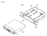
図1は従来技術によるバッテリーパックを挿入することを説明するための斜視図である。図1を参照すると、バッテリーパック10を取り囲んで収容するバッテリーラック20にバッテリーパック10を挿入する。ここで、バッテリーラック20に複数のローラー21が形成されているので、摩擦なしに挿入可能である。また、バッテリーパック10には第1突部11が形成され、バッテリーラック20には第1突部11と噛み合って固定される第2突部22が形成され、バッテリーパック10がバッテリーラック20に挿入されてから固定される電力貯蔵装置を示している。
FIG. 1 is a perspective view illustrating insertion of a conventional battery pack. Referring to FIG. 1, the
しかし、前記従来技術は、ローラー21の形成によって製品の体積が増加し、バッテリーパック10が収納される空間ごとにローラー21を設けなければならないため、製作コストが増加する欠点がある。
However, the prior art has disadvantages in that the volume of the product increases due to the formation of the
本発明は、前記のような問題点を解決するために、バッテリーラックにバッテリーパックを挿入するとき、相互間の摩擦力を減少させて小さい力でも積載することができる移送ジグ及びこれを用いたバッテリーパック積載方法を提供することを目的とする。 In order to solve the above-mentioned problems, the present invention provides a transfer jig that can reduce the frictional force between battery packs and load them with a small force when inserting battery packs into a battery rack, and a transfer jig using the same. The purpose is to provide a battery pack loading method.
また、本発明は、作業者の疲労度を減少させ、作業時間を縮めることにより、作業効率性を向上させることができる移送ジグ及びこれを用いたバッテリーパック積載方法を提供することを目的とする。 Another object of the present invention is to provide a transfer jig that can improve work efficiency by reducing worker fatigue and shortening work time, and a battery pack loading method using the same. .
前記のような問題点を解決するための本発明による移送ジグは、所定の距離で離隔している複数の垂直フレーム(110)、及びバッテリーパック(300)を収納する収納空間(S)を形成するように前記垂直フレーム(110)の高さ方向に沿って所定の間隔で離隔して位置する複数のL字形水平フレーム(120)を含むバッテリーラックに複数のバッテリーパック(300)を積載するための移送ジグ(200)であって、前記移送ジグ(200)は、所定の距離で離隔している一対の側面フレーム(210)と、前記側面フレーム(210)に対して垂直に位置する複数の正面フレーム(220)と、複数のガイドローラー(230)とを含むことを特徴とする。 In order to solve the above-mentioned problems, a transfer jig according to the present invention includes a plurality of vertical frames (110) separated by a predetermined distance, and a storage space (S) for storing a battery pack (300). In order to load a plurality of battery packs (300) on a battery rack including a plurality of L-shaped horizontal frames (120) spaced apart from each other at predetermined intervals along the height direction of the vertical frame (110), The transfer jig (200) includes a pair of side frames (210) separated by a predetermined distance, and a plurality of side frames (210) positioned perpendicularly to the side frames (210). It is characterized by including a front frame (220) and a plurality of guide rollers (230).
また、本発明による移送ジグにおいて、前記側面フレーム(210)は第1側面フレーム(211)及び第2側面フレーム(212)からなり、前記正面フレーム(220)は、前面から第1正面フレーム(221)、第2正面フレーム(222)及び第3正面フレーム(223)が順に位置することを特徴とする。 In addition, in the transfer jig according to the present invention, the side frame (210) includes a first side frame (211) and a second side frame (212), and the front frame (220) is connected to the first front frame (221) from the front side. ), a second front frame (222) and a third front frame (223) are located in this order.
また、本発明による移送ジグにおいて、前記ガイドローラー(230)は、前記側面フレーム(210)の内側上部に垂直に位置する複数の第1ガイドローラー(231)と、前記側面フレーム(210)の外側下部に垂直に位置する複数の第2ガイドローラー(232)とを含むことを特徴とする。 Further, in the transfer jig according to the present invention, the guide roller (230) includes a plurality of first guide rollers (231) vertically located on the inner upper part of the side frame (210), and an outer side of the side frame (210). It is characterized by including a plurality of second guide rollers (232) located vertically at the bottom.
また、本発明による移送ジグにおいて、ガイドローラー(230)は、前記正面フレーム(220)の下側に位置するとともに地面に平行に位置する複数の第3ガイドローラー(233)をさらに含むことを特徴とする。 Further, in the transfer jig according to the present invention, the guide roller (230) further includes a plurality of third guide rollers (233) located below the front frame (220) and parallel to the ground. shall be.
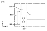
また、本発明による移送ジグにおいて、前記第1正面フレーム(221)には一つ以上の切開部(221’)が形成されていることを特徴とする。 Further, in the transfer jig according to the present invention, the first front frame (221) is provided with one or more cutouts (221').
また、本発明による移送ジグにおいて、前記水平フレーム(120)は、前記垂直フレーム(110)に固定される垂直支持部(121)と、前記バッテリーパック(300)が装着される水平支持部(122)とからなり、前記第1ガイドローラー(231)は前記水平支持部(122)の内側に位置し、バッテリーパック(300)が、前記水平支持部(122)と接触しないように、前記水平支持部(122)より所定の高さに突出することを特徴とする。 Further, in the transfer jig according to the present invention, the horizontal frame (120) includes a vertical support part (121) fixed to the vertical frame (110), and a horizontal support part (122) to which the battery pack (300) is attached. ), the first guide roller (231) is located inside the horizontal support part (122), and the first guide roller (231) is arranged inside the horizontal support part (122) so that the battery pack (300) does not come into contact with the horizontal support part (122). It is characterized by protruding from the portion (122) to a predetermined height.
また、本発明による移送ジグにおいて、前記第3ガイドローラー(233)は前記水平支持部(122)の内側端面に沿って移動することを特徴とする。 Further, in the transfer jig according to the present invention, the third guide roller (233) moves along an inner end surface of the horizontal support part (122).
また、本発明による移送ジグにおいて、前記第1正面フレーム(221)の下側角部は前記水平支持部(122)より下側に所定の長さに延びた延長部(221”)を備えることを特徴とする。 In the transfer jig according to the present invention, the lower corner of the first front frame (221) may include an extension (221'') extending to a predetermined length below the horizontal support (122). It is characterized by
また、本発明による移送ジグを用いた積載方法は、水平フレーム(120)に沿って移送ジグ(200)を収納空間(S)に押し込む第1段階と、前記移送ジグ(200)の上面によってバッテリーパック(300)を挿入する第2段階と、前記移送ジグ(200)をバッテリーラック(100)から引き出す第3段階とを含むことを特徴とする。 In addition, the loading method using the transfer jig according to the present invention includes a first step of pushing the transfer jig (200) into the storage space (S) along the horizontal frame (120), and a top surface of the transfer jig (200) The method is characterized in that it includes a second step of inserting the pack (300) and a third step of pulling out the transfer jig (200) from the battery rack (100).
また、本発明による移送ジグを用いた積載方法において、前記第1段階は、バッテリーパック(300)が装着される収納空間の下側に位置する水平フレーム(120)に沿って押し込むことを特徴とする。 Further, in the loading method using a transfer jig according to the present invention, the first step is characterized in that the battery pack (300) is pushed along a horizontal frame (120) located below the storage space in which the battery pack (300) is installed. do.
また、本発明による移送ジグを用いた積載方法において、前記バッテリーラック(100)の上部から順次バッテリーパック(300)を積載することを特徴とする。 Further, in the loading method using a transfer jig according to the present invention, the battery packs (300) are sequentially loaded from the top of the battery rack (100).
本発明によるバッテリーラックにバッテリーパックを積載するための移送ジグは、バッテリーパックが装着される第1ガイドローラーを備えているので、別途の移送装備なしもバッテリーパックを移動及び積載することができるという利点がある。 The transfer jig for loading battery packs on a battery rack according to the present invention is equipped with a first guide roller on which the battery pack is attached, so that the battery pack can be moved and loaded without any separate transfer equipment. There are advantages.
また、本発明による移送ジグは、第2ガイドローラーを備えているので、バッテリーラックに移送ジグを装着するか脱着することが非常に容易であるという利点がある。 Further, since the transfer jig according to the present invention includes the second guide roller, it is advantageous in that it is very easy to attach or detach the transfer jig to the battery rack.
さらに、本発明による移送ジグは、第3ガイドローラーを備えているので、移送ジグの前後スライド移動の際に左右に搖れることを防止することができ、作業の安全性及び正確度が向上する利点がある。 Furthermore, since the transfer jig according to the present invention is equipped with the third guide roller, it is possible to prevent the transfer jig from shaking from side to side when sliding back and forth, improving work safety and accuracy. There are advantages.
本出願で、“含む”、“有する”または“備える”などの用語は明細書上に記載された特徴、数字、段階、構成要素、部分品またはこれらの組合せが存在することを指定しようとするものであり、一つまたはそれ以上の他の特徴、数字、段階、動作、構成要素、部分品またはこれらの組合せなどの存在または付加の可能性を予め排除しないものと理解されなければならない。 In this application, terms such as "comprising," "having," or "comprising" are intended to specify the presence of features, numbers, steps, components, components, or combinations thereof that are described in the specification. It should be understood that this does not exclude in advance the possibility of the presence or addition of one or more other features, figures, steps, acts, components, parts or combinations thereof.
また、図面全般にわたって類似の機能及び作用をする部分に対しては同じ図面符号を使う。明細書全般で、ある部分が他の部分と連結されていると言うとき、これは直接的に連結されている場合だけでなく、その間にさらに他の素子を挟んで間接的に連結されている場合も含む。また、ある構成要素を含むというとは、特に反対の記載がない限り、他の構成要素を除くものではなく、他の構成要素をさらに含むことができることを意味する。 Further, the same drawing symbols are used throughout the drawings for parts having similar functions and actions. Throughout the specification, when we say that a part is connected to another part, we mean not only direct connection, but also indirect connection with another element in between. Including cases. Furthermore, the expression "containing a certain component" does not mean that other components are excluded, unless there is a specific statement to the contrary, and means that other components can be further included.
以下、本発明によるバッテリーラックにバッテリーパックを積載するための移送ジグ及びこれを用いた積載方法について添付図面を参考して説明する。 Hereinafter, a transfer jig for loading battery packs on a battery rack and a loading method using the same according to the present invention will be described with reference to the accompanying drawings.
図2は本発明の好適な実施例によるバッテリーラックに移送ジグが結合された状態を示す斜視図である。 FIG. 2 is a perspective view showing a transfer jig coupled to a battery rack according to a preferred embodiment of the present invention.
図2を参照して説明すると、本発明によるバッテリーラック100は、垂直フレーム110と、水平フレーム120とを含む。
Referring to FIG. 2, a
垂直フレーム110は、一例として略六面体状のバッテリーパックの角部を支持するように、所定の距離で離隔して複数、例えば4個が位置することができるが、必要によっては6個など、その個数はいくらでも変更可能である。
For example, a plurality of
水平フレーム120は、複数のバッテリーパックを多段で収納することができるように、垂直フレーム110の内側に位置している。具体的には、水平フレーム120は、垂直フレーム110の内側面に固定される垂直支持部121と、垂直支持部121の下端から直角に延びた水平支持部122とからなる略L字形を有する。
The
前記のような構成を有する水平フレーム120は、バッテリーパック300を収納することができる収納空間S、すなわちバッテリーパック300の底面の縁端が互いに向き合う一対の水平支持部122によって支持されるように、垂直フレーム110の高さ方向に沿って所定の間隔で離隔して複数が設けられている。
The
ここで、バッテリーパック300は複数の単位モジュールからなり、単位モジュールは1個以上の電池セルが直列または並列に連結されており、前記のような電池セル、単位モジュール及びバッテリーパックは一般的な構成に相当するので、その具体的な説明は省略する。
Here, the
一方、図面には図示されていないが、バッテリーラック100の最上端、中間または下側収納空間には収納されたバッテリーパックを制御管理するための制御部を追加的に収納することができる。
Meanwhile, although not shown in the drawings, a control unit for controlling and managing the stored battery packs may be additionally housed in the uppermost, middle, or lower storage space of the
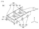
図3は本発明の好適な実施例による移送ジグの移動を説明するための斜視図、図4は本発明の好適な実施例による移送ジグの斜視図である。 FIG. 3 is a perspective view for explaining movement of a transfer jig according to a preferred embodiment of the present invention, and FIG. 4 is a perspective view of a transfer jig according to a preferred embodiment of the present invention.
本発明による移送ジグ200はバッテリーラック100の収納空間にスライド方式で装着及び脱着され、バッテリーパック300を積載するときには、移送ジグ200を収納空間に先に装着した後、移送ジグ200の上面にバッテリーパック300を移動させる。したがって、移送ジグ200はスライド移動が可能でありながらもバッテリーパック300を容易に移動させることができる構造を有する。
The
図4に示すように、本発明による移送ジグ200は、側面フレーム210、正面フレーム220及び複数のガイドローラー230を含む。
As shown in FIG. 4, the
まず、側面フレーム210は、所定の距離で離隔したままで垂直方向に位置する一対、すなわち第1側面フレーム211及び第2側面フレーム212からなる。第1側面フレーム211はバッテリーパック300の長手方向(Y軸方向)に沿って一側を支持し、第2側面フレーム212は他側を支持する。
First, the
側面フレーム210に対して垂直に位置する正面フレーム220は第1側面フレーム211と第2側面フレーム212を連結する役割を果たす。一例として、正面から見るとき(図4で左側)、第1正面フレーム221、第2正面フレーム222及び第3正面フレーム223を含むことができる。
The
第1正面フレーム221は一対の側面フレーム210の前端に位置し、第3正面フレーム223は後部、そして第2正面フレーム222は側面フレーム210の中間に位置することができる。
The first
ここで、第1正面フレーム221には一つ以上の切開部221’が形成されることが好ましい。これは、移送ジグ200をバッテリーラック100の収納空間に装着するかまたは分離するとき、作業者が把持することができる取っ手の役割とともに、移送ジグ200に装着されたバッテリーパック300が所定の方向に正常に移動するかを確認するための透視窓としても活用することができるので、作業の容易性及び安全性を確保するためである。
Here, it is preferable that the first
第1正面フレーム221の下端の両側端には所定の長さに下方に延びた延長部221”が形成されている。これは、バッテリーラック100の収納空間に移送ジグ200を装着するとき、過度に押し込まれることを防止するためである。すなわち、水平フレーム120に沿って前後方にスライド移動する移送ジグ200がバッテリーラック100の後方に落下することを防止するためのものであり、延長部221”の下端部が水平支持部122にかかってそれ以上後方に移動することができない。
Extensions 221'' extending downward to a predetermined length are formed at both ends of the lower end of the first
一対の側面フレーム210の中間に位置する第2正面フレーム222、及び後部に位置する第3正面フレーム223にも一つ以上の切開部221’が設けられることが好ましいが、必ずしもこれに制限されるものではない。しかし、移送ジグの重さ、材料費の節減及びバッテリーパック300の積載時の確認などに有用であるので、なるべく備えることが良い。
It is preferable that the second
もちろん、図面には正面フレームが3個であるものとして示されているが、これは一例に過ぎないだけで、いくらでも個数の変更が可能であるというのは言うまでもない。 Of course, the drawings show three front frames, but this is just an example, and it goes without saying that the number can be changed as desired.
次に、ガイドローラー230について説明する。ガイドローラー230は、第1ガイドローラー231、第2ガイドローラー232及び第3ガイドローラー233を含む。
Next, the
図5は本発明の好適な実施例による移送ジグにおいてバッテリーパックの底面と密着する第1ガイドローラーの拡大図である。図4及び図5を一緒に参照して説明すると、第1ガイドローラー231は、第1側面フレーム211及び第2側面フレーム212の内側上部にそれぞれ3個ずつ設けられている。
FIG. 5 is an enlarged view of the first guide roller in close contact with the bottom surface of the battery pack in the transfer jig according to the preferred embodiment of the present invention. Referring to FIGS. 4 and 5 together, three
第1ガイドローラー231は、移送ジグ200の上部に載置されたバッテリーパック300を容易に移動させる機能を果たす。すなわち、バッテリーパック300は6個の第1ガイドローラー231に載置されるので、別途の移送装置なしも作業者が単独でバッテリーパック300を移動させることができるだけでなく、過度な力をかけなくても良いので、作業者の疲労度の改善と作業時間の短縮に寄与することができる。
The
ここで、バッテリーラック100との間で摩擦が発生しないように、載置されたバッテリーパック300は第1ガイドローラー231のみによって支持されなければならない。したがって、第1ガイドローラー231の最上端部はバッテリーラック100の水平支持部122より少し高く突出しなければならない。
Here, the placed
たとえ図面には第1ガイドローラー231が6個であるものとして示されているが、これは一例に過ぎないだけで、いくらでも個数の変更が可能であるというのは言うまでもない。
Although the drawings show six
図6は本発明の好適な実施例による移送ジグにおいてバッテリーラックの水平フレームと密着する第2ガイドローラーの拡大図である。図4及び図6を一緒に参照して説明すると、第2ガイドローラー232は、第1側面フレーム211及び第2側面フレーム212の外側下部にそれぞれ3個ずつ設けられる。
FIG. 6 is an enlarged view of the second guide roller in close contact with the horizontal frame of the battery rack in the transfer jig according to the preferred embodiment of the present invention. Referring to FIGS. 4 and 6 together, three
第2ガイドローラー232は移送ジグ200自体を容易に移動させる機能を果たす。バッテリーラック100に複数のバッテリーパック300を収納するためには、それに比例して移送ジグ200の装着及び脱着を繰り返さなければならない。この際、別途の着脱装置なしに作業者単独で遂行することができることが好ましい。
The
このために、第2ガイドローラー232は、水平支持部122と密着したままでスライド移動することができるように、第1側面フレーム211及び第2側面フレーム212の外側に設けられている。
For this purpose, the
ここで、バッテリーラック100との摩擦を最小化するために、第2ガイドローラー232の最下端は側面フレーム210の下端より少し下方に突出している。
Here, in order to minimize friction with the
たとえ図面には第2ガイドローラー232が6個であるものとして示されているが、これは一例に過ぎないだけで、いくらでも個数の変更が可能であるというのは言うまでもない。
Although the drawings show six
図7は本発明の好適な実施例による移送ジグにおいてバッテリーラックの水平フレームと密着する第3ガイドローラーの拡大図である。 FIG. 7 is an enlarged view of the third guide roller in close contact with the horizontal frame of the battery rack in the transfer jig according to the preferred embodiment of the present invention.
図4及び図7を一緒に参照して説明すると、正面フレーム220と物理的に連結されている第3ガイドローラー233は正面フレーム220の下側に位置するとともに地面に平行に位置する複数個からなることができる。移送ジグ200が水平フレーム120に沿って前後方に移動するとき、第3ガイドローラー233は水平支持部122の内側端面に密着した状態で移動するので、移送ジグ200がスライド移動するときに左右に搖れることを防止することができ、作業の安全性及び正確度が向上する利点がある。
Referring to FIGS. 4 and 7 together, the
添付図面には第3ガイドローラー233が第2正面フレーム222及び第3正面フレーム223にそれぞれ2個ずつが設けられるものとして示されているが、第1正面フレーム221にも設けられることができるというのは言うまでもない。
Although the accompanying drawings show that two
次に、前述した移送ジグ200を使ってバッテリーラック100に複数のバッテリーパック300を積載する方法について図3を参照して説明する。
Next, a method of loading a plurality of battery packs 300 onto the
本発明によるバッテリーパック積載方法は、水平フレーム120に沿って移送ジグ200を収納空間Sに押し込む第1段階、移送ジグ200の上面に沿ってバッテリーパック300を移動させる第2段階、及び移送ジグ200をバッテリーラック100から引き出す第3段階を含む。
The battery pack loading method according to the present invention includes a first step of pushing the
第1段階はバッテリーパック300が収納される収納空間の下側に移送ジグ200を押し込む段階であり、一対の水平支持部122に移送ジグ200の第2ガイドローラー232を載置した後、収納空間に押し込む。
The first step is to push the
第2段階では、収納空間に移動した移送ジグ200の上部、すなわち第1ガイドローラー231にバッテリーパック300の一部を載置した後、所定の位置までバッテリーパック300を収納空間内に押し込む。
In the second step, a part of the
第3段階では、第2段階で収納したバッテリーパック300の下側に他のバッテリーパック300を装着するために、収納空間S内に位置する移送ジグ200を脱着させる。
In the third stage, the
その後、前述した第1段階から第3段階を繰り返し遂行することにより、バッテリーラック100に所望数量のバッテリーパック300を収納させる。
Thereafter, by repeatedly performing the first to third steps described above, a desired number of battery packs 300 are stored in the
以上で本発明の内容の特定部分を詳細に記述したが、当該分野の通常の知識を有する者にこのような具体的技術はただ好適な実施様態であるだけであり、これによって本発明の範囲が制限されるものではなく、本発明の範疇及び技術思想の範囲内で多様な変更及び修正が可能であるというのは当業者に明らかであり、このような変形及び修正が添付の特許請求の範囲に属するというのは言うまでもない。 Although specific parts of the content of the present invention have been described in detail above, those with ordinary knowledge in the field will understand that such specific techniques are only preferred embodiments, and that this does not limit the scope of the present invention. It is obvious to those skilled in the art that the invention is not limited to the above, and that various changes and modifications can be made within the scope and technical idea of the present invention, and such changes and modifications are not limited to the scope of the appended claims. Needless to say, it falls within the range.
100 バッテリーラック
110 垂直フレーム
120 水平フレーム
121 垂直支持部
122 水平支持部
200 移送ジグ
210 側面フレーム
211 第1側面フレーム
212 第2側面フレーム
220 正面フレーム
221 第1正面フレーム
221’ 切開部
221” 延長部
222 第2正面フレーム
223 第3正面フレーム
230 ガイドローラー
231 第1ガイドローラー
232 第2ガイドローラー
233 第3ガイドローラー
300 バッテリーパック
S 収納空間
100
Claims (11)
前記移送ジグは、所定の距離で離隔している一対の側面フレームと、
前記側面フレームに対して垂直に位置する複数の正面フレームと、
複数のガイドローラーと、を含み、
前記水平フレームは、前記垂直フレームに固定される垂直支持部と、前記垂直支持部から延びた水平支持部とからなり、
前記ガイドローラーは、前記側面フレームの上部に位置する複数の第1ガイドローラーを含み、
前記第1ガイドローラーの最上端部は、前記移送ジグが前記収納空間の下側に位置する状態において、前記移送ジグの上部に載置されたバッテリーパックを前記第1ガイドローラーのみで支持して移動させることができるように、前記バッテリーラックの前記水平支持部より高く突出している、バッテリーラックにバッテリーパックを積載するための移送ジグ。 a plurality of vertical frames spaced apart from each other by a predetermined distance; and a plurality of L-shaped horizontal frames spaced apart from each other by a predetermined distance along the height of the vertical frames to form a storage space for storing a battery pack. A transfer jig for loading a plurality of battery packs onto a battery rack including a frame, the transfer jig comprising:
The transfer jig includes a pair of side frames separated by a predetermined distance;
a plurality of front frames positioned perpendicularly to the side frames;
a plurality of guide rollers;
The horizontal frame includes a vertical support part fixed to the vertical frame and a horizontal support part extending from the vertical support part,
The guide rollers include a plurality of first guide rollers located at the top of the side frame,
The uppermost end of the first guide roller supports only the battery pack placed on the top of the transfer jig when the transfer jig is located below the storage space. a transfer jig for loading battery packs on a battery rack, protruding higher than the horizontal support of the battery rack so as to be able to be moved;
前記正面フレームは、前面から第1正面フレーム、第2正面フレーム及び第3正面フレームが順に位置する、請求項1に記載のバッテリーラックにバッテリーパックを積載するための移送ジグ。 The side frame includes a first side frame and a second side frame,
The transfer jig for loading battery packs on a battery rack according to claim 1, wherein the front frame includes a first front frame, a second front frame, and a third front frame located in this order from the front.
前記ガイドローラーは、前記側面フレームの外側下部に垂直に位置する複数の第2ガイドローラーをさらに含む、請求項2に記載のバッテリーラックにバッテリーパックを積載するための移送ジグ。 the first guide roller is located vertically on the inner upper part of the side frame;
The transfer jig for loading battery packs on a battery rack as claimed in claim 2, wherein the guide roller further includes a plurality of second guide rollers vertically located at an outer lower part of the side frame.
水平フレームに沿って移送ジグを収納空間に押し込む第1段階と、
前記移送ジグの上面に沿ってバッテリーパックを挿入する第2段階と、
前記移送ジグをバッテリーラックから引き出す第3段階と、を含む、バッテリーパック積載方法。 9. A method of loading a plurality of battery packs on a battery rack using the transfer jig according to any one of claims 1 to 8, comprising:
a first step of pushing the transfer jig into the storage space along the horizontal frame;
a second step of inserting a battery pack along the top surface of the transfer jig;
a third step of pulling out the transfer jig from the battery rack.
Applications Claiming Priority (3)
| Application Number | Priority Date | Filing Date | Title |
|---|---|---|---|
| KR1020200036003A KR102927317B1 (en) | 2020-03-25 | 2020-03-25 | Transfer jig for loading battery pack into battery rack and battery rack loading method using same |
| KR10-2020-0036003 | 2020-03-25 | ||
| PCT/KR2021/003214 WO2021194146A1 (en) | 2020-03-25 | 2021-03-16 | Conveyance jig for loading battery pack onto battery rack, and battery rack loading method using same |
Publications (2)
| Publication Number | Publication Date |
|---|---|
| JP2022537991A JP2022537991A (en) | 2022-08-31 |
| JP7348317B2 true JP7348317B2 (en) | 2023-09-20 |
Family
ID=77890536
Family Applications (1)
| Application Number | Title | Priority Date | Filing Date |
|---|---|---|---|
| JP2021575022A Active JP7348317B2 (en) | 2020-03-25 | 2021-03-16 | A transfer jig for loading battery packs onto a battery rack and a battery pack loading method using the same |
Country Status (7)
| Country | Link |
|---|---|
| US (1) | US12407054B2 (en) |
| EP (1) | EP4024583B1 (en) |
| JP (1) | JP7348317B2 (en) |
| KR (1) | KR102927317B1 (en) |
| CN (1) | CN114342165B (en) |
| ES (1) | ES3053188T3 (en) |
| WO (1) | WO2021194146A1 (en) |
Families Citing this family (8)
| Publication number | Priority date | Publication date | Assignee | Title |
|---|---|---|---|---|
| US20240409324A1 (en) * | 2021-08-18 | 2024-12-12 | Lg Energy Solution, Ltd. | Battery module transfer jig |
| KR102367414B1 (en) * | 2021-11-09 | 2022-02-25 | 주식회사 엔시스 | Secondary battery sorting equipment |
| KR20240100030A (en) * | 2022-12-22 | 2024-07-01 | 주식회사 엘지에너지솔루션 | Battery pack elevating device |
| CN115922620A (en) * | 2022-12-28 | 2023-04-07 | 合肥合孚智慧能源有限公司 | A general-purpose battery module assembly and disassembly tooling |
| KR102601653B1 (en) * | 2023-05-30 | 2023-11-14 | 이온어스(주) | Battery rack and battery case including the same |
| JP7798085B2 (en) * | 2023-06-07 | 2026-01-14 | トヨタ自動車株式会社 | Battery device and method for manufacturing the battery device |
| CN119009151B (en) * | 2024-08-07 | 2025-09-30 | 珠海华冠科技股份有限公司 | An all-in-one machine for folding tabs and loading batteries and its method |
| KR102827893B1 (en) | 2024-11-06 | 2025-07-01 | (주)코리아인더스 | Object transport device |
Citations (1)
| Publication number | Priority date | Publication date | Assignee | Title |
|---|---|---|---|---|
| JP2017073270A (en) | 2015-10-07 | 2017-04-13 | 田淵電機株式会社 | Storage battery unit and storage battery housing device |
Family Cites Families (26)
| Publication number | Priority date | Publication date | Assignee | Title |
|---|---|---|---|---|
| JPS5726297Y2 (en) * | 1976-11-26 | 1982-06-08 | ||
| JP2640010B2 (en) * | 1990-04-25 | 1997-08-13 | 三洋電機株式会社 | Shelf unloading device |
| JPH048828A (en) | 1990-04-25 | 1992-01-13 | Mitsui Eng & Shipbuild Co Ltd | Gas turbine cogeneration system |
| JP2843228B2 (en) * | 1993-03-26 | 1999-01-06 | 日本碍子株式会社 | Assembly method of assembled battery |
| US5610802A (en) * | 1995-05-23 | 1997-03-11 | Zb B Technologies, Inc. | Compact energy storage system |
| KR0148930B1 (en) * | 1995-08-31 | 1998-10-15 | 배순훈 | Mobile trolley for battery pallet with rolling roll |
| JPH09220937A (en) | 1996-02-16 | 1997-08-26 | Araco Corp | Battery carrier for electric vehicles |
| JP2938843B2 (en) * | 1997-03-25 | 1999-08-25 | 日本碍子株式会社 | Apparatus and method for installing heavy object on gantry |
| JP3804919B2 (en) | 2001-03-19 | 2006-08-02 | 日本輸送機株式会社 | Battery powered forklift |
| KR101158796B1 (en) * | 2007-11-08 | 2012-06-26 | 박윤식 | Roller type slide for household electric appliaces |
| US8366371B2 (en) * | 2007-11-30 | 2013-02-05 | Sacket Material Handling Systems, Inc. | Industrial battery charging, storage and handling system |
| KR100960098B1 (en) | 2009-02-13 | 2010-05-31 | (주)넷메이커 | Hard disk drive hot swap rack for server computer and server computer with the same |
| US9850114B2 (en) * | 2011-06-07 | 2017-12-26 | Crown Equipment Corporation | Battery transfer apparatus |
| CN102320235A (en) * | 2011-08-31 | 2012-01-18 | 湖南南车时代电动汽车股份有限公司 | Method and device for installing battery box of trolley bus |
| KR20160094235A (en) | 2015-01-30 | 2016-08-09 | 삼성에스디아이 주식회사 | Energy storage device |
| KR20170047539A (en) | 2015-10-23 | 2017-05-08 | 주식회사 코캄 | Battery pack |
| KR102101147B1 (en) | 2016-03-31 | 2020-04-16 | 주식회사 엘지화학 | Battery Rack |
| US10431781B2 (en) * | 2017-01-02 | 2019-10-01 | General Electric Company | Battery loading magazine |
| KR101799537B1 (en) | 2017-01-23 | 2017-11-20 | (주)알씨디에이치 | Assistant DC Power Supplying System for Nuclear Power Plant |
| KR200487164Y1 (en) * | 2017-03-02 | 2018-08-14 | 엘에스산전 주식회사 | Battery Rack Assembly |
| EP3437696B1 (en) | 2017-08-01 | 2021-02-24 | Braun GmbH | Light-based epilation device and method of cosmetic hair removal |
| CN107863473A (en) | 2017-11-07 | 2018-03-30 | 刘琴兰 | A kind of lithium battery fixing device of electric intelligent control on electric car |
| CN208484671U (en) | 2018-05-09 | 2019-02-12 | 蔚来汽车有限公司 | Battery transportation device and battery replacement station |
| CN109501761A (en) * | 2018-05-09 | 2019-03-22 | 蔚来汽车有限公司 | Battery transportation device and battery replacement station |
| CN110893790B (en) * | 2018-08-22 | 2022-12-23 | 富泰华工业(深圳)有限公司 | Automatic charging and replacing system and method for electric vehicle |
| CN109860684B (en) | 2019-01-28 | 2023-10-10 | 东莞市天蓝智能装备有限公司 | Stereoscopic warehouse type intelligent capacity-dividing and formation equipment |
-
2020
- 2020-03-25 KR KR1020200036003A patent/KR102927317B1/en active Active
-
2021
- 2021-03-16 WO PCT/KR2021/003214 patent/WO2021194146A1/en not_active Ceased
- 2021-03-16 US US17/638,998 patent/US12407054B2/en active Active
- 2021-03-16 EP EP21774570.2A patent/EP4024583B1/en active Active
- 2021-03-16 JP JP2021575022A patent/JP7348317B2/en active Active
- 2021-03-16 ES ES21774570T patent/ES3053188T3/en active Active
- 2021-03-16 CN CN202180005222.0A patent/CN114342165B/en active Active
Patent Citations (1)
| Publication number | Priority date | Publication date | Assignee | Title |
|---|---|---|---|---|
| JP2017073270A (en) | 2015-10-07 | 2017-04-13 | 田淵電機株式会社 | Storage battery unit and storage battery housing device |
Also Published As
| Publication number | Publication date |
|---|---|
| JP2022537991A (en) | 2022-08-31 |
| WO2021194146A1 (en) | 2021-09-30 |
| EP4024583A1 (en) | 2022-07-06 |
| EP4024583B1 (en) | 2025-10-15 |
| EP4024583A4 (en) | 2024-06-19 |
| ES3053188T3 (en) | 2026-01-20 |
| US20220336905A1 (en) | 2022-10-20 |
| CN114342165A (en) | 2022-04-12 |
| KR102927317B1 (en) | 2026-02-13 |
| US12407054B2 (en) | 2025-09-02 |
| KR20210119651A (en) | 2021-10-06 |
| CN114342165B (en) | 2025-01-14 |
Similar Documents
| Publication | Publication Date | Title |
|---|---|---|
| JP7348317B2 (en) | A transfer jig for loading battery packs onto a battery rack and a battery pack loading method using the same | |
| US11133551B2 (en) | Battery pack | |
| JP7045577B2 (en) | Battery pack and cars containing it | |
| KR102352686B1 (en) | Battery module, battery pack comprising the battery module and vehicle comprising the battery pack | |
| JP7459230B2 (en) | Battery module, battery pack including the battery module, and automobile | |
| JP7221994B2 (en) | BATTERY PACK AND POWER STORAGE DEVICE INCLUDING THE SAME | |
| US12308410B2 (en) | Battery rack including bracket creating space between walls and rack case and power storage apparatus comprising same | |
| CN116261803A (en) | Battery racks, energy storage devices and power generation systems | |
| JP7451685B2 (en) | Battery modules, battery packs containing them, and automobiles | |
| KR20210015550A (en) | Battery pack and vehicle comprising the battery pack | |
| CN116134663A (en) | Battery racks, power storage and data storage | |
| KR101847680B1 (en) | Battery pack | |
| KR102178719B1 (en) | Battery rack and energy storage system comprising the battery rack | |
| KR20180047511A (en) | Energy storage system | |
| KR20220080622A (en) | Battery Pack, Power System, and Vehicle | |
| KR102689423B1 (en) | Stack magazine | |
| KR102178818B1 (en) | Battery module, battery pack comprising the battery module and vehicle comprising the battery pack | |
| KR20220048723A (en) | Battery pack assembly guide jig | |
| EP4564587A1 (en) | Battery rack | |
| KR101843398B1 (en) | Module type battery safety stand | |
| KR102165018B1 (en) | Battery module, battery pack comprising the battery module and vehicle comprising the battery pack | |
| CN119234349A (en) | Energy storage system | |
| CN121005155A (en) | Battery storage devices, battery testing systems, and battery production lines | |
| KR20130007862A (en) | Battery case with connecting structure of insert type |
Legal Events
| Date | Code | Title | Description |
|---|---|---|---|
| A621 | Written request for application examination |
Free format text: JAPANESE INTERMEDIATE CODE: A621 Effective date: 20211216 |
|
| A977 | Report on retrieval |
Free format text: JAPANESE INTERMEDIATE CODE: A971007 Effective date: 20230116 |
|
| A131 | Notification of reasons for refusal |
Free format text: JAPANESE INTERMEDIATE CODE: A131 Effective date: 20230130 |
|
| A521 | Request for written amendment filed |
Free format text: JAPANESE INTERMEDIATE CODE: A523 Effective date: 20230501 |
|
| TRDD | Decision of grant or rejection written | ||
| A01 | Written decision to grant a patent or to grant a registration (utility model) |
Free format text: JAPANESE INTERMEDIATE CODE: A01 Effective date: 20230828 |
|
| A61 | First payment of annual fees (during grant procedure) |
Free format text: JAPANESE INTERMEDIATE CODE: A61 Effective date: 20230907 |
|
| R150 | Certificate of patent or registration of utility model |
Ref document number: 7348317 Country of ref document: JP Free format text: JAPANESE INTERMEDIATE CODE: R150 |