JP7347775B2 - Monitoring device, monitoring system, monitoring method, and program - Google Patents
Monitoring device, monitoring system, monitoring method, and program Download PDFInfo
- Publication number
- JP7347775B2 JP7347775B2 JP2018221560A JP2018221560A JP7347775B2 JP 7347775 B2 JP7347775 B2 JP 7347775B2 JP 2018221560 A JP2018221560 A JP 2018221560A JP 2018221560 A JP2018221560 A JP 2018221560A JP 7347775 B2 JP7347775 B2 JP 7347775B2
- Authority
- JP
- Japan
- Prior art keywords
- data
- image data
- point cloud
- unit
- converted
- Prior art date
- Legal status (The legal status is an assumption and is not a legal conclusion. Google has not performed a legal analysis and makes no representation as to the accuracy of the status listed.)
- Active
Links
Images


Classifications
-
- Y—GENERAL TAGGING OF NEW TECHNOLOGICAL DEVELOPMENTS; GENERAL TAGGING OF CROSS-SECTIONAL TECHNOLOGIES SPANNING OVER SEVERAL SECTIONS OF THE IPC; TECHNICAL SUBJECTS COVERED BY FORMER USPC CROSS-REFERENCE ART COLLECTIONS [XRACs] AND DIGESTS
- Y02—TECHNOLOGIES OR APPLICATIONS FOR MITIGATION OR ADAPTATION AGAINST CLIMATE CHANGE
- Y02P—CLIMATE CHANGE MITIGATION TECHNOLOGIES IN THE PRODUCTION OR PROCESSING OF GOODS
- Y02P90/00—Enabling technologies with a potential contribution to greenhouse gas [GHG] emissions mitigation
- Y02P90/02—Total factory control, e.g. smart factories, flexible manufacturing systems [FMS] or integrated manufacturing systems [IMS]
Description
本発明は、監視装置、監視システム、監視方法、及びプログラムに関する。 The present invention relates to a monitoring device, a monitoring system, a monitoring method, and a program.
ガラス工場、製鉄所などの工場では、工場の屋外若しくは屋内に設置された原料ヤードで、ガラスの原料である珪砂、鉄鋼の原料である鉄鉱石などの原材料を保管している。原料ヤードに保管された原材料は、スタッカ、リクレーマなどのヤード機械で高炉等に搬送される。原料ヤード、高炉等の現場の監視(巡視、巡回点検、環境整備、清掃、保守点検など)の際、作業員が徒歩、又は、移動体(車等)に乗って定期的に現場に出向いて、作業者が目視したり、カメラで撮影し、撮影した画像を確認して、現場を監視している。 In factories such as glass factories and steel mills, raw materials such as silica sand, which is the raw material for glass, and iron ore, which is the raw material for steel, are stored in raw material yards installed either outdoors or indoors. Raw materials stored in raw material yards are transported to blast furnaces and the like using yard machines such as stackers and reclaimers. When monitoring sites such as raw material yards and blast furnaces (patrol, patrol inspection, environmental preparation, cleaning, maintenance inspection, etc.), workers regularly visit the site on foot or in a mobile vehicle (car, etc.). , workers monitor the site by visually observing, photographing with a camera, and checking the images.
現場に出向いて監視する方法では、いくつかの問題がある。例えば、人手に任せた現場の監視は、広域範囲に及ぶため、多大な時間が掛かる。また、原材料の形態は様々であるため、作業者の確認が感覚的になったり、作業者の経験に依存して、監視基準がばらつく可能性がある。さらに、原材料は様々な種類があるので、単なる監視だけでなく原材料の性質を把握する必要がある。 There are several problems with the on-site monitoring method. For example, on-site monitoring that is left to humans to do covers a wide area and takes a lot of time. Furthermore, since raw materials come in various forms, the operator may have to check intuitively, and monitoring standards may vary depending on the operator's experience. Furthermore, since there are various types of raw materials, it is necessary not only to simply monitor but also to understand the properties of the raw materials.
このような問題を解決するために、現場に設置された可視カメラ及び赤外線カメラを用いて、現場の監視を自動的かつ連続的に行うことができる方法がある(例えば、特許文献1参照)。 In order to solve such problems, there is a method of automatically and continuously monitoring the site using a visible camera and an infrared camera installed at the site (for example, see Patent Document 1).
以下の分析は、本願発明者により与えられる。 The following analysis is provided by the inventor.
しかしながら、監視手段として特許文献1に記載された可視カメラや赤外線カメラだけでなく、原材料の形態や種類、顧客の要望に応じて、様々な種類のカメラを用いて現場の様々な状況を監視できるようになることが期待される。
However, in addition to the visible cameras and infrared cameras described in
本発明の主な課題は、現場の様々な状況を監視することに貢献することができる監視装置、監視システム、監視方法、及びプログラムを提供することである。 The main object of the present invention is to provide a monitoring device, a monitoring system, a monitoring method, and a program that can contribute to monitoring various situations in the field.
第1の視点に係る監視装置は、拠点を撮影する監視カメラからの撮影データが動画データであるときに前記動画データを画像データに変換する画像化部と、前記撮影データが3次元データであるときに前記3次元データを点群データに変換する点群化部と、第1モードのときに、前記画像化部で変換された前記画像データ、又は、前記点群化部で変換された前記点群データ、若しくは、前記撮影データが静止画データであるときの前記静止画データを用いて、機械学習して予測モデルを作成する予測モデル作成部と、前記第1モードとは異なる第2モードのときに、前記画像化部で変換された前記画像データ、又は、前記点群化部で変換された前記点群データ、若しくは、前記撮影データが静止画データであるときの前記静止画データと、前記予測モデル作成部で作成された前記予測モデルと、を比較することにより、前記画像データ又は前記点群データ若しくは前記静止画データに含まれる監視対象物の変化を判定するモデル判定部と、前記第2モードのときに、前記点群化部で変換された前記点群データに含まれる前記監視対象物の所定形態を計測し、計測された計測値と、予め設定された基準値と、を比較することにより、前記監視対象物の変化を判定する基準値判定部と、を備え、前記予測モデルの作成に用いた前記画像データ又は前記点群データ若しくは前記静止画データの種類は、前記第2モードで比較される前記画像データ又は前記点群データ若しくは前記静止画データの種類に対応しており、前記予測モデルは、前記機械学習によって抽出された特徴を有する対象物に係るデータである。 The monitoring device according to the first viewpoint includes an imaging unit that converts the video data into image data when the video data from the surveillance camera that photographs the base is video data, and the video data is three-dimensional data. a point cloud forming unit that sometimes converts the three-dimensional data into point cloud data; and when in the first mode, the image data converted by the imaging unit or the point cloud forming unit converting the three-dimensional data into point cloud data; a predictive model creation unit that creates a predictive model through machine learning using point cloud data or the still image data when the photographic data is still image data; and a second mode different from the first mode. The image data converted by the imaging section, the point cloud data converted by the point cloud forming section, or the still image data when the photographed data is still image data. , a model determination unit that determines a change in the monitored object included in the image data, the point cloud data, or the still image data by comparing the prediction model created by the prediction model creation unit; When in the second mode, a predetermined form of the monitoring target included in the point cloud data converted by the point cloud forming unit is measured, and a measured value and a preset reference value are obtained; a reference value determination unit that determines a change in the monitored object by comparing the values, and the type of the image data, the point cloud data, or the still image data used to create the prediction model is The prediction model corresponds to the type of the image data, the point cloud data, or the still image data to be compared in the second mode, and the prediction model is data related to an object having features extracted by the machine learning. There is .
第2の視点に係る監視システムは、拠点を撮影する監視カメラと、前記第1の視点に係る監視装置と、を備える。 The monitoring system related to the second viewpoint includes a monitoring camera that photographs the base, and a monitoring device related to the first viewpoint.
第3の視点に係る監視方法は、拠点を撮影する監視カメラからの撮影データが動画データであるときに前記動画データを画像データに変換するステップと、前記撮影データが3次元データであるときに前記3次元データを点群データに変換するステップと、第1モードのときに、変換された前記画像データ、又は、変換された前記点群データ、若しくは、前記撮影データが静止画データであるときの前記静止画データを用いて、機械学習して予測モデルを作成するステップと、前記第1モードとは異なる第2モードのときに、変換された前記画像データ、又は、変換された前記点群データ、若しくは、前記撮影データが静止画データであるときの前記静止画データと、作成された前記予測モデルと、を比較することにより、前記画像データ又は前記点群データ若しくは前記静止画データに含まれる監視対象物の変化を判定するステップと、前記第2モードのときに、変換された前記点群データに含まれる前記監視対象物の所定形態を計測し、計測された計測値と、予め設定された基準値と、を比較することにより、前記監視対象物の変化を判定するステップと、を含み、前記予測モデルの作成に用いた前記画像データ又は前記点群データ若しくは前記静止画データの種類は、前記第2モードで比較される前記画像データ又は前記点群データ若しくは前記静止画データの種類に対応しており、前記予測モデルは、前記機械学習によって抽出された特徴を有する対象物に係るデータである。 The monitoring method according to the third viewpoint includes a step of converting the video data into image data when the video data from a surveillance camera that photographs the base is video data, and a step of converting the video data into image data when the video data is three-dimensional data. converting the three-dimensional data into point cloud data; and when in the first mode, the converted image data, the converted point group data, or the photographic data is still image data. a step of performing machine learning to create a predictive model using the still image data; and in a second mode different from the first mode, the converted image data or the converted point cloud. data, or the still image data when the photographed data is still image data, and the created prediction model, measuring a predetermined form of the monitoring object included in the converted point cloud data in the second mode, and measuring the measured value and a preset value. of the image data, the point cloud data, or the still image data used to create the prediction model, The type corresponds to the type of the image data, the point cloud data, or the still image data to be compared in the second mode, and the prediction model is based on the object having the features extracted by the machine learning. This is such data .
第4の視点に係るプログラムは、拠点を撮影する監視カメラからの撮影データが動画データであるときに前記動画データを画像データに変換する処理と、前記撮影データが3次元データであるときに前記3次元データを点群データに変換する処理と、第1モードのときに、変換された前記画像データ、又は、変換された前記点群データ、若しくは、前記撮影データが静止画データであるときの前記静止画データを用いて、機械学習して予測モデルを作成する処理と、前記第1モードとは異なる第2モードのときに、変換された前記画像データ、又は、変換された前記点群データ、若しくは、前記撮影データが静止画データであるときの前記静止画データと、作成された前記予測モデルと、を比較することにより、前記画像データ又は前記点群データ若しくは前記静止画データに含まれる監視対象物の変化を判定する処理と、前記第2モードのときに、変換された前記点群データに含まれる前記監視対象物の所定形態を計測し、計測された計測値と、予め設定された基準値と、を比較することにより、前記監視対象物の変化を判定する処理と、をハードウェア資源に実行させ、前記予測モデルの作成に用いた前記画像データ又は前記点群データ若しくは前記静止画データの種類は、前記第2モードで比較される前記画像データ又は前記点群データ若しくは前記静止画データの種類に対応しており、前記予測モデルは、前記機械学習によって抽出された特徴を有する対象物に係るデータである。 The program related to the fourth viewpoint includes a process of converting video data into image data when the photographed data from a surveillance camera photographing the base is video data, and a process of converting the video data into image data when the photographed data is three-dimensional data. A process of converting three-dimensional data into point cloud data, and when the converted image data, the converted point group data, or the photographic data is still image data in the first mode. A process of creating a predictive model by machine learning using the still image data, and the converted image data or the converted point cloud data in a second mode different from the first mode. , or, by comparing the still image data when the photographed data is still image data and the created prediction model, the information contained in the image data, the point cloud data, or the still image data a process of determining a change in the monitored object; and, in the second mode, measuring a predetermined form of the monitored object included in the converted point cloud data, and combining the measured measurement value with a preset A process of determining a change in the monitored object by comparing with a reference value determined by The type of still image data corresponds to the type of the image data, the point cloud data, or the still image data to be compared in the second mode, and the prediction model is based on the features extracted by the machine learning. This is data related to the objects that are held .
なお、プログラムは、コンピュータが読み取り可能な記憶媒体に記録することができる。記憶媒体は、半導体メモリ、ハードディスク、磁気記録媒体、光記録媒体等の非トランジェント(non-transient)なものとすることができる。また、本開示では、コンピュータプログラム製品として具現することも可能である。 Note that the program can be recorded on a computer-readable storage medium. The storage medium can be non-transient, such as a semiconductor memory, a hard disk, a magnetic recording medium, an optical recording medium, etc. Further, the present disclosure can also be implemented as a computer program product.
前記第1~第4の視点によれば、現場の様々な状況を監視することに貢献することができる。 According to the first to fourth viewpoints, it is possible to contribute to monitoring various situations at the site.
以下に説明する本開示では、モード1に係る監視装置及びその変形モードを適宜選択して組み合わせることができる。
In the present disclosure described below, the monitoring device according to
前記モード1に係る監視装置として、拠点を撮影する監視カメラからの撮影データが動画データであるときに前記動画データを画像データに変換する画像化部を備える。前記監視装置は、前記撮影データが3次元データであるときに前記3次元データを点群データに変換する点群化部を備える。前記監視装置は、第1モードのときに、前記画像化部で変換された前記画像データ、又は、前記点群化部で変換された前記点群データ、若しくは、前記撮影データが画像データであるときの他の画像データを用いて、機械学習して予測モデルを作成する予測モデル作成部を備える。前記監視装置は、前記第1モードとは異なる第2モードのときに、前記画像化部で変換された前記画像データ、又は、前記点群化部で変換された前記点群データ、若しくは、前記撮影データが画像データであるときの前記他の画像データと、前記予測モデル作成部で作成された前記予測モデルと、を比較することにより、前記画像データ又は前記点群データ若しくは前記他の画像データに含まれる監視対象物の変化を判定するモデル判定部を備える。前記監視装置は、前記第2モードのときに、前記点群化部で変換された前記点群データに含まれる前記監視対象物の所定形態を計測し、計測された計測値と、予め設定された基準値と、を比較することにより、前記監視対象物の変化を判定する基準値判定部を備える。
The monitoring device according to
前記モード1に係る監視装置の変形モードとして、前記監視カメラからのデータの出力経路を制御する第1経路制御部を備える。前記監視装置は、前記画像化部又は前記点群化部若しくは前記第1経路制御部からのデータの出力経路を制御する第2経路制御部を備える。前記第1経路制御部は、前記撮影データが動画データであるときに、前記動画データを前記画像化部に向けて出力する。前記第1経路制御部は、前記撮影データが3次元データであるときに、前記3次元データを前記点群化部に向けて出力する。前記第1経路制御部は、前記撮影データが画像データであるときの前記他の画像データを第2経路制御部に向けて出力する。前記第2経路制御部は、前記第1モードのときに、前記画像化部からの前記画像データ、又は、前記点群化部からの前記点群データ、若しくは、前記第1経路制御部からの前記他の画像データを前記モデル作成部に向けて出力する。前記第2経路制御部は、前記第2モードのときに、前記画像化部からの前記画像データ、又は、前記第1経路制御部からの前記他の画像データを前記モデル判定部に向けて出力し、若しくは、前記点群化部からの前記点群データを前記モデル判定部及び前記基準値判定部に向けて出力する。前記監視装置は、前記監視カメラからの前記撮影データを取得して前記第1経路制御部に向けて出力するデータ取得部を備える。前記監視装置は、前記モデル判定部及び前記基準値判定部の少なくとも1つからの判定結果を出力する出力部を備える。前記出力部は、前記判定結果を前記データ取得部に向けて出力する。前記データ取得部は、前記出力部からの前記判定結果に基づいて前記監視対象物の変化を確認し、変化の程度に応じて前記監視カメラからの前記撮影データを取得する時間間隔を調整する。前記撮影データは、時刻情報、位置情報、カメラ情報及び対象物情報の少なくとも1つの情報を含む。前記判定結果は、前記時刻情報、前記位置情報、前記カメラ情報及び前記対象物情報の少なくとも1つの情報を含む。前記画像化部は、前記動画データから、予め設定されたサンプリング周期で前記画像データを切り出し、切り出した前記画像データを所定の画像処理することによって、前記動画データから前記画像データに変換する。前記所定の画像処理は、精細化、高解像度化、ノイズ除去、低解像度化、オープニング処理、及び、モルフォロジー変換の少なくとも1つの処理である。前記点群化部は、前記3次元データを1次点群データに変換し、変換された前記1次点群データに基づいてモデルデータを生成し、生成された前記モデルデータを2次点群データに変換することによって、前記3次元データを前記点群データに変換する。前記点群化部は、変換された前記点群データに対してフィルタ処理を実行する。前記監視装置は、前記第1モードのときに、前記画像化部で変換された前記画像データ、又は、前記点群化部で変換された前記点群データ、若しくは、前記撮影データが画像データであるときの他の画像データに予測モデル用ラベルを付与し、前記予測モデル用ラベルが付与されたデータを前記予測モデル作成部に向けて出力するラベル付与部を備える。
As a modified mode of the monitoring device according to
本開示では、モード2に係る監視システム及びその変形モードを適宜選択して組み合わせることができる。 In the present disclosure, the monitoring system according to Mode 2 and its modified modes can be appropriately selected and combined.
前記モード2に係る監視システムとして、拠点を撮影する監視カメラと、前記モード1に係る監視装置と、を備える。
The monitoring system according to Mode 2 includes a monitoring camera that photographs a base, and a monitoring device according to
前記モード2に係る監視システムの変形モードとして、前記監視カメラを搭載するとともに、衛星測位装置を搭載し、かつ、前記監視装置と通信可能にする通信部を有する自動運転車両を備える。前記自動運転車両は、前記衛星測位装置で測位した測位情報を、前記監視カメラで撮影された前記撮影データに含めて、前記通信部を介して前記監視装置に送信する。 As a modified mode of the monitoring system according to Mode 2, an automatic driving vehicle is provided which is equipped with the monitoring camera, is also equipped with a satellite positioning device, and has a communication unit that enables communication with the monitoring device. The self-driving vehicle includes positioning information measured by the satellite positioning device in the photographic data taken by the monitoring camera, and transmits the data to the monitoring device via the communication unit.
本開示では、モード3に係る監視方法として、拠点を撮影する監視カメラからの撮影データが動画データであるときに前記動画データを画像データに変換するステップと、前記撮影データが3次元データであるときに前記3次元データを点群データに変換するステップと、第1モードのときに、変換された前記画像データ、又は、変換された前記点群データ、若しくは、前記撮影データが画像データであるときの他の画像データを用いて、機械学習して予測モデルを作成するステップと、前記第1モードとは異なる第2モードのときに、変換された前記画像データ、又は、変換された前記点群データ、若しくは、前記撮影データが画像データであるときの前記他の画像データと、作成された前記予測モデルと、を比較することにより、前記画像データ又は前記点群データ若しくは前記他の画像データに含まれる監視対象物の変化を判定するステップと、前記第2モードのときに、変換された前記点群データに含まれる前記監視対象物の所定形態を計測し、計測された計測値と、予め設定された基準値と、を比較することにより、前記監視対象物の変化を判定するステップと、を含む。 In the present disclosure, as a monitoring method according to mode 3, the step of converting the video data into image data when the photographed data from the surveillance camera photographing the base is video data, and the step of converting the video data into image data, and the photographed data is three-dimensional data. Sometimes, the step of converting the three-dimensional data into point cloud data, and in the first mode, the converted image data, the converted point group data, or the photographic data is image data. a step of creating a predictive model by machine learning using other image data at the time; and a step of creating a predictive model by machine learning using other image data at the time, and at the time of a second mode different from the first mode, the converted image data or the converted point. By comparing the group data or the other image data when the photographed data is image data and the created prediction model, the image data, the point group data, or the other image data determining a change in the monitored object included in the second mode; and measuring a predetermined form of the monitored object included in the converted point cloud data in the second mode, and a measured value; and a step of determining a change in the monitored object by comparing with a preset reference value.
本開示では、モード4に係るプログラムとして、拠点を撮影する監視カメラからの撮影データが動画データであるときに前記動画データを画像データに変換する処理と、前記撮影データが3次元データであるときに前記3次元データを点群データに変換する処理と、第1モードのときに、変換された前記画像データ、又は、変換された前記点群データ、若しくは、前記撮影データが画像データであるときの他の画像データを用いて、機械学習して予測モデルを作成する処理と、前記第1モードとは異なる第2モードのときに、変換された前記画像データ、又は、変換された前記点群データ、若しくは、前記撮影データが画像データであるときの前記他の画像データと、作成された前記予測モデルと、を比較することにより、前記画像データ又は前記点群データ若しくは前記他の画像データに含まれる監視対象物の変化を判定する処理と、前記第2モードのときに、変換された前記点群データに含まれる前記監視対象物の所定形態を計測し、計測された計測値と、予め設定された基準値と、を比較することにより、前記監視対象物の変化を判定する処理と、をハードウェア資源に実行させる。 In the present disclosure, as a program related to mode 4, when the photographed data from a surveillance camera photographing a base is video data, the video data is converted into image data, and when the photographic data is three-dimensional data, the process converts the video data into image data. a process of converting the three-dimensional data into point cloud data, and when in a first mode, the converted image data, the converted point group data, or the photographic data is image data. A process of creating a predictive model by machine learning using other image data, and the converted image data or the converted point cloud when in a second mode different from the first mode. data, or the other image data when the photographed data is image data, and the created prediction model, the image data, the point cloud data, or the other image data. a process of determining a change in the included monitoring target; and, in the second mode, measuring a predetermined form of the monitoring target included in the converted point cloud data; A hardware resource is caused to execute a process of determining a change in the monitored object by comparing the set reference value with the set reference value.
以下、実施形態について図面を参照しつつ説明する。なお、本出願において図面参照符号を付している場合は、それらは、専ら理解を助けるためのものであり、図示の態様に限定することを意図するものではない。また、下記の実施形態は、あくまで例示であり、本発明を限定するものではない。また、以降の説明で参照する図面等のブロック間の接続線は、双方向及び単方向の双方を含む。一方向矢印については、主たる信号(データ)の流れを模式的に示すものであり、双方向性を排除するものではない。さらに、本願開示に示す回路図、ブロック図、内部構成図、接続図などにおいて、明示は省略するが、入力ポート及び出力ポートが各接続線の入力端及び出力端のそれぞれに存在する。入出力インタフェイスも同様である。 Hereinafter, embodiments will be described with reference to the drawings. Note that when drawing reference symbols are used in this application, they are solely for the purpose of aiding understanding, and are not intended to limit the embodiments to the illustrated embodiments. Furthermore, the embodiments described below are merely illustrative and do not limit the present invention. Furthermore, connection lines between blocks in the drawings and the like referred to in the following description include both bidirectional and unidirectional connections. The unidirectional arrows schematically indicate the main signal (data) flow, and do not exclude bidirectionality. Furthermore, in the circuit diagrams, block diagrams, internal configuration diagrams, connection diagrams, etc. shown in the present disclosure, although not explicitly stated, an input port and an output port are present at the input end and output end of each connection line, respectively. The same applies to the input/output interface.
[実施形態1]
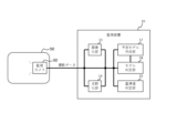
実施形態1に係る監視システムについて図面を用いて説明する。図1は、実施形態1に係る監視システムの構成を模式的に示したブロック図である。図2は、実施形態1に係る監視システムにおける監視装置の詳細な構成を模式的に示したブロック図である。図3~図8は、実施形態1に係る監視システムにおける監視装置の各種データの処理経路を模式的に示した図である。
[Embodiment 1]
A monitoring system according to
監視システム1は、拠点50a~50n(例えば、原料ヤード、倉庫、工場、搬送経路、高炉等)に存在する監視対象物(以下「対象物」という場合がある)を監視(点検)するシステムである。監視システム1は、監視装置10と、監視カメラ30a~30nと、ネットワーク40と、を有する。
The
ここで、監視対象物として、例えば、原料ヤードや倉庫における原材料、工場、高炉、搬送経路における落鉱落炭等とすることができる。 Here, the objects to be monitored may be, for example, raw materials in a raw material yard or warehouse, a factory, a blast furnace, or fallen coal on a transport route.
監視装置10は、監視カメラ30a~30nを用いて拠点50a~50nに存在する対象物を監視する装置である(図1参照)。監視装置10は、ネットワーク40を介して監視カメラ30a~30nと通信可能に接続されている。監視装置10は、データ取得部11と、経路制御部12と、画像化部13と、点群化部14と、経路制御部15と、ラベル付与部16と、予測モデル作成部17と、モデル判定部18と、基準値判定部19と、出力部20と、を有する(図2参照)。監視装置10には、例えば、プロセッサ、メモリ、ネットワークインタフェイス等を含むハードウェア資源(例えば、情報処理装置、コンピュータ)を用いることができる。この場合、ハードウェア資源は、プログラムを記憶するメモリを利用しながら、プロセッサにおいて当該プログラムを実行することにより、仮想的な、データ取得部11、経路制御部12、画像化部13、点群化部14、経路制御部15、ラベル付与部16、予測モデル作成部17、モデル判定部18、基準値判定部19、及び、出力部20を実現するようにしてもよい。
The
データ取得部11は、監視カメラ(図1の30a~30n)で撮影された撮影データを、ネットワーク(図1の40)を介して取得する機能部である(図2参照)。データ取得部11は、ネットワーク(図1の40)を介して監視カメラ(図1の30a~30n)と通信可能に接続されている。データ取得部11は、取得した撮影データを経路制御部12に向けて出力する(図3~図8参照)。データ取得部11で取得する撮影データは、様々な撮影形式の監視カメラ(図1の30a~30n;赤外線カメラ、ハイパースペクトルカメラ、RGB(Red Green Blue)カメラ、3次元センサ、デプスセンサ等)で撮影された撮影データ(動画データ、画像データ、3次元データ等)を用いることができる。
The
ここで、撮影データは、監視カメラ30a~30nで撮影されたデータであり、動画データ、画像データ、3次元データのいずれかである。
Here, the photographed data is data photographed by the
経路制御部12は、データ取得部11で取得した撮影データの出力経路を制御する機能部(第1経路制御部)である(図2参照)。経路制御部12は、撮影データの種別(動画データ、画像データ、3次元データ)を判断する。経路制御部12は、撮影データが動画データ(赤外線カメラ、ハイパースペクトルカメラ、RGBカメラ等で撮影した動画データ)であるときに、当該動画データを画像化部13に向けて出力する(図3、図6参照)。経路制御部12は、撮影データが画像データ(赤外線カメラ、ハイパースペクトルカメラ、RGBカメラ等で撮影した静止画データ)であるときに、当該画像データを経路制御部15に向けて出力する(図4、図7参照)。経路制御部12は、撮影データが3次元データ(例えば、3次元カメラ、デプスセンサ等で撮影した3次元データ)であるときに、当該3次元データを点群化部14に向けて出力する(図5、図8参照)。 The route control unit 12 is a functional unit (first route control unit) that controls the output route of the imaging data acquired by the data acquisition unit 11 (see FIG. 2). The route control unit 12 determines the type of photographic data (video data, image data, three-dimensional data). When the photographed data is video data (video data taken with an infrared camera, hyperspectral camera, RGB camera, etc.), the route control unit 12 outputs the video data to the imaging unit 13 (FIG. 3, (See Figure 6). When the photographed data is image data (still image data taken with an infrared camera, hyperspectral camera, RGB camera, etc.), the route control unit 12 outputs the image data to the route control unit 15 (FIG. 4). , see Figure 7). When the photographed data is three-dimensional data (for example, three-dimensional data photographed with a three-dimensional camera, depth sensor, etc.), the path control section 12 outputs the three-dimensional data to the point group forming section 14 (see FIG. 5, see Figure 8).
画像化部13は、経路制御部12からの動画データを画像データに変換する機能部である(図2参照)。画像化部13は、動画データから、予め設定されたサンプリング周期で画像データを切り出し、切り出した画像データを所定の画像処理(例えば、精細化、高解像度化、ノイズ除去、低解像度化、オープニング処理、モルフォロジー変換等)することによって、動画データから画像データに変換する。なお、画像処理は、必要に応じて、省略することができる。画像化部13は、変換された画像データを経路制御部15に向けて出力する(図3、図6参照)。
The
点群化部14は、経路制御部12からの3次元データを点群データに変換する機能部である(図2参照)。点群化部14は、3次元データを1次点群データに変換し、変換された1次点群データに基づいてモデルデータ(例えば、CAD(Computer Aided Design)データ)を生成し、生成されたモデルデータを2次点群データに変換することによって、3次元データを点群データに変換する。点群データに変換した際、点群化部14は、必要に応じて、点群データに対してフィルタ処理を実行し、はずれ点群の除去やダウンサンプリングを行うようにしてもよく、予測モデル作成部17で機械学習する部分以外の点群を除去するようにしてもよい。なお、モデルデータの生成、及び、モデルデータの点群データへの変換は、必要に応じて、省略することができる。点群化部14は、変換された点群データ(モデルデータを生成した場合は2次点群データ)を経路制御部15に向けて出力する(図5、図8参照)。ここで、点群化部14において3次元データを点群データに変換しているのは、3次元カメラやデプスセンサで撮影された3次元データはフォーマットがメーカ固有で統一されていないことが多いため画一的な処理が行い難いのに対し、点群データはフォーマットが統一されて画一的な処理が行い易いからである。
The point
経路制御部15は、画像化部13からの画像データ、及び、経路制御部12からの画像データ、並びに、点群化部14からの点群データの出力経路を制御する機能部(第2経路制御部)である(図2参照)。経路制御部15は、学習モードのときに、画像化部13からの画像データ、又は、経路制御部12からの画像データ、若しくは、点群化部14からの点群データをラベル付与部16に向けて出力する(図3、図4、図5参照)。経路制御部15は、運用モードのときに、画像化部13からの画像データ、又は、経路制御部12からの画像データをモデル判定部18に向けて出力する(図6、図7参照)。経路制御部15は、運用モードのときに、点群化部14からの点群データをモデル判定部18及び基準値判定部19に向けて出力する(図8参照)。
The
ここで、学習モードとは、予測モデル作成部17において機械学習(有用な規則、ルール、知識表現、判断基準等の特徴を抽出)するときのモード(第1モード)である。運用モードとは、モデル判定部18及び基準値判定部19において通常運用(判定処理)するときのモード(第2モード)である。
Here, the learning mode is a mode (first mode) when performing machine learning (extracting features such as useful rules, knowledge expressions, and judgment criteria) in the predictive
ラベル付与部16は、学習モードのときに、経路制御部15からのデータ(画像データ、点群データ)に予測モデル用ラベルを付与する機能部である(図2参照)。ラベル付与部16は、予測モデル用ラベルが付与されたデータ(ラベル付きデータ)を予測モデル作成部17に向けて出力する。
The
予測モデル作成部17は、ラベル付与部16からのラベル付きデータを用いて機械学習(有用な規則、ルール、知識表現、判断基準等の特徴を抽出)して予測モデルを作成する機能部である。予測モデルは、機械学習によって抽出された特徴(予測される対象物の特徴)を有する対象物(オブジェクト)に係るモデル(データ)であり、モデル判定部18における判定基準となる。予測モデル作成部17は、作成された予測モデルをモデル判定部18に向けて出力する。
The predictive
モデル判定部18は、経路制御部15からのデータ(画像データ、点群データ)と、予測モデル作成部17で作成された対応する予測モデルと、を比較することにより、当該データに含まれる対象物の変化を判定する機能部である(図2、図6~図8参照)。モデル判定部18は、予測モデル作成部17で作成された最新の予測モデルを保持する。判定では、温度(データが赤外線カメラ由来の画像データの場合)、成分(データがハイパースペクトルカメラ由来の画像データの場合)、見た目(データがRGBカメラ由来の画像データの場合)、点群(データが3次元カメラ由来の点群データの場合)で判定することができる。対象物の変化の判定では、対象物有りの確信度(%)、対象物無しの確信度(%)を用いて判定を実施することができる。例えば、対象物有と判断された確信度が85%以上のものを対象物有りと最終的に判断するように判定を行うことができる。確信度は判定したい状況に応じてチューニングすることが可能である。また、対象物の変化の判定では、データに含まれる対象物が予測モデルに対してどの程度(例えば、何%)変化しているかを判定することができ、変化が上限及び下限の範囲内にあるか否かを判定することができる。モデル判定部18は、対象物の変化の判定に係る結果(判定結果)を出力部20に向けて出力する。判定結果には、時刻情報、位置情報、カメラ情報、対象物情報等を含めることができる。
The
基準値判定部19は、経路制御部15からの点群データに含まれる対象物の所定形態に係る計測値(例えば、体積、形状の大きさ、面積等の形態の計測値)と、予め設定された基準値と、を比較することにより、当該対象物の変化を判定する機能部である(図2、図8参照)。基準値判定部19は、経路制御部15からの点群データから対象物に係る点群を抽出する。基準値判定部19は、抽出された対象物に係る点群に基づいて当該対象物の所定形態を計測する。基準値判定部19は、学習モードでは、計測された対象物に係る所定形態の計測値を基準値として保持する。基準値については、計測される対象物に係る所定形態に応じて予め設定され、例えば、体積、形状の大きさ、面積等とすることができる。基準値判定部19は、運用モードでは、計測された対象物に係る所定形態の計測値と、予め設定された基準値と、を比較することにより、当該対象物の変化を判定する。対象物の変化の判定では、対象物に係る所定形態の計測値が基準値に対してどの程度(例えば、何%)変化しているかを判定することができ、変化の程度が上限及び下限の範囲内にあるか否かを判定することができる。基準値判定部19は、対象物の変化の判定に係る結果(判定結果)を出力部20に向けて出力する。判定結果には、時刻情報、位置情報、カメラ情報、対象物情報等を含めることができる。
The reference
出力部20は、モデル判定部18又は基準値判定部19からの判定結果を出力(表示、送信、音声出力、印刷等)する機能部である(図2参照)。出力部20は、判定結果をデータ取得部11に向けて出力するようにし、データ取得部11にて、判定結果に基づいて対象物の変化を確認し、変化の程度に応じて監視カメラ30a~30nからの撮影データを取得する時間間隔を調整するようにしてもよい。例えば、対象物の変化が大きければ撮影データを取得する時間間隔を短くし、対象物の変化が小さければ撮影データを取得する時間間隔を長くすることができる。撮影データを取得する時間間隔を短くすることで、対象物の変化を早期かつ正確に把握することができ、撮影データを取得する時間間隔を長くすることで、システムの消費電力を抑えることができる。出力部20として、例えば、表示を行うディスプレイ、データ転送を行うインタフェイス、音声を出力するスピーカ、印刷を行うプリンタその他の出力手段を用いることができ、図示しない通信部及びネットワークを介して有線又は無線により通信可能に接続された出力部を有する情報端末等を用いてもよい。
The
監視カメラ30a~30nは、監視対象物(対象物)を撮影するカメラ(センサを含む)である(図1参照)。監視カメラ30a~30nは、撮影した対象物に係る撮影データ(動画データ、画像データ、3次元データのいずれか)を生成し、生成された撮影データを監視装置10のデータ取得部(図2~図8の11)に向けて出力する。監視カメラ30a~30nは、データ取得部(図2~図8の11)での撮影データを取得する時間間隔に応じて撮影データを出力するようにしてもよい。監視カメラ30a~30nには、各種カメラを用いることができる。撮影データには、時刻情報、位置情報、カメラ情報、対象物情報等を含めることができる。
The
監視カメラ30a~30nは、多数の拠点50a~50nに設置される。監視カメラ30a~30nは、顧客の要望に応じて各種のカメラが選択される。監視カメラ30a~30nは、拠点50a~50nごとに1台だけでなく2台以上設置してもよく、1つの拠点に異なる種類のカメラを複数台設置してもよい。顧客に対して対象物を監視する際に、どのような目的で何をどの範囲で監視したいのかの要望を確認する。これにより、顧客の要望に応じたサービス展開を柔軟に組み合わせることができる。
監視カメラ30a~30nには、例えば、赤外線カメラ、ハイパースペクトルカメラ、RGBカメラ、3次元カメラ、デプスセンサ等を用いることができる。
For example, an infrared camera, a hyperspectral camera, an RGB camera, a three-dimensional camera, a depth sensor, etc. can be used as the
例えば、落鉱落炭を対象物とする場合、落鉱落炭は発火のおそれもあることから、監視カメラ30a~30nには、温度を検出することが可能な赤外線カメラを用いることができる。赤外線カメラによれば、温度情報により落鉱落炭の温度変化を抽出することができる。これにより、人の目には見えない温度での判定が可能である。
For example, when the target object is fallen coal, there is a risk that the fallen coal may catch fire, so infrared cameras capable of detecting temperature can be used as the
また、工場の敷地には落鉱落炭だけでなく土やその他の成分の堆積物も存在していることから、監視カメラ30a~30nには、成分を検出することが可能なハイパースペクトルカメラを用いることができる。ハイパースペクトルカメラによれば、波長情報により落鉱落炭の成分を抽出することができる。これにより、人の目には見えない成分での判定が可能である。
In addition, since there is not only fallen coal but also deposits of soil and other components on the factory site, the
また、対象物の「見た目」の特徴を検出する場合、監視カメラ30a~30nには、RGBカメラを用いることができる。RGBカメラによれば、見た目のテクスチャ情報などにより落鉱落炭を抽出することができる。これにより、人の見た目での判定と同様な判定が可能である。
Further, when detecting the "appearance" characteristics of the object, RGB cameras can be used as the
さらに、対象物の形状の大きさや体積を検出する場合、監視カメラ30a~30nには、3次元カメラやデプスセンサを用いることができる。3次元カメラやデプスセンサを用いれば、人の目では計測できない3次元データを活用して、不定形な対象物(原材料、落鉱落炭)の正確な形状の大きさや体積の検出が可能となり、原材料の在庫管理を行い、不足する原材料を自動的に発注することができ、また、落鉱落炭の堆積管理を行い、清掃を行う場所やタイミングを絞り込むことができる。3次元カメラは、屋内/屋外撮影、撮影距離、撮影制度に応じて、3D-LiDAR(Light Detection And Ranging)、ToF(Time of Flight)カメラ、ステレオカメラなど多数の種類が存在し、撮影された3次元データのフォーマットが異なるが、点群化部14で画一的な処理が可能であるので、どのような種類の3次元カメラでもお客様の用途に応じて選択することができる。
Further, when detecting the size or volume of the object, a three-dimensional camera or a depth sensor can be used as the
なお、1つの拠点50a~50nに1種類の監視カメラ30a~30nのみを設置した場合、対象物の変化の判定が困難なことがあるが、1つの拠点50a~50nに複数種類の監視カメラ30a~30nを設置して複数種類の判定結果を得てフュージョンさせることにより、効果的に対象物の変化の判定を行うことができる。
Note that if only one type of
ネットワーク40は、監視装置10と監視カメラ30a~30nとを有線又は無線により通信可能に接続する情報通信網である(図1参照)。ネットワーク40には、例えば、LAN(Local Area Network)、PAN(Personal Area Network)、CAN(Campus Area Network)、MAN(Metropolitan Area Network)、WAN(Wide Area Network)、GAN(Global Area Network)等を用いることができる。
The
次に、実施形態1に係る監視システムにおける監視装置の画像化部の動作について図面を用いて説明する。図9は、実施形態1に係る監視システムにおける監視装置の画像化部の動作を模式的に示したフローチャート図である。なお、監視システム1及び監視装置10の構成部については、図1及び図2を参照されたい。
Next, the operation of the imaging unit of the monitoring device in the monitoring system according to the first embodiment will be explained using the drawings. FIG. 9 is a flowchart diagram schematically showing the operation of the imaging unit of the monitoring device in the monitoring system according to the first embodiment. Note that for the components of the
まず、画像化部13は、経路制御部12からの動画データ(監視カメラ30a~30n(赤外線カメラ、ハイパースペクトルカメラ、RGBカメラ等)で撮影した動画データ)を取得する(ステップA1)。
First, the
次に、画像化部13は、ステップA1で取得した動画データから予め設定されたサンプリング周期で画像データを切り出す(ステップA2)。
Next, the
次に、画像化部13は、ステップA2で切り出された画像データを精細化(例えば、高解像度化、ノイズ除去)する(ステップA3)。
Next, the
最後に、画像化部13は、ステップA3で精細化された画像データを経路制御部15に向けて出力し(ステップA4)、その後、終了する。
Finally, the
次に、実施形態1に係る監視システムにおける監視装置の点群化部の動作について図面を用いて説明する。図10は、実施形態1に係る監視システムにおける監視装置の点群化部の動作を模式的に示したフローチャート図である。なお、監視システム1及び監視装置10の構成部については、図1及び図2を参照されたい。
Next, the operation of the point cloud forming section of the monitoring device in the monitoring system according to the first embodiment will be explained using the drawings. FIG. 10 is a flowchart diagram schematically showing the operation of the point cloud forming section of the monitoring device in the monitoring system according to the first embodiment. Note that for the components of the
まず、点群化部14は、経路制御部12からの3次元データを取得する(ステップB1)。
First, the point
次に、点群化部14は、ステップB1で取得した3次元データを1次点群データに変換する(ステップB2)。
Next, the point
次に、点群化部14は、ステップB2で変換された1次点群データに基づいてモデルデータ(例えば、CADデータ)を生成する(ステップB3)。
Next, the point
次に、点群化部14は、ステップB3で生成されたモデルデータを2次点群データに変換する(ステップB4)。
Next, the point
最後に、点群化部14は、ステップB4で変換された2次点群データを経路制御部15に向けて出力し(ステップB5)、その後、終了する。
Finally, the point
次に、実施形態1に係る監視システムにおける監視装置のモデル判定部の動作について図面を用いて説明する。図11は、実施形態1に係る監視システムにおける監視装置のモデル判定部の動作を模式的に示したフローチャート図である。なお、監視システム1及び監視装置10の構成部については、図1及び図2を参照されたい。ここでは、予め予測モデル作成部17により予測モデルが作成され、作成された予測モデルがモデル判定部18に保持されているものとする。
Next, the operation of the model determination unit of the monitoring device in the monitoring system according to the first embodiment will be explained using the drawings. FIG. 11 is a flowchart diagram schematically showing the operation of the model determination unit of the monitoring device in the monitoring system according to the first embodiment. Note that for the components of the
まず、モデル判定部18は、経路制御部15からのデータ(画像データ、点群データ(モデルデータを生成した場合は2次点群データ))を取得する(ステップC1)。
First, the
次に、モデル判定部18は、ステップC1で取得したデータと、予測モデル作成部17で作成された対応する予測モデルと、を比較する(ステップC2)。
Next, the
次に、モデル判定部18は、ステップC2での比較により、ステップC1で取得したデータに含まれた対象物の変化を判定する(ステップC3)。
Next, the
最後に、モデル判定部18は、ステップC3での判定に係る結果(判定結果)を出力部20に向けて出力し(ステップC4)、その後、終了する。
Finally, the
次に、実施形態1に係る監視システムにおける監視装置の基準値判定部の動作について図面を用いて説明する。図12は、実施形態1に係る監視システムにおける監視装置の基準値判定部の動作を模式的に示したフローチャート図である。なお、監視システム1及び監視装置10の構成部については、図1及び図2を参照されたい。
Next, the operation of the reference value determining section of the monitoring device in the monitoring system according to the first embodiment will be described using the drawings. FIG. 12 is a flowchart diagram schematically showing the operation of the reference value determination unit of the monitoring device in the monitoring system according to the first embodiment. Note that for the components of the
まず、基準値判定部19は、経路制御部15からの点群データを取得する(ステップD1)。
First, the reference
次に、基準値判定部19は、ステップD1で取得した点群データから対象物に係る点群を抽出する(ステップD2)。
Next, the reference
次に、基準値判定部19は、ステップD2で抽出された対象物に係る点群に基づいて当該対象物の所定形態を計測する(ステップD3)。
Next, the reference
次に、基準値判定部19は、ステップD3で計測された対象物に係る所定形態の計測値(例えば、体積、形状の大きさ等の形態の計測値)と、予め設定された基準値と、を比較する(ステップD4)。
Next, the reference
次に、基準値判定部19は、ステップD4での比較により、ステップD1で取得した点群データに含まれた対象物の変化を判定する(ステップD5)。
Next, the reference
最後に、基準値判定部19は、ステップD5での対象物の変化の判定に係る結果(判定結果)を出力部20に向けて出力し(ステップD6)、その後、終了する。
Finally, the reference
以上のような監視システム1は、スマートファクトリ分野における原材料の管理、鉱業分野における落鉱落炭の管理、食品製造業の分野における原材料の管理、廃棄物処理業の分野における廃棄物の管理、各種施設におけるトイレ掃除の管理等に利用することができる。
The above-mentioned
実施形態1によれば、以下のような効果を奏する。 According to the first embodiment, the following effects are achieved.
第1の効果は、お客さまの要望に応じて最適な種類の監視カメラ30a~30nを選択することが可能となるので、現場の様々な状況を監視することに貢献することができる。
The first effect is that it is possible to select the optimal type of
第2の効果は、撮影した撮影データの中から監視対象物の形状、大きさ、体積、温度、成分等を検出することができるので、作業員の見た目だけでは判別がつかない要素についても監視することができる。 The second effect is that it is possible to detect the shape, size, volume, temperature, composition, etc. of the monitored object from the photographed data, so it is possible to monitor elements that cannot be determined by the worker's appearance alone. can do.
第3の効果は、監視したい場所に監視カメラ30a~30nを設置することで、作業員が現場に出向かずに遠隔地で、監視対象物の形状、大きさ、体積、温度、成分等を監視することができ、監視業務を効率化させることができる。
The third effect is that by installing the
第4の効果は、監視対象物の検出内容に応じて基準値を設定することで、監視対象物の異常を検出することができる。 The fourth effect is that an abnormality in the monitored object can be detected by setting a reference value according to the detected content of the monitored object.
第5の効果は、1つの監視システム1に様々な監視カメラ30a~30nをフュージョンさせて活用し、監視業務自体の品質向上を図ることができる。
The fifth effect is that
第6の効果は、監視を定常的に実施しているだけでなく、監視対象物の状況変化に応じて、監視を行う時間間隔を調整することができるので、監視システム1の消費電力を抑えることができる。
The sixth effect is that the power consumption of the
第7の効果は、監視カメラ30a~30nとして3次元カメラを活用することで、位置の取得が可能になり、清掃すべき場所、発注すべき対象を絞り込むことができ、広範囲な点検・監視を実現することができる。
The seventh effect is that by using three-dimensional cameras as the
第8の効果は、原材料の在庫管理においては、自動的に不足する対象物の発注を行ったり、在庫補充後の安定した状態までをライフサイクルとして管理することができる。また、落鉱落炭の堆積管理においては、清掃を行うタイミングを知らせることができる。 The eighth effect is that in raw material inventory management, it is possible to automatically order items that are in short supply, and to manage the period up to a stable state after inventory replenishment as a life cycle. In addition, in managing the accumulation of fallen coal, it is possible to notify the timing of cleaning.
[実施形態2]
実施形態2に係る監視システムについて図面を用いて説明する。図13は、実施形態2に係る監視システムの構成を模式的に示したブロック図である。
[Embodiment 2]
A monitoring system according to a second embodiment will be explained using the drawings. FIG. 13 is a block diagram schematically showing the configuration of a monitoring system according to the second embodiment.
実施形態2は、実施形態1の変形例であり、拠点50a~50nごとに監視カメラを設置するのをやめ、監視カメラ30(1つの監視カメラ、複数種類の監視カメラでも可)及び通信部80(無線通信部)を搭載した自動運転車両60を用いて、監視対象物が存在する拠点50a~50nを巡回して、撮影データを、通信部80及びネットワーク40を介して監視装置10で取得できるようにしたものである。自動運転車両60は、衛星測位装置70(例えば、GPS;Global Positioning System)を搭載している。衛星測位装置70で測位した測位情報は、撮影データに含めて、通信部80及びネットワーク40を介して監視装置10に送信される。監視装置10は、当該測位情報により撮影データの撮影位置を特定することができる。その他の構成は実施形態1と同様である。
Embodiment 2 is a modification of
実施形態2によれば、実施形態1と同様に、現場の様々な状況を監視することに貢献することができる。 According to the second embodiment, similarly to the first embodiment, it is possible to contribute to monitoring various situations at the site.
[実施形態3]
実施形態3に係る監視装置について図面を用いて説明する。図14は、実施形態3に係る監視装置の構成を模式的に示したブロック図である。
[Embodiment 3]
A monitoring device according to Embodiment 3 will be explained using the drawings. FIG. 14 is a block diagram schematically showing the configuration of a monitoring device according to the third embodiment.
監視装置10は、監視カメラ30を用いて拠点50に存在する監視対象物を監視する装置である(図14参照)。監視装置10は、画像化部13と、点群化部14と、予測モデル作成部17と、モデル判定部18と、基準値判定部19と、を備える。
The
画像化部13は、拠点50を撮影する監視カメラ30からの撮影データが動画データであるときに当該動画データを画像データに変換する(図14参照)。
The
点群化部14は、撮影データが3次元データであるときに当該3次元データを点群データに変換する(図14参照)。
The point
予測モデル作成部17は、第1モードのときに、画像化部13で変換された画像データ、又は、点群化部14で変換された点群データ、若しくは、撮影データが画像データであるときの他の画像データを用いて、機械学習して予測モデルを作成する(図14参照)。
When in the first mode, the predictive
モデル判定部18は、第1モードとは異なる第2モードのときに、画像化部13で変換された画像データ、又は、点群化部14で変換された点群データ、若しくは、撮影データが画像データであるときの他の画像データと、予測モデル作成部17で作成された予測モデルと、を比較することにより、画像データ又は点群データ若しくは他の画像データに含まれる監視対象物の変化を判定する。
The
基準値判定部19と、第2モードのときに、点群化部14で変換された点群データに含まれる監視対象物の所定形態を計測し、計測された計測値と、予め設定された基準値と、を比較することにより、監視対象物の変化を判定する。
The reference
実施形態3によれば、実施形態1と同様に、現場の様々な状況を監視することに貢献することができる。 According to the third embodiment, similarly to the first embodiment, it is possible to contribute to monitoring various situations at the site.
なお、実施形態1~3に係る監視装置は、いわゆるハードウェア資源(情報処理装置、コンピュータ)により構成することができ、図15に例示する構成を備えたものを用いることができる。例えば、ハードウェア資源100は、内部バス104により相互に接続される、プロセッサ101、メモリ102、ネットワークインタフェイス103等を備える。
Note that the monitoring devices according to
なお、図15に示す構成は、ハードウェア資源100のハードウェア構成を限定する趣旨ではない。ハードウェア資源100は、図示しないハードウェア(例えば、入出力インタフェイス)を含んでもよい。あるいは、装置に含まれるプロセッサ101等のユニットの数も図15の例示に限定する趣旨ではなく、例えば、複数のプロセッサ101がハードウェア資源100に含まれていてもよい。プロセッサ101には、例えば、CPU(Central Processing Unit)、MPU(Micro Processor Unit)、GPU(Graphics Processing Unit)等を用いることができる。
Note that the configuration shown in FIG. 15 is not intended to limit the hardware configuration of the
メモリ102には、例えば、RAM(Random Access Memory)、ROM(Read Only Memory)、HDD(Hard Disk Drive)、SSD(Solid State Drive)等を用いることができる。
As the
ネットワークインタフェイス103には、例えば、LAN(Local Area Network)カード、ネットワークアダプタ、ネットワークインタフェイスカード等を用いることができる。
For the
ハードウェア資源100の機能は、上述の処理モジュールにより実現される。当該処理モジュールは、例えば、メモリ102に格納されたプログラムをプロセッサ101が実行することで実現される。また、そのプログラムは、ネットワークを介してダウンロードするか、あるいは、プログラムを記憶した記憶媒体を用いて、更新することができる。さらに、上記処理モジュールは、半導体チップにより実現されてもよい。即ち、上記処理モジュールが行う機能は、何らかのハードウェアにおいてソフトウェアが実行されることによって実現できればよい。
The functions of the
上記実施形態の一部または全部は以下の付記のようにも記載され得るが、以下には限られない。 Some or all of the above embodiments may be described as in the following supplementary notes, but are not limited to the following.
[付記1]
本発明では、前記第1の視点に係る監視装置の形態が可能であり、以下の通りである。
拠点を撮影する監視カメラからの撮影データが動画データであるときに前記動画データを画像データに変換する画像化部と、
前記撮影データが3次元データであるときに前記3次元データを点群データに変換する点群化部と、
第1モードのときに、前記画像化部で変換された前記画像データ、又は、前記点群化部で変換された前記点群データ、若しくは、前記撮影データが画像データであるときの他の画像データを用いて、機械学習して予測モデルを作成する予測モデル作成部と、
前記第1モードとは異なる第2モードのときに、前記画像化部で変換された前記画像データ、又は、前記点群化部で変換された前記点群データ、若しくは、前記撮影データが画像データであるときの前記他の画像データと、前記予測モデル作成部で作成された前記予測モデルと、を比較することにより、前記画像データ又は前記点群データ若しくは前記他の画像データに含まれる監視対象物の変化を判定するモデル判定部と、
前記第2モードのときに、前記点群化部で変換された前記点群データに含まれる前記監視対象物の所定形態を計測し、計測された計測値と、予め設定された基準値と、を比較することにより、前記監視対象物の変化を判定する基準値判定部と、
を備える、
監視装置。
[Additional note 1]
In the present invention, the configuration of the monitoring device according to the first viewpoint is possible, and is as follows.
an imaging unit that converts the video data into image data when the shooting data from a surveillance camera that photographs the base is video data;
a point group forming unit that converts the three-dimensional data into point cloud data when the photographic data is three-dimensional data;
In the first mode, the image data converted by the imaging section, the point cloud data converted by the point group forming section, or another image when the photographic data is image data. A predictive model creation unit that uses data to perform machine learning to create a predictive model;
When in a second mode different from the first mode, the image data converted by the imaging section, the point cloud data converted by the point group forming section, or the photographed data is image data. By comparing the other image data when a model determination unit that determines changes in objects;
When in the second mode, a predetermined form of the monitoring target included in the point cloud data converted by the point cloud forming unit is measured, and a measured value and a preset reference value are obtained; a reference value determination unit that determines a change in the monitored object by comparing the
Equipped with
Monitoring equipment.
[付記2]
前記監視カメラからのデータの出力経路を制御する第1経路制御部と、
前記画像化部又は前記点群化部若しくは前記第1経路制御部からのデータの出力経路を制御する第2経路制御部と、
をさらに備え、
前記第1経路制御部は、
前記撮影データが動画データであるときに、前記動画データを前記画像化部に向けて出力し、
前記撮影データが3次元データであるときに、前記3次元データを前記点群化部に向けて出力し、
前記撮影データが画像データであるときの前記他の画像データを第2経路制御部に向けて出力し、
前記第2経路制御部は、
前記第1モードのときに、前記画像化部からの前記画像データ、又は、前記点群化部からの前記点群データ、若しくは、前記第1経路制御部からの前記他の画像データを前記モデル作成部に向けて出力し、
前記第2モードのときに、前記画像化部からの前記画像データ、又は、前記第1経路制御部からの前記他の画像データを前記モデル判定部に向けて出力し、若しくは、前記点群化部からの前記点群データを前記モデル判定部及び前記基準値判定部に向けて出力する、
付記1記載の監視装置。
[Additional note 2]
a first route control unit that controls an output route of data from the surveillance camera;
a second route control unit that controls an output route of data from the imaging unit, the point grouping unit, or the first route control unit;
Furthermore,
The first route control unit includes:
When the photographic data is video data, outputting the video data to the imaging unit,
when the photographic data is three-dimensional data, outputting the three-dimensional data to the point group forming section;
outputting the other image data when the photographing data is image data to a second path control unit;
The second route control section includes:
When in the first mode, the image data from the imaging section, the point cloud data from the point group forming section, or the other image data from the first path control section are used as the model. Output to the creation department,
When in the second mode, the image data from the imaging section or the other image data from the first path control section is output to the model determination section, or the point grouping is performed. outputting the point cloud data from the unit to the model determining unit and the reference value determining unit;
The monitoring device described in
[付記3]
前記監視カメラからの前記撮影データを取得して前記第1経路制御部に向けて出力するデータ取得部と、
前記モデル判定部及び前記基準値判定部の少なくとも1つからの判定結果を出力する出力部と、
をさらに備え、
前記出力部は、前記判定結果を前記データ取得部に向けて出力し、
前記データ取得部は、前記出力部からの前記判定結果に基づいて前記監視対象物の変化を確認し、変化の程度に応じて前記監視カメラからの前記撮影データを取得する時間間隔を調整する、
付記2記載の監視装置。
[Additional note 3]
a data acquisition unit that acquires the photographic data from the surveillance camera and outputs it to the first route control unit;
an output unit that outputs a determination result from at least one of the model determination unit and the reference value determination unit;
Furthermore,
The output unit outputs the determination result to the data acquisition unit,
The data acquisition unit checks a change in the monitored object based on the determination result from the output unit, and adjusts a time interval for acquiring the photographed data from the surveillance camera according to the degree of change.
Monitoring device described in Appendix 2.
[付記4]
前記撮影データは、時刻情報、位置情報、カメラ情報及び対象物情報の少なくとも1つの情報を含み、
前記判定結果は、前記時刻情報、前記位置情報、前記カメラ情報及び前記対象物情報の少なくとも1つの情報を含む、
付記3記載の監視装置。
[Additional note 4]
The photographic data includes at least one of time information, position information, camera information, and object information,
The determination result includes at least one of the time information, the position information, the camera information, and the object information.
Monitoring device described in Appendix 3.
[付記5]
前記画像化部は、前記動画データから、予め設定されたサンプリング周期で前記画像データを切り出し、切り出した前記画像データを所定の画像処理することによって、前記動画データから前記画像データに変換する、
付記1乃至4のいずれか一に記載の監視装置。
[Additional note 5]
The imaging unit cuts out the image data from the video data at a preset sampling period, and converts the video data into the image data by performing predetermined image processing on the cut out image data.
The monitoring device according to any one of
[付記6]
前記所定の画像処理は、精細化、高解像度化、ノイズ除去、低解像度化、オープニング処理、及び、モルフォロジー変換の少なくとも1つの処理である、
付記5記載の監視装置。
[Additional note 6]
The predetermined image processing is at least one of refinement, resolution enhancement, noise removal, resolution reduction, opening processing, and morphological conversion.
The monitoring device described in Appendix 5.
[付記7]
前記点群化部は、前記3次元データを1次点群データに変換し、変換された前記1次点群データに基づいてモデルデータを生成し、生成された前記モデルデータを2次点群データに変換することによって、前記3次元データを前記点群データに変換する、
付記1乃至6のいずれか一に記載の監視装置。
[Additional note 7]
The point cloud generation unit converts the three-dimensional data into first-order point cloud data, generates model data based on the converted first-order point cloud data, and converts the generated model data into a second-order point cloud. converting the three-dimensional data into the point cloud data by converting it into data;
The monitoring device according to any one of
[付記8]
前記点群化部は、変換された前記点群データに対してフィルタ処理を実行する、
付記7記載の監視装置。
[Additional note 8]
The point cloud forming unit performs filter processing on the converted point cloud data.
Monitoring device described in Appendix 7.
[付記9]
前記第1モードのときに、前記画像化部で変換された前記画像データ、又は、前記点群化部で変換された前記点群データ、若しくは、前記撮影データが画像データであるときの他の画像データに予測モデル用ラベルを付与し、前記予測モデル用ラベルが付与されたデータを前記予測モデル作成部に向けて出力するラベル付与部をさらに備える、
付記1乃至6のいずれか一に記載の監視装置。
[Additional note 9]
When in the first mode, the image data converted by the imaging section, the point cloud data converted by the point group forming section, or other when the photographic data is image data. further comprising a labeling unit that adds a predictive model label to the image data and outputs the data to which the predictive model label is added to the predictive model creating unit;
The monitoring device according to any one of
[付記10]
本発明では、前記第2の視点に係る監視システムの形態が可能であり、以下の通りである。
拠点を撮影する監視カメラと、
付記1乃至9のいずれか一に記載の監視装置と、
を備える、
監視システム。
[Additional note 10]
In the present invention, the form of the monitoring system according to the second viewpoint is possible, and is as follows.
Surveillance cameras that photograph the base,
A monitoring device according to any one of
Equipped with
Monitoring system.
[付記11]
前記監視カメラを搭載するとともに、衛星測位装置を搭載し、かつ、前記監視装置と通信可能にする通信部を有する自動運転車両をさらに備え、
前記自動運転車両は、前記衛星測位装置で測位した測位情報を、前記監視カメラで撮影された前記撮影データに含めて、前記通信部を介して前記監視装置に送信する、
付記10記載の監視システム。
[Additional note 11]
Further comprising an automatic driving vehicle equipped with the surveillance camera, a satellite positioning device, and a communication unit capable of communicating with the surveillance device,
The self-driving vehicle includes positioning information obtained by the satellite positioning device in the photographic data taken by the monitoring camera, and transmits the data to the monitoring device via the communication unit.
The monitoring system described in
[付記12]
本発明では、前記第3の視点に係る監視方法の形態が可能であり、以下の通りである。
拠点を撮影する監視カメラからの撮影データが動画データであるときに前記動画データを画像データに変換するステップと、
前記撮影データが3次元データであるときに前記3次元データを点群データに変換するステップと、
第1モードのときに、変換された前記画像データ、又は、変換された前記点群データ、若しくは、前記撮影データが画像データであるときの他の画像データを用いて、機械学習して予測モデルを作成するステップと、
前記第1モードとは異なる第2モードのときに、変換された前記画像データ、又は、変換された前記点群データ、若しくは、前記撮影データが画像データであるときの前記他の画像データと、作成された前記予測モデルと、を比較することにより、前記画像データ又は前記点群データ若しくは前記他の画像データに含まれる監視対象物の変化を判定するステップと、
前記第2モードのときに、変換された前記点群データに含まれる前記監視対象物の所定形態を計測し、計測された計測値と、予め設定された基準値と、を比較することにより、前記監視対象物の変化を判定するステップと、
を含む、
監視方法。
[Additional note 12]
In the present invention, the monitoring method according to the third viewpoint is possible, and is as follows.
When the photographed data from a surveillance camera photographing the base is video data, converting the video data into image data;
converting the three-dimensional data into point cloud data when the photographic data is three-dimensional data;
In the first mode, a predictive model is modeled by machine learning using the converted image data, the converted point cloud data, or other image data when the shooting data is image data. and the steps to create
When in a second mode different from the first mode, the converted image data, the converted point group data, or the other image data when the photographic data is image data; determining a change in the monitored object included in the image data, the point cloud data, or the other image data by comparing with the created prediction model;
In the second mode, by measuring a predetermined form of the monitored object included in the converted point cloud data and comparing the measured value with a preset reference value, determining a change in the monitored object;
including,
Monitoring method.
[付記13]
本発明では、前記第4の視点に係るプログラムの形態が可能であり、以下の通りである。
拠点を撮影する監視カメラからの撮影データが動画データであるときに前記動画データを画像データに変換する処理と、
前記撮影データが3次元データであるときに前記3次元データを点群データに変換する処理と、
第1モードのときに、変換された前記画像データ、又は、変換された前記点群データ、若しくは、前記撮影データが画像データであるときの他の画像データを用いて、機械学習して予測モデルを作成する処理と、
前記第1モードとは異なる第2モードのときに、変換された前記画像データ、又は、変換された前記点群データ、若しくは、前記撮影データが画像データであるときの前記他の画像データと、作成された前記予測モデルと、を比較することにより、前記画像データ又は前記点群データ若しくは前記他の画像データに含まれる監視対象物の変化を判定する処理と、
前記第2モードのときに、変換された前記点群データに含まれる前記監視対象物の所定形態を計測し、計測された計測値と、予め設定された基準値と、を比較することにより、前記監視対象物の変化を判定する処理と、
をハードウェア資源に実行させる、
プログラム。
[Additional note 13]
In the present invention, the form of the program according to the fourth aspect is possible, and is as follows.
When the photographed data from a surveillance camera photographing the base is video data, a process of converting the video data into image data;
a process of converting the three-dimensional data into point cloud data when the photographic data is three-dimensional data;
In the first mode, a predictive model is modeled by machine learning using the converted image data, the converted point cloud data, or other image data when the shooting data is image data. The process of creating
When in a second mode different from the first mode, the converted image data, the converted point group data, or the other image data when the photographic data is image data; A process of determining a change in the monitored object included in the image data, the point cloud data, or the other image data by comparing the created prediction model with the created prediction model;
In the second mode, by measuring a predetermined form of the monitored object included in the converted point cloud data and comparing the measured value with a preset reference value, a process of determining a change in the monitored object;
to be executed by hardware resources,
program.
なお、上記の特許文献の開示を、本書に引用をもって繰り込むものとする。本発明の全開示(特許請求の範囲及び図面を含む)の枠内において、さらにその基本的技術思想に基づいて、実施形態ないし実施例の変更・調整が可能である。また、本発明の全開示の枠内において種々の開示要素(各請求項の各要素、各実施形態ないし実施例の各要素、各図面の各要素等を含む)の多様な組み合わせないし選択(必要により不選択)が可能である。すなわち、本発明は、請求の範囲及び図面を含む全開示、技術的思想にしたがって当業者であればなし得るであろう各種変形、修正を含むことは勿論である。また、本願に記載の数値及び数値範囲については、明記がなくともその任意の中間値、下位数値、及び、小範囲が記載されているものとみなされる。 Furthermore, the disclosures of the above patent documents are incorporated into this book by reference. Within the framework of the entire disclosure of the present invention (including claims and drawings), changes and adjustments to the embodiments and examples are possible based on the basic technical idea thereof. Furthermore, various combinations or selections (as necessary) of various disclosed elements (including each element of each claim, each element of each embodiment or example, each element of each drawing, etc.) within the framework of the entire disclosure of the present invention. (not selected) is possible. That is, it goes without saying that the present invention includes the entire disclosure including the claims and drawings, as well as various modifications and modifications that a person skilled in the art would be able to make in accordance with the technical idea. Furthermore, with respect to the numerical values and numerical ranges described in this application, any intermediate values, lower numerical values, and small ranges thereof are deemed to be included even if not explicitly stated.
1 監視システム
10 監視装置
11 データ取得部
12 経路制御部
13 画像化部
14 点群化部
15 経路制御部
16 ラベル付与部
17 予測モデル作成部
18 モデル判定部
19 基準値判定部
20 出力部
30、30a~30n 監視カメラ
40 ネットワーク
50、50a~50n 拠点
60 自動運転車両
70 衛星測位装置
80 通信部
100 ハードウェア資源
101 プロセッサ
102 メモリ
103 ネットワークインタフェイス
104 内部バス
1 Monitoring
Claims (10)
前記撮影データが3次元データであるときに前記3次元データを点群データに変換する点群化部と、
第1モードのときに、前記画像化部で変換された前記画像データ、又は、前記点群化部で変換された前記点群データ、若しくは、前記撮影データが静止画データであるときの前記静止画データを用いて、機械学習して予測モデルを作成する予測モデル作成部と、
前記第1モードとは異なる第2モードのときに、前記画像化部で変換された前記画像データ、又は、前記点群化部で変換された前記点群データ、若しくは、前記撮影データが静止画データであるときの前記静止画データと、前記予測モデル作成部で作成された前記予測モデルと、を比較することにより、前記画像データ又は前記点群データ若しくは前記静止画データに含まれる監視対象物の変化を判定するモデル判定部と、
前記第2モードのときに、前記点群化部で変換された前記点群データに含まれる前記監視対象物の所定形態を計測し、計測された計測値と、予め設定された基準値と、を比較することにより、前記監視対象物の変化を判定する基準値判定部と、
を備え、
前記予測モデルの作成に用いた前記画像データ又は前記点群データ若しくは前記静止画データの種類は、前記第2モードで比較される前記画像データ又は前記点群データ若しくは前記静止画データの種類に対応しており、
前記予測モデルは、前記機械学習によって抽出された特徴を有する対象物に係るデータである、
監視装置。 an imaging unit that converts the video data into image data when the shooting data from a surveillance camera that photographs the base is video data;
a point group forming unit that converts the three-dimensional data into point cloud data when the photographic data is three-dimensional data;
In the first mode, the image data converted by the imaging section, the point cloud data converted by the point group forming section, or the still image data when the photographic data is still image data. a predictive model creation unit that performs machine learning to create a predictive model using the image data;
When in a second mode different from the first mode, the image data converted by the imaging section, the point cloud data converted by the point cloud forming section, or the photographed data is a still image. By comparing the still image data when it is data with the prediction model created by the prediction model creation unit, the monitoring target included in the image data, the point cloud data, or the still image data is detected. a model determination unit that determines a change in
When in the second mode, a predetermined form of the monitoring target included in the point cloud data converted by the point cloud forming unit is measured, and a measured value and a preset reference value are obtained; a reference value determination unit that determines a change in the monitored object by comparing the
Equipped with
The type of the image data, the point cloud data, or the still image data used to create the prediction model corresponds to the type of the image data, the point cloud data, or the still image data to be compared in the second mode. and
The prediction model is data related to an object having features extracted by the machine learning,
Monitoring equipment.
前記画像化部又は前記点群化部若しくは前記第1経路制御部からのデータの出力経路を制御する第2経路制御部と、
をさらに備え、
前記第1経路制御部は、
前記撮影データが動画データであるときに、前記動画データを前記画像化部に向けて出力し、
前記撮影データが3次元データであるときに、前記3次元データを前記点群化部に向けて出力し、
前記撮影データが静止画データであるときの前記静止画データを第2経路制御部に向けて出力し、
前記第2経路制御部は、
前記第1モードのときに、前記画像化部からの前記画像データ、又は、前記点群化部からの前記点群データ、若しくは、前記第1経路制御部からの前記静止画データを前記予測モデル作成部に向けて出力し、
前記第2モードのときに、前記画像化部からの前記画像データ、又は、前記第1経路制御部からの前記静止画データを前記モデル判定部に向けて出力し、若しくは、前記点群化部からの前記点群データを前記モデル判定部及び前記基準値判定部に向けて出力する、
請求項1記載の監視装置。 a first route control unit that controls an output route of data from the surveillance camera;
a second route control unit that controls an output route of data from the imaging unit, the point grouping unit, or the first route control unit;
Furthermore,
The first route control unit includes:
When the photographic data is video data, outputting the video data to the imaging unit,
when the photographic data is three-dimensional data, outputting the three-dimensional data to the point group forming section;
outputting the still image data when the photographing data is still image data to a second path control unit;
The second route control section includes:
When in the first mode, the image data from the imaging unit, the point cloud data from the point cloud forming unit, or the still image data from the first path control unit are used in the prediction model. Output to the creation department,
When in the second mode, the image data from the imaging section or the still image data from the first path control section is output to the model determination section, or the point cloud formation section outputting the point cloud data from to the model determination unit and the reference value determination unit;
The monitoring device according to claim 1.
前記モデル判定部及び前記基準値判定部の少なくとも1つからの判定結果を出力する出力部と、
をさらに備え、
前記出力部は、前記判定結果を前記データ取得部に向けて出力し、
前記データ取得部は、前記出力部からの前記判定結果に基づいて前記監視対象物の変化を確認し、変化の程度に応じて前記監視カメラからの前記撮影データを取得する時間間隔を調整する、
請求項2記載の監視装置。 a data acquisition unit that acquires the photographic data from the surveillance camera and outputs it to the first route control unit;
an output unit that outputs a determination result from at least one of the model determination unit and the reference value determination unit;
Furthermore,
The output unit outputs the determination result to the data acquisition unit,
The data acquisition unit checks a change in the monitored object based on the determination result from the output unit, and adjusts a time interval for acquiring the photographed data from the surveillance camera according to the degree of change.
The monitoring device according to claim 2.
請求項1乃至3のいずれか一に記載の監視装置。 The imaging unit cuts out the image data from the video data at a preset sampling period, and converts the video data into the image data by performing predetermined image processing on the cut out image data.
A monitoring device according to any one of claims 1 to 3.
請求項1乃至4のいずれか一に記載の監視装置。 The point cloud generation unit converts the three-dimensional data into first-order point cloud data, generates model data based on the converted first-order point cloud data, and converts the generated model data into a second-order point cloud. converting the three-dimensional data into the point cloud data by converting it into data;
A monitoring device according to any one of claims 1 to 4.
請求項1乃至5のいずれか一に記載の監視装置。 When in the first mode, the image data converted by the imaging section, the point cloud data converted by the point group forming section, or the photographed data is still image data. Further comprising a labeling unit that adds a predictive model label to the still image data and outputs the data to which the predictive model label is added to the predictive model creation unit.
A monitoring device according to any one of claims 1 to 5.
請求項1乃至6のいずれか一に記載の監視装置と、
を備える、
監視システム。 Surveillance cameras that photograph the base,
A monitoring device according to any one of claims 1 to 6,
Equipped with
Monitoring system.
前記自動運転車両は、前記衛星測位装置で測位した測位情報を、前記監視カメラで撮影された前記撮影データに含めて、前記通信部を介して前記監視装置に送信する、
請求項7記載の監視システム。 Further comprising an automatic driving vehicle equipped with the surveillance camera, a satellite positioning device, and a communication unit capable of communicating with the surveillance device,
The self-driving vehicle includes positioning information obtained by the satellite positioning device in the photographic data taken by the monitoring camera, and transmits the data to the monitoring device via the communication unit.
The monitoring system according to claim 7.
前記撮影データが3次元データであるときに前記3次元データを点群データに変換するステップと、
第1モードのときに、変換された前記画像データ、又は、変換された前記点群データ、若しくは、前記撮影データが静止画データであるときの前記静止画データを用いて、機械学習して予測モデルを作成するステップと、
前記第1モードとは異なる第2モードのときに、変換された前記画像データ、又は、変換された前記点群データ、若しくは、前記撮影データが静止画データであるときの前記静止画データと、作成された前記予測モデルと、を比較することにより、前記画像データ又は前記点群データ若しくは前記静止画データに含まれる監視対象物の変化を判定するステップと、
前記第2モードのときに、変換された前記点群データに含まれる前記監視対象物の所定形態を計測し、計測された計測値と、予め設定された基準値と、を比較することにより、前記監視対象物の変化を判定するステップと、
を含み、
前記予測モデルの作成に用いた前記画像データ又は前記点群データ若しくは前記静止画データの種類は、前記第2モードで比較される前記画像データ又は前記点群データ若しくは前記静止画データの種類に対応しており、
前記予測モデルは、前記機械学習によって抽出された特徴を有する対象物に係るデータである、
監視方法。 When the photographed data from a surveillance camera photographing the base is video data, converting the video data into image data;
converting the three-dimensional data into point cloud data when the photographic data is three-dimensional data;
In the first mode, prediction is performed by machine learning using the converted image data, the converted point cloud data, or the still image data when the photographed data is still image data. a step of creating a model;
When in a second mode different from the first mode, the converted image data, the converted point group data, or the still image data when the photographic data is still image data; determining a change in the monitored object included in the image data, the point cloud data, or the still image data by comparing with the created prediction model;
In the second mode, by measuring a predetermined form of the monitored object included in the converted point cloud data and comparing the measured value with a preset reference value, determining a change in the monitored object;
including;
The type of the image data, the point cloud data, or the still image data used to create the prediction model corresponds to the type of the image data, the point cloud data, or the still image data to be compared in the second mode. and
The prediction model is data related to an object having features extracted by the machine learning,
Monitoring method.
前記撮影データが3次元データであるときに前記3次元データを点群データに変換する処理と、
第1モードのときに、変換された前記画像データ、又は、変換された前記点群データ、若しくは、前記撮影データが静止画データであるときの前記静止画データを用いて、機械学習して予測モデルを作成する処理と、
前記第1モードとは異なる第2モードのときに、変換された前記画像データ、又は、変換された前記点群データ、若しくは、前記撮影データが静止画データであるときの前記静止画データと、作成された前記予測モデルと、を比較することにより、前記画像データ又は前記点群データ若しくは前記静止画データに含まれる監視対象物の変化を判定する処理と、
前記第2モードのときに、変換された前記点群データに含まれる前記監視対象物の所定形態を計測し、計測された計測値と、予め設定された基準値と、を比較することにより、前記監視対象物の変化を判定する処理と、
をハードウェア資源に実行させ、
前記予測モデルの作成に用いた前記画像データ又は前記点群データ若しくは前記静止画データの種類は、前記第2モードで比較される前記画像データ又は前記点群データ若しくは前記静止画データの種類に対応しており、
前記予測モデルは、前記機械学習によって抽出された特徴を有する対象物に係るデータである、
プログラム。 When the photographed data from a surveillance camera photographing the base is video data, a process of converting the video data into image data;
a process of converting the three-dimensional data into point cloud data when the photographic data is three-dimensional data;
In the first mode, prediction is performed by machine learning using the converted image data, the converted point cloud data, or the still image data when the photographed data is still image data. The process of creating a model,
When in a second mode different from the first mode, the converted image data, the converted point group data, or the still image data when the photographic data is still image data; A process of determining a change in a monitoring target included in the image data, the point cloud data, or the still image data by comparing the created prediction model with the created prediction model;
In the second mode, by measuring a predetermined form of the monitored object included in the converted point cloud data and comparing the measured value with a preset reference value, a process of determining a change in the monitored object;
to be executed by hardware resources ,
The type of the image data, the point cloud data, or the still image data used to create the prediction model corresponds to the type of the image data, the point cloud data, or the still image data to be compared in the second mode. and
The prediction model is data related to an object having features extracted by the machine learning,
program.
Priority Applications (1)
| Application Number | Priority Date | Filing Date | Title |
|---|---|---|---|
| JP2018221560A JP7347775B2 (en) | 2018-11-27 | 2018-11-27 | Monitoring device, monitoring system, monitoring method, and program |
Applications Claiming Priority (1)
| Application Number | Priority Date | Filing Date | Title |
|---|---|---|---|
| JP2018221560A JP7347775B2 (en) | 2018-11-27 | 2018-11-27 | Monitoring device, monitoring system, monitoring method, and program |
Publications (2)
| Publication Number | Publication Date |
|---|---|
| JP2020087036A JP2020087036A (en) | 2020-06-04 |
| JP7347775B2 true JP7347775B2 (en) | 2023-09-20 |
Family
ID=70908273
Family Applications (1)
| Application Number | Title | Priority Date | Filing Date |
|---|---|---|---|
| JP2018221560A Active JP7347775B2 (en) | 2018-11-27 | 2018-11-27 | Monitoring device, monitoring system, monitoring method, and program |
Country Status (1)
| Country | Link |
|---|---|
| JP (1) | JP7347775B2 (en) |
Families Citing this family (3)
| Publication number | Priority date | Publication date | Assignee | Title |
|---|---|---|---|---|
| CN112506081A (en) * | 2020-11-30 | 2021-03-16 | 苏州迈创信息技术有限公司 | Public toilet environment monitoring system for security protection |
| CN115588265B (en) * | 2022-12-12 | 2023-04-07 | 华能酒泉风电有限责任公司 | Intelligent monitoring system of wind power plant |
| CN117666510A (en) * | 2023-12-07 | 2024-03-08 | 湖州成鑫钢化玻璃有限公司 | Production control system and method for toughened glass |
Citations (3)
| Publication number | Priority date | Publication date | Assignee | Title |
|---|---|---|---|---|
| JP2017102838A (en) | 2015-12-04 | 2017-06-08 | トヨタ自動車株式会社 | Database construction system for article recognition algorism machine-learning |
| WO2018179361A1 (en) | 2017-03-31 | 2018-10-04 | 日本電気株式会社 | Image-processing device, image-processing method, and recording medium |
| JP2018185208A (en) | 2017-04-25 | 2018-11-22 | 富士通株式会社 | Change detection program, change detector, and change detection method |
Family Cites Families (1)
| Publication number | Priority date | Publication date | Assignee | Title |
|---|---|---|---|---|
| JPH09293141A (en) * | 1996-04-24 | 1997-11-11 | Hitachi Ltd | Mobile object detection device |
-
2018
- 2018-11-27 JP JP2018221560A patent/JP7347775B2/en active Active
Patent Citations (3)
| Publication number | Priority date | Publication date | Assignee | Title |
|---|---|---|---|---|
| JP2017102838A (en) | 2015-12-04 | 2017-06-08 | トヨタ自動車株式会社 | Database construction system for article recognition algorism machine-learning |
| WO2018179361A1 (en) | 2017-03-31 | 2018-10-04 | 日本電気株式会社 | Image-processing device, image-processing method, and recording medium |
| JP2018185208A (en) | 2017-04-25 | 2018-11-22 | 富士通株式会社 | Change detection program, change detector, and change detection method |
Also Published As
| Publication number | Publication date |
|---|---|
| JP2020087036A (en) | 2020-06-04 |
Similar Documents
| Publication | Publication Date | Title |
|---|---|---|
| JP7347775B2 (en) | Monitoring device, monitoring system, monitoring method, and program | |
| KR102022496B1 (en) | Process management and monitoring system using vision image detection and a method thereof | |
| US10334965B2 (en) | Monitoring device, monitoring system, and monitoring method | |
| US20200302188A1 (en) | Intra-facility activity analysis device, intra-facility activity analysis system, and intra-facility activity analysis method | |
| EP3434626B1 (en) | Projection instruction device, parcel sorting system, and projection instruction method | |
| JP2023076913A (en) | Abnormality determination device | |
| CN105051781A (en) | Machine-vision system and method for remote quality inspection of a product | |
| EP3023912A1 (en) | Crack data collection apparatus and server apparatus to collect crack data | |
| EP3434621B1 (en) | Instruction projecting device, parcel sorting system and instruction projecting method | |
| KR101804358B1 (en) | Equipment monitoring system using image analysis | |
| JP2015103104A (en) | Information processing apparatus, information processing method, and information processing system | |
| JP7145970B2 (en) | Inspection support device for concrete structure, inspection support method, and inspection support program | |
| JP6610640B2 (en) | Position recognition method and system, and abnormality determination method and system | |
| JP7406451B2 (en) | programmable logic controller | |
| KR102260123B1 (en) | Apparatus for Sensing Event on Region of Interest and Driving Method Thereof | |
| CN111178424A (en) | Petrochemical production site safety compliance real-time detection system and method | |
| JP2016180681A (en) | Ground collapse detection system | |
| US11120676B2 (en) | Intrusion detection methods and devices | |
| KR102479951B1 (en) | Construction safety managing system, server and method based on IoT | |
| WO2020175589A1 (en) | Information providing system | |
| US20200160208A1 (en) | Model sharing among edge devices | |
| JP6702402B2 (en) | Image processing system, image processing method, and image processing program | |
| US10922819B2 (en) | Method and apparatus for detecting deviation from a motion pattern in a video | |
| US10916017B2 (en) | Method and apparatus for detecting motion deviation in a video sequence | |
| JP6223897B2 (en) | Abnormality detection device and abnormality detection system |
Legal Events
| Date | Code | Title | Description |
|---|---|---|---|
| A621 | Written request for application examination |
Free format text: JAPANESE INTERMEDIATE CODE: A621 Effective date: 20211007 |
|
| A977 | Report on retrieval |
Free format text: JAPANESE INTERMEDIATE CODE: A971007 Effective date: 20221007 |
|
| A131 | Notification of reasons for refusal |
Free format text: JAPANESE INTERMEDIATE CODE: A131 Effective date: 20221129 |
|
| A521 | Request for written amendment filed |
Free format text: JAPANESE INTERMEDIATE CODE: A523 Effective date: 20221213 |
|
| A131 | Notification of reasons for refusal |
Free format text: JAPANESE INTERMEDIATE CODE: A131 Effective date: 20230411 |
|
| A521 | Request for written amendment filed |
Free format text: JAPANESE INTERMEDIATE CODE: A523 Effective date: 20230420 |
|
| TRDD | Decision of grant or rejection written | ||
| A01 | Written decision to grant a patent or to grant a registration (utility model) |
Free format text: JAPANESE INTERMEDIATE CODE: A01 Effective date: 20230808 |
|
| A61 | First payment of annual fees (during grant procedure) |
Free format text: JAPANESE INTERMEDIATE CODE: A61 Effective date: 20230831 |
|
| R151 | Written notification of patent or utility model registration |
Ref document number: 7347775 Country of ref document: JP Free format text: JAPANESE INTERMEDIATE CODE: R151 |