JP7347313B2 - power system - Google Patents
power system Download PDFInfo
- Publication number
- JP7347313B2 JP7347313B2 JP2020070354A JP2020070354A JP7347313B2 JP 7347313 B2 JP7347313 B2 JP 7347313B2 JP 2020070354 A JP2020070354 A JP 2020070354A JP 2020070354 A JP2020070354 A JP 2020070354A JP 7347313 B2 JP7347313 B2 JP 7347313B2
- Authority
- JP
- Japan
- Prior art keywords
- switch
- abnormality
- inter
- load
- mode
- Prior art date
- Legal status (The legal status is an assumption and is not a legal conclusion. Google has not performed a legal analysis and makes no representation as to the accuracy of the status listed.)
- Active
Links
Images


Classifications
-
- H—ELECTRICITY
- H02—GENERATION; CONVERSION OR DISTRIBUTION OF ELECTRIC POWER
- H02J—CIRCUIT ARRANGEMENTS OR SYSTEMS FOR SUPPLYING OR DISTRIBUTING ELECTRIC POWER; SYSTEMS FOR STORING ELECTRIC ENERGY
- H02J7/00—Circuit arrangements for charging or depolarising batteries or for supplying loads from batteries
- H02J7/0013—Circuit arrangements for charging or depolarising batteries or for supplying loads from batteries acting upon several batteries simultaneously or sequentially
- H02J7/0024—Parallel/serial switching of connection of batteries to charge or load circuit
-
- H—ELECTRICITY
- H02—GENERATION; CONVERSION OR DISTRIBUTION OF ELECTRIC POWER
- H02H—EMERGENCY PROTECTIVE CIRCUIT ARRANGEMENTS
- H02H3/00—Emergency protective circuit arrangements for automatic disconnection directly responsive to an undesired change from normal electric working condition with or without subsequent reconnection ; integrated protection
- H02H3/02—Details
- H02H3/05—Details with means for increasing reliability, e.g. redundancy arrangements
-
- B—PERFORMING OPERATIONS; TRANSPORTING
- B60—VEHICLES IN GENERAL
- B60R—VEHICLES, VEHICLE FITTINGS, OR VEHICLE PARTS, NOT OTHERWISE PROVIDED FOR
- B60R16/00—Electric or fluid circuits specially adapted for vehicles and not otherwise provided for; Arrangement of elements of electric or fluid circuits specially adapted for vehicles and not otherwise provided for
- B60R16/02—Electric or fluid circuits specially adapted for vehicles and not otherwise provided for; Arrangement of elements of electric or fluid circuits specially adapted for vehicles and not otherwise provided for electric constitutive elements
- B60R16/03—Electric or fluid circuits specially adapted for vehicles and not otherwise provided for; Arrangement of elements of electric or fluid circuits specially adapted for vehicles and not otherwise provided for electric constitutive elements for supply of electrical power to vehicle subsystems or for
- B60R16/033—Electric or fluid circuits specially adapted for vehicles and not otherwise provided for; Arrangement of elements of electric or fluid circuits specially adapted for vehicles and not otherwise provided for electric constitutive elements for supply of electrical power to vehicle subsystems or for characterised by the use of electrical cells or batteries
-
- B—PERFORMING OPERATIONS; TRANSPORTING
- B60—VEHICLES IN GENERAL
- B60T—VEHICLE BRAKE CONTROL SYSTEMS OR PARTS THEREOF; BRAKE CONTROL SYSTEMS OR PARTS THEREOF, IN GENERAL; ARRANGEMENT OF BRAKING ELEMENTS ON VEHICLES IN GENERAL; PORTABLE DEVICES FOR PREVENTING UNWANTED MOVEMENT OF VEHICLES; VEHICLE MODIFICATIONS TO FACILITATE COOLING OF BRAKES
- B60T17/00—Component parts, details, or accessories of power brake systems not covered by groups B60T8/00, B60T13/00 or B60T15/00, or presenting other characteristic features
- B60T17/18—Safety devices; Monitoring
-
- B—PERFORMING OPERATIONS; TRANSPORTING
- B62—LAND VEHICLES FOR TRAVELLING OTHERWISE THAN ON RAILS
- B62D—MOTOR VEHICLES; TRAILERS
- B62D5/00—Power-assisted or power-driven steering
- B62D5/04—Power-assisted or power-driven steering electrical, e.g. using an electric servo-motor connected to, or forming part of, the steering gear
- B62D5/0457—Power-assisted or power-driven steering electrical, e.g. using an electric servo-motor connected to, or forming part of, the steering gear characterised by control features of the drive means as such
-
- H—ELECTRICITY
- H02—GENERATION; CONVERSION OR DISTRIBUTION OF ELECTRIC POWER
- H02H—EMERGENCY PROTECTIVE CIRCUIT ARRANGEMENTS
- H02H3/00—Emergency protective circuit arrangements for automatic disconnection directly responsive to an undesired change from normal electric working condition with or without subsequent reconnection ; integrated protection
- H02H3/08—Emergency protective circuit arrangements for automatic disconnection directly responsive to an undesired change from normal electric working condition with or without subsequent reconnection ; integrated protection responsive to excess current
-
- H—ELECTRICITY
- H02—GENERATION; CONVERSION OR DISTRIBUTION OF ELECTRIC POWER
- H02J—CIRCUIT ARRANGEMENTS OR SYSTEMS FOR SUPPLYING OR DISTRIBUTING ELECTRIC POWER; SYSTEMS FOR STORING ELECTRIC ENERGY
- H02J1/00—Circuit arrangements for dc mains or dc distribution networks
- H02J1/08—Three-wire systems; Systems having more than three wires
- H02J1/084—Three-wire systems; Systems having more than three wires for selectively connecting the load or loads to one or several among a plurality of power lines or power sources
- H02J1/086—Three-wire systems; Systems having more than three wires for selectively connecting the load or loads to one or several among a plurality of power lines or power sources for providing alternative feeding paths between load or loads and source or sources when the main path fails
-
- H—ELECTRICITY
- H02—GENERATION; CONVERSION OR DISTRIBUTION OF ELECTRIC POWER
- H02J—CIRCUIT ARRANGEMENTS OR SYSTEMS FOR SUPPLYING OR DISTRIBUTING ELECTRIC POWER; SYSTEMS FOR STORING ELECTRIC ENERGY
- H02J7/00—Circuit arrangements for charging or depolarising batteries or for supplying loads from batteries
- H02J7/14—Circuit arrangements for charging or depolarising batteries or for supplying loads from batteries for charging batteries from dynamo-electric generators driven at varying speed, e.g. on vehicle
- H02J7/1423—Circuit arrangements for charging or depolarising batteries or for supplying loads from batteries for charging batteries from dynamo-electric generators driven at varying speed, e.g. on vehicle with multiple batteries
-
- B—PERFORMING OPERATIONS; TRANSPORTING
- B60—VEHICLES IN GENERAL
- B60R—VEHICLES, VEHICLE FITTINGS, OR VEHICLE PARTS, NOT OTHERWISE PROVIDED FOR
- B60R16/00—Electric or fluid circuits specially adapted for vehicles and not otherwise provided for; Arrangement of elements of electric or fluid circuits specially adapted for vehicles and not otherwise provided for
- B60R16/02—Electric or fluid circuits specially adapted for vehicles and not otherwise provided for; Arrangement of elements of electric or fluid circuits specially adapted for vehicles and not otherwise provided for electric constitutive elements
- B60R16/03—Electric or fluid circuits specially adapted for vehicles and not otherwise provided for; Arrangement of elements of electric or fluid circuits specially adapted for vehicles and not otherwise provided for electric constitutive elements for supply of electrical power to vehicle subsystems or for
Description
本発明は、電源システムに関する。 The present invention relates to a power supply system.
近年、車両に適用され、この車両の挙動を制御可能な電源システムが知られている。この電源システムでは、車両の運転時に、例えば電動ブレーキ装置や電動ステアリング装置など、車両の運転に必要な機能を実施する負荷で異常が発生し、これによりその機能が失われてしまうと、車両の運転を継続することができない。車両の運転中における異常発生時でも、その機能が失われないようにするために、1つの機能を実施する負荷として第1負荷及び第2負荷を有する装置が知られている。 In recent years, power supply systems that are applied to vehicles and can control the behavior of the vehicles have been known. In this power supply system, when an abnormality occurs in a load that performs functions necessary for vehicle operation, such as an electric brake device or an electric steering device, when the vehicle is operating, and the function is lost as a result, the vehicle Unable to continue driving. 2. Description of the Related Art Devices are known that have a first load and a second load as loads that perform one function in order to prevent the function from being lost even when an abnormality occurs during operation of a vehicle.
この装置に適用される電源システムとして、例えば特許文献1では、第1負荷に接続された第1電源を含む第1系統と、第2負荷に接続された第2電源を含む第2系統と、を有するものが知られている。この電源システムでは、各系統を接続する接続経路に系統間スイッチが設けられており、系統間スイッチは、コントローラにより一方の系統で異常が発生したと判定された場合にオフ状態とされる。これにより、異常が発生していない他方の系統の負荷により車両の運転に必要な機能を確保し、車両の運転を継続することが可能となる。
As a power supply system applied to this device, for example, in
しかしながら、異常が発生したと判定されてから系統間スイッチがオフ状態になるまでには所定の遮断期間が必要となり、この遮断期間に他方の系統における負荷の電圧が当該負荷の動作電圧の下限値よりも低下すると、負荷の動作を継続することができない。 However, a predetermined cut-off period is required after it is determined that an abnormality has occurred until the inter-system switch is turned off, and during this cut-off period, the voltage of the load in the other system is lower than the lower limit of the operating voltage of the load. If the value drops below this level, the load cannot continue operating.
本発明は、上記課題を解決するためになされたものであり、その目的は、異常が発生した場合でも負荷の動作を継続できる電源システムを提供することにある。 The present invention has been made to solve the above problems, and its purpose is to provide a power supply system that can continue the operation of a load even when an abnormality occurs.
上記課題を解決するための第1の手段は、第1負荷に接続された第1電源を含む第1系統と、第2負荷に接続された第2電源を含む第2系統と、各系統を互いに接続する接続経路と、を有する電源システムであって、前記接続経路に設けられた系統間スイッチと、前記接続経路において前記系統間スイッチに直列接続され、所定のインダクタンス成分を有するインダクタンス部と、前記第1系統及び前記第2系統のいずれか一方で異常が発生したことを判定する異常判定部と、前記異常判定部により異常が発生したと判定された場合に前記系統間スイッチにオフ指令を出力する状態制御部と、を備え、前記異常判定部により前記第1系統及び前記第2系統のいずれか一方で異常が発生したと判定されてから、前記状態制御部のオフ指令に応じて前記系統間スイッチがオフ状態になるまでの期間を遮断期間とする場合、異常が発生していない他方の系統と前記接続経路とにより構成される回路の時定数が、前記遮断期間に前記他方の系統における負荷の電圧が当該負荷の動作電圧の下限値よりも低下しないという条件を満たす時定数となるように、前記所定のインダクタンス成分が設定されている。 A first means for solving the above problem is to connect each system to a first system including a first power source connected to a first load, a second system including a second power source connected to a second load, and a second system including a first power source connected to a first load. A power supply system having a connection path that connects to each other, an intersystem switch provided in the connection path, and an inductance section that is connected in series to the intersystem switch in the connection path and has a predetermined inductance component. an abnormality determination unit that determines that an abnormality has occurred in either the first system or the second system; and an abnormality determination unit that issues an off command to the inter-system switch when the abnormality determination unit determines that an abnormality has occurred. a state control unit that outputs an output, and after the abnormality determination unit determines that an abnormality has occurred in either the first system or the second system, the state control unit outputs the When the period until the inter-system switch turns off is defined as the cut-off period, the time constant of the circuit constituted by the other system in which no abnormality has occurred and the connection path is the same as that of the other system during the cut-off period. The predetermined inductance component is set so as to have a time constant that satisfies the condition that the voltage of the load does not drop below the lower limit of the operating voltage of the load.
上記構成によれば、第1,第2系統を互いに接続する接続経路に系統間スイッチが設けられている。そのため、系統間スイッチをオン状態とすることで、第1,第2系統間で相互の電力供給が可能であり、第1負荷及び第2負荷に対して、第1電源及び第2電源による冗長的な電力供給が可能となる。また、一方の系統で異常が発生したと判定された場合には、系統間スイッチをオフ状態とすることで、異常が発生していない他方の系統における負荷の動作を継続することが可能となっている。 According to the above configuration, the intersystem switch is provided in the connection path that connects the first and second systems to each other. Therefore, by turning on the inter-system switch, it is possible to mutually supply power between the first and second systems, and the first and second power supplies provide redundant power for the first and second loads. power supply becomes possible. Additionally, if it is determined that an abnormality has occurred in one system, by turning off the intersystem switch, it is possible to continue operating loads in the other system where the abnormality has not occurred. ing.
しかしながら、異常が発生したと判定されてから系統間スイッチがオフ状態となるまでには所定の遮断期間が必要となり、この遮断期間に他方の系統における負荷の電圧が当該負荷の動作電圧の下限値よりも低下すると、負荷の動作を継続することができない。 However, a predetermined cut-off period is required after it is determined that an abnormality has occurred until the inter-system switch is turned off, and during this cut-off period, the voltage of the load in the other system is lower than the lower limit of the operating voltage of the load. If the value drops below this level, the load cannot continue operating.
この点、上記構成では、接続経路において系統間スイッチと直列接続されたインダクタンス部を設けるようにした。そして、このインダクタンス部のインダクタンス成分により、他方の系統と接続経路とにより構成される回路の時定数が、遮断期間に他方の系統における負荷の電圧が当該負荷の動作電圧の下限値よりも低下しない、という条件を満たす時定数となるようにした。つまり、一方の系統で異常が発生しても、この異常により発生する過渡的な電流変化とインダクタンス部のインダクタンス成分とにより、系統間に過渡的な電圧差を発生させ、他方の系統における負荷の電圧が当該負荷の動作電圧の下限値よりも低下しないようにした。これにより、他方の系統における負荷の動作を継続することができる。 In this regard, in the above configuration, an inductance section connected in series with the intersystem switch is provided in the connection path. The inductance component of this inductance section ensures that the time constant of the circuit constituted by the other system and the connection path is such that the voltage of the load in the other system does not drop below the lower limit of the operating voltage of the load during the cutoff period. The time constant was set to satisfy the following conditions. In other words, even if an abnormality occurs in one system, the transient current change caused by this abnormality and the inductance component of the inductance section will cause a transient voltage difference between the systems, and the load on the other system will increase. The voltage was prevented from dropping below the lower limit of the operating voltage of the load. Thereby, the operation of the load in the other system can be continued.
例えば、接続経路に所定の抵抗値を有する抵抗部を設け、異常により発生する過渡的な電流変化と当該抵抗部の抵抗値とにより、過渡的な電圧差を発生させることも可能である。しかし、接続経路に抵抗部が設けられると、異常が発生していない正常時において系統間に常に電圧差が発生するとともに、電力損失が発生してしまう。上記構成では、接続経路にインダクタンス部を設けることで、正常時における系統間の電圧差及び電力損失の発生を抑制することができる。 For example, it is also possible to provide a resistance section having a predetermined resistance value in the connection path, and to generate a transient voltage difference by a transient current change caused by an abnormality and the resistance value of the resistance section. However, if a resistance section is provided in the connection path, a voltage difference will always occur between the systems during normal times when no abnormality has occurred, and power loss will occur. In the above configuration, by providing the inductance portion in the connection path, it is possible to suppress the voltage difference between the systems and the generation of power loss during normal times.
第2の手段では、前記接続経路には、前記インダクタンス部を迂回するバイパス経路が設けられており、前記系統間スイッチは、第1系統間スイッチであり、前記バイパス経路に設けられた第2系統間スイッチを備える。 In the second means, the connection path is provided with a bypass path that detours around the inductance section, the inter-system switch is a first inter-system switch, and the connection path is provided with a bypass path that bypasses the inductance section, and the inter-system switch is a first inter-system switch, and the Equipped with an interval switch.
上記構成によれば、接続経路にインダクタンス部を迂回するバイパス経路が設けられており、このバイパス経路に第2系統間スイッチが設けられている。そのため、第2系統間スイッチをオン状態とすることで、インダクタンス部を介さずに第1,第2系統を互いに接続することが可能となっている。このため、異常が発生していない正常時において第1,第2系統間で相互の電力供給をする場合に、インダクタンス部のインダクタンス値による各負荷の電圧変動の遅延を抑制することができる。 According to the above configuration, a bypass path that detours around the inductance section is provided in the connection path, and a second inter-system switch is provided in this bypass path. Therefore, by turning on the second inter-system switch, it is possible to connect the first and second systems to each other without using an inductance section. Therefore, when mutually supplying power between the first and second systems in a normal state where no abnormality has occurred, it is possible to suppress the delay in voltage fluctuation of each load due to the inductance value of the inductance section.
第3の手段では、前記第1負荷及び前記第2負荷は、移動体において運転に必要な少なくとも1つの機能を実施する負荷であって、かつ前記移動体の運転支援機能を実施する負荷であり、前記移動体は、前記運転支援機能を用いる第1モードによる走行と、前記運転支援機能を用いない第2モードによる走行が可能であり、前記状態制御部は、前記第1モードにおいて前記第1系統間スイッチにオン指令を出力するとともに前記第2系統間スイッチにオフ指令を出力し、前記第2モードにおいて少なくとも前記第2系統間スイッチにオン指令を出力し、前記バイパス経路を介して前記第1系統と前記第2系統とを導通させる。 In the third means, the first load and the second load are loads that perform at least one function necessary for driving in the mobile body, and loads that perform a driving support function of the mobile body. , the movable body is capable of traveling in a first mode using the driving support function and a second mode not using the driving support function, and the state control unit is configured to control the first mode in the first mode. outputs an on command to the intersystem switch and outputs an off command to the second intersystem switch; outputs an on command to at least the second intersystem switch in the second mode; The first system and the second system are brought into continuity.
運転に必要な機能であって、かつ運転支援機能を実施する負荷として、第1負荷及び第2負荷を有する移動体に適用される電源システムにおいて、運転支援機能を用いる第1モードによる走行と、運転支援機能を用いない第2モードによる走行とを切り替え可能なものがある。上記構成では、第1モードにおいて第1系統間スイッチにオン指令を出力するとともに第2系統間スイッチにオフ指令を出力するようにした。これにより、インダクタンス部を介して第1系統と第2系統とを接続することができ、いずれか一方の系統で異常が発生した場合でも、異常が発生していない系統における電源の確保が可能となり、運転支援機能を継続して用いることができる。 In a power supply system applied to a mobile body having a first load and a second load as loads necessary for driving and implementing the driving support function, traveling in a first mode using the driving support function; Some vehicles are capable of switching between driving in a second mode that does not use the driving support function. In the above configuration, in the first mode, an ON command is output to the first inter-system switch, and an OFF command is output to the second inter-system switch. This allows the first system and the second system to be connected via the inductance section, and even if an abnormality occurs in either system, it is possible to secure power in the system where the abnormality does not occur. , the driving support function can be used continuously.
また、第2モードにおいて少なくとも第2系統間スイッチにオン指令を出力し、バイパス経路を介して第1系統と第2系統とを導通させるようにした。これにより、インダクタンス部を介さずに第1系統と第2系統とを接続することができ、異常が発生していない正常時における各負荷の電圧変動の遅延を抑制することができる。つまり、第1モードにおける電源喪失を抑制しつつ、第2モードにおける動作遅延を抑制することができる。 Further, in the second mode, an ON command is output to at least the second inter-system switch to establish continuity between the first system and the second system via the bypass path. Thereby, it is possible to connect the first system and the second system without using an inductance section, and it is possible to suppress delays in voltage fluctuations of each load during normal times when no abnormality has occurred. In other words, it is possible to suppress power loss in the first mode while suppressing operation delay in the second mode.
第4の手段では、前記状態制御部は、前記第1モードにおいて前記異常判定部により異常が発生したと判定された場合に、前記第1系統間スイッチにオフ指令を出力する。上記構成によれば、運転支援機能を用いている場合において、電源が喪失されることを好適に抑制できる。 In the fourth means, the state control unit outputs an off command to the first inter-system switch when the abnormality determination unit determines that an abnormality has occurred in the first mode. According to the above configuration, when the driving support function is used, loss of power can be suitably suppressed.
第5の手段では、前記状態制御部は、前記第2モードにおいて前記異常判定部により異常が発生したと判定された場合に、前記第1系統間スイッチ及び前記第2系統間スイッチにオフ指令を出力する。 In the fifth means, the state control unit issues an OFF command to the first inter-system switch and the second inter-system switch when the abnormality determination unit determines that an abnormality has occurred in the second mode. Output.
第2モードでは、リアクトル38を介さずに第1系統と第2系統とが導通している。そのため、第2モードにおいて異常が発生したと判定された場合において、第1系統間スイッチ及び第2系統間スイッチにオフ指令が出力されても、遮断期間に他方の系統における負荷の電圧が当該負荷の動作電圧の下限値よりも低下することを抑制できない。上記構成では、第2モードにおいて運転支援機能が用いられていない。そのため、遮断期間に他方の系統における負荷の電圧が当該負荷の動作電圧の下限値よりも低下した場合には、移動体の運転者により移動体の運転を継続することができる。そして、遮断期間後は、異常が発生していない他方の系統における負荷を用いて移動体の運転を継続することができる。
In the second mode, the first system and the second system are electrically connected without going through the
第6の手段では、前記バイパス経路は、前記第1系統間スイッチ及び前記インダクタンス部を迂回しており、システム休止状態で、前記第2系統間スイッチにより前記第2系統側への暗電流の供給が可能となっている。 In the sixth means, the bypass path bypasses the first inter-system switch and the inductance section, and when the system is in a halt state, the second inter-system switch supplies dark current to the second system side. is possible.
上記構成では、電源システムの休止状態(システム休止状態)において、第2系統間スイッチがオンに維持されており、第2系統間スイッチにより第2系統側への暗電流の供給が可能となっている。そして、電源システムの動作状態において、暗電流供給用の経路であるバイパス経路を用いて、インダクタンス部を介さずに第1,第2系統を互いに接続する。そのため、暗電流供給用の経路とは別に、インダクタンス部を介さずに第1,第2系統を互いに接続する経路を設ける必要がなく、電源システムの構成を簡略化できる。 In the above configuration, when the power supply system is in a hibernation state (system hibernation state), the second inter-system switch is kept on, and the second inter-system switch enables the supply of dark current to the second system side. There is. Then, in the operating state of the power supply system, the first and second systems are connected to each other without using an inductance section using a bypass path that is a path for supplying dark current. Therefore, there is no need to provide a path for connecting the first and second systems to each other without using an inductance section, in addition to the path for supplying dark current, and the configuration of the power supply system can be simplified.
(実施形態)
以下、本発明に係る電源システムを車載の電源システム100として具体化した実施形態について、図面を参照しつつ説明する。
(Embodiment)
DESCRIPTION OF THE PREFERRED EMBODIMENTS Hereinafter, an embodiment in which a power supply system according to the present invention is embodied as a vehicle-mounted
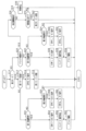
図1に示すように、電源システム100は、一般負荷30及び特定負荷32に電力を供給するシステムである。電源システム100は、高圧蓄電池10と、DCDCコンバータ(以下、単にコンバータ)12と、第1低圧蓄電池14と、第2低圧蓄電池16と、第1スイッチ部20と、第2スイッチ部22と、第3スイッチ部24と、制御装置40と、を備えている。
As shown in FIG. 1, the
高圧蓄電池10は、第1低圧蓄電池14及び第2低圧蓄電池16よりも高い定格電圧(例えば数百V)を有しており、例えばリチウムイオン蓄電池である。コンバータ12は、高圧蓄電池10から供給される電力を、一般負荷30及び特定負荷32の動作電圧VM(例えば12V)の電力に変換して、一般負荷30及び特定負荷32に供給する。
The high
一般負荷30は、移動体としての車両において運転支援に用いられない電気負荷(以下、単に負荷)であり、例えばエアコン、オーディオ装置、パワーウィンドウ等である。
The
一方、特定負荷32は、車両の運転支援に用いられる少なくとも1つの機能を実施する負荷である。詳細には、特定負荷32は、車両の運転支援機能を実施する負荷であり、例えば車両の操舵を制御する電動パワーステアリング装置50、車輪に制動力を付与する電動ブレーキ装置51、車両周囲の状況を監視する走行制御装置52等である。
On the other hand, the
そのため、これらの特定負荷32に異常が発生し、その機能が失われると、運転支援を行うことができない。そのため、特定負荷32では、異常が発生した場合でもその機能が失われないようにするため、機能毎に冗長に設けられた第1負荷34と第2負荷36とを有している。具体的には、電動パワーステアリング装置50は、第1ステアリングモータ50Aと第2ステアリングモータ50Bとを有している。電動ブレーキ装置51は、第1ブレーキ装置51Aと第2ブレーキ装置51Bとを有している。走行制御装置52は、カメラ52Aとレーザレーダ52Bとを有している。第1ステアリングモータ50Aと第1ブレーキ装置51Aとカメラ52Aとが、第1負荷34に相当し、第2ステアリングモータ50Bと第2ブレーキ装置51Bとレーザレーダ52Bとが、第2負荷36に相当する。
Therefore, if an abnormality occurs in these
第1負荷34と第2負荷36とは、併せて1つの機能を実現するものであるが、それぞれ単独でもその機能の一部を実現可能なものである。例えば電動パワーステアリング装置50では、第1ステアリングモータ50Aと第2ステアリングモータ50Bとにより車両の自由な操舵が可能であり、操舵速度や操舵範囲等に一定の制限がある中で、各ステアリングモータ50A,50Bにより車両の操舵が可能である。
The
各特定負荷32は、手動運転において、ドライバによる制御を支援する機能を実現する。また、各特定負荷32は、車両の走行や停止などの挙動を自動で制御する自動運転において、自動運転に必要な機能を実現する。そのため、特定負荷32は、車両の走行(運転)に必要な少なくとも1つの機能を実施する負荷ともいうことができる。
Each
第1負荷34は、第1系統内経路LA1を介してコンバータ12に接続されており、この第1系統内経路LA1に第1低圧蓄電池14及び一般負荷30が接続されている。第1低圧蓄電池14は、例えば鉛蓄電池である。本実施形態では、第1系統内経路LA1により接続されたコンバータ12、第1低圧蓄電池14、一般負荷30及び第1負荷34により、第1系統ES1が構成されている。第1系統内経路LA1には、第1系統ES1のインダクタンス成分ZA1が示されている。なお、本実施形態において、コンバータ12及び第1低圧蓄電池14が「第1電源」に相当する。
The
また、第2負荷36は、第2系統内経路LA2を介して第2低圧蓄電池16に接続されている。第2低圧蓄電池16は、例えばリチウムイオン蓄電池である。本実施形態では、第2系統内経路LA2により接続された第2低圧蓄電池16及び第2負荷36により、第2系統ES2が構成されている。第2系統内経路LA2には、第2系統ES2のインダクタンス成分ZA2が示されている。なお、本実施形態において、第2低圧蓄電池16が「第2電源」に相当する。
Further, the
第1スイッチ部20は、各系統を互いに接続する第1接続経路LB1に設けられている。第1接続経路LB1は、第1系統内経路LA1と第2系統内経路LA2とを接続しており、第1スイッチ部20は、直列接続された第1スイッチSW1と第2スイッチSW2とを備えている。第1スイッチ部20において、第1スイッチSW1は、第2スイッチSW2よりも第1系統ES1側に設けられている。なお、本実施形態において、第1スイッチSW1及び第2スイッチSW2が「系統間スイッチ、第1系統間スイッチ」に相当する。
The
本実施形態では、第1,第2スイッチSW1,SW2として、NチャネルMOSFET(以下、単にMOSFET)が用いられている。そのため、第1スイッチSW1には第1寄生ダイオードDA1が並列接続されており、第2スイッチSW2には第2寄生ダイオードDA2が並列接続されている。本実施形態では、第1,第2寄生ダイオードDA1,DA2の向きが互いに逆向きとなるように、第1,第2スイッチSW1,SW2が直列接続されている。詳細には、第1寄生ダイオードDA1は、アノードを第2系統ES2側、カソードを第1系統ES1側となるように配置されており、第2寄生ダイオードDA2は、アノードを第1系統ES1側、カソードを第2系統ES2側となるように配置されている。 In this embodiment, N-channel MOSFETs (hereinafter simply referred to as MOSFETs) are used as the first and second switches SW1 and SW2. Therefore, a first parasitic diode DA1 is connected in parallel to the first switch SW1, and a second parasitic diode DA2 is connected in parallel to the second switch SW2. In this embodiment, the first and second switches SW1 and SW2 are connected in series so that the directions of the first and second parasitic diodes DA1 and DA2 are opposite to each other. Specifically, the first parasitic diode DA1 is arranged such that its anode is placed on the second system ES2 side and its cathode is placed on the first system ES1 side, and the second parasitic diode DA2 has its anode placed on the first system ES1 side, and its cathode is placed on the first system ES1 side. The cathode is arranged on the second system ES2 side.
第1接続経路LB1には、第1電流検出部26が設けられている。第1電流検出部26は、第1接続経路LB1のうち第1スイッチ部20よりも第1系統ES1側の部分に設けられており、当該部分に流れる系統間電流IA(図3参照)の大きさ及び向きを検出する。
A first
第2スイッチ部22は、各系統を互いに接続する第2接続経路LB2に設けられている。第2接続経路LB2は、第1接続経路LB1とは別に、第1系統内経路LA1と第2系統内経路LA2とを接続しており、第1スイッチ部20は、第3スイッチSW3を備えている。つまり、第1スイッチ部20と第2スイッチ部22とは、第1系統内経路LA1と第2系統内経路LA2との間に並列接続されている。
The
本実施形態では、第3スイッチSW3として、ノーマリクローズ式のリレーが用いられている。また、第3スイッチSW3として、機械式のリレーが用いられている。そのため、第3スイッチSW3は、第1,第2スイッチSW1,SW2に比べてオンオフを切り替える切替速度が遅い。なお、第3スイッチSW3には、寄生ダイオードが設けられていない。 In this embodiment, a normally closed relay is used as the third switch SW3. Further, a mechanical relay is used as the third switch SW3. Therefore, the switching speed of the third switch SW3 is slower than that of the first and second switches SW1 and SW2. Note that the third switch SW3 is not provided with a parasitic diode.
第2接続経路LB2には、第2電流検出部28が設けられている。第2電流検出部28は、第2接続経路LB2のうち第2スイッチ部22よりも第1系統ES1側の部分に設けられており、当該部分に流れる系統間電流IAの大きさ及び向きを検出する。各電流検出部26,28の検出値は、制御装置40に入力される。
A second
第3スイッチ部24は、第2系統内経路LA2に設けられている。詳細には、第3スイッチ部24は、第2系統内経路LA2において、第1,第2接続経路LB1,LB2との接続点と第2低圧蓄電池16との間に設けられており、直列接続された第4スイッチSW4と第5スイッチSW5とを備えている。第3スイッチ部24において、第4スイッチSW4は、第5スイッチSW5よりも第1,第2接続経路LB1,LB2側に設けられている。
The
本実施形態では、第4,第5スイッチSW1,SW2として、MOSFETが用いられている。そのため、第4スイッチSW4には第4寄生ダイオードDA4が並列接続されており、第5スイッチSW5には第5寄生ダイオードDA5が並列接続されている。本実施形態では、第4,第5寄生ダイオードDA4,DA5の向きが互いに逆向きとなるように、第4,第5スイッチSW4,SW5が直列接続されている。詳細には、第4寄生ダイオードDA4は、アノードを第2低圧蓄電池16側、カソードを第1,第2接続経路LB1,LB2側となるように配置されており、第5寄生ダイオードDA5は、アノードを第1,第2接続経路LB1,LB2側、カソードを第2低圧蓄電池16側となるように配置されている。
In this embodiment, MOSFETs are used as the fourth and fifth switches SW1 and SW2. Therefore, a fourth parasitic diode DA4 is connected in parallel to the fourth switch SW4, and a fifth parasitic diode DA5 is connected in parallel to the fifth switch SW5. In this embodiment, the fourth and fifth switches SW4 and SW5 are connected in series so that the directions of the fourth and fifth parasitic diodes DA4 and DA5 are opposite to each other. Specifically, the fourth parasitic diode DA4 is arranged such that its anode is on the second low
制御装置40は、各電流検出部26,28の検出値に基づいて、第1~第5スイッチSW1~SW5を切替操作すべく、第1~第5切替信号SC1~SC5を生成し、第1~第5切替信号SC1~SC5による指令を第1~第5スイッチSW1~SW5に出力する。制御装置40は、コンバータ12を動作制御すべく、制御信号SDを生成し、制御信号SDによる指令をコンバータ12に出力する。制御信号SDにより、コンバータ12の動作状態と動作停止状態とが切り替えられる。
The
また、制御装置40は、報知部44と、IGスイッチ45と、入力部46とに接続されており、これらを制御する。報知部44は、視覚または聴覚的にドライバに報知する装置であり、例えば車室内に設置されたディスプレイやスピーカである。IGスイッチ45は、車両の起動スイッチである。制御装置40は、IGスイッチ45のオンオフ状態を監視する。入力部46は、ドライバの操作を受け付ける装置であり、例えばハンドル、レバー、ボタン、ペダル、音声入力装置である。
Further, the
制御装置40は、上述した特定負荷32を用いて車両を手動運転及び自動運転する。制御装置40は、CPU、ROM、RAM、フラッシュメモリ等からなる周知のマイクロコンピュータを備えている。CPUは、ROM内の演算プログラムや制御データを参照して、手動運転及び自動運転するための種々の機能を実現する。
The
なお、手動運転とは、ドライバの操作によって車両を運転制御する状態を表す。また、自動運転とは、ドライバの操作によらず制御装置40による制御内容で車両を運転制御する状態を表す。具体的には、自動運転とは、米国運輸省道路交通安全局(NHTSA)によって定められたレベル0からレベル5までの自動運転レベルのうち、レベル3以上の自動運転のことをいう。レベル3は、制御装置40が、走行環境を観測しつつ、ハンドル操作と加減速との両方を制御するレベルである。
Note that manual operation refers to a state in which the vehicle is controlled by the driver's operation. Further, automatic driving refers to a state in which the vehicle is controlled by the control content of the
また、制御装置40は、上述した特定負荷32を用いて、LKA(Lane Keeping Assist)、LCA(Lane Change Assist)、PCS(Pre-Crash Safety)等の運転支援機能を実施可能である。制御装置40は、車両の運転モードを、運転支援機能を用いる第1モードと、運転支援機能を用いない第2モードとに切り替え可能であり、車両は各運転モードによる走行が可能となっている。制御装置40は、入力部46を介したドライバの切替指示により、第1モードと第2モードとを切り替える。ここで、第1モードには、ドライバが運転支援機能を用いて車両を手動運転するモードとともに、車両を自動運転するモードが含まれる。第2モードは、ドライバが運転支援機能を用いずに車両を手動運転するモードである。
Further, the
第1モードにおいて、制御装置40は、第1系統ES1及び第2系統ES2に異常が発生したか否かを判定し、いずれの系統ES1,ES2でも異常が発生していないと判定された場合、第1負荷34と第2負荷36とを用いて車両の自動運転及び運転支援が行われる。これにより、第1,第2負荷34,36は協働して自動運転及び運転支援に必要な1つの機能を実施する。本実施形態において、異常は、地絡や断線等の電源失陥異常である。
In the first mode, the
一方、いずれか一方の系統ES1,ES2で異常が発生したと判定された場合、第1~第3スイッチSW1~SW3をオフ状態とし、第1系統ES1と第2系統ES2とを電気的に絶縁する。これにより、いずれか一方の系統ES1,ES2で異常が発生した場合でも、異常が発生していない他方の系統ES1,ES2の負荷34,36を動作させることができる。
On the other hand, if it is determined that an abnormality has occurred in either system ES1 or ES2, the first to third switches SW1 to SW3 are turned off to electrically isolate the first system ES1 and second system ES2. do. Thereby, even if an abnormality occurs in one of the systems ES1 and ES2, the
ところで、いずれか一方の系統ES1,ES2で異常が発生したと判定されてから、第1~第3スイッチSW1~SW3がオフされるまでには所定の遮断期間TS(図3参照)が必要となる。そのため、この遮断期間TSに他方の系統ES1,ES2における負荷34,36の電圧が、当該負荷34,36の動作電圧VMの下限値Vth(図3参照)よりも低下すると、負荷34,36の動作を継続することができない。
By the way, a predetermined cutoff period TS (see FIG. 3) is required from when it is determined that an abnormality has occurred in one of the systems ES1 and ES2 until the first to third switches SW1 to SW3 are turned off. Become. Therefore, if the voltage of the
この場合に、第1モードにおいて比較的切替速度が遅い第3スイッチSW3をオフ状態とすることで、遮断期間TSを短縮できる。しかし、比較的切替速度が速い第1,第2スイッチSW1,SW2であっても、第1,第2スイッチSW1,SW2がオフされるまでには所定の遮断期間TSが必要となる。そのため、いずれか一方の系統ES1,ES2で異常が発生した場合でも、他方の系統ES1,ES2の負荷34,36の動作を継続できる技術が望まれている。
In this case, the cutoff period TS can be shortened by turning off the third switch SW3, which has a relatively slow switching speed in the first mode. However, even if the first and second switches SW1 and SW2 have relatively fast switching speeds, a predetermined cutoff period TS is required before the first and second switches SW1 and SW2 are turned off. Therefore, even if an abnormality occurs in one of the systems ES1 and ES2, a technique is desired that allows the
本実施形態では、第1接続経路LB1において第1スイッチ部20と直列接続されたリアクトル38を設け、このリアクトル38のインダクタンス成分ZBを以下のように設定した。具体的には、他方の系統ES1,ES2と第1接続経路LB1とにより構成される回路の時定数TM(図3参照)が、遮断期間TSに他方の系統ES1,ES2における負荷34,36の電圧が動作電圧VMの下限値Vthよりも低下しないという条件を満たす時定数となるように、リアクトル38のインダクタンス成分ZBが設定されている。
In this embodiment, a
詳細には、いずれか一方の系統ES1,ES2で異常が発生してから、他方の系統ES1,ES2における負荷34,36の電圧が動作電圧VMの下限値Vthに低下するまでの期間を低下期間TL(図3参照)とする。また、異常が発生してから異常が発生したと判定されるまでの期間を判定期間TD(図3参照)とする。この場合に、他方の系統ES1,ES2のインダクタンス成分ZA1,ZA2と、リアクトル38のインダクタンス成分ZBとにより特定される時定数TMが、下記の(式1)を満たす時定数となるように、リアクトル38のインダクタンス成分ZBが設定されている。
Specifically, the drop period is the period from when an abnormality occurs in either system ES1, ES2 until the voltage of the
TL>TD+TS・・・(式1)
そして、本実施形態では、いずれか一方の系統ES1,ES2で異常が発生したことを判定し、異常が発生したと判定された場合に、第1,第2スイッチSW1,SW2をオフ状態とする制御処理を実施する。これにより、いずれか一方の系統ES1,ES2で異常が発生しても、他方の系統ES1,ES2における負荷34,36の動作を継続することができる。なお、本実施形態において、リアクトル38が「インダクタンス部」に相当する。
TL>TD+TS...(Formula 1)
In this embodiment, it is determined that an abnormality has occurred in one of the systems ES1 and ES2, and when it is determined that an abnormality has occurred, the first and second switches SW1 and SW2 are turned off. Perform control processing. Thereby, even if an abnormality occurs in one of the systems ES1 and ES2, the operations of the
リアクトル38は、第1接続経路LB1のうち第1スイッチ部20よりも第2系統ES2側に設けられている。そのため、第2接続経路LB2は、第1スイッチ部20及びリアクトル38を迂回して第1系統内経路LA1と第2系統内経路LA2とを接続する。なお、本実施形態において、第2接続経路LB2が「バイパス経路」に相当し、第3スイッチSW3が「第2系統間スイッチ」に相当する。
The
図2に、本実施形態の制御処理のフローチャートを示す。制御装置40は、IGスイッチ45がオン状態(閉状態)に切り替えられると、所定の制御周期毎に制御処理を繰り返し実施する。なお、IGスイッチ45のオン状態への切り替え当初において、車両の運転モードは第2モードに設定されており、第1~第3スイッチSW1~SW3がオンされている。
FIG. 2 shows a flowchart of the control processing of this embodiment. When the
制御処理を開始すると、まずステップS10において、車両の運転モードが第2モードであるか否かを判定する。ステップS10で肯定判定すると、つまり車両の運転モードが第2モードであると、ステップS12において、第1モードでの車両の走行を実施するか否かを判定する。例えば第1系統ES1及び第2系統ES2のいずれか一方で異常が発生している場合には、第1モード実施の前提条件が成立していないため、ステップS12で否定判定し、ステップS50,S52に進む。 When the control process is started, first in step S10, it is determined whether the driving mode of the vehicle is the second mode. If an affirmative determination is made in step S10, that is, if the driving mode of the vehicle is the second mode, it is determined in step S12 whether or not the vehicle is to be driven in the first mode. For example, if an abnormality has occurred in either the first system ES1 or the second system ES2, the preconditions for implementing the first mode are not satisfied, so a negative determination is made in step S12, and steps S50 and S52 are made. Proceed to.
一方、ドライバからの第1モードへの切替指示があり、かつ上記異常が発生していない場合には、第1モード実施の前提条件が成立しているため、ステップS12で肯定判定する。この場合、ステップS14において、第3スイッチSW3にオフ指令を出力する。続くステップS16において、車両の運転モードを第2モードから第1モードに切り替え、制御処理を終了する。第1モードへの切り替えは、例えば入力部46を介してドライバから運転支援機能を用いる指示、又は自動運転の指示等の切替指示が入力された場合に実施される。
On the other hand, if there is an instruction to switch to the first mode from the driver and the above-mentioned abnormality has not occurred, the preconditions for implementing the first mode are satisfied, so an affirmative determination is made in step S12. In this case, in step S14, an off command is output to the third switch SW3. In the following step S16, the driving mode of the vehicle is switched from the second mode to the first mode, and the control processing is ended. Switching to the first mode is performed, for example, when a switching instruction such as an instruction to use a driving support function or an instruction for automatic driving is input from the driver via the
一方、ステップS10で否定判定すると、つまり車両の運転モードが第1モードであると、ステップS20において、ドライバ報知中であるかを判定する。ここで、ドライバ報知は、第1系統ES1及び第2系統ES2のいずれか一方で異常が発生したことをドライバに知らせるとともに、ドライバに第1モードを中止する旨を知らせ、第2モードへの切り替えを促すものである。 On the other hand, if a negative determination is made in step S10, that is, if the driving mode of the vehicle is the first mode, it is determined in step S20 whether driver notification is in progress. Here, the driver notification notifies the driver that an abnormality has occurred in either the first system ES1 or the second system ES2, and also notifies the driver that the first mode will be discontinued and switches to the second mode. It is intended to encourage
ステップS20で否定判定すると、ステップS22,S24において、第1系統ES1及び第2系統ES2のいずれか一方で異常が発生したことを判定する。具体的には、ステップS22において、第1系統ES1に異常が発生したか否かを判定する。ステップS22で否定判定すると、ステップS24において、第2系統ES2に異常が発生したか否かを判定する。 If a negative determination is made in step S20, it is determined in steps S22 and S24 that an abnormality has occurred in either the first system ES1 or the second system ES2. Specifically, in step S22, it is determined whether an abnormality has occurred in the first system ES1. If a negative determination is made in step S22, it is determined in step S24 whether or not an abnormality has occurred in the second system ES2.
いずれの系統ES1,ES2でも異常が発生していないと判定された場合、ステップS24で否定判定する。この場合、制御処理を終了し、第1モードでの車両の走行が継続される。 If it is determined that no abnormality has occurred in either system ES1 or ES2, a negative determination is made in step S24. In this case, the control process is ended and the vehicle continues to run in the first mode.
一方、いずれか一方の系統ES1,ES2で異常が発生したと判定された場合、第1,第2スイッチSW1,SW2にオフ指令を出力するとともに、異常が発生した系統側への電力供給を停止させる。具体的には、ステップS22で肯定判定すると、まずステップS26において第1,第2スイッチSW1,SW2にオフ指令を出力する。続くステップS28においてコンバータ12を動作停止状態に切り替える指令を出力する。その結果、高圧蓄電池10及び第2低圧蓄電池16から第1負荷34への電力供給が停止される。
On the other hand, if it is determined that an abnormality has occurred in either system ES1 or ES2, an off command is output to the first and second switches SW1 and SW2, and the power supply to the system where the abnormality has occurred is stopped. let Specifically, if an affirmative determination is made in step S22, an off command is first output to the first and second switches SW1 and SW2 in step S26. In the following step S28, a command to switch the
また、ステップS24で肯定判定すると、まずステップS30において第1,第2スイッチSW1,SW2にオフ指令を出力する。続くステップS32において第4スイッチSW4及び第5スイッチSW5にオフ指令を出力する。これにより、高圧蓄電池10及び第1,第2低圧蓄電池14,16から第2負荷36への電力供給が停止される。
Moreover, if an affirmative determination is made in step S24, first, in step S30, an off command is output to the first and second switches SW1 and SW2. In the following step S32, an off command is output to the fourth switch SW4 and the fifth switch SW5. As a result, the power supply from the high
つまり、いずれか一方の系統ES1,ES2で異常が発生したと判定された場合、まず第1,第2スイッチSW1,SW2をオフ状態(開状態)とし、異常が発生していない系統側の負荷34,36への電力供給を確保する。その後、高圧蓄電池10及び第2低圧蓄電池16からの電力供給を停止し、これらの蓄電池10,16の過放電を抑制する。
In other words, if it is determined that an abnormality has occurred in one of the systems ES1 and ES2, first the first and second switches SW1 and SW2 are turned off (open), and the load on the system side where the abnormality has not occurred is turned off. Secure power supply to 34 and 36. Thereafter, power supply from the high
なお、異常の発生は、第1電流検出部26で検出される系統間電流IAの大きさ及び向きにより判定することができる。例えば第1系統ES1で地絡が発生した場合、第1電流検出部26で検出される系統間電流IAの向きは、第2系統ES2から第1系統ES1に向かう向きであり、第1電流検出部26で検出される系統間電流IAの大きさは、正常電流範囲の上限値Ith(図3参照)よりも大きい。また例えば第2系統ES2で地絡が発生した場合、第1電流検出部26で検出される系統間電流IAの向きは、第1系統ES1から第2系統ES2に向かう向きであり、第1電流検出部26で検出される系統間電流IAの大きさは、正常電流範囲の上限値Ithよりも大きい。そのため、制御装置40は、第1電流検出部26で検出される系統間電流IAの大きさ及び向きにより、どちらの系統ES1,ES2で異常が発生したかを判定することができる。
Note that the occurrence of an abnormality can be determined based on the magnitude and direction of the intersystem current IA detected by the first
その後、ステップS34において、報知部44を介してドライバに第1モードを中止する旨を報知し、制御処理を終了する。
Thereafter, in step S34, the driver is notified via the
一方、ステップS20で肯定判定すると、つまりドライバ報知中であると、ステップS36において、ステップS34でドライバに報知してからの経過時間が所定期間経過したか否かを判定する。所定期間は、第2低圧蓄電池16の蓄電容量に基づいて設定されている。ステップS36で肯定判定すると、ステップS38において、車両の走行が停止され、制御処理を終了する。これにより、第1系統ES1で異常が発生した場合において、第2低圧蓄電池16が過放電状態となることが抑制される。
On the other hand, if an affirmative determination is made in step S20, that is, if driver notification is in progress, it is determined in step S36 whether or not a predetermined period of time has elapsed since the driver was notified in step S34. The predetermined period is set based on the storage capacity of the second low
ステップS36で否定判定すると、ステップS40において、入力部46を介してドライバから第2モードへの切替指示が入力されたか否かを判定する。つまり、報知に応じたドライバの応答があったか否かを判定する。ステップS40で否定判定すると、制御処理を終了し、異常が発生していない系統側の負荷34,36を用いて、第1モードでの車両の走行が継続される。
If a negative determination is made in step S36, it is determined in step S40 whether or not an instruction to switch to the second mode has been input from the driver via the
一方、ステップS40で肯定判定すると、ステップS42において、車両の運転モードを第1モードから第2モードに切り替え、制御処理を終了する。この場合、いずれか一方の系統ES1,ES2で異常が発生したと判定されているため、第2モードへの切り替えであっても、第3スイッチSW3にオン指令が出力されない。 On the other hand, if an affirmative determination is made in step S40, the driving mode of the vehicle is switched from the first mode to the second mode in step S42, and the control process is ended. In this case, since it is determined that an abnormality has occurred in one of the systems ES1 and ES2, an ON command is not output to the third switch SW3 even when switching to the second mode.
ステップS50,S52では、つまり車両の運転モードが第2モードであると、第1系統ES1及び第2系統ES2のいずれか一方で異常が発生したことを判定する。具体的には、ステップS50において、第1系統ES1に異常が発生したか否かを判定する。ステップS50で否定判定すると、ステップS52において、第2系統ES2に異常が発生したか否かを判定する。なお、本実施形態において、ステップS22,S24,S50,S52の処理が「異常判定部」に相当する。 In steps S50 and S52, if the driving mode of the vehicle is the second mode, it is determined that an abnormality has occurred in either the first system ES1 or the second system ES2. Specifically, in step S50, it is determined whether an abnormality has occurred in the first system ES1. If a negative determination is made in step S50, it is determined in step S52 whether or not an abnormality has occurred in the second system ES2. In addition, in this embodiment, the processes of steps S22, S24, S50, and S52 correspond to the "abnormality determination section".
いずれの系統ES1,ES2でも異常が発生していないと判定された場合、ステップS52で否定判定する。この場合、制御処理を終了し、第2モードでの車両の走行が継続される。 If it is determined that no abnormality has occurred in either system ES1 or ES2, a negative determination is made in step S52. In this case, the control process is ended and the vehicle continues to run in the second mode.
一方、いずれか一方の系統ES1,ES2で異常が発生したと判定された場合、第1~第3スイッチSW1~SW3にオフ指令を出力するとともに、異常が発生した系統側への電力供給を停止させる。具体的には、ステップS50で肯定判定すると、まずステップS54において第1~第3スイッチSW1~SW3にオフ指令を出力する。続くステップS56においてコンバータ12を動作停止状態に切り替える指令を出力する。
On the other hand, if it is determined that an abnormality has occurred in either system ES1 or ES2, an off command is output to the first to third switches SW1 to SW3, and the power supply to the system in which the abnormality has occurred is stopped. let Specifically, if an affirmative determination is made in step S50, an off command is first output to the first to third switches SW1 to SW3 in step S54. In the following step S56, a command to switch the
また、ステップS52で肯定判定すると、まずステップS58において第1~第3スイッチSW1~SW3にオフ指令を出力する。続くステップS60において第4スイッチSW4及び第5スイッチSW5にオフ指令を出力する。なお、本実施形態において、ステップS26,S30,S54,S58の処理が「状態制御部」に相当する。 Further, if an affirmative determination is made in step S52, an off command is first output to the first to third switches SW1 to SW3 in step S58. In the following step S60, an off command is output to the fourth switch SW4 and the fifth switch SW5. In addition, in this embodiment, the processes of steps S26, S30, S54, and S58 correspond to a "state control unit".
その後、ステップS62において、報知部44を介して、ドライバに第1系統ES1及び第2系統ES2のいずれか一方で異常が発生したことを報知し、制御処理を終了する。
Thereafter, in step S62, the driver is notified via the
続いて、図3に、制御処理の一例を示す。図3は、第1モードでの車両の走行中に第2系統ES2で地絡が発生した場合における第1電圧VAと第2電圧VBの推移を示す。ここで、第1電圧VAは、第1系統ES1の第1負荷34に印加される電圧であり、第2電圧VBは、第2系統ES2の第2負荷36に印加される電圧である。
Next, FIG. 3 shows an example of control processing. FIG. 3 shows changes in the first voltage VA and the second voltage VB when a ground fault occurs in the second system ES2 while the vehicle is running in the first mode. Here, the first voltage VA is the voltage applied to the
図3において、(A)は、IGスイッチ45の状態の推移を示し、(B)は、車両の運転モードの推移を示す。また、(C)は、第1,第2スイッチSW1,SW2のオンオフ状態の推移を示し、(D)は、第3スイッチSW3のオンオフ状態の推移を示し、(E)は、第4,第5スイッチSW4,SW5のオンオフ状態の推移を示す。さらに、(F)は、地絡の判定結果の推移を示し、(G)は、第1電圧VAの推移を示し、(H)は、第2電圧VBの推移を示し、(I)は、系統間電流IAの推移を示す。
In FIG. 3, (A) shows the transition of the state of the
図3(G)では、第1接続経路LB1にリアクトル38が設けられる本実施形態の第1電圧VAの推移が実線で示されており、第1接続経路LB1にリアクトル38が設けられない比較例の第1電圧VAの推移が破線で示されている。また、図3(G)では、本実施形態の第1電圧VAの推移において、第2系統ES2で地絡が発生した場合における第1電圧VAの低下の推移が一点鎖線で示されている。
In FIG. 3(G), the transition of the first voltage VA in this embodiment in which the
図3に示すように、時刻t1までのIGスイッチ45のオフ期間、つまり電源システム100の休止状態において、第3スイッチSW3がオン状態とされている。そのため、IGスイッチ45のオフ期間では、第3スイッチSW3により第1低圧蓄電池14から第2系統ES2側への暗電流IBの供給が可能となっている。一方、IGスイッチ45のオフ期間では、第1,第2,第4,第5スイッチSW1,SW2,SW4,SW5がオフされており、コンバータ12が動作停止状態に切り替えられている。
As shown in FIG. 3, the third switch SW3 is in the on state during the off period of the
時刻t0にIGスイッチ45がオンされると、第1,第2,第4,第5スイッチSW1,SW2,SW4,SW5にオン指令が出力されるとともに、コンバータ12を動作状態に切り替える指令が出力される。これにより、その後の時刻t1に、第1,第2スイッチSW1,SW2がオン状態とされ、車両の運転モードが第2モードに設定される。つまり、第2モードでは、第1~第3スイッチSW1~SW3がオン状態とされる。
When the
また、第4スイッチSW4及び第5スイッチSW5がオン状態とされ、コンバータ12が動作状態に切り替えられる。これにより、第1電圧VA及び第2電圧VBが動作電圧VMまで上昇し、系統間電流IAが所定の動作電流IMまで上昇する。第2モードでは、第3スイッチSW3がオンされているため、系統間電流IAは第2接続経路LB2を介して流れる。そのため、第1電圧VA及び第2電圧VBの上昇が、第1接続経路LB1に設けられたリアクトル38のインダクタンス成分ZBにより遅延することが抑制される。
Further, the fourth switch SW4 and the fifth switch SW5 are turned on, and the
その後、入力部46を介してドライバから第1モードへの切替指示が入力されると、第3スイッチSW3にオン指令が出力される。そして、その後の時刻t2に第3スイッチSW3がオフ状態とされ、車両の運転モードが第2モードから第1モードに切り替えられる。つまり、第1モードでは、第1,第2スイッチSW1,SW2がオン状態とされ、第3スイッチSW3がオフ状態とされる。
Thereafter, when an instruction to switch to the first mode is input from the driver via the
第1モードでの車両の走行中に、第1系統ES1及び第2系統ES2のいずれか一方で地絡が発生したことが判定される。いずれの系統ES1,ES2でも地絡が発生していないと判定された場合、第1,第2スイッチSW1,SW2がオン状態に維持される。これにより、コンバータ12及び第1,第2低圧蓄電池14,16のそれぞれから第1,第2負荷34,36に電力供給が行われる。コンバータ12からの電力供給により、長時間の自動運転時にも継続的な電力供給が可能となり、第1,第2低圧蓄電池14,16からの電力供給により、電圧変動の少ない電力供給が可能となる。その結果、時刻t2から時刻t3までの期間では、第1負荷34と第2負荷36とを用いた自動運転及び運転支援が行われる。
While the vehicle is running in the first mode, it is determined that a ground fault has occurred in either the first system ES1 or the second system ES2. When it is determined that a ground fault has not occurred in any of the systems ES1 and ES2, the first and second switches SW1 and SW2 are maintained in the on state. Thereby, power is supplied to the first and
いずれか一方の系統ES1,ES2で地絡が発生したと判定された場合、第1,第2スイッチSW1,SW2がオフ状態に切り替えられる。本実施形態では、時刻t3に第2系統ES2で地絡が発生する。これにより、第1電圧VA及び第2電圧VBが低下する。また、第1電流検出部26が地絡電流IDまで上昇する。
When it is determined that a ground fault has occurred in one of the systems ES1 and ES2, the first and second switches SW1 and SW2 are switched to the off state. In this embodiment, a ground fault occurs in the second system ES2 at time t3. As a result, the first voltage VA and the second voltage VB decrease. Further, the first
図3(I)に実線で示すように、時刻t3に第2系統ES2で地絡が発生すると、系統間電流IAが上昇し、その後の時刻t4に、系統間電流IAの大きさが正常電流範囲の上限値Ithよりも大きくなる。しかし、制御処理は制御周期毎に実施されため、制御装置40は、時刻t4よりも後の時刻t5において、系統間電流IAの大きさが正常電流範囲の上限値Ithよりも大きくなった、つまり地絡が発生したと判定する。そして、この時刻t5に、第1,第2スイッチSW1,SW2にオフ指令が出力される。時刻t3から時刻t5までの期間が、判定期間TDに相当する。
As shown by the solid line in FIG. 3(I), when a ground fault occurs in the second system ES2 at time t3, the intersystem current IA increases, and at the subsequent time t4, the magnitude of the intersystem current IA changes to the normal current. It becomes larger than the upper limit value Ith of the range. However, since the control process is performed every control cycle, the
その後、時刻t6に第1,第2スイッチSW1,SW2がオフ状態になる。時刻t5から時刻t6までの期間は、第1,第2スイッチSW1,SW2の切替速度等に基づいて決定される。時刻t5から時刻t6までの期間が、遮断期間TSに相当する。これにより、第1電流検出部26がゼロまで低下し、第1電圧VAの減少が停止する。つまり、第2系統ES2の地絡により、第1電圧VAは時刻t3から時刻t5までの期間に亘って低下する。
Thereafter, at time t6, the first and second switches SW1 and SW2 are turned off. The period from time t5 to time t6 is determined based on the switching speeds of the first and second switches SW1 and SW2. The period from time t5 to time t6 corresponds to the cutoff period TS. As a result, the first
図3(G)に破線で示すように、第1接続経路LB1にリアクトル38が設けられていないと、第1電圧VAは第1系統ES1のインダクタンス成分ZA1により特定される時定数により減少する。第1系統ES1のインダクタンス成分ZA1は比較的小さいため、第1系統ES1のインダクタンス成分ZA1により特定される時定数は小さい。そのため、図3(H),(G)に示すように、第1電圧VAは、第2電圧VBと同じ速さで低下し、遮断期間TSに第1電圧VAが動作電圧VMの下限値Vthよりも低下してしまう。その結果、遮断期間TS後において第1電圧VAが動作電圧VMの下限値Vthよりも上昇するまでの期間において、第1負荷34の動作が中断されてしまう。特に、第1モードにおいて車両が自動運転されている場合には、ドライバによる車両の制御ができないことから、走行安全性が確保されない。
As shown by the broken line in FIG. 3(G), if the
本実施形態では、第1接続経路LB1にリアクトル38が設けられている。そして、第1系統ES1のインダクタンス成分ZA1と、リアクトル38のインダクタンス成分ZBとにより特定される時定数TMにより、第1電圧VAが、遮断期間TS後の時刻t7に動作電圧VMの下限値Vthよりも低下するようにした(図3(G)の一点鎖線参照)。これにより、第2系統ES2に地絡が発生しても、第1電圧VAが動作電圧VMの下限値Vthよりも高い状態が維持され、第1負荷34の動作を継続することができる。時刻t3から時刻t7までの期間が、低下期間TLに相当する。
In this embodiment, a
その後、時刻t8に第4スイッチSW4及び第5スイッチSW5がオフ状態とされる。これにより、第2低圧蓄電池16の過放電が抑制される。そして、入力部46を介してドライバから切替指示が入力されると、時刻t9に車両の運転モードが第1モードから第2モードに切り替えられる。
Thereafter, at time t8, the fourth switch SW4 and the fifth switch SW5 are turned off. This suppresses overdischarge of the second low
以上詳述した本実施形態によれば、以下の効果が得られるようになる。 According to this embodiment described in detail above, the following effects can be obtained.
・本実施形態では、第1,第2系統ES1,ES2を互いに接続する第1接続経路LB1に、第1,第2スイッチSW1,SW2が設けられている。そのため、第1,第2スイッチSW1,SW2をオン状態とすることで、第1,第2系統ES1,ES2間で相互の電力供給が可能であり、第1負荷34及び第2負荷36に対して、コンバータ12及び第1,第2低圧蓄電池14,16による冗長的な電力供給が可能となる。また、一方の系統ES1,ES2で異常が発生したと判定された場合には、第1,第2スイッチSW1,SW2をオフ状態とすることで、異常が発生していない他方の系統ES1,ES2における負荷34,36の動作を継続することが可能となっている。
- In this embodiment, the first and second switches SW1 and SW2 are provided in the first connection path LB1 that connects the first and second systems ES1 and ES2 to each other. Therefore, by turning on the first and second switches SW1 and SW2, it is possible to mutually supply power between the first and second systems ES1 and ES2, and to the
具体的には、第1接続経路LB1において、第1,第2スイッチSW1,SW2と直列接続されたリアクトル38を設けるようにした。そして、このリアクトル38のインダクタンス成分ZBにより、他方の系統ES1,ES2と第1接続経路LB1とにより構成される回路の時定数TMが、遮断期間TSに他方の系統ES1,ES2における負荷34,36の電圧VA,VBが動作電圧VMの下限値Vthよりも低下しないという条件を満たす時定数となるようにした。つまり、一方の系統ES1,ES2で異常が発生しても、この異常により発生する過渡的な電流変化とリアクトル38のインダクタンス成分ZBとにより、系統間に過渡的な電圧差を発生させるようにした。そして、この過渡的な電圧差により、他方の系統ES1,ES2における負荷34,36の電圧VA,VBが、動作電圧VMの下限値Vthよりも低下しないようにした。これにより、他方の系統ES1,ES2における負荷34,36の動作を継続することができる。
Specifically, in the first connection path LB1, a
例えば、第1接続経路LB1に所定の抵抗値を有する抵抗部を設け、異常により発生する過渡的な電流変化と、当該抵抗部の抵抗値とにより過渡的な電圧差を発生させることも可能である。しかし、第1接続経路LB1に抵抗部が設けられると、異常が発生していない正常時において系統間に常に電圧差が発生するとともに、電力損失が発生してしまう。上記構成では、第1接続経路LB1にリアクトル38を設けることで、正常時における系統間の電圧差及び電力損失の発生を抑制することができる。
For example, it is also possible to provide a resistor section having a predetermined resistance value in the first connection path LB1, and to generate a transient voltage difference due to a transient current change caused by an abnormality and the resistance value of the resistor section. be. However, if a resistance section is provided in the first connection path LB1, a voltage difference will always occur between the systems during normal times when no abnormality has occurred, and power loss will occur. In the above configuration, by providing the
・本実施形態では、第1,第2系統ES1,ES2との間に、リアクトル38を迂回して第1,第2系統ES1,ES2を互いに接続する第2接続経路LB2が設けられており、この第2接続経路LB2に第3スイッチSW3が設けられている。そのため、第3スイッチSW3をオン状態とすることで、リアクトル38を介さずに第1,第2系統ES1,ES2を互いに接続することが可能となっている。このため、異常が発生していない正常時において第1,第2系統ES1,ES2間で相互の電力供給をする場合に、リアクトル38のインダクタンス成分ZBによる各負荷34,36の電圧変動の遅延を抑制することができる。
- In this embodiment, a second connection path LB2 is provided between the first and second systems ES1 and ES2, which bypasses the
・本実施形態では、第1負荷34及び第2負荷36は、車両の走行に必要な機能であって、かつ運転支援機能を実施する負荷である。そして、運転支援機能を用いる第1モードによる走行と、運転支援機能を用いない第2モードによる走行とが切り替え可能となっている。本実施形態では、第1モードにおいて、第1,第2スイッチSW1,SW2にオン指令を出力するとともに第3スイッチSW3にオフ指令を出力した。これにより、リアクトル38を介して第1系統ES1と第2系統ES2とを接続することができ、いずれか一方の系統ES1,ES2で異常が発生した場合でも、異常が発生していない系統ES1,ES2における電源の確保が可能となり、運転支援機能を継続して用いることができる。
- In this embodiment, the
また、第2モードにおいて第1,第2スイッチSW1,SW2及び第3スイッチSW3にオン指令を出力し、第2接続経路LB2を介して第1系統ES1と第2系統ES2とを導通、つまり電気的に接続するようにした。これにより、リアクトル38を介さずに第1系統ES1と第2系統ES2とを接続することができ、異常が発生していない正常時における各負荷34,36の電圧変動の遅延を抑制することができる。つまり、第1モードにおける電源喪失を抑制しつつ、第2モードにおける動作遅延を抑制することができる。
Further, in the second mode, an ON command is output to the first and second switches SW1, SW2 and the third switch SW3, and the first system ES1 and the second system ES2 are connected to each other via the second connection path LB2, that is, electrically connected. I made it connect to the target. As a result, the first system ES1 and the second system ES2 can be connected without going through the
・第2モードでは、リアクトル38を介さずに第1系統ES1と第2系統ES2とが導通している。そのため、第2モードにおいて異常が発生したと判定された場合において、第1,第2スイッチSW1,SW2及び第3スイッチSW3にオフ指令が出力されても、遮断期間TSに他方の系統における負荷34,36の電圧VA,VBが動作電圧VMの下限値Vthよりも低下することを抑制できない。上記構成では、第2モードにおいて運転支援機能が用いられていない。そのため、遮断期間TSに他方の系統ES1,ES2における負荷34,36の電圧VA,VBが動作電圧VMの下限値Vthよりも低下した場合には、車両のドライバにより車両の走行を継続することができる。そして、遮断期間TS後は、異常が発生していない他方の系統ES1,ES2における負荷34,36を用いて車両の走行を継続することができる。
- In the second mode, the first system ES1 and the second system ES2 are electrically connected without using the
・本実施形態では、電源システム100の休止状態(システム休止状態)において、第3スイッチSW3がオンに維持されており、第3スイッチSW3により第2系統ES2側への暗電流IBの供給が可能となっている。そして、電源システム100の動作状態において、暗電流IB供給用の経路である第2接続経路LB2を用いて、リアクトル38を介さずに第1,第2系統ES1,ES2を互いに接続する。そのため、暗電流IB供給用の経路とは別に、リアクトル38を介さずに第1,第2系統ES1,ES2を互いに接続する経路を設ける必要がなく、電源システム100の構成を簡略化できる。
- In this embodiment, the third switch SW3 is kept on in the hibernation state (system hibernation state) of the
(その他の実施形態)
本発明は上記実施形態の記載内容に限定されず、次のように実施されてもよい。
(Other embodiments)
The present invention is not limited to the contents described in the above embodiments, and may be implemented as follows.
・移動体は、車両に限られず、例えば船や飛行体などであってもよい。 - The moving object is not limited to a vehicle, and may be, for example, a ship or a flying object.
・各負荷34,36は、例えば以下の装置であってもよい。
- Each
・エンジンに駆動力を付与する走行用モータとその駆動回路であってもよい。この場合、第1,第2負荷34,36のそれぞれは、例えば3相の永久磁石同期モータと3相インバータ装置である。
- It may be a traveling motor that provides driving force to the engine and its drive circuit. In this case, each of the first and
・制動時の車輪のロックを防止するアンチロックブレーキ装置であってもよい。この場合、第1,第2負荷34,36のそれぞれは、例えば制動時のブレーキ油圧を独立に調整できるABSアクチュエータである。
- An anti-lock brake device that prevents wheels from locking during braking may be used. In this case, each of the first and
・自車両の前を走行する前走車を検出し、前走車が検知された場合には前走車との車間距離を一定に維持し、前走車が検知されなくなった場合には自車両を予め設定された車速で走行させるクルーズコントロール装置であってもよい。この場合、第1,第2負荷34,36のそれぞれは、例えばミリ波レーダである。
・Detects the vehicle in front of the vehicle that is driving in front of the host vehicle, and when the vehicle in front is detected, maintains a constant distance between the vehicle and the vehicle in front, and when the vehicle in front is no longer detected, the vehicle in front of the vehicle is detected. It may be a cruise control device that causes the vehicle to travel at a preset speed. In this case, each of the first and
・各負荷34,36は、必ずしも同じ構成の組合せである必要がなく、同等の機能を異なる形式の機器で実現する組合せであってもよい。
- The
・第1,第2スイッチSW1,SW2は、MOSFETに限られず、例えばIGBTであってもよい。第4,第5スイッチSW4,SW5についても同様である。 - The first and second switches SW1 and SW2 are not limited to MOSFETs, and may be, for example, IGBTs. The same applies to the fourth and fifth switches SW4 and SW5.
・第1接続経路LB1に設けられるインダクタンス部は、リアクトル38に限られない。図4に示すように、第1接続経路LB1を延長して設けてもよい。この場合、リアクトル38は不要となり、インダクタンス部は、第1接続経路LB1の延長部LCとなり、インダクタンス成分は、この延長部LCのインダクタンス成分となる。
- The inductance section provided in the first connection path LB1 is not limited to the
・第2接続経路LB2は、リアクトル38のみを迂回していてもよい。つまり、第2接続経路LB2の一端が、第1接続経路LB1における第1スイッチ部20とリアクトル38との間の中間点に接続されており、第2接続経路LB2の他端が、第1接続経路LB1におけるリアクトル38と第2系統内経路LA2との間の中間に接続されていてもよい。これにより、第2スイッチ部22及びリアクトル38は並列接続され、第1スイッチ部20及び第2スイッチ部22は直列接続される。この場合、第1~第3スイッチSW1~SW3がオン状態とされることで、第1系統ES1と第2系統ES2とが導通する。
- The second connection path LB2 may bypass only the
・電源システム100において、第1電流検出部26と制御装置40とを一体構造としてもよい。これにより、制御装置40が系統間電流IAを取得する取得期間を短縮でき、判定期間TDを短縮することができる。また、第2低圧蓄電池16、第1スイッチ部20、第3スイッチ部24及びリアクトル38を一体構造としてもよい。これにより、第2系統ES2のインダクタンス成分ZA2を減少させることができるとともに、リアクトル38のインダクタンス成分ZBの設定が容易となる。
- In the
・上記実施形態では、第1接続経路LB1と第2接続経路LB2とがそれぞれ1つ設けられる例を示したが、これに限られない。図5に示すように、第1接続経路LB1が2つ設けられ、第2接続経路LB2が設けられなくてもよい。この場合に、2つの第1接続経路LB1と、第1,第2系統内経路LA1,LA2とを環状に接続するようにしてもよい。 - In the above embodiment, an example was shown in which one first connection path LB1 and one second connection path LB2 were provided, but the present invention is not limited to this. As shown in FIG. 5, two first connection paths LB1 may be provided and no second connection path LB2 may be provided. In this case, the two first connection paths LB1 and the first and second intra-system paths LA1 and LA2 may be connected in a circular manner.
また、図6に示すように、第1接続経路LB1が1つ設けられ、第2接続経路LB2が設けられなくてもよい。この場合に、第1接続経路LB1に2つの第1スイッチ部20を設けるとともに、第1低圧蓄電池14及び第2低圧蓄電池16に代えて、第3低圧蓄電池18を設け、この第3低圧蓄電池18を2つの第1スイッチ部20の間に接続してもよい。これにより、電源システム100に含まれる低圧蓄電装置の数を減らすことができ、電源システム100の製造コストを削減できる。この場合、第2系統ES2にコンバータ13が設けられていることが好ましい。
Furthermore, as shown in FIG. 6, one first connection path LB1 may be provided and the second connection path LB2 may not be provided. In this case, two
・上記実施形態では、電源システム100が手動運転及び自動運転による走行が可能な車両に適用される例を示したが、これに限られない。完全自動運転車など自動運転による走行のみが可能な車両に適用されてもよければ、手動運転による走行のみが可能な車両に適用されてもよい。
- In the above embodiment, an example was shown in which the
例えば自動運転による走行のみが可能な車両に適用された場合、いずれか一方の系統ES1,ES2での異常が発生したときには、異常が発生していない他方の系統ES1,ES2の負荷34,36を用いて、自動運転により車両の走行を停止させる、又は安全な場所に移動させた後に車両を停止させる処理が実施されてもよい。
For example, when applied to a vehicle that can only run automatically, when an abnormality occurs in one of the systems ES1 and ES2, the
・上記実施形態では、いずれか一方の系統ES1,ES2で異常が発生したと判定された場合、異常が発生した系統ES1,ES2側への電力供給を停止させる例を示したが、これに限られず、異常が発生した系統ES1,ES2側への電力供給を減少させてもよい。 - In the above embodiment, when it is determined that an abnormality has occurred in one of the systems ES1 and ES2, the power supply to the system ES1 and ES2 where the abnormality has occurred is stopped, but the present invention is not limited to this. Instead, the power supply to the systems ES1 and ES2 where the abnormality has occurred may be reduced.
・異常の検出方法は、電流を用いた検出方法に限られない。例えば電圧を用いて異常を検出してもよい。 - The abnormality detection method is not limited to the detection method using electric current. For example, an abnormality may be detected using voltage.
12…コンバータ、14…第1低圧蓄電池、16…第2低圧蓄電池、34…第1負荷、36…第2負荷、38…リアクトル、40…制御装置、100…電源システム、ES1…第1系統、ES2…第2系統、LB1…第1接続経路、SW1…第1スイッチ、SW2…第2スイッチ、Vth…下限値、ZB…インダクタンス成分。 12... Converter, 14... First low voltage storage battery, 16... Second low voltage storage battery, 34... First load, 36... Second load, 38... Reactor, 40... Control device, 100... Power supply system, ES1... First system, ES2...second system, LB1...first connection path, SW1...first switch, SW2...second switch, Vth...lower limit value, ZB...inductance component.
Claims (5)
第2負荷(36)に接続された第2電源(16)を含む第2系統(ES2)と、
前記各系統を互いに接続する接続経路(LB1)と、
を有する電源システム(100)であって、
前記接続経路に設けられた第1系統間スイッチ(SW1,SW2)と、
前記接続経路において前記第1系統間スイッチに直列接続され、所定のインダクタンス成分(ZB)を有するインダクタンス部(38)と、
前記各系統を互いに接続し、かつ前記インダクタンス部を迂回するバイパス経路(LB2)と、
前記バイパス経路に設けられた第2系統間スイッチ(SW3)と、
前記第1系統及び前記第2系統のいずれか一方で異常が発生したことを判定する異常判定部(40)と、
前記異常判定部により異常が発生したと判定された場合に前記第1系統間スイッチにオフ指令を出力する状態制御部(40)と、を備え、
前記異常判定部により前記第1系統及び前記第2系統のいずれか一方で異常が発生したと判定されてから、前記状態制御部のオフ指令に応じて前記第1系統間スイッチがオフ状態になるまでの期間を遮断期間とする場合、
異常が発生していない他方の系統と前記接続経路とにより構成される回路の時定数が、前記遮断期間に前記他方の系統における負荷の電圧が当該負荷の動作電圧の下限値(Vth)よりも低下しないという条件を満たす時定数となるように、前記所定のインダクタンス成分が設定されている電源システム。 a first system (ES1) including a first power source (12, 14) connected to a first load (34);
a second system (ES2) including a second power supply (16) connected to a second load (36);
a connection path (LB1) that connects the respective systems to each other;
A power supply system (100) having:
a first inter-system switch (SW1, SW2) provided in the connection path;
an inductance section (38) connected in series to the first inter-system switch in the connection path and having a predetermined inductance component (ZB);
a bypass path (LB2) that connects the respective systems to each other and bypasses the inductance section;
a second inter-system switch (SW3) provided in the bypass path;
an abnormality determination unit (40) that determines that an abnormality has occurred in either the first system or the second system;
a state control unit (40) that outputs an off command to the first inter-system switch when the abnormality determination unit determines that an abnormality has occurred;
After the abnormality determination unit determines that an abnormality has occurred in either the first system or the second system, the first inter-system switch is turned off in response to an off command from the state control unit. If the period up to is set as the cutoff period,
The time constant of the circuit configured by the other system in which no abnormality has occurred and the connection path is such that the voltage of the load in the other system is lower than the lower limit value (Vth) of the operating voltage of the load during the cutoff period. A power supply system in which the predetermined inductance component is set to have a time constant that satisfies a condition that the inductance component does not decrease.
前記移動体は、前記運転支援機能を用いる第1モードによる走行と、前記運転支援機能を用いない第2モードによる走行が可能であり、
前記状態制御部は、
前記第1モードにおいて前記第1系統間スイッチにオン指令を出力するとともに前記第2系統間スイッチにオフ指令を出力し、
前記第2モードにおいて少なくとも前記第2系統間スイッチにオン指令を出力し、前記バイパス経路を介して前記第1系統と前記第2系統とを導通させる請求項1に記載の電源システム。 The first load and the second load are loads that implement at least one function necessary for operation in the mobile body, and loads that implement a driving support function of the mobile body,
The mobile object is capable of traveling in a first mode using the driving support function and in a second mode not using the driving support function,
The state control unit includes:
outputting an on command to the first inter-system switch in the first mode and outputting an off command to the second inter-system switch;
The power supply system according to claim 1 , wherein in the second mode, an on command is output to at least the second inter-system switch to connect the first system and the second system via the bypass path.
システム休止状態で、前記第2系統間スイッチにより前記第2系統側への暗電流の供給が可能となっている請求項1から4までのいずれか一項に記載の電源システム。 The bypass path bypasses the first inter-system switch and the inductance section,
5. The power supply system according to claim 1, wherein the second inter-system switch allows dark current to be supplied to the second system when the system is in a halt state.
Priority Applications (3)
| Application Number | Priority Date | Filing Date | Title |
|---|---|---|---|
| JP2020070354A JP7347313B2 (en) | 2020-04-09 | 2020-04-09 | power system |
| CN202110375851.4A CN113511155A (en) | 2020-04-09 | 2021-04-08 | Power supply system |
| US17/226,246 US11949260B2 (en) | 2020-04-09 | 2021-04-09 | Power supply system |
Applications Claiming Priority (1)
| Application Number | Priority Date | Filing Date | Title |
|---|---|---|---|
| JP2020070354A JP7347313B2 (en) | 2020-04-09 | 2020-04-09 | power system |
Publications (2)
| Publication Number | Publication Date |
|---|---|
| JP2021168538A JP2021168538A (en) | 2021-10-21 |
| JP7347313B2 true JP7347313B2 (en) | 2023-09-20 |
Family
ID=78007007
Family Applications (1)
| Application Number | Title | Priority Date | Filing Date |
|---|---|---|---|
| JP2020070354A Active JP7347313B2 (en) | 2020-04-09 | 2020-04-09 | power system |
Country Status (3)
| Country | Link |
|---|---|
| US (1) | US11949260B2 (en) |
| JP (1) | JP7347313B2 (en) |
| CN (1) | CN113511155A (en) |
Families Citing this family (3)
| Publication number | Priority date | Publication date | Assignee | Title |
|---|---|---|---|---|
| JP7453897B2 (en) * | 2020-11-13 | 2024-03-21 | 本田技研工業株式会社 | Vehicle power supply device and control method for vehicle power supply device |
| JP2023070501A (en) * | 2021-11-09 | 2023-05-19 | 株式会社デンソー | Power supply monitor device and control system |
| JP2023090443A (en) * | 2021-12-17 | 2023-06-29 | 株式会社デンソー | Power supply monitoring device |
Citations (4)
| Publication number | Priority date | Publication date | Assignee | Title |
|---|---|---|---|---|
| JP2004350426A (en) | 2003-05-22 | 2004-12-09 | Denso Corp | Power supply system for vehicle |
| JP2017192251A (en) | 2016-04-15 | 2017-10-19 | 株式会社オートネットワーク技術研究所 | Relay device |
| JP2018182888A (en) | 2017-04-12 | 2018-11-15 | 矢崎総業株式会社 | Power supply system |
| JP2019146305A (en) | 2018-02-16 | 2019-08-29 | トヨタ自動車株式会社 | Power supply system |
Family Cites Families (3)
| Publication number | Priority date | Publication date | Assignee | Title |
|---|---|---|---|---|
| JP6930505B2 (en) | 2017-09-22 | 2021-09-01 | 株式会社デンソー | Power system |
| JP7191750B2 (en) * | 2019-03-26 | 2022-12-19 | 株式会社デンソーテン | power control unit |
| JP7409206B2 (en) * | 2020-04-09 | 2024-01-09 | 株式会社デンソー | power system |
-
2020
- 2020-04-09 JP JP2020070354A patent/JP7347313B2/en active Active
-
2021
- 2021-04-08 CN CN202110375851.4A patent/CN113511155A/en active Pending
- 2021-04-09 US US17/226,246 patent/US11949260B2/en active Active
Patent Citations (4)
| Publication number | Priority date | Publication date | Assignee | Title |
|---|---|---|---|---|
| JP2004350426A (en) | 2003-05-22 | 2004-12-09 | Denso Corp | Power supply system for vehicle |
| JP2017192251A (en) | 2016-04-15 | 2017-10-19 | 株式会社オートネットワーク技術研究所 | Relay device |
| JP2018182888A (en) | 2017-04-12 | 2018-11-15 | 矢崎総業株式会社 | Power supply system |
| JP2019146305A (en) | 2018-02-16 | 2019-08-29 | トヨタ自動車株式会社 | Power supply system |
Also Published As
| Publication number | Publication date |
|---|---|
| CN113511155A (en) | 2021-10-19 |
| US20210320506A1 (en) | 2021-10-14 |
| US11949260B2 (en) | 2024-04-02 |
| JP2021168538A (en) | 2021-10-21 |
Similar Documents
| Publication | Publication Date | Title |
|---|---|---|
| JP7347313B2 (en) | power system | |
| US11312239B2 (en) | Power source system | |
| JP7306321B2 (en) | power system | |
| US20230075428A1 (en) | Control apparatus and power supply system | |
| US20230104265A1 (en) | Power system | |
| JP7409206B2 (en) | power system | |
| US11919420B2 (en) | Power supply system | |
| JP7342819B2 (en) | power system | |
| WO2023085130A1 (en) | Power supply monitoring device and control system | |
| JP7392629B2 (en) | power system | |
| WO2023112618A1 (en) | Power source monitoring device | |
| JP7276291B2 (en) | power system | |
| WO2023095567A1 (en) | Power supply monitoring device | |
| US20230140511A1 (en) | Park pawl control with redundant power sources for e-securement systems for battery electric vehicles | |
| JP7363754B2 (en) | power system | |
| JP2023007922A (en) | Power supply system | |
| CN116507522A (en) | Power supply system |
Legal Events
| Date | Code | Title | Description |
|---|---|---|---|
| A621 | Written request for application examination |
Free format text: JAPANESE INTERMEDIATE CODE: A621 Effective date: 20220714 |
|
| A977 | Report on retrieval |
Free format text: JAPANESE INTERMEDIATE CODE: A971007 Effective date: 20230328 |
|
| A131 | Notification of reasons for refusal |
Free format text: JAPANESE INTERMEDIATE CODE: A131 Effective date: 20230404 |
|
| A521 | Request for written amendment filed |
Free format text: JAPANESE INTERMEDIATE CODE: A523 Effective date: 20230522 |
|
| TRDD | Decision of grant or rejection written | ||
| A01 | Written decision to grant a patent or to grant a registration (utility model) |
Free format text: JAPANESE INTERMEDIATE CODE: A01 Effective date: 20230808 |
|
| A61 | First payment of annual fees (during grant procedure) |
Free format text: JAPANESE INTERMEDIATE CODE: A61 Effective date: 20230821 |
|
| R151 | Written notification of patent or utility model registration |
Ref document number: 7347313 Country of ref document: JP Free format text: JAPANESE INTERMEDIATE CODE: R151 |