JP7345687B2 - air conditioning system - Google Patents
air conditioning system Download PDFInfo
- Publication number
- JP7345687B2 JP7345687B2 JP2022569675A JP2022569675A JP7345687B2 JP 7345687 B2 JP7345687 B2 JP 7345687B2 JP 2022569675 A JP2022569675 A JP 2022569675A JP 2022569675 A JP2022569675 A JP 2022569675A JP 7345687 B2 JP7345687 B2 JP 7345687B2
- Authority
- JP
- Japan
- Prior art keywords
- air conditioning
- indoor
- air
- opening
- humidity
- Prior art date
- Legal status (The legal status is an assumption and is not a legal conclusion. Google has not performed a legal analysis and makes no representation as to the accuracy of the status listed.)
- Active
Links
Images


Classifications
-
- F—MECHANICAL ENGINEERING; LIGHTING; HEATING; WEAPONS; BLASTING
- F24—HEATING; RANGES; VENTILATING
- F24F—AIR-CONDITIONING; AIR-HUMIDIFICATION; VENTILATION; USE OF AIR CURRENTS FOR SCREENING
- F24F11/00—Control or safety arrangements
- F24F11/30—Control or safety arrangements for purposes related to the operation of the system, e.g. for safety or monitoring
- F24F11/46—Improving electric energy efficiency or saving
-
- F—MECHANICAL ENGINEERING; LIGHTING; HEATING; WEAPONS; BLASTING
- F24—HEATING; RANGES; VENTILATING
- F24F—AIR-CONDITIONING; AIR-HUMIDIFICATION; VENTILATION; USE OF AIR CURRENTS FOR SCREENING
- F24F11/00—Control or safety arrangements
- F24F11/62—Control or safety arrangements characterised by the type of control or by internal processing, e.g. using fuzzy logic, adaptive control or estimation of values
- F24F11/63—Electronic processing
- F24F11/64—Electronic processing using pre-stored data
-
- F—MECHANICAL ENGINEERING; LIGHTING; HEATING; WEAPONS; BLASTING
- F24—HEATING; RANGES; VENTILATING
- F24F—AIR-CONDITIONING; AIR-HUMIDIFICATION; VENTILATION; USE OF AIR CURRENTS FOR SCREENING
- F24F2110/00—Control inputs relating to air properties
- F24F2110/10—Temperature
-
- F—MECHANICAL ENGINEERING; LIGHTING; HEATING; WEAPONS; BLASTING
- F24—HEATING; RANGES; VENTILATING
- F24F—AIR-CONDITIONING; AIR-HUMIDIFICATION; VENTILATION; USE OF AIR CURRENTS FOR SCREENING
- F24F2110/00—Control inputs relating to air properties
- F24F2110/20—Humidity
Description
本開示は、空気調和システムに関する。 The present disclosure relates to air conditioning systems.
従来から、室内の環境状態に応じて、室内の換気量を調整する換気制御装置が知られている。たとえば、特許文献1(特開平7-120022号公報)の換気制御装置は、室内の換気を行う換気扇と、室内の環境状態を検知する複数のセンサと、センサの出力値を入力層への入力とし、出力層に換気量を割当てて学習させたニューラルネットワークと、ニューラルネットワークの出力層の出力値から換気量を選択する判定部と、判定部の選択結果に基づいて換気扇の動作を制御する駆動制御部とを備える。 2. Description of the Related Art Conventionally, ventilation control devices have been known that adjust the amount of indoor ventilation depending on the indoor environmental condition. For example, the ventilation control device disclosed in Patent Document 1 (Japanese Unexamined Patent Publication No. 7-120022) includes a ventilation fan that ventilates the room, a plurality of sensors that detect the indoor environmental condition, and the output values of the sensors are input to the input layer. a neural network that is trained by assigning ventilation volume to the output layer; a determination unit that selects the ventilation volume from the output value of the output layer of the neural network; and a drive that controls the operation of the ventilation fan based on the selection result of the determination unit. and a control section.
特許文献1に記載の換気制御装置は、換気量を最適化することができるが、人が窓などの空気調和管理空間の開口部を開けることによってランダムに発生する自然換気に応じた空気調和設備の制御ができない。
The ventilation control device described in
それゆえに、本開示の目的は、自然換気に応じた空気調和設備の制御が可能な空気調和システムを提供することである。 Therefore, an object of the present disclosure is to provide an air conditioning system that can control air conditioning equipment according to natural ventilation.
本開示の空気調和システムは、空気調和設備と、空気調和管理空間の開口部が開いた状態である旨の通知を受けたときに、空調吹き出し口が結露しない複数の室内目標温度および室内目標湿度の組み合わせの候補のうち、消費電力が最小の候補を選択し、選択した候補に基づいて、空気調和設備を制御する制御装置とを備える。 The air conditioning system of the present disclosure has a plurality of indoor target temperatures and indoor target humidity that prevent dew condensation from the air conditioning outlet when receiving notification that the air conditioning equipment and the opening of the air conditioning managed space are open. A control device that selects the candidate with the minimum power consumption from among the combination candidates and controls the air conditioning equipment based on the selected candidate.
本開示の空気調和システムによれば、空調吹き出し口が結露しない複数の室内目標温度および室内目標湿度の組み合わせの候補のうち、消費電力が最小の候補を選択するので、自然換気に応じた空気調和設備の制御が可能である。 According to the air conditioning system of the present disclosure, the candidate with the lowest power consumption is selected from among the multiple combination candidates of indoor target temperature and indoor target humidity in which the air conditioning outlet does not condense, so air conditioning according to natural ventilation is performed. Equipment can be controlled.
以下、実施の形態について、図面を参照して説明する。
実施の形態1.
図1は、実施の形態1の空気調和システム100の構成を表わす図である。Hereinafter, embodiments will be described with reference to the drawings.
FIG. 1 is a diagram showing the configuration of an
空気調和システム100は、制御盤500と、空気調和設備200とを備える。実施の形態1において、空気調和設備200は、内調機として動作する空気調和装置1と、外調機として動作する換気装置13とを備える。空気調和装置1は、主に空気調和管理空間である室内901の顕熱負荷を処理する。換気装置13は、空気調和管理空間である室内901の換気と主に室内901の潜熱負荷の処理とを行なう。
図2は、実施の形態1の制御盤500の構成を表わす図である。
制御盤500は、目標温湿度入力部44と、制御装置600と、学習装置101と、学習済みモデル記憶装置301と、推論装置201とを備える。制御装置600は、空気調和制御部601と、表示装置701とを備える。FIG. 2 is a diagram showing the configuration of
The
制御装置600は、空気調和管理空間の開口部が開いた状態である旨の通知を受けたときに、空調吹き出し口が結露しない複数の室内目標温度および室内目標湿度の組み合わせの候補のうち、消費電力が最小の候補を選択し、選択した候補に基づいて、空気調和設備200を制御する。空気調和和管理空間とは、たとえば室内である。開口部とは、窓、ドア、またはシャッタなどである。開閉状態とは、開いている状態、または閉じている状態である。
When the
制御装置600は、空気調和管理空間の開口部が開いた状態のときに、空調吹き出し口が結露しない複数の室内目標温度および室内目標湿度の組み合わせの候補が存在しない場合には、空気調和設備200の冷媒の循環を停止させるとともに、空気調和設備200を送風運転させる。
When the opening of the air-conditioning managed space is open, if there are no candidates for combinations of a plurality of indoor target temperatures and indoor target humidity in which the air-conditioning outlet does not condense, the
制御装置600は、空気調和管理空間の開口部が開いた状態である旨の通知を受けた後、空気調和管理空間の開口部が閉じた状態である旨の通知を受けたときには、空気調和管理空間の開口部が開いた状態である旨の通知を受ける前に目標温湿度入力部44を通じてユーザによって設定された室内目標温度および室内目標湿度に基づいて、空気調和設備200を制御する。
When the
空気調和装置1は、複数の室内機11と室外機12とを備える。室外機12は室外に設置されている。室内機11は室内901に設置されている。室外機12及び各室内機11のそれぞれは、伝送線903により制御装置600に接続される。換気装置13は、伝送線903により制御装置600に接続される。
The
図3は、空気調和システム100の冷媒回路の概略図である。
空気調和装置1は、圧縮機2と、四方弁3と、室外熱交換器4と、膨張弁5と、室内熱交換器6とを備える。これらが順次配管で接続され、冷媒が循環するように構成された冷凍サイクルが形成される。空気調和装置1は、さらに、室外熱交換器用送風機7及び室内熱交換器用送風機8を備える。FIG. 3 is a schematic diagram of the refrigerant circuit of the
The
室外機12に、圧縮機2、四方弁3、室外熱交換器4及び室外熱交換器用送風機7が設置される。室内機11に、膨張弁5、室内熱交換器6及び室内熱交換器用送風機8が設置される。
A
室外機12に蒸発温度検出装置31が設けられている。各室内機11のそれぞれに、室内機11の吸込空気の温湿度を検出する吸込温湿度検出装置32が設けられている。
An evaporation
換気装置13は、換気装置搭載膨張弁5a及び換気装置用冷却器9を備える。互いに直列に接続された換気装置搭載膨張弁5a及び換気装置用冷却器9が、膨張弁5及び室内熱交換器6に並列に接続されている。換気装置13には、換気装置用冷却器9に空気を通過させるための給気用送風機10が設置される。
The
空気調和装置1は、圧縮機2から吐出した冷媒の流れ方向を四方弁3により切り換えて冷房運転又は暖房運転に切り換え可能に構成される。四方弁3が図3の実線側に切り換えられた場合、室内熱交換器6及び換気装置用冷却器9が蒸発器、室外熱交換器4が凝縮器となり冷房運転が実施される。四方弁3を図3の点線側に切り換えられた場合、室内熱交換器6が凝縮器、室外熱交換器4が蒸発器となり暖房運転が実施される。図3には、冷房運転時の冷媒の流れが示されている。
The
図4は、換気装置13の概略構成を示す図である。
換気装置13は、本体ケーシング13a内に、換気装置用冷却器9と、全熱交換器22と、給気用送風機10と、排気用送風機21とを備える。本体ケーシング13a内には、給気通風路Aと排気通風路Bとが互いに独立して形成されている。給気通風路Aは、給気用送風機10により室外空気OAを取り入れて全熱交換器22及び換気装置用冷却器9に通過させ、調整空気SAとして室内901に供給する。排気通風路Bは、排気用送風機21により室内空気RAを取り入れて全熱交換器22に通過させ、排気EAとして室外に排気する。以下では、給気通風路Aにおいて全熱交換器22を通過した後、換気装置用冷却器9に流入する空気を冷却器流入空気IAという。FIG. 4 is a diagram showing a schematic configuration of the
The
換気装置13は更に、冷却器流入空気IAの温度及び湿度を検出する冷却器流入温湿度検出装置23と、室内空気RAのCO2濃度を検出するCO2濃度検出装置24と、換気風量検出装置25とを備える。これらの検出装置23~25の検出値は、伝送線903を介して制御装置600に出力される。
The
全熱交換器22は、例えば互いに直交する通風路が交互に積層された構造を有する。全熱交換器22の通風路に室内空気RAと室外空気OAとが通過することによって両気流の間で全熱交換が行われる。換気装置用冷却器9は、上述したように冷凍サイクルの蒸発器で構成され、自身を通過する空気を露点温度以下に冷却して除湿する。換気装置13は、全熱交換器22と換気装置用冷却器9とにより室内901の潜熱負荷を処理する。
The
給気用送風機10及び排気用送風機21は、回転数制御により換気装置13内を流れる空気の風量を制御する。
The
このように構成された換気装置13では、室内901の環境(空気質、例えばCO2濃度)を良好に保つ(例えば、CO2濃度を1000ppm以下に保つ)ための必要換気量(風量VA)で換気が行われるように、制御装置600により給気用送風機10及び排気用送風機21の回転数が制御される。換気装置13は、室外空気OAを、給気通風路Aの全熱交換器22及び換気装置用冷却器9に通過させて除湿した上で室内901に供給する一方、室内空気RAを排気通風路Bに通過させて室外に排気することで、室内901の潜熱負荷を処理する。
In the
空気調和システム100は、さらに、室内温度センサ501と、室内湿度センサ502と、室外温度センサ503と、室外湿度センサ504とを備える。
The
室内温度センサ501、および室内湿度センサ502は、室内に配置され、室外温度センサ503、および室外湿度センサ504は、室外に配置される。
制御装置600は、室内温度センサ501、室内湿度センサ502、室外温度センサ503、および室外湿度センサ504のそれぞれと、伝送線903で接続されている。
The
室内温度センサ501は、室内温度Taを検出する。室外温度センサ503は、外気温度Tbを検出する。目標温湿度入力部44は、ユーザの操作に基づいて、室内の目標温度Ta_tgtを設定する。
室内湿度センサ502は、室内湿度Xaを検出する。室外湿度センサ504は、外気湿度Xbを検出する。目標温湿度入力部44は、ユーザの操作に基づいて、室内の目標湿度Xa_tgtを設定する。
空気調和制御部601は、空気調和装置1内の検出装置31、32の検出値、および換気装置13の検出装置23~25の検出値に基づいて、空気調和制御を実行する。
The air
空気調和制御部601は、室内温度センサ501によって検出された室内温度Taと、目標温湿度入力部44で設定された目標温度Ta_tgtとの温度差ΔTを空調顕熱負荷Q1として算出する。
The air
空気調和制御部601は、以下の式によって、外気潜熱負荷Q2oを算出する。
Q2o=VA×ρa×(Xa_o-Xa_tgt)・・・(1)
VAは、換気風量検出装置25によって検出された換気風量、Xa_oは、全熱交換器22を通過後の空気の湿度、ρaは、空気の密度を表わす。The air
Q2o=VA×ρa×(Xa_o−Xa_tgt)...(1)
VA represents the ventilation air volume detected by the ventilation air
空気調和制御部601は、以下の式によって、人体潜熱負荷Q2mを算出する。
Q2m=Qi×N・・・(2)
Qiは1人当りの潜熱負荷、Nは在室人数である。在室人数Nは、CO2濃度、換気風量検出装置25の検出値VA、または人感センサなどを用いて求めることができる。The air
Q2m=Qi×N...(2)
Qi is the latent heat load per person, and N is the number of people in the room. The number of people in the room N can be determined using the CO2 concentration, the detection value VA of the ventilation airflow
空気調和制御部601は、外気潜熱負荷Q2oと人体潜熱負荷Q2mとの和を空調潜熱負荷Q2として算出する。
The air
Q2=Q2o+Q2m・・・(3)
学習済みモデル記憶装置301は、空気調和管理空間内の熱負荷量に関するデータから、空気調和管理空間の開口部の開閉状態を推論する学習済みモデルを記憶する。Q2=Q2o+Q2m...(3)
The trained
学習装置101は、学習済みモデルを生成して、学習済みモデル記憶装置301に記憶させる。
The
図5は、実施の形態1における空気調和管理空間内の熱負荷量に関するデータを表わす図である。実施の形態1における空気調和管理空間内の熱負荷量に関するデータは、外気温度、外気湿度、室内温度、室内湿度、空調顕熱負荷、空調潜熱負荷、室内の設備の電力消費量および日時のうち少なくとも1つを含む。これらの空気調和管理空間内の熱負荷量に関するデータは、空気調和管理空間の開口部の開閉状態との間の関連性が高い。 FIG. 5 is a diagram showing data regarding the amount of heat load in the air conditioning managed space in the first embodiment. The data regarding the amount of heat load in the air-conditioned managed space in the first embodiment includes outside air temperature, outside air humidity, indoor temperature, indoor humidity, air conditioning sensible heat load, air conditioning latent heat load, power consumption of indoor equipment, and date and time. Contains at least one. These data regarding the amount of heat load in the air conditioning controlled space have a high correlation with the opening/closing state of the opening of the air conditioning controlled space.
空気調和制御部601は、室外温度センサ503から外気温度Tbを取得する。空気調和制御部601は、室外湿度センサ504から外気湿度Xbを取得する。空気調和制御部601は、室内温度センサ501から室内温度Taを取得する。空気調和制御部601は、室内湿度センサ502から室内湿度Xaを取得する。
The air
空気調和制御部601は、室内温度Taと、目標温湿度入力部44で設定された目標温度Ta_tgtとの温度差ΔTを空調顕熱負荷Q1として算出する。
The air
空気調和制御部601は、式(1)~(3)に従って、空調潜熱負荷Q2を算出する。
空気調和制御部601は、配電盤などから室内の設備の電力消費量を取得する。室内の設備の電力消費量は、空気調和システム、照明機器、パソコン、およびディスプレイなどの電力消費量を含む。空気調和制御部601は、内部のタイマなどによって日時を取得する。The air
The air
外気温度、外気湿度、室内温度、室内湿度、空調顕熱負荷、空調潜熱負荷、室内の設備の電力消費量および日時は、空気調和制御部601から学習装置101および推論装置201に送られる。
The outside air temperature, outside air humidity, indoor temperature, indoor humidity, air conditioning sensible heat load, air conditioning latent heat load, power consumption of indoor equipment, and date and time are sent from the air
推論装置201は、学習済みモデル記憶装置301に記憶させている学習済みモデルを用いて、空気調和管理空間の開口部の開閉状態を推論する。
The
図6は、学習装置101の構成を表わす図である。学習装置101は、操作入力部104、データ取得部102、およびモデル生成部103を備える。
FIG. 6 is a diagram showing the configuration of the
操作入力部104は、ユーザが現在の開口部の開閉状態を入力し、制御装置600へ出力する。
The
データ取得部102は、操作入力部104から、空気調和管理空間の開口部の開閉状態を(正解)を取得する。たとえば、開いた状態を「0」、閉じた状態を「1」とする。データ取得部102は、操作入力部104から空気調和管理空間の開口部の開閉状態を取得した時点の空気調和管理空間内の熱負荷量に関するデータを空気調和制御部601から取得する。
The
モデル生成部103は、データ取得部102が取得した空気調和管理空間内の熱負荷量に関するデータと、空気調和管理空間の開口部の開閉状態(正解)とが互いに関連付けられた学習用データに基づいて、空気調和管理空間内の熱負荷量に関するデータから、空気調和管理空間の開口部の開閉状態を推論する学習済みモデルを生成する。
The
モデル生成部103が用いる学習アルゴリズムとして、教師あり学習、教師なし学習、または強化学習等の公知のアルゴリズムを用いることができる。一例として、ニューラルネットワークを適用した場合について説明する。
As a learning algorithm used by the
図7は、ニューラルネットワークの構成を表わす図である。
モデル生成部103は、例えば、ニューラルネットワークモデルに従って、いわゆる教師あり学習により、空気調和管理空間の開口部の開閉状態を学習する。ここで、教師あり学習とは、入力と結果(ラベル)のデータの組を学習装置101に与えることによって、それらの学習用データにある特徴を学習し、入力から結果を推論する手法をいう。FIG. 7 is a diagram showing the configuration of a neural network.
The
ニューラルネットワークは、複数のニューロンからなる入力層、複数のニューロンからなる中間層(隠れ層)、及び複数のニューロンからなる出力層によって構成される。中間層は、1層、又は2層以上でもよい。 A neural network is composed of an input layer consisting of a plurality of neurons, an intermediate layer (hidden layer) consisting of a plurality of neurons, and an output layer consisting of a plurality of neurons. The intermediate layer may be one layer or two or more layers.
例えば、3層のニューラルネットワークであれば、複数の入力が入力層(X1~X3)に入力されると、その値に重みW1(w11~w16)を掛けて中間層(Y1~Y2)に入力され、その結果にさらに重みW2(w21~w26)を掛けて出力層(Z1~Z3)から出力される。この出力結果は、重みW1とW2の値によって変わる。 For example, in a three-layer neural network, when multiple inputs are input to the input layer (X1 to X3), the values are multiplied by weight W1 (w11 to w16) and input to the middle layer (Y1 to Y2). The result is further multiplied by weight W2 (w21 to w26) and output from the output layer (Z1 to Z3). This output result changes depending on the values of weights W1 and W2.
ニューラルネットワークは、データ取得部102によって取得される学習用データに従って、いわゆる教師あり学習により、空気調和管理空間内の熱負荷量に関するデータから、空気調和管理空間の開口部の開閉状態を推論する学習済みモデルを生成する。
In accordance with the learning data acquired by the
すなわち、ニューラルネットワークは、入力層に空気調和管理空間内の熱負荷量に関するデータを入力して出力層から出力された結果が、空気調和管理空間の開口部の開閉状態(正解)に近づくように重みW1とW2を調整することで学習する。 In other words, the neural network inputs data regarding the amount of heat load in the air-conditioned space into the input layer, so that the result output from the output layer approaches the open/closed state (correct answer) of the opening in the air-conditioned space. Learning is performed by adjusting weights W1 and W2.
モデル生成部103は、以上のような学習を実行することで学習済みモデルを生成し、出力する。
The
学習済みモデル記憶装置301は、モデル生成部103から出力された学習済みモデルを記憶する。
The trained
図8は、学習装置101の学習手順を表わすフローチャートである。
ステップb1において、データ取得部102は、操作入力部104を通じて、ユーザが入力する空気調和管理空間の開口部の開閉状態を(正解)を取得する。データ取得部102は、操作入力部104を通じてユーザから入力される空気調和管理空間の開口部の開閉状態を取得した時点の空気調和管理空間内の熱負荷量に関するデータを空気調和制御部601から取得する。FIG. 8 is a flowchart showing the learning procedure of the
In step b1, the
ステップb2において、モデル生成部103は、データ取得部102が取得した空気調和管理空間内の熱負荷量に関するデータと、空気調和管理空間の開口部の開閉状態(正解)とが互いに関連付けられた学習用データに基づいて、空気調和管理空間内の熱負荷量に関するデータから、空気調和管理空間の開口部の開閉状態を推論する学習済みモデルを生成する。
In step b2, the
ステップb3において、学習済みモデル記憶装置301は、モデル生成部103が生成した学習済みモデルを記憶する。
In step b3, the trained
図9は、推論装置201の構成を表わす図である。推論装置201は、データ取得部202、および推論部203を備える。
FIG. 9 is a diagram showing the configuration of the
データ取得部202は、空気調和管理空間内の熱負荷量に関するデータを空気調和制御部601から取得する。
The
推論部203は、学習済みモデル記憶装置301に記憶されている学習済みモデルを利用して、データ取得部202によって取得した空気調和管理空間内の熱負荷量に関するデータから空気調和管理空間の開口部の開閉状態を推論する。すなわち、推論部203は、学習済みモデルにデータ取得部202で取得した空気調和管理空間内の熱負荷量に関するデータを入力することによって、空気調和管理空間内の熱負荷量に関するデータから推論される空気調和管理空間の開口部の開閉状態を出力することができる。
The
図10は、推論装置201の推論手順を表わすフローチャートである。
ステップc1において、データ取得部202は、空気調和管理空間内の熱負荷量に関するデータを空気調和制御部601から取得する。FIG. 10 is a flowchart showing the inference procedure of the
In step c1, the
ステップc2において、推論部203は、学習済みモデル記憶装置301に記憶されている学習済みモデルを利用して、データ取得部202によって取得した空気調和管理空間内の熱負荷量に関するデータから空気調和管理空間の開口部の開閉状態を推論する。
In step c2, the
ステップc3において、推論部203は、学習済みモデルにより得られた空気調和管理空間の開口部の開閉状態を空気調和制御部601に出力する。
In step c3, the
ステップc4において、空気調和管理空間の開口部が閉じた状態の場合に、処理がステップc5に進み、空気調和管理空間の開口部が開いた状態の場合に、処理がステップc6に進む。 In step c4, if the opening of the air conditioning managed space is closed, the process proceeds to step c5, and if the opening of the air conditioning managed space is open, the process proceeds to step c6.
ステップc5において、推論部203は、空気調和管理空間の開口部が閉じた状態であることを空気調和制御部601に通知する。ステップc6において、制御装置600は、空気調和管理空間の開口部が開いた状態であることを空気調和制御部601に通知する。
In step c5, the
図11は、実施の形態1の空気調和制御の手順を表わすフローチャートである。
ステップS101において、空気調和制御部601は、目標温湿度入力部44を通じてユーザによって設定された室内目標温度および室内目標湿度に基づいて、空気調和装置1および換気装置13の通常運転を開始させる。FIG. 11 is a flowchart showing the procedure of air conditioning control according to the first embodiment.
In step S101, the air
ステップS102において、空気調和制御部601が、空気調和管理空間の開口部が開いた状態である旨の通知を受信した場合には、処理がステップS103に進む。
In step S102, if the air
ステップS103において、空気調和制御部601は、結露防止制御を開始する。
ステップS104において、空気調和制御部601が、空気調和管理空間の開口部が閉じた状態である旨の通知を受信した場合には、処理がステップS105に進む。In step S103, the air
In step S104, if the air
ステップS105において、空気調和制御部601は、空気調和装置1および換気装置13に通常運転を再開させる。空気調和制御部601は、ステップS102の前において、目標温湿度入力部44を通じてユーザによって設定された室内目標温度および室内目標湿度に基づいて、空気調和装置1および換気装置13の通常運転を再開させる。
In step S105, the air
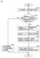
図12は、実施の形態1の結露防止制御の手順を表わすフローチャートである。
ステップS201において、空気調和制御部601は、空気調和制御部601は、室内温度センサ501から室内温度Taを取得し、室内湿度センサ502から室内湿度Xaを取得する。FIG. 12 is a flowchart showing the procedure of dew condensation prevention control according to the first embodiment.
In step S201, the air
ステップS202において、空調吹き出し口が結露しないような目標温度と目標湿度との組み合わせの候補が存在する場合に、処理がステップS203に進む。空調吹き出し口が結露しないような目標温度と目標湿度との組み合わせの候補が存在しない場合に、処理がステップS207に進む。 In step S202, if there is a candidate combination of target temperature and target humidity that does not cause dew condensation at the air conditioning outlet, the process proceeds to step S203. If there is no candidate combination of target temperature and target humidity that does not cause dew condensation on the air conditioning outlet, the process proceeds to step S207.
ステップS203において、空気調和制御部601は、各候補について、空調顕熱負荷Q1および空調潜熱負荷Q2を算出する。空気調和制御部601は、室内温度Taと、目標温湿度入力部44で設定された目標温度Ta_tgtとの温度差ΔTを空調顕熱負荷Q1として算出する。空気調和制御部601は、式(1)に基づいて、目標温湿度入力部44で設定された目標温度Ta_tgtを用いて、外気潜熱負荷Q2oを算出する。空気調和制御部601は、式(2)に従って、人体潜熱負荷Q2mを算出する。空気調和制御部601は、外気潜熱負荷Q2oと人体潜熱負荷Q2mとの和を空調潜熱負荷Q2として算出する。
In step S203, the air
ステップS204において、空気調和制御部601は、各候補について、その空調顕熱負荷Q1および空調潜熱負荷Q2に基づいて、予め定められたテーブルを参照して、空気調和装置1の消費電力と換気装置の消費電力との和Qxyを求める。
In step S204, the air
ステップS205において、空気調和制御部601は、消費電力の和Qxyが最小の候補を室内の目標温度Ta_tgt、および室内の目標湿度Xa_tgtの組み合わせに設定する。
In step S205, the air
ステップS206において、空気調和制御部601は、室内の目標温度Ta_tgt、および室内の目標湿度Xa_tgtの組み合わせに基づいて、空気調和装置1および換気装置13を制御する。
In step S206, the air
ステップS207において、空気調和制御部601は、空気調和装置1および換気装置13の冷媒の循環を停止させるとともに、空気調和装置1および換気装置13に送風運転をさせる。空気調和制御部601は、室内熱交換器用送風機8および給気用送風機10を運転させることによって、空気調和装置1および換気装置13に送風運転をさせる。
In step S207, the air
図13は、空調吹き出し口が結露しないような目標温度と目標湿度との組み合わせの候補の第1の例を表わす図である。 FIG. 13 is a diagram showing a first example of a candidate combination of target temperature and target humidity that will prevent dew condensation from the air conditioning outlet.
空気調和制御部601は、検出された室内温度Ta、および検出された室内湿度Xaに基づいて、空調吹き出し口が結露しない複数の室内の目標温度および室内の目標湿度の組み合わせの候補を設定する。空気調和制御部601は、(Ta,Xa)の4近傍(Ta+α、Xa-β)、(Ta+α、Xa+β)、(Ta-α、Xa-β)、(Ta-α、Xa+β)のうち、空気線図の相対湿度が100%の曲線よりも下側にあるものを空調吹き出し口が結露しないような目標温度と目標湿度との組み合わせの候補に設定する。ただし、αおよびβは、予め定められた値である。
Based on the detected indoor temperature Ta and the detected indoor humidity Xa, the air
本実施の形態によれば、空気調和管理空間の開口部からの自然換気の有無に応じて、空気調和設備を制御することができる。本実施の形態では、開口部が開いていることが検出された場合に、消費電力を抑制しつつ、結露を防止するように空気調和制御を実行することができる。 According to this embodiment, the air conditioning equipment can be controlled depending on the presence or absence of natural ventilation from the opening of the air conditioning managed space. In this embodiment, when it is detected that the opening is open, air conditioning control can be performed to prevent dew condensation while suppressing power consumption.
なお、開口部が開いていることが検出された場合に、開口部の閉め忘れしないようにユーザに通知してもよい。開口部が閉じていることが検出された場合に、ウイルスの感染防止のために開口部を開くようにユーザに通知してもよい。 Note that when it is detected that the opening is open, the user may be notified so as not to forget to close the opening. If it is detected that the opening is closed, the user may be notified to open the opening to prevent virus infection.
実施の形態1の変形例1.
図14は、空調吹き出し口が結露しないような目標温度と目標湿度との組み合わせの候補の第2の例を表わす図である。
FIG. 14 is a diagram illustrating a second example of a candidate combination of target temperature and target humidity that will prevent dew condensation from the air conditioning outlet.
冷房運転時において、Tx以下の温度に設定が可能であるとする。空気調和制御部601は、検出された室内温度Ta、および検出された室内湿度Xaに基づいて、空調吹き出し口が結露しない複数の室内目標温度および室内目標湿度の組み合わせの候補を設定する。
It is assumed that during cooling operation, the temperature can be set to Tx or lower. Based on the detected indoor temperature Ta and the detected indoor humidity Xa, the air
空気調和制御部601は、(Ta,Xa)の4近傍(Ta+α、Xa-β)、(Ta+α、Xa+β)、(Ta-α、Xa-β)、(Ta-α、Xa+β)のうち、空気線図の相対湿度が100%の曲線よりも下側にあり、かつ冷房運転時に設定可能上限温度Tx以下のものを空調吹き出し口が結露しないような目標温度と目標湿度との組み合わせの候補に設定する。ただし、αおよびβは、予め定められた値である。図14の例では、空調吹き出し口が結露しないような目標温度と目標湿度との組み合わせの候補が存在しない。
The air
実施の形態1の変形例2.
図15は、空調吹き出し口が結露しないような目標温度と目標湿度との組み合わせの候補の第3の例を表わす図である。
FIG. 15 is a diagram showing a third example of a candidate combination of target temperature and target humidity that will prevent dew condensation from the air conditioning outlet.
空気調和制御部601は、空気線図の相対湿度が100%の曲線よりも下側にある、一定間隔dごとの格子上の点を空調吹き出し口が結露しないような目標温度と目標湿度との組み合わせの候補に設定する。
The air
実施の形態2.
図16は、実施の形態2の空気調和システム100の構成を表わす図である。
FIG. 16 is a diagram showing the configuration of an
実施の形態2の空気調和システム100が、実施の形態1の空気調和システム100と相違する点は、実施の形態2の空気調和システム100は、換気装置13を備えない点である。
The
図17は、実施の形態2における空気調和管理空間内の熱負荷量に関するデータを表わす図である。実施の形態2における空気調和管理空間内の熱負荷量に関するデータは、外気温度、外気湿度、室内温度、室内湿度、空調顕熱負荷、室内の設備の電力消費量および日時のうち少なくとも1つを含む。実施の形態2では、実施の形態1と異なり、空気調和管理空間内の熱負荷量に関するデータは、空調潜熱負荷を有さない。 FIG. 17 is a diagram showing data regarding the amount of heat load in the air conditioning managed space in the second embodiment. The data regarding the amount of heat load in the air conditioning managed space in the second embodiment includes at least one of outside air temperature, outside air humidity, indoor temperature, indoor humidity, air conditioning sensible heat load, power consumption of indoor equipment, and date and time. include. In the second embodiment, unlike the first embodiment, the data regarding the amount of heat load in the air conditioning managed space does not include the air conditioning latent heat load.
学習装置101は、図17に示す熱負荷量に関するデータから、空気調和管理空間の開口部の開閉状態を推論する学習済みモデルを生成する。推論装置201は、学習済みモデルに図17に示す熱負荷量に関するデータを入力して、空気調和管理空間の開口部の開閉状態を出力する。
The
図18は、実施の形態2の結露防止制御の手順を表わすフローチャートである。
ステップS301において、空気調和制御部601は、空気調和制御部601は、室内温度センサ501から室内温度Taを取得し、室内湿度センサ502から室内湿度Xaを取得する。FIG. 18 is a flowchart showing the procedure of dew condensation prevention control according to the second embodiment.
In step S<b>301 , the air
ステップS302において、空調吹き出し口が結露しないような目標温度と目標湿度との組み合わせの候補が存在する場合に、処理がステップS303に進む。空調吹き出し口が結露しないような目標温度と目標湿度との組み合わせの候補が存在しない場合に、処理がステップS307に進む。 In step S302, if there is a candidate combination of target temperature and target humidity that does not cause dew condensation at the air conditioning outlet, the process proceeds to step S303. If there is no candidate combination of target temperature and target humidity that does not cause dew condensation on the air conditioning outlet, the process advances to step S307.
ステップS303において、空気調和制御部601は、各候補について、空調顕熱負荷Q1を算出する。空気調和制御部601は、室内温度Taと、目標温湿度入力部44で設定された目標温度Ta_tgtとの温度差ΔTを空調顕熱負荷Q1として算出する。
In step S303, the air
ステップS304において、空気調和制御部601は、各候補について、その空調顕熱負荷Q1に基づいて、予め定められたテーブルを参照して、空気調和装置1の消費電力Qxを求める。
In step S304, the air
ステップS305において、空気調和制御部601は、消費電力Qxが最小の候補を室内の目標温度Ta_tgt、および室内の目標湿度Xa_tgtの組み合わせに設定する。
In step S305, the air
ステップS306において、空気調和制御部601は、室内の目標温度Ta_tgt、および室内の目標湿度Xa_tgtの組み合わせに基づいて、空気調和装置1を制御する。
In step S306, the air
ステップS307において、空気調和制御部601は、空気調和装置1に送風運転をさせる。すなわち、空気調和制御部601は、空気調和システム内の冷媒の循環を停止させるとともに、室内熱交換器用送風機8を運転させる。
In step S307, the air
実施の形態3.
図19は、実施の形態3の空気調和システム100の構成を表わす図である。
FIG. 19 is a diagram showing the configuration of an
実施の形態3の空気調和システム100が、実施の形態1の空気調和システムと相違する点は、実施の形態3の空気調和システム100は、開口部検出センサ801を備える点である。
The
開口部検出センサ801は、空気調和管理空間の開閉状態を検出して、開閉状態を表わす検出信号を制御盤500へ出力する。
The
図20は、実施の形態3の制御盤500の構成を表わす図である。
実施の形態3の制御盤500は、学習装置101、学習済みモデル記憶装置301、おおよび推論装置201を備えない。空気調和制御部601は、開口部検出センサ801から空気調和管理空間の開閉状態を表わす検出信号を受ける。空気調和制御部601は、検出信号で表される空気調和管理空間の開閉状態に基づいて、実施の形態1と同様にして空気調和制御を実行する。FIG. 20 is a diagram showing the configuration of a
The
変形例.
(1)学習装置101及び推論装置201は、空気調和システムの内部に設けられるが、ネットワークを通じて、空気調和システムと接続され、空気調和システムとは別個の装置であってもよい。さらに、学習装置101及び推論装置201は、クラウドサーバ上に存在していてもよい。Variation example.
(1) Although the
(2)実施の形態では、モデル生成部103が用いる学習アルゴリズムに教師あり学習を適用した場合について説明したが、これに限られるものではない。学習アルゴリズムについては、教師あり学習以外にも、強化学習、教師なし学習、又は半教師あり学習等を適用することも可能である。
(2) In the embodiment, a case has been described in which supervised learning is applied to the learning algorithm used by the
モデル生成部103は、複数の空気調和システムにおいて作成される学習用データに従って、開口部の開口状態を学習するようにしてもよい。モデル生成部103は、同一のエリアで使用される複数の空気調和システムから学習用データを取得してもよいし、異なるエリアで独立して動作する複数の空気調和システムから収集される学習用データを利用して開口部の開口状態を学習してもよい。また、学習用データを収集する空気調和システムを途中で対象に追加したり、対象から除去することも可能である。さらに、ある空気調和システムに関して開口部の開閉状態を学習した学習装置を、これとは別の空気調和システムに適用し、この別の空気調和システムに関して開口部の開閉状態を再学習して更新するようにしてもよい。
The
(3)モデル生成部103が用いられる学習アルゴリズムとしては、特徴量そのものの抽出を学習する、深層学習を用いることもでき、他の公知の方法、例えば遺伝的プログラミング、機能論理プログラミング、またはサポートベクターマシンなどに従って機械学習を実行してもよい。
(3) As the learning algorithm used by the
(4)図21は、学習装置101、推論装置201、または制御装置600のハードウェア構成を表わす図である。
(4) FIG. 21 is a diagram showing the hardware configuration of the
学習装置101、推論装置201、および制御装置600は、相当する動作をデジタル回路のハードウェアまたはソフトウェアで構成することができる。学習装置101、推論装置201、および制御装置600の機能をソフトウェアを用いて実現する場合には、学習装置101、推論装置201、および制御装置600は、例えば、図21に示すように、バス5003によって接続されたプロセッサ5002とメモリ5001とを備え、メモリ5001に記憶されたプログラムをプロセッサ5002が実行するようにすることができる。
The corresponding operations of the
(5)上記の実施形態では、推論装置は、学習済みモデルを用いて、データ取得部が取得した入力データから、空気調和管理空間の開口部の開閉状態を推論するものとしたが、これに限定するものではない。たとえば、推論装置は、ルールベース推論、または事例ベース推論に基づいて、データ取得部が取得した入力データから、空気調和管理空間の開口部の開閉状態を推論するものとしてもよい。 (5) In the above embodiment, the inference device uses the trained model to infer the open/closed state of the opening of the air conditioning managed space from the input data acquired by the data acquisition unit. It is not limited. For example, the inference device may infer the open/closed state of the opening of the air conditioning managed space from the input data acquired by the data acquisition unit based on rule-based inference or case-based inference.
(6)上記の実施形態では、制御装置600は、空気調和管理空間の開口部が開いた状態のときに、空調吹き出し口が結露しない複数の室内目標温度および室内目標湿度の組み合わせの候補が存在しない場合には、空気調和設備200の冷媒の循環を停止させるとともに、空気調和設備200を送風運転させたが、これに限定されるものではない。このような場合には、制御装置600は、空気調和設備200の送風運転も停止するものとしてもよい。
(6) In the above embodiment, the
今回開示された実施の形態はすべての点で例示であって制限的なものではないと考えられるべきである。本開示の範囲は上記した説明ではなくて請求の範囲によって示され、請求の範囲と均等の意味及び範囲内でのすべての変更が含まれることが意図される。 The embodiments disclosed this time should be considered to be illustrative in all respects and not restrictive. The scope of the present disclosure is indicated by the claims rather than the above description, and it is intended that all changes within the meaning and range equivalent to the claims are included.
1 空気調和装置、2 圧縮機、3 四方弁、4 室外熱交換器、5 膨張弁、5a 換気装置搭載膨張弁、6 室内熱交換器、7 室外熱交換器用送風機、8 室内熱交換器用送風機、9 換気装置用冷却器、10 給気用送風機、11 室内機、12 室外機、13 換気装置、21 排気用送風機、22 全熱交換器、23 湿度検出装置、24 CO2濃度検出装置、25 換気風量検出装置、31 蒸発温度検出装置、32 吸込温湿度検出装置、44 目標温湿度入力部、100 空気調和システム、101 学習装置、102,202 データ取得部、103 モデル生成部、104 操作入力部、200 空気調和設備、201 推論装置、203 推論部、301 学習済みモデル記憶装置、500 制御盤、501 室内温度センサ、502 室内湿度センサ、503 室外温度センサ、504 室外湿度センサ、600 制御装置、601 空気調和制御部、701 表示装置、801 開口部検出センサ、901 室内、903 伝送線、5001 メモリ、5002 プロセッサ、5003 バス。 1 Air conditioner, 2 Compressor, 3 Four-way valve, 4 Outdoor heat exchanger, 5 Expansion valve, 5a Ventilator-equipped expansion valve, 6 Indoor heat exchanger, 7 Outdoor heat exchanger blower, 8 Indoor heat exchanger blower, 9 Cooler for ventilation system, 10 Air supply blower, 11 Indoor unit, 12 Outdoor unit, 13 Ventilation system, 21 Exhaust blower, 22 Total heat exchanger, 23 Humidity detection device, 24 CO2 concentration detection device, 25 Ventilation air volume Detection device, 31 Evaporation temperature detection device, 32 Suction temperature and humidity detection device, 44 Target temperature and humidity input unit, 100 Air conditioning system, 101 Learning device, 102, 202 Data acquisition unit, 103 Model generation unit, 104 Operation input unit, 200 Air conditioning equipment, 201 Inference device, 203 Inference unit, 301 Learned model storage device, 500 Control panel, 501 Indoor temperature sensor, 502 Indoor humidity sensor, 503 Outdoor temperature sensor, 504 Outdoor humidity sensor, 600 Control device, 601 Air conditioning Control unit, 701 Display device, 801 Opening detection sensor, 901 Indoor, 903 Transmission line, 5001 Memory, 5002 Processor, 5003 Bus.
Claims (11)
空気調和管理空間の開口部が開いた状態である旨の通知を受けたときに、空調吹き出し口が結露しない複数の室内目標温度および室内目標湿度の組み合わせの候補のうち、消費電力が最小の候補を選択し、選択した候補に基づいて、前記空気調和設備を制御する制御装置と、を備えた空気調和システム。air conditioning equipment,
When receiving a notification that the opening of the air-conditioned space is open, select the candidate with the lowest power consumption among the multiple combinations of indoor target temperature and indoor humidity that will prevent condensation from forming on the air-conditioning vents. an air conditioning system comprising: a control device that selects a candidate, and controls the air conditioning equipment based on the selected candidate.
室内湿度を検出する室内湿度センサと、をさらに備え、
前記制御装置は、検出された前記室内温度、および検出された前記室内湿度に基づいて、空調吹き出し口が結露しない複数の室内目標温度および室内目標湿度の組み合わせの候補を設定する、請求項1または2記載の空気調和システム。An indoor temperature sensor that detects indoor temperature,
It further includes an indoor humidity sensor that detects indoor humidity,
2. The control device according to claim 1, wherein the control device sets a plurality of candidate combinations of an indoor target temperature and an indoor target humidity in which the air conditioning outlet does not condense, based on the detected indoor temperature and the detected indoor humidity. The air conditioning system described in 2.
空気調和管理空間内の熱負荷量に関するデータを取得するデータ取得部と、
前記空気調和管理空間内の熱負荷量に関するデータから前記空気調和管理空間の開口部の開閉状態を推論するための学習済みモデルに前記データ取得部が取得した熱負荷量に関するデータを入力して、前記空気調和管理空間の開口部の開閉状態を推論する推論部と、
を含む、請求項5記載の空気調和システム。The inference device includes:
a data acquisition unit that acquires data regarding the amount of heat load in the air conditioning managed space;
inputting the data regarding the amount of heat load acquired by the data acquisition unit into a trained model for inferring the opening/closing state of the opening of the air conditioning managed space from the data regarding the amount of heat load within the air conditioning managed space; an inference unit that infers the open/closed state of the opening of the air conditioning managed space;
The air conditioning system according to claim 5, comprising:
空気調和装置と、
熱交換機能を有する換気装置と、を含み、
前記空気調和管理空間内の熱負荷量に関するデータは、外気温度、外気湿度、室内温度、室内湿度、空調顕熱負荷、空調潜熱負荷、室内の設備の電力消費量、および日時のうち少なくとも1つを含む、請求項6に記載の空気調和システム。The air conditioning equipment is
air conditioner,
A ventilation device having a heat exchange function,
The data regarding the amount of heat load in the air conditioning managed space includes at least one of outside air temperature, outside air humidity, indoor temperature, indoor humidity, air conditioning sensible heat load, air conditioning latent heat load, power consumption of indoor equipment, and date and time. The air conditioning system according to claim 6, comprising:
空気調和装置を含み、
換気装置を含まず、
前記空気調和管理空間内の熱負荷量に関するデータは、外気温度、外気湿度、室内温度、室内湿度、空調顕熱負荷、室内の設備の電力消費量、および日時のうち少なくとも1つを含む、請求項6に記載の空気調和システム。The air conditioning equipment is
including air conditioning equipment;
Does not include ventilation equipment
The data regarding the amount of heat load in the air conditioning managed space includes at least one of outside air temperature, outside air humidity, indoor temperature, indoor humidity, air conditioning sensible heat load, power consumption of indoor equipment, and date and time. The air conditioning system according to item 6.
Applications Claiming Priority (1)
| Application Number | Priority Date | Filing Date | Title |
|---|---|---|---|
| PCT/JP2020/047515 WO2022130634A1 (en) | 2020-12-18 | 2020-12-18 | Air conditioning system |
Publications (2)
| Publication Number | Publication Date |
|---|---|
| JPWO2022130634A1 JPWO2022130634A1 (en) | 2022-06-23 |
| JP7345687B2 true JP7345687B2 (en) | 2023-09-15 |
Family
ID=82059288
Family Applications (1)
| Application Number | Title | Priority Date | Filing Date |
|---|---|---|---|
| JP2022569675A Active JP7345687B2 (en) | 2020-12-18 | 2020-12-18 | air conditioning system |
Country Status (2)
| Country | Link |
|---|---|
| JP (1) | JP7345687B2 (en) |
| WO (1) | WO2022130634A1 (en) |
Citations (2)
| Publication number | Priority date | Publication date | Assignee | Title |
|---|---|---|---|---|
| JP2017142013A (en) | 2016-02-10 | 2017-08-17 | 三菱電機株式会社 | Controller, control system and program |
| WO2019087264A1 (en) | 2017-10-30 | 2019-05-09 | 三菱電機株式会社 | Air conditioning device, control method, and program |
Family Cites Families (2)
| Publication number | Priority date | Publication date | Assignee | Title |
|---|---|---|---|---|
| CN104896685B (en) * | 2014-03-03 | 2019-06-28 | 松下电器(美国)知识产权公司 | Method for sensing, sensor-based system and the air-conditioning equipment comprising them |
| JP6662362B2 (en) * | 2017-08-31 | 2020-03-11 | 株式会社デンソー | Dust concentration detector |
-
2020
- 2020-12-18 WO PCT/JP2020/047515 patent/WO2022130634A1/en active Application Filing
- 2020-12-18 JP JP2022569675A patent/JP7345687B2/en active Active
Patent Citations (2)
| Publication number | Priority date | Publication date | Assignee | Title |
|---|---|---|---|---|
| JP2017142013A (en) | 2016-02-10 | 2017-08-17 | 三菱電機株式会社 | Controller, control system and program |
| WO2019087264A1 (en) | 2017-10-30 | 2019-05-09 | 三菱電機株式会社 | Air conditioning device, control method, and program |
Also Published As
| Publication number | Publication date |
|---|---|
| JPWO2022130634A1 (en) | 2022-06-23 |
| WO2022130634A1 (en) | 2022-06-23 |
Similar Documents
| Publication | Publication Date | Title |
|---|---|---|
| Lee et al. | Deep-learning-based fault detection and diagnosis of air-handling units | |
| Karunakaran et al. | Energy efficient fuzzy based combined variable refrigerant volume and variable air volume air conditioning system for buildings | |
| Nassif | Modeling and optimization of HVAC systems using artificial neural network and genetic algorithm | |
| US20170108231A1 (en) | Air-conditioning and ventilation apparatus | |
| JP6120820B2 (en) | Ventilation system | |
| Chu et al. | Thermal comfort control on multi-room fan coil unit system using LEE-based fuzzy logic | |
| WO2021199381A1 (en) | Air conditioning system and method for controlling air conditioner | |
| CN113039395B (en) | Ventilation adjusting device and ventilation adjusting method | |
| EP3862645A1 (en) | Air conditioner and method for controlling the same | |
| JP2012037159A (en) | Control device for air conditioner and control device for freezer | |
| JP6833057B2 (en) | Air conditioners, control methods and programs | |
| JP6897848B2 (en) | Air conditioning system | |
| JP2019163885A (en) | Air-conditioning control device, air-conditioning control method and computer program | |
| JP7345687B2 (en) | air conditioning system | |
| JP2015169399A (en) | Ventilator | |
| JP2005301582A (en) | Process management device | |
| JP6775198B2 (en) | Air supply control method, air supply control device, and ventilation system | |
| JP2014173795A (en) | Ventilation system | |
| WO2022130633A1 (en) | Air conditioning system and learning device for air conditioning system | |
| JP7378497B2 (en) | Model sharing system, model management device, and air conditioner control device | |
| WO2022101989A1 (en) | Air conditioning device, and learning device of air conditioning device | |
| JP2004271095A (en) | Air conditioner | |
| JP6842858B2 (en) | Ventilation device and air supply adjustment method | |
| JPH11108415A (en) | Control device for air-conditioner | |
| Xu | HVAC system study: a data-driven approach |
Legal Events
| Date | Code | Title | Description |
|---|---|---|---|
| A621 | Written request for application examination |
Free format text: JAPANESE INTERMEDIATE CODE: A621 Effective date: 20221025 |
|
| TRDD | Decision of grant or rejection written | ||
| A01 | Written decision to grant a patent or to grant a registration (utility model) |
Free format text: JAPANESE INTERMEDIATE CODE: A01 Effective date: 20230808 |
|
| A61 | First payment of annual fees (during grant procedure) |
Free format text: JAPANESE INTERMEDIATE CODE: A61 Effective date: 20230905 |
|
| R150 | Certificate of patent or registration of utility model |
Ref document number: 7345687 Country of ref document: JP Free format text: JAPANESE INTERMEDIATE CODE: R150 |