JP7345680B2 - Inference device, inference method, and inference program - Google Patents
Inference device, inference method, and inference program Download PDFInfo
- Publication number
- JP7345680B2 JP7345680B2 JP2022562623A JP2022562623A JP7345680B2 JP 7345680 B2 JP7345680 B2 JP 7345680B2 JP 2022562623 A JP2022562623 A JP 2022562623A JP 2022562623 A JP2022562623 A JP 2022562623A JP 7345680 B2 JP7345680 B2 JP 7345680B2
- Authority
- JP
- Japan
- Prior art keywords
- image
- inference
- feature
- dimensional position
- unit
- Prior art date
- Legal status (The legal status is an assumption and is not a legal conclusion. Google has not performed a legal analysis and makes no representation as to the accuracy of the status listed.)
- Active
Links
- 238000000034 method Methods 0.000 title claims description 26
- 238000001514 detection method Methods 0.000 claims description 82
- 238000000605 extraction Methods 0.000 claims description 58
- 238000004458 analytical method Methods 0.000 claims description 47
- 238000006243 chemical reaction Methods 0.000 claims description 44
- 230000002123 temporal effect Effects 0.000 claims description 29
- 239000000284 extract Substances 0.000 claims description 9
- 239000013598 vector Substances 0.000 description 62
- 238000010586 diagram Methods 0.000 description 14
- 238000013527 convolutional neural network Methods 0.000 description 11
- 230000005856 abnormality Effects 0.000 description 9
- 238000005070 sampling Methods 0.000 description 8
- 238000013528 artificial neural network Methods 0.000 description 6
- 238000013500 data storage Methods 0.000 description 6
- 230000002159 abnormal effect Effects 0.000 description 2
- 239000002131 composite material Substances 0.000 description 2
- 230000000306 recurrent effect Effects 0.000 description 2
- 230000000630 rising effect Effects 0.000 description 2
- 230000011218 segmentation Effects 0.000 description 2
- 101000911772 Homo sapiens Hsc70-interacting protein Proteins 0.000 description 1
- 239000000470 constituent Substances 0.000 description 1
- 230000001419 dependent effect Effects 0.000 description 1
- 230000006870 function Effects 0.000 description 1
- 230000003287 optical effect Effects 0.000 description 1
- 238000011176 pooling Methods 0.000 description 1
- 239000004065 semiconductor Substances 0.000 description 1
Images


Classifications
-
- G—PHYSICS
- G06—COMPUTING; CALCULATING OR COUNTING
- G06T—IMAGE DATA PROCESSING OR GENERATION, IN GENERAL
- G06T7/00—Image analysis
- G06T7/70—Determining position or orientation of objects or cameras
- G06T7/73—Determining position or orientation of objects or cameras using feature-based methods
- G06T7/74—Determining position or orientation of objects or cameras using feature-based methods involving reference images or patches
-
- G—PHYSICS
- G06—COMPUTING; CALCULATING OR COUNTING
- G06T—IMAGE DATA PROCESSING OR GENERATION, IN GENERAL
- G06T7/00—Image analysis
- G06T7/70—Determining position or orientation of objects or cameras
- G06T7/73—Determining position or orientation of objects or cameras using feature-based methods
- G06T7/75—Determining position or orientation of objects or cameras using feature-based methods involving models
-
- G—PHYSICS
- G06—COMPUTING; CALCULATING OR COUNTING
- G06N—COMPUTING ARRANGEMENTS BASED ON SPECIFIC COMPUTATIONAL MODELS
- G06N5/00—Computing arrangements using knowledge-based models
- G06N5/04—Inference or reasoning models
-
- G—PHYSICS
- G06—COMPUTING; CALCULATING OR COUNTING
- G06T—IMAGE DATA PROCESSING OR GENERATION, IN GENERAL
- G06T5/00—Image enhancement or restoration
- G06T5/70—Denoising; Smoothing
-
- G—PHYSICS
- G06—COMPUTING; CALCULATING OR COUNTING
- G06T—IMAGE DATA PROCESSING OR GENERATION, IN GENERAL
- G06T7/00—Image analysis
- G06T7/10—Segmentation; Edge detection
- G06T7/11—Region-based segmentation
-
- G—PHYSICS
- G06—COMPUTING; CALCULATING OR COUNTING
- G06T—IMAGE DATA PROCESSING OR GENERATION, IN GENERAL
- G06T7/00—Image analysis
- G06T7/20—Analysis of motion
- G06T7/269—Analysis of motion using gradient-based methods
-
- G—PHYSICS
- G06—COMPUTING; CALCULATING OR COUNTING
- G06T—IMAGE DATA PROCESSING OR GENERATION, IN GENERAL
- G06T7/00—Image analysis
- G06T7/20—Analysis of motion
- G06T7/277—Analysis of motion involving stochastic approaches, e.g. using Kalman filters
-
- G—PHYSICS
- G06—COMPUTING; CALCULATING OR COUNTING
- G06T—IMAGE DATA PROCESSING OR GENERATION, IN GENERAL
- G06T7/00—Image analysis
- G06T7/50—Depth or shape recovery
-
- G—PHYSICS
- G06—COMPUTING; CALCULATING OR COUNTING
- G06T—IMAGE DATA PROCESSING OR GENERATION, IN GENERAL
- G06T7/00—Image analysis
- G06T7/70—Determining position or orientation of objects or cameras
- G06T7/77—Determining position or orientation of objects or cameras using statistical methods
-
- G—PHYSICS
- G06—COMPUTING; CALCULATING OR COUNTING
- G06V—IMAGE OR VIDEO RECOGNITION OR UNDERSTANDING
- G06V10/00—Arrangements for image or video recognition or understanding
- G06V10/40—Extraction of image or video features
-
- G—PHYSICS
- G06—COMPUTING; CALCULATING OR COUNTING
- G06V—IMAGE OR VIDEO RECOGNITION OR UNDERSTANDING
- G06V10/00—Arrangements for image or video recognition or understanding
- G06V10/40—Extraction of image or video features
- G06V10/62—Extraction of image or video features relating to a temporal dimension, e.g. time-based feature extraction; Pattern tracking
-
- G—PHYSICS
- G06—COMPUTING; CALCULATING OR COUNTING
- G06V—IMAGE OR VIDEO RECOGNITION OR UNDERSTANDING
- G06V10/00—Arrangements for image or video recognition or understanding
- G06V10/70—Arrangements for image or video recognition or understanding using pattern recognition or machine learning
- G06V10/74—Image or video pattern matching; Proximity measures in feature spaces
- G06V10/75—Organisation of the matching processes, e.g. simultaneous or sequential comparisons of image or video features; Coarse-fine approaches, e.g. multi-scale approaches; using context analysis; Selection of dictionaries
- G06V10/751—Comparing pixel values or logical combinations thereof, or feature values having positional relevance, e.g. template matching
-
- G—PHYSICS
- G06—COMPUTING; CALCULATING OR COUNTING
- G06V—IMAGE OR VIDEO RECOGNITION OR UNDERSTANDING
- G06V10/00—Arrangements for image or video recognition or understanding
- G06V10/70—Arrangements for image or video recognition or understanding using pattern recognition or machine learning
- G06V10/764—Arrangements for image or video recognition or understanding using pattern recognition or machine learning using classification, e.g. of video objects
-
- G—PHYSICS
- G06—COMPUTING; CALCULATING OR COUNTING
- G06V—IMAGE OR VIDEO RECOGNITION OR UNDERSTANDING
- G06V10/00—Arrangements for image or video recognition or understanding
- G06V10/70—Arrangements for image or video recognition or understanding using pattern recognition or machine learning
- G06V10/77—Processing image or video features in feature spaces; using data integration or data reduction, e.g. principal component analysis [PCA] or independent component analysis [ICA] or self-organising maps [SOM]; Blind source separation
- G06V10/7715—Feature extraction, e.g. by transforming the feature space, e.g. multi-dimensional scaling [MDS]; Mappings, e.g. subspace methods
-
- G—PHYSICS
- G06—COMPUTING; CALCULATING OR COUNTING
- G06V—IMAGE OR VIDEO RECOGNITION OR UNDERSTANDING
- G06V10/00—Arrangements for image or video recognition or understanding
- G06V10/70—Arrangements for image or video recognition or understanding using pattern recognition or machine learning
- G06V10/77—Processing image or video features in feature spaces; using data integration or data reduction, e.g. principal component analysis [PCA] or independent component analysis [ICA] or self-organising maps [SOM]; Blind source separation
- G06V10/774—Generating sets of training patterns; Bootstrap methods, e.g. bagging or boosting
-
- G—PHYSICS
- G06—COMPUTING; CALCULATING OR COUNTING
- G06V—IMAGE OR VIDEO RECOGNITION OR UNDERSTANDING
- G06V10/00—Arrangements for image or video recognition or understanding
- G06V10/70—Arrangements for image or video recognition or understanding using pattern recognition or machine learning
- G06V10/82—Arrangements for image or video recognition or understanding using pattern recognition or machine learning using neural networks
-
- G—PHYSICS
- G06—COMPUTING; CALCULATING OR COUNTING
- G06V—IMAGE OR VIDEO RECOGNITION OR UNDERSTANDING
- G06V20/00—Scenes; Scene-specific elements
- G06V20/40—Scenes; Scene-specific elements in video content
- G06V20/44—Event detection
-
- G—PHYSICS
- G06—COMPUTING; CALCULATING OR COUNTING
- G06V—IMAGE OR VIDEO RECOGNITION OR UNDERSTANDING
- G06V20/00—Scenes; Scene-specific elements
- G06V20/50—Context or environment of the image
- G06V20/52—Surveillance or monitoring of activities, e.g. for recognising suspicious objects
-
- G—PHYSICS
- G06—COMPUTING; CALCULATING OR COUNTING
- G06T—IMAGE DATA PROCESSING OR GENERATION, IN GENERAL
- G06T2207/00—Indexing scheme for image analysis or image enhancement
- G06T2207/20—Special algorithmic details
- G06T2207/20076—Probabilistic image processing
-
- G—PHYSICS
- G06—COMPUTING; CALCULATING OR COUNTING
- G06T—IMAGE DATA PROCESSING OR GENERATION, IN GENERAL
- G06T2207/00—Indexing scheme for image analysis or image enhancement
- G06T2207/20—Special algorithmic details
- G06T2207/20081—Training; Learning
-
- G—PHYSICS
- G06—COMPUTING; CALCULATING OR COUNTING
- G06T—IMAGE DATA PROCESSING OR GENERATION, IN GENERAL
- G06T2207/00—Indexing scheme for image analysis or image enhancement
- G06T2207/20—Special algorithmic details
- G06T2207/20084—Artificial neural networks [ANN]
-
- G—PHYSICS
- G06—COMPUTING; CALCULATING OR COUNTING
- G06T—IMAGE DATA PROCESSING OR GENERATION, IN GENERAL
- G06T2207/00—Indexing scheme for image analysis or image enhancement
- G06T2207/30—Subject of image; Context of image processing
- G06T2207/30181—Earth observation
- G06T2207/30192—Weather; Meteorology
-
- G—PHYSICS
- G06—COMPUTING; CALCULATING OR COUNTING
- G06T—IMAGE DATA PROCESSING OR GENERATION, IN GENERAL
- G06T2207/00—Indexing scheme for image analysis or image enhancement
- G06T2207/30—Subject of image; Context of image processing
- G06T2207/30248—Vehicle exterior or interior
- G06T2207/30252—Vehicle exterior; Vicinity of vehicle
Landscapes
- Engineering & Computer Science (AREA)
- Theoretical Computer Science (AREA)
- Physics & Mathematics (AREA)
- General Physics & Mathematics (AREA)
- Computer Vision & Pattern Recognition (AREA)
- Multimedia (AREA)
- Evolutionary Computation (AREA)
- Software Systems (AREA)
- Computing Systems (AREA)
- Artificial Intelligence (AREA)
- Databases & Information Systems (AREA)
- General Health & Medical Sciences (AREA)
- Medical Informatics (AREA)
- Health & Medical Sciences (AREA)
- Bioinformatics & Computational Biology (AREA)
- Bioinformatics & Cheminformatics (AREA)
- Life Sciences & Earth Sciences (AREA)
- Evolutionary Biology (AREA)
- Probability & Statistics with Applications (AREA)
- Computational Linguistics (AREA)
- Data Mining & Analysis (AREA)
- General Engineering & Computer Science (AREA)
- Mathematical Physics (AREA)
- Image Analysis (AREA)
- Length Measuring Devices By Optical Means (AREA)
Description
本開示は、推論装置、推論方法及び推論プログラムに関するものである。 The present disclosure relates to an inference device, an inference method, and an inference program.
例えば、特許文献1には、自律移動装置の異常発生を検知する異常検知方法が開示されている。当該異常検知方法では、センサ群及び制御部のそれぞれを用いて、自律移動装置の異常発生を検知する。
センサ群は、自律移動装置における現在の状態を検知する。制御部は、センサ群から、検知開始時点から現時点までのセンサデータである時系列データを取得する。制御部は、時系列データを第1所定間隔毎に分割することで、複数の分割データを生成し、複数の分割データと時系列データとから複数のグラフを生成する。また、制御部は、複数のグラフを学習モデルに与えて、学習モデルから、異常発生の検知結果を取得する。異常発生の検知結果の中には、自律移動装置の異常な位置が含まれている。For example, Patent Document 1 discloses an abnormality detection method for detecting the occurrence of an abnormality in an autonomous mobile device. In the abnormality detection method, the occurrence of an abnormality in the autonomous mobile device is detected using each of the sensor group and the control unit.
The sensor group detects the current state of the autonomous mobile device. The control unit acquires time-series data, which is sensor data from the detection start point to the present time, from the sensor group. The control unit generates a plurality of divided data by dividing the time series data at first predetermined intervals, and generates a plurality of graphs from the plurality of divided data and the time series data. Further, the control unit provides the plurality of graphs to the learning model and obtains a detection result of the occurrence of an abnormality from the learning model. The abnormality detection results include the abnormal position of the autonomous mobile device.
自律移動装置が飛翔体であれば、自律移動装置の航行は、自然環境の状態変化に影響される。自然環境の状態としては、例えば、風の強さ、風の向き、雨の有無、降雨量、雪の有無、又は、積雪量がある。
特許文献1に開示されている異常検知方法では、自然環境の状態がどのように変化しても、自律移動装置の異常発生を検知できるようにするには、自律移動装置の航行時に想定される、全ての自然環境の状態を考慮して、学習モデルを学習させる必要がある。しかしながら、全ての自然環境の状態を考慮して、学習モデルを学習させるには、極めて膨大な学習データを用意する必要があり、現実的には、十分な学習データを用意することができないことがある。このため、当該異常検知方法では、自然環境の状態によっては、自律移動装置の異常発生を検知できないことがあるという課題があった。If the autonomous mobile device is a flying object, the navigation of the autonomous mobile device is affected by changes in the state of the natural environment. The state of the natural environment includes, for example, the strength of the wind, the direction of the wind, the presence or absence of rain, the amount of rainfall, the presence or absence of snow, or the amount of snowfall.
In the anomaly detection method disclosed in Patent Document 1, in order to be able to detect the occurrence of an abnormality in an autonomous mobile device no matter how the state of the natural environment changes, it is necessary to , it is necessary to train the learning model by considering all the conditions of the natural environment. However, in order to train a learning model by considering all the natural environment conditions, it is necessary to prepare an extremely large amount of training data, and in reality, it may not be possible to prepare enough training data. be. Therefore, this abnormality detection method has a problem in that it may not be possible to detect the occurrence of an abnormality in the autonomous mobile device depending on the state of the natural environment.
本開示は、上記のような課題を解決するためになされたもので、自然環境の状態を考慮して、学習モデルを学習させることなく、検知対象物体の3次元位置の時間的な変化を解析することができる推論装置を得ることを目的とする。 The present disclosure was made in order to solve the above-mentioned problems, and it is possible to analyze temporal changes in the three-dimensional position of a detection target object without training a learning model, taking into account the state of the natural environment. The purpose is to obtain an inference device that can.
本開示に係る推論装置は、学習用画像と画像のドメインが異なる場合と、事前学習したタスクと認識タスクの異なる場合とのうち、1つ以上が異なる場合において、検知対象物体が映っている画像である推論対象画像を示す画像信号を取得する画像信号取得部と、画像信号取得部により取得された画像信号を、学習用画像の学習が済んでいる第1の学習モデルに与えて、第1の学習モデルから、推論対象画像に映っている検知対象物体の複数の特徴量のそれぞれがぼかされてから複数の特徴量が結合された特徴量であって、検知対象物体の3次元位置の推論に用いられる特徴量である推論時特徴量を取得する特徴量抽出部とを備えている。また、推論装置は、推論対象画像と画像のドメイン及び認識タスクのそれぞれが同じ対象である変換用画像に映っている検知対象物体の登録済みの特徴量である代表特徴量と特徴量抽出部により取得された推論時特徴量とに基づいて、推論対象画像に映っている検知対象物体の3次元位置を推定する3次元位置推定部と、3次元位置推定部による3次元位置の推定結果に基づいて、推論対象画像に映っている検知対象物体の3次元位置の時間的な変化を解析する変化解析部とを備えている。 The inference device according to the present disclosure uses an image in which a detection target object is displayed when one or more of the following: a training image and a domain of the image are different, and a pre-trained task and a recognition task are different. An image signal acquisition section that acquires an image signal indicating an inference target image, and the image signal acquired by the image signal acquisition section are given to a first learning model that has already been trained on the learning image. From the learning model of and a feature extraction unit that obtains an inference feature that is a feature used in inference. In addition, the inference device uses representative features, which are registered features of the detection target object appearing in the conversion image, which is the same target as the inference target image, image domain, and recognition task, and a feature extractor. a 3D position estimation unit that estimates the 3D position of the detection target object shown in the inference target image based on the acquired inference feature amount; and a change analysis unit that analyzes temporal changes in the three-dimensional position of the detection target object shown in the inference target image.
本開示によれば、自然環境の状態を考慮して、学習モデルを学習させることなく、検知対象物体の3次元位置の時間的な変化を解析することができる。 According to the present disclosure, it is possible to analyze temporal changes in the three-dimensional position of a detection target object without having to learn a learning model in consideration of the state of the natural environment.
以下、本開示をより詳細に説明するために、本開示を実施するための形態について、添付の図面に従って説明する。 Hereinafter, in order to explain the present disclosure in more detail, embodiments for carrying out the present disclosure will be described with reference to the accompanying drawings.
実施の形態1.
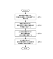
図1は、実施の形態1に係る推論装置4を示す構成図である。
図2は、実施の形態1に係る推論装置4のハードウェアを示すハードウェア構成図である。
図1において、モデル記憶部1は、例えば、ハードディスク、又は、RAM(Random Access Memory)によって実現される。
モデル記憶部1は、第1の学習モデル1aを記憶している。Embodiment 1.
FIG. 1 is a configuration diagram showing an inference device 4 according to the first embodiment.
FIG. 2 is a hardware configuration diagram showing the hardware of the inference device 4 according to the first embodiment.
In FIG. 1, a model storage unit 1 is realized by, for example, a hard disk or a RAM (Random Access Memory).
The model storage unit 1 stores a
第1の学習モデル1aは、例えば、多層ニューラルネットワーク(Deep Neural Networks:DNNs)によって実現される。DNNsの中には、畳み込みニューラルネットワークであるCNNs(Convolutional Neural Networks)が含まれる。
学習モデル1aは、学習時に、学習データとして、学習用画像を示す画像信号が与えられて、学習用画像の学習が済んでいる。学習用画像は、例えば、画像認識タスクに用いられる画像である。
学習用画像のドメインである画像の種類は、どのようなものでもよく、学習用画像は、例えば、RGB画像、TIR画像、又は、CGシミュレータによって生成された画像のいずれかである。
図1に示す推論装置4では、説明の便宜上、学習用画像がRGB画像であるものとして説明する。学習モデル1aは、大量のRGB画像が与えられて、RGB画像を学習しているものである。
学習モデル1aは、後述する特徴量抽出部12から、学習用画像と画像のドメイン及び認識タスクのそれぞれが異なる場合において、検知対象物体が映っている画像である変換用画像を示す画像信号が与えられたとき、変換用画像に映っている検知対象物体の複数の特徴量のそれぞれがぼかされてから複数の特徴量が結合された特徴量であって、検知対象物体の3次元位置の推論に用いられる特徴量を示す特徴ベクトルを特徴量抽出部12に出力する。
変換用画像は、学習用画像と画像のドメイン及び認識タスクのうち、1つ以上が異なる画像であればよい。図1に示す推論装置4では、説明の便宜上、変換用画像がTIR画像であるものとして説明する。
The
During learning, the
The type of image that is the domain of the learning image may be of any type, and the learning image is, for example, an RGB image, a TIR image, or an image generated by a CG simulator.
For convenience of explanation, the inference device 4 shown in FIG. 1 will be described assuming that the learning image is an RGB image. The
The
The conversion image may be an image that differs from the training image in one or more of the domain of the image and the recognition task. For convenience of explanation, the inference device 4 shown in FIG. 1 will be described assuming that the conversion image is a TIR image.
第1の学習モデル1aを実現するCNNsは、非常にディープなCNNsである。非常にディープなCNNsとしては、例えば、101層あるResNetがある。このため、例えば3次元位置の推定時において、第1の学習モデル1aの入力層に画像信号が与えられたときに、第1の学習モデル1aの出力層から出力される特徴ベクトルが示す特徴量は、高次元特徴量である。高次元特徴量は、複数の次元の特徴量を含むものであり、高次元特徴量を示す特徴ベクトルとしては、例えば、Tensorが用いられる。
学習モデル1aに含まれている複数段の隠れ層のうち、浅い層から出力される低次元特徴量は、例えば、色、輝度、又は、方向を示すものである。このため、低次元特徴量は、入力層に与えられる画像信号が示す画像のドメインに依存する。つまり、RGB画像の画像信号が学習モデル1aの入力層に与えられたときに、学習モデル1aの浅い層から出力される特徴ベクトルが示す特徴量と、TIR画像の画像信号が学習モデル1aの入力層に与えられたときに、学習モデル1aの浅い層から出力される特徴ベクトルが示す特徴量とは、大きく異なることがある。
一方、学習モデル1aの十分に深い中間層から出力される高次元特徴量は、検知対象物体の良否等を表現する概念的な特徴を示すものである。このため、高次元特徴量は、入力層に与えられる画像信号が示す画像のドメインへの依存度が極めて低い概念的な情報となる。また、より深い層の高次元特徴を採用することで、タスクへの依存度の低い汎用的な情報を取得することが可能となる。概念的な物体の特徴は、例えば、“Objectness”、又は、“Informativeness”が知られている。
つまり、RGB画像の画像信号が学習モデル1aの入力層に与えられたときに、学習モデル1aの出力層から出力される特徴ベクトルが示す高次元特徴量と、TIR画像の画像信号が学習モデル1aの入力層に与えられたときに、学習モデル1aの出力層から出力される特徴ベクトルが示す高次元特徴量との差異は小さい。
したがって、学習モデル1aがCNNsによって実現されて、推論装置4が、CNNsの十分に深い中間層から出力される特徴ベクトルが示す高次元特徴量を用いる場合、入力層に与えられる画像信号が示す画像のドメインへの依存性と認識タスクへの依存性とが軽減される。
The CNNs that realize the
Among the multiple stages of hidden layers included in the
On the other hand, the high-dimensional feature amount output from the sufficiently deep intermediate layer of the
In other words, when the image signal of the RGB image is given to the input layer of the
Therefore, when the
モデル記憶部2は、例えば、ハードディスク、又は、RAMによって実現される。
モデル記憶部2は、第2の学習モデル2aを記憶している。
第2の学習モデル2aは、例えば、回帰型ニューラルネットワークであるRNNs(Recurrent Neural Networks)によって実現される。
第2の学習モデル2aは、自在学習の学習モデルであって、3次元位置を学習して3次元位置の時間的な変化を回帰する学習モデルである。
第2の学習モデル2aは、後述する変化解析部16から、後述する3次元位置推定部15による3次元位置の推定結果が与えられたとき、検検知対象物体の3次元位置の時間的な変化を示す位置データとして、検知対象物体の将来の時刻の3次元位置を示す信号を変化解析部16に出力する。The
The
The
The
The
図1に示す推論装置4では、第1の学習モデル1a及び第2の学習モデル2aのそれぞれが推論装置4の外部に設けられている。しかし、これは一例に過ぎず、例えば、第1の学習モデル1aが特徴量抽出部12に内蔵され、第2の学習モデル2aが変化解析部16に内蔵されていてもよい。
In the inference device 4 shown in FIG. 1, the
検知対象物体は、例えば、ドローン、空飛ぶクルマ、ヘリコプター、自動車、又は、船舶である。図1に示す推論装置4では、説明の便宜上、検知対象物体が、ドローン、空飛ぶクルマ、又は、ヘリコプターのいずれかに認識される例を説明する。
また、図1に示す推論装置4では、3次元位置推定部15により認識される検知対象物体の3次元位置が、例えば、高次元特徴における物体の存在範囲(Objectness)を含む特徴ベクトルが登録された代表特徴量記憶部14より、検知対象物体の存在範囲(Objectness)を含む代表特徴量を取得し、代表特徴量と特徴抽出部12より抽出された推論時特徴量とを比較して、複数の検知対象物体の代表特徴量の中で、特徴量抽出部12により抽出された推論時特徴量に対応している代表特徴量を特定する。最も類似した代表特徴量を持つクラスが検出対象物体の所属するクラスとなる。さらに、推論時特徴量には、推論時に入力された画像に含まれる検出対象物体の存在範囲(Objectness)を含むため、推論時特徴量の高次元特徴の記述方法をTensor等から二次元空間へ変換することで空間的な物体の存在位置を表すことが可能となる。The object to be detected is, for example, a drone, a flying car, a helicopter, a car, or a ship. In the inference device 4 shown in FIG. 1, for convenience of explanation, an example will be described in which the object to be detected is recognized as either a drone, a flying car, or a helicopter.
In addition, in the inference device 4 shown in FIG. 1, the three-dimensional position of the detection target object recognized by the three-dimensional
検知対象物体が、ドローン、空飛ぶクルマ、又は、ヘリコプターのいずれかに認識される場合には、第1の学習モデル1aに与えられる学習データは、学習用画像を示す画像信号を含む学習データである。学習用画像は、説明の便宜上、RGB画像であるものとする。
When the detection target object is recognized by a drone, a flying car, or a helicopter, the learning data given to the
第2の学習モデル2aに与えられる学習データは、3次元位置推定部15による3次元位置の推定結果である。
第2の学習モデル2aは、3次元位置の推定結果が与えられると、3次元位置を学習して3次元位置の時間的な変化を回帰する。The learning data given to the
When the
カメラ3は、例えば、赤外線カメラによって実現される。
カメラ3は、検知対象物体を撮影する。
推論装置4が学習時とは異なるドメインの画像を登録する際(以下「ドメイン変換時」という)には、カメラ3は、検知対象物体が映っている変換用画像を示す画像信号として、例えば、検知対象物体が映っているTIR画像を示す画像信号を推論装置4に出力する。
推論装置4が検知対象物体の3次元位置を推定する位置推定時には、カメラ3は、検知対象物体が映っている推論対象画像を示す画像信号として、例えば、検知対象物体が映っているTIR画像を示す画像信号を推論装置4に出力する。
図1では、カメラ3が、変換用画像を示す画像信号を推論装置4に出力している。しかし、これは一例に過ぎず、検知対象物体が映っている変換用画像を示す画像信号を記憶している図示せぬ記憶部から、当該画像信号が推論装置4に出力されるものであってもよい。Camera 3 is realized by, for example, an infrared camera.
The camera 3 photographs the object to be detected.
When the inference device 4 registers an image in a domain different from the one used during learning (hereinafter referred to as "during domain conversion"), the camera 3 uses, for example, an image signal indicating the conversion image in which the object to be detected is shown. An image signal indicating a TIR image showing the object to be detected is output to the inference device 4.
When the inference device 4 estimates the three-dimensional position of the object to be detected, the camera 3 uses, for example, a TIR image in which the object to be detected is shown as an image signal indicating the image to be inferred in which the object to be detected is shown. The image signal shown is output to the inference device 4.
In FIG. 1, the camera 3 outputs an image signal indicating a conversion image to the inference device 4. However, this is just an example, and the image signal is output to the inference device 4 from a storage unit (not shown) that stores an image signal indicating a conversion image in which the object to be detected is reflected. Good too.
画像信号取得部11は、例えば、図2に示す画像信号取得回路21によって実現される。
ドメイン変換時には、画像信号取得部11は、カメラ3から、検知対象物体が映っている変換用画像を示す画像信号を取得する。
そして、画像信号取得部11は、変換用画像を示す画像信号を特徴量抽出部12に出力する。
位置推定時には、画像信号取得部11は、カメラ3から、検知対象物体が映っている推論対象画像を示す画像信号を取得する。
そして、画像信号取得部11は、推論対象画像を示す画像信号を特徴量抽出部12に出力する。
変換用画像と推論対象画像とは、画像の種類が同じであり、例えば、共にTIR画像である。The image signal acquisition unit 11 is realized, for example, by an image
At the time of domain conversion, the image signal acquisition unit 11 acquires from the camera 3 an image signal indicating a conversion image in which the object to be detected is shown.
Then, the image signal acquisition unit 11 outputs an image signal indicating the conversion image to the feature
At the time of position estimation, the image signal acquisition unit 11 acquires an image signal indicating an inference target image in which a detection target object is shown from the camera 3.
Then, the image signal acquisition unit 11 outputs an image signal indicating the inference target image to the feature
The conversion image and the inference target image have the same type of image, for example, are both TIR images.
特徴量抽出部12は、例えば、図2に示す特徴量抽出回路22によって実現される。
ドメイン変換時には、特徴量抽出部12は、画像信号取得部11により取得された画像信号を第1の学習モデル1aに与えて、第1の学習モデル1aから、変換用画像に映っている検知対象物体の複数の特徴量のそれぞれがぼかされてから複数の特徴量が結合された特徴量である代表特徴量を示す特徴ベクトルを取得する。代表特徴量は、検知対象物体の3次元位置の推論に用いられる特徴量である。
特徴量抽出部12は、特徴ベクトルを代表特徴量登録部13に出力する。
位置推定時には、特徴量抽出部12は、画像信号取得部11により取得された画像信号を第1の学習モデル1aに与えて、第1の学習モデル1aから、推論対象画像に映っている検知対象物体の特徴量のそれぞれがぼかされてから複数の特徴量が結合された特徴量である推論時特徴量を示す特徴ベクトルを取得する。推論時特徴量は、検知対象物体の3次元位置の推論に用いられる特徴量である。
特徴量抽出部12は、特徴ベクトルを3次元位置推定部15に出力する。
複数の特徴量のそれぞれをぼかす処理としては、“Pooling Operation”が知られている。The
During domain conversion, the
The
During position estimation, the
The
“Pooling Operation” is known as a process for blurring each of a plurality of feature amounts.
代表特徴量登録部13は、例えば、図2に示す代表特徴量登録回路23によって実現される。
代表特徴量登録部13は、特徴量抽出部12により取得された代表特徴量を登録する。
即ち、代表特徴量登録部13は、いずれかの領域に存在しているドローンの特徴量を示す特徴ベクトルを取得し、特徴ベクトルを代表特徴量記憶部14に記憶させる。
また、代表特徴量登録部13は、いずれかの領域に存在している空飛ぶクルマの特徴量を示す特徴ベクトルを取得し、特徴ベクトルを代表特徴量記憶部14に記憶させる。
また、代表特徴量登録部13は、いずれかの領域に存在しているヘリコプターの特徴量を示す特徴ベクトルを取得し、特徴ベクトルを代表特徴量記憶部14に記憶させる。The representative feature
The representative feature
That is, the representative feature
Further, the representative feature
Further, the representative feature
代表特徴量記憶部14は、例えば、図2に示す代表特徴量記憶回路24によって実現される。
代表特徴量記憶部14は、代表特徴量を示す特徴ベクトルを記憶する。The representative feature
The representative feature
3次元位置推定部15は、例えば、図2に示す3次元位置推定回路25によって実現される。
3次元位置推定部15は、特徴量抽出部12から、推論対象画像に映っている検知対象物体の特徴量を示す特徴ベクトルを取得し、代表特徴量記憶部14から、代表特徴量を示す特徴ベクトルを取得する。
3次元位置推定部15は、代表特徴量と推論対象画像に映っている検知対象物体の特徴量とに基づいて、推論対象画像に映っている検知対象物体の3次元位置を推定する。
具体的には、3次元位置推定部15は、代表特徴量と推論時特徴量とに基づいて、推論対象画像に映っている検知対象物体の種類及び存在している領域のそれぞれを認識する。
具体的には、3次元位置推定部15は、高次元特徴における物体の存在範囲(Objectness)及び物体の種類の双方を含む特徴ベクトルが登録された代表特徴量記憶部14より、検知対象物体の存在範囲(Objectness)及び物体の種類の双方を含む代表特徴量を取得し、代表特徴量と特徴抽出部12より抽出された推論時特徴量とを比較して、複数の検知対象物体の代表特徴量の中で、特徴量抽出部12により抽出された推論時特徴量に対応している代表特徴量を特定する。最も類似した代表特徴量を持つクラスが検出対象物体の所属するクラスとなる。さらに推論時特徴量には、推論時に入力された画像に含まれる検出対象物体の存在範囲(Objectness)を含むため、推論時特徴量の高次元特徴の記述方法をTensor等から二次元空間へ変換することで空間的な物体の存在位置を表すことが可能となる。
3次元位置推定部15は、検知対象物体の認識結果を示す表示データを生成し、表示データを表示装置5に出力する。ここで、二次元空間上に矩形として表現した場合は、物体検出(Object Detection)タスクとなり、二次元空間上に領域として表現した場合は、セグメンテーション(Sematic Segmentation)タスクとなる。The three-dimensional
The three-dimensional
The three-dimensional
Specifically, the three-dimensional
Specifically, the three-dimensional
The three-dimensional
変化解析部16は、例えば、図2に示す変化解析回路26によって実現される。
変化解析部16は、3次元位置推定部15による3次元位置の推定結果に基づいて、推論対象画像に映っている検知対象物体の3次元位置の時間的な変化を解析する。
具体的には、変化解析部16は、3次元位置推定部15による次元位置の推定結果を第2の学習モデル2aに与えて、第2の学習モデル2aから、検知対象物体の3次元位置の時間的な変化を示す位置データを取得する。
また、変化解析部16は、位置データに基づいて、検知対象物体が落下するか否かを判定する処理のほか、検知対象物体を多クラスに分類する処理として、検知対象物体が、例えば、ホバリングしているのか、上昇しているのか、下降しているのか、前進しているのか、又は、後退しているのかを判定する。
変化解析部16は、検知対象物体の3次元位置の時間的な変化の解析結果を示す表示データを生成し、表示データを表示装置5に出力する。
また、変化解析部16は、上記の判定処理の判定結果を示す表示データを生成し、表示データを表示装置5に出力する。The
The
Specifically, the
In addition to the process of determining whether or not the object to be detected falls based on the position data, the
The
Further, the
表示装置5は、3次元位置推定部15から出力された表示データに従って、3次元位置の推定結果を図示せぬディスプレイに表示させる。
また、表示装置5は、変化解析部16から出力された表示データに従って、検知対象物体の3次元位置の時間的な変化の解析結果と、判定処理の判定結果とを図示せぬディスプレイに表示させる。The
Further, the
図1では、推論装置4の構成要素である画像信号取得部11、特徴量抽出部12、代表特徴量登録部13、代表特徴量記憶部14、3次元位置推定部15及び変化解析部16のそれぞれが、図2に示すような専用のハードウェアによって実現されるものを想定している。即ち、推論装置4が、画像信号取得回路21、特徴量抽出回路22、代表特徴量登録回路23、代表特徴量記憶回路24、3次元位置推定回路25及び変化解析回路26によって実現されるものを想定している。
代表特徴量記憶回路24は、例えば、RAM(Random Access Memory)、ROM(Read Only Memory)、フラッシュメモリ、EPROM(Erasable Programmable Read Only Memory)、EEPROM(Electrically Erasable Programmable Read Only Memory)等の不揮発性又は揮発性の半導体メモリ、磁気ディスク、フレキシブルディスク、光ディスク、コンパクトディスク、ミニディスク、あるいは、DVD(Digital Versatile Disc)が該当する。
画像信号取得回路21、特徴量抽出回路22、代表特徴量登録回路23、3次元位置推定回路25及び変化解析回路26のそれぞれは、例えば、単一回路、複合回路、プログラム化したプロセッサ、並列プログラム化したプロセッサ、ASIC(Application Specific Integrated Circuit)、FPGA(Field-Programmable Gate Array)、又は、これらを組み合わせたものが該当する。In FIG. 1, the components of the inference device 4, such as an image signal acquisition section 11, a
The representative feature
Each of the image
推論装置4の構成要素は、専用のハードウェアによって実現されるものに限るものではなく、推論装置4が、ソフトウェア、ファームウェア、又は、ソフトウェアとファームウェアとの組み合わせによって実現されるものであってもよい。
ソフトウェア又はファームウェアは、プログラムとして、コンピュータのメモリに格納される。コンピュータは、プログラムを実行するハードウェアを意味し、例えば、CPU(Central Processing Unit)、GPU(Graphical Processing Unit)、中央処理装置、処理装置、演算装置、マイクロプロセッサ、マイクロコンピュータ、プロセッサ、あるいは、DSP(Digital Signal Processor)が該当する。The components of the inference device 4 are not limited to those realized by dedicated hardware, and the inference device 4 may be realized by software, firmware, or a combination of software and firmware. .
Software or firmware is stored in a computer's memory as a program. A computer means hardware that executes a program, such as a CPU (Central Processing Unit), a GPU (Graphical Processing Unit), a central processing unit, a processing unit, an arithmetic unit, a microprocessor, a microcomputer, a processor, or a DSP. (Digital Signal Processor).
図3は、推論装置4が、ソフトウェア又はファームウェア等によって実現される場合のコンピュータのハードウェア構成図である。
推論装置4が、ソフトウェア又はファームウェア等によって実現される場合、代表特徴量記憶部14がコンピュータのメモリ31上に構成される。画像信号取得部11、特徴量抽出部12、代表特徴量登録部13、3次元位置推定部15及び変化解析部16におけるそれぞれの処理手順をコンピュータに実行させるためのプログラムがメモリ31に格納される。そして、コンピュータのプロセッサ32がメモリ31に格納されているプログラムを実行する。FIG. 3 is a hardware configuration diagram of a computer when the inference device 4 is realized by software, firmware, or the like.
When the inference device 4 is realized by software, firmware, etc., the representative feature
また、図2では、推論装置4の構成要素のそれぞれが専用のハードウェアによって実現される例を示し、図3では、推論装置4がソフトウェア又はファームウェア等によって実現される例を示している。しかし、これは一例に過ぎず、推論装置4における一部の構成要素が専用のハードウェアによって実現され、残りの構成要素がソフトウェア又はファームウェア等によって実現されるものであってもよい。 Further, FIG. 2 shows an example in which each of the components of the inference device 4 is realized by dedicated hardware, and FIG. 3 shows an example in which the inference device 4 is realized by software, firmware, or the like. However, this is just an example, and some of the components in the inference device 4 may be realized by dedicated hardware, and the remaining components may be realized by software, firmware, or the like.
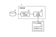
図4は、学習装置7を示す構成図である。
図5は、学習装置7のハードウェアを示すハードウェア構成図である。
学習データ記憶部6は、例えば、ハードディスク、又は、RAMによって実現される。
学習データ記憶部6は、学習データとして、学習用画像を示す画像信号を記憶している。FIG. 4 is a configuration diagram showing the
FIG. 5 is a hardware configuration diagram showing the hardware of the
The learning data storage unit 6 is realized by, for example, a hard disk or a RAM.
The learning data storage unit 6 stores an image signal indicating a learning image as learning data.
学習装置7は、学習データ取得部41及び学習処理部42を備えている。
学習データ取得部41は、例えば、図5に示す学習データ取得回路51によって実現される。
学習データ取得部41は、学習データ記憶部6から、学習データを取得する。
学習データ取得部41は、学習データを学習処理部42に出力する。The
The learning
The learning
The learning
学習処理部42は、例えば、図5に示す学習処理回路52によって実現される。
学習処理部42は、学習データ取得部41から、大量の学習データを取得する。
学習処理部42は、それぞれの学習データを学習モデル1aに与えて、それぞれの学習データに含まれている画像信号が示す学習用画像を学習モデル1aに学習させる。
学習済みの学習モデル1aは、ドメイン変換時、又は、位置推定時において、画像信号が与えられたとき、当該画像信号に対応する特徴ベクトルを出力する。The
The
The
When the trained
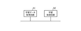
図4では、学習装置7の構成要素である学習データ取得部41及び学習処理部42のそれぞれが、図5に示すような専用のハードウェアによって実現されるものを想定している。即ち、学習装置7が、学習データ取得回路51及び学習処理回路52によって実現されるものを想定している。
学習データ取得部41及び学習処理部42のそれぞれは、例えば、単一回路、複合回路、プログラム化したプロセッサ、並列プログラム化したプロセッサ、ASIC、FPGA、又は、これらを組み合わせたものが該当する。In FIG. 4, it is assumed that each of the learning
Each of the learning
学習装置7の構成要素は、専用のハードウェアによって実現されるものに限るものではなく、学習装置7が、ソフトウェア、ファームウェア、又は、ソフトウェアとファームウェアとの組み合わせによって実現されるものであってもよい。
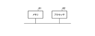
図6は、学習装置7が、ソフトウェア又はファームウェア等によって実現される場合のコンピュータのハードウェア構成図である。
学習装置7が、ソフトウェア又はファームウェア等によって実現される場合、学習データ取得部41及び学習処理部42におけるそれぞれの処理手順をコンピュータに実行させるためのプログラムがメモリ61に格納される。そして、コンピュータのプロセッサ62がメモリ61に格納されているプログラムを実行する。The components of the
FIG. 6 is a hardware configuration diagram of a computer when the
When the
また、図5では、学習装置7の構成要素のそれぞれが専用のハードウェアによって実現される例を示し、図6では、学習装置7がソフトウェア又はファームウェア等によって実現される例を示している。しかし、これは一例に過ぎず、学習装置7における一部の構成要素が専用のハードウェアによって実現され、残りの構成要素がソフトウェア又はファームウェア等によって実現されるものであってもよい。
Further, FIG. 5 shows an example in which each of the constituent elements of the
最初に、図4に示す学習装置7の動作について説明する。
学習データ記憶部6には、大量の学習データが記憶されており、それぞれの学習データには、学習用画像を示す画像信号が含まれている。First, the operation of the
A large amount of learning data is stored in the learning data storage unit 6, and each learning data includes an image signal indicating a learning image.
学習装置7の学習データ取得部41は、学習データ記憶部6から、大量の学習データを取得する。
学習データ取得部41は、それぞれの学習データを学習処理部42に出力する。The learning
The learning
学習処理部42は、学習データ取得部41から、それぞれの学習データを取得する。
学習処理部42は、それぞれの学習データを第1の学習モデル1aに与えて、それぞれの学習データに含まれている画像信号が示す学習用画像を学習モデル1aに学習させる。
学習済みの学習モデル1aは、例えば、RGB画像を示す画像信号が入力層に与えられると、出力層から、当該画像信号に対応する特徴ベクトルとして、RGB画像に映っている検知対象物体の高次元特徴量を示す特徴ベクトルを出力する。
学習モデル1aに学習に用いられている学習用画像が、例えば、RGB画像であって、TIR画像が、学習用画像として用いられていない場合、RGB画像に映っている検知対象物体とTIR画像に映っている検知対象物体とが、共に正常な同一物体であったとしても、RGB画像を示す画像信号が入力層に与えられたときに、出力層から出力される特徴ベクトルと、TIR画像を示す画像信号が入力層に与えられたときに、出力層から出力される特徴ベクトルとが相違することがある。
ただし、学習モデル1aを実現するCNNsは、非常にディープなCNNsであり、学習モデル1aの十分に深い中間層から出力される特徴ベクトルは、高次元特徴量を示すものある。このため、上記の相違は僅かなものである。
また、学習モデル1aの出力層から出力される特徴ベクトルが示す特徴量は、上述したように、検知対象物体の、十分に深い中間層の複数の層の複数の特徴量のそれぞれがぼかされてから複数の層の特徴量が結合された特徴量である。このため、特徴ベクトルが示す特徴量は、画像のドメインの依存性及び認識タスクの依存性のそれぞれが排除された頑健な特徴を示すものである。The
The
For example, when an image signal indicating an RGB image is given to the input layer, the trained
For example, if the learning image used for learning in the
However, the CNNs that realize the
In addition, as described above, the feature quantities indicated by the feature vector output from the output layer of the
次に、ドメイン変換時における推論装置4の動作について説明する。
図7は、ドメイン変換時の推論装置4の処理手順を示すフローチャートである。
カメラ3は、検知対象物体を撮影する。カメラ3により撮影される検知対象物体は、ドローン、空飛ぶクルマ、又は、ヘリコプターのいずれかである。ただし、推論装置4は、検知対象物体を、例えば1000に分類することも可能である。このため、検知対象物体を、ドローン、空飛ぶクルマ、又は、ヘリコプターの3つに分類することは、あくまでも、一例である。また、カメラ3により撮影される検知対象物体は、いずれかの領域に存在している。
カメラ3は、いずれかの領域に存在している検知対象物体が映っている変換用画像を示す画像信号として、例えば、検知対象物体が映っているTIR画像を示す画像信号を推論装置4に出力する。Next, the operation of the inference device 4 during domain conversion will be explained.
FIG. 7 is a flowchart showing the processing procedure of the inference device 4 during domain conversion.
The camera 3 photographs the object to be detected. The detection target object photographed by the camera 3 is either a drone, a flying car, or a helicopter. However, the inference device 4 can also classify the objects to be detected into, for example, 1000 objects. For this reason, classifying the object to be detected into three categories, ie, a drone, a flying car, or a helicopter, is just an example. Furthermore, the detection target object photographed by the camera 3 exists in one of the regions.
The camera 3 outputs, for example, an image signal indicating a TIR image showing the detection target object to the inference device 4 as an image signal indicating a conversion image showing the detection target object existing in any region. do.
画像信号取得部11は、カメラ3から、検知対象物体が映っている変換用画像を示す画像信号を取得する(図7のステップST1)。
具体的には、画像信号取得部11は、カメラ3から、いずれかの領域に存在しているドローンが映っている変換用画像を示す画像信号を取得し、変換用画像を示す画像信号を特徴量抽出部12に出力する。
また、画像信号取得部11は、カメラ3から、いずれかの領域に存在している空飛ぶクルマが映っている変換用画像を示す画像信号を取得し、変換用画像を示す画像信号を特徴量抽出部12に出力する。
また、画像信号取得部11は、カメラ3から、いずれかの領域に存在しているヘリコプターが映っている変換用画像を示す画像信号を取得し、変換用画像を示す画像信号を特徴量抽出部12に出力する。The image signal acquisition unit 11 acquires an image signal indicating a conversion image in which the object to be detected is shown from the camera 3 (step ST1 in FIG. 7).
Specifically, the image signal acquisition unit 11 acquires an image signal indicating a conversion image in which a drone existing in any area is shown from the camera 3, and converts the image signal indicating the conversion image into a characteristic. It is output to the
Further, the image signal acquisition unit 11 acquires an image signal indicating a conversion image in which a flying car existing in any area is shown from the camera 3, and converts the image signal indicating the conversion image into a feature amount. It is output to the
The image signal acquisition unit 11 also acquires an image signal indicating a conversion image in which a helicopter existing in one of the areas is shown from the camera 3, and transmits the image signal indicating the conversion image to the feature amount extraction unit. Output to 12.
特徴量抽出部12は、画像信号取得部11から、いずれかの領域に存在している検知対象物体が映っている変換用画像を示す画像信号を取得する。
特徴量抽出部12は、それぞれの画像信号から、それぞれの変換用画像に映っている検知対象物体の特徴量を抽出する(図7のステップST2)。
具体的には、特徴量抽出部12は、画像信号取得部11から、いずれかの領域に存在しているドローンが映っている変換用画像を示す画像信号を取得する。
特徴量抽出部12は、それぞれの画像信号を第1の学習モデル1aに与えて、第1の学習モデル1aから、いずれかの領域に存在しているドローンの複数の特徴量のそれぞれがぼかされてから複数の特徴量が結合された代表特徴量を示す特徴ベクトルを取得する。
特徴量抽出部12は、特徴ベクトルを代表特徴量登録部13に出力する。The feature
The feature
Specifically, the feature
The
The
また、特徴量抽出部12は、画像信号取得部11から、いずれかの領域に存在している空飛ぶクルマが映っている変換用画像を示す画像信号を取得する。
特徴量抽出部12は、それぞれの画像信号を第1の学習モデル1aに与えて、第1の学習モデル1aから、いずれかの領域に存在している空飛ぶクルマの複数の特徴量のそれぞれがぼかされてから複数の特徴量が結合された代表特徴量を示す特徴ベクトルを取得する。
特徴量抽出部12は、特徴ベクトルを代表特徴量登録部13に出力する。Further, the feature
The
The
また、特徴量抽出部12は、画像信号取得部11から、いずれかの領域に存在しているヘリコプターが映っている変換用画像を示す画像信号を取得する。
特徴量抽出部12は、それぞれの画像信号を第1の学習モデル1aに与えて、第1の学習モデル1aから、いずれかの領域に存在しているヘリコプターの複数の特徴量のそれぞれがぼかされてから複数の特徴量が結合された代表特徴量を示す特徴ベクトルを取得する。
特徴量抽出部12は、特徴ベクトルを代表特徴量登録部13に出力する。Further, the
The
The
代表特徴量登録部13は、特徴量抽出部12から、それぞれの特徴ベクトルを取得する。
代表特徴量登録部13は、それぞれの特徴ベクトルを代表特徴量記憶部14に記憶させることで、代表特徴量を登録する(図7のステップST3)。The representative
The representative feature
ここで、代表特徴量を示す特徴ベクトルは、Tensorで表現されている。Tensorは、Vectorよりも高次元な情報を表現できるものであり、フィーチャーマップと呼ばれることがある。
Tensorは、高次元な情報を表現できるものであるため、代表特徴量登録部13が、Tensorで表現されている特徴ベクトルをそのまま代表特徴量記憶部14に記憶させた場合、3次元位置推定部15が特徴ベクトルを照合する際に、多くの処理時間を要することがある。
3次元位置推定部15が特徴ベクトルを照合する際に要する処理時間を短縮するために、代表特徴量登録部13が、代表特徴量を示す特徴ベクトルを、Tensorよりも次元数が少ないワンホットベクトル(One-hot-vector)に変換し、ワンホットベクトルを代表特徴量記憶部14に記憶させるようにしてもよい。
代表特徴量登録部13によって登録される特徴ベクトルが、Tensor、又は、ワンホットベクトルのいずれであっても、数百次元等の高次元の情報が表現されるものである。このため、種類が同一である複数の検知対象物体の間に多少のばらつきがあったとしても、特徴ベクトルは、当該検知対象物体の代表的な特徴が高次元で記述されたものになっている。Here, the feature vector indicating the representative feature amount is expressed in Tensor. Tensors can express higher-dimensional information than Vectors, and are sometimes called feature maps.
Since a Tensor can express high-dimensional information, if the representative
In order to reduce the processing time required when the three-dimensional
Regardless of whether the feature vector registered by the representative feature
次に、位置推定時の推論装置4の動作について説明する。
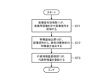
図8は、位置推定時の推論装置4の処理手順である推論方法を示すフローチャートである。
カメラ3は、検知対象物体を撮影する。カメラ3により撮影される検知対象物体は、ドローン、空飛ぶクルマ、又は、ヘリコプターのいずれであるのかが不明である。また、カメラ3により撮影される検知対象物体が存在している領域は、不明である。
カメラ3は、検知対象物体が映っている推論対象画像を示す画像信号として、例えば、検知対象物体が映っているTIR画像を示す画像信号を推論装置4に出力する。Next, the operation of the inference device 4 during position estimation will be explained.
FIG. 8 is a flowchart showing an inference method that is a processing procedure of the inference device 4 when estimating a position.
The camera 3 photographs the object to be detected. It is unclear whether the detection target object photographed by the camera 3 is a drone, a flying car, or a helicopter. Further, the area where the detection target object photographed by the camera 3 exists is unknown.
The camera 3 outputs, for example, an image signal indicating a TIR image in which the detection target object is shown to the inference device 4 as an image signal indicating the inference target image in which the detection target object is shown.
画像信号取得部11は、カメラ3から、検知対象物体が映っている推論対象画像を示す画像信号を取得する(図8のステップST11)。
画像信号取得部11は、推論対象画像を示す画像信号を特徴量抽出部12に出力する。The image signal acquisition unit 11 acquires an image signal indicating an inference target image in which a detection target object is shown from the camera 3 (step ST11 in FIG. 8).
The image signal acquisition unit 11 outputs an image signal indicating the inference target image to the feature
特徴量抽出部12は、画像信号取得部11から、推論対象画像を示す画像信号を取得する。
特徴量抽出部12は、画像信号から、推論対象画像に映っている検知対象物体の特徴量を抽出する(図8のステップST12)。
具体的には、特徴量抽出部12は、画像信号を第1の学習モデル1aに与えて、第1の学習モデル1aから、推論対象画像に映っている検知対象物体の高次元特徴量を示す特徴ベクトルを取得する。
特徴量抽出部12は、特徴ベクトルを3次元位置推定部15に出力する。The
The feature
Specifically, the feature
The
3次元位置推定部15は、特徴量抽出部12から、特徴ベクトルを取得する。
3次元位置推定部15は、代表特徴量記憶部14から、代表特徴量を示す特徴ベクトルを複数取得する。
3次元位置推定部15は、複数の代表特徴量を示す特徴ベクトルと、特徴量抽出部12から取得した特徴ベクトルとに基づいて、推論対象画像に映っている検知対象物体の3次元位置を推定する(図8のステップST13)。The three-dimensional
The three-dimensional
The three-dimensional
具体的には、3次元位置推定部15は、複数の代表特徴量を示す特徴ベクトルと、特徴量抽出部12から取得した特徴ベクトルとの類似度をそれぞれ算出する。
Specifically, the three-dimensional
3次元位置推定部15は、認識したい対象の数だけ登録してある代表特徴量と推論時特徴量との類似度の中で、最も高い類似度を特定し、最も高い類似度に対応する代表特徴量を特定する。3次元位置推定部15は、特定することで、どのクラスに属するのかを判別することが可能となる。
The three-dimensional
3次元位置推定部15は、最も類似した代表特徴量を持つクラスが検出対象物体の所属するクラスとなる。例えば、代表特徴量と推論時特徴量のいずれもがTIR画像を入力とした場合、学習時のドメインを超えたクラス識別が可能となる。
さらに、推論時特徴量には推論時に入力された画像に含まれる検出対象物体の存在範囲(Objectness)を含むため、推論時特徴量の高次元特徴の記述方法をTensor等から二次元空間へ変換することで空間的な物体の存在位置を表すことが可能となる。これによって、学習時のタスクが画像識別(Image Classification)であった場合、タスクを超えた認識が可能となる。In the three-dimensional
Furthermore, since the inference feature includes the existence range (Objectness) of the detection target object included in the image input at the time of inference, the method for describing the high-dimensional features of the inference feature should be converted from Tensor etc. to a two-dimensional space. This makes it possible to represent the spatial location of an object. As a result, when the task during learning is image classification, recognition beyond the task becomes possible.
3次元位置推定部15は、最も類似度の高い代表特徴量が、例えば、ドローンの代表特徴量であれば、推論対象画像に映っている検知対象物体の種類がドローンであることを認識し、かつ、検知対象物体の存在している領域を認識する。
3次元位置推定部15は、最も類似度の高い代表特徴量が、例えば、空飛ぶクルマの代表特徴量であれば、推論対象画像に映っている検知対象物体の種類が空飛ぶクルマであることを認識し、かつ、検知対象物体の存在している領域を認識する。
3次元位置推定部15は、最も類似度の高い代表特徴量が、例えば、ヘリコプターの代表特徴量であれば、推論対象画像に映っている検知対象物体の種類がヘリコプターであることを認識し、かつ、検知対象物体の存在している領域を認識する。If the representative feature with the highest degree of similarity is, for example, a representative feature of a drone, the three-dimensional
For example, if the representative feature with the highest degree of similarity is a representative feature of a flying car, the three-dimensional
If the representative feature with the highest degree of similarity is, for example, a representative feature of a helicopter, the three-dimensional
3次元位置推定部15は、3次元位置の推定結果を変化解析部16に出力する。
また、3次元位置推定部15は、3次元位置の推定結果を示す表示データを生成し、表示データを表示装置5に出力する。
なお、3次元位置推定部15は、画像信号取得部11が画像信号を取得する毎に、3次元位置の推定結果を変化解析部16に出力する。画像信号取得部11が画像信号を取得するサンプリング時刻がtnであれば、3次元位置推定部15は、サンプリング時刻tnにおける3次元位置の推定結果を変化解析部16に出力する。The three-dimensional
Furthermore, the three-dimensional
Note that the three-dimensional
変化解析部16は、3次元位置推定部15から、サンプリング時刻tnにおける3次元位置の推定結果を取得し、3次元位置の推定結果を第2の学習モデル2aに与える。
なお、変化解析部16は、ドローンの3次元位置の時間的な変化を示す位置データを取得する必要がある場合、ドローンの3次元位置の推定結果を第2の学習モデル2aに与える。
変化解析部16は、空飛ぶクルマの3次元位置の時間的な変化を示す位置データを取得する必要がある場合、空飛ぶクルマの3次元位置の推定結果を第2の学習モデル2aに与える。
変化解析部16は、ヘリコプターの3次元位置の時間的な変化を示す位置データを取得する必要がある場合、ヘリコプターの3次元位置の推定結果を第2の学習モデル2aに与える。The
Note that, when it is necessary to acquire position data indicating a temporal change in the three-dimensional position of the drone, the
When it is necessary to obtain position data indicating temporal changes in the three-dimensional position of the flying car, the
When it is necessary to acquire position data indicating a temporal change in the three-dimensional position of the helicopter, the
第2の学習モデル2aは、3次元位置を学習して3次元位置の時間的な変化を回帰する学習モデルである。このため、第2の学習モデル2aは、変化解析部16から、サンプリング時刻tnにおける3次元位置の推定結果が与えられると、当該推定結果に対応する将来のサンプリング時刻における検知対象物体の3次元位置の時間的な変化を示す位置データを変化解析部16に出力する。
変化解析部16は、第2の学習モデル2aから、将来のサンプリング時刻における検知対象物体の3次元位置の時間的な変化を示す位置データとして、例えば、将来のサンプリング時刻tn+1~tn+3における検知対象物体の3次元位置の時間的な変化を示す位置データを取得する。The
The
図1に示す推論装置4では、変化解析部16が、第2の学習モデル2aを用いて、検知対象物体の3次元位置の時間的な変化を示す位置データを取得している。しかし、これは一例に過ぎず、変化解析部16は、検知対象物体の3次元位置を予測するための予測関数に対して、サンプリング時刻tnにおける検知対象物体の3次元位置の推定結果を与えることで、検知対象物体の3次元位置の時間的な変化を示す位置データを取得するようにしてもよい。
In the inference device 4 shown in FIG. 1, the
変化解析部16は、位置データに基づいて、検知対象物体が落下するか否かを判定する。
例えば、検知対象物体の将来の位置が、地上の位置を示していれば、変化解析部16は、検知対象物体が落下すると判定する。検知対象物体の将来の位置が、地上の位置を示していなければ、変化解析部16は、検知対象物体が落下しないと判定する。
また、変化解析部16は、位置データに基づいて、検知対象物体を多クラスに分類する処理として、検知対象物体が、例えば、ホバリングしているのか、上昇しているのか、下降しているのか、前進しているのか、又は、後退しているのかを判定する。The
For example, if the future position of the object to be detected indicates a position on the ground, the
In addition, the
変化解析部16は、検知対象物体の3次元位置の時間的な変化の解析結果を示す表示データを生成し、表示データを表示装置5に出力する。
また、変化解析部16は、上記の判定処理の判定結果を示す表示データを生成し、表示データを表示装置5に出力する。The
Further, the
表示装置5は、3次元位置推定部15から出力された表示データに従って、3次元位置の推定結果を図示せぬディスプレイに表示させる。3次元位置の推定結果は、検知対象物体の種類と検知対象物体の3次元位置とを示すものである。
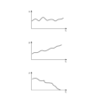
また、表示装置5は、図9に示すように、変化解析部16から出力された表示データに従って、検知対象物体の3次元位置の時間的な変化の解析結果と、検知対象物体が落下するか否か等の判定結果とを図示せぬディスプレイに表示させる。
図9は、検知対象物体の3次元位置の時間的な変化を示す説明図である。
図9は、時刻tにおける検知対象物体のx方向の位置と、時刻tにおける検知対象物体のy方向の位置とを示している。
図9において、x方向は、カメラ3の撮影方向と直交する方向であって、例えば、地面と水平な方向である。
y方向は、カメラ3の撮影方向と平行な方向である。z方向は、カメラ3の撮影方向と直交する方向であって、例えば、地面と垂直な方向である。
図9の例では、検知対象物体のz方向の位置が、或る時刻において、地上の位置になっているため、検知対象物体が落下する旨の判定結果を明示している。図9において、検知対象物体が落下する旨の判定結果が“メッセージ”として表示されるようにしてもよい。The
In addition, as shown in FIG. 9, the
FIG. 9 is an explanatory diagram showing temporal changes in the three-dimensional position of the object to be detected.
FIG. 9 shows the position of the object to be detected in the x direction at time t and the position of the object to be detected in the y direction at time t.
In FIG. 9, the x direction is a direction perpendicular to the photographing direction of the camera 3, and is, for example, a direction horizontal to the ground.
The y direction is a direction parallel to the photographing direction of the camera 3. The z direction is a direction perpendicular to the photographing direction of the camera 3, and is, for example, a direction perpendicular to the ground.
In the example of FIG. 9, since the position of the object to be detected in the z direction is on the ground at a certain time, the determination result that the object to be detected is falling is clearly shown. In FIG. 9, the determination result that the object to be detected is falling may be displayed as a "message".
以上の実施の形態1では、学習用画像と画像のドメインが異なる場合と、事前学習したタスクと認識タスクの異なる場合とのうち、1つ以上が異なる場合において、検知対象物体が映っている画像である推論対象画像を示す画像信号を取得する画像信号取得部11と、画像信号取得部11により取得された画像信号を、学習用画像の学習が済んでいる第1の学習モデル1aに与えて、第1の学習モデル1aから、推論対象画像に映っている検知対象物体の複数の特徴量のそれぞれがぼかされてから複数の特徴量が結合された特徴量であって、検知対象物体の3次元位置の推論に用いられる特徴量である推論時特徴量を取得する特徴量抽出部12とを備えるように、推論装置4を構成した。また、推論装置4は、推論対象画像と画像のドメイン及び認識タスクのそれぞれが同じ対象である変換用画像に映っている検知対象物体の登録済みの特徴量である代表特徴量と特徴量抽出部12により取得された推論時特徴量とに基づいて、推論対象画像に映っている検知対象物体の3次元位置を推定する3次元位置推定部15と、3次元位置推定部15による3次元位置の推定結果に基づいて、推論対象画像に映っている検知対象物体の3次元位置の時間的な変化を解析する変化解析部16とを備えている。したがって、推論装置4は、自然環境の状態を考慮して、第1の学習モデルを学習させることなく、検知対象物体の3次元位置の時間的な変化を解析することができる。
In Embodiment 1 above, when one or more of the training image and the image domain are different, and the pre-trained task and the recognition task are different, an image in which the object to be detected is displayed is used. An image signal acquisition unit 11 that acquires an image signal indicating the inference target image, and the image signal acquired by the image signal acquisition unit 11 are given to the
また、実施の形態1では、画像信号取得部11が、変換用画像を示す画像信号を取得し、特徴量抽出部12が、変換用画像を示す画像信号を第1の学習モデル1aに与えて、第1の学習モデル1aから、変換用画像に映っている検知対象物体の複数の特徴量のそれぞれがぼかされてから複数の特徴量が結合された特徴量である代表特徴量を取得するように、推論装置4を構成した。また、推論装置4は、特徴量抽出部12により取得された代表特徴量を登録する代表特徴量登録部13を備えている。したがって、推論装置4は、検知対象物体の3次元位置の推定に用いることが可能な代表特徴量を登録することができる。
Further, in the first embodiment, the image signal acquisition unit 11 acquires an image signal indicating the conversion image, and the feature
図1に示す推論装置4では、特徴量抽出部12が、非常にディープなCNNsによって実現されている第1の学習モデル1aに対して画像信号を与えて、第1の学習モデル1aから、検知対象物体の複数の特徴量のそれぞれがぼかされてから複数の特徴量が結合された特徴量を取得している。
第1の学習モデル1aが非常にディープなCNNsによって実現されている場合には、上述したように、第1の学習モデル1aの入力層に与えられる画像信号が示す推論対象画像のドメインが学習用画像と異なっていても、また、検知対象物体が異なっていても、出力層から出力される特徴ベクトルの相違は僅かなものとなる。
これに対して、第1の学習モデル1aが一般的なニューラルネットワーク等によって実現されている場合、第1の学習モデル1aの入力層に与えられる画像信号が示す推論対象画像のドメイン、又は、推論対象画像に映っている検知対象物体が、学習用画像と異なっていれば、出力層から出力される特徴ベクトルの相違が大きくなることがある。
しかしながら、変換用画像のドメインと推論対象画像のドメインとが同じである。このため、第1の学習モデル1aが一般的なニューラルネットワーク等によって実現されている場合でも、推論対象画像に映っている検知対象物体が正常な物体であれば、ドメイン変換時に特徴量抽出部12により取得される代表特徴量と、位置推定時に特徴量抽出部12により取得される推論時特徴量とは、概ね同じような値となる。
一方、推論対象画像に映っている検知対象物体が異常な物体であれば、ドメイン変換時に特徴量抽出部12により取得される代表特徴量と、位置推定時に特徴量抽出部12により取得される推論時特徴量とは、大きく異なる値となる。
したがって、第1の学習モデル1aが一般的なニューラルネットワーク等によって実現されている場合でも、3次元位置推定部15が、高精度に検知対象物体の3次元位置を推定することが可能である。In the inference apparatus 4 shown in FIG. After each of the plurality of features of the target object is blurred, a feature obtained by combining the plurality of features is obtained.
When the
On the other hand, if the
However, the domain of the conversion image and the domain of the inference target image are the same. Therefore, even if the
On the other hand, if the detection target object shown in the inference target image is an abnormal object, the representative feature obtained by the
Therefore, even if the
なお、本開示は、実施の形態の任意の構成要素の変形、もしくは実施の形態の任意の構成要素の省略が可能である。 Note that in the present disclosure, any component of the embodiments may be modified or any component of the embodiments may be omitted.
本開示は、推論装置、推論方法及び推論プログラムに適している。 The present disclosure is suitable for an inference device, an inference method, and an inference program.
1 モデル記憶部、1a 第1の学習モデル、2 モデル記憶部、2a 第2の学習モデル、3 カメラ、4 推論装置、5 表示装置、6 学習データ記憶部、7 学習装置、11 画像信号取得部、12 特徴量抽出部、13 代表特徴量登録部、14 代表特徴量記憶部、15 3次元位置推定部、16 変化解析部、21 画像信号取得回路、22 特徴量抽出回路、23 代表特徴量登録回路、24 代表特徴量記憶回路、25 3次元位置推定回路、26 変化解析回路、31 メモリ、32 プロセッサ、41 学習データ取得部、42 学習処理部、51 学習データ取得回路、52 学習処理回路、61 メモリ、62 プロセッサ。 Reference Signs List 1 model storage unit, 1a first learning model, 2 model storage unit, 2a second learning model, 3 camera, 4 inference device, 5 display device, 6 learning data storage unit, 7 learning device, 11 image signal acquisition unit , 12 feature extraction unit, 13 representative feature registration unit, 14 representative feature storage unit, 15 three-dimensional position estimation unit, 16 change analysis unit, 21 image signal acquisition circuit, 22 feature extraction circuit, 23 representative feature registration circuit, 24 representative feature storage circuit, 25 three-dimensional position estimation circuit, 26 change analysis circuit, 31 memory, 32 processor, 41 learning data acquisition section, 42 learning processing section, 51 learning data acquisition circuit, 52 learning processing circuit, 61 Memory, 62 Processor.
Claims (6)
前記画像信号取得部により取得された画像信号を、前記学習用画像の学習が済んでいる第1の学習モデルに与えて、前記第1の学習モデルから、前記推論対象画像に映っている検知対象物体の複数の特徴量のそれぞれがぼかされてから前記複数の特徴量が結合された特徴量であって、前記検知対象物体の3次元位置の推論に用いられる特徴量である推論時特徴量を取得する特徴量抽出部と、
前記推論対象画像と画像のドメイン及び認識タスクのそれぞれが同じ対象である変換用画像に映っている検知対象物体の登録済みの特徴量である代表特徴量と前記特徴量抽出部により取得された推論時特徴量とに基づいて、前記推論対象画像に映っている検知対象物体の3次元位置を推定する3次元位置推定部と、
前記3次元位置推定部による3次元位置の推定結果に基づいて、前記推論対象画像に映っている検知対象物体の3次元位置の時間的な変化を解析する変化解析部と
を備えた推論装置。 An image showing an inference target image that is an image showing a detection target object when one or more of the training images and the image domain are different, and the pre-trained task and the recognition task are different. an image signal acquisition unit that acquires a signal;
The image signal acquired by the image signal acquisition unit is given to a first learning model that has been trained on the learning image, and the detection target appearing in the inference target image is determined from the first learning model. an inference feature quantity that is a feature quantity obtained by combining the plurality of feature quantities after each of the plurality of feature quantities of the object is blurred, and is a feature quantity used for inference of the three-dimensional position of the object to be detected; a feature extraction unit that obtains the
The inference obtained by the feature extracting unit and the representative feature which is the registered feature of the detection target object appearing in the conversion image in which the inference target image, the domain of the image, and the recognition task are each the same target. a three-dimensional position estimation unit that estimates the three-dimensional position of the detection target object shown in the inference target image based on the time feature amount;
An inference device comprising: a change analysis unit that analyzes temporal changes in a three-dimensional position of a detection target object shown in the inference target image based on a three-dimensional position estimation result by the three-dimensional position estimation unit.
前記変換用画像を示す画像信号を取得し、
前記特徴量抽出部は、
前記変換用画像を示す画像信号を前記第1の学習モデルに与えて、前記第1の学習モデルから、前記変換用画像に映っている検知対象物体の複数の特徴量のそれぞれがぼかされてから当該複数の特徴量が結合された特徴量であって、前記検知対象物体の3次元位置の推論に用いられる特徴量である代表特徴量を取得し、
前記特徴量抽出部により取得された代表特徴量を登録する代表特徴量登録部を備えたことを特徴とする請求項1記載の推論装置。 The image signal acquisition unit includes:
obtaining an image signal indicating the conversion image;
The feature amount extraction unit is
An image signal indicating the conversion image is given to the first learning model , and each of the plurality of feature amounts of the detection target object shown in the conversion image is blurred from the first learning model. Obtaining a representative feature amount, which is a feature amount in which the plurality of feature amounts are combined, and is a feature amount used for inference of the three-dimensional position of the detection target object,
2. The inference device according to claim 1, further comprising a representative feature registration unit that registers the representative feature obtained by the feature extraction unit.
種類及び存在している領域のそれぞれが互いに異なる複数の検知対象物体の代表特徴量と前記特徴量抽出部により取得された推論時特徴量とを比較して、前記複数の検知対象物体の代表特徴量の中で、前記特徴量抽出部により取得された推論時特徴量に対応している代表特徴量を特定し、前記代表特徴量の特定結果に基づいて、前記推論対象画像に映っている検知対象物体の認識として、前記検知対象物体の種類及び存在している3次元領域のそれぞれを推定することを特徴とする請求項1記載の推論装置。 The three-dimensional position estimating unit is
Representative features of a plurality of detection target objects having different types and existing regions are compared with the inference feature obtained by the feature extraction unit, and representative features of the plurality of detection target objects are compared. Among the quantities, a representative feature corresponding to the inference feature acquired by the feature extraction unit is identified, and based on the identification result of the representative feature, the detection appearing in the inference target image is determined. 2. The inference device according to claim 1, wherein the recognition of the target object includes estimating the type of the detection target object and the three-dimensional region in which it exists.
3次元位置を学習して3次元位置の時間的な変化を回帰する第2の学習モデルに対して、前記3次元位置推定部による3次元位置の推定結果を与えて、前記第2の学習モデルから、当該検知対象物体の3次元位置の時間的な変化を示す位置データを取得することを特徴とする請求項1記載の推論装置。 The change analysis section includes:
The estimation result of the 3D position by the 3D position estimator is given to the second learning model that learns the 3D position and regresses the temporal change in the 3D position, and the second learning model 2. The inference device according to claim 1, wherein position data indicating a temporal change in the three-dimensional position of the detection target object is acquired from the detection target object.
特徴量抽出部が、前記画像信号取得部により取得された画像信号を、前記学習用画像の学習が済んでいる第1の学習モデルに与えて、前記第1の学習モデルから、前記推論対象画像に映っている検知対象物体の複数の特徴量のそれぞれがぼかされてから前記複数の特徴量が結合された特徴量であって、前記検知対象物体の3次元位置の推論に用いられる特徴量である推論時特徴量を取得し、
3次元位置推定部が、前記推論対象画像と画像のドメイン及び認識タスクのそれぞれが同じ対象である変換用画像に映っている検知対象物体の登録済みの特徴量である代表特徴量と前記特徴量抽出部により取得された推論時特徴量とに基づいて、前記推論対象画像に映っている検知対象物体の3次元位置を推定し、
変化解析部が、前記3次元位置推定部による3次元位置の推定結果に基づいて、前記推論対象画像に映っている検知対象物体の3次元位置の時間的な変化を解析する
推論方法。 The image is an image in which the object to be detected is detected by the image signal acquisition unit in one or more of the following cases: when the training image and the image domain are different, and when the pre-trained task and the recognition task are different. Obtain an image signal indicating the inference target image,
The feature amount extraction unit provides the image signal acquired by the image signal acquisition unit to a first learning model that has been trained on the learning image, and extracts the inference target image from the first learning model. A feature quantity obtained by combining a plurality of feature quantities of the object to be detected after each of the plurality of feature quantities of the object to be detected is blurred, the feature quantity being used for inference of the three-dimensional position of the object to be detected. Obtain the inference feature quantity that is
The three-dimensional position estimating unit calculates the representative feature amount that is a registered feature amount of the detection target object appearing in the conversion image, which is the same target as the inference target image, the domain of the image, and the recognition task, respectively, and the feature amount. Estimating the three-dimensional position of the detection target object shown in the inference target image based on the inference feature acquired by the extraction unit,
An inference method, wherein a change analysis unit analyzes a temporal change in a three-dimensional position of a detection target object shown in the inference target image based on a three-dimensional position estimation result by the three-dimensional position estimation unit.
特徴量抽出部が、前記画像信号取得部により取得された画像信号を、前記学習用画像の学習が済んでいる第1の学習モデルに与えて、前記第1の学習モデルから、前記推論対象画像に映っている検知対象物体の複数の特徴量のそれぞれがぼかされてから前記複数の特徴量が結合された特徴量であって、前記検知対象物体の3次元位置の推論に用いられる特徴量である推論時特徴量を取得する特徴量取得手順と、
3次元位置推定部が、前記推論対象画像と画像のドメイン及び認識タスクのそれぞれが同じ対象である変換用画像に映っている検知対象物体の登録済みの特徴量である代表特徴量と前記特徴量抽出部により取得された推論時特徴量とに基づいて、前記推論対象画像に映っている検知対象物体の3次元位置を推定する3次元位置推定手順と、
変化解析部が、前記3次元位置推定部による3次元位置の推定結果に基づいて、前記推論対象画像に映っている検知対象物体の3次元位置の時間的な変化を解析する変化解析手順とをコンピュータに実行させるための推論プログラム。 The image is an image in which the object to be detected is detected by the image signal acquisition unit in one or more of the following cases: when the training image and the image domain are different, and when the pre-trained task and the recognition task are different. an image signal acquisition procedure for acquiring an image signal indicating an inference target image;
The feature amount extraction unit provides the image signal acquired by the image signal acquisition unit to a first learning model that has been trained on the learning image, and extracts the inference target image from the first learning model. A feature quantity obtained by combining a plurality of feature quantities of the object to be detected after each of the plurality of feature quantities of the object to be detected is blurred, the feature quantity being used for inference of the three-dimensional position of the object to be detected. a feature amount acquisition procedure for acquiring an inference feature amount that is
The three-dimensional position estimating unit calculates the representative feature amount that is a registered feature amount of the detection target object appearing in the conversion image, which is the same target as the inference target image, the domain of the image, and the recognition task, respectively, and the feature amount. a three-dimensional position estimation procedure for estimating the three-dimensional position of the detection target object shown in the inference target image based on the inference-time feature acquired by the extraction unit;
a change analysis procedure in which a change analysis unit analyzes a temporal change in a three-dimensional position of a detection target object shown in the inference target image based on a three-dimensional position estimation result by the three-dimensional position estimation unit; An inference program that is run by a computer.
Applications Claiming Priority (1)
| Application Number | Priority Date | Filing Date | Title |
|---|---|---|---|
| PCT/JP2022/029598 WO2023277201A1 (en) | 2022-08-02 | 2022-08-02 | Inference device, inference method, and inference program |
Publications (2)
| Publication Number | Publication Date |
|---|---|
| JPWO2023277201A1 JPWO2023277201A1 (en) | 2023-01-05 |
| JP7345680B2 true JP7345680B2 (en) | 2023-09-15 |
Family
ID=84692822
Family Applications (1)
| Application Number | Title | Priority Date | Filing Date |
|---|---|---|---|
| JP2022562623A Active JP7345680B2 (en) | 2022-08-02 | 2022-08-02 | Inference device, inference method, and inference program |
Country Status (6)
| Country | Link |
|---|---|
| US (1) | US20240046512A1 (en) |
| JP (1) | JP7345680B2 (en) |
| KR (1) | KR20240019055A (en) |
| CN (1) | CN116368535A (en) |
| CA (1) | CA3193358A1 (en) |
| WO (1) | WO2023277201A1 (en) |
Citations (4)
| Publication number | Priority date | Publication date | Assignee | Title |
|---|---|---|---|---|
| JP2019185127A (en) | 2018-04-02 | 2019-10-24 | キヤノン株式会社 | Learning device of multilayer neural network and control method thereof |
| JP2019212296A (en) | 2018-05-31 | 2019-12-12 | キヤノンメディカルシステムズ株式会社 | Medical information processing device, method and program |
| JP2020101948A (en) | 2018-12-20 | 2020-07-02 | 株式会社日立製作所 | Action recognition system and action recognition method |
| JP2022037955A (en) | 2020-08-26 | 2022-03-10 | 株式会社日立製作所 | System for selecting learning model |
Family Cites Families (1)
| Publication number | Priority date | Publication date | Assignee | Title |
|---|---|---|---|---|
| JP2021110973A (en) | 2020-01-06 | 2021-08-02 | オムロン株式会社 | Human body detection apparatus and human body detection method |
-
2022
- 2022-08-02 US US18/028,953 patent/US20240046512A1/en active Pending
- 2022-08-02 CN CN202280006871.7A patent/CN116368535A/en active Pending
- 2022-08-02 WO PCT/JP2022/029598 patent/WO2023277201A1/en unknown
- 2022-08-02 CA CA3193358A patent/CA3193358A1/en active Pending
- 2022-08-02 KR KR1020237012153A patent/KR20240019055A/en unknown
- 2022-08-02 JP JP2022562623A patent/JP7345680B2/en active Active
Patent Citations (4)
| Publication number | Priority date | Publication date | Assignee | Title |
|---|---|---|---|---|
| JP2019185127A (en) | 2018-04-02 | 2019-10-24 | キヤノン株式会社 | Learning device of multilayer neural network and control method thereof |
| JP2019212296A (en) | 2018-05-31 | 2019-12-12 | キヤノンメディカルシステムズ株式会社 | Medical information processing device, method and program |
| JP2020101948A (en) | 2018-12-20 | 2020-07-02 | 株式会社日立製作所 | Action recognition system and action recognition method |
| JP2022037955A (en) | 2020-08-26 | 2022-03-10 | 株式会社日立製作所 | System for selecting learning model |
Also Published As
| Publication number | Publication date |
|---|---|
| CN116368535A (en) | 2023-06-30 |
| CA3193358A1 (en) | 2023-01-05 |
| JPWO2023277201A1 (en) | 2023-01-05 |
| US20240046512A1 (en) | 2024-02-08 |
| KR20240019055A (en) | 2024-02-14 |
| WO2023277201A1 (en) | 2023-01-05 |
Similar Documents
| Publication | Publication Date | Title |
|---|---|---|
| US11823429B2 (en) | Method, system and device for difference automatic calibration in cross modal target detection | |
| US11734786B2 (en) | Low- and high-fidelity classifiers applied to road-scene images | |
| Blum et al. | Fishyscapes: A benchmark for safe semantic segmentation in autonomous driving | |
| CN108416394B (en) | Multi-target detection model building method based on convolutional neural networks | |
| CN112287860B (en) | Training method and device of object recognition model, and object recognition method and system | |
| WO2017079522A1 (en) | Subcategory-aware convolutional neural networks for object detection | |
| WO2020046960A1 (en) | System and method for optimizing damage detection results | |
| CN112991413A (en) | Self-supervision depth estimation method and system | |
| US11762454B2 (en) | Method and apparatus with image augmentation | |
| JP6397379B2 (en) | CHANGE AREA DETECTION DEVICE, METHOD, AND PROGRAM | |
| US11822621B2 (en) | Systems and methods for training a machine-learning-based monocular depth estimator | |
| CN110033481A (en) | Method and apparatus for carrying out image procossing | |
| CN112085789B (en) | Pose estimation method, device, equipment and medium | |
| US11392804B2 (en) | Device and method for generating label objects for the surroundings of a vehicle | |
| JP5262705B2 (en) | Motion estimation apparatus and program | |
| CN111428539A (en) | Target tracking method and device | |
| CN113095351A (en) | Method for generating marked data by means of an improvement of the initial marking | |
| CN117830356A (en) | Target tracking method, device, equipment and medium | |
| Acun et al. | D3NET (divide and detect drivable area net): deep learning based drivable area detection and its embedded application | |
| US20230260259A1 (en) | Method and device for training a neural network | |
| JP7345680B2 (en) | Inference device, inference method, and inference program | |
| CN115713750A (en) | Lane line detection method and device, electronic equipment and storage medium | |
| JP2019046278A (en) | Information processor, control method, computer program, storage medium, and model creation device | |
| JP7128578B2 (en) | Object detection device, object detection program, object detection method, and learning device | |
| US20220012506A1 (en) | System and method of segmenting free space based on electromagnetic waves |
Legal Events
| Date | Code | Title | Description |
|---|---|---|---|
| A621 | Written request for application examination |
Free format text: JAPANESE INTERMEDIATE CODE: A621 Effective date: 20221014 |
|
| A131 | Notification of reasons for refusal |
Free format text: JAPANESE INTERMEDIATE CODE: A131 Effective date: 20230620 |
|
| A521 | Request for written amendment filed |
Free format text: JAPANESE INTERMEDIATE CODE: A523 Effective date: 20230725 |
|
| TRDD | Decision of grant or rejection written | ||
| A01 | Written decision to grant a patent or to grant a registration (utility model) |
Free format text: JAPANESE INTERMEDIATE CODE: A01 Effective date: 20230808 |
|
| A61 | First payment of annual fees (during grant procedure) |
Free format text: JAPANESE INTERMEDIATE CODE: A61 Effective date: 20230905 |
|
| R150 | Certificate of patent or registration of utility model |
Ref document number: 7345680 Country of ref document: JP Free format text: JAPANESE INTERMEDIATE CODE: R150 |