JP7343079B1 - filter - Google Patents
filter Download PDFInfo
- Publication number
- JP7343079B1 JP7343079B1 JP2023525487A JP2023525487A JP7343079B1 JP 7343079 B1 JP7343079 B1 JP 7343079B1 JP 2023525487 A JP2023525487 A JP 2023525487A JP 2023525487 A JP2023525487 A JP 2023525487A JP 7343079 B1 JP7343079 B1 JP 7343079B1
- Authority
- JP
- Japan
- Prior art keywords
- convex portion
- filter
- holes
- gap
- base
- Prior art date
- Legal status (The legal status is an assumption and is not a legal conclusion. Google has not performed a legal analysis and makes no representation as to the accuracy of the status listed.)
- Active
Links
- 230000005489 elastic deformation Effects 0.000 description 34
- 239000012530 fluid Substances 0.000 description 28
- 230000004048 modification Effects 0.000 description 25
- 238000012986 modification Methods 0.000 description 25
- 238000010586 diagram Methods 0.000 description 19
- 210000004027 cell Anatomy 0.000 description 17
- 238000004519 manufacturing process Methods 0.000 description 10
- 239000010949 copper Substances 0.000 description 9
- 238000001914 filtration Methods 0.000 description 9
- KFZMGEQAYNKOFK-UHFFFAOYSA-N Isopropanol Chemical compound CC(C)O KFZMGEQAYNKOFK-UHFFFAOYSA-N 0.000 description 6
- 230000000694 effects Effects 0.000 description 6
- 239000000758 substrate Substances 0.000 description 6
- 241000894006 Bacteria Species 0.000 description 4
- SECXISVLQFMRJM-UHFFFAOYSA-N N-Methylpyrrolidone Chemical compound CN1CCCC1=O SECXISVLQFMRJM-UHFFFAOYSA-N 0.000 description 4
- 238000003491 array Methods 0.000 description 4
- 238000011161 development Methods 0.000 description 4
- 239000007788 liquid Substances 0.000 description 4
- 229910052751 metal Inorganic materials 0.000 description 4
- 239000002184 metal Substances 0.000 description 4
- 238000007747 plating Methods 0.000 description 4
- WGTYBPLFGIVFAS-UHFFFAOYSA-M tetramethylammonium hydroxide Chemical compound [OH-].C[N+](C)(C)C WGTYBPLFGIVFAS-UHFFFAOYSA-M 0.000 description 4
- 238000009713 electroplating Methods 0.000 description 3
- 239000000463 material Substances 0.000 description 3
- 230000000737 periodic effect Effects 0.000 description 3
- 238000012545 processing Methods 0.000 description 3
- 230000003746 surface roughness Effects 0.000 description 3
- 239000010936 titanium Substances 0.000 description 3
- QTBSBXVTEAMEQO-UHFFFAOYSA-N Acetic acid Natural products CC(O)=O QTBSBXVTEAMEQO-UHFFFAOYSA-N 0.000 description 2
- 241000206602 Eukaryota Species 0.000 description 2
- 206010028980 Neoplasm Diseases 0.000 description 2
- PXHVJJICTQNCMI-UHFFFAOYSA-N Nickel Chemical compound [Ni] PXHVJJICTQNCMI-UHFFFAOYSA-N 0.000 description 2
- KDLHZDBZIXYQEI-UHFFFAOYSA-N Palladium Chemical compound [Pd] KDLHZDBZIXYQEI-UHFFFAOYSA-N 0.000 description 2
- RTAQQCXQSZGOHL-UHFFFAOYSA-N Titanium Chemical compound [Ti] RTAQQCXQSZGOHL-UHFFFAOYSA-N 0.000 description 2
- 201000011510 cancer Diseases 0.000 description 2
- 238000001035 drying Methods 0.000 description 2
- BASFCYQUMIYNBI-UHFFFAOYSA-N platinum Chemical compound [Pt] BASFCYQUMIYNBI-UHFFFAOYSA-N 0.000 description 2
- 239000000243 solution Substances 0.000 description 2
- 229910052719 titanium Inorganic materials 0.000 description 2
- 238000007740 vapor deposition Methods 0.000 description 2
- RYGMFSIKBFXOCR-UHFFFAOYSA-N Copper Chemical compound [Cu] RYGMFSIKBFXOCR-UHFFFAOYSA-N 0.000 description 1
- 241000588724 Escherichia coli Species 0.000 description 1
- 241000233866 Fungi Species 0.000 description 1
- 241000187479 Mycobacterium tuberculosis Species 0.000 description 1
- 229910001252 Pd alloy Inorganic materials 0.000 description 1
- BQCADISMDOOEFD-UHFFFAOYSA-N Silver Chemical compound [Ag] BQCADISMDOOEFD-UHFFFAOYSA-N 0.000 description 1
- 241000700605 Viruses Species 0.000 description 1
- -1 acetic acid peroxide Chemical class 0.000 description 1
- 230000001464 adherent effect Effects 0.000 description 1
- 229910045601 alloy Inorganic materials 0.000 description 1
- 239000000956 alloy Substances 0.000 description 1
- 239000012620 biological material Substances 0.000 description 1
- 239000006143 cell culture medium Substances 0.000 description 1
- 239000006285 cell suspension Substances 0.000 description 1
- 230000008859 change Effects 0.000 description 1
- 239000012141 concentrate Substances 0.000 description 1
- 229910052802 copper Inorganic materials 0.000 description 1
- 230000007423 decrease Effects 0.000 description 1
- 238000013461 design Methods 0.000 description 1
- 239000003814 drug Substances 0.000 description 1
- 239000008151 electrolyte solution Substances 0.000 description 1
- 229940021013 electrolyte solution Drugs 0.000 description 1
- 238000005530 etching Methods 0.000 description 1
- PCHJSUWPFVWCPO-UHFFFAOYSA-N gold Chemical compound [Au] PCHJSUWPFVWCPO-UHFFFAOYSA-N 0.000 description 1
- 229910052737 gold Inorganic materials 0.000 description 1
- 239000010931 gold Substances 0.000 description 1
- 238000007654 immersion Methods 0.000 description 1
- 230000006872 improvement Effects 0.000 description 1
- 210000004263 induced pluripotent stem cell Anatomy 0.000 description 1
- 210000000265 leukocyte Anatomy 0.000 description 1
- 239000011159 matrix material Substances 0.000 description 1
- 210000002901 mesenchymal stem cell Anatomy 0.000 description 1
- 229910044991 metal oxide Inorganic materials 0.000 description 1
- 150000004706 metal oxides Chemical class 0.000 description 1
- 238000000034 method Methods 0.000 description 1
- 210000005087 mononuclear cell Anatomy 0.000 description 1
- 210000002569 neuron Anatomy 0.000 description 1
- 229910052759 nickel Inorganic materials 0.000 description 1
- BSIDXUHWUKTRQL-UHFFFAOYSA-N nickel palladium Chemical compound [Ni].[Pd] BSIDXUHWUKTRQL-UHFFFAOYSA-N 0.000 description 1
- 229910052763 palladium Inorganic materials 0.000 description 1
- 230000035699 permeability Effects 0.000 description 1
- 229910052697 platinum Inorganic materials 0.000 description 1
- 238000003825 pressing Methods 0.000 description 1
- 230000001172 regenerating effect Effects 0.000 description 1
- 230000004044 response Effects 0.000 description 1
- 229910052710 silicon Inorganic materials 0.000 description 1
- 239000010703 silicon Substances 0.000 description 1
- 229910052709 silver Inorganic materials 0.000 description 1
- 239000004332 silver Substances 0.000 description 1
- 239000007921 spray Substances 0.000 description 1
- 238000004544 sputter deposition Methods 0.000 description 1
- 238000003756 stirring Methods 0.000 description 1
- 239000000126 substance Substances 0.000 description 1
- 238000005406 washing Methods 0.000 description 1
- XLYOFNOQVPJJNP-UHFFFAOYSA-N water Substances O XLYOFNOQVPJJNP-UHFFFAOYSA-N 0.000 description 1
Images


Classifications
-
- B—PERFORMING OPERATIONS; TRANSPORTING
- B01—PHYSICAL OR CHEMICAL PROCESSES OR APPARATUS IN GENERAL
- B01D—SEPARATION
- B01D29/00—Filters with filtering elements stationary during filtration, e.g. pressure or suction filters, not covered by groups B01D24/00 - B01D27/00; Filtering elements therefor
- B01D29/01—Filters with filtering elements stationary during filtration, e.g. pressure or suction filters, not covered by groups B01D24/00 - B01D27/00; Filtering elements therefor with flat filtering elements
- B01D29/05—Filters with filtering elements stationary during filtration, e.g. pressure or suction filters, not covered by groups B01D24/00 - B01D27/00; Filtering elements therefor with flat filtering elements supported
-
- B—PERFORMING OPERATIONS; TRANSPORTING
- B01—PHYSICAL OR CHEMICAL PROCESSES OR APPARATUS IN GENERAL
- B01D—SEPARATION
- B01D39/00—Filtering material for liquid or gaseous fluids
- B01D39/14—Other self-supporting filtering material ; Other filtering material
- B01D39/20—Other self-supporting filtering material ; Other filtering material of inorganic material, e.g. asbestos paper, metallic filtering material of non-woven wires
-
- B—PERFORMING OPERATIONS; TRANSPORTING
- B01—PHYSICAL OR CHEMICAL PROCESSES OR APPARATUS IN GENERAL
- B01D—SEPARATION
- B01D39/00—Filtering material for liquid or gaseous fluids
- B01D39/10—Filter screens essentially made of metal
-
- C—CHEMISTRY; METALLURGY
- C12—BIOCHEMISTRY; BEER; SPIRITS; WINE; VINEGAR; MICROBIOLOGY; ENZYMOLOGY; MUTATION OR GENETIC ENGINEERING
- C12M—APPARATUS FOR ENZYMOLOGY OR MICROBIOLOGY; APPARATUS FOR CULTURING MICROORGANISMS FOR PRODUCING BIOMASS, FOR GROWING CELLS OR FOR OBTAINING FERMENTATION OR METABOLIC PRODUCTS, i.e. BIOREACTORS OR FERMENTERS
- C12M1/00—Apparatus for enzymology or microbiology
- C12M1/12—Apparatus for enzymology or microbiology with sterilisation, filtration or dialysis means
Landscapes
- Chemical & Material Sciences (AREA)
- Life Sciences & Earth Sciences (AREA)
- Health & Medical Sciences (AREA)
- Engineering & Computer Science (AREA)
- Bioinformatics & Cheminformatics (AREA)
- Chemical Kinetics & Catalysis (AREA)
- Organic Chemistry (AREA)
- Biotechnology (AREA)
- Zoology (AREA)
- Wood Science & Technology (AREA)
- Microbiology (AREA)
- Sustainable Development (AREA)
- Biomedical Technology (AREA)
- Medicinal Chemistry (AREA)
- Biochemistry (AREA)
- General Engineering & Computer Science (AREA)
- General Health & Medical Sciences (AREA)
- Genetics & Genomics (AREA)
- Geology (AREA)
- Devices For Use In Laboratory Experiments (AREA)
- Sampling And Sample Adjustment (AREA)
- Food-Manufacturing Devices (AREA)
- Filtering Materials (AREA)
Abstract
本発明のフィルタは、第1主面と前記第1主面と反対側の第2主面とを有し、前記第1主面と前記第2主面とを連通する複数の貫通孔が設けられたフィルタ基体部を備え、前記フィルタ基体部は、隣り合う2つの貫通孔との間に設けられた弾性変形可能な第1凸部及び第2凸部を含み、前記第1凸部と前記第2凸部との間には、前記隣り合う2つの貫通孔とを連通するギャップが設けられている。The filter of the present invention has a first main surface and a second main surface opposite to the first main surface, and is provided with a plurality of through holes that communicate with the first main surface and the second main surface. The filter base portion includes a first convex portion and a second convex portion that are elastically deformable and are provided between two adjacent through holes, and the first convex portion and the second convex portion are provided between two adjacent through holes. A gap is provided between the second convex portion and the two adjacent through holes.
Description
本発明は、フィルタに関する。 FIELD OF THE INVENTION The present invention relates to a filter.
例えば、細胞を捕捉するためのフィルタとして、特許文献1には、細胞捕捉金属フィルタが開示されている。
For example, as a filter for capturing cells,
しかしながら、特許文献1に記載のフィルタでは、利便性を向上させるという点で未だ改善の余地がある。
However, the filter described in
本発明は、利便性を向上させることができるフィルタを提供することを目的とする。 An object of the present invention is to provide a filter that can improve convenience.
本発明の一態様のフィルタは、
第1主面と前記第1主面と反対側の第2主面とを有し、前記第1主面と前記第2主面とを連通する複数の貫通孔が設けられたフィルタ基体部を備え、
前記フィルタ基体部は、隣り合う2つの貫通孔との間に設けられた弾性変形可能な第1凸部及び第2凸部を含み、
前記第1凸部と前記第2凸部との間には、前記隣り合う2つの貫通孔とを連通するギャップが設けられている。A filter according to one embodiment of the present invention includes:
A filter base portion having a first main surface and a second main surface opposite to the first main surface, and provided with a plurality of through holes communicating the first main surface and the second main surface. Prepare,
The filter base portion includes an elastically deformable first convex portion and a second convex portion provided between two adjacent through holes,
A gap is provided between the first convex portion and the second convex portion, which communicates the two adjacent through holes.
本発明によれば、利便性を向上させることができるフィルタを提供することができる。 According to the present invention, it is possible to provide a filter that can improve convenience.
(本発明に至った経緯)
特許文献1に記載のメッシュ部材のように、複数の貫通孔が設けられたフィルタが知られている。このようなフィルタでは、複数の貫通孔の形状及び大きさが統一されている。(How the present invention was achieved)
BACKGROUND ART Filters provided with a plurality of through holes, such as the mesh member described in
特許文献1に記載のフィルタを用いて濾過をする場合、フィルタで捕捉したい対象物のサイズが変わるとフィルタを交換することが多い。フィルタを交換するためには、濾過装置からフィルタを取り外し、新しいフィルタを取り付ける作業が発生する。当該作業は、ユーザにとって利便性に欠ける。
When performing filtration using the filter described in
そこで、本発明者らは、1つのフィルタで異なるサイズの対象物を濾過することができるフィルタの構成を見出し、以下の発明に至った。 Therefore, the present inventors discovered a filter configuration that can filter objects of different sizes with one filter, and arrived at the following invention.
本発明の一態様のフィルタは、第1主面と前記第1主面と反対側の第2主面とを有し、前記第1主面と前記第2主面とを連通する複数の貫通孔が設けられたフィルタ基体部を備え、前記フィルタ基体部は、隣り合う2つの貫通孔との間に設けられた弾性変形可能な第1凸部及び第2凸部を含み、前記第1凸部と前記第2凸部との間には、前記隣り合う2つの貫通孔とを連通するギャップが設けられている。 The filter according to one aspect of the present invention has a first main surface and a second main surface opposite to the first main surface, and has a plurality of through holes communicating with the first main surface and the second main surface. The filter base portion includes a filter base portion provided with a hole, and the filter base portion includes a first convex portion and a second convex portion that are elastically deformable and are provided between two adjacent through holes, and the first convex portion A gap is provided between the second convex portion and the second convex portion to communicate with the two adjacent through holes.
このような構成により、利便性を向上させることができる。 With such a configuration, convenience can be improved.
前記フィルタ基体部は、第1方向に延び、且つ互いに平行に配置される複数の第1基体部と、前記第1方向と交差する第2方向に延び、且つ互いに平行に配置される複数の第2基体部と、を含み、前記複数の貫通孔は、前記複数の第1基体部および前記複数の第2基体部によって画定され、前記第1凸部及び前記第2凸部は、前記複数の第1基体部の一部を構成してもよい。 The filter base portion includes a plurality of first base portions extending in a first direction and arranged parallel to each other, and a plurality of first base portions extending in a second direction intersecting the first direction and arranged parallel to each other. 2 base parts, the plurality of through holes are defined by the plurality of first base parts and the plurality of second base parts, and the first convex part and the second convex part are defined by the plurality of first base parts and the plurality of second base parts. It may constitute a part of the first base portion.
このような構成により、フィルタの機械強度を向上させると共に、利便性を向上させることができる。 With such a configuration, it is possible to improve the mechanical strength of the filter and to improve convenience.
前記第1凸部及び前記第2凸部は、前記隣り合う2つの貫通孔との間で、前記第1方向に沿って延び、前記第1凸部の端部は、前記第2凸部の端部と対向してもよい。 The first protrusion and the second protrusion extend along the first direction between the two adjacent through holes, and the end of the first protrusion is connected to the second protrusion. It may be opposite to the end.
このような構成により、第1凸部及び第2凸部の弾性変形によるギャップの大きさを調整しやすくなり、利便性をより向上させることができる。 With such a configuration, the size of the gap due to elastic deformation of the first convex portion and the second convex portion can be easily adjusted, and convenience can be further improved.
前記フィルタ基体部は、隣り合う2つの貫通孔との間に設けられた第3凸部及び第4凸部を含み、前記第3凸部と前記第4凸部との間には、前記隣り合う2つの貫通孔とを連通するギャップが設けられており、前記第3凸部及び前記第4凸部は、前記複数の第2基体部の一部を構成してもよい。 The filter base portion includes a third convex portion and a fourth convex portion provided between two adjacent through holes, and a portion between the third convex portion and the fourth convex portion is provided between the adjacent two through holes. A gap may be provided to communicate the two matching through holes, and the third convex portion and the fourth convex portion may constitute a part of the plurality of second base portions.
このような構成により、フィルタにおいて弾性変形可能な箇所を増やすことができ、利便性をさらに向上させることができる。 With such a configuration, the number of elastically deformable parts of the filter can be increased, and convenience can be further improved.
前記第3凸部及び前記第4凸部は、前記第1凸部及び前記第2凸部によって画定される貫通孔と隣り合う貫通孔との間に設けられていてもよい。 The third convex portion and the fourth convex portion may be provided between a through hole defined by the first convex portion and the second convex portion and an adjacent through hole.
このような構成により、貫通孔周辺でより弾性変形しやすくなり、弾性変形による貫通孔の開口面積を大きくすることができる。 With such a configuration, elastic deformation is more likely to occur around the through hole, and the opening area of the through hole due to elastic deformation can be increased.
前記複数の第1基体部は、等間隔で配置され、前記複数の第2基体部は、等間隔で配置され、前記複数の第2基体部は、前記複数の第1基体部と直交してもよい。 The plurality of first base parts are arranged at equal intervals, the plurality of second base parts are arranged at equal intervals, and the plurality of second base parts are orthogonal to the plurality of first base parts. Good too.
このような構成により、フィルタの機械強度を向上させると共に、弾性変形しやすくなり、利便性を向上させることができる。 With such a configuration, the mechanical strength of the filter can be improved, and the filter can be easily deformed elastically, thereby improving convenience.
前記第1主面側から見て、前記複数の貫通孔は、正方形状を有し、前記ギャップの大きさは、前記ギャップと連通する側の貫通孔を画定する一辺の0.25倍以下であってもよい。 When viewed from the first main surface side, the plurality of through holes have a square shape, and the size of the gap is 0.25 times or less of a side defining the through hole on the side communicating with the gap. There may be.
このような構成により、第1凸部及び第2凸部の弾性変形によるギャップの大きさの調整が容易となる。 With such a configuration, the size of the gap can be easily adjusted by elastic deformation of the first convex portion and the second convex portion.
前記第1主面側から見て、前記複数の貫通孔は、円形状を有し、前記ギャップの大きさは、前記ギャップと連通する貫通孔の直径の0.25倍以下であってもよい。 When viewed from the first main surface side, the plurality of through holes may have a circular shape, and the size of the gap may be 0.25 times or less the diameter of the through hole communicating with the gap. .
このような構成により、第1凸部及び第2凸部の弾性変形によるギャップの大きさの調整が容易となる。 With such a configuration, the size of the gap can be easily adjusted by elastic deformation of the first convex portion and the second convex portion.
前記第1凸部の長さは、前記第2凸部の長さの0.8倍以上1.2倍以下であってもよい。 The length of the first convex portion may be 0.8 times or more and 1.2 times or less the length of the second convex portion.
このような構成により、第1凸部及び第2凸部の弾性変形が同等程度になり、ギャップの大きさの調整が容易となる。 With such a configuration, the elastic deformation of the first convex portion and the second convex portion is approximately the same, making it easy to adjust the size of the gap.
前記第1凸部の長さは、前記第2凸部の長さよりも大きくてもよい。 The length of the first convex portion may be greater than the length of the second convex portion.
このような構成により、第2凸部と比べて第1凸部の弾性変形を容易にすることができる。 Such a configuration allows the first protrusion to be elastically deformed more easily than the second protrusion.
以下、本発明に係る実施の形態1について、添付の図面を参照しながら説明する。また、各図においては、説明を容易なものとするため、各要素を誇張して示している。
(実施の形態1)
[全体構成]
図1は、本発明に係る実施の形態1のフィルタ1の一例を第1主面PS1側から見た概略図である。図2は、本発明に係る実施の形態1のフィルタ1の一例を第2主面PS2側から見た概略図である。図中において、X、Y、Z方向は、それぞれフィルタ1の縦方向、横方向、厚み方向を示している。(Embodiment 1)
[overall structure]
FIG. 1 is a schematic diagram of an example of a
例えば、フィルタ1は、濾過対象物を含む流体を濾過するフィルタである。
For example, the
本明細書において、「濾過対象物」とは、流体に含まれる対象物のうち濾過されるべき対象物を意味している。例えば、濾過対象物は、流体に含まれる生物由来物質であってもよい。「生物由来物質」とは、細胞(真核生物)、細菌(真正細菌)、ウィルス等の生物に由来する物質を意味する。細胞(真核生物)としては、例えば、人工多能性幹細胞(iPS細胞)、ES細胞、幹細胞、間葉系幹細胞、単核球細胞、単細胞、細胞塊、浮遊性細胞、接着性細胞、神経細胞、白血球、再生医療用細胞、自己細胞、がん細胞、血中循環がん細胞(CTC)、HL-60、HELA、菌類を含む。細菌(真正細菌)としては、例えば、大腸菌、結核菌を含む。 In this specification, the term "object to be filtered" refers to an object to be filtered among objects contained in a fluid. For example, the object to be filtered may be a biological substance contained in the fluid. "Biological material" means a material derived from living organisms such as cells (eukaryotes), bacteria (eubacteria), and viruses. Examples of cells (eukaryotes) include induced pluripotent stem cells (iPS cells), ES cells, stem cells, mesenchymal stem cells, mononuclear cells, single cells, cell clusters, floating cells, adherent cells, and nerve cells. Including cells, white blood cells, cells for regenerative medicine, autologous cells, cancer cells, circulating cancer cells (CTC), HL-60, HELA, and fungi. Examples of bacteria (eubacteria) include Escherichia coli and Mycobacterium tuberculosis.
流体としては、例えば、液体又は気体が挙げられる。液体としては、例えば、例えば、電解質溶液、細胞懸濁液、細胞培養培地などが挙げられる。 Examples of the fluid include liquid or gas. Examples of liquids include electrolyte solutions, cell suspensions, cell culture media, and the like.
フィルタ1は、金属製フィルタである。フィルタ1を構成する材料は、金属及び金属酸化物のうち少なくともいずれかを主成分とする。フィルタ1を構成する材料は、例えば、金、銀、銅、白金、ニッケル、パラジウム、チタン、これらの合金及びこれらの酸化物であってもよい。特に、チタンや、ニッケル-パラジウム合金を使用することにより、金属の溶出が少なく、濾過対象物への影響を低減することができる。
図1及び図2に示すように、フィルタ1は、フィルタ部10と、フィルタ部10の外周に設けられた枠部20と、を有する。また、フィルタ1は、第1主面PS1と第1主面PS1と反対側の第2主面PS2とを有する。実施の形態1では、フィルタ部10と枠部20とは一体で形成されている。
As shown in FIGS. 1 and 2, the
<フィルタ部>
フィルタ部10は、濾過対象物を含む流体を濾過する部分である。フィルタ部10は、第1主面PS1と第2主面PS2とを連通する複数の貫通孔11が設けられたフィルタ基体部12で構成されている。また、フィルタ部10においては、フィルタ基体部12の第2主面PS2に複数の支持部13が配置されている。<Filter section>
The
フィルタ部10の形状は、フィルタ1の厚み方向(Z方向)から見て、例えば、円形、多角形、楕円形である。実施の形態1では、フィルタ部10の形状は、略円形である。なお、本明細書において、「略円形」とは、短径の長さに対する長径の長さの比が1.0以上1.2以下であることをいう。
The shape of the
<枠部>
枠部20は、フィルタ部10の外周に設けられており、フィルタ部10に比べて単位面積当たりの貫通孔11の数が少ない部分である。枠部20における貫通孔11の数は、フィルタ部10における貫通孔11の数の1%以下である。枠部20の厚みは、フィルタ部10の厚みよりも厚くてもよい。このような構成により、フィルタ1の機械強度を高めることができる。<Frame>
The
フィルタ1を装置に接続して使用する場合、枠部20は、フィルタ1と装置とを接続する接続部として機能してもよい。また、枠部20には、フィルタ1の情報(貫通孔11の寸法など)を表示してもよい。
When the
枠部20は、フィルタ部10の第1主面PS1側から見て、リング状に形成されている。フィルタ1を第1主面PS1側から見て、枠部20の中心は、フィルタ部10の中心と一致する。即ち、枠部20は、フィルタ1と同心円上に形成されている。
The
以下、フィルタ部10について詳細に説明する。
The
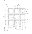
図3は、フィルタ部10の一部の拡大模式図である。図3は、複数の貫通孔11が設けられたフィルタ基体部12の一部を拡大した図であり、フィルタ1の第1主面PS1側から見た図である。
FIG. 3 is an enlarged schematic diagram of a portion of the
図3に示すように、複数の貫通孔11は、フィルタ部10の第1主面PS1及び第2主面PS2上に周期的に配置されている。具体的には、複数の貫通孔11は、フィルタ部10においてマトリクス状に等間隔で設けられている。
As shown in FIG. 3, the plurality of through
実施の形態1では、複数の貫通孔11は、フィルタ部10の第1主面PS1側(Z方向)から見て正方形の各辺と平行な2つの配列方向、即ち図3中のX方向とY方向に沿って設けられている。このように、複数の貫通孔11を正方格子配列で設けることによって、開口率を高めることが可能であり、流体に対するフィルタ1の抵抗を低減することができる。このような構成により、処理時間を短くし、濾過対象物へのストレスを低減することができる。また、複数の貫通孔11の配列の対称性が向上するため、フィルタ1の観察が容易になる。
In the first embodiment, the plurality of through
なお、複数の貫通孔11の配列は、正方格子配列に限定されず、例えば、準周期配列、又は周期配列であってもよい。周期配列の例としては、方形配列であれば、2つの配列方向の間隔が等しくない長方形配列でもよく、三角格子配列又は正三角格子配列などであってもよい。なお、貫通孔11は、フィルタ部10に複数設けられていればよく、配列は限定されない。
Note that the arrangement of the plurality of through
貫通孔11の間隔bは、分離する濾過対象物に応じて適宜設計される。例えば、濾過対象物が細胞である場合、貫通孔11の間隔bは、細胞の種類(大きさ、形態、性質、弾性)又は量に応じて適宜設計される。ここで、貫通孔11の間隔bとは、図3に示すように、貫通孔11をフィルタ部10の第1主面PS1側から見て、任意の貫通孔11の中心と隣接する貫通孔11の中心との距離を意味する。実施の形態1では、貫通孔11は第1主面PS1側から見て正方形である。貫通孔11の中心は、2つの対角線が交差する交点となる。
The interval b between the through
周期配列の構造体の場合、貫通孔11の間隔bは、例えば、貫通孔11の一辺aの1倍より大きく10倍以下であり、好ましくは貫通孔11の一辺aの3倍以下である。あるいは、例えば、フィルタ部10の開口率は10%以上であり、好ましくは、開口率は25%以上である。このような構成により、流体に対するフィルタ部10での抵抗を低減することができる。そのため、処理時間を短くすることができ、細胞へのストレスを低減することができる。なお、開口率とは、(貫通孔11が占める面積)/(貫通孔11が空いていないと仮定したときの第1主面PS1の投影面積)で計算される。
In the case of a periodic array structure, the interval b between the through
貫通孔11は、第1主面PS1側の開口と第2主面PS2側の開口とが連続した壁面を通じて連通している。具体的には、貫通孔11は、第1主面PS1側の開口が第2主面PS2側の開口に投影可能に設けられている。即ち、フィルタ部10を第2主面PS2側から見た場合に、貫通孔11は、第2主面PS2側の開口が第1主面PS1側の開口と重なるように設けられている。実施の形態1では、貫通孔11を画定する内壁は、第1主面PS1及び第2主面PS2に対して垂直となるように設けられている。
In the through
貫通孔11の形状は第1主面PS1側から見て正方形であり、貫通孔11の一辺aは0.5μm以上400μm以下である。好ましくは、貫通孔11の一辺aは1μm以上30μm以下である。
The shape of the through
なお、貫通孔11の形状は、第1主面PS1側から見て正方形に限定されない。例えば、貫通孔11の形状は、第1主面PS1側から見て、円形、楕円形、矩形、多角形などであってもよい。
Note that the shape of the through
フィルタ部10において、貫通孔11が形成されていない部分は、フィルタ基体部12によって形成されている。図3に示すように、フィルタ基体部12は、格子状に形成されている。具体的には、フィルタ基体部12は、複数の第1基体部12Aと、複数の第2基体部12Bと、を含む。複数の第1基体部12Aは、第1方向に延び、且つ互いに平行に配置される。複数の第2基体部12Bは、第1方向と交差する第2方向に延び、且つ互いに平行に配置される。
In the
複数の第1基体部12A及び複数の第2基体部12Bは、板状の部材で形成されている。複数の第1基体部12Aと複数の第2基体部12Bとが交差することによって、複数の貫通孔11が画定される。実施の形態1では、複数の第1基体部12Aが延びる第1方向はX方向であり、複数の第2基体部12Bが延びる第2方向はY方向である。即ち、実施の形態1では、第1方向と第2方向とは直交する。また、複数の第1基体部12A及び複数の第2基体部12Bは、等間隔で配置される。
The plurality of
実施の形態1では、複数の第1基体部12A及び複数の第2基体部12Bは、一体で形成されている。
In the first embodiment, the plurality of
図3に示すように、フィルタ基体部12は、弾性変形部30を含む。弾性変形部30は、所定の力以上の力を受けると弾性変形する部分である。フィルタ部10には、複数の弾性変形部30が設けられている。
As shown in FIG. 3, the
弾性変形部30は、弾性変形可能な第1凸部31及び第2凸部32を含む。第1凸部31及び第2凸部32は、板状の部材で形成されている。例えば、第1凸部31及び第2凸部32は、任意の厚さ又は幅で設計することにより、弾性変形可能になっている。第1凸部31及び第2凸部32は、複数の第1基体部12Aの一部を構成している。
The elastically
第1凸部31及び第2凸部32は、隣り合う2つの貫通孔11A,11Bとの間に設けられている。第1凸部31及び第2凸部32は、隣り合う2つの貫通孔11A,11Bとの間で、第1方向(X方向)に沿って延びている。本明細書では、隣り合う2つの貫通孔11A,11Bを、それぞれ、第1貫通孔11A、第2貫通孔11Bと称する場合がある。
The first
第1凸部31及び第2凸部32は、隣り合う2つの第2基体部12Bから第1方向(X方向)に沿って突出している。また、第1凸部31の端部31aは、第2凸部32の端部32aと対向する。第1凸部31の端部31aとは、第1凸部31の自由端を意味する。第2凸部32の端部32aとは、第2凸部32の自由端を意味する。
The first
なお、第1凸部31及び第2凸部32の形状は、図3に示す例に限定されない。例えば、第1凸部31及び第2凸部32の幅は、フィルタ基体部12に接続される基部と端部とで異なっていてもよい。また、第1凸部31及び第2凸部32の幅は、基部から端部に向かって変化していてもよい。
Note that the shapes of the first
第1凸部31と第2凸部32との間には、隣り合う2つの貫通孔11A,11Bとを連通するギャップ33が設けられている。具体的には、第1凸部31の端部31aと第2凸部32の端部32aとの間に、ギャップ33が形成されている。
A
ギャップ33の大きさは、ギャップ33と連通する側の貫通孔11A,11Bを画定する一辺aの0.25倍以下である。好ましくは、ギャップ33の大きさは、ギャップ33と連通する側の貫通孔11A,11Bを画定する一辺aの0.2倍以下である。より好ましくは、ギャップ33の大きさは、ギャップ33と連通する側の貫通孔11A,11Bを画定する一辺aの0.1倍以下である。なお、ギャップ33の大きさとは、第1主面PS1側から見て、第1凸部31及び第2凸部32の延びる方向におけるギャップ33のサイズを意味する。
The size of the
第1凸部31の長さは、第2凸部32の長さと略等しい。例えば、第1凸部31の長さは、第2凸部32の長さの0.8倍以上1.2倍以下である。好ましくは、第1凸部31の長さは、第2凸部32の長さの0.9倍以上1.1倍以下である。なお、第1凸部31の長さ及び第2凸部32の長さとは、第1方向(X方向)における寸法を意味する。
The length of the first
また、第1凸部31の厚み及び第2凸部32の厚みは、貫通孔11のサイズ、即ち、貫通孔の一辺aより小さいことが好ましい。このような構成により、第1凸部31及び第2凸部32が弾性変形しやすくなる。なお、第1凸部31の厚み及び第2凸部32の厚みとは、フィルタ1の厚み方向(Z方向)の寸法を意味する。
Further, the thickness of the first
フィルタ部10においては、複数の第1凸部31及び複数の第2凸部32が設けられている。例えば、複数の第1凸部31及び複数の第2凸部32は、フィルタ部10に分散して設けられている。
In the
フィルタ部10におけるフィルタ基体部12の厚みは、0.5μm以上20μm以下である。これにより、機械強度を備えた上で、フィルタ1を通過する流体の圧力損失を低減することができる。好ましくは、フィルタ部10におけるフィルタ基体部12の厚みは、1.0μm以上3μm以下である。これにより、フィルタ1を通過する流体の圧力損失をさらに低減することができる。
The thickness of the
実施の形態1では、フィルタ基体部12の厚みは、略一定に設計されている。フィルタ基体部12の厚みを略一定にすることで、湾曲部40の位置や反り量を再現性良く制御することができる。「略一定」とは、フィルタ基体部12の厚みが、±5%以内の誤差に収まっていることを意味する。なお、フィルタ基体部12の厚みは、略一定に限定されない。
In the first embodiment, the thickness of the
フィルタ部10において、第1主面PS1及び第2主面PS2の表面粗さは、小さいことが好ましい。ここで、表面粗さとは、任意の5箇所において触針式段差計で測定された最大値と最小値の差の平均値を意味する。実施の形態1では、表面粗さは、濾過対象物の大きさより小さいことが好ましく、濾過対象物の大きさの半分より小さいことがより好ましい。濾過対象物の付着を低減し、濾過対象物をフィルタ1で捕捉後に高効率で回収できるためである。
In the
[動作]
フィルタ1の動作の一例について図4A及び図4Bを用いて説明する。図4A及び図4Bは、弾性変形部30の動作を説明するための概略模式図である。なお、図4A及び図4中の符号「F1」及び「F2」は、流体を送液する第1圧力及び第2圧力を示す。また、第2圧力F2は第1圧力F1より大きい。[motion]
An example of the operation of the
図4Aに示すように、フィルタ1に対して第1圧力F1で流体を通過させる。第1圧力F1は、弾性変形部30が弾性変形する力よりも小さい。このため、弾性変形部30は、弾性変形しない。即ち、フィルタ1に対して第1圧力F1が負荷されている状態では、弾性変形部30における第1凸部31及び第2凸部32は、第1方向(X方向)に沿って延びた状態で維持される。
As shown in FIG. 4A, fluid is passed through the
したがって、弾性変形部30に対して第1圧力F1が負荷された状態では、ギャップ33の大きさは最も小さい第1サイズL1となる。このため、隣り合う第1貫通孔11Aと第2貫通孔11Bとは、弾性変形部30によって実質的に隔てられた状態となる。「実質的に隔てられた状態」とは、第1貫通孔11Aと第2貫通孔11Bとがギャップ33により繋がっているものの、第1貫通孔11A及び第2貫通孔11Bで捕捉したい濾過対象物がギャップ33を通過できない状態を意味する。これにより、フィルタ1においては、第1貫通孔11Aおよび第2貫通孔11Bより大きい濾過対象物は、フィルタ1を通過することができず、フィルタ1の第1主面PS1上に捕捉される。
Therefore, when the first pressure F1 is applied to the elastically
図4Bに示すように、フィルタ1に対して第1圧力F1より大きい第2圧力F2で流体を通過させる。第2圧力F2は、弾性変形部30が弾性変形する力よりも大きい。このため、弾性変形部30は、第2圧力F2を受けて弾性変形する。即ち、フィルタ1に対して第2圧力F2が負荷されている状態では、弾性変形部30における第1凸部31及び第2凸部32は、流体の流れ方向に向かって変形する。
As shown in FIG. 4B, fluid is passed through the
具体的には、第1凸部31の端部31a及び第2凸部32の端部32bが、流体の流れ方向に向かって移動する。第1凸部31の端部31aと反対側の端部、および第2凸部32の端部32aの反対側の端部は、それぞれ、第2基体部12Bと接続されており、固定端となっている。このため、第1凸部31及び第2凸部32は、流体の流れ方向に向かって屈曲するように弾性変形する。言い換えると、第1凸部31及び第2凸部32は、隣接する2つの第2基体部12Bによって片持ち支持されている。
Specifically, the
第1凸部31と第2凸部32とが弾性変形することによって、ギャップ33の大きさが第1サイズL1から第2サイズL2に大きくなる。このため、隣り合う第1貫通孔11Aと第2貫通孔11Bとが弾性変形部30によって実質的に隔てられた状態が解除され、隣り合う第1貫通孔11Aと第2貫通孔11Bとが実質的に繋がった状態となる。「実質的に繋がった状態」とは、第1貫通孔11Aと第2貫通孔11Bとがギャップ33により大部分が繋がり、第1貫通孔11A及び第2貫通孔11Bのサイズより大きい濾過対象物が第1貫通孔11A、第2貫通孔11B及びギャップ33を通過できる状態を意味する。これにより、第2圧力F2が負荷された状態では、第1貫通孔11A及び第2貫通孔11Bのサイズより大きい濾過対象物がフィルタ1を通過することができる。
By elastically deforming the first
また、弾性変形部30に負荷される圧力が第2圧力F2より小さくなると、第1凸部31及び第2凸部32は元の形状に戻る方向に移動する。即ち、第1凸部31の端部31a及び第2凸部32の端部32aは、流体の流れ方向と反対方向に移動する。これにより、ギャップ33の大きさが第2サイズL2よりも小さくなる。例えば、第1圧力よりF1より大きく第2圧力F2より小さい圧力を弾性変形部30に対して負荷した場合、ギャップ33の大きさは第1サイズL1より大きく第2サイズL2よりも小さくなる。
Further, when the pressure applied to the elastically
このように、弾性変形部30に負荷する圧力を調整することによって、弾性変形部30の変形を制御することができる。これにより、ギャップ33の大きさを変更し、第1貫通孔11A及び第2貫通孔11Bを通過可能な濾過対象物の大きさを調整することができる。言い換えると、弾性変形部30は、負荷する圧力により調整可能な弁として機能する。その結果、フィルタ1では、フィルタ1を交換せずとも、フィルタ1に対して負荷する圧力を調整することによって、サイズの異なる複数の濾過対象物を濾過することができる。
In this way, by adjusting the pressure applied to the
[製造方法]
フィルタ1の製造方法の一例について図5A~図5Gを用いて説明する。図5A~図5Gは、本発明に係る実施の形態1のフィルタ1の製造工程の一例を示す。[Production method]
An example of a method for manufacturing the
図5Aに示すように、シリコンなどの基板41を準備する。基板41は、例えば、表面洗浄されていてもよい。
As shown in FIG. 5A, a
図5Bに示すように、基板41上にCu膜42を形成する。例えば、Cu膜42は、スパッタ成膜装置によりスパッタリングすることによって形成される。あるいは、Cu膜42は、蒸着装置により蒸着することによって形成されてもよい。このとき、基板41とCu膜42との接着性を向上させるために、基板41とCu膜42との間にTi膜を形成してもよい。
As shown in FIG. 5B, a
図5Cに示すように、Cu膜42上にレジストを塗布し、乾燥させることでレジスト膜43を形成する。例えば、Cu膜42上にスピンコーターを用いて感光性ポジ型液体レジスト(住友化学株式会社製:Pfi-3A)を塗布する。次に、ホットプレートを用いてレジストを加熱乾燥して、レジスト膜43を形成する。
As shown in FIG. 5C, a resist
図5Dに示すように、レジスト膜43を露光および現像処理し、フィルタ基体部12に相当する箇所のレジスト膜43を除去する。例えば、露光機にはi線ステッパー(Canon製Pfi-37A)を使用する。例えば、露光では、弾性変形部30及びギャップ33を形成するためにマスクを使用する。具体的には、フィルタ基体部12に相当する箇所のレジスト膜43において、ギャップ33を形成したい位置にライン状のマスクを設計する。
As shown in FIG. 5D, the resist
現像はパドル現像装置を使用して行われる。現像液はTMAH(Tetramethylammonium hydroxide)を使用する。露光および現像処理した後、水洗及び乾燥処理を行う。なお、ライン状のマスクが設計された箇所には、レジスト残渣が形成される。 Development is performed using a paddle development device. TMAH (Tetramethylammonium hydroxide) is used as a developer. After exposure and development, washing and drying are performed. Note that resist residue is formed at the locations where the line-shaped mask is designed.
図5Eに示すように、電解めっき装置を用いて電解めっきを行う。これにより、レジスト膜43を除去した部分にめっき膜44を形成する。また、上述したように、フィルタ基体部12に相当する箇所において、マスクが設計されている箇所にレジスト残渣が形成されている状態である。この状態で電解めっきを行うと、レジスト残渣が形成されている位置ではめっき膜44が形成されない。これにより、弾性変形部30及びギャップ33を形成することができる。なお、レジスト残渣の厚みが小さくなるほど、第1凸部31及び第2凸部32の厚みは均一になりやすく、レジスト残渣の厚みが大きくなるほど、第1凸部及び第2凸部32の厚みは端部に向かって薄くなる。レジスト残渣の厚みは、マスクの設計、露光および現像の条件によって調整できる。
As shown in FIG. 5E, electrolytic plating is performed using an electrolytic plating apparatus. As a result, a
図5Fに示すように、高圧スプレー処理が可能なレジスト剥離装置を用い、剥離液NMP(N-methyl-2-pyrrolidone)でレジスト膜43を剥離する。その後、めっき膜44をIPA(Isopropyl alcohol)洗浄及び水洗処理し、乾燥させる。
As shown in FIG. 5F, the resist
図5Gに示すように、エッチング液として酢酸過水を調整し、スターラーを攪拌させながら浸漬処理してCu膜42をエッチング除去する。これにより、基板41からめっき膜44を剥離することによって、フィルタ基体部12を作製する。
As shown in FIG. 5G, acetic acid peroxide is prepared as an etching solution, and the
このようにして、フィルタ1を作製することができる。
In this way,
[効果]
実施の形態1に係るフィルタ1によれば、以下の効果を奏することができる。[effect]
According to the
フィルタ1は、第1主面PS1と第1主面PS1と反対側の第2主面PS2とを有し、第1主面PS1と第2主面PS2とを連通する複数の貫通孔11が設けられたフィルタ基体部12を備える。フィルタ基体部12は、隣り合う2つの貫通孔11A,11Bとの間に設けられた弾性変形可能な第1凸部31及び第2凸部32を含む。第1凸部31と第2凸部32との間には、隣り合う2つの貫通孔11A,11Bとを連通するギャップ33が設けられている。
The
このような構成により、フィルタ1の利便性を向上させることができる。フィルタ1を用いて濾過する場合、フィルタ1に対して負荷する圧力を調整することによってフィルタ1を通過可能な濾過対象物のサイズを調整することができる。
With such a configuration, the convenience of the
例えば、第1凸部31及び第2凸部32が弾性変形しない程度の圧力がフィルタ1に負荷されている状態で流体の濾過を行う場合、第1凸部31及び第2凸部32は弾性変形せずに隣り合う2つの貫通孔11A,11Bの間に位置する。このため、隣り合う2つの貫通孔11A,11Bより大きい濾過対象物は、貫通孔11A,11Bを通じてフィルタ1を通過することができずに第1主面PS1上に捕捉される。
For example, when filtering fluid in a state where the
第1凸部31及び第2凸部32が弾性変形する程度の圧力がフィルタ1に負荷されている状態で流体の濾過を行う場合、第1凸部31及び第2凸部32は、流体の流れる方向に向かって弾性変形する。これにより、ギャップ33が大きくなり、隣り合う2つの貫通孔11A,11Bとが連通する領域が大きくなる。即ち、隣り合う2つの貫通孔11A,11Bが形成されている部分の開口面積が大きくなる。その結果、隣り合う2つの貫通孔11A,11Bより大きい濾過対象物は、貫通孔11A,11B及びギャップ33を通じてフィルタ1を通過することができる。
When filtering fluid in a state where the
このように、フィルタ1に対して負荷する圧力を負荷することによって、隣り合う2つの貫通孔11A,11Bを隔てる第1凸部31及び第2凸部32を弾性変形させることができる。また、フィルタ1に負荷する圧力を調整することによって、第1凸部31と第2凸部32との間に形成されるギャップ33の大きさを調整することができる。これにより、第1主面PS1側から見て隣り合う2つの貫通孔11A,11Bとの連通している領域をギャップ33によって調整し、捕捉したい濾過対象物のサイズを選択することができる。その結果、捕捉したい濾過対象物のサイズに応じて、フィルタ1を交換せずとも濾過を行うことができるため、フィルタ1の利便性を向上させることができる。
In this manner, by applying pressure to the
また、第1凸部31及び第2凸部32が弾性変形していない状態で流体の濾過を行う場合、ギャップ33に流体が流れることによって、濾過対象物による目詰まりを抑制することができる。即ち、ギャップ33によってフィルタ1の通液性を向上させることができる。
Further, when fluid is filtered in a state where the first
また、濾過中にフィルタ1に対して負荷する圧力を小さくすることによって、第1凸部31及び第2凸部32が弾性力によって流体の流れ方向と反対方向に戻る。このとき、第1凸部31及び第2凸部32は、流体の流れる力に逆らって移動するため、フィルタ1の近傍において乱流が生じる。この乱流により、フィルタ1の第1主面PS1上に捕捉された濾過対象物が第1主面PS1から離れる方向に剥離させることができる。これにより、濾過対象物による目詰まりを抑制することができる。
Furthermore, by reducing the pressure applied to the
また、第1凸部31及び第2凸部32が流体の流れる方向に弾性変形している間、流体が隣り合う貫通孔11A,11B及びギャップ33によって開口面積を大きくなるため、流体が隣り合う貫通孔11A,11B及びギャップ33に流入しやすくなる。このため、流体により生じる圧力が隣り合う貫通孔11A,11B及びギャップ33付近に集中しやすくなる。これにより、フィルタ1にかかる圧力を隣り合う貫通孔11A,11B及びギャップ33から逃がし、フィルタ1の破損を抑制することができる。
Further, while the first
フィルタ基体部12は、複数の第1基体部12Aと、複数の第2基体部(12B)と、を含む。複数の第1基体部12Aは、第1方向に延び、且つ互いに平行に配置される。複数の第2基体部12Bは、第1方向と交差する第2方向に延び、且つ互いに平行に配置される。複数の貫通孔11は、複数の第1基体部12Aおよび複数の第2基体部12Bによって画定される。第1凸部31及び第2凸部32は、複数の第1基体部12Aの一部を構成する。このような構成により、フィルタ1の機械的強度を向上させると共に、利便性を向上させることができる。
The
第1凸部31及び第2凸部32は、隣り合う2つの貫通孔11A,11Bとの間で、第1方向に沿って延びる。第1凸部31の端部31aは、第2凸部32の端部32aと対向する。このような構成により、第1凸部31及び第2凸部32の弾性変形によるギャップ33の大きさの調整が容易となる。その結果、フィルタ1の利便性を更に向上させることができる。
The first
複数の第1基体部12Aは、等間隔で配置される。複数の第2基体部12Bは、等間隔で配置される。複数の第2基体部12Bは、複数の第1基体部12Aと直交する。このような構成により、格子状のフィルタ基体部12を形成することができ、フィルタ1の濾過効率を向上させることができる。
The plurality of
第1主面PS1側から見て、複数の貫通孔11は、正方形状を有する。ギャップ33の大きさは、ギャップ33と連通する側の貫通孔11A、11Bを画定する一辺aの0.25倍以下である。このような構成により、捕捉したい濾過対象物の大きさを容易に調整できる。例えば、第1凸部31及び第2凸部32が弾性変形していないとき、貫通孔11A,11Bよりも大きい濾過対象物を通過させず、第1凸部31及び第2凸部32が弾性変形していないとき、貫通孔11A,11Bよりも大きい濾過対象物を通過させることができる。
The plurality of through
第1凸部31の長さは、第2凸部32の長さの0.8倍以上1.2倍以下である。このような構成により、第1凸部31の弾性変形と第2凸部32の弾性変形とが同じになりやすい。これにより、ギャップ33の大きさの調整が容易となる。
The length of the first
なお、実施の形態1では、フィルタ1が枠部20を備える例について説明したが、これに限定されない。例えば、フィルタ1は枠部20を備えていなくてもよい。
Note that in the first embodiment, an example in which the
実施の形態1では、第1凸部31の長さと第2凸部32の長さとが略等しい例について説明したが、これに限定されない。例えば、第1凸部31の長さと第2凸部32の長さとが異なっていてもよい。
In the first embodiment, an example has been described in which the length of the first
実施の形態1では、第1凸部31と第2凸部32とが第1基体部12Aの一部を構成する例について説明したが、これに限定されない。例えば、第1凸部31と第2凸部32とが第2基体部12Bの一部を構成していてもよい。
In the first embodiment, an example has been described in which the first
以下、変形例について説明する。 Modifications will be described below.
[変形例1]
図6は、変形例1のフィルタ部10Aの一部の拡大模式図である。図6に示すように、変形例1の弾性変形部30Aにおいて、第1凸部31Aの長さと第2凸部32Aの長さが異なっていてもよい。変形例1では、第1凸部31Aの長さは、第2凸部32Aの長さよりも大きい。このような構成により、第1凸部31Aは、第2凸部32Aよりも弾性変形しやすい。[Modification 1]
FIG. 6 is an enlarged schematic diagram of a portion of the
図7A~図7Cは、変形例1の弾性変形部30Aの動作を説明するための概略模式図である。図7A~図7Cにおいて、符号「F11」,「F12」,「F13」は、それぞれ、フィルタ1に負荷される第1圧力、第2圧力及び第3圧力を示す。なお、圧力の大きさの関係は、「F11<F12<F13」である。
7A to 7C are schematic diagrams for explaining the operation of the
図7Aに示すように、第1圧力F11が負荷されている状態では、第1凸部31A及び第2凸部32Aが弾性変形しない。このため、ギャップ33Aの大きさは、最小である第1サイズL11となる。
As shown in FIG. 7A, in a state where the first pressure F11 is applied, the first
図7Bに示すように、第2圧力F12が負荷されている状態では、第1凸部31Aは弾性変形する一方、第2凸部32Aは弾性変形しない。このため、ギャップ33Aの大きさは、第1サイズL11より大きい第2サイズL12となる。
As shown in FIG. 7B, when the second pressure F12 is applied, the first
図7Cに示すように、第3圧力F13が負荷されている状態では、第1凸部31A及び第2凸部32Aは弾性変形する。このため、ギャップ33Aの大きさは、第2サイズL12より大きい第3サイズL13となる。
As shown in FIG. 7C, in a state where the third pressure F13 is applied, the first
このように、第1凸部31Aの長さが第2凸部32の長さよりも大きい場合も、ギャップ33の大きさを調整することができる。これにより、変形例1においても、実施の形態1で述べた効果と同様の効果を奏することができる。
In this way, even when the length of the first
また、第1凸部31の長さが長くなるため、弾性変形した後、元の形状に戻る際に、流体の流れに逆らう力も大きくなりやすい。このため、乱流を発生しやすくなり、フィルタ1の第1主面PS1上に捕捉された濾過対象物をフィルタ1から剥離しやすくなる。
Moreover, since the length of the first
[変形例2]
図8は、変形例2のフィルタ部10Bの一部の拡大模式図である。図8に示すように、変形例2のフィルタ部10Bにおいて、フィルタ基体部12は、弾性変形部34をさらに含む。弾性変形部34は、隣り合う2つの貫通孔11A,11Cとの間に設けられている。[Modification 2]
FIG. 8 is an enlarged schematic diagram of a part of the
弾性変形部34は、弾性変形可能な第3凸部35及び第4凸部36を含む。変形例2にておいて、第3凸部35及び第4凸部36は、実施の形態1で述べた第1凸部31及び第2凸部32と同様である。
The elastically
具体的には、第3凸部35及び第4凸部36は、第1凸部31及び第2凸部32によって画定される貫通孔11Aと隣り合う貫通孔11Cとの間に設けられている。第3凸部35及び第4凸部36は、複数の第2基体部12Bの一部を構成する。
Specifically, the third
第3凸部35及び第4凸部36は、隣り合う2つの第1基体部12Aから第2方向(Y方向)に沿って突出している。また、第3凸部35の端部35aは、第4凸部36の端部36aと対向する。第3凸部35の端部35aとは、第3凸部35の自由端を意味する。第4凸部36の端部36aとは、第4凸部36の自由端を意味する。
The third
第3凸部35と第4凸部36との間には、隣り合う2つの貫通孔11A,11Cとを連通するギャップ37が設けられている。具体的には、第3凸部35の端部35aと第4凸部36の端部36aとの間に、ギャップ37が形成されている。
A
このような構成により、弾性変形部34においても、弾性変形部30と同様の効果を奏することができ、変形例2においても実施の形態1で述べた効果と同様の効果を奏することができる。
With such a configuration, the
また、変形例2では、弾性変形部30と弾性変形部34とを第1貫通孔11Aの付近に設けている。このため、第1貫通孔11Aを画定するフィルタ基体部12の部分38が、流体が流れる際に圧力を受けて弾性変形する。これにより、開口面積をより大きくすることができる。また、部分38は振動しやすいため、フィルタ1に捕捉された濾過対象物をフィルタ1から剥離しやすくなり、目詰まりを抑制することができる。
Furthermore, in the second modification, the
[変形例3]
図9は、変形例3のフィルタ部10Cの一部の拡大模式図である。図9に示すように、変形例3では、複数の貫通孔14が第1主面PS1側から見て直径dの円形状を有する。[Modification 3]
FIG. 9 is an enlarged schematic diagram of a part of the filter section 10C of the third modification. As shown in FIG. 9, in Modification 3, the plurality of through
弾性変形部30Cは、隣り合う2つの貫通孔14A,14Bとの間に設けられている。第1凸部31C及び第2凸部32Cは、貫通孔14A,14Bの形状に沿って第1方向(X方向)に突出している。第1凸部31Cと第2凸部32Cとの間には、ギャップ33Cが設けられている。例えば、ギャップ33Cの大きさは、ギャップ33Cと連通する貫通孔14A、14Bの直径の0.25倍以下である。
The
変形例3においても、実施の形態1で述べた効果と同様の効果を奏することができる。
Modification 3 can also provide the same effects as those described in
なお、本明細書において、「第1」、「第2」などの用語は、説明のためだけに用いられるものであり、相対的な重要性または技術的特徴の順位を明示または暗示するものとして理解されるべきではない。「第1」と「第2」と限定されている特徴は、1つまたはさらに多くの当該特徴を含むことを明示または暗示するものである。 Note that in this specification, terms such as "first" and "second" are used only for explanation, and are not used to express or imply relative importance or ranking of technical features. Not to be understood. Features defined as "first" and "second" are expressly or implied to include one or more such features.
本発明は、添付図面を参照しながら好ましい実施形態に関連して充分に記載されているが、この技術の熟練した人々にとっては種々の変形や修正は明白である。そのような変形や修正は、添付した特許請求の範囲による本発明の範囲から外れない限りにおいて、その中に含まれると理解されるべきである。 Although the invention has been fully described with reference to preferred embodiments and with reference to the accompanying drawings, various variations and modifications will become apparent to those skilled in the art. It is to be understood that such variations and modifications are included insofar as they do not depart from the scope of the invention as defined by the appended claims.
本発明のフィルタは、流体中の濾過対象物を濾過する用途に有用である。 The filter of the present invention is useful for filtering objects to be filtered in a fluid.
1 フィルタ
10,10A,10B,10C フィルタ部
11 貫通孔
11A 第1貫通孔
11B 第2貫通孔
11C 第3貫通孔
12 フィルタ基体部
12A 第1基体部
12B 第2基体部
13 支持部
13A 第1支持部
13B 第2支持部
14 貫通孔
14A 第1貫通孔
14B 第2貫通孔
20 枠部
30,30A,30B,30C 弾性変形部
31,31A,31C 第1凸部
31a 端部
32,32A,32C 第2凸部
32a 端部
33,33A,33C ギャップ
34 弾性変形部
35 第3凸部
35a 端部
36 第4凸部
36a 端部
37 ギャップ
38 部分1
Claims (10)
前記フィルタ基体部は、隣り合う2つの貫通孔との間に設けられた弾性変形可能な第1凸部及び第2凸部を含み、
前記第1凸部と前記第2凸部との間には、前記隣り合う2つの貫通孔とを連通するギャップが設けられている、
フィルタ。 A filter base portion having a first main surface and a second main surface opposite to the first main surface, and provided with a plurality of through holes communicating the first main surface and the second main surface. Prepare,
The filter base portion includes an elastically deformable first convex portion and a second convex portion provided between two adjacent through holes,
A gap is provided between the first convex portion and the second convex portion, which communicates the two adjacent through holes.
filter.
第1方向に延び、且つ互いに平行に配置される複数の第1基体部と、
前記第1方向と交差する第2方向に延び、且つ互いに平行に配置される複数の第2基体部と、
を含み、
前記複数の貫通孔は、前記複数の第1基体部および前記複数の第2基体部によって画定され、
前記第1凸部及び前記第2凸部は、前記複数の第1基体部の一部を構成する、
請求項1に記載のフィルタ。 The filter base portion includes:
a plurality of first base portions extending in a first direction and arranged parallel to each other;
a plurality of second base portions extending in a second direction intersecting the first direction and arranged parallel to each other;
including;
The plurality of through holes are defined by the plurality of first base parts and the plurality of second base parts,
The first convex portion and the second convex portion constitute a part of the plurality of first base portions,
The filter according to claim 1.
前記第1凸部の端部は、前記第2凸部の端部と対向する、
請求項2に記載のフィルタ。 The first convex portion and the second convex portion extend along the first direction between the two adjacent through holes,
An end of the first convex portion faces an end of the second convex portion,
The filter according to claim 2.
前記第3凸部と前記第4凸部との間には、前記隣り合う2つの貫通孔とを連通するギャップが設けられており、
前記第3凸部及び前記第4凸部は、前記複数の第2基体部の一部を構成する、
請求項2又は3に記載のフィルタ。 The filter base portion includes a third convex portion and a fourth convex portion provided between two adjacent through holes,
A gap is provided between the third convex portion and the fourth convex portion, and the gap communicates with the two adjacent through holes;
The third convex portion and the fourth convex portion constitute a part of the plurality of second base portions,
The filter according to claim 2 or 3.
請求項4に記載のフィルタ。 The third convex portion and the fourth convex portion are provided between a through hole defined by the first convex portion and the second convex portion and an adjacent through hole,
The filter according to claim 4.
前記複数の第2基体部は、等間隔で配置され、
前記複数の第2基体部は、前記複数の第1基体部と直交する、
請求項2又は3に記載のフィルタ。 The plurality of first base portions are arranged at equal intervals,
the plurality of second base parts are arranged at equal intervals,
The plurality of second base portions are orthogonal to the plurality of first base portions,
The filter according to claim 2 or 3 .
前記ギャップの大きさは、前記ギャップと連通する側の貫通孔を画定する一辺の0.25倍以下である、
請求項1~3のいずれか一項に記載のフィルタ。 The plurality of through holes have a square shape when viewed from the first main surface side,
The size of the gap is 0.25 times or less of the side defining the through hole on the side communicating with the gap,
The filter according to any one of claims 1 to 3 .
前記ギャップの大きさは、前記ギャップと連通する貫通孔の直径の0.25倍以下である、
請求項1~3のいずれか一項に記載のフィルタ。 The plurality of through holes have a circular shape when viewed from the first main surface side,
The size of the gap is 0.25 times or less the diameter of the through hole communicating with the gap,
The filter according to any one of claims 1 to 3 .
請求項1~3のいずれか一項に記載のフィルタ。 The length of the first convex portion is 0.8 times or more and 1.2 times or less the length of the second convex portion.
The filter according to any one of claims 1 to 3 .
請求項1~3のいずれか一項に記載のフィルタ。 The length of the first convex portion is greater than the length of the second convex portion,
The filter according to any one of claims 1 to 3 .
Applications Claiming Priority (3)
| Application Number | Priority Date | Filing Date | Title |
|---|---|---|---|
| JP2021214998 | 2021-12-28 | ||
| JP2021214998 | 2021-12-28 | ||
| PCT/JP2022/046220 WO2023127526A1 (en) | 2021-12-28 | 2022-12-15 | Filter |
Publications (3)
| Publication Number | Publication Date |
|---|---|
| JPWO2023127526A1 JPWO2023127526A1 (en) | 2023-07-06 |
| JP7343079B1 true JP7343079B1 (en) | 2023-09-12 |
| JPWO2023127526A5 JPWO2023127526A5 (en) | 2023-11-29 |
Family
ID=86998785
Family Applications (1)
| Application Number | Title | Priority Date | Filing Date |
|---|---|---|---|
| JP2023525487A Active JP7343079B1 (en) | 2021-12-28 | 2022-12-15 | filter |
Country Status (4)
| Country | Link |
|---|---|
| US (1) | US20230321564A1 (en) |
| JP (1) | JP7343079B1 (en) |
| GB (1) | GB2617008A (en) |
| WO (1) | WO2023127526A1 (en) |
Citations (7)
| Publication number | Priority date | Publication date | Assignee | Title |
|---|---|---|---|---|
| JP2008199994A (en) * | 2007-02-22 | 2008-09-04 | Toray Ind Inc | Flat membrane element for filtering culture liquid |
| JP2011147872A (en) * | 2010-01-21 | 2011-08-04 | Kansai Kanaami Kk | Laminated/sintered filter |
| JP2015188323A (en) * | 2014-03-27 | 2015-11-02 | 日立化成株式会社 | Cell-capturing metal filter, cell-capturing metal filter sheet, manufacturing method of cell-capturing metal filter sheet, and cell-capturing device |
| WO2017030069A1 (en) * | 2015-08-19 | 2017-02-23 | 日本スレッド株式会社 | Filtration device |
| WO2020039936A1 (en) * | 2018-08-23 | 2020-02-27 | 株式会社村田製作所 | Filter |
| WO2020066578A1 (en) * | 2018-09-28 | 2020-04-02 | 株式会社村田製作所 | Filtration filter and filtration method |
| JP2021003680A (en) * | 2019-06-27 | 2021-01-14 | 株式会社イチネンジコーポリマー | Resin production equipment |
-
2022
- 2022-12-15 JP JP2023525487A patent/JP7343079B1/en active Active
- 2022-12-15 GB GB2309533.4A patent/GB2617008A/en active Pending
- 2022-12-15 WO PCT/JP2022/046220 patent/WO2023127526A1/en active Application Filing
-
2023
- 2023-06-14 US US18/334,772 patent/US20230321564A1/en active Pending
Patent Citations (7)
| Publication number | Priority date | Publication date | Assignee | Title |
|---|---|---|---|---|
| JP2008199994A (en) * | 2007-02-22 | 2008-09-04 | Toray Ind Inc | Flat membrane element for filtering culture liquid |
| JP2011147872A (en) * | 2010-01-21 | 2011-08-04 | Kansai Kanaami Kk | Laminated/sintered filter |
| JP2015188323A (en) * | 2014-03-27 | 2015-11-02 | 日立化成株式会社 | Cell-capturing metal filter, cell-capturing metal filter sheet, manufacturing method of cell-capturing metal filter sheet, and cell-capturing device |
| WO2017030069A1 (en) * | 2015-08-19 | 2017-02-23 | 日本スレッド株式会社 | Filtration device |
| WO2020039936A1 (en) * | 2018-08-23 | 2020-02-27 | 株式会社村田製作所 | Filter |
| WO2020066578A1 (en) * | 2018-09-28 | 2020-04-02 | 株式会社村田製作所 | Filtration filter and filtration method |
| JP2021003680A (en) * | 2019-06-27 | 2021-01-14 | 株式会社イチネンジコーポリマー | Resin production equipment |
Also Published As
| Publication number | Publication date |
|---|---|
| GB202309533D0 (en) | 2023-08-09 |
| GB2617008A (en) | 2023-09-27 |
| US20230321564A1 (en) | 2023-10-12 |
| WO2023127526A1 (en) | 2023-07-06 |
| JPWO2023127526A1 (en) | 2023-07-06 |
Similar Documents
| Publication | Publication Date | Title |
|---|---|---|
| US11052337B2 (en) | Filtration filter and filtration filter device | |
| JP6665880B2 (en) | Filter for filtering nucleated cells and filtration method using the same | |
| JP6249124B1 (en) | Filtration filter for nucleated cells and filtration method using the same | |
| US11833472B2 (en) | Filtration filter and filtration method | |
| JP6575695B2 (en) | Cell filtration filter | |
| JP7380722B2 (en) | filtration filter | |
| WO2022113713A1 (en) | Filter | |
| JP7343079B1 (en) | filter | |
| JP2023024826A (en) | filtration filter | |
| US20230053689A1 (en) | Filter | |
| WO2023282002A1 (en) | Filter | |
| JP7111184B2 (en) | filtration filter | |
| JP6927413B2 (en) | Filtration filter and filtration device | |
| JP7293845B2 (en) | Evaporation mask manufacturing method | |
| JP2005520930A (en) | Apparatus and method for electroplating a wafer surface |
Legal Events
| Date | Code | Title | Description |
|---|---|---|---|
| A521 | Request for written amendment filed |
Free format text: JAPANESE INTERMEDIATE CODE: A523 Effective date: 20230426 |
|
| A621 | Written request for application examination |
Free format text: JAPANESE INTERMEDIATE CODE: A621 Effective date: 20230426 |
|
| A871 | Explanation of circumstances concerning accelerated examination |
Free format text: JAPANESE INTERMEDIATE CODE: A871 Effective date: 20230426 |
|
| TRDD | Decision of grant or rejection written | ||
| A01 | Written decision to grant a patent or to grant a registration (utility model) |
Free format text: JAPANESE INTERMEDIATE CODE: A01 Effective date: 20230801 |
|
| A61 | First payment of annual fees (during grant procedure) |
Free format text: JAPANESE INTERMEDIATE CODE: A61 Effective date: 20230814 |
|
| R150 | Certificate of patent or registration of utility model |
Ref document number: 7343079 Country of ref document: JP Free format text: JAPANESE INTERMEDIATE CODE: R150 |