JP7342425B2 - Robot management system and robot management system control method - Google Patents
Robot management system and robot management system control method Download PDFInfo
- Publication number
- JP7342425B2 JP7342425B2 JP2019101032A JP2019101032A JP7342425B2 JP 7342425 B2 JP7342425 B2 JP 7342425B2 JP 2019101032 A JP2019101032 A JP 2019101032A JP 2019101032 A JP2019101032 A JP 2019101032A JP 7342425 B2 JP7342425 B2 JP 7342425B2
- Authority
- JP
- Japan
- Prior art keywords
- robot
- time
- backup
- backup data
- unit
- Prior art date
- Legal status (The legal status is an assumption and is not a legal conclusion. Google has not performed a legal analysis and makes no representation as to the accuracy of the status listed.)
- Active
Links
Images


Classifications
-
- G—PHYSICS
- G06—COMPUTING OR CALCULATING; COUNTING
- G06F—ELECTRIC DIGITAL DATA PROCESSING
- G06F11/00—Error detection; Error correction; Monitoring
- G06F11/07—Responding to the occurrence of a fault, e.g. fault tolerance
- G06F11/14—Error detection or correction of the data by redundancy in operations
- G06F11/1402—Saving, restoring, recovering or retrying
- G06F11/1415—Saving, restoring, recovering or retrying at system level
- G06F11/1438—Restarting or rejuvenating
-
- B—PERFORMING OPERATIONS; TRANSPORTING
- B25—HAND TOOLS; PORTABLE POWER-DRIVEN TOOLS; MANIPULATORS
- B25J—MANIPULATORS; CHAMBERS PROVIDED WITH MANIPULATION DEVICES
- B25J9/00—Program-controlled manipulators
- B25J9/16—Program controls
- B25J9/1674—Program controls characterised by safety, monitoring, diagnostic
-
- G—PHYSICS
- G06—COMPUTING OR CALCULATING; COUNTING
- G06F—ELECTRIC DIGITAL DATA PROCESSING
- G06F11/00—Error detection; Error correction; Monitoring
- G06F11/07—Responding to the occurrence of a fault, e.g. fault tolerance
- G06F11/14—Error detection or correction of the data by redundancy in operations
- G06F11/1446—Point-in-time backing up or restoration of persistent data
-
- B—PERFORMING OPERATIONS; TRANSPORTING
- B25—HAND TOOLS; PORTABLE POWER-DRIVEN TOOLS; MANIPULATORS
- B25J—MANIPULATORS; CHAMBERS PROVIDED WITH MANIPULATION DEVICES
- B25J9/00—Program-controlled manipulators
- B25J9/16—Program controls
- B25J9/1602—Program controls characterised by the control system, structure, architecture
-
- B—PERFORMING OPERATIONS; TRANSPORTING
- B25—HAND TOOLS; PORTABLE POWER-DRIVEN TOOLS; MANIPULATORS
- B25J—MANIPULATORS; CHAMBERS PROVIDED WITH MANIPULATION DEVICES
- B25J9/00—Program-controlled manipulators
- B25J9/16—Program controls
- B25J9/1679—Program controls characterised by the tasks executed
- B25J9/1682—Dual arm manipulator; Coordination of several manipulators
-
- G—PHYSICS
- G05—CONTROLLING; REGULATING
- G05B—CONTROL OR REGULATING SYSTEMS IN GENERAL; FUNCTIONAL ELEMENTS OF SUCH SYSTEMS; MONITORING OR TESTING ARRANGEMENTS FOR SUCH SYSTEMS OR ELEMENTS
- G05B19/00—Program-control systems
- G05B19/02—Program-control systems electric
- G05B19/418—Total factory control, i.e. centrally controlling a plurality of machines, e.g. direct or distributed numerical control [DNC], flexible manufacturing systems [FMS], integrated manufacturing systems [IMS] or computer integrated manufacturing [CIM]
- G05B19/4184—Total factory control, i.e. centrally controlling a plurality of machines, e.g. direct or distributed numerical control [DNC], flexible manufacturing systems [FMS], integrated manufacturing systems [IMS] or computer integrated manufacturing [CIM] characterised by fault tolerance, reliability of production system
-
- G—PHYSICS
- G05—CONTROLLING; REGULATING
- G05B—CONTROL OR REGULATING SYSTEMS IN GENERAL; FUNCTIONAL ELEMENTS OF SUCH SYSTEMS; MONITORING OR TESTING ARRANGEMENTS FOR SUCH SYSTEMS OR ELEMENTS
- G05B23/00—Testing or monitoring of control systems or parts thereof
- G05B23/02—Electric testing or monitoring
- G05B23/0205—Electric testing or monitoring by means of a monitoring system capable of detecting and responding to faults
- G05B23/0259—Electric testing or monitoring by means of a monitoring system capable of detecting and responding to faults characterized by the response to fault detection
- G05B23/0264—Control of logging system, e.g. decision on which data to store; time-stamping measurements
-
- G—PHYSICS
- G05—CONTROLLING; REGULATING
- G05B—CONTROL OR REGULATING SYSTEMS IN GENERAL; FUNCTIONAL ELEMENTS OF SUCH SYSTEMS; MONITORING OR TESTING ARRANGEMENTS FOR SUCH SYSTEMS OR ELEMENTS
- G05B23/00—Testing or monitoring of control systems or parts thereof
- G05B23/02—Electric testing or monitoring
- G05B23/0205—Electric testing or monitoring by means of a monitoring system capable of detecting and responding to faults
- G05B23/0259—Electric testing or monitoring by means of a monitoring system capable of detecting and responding to faults characterized by the response to fault detection
- G05B23/0267—Fault communication, e.g. human machine interface [HMI]
- G05B23/0272—Presentation of monitored results, e.g. selection of status reports to be displayed; Filtering information to the user
-
- G—PHYSICS
- G06—COMPUTING OR CALCULATING; COUNTING
- G06F—ELECTRIC DIGITAL DATA PROCESSING
- G06F11/00—Error detection; Error correction; Monitoring
- G06F11/07—Responding to the occurrence of a fault, e.g. fault tolerance
- G06F11/14—Error detection or correction of the data by redundancy in operations
- G06F11/1446—Point-in-time backing up or restoration of persistent data
- G06F11/1448—Management of the data involved in backup or backup restore
-
- G—PHYSICS
- G06—COMPUTING OR CALCULATING; COUNTING
- G06F—ELECTRIC DIGITAL DATA PROCESSING
- G06F11/00—Error detection; Error correction; Monitoring
- G06F11/07—Responding to the occurrence of a fault, e.g. fault tolerance
- G06F11/14—Error detection or correction of the data by redundancy in operations
- G06F11/1446—Point-in-time backing up or restoration of persistent data
- G06F11/1458—Management of the backup or restore process
-
- G—PHYSICS
- G05—CONTROLLING; REGULATING
- G05B—CONTROL OR REGULATING SYSTEMS IN GENERAL; FUNCTIONAL ELEMENTS OF SUCH SYSTEMS; MONITORING OR TESTING ARRANGEMENTS FOR SUCH SYSTEMS OR ELEMENTS
- G05B2219/00—Program-control systems
- G05B2219/30—Nc systems
- G05B2219/31—From computer integrated manufacturing till monitoring
- G05B2219/31333—Database to backup and restore factory controllers
-
- G—PHYSICS
- G06—COMPUTING OR CALCULATING; COUNTING
- G06F—ELECTRIC DIGITAL DATA PROCESSING
- G06F2201/00—Indexing scheme relating to error detection, to error correction, and to monitoring
- G06F2201/84—Using snapshots, i.e. a logical point-in-time copy of the data
-
- Y—GENERAL TAGGING OF NEW TECHNOLOGICAL DEVELOPMENTS; GENERAL TAGGING OF CROSS-SECTIONAL TECHNOLOGIES SPANNING OVER SEVERAL SECTIONS OF THE IPC; TECHNICAL SUBJECTS COVERED BY FORMER USPC CROSS-REFERENCE ART COLLECTIONS [XRACs] AND DIGESTS
- Y02—TECHNOLOGIES OR APPLICATIONS FOR MITIGATION OR ADAPTATION AGAINST CLIMATE CHANGE
- Y02P—CLIMATE CHANGE MITIGATION TECHNOLOGIES IN THE PRODUCTION OR PROCESSING OF GOODS
- Y02P90/00—Enabling technologies with a potential contribution to greenhouse gas [GHG] emissions mitigation
- Y02P90/02—Total factory control, e.g. smart factories, flexible manufacturing systems [FMS] or integrated manufacturing systems [IMS]
Landscapes
- Engineering & Computer Science (AREA)
- Theoretical Computer Science (AREA)
- Physics & Mathematics (AREA)
- General Physics & Mathematics (AREA)
- Quality & Reliability (AREA)
- General Engineering & Computer Science (AREA)
- Robotics (AREA)
- Mechanical Engineering (AREA)
- Automation & Control Theory (AREA)
- Human Computer Interaction (AREA)
- Manufacturing & Machinery (AREA)
- Manipulator (AREA)
Description
本発明は、ロボット管理システムおよびロボット管理システムの制御方法に関するものである。 The present invention relates to a robot management system and a method of controlling the robot management system.
対象物の保持、搬送および組立て等の作業を行う産業用ロボットが広く普及している。このような産業用ロボットの動作は、ロボットコントローラーに保存されているプログラムによって制御される。プログラムには、作業手順や動作内容が規定されており、これを実行することによって作業を行うことができる。 Industrial robots that perform tasks such as holding, transporting, and assembling objects are widely used. The operations of such industrial robots are controlled by programs stored in the robot controller. Work procedures and operation contents are defined in the program, and the work can be performed by executing these.
例えば、特許文献1には、ロボットに制御信号を出力する制御部と、プログラム保存部を有する記憶部と、を有するロボット制御装置が開示されている。また、このロボット制御装置は、バックアップ保存部と、バックアップ保存処理部と、を有している。バックアップ保存処理部は、バックアップ保存部に保存されているプログラムをバックアップ保存する機能を有している。このような機能により、プログラムの消失を効果的に防止することができる。
For example,
例えば、何らかの原因により、プログラム保存部に保存しているプログラムを消失した場合には、バックアップ保存部に保存されているプログラムを用いて復旧させることになる。このため、特許文献1に記載されているようなプログラムのバックアップ保存は、できるだけ頻繁に行うことが望ましい。しかしながら、バックアップ保存を忘れる等して、バックアップ保存した時から時間が経過している場合、消失したプログラムと、バックアップ保存されていたプログラムと、に大きな差異が生じる。そうすると、消失したプログラムを有効な状態にまで復旧させることが難しい場合がある。
For example, if the program stored in the program storage section is lost for some reason, the program stored in the backup storage section will be used to restore the program. For this reason, it is desirable to back up programs as described in
本発明の適用例に係るロボット管理システムは、ロボットを制御するロボット制御部と、前記ロボットを制御するプログラムを保存するプログラム保存部と、前記プログラムのバックアップデータを生成するバックアップ生成部と、を備える制御装置と、
前記制御装置と接続され、前記制御装置を管理する管理装置と、
を有し、
前記管理装置は、
前記バックアップ生成部が前記バックアップデータを生成した生成時刻を取得する取得部と、
前記生成時刻と現在の時刻との差が第1所定値以上であるとき、報知内容を表示部に表示させる表示制御部と、
を備えることを特徴とする。
A robot management system according to an application example of the present invention includes a robot control unit that controls a robot, a program storage unit that stores a program that controls the robot, and a backup generation unit that generates backup data of the program. a control device;
a management device that is connected to the control device and manages the control device;
has
The management device includes:
an acquisition unit that acquires a generation time when the backup generation unit generated the backup data;
a display control unit that displays notification content on a display unit when the difference between the generation time and the current time is a first predetermined value or more;
It is characterized by having the following.
以下、本発明のロボット管理システムおよびロボット管理システムの制御方法の好適な実施形態を添付図面に基づいて詳細に説明する。 DESCRIPTION OF THE PREFERRED EMBODIMENTS Preferred embodiments of a robot management system and a method of controlling a robot management system according to the present invention will be described in detail below with reference to the accompanying drawings.
1.第1実施形態
まず、第1実施形態について説明する。
1. First Embodiment First, the first embodiment will be described.
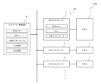
図1は、第1実施形態に係るロボット管理システムを示す斜視図である。図2は、図1に示すロボット管理システムの機能ブロック図である。図3は、図2に示すロボット管理システムの機能を実現するハードウェア構成の一例を示す概念図である。 FIG. 1 is a perspective view showing a robot management system according to a first embodiment. FIG. 2 is a functional block diagram of the robot management system shown in FIG. 1. FIG. 3 is a conceptual diagram showing an example of a hardware configuration that realizes the functions of the robot management system shown in FIG. 2.
なお、本明細書において、「接続」とは、直接的に接続されている場合と、任意の部材を介して間接的に接続されている場合の双方を含む。 Note that in this specification, "connection" includes both a direct connection and an indirect connection via an arbitrary member.
1.1 ロボット管理システム
図1に示すロボット管理システム100は、ロボット1の駆動を制御するロボットコントローラー5と、ロボットコントローラー5を管理するコントローラー管理装置6と、を有している。
1.1 Robot Management System The
このようなロボット管理システム100は、ロボット1と接続されることにより、マニピュレーターであるロボット1の駆動を制御する。これにより、ロボット1は様々な作業、例えば作業対象物の保持、搬送および組立て等の作業を行うことができる。
The
図1に示すロボットシステム1000は、このようなロボット管理システム100と、ロボット管理システム100に接続された少なくとも1つのロボット1と、で構成されている。図1に示すロボット管理システム100は、複数のロボットコントローラー5を有しており、これらが1つのコントローラー管理装置6に接続されている。また、ロボットコントローラー5には、それぞれロボット1が接続されている。
The
これらの各部は、有線または無線により通信可能とされ、その通信は、インターネットのようなネットワークを介してなされてもよい。 Each of these units is capable of communicating by wire or wirelessly, and the communication may be performed via a network such as the Internet.
図2に示すように、本実施形態に係るロボットコントローラー5は、ロボット1を制御するロボット制御部52と、ロボット1を制御するプログラムを保存するプログラム保存部53と、プログラムのバックアップデータを生成するバックアップ生成部55と、を備えている。
As shown in FIG. 2, the
さらに、本実施形態に係るコントローラー管理装置6は、バックアップ生成部55がバックアップデータを生成した生成時刻を取得する時刻取得部62と、生成時刻と現在の時刻との差が第1所定値以上であるとき、その旨やバックアップ処理の実行を促す旨の報知内容を表示部67に表示させる表示制御部66と、を備えている。
Furthermore, the
このようなロボット管理システム100によれば、バックアップデータが生成された生成時刻と現在の時刻との差に基づいて、バックアップデータの生成から所定の時間が経過している場合に、その旨をユーザーに知らせる表示を行うことができる。これにより、バックアップ処理の頻度が低下するのを防止して、有効なバックアップデータの生成、保存が可能になる。その結果、プログラムが消失するといった不具合に対し、適切な状態への復旧作業を容易に行うことができる。
According to such a
以下、ロボット管理システム100の各部について詳述する。
1.1.1 ロボット
図1に示すロボット1は、いわゆる6軸の垂直多関節ロボットであり、基台110と、基台110に接続されたロボットアーム10と、を有する。
Each part of the
1.1.1 Robot The
基台110は、ロボット1を任意の設置箇所に取り付ける部分である。換言すれば、基台110は、設置箇所とロボットアーム10とを接続している。
The
図1に示すように、ロボットアーム10は、アーム11、アーム12、アーム13、アーム14、アーム15、およびアーム16を有する。これらアーム11~16は、基端側、すなわち基台110側から、先端側、すなわち基台110とは反対側、に向かってこの順に連結されている。各アーム11~16は、隣り合うアームまたは基台110に対して回動可能になっている。例えば、アーム16は、図1に示すように円盤状をなし、アーム15に対して回動可能になっている。
As shown in FIG. 1, the
このようなロボットアーム10の先端には、図1に示すように、作業対象物を把持する把持ハンド17が接続されている。なお、把持ハンド17は、交換可能であり、把持ハンド17に代えて、吸着ハンド、磁気ハンド、ねじ止めツール、係合ツール等が用いられてもよい。
As shown in FIG. 1, a gripping
ロボット1は、一方のアームを他方のアームまたは基台110に対して回動させる図示しないモーターと、図示しない減速機と、を備える駆動部を有する。また、ロボット1は、モーターまたは減速機の回転軸の回転角度を検出する図示しない位置センサーを有する。駆動部および位置センサーは、例えば基台110および各アーム11~16に設けられており、各アーム11~16を互いに独立して駆動可能にしている。なお、各駆動部および各位置センサーは、それぞれロボットコントローラー5と電気的に接続されている。
The
ロボット1には、この他に任意の部材、機器等が設けられていてもよい。具体的には、作業対象物やロボット1またはその周辺を撮像する撮像部、ロボット1に加わる外力を検出する力センサーのような各種センサー等が挙げられる。
The
なお、ロボット1のアームの数は、1~5本または7本以上であってもよい。また、ロボット1は、スカラロボットであってもよく、2つまたはそれ以上のロボットアーム10を備える双腕ロボットであってもよい。
Note that the number of arms of the
1.1.2 ロボットコントローラー
図2に示すロボットコントローラー5は、ロボット1の駆動を制御する機能を有し、対応するロボット1に対して、通信可能に接続されている。
1.1.2 Robot Controller The
図2に示すロボットコントローラー5は、通信部51と、ロボット制御部52と、プログラム保存部53と、バックアップ管理部54と、バックアップ生成部55と、バックアップ保存部56と、時刻取得部57と、イベント処理部58と、を備えている。これらの各部は、相互に通信可能に接続されている。
The
このようなロボットコントローラー5の機能は、例えば図3に示すハードウェア構成によって実現可能である。
Such functions of the
図3に示すロボットコントローラー5は、互いに通信可能に接続されたプロセッサー、メモリーおよび外部インターフェースを備えている。
The
このうち、図3に示すプロセッサーとしては、例えばCPU(Central Processing Unit)等が挙げられる。 Among these, examples of the processor shown in FIG. 3 include a CPU (Central Processing Unit).
また、図3に示すメモリーとしては、例えばRAM(Random Access Memory)等の揮発性メモリーや、ROM(Read Only Memory)等の不揮発性メモリー等が挙げられる。なお、メモリーは、非着脱式に限らず、着脱式の外部記憶装置であってもよい。 Furthermore, examples of the memory shown in FIG. 3 include volatile memories such as RAM (Random Access Memory), non-volatile memories such as ROM (Read Only Memory), and the like. Note that the memory is not limited to a non-removable type, and may be a removable external storage device.
さらに、図3に示す外部インターフェースとしては、各種の通信用コネクターが挙げられる。一例として、USB(Universal Serial Bus)コネクター、RS-232Cコネクター、有線LAN(Local Area Network)等が挙げられる。また、外部インターフェースは、無線LANのような無線通信を可能とする送受信機であってもよい。 Furthermore, the external interface shown in FIG. 3 includes various communication connectors. Examples include a USB (Universal Serial Bus) connector, an RS-232C connector, and a wired LAN (Local Area Network). Further, the external interface may be a transceiver that enables wireless communication such as a wireless LAN.
また、ロボットコントローラー5は、前述した構成要素に加えて、さらに他のハードウェア構成要素を備えていてもよい。
Furthermore, the
次に、図2に示すロボットコントローラー5の各部について説明する。
通信部51は、ロボットコントローラー5とこれに対応するロボット1との通信、および、ロボットコントローラー5とコントローラー管理装置6との通信を行う。
Next, each part of the
The
ロボット制御部52は、プログラム保存部53に保存された各種プログラム等を実行する。これにより、ロボット1の駆動の制御、各種演算、各種判断等の処理が実現される。一例として、前述した駆動部の駆動を制御することにより、ロボットアーム10および把持ハンド17を駆動し、作業対象物を把持し、搬送、組立て等を行う。
The
プログラム保存部53は、ロボット制御部52が実行するプログラムを保存する。プログラムは、作業内容ごとに用意され、随時更新可能な状態で保存される。また、プログラム保存部53は、プログラム以外のデータを保存するようになっていてもよい。プログラム以外のデータとしては、例えば、ロボットコントローラー5の設定情報、ロボット1のエラー発生履歴、ロボットコントローラー5のエラー発生履歴等が挙げられる。
The
バックアップ管理部54は、バックアップ生成部55によるバックアップ処理を管理する。具体的には、バックアップ生成部55がバックアップデータを生成した際、その生成時刻をバックアップデータに関連付けてバックアップ保存部56に保存する。後述するコントローラー管理装置6は、この生成時刻を含む情報を、ロボットコントローラー5からの通知として収集し、バックアップ処理を管理する。なお、この通知は、バックアップ管理部54からコントローラー管理装置6に向けて出力されてもよい。
The
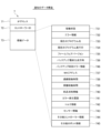
図4は、コントローラー管理装置6が取得する通知7の内容の一例を示す概念図である。図5は、バックアップデータ8の内容の一例を示す概念図である。
FIG. 4 is a conceptual diagram showing an example of the contents of the
コントローラー管理装置6が受信する通知7は、通信規格に応じた様々な形式のデータ構造を有していてもよいが、図4では、IPアドレスが付与された通信用のパケットまたはフレームの例を図示している。
The
図4に示す通知7は、IPアドレス71と、コントローラーID72と、情報データ73と、を含んでいる。
The
IPは、Internet Protocolである。IPアドレス71は、例えば通知7の送信元のアドレスと送信先のアドレスの双方を含む。コントローラーID72は、通知7の送信元のロボットコントローラー5に固有なID(識別番号)を含む。情報データ73は、ロボット1やロボットコントローラー5に関する各種の情報を含む。
IP is Internet Protocol. The
図4には、情報データ73の内容の一例を示している。図4に示す情報データ73には、ロボット1やロボットコントローラー5の稼働状態731、ロボット1やロボットコントローラー5のエラー情報732、ロボット制御部52が現在実行しているプログラム名733、ロボット制御部52が現在実行しているプログラム実行行734、ロボットコントローラー5を制御するファームウェアのバージョン情報735、バックアップ生成部55によるバックアップデータ8の最終生成日時736、通信部51のMAC(Media Access Control)アドレス737、ロボット1やロボットコントローラー5の連続稼働時間738、ロボット1やロボットコントローラー5の累積稼働時間739、ロボット1の部品消耗情報740、ロボット1やロボットコントローラー5のエラー発生履歴741、ロボット1のトルク情報742、および、ロボット1のセンサー情報743が含まれている。
FIG. 4 shows an example of the contents of the
このうち、稼働状態731は、例えばロボット1やロボットコントローラー5に複数の動作モードがある場合、いずれのモードで稼働しているのかを表す情報である。例えば、動作中、停止中、一時停止、非常停止などの情報である。
Of these, the operating
また、ロボット1のトルク情報742とは、例えばロボット1の駆動部のモーターに流れる電流値である。
Further, the
さらに、ロボット1のセンサー情報743とは、例えばロボット1またはロボットコントローラー5が備える図示しない位置センサー、力センサー、感圧センサー、近接センサー、温度センサー、振動センサー等の各種センサーから受信したデータである。
Further, the
また、情報データ73には、それ以外の情報として、その他コントローラー情報744、その他ロボット情報745等が含まれていてもよい。
Further, the
なお、通知7には、これら以外の情報が含まれていてもよい。また、前述した通知7の構成要素の一部が省略されていてもよい。
Note that the
バックアップ生成部55は、後述するイベント処理部58から出力されるコマンドに基づいて、プログラム保存部53に保存されているプログラムや各種データのバックアップデータ8を生成する。バックアップデータ8は、その時点におけるプログラムや各種データを復元可能な内容を含む。生成したバックアップデータ8は、バックアップ保存部56に保存される。
The
図5に示すバックアップデータ8は、構成要素として、コントローラー状態81と、ロボット状態82と、ロボット制御プログラム83と、ロボット制御用ポイントデータ84と、エラー発生履歴85と、設定情報86と、センサーデータ情報87と、その他情報88と、を含んでいる。
The backup data 8 shown in FIG. 5 includes a
このうち、コントローラー状態81は、例えば、ロボットコントローラー5が稼働している際の、RAM等のメモリーに記憶されているデータ、ファームウェアのバージョン情報、エラー情報、ワーニング情報、外部との接続状態を示す情報等を含む。
Among these, the
また、ロボット状態82は、例えば、ロボット1のトルク情報、センサー情報等を含む。
Further, the
さらに、ロボット制御プログラム83は、例えば、プログラム保存部53に保存されているプログラムの他、プログラムの実行状態を示す情報、例えばプロジェクト名、実行行番号、変数値等を含む。なお、ロボット制御プログラム83は、プログラムソースコードであってもよいし、コンパイル後の機械語であってもよい。
Furthermore, the
また、ロボット制御用ポイントデータ84は、例えば、ロボット1の動作を教示する位置情報を含む。
Further, the robot
さらに、エラー発生履歴85は、例えば、ロボット1やロボットコントローラー5におけるエラーの発生履歴である。また、エラー発生履歴85は、少なくとも、発生日時と、エラーコードのようなエラー内容と、を含み、そのデータ形式は、例えば要素データを配列したテキスト形式とされる。
Further, the
また、設定情報86は、例えば、ロボットコントローラー5の各種設定に関する設定値を含む。
Further, the setting
さらに、センサーデータ情報87は、例えば、各種センサーから受信したデータであり、好ましくはバイナリー形式で表現された各種センサーからのサンプリングデータとされる。これらのデータをバックアップデータ8に含むことにより、事後に動作解析を行う機会が失われるのを防止することができる。
Further, the
また、その他情報88としては、例えば、バックアップデータ8を生成するようにイベント処理部58が指令を出力する際、そのトリガーの内容等が挙げられる。
Further, the
なお、バックアップデータ8のデータ形式は、特に限定されないが、例えば、CSV(Comma Separated Value)形式、XML(Extensible Markup Language)形式、JSON(JavaScript(登録商標) Object Notation)形式等が挙げられる。 Note that the data format of the backup data 8 is not particularly limited, and examples thereof include a CSV (Comma Separated Value) format, an XML (Extensible Markup Language) format, a JSON (JavaScript (registered trademark) Object Notation) format, and the like.
また、バックアップデータ8のファイル形式は、前述した各構成要素が個別のファイルとして存在しているファイル集合体の形式であってもよく、1つのファイルにパッケージされた形式であってもよい。 Further, the file format of the backup data 8 may be a file collection format in which each component described above exists as an individual file, or may be a format in which the components are packaged into one file.
なお、前述したバックアップデータ8は、構成要素の一部が省略されていてもよく、別の構成要素を追加で含んでいてもよい。 Note that the backup data 8 described above may omit some of the constituent elements or may additionally include other constituent elements.
バックアップ保存部56は、バックアップ生成部55により生成されたバックアップデータ8を保存する。なお、バックアップ保存部56は、ロボットコントローラー5以外の場所、例えば、コントローラー管理装置6、図示しないデータサーバー等であってもよい。また、バックアップデータ8は、プログラム等を復旧可能であれば、プログラムの一部のみ、および、プログラム以外の情報の一部のみ、が含まれたデータであってもよい。さらに、バックアップデータ8は、生成時刻ごとに保存され、任意の生成時刻のデータを読み出し可能な状態で保存されていてもよい。
The
時刻取得部57は、バックアップデータ8が生成された日時を取得する。この日時は、例えばロボットコントローラー5またはコントローラー管理装置6が備える内部時計から取得した日時であってもよいし、インターネットを介して時刻サーバーから取得した日時であってもよい。また、取得する時刻は、コントローラー管理装置6やロボットコントローラー5に適用される独自の時刻であってもよい。つまり、日、時、分、秒、で表現される一般的な時刻である必要はなく、任意の時点から任意の間隔で計時される時刻であってもよい。取得した日時は、バックアップ管理部54により、バックアップデータ8に関連付けられる。
The
イベント処理部58は、バックアップ生成部55に向けてバックアップ生成情報を出力する。このバックアップ生成情報は、バックアップ処理を実行するトリガーであり、例えば、イベント処理部58が、ロボットコントローラー5の内部におけるイベント、または、ロボットコントローラー5の外部におけるイベントを収集し、それらに基づいて出力される。
The
具体的には、ロボットコントローラー5の内部におけるイベント(事象)としては、例えば、所定の時間間隔で定期的に発生するイベント、ロボット1の動作の停止または休止に伴うイベント、ロボット1またはロボットコントローラー5におけるエラーまたはワーニングの発生に伴うイベント、プログラムの変数値が一定の条件を満たしたとき、具体例として正常値を逸脱したときに発生するイベント、ロボットコントローラー5に外部記憶装置を接続したことに伴うイベント、ロボットコントローラー5に接続された操作ボタンまたは操作パネル等のユーザーインターフェースを操作したことに伴うイベント、ロボット制御プログラム83またはロボット制御用ポイントデータ84が更新されたことに伴うイベント等が挙げられる。
Specifically, events within the
また、ロボットコントローラー5の外部におけるイベントとしては、例えば、コントローラー管理装置6から出力された、バックアップ処理を実行する指令が挙げられる。
Furthermore, an example of an event outside the
1.1.3 コントローラー管理装置
図2に示すコントローラー管理装置6は、複数のロボットコントローラー5と接続され、これらを一括して管理する。なお、コントローラー管理装置6は、1つのロボットコントローラー5に接続されていてもよい。
1.1.3 Controller Management Device The
図2に示すコントローラー管理装置6は、通信部61と、時刻取得部62と、データ取得部63と、エラー判定部64と、保存部65と、表示制御部66と、表示部67と、受付部68と、を備えている。これらの各部は、相互に通信可能に接続されている。
The
このようなコントローラー管理装置6の機能は、例えば図3に示すハードウェア構成によって実現可能である。
Such functions of the
図3に示すコントローラー管理装置6は、互いに通信可能に接続されたプロセッサー、メモリー、外部インターフェース、入力装置、および出力装置を備えている。
The
このうち、図3に示すプロセッサーとしては、例えばCPU(Central Processing Unit)等が挙げられる。 Among these, examples of the processor shown in FIG. 3 include a CPU (Central Processing Unit).
また、図3に示すメモリーとしては、例えばRAM(Random Access Memory)等の揮発性メモリーや、ROM(Read Only Memory)等の不揮発性メモリー等が挙げられる。なお、メモリーは、非着脱式に限らず、着脱式の外部記憶装置であってもよい。 Furthermore, examples of the memory shown in FIG. 3 include volatile memories such as RAM (Random Access Memory), non-volatile memories such as ROM (Read Only Memory), and the like. Note that the memory is not limited to a non-removable type, and may be a removable external storage device.
さらに、図3に示す外部インターフェースとしては、各種の通信用コネクターが挙げられる。一例として、USB(Universal Serial Bus)コネクター、RS-232Cコネクター、有線LAN(Local Area Network)等が挙げられる。また、外部インターフェースは、無線LANのような無線通信を可能とする送受信機であってもよい。 Furthermore, the external interface shown in FIG. 3 includes various communication connectors. Examples include a USB (Universal Serial Bus) connector, an RS-232C connector, and a wired LAN (Local Area Network). Further, the external interface may be a transceiver that enables wireless communication such as a wireless LAN.
また、図3に示す入力装置としては、例えば、キーボード、タッチパネル等が挙げられ、出力装置としては、例えば、モニター等が挙げられる。 Further, examples of the input device shown in FIG. 3 include a keyboard, a touch panel, etc., and examples of the output device include a monitor.
なお、ロボットコントローラー5は、前述した構成要素に加えて、さらに他のハードウェア構成要素を備えていてもよい。
Note that the
次に、図2に示すコントローラー管理装置6の各部について説明する。
通信部61は、コントローラー管理装置6と各ロボットコントローラー5との通信を行う。
Next, each part of the
The
時刻取得部62は、現在の時刻を取得する。この時刻は、例えばコントローラー管理装置6が備える内部時計から取得した日時であってもよいし、インターネットを介して時刻サーバーから取得した日時であってもよい。また、取得する時刻は、コントローラー管理装置6やロボットコントローラー5に適用される独自の時刻であってもよい。つまり、日、時、分、秒、で表現される一般的な時刻である必要はなく、任意の時点から任意の間隔で計時される時刻であってもよい。
The
データ取得部63は、ロボットコントローラー5から定期的に図4に示す通知7等のデータを取得する。通知7は、それ全体がバックアップ保存部56に保存されているものでもよいし、その内容が個別に異なる場所に保存されていて、それらをデータ取得部63が収集してなるものでもよい。取得したデータは、保存部65に保存する。なお、コントローラー管理装置6が複数のロボットコントローラー5に接続されている場合には、通知7に含まれるコントローラーID72等に基づいて、各通知7と各ロボットコントローラー5とを関連付けた状態で保存する。
The
エラー判定部64は、保存部65に保存されている通知7を読み出す。そして、通知7に含まれているバックアップデータ8の最終生成日時736と、時刻取得部62が取得した現在の日時と、を比較する。そして、これらの差が第1所定値以上であるときには、バックアップ時刻エラー情報を生成する。このバックアップ時刻エラー情報は、表示制御部66に出力される。
The
保存部65は、データ取得部63が収集したデータ、受付部68が受け付けたデータ、最終生成日時736と現在の時刻との差に関してあらかじめ規定された第1所定値等を保存する。
The
表示制御部66は、エラー判定部64が生成したバックアップ時刻エラー情報に基づいて、任意の報知内容を表示部67に表示させる。
The
表示部67は、表示制御部66からの信号に基づき、任意の報知内容を表示する。
受付部68は、エラー判定部64がバックアップ時刻エラー情報を生成する際に用いる第1所定値等を外部から受け付ける。受け付けた第1所定値は、保存部65に保存する。
The
The
1.2 ロボット管理システムの制御方法
次に、ロボット管理システム100の制御方法について説明する。
1.2 Control method of robot management system Next, a control method of
図6は、第1実施形態に係るロボット管理システムの制御方法を示すフローチャートである。 FIG. 6 is a flowchart showing a control method of the robot management system according to the first embodiment.
図6に示すステップS1では、イベント処理部58がバックアップ生成情報を生成し、バックアップ生成部55に出力する。バックアップ生成情報を受けたバックアップ生成部55は、バックアップデータ8を生成し、バックアップ保存部56に保存する。また、バックアップデータ8が生成された日時を時刻取得部57が取得し、バックアップ保存部56に保存する。
In step S1 shown in FIG. 6, the
なお、バックアップ生成部55は、好ましくはロボット1の動作が停止しているとき、バックアップデータ8を生成するのが好ましい。このようなタイミングでバックアップデータ8を生成することにより、バックアップデータ8にプログラムやその他の情報を含める際、変化が少ない状態で取得した情報を含めることができる。これにより、バックアップデータ8の有効性をより高めることができる。ただし、バックアップデータ8の生成は、ロボット1の動作が停止しているときに限られるものではない。
Note that the
図6に示すステップS2では、コントローラー管理装置6がバックアップ保存部56に保存されている通知7を取得する。通知7は、前述したように、バックアップデータ8の最終作成日時を含むことから、コントローラー管理装置6によってバックアップデータ8の生成時刻が取得される。
In step S2 shown in FIG. 6, the
図6に示すステップS3では、コントローラー管理装置6の時刻取得部62が現在の時刻を取得する。
In step S3 shown in FIG. 6, the
図6に示すステップS4では、コントローラー管理装置6のエラー判定部64が、バックアップデータ8の生成時刻と現在の時刻とを比較する。そして、生成時刻と現在の時刻との差が第1所定値以上であるか否かを判断する。
In step S4 shown in FIG. 6, the
差が第1所定値以上であった場合には、ステップS5に移行する。ステップS5では、表示制御部66により、表示部67に報知内容を表示させる。報知内容としては、例えば、生成時刻と現在の時刻との差が第1所定値以上になった事実、バックアップデータ8の更新の案内等が挙げられる。このような表示を行うことにより、ユーザーにバックアップデータ8の更新操作を促すことができる。これにより、有効なバックアップデータ8を確保することができ、プログラム等が消失した場合でも、有効な状態、つまり、プログラム等が消失する前の正常な状態に復旧させることができる。その結果、ロボット1のダウンタイムを最小限に留めることができる。
If the difference is greater than or equal to the first predetermined value, the process moves to step S5. In step S5, the
一方、差が第1所定値未満であった場合には、保存されているバックアップデータ8が比較的新しく、直ちに更新する必要がないとみなすことができる。このため、ステップS3に戻る。 On the other hand, if the difference is less than the first predetermined value, it can be considered that the stored backup data 8 is relatively new and does not need to be updated immediately. Therefore, the process returns to step S3.
なお、表示部67には、複数のロボットコントローラー5について、バックアップデータ8の最終生成日時が一覧表示されているのが好ましい。これにより、複数のロボットコントローラー5を一括して管理することができるので、管理の効率を高めることができる。
Note that it is preferable that the
また、その場合、報知内容としては、例えば、第1所定値以上になっているバックアップデータ8の最終生成日時の表示色を変更する、文字を反転表示させる、文字を点滅させる、文字フォントを変更する、といった内容であってもよい。 In that case, the notification contents include, for example, changing the display color of the last generation date and time of the backup data 8 whose value is equal to or higher than the first predetermined value, displaying the characters in reverse, flashing the characters, and changing the character font. The content may be such as "to do".
また、この第1所定値は、バックアップデータ8の更新を促す頻度を左右する。したがって、バックアップデータ8をできるだけ最新の状態に維持するためには、第1所定値をできるだけ短くすればよい。一方、第1所定値が短すぎる場合には、バックアップデータ8の更新の頻度が多くなりすぎて、手間がかかる。このため、第1所定値を適宜設定することにより、バックアップデータ8の更新の頻度を最適化することができる。 Further, this first predetermined value influences the frequency with which updating of the backup data 8 is prompted. Therefore, in order to keep the backup data 8 as up-to-date as possible, the first predetermined value may be made as short as possible. On the other hand, if the first predetermined value is too short, the backup data 8 will be updated too frequently, which will take time and effort. Therefore, by appropriately setting the first predetermined value, the frequency of updating the backup data 8 can be optimized.
具体的な第1所定値は、状況に応じて異なるため、一概には言えないが、好ましくは1時間以上10日以下程度とされ、より好ましくは3時間以上3日以下程度とされる。これにより、ロボット管理システム100の負荷を抑えつつ、有効な状態のバックアップデータ8を確保することができる。
The specific first predetermined value varies depending on the situation, so it cannot be generalized, but it is preferably about 1 hour or more and about 10 days or less, and more preferably about 3 hours or more and about 3 days or less. Thereby, it is possible to secure backup data 8 in a valid state while suppressing the load on the
よって、第1所定値は、目的とするバックアップデータ8の更新の頻度に応じて、ユーザーが設定可能になっているのが好ましい。したがって、本実施形態に係る管理装置であるコントローラー管理装置6は、前述したように、第1所定値を外部から受け付ける受付部68を備えている。これにより、ユーザーが第1所定値を任意に設定することができる。
Therefore, it is preferable that the first predetermined value can be set by the user depending on the frequency of update of the target backup data 8. Therefore, the
なお、ステップS2において、コントローラー管理装置6は、通知7を定期的に取得するのが好ましい。これにより、バックアップデータ8の生成時刻についても定期的に取得することができる。そして、バックアップデータ8の更新が必要か否かを頻繁に確認することができる。このため、確認の頻度が下がることに伴うバックアップデータ8の有効性の低下を防止することができる。
Note that, in step S2, it is preferable that the
通知7を取得する頻度としては、例えば、30分間に1回以上であるのが好ましく、5分に1回以上であるのがより好ましく、1分に1回以上であるのがさらに好ましい。このような頻度で通知7を取得することにより、バックアップデータ8の更新頻度が高くなるので、バックアップデータ8の有効性を特に高めることができる。
The frequency of acquiring the
また、コントローラー管理装置6の取得部であるデータ取得部63は、通知7として、バックアップデータ8の最終生成日時に加え、その他の情報を取得してもよい。例えば、データ取得部63は、前述したように、少なくとも、ロボット1の連続稼働時間738、ロボット1の累積稼働時間739、ロボット1の部品消耗情報740、ロボット1のエラー発生履歴741、ロボット1のトルク情報742、およびロボット1のセンサー情報743のうちの少なくとも1つの情報を取得する機能を有していてもよい。そして、コントローラー管理装置6は、データ取得部63により取得されたこれらの情報に基づいて、バックアップ生成部55がバックアップデータ8を生成する時期を変更する機能を有していてもよい。
Further, the
時期の変更パターンとしては、特に限定されないが、例えば、バックアップデータ8の生成が予定されていたタイミングを早めるように変更するパターンが挙げられる。データ取得部63がこのような機能を有することにより、通知7に含まれている情報に基づいて、ロボットコントローラー5の設定が大きく変わったこと、または、近い将来にロボット1に不具合が起きる確率が高くなること等を、コントローラー管理装置6において予測することが可能になる。これらが起きると、ロボットコントローラー5に保存されている各種情報が大きく変化するため、その後のロボットコントローラー5の安定稼働を考慮すると、できるだけ早期にバックアップ処理を実行することが望まれる。
The timing change pattern is not particularly limited, but includes, for example, a pattern in which the timing at which the backup data 8 was scheduled to be generated is changed earlier. Since the
そこで、本実施形態では、これらの情報に基づいて、例えばバックアップデータ8を生成する時期を早める、つまり、第1所定値を短縮させることができる。これにより、ロボットコントローラー5においてバックアップが必要な状況を早期に見出し、プログラムの消失等の問題が生じる前にバックアップ処理を実行するように、ユーザーに対して促すことができる。
Therefore, in the present embodiment, based on this information, for example, the time to generate the backup data 8 can be brought forward, that is, the first predetermined value can be shortened. As a result, a situation in which backup is required in the
なお、バックアップデータ8の生成時期を早めるのは、変更パターンの一例であり、生成時期を遅らせるようにしてもよい。 Note that advancing the generation time of the backup data 8 is an example of a change pattern, and the generation time may be delayed.
さらに、本実施形態に係る管理装置であるコントローラー管理装置6は、これらの情報の具体的な変化に基づいて、バックアップデータ8の生成時期を変更する、つまり、前述した第1所定値を変更するようにしてもよい。
Further, the
一例として、データ取得部63が、ある第1時刻、および第1時刻より後の第2時刻に、それぞれ前述した各種の情報を取得する機能を有しているものとする。この場合、コントローラー管理装置6は、第1時刻に取得された情報と、第2時刻に取得された情報と、を比較し、情報の変化量が第2所定値以上であるとき、バックアップ生成部55がバックアップデータ8を生成する時期を変更させる。具体的には、第1所定値を短縮させることにより、結果的に、イベント処理部58に対し、バックアップ処理を早期に実行する指令を出力する。このような機能により、バックアップが必要な状況を、より早期に、かつ、より確実に見出すことができる。その結果、プログラムの消失等の問題が生じる前に、さらに確実にバックアップ処理が実行されるように、ユーザーに対して促すことができる。
As an example, it is assumed that the
なお、第2所定値は、例えばロボットコントローラー5の作動が不安定になる場合の前述した情報の実績値、あるいは、メンテナンスが必要になる条件等に基づいて適宜設定される。例えば、ロボット1の連続稼働時間738がある時間以上になると、ロボットコントローラー5の挙動が不安定になるという実績があった場合には、その時間を第2所定値として設定すればよい。また、ロボット1の部品の摩耗量に伴う交換条件が決まっている場合には、必然的にメンテナンス作業が伴うことから、その交換条件を第2所定値として設定してもよい。
Note that the second predetermined value is appropriately set based on, for example, the actual value of the above-mentioned information when the operation of the
以上のようにして、ステップS5では表示部67に報知内容を表示させるが、さらに、ステップS5の後、バックアップデータ8の更新作業に移行するようにしてもよい。その場合、コントローラー管理装置6は、表示部67に表示されているバックアップデータ8の最終生成日時736が選択操作されることによって、容易な移行を支援できるようになっていてもよい。例えば、最終生成日時736が表示されている表示部67において、入力装置のカーソルを最終生成日時736に合わせ、クリック操作することにより、更新作業の操作画面に移行するようになっていてもよい。これにより、直感的に移行することができるので、バックアップデータ8の更新作業をより容易に行うことができる。
As described above, the notification content is displayed on the
なお、その場合には、ロボットコントローラー5のイベント処理部58における設定により、即座にバックアップデータ8の更新を行うのではなく、ロボット1の動作の停止または休止に伴うイベントの通知を待ってから行うように設定しておくのが好ましい。
In this case, depending on the settings in the
また、かかる観点から、表示部67には、前述したような報知内容に加えて、バックアップデータ8の生成に要する時間が表示されるようになっていてもよい。つまり、バックアップデータ8を生成している最中は、ロボット1の動作を停止していることが望ましいので、生成に要する時間を表示させることによって、ユーザーが、バックアップデータ8の更新作業に移行するタイミングを図りやすくなる。これにより、ロボット1のダウンタイムを最小限に留めることができる。
Further, from this point of view, the
さらに、バックアップ生成部55がバックアップデータ8を生成する際には、ロボット1の動作が停止する合間に生成するようにしてもよいが、ロボット制御部52に対し、ロボット1の動作を停止させる停止指示情報を出力するようにしてもよい。これにより、任意のタイミングでロボット1の動作を停止させることができ、バックアップデータ8を生成しやすくなる。
Furthermore, when the
なお、この場合、ロボット1の動作の停止は、バックアップデータ8の生成に付随して自動的に行うことになるが、ロボット1の動作の停止をユーザーが指示するようにしてもよい。すなわち、本実施形態に係るコントローラー管理装置6には、バックアップデータ8の更新作業をユーザーが行い、ロボット1の動作の停止もユーザーが行う「マニュアルモード」と、更新作業をユーザーが行い、ロボット1の動作の停止は自動で行う「セミオートモード」の2つの操作モードが設けられていてもよい。
In this case, the operation of the
以上のように、本実施形態に係るロボット管理システム100の制御方法は、ロボット1を制御する制御装置であるロボットコントローラー5と、ロボットコントローラー5と接続され、ロボットコントローラー5を管理する管理装置であるコントローラー管理装置6と、を有するロボット管理システム100を制御する方法であって、ロボットコントローラー5が、ロボット1を制御するプログラムのバックアップデータ8を生成するステップS1と、コントローラー管理装置6が、バックアップデータ8を生成した生成時刻をロボットコントローラー5から取得するステップS2と、生成時刻と現在の時刻との差が第1所定値以上であるとき、コントローラー管理装置6が、報知内容を表示部67に表示させるステップS5と、を有する。
As described above, the control method of the
このような制御方法によれば、表示部67において、例えばバックアップデータ8の更新が必要である旨、表示して、ユーザーに知らせることができる。これにより、ユーザーによるバックアップデータ8の更新操作を促し、バックアップデータ8の更新を促すことができる。つまり、ロボットコントローラー5の復旧に有効なバックアップデータ8を生成するタイミングをユーザーに知らせ、生成を支援する。その結果、有効なバックアップデータ8を生成することができ、ロボットコントローラー5においてプログラム等が消失した場合でも、有効な状態への復旧が容易になる。
According to such a control method, it is possible to display on the
また、本実施形態に係るロボット管理システム100は、ロボット1を制御するロボット制御部52と、ロボット1を制御するプログラムを保存するプログラム保存部53と、プログラムのバックアップデータ8を生成するバックアップ生成部55と、を備える制御装置であるロボットコントローラー5と、ロボットコントローラー5と接続され、ロボットコントローラー5を管理する管理装置であるコントローラー管理装置6と、を有している。そして、コントローラー管理装置6は、バックアップ生成部55がバックアップデータ8を生成した生成時刻を取得する取得部であるデータ取得部63と、生成時刻と現在の時刻との差が第1所定値以上であるとき、報知内容を表示部67に表示させる表示制御部66と、を備える。
The
このようなロボット管理システム100によれば、有効なバックアップデータ8を生成することができ、ロボットコントローラー5においてプログラム等が消失した場合でも、有効な状態への復旧が容易になる。
According to such a
また、各ロボットコントローラー5からの通知7に基づいてコントローラー管理装置6側でバックアップ処理の必要の有無を判定することにより、例えばロボットコントローラー5ごとに第1所定値を変更することも容易であるため、設定自由度の高いロボット管理システム100を実現することができる。
Furthermore, it is easy to change the first predetermined value for each
2.第2実施形態
次に、第2実施形態について説明する。
2. Second Embodiment Next, a second embodiment will be described.
図7は、第2実施形態に係るロボット管理システムを示す機能ブロック図である。図8は、第2実施形態に係るロボット管理システムの制御方法を示すフローチャートである。 FIG. 7 is a functional block diagram showing a robot management system according to the second embodiment. FIG. 8 is a flowchart showing a control method for the robot management system according to the second embodiment.
以下、第2実施形態について説明するが、以下の説明では、第1実施形態との相違点を中心に説明し、同様の事項についてはその説明を省略する。なお、図7および図8において、第1実施形態と同様の構成については、同一の符号を付している。 Hereinafter, the second embodiment will be described. In the following explanation, the differences from the first embodiment will be mainly explained, and the explanation of similar matters will be omitted. Note that in FIGS. 7 and 8, the same components as in the first embodiment are designated by the same reference numerals.
前述した第1実施形態では、表示部67に報知内容を表示させることにより、ユーザーにバックアップデータ8の更新作業を促すようにしているが、本実施形態では、コントローラー管理装置6からの指令に基づいて、バックアップデータ8の更新作業を行う。
In the first embodiment described above, the user is prompted to update the backup data 8 by displaying the notification content on the
具体的には、図7に示すコントローラー管理装置6は、バックアップ指令部69を備えている。バックアップ指令部69は、エラー判定部64で生成されたバックアップ時刻エラー情報に基づいて、該当するロボットコントローラー5にバックアップ指令を出力する。このバックアップ指令は、ロボットコントローラー5に固有なID、バックアップ処理の実行命令等を含むデータであり、該当するロボットコントローラー5のイベント処理部58において処理される。イベント処理部58では、バックアップ指令の内容に基づいて、バックアップデータ8を生成させるためのバックアップ生成情報をバックアップ生成部55に出力する。そして、バックアップ生成部55により新たなバックアップデータ8が生成される。
Specifically, the
以上のように、ロボット管理システム100は、ロボット1を制御するロボット制御部52と、ロボット1を制御するプログラムを保存するプログラム保存部53と、プログラムのバックアップデータ8を生成するバックアップ生成部55と、を備える制御装置であるロボットコントローラー5と、ロボットコントローラー5と接続され、ロボットコントローラー5を管理する管理装置であるコントローラー管理装置6と、を有している。そして、コントローラー管理装置6は、バックアップ生成部55がバックアップデータ8を生成した生成時刻を取得する取得部であるデータ取得部63と、生成時刻と現在の時刻との差が第1所定値以上であるとき、バックアップ生成部55に新たなバックアップデータ8の生成を実行させる実行部であるバックアップ指令部69を備える。
As described above, the
このようなロボット管理システム100によれば、有効なバックアップデータ8を生成することができ、ロボットコントローラー5においてプログラム等が消失した場合でも、有効な状態への復旧が容易になる。また、特に、エラー判定部64での判定の結果、バックアップ処理が必要であると判定された場合には、自動的にバックアップ処理を行わせることができるので、ユーザーの負担を減らすとともに、より確実なバックアップデータ8の生成が可能になる。
According to such a
次に、図8を参照しつつ、第2実施形態に係るロボット管理システム100の制御方法について説明する。
Next, a method of controlling the
まず、図8のステップS1からステップS4までは、第1実施形態と同様である。
図8に示すステップS5では、ステップS4における判定の結果、バックアップデータ8の生成時刻と現在の時刻との差が第1所定値以上であった場合、ステップS5に移行する。図8に示すステップS5では、コントローラー管理装置6のバックアップ指令部69が、ロボットコントローラー5のイベント処理部58にバックアップ指令を出力する。つまり、バックアップ生成部55によるバックアップデータ8の生成を実行させる。これにより、バックアップ生成部55によって新たなバックアップデータ8が生成される。
First, steps S1 to S4 in FIG. 8 are the same as in the first embodiment.
In step S5 shown in FIG. 8, if the difference between the generation time of the backup data 8 and the current time is equal to or greater than the first predetermined value as a result of the determination in step S4, the process moves to step S5. In step S5 shown in FIG. 8, the
以上のように、本実施形態に係るロボット管理システム100の制御方法は、ロボット1を制御する制御装置であるロボットコントローラー5と、ロボットコントローラー5と接続され、ロボットコントローラー5を管理する管理装置であるコントローラー管理装置6と、を有するロボット管理システム100を制御する方法であって、ロボットコントローラー5が、ロボット1を制御するプログラムのバックアップデータ8を生成するステップS1と、コントローラー管理装置6が、バックアップデータ8を生成した生成時刻をロボットコントローラー5から取得するステップS2と、生成時刻と現在の時刻との差が第1所定値以上であるとき、コントローラー管理装置6が、ロボットコントローラー5に新たなバックアップデータ8の生成を実行させるステップS5と、を有する。
As described above, the control method of the
このような制御方法によれば、有効なバックアップデータ8を自動的に生成することができ、ロボットコントローラー5においてプログラム等が消失した場合でも、有効な状態への復旧を容易かつ確実に行える。
According to such a control method, valid backup data 8 can be automatically generated, and even if a program or the like is lost in
さらに、バックアップ生成部55がバックアップデータ8を生成する際には、ロボット1の動作が停止する合間に生成するようにしてもよいが、ロボット制御部52に対し、ロボット1の動作を停止させる停止指示情報を出力するようにしてもよい。これにより、任意のタイミングでロボット1の動作を停止させることができ、バックアップデータ8を生成しやすくなる。
Furthermore, when the
なお、この場合、ロボット1の動作の停止は、バックアップデータ8の生成に付随して自動的に行うことになるが、ロボット1の動作の停止をユーザーが指示するようにしてもよい。すなわち、本実施形態に係るコントローラー管理装置6には、バックアップデータ8の更新作業を自動的に開始する一方、ロボット1の動作の停止はユーザーが行う「セミオートモード」と、更新作業を自動的に開始し、ロボット1の動作の停止も自動で行う「フルオートモード」の2つの操作モードが設けられていてもよい。
In this case, the operation of the
その他、以上のような第2実施形態においても、第1実施形態と同様の効果が得られる。 In addition, in the second embodiment as described above, the same effects as in the first embodiment can be obtained.
また、第2実施形態には、第1実施形態の構成が付加されていてもよい。すなわち、コントローラー管理装置6が新たなバックアップデータ8の生成を実行させる一方、表示部67に報知内容を表示させるようにしてもよい。
Further, the configuration of the first embodiment may be added to the second embodiment. That is, while the
3.第3実施形態
次に、第3実施形態について説明する。
3. Third Embodiment Next, a third embodiment will be described.
図9は、第3実施形態に係るロボット管理システムを示す機能ブロック図である。図10は、コントローラー管理装置6が取得する通知7の内容の一例を示す概念図である。
FIG. 9 is a functional block diagram showing a robot management system according to the third embodiment. FIG. 10 is a conceptual diagram showing an example of the contents of the
以下、第3実施形態について説明するが、以下の説明では、第2実施形態との相違点を中心に説明し、同様の事項についてはその説明を省略する。なお、図9において、第2実施形態と同様の構成については、同一の符号を付している。 The third embodiment will be described below. In the following description, differences from the second embodiment will be mainly explained, and descriptions of similar matters will be omitted. Note that in FIG. 9, the same components as in the second embodiment are designated by the same reference numerals.
前述した第2実施形態では、コントローラー管理装置6がエラー判定部64を備えているのに対し、本実施形態では、図9に示すように、ロボットコントローラー5がエラー判定部59を備えている。このため、第1実施形態では、各ロボットコントローラー5から出力された通知7に基づいて、コントローラー管理装置6のエラー判定部64がバックアップ処理の必要性を判定していたのに対し、本実施形態では、ロボットコントローラー5のエラー判定部59がこの機能を担っている。そして、ロボットコントローラー5からコントローラー管理装置6に出力する通知7は、図10に示すように、エラー判定部59における判定結果、すなわちバックアップ時刻エラー情報746を含んでいる。
In the second embodiment described above, the
そうすると、本実施形態に係るコントローラー管理装置6のバックアップ指令部69は、バックアップ時刻エラー情報746に基づいて、該当するロボットコントローラー5にバックアップ指令を出力する。このバックアップ指令は、該当するロボットコントローラー5のイベント処理部58において処理される。イベント処理部58では、バックアップ指令の内容に基づいて、バックアップデータ8を生成させるためのバックアップ生成情報をバックアップ生成部55に出力する。そして、バックアップ生成部55によりバックアップデータ8が生成される。
Then, the
その他、以上のような第3実施形態においても、第2実施形態と同様の効果が得られる。 In addition, the same effects as in the second embodiment can be obtained in the third embodiment as described above.
また、本実施形態では、コントローラー管理装置6に複数のロボットコントローラー5が接続されている場合、各ロボットコントローラー5がエラー判定部59を備えている。このため、エラー判定処理の輻輳が生じにくいことから、例えばバックアップデータ8の生成をより迅速に行うことができるといった利点もある。
Further, in this embodiment, when a plurality of
以上、本発明のロボット管理システムおよびロボット管理システムの制御方法を図示の実施形態に基づいて説明したが、本発明は、これに限定されるものではなく、各部の構成は、同様の機能を有する任意の構成のものに置換することができる。また、ロボット管理システムの前記実施形態には、それぞれ他の任意の構成物が付加されていてもよい。さらに、ロボット管理システムの制御方法の前記実施形態には、任意の目的の工程が付加されていてもよい。 Although the robot management system and the control method for the robot management system of the present invention have been described above based on the illustrated embodiments, the present invention is not limited thereto, and the configurations of each part have similar functions. It can be replaced with any configuration. Moreover, other arbitrary components may be added to each of the embodiments of the robot management system. Furthermore, the above-mentioned embodiment of the control method for a robot management system may include an arbitrary desired step.
1…ロボット、5…ロボットコントローラー、6…コントローラー管理装置、7…通知、8…バックアップデータ、10…ロボットアーム、11…アーム、12…アーム、13…アーム、14…アーム、15…アーム、16…アーム、17…把持ハンド、51…通信部、52…ロボット制御部、53…プログラム保存部、54…バックアップ管理部、55…バックアップ生成部、56…バックアップ保存部、57…時刻取得部、58…イベント処理部、59…エラー判定部、61…通信部、62…時刻取得部、63…データ取得部、64…エラー判定部、65…保存部、66…表示制御部、67…表示部、68…受付部、69…バックアップ指令部、71…IPアドレス、72…コントローラーID、73…情報データ、81…コントローラー状態、82…ロボット状態、83…ロボット制御プログラム、84…ロボット制御用ポイントデータ、85…エラー発生履歴、86…設定情報、87…センサーデータ情報、88…その他情報、100…ロボット管理システム、110…基台、731…稼働状態、732…エラー情報、733…プログラム名、734…プログラム実行行、735…ファームウェアバージョン、736…最終生成日時、737…MACアドレス、738…連続稼働時間、739…累積稼働時間、740…部品消耗情報、741…エラー発生履歴、742…トルク情報、743…センサー情報、744…その他コントローラー情報、745…その他ロボット情報、746…バックアップ時刻エラー情報、1000…ロボットシステム、S1…ステップ、S2…ステップ、S3…ステップ、S4…ステップ、S5…ステップ 1...Robot, 5...Robot controller, 6...Controller management device, 7...Notification, 8...Backup data, 10...Robot arm, 11...Arm, 12...Arm, 13...Arm, 14...Arm, 15...Arm, 16 ...Arm, 17...Gripping hand, 51...Communication unit, 52...Robot control unit, 53...Program storage unit, 54...Backup management unit, 55...Backup generation unit, 56...Backup storage unit, 57...Time acquisition unit, 58 ...Event processing section, 59...Error judgment section, 61...Communication section, 62...Time acquisition section, 63...Data acquisition section, 64...Error judgment section, 65...Storage section, 66...Display control section, 67...Display section, 68...Reception unit, 69...Backup command unit, 71...IP address, 72...Controller ID, 73...Information data, 81...Controller status, 82...Robot status, 83...Robot control program, 84...Robot control point data, 85...Error occurrence history, 86...Setting information, 87...Sensor data information, 88...Other information, 100...Robot management system, 110...Base, 731...Operating status, 732...Error information, 733...Program name, 734... Program execution line, 735... Firmware version, 736... Last generation date and time, 737... MAC address, 738... Continuous operating time, 739... Cumulative operating time, 740... Parts wear information, 741... Error occurrence history, 742... Torque information, 743 ...Sensor information, 744...Other controller information, 745...Other robot information, 746...Backup time error information, 1000...Robot system, S1...Step, S2...Step, S3...Step, S4...Step, S5...Step
Claims (9)
前記制御装置と接続され、前記制御装置を管理する管理装置と、
を有し、
前記管理装置は、
前記バックアップ生成部が前記バックアップデータを生成した生成時刻を取得する取得部と、
前記生成時刻と現在の時刻との差が第1所定値以上であるとき、前記生成時刻と前記現在の時刻との差が前記第1所定値以上であること、または、前記バックアップデータの更新を促す案内を表示部に表示させる表示制御部と、
を備え、
前記取得部は、第1時刻、および前記第1時刻より後の第2時刻に、それぞれ摩耗量に関する情報を取得する機能を有し、
前記第1時刻に取得された前記摩耗量に関する情報と、前記第2時刻に取得された前記摩耗量に関する情報と、を比較し、前記摩耗量に関する情報の変化量が前記ロボットの部品の摩耗量に伴う交換条件以上であるとき、前記管理装置は、前記表示制御部が前記案内を前記表示部に表示させる時期を変更させることを特徴とするロボット管理システム。 A robot control unit that controls a robot, a program storage unit that stores a program that controls the robot, a backup generation unit that generates backup data including the program, and a backup storage unit that stores the backup data. A control device comprising;
a management device that is connected to the control device and manages the control device;
has
The management device includes:
an acquisition unit that acquires a generation time when the backup generation unit generated the backup data;
When the difference between the generation time and the current time is at least a first predetermined value, the difference between the generation time and the current time is at least the first predetermined value, or the backup data is not updated. a display control unit that displays prompting information on the display unit;
Equipped with
The acquisition unit has a function of acquiring information regarding the amount of wear at a first time and a second time after the first time,
The information regarding the amount of wear acquired at the first time and the information regarding the amount of wear acquired at the second time are compared, and the amount of change in the information regarding the amount of wear is determined by the amount of wear of the parts of the robot. The robot management system is characterized in that the management device causes the display control unit to change the timing at which the guidance is displayed on the display unit when the exchange condition is equal to or greater than the exchange condition associated with the robot management system.
前記制御装置と接続され、前記制御装置を管理する管理装置と、
を有し、
前記管理装置は、
前記バックアップ生成部が前記バックアップデータを生成した生成時刻を取得する取得部と、
前記生成時刻と現在の時刻との差が第1所定値以上であるとき、前記バックアップ生成部に新たな前記バックアップデータの生成を実行させる実行部と、
を備え、
前記取得部は、第1時刻、および前記第1時刻より後の第2時刻に、それぞれ摩耗量に関する情報を取得する機能を有し、
前記第1時刻に取得された前記摩耗量に関する情報と、前記第2時刻に取得された前記摩耗量に関する情報と、を比較し、前記摩耗量に関する情報の変化量が前記ロボットの部品の摩耗量に伴う交換条件以上であるとき、前記管理装置は、前記バックアップ生成部が前記バックアップデータを生成する時期を変更させることを特徴とするロボット管理システム。 A robot control unit that controls a robot, a program storage unit that stores a program that controls the robot, a backup generation unit that generates backup data including the program, and a backup storage unit that stores the backup data. A control device comprising;
a management device that is connected to the control device and manages the control device;
has
The management device includes:
an acquisition unit that acquires a generation time when the backup generation unit generated the backup data;
an execution unit that causes the backup generation unit to generate new backup data when the difference between the generation time and the current time is a first predetermined value or more;
Equipped with
The acquisition unit has a function of acquiring information regarding the amount of wear at a first time and a second time after the first time,
The information regarding the amount of wear acquired at the first time and the information regarding the amount of wear acquired at the second time are compared, and the amount of change in the information regarding the amount of wear is determined by the amount of wear of the parts of the robot. The robot management system is characterized in that the management device causes the backup generation unit to change the timing at which the backup data is generated when the exchange condition is equal to or greater than the exchange condition associated with the robot management system.
前記取得部は、前記ロボットの連続稼働時間、前記ロボットの累積稼働時間、前記ロボットの部品消耗情報、前記ロボットのエラー発生履歴、前記ロボットのトルク情報、および前記ロボットのセンサー情報のうちの少なくとも1つの情報を取得する機能を有し、
前記取得部により取得された前記情報に基づいて、前記管理装置は、前記時期を変更させる請求項1ないし4のいずれか1項に記載のロボット管理システム。 The backup data further includes at least one of a state of the control device, a state of the robot, point data for controlling the robot, an error history of the robot, setting information of the control device, and sensor data information. Contains data;
The acquisition unit is configured to acquire at least one of continuous operating time of the robot, cumulative operating time of the robot, parts consumption information of the robot, error occurrence history of the robot, torque information of the robot, and sensor information of the robot. It has the function to obtain information on
The robot management system according to any one of claims 1 to 4, wherein the management device changes the timing based on the information acquired by the acquisition unit.
前記第1時刻に取得された前記情報と、前記第2時刻に取得された前記情報と、を比較し、前記情報の変化量が第2所定値以上であるとき、前記管理装置は、前記時期を変更させる請求項5に記載のロボット管理システム。 The acquisition unit acquires the information at the first time and the second time, respectively,
The information acquired at the first time and the information acquired at the second time are compared, and when the amount of change in the information is equal to or greater than a second predetermined value, the management device The robot management system according to claim 5, wherein the robot management system changes the robot management system.
前記制御装置が、前記ロボットを制御するプログラムを含むバックアップデータを生成し、保存するステップと、
前記管理装置が、前記バックアップデータを生成した生成時刻を前記制御装置から取得するステップと、
前記生成時刻と現在の時刻との差が第1所定値以上であるとき、前記管理装置が、前記生成時刻と前記現在の時刻との差が前記第1所定値以上であること、または、前記バックアップデータの更新を促す案内を表示部に表示させるステップと、
を有し、
前記管理装置が、第1時刻、および前記第1時刻より後の第2時刻に、それぞれ摩耗量に関する情報を取得し、前記第1時刻に取得された前記摩耗量に関する情報と、前記第2時刻に取得された前記摩耗量に関する情報と、を比較し、前記摩耗量に関する情報の変化量が前記ロボットの部品の摩耗量に伴う交換条件以上であるとき、前記表示部に表示させる時期を変更させるステップと、
を有することを特徴とするロボット管理システムの制御方法。 A method for controlling a robot management system comprising: a control device for controlling a robot; and a management device connected to the control device and managing the control device, the method comprising:
a step in which the control device generates and saves backup data including a program for controlling the robot;
a step in which the management device obtains a generation time at which the backup data was generated from the control device;
When the difference between the generation time and the current time is at least a first predetermined value, the management device determines that the difference between the generation time and the current time is at least the first predetermined value; displaying on the display a guide to update the backup data;
has
The management device acquires information regarding the amount of wear at a first time and a second time after the first time, and stores the information regarding the amount of wear acquired at the first time and the second time. and when the amount of change in the information regarding the amount of wear acquired is equal to or greater than the replacement condition associated with the amount of wear of the parts of the robot, changing the timing to display on the display unit. step and
A method for controlling a robot management system, comprising:
前記制御装置が、前記ロボットを制御するプログラムを含むバックアップデータを生成し、保存するステップと、
前記管理装置が、前記バックアップデータを生成した生成時刻を前記制御装置から取得するステップと、
前記生成時刻と現在の時刻との差が第1所定値以上であるとき、前記管理装置が、前記制御装置に新たな前記バックアップデータの生成を実行させるステップと、
を有し、
前記管理装置が、第1時刻、および前記第1時刻より後の第2時刻に、それぞれ摩耗量に関する情報を取得し、前記第1時刻に取得された前記摩耗量に関する情報と、前記第2時刻に取得された前記摩耗量に関する情報と、を比較し、前記摩耗量に関する情報の変化量が前記ロボットの部品の摩耗量に伴う交換条件以上であるとき、前記バックアップデータを生成する時期を変更させるステップと、
を有することを特徴とするロボット管理システムの制御方法。 A method for controlling a robot management system comprising: a control device for controlling a robot; and a management device connected to the control device and managing the control device, the method comprising:
a step in which the control device generates and saves backup data including a program for controlling the robot;
a step in which the management device obtains a generation time at which the backup data was generated from the control device;
when the difference between the generation time and the current time is greater than or equal to a first predetermined value, the management device causes the control device to generate new backup data;
has
The management device acquires information regarding the amount of wear at a first time and a second time after the first time, and stores the information regarding the amount of wear acquired at the first time and the second time. , and when the amount of change in the information regarding the amount of wear is equal to or greater than the replacement condition associated with the amount of wear of the parts of the robot , the timing for generating the backup data is changed. the step of
A method for controlling a robot management system, comprising:
前記制御装置と接続され、前記制御装置を管理する管理装置と、
を有し、
前記管理装置は、
前記バックアップ生成部が前記バックアップデータを生成した生成時刻を取得する取得部と、
前記生成時刻と現在の時刻との差が第1所定値以上であるとき、前記生成時刻と前記現在の時刻との差が前記第1所定値以上であること、または、前記バックアップデータの更新を促す案内を表示部に表示させる表示制御部と、
を備え、
前記バックアップデータには、センサーデータ情報が含まれることを特徴とするロボット管理システム。 A robot control unit that controls a robot, a program storage unit that stores a program that controls the robot, a backup generation unit that generates backup data including the program, and a backup storage unit that stores the backup data. A control device comprising;
a management device that is connected to the control device and manages the control device;
has
The management device includes:
an acquisition unit that acquires a generation time when the backup generation unit generated the backup data;
When the difference between the generation time and the current time is at least a first predetermined value, the difference between the generation time and the current time is at least the first predetermined value, or the backup data is not updated. a display control unit that displays prompting guidance on the display unit;
Equipped with
A robot management system, wherein the backup data includes sensor data information.
Priority Applications (3)
| Application Number | Priority Date | Filing Date | Title |
|---|---|---|---|
| JP2019101032A JP7342425B2 (en) | 2019-05-30 | 2019-05-30 | Robot management system and robot management system control method |
| CN202010461420.5A CN112015589B (en) | 2019-05-30 | 2020-05-27 | Robot management system and control method of robot management system |
| US16/886,834 US11628570B2 (en) | 2019-05-30 | 2020-05-29 | Robot management system and control method for robot management system |
Applications Claiming Priority (1)
| Application Number | Priority Date | Filing Date | Title |
|---|---|---|---|
| JP2019101032A JP7342425B2 (en) | 2019-05-30 | 2019-05-30 | Robot management system and robot management system control method |
Publications (3)
| Publication Number | Publication Date |
|---|---|
| JP2020192657A JP2020192657A (en) | 2020-12-03 |
| JP2020192657A5 JP2020192657A5 (en) | 2022-05-02 |
| JP7342425B2 true JP7342425B2 (en) | 2023-09-12 |
Family
ID=73507145
Family Applications (1)
| Application Number | Title | Priority Date | Filing Date |
|---|---|---|---|
| JP2019101032A Active JP7342425B2 (en) | 2019-05-30 | 2019-05-30 | Robot management system and robot management system control method |
Country Status (3)
| Country | Link |
|---|---|
| US (1) | US11628570B2 (en) |
| JP (1) | JP7342425B2 (en) |
| CN (1) | CN112015589B (en) |
Families Citing this family (7)
| Publication number | Priority date | Publication date | Assignee | Title |
|---|---|---|---|---|
| JP7528627B2 (en) * | 2020-08-20 | 2024-08-06 | セイコーエプソン株式会社 | Robot monitoring system, data server, and data server processing method |
| US12569999B2 (en) | 2021-04-01 | 2026-03-10 | Sanctuary Cognitive Systems Corporation | Configuring and managing fleets of dynamic mechanical systems |
| US20240217106A1 (en) * | 2021-07-13 | 2024-07-04 | Fanuc Corporation | Teach pendant, robot system and robot control device |
| CN114029942A (en) * | 2021-09-29 | 2022-02-11 | 西门子(中国)有限公司 | Method and device for controlling and monitoring robot operation and computer readable storage medium |
| KR102663681B1 (en) * | 2021-12-30 | 2024-05-14 | 주식회사 클로봇 | A robot management system including failover manager, and a robot management method using the same |
| JP2023103896A (en) * | 2022-01-14 | 2023-07-27 | セイコーエプソン株式会社 | Trouble recovery means presentation system, trouble recovery means presentation method, and trouble recovery means presentation program |
| JP7815959B2 (en) * | 2022-04-15 | 2026-02-18 | セイコーエプソン株式会社 | Robot management system, robot management device, and robot management method |
Citations (9)
| Publication number | Priority date | Publication date | Assignee | Title |
|---|---|---|---|---|
| US20040103168A1 (en) | 2002-11-25 | 2004-05-27 | Honda Giken Kogyo Kabushiki Kaisha | Method and system for backing up programmable logic controllers over network |
| JP2006281421A (en) | 2005-04-05 | 2006-10-19 | Yaskawa Electric Corp | Robot and robot abnormality detection method |
| JP2007190663A (en) | 2006-01-23 | 2007-08-02 | Seiko Epson Corp | Maintenance method and robot controller |
| JP2010092927A (en) | 2008-10-03 | 2010-04-22 | Dainippon Screen Mfg Co Ltd | Substrate processing device, device information storing method and program for substrate processing device, and recording medium with the program recorded |
| JP2012058937A (en) | 2010-09-08 | 2012-03-22 | Hitachi-Ge Nuclear Energy Ltd | Equipment diagnostic method and equipment diagnostic system for nuclear power plant |
| JP2014102636A (en) | 2012-11-19 | 2014-06-05 | Toshiba Corp | Data conservation device, method thereof and system |
| WO2016071974A1 (en) | 2014-11-05 | 2016-05-12 | 三菱電機株式会社 | Remote control device and control system |
| WO2017077654A1 (en) | 2015-11-06 | 2017-05-11 | 三菱電機株式会社 | Programmable controller, control system, and control method |
| WO2019087484A1 (en) | 2017-10-30 | 2019-05-09 | ソニー株式会社 | Information processing device, information processing method, and program |
Family Cites Families (11)
| Publication number | Priority date | Publication date | Assignee | Title |
|---|---|---|---|---|
| JPS50156167A (en) * | 1974-06-10 | 1975-12-17 | ||
| JPH0281203A (en) | 1988-09-19 | 1990-03-22 | Tokico Ltd | Robot control system |
| JPH0537490U (en) * | 1991-10-21 | 1993-05-21 | 株式会社不二越 | Controller for industrial robots |
| JPH11296224A (en) * | 1998-04-07 | 1999-10-29 | Mitsubishi Electric Corp | Preventive maintenance method for protected equipment |
| CN101051285A (en) * | 2006-09-21 | 2007-10-10 | 上海交通大学 | File matching method in computer network data backup |
| JP2010079588A (en) * | 2008-09-26 | 2010-04-08 | Hitachi Ltd | Storage control device having virtual volume |
| US10616080B2 (en) | 2014-11-26 | 2020-04-07 | Fanuc America Corporation | System for diagnosis of robot state |
| JP6641233B2 (en) | 2016-06-08 | 2020-02-05 | 三菱電機株式会社 | Robot controller |
| CN106708661B (en) * | 2016-12-09 | 2020-05-19 | 浙江宇视科技有限公司 | Data backup method and device in wide area network environment |
| CN106991574A (en) * | 2017-04-10 | 2017-07-28 | 上海云剑信息技术有限公司 | The business model of robot self-consciousness value |
| CN107203441A (en) * | 2017-08-01 | 2017-09-26 | 常州昊云工控科技有限公司 | Double copies data storage device and its method of work, robot |
-
2019
- 2019-05-30 JP JP2019101032A patent/JP7342425B2/en active Active
-
2020
- 2020-05-27 CN CN202010461420.5A patent/CN112015589B/en active Active
- 2020-05-29 US US16/886,834 patent/US11628570B2/en active Active
Patent Citations (9)
| Publication number | Priority date | Publication date | Assignee | Title |
|---|---|---|---|---|
| US20040103168A1 (en) | 2002-11-25 | 2004-05-27 | Honda Giken Kogyo Kabushiki Kaisha | Method and system for backing up programmable logic controllers over network |
| JP2006281421A (en) | 2005-04-05 | 2006-10-19 | Yaskawa Electric Corp | Robot and robot abnormality detection method |
| JP2007190663A (en) | 2006-01-23 | 2007-08-02 | Seiko Epson Corp | Maintenance method and robot controller |
| JP2010092927A (en) | 2008-10-03 | 2010-04-22 | Dainippon Screen Mfg Co Ltd | Substrate processing device, device information storing method and program for substrate processing device, and recording medium with the program recorded |
| JP2012058937A (en) | 2010-09-08 | 2012-03-22 | Hitachi-Ge Nuclear Energy Ltd | Equipment diagnostic method and equipment diagnostic system for nuclear power plant |
| JP2014102636A (en) | 2012-11-19 | 2014-06-05 | Toshiba Corp | Data conservation device, method thereof and system |
| WO2016071974A1 (en) | 2014-11-05 | 2016-05-12 | 三菱電機株式会社 | Remote control device and control system |
| WO2017077654A1 (en) | 2015-11-06 | 2017-05-11 | 三菱電機株式会社 | Programmable controller, control system, and control method |
| WO2019087484A1 (en) | 2017-10-30 | 2019-05-09 | ソニー株式会社 | Information processing device, information processing method, and program |
Also Published As
| Publication number | Publication date |
|---|---|
| JP2020192657A (en) | 2020-12-03 |
| CN112015589A (en) | 2020-12-01 |
| US20200376652A1 (en) | 2020-12-03 |
| US11628570B2 (en) | 2023-04-18 |
| CN112015589B (en) | 2024-03-22 |
Similar Documents
| Publication | Publication Date | Title |
|---|---|---|
| JP7342425B2 (en) | Robot management system and robot management system control method | |
| CN110267770B (en) | Robot system and control method thereof | |
| CN107921640B (en) | Remote operation robot system and operation method thereof | |
| JP4220979B2 (en) | Control unit display system | |
| JP6623522B2 (en) | Robots, robot systems and servers | |
| CN107107348B (en) | Robot maintenance support device and method | |
| EP2783808A2 (en) | Robot system, method for controlling robot, and method for producing to-be-processed material | |
| TWI521340B (en) | Programmable logic controller | |
| JP4461878B2 (en) | Industrial robot | |
| JP2005190437A (en) | Control device management system | |
| CN108778596A (en) | Welding robot mechanism | |
| CN113635305A (en) | Robot motion protection method, device, controller and storage medium | |
| JP7343323B2 (en) | Failure prediction system | |
| JP2020019079A (en) | Robot system | |
| JP7130369B2 (en) | robot system | |
| WO2016071974A1 (en) | Remote control device and control system | |
| TW201817562A (en) | Method for operating robot, computer program, and robot system | |
| JP2009531756A (en) | Control unit with built-in machine model | |
| JP2011045937A (en) | Robot system | |
| JP2000176648A (en) | Welding control device | |
| JP7815959B2 (en) | Robot management system, robot management device, and robot management method | |
| JP7695368B2 (en) | Diagnostic device and recording medium having a program recorded thereon | |
| JP2022128114A (en) | Maintenance support system | |
| US20240012385A1 (en) | Control device | |
| US20250165933A1 (en) | Industrial machine maintenance management device and production system |
Legal Events
| Date | Code | Title | Description |
|---|---|---|---|
| RD07 | Notification of extinguishment of power of attorney |
Free format text: JAPANESE INTERMEDIATE CODE: A7427 Effective date: 20200811 |
|
| RD04 | Notification of resignation of power of attorney |
Free format text: JAPANESE INTERMEDIATE CODE: A7424 Effective date: 20210915 |
|
| RD03 | Notification of appointment of power of attorney |
Free format text: JAPANESE INTERMEDIATE CODE: A7423 Effective date: 20211102 |
|
| A521 | Request for written amendment filed |
Free format text: JAPANESE INTERMEDIATE CODE: A523 Effective date: 20220421 |
|
| A621 | Written request for application examination |
Free format text: JAPANESE INTERMEDIATE CODE: A621 Effective date: 20220421 |
|
| A977 | Report on retrieval |
Free format text: JAPANESE INTERMEDIATE CODE: A971007 Effective date: 20230215 |
|
| A131 | Notification of reasons for refusal |
Free format text: JAPANESE INTERMEDIATE CODE: A131 Effective date: 20230221 |
|
| A521 | Request for written amendment filed |
Free format text: JAPANESE INTERMEDIATE CODE: A523 Effective date: 20230421 |
|
| A131 | Notification of reasons for refusal |
Free format text: JAPANESE INTERMEDIATE CODE: A131 Effective date: 20230613 |
|
| A521 | Request for written amendment filed |
Free format text: JAPANESE INTERMEDIATE CODE: A523 Effective date: 20230714 |
|
| TRDD | Decision of grant or rejection written | ||
| A01 | Written decision to grant a patent or to grant a registration (utility model) |
Free format text: JAPANESE INTERMEDIATE CODE: A01 Effective date: 20230801 |
|
| A61 | First payment of annual fees (during grant procedure) |
Free format text: JAPANESE INTERMEDIATE CODE: A61 Effective date: 20230814 |
|
| R150 | Certificate of patent or registration of utility model |
Ref document number: 7342425 Country of ref document: JP Free format text: JAPANESE INTERMEDIATE CODE: R150 |