JP7341530B2 - Hollow structure and its manufacturing method - Google Patents
Hollow structure and its manufacturing method Download PDFInfo
- Publication number
- JP7341530B2 JP7341530B2 JP2021502196A JP2021502196A JP7341530B2 JP 7341530 B2 JP7341530 B2 JP 7341530B2 JP 2021502196 A JP2021502196 A JP 2021502196A JP 2021502196 A JP2021502196 A JP 2021502196A JP 7341530 B2 JP7341530 B2 JP 7341530B2
- Authority
- JP
- Japan
- Prior art keywords
- core layer
- layer
- hollow
- plate material
- mold
- Prior art date
- Legal status (The legal status is an assumption and is not a legal conclusion. Google has not performed a legal analysis and makes no representation as to the accuracy of the status listed.)
- Active
Links
- 238000004519 manufacturing process Methods 0.000 title claims description 16
- 239000010410 layer Substances 0.000 claims description 232
- 239000012792 core layer Substances 0.000 claims description 153
- 239000000463 material Substances 0.000 claims description 80
- 238000000034 method Methods 0.000 claims description 58
- 238000010438 heat treatment Methods 0.000 claims description 48
- 229920005992 thermoplastic resin Polymers 0.000 claims description 48
- 238000000465 moulding Methods 0.000 claims description 32
- 238000003825 pressing Methods 0.000 claims description 31
- 238000005304 joining Methods 0.000 claims description 9
- 210000004027 cell Anatomy 0.000 description 77
- 230000004308 accommodation Effects 0.000 description 60
- 238000005192 partition Methods 0.000 description 44
- 238000013461 design Methods 0.000 description 33
- 229920005989 resin Polymers 0.000 description 24
- 239000011347 resin Substances 0.000 description 24
- 239000012790 adhesive layer Substances 0.000 description 19
- -1 polypropylene Polymers 0.000 description 17
- 230000002093 peripheral effect Effects 0.000 description 16
- 238000003860 storage Methods 0.000 description 15
- 239000004743 Polypropylene Substances 0.000 description 14
- 229920001155 polypropylene Polymers 0.000 description 14
- 239000004033 plastic Substances 0.000 description 11
- 229920003023 plastic Polymers 0.000 description 11
- 229910000831 Steel Inorganic materials 0.000 description 10
- 239000010959 steel Substances 0.000 description 10
- 239000007787 solid Substances 0.000 description 8
- 238000005452 bending Methods 0.000 description 7
- 229910052751 metal Inorganic materials 0.000 description 7
- 239000002184 metal Substances 0.000 description 7
- 239000000853 adhesive Substances 0.000 description 6
- 230000001070 adhesive effect Effects 0.000 description 6
- 230000006835 compression Effects 0.000 description 5
- 238000007906 compression Methods 0.000 description 5
- 238000010586 diagram Methods 0.000 description 4
- 238000012805 post-processing Methods 0.000 description 4
- 229920003002 synthetic resin Polymers 0.000 description 4
- 239000000057 synthetic resin Substances 0.000 description 4
- 238000005520 cutting process Methods 0.000 description 3
- 230000000694 effects Effects 0.000 description 3
- 239000000835 fiber Substances 0.000 description 3
- 239000002356 single layer Substances 0.000 description 3
- 229920000049 Carbon (fiber) Polymers 0.000 description 2
- 238000013459 approach Methods 0.000 description 2
- 239000004566 building material Substances 0.000 description 2
- 239000004917 carbon fiber Substances 0.000 description 2
- 230000008602 contraction Effects 0.000 description 2
- 239000000428 dust Substances 0.000 description 2
- 239000000155 melt Substances 0.000 description 2
- 150000002739 metals Chemical class 0.000 description 2
- 239000004745 nonwoven fabric Substances 0.000 description 2
- 229920002994 synthetic fiber Polymers 0.000 description 2
- 239000012209 synthetic fiber Substances 0.000 description 2
- RNFJDJUURJAICM-UHFFFAOYSA-N 2,2,4,4,6,6-hexaphenoxy-1,3,5-triaza-2$l^{5},4$l^{5},6$l^{5}-triphosphacyclohexa-1,3,5-triene Chemical compound N=1P(OC=2C=CC=CC=2)(OC=2C=CC=CC=2)=NP(OC=2C=CC=CC=2)(OC=2C=CC=CC=2)=NP=1(OC=1C=CC=CC=1)OC1=CC=CC=C1 RNFJDJUURJAICM-UHFFFAOYSA-N 0.000 description 1
- 229910000838 Al alloy Inorganic materials 0.000 description 1
- 208000031872 Body Remains Diseases 0.000 description 1
- 229910000881 Cu alloy Inorganic materials 0.000 description 1
- JOYRKODLDBILNP-UHFFFAOYSA-N Ethyl urethane Chemical compound CCOC(N)=O JOYRKODLDBILNP-UHFFFAOYSA-N 0.000 description 1
- 229910000640 Fe alloy Inorganic materials 0.000 description 1
- 239000004952 Polyamide Substances 0.000 description 1
- 239000004698 Polyethylene Substances 0.000 description 1
- NIXOWILDQLNWCW-UHFFFAOYSA-N acrylic acid group Chemical group C(C=C)(=O)O NIXOWILDQLNWCW-UHFFFAOYSA-N 0.000 description 1
- XECAHXYUAAWDEL-UHFFFAOYSA-N acrylonitrile butadiene styrene Chemical compound C=CC=C.C=CC#N.C=CC1=CC=CC=C1 XECAHXYUAAWDEL-UHFFFAOYSA-N 0.000 description 1
- 229920000122 acrylonitrile butadiene styrene Polymers 0.000 description 1
- 239000004676 acrylonitrile butadiene styrene Substances 0.000 description 1
- 239000003086 colorant Substances 0.000 description 1
- 210000002777 columnar cell Anatomy 0.000 description 1
- 230000007423 decrease Effects 0.000 description 1
- 239000004744 fabric Substances 0.000 description 1
- 239000003063 flame retardant Substances 0.000 description 1
- 239000006261 foam material Substances 0.000 description 1
- 239000003365 glass fiber Substances 0.000 description 1
- 230000005484 gravity Effects 0.000 description 1
- 239000010985 leather Substances 0.000 description 1
- 239000002649 leather substitute Substances 0.000 description 1
- 238000002844 melting Methods 0.000 description 1
- 230000008018 melting Effects 0.000 description 1
- VNWKTOKETHGBQD-UHFFFAOYSA-N methane Chemical compound C VNWKTOKETHGBQD-UHFFFAOYSA-N 0.000 description 1
- 238000012986 modification Methods 0.000 description 1
- 230000004048 modification Effects 0.000 description 1
- 238000010422 painting Methods 0.000 description 1
- 238000005498 polishing Methods 0.000 description 1
- 229920002647 polyamide Polymers 0.000 description 1
- 229920001707 polybutylene terephthalate Polymers 0.000 description 1
- 229920000573 polyethylene Polymers 0.000 description 1
- 230000002787 reinforcement Effects 0.000 description 1
- 239000012779 reinforcing material Substances 0.000 description 1
- 230000035939 shock Effects 0.000 description 1
- 239000000454 talc Substances 0.000 description 1
- 229910052623 talc Inorganic materials 0.000 description 1
- 238000007666 vacuum forming Methods 0.000 description 1
- 239000002759 woven fabric Substances 0.000 description 1
Images


Classifications
-
- B—PERFORMING OPERATIONS; TRANSPORTING
- B29—WORKING OF PLASTICS; WORKING OF SUBSTANCES IN A PLASTIC STATE IN GENERAL
- B29C—SHAPING OR JOINING OF PLASTICS; SHAPING OF MATERIAL IN A PLASTIC STATE, NOT OTHERWISE PROVIDED FOR; AFTER-TREATMENT OF THE SHAPED PRODUCTS, e.g. REPAIRING
- B29C43/00—Compression moulding, i.e. applying external pressure to flow the moulding material; Apparatus therefor
- B29C43/02—Compression moulding, i.e. applying external pressure to flow the moulding material; Apparatus therefor of articles of definite length, i.e. discrete articles
- B29C43/20—Making multilayered or multicoloured articles
-
- B—PERFORMING OPERATIONS; TRANSPORTING
- B29—WORKING OF PLASTICS; WORKING OF SUBSTANCES IN A PLASTIC STATE IN GENERAL
- B29C—SHAPING OR JOINING OF PLASTICS; SHAPING OF MATERIAL IN A PLASTIC STATE, NOT OTHERWISE PROVIDED FOR; AFTER-TREATMENT OF THE SHAPED PRODUCTS, e.g. REPAIRING
- B29C43/00—Compression moulding, i.e. applying external pressure to flow the moulding material; Apparatus therefor
- B29C43/32—Component parts, details or accessories; Auxiliary operations
- B29C43/34—Feeding the material to the mould or the compression means
-
- B—PERFORMING OPERATIONS; TRANSPORTING
- B32—LAYERED PRODUCTS
- B32B—LAYERED PRODUCTS, i.e. PRODUCTS BUILT-UP OF STRATA OF FLAT OR NON-FLAT, e.g. CELLULAR OR HONEYCOMB, FORM
- B32B3/00—Layered products comprising a layer with external or internal discontinuities or unevennesses, or a layer of non-planar shape; Layered products comprising a layer having particular features of form
- B32B3/26—Layered products comprising a layer with external or internal discontinuities or unevennesses, or a layer of non-planar shape; Layered products comprising a layer having particular features of form characterised by a particular shape of the outline of the cross-section of a continuous layer; characterised by a layer with cavities or internal voids ; characterised by an apertured layer
Landscapes
- Engineering & Computer Science (AREA)
- Mechanical Engineering (AREA)
- Laminated Bodies (AREA)
- Casting Or Compression Moulding Of Plastics Or The Like (AREA)
Description
本開示は、中空構造体及びその製造方法に関する。 The present disclosure relates to a hollow structure and a method for manufacturing the same.
熱可塑性樹脂製の中空構造体は軽量であって適度な剛性を備えている。そのため、様々な立体形状に成形された中空構造体が、例えば家具または建材として、様々な分野で幅広く利用されている。特許文献1は、熱可塑性樹脂製のプラスチックハニカム体をプレス成形して、凹凸形状を有する中空構造体を成形する方法と、この中空構造体を住宅の内装部材として使用することと、を開示している。
The hollow structure made of thermoplastic resin is lightweight and has appropriate rigidity. Therefore, hollow structures molded into various three-dimensional shapes are widely used in various fields, for example, as furniture or building materials.
上記公報に記載された内装部材が有する凹凸形状は、受け型及び押し型によって画定されるキャビティ内で、プラスチックハニカム体をプレス成形することによって、成形される。上記公報は、従来のプレス成形で使用される、凹部を有する受け型と、この凹部に対応する凸部を有する押し型とを開示している。さらに、上記公報は、こうした従来のプレス成形における課題として、プラスチックハニカム体の外層が凸部及び凹部に沿うように延伸されることによって薄くなること、及び、プラスチックハニカム体が有する複数の区画壁が座屈することによってプレス成形後の圧縮強度が低下すること、を開示している。 The uneven shape of the interior member described in the above publication is formed by press-molding a plastic honeycomb body within a cavity defined by a receiving mold and a pressing mold. The above publication discloses a receiving mold having a concave portion and a pressing mold having a convex portion corresponding to the concave portion, which are used in conventional press molding. Furthermore, the above-mentioned publication discloses that, as a problem in such conventional press forming, the outer layer of the plastic honeycomb body becomes thinner by being stretched along the convex portions and concave portions, and that the plurality of partition walls of the plastic honeycomb body become thin. It is disclosed that the compressive strength after press molding decreases due to buckling.
上記公報は、内装部材として必要な圧縮強度を確保するために、受け型の凹部に対応する部分に、複数の板状の熱刃を有する押し型を使用することを提案している。プレス成形時には、プラスチックハニカム体を、その表面を受け型に向けた状態で受け型の上に置いて、押し型を下降させる。すると、プラスチックハニカム体は、その裏面が押し型から延びる板状の熱刃によって溶融されつつ、受け型の凹部に向かって押される。このプレス成形によって得られるプレス成形品には、複数の熱刃によって複数の凹溝が形成され、凹溝の周囲には、溶融した樹脂によって溶融壁が形成される。プラスチックハニカム体には、熱刃の近傍を除いて、プレス成形時の押圧力が作用しにくい。そのため、プラスチックハニカム体の区画壁が座屈することが抑制される。これにより、プラスチックハニカム体の圧縮強度がプレス成形前より向上するので、圧縮強度に優れた内装部材が得られる。 The above-mentioned publication proposes using a pressing mold having a plurality of plate-shaped hot blades in the portion corresponding to the recess of the receiving mold in order to ensure the compressive strength necessary for the interior member. During press molding, the plastic honeycomb body is placed on the receiving mold with its surface facing the receiving mold, and the pressing mold is lowered. Then, the plastic honeycomb body is pressed toward the recess of the receiving mold while its back surface is melted by a plate-shaped hot blade extending from the pressing mold. In the press-formed product obtained by this press-forming, a plurality of grooves are formed by a plurality of hot blades, and a molten wall is formed around the grooves by molten resin. The pressing force during press molding is difficult to act on the plastic honeycomb body except in the vicinity of the hot blade. Therefore, buckling of the partition walls of the plastic honeycomb body is suppressed. As a result, the compressive strength of the plastic honeycomb body is improved compared to before press molding, so that an interior member with excellent compressive strength can be obtained.
内装部材に凹部を形成する場合、凹溝の周辺部分には溶融壁が形成されるが、それ以外の部分にはプラスチックハニカム体の内外を区画する薄い外層が残存する。そのため、内装部材の凹溝以外の部分に衝撃が加わると、外層がその衝撃に耐えられずに変形する虞がある。 When a recess is formed in an interior member, a melted wall is formed around the recessed groove, but a thin outer layer that partitions the inside and outside of the plastic honeycomb body remains in other parts. Therefore, if an impact is applied to a portion of the interior member other than the groove, the outer layer may not be able to withstand the impact and may be deformed.
本開示の目的は、衝撃強度に優れた中空構造体及びその製造方法を提供することである。 An object of the present disclosure is to provide a hollow structure with excellent impact strength and a method for manufacturing the same.
本開示の一態様に係る中空構造体は、第1面と、前記第1面の反対側の第2面とを有する板状の中空部分と、前記中空部分の前記第1面に開口する凹部を画定する密集部分であって、前記第2面から突出する密集部分と、を備える。前記中空部分は、複数のセルを含む熱可塑性樹脂製のコア層と、前記コア層に積層された熱可塑性樹脂製のスキン層と、を有する。前記凹部の深さは、前記中空部分の厚さ以上である。前記密集部分は、前記コア層および前記スキン層とつながった熱可塑性樹脂によって構成される。前記密集部分の厚さは、前記中空部分の厚さより薄い。 A hollow structure according to an aspect of the present disclosure includes a plate-shaped hollow portion having a first surface and a second surface opposite to the first surface, and a recess opening to the first surface of the hollow portion. a dense portion protruding from the second surface, the dense portion defining the second surface. The hollow portion includes a core layer made of thermoplastic resin and including a plurality of cells, and a skin layer made of thermoplastic resin laminated on the core layer. The depth of the recess is greater than or equal to the thickness of the hollow portion. The dense portion is composed of a thermoplastic resin connected to the core layer and the skin layer. The thickness of the dense portion is thinner than the thickness of the hollow portion.
本開示の一態様に係る中空構造体の製造方法は、熱可塑性樹脂製の中空板材の少なくとも一部を溶融させるために加熱対象を加熱することと、加熱により少なくとも一部が溶融した前記中空板材を前記金型内に配置することと、前記中空板材を前記金型内でプレス成形することによって、前記中空板材の溶融した部分に、前記中空板材の厚さ以上の深さを有する凹部を画定する密集部分を形成することと、を含む。前記密集部分を形成することは、前記中空板材から前記密集部分を突出させることと、前記密集部分の厚さを前記中空板材の厚さより薄くすることと、を含む。 A method for manufacturing a hollow structure according to one aspect of the present disclosure includes heating a heating target to melt at least a portion of a hollow plate made of a thermoplastic resin, and the hollow plate having at least a portion melted by the heating. A recess having a depth equal to or greater than the thickness of the hollow plate is defined in the melted portion of the hollow plate by placing the hollow plate in the mold and press-forming the hollow plate in the mold. forming a dense area that Forming the dense portion includes making the dense portion protrude from the hollow plate material, and making the thickness of the dense portion thinner than the thickness of the hollow plate material.
明細書および請求の範囲において、「第1」、「第2」などの用語は、同様な構成要素を区別するために使用するものであり、必ずしも特定の連続する、または時系列に従った順番を表すために使用するのではない。 In the specification and claims, terms such as "first", "second", etc. are used to distinguish between similar elements and not necessarily in a particular sequential or chronological order. It is not used to represent.
明細書及び/または特許請求の範囲に開示された全ての特徴は、当初の開示の目的のために、ならびに、実施形態及び/または特許請求の範囲における特徴の組み合わせから独立して特許請求の範囲に記載の発明を限定する目的のために、互いに別個にかつ独立して開示されることを意図したものである。 All features disclosed in the specification and/or claims are included in the claims for purposes of the original disclosure and independently of any combination of features in the embodiments and/or claims. are intended to be disclosed separately and independently from each other for purposes of limiting the invention described herein.
開示された実施形態は、本発明の範囲を限定するものと見なされるべきではなく、同等の機能または同じ機能を果たす別個の実施形態の特徴は、補正された請求項の範囲内で開示された実施形態間で交換することができる。端点による数値範囲の列挙は、その範囲内のすべての数を含む。例えば、1から5は、1、1.5、2、2.75、3、3.80、4、および5を含む。 The disclosed embodiments should not be considered as limiting the scope of the invention, and features of separate embodiments that perform equivalent or the same function are disclosed within the scope of the amended claims. Can be interchanged between embodiments. Enumeration of a numerical range by endpoints includes all numbers within that range. For example, 1 to 5 includes 1, 1.5, 2, 2.75, 3, 3.80, 4, and 5.
本実施形態の中空構造体について、図1~図4に基づいて説明する。 The hollow structure of this embodiment will be explained based on FIGS. 1 to 4.
本実施形態の中空構造体は、工具類を収納するための工具箱1の内部に設けられた収容板7である。
The hollow structure of this embodiment is a
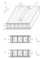
図1に示すように、工具箱1は、直方体の箱である本体部2と、本体部2に回動可能に取り付けられた蓋部3とを備える。蓋部3は、本体部2が有する開口を覆う。蓋部3は、本体部2に対して回動することにより、本体部2の開口が蓋部3で閉塞された閉位置と、本体部2の開口が開放された開位置とに変位し得る。蓋部3は第1係合部4を有し、本体部2は第1係合部4に係合する第2係合部5を有する。第1係合部4が第2係合部5に係合することにより、蓋部3は閉位置に保持される。図1においては、本体部2の第2係合部5が配置された面を前面とし、使用状態において本体部2が開口する方向を上方として、説明する。また、本体部2の前面を正面視した場合を基準として、上(Z軸方向)、下、左、右(X軸方向)、前、後(Y軸方向)の各方向を規定する。X軸、Y軸及びZ軸は互いに直交する方向軸である。
As shown in FIG. 1, the
本体部2内の右側には、複数の収容トレー6が収納されている。これら収容トレー6は、本体部2の上下方向に複数段重ねられている。本体部2は、周壁と、周壁から本体部2内に向けて突出する複数の支持突部(図示略)を有する。各収容トレー6は、本体部2の複数の支持突部上に、位置決めされた状態で置かれている。各収容トレー6内は、複数の区画に仕切られている。これら区画内には、レンチ、スパナ、ドライバー、またはニッパーといった工具類、あるいは、ケーブルまたは釘といった部品を仕分けして収容することができる。
A plurality of
図1に示すように、本体部2内には、収容トレー6の左側に、収容板7が収納されている。収容板7は、図示しない複数の支持突部上に、位置決めされた状態で置かれている。収容板7は、例えば電動ドリルのように、不規則な形状で比較的嵩張る工具を安定して収容するための凹部10を有する。例えば、本実施形態の収容板7は、電動ドリルを収容するために使用される。
As shown in FIG. 1, a
図2(a)及び図2(b)に示すように、収容板7は、板状の中空部分16と、凹部10を画定する密集部分20aとを有する。中空部分16は上面である第1面7aと、下面である第2面7bとを有する。密集部分20aは、収容板7の略中央部に位置して、第2面7bから下方に突出する突出部である。凹部10は第1面7aに開口する。凹部10の形状は、収容すべき物、例えば電動ドリルの形状に対応する。電動ドリルを凹部10に収容すると、電動ドリルは安定した状態で保持される。
As shown in FIGS. 2(a) and 2(b), the
密集部分20aは、凹部10の開口から延びる周壁11と、周壁11の突出端(下端)を閉じる底壁12と、周壁11と底壁12を滑らかにつなぐ湾曲部15とを有する。底壁12の面積は凹部10の開口面積よりも小さい。周壁11は、底壁12に近づくに従って先細になるように、第1面7a及び第2面7bに対して傾斜している。収容板7は、電動ドリルを収容するための凹部10の他にも、例えば、電動ドリルの交換用のドリル刃を収容するための凹部、および、収容板7を把持するための孔のうち少なくとも一方を有してもよい。第1及び第2面7a,7bは平坦面または湾曲面であってもよいし、凹凸模様を有してもよい。
The
本実施形態の収容板7の外形は、例えば、約25cm×約30cmの略長方形であり、中空部分16の厚さは約2cmである。凹部10の深さは、例えば約4cmである。このように、凹部10は収容板7の厚さ以上の深さを有しており、密集部分20aは、収容板7の厚さ以上の突出長さを有している。凹部10の深さまたは密集部分20aの突出長さは、例えば、中空部分16の厚さの1.5~4倍であり、2~4倍であることが好ましく、2~3倍であることがより好ましい。
The outer shape of the
凹部10の底壁12は、収容板7の第2面7bより下方、すなわち収容板7の厚さ方向(Z軸に沿う方向)に離れた位置にある。第1面7a、第2面7b及び底壁12は、収容板7の厚さ方向に沿ってこの順に並ぶ。
The
図3(a)及び図3(b)に示すように、周壁11は、内面11aと外面11bとを有する。収容板7は、第1面7aと内面11aとの間に、第1面7aと内面11aとを滑らかにつなぐ湾曲面13を有する。湾曲面13は、凹部10の開口端縁である。収容板7は、第2面7bと外面11bとの間に、第2面7bと外面11bとを滑らかにつなぐ湾曲面14を有する。湾曲面13の曲率半径は、湾曲面14の曲率半径と同じかそれよりも大きい。湾曲部15の曲率半径は、湾曲面13の曲率半径より大きい。
As shown in FIGS. 3(a) and 3(b), the
図3(b)に示すように、収容板7は、外縁全周に亘る端面7cを有する。端面7cは、第2面7bに近づくに従って先細になるように、第1面7a及び第2面7bに対して傾斜している。第2面7bを含む平面(図3(b)に破線で示す)に対する端面7cの傾斜角度θは、70゜以上であることが好ましく、80゜以上であることがより好ましく、85゜以上であることがさらに好ましい。傾斜角度θが90゜に近づくほど、収容板7を本体部2の支持突部上に安定して置くことができる。
As shown in FIG. 3(b), the
収容板7は、第2面7bと端面7cとの間に、第2面7bと端面7cとを滑らかにつなぐ湾曲面43を有する。湾曲面43の曲率半径は、例えば約1~5mmである。
The
図2(b)、図3(a)及び図3(b)に示すように、中空部分16は、内部に複数のセルSが並ぶ中空板である。中空部分16は、板状のコア層20と、コア層20の両面にそれぞれ接合された、コア層20より厚さの薄いシートである第1及び第2スキン層30,40とを備える。
As shown in FIGS. 2(b), 3(a), and 3(b), the
図4(a)にコア層20を示す。コア層20は、熱可塑性樹脂製のシート材(後で説明する第1シート材100)を予め規定した形状に成形した後、その成形したシート材を折り畳むことによって形成される。このシート材の厚さは、例えば約0.3mm~1.0mmであり、本実施形態では約0.5mmである。
The
コア層20は、第1壁21と、第2壁22と、第1壁21と第2壁22との間に延びる複数の区画壁23とを備える。第1壁21、第2壁22及び複数の区画壁23は、六角柱形状の複数のセルSを区画する。以下で説明するように、第1壁21及び第2壁22は、実際には1層構造の部分と2層構造の部分とを含むが、図3(a)、図3(b)及び図4(a)では、簡素化して、第1壁21及び第2壁22を1層構造で図示している。
The
図4(b)及び図4(c)に示すように、複数のセルSは、複数の第1セルS1及び複数の第2セルS2を含む。図4(b)に示すように、各第1セルS1を区画する第1壁21は、2層構造を有する。第1壁21を構成する2層は互いに接合されている。コア層20を成形するときに熱可塑性樹脂が熱収縮することにより、2層構造の第1壁21には図示しない開口部が形成される。各第1セルS1を区画する第2壁22は、1層構造を有する。
As shown in FIGS. 4(b) and 4(c), the multiple cells S include multiple first cells S1 and multiple second cells S2. As shown in FIG. 4(b), the
図4(c)に示すように、各第2セルS2を区画する第1壁21は1層構造を有する。第2セルS2を区画する第2壁22は2層構造を有する。第2壁22を構成する2層は互いに接合されている。コア層20を成形するときに熱可塑性樹脂が熱収縮することにより、2層構造の第2壁22には図示しない開口部が形成される。
As shown in FIG. 4(c), the
図4(b)及び図4(c)に示すように、隣接する第1セルS1同士の間に位置する区画壁23と、隣接する第2セルS2同士の間に位置する区画壁23とは、共に2層構造を有する。この区画壁23を構成する2層は、コア層20の厚さ方向における中央に、互いに熱溶着されていない部分を有している。したがって、コア層20内にある複数のセルSは、区画壁23を構成する2層の間を通じて、互いに連通し得る。
As shown in FIGS. 4(b) and 4(c), the
図4(a)に示すように、X軸に沿って並ぶ複数の第1セルS1は第1セル列を形成する。同様に、X軸に沿って並ぶ複数の第2セルS2は第2セル列を形成する。第1セル列と第2セル列とは、Y軸に沿って交互に配列されている。複数の第1セルS1及び複数の第2セルS2を含むコア層20は、全体としてハニカム構造を有する。
As shown in FIG. 4(a), the plurality of first cells S1 lined up along the X axis form a first cell column. Similarly, the plurality of second cells S2 lined up along the X axis form a second cell column. The first cell rows and the second cell rows are arranged alternately along the Y axis. The
図3(a)及び図3(b)に示すように、第1スキン層30は、第1内層31と第1意匠層32とを含む。第1内層31は第1意匠層32とコア層20との間に配置される。第1意匠層32の外面(第1内層31と反対側の面)は、収容板7の第1面7aを画定する。第1内層31は、図示しない接着層を介してコア層20に接合されており、第1意匠層32は、図示しない接着層を介して第1内層31に接合されている。
As shown in FIGS. 3A and 3B, the
第2スキン層40は、第2内層41と第2意匠層42とを含む。第2内層41は第2意匠層42とコア層20との間に配置される。第2意匠層42の外面(第2内層41と反対側の面)は、収容板7の第2面7bを画定する。第2内層41は、図示しない接着層を介してコア層20に接合されており、第2意匠層42は、図示しない接着層を介して第2内層41に接合されている。
The
コア層20、第1内層31、及び第2内層41は、熱可塑性樹脂で構成されている。コア層20を構成する熱可塑性樹脂は、従来周知の熱可塑性樹脂であればよい。熱可塑性樹脂の例は、ポリプロピレン、ポリアミド、ポリエチレン、アクリロニトリル‐ブタジエン‐スチレン共重合体、アクリル、ポリブチレンテレフタレートである。本実施形態のコア層20は、ポリプロピレン製である。同様に、第1内層31及び第2内層41を構成する熱可塑性樹脂も、従来周知の熱可塑性樹脂であればよい。本実施形態の第1内層31及び第2内層41は、コア層20と同じポリプロピレン製である。コア層20及び内層31,41を構成する樹脂は、コア層20の樹脂流動性(メルトマスフローレイト:MFR)より内層31,41の樹脂流動性(MFR)の方が小さくなるようにするとよい。第1内層31及び第2内層41の厚さは、例えば約0.3mm~1.0mmである。本実施形態の第1内層31及び第2内層41の厚さは、約0.5mmである。
The
意匠層32,42は、収容板7の外面に意匠性を付与する。意匠層32,42の材質は、例えば、従来周知の合成樹脂、合成皮革、合成繊維、金属、天然皮革、天然繊維、炭素繊維、またはフォーム材から選択される。意匠層32,42は、不織布、織物、編物、合成樹脂シート(例えば、合成樹脂を延伸した平滑な延伸シート)、または金属シートであってもよい。さらに、意匠層32,42には、模様または文字がプリントされていてもよいし、異なる色の繊維が含まれていてもよい。本実施形態の意匠層32,42は、ポリプロピレン製の不織布シートである。意匠層32,42の厚さは、例えば約0.3mm~1.0mmである。本実施形態の意匠層32,42の厚さは、約0.5mmである。
The design layers 32 and 42 provide design to the outer surface of the
コア層20と内層31,41とを接合している接着層は、内層31,41を構成するポリプロピレンと相溶性のある樹脂で構成されている。また、第1内層31と第1意匠層32とを接合している接着層、及び、第2内層41と第2意匠層42を接合している接着層は、内層31,41を構成するポリプロピレンと相溶性のある樹脂で構成されている。
The adhesive layer bonding the
図3(a)及び図3(b)に示すように、密集部分20aの厚さは、中空部分16の厚さよりも薄い。密集部分20aは、セルSの形状を識別できない程度に、コア層20(区画壁23、第1壁21及び第2壁22)及びスキン層30,40(内層31,41)を変形させた部分であり、これらの材料である熱可塑性樹脂が溶融した後に一体化した部分である。密集部分20aにおいて、セルSは潰れており、その内部にはほとんど隙間がない。すなわち、密集部分20aは中空部分16よりも空隙率が低い。内部に全く隙間のない樹脂の塊の空隙率が0%であるとき、中空部分16の空隙率は80%程度である。また、密集部分20aの空隙率は例えば1~15%であり、1~10%であることが好ましく、1~5%であることがより好ましい。
As shown in FIGS. 3(a) and 3(b), the thickness of the
図3(b)に示すように、密集部分20aは領域20A、領域20B及び領域20Cを含む。領域20Aは底壁12に相当する部分であり、領域20Cは厚さ方向Zにおいて第1面7aと第2面7bの間に位置する部分であり、領域20Bは周壁11のうち領域20Aと領域20Bとの間に位置する部分である。
As shown in FIG. 3(b), the
領域20Aは、コア層20をZ軸に沿う方向に押し潰して圧縮した部分である。領域20Aの縦断面を拡大すると、折れ曲がった区画壁23及び樹脂溜まり(樹脂の塊)が観察される。具体的には、区画壁23が圧縮された部分では樹脂溜まりが観察され、区画壁23が存在していなかった部分にはわずかな空間が観察される。そのため、領域20Aの横断面を拡大して観察すると、樹脂溜まりは網目状に分布している。また、領域20Aにおいて、樹脂溜まりは底壁12の外縁より中央に近い領域に密集している。領域20Aの外縁の近くでは、中央付近と比較して、圧縮された区画壁23が多く分布している。これは、後に説明するプレス工程において凹部10を成形する際に、領域20Aの外縁近くより中央付近のほうが熱可塑性樹脂が溶融しやすいことに起因する。領域20Aにわずかに残された各空間の幅(最大長さ)は、各樹脂溜まりの幅(最大長さ)より狭いか略同一である。密集部分20aにおいて、複数の樹脂溜まりが互いに繋がると、その部分にはほぼ隙間がなくなる。密集部分20aは、中空部分16のコア層20およびスキン層30,40とつながった熱可塑性樹脂によって構成される。
The
領域20Aの厚さは、中空部分16における第1壁21、第2壁22、及びスキン層30,40の各厚さを互いに合算した厚さより厚いか略同一である。例えば、第1シート材100の厚さが約0.5mm、第1内層31及び第2内層41の厚さが約0.5mm、意匠層32,42の厚さが約0.5mmの場合、底壁12の厚さは約3.5mmより厚いか略同一である。
The thickness of the
領域20B及び領域20Cは、その形成時に、コア層20がZ軸に沿って伸ばされるように変形することにより、元のコア層20よりも厚さが薄くなる。領域20B及び領域20Cの厚さは、領域20Aの厚さよりも薄い。周壁11は、その形成時に、内層31,41がコア層20とともにZ軸に沿って伸ばされる。そのため、周壁11の厚さは、底壁12の厚さより薄い。周壁11での単位体積当たりの樹脂量は、底壁12での単位体積当たりの樹脂量より少ない。
When forming the
領域20Bと領域20Cを比較すると、領域20Bでは、コア層20が内層31,41と互いに溶融して一体化しているのに対し、領域20Cではコア層20は第1内層31のみと溶融して一体化している。そのため、領域20Cの厚さは、領域20Bの厚さより薄い。
Comparing the
図3(b)に示すように、中空部分16において、湾曲面13,14の内側の領域を、それぞれ領域13A,14Aという。領域13A,14Aには、樹脂溜まり及び折り重なった区画壁23がある。領域14Aは、領域13Aよりも空隙率が低い。さらに、湾曲部15の空隙率は領域14Aの空隙率より低い。
As shown in FIG. 3(b), in the
図3(a)及び図3(b)に示すように、収容板7はその外縁全周に、コア層20が押し潰された密集部分20bを有する。密集部分20bの厚さは中空部分16の厚さより薄い。密集部分20bは、凹部10と同様に、コア層20、第1内層31および第2内層41を厚さ方向に圧縮して、セルSの形状を識別できない程度に変形させた部分であり、これらの材料である熱可塑性樹脂が一体化した部分である。密集部分20bにおいて、セルSは潰れており、その内部にはほとんど隙間がない。
As shown in FIGS. 3(a) and 3(b), the
第2スキン層40の外縁全周は、密集部分20bに向かって曲げられているのに対して、第1スキン層30の外縁は曲げられていない。第1スキン層30の外縁と第2スキン層40の外縁とは、密集部分20bを間に挟んで互いに突き合わされている。第1内層31の外縁及び第2内層41の外縁は、密集部分20bと一体化している。
The entire outer edge of the
図3(b)に示すように、スキン層40は、湾曲面43と外縁との間に、コア層20を側方から覆う端面44を有する。つまり、収容板7の端面7cは、第1スキン層30の外縁、コア層20の密集部分20b、及び第2スキン層40の端面44を含む。
As shown in FIG. 3(b), the
次に、本実施形態の収容板7の作用について説明する。
Next, the function of the
収容板7は、複数のセルSを含む中空部分16と、電動ドリルを収容するための凹部10(密集部分20a)とを有する。凹部10は、電動ドリルの外形に沿う形状を有し、その深さは約4cmである。凹部10内に電動ドリルを収容すると、電動ドリルは凹部10内でがたつくことなく安定して保持される。収容板7は、その外縁全体に、第2スキン層40の曲げられた外縁である端面44を有し、端面44は第1及び第2面7a,7bに対する急斜面である。そのため、収容板7は支持突部によって安定して支持される。
The
密集部分20aは、中空部分16より厚さが薄く、その内部にはほぼ隙間がない。つまり、周壁11、底壁12及び湾曲部15は中空構造を有さない。そのため、密集部分20aは衝撃に耐えうるだけの強度を有する。したがって、密集部分20aに何らかの衝撃が加わったとしても、衝撃の影響を受けにくい。例えば、工具箱1内に収容された工具類が密集部分20aに当たったとしても、その衝撃の影響を受けにくい。これに対して、中空構造の薄い外壁に衝撃が加わると、その外壁に孔があく虞がある。
The
本実施形態の収容板7において、中空部分16の厚さが約2cmであり、凹部10の深さが約4cmであるので、底壁12は第2面7bより下方に位置している。そのため、工具箱1内の収容板7より下方の空間に収容された他の工具が底壁12に当たることがある。底壁12は中空構造ではなく密集部分20aなので、接触した場合の衝撃による影響を受けにくい。底壁12は、厚さが多少不均一であっても、その表面(凹部10を画定する表面及びその反対側の裏面)はなだらかである。そのため、密集部分20aに物が引っかかりにくい。
In the
次に、収容板7を製造する方法を、図5(a)~図5(c)及び図6(a)~図6(f)に従って、その作用とともに説明する。
Next, a method for manufacturing the
収容板7を製造する方法は、コア層成形工程と、加熱工程と、接合工程と、プレス工程と、後加工工程と、を含む。コア層成形工程では、一枚のシート材からコア層20を成形する。加熱工程では、加熱対象であるコア層20及びスキン層30,40を加熱する。接合工程では、コア層20の両面にそれぞれスキン層30,40を接合して、中空板材を得る。プレス工程では、中空板材をプレス成形することにより、凹部10を有する中間体60を得る。後加工工程では、中間体60の端面を整えて、収容板7を得る。本実施形態では、接合工程をプレス工程と同時に行っている。
The method for manufacturing the
先ず、コア層成形工程について説明する。コア層成形工程では、図5(a)に示す第1シート材100を折り畳む。
First, the core layer forming process will be explained. In the core layer forming step, the
第1シート材100は、熱可塑性樹脂製であり、図5(a)に示すような、予め規定された形状に成形されている。第1シート材100は、帯状の平面領域110と膨出領域120とを有し、平面領域110と膨出領域120とは、第1シート材100の長手方向(X軸)に沿って交互に並んでいる。各膨出領域120は、平面領域110と面一の平面部と、平面部からZ軸に沿って膨出した一の第1膨出部121と、第1膨出部121と一体成形された複数の第2膨出部122と、を有する。第1膨出部121は、平面部と平行な第1膨出面と、平面部と第1膨出面との間に延びる2つの接続面とを有する。第1膨出面は、膨出領域120の延びる方向(Y軸に沿う方向)の全体にわたって延びている。第1膨出面と接続面とのなす角は90度であることが好ましい。第1膨出部121は図5(a)において下方に開口する溝状である。また、第1膨出部121の幅(X軸に沿う長さ)は、平面領域110の幅(X軸に沿う長さ)と等しく、かつ第1膨出部121の膨出高さ(Z軸に沿う長さ)の2倍の長さである。
The
各第2膨出部122は、第1膨出面から延びる第2膨出面と、正六角形を最も長い対角線で二分して得られる台形状の端面と、第1膨出面から平面部まで伸びる2つの傾斜面とを有する。複数の第2膨出部122は、X軸に沿って延びて第1膨出部121と直交しているとともに、Y軸に沿って並んでいる。第2膨出部122の膨出高さ(Z軸に沿う長さ)は第1膨出部121の膨出高さ(Z軸に沿う長さ)と等しい。Y軸に沿って並ぶ第2膨出部122の間隔は、第2膨出面の幅(Y軸に沿う長さ)と等しい。
Each of the
第1膨出部121及び第2膨出部122は、シートの塑性を利用して、シートの一部を膨出させることにより形成される。すなわち、第1シート材100は、真空成形法または真空圧空成形法のような、周知の成形方法によって1枚のシートから成形される。
The first bulging
図5(a)及び図5(b)に示すように、境界線Pは平面領域110と膨出領域120との境界であり、境界線Qは第1膨出部121の第1膨出面と接続面との境界である。第1シート材100を、境界線P,Qに沿って折り畳むことでコア層20が形成される。具体的には、第1シート材100を、境界線Pにて谷折りするとともに、境界線Qにて山折りする。そして、図5(b)及び図5(c)に示すように、第1膨出部121の第1膨出面と接続面とをZ軸に沿って重ね、第2膨出部122の端面と平面領域110とをZ軸に沿って重ねる。これによって、各膨出領域120には、Y軸に沿って延びる一の角柱状の区画体130が形成される。こうした区画体130がX軸に沿って連続して形成されていくことにより、中空板状のコア層20が形成される。
As shown in FIGS. 5(a) and 5(b), the boundary line P is the boundary between the
コア層20の第1壁21は、第1膨出部121の第1膨出面と接続面とが重なった2層構造を有し、コア層20の第2壁22は、第2膨出部122の端面と平面領域110とが重なった2層構造を有する。図5(c)に示すように、第1及び第2壁21,22の2層構造の部分は重ね合わせ部131である。
The
各膨出領域120においてX軸に沿って並ぶ2つの第2膨出部122が画定する六角柱形状の領域が第2セルS2となり、膨出領域120の平面部と第2膨出部122の傾斜面とが画定する六角柱形状の領域が第1セルS1となる。すなわち、第2膨出面及び傾斜面が第2セルS2の区画壁23となり、傾斜面と平面部とが第1セルS1の区画壁23となる。X軸に沿って重なる2つの第2膨出面、及び、X軸に沿って重なる2つの平面部は、2層構造を有する区画壁23となる。なお、こうした折り畳み工程を実施するに際して、第1シート材100を加熱することによって軟化させておいてもよい。
In each
次に、加熱工程について説明する。 Next, the heating process will be explained.
加熱工程に先立って、図6(a)に示すように、コア層成形工程で製造したコア層20とスキン層30,40とを、収容板7より一回り大きな外形になるように切断する。コア層20及びスキン層30,40は、例えば、収容板7の大きさより、長手方向及び短手方向にそれぞれ約50mm大きい長方形にする。なお、図6(a)~図6(f)では、コア層20の中空構造を含め、各構成要素の詳細を省略して示している。
Prior to the heating step, as shown in FIG. 6(a), the
第1スキン層30は、あらかじめ第1内層31に第1意匠層32が積層されたシートである。第1内層31と第1意匠層32は、第1内層31の材料であるポリプロピレンと相溶性のある樹脂で構成された接着層を介して接合されている。第2スキン層40は、あらかじめ第2内層41に第2意匠層42が積層されたシートである。第2内層41と第2意匠層42は、第2内層41の材料であるポリプロピレンと相溶性のある樹脂で構成された接着層を介して接合されている。第1内層31における第1意匠層32と反対側の面には、第1内層31の材料であるポリプロピレンと相溶性のある樹脂で構成された接着層がコーティングされている。第2内層41における第2意匠層42と反対側の面には、第2内層41の材料であるポリプロピレンと相溶性のある樹脂で構成された接着層がコーティングされている。
The
図6(b)に示すように、コア層20加熱するために、規定温度に設定された加熱炉71内にコア層20を入れて、規定時間保持する。同様に、第1及び第2スキン層30,40を加熱するために、規定温度に設定された加熱炉72内にスキン層30,40を入れて、規定時間保持する。加熱炉71内の温度は、コア層20を構成する熱可塑性樹脂(本実施形態では、ポリプロピレン)が溶融する温度に設定されている。加熱炉71内の温度は、スキン層30,40を構成する熱可塑性樹脂(本実施形態では、ポリプロピレン)が溶融する程度に設定されている。
As shown in FIG. 6(b), in order to heat the
加熱工程においては、加熱炉71内で、コア層20の表面温度が部位によって異なるように調整される。同様に、加熱炉72内で、スキン層30,40の表面温度が部位によって異なるように調整される。例えば、コア層20の温度を相対的に低くしたい部分を遮蔽材73で覆ってもよい。図6(b)では、加熱炉71内にのみ遮蔽材73を図示しているが、加熱炉72内にも、スキン層30,40を部分的に覆う遮蔽材73を配置してもよい。あるいは、加熱炉72内には遮蔽材73を配置せず、スキン層30,40の全体を均一に加熱してもよい。遮蔽材73は複数の細かな貫通孔を有してもよい。貫通孔の大きさまたは数を変更することによって、遮蔽材73を設置した部分の表面温度を、それぞれ加熱炉71,72内の温度よりどの程度低くするかを、調整することができる。あるいは、貫通孔を有さない遮蔽材を配置することによって、より遮熱効果を高めることもできる。
In the heating process, the surface temperature of the
遮蔽材73は、後のプレス工程において、中空板材の厚さを薄くしない部分、すなわち、コア層20及びスキン層30,40を溶融させない部分を覆う。図6(d)に示すプレス工程では、プレス成形により中空板材の中央部に凹部10が形成されると同時に中空板材の外縁に圧縮部61が形成される。遮蔽材73は、圧縮部61及び凹部10を除く部分に配置される。
The shielding
遮蔽材73の配置により、加熱炉71内において、コア層20の潰し幅が小さいかほとんど潰さない部分の表面温度を相対的に低くし、コア層20の潰し幅が大きい部分の表面温度を相対的に高くする。コア層20の潰し幅が大きい部分の表面温度は、加熱炉71内の加熱温度と同程度である。スキン層30,40の表面温度を調整する方法についても、コア層20の場合と同様である。
By arranging the shielding
次に、接合工程及びプレス工程について説明する。 Next, the bonding process and the pressing process will be explained.
図6(c)に示すように、プレス工程(及び接合工程)に使用する金型は、第1金型81及び第2金型82を備えている。本実施形態の第1及び第2金型81,82は、全体が加熱されることなく常温で使用される。
As shown in FIG. 6(c), the mold used in the pressing process (and bonding process) includes a
第2金型82は、第1金型81と当接する第2平坦面82cと、第2平坦面82cより凹んだ第1段差面82aと、第1段差面82aよりさらに凹んだ第2段差面82bとを有する。第2金型82は、さらに、第2平坦面82cと第1段差面82aの外縁との間に伸びる傾斜成形面82dと、を有する。傾斜成形面82dは第2平坦面82c及び第1段差面82aに対して傾斜している。第1段差面82aと傾斜成形面82dとは、湾曲面82eを介して滑らかにつながっている。傾斜成形面82d、湾曲面82e及び第1段差面82aは、収容板7の中空部分16を形成するための凹部であり、長方形の外形を有する。傾斜成形面82dは、収容板7の端面7c(端面44)を形成するための面である。湾曲面82eは湾曲面43を形成するための面である。傾斜成形面82dの長手方向の長さは、収容板7の長手方向の長さとほぼ同一であり、傾斜成形面82dの短手方向の長さは、収容板7の短手方向の長さとほぼ同一である。第1段差面82aの深さは、収容板7の厚さより少し浅い。
The
第2段差面82bは、密集部分20a(凹部10)を形成するための凹部であり、電動ドリルの外形に沿った外縁を有する。第1段差面82aと第2段差面82bとは、湾曲面82f,82gを介して滑らかにつながっている。湾曲面82fは湾曲面14を成形するための面であり、湾曲面82gは湾曲部15を成形するための面である。第2段差面82bの第1段差面82aに対する深さは、約2cmである。なお、第1及び第2段差面82a,82bの外形及び深さは、コア層20及びスキン層30,40の熱収縮を考慮して設定してもよい。
The second stepped
第1金型81は、型締め時に第2平坦面82cと当接する第1平坦面81dと、第1平坦面81dより凹んだ段差面81a,81bと、第1平坦面81dより突出する突出面81cとを有する。外側段差面81bの外形は長方形であり、内側段差面81aは外側段差面81bの内側に位置する。外側段差面81bと第1平坦面81dとの間には、両者に直交する交差面81eが延びている。内側段差面81aと突出面81cとの間には、突出傾斜面81fが延びている。突出傾斜面81fと内側段差面81aとは湾曲面81gによって滑らかにつながっている。突出傾斜面81fと突出面81cとは湾曲面81hによって滑らかにつながっている。
The
段差面81a,81bは面一であり、その深さは、後に説明する中間体60の圧縮部61の厚さとほぼ同一である。内側段差面81aは、第1面7aを成形するための面であり、外側段差面81b及び交差面81eは、中間体60の圧縮部61を成形するための部分である。突出傾斜面81fは領域20B及び領域20Cを成形するための面である。湾曲面81gは湾曲面13を成形するための面である。湾曲面81hは湾曲部15を成形するための面である。
The stepped surfaces 81a and 81b are flush with each other, and their depth is approximately the same as the thickness of the compressed
図6(c)に点線で示すように、型締めしたときに、内側段差面81aは第2段差面82bと対向し、外側段差面81bは第2平坦面82cと対向する。突出面81cは、領域20Aを成形するための面であり、その外形は第2段差面82b(電動ドリル)の外形に沿う。突出面81cは、内側段差面81aより約4cm突出している。
As shown by the dotted line in FIG. 6(c), when the mold is clamped, the inner stepped
図6(c)に示すように、第2金型82の上に、加熱された第2スキン層40、コア層20及び第1スキン層30を、下からこの順で積層する。これを積層体70という。このとき、積層体70は、段差面82a,82bを覆うように、その外縁が第2平坦面82cの上に置かれる。
As shown in FIG. 6(c), the heated
積層体70は、遮蔽材73を用いて調整した表面温度に応じて、第1及び第2金型81,82に対して位置決めする。具体的には、積層体70の表面温度が低い部分を、内側段差面81aと第1段差面82aとの間に配置する。また、積層体70の表面温度が高い中心部分を、突出面81cと第2段差面82bとの間に配置する。さらに、積層体70の表面温度を高い外縁部分を、第1金型81の外側段差面81bの位置に合わせる。
The
積層体70は、型締めしたときに第1金型81と第2金型82の間に画定される成形空間の高さ、すなわち第1金型81と第2金型82との距離に基づいて位置決めされる。成形空間は、第1段差面82aと内側段差面81aとの間の非圧縮空間と、第2段差面82bと突出面81cとの間の内側圧縮空間と、第1平坦面81dと外側段差面81bとの間の外側圧縮空間と、を含む。例えば、非圧縮空間の高さが約2cmである場合、内側圧縮空間及び外側圧縮空間の高さは非圧縮空間よりも相対的に低く、例えば約3.5mmである。
The laminate 70 is formed based on the height of the molding space defined between the
積層体70のうち、非圧縮空間に配置された領域を非圧縮領域75、内側圧縮空間に配置された領域を内側圧縮領域76、外側圧縮空間に配置された領域を外側圧縮領域77という。積層体70(コア層20及びスキン層30,40)の温度は、成形空間の高さに対応して調整されている。すなわち、非圧縮領域75の温度は、内側圧縮領域76及び外側圧縮領域77の温度よりも低い。
In the
積層体70を第2金型82の上に置いた状態では、加熱されたスキン層30,40にコーティングされた接着層は、熱可塑性樹脂の一部が熱溶融した状態になっている。そのため、第2金型82の上に位置決めされたコア層20及びスキン層30,40は、これら接着層を介して仮接合されている。
When the laminate 70 is placed on the
図6(d)に示すように、第1金型81を第2金型82に向けて移動させることにより、プレス工程及び接合工程が行われる。第1金型81及び第2金型82は、図示しない吸引孔を複数有している。型締め時には、吸引孔を通じて積層体70(互いに仮接合されたコア層20及びスキン層30,40)を吸引する。これにより、第1及び第2金型81,82に積層体70を密着させる。プレス時の圧力及びプレス時間は、適宜設定すればよい。
As shown in FIG. 6(d), the pressing process and the joining process are performed by moving the
型締め時には、スキン層30,40にコーティングされた接着層に加えて、加熱されたコア層20及びスキン層30,40も部分的に溶融している。そのため、型締めによって、コア層20の両面にそれぞれ第1及び第2スキン層30,40が接合される。このとき、2層構造を有する第1及び第2壁21,22には、図示しない開口部が形成される。また、一の区画壁23を構成する2層は、コア層20の厚さ方向の両端が互いに熱溶着されるが、同厚さ方向の中央付近には、互いに熱溶着されない部分が残る。これにより、コア層20とスキン層30,40との間の空気が、第1及び第2壁21,22の開口部及びコア層20内の隙間を通じて抜けやすい。そのため、意図しない空気溜まりの発生が抑制され、コア層20とスキン層30,40との接合強度が向上する。
At the time of mold clamping, in addition to the adhesive layer coated on the skin layers 30, 40, the
プレス加工により、積層体70は成形空間の形状に成形された中間体60となる。
By pressing, the laminate 70 becomes an
図6(d)に示すように、外側圧縮空間内に配置されたコア層20は熱溶融して、第1壁21、第2壁22、及び区画壁23が一体化した中実状になる。さらに、この溶融したコア層20と、溶融した内層31,41とが一体化することにより、中間体60の圧縮部61が形成される。熱可塑性樹脂でない意匠層32,42は溶融しないので、外面の質感及び模様が維持される。
As shown in FIG. 6(d), the
内側圧縮空間、すなわち突出面81cと第2段差面82bとの間においても、同様に、コア層20及び内層31,41が熱溶融して一体化することにより、密集部分20a(凹部10)が形成される。湾曲部15の曲率半径は湾曲面13の曲率半径より大きく、湾曲面13の曲率半径は湾曲面14の曲率半径と同じかそれよりも大きい。そのため、内側圧縮領域76が第2金型82に沿って引き延ばされるときに、内側圧縮領域76(密集部分20a)に意図しない孔があくことがない。
Similarly, in the inner compressed space, that is, between the protruding
非圧縮空間、すなわち内側段差面81aと第1段差面82aとの間に配置されたコア層20(非圧縮領域75)は、ほとんど圧縮されない。特に、第1及び第2壁21,22と比較して、区画壁23には熱が伝わりにくいので、区画壁23は変形しにくい。
The core layer 20 (non-compressible region 75) disposed in the non-compressible space, that is, between the
内側圧縮領域76と非圧縮領域75とは、温度が異なる。この温度差に起因して、熱可塑性樹脂の溶融状態に差が出るため、湾曲面13,14の曲率半径が小さくなる。
The inner
この温度差に起因して、湾曲面13,14の内側の領域13A,14Aでは、樹脂溜まりが形成されたり、区画壁23が折り重なったりする。図3(b)に示すように、凹部10に隣接する複数のセルS(以下、内側1列目のセルSという)と、内側1列目のセルSに隣接する複数のセルS(以下、内側2列目のセルSという)とは、厚さ方向Zに圧縮されるが、内側2列目のセルSよりも外側のセルS、すなわち中空部分16のセルSは厚さ方向Zに圧縮されない。そのため、中空部分16の区画壁23は曲がったり折れたりしていない。このように、凹部10周辺でもコア層20のハニカム構造が維持されることにより、収容板7の曲げ強度が保持されている。内側1,2列目のセルSを区画する区画壁23は、図3(b)に示すように、両端が湾曲面13,14に沿うように折れ曲がる。そのため、折れ曲がった区画壁23が湾曲面13,14を部分的に突出させるようなことがない。
Due to this temperature difference, resin pools are formed in the
内側1列目のセルSは、凹部10の開口縁、すなわち湾曲面13に沿って並び、部分的に圧縮された第1壁21を有する。内側1列目のセルSは、湾曲面13に沿って交互に並ぶ第1セルS1と第2セルS2とを含む。第1セルS1の第1壁21は二層構造を有し、第2セルS2の第1壁21は一層構造を含む。一層構造の第1壁21は、二層構造の第1壁21よりも、プレス成形時に伸びやすい。そのため、凹部10の開口縁は部分的に大きく変形することがない。
The cells S in the first inner row are arranged along the opening edge of the
図3(a)に示すように、凹部10の開口が角10aを有する場合、内側1列目のセルSのうち、角10aから離れた位置にあるセルSの第1壁21は、角10aにあるセルSの第1壁21より大きく引き伸ばされる。この場合にも、一層構造の第1壁21が伸びることにより、湾曲面13の意図しない変形が低減される。
As shown in FIG. 3(a), when the opening of the
内側1列目のセルSは、内側2列目のセルSよりも圧縮される。そのため、例えば、図3(b)に示すように、内側1列目のセルSの区画壁23が1つの屈曲部を有するときに、内側2列目のセルSの区画壁23は2つの屈曲部を有することがある。このとき、2つの屈曲部は互いに重なり合うことがある。
The cell S in the first inner column is compressed more than the cell S in the second inner column. Therefore, for example, as shown in FIG. 3(b), when the
非圧縮領域75と外側圧縮領域77とで温度が異なるため、両者の間で熱可塑性樹脂の溶融状態に差が生じる。その結果、湾曲面43の曲率半径が小さくなる。これにより、端面7c(端面44)の傾斜角度θを90°に近づけることができる。一方、第1スキン層30は曲げられることなく、平坦な状態が維持される。
Since the temperature is different between the
非圧縮領域75と外側圧縮領域77(圧縮部61)との温度差が大きいので、コア層20では、収容板7の端面7cのすぐ内側のセル(以下、最外縁のセルSという)と、最外縁のセルSのすぐ内側のセルS(以下、外側2列目のセルSという)とが厚さ方向Zに圧縮されるが、外側2列目のセルSより内側のセルS、すなわち中空部分16のセルSは圧縮されていない。そのため、中空部分16の区画壁23は曲がったり折れたりしていない。このように、端面7c近傍でもコア層20のハニカム構造が維持されることにより、収容板7の曲げ強度が保持されている。
Since the temperature difference between the
第2金型82から第1金型81を離間させて中間体60を冷却した後、図6(e)に示すように、中間体60を第2金型82から取り出す。接合工程及びプレス工程を経て得られた中間体60は、コア層20の両面にそれぞれ接合された第1及び第2スキン層30,40を有する。中間体60は、外縁の全周に亘って延びる圧縮部61と、中央に形成された凹部10(密集部分20a)とを有する。密集部分20aの厚さ及び圧縮部61の厚さは約3.5mmであり、非圧縮領域75の厚さは約2cmである。
After the
次に、後加工工程について説明する。 Next, the post-processing process will be explained.
図6(f)に示すように、中間体60の圧縮部61を、図示しない切断冶具で切り落として、収容板7を得る。図3(a)及び図3(b)に示すように、切断した中間体60の切断面、すなわち収容板7の端面7cには、スキン層30の端縁とスキン層40の端縁との間にコア層20の密集部分20bが露出している。端面7cは、スキン層30の端縁、スキン層40の端面44、及びコア層20の密集部分20bを含む。その後、中間体60の切断面を研磨及び塗装して、端面7cの形状を整える。圧縮部61を切断する切断冶具としてトムソン刃またはレーザーを使用した場合には、研磨及び塗装を行わなくてもよい。
As shown in FIG. 6(f), the compressed
以上の各工程を経て、収容板7が得られる。
The
本実施形態によれば、次のような効果を得ることができる。 According to this embodiment, the following effects can be obtained.
(1)収容板7が有する密集部分20a(凹部10)は、コア層20及びスキン層30,40が溶融して一体化した部分を含む。具体的には、コア層20を構成する熱可塑性樹脂と、第1内層31及び第2内層41を構成する熱可塑性樹脂とが一体化している。
(1) The
密集部分20aが中空のセルを含む場合、密集部分20aに何らかの衝撃が加わると、セルSを区画する薄い壁が変形するおそれがある。この点、密集部分20aは、熱可塑性樹脂が一体化した中実状である。そのため、密集部分20aに何らかの衝撃が加わったとしてもその影響を低減できる。したがって、収容板7は衝撃強度に優れている。
When the
(2)密集部分20a内にあったコア層20はプレス工程で押し潰されることにより、セルSの形状が識別できない程度に変形している。その結果、密集部分20a内部には、隙間がほとんどない。そのため、密集部分20aは、衝撃に対して高い強度を備えている。
(2) The
(3)収容板7は工具箱1内に収納されているとともに、密集部分20aは中空部分16の厚さ以上の深さを有する。そのため、工具箱1内で収容板7の下方に収納された工具類が密集部分20aに衝突することがある。この場合にも、中実状の密集部分20aは衝撃強度に優れているので、衝突の影響を抑制することができる。
(3) The
(4)凹部10の開口縁は湾曲面13であり、密集部分20aの周壁11は中空部分16及び底壁12に対して急な角度で傾斜している。そのため、凹部10の容量を大きく確保することができる。
(4) The opening edge of the
(5)収容板7の湾曲面43は曲率半径が約5~10mmであり、端面44(端面7c)は急斜面である。そのため、収容板7を工具箱1の支持突部上に置いたとき、収容板7を支持突部で安定して支持することができる。また、支持突部と収容板7との間にゴミまたは埃が溜まることを抑制することができる。
(5) The
(6)密集部分20aの周辺では、内側1列目及び2列目のセルSは厚さ方向に圧縮されているが、これらよりも外側のセルSは圧縮されていない。すなわち、中空部分16の区画壁23は曲がったり折れたりしていない。密集部分20aの周辺でもコア層20のハニカム構造が維持されることにより、収容板7の曲げ強度が保持されている。
(6) Around the
(7)収容板7の端面7c近傍では、最外縁のセルS及び外側2列目のセルSは厚さ方向に圧縮されているが、これらより内側のセルSは圧縮されていない。すなわち、中空部分16の区画壁23は曲がったり折れたりしていない。収容板7の端面7c近傍でもコア層20のハニカム構造が維持されることにより、収容板7の曲げ強度が保持されている。
(7) Near the
(8)収容板7の端面7cに露出する端面44はコア層20を側方から覆っている。そのため、コア層20内に並ぶ複数のセルS内に異物、例えばゴミまたは埃が入ることを抑制することができる。
(8) The end face 44 exposed at the
(9)収容板7はポリプロピレン製である。ポリプロピレンは、他の汎用熱可塑性樹脂に比べて比重が小さく、強度に優れている。そのため、収容板7は、軽量で衝撃強度に優れている。
(9) The
(10)プレス工程では、内側圧縮領域76の温度が非圧縮領域75の温度よりも高い状態でプレス成形する。そのため、内側圧縮領域76のコア層20、第1内層31、及び第2内層41が、非圧縮領域75のコア層20、第1内層31、及び第2内層41より溶融されやすい。加熱により溶融した熱可塑性樹脂は、その後に冷却されることによって一体化してほぼ隙間のない中実状になりやすい。異なる形状に成形する部位によって温度が異なるように加熱することで、必要な部分での衝撃強度を確保することができる。
(10) In the pressing step, press molding is performed in a state where the temperature of the inner
(11)接合工程をプレス工程と同時に行うことにより、製造工程を簡略化することができる。そのため、作業性及びコスト面において有利である。 (11) By performing the bonding process at the same time as the pressing process, the manufacturing process can be simplified. Therefore, it is advantageous in terms of workability and cost.
(12)加熱工程では、非圧縮領域75を遮蔽材73で覆って加熱している。そのため、コア層20及びスキン層30,40において部分的に温度を異ならせることを容易に実行することができる。
(12) In the heating step, the
(13)加熱工程では、遮蔽材73を設置することにより、コア層20及びスキン層30,40の表面温度を部分的に異ならせている。そのため、その後に続く接合工程及びプレス工程において、第1及び第2金型81,82を加熱する必要がない。よって、一度のプレス成形によって、密集部分20a及び圧縮部61を形成することができる。これにより、工程が簡略化されるので、作業性及びコスト面において有利である。
(13) In the heating step, the surface temperatures of the
(14)接合工程及びプレス工程で使用する第1及び第2金型81,82は、型締めした状態では、内側圧縮空間の高さが約3.5mmである。そして、内側圧縮空間内には、加熱工程において相対的に高温に加熱された内側圧縮領域76が配置される。そのため、プレス成形により、内側圧縮領域76のコア層20が押し潰されるとともに、コア層20、第1内層31、及び第2内層41が一体化して厚さが約3.5mmにまで薄くなる。このように、良好な寸法精度で密集部分20aを成形することができる。
(14) In the first and
(15)コア層20及びスキン層30,40は、加熱工程であらかじめ加熱された後に、第2金型82上に置かれる。このとき、第1及び第2スキン層30,40にそれぞれコーティングされた熱可塑性樹脂製の接着層は、熱溶融している。そのため、コア層20の両面に対して第1及び第2スキン層30,40がそれぞれ仮接合される。これにより、コア層20に対して第1及び第2スキン層30,40を精度よく位置決めすることができる。
(15) The
(16)加熱工程で加熱されるスキン層30は、あらかじめ互いに積層された第1内層31と第1意匠層32とを備える、スキン層40は、あらかじめ互いに積層された第2内層41と第2意匠層42とを備える。そのため、接合工程では、コア層20に対して第1及び第2スキン層30,40を位置決めすればよい。すなわち、内層31,41及び意匠層32,42を別個に位置決めする場合に比べて作業効率が向上する。
(16) The
(17)加熱工程では、コア層20を加熱炉71で加熱し、第1及び第2スキン層30,40を加熱炉72で加熱している。そのため、コア層20とスキン層30,40とで、温度調整及び温度管理がしやすい。また、各層を均質な温度に加熱することができる。
(17) In the heating step, the
(18)第1及び第2金型81,82は、複数の吸引孔を有する。この吸引孔を通じてコア層20及びスキン層30,40を吸引することにより、金型81,82内部にコア層20及びスキン層30,40を密着させて、適切に位置決めすることができる。これにより、コア層20及びスキン層30,40の位置ずれを抑制することができる。その結果、精度の高い収容板7を製造することができる。
(18) The first and
上記実施形態は、次のように変更することができる。なお、上記実施形態及び以下の変更例は、技術的に矛盾しない範囲で互いに組み合わせて適用することができる。 The above embodiment can be modified as follows. Note that the above embodiment and the following modification examples can be applied in combination with each other within a technically consistent range.
・スキン層30は意匠層32を有さなくてもよい。これに代えて、あるいはこれに加えて、スキン層40が意匠層42を有さなくてもよい。
- The
・第1内層31及び第2内層41の少なくとも一方の材質が熱可塑性樹脂製でなくてもよく、例えば、従来周知の他の合成樹脂、合成皮革、合成繊維、金属、天然皮革、または天然繊維であってもよい。この場合、熱可塑性樹脂製でないシート層31,41には、コア層20を構成する熱可塑性樹脂と相溶性のある熱可塑性樹脂製の接着層をそれぞれコーティングし、これら接着層を介してコア層20に接合するとよい。この場合、密集部分20aは、コア層20(熱可塑性樹脂)と、シート層31,41にコーティングされた接着層とが一体化して、内部にほぼ隙間がない中実状になる。これにより、衝撃に強い密集部分20aとなる。
- The material of at least one of the first
・スキン層30,40は互いに異なる構成を有してもよい。例えば、意匠層32,42が互いに異なる材質または異なる形態であってもよいし、或いは、内層31,41が互いに異なる材質または異なる形態であってもよい。
- The skin layers 30 and 40 may have mutually different configurations. For example, the design layers 32 and 42 may be made of different materials or have different shapes, or the
・収容板7は、スキン層30,40のいずれか一方を有さなくてもよい。
- The
・収容板7の剛性を高めるために、スキン層30とコア層20の間、または、スキン層40とコア層20との間に、薄い鋼板を接合してもよい。鋼板の材質としては、例えばアルミニウム合金、鉄合金、銅合金などの金属製の薄板が挙げられる。鋼板の厚さは約0.05mm~0.5mmであることが好ましい。鋼板を接合する位置は、プレス工程のしやすさを考慮すると、非圧縮領域75(凹部10以外の部分)に設けることが好ましいが、特に限定されるものではない。例えば、収容板7の一方の端縁から他方の端縁に掛けて鋼板を接合することで収容板7の曲げ強度を向上させることができる。また、凹部10の外縁に沿って鋼板を接合することで、湾曲面13,14の曲率半径を小さくすることができる。或いは、収容板7(中空構造体)がヒンジ部を有する場合、このヒンジ部に沿って鋼板を接合することで、ヒンジ部を補強するとともに曲げ強度を向上させたり、ヒンジ部での曲率半径を小さくしたりすることができる。
- In order to increase the rigidity of the
また、鋼板以外にも、コア層20内に複数の金属棒材を圧入したり、コア層20のセルS内にウレタン等の樹脂材を注入したりしてもよい。圧入する金属棒材の断面形状は特に限定されず、例えば、断面円形または断面溝状の棒材の他、H鋼またはL鋼であってもよい。また、圧入した金属棒材の周囲に接着剤を注入すれば、さらなる補強をすることができる。
In addition to steel plates, a plurality of metal rods may be press-fitted into the
・収容板7の剛性を高めるために、コア層20及びスキン層30,40のうち少なくとも一つを、炭素繊維またはガラス繊維のような引張弾性率の高い素材、あるいは、タルクのような補強材を含有する熱可塑性樹脂で構成してもよい。
- In order to increase the rigidity of the
・コア層20及びスキン層30,40のうち少なくとも一つを、各種機能性樹脂を添加した熱可塑性樹脂で構成してもよい。例えば、熱可塑性樹脂に難燃性の樹脂を添加することにより、難燃性を高めることが可能である。
- At least one of the
・中空構造体は、電動ドリルを収容する収容板7に限定されない。例えば、中空構造体は、他の工具類を収容する容器または板に使用してもよい、自動車の内装部材または建材に使用してもよい。例えば、中空構造体は、自動車の後部に設けられたラゲッジルームの底面を形成するラゲッジボードに適用することもできる。こうしたラゲッジボードが有する凹部(密集部分)は、同ラゲッジボードを車体に固定するために使用される。具体的には、ラゲッジボードは、その端部に、下方に突出した密集部分(突出部)を有し、この密集部分が車体に設けられた貫通孔に挿入されることによって、車体に固定される。つまり、密集部分(突出部)は、ラゲッジボードを支持または固定するための支持突起として使用される。この支持突起(密集部分)は熱可塑性樹脂が一体化した中実状であるため、衝撃強度に優れ、ラゲッジボードを安定して支持または固定することができる。また、ラゲッジボードの下部には工具などを収納可能なスペースが設けられている場合がある。この場合、下方に収納された工具が支持突部(密集部分)に衝突したとしても、その衝撃等に対して優れた衝撃強度を発揮することができる。
- The hollow structure is not limited to the
・コア層20及びスキン層30,40の厚さ、及び、第1シート材100の厚さは、任意に変更することができる。
- The thickness of the
・収容板7は、凹部10(密集部分20a)の他に、第1及び第2面7a,7bの少なくとも一方から突出する突出部または第1及び第2面7a,7bの少なくとも一方に開口する凹部を有してもよい。これにより、工具箱1内において、収容板7の上方または下方にある凹凸形状との干渉を避けたり、形成される空間に他の物を収容したりすることができる。また、収容板7が貫通孔を有してもよい。この貫通孔は、例えば、収容板7を持ち上げるための持ち手として使用してもよい。
- In addition to the recessed portion 10 (
・収容板7における凹部10(密集部分20a)の位置は変更してもよく、例えば、収容板7の端縁に凹部(密集部分)を配置してもよい。収容板7の端縁には衝撃が掛かり易いので、その部分に中実状の密集部分を配置することにより、収容板7の衝撃に対する強度が向上する。そのため、例えば収容板7を誤って落下させた場合にも変形を抑制することができる。また、端縁を中実状にすることにより、最外縁のセルSを封止することができる。
- The position of the recessed part 10 (
・収容板7の端面7cは、互いに近づくように湾曲した第1及び第2スキン層30,40の外縁を含んでもよいし、平坦な第2スキン層40の外縁に近づくように湾曲した第1スキン層30の外縁を含んでもよい。
- The
・収容板7の端面7cは、第2スキン層40の端面44に代えて、第2スキン層40とは異なる別部材を含んでもよい。この場合、収容板7は、最外縁のセルSを封止する第1部材と、その第1部材を覆う第2部材とを備えてもよい。
- The
・凹部10(密集部分20a)の形状は変更することができる。例えば、周壁11はなだらかな斜面であってもよい。周壁11及び湾曲面13,14の形状は、凹部10に収容する物の形状に合わせて決定すればよい。
- The shape of the recessed portion 10 (
・端面44の傾斜角度θは、70゜未満でもよい。また、湾曲面43の曲率半径は上記実施形態のものに限定されない。
- The inclination angle θ of the
・コア層20は、例えば、複数の帯状のシートを所定間隔毎に屈曲させることによって形成される区画壁と、これら帯状のシートの両側にそれぞれ配置された第1及び第2シート層とを有してもよい。
- The
・図7(a)~(c)に示す変更例のように、断面台形状の突出面が複数並んだ三次元構造体である第2シート材200を境界線R,Tに沿って折り込んでいくことにより、ハニカム構造体であるコア層24を形成してもよい。第2シート材200は、Z軸に沿って互いに反対方向に膨出する複数の第1膨出部210及び第2膨出部220を有する。複数の第1及び第2膨出部210,220はX軸に沿って延びるとともに、X軸に沿って並んでいる。各第1膨出部210は、第1膨出面210aと、2つの端面210cと、2つの接続面210bとを有する。各第2膨出部220は、第2膨出面220aと、2つの端面220cと、2つの接続面220bとを有する。
- As in the modified example shown in FIGS. 7(a) to (c), the
より詳細には、図7(b)に示すように、第2シート材200は、境界線Rに沿って山折りされ、境界線Tに沿って谷折りされる。図7(c)に示すように、境界線Tを挟んで並ぶ2つ第1膨出部210は、互いの第1膨出面210a同士が当接して、2層構造の区画壁27となる。接続面210bは、1層構造の区画壁27となる。X軸に沿って並ぶ2つの端面210cは第1壁25となる。
More specifically, as shown in FIG. 7(b), the
境界線Rを挟んで並ぶ2つの第2膨出部220は、互いの第2膨出面220a同士が当接して、2層構造の区画壁27となる。接続面220bは、1層構造の区画壁27となる。X軸に沿って並ぶ2つの端面220cは第2壁26となる。
The two
このようにして得られたコア層24の両面にそれぞれ第1及び第2スキン層30,40を接合すると、中空板材となる。
When the first and second skin layers 30 and 40 are respectively bonded to both surfaces of the
・セルSの形状は任意に変更することができる。例えば、四角柱状または八角柱状のような多角形状であってもよいし、円柱状であってもよいし、接頭円錐形状であってもよい。また、複数のセルSは、異なる形状のセルを含んでもよい。隣り合うセルの間に隙間(空間)が存在していてもよい。 - The shape of the cell S can be changed arbitrarily. For example, it may have a polygonal shape such as a quadrangular prism shape or an octagonal prism shape, a cylindrical shape, or a prefixed conical shape. Further, the plurality of cells S may include cells of different shapes. A gap (space) may exist between adjacent cells.
・コア層20は、予め規定された凹凸形状を有するコア層と、このコア層の両面にそれぞれ接合された第1及び第2シート層とを有してもよい。このような構成のコア層の例は、例えば特開2014-205341号公報に開示されている。コア層20は、断面がハーモニカ状のプラスチックダンボールであってもよい。
- The
・加熱工程における加熱温度は、コア層20を構成する熱可塑性樹脂の材質、スキン層30,40を構成する熱可塑性樹脂の材質、または、スキン層30,40にコーティングされた接着層を構成する熱可塑性樹脂の材質などに応じて、適宜変更することができる。
- The heating temperature in the heating step depends on the material of the thermoplastic resin forming the
・加熱工程において、コア層20及びスキン層30,40は同じ加熱炉内で加熱してもよい。
- In the heating step, the
・加熱工程において、コア層20及びスキン層30,40は、加熱炉71,72内ではなく、開放された環境下で加熱されてもよい。例えば、コア層20及びスキン層30,40はバーナー、IHヒータ、または赤外線ヒータで加熱してもよい。
- In the heating step, the
・加熱工程において、コア層20及びスキン層30,40の表面温度を部位によって異なるように調整するために、遮蔽材73による遮蔽以外の方法を使用してもよい。例えば、バーナー、IHヒータ、または赤外線ヒータで、コア層20及びスキン層30,40を部分的に加熱してもよい。
- In the heating step, a method other than shielding with the shielding
・スキン層30,40は、予めコーティングされた接着層を備えず、接合する際にスキン層30,40に接着剤を塗布するようにしてもよい。 - The skin layers 30, 40 may not be provided with a pre-coated adhesive layer, and an adhesive may be applied to the skin layers 30, 40 when bonding.
・収容板7を製造する方法に含まれる複数の工程の順序は変更することができる。例えば、コア層20とスキン層30,40とは、互いに接着剤で接合して中空板材を形成した(接合工程)後に、加熱炉内で加熱し(加熱工程)、その後、加熱された中空板材をプレス成形(プレス工程)してもよい。この場合の加熱対象は中空板材である。このように、接合工程と、プレス工程とは別々に行ってもよい。
- The order of a plurality of steps included in the method for manufacturing the
あるいは、一つの製造ライン上で、凹凸形状が賦形されたシート材を折り畳んでコア層を成形し、コア層の両面に接着剤を塗布した後に、コア層の両面に第1及び第2スキン層をそれぞれ接着してもよい。この場合、コア層成形工程と接合工程とを一つの製造ライン上で連続的に行うことができるので、作業効率がよい。この場合、コア層の両面に接着剤を塗布する代わりに、あらかじめ接着剤が塗布されたスキン層を供給するようにしてもよい。 Alternatively, on one production line, a core layer is formed by folding a sheet material with an uneven shape, and after applying an adhesive to both sides of the core layer, first and second skins are formed on both sides of the core layer. The layers may be glued together. In this case, the core layer molding process and the bonding process can be performed continuously on one production line, resulting in good work efficiency. In this case, instead of applying adhesive to both sides of the core layer, a skin layer coated with adhesive may be provided in advance.
・金型81,82が有する吸引孔の形状は特に限定されず、例えばスリット状の吸引溝であってもよい。金型81,82は、吸引孔を有さなくてもよい。
- The shape of the suction holes that the
・接合工程及びプレス工程は、金型81,82を加熱した状態で行ってもよい。
- The joining process and the pressing process may be performed with the
・接合工程、プレス工程で使用する金型は、金型81,82とは異なる形状であってもよい。例えば、図6(d)の第2金型82に一点鎖線で示したように、第2金型82が湾曲面14を形成するための可動型83を備えてもよい。湾曲面14の下方に可動型83を配置することにより、湾曲面14の曲率半径がより小さくなるようにしたり、凹部10の周壁11をより急斜面にしたりすることができる。
- The mold used in the joining process and the pressing process may have a different shape from the
Claims (5)
前記中空部分の前記第1面に開口する凹部を画定する密集部分であって、前記第2面から突出する密集部分と、を備え、
前記中空部分は、
複数のセルを含む熱可塑性樹脂製のコア層と、
前記コア層に積層された熱可塑性樹脂製のスキン層と、を有し、
前記凹部の深さは、前記中空部分の厚さ以上であり、
前記密集部分は、前記セルの形状を識別できない程度に、前記コア層及び前記スキン層を変形させた部分であって、前記コア層及び前記スキン層の材料である熱可塑性樹脂が溶融した後に一体化した部分であり、
前記密集部分の厚さは、前記中空部分の厚さより薄く、
前記密集部分は、前記中空部分よりも空隙率が低い、
中空構造体。 a plate-shaped hollow portion having a first surface and a second surface opposite to the first surface;
a dense portion defining a recess opening in the first surface of the hollow portion, the dense portion protruding from the second surface;
The hollow part is
a thermoplastic resin core layer containing a plurality of cells;
a skin layer made of thermoplastic resin laminated on the core layer,
The depth of the recess is greater than or equal to the thickness of the hollow portion,
The dense portion is a portion where the core layer and the skin layer are deformed to such an extent that the shapes of the cells cannot be discerned, and are integrated after the thermoplastic resin that is the material of the core layer and the skin layer is melted. This is the part that has become
The thickness of the dense portion is thinner than the thickness of the hollow portion,
The dense portion has a lower porosity than the hollow portion .
hollow structure.
熱可塑性樹脂製の中空板材の少なくとも一部を溶融させるために加熱対象を加熱することと、
加熱により少なくとも一部が溶融した前記中空板材を金型内に配置することと、
前記中空板材を前記金型内でプレス成形することによって、前記中空板材の溶融した部分に、前記中空板材の厚さ以上の深さを有する凹部を画定する密集部分を形成することと、
を含み、
前記密集部分を形成することは、
前記中空板材から前記密集部分を突出させることと、
前記密集部分の厚さを前記中空板材の厚さより薄くすることと、を含む、
中空構造体の製造方法。A method for manufacturing a hollow structure, the method comprising:
heating an object to be heated in order to melt at least a portion of the hollow plate material made of thermoplastic resin;
placing the hollow plate material at least partially melted by heating in a mold;
Press-molding the hollow plate material in the mold to form a dense portion defining a recessed portion having a depth equal to or greater than the thickness of the hollow plate material in the molten portion of the hollow plate material;
including;
Forming the dense portion includes:
Protruding the dense portion from the hollow plate material;
making the thickness of the dense portion thinner than the thickness of the hollow plate material,
A method for manufacturing a hollow structure.
前記加熱対象は、前記コア層及び前記スキン層であり、
前記中空板材を前記金型内に配置することは、前記金型の上に、前記スキン層と前記コア層とを積層した積層体を位置決めすることを含み、
前記プレス成形することは、前記コア層及び前記スキン層を前記金型内でプレスすることにより、前記コア層に前記スキン層を接合し、かつ、前記コア層を押し潰して前記密集部分を形成することと、を含む、
請求項2に記載の中空構造体の製造方法。The hollow plate material has a core layer including a plurality of cells, and a skin layer that is a thinner sheet than the core layer,
The objects to be heated are the core layer and the skin layer,
Placing the hollow plate material in the mold includes positioning a laminate including the skin layer and the core layer on the mold,
The press-molding includes pressing the core layer and the skin layer in the mold to join the skin layer to the core layer and crushing the core layer to form the dense portion. and including;
A method for manufacturing a hollow structure according to claim 2.
前記方法は、
前記コア層に前記スキン層を接合することによって前記中空板材を形成することをさらに含み、
前記加熱対象は前記中空板材であり、
前記プレス成形することは、加熱された前記中空板材を前記金型内でプレスすることにより、前記複数のセルのうち一部を押し潰して前記密集部分を形成することを含む、
請求項2に記載の中空構造体の製造方法。The hollow plate material has a core layer including a plurality of cells, and a skin layer that is a thinner sheet than the core layer,
The method includes:
further comprising forming the hollow plate material by joining the skin layer to the core layer,
The heating target is the hollow plate material,
The press-molding includes pressing the heated hollow plate material in the mold to crush some of the plurality of cells to form the dense portion.
A method for manufacturing a hollow structure according to claim 2.
前記加熱することは、前記加熱対象の前記非圧縮領域を遮蔽材で覆うことを含む、
請求項3又は4に記載の中空構造体の製造方法。The heating target includes a compressed region crushed by the press molding and a non-compressed region not crushed by the press molding,
The heating includes covering the uncompressed region of the heating target with a shielding material.
A method for manufacturing a hollow structure according to claim 3 or 4.
Applications Claiming Priority (3)
| Application Number | Priority Date | Filing Date | Title |
|---|---|---|---|
| JP2019030447 | 2019-02-22 | ||
| JP2019030447 | 2019-02-22 | ||
| PCT/JP2020/007100 WO2020171208A1 (en) | 2019-02-22 | 2020-02-21 | Hollow structure and manufacturing method therefor |
Publications (3)
| Publication Number | Publication Date |
|---|---|
| JPWO2020171208A1 JPWO2020171208A1 (en) | 2021-12-23 |
| JPWO2020171208A5 JPWO2020171208A5 (en) | 2022-12-22 |
| JP7341530B2 true JP7341530B2 (en) | 2023-09-11 |
Family
ID=72144054
Family Applications (1)
| Application Number | Title | Priority Date | Filing Date |
|---|---|---|---|
| JP2021502196A Active JP7341530B2 (en) | 2019-02-22 | 2020-02-21 | Hollow structure and its manufacturing method |
Country Status (3)
| Country | Link |
|---|---|
| JP (1) | JP7341530B2 (en) |
| CN (1) | CN113498373B (en) |
| WO (1) | WO2020171208A1 (en) |
Families Citing this family (1)
| Publication number | Priority date | Publication date | Assignee | Title |
|---|---|---|---|---|
| JP7492725B2 (en) * | 2020-02-26 | 2024-05-30 | 岐阜プラスチック工業株式会社 | Hollow structure and its manufacturing method |
Citations (4)
| Publication number | Priority date | Publication date | Assignee | Title |
|---|---|---|---|---|
| JP2003334825A (en) | 2002-03-13 | 2003-11-25 | Nissei Co Ltd | Method for manufacturing biodegradable molding and molding mold used in method |
| JP2009529445A (en) | 2006-03-14 | 2009-08-20 | ペーパー テクノロジーズ エス.アール.エル. | Compression molded fluff cellulose material |
| JP5756251B2 (en) | 2004-04-08 | 2015-07-29 | ロレアル | Composition for application to skin, lips, nails and / or hair |
| JP2016153166A (en) | 2013-06-28 | 2016-08-25 | 日産自動車株式会社 | Hollow plate |
Family Cites Families (8)
| Publication number | Priority date | Publication date | Assignee | Title |
|---|---|---|---|---|
| JPS5756251A (en) * | 1980-09-22 | 1982-04-03 | Dainippon Printing Co Ltd | Manufacture of shape of composite sheet |
| JP5852804B2 (en) * | 2011-08-04 | 2016-02-03 | 岐阜プラスチック工業株式会社 | Synthetic resin structure |
| US8690233B2 (en) * | 2012-04-23 | 2014-04-08 | Global Ip Holdings, Llc | Carpeted automotive vehicle load floor having a living hinge |
| JP5926612B2 (en) * | 2012-05-22 | 2016-05-25 | 岐阜プラスチック工業株式会社 | Hollow structure manufacturing method, manufacturing apparatus, and end face sealing structure |
| JP5898567B2 (en) * | 2012-05-22 | 2016-04-06 | 岐阜プラスチック工業株式会社 | Hollow structure manufacturing method, manufacturing apparatus, and end face sealing structure |
| JP6892099B2 (en) * | 2015-12-17 | 2021-06-18 | 岐阜プラスチック工業株式会社 | Manufacturing method of laminated structure |
| US10442171B2 (en) * | 2015-12-17 | 2019-10-15 | Gifu Plastic Industry Co., Ltd. | Lamination structure and a method for manufacturing the same |
| JP7204172B2 (en) * | 2017-06-27 | 2023-01-16 | 岐阜プラスチック工業株式会社 | hollow plate |
-
2020
- 2020-02-21 CN CN202080014960.7A patent/CN113498373B/en active Active
- 2020-02-21 JP JP2021502196A patent/JP7341530B2/en active Active
- 2020-02-21 WO PCT/JP2020/007100 patent/WO2020171208A1/en active Application Filing
Patent Citations (4)
| Publication number | Priority date | Publication date | Assignee | Title |
|---|---|---|---|---|
| JP2003334825A (en) | 2002-03-13 | 2003-11-25 | Nissei Co Ltd | Method for manufacturing biodegradable molding and molding mold used in method |
| JP5756251B2 (en) | 2004-04-08 | 2015-07-29 | ロレアル | Composition for application to skin, lips, nails and / or hair |
| JP2009529445A (en) | 2006-03-14 | 2009-08-20 | ペーパー テクノロジーズ エス.アール.エル. | Compression molded fluff cellulose material |
| JP2016153166A (en) | 2013-06-28 | 2016-08-25 | 日産自動車株式会社 | Hollow plate |
Also Published As
| Publication number | Publication date |
|---|---|
| CN113498373A (en) | 2021-10-12 |
| WO2020171208A1 (en) | 2020-08-27 |
| JPWO2020171208A1 (en) | 2021-12-23 |
| CN113498373B (en) | 2023-09-19 |
Similar Documents
| Publication | Publication Date | Title |
|---|---|---|
| CN110785281B (en) | Sheet material | |
| JP7341530B2 (en) | Hollow structure and its manufacturing method | |
| US20170203707A1 (en) | Bumper module | |
| JP7204172B2 (en) | hollow plate | |
| WO2019078341A1 (en) | Plate material and luggage board | |
| JP7017227B2 (en) | Board material | |
| JP2021119059A (en) | Hollow structure and method for producing the same | |
| JP7184319B2 (en) | luggage board | |
| JP7365673B2 (en) | hollow structure | |
| JP6235254B2 (en) | Hollow structure panel | |
| JP7492725B2 (en) | Hollow structure and its manufacturing method | |
| JP3136127B2 (en) | Assembling type shock absorber | |
| JP7201200B2 (en) | Soundproof panel and its manufacturing method | |
| JP6990919B2 (en) | Hollow structure and its manufacturing method | |
| KR101053829B1 (en) | Heart-shaped core material with honeycomb structure and partition material using same | |
| JP7391358B2 (en) | hollow structure | |
| JP7448919B2 (en) | Hollow structure and its manufacturing method | |
| JP4033143B2 (en) | Panel forming method and forming apparatus | |
| US20210021112A1 (en) | Wire exterior body and exterior-covered wire harness | |
| JP7271007B2 (en) | Manufacturing method of hollow structure | |
| JP2022168585A (en) | hollow structure | |
| JP2022032262A (en) | Hollow structure and method of manufacturing the same | |
| JP7477255B2 (en) | Pouch-type case molding device and method for manufacturing pouch-type cases using the same | |
| JP7204178B2 (en) | Press-molded product made by press-molding a hollow plate material | |
| JP7353871B2 (en) | Hollow structural plate and its manufacturing method |
Legal Events
| Date | Code | Title | Description |
|---|---|---|---|
| A521 | Request for written amendment filed |
Free format text: JAPANESE INTERMEDIATE CODE: A523 Effective date: 20221214 |
|
| A621 | Written request for application examination |
Free format text: JAPANESE INTERMEDIATE CODE: A621 Effective date: 20230127 |
|
| TRDD | Decision of grant or rejection written | ||
| A01 | Written decision to grant a patent or to grant a registration (utility model) |
Free format text: JAPANESE INTERMEDIATE CODE: A01 Effective date: 20230808 |
|
| A61 | First payment of annual fees (during grant procedure) |
Free format text: JAPANESE INTERMEDIATE CODE: A61 Effective date: 20230823 |
|
| R150 | Certificate of patent or registration of utility model |
Ref document number: 7341530 Country of ref document: JP Free format text: JAPANESE INTERMEDIATE CODE: R150 |