JP7341240B2 - dog clutch - Google Patents
dog clutch Download PDFInfo
- Publication number
- JP7341240B2 JP7341240B2 JP2021538529A JP2021538529A JP7341240B2 JP 7341240 B2 JP7341240 B2 JP 7341240B2 JP 2021538529 A JP2021538529 A JP 2021538529A JP 2021538529 A JP2021538529 A JP 2021538529A JP 7341240 B2 JP7341240 B2 JP 7341240B2
- Authority
- JP
- Japan
- Prior art keywords
- teeth
- sleeve
- shaft
- axial direction
- convex portion
- Prior art date
- Legal status (The legal status is an assumption and is not a legal conclusion. Google has not performed a legal analysis and makes no representation as to the accuracy of the status listed.)
- Active
Links
Images


Classifications
-
- F—MECHANICAL ENGINEERING; LIGHTING; HEATING; WEAPONS; BLASTING
- F16—ENGINEERING ELEMENTS AND UNITS; GENERAL MEASURES FOR PRODUCING AND MAINTAINING EFFECTIVE FUNCTIONING OF MACHINES OR INSTALLATIONS; THERMAL INSULATION IN GENERAL
- F16D—COUPLINGS FOR TRANSMITTING ROTATION; CLUTCHES; BRAKES
- F16D11/00—Clutches in which the members have interengaging parts
- F16D11/08—Clutches in which the members have interengaging parts actuated by moving a non-rotating part axially
- F16D11/10—Clutches in which the members have interengaging parts actuated by moving a non-rotating part axially with clutching members movable only axially
-
- F—MECHANICAL ENGINEERING; LIGHTING; HEATING; WEAPONS; BLASTING
- F16—ENGINEERING ELEMENTS AND UNITS; GENERAL MEASURES FOR PRODUCING AND MAINTAINING EFFECTIVE FUNCTIONING OF MACHINES OR INSTALLATIONS; THERMAL INSULATION IN GENERAL
- F16D—COUPLINGS FOR TRANSMITTING ROTATION; CLUTCHES; BRAKES
- F16D11/00—Clutches in which the members have interengaging parts
- F16D2011/008—Clutches in which the members have interengaging parts characterised by the form of the teeth forming the inter-engaging parts; Details of shape or structure of these teeth
Landscapes
- Engineering & Computer Science (AREA)
- General Engineering & Computer Science (AREA)
- Mechanical Engineering (AREA)
- Mechanical Operated Clutches (AREA)
Description
本発明は、同軸上にある駆動部材と被動部材との間において動力の伝達・遮断を行う機能をもつかみ合いクラッチに関するものである。 The present invention relates to a mating clutch that also has the function of transmitting and interrupting power between a coaxial driving member and a driven member.
相対する円筒端面に設けられた凸部によって係合を行うかみ合いクラッチが知られている(特許文献1)。 BACKGROUND ART A dog clutch is known in which engagement is performed by convex portions provided on opposing cylindrical end surfaces (Patent Document 1).
この種のかみ合いクラッチでは、係合のときに回転方向の力がかかる凸部の強度を高くすることが求められている。 In this type of dog clutch, it is required to increase the strength of the convex portion to which a rotational force is applied during engagement.
本発明はこの要求に応えるためになされたものであり、凸部の強度を高くできるかみ合いクラッチを提供することを目的としている。 The present invention was made in response to this demand, and an object of the present invention is to provide a dog clutch that can increase the strength of the convex portion.
この目的を達成するために本発明のかみ合いクラッチは、軸部材の中心軸上において動力の伝達・遮断を行うものであって、軸部材に配置されるスリーブを備え、軸部材の外周面に中心軸と平行に溝が形成され、スリーブは、連結部材と、連結部材によって中心軸の周りに互いに間隔をあけて連結され連結部材の端面から軸方向に突出する複数の凸部と、を備え、中心軸と平行であって溝にはまり合う歯が、少なくとも凸部の内面に形成されている。 In order to achieve this object, the dog clutch of the present invention transmits and interrupts power on the central axis of a shaft member, and includes a sleeve disposed on the shaft member, and a sleeve located on the outer peripheral surface of the shaft member. A groove is formed parallel to the axis, and the sleeve includes a connecting member and a plurality of protrusions that are connected to each other at intervals around the central axis by the connecting member and protrude in the axial direction from the end surface of the connecting member, Teeth that are parallel to the central axis and fit into the groove are formed on at least the inner surface of the convex portion.
請求項1記載のかみ合いクラッチによれば、スリーブは、連結部材の端面から軸方向に突出する複数の凸部が、中心軸の周りに互いに間隔をあけて連結されている。スリーブが配置される軸部材の外周面に溝が形成されており、溝にはまり合う歯が、少なくとも凸部の内面に形成されている。溝および歯は軸部材の中心軸と平行なので、スリーブは軸部材に対して軸方向に移動できる。スリーブが軸方向に移動して凸部によって係合を行うときに、凸部に形成された歯を介して凸部と軸部材との間にトルクが伝達される。これにより凸部に歯が形成されていない場合に比べ、凸部の曲げ応力を抑制できる。凸部の強度を高くできるので、凸部によって係合を行うときに、凸部に回転方向の力が加わることによる、連結部材と凸部とがなす隅を起点とする凸部や連結部材の破損を抑制できる。 According to the dog clutch according to the first aspect, the sleeve has a plurality of convex portions that protrude in the axial direction from the end face of the connecting member and are connected to each other at intervals around the central axis. A groove is formed on the outer peripheral surface of the shaft member on which the sleeve is disposed, and teeth that fit into the groove are formed on at least the inner surface of the convex portion. The grooves and teeth are parallel to the central axis of the shaft, allowing the sleeve to move axially relative to the shaft. When the sleeve moves in the axial direction and engages with the protrusion, torque is transmitted between the protrusion and the shaft member via the teeth formed on the protrusion. This makes it possible to suppress bending stress on the protrusion compared to the case where teeth are not formed on the protrusion. Since the strength of the convex part can be increased, when engaging with the convex part, force in the rotational direction is applied to the convex part, and the convex part and the connecting member start from the corner formed by the convex part and the convex part. Damage can be suppressed.
請求項2記載のかみ合いクラッチによれば、歯は凸部のみに形成されているので、連結部材にも歯が形成される場合に比べ、歯による連結部材の断面積の低下を抑制できる。よって、請求項1の効果に加え、連結部材の強度の低下を抑制できる。さらに、凸部だけでなく連結部材にも歯が形成される場合に比べ、溝と擦れ合う歯の面積を減らすことができるので、溝と歯との間の摩擦を抑制することができる。 According to the dog clutch according to the second aspect, since the teeth are formed only on the convex portion, reduction in the cross-sectional area of the connecting member due to the teeth can be suppressed compared to a case where teeth are also formed on the connecting member. Therefore, in addition to the effect of claim 1, it is possible to suppress a decrease in the strength of the connecting member. Furthermore, compared to the case where teeth are formed not only on the convex portion but also on the connecting member, the area of the teeth that rub against the grooves can be reduced, so friction between the grooves and the teeth can be suppressed.
請求項3記載のかみ合いクラッチによれば、歯は軸方向の全長に亘って完全な山形なので、請求項1又は2の効果に加え、歯の強度を確保できる。 According to the dog clutch according to the third aspect, since the teeth are perfectly chevron-shaped over the entire length in the axial direction, in addition to the effects of the first or second aspect, the strength of the teeth can be ensured.
請求項4記載のかみ合いクラッチによれば、軸部材は、スリーブの凸部と係合を行う凸部が設けられた相手部材が配置される軸と、相手部材と軸方向に並んで軸に配置される円筒状のハブと、を備える。ハブの内周部が軸に固定され、内周部の径方向の外側に連なる外周部にスリーブが配置され、外周部の先端部は内周部よりも軸線方向に張り出す。先端部の径方向の内側に相手部材の一部が存在するので、ハブと相手部材とが並ぶ軸方向の寸法を先端部の分だけ短縮できる。よって、請求項1から3のいずれかの効果に加え、かみ合いクラッチの軸方向の寸法を小さくできる。 According to the dog clutch according to claim 4, the shaft member is disposed on the shaft in line with the mating member in the axial direction, and the shaft member is arranged with the mating member provided with the convex portion that engages with the convex portion of the sleeve. and a cylindrical hub. The inner circumference of the hub is fixed to the shaft, a sleeve is disposed on the outer circumference continuous to the outside in the radial direction of the inner circumference, and the tip of the outer circumference protrudes more than the inner circumference in the axial direction. Since a portion of the mating member exists inside the tip in the radial direction, the axial dimension in which the hub and the mating member are lined up can be shortened by the amount of the tip. Therefore, in addition to the effects of any one of claims 1 to 3, the axial dimension of the dog clutch can be reduced.
以下、本発明の好ましい実施の形態について添付図面を参照して説明する。まず図1を参照してかみ合いクラッチ10の概略構成を説明する。図1は一実施の形態におけるかみ合いクラッチ10が配置された変速機30の断面図である。図1では、変速機30に配置されたかみ合いクラッチ10を中心にして、変速機30の軸方向の外側の部分の図示が省略されている。
Hereinafter, preferred embodiments of the present invention will be described with reference to the accompanying drawings. First, the schematic structure of the
かみ合いクラッチ10は、同一の中心軸O上にある軸部材11と相手部材との間の動力の伝達・遮断を行う装置であり、スリーブ20を備えている。本実施形態では、かみ合いクラッチ10は常時かみ合い式の変速機30に用いられている。軸部材11は駆動軸であり、相手部材は、歯数が互いに異なる第1駆動ギヤ32及び第2駆動ギヤ36である。変速機30は、軸部材11の中心軸Oと平行に配置される第2軸31(被動軸)を備え、第2軸31には、第1駆動ギヤ32及び第2駆動ギヤ36にそれぞれ常時かみ合う第1被動ギヤ40及び第2被動ギヤ41が配置されている。
The
軸部材11は、中心軸Oに沿って延びる軸12と、軸12に対して相対回転不能かつ軸方向に移動不能に軸12に配置される円筒状のハブ13と、を備えている。ハブ13は、軸12に固定される内周部14と、内周部14の径方向の外側に連なる外周部15と、を備えている。外周部15の軸方向の両側に先端部16が設けられている。先端部16は、内周部14よりも軸方向に張り出している。ハブ13の外周部15には、スリーブ20が配置されている。
The
第1駆動ギヤ32は、軸12に対して相対回転可能かつ軸方向へ移動不能に軸12に配置される円筒状の部材である。第1駆動ギヤ32は、スリーブ20が配置されたハブ13の軸方向の隣に配置されている。第1駆動ギヤ32は、スリーブ20の側を向く軸方向の端面に、軸方向へ向かって突出する凸部33が設けられている。凸部33は、ハブ13の先端部16よりも径方向の外側に位置する。第1駆動ギヤ32のうち凸部33よりも径方向の内側の円筒部34は、軸方向の端部35が、ハブ13の先端部16よりも径方向の内側に位置する。
The
第2駆動ギヤ36は、軸12に対して相対回転可能かつ軸方向へ移動不能に軸12に配置される円筒状の部材である。第2駆動ギヤ36は、第1駆動ギヤ32の反対側のハブ13の軸方向の隣に配置されている。第2駆動ギヤ36は、スリーブ20の側を向く軸方向の端面に、軸方向へ向かって突出する凸部37が設けられている。凸部37は、ハブ13の先端部16よりも径方向の外側に位置する。第2駆動ギヤ36のうち凸部37よりも径方向の内側の円筒部38は、軸方向の端部39が、ハブ13の先端部16よりも径方向の内側に位置する。
The
第1駆動ギヤ32は、第2軸31に配置された第1被動ギヤ40に常時かみ合う。第1被動ギヤ40は、第2軸31に対して相対回転不能かつ軸方向へ移動不能に第2軸31に配置される円筒状の部材である。第2駆動ギヤ36は、第2軸31に配置された第2被動ギヤ41に常時かみ合う。第2被動ギヤ41は、第2軸31に対して相対回転不能かつ軸方向へ移動不能に第2軸31に配置される円筒状の部材である。
The
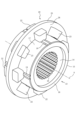
図2を参照してスリーブ20について説明する。図2はスリーブ20の斜視図である。図2に示すようにスリーブ20は、複数の凸部21と、中心軸Oの周りに互いに間隔をあけて凸部21を連結する連結部材25と、を備えている。連結部材25はフォーク(図示せず)にはまる。本実施形態では、連結部材25は一体に成形されている。
The
凸部21は、中心軸Oに沿って延びる四角柱状に形成されている。凸部21は、連結部材25の軸方向の端面26の両方から軸方向へ向けて突出している。本実施形態では、連結部材25の端面26の片方から8つの凸部21が突出し、片方の凸部21と同じ位置において、端面26のもう片方から8つの凸部21が突出している。凸部21は、端面26からの軸方向の突出長さが異なる第1歯22及び第2歯23を備えている。第1歯22は、第2歯23よりも端面26からの軸方向の突出長さが長いので、第1歯22の軸方向の先端は、第2歯23の軸方向の先端よりも軸方向の外側に位置する。第1歯22及び第2歯23は、中心軸Oの周りに交互に配置されている。
The
凸部21のうち中心軸Oの側を向く内面21aには、中心軸Oに平行な歯24が形成されている。さらに、中心軸Oの側を向く連結部材25の内面27のうち凸部21が連なる部分には、中心軸Oに平行な歯24が形成されている。歯24は、連結部材25、及び、連結部材25の端面26から突出する凸部21に切れ目なく連なっている。これにより歯24が破損し難くなる。
本実施形態では、凸部21のみに歯24が形成されている。「凸部21のみに歯24が形成される」というのは、凸部21の歯24に連なる歯が連結部材25の内面27に形成されるものを含む。しかし、凸部21が形成されていない連結部材25の内面27に歯24が形成されるものは含まない。
In this embodiment,
歯24は、凸部21の軸方向の全長、及び、連結部材25のうち凸部21に挟まれた部位に設けられている。凸部21に設けられた全ての歯24は、軸方向の全長に亘って完全な山形である。即ち、中心軸Oに垂直な歯24の断面の形状は、凸部21の軸方向の全長に亘って同一である。本実施形態では、第1歯22に歯24は形成されているが、第2歯23に歯24は形成されていない。
The
凸部21の内面21aに加え、連結部材25の内面27の全周に亘って歯24を同じピッチで形成すると、凸部21と連結部材25との境界において、歯24の山形が不完全になり易い。本実施形態では、凸部21、及び、連結部材25のうち凸部21に挟まれた部分に歯24が設けられており、それ以外の部分に歯24が設けられていないので、凸部21と連結部材25との境界に歯24を形成しなくても済む。そのため凸部21に同一のピッチで形成した歯24の山形を、軸方向の全長に亘って完全にし易い。
If the
図3はスリーブ20が配置されたハブ13の斜視図である。ハブ13の内周部14の内周面には、軸12(図1参照)に結合するスプライン18が形成されている。ハブ13の外周部15の外周面17には、中心軸Oに平行な溝19が形成されている。溝19は、外周面17の軸方向の全長に亘って設けられている。本実施形態では、ハブ13の外周面17のうちスリーブ20の歯24が配置される部位に、歯24と同数の溝19が形成されている。溝19の長さは歯24の長さよりも長い。スリーブ20に形成された歯24が、ハブ13の溝19にはまり合うので、スリーブ20はハブ13に対して軸方向に移動できるが、スリーブ20はハブ13の周りを回転できない。
FIG. 3 is a perspective view of the
本実施形態では、溝19はハブ13の外周面17の一部(4か所)に形成されているので、ハブ13の外周面17の全周に亘って溝19が形成される場合に比べ、溝19の加工量を抑制できる。しかし、必ずしもこれに限られるものではない。ハブ13の外周面17の全周に亘って溝19を形成することは当然可能である。
In this embodiment, the
溝19及び歯24の形状は特に限定されない。溝19や歯24は、側面から見て、例えばインボリュート曲線などの曲線に囲まれたものや角型など適宜設定される。また、溝19の中を転がるボールやコロを歯24に設けたり、歯24が転がるボールやコロを溝19に設けたりすることは当然可能である。これにより歯24と溝19との摩擦をより小さくできる。
The shapes of the
次に、かみ合いクラッチ10を用いた変速機30の変速方法について説明する。ここでは一例として、第1駆動ギヤ32にかみ合いクラッチ10が係合する場合について説明する。
Next, a method of shifting the
軸12と一体に回転しているハブ13と、軸12の周りを空転している第1駆動ギヤ32と、の間に動力を伝達するときは、ハブ13と一体に回転しているスリーブ20は、フォーク(図示せず)により軸方向に移動し第1駆動ギヤ32に近づく。このときは、中心軸Oと平行な歯24に回転方向の力がかかり、凸部21に形成された歯24の軸方向に延びる部分に溝19の軸方向に延びる部分が接する。歯24が連結部材25の内側のみに形成されている場合に比べ、歯24の軸方向の長さを長くできるので、フォークが連結部材25に力を加えるスリーブ20のモーメントを抑制できる。その結果、ハブ13の中心軸Oに対するスリーブ20の傾きを抑制できるので、スリーブ20が傾いてロックすることなく、ハブ13の軸方向へスリーブ20がスムーズに移動する。
When transmitting power between the
スリーブ20の凸部21の第1歯22は第2歯23よりも長いので、スリーブ20が回転しながら第1駆動ギヤ32に近づくと、まず、スリーブ20の第1歯22の歯先が第1駆動ギヤ32の凸部33の歯先に当たる。第2歯23よりも軸方向に長い第1歯22が凸部21にあるので、スリーブ20の凸部21と第1駆動ギヤ32の凸部33とをかみ合い易くできる。スリーブ20の凸部21と第1駆動ギヤ32の凸部33とがかみ合うと、第1駆動ギヤ32は軸部材11及びスリーブ20と一体に回転し、スリーブ20は軸部材11と第1駆動ギヤ32との間に動力を伝達する。
Since the
スリーブ20は凸部21に歯24が形成されているので、第1駆動ギヤ32の凸部33に凸部21がかみ合うときに、凸部21の歯24を介してスリーブ20とハブ13との間にトルクが伝達される。凸部21の歯24がハブ13(軸部材11)の溝19にはまり合うので、凸部21に歯24が形成されないで連結部材25の内側に歯24が形成される場合に比べ、凸部21の曲げ応力を抑制できる。その結果、第1駆動ギヤ32の凸部33に凸部21がかみ合うときに、凸部21に回転方向の力が加わることによる、凸部21と連結部材25とがなす隅を起点とする連結部材25や凸部21の破損を抑制できる。
Since the
ハブ13の溝19にはまり合う歯24を凸部21に設けることによって凸部21の強度を高くするので、凸部21を補強するために、凸部21と連結部材25とがなす隅の丸み(歯元R)を大きくしたり隅に補強リブを設けたりしなくても良い。凸部21と連結部材25がなす隅の丸みを大きくしたり補強リブを設けたりすると、凸部21のかみ合い深さが浅くなるという問題点があるが、かみ合いクラッチ10によればこれを防止することができ、凸部21のかみ合い深さを確保できる。
The strength of the
かみ合いクラッチ10は、凸部21のみに歯24が形成されているので、凸部21だけでなく、凸部21が形成されていない連結部材25の内面27にも歯24が形成される場合に比べ、歯24による連結部材25の断面積の低下を抑制できる。よって、連結部材25の強度の低下を抑制できる。さらに、凸部21だけでなく連結部材25にも歯24が形成される場合に比べ、溝19と擦れ合う歯24の面積を減らすことができるので、溝19と歯24との間の摩擦を抑制できる。
In the
かみ合いクラッチ10は、凸部21の第1歯22のみに歯24が形成されている。第1歯22に加え第2歯23にも歯24が形成される場合は、第1歯22が第1駆動ギヤ32の凸部33にかみ合うときに、第1歯22が凸部33から受ける回転方向の力が、歯24を介してハブ13に伝わり、第2歯23にも加わる。第1歯22及び第2歯23に形成される歯24の製造誤差によって、第2歯23の歯24に力がかかり、第1歯22の歯24に力がかからない場合が生じ得る。その場合に第1駆動ギヤ32の凸部33が第1歯22に加える力が大きいと、第1歯22が破損するおそれがある。これを防ぐために、凸部21の第1歯22のみに歯24を形成することにより、第1歯22が凸部33から力を受けるときに、第2歯23に力がかからないようにできる。
In the
全ての歯24は凸部21の軸方向の全長に亘って完全な山形なので、中心軸Oに垂直な歯24の断面の形状を同一にできる。これにより全ての歯24の強度を確保できる。その結果、凸部21に回転方向の力がかかったときに、歯24の角が欠けたり割れたりすることを防ぐことができる。
Since all the
ハブ13に形成された溝19の長さは、凸部21に形成された歯24の長さよりも長いので、ハブ13の軸方向の外側にスリーブ20が移動したときに溝19から歯24が外れないようにできる。よって、スリーブ20が軸方向に移動する範囲において、中心軸Oに対するスリーブ20の傾きを抑制できる。
The length of the
ハブ13の溝19の長さを凸部21の歯24の長さよりも長くする場合に、ハブ13の全体を溝19の長さと同じにすると、ハブ13の両側に第1駆動ギヤ32及び第2駆動ギヤ36が並んだときの軸方向の全長が長くなる。これに対しかみ合いクラッチ10は、軸12に固定される内周部14の軸方向の長さが、溝19が形成される外周部15の軸方向の長さよりも短い。さらに、内周部14よりも軸方向に張り出す外周部15の先端部16の径方向の内側に、第1駆動ギヤ32及び第2駆動ギヤ36の円筒部34,38の軸方向の端部35が位置する。これにより径方向に重なる先端部16及び端部35の分だけ軸方向の寸法を短縮できる。よって、かみ合いクラッチ10の軸方向の寸法を小さくできる。
When the length of the
以上、実施の形態に基づき本発明を説明したが、本発明はこの実施形態に何ら限定されるものではなく、本発明の趣旨を逸脱しない範囲内で種々の改良変形が可能であることは容易に推察できるものである。例えば、ハブ13に形成された溝19の数や形状、スリーブ20の凸部21の数や形状、連結部材25の形状、スリーブ20に形成された歯24の数や形状などは適宜設定できる。また、中心軸Oに垂直な凸部21の断面の形状は矩形状、扇形状など適宜設定できる。
Although the present invention has been described above based on the embodiments, the present invention is not limited to these embodiments in any way, and it is easy to make various improvements and modifications without departing from the spirit of the present invention. This can be inferred. For example, the number and shape of the
実施形態では、スリーブ20の凸部21の第1歯22と第2歯23とが交互に配置される場合について説明したが、必ずしもこれに限られるものではない。第1歯22や第2歯23が配置される位置や数は適宜設定できる。第1歯22や第2歯23を設けないで、全ての凸部21の軸方向の長さを同一にすることは当然可能である。
In the embodiment, a case has been described in which the
実施形態では、変速機30の駆動側にかみ合いクラッチ10を配置する場合について説明したが、これに限られるものではない。変速機30の被動側にかみ合いクラッチ10を配置することは当然可能である。
In the embodiment, a case has been described in which the
実施形態では、かみ合いクラッチ10を変速機30に配置する場合について説明したが、必ずしもこれに限られるものではない。変速機に限らず、動力の伝達・遮断を行う機能を要する種々の装置に、かみ合いクラッチ10を配置することは当然可能である。
In the embodiment, a case has been described in which the
実施形態では、かみ合いクラッチ10を変速機30に配置する場合について説明したので、第1駆動ギヤ32、第2駆動ギヤ36を相手部材とした。動力の伝達・遮断を行う機能を要する種々の装置にかみ合いクラッチ10を配置する場合には、その装置に応じて相手部材が適宜設定される。
In the embodiment, since the case where the
実施形態では、スリーブ20の凸部21に形成された歯24が、連結部材25のうち凸部21に挟まれる部分に形成された歯24に連なる場合について説明したが、必ずしもこれに限られるものではない。歯24のうち、連結部材25のうち凸部21が連なる部分の歯を省略することは当然可能である。連結部材25の歯を省略しても、係合を行うときに回転方向の力が加わる凸部21に歯24が形成されているので、凸部21の曲げ応力を抑制できるからである。
In the embodiment, a case has been described in which the
実施形態では、スリーブ20の連結部材25の内面27と凸部21の内面21aとが同一の円筒面上にある場合について説明したが、必ずしもこれに限られるものではない。例えば、連結部材25のうち凸部21が連なる部分の歯24を省略して、連結部材25の内面27を、凸部21の内面21aよりも中心軸Oから離れた位置に配置することは当然可能である。また、凸部21間を連結する連結部材25を直線状にする場合には、連結部材25の内面27を円筒面上に配置しなくても良い。
In the embodiment, a case has been described in which the
実施形態では、スリーブ20の軸方向の両側に相手部材(第1駆動ギヤ32、第2駆動ギヤ36)が配置される場合について説明したが、必ずしもこれに限られるものではない。スリーブ20の片方に、凸部を有する相手部材を配置することは当然可能である。その場合には、連結部材25の軸方向の両側に凸部21が突出している必要はなく、スリーブの端面のうち相手部材が対向している側に凸部を設ける。
In the embodiment, a case has been described in which the mating members (
実施形態では、軸12及び円筒状のハブ13を軸部材11が備える場合について説明したが、必ずしもこれに限られるものではない。スリーブ20に形成された歯24がはまり合う溝19が軸部材11の外周面に形成されていれば、軸部材11の形状や構造は適宜設定できる。
In the embodiment, a case has been described in which the
実施形態では、凸部21のうち第1歯22のみに歯24が形成される場合について説明したが、必ずしもこれに限られるものではない。第1歯22以外に、第2歯23や連結部材25の内面27に歯24を設けることは当然可能である。
In the embodiment, a case has been described in which the
実施形態では、軸方向の長さが異なる内周部14及び外周部15をハブ13に設ける場合について説明したが、必ずしもこれに限られるものではない。ハブ13の全体を溝19の長さと同じ長さにすることは当然可能である。
In the embodiment, a case has been described in which the
10 かみ合いクラッチ
11 軸部材
12 軸
13 ハブ
14 内周部
15 外周部
16 先端部
17 外周面
19 溝
20 スリーブ
21 凸部
21a 内面
22 第1歯
23 第2歯
24 歯
25 連結部材
26 端面
32 第1駆動ギヤ(相手部材)
36 第2駆動ギヤ(相手部材)
O 中心軸
10
22 1st tooth
23 second tooth
24
36 Second drive gear (mating member)
O center axis
Claims (4)
前記軸部材に配置されるスリーブを備え、
前記軸部材の外周面に、前記中心軸と平行に溝が形成され、
前記スリーブは、連結部材と、前記連結部材によって前記中心軸の周りに互いに間隔をあけて連結され前記連結部材の端面から軸方向に突出する複数の凸部と、を備え、
前記凸部は、前記軸方向の突出長さが異なる第1歯および第2歯を含み、
前記第1歯は、前記第2歯よりも前記突出長さが長く、
前記中心軸と平行であって前記溝にはまり合う歯が、前記第1歯の内面に形成され、前記第2歯の内面に前記歯が無いかみ合いクラッチ。 A dog clutch that transmits and interrupts power on the central axis of a shaft member,
comprising a sleeve disposed on the shaft member,
A groove is formed on the outer circumferential surface of the shaft member parallel to the central axis,
The sleeve includes a connecting member and a plurality of convex portions that are connected to each other at intervals around the central axis by the connecting member and protrude in the axial direction from an end surface of the connecting member,
The convex portion includes first teeth and second teeth having different protrusion lengths in the axial direction,
The first tooth has a longer protruding length than the second tooth,
A dog clutch, wherein teeth that are parallel to the central axis and fit into the grooves are formed on the inner surface of the first teeth , and there are no teeth on the inner surfaces of the second teeth .
前記軸部材は、前記相手部材が配置される軸と、前記相手部材と軸線方向に並んで前記軸に配置される円筒状のハブと、を備え、
前記ハブは、前記軸に固定される内周部と、前記内周部の径方向の外側に連なり前記スリーブが配置される外周部と、を備え、
前記外周部は、前記内周部よりも軸方向に張り出す先端部を備え、
前記先端部の径方向の内側に前記相手部材の一部が存在する請求項1から3のいずれかに記載のかみ合いクラッチ。 a mating member provided with a convex portion that engages with the convex portion of the sleeve;
The shaft member includes a shaft on which the mating member is arranged, and a cylindrical hub arranged on the shaft in line with the mating member in the axial direction,
The hub includes an inner circumferential portion fixed to the shaft, and an outer circumferential portion extending radially outward from the inner circumferential portion and on which the sleeve is disposed,
The outer circumferential portion includes a tip portion that projects further in the axial direction than the inner circumferential portion,
The dog clutch according to any one of claims 1 to 3, wherein a part of the mating member exists inside the tip portion in the radial direction.
Applications Claiming Priority (1)
| Application Number | Priority Date | Filing Date | Title |
|---|---|---|---|
| PCT/JP2019/030507 WO2021024304A1 (en) | 2019-08-02 | 2019-08-02 | Dog clutch |
Publications (2)
| Publication Number | Publication Date |
|---|---|
| JPWO2021024304A1 JPWO2021024304A1 (en) | 2021-02-11 |
| JP7341240B2 true JP7341240B2 (en) | 2023-09-08 |
Family
ID=74503968
Family Applications (1)
| Application Number | Title | Priority Date | Filing Date |
|---|---|---|---|
| JP2021538529A Active JP7341240B2 (en) | 2019-08-02 | 2019-08-02 | dog clutch |
Country Status (3)
| Country | Link |
|---|---|
| EP (1) | EP4008921A4 (en) |
| JP (1) | JP7341240B2 (en) |
| WO (1) | WO2021024304A1 (en) |
Families Citing this family (1)
| Publication number | Priority date | Publication date | Assignee | Title |
|---|---|---|---|---|
| US20240052922A1 (en) * | 2022-08-15 | 2024-02-15 | Dana Heavy Vehicle Systems Group, Llc | Multi-speed gearbox and assembly method |
Citations (2)
| Publication number | Priority date | Publication date | Assignee | Title |
|---|---|---|---|---|
| JP2018044641A (en) | 2016-09-15 | 2018-03-22 | トヨタ自動車株式会社 | Transmission for vehicle |
| JP2019127976A (en) | 2018-01-23 | 2019-08-01 | ジヤトコ株式会社 | transmission |
Family Cites Families (5)
| Publication number | Priority date | Publication date | Assignee | Title |
|---|---|---|---|---|
| JPS5825139Y2 (en) * | 1978-09-28 | 1983-05-30 | ヤンマーディーゼル株式会社 | Structure of clutch part in front drive clutch etc. |
| JPS5852334U (en) * | 1981-10-05 | 1983-04-09 | セイレイ工業株式会社 | clutch structure |
| GB2472838A (en) * | 2009-08-21 | 2011-02-23 | Hewland Engineering Ltd | Dog drive |
| JP5461334B2 (en) | 2010-07-28 | 2014-04-02 | 本田技研工業株式会社 | Dog clutch |
| JP6577441B2 (en) * | 2016-10-27 | 2019-09-18 | トヨタ自動車株式会社 | Dog clutch |
-
2019
- 2019-08-02 WO PCT/JP2019/030507 patent/WO2021024304A1/en unknown
- 2019-08-02 JP JP2021538529A patent/JP7341240B2/en active Active
- 2019-08-02 EP EP19940365.0A patent/EP4008921A4/en active Pending
Patent Citations (2)
| Publication number | Priority date | Publication date | Assignee | Title |
|---|---|---|---|---|
| JP2018044641A (en) | 2016-09-15 | 2018-03-22 | トヨタ自動車株式会社 | Transmission for vehicle |
| JP2019127976A (en) | 2018-01-23 | 2019-08-01 | ジヤトコ株式会社 | transmission |
Also Published As
| Publication number | Publication date |
|---|---|
| EP4008921A1 (en) | 2022-06-08 |
| JPWO2021024304A1 (en) | 2021-02-11 |
| EP4008921A4 (en) | 2023-04-19 |
| WO2021024304A1 (en) | 2021-02-11 |
Similar Documents
| Publication | Publication Date | Title |
|---|---|---|
| JP6485543B2 (en) | Torque transmission joint and worm reducer | |
| CN105626715B (en) | Vibration damping friction of wet clutch | |
| JPS59217055A (en) | Differential gear using detachable ring | |
| JP6333999B2 (en) | Speed change mechanism | |
| JP7341240B2 (en) | dog clutch | |
| JP5929451B2 (en) | Torque transmission joint and electric power steering device | |
| JP6262375B2 (en) | Speed change mechanism | |
| JP4542809B2 (en) | Torque interrupting device | |
| JP5157666B2 (en) | Elastic shaft coupling and electric power steering device | |
| EP2236861A1 (en) | Belt type stepless transmission and pulley for the same | |
| JP5757970B2 (en) | Worm gear mechanism | |
| JP6590569B2 (en) | transmission | |
| JP7457489B2 (en) | planetary gearbox | |
| JP7302523B2 (en) | Method for manufacturing drive drum | |
| WO2017017724A1 (en) | Transmission | |
| WO2022264408A1 (en) | Torque transmitting element | |
| JPH0544814A (en) | Oil pump drive shaft connecting structure | |
| JP2019138450A (en) | Speed reducer, motor unit, and cleaning robot | |
| JP7317321B2 (en) | transmission | |
| JP7213148B2 (en) | Clutch mechanism and motor device | |
| KR100620813B1 (en) | Spacer of Manual Transmission | |
| JP4583304B2 (en) | Gear device | |
| JP2020159402A (en) | Seal device of vehicle | |
| JP6966530B2 (en) | Lock type bidirectional clutch using coil spring | |
| JP6551522B2 (en) | Torque transmission joint and worm reducer |
Legal Events
| Date | Code | Title | Description |
|---|---|---|---|
| A621 | Written request for application examination |
Free format text: JAPANESE INTERMEDIATE CODE: A621 Effective date: 20220107 |
|
| A131 | Notification of reasons for refusal |
Free format text: JAPANESE INTERMEDIATE CODE: A131 Effective date: 20230314 |
|
| A521 | Request for written amendment filed |
Free format text: JAPANESE INTERMEDIATE CODE: A523 Effective date: 20230509 |
|
| TRDD | Decision of grant or rejection written | ||
| A01 | Written decision to grant a patent or to grant a registration (utility model) |
Free format text: JAPANESE INTERMEDIATE CODE: A01 Effective date: 20230808 |
|
| A61 | First payment of annual fees (during grant procedure) |
Free format text: JAPANESE INTERMEDIATE CODE: A61 Effective date: 20230829 |
|
| R150 | Certificate of patent or registration of utility model |
Ref document number: 7341240 Country of ref document: JP Free format text: JAPANESE INTERMEDIATE CODE: R150 |