JP7340428B2 - game machine - Google Patents
game machine Download PDFInfo
- Publication number
- JP7340428B2 JP7340428B2 JP2019210387A JP2019210387A JP7340428B2 JP 7340428 B2 JP7340428 B2 JP 7340428B2 JP 2019210387 A JP2019210387 A JP 2019210387A JP 2019210387 A JP2019210387 A JP 2019210387A JP 7340428 B2 JP7340428 B2 JP 7340428B2
- Authority
- JP
- Japan
- Prior art keywords
- game
- passage forming
- forming part
- winning
- screw member
- Prior art date
- Legal status (The legal status is an assumption and is not a legal conclusion. Google has not performed a legal analysis and makes no representation as to the accuracy of the status listed.)
- Active
Links
Images


Landscapes
- Pinball Game Machines (AREA)
Description
本発明は、遊技が可能な遊技機に関する。 The present invention relates to a gaming machine capable of playing games.
遊技機の一例であるパチンコ遊技機において、遊技場に設置された遊技島から供給される遊技媒体を貯留可能な貯留部と、遊技媒体を払出すことが可能な払出装置(払出部)と、貯留部に供給された遊技媒体を払出部に誘導する誘導通路を形成する誘導通路形成部と、を備え、これら貯留部や誘導通路形成部がねじ部材により遊技枠に取付けられたもの等があった(例えば、特許文献1参照)。 A pachinko game machine, which is an example of a game machine, includes a storage part that can store game media supplied from a game island installed in a game parlor, a payout device (payout part) that can pay out the game media, A guide passage forming part that forms a guide passage for guiding the game media supplied to the storage part to the payout part, and the storage part and the guide passage forming part are attached to the game frame with screw members. (For example, see Patent Document 1).
上記特許文献1に記載の遊技機では、これら貯留部や誘導通路形成部を遊技枠に取付けるためのねじ部材や遊技島の内部に取付けられたねじ部材等が外れて、貯留部や誘導通路形成部に落下した場合、遊技媒体とともにねじ部材が払出装置に混入してしまい、遊技媒体を正常に払出しすることができなくなったり、払出装置が故障したり、あるいは、遊技媒体とともにねじ部材が遊技者に払出されたりすることがあるという問題があった。
In the gaming machine described in
本発明は、このような問題点に着目してなされたもので、払出部にねじ部材が混入することを防止することができる遊技機を提供することを目的とする。 The present invention has been made with attention to such problems, and an object of the present invention is to provide a gaming machine that can prevent screw members from getting mixed into the payout section.
手段Aの遊技機は、
可変表示を実行可能であり、遊技者にとって有利な有利状態に制御可能な遊技機であって、
始動領域と、
発光可能な発光手段と、
可変表示に対応する特定表示を表示可能な表示手段と、
所定条件が成立したことに基づいて、前記特定表示を表示する特定表示演出と、前記発光手段を発光させる特定発光演出と、を実行可能な演出実行手段と、
遊技媒体を貯留可能な貯留部と、
遊技媒体を払出すことが可能な払出部と、
上面が開口し、前記貯留部の遊技媒体を前記払出部に誘導する誘導通路を形成する誘導通路形成部と、
前記誘導通路形成部の上面を覆うように設けられたねじ落下制限部と、
を備え、
前記払出部から払出された遊技媒体が前記始動領域に進入したことに基づいて前記特定表示を表示可能であり、
前記ねじ落下制限部は、該ねじ落下制限部上に落下した遊技媒体が滞留せずに、かつ該ねじ落下制限部上に落下したねじ部材が前記誘導通路形成部へ落下せずに該ねじ落下制限部上に滞留可能となるように、該ねじ落下制限部上に落下したねじ部材を係止可能である一方、該ねじ落下制限部上に落下した遊技媒体を係止しないように形成された孔部を有し、
前記演出実行手段は、前記特定表示演出において前記特定表示の表示が完了するよりも前に前記発光手段の発光が遊技者から認識可能となるように前記特定発光演出を実行し、
前記発光手段は、前記特定発光演出が開始されてから所定タイミングまでの第1期間と該所定タイミングから該特定発光演出の対象である可変表示の特定タイミングまでの第2期間において前記特定発光演出に応じた態様にて発光する、
ことを特徴としている。
手段1の遊技機は、
可変表示を実行可能であり、遊技者にとって有利な有利状態(例えば、大当り遊技状態)に制御可能な遊技機(例えば、パチンコ遊技機1)であって、
遊技媒体(例えば、遊技球P)を貯留可能な貯留部(例えば、球タンク形成部201)と、
遊技媒体を払出すことが可能な払出部(例えば、払出装置200)と、
上面が開口し、前記貯留部の遊技媒体を前記払出部に誘導する誘導通路(例えば、第1誘導通路や第2誘導通路)を形成する誘導通路形成部(例えば、第1誘導通路形成部202や第2誘導通路形成部204)と、
前記誘導通路形成部の上面の一部を覆うように設けられたカバー部(例えば、第1カバー体310、第2カバー体320、第3カバー体330)と、
を備え、
前記カバー部に、該カバー部上に落下したねじ部材(例えば、ねじ部材N1~N6、N11~N16)の前記誘導通路形成部への落下を制限するための所定制限部(例えば、長孔316A~316C、凹溝326A~326C、凹部336)が設けられ(図22、図24参照)、
前記誘導通路形成部に、該誘導通路形成部に落下したねじ部材の前記払出部への移動を制限するための特定制限部(例えば、孔部271A~271H)が複数設けられており(図11、図12、図27参照)、
前記所定制限部は、前記カバー部上に落下したねじ部材(例えば、ねじ部材N1~N6、N11~N16)を該カバー部上に滞留させることが可能な第1滞留部(例えば、長孔316A~316C)と第2滞留部(例えば、凹溝326A~326C)とを含み、
前記第2滞留部は、前記第1滞留部よりも前記払出部(例えば、払出装置200)に近い位置に設けられ、該第1滞留部よりも大きく(L22B>L21)、
さらに、
発光可能な発光手段(例えば、メインランプ9a、枠ランプ9b、アタッカランプ9c、可動体ランプ9d、入賞時フラッシュ用ランプ135SG009F)と、
可変表示に対応する特定表示(例えば、保留表示とアクティブ表示)を表示可能な表示手段(例えば、画像表示装置5)と、
所定条件が成立したこと(例えば、始動入賞の発生)に基づいて、前記特定表示を表示する特定表示演出(例えば、保留表示やアクティブ表示を表示パターンα~表示パターンγのいずれかで表示する部分)と、前記発光手段を発光させる特定発光演出(例えば、入賞時フラッシュ演出)と、を実行可能な演出実行手段(例えば、演出制御用CPU120)と、
を備え、
前記演出実行手段は、前記特定表示演出において前記特定表示の表示が完了するよりも前に前記発光手段の発光が遊技者から認識可能となるように前記特定発光演出を実行し(例えば、図40-28、図40-29(A)~図40-32(H)、図40-49(A)~図40-50(D)に示すように、保留表示の表示が完了するよりも前から入賞時フラッシュ用ランプ135SG009Fを点灯させる部分)、
前記特定発光演出が実行されないときよりも前記特定発光演出が実行されるときの方が有利状態に制御される割合が高く(例えば、図40-24に示すように、入賞時フラッシュ演出が実行される場合は、入賞時フラッシュ演出が実行されない場合よりも大当り遊技状態に制御される割合が高い部分)、
前記発光手段は、第1発光手段(例えば、入賞時フラッシュ用ランプ135SG009F)と、該第1発光手段とは異なる第2発光手段(例えば、メインランプ9a、枠ランプ9b、アタッカランプ9c、可動体ランプ9d)と、を含み、
前記第1発光手段は、前記特定発光演出が開始されてから所定タイミングまでの第1期間(例えば、前期入賞時フラッシュ演出が開始されてから該前期入賞時フラッシュ演出の終了タイミングまでの期間)と該所定タイミングから該特定発光演出の対象である可変表示の特定タイミングまでの第2期間(例えば、後期入賞時フラッシュ演出が開始されてから入賞時フラッシュ演出対象である可変表示のリーチ演出開始タイミングまでの期間)において前記特定発光演出に応じた態様にて発光し(例えば、図40-28に示すように、入賞時フラッシュ用ランプ135SG009Fは、前期入賞時フラッシュ演出の実行期間中は、輝度C1且つ周期T1にて点滅し、後期入賞時フラッシュ演出実行期間中は輝度C2且つ周期T2にて点滅する部分)、
前記第2発光手段は、前記第1期間において前記特定発光演出に応じた態様にて発光し、前記第2期間において実行中の可変表示に応じた態様にて発光する(例えば、図40-28に示すように、メインランプ9a、枠ランプ9b、アタッカランプ9c、可動体ランプ9dは、前期入賞時フラッシュ演出の実行期間中は、輝度C1且つ周期T1にて点滅し、後期入賞時フラッシュ演出実行期間中は輝度C2且つ周期T0にて点滅する部分)、
ことを特徴としている。
この特徴によれば、カバー部上に落下したねじ部材が誘導通路形成部内に落下することを防止することができる。
The gaming machine of means A is
A gaming machine that can perform variable display and can be controlled to an advantageous state that is advantageous to a player,
a starting area;
A light emitting means capable of emitting light;
a display means capable of displaying a specific display corresponding to the variable display;
Effect execution means capable of executing a specific display effect of displaying the specific display and a specific light emission effect of causing the light emitting means to emit light based on a predetermined condition being satisfied;
a storage section capable of storing game media;
a payout unit capable of paying out game media;
a guide passage forming part having an open top surface and forming a guide passage for guiding game media in the storage part to the payout part;
a screw drop restriction portion provided to cover the upper surface of the guide passage forming portion;
Equipped with
The specific display can be displayed based on the game media paid out from the payout unit entering the starting area,
The screw fall restriction section prevents the game medium that has fallen onto the screw fall restriction section from staying therein, and prevents the screw member that has fallen onto the screw fall restriction section from falling into the guide path forming section. The screw member is formed so as to be able to stay on the restricting portion and to be able to lock a screw member that has fallen onto the screw fall restricting portion, but not to lock a game medium that has fallen onto the screw falling restricting portion. having a hole,
The performance execution means executes the specific light emission performance so that the light emission of the light emission unit becomes recognizable to the player before the display of the specific display is completed in the specific display performance,
The light emitting means performs the specific light emitting effect during a first period from the start of the specific light emitting effect to a predetermined timing and a second period from the predetermined timing to a specific timing of the variable display that is the target of the specific light emitting effect. emits light in a corresponding manner,
It is characterized by
The gaming machine of
A gaming machine (for example, Pachinko gaming machine 1) that can perform variable display and can be controlled to an advantageous state (for example, a jackpot gaming state) that is advantageous to the player,
a storage section (for example, ball tank forming section 201) capable of storing game media (for example, game balls P);
A payout unit (for example, payout device 200) capable of paying out game media;
A guiding passage forming part (for example, first guiding passage forming part 202) having an open top surface and forming a guiding passage (for example, a first guiding passage or a second guiding passage) for guiding game media in the storage part to the dispensing part. and second guide passage forming part 204),
a cover part (for example, a first cover body 310, a second cover body 320, a third cover body 330) provided so as to cover a part of the upper surface of the guide passage forming part;
Equipped with
The cover part is provided with a predetermined restriction part (for example, the elongated hole 316A) for restricting the screw members (for example, screw members N1 to N6, N11 to N16) that have fallen onto the cover part from falling into the guide passage forming part. ~316C, concave grooves 326A~326C, and concave portions 336) (see FIGS. 22 and 24),
A plurality of specific restriction parts (for example, holes 271A to 271H) are provided in the guide passage forming part for restricting the movement of the screw member that has fallen into the guiding passage forming part to the dispensing part (FIG. 11). , see Figures 12 and 27),
The predetermined restriction section includes a first retention section (for example, the elongated hole 316A) that can retain the screw members (for example, screw members N1 to N6, N11 to N16) that have fallen onto the cover section. - 316C) and a second retention part (for example, grooves 326A to 326C),
The second retention part is provided at a position closer to the dispensing part (for example, the dispensing device 200) than the first retention part, and is larger than the first retention part (L22B>L21),
moreover,
Light-emitting means capable of emitting light (for example,
Display means (e.g., image display device 5) capable of displaying a specific display (e.g., pending display and active display) corresponding to the variable display;
A specific display effect that displays the specific display based on the establishment of a predetermined condition (for example, the occurrence of a starting prize) (for example, a part that displays a pending display or an active display in any of display patterns α to display patterns γ) ), and a specific light emitting effect (for example, a flash effect when winning a prize) that causes the light emitting means to emit light;
Equipped with
The effect executing means executes the specific light emitting effect so that the light emission of the light emitting means can be recognized by the player before the display of the specific display is completed in the specific display effect (for example, as shown in FIG. -28, as shown in Figures 40-29(A) to 40-32(H), and 40-49(A) to 40-50(D), before the display of the pending display is completed. The part that lights up the flash lamp 135SG009F when winning a prize),
The rate of being controlled to an advantageous state is higher when the specific light emitting effect is executed than when the specific light emitting effect is not executed (for example, as shown in FIG. 40-24, when the winning flash effect is executed, (If the flash effect is not executed at the time of winning, the percentage of control to be in the jackpot gaming state is higher than when the flash effect is not executed)
The light emitting means includes a first light emitting means (e.g. winning flash lamp 135SG009F) and a second light emitting means different from the first light emitting means (e.g.
The first light emitting means includes a first period from the start of the specific light emitting effect to a predetermined timing (for example, a period from the start of the previous period winning flash effect to the end timing of the previous period winning flash effect); A second period from the predetermined timing to the specific timing of the variable display that is the target of the specific light emitting effect (for example, from the start of the late winning flash effect to the start timing of the variable display that is the target of the winning flash effect) (for example, as shown in FIG. 40-28, the winning flash lamp 135SG009F has a brightness of C1 and (The part that blinks at cycle T1, and during the execution period of the flash effect at the time of winning in the second half, the brightness is C2 and blinks at cycle T2),
The second light emitting means emits light in a manner corresponding to the specific light emitting effect during the first period, and emits light in a manner according to the variable display being executed during the second period (for example, in FIG. 40-28 As shown in , the
It is characterized by
According to this feature, the screw member that has fallen onto the cover part can be prevented from falling into the guide passage forming part.
また、後述する発明を実施するための形態には、以下の手段2の遊技機に係る発明が含まれる。従来より、遊技機において、特開2016-105941号公報に示されているような、所定条件(遊技球の始動領域への進入)が成立したことに基づいて、該所定条件の成立に基づく特定表示(保留表示やアクティブ表示)を表示手段に表示するとともに、該所定条件の成立に基づく可変表示を対象として、該可変表示の開始前から有利状態に制御されることを示唆する先読み予告を実行可能であり、発光手段を発光させることにより先読み予告(特定発光演出)を実行可能としているものがあった。しかしながら、このような遊技機にあっては、特定表示の表示が開始されるタイミングと特定発光演出が開始されるタイミングによっては、特定発光演出の対象である特定表示を遊技者が認識し難くなってしまうことが考えられ、この点に鑑み、特定発光演出の対象となっている特定表示を遊技者が認識し易くできる遊技機の提供が求められている。
Further, the embodiments for carrying out the invention described below include the invention related to the gaming machine of
手段2の遊技機は、
可変表示を実行可能であり、遊技者にとって有利な有利状態(例えば、大当り遊技状態)に制御可能な遊技機(例えば、パチンコ遊技機1)であって、
発光可能な発光手段(例えば、メインランプ9a、枠ランプ9b、アタッカランプ9c、可動体ランプ9d、入賞時フラッシュ用ランプ135SG009F)と、
可変表示に対応する特定表示(例えば、保留表示とアクティブ表示)を表示可能な表示手段(例えば、画像表示装置5)と、
所定条件が成立したこと(例えば、始動入賞の発生)に基づいて、前記特定表示を表示する特定表示演出(例えば、保留表示やアクティブ表示を表示パターンα~表示パターンγのいずれかで表示する部分)と、前記発光手段を発光させる特定発光演出(例えば、入賞時フラッシュ演出)と、を実行可能な演出実行手段(例えば、演出制御用CPU120)と、
を備え、
前記演出実行手段は、前記特定表示演出において前記特定表示の表示が完了するよりも前に前記発光手段の発光が遊技者から認識可能となるように前記特定発光演出を実行し(例えば、図40-28、図40-29(A)~図40-32(H)、図40-49(A)~図40-50(D)に示すように、保留表示の表示が完了するよりも前から入賞時フラッシュ用ランプ135SG009Fを点灯させる部分)、
前記特定発光演出が実行されないときよりも前記特定発光演出が実行されるときの方が有利状態に制御される割合が高く(例えば、図40-24に示すように、入賞時フラッシュ演出が実行される場合は、入賞時フラッシュ演出が実行されない場合よりも大当り遊技状態に制御される割合が高い部分)、
前記発光手段は、第1発光手段(例えば、入賞時フラッシュ用ランプ135SG009F)と、該第1発光手段とは異なる第2発光手段(例えば、メインランプ9a、枠ランプ9b、アタッカランプ9c、可動体ランプ9d)と、を含み、
前記第1発光手段は、前記特定発光演出が開始されてから所定タイミングまでの第1期間(例えば、前期入賞時フラッシュ演出が開始されてから該前期入賞時フラッシュ演出の終了タイミングまでの期間)と該所定タイミングから該特定発光演出の対象である可変表示の特定タイミングまでの第2期間(例えば、後期入賞時フラッシュ演出が開始されてから入賞時フラッシュ演出対象である可変表示のリーチ演出開始タイミングまでの期間)において前記特定発光演出に応じた態様にて発光し(例えば、図40-28に示すように、入賞時フラッシュ用ランプ135SG009Fは、前期入賞時フラッシュ演出の実行期間中は、輝度C1且つ周期T1にて点滅し、後期入賞時フラッシュ演出実行期間中は輝度C2且つ周期T2にて点滅する部分)、
前記第2発光手段は、前記第1期間において前記特定発光演出に応じた態様にて発光し、前記第2期間において実行中の可変表示に応じた態様にて発光する(例えば、図40-28に示すように、メインランプ9a、枠ランプ9b、アタッカランプ9c、可動体ランプ9dは、前期入賞時フラッシュ演出の実行期間中は、輝度C1且つ周期T1にて点滅し、後期入賞時フラッシュ演出実行期間中は輝度C2且つ周期T0にて点滅する部分)、
ことを特徴としている。
この特徴によれば、特定表示の表示完了よりも前に発光手段が発光するため、特定発光演出の対象となっている特定表示を遊技者が認識し易くなるとともに、特定発光演出の第1期間においては、第1発光手段だけではなく、第2発光手段についても特定発光演出に応じた態様にて発光させることで特定発光演出をより際立たせることができるので、該特定発光演出の対象となっている特定表示をより一層、遊技者が認識し易くなる。
The gaming machine of
A gaming machine (for example, Pachinko gaming machine 1) that can perform variable display and can be controlled to an advantageous state (for example, a jackpot gaming state) that is advantageous to the player,
Light-emitting means capable of emitting light (for example,
Display means (e.g., image display device 5) capable of displaying a specific display (e.g., pending display and active display) corresponding to the variable display;
A specific display effect that displays the specific display based on the establishment of a predetermined condition (for example, the occurrence of a starting prize) (for example, a part that displays a pending display or an active display in any of display patterns α to display patterns γ) ), and a specific light emitting effect (for example, a flash effect when winning a prize) that causes the light emitting means to emit light;
Equipped with
The effect executing means executes the specific light emitting effect so that the light emission of the light emitting means can be recognized by the player before the display of the specific display is completed in the specific display effect (for example, as shown in FIG. -28, as shown in Figures 40-29(A) to 40-32(H), and 40-49(A) to 40-50(D), before the display of the pending display is completed. The part that lights up the flash lamp 135SG009F when winning a prize),
The rate of being controlled to an advantageous state is higher when the specific light emitting effect is executed than when the specific light emitting effect is not executed (for example, as shown in FIG. 40-24, when the winning flash effect is executed, (If the flash effect is not executed at the time of winning, the percentage of control to be in the jackpot gaming state is higher than when the flash effect is not executed)
The light emitting means includes a first light emitting means (e.g. winning flash lamp 135SG009F) and a second light emitting means different from the first light emitting means (e.g.
The first light emitting means includes a first period from the start of the specific light emitting effect to a predetermined timing (for example, a period from the start of the previous period winning flash effect to the end timing of the previous period winning flash effect); A second period from the predetermined timing to the specific timing of the variable display that is the target of the specific light emitting effect (for example, from the start of the late winning flash effect to the start timing of the variable display that is the target of the winning flash effect) (for example, as shown in FIG. 40-28, the winning flash lamp 135SG009F has a brightness of C1 and (The part that blinks at cycle T1, and during the execution period of the flash effect at the time of winning in the second half, the brightness is C2 and blinks at cycle T2),
The second light emitting means emits light in a manner corresponding to the specific light emitting effect during the first period, and emits light in a manner according to the variable display being executed during the second period (for example, in FIG. 40-28 As shown in , the
It is characterized by
According to this feature, since the light emitting means emits light before the display of the specific display is completed, it becomes easier for the player to recognize the specific display that is the target of the specific light emission effect, and the first period of the specific light emission effect In this case, the specific light emitting effect can be made more conspicuous by causing not only the first light emitting means but also the second light emitting means to emit light in a manner corresponding to the specific light emitting effect. This makes it easier for the player to recognize the specific display.
尚、本発明は、本発明の請求項に記載された発明特定事項のみを有するものであっても良いし、本発明の請求項に記載された発明特定事項とともに該発明特定事項以外の構成を有するものであっても良い。 Note that the present invention may have only the matters specifying the invention described in the claims of the present invention, or may include configurations other than the matters specifying the invention together with the matters specifying the invention described in the claims of the present invention. It may be something that you have.
本発明に係る遊技機を実施するための形態を図面に基づいて以下に説明する。 DESCRIPTION OF THE PREFERRED EMBODIMENTS A mode for implementing a gaming machine according to the present invention will be explained below based on the drawings.
(形態)
形態1の遊技機は、
遊技媒体(例えば、遊技球P)を貯留可能な貯留部(例えば、球タンク形成部201)と、
遊技媒体を払出すことが可能な払出部(例えば、払出装置200)と、
上面が開口し、前記貯留部の遊技媒体を前記払出部に誘導する誘導通路(例えば、第1誘導通路や第2誘導通路)を形成する誘導通路形成部(例えば、第1誘導通路形成部202や第2誘導通路形成部204)と、
を備える
ことを特徴としている。
(form)
a storage section (for example, ball tank forming section 201) capable of storing game media (for example, game balls P);
A payout unit (for example, payout device 200) capable of paying out game media;
A guiding passage forming part (for example, first guiding passage forming part 202) having an open top surface and forming a guiding passage (for example, a first guiding passage or a second guiding passage) for guiding game media in the storage part to the dispensing part. and second guide passage forming part 204),
It is characterized by having the following.
形態2の遊技機は、形態1に記載の遊技機であって、
前記誘導通路形成部の上面の一部を覆うように設けられたカバー部(例えば、第1カバー体310のカバー部314、第2カバー体320のカバー部324、第3カバー体330のカバー部334)を備え、
前記カバー部に、該カバー部上に落下したねじ部材(例えば、ねじ部材N1~N6、N11~N16)の前記誘導通路形成部(例えば、第1誘導通路形成部202)への落下を制限するための所定制限部(例えば、長孔316A~316C、凹溝326A~326C、凹部336)が設けられている(図22、図24参照)
ことを特徴としている。
この特徴によれば、カバー部上に落下したねじ部材が誘導通路形成部内に落下することを防止することができる。
The gaming machine of
A cover part provided to cover a part of the upper surface of the guide passage forming part (for example, the
The cover part restricts screw members (for example, screw members N1 to N6, N11 to N16) that have fallen onto the cover part from falling to the guide passage forming part (for example, the first guide passage forming part 202). Predetermined limiting portions (for example, long holes 316A to 316C, grooves 326A to 326C, and recessed portion 336) are provided for this purpose (see FIGS. 22 and 24).
It is characterized by
According to this feature, the screw member that has fallen onto the cover part can be prevented from falling into the guide passage forming part.
形態3の遊技機は、形態2に記載の遊技機であって、
前記所定制限部(例えば、長孔316A~316C、凹溝326A~326C、凹部336)は、前記カバー部上に落下した遊技媒体を滞留させることなく該カバー部上から落下可能に設けられている
ことを特徴としている。
この特徴によれば、所定制限部に遊技媒体が滞留することがなく、常にねじ部材を滞留させることが可能な状態を維持できるため、カバー部上に落下したねじ部材が誘導通路形成部内に落下することを防止することができる。
The gaming machine of
The predetermined restriction portions (for example, the elongated holes 316A to 316C, the grooves 326A to 326C, and the recessed portion 336) are provided so that the game media that has fallen onto the cover portion can fall from above the cover portion without being retained. It is characterized by
According to this feature, the game medium does not stay in the predetermined restriction part, and a state in which the screw member can be retained at all times can be maintained, so that the screw member that falls onto the cover part falls into the guide passage forming part. This can be prevented.
形態4の遊技機は、形態2または3に記載の遊技機であって、
前記所定制限部は、前記カバー部上に落下したねじ部材(例えば、ねじ部材N1~N6、N11~N16)を該カバー部上に滞留させることが可能な第1滞留部(例えば、長孔316A~316C)と第2滞留部(例えば、凹溝326A~326C)とを含み、
前記第2滞留部は、前記第1滞留部よりも前記払出部(例えば、払出装置200)に近い位置に設けられ、該第1滞留部よりも大きい(L22B>L21)
ことを特徴としている。
この特徴によれば、払出部に近づくにつれてねじ部材が滞留部に滞留されやすくなるため、カバー部上に落下したねじ部材が移動して誘導通路形成部内に落下することを防止することができる。
The gaming machine of
The predetermined restriction section includes a first retention section (for example, the elongated hole 316A) that can retain the screw members (for example, screw members N1 to N6, N11 to N16) that have fallen onto the cover section. - 316C) and a second retention part (for example, grooves 326A to 326C),
The second retention part is provided at a position closer to the dispensing part (for example, the dispensing device 200) than the first retention part, and is larger than the first retention part (L22B>L21).
It is characterized by
According to this feature, since the screw member is more likely to be retained in the retention part as it approaches the dispensing part, it is possible to prevent the screw member that has fallen onto the cover part from moving and falling into the guide passage forming part.
形態5の遊技機は、形態1~4のいずれかに記載の遊技機であって、
前記誘導通路形成部(例えば、第1誘導通路形成部202)に、該誘導通路形成部に落下したねじ部材(例えば、ねじ部材N1~N6、N11~N16)の前記払出部(例えば、払出装置200)への移動を制限するための特定制限部(例えば、孔部271A~271H)が複数設けられている(図12、図27参照)
ことを特徴としている。
この特徴によれば、誘導通路形成部内に混入したねじ部材が払出部に混入することを防止することができる。
The gaming machine of
The screw members (for example, screw members N1 to N6, N11 to N16) that have fallen into the guide passage forming part (for example, the first guiding passage forming part 202) are placed in the dispensing part (for example, by the dispensing device). A plurality of specific restriction parts (for example, holes 271A to 271H) are provided for restricting movement to 200) (see FIGS. 12 and 27).
It is characterized by
According to this feature, it is possible to prevent the screw member that has entered the guide passage forming section from entering the dispensing section.
形態6の遊技機は、形態5に記載の遊技機であって、
前記特定制限部は、複数の孔部(例えば、孔部271A~271H)であり、
前記複数の孔部のうち少なくとも2以上の孔部は、前記誘導通路形成部に混入したねじ部材を前記払出部に到達する前に前記誘導通路形成部外に落下させることが可能な大きさを有する(L11>L2、図11参照)
ことを特徴としている。
この特徴によれば、誘導通路形成部にねじ部材が混入しても孔部から誘導通路形成部外に落下させることができるため、誘導通路形成部内に混入したねじ部材が払出部に混入することを防止することができる。また、誘導通路形成部内に混入したねじ部材により遊技媒体の流下が阻害されることを防止することができる。
The gaming machine of
The specific restriction portion is a plurality of holes (for example, holes 271A to 271H),
At least two or more of the plurality of holes have a size that allows the screw member mixed in the guide passage forming part to fall out of the guiding passage forming part before reaching the dispensing part. (L11>L2, see Figure 11)
It is characterized by
According to this feature, even if a screw member gets mixed into the guide passage forming part, it can be dropped from the hole to the outside of the guiding passage forming part, so that the screw member mixed inside the guiding passage forming part does not get mixed into the dispensing part. can be prevented. Furthermore, it is possible to prevent the flow of the game medium from being obstructed by the screw member mixed into the guide passage forming portion.
形態7の遊技機は、形態6に記載の遊技機であって、
前記複数の孔部は、それぞれ大きさが異なり、
前記複数の孔部のうち最も大きい所定孔部は、前記払出部に最も近い位置に設けられている(例えば、孔部271Hの左右寸法L12は他の孔部271A~271Gの左右寸法より大きい。図12参照)
ことを特徴としている。
この特徴によれば、所定孔部からねじ部材を好適に誘導通路形成部外に落下させることができるため、誘導通路形成部内に落下したねじ部材が払出部に混入することを防止することができる。
The gaming machine of
The plurality of holes have different sizes,
The largest predetermined hole among the plurality of holes is provided at the position closest to the dispensing section (for example, the left-right dimension L12 of the hole 271H is larger than the left-right dimensions of the other holes 271A to 271G). (See Figure 12)
It is characterized by
According to this feature, since the screw member can be suitably dropped from the predetermined hole to the outside of the guide passage forming part, it is possible to prevent the screw member that has fallen into the guide passage forming part from getting mixed into the dispensing part. .
形態8の遊技機は、形態6または7に記載の遊技機であって、
前記誘導通路形成部(例えば、第1誘導通路形成部202)の上面において前記カバー部(例えば、第1カバー体310のカバー部314、第2カバー体320のカバー部324、第3カバー体330のカバー部334)により覆われていない非被覆領域(例えば、非被覆領域350)があり、
複数の前記特定制限部のうち少なくとも一部(例えば、孔部271B~271H)は、前記誘導通路形成部における前記非被覆領域に対応する位置に設けられている(図27参照)
ことを特徴としている。
この特徴によれば、ねじ部材が非被覆領域から誘導通路形成部に混入しても、孔部から誘導通路形成部外に落下させることができる。
The gaming machine of
The cover parts (for example, the
At least some of the plurality of specific restriction parts (for example, holes 271B to 271H) are provided at positions corresponding to the non-covered areas in the guide passage forming part (see FIG. 27).
It is characterized by
According to this feature, even if the screw member enters the guide passage forming part from the non-covered area, it can be dropped out of the guiding passage forming part through the hole.
形態9の遊技機は、形態1~8のいずれかに記載の遊技機であって、
前記貯留部(例えば、球タンク形成部201)が設けられた遊技枠(例えば、遊技機用枠3)を備え、
前記貯留部は、
前記遊技枠の所定部(例えば、第1突出部224)の上面側に配置され、
前記所定部の上面との間にねじ部材が進入しないように該所定部の上面に近接または当接している(L30<L1、図19(B)参照)
ことを特徴としている。
この特徴によれば、ねじ部材が遊技枠の所定部と貯留部との間に入り込んで部材が破損してしまうことを防止することができる。
The gaming machine of
A game frame (for example, a game machine frame 3) in which the storage section (for example, the ball tank forming section 201) is provided,
The storage section is
disposed on the upper surface side of a predetermined part (for example, the first protrusion 224) of the game frame,
The screw member is close to or in contact with the upper surface of the predetermined portion so as not to enter between the screw member and the upper surface of the predetermined portion (L30<L1, see FIG. 19(B)).
It is characterized by
According to this feature, it is possible to prevent the screw member from entering between the predetermined portion of the game frame and the storage portion and damaging the member.
形態10の遊技機は、形態1~9のいずれかに記載の遊技機であって、
前記誘導通路形成部(例えば、第1誘導通路形成部202)よりも下方位置に取付けられる第1基板(例えば、主基板11、演出制御基板12など)と、
前記誘導通路形成部よりも上方位置に取付けられる第2基板(例えば、ターミナル基板210)と、
を備え、
前記第1基板はねじ部材を用いた取付方法により取付けられる一方で、前記第2基板はねじ部材を用いた取付方法とは異なる取付方法により取付けられる(例えば、基板ケース11A,12Aなどはねじ部材により遊技盤2に取付けられる一方で、ターミナル基板210は、ねじ部材とは異なる取付手段としての複数の規制部235及び係止部236からなる係止手段を用いて基板取付枠211に取付けられる。図17参照)
ことを特徴としている。
この特徴によれば、誘導通路形成部内に落下したねじ部材が払出部に混入することを防止することができる。
The gaming machine of
a first board (for example, the
a second board (for example, a terminal board 210) attached at a position above the guide path forming part;
Equipped with
The first board is mounted by a mounting method using screw members, while the second board is mounted by a mounting method different from the mounting method using screw members (for example, the board cases 11A, 12A, etc. are mounted by a mounting method using screw members). While the terminal board 210 is attached to the
It is characterized by
According to this feature, it is possible to prevent the screw member that has fallen into the guide passage forming section from getting mixed into the dispensing section.
形態11の遊技機は、形態10に記載の遊技機であって、
前記第2基板は、所定の信号を前記遊技機の外部に出力するための配線(例えば、ケーブルC)が接続される外部出力用基板(例えば、ターミナル基板210)であり、
前記第1基板は、前記外部出力用基板よりも接続される配線数が少ない(例えば、第1誘導通路形成部202の上方に設けられる第1基板としてのターミナル基板210の複数の接続孔部231に接続可能なケーブルCの接続本数は第1本数(例えば、20本)とされている一方で、第1誘導通路形成部202の下方に設けられる主基板11や演出制御基板12などの第2基板にも各々の信号線が接続されるが、第1本数より少ない本数である第2本数(例えば、10本)とされている。)
ことを特徴としている。
この特徴によれば、接続する配線数が多く配線接続作業の際に外力が加わりやすい第2基板がねじ部材で取付けられないことで、外部出力用基板に外力が加わることによりねじ部材が外れて誘導通路形成部内に落下することを防止することができる。
The gaming machine of
The second board is an external output board (for example, terminal board 210) to which wiring (for example, cable C) for outputting a predetermined signal to the outside of the gaming machine is connected;
The first board has a smaller number of connected wires than the external output board (for example, the number of connection holes 231 of the terminal board 210 as the first board provided above the first guide path forming part 202 The number of cables C that can be connected to is the first number (for example, 20), while the number of cables C that can be connected to the Each signal line is also connected to the board, but the second number (for example, 10) is smaller than the first number.)
It is characterized by
According to this feature, since the second board, which has a large number of connected wires and is likely to be subject to external force during wiring connection work, cannot be attached with screw members, the screw members may come off due to external force being applied to the external output board. It is possible to prevent it from falling into the guide passage forming section.
形態12の遊技機は、形態10または11に記載の遊技機であって、
前記貯留部(例えば、球タンク形成部201)が設けられた遊技枠(例えば、遊技機用枠3)と、
前記外部出力用基板を前記遊技枠に取付けるための取付枠(例えば、基板取付枠211)と、
を備え、
前記取付枠は、該取付枠に落下したねじ部材の前記誘導通路形成部への移動を制限するための取付枠制限部(例えば、凹部242)を有する
ことを特徴としている。
この特徴によれば、外部出力用基板の取付枠を利用して、誘導通路形成部内に落下したねじ部材が払出部に混入することを防止することができる。
The gaming machine of
a game frame (for example, a game machine frame 3) in which the storage section (for example, the ball tank forming section 201) is provided;
a mounting frame (for example, board mounting frame 211) for mounting the external output board to the game frame;
Equipped with
The mounting frame is characterized in that it has a mounting frame restriction portion (for example, the recess 242) for restricting the movement of the screw member that has fallen onto the mounting frame toward the guide path forming portion.
According to this feature, by using the mounting frame of the external output board, it is possible to prevent a screw member that has fallen into the guide path forming section from getting mixed into the dispensing section.
形態13の遊技機は、形態1~12のいずれかに記載の遊技機であって、
前記誘導通路形成部(例えば、第1誘導通路形成部202)の周辺に、該誘導通路形成部に向けて移動してきたねじ部材(例えば、ねじ部材N1~N6、N11~N16)の前記誘導通路形成部への落下を制限するための特別制限部(例えば、凹部280,290,214,242,243)が設けられている(図22(C)、図23(A)(B)、図24参照)
ことを特徴としている。
この特徴によれば、ねじ部材が誘導通路形成部内に落下することを防止することができる。
The gaming machine of
The guide passages of the screw members (for example, screw members N1 to N6, N11 to N16) that have moved toward the guide passage forming part (for example, the first guide passage forming part 202) are located around the guide passage forming part (for example, the first guide passage forming part 202). Special restriction parts (for example, recesses 280, 290, 214, 242, 243) are provided to restrict falling into the forming part (Fig. 22(C), Fig. 23(A), (B), Fig. 24 reference)
It is characterized by
According to this feature, it is possible to prevent the screw member from falling into the guide passage forming portion.
形態14の遊技機は、形態13に記載の遊技機であって、
前記特別制限部は、前記誘導通路形成部(例えば、第1誘導通路形成部202)に向けて移動してきたねじ部材(例えば、ねじ部材N1~N6、N11~N16)を該誘導通路形成部に到達する前に滞留させることが可能な特別滞留部(例えば、凹部280,290,214,242,243)であり、被取付部に取付けられたねじ部材の下方に設けられ、
前記被取付部から外れたが前記特別滞留部に滞留しなかったねじ部材が前記カバー部に向けて移動可能である(図22(C)、図23(A)(B)、図24参照)
ことを特徴としている。
この特徴によれば、被取付部から外れたねじ部材が誘導通路形成部内に落下することを防止することができる。
The gaming machine of
The special restriction section prevents the screw members (for example, screw members N1 to N6, N11 to N16) that have moved toward the guide passage formation section (for example, the first guidance passage formation section 202) to the guidance passage formation section. A special retention part (for example, recesses 280, 290, 214, 242, 243) that can be retained before reaching the attached part, and is provided below the screw member attached to the attached part,
The screw member that has come off from the attached part but does not stay in the special retention part can move toward the cover part (see FIG. 22(C), FIG. 23(A)(B), and FIG. 24).
It is characterized by
According to this feature, it is possible to prevent the screw member detached from the attached portion from falling into the guide passage forming portion.
形態15の遊技機は、形態13または14に記載の遊技機であって、
前記特別滞留部は、ねじ部材の少なくとも一部を収容可能な凹部(例えば、凹部280,290,214,242,243)であり、
前記凹部の深さは、ねじ部材が収容された状態において該ねじ部材の一部が突出する深さである(図22(C)、図23(A)(B)、図24参照)
ことを特徴としている。
この特徴によれば、凹部に滞留したねじ部材を容易に取出すことができる。
The gaming machine of
The special retention portion is a recess (for example, recess 280, 290, 214, 242, 243) that can accommodate at least a portion of the screw member,
The depth of the recess is the depth at which a part of the screw member protrudes when the screw member is accommodated (see FIGS. 22(C), 23(A), 24(B), and 24).
It is characterized by
According to this feature, the screw member staying in the recess can be easily taken out.
形態16の遊技機は、形態1~15のいずれかに記載の遊技機であって、
前記誘導通路形成部(例えば、第1誘導通路形成部202)の上面の一部を覆うように設けられたカバー部(例えば、第3カバー体330のカバー部334)を備え、
前記カバー部は、前記払出部側に向けて下方に傾斜するように設けられ、
前記カバー部における傾斜方向の前記払出部側に、該カバー部上に落下したねじ部材を該カバー部に滞留させることが可能な特定部(例えば、球止め部材340)が設けられている(図15、図26、図27参照)
ことを特徴としている。
この特徴によれば、誘導通路形成部内に落下したねじ部材が払出部に混入することを防止することができる。
The gaming machine of Form 16 is the gaming machine according to any one of
a cover part (for example, the cover part 334 of the third cover body 330) provided so as to cover a part of the upper surface of the guide passage forming part (for example, the first guide passage forming part 202);
The cover part is provided so as to be inclined downward toward the dispensing part side,
A specific portion (for example, a ball stopper member 340) that can retain a screw member that has fallen onto the cover portion in the cover portion is provided on the dispensing portion side in the inclination direction of the cover portion (see FIG. 15, see Figures 26 and 27)
It is characterized by
According to this feature, it is possible to prevent the screw member that has fallen into the guide passage forming section from getting mixed into the dispensing section.
形態17の遊技機は、形態16に記載の遊技機であって、
前記特定部(例えば、球止め部材340)は、前記誘導通路形成部(例えば、第1誘導通路形成部202)の遊技媒体(例えば、遊技球P)を流下可能とする第1状態と、前記誘導通路形成部の遊技媒体を流下困難または流下不能とする第2状態と、に変化可能であり(例えば、回動部341が起立位置に位置し、前壁部341Aがスリット344から上方に逸脱して第1誘導通路形成部202の遊技球を第2誘導通路形成部204に流下可能とする第1状態と、回動部341が傾倒位置に位置し、前壁部341Aがスリット344に挿入され遊技球に接触可能となり、第1誘導通路形成部202の遊技球を第2誘導通路形成部204に流下不能(または流下困難)とする第2状態と、に変化可能とされている。)、
前記特定部が前記第2状態のときの方が、前記第1状態のときよりもねじ部材が滞留しやすい(図26参照)
ことを特徴としている。
この特徴によれば、誘導通路形成部内に落下したねじ部材が払出部に混入することを防止することができる。
The gaming machine of
The specific portion (e.g., ball stopper member 340) sets the guide path forming portion (e.g., first guide path forming portion 202) in a first state in which the game medium (e.g., game ball P) can flow down; It is possible to change to a second state in which it is difficult or impossible for the game medium in the guide passage forming part to flow down (for example, the rotating part 341 is located in the upright position and the front wall part 341A deviates upward from the slit 344). A first state in which the game balls in the first guide path forming part 202 can flow down to the second guide path forming part 204, and a first state in which the rotating part 341 is located at the tilted position and the front wall part 341A is inserted into the slit 344. (It is possible to change into a second state in which the game ball in the first guide path forming part 202 cannot flow down (or it is difficult to flow down) into the second guide path forming part 204.) ,
When the specific portion is in the second state, the screw member is more easily retained than when it is in the first state (see FIG. 26).
It is characterized by
According to this feature, it is possible to prevent the screw member that has fallen into the guide passage forming section from getting mixed into the dispensing section.
形態18の遊技機は、形態16または17に記載の遊技機であって、
前記カバー部は、
前記カバー部上に落下したねじ部材を該カバー部上に滞留させることが可能な滞留部(例えば、長孔316A~316C、凹溝326A~326C、凹部336)が設けられた第1カバー部(例えば、第1カバー体310のカバー部324、第2カバー体320のカバー部324)と、
前記第1カバー部とは異なり前記特定部が設けられた第2カバー部(例えば、第3カバー体330のカバー部334)と、
を含む
ことを特徴としている。
この特徴によれば、誘導通路形成部内に落下したねじ部材が払出部に混入することを防止することができる。
The gaming machine of Form 18 is the gaming machine according to
The cover part is
A first cover part provided with a retention part (for example, elongated holes 316A to 316C, grooves 326A to 326C, and recessed part 336) capable of retaining a screw member that has fallen onto the cover part ( For example, the cover part 324 of the first cover body 310, the cover part 324 of the second cover body 320),
A second cover part (for example, the cover part 334 of the third cover body 330), which is different from the first cover part and is provided with the specific part;
It is characterized by including.
According to this feature, it is possible to prevent the screw member that has fallen into the guide passage forming section from getting mixed into the dispensing section.
形態19の遊技機は、形態18に記載の遊技機であって、
前記第2カバー部(例えば、第3カバー体330のカバー部334)は、緩み止め部(例えば、フランジ部F)を有するねじ部材(例えば、ねじ部材N16)にて取付けられている(図8参照)
ことを特徴としている。
この特徴によれば、誘導通路形成部内に落下したねじ部材が払出部に混入することを防止することができる。
The gaming machine of Form 19 is the gaming machine according to Form 18,
The second cover part (for example, the cover part 334 of the third cover body 330) is attached with a screw member (for example, the screw member N16) having a locking part (for example, the flange part F) (FIG. 8). reference)
It is characterized by
According to this feature, it is possible to prevent the screw member that has fallen into the guide passage forming section from getting mixed into the dispensing section.
形態20の遊技機は、形態1~19のいずれかに記載の遊技機であって、
前記貯留部(例えば、球タンク形成部201)が設けられた遊技枠(例えば、遊技機用枠3)を備え、
前記貯留部は、緩み止め部を有するねじ部材(例えば、ねじ部材N11~N14)によって複数個所で前記遊技枠に取付けられ、
前記貯留部及び前記誘導通路形成部(例えば、第1誘導通路形成部202)を前記遊技枠に取付けるためのねじ部材は、該遊技枠から外れても前記誘導通路形成部外に落下するように取付けられている(図8参照)
ことを特徴としている。
この特徴によれば、貯留部を取付けるねじ部材を遊技枠から外れにくくする一方で、貯留部と誘導通路形成部を取付けるねじ部材は、外れたとしても誘導通路形成部外に落下するため、誘導通路形成部内に落下したねじ部材が払出部に混入することを防止することができる。
The gaming machine of
A game frame (for example, a game machine frame 3) in which the storage section (for example, the ball tank forming section 201) is provided,
The storage portion is attached to the gaming frame at a plurality of locations by screw members having locking portions (for example, screw members N11 to N14),
The screw members for attaching the storage portion and the guide path forming portion (for example, the first guide path forming portion 202) to the game frame are configured so that they fall outside the guide path forming portion even if they are removed from the game frame. Installed (see Figure 8)
It is characterized by
According to this feature, while the screw member that attaches the storage part is difficult to come off from the game frame, the screw member that attaches the storage part and the guide passage forming part falls outside the guide passage forming part even if it comes off. It is possible to prevent the screw member that has fallen into the passage forming part from getting mixed into the dispensing part.
形態21の遊技機は、形態20に記載の遊技機であって、
前記貯留部(例えば、球タンク形成部201)及び前記誘導通路形成部(例えば、第1誘導通路形成部202)を前記遊技枠(例えば、遊技機用枠3)に取付けるための複数のねじ部材のうち、前記遊技機の周縁部近傍の所定ねじ部材(例えば、ねじ部材N12)は、アース線(例えば、アース線226)を取付けるためのねじ部材と兼用されている(図8参照)
ことを特徴としている。
この特徴によれば、ねじ部材を減らすことができるため、誘導通路形成部内に落下したねじ部材が払出部に混入することを防止することができる。
The gaming machine of
A plurality of screw members for attaching the storage portion (e.g., ball tank forming portion 201) and the guiding passage forming portion (e.g., first guiding passage forming portion 202) to the gaming frame (e.g., gaming machine frame 3). Among them, a predetermined screw member (for example, screw member N12) near the periphery of the gaming machine is also used as a screw member for attaching a ground wire (for example, ground wire 226) (see FIG. 8).
It is characterized by
According to this feature, since the number of screw members can be reduced, it is possible to prevent screw members that have fallen into the guide passage forming section from getting mixed into the dispensing section.
形態22の遊技機は、形態20または21に記載の遊技機であって、
前記貯留部(例えば、球タンク形成部201)を前記遊技枠(例えば、遊技機用枠3)に取付けるためのねじ部材(例えば、ねじ部材N11~N14)は、該遊技枠を補強するための金属部材(例えば、金属板222)に取付けられている(図8参照)
ことを特徴としている。
この特徴によれば、貯留部を強固に取付けることができる。
The gaming machine of Form 22 is the gaming machine according to
The screw members (for example, screw members N11 to N14) for attaching the storage section (for example, the ball tank forming section 201) to the game frame (for example, the game machine frame 3) are used to reinforce the game frame. Attached to a metal member (for example, metal plate 222) (see FIG. 8)
It is characterized by
According to this feature, the storage section can be firmly attached.
形態23の遊技機は、形態20~22のいずれかに記載の遊技機であって、
前記遊技枠(例えば、遊技機用枠3)における前記誘導通路形成部(例えば、第1誘導通路形成部202)の上方位置に取付けられているねじ部材(例えば、ねじ部材N3~N6)は、前記緩み止め部を有するねじ部材とは異なるねじ部材である
ことを特徴としている。
この特徴によれば、誘導通路形成部内に落下したねじ部材が払出部に混入することを防止することができる。
The gaming machine of
The screw members (for example, screw members N3 to N6) attached above the guide passage forming part (for example, the first guide passage forming part 202) in the game frame (for example, the game machine frame 3) are The present invention is characterized in that the screw member is different from the screw member having the locking portion.
According to this feature, it is possible to prevent the screw member that has fallen into the guide passage forming section from getting mixed into the dispensing section.
形態24の遊技機は、形態20~23のいずれかに記載の遊技機であって、
前記遊技枠(例えば、遊技機用枠3)に着脱可能な遊技盤(例えば、遊技盤2)を備え、
前記遊技盤における前記誘導通路形成部(例えば、第1誘導通路形成部202)よりも下方の領域には、落下してきたねじ部材を流下させることが可能な傾斜面(例えば、カバー体220の上壁部220H)が設けられている(図18~図20、図27参照)
ことを特徴としている。
この特徴によれば、誘導通路形成部から遊技盤に落下したねじ部材が跳ねて再び誘導通路形成部に混入されることを防止することができる。
The gaming machine of
A game board (for example, game board 2) that can be attached and detached to the game frame (for example, game machine frame 3) is provided,
In the area below the guide passage forming part (for example, the first guide passage forming part 202) of the game board, there is an inclined surface (for example, above the cover body 220) that allows the falling screw member to flow down. A wall portion 220H) is provided (see FIGS. 18 to 20 and 27).
It is characterized by
According to this feature, it is possible to prevent the screw member that has fallen from the guide path forming part to the game board from bouncing back and being mixed into the guide path forming part again.
形態25の遊技機は、形態1~24のいずれかに記載の遊技機であって、
前記誘導通路形成部(例えば、第1誘導通路形成部202)の上面の一部を覆うように設けられたカバー部(例えば、変形例1のカバー部360)を備え、
前記誘導通路形成部は、
一側方(例えば、左側方)に向けて下側に傾斜するように延設される第1通路形成部(例えば、第1誘導通路形成部202)と、
前記第1通路形成部の下側の端部から下方に向けて延設される第2通路形成部(例えば、第2誘導通路形成部204)と、
を有し、
前記カバー部は、該カバー部上に落下したねじ部材が移動して下側の端部から前記誘導通路形成部外に落下するように前記第1通路形成部に沿って設けられる(図29(A)参照)
ことを特徴としている。
この特徴によれば、誘導通路形成部内に落下したねじ部材が払出部に混入することを防止することができる。
The gaming machine of
a cover part (for example, the cover part 360 of Modification 1) provided so as to cover a part of the upper surface of the guide passage forming part (for example, the first guide passage forming part 202);
The guide passage forming part is
a first passage forming part (e.g., first guide passage forming part 202) extending downwardly toward one side (e.g., left side);
a second passage forming part (e.g., second guide passage forming part 204) extending downward from the lower end of the first passage forming part;
has
The cover part is provided along the first passage forming part so that the screw member that has fallen onto the cover part moves and falls from the lower end to the outside of the guiding passage forming part (FIG. 29). See A))
It is characterized by
According to this feature, it is possible to prevent the screw member that has fallen into the guide passage forming section from getting mixed into the dispensing section.
形態26の遊技機は、形態2~25のいずれかに記載の遊技機であって、
前記カバー部(例えば、変形例1のカバー部360)における前記所定制限部(例えば、凹部361)の近傍位置に、前記誘導通路形成部に対し交差するように配線(例えば、ケーブルCH)が設けられている(図29(B)参照)
ことを特徴としている。
この特徴によれば、ねじ部材が配線に引っ掛かり所定制限部に滞留しやすくなる。
The gaming machine of Form 26 is the gaming machine according to any one of
A wiring (for example, a cable CH) is provided at a position near the predetermined limiting part (for example, the recess 361) in the cover part (for example, the cover part 360 of Modification 1) so as to intersect with the guide passage forming part. (See Figure 29(B))
It is characterized by
According to this feature, the screw member is likely to get caught on the wiring and stay in the predetermined restriction portion.
(パチンコ遊技機1の構成等)
まず、パチンコ遊技機1の構成を説明する。尚、以下の説明においては、遊技者が位置する方向をパチンコ遊技機1の前方とし、その反対の方向を後方とする。また、パチンコ遊技機1の前方に位置する遊技者から見たときの上下左右の方向を基準として説明する。
(Configuration of
First, the configuration of the
図1は、パチンコ遊技機1の正面図であり、主要部材の配置レイアウトを示す。パチンコ遊技機(遊技機)1は、大別して、遊技盤面を構成する遊技盤(ゲージ盤)2と、遊技盤2を支持固定する遊技機用枠(台枠)3とから構成されている。遊技盤2には、遊技領域Yが形成され、この遊技領域Yには、遊技媒体としての遊技球が、所定の打球発射装置から発射されて打ち込まれる。また、遊技機用枠3には、ガラス窓50aを有するガラス扉枠50が左側辺を中心として回動可能に設けられ、該ガラス扉枠50により遊技領域Yを開閉できるようになっており、ガラス扉枠50を閉鎖したときにガラス窓50aを通して遊技領域Yを透視できるようになっている。
FIG. 1 is a front view of a
図1に示すように、遊技盤2は、アクリル樹脂、ポリカーボネート樹脂、メタクリル樹脂等の透光性を有する合成樹脂材にて正面視略四角形状に形成され、前面である遊技盤面に障害釘(図示略)やガイドレール2b等が設けられた盤面板と、該盤面板の背面側に一体的に取付けられるスペーサ部材と、から構成されている。尚、遊技盤2は、ベニヤ板等の非透光性部材にて正面視略四角形状に構成され、前面である遊技盤面に障害釘(図示略)やガイドレール2b等が設けられた盤面板にて構成されていてもよい。
As shown in FIG. 1, the
遊技盤2の所定位置(図1に示す例では、遊技領域Yの左下)には、複数種類の特別識別情報としての特別図柄(特図ともいう。)の可変表示(特図ゲームともいう)を行う、第1特別図柄表示装置4A及び第2特別図柄表示装置4Bが設けられている。これらは、それぞれ、7セグメントのLEDなどからなる。特別図柄は、「0」~「9」を示す数字や「-」などの点灯パターンなどにより表される。特別図柄には、LEDを全て消灯したパターンが含まれてもよい。
At a predetermined position on the game board 2 (in the example shown in FIG. 1, the lower left of the gaming area Y), special symbols (also referred to as special symbols) as multiple types of special identification information are variably displayed (also referred to as a special symbol game). A first special
尚、特別図柄の「可変表示」とは、例えば、複数種類の特別図柄を変動可能に表示することである(後述の他の図柄についても同じ)。変動としては、複数の図柄の更新表示、複数の図柄のスクロール表示、1以上の図柄の変形、1以上の図柄の拡大/縮小などがある。特別図柄や後述の普通図柄の変動では、複数種類の特別図柄又は普通図柄が更新表示される。後述の飾り図柄の変動では、複数種類の飾り図柄がスクロール表示又は更新表示されたり、1以上の飾り図柄が変形や拡大/縮小されたりする。尚、変動には、ある図柄を点滅表示する態様も含まれる。可変表示の最後には、表示結果として所定の特別図柄が停止表示(導出又は導出表示などともいう)される(後述の他の図柄の可変表示についても同じ)。尚、可変表示を変動表示、変動と表現する場合がある。 In addition, "variable display" of special symbols means, for example, to display a plurality of types of special symbols in a variable manner (the same applies to other symbols described later). The variations include updated display of a plurality of symbols, scroll display of a plurality of symbols, deformation of one or more symbols, enlargement/reduction of one or more symbols, and the like. In the variation of special symbols and normal symbols described below, a plurality of types of special symbols or normal symbols are updated and displayed. In the variation of decorative patterns described below, a plurality of types of decorative patterns are scrolled or updated, or one or more decorative patterns are deformed or enlarged/reduced. Incidentally, the variation also includes a mode in which a certain symbol is displayed blinking. At the end of the variable display, a predetermined special symbol is stopped and displayed (also referred to as derivation or derivation display) as a display result (the same applies to the variable display of other symbols described later). Note that the variable display may be expressed as a variable display or fluctuation.
尚、第1特別図柄表示装置4Aにおいて可変表示される特別図柄を「第1特図」ともいい、第2特別図柄表示装置4Bにおいて可変表示される特別図柄を「第2特図」ともいう。また、第1特図を用いた特図ゲームを「第1特図ゲーム」といい、第2特図を用いた特図ゲームを「第2特図ゲーム」ともいう。尚、特別図柄の可変表示を行う特別図柄表示装置は1種類であってもよい。
The special symbol variably displayed on the first special
遊技盤2における遊技領域Yの中央付近には画像表示装置5が設けられている。画像表示装置5は、例えばLCD(液晶表示装置)や有機EL(Electro Luminescence)等から構成され、各種の演出画像を表示する。画像表示装置5は、プロジェクタ及びスクリーンから構成されていてもよい。画像表示装置5には、各種の演出画像が表示される。尚、遊技盤2における開口2cには枠状のセンター飾り枠51が設けられている。
An
例えば、画像表示装置5の画面上では、第1特図ゲームや第2特図ゲームと同期して、特別図柄とは異なる複数種類の装飾識別情報としての飾り図柄(数字などを示す図柄など)の可変表示が行われる。ここでは、第1特図ゲームまたは第2特図ゲームに同期して、「左」、「中」、「右」の各飾り図柄表示エリア5L、5C、5Rにおいて飾り図柄が可変表示(例えば上下方向のスクロール表示や更新表示)される。尚、同期して実行される特図ゲーム及び飾り図柄の可変表示を総称して単に可変表示ともいう。
For example, on the screen of the
画像表示装置5の画面上には、実行が保留されている可変表示に対応する保留表示や、実行中の可変表示に対応するアクティブ表示を表示するための表示エリアが設けられていてもよい。保留表示およびアクティブ表示を総称して可変表示に対応する可変表示対応表示ともいう。
A display area may be provided on the screen of the
保留されている可変表示の数は保留記憶数ともいう。第1特図ゲームに対応する保留記憶数を第1保留記憶数、第2特図ゲームに対応する保留記憶数を第2保留記憶数ともいう。また、第1保留記憶数と第2保留記憶数との合計を合計保留記憶数ともいう。 The number of pending variable displays is also called the number of pending memories. The number of pending memories corresponding to the first special figure game is also referred to as the first number of pending memories, and the number of pending memories corresponding to the second special figure game is also referred to as the second number of pending memories. Further, the sum of the first number of pending memories and the second number of pending memories is also referred to as the total number of pending memories.
また、遊技盤2の所定位置(図1に示す例では、遊技領域の左下)には、複数のLEDを含んで構成された第1保留表示器25Aと第2保留表示器25Bとが設けられ、第1保留表示器25Aは、LEDの点灯個数によって、第1保留記憶数を表示し、第2保留表示器25Bは、LEDの点灯個数によって、第2保留記憶数を表示する。
Furthermore, a
画像表示装置5の下方には、入賞球装置6Aと、可変入賞球装置6Bとが設けられている。
Below the
入賞球装置6Aは、例えば所定の玉受部材によって常に遊技球が進入可能な一定の開放状態に保たれる第1始動入賞口を形成する。第1始動入賞口に遊技球が進入したときには、所定個(例えば3個)の賞球が払い出されるとともに、第1特図ゲームが開始され得る。
The winning
可変入賞球装置6B(普通電動役物)は、ソレノイド81(図2参照)によって閉鎖状態と開放状態とに変化する第2始動入賞口を形成する。可変入賞球装置6Bは、例えば、ソレノイド81によって開閉駆動される始動入賞口扉を備え、ソレノイド81がオフ状態であるときに始動入賞口扉が閉鎖位置となることにより、第2始動入賞口に遊技球が進入しない閉鎖状態になる(第2始動入賞口が閉鎖状態になるともいう。)。その一方で、可変入賞球装置6Bは、ソレノイド81がオン状態であるときに始動入賞口扉が開放位置となることにより、第2始動入賞口に遊技球が進入できる開放状態になる(第2始動入賞口が開放状態になるともいう。)。第2始動入賞口に遊技球が進入したときには、所定個(例えば3個)の賞球が払い出されるとともに、第2特図ゲームが開始され得る。なお、可変入賞球装置6Bは、閉鎖状態と開放状態とに変化するものであればよく、一対の可動翼片を有する電動チューリップ型役物を備えるものに限定されない。また、第2始動入賞口に遊技球が進入したときには、所定個(例えば3個)の賞球が払い出されるとともに、第2特図ゲームが開始され得る。
The variable prize winning
遊技盤2の所定位置(図1に示す例では、遊技領域の左右下方4箇所)には、所定の玉受部材によって常に一定の開放状態に保たれる一般入賞口10が設けられる。この場合には、一般入賞口10のいずれかに進入したときには、所定個数(例えば10個)の遊技球が賞球として払い出される。
At predetermined positions on the game board 2 (in the example shown in FIG. 1, four locations on the left and right lower sides of the game area), general winning
入賞球装置6Aと可変入賞球装置6Bの間には、大入賞口を有する特別可変入賞球装置7が設けられている。特別可変入賞球装置7は、ソレノイド82(図2参照)によって開閉駆動される大入賞口扉を備え、その大入賞口扉によって開放状態と閉鎖状態とに変化する特定領域としての大入賞口を形成する。
A special variable winning
一例として、特別可変入賞球装置7では、大入賞口扉用(特別電動役物用)のソレノイド82がオフ状態であるときに大入賞口扉が大入賞口を閉鎖状態として、遊技球が大入賞口に進入(通過)できなくなる。その一方で、特別可変入賞球装置7では、大入賞口扉用のソレノイド82がオン状態であるときに大入賞口扉が大入賞口を開放状態として、遊技球が大入賞口に進入しやすくなる。
As an example, in the special variable winning
大入賞口に遊技球が進入したときには、所定個数(例えば14個)の遊技球が賞球として払い出される。大入賞口に遊技球が進入したときには、例えば第1始動入賞口や第2始動入賞口及び一般入賞口10に遊技球が進入したときよりも多くの賞球が払い出される。
When game balls enter the grand prize opening, a predetermined number (for example, 14) of game balls are paid out as prize balls. When the game ball enters the big winning hole, more prize balls are paid out than when the game ball enters the first starting winning hole, the second starting winning hole, and the general winning
一般入賞口を含む各入賞口に遊技球が進入することを「入賞」ともいう。特に、始動口(第1始動入賞口、第2始動入賞口始動口)への入賞を始動入賞ともいう。 The entry of a game ball into each winning hole, including the general winning hole, is also referred to as "winning." In particular, winning in the starting opening (first starting winning opening, second starting winning opening starting opening) is also referred to as starting winning.
遊技盤2の所定位置(図1に示す例では、遊技領域Yの左下)には、普通図柄表示器20が設けられている。一例として、普通図柄表示器20は、7セグメントのLEDなどからなり、特別図柄とは異なる複数種類の普通識別情報としての普通図柄の可変表示を行う。普通図柄は、「0」~「9」を示す数字や「-」などの点灯パターンなどにより表される。普通図柄には、LEDを全て消灯したパターンが含まれてもよい。このような普通図柄の可変表示は、普図ゲームともいう。
A
画像表示装置5の右方には、遊技球が通過可能な通過ゲート41が設けられている。遊技球が通過ゲート41を通過したことに基づき、普図ゲームが実行される。
A
普通図柄表示器20の下方には、普図保留表示器25Cが設けられている。普図保留表示器25Cは、例えば4個のLEDを含んで構成され、実行が保留されている普図ゲームの数である普図保留記憶数をLEDの点灯個数により表示する。
A normal
遊技盤2の表面には、上記の構成以外にも、遊技球の流下方向や速度を変化させる風車及び多数の障害釘が設けられている。遊技領域Yの最下方には、いずれの入賞口にも進入しなかった遊技球が取り込まれるアウト口(図示略)が設けられている。
In addition to the above structure, the surface of the
遊技機用枠3の左右上部位置には、効果音等を再生出力するためのスピーカ8L、8Rが設けられており、さらに遊技領域Y周辺部には、遊技効果用の遊技効果ランプ9が設けられている。遊技効果ランプ9は、LEDを含んで構成されている。
遊技盤2の所定位置(図1では図示略)には、演出に応じて動作する可動体32が設けられている。
A
遊技機用枠3の右下部位置には、遊技球を打球発射装置により遊技領域Yに向けて発射するために遊技者等によって操作される打球操作ハンドル(操作ノブ)30が設けられている。
A ball-hitting operation handle (operation knob) 30 is provided at the lower right position of the
遊技領域Yの下方における遊技機用枠3の所定位置には、賞球として払い出された遊技球や所定の球貸機により貸し出された遊技球を、打球発射装置へと供給可能に保持(貯留)する打球供給皿(上皿)が設けられている。上皿の下方には、上皿満タン時に賞球が払い出される払出口が設けられている。尚、打球供給皿(下皿)が設けられていてもよい。
At a predetermined position of the
遊技領域Yの下方における遊技機用枠3の所定位置には、遊技者が把持して傾倒操作が可能なスティックコントローラ31Aが取付けられている。スティックコントローラ31Aには、遊技者が押下操作可能なトリガボタンが設けられている。スティックコントローラ31Aに対する操作は、コントローラセンサユニット35A(図2参照)により検出される。
At a predetermined position of the
遊技領域Yの下方における遊技機用枠3の所定位置には、遊技者が押下操作などにより所定の指示操作を可能なプッシュボタン31Bが設けられている。プッシュボタン31Bに対する操作は、プッシュセンサ35B(図2参照)により検出される。
At a predetermined position of the
パチンコ遊技機1では、遊技者の動作(操作等)を検出する検出手段として、スティックコントローラ31Aやプッシュボタン31Bが設けられるが、これら以外の検出手段が設けられていてもよい。
In the
(遊技の進行の概略)
パチンコ遊技機1が備える打球操作ハンドル30への遊技者による回転操作により、遊技球が遊技領域Yに向けて発射される。遊技球が通過ゲート41を通過すると、普通図柄表示器20による普図ゲームが開始される。尚、前回の普図ゲームの実行中の期間等に遊技球が通過ゲート41を通過した場合(遊技球が通過ゲート41を通過したが当該通過に基づく普図ゲームを直ちに実行できない場合)には、当該通過に基づく普図ゲームは所定の上限数(例えば4)まで保留される。
(Outline of game progress)
A game ball is launched toward the game area Y by a player's rotational operation on the ball-hitting operation handle 30 provided in the
この普図ゲームでは、特定の普通図柄(普図当り図柄)が停止表示されれば、普通図柄の表示結果が「普図当り」となる。その一方、確定普通図柄として、普図当り図柄以外の普通図柄(普図ハズレ図柄)が停止表示されれば、普通図柄の表示結果が「普図ハズレ」となる。「普図当り」となると、可変入賞球装置6Bを所定期間開放状態とする開放制御が行われる(第2始動入賞口が開放状態になる)。
In this general pattern game, if a specific normal pattern (a pattern per normal pattern) is stopped and displayed, the display result of the normal pattern becomes ``a common pattern hit''. On the other hand, if a normal symbol other than the regular symbol (ordinary symbol losing symbol) is stopped and displayed as a confirmed ordinary symbol, the display result of the ordinary symbol becomes "ordinary symbol losing". When it becomes a "normal map hit", opening control is performed to keep the variable winning
入賞球装置6Aに形成された第1始動入賞口に遊技球が進入すると、第1特別図柄表示装置4Aによる第1特図ゲームが開始される。
When the game ball enters the first starting winning hole formed in the winning
可変入賞球装置6Bに形成された第2始動入賞口に遊技球が進入すると、第2特別図柄表示装置4Bによる第2特図ゲームが開始される。
When a game ball enters the second starting winning hole formed in the variable winning
尚、特図ゲームの実行中の期間や、後述する大当り遊技状態や小当り遊技状態に制御されている期間に、遊技球が始動入賞口へ進入(入賞)した場合(始動入賞が発生したが当該始動入賞に基づく特図ゲームを直ちに実行できない場合)には、当該進入に基づく特図ゲームは所定の上限数(例えば4)までその実行が保留される。 In addition, if the game ball enters the starting prize opening (winning) during the period when the special drawing game is being executed or during the period when it is controlled in the jackpot game state or small winning game state described later (although the starting prize has occurred) If the special pattern game based on the starting prize cannot be executed immediately), the execution of the special pattern game based on the entry is suspended until a predetermined upper limit number (for example, 4).
特図ゲームにおいて、確定特別図柄として特定の特別図柄(大当り図柄、例えば「7」、後述の大当り種別に応じて実際の図柄は異なる。)が停止表示されれば、「大当り」となり、大当り図柄とは異なる所定の特別図柄(小当り図柄、例えば「2」)が停止表示されれば、「小当り」となる。また、大当り図柄や小当り図柄とは異なる特別図柄(ハズレ図柄、例えば「-」)が停止表示されれば「ハズレ」となる。 In the special pattern game, if a specific special pattern (a jackpot pattern, e.g. "7", the actual pattern differs depending on the jackpot type described later) is stopped and displayed as a confirmed special pattern, it becomes a "jackpot" and the jackpot pattern If a predetermined special symbol (a small winning symbol, for example "2") different from the above is stopped and displayed, it becomes a "small winning". Further, if a special symbol (a losing symbol, for example "-") different from the jackpot symbol or the small winning symbol is stopped and displayed, it becomes a "loser".
特図ゲームでの表示結果が「大当り」になった後には、遊技者にとって有利な有利状態として大当り遊技状態に制御される。特図ゲームでの表示結果が「小当り」になった後には、小当り遊技状態に制御される。 After the display result in the special figure game becomes a "jackpot", the game is controlled to be in a jackpot game state as an advantageous state for the player. After the display result in the special figure game becomes a "small win", the game is controlled to a small win game state.
大当り遊技状態においては、遊技者は、遊技球を大入賞口に進入させることで、賞球を得ることができる。従って、大当り遊技状態は、遊技者にとって有利な状態である。大当り遊技状態におけるラウンド数が多い程、また、開放上限期間が長い程遊技者にとって有利となる。 In the jackpot game state, the player can receive a prize ball by entering the game ball into the jackpot opening. Therefore, the jackpot gaming state is an advantageous state for the player. The greater the number of rounds in the jackpot gaming state and the longer the open upper limit period, the more advantageous it is for the player.
尚、「大当り」には、大当り種別が設定されている。例えば、大入賞口の開放態様(ラウンド数や開放上限期間)や、大当り遊技状態後の遊技状態(後述の、通常状態、時短状態、確変状態など)を複数種類用意し、これらに応じて大当り種別が設定されている。大当り種別として、多くの賞球を得ることができる大当り種別や、賞球の少ない又はほとんど賞球を得ることができない大当り種別が設けられていてもよい。 Incidentally, the jackpot type is set in "jackpot". For example, we prepare multiple types of opening modes for the jackpot (number of rounds and upper limit opening period) and gaming states after the jackpot gaming state (normal state, time-saving state, variable probability state, etc., described later), and the jackpot can be adjusted accordingly. Type is set. As the jackpot type, there may be provided a jackpot type in which a large number of prize balls can be obtained, and a jackpot type in which a small number of prize balls or hardly any prize balls can be obtained.
小当り遊技状態では、特別可変入賞球装置7により形成される大入賞口が所定の開放態様で開放状態となる。例えば、小当り遊技状態では、一部の大当り種別のときの大当り遊技状態と同様の開放態様(大入賞口の開放回数が上記ラウンド数と同じであり、かつ、大入賞口の閉鎖タイミングも同じ等)で大入賞口が開放状態となる。尚、大当り種別と同様に、「小当り」にも小当り種別を設けてもよい。
In the small winning game state, the big winning opening formed by the special variable winning
大当り遊技状態が終了した後は、上記大当り種別に応じて、時短状態や確変状態に制御されることがある。 After the jackpot gaming state ends, depending on the above-mentioned jackpot type, it may be controlled to a time saving state or a variable probability state.
時短状態では、平均的な特図変動時間(特図を変動させる期間)を通常状態よりも短縮させる制御(時短制御)が実行される。時短状態では、平均的な普図変動時間(普図を変動させる期間)を通常状態よりも短縮させたり、普図ゲームで「普図当り」となる確率を通常状態よりも向上させる等により、第2始動入賞口に遊技球が進入しやすくなる制御(高開放制御、高ベース制御)も実行される。時短状態は、特別図柄(特に第2特別図柄)の変動効率が向上する状態であるので、遊技者にとって有利な状態である。 In the time-saving state, control (time-saving control) is executed to shorten the average special symbol variation time (period for varying the special symbol) compared to the normal state. In the short time state, by shortening the average fluctuation time (period for changing the general pattern) than in the normal state, and by increasing the probability of hitting the normal pattern in the general drawing game compared to the normal state, etc. Control (high opening control, high base control) that makes it easier for game balls to enter the second starting prize opening is also executed. The time saving state is a state in which the variation efficiency of the special symbols (especially the second special symbol) is improved, so it is an advantageous state for the player.
確変状態(確率変動状態)では、時短制御に加えて、表示結果が「大当り」となる確率が通常状態よりも高くなる確変制御が実行される。確変状態は、特別図柄の変動効率が向上することに加えて「大当り」となりやすい状態であるので、遊技者にとってさらに有利な状態である。 In the variable probability state (probability variable state), in addition to the time saving control, variable probability control is executed in which the probability that the displayed result is a "jackpot" is higher than in the normal state. The variable probability state is a state that is more advantageous to the player because it improves the efficiency of changing the special symbols and is also a state where it is easy to hit the jackpot.
時短状態や確変状態は、所定回数の特図ゲームが実行されたことと、次回の大当り遊技状態が開始されたこと等といった、いずれか1つの終了条件が先に成立するまで継続する。所定回数の特図ゲームが実行されたことが終了条件となるものを、回数切り(回数切り時短、回数切り確変等)ともいう。 The time saving state and the variable probability state continue until any one of the end conditions is met first, such as the execution of the special figure game a predetermined number of times and the start of the next jackpot game state. A condition where the termination condition is that the special figure game has been executed a predetermined number of times is also called number-cutting (number-cutting time reduction, number-cutting probability variable, etc.).
通常状態とは、遊技者にとって有利な大当り遊技状態等の有利状態、時短状態、確変状態等の特別状態以外の遊技状態のことであり、普図ゲームにおける表示結果が「普図当り」となる確率及び特図ゲームにおける表示結果が「大当り」となる確率などのパチンコ遊技機1が、パチンコ遊技機1の初期設定状態(例えばシステムリセットが行われた場合のように、電源投入後に所定の復帰処理を実行しなかったとき)と同一に制御される状態である。
A normal state is a gaming state other than a special state such as an advantageous state such as a jackpot game state that is advantageous to the player, a time saving state, or a variable probability state, and the display result in the Fuzu game is "Fuzu hit". The
確変制御が実行されている状態を高確状態、確変制御が実行されていない状態を低確状態ともいう。時短制御が実行されている状態を高ベース状態、時短制御が実行されていない状態を低ベース状態ともいう。これらを組み合わせて、時短状態は低確高ベース状態、確変状態は高確高ベース状態、通常状態は低確低ベース状態などともいわれる。高確状態かつ低ベース状態は高確低ベース状態ともいう。 A state in which variable probability control is being executed is also referred to as a high probability state, and a state in which variable probability control is not executed is also referred to as a low probability state. A state in which time saving control is being executed is also referred to as a high base state, and a state in which time saving control is not being executed is also referred to as a low base state. Combining these, the time-saving state is also called a low-probability high-base state, the variable-probability state is a high-probability high-base state, and the normal state is called a low-probability low-base state. The high certainty state and low base state is also referred to as the high certainty low base state.
小当り遊技状態が終了した後は、遊技状態の変更が行われず、特図ゲームの表示結果が「小当り」となる以前の遊技状態に継続して制御される(但し、「小当り」発生時の特図ゲームが、上記回数切りにおける上記所定回数目の特図ゲームである場合には、当然遊技状態が変更される)。尚、特図ゲームの表示結果として「小当り」がなくてもよい。 After the small hit game state ends, the game state is not changed, and the display result of the special figure game continues to be controlled to the previous game state when it became a "small win" (However, if a "small win" occurs) If the special figure game of the hour is the special figure game of the predetermined number of times in the above-mentioned number cut, the game state is naturally changed). Incidentally, there is no need for a "small win" to be displayed as a result of the special figure game.
尚、遊技状態は、大当り遊技状態中に遊技球が特定領域(例えば、大入賞口内の特定領域)を通過したことに基づいて、変化してもよい。例えば、遊技球が特定領域を通過したとき、その大当り遊技状態後に確変状態に制御してもよい。 Incidentally, the gaming state may change based on the fact that the game ball has passed through a specific area (for example, a specific area within the big winning opening) during the jackpot gaming state. For example, when the game ball passes through a specific area, the control may be changed to a variable probability state after the jackpot game state.
(演出の進行など)
パチンコ遊技機1では、遊技の進行に応じて種々の演出(遊技の進行状況を報知したり、遊技を盛り上げたりする演出)が実行される。当該演出について以下説明する。なお、当該演出は、画像表示装置5に各種の演出画像を表示することによって行われるが、当該表示に加えて、または当該表示に代えて、スピーカ8L、8Rからの音声出力、遊技効果ランプ9の点灯や消灯、可動体32の動作、あるいは、これらの一部または全部を含む任意の演出装置を用いた演出として行われてもよい。
(Progress of production, etc.)
In the
遊技の進行に応じて実行される演出として、画像表示装置5に設けられた「左」、「中」、「右」の飾り図柄表示エリア5L、5C、5Rでは、第1特図ゲーム又は第2特図ゲームが開始されることに対応して、飾り図柄の可変表示が開始される。第1特図ゲームや第2特図ゲームにおいて表示結果(確定特別図柄ともいう。)が停止表示されるタイミングでは、飾り図柄の可変表示の表示結果となる確定飾り図柄(3つの飾り図柄の組合せ)も停止表示(導出)される。
As a performance executed according to the progress of the game, the "left", "middle", "right" decorative
飾り図柄の可変表示が開始されてから終了するまでの期間では、飾り図柄の可変表示の態様が所定のリーチ態様となる(リーチが成立する)ことがある。ここで、リーチ態様とは、画像表示装置5の画面上にて停止表示された飾り図柄が後述の大当り組合せの一部を構成しているときに未だ停止表示されていない飾り図柄については可変表示が継続している態様などのことである。
During the period from when the variable display of the decorative symbols starts until it ends, the mode of the variable display of the decorative symbols may become a predetermined reach mode (reach is established). Here, the reach mode refers to the variable display of decorative symbols that are not yet displayed while the decorative symbols that are stopped and displayed on the screen of the
また、飾り図柄の可変表示中に上記リーチ態様となったことに対応してリーチ演出が実行される。パチンコ遊技機1では、演出態様に応じて表示結果(特図ゲームの表示結果や飾り図柄の可変表示の表示結果)が「大当り」となる割合(大当り信頼度、大当り期待度とも呼ばれる。)が異なる複数種類のリーチ演出が実行される。リーチ演出には、例えば、ノーマルリーチと、ノーマルリーチよりも大当り信頼度の高いスーパーリーチと、がある。
Furthermore, a ready-to-win effect is executed in response to the above-mentioned ready-to-win mode being set during the variable display of the decorative symbols. In the
特図ゲームの表示結果が「大当り」となるときには、画像表示装置5の画面上において、飾り図柄の可変表示の表示結果として、予め定められた大当り組合せとなる確定飾り図柄が導出される(飾り図柄の可変表示の表示結果が「大当り」となる)。一例として、「左」、「中」、「右」の飾り図柄表示エリア5L、5C、5Rにおける所定の有効ライン上に同一の飾り図柄(例えば、「7」等)が揃って停止表示される。
When the display result of the special figure game becomes a "jackpot", a fixed decorative pattern that becomes a predetermined jackpot combination is derived as a display result of the variable display of decorative patterns on the screen of the image display device 5 (decorative pattern). The display result of the variable display of symbols is a "jackpot"). As an example, the same decorative symbols (for example, "7", etc.) are all stopped and displayed on predetermined valid lines in the "left", "middle", and "right" decorative
大当り遊技状態の終了後に確変状態に制御される「確変大当り」である場合には、奇数の飾り図柄(例えば、「7」等)が揃って停止表示され、大当り遊技状態の終了後に確変状態に制御されない「非確変大当り(通常大当り)」である場合には、偶数の飾り図柄(例えば、「6」等)が揃って停止表示されるようにしてもよい。この場合、奇数の飾り図柄を確変図柄、偶数の飾り図柄を非確変図柄(通常図柄)ともいう。非確変図柄でリーチ態様となった後に、最終的に「確変大当り」となる昇格演出を実行するようにしてもよい。 In the case of a "probable variable jackpot" that is controlled to a variable probability state after the end of the jackpot gaming state, odd-numbered decorative symbols (for example, "7", etc.) are stopped and displayed, and the variable probability state is changed after the jackpot gaming state ends. In the case of an uncontrolled "uncertain variable jackpot (normal jackpot)", even-numbered decorative symbols (for example, "6", etc.) may be stopped and displayed all together. In this case, the odd-numbered decorative patterns are also referred to as variable probability patterns, and the even-numbered decorative patterns are also referred to as non-probable variable patterns (normal patterns). After reaching the reach mode with non-probability variable symbols, a promotion performance that ultimately becomes a "probability variable jackpot" may be executed.
特図ゲームの表示結果が「小当り」となるときには、画像表示装置5の画面上において、飾り図柄の可変表示の表示結果として、予め定められた小当り組合せとなる確定飾り図柄(例えば、「1 3 5」等)が導出される(飾り図柄の可変表示の表示結果が「小当り」となる)。一例として、「左」、「中」、「右」の飾り図柄表示エリア5L、5C、5Rにおける所定の有効ライン上にチャンス目を構成する飾り図柄が停止表示される。尚、特図ゲームの表示結果が、一部の大当り種別(小当り遊技状態と同様の態様の大当り遊技状態の大当り種別)の「大当り」となるときと、「小当り」となるときとで、共通の確定飾り図柄が導出表示されてもよい。
When the display result of the special figure game becomes a "small win", on the screen of the
特図ゲームの表示結果が「ハズレ」となる場合には、飾り図柄の可変表示の態様がリーチ態様とならずに、飾り図柄の可変表示の表示結果として、非リーチ組合せの確定飾り図柄(「非リーチハズレ」ともいう。)が停止表示される(飾り図柄の可変表示の表示結果が「非リーチハズレ」となる)ことがある。また、表示結果が「ハズレ」となる場合には、飾り図柄の可変表示の態様がリーチ態様となった後に、飾り図柄の可変表示の表示結果として、大当り組合せでない所定のリーチ組合せ(「リーチハズレ」ともいう)の確定飾り図柄が停止表示される(飾り図柄の可変表示の表示結果が「リーチハズレ」となる)こともある。 If the display result of the special pattern game is a "lose", the mode of variable display of the decorative pattern does not become the reach mode, and the display result of the variable display of the decorative pattern is the fixed decorative pattern of the non-reach combination (" ) may be stopped and displayed (the display result of the variable display of decorative symbols may be "non-reach loss"). In addition, if the display result is a "lose", after the variable display mode of the decorative design becomes the reach mode, a predetermined reach combination that is not a jackpot combination ("reach loss") is displayed as the display result of the variable display of the decorative symbol. The fixed decorative pattern (also referred to as "decorative pattern") may be stopped and displayed (the display result of the variable display of the decorative pattern may be "reach loss").
パチンコ遊技機1が実行可能な演出には、上記の可変表示対応表示(保留表示やアクティブ表示)を表示することも含まれる。また、他の演出として、例えば、大当り信頼度を予告する予告演出等が飾り図柄の可変表示中に実行される。予告演出には、実行中の可変表示における大当り信頼度を予告する予告演出や、実行前の可変表示(実行が保留されている可変表示)における大当り信頼度を予告する先読み予告演出がある。先読み予告演出として、可変表示対応表示(保留表示やアクティブ表示)の表示態様を通常とは異なる態様に変化させる演出が実行されるようにしてもよい。
The performances that can be performed by the
また、画像表示装置5において、飾り図柄の可変表示中に飾り図柄を一旦仮停止させた後に可変表示を再開させることで、1回の可変表示を擬似的に複数回の可変表示のように見せる擬似連演出を実行するようにしてもよい。
In addition, in the
大当り遊技状態中にも、大当り遊技状態を報知する大当り中演出が実行される。大当り中演出としては、ラウンド数を報知する演出や、大当り遊技状態の価値が向上することを示す昇格演出が実行されてもよい。また、小当り遊技状態中にも、小当り遊技状態を報知する小当り中演出が実行される。尚、小当り遊技状態中と、一部の大当り種別(小当り遊技状態と同様の態様の大当り遊技状態の大当り種別で、例えばその後の遊技状態を高確状態とする大当り種別)での大当り遊技状態とで、共通の演出を実行することで、現在が小当り遊技状態中であるか、大当り遊技状態中であるかを遊技者に分からないようにしてもよい。そのような場合であれば、小当り遊技状態の終了後と大当り遊技状態の終了後とで共通の演出を実行することで、高確状態であるか低確状態であるかを識別できないようにしてもよい。 Even during the jackpot game state, a jackpot performance for notifying the jackpot game state is executed. As the jackpot performance, a performance that notifies the number of rounds or a promotion performance that indicates that the value of the jackpot game state is improved may be executed. Further, even during the small winning game state, a small winning performance for notifying the small winning gaming state is executed. In addition, jackpot games during the small win game state and some jackpot types (jackpot types in the jackpot game state in the same manner as the small win game state, for example, jackpot types that make the subsequent gaming state a high probability state) By performing a common performance depending on the state, the player may not be able to tell whether the player is currently in a small win game state or a jackpot game state. In such a case, by executing a common performance after the end of the small win gaming state and after the end of the jackpot gaming state, it is possible to make it impossible to distinguish between a high probability state and a low probability state. It's okay.
また、例えば特図ゲーム等が実行されていないときには、画像表示装置5にデモ(デモンストレーション)画像が表示される(客待ちデモ演出が実行される)。 Further, for example, when a special figure game or the like is not being executed, a demonstration image is displayed on the image display device 5 (a customer waiting demonstration effect is executed).
(基板構成)
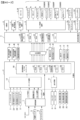
パチンコ遊技機1には、例えば図2に示すような主基板11、演出制御基板12、音声制御基板13、ランプ制御基板14、中継基板15などが搭載されている。その他にも、パチンコ遊技機1の背面には、例えば払出制御基板37(図3参照)、情報端子基板、発射制御基板、電源基板91(図3参照)などといった、各種の基板が配置されている。
(Substrate configuration)
The
主基板11は、メイン側の制御基板であり、パチンコ遊技機1における上記遊技の進行(特図ゲームの実行(保留の管理を含む)、普図ゲームの実行(保留の管理を含む)、大当り遊技状態、小当り遊技状態、遊技状態など)を制御する機能を有する。主基板11は、遊技制御用マイクロコンピュータ100、スイッチ回路110、ソレノイド回路111などを有する。
The
主基板11に搭載された遊技制御用マイクロコンピュータ100は、例えば1チップのマイクロコンピュータであり、ROM(Read Only Memory)101と、RAM(Random Access Memory)102と、CPU(Central Processing Unit)103と、乱数回路104と、I/O(Input/Output port)105とを備える。
The
CPU103は、ROM101に記憶されたプログラムを実行することにより、遊技の進行を制御する処理(主基板11の機能を実現する処理)を行う。このとき、ROM101が記憶する各種データ(後述の変動パターン、後述の演出制御コマンド、後述の各種決定を行う際に参照される各種テーブルなどのデータ)が用いられ、RAM102がメインメモリとして使用される。RAM102は、その一部または全部がパチンコ遊技機1に対する電力供給が停止しても、所定期間記憶内容が保存されるバックアップRAMとなっている。尚、ROM101に記憶されたプログラムの全部又は一部をRAM102に展開して、RAM102上で実行するようにしてもよい。
The
また、CPU103は、第1始動入賞や第2始動入賞があったか否かを判定し、入賞があった場合には、特図表示結果判定用、大当り種別判定用、変動パターン判定用などの乱数値をそれぞれ抽出して、第1特図保留記憶部や第2特図保留記憶部における空きエントリの最上位に格納(記憶)する始動入賞処理を実行する。
In addition, the
また、CPU103は、第1特図保留記憶部や第2特図保留記憶部に記憶されている保留データの有無などに基づいて特図ゲームを開始するか否かの判定や、特図表示結果判定用の乱数値を示す数値データに基づき、特別図柄や演出図柄の変動表示結果を「大当り」とするか否かを、その変動表示結果が導出表示される前に決定(事前決定)する特別図柄通常処理を実行する。つまり、CPU103は、特図ゲームの変動表示を開始するときに、始動入賞が発生したときに記憶した乱数値に基づいて、当該変動表示の表示結果として大当り表示結果を導出表示するか否かを決定(抽選)する処理を実行する。
In addition, the
乱数回路104は、遊技の進行を制御するときに使用される各種の乱数値(遊技用乱数)を示す数値データを更新可能にカウントする。遊技用乱数は、CPU103が所定のコンピュータプログラムを実行することで更新されるもの(ソフトウェアで更新されるもの)であってもよい。
The
I/O105は、例えば各種信号(後述の検出信号)が入力される入力ポートと、各種信号(第1特別図柄表示装置4A、第2特別図柄表示装置4B、普通図柄表示器20、第1保留表示器25A、第2保留表示器25B、普図保留表示器25Cなどを制御(駆動)する信号、ソレノイド駆動信号)を伝送するための出力ポートとを含んで構成される。
The I/
スイッチ回路110は、遊技球検出用の各種スイッチ(ゲートスイッチ21、始動口スイッチ(第1始動口スイッチ22Aおよび第2始動口スイッチ22B)、カウントスイッチ23)からの検出信号(遊技球が通過又は進入してスイッチがオンになったことを示す検出信号など)を取り込んで遊技制御用マイクロコンピュータ100に伝送する。検出信号の伝送により、遊技球の通過又は進入が検出されたことになる。
The
ソレノイド回路111は、遊技制御用マイクロコンピュータ100からのソレノイド駆動信号(例えば、ソレノイド81やソレノイド82をオンする信号など)を、普通電動役物用のソレノイド81や大入賞口扉用のソレノイド82に伝送する。
The
主基板11(遊技制御用マイクロコンピュータ100)は、遊技の進行の制御の一部として、遊技の進行に応じて演出制御コマンド(遊技の進行状況等を指定(通知)するコマンド)を演出制御基板12に供給する。主基板11から出力された演出制御コマンドは、中継基板15により中継され、演出制御基板12に供給される。当該演出制御コマンドには、例えば主基板11における各種の決定結果(例えば、特図ゲームの表示結果(大当り種別を含む。)、特図ゲームを実行する際に使用される変動パターン(詳しくは後述))、遊技の状況(例えば、可変表示の開始や終了、大入賞口の開放状況、入賞の発生、保留記憶数、遊技状態)、エラーの発生等を指定するコマンド等が含まれる。
The main board 11 (game control microcomputer 100) is a production control board that sends production control commands (commands that specify (notify) the progress of the game, etc.) according to the progress of the game as part of the control of the progress of the game. Supply to 12. The production control command output from the
演出制御基板12は、主基板11とは独立したサブ側の制御基板であり、演出制御コマンドを受信し、受信した演出制御コマンドに基づいて演出(遊技の進行に応じた種々の演出であり、可動体32の駆動、エラー報知、電断復旧の報知等の各種報知を含む)を実行する機能を有する。
The
演出制御基板12には、演出制御用CPU120と、ROM121と、RAM122と、表示制御部123と、乱数回路124と、I/O125とが搭載されている。
The
演出制御用CPU120は、ROM121に記憶されたプログラムを実行することにより、表示制御部123とともに演出を実行するための処理(演出制御基板12の上記機能を実現するための処理であり、実行する演出の決定等を含む)を行う。このとき、ROM121が記憶する各種データ(各種テーブルなどのデータ)が用いられ、RAM122がメインメモリとして使用される。
The
演出制御用CPU120は、コントローラセンサユニット35Aやプッシュセンサ35Bからの検出信号(遊技者による操作を検出したときに出力される信号であり、操作内容を適宜示す信号)に基づいて演出の実行を表示制御部123に指示することもある。
The
表示制御部123は、VDP(Video Display Processor)、CGROM(Character Generator ROM)、VRAM(Video RAM)などを備え、演出制御用CPU120からの演出の実行指示に基づき、演出を実行する。
The
表示制御部123は、演出制御用CPU120からの演出の実行指示に基づき、実行する演出に応じた映像信号を画像表示装置5に供給することで、演出画像を画像表示装置5に表示させる。表示制御部123は、さらに、演出画像の表示に同期した音声出力や、遊技効果ランプ9の点灯/消灯を行うため、音指定信号(出力する音声を指定する信号)を音声制御基板13に供給したり、ランプ信号(ランプの点灯/消灯態様を指定する信号)をランプ制御基板14に供給したりする。また、表示制御部123は、可動体32を動作させる信号を当該可動体32または当該可動体32を駆動する駆動回路に供給する。
The
音声制御基板13は、スピーカ8L、8Rを駆動する各種回路を搭載しており、当該音指定信号に基づきスピーカ8L、8Rを駆動し、当該音指定信号が指定する音声をスピーカ8L、8Rから出力させる。
The
ランプ制御基板14は、遊技効果ランプ9を駆動する各種回路を搭載しており、当該ランプ信号に基づき遊技効果ランプ9を駆動し、当該ランプ信号が指定する態様で遊技効果ランプ9を点灯/消灯する。このようにして、表示制御部123は、音声出力、ランプの点灯/消灯を制御する。
The
なお、音声出力、ランプの点灯/消灯の制御(音指定信号やランプ信号の供給等)、可動体32の制御(可動体32を動作させる信号の供給等)は、演出制御用CPU120が実行するようにしてもよい。
Note that the
乱数回路124は、各種演出を実行するために使用される各種の乱数値(演出用乱数)を示す数値データを更新可能にカウントする。演出用乱数は、演出制御用CPU120が所定のコンピュータプログラムを実行することで更新されるもの(ソフトウェアで更新されるもの)であってもよい。
The
演出制御基板12に搭載されたI/O125は、例えば主基板11などから伝送された演出制御コマンドを取り込むための入力ポートと、各種信号(映像信号、音指定信号、ランプ信号)を伝送するための出力ポートとを含んで構成される。
The I/
演出制御基板12、音声制御基板13、ランプ制御基板14といった、主基板11以外の基板をサブ基板ともいう。パチンコ遊技機1のようにサブ基板が機能別に複数設けられていてもよいし、1のサブ基板が複数の機能を有するように構成してもよい。
Boards other than the
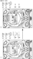
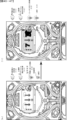
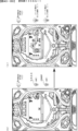
(パチンコ遊技機の背面構造)
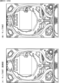
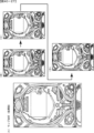
次に、図3~図7に基づいて、パチンコ遊技機1の背面構造について説明する。図3は、パチンコ遊技機を示す背面図である。図4は、パチンコ遊技機を示す左側面図である。図5は、遊技盤が取付けられた遊技機用枠を示す平面図である。図6は、パチンコ遊技機を斜め後ろから見た状態を示す斜視図である。図7は、遊技機枠から遊技盤が取外された状態を示す斜視図である。尚、図5~図7においてガラス扉枠50の図示は省略している。
(Back structure of pachinko machine)
Next, the back structure of the
図3~図7に示すように、パチンコ遊技機1は、遊技盤2と、遊技盤2が着脱可能に設けられる遊技機用枠3と、遊技機用枠3の左側辺を中心として該遊技機用枠3の前面を開閉可能に設けられたガラス扉枠50と、遊技機用枠3を左側辺を中心として開閉可能に支持する四角枠状の外枠60と、を有し、遊技場に設置された遊技島(図示略)に外枠60を固定することにより遊技島に設置できるようになっている。
As shown in FIGS. 3 to 7, the
遊技機用枠3の背面上部には、遊技島(図示略)の内部に設けられた遊技球(以下、遊技球Pと言うこともある)の循環経路から補給装置150(図3、図4参照)を介して供給される遊技球を貯留可能な貯留部を形成する球タンク形成部201と、球タンク形成部201に貯留された遊技球を左側に向けて誘導する第1誘導通路を形成する第1誘導通路形成部202と、からなる第1通路形成体203が、遊技機用枠3の上辺部3Aに沿うように左右方向に延設されている。また、第1誘導通路形成部202の上方位置には、後述するターミナル基板210が設けられている。
At the upper back side of the
補給装置150は、遊技島の循環経路の遊技球を誘導可能なノズル等からなる誘導部材150Aと、該誘導部材150Aにより導かれた遊技球を所定数(例えば、10個など)ずつ送出することが可能なスプロケット(図示略)、該スプロケットを駆動する駆動源(図示略)、外枠60の開口が遊技機用枠3により閉鎖される閉鎖状態であるときに該遊技機用枠3に押圧されるレバースイッチ(図示略)と、を有し、閉鎖状態においてレバースイッチ(図示略)が遊技機用枠3にて押圧されているときにはスプロケットにて送出された遊技球が球タンク形成部201に落下可能となり、開放状態においてレバースイッチ(図示略)が遊技機用枠3にて押圧されていないときにはスプロケットにて送出された遊技球が落下不能に保持される。そして、外枠60が閉鎖状態であるときに球タンク形成部201に貯留されている遊技球数が減少すると、駆動源によりスプロケットが回転して遊技球が所定個数ずつ送出され球タンク形成部201に供給されるようになっている。また、補給装置150は、複数の部材を複数のねじ部材(図示略)により組付けることによりケース体150Bが構成され、該ケース体150Bが複数のねじ部材(図示略)を用いて遊技島の所定個所に固設されている。
The replenishment device 150 includes a guiding member 150A that includes a nozzle or the like that can guide game balls in the circulation path of the game island, and a system that sends out a predetermined number (for example, 10, etc.) of game balls guided by the guiding member 150A. A sprocket (not shown) that can drive the sprocket, a drive source (not shown) that drives the sprocket, and a sprocket (not shown) that can be pressed against the
また、第1誘導通路形成部202により左側に誘導された遊技球を下方に誘導する第2誘導通路を形成する第2誘導通路形成部204と、第2誘導通路形成部204により誘導された遊技球を払出すことが可能な払出部を構成する払出装置200と、払出装置200により払出された遊技球を上皿に誘導する、つまり、遊技者に遊技球を払出すための払出通路を形成する払出通路形成部205と、第2誘導通路形成部204により誘導された遊技球を払出装置200から払出通路形成部205に払出すことなく、パチンコ遊技機1の外部に排出するためにパチンコ遊技機1の背面側下部に設けられた図示しない排出部(図示略)に誘導する球抜き通路を形成する球抜き通路形成部206と、からなる第2通路形成体207が、遊技機用枠3の背面左側辺部に沿うように上下方向に延設されている。
In addition, a second guiding passage forming part 204 forms a second guiding passage that guides the game ball guided to the left side by the first guiding passage forming part 202 downward, and a game ball guided by the second guiding passage forming part 204 is provided. A dispensing device 200 forming a dispensing unit capable of dispensing balls, and a dispensing passage for guiding game balls dispensed by the dispensing device 200 to an upper tray, that is, dispensing game balls to a player. In order to discharge the game balls guided by the payout passage forming part 205 and the second guiding passage forming part 204 from the payout device 200 to the payout passage forming part 205 to the outside of the
払出装置200は、略直方体状に形成されるケース体からなり、内部には遊技球を所定球数(例えば、1球)ずつ払い出すためのスプロケット、該スプロケットを回転させるための払出モータ、遊技球の流路を払出通路と球抜き通路とに切り替え可能な切替弁、該切替弁の切り替え操作を行うための操作レバー等が設けられている。また、遊技機用枠3の背面下部には、電源基板91が収納された基板ケース91Aや払出制御基板37が収納された基板ケース37A等が設けられている。
The payout device 200 consists of a case body formed in a substantially rectangular parallelepiped shape, and inside includes a sprocket for paying out a predetermined number of game balls (for example, one ball), a payout motor for rotating the sprocket, and a game ball. A switching valve capable of switching the ball flow path between a dispensing passage and a ball extraction passage, an operating lever for switching the switching valve, and the like are provided. Furthermore, a board case 91A in which a
尚、本実施の形態では、第2誘導通路の所定個所に遊技球を検出可能な球切れスイッチ(図示略)が設けられており、CPU103は、球切れスイッチ(図示略)からの検出信号の入力状態に基づいて、払出装置200の上流側の第2誘導通路に払出すための遊技球があるか否かを常時監視している。そして、球切れスイッチ(図示略)のオフ状態が所定時間以上継続した場合、球詰まりなど何らかの理由で遊技球が払出装置200に供給されていない、つまり、補給エラーが発生したと判定し、払出装置200による払出動作を中止する。また、主基板11に接続される所定の表示器(図示略)にて補給エラー表示を行うとともに、補給エラーコマンドを演出制御基板12に出力することで、演出制御用CPU120にガラス扉枠50の前面所定個所に設けられた遊技効果ランプ9をエラー態様にて発光させるなどして、補給エラーが生じている旨の報知処理を実行可能である。
In this embodiment, a ball-out switch (not shown) capable of detecting game balls is provided at a predetermined location in the second guide path, and the
図7に示すように、遊技機用枠3の略中央部に形成された開口部221には、遊技機用枠3の前面側から遊技盤2が着脱可能に配置される。遊技盤2は、前述した盤面板及びスペーサ部材からなる板状体2aと、板状体2aの前面側に設けられる各種遊技用部品(例えば、障害釘や入賞装置など)や、板状体2aの背面側に設けられる画像表示装置5、可動体32を有する演出装置や、演出制御基板12が収納された基板ケース12A、主基板11が収納された基板ケース11A等の電子部品や、板状部及び演出装置や電子部品等を保護するカバー体220と、を含む構造体とされている。
As shown in FIG. 7, the
尚、基板ケース11A,12A,91A,37Aは、透明な合成樹脂材からなるベース部材とカバー部材とにより各基板を内部に収納可能に構成され、これらのうち基板ケース11A,12Aにあっては、各々1個または複数のねじ部材N20,N21(図3参照)により遊技機用枠3または遊技盤2に取付けられ、基板ケース91A,37Aは係止手段(図示略)により遊技機用枠3または遊技盤2に取付けられている。また、カバー体220は、透明な合成樹脂材により前面が開口する箱状に形成され、背面の一部は右側辺を中心として回動可能な開閉部220Aとされ、遊技盤2の背面の一部を開閉可能とされている。
Note that the board cases 11A, 12A, 91A, and 37A are constructed by a base member made of a transparent synthetic resin material and a cover member so that each board can be stored therein. , are attached to the
図4~図6に示すように、遊技機用枠3の背面に設けられた第1通路形成体203、第2通路形成体207と、遊技盤2の背面を構成するカバー体220は、遊技機用枠3により外枠60を閉鎖した状態において、外枠60よりも後方に突出する。特に第1通路形成体203は、球タンク形成部201の上面開口が遊技機用枠3の背面上部における外枠60の上板の後方位置に配置されるように設けられていることで、パチンコ遊技機1の外枠60を遊技島(図示略)に固定した状態において、遊技島の上方の循環経路から補給装置150を介して球タンク形成部201に遊技球を供給できるようになっている。
As shown in FIGS. 4 to 6, the first passage forming body 203, the second passage forming body 207 provided on the back side of the
(第1通路形成体203の取付構造)
次に、第1通路形成体203の遊技機用枠3への取付構造について、図8及び図9に基づいて説明する。図8は、通路形成体の遊技機用枠への取付構造を示す分解斜視図である。図9は、遊技機用枠の背面上部を示す拡大背面図である。
(Mounting structure of first passage forming body 203)
Next, the attachment structure of the first passage forming body 203 to the
図8及び図9に示すように、遊技機用枠3は、正面視略長方形状をなす枠体であり、遊技盤2を取付けるための開口部221が形成されており、開口部221の上方の上辺部3Aの背面には、補強用の金属板222が左右方向に向けて設けられている。また、金属板222の背面には、第1通路形成体203を遊技機用枠3に取付けるための取付部材223が取付けられている。
As shown in FIGS. 8 and 9, the
取付部材223は、合成樹脂材により金属板222を背面側から被覆可能に形成され、前後方向を向く複数の取付孔H1~H5に背面側から取付けたねじ部材N1~N5を、金属板222に形成された複数のねじ孔に各々螺入することで金属板222に取付けられている。取付部材223の右側には、板状の第1突出部224が後方に向けて突設され、取付部材223の左側には、上壁部225A、後壁部225B及び左右の側壁部225Cからなる立体状の第2突出部225が後方に向けて突設されている。
The mounting member 223 is formed of a synthetic resin material so that it can cover the
第1突出部224は、第2突出部225の上壁部225Aより下方位置から後方に向けて突出しており、その上側には球タンク形成部201が配置される。また、第2突出部225の後壁部225Bの後側には、第1誘導通路形成部202が配置されるとともに、その上側には、ターミナル基板210を取付けるための基板取付枠211が取付けられている。基板取付枠211は、下辺から下方に突設された係止片212を後壁部225Bに形成された係止孔213に挿入した状態で、上部に形成された取付孔H6に背面側から取付けたねじ部材N6を、取付部材223に形成されたねじ孔に螺入することで取付部材223に取付けられる。
The first protruding part 224 protrudes rearward from a lower position than the upper wall part 225A of the second protruding part 225, and the spherical
このように取付部材223は、後方に突出する第1突出部224と第2突出部225とを有することで、遊技盤2の上方を覆うように形成されている。よって、遊技島の上部から球タンク形成部201に供給される遊技球などが遊技盤2内に進入することが防止されている。つまり、取付部材223は遊技盤2の保護カバーとして機能している。
In this way, the mounting member 223 is formed to cover the upper side of the
第1通路形成体203は、複数の取付孔H11~H14に背面側から取付けたねじ部材N11~N14、及び取付孔H15に上側から取付けたねじ部材N15を、取付部材223に形成された複数のねじ孔に各々螺入することで取付部材223に取付けられている。尚、取付孔H12に取付けるねじ部材N12は、第1通路形成体203に帯電した電気を除去するためのアース線226を第1通路形成体203に取付けるためのねじ部材と兼用されている。また、第1通路形成体203の上部には、後述する第1カバー体310、第2カバー体320、第3カバー体330が取付けられている。第3カバー体330は、取付孔H16に上方から取付けたねじ部材N16を第1通路形成体203の後壁に形成されたねじ孔に螺入することで第1通路形成体203に取付けられている。 The first passage forming body 203 has screw members N11 to N14 attached to the plurality of attachment holes H11 to H14 from the back side, and screw members N15 attached to the attachment hole H15 from the upper side. They are attached to the attachment member 223 by being screwed into the respective screw holes. Note that the screw member N12 attached to the attachment hole H12 is also used as a screw member for attaching the ground wire 226 to the first passage forming body 203 for removing electricity charged in the first passage forming body 203. Moreover, a first cover body 310, a second cover body 320, and a third cover body 330, which will be described later, are attached to the upper part of the first passage forming body 203. The third cover body 330 is attached to the first passage forming body 203 by screwing the screw member N16 attached from above into the attachment hole H16 into the screw hole formed in the rear wall of the first passage forming body 203. There is.
上記したねじ部材N1~N6、N11~N16は、図8中拡大図に示すように、雄ねじ部NSと頭部NHとからなり、このうち、ねじ部材N1、N2、N11~N16は、頭部の座面に緩み止め部としてのフランジ部Fが一体に形成されたフランジ付きねじとされ、座面の接地面積を広くして摩擦力を高めることで、ねじ部材N3~N6に比べて緩みにくいねじ部材とされている。 As shown in the enlarged view in FIG. 8, the screw members N1 to N6, N11 to N16 described above are composed of a male screw portion NS and a head NH. This is a flanged screw with a flange part F as a locking part integrally formed on the seat surface of the screw, and by widening the ground contact area of the seat surface and increasing the frictional force, it is less likely to loosen compared to screw members N3 to N6. It is a screw member.
例えば、各ねじ部材N1~N6、N11~N16の雄ねじ部NSの直径L1は約1~3mm、頭部NHの直径L2は約4~7mmとされ、フランジ部Fの直径L3は、頭部NHの直径L2よりも長寸で約8~10mmとされている。 For example, the diameter L1 of the male threaded portion NS of each screw member N1 to N6, N11 to N16 is approximately 1 to 3 mm, the diameter L2 of the head NH is approximately 4 to 7 mm, and the diameter L3 of the flange portion F is approximately 1 to 3 mm. The length is about 8 to 10 mm longer than the diameter L2.
尚、ねじ部材N1~N6、N11~N16の大きさ、種類などは任意であり、直径L1~L3の寸法も上記した寸法に限定されるものではない。また、フランジ付きねじからなるねじ部材N1、N2、N11~N16は、フランジ部F(座金)が一体に形成されたねじ部材であるが、フランジ部Fの替わりに、ねじ部材とは別個のワッシャをねじ部材に装着して取付けてもよく、フランジ部Fやワッシャが本発明の緩み止め部を構成する。また、ねじ部材は、ビスやボルト等、緩むと被取付部から離脱してしまう部材を含むものとする。また、緩み止め部は、頭部NHやフランジ部F(座金)の裏面に凹凸状に形成された頭部NHの回止め部や接着剤等も含まれる。 Incidentally, the sizes and types of the screw members N1 to N6 and N11 to N16 are arbitrary, and the dimensions of the diameters L1 to L3 are not limited to the above dimensions. Further, the screw members N1, N2, N11 to N16, which are made of flanged screws, are screw members in which a flange portion F (washer) is integrally formed, but instead of the flange portion F, a washer separate from the screw member is used. It may be attached by attaching it to a screw member, and the flange portion F and the washer constitute the locking portion of the present invention. Further, the screw member includes a member such as a screw or a bolt that, when loosened, separates from the attached part. Further, the locking portion includes a locking portion of the head NH that is formed in an uneven shape on the back surface of the head NH and the flange portion F (washer), an adhesive, and the like.
図8及び図9に示すように、第1通路形成体203は、遊技島の上方から供給される遊技球を球タンク形成部201にて受止めて貯留する必要があるとともに、第1誘導通路において球詰まりなどが発生しにくいように、また、球詰まりが発生した場合にこれを容易に解消することができるように上面が開放する凹状に形成されている。
As shown in FIGS. 8 and 9, the first passage forming body 203 needs to receive and store game balls supplied from above the game island in the ball
また、球タンク形成部201にて上下方向に重なって滞留する遊技球が第1誘導通路形成部202に流入していく箇所には第1カバー体310や第2カバー体320が上面を被覆するように配置され、また、第1誘導通路形成部202から第2誘導通路形成部204に流入していく箇所には第3カバー体330が上面を被覆するように配置されることで、遊技球が整流されるようになっている。しかし、第1通路形成体203の上面開口の一部はこれら第1カバー体310、第2カバー体320及び第3カバー体330により被覆されるが、球タンク形成部201及び非被覆領域350(図27参照)の上面開口は開放されている。
In addition, a first cover body 310 and a second cover body 320 cover the upper surface of a portion where game balls stacked in the vertical direction in the ball
一方、第1通路形成体203の周辺近傍には、遊技機用枠3や取付部材223に取付けられる複数のねじ部材N1~N6、N11~N16が配置されている。また、遊技島に固定されるパチンコ遊技機1の上方には、遊技島を構成する躯体などを組付けるためのねじ部材(図示略)や、遊技島の内部に配置される各種装置(例えば、補給装置150など)等を躯体などに取付けるためのねじ部材(図示略)や、各種装置のケース体を構成する複数の部材を組付けるための複数のねじ部材などが多数配置されている。
On the other hand, near the periphery of the first passage forming body 203, a plurality of screw members N1 to N6 and N11 to N16 are arranged to be attached to the
これらねじ部材は、遊技島やパチンコ遊技機1に生じる振動や衝撃などにより緩んで抜け落ちてしまうと、振動や衝撃あるいは遊技機用枠3の開閉などにより転がって、球タンク形成部201や第1誘導通路形成部202の非被覆領域350から内部に落下して遊技球の誘導通路に混入する可能性がある。特に補給装置150などは、図3及び図4に示すように球タンク形成部201の直上近傍に配置されており、また、所定個数の遊技球を球タンク形成部201に送出することで遊技島の循環経路から新たな遊技球が供給される際や、遊技機用枠3が開閉する際に振動が生じやすい装置であるため、補給装置150を遊技島の躯体などに取付けるためのねじ部材(図示略)や、補給装置150のケース体150Bを構成する複数の部材を組付けるための複数のねじ部材が振動により緩んで抜け落ちた場合、球タンク形成部201や第1誘導通路形成部202内に落下する可能性が極めて高い。
If these screw members loosen and fall out due to vibrations or shocks occurring in the game island or the
そして、球タンク形成部201や第1誘導通路形成部202にねじ部材が落下すると、遊技球の流下とともに払出装置200側に向けて移動し、最終的に払出装置200に混入する可能がある。このように払出装置200にねじ部材が進入すると、スプロケットや切換え弁がねじ部材により損傷したり、球詰まりが生じて払出モータに負荷がかかり故障したり、あるいは、遊技球とともにねじ部材が遊技者に払出されてしまい、遊技者に違和感や不信感を与えてしまう虞があった。
If the screw member falls into the ball
そこで本実施の形態では、以下に説明するように、第1誘導通路形成部202に落下したねじ部材が払出装置200に混入して払出装置200が破損、故障したり、遊技球とともにねじ部材が遊技者に払出されることを抑制するために様々な対策が施されている。 Therefore, in this embodiment, as will be explained below, the screw member that has fallen into the first guide path forming part 202 may get mixed into the payout device 200 and cause the payout device 200 to be damaged or malfunction, or the screw member may be lost together with the game ball. Various measures have been taken to prevent players from paying out money.
(第1通路形成体203)
次に、第1通路形成体203について、図10~図16に基づいて説明する。図10は、(A)は第1通路形成体を示す平面図、(B)は第1通路形成体を示す背面図である。図11は、(A)は図10(A)のA-A断面図、(B)は図10(A)のB-B断面図、(C)は図10(A)のC-C断面図である。図12は、(A)は第1誘導通路形成部を示す平面図、(B)は(A)のD-D断面図である。図13は、(A)は第1カバー体を示す平面図、(B)は(A)のE-E断面図、(C)は(A)のF-F断面図である。図14は、(A)は第2カバー体を示す平面図、(B)は(A)のG-G断面図、(C)は(A)のH-H断面図である。図15は、(A)は第3カバー体を示す平面図、(B)は(A)のI-I断面図、(C)は(A)のJ-J断面図、(D)は第3カバー体を示す斜視図、(E)は球止め部材を示す斜視図である。図16は、(A)は球止め部材が第1状態である状態を示す第1誘導通路形成部を示す縦断面図、(B)は球止め部材が第2状態である状態を示す第1誘導通路形成部を示す縦断面図である。
(First passage forming body 203)
Next, the first passage forming body 203 will be explained based on FIGS. 10 to 16. In FIG. 10, (A) is a plan view showing the first passage forming body, and (B) is a rear view showing the first passage forming body. 11, (A) is a sectional view taken along line AA in FIG. 10(A), (B) is a sectional view taken along line BB in FIG. 10(A), and (C) is a sectional view taken along line CC in FIG. It is a diagram. In FIG. 12, (A) is a plan view showing the first guide passage forming part, and (B) is a sectional view taken along line DD in (A). In FIG. 13, (A) is a plan view showing the first cover body, (B) is a sectional view taken along line EE in (A), and (C) is a sectional view taken along line FF in (A). In FIG. 14, (A) is a plan view showing the second cover body, (B) is a cross-sectional view taken along line GG in (A), and (C) is a cross-sectional view taken along line H-H in (A). 15, (A) is a plan view showing the third cover body, (B) is a cross-sectional view taken along line II in (A), (C) is a cross-sectional view taken along line J-J in (A), and (D) is a top view showing the third cover body. 3 is a perspective view showing the cover body, and (E) is a perspective view showing the ball stopper member. 16, (A) is a longitudinal cross-sectional view showing the first guide passage forming part showing the state where the ball stopper member is in the first state, and (B) is a longitudinal sectional view showing the state where the ball stopper member is in the second state. FIG. 3 is a longitudinal cross-sectional view showing a guide passage forming part.
図10~図12に示すように、第1通路形成体203は、導電性を有する合成樹脂材により、底壁部203Aと該底壁部203Aの周縁に立設される立壁部203Bとにより上面が開口する凹状または凹溝状に形成され、右側に配置される球タンク形成部201と、左側に配置される第1誘導通路形成部202とを有する。球タンク形成部201は、平面視横長長方形状に形成され、第1誘導通路形成部202は、球タンク形成部201の左側から斜め後方に向けて延びる上流部と左右方向に延びる下流部とからなる。球タンク形成部201の前後方向の寸法は、第1誘導通路形成部202の前後方向の寸法よりも長寸とされており、第1誘導通路形成部202よりも多くの遊技球を貯留可能とされている。また、底壁部203Aは、球タンク形成部201の左側から第1誘導通路形成部202の右側に向けて漸次下方に傾斜するように形成されているため、球タンク形成部201に供給された遊技球は、球タンク形成部201及び第1誘導通路形成部202を左側に向けて自然流下するようになっている。
As shown in FIGS. 10 to 12, the first passage forming body 203 is made of a conductive synthetic resin material and has a bottom wall portion 203A and a standing wall portion 203B standing on the periphery of the bottom wall portion 203A. It is formed in the shape of a concave or groove with an opening, and has a spherical
球タンク形成部201の右側の立壁部203Bの外面には上下方向を向く取付片261が突設されており、取付片261には前後方向を向く取付孔H11,H12が上下に形成されている。また、取付片261の後側には取付片265が突設されており、取付片265には上下方向を向く取付孔H15が形成されている。第1誘導通路形成部202の左側の立壁部203Bの外面には上下方向を向く取付片262が突設されており、取付片262には前後方向を向く取付孔H14が形成されている。第1誘導通路形成部202の上流部の前側の立壁部203Bの外面には水平壁部264が前方に向けて突設されている。水平壁部264の前辺には取付片263が立設されており、取付片263には前後方向を向く取付孔H13が形成されている。
A mounting piece 261 that faces in the vertical direction is protruded from the outer surface of the standing wall part 203B on the right side of the spherical
そして第1通路形成体203は、これら取付孔H11~H15に取付けた複数のねじ部材N11~N15を取付部材223に形成されたねじ孔に螺入することで遊技機用枠3に取付けられる。また、水平壁部264の上面における取付片263の後方近傍位置には、平面視略四角形状をなす凹部280が形成されている。
The first passage forming body 203 is attached to the
図11及び図12に示すように、第1誘導通路形成部202の上流部における底壁部203Aと後側の立壁部203Bとの角部には、孔部270A,270Bが形成されている(図11(A)参照)。孔部271A,271Bの下流側(左側)における底壁部203Aの前後方向の略中央位置には、孔部271A~271Hが下流側に向けて複数形成されている。また、第1誘導通路形成部202の下流側端部の底壁部203Aには、下方の第2誘導通路形成部204に遊技球を落下させるための連絡孔272が貫通して形成されている。 As shown in FIGS. 11 and 12, holes 270A and 270B are formed at the corners of the bottom wall section 203A and the rear vertical wall section 203B at the upstream portion of the first guide passage forming section 202. (See FIG. 11(A)). A plurality of holes 271A to 271H are formed downstream of the holes 271A and 271B at substantially the center in the front-rear direction of the bottom wall 203A on the downstream side (left side) of the holes 271A and 271B. Furthermore, a communication hole 272 for dropping a game ball into the second guide passage forming part 204 below is formed to penetrate through the bottom wall part 203A of the downstream end of the first guiding passage forming part 202. .
第1誘導通路形成部202の途中には、遊技球を前後方向に蛇行させながら左側に向けて流下させる蛇行部273が形成されており、複数の孔部271A~271Hのうち孔部271B~271Fが蛇行部273に対応する位置に形成されている。このような蛇行部273を設けることで後続球による球圧が増大しないようにしている。 A meandering part 273 is formed in the middle of the first guide passage forming part 202, which causes the game ball to flow down to the left side while meandering in the front-back direction, and among the plurality of holes 271A to 271H, holes 271B to 271F are formed. is formed at a position corresponding to the meandering portion 273. By providing such a meandering portion 273, the ball pressure caused by the following ball is prevented from increasing.
また、第1誘導通路形成部202の前後の立壁部203B,203B下部の離間寸法L10は、遊技球の直径2R(約11mm)よりも長寸で、直径2Rの2倍の寸法(約22mm)よりも短寸とされている(11mm<L10<22mm)。つまり、第1誘導通路形成部202は、遊技球を下流側に向けて1列で誘導可能に形成されている。 In addition, the distance L10 between the lower portions of the standing walls 203B and 203B before and after the first guide passage forming portion 202 is longer than the diameter 2R (approximately 11 mm) of the game ball, and is twice the diameter 2R (approximately 22 mm). (11mm<L10<22mm). In other words, the first guide passage forming section 202 is formed so as to be able to guide the game balls in one row toward the downstream side.
孔部271A,271Bを除く孔部271A~271Hの前後寸法L11は、前述したねじ部材N3~N6の頭部NHの直径L2より若干長いため(L11>L2)、後述するようにねじ部材N3~N6が第1誘導通路形成部202に混入した場合でも孔部271A~271Hからねじ部材N3~N6が落下可能とされている。また、最下流側に形成された孔部271Hは、他の孔部271A~271Gと比べて左右寸法L12(遊技球の流下方向の寸法)が最も長いため、ねじ部材N3~N6が連絡孔272に到達する前に確実に第1誘導通路形成部202外へ落下させることができる。 Since the longitudinal dimension L11 of the holes 271A to 271H excluding the holes 271A and 271B is slightly longer than the diameter L2 of the head NH of the screw members N3 to N6 described above (L11>L2), as will be described later, Even if N6 gets mixed into the first guide passage forming portion 202, the screw members N3 to N6 can fall from the holes 271A to 271H. In addition, since the hole 271H formed on the most downstream side has the longest left-right dimension L12 (dimension in the downstream direction of the game ball) compared to the other holes 271A to 271G, screw members N3 to N6 are connected to the communication hole 271H. It is possible to reliably make it fall out of the first guide passage forming part 202 before it reaches.
つまり、これら孔部271A~271Hは、第1誘導通路形成部202に落下したねじ部材N3~N6の払出装置200への移動を制限するための特定制限部を構成している。尚、これら複数の孔部271A~271Hからは、ねじ部材以外のゴミや埃、あるいは何らかの部材等も落下可能であるため、これらにより球詰まりが生じることが防止される。 In other words, these holes 271A to 271H constitute a specific restriction part for restricting the movement of the screw members N3 to N6 that have fallen into the first guide passage forming part 202 to the dispensing device 200. Incidentally, dirt and dust other than the screw members, or some other members can also fall from these plurality of holes 271A to 271H, so that clogging of the ball due to these can be prevented.
(第1カバー体310)
図13(A)~図13(C)に示すように、第1カバー体310は、球タンク形成部201の前側の立壁部203Bの上端縁に沿うように延設され、立壁部203Bの上端に上方から嵌合可能な断面視下向きコ字形をなす取付部311と、取付部311の右側から後側に向けて延設される立壁部312と、立壁部312の下部から右側(球タンク形成部201側)に向けて下方に傾斜するように延びる板状の球押え部313と、立壁部312の下部から左側(第1誘導通路形成部202側)に向けて延びるカバー部314と、取付部311の前側及びカバー部314の前後側に弾性変形可能に形成された複数の係止部315A~315Dと、から主に構成される。
(First cover body 310)
As shown in FIGS. 13(A) to 13(C), the first cover body 310 extends along the upper edge of the standing wall portion 203B on the front side of the spherical
このように構成された第1カバー体310は、立壁部312を球タンク形成部201と第1誘導通路形成部202との境目付近に配置した状態で、取付部311を球タンク形成部201の前側の立壁部203Bの上端に上方から嵌合させることで、複数の係止部315A~315Dが立壁部203Bの外面に形成された被係止部317(図18参照)に弾性的に係止することで第1通路形成体203に取付けられる。取付けられた状態において、球押え部313が球タンク形成部201の下流側の一部を上方から被覆するように配置されるとともに、カバー部314が第1誘導通路形成部202の上流側の一部を上方から被覆するとともに、カバー部314の上面が第1誘導通路形成部202側に向けて僅かに下方に傾斜するように配置される(図9参照)。
The first cover body 310 configured in this manner has the mounting portion 311 attached to the spherical
第1カバー体310が第1通路形成体203に取付けられた状態において、球押え部313が球タンク形成部201側に配置されることで、遊技島(図示略)から球タンク形成部201に供給された遊技球が上下方向に積み重なるように貯留した場合でも、遊技球が第1誘導通路形成部202側に流下していく際に球押え部313により下側に向けて押えられることで整流されるようになっている。
When the first cover body 310 is attached to the first passage forming body 203, the ball holding part 313 is arranged on the ball
カバー部314には、平面視横長長方形状をなす左右方向に延びる長孔316A~316Cが、互いに平行をなすように列状に配置された状態で上下に貫通して形成されている。各長孔316A~316Cは、前後寸法L21が全て同一とされ、前後寸法L21は、遊技球の直径2Rよりも短寸であり、かつ、前述したねじ部材N1~N6,N11~N16の頭部NHの直径L2よりも短寸となっている(L21<2R、L21<L2)。つまり、長孔316A~316Cは、遊技球及びねじ部材N1~N6,N11~N16を落下不能な大きさに形成されている。尚、カバー部314の下面における各長孔316A~316Cの周縁からは補強用のリブが垂下されている。
In the
また、長孔316A~316Cは遊技球の流下方向に沿うように延設されているため、図13(B)(C)に示すように、長孔316A~316Cの上部に遊技球Pが落下した場合、遊技球Pは流下方向(左側)に向けて移動可能である。 In addition, since the long holes 316A to 316C extend along the downward direction of the game ball, the game ball P falls onto the upper part of the long holes 316A to 316C, as shown in FIGS. 13(B) and 13(C). In this case, the game ball P can be moved in the downstream direction (left side).
(第2カバー体320)
図14(A)~図14(C)に示すように、第2カバー体320は、第1誘導通路形成部202の上流部に沿うように形成された板状のカバー部324と、カバー部324の前後側に弾性変形可能に形成された複数の係止部325A,325Bと、から主に構成され、カバー部324の右側端部を第1カバー体310のカバー部314の左側端部に近接させた状態で、複数の係止部325A,325Bが立壁部302Bの外面に形成された被係止部317(図20参照)に弾性的に係止することで、第1通路形成体203に取付けられる。取付けられた状態において、カバー部324が第1誘導通路形成部202の上流側の一部を上方から被覆するとともに、遊技球の流下方向に向けて下方に傾斜するように配置される(図9参照)。
(Second cover body 320)
As shown in FIGS. 14(A) to 14(C), the second cover body 320 includes a plate-shaped cover portion 324 formed along the upstream portion of the first guide passage forming portion 202, and a cover portion The right end of the cover part 324 is connected to the left end of the
カバー部324の上面には、左右方向に延びる凹溝326A~326Cが、互いに列状に配置された状態で形成されている。各凹溝326A~326Cは、前後寸法L22A~L22Cが各々異なるが、各々遊技球の直径2Rよりも短寸とされている(L22A~L22C<2R)。尚、前後寸法が最も長い中央の凹溝326Bの前後寸法L22Bは、前述したねじ部材N1~N6,N11~N16の頭部NHの直径L2よりも長寸となっている(L22B>L2)。つまり、凹溝326Bは、遊技球を収容不能、かつ、ねじ部材N1~N6,N11~N16を収容可能な大きさに形成されている。また、凹溝326Bの前後寸法L22Bは、カバー部314の長孔316A~316Cの前後寸法L21よりも長寸とされている(L22B>L21)。 Concave grooves 326A to 326C extending in the left-right direction are formed on the upper surface of the cover portion 324 and are arranged in a row. The respective grooves 326A to 326C have different longitudinal dimensions L22A to L22C, but are each shorter than the diameter 2R of the game ball (L22A to L22C<2R). Note that the longitudinal dimension L22B of the central groove 326B, which has the longest longitudinal dimension, is longer than the diameter L2 of the heads NH of the aforementioned screw members N1 to N6, N11 to N16 (L22B>L2). That is, the concave groove 326B is formed in a size that cannot accommodate the game balls, but can accommodate the screw members N1 to N6, N11 to N16. Further, the longitudinal dimension L22B of the groove 326B is longer than the longitudinal dimension L21 of the elongated holes 316A to 316C of the cover portion 314 (L22B>L21).
また、凹溝326Aの前後寸法L22Aと凹溝326Cの前後寸法L22Cは、ねじ部材N1~N6,N11~N16の雄ねじ部NSの直径L1よりも長寸であるため(L22B>L1、L22C>L1)、少なくとも雄ねじ部NSを収容可能な大きさとされている。 In addition, the front-rear dimension L22A of the groove 326A and the front-rear dimension L22C of the groove 326C are longer than the diameter L1 of the male threaded portion NS of the screw members N1 to N6, N11 to N16 (L22B>L1, L22C>L1 ), is sized to accommodate at least the male threaded portion NS.
また、凹溝326A~326Cは遊技球の流下方向に沿うように延設され、かつ、遊技球の流下方向に向けて下方に傾斜するように配置されるため、図14(B)(C)に示すように、凹溝326A~326Cの上部に遊技球Pが落下した場合、遊技球Pが流下方向(左側)に向けて誘導される。 In addition, the grooves 326A to 326C extend along the downward direction of the game ball and are arranged so as to be inclined downward in the downward direction of the game ball, so that the grooves 326A to 326C shown in FIGS. As shown in , when the game ball P falls onto the upper part of the grooves 326A to 326C, the game ball P is guided in the downstream direction (left side).
(第3カバー体330)
図15(A)~図15(C)及び図16に示すように、第3カバー体330は、第1誘導通路形成部202の下流部に沿うように形成された板状のカバー部334と、カバー部334の左端の前後側に弾性変形可能に形成された複数の係止部335A~335Dと、背面における係止部335C,335Dの間に突設されねじ部材N15が上方から取付けられる取付孔H15が形成された取付部331と、カバー部334の上面左端部に設けられた球止め部材340と、から主に構成され、カバー部324の左端の複数の係止部335A~335Dを立壁部302Bの外面に形成された被係止部317(図20参照)に弾性的に係止するとともに、取付孔H15に取付けたねじ部材N15を立壁部203Bの外面に設けられたねじ孔に螺入することで第1通路形成体203に取付けられる。取付けられた状態において、カバー部334が第1誘導通路形成部202の下流部を上方から被覆するとともに、遊技球の流下方向に向けて下方に傾斜するように配置される(図9参照)。
(Third cover body 330)
As shown in FIG. 15(A) to FIG. 15(C) and FIG. , a plurality of locking portions 335A to 335D that are formed to be elastically deformable on the front and rear sides of the left end of the cover portion 334, and a screw member N15 protruding between the locking portions 335C and 335D on the back surface and attached from above; It mainly consists of a mounting part 331 in which a hole H15 is formed and a
カバー部334は、左側から右側に向けて斜め上方に延びるように延設されており、上面における右端部から左側に向けて所定深さの凹部336が延設されている。右側の一部は蛇行部273に差し掛かるため、蛇行部273の形状に対応して形成されている。また、凹部336に対応する位置には、平面視横長コ字形をなすスリット337が形成されることで、左端側が上下方向に揺動するように弾性変形可能な整流板338が形成されているとともに、右端部には、右側に向けて下方に傾斜する傾斜板部339が形成されていることで、上下に積み重なった遊技球Pを底壁部203Aに向けて押し付けるように誘導しながら均すことができるようになっている(図16参照)。 The cover portion 334 extends obliquely upward from the left side to the right side, and has a recessed portion 336 having a predetermined depth extending from the right end portion of the upper surface toward the left side. A part of the right side approaches the meandering portion 273, and is therefore formed in accordance with the shape of the meandering portion 273. Furthermore, a slit 337 having a horizontally long U-shape in plan view is formed at a position corresponding to the recess 336, thereby forming a rectifying plate 338 whose left end side can be elastically deformed so as to swing in the vertical direction. By forming an inclined plate part 339 that slopes downward toward the right side at the right end part, the game balls P stacked up and down can be leveled while guiding them to be pressed toward the bottom wall part 203A. (See Figure 16).
凹部336の前後寸法L23は、遊技球の直径2Rよりも長寸とされ、また、前述したねじ部材N1~N6,N11~N16の頭部NHの直径L2よりも長寸となっている(L23>2R、L23>L2)。つまり、凹部336は、遊技球P及びねじ部材N1~N6,N11~N16の頭部NHを収容可能な大きさに形成されている。また、凹部336の前後寸法L23は、カバー部324の凹溝326Bの前後寸法L22Bよりも長寸とされている(L23>L22B)。 The longitudinal dimension L23 of the recess 336 is longer than the diameter 2R of the game ball, and is also longer than the diameter L2 of the head NH of the screw members N1 to N6, N11 to N16 (L23 >2R, L23>L2). That is, the recess 336 is formed in a size that can accommodate the game ball P and the heads NH of the screw members N1 to N6, N11 to N16. Further, the front-to-back dimension L23 of the recess 336 is longer than the front-to-back dimension L22B of the groove 326B of the cover part 324 (L23>L22B).
また、凹部336は遊技球の流下方向に沿うように延設され、かつ、遊技球の流下方向に向けて下方に傾斜するように配置されるため、図15(D)に示すように、凹部336の上部に遊技球Pが落下した場合、遊技球Pが流下方向(左側)に向けて誘導される。 In addition, since the recess 336 extends along the downward direction of the game ball and is arranged to be inclined downward in the downward direction of the game ball, the recess 336 When the game ball P falls to the top of 336, the game ball P is guided in the downstream direction (left side).
また、スリット337の前後寸法L24は、前述したねじ部材N1~N6,N11~N16の頭部NHの直径L2よりも短寸となっているため(L24<L2)、ねじ部材N1~N6,N11~N16がスリット337から落下することはない。 In addition, the front-rear dimension L24 of the slit 337 is shorter than the diameter L2 of the head NH of the screw members N1-N6, N11-N16 (L24<L2), so that ~N16 will not fall from the slit 337.
球止め部材340は、背面視略三角形状をなす板状の前壁部341Aと、前壁部341Aの背面側に配置される後壁部341Bと、前壁部341Aと後壁部341Bとを接続する左壁部341Cと、左壁部341Cの上端に突設される突壁部341Dと、を有する回動部341と、前後方向を向く円筒状の軸部342と、から構成される。カバー部334の上面左側には、軸部342の前後端を回動可能に支持する軸受部343A,343Bが立設されている。また、カバー部334における軸受部343Aの右側には、前壁部341Aを挿入可能なスリット344が貫通して形成されている。
The
図16に示すように、第3カバー体330は、第1通路形成体203に取付けた状態において、カバー部324により第1誘導通路形成部202の下流部の上方が被覆される。カバー部324は、下流側(左側)に向けて底壁部203Aに近づくように下方に傾斜するように配置されるため、第1誘導通路形成部202内で上下に積み重なっている遊技球Pを流下させながら均していき、最終的に連絡孔272から1個ずつ流出させることができるようにする。特に、整流板338は、遊技球が接触したときに弾性変形可能であることで、球詰まりが生じない程度に遊技球を下方に押し付けるように均していく(整流していく)。 As shown in FIG. 16, when the third cover body 330 is attached to the first passage forming body 203, the upper part of the downstream part of the first guide passage forming part 202 is covered by the cover part 324. Since the cover part 324 is arranged so as to be inclined downward so as to approach the bottom wall part 203A toward the downstream side (left side), the cover part 324 protects the game balls P stacked vertically in the first guide passage forming part 202. The fluid is leveled while flowing down, and finally it is made to flow out one by one from the communication hole 272. In particular, the rectifying plate 338 is elastically deformable when the game balls come into contact with it, so that it smoothes the game balls by pressing them downward to the extent that ball clogging does not occur.
(球止め部材340)
球止め部材340は、図16(A)に示すように、回動部341が上方に起立する起立位置と右側に傾倒する傾倒位置との間で回動可能とされており、回動部341が起立位置に位置し、前壁部341Aがスリット344から上方に逸脱して第1誘導通路形成部202の遊技球を第2誘導通路形成部204に流下可能とする第1状態と、回動部341が傾倒位置に位置し、前壁部341Aがスリット344に挿入され遊技球に接触可能となり、第1誘導通路形成部202の遊技球を第2誘導通路形成部204に流下不能(または流下困難)とする第2状態、つまり、球止め状態と、に変化可能とされている。
(Ball stopper member 340)
As shown in FIG. 16(A), the
このように球止め部材340を第2状態とすることで、第2誘導通路形成部204への遊技球の進入を規制することができるため、この状態で第2誘導通路形成部204内の遊技球を抜き取り、払出装置200を取外して点検または交換したりすることが可能となる。
By setting the
また、図16(A)に示すように、球止め部材340が第1状態にあるときには、回動部341の右側が開放し、前壁部341A、後壁部341B、左壁部341Cからなる平面視略コ字形の壁部により囲まれた空間部が、後述するようにねじ部材N1~N6,N11~N16が滞留可能な滞留部として機能する。一方、図16(B)に示すように、球止め部材340が第2状態にあるときには、回動部341が傾倒してしまうが、突壁部341Dが通路を横切るように起立状態で位置するため、後述するようにねじ部材N1~N6,N11~N16を突壁部341Dの右側に滞留させることが可能となる。
Further, as shown in FIG. 16(A), when the
(ターミナル基板210)
次に、ターミナル基板210について、図17に基づいて図8を参照しながら説明する。図17は、(A)はターミナル基板が取付けられた基板取付枠を示す斜視図、(B)は(A)のK-K断面、(C)は(B)のL-L断面図である。
(Terminal board 210)
Next, the terminal board 210 will be described based on FIG. 17 and with reference to FIG. 8. In FIG. 17, (A) is a perspective view showing the board mounting frame to which the terminal board is attached, (B) is a KK cross section of (A), and (C) is a LL cross section of (B). .
図8及び図17に示すように、ターミナル基板210は、背面視横長長方形状をなし、背面には、主基板11等と繋がる信号線ケーブル(図示略)が着脱されるケーブル接続部(図示略)と、ホールコンピュータ等の外部装置に繋がる複数本のケーブルC(図3参照)を接続するための複数の接続孔部231が設けられた実装部材232と、が実装されている。実装部材232の内部における各接続孔部231に対応する位置には、各ケーブルCの先端を挟持するための接続ピンチ(図示略)が設けられている。この接続ピンチを閉じる方向、即ちケーブルCの先端を挟持する方向に付勢するためのバネ(図示略)が設けられている。そして、実装部材232には、バネ(図示略)の付勢力に抗して各接続ピンチ(図示略)を開放させるための操作部233が複数設けられている。
As shown in FIGS. 8 and 17, the terminal board 210 has a horizontally long rectangular shape when viewed from the rear, and has a cable connection section (not shown) on the back where a signal line cable (not shown) connected to the
第1誘導通路形成部202の上方に設けられる第1基板としてのターミナル基板210の複数の接続孔部231に接続可能なケーブルCの接続本数は第1本数(例えば、20本)とされている一方で、第1誘導通路形成部202の下方に設けられる主基板11や演出制御基板12などの第2基板にも各々の信号線が接続されるが、第1本数より少ない本数である第2本数(例えば、10本)とされている。
The number of cables C that can be connected to the plurality of connection holes 231 of the terminal board 210 as the first board provided above the first guide path forming part 202 is a first number (for example, 20). On the other hand, each signal line is also connected to second boards such as the
この操作部233は、各接続孔部231に対応して複数設けられ、側面視で略鉤状をなし、その基端側を揺動軸として前後方向に揺動される。前述の接続ピンチ(図示略)を開放させる際には、操作部233を上方または下方に押圧操作をして操作部233を揺動させることで接続ピンチ(図示略)を開放される。そして、接続ピンチが開放された状態で接続孔部231にケーブルCの先端を挿入し、操作部233の押圧操作をやめると、バネ(図示略)の付勢力によって接続ピンチが閉じるようになり、ケーブルCが保持されるようになる。尚、左右方向に並んだ各操作部233は、所定の操作部233を押圧操作する際に、隣り合う操作部233が押圧操作の邪魔にならないように、左右方向に交互に異なる形状となっている。 A plurality of operating sections 233 are provided corresponding to each of the connection holes 231, have a substantially hook shape when viewed from the side, and are swung back and forth with the base end thereof as a swiveling axis. When the aforementioned connection pinch (not shown) is released, the connection pinch (not shown) is released by pressing the operation part 233 upward or downward and swinging the operation part 233. Then, when the tip of the cable C is inserted into the connection hole 231 with the connection pinch open and the pressing operation of the operation part 233 is stopped, the connection pinch is closed by the biasing force of a spring (not shown). Cable C is now held. The operating sections 233 arranged in the left-right direction have alternately different shapes in the left-right direction so that when a predetermined operating section 233 is pressed, adjacent operating sections 233 do not interfere with the pressing operation. There is.
基板取付枠211は、下辺から下方に突設された係止片212を後壁部225Bに形成された係止孔213に挿入した状態で、上部に形成された取付孔H6に背面側から取付けたねじ部材N6を、取付部材223に形成されたねじ孔に螺入することで取付部材223に取付けられる。また、基板取付枠211には、横長長方形状の開口部234が形成されている。 The board mounting frame 211 is mounted from the back side into the mounting hole H6 formed at the top with the locking piece 212 protruding downward from the lower side inserted into the locking hole 213 formed in the rear wall portion 225B. It is attached to the attachment member 223 by screwing the screw member N6 into the screw hole formed in the attachment member 223. Further, the board mounting frame 211 has an opening 234 in the shape of a horizontally long rectangle.
基板取付枠211の内面には、前面側から挿入したターミナル基板210の周縁に係止することで、ターミナル基板210の前方への移動を規制する複数の規制部235と、規制部235により前方への移動が規制されたターミナル基板210の周縁に前面側から弾性的に係止可能な複数の係止部236と、ターミナル基板210の周縁に当接して配置位置を決定する位置決め片237と、を有する。よって、ターミナル基板210は、基板取付枠211の前面側から挿入し、複数の規制部235にて前方への移動が規制された状態で係止部236が弾性的に係止することで基板取付枠211に取付けられる。つまり、ターミナル基板210は、ねじ部材とは異なる取付手段としての複数の規制部235及び係止部236を用いて(ねじ部材を用いた取付方法とは異なる取付方法にて)基板取付枠211に取付けられる。 On the inner surface of the board mounting frame 211, there are a plurality of regulating parts 235 that restrict the forward movement of the terminal board 210 by locking on the peripheral edge of the terminal board 210 inserted from the front side, and a plurality of regulating parts 235 that restrict the forward movement of the terminal board 210. A plurality of locking portions 236 that can be elastically locked from the front side to the peripheral edge of the terminal board 210 whose movement is restricted, and a positioning piece 237 that comes into contact with the peripheral edge of the terminal board 210 to determine the arrangement position. have Therefore, the terminal board 210 is inserted from the front side of the board mounting frame 211, and the board is mounted by being elastically locked by the locking part 236 while the forward movement is restricted by the plurality of restriction parts 235. It is attached to the frame 211. In other words, the terminal board 210 is attached to the board mounting frame 211 using a plurality of restricting parts 235 and locking parts 236 as mounting means different from screw members (by a mounting method different from the mounting method using screw members). Installed.
ターミナル基板210は、ケーブルCを接続可能な接続孔部231が複数形成されているため、複数本のケーブルCを接続孔部231に接続する配線作業時において、各ケーブルCに対応する操作部233を操作する必要がある。また、パチンコ遊技機1が遊技島に固定されている状態において、遊技場の店員等が点検等のために遊技機用枠3を開放すると、遊技島の上部から垂下されるケーブルCが外枠60の前方に引き回されて接続部に張力がかかることがある。つまり、ターミナル基板210は取付部に負荷がかかりやすいことで、ねじ部材により基板取付枠211や取付部材223に取付けるとねじ部材が緩んで外れやすくなるため、ねじ部材を用いない取付方法にて取付けている。
Since the terminal board 210 is formed with a plurality of connection holes 231 to which cables C can be connected, during wiring work to connect a plurality of cables C to the connection holes 231, the operation section 233 corresponding to each cable C is connected to the terminal board 210. need to be operated. In addition, when the
また、ターミナル基板210が基板取付枠211に取付けられた状態において、ターミナル基板210の接続孔部231や操作部233が開口部234から背面側に臨むようになっている(図17(A)参照)。また、複数の操作部233が後方に向けて略水平に突出するため、後述するようにこれら左右に並設される複数の操作部233によりねじ部材N3~N6を保持することができる。また、ターミナル基板210の下部と基板取付枠211の前部との間に、ねじ部材N3~N6を収容可能な凹部242が形成される。 Furthermore, when the terminal board 210 is attached to the board mounting frame 211, the connection hole 231 and the operation part 233 of the terminal board 210 face the back side through the opening 234 (see FIG. 17(A)). ). Further, since the plurality of operation parts 233 protrude rearward substantially horizontally, the screw members N3 to N6 can be held by the plurality of operation parts 233 arranged side by side on the left and right, as described later. Furthermore, a recess 242 is formed between the lower part of the terminal board 210 and the front part of the board mounting frame 211, in which the screw members N3 to N6 can be accommodated.
(ねじ部材N1~N16の取付状態)
次に、ねじ部材N1~N16の取付状態について、図18~図21に基づいて説明する。図18は、遊技枠の背面における球タンク部の周辺を斜め後ろから見た状態を示す斜視図である。図19は、(A)は遊技枠の背面における球タンク部の周辺を示す平面図、(B)は(A)のM-M断面図である。図20は、遊技枠の背面における第1誘導通路形成部の周辺を斜め後ろから見た状態を示す斜視図である。図21は、遊技枠の背面における第1誘導通路形成部の周辺を示す平面図である。図22は、(A)は図21のN-N断面図、(B)はねじ部材の回転状態を示す図、(C)は図21のO-O断面図である。図23は、(A)は図21のP-P断面図、(B)は図21のQ-Q断面図である。図24は、図21のR-R断面図である。図25は、図21のS-S断面図である。図26は、(A)は球止め部材が第1状態であるときのねじ部材の滞留状態、(B)は(A)のT-T断面図、(C)は球止め部材が第2状態であるときのねじ部材の滞留状態、(D)は(C)のU-U断面図である。図27は、ねじ部材の移動状況を示す第1誘導通路形成部の縦断面図である。図28は、カバー部上の遊技球の移動状態を示す第1誘導通路形成部の縦断面図である。
(Installation status of screw members N1 to N16)
Next, the mounting state of the screw members N1 to N16 will be explained based on FIGS. 18 to 21. FIG. 18 is a perspective view showing the periphery of the ball tank section on the back side of the game frame as seen diagonally from behind. In FIG. 19, (A) is a plan view showing the vicinity of the ball tank portion on the back side of the game frame, and (B) is a cross-sectional view taken along the line MM in (A). FIG. 20 is a perspective view showing the periphery of the first guide passage forming portion on the back side of the game frame as viewed diagonally from behind. FIG. 21 is a plan view showing the periphery of the first guide path forming section on the back side of the game frame. 22, (A) is a sectional view taken along the line NN in FIG. 21, (B) is a view showing the rotating state of the screw member, and (C) is a sectional view taken along the line OO in FIG. 21. In FIG. 23, (A) is a sectional view taken along line PP in FIG. 21, and (B) is a sectional view taken along line QQ in FIG. FIG. 24 is a sectional view taken along the line RR in FIG. 21. FIG. 25 is a sectional view taken along the line SS in FIG. 21. 26, (A) is the retention state of the screw member when the ball stopper member is in the first state, (B) is a TT sectional view of (A), and (C) is the ball stopper member in the second state. (D) is a sectional view taken along line U-U in (C) when the screw member is in a retained state. FIG. 27 is a longitudinal sectional view of the first guide passage forming portion showing the movement of the screw member. FIG. 28 is a longitudinal cross-sectional view of the first guide passage forming part showing the moving state of the game ball on the cover part.
図9、図18及び図19(A)に示すように、遊技機用枠3の背面における球タンク形成部201及びその周辺には、取付部材223を金属板222に取付けるためのねじ部材N1~N2や、第1通路形成体203を取付部材223に取付けるためのねじ部材N11,N12,N15が取付けられている。
As shown in FIG. 9, FIG. 18, and FIG. 19(A), screw members N1 to 223 for attaching the mounting member 223 to the
詳しくは、ねじ部材N1,N2は、球タンク形成部201から右側に離れ、かつ、球タンク形成部201における立壁部203Bの上端縁よりも下方位置において、背面側から前方に向けて取付けられているため、パチンコ遊技機1に生じた振動や衝撃などによりねじ部材N1,N2が緩んで後方に抜け落ちたとしても、図18に示すように球タンク形成部201内に落下する可能性は極めて低い。
Specifically, the screw members N1 and N2 are attached toward the front from the back side at a position apart from the spherical
ねじ部材N11,N12は、球タンク形成部201の右側の立壁部203Bの外面で、かつ、球タンク形成部201の上端縁よりも下方位置において、背面側から前方に向けて取付けられているため、パチンコ遊技機1に生じた振動や衝撃などによりねじ部材N11,N12が緩んで後方に抜け落ちたとしても、図18に示すように球タンク形成部201内に落下する可能性は極めて低い。
Because the screw members N11 and N12 are attached to the outer surface of the right standing wall portion 203B of the spherical
ねじ部材N15は、球タンク形成部201の右側の立壁部203Bの外面で、かつ、球タンク形成部201の上端縁よりも下方位置において、上側から下方に向けて取付けられているため、パチンコ遊技機1に生じた振動や衝撃などによりねじ部材N15が緩んで上方に抜け落ちたとしても、図18に示すように球タンク形成部201内に落下する可能性は極めて低い。
The screw member N15 is attached from the top to the bottom on the outer surface of the right standing wall 203B of the ball
また、ねじ部材N1,N2,N11,N12,N15は、遊技島の上方の循環経路から補給装置150により供給される遊技球を受止めて貯留するとともに多数の遊技球の荷重がかかる球タンク形成部201の周辺に配置されていることで、振動や衝撃が生じやすいので、被取付部との接地面積が大きく緩みが生じにくいフランジ付きねじ部材が使用されている。
Further, the screw members N1, N2, N11, N12, and N15 form a ball tank that receives and stores game balls supplied by the supply device 150 from the circulation path above the game island, and receives the load of a large number of game balls. Since vibrations and shocks are likely to occur due to the arrangement around the
また、球タンク形成部201の周辺のねじ部材N1,N2,N11,N12,N15は、緩んで抜け落ちても球タンク形成部201内に落下しにくい位置、つまり、球タンク形成部201の上面開口よりも下方に配置されているので、遊技島の上方の循環経路から補給装置150により供給される遊技球を受止めて貯留するために上方が開口する球タンク形成部201内に混入することが抑制されている。
Further, the screw members N1, N2, N11, N12, and N15 around the spherical
また、図19(B)に示すように、球タンク形成部201は、取付部材223において後方に向けて突出する板状の第1突出部224の上面側に近接(または当接でもよい)して配置されており、底壁部203Aと第1突出部224との間の隙間L30は、ねじ部材の雄ねじ部NSの直径L1よりも短寸とされていることで(L30<L1)、底壁部203Aと第1突出部224との間にねじ部材が挟まって球タンク形成部201の近傍に保持されてしまうことはほぼない。
Further, as shown in FIG. 19(B), the spherical
また、球タンク形成部201の底壁部203Aの後部とカバー体220の上壁部220Hとの間に形成された隙間L31は、フランジ付きねじ部材の頭部L2やフランジ部Fの直径L3よりも長寸とされていることで(L3>L2)、隙間L31にフランジ付きねじ部材が挟まって球タンク形成部201の近傍に保持されてしまうことはほぼない。
Moreover, the gap L31 formed between the rear part of the bottom wall part 203A of the spherical
また、図18及び図19(B)に示すように、仮にねじ部材N15が被取付部としての取付孔H15から抜け落ちてカバー体220の上壁部220H上に落下した場合、上壁部220Hは、背面側に向けて下方に傾斜していることで、落下したねじ部材N15は後方または左方のいずれかに流下するため、球タンク形成部201の近傍に保持されてしまうことはほぼない。よって、落下したねじ部材N15が球タンク形成部201の下方に設けられた各基板ケース11A,12A,37A,91A内に混入し、基板の配線に接触して断線等を生じさせることを抑制できる。
Further, as shown in FIGS. 18 and 19(B), if the screw member N15 falls off from the mounting hole H15 as the mounted part and falls onto the upper wall part 220H of the cover body 220, the upper wall part 220H Since the screw member N15 is tilted downward toward the back side, the fallen screw member N15 flows down either to the rear or to the left, so it is almost never held in the vicinity of the spherical
一方、図9、図20及び図21(A)に示すように、第1誘導通路形成部202及びその周辺には、取付部材223を金属板222に取付けるためのねじ部材N3~N5と、基板取付枠211を取付部材223に取付けるためのねじ部材N6と、第1通路形成体203を取付部材223に取付けるためのねじ部材N13,N14と、第3カバー体330を第1誘導通路形成部202に取付けるためのねじ部材N16と、が取付けられている。
On the other hand, as shown in FIGS. 9, 20, and 21(A), screw members N3 to N5 for attaching the mounting member 223 to the
詳しくは、ねじ部材N3~N6は、第1誘導通路形成部202から前側に離れ、かつ、第1誘導通路形成部202における立壁部203Bの上端縁よりも上方位置において、背面側から前方に向けて取付けられており、また、ねじ部材N3~N6各々の取付位置と第1誘導通路形成部202との間には、取付部材223の第2突出部225が配置されていることで、ねじ部材N3~N6各々の取付位置から第1誘導通路形成部202まではある程度離れているが、第2突出部225の上壁部225Aは背面側に向けて下方に傾斜しているため、パチンコ遊技機1に生じた振動や衝撃などによりねじ部材N3~N6が緩んで後方に抜け落ちた場合、図20に示すように第2突出部225の上壁部225A上を後方に向けて移動して第1誘導通路形成部202内に落下する可能性が高い。 Specifically, the screw members N3 to N6 are separated from the first guide passage forming part 202 to the front side and are directed forward from the back side at a position above the upper end edge of the vertical wall part 203B in the first guide passage forming part 202. In addition, the second protruding portion 225 of the mounting member 223 is disposed between the mounting position of each of the screw members N3 to N6 and the first guide passage forming portion 202, so that the screw member Although there is a certain distance from the mounting position of each of N3 to N6 to the first guide passage forming portion 202, the upper wall portion 225A of the second protruding portion 225 is inclined downward toward the back side, so that the pachinko game machine If the screw members N3 to N6 become loose due to the vibration or shock generated in the first part and fall out backward, they move backward on the upper wall part 225A of the second protruding part 225, as shown in FIG. There is a high possibility that it will fall into the guide passage forming part 202.
図20~図22に示すように、ねじ部材N3は、取付部材223において、第1誘導通路形成部202の上流部から前方に離れ、かつ、立壁部203Bの上端縁よりも上方位置に形成された取付孔H3に取付けられている。また、上壁部225Aの上面における取付孔H3に対応する位置には、ねじ部材N3を取付孔H3に取付ける際に頭部NHとの干渉を避けるための凹溝227が後方に向けて直線状に延設されている。尚、凹溝227は、後側に向けて左右幅が先細りとなり浅くなるように形成されているが、上壁部225Aの上面が背面側に向けて下方に傾斜していることで、凹溝227の底面は略水平(または背面側に向けて僅かに下方に傾斜している)となっている。 As shown in FIGS. 20 to 22, the screw member N3 is formed in the mounting member 223 at a position that is spaced forward from the upstream portion of the first guide passage forming portion 202 and above the upper edge of the vertical wall portion 203B. It is attached to the mounting hole H3. Further, at a position corresponding to the mounting hole H3 on the upper surface of the upper wall portion 225A, a groove 227 is formed in a straight line toward the rear to avoid interference with the head NH when installing the screw member N3 to the mounting hole H3. It has been extended to Note that the groove 227 is formed so that the left and right width tapers toward the rear side and becomes shallower. The bottom surface of 227 is approximately horizontal (or slightly inclined downward toward the back side).
よって、パチンコ遊技機1に生じた振動や衝撃などによりねじ部材N3が緩んで後方に抜け落ちた場合、第2突出部225の上壁部225A上における凹溝227に落下する可能性が高い(図22(A)参照)。また、凹溝227に落下したねじ部材N3は、振動や衝撃が生じたときに後方に向けて直線状に移動するように案内されやすいが、凹溝227は後方に向けて略水平であるため、凹溝227以外の領域に比べてねじ部材N3が後方に移動しにくい。つまり、凹溝227は、第1誘導通路形成部202に向けて移動するねじ部材N3の第1誘導通路形成部202への落下を制限するための特別制限部を構成している。
Therefore, if the screw member N3 becomes loose due to vibration or shock generated in the
ここで、ねじ部材N3を含む全てのねじ部材は、頭部NHと雄ねじ部NSとからなることで、平坦面状の上壁部225Aの上面に落下すると頭部NHの周縁と雄ねじ部NSの先端との2点が接した状態(図22(A)参照)で傾倒する姿勢になることが多いため、図22(B)に示すように傾倒したねじ部材N3は、振動や衝撃が生じたときに、雄ねじ部NSの先端を中心として頭部NHが首を振るように回転して向きが変わることがある。よって、上壁部225Aの上面における凹溝227以外の平坦面に落下した場合や、凹溝227の後端から逸脱した場合は、後方に向けて直線的に移動することもあれば、頭部NHが首を振るように回転することで左側または右側に曲がるように移動することもある。すなわち、図20において矢印で示すように、後方に向けて右側に曲がるように移動した場合は第1カバー体310上に落下する可能性が高く、後方に向けて直線的に移動した場合は第2カバー体320上に落下する可能性が高く、後方に向けて左側に曲がるように移動した場合は第1誘導通路の手前の水平壁部264上に落下する可能性が高い。 Here, all screw members including the screw member N3 are composed of a head NH and a male threaded portion NS, so that when falling onto the upper surface of the flat upper wall portion 225A, the periphery of the head NH and the male threaded portion NS Since the screw member N3 is often tilted with two points in contact with the tip (see Figure 22(A)), the screw member N3 tilted as shown in Figure 22(B) is subject to vibrations and shocks. Sometimes, the head NH rotates and changes its direction around the tip of the male threaded portion NS. Therefore, if it falls onto a flat surface other than the groove 227 on the upper surface of the upper wall portion 225A, or if it deviates from the rear end of the groove 227, it may move linearly rearward or the head may fall. The NH may turn to the left or right by shaking its head. That is, as shown by the arrow in FIG. 20, if it moves rearward and curves to the right, there is a high possibility that it will fall onto the first cover body 310, and if it moves rearward in a straight line, it will most likely fall on the first cover body 310. There is a high possibility that the object will fall onto the second cover body 320, and if it moves backward and curves to the left, there is a high possibility that it will fall onto the horizontal wall section 264 in front of the first guide path.
図20及び図21に示すように、取付孔H3から抜け落ちたねじ部材N3は、凹溝227の後端まで案内された後、後方に向けて右側に曲がるように移動した場合、第1カバー体310のカバー部314上に落下する可能性が高い。図22(A)に示すように、カバー部314上にねじ部材N3が落下すると、ねじ部材N3は、長孔316A~316Cに対し雄ねじ部NSが交差するように傾倒したり、雄ねじ部NSが長孔316A~316Cのいずれかに挿入されるが頭部NHが抜け落ちずに係止されることで、カバー部314から第1誘導通路形成部202内に落下せずにカバー部314上に滞留することになる。つまり、長孔316A~316Cは、第1誘導通路形成部202の上面の一部を覆うように設けられたカバー部314上に落下したねじ部材N3の第1誘導通路形成部202への落下を制限するための所定制限部を構成している。
As shown in FIGS. 20 and 21, when the screw member N3 that has fallen out of the mounting hole H3 is guided to the rear end of the groove 227 and then moves rearward to bend to the right, the first cover body There is a high possibility that it will fall onto the
また、図20及び図21に示すように、凹溝227の後端まで案内された後、後方に向けて直線的に移動した場合、第2カバー体320のカバー部324上または第1通路形成体203の水平壁部264上に落下する可能性が高い。図22(C)に示すように、カバー部324上にねじ部材N3が落下すると、ねじ部材N3は、凹溝326A~326Cに対し雄ねじ部NSが交差するように傾倒したり、雄ねじ部NSや頭部NHの一部が凹溝326A~326C内に収容されることで、カバー部324から第1誘導通路形成部202内に落下せずにカバー部324上に滞留することになる。つまり、凹溝326A~326Cは、第1誘導通路形成部202の上面の一部を覆うように設けられたカバー部324上に落下したねじ部材N3の第1誘導通路形成部202への落下を制限するための所定制限部を構成している。 Further, as shown in FIGS. 20 and 21, when the groove 227 is guided to the rear end and then moved linearly toward the rear, the cover part 324 of the second cover body 320 or the first passage There is a high possibility that the object will fall onto the horizontal wall 264 of the body 203. As shown in FIG. 22(C), when the screw member N3 falls onto the cover part 324, the screw member N3 is tilted so that the male thread part NS intersects with the grooves 326A to 326C, or the male thread part NS and Since a part of the head NH is accommodated in the grooves 326A to 326C, it stays on the cover part 324 without falling from the cover part 324 into the first guide passage forming part 202. In other words, the grooves 326A to 326C prevent the screw member N3, which has fallen onto the cover part 324 provided to cover a part of the upper surface of the first guide passage forming part 202, from falling into the first guiding passage forming part 202. It constitutes a predetermined restriction section for restriction.
また、第2突出部225の後壁部225Bと第1誘導通路形成部202との間に設けられた第1通路形成体203の水平壁部264上に落下した場合は、水平壁部264上に傾倒した状態で滞留する。つまり、水平壁部264側が、後壁部225Bと第1誘導通路形成部202との間において、上壁部225A及び立壁部203Bの上端縁よりも下方に配置されていることで、上壁部225A、立壁部203B及び水平壁部264により上方が開放する凹部290が形成されているため、この凹部290内に収容され滞留することになる。つまり、凹部290は、第1誘導通路形成部202の周辺である取付孔H3と第1誘導通路形成部202との間に設けられ、第1誘導通路形成部202に向けて移動してきたねじ部材N3の第1誘導通路形成部202への落下を制限するための特別制限部を構成している。 In addition, if the second protruding portion 225 falls onto the horizontal wall portion 264 of the first passage forming body 203 provided between the rear wall portion 225B and the first guiding passage forming portion 202, Remains in a tilted state. In other words, the horizontal wall portion 264 side is disposed below the upper end edges of the upper wall portion 225A and the vertical wall portion 203B between the rear wall portion 225B and the first guide passage forming portion 202, so that the upper wall portion 225A, the vertical wall portion 203B, and the horizontal wall portion 264 form a recessed portion 290 that is open at the top, so that it is accommodated and retained within this recessed portion 290. In other words, the recess 290 is provided between the mounting hole H3 around the first guide passage forming part 202 and the first guiding passage forming part 202, and the recess 290 is a screw member that has moved toward the first guiding passage forming part 202. It constitutes a special restriction part for restricting the fall of N3 to the first guide passage forming part 202.
図20及び図21に示すように、ねじ部材N13は、第1通路形成体203において、第1誘導通路形成部202の上流部から前方に離れ、かつ、立壁部203Bの上端縁よりもやや上方位置である取付片263に形成された取付孔H13に取付けられている。よって、パチンコ遊技機1に生じた振動や衝撃などによりねじ部材N13が緩んで後方に抜け落ちた場合、水平壁部264における取付孔H13の後側近傍に形成された凹部280に落下する可能性が高い(図23(A)参照)。詳しくは、水平壁部264が、取付片263と第1誘導通路形成部202との間において、上壁部225A及び立壁部203Bの上端縁よりも下方に配置されていることで、上壁部225A、立壁部203B及び水平壁部264により上方が開放する凹部290内における取付孔H13の近傍に、凹部290より小さい凹部280が形成されているため、この凹部280内に収容され滞留することになる。
As shown in FIGS. 20 and 21, in the first passage forming body 203, the screw member N13 is spaced forward from the upstream part of the first guide passage forming part 202 and slightly above the upper edge of the vertical wall part 203B. It is attached to the attachment hole H13 formed in the attachment piece 263, which is the position. Therefore, if the screw member N13 becomes loose due to vibration or shock generated in the
また、図20及び図23(B)に示すように、パチンコ遊技機1に生じた振動や衝撃などによりねじ部材N13が緩んで後方に抜け落ちた場合、水平壁部264の左側下方に配置された基板取付枠211の右側付近に設けられた凹部214に落下して滞留することもある。つまり、凹部214は、第1誘導通路形成部202の周辺である取付孔H13と第1誘導通路形成部202との間に設けられ、第1誘導通路形成部202に向けて移動してきたねじ部材N13の第1誘導通路形成部202への落下を制限するための特別制限部を構成している。
In addition, as shown in FIGS. 20 and 23(B), if the screw member N13 loosens and falls off backward due to vibrations or shocks generated in the
図20及び図21に示すように、ねじ部材N4は、取付部材223において、第1誘導通路形成部202の下流部から前方に離れ、かつ、立壁部203Bの上端縁よりも上方位置に形成された取付孔H4に取付けられている。よって、パチンコ遊技機1に生じた振動や衝撃などによりねじ部材N4が緩んで後方に抜け落ちた場合、第2突出部225の上壁部225A上に落下する可能性が高い(図24参照)。
As shown in FIGS. 20 and 21, the screw member N4 is formed in the mounting member 223 at a position that is spaced forward from the downstream portion of the first guide passage forming portion 202 and above the upper end edge of the vertical wall portion 203B. It is attached to the mounting hole H4. Therefore, if the screw member N4 loosens and falls off backward due to vibrations or shocks generated in the
図20、図21及び図24に示すように、取付孔H4から抜け落ちたねじ部材N4は、後方に向けて右側に曲がるように移動した場合、後方に向けて直線的に移動した場合、後方に向けて右側に曲がるように移動した場合のいずれにおいても、図24に示すように、上壁部225A上から基板取付枠211の上壁部211Hの後端から落下する。上壁部211Hの後端から落下したねじ部材N4は、開口部234から内部に進入して、基板取付枠211とターミナル基板210とにより形成される凹部242に収容され滞留するか、基板取付枠211と立壁部203Bとの間に形成される凹部243に雄ねじ部NSが挿入されるが頭部NHが抜け落ちずに係止されることで滞留する可能性がある。つまり、凹部242や凹部243は、第1誘導通路形成部202の周辺である取付孔H4と第1誘導通路形成部202との間に設けられ、第1誘導通路形成部202に向けて移動してきたねじ部材N4の第1誘導通路形成部202への落下を制限するための特別制限部を構成している。 As shown in FIGS. 20, 21, and 24, when the screw member N4 that has fallen out of the mounting hole H4 moves rearward to the right, when it moves rearward in a straight line, when it moves backward In either case, as shown in FIG. 24, when the board mount frame 211 moves to the right, it falls from the top wall 225A and from the rear end of the top wall 211H of the board mounting frame 211. The screw member N4 that has fallen from the rear end of the upper wall portion 211H enters the inside through the opening 234 and is accommodated and retained in the recess 242 formed by the board mounting frame 211 and the terminal board 210, or the screw member N4 falls from the rear end of the upper wall portion 211H. Although the male threaded portion NS is inserted into the recessed portion 243 formed between the vertical wall portion 211 and the vertical wall portion 203B, there is a possibility that the head portion NH is retained without falling off. In other words, the recess 242 and the recess 243 are provided between the mounting hole H4 around the first guide passage forming part 202 and the first guiding passage forming part 202, and are moved toward the first guiding passage forming part 202. It constitutes a special restriction part for restricting the fall of the threaded member N4 to the first guide passage forming part 202.
尚、図24に示すように、ねじ部材N4が上壁部211Hの後端から落下したときに、複数の操作部233上にねじ部材N4が保持されることもある。また、パチンコ遊技機1が遊技島に固定された状態では、複数の接続孔部231に接続された複数本のケーブルCが遊技島の上部から垂下されているため(図3参照)、これらケーブルCによりねじ部材N4の上壁部211Hの後端からの落下が防止されることもある。つまり、操作部233やケーブルCは、第1誘導通路形成部202の周辺である取付孔H4と第1誘導通路形成部202との間に設けられ、第1誘導通路形成部202に向けて移動してきたねじ部材N4の第1誘導通路形成部202への落下を制限するための特別制限部を構成している。
Note that, as shown in FIG. 24, when the screw member N4 falls from the rear end of the upper wall portion 211H, the screw member N4 may be held on the plurality of operation parts 233. Furthermore, when the
また、ねじ部材N4が、取付孔H4から抜け落ちて後方に向けて右側に曲がるように移動した後、立壁部203Bを越えた場合は、第1誘導通路形成部202の上面開口において第1カバー体310、第2カバー体320及び第3カバー体330のいずれにも被覆されない、第2カバー体320と第3カバー体330との間に設けられた非被覆領域350から第1誘導通路形成部202に落下する。第1誘導通路形成部202に落下したねじ部材N4は、遊技球Pの流下に応じて下流側に向けて移動しながら遊技球の間から抜け落ちて底壁部203Aに近づいていくので、第1誘導通路形成部202における非被覆領域350に対応する位置に形成された孔部271B~271Dのいずれかから落下して第1誘導通路形成部202外へ排出される。 In addition, if the screw member N4 falls out of the mounting hole H4 and moves backward and to the right, and then crosses the vertical wall portion 203B, the first cover body 310, the first guide passage forming portion 202 from the non-covered region 350 provided between the second cover body 320 and the third cover body 330, which is not covered by either the second cover body 320 or the third cover body 330. to fall. The screw member N4 that has fallen into the first guide passage forming part 202 falls out from between the game balls while moving toward the downstream side according to the flow of the game ball P and approaches the bottom wall part 203A, It falls through one of the holes 271B to 271D formed at a position corresponding to the non-covered area 350 in the guide passage forming part 202 and is discharged to the outside of the first guide passage forming part 202.
また、これら孔部271B~271Dのいずれかから落下しなかった場合でも、最終的には、孔部271A~271Hのいずれかから落下して第1誘導通路形成部202外へ排出される。つまり、孔部271A~271Hは、球タンク形成部201または第1誘導通路形成部202に落下したねじ部材N4の払出装置200への移動を制限するための特定制限部を構成している。
Furthermore, even if it does not fall from any of the holes 271B to 271D, it will eventually fall from any of the holes 271A to 271H and be discharged to the outside of the first guide passage forming section 202. In other words, the holes 271A to 271H constitute a specific restriction part for restricting the movement of the screw member N4 that has fallen into the ball
一方、ねじ部材N4が、取付孔H4から抜け落ちて後方に向けて左側に曲がるように移動した後、立壁部203Bを越えた場合は、第3カバー体330のカバー部334上の凹部336上に落下することで、カバー部334から第1誘導通路形成部202内に落下せずに凹部336に収容され滞留することになる。つまり、凹部336は、第1誘導通路形成部202の上面の一部を覆うように設けられたカバー部334上に落下したねじ部材N4の第1誘導通路形成部202への落下を制限するための所定制限部を構成している。 On the other hand, if the screw member N4 falls out of the mounting hole H4 and moves rearward to bend to the left and then crosses the vertical wall portion 203B, the screw member N4 falls onto the recess 336 on the cover portion 334 of the third cover body 330. By falling, it is accommodated and retained in the recess 336 without falling from the cover part 334 into the first guide passage forming part 202. In other words, the recessed portion 336 is designed to restrict the screw member N4 that has fallen onto the cover portion 334 provided to cover a portion of the upper surface of the first guiding path forming portion 202 from falling into the first guiding path forming portion 202. This constitutes a predetermined restriction section.
図20及び図21に示すように、ねじ部材N6は、基板取付枠211において、第1誘導通路形成部202の下流部から前方に離れ、かつ、立壁部203Bの上端縁よりも上方位置に形成された取付孔H6に取付けられている。よって、パチンコ遊技機1に生じた振動や衝撃などによりねじ部材N6が緩んで後方に抜け落ちた場合、基板取付枠211の上壁部211H上に落下する可能性が高い(図25参照)。
As shown in FIGS. 20 and 21, the screw member N6 is formed in the board mounting frame 211 at a position that is spaced forward from the downstream part of the first guide passage forming section 202 and above the upper edge of the vertical wall section 203B. It is attached to the attached attachment hole H6. Therefore, if the screw member N6 becomes loose due to vibration or shock generated in the
図20、図21及び図25に示すように、取付孔H6から抜け落ちたねじ部材N6は、後方に向けて延設された複数のリブ211Aにより後方に向けて直線的に移動するように案内された後、右側に曲がるように移動した場合、図25に示すように、第3カバー体330のカバー部334上における球止め部材340の上流側近傍位置に落下する。図16にて説明したように、カバー部334は、下流側(払出装置200側)に向けて下方に傾斜するように第1誘導通路形成部202の上面開口を被覆するため、カバー部334上における球止め部材340の上流側近傍位置に落下したねじ部材N6は、下流側に向けて移動する可能性が高い。
As shown in FIGS. 20, 21, and 25, the screw member N6 that has fallen out of the mounting hole H6 is guided to move linearly rearward by a plurality of ribs 211A extending rearward. After that, when it moves to the right, it falls to a position near the upstream side of the
下流側に移動したねじ部材N6は、図26に示すように、カバー部334における傾斜下位側である下流側端部(左側端部)に設けられた球止め部材340に当接し、下流側(左側)への移動が規制されることでカバー部334上に滞留する。
As shown in FIG. 26, the screw member N6 that has moved to the downstream side contacts the
具体的には、図26(A)(B)に示すように、球止め部材340が第1状態である場合は、回動部341の右側が開放し、前壁部341A、後壁部341B、左壁部341Cからなる平面視略コ字形の壁部により囲まれた空間部にねじ部材N6を滞留させることができるため、ねじ部材N6をカバー部334上から落下させることなく保持しておくことができる。一方、図26(C)(D)に示すように、球止め部材340が第2状態にあるときには、突壁部341Dが通路を横切るように起立状態で位置するため、ねじ部材N6を突壁部341Dの右側に滞留させることができるため、ねじ部材N6をカバー部334上から落下させることなく保持しておくことができる。
Specifically, as shown in FIGS. 26A and 26B, when the
尚、第2状態では、突壁部341Dが傾斜方向に対し交差するように配置されるだけで、前後側が開放されているため移動が規制されたねじ部材N6が後方または前方に落下する可能があるのに対し、第1状態では、移動を規制したねじ部材N6の前後左側が前壁部341A、後壁部341B、左壁部341Cにより覆われているため、移動を規制したねじ部材N6の左側にのみ左壁部341Cが位置する第2状態よりも確実に滞留させておくことができる。つまり、球止め部材340は、カバー部334における傾斜方向の払出装置200側に設けられ、該カバー部334上に落下したねじ部材N6を該カバー部334に滞留させることが可能な特定部を構成している。
In the second state, the protruding wall portion 341D is only disposed so as to intersect with the inclination direction, and the front and rear sides are open, so there is a possibility that the screw member N6 whose movement is restricted may fall backward or forward. On the other hand, in the first state, the front and left sides of the screw member N6 whose movement is restricted are covered by the front wall 341A, the rear wall 341B, and the left wall 341C, so the screw member N6 whose movement is restricted is It is possible to retain the liquid more reliably than in the second state in which the left wall portion 341C is located only on the left side. That is, the
図20及び図21に示すように、ねじ部材N5は、取付部材223において、第1誘導通路形成部202の下流部から前右側方に離れ、かつ、立壁部203Bの上端縁よりも上方位置に形成された取付孔H5に取付けられているが、取付孔H5の真後ろには第1誘導通路形成部202が配置されておらず、また、第2突出部225の上壁部225Aも途中で切りかかれてしまっているので、振動や衝撃などによりねじ部材N5が緩んで後方に抜け落ちた場合、第2突出部225の上壁部225Aに落下するが、第1誘導通路形成部202に到達する前に上壁部225Aから第1誘導通路形成部202外へ落下してしまう可能性が高い。 As shown in FIGS. 20 and 21, the screw member N5 is located in the mounting member 223 at a position that is away from the downstream part of the first guide passage forming part 202 to the front and right side and is above the upper edge of the vertical wall part 203B. Although it is attached to the formed attachment hole H5, the first guide passage forming part 202 is not arranged directly behind the attachment hole H5, and the upper wall part 225A of the second protrusion 225 is also cut in the middle. Therefore, if the screw member N5 loosens due to vibration or impact and falls off backward, it will fall onto the upper wall portion 225A of the second protrusion 225, but before it reaches the first guide passage forming portion 202. There is a high possibility that it will fall from the upper wall portion 225A to the outside of the first guide passage forming portion 202.
また、ねじ部材N16は、第3カバー体330において、第1誘導通路形成部202の後側で、かつ、立壁部203Bの上端縁よりも下方位置に形成された取付孔H16に取付けられているため、振動や衝撃などによりねじ部材N5が緩んで後方に抜け落ちた場合、第1誘導通路形成部202内に落下することなく、第1誘導通路形成部202外へ落下してしまう可能性が高い。 Further, the screw member N16 is attached to a mounting hole H16 formed in the third cover body 330 on the rear side of the first guide passage forming section 202 and at a position below the upper end edge of the vertical wall section 203B. Therefore, if the screw member N5 loosens due to vibration or impact and falls out backwards, there is a high possibility that it will fall outside the first guiding passage forming part 202 without falling into the first guiding passage forming part 202. .
(作用・効果)
以上説明したように、本実施の形態におけるパチンコ遊技機1にあっては、図27に示すように、遊技機用枠3における第1誘導通路形成部202よりも上方位置に設けられたねじ部材N3~N6等が、パチンコ遊技機1に生じた振動や衝撃などにより緩みが生じて抜け落ち、振動や衝撃あるいは遊技機用枠3の開閉などにより上壁部225A上を後方へ移動した後、カバー部314,324,334上に落下したときには、長孔316A~316C、凹溝326A~326C、凹部336や球止め部材340により、第1誘導通路形成部202への落下が制限されることで、カバー部314,324,334から第1誘導通路形成部202内に落下することなくカバー部314,324,334上に滞留する可能性が高いため、第1誘導通路形成部202内に落下したねじ部材が移動して払出装置200に混入することを抑制できる。また、長孔316A~316Cや凹溝326A~326Cの左側(下流側)端部には立壁部が形成されているため、ねじ部材が左側に移動してきても第1誘導通路形成部202内への落下を好適に防止できる。
(action/effect)
As explained above, in the
また、図28に示すように、第1誘導通路形成部202の上面において、非被覆領域350を除く領域については、カバー部314,324,334により被覆されているが、球タンク形成部201に補給された遊技球がこぼれるなどして上流部側のカバー部314,324上に乗ってしまった場合でも、長孔316A~316Cや凹溝326A~326Cの前後寸法は遊技球Pの直径2Rよりも狭いことで、遊技球Pは左側に向けて転動した後、カバー部324の左端部から非被覆領域350に落下して第1誘導通路形成部202内に戻されるようになっている。
Further, as shown in FIG. 28, on the upper surface of the first guide passage forming part 202, the area other than the non-covered area 350 is covered with
よって、カバー部314,324上に乗ってしまった遊技球を第1誘導通路形成部202内に戻すことができるだけでなく、長孔316A~316Cや凹溝326A~326Cに遊技球Pが滞留していることで、落下してきたねじ部材Nが滞留するスペースが制限されてしまったり、滞留している遊技球に接触して非被覆領域350から第1誘導通路形成部202内に落下してしまうことを防止することができる。
Therefore, not only can the game balls that have ridden on the
また、遊技球がカバー部334上に落下した場合は、カバー部334上を左側に向けて流下して球止め部材340により流下が規制されるか、あるいは第1誘導通路形成部202外へ落下する。
In addition, when a game ball falls onto the cover part 334, it either flows down on the cover part 334 toward the left side and is regulated by the
また、第1滞留部としての長孔316A~316Cと第2滞留部としての凹溝326A~326Cとにおいて、凹溝326Bは、長孔316A~316Cよりも払出装置200に近い位置に設けられ、該長孔316Bの前後寸法L22よりも前後寸法L22Bが大きい(L22B>L21)。このようにすることで、払出装置200に近づくにつれてねじ部材が滞留部に滞留されやすくなるため、カバー部314,324上に落下したねじ部材が移動して第1誘導通路形成部202内に落下することを防止することができる。
Further, in the long holes 316A to 316C as the first retention part and the grooves 326A to 326C as the second retention part, the groove 326B is provided at a position closer to the dispensing device 200 than the long holes 316A to 316C, The longitudinal dimension L22B is larger than the longitudinal dimension L22 of the long hole 316B (L22B>L21). By doing this, as the screw member approaches the dispensing device 200, the screw member is more likely to be retained in the retention part, so the screw member that has fallen onto the
一方、カバー部314,324,334上に落下して滞留しているねじ部材N3~N6が、振動や衝撃などにより移動して、カバー部324とカバー部334との間に設けられた非被覆領域350から第1誘導通路形成部202内に落下した場合や、あるいは、ねじ部材N4のように、上壁部225A上を後方へ移動した後、非被覆領域350から第1誘導通路形成部202内にダイレクトに落下した場合でも、第1誘導通路形成部202内の遊技球Pの流下に応じて、下流側に向けて移動しながら遊技球の間から抜け落ちて底壁部203Aに近づいていくことで、孔部271A~271Hのいずれかから落下して第1誘導通路形成部202外へ排出されるため、第1誘導通路形成部202内に落下したねじ部材が移動して払出装置200に混入することを抑制できる。
On the other hand, the screw members N3 to N6 that have fallen and remained on the
また、底壁部203Aに形成された複数の孔部271A~271Hは、第1誘導通路形成部202における中流部(蛇行部273付近)から下流部にかけて形成されており、球タンク形成部201に近い位置に形成された孔部270A,270Bと孔部271A~271Hのうち最も上流側の孔部271Aと間には、孔部が形成されていない領域がある。このように、第1誘導通路形成部202における上流部に複数の孔部が形成されていない領域が形成されていることで、球タンク形成部201からの遊技球が上下に積み重なった状態で流下することで球圧がかかる第1誘導通路形成部202における上流部付近の底壁部203Aの強度低下を好適に防止できる。
Further, the plurality of holes 271A to 271H formed in the bottom wall portion 203A are formed from the midstream portion (near the meandering portion 273) to the downstream portion of the first guide passage forming portion 202, and are formed in the spherical
また、このように第1誘導通路形成部202に孔部が形成されていない領域が形成されることで、第1誘導通路形成部202から落下したねじ部材がカバー体220の後壁部に形成された放熱孔220B(図6参照)などからカバー体220の内部に進入することを適度に抑えることができる。 Further, by forming a region in which no hole is formed in the first guide passage forming part 202 in this way, the screw member that has fallen from the first guiding passage forming part 202 is formed on the rear wall part of the cover body 220. Intrusion into the inside of the cover body 220 through the heat dissipation holes 220B (see FIG. 6) and the like can be appropriately suppressed.
また、第1誘導通路形成部202において孔部が形成されていない領域に対応する位置に第1カバー体310や第2カバー体320が設けられることで、第1誘導通路形成部202にねじ部材が落下することを抑制することができるとともに、第1誘導通路形成部202に落下したねじ部材が第1誘導通路形成部202外へ落下せずに払出装置200に混入してしまうことを抑制することができる。 Further, by providing the first cover body 310 and the second cover body 320 at positions corresponding to the areas where holes are not formed in the first guide passage forming part 202, the first guiding passage forming part 202 is provided with a screw member. It is possible to prevent the screw member from falling into the first guide path forming part 202 and to prevent the screw member falling into the first guide path forming part 202 from falling outside the first guide path forming part 202 and being mixed into the dispensing device 200. be able to.
また、複数の孔部271A~271Hのうち最も大きい孔部271Hは、払出装置200に最も近い位置に設けられていることで、孔部271Hからねじ部材を好適に第1誘導通路形成部202外に落下させることができるため、第1誘導通路形成部202内に落下したねじ部材が払出装置200に混入することを防止することができる。 Further, the largest hole 271H among the plurality of holes 271A to 271H is provided at the position closest to the dispensing device 200, so that the screw member can be suitably inserted from the hole 271H to the outside of the first guide passage forming portion 202. Therefore, it is possible to prevent the screw member that has fallen into the first guide passage forming portion 202 from entering the dispensing device 200.
詳しくは、図27に示すように、球タンク形成部201や非被覆領域350から第1誘導通路形成部202内にねじ部材が落下した場合、球タンク形成部201や非被覆領域350では遊技球が上下に積み重なっている状態であるため、ねじ部材は遊技球の上部に位置していることが多いが、孔部271Hは、カバー部334の整流板338の下流側に配置されている、つまり、遊技球が上下1段に整流される位置に配置されているため、ねじ部材が孔部271Hに落下しやすい。よって、第1誘導通路形成部202内に落下したねじ部材が払出装置200に混入することを防止することができる。
Specifically, as shown in FIG. 27, when a screw member falls from the ball
また、複数の孔部271B~271Hのうち少なくとも一部の孔部271B~271Dは、第1誘導通路形成部202における非被覆領域350に対応する位置に設けられているため、ねじ部材が非被覆領域350から第1誘導通路形成部202に混入しても、孔部271B~271Dから第1誘導通路形成部202外に落下させることができる。 Furthermore, at least some of the holes 271B to 271H among the plurality of holes 271B to 271H are provided at positions corresponding to the non-covered region 350 in the first guide passage forming part 202, so that the screw member is not covered. Even if it enters the first guide passage forming part 202 from the area 350, it can fall out of the first guiding passage forming part 202 through the holes 271B to 271D.
さらに、複数の孔部271B~271Hのうち少なくとも一部の孔部271E~271Hは、第1誘導通路形成部202における非被覆領域350よりも払出装置200側に設けられていることで、上記のように非被覆領域350から第1誘導通路形成部202に落下した遊技球が孔部271B~271Dに到達しない場合でも、遊技球の流下とともに移動しながら下方に近づいて孔部271E~271Hから落下する確率が高くなるため、第1誘導通路形成部202内に落下したねじ部材が払出装置200に混入することを防止することができる。 Furthermore, at least some of the holes 271E to 271H among the plurality of holes 271B to 271H are provided closer to the dispensing device 200 than the non-covered area 350 in the first guide passage forming part 202, so that the above-mentioned As shown, even if a game ball that has fallen from the non-covered area 350 to the first guide path forming part 202 does not reach the holes 271B to 271D, it moves as the game ball flows down and approaches the downward direction and falls from the holes 271E to 271H. Since the probability that this occurs increases, it is possible to prevent the screw member that has fallen into the first guide passage forming portion 202 from entering the dispensing device 200.
また、図22(C)、図23(A)(B)、図24に示すように、第1誘導通路形成部202に向けて移動してきたねじ部材N3~N6を該第1誘導通路形成部202に到達する前に滞留させることが可能な特別滞留部としての凹部280,290,214,242,243は、被取付部としての取付孔H3~H6に取付けられたねじ部材N3~N6の下方に設けられ、取付孔H3~H6から外れたが凹部280,290,214,242,243に滞留しなかったねじ部材N3~N6がカバー部314,324,334に向けて移動可能であることで、取付孔H3~H6から外れたねじ部材N3~N6が第1誘導通路形成部202内に落下することを防止することができる。
Further, as shown in FIGS. 22(C), 23(A), (B), and 24, the screw members N3 to N6 that have moved toward the first guiding passage forming part 202 are removed from the first guiding passage forming part 202. Recesses 280, 290, 214, 242, 243 as special retention parts that can be retained before reaching 202 are below the screw members N3 to N6 installed in the attachment holes H3 to H6 as the attached parts. The screw members N3 to N6, which were provided in the mounting holes H3 to H6 but did not stay in the recesses 280, 290, 214, 242, and 243, are movable toward the
また、凹部280,290,214,242,243の深さは、ねじ部材N3~N6が収容された状態においてねじ部材N3~N6の一部が突出する深さであるため、凹部280,290,214,242,243に滞留したねじ部材N3~N6を容易に取出すことができる。 Further, the depth of the recesses 280, 290, 214, 242, and 243 is such that a portion of the screw members N3 to N6 protrudes when the screw members N3 to N6 are housed. The screw members N3 to N6 retained in 214, 242, and 243 can be easily taken out.
また、凹部280,290,214,242,243や、上記した長孔316A~316C、凹溝326A~326C、凹部336は、落下してきたねじ部材の第1誘導通路形成部202への落下を規制(または阻害)するだけでなく、第1誘導通路形成部202外に滞留させておくことが可能な滞留部であることで、遊技場の店員等が点検等を行う際にねじ部材を発見することが可能となるため、いずれのねじ部材が外れてしまったのかを特定しやすくなるので、ねじ部材の払出装置200への混入に対する対処策を講じやすくなる。 Further, the recesses 280, 290, 214, 242, 243, the elongated holes 316A to 316C, the grooves 326A to 326C, and the recess 336 prevent the falling screw member from falling into the first guide passage forming portion 202. (or obstruct), but also allows the retention part to remain outside the first guide passage forming part 202, so that the screw member can be discovered by the staff of the game parlor etc. when performing inspection etc. This makes it easier to identify which screw member has come off, making it easier to take countermeasures against screw members getting mixed into the dispensing device 200.
また、特定部としての球止め部材340は、回動部341が起立位置に位置し、前壁部341Aがスリット344から上方に逸脱して第1誘導通路形成部202の遊技球を第2誘導通路形成部204に流下可能とする第1状態と、回動部341が傾倒位置に位置し、前壁部341Aがスリット344に挿入され遊技球に接触可能となり、第1誘導通路形成部202の遊技球を第2誘導通路形成部204に流下不能(または流下困難)とする第2状態と、に変化可能とされており、球止め部材340が第2状態のときの方が、第1状態のときよりもねじ部材が滞留しやすい形態となっていることで、第1誘導通路形成部202内に落下したねじ部材が払出装置200に混入することを防止することができる。
In addition, in the
より詳しくは、球止め部材340を第2状態とするのは、前述したように、第1誘導通路や第2誘導通路内の遊技球を抜き出すとき、つまり、遊技場の店員等がパチンコ遊技機1の点検やメンテナンス作業を行うときであるのに対し、球止め部材340を第1状態とするのはパチンコ遊技機1が稼働状態であるとき、つまり、遊技場の店員等が監視できないときであるため、このような状態においてねじ部材が第1誘導通路形成部202内に混入することを好適に防止することができる。
More specifically, as mentioned above, the
また、球タンク形成部201は、緩み止め部としてのフランジ部Fを有するねじ部材N11~N14によって複数個所で遊技機用枠3に取付けられ、球タンク形成部201及び第1誘導通路形成部202を遊技機用枠3に取付けるためのねじ部材N11~N14は、該遊技機用枠3から外れても第1誘導通路形成部202外に落下するように、第1誘導通路形成部202や球タンク形成部201の立壁部203Bの上端縁よりも下方位置に取付けられている。よって、球タンク形成部201を取付けるねじ部材N11~N14は振動や遊技球の重量がかかり緩みやすいので、フランジ付きねじ部材として遊技機用枠3から外れにくくする一方で、球タンク形成部201及び第1誘導通路形成部202を取付けるねじ部材N11~N14は、外れたとしても第1誘導通路形成部202外に落下するため、第1誘導通路形成部202内に落下したねじ部材が払出装置200に混入することを防止することができる。
Further, the ball
また、球タンク形成部201及び第1誘導通路形成部202を遊技機用枠3に取付けるための複数のねじ部材のうち、パチンコ遊技機1の周縁部近傍の所定ねじ部材(例えば、ねじ部材N12)は、アース線(例えば、アース線226)を取付けるためのねじ部材と兼用されていることで、ねじ部材(部品点数)を減らすことができるため、第1誘導通路形成部202内に落下したねじ部材が払出装置200に混入することを防止することができる。尚、アース線ではなく、球タンク形成部201及び第1誘導通路形成部202以外の所定部材を取付けるねじ部材と兼用してもよい。
Further, among the plurality of screw members for attaching the ball
また、球タンク形成部201を遊技機用枠3に取付けるためのねじ部材N11~N14は、該遊技機用枠3を補強するための金属板222に取付けられていることで、球タンク形成部201を強固に取付けることができるとともに、振動が発生しにくくなるのでねじ部材の緩みを好適に抑制することができる。
Moreover, the screw members N11 to N14 for attaching the ball
また、遊技機用枠3における第1誘導通路形成部202の上方位置に取付けられているねじ部材N3~N6は、フランジ部Fを有しない頭部NHの直径が小さいねじ部材であることで、第1誘導通路形成部202内に落下した場合でも、孔部271A~271Hから落下させやすいため、ねじ部材が払出装置200に混入することを防止することができる。
In addition, the screw members N3 to N6 installed above the first guide passage forming portion 202 in the
また、図19(B)、図27に示すように、遊技機用枠3に着脱可能な遊技盤2における第1誘導通路形成部202よりも下方の領域には、落下してきたねじ部材を後方または払出装置200側に流下させることが可能な傾斜面(例えば、カバー体220の上壁部220H)が第1誘導通路形成部202に対し隙間を隔てて設けられていることで、カバー体220の上壁部220Hに落下したねじ部材が跳ねて再び第1誘導通路形成部202に混入されることを防止することができる。
In addition, as shown in FIGS. 19(B) and 27, in the area below the first guiding path forming part 202 of the
また、特に図示はしないが、基板ケース11A,12A,37A,91Aは、カバー体220の後壁部よりも後方に突出しないように設けられており、カバー体220の上壁部220Hに落下したねじ部材は後方または払出装置200側に流下するように案内されることで、上壁部220Hに落下したねじ部材が下方に配置された基板ケース11A,12A,37A,91A内に落下することを防止できる。 Further, although not particularly illustrated, the board cases 11A, 12A, 37A, and 91A are provided so as not to protrude rearward beyond the rear wall portion of the cover body 220, and if the board cases 11A, 12A, 37A, and 91A fall onto the upper wall portion 220H of the cover body 220, The screw members are guided so as to flow backward or toward the dispensing device 200, thereby preventing the screw members that have fallen onto the upper wall portion 220H from falling into the board cases 11A, 12A, 37A, and 91A arranged below. It can be prevented.
また、カバー体220は、遊技盤2の背面側に設けられた画像表示装置5、可動体を有する演出用装置、演出制御基板12を被覆するように設けられることで、これらの駆動源から生じる熱を放出する複数の放熱孔220Bが後壁部の上部に形成されているが(図6参照)、これら放熱孔220Bは、ねじ部材の雄ねじ部NSは挿入可能であっても、少なくとも頭部NHを挿入不能な大きさであることが好ましい。また、第1誘導通路形成部202の直下に配置される上壁部220Hは、上方の孔部270A,270B、271A~271Hからねじ部材が落下してくる可能性が高いため、放熱孔220Bは、少なくとも上壁部220Hにおいて孔部270A,270B、271A~271Hに対応しない位置に形成するか、上壁部220H以外の部位(例えば、後壁部など)に形成することが好ましい。このようにすることで、落下してきたねじ部材がカバー体220内に落下して画像表示装置5、可動体を有する演出用装置、演出制御基板12などに悪影響を及ぼすことを抑制できる。
In addition, the cover body 220 is provided to cover the
(変形例1)
次に、本発明の変形例1について、図29に基づいて説明する。図29は、(A)は変形例としてのカバー部を示す概略背面図、(B)はケーブルがカバー部に交差するように配線された状態を示す概略背面図である。
(Modification 1)
Next,
前記実施の形態では、球タンク形成部201の遊技球を払出装置200に誘導する誘導通路を形成する誘導通路形成部は、左側方に向けて下側に傾斜するように延設される第1誘導通路形成部202と、第1誘導通路形成部202の下側の左端部から下方に向けて延設される第2誘導通路形成部204と、を有し、第1誘導通路形成部202の上面の一部を覆うように設けられた第3カバー体330のカバー部334は、図16に示すように、左端部の上面に球止め部材340が上方に突出するように設けられていることで、カバー部334上を左側に移動するねじ部材Nを受止めて滞留可能に構成されている形態を例示したが、本発明はこれに限定されるものではなく、本変形例1のカバー部360のように、カバー部360の左端部360Rが、下方の第2誘導通路形成部204に向けて湾曲するR形状に形成されていてもよい。
In the embodiment described above, the guiding passage forming part that forms the guiding passage for guiding the game balls of the ball
このようにすることで、カバー部360上に落下した遊技球Pやねじ部材Nは、左端部側に向けて移動した場合、カバー部360上に滞留することなく、第1誘導通路形成部202の左端部からダイレクトに第1誘導通路形成部202外に落下するため、ねじ部材Nが払出装置200に混入することを防止することができる。 By doing so, when the game ball P and the screw member N that have fallen onto the cover part 360 move toward the left end side, they do not stay on the cover part 360 and can be moved to the first guiding passage forming part 202. Since the screw member N falls directly out of the first guide passage forming portion 202 from the left end thereof, it is possible to prevent the screw member N from getting mixed into the dispensing device 200 .
また、図29(B)に示すように、カバー部360の上面に、ねじ部材Nを滞留させることが可能な凹部361が形成されたものにおいて、カバー部360における凹部361の近傍位置に、第1誘導通路形成部202における遊技球の流下方向に対し交差するようにケーブルCHが設けられていてもよい。 Further, as shown in FIG. 29(B), in a case where a recess 361 in which the screw member N can be retained is formed on the upper surface of the cover part 360, a recess 361 is formed in the cover part 360 at a position near the recess 361. A cable CH may be provided so as to intersect with the downward direction of the game ball in the first guide path forming section 202.
このようにすることで、凹部361に滞留したが傾斜により移動する可能性があるねじ部材Nや遊技球Pを、ケーブルCにより移動を規制することで滞留させておくことができる。 By doing so, the screw member N and the game ball P, which have stayed in the recess 361 but may move due to the inclination, can be kept by restricting their movement with the cable C.
(変形および応用に関する説明)
例えば、前記実施の形態では、ねじ部材として、パチンコ遊技機1の遊技機用枠3に取付部材223や第1通路形成体203等を取付けるためのねじ部材N1~6、N11~16や、パチンコ遊技機1の他の個所に取付けられるねじ部材(図示略)や、遊技島を構成する躯体などを組付けるためのねじ部材(図示略)や、遊技島の内部に配置される各種装置(例えば、補給装置150など)等を躯体などに取付けるためのねじ部材(図示略)等を対象とした形態を例示したが、本発明はこれに限定されるものではなく、遊技機の製造時や遊技場でのメンテナンス時などにおいて取付けを忘れるなど何らかの理由でパチンコ遊技機1に残留してしまったねじ部材等の全てのねじ部材が対象可能であるが、少なくともパチンコ遊技機1に予め取付けられているねじ部材が払出装置200へ混入することを防止できるようになっていることが好ましい。
(Explanation regarding transformation and application)
For example, in the embodiment, the screw members N1 to 6, N11 to 16 for attaching the mounting member 223, the first passage forming body 203, etc. to the
また、前記実施の形態では、遊技媒体を貯留可能な貯留部として、底壁部203Aと立壁部Bとにより上面が開口する箱状に形成された球タンク形成部201を適用した形態を例示したが、本発明はこれに限定されるものではなく、貯留部は遊技球を貯留可能であれば、上記球タンク形成部201のように第1誘導通路形成部202の前後寸法よりも前後寸法が長いものでなくてもよく、第1誘導通路形成部202と前後寸法がほぼ同一または短いものであってもよい。また、補給装置150から供給される遊技球を受止め可能であれば、必ずしも上面は開放されていなくてもよい。
Further, in the embodiment, the spherical
また、前記実施の形態では、遊技媒体を払出すことが可能な払出部として、回転可能なスプロケットにより遊技球を払出し可能な払出装置200を適用した形態を例示したが、本発明はこれに限定されるものではなく、スプロケット以外の部材により遊技球を払出し可能な払出装置であってもよい。 In addition, in the embodiment described above, an example is given in which the payout device 200 that can pay out game balls using a rotatable sprocket is applied as a payout unit that can pay out game media, but the present invention is limited to this. Instead, it may be a payout device that can pay out game balls using a member other than the sprocket.
また、前記実施の形態では、上面が開口し、貯留部の遊技媒体を払出部に誘導する誘導通路を形成する誘導通路形成部として、底壁部203Aと立壁部203Bとにより上面が開口する凹溝状に形成された第1誘導通路形成部202を適用した形態を例示したが、本発明はこれに限定されるものではなく、上面の一部に開口が形成された筒状部材からなる誘導通路形成部であってもよく、形状や大きさ等は種々に変更可能である。尚、球タンク形成部201と幅寸法(前後寸法)が略同一または大きくてもよく、遊技球を複数列で流下可能に誘導するものでもよい。
Further, in the embodiment described above, as a guide passage forming section that is open at the top and forms a guide passage for guiding game media in the storage section to the payout section, a recess whose top surface is open is formed by the bottom wall section 203A and the vertical wall section 203B. Although the first guide passage forming portion 202 formed in the shape of a groove is illustrated, the present invention is not limited thereto. It may be a passage forming part, and its shape, size, etc. can be changed in various ways. In addition, the width dimension (front-back dimension) may be substantially the same as or larger than the ball
また、前記実施の形態では、遊技球を貯留可能な貯留部としての球タンク形成部201と、上面が開口し、球タンク形成部201の遊技球を払出装置200に誘導する第1誘導通路を形成する第1誘導通路形成部202とが一体成型されている形態を例示したが、本発明はこれに限定されるものではなく、球タンク形成部201と第1誘導通路形成部202とが別個の部材をねじ部材などにより組付けることにより一体に形成されていてもよい。この場合、球タンク形成部201と第1誘導通路形成部202とを組付けるねじ部材についても本発明のねじ部材の対象となる。
In addition, in the embodiment, the ball
また、前記実施の形態では、第1誘導通路形成部202の上面開口からねじ部材が混入しうる形態を例示したが、本発明はこれに限定されるものではなく、第1誘導通路形成部202の立壁側に形成された孔部や切欠部等からねじ部材が混入しうるものであってもよい。また、第2誘導通路形成部204についてもねじ部材が混入しうる場合、ねじ部材の第2誘導通路形成部204への落下を制限するための所定制限部や、第2誘導通路形成部204に落下したねじ部材の払出装置200への移動を制限するための特定制限部等を設けてもよい。 Further, in the embodiment, a configuration in which a screw member can enter from the upper surface opening of the first guide passage forming part 202 has been illustrated, but the present invention is not limited to this, and the first guiding passage forming part 202 The screw member may be allowed to enter through holes, notches, etc. formed on the side of the vertical wall. In addition, if a screw member may be mixed in the second guide passage forming part 204, a predetermined restriction part for restricting the screw member from falling into the second guiding passage forming part 204, or A specific restriction section or the like may be provided to restrict the movement of the fallen screw member to the dispensing device 200.
また、前記実施の形態では、第1誘導通路形成部202の上面の一部を覆うように設けられたカバー部として、第1カバー体310、第2カバー体320、第3カバー体330を適用した形態を例示したが、本発明はこれに限定されるものではなく、第1誘導通路形成部202の上面の全領域がカバー部により被覆されていてもよい。 Further, in the embodiment described above, the first cover body 310, the second cover body 320, and the third cover body 330 are applied as the cover parts provided so as to cover a part of the upper surface of the first guide passage forming part 202. Although the present invention is not limited to this embodiment, the entire upper surface of the first guide passage forming section 202 may be covered by the cover section.
また、前記実施の形態では、第1誘導通路形成部202の上面の一部の領域を覆うカバー部は、第1誘導通路形成部202とは別個の部材にて構成されていてもよいし、第1誘導通路形成部202と予め一体に形成されていてもよい。つまり、第1誘導通路形成部202が予め四角筒状に形成されているものであってもよい。 Further, in the embodiment, the cover part that covers a part of the upper surface of the first guide passage forming part 202 may be made of a separate member from the first guiding passage forming part 202, or It may be formed integrally with the first guide passage forming portion 202 in advance. That is, the first guide passage forming portion 202 may be formed in advance into a square tube shape.
また、前記実施の形態では、カバー部314,324,334上に落下したねじ部材の第1誘導通路形成部202への落下を制限するための所定制限部として、ねじ部材をカバー部上に滞留させることが可能な孔部としての長孔316A~316Cや、凹部としての凹溝326A~326Cや凹部336を適用した形態を例示したが、本発明はこれに限定されるものではなく、ねじ部材のカバー部上からの落下を規制(または阻害)可能な落下規制部(落下阻害部)や、カバー部上でのねじ部材の移動を規制(または阻害)可能な移動規制部(移動阻害部)や、ねじ部材をカバー部上から第1誘導通路形成部202外へ落下可能に誘導する傾斜面などの落下誘導部等であってもよい。尚、落下や移動を規制または阻害可能な手段としては、凸部や凹部だけでなく、金属製のねじ部材を吸着可能な磁石や、ねじ部材を粘着可能な粘着部などであってもよい。
Further, in the embodiment described above, the screw member is retained on the cover portion as a predetermined restriction portion for restricting the screw member that has fallen onto the
つまり、カバー部314,324,334上に落下したねじ部材の第1誘導通路形成部202への落下を制限するための所定制限部とは、ねじ部材の第1誘導通路形成部202への落下を不能とするものだけでなく、落下を困難とすることができるものであればよい。
In other words, the predetermined restriction section for restricting the screw member that has fallen onto the
また、前記実施の形態では、第1誘導通路形成部202に設けられ、該第1誘導通路形成部202に落下したねじ部材の払出装置200への移動を制限するための特定制限部として、複数の孔部271A~271Hを適用した形態を例示したが、本発明はこれに限定されるものではなく、第1誘導通路形成部202に落下したねじ部材の払出装置200側への移動を規制(または阻害)可能な移動規制部(移動阻害部)であってもよい。尚、払出装置200側への移動を規制または阻害可能な手段としては、凸部や凹部だけでなく、金属製のねじ部材を吸着可能な磁石や、ねじ部材を粘着可能な粘着部などであってもよく、これらは遊技球の流下に影響しない位置(例えば、底壁部203Aと立壁部203Bとの間の角部など、遊技球が接触しない部分)に設けることが好ましい。 Further, in the embodiment, a plurality of specific restricting parts are provided in the first guiding passage forming part 202 and for restricting the movement of the screw member that has fallen into the first guiding passage forming part 202 to the dispensing device 200. Although the embodiment in which the holes 271A to 271H are applied is shown as an example, the present invention is not limited to this, and the present invention is not limited to this. or inhibition) may be a movement regulating section (movement inhibiting section). Note that means that can restrict or inhibit movement toward the dispensing device 200 side include not only convex portions and concave portions, but also magnets that can attract metal screw members, adhesive portions that can adhere screw members, etc. It is preferable to provide these at a position that does not affect the flow of the game ball (for example, a part where the game ball does not come into contact, such as a corner between the bottom wall part 203A and the standing wall part 203B).
つまり、第1誘導通路形成部202に設けられ、該第1誘導通路形成部202に落下したねじ部材の払出装置200への移動を制限するための特定制限部とは、ねじ部材の払出装置200側への移動を制限できるものであれば、必ずしも第1誘導通路形成部202に混入したねじ部材の払出装置200側への移動を不能とするものだけでなく、移動を困難とすることができるものであればよい。 In other words, the specific restriction section provided in the first guide passage forming part 202 and for restricting the movement of the screw member that has fallen into the first guide passage forming part 202 to the dispensing device 200 is the As long as it can restrict the movement to the side, it does not necessarily make it impossible for the screw member mixed in the first guide passage forming part 202 to move to the dispensing device 200 side, but it can make the movement difficult. It is fine as long as it is something.
また、第1誘導通路形成部202に設けられた特定制限部により、第1誘導通路形成部202に落下したねじ部材の払出装置200への移動が制限(規制、阻害)された場合、移動が制限され第1誘導通路内に滞留しているねじ部材により遊技球の流下も制限されてしまい球詰まりが生じる可能性が高い。球詰まりが生じた場合、前述したように補給エラー報知が実行されることで、遊技場の店員等が遊技機用枠3を開放して背面にある球タンク形成部201や第1誘導通路形成部202における遊技球の状況を目視により点検する可能性が高い。このとき、ねじ部材が払出装置200まで移動せずに第1誘導通路形成部202に滞留していることで、球詰まりの原因がねじ部材であったことを店員等が特定しやすくなるので、適切な対処を行うことが可能となる。
Furthermore, when the movement of the screw member that has fallen into the first guide path forming section 202 to the dispensing device 200 is restricted (regulated, inhibited) by the specific restriction section provided in the first guiding path forming section 202, the movement is restricted. The downward movement of the game balls is also restricted by the screw member that is restricted and remains in the first guide passage, and there is a high possibility that the balls will become clogged. If balls become clogged, a replenishment error notification is executed as described above, and a staff member at the game hall opens the
また、前記実施の形態では、複数の孔部271A~271Hが全てねじ部材を落下可能な大きさを有する形態を例示したが、本発明はこれに限定されるものではなく、複数の孔部271A~271Hのうち少なくとも2以上の孔部がねじ部材を落下可能に形成されていれば、他の孔部はねじ部材を落下可能でなくてもよい。また、複数の孔部271A~271Hの形状、大きさは任意であり、上記した形態に限らず種々に変更可能である。 Further, in the embodiment described above, the plurality of holes 271A to 271H all have a size that allows the screw member to fall, but the present invention is not limited to this, and the plurality of holes 271A to 271H are As long as at least two of the holes 271H to 271H are formed so that the screw member can be dropped, the other holes do not need to be able to drop the screw member. Further, the shape and size of the plurality of holes 271A to 271H are arbitrary, and can be changed in various ways without being limited to the above-mentioned form.
また、前記実施の形態では、第1誘導通路形成部202よりも下方位置に取付けられる第1基板として、主基板11、演出制御基板12を適用した形態を例示したが、本発明はこれに限定されるものではなく、中継基板など他の基板も対象としてもよい。
Furthermore, in the embodiment described above, the
また、前記実施の形態では、第1誘導通路形成部202よりも上方位置に取付けられる第2基板として、ターミナル基板210を適用した形態を例示したが、本発明はこれに限定されるものではなく、第2基板として、中継基板など他の基板も対象としてもよい。 Further, in the embodiment, the terminal board 210 is used as the second board mounted above the first guide passage forming part 202, but the present invention is not limited to this. , Other substrates such as a relay board may also be used as the second board.
また、前記実施の形態では、第1基板としての主基板11、演出制御基板12は、これら基板が収納される基板ケース11A,12Aがねじ部材N20,N21により遊技盤2に取付けられる形態を例示したが、本発明はこれに限定されるものではなく、第1基板としての上記各種基板が基板ケースを介すことなく直接遊技盤2や遊技機用枠3に取付けられていてもよい。
Further, in the embodiment, the
また、前記実施の形態では、第1基板としての主基板11、演出制御基板12は、各基板が収納される基板ケース11A,12Aがねじ部材N20,N21にて、つまり、ねじ部材を用いた取付方法により遊技盤2に取付けられ、第2基板としてのターミナル基板210は、ねじ部材とは異なる取付手段としての複数の規制部235及び係止部236からなる係止手段を用いて、つまり、ねじ部材を用いた取付方法とは異なる取付方法により基板取付枠211に取付けられる形態を例示したが、本発明はこれに限定されるものではなく、ラッチ部材などによる係止手段や、カシメピンなどによる取付手段や、接着剤などによる接着手段等を含むものであってもよい。
In addition, in the embodiment, the
また、前記実施の形態では、第1誘導通路形成部202の周辺に設けられ、該第1誘導通路形成部202に向けて移動してきたねじ部材の第1誘導通路形成部202への落下を制限するための特別制限部として、凹部280,290,214,242,243を適用した形態を例示したが、本発明はこれに限定されるものではなく、ねじ部材の第1誘導通路形成部202への落下を規制(または阻害)可能な落下規制部(落下阻害部)や、第1誘導通路形成部202へのねじ部材の移動を規制(または阻害)可能な移動規制部(移動阻害部)や、ねじ部材を第1誘導通路形成部202外へ落下可能に誘導する傾斜面などの落下誘導部等であってもよい。尚、第1誘導通路形成部202への落下や移動を規制または阻害可能な手段としては、凸部や凹部だけでなく、金属製のねじ部材を吸着可能な磁石や、ねじ部材を粘着可能な粘着部などであってもよい。 Further, in the embodiment described above, the screw member is provided around the first guide passage forming part 202 to prevent the screw member that has moved toward the first guiding passage forming part 202 from falling into the first guiding passage forming part 202. Although a configuration in which the recesses 280, 290, 214, 242, and 243 are applied as special restriction portions for the purpose of A fall regulating part (fall inhibiting part) that can regulate (or inhibit) the fall of the screw member, a movement regulating part (movement inhibiting part) that can regulate (or inhibit) the movement of the screw member to the first guide path forming part 202, , a fall guiding portion such as an inclined surface that guides the screw member so that it can fall out of the first guiding path forming portion 202 may be used. Note that means that can restrict or inhibit falling or movement toward the first guide path forming portion 202 include not only convex portions and concave portions, but also magnets capable of attracting metal screw members, and means capable of adhering screw members. It may also be an adhesive part or the like.
つまり、外れたねじ部材の第1誘導通路形成部202への落下を制限するための特別制限部とは、ねじ部材の第1誘導通路形成部202への落下を不能とするものだけでなく、落下を困難とすることができるものであればよい。例えば、落下規制部(落下阻害部)としての凸部や、移動規制部(移動阻害部)としての凹部や孔部などが、上壁部225Aなどの所定位置に設けられていればよい。 In other words, the special restriction part for restricting the screw member that has come off from falling into the first guide passage forming part 202 is not only one that makes it impossible for the screw member to fall into the first guiding passage forming part 202; Any material that can be made difficult to fall is sufficient. For example, a convex portion serving as a fall regulating portion (fall inhibiting portion), a recessed portion or a hole serving as a movement regulating portion (movement inhibiting portion), etc. may be provided at a predetermined position such as the upper wall portion 225A.
また、前記実施の形態では、特別制限部としての凹部280,290,214,242,243などが設けられる第1誘導通路形成部202の周辺が、前側の立壁部203Bの近傍位置である形態を例示したが、本発明はこれに限定されるものではなく、少なくともねじ部材が取付けられる被取付部(取付孔)と誘導通路形成部との間であれば、必ずしも立壁部203Bの近傍位置に設けられていなくてもよく、例えば、ねじ部材の被取付部と誘導通路形成部との間において誘導通路形成部よりも被取付部に近い位置に設けられていてもよい。 Further, in the embodiment described above, the periphery of the first guide passage forming part 202 in which the recesses 280, 290, 214, 242, 243, etc. as special restriction parts are provided is located near the front vertical wall part 203B. Although illustrated, the present invention is not limited thereto, and at least as long as it is between the attached part (attachment hole) to which the screw member is attached and the guide passage forming part, it is not necessarily provided at a position near the vertical wall part 203B. For example, the screw member may be provided between the attached portion of the screw member and the guide passage forming portion at a position closer to the attached portion than the guiding passage forming portion.
また、前記実施の形態では、カバー部334における傾斜方向の払出装置200側に、該カバー部334上に落下したねじ部材N6を該カバー部334に滞留させることが可能な特定部として、第1誘導通路形成部202の遊技球を流下可能とする第1状態と、流下困難または流下不能とする第2状態と、に変化可能な球止め部材340を適用した形態を例示したが、本発明はこれに限定されるものではなく、カバー部334における傾斜方向の払出装置200側(傾斜下位側)に設けられる部材であれば、球止め機能を有していなくても、ねじ部材の移動を規制(または阻害)可能な凸部や立壁部、配線押えなどであってもよい。
Further, in the embodiment, a first specifying portion is provided on the dispensing device 200 side in the oblique direction of the cover portion 334 as a specific portion capable of retaining the screw member N6 that has fallen onto the cover portion 334. Although the embodiment in which the
また、前記実施の形態では、特定部としての球止め部材340が、カバー部334における傾斜方向の払出装置200側に設けられている形態を例示したが、本発明はこれに限定されるものではなく、特定部は、一のカバー部における払出装置200側の端部に設けられていれば、カバー部314,324の払出装置200側の端部に設けられていてもよい。
Further, in the embodiment, the
また、前記実施の形態では、特定部としての球止め部材340が、カバー部334とは別個の部材にて構成されている形態を例示したが、本発明はこれに限定されるものではなく、カバー部334を構成する部材の一部に特定部(球止め部)が一体的に形成されていてもよい。
Further, in the embodiment, the
また、前記実施の形態では、緩み止め部の一例として、ねじ部材N1、N2、N11~N16の頭部NHよりも大径であり該頭部NHに一体に形成されたフランジ部F(座金)を適用した形態を例示したが、本発明はこれに限定されるものではなく、フランジ部Fの替わりに、ねじ部材とは別個に形成されねじ部材に装着可能なワッシャなどでもよいし、頭部NHやフランジ部F(座金)の裏面に凹凸状に形成された頭部NHの回止め部や接着剤等も含まれる。また、ねじ部材は、ドライバなどの工具により取付け可能なものだけでなく、蝶ねじであってもよいし、ビスやボルト等、緩むと被取付部から離脱してしまう部材を含む。 Further, in the embodiment, as an example of the locking part, a flange part F (washer) having a larger diameter than the head part NH of the screw members N1, N2, N11 to N16 and integrally formed with the head part NH is used. Although the present invention is not limited to this, the flange portion F may be replaced with a washer etc. that is formed separately from the screw member and can be attached to the screw member, or a head It also includes the rotation stopper of the head NH formed in an uneven shape on the back surface of the NH and the flange portion F (washer), adhesive, and the like. Further, the screw member is not limited to one that can be attached with a tool such as a screwdriver, but may also be a thumbscrew, and includes members such as screws and bolts that separate from the attached part when loosened.
また、前記実施の形態では、貯留部としての球タンク形成部201は、緩み止め部であるフランジ部Fを有するねじ部材N11~N14によって複数個所で遊技機用枠3に取付けられ、球タンク形成部201及び第1誘導通路形成部202を遊技機用枠3に取付けるためのねじ部材N11~N14は、該遊技機用枠3から外れても第1誘導通路形成部202外に落下するように、第1誘導通路形成部202や球タンク形成部201の立壁部203Bの上端縁よりも下方位置に取付けられている形態を例示したが、本発明はこれに限定されるものではなく、第1誘導通路形成部202や球タンク形成部201の立壁部203Bの上端縁よりも上方位置であっても、例えば、第1誘導通路形成部202や球タンク形成部201の直上位置から水平方向にずれた非直上位置に取付けられていれば、ねじ部材が第1誘導通路形成部202にダイレクトに落下することを防止できる。また、落下したねじ部材が所定の誘導部(例えば、上壁部225Aに形成された凹溝など)などにより、第1誘導通路形成部202外に落下するように誘導されるようになっていてもよい。
Further, in the embodiment described above, the ball
また、前記実施の形態における所定制限部、特定制限部、特別制限部、特定部は、パチンコ遊技機1に取付けられているねじ部材N1~N6、N11~N16だけでなく、遊技島などパチンコ遊技機1以外のねじ部材についての払出装置200への移動を制限または規制(阻害)する形態を例示したが、本発明はこれに限定されるものではなく、少なくともパチンコ遊技機1に取付けられているねじ部材N1~N6、N11~N16、さらには第1誘導通路形成部202や球タンク形成部201の上方位置に取付けられているねじ部材N3~N6についての払出装置200への移動を制限または規制(阻害)可能な大きさや形態にて形成されていることが好ましい。
In addition, the predetermined restriction part, specific restriction part, special restriction part, and identification part in the embodiment are not limited to the screw members N1 to N6 and N11 to N16 attached to the
(特徴部053SG)
次に、本発明に係る特徴部053SGにおける遊技機を実施するための形態について、図30-1~図30-24に基づいて説明する。
(Characteristic part 053SG)
Next, a mode for implementing a gaming machine in the feature section 053SG according to the present invention will be described based on FIGS. 30-1 to 30-24.
特徴部053SGにおける遊技機は、遊技場等に設置されるパチンコ遊技機や、スロットマシンなどであり、特に、図30-1に示すように、遊技の制御を行う遊技制御用マイクロコンピュータが搭載された遊技制御基板を備える。尚、以下に説明する遊技機として、上記実施の形態のパチンコ遊技機1が適用可能であり、遊技制御基板は、上記実施の形態の主基板11、演出制御基板は演出制御基板12が適用可能である。
The gaming machine in the feature section 053SG is a pachinko gaming machine installed in a gaming hall, a slot machine, etc., and in particular, as shown in FIG. It is equipped with a gaming control board. The
遊技制御基板には、図30-1に示すように、各種スイッチやセンサ等の遊技の進行に応じた入力状況を検出する複数の入力部品が接続されている。入力部品は、例えば、遊技者による操作を検出する検出スイッチ、遊技球やメダル等の遊技媒体の通過を検出する検出スイッチ、リールなどの遊技に用いられる可動物の位置を特定するセンサ、遊技者の有利度等の各種設定に用いられる検出スイッチ、ドアの開放や異常等を検出する検出スイッチなどである。 As shown in FIG. 30-1, the game control board is connected to a plurality of input components such as various switches and sensors that detect input conditions according to the progress of the game. Input components include, for example, a detection switch that detects an operation by a player, a detection switch that detects the passage of game media such as game balls and medals, a sensor that specifies the position of a movable object used in a game such as a reel, and a sensor that identifies the position of a movable object used in a game such as a reel. These include detection switches used for various settings such as the degree of advantage, and detection switches for detecting door openings, abnormalities, etc.
また、遊技制御基板には、図30-1に示すように、これら入力部品からの入力信号を検出する入力回路が搭載されており、入力回路による入力部品からの入力信号の検出状況が特定される入力データが遊技制御用マイクロコンピュータに伝送されることで遊技制御用マイクロコンピュータによる遊技の制御に用いられる。 In addition, as shown in Figure 30-1, the game control board is equipped with an input circuit that detects input signals from these input components, and the detection status of input signals from the input components by the input circuit is specified. The input data is transmitted to the game control microcomputer and used to control the game by the game control microcomputer.
また、遊技制御基板には、図30-1に示すように、表示器やLED、モータ、ソレノイド等の遊技の進行に応じた出力制御を行う複数の出力部品が接続されている。出力部品は、例えば、抽選結果に応じた表示を行う表示器、遊技の進行状況や遊技機の状態を表示する表示器、遊技者に対して操作態様を指示する表示器、遊技者所有の価値を表示する表示器、遊技状態を示すLED、異常の発生を報知するLED、リールや可変入賞装置などの遊技に用いられる可動部を動作させるモータ、ソレノイドなどである。 Further, as shown in FIG. 30-1, the game control board is connected to a plurality of output parts such as a display, an LED, a motor, a solenoid, etc., which perform output control according to the progress of the game. Output parts include, for example, a display that displays according to lottery results, a display that displays the progress of the game and the status of the gaming machine, a display that instructs the player on how to operate, and a value owned by the player. LEDs that indicate the game status, LEDs that notify the occurrence of an abnormality, motors and solenoids that operate movable parts used in games such as reels and variable winning devices.
また、遊技制御基板には、図30-1に示すように、遊技制御用マイクロコンピュータから伝送される出力データに基づいて対応する出力部品に対して出力信号を出力する出力回路が設けられており、遊技制御用マイクロコンピュータは、出力回路に出力データを伝送することにより、遊技の進行に応じた出力部品の制御を行う。 Furthermore, as shown in Figure 30-1, the game control board is provided with an output circuit that outputs an output signal to the corresponding output component based on the output data transmitted from the game control microcomputer. , the game control microcomputer controls the output parts according to the progress of the game by transmitting output data to the output circuit.
また、遊技制御用マイクロコンピュータと、入力回路及び出力回路は、データバスを介して接続されており、入力回路から遊技制御用マイクロコンピュータへの入力データの伝送及び遊技制御用マイクロコンピュータから出力回路への出力データの伝送は、共用のデータバスを介して行われる。 In addition, the game control microcomputer, input circuit, and output circuit are connected via a data bus, and input data is transmitted from the input circuit to the game control microcomputer, and from the game control microcomputer to the output circuit. The transmission of the output data of is carried out via a shared data bus.
また、全ての入力回路が共用のデータバスを介して接続されているのではなく、一部の入力回路は、データバスを介すことなく直接遊技制御用マイクロコンピュータに接続され、共用のデータバスを介することなく入力回路から遊技制御用マイクロコンピュータへの入力データが伝送されるようになっている。 Also, rather than all input circuits being connected via a shared data bus, some input circuits are directly connected to the gaming control microcomputer without going through a data bus, and are connected via a shared data bus. Input data is transmitted from the input circuit to the game control microcomputer without going through the input circuit.
尚、出力回路については、いずれも共用のデータバスを介して接続される構成であるが、一部の出力回路が、データバスを介すことなく直接遊技制御用マイクロコンピュータに接続され、共用のデータバスを介することなく遊技制御用マイクロコンピュータから出力回路へ出力データが伝送される構成でも良い。 In addition, all output circuits are configured to be connected via a shared data bus, but some output circuits are directly connected to the game control microcomputer without going through the data bus, and are connected to the shared data bus. A configuration may also be used in which output data is transmitted from the game control microcomputer to the output circuit without going through the data bus.
また、データバスは、外部出力端子に接続されており、遊技制御用マイクロコンピュータからの出力データが外部出力信号として外部機器に対して出力されるようになっており、外部機器では、外部出力信号として出力された出力データを用いて遊技機の性能等を検査することが可能とされている。 In addition, the data bus is connected to an external output terminal, and the output data from the gaming control microcomputer is output to external equipment as an external output signal. It is possible to inspect the performance, etc. of a gaming machine using the output data outputted as .
次に、本発明の遊技機が備える遊技制御基板について以下の実施例1~3を用いて説明する。 Next, the game control board included in the game machine of the present invention will be explained using Examples 1 to 3 below.
実施例1における遊技制御基板の構造について説明する。遊技制御基板は、一方の面に電子部品が実装され、他方の面には電子部品が実装されず、電子部品が備える端子がハンダ付けされる構成であり、以下では、電子部品が実装される面を実装面と呼び、電子部品が実装されず、電子部品が備える端子がハンダ付けされる面をハンダ面と呼ぶ。 The structure of the game control board in Example 1 will be explained. The game control board has an electronic component mounted on one surface, no electronic component mounted on the other surface, and a terminal provided on the electronic component is soldered.In the following, the electronic component is mounted. The surface is called the mounting surface, and the surface on which electronic components are not mounted and the terminals of the electronic components are soldered is called the soldering surface.
図30-2は、本実施例における遊技制御基板の実装面を示す図であり、図30-3は、本実施例における遊技制御基板のハンダ面を示す図である。図30-2及び図30-3に示すように、遊技制御基板は、縦方向に延びる一対の短辺と横方向に延びる一対の長辺とからなる長方形状であり、絶縁性を有するプリント板によって構成される。また、遊技制御基板には、実装面とハンダ面を貫通するスルーホールが複数形成されているとともに、遊技制御基板の実装面及びハンダ面には、スルーホールを適宜連結するように導電体で構成された複数の配線パターンが形成されている。また、遊技制御基板の実装面及びハンダ面の配線パターンが形成されていない領域には、絶縁体で構成された絶縁領域及び導電体で形成され、グランドを構成するグランド領域が形成されている。グランド領域は、遊技制御基板の実装面及びハンダ面において配線パターン及び絶縁領域が形成された領域以外のほぼ全域にわたって形成されたベタグランドである。 FIG. 30-2 is a diagram showing the mounting surface of the game control board in this example, and FIG. 30-3 is a diagram showing the solder surface of the game control board in this example. As shown in FIGS. 30-2 and 30-3, the game control board has a rectangular shape consisting of a pair of short sides extending in the vertical direction and a pair of long sides extending in the horizontal direction, and is an insulating printed board. Consisted of. In addition, the game control board is formed with a plurality of through holes that penetrate through the mounting surface and the solder surface, and the mounting surface and the solder surface of the game control board are made of a conductor so as to connect the through holes as appropriate. A plurality of wiring patterns are formed. Further, in the area where the wiring pattern is not formed on the mounting surface and the solder surface of the game control board, an insulating region made of an insulator and a ground region made of a conductor and forming a ground are formed. The ground area is a solid ground formed over almost the entire area other than the area where the wiring pattern and the insulation area are formed on the mounting surface and solder surface of the game control board.
図30-2に示すように、実装面には、縦方向に延びる配線パターンが横方向に延びる配線パターンの割合よりも多く配置されており、一方、図30-3に示すように、ハンダ面には、横方向に延びる配線パターンが縦方向に延びる配線パターンの割合よりも多く配置されている。このため、縦方向に延びる配線パターンが実装面に集約され、横方向に延びる配線パターンがハンダ面に集約されることとなり、縦方向に延びる配線パターンと横方向に延びる配線パターンが交差する場合に配線パターンを迂回する等の設計を極力減らせるようになっている。 As shown in Figure 30-2, on the mounting surface, the proportion of wiring patterns extending in the vertical direction is greater than the proportion of wiring patterns extending in the horizontal direction. , the number of wiring patterns extending in the horizontal direction is greater than the proportion of wiring patterns extending in the vertical direction. Therefore, the wiring patterns extending in the vertical direction are concentrated on the mounting surface, the wiring patterns extending in the horizontal direction are concentrated on the soldering surface, and when the wiring patterns extending in the vertical direction and the wiring patterns extending in the horizontal direction intersect, Designs such as detours around wiring patterns can be minimized.
また、図30-3に示すように、ハンダ面に配置された配線パターンは、長辺と同じ横方向に延びる配線が多いため、実装面に配置された配線パターンよりも配線パターンの距離が長くなるものが多いが、前述のように、電子部品は実装面にのみ実装され、ハンダ面には実装されることがなく、ハンダ面に配置された比較的距離の長い配線パターンが電子部品によって阻害されることが回避されている。 In addition, as shown in Figure 30-3, the wiring pattern placed on the solder side has many wires that extend in the same horizontal direction as the long side, so the distance between the wiring patterns is longer than that of the wiring pattern placed on the mounting surface. However, as mentioned above, electronic components are mounted only on the mounting surface, not on the solder surface, and the relatively long wiring pattern placed on the solder surface is obstructed by the electronic components. This is avoided.
また、ハンダ面に形成された配線パターンを分岐させる際に、分岐先の配線パターンのうち一方はハンダ面に形成され、他方はスルーホールを通じて実装面に形成されるようになっており、分岐先の一方の配線パターンを迂回させたり、分岐先の一方の配線パターンと他方の配線パターンとを同一面で交差させたりすることなく分岐されるようになっている。 Also, when branching a wiring pattern formed on the solder surface, one of the wiring patterns at the branch destination is formed on the solder surface, and the other is formed on the mounting surface through a through hole. The wiring pattern is branched without detouring one wiring pattern or crossing one wiring pattern and the other wiring pattern at the branch destination on the same plane.
図30-4は、本実施例における遊技制御基板に入力回路及び出力回路が実装された状態の実装面を示す図である。 FIG. 30-4 is a diagram showing the mounting surface of the input circuit and output circuit mounted on the game control board in this embodiment.
図30-4に示すように、遊技制御基板の実装面には、前述した遊技制御用マイクロコンピュータや入力回路、出力回路等の電子部品が実装されている。これらの電子部品は、一の方向に並ぶ複数の端子からなる端子列が一列または複数列を備える電子部品を含む。そして、これらの端子列を備える電子部品は、その多くが、遊技制御基板の長辺に沿って、すなわち横方向に並ぶように配置されている。前述のように、実装面では、縦方向に延びる配線パターンの割合が多く、端子列を備える電子部品は、多くの場合、遊技制御基板の長辺にそって、すなわち横方向に並ぶように配置されることで、縦方向に延びる配線パターンの方向を変えることなく、そのまま横方向に並ぶ端子列に接続させることができるようになっている。 As shown in FIG. 30-4, electronic components such as the aforementioned game control microcomputer, input circuit, output circuit, etc. are mounted on the mounting surface of the game control board. These electronic components include electronic components having one or more terminal rows each consisting of a plurality of terminals arranged in one direction. Most of the electronic components including these terminal rows are arranged along the long sides of the game control board, that is, so as to be lined up in the lateral direction. As mentioned above, on the mounting surface, a large proportion of the wiring patterns extend in the vertical direction, and electronic components with terminal rows are often arranged along the long sides of the game control board, that is, lined up in the horizontal direction. By doing so, the wiring pattern extending in the vertical direction can be directly connected to the rows of terminals arranged in the horizontal direction without changing the direction of the wiring pattern.
また、端子列を備える電子部品のうち入力回路及び出力回路は、図30-4に示すように、長方形状に形成されるとともに、短辺側の一方に凹状の切欠が設けられるとともに、表面に型番が印字されており、切欠の向きと型番の印字方向により部品の向きが特定できるようになっている。そして、図30-4に示すように、入力回路は、図30-4中において切欠が左側となり、かつ型番の印字方向が左から右に向かう方向となるように配置される一方、出力回路は、図30-4中において切欠が右向きとなり、かつ型番の印字方向が右から左に向かう方向となるように配置されており、これらの電子部品が切欠の位置及び型番の印字方向によって入力回路であるか、出力回路であるか、が特定可能とされている。 In addition, the input circuit and the output circuit of the electronic components having terminal rows are formed in a rectangular shape, and have a concave cutout on one of the short sides, and a surface of the input circuit and the output circuit, as shown in Figure 30-4. The model number is printed, and the orientation of the part can be identified by the direction of the notch and the direction in which the model number is printed. As shown in Figure 30-4, the input circuit is arranged so that the notch is on the left side in Figure 30-4 and the direction in which the model number is printed is from left to right, while the output circuit is , in Figure 30-4, the notches are arranged to the right, and the model number is printed in the direction from right to left. It is said that it is possible to specify whether there is an output circuit or an output circuit.
図30-5は、本実施例における遊技制御基板のハンダ面に形成されたデータバスの構成を示す図であり、図30-6は、本実施例における遊技制御基板の実装面においてデータバスから分岐した配線パターンを示す図である。 FIG. 30-5 is a diagram showing the configuration of the data bus formed on the solder surface of the game control board in this example, and FIG. 30-6 is a diagram showing the structure of the data bus formed on the solder surface of the game control board in this example. FIG. 3 is a diagram showing a branched wiring pattern.
遊技制御基板には、前述のように入力回路から遊技制御用マイクロコンピュータへの入力データの伝送及び遊技制御用マイクロコンピュータから出力回路への出力データの伝送に共用されるデータバスが形成されている。本実施例の遊技制御基板に形成されたデータバスは、ハンダ面に形成された横方向に延びる8本の配線パターンにて構成されており、図30-5に示すように、遊技制御基板の左側に実装された遊技制御用マイクロコンピュータの端子が接続されるスルーホールから右側に向けて横方向に延びるように形成された8本の配線パターンからなる。データバスと入力回路、出力回路等の電子部品とは、図30-6に示すように、スルーホールを通して実装面側に分岐し、上下方向に向けて縦方向に延びるように形成された配線パターンにより接続される。 As mentioned above, the game control board is formed with a data bus that is shared for transmitting input data from the input circuit to the game control microcomputer and for transmitting output data from the game control microcomputer to the output circuit. . The data bus formed on the game control board of this example is composed of eight horizontally extending wiring patterns formed on the solder surface, and as shown in Figure 30-5, the data bus formed on the game control board It consists of eight wiring patterns formed so as to extend horizontally toward the right side from a through hole to which the terminals of the game control microcomputer mounted on the left side are connected. As shown in Figure 30-6, electronic components such as data buses, input circuits, and output circuits are connected to wiring patterns that are formed so as to branch to the mounting surface side through through holes and extend vertically in the vertical direction. Connected by
このように遊技制御用マイクロコンピュータと横方向に離れた入力回路、出力回路等の電子部品とをデータバスを介して接続する場合に、まず、遊技制御用マイクロコンピュータの端子が横方向に延びるハンダ面のデータバスに接続され、電子部品が実装される位置でスルーホールを通して電子部品に向けて縦方向に延びる実装面側の配線パターンに分岐し、電子部品と接続されることとなる。このため、データバスから分岐した配線パターンを迂回する必要がなく、遊技制御用マイクロコンピュータと横方向に離れた電子部品とを効率良く接続することができる。また、データバスを構成する配線パターンが、電子部品が実装されないハンダ面に形成されるので、データバスへの電子部品からのノイズの影響を受け難く、さらに、データバスと電子部品とは、スルーホールを通して実装面側に分岐した配線パターンにより接続されるので、実装面側の配線パターンが短くなり、この間の電子部品からのノイズの影響も受け難いようになっている。 In this way, when connecting the game control microcomputer and electronic components such as input circuits and output circuits that are separated laterally via a data bus, first, the terminals of the game control microcomputer are soldered horizontally. It is connected to the data bus on the surface, and branches into a wiring pattern on the mounting surface side that extends vertically toward the electronic component through a through hole at the position where the electronic component is mounted, and is connected to the electronic component. Therefore, there is no need to take a detour through a wiring pattern branched from the data bus, and the game control microcomputer and electronic components separated laterally can be efficiently connected. In addition, since the wiring patterns that make up the data bus are formed on the solder surface where electronic components are not mounted, the data bus is less susceptible to noise from electronic components. Since the connection is made by a wiring pattern that branches to the mounting surface side through the hole, the wiring pattern on the mounting surface side is short and is less susceptible to the influence of noise from electronic components during this period.
図30-5に示すように、データバスを構成する横方向に延びる配線パターンは、一直線上に形成されるのではなく、横方向に延びる複数の配線パターンに分割して形成されている。分割されたそれぞれの配線パターンの長さ(L1~L8)は、データバスにおいてデータを伝送する際のバスクロック(データバスでデータを伝送する際に用いる周波数)に応じて共振が最大となるアンテナ長(λ(バスクロック)/2)よりも短く形成されている。このため、データバスを構成する配線パターンがバスクロックに対応するアンテナ長となって、共振により意図しない電波を発してしまうことが防止されるようになっている。さらに、バスクロックに対応するアンテナ長の1/2の長さとなった場合にも、基板の表面に反射して強い共振が発生してしまうことがあるため、分割されたそれぞれの配線パターンの長さ(L1~L8)は、バスクロックに応じて共振が最大となるアンテナ長の1/2とならない長さに形成されており、基板の表面に反射することにより強い共振が発生してしまい、電波を発してしまうことも防止されるようになっている。 As shown in FIG. 30-5, the horizontally extending wiring patterns constituting the data bus are not formed in a straight line, but are divided into a plurality of horizontally extending wiring patterns. The length of each divided wiring pattern (L1 to L8) is determined by the antenna with maximum resonance depending on the bus clock (frequency used when transmitting data on the data bus) when transmitting data on the data bus. It is formed to be shorter than the length (λ (bus clock)/2). Therefore, the wiring pattern constituting the data bus has an antenna length corresponding to the bus clock, thereby preventing unintended radio waves from being emitted due to resonance. Furthermore, even if the length of the antenna corresponding to the bus clock is 1/2, strong resonance may occur due to reflection on the surface of the board. The lengths (L1 to L8) are formed to a length that is not 1/2 of the antenna length at which resonance is maximum depending on the bus clock, and strong resonance occurs due to reflection on the surface of the board. Emission of radio waves is also prevented.
また、バスクロックは、実装される遊技制御用マイクロコンピュータや発振器によって異なるが、分割されたそれぞれの配線パターンの長さ(L1~L8)は、そのうち想定される最大周波数となるバスクロックに応じて共振が最大となるアンテナ長よりも短く、さらに最大周波数となるバスクロックに応じて共振が最大となるアンテナ長の1/2とならない長さとなるように形成されている。このため、想定される最大周波数未満のバスクロックでデータが伝送される場合でも、意図しない電波を発生してしまうことが防止されるようになっている。 In addition, although the bus clock varies depending on the installed game control microcomputer and oscillator, the length of each divided wiring pattern (L1 to L8) depends on the bus clock that has the expected maximum frequency. It is formed to be shorter than the antenna length at which resonance is maximum, and further not to be half the antenna length at which resonance is maximum, depending on the bus clock at maximum frequency. Therefore, even if data is transmitted using a bus clock that is less than the expected maximum frequency, unintended radio waves are prevented from being generated.
図30-5に示すように、データバスを構成する複数に分割された横方向の配線パターン同士は、斜め右方向または斜め左方向、すなわち複数に分割された横方向の配線パターンの方向とは異なる方向に延びる配線パターンを挟んで接続されている。また、複数に分割された横方向の配線パターンと斜め右方向または斜め左方向の配線パターンとは、鈍角に屈曲して接続されている。このため、配線パターンの屈曲部分から意図しない電波を発してしまうことが防止される。 As shown in Figure 30-5, the horizontal wiring patterns that are divided into a plurality of parts constituting the data bus are diagonally rightward or diagonally leftward, that is, the direction of the horizontal wiring patterns that are divided into a plurality of parts is They are connected across wiring patterns that extend in different directions. Further, the horizontal wiring pattern divided into a plurality of parts and the diagonally rightward or diagonally leftward wiring pattern are bent at an obtuse angle and connected. This prevents unintended radio waves from being emitted from the bent portion of the wiring pattern.
また、図30-5に示すように、複数に分割された横方向の配線パターン同士を接続する斜め方向の配線パターン上に設けられたスルーホール(図30-5に示すA~F)を通して実装面側の配線パターン(図30-6に示すA~Fに接続される配線パターン)に分岐するようになっており、複数に分割された横方向の配線パターン同士を接続する斜め方向の配線パターンを利用してデータバスを構成する配線パターンが分岐されるようになっている。 In addition, as shown in Figure 30-5, mounting is carried out through through holes (A to F shown in Figure 30-5) provided on the diagonal wiring pattern that connects the horizontal wiring patterns divided into multiple parts. It is designed to branch into side wiring patterns (wiring patterns connected to A to F shown in Figure 30-6), and is a diagonal wiring pattern that connects horizontal wiring patterns divided into multiple parts. The wiring pattern that makes up the data bus is now branched using
尚、実施例1における遊技制御基板では、横方向の配線パターンの長さを共振が最大となるアンテナ長よりも短くするために、横方向の配線パターンを複数の配線パターンに分割するとともに、複数に分割された横方向の配線パターン同士を同じハンダ面上に形成された斜め方向の配線パターンにより接続する構成であるが、複数に分割された横方向の配線パターン同士を実装面側に形成された配線パターンにより接続する構成、すなわち横方向の配線パターンの長さを共振が最大となるアンテナ長よりも短くなるように、横方向の配線パターンをハンダ面と実装面に交互に形成する構成としても良い。このような構成においては、横方向の配線パターンがハンダ面または実装面から他方の面に切り替わる箇所で分岐させることが好ましく、このような構成とすることで、分岐後の配線パターンを迂回したり、同一面上で交差させることなくデータバスを構成する配線パターンを分岐させることが可能となる。 In addition, in the game control board in Example 1, in order to make the length of the horizontal wiring pattern shorter than the antenna length at which resonance is maximized, the horizontal wiring pattern is divided into a plurality of wiring patterns. In this configuration, horizontal wiring patterns divided into multiple parts are connected to each other by diagonal wiring patterns formed on the same solder surface. In other words, the horizontal wiring pattern is formed alternately on the solder surface and the mounting surface so that the length of the horizontal wiring pattern is shorter than the antenna length that maximizes resonance. Also good. In such a configuration, it is preferable to branch the horizontal wiring pattern at a point where it switches from the solder surface or the mounting surface to the other surface, and by adopting such a configuration, it is possible to bypass the wiring pattern after branching. , it becomes possible to branch the wiring patterns constituting the data bus without crossing them on the same plane.
図30-7は、本実施例における遊技制御基板の実装面に形成されたグランド領域の構成を示す図であり、図30-8は、本実施例における遊技制御基板のハンダ面に形成されたグランド領域の構成を示す図である。 FIG. 30-7 is a diagram showing the configuration of the ground area formed on the mounting surface of the game control board in this example, and FIG. 30-8 is a diagram showing the configuration of the ground area formed on the solder surface of the game control board in this example. FIG. 3 is a diagram showing the configuration of a ground area.
図30-7及び図30-8に示すように、遊技制御基板の実装面及びハンダ面において配線パターン及び絶縁領域が形成された領域以外のほぼ全域にわたってグランド領域が形成されている。遊技制御基板に形成されたグランド領域は、絶縁領域を介して電気的に隔てられた第1グランド領域と第2グランド領域とから構成される。実装面及びハンダ面のいずれにおいても、第1グランド領域は遊技制御基板の左側の領域に形成され、第2グランド領域は遊技制御基板の右側の領域に形成される。 As shown in FIGS. 30-7 and 30-8, a ground area is formed over almost the entire area other than the area where the wiring pattern and the insulation area are formed on the mounting surface and solder surface of the game control board. The ground area formed on the game control board is composed of a first ground area and a second ground area that are electrically separated via an insulating area. On both the mounting surface and the soldering surface, the first ground region is formed in the left region of the game control board, and the second ground region is formed in the right region of the game control board.
また、図30-7に示すように、遊技制御用マイクロコンピュータや入力回路、出力回路等、低電圧(本実施例では、Vcc(+5V))の信号が伝達される配線パターンが接続される電子部品(低電圧部品)は第1グランド領域が形成された左側の領域に実装され、低電圧部品のグランド端子は第1グランド領域に接続される。一方、モータやソレノイド等を動作させるための駆動回路等、高電圧(本実施例では、VLD(+24V))の信号が伝達される配線パターンが接続される電子部品(高電圧部品)は第2グランド領域が形成された右側の領域に実装され、高電圧部品のグランド端子は、第2グランド領域に接続される。このため、グランド領域を介して高電圧部品から低電圧部品に意図しない電流が逆流してしまうことが防止される。また、第1グランド領域と第2グランド領域が遊技制御基板の対向する辺側にそれぞれ形成されているので、一時的に電位差が生じても互いに干渉することが防止される。 In addition, as shown in Figure 30-7, wiring patterns to which low voltage (Vcc (+5V) in this example) signals are transmitted are connected to the game control microcomputer, input circuit, output circuit, etc. Electronic components (low voltage components) are mounted in the left region where the first ground region is formed, and the ground terminals of the low voltage components are connected to the first ground region. On the other hand, electronic components (high-voltage components) to which wiring patterns for transmitting high-voltage (VLD (+24V) in this example) signals are connected, such as drive circuits for operating motors, solenoids, etc. The high voltage component is mounted in the right region where the second ground region is formed, and the ground terminal of the high voltage component is connected to the second ground region. This prevents unintended current from flowing back from the high voltage component to the low voltage component via the ground area. Furthermore, since the first ground region and the second ground region are formed on opposite sides of the game control board, they are prevented from interfering with each other even if a temporary potential difference occurs.
また、図30-9に示すように、第1グランド領域と第2グランド領域との間には、コンデンサが設けられているため、このコンデンサによって第1グランド領域と第2グランド領域との間に一時的に電位差が生じても一方のグランド領域から他方のグランド領域に電流が流れてしまうことが防止される。 Furthermore, as shown in Figure 30-9, since a capacitor is provided between the first ground area and the second ground area, this capacitor causes a gap between the first ground area and the second ground area. Even if a potential difference temporarily occurs, current is prevented from flowing from one ground region to the other ground region.
また、図30-7及び図30-8に示すように、実装面及びハンダ面には、第1グランド領域と第2グランド領域との間に配線パターンが形成されない絶縁領域が形成され、第1グランド領域と第2グランド領域が電気的に隔てられるようになっている。さらに、実装面における第1グランド領域及び第2グランド領域と、ハンダ面における第1グランド領域及び第2グランド領域と、が重なるように形成されているとともに、実装面において第1グランド領域と第2グランド領域を隔てる絶縁領域と、ハンダ面において第1グランド領域と第2グランド領域を隔てる絶縁領域も重なるように形成されているため、実装面及びハンダ面の一方の面から他方の面に対して一時的に電位差が生じても互いに干渉することが防止されるようになっている。 Furthermore, as shown in FIGS. 30-7 and 30-8, an insulating region in which no wiring pattern is formed is formed between the first ground region and the second ground region on the mounting surface and the solder surface, and the first The ground area and the second ground area are electrically separated. Further, the first ground area and the second ground area on the mounting surface are formed to overlap with the first ground area and the second ground area on the solder surface, and the first ground area and the second ground area on the mounting surface are formed so as to overlap with each other. Since the insulating area that separates the ground area and the insulating area that separates the first and second ground areas on the solder surface overlap, there is Even if a temporary potential difference occurs, interference with each other is prevented.
図30-10は、本実施例における遊技制御基板の実装面に実装されたコネクタの構成を示す図であり、図30-11は、本実施例における遊技制御基板のハンダ面に形成されたコネクタ周辺の配線パターンを示す図であり、図30-12は、本実施例における遊技制御基板が基板ケースに収納された状態を示す図である。 Figure 30-10 is a diagram showing the configuration of the connector mounted on the mounting surface of the game control board in this example, and Figure 30-11 is a diagram showing the connector formed on the solder side of the game control board in this example. It is a diagram showing a peripheral wiring pattern, and FIG. 30-12 is a diagram showing a state in which the game control board in this embodiment is housed in a board case.
図30-10に示すように、遊技制御基板には、実装面の下辺寄りに、遊技制御基板外部からの配線を接続するための複数のコネクタCN1~CN7が実装されている。遊技制御基板からの配線には、抽選の契機となる信号、抽選確率等の遊技者にとっての有利度を規定する設定値を変更可能な状態へ移行させるための信号、設定値を変更するための信号、遊技者にとって有利な情報を外部の表示器に表示させる信号等、遊技の有利度に関連する信号が入力または出力される配線、エラーの解除操作の検出信号が入力される配線、バックアップ電源の供給ラインとしての配線が含まれる。 As shown in FIG. 30-10, a plurality of connectors CN1 to CN7 for connecting wiring from outside the game control board are mounted on the game control board near the lower side of the mounting surface. The wiring from the game control board includes a signal that triggers a lottery, a signal that allows setting values that define advantages for players such as lottery probability to change to a state that can be changed, and a signal that allows changing the setting value. Wiring that inputs or outputs signals related to the advantageousness of the game, such as signals that display information advantageous to the player on an external display, wiring that inputs detection signals for error cancellation operations, and backup power supplies. Includes wiring as a supply line.
図30-10に示すように、コネクタCN1~CN7に設けられた端子は、実装面、すなわちコネクタCN1~CN7が実装された側の面に形成された配線パターンには直接接続されず、図30-11に示すように、ハンダ面、すなわちコネクタCN1~CN7が実装された面とは反対側の面に形成された配線パターンに接続される。一方、図30-10に示すように、実装面におけるコネクタCN1~CN7の実装部分の周辺には、配線パターンは形成されておらず、その周辺には、コネクタナンバ等のコネクタに関する情報が印字されている。尚、コネクタCN1~CN7の実装部分の周辺に印字される情報は、コネクタナンバに限らず、端子の数やコネクタの方向、接続先に関する情報等が印字される構成でも良い。 As shown in FIG. 30-10, the terminals provided on the connectors CN1 to CN7 are not directly connected to the wiring pattern formed on the mounting surface, that is, the surface on which the connectors CN1 to CN7 are mounted. As shown at -11, it is connected to a wiring pattern formed on the solder surface, that is, the surface opposite to the surface on which the connectors CN1 to CN7 are mounted. On the other hand, as shown in Figure 30-10, no wiring pattern is formed around the mounting parts of connectors CN1 to CN7 on the mounting surface, and information about the connectors such as connector numbers is printed around them. ing. Note that the information printed around the mounting portions of the connectors CN1 to CN7 is not limited to the connector number, but may also include information regarding the number of terminals, the direction of the connector, the connection destination, etc.
図30-11に示すように、ハンダ面においてコネクタCN1~CN7に設けられた端子と接続された配線パターンは、端子と接続された側とは反対側の端部においてスルーホールを通して実装面の配線パターンに接続される。特に、図30-10及び図30-11に示すa~hのスルーホールは、電子部品の端子が接続されるスルーホールであり、コネクタCN1~CN7に設けられた端子と接続された配線パターンが最初に電子部品に接続される箇所に設けられている。このため、電子部品へ接続するためのスルーホールを利用してハンダ面から実装面の配線パターンに接続させることができる。 As shown in Figure 30-11, the wiring pattern connected to the terminals provided on connectors CN1 to CN7 on the solder side passes through the through hole at the end opposite to the side connected to the terminal, and the wiring on the mounting surface. connected to the pattern. In particular, the through holes a to h shown in Figures 30-10 and 30-11 are through holes to which terminals of electronic components are connected, and the wiring patterns connected to the terminals provided in connectors CN1 to CN7. It is provided at the location where it is first connected to the electronic component. Therefore, the solder surface can be connected to the wiring pattern on the mounting surface by using the through hole for connecting to the electronic component.
図30-12(A)(B)に示すように、遊技制御基板は、基板ケースに収納された状態で遊技機に取付けられる。基板ケースは、ワンウェイネジ、封印シールまたは溶着等により封止可能とされており、一度封止されると、痕跡を残すことなく開放することが困難な構成である。このため、遊技制御基板を基板ケースに収納した状態で遊技機に取り付けることで、遊技制御基板に対する不正が防止される構造となっている。 As shown in FIGS. 30-12(A) and (B), the game control board is attached to the gaming machine while being housed in the board case. The board case can be sealed with one-way screws, seals, welding, etc., and once sealed, it is difficult to open it without leaving traces. Therefore, by attaching the game control board to the gaming machine while it is housed in the board case, the game control board is structured to be prevented from being tampered with.
また、図30-12(A)(B)に示すように、基板ケースには、遊技制御基板を収納した状態においてコネクタCN1~CN7周辺の領域を被覆する被覆部が設けられている。一方、図30-10に示すように、遊技制御基板の実装面のうち基板ケースの被覆部によって被覆される領域には、配線パターンが形成されず、当該領域を避けて配線パターンが形成されている。被覆部には、コネクタCN1~CN7とほぼ同形の挿通孔が設けられており、これら挿通孔を通してコネクタCN1~CN7が外部に露呈し、外部からの配線を接続可能とされている。 Further, as shown in FIGS. 30-12(A) and (B), the board case is provided with a covering portion that covers the area around the connectors CN1 to CN7 when the game control board is housed. On the other hand, as shown in Figure 30-10, the wiring pattern is not formed in the area covered by the covering part of the board case on the mounting surface of the game control board, but the wiring pattern is formed avoiding the area. There is. The covering portion is provided with insertion holes having substantially the same shape as the connectors CN1 to CN7, through which the connectors CN1 to CN7 are exposed to the outside and can be connected to external wiring.
このように基板ケースに遊技制御基板を収納した場合でも、コネクタCN1~CN7を外部からの配線と接続するため、コネクタCN1~CN7の周囲に若干の隙間が生じることとなるが、コネクタCN1~CN7に設けられた端子は、実装面、すなわちコネクタCN1~CN7が実装された側の面に形成された配線パターンには直接接続されず、ハンダ面、すなわちコネクタCN1~CN7が実装された面とは反対側の面に形成された配線パターンに接続されるようになっており、基板ケースよりコネクタCN1~CN7が露呈する部分の周囲からコネクタCN1~CN7の端子に接続される配線パターンを短絡させたり断線されたりする不正行為が防止されるようになっている。 Even when the game control board is stored in the board case in this way, there will be some gaps around the connectors CN1 to CN7 because the connectors CN1 to CN7 are connected to external wiring, but the connectors CN1 to CN7 The terminals provided on the terminals are not directly connected to the wiring pattern formed on the mounting surface, that is, the surface on which connectors CN1 to CN7 are mounted, and are not directly connected to the wiring pattern formed on the soldering surface, that is, the surface on which connectors CN1 to CN7 are mounted. It is designed to be connected to the wiring pattern formed on the opposite side, and the wiring pattern connected to the terminals of connectors CN1 to CN7 can be short-circuited from around the part where connectors CN1 to CN7 are exposed from the board case. This prevents fraudulent activities such as disconnection.
また、実装面におけるコネクタCN1~CN7の実装部分の周辺は基板ケースの被覆部によって被覆されるとともに、被覆部により被覆される領域には、コネクタCN1~CN7に設けられた端子に接続される配線パターンを含むいずれの配線パターンも形成されず、コネクタCN1~CN7に設けられた端子に接続された配線パターンは、被覆部以外の領域で実装面の配線パターンに接続されるようになっており、基板ケースよりコネクタCN1~CN7が露呈する部分の周囲からコネクタCN1~CN7の端子に接続される配線パターンを短絡させたり断線されたりする不正行為が確実に防止されるようになっている。 Furthermore, the area around the mounting portion of the connectors CN1 to CN7 on the mounting surface is covered by the covering part of the board case, and the area covered by the covering part has wiring connected to the terminals provided on the connectors CN1 to CN7. None of the wiring patterns including patterns are formed, and the wiring patterns connected to the terminals provided on the connectors CN1 to CN7 are connected to the wiring patterns on the mounting surface in areas other than the covering part, Illegal acts such as short-circuiting or disconnecting the wiring patterns connected to the terminals of the connectors CN1-CN7 from around the portion where the connectors CN1-CN7 are exposed from the board case are reliably prevented.
図30-13は、本実施例における遊技制御基板に実装された遊技制御用マイクロコンピュータへのバックアップ電源の供給に係る回路図である。 FIG. 30-13 is a circuit diagram related to the supply of backup power to the game control microcomputer mounted on the game control board in this embodiment.
図30-13に示すように、Vcc(+5V)は、電源基板にて生成されるとともに、遊技制御基板に搭載された遊技制御用マイクロコンピュータの電源入力端子Vccに接続される。また、Vcc(+5V)は、電源基板において遊技制御用マイクロコンピュータに供給されるラインと分岐し、逆流防止用ダイオードを介して充電用コンデンサに接続されており、逆流防止用ダイオードと充電用コンデンサとの間で分岐したラインが遊技制御用マイクロコンピュータのバックアップ電源入力端子VBBに接続される。 As shown in FIG. 30-13, Vcc (+5V) is generated on the power supply board and is connected to the power input terminal Vcc of the game control microcomputer mounted on the game control board. In addition, Vcc (+5V) is branched from the line supplied to the gaming control microcomputer on the power supply board, and is connected to the charging capacitor via the backflow prevention diode. A line branched between is connected to a backup power supply input terminal VBB of the game control microcomputer.
電力が供給されている間は、Vcc(+5V)が遊技制御用マイクロコンピュータの駆動用電源として供給されるとともに、充電用コンデンサに充電される。一方、電力の供給が停止した場合には、Vcc(+5V)の供給が停止することで、充電用コンデンサに充電されたバックアップ電源VBBが遊技制御用マイクロコンピュータに供給されるようになっており、遊技制御用マイクロコンピュータは、バックアップ電源VBBの供給を受けることで、遊技制御用マイクロコンピュータが備えるRAMに格納されたデータが保持されるようになっている。尚、本実施例では、バックアップ電源が、遊技制御基板外の電源基板から供給される構成であるが、遊技制御基板内に設けられた回路から供給される構成でも良い。 While power is being supplied, Vcc (+5V) is supplied as a power source for driving the game control microcomputer, and the charging capacitor is charged. On the other hand, when the power supply is stopped, the supply of Vcc (+5V) is stopped, and the backup power supply VBB charged in the charging capacitor is supplied to the game control microcomputer. The game control microcomputer is supplied with a backup power supply VBB so that data stored in the RAM included in the game control microcomputer is retained. In this embodiment, the backup power source is supplied from a power supply board outside the game control board, but it may be supplied from a circuit provided within the game control board.
図30-14は、本実施例における遊技制御基板のハンダ面に形成された電源供給用の配線パターンを示す図であり、図30-15は、本実施例における遊技制御基板の実装面に形成された配線パターンとハンダ面に形成された電源供給用の配線パターンとの関係を示す図である。 FIG. 30-14 is a diagram showing a power supply wiring pattern formed on the solder surface of the game control board in this example, and FIG. 30-15 is a diagram showing a wiring pattern formed on the mounting surface of the game control board in this example. FIG. 3 is a diagram showing the relationship between the printed wiring pattern and the power supply wiring pattern formed on the solder surface.
図30-14に示すように、遊技制御基板のハンダ面には、電源供給用ラインを構成する配線パターンとして、通常電源を供給する配線パターンVcc1~3と、バックアップ電源を供給する配線パターンVBBと、が形成されている。配線パターンVcc1~3は、図30-14及び図30-15に示すように、ハンダ面に形成された配線パターンと実装面に形成された配線パターンとによって構成され、遊技制御基板に実装された電子部品に接続される。一方、配線パターンVBBは、図30-14に示すように、ハンダ面に形成された配線パターンのみから構成される。すなわち配線パターンVBBは、実装面に形成された配線パターンと接続されることなく、ハンダ面に形成された配線パターンのみを通って遊技制御用マイクロコンピュータのバックアップ電源入力端子VBBに接続される。すなわち、電源基板からのバックアップ電源VBBが供給される配線パターンVBBはハンダ面のみに形成されている。このため、バックアップ電源VBBが供給される配線パターンVBBは、実装面に実装された電子部品を迂回する必要がなく、遊技制御用マイクロコンピュータまでの配線パターンの距離を短くできるため、外部からのノイズを受けにくく、ノイズによってRAMに記憶されているデータが破損してしまうことが防止されるようになっている。 As shown in FIG. 30-14, on the solder side of the game control board, there are wiring patterns Vcc1 to Vcc3 that supply normal power, and wiring patterns VBB that supply backup power, as wiring patterns that constitute the power supply line. , is formed. As shown in FIGS. 30-14 and 30-15, the wiring patterns Vcc1 to Vcc3 are composed of a wiring pattern formed on the solder surface and a wiring pattern formed on the mounting surface, and are mounted on the game control board. Connected to electronic components. On the other hand, the wiring pattern VBB is composed only of the wiring pattern formed on the solder surface, as shown in FIG. 30-14. That is, the wiring pattern VBB is connected to the backup power input terminal VBB of the game control microcomputer through only the wiring pattern formed on the solder surface without being connected to the wiring pattern formed on the mounting surface. That is, the wiring pattern VBB to which the backup power supply VBB is supplied from the power supply board is formed only on the solder surface. Therefore, the wiring pattern VBB to which the backup power supply VBB is supplied does not need to bypass the electronic components mounted on the mounting surface, and the distance of the wiring pattern to the game control microcomputer can be shortened, so it is free from external noise. This prevents data stored in the RAM from being damaged by noise.
また、図30-15に示すように、実装面において、ハンダ面側に配線パターンVBBが形成された部分には、ベタグランドが形成されている。このため、実装面に形成されたベタグランドによってノイズが遮断されることで、ハンダ面側の配線パターンVBBがノイズの影響を受けにくいようになっている。また、図30-15に示すように、ハンダ面に形成された配線パターンのうち、バックアップ電源を供給する配線パターンVBBの方が、通常電源を供給する配線パターンVcc1~3よりも、実装面側の対応する領域において実装面側に形成された配線パターン、特に信号の伝送に用いられる配線パターンと交差する箇所が少なくなる位置に形成されている。このため、実装面側に形成された信号の伝送に用いられる配線パターンからのバックアップ電源が供給される配線パターンVBBに対するノイズの影響が極力抑えられるようになっている。 Further, as shown in FIG. 30-15, on the mounting surface, a solid ground is formed in the portion where the wiring pattern VBB is formed on the solder surface side. Therefore, noise is blocked by the solid ground formed on the mounting surface, making the wiring pattern VBB on the solder surface side less susceptible to noise. Also, as shown in Figure 30-15, among the wiring patterns formed on the solder surface, the wiring pattern VBB for supplying backup power is closer to the mounting surface than the wiring patterns Vcc1 to 3 for supplying normal power. It is formed at a position where the number of intersections with the wiring pattern formed on the mounting surface side, especially the wiring pattern used for signal transmission, is reduced in the corresponding area. Therefore, the influence of noise on the wiring pattern VBB to which backup power is supplied from the wiring pattern formed on the mounting surface side and used for signal transmission is suppressed as much as possible.
尚、本実施例では、ハンダ面に形成された配線パターンのうち、バックアップ電源を供給する配線パターンVBBの方が、通常電源を供給する配線パターンVcc1~3よりも、実装面側の対応する領域において実装面側に形成された信号の伝送に用いられる配線パターンと交差する箇所が少なくなる位置に形成される構成であるが、ハンダ面に形成された配線パターンのうち、抽選の契機となる信号等、遊技者の利益に関わる信号が伝送される配線パターンの方が、出力部品の制御を行う信号等、直接遊技者の履歴に関わらない信号が伝送される配線パターンよりも、実装面側の対応する領域において実装面側に形成された信号の伝送に用いられる配線パターンと交差する箇所が少なくなる位置に形成される構成とすることで、実装面側に形成された信号の伝送に用いられる配線パターンからの遊技者の利益に関わる信号が伝送される配線パターンに対するノイズの影響が極力抑えられる。 Note that, in this embodiment, among the wiring patterns formed on the solder surface, the wiring pattern VBB for supplying backup power is closer to the corresponding area on the mounting surface side than the wiring patterns Vcc1 to 3 for supplying normal power. The configuration is such that it is formed in a position where there are fewer intersections with the wiring pattern used for signal transmission formed on the mounting side, but among the wiring patterns formed on the solder side, the signal that triggers the lottery Wiring patterns that transmit signals that are related to the player's interests, such as signals that control output parts, are better suited to the mounting side than wiring patterns that transmit signals that are not directly related to the player's history, such as signals that control output parts. By configuring the wiring pattern to be formed in a position where there are fewer intersections with the wiring pattern used for transmitting signals formed on the mounting surface side in the corresponding area, it can be used for transmitting signals formed on the mounting surface side. The influence of noise on the wiring pattern through which signals related to the player's profits are transmitted is suppressed as much as possible.
また、ハンダ面に形成された配線パターンのうち、遊技制御用マイクロコンピュータに対するリセット信号が伝送される配線パターンや遊技制御用マイクロコンピュータに対して動作クロックを与える配線パターン等の比較的重要度の高い信号が伝送される配線パターンの方が、その他の信号が伝送される配線パターンよりも、実装面側の対応する領域において実装面側に形成された信号の伝送に用いられる配線パターンと交差する箇所が少なくなる位置に形成される構成とすることで、実装面側に形成された信号の伝送に用いられる配線パターンからの比較的重要度の高い信号が伝送される配線パターンに対するノイズの影響が極力抑えられる。 In addition, among the wiring patterns formed on the solder surface, wiring patterns that transmit reset signals to the game control microcomputer and wiring patterns that provide an operating clock to the game control microcomputer are relatively important. A location where the wiring pattern for signal transmission intersects with the wiring pattern used for signal transmission formed on the mounting surface side in the corresponding area on the mounting surface side, rather than the wiring pattern for transmitting other signals. By configuring the wiring pattern to be formed in a position where there is less noise, the influence of noise on the wiring pattern used to transmit signals of relatively high importance from the wiring pattern formed on the mounting surface side used for signal transmission is minimized. It can be suppressed.
図30-16は、遊技制御基板をスロットマシンに取付けた状況の一例を示す図である。スロットマシンには、液晶表示器や演出の制御を行う演出制御基板、複数のリールからなるリールユニット、メダルの払出を行うホッパーユニット等の遊技に関連する遊技部品が搭載されている。そして、遊技制御基板をスロットマシンに取り付ける場合には、遊技制御基板は、実装面側、すなわちバックアップ電源が供給される配線パターンVBBが形成されたハンダ面とは反対側の面が遊技部品側に配置されるように取り付けられる。このような構成とすることで、バックアップ電源が供給される配線パターンVBBに対する遊技部品から発せられるノイズの影響が抑えられる。 FIG. 30-16 is a diagram showing an example of a situation in which a game control board is attached to a slot machine. Slot machines are equipped with game components related to games, such as a liquid crystal display, a production control board that controls production, a reel unit consisting of a plurality of reels, and a hopper unit that pays out medals. When attaching the game control board to the slot machine, the mounting side of the game control board, that is, the side opposite to the solder side on which the wiring pattern VBB to which backup power is supplied is formed, should be placed on the game component side. Attached to be placed. With such a configuration, the influence of noise emitted from the game components on the wiring pattern VBB to which backup power is supplied can be suppressed.
図30-17は、遊技制御基板をパチンコ遊技機に取付けた状況の一例を示す図である。パチンコ遊技機は、遊技場に設置される際に、他のパチンコ遊技機等の他の遊技装置と、背面同士が向き合う態様で設置されることが多い。そして、遊技制御基板をパチンコ遊技機に取り付ける場合には、遊技制御基板は、実装面側、すなわちバックアップ電源が供給される配線パターンVBBが形成されたハンダ面とは反対側の面が他の遊技装置側に配置されるように取り付けられる。このような構成とすることで、バックアップ電源が供給される配線パターンVBBに対する他の遊技装置から発せられるノイズの影響が抑えられる。 FIG. 30-17 is a diagram showing an example of a situation in which a game control board is attached to a pachinko game machine. When a pachinko game machine is installed in a game parlor, it is often installed so that its back faces face each other with other game devices such as other pachinko game machines. When the game control board is attached to a pachinko game machine, the mounting side of the game control board, that is, the side opposite to the solder side on which the wiring pattern VBB to which backup power is supplied is formed, is used for other games. It is attached so that it is placed on the device side. With this configuration, the influence of noise emitted from other gaming machines on the wiring pattern VBB to which backup power is supplied can be suppressed.
(作用効果1)
本実施例の遊技制御基板は、実装面とハンダ面の双方に配線パターンが形成されるとともに、実装面に形成される配線パターンは、第1方向(上下方向)に延びる配線パターンの割合が第1方向と異なる第2方向(左右方向)に延びる配線パターンの割合よりも多く、ハンダ面に形成される配線パターンは、第2方向(左右方向)に延びる配線パターンの割合が第1方向(上下方向)に延びる配線パターンの割合よりも多いことを特徴としている。このような構成によれば、第1方向(上下方向)に延びる配線パターンが実装面に集約され、第2方向(左右方向)に延びる配線パターンがハンダ面に集約されることで、第1方向(上下方向)に延びる配線パターンと第2方向(左右方向)に延びる配線パターンが交差する場合に配線パターンを迂回する等の設計を極力減らすことができる。
(effect 1)
In the game control board of this embodiment, wiring patterns are formed on both the mounting surface and the soldering surface, and the wiring pattern formed on the mounting surface has a proportion of the wiring pattern extending in the first direction (vertical direction). The proportion of wiring patterns formed on the solder surface is larger than the proportion of wiring patterns extending in the second direction (horizontal direction), which is different from the first direction. It is characterized by a larger proportion of the wiring patterns extending in the direction). According to such a configuration, the wiring patterns extending in the first direction (vertical direction) are concentrated on the mounting surface, and the wiring patterns extending in the second direction (horizontal direction) are concentrated on the soldering surface, so that the wiring patterns extending in the first direction (vertical direction) are concentrated on the soldering surface. When a wiring pattern extending in the vertical direction (vertical direction) intersects with a wiring pattern extending in the second direction (horizontal direction), it is possible to minimize the need for detours around the wiring pattern.
本実施例の遊技制御基板は、第1方向(上下方向)に延びる1対の辺(左辺及び右辺)と第2方向(左右方向)に延びる1対の辺(上辺及び下辺)とからなる四角形状であることを特徴としている。このような構成によれば、遊技制御基板の形状に沿って配線パターンを無駄なく形成することができる。 The game control board of this embodiment is a square consisting of a pair of sides (left side and right side) extending in a first direction (vertical direction) and a pair of sides (upper side and lower side) extending in a second direction (horizontal direction). It is characterized by its shape. According to such a configuration, the wiring pattern can be formed without waste along the shape of the game control board.
本実施例の遊技制御基板は、複数の端子からなる端子列を備える電子部品が、端子列が第2方向(左右方向)に並ぶように配置されることを特徴としている。このような構成によれば、第1方向(左右方向)に延びる配線パターンをそのまま電子部品に接続することができる。 The game control board of this embodiment is characterized in that electronic components including a terminal row consisting of a plurality of terminals are arranged so that the terminal rows are lined up in the second direction (horizontal direction). According to such a configuration, the wiring pattern extending in the first direction (left-right direction) can be directly connected to the electronic component.
本実施例の遊技制御基板は、第1方向(上下方向)に延びる1対の短辺(左辺及び右辺)と前記第2方向(左右方向)に延びる1対の長辺(上辺及び下辺)とからなる長方形状であり、実装面のみに電子部品が実装され、ハンダ面には電子部品が実装されないことを特徴としている。このような構成によれば、ハンダ面において距離が長くなり得る第2方向(左右方向)の配線パターンを電子部品によって阻害されることなく形成することができる。 The game control board of this embodiment has a pair of short sides (left side and right side) extending in the first direction (vertical direction) and a pair of long sides (upper side and lower side) extending in the second direction (horizontal direction). It has a rectangular shape, and is characterized in that electronic components are mounted only on the mounting surface, and no electronic components are mounted on the solder surface. According to such a configuration, a wiring pattern in the second direction (horizontal direction), which can be long in distance, can be formed on the solder surface without being obstructed by electronic components.
本実施例の遊技制御基板は、配線パターンが、1の配線パターンから2の配線パターンに分岐する配線パターンを含み、分岐先の2の配線パターンのうち一方の配線パターンは実装面に形成され、他方の配線パターンはハンダ面に形成されることを特徴としている。このような構成によれば、分岐先の一方の配線パターンを迂回させたり、分岐先の一方の配線パターンと他方の配線パターンとを同一面で交差させたりする必要がなく、好適に配線パターンを形成することができる。 In the game control board of this embodiment, the wiring pattern includes a wiring pattern that branches from a first wiring pattern to a second wiring pattern, and one of the two wiring patterns at the branch destination is formed on the mounting surface, The other wiring pattern is characterized in that it is formed on the solder surface. According to such a configuration, it is not necessary to detour one wiring pattern at the branch destination or to cross one wiring pattern at the branch destination and the other wiring pattern on the same plane, and the wiring pattern can be suitably arranged. can be formed.
(作用効果2)
本実施例の遊技制御基板は、特定方向(左右方向)に離れた第1端子(遊技制御用マイクロコンピュータの端子)と第2端子(入力回路、出力回路の端子)を接続し、特定信号(入力データ、出力データ)の送信に用いられる特定配線パターン(データバス)が形成され、特定配線パターン(データバス)は、特定方向(左右方向)に延びる直線の配線パターンからなる複数の配線パターンに分割して形成され、特定方向(左右方向)に延びる直線の配線パターンが各々特定信号(入力データ、出力データ)の周波数(バスクロック)に応じたアンテナ長である特定長さ(λ/2)よりも短く形成されることを特徴としている。このような構成によれば、特定配線パターン(データバス)が特定方向(左右方向)に延びる直線の配線パターンからなる複数の配線パターンに分割して形成され、特定方向(左右方向)に延びる直線の配線パターンは各々特定信号(入力データ、出力データ)の周波数(バスクロック)に応じたアンテナ長である特定長さ(λ/2)よりも短く形成されることで、特定配線パターン(データバス)が特定信号(入力データ、出力データ)の周波数(バスクロック)に応じたアンテナ長となることを防止し、意図しない電波を発してしまうことを防止できる。
(effect 2)
The game control board of this embodiment connects the first terminal (terminal of the game control microcomputer) and the second terminal (terminal of the input circuit, output circuit) separated in a specific direction (left and right direction), and connects a specific signal (terminal of the input circuit, output circuit). A specific wiring pattern (data bus) used for transmitting (input data, output data) is formed, and the specific wiring pattern (data bus) is divided into multiple wiring patterns consisting of straight wiring patterns extending in a specific direction (left/right direction). Each straight line wiring pattern that is formed by dividing and extending in a specific direction (left and right) has a specific length (λ/2), which is the antenna length according to the frequency (bus clock) of the specific signal (input data, output data). It is characterized by being formed shorter than the According to such a configuration, a specific wiring pattern (data bus) is formed by dividing into a plurality of wiring patterns each consisting of a straight line wiring pattern extending in a particular direction (horizontal direction); Each wiring pattern is formed shorter than a specific length (λ/2), which is the antenna length according to the frequency (bus clock) of the specific signal (input data, output data), so that the specific wiring pattern (data bus ) can be prevented from having an antenna length that corresponds to the frequency (bus clock) of a specific signal (input data, output data), and can prevent unintended radio waves from being emitted.
本実施例の遊技制御基板は、特定方向(左右方向)に延びる直線の配線パターン同士が、特定方向(左右方向)と異なる方向(斜め方向)に延びる配線パターンにより接続されることを特徴としている。このような構成によれば、特定配線パターン(データバス)を簡単な構造で特定方向(左右方向)に延びる直線の配線パターンに分割することができる。 The game control board of this embodiment is characterized in that straight wiring patterns extending in a specific direction (left-right direction) are connected by wiring patterns extending in a direction (diagonal direction) different from the specific direction (left-right direction). . According to such a configuration, a specific wiring pattern (data bus) can be divided into linear wiring patterns extending in a specific direction (horizontal direction) with a simple structure.
尚、本実施例の遊技制御基板は、特定方向(左右方向)に延びる直線の配線パターン同士が、特定方向(左右方向)と異なる方向(斜め方向)に延びる配線パターンにより接続される構成であるが、実装面とハンダ面に配線パターンが形成され、特定方向(左右方向)に延びる直線の配線パターンが、実装面とハンダ面に交互に形成される構成としても良い。このような構成においても、特定配線パターン(データバス)を簡単な構造で特定方向(左右方向)に延びる直線の配線パターンに分割することができる。 In addition, the game control board of this embodiment has a configuration in which straight wiring patterns extending in a specific direction (left-right direction) are connected by wiring patterns extending in a direction (diagonal direction) different from the specific direction (left-right direction). However, a configuration may also be adopted in which wiring patterns are formed on the mounting surface and the soldering surface, and straight wiring patterns extending in a specific direction (horizontal direction) are alternately formed on the mounting surface and the soldering surface. Even in such a configuration, the specific wiring pattern (data bus) can be divided into linear wiring patterns extending in a specific direction (horizontal direction) with a simple structure.
本実施例の遊技制御基板は、特定配線パターン(データバス)が、特定方向(左右方向)に延びる一の配線パターンと他の配線パターンの間で特定配線パターン(データバス)とは異なる配線パターンに分岐することを特徴としている。このような構成によれば、特定方向に延びる一の配線パターンと他の配線パターンとの間を利用して特定配線パターン(データバス)を好適に分岐させることができる。 In the game control board of this embodiment, a specific wiring pattern (data bus) is a wiring pattern that is different from the specific wiring pattern (data bus) between one wiring pattern and another wiring pattern extending in a specific direction (horizontal direction). It is characterized by branching into According to such a configuration, the specific wiring pattern (data bus) can be suitably branched using the space between one wiring pattern and another wiring pattern extending in a specific direction.
本実施例の遊技制御基板は、特定方向(左右方向)に延びる直線の配線パターンが各々特定信号(入力データ、出力データ)の最大周波数(バスクロックとして想定される最大周波数)に応じたアンテナ長である特定長さ(λ/2)よりも短く形成されることを特徴としている。このような構成によれば、特定方向(左右方向)に延びる直線の配線パターンの長さが、特定信号(入力データ、出力データ)の最大周波数に対応するアンテナ長よりも短いので、最大周波数以下で信号が送信されても意図しない電波を発してしまうことを防止できる。 In the game control board of this embodiment, the straight wiring pattern extending in a specific direction (left and right direction) has an antenna length corresponding to the maximum frequency (maximum frequency assumed as a bus clock) of each specific signal (input data, output data). It is characterized by being formed shorter than a specific length (λ/2). According to such a configuration, since the length of the straight wiring pattern extending in a specific direction (left and right direction) is shorter than the antenna length corresponding to the maximum frequency of a specific signal (input data, output data), This prevents unintended radio waves from being emitted even if a signal is transmitted.
本実施例の遊技制御基板は、特定方向に延びる直線の配線パターンが、特定信号(入力データ、出力データ)の周波数(バスクロック)に応じたアンテナ長である特定長さ(λ/2)の1/2(λ/4)とならない長さであることを特徴としている。このような構成によれば、特定方向(左右方向)に延びる直線の配線パターンが特定長さ(λ/2)の1/2となり、基板の表面からの反射によって強い共振が発生してしまうことがないので、意図しない電波を発してしまうことを防止できる。 In the gaming control board of this embodiment, the straight wiring pattern extending in a specific direction has a specific length (λ/2), which is the antenna length according to the frequency (bus clock) of a specific signal (input data, output data). It is characterized by a length that is not 1/2 (λ/4). According to such a configuration, the straight wiring pattern extending in a specific direction (left-right direction) becomes 1/2 of the specific length (λ/2), and strong resonance occurs due to reflection from the surface of the board. Since there is no radio wave, it is possible to prevent unintended radio waves from being emitted.
(作用効果3)
本実施例の遊技制御基板は、第1電圧(Vcc(+5V))の信号が伝達される配線パターンが接続される第1電子部品(低電圧部品)と、第2電圧(VDL(+24V))の信号が伝達される配線パターンが接続される第2電子部品(高電圧部品)と、が実装され、第1電子部品(低電圧部品)は第1グランド領域に接続され、第2電子部品(高電圧部品)は第1グランド領域と絶縁部によって隔てられた第2グランド領域に接続されることを特徴としている。このような構成によれば、第1電圧(Vcc(+5V))の信号が伝達される配線パターンが接続される第1電子部品(低電圧部品)は第1グランド領域に接続され、第2電圧(VDL(+24V))の信号が伝達される配線パターンが接続される第2電子部品(高電圧部品)は第1グランド領域と絶縁部(絶縁領域)によって隔てられた第2グランド領域に接続されるので、グランドを介して意図しない電流が逆流してしまうことを防止できる。
(Effect 3)
The game control board of this embodiment includes a first electronic component (low voltage component) connected to a wiring pattern to which a signal of a first voltage (Vcc (+5V)) is transmitted, and a second voltage (VDL (+24V)). A second electronic component (high voltage component) is connected to a wiring pattern through which a signal is transmitted, a first electronic component (low voltage component) is connected to the first ground area, and a second electronic component ( A high voltage component) is characterized in that it is connected to a second ground area separated from the first ground area by an insulating part. According to such a configuration, the first electronic component (low voltage component) to which the wiring pattern to which the signal of the first voltage (Vcc (+5V)) is transmitted is connected to the first ground area, and the second voltage (VDL (+24V)) The second electronic component (high voltage component) to which the wiring pattern to which the signal is transmitted is connected is connected to the second ground area separated from the first ground area by the insulation part (insulation area). This prevents unintended current from flowing backwards through the ground.
尚、本実施例の遊技制御基板は、第1電圧(Vcc(+5V))の信号が伝達される配線パターンが接続される第1電子部品(低電圧部品)が第1グランド領域に接続され、第2電圧(VDL(+24V))の信号が伝達される配線パターンが接続される第2電子部品(高電圧部品)が第1グランド領域と絶縁部によって隔てられた第2グランド領域に接続される構成であるが、第1電子部品と、第2電子部品と、で接続される配線パターンを流れる電流差が大きい構成において、第1電子部品が第1グランド領域に接続され、第2電子部品が第1グランド領域と絶縁部によって隔てられた第2グランド領域に接続される構成としても良く、このような構成とすることで、第1電子部品と、第2電子部品と、で接続される配線パターンを流れる電流差が大きい場合でも、第1電子部品は第1グランド領域に接続され、第2電子部品は第2グランド領域に接続されるので、グランドを介して意図しない電流が逆流してしまうことを防止できる。 In addition, in the game control board of this embodiment, the first electronic component (low voltage component) to which the wiring pattern to which the signal of the first voltage (Vcc (+5V)) is transmitted is connected is connected to the first ground area, A second electronic component (high voltage component) to which a wiring pattern to which a second voltage (VDL (+24V)) signal is transmitted is connected to a second ground region separated from the first ground region by an insulating section. Regarding the configuration, in a configuration in which there is a large difference in current flowing through wiring patterns connected between the first electronic component and the second electronic component, the first electronic component is connected to the first ground area, and the second electronic component is connected to the first ground area. It may be configured to be connected to a second ground area separated from the first ground area by an insulating part, and with such a configuration, the wiring connected between the first electronic component and the second electronic component. Even if the difference in current flowing through the patterns is large, the first electronic component is connected to the first ground area and the second electronic component is connected to the second ground area, so unintended current flows backward through the ground. This can be prevented.
本実施例の遊技制御基板は、第1グランド領域と第2グランド領域の間にコンデンサが設けられていることを特徴としている。このような構成によれば、コンデンサによって第1グランド領域と第2グランド領域との間に一時的に電位差が生じても一方のグランド領域から他方のグランド領域に電流が流れてしまうことを防止できる。 The game control board of this embodiment is characterized in that a capacitor is provided between the first ground area and the second ground area. According to such a configuration, even if a potential difference temporarily occurs between the first ground region and the second ground region due to the capacitor, it is possible to prevent current from flowing from one ground region to the other ground region. .
本実施例の遊技制御基板は、一辺側(左側)に第1グランド領域が形成され、一辺に対向する他辺側(右側)に第2グランド領域が形成され、第1電子部品(低電圧部品)は第1グランド領域に実装され、第2電子部品(高電圧部品)は第2グランド領域に実装されることを特徴としている。このような構成によれば、第1グランド領域と第2グランド領域が遊技制御基板の対向する辺側にそれぞれ形成されているので、一時的に電位差が生じても互いに干渉することを防止できる。 The game control board of this embodiment has a first ground area formed on one side (left side), a second ground area formed on the other side (right side) opposite to the one side, and a first electronic component (low voltage component). ) is mounted in the first ground area, and the second electronic component (high voltage component) is mounted in the second ground area. According to such a configuration, since the first ground area and the second ground area are respectively formed on opposing sides of the game control board, they can be prevented from interfering with each other even if a potential difference occurs temporarily.
本実施例の遊技制御基板は、実装面及びハンダ面の双方に、第1グランド領域と第2グランド領域との間に配線パターンが形成されない非配線パターン領域(絶縁領域)が形成されていることを特徴としている。このような構成によれば、第1グランド領域と第2グランド領域の間の絶縁性を高めることができる。 The game control board of this example has a non-wiring pattern area (insulating area) in which no wiring pattern is formed between the first ground area and the second ground area on both the mounting surface and the soldering surface. It is characterized by According to such a configuration, the insulation between the first ground region and the second ground region can be improved.
尚、本実施例の遊技制御基板は、実装面及びハンダ面の双方に、第1グランド領域と第2グランド領域との間に非配線パターン領域(絶縁領域)が形成される構成であるが、少なくとも実装面及びハンダ面のうち少なくとも一方の面に、第1グランド領域と第2グランド領域との間に非配線パターン領域(絶縁領域)が形成される構成であっても、第1グランド領域と第2グランド領域の間の絶縁性を高めることができる。 Note that the game control board of this embodiment has a configuration in which a non-wiring pattern area (insulating area) is formed between the first ground area and the second ground area on both the mounting surface and the solder surface. Even in a configuration in which a non-wiring pattern area (insulating area) is formed between the first ground area and the second ground area on at least one of the mounting surface and the soldering surface, the first ground area and The insulation between the second ground regions can be improved.
本実施例の遊技制御基板は、実装面における第1グランド領域及び第2グランド領域と、ハンダ面における第1グランド領域及び第2グランド領域と、はそれぞれ対応する領域に形成されており、実装面の非配線パターン領域(絶縁領域)とハンダ面の非配線パターン領域(絶縁領域)も対応する領域に形成されていることを特徴としている。このような構成によれば、実装面及びハンダ面の一方の面から他方の面に対して一時的に電位差が生じても互いに干渉することを防止できる。 In the game control board of this embodiment, the first ground area and the second ground area on the mounting surface and the first ground area and the second ground area on the solder surface are formed in corresponding areas, respectively, and the mounting surface The non-wiring pattern area (insulating area) on the solder surface and the non-wiring pattern area (insulating area) on the solder surface are also formed in corresponding areas. According to such a configuration, even if a potential difference temporarily occurs from one surface of the mounting surface and the soldering surface to the other surface, interference with each other can be prevented.
(作用効果4)
本実施例の遊技制御基板は、基板ケースに収納された状態で遊技機に取付けられ、実装面には遊技制御基板外部からの配線を取付けるためのコネクタ(コネクタCN1~CN7)が実装され、コネクタ(コネクタCN1~CN7)の端子はハンダ面に形成された配線パターンと接続されることを特徴としている。このような構成によれば、コネクタ(コネクタCN1~CN7)の端子がコネクタ(コネクタCN1~CN7)が実装された実装面ではなく、反対側のハンダ面に形成された配線パターンと接続されるので、基板ケースよりコネクタ(コネクタCN1~CN7)が露呈する部分の周囲からコネクタ(コネクタCN1~CN7)の端子に接続される配線パターンを短絡させたり断線されたりする不正行為を防止することができる。
(Effect 4)
The game control board of this embodiment is installed in a game machine while being housed in a board case, and connectors (connectors CN1 to CN7) for attaching wiring from the outside of the game control board are mounted on the mounting surface. The terminals of (connectors CN1 to CN7) are characterized in that they are connected to wiring patterns formed on the solder surface. According to this configuration, the terminals of the connectors (connectors CN1 to CN7) are connected not to the mounting surface on which the connectors (connectors CN1 to CN7) are mounted, but to the wiring pattern formed on the solder surface on the opposite side. It is possible to prevent unauthorized acts such as short-circuiting or disconnection of the wiring patterns connected to the terminals of the connectors (connectors CN1 to CN7) from around the part where the connectors (connectors CN1 to CN7) are exposed from the board case.
本実施例の遊技制御基板は、コネクタ(コネクタCN1~CN7)に接続される配線が、遊技の有利度に関連する配線(設定値を変更可能な状態へ移行させるための信号、設定値を変更するための信号、遊技者にとって有利な情報を外部の表示器に表示させる信号等が入力または出力される配線)を含むことを特徴としている。このような構成によれば、遊技の有利度に関連する不正行為を防止できる。 In the game control board of this embodiment, the wiring connected to the connectors (connectors CN1 to CN7) is the wiring related to the gaming advantage (signal for transitioning to a state where the setting value can be changed, changing the setting value It is characterized by including wiring for inputting or outputting signals for displaying information advantageous to the player on an external display. According to such a configuration, fraudulent acts related to the advantage of the game can be prevented.
本実施例の遊技制御基板は、実装面におけるコネクタ(コネクタCN1~CN7)の実装部分の周辺には当該コネクタ(コネクタCN1~CN7)に関する情報(コネクタナンバ)が表示されることを特徴としている。このような構成によれば、コネクタ(コネクタCN1~CN7)の端子はハンダ面に形成された配線パターンに接続され、実装面においてコネクタ(コネクタCN1~CN7)の実装部分の周辺には配線パターンが形成されないため、この部分にコネクタ(コネクタCN1~CN7)に関する情報(コネクタナンバ)を表示することで、実装面における配線パターンが形成されない部分を有効に利用することができる。 The game control board of this embodiment is characterized in that information (connector number) regarding the connectors (connectors CN1 to CN7) is displayed around the mounting portion of the connectors (connectors CN1 to CN7) on the mounting surface. According to this configuration, the terminals of the connectors (connectors CN1 to CN7) are connected to the wiring pattern formed on the solder surface, and the wiring pattern is formed around the mounting part of the connectors (connectors CN1 to CN7) on the mounting surface. Therefore, by displaying information (connector number) regarding the connectors (connectors CN1 to CN7) in this area, it is possible to effectively utilize the area on the mounting surface where the wiring pattern is not formed.
本実施例の遊技制御基板は、基板ケースが、コネクタ(コネクタCN1~CN7)周辺の領域を被覆する被覆部を備えており、コネクタ(コネクタCN1~CN7)の端子に接続される配線パターンは、被覆部に被覆されている領域においてハンダ面に形成されることを特徴としている。このような構成によれば、コネクタ(コネクタCN1~CN7)周辺部においてもコネクタ(コネクタCN1~CN7)の端子に接続される配線パターンが実装面に形成されることがないので、基板ケースよりコネクタ(コネクタCN1~CN7)が露呈する部分の周囲からコネクタ(コネクタCN1~CN7)の端子に接続される配線パターンを短絡させたり断線されたりする不正行為を確実に防止することができる。 In the game control board of this embodiment, the board case includes a covering part that covers the area around the connectors (connectors CN1 to CN7), and the wiring pattern connected to the terminals of the connectors (connectors CN1 to CN7) is as follows. It is characterized in that it is formed on the solder surface in the area covered by the covering part. According to this configuration, the wiring pattern connected to the terminals of the connectors (connectors CN1 to CN7) is not formed on the mounting surface even in the peripheral area of the connectors (connectors CN1 to CN7), so the connector It is possible to reliably prevent fraudulent acts such as short-circuiting or disconnection of the wiring patterns connected to the terminals of the connectors (CN1 to CN7) from around the exposed portions of the connectors (CN1 to CN7).
本実施例の遊技制御基板は、コネクタ(コネクタCN1~CN7)の端子に接続される配線パターンが、最初に電子部品に接続される箇所で実装面の配線パターンに接続されることを特徴としている。このような構成によれば、電子部品へ接続するためのスルーホールを利用して実装面の配線パターンに接続させることができる。 The game control board of this embodiment is characterized in that the wiring pattern connected to the terminals of the connectors (connectors CN1 to CN7) is connected to the wiring pattern on the mounting surface at the point where it is first connected to the electronic component. . According to such a configuration, it is possible to connect to the wiring pattern on the mounting surface using the through hole for connecting to the electronic component.
(作用効果5)
本実施例の遊技制御基板は、実装面には、記憶手段(RAM)を有する遊技制御用マイクロコンピュータを含む複数の電子部品が搭載され、ハンダ面には、電子部品が搭載されず、遊技制御用マイクロコンピュータは、配線パターンにより供給される特定電源(バックアップ電源(VBB))により記憶手段(RAM)の記憶内容を保持可能であり、特定電源(バックアップ電源(VBB))を遊技制御用マイクロコンピュータへ供給する配線パターン(VBB)は、ハンダ面のみに形成されていることを特徴としている。このような構成によれば、特定電源(バックアップ電源(VBB))を遊技制御用マイクロコンピュータへ供給する配線パターンは、電子部品が搭載されないハンダ面のみに形成されているので、電子部品を迂回して形成する必要がなく、配線パターンの距離を短くできるため、外部からのノイズを受けにくく、ノイズによって記憶手段(RAM)に記憶されているデータが破損してしまうことを防止できる。
(Effect 5)
In the game control board of this embodiment, a plurality of electronic components including a microcomputer for game control having a storage means (RAM) are mounted on the mounting surface, and no electronic components are mounted on the solder surface. The microcomputer for game control can hold the memory contents of the storage means (RAM) using a specific power supply (backup power supply (VBB)) supplied by the wiring pattern, and the specific power supply (backup power supply (VBB)) is used by the microcomputer for game control. The wiring pattern (VBB) to be supplied to the semiconductor device is characterized in that it is formed only on the solder surface. According to such a configuration, the wiring pattern for supplying a specific power source (backup power source (VBB)) to the game control microcomputer is formed only on the solder surface where no electronic components are mounted, so it is possible to bypass the electronic components. Since it is not necessary to form a wiring pattern and the distance of the wiring pattern can be shortened, it is less susceptible to external noise, and it is possible to prevent data stored in the storage means (RAM) from being damaged by noise.
本実施例の遊技制御基板は、実装面側が遊技に関連する遊技部品(液晶表示器や演出の制御を行う演出制御基板等)側に配置されるように取付けられることを特徴としている。このような構成によれば、特定電源(バックアップ電源(VBB))を遊技制御用マイクロコンピュータへ供給する配線パターン(VBB)に対する遊技部品から発せられるノイズの影響を防ぐことができる。 The game control board of this embodiment is characterized in that it is mounted so that the mounting surface side is placed on the side of game components related to the game (such as a liquid crystal display and a performance control board that controls the performance). According to such a configuration, it is possible to prevent the influence of noise emitted from the game components on the wiring pattern (VBB) that supplies a specific power source (backup power source (VBB)) to the game control microcomputer.
本実施例の遊技制御基板は、実装面側が他の遊技装置(他の遊技機)側に配置されるように取付けられることを特徴としている。このような構成によれば、特定電源(バックアップ電源(VBB))を遊技制御用マイクロコンピュータへ供給する配線パターン(VBB)に対する他の遊技装置から発せられるノイズの影響を防ぐことができる。 The game control board of this embodiment is characterized in that it is mounted so that the mounting surface side is placed on the other gaming machine (other gaming machine) side. According to such a configuration, it is possible to prevent the influence of noise emitted from other gaming devices on the wiring pattern (VBB) that supplies a specific power source (backup power source (VBB)) to the gaming control microcomputer.
本実施例の遊技制御基板は、ハンダ面において特定電源(バックアップ電源(VBB))を遊技制御用マイクロコンピュータに供給する配線パターン(VBB)が設けられる領域に対応する実装面側の領域にはベタグランドが形成されていることを特徴としている。このような構成によれば、実装面に形成されたベタグランドにより実装面側からのノイズを遮断することができる。 The game control board of this embodiment has a solid area on the mounting surface side corresponding to the area where the wiring pattern (VBB) for supplying a specific power source (backup power source (VBB)) to the game control microcomputer is provided on the solder surface. It is characterized by the formation of a ground. According to such a configuration, noise from the mounting surface side can be blocked by the solid ground formed on the mounting surface.
本実施例の遊技制御基板は、特定電源(バックアップ電源(VBB))を遊技制御用マイクロコンピュータに供給する配線パターン(VBB)は、他の電源を供給する配線パターン(Vcc1~3)よりも、実装面側の対応する領域で信号を送信する配線パターンと交差する箇所が少ないことを特徴としている。このような構成によれば、実装面側で信号を送信する配線パターンからのノイズの影響を極力防ぐことができる。 In the game control board of this embodiment, the wiring pattern (VBB) for supplying a specific power supply (backup power supply (VBB)) to the game control microcomputer is set to A feature is that there are few intersections with the wiring pattern for transmitting signals in the corresponding area on the mounting surface side. According to such a configuration, the influence of noise from the wiring pattern for transmitting signals on the mounting surface side can be prevented as much as possible.
以上、本発明の実施例1を図面により説明してきたが、本発明はこの実施例に限定されるものではなく、本発明の主旨を逸脱しない範囲における変更や追加があっても本発明に含まれることは言うまでもない。 Although the first embodiment of the present invention has been described above with reference to the drawings, the present invention is not limited to this embodiment, and any changes or additions that do not depart from the spirit of the present invention are included in the present invention. Needless to say, it can be done.
例えば、本実施例では、本発明に係る構成を遊技の制御を行う遊技制御基板に適用した例について説明しているが、遊技機に搭載される他の基板、例えば、演出の制御を行う基板、遊技媒体や遊技用価値の付与に関する制御を行う基板、さらには、基板同士を中継する基板等に対して本発明に係る構成を適用しても良い。 For example, in this embodiment, an example is explained in which the configuration according to the present invention is applied to a game control board that controls games, but other boards installed in a gaming machine, such as a board that controls performances. The configuration according to the present invention may be applied to a board that controls the provision of game media and gaming value, and further, a board that relays between boards.
実施例2における遊技制御基板の構造について説明する。遊技制御基板は、実施例1と同様に、一方の面に電子部品が実装され、他方の面には電子部品が実装されず、電子部品が備える端子がハンダ付けされる構成である。尚、実施例2における遊技制御基板の構成は、実施例1における遊技制御基板の構成と基本的な構成は同じであり、ここでは、主に実施例1の遊技制御基板と異なる構成について説明する。 The structure of the game control board in Example 2 will be explained. Similar to the first embodiment, the game control board has a configuration in which electronic components are mounted on one surface, no electronic components are mounted on the other surface, and terminals included in the electronic components are soldered. The configuration of the game control board in Example 2 is basically the same as the configuration of the game control board in Example 1, and here, mainly the different configurations from the game control board in Example 1 will be explained. .
図30-18は、実施例1における遊技制御基板の実装面を示す図であり、図30-19は、本実施例における遊技制御基板のハンダ面を示す図である。 FIG. 30-18 is a diagram showing the mounting surface of the game control board in Example 1, and FIG. 30-19 is a diagram showing the solder surface of the game control board in this example.
図30-18及び図30-19に示すように、遊技制御基板は、縦方向に延びる一対の短辺と横方向に延びる一対の長辺とからなる長方形状であり、絶縁性を有するプリント板によって構成される。また、遊技制御基板には、スルーホールが複数形成されているとともに、遊技制御基板の実装面及びハンダ面には、スルーホールを適宜連結するように複数の配線パターンが形成されている。また、遊技制御基板の実装面及びハンダ面の配線パターンが形成されていない領域には、絶縁領域及びグランド領域が形成されている。 As shown in FIGS. 30-18 and 30-19, the game control board has a rectangular shape consisting of a pair of short sides extending in the vertical direction and a pair of long sides extending in the horizontal direction, and is an insulating printed board. Consisted of. In addition, a plurality of through holes are formed in the game control board, and a plurality of wiring patterns are formed on the mounting surface and solder surface of the game control board so as to appropriately connect the through holes. Furthermore, an insulating region and a ground region are formed in the mounting surface and solder surface of the game control board in the region where the wiring pattern is not formed.
実施例2における遊技制御基板においても、実施例1の遊技制御基板と同様に、入力回路及び出力回路が実装されており、これら入力回路及び出力回路は、長方形状に形成されるとともに、短辺側の一方に凹状の切欠が設けられるとともに、表面に型番が印字されており、切欠の向きと型番の印字方向により部品の向きが特定できるようになっている。そして、入力回路は、図中において切欠が左側となり、かつ型番の印字方向が左から右に向かう方向となるように配置される一方、出力回路は、図中において切欠が右向きとなり、かつ型番の印字方向が右から左に向かう方向となるように配置されており、これらの電子部品が切欠の位置及び型番の印字方向によって入力回路であるか、出力回路であるか、が特定可能とされている。 Similarly to the game control board of Example 1, the game control board in Example 2 is also equipped with an input circuit and an output circuit, and these input circuits and output circuits are formed in a rectangular shape, and A concave notch is provided on one of the sides, and a model number is printed on the surface, so that the orientation of the part can be identified by the direction of the notch and the direction in which the model number is printed. The input circuit is arranged so that the cutout is on the left side in the figure and the printing direction of the model number is from left to right, while the output circuit is arranged so that the cutout is on the right side in the figure and the model number is printed in the direction from left to right. They are arranged so that the printing direction is from right to left, and it is possible to identify whether these electronic components are input circuits or output circuits by the position of the notch and the direction in which the model number is printed. There is.
図30-20は、本実施例における遊技制御基板のハンダ面に形成されたデータバスの構成を示す図であり、図30-21は、本実施例における遊技制御基板の実装面においてデータバスから分岐した配線パターンを示す図である。 FIG. 30-20 is a diagram showing the configuration of the data bus formed on the solder surface of the game control board in this example, and FIG. 30-21 is a diagram showing the configuration of the data bus formed on the solder surface of the game control board in this example. FIG. 3 is a diagram showing a branched wiring pattern.
遊技制御基板には、入力回路から遊技制御用マイクロコンピュータへの入力データの伝送及び遊技制御用マイクロコンピュータから出力回路への出力データの伝送に共用されるデータバスが形成されている。本実施例の遊技制御基板に形成されたデータバスは、ハンダ面に形成された横方向に延びる8本の配線パターンにて構成されており、図30-20に示すように、遊技制御基板の左側に実装された遊技制御用マイクロコンピュータの端子が接続されるスルーホールから右側に向けて横方向に延びるように形成された8本の配線パターンからなる。データバスと入力回路及び出力回路とは、図30-21に示すように、スルーホールを通して実装面側に分岐し、上下方向に向けて縦方向に延びるように形成された配線パターンにより接続される。 A data bus is formed on the game control board, which is used for transmitting input data from the input circuit to the game control microcomputer and for transmitting output data from the game control microcomputer to the output circuit. The data bus formed on the game control board of this example is composed of eight horizontally extending wiring patterns formed on the solder surface, and as shown in Figure 30-20, the data bus formed on the game control board It consists of eight wiring patterns formed so as to extend horizontally toward the right side from a through hole to which the terminals of the game control microcomputer mounted on the left side are connected. As shown in Figure 30-21, the data bus, input circuit, and output circuit are connected by a wiring pattern that branches to the mounting surface side through a through hole and extends vertically in the vertical direction. .
このように遊技制御用マイクロコンピュータと横方向に離れた入力回路及び出力回路とをデータバスを介して接続する場合に、まず、遊技制御用マイクロコンピュータの端子が横方向に延びるハンダ面のデータバスに接続され、入力回路または出力回路が実装される位置でスルーホールを通して入力回路または出力回路に向けて縦方向に延びる実装面側の配線パターンに分岐し、入力回路または出力回路と接続されることとなる。このため、データバスから分岐した配線パターンを迂回する必要がなく、遊技制御用マイクロコンピュータと横方向に離れた入力回路及び出力回路とを効率良く接続することができる。また、データバスを構成する配線パターンが、電子部品が実装されないハンダ面に形成されるので、データバスへの電子部品からのノイズの影響を受け難く、さらに、データバスと入力回路及び出力回路とは、スルーホールを通して実装面側に分岐した配線パターンにより接続されるので、実装面側の配線パターンが短くなり、この間の電子部品からのノイズの影響も受け難いようになっている。 In this way, when connecting a game control microcomputer and input circuits and output circuits that are separated laterally via a data bus, first, the terminals of the game control microcomputer are connected to a data bus on the solder side that extends laterally. At the position where the input circuit or output circuit is mounted, it branches into a wiring pattern on the mounting surface side that extends vertically toward the input circuit or output circuit through a through hole, and is connected to the input circuit or output circuit. becomes. Therefore, there is no need to take a detour through a wiring pattern branched from the data bus, and the game control microcomputer can be efficiently connected to input circuits and output circuits that are separated laterally. In addition, since the wiring pattern that makes up the data bus is formed on the solder surface where electronic components are not mounted, the data bus is less susceptible to noise from electronic components, and furthermore, the data bus is connected to the input circuit and output circuit. are connected by a wiring pattern that branches to the mounting surface side through a through hole, so that the wiring pattern on the mounting surface side is short and is less susceptible to the influence of noise from electronic components during this time.
また、図30-22に示すように、データバスには、データバスに接続されるいずれの入力回路及び出力回路よりも遊技制御用マイクロコンピュータに近い位置においてノイズ除去回路と接続されるようになっており、遊技制御用マイクロコンピュータに対してデータバスに乗ったノイズが影響し難いようになっている。 In addition, as shown in Figure 30-22, the data bus is connected to a noise removal circuit at a position closer to the gaming control microcomputer than any of the input circuits and output circuits connected to the data bus. This makes it difficult for noise on the data bus to affect the game control microcomputer.
また、遊技制御基板には、図30-20に示すように、図中上辺側の近傍に遊技制御基板の外部からの配線を接続するためのコネクタCN10~CN17が実装されるとともに、データバスを構成する配線パターンは、遊技制御基板の図中下辺寄りの領域、すなわちコネクタCN10~CN17が実装される一辺側と対向する他辺側寄りの領域に形成されている。このため、遊技制御基板の外部の電子部品と信号の入出力が行われるコネクタCN10~CN17とデータバスとの間に入力回路や出力回路等の電子部品を実装する領域が広く担保されるようになっている。 In addition, as shown in Figure 30-20, the game control board has connectors CN10 to CN17 mounted near the top side in the figure for connecting wiring from outside the game control board, and also connects a data bus. The constituting wiring pattern is formed in a region of the game control board near the bottom side in the figure, that is, a region near the other side opposite to one side where the connectors CN10 to CN17 are mounted. For this reason, a wide area for mounting electronic components such as input circuits and output circuits is secured between the data bus and the connectors CN10 to CN17 where signals are input/output to and from external electronic components of the game control board. It has become.
図30-20及び図30-21に示すように、遊技制御基板には、遊技の制御に用いられる入力部品のうち比較的重要度の低い第1入力部品からの入力信号(抽選の契機とならないセンサやスイッチの検出信号など)の入力を検出する第1入力回路、第1入力部品よりも重要度の高い第2入力部品からの入力信号(抽選の契機となるセンサやスイッチの検出信号、有利度を規定する設定値を変更する検出信号など)の入力を検出する第2入力回路、遊技制御用マイクロコンピュータからの出力データに基づき、ソレノイドやモータ等、遊技の進行に応じて可動部の動作を行う第1出力部品に対して出力信号を出力する第1出力回路、遊技制御用マイクロコンピュータからの出力データに基づき、各種表示器やLED等、遊技の進行に応じた表示を行う第2出力部品に対して出力信号を出力する第2出力回路、遊技制御用マイクロコンピュータからの出力データに基づき、遊技制御基板に実装され、一定期間において遊技を行った際の払出率等、当該遊技機の性能を表示する性能表示器に対して出力信号を出力する第3出力回路が実装されている。 As shown in Figures 30-20 and 30-21, the game control board receives an input signal from the first input component, which is relatively less important among the input components used to control the game (which does not trigger the lottery). A first input circuit that detects an input from a second input component that is more important than the first input component (a sensor or switch detection signal that triggers a lottery, an advantageous Based on the output data from the game control microcomputer, the movable parts such as solenoids and motors operate according to the progress of the game. A first output circuit that outputs an output signal to the first output component that performs the process, and a second output that displays various displays, LEDs, etc. according to the progress of the game based on the output data from the game control microcomputer. A second output circuit that outputs output signals to the components is mounted on the game control board based on output data from the game control microcomputer, and is used to determine the payout rate etc. of the game machine when playing games over a certain period of time. A third output circuit is implemented to output an output signal to a performance indicator that displays performance.
これらの入力回路及び出力回路のうち第1出力回路、第1出力回路、第2出力回路及び第3出力回路は、データバスに接続され、入力データの伝送及び出力データの伝送がデータバスを介して行われる。 Among these input circuits and output circuits, the first output circuit, first output circuit, second output circuit, and third output circuit are connected to a data bus, and input data transmission and output data transmission are performed via the data bus. will be carried out.
図30-20に示すように、ハンダ面において遊技制御用マイクロコンピュータの端子に接続されたデータバスを構成する配線パターンは、複数の箇所でスルーホールを通して実装面側に分岐し、実装面において縦方向に形成された配線パターンに接続される。図30-21に示すように、図中Mの位置でスルーホールを通して実装面側に分岐した配線パターンは第1入力回路の端子と接続される。また、図中Nの位置でスルーホールを通して実装面側に分岐した配線パターンは第3出力回路の端子と接続される。また、図中O、Pの位置でスルーホールを通して実装面側に分岐した配線パターンは第1出力回路の端子と接続される。また、図中Qの位置でスルーホールを通して接続された実装面側の配線パターンは、第2出力回路の端子と接続されるとともに、実装面上で分岐し、一部の配線パターンは、そのまま外部出力端子に接続され、残りの配線パターンは、図中Rの位置で一度スルーホールを通してハンダ面側の配線パターンに接続され、図中Sの位置で再度スルーホールを通して実装面側の配線パターンに接続されて外部出力端子に接続される。 As shown in Figure 30-20, the wiring pattern constituting the data bus connected to the terminals of the game control microcomputer on the solder side branches to the mounting side through through holes at multiple locations, and vertically branches on the mounting side. It is connected to the wiring pattern formed in the direction. As shown in FIGS. 30-21, the wiring pattern branched to the mounting surface side through the through hole at the position M in the figure is connected to the terminal of the first input circuit. Further, a wiring pattern branched to the mounting surface side through a through hole at a position N in the figure is connected to a terminal of a third output circuit. Further, wiring patterns branched to the mounting surface side through through holes at positions O and P in the figure are connected to terminals of the first output circuit. In addition, the wiring pattern on the mounting surface side connected through the through hole at position Q in the figure is connected to the terminal of the second output circuit and branches on the mounting surface, and some wiring patterns are left as they are to the outside. The remaining wiring pattern is connected to the wiring pattern on the solder side through a through hole at position R in the figure, and then connected to the wiring pattern on the mounting side through a through hole again at position S in the figure. and connected to the external output terminal.
図30-20及び図30-21に示すように、共用のデータバスによって接続される入力回路及び出力回路のうち入力回路は、出力回路よりも遊技制御用マイクロコンピュータまでの配線パターンの長さが短くなるようにデータバスに接続されている。このため、遊技の制御に用いられる入力データがノイズ等の影響を受け難いようになっている。 As shown in Figures 30-20 and 30-21, among the input and output circuits connected by a shared data bus, the input circuit has a longer wiring pattern to the gaming control microcomputer than the output circuit. Connected to the data bus so that it is short. Therefore, the input data used to control the game is less likely to be affected by noise or the like.
また、図30-20及び図30-21に示すように、共用のデータバスによって接続される複数の出力回路うち遊技の進行に応じて可動部の動作を行う第1出力部品に対して出力信号を出力する第1出力回路は、遊技の進行に応じた表示を行う第2出力部品に対して出力信号を出力する第2出力回路よりも遊技制御用マイクロコンピュータまでの配線パターンの長さが短くなるようにデータバスに接続されている。このため、出力データがノイズ等の影響を受けることで遊技の進行に応じた可動部の動作に影響を与えてしまうことが防止されるようになっている。 In addition, as shown in FIGS. 30-20 and 30-21, output signals are sent to the first output component that operates the movable part according to the progress of the game among the plurality of output circuits connected by a shared data bus. The first output circuit that outputs the output signal has a shorter wiring pattern to the game control microcomputer than the second output circuit that outputs the output signal to the second output component that displays according to the progress of the game. connected to the data bus. This prevents the output data from being affected by noise or the like, which would affect the operation of the movable part in accordance with the progress of the game.
また、図30-20及び図30-21に示すように、共用のデータバスによって接続される複数の出力回路うち性能表示器に対して出力信号を出力する第3出力回路は、性能表示器以外の遊技の進行に応じた表示を行う表示器(第2出力部品)に対して出力信号を出力する第2出力回路よりも遊技制御用マイクロコンピュータまでの配線パターンの長さが短くなるようにデータバスに接続されている。このため、不正部品の配置等による性能表示の内容改変の不正がされ難いようになっている。 Furthermore, as shown in Figures 30-20 and 30-21, among the plurality of output circuits connected by a shared data bus, the third output circuit that outputs an output signal to the performance display is other than the performance display. The length of the wiring pattern to the game control microcomputer is shorter than the second output circuit that outputs an output signal to the display device (second output component) that displays the progress of the game. connected to the bus. For this reason, it is difficult to tamper with the contents of the performance display due to the placement of unauthorized parts, etc.
また、図30-21に示すように、ハンダ面側のデータバスを構成する配線パターンから、図中Qの位置でスルーホールを通して接続された実装面側の配線パターンが、遊技の進行に応じた出力を行う第2出力部品に対して出力信号を出力する第2出力回路の端子に接続されるとともに、実装面状で分岐し、分岐した配線パターンが遊技の進行に応じた出力信号を外部機器に対して出力するための外部出力端子に接続される。このように、ハンダ面に形成されたデータバスからスルーホールを通して接続された実装面の配線パターンを利用して実装面側で遊技の進行に応じた出力を行うために第2出力回路に接続される配線パターンと遊技の進行に応じた出力信号を外部機器に対して出力するための外部出力端子に接続される配線パターンに分岐させるので、第2出力回路に接続される配線パターン、外部出力端子に接続される配線パターンそれぞれに分岐させるために実装面に形成されたデータバスからハンダ面側に分岐させる必要がないので、配線パターンが簡素に形成される。 In addition, as shown in Figure 30-21, the wiring pattern on the mounting side, which is connected through the through hole at the position Q in the figure, from the wiring pattern constituting the data bus on the solder side, changes depending on the progress of the game. It is connected to the terminal of the second output circuit that outputs the output signal to the second output component that outputs, and the wiring pattern branches on the mounting surface and outputs the output signal according to the progress of the game to the external device. Connected to the external output terminal for output to. In this way, the data bus formed on the solder surface is connected to the second output circuit in order to output according to the progress of the game on the mounting surface using the wiring pattern on the mounting surface connected through the through hole. The wiring pattern is divided into the wiring pattern connected to the second output circuit and the external output terminal for outputting output signals according to the progress of the game to external equipment. Since there is no need to branch from the data bus formed on the mounting surface to the solder surface side in order to branch to each wiring pattern connected to the wiring pattern, the wiring pattern can be formed simply.
尚、ハンダ面側のデータバスを構成する配線パターンからスルーホールを通して接続された実装面側の配線パターンが、遊技の進行に応じた出力を行う第2出力部品に対して出力信号を出力する第2出力回路の端子に接続されるとともに、実装面状で分岐し、分岐した配線パターンが遊技の進行に応じた出力信号を外部機器に対して出力するための出力回路に接続される構成としても良く、このような構成であっても、ハンダ面に形成されたデータバスからスルーホールを通して接続された実装面の配線パターンを利用して実装面側で遊技の進行に応じた出力を行うために第2出力回路に接続される配線パターンと遊技の進行に応じた出力信号を外部機器に対して出力するための出力回路に接続される配線パターンに分岐させることで、複数の出力回路に接続される配線パターンそれぞれに分岐させるために実装面に形成されたデータバスからハンダ面側に分岐させる必要がないので、配線パターンが簡素に形成される。 In addition, the wiring pattern on the mounting side connected through the through hole from the wiring pattern constituting the data bus on the solder side is a second output component that outputs an output signal to a second output component that outputs according to the progress of the game. In addition to being connected to the terminals of the 2-output circuit, it also has a configuration in which it branches on the mounting surface, and the branched wiring pattern is connected to an output circuit for outputting output signals to external equipment in accordance with the progress of the game. Even with this configuration, it is possible to use the wiring pattern on the mounting surface connected through the through hole from the data bus formed on the solder surface to output output according to the progress of the game on the mounting surface. By branching the wiring pattern connected to the second output circuit and the wiring pattern connected to the output circuit for outputting output signals according to the progress of the game to external equipment, it is possible to connect to multiple output circuits. Since there is no need to branch from the data bus formed on the mounting surface to the solder surface side in order to branch to each wiring pattern, the wiring pattern can be formed simply.
入力回路のうち第2入力回路は、データバスに接続されず、データバスを介することなく、直接遊技制御用マイクロコンピュータに対して入力データの伝送が行われる。図30-21に示すように、実装面において遊技制御用マイクロコンピュータの端子と接続された配線パターンは、図中Tの位置で一度スルーホールを通してハンダ面側の配線パターンに接続され、図中Uの位置で再度スルーホールを通して実装面側の配線パターンに接続され、第2入力回路の端子に接続される。 The second input circuit among the input circuits is not connected to the data bus, and input data is directly transmitted to the game control microcomputer without going through the data bus. As shown in Figure 30-21, the wiring pattern connected to the terminals of the game control microcomputer on the mounting surface is connected to the wiring pattern on the solder side through a through hole at position T in the diagram, and then connected to the wiring pattern on the solder side at position T in the diagram. At this position, it is connected to the wiring pattern on the mounting surface side through the through hole again, and then connected to the terminal of the second input circuit.
このように、遊技の制御に用いられる入力部品のうち比較的重要度の低い第1入力部品からの入力信号の入力を検出する第1入力回路は、データバスを介して遊技制御用マイクロコンピュータと接続される一方で、第1入力部品よりも重要度の高い第2入力部品からの入力信号の入力を検出する第2入力回路は、データバスに接続されず、データバスを介することなく、直接遊技制御用マイクロコンピュータと接続されるようになっており、第2入力部品からの入力信号に基づく入力データは、他の入力回路から入力データや出力回路への出力データが伝送されるデータバスを介さずに遊技制御用マイクロコンピュータに伝送されるので、重要な入力信号に基づく入力データが他の入力回路から入力データや出力回路への出力データの影響を受けることなく、遊技制御用マイクロコンピュータに伝送されることとなる。 In this way, the first input circuit that detects the input signal from the first input component, which is relatively less important among the input components used for game control, connects to the game control microcomputer via the data bus. A second input circuit that detects an input signal from a second input component that has higher importance than the first input component is connected directly to the data bus without being connected to the data bus. It is connected to the game control microcomputer, and the input data based on the input signal from the second input component is transmitted through the data bus through which input data from other input circuits and output data to the output circuit are transmitted. Since the input data based on important input signals is transmitted to the gaming control microcomputer without going through any intermediaries, the input data based on important input signals is not affected by the input data from other input circuits or the output data to the output circuit. It will be transmitted.
(作用効果6)
本実施例の遊技制御基板は、入力回路からの入力データの遊技制御用マイクロコンピュータへの伝送及び遊技制御用マイクロコンピュータからの出力データの出力回路への伝送に共用されるデータバスが形成されており、入力回路は、出力回路よりも遊技制御用マイクロコンピュータまでの配線パターンが短くなるようにデータバスに接続されることを特徴としている。このような構成によれば、遊技制御用マイクロコンピュータの制御に用いられる電子部品(入力部品)からの入力信号に基づく入力データを遊技制御用マイクロコンピュータに伝送する入力回路が、遊技制御用マイクロコンピュータから伝送された出力データに基づいて電子部品(出力部品)に対して出力信号を出力する出力回路よりも遊技制御用マイクロコンピュータまでの配線パターンが短くなるようにデータバスに接続されるので、入力データがノイズ等の影響を受けることを防止できる。
(Effect 6)
In the game control board of this embodiment, a data bus is formed which is shared for transmitting input data from the input circuit to the game control microcomputer and for transmitting output data from the game control microcomputer to the output circuit. The input circuit is characterized in that it is connected to the data bus so that the wiring pattern up to the game control microcomputer is shorter than that of the output circuit. According to such a configuration, the input circuit that transmits input data based on input signals from electronic components (input components) used for controlling the game control microcomputer to the game control microcomputer is connected to the game control microcomputer. The input circuit is connected to the data bus in such a way that the wiring pattern to the gaming control microcomputer is shorter than the output circuit that outputs output signals to electronic components (output components) based on the output data transmitted from the input circuit. Data can be prevented from being affected by noise and the like.
尚、本実施例の遊技制御基板は、入力回路が、出力回路よりも遊技制御用マイクロコンピュータまでの配線パターンが短くなるようにデータバスに接続される構成であるが、出力回路が、入力回路よりも遊技制御用マイクロコンピュータまでの配線パターンが短くなるようにデータバスに接続される構成としても良く、このような構成とすることで、遊技制御用マイクロコンピュータから伝送された出力データに基づいて電子部品(出力部品)に対して出力信号を出力する出力回路が、遊技制御用マイクロコンピュータの制御に用いられる電子部品(入力部品)からの入力信号に基づく入力データを遊技制御用マイクロコンピュータに伝送する入力回路よりも遊技制御用マイクロコンピュータまでの配線パターンが短くなるようにデータバスに接続されるので、出力データがノイズ等の影響を受けることを防止できる。 The game control board of this embodiment has a configuration in which the input circuit is connected to the data bus so that the wiring pattern to the game control microcomputer is shorter than the output circuit, but the output circuit is connected to the input circuit. It is also possible to connect to the data bus so that the wiring pattern to the game control microcomputer is shorter than that of the game control microcomputer. An output circuit that outputs an output signal to an electronic component (output component) transmits input data to the gaming control microcomputer based on an input signal from an electronic component (input component) used to control the gaming control microcomputer. Since the wiring pattern up to the game control microcomputer is connected to the data bus so as to be shorter than the input circuit, the output data can be prevented from being affected by noise or the like.
本実施例の遊技制御基板は、入力回路からの入力データの遊技制御用マイクロコンピュータへの伝送及び遊技制御用マイクロコンピュータからの出力データの出力回路への伝送に共用されるデータバスが形成されており、出力回路は、遊技制御用マイクロコンピュータから伝送された出力データに基づいて遊技の進行に応じた可動部の動作を行う第1出力部品に対して出力信号を出力する第1出力回路と、遊技制御用マイクロコンピュータから伝送された出力データに基づいて遊技の進行に応じた表示を行う第2出力部品に対して出力信号を出力する第2出力回路と、を含み、第1出力回路は、第2出力回路よりも遊技制御用マイクロコンピュータまでの配線パターンが短くなるようにデータバスに接続されることを特徴としている。このような構成によれば、遊技の進行に応じた可動部の動作を行う第1出力部品に対して出力信号を出力する第1出力回路が、遊技の進行に応じた表示を行う第2出力部品に対して出力信号を出力する第2出力回路よりも遊技制御用マイクロコンピュータまでの配線パターンが短くなるようにデータバスに接続されるので、出力データがノイズ等の影響を受けることで遊技の進行に応じた可動部の動作に影響を与えてしまうことを防止できる。 In the game control board of this embodiment, a data bus is formed which is shared for transmitting input data from the input circuit to the game control microcomputer and for transmitting output data from the game control microcomputer to the output circuit. a first output circuit that outputs an output signal to a first output component that operates a movable part according to the progress of the game based on output data transmitted from the game control microcomputer; a second output circuit that outputs an output signal to a second output component that performs display according to the progress of the game based on output data transmitted from the game control microcomputer, and the first output circuit includes: It is characterized in that it is connected to the data bus so that the wiring pattern up to the game control microcomputer is shorter than the second output circuit. According to such a configuration, the first output circuit outputs an output signal to the first output component that operates the movable part according to the progress of the game, and the second output circuit outputs the output signal to the first output component that operates the movable part according to the progress of the game. Since the wiring pattern up to the game control microcomputer is connected to the data bus so that it is shorter than the second output circuit that outputs output signals to the components, the output data may be affected by noise etc. It is possible to prevent the operation of the movable part from being affected in accordance with the progress.
尚、本実施例の遊技制御基板は、第1出力回路が、第2出力回路よりも遊技制御用マイクロコンピュータまでの配線パターンが短くなるようにデータバスに接続される構成であるが、第2出力回路が、第1出力回路よりも遊技制御用マイクロコンピュータまでの配線パターンが短くなるようにデータバスに接続される構成としても良く、このような構成とすることで、遊技の進行に応じた表示を行う第2出力部品に対して出力信号を出力する第2出力回路が、遊技の進行に応じた可動部の動作を行う第1出力部品に対して出力信号を出力する第1出力回路よりも遊技制御用マイクロコンピュータまでの配線パターンが短くなるようにデータバスに接続されるので、出力データがノイズ等の影響を受けることで遊技の進行に応じた表示に影響を与えてしまうことを防止できる。 The game control board of this embodiment has a configuration in which the first output circuit is connected to the data bus so that the wiring pattern to the game control microcomputer is shorter than that of the second output circuit. The output circuit may be configured to be connected to the data bus so that the wiring pattern to the game control microcomputer is shorter than that of the first output circuit. A second output circuit outputs an output signal to a second output component that performs display, and a first output circuit outputs an output signal to a first output component that operates a movable part according to the progress of the game. is connected to the data bus so that the wiring pattern up to the game control microcomputer is short, which prevents output data from being affected by noise and other factors that affect the display as the game progresses. can.
また、実施例1の遊技制御基板のように、遊技制御用マイクロコンピュータが配置される左側に、低電圧部品が実装される第1グランド領域が形成され、右側に高電圧部品が実装される第2グランド領域が形成される場合に、遊技の進行に応じた可動部の動作を行う第1出力部品に対して出力信号を出力する第1出力回路は高電圧部品に属することが多いことから第2グランド領域に実装され、遊技の進行に応じた表示を行う第2出力部品に対して出力信号を出力する第2出力回路は低電圧部品に属することが多いことから第1グランド領域に実装されることとなる。このような構成においては、第2出力回路が、第1出力回路よりも遊技制御用マイクロコンピュータまでの配線パターンが短くなるようにデータバスに接続される構成とし、第2出力回路を第1グランド領域に実装させることで、低電圧部品である第2出力回路を、高電圧部品である第1出力回路とともに第2グランド領域に実装させる必要がなく、第2出力回路に負荷がかかることを防止できる。 In addition, like the game control board of Example 1, the first ground area where low voltage components are mounted is formed on the left side where the game control microcomputer is arranged, and the first ground area where high voltage components are mounted on the right side. When a two-ground area is formed, the first output circuit that outputs an output signal to the first output component that operates the movable part according to the progress of the game often belongs to high-voltage components. The second output circuit, which is mounted in the second ground area and outputs an output signal to the second output part that displays according to the progress of the game, is mounted in the first ground area because it often belongs to low voltage parts. The Rukoto. In such a configuration, the second output circuit is connected to the data bus so that the wiring pattern to the gaming control microcomputer is shorter than that of the first output circuit, and the second output circuit is connected to the first ground. By mounting the second output circuit, which is a low-voltage component, in the second ground region, there is no need to mount the second output circuit, which is a low-voltage component, together with the first output circuit, which is a high-voltage component, in the second ground region, which prevents a load from being applied to the second output circuit. can.
本実施例の遊技制御基板は、入力回路からの入力データの遊技制御用マイクロコンピュータへの伝送及び遊技制御用マイクロコンピュータからの出力データの出力回路への伝送に共用されるデータバスが形成されており、実装面のみに電子部品が実装されるとともに、ハンダ面にデータバスが形成され、データバスからスルーホールを通して接続された実装面の配線パターンを、実装面において遊技の進行に応じた出力を行うための第2出力回路に接続される配線パターンと遊技の進行に応じた出力信号を外部機器に対して出力する外部出力端子に接続される配線パターンに分岐することを特徴としている。このような構成によれば、ハンダ面に形成されたデータバスからスルーホールを通して接続された実装面の配線パターンを利用して実装面側で遊技の進行に応じた出力を行うための第2出力回路に接続される配線パターンと遊技の進行に応じた出力信号を外部機器に対して出力するための外部出力端子に接続される配線パターンに分岐させるので、これらの配線パターンそれぞれに分岐させるためにハンダ面に形成されたデータバスから実装面側に分岐させる必要がないので、配線パターンを簡素に形成することができる。 In the game control board of this embodiment, a data bus is formed which is shared for transmitting input data from the input circuit to the game control microcomputer and for transmitting output data from the game control microcomputer to the output circuit. Electronic components are mounted only on the mounting surface, and a data bus is formed on the solder surface, and the wiring pattern on the mounting surface connected from the data bus through the through hole is output on the mounting surface according to the progress of the game. It is characterized by branching into a wiring pattern connected to a second output circuit for playing the game and a wiring pattern connected to an external output terminal for outputting an output signal according to the progress of the game to an external device. According to such a configuration, the second output for outputting according to the progress of the game on the mounting surface side using the wiring pattern on the mounting surface connected through the through hole from the data bus formed on the solder surface. The wiring pattern connected to the circuit and the wiring pattern connected to the external output terminal for outputting output signals according to the progress of the game to external equipment are to be branched, so in order to branch to each of these wiring patterns, Since there is no need to branch from the data bus formed on the solder surface to the mounting surface side, the wiring pattern can be formed simply.
本実施例の遊技制御基板は、入力回路からの入力データの遊技制御用マイクロコンピュータへの伝送及び遊技制御用マイクロコンピュータからの出力データの出力回路への伝送に共用されるデータバスが形成されており、遊技制御用マイクロコンピュータの制御に用いられる第1入力部品からの入力信号に基づく入力データを遊技制御用マイクロコンピュータに伝送する第1入力回路と、遊技制御用マイクロコンピュータの制御に用いられる第2入力部品からの入力信号に基づく入力データを遊技制御用マイクロコンピュータに伝送する第2入力回路と、遊技制御用マイクロコンピュータから伝送された出力データに基づいて第1出力部品、第2出力部品に対して出力信号を出力する第1出力回路、第2出力回路と、を含み、第1入力回路、第1出力回路及び第2出力回路は、データバスを介して遊技制御用マイクロコンピュータに接続され、第2入力回路は、データバスを介さずに遊技制御用マイクロコンピュータに接続されることを特徴としている。このような構成によれば、第2入力部品からの入力信号に基づく入力データは、他の入力回路からの入力データや出力回路への出力データが伝送されるデータバスを介さずに遊技制御用マイクロコンピュータに伝送されるので、重要な入力信号に基づく入力データを他の入力回路からの入力データや出力回路への出力データの影響を受けることなく、遊技制御用マイクロコンピュータに伝送することができる。 In the game control board of this embodiment, a data bus is formed which is shared for transmitting input data from the input circuit to the game control microcomputer and for transmitting output data from the game control microcomputer to the output circuit. a first input circuit that transmits input data based on an input signal from a first input component used to control the game control microcomputer to the game control microcomputer, and a first input circuit that is used to control the game control microcomputer. A second input circuit transmits input data based on input signals from two input components to the game control microcomputer, and a second output circuit transmits input data to the first output component and second output component based on output data transmitted from the game control microcomputer. The first output circuit, the first output circuit, and the second output circuit are connected to a gaming control microcomputer via a data bus. , the second input circuit is characterized in that it is connected to the game control microcomputer without a data bus. According to such a configuration, the input data based on the input signal from the second input component is used for game control without going through the data bus through which input data from other input circuits and output data to the output circuit are transmitted. Since it is transmitted to the microcomputer, input data based on important input signals can be transmitted to the game control microcomputer without being affected by input data from other input circuits or output data to the output circuit. .
本実施例の遊技制御基板は、実装面のみに電子部品が実装されるとともに、ハンダ面にデータバスが形成されることを特徴としている。このような構成によれば、データバスへの電子部品からのノイズの影響を防ぐことができる。 The game control board of this embodiment is characterized in that electronic components are mounted only on the mounting surface, and a data bus is formed on the solder surface. According to such a configuration, it is possible to prevent the influence of noise from electronic components on the data bus.
本実施例の遊技制御基板は、データバスと入力回路及び出力回路とは、スルーホールを通してデータバスが形成されたハンダ面とは反対側の実装面に分岐した配線パターンにより接続されることを特徴としている。このような構成によれば、データバスから入力回路及び出力回路までの配線パターンの距離が短くなるため、ノイズの影響を軽減することができる。 The game control board of this embodiment is characterized in that the data bus, input circuit, and output circuit are connected through a through hole to the mounting surface opposite to the solder surface on which the data bus is formed, by a wiring pattern that branches out. It is said that According to such a configuration, the distance of the wiring pattern from the data bus to the input circuit and the output circuit is shortened, so that the influence of noise can be reduced.
本実施例の遊技制御基板は、一辺側(上辺側)の近傍に基板外部からの配線を取付けるためのコネクタ(コネクタCN10~CN17)が実装されるとともに、データバスは遊技制御基板における一辺と対向する他辺(下辺)寄りの領域に形成されていることを特徴としている。このような構成によれば、コネクタ(コネクタCN10~CN17)とデータバスとの間に入力回路や出力回路等の電子部品を実装する領域を担保できるので、基板領域を有効に活用することができる。 In the gaming control board of this embodiment, connectors (connectors CN10 to CN17) for attaching wiring from outside the board are mounted near one side (upper side), and the data bus is opposite to one side of the gaming control board. It is characterized by being formed in an area closer to the other side (lower side). According to this configuration, an area for mounting electronic components such as input circuits and output circuits can be secured between the connectors (connectors CN10 to CN17) and the data bus, so that the board area can be used effectively. .
本実施例の遊技制御基板は、遊技機の性能を表示する性能表示器が実装され、性能表示器に対して出力信号を出力する第3出力回路は、他の表示器に対して出力信号を出力する第2出力回路よりも遊技制御用マイクロコンピュータまでの配線パターンが短くなるようにデータバスに接続されることを特徴としている。このような構成によれば、性能表示器に対して出力信号を出力する第3出力回路が、他の表示器に対して出力信号を出力する第2出力回路よりも遊技制御用マイクロコンピュータまでの配線パターンが短いことで、不正部品の配置等による表示内容改変の不正等を困難にできる。 The gaming control board of this embodiment is equipped with a performance indicator that displays the performance of the gaming machine, and a third output circuit that outputs an output signal to the performance indicator outputs an output signal to other indicators. It is characterized in that it is connected to the data bus so that the wiring pattern up to the game control microcomputer is shorter than the second output circuit that outputs. According to such a configuration, the third output circuit that outputs an output signal to the performance display device is more connected to the gaming control microcomputer than the second output circuit that outputs an output signal to other display devices. By shortening the wiring pattern, it is possible to make it difficult to tamper with display contents due to the placement of illegal parts.
本実施例の遊技制御基板は、入力回路と出力回路とが、部品の向きが異なるように実装されることを特徴としている。このような構成によれば、入力回路と出力回路の違いを容易に把握することができる。 The game control board of this embodiment is characterized in that the input circuit and the output circuit are mounted so that the orientation of the components is different. According to such a configuration, it is possible to easily understand the difference between the input circuit and the output circuit.
本実施例の遊技制御基板は、データバスは、入力回路及び出力回路よりも遊技制御用マイクロコンピュータに近い位置でノイズ除去回路と接続されることを特徴としている。このような構成によれば、遊技制御用マイクロコンピュータに対するノイズの影響を防止することができる。 The game control board of this embodiment is characterized in that the data bus is connected to the noise removal circuit at a position closer to the game control microcomputer than the input circuit and output circuit. According to such a configuration, it is possible to prevent the influence of noise on the game control microcomputer.
以上、本発明の実施例2を説明してきたが、本発明はこの実施例2に限定されるものではなく、本発明の主旨を逸脱しない範囲における変更や追加があっても本発明に含まれることは言うまでもない。また、実施例1と同一もしくは類似する構成については、実施例1で説明したものと同様の効果を有するものである。また、実施例1について例示した変形例についても実施例2に適用可能である。 Although the second embodiment of the present invention has been described above, the present invention is not limited to this second embodiment, and even if there are changes or additions within the scope of the gist of the present invention, they are included in the present invention. Needless to say. Furthermore, configurations that are the same as or similar to those of the first embodiment have the same effects as those described in the first embodiment. Furthermore, the modifications illustrated in the first embodiment are also applicable to the second embodiment.
実施例3における遊技制御基板の構造について説明する。遊技制御基板は、実施例1、2と同様に、一方の面に電子部品が実装され、他方の面には電子部品が実装されず、電子部品が備える端子がハンダ付けされる構成である。尚、実施例3における遊技制御基板は、実装される電子部品及びスルーホールの構造に特徴を有するものであり、ここでは、電子部品及びスルーホールの構造について説明する。 The structure of the game control board in Example 3 will be explained. Similar to Examples 1 and 2, the game control board has a configuration in which electronic components are mounted on one surface, no electronic components are mounted on the other surface, and terminals included in the electronic components are soldered. In addition, the game control board in Example 3 is characterized by the structure of the electronic components and through-holes mounted, and here, the structure of the electronic components and the through-holes will be explained.
図30-23は、実施例3における遊技制御基板に実装される特定電子部品の構造を示す斜視図であり、(A)は、特定電子部品の上方からの斜視図であり、(B)は、特定電子部品の下方からの斜視図である。 30-23 are perspective views showing the structure of specific electronic components mounted on the game control board in Example 3, (A) is a perspective view from above of the specific electronic components, and (B) is , is a perspective view from below of the specific electronic component.
特定電子部品は、キースイッチ等の比較的大型の電子部品であり、特定電子部品の下部には、図30-23(A)(B)に示すように、特定電子部品の基板への固定を目的とし、特定電子部品の信号や電力の伝搬には用いられない固定用端子1、2と、基板の配線パターンと接続され、特定電子部品の信号や電力の伝搬に用いられる接続用端子と、が設けられる。また、特定電子部品の側面における固定用端子1、2の上方には、当該特定電子部品の型番が刻印または印字されている。
The specified electronic component is a relatively large electronic component such as a key switch, and the lower part of the specified electronic component has a mounting plate for fixing the specified electronic component to the board, as shown in Figures 30-23 (A) and (B). fixed
尚、本実施例では、特定電子部品として固定用端子と、接続用端子の双方を備えるキースイッチを例示しているが、他の電子部品を特定電子部品として適用しても良いし、また、固定用端子を備えず、接続用端子のみ備える電子部品を特定電子部品として適用しても良い。 In this embodiment, a key switch having both a fixing terminal and a connection terminal is exemplified as the specific electronic component, but other electronic components may be used as the specific electronic component. An electronic component that does not include a fixing terminal but only has a connection terminal may be used as the specific electronic component.
遊技制御基板に設けられたスルーホールは、通常スルーホールと、特定スルーホールと、からなる。通常スルーホールは、図30-24(A)に示すように、ハンダ面からスルーホールの内周面にかけて導電体である銅メッキ処理が施されることで、スルーホールが実装面とハンダ面とで導通するスルーホールである。一方、特定スルーホールは、図30-24(B)に示すように、スルーホールの内周面には銅メッキ処理が施されず、スルーホールが実装面とハンダ面とで導通しないスルーホールである。 The through hole provided in the game control board consists of a normal through hole and a specific through hole. Normally, as shown in Figure 30-24 (A), through-holes are plated with copper, which is a conductor, from the solder surface to the inner circumferential surface of the through-hole, so that the through-hole is connected to the mounting surface and the solder surface. It is a through-hole that conducts through. On the other hand, as shown in Figure 30-24 (B), a specific through hole is a through hole in which copper plating is not applied to the inner peripheral surface of the through hole, and the through hole does not conduct between the mounting surface and the solder surface. be.
通常スルーホールにハンダ面側からハンダ付けする場合には、図30-24(A)に示すように、スルーホール内に銅メッキ処理が施されているため、スルーホール内のハンダが実装面までフローアップするが、特定スルーホールにハンダ面側からハンダ付けする場合には、図30-24(B)に示すように、スルーホール内に銅メッキ処理が施されていないため、スルーホール内をハンダがフローアップせず、ハンダが実装面まで到達しないようになっている。 Normally, when soldering a through hole from the solder side, as shown in Figure 30-24 (A), the through hole is copper plated, so the solder inside the through hole reaches the mounting surface. However, when soldering to a specific through hole from the solder side, as shown in Figure 30-24 (B), the inside of the through hole must be soldered because copper plating is not applied inside the through hole. This prevents solder from flowing up and reaching the mounting surface.
本実施例において特定電子部品は、固定用端子1、2が特定スルーホールに挿通され、接続用端子が通常スルーホールに挿通され、ハンダ面側からハンダ付けすることにより固定される。
In this embodiment, the specific electronic component is fixed by inserting the
このように、固定用端子1、2は、特定スルーホールに挿通され、ハンダ面側からハンダ付けにより固定されるので、ハンダが実装面に到達しないので、ハンダ付けした際に、ハンダが特定電子部品の実装される実装面側に上がりすぎて、固定用端子1、2の上方に印字または刻印された型番がハンダによって隠れてしまう等の不具合を防止できる。
In this way, the
特に、型番がハンダによって隠れてしまうことにより部品が不正に交換されても発見できない虞があり、また、型式試験において型番が隠れていると、部品構成の特定ができず試験を通らず、認可を受けることができなくなる虞や、遊技店への設置時において型番が確認できないことで遊技店への設置が認められない虞があるが、上部に型番が印字または刻印された端子を特定スルーホールにて固定することで、このような不具合を防止することができる。 In particular, if the model number is hidden by solder, there is a risk that it will not be discovered even if a part is illegally replaced.Furthermore, if the model number is hidden during the type test, the component configuration cannot be identified and the test will not pass, resulting in approval. There is a risk that the terminals with the model number printed or engraved on the top may not be approved for installation at the gaming parlor because the model number cannot be confirmed at the time of installation at the gaming parlor. This problem can be prevented by fixing with.
一方、固定用端子1、2は、特定電子部品の信号や電力の伝搬には用いられない端子であるため、特定スルーホールでハンダ付けした際に、電気的接続が弱くなっても問題が生じることがない。一方で、接続用端子は、通常スルーホールに挿通され、ハンダ面側からハンダ付けにより固定されるので、ハンダが実装面まで到達することで電気的接続を確実にすることができる。
On the other hand, fixing
(作用効果7)
本実施例の遊技制御基板は、実装面とハンダ面のうち実装面に複数の電子部品が実装されるとともに、実装面とハンダ面に配線パターンが形成されており、複数の電子部品は、実装面とハンダ面を貫通するスルーホールに端子を挿通させ、スルーホールと端子をハンダ付けすることで固定され、複数の電子部品のうち特定電子部品が固定される特定スルーホールが形成されており、特定スルーホールは、実装面ハンダ面が導通せず、特定電子部品の端子がハンダ面からハンダ付けされたときにハンダが実装面に到達しないことを特徴としている。このような構成によれば、特定スルーホールは、実装面とハンダ面が導通せず、特定電子部品の端子がハンダ面からハンダ付けされたときにハンダが実装面に到達しないので、ハンダ付けした際に、ハンダが電子部品の実装される実装面側に上がりすぎて不具合の原因となることを防止できる。
(Effect 7)
In the gaming control board of this embodiment, a plurality of electronic components are mounted on the mounting surface of the mounting surface and the soldering surface, and a wiring pattern is formed on the mounting surface and the soldering surface. A terminal is inserted into a through hole that penetrates the surface and the solder surface, and the terminal is fixed by soldering the through hole and the terminal, forming a specific through hole to which a specific electronic component among multiple electronic components is fixed. The specific through hole is characterized in that the solder surface of the mounting surface is not electrically conductive, and when the terminal of the specific electronic component is soldered from the solder surface, the solder does not reach the mounting surface. According to such a configuration, the specific through hole does not conduct between the mounting surface and the soldering surface, and when the terminal of the specific electronic component is soldered from the soldering surface, the solder does not reach the mounting surface. At this time, it is possible to prevent the solder from rising too much to the mounting surface side on which electronic components are mounted and causing problems.
本実施例の遊技制御基板は、特定スルーホールに特定電子部品の固定用の端子(固定用端子1、2)が挿通されてハンダ付けされることを特徴としている。このような構成によれば、特定スルーホールは、特定スルーホールにハンダ付けされるのは、特定電子部品の固定用の端子(固定用端子1、2)であるため、ハンダが実装面に到達しないことで電気的接続が弱くなっても問題が生じることがない。
The game control board of this embodiment is characterized in that terminals for fixing specific electronic components (fixing
尚、本実施例の遊技制御基板は、特定スルーホールに特定電子部品の固定用の端子(固定用端子1、2)が挿通されてハンダ付けされる構成であるが、特定スルーホールに特定電子部品の信号や電力を伝搬する端子(接続用端子)が挿通されてハンダ付けされる構成としても良く、このような構成によれば、ハンダが電子部品の実装される実装面側に上がりすぎて特定電子部品の信号や電力を伝搬する端子が他の端子とショートしてしまうことなどによる不具合を防止できる。
The game control board of this embodiment has a structure in which terminals for fixing specific electronic components (fixing
本実施例の遊技制御基板は、特定電子部品の型番が、端子(固定用端子1、2)の上方に表示(印字または刻印)されていることを特徴としている。このような構成によれば、ハンダが電子部品の実装される実装面側に上がりすぎて特定電子部の型番が隠れてしまうことを防止できる。
The game control board of this embodiment is characterized in that the model number of the specific electronic component is displayed (printed or engraved) above the terminals (fixing
以上、本発明の実施例3を説明してきたが、本発明はこの実施例3に限定されるものではなく、本発明の主旨を逸脱しない範囲における変更や追加があっても本発明に含まれることは言うまでもない。また、実施例1、2と同一もしくは類似する構成については、実施例1、2で説明したものと同様の効果を有するものである。また、実施例1、2について例示した変形例についても実施例3に適用可能である。 Although the third embodiment of the present invention has been described above, the present invention is not limited to this third embodiment, and any changes or additions that do not depart from the gist of the present invention are included in the present invention. Needless to say. Furthermore, configurations that are the same as or similar to those of the first and second embodiments have the same effects as those described in the first and second embodiments. Moreover, the modifications illustrated in Examples 1 and 2 are also applicable to Example 3.
(特徴部053SGの発明)
以上説明したように、特徴部053SGには、以下に示す発明が含まれている。つまり、従来、例えば、特開2016-93428号公報等に記載されたもののように、パチンコ遊技機やスロットマシン等の遊技機は、電子機器が実装された基板を備えるものが一般的であり、この種の基板には、CPU等の制御手段と他の電子機器との間で一のデータバスを用いてデータの入出力を行うものが提案されている。この種の基板においては、配線パターンの設計に関して種々の課題が存在している。そこで、基板の配線パターンが好適に形成された遊技機を提供することを目的として、特徴部053SGの(1)の遊技機は、
遊技が可能な遊技機であって、
制御手段(遊技制御用マイクロコンピュータ)と、前記制御手段(遊技制御用マイクロコンピュータ)の制御に用いられる電子部品(入力部品)からの入力信号に基づく入力データを前記制御手段(遊技制御用マイクロコンピュータ)に伝送する入力回路と、前記制御手段(遊技制御用マイクロコンピュータ)から伝送された出力データに基づいて電子部品(出力部品)に対して出力信号を出力する出力回路と、が実装されるとともに、配線パターンが形成された基板(遊技制御基板)を備え、
前記配線パターンは、前記入力回路からの入力データの前記制御手段(遊技制御用マイクロコンピュータ)への伝送及び前記制御手段(遊技制御用マイクロコンピュータ)からの出力データの前記出力回路への伝送に共用されるデータバスを含み、
前記入力回路は、前記出力回路よりも前記制御手段(遊技制御用マイクロコンピュータ)までの配線パターンが短くなるように前記データバスに接続される
ことを特徴としている。
この特徴によれば、制御手段の制御に用いられる電子部品からの入力信号に基づく入力データを制御手段に伝送する入力回路が、制御手段から伝送された出力データに基づいて電子部品に対して出力信号を出力する出力回路よりも制御手段までの配線パターンが短くなるようにデータバスに接続されるので、入力データがノイズ等の影響を受けることを防止できる。
(Invention of characteristic part 053SG)
As explained above, the feature section 053SG includes the following inventions. In other words, conventionally, gaming machines such as pachinko gaming machines and slot machines have generally been equipped with a board on which electronic devices are mounted, as described in, for example, Japanese Patent Application Publication No. 2016-93428. As this type of board, one has been proposed that inputs and outputs data between a control means such as a CPU and other electronic equipment using one data bus. In this type of board, various problems exist regarding the design of the wiring pattern. Therefore, for the purpose of providing a gaming machine in which the wiring pattern of the board is suitably formed, the gaming machine of feature part 053SG (1) is as follows:
A gaming machine that can play games,
A control means (microcomputer for game control) and input data based on input signals from electronic components (input parts) used to control the control means (microcomputer for game control) are transmitted to the control means (microcomputer for game control). ), and an output circuit that outputs an output signal to the electronic component (output component) based on the output data transmitted from the control means (microcomputer for game control). , includes a board (gaming control board) on which a wiring pattern is formed,
The wiring pattern is commonly used for transmitting input data from the input circuit to the control means (microcomputer for game control) and for transmitting output data from the control means (microcomputer for game control) to the output circuit. including a data bus that is
The input circuit is characterized in that it is connected to the data bus so that the wiring pattern to the control means (game control microcomputer) is shorter than that of the output circuit.
According to this feature, an input circuit that transmits input data to the control means based on an input signal from an electronic component used for controlling the control means outputs data to the electronic component based on output data transmitted from the control means. Since the wiring pattern up to the control means is connected to the data bus so as to be shorter than the output circuit that outputs the signal, input data can be prevented from being affected by noise or the like.
特徴部053SGの(2)の遊技機は、(1)に記載の遊技機であって、
前記基板(遊技制御基板)は、第1面(実装面)のみに電子部品が実装されるとともに、第2面(ハンダ面)に前記データバスが形成される
ことを特徴としている。
この特徴によれば、データバスへの電子部品からのノイズの影響を防ぐことができる。
The gaming machine (2) of characteristic part 053SG is the gaming machine described in (1),
The board (game control board) is characterized in that electronic components are mounted only on the first surface (mounting surface), and the data bus is formed on the second surface (solder surface).
According to this feature, it is possible to prevent the influence of noise from electronic components on the data bus.
特徴部053SGの(3)の遊技機は、(1)または(2)に記載の遊技機であって、
前記データバスと前記入力回路及び前記出力回路とは、スルーホールを通して前記データバスが形成された面(ハンダ面)とは反対側の面(実装面)に分岐した配線パターンにより接続される
ことを特徴としている。
この特徴によれば、データバスから入力回路及び出力回路までの配線パターンの距離が短くなるため、ノイズの影響を軽減することができる。
特徴部053SGの(4)の遊技機は、(1)~(3)のいずれかに記載の遊技機であって、
前記基板(遊技制御基板)には、一辺側(上辺側)の近傍に前記基板外部からの配線を取付けるためのコネクタ(コネクタCN10~CN17)が実装されるとともに、前記データバスは前記基板(遊技制御基板)における前記一辺と対向する他辺(下辺)寄りの領域に形成されている
ことを特徴としている。
この特徴によれば、コネクタとデータバスとの間に入力回路や出力回路等の電子部品を実装する領域を担保できるので、基板領域を有効に活用することができる。
The gaming machine (3) of characteristic part 053SG is the gaming machine described in (1) or (2),
The data bus, the input circuit, and the output circuit are connected through a through hole to a surface (mounting surface) opposite to the surface (soldering surface) on which the data bus is formed by a wiring pattern that branches out. It is a feature.
According to this feature, the distance of the wiring pattern from the data bus to the input circuit and the output circuit is shortened, so that the influence of noise can be reduced.
The gaming machine (4) of characteristic part 053SG is the gaming machine described in any one of (1) to (3),
On the board (game control board), connectors (connectors CN10 to CN17) for attaching wiring from outside the board are mounted near one side (upper side), and the data bus is connected to the board (game control board). It is characterized in that it is formed in a region near the other side (lower side) opposite to the one side of the control board).
According to this feature, an area for mounting electronic components such as input circuits and output circuits can be secured between the connector and the data bus, so that the board area can be used effectively.
特徴部053SGの(5)の遊技機は、(1)~(4)のいずれかに記載の遊技機であって、
前記基板(遊技制御基板)には、前記遊技機の性能を表示する性能表示器が実装され、
前記性能表示器に対して出力信号を出力する出力回路(第3出力回路)は、他の表示器に対して出力信号を出力する出力回路(第2出力回路)よりも前記制御手段(遊技制御用マイクロコンピュータ)までの配線パターンが短くなるように前記データバスに接続される
ことを特徴としている。
この特徴によれば、性能表示器に対して出力信号を出力する出力回路が、他の表示器に対して出力信号を出力する出力回路よりも制御手段までの配線パターンが短いことで、不正部品の配置等による表示内容改変の不正等を困難にできる。
The gaming machine (5) of characteristic part 053SG is the gaming machine described in any one of (1) to (4),
A performance indicator that displays the performance of the gaming machine is mounted on the board (gaming control board),
The output circuit (third output circuit) that outputs an output signal to the performance display device is more effective than the output circuit (second output circuit) that outputs an output signal to the other display device. The device is characterized in that it is connected to the data bus in such a way that the wiring pattern up to the microcomputer (for use with the computer) is short.
According to this feature, the output circuit that outputs the output signal to the performance indicator has a shorter wiring pattern to the control means than the output circuit that outputs the output signal to other indicators, so it is possible to prevent unauthorized parts from being used. It is possible to make it difficult to tamper with the display contents by changing the arrangement of the display, etc.
特徴部053SGの(6)の遊技機は、(1)~(5)のいずれかに記載の遊技機であって、
前記入力回路と前記出力回路とは、部品の向きが異なるように前記基板に実装される
ことを特徴としている。
この特徴によれば、入力回路と出力回路の違いを容易に把握することができる。
The gaming machine (6) of feature part 053SG is the gaming machine described in any one of (1) to (5),
The input circuit and the output circuit are characterized in that they are mounted on the board so that their components are oriented in different directions.
According to this feature, it is possible to easily understand the difference between an input circuit and an output circuit.
特徴部053SGの(7)の遊技機は、(1)~(6)のいずれかに記載の遊技機であって、
前記データバスは、前記入力回路及び前記出力回路よりも前記制御手段(遊技制御用マイクロコンピュータ)に近い位置でノイズ除去回路と接続される
ことを特徴としている。
この特徴によれば、制御手段に対するノイズの影響を防止することができる。
The gaming machine (7) of characteristic part 053SG is the gaming machine described in any one of (1) to (6),
The data bus is characterized in that it is connected to the noise removal circuit at a position closer to the control means (game control microcomputer) than the input circuit and the output circuit.
According to this feature, it is possible to prevent the influence of noise on the control means.
特徴部053SGの(8)の遊技機は、
遊技が可能な遊技機であって、
制御手段(遊技制御用マイクロコンピュータ)と、前記制御手段(遊技制御用マイクロコンピュータ)の制御に用いられる電子部品(入力部品)からの入力信号に基づく入力データを前記制御手段(遊技制御用マイクロコンピュータ)に伝送する入力回路と、前記制御手段(遊技制御用マイクロコンピュータ)から伝送された出力データに基づいて電子部品(出力部品)に対して出力信号を出力する出力回路と、が実装されるとともに、配線パターンが形成された基板(遊技制御基板)を備え、
前記配線パターンは、前記入力回路からの入力データの前記制御手段(遊技制御用マイクロコンピュータ)への伝送及び前記制御手段(遊技制御用マイクロコンピュータ)からの出力データの前記出力回路への伝送に共用されるデータバスを含み、
前記出力回路は、前記制御手段(遊技制御用マイクロコンピュータ)から伝送された出力データに基づいて遊技の進行に応じた可動部の動作を行う第1電子部品(第1出力部品)に対して出力信号を出力する第1出力回路(第1出力回路)と、前記制御手段(遊技制御用マイクロコンピュータ)から伝送された出力データに基づいて遊技の進行に応じた表示を行う第2電子部品(第2出力部品)に対して出力信号を出力する第2出力回路(第2出力回路)と、を含み、
前記第1出力回路(第1出力回路)は、前記第2出力回路(第2出力回路)よりも前記制御手段(遊技制御用マイクロコンピュータ)までの配線パターンが短くなるように前記データバスに接続される
ことを特徴としている。
この特徴によれば、遊技の進行に応じた可動部の動作を行う第1電子部品に対して出力信号を出力する第1出力回路が、遊技の進行に応じた表示を行う第2電子部品に対して出力信号を出力する第2出力回路よりも制御手段までの配線パターンが短くなるようにデータバスに接続されるので、出力データがノイズ等の影響を受けることで遊技の進行に応じた可動部の動作に影響を与えてしまうことを防止できる。
The gaming machine (8) of feature part 053SG is
A gaming machine that can play games,
A control means (microcomputer for game control) and input data based on input signals from electronic components (input parts) used to control the control means (microcomputer for game control) are transmitted to the control means (microcomputer for game control). ), and an output circuit that outputs an output signal to the electronic component (output component) based on the output data transmitted from the control means (microcomputer for game control). , includes a board (gaming control board) on which a wiring pattern is formed,
The wiring pattern is commonly used for transmitting input data from the input circuit to the control means (microcomputer for game control) and for transmitting output data from the control means (microcomputer for game control) to the output circuit. including a data bus that is
The output circuit outputs an output to a first electronic component (first output component) that operates a movable part according to the progress of the game based on output data transmitted from the control means (game control microcomputer). A first output circuit (first output circuit) that outputs a signal, and a second electronic component (second output circuit) that performs display according to the progress of the game based on output data transmitted from the control means (game control microcomputer). a second output circuit (second output circuit) that outputs an output signal to the second output component);
The first output circuit (first output circuit) is connected to the data bus so that the wiring pattern to the control means (game control microcomputer) is shorter than that of the second output circuit (second output circuit). It is characterized by being
According to this feature, the first output circuit outputs an output signal to the first electronic component that operates the movable part according to the progress of the game, and the first output circuit outputs the output signal to the second electronic component that performs the display according to the progress of the game. On the other hand, since it is connected to the data bus in such a way that the wiring pattern to the control means is shorter than that of the second output circuit that outputs the output signal, the output data is not affected by noise etc. This can prevent the operation of the parts from being affected.
特徴部053SGの(9)の遊技機は、
遊技が可能な遊技機であって、
制御手段(遊技制御用マイクロコンピュータ)と、前記制御手段(遊技制御用マイクロコンピュータ)の制御に用いられる電子部品(入力部品)からの入力信号に基づく入力データを前記制御手段(遊技制御用マイクロコンピュータ)に伝送する入力回路と、前記制御手段(遊技制御用マイクロコンピュータ)から伝送された出力データに基づいて電子部品(出力部品)に対して出力信号を出力する出力回路と、が実装されるとともに、配線パターンが形成された基板(遊技制御基板)を備え、
前記配線パターンは、前記入力回路からの入力データの前記制御手段(遊技制御用マイクロコンピュータ)への伝送及び前記制御手段(遊技制御用マイクロコンピュータ)からの出力データの前記出力回路への伝送に共用されるデータバスを含み、
前記基板(遊技制御基板)は、第1面(実装面)のみに電子部品が実装されるとともに、第2面(ハンダ面)に前記データバスが形成され、前記データバスからスルーホールを通して接続された前記第1面(実装面)の配線パターンを、前記第1面(実装面)において遊技の進行に応じた出力を行うための第1配線パターン(第2出力回路に接続される配線パターン)と遊技の進行に応じた出力信号を外部機器に対して出力するための第2配線パターン(外部出力端子に接続される配線パターン)に分岐する
ことを特徴としている。
この特徴によれば、第2面に形成されたデータバスからスルーホールを通して接続された第1面の配線パターンを利用して第1面側で遊技の進行に応じた出力を行うための第1配線パターンと遊技の進行に応じた出力信号を外部機器に対して出力するための第2配線パターンに分岐させるので、第1配線パターン、第2配線パターンそれぞれに分岐させるために第2面に形成されたデータバスから第1面側に分岐させる必要がないので、配線パターンを簡素に形成することができる。
The gaming machine (9) of feature part 053SG is,
A gaming machine that can play games,
A control means (microcomputer for game control) and input data based on input signals from electronic components (input parts) used to control the control means (microcomputer for game control) are transmitted to the control means (microcomputer for game control). ), and an output circuit that outputs an output signal to the electronic component (output component) based on the output data transmitted from the control means (microcomputer for game control). , includes a board (gaming control board) on which a wiring pattern is formed,
The wiring pattern is commonly used for transmitting input data from the input circuit to the control means (microcomputer for game control) and for transmitting output data from the control means (microcomputer for game control) to the output circuit. including a data bus that is
The board (game control board) has electronic components mounted only on the first surface (mounting surface), and the data bus is formed on the second surface (solder surface), and is connected to the data bus through a through hole. A first wiring pattern (a wiring pattern connected to a second output circuit) for outputting the wiring pattern on the first surface (mounting surface) according to the progress of the game on the first surface (mounting surface). It is characterized by branching into a second wiring pattern (a wiring pattern connected to an external output terminal) for outputting an output signal to an external device in accordance with the progress of the game.
According to this feature, the data bus formed on the second side is connected to the first side by using the wiring pattern on the first side through the through hole to perform output according to the progress of the game on the first side. Since the wiring pattern and the output signal according to the progress of the game are branched to the second wiring pattern for outputting to the external device, the wiring pattern is formed on the second side in order to branch into the first wiring pattern and the second wiring pattern, respectively. Since there is no need to branch the data bus to the first surface side, the wiring pattern can be formed simply.
特徴部053SGの(10)の遊技機は、
遊技が可能な遊技機であって、
制御手段(遊技制御用マイクロコンピュータ)と、前記制御手段(遊技制御用マイクロコンピュータ)の制御に用いられる電子部品(入力部品)からの入力信号に基づく入力データを前記制御手段(遊技制御用マイクロコンピュータ)に伝送する入力回路と、前記制御手段(遊技制御用マイクロコンピュータ)から伝送された出力データに基づいて電子部品(出力部品)に対して出力信号を出力する出力回路と、が実装されるとともに、配線パターンが形成された基板(遊技制御基板)を備え、
前記配線パターンは、前記入力回路からの入力データの前記制御手段(遊技制御用マイクロコンピュータ)への伝送及び前記制御手段(遊技制御用マイクロコンピュータ)からの出力データの前記出力回路への伝送に共用されるデータバスを含み、
前記制御手段(遊技制御用マイクロコンピュータ)の制御に用いられる第1電子部品(第1入力部品)からの入力信号に基づく入力データを前記制御手段(遊技制御用マイクロコンピュータ)に伝送する第1入力回路(第1入力回路)と、前記制御手段(遊技制御用マイクロコンピュータ)の制御に用いられる第2電子部品(第2入力部品)からの入力信号に基づく入力データを前記制御手段(遊技制御用マイクロコンピュータ)に伝送する第2入力回路(第2入力回路)と、前記制御手段(遊技制御用マイクロコンピュータ)から伝送された出力データに基づいて第3電子部品(第1出力部品、第2出力部品)に対して出力信号を出力する出力回路(第1出力回路、第2出力回路)と、を含み、
前記第1入力回路(第1入力回路)及び前記出力回路(第1出力回路、第2出力回路)は、前記データバスを介して前記制御手段(遊技制御用マイクロコンピュータ)に接続され、
前記第2入力回路(第2入力回路)は、前記データバスを介さずに前記制御手段(遊技制御用マイクロコンピュータ)に接続される
ことを特徴としている。
この特徴によれば、第2電子部品からの入力信号に基づく入力データは、他の入力回路からの入力データや出力回路への出力データが伝送されるデータバスを介さずに制御手段に伝送されるので、重要な入力信号に基づく入力データを他の入力回路からの入力データや出力回路への出力データの影響を受けることなく、制御手段に伝送することができる。
The gaming machine (10) of feature part 053SG is,
A gaming machine that can play games,
A control means (microcomputer for game control) and input data based on input signals from electronic components (input parts) used to control the control means (microcomputer for game control) are transmitted to the control means (microcomputer for game control). ), and an output circuit that outputs an output signal to the electronic component (output component) based on the output data transmitted from the control means (microcomputer for game control). , includes a board (gaming control board) on which a wiring pattern is formed,
The wiring pattern is commonly used for transmitting input data from the input circuit to the control means (microcomputer for game control) and for transmitting output data from the control means (microcomputer for game control) to the output circuit. including a data bus that is
a first input that transmits input data based on an input signal from a first electronic component (first input component) used to control the control means (game control microcomputer) to the control means (game control microcomputer); A circuit (first input circuit) and input data based on input signals from a second electronic component (second input component) used to control the control means (microcomputer for game control) are input to the control means (microcomputer for game control). A second input circuit (second input circuit) transmits to the microcomputer) and a third electronic component (first output component, second output component) based on the output data transmitted from the control means (game control microcomputer). an output circuit (first output circuit, second output circuit) that outputs an output signal to the component);
The first input circuit (first input circuit) and the output circuit (first output circuit, second output circuit) are connected to the control means (game control microcomputer) via the data bus,
The second input circuit (second input circuit) is characterized in that it is connected to the control means (game control microcomputer) without going through the data bus.
According to this feature, the input data based on the input signal from the second electronic component is transmitted to the control means without going through the data bus through which input data from other input circuits and output data to the output circuit are transmitted. Therefore, input data based on important input signals can be transmitted to the control means without being influenced by input data from other input circuits or output data to the output circuit.
特徴部053SGの(11)の遊技機は、
遊技が可能な遊技機であって、
制御手段(遊技制御用マイクロコンピュータ)と、前記制御手段(遊技制御用マイクロコンピュータ)の制御に用いられる電子部品(入力部品)からの入力信号に基づく入力データを前記制御手段(遊技制御用マイクロコンピュータ)に伝送する入力回路と、前記制御手段(遊技制御用マイクロコンピュータ)から伝送された出力データに基づいて電子部品(出力部品)に対して出力信号を出力する出力回路と、が実装されるとともに、配線パターンが形成された基板(遊技制御基板)を備え、
前記配線パターンは、前記入力回路からの入力データの前記制御手段(遊技制御用マイクロコンピュータ)への伝送及び前記制御手段(遊技制御用マイクロコンピュータ)からの出力データの前記出力回路への伝送に共用されるデータバスを含み、
前記出力回路は、前記入力回路よりも前記制御手段(遊技制御用マイクロコンピュータ)までの配線パターンが短くなるように前記データバスに接続される
ことを特徴としている。
この特徴によれば、制御手段から伝送された出力データに基づいて電子部品に対して出力信号を出力する出力回路が、制御手段の制御に用いられる電子部品からの入力信号に基づく入力データを前記制御手段に伝送する入力回路よりも制御手段までの配線パターンが短くなるようにデータバスに接続されるので、出力データがノイズ等の影響を受けることを防止できる。
The gaming machine (11) of feature part 053SG is,
A gaming machine that can play games,
A control means (microcomputer for game control) and input data based on input signals from electronic components (input parts) used to control the control means (microcomputer for game control) are transmitted to the control means (microcomputer for game control). ), and an output circuit that outputs an output signal to the electronic component (output component) based on the output data transmitted from the control means (microcomputer for game control). , includes a board (gaming control board) on which a wiring pattern is formed,
The wiring pattern is commonly used for transmitting input data from the input circuit to the control means (microcomputer for game control) and for transmitting output data from the control means (microcomputer for game control) to the output circuit. including a data bus that is
The output circuit is characterized in that it is connected to the data bus so that the wiring pattern to the control means (game control microcomputer) is shorter than that of the input circuit.
According to this feature, the output circuit that outputs an output signal to the electronic component based on the output data transmitted from the control means outputs the input data based on the input signal from the electronic component used for controlling the control means. Since the output data is connected to the data bus so that the wiring pattern to the control means is shorter than the input circuit that transmits data to the control means, it is possible to prevent the output data from being affected by noise or the like.
特徴部053SGの(12)の遊技機は、
遊技が可能な遊技機であって、
制御手段(遊技制御用マイクロコンピュータ)と、前記制御手段(遊技制御用マイクロコンピュータ)の制御に用いられる電子部品(入力部品)からの入力信号に基づく入力データを前記制御手段(遊技制御用マイクロコンピュータ)に伝送する入力回路と、前記制御手段(遊技制御用マイクロコンピュータ)から伝送された出力データに基づいて電子部品(出力部品)に対して出力信号を出力する出力回路と、が実装されるとともに、配線パターンが形成された基板(遊技制御基板)を備え、
前記配線パターンは、前記入力回路からの入力データの前記制御手段(遊技制御用マイクロコンピュータ)への伝送及び前記制御手段(遊技制御用マイクロコンピュータ)からの出力データの前記出力回路への伝送に共用されるデータバスを含み、
前記出力回路は、前記制御手段(遊技制御用マイクロコンピュータ)から伝送された出力データに基づいて遊技の進行に応じた可動部の動作を行う第1電子部品(第1出力部品)に対して出力信号を出力する第1出力回路(第1出力回路)と、前記制御手段(遊技制御用マイクロコンピュータ)から伝送された出力データに基づいて遊技の進行に応じた表示を行う第2電子部品(第2出力部品)に対して出力信号を出力する第2出力回路(第2出力回路)と、を含み、
前記第2出力回路(第2出力回路)は、前記第1出力回路(第1出力回路)よりも前記制御手段(遊技制御用マイクロコンピュータ)までの配線パターンが短くなるように前記データバスに接続される
ことを特徴としている。
この特徴によれば、遊技の進行に応じた表示を行う第2電子部品に対して出力信号を出力する第2出力回路が、遊技の進行に応じた可動部の動作を行う第1電子部品に対して出力信号を出力する第1出力回路よりも制御手段までの配線パターンが短くなるようにデータバスに接続されるので、出力データがノイズ等の影響を受けることで遊技の進行に応じた表示に影響を与えてしまうことを防止できる。
The gaming machine (12) of feature part 053SG is,
A gaming machine that can play games,
A control means (microcomputer for game control) and input data based on input signals from electronic components (input parts) used to control the control means (microcomputer for game control) are transmitted to the control means (microcomputer for game control). ), and an output circuit that outputs an output signal to the electronic component (output component) based on the output data transmitted from the control means (microcomputer for game control). , includes a board (gaming control board) on which a wiring pattern is formed,
The wiring pattern is commonly used for transmitting input data from the input circuit to the control means (microcomputer for game control) and for transmitting output data from the control means (microcomputer for game control) to the output circuit. including a data bus that is
The output circuit outputs an output to a first electronic component (first output component) that operates a movable part according to the progress of the game based on output data transmitted from the control means (game control microcomputer). A first output circuit (first output circuit) that outputs a signal, and a second electronic component (second output circuit) that performs display according to the progress of the game based on output data transmitted from the control means (game control microcomputer). a second output circuit (second output circuit) that outputs an output signal to the second output component);
The second output circuit (second output circuit) is connected to the data bus so that the wiring pattern to the control means (game control microcomputer) is shorter than that of the first output circuit (first output circuit). It is characterized by being
According to this feature, the second output circuit that outputs an output signal to the second electronic component that performs display according to the progress of the game is connected to the first electronic component that operates the movable part according to the progress of the game. On the other hand, since it is connected to the data bus in such a way that the wiring pattern to the control means is shorter than that of the first output circuit that outputs the output signal, the output data is not affected by noise, etc., so the display changes depending on the progress of the game. can be prevented from affecting.
前記実施の形態では、遊技機の一例としてパチンコ遊技機1を例示しているが、本発明はこれに限定されるものではなく、例えば、予め定められた球数の遊技球が遊技機内部に循環可能に内封され、遊技者による貸出要求に応じて貸し出された貸出球や、入賞に応じて付与された賞球数が加算される一方、遊技に使用された遊技球数が減算されて記憶される、所謂、封入式遊技機にも本発明を適用可能である。これら封入式遊技機においては遊技球ではなく得点やポイントが遊技者に付与されるので、これら付与される得点やポイントが遊技価値に該当する。
In the above embodiment, the
また、前記実施の形態では、遊技媒体の一例として、球状の遊技球(パチンコ球)が適用されていたが、球状の遊技媒体に限定されるものではなく、例えば、メダル等の非球状の遊技媒体であってもよい。 Furthermore, in the above embodiment, a spherical game ball (pachinko ball) is used as an example of the game medium, but the game medium is not limited to a spherical game medium, and for example, non-spherical game balls such as medals, It may be a medium.
また、前記実施の形態では、遊技機の一例としてパチンコ遊技機が適用されていたが、例えば遊技用価値を用いて1ゲームに対して所定数の賭数を設定することによりゲームが開始可能となるとともに、各々が識別可能な複数種類の図柄を変動表示可能な変動表示装置に変動表示結果が導出されることにより1ゲームが終了し、該変動表示装置に導出された変動表示結果に応じて入賞が発生可能とされたスロットマシンにも適用可能である。 Furthermore, in the embodiment described above, a pachinko game machine is applied as an example of a game machine, but a game can be started by setting a predetermined number of bets for one game using, for example, a game value. At the same time, one game ends when a variable display result is derived to a variable display device capable of variably displaying a plurality of types of symbols, each of which can be identified. It is also applicable to slot machines that allow winnings to occur.
本発明の遊技機は、遊技媒体を封入し入賞の発生に基づいて得点を付与する封入式遊技機やスロットマシンなどにも適用することができる。また、遊技が可能な遊技機とは、少なくとも遊技を行うものであれば良く、パチンコ遊技機やスロットマシンに限らず、一般ゲーム機であっても良い。 The gaming machine of the present invention can also be applied to an enclosed gaming machine, a slot machine, etc. in which game media are enclosed and points are awarded based on the occurrence of winnings. Furthermore, the gaming machine that allows games may be any machine that allows at least playing games, and is not limited to pachinko gaming machines or slot machines, but may be general gaming machines.
本発明は、以上に説明したものに限られるものではない。また、その具体的な構成は、上述の実施形態や後述の他の形態例に加えて、本発明の要旨を逸脱しない範囲における変更や追加があってもこの発明に含まれる。 The present invention is not limited to what has been described above. In addition, the specific configuration is included in the present invention even if there are changes or additions within the scope of the present invention, in addition to the above-mentioned embodiments and other embodiments described below.
また、上述した実施の形態及び各変形例に示した構成、後述の形態例及び各変形例に示した構成のうち、全部又は一部の構成を任意に組み合わせることとしてもよい。 Further, all or some of the configurations shown in the embodiment and each modification example described above, and the configurations shown in the embodiment example and each modification example described below may be combined arbitrarily.
なお、今回開示された上述の実施形態及び後述の形態はすべての点で例示であって制限的なものではないと考えられるべきである。この発明の範囲は上述の説明及び後述の説明ではなく特許請求の範囲によって示され、特許請求の範囲と均等な意味および範囲内でのすべての変更が含まれることが意図される。 It should be noted that the above-described embodiments and the later-described embodiments disclosed this time are illustrative in all respects and should not be considered restrictive. The scope of the present invention is indicated by the claims rather than the above description and the following description, and it is intended that all changes within the meaning and range equivalent to the claims are included.
本発明の遊技機としては、他にも、可変表示を実行可能であり、遊技者にとって有利な有利状態(例えば、大当り遊技状態)に制御可能な遊技機(例えば、パチンコ遊技機1)であって、遊技媒体(例えば、遊技球P)を貯留可能な貯留部(例えば、球タンク形成部201)と、遊技媒体を払出すことが可能な払出部(例えば、払出装置200)と、上面が開口し、前記貯留部の遊技媒体を前記払出部に誘導する誘導通路(例えば、第1誘導通路や第2誘導通路)を形成する誘導通路形成部(例えば、第1誘導通路形成部202や第2誘導通路形成部204)と、前記誘導通路形成部の上面の一部を覆うように設けられたカバー部(例えば、第1カバー体310、第2カバー体320、第3カバー体330)と、を備え、前記カバー部に、該カバー部上に落下したねじ部材(例えば、ねじ部材N1~N6、N11~N16)の前記誘導通路形成部への落下を制限するための所定制限部(例えば、長孔316A~316C、凹溝326A~326C、凹部336)が設けられ(図22、図24参照)、前記誘導通路形成部に、該誘導通路形成部に落下したねじ部材の前記払出部への移動を制限するための特定制限部(例えば、孔部271A~271H)が複数設けられており(図11、図12、図27参照)、前記所定制限部は、前記カバー部上に落下したねじ部材(例えば、ねじ部材N1~N6、N11~N16)を該カバー部上に滞留させることが可能な第1滞留部(例えば、長孔316A~316C)と第2滞留部(例えば、凹溝326A~326C)とを含み、前記第2滞留部は、前記第1滞留部よりも前記払出部(例えば、払出装置200)に近い位置に設けられ、該第1滞留部よりも大きく(L22B>L21)、さらに、発光可能な発光手段(例えば、メインランプ9a、枠ランプ9b、アタッカランプ9c、可動体ランプ9d、入賞時フラッシュ用ランプ135SG009F)と、可変表示に対応する特定表示(例えば、保留表示とアクティブ表示)を表示可能な表示手段(例えば、画像表示装置5)と、所定条件が成立したこと(例えば、始動入賞の発生)に基づいて、前記特定表示を表示する特定表示演出(例えば、保留表示やアクティブ表示を表示パターンα~表示パターンγのいずれかで表示する部分)と、前記発光手段を発光させる特定発光演出(例えば、入賞時フラッシュ演出)と、を実行可能な演出実行手段(例えば、演出制御用CPU120)と、を備え、前記演出実行手段は、前記特定表示演出において前記特定表示の表示が完了するよりも前に前記発光手段の発光が遊技者から認識可能となるように前記特定発光演出を実行し(例えば、図40-28、図40-29(A)~図40-32(H)、図40-49(A)~図40-50(D)に示すように、保留表示の表示が完了するよりも前から入賞時フラッシュ用ランプ135SG009Fを点灯させる部分)、前記特定発光演出が実行されないときよりも前記特定発光演出が実行されるときの方が有利状態に制御される割合が高く(例えば、図40-24に示すように、入賞時フラッシュ演出が実行される場合は、入賞時フラッシュ演出が実行されない場合よりも大当り遊技状態に制御される割合が高い部分)、前記発光手段は、第1発光手段(例えば、入賞時フラッシュ用ランプ135SG009F)と、該第1発光手段とは異なる第2発光手段(例えば、メインランプ9a、枠ランプ9b、アタッカランプ9c、可動体ランプ9d)と、を含み、前記第1発光手段は、前記特定発光演出が開始されてから所定タイミングまでの第1期間(例えば、前期入賞時フラッシュ演出が開始されてから該前期入賞時フラッシュ演出の終了タイミングまでの期間)と該所定タイミングから該特定発光演出の対象である可変表示の特定タイミングまでの第2期間(例えば、後期入賞時フラッシュ演出が開始されてから入賞時フラッシュ演出対象である可変表示のリーチ演出開始タイミングまでの期間)において前記特定発光演出に応じた態様にて発光し(例えば、図40-28に示すように、入賞時フラッシュ用ランプ135SG009Fは、前期入賞時フラッシュ演出の実行期間中は、輝度C1且つ周期T1にて点滅し、後期入賞時フラッシュ演出実行期間中は輝度C2且つ周期T2にて点滅する部分)、前記第2発光手段は、前記第1期間において前記特定発光演出に応じた態様にて発光し、前記第2期間において実行中の可変表示に応じた態様にて発光する(例えば、図40-28に示すように、メインランプ9a、枠ランプ9b、アタッカランプ9c、可動体ランプ9dは、前期入賞時フラッシュ演出の実行期間中は、輝度C1且つ周期T1にて点滅し、後期入賞時フラッシュ演出実行期間中は輝度C2且つ周期T0にて点滅する部分)遊技機が挙げられる。
The gaming machine of the present invention is also a gaming machine (for example, Pachinko gaming machine 1) that can perform variable display and can be controlled to an advantageous state (for example, jackpot gaming state) that is advantageous to the player. A storage part (e.g., ball tank forming part 201) that can store game media (e.g., game balls P), a payout part (e.g., payout device 200) that can pay out game media, and an upper surface. A guiding passage forming part (for example, a first guiding passage forming part 202 or a second guiding passage) that opens and forms a guiding passage (for example, a first guiding passage or a second guiding passage) that guides game media in the storage part to the dispensing part. 2 guiding passage forming part 204), and a cover part (for example, a first cover body 310, a second cover body 320, a third cover body 330) provided so as to cover a part of the upper surface of the guiding passage forming part. , the cover part has a predetermined restriction part (for example, a predetermined restricting part) for restricting the screw members (for example, screw members N1 to N6, N11 to N16) that have fallen onto the cover part from falling into the guide passage forming part. , elongated holes 316A to 316C, grooves 326A to 326C, and a recess 336) (see FIGS. 22 and 24), and the guide passage forming part is provided with screw members that have fallen into the guiding passage forming part to the dispensing part. A plurality of specific restriction parts (for example, holes 271A to 271H) are provided for restricting the movement of the cover (see FIGS. 11, 12, and 27), and the predetermined restriction part is provided with a A first retaining portion (e.g., long holes 316A to 316C) and a second retaining portion (e.g., groove 326A to 326C), the second retention part is provided at a position closer to the dispensing part (for example, the dispensing device 200) than the first retention part, and is larger than the first retention part (L22B> L21), furthermore, a light emitting means that can emit light (e.g.,
このような構成によれば、カバー部上に落下したねじ部材が誘導通路形成部内に落下することを防止することができる。また、誘導通路形成部内に混入したねじ部材が払出部に混入することを防止することができる。また、払出部に近づくにつれてねじ部材が滞留部に滞留されやすくなるため、カバー部上に落下したねじ部材が移動して誘導通路形成部内に落下することを防止することができる。また、特定表示の表示完了よりも前に発光手段が発光するため、特定発光演出の対象となっている特定表示を遊技者が認識し易くなるとともに、特定発光演出の第1期間においては、第1発光手段だけではなく、第2発光手段についても特定発光演出に応じた態様にて発光させることで特定発光演出をより際立たせることができるので、該特定発光演出の対象となっている特定表示をより一層、遊技者が認識し易くなる。 According to such a configuration, the screw member that has fallen onto the cover part can be prevented from falling into the guide passage forming part. Furthermore, it is possible to prevent the screw member that has entered the guide passage forming section from entering the dispensing section. Moreover, since the screw member becomes more likely to be retained in the retention part as it approaches the dispensing part, it is possible to prevent the screw member that has fallen onto the cover part from moving and falling into the guide passage forming part. In addition, since the light emitting means emits light before the display of the specific display is completed, it becomes easier for the player to recognize the specific display that is the target of the specific light emission effect, and in the first period of the specific light emission effect, By causing not only the first light emitting means but also the second light emitting means to emit light in a manner corresponding to the specific light emitting effect, it is possible to make the specific light emitting effect more conspicuous. This makes it even easier for players to recognize.
つまり、誘導通路形成部内や払出部にねじ部材が落下、混入することを防止することにより故障しにくい遊技機とすることができるとともに、発光手段の発光態様により特定発光演出の対象となっている特定表示を遊技者が認識し易い遊技機とすることができる。すなわち、遊技場に設置したときに故障しにくく演出が遊技者にわかりやすい遊技機を提供することができる。 In other words, by preventing the screw members from falling or getting mixed into the guide passage forming part or the payout part, the gaming machine can be made less prone to malfunctions, and is also subject to specific light emitting effects depending on the light emitting mode of the light emitting means. It is possible to provide a gaming machine in which the specific display is easy for the player to recognize. In other words, it is possible to provide a gaming machine that is unlikely to malfunction when installed in a gaming parlor and whose effects are easy to understand for players.
さらに、誘導通路形成部内や払出部にねじ部材が落下、混入することを防止でき、また、特定発光演出の対象となっている特定表示を遊技者が認識し易くなる遊技機の形態の一例として、可変表示を実行可能であり、遊技者にとって有利な有利状態(例えば、大当り遊技状態)に制御可能な遊技機(例えば、パチンコ遊技機1)であって、発光可能な発光手段(例えば、メインランプ9a、枠ランプ9b、アタッカランプ9c、可動体ランプ9d、入賞時フラッシュ用ランプ135SG009F)と、可変表示に対応する特定表示(例えば、保留表示とアクティブ表示)を表示可能な表示手段(例えば、画像表示装置5)と、所定条件が成立したこと(例えば、始動入賞の発生)に基づいて、前記特定表示を表示する特定表示演出(例えば、保留表示やアクティブ表示を表示パターンα~表示パターンγのいずれかで表示する部分)と、前記発光手段を発光させる特定発光演出(例えば、入賞時フラッシュ演出)と、を実行可能な演出実行手段(例えば、演出制御用CPU120)と、を備え、前記演出実行手段は、前記特定表示演出において前記特定表示の表示が完了するよりも前に前記発光手段の発光が遊技者から認識可能となるように前記特定発光演出を実行し(例えば、図40-28、図40-29(A)~図40-32(H)、図40-49(A)~図40-50(D)に示すように、保留表示の表示が完了するよりも前から入賞時フラッシュ用ランプ135SG009Fを点灯させる部分)、前記特定発光演出が実行されないときよりも前記特定発光演出が実行されるときの方が有利状態に制御される割合が高く(例えば、図40-24に示すように、入賞時フラッシュ演出が実行される場合は、入賞時フラッシュ演出が実行されない場合よりも大当り遊技状態に制御される割合が高い部分)、前記発光手段は、第1発光手段(例えば、入賞時フラッシュ用ランプ135SG009F)と、該第1発光手段とは異なる第2発光手段(例えば、メインランプ9a、枠ランプ9b、アタッカランプ9c、可動体ランプ9d)と、を含み、前記第1発光手段は、前記特定発光演出が開始されてから所定タイミングまでの第1期間(例えば、前期入賞時フラッシュ演出が開始されてから該前期入賞時フラッシュ演出の終了タイミングまでの期間)と該所定タイミングから該特定発光演出の対象である可変表示の特定タイミングまでの第2期間(例えば、後期入賞時フラッシュ演出が開始されてから入賞時フラッシュ演出対象である可変表示のリーチ演出開始タイミングまでの期間)において前記特定発光演出に応じた態様にて発光し(例えば、図40-28に示すように、入賞時フラッシュ用ランプ135SG009Fは、前期入賞時フラッシュ演出の実行期間中は、輝度C1且つ周期T1にて点滅し、後期入賞時フラッシュ演出実行期間中は輝度C2且つ周期T2にて点滅する部分)、前記第2発光手段は、前記第1期間において前記特定発光演出に応じた態様にて発光し、前記第2期間において実行中の可変表示に応じた態様にて発光する(例えば、図40-28に示すように、メインランプ9a、枠ランプ9b、アタッカランプ9c、可動体ランプ9dは、前期入賞時フラッシュ演出の実行期間中は、輝度C1且つ周期T1にて点滅し、後期入賞時フラッシュ演出実行期間中は輝度C2且つ周期T0にて点滅する部分)以下に、これらの遊技機の形態例の一例を他の形態例として説明する。
Furthermore, as an example of a form of a gaming machine that can prevent screw members from falling or getting mixed into the guide path forming part or the payout part, and also makes it easier for players to recognize the specific display that is the target of the specific light emission effect. , a gaming machine (e.g., Pachinko gaming machine 1) capable of performing variable display and controllable to an advantageous state (e.g., jackpot gaming state) that is advantageous to the player, and including a light emitting means (e.g., a
(形態)
形態A1の遊技機は、
可変表示を実行可能であり、遊技者にとって有利な有利状態(例えば、大当り遊技状態)に制御可能な遊技機(例えば、パチンコ遊技機1)であって、
発光可能な発光手段(例えば、メインランプ9a、枠ランプ9b、アタッカランプ9c、可動体ランプ9d、入賞時フラッシュ用ランプ135SG009F)と、
可変表示に対応する特定表示(例えば、保留表示とアクティブ表示)を表示可能な表示手段(例えば、画像表示装置5)と、
所定条件が成立したこと(例えば、始動入賞の発生)に基づいて、前記特定表示を表示する特定表示演出(例えば、保留表示やアクティブ表示を表示パターンα~表示パターンγのいずれかで表示する部分、特定表示表示開始演出)と、前記発光手段を発光させる特定発光演出(例えば、入賞時フラッシュ演出)と、を実行可能な演出実行手段(例えば、演出制御用CPU120)と、
を備え、
前記演出実行手段は、前記特定表示演出において前記特定表示の表示が完了するよりも前に前記発光手段の発光が遊技者から認識可能となるように前記特定発光演出を実行し(例えば、図40-28、図40-29(A)~図40-32(H)、図40-49(A)~図40-50(D)に示すように、保留表示の表示が完了するよりも前から入賞時フラッシュ用ランプ135SG009Fを点灯させる部分)、
前記特定発光演出が実行されないときよりも前記特定発光演出が実行されるときの方が有利状態に制御される割合が高く(例えば、図40-24に示すように、入賞時フラッシュ演出が実行される場合は、入賞時フラッシュ演出が実行されない場合よりも大当り遊技状態に制御される割合が高い部分)、
前記発光手段は、第1発光手段(例えば、入賞時フラッシュ用ランプ135SG009F)と、該第1発光手段とは異なる第2発光手段(例えば、メインランプ9a、枠ランプ9b、アタッカランプ9c、可動体ランプ9d)と、を含み、
前記第1発光手段は、前記特定発光演出が開始されてから所定タイミングまでの第1期間(例えば、前期入賞時フラッシュ演出が開始されてから該前期入賞時フラッシュ演出の終了タイミングまでの期間)と該所定タイミングから該特定発光演出の対象である可変表示の特定タイミングまでの第2期間(例えば、後期入賞時フラッシュ演出が開始されてから入賞時フラッシュ演出対象である可変表示のリーチ演出開始タイミングまでの期間)において前記特定発光演出に応じた態様にて発光し(例えば、図40-28に示すように、入賞時フラッシュ用ランプ135SG009Fは、前期入賞時フラッシュ演出の実行期間中は、輝度C1且つ周期T1にて点滅し、後期入賞時フラッシュ演出実行期間中は輝度C2且つ周期T2にて点滅する部分)、
前記第2発光手段は、前記第1期間において前記特定発光演出に応じた態様にて発光し、前記第2期間において実行中の可変表示に応じた態様にて発光する(例えば、図40-28に示すように、メインランプ9a、枠ランプ9b、アタッカランプ9c、可動体ランプ9dは、前期入賞時フラッシュ演出の実行期間中は、輝度C1且つ周期T1にて点滅し、後期入賞時フラッシュ演出実行期間中は輝度C2且つ周期T0にて点滅する部分)、@ことを特徴としている。
この特徴によれば、特定表示の表示完了よりも前に発光手段が発光するため、特定発光演出の対象となっている特定表示を遊技者が認識し易くなるとともに、特定発光演出の第1期間においては、第1発光手段だけではなく、第2発光手段についても特定発光演出に応じた態様にて発光させることで特定発光演出をより際立たせることができるので、該特定発光演出の対象となっている特定表示をより一層、遊技者が認識し易くなる。
(form)
The gaming machine of form A1 is
A gaming machine (for example, Pachinko gaming machine 1) that can perform variable display and can be controlled to an advantageous state (for example, a jackpot gaming state) that is advantageous to the player,
Light-emitting means capable of emitting light (for example,
Display means (e.g., image display device 5) capable of displaying a specific display (e.g., pending display and active display) corresponding to the variable display;
A specific display effect that displays the specific display based on the establishment of a predetermined condition (for example, the occurrence of a starting prize) (for example, a part that displays a pending display or an active display in any of display patterns α to display patterns γ) , a specific display display start effect) and a specific light emission effect that causes the light emitting means to emit light (for example, a flash effect when winning a prize);
Equipped with
The effect executing means executes the specific light emitting effect so that the light emission of the light emitting means can be recognized by the player before the display of the specific display is completed in the specific display effect (for example, as shown in FIG. -28, as shown in Figures 40-29(A) to 40-32(H), and 40-49(A) to 40-50(D), before the display of the pending display is completed. The part that lights up the flash lamp 135SG009F when winning a prize),
The rate of being controlled to an advantageous state is higher when the specific light emitting effect is executed than when the specific light emitting effect is not executed (for example, as shown in FIG. 40-24, when the winning flash effect is executed, (If the flash effect is not executed at the time of winning, the percentage of control to be in the jackpot gaming state is higher than when the flash effect is not executed)
The light emitting means includes a first light emitting means (e.g. winning flash lamp 135SG009F) and a second light emitting means different from the first light emitting means (e.g.
The first light emitting means includes a first period from the start of the specific light emitting effect to a predetermined timing (for example, a period from the start of the previous period winning flash effect to the end timing of the previous period winning flash effect); A second period from the predetermined timing to the specific timing of the variable display that is the target of the specific light emitting effect (for example, from the start of the late winning flash effect to the start timing of the variable display that is the target of the winning flash effect) (for example, as shown in FIG. 40-28, the winning flash lamp 135SG009F has a brightness of C1 and (The part that blinks at cycle T1, and during the execution period of the flash effect at the time of winning in the second half, the brightness is C2 and blinks at cycle T2),
The second light emitting means emits light in a manner corresponding to the specific light emitting effect during the first period, and emits light in a manner according to the variable display being executed during the second period (for example, in FIG. 40-28 As shown in , the
According to this feature, since the light emitting means emits light before the display of the specific display is completed, it becomes easier for the player to recognize the specific display that is the target of the specific light emission effect, and the first period of the specific light emission effect In this case, the specific light emitting effect can be made more conspicuous by causing not only the first light emitting means but also the second light emitting means to emit light in a manner corresponding to the specific light emitting effect. This makes it easier for the player to recognize the specific display.
形態A2の遊技機は、形態A1に記載の遊技機であって、
前記特定表示演出は、前記特定表示の出現演出が実行される出現演出部(例えば、図40-15、図40-30(D)~図40-32(H)、図40-49(B)~図40-50(D)に示すように、演出制御用CPU120が特定表示表示開始演出実行処理を実行することで、保留表示やアクティブ表示が下部から上部にかけて漸次出現する出現アニメーションが表示される部分)と、該出現演出後において所定位置にて前記特定表示の表示態様が周期的に変化する周期演出が実行される周期演出部(例えば、図40-15、図40-30(D)~図40-32(H)、図40-49(B)~図40-50(D)に示すように、演出制御用CPU120が特定表示回転表示演出実行処理を実行することで、保留表示やアクティブ表示が回転アニメーションとして表示される部分)とで構成され、
前記特定表示の表示が完了するタイミングは、前記周期演出の開始タイミングである(例えば、図40-19及び図40-20に示すように、保留表示やアクティブ表示の出現アニメーションが完了したタイミングから、これら保留表示やアクティブ表示の回転アニメーションが開始される部分)
ことを特徴としている。
この特徴によれば、特定表示への遊技者の注目を高めることができる。
The gaming machine of form A2 is the gaming machine described in form A1,
The specific display effect is performed by an appearance effect section (for example, FIG. 40-15, FIG. 40-30(D) to FIG. 40-32(H), FIG. 40-49(B)) where the appearance effect of the specific display is executed. ~As shown in Figure 40-50 (D), when the
The timing when the display of the specific display is completed is the start timing of the periodic effect (for example, as shown in FIGS. 40-19 and 40-20, from the timing when the appearance animation of the pending display or active display is completed, (The part where the rotation animation of these pending and active displays starts)
It is characterized by
According to this feature, it is possible to increase the player's attention to the specific display.
形態A3の遊技機は、形態A1または形態A2に記載の遊技機であって、
前記演出実行手段は、前記特定発光演出を前記特定表示演出の開始よりも前に開始可能である(例えば、図40-29(A)~図40-32(H)に示すように、特定表示表示開始演出Bを実行する場合は、保留表示やアクティブ表示の表示開始よりも前のタイミングから入賞時フラッシュ演出としての入賞時フラッシュ用ランプ135SG009Fやメインランプ9a、枠ランプ9b、アタッカランプ9c、可動体ランプ9dが発光する部分)
ことを特徴としている。
この特徴によれば、特定表示演出の開始よりも前に特定発光演出を開始するので、特定発光演出をより際立たせることができる。
The gaming machine of form A3 is the gaming machine described in form A1 or form A2,
The effect execution means can start the specific light emission effect before the start of the specific display effect (for example, as shown in FIGS. 40-29(A) to 40-32(H), When executing display start effect B, the winning flash lamp 135SG009F,
It is characterized by
According to this feature, since the specific light emission effect is started before the start of the specific display effect, the specific light emission effect can be made more conspicuous.
形態A4の遊技機は、形態A1~形態A3のいずれかに記載の遊技機であって、
前記特定表示演出は、前記特定表示が出現する出現演出(例えば、特定表示表示開始演出)を含み、
前記表示手段は、前記特定表示を複数の異なる表示態様(例えば、保留表示やアクティブ表示が下部から上部にかけて漸次出現する出現アニメーションを実行するのみの特定表示表示開始演出Aと、キャラクタAが第1保留記憶表示エリア135SG005Dやアクティブ表示エリア135SG005Aに作用した後に保留表示やアクティブ表示が下部から上部にかけて漸次出現する出現アニメーションを実行する特定表示表示開始演出B)にて表示可能であって、
前記出現演出の期間は、前記特定表示の表示態様によって異なり(例えば、特定表示表示開始演出Aは0.2秒であり、特定表示表示開始演出Bは1.2秒)、
前記特定発光演出は、最も短期間の前記出現演出の終了タイミングよりも前に開始される(例えば、図40-28及び図40-49(A)~図40-50(D)に示すように、入賞時フラッシュ演出は特定表示表示開始演出Aの終了タイミングよりも前から開始される部分)
ことを特徴としている。
この特徴によれば、特定表示の表示態様がいずれであっても、出現演出が終了する前に特定発光演出を開始できるので、特定発光演出の対象となっている特定表示を確実に遊技者が認識できる。
The gaming machine of form A4 is the gaming machine according to any one of forms A1 to A3,
The specific display effect includes an appearance effect in which the specific display appears (for example, a specific display start effect),
The display means displays the specific display in a plurality of different display modes (for example, a specific display display start effect A that only performs an appearance animation in which a pending display or an active display gradually appears from the bottom to the top, and a first display mode in which the character A is It can be displayed in specific display display start effect B) that executes an appearance animation in which the pending display and active display gradually appear from the bottom to the top after acting on the pending memory display area 135SG005D and the active display area 135SG005A,
The period of the appearance effect varies depending on the display mode of the specific display (for example, specific display display start effect A is 0.2 seconds, specific display display start effect B is 1.2 seconds),
The specific light emission effect is started before the end timing of the shortest appearance effect (for example, as shown in FIGS. 40-28 and 40-49(A) to 40-50(D) , the part where the winning flash effect starts before the end timing of the specific display display start effect A)
It is characterized by
According to this feature, regardless of the display mode of the specific display, the specific light emission effect can be started before the appearance effect ends, so that the player can surely see the specific display that is the target of the specific light emission effect. Recognizable.
形態A5の遊技機は、形態A1~形態A4のいずれかに記載の遊技機であって、
前記演出実行手段は、前記第1発光手段と前記第2発光手段を低輝度状態に一旦制御した後に前記特定発光演出を開始する(例えば、図40-28、図40-29(A)、図40-29(B)、図40-49(A)、図40-49(B)に示すように、始動入賞に基づいて入賞時フラッシュ演出の実行を決定した場合、一旦入賞時フラッシュ用ランプ135SG009F、メインランプ9a、枠ランプ9b、アタッカランプ9c、可動体ランプ9dを消灯する部分)
ことを特徴としている。
この特徴によれば、特定発光演出の開始を遊技者が認識し易くなる。
尚、本発明における「低輝度状態」は、低輝度にて発光している状態だけではなく、発光していない状態も含む。
The gaming machine of form A5 is the gaming machine according to any one of forms A1 to A4,
The effect executing means starts the specific light emitting effect after once controlling the first light emitting means and the second light emitting means to a low brightness state (for example, as shown in FIG. 40-28, FIG. 40-29(A), 40-29(B), FIG. 40-49(A), and FIG. 40-49(B), when it is decided to execute the winning flash effect based on the starting winning, the winning flash lamp 135SG009F , the part that turns off the
It is characterized by
According to this feature, it becomes easier for the player to recognize the start of the specific light emission performance.
Note that the "low brightness state" in the present invention includes not only a state in which light is emitted at low brightness but also a state in which no light is emitted.
形態A6の遊技機は、形態A1~形態A5のいずれかに記載の遊技機であって、
前記演出実行手段は、前記表示手段を低視認状態に一旦制御した後に前記特定発光演出を開始する(例えば、変形例135SG-11に示すように、入賞時フラッシュ演出を実行する場合は、一旦画像表示装置5に内蔵されているバックライト等の輝度を低下させることによって画像表示装置5に表示されている画像の視認性を低下させた後に入賞時フラッシュ演出を開始する部分)
ことを特徴としている。
この特徴によれば、特定発光演出の開始を遊技者が認識し易くなる。
尚、本発明における「低視認状態」は、表示手段における視認性が、直前の状態よりも低下した状態となるものであれば、表示手段の明るさの低下以外の手法により表示の視認性が低下した状態も含む。
The gaming machine of form A6 is the gaming machine according to any one of forms A1 to A5,
The effect execution means starts the specific light emitting effect after once controlling the display means to a low visibility state (for example, as shown in Modification Example 135SG-11, when executing a flash effect at the time of winning, the image (The part that starts the flash effect at the time of winning after reducing the visibility of the image displayed on the
It is characterized by
According to this feature, it becomes easier for the player to recognize the start of the specific light emission performance.
Note that the "low visibility state" in the present invention refers to a state in which the visibility of the display means is lower than the previous state, and the visibility of the display is reduced by a method other than reducing the brightness of the display means. It also includes a degraded state.
形態A7の遊技機は、形態A1~形態A6のいずれかに記載の遊技機であって、
前記演出実行手段は、可変表示の実行中に有利状態に制御されることを示唆する示唆演出(例えば、予告演出)を実行可能であるとともに、該示唆演出を実行しているときと該示唆演出を実行していないときとで前記特定発光演出を実行可能であって(例えば、図40-29(A)~図40-48(n)、図40-49(A)~図40-68(n)に示すように、予告演出の実行中である場合と実行中でない場合とで入賞時フラッシュ演出を実行可能な部分)、
可変表示に対応する可変表示対応音(図40-28に示す可変表示対応音)と、前記示唆演出に対応する示唆演出対応音(図40-29(A)に示す予告演出対応音)と、前記特定発光演出に対応する特定発光演出対応音(図40-29(B)に示す入賞時フラッシュ演出対応音)と、を出力可能な音出力手段(例えば、スピーカ8L、8R)を備え、
前記音出力手段は、
前記可変表示対応音を出力している場合に前記特定発光演出が実行されるときにおいて、出力中の該可変表示対応音よりも優先して前記特定発光演出対応音を出力可能であり(例えば、図40-29(B)に示すように、可変表示の実行中に入賞時フラッシュ演出を実行するときには、スピーカ8L、8Rから可変表示対応音を音量V2にて出力する一方で入賞時フラッシュ演出対応音を音量V1(V1>V2)にて出力する部分)、
前記示唆演出対応音を出力している場合に前記特定発光演出が実行されるときにおいて、出力中の該示唆演出対応音よりも優先して前記特定発光演出対応音を出力可能である(例えば、図40-29(B)に示すように、予告演出の実行中に入賞時フラッシュ演出を実行するときには、スピーカ8L、8Rから予告演出対応音を音量V2にて出力する一方で入賞時フラッシュ演出対応音を音量V1(V1>V2)にて出力する部分)
ことを特徴としている。
この特徴によれば、可変表示対応音や示唆演出対応音が出力されていても、特定発光演出対応音を聞き取り易くなり、該特定発光演出対応音の出力によって特定発光演出の実行を遊技者が認識し易くなる。
The gaming machine of form A7 is the gaming machine according to any one of forms A1 to A6,
The effect execution means is capable of executing a suggestive effect (for example, a preview effect) that suggests that the variable display will be controlled in an advantageous state while executing the variable display, and is capable of executing a suggestive effect that indicates that the variable display will be controlled in an advantageous state. The specific light emitting effect can be executed even when the As shown in (n), the part where the winning flash effect can be executed depending on whether the preview effect is being executed or not),
A variable display compatible sound corresponding to the variable display (the variable display compatible sound shown in FIG. 40-28), a suggestive performance compatible sound corresponding to the suggestive performance (the preview performance compatible sound shown in FIG. 40-29(A)), A sound output means (for example,
The sound output means includes:
When the specific light emitting effect is executed while the variable display compatible sound is being output, the specific light emitting effect compatible sound can be output with priority over the variable display compatible sound that is being output (for example, As shown in FIG. 40-29 (B), when executing the winning flash effect while the variable display is being executed, the variable display compatible sound is output from the
When the specific light emitting effect is executed while the sound corresponding to the suggestive effect is being output, the sound corresponding to the specific light emitting effect can be output with priority over the sound corresponding to the suggestive effect being output (for example, As shown in FIG. 40-29(B), when the winning flash effect is executed during the execution of the preview effect, the sound corresponding to the notice effect is output from the
It is characterized by
According to this feature, even if the sound corresponding to the variable display or the sound corresponding to the suggestive effect is output, the sound corresponding to the specific light emission effect can be easily heard, and the output of the sound corresponding to the specific light emission effect allows the player to execute the specific light emission effect. It becomes easier to recognize.
形態A8の遊技機は、形態A1~形態A7のいずれかに記載の遊技機であって、
音を出力可能な音出力手段(例えば、スピーカ8L、8R)を備え、
前記演出実行手段は、前記特定発光演出において、前記特定表示の表示完了及び前記発光手段の発光のいずれよりも前に特定発光演出対応音を前記音出力手段から出力する(例えば、図40-28、図40-29(A)~図40-32(H)、図40-49(A)~図40-50(D)に示すように、始動入賞に応じて入賞時フラッシュ演出の実行が決定された場合は、スピーカ8L、8Rから入賞時フラッシュ演出対応音の出力が開始されてから入賞時フラッシュ用ランプ135SG009Fの点滅が開始されるとともに、保留表示やアクティブ表示の出現アニメーションが完了する部分)
ことを特徴としている。
この特徴によれば、特定発光演出対応音の出力により、所定条件の成立を遊技者にいち早く認識させることができるので、遊技興趣を向上できる。
The gaming machine of form A8 is the gaming machine according to any one of forms A1 to A7,
Equipped with sound output means (for example,
The effect executing means outputs a sound corresponding to the specific light emitting effect from the sound output means before the completion of the display of the specific display and the light emission of the light emitting means in the specific light emitting effect (for example, FIG. 40-28 , As shown in Figures 40-29(A) to 40-32(H), and Figures 40-49(A) to 40-50(D), execution of the winning flash effect is determined in response to the starting winning. (If this is the case, the output of the sound corresponding to the winning flash effect will start from the
It is characterized by
According to this feature, it is possible to make the player quickly recognize that the predetermined condition is met by outputting the sound corresponding to the specific light emission effect, thereby improving the interest in the game.
形態A9の遊技機は、形態A1~形態A7のいずれかに記載の遊技機であって、
音を出力可能な音出力手段(例えば、スピーカ8L、8R)を備え、
前記演出実行手段は、前記特定発光演出において、
特定発光演出対応音を前記音出力手段から出力可能であり(例えば、スピーカ8L、8Rから入賞時フラッシュ演出対応音を出力可能な部分)、
前記発光手段を、前記特定表示の表示完了及び前記特定発光演出対応音の出力よりも前に発光させる(例えば、変形例135SG-12に示すように、始動入賞に応じて入賞時フラッシュ演出の実行が決定された場合は、入賞時フラッシュ用ランプ135SG009Fの点滅が開始されてからスピーカ8L、8Rから入賞時フラッシュ演出対応音が出力されるとともに保留表示やアクティブ表示の出現アニメーションが完了する部分)
ことを特徴としている。
この特徴によれば、発光手段の発光により、所定条件の成立を遊技者にいち早く認識させることができるので、遊技興趣を向上できる。
The gaming machine of form A9 is the gaming machine according to any one of forms A1 to A7,
Equipped with sound output means (for example,
In the specific light emission effect, the effect execution means includes:
A sound corresponding to a specific light emission effect can be output from the sound output means (for example, a part capable of outputting a sound corresponding to a flash effect when winning a prize from
The light emitting means is caused to emit light before the completion of the display of the specific display and the output of the sound corresponding to the specific light emission effect (for example, as shown in Modified Example 135SG-12, execution of a winning flash effect in response to a winning start) If it is determined, after the winning flash lamp 135SG009F starts blinking, the sound corresponding to the winning flash effect is output from the
It is characterized by
According to this feature, the player can quickly recognize that the predetermined condition has been met by the light emitted from the light emitting means, thereby improving the player's interest in the game.
形態A10の遊技機は、形態A1~形態A9のいずれかに記載の遊技機であって、
前記特定発光演出は、前記第1期間において前記第1発光手段が前記特定発光演出に応じた態様である所定態様で発光し、前記第2期間において前記第1発光手段が前記所定態様よりも強調度合いが低い特定態様で発光する演出である(例えば、図40-28に示すように、前期入賞時フラッシュ演出の実行期間中では、入賞時フラッシュ用ランプ135SG009Fを輝度C1にて点滅させ、後期入賞時フラッシュ演出の実行期間中では、入賞時フラッシュ用ランプ135SG009Fを輝度C2(C1>C2)にて点滅させる部分)
ことを特徴としている。
この特徴によれば、少なくとも第1発光手段を所定態様で発光させることによって遊技者に特定発光演出の開始を認識させることができるとともに、第1発光手段が第2期間においても所定態様にて継続して発光してしまうことによって他の演出の障害となって遊技興趣が低下することを抑えることができる。
尚、本発明における「強調度合いが低い特定態様」は、点滅速度が遅いことによって強調度合いが低い低速点滅態様を含む。
The gaming machine of form A10 is the gaming machine according to any one of forms A1 to A9,
The specific light emitting effect is such that during the first period, the first light emitting means emits light in a predetermined manner that corresponds to the specific light emitting effect, and during the second period, the first light emitting means emits light in a predetermined manner that is more emphasized than the predetermined manner. This is a performance that emits light in a specific manner with a low degree of intensity (for example, as shown in Figure 40-28, during the execution period of the first-term winning flash performance, the winning flash lamp 135SG009F is blinked at brightness C1, During the execution period of the time flash effect, the part where the winning flash lamp 135SG009F blinks at the brightness C2 (C1>C2))
It is characterized by
According to this feature, by causing at least the first light emitting means to emit light in a predetermined manner, the player can be made aware of the start of a specific light emitting effect, and the first light emitting means continues to emit light in a predetermined manner during the second period as well. It is possible to prevent the game from becoming less interesting due to the light emitting and interfering with other effects.
Note that the "specific mode with a low degree of emphasis" in the present invention includes a low-speed blinking mode in which the degree of emphasis is low due to a slow blinking speed.
形態A11の遊技機は、形態A10に記載の遊技機であって、
前記第2期間は、前記特定発光演出の対象である可変表示が実行される前の期間と、前記特定発光演出の対象である可変表示の実行中の期間とを含む(例えば、図40-28に示すように、後期入賞時フラッシュ演出の実行期間は、入賞時フラッシュ演出の対象である可変表示よりも前の可変表示が実行される期間と、入賞時フラッシュ演出の対象である可変表示の実行期間とを含んでいる部分)、
ことを特徴としている。
この特徴によれば、特定発光演出の対象である可変表示の開始前後に亘って第1発光手段が特定態様にて発光するため、該対象の可変表示であることを遊技者が認識し易くなるので、遊技興趣を向上できる。
The gaming machine of form A11 is the gaming machine described in form A10,
The second period includes a period before the variable display that is the target of the specific light emission effect is executed, and a period during which the variable display that is the target of the specific light emission effect is being executed (for example, in FIG. 40-28 As shown in , the execution period of the late winning flash effect includes the period during which the variable display that precedes the variable display that is the target of the winning flash effect, and the execution period of the variable display that is the target of the winning flash effect. period),
It is characterized by
According to this feature, since the first light emitting means emits light in a specific manner before and after the start of the variable display that is the target of the specific light emission effect, it becomes easier for the player to recognize that the variable display is the target of the specific light emission effect. Therefore, it is possible to improve the interest in the game.
形態A12の遊技機は、形態A10または形態A11に記載の遊技機であって、
前記第1発光手段は、前記特定発光演出の対象である可変表示が開始されるときに、前記所定態様で発光する(例えば、変形例135SG-13に示すように、入賞時フラッシュ演出の対象である可変表示が開始されるときに、入賞時フラッシュ用ランプ135SG009Fを輝度C1且つ周期T1で点滅させる部分)
ことを特徴としている。
この特徴によれば、特定発光演出の対象である可変表示であることを遊技者が認識し易くでき、遊技興趣を向上できる。
The gaming machine of form A12 is the gaming machine according to form A10 or form A11,
The first light emitting means emits light in the predetermined manner when the variable display that is the target of the specific light emission effect is started (for example, as shown in Modified Example 135SG-13, when the variable display that is the target of the specific light emission effect is started, the first light emitting means emits light in the predetermined manner). When a certain variable display starts, the winning flash lamp 135SG009F flashes at a brightness of C1 and a cycle of T1)
It is characterized by
According to this feature, it is possible for the player to easily recognize that the variable display is the object of the specific light emission effect, and the enjoyment of the game can be improved.
形態A13の遊技機は、形態A1~形態A12のいずれかに記載の遊技機であって、
前記表示手段は、前記第1期間において前記特定発光演出に対応する特定発光演出対応画像を第1表示態様にて表示し、前記第2期間において前記特定発光演出対応画像を前記第1表示態様よりも強調度合いが低い第2表示態様にて表示する(例えば、図40-28に示すように、前期入賞時フラッシュ演出の実行期間中は、画像表示装置5においてエフェクト画像135SG005Eを表示し、後期入賞時フラッシュ演出の実行期間中は、画像表示装置5においてシルエット画像135SG005Sを表示する部分)
ことを特徴としている。
この特徴によれば、第1期間では表示手段にて特定発光演出対応画像を第1表示態様にて表示することによって遊技者に特定発光演出の開始を認識させることができ、第2期間では表示手段にて特定発光演出対応画像を第2表示態様にて表示することで、表示手段が特定発光演出対応画像を第1表示態様で表示し続けることにより他の表示の障害となって遊技興趣が低下することを抑えることができる。
The gaming machine of form A13 is the gaming machine according to any one of forms A1 to A12,
The display means displays a specific light emission effect compatible image corresponding to the specific light emission effect in a first display mode during the first period, and displays the specific light emission effect compatible image from the first display mode during the second period. (For example, as shown in FIG. 40-28, during the execution period of the flash effect at the time of winning in the first period, the effect image 135SG005E is displayed on the
It is characterized by
According to this feature, in the first period, the image corresponding to the specific light emission effect can be displayed on the display means in the first display mode to make the player recognize the start of the specific light emission effect, and in the second period, the image corresponding to the specific light emission effect can be displayed in the first display mode. By displaying the image compatible with the specific light emitting effect in the second display mode by the means, the display means continues to display the image compatible with the specific light emitting effect in the first display mode, which obstructs other displays and reduces the interest in the game. It is possible to suppress the decline.
形態A14の遊技機は、形態A13に記載の遊技機であって、
前記表示手段は、前記特定発光演出の対象である可変表示が開始されるときに、前記特定発光演出対応画像を第1表示態様にて表示する(例えば、変形例135SG-13に示すように、入賞時フラッシュ演出の対象である可変表示が開始されるときに、画像表示装置5においてエフェクト画像135SG005Eを表示させる部分)、
ことを特徴としている。
この特徴によれば、特定発光演出の対象である可変表示であることを遊技者が認識し易くでき、遊技興趣を向上できる。
The gaming machine of form A14 is the gaming machine described in form A13,
The display means displays the specific light emission compatible image in a first display mode when the variable display that is the target of the specific light emission effect is started (for example, as shown in Modified Example 135SG-13, (a portion for displaying the effect image 135SG005E on the
It is characterized by
According to this feature, it is possible for the player to easily recognize that the variable display is the object of the specific light emission effect, and the enjoyment of the game can be improved.
形態A15の遊技機は、形態A1~形態A14のいずれかに記載の遊技機であって、
前記特定発光演出に対応する特定発光演出対応音を出力可能な音出力手段(例えば、スピーカ8L、8R)を備え、
前記音出力手段は、前記第1期間において前記特定発光演出対応音を第1出力態様にて出力し、前記第2期間において前記特定発光演出対応音を出力しない若しくは前記第1出力態様よりも強度度合いが低い第2出力態様にて出力する(例えば、図40-28に示すように、前期入賞時フラッシュ演出の実行期間中では、スピーカ8L、8Rから入賞時フラッシュ演出対応音を音量V1にて出力し、後期入賞時フラッシュ演出の実行期間中では、スピーカ8l、8Rから入賞時フラッシュ演出対応音を音量V2(V1>V2)にて出力する部分)、
ことを特徴としている。
この特徴によれば、特定発光演出対応音が第1出力態様にて出力されることによって、特定発光演出が開始されたことを遊技者に容易に認識させることが可能となるとともに、特定発光演出の実行中は、特定発光演出対応音が出力されない若しくは第2出力態様にて出力されることによって、他の演出が特定発光演出対応音によって阻害されることによる遊技興趣の低下を抑えることができる。
The gaming machine of form A15 is the gaming machine according to any one of forms A1 to A14,
comprising a sound output means (for example,
The sound output means outputs the sound corresponding to the specific light emission effect in a first output mode during the first period, and does not output the sound corresponding to the specific light emission effect during the second period, or outputs the sound corresponding to the specific light emission effect at a higher intensity than the first output mode. Output in the second output mode with a lower level (For example, as shown in Figure 40-28, during the execution period of the flash effect at the time of winning in the first period, the sound corresponding to the flash effect at the time of winning is output from the
It is characterized by
According to this feature, by outputting the sound corresponding to the specific light emission effect in the first output mode, it is possible to easily make the player recognize that the specific light emission effect has started, and it is possible to easily make the player recognize that the specific light emission effect has started. During execution, the sound corresponding to the specific light emission effect is not output or is output in the second output mode, so that it is possible to suppress a decline in game interest due to other effects being obstructed by the sound corresponding to the specific light emission effect. .
形態A16の遊技機は、形態A15に記載の遊技機であって、
前記音出力手段は、前記特定発光演出の対象である可変表示が開始されるときに、前記特定発光演出対応音を前記第1出力態様にて出力する(例えば、変形例135SG-13に示すように、入賞時フラッシュ演出の対象である可変表示が開始されるときに、スピーカ8L、8Rから入賞時フラッシュ演出対応音を音量V1にて出力させる部分)、
ことを特徴としている。
この特徴によれば、特定発光演出の対象である可変表示であることを遊技者が認識し易くでき、遊技興趣を向上できる。
The gaming machine of form A16 is the gaming machine described in form A15,
The sound output means outputs the sound corresponding to the specific light emission effect in the first output mode when the variable display that is the target of the specific light emission effect is started (for example, as shown in Modified Example 135SG-13). (a part that outputs a sound corresponding to the winning flash effect from the
It is characterized by
According to this feature, it is possible for the player to easily recognize that the variable display is the target of the specific light emission effect, and the enjoyment of the game can be improved.
形態A17の遊技機は、形態A1~形態A16のいずれかに記載の遊技機であって、
前記第1発光手段は、前記特定発光演出の対象である可変表示が開始される前の前記第2期間における可変表示の表示結果の表示期間において前記特定発光演出に応じた態様での発光を停止する(例えば、変形例135SG-1とし図40-69に示すように、演出制御用CPU120は、後期入賞時フラッシュ演出の実行中に図柄確定コマンドを受信したことに基づいて、スピーカ8L、8Rからの入賞時フラッシュ演出対応音の出力の停止、入賞時フラッシュ用ランプ135SG009Fの消灯、画像表示装置5におけるシルエット画像135SG005Sの非表示化、後期入賞時フラッシュ演出用プロセスタイマをクリアする等によって、図柄確定期間中は後期入賞時フラッシュ演出としての入賞時フラッシュ演出対応音の出力、入賞時フラッシュ用ランプ135SG009Fの発光、シルエット画像135SG005Sの表示を実行しないようにし、第1可変表示開始コマンドを受信したことに基づいて、改めて後期入賞時フラッシュ演出プロセステーブルの選択と後期入賞時フラッシュ演出用プロセスタイマの再セット及びスタートを行うことによって、新たな可変表示の開始に応じて後期入賞時フラッシュ演出(入賞時フラッシュ演出対応音の出力、入賞時フラッシュ用ランプ135SG009Fの発光、シルエット画像135SG005Sの表示)を開始する部分)、
ことを特徴としている。
この特徴によれば、発光手段の発光を一旦停止することにより、可変表示が継続しているものと遊技者が誤認してしまうことを防止できる。
The gaming machine of form A17 is the gaming machine according to any one of forms A1 to A16,
The first light emitting means stops emitting light in a manner corresponding to the specific light emitting effect during a display period of the display result of the variable display in the second period before the start of the variable display that is the target of the specific light emitting effect. (For example, as shown in FIG. 40-69 in the modified example 135SG-1, the
It is characterized by
According to this feature, by temporarily stopping the light emission of the light emitting means, it is possible to prevent the player from misunderstanding that the variable display is continuing.
形態A18の遊技機は、形態A1~形態A17のいずれかに記載の遊技機であって、
可変表示が開始されてから表示結果が導出されるまでに一旦仮停止させた後に再度可変表示させる再可変表示演出(例えば、擬似連演出)を実行可能な遊技機であって、
前記第1発光手段は、前記特定発光演出の対象である可変表示が開始される前の前記第2期間に実行される再可変表示演出が実行されるときの仮停止において前記特定発光演出に応じた態様での発光を継続する(例えば、変形例135SG-1として図40-69、図40-70(A)~図40-89(n)に示すように、入賞時フラッシュ演出の対象である可変表示よりも前に実行される可変表示での飾り図柄の仮停止期間中においては、入賞時フラッシュ用ランプ135SG009Fの輝度C2且つ周期T2の点滅を継続する部分)、
ことを特徴としている。
この特徴によれば、仮停止であるにもかかわらず、可変表示が終了したと遊技者が誤認してしまうことを防止できる。
The gaming machine of form A18 is the gaming machine according to any one of forms A1 to A17,
A gaming machine capable of performing a re-variable display performance (for example, a pseudo continuous performance) in which the variable display is temporarily stopped after the variable display is started until the display result is derived, and then the variable display is displayed again.
The first light emitting means is configured to respond to the specific light emitting effect during a temporary stop when a re-variable display effect is executed during the second period before the variable display that is the target of the specific light emitting effect is started. (For example, as shown in FIG. 40-69 and FIG. 40-70(A) to FIG. 40-89(n) as modification example 135SG-1, the flash effect is the subject of winning.) During the temporary stop period of the decorative pattern in the variable display that is executed before the variable display, the winning flash lamp 135SG009F continues to blink at the brightness C2 and the period T2),
It is characterized by
According to this feature, it is possible to prevent the player from misperceiving that the variable display has ended despite the temporary stop.
形態A19の遊技機は、形態A1~形態A18のいずれかに記載の遊技機であって、
可変表示が開始されてから表示結果が導出されるまでに一旦仮停止させた後に再度可変表示させる再可変表示演出(例えば、擬似連演出)を実行可能な遊技機であって、
前記第1発光手段は、
前記特定発光演出の対象である可変表示中においても前記第2期間として前記特定発光演出に応じた態様にて発光し(例えば、変形例135SG-1として図40-69、図40-70(A)~図40-89(n)に示すように、入賞時フラッシュ演出の対象である可変表示中においても入賞時フラッシュ用ランプ135SG009Fを輝度C1且つ周期T2にて点滅させる部分)、
前記特定発光演出の対象である可変表示において前記再可変表示演出が実行されるときの仮停止においても、前記特定発光演出に応じた態様での発光を継続する(例えば、変形例135SG-1として図40-69、図40-70(A)~図40-89(n)に示すように、入賞時フラッシュ演出の対象である可変表示中の飾り図柄の仮停止期間中においては、入賞時フラッシュ用ランプ135SG009Fの輝度C2且つ周期T2の点滅を継続する部分)、
ことを特徴としている。
この特徴によれば、仮停止であるにもかかわらず、可変表示が終了したと遊技者が誤認してしまうことを防止できる。
The gaming machine of form A19 is the gaming machine according to any one of forms A1 to A18,
A gaming machine capable of performing a re-variable display performance (for example, a pseudo continuous performance) in which the variable display is temporarily stopped after the variable display is started until the display result is derived, and then the variable display is displayed again.
The first light emitting means is
Even during the variable display that is the target of the specific light emission effect, light is emitted in a manner corresponding to the specific light emission effect during the second period (for example, as modified example 135SG-1, FIGS. 40-69 and 40-70 (A ) ~ As shown in FIG. 40-89(n), the winning flash lamp 135SG009F flashes at the brightness C1 and the cycle T2 even during the variable display that is the subject of the winning flash effect),
Even during a temporary stop when the re-variable display effect is executed in the variable display that is the target of the specific light emission effect, the light emission continues in a manner corresponding to the specific light emission effect (for example, as modification 135SG-1) As shown in Figures 40-69 and 40-70(A) to Figure 40-89(n), during the temporary suspension period of the decorative symbols in the variable display that are subject to the winning flash effect, the winning flash part of the lamp 135SG009F that continues to blink at a brightness of C2 and a cycle of T2),
It is characterized by
According to this feature, it is possible to prevent the player from misperceiving that the variable display has ended even though it is temporarily stopped.
形態A20の遊技機は、形態A1~形態A16のいずれかに記載の遊技機であって、
前記第1発光手段は、前記特定発光演出の対象である可変表示が開始される前の前記第2期間における可変表示の表示結果の表示期間において前記特定発光演出に応じた態様での発光を継続する(例えば、図40-29(A)~図40-48(n)に示すように、後期入賞時フラッシュ演出の実行中において、入賞時フラッシュ演出の対象である可変表示が開始されるよりも前の可変表示の図柄確定期間では入賞時フラッシュ用ランプ135SG009Fの点滅を継続する部分)、
ことを特徴としている。
この特徴によれば、第2期間における可変表示の表示結果の表示期間についても発光が継続されることにより、有利状態に制御されることへの遊技者の期待感を特定発光演出の対象である可変表示の開始まで的確に維持することができ、遊技興趣を向上できる。
The gaming machine of form A20 is the gaming machine according to any one of forms A1 to A16,
The first light emitting means continues to emit light in a manner corresponding to the specific light emitting effect during a display period of the display result of the variable display in the second period before the start of the variable display that is the target of the specific light emitting effect. (For example, as shown in Figures 40-29 (A) to 40-48 (n), during the execution of the flash effect at the time of winning a prize in the latter half, before the variable display that is the target of the flash effect at the time of winning a prize is started) During the previous variable display pattern confirmation period, the part where the flash lamp 135SG009F continues to blink when winning a prize),
It is characterized by
According to this feature, by continuing to emit light during the display period of the display result of the variable display in the second period, the player's expectation of being controlled to an advantageous state is targeted by the specific light emitting effect. It is possible to accurately maintain the variable display until the start of the variable display, and it is possible to improve the interest in the game.
形態A21の遊技機は、形態A20に記載の遊技機であって、
前記表示手段において、第1演出識別情報(例えば、飾り図柄)の可変表示と該第1演出識別情報よりも視認性が低い第2演出識別情報(例えば、小図柄)の可変表示を実行可能な遊技機であって、
前記結果表示期間においては、停止状態の第2演出識別情報が前記表示手段に表示される(例えば、図40-33(J)等に示すように、図柄確定期間においては、小図柄が可変表示を停止した状態で表示される部分)、
ことを特徴としている。
この特徴によれば、結果表示期間において発光が継続していても、停止状態の第2演出識別情報が表示されているので、結果表示期間であることを遊技者に認識させることができる。
The gaming machine of form A21 is the gaming machine described in form A20,
The display means is capable of variably displaying first performance identification information (for example, a decorative pattern) and variable display of second performance identification information (for example, a small pattern) whose visibility is lower than that of the first performance identification information. A gaming machine,
During the result display period, the second performance identification information in a stopped state is displayed on the display means (for example, as shown in FIG. 40-33 (J), during the pattern confirmation period, small symbols are displayed variably. (the part displayed when the is stopped),
It is characterized by
According to this feature, even if the light emission continues during the result display period, the second performance identification information in the stopped state is displayed, so the player can be made aware that it is the result display period.
形態A22の遊技機は、形態A21に記載の遊技機であって、
前記表示手段は、前記第2期間において前記特定発光演出に対応する特定発光演出対応表示を、第2演出識別情報の表示に重複しないように表示可能である(例えば、図40-33(J)等に示すように、入賞時フラッシュ演出の実行中は、画像表示装置5の第1表示領域135SG005Fの右部にてシルエット画像135SG005Sが表示される一方で、小図柄135SG005Mは画像表示装置5の第1表示領域135SG005Fの左端部に表示されている部分)、
ことを特徴としている。
この特徴によれば、特定発光演出対応表示が第2演出識別情報の表示に重複表示されることによって可変表示の終了を遊技者が認識し難くなってしまうことを防ぐことができる。
The gaming machine of form A22 is the gaming machine described in form A21,
The display means can display a specific light emission performance corresponding display corresponding to the specific light emission performance in the second period so as not to overlap with the display of the second performance identification information (for example, as shown in FIG. 40-33 (J) As shown in FIG. 3, while the winning flash effect is being executed, the silhouette image 135SG005S is displayed on the right side of the first display area 135SG005F of the
It is characterized by
According to this feature, it is possible to prevent the player from becoming difficult to recognize the end of the variable display due to the display corresponding to the specific light emission effect being displayed overlappingly with the display of the second effect identification information.
形態A23の遊技機は、形態A1~形態A22のいずれかに記載の遊技機であって、
前記演出実行手段は、有利状態に制御されることを示唆する特定演出(例えば、スーパーリーチのリーチ演出)を実行可能であり、
前記第1発光手段は、前記特定発光演出の対象である可変表示において前記特定演出が実行される場合に、該特定演出が開始されるまで前記特定発光演出に応じた態様で発光し、該特定演出が開始される際に該特定演出に応じた態様での発光を開始する(例えば、変形例135SG-2として図40-90に示すように、入賞時フラッシュ演出の対象であるスーパーリーチの可変表示において、スーパーリーチのリーチ演出の開始前は入賞時フラッシュ用ランプ135SG009Fを輝度C2且つ周期T2にて点滅させ、スーパーリーチのリーチ演出の開始タイミングからは入賞時フラッシュ用ランプ135SG009Fを輝度C2にて点灯させる部分)、
ことを特徴としている。
この特徴によれば、特定演出が開始される際には、発光手段が特定発光演出に応じた態様に替えて特定演出に応じた態様で発光するので、特定演出の遊技興趣を向上できる。
The gaming machine of form A23 is the gaming machine according to any one of forms A1 to A22,
The performance execution means is capable of executing a specific performance (for example, a reach performance of super reach) that suggests control to be in an advantageous state,
When the specific effect is executed in the variable display that is the target of the specific light emission effect, the first light emitting means emits light in a manner according to the specific light emission effect until the specific effect is started, and When the performance starts, it starts emitting light in a manner corresponding to the specific performance (for example, as shown in Figure 40-90 as modification 135SG-2, the super reach that is the target of the flash performance when winning is variable). In the display, the winning flash lamp 135SG009F flashes at a brightness of C2 and cycle T2 before the start of the super reach reach effect, and from the start timing of the super reach reach effect, the winning flash lamp 135SG009F flashes at a brightness of C2. part to light),
It is characterized by
According to this feature, when the specific performance is started, the light emitting means emits light in a manner corresponding to the specific performance instead of in a manner corresponding to the specific light emission performance, so that the game interest of the specific performance can be improved.
形態A24の遊技機は、形態A23に記載の遊技機であって、
前記表示手段は、前記特定演出が開始されるときに該特定演出の開始に対応する特定演出開始画像を表示可能であって(例えば、図40-96(K)~図40-98(O)、図40-104(K)~図40-106(O)に示すように、第1表示領域135SG005Fを白色表示(ホワイトアウト)させる部分)、
前記第1発光手段は、前記表示手段の表示が前記特定演出開始画像に切り替わる際に低輝度状態となり、該低輝度状態となった後に前記特定演出に応じた態様にて発光する(例えば、図40-90に示すように、ホワイトアウトの期間中は、入賞時フラッシュ用ランプ135SG009Fを消灯させ、その後のスーパーリーチのリーチ演出開始タイミングから入賞時フラッシュ用ランプ135SG009Fを輝度C2にて点灯させる部分)、
ことを特徴としている。
この特徴によれば、第1発光手段の発光態様が、特定演出開始画像への切り替わりに伴う低輝度状態を挟んで変化するため、これら発光態様の変化により違和感を遊技者に与えてしまうことを防ぐことができるので、遊技興趣を向上できる。
The gaming machine of form A24 is the gaming machine described in form A23,
The display means is capable of displaying a specific effect start image corresponding to the start of the specific effect when the specific effect is started (for example, FIG. 40-96(K) to FIG. 40-98(O)). , as shown in FIGS. 40-104(K) to 40-106(O), a portion where the first display area 135SG005F is displayed in white (whiteout),
The first light emitting means enters a low brightness state when the display of the display means switches to the specific effect start image, and after entering the low brightness state, emits light in a manner corresponding to the specific effect (for example, as shown in FIG. As shown in 40-90, during the whiteout period, the winning flash lamp 135SG009F is turned off, and then the winning flash lamp 135SG009F is turned on at brightness C2 from the start timing of the super reach reach effect.) ,
It is characterized by
According to this feature, since the light emitting mode of the first light emitting means changes with a low brightness state accompanying switching to the specific performance start image, it is possible to prevent the player from feeling uncomfortable due to these changes in the light emitting mode. Since this can be prevented, the enjoyment of the game can be improved.
形態A25の遊技機は、形態A23または形態A24に記載の遊技機であって、
可動体(例えば、可動体32)を備え、
前記演出実行手段は、前記特定演出として、該特定演出の開始時において前記可動体を動作させる動作演出(例えば、図40-90に示す可動体動作演出)と、該動作演出の実行を示唆する動作示唆演出(例えば、図40-90に示す可動体動作示唆演出)と、を実行可能であり、
前記第1発光手段は、前記動作示唆演出の実行に際して低輝度状態となり、該低輝度状態となった後に、前記特定演出に応じた態様である前記動作演出に応じた態様にて発光する(例えば、図40-90に示すように、ホワイトアウトの期間中である可動体動作示唆演出の実行期間中において入賞時フラッシュ用ランプ135SG009Fを消灯させ、その後のスーパーリーチのリーチ演出開始タイミングから入賞時フラッシュ用ランプ135SG009Fを輝度C2にて点灯させる部分)、
ことを特徴としている。
この特徴によれば、第1発光手段の発光態様が、示唆演出の実行に伴う低輝度状態を挟んで変化するため、これら発光態様の変化により違和感を遊技者に与えてしまうことを防ぐことができるので、遊技興趣を向上できる。
The gaming machine of form A25 is the gaming machine described in form A23 or form A24,
A movable body (for example, movable body 32) is provided,
The performance execution means suggests, as the specific performance, an action performance that causes the movable body to move at the start of the specific performance (for example, a movable body movement performance shown in FIGS. 40-90), and execution of the motion performance. It is possible to perform a motion suggestion performance (for example, a movable body motion suggestion performance shown in FIGS. 40-90),
The first light emitting means enters a low brightness state when executing the action suggesting effect, and after entering the low brightness state, emits light in a manner corresponding to the action effect which is a mode corresponding to the specific effect (for example, , as shown in Figure 40-90, the winning flash lamp 135SG009F is turned off during the execution period of the movable body motion suggestion effect during the whiteout period, and the winning flash is turned off from the start timing of the super reach reach effect thereafter. The part that lights up the lamp 135SG009F at brightness C2),
It is characterized by
According to this feature, since the light emitting mode of the first light emitting means changes with a low brightness state accompanying the execution of the suggestive effect, it is possible to prevent the player from feeling uncomfortable due to these changes in the light emitting mode. As a result, you can increase your interest in playing games.
形態A26の遊技機は、形態A1~形態A25のいずれかに記載の遊技機であって、
前記第1発光手段は、
前記特定発光演出と異なる特別演出が前記演出実行手段によって実行されたときに該特別演出に応じた態様にて発光可能であり(例えば、変形例135SG-3として図40-108(A)に示すように、入賞時フラッシュ演出が実行されていない可変表示中にステップアップ演出を実行する場合は、該ステップアップ演出に応じた態様で入賞時フラッシュ用ランプ135SG009Fを点灯可能な部分)、
前記特別演出の実行中に前記特定発光演出が開始されたときは、前記特別演出に応じた態様よりも優先して前記特定発光演出に応じた態様にて発光する(例えば、変形例135SG-3として図40-108(B)に示すように、入賞時フラッシュ演出が実行されている可変表示中にステップアップ演出を実行する場合は、入賞時フラッシュ演出に応じた態様での入賞時フラッシュ用ランプ135SG009Fの点灯(点滅)を継続する部分)、
ことを特徴としている。
この特徴によれば、特別演出の終了タイミング等の不適切なタイミングで特定発光演出に応じた態様の発光が開始されてしまうことを防ぐことができる。
The gaming machine of form A26 is the gaming machine according to any one of forms A1 to A25,
The first light emitting means is
When a special performance different from the specific light emission performance is executed by the performance execution means, it is possible to emit light in a manner corresponding to the special performance (for example, as shown in FIG. 40-108(A) as modification 135SG-3). (As shown in the figure, when a step-up effect is executed during a variable display in which a winning flash effect is not being executed, the winning flash lamp 135SG009F can be lit in a manner corresponding to the step-up effect).
When the specific light emitting effect is started during the execution of the special effect, the light is emitted in a manner corresponding to the specific light emitting effect with priority over a manner corresponding to the special effect (for example, modification 135SG-3 As shown in Figure 40-108(B), when performing a step-up effect during a variable display in which a winning flash effect is being executed, the winning flash lamp is set in a manner corresponding to the winning flash effect. 135SG009F continues to light up (flashing)),
It is characterized by
According to this feature, it is possible to prevent light emission in a mode corresponding to the specific light emission effect from being started at an inappropriate timing such as the end timing of the special effect.
形態A27の遊技機は、形態A1~形態A26のいずれかに記載の遊技機であって、
前記第1発光手段の前記特定発光演出に応じた態様での発光は、該特定発光演出の対象である可変表示中における第1タイミングで終了するときと該第1タイミングよりも後の第2タイミングで終了するときとがあり(例えば、変形例135SG-4として図40-119(A)及び図40-119(B)に示すように、入賞時フラッシュ用ランプ135SG009Fの入賞時フラッシュ演出に応じた発光態様を終了するタイミングとしては、入賞時フラッシュ演出の対象である可変表示中の可動体動作演出を開始するタイミングと、スーパーリーチのリーチ演出を開始するタイミングと、がある部分)、
前記第1発光手段の前記特定発光演出に応じた態様での発光が前記第1タイミングで終了するときと前記第1発光手段の前記特定発光演出に応じた態様での発光が前記第2タイミングで終了するときとで有利状態に制御される割合が異なる(例えば、変形例135SG-4として図40-119(C)に示すように、入賞時フラッシュ用ランプ135SG009Fの発光態様を、入賞時フラッシュ演出に応じた発光態様から可動体動作演出の開始タイミングから該可動体動作演出に応じた発光態様とする場合とリーチ演出の開始タイミングから該リーチ演出に応じた発光態様とする場合とで大当り期待度が異なる部分)、
ことを特徴としている。
この特徴によれば、特定発光演出に応じた態様での発光が終了するタイミングに遊技者を注目させることができるので、遊技興趣を向上できる。
The gaming machine of form A27 is the gaming machine according to any one of forms A1 to A26,
The first light emitting means emits light in a manner corresponding to the specific light emitting effect, when it ends at a first timing during the variable display that is the target of the specific light emitting effect, and at a second timing after the first timing. (For example, as shown in FIG. 40-119(A) and FIG. 40-119(B) as modification example 135SG-4, the winning flash lamp 135SG009F responds to the winning flash effect. The timing to end the light emitting mode is the timing to start the movable body movement performance during the variable display that is the target of the flash performance when winning a prize, and the timing to start the reach performance of super reach),
When the light emission of the first light emitting means in a manner according to the specific light emission effect ends at the first timing, and when the light emission of the first light emitting means in a manner according to the specific light emission effect ends at the second timing. The rate at which the winning state is controlled to be advantageous differs depending on the end of the game. Expectation level of jackpot in the case where the light emission mode is changed from the start timing of the movable body movement performance according to the light emission mode according to the movable body movement performance, and when the light emission mode is changed according to the said reach performance from the start timing of the reach performance. (different parts),
It is characterized by
According to this feature, it is possible to draw the player's attention to the timing at which the light emission ends in a manner corresponding to the specific light emission effect, thereby improving the interest in the game.
形態A28の遊技機は、形態A27に記載の遊技機であって、
前記特定発光演出に応じた態様での発光が、前記第1タイミングで終了するときと前記第2タイミングで終了するときとで、該終了の際に前記演出実行手段によって実行されている演出が異なる(例えば、変形例135SG-4として図40-119に示すように、入賞時フラッシュ用ランプ135SG009Fの入賞時フラッシュ演出に応じた発光態様を終了するタイミングに応じて、可動体動作演出の実行期間中である場合とスーパーリーチのリーチ演出の実行期間中である場合とがある)、
ことを特徴としている。
この特徴によれば、終了タイミングが、第1タイミングであるのか第2タイミングであるのかを遊技者が認識し易くできる。
The gaming machine of form A28 is the gaming machine described in form A27,
The effect executed by the effect execution means at the time of the end is different depending on when the light emission in a manner corresponding to the specific light emission effect ends at the first timing and when it ends at the second timing. (For example, as shown in FIG. 40-119 as modification example 135SG-4, during the execution period of the movable body movement effect, depending on the timing of ending the light emitting mode corresponding to the winning flash effect of the winning flash lamp 135SG009F, In some cases, it may be during the execution period of Super Reach's reach effect),
It is characterized by
According to this feature, the player can easily recognize whether the end timing is the first timing or the second timing.
形態A29の遊技機は、形態A1~形態A28のいずれかに記載の遊技機であって、
前記演出実行手段は、可変表示中に第1演出(例えば、変形例135SG-4として図40-119に示す可動体動作演出)と該第1演出とは異なる第2演出(例えば、変形例135SG-4として図40-119に示すスーパーリーチのリーチ演出)を実行可能であり、
前記第1発光手段は、
前記特定発光演出の対象である可変表示中における前記第1演出の実行に伴って前記特定発光演出に応じた態様の発光から該第1演出に応じた態様の発光に変化可能であり(例えば、変形例135SG-4として図40-119(A)に示すように、入賞時フラッシュ用ランプ135SG009Fの発光態様を、入賞時フラッシュ演出に応じた発光態様から可動体動作演出の開始タイミングから該可動体動作演出に応じた発光態様に変化させる部分)、
前記特定発光演出の対象である可変表示中における前記第2演出の実行に伴って前記特定発光演出に応じた態様の発光から該第2演出に応じた態様の発光に変化可能であり(例えば、変形例135SG-4として図40-119(B)に示すように、入賞時フラッシュ用ランプ135SG009Fの発光態様を、リーチ演出の開始タイミングから該リーチ演出に応じた発光態様に変化させる部分)、
前記特定発光演出に応じた態様の発光から前記第1演出に応じた態様の発光に変化するときと前記特定発光演出に応じた態様の発光から前記第2演出に応じた態様の発光に変化するときとで有利状態に制御される割合が異なる(例えば、変形例135SG-4として図40-119(C)に示すように、入賞時フラッシュ用ランプ135SG009Fの発光態様を、入賞時フラッシュ演出に応じた発光態様から可動体動作演出の開始タイミングから該可動体動作演出に応じた発光態様とする場合とリーチ演出の開始タイミングから該リーチ演出に応じた発光態様とする場合とで大当り期待度が異なる部分)、
ことを特徴としている。
この特徴によれば、第1発光手段の発光態様が変化するときに実行されている演出に遊技者を注目させることができるので、遊技興趣を向上できる。
The gaming machine of form A29 is the gaming machine according to any one of forms A1 to A28,
The performance execution means executes a first performance (for example, a movable body movement performance shown in FIG. 40-119 as a modification example 135SG-4) and a second performance different from the first performance (for example, a modification example 135SG-4) during variable display. -4, it is possible to execute the super reach reach effect shown in Figure 40-119),
The first light emitting means is
With the execution of the first effect during the variable display that is the target of the specific light emission effect, it is possible to change the light emission in a mode corresponding to the specific light emission effect to the light emission mode in a mode corresponding to the first effect (for example, As shown in FIG. 40-119(A) as modification example 135SG-4, the light emitting mode of the winning flash lamp 135SG009F is changed from the light emitting mode corresponding to the winning flash performance to the start timing of the movable body movement performance. (The part that changes the lighting mode according to the motion effect),
With the execution of the second effect during the variable display that is the target of the specific light emission effect, the light emission in a mode corresponding to the specific light emission effect can be changed to the light emission mode in a mode corresponding to the second effect (for example, As shown in FIG. 40-119(B) as modification example 135SG-4, the part that changes the light emission mode of the winning flash lamp 135SG009F from the start timing of the reach effect to the light emission mode according to the reach effect),
When changing from a mode of light emission corresponding to the specific light emission effect to a mode of light emission corresponding to the first effect, and when changing from a mode of light emission corresponding to the specific light emission effect to a mode of light emission corresponding to the second effect. The rate at which the advantageous state is controlled differs depending on the time (for example, as shown in FIG. 40-119(C) as a modified example 135SG-4, the lighting mode of the winning flash lamp 135SG009F is changed depending on the winning flash performance). The expectation level of jackpot is different depending on the case where the light emission mode is set from the start timing of the movable body movement performance to the light emission mode according to the movable body movement performance, and the case where the light emission mode is set from the start timing of the reach performance to the light emission mode according to the reach performance. part),
It is characterized by
According to this feature, it is possible to draw the player's attention to the effect being executed when the light emitting mode of the first light emitting means changes, thereby improving the interest in the game.
形態A30の遊技機は、形態A1~形態A28のいずれかに記載の遊技機であって、
可動体(例えば、可動体32)を備え、
前記演出実行手段は、前記可動体を動作させる動作演出(例えば、可動体動作演出)と、該動作演出の実行を示唆する動作示唆演出(例えば、可動体動作示唆演出)と、有利状態に制御されることを示唆する特定演出(例えば、スーパーリーチのリーチ演出)と、を実行可能であり、
前記第1発光手段は、
前記特定発光演出の対象である可変表示中における前記動作示唆演出の実行に伴って前記特定発光演出に応じた態様の発光から該動作示唆演出に応じた態様に変化可能であり(例えば、変形例135SG-4に示すように、入賞時フラッシュ用ランプ135SG009Fの発光態様を、入賞時フラッシュ演出に応じた発光態様から可動体動作示唆演出の開始タイミングから該可動体動作示唆演出に応じた発光態様に変化させる部分)、
前記特定発光演出の対象である可変表示中における前記特定演出の実行に伴って前記特定発光演出に応じた態様の発光から該特定演出に応じた態様の発光に変化可能であり(例えば、変形例135SG-4に示すように、入賞時フラッシュ用ランプ135SG009Fの発光態様を、入賞時フラッシュ演出に応じた発光態様からスーパーリーチのリーチ演出の開始タイミングから該リーチ演出に応じた発光態様に変化させる部分)、
前記特定発光演出に応じた態様の発光から前記動作示唆演出に応じた態様に変化するときと前記特定演出に応じた態様の発光に変化するときとで有利状態に制御される割合が異なる(例えば、変形例135SG-4に示すように、入賞時フラッシュ用ランプ135SG009Fの発光態様を、入賞時フラッシュ演出に応じた発光態様から可動体動作示唆演出の開始タイミングから該可動体動作示唆演出に応じた発光態様とする場合とリーチ演出の開始タイミングから該リーチ演出に応じた発光態様とする場合とで大当り期待度が異なる部分)、
ことを特徴としている。
この特徴によれば、第1発光手段の発光態様が変化するときに実行されている演出に遊技者を注目させることができるので、遊技興趣を向上できる。
The gaming machine of form A30 is the gaming machine according to any one of forms A1 to A28,
A movable body (for example, movable body 32) is provided,
The performance execution means controls an action performance that causes the movable body to move (for example, a movable body motion performance), a motion suggestion performance that suggests execution of the motion performance (for example, a movable body motion suggestion performance), and an advantageous state. It is possible to carry out a specific performance (for example, a reach performance of super reach) that suggests that the
The first light emitting means is
With the execution of the action suggestion effect during the variable display that is the target of the specific light emission effect, the light emission can change from a mode of light emission corresponding to the specific light emission effect to a mode corresponding to the action suggestion effect (for example, a modified example). As shown in 135SG-4, the light emitting mode of the winning flash lamp 135SG009F is changed from the light emitting mode corresponding to the winning flash performance to the light emitting mode corresponding to the movable body motion suggesting performance from the start timing of the movable body motion suggesting performance. part to be changed),
With the execution of the specific effect during the variable display that is the target of the specific light emission effect, it is possible to change the light emission in a mode corresponding to the specific light emission effect to the light emission mode in a mode corresponding to the specific effect (for example, a modified example As shown in 135SG-4, a part that changes the light emission mode of the winning flash lamp 135SG009F from the light emission mode corresponding to the winning flash effect to the light emission mode corresponding to the reach effect from the start timing of the super reach effect. ),
The rate at which the light is controlled to an advantageous state is different when changing from the light emission mode corresponding to the specific light emission effect to the mode corresponding to the action suggestion effect and when changing to the light emission mode corresponding to the specific light emission effect (for example, , as shown in Modified Example 135SG-4, the lighting mode of the winning flash lamp 135SG009F is changed from the lighting mode corresponding to the winning flash performance to the start timing of the movable body motion suggesting performance according to the movable body motion suggesting performance. (The part where the jackpot expectation level differs depending on the lighting mode and the lighting mode depending on the reach effect from the start timing of the reach effect),
It is characterized by
According to this feature, it is possible to draw the player's attention to the effect being executed when the light emitting mode of the first light emitting means changes, thereby improving the interest in the game.
形態A31の遊技機は、形態A1~形態A30のいずれかに記載の遊技機であって、
前記特定表示の表示態様として通常態様(例えば、表示パターンα)、特殊態様(例えば、変形例135SG-5として図40-120に示す表示パターンδと表示パターンε)及び特別態様(例えば、表示パターンβと表示パターンγ)があり、
前記特別態様は、第1特別態様(例えば、表示パターンγ)と該第1特別態様とは異なる第2特別態様(例えば、表示パターンβ)とを含み、
前記特定表示が前記第1特別態様にて表示されるときは、前記特定表示が前記第2特別態様にて表示されるときよりも有利状態に制御される割合が高く(例えば、図40-17に示すように、保留表示やアクティブ表示が表示パターンγにて表示されるときは、表示パターンβにて表示されるときよりも高い割合で大当り遊技状態に制御される部分)、
前記特殊態様の特定表示は前記第1特別態様と前記第2特別態様とのいずれにも変化可能であって(例えば、変形例135SG-5として図40-120に示すように、表示パターンδや表示パターンεにて表示されている保留表示やアクティブ表示が表示パターンβや表示パターンγの保留表示やアクティブ表示に変化可能な部分)、
前記特定表示が前記特殊態様にて表示されるときの方が前記特別態様にて表示されるときよりも前記特定発光演出が実行される割合が高い(例えば、変形例135SG-5として図40-120に示すように、保留表示やアクティブ表示が表示パターンδや表示パターンεで表示される場合の方が、保留表示やアクティブ表示が表示パターンβや表示パターンγで表示される場合よりも共に入賞時フラッシュ演出が実行される割合が高い部分)、
ことを特徴としている。
この特徴によれば、特定表示が特殊態様にて表示されるときに特定発光演出が高い割合で実行されることにより、該特殊態様が第1特別態様と第2特別態様のどちらに変化するかに対して遊技者を注目させることができ、遊技興趣を向上できる。
The gaming machine of form A31 is the gaming machine according to any one of forms A1 to A30,
The display modes of the specific display include a normal mode (for example, display pattern α), a special mode (for example, display pattern δ and display pattern ε shown in FIG. 40-120 as modification 135SG-5), and a special mode (for example, display pattern β and display pattern γ).
The special aspect includes a first special aspect (for example, display pattern γ) and a second special aspect (for example, display pattern β) different from the first special aspect,
When the specific display is displayed in the first special mode, the ratio of being controlled to an advantageous state is higher than when the specific display is displayed in the second special mode (for example, in FIG. 40-17 As shown in the figure, when the pending display or the active display is displayed in the display pattern γ, the part that is controlled to be in the jackpot gaming state at a higher rate than when it is displayed in the display pattern β),
The specific display of the special mode can be changed to either the first special mode or the second special mode (for example, as shown in FIG. 40-120 as modification 135SG-5, the display pattern δ or The part where the pending display or active display displayed in display pattern ε can be changed to the pending display or active display in display pattern β or display pattern γ),
When the specific display is displayed in the special mode, the percentage of execution of the specific light emitting effect is higher than when the specific display is displayed in the special mode (for example, as shown in FIG. 40 as Modified Example 135SG-5). As shown in 120, when the pending display and the active display are displayed in the display pattern δ and the display pattern ε, it is easier to win a prize than when the pending display and the active display are displayed in the display pattern β and the display pattern γ. (parts where flash effects are executed at a high rate),
It is characterized by
According to this feature, when a specific display is displayed in a special mode, by executing a specific light emitting effect at a high rate, it is determined whether the special mode changes to the first special mode or the second special mode. It is possible to draw the attention of the player to the game, thereby increasing the player's interest in the game.
形態A32の遊技機は、形態A31に記載の遊技機であって、
前記特殊態様は、特定色(例えば、変形例135SG-5として図40-120に示すように、白色の点滅)の態様であり、
前記特別態様は、前記特定色と異なる特別色(例えば、図40-17に示すように、青色や赤色)の態様であり、
前記通常態様は、前記特定色および前記特別色以外の色(例えば、白色)の態様であり、
前記特定色の特定表示は、前記特定発光演出が実行されていないときよりも前記特定発光演出が実行されているときの方が前記特別色に変化する割合が高い(例えば、変形例135SG-5に示すように、保留表示やアクティブ表示が表示パターンδや表示パターンεにて表示された場合については、共に入賞時フラッシュ演出が実行されているか否かに応じて該特定表示の表示パターンが表示パターンβや表示パターンγに変化する割合が異なる部分)、
ことを特徴としている。
この特徴によれば、特定表示の態様の違いを色の違いによって容易に把握できるとともに、特定色の特定表示が表示されたときに、特定発光演出が実行されているか否かに遊技者を注目させることができ、遊技興趣を向上できる。
The gaming machine of form A32 is the gaming machine described in form A31,
The special mode is a mode of a specific color (for example, blinking white as shown in FIG. 40-120 as modification example 135SG-5),
The special aspect is an aspect of a special color different from the specific color (for example, as shown in FIG. 40-17, blue or red),
The normal mode is a mode of a color other than the specific color and the special color (for example, white),
The specific display of the specific color changes to the special color at a higher rate when the specific light emitting effect is being executed than when the specific light emitting effect is not being executed (for example, Modified Example 135SG-5 As shown in , when a pending display or an active display is displayed in display pattern δ or display pattern ε, the display pattern of the specific display is displayed depending on whether or not the winning flash effect is executed. parts with different rates of change to pattern β and display pattern γ),
It is characterized by
According to this feature, the difference in the mode of specific display can be easily understood by the difference in color, and when a specific display of a specific color is displayed, the player pays attention to whether or not a specific light emitting effect is being executed. It is possible to improve the player's interest in the game.
形態A33の遊技機は、形態A31または形態A32に記載の遊技機であって、
前記演出実行手段は、前記特殊態様にて表示されている特定表示が前記特別態様に変化することを示唆する変化示唆演出を第1態様と該第1態様とは異なる第2態様にて実行可能であり(例えば、変形例135SG-5に示す第1作用演出と第2作用演出とを実行可能な部分)、
前記特殊態様は、前記変化示唆演出が前記第2態様にて実行されたときには前記第1態様にて実行されたときよりも高い割合にて前記特別態様に変化し(例えば、変形例135SG-5に示すように、第2作用演出は、表示パターンδにて表示されている特定表示に作用することで第1作用演出よりも高い割合で特定表示を表示パターンβや表示パターンγに変化可能な演出である部分)、
前記変化示唆演出が前記第2態様にて実行されるときの方が前記第1態様にて実行されるときよりも前記特定発光演出が実行される割合が高い(例えば、変形例135SG-5に示すように、第2作用演出が実行されるときは、第1作用演出が実行されるときよりも高い割合で入賞時フラッシュ演出が実行される部分)、
ことを特徴としている。
この特徴によれば、変化示唆演出が第1態様と第2態様のいずれの態様にて実行されるかに遊技者を注目させることができるとともに、特定発光演出の実行によって、変化示唆演出が第2態様にて実行されることへの期待感を高めることができる。
The gaming machine of form A33 is the gaming machine described in form A31 or form A32,
The effect execution means is capable of executing a change suggestion effect that suggests that the specific display displayed in the special mode changes to the special mode in a first mode and a second mode different from the first mode. (For example, a part where the first effect and second effect shown in Modification Example 135SG-5 can be executed),
The special mode changes to the special mode at a higher rate when the change suggestion effect is executed in the second mode than when it is executed in the first mode (for example, in Modified Example 135SG-5). As shown in , the second effect can change the specific display to the display pattern β or the display pattern γ at a higher rate than the first effect by acting on the specific display displayed in the display pattern δ. The part that is a performance),
When the change suggestion effect is executed in the second mode, the specific light emission effect is executed at a higher rate than when it is executed in the first mode (for example, in Modification 135SG-5). As shown, when the second effect is executed, the winning flash effect is executed at a higher rate than when the first effect is executed),
It is characterized by
According to this feature, it is possible to draw the player's attention to whether the change suggestion effect is executed in the first mode or the second mode, and the change suggestion effect is executed in the first mode by executing the specific light emission effect. It is possible to increase expectations for the implementation in two ways.
形態A34の遊技機は、形態A33に記載の遊技機であって、
前記特殊態様は、前記変化示唆演出が前記第2態様にて実行されて前記特別態様に変化する割合が低い第1特殊態様(例えば、変形例135SG-5として図40-120に示す表示パターンδ)と、前記変化示唆演出が前記第2態様にて実行されて前記特別態様に変化する割合が前記第1特殊態様よりも高い第2特殊態様(例えば、変形例135SG-5として図40-120に示す表示パターンε)とを含み、
前記特定表示が前記第2特殊態様にて表示されているときの方が前記第1特殊態様にて表示されているときよりも前記特定発光演出が実行される割合が高い(例えば、特定表示が表示パターンεにて表示されている場合は、特定表示が表示パターンδにて表示されている場合よりも共に入賞時フラッシュ演出が実行される割合が高い部分)、
ことを特徴としている。
この特徴によれば、特定表示が第1特殊態様と第2特殊態様のいずれで表示されるかに遊技者を注目させることができるとともに、特別態様に変化する割合が高い第2特殊態様のときに高い割合で特定発光演出が実行されるので、特定発光演出の実行によって、第2特殊態様にて特定表示が表示されることへの期待感を高めることができる。
The gaming machine of form A34 is the gaming machine described in form A33,
The special mode is a first special mode in which the change suggestion effect is executed in the second mode and the rate of change to the special mode is low (for example, the display pattern δ shown in FIG. 40-120 as modification 135SG-5). ), and a second special mode in which the rate at which the change suggestion effect is executed in the second mode and changes to the special mode is higher than that in the first special mode (for example, as shown in FIG. 40-120 as modification example 135SG-5). The display pattern ε) shown in
When the specific display is displayed in the second special mode, the percentage of execution of the specific light emitting effect is higher than when the specific display is displayed in the first special mode (for example, when the specific display is displayed in the first special mode) When the display pattern ε is displayed, the percentage of flash effects executed at the time of winning is higher than when the specific display is displayed using the display pattern δ),
It is characterized by
According to this feature, it is possible to draw the player's attention to whether the specific display is displayed in the first special mode or the second special mode, and when the second special mode has a high rate of change to the special mode. Since the specific light emitting effect is executed at a high rate in the second special mode, the execution of the specific light emitting effect can increase expectations for the specific display to be displayed in the second special mode.
形態A35の遊技機は、形態A1~形態A34のいずれかに記載の遊技機であって、
前記表示手段は、前記特定発光演出中において該特定発光演出に対応する特定発光演出対応表示を、該特定発光演出の対象の可変表示に対応する特定表示に重なるように表示可能である(例えば、変形例135SG-7に示すように、入賞時フラッシュ演出として画像表示装置5に表示されるシルエット画像135SG005Sを、アクティブ表示エリア135SG005A内のアクティブ表示に重複するように表示可能な部分)、
ことを特徴としている。
この特徴によれば、特定発光演出に対応する特定表示を遊技者が認識し易くできるとともに、特定発光演出対応表示によって特定表示が隠れるようになるので、遊技者に意外性を付与して遊技興趣を向上できる。
The gaming machine of form A35 is the gaming machine according to any one of forms A1 to A34,
The display means is capable of displaying a specific light emitting effect corresponding display corresponding to the specific light emitting effect during the specific light emitting effect so as to overlap a specific display corresponding to a variable display of a target of the specific light emitting effect (for example, As shown in modification example 135SG-7, a silhouette image 135SG005S displayed on the
It is characterized by
According to this feature, the specific display corresponding to the specific light emitting effect can be easily recognized by the player, and the specific display can be hidden by the display corresponding to the specific light emitting effect, giving the player a sense of surprise and increasing the enjoyment of the game. can be improved.
形態A36の遊技機は、形態A35に記載の遊技機であって、
前記表示手段は、種類が異なる複数の前記特定発光演出対応表示を表示可能であって(例えば、変形例135SG-7に示すように、入賞時フラッシュ演出として、画像表示装置5において大きさの異なるシルエット画像135SG005Sを表示可能な部分)、
前記特定表示への重複態様が、前記特定発光演出対応表示の種類に応じて異なる(例えば、変形例135SG-7として図40-129(L)や図40-130(N)等に示すように、表示されるシルエット画像135SG005Sの大きさに応じてシルエット画像135SG005Sとアクティブ表示エリア135SG005Aとの重複態様が異なる部分)
ことを特徴としている。
この特徴によれば、複数の特定発光演出対応表示が表示されるとともに、表示される特定発光演出対応表示によって特定表示への重複態様が変化するので、遊技興趣を向上できる。
The gaming machine of form A36 is the gaming machine described in form A35,
The display means is capable of displaying a plurality of displays corresponding to the specific light emitting effect of different types (for example, as shown in Modified Example 135SG-7, the display means can display a plurality of displays corresponding to the specific light emitting effect of different sizes on the
The manner of overlapping with the specific display differs depending on the type of display corresponding to the specific light emitting effect (for example, as shown in FIG. 40-129(L) and FIG. 40-130(N) as modification example 135SG-7). , a portion where the overlapping aspect of the silhouette image 135SG005S and the active display area 135SG005A differs depending on the size of the displayed silhouette image 135SG005S)
It is characterized by
According to this feature, a plurality of displays corresponding to specific light emitting effects are displayed, and the manner of overlapping with the specific display changes depending on the displayed display corresponding to specific light emitting effects, so that the game enjoyment can be improved.
形態A37の遊技機は、形態A35または形態A36に記載の遊技機であって、
前記特定表示は、未だ実行されていない可変表示に対応する第1特定表示(例えば、保留表示)と、実行中の可変表示に対応する第2可変表示(例えば、アクティブ表示)と、を含み、
前記表示手段は、前記特定発光演出対応表示を、前記特定発光演出の対象である可変表示が開始される前においては該特定発光演出に対応する前記第1特定表示に重複するように表示可能であるとともに、前記特定発光演出の対象である可変表示中においては該特定発光演出に対応する前記第2特定表示に重複するように表示可能である(例えば、変形例135SG-7に示すように、入賞時フラッシュ演出の対象である可変表示が開始される前では、第1保留記憶表示エリア135SG005Dに表示されている入賞時フラッシュ演出の対象である保留表示に重複するようにシルエット画像135SG005Sを表示し、該入賞時フラッシュ演出の対象である可変表示の実行中は、アクティブ表示エリア135SG005Aに表示されている入賞時フラッシュ演出の対象であるアクティブ表示に重複するようにシルエット画像135SG005Sを表示する部分)、
ことを特徴としている。
この特徴によれば、特定発光演出に対応する第1特定表示並びに第2特定表示を遊技者が認識し易くできるとともに、特定発光演出対応表示によって第1特定表示だけではなく第2特定表示も隠れるようになるので、遊技者に意外性をより一層付与して遊技興趣を向上できる。
The gaming machine of form A37 is the gaming machine described in form A35 or form A36,
The specific display includes a first specific display (for example, a pending display) corresponding to a variable display that has not been executed yet, and a second variable display (for example, an active display) that corresponds to a variable display that is being executed,
The display means can display the display corresponding to the specific light emission effect so as to overlap with the first specific display corresponding to the specific light emission effect before the variable display that is the target of the specific light emission effect is started. In addition, during the variable display that is the target of the specific light emission effect, it can be displayed so as to overlap the second specific display corresponding to the specific light emission effect (for example, as shown in Modification Example 135SG-7, Before the variable display that is the object of the winning flash effect is started, the silhouette image 135SG005S is displayed so as to overlap the pending display that is the object of the winning flash effect that is displayed in the first holding memory display area 135SG005D. , during execution of the variable display that is the target of the winning flash effect, a portion that displays the silhouette image 135SG005S so as to overlap the active display that is the target of the winning flash effect that is displayed in the active display area 135SG005A),
It is characterized by
According to this feature, the first specific display and the second specific display corresponding to the specific light emission performance can be easily recognized by the player, and not only the first specific display but also the second specific display can be hidden by the display corresponding to the specific light emission performance. Therefore, it is possible to provide even more surprises to the players and improve their enjoyment of the game.
形態A38の遊技機は、形態A1~形態A37のいずれかに記載の遊技機であって、
可変表示が開始されてから表示結果が導出されるまでに一旦仮停止させた後に再度可変表示させる再可変表示演出(例えば、擬似連演出)を実行可能な遊技機であって、
前記表示手段は、前記再可変表示演出に関する再可変関連表示を表示可能であるとともに、前記特定発光演出中において該特定発光演出に対応する特定発光演出対応表示を、前記再可変関連表示に重複して表示可能である(例えば、入賞時フラッシュ演出の実行中の可変表示において擬似連演出が実行される場合については、飾り図柄が仮停止する際に「中」の飾り図柄表示エリア5Cに停止する特殊図柄(図40-40等参照)に入賞時フラッシュ演出としてのシルエット画像135SG005Sが重複して表示可能な部分)、
ことを特徴としている。
この特徴によれば、特定発光演出対応表示によって再可変関連表示が隠れるようになるので、遊技者に意外性を付与して遊技興趣を向上できる。
The gaming machine of form A38 is the gaming machine according to any one of forms A1 to A37,
A gaming machine capable of performing a re-variable display performance (for example, a pseudo continuous performance) in which the variable display is temporarily stopped after the variable display is started until the display result is derived, and then the variable display is displayed again.
The display means is capable of displaying a re-variable related display regarding the re-variable display performance, and also displays a specific light-emitting performance corresponding display corresponding to the specific light-emission performance during the specific light-emitting performance, overlapping with the re-variable related display. (For example, if a pseudo continuous effect is executed in the variable display during the winning flash effect, when the decorative pattern temporarily stops, it will stop in the "middle" decorative
It is characterized by
According to this feature, the re-variable related display is hidden by the display corresponding to the specific light emitting effect, so it is possible to provide surprise to the player and improve the interest in the game.
形態A39の遊技機は、形態A35~形態A38のいずれかに記載の遊技機であって、
前記表示手段は、前記特定発光演出の対象である可変表示中においても前記特定発光演出対応表示を表示可能である(例えば、図40-28、図40-42(a)~図40-47(l)に示すように、入賞時フラッシュ演出の対象である可変表示においても画像表示装置5においてシルエット画像135SG005Sが表示される部分)、
ことを特徴としている。
この特徴によれば、特定発光演出の対象である可変表示であることを遊技者が認識し易くなるとともに、特定発光演出の対象である可変表示の興趣も向上できる。
The gaming machine of form A39 is the gaming machine according to any one of forms A35 to A38,
The display means can display the display corresponding to the specific light emission effect even during the variable display that is the target of the specific light emission effect (for example, FIG. 40-28, FIG. 40-42(a) to FIG. 40-47( As shown in l), the silhouette image 135SG005S is displayed on the
It is characterized by
According to this feature, it becomes easier for the player to recognize that the variable display is the target of the specific light emission effect, and the interest of the variable display that is the target of the specific light emission effect can be improved.
形態A40の遊技機は、形態A1~形態A39のいずれかに記載の遊技機であって、
前記演出実行手段は、
前記特定発光演出に対応した可変表示中においても継続して前記第1発光手段を該特定発光演出に応じた態様にて発光させ、該特定発光演出に対応した可変表示が終了する前の所定終了タイミングにおいて該発光を終了させる演出制御が可能であり(例えば、図40-28に示すように、入賞時フラッシュ演出の対象である可変表示中は、リーチ演出の開始前において入賞時フラッシュ用ランプ135SG009Fを輝度C2且つ周期T2にて点滅させ、リーチ演出の開始タイミングにおいて入賞時フラッシュ用ランプ135SG009Fを消灯する部分)、
所定事象が発生したことにより前記所定終了タイミングにおいて前記第1発光手段の前記特定発光演出に応じた態様の発光が終了されなかった場合、前記所定終了タイミングよりも後の特定終了タイミングにおいて該第1発光手段の発光を終了させる特別終了制御を行う(例えば、図40-22に示すように、静電気の発生等によって演出制御用CPU120が演出対象の可変表示のリーチ演出の開始タイミングであることを判定できなかった場合は、該リーチ演出の開始タイミングよりも後のタイミングである可変表示の終了タイミング(図柄確定コマンドの受信タイミング)において改めて入賞時フラッシュ用ランプ135SG009Fの点滅を含めた後期入賞時フラッシュ演出を終了する部分)、
ことを特徴としている。
この特徴によれば、特定発光演出に応じた態様の発光が正常に終了しなかった場合の違和感を低減できる。
The gaming machine of form A40 is the gaming machine according to any one of forms A1 to A39,
The performance execution means is
Even during the variable display corresponding to the specific light emitting effect, the first light emitting means continues to emit light in a manner corresponding to the specific light emitting effect, and the variable display corresponding to the specific light emitting effect ends at a predetermined time. It is possible to control the effect to end the light emission at the timing (for example, as shown in Figure 40-28, during the variable display that is the target of the winning flash effect, the winning flash lamp 135SG009F can be activated before the start of the ready-to-win effect). flashes at a brightness of C2 and a cycle of T2, and turns off the winning flash lamp 135SG009F at the start timing of the reach effect),
If the light emission of the first light emitting means in the manner corresponding to the specific light emission effect is not terminated at the predetermined end timing due to the occurrence of a predetermined event, the first light emitting means is not terminated at a specific end timing subsequent to the predetermined end timing. Perform special end control to end the light emission of the light emitting means (for example, as shown in FIG. 40-22, the
It is characterized by
According to this feature, it is possible to reduce the sense of discomfort when light emission in a mode corresponding to a specific light emission effect is not normally completed.
形態A41の遊技機は、形態A40に記載の遊技機であって、
遊技の進行を制御可能な遊技制御手段(例えば、CPU103)を備え、
前記遊技制御手段は、可変表示が終了したときに可変表示の終了を通知する可変表示終了情報を前記演出実行手段に対して送信可能であり(例えば、図40-4(A)に示すように、CPU103が飾り図柄の可変表示の停止を指定する図柄確定コマンドを送信可能な部分)、
前記演出実行手段は、前記特定終了タイミングとして、前記可変表示終了情報を受信したことに基づいて前記特定終了制御を行う(例えば、図40-22に示すように、演出制御用CPU120は、図柄確定コマンドを受信したことに基づいて後期入賞時フラッシュ演出を終了する部分)、
ことを特徴としている。
この特徴によれば、特定発光演出に応じた態様の発光を終了させる際の違和感をより一層低減できる。
The gaming machine of form A41 is the gaming machine described in form A40,
Equipped with a game control means (for example, CPU 103) capable of controlling the progress of the game,
The game control means is capable of transmitting variable display end information that notifies the end of the variable display to the performance execution means when the variable display ends (for example, as shown in FIG. 40-4(A) , a part where the
The performance execution means performs the specific end control based on receiving the variable display end information as the specific end timing (for example, as shown in FIG. 40-22, the
It is characterized by
According to this feature, it is possible to further reduce the sense of discomfort when ending light emission in a manner that corresponds to a specific light emission performance.
形態A42の遊技機は、形態A39~形態A41のいずれかに記載の遊技機であって、
前記所定終了タイミングは第1所定終了タイミングと第2所定終了タイミングとを含み(例えば、変形例135SG-4に示すように、可動体動作示唆演出の開始タイミングとリーチ演出の開始タイミングとで入賞時フラッシュ用ランプ135SG009Fの点滅を終了可能な部分)、
前記特定終了タイミングは前記所定終了タイミング及び前記第2所定終了タイミングよりも後のタイミングである(例えば、変形例135SG-4に示すように、静電気の発生等によって演出制御用CPU120が入賞時フラッシュ用ランプ135SG009Fの点滅を停止できなかった場合は、可動体動作示唆演出の開始タイミングやリーチ演出の開始タイミングよりも後のタイミングである可変表示の終了タイミングにおいて改めて入賞時フラッシュ用ランプ135SG009Fの点滅を含めた後期入賞時フラッシュ演出を終了する部分)、
ことを特徴としている。
この特徴によれば、第2所定終了タイミングで終了できなかった場合でも、特定終了タイミングにおいて特定発光演出に応じた態様の発光を終了させることができる。
The gaming machine of form A42 is the gaming machine according to any one of forms A39 to A41,
The predetermined end timing includes a first predetermined end timing and a second predetermined end timing. (portion where flash lamp 135SG009F can stop flashing),
The specific end timing is a timing later than the predetermined end timing and the second predetermined end timing (for example, as shown in Modified Example 135SG-4, the
It is characterized by
According to this feature, even if the light emission cannot be ended at the second predetermined end timing, it is possible to end the light emission in a manner corresponding to the specific light emission performance at the specific end timing.
形態A43の遊技機は、形態A1~形態A42のいずれかに記載の遊技機であって、
前記演出実行手段は、
有利状態に制御されることを示唆する特定演出(例えば、スーパーリーチのリーチ演出)を実行可能であり、
前記特定演出を実行している場合に前記所定条件が成立したときは、前記特定発光演出を実行しない(例えば、図40-21に示すように、スーパーリーチのリーチ演出の実行中に第1始動口への始動入賞が発生した場合には入賞時フラッシュ演出の実行を決定しない部分)、
ことを特徴としている。
この特徴によれば、特定演出への注目が低下してしまうことによる遊技興趣の低下を防止できる。
The gaming machine of form A43 is the gaming machine according to any one of forms A1 to A42,
The performance execution means is
It is possible to execute a specific performance (for example, a super reach performance) that suggests that the game will be controlled in an advantageous state.
If the predetermined condition is satisfied while the specific effect is being executed, the specific light emission effect is not executed (for example, as shown in FIG. (The part that does not decide to execute the flash effect at the time of winning if a starting winning occurs in the mouth),
It is characterized by
According to this feature, it is possible to prevent a decrease in interest in the game due to a decrease in attention to a specific performance.
形態A44の遊技機は、形態A1~形態A43のいずれかに記載の遊技機であって、
前記演出実行手段は、可変表示の残り期間が所定期間と同一または該所定期間よりも短いときに前記所定条件が成立した場合には前記特定発光演出を実行せず、可変表示の残り期間が前記所定期間よりも長いときに前記所定条件が成立した場合には前記特定発光演出を実行可能である(例えば、変形例135SG-8に示すように、可変表示の実行中に第1始動口への始動入賞が発生した場合は、該可変表示の残り期間を特定し、該特定した期間が前期入賞時フラッシュ演出の実行期間以下であれば、入賞時フラッシュ演出の実行を決定しない部分)、
ことを特徴としている。
この特徴によれば、可変表示の残り期間が短いときに特定発光演出が実行されることによって、特定発光演出の対象の特定表示が解り難くなってしまうことを防ぐことができる。
The gaming machine of form A44 is the gaming machine according to any one of forms A1 to A43,
If the predetermined condition is satisfied when the remaining period of the variable display is equal to or shorter than the predetermined period, the effect execution means does not execute the specific light emitting effect, If the predetermined condition is satisfied for a period longer than the predetermined period, the specific light emission effect can be executed (for example, as shown in Modified Example 135SG-8, when the first starting port is When a starting winning occurs, the remaining period of the variable display is specified, and if the specified period is less than the execution period of the winning flash effect in the previous period, the execution of the winning flash effect is not determined),
It is characterized by
According to this feature, it is possible to prevent the specific display of the target of the specific light emitting effect from becoming difficult to understand due to the specific light emitting effect being executed when the remaining period of the variable display is short.
形態A45の遊技機は、形態A1~形態A44のいずれかに記載の遊技機であって、
前記演出実行手段は、
有利状態に制御されることを示唆する特定演出を、有利状態に制御されない可変表示においても実行可能であり(例えば、図40-9に示すように、可変表示結果がはずれである可変表示においてもスーパーリーチのリーチ演出を実行可能な部分)、
有利状態に制御されない可変表示における前記特定演出の実行中に前記所定条件が成立したときは、該可変表示の次の可変表示の開始に応じて前記特定発光演出を実行可能である(例えば、変形例135SG-8に示すように、可変表示の実行中に第1始動口への始動入賞が発生した場合は、該可変表示の残り期間を特定し、該特定した期間が前期入賞時フラッシュ演出の実行期間以下である場合は、該可変表示の可変表示結果がはずれであることを条件に、次の可変表示の開始タイミングから入賞時フラッシュ演出を実行可能な部分)、
ことを特徴としている。
この特徴によれば、特定演出と特定発光演出が重複して実行されることによる特定演出と特定発光演出の興趣が低下してしまうことを防止できる。
The gaming machine of form A45 is the gaming machine according to any one of forms A1 to A44,
The performance execution means is
It is possible to execute a specific effect that suggests that the control will be in an advantageous state even in a variable display that is not controlled in an advantageous state (for example, as shown in FIG. 40-9, even in a variable display where the variable display result is a failure). The part where you can perform the super reach reach effect),
When the predetermined condition is satisfied during execution of the specific effect in a variable display that is not controlled to an advantageous state, the specific light emitting effect can be executed in response to the start of the next variable display of the variable display (for example, a modified As shown in Example 135SG-8, if a starting winning occurs at the first starting opening while the variable display is being executed, the remaining period of the variable display is specified, and the specified period is the flash effect at the time of winning in the previous period. If it is less than the execution period, the winning flash effect can be executed from the start timing of the next variable display, provided that the variable display result of the variable display is a loss),
It is characterized by
According to this feature, it is possible to prevent the specific effect and the specific light emission effect from becoming less interesting due to the specific effect and the specific light emission effect being executed overlappingly.
形態A46の遊技機は、形態A1~形態A45のいずれかに記載の遊技機であって、
遊技媒体が通過することで前記所定条件が成立する特定領域(例えば、第1始動入賞口を形成する入賞球装置6A)と、
前記特定領域の周囲に設けられ、異なる発光態様にて発光可能な特定発光手段(例えば、始動口ランプ135SG009S)と、
を備え、
前記表示手段は、前記特定表示を有利状態に制御される割合が異な複数の表示態様のいずれかの表示態様にて表示可能であり(例えば、図40-17に示すように、保留表示やアクティブ表示を大当り期待度の異なる表示パターンα~表示パターンγのいずれかで表示可能な部分)、
前記特定発光手段は、前記特定発光演出が実行されるか否かにかかわらず、前記特定表示の表示態様に対応した発光態様にて発光可能である(例えば、図40-28に示すように、始動口ランプ135SG009Sは、表示パターンβや表示パターンγでの表示が決定した場合は、入賞時フラッシュ演出としての入賞時フラッシュ用ランプ135SG009Fの点滅や遊技効果ランプ9等の発光態様にかかわらず、始動入賞の発生から該始動入賞に基づく可変表示の終了まで表示パターンβや表示パターンγに応じた色で発光する部分)、
ことを特徴としている。
この特徴によれば、特定表示の表示態様を、特定領域の周囲に設けられた特定発光手段の発光態様によっても認識できるので、遊技興趣を向上できる。
The gaming machine of form A46 is the gaming machine according to any one of forms A1 to A45,
A specific area where the predetermined condition is satisfied when the game medium passes through (for example, the winning
a specific light emitting means (for example, a starting port lamp 135SG009S) provided around the specific area and capable of emitting light in different light emission modes;
Equipped with
The display means can display the specific display in any one of a plurality of display modes that differ in the rate at which the specific display is controlled to an advantageous state (for example, as shown in FIG. 40-17, a pending display or an active (a part where the display can be displayed in any of display patterns α to display patterns γ with different jackpot expectations),
The specific light emitting means is capable of emitting light in a light emission mode corresponding to the display mode of the specific display regardless of whether or not the specific light emission effect is executed (for example, as shown in FIG. 40-28, When the display pattern β or the display pattern γ is determined, the starting port lamp 135SG009S starts regardless of the blinking of the winning flash lamp 135SG009F as a winning flash effect or the lighting mode of the
It is characterized by
According to this feature, the display mode of the specific display can also be recognized by the light emission mode of the specific light emitting means provided around the specific area, so that the enjoyment of the game can be improved.
形態A47の遊技機は、形態A46に記載の遊技機であって、
前記特定発光手段が発光可能な発光態様の数の方が、前記第1発光手段が前記特定発光演出において発光可能な発光態様の数よりも多い(例えば、変形例135SG-9に示すように、始動口ランプ発光演出における始動口ランプ135SG009Sの発光態様数を入賞時フラッシュ演出における入賞時フラッシュ用ランプ135SG009Fの発光態様数よりも多く設ける部分)、
ことを特徴としている。
この特徴によれば、特定発光手段の発光バリエーションが多くなるため、遊技興趣を向上できる。
The gaming machine of form A47 is the gaming machine described in form A46,
The number of light emitting modes in which the specific light emitting means can emit light is greater than the number of light emitting modes in which the first light emitting means can emit light in the specific light emitting effect (for example, as shown in Modified Example 135SG-9, (a part where the number of light emitting modes of the starting gate lamp 135SG009S in the starting gate lamp light emission performance is greater than the number of light emitting modes of the winning flash lamp 135SG009F in the winning flash performance);
It is characterized by
According to this feature, the light emission variations of the specific light emitting means are increased, so that the enjoyment of the game can be improved.
形態A48の遊技機は、形態A46または形態A47に記載の遊技機であって、
前記第1発光手段の発光領域は、前記特定発光手段の発光領域よりも大きく(例えば、変形例135SG-10に示すように、入賞時フラッシュ演出として入賞時フラッシュ用ランプ135SG009Fが発光する発光領域を、始動口ランプ発光演出として始動口ランプ135SG009Sが発光する発光領域よりも大きく設ける部分)、
1の前記所定条件の成立にもとづいて前記特定発光手段が前記特定表示の表示態様に応じた発光を行う期間は、該所定条件の成立にもとづいて前記第1発光手段が前記特定発光演出に応じた発光を行う期間よりも長い(始動入賞に基づいて入賞時フラッシュ演出と保留表示予告演出の両方の実行が決定される場合については、入賞時フラッシュ用ランプ135SG009Fは、始動入賞が発生してから始動入賞フラッシュ演出の対象である可変表示のリーチ演出の開始タイミングまで発光する一方で、始動口ランプ135SG009Sは、始動入賞が発生してから保留表示予告演出の対象である可変表示(入賞時フラッシュ演出の対象である可変表示)の終了まで発光する部分)、
ことを特徴としている。
この特徴によれば、第1発光手段による特定発光演出に応じた発光が過度に長く実行されることによる遊技興趣の低下を防止しつつ、特定発光手段の発光態様により有利状態となることへの遊技者の期待感を長く維持できる。
The gaming machine of form A48 is the gaming machine described in form A46 or form A47,
The light emitting area of the first light emitting means is larger than the light emitting area of the specific light emitting means (for example, as shown in Modified Example 135SG-10, the light emitting area where the winning flash lamp 135SG009F emits light as a winning flash effect is , a portion provided larger than the light emitting area where the starting port lamp 135SG009S emits light as a lighting effect of the starting port lamp),
The period during which the specific light emitting means emits light according to the display mode of the specific display based on the establishment of the predetermined condition of No. 1 is such that the first light emitting means emits light according to the specific light emission effect based on the establishment of the predetermined condition. (If it is decided to execute both the winning flash effect and the pending display notice effect based on the starting winning, the winning flash lamp 135SG009F will emit light after the starting winning occurs.) While the starting lamp 135SG009S emits light until the start timing of the ready-to-win display on the variable display that is the target of the start-up winning flash display, the starting exit lamp 135SG009S emits light until the start timing of the ready-to-win display that is the target of the start winning flash display, while the start exit lamp 135SG009S displays the variable display that is the target of the pending display notice display (flash display when winning) after the start winning occurs. (the part that emits light until the end of the variable display),
It is characterized by
According to this feature, it is possible to prevent a decline in game interest due to excessively long execution of light emission by the first light emitting means in accordance with the specific light emitting effect, and to prevent the light emitting mode of the specific light emitting means from becoming more advantageous. Players' expectations can be maintained for a long time.
形態A49の遊技機は、形態A46~形態A48のいずれかに記載の遊技機であって、
前記第1発光手段と前記特定発光手段は、いずれも点滅発光が可能であり(例えば、図40-28に示すように、入賞時フラッシュ用ランプ135SG009Fが点滅可能な部分と、変形例135SG-10に示すように、始動口ランプ135SG009Sが点滅可能な部分)、
前記第1発光手段の点滅周期は、前記特定発光手段の点滅周期と異なる(例えば、変形例135SG-10に示すように、始動口ランプ135SG009Sの点滅周期を入賞時フラッシュ演出としての入賞時フラッシュ用ランプ135SG009Fの点滅周期と異ならせる部分)、
ことを特徴としている。
この特徴によれば、点滅周期が異なるので、第1発光手段と特定発光手段の双方に遊技者を注目させることができるので、遊技興趣を向上できる。
The gaming machine of form A49 is the gaming machine according to any one of forms A46 to A48,
Both the first light emitting means and the specific light emitting means are capable of blinking light emission (for example, as shown in FIG. As shown in the section where the starting port lamp 135SG009S can flash),
The flashing cycle of the first light emitting means is different from the flashing cycle of the specific light emitting means (for example, as shown in Modified Example 135SG-10, the flashing cycle of the starting gate lamp 135SG009S is set as a winning flash effect as a winning flash effect). Parts that differ from the blinking cycle of lamp 135SG009F),
It is characterized by
According to this feature, since the blinking cycles are different, it is possible to draw the player's attention to both the first light emitting means and the specific light emitting means, thereby improving the interest in the game.
(パチンコ遊技機1の構成等)
図31は、パチンコ遊技機1の正面図であり、主要部材の配置レイアウトを示す。パチンコ遊技機(遊技機)1は、大別して、遊技盤面を構成する遊技盤(ゲージ盤)2と、遊技盤2を支持固定する遊技機用枠(台枠)3とから構成されている。遊技盤2には、遊技領域が形成され、この遊技領域には、遊技媒体としての遊技球が、所定の打球発射装置から発射されて打ち込まれる。
(Configuration of
FIG. 31 is a front view of the
なお、特別図柄の「可変表示」とは、例えば、複数種類の特別図柄を変動可能に表示することである(後述の他の図柄についても同じ)。変動としては、複数の図柄の更新表示、複数の図柄のスクロール表示、1以上の図柄の変形、1以上の図柄の拡大/縮小などがある。特別図柄や後述の普通図柄の変動では、複数種類の特別図柄又は普通図柄が更新表示される。後述の飾り図柄の変動では、複数種類の飾り図柄がスクロール表示又は更新表示されたり、1以上の飾り図柄が変形や拡大/縮小されたりする。なお、変動には、ある図柄を点滅表示する態様も含まれる。可変表示の最後には、表示結果として所定の特別図柄が停止表示(導出または導出表示などともいう)される(後述の他の図柄の可変表示についても同じ)。なお、可変表示を変動表示、変動と表現する場合がある。 Note that "variable display" of special symbols means, for example, displaying a plurality of types of special symbols in a variable manner (the same applies to other symbols described later). The variations include updated display of a plurality of symbols, scroll display of a plurality of symbols, deformation of one or more symbols, enlargement/reduction of one or more symbols, and the like. In the variation of special symbols and normal symbols described below, a plurality of types of special symbols or normal symbols are updated and displayed. In the variation of decorative patterns described below, a plurality of types of decorative patterns are scrolled or updated, or one or more decorative patterns are deformed or enlarged/reduced. Note that the variation also includes a mode in which a certain symbol is displayed blinking. At the end of the variable display, a predetermined special symbol is stopped and displayed (also referred to as derivation or derivation display) as a display result (the same applies to the variable display of other symbols described later). Note that the variable display may be expressed as a variable display or fluctuation.
なお、第1特別図柄表示装置4Aにおいて可変表示される特別図柄を「第1特図」ともいい、第2特別図柄表示装置4Bにおいて可変表示される特別図柄を「第2特図」ともいう。また、第1特図を用いた特図ゲームを「第1特図ゲーム」といい、第2特図を用いた特図ゲームを「第2特図ゲーム」ともいう。なお、特別図柄の可変表示を行う特別図柄表示装置は1種類であってもよい。
The special symbol variably displayed on the first special
遊技盤2における遊技領域の中央付近には画像表示装置5が設けられている。画像表示装置5は、例えばLCD(液晶表示装置)や有機EL(Electro Luminescence)等から構成され、各種の演出画像を表示する。画像表示装置5は、プロジェクタおよびスクリーンから構成されていてもよい。画像表示装置5には、各種の演出画像が表示される。
An
例えば、画像表示装置5の画面上では、第1特図ゲームや第2特図ゲームと同期して、特別図柄とは異なる複数種類の装飾識別情報としての飾り図柄(数字などを示す図柄など)の可変表示が行われる。ここでは、第1特図ゲームまたは第2特図ゲームに同期して、「左」、「中」、「右」の各飾り図柄表示エリア5L、5C、5Rにおいて飾り図柄が可変表示(例えば上下方向のスクロール表示や更新表示)される。なお、同期して実行される特図ゲームおよび飾り図柄の可変表示を総称して単に可変表示ともいう。
For example, on the screen of the
画像表示装置5の画面上には、実行が保留されている可変表示に対応する保留表示や、実行中の可変表示に対応するアクティブ表示を表示するための表示エリアが設けられていてもよい。保留表示およびアクティブ表示を総称して可変表示に対応する可変表示対応表示ともいう。
A display area may be provided on the screen of the
保留されている可変表示の数は保留記憶数ともいう。第1特図ゲームに対応する保留記憶数を第1保留記憶数、第2特図ゲームに対応する保留記憶数を第2保留記憶数ともいう。第1保留記憶数と第2保留記憶数との合計を合計保留記憶数ともいう。 The number of pending variable displays is also called the number of pending memories. The number of pending memories corresponding to the first special figure game is also referred to as the first number of pending memories, and the number of pending memories corresponding to the second special figure game is also referred to as the second number of pending memories. The sum of the first number of pending memories and the second number of pending memories is also referred to as the total number of pending memories.
遊技盤2の所定位置には、複数のLEDを含んで構成された第1保留表示器25Aと第2保留表示器25Bとが設けられている。第1保留表示器25Aは、LEDの点灯個数によって、第1保留記憶数を表示する。第2保留表示器25Bは、LEDの点灯個数によって、第2保留記憶数を表示する。
A
画像表示装置5の下方には入賞球装置6Aが設けられており、該入賞球装置6Aの右側方には、可変入賞球装置6Bが設けられている。
A winning
入賞球装置6Aは、例えば所定の玉受部材によって常に遊技球が進入可能な一定の開放状態に保たれる第1始動入賞口を形成する。第1始動入賞口に遊技球が進入したときには、所定個(例えば3個)の賞球が払い出されるとともに、第1特図ゲームが開始され得る。
The winning
可変入賞球装置6B(普通電動役物)は、ソレノイド81(図33参照)によって閉鎖状態と開放状態とに変化する第2始動入賞口を形成する。可変入賞球装置6Bは、例えば、一対の可動翼片を有する電動チューリップ型役物を備え、ソレノイド81がオフ状態であるときに可動翼片が垂直位置となることにより、当該可動翼片の先端が入賞球装置6Aに近接し、第2始動入賞口に遊技球が進入しない閉鎖状態になる(第2始動入賞口が閉鎖状態になるともいう。)。その一方で、可変入賞球装置6Bは、ソレノイド81がオン状態であるときに可動翼片が傾動位置となることにより、第2始動入賞口に遊技球が進入できる開放状態になる(第2始動入賞口が開放状態になるともいう。)。第2始動入賞口に遊技球が進入したときには、所定個(例えば3個)の賞球が払い出されるとともに、第2特図ゲームが開始され得る。なお、可変入賞球装置6Bは、閉鎖状態と開放状態とに変化するものであればよく、電動チューリップ型役物を備えるものに限定されない。
The variable prize winning
遊技盤2の所定位置(図31に示す例では、遊技領域の左下方3箇所と可変入賞球装置6Bの上方1箇所)には、所定の玉受部材によって常に一定の開放状態に保たれる一般入賞口10が設けられる。この場合には、一般入賞口10のいずれかに進入したときには、所定個数(例えば10個)の遊技球が賞球として払い出される。
At predetermined positions on the game board 2 (in the example shown in FIG. 31, three locations on the lower left of the gaming area and one location above the variable winning
入賞球装置6Aと可変入賞球装置6Bとの間には、大入賞口を有する特別可変入賞球装置7が設けられている。特別可変入賞球装置7は、ソレノイド82(図33参照)によって開閉駆動される大入賞口扉を備え、その大入賞口扉によって開放状態と閉鎖状態とに変化する特定領域としての大入賞口を形成する。
A special variable winning
一例として、特別可変入賞球装置7では、大入賞口扉用(特別電動役物用)のソレノイド82がオフ状態であるときに大入賞口扉が大入賞口を閉鎖状態として、遊技球が大入賞口に進入(通過)できなくなる。その一方で、特別可変入賞球装置7では、大入賞口扉用のソレノイド82がオン状態であるときに大入賞口扉が大入賞口を開放状態として、遊技球が大入賞口に進入しやすくなる。
As an example, in the special variable winning
大入賞口に遊技球が進入したときには、所定個数(例えば14個)の遊技球が賞球として払い出される。大入賞口に遊技球が進入したときには、例えば第1始動入賞口や第2始動入賞口および一般入賞口10に遊技球が進入したときよりも多くの賞球が払い出される。
When game balls enter the grand prize opening, a predetermined number (for example, 14) of game balls are paid out as prize balls. When the game ball enters the big winning hole, more prize balls are paid out than when the game ball enters the first starting winning hole, the second starting winning hole, and the general winning
一般入賞口10を含む各入賞口に遊技球が進入することを「入賞」ともいう。特に、始動口(第1始動入賞口、第2始動入賞口)への入賞を始動入賞ともいう。
Entering the game ball into each winning hole including the general winning
遊技盤2の所定位置(図31に示す例では、遊技領域の左下方)には、普通図柄表示器20が設けられている。一例として、普通図柄表示器20は、7セグメントのLEDなどからなり、特別図柄とは異なる複数種類の普通識別情報としての普通図柄の可変表示を行う。普通図柄は、「0」~「9」を示す数字や「-」などの点灯パターンなどにより表される。普通図柄には、LEDを全て消灯したパターンが含まれてもよい。このような普通図柄の可変表示は、普図ゲームともいう。
A
画像表示装置5の右方には、遊技球が通過可能な通過ゲート41が設けられている。遊技球が通過ゲート41を通過したことに基づき、普図ゲームが実行される。
A
普通図柄表示器20の下方には、普図保留表示器25Cが設けられている。普図保留表示器25Cは、例えば4個のLEDを含んで構成され、実行が保留されている普図ゲームの数である普図保留記憶数をLEDの点灯個数により表示する。
A normal
遊技盤2の表面には、上記の構成以外にも、遊技球の流下方向や速度を変化させる風車および多数の障害釘が設けられている。遊技領域の最下方には、いずれの入賞口にも進入しなかった遊技球が取り込まれるアウト口が設けられている。
In addition to the above structure, the surface of the
遊技機用枠3の左右上部位置には、効果音等を再生出力するためのスピーカ8L、8Rが設けられている。遊技機用枠3における画像表示装置5の上方位置にはメインランプ9aが設けられており、該メインランプ9aの左右には、遊技領域を包囲するように枠ランプ9bが設けられている。更に、遊技盤2における特別可変入賞球装置7の近傍位置にはアタッカランプ9cが設けられている。
At the left and right upper positions of the
遊技盤2の所定位置(図31では画像表示装置5の上方位置)には、演出に応じて動作する可動体32が設けられている。また、可動体32には、可動体ランプ9dが設けられている。該可動体ランプ9dと前述したメインランプ9a、枠ランプ9b、アタッカランプ9cとは纏めて遊技効果ランプ9と呼称する場合がある。尚、これらメインランプ9a、枠ランプ9b、アタッカランプ9c、可動体ランプ9dは、LEDを含んで構成されている。
A
遊技機用枠3の右下部位置には、遊技球を打球発射装置により遊技領域に向けて発射するために遊技者等によって操作される打球操作ハンドル(操作ノブ)30が設けられている。
At the lower right position of the
遊技領域の下方における遊技機用枠3の所定位置には、賞球として払い出された遊技球や所定の球貸機により貸し出された遊技球を、打球発射装置へと供給可能に保持(貯留)する打球供給皿(上皿)が設けられている。尚、遊技機用枠3には、上皿とは別に、上皿満タン時に賞球が払い出される払出部(打球供給皿)を設けてもよい。
At a predetermined position of the
遊技領域の下方における遊技機用枠3の所定位置には、遊技者が把持して傾倒操作が可能なスティックコントローラ31Aが取り付けられている。スティックコントローラ31Aには、遊技者が押下操作可能なトリガボタンが設けられている。スティックコントローラ31Aに対する操作は、コントローラセンサユニット35A(図33参照)により検出される。
A
遊技領域の下方における遊技機用枠3の所定位置には、遊技者が押下操作などにより所定の指示操作を可能なプッシュボタン31Bが設けられている。プッシュボタン31Bに対する操作は、プッシュセンサ35B(図33参照)により検出される。
At a predetermined position of the
パチンコ遊技機1では、遊技者の動作(操作等)を検出する検出手段として、スティックコントローラ31Aやプッシュボタン31Bが設けられるが、これら以外の検出手段が設けられていてもよい。
In the
図32は、パチンコ遊技機1の背面斜視図である。パチンコ遊技機1の背面には、基板ケース201に収納された主基板11が搭載されている。主基板11には、設定キー51や設定切替スイッチ52が設けられている。設定キー51は、設定変更状態または設定確認状態に切り替えるための錠スイッチとして機能する。設定切替スイッチ52は、設定変更状態において大当りの当選確率や出玉率等の設定値を変更するための設定スイッチとして機能する。設定キー51や設定切替スイッチ52は、例えば電源基板17の所定位置といった、主基板11の外部に取り付けられてもよい。
FIG. 32 is a rear perspective view of the
主基板11の背面中央には、表示モニタ29が配置され、表示モニタ29の側方には表示切替スイッチ31が配置されている。表示モニタ29は、例えば7セグメントのLED表示装置を用いて、構成されていればよい。表示モニタ29および表示切替スイッチ31は、遊技機用枠3を開放した状態で遊技盤2の裏面側を視認した場合に、主基板11を視認する際の正面に配置されている。
A display monitor 29 is arranged at the center of the back surface of the
表示モニタ29は、例えば連比や役比、ベースなどの入賞情報を表示可能である。連比は、賞球合計数のうち大入賞口(アタッカー)への入賞による賞球数が占める割合である。役比は、賞球合計数のうち第2始動入賞口(電チュー)への入賞による賞球数と大入賞口(アタッカー)への入賞による賞球数が占める割合である。ベースは、打ち出した遊技球数に対する賞球合計数が占める割合である。設定変更状態や設定確認状態であるときに、表示モニタ29は、パチンコ遊技機1における設定値を表示可能である。表示モニタ29は、設定変更状態や設定確認状態であるときに、変更や確認の対象となる設定値などを表示可能であればよい。
The display monitor 29 can display winning information such as consecutive ratios, winning ratios, and bases. The consecutive ratio is the ratio of the number of prize balls that land in the big prize opening (attacker) out of the total number of prize balls. The winning ratio is the ratio of the number of prize balls that land in the second starting prize opening (electronic chew) and the number of prize balls that land in the grand prize opening (attacker) out of the total number of prize balls. The base is the ratio of the total number of prize balls to the number of game balls launched. When in the setting change state or setting confirmation state, the display monitor 29 can display the setting values in the
設定キー51や設定切替スイッチ52は、遊技機用枠3を閉鎖した状態であるときに、パチンコ遊技機1の正面側から操作が不可能となっている。遊技機用枠3には、ガラス窓を有するガラス扉枠3aが回動可能に設けられ、ガラス扉枠3aにより遊技領域を開閉可能に構成されている。ガラス扉枠3aを閉鎖したときに、ガラス窓を通して遊技領域を透視可能である。
The setting
パチンコ遊技機1において、縦長の方形枠状に形成された外枠1aの右端部には、セキュリティカバー50Aが取り付けられている。セキュリティカバー50Aは、遊技機用枠3を閉鎖したときに、設定キー51や設定切替スイッチ52を含む基板ケース201の右側部を、背面側から被覆する。セキュリティカバー50Aは、短片50Aaおよび長片50Abを含む略L字状の部材であり、透明性を有する合成樹脂により構成されていればよい。
In the
(遊技の進行の概略)
パチンコ遊技機1が備える打球操作ハンドル30への遊技者による回転操作により、遊技球が遊技領域に向けて発射される。遊技球が通過ゲート41を通過すると、普通図柄表示器20による普図ゲームが開始される。なお、前回の普図ゲームの実行中の期間等に遊技球が通過ゲート41を通過した場合(遊技球が通過ゲート41を通過したが当該通過に基づく普図ゲームを直ちに実行できない場合)には、当該通過に基づく普図ゲームは所定の上限数(例えば4)まで保留される。
(Outline of game progress)
When a player rotates a ball-hitting operation handle 30 provided in the
この普図ゲームでは、特定の普通図柄(普図当り図柄)が停止表示されれば、普通図柄の表示結果が「普図当り」となる。その一方、確定普通図柄として、普図当り図柄以外の普通図柄(普図ハズレ図柄)が停止表示されれば、普通図柄の表示結果が「普図ハズレ」となる。「普図当り」となると、可変入賞球装置6Bを所定期間開放状態とする開放制御が行われる(第2始動入賞口が開放状態になる)。
In this general pattern game, if a specific normal pattern (a pattern per normal pattern) is stopped and displayed, the display result of the normal pattern becomes ``a common pattern hit''. On the other hand, if a normal symbol other than the regular symbol (ordinary symbol losing symbol) is stopped and displayed as a confirmed ordinary symbol, the display result of the ordinary symbol becomes "ordinary symbol losing". When it becomes a "normal map hit", opening control is performed to keep the variable winning
入賞球装置6Aに形成された第1始動入賞口に遊技球が進入すると、第1特別図柄表示装置4Aによる第1特図ゲームが開始される。
When the game ball enters the first starting winning hole formed in the winning
可変入賞球装置6Bに形成された第2始動入賞口に遊技球が進入すると、第2特別図柄表示装置4Bによる第2特図ゲームが開始される。
When a game ball enters the second starting winning hole formed in the variable winning
なお、特図ゲームの実行中の期間や、後述する大当り遊技状態や小当り遊技状態に制御されている期間に、遊技球が始動入賞口へ進入(入賞)した場合(始動入賞が発生したが当該始動入賞に基づく特図ゲームを直ちに実行できない場合)には、当該進入に基づく特図ゲームは所定の上限数(例えば4)までその実行が保留される。 In addition, if the game ball enters the starting prize opening (wins) during the period when the special drawing game is being executed or during the period when it is controlled in the jackpot game state or small winning game state (described later) (the starting prize has occurred) If the special pattern game based on the starting prize cannot be executed immediately), the execution of the special pattern game based on the entry is suspended until a predetermined upper limit number (for example, 4).
特図ゲームにおいて、確定特別図柄として特定の特別図柄(大当り図柄、例えば「7」、後述の大当り種別に応じて実際の図柄は異なる。)が停止表示されれば、「大当り」となり、大当り図柄とは異なる所定の特別図柄(小当り図柄、例えば「2」)が停止表示されれば、「小当り」となる。また、大当り図柄や小当り図柄とは異なる特別図柄(ハズレ図柄、例えば「-」)が停止表示されれば「ハズレ」となる。 In the special pattern game, if a specific special pattern (a jackpot pattern, e.g. "7", the actual pattern differs depending on the jackpot type described later) is stopped and displayed as a confirmed special pattern, it becomes a "jackpot" and the jackpot pattern If a predetermined special symbol (a small winning symbol, for example "2") different from the above is stopped and displayed, it becomes a "small winning". Further, if a special symbol (a losing symbol, for example "-") different from the jackpot symbol or the small winning symbol is stopped and displayed, it becomes a "loser".
特図ゲームでの表示結果が「大当り」になった後には、遊技者にとって有利な有利状態として大当り遊技状態に制御される。特図ゲームでの表示結果が「小当り」になった後には、小当り遊技状態に制御される。 After the display result in the special figure game becomes a "jackpot", the game is controlled to be in a jackpot game state as an advantageous state for the player. After the display result in the special figure game becomes a "small win", the game is controlled to a small win game state.
大当り遊技状態では、特別可変入賞球装置7により形成される大入賞口が所定の態様で開放状態となる。当該開放状態は、所定期間(例えば29秒間や1.8秒間)の経過タイミングと、大入賞口に進入した遊技球の数が所定個数(例えば9個)に達するまでのタイミングと、のうちのいずれか早いタイミングまで継続される。前記所定期間は、1ラウンドにおいて大入賞口を開放することができる上限期間であり、以下、開放上限期間ともいう。このように大入賞口が開放状態となる1のサイクルをラウンド(ラウンド遊技)という。大当り遊技状態では、当該ラウンドが所定の上限回数(15回や2回)に達するまで繰り返し実行可能となっている。
In the jackpot game state, the jackpot formed by the special variable winning
大当り遊技状態においては、遊技者は、遊技球を大入賞口に進入させることで、賞球を得ることができる。従って、大当り遊技状態は、遊技者にとって有利な状態である。大当り遊技状態におけるラウンド数が多い程、また、開放上限期間が長い程遊技者にとって有利となる。 In the jackpot game state, the player can receive a prize ball by entering the game ball into the jackpot opening. Therefore, the jackpot gaming state is an advantageous state for the player. The greater the number of rounds in the jackpot gaming state and the longer the open upper limit period, the more advantageous it is for the player.
なお、「大当り」には、大当り種別が設定されている。例えば、大入賞口の開放態様(ラウンド数や開放上限期間)や、大当り遊技状態後の遊技状態(通常状態、時短状態、確変状態など)を複数種類用意し、これらに応じて大当り種別が設定されている。大当り種別として、多くの賞球を得ることができる大当り種別や、賞球の少ない大当り種別、または、ほとんど賞球を得ることができない大当り種別が設けられていてもよい。 In addition, the jackpot type is set in "Jackpot". For example, we prepare multiple types of opening modes for the jackpot (number of rounds and maximum opening period) and gaming states after the jackpot gaming state (normal state, time-saving state, variable probability state, etc.), and set the jackpot type accordingly. has been done. As the jackpot types, there may be provided a jackpot type in which many prize balls can be obtained, a jackpot type in which few prize balls can be obtained, or a jackpot type in which few prize balls can be obtained.
小当り遊技状態では、特別可変入賞球装置7により形成される大入賞口が所定の開放態様で開放状態となる。例えば、小当り遊技状態では、一部の大当り種別のときの大当り遊技状態と同様の開放態様(大入賞口の開放回数が上記ラウンド数と同じであり、かつ、大入賞口の閉鎖タイミングも同じ等)で大入賞口が開放状態となる。なお、大当り種別と同様に、「小当り」にも小当り種別を設けてもよい。
In the small winning game state, the big winning opening formed by the special variable winning
大当り遊技状態が終了した後は、上記大当り種別に応じて、時短状態や確変状態に制御されることがある。 After the jackpot gaming state ends, depending on the above-mentioned jackpot type, it may be controlled to a time saving state or a variable probability state.
時短状態では、平均的な特図変動時間(特図を変動させる期間)を通常状態よりも短縮させる制御(時短制御)が実行される。時短状態では、平均的な普図変動時間(普図を変動させる期間)を通常状態よりも短縮させたり、普図ゲームで「普図当り」となる確率を通常状態よりも向上させる等により、第2始動入賞口に遊技球が進入しやすくなる制御(高開放制御、高ベース制御)も実行される。時短状態は、特別図柄(特に第2特別図柄)の変動効率が向上する状態であるので、遊技者にとって有利な状態である。 In the time-saving state, control (time-saving control) is executed to shorten the average special symbol variation time (period for varying the special symbol) compared to the normal state. In the short time state, by shortening the average fluctuation time (period for changing the general pattern) than in the normal state, and by increasing the probability of hitting the normal pattern in the general drawing game compared to the normal state, etc. Control (high opening control, high base control) that makes it easier for game balls to enter the second starting prize opening is also executed. The time saving state is a state in which the variation efficiency of the special symbols (especially the second special symbol) is improved, so it is an advantageous state for the player.
確変状態(確率変動状態)では、時短制御に加えて、表示結果が「大当り」となる確率が通常状態よりも高くなる確変制御が実行される。確変状態は、特別図柄の変動効率が向上することに加えて「大当り」となりやすい状態であるので、遊技者にとってさらに有利な状態である。 In the variable probability state (probability variable state), in addition to the time saving control, variable probability control is executed in which the probability that the displayed result is a "jackpot" is higher than in the normal state. The variable probability state is a state that is more advantageous to the player because it improves the efficiency of changing the special symbols and is also a state where it is easy to hit the jackpot.
時短状態や確変状態は、所定回数の特図ゲームが実行されたことと、次回の大当り遊技状態が開始されたこと等といった、いずれか1つの終了条件が先に成立するまで継続する。所定回数の特図ゲームが実行されたことが終了条件となるものを、回数切り(回数切り時短、回数切り確変等)ともいう。 The time saving state and the variable probability state continue until any one of the end conditions is met first, such as the execution of the special figure game a predetermined number of times and the start of the next jackpot game state. A condition where the termination condition is that the special figure game has been executed a predetermined number of times is also called number-cutting (number-cutting time reduction, number-cutting probability variable, etc.).
通常状態とは、遊技者にとって有利な大当り遊技状態等の有利状態、時短状態、確変状態等の特別状態以外の遊技状態のことであり、普図ゲームにおける表示結果が「普図当り」となる確率および特図ゲームにおける表示結果が「大当り」となる確率などのパチンコ遊技機1が、パチンコ遊技機1の初期設定状態(例えばシステムリセットが行われた場合のように、電源投入後に所定の復帰処理を実行しなかったとき)と同一に制御される状態である。
A normal state is a gaming state other than a special state such as an advantageous state such as a jackpot game state that is advantageous to the player, a time saving state, or a variable probability state, and the display result in the Fuzu game is "Fuzu hit". The
確変制御が実行されている状態を高確状態、確変制御が実行されていない状態を低確状態ともいう。時短制御が実行されている状態を高ベース状態、時短制御が実行されていない状態を低ベース状態ともいう。これらを組み合わせて、時短状態は低確高ベース状態、確変状態は高確高ベース状態、通常状態は低確低ベース状態などともいわれる。高確状態かつ低ベース状態は高確低ベース状態ともいう。 A state in which variable probability control is being executed is also referred to as a high probability state, and a state in which variable probability control is not executed is also referred to as a low probability state. A state in which time saving control is being executed is also referred to as a high base state, and a state in which time saving control is not being executed is also referred to as a low base state. Combining these, the time-saving state is also called a low-probability high-base state, the variable-probability state is a high-probability high-base state, and the normal state is called a low-probability low-base state. The high certainty state and low base state is also referred to as the high certainty low base state.
小当り遊技状態が終了した後は、遊技状態の変更が行われず、特図ゲームの表示結果が「小当り」となる以前の遊技状態に継続して制御される(但し、「小当り」発生時の特図ゲームが、上記回数切りにおける上記所定回数目の特図ゲームである場合には、当然遊技状態が変更される)。なお、特図ゲームの表示結果として「小当り」がなくてもよい。 After the small hit game state ends, the game state is not changed, and the display result of the special figure game continues to be controlled to the previous game state when it became a "small win" (However, if a "small win" occurs) If the special figure game of the hour is the special figure game of the predetermined number of times in the above-mentioned number cut, the game state is naturally changed). It should be noted that the display result of the special figure game does not need to be a "small win".
なお、遊技状態は、大当り遊技状態中に遊技球が特定領域(例えば、大入賞口内の特定領域)を通過したことに基づいて、変化してもよい。例えば、遊技球が特定領域を通過したとき、その大当り遊技状態後に確変状態に制御してもよい。
(演出の進行など)
Note that the gaming state may change based on the game ball passing through a specific area (for example, a specific area within the big winning opening) during the jackpot gaming state. For example, when the game ball passes through a specific area, the control may be changed to a variable probability state after the jackpot game state.
(Progress of production, etc.)
パチンコ遊技機1では、遊技の進行に応じて種々の演出(遊技の進行状況を報知したり、遊技を盛り上げたりする演出)が実行される。当該演出について以下説明する。なお、当該演出は、画像表示装置5に各種の演出画像を表示することによって行われるが、当該表示に加えて、または当該表示に代えて、スピーカ8L、8Rからの音声出力、遊技効果ランプ9の点灯や消灯、可動体32の動作、あるいは、これらの一部または全部を含む任意の演出装置を用いた演出として行われてもよい。
In the
遊技の進行に応じて実行される演出として、画像表示装置5に設けられた「左」、「中」、「右」の飾り図柄表示エリア5L、5C、5Rでは、第1特図ゲームまたは第2特図ゲームが開始されることに対応して、飾り図柄の可変表示が開始される。第1特図ゲームや第2特図ゲームにおいて表示結果(確定特別図柄ともいう。)が停止表示されるタイミングでは、飾り図柄の可変表示の表示結果となる確定飾り図柄(3つの飾り図柄の組合せ)も停止表示(導出)される。
As a performance executed according to the progress of the game, the "left", "middle", "right" decorative
飾り図柄の可変表示が開始されてから終了するまでの期間では、飾り図柄の可変表示の態様が所定のリーチ態様となる(リーチが成立する)ことがある。ここで、リーチ態様とは、画像表示装置5の画面上にて停止表示された飾り図柄が後述の大当り組合せの一部を構成しているときに未だ停止表示されていない飾り図柄については可変表示が継続している態様などのことである。
During the period from when the variable display of the decorative symbols starts until it ends, the mode of the variable display of the decorative symbols may become a predetermined reach mode (reach is established). Here, the reach mode refers to the variable display of decorative symbols that are not yet displayed while the decorative symbols that are stopped and displayed on the screen of the
また、飾り図柄の可変表示中に上記リーチ態様となったことに対応してリーチ演出が実行される。パチンコ遊技機1では、演出態様に応じて表示結果(特図ゲームの表示結果や飾り図柄の可変表示の表示結果)が「大当り」となる割合(大当り信頼度、大当り期待度とも呼ばれる。)が異なる複数種類のリーチ演出が実行される。リーチ演出には、例えば、ノーマルリーチと、ノーマルリーチよりも大当り信頼度の高いスーパーリーチと、がある。
Furthermore, a ready-to-win effect is executed in response to the above-mentioned ready-to-win mode being set during the variable display of the decorative symbols. In the
特図ゲームの表示結果が「大当り」となるときには、画像表示装置5の画面上において、飾り図柄の可変表示の表示結果として、予め定められた大当り組合せとなる確定飾り図柄が導出される(飾り図柄の可変表示の表示結果が「大当り」となる)。一例として、「左」、「中」、「右」の飾り図柄表示エリア5L、5C、5Rにおける所定の有効ライン上に同一の飾り図柄(例えば、「7」等)が揃って停止表示される。
When the display result of the special figure game becomes a "jackpot", a fixed decorative pattern that becomes a predetermined jackpot combination is derived as a display result of the variable display of decorative patterns on the screen of the image display device 5 (decorative pattern). The display result of the variable display of symbols is a "jackpot"). As an example, the same decorative symbols (for example, "7", etc.) are all stopped and displayed on predetermined valid lines in the "left", "middle", and "right" decorative
大当り遊技状態の終了後に確変状態に制御される「確変大当り」である場合には、奇数の飾り図柄(例えば、「7」等)が揃って停止表示され、大当り遊技状態の終了後に確変状態に制御されない「非確変大当り(通常大当り)」である場合には、偶数の飾り図柄(例えば、「6」等)が揃って停止表示されるようにしてもよい。この場合、奇数の飾り図柄を確変図柄、偶数の飾り図柄を非確変図柄(通常図柄)ともいう。非確変図柄でリーチ態様となった後に、最終的に「確変大当り」となる昇格演出を実行するようにしてもよい。 In the case of a "probable variable jackpot" that is controlled to a variable probability state after the end of the jackpot gaming state, odd-numbered decorative symbols (for example, "7", etc.) are stopped and displayed, and the variable probability state is changed after the jackpot gaming state ends. In the case of an uncontrolled "uncertain variable jackpot (normal jackpot)", even-numbered decorative symbols (for example, "6", etc.) may be stopped and displayed all together. In this case, the odd-numbered decorative patterns are also referred to as variable probability patterns, and the even-numbered decorative patterns are also referred to as non-probable variable patterns (normal patterns). After reaching the reach mode with non-probability variable symbols, a promotion performance that ultimately becomes a "probability variable jackpot" may be executed.
特図ゲームの表示結果が「小当り」となるときには、画像表示装置5の画面上において、飾り図柄の可変表示の表示結果として、予め定められた小当り組合せとなる確定飾り図柄(例えば、「1 3 5」等)が導出される(飾り図柄の可変表示の表示結果が「小当り」となる)。一例として、「左」、「中」、「右」の飾り図柄表示エリア5L、5C、5Rにおける所定の有効ライン上にチャンス目を構成する飾り図柄が停止表示される。なお、特図ゲームの表示結果が、一部の大当り種別(小当り遊技状態と同様の態様の大当り遊技状態の大当り種別)の「大当り」となるときと、「小当り」となるときとで、共通の確定飾り図柄が導出表示されてもよい。
When the display result of the special figure game becomes a "small win", on the screen of the
特図ゲームの表示結果が「ハズレ」となる場合には、飾り図柄の可変表示の態様がリーチ態様とならずに、飾り図柄の可変表示の表示結果として、非リーチ組合せの確定飾り図柄(「非リーチハズレ」ともいう。)が停止表示される(飾り図柄の可変表示の表示結果が「非リーチハズレ」となる)ことがある。また、表示結果が「ハズレ」となる場合には、飾り図柄の可変表示の態様がリーチ態様となった後に、飾り図柄の可変表示の表示結果として、大当り組合せでない所定のリーチ組合せ(「リーチハズレ」ともいう)の確定飾り図柄が停止表示される(飾り図柄の可変表示の表示結果が「リーチハズレ」となる)こともある。 If the display result of the special pattern game is a "lose", the mode of variable display of the decorative pattern does not become the reach mode, and the display result of the variable display of the decorative pattern is the fixed decorative pattern of the non-reach combination (" ) may be stopped and displayed (the display result of the variable display of decorative symbols may be "non-reach loss"). In addition, if the display result is a "lose", after the variable display mode of the decorative design becomes the reach mode, a predetermined reach combination that is not a jackpot combination ("reach loss") is displayed as the display result of the variable display of the decorative symbol. The fixed decorative pattern (also referred to as "decorative pattern") may be stopped and displayed (the display result of the variable display of the decorative pattern may be "reach loss").
パチンコ遊技機1が実行可能な演出には、上記の可変表示対応表示(保留表示やアクティブ表示)を表示することも含まれる。また、他の演出として、例えば、大当り信頼度を予告する予告演出等が飾り図柄の可変表示中に実行される。予告演出には、実行中の可変表示における大当り信頼度を予告する予告演出や、実行前の可変表示(実行が保留されている可変表示)における大当り信頼度を予告する先読予告演出がある。先読予告演出として、可変表示対応表示(保留表示やアクティブ表示)の表示態様を通常とは異なる態様に変化させる演出が実行されるようにしてもよい。
The performances that can be performed by the
また、画像表示装置5において、飾り図柄の可変表示中に飾り図柄を一旦仮停止させた後に可変表示を再開させることで、1回の可変表示を擬似的に複数回の可変表示のように見せる擬似連演出を実行するようにしてもよい。
In addition, in the
大当り遊技状態中にも、大当り遊技状態を報知する大当り中演出が実行される。大当り中演出としては、ラウンド数を報知する演出や、大当り遊技状態の価値が向上することを示す昇格演出が実行されてもよい。また、小当り遊技状態中にも、小当り遊技状態を報知する小当り中演出が実行される。なお、小当り遊技状態中と、一部の大当り種別(小当り遊技状態と同様の態様の大当り遊技状態の大当り種別で、例えばその後の遊技状態を高確状態とする大当り種別)での大当り遊技状態とで、共通の演出を実行することで、現在が小当り遊技状態中であるか、大当り遊技状態中であるかを遊技者に分からないようにしてもよい。そのような場合であれば、小当り遊技状態の終了後と大当り遊技状態の終了後とで共通の演出を実行することで、高確状態であるか低確状態であるかを識別できないようにしてもよい。 Even during the jackpot game state, a jackpot performance for notifying the jackpot game state is executed. As the jackpot performance, a performance that notifies the number of rounds or a promotion performance that indicates that the value of the jackpot game state is improved may be executed. Further, even during the small winning game state, a small winning performance for notifying the small winning gaming state is executed. In addition, the jackpot game during the small win game state and some jackpot types (jackpot type of the jackpot game state in the same manner as the small win game state, for example, the jackpot type that makes the subsequent gaming state a high probability state). By performing a common performance depending on the state, the player may not be able to tell whether the player is currently in a small win game state or a jackpot game state. In such a case, by executing a common performance after the end of the small win gaming state and after the end of the jackpot gaming state, it is possible to make it impossible to distinguish between a high probability state and a low probability state. It's okay.
また、例えば特図ゲーム等が実行されていないときには、画像表示装置5にデモ(デモンストレーション)画像が表示される(客待ちデモ演出が実行される)。 Further, for example, when a special figure game or the like is not being executed, a demonstration image is displayed on the image display device 5 (a customer waiting demonstration effect is executed).
(基板構成)
パチンコ遊技機1には、例えば図33に示すような主基板11、演出制御基板12、音声制御基板13、ランプ制御基板14、中継基板15などが搭載されている。その他にも、パチンコ遊技機1の背面には、例えば払出制御基板、情報端子基板、発射制御基板などといった、各種の基板が配置されている。さらには、電源基板17も搭載されている。各種制御基板は、導体パターンが形成されて電気部品を実装可能なプリント配線板などの電子回路基板だけでなく、電子回路基板に電気部品が実装されて特定の電気的機能を実現するように構成された電子回路実装基板を含む概念である。
(Substrate configuration)
The
パチンコ遊技機1では、商用電源などの外部電源におけるAC100Vといった交流電源からの電力を、電源基板17により主基板11や演出制御基板12などの各種制御基板を含めた電気部品に供給可能である。電源基板17は、例えば交流(AC)を直流(DC)に変換するための整流回路、所定の直流電圧を特定の直流電圧(例えば直流12Vや直流5Vなど)に変換するための電源回路などを備えている。
In the
主基板11は、メイン側の制御基板であり、パチンコ遊技機1における上記遊技の進行(特図ゲームの実行(保留の管理を含む)、普図ゲームの実行(保留の管理を含む)、大当り遊技状態、小当り遊技状態、遊技状態など)を制御する機能を有する。主基板11は、遊技制御用マイクロコンピュータ100、スイッチ回路110、ソレノイド回路111などを有する。
The
主基板11に搭載された遊技制御用マイクロコンピュータ100は、例えば1チップのマイクロコンピュータであり、ROM(Read Only Memory)101と、RAM(Random Access Memory)102と、CPU(Central Processing Unit)103と、乱数回路104と、I/O(Input/Output port)105とを備える。
The
CPU103は、ROM101に記憶されたプログラムを実行することにより、遊技の進行を制御する処理(主基板11の機能を実現する処理)を行う。このとき、ROM101が記憶する各種データ(後述の変動パターン、後述の演出制御コマンド、後述の各種決定を行う際に参照される各種テーブルなどのデータ)が用いられ、RAM102がメインメモリとして使用される。RAM102は、その一部または全部がパチンコ遊技機1に対する電力供給が停止しても、所定期間記憶内容が保存されるバックアップRAMとなっている。なお、ROM101に記憶されたプログラムの全部または一部をRAM102に展開して、RAM102上で実行するようにしてもよい。
The
乱数回路104は、遊技の進行を制御するときに使用される各種の乱数値(遊技用乱数)を示す数値データを更新可能にカウントする。遊技用乱数は、CPU103が所定のコンピュータプログラムを実行することで更新されるもの(ソフトウェアで更新されるもの)であってもよい。
The
I/O105は、例えば各種信号(後述の検出信号)が入力される入力ポートと、各種信号(第1特別図柄表示装置4A、第2特別図柄表示装置4B、普通図柄表示器20、第1保留表示器25A、第2保留表示器25B、普図保留表示器25Cなどを制御(駆動)する信号、ソレノイド駆動信号)を伝送するための出力ポートとを含んで構成される。
The I/
スイッチ回路110は、遊技球検出用の各種スイッチ(ゲートスイッチ21、始動口スイッチ(第1始動口スイッチ22Aおよび第2始動口スイッチ22B)、カウントスイッチ23)からの検出信号(遊技球が通過または進入してスイッチがオンになったことを示す検出信号など)を取り込んで遊技制御用マイクロコンピュータ100に伝送する。検出信号の伝送により、遊技球の通過または進入が検出されたことになる。
The
スイッチ回路110には、電源基板17からのリセット信号、電源断信号、クリア信号が取り込まれて遊技制御用マイクロコンピュータ100に伝送される。リセット信号は、遊技制御用マイクロコンピュータ100などの制御回路を動作停止状態とするための動作停止信号であり、電源監視回路、ウォッチドッグタイマ内蔵IC、システムリセットICのいずれかを用いて出力可能であればよい。電源断信号は、パチンコ遊技機1において用いられる所定電源電圧が所定値を超えるとオフ状態となり、所定電源電圧が所定値以下になった期間が電断基準時間以上まで継続したときにオン状態となる。クリア信号は、例えば電源基板17に設けられたクリアスイッチに対する押下操作などに応じてオン状態となる。
A reset signal, a power-off signal, and a clear signal from the
ソレノイド回路111は、遊技制御用マイクロコンピュータ100からのソレノイド駆動信号(例えば、ソレノイド81やソレノイド82をオンする信号など)を、普通電動役物用のソレノイド81や大入賞口扉用のソレノイド82に伝送する。
The
主基板11には、表示モニタ29、表示切替スイッチ31、設定キー51、設定切替スイッチ52、扉開放センサ90が接続されている。扉開放センサ90は、ガラス扉枠3aを含めた遊技機用枠3の開放を検知する。
A
主基板11(遊技制御用マイクロコンピュータ100)は、遊技の進行の制御の一部として、遊技の進行に応じて演出制御コマンド(遊技の進行状況等を指定(通知)するコマンド)を演出制御基板12に供給する。主基板11から出力された演出制御コマンドは、中継基板15により中継され、演出制御基板12に供給される。当該演出制御コマンドには、例えば主基板11における各種の決定結果(例えば、特図ゲームの表示結果(大当り種別を含む。)、特図ゲームを実行する際に使用される変動パターン(詳しくは後述))、遊技の状況(例えば、可変表示の開始や終了、大入賞口の開放状況、入賞の発生、保留記憶数、遊技状態)、エラーの発生等を指定するコマンド等が含まれる。
The main board 11 (game control microcomputer 100) is a production control board that sends production control commands (commands that specify (notify) the progress of the game, etc.) according to the progress of the game as part of the control of the progress of the game. Supply to 12. The production control command output from the
演出制御基板12は、主基板11とは独立したサブ側の制御基板であり、演出制御コマンドを受信し、受信した演出制御コマンドに基づいて演出(遊技の進行に応じた種々の演出であり、可動体32の駆動、エラー報知、電断復旧の報知等の各種報知を含む)を実行する機能を有する。
The
演出制御基板12には、演出制御用CPU120と、ROM121と、RAM122と、表示制御部123と、乱数回路124と、I/O125とが搭載されている。
The
演出制御用CPU120は、ROM121に記憶されたプログラムを実行することにより、表示制御部123とともに演出を実行するための処理(演出制御基板12の上記機能を実現するための処理であり、実行する演出の決定等を含む)を行う。このとき、ROM121が記憶する各種データ(各種テーブルなどのデータ)が用いられ、RAM122がメインメモリとして使用される。
The
演出制御用CPU120は、コントローラセンサユニット35Aやプッシュセンサ35Bからの検出信号(遊技者による操作を検出したときに出力される信号であり、操作内容を適宜示す信号)に基づいて演出の実行を表示制御部123に指示することもある。
The
表示制御部123は、VDP(Video Display Processor)、CGROM(Character Generator ROM)、VRAM(Video RAM)などを備え、演出制御用CPU120からの演出の実行指示に基づき、演出を実行する。
The
表示制御部123は、演出制御用CPU120からの演出の実行指示に基づき、実行する演出に応じた映像信号を画像表示装置5に供給することで、演出画像を画像表示装置5に表示させる。表示制御部123は、さらに、演出画像の表示に同期した音声出力や、遊技効果ランプ9の点灯/消灯を行うため、音指定信号(出力する音声を指定する信号)を音声制御基板13に供給したり、ランプ信号(ランプの点灯/消灯態様を指定する信号)をランプ制御基板14に供給したりする。また、表示制御部123は、可動体32を動作させる信号を当該可動体32または当該可動体32を駆動する駆動回路に供給する。
The
音声制御基板13は、スピーカ8L、8Rを駆動する各種回路を搭載しており、当該音指定信号に基づきスピーカ8L、8Rを駆動し、当該音指定信号が指定する音声をスピーカ8L、8Rから出力させる。
The
ランプ制御基板14は、遊技効果ランプ9を駆動する各種回路を搭載しており、当該ランプ信号に基づき遊技効果ランプ9を駆動し、当該ランプ信号が指定する態様で遊技効果ランプ9を点灯/消灯する。このようにして、表示制御部123は、音声出力、ランプの点灯/消灯を制御する。
The
なお、音声出力、ランプの点灯/消灯の制御(音指定信号やランプ信号の供給等)、可動体32の制御(可動体32を動作させる信号の供給等)は、演出制御用CPU120が実行するようにしてもよい。
Note that the
乱数回路124は、各種演出を実行するために使用される各種の乱数値(演出用乱数)を示す数値データを更新可能にカウントする。演出用乱数は、演出制御用CPU120が所定のコンピュータプログラムを実行することで更新されるもの(ソフトウェアで更新されるもの)であってもよい。
The
演出制御基板12に搭載されたI/O125は、例えば主基板11などから伝送された演出制御コマンドを取り込むための入力ポートと、各種信号(映像信号、音指定信号、ランプ信号)を伝送するための出力ポートとを含んで構成される。
The I/
演出制御基板12、音声制御基板13、ランプ制御基板14といった、主基板11以外の基板をサブ基板ともいう。パチンコ遊技機1のようにサブ基板が機能別に複数設けられていてもよいし、1のサブ基板が複数の機能を有するように構成してもよい。
Boards other than the
(動作)
次に、パチンコ遊技機1の動作(作用)を説明する。
(motion)
Next, the operation (function) of the
(主基板11の主要な動作)
まず、主基板11における主要な動作を説明する。パチンコ遊技機1に対して電力供給が開始されると、遊技制御用マイクロコンピュータ100が起動し、CPU103によって遊技制御メイン処理が実行される。図34は、主基板11におけるCPU103が実行する遊技制御メイン処理を示すフローチャートである。
(Main operations of main board 11)
First, the main operations of the
図34に示す遊技制御メイン処理において、CPU103は、まず、割込禁止に設定する(ステップS1)。続いて、必要な初期設定を行う(ステップS2)。初期設定には、スタックポインタの設定、内蔵デバイス(CTC(カウンタ/タイマ回路)、パラレル入出力ポート等)のレジスタ設定、RAM102をアクセス可能状態にする設定等が含まれる。
In the game control main process shown in FIG. 34, the
次いで、復旧条件が成立したか否かを判定する(ステップS3)。復旧条件は、クリア信号がオフ状態であり、バックアップデータがあり、バックアップRAMが正常である場合に、成立可能である。パチンコ遊技機1の電力供給が開始されたときに、例えば電源基板17に設けられたクリアスイッチが押下操作されていれば、オン状態のクリア信号が遊技制御用マイクロコンピュータ100に入力される。このようなオン状態のクリア信号が入力されている場合には、ステップS3にて復旧条件が成立していないと判定すればよい。バックアップデータは、遊技制御用のバックアップRAMとなるRAM102に保存可能であればよい。ステップS3では、バックアップデータの有無やデータ誤りの有無などを確認あるいは検査して、復旧条件が成立し得るか否かを判定すればよい。
Next, it is determined whether the recovery conditions are satisfied (step S3). The recovery condition can be satisfied when the clear signal is off, there is backup data, and the backup RAM is normal. If, for example, a clear switch provided on the
復旧条件が成立した場合には(ステップS3;Yes)、復旧処理(ステップS4)を実行した後に、設定確認処理(ステップS5)を実行する。ステップS4の復旧処理により、RAM102の記憶内容に基づいて作業領域の設定が行われる。RAM102に記憶されたバックアップデータを用いて作業領域を設定することで、電力供給が停止したときの遊技状態に復旧し、例えば特別図柄の変動中であった場合には、停止前の状態から特別図柄の変動を再開可能であればよい。
If the recovery condition is satisfied (step S3; Yes), the setting confirmation process (step S5) is executed after executing the recovery process (step S4). Through the recovery process in step S4, a work area is set based on the contents stored in the
復旧条件が成立しなかった場合には(ステップS3;No)、初期化処理(ステップS6)を実行した後に、設定変更処理(ステップS7)を実行する。ステップS6の初期化処理は、RAM102に記憶されるフラグ、カウンタ、バッファをクリアするクリア処理を含み、クリア処理の実行により作業領域に初期値が設定される。
If the recovery condition is not satisfied (step S3; No), initialization processing (step S6) is performed, and then setting change processing (step S7) is performed. The initialization process in step S6 includes a clear process for clearing the flags, counters, and buffers stored in the
ステップS5の設定確認処理では、予め定められた設定確認条件が成立したか否かを判定する。設定確認条件は、例えば電力供給が開始されたときに、扉開放センサ90からの検出信号がオン状態であるとともに設定キー51がオン操作されている場合に成立する。ステップS5の設定確認処理が実行されるのは、ステップS3において、クリア信号がオフ状態であることを含めた復旧条件が成立した場合である。したがって、設定確認条件が成立し得るのは、クリア信号がオフ状態である場合となるので、クリア信号がオフ状態であることも、設定確認条件に含めることができる。
In the setting confirmation process of step S5, it is determined whether predetermined setting confirmation conditions are satisfied. The setting confirmation condition is satisfied, for example, when the detection signal from the door
ステップS5の設定確認処理において設定確認条件が成立した場合には、パチンコ遊技機1において設定されている設定値を確認可能な設定確認状態となり、主基板11から演出制御基板12に対して、設定確認開始コマンドが送信される。設定確認状態においては、パチンコ遊技機1にて設定されている設定値を表示モニタ29の表示により確認することが可能となっている。設定確認状態を終了するときには、主基板11から演出制御基板12に対して、設定確認終了コマンドが送信される。
If the setting confirmation conditions are satisfied in the setting confirmation process in step S5, the setting confirmation state is reached in which the setting values set in the
パチンコ遊技機1が設定確認状態であるときには、パチンコ遊技機1における遊技の進行を停止させる遊技停止状態としてもよい。遊技停止状態であるときには、打球操作ハンドルの操作による遊技球の発射、各種スイッチによる遊技球の検出などが停止され、また、第1特別図柄表示装置4Aや第2特別図柄表示装置4B、普通図柄表示器20において、ハズレ図柄などを停止表示したり、ハズレ図柄とは異なる遊技停止状態に対応した表示が行われたりするように制御すればよい。設定確認状態が終了するときには、これに伴う遊技停止状態も終了すればよい。
When the
ステップS7の設定変更処理では、予め定められた設定変更条件が成立したか否かを判定する。設定変更条件は、例えば電力供給が開始されたときに、扉開放センサ90からの検出信号がオン状態であるとともに設定キー51がオン操作されている場合に成立する。設定変更条件は、クリア信号がオン状態であることを含んでいてもよい。
In the setting change process of step S7, it is determined whether predetermined setting change conditions are satisfied. The setting change condition is satisfied, for example, when the detection signal from the door
ステップS7の設定変更処理において設定変更条件が成立した場合には、パチンコ遊技機1において設定されている設定値を変更可能な設定変更状態となり、主基板11から演出制御基板12に対して、設定変更開始コマンドが送信される。設定変更状態においては、表示モニタ29に設定値が表示され、設定切替スイッチ52の操作を検出するごとに表示モニタ29に表示している数値を順次更新して表示する。その後、設定キー51が遊技場の係員などによる操作でオフとなったことに基づいて、表示モニタ29に表示されている設定値をRAM102のバックアップ領域に格納(更新記憶)するとともに、表示モニタ29を消灯させる。設定変更状態を終了するときには、主基板11から演出制御基板12に対して、設定変更終了コマンドが送信される。
If the setting change conditions are satisfied in the setting change process in step S7, the setting change state is entered in which the setting values set in the
パチンコ遊技機1が設定変更状態であるときには、設定確認状態であるときと同様に、パチンコ遊技機1を遊技停止状態としてもよい。設定変更状態が終了するときには、これに伴う遊技停止状態も終了すればよい。
When the
演出制御基板12側では、設定確認開始コマンドや設定変更開始コマンドを受信すると、設定確認中である旨や設定変更中である旨を報知する制御が行われてもよい。例えば、画像表示装置5において所定の画像を表示したり、スピーカ8L、8Rから所定の音を出力したり、遊技効果ランプ9といった発光部材を所定の態様により発光させたりしてもよい。
On the
クリア信号は、例えば電源基板17に設けられたクリアスイッチの押下操作などによりオン状態となる。したがって、電力供給が開始されたときに、扉開放センサ90からの検出信号がオンであるとともに設定キー51がオンである場合には、クリアスイッチがオンであればステップS6の初期化処理とともにステップS7の設定変更処理が実行されて設定変更状態に制御可能となり、クリアスイッチがオフであればステップS4の復旧処理とともにステップS5の設定確認処理が実行されて設定確認状態に制御可能となる。電力供給が開始されたときに、扉開放センサ90からの検出信号がオフである場合、または設定キー51がオフである場合には、クリアスイッチがオンであればステップS6の初期化処理が実行される一方で設定変更状態には制御されず、クリアスイッチがオフであればステップS4の復旧処理が実行される一方で設定確認状態には制御されない。
The clear signal is turned on, for example, by pressing down a clear switch provided on the
設定確認処理または設定変更処理を実行した後に、CPU103は、乱数回路104を初期設定する乱数回路設定処理を実行する(ステップS8)。そして、所定時間(例えば2ms)毎に定期的にタイマ割込がかかるように遊技制御用マイクロコンピュータ100に内蔵されているCTCのレジスタの設定を行い(ステップS9)、割込みを許可する(ステップS10)。その後、ループ処理に入る。以後、所定時間(例えば2ms)ごとにCTCから割込み要求信号がCPU103へ送出され、CPU103は定期的にタイマ割込み処理を実行することができる。
After executing the setting confirmation process or the setting change process, the
こうした遊技制御メイン処理を実行したCPU103は、CTCからの割込み要求信号を受信して割込み要求を受け付けると、図35のフローチャートに示す遊技制御用タイマ割込み処理を実行する。図35に示す遊技制御用タイマ割込み処理を開始すると、CPU103は、まず、所定のスイッチ処理を実行することにより、スイッチ回路110を介してゲートスイッチ21、第1始動口スイッチ22A、第2始動口スイッチ22B、カウントスイッチ23といった各種スイッチからの検出信号の受信の有無を判定する(ステップS21)。続いて、所定のメイン側エラー処理を実行することにより、パチンコ遊技機1の異常診断を行い、その診断結果に応じて必要ならば警告を発生可能とする(ステップS22)。この後、所定の情報出力処理を実行することにより、例えばパチンコ遊技機1の外部に設置されたホール管理用コンピュータに供給される大当り情報(大当りの発生回数等を示す情報)、始動情報(始動入賞の回数等を示す情報)、確率変動情報(確変状態となった回数等を示す情報)などのデータを出力する(ステップS23)。
When the
情報出力処理に続いて、主基板11の側で用いられる遊技用乱数の少なくとも一部をソフトウェアにより更新するための遊技用乱数更新処理を実行する(ステップS24)。この後、CPU103は、特別図柄プロセス処理を実行する(ステップS25)。CPU103がタイマ割込み毎に特別図柄プロセス処理を実行することにより、特図ゲームの実行および保留の管理や、大当り遊技状態や小当り遊技状態の制御、遊技状態の制御などが実現される。
Following the information output process, a gaming random number updating process is executed to update at least a part of the gaming random numbers used on the
特別図柄プロセス処理に続いて、普通図柄プロセス処理が実行される(ステップS26)。CPU103がタイマ割込み毎に普通図柄プロセス処理を実行することにより、ゲートスイッチ21からの検出信号に基づく(通過ゲート41に遊技球が通過したことに基づく)普図ゲームの実行および保留の管理や、「普図当り」に基づく可変入賞球装置6Bの開放制御などを可能にする。普図ゲームの実行は、普通図柄表示器20を駆動することにより行われ、普図保留表示器25Cを点灯させることにより普図保留数を表示する。
Following the special symbol process, the normal symbol process is executed (step S26). The
普通図柄プロセス処理を実行した後、遊技制御用タイマ割込み処理の一部として、電断が発生したときの処理、賞球を払い出すための処理等などが行われてもよい。その後、CPU103は、コマンド制御処理を実行する(ステップS27)。CPU103は、上記各処理にて演出制御コマンドを送信設定することがある。ステップS27のコマンド制御処理では、送信設定された演出制御コマンドを演出制御基板12などのサブ側の制御基板に対して伝送させる処理が行われる。コマンド制御処理を実行した後には、割込みを許可してから、遊技制御用タイマ割込み処理を終了する。
After executing the normal symbol process processing, processing when a power outage occurs, processing for paying out prize balls, etc. may be performed as part of the game control timer interrupt processing. After that, the
図36は、特別図柄プロセス処理として、図35に示すステップS25にて実行される処理の一例を示すフローチャートである。この特別図柄プロセス処理において、CPU103は、まず、始動入賞判定処理を実行する(ステップS101)。
FIG. 36 is a flowchart showing an example of the process executed in step S25 shown in FIG. 35 as the special symbol process process. In this special symbol process, the
始動入賞判定処理では、始動入賞の発生を検出し、RAM102の所定領域に保留情報を格納し保留記憶数を更新する処理が実行される。始動入賞が発生すると、表示結果(大当り種別を含む)や変動パターンを決定するための乱数値が抽出され、保留情報として記憶される。また、抽出した乱数値に基づいて、表示結果や変動パターンを先読判定する処理が実行されてもよい。保留情報や保留記憶数を記憶した後には、演出制御基板12に始動入賞の発生、保留記憶数、先読判定等の判定結果を指定するための演出制御コマンドを送信するための送信設定が行われる。こうして送信設定された始動入賞時の演出制御コマンドは、例えば特別図柄プロセス処理が終了した後、図34に示すステップS27のコマンド制御処理が実行されることなどにより、主基板11から演出制御基板12に対して伝送される。
In the starting winning determination process, a process is executed to detect the occurrence of a starting winning, store pending information in a predetermined area of the
ステップS101にて始動入賞判定処理を実行した後、CPU103は、RAM102に設けられた特図プロセスフラグの値に応じて、ステップS110~S120の処理のいずれかを選択して実行する。なお、特別図柄プロセス処理の各処理(ステップS110~S120)では、各処理に対応した演出制御コマンドを演出制御基板12に送信するための送信設定が行われる。
After executing the starting winning determination process in step S101, the
ステップS110の特別図柄通常処理は、特図プロセスフラグの値が“0”(初期値)のときに実行される。この特別図柄通常処理では、保留情報の有無などに基づいて、第1特図ゲームまたは第2特図ゲームを開始するか否かの判定が行われる。また、特別図柄通常処理では、表示結果決定用の乱数値に基づき、特別図柄や飾り図柄の表示結果を「大当り」または「小当り」とするか否かや「大当り」とする場合の大当り種別を、その表示結果が導出表示される以前に決定(事前決定)する。さらに、特別図柄通常処理では、決定された表示結果に対応して、特図ゲームにおいて停止表示させる確定特別図柄(大当り図柄や小当り図柄、ハズレ図柄のいずれか)が設定される。その後、特図プロセスフラグの値が“1”に更新され、特別図柄通常処理は終了する。なお、第2特図を用いた特図ゲームが第1特図を用いた特図ゲームよりも優先して実行されるようにしてもよい(特図2優先消化ともいう)。また、第1始動入賞口および第2始動入賞口への遊技球の入賞順序を記憶し、入賞順に特図ゲームの開始条件を成立させるようにしてもよい(入賞順消化ともいう)。
The special symbol normal process in step S110 is executed when the value of the special symbol process flag is "0" (initial value). In this special symbol normal processing, it is determined whether or not to start the first special symbol game or the second special symbol game based on the presence or absence of reservation information. In addition, in the special symbol normal processing, based on the random value for determining the display result, it is determined whether the display result of the special symbol or decorative symbol is a "big hit" or "small win" and the type of jackpot when it is determined to be a "jackpot". is determined (pre-determined) before the display result is derived and displayed. Furthermore, in the special symbol normal processing, a confirmed special symbol (any of a jackpot symbol, a small prize symbol, or a losing symbol) to be stopped and displayed in the special symbol game is set in accordance with the determined display result. After that, the value of the special symbol process flag is updated to "1", and the special symbol normal processing ends. Note that the special pattern game using the second special pattern may be executed with priority over the special pattern game using the first special pattern (also referred to as
乱数値に基づき各種の決定を行う場合には、ROM101に格納されている各種のテーブル(乱数値と比較される決定値が決定結果に割り当てられているテーブル)が参照される。主基板11における他の決定、演出制御基板12における各種の決定についても同じである。演出制御基板12においては、各種のテーブルがROM121に格納されている。
When making various decisions based on random numbers, various tables (tables in which decision values to be compared with random numbers are assigned to decision results) stored in the
ステップS111の変動パターン設定処理は、特図プロセスフラグの値が“1”のときに実行される。この変動パターン設定処理には、表示結果を「大当り」または「小当り」とするか否かの事前決定結果等に基づき、変動パターン決定用の乱数値を用いて変動パターンを複数種類のいずれかに決定する処理などが含まれている。変動パターン設定処理では、変動パターンを決定したときに、特図プロセスフラグの値が“2”に更新され、変動パターン設定処理は終了する。 The variation pattern setting process in step S111 is executed when the value of the special figure process flag is "1". In this fluctuation pattern setting process, based on the pre-determined result of whether the display result will be a "big hit" or "small hit", a random value for determining the fluctuation pattern is used to select one of multiple types of fluctuation patterns. It includes the process of determining the In the variation pattern setting process, when the variation pattern is determined, the value of the special figure process flag is updated to "2", and the variation pattern setting process ends.
変動パターンは、特図ゲームの実行時間(特図変動時間)(飾り図柄の可変表示の実行時間でもある)や、飾り図柄の可変表示の態様(リーチの有無等)、飾り図柄の可変表示中の演出内容(リーチ演出の種類等)を指定するものであり、可変表示パターンとも呼ばれる。 The variation pattern includes the execution time of the special figure game (special figure variation time) (also the execution time of the variable display of decorative symbols), the variable display mode of the ornamental symbols (the presence or absence of reach, etc.), and the variable display period of the decorative symbols. It specifies the content of the performance (type of reach performance, etc.), and is also called a variable display pattern.
ステップS112の特別図柄変動処理は、特図プロセスフラグの値が“2”のときに実行される。この特別図柄変動処理には、第1特別図柄表示装置4Aや第2特別図柄表示装置4Bにおいて特別図柄を変動させるための設定を行う処理や、その特別図柄が変動を開始してからの経過時間を計測する処理などが含まれている。また、計測された経過時間が変動パターンに対応する特図変動時間に達したか否かの判定も行われる。そして、特別図柄の変動を開始してからの経過時間が特図変動時間に達したときには、特図プロセスフラグの値が“3”に更新され、特別図柄変動処理は終了する。
The special symbol variation process in step S112 is executed when the value of the special symbol process flag is "2". This special symbol variation process includes a process of making settings for varying the special symbol in the first special
ステップS113の特別図柄停止処理は、特図プロセスフラグの値が“3”のときに実行される。この特別図柄停止処理には、第1特別図柄表示装置4Aや第2特別図柄表示装置4Bにて特別図柄の変動を停止させ、特別図柄の表示結果となる確定特別図柄を停止表示(導出)させるための設定を行う処理が含まれている。そして、表示結果が「大当り」である場合には特図プロセスフラグの値が“4”に更新される。その一方で、大当りフラグがオフであり、表示結果が「小当り」である場合には、特図プロセスフラグの値が“8”に更新される。また、表示結果が「ハズレ」である場合には、特図プロセスフラグの値が“0”に更新される。表示結果が「小当り」または「ハズレ」である場合、時短状態や確変状態に制御されているときであって、回数切りの終了成立する場合には、遊技状態も更新される。特図プロセスフラグの値が更新されると、特別図柄停止処理は終了する。
The special symbol stop process in step S113 is executed when the value of the special symbol process flag is "3". In this special symbol stopping process, the fluctuation of the special symbol is stopped in the first special
ステップS114の大当り開放前処理は、特図プロセスフラグの値が“4”のときに実行される。この大当り開放前処理には、表示結果が「大当り」となったことなどに基づき、大当り遊技状態においてラウンドの実行を開始して大入賞口を開放状態とするための設定を行う処理などが含まれている。大入賞口を開放状態とするときには、大入賞口扉用のソレノイド82に対してソレノイド駆動信号を供給する処理が実行される。このときには、例えば大当り種別がいずれであるかに対応して、大入賞口を開放状態とする開放上限期間や、ラウンドの上限実行回数を設定する。これらの設定が終了すると、特図プロセスフラグの値が“5”に更新され、大当り開放前処理は終了する。
The jackpot opening preprocessing in step S114 is executed when the value of the special figure process flag is "4". This jackpot opening pre-processing includes processing to start a round in the jackpot game state and set the jackpot opening state based on the display result being a "jackpot", etc. It is. When the big winning opening is opened, a process is executed to supply a solenoid drive signal to the
ステップS115の大当り開放中処理は、特図プロセスフラグの値が“5”のときに実行される。この大当り開放中処理には、大入賞口を開放状態としてからの経過時間を計測する処理や、その計測した経過時間やカウントスイッチ23によって検出された遊技球の個数などに基づいて、大入賞口を開放状態から閉鎖状態に戻すタイミングとなったか否かを判定する処理などが含まれている。そして、大入賞口を閉鎖状態に戻すときには、大入賞口扉用のソレノイド82に対するソレノイド駆動信号の供給を停止させる処理などを実行した後、特図プロセスフラグの値が“6”に更新し、大当り開放中処理を終了する。
The jackpot opening process in step S115 is executed when the value of the special figure process flag is "5". This jackpot opening process includes a process of measuring the elapsed time since the jackpot opening is opened, and a process of measuring the elapsed time from when the jackpot opening is opened, and based on the measured elapsed time and the number of game balls detected by the
ステップS116の大当り開放後処理は、特図プロセスフラグの値が“6”のときに実行される。この大当り開放後処理には、大入賞口を開放状態とするラウンドの実行回数が設定された上限実行回数に達したか否かを判定する処理や、上限実行回数に達した場合に大当り遊技状態を終了させるための設定を行う処理などが含まれている。そして、ラウンドの実行回数が上限実行回数に達していないときには、特図プロセスフラグの値が“5”に更新される一方、ラウンドの実行回数が上限実行回数に達したときには、特図プロセスフラグの値が“7”に更新される。特図プロセスフラグの値が更新されると、大当り解放後処理は終了する。 The jackpot opening process in step S116 is executed when the value of the special figure process flag is "6". This jackpot opening process includes a process to determine whether the number of rounds to open the jackpot has reached the set upper limit number of runs, and a process to enter the jackpot game state when the upper limit number of runs has been reached. This includes processing to make settings for terminating the process. When the number of executions of the round has not reached the upper limit number of executions, the value of the special figure process flag is updated to "5", while when the number of executions of the round has reached the upper limit number of executions, the value of the special figure process flag is updated to "5". The value is updated to "7". When the value of the special figure process flag is updated, the jackpot release post-processing ends.
ステップS117の大当り終了処理は、特図プロセスフラグの値が“7”のときに実行される。この大当り終了処理には、大当り遊技状態の終了を報知する演出動作としてのエンディング演出が実行される期間に対応した待ち時間が経過するまで待機する処理や、大当り遊技状態の終了に対応して確変制御や時短制御を開始するための各種の設定を行う処理などが含まれている。こうした設定が行われたときには、特図プロセスフラグの値が“0”に更新され、大当り終了処理は終了する。 The jackpot end process in step S117 is executed when the value of the special figure process flag is "7". This jackpot ending process includes a process of waiting until the waiting time corresponding to the period in which the ending performance is executed as a performance operation to notify the end of the jackpot gaming state, and a process of waiting until the waiting time corresponding to the end of the jackpot gaming state has changed. It includes processing to perform various settings for starting control and time-saving control. When such settings are made, the value of the special figure process flag is updated to "0", and the jackpot ending process ends.
ステップS118の小当り開放前処理は、特図プロセスフラグの値が“8”のときに実行される。この小当り開放前処理には、表示結果が「小当り」となったことに基づき、小当り遊技状態において大入賞口を開放状態とするための設定を行う処理などが含まれている。このときには、特図プロセスフラグの値が“9”に更新され、小当り開放前処理は終了する。 The small hit opening preprocessing in step S118 is executed when the value of the special figure process flag is "8". This small win opening pre-processing includes processing for setting the large winning opening to be open in the small winning gaming state based on the display result being "small winning". At this time, the value of the special figure process flag is updated to "9", and the small hit release preprocessing ends.
ステップS119の小当り開放中処理は、特図プロセスフラグの値が“9”のときに実行される。この小当り開放中処理には、大入賞口を開放状態としてからの経過時間を計測する処理や、その計測した経過時間などに基づいて、大入賞口を開放状態から閉鎖状態に戻すタイミングとなったか否かを判定する処理などが含まれている。大入賞口を閉鎖状態に戻して小当り遊技状態の終了タイミングとなったときには、特図プロセスフラグの値が“10”に更新され、小当り開放中処理は終了する。 The small winning opening process in step S119 is executed when the value of the special figure process flag is "9". This small win opening process includes a process that measures the elapsed time since the big winning opening was opened, and a timing that returns the big winning opening from the open state to the closed state based on the measured elapsed time. This includes processing to determine whether or not the When the big winning opening is returned to the closed state and the timing for ending the small winning game state is reached, the value of the special figure process flag is updated to "10" and the small winning opening process ends.
ステップS120の小当り終了処理は、特図プロセスフラグの値が“10”のときに実行される。この小当り終了処理には、小当り遊技状態の終了を報知する演出動作が実行される期間に対応した待ち時間が経過するまで待機する処理などが含まれている。ここで、小当り遊技状態が終了するときには、小当り遊技状態となる以前のパチンコ遊技機1における遊技状態を継続させる。小当り遊技状態の終了時における待ち時間が経過したときには、特図プロセスフラグの値が“0”に更新され、小当り終了処理は終了する。
The small hit end process of step S120 is executed when the value of the special figure process flag is "10". This small win ending process includes a process of waiting until a waiting time corresponding to a period in which a performance operation to notify the end of the small win game state has elapsed. Here, when the small winning gaming state ends, the gaming state in the
パチンコ遊技機1は、設定値に応じて大当りの当選確率や出玉率が変わる構成とされている。例えば、特別図柄プロセス処理の特別図柄通常処理において、設定値に応じた表示結果判定テーブル(当選確率)を用いることにより、大当りの当選確率や出玉率が変わるようになっている。例えば設定値は1~6の6段階からなり、6が最も大当りの当選確率が高く、6、5、4、3、2、1の順に値が小さくなるほど大当りの当選確率が低くなる。この例において、設定値として6が設定されている場合には遊技者にとって最も有利度が高く、6、5、4、3、2、1の順に値が小さくなるほど有利度が段階的に低くなる。設定値に応じて大当りの当選確率が変われば、出玉率も設定値に応じて変わってもよい。大当りの当選確率は設定値にかかわらず一定であるのに対し、大当り遊技状態におけるラウンド数が設定値に応じて変わってもよい。パチンコ遊技機1は、遊技者にとっての有利度が異なる複数の設定値のうちいずれかを設定可能に構成されていればよい。パチンコ遊技機1において設定されている設定値は、主基板11の側から演出制御基板12の側へ設定値指定コマンドが送信されることにより通知される。
The
図37は、表示結果判定テーブルの構成例を示している。図37(A)は、変動特図が第1特図である場合に用いられる第1特図用表示結果判定テーブルの構成例を示し、図37(B)は、変動特図が第2特図である場合に用いられる第2特図用表示結果判定テーブルの構成例を示している。表示結果判定テーブルは、ROM101に記憶されているデータの集まりである。表示結果判定テーブルでは、設定値に応じて、乱数値MR1と比較される当り判定値が特別図柄の可変表示結果である特図表示結果に割り当てられている。乱数値MR1は、表示結果決定用の乱数値であり、0~65535の範囲でランダムに値が更新される。表示結果判定テーブルとして、第1特図と第2特図とで共通の表示結果判定テーブルを用いるようにしてもよい。
FIG. 37 shows an example of the configuration of the display result determination table. FIG. 37(A) shows a configuration example of the display result determination table for the first special figure used when the variable special figure is the first special figure, and FIG. 37(B) shows a configuration example of the display result determination table for the first special figure used when the variable special figure is the second special figure. A configuration example of a second special figure display result determination table used in the case of a figure is shown. The display result determination table is a collection of data stored in the
表示結果判定テーブルにおいては、遊技状態が確変状態(高確状態)であるときに、通常状態または時短状態(低確状態)であるときよりも多くの判定値が、「大当り」の特図表示結果に割り当てられている。これにより、パチンコ遊技機1において確変制御が行われる確変状態といった高確状態であるときには、通常状態または時短状態といった低確状態であるときに比べて、大当り遊技状態に制御すると決定される確率が高くなる。
In the display result judgment table, when the gaming state is in a variable probability state (high probability state), more judgment values are displayed as special symbols for "jackpot" than when the gaming state is in the normal state or time saving state (low probability state). assigned to the result. As a result, when the
第1特図用表示結果判定テーブルにおいては、遊技状態や設定値にかかわらず、特図表示結果を「小当り」として小当り遊技状態に制御すると決定される確率が同一値となるように判定値が割り当てられている。第2特図用表示結果判定テーブルにおいては、遊技状態や設定値にかかわらず、特図表示結果を「小当り」として小当り遊技状態に制御すると決定される確率が第1特図用表示結果判定テーブルとは異なる同一値となるように判定値が割り当てられている。なお、設定値に応じて特図表示結果を「小当り」として小当り遊技状態に制御すると決定される確率を異ならせてもよい。変動特図にかかわらず特図表示結果を「小当り」として小当り遊技状態に制御すると決定される確率を同一確率としてもよい。 In the first special figure display result determination table, the probability that the special figure display result will be determined as a "small hit" and controlled to a small win gaming state is determined to be the same value, regardless of the gaming state or setting value. A value is assigned. In the second special figure display result determination table, the first special figure display result is the probability that the special figure display result will be determined as a "small hit" and will be controlled in a small win game state, regardless of the gaming state or setting value. Judgment values are assigned so that they are the same value but different from those in the judgment table. In addition, the probability that the special figure display result is determined to be a "small win" and controlled to a small win gaming state may be varied depending on the set value. Regardless of the variable special figure, the probability of determining that the special figure display result will be a "small win" and control to a small win game state may be set to be the same probability.
第1特図用表示結果判定テーブルおよび第2特図用表示結果判定テーブルでは、遊技状態が通常状態または時短状態の場合に、当り判定値のうち1020から1237までの範囲が、設定値にかかわらず大当りを判定するための大当り判定値の共通数値範囲に設定されている。設定値が1の場合は、1020から1237までが「大当り」に割り当てられ、大当りを判定するための大当り判定値の共通数値範囲のみが設定されている一方で、設定値2~設定値6の場合は、大当り判定値の共通数値範囲から連続するように、1238から各設定値に応じた数値範囲が大当り判定値の非共通数値範囲に設定されている。
In the display result determination table for the first special figure and the display result determination table for the second special figure, when the gaming state is the normal state or the time saving state, the range from 1020 to 1237 of the hit judgment values is determined regardless of the set value. It is set to a common numerical range of jackpot determination values for determining jackpots. When the setting value is 1, 1020 to 1237 are assigned to "jackpot", and only the common numerical range of jackpot judgment values for determining jackpots is set, while setting
第1特図用表示結果判定テーブルおよび第2特図用表示結果判定テーブルでは、遊技状態が確変状態の場合に、当り判定値のうち1020から1346までの範囲が、設定値にかかわらず大当りを判定するための大当り判定値の共通数値範囲に設定されている。設定値が1の場合は、1020から1346までが「大当り」に割り当てられることで、大当りを判定するための大当り判定値の共通数値範囲のみが設定され、その一方で、設定値2~設定値6の場合は、大当り判定値の共通数値範囲から連続するように、1346から各設定値に応じた数値範囲が大当り判定値の非共通数値範囲に設定される。
In the display result determination table for the first special figure and the display result determination table for the second special figure, when the gaming state is in a variable probability state, the range from 1020 to 1346 among the hit determination values indicates that the jackpot will be won regardless of the set value. It is set to a common numerical range of jackpot judgment values for judgment. When the setting value is 1, by assigning 1020 to 1346 to "jackpot", only the common numerical range of jackpot judgment values for determining jackpots is set, while on the other hand, setting
第1特図用表示結果判定テーブルでは、遊技状態が通常状態または時短状態である場合に、当り判定値のうち32767から33094までの範囲が、設定値にかかわらず小当りを判定するための小当り判定値の共通数値範囲に設定されている。小当り判定値は、設定値が1~6のいずれである場合にも、大当り判定値の共通数値範囲および非共通数値範囲とは異なる数値範囲に設定されている。これにより、小当り判定値の数値範囲が各設定値に応じて変化する大当り判定値の範囲に重複することが防止されている。 In the display result determination table for the first special figure, when the gaming state is the normal state or the time saving state, the range from 32767 to 33094 of the hit determination values is the small value for determining a small hit regardless of the setting value. It is set to a common numerical range of hit judgment values. The small hit determination value is set to a numerical range different from the common numerical range and non-common numerical range of the jackpot determination value, regardless of the set value from 1 to 6. This prevents the numerical range of the small hit determination value from overlapping the range of the jackpot determination value, which changes according to each set value.
第1特図用表示結果判定テーブルでは、遊技状態が確変状態である場合に、遊技状態が通常状態または時短状態である場合と同じく、当り判定値のうち32767から33094までの範囲が、設定値にかかわらず小当りを判定するための小当り判定値の共通数値範囲に設定されている。小当り判定値は、設定値が1~6のいずれである場合にも、大当り判定値の共通数値範囲および非共通数値範囲とは異なる数値範囲に設定されている。これにより、小当り判定値の数値範囲が各設定値に応じて変化する大当り判定値の範囲に重複することが防止されている。 In the display result determination table for the first special figure, when the gaming state is in the variable probability state, the range from 32767 to 33094 of the hit judgment values is set to It is set to a common numerical range of the small hit determination value for determining a small hit regardless of the number of small hits. The small hit determination value is set to a numerical range different from the common numerical range and non-common numerical range of the jackpot determination value, regardless of the set value from 1 to 6. This prevents the numerical range of the small hit determination value from overlapping the range of the jackpot determination value, which changes according to each set value.
第2特図用表示結果判定テーブルでは、遊技状態が通常状態または時短状態である場合に、当り判定値のうち32767から33421までの範囲が、設定値にかかわらず小当りを判定するための小当り判定値の共通数値範囲に設定されている。小当り判定値は、設定値が1~6のいずれである場合にも、大当り判定値の共通数値範囲および非共通数値範囲とは異なる数値範囲に設定されている。これにより、小当り判定値の数値範囲が各設定値に応じて変化する大当り判定値の範囲に重複することが防止されている。 In the display result determination table for the second special figure, when the gaming state is the normal state or the time saving state, the range from 32767 to 33421 of the hit determination values is the small value for determining a small hit regardless of the set value. It is set to a common numerical range of hit judgment values. The small hit determination value is set to a numerical range different from the common numerical range and non-common numerical range of the jackpot determination value, regardless of the set value from 1 to 6. This prevents the numerical range of the small hit determination value from overlapping the range of the jackpot determination value, which changes according to each set value.
第2特図用表示結果判定テーブルでは、遊技状態が確変状態である場合に、遊技状態が通常状態または時短状態である場合と同じく、当り判定値のうち32767から33421までの範囲が、設定値にかかわらず小当りを判定するための小当り判定値の共通数値範囲に設定されている。小当り判定値は、設定値が1~6のいずれである場合にも、大当り判定値の共通数値範囲および非共通数値範囲とは異なる数値範囲に設定されている。これにより、小当り判定値の数値範囲が各設定値に応じて変化する大当り判定値の範囲に重複することが防止されている。 In the display result determination table for the second special figure, when the gaming state is in the variable probability state, the range from 32767 to 33421 of the hit judgment values is the set value, just as when the gaming state is in the normal state or time saving state. It is set to a common numerical range of the small hit determination value for determining a small hit regardless of the number of small hits. The small hit determination value is set to a numerical range different from the common numerical range and non-common numerical range of the jackpot determination value, regardless of the set value from 1 to 6. This prevents the numerical range of the small hit determination value from overlapping the range of the jackpot determination value, which changes according to each set value.
パチンコ遊技機1に設定可能な設定値は、5個以下や7個以上であってもよい。パチンコ遊技機1に設定される設定値が小さいほど遊技者にとって有利となるようにしてもよい。パチンコ遊技機1に設定される設定値に応じて遊技性が変化するようにしてもよい。例えば、パチンコ遊技機1に設定される設定値が1である場合は、通常状態での大当り確率が1/320、確変状態が65%の割合でループする遊技性(いわゆる確変ループタイプ)とし、パチンコ遊技機1に設定されている設定値が2である場合は、通常状態での大当り確率が1/200、大当り遊技中に遊技球が、特別可変入賞球装置7の内部に設けられた所定スイッチを通過することに基づいて大当り遊技終了後の遊技状態を確変状態に制御する一方で、変動特図に応じて大当り遊技中に遊技球が所定スイッチを通過する割合が異なる遊技性(いわゆるV確変タイプ)とし、パチンコ遊技機1に設定されている設定値が3である場合は、大当り確率が1/320で小当り確率が1/50であり、高ベース中(時短制御中)に遊技球が特別可変入賞球装置7の内部に設けられた所定スイッチを通過することに基づいて大当り遊技状態に制御する遊技性(いわゆる1種2種混合タイプ)としてもよい。パチンコ遊技機1に設定されている設定値が1~3のいずれかである場合は遊技性が同一であるが、これら設定値が1~3のいずれかである場合よりも大当り確率や小当り確率が高い一方で大当り遊技中に獲得可能な賞球数が少ない設定(例えば、パチンコ遊技機1に設定されている設定値が4~6のいずれかである場合)を設けてもよい。設定値に応じて遊技性を変化させる場合は、共通のスイッチを異なる用途に使用してもよい。具体的には、設定値が1~3の場合は、特別可変入賞球装置7内に設けられた所定スイッチを演出用スイッチ(遊技球が所定領域を通過する毎に所定の演出を実行するためのスイッチ)として使用し、設定値が4~6の場合は、所定スイッチを遊技用スイッチ(遊技球が所定スイッチを通過したことに基づいて遊技状態を確変状態や大当り遊技状態に制御するためのスイッチ)として使用してもよい。
The number of setting values that can be set in the
大当り種別は、大当り種別判定テーブルにおける判定値の割当てに基づいて、設定値に応じて異なる割合で決定されてもよい。あるいは、大当り種別は、設定値にかかわらず共通の割合で決定されてもよい。変動パターンは、変動パターン判定テーブルにおける判定値の割当てに基づいて、設定値に応じて異なる割合で決定されてもよい。あるいは、変動パターンは、設定値にかかわらず共通の割合で決定されてもよい。設定値に応じてノーマルリーチやスーパーリーチの実行割合が異なることで、ノーマルリーチやスーパーリーチが実行される頻度により設定値が示唆されてもよい。あるいは、設定値にかかわらずノーマルリーチやスーパーリーチの実行割合は共通であってもよい。その他、設定値に応じて、異なる割合で任意の設定示唆演出を実行可能としたものであってもよい。 The jackpot type may be determined at different ratios depending on the setting value based on the allocation of judgment values in the jackpot type judgment table. Alternatively, the jackpot type may be determined by a common ratio regardless of the setting value. The variation pattern may be determined at different rates depending on the set value, based on the allocation of determination values in the variation pattern determination table. Alternatively, the variation pattern may be determined at a common rate regardless of the set value. The setting value may be suggested by the frequency with which normal reach and super reach are performed by varying the execution rate of normal reach and super reach depending on the setting value. Alternatively, the execution rate of normal reach and super reach may be the same regardless of the setting value. In addition, it may be possible to perform arbitrary setting suggestion effects at different rates depending on the setting value.
(演出制御基板12の主要な動作)
次に、演出制御基板12における主要な動作を説明する。演出制御基板12では、電源基板等から電源電圧の供給を受けると、演出制御用CPU120が起動して、図38のフローチャートに示すような演出制御メイン処理を実行する。図38に示す演出制御メイン処理を開始すると、演出制御用CPU120は、まず、所定の初期化処理を実行して(ステップS71)、RAM122のクリアや各種初期値の設定、また演出制御基板12に搭載されたCTC(カウンタ/タイマ回路)のレジスタ設定等を行う。また、初期動作制御処理を実行する(ステップS72)。初期動作制御処理では、可動体32を駆動して初期位置に戻す制御、所定の動作確認を行う制御といった可動体32の初期動作を行う制御が実行される。
(Main operations of the production control board 12)
Next, the main operations in the
その後、タイマ割込みフラグがオンとなっているか否かの判定を行う(ステップS73)。タイマ割込みフラグは、例えばCTCのレジスタ設定に基づき、所定時間(例えば2ミリ秒)が経過するごとにオン状態にセットされる。このとき、タイマ割込みフラグがオフであれば(ステップS73;No)、ステップS73の処理を繰り返し実行して待機する。 Thereafter, it is determined whether the timer interrupt flag is on (step S73). The timer interrupt flag is set to an on state every time a predetermined time (for example, 2 milliseconds) elapses, based on, for example, a register setting of the CTC. At this time, if the timer interrupt flag is off (step S73; No), the process of step S73 is repeatedly executed and the process waits.
また、演出制御基板12の側では、所定時間が経過するごとに発生するタイマ割込みとは別に、主基板11からの演出制御コマンドを受信するための割込みが発生する。この割込みは、例えば主基板11からの演出制御INT信号がオン状態となることにより発生する割込みである。演出制御INT信号がオン状態となることによる割込みが発生すると、演出制御用CPU120は、自動的に割込み禁止に設定するが、自動的に割込み禁止状態にならないCPUを用いている場合には、割込み禁止命令(DI命令)を発光することが望ましい。演出制御用CPU120は、演出制御INT信号がオン状態となることによる割込みに対応して、例えば所定のコマンド受信割込み処理を実行する。このコマンド受信割込み処理では、I/O125に含まれる入力ポートのうちで、中継基板15を介して主基板11から送信された制御信号を受信する所定の入力ポートより、演出制御コマンドを取り込む。このとき取り込まれた演出制御コマンドは、例えばRAM122に設けられた演出制御コマンド受信用バッファに格納する。その後、演出制御用CPU120は、割込み許可に設定してから、コマンド受信割込み処理を終了する。
Furthermore, on the side of the
ステップS73にてタイマ割込みフラグがオンである場合には(ステップS73;Yes)、タイマ割込みフラグをクリアしてオフ状態にするとともに(ステップS74)、コマンド解析処理を実行する(ステップS75)。コマンド解析処理では、例えば主基板11の遊技制御用マイクロコンピュータ100から送信されて演出制御コマンド受信用バッファに格納されている各種の演出制御コマンドを読み出した後に、その読み出された演出制御コマンドに対応した設定や制御などが行われる。例えば、どの演出制御コマンドを受信したかや演出制御コマンドが特定する内容等を演出制御プロセス処理等で確認できるように、読み出された演出制御コマンドをRAM122の所定領域に格納したり、RAM122に設けられた受信フラグをオンしたりする。また、演出制御コマンドが遊技状態を特定する場合、遊技状態に応じた背景の表示を表示制御部123に指示してもよい。
If the timer interrupt flag is on in step S73 (step S73; Yes), the timer interrupt flag is cleared and turned off (step S74), and command analysis processing is executed (step S75). In the command analysis process, for example, after reading various production control commands transmitted from the
ステップS75にてコマンド解析処理を実行した後には、演出制御プロセス処理を実行する(ステップS76)。演出制御プロセス処理では、例えば画像表示装置5の表示領域における演出画像の表示動作、スピーカ8L、8Rからの音声出力動作、遊技効果ランプ9および装飾用LEDといった装飾発光体における点灯動作、可動体32の駆動動作といった、各種の演出装置を動作させる制御が行われる。また、各種の演出装置を用いた演出動作の制御内容について、主基板11から送信された演出制御コマンド等に応じた判定や決定、設定などが行われる。
After executing the command analysis process in step S75, the production control process process is executed (step S76). In the effect control process processing, for example, the display operation of the effect image in the display area of the
ステップS76の演出制御プロセス処理に続いて、演出用乱数更新処理が実行され(ステップS77)、演出制御基板12の側で用いられる演出用乱数の少なくとも一部がソフトウェアにより更新される。その後、ステップS73の処理に戻る。ステップS73の処理に戻る前に、他の処理が実行されてもよい。
Following the performance control process processing in step S76, a performance random number update process is executed (step S77), and at least a portion of the performance random numbers used on the
図39は、演出制御プロセス処理として、図38のステップS76にて実行される処理の一例を示すフローチャートである。図39に示す演出制御プロセス処理において、演出制御用CPU120は、まず、先読予告設定処理を実行する(ステップS161)。先読予告設定処理では、例えば、主基板11から送信された始動入賞時の演出制御コマンドに基づいて、先読予告演出を実行するための判定や決定、設定などが行われる。また、当該演出制御コマンドから特定される保留記憶数に基づき保留表示を表示するための処理が実行される。
FIG. 39 is a flowchart showing an example of the process executed in step S76 of FIG. 38 as the production control process process. In the performance control process shown in FIG. 39, the
ステップS161の処理を実行した後、演出制御用CPU120は、例えばRAM122に設けられた演出プロセスフラグの値に応じて、以下のようなステップS170~S177の処理のいずれかを選択して実行する。
After executing the process of step S161, the
ステップS170の可変表示開始待ち処理は、演出プロセスフラグの値が“0”(初期値)のときに実行される処理である。この可変表示開始待ち処理は、主基板11から可変表示の開始を指定するコマンドなどを受信したか否かに基づき、画像表示装置5における飾り図柄の可変表示を開始するか否かを判定する処理などを含んでいる。画像表示装置5における飾り図柄の可変表示を開始すると判定された場合、演出プロセスフラグの値を“1”に更新し、可変表示開始待ち処理を終了する。
The variable display start waiting process in step S170 is a process that is executed when the value of the production process flag is "0" (initial value). This variable display start waiting process is a process of determining whether or not to start variable display of decorative patterns on the
ステップS171の可変表示開始設定処理は、演出プロセスフラグの値が“1”のときに実行される処理である。この可変表示開始設定処理では、演出制御コマンドにより特定される表示結果や変動パターンに基づいて、飾り図柄の可変表示の表示結果(確定飾り図柄)、飾り図柄の可変表示の態様、リーチ演出や各種予告演出などの各種演出の実行の有無やその態様や実行開始タイミングなどを決定する。そして、その決定結果等を反映した演出制御パターン(表示制御部123に演出の実行を指示するための制御データの集まり)を設定する。その後、設定した演出制御パターンに基づいて、飾り図柄の可変表示の実行開始を表示制御部123に指示し、演出プロセスフラグの値を“2”に更新し、可変表示開始設定処理を終了する。表示制御部123は、飾り図柄の可変表示の実行開始の指示により、画像表示装置5において、飾り図柄の可変表示を開始させる。
The variable display start setting process in step S171 is a process that is executed when the value of the production process flag is "1". In this variable display start setting process, based on the display result and fluctuation pattern specified by the production control command, the display result of the variable display of the decorative pattern (determined decorative pattern), the mode of variable display of the decorative pattern, the reach effect, etc. It determines whether or not various performances such as preview performances are to be executed, their mode, execution start timing, and the like. Then, a performance control pattern (a collection of control data for instructing the
ステップS172の可変表示中演出処理は、演出プロセスフラグの値が“2”のときに実行される処理である。この可変表示中演出処理において、演出制御用CPU120は、表示制御部123を指示することで、ステップS171にて設定された演出制御パターンに基づく演出画像を画像表示装置5の表示画面に表示させることや、可動体32を駆動させること、音声制御基板13に対する指令(効果音信号)の出力によりスピーカ8L、8Rから音声や効果音を出力させること、ランプ制御基板14に対する指令(電飾信号)の出力により遊技効果ランプ9や装飾用LEDを点灯/消灯/点滅させることといった、飾り図柄の可変表示中における各種の演出制御を実行する。こうした演出制御を行った後、例えば演出制御パターンから飾り図柄の可変表示終了を示す終了コードが読み出されたこと、あるいは、主基板11から確定飾り図柄を停止表示させることを指定するコマンドを受信したことなどに対応して、飾り図柄の表示結果となる確定飾り図柄を停止表示させる。確定飾り図柄を停止表示したときには、演出プロセスフラグの値が“3”に更新され、可変表示中演出処理は終了する。
The variable display effect processing in step S172 is a process that is executed when the value of the effect process flag is "2". In this variable display performance process, the
ステップS173の特図当り待ち処理は、演出プロセスフラグの値が“3”のときに実行される処理である。この特図当り待ち処理において、演出制御用CPU120は、主基板11から大当り遊技状態または小当り遊技状態を開始することを指定する演出制御コマンドの受信があったか否かを判定する。そして、大当り遊技状態または小当り遊技状態を開始することを指定する演出制御コマンドを受信したきに、そのコマンドが大当り遊技状態の開始を指定するものであれば、演出プロセスフラグの値を“6”に更新する。これに対して、そのコマンドが小当り遊技状態の開始を指定するものであれば、演出プロセスフラグの値を小当り中演出処理に対応した値である“4”に更新する。また、大当り遊技状態または小当り遊技状態を開始することを指定するコマンドを受信せずに、当該コマンドの受信待ち時間が経過したときには、特図ゲームにおける表示結果が「ハズレ」であったと判定して、演出プロセスフラグの値を初期値である“0”に更新する。演出プロセスフラグの値を更新すると、特図当り待ち処理を終了する。
The special figure hit waiting process in step S173 is a process that is executed when the value of the production process flag is "3". In this special figure winning waiting process, the
ステップS174の小当り中演出処理は、演出プロセスフラグの値が“4”のときに実行される処理である。この小当り中演出処理において、演出制御用CPU120は、例えば小当り遊技状態における演出内容に対応した演出制御パターン等を設定し、その設定内容に基づく小当り遊技状態における各種の演出制御を実行する。また、小当り中演出処理では、例えば主基板11から小当り遊技状態を終了することを指定するコマンドを受信したことに対応して、演出プロセスフラグの値を小当り終了演出に対応した値である“5”に更新し、小当り中演出処理を終了する。
The small hit performance process in step S174 is a process that is executed when the value of the performance process flag is "4". In this small win performance processing, the
ステップS175の小当り終了演出処理は、演出プロセスフラグの値が“5”のときに実行される処理である。この小当り終了演出処理において、演出制御用CPU120は、例えば小当り遊技状態の終了などに対応した演出制御パターン等を設定し、その設定内容に基づく小当り遊技状態の終了時における各種の演出制御を実行する。その後、演出プロセスフラグの値を初期値である“0”に更新し、小当り終了演出処理を終了する。
The small hit end production process in step S175 is a process that is executed when the value of the production process flag is "5". In this small hit end performance process, the
ステップS176の大当り中演出処理は、演出プロセスフラグの値が“6”のときに実行される処理である。この大当り中演出処理において、演出制御用CPU120は、例えば大当り遊技状態における演出内容に対応した演出制御パターン等を設定し、その設定内容に基づく大当り遊技状態における各種の演出制御を実行する。また、大当り中演出処理では、例えば主基板11から大当り遊技状態を終了することを指定するコマンドを受信したことに対応して、演出プロセスフラグの値をエンディング演出処理に対応した値である“7”に更新し、大当り中演出処理を終了する。
The jackpot performance process in step S176 is a process that is executed when the value of the performance process flag is "6". In this jackpot performance process, the
ステップS177のエンディング演出処理は、演出プロセスフラグの値が“7”のときに実行される処理である。このエンディング演出処理において、演出制御用CPU120は、例えば大当り遊技状態の終了などに対応した演出制御パターン等を設定し、その設定内容に基づく大当り遊技状態の終了時におけるエンディング演出の各種の演出制御を実行する。その後、演出プロセスフラグの値を初期値である“0”に更新し、エンディング演出処理を終了する。
The ending effect processing in step S177 is a process that is executed when the value of the effect process flag is "7". In this ending performance processing, the
(基本説明の変形例)
この発明は、上記基本説明で説明したパチンコ遊技機1に限定されず、本発明の趣旨を逸脱しない範囲で、様々な変形および応用が可能である。
(Variation of basic explanation)
This invention is not limited to the
上記基本説明のパチンコ遊技機1は、入賞の発生に基づいて所定数の遊技媒体を景品として払い出す払出式遊技機であったが、遊技媒体を封入し入賞の発生に基づいて得点を付与する封入式遊技機であってもよい。
The
特別図柄の可変表示中に表示されるものは1種類の図柄(例えば、「-」を示す記号)だけで、当該図柄の表示と消灯とを繰り返すことによって可変表示を行うようにしてもよい。さらに可変表示中に当該図柄が表示されるものも、可変表示の停止時には、当該図柄が表示されなくてもよい(表示結果としては「-」を示す記号が表示されなくてもよい)。 Only one type of symbol (for example, a symbol indicating "-") may be displayed during the variable display of the special symbol, and the variable display may be performed by repeatedly displaying and extinguishing the symbol. Further, even if the symbol is displayed during the variable display, the symbol does not need to be displayed when the variable display is stopped (the symbol indicating "-" does not need to be displayed as a display result).
上記基本説明では、遊技機としてパチンコ遊技機1を示したが、メダルが投入されて所定の賭け数が設定され、遊技者による操作レバーの操作に応じて複数種類の図柄を回転させ、遊技者によるストップボタンの操作に応じて図柄を停止させたときに停止図柄の組合せが特定の図柄の組み合わせになると、所定数のメダルが遊技者に払い出されるゲームを実行可能なスロット機(例えば、ビッグボーナス、レギュラーボーナス、RT、AT、ART、CZ(以下、ボーナス等)のうち1以上を搭載するスロット機)にも本発明を適用可能である。
In the above basic explanation, the
本発明を実現するためのプログラムおよびデータは、パチンコ遊技機1に含まれるコンピュータ装置などに対して、着脱自在の記録媒体により配布・提供される形態に限定されるものではなく、予めコンピュータ装置などの有する記憶装置にインストールしておくことで配布される形態を採っても構わない。さらに、本発明を実現するためのプログラムおよびデータは、通信処理部を設けておくことにより、通信回線等を介して接続されたネットワーク上の、他の機器からダウンロードすることによって配布する形態を採っても構わない。
The program and data for realizing the present invention are not limited to the form in which they are distributed and provided to a computer device included in the
そして、ゲームの実行形態も、着脱自在の記録媒体を装着することにより実行するものだけではなく、通信回線等を介してダウンロードしたプログラムおよびデータを、内部メモリ等に一旦格納することにより実行可能とする形態、通信回線等を介して接続されたネットワーク上における、他の機器側のハードウェア資源を用いて直接実行する形態としてもよい。さらには、他のコンピュータ装置等とネットワークを介してデータの交換を行うことによりゲームを実行するような形態とすることもできる。 The game can be executed not only by attaching a removable recording medium, but also by temporarily storing the program and data downloaded via a communication line in internal memory, etc. It may also be executed directly using hardware resources of other devices on a network connected via a communication line or the like. Furthermore, the game may be executed by exchanging data with other computer devices via a network.
なお、本明細書において、演出の実行割合などの各種割合の比較の表現(「高い」、「低い」、「異ならせる」などの表現)は、一方が「0%」の割合であることを含んでもよい。例えば、一方が「0%」の割合で、他方が「100%」の割合または「100%」未満の割合であることも含む。 In addition, in this specification, expressions that compare various proportions such as the execution rate of production (expressions such as "higher", "lower", "different", etc.) do not mean that one is a proportion of "0%". May include. For example, one of the ratios is "0%" and the other is "100%" or a ratio of less than "100%".
(特徴部135SGに関する説明)
次に、本発明の実施の形態における特徴部135SG(以下、本特徴部135SGと略記する)について説明する。図40-1は、本特徴部135SGにおけるパチンコ遊技機1の正面図である。図40-1に示すように、本特徴部135SGのパチンコ遊技機1においては、画像表示装置5の右側方にキャラクタAを模した入賞時フラッシュ用ランプ135SG009Fが設けられており、入賞球装置6Aの近傍には、該入賞球装置6A(第1始動口)を発光させるための始動口ランプ135SG009Sが設けられている。
(Explanation regarding characteristic part 135SG)
Next, the feature section 135SG (hereinafter abbreviated as main feature section 135SG) in the embodiment of the present invention will be described. FIG. 40-1 is a front view of the
更に、スティックコントローラ31A内には該スティックコントローラ31Aを発光させるためのスティックランプ135SG009Xが設けられており、プッシュボタン31B内には該プッシュボタン31Bを発光させるためのボタンランプ135SG009Yが設けられている。これらスティックランプ135SG009Xとボタンランプ135Sg009Yは、前述したメインランプ9a、枠ランプ9b、アタッカランプ9c、可動体ランプ9dとともに本特徴部135SGにおける遊技効果ランプ9を構成する。
Further, a stick lamp 135SG009X for causing the
図40-2に示すように、入賞時フラッシュ用ランプ135SG009F、始動口ランプ135SG009S、スティックランプ135SG09X、ボタンランプ135SG009Yはランプ制御基板14に接続されており、該ランプ制御基板14を介した演出制御用CPU120からの制御によって点灯(点滅)可能となっている。
As shown in FIG. 40-2, the winning flash lamp 135SG009F, the starting lamp 135SG009S, the stick lamp 135SG09X, and the button lamp 135SG009Y are connected to the
図40-3は、本特徴部135SGにおける画像表示装置5を示す説明図である。本特徴部135SGにおける画像表示装置5の表示領域の大部分は、飾り図柄の可変表示やリーチ演出等の演出を表示するための第1表示領域135SG005Fを構成している。また、画像表示装置5の下端部は、第1特図保留記憶数を円形の保留表示の数によって表示可能な第1保留記憶表示エリア135SG005Dと、第2特図保留記憶数を円形の保留表示の数によって表示可能な第2保留記憶表示エリア135SG005Uと、遊技状態や実行中の演出等を示すテロップを表示可能なテロップ表示エリア135SG005Tと、を含む第2表示領域135SG005Saを構成している。
FIG. 40-3 is an explanatory diagram showing the
そして、画像表示装置5の右上端部は、特別図柄の可変表示中であることを示す第4図柄135SG005Jと第1特図保留記憶数の表示及び第2特図保留記憶数の表示を含む第3表示領域135SG005Sbを構成している。
The upper right end of the
このうち第1表示領域135SG005Fの中央部には、「左」、「中」、「右」の各飾り図柄表示エリア5L,5C,5Rが配置されており、飾り図柄の可変表示を実行可能となっている。また、第1表示領域135SG005Fの左端部には、各飾り図柄よりも小さいサイズの小図柄135SG005Mが表示されている。該小図柄は、「左」の各飾り図柄表示エリア5Lに表示されている飾り図柄、「中」の各飾り図柄表示エリア5Cに表示されている飾り図柄、「右」の各飾り図柄表示エリア5Rに表示されている飾り図柄のそれぞれに対応する図柄が縦に並列されている。また、該小図柄135SG005Mは、可変表示中は非表示化させることが無く、常時画像表示装置5の第1表示領域135SG005F内に表示されている図柄でもある。
Among these, "left", "middle", and "right" decorative
尚、本特徴部135SGでは、図40-3に示すように、画像表示装置5の第1表示領域135SG005Fの中央部に飾り図柄が配置されており、小図柄135SG005Mは、画像表示装置5の第1表示領域135SG005Fの左端部において飾り図柄よりも小さいサイズにて配置されている。このため、小図柄135SG005Mの視認性は、飾り図柄の視認性よりも低くなっている。 In addition, in the main feature section 135SG, as shown in FIG. It is arranged at the left end of the 1 display area 135SG005F in a smaller size than the decorative pattern. Therefore, the visibility of the small pattern 135SG005M is lower than the visibility of the decorative pattern.
更に、本特徴部135SGにおける第1表示領域135SG005Fの中央下部には、実行中の可変表示に対応する保留表示をアクティブ表示として表示するためのアクティブ表示エリア135SG005Aが設けられている。 Furthermore, an active display area 135SG005A is provided at the lower center of the first display area 135SG005F in the main feature section 135SG for displaying a pending display corresponding to the variable display being executed as an active display.
以降、本特徴部135SGでは、保留表示とアクティブ表示とを総称して特定表示と呼称する場合がある。 Hereinafter, in this feature section 135SG, the pending display and the active display may be collectively referred to as a specific display.
図40-4(A)は、本特徴部135SGで用いられる演出制御コマンドの内容の一例を示す説明図である。演出制御コマンドは、例えば2バイト構成であり、1バイト目はMODE(コマンドの分類)を示し、2バイト目はEXT(コマンドの種類)を表す。MODEデータの先頭ビット(ビット7)は必ず「1」とされ、EXTデータの先頭ビットは「0」とされる。尚、図40-4(A)に示されたコマンド形態は一例であって、他のコマンド形態を用いてもよい。また、この例では、制御コマンドが2つの制御信号で構成されることになるが、制御コマンドを構成する制御信号数は、1であってもよいし、3以上の複数であってもよい。 FIG. 40-4(A) is an explanatory diagram showing an example of the content of the production control command used in the feature section 135SG. The production control command has, for example, a 2-byte configuration, with the first byte indicating MODE (command classification) and the second byte indicating EXT (command type). The first bit (bit 7) of MODE data is always set to "1", and the first bit of EXT data is set to "0". Note that the command format shown in FIG. 40-4(A) is an example, and other command formats may be used. Further, in this example, the control command is made up of two control signals, but the number of control signals making up the control command may be one, or may be three or more.
図40-4(A)に示す例において、コマンド8001Hは、第1特別図柄表示装置4Aにおける第1特図を用いた特図ゲームにおける可変表示の開始を指定する第1可変表示開始コマンドである。コマンド8002Hは、第2特別図柄表示装置4Bにおける第2特図を用いた特図ゲームにおける可変表示の開始を指定する第2可変表示開始コマンドである。コマンド81XXHは、特図ゲームにおける特別図柄の可変表示に対応して画像表示装置5における「左」、「中」、「右」の各飾り図柄表示エリア5L,5C,5Rで可変表示される飾り図柄(演出図柄ともいう)などの変動パターン(変動時間(可変表示時間))を指定する変動パターン指定コマンドである。ここで、XXHは不特定の16進数であることを示し、演出制御コマンドによる指示内容に応じて任意に設定される値であればよい。尚、変動パターン指定コマンドでは、指定する変動パターンなどに応じて、異なるEXTデータが設定される。
In the example shown in FIG. 40-4(A), command 8001H is a first variable display start command that specifies the start of variable display in a special pattern game using the first special pattern on the first special
コマンド8CXXHは、可変表示結果指定コマンドであり、特別図柄や飾り図柄などの可変表示結果を指定する演出制御コマンドである。可変表示結果指定コマンドでは、例えば図40-4(B)に示すように、可変表示結果(変動表示結果ともいう)が「はずれ」であるか「大当り」や「小当り」であるかの決定結果(事前決定結果)や、可変表示結果が「大当り」となる場合の大当り種別を複数種類のいずれとするかの決定結果(大当り種別決定結果)に応じて、異なるEXTデータが設定される。 Command 8CXXH is a variable display result designation command, and is an effect control command that designates variable display results such as special symbols and decorative symbols. In the variable display result specification command, for example, as shown in Figure 40-4 (B), it is determined whether the variable display result (also referred to as variable display result) is a "miss", a "big hit", or a "small hit". Different EXT data is set depending on the result (predetermined result) and the result of determining which of a plurality of types of jackpot is to be selected when the variable display result is "jackpot" (jackpot type determination result).
可変表示結果指定コマンドでは、例えば、図40-4(B)に示すように、コマンド8C00Hは、可変表示結果が「はずれ」となる旨の事前決定結果を示す第1可変表示結果指定コマンドである。コマンド8C01Hは、可変表示結果が「大当り」で大当り種別が「確変大当りA」となる旨の事前決定結果及び大当り種別決定結果を通知する第2可変表示結果指定コマンドである。コマンド8C02Hは、可変表示結果が「大当り」で大当り種別が「確変大当りB」となる旨の事前決定結果及び大当り種別決定結果を通知する第3可変表示結果指定コマンドである。コマンド8C03Hは、可変表示結果が「大当り」で大当り種別が「確変大当りC」となる旨の事前決定結果及び大当り種別決定結果を通知する第4可変表示結果指定コマンドである。コマンド8C04Hは、可変表示結果が「大当り」で大当り種別が「非確変大当り」となる旨の事前決定結果及び大当り種別決定結果を通知する第5可変表示結果指定コマンドである。コマンド8C05Hは、可変表示結果が「小当り」となる旨の事前決定結果を通知する第6可変表示結果指定コマンドである。 Among the variable display result designation commands, for example, as shown in FIG. 40-4(B), command 8C00H is the first variable display result designation command that indicates the predetermined result that the variable display result is "miss". . Command 8C01H is a second variable display result designation command that notifies the pre-determined result that the variable display result is "jackpot" and the jackpot type is "probable variable jackpot A" and the jackpot type determination result. Command 8C02H is a third variable display result designation command that notifies the pre-determined result that the variable display result is "jackpot" and the jackpot type is "probable variable jackpot B" and the jackpot type determination result. Command 8C03H is a fourth variable display result designation command that notifies the pre-determined result that the variable display result is "jackpot" and the jackpot type is "probable variable jackpot C" and the jackpot type determination result. Command 8C04H is a fifth variable display result designation command that notifies the predetermined result that the variable display result is "jackpot" and the jackpot type is "uncertain variable jackpot" and the jackpot type determination result. Command 8C05H is a sixth variable display result designation command that notifies a predetermined result that the variable display result is a "small win."
コマンド8F00Hは、画像表示装置5における「左」、「中」、「右」の各飾り図柄表示エリア5L,5C,5Rで飾り図柄の変動停止(確定)を指定する図柄確定コマンドである。コマンド95XXHは、パチンコ遊技機1における現在の遊技状態を指定する遊技状態指定コマンドである。遊技状態指定コマンドでは、例えばパチンコ遊技機1における現在の遊技状態に応じて、異なるEXTデータが設定される。具体的な一例として、コマンド9500Hを時短制御と確変制御がいずれも行われない遊技状態(低確低ベース状態、通常状態)に対応した第1遊技状態指定コマンドとし、コマンド9501Hを時短制御が行われる一方で確変制御は行われない遊技状態(低確高ベース状態、時短状態)に対応した第2遊技状態指定コマンドとする。また、コマンド9502Hを確変制御が行われる一方で時短制御は行われない遊技状態(高確低ベース状態、時短なし確変状態)に対応した第3遊技状態指定コマンドとし、コマンド9503Hを時短制御と確変制御がともに行われる遊技状態(高確高ベース状態、時短付確変状態)に対応した第4遊技状態指定コマンドとする。
Command 8F00H is a symbol confirmation command that specifies stopping (determination) of variation of decorative symbols in each of the "left", "middle", and "right" decorative
コマンドA0XXHは、大当り遊技や小当り遊技の開始を示す演出画像の表示を指定する当り開始指定コマンド(「ファンファーレコマンド」ともいう)である。コマンドA1XXHは、大当り遊技状態において、大入賞口が開放状態となっている期間であることを通知する大入賞口開放中通知コマンドである。コマンドA2XXHは、大当り遊技状態において、大入賞口が開放状態から閉鎖状態に変化した期間であることを通知する大入賞口開放後通知コマンドである。コマンドA3XXHは、大当り遊技や小当りの終了時における演出画像の表示を指定する当り終了指定コマンドである。 The command A0XXH is a win start designation command (also referred to as a "fanfare command") that designates the display of an effect image indicating the start of a jackpot game or a small win game. Command A1XXH is a big winning hole opening notification command that notifies that the big winning hole is in an open state in the jackpot gaming state. Command A2XXH is a post-opening notification command for the jackpot that notifies that the jackpot has changed from the open state to the closed state during the jackpot gaming state. Command A3XXH is a winning end designation command that designates the display of an effect image at the end of a jackpot game or a small winning.
当り開始指定コマンドや当り終了指定コマンドでは、例えば可変表示結果指定コマンドと同様のEXTデータが設定されることなどにより、事前決定結果や大当り種別決定結果に応じて異なるEXTデータが設定されてもよい。あるいは、当り開始指定コマンドや当り終了指定コマンドでは、事前決定結果及び大当り種別決定結果と設定されるEXTデータとの対応関係を、可変表示結果指定コマンドにおける対応関係とは異ならせるようにしてもよい。大入賞口開放中通知コマンドや大入賞口開放後通知コマンドでは、例えば、後述する大当り状態におけるラウンドの実行回数(例えば「1」~「10」)に対応して、異なるEXTデータが設定される。 In the winning start designation command and the winning end designation command, for example, the same EXT data as the variable display result designation command may be set, so that different EXT data may be set depending on the predetermined result or the jackpot type determination result. . Alternatively, in the winning start designation command and the winning end designation command, the correspondence relationship between the pre-determined result and the jackpot type determination result and the set EXT data may be made different from the correspondence relationship in the variable display result designation command. . In the notification command while the big winning hole is open and the notification command after the big winning hole is opened, different EXT data is set, for example, corresponding to the number of rounds to be executed in the jackpot state (for example, "1" to "10"), which will be described later. .
コマンドB100Hは、入賞球装置6Aが形成する第1始動入賞口を通過(進入)した遊技球が第1始動口スイッチ22Aにより検出されて始動入賞(第1始動入賞)が発生したことに基づき、第1特別図柄表示装置4Aにおける第1特図を用いた特図ゲームを実行するための第1始動条件が成立したことを通知する第1始動口入賞指定コマンドである。コマンドB200Hは、可変入賞球装置6Bが形成する第2始動入賞口を通過(進入)した遊技球が第2始動口スイッチ22Bにより検出されて始動入賞(第2始動入賞)が発生したことに基づき、第2特別図柄表示装置4Bにおける第2特図を用いた特図ゲームを実行するための第2始動条件が成立したことを通知する第2始動口入賞指定コマンドである。
The command B100H is based on the fact that the game ball that passed through (entered) the first starting prize opening formed by the winning
コマンドC1XXHは、特図保留記憶数を特定可能とするために、第1特図保留記憶数を通知する第1保留記憶数通知コマンドである。コマンドC2XXHは、特図保留記憶数を特定可能とするために、第2特図保留記憶数を通知する第2保留記憶数通知コマンドである。第1保留記憶数通知コマンドは、例えば第1始動入賞口を遊技球が通過(進入)して第1始動条件が成立したことに基づいて、第1始動口入賞指定コマンドが送信されるときに、主基板11から演出制御基板12に対して送信される。第2保留記憶数通知コマンドは、例えば第2始動入賞口を遊技球が通過(進入)して第2始動条件が成立したことに基づいて、第2始動口入賞指定コマンドが送信されるときに、主基板11から演出制御基板12に対して送信される。また、第1保留記憶数通知コマンドや第2保留記憶数通知コマンドは、第1開始条件と第2開始条件のいずれかが成立したとき(保留記憶数が減少したとき)に、特図ゲームの実行が開始されることなどに対応して送信されるようにしてもよい。
The command C1XXH is a first pending memory number notification command that notifies the first special figure pending memory number in order to make it possible to specify the special figure pending memory number. Command C2XXH is a second pending memory number notification command that notifies the second special figure pending memory number in order to make it possible to specify the special figure pending memory number. The first pending storage number notification command is, for example, when the first starting opening winning designation command is sent based on the game ball passing (entering) the first starting winning opening and the first starting condition being satisfied. , is transmitted from the
第1保留記憶数通知コマンドや第2保留記憶数通知コマンドに代えて、合計保留記憶数を通知する合計保留記憶数通知コマンドを送信するようにしてもよい。即ち、合計保留記憶数の増加(または減少)を通知するための合計保留記憶数通知コマンドが用いられてもよい。 Instead of the first pending memory number notification command and the second pending memory number notification command, a total pending memory number notification command that notifies the total number of pending memories may be transmitted. That is, a total number of pending memories notification command may be used to notify an increase (or decrease) in the total number of pending memories.
コマンドC4XXHおよびコマンドC6XXHは、入賞時判定結果の内容を示す演出制御コマンド(入賞時判定結果指定コマンド)である。このうち、コマンドC4XXHは、入賞時判定結果として、可変表示結果が「大当り」となるか否か及び大当り種別(確変や非確変)の判定結果および小当りとなることを示す図柄指定コマンドである。また、コマンドC6XXHは、入賞時判定結果として、変動パターン判定用の乱数値が、「非リーチ」、「スーパーリーチ」、「その他」のいずれの変動パターンとなるかの判定結果を示す変動カテゴリコマンドである。 Command C4XXH and command C6XXH are production control commands (winning determination result designation commands) that indicate the content of the winning determination result. Among these, the command C4XXH is a symbol designation command that indicates whether the variable display result is a "jackpot" or not, the jackpot type (probable variable or non-probable variable), and a small hit as the winning determination result. . In addition, the command C6XXH is a fluctuation category command that indicates whether the random value for fluctuation pattern determination is a "non-reach", "super reach", or "other" fluctuation pattern as a winning determination result. It is.
尚、図40-4(A)に示すコマンドは一例であり、これらのコマンドの一部を有しないものであってもよいし、これらのコマンドに代えて異なるコマンドを用いてもよいし、これらのコマンドと異なるコマンドを追加してもよい。例えば、各入賞口に遊技球が入賞したことにもとづいて払い出される賞球数を特定可能とするための賞球数通知コマンドや、遊技球が通過ゲート41を通過したことを通知するためのゲート通過通知コマンドや、確変制御や時短制御が実行される残りの回数を通知する通知コマンド等を設けるようにしてもよい。
Note that the commands shown in Figure 40-4(A) are just examples; some of these commands may be omitted, different commands may be used in place of these commands, or some of these commands may not be included. You may add a command different from the one in . For example, a prize ball number notification command that allows you to specify the number of prize balls that will be paid out based on the game balls entering each winning slot, and a gate notification command that allows you to notify that the game ball has passed through the
図40-5は、主基板11の側においてカウントされる乱数値を例示する説明図である。図40-5に示すように、本特徴部135SGでは、主基板11の側において、特図表示結果判定用の乱数値MR1、大当り種別判定用の乱数値MR2、変動パターン判定用の乱数値MR3、普図表示結果判定用の乱数値MR4のそれぞれを示す数値データが、カウント可能に制御される。尚、遊技効果を高めるために、これら以外の乱数値が用いられてもよい。こうした遊技の進行を制御するために用いられる乱数は、遊技用乱数ともいう。
FIG. 40-5 is an explanatory diagram illustrating random numbers counted on the
乱数回路104は、これらの乱数値MR1~MR4の一部または全部を示す数値データをカウントするものであればよい。CPU103は、例えば図40-10に示す遊技制御カウンタ設定部135SG154に設けられたランダムカウンタといった、乱数回路104とは異なるランダムカウンタを用いて、ソフトウェアによって各種の数値データを更新することで、乱数値MR1~MR4の一部を示す数値データをカウントするようにしてもよい。
The
特図表示結果判定用の乱数値MR1は、特図ゲームにおける特別図柄などの可変表示結果を「大当り」として大当り遊技状態に制御するか否かを決定するために用いられる乱数値であり、例えば「1」~「65536」の範囲の値をとる。大当り種別判定用の乱数値MR2は、可変表示結果を「大当り」とする場合における大当り種別を「確変大当りA」、「確変大当りB」、「確変大当りC」、「非確変大当り」のいずれかに決定するために用いられる乱数値であり、例えば「1」~「100」の範囲の値をとる。 The random number value MR1 for determining the special pattern display result is a random number value used to determine whether or not to control a variable display result such as a special pattern in a special pattern game as a "jackpot" into a jackpot game state. For example, It takes a value in the range of "1" to "65536". The random number MR2 for determining the jackpot type determines whether the jackpot type is "probable variable jackpot A", "probable variable jackpot B", "probable variable jackpot C", or "non-probable variable jackpot" when the variable display result is "jackpot". This is a random number value used to determine the value, and takes, for example, a value in the range of "1" to "100".
変動パターン判定用の乱数値MR3は、特別図柄や飾り図柄の可変表示における変動パターンを、予め用意された複数種類のいずれかに決定するために用いられる乱数値であり、例えば「1」~「997」の範囲の値をとる。 The random number value MR3 for determining the variation pattern is a random number value used to determine the variation pattern in the variable display of special symbols and decorative symbols to one of multiple types prepared in advance, and is, for example, "1" to " Takes a value in the range of ``997''.
普図表示結果判定用の乱数値MR4は、普通図柄表示器20による普図ゲームにおける可変表示結果を「普図当り」とするか「普図はずれ」とするかなどの決定を行うために用いられる乱数値であり、例えば「3」~「13」の範囲の値をとる。
The random number MR4 for determining the general pattern display result is used to determine whether the variable display result in the general pattern game by the
図40-6(A)は、ROM101に記憶される特図表示結果判定テーブル1の構成例を示している。本特徴部135SGでは、特図表示結果判定テーブルとして、第1特図と第2特図とで共通の特図表示結果判定テーブルを用いているが、本発明はこれに限定されるものではなく、第1特図と第2特図とで個別の特図表示結果判定テーブルを用いるようにしてもよい。
FIG. 40-6(A) shows a configuration example of the special figure display result determination table 1 stored in the
特図表示結果判定テーブル1は、第1特別図柄表示装置4Aによる第1特図を用いた特図ゲームや第2特別図柄表示装置4Bによる第2特図を用いた特図ゲームにおいて可変表示結果となる確定特別図柄が導出表示される以前に、その可変表示結果を「大当り」として大当り遊技状態に制御するか否かを、特図表示結果判定用の乱数値MR1に基づいて決定するために参照されるテーブルである。
The special figure display result determination table 1 is a variable display result in a special figure game using the first special figure by the first special
本特徴部135SGにおける特図表示結果判定テーブル1では、パチンコ遊技機1における遊技状態が通常状態または時短状態(低確状態)であるか、確変状態(高確状態)であるかに応じて、特図表示結果判定用の乱数値MR1と比較される数値(判定値)が、「大当り」や「はずれ」の特図表示結果に割り当てられている。
In the special figure display result determination table 1 in the feature section 135SG, depending on whether the gaming state in the
特図表示結果判定テーブル1において、特図表示結果判定用の乱数値MR1と比較される判定値を示すテーブルデータは、特図表示結果を「大当り」として大当り遊技状態に制御するか否かの決定結果に割り当てられる判定用データとなっている。本特徴部135SGにおける特図表示結果判定テーブル1では、遊技状態が確変状態(高確状態)であるときに、通常状態または時短状態(低確状態)であるときよりも多くの判定値が、「大当り」の特図表示結果に割り当てられている。これにより、パチンコ遊技機1において確変制御が行われる確変状態(高確状態)では、通常状態または時短状態(低確状態)であるときに特図表示結果を「大当り」として大当り遊技状態に制御すると決定される確率(本特徴部135SGでは約1/300)に比べて、特図表示結果を「大当り」として大当り遊技状態に制御すると決定される確率が高くなる(本特徴部135SGでは約1/30)。即ち、特図表示結果判定テーブル1では、パチンコ遊技機1における遊技状態が確変状態(高確状態)であるときに、通常状態や時短状態であるときに比べて大当り遊技状態に制御すると決定される確率が高くなるように、判定用データが大当り遊技状態に制御するか否かの決定結果に割り当てられている。
In the special figure display result determination table 1, the table data indicating the determination value to be compared with the random number MR1 for determining the special figure display result determines whether or not the special figure display result is treated as a "jackpot" and controlled to a jackpot gaming state. This is judgment data assigned to the decision result. In the special figure display result determination table 1 in this feature section 135SG, when the gaming state is in a variable probability state (high probability state), there are more determination values than when the gaming state is in the normal state or the time saving state (low probability state). It is assigned to the special figure display result of "Jackpot". As a result, in a variable probability state (high probability state) in which probability variable control is performed in the
また、図40-6(B)は、ROM101に記憶される特図表示結果判定テーブル2の構成例を示している。特図表示結果判定テーブル2は、第1特別図柄表示装置4Aによる第1特図を用いた特図ゲームや第2特別図柄表示装置4Bによる第2特図を用いた特図ゲームにおいて可変表示結果となる確定特別図柄が導出表示される以前に、その可変表示結果を「小当り」として小当り遊技状態に制御するか否かを、特図表示結果判定用の乱数値MR1に基づいて決定するために参照されるテーブルである。
Further, FIG. 40-6(B) shows a configuration example of the special figure display result determination table 2 stored in the
本特徴部135SGにおける特図表示結果判定テーブル2では、パチンコ遊技機1における遊技状態が通常状態または時短状態(低確状態)であるか、確変状態(高確状態)であるかにかかわらず、特図表示結果判定用の乱数値MR1と比較される数値(判定値)が、「小当り」の特図表示結果に割り当てられている。
In the special figure display result determination table 2 in this feature section 135SG, regardless of whether the gaming state in the
特図表示結果判定テーブル2において、特図表示結果判定用の乱数値MR1と比較される判定値を示すテーブルデータは、特図表示結果を「小当り」として小当り遊技状態に制御するか否かの決定結果に割り当てられる判定用データとなっている。本特徴部135SGにおける特図表示結果判定テーブル2では、第1特図の特図ゲームである場合と第2特図である場合とで「小当り」に割り当てられている判定値数が異なっている。具体的には、第1特図の特図ゲームである場合は、「小当り」に判定値が割り当てられているが、第2特図の特図ゲームである場合には「小当り」に判定値が割り当てられていない。よって、後述するように、第2特図の可変表示が第1特図の可変表示よりも優先して実行され、時短制御が実行されることにより可変入賞球装置6Bが形成する第2始動入賞口への入賞が発生して第2特図の可変表示が多く実行される高ベース状態では、「小当り」がほぼ発生しないようになっており、可変入賞球装置6Bが形成する第2始動入賞口に遊技球が進入しやすい高ベース状態において、遊技球を多く獲得できない小当りの発生を回避して遊技興趣が低下してしまうことを防止できるようになっている。
In the special figure display result determination table 2, the table data indicating the determination value to be compared with the random value MR1 for determining the special figure display result determines whether to control the special figure display result to a "small hit" game state as a "small hit". This is the judgment data assigned to the decision result. In the special figure display result judgment table 2 in this feature section 135SG, the number of judgment values assigned to the "small hit" is different depending on the first special figure game and the second special figure game. There is. Specifically, if it is a special game of the first special figure, a judgment value is assigned to the "small hit", but if it is a special figure game of the second special figure, the judgment value is assigned to the "small hit". No judgment value has been assigned. Therefore, as will be described later, the variable display of the second special figure is executed with priority over the variable display of the first special figure, and the time saving control is executed to generate the second starting winning prize formed by the variable winning
図40-7(A)は、ROM101に記憶される大当り種別判定テーブルの構成例を示している。本特徴部135SGにおける大当り種別判定テーブルは、特図表示結果を「大当り」として大当り遊技状態に制御すると決定されたときに、大当り種別判定用の乱数値MR2に基づき、大当り種別を複数種類のいずれかに決定するために参照されるテーブルである。大当り種別判定テーブルでは、特図ゲームにおいて可変表示(変動表示)が行われた特別図柄が第1特図(第1特別図柄表示装置お4Aによる特図ゲーム)であるか第2特図(第2特別図柄表示装置4Bによる特図ゲーム)であるかに応じて、大当り種別判定用の乱数値MR2と比較される数値(判定値)が、「非確変大当り」や「確変大当りA」、「確変大当りB」、「確変大当りC」といった複数種類の大当り種別に割り当てられている。
FIG. 40-7(A) shows a configuration example of the jackpot type determination table stored in the
ここで、本特徴部135SGにおける大当り種別について、図40-7(B)を用いて説明すると、本特徴部135SGでは、大当り種別として、大当り遊技状態の終了後において高確制御と時短制御とが実行されて高確高ベース状態に移行する「確変大当りA」や「確変大当りB」と、大当り遊技状態の終了後において高確制御が実行されるが時短制御が実行されない高確低ベース状態に移行する「確変大当りC」と、大当り遊技状態の終了後において時短制御のみが実行されて低確高ベース状態に移行する「非確変大当り」とが設定されている。 Here, to explain the jackpot types in this feature section 135SG using FIG. "Probability variable jackpot A" and "Probability variable jackpot B" which are executed and move to a high-precision high base state, and a high-probability low base state in which high-precision control is executed but time-saving control is not executed after the jackpot gaming state ends. A "probable variable jackpot C" that transitions, and a "non-probable variable jackpot" that transitions to a low-probability-high base state after the end of the jackpot gaming state where only the time saving control is executed are set.
「確変大当りA」による大当り遊技状態は、特別可変入賞球装置7を遊技者にとって有利な第1状態に変化させるラウンドが10回(いわゆる10ラウンド)、繰返し実行される通常開放大当りである。一方、「確変大当りB」による大当り遊技状態は、特別可変入賞球装置7を遊技者にとって有利な第1状態に変化させるラウンドが5回(いわゆる5ラウンド)、繰返し実行される通常開放大当りである。そして、「確変大当りC」による大当り遊技状態は、特別可変入賞球装置7を遊技者にとって有利な第1状態に変化させるランドが2回(いわゆる2ラウンド)、繰り返し実行される通常開放大当りである。また、「確変大当りC」「非確変大当り」による大当り遊技状態は、特別可変入賞球装置7を遊技者にとって有利な第1状態に変化させるラウンドが2回(いわゆる2ラウンド)、繰返し実行される通常開放大当りである。よって、「確変大当りA」を10ラウンド(10R)確変大当りと呼称し、「確変大当りB」を5ラウンド(5R)確変大当りと呼称し、「確変大当りC」を2ラウンド(2R)確変大当りと呼称する場合がある。
The jackpot game state by the "probable variable jackpot A" is a normal open jackpot in which rounds of changing the special variable winning
また、特に図示はしないが、本特徴部135SGにおける小当り遊技状態は、特別可変入賞球装置7を遊技者にとって有利な第1状態に2回変化させるとともに、該開放時間が0.1秒となっている。尚、小当り遊技の終了後は、該小当り遊技直前の遊技状態が引き継がれる。
Although not particularly shown, the small winning game state in the feature section 135SG changes the special variable winning
確変大当りの大当り遊技状態の終了後において実行される高確制御と時短制御は、該大当り遊技状態の終了後において再度大当りが発生するまで継続して実行される。よって、再度発生した大当りが確変大当りである場合には、大当り遊技状態の終了後に再度、高確制御と時短制御が実行されるので、大当り遊技状態が通常状態を介することなく連続的に発生する、いわゆる連荘状態となる。 The high probability control and time saving control that are executed after the end of the jackpot game state of the variable probability jackpot are continuously performed until the jackpot occurs again after the end of the jackpot game state. Therefore, if the jackpot that occurs again is a variable probability jackpot, the high probability control and time saving control are executed again after the jackpot gaming state ends, so the jackpot gaming state occurs continuously without going through the normal state. , resulting in a so-called consecutive housing situation.
一方、「非確変大当り」による大当り遊技状態の終了後において実行される時短制御は、所定回数(本特徴部135SGでは100回)の特図ゲームが実行されること、或いは該所定回数の特図ゲームが実行される前に大当り遊技状態となることにより終了する。 On the other hand, the time saving control executed after the end of the jackpot game state due to the "non-probable variable jackpot" requires that the special figure game be executed a predetermined number of times (100 times in this feature section 135SG), or that the special figure game be executed the predetermined number of times. The game ends by entering a jackpot game state before the game is executed.
図40-7(A)に示す大当り種別判定テーブルの設定例では、可変表示される特図が第1特図であるか第2特図であるかに応じて、「確変大当りA」、「確変大当りB」、「確変大当りC」、「非確変大当り」の大当り種別に対する判定値の割当てが異なっている。即ち、可変表示される特図が第1特図である場合には、所定範囲の判定値(「81」~「100」の範囲の値)がラウンド数の少ない「確変大当りB」や「確変大当りC」の大当り種別に割り当てられる一方で、可変表示される特図が第2特図である場合には、「確変大当りB」や「確変大当りC」の大当り種別に対して判定値が割り当てられていない。このような設定により、第1特別図柄表示装置4Aによる第1特図を用いた特図ゲームを開始するための第1開始条件が成立したことに基づいて大当り種別を複数種類のいずれかに決定する場合と、第2特別図柄表示装置4Bによる第2特図を用いた特図ゲームを開始するための第2開始条件が成立したことに基づいて大当り種別を複数種類のいずれかに決定する場合とで、大当り種別をラウンド数の少ない「確変大当りB」や「確変大当りC」に決定する割合を、異ならせることができる。特に、第2特図を用いた特図ゲームでは大当り種別を「確変大当りB」や「確変大当りC」としてラウンド数の少ない通常開放大当り状態や高速開放大当り状態に制御すると決定されることがないので、例えば時短制御に伴う高開放制御により、可変入賞球装置6Bが形成する第2始動入賞口に遊技球が進入しやすい遊技状態において、得られる賞球が少ない大当り状態の頻発を回避して遊技興趣が低下してしまうことを防止できるようになっている。
In the setting example of the jackpot type determination table shown in FIG. 40-7(A), depending on whether the variably displayed special symbol is the first special symbol or the second special symbol, "probable variable jackpot A", " The assignment of determination values to the jackpot types of "probable variable jackpot B", "probable variable jackpot C", and "non-probable variable jackpot" is different. In other words, when the variably displayed special figure is the first special figure, the judgment value in the predetermined range (value in the range of "81" to "100") is "Probable Variable Jackpot B" or "Probable Variable Jacket B" with a small number of rounds. If the variablely displayed special figure is the second special figure, a judgment value is assigned to the jackpot type of "probable variable jackpot B" or "probable variable jackpot C". It has not been done. With such settings, the jackpot type is determined to be one of a plurality of types based on the first starting condition for starting the special pattern game using the first special pattern displayed by the first special pattern display device 4A. and when the jackpot type is determined to be one of a plurality of types based on the fulfillment of the second start condition for starting the special symbol game using the second special symbol by the second special
尚、図40-7(A)に示す大当り種別判定テーブルの設定例では、「非確変」の大当り種別に対する判定値の割当ては、第1特図の特図ゲームであるか第2特図であるかに係わらず同一とされているので、非確変の大当りとなる確率と確変の大当りとなる確率は、第1特図の特図ゲームであるか第2特図であるかにかかわらず同一とされている。 In addition, in the setting example of the jackpot type determination table shown in Figure 40-7(A), the assignment of the determination value to the jackpot type of "non-probable variation" is determined by whether it is the first special figure game or the second special figure game. Since it is the same regardless of whether it is the same, the probability of a non-probable jackpot and the probability of a fixed jackpot are the same regardless of whether it is the first special game or the second special game. It is said that
よって、前述したように、「確変大当りB」や「確変大当りC」に対する判定値の割り当てが、第1特図の特図ゲームであるか第2特図であるかに応じて異なることに応じて、「確変大当りA」に対する判定値の割り当ても第1特図の特図ゲームであるか第2特図であるかに応じて異なり、ラウンド数の多い「確変大当りA」については、第2特図の特図ゲームである場合の方が第1特図の特図ゲームである場合よりも決定され易くなるように設定されている。 Therefore, as mentioned above, the allocation of judgment values for "probable strange jackpot B" and "probable strange jackpot C" differs depending on whether it is a special game of the first special figure or the second special figure. Therefore, the assignment of the judgment value for "Probable Variable Jackpot A" also differs depending on whether it is the first special figure game or the second special figure game, and for "Probable Variable Jackpot A" which has a large number of rounds, It is set so that it is easier to decide if it is a special figure game of a special figure than if it is a special figure game of the first special figure.
尚、第2特図の特図ゲームである場合にも、第1特図の特図ゲームである場合とは異なる所定範囲の判定値が、「確変大当りB」や「確変大当りC」の大当り種別に割り当てられるようにしてもよい。例えば、第2特図の特図ゲームである場合には、第1特図の特図ゲームである場合に比べて少ない判定値が、「確変大当りB」や「確変大当りC」の大当り種別に割り当てられてもよい。あるいは、第1特図の特図ゲームであるか第2特図であるかにかかわらず、共通のテーブルデータを参照して、大当り種別の決定を行うようにしてもよい。 In addition, even in the case of the special game of the second special figure, the judgment value in a predetermined range that is different from the case of the special figure game of the first special figure is the jackpot of "probable strange jackpot B" or "probable strange jackpot C". It may be possible to assign it to a type. For example, in the case of a special pattern game with the second special pattern, the judgment value is smaller than in the case of a special pattern game with the first special pattern, for the jackpot types of "probable variable jackpot B" and "probable variable jackpot C". May be assigned. Alternatively, the jackpot type may be determined by referring to common table data regardless of whether it is a first special figure game or a second special figure game.
図40-8は、本特徴部135SGにおける変動パターンを示している。本特徴部135SGでは、可変表示結果が「はずれ」となる場合のうち、飾り図柄の可変表示態様が「非リーチ」である場合と「リーチ」である場合のそれぞれに対応して、また、可変表示結果が「大当り」や「小当り」となる場合などに対応して、複数の変動パターンが予め用意されている。尚、可変表示結果が「はずれ」で飾り図柄の変動表示態様が「非リーチ」である場合に対応した変動パターンは、非リーチ変動パターン(「非リーチはずれ変動パターン」ともいう)と称され、可変表示結果が「はずれ」で飾り図柄の変動表示態様が「リーチ」である場合に対応した変動パターンは、リーチ変動パターン(「リーチはずれ変動パターン」ともいう)と称される。また、非リーチ変動パターンとリーチ変動パターンは、可変表示結果が「はずれ」となる場合に対応したはずれ変動パターンに含まれる。可変表示結果が「大当り」である場合に対応した変動パターンは、大当り変動パターンと称される。 FIG. 40-8 shows a variation pattern in the main feature section 135SG. In this feature section 135SG, among the cases where the variable display result is "miss", the variable display mode of the decorative pattern is "non-reach" and "reach", and the variable A plurality of variation patterns are prepared in advance in response to cases where the display result is a "big hit" or a "small win." In addition, the variation pattern corresponding to the case where the variable display result is "miss" and the variation display mode of the decorative symbol is "non-reach" is called a non-reach variation pattern (also referred to as "non-reach variation pattern"), A variation pattern corresponding to a case where the variable display result is "miss" and the variation display mode of the decorative symbol is "reach" is referred to as a reach variation pattern (also referred to as "reach variation pattern"). Further, the non-reach variation pattern and the reach variation pattern are included in the off-reach variation pattern corresponding to the case where the variable display result is "off". A variation pattern corresponding to a case where the variable display result is a "jackpot" is referred to as a jackpot variation pattern.
大当り変動パターンやリーチ変動パターンには、ノーマルリーチのリーチ演出が実行されるノーマルリーチ変動パターンと、スーパーリーチのリーチ演出が実行されるスーパーリーチ変動パターンとがある。尚、本特徴部135SGでは、ノーマルリーチ変動パターンとしては、後述する擬似連演出が実行されないノーマルリーチ変動パターンと、後述する擬似連演出が1回実行されるノーマルリーチ変動パターンとで、共通のノーマルリーチのリーチ演出が実行されるようになっている。更に、スーパーリーチ変動パターンとしては、後述する擬似連演出が2回実行されるスーパーリーチ変動パターンと、後述する擬似連演出が3回実行されるスーパーリーチ変動パターンとで、共通のスーパーリーチのリーチ演出が実行されるようになっている。つまり、本特徴部135SGでは、ノーマルリーチのリーチ演出やスーパーリーチのリーチ演出として、各1種類のリーチ演出のみが設けられている形態を例示しているが、本発明はこれに限定されるものではなく、ノーマルリーチのリーチ演出やスーパーリーチのリーチ演出としては、複数のリーチ演出を設けてもよい。 The jackpot fluctuation pattern and the reach fluctuation pattern include a normal reach fluctuation pattern in which a normal reach reach effect is executed, and a super reach fluctuation pattern in which a super reach reach effect is executed. In addition, in this characteristic part 135SG, the normal reach variation pattern includes a normal reach variation pattern in which a pseudo continuous effect described below is not executed, and a normal reach variation pattern in which a pseudo continuous effect described below is executed once, and a common normal reach variation pattern. is now executed. Furthermore, the super reach variation pattern includes a super reach variation pattern in which a pseudo continuous effect is executed twice, which will be described later, and a super reach variation pattern in which a pseudo continuous effect, which will be described later, is executed three times. The performance is now executed. In other words, although this feature section 135SG exemplifies a form in which only one type of reach performance is provided as a normal reach reach performance and a super reach reach performance, the present invention is not limited to this. Instead, a plurality of reach effects may be provided as normal reach effects and super reach effects.
尚、本特徴部135SGにおける変動パターンには、可変表示結果が「小当り」または可変表示結果が「大当り」であり大当り種別が「確変大当りC」である場合に対応する特殊当りの変動パターン(PC1-1)も含まれている。 Incidentally, the variation pattern in this feature section 135SG includes a special winning variation pattern ( PC1-1) is also included.
図40-8に示すように、本特徴部135SGにおけるノーマルリーチのリーチ演出が実行されるノーマルリーチ変動パターンの特図可変表示時間については、スーパーリーチ変動パターンよりも短く設定されている。 As shown in FIG. 40-8, the special figure variable display time of the normal reach variation pattern in which the normal reach variation pattern in this feature section 135SG is executed is set shorter than that of the super reach variation pattern.
また、本特徴部135SGにおけるノーマルリーチ変動パターンには、可変表示中に飾り図柄の仮停止と再可変表示を行う擬似連演出を実行しない変動パターンと、可変表示中に擬似連演出を1回実行する変動パターンとがある。尚、ノーマルリーチ変動パターンにおいて、可変表示中に擬似連演出を実行しない変動パターンは、可変表示中に擬似連演出を1回実行する変動パターンよりも特図変動時間が短く設定されている。 In addition, the normal reach variation patterns in this feature section 135SG include a variation pattern in which a pseudo continuous effect is not executed, in which the decorative symbol is temporarily stopped and variable displayed again during a variable display, and a pseudo continuous effect is executed once during a variable display. There is a variation pattern. In addition, in the normal reach variation pattern, the variation pattern in which the pseudo continuous effect is not performed during the variable display is set to have a shorter special figure variation time than the variation pattern in which the pseudo continuous effect is executed once during the variable display.
更に、本特徴部135SGにおけるスーパーリーチ変動パターンについては、可変表示中に擬似連演出を2回実行する変動パターンと、可変表示中に擬似連演出を3回実行する変動パターンとがある。尚、スーパーリーチ変動パターンにおいて、可変表示中に擬似連演出を2回実行する変動パターンは、可変表示中に擬似連演出を3回実行する変動パターンよりも特図変動時間が短く設定されている。 Furthermore, regarding the super reach variation patterns in this feature section 135SG, there are a variation pattern in which a pseudo continuous effect is executed twice during a variable display, and a variation pattern in which a pseudo continuous effect is executed three times during a variable display. In addition, in the super reach variation pattern, the variation pattern in which the pseudo continuous effect is executed twice during the variable display is set to have a shorter special symbol variation time than the variation pattern in which the pseudo continuous effect is executed 3 times during the variable display. .
尚、本特徴部135SGでは、スーパーリーチ、ノーマルリーチ、非リーチの順に可変表示結果が「大当り」となる大当り期待度が高くなるように設定されているため、ノーマルリーチ変動パターン及びスーパーリーチ変動パターンにおいては特図変動時間が長いほど大当り期待度が高くなっている。 In addition, in this characteristic section 135SG, since the variable display result is set to be a "jackpot" and the jackpot expectation level increases in the order of super reach, normal reach, and non-reach, in the normal reach variation pattern and the super reach variation pattern, The longer the special figure fluctuation time, the higher the expectation of a jackpot.
つまり、本特徴部135SGにおけるノーマルリーチ変動パターンとスーパーリーチ変動パターンについては、可変表示中に実行する擬似連演出回数が多いほど大当り期待度が高くなっている。 In other words, regarding the normal reach variation pattern and the super reach variation pattern in this feature section 135SG, the greater the number of times the pseudo continuous performance is executed during the variable display, the higher the jackpot expectation level becomes.
また、本特徴部135SGにおいては、後述するように、これら変動パターンを、例えば、非リーチの種別や、ノーマルリーチの種別や、スーパーリーチの種別等のように、変動パターンの種別を先に決定してから、該決定した種別に属する変動パターンから実行する変動パターンを決定するのではなく、これらの種別を決定することなしに変動パターン判定用の乱数値MR3のみを用いて決定するようにしているが、本発明はこれに限定されるものではなく、たとえば、変動パターン判定用の乱数値MR3に加えて、変動パターン種別判定用の乱数値を設けて、これら変動パターン種別判定用の乱数値から変動パターンの種別を先に決定してから、該決定した種別に属する変動パターンから実行する変動パターンを決定するようにしてもよい。 In addition, in this feature section 135SG, as will be described later, the type of these fluctuation patterns is determined first, such as a non-reach type, a normal reach type, a super reach type, etc. After that, instead of determining the fluctuation pattern to be executed from among the fluctuation patterns belonging to the determined type, the fluctuation pattern is determined using only the random number MR3 for determining the fluctuation pattern without determining these types. However, the present invention is not limited to this. For example, in addition to the random number MR3 for determining the variation pattern, a random number for determining the type of variation pattern may be provided, and from these random numbers for determining the type of variation pattern. The type of variation pattern may be determined first, and then the variation pattern to be executed may be determined from the variation patterns belonging to the determined type.
図40-9は、本特徴部135SGにおける変動パターンの決定方法の説明図である。本特徴部135SGでは、実行する可変表示の表示結果や保留記憶数に応じて、選択する変動パターン判定テーブルを異ならせている。 FIG. 40-9 is an explanatory diagram of a method for determining a variation pattern in this characteristic section 135SG. In this feature section 135SG, the variation pattern determination table to be selected differs depending on the display result of the variable display to be executed and the number of pending memories.
具体的には、図40-9に示すように、可変表示結果が非確変大当りである場合は、大当り用変動パターン判定テーブルAを選択し、該大当り用変動パターン判定テーブルAを用いて変動パターンをPB1-1(ノーマルリーチ大当りの変動パターン)、PB1-2(ノーマルリーチ擬似連演出1回大当りの変動パターン)、PB1-3(スーパーリーチ擬似連演出2回大当りの変動パターン)、PB1-4(スーパーリーチ擬似連演出3回大当りの変動パターン)とから決定する。また、可変表示結果が確変大当りである場合は、大当り用変動パターン判定テーブルBを選択し、該大当り用変動パターン判定テーブルBを用いて変動パターンをPB1-1(ノーマルリーチ大当りの変動パターン)、PB1-2(ノーマルリーチ擬似連演出1回大当りの変動パターン)、PB1-3(ノーマルリーチ擬似連演出2回大当りの変動パターン)、PB1-4(ノーマルリーチ擬似連演出3回大当りの変動パターン)とから決定する。
Specifically, as shown in FIG. 40-9, if the variable display result is a non-probable variable jackpot, select the jackpot variation pattern determination table A, and use the jackpot variation pattern determination table A to determine the variation pattern. PB1-1 (variation pattern of normal reach jackpot), PB1-2 (variation pattern of normal reach pseudo-continuous performance 1-time jackpot), PB1-3 (variation pattern of super reach pseudo-continuous performance 2-time jackpot), PB1-4 (super It is determined from the variable pattern of reach pseudo
尚、図40-9に示すように、大当り用変動パターン判定テーブルAと大当り用変動パターン判定テーブルBとでは、PB1-1~PB1-4に対する決定割合が異なっている。具体的には、大当り用変動パターン判定テーブルAでは、PB1-1を30%の割合で決定し、PB1-2を45%の割合で決定し、PB1-3を20%の割合で決定し、PB1-4を5%の割合で決定する。一方で、大当り用変動パターン判定テーブルBでは、PB1-1を5%の割合で決定し、PB1-2を20%の割合で決定し、PB1-3を30%の割合で決定し、PB1-4を45%の割合で決定する。つまり、本特徴部135SGでは、可変表示結果が確変大当りである場合は、可変表示結果が非確変大当ある場合よりも高い割合でスーパーリーチの変動パターンに決定されるようになっている。更に、擬似連演出の実行回数に注目すると、可変表示結果が確変大当りである場合は、可変表示結果が非確変大当ある場合よりも可変表示中に多くの擬似連演出が実行され易くなっている。このため、本特徴部135SGでは、可変表示における変動パターン及び擬似連演出の実行回数に対して遊技者を注目させることが可能となっている。 As shown in FIG. 40-9, the jackpot variation pattern determination table A and the jackpot variation pattern determination table B have different determination ratios for PB1-1 to PB1-4. Specifically, in the jackpot fluctuation pattern determination table A, PB1-1 is determined at a rate of 30%, PB1-2 is determined at a rate of 45%, PB1-3 is determined at a rate of 20%, Determine PB1-4 at a rate of 5%. On the other hand, in jackpot fluctuation pattern determination table B, PB1-1 is determined at a rate of 5%, PB1-2 is determined at a rate of 20%, PB1-3 is determined at a rate of 30%, and PB1-1 is determined at a rate of 20%. 4 at a rate of 45%. In other words, in this feature section 135SG, when the variable display result is a probability variable jackpot, the super reach variation pattern is determined at a higher rate than when the variable display result is a non-probability variable jackpot. Furthermore, when paying attention to the number of times pseudo-continuous effects are executed, when the variable display result is a variable probability jackpot, it is easier to execute many pseudo-continuous effects during the variable display than when the variable display result is a non-probable variable jackpot. There is. Therefore, this feature section 135SG allows the player to pay attention to the variation pattern in the variable display and the number of executions of the pseudo continuous performance.
また、可変表示結果が小当りである場合は、特殊当り用変動パターン判定テーブルを選択し、該特殊当り用変動パターン判定テーブルを用いて変動パターンをPC1-1(特殊当りの変動パターン)に決定する。 In addition, if the variable display result is a small hit, select the special win fluctuation pattern determination table, and use the special win fluctuation pattern determination table to determine the fluctuation pattern as PC1-1 (special win fluctuation pattern). do.
また、通常遊技状態(低ベース状態)において可変表示結果が「はずれ」であり、且つ変動特図の保留記憶数が2個以下である場合は、はずれ用変動パターン判定テーブルAを選択し、該はずれ用変動パターン判定テーブルAを用いて変動パターンをPA1-1(非リーチはずれの変動パターン)、PA2-1(ノーマルリーチはずれの変動パターン)、PA2-2(ノーマルリーチ擬似連演出1回はずれの変動パターン)、PA2-3(スーパーリーチ擬似連演出2回はずれの変動パターン)、PA2-4(スーパーリーチ擬似連演出3回はずれの変動パターン)から決定する。 In addition, if the variable display result is "Loss" in the normal gaming state (low base state) and the number of pending memory of variable special symbols is 2 or less, select the variation pattern determination table A for losses, and select the corresponding variation pattern judgment table A. Using variation pattern determination table A for miss, change the variation patterns to PA1-1 (non-reach variation pattern), PA2-1 (normal reach variation pattern), and PA2-2 (normal reach pseudo-continuous performance 1-time variation variation pattern). ), PA2-3 (fluctuation pattern with two missed super reach pseudo consecutive performances), and PA2-4 (fluctuation pattern with three missed super reach pseudo consecutive performances).
また、通常遊技状態(低ベース状態)において可変表示結果が「はずれ」であり、且つ変動特図の保留記憶数が3個である場合は、はずれ用変動パターン判定テーブルBを選択し、該はずれ用変動パターン判定テーブルBを用いて変動パターンをPA1-2(非リーチはずれの短縮変動パターン)、PA2-1(ノーマルリーチはずれの変動パターン)、PA2-2(ノーマルリーチ擬似連演出1回はずれの変動パターン)、PA2-3(スーパーリーチ擬似連演出2回はずれの変動パターン)、PA2-4(スーパーリーチ擬似連演出3回はずれの変動パターン)から決定する。 In addition, if the variable display result is "Low" in the normal gaming state (low base state) and the number of pending memory of variable special symbols is 3, select the fluctuation pattern judgment table B for the loss, and Using fluctuation pattern determination table B, change the fluctuation patterns into PA1-2 (shortened fluctuation pattern with non-reach miss), PA2-1 (variation pattern with normal reach miss), and PA2-2 (variation pattern with one miss of normal reach pseudo-continuous performance). ), PA2-3 (fluctuation pattern with two missed super reach pseudo consecutive performances), and PA2-4 (fluctuation pattern with three missed super reach pseudo consecutive performances).
また、通常遊技状態(低ベース状態)において可変表示結果が「はずれ」であり、且つ変動特図の保留記憶数が3個である場合は、はずれ用変動パターン判定テーブルBを選択し、該はずれ用変動パターン判定テーブルBを用いて変動パターンをPA1-2(非リーチはずれの短縮変動パターン)、PA2-1(ノーマルリーチはずれの変動パターン)、PA2-2(ノーマルリーチ擬似連演出1回はずれの変動パターン)、PA2-3(スーパーリーチ擬似連演出2回はずれの変動パターン)、PA2-4(スーパーリーチ擬似連演出3回はずれの変動パターン)から決定する。 In addition, if the variable display result is "Low" in the normal gaming state (low base state) and the number of pending memory of variable special symbols is 3, select the fluctuation pattern judgment table B for the loss, and Using fluctuation pattern determination table B, change the fluctuation patterns into PA1-2 (shortened fluctuation pattern with non-reach miss), PA2-1 (variation pattern with normal reach miss), and PA2-2 (variation pattern with one miss of normal reach pseudo-continuous performance). ), PA2-3 (fluctuation pattern with two missed super reach pseudo consecutive performances), and PA2-4 (fluctuation pattern with three missed super reach pseudo consecutive performances).
また、通常遊技状態(低ベース状態)において可変表示結果が「はずれ」であり、且つ変動特図の保留記憶数が4個である場合は、はずれ用変動パターン判定テーブルCを選択し、該はずれ用変動パターン判定テーブルCを用いて変動パターンをPA1-3(非リーチはずれの短縮変動パターン)、PA2-1(ノーマルリーチはずれの変動パターン)、PA2-2(ノーマルリーチ擬似連演出1回はずれの変動パターン)、PA2-3(スーパーリーチ擬似連演出2回はずれの変動パターン)、PA2-4(スーパーリーチ擬似連演出3回はずれの変動パターン)から決定する。 In addition, if the variable display result is "Low" in the normal gaming state (low base state) and the number of pending memory of variable special symbols is 4, select the fluctuation pattern judgment table C for the loss, and select the fluctuation pattern judgment table C for the loss. Using fluctuation pattern determination table C, change the fluctuation patterns into PA1-3 (shortened fluctuation pattern with non-reach miss), PA2-1 (variation pattern with normal reach miss), and PA2-2 (variation pattern with one miss of normal reach pseudo-continuous performance). ), PA2-3 (fluctuation pattern with two missed super reach pseudo consecutive performances), and PA2-4 (fluctuation pattern with three missed super reach pseudo consecutive performances).
また、時短状態(高ベース状態)において可変表示結果が「はずれ」である場合は、はずれ用変動パターン判定テーブルDを選択し、該はずれ用変動パターン判定テーブルDを用いて変動パターンをPA1-4(非リーチはずれの時短用短縮変動パターン)、PA2-1(ノーマルリーチはずれの変動パターン)、PA2-2(ノーマルリーチ擬似連演出1回はずれの変動パターン)、PA2-3(スーパーリーチ擬似連演出2回はずれの変動パターン)、PA2-4(スーパーリーチ擬似連演出3回はずれの変動パターン)とから決定する。
In addition, if the variable display result is "miss" in the time saving state (high base state), select the variation pattern determination table D for failure, and change the fluctuation pattern to PA1-4 using the fluctuation pattern determination table D for failure. (time-saving shortening variation pattern with non-reach miss), PA2-1 (variation pattern with normal reach miss), PA2-2 (variation pattern with 1 miss of normal reach pseudo-continuous performance), PA2-3 (super reach
つまり、本特徴部135SGにおいて可変表示結果が「はずれ」となる場合は、変動特図の保留記憶数が3個や4個等であること、或いは、時短状態であることにもとづいて、特図可変表示時間が通常の非リーチはずれの変動パターン(PA1-1)よりも短い短縮用の変動パターン(PA1-2、PA1-3、PA1-4)により可変表示が実行される割合が高くなるので、遊技が間延びしてしまうことを防止しつつ、次に可変表示結果が大当りとなるまでの期間を短縮することが可能となっている。 In other words, when the variable display result in this feature section 135SG is "off", the special figure is displayed based on the fact that the number of pending memory of the variable special figure is 3 or 4, or that the time is shortened. The rate at which variable display is executed is higher due to shortening variation patterns (PA1-2, PA1-3, PA1-4) whose variable display time is shorter than the normal non-reach variation pattern (PA1-1). This makes it possible to prevent the game from being delayed and shorten the period until the next variable display result becomes a jackpot.
本特徴部135SGにおけるRAM102には、パチンコ遊技機1における遊技の進行などを制御するために用いられる各種のデータを保持する領域として、例えば図40-10に示すような遊技制御用データ保持エリア135SG150が設けられている。図40-10に示す遊技制御用データ保持エリア135SG150は、第1特図保留記憶部135SG151Aと、第2特図保留記憶部135SG151Bと、普図保留記憶部135SG151Cと、遊技制御フラグ設定部135SG152と、遊技制御タイマ設定部135SG153と、遊技制御カウンタ設定部135SG154と、遊技制御バッファ設定部135SG155とを備えている。
The
第1特図保留記憶部135SG151Aは、入賞球装置6Aが形成する第1始動入賞口を遊技球が通過(進入)して始動入賞(第1始動入賞)が発生したものの未だ開始されていない特図ゲーム(第1特別図柄表示装置4Aにおける第1特図を用いた特図ゲーム)の保留データを記憶する。一例として、第1特図保留記憶部135SG151Aは、第1始動入賞口への入賞順(遊技球の検出順)に保留番号と関連付けて、その遊技球の通過(進入)における第1始動条件の成立に基づいてCPU103により乱数回路104等から抽出された特図表示結果判定用の乱数値MR1や大当り種別判定用の乱数値MR2、変動パターン判定用の乱数値MR3を示す数値データなどを保留データとして、その記憶数が所定の上限値(例えば「4」)に達するまで記憶する。こうして第1特図保留記憶部135SG151Aに記憶された保留データは、第1特図を用いた特図ゲームの実行が保留されていることを示し、この特図ゲームにおける可変表示結果(特図表示結果)に基づき大当りとなるか否かなどを判定可能にする保留情報となる。
The first special figure reservation storage unit 135SG151A stores special figures that have not yet started, although the game ball has passed (entered) the first starting prize opening formed by the winning
第2特図保留記憶部135SG151Bは、可変入賞球装置6Bが形成する第2始動入賞口を遊技球が通過(進入)して始動入賞(第2始動入賞)が発生したものの未だ開始されていない特図ゲーム(第2特別図柄表示装置4Bにおける第2特図を用いた特図ゲーム)の保留データを記憶する。一例として、第2特図保留記憶部135SG151Bは、第2始動入賞口への入賞順(遊技球の検出順)に保留番号と関連付けて、その遊技球の通過(進入)における第2始動条件の成立に基づいてCPU103により乱数回路104等から抽出された特図表示結果判定用の乱数値MR1や大当り種別判定用の乱数値MR2、変動パターン判定用の乱数値MR3を示す数値データなどを保留データとして、その数が所定の上限値(例えば「4」)に達するまで記憶する。こうして第2特図保留記憶部135SG151Bに記憶された保留データは、第2特図を用いた特図ゲームの実行が保留されていることを示し、この特図ゲームにおける可変表示結果(特図表示結果)に基づき大当りとなるか否かなどを判定可能にする保留情報となる。
The second special figure reservation storage unit 135SG151B indicates that although the game ball has passed (entered) the second starting prize opening formed by the variable winning
尚、第1始動入賞口を遊技球が通過(進入)したことによる第1始動条件の成立に基づく保留情報(第1保留情報)と、第2始動入賞口を遊技球が通過(進入)したことによる第2始動入賞の成立に基づく保留情報(第2保留情報)とを、共通の保留記憶部にて保留番号と対応付けて記憶するようにしてもよい。この場合には、第1始動入賞口と第2始動入賞口のいずれを遊技球が通過(進入)したかを示す始動口データを保留情報に含め、保留番号と対応付けて記憶させればよい。 In addition, there is hold information (first hold information) based on the establishment of the first starting condition due to the game ball passing (entering) the first starting prize opening, and holding information (first holding information) based on the establishment of the first starting condition due to the gaming ball passing (entering) the second starting winning opening. The reservation information (second reservation information) based on the establishment of the second starting winning may be stored in a common reservation storage unit in association with the reservation number. In this case, starting hole data indicating whether the game ball passed through (entered) the first starting winning hole or the second starting winning hole may be included in the hold information and stored in association with the holding number. .
普図保留記憶部135SG151Cは、通過ゲート41を通過した遊技球がゲートスイッチ21によって検出されたにもかかわらず、未だ普通図柄表示器20により開始されていない普図ゲームの保留情報を記憶する。例えば、普図保留記憶部135SG151Cは、遊技球が通過ゲート41を通過した順に保留番号と対応付けて、その遊技球の通過に基づいてCPU103により乱数回路104等から抽出された普図表示結果判定用の乱数値MR4を示す数値データなどを保留データとして、その数が所定の上限値(例えば「4」)に達するまで記憶する。
The normal pattern holding storage section 135SG151C stores the holding information of the normal pattern game which has not been started by the
遊技制御フラグ設定部135SG152には、パチンコ遊技機1における遊技の進行状況などに応じて状態を更新可能な複数種類のフラグが設けられている。例えば、遊技制御フラグ設定部135SG152には、複数種類のフラグそれぞれについて、フラグの値を示すデータや、オン状態あるいはオフ状態を示すデータが記憶される。
The game control flag setting section 135SG152 is provided with a plurality of types of flags whose states can be updated according to the progress of the game in the
遊技制御タイマ設定部135SG153には、パチンコ遊技機1における遊技の進行を制御するために用いられる各種のタイマが設けられている。例えば、遊技制御タイマ設定部135SG153には、複数種類のタイマそれぞれにおけるタイマ値を示すデータが記憶される。
The game control timer setting section 135SG153 is provided with various timers used to control the progress of the game in the
遊技制御カウンタ設定部135SG154には、パチンコ遊技機1における遊技の進行を制御するために用いられるカウント値を計数するための複数種類のカウンタが設けられている。例えば、遊技制御カウンタ設定部135SG154には、複数種類のカウンタそれぞれにおけるカウント値を示すデータが記憶される。ここで、遊技制御カウンタ設定部135SG154には、遊技用乱数の一部または全部をCPU103がソフトウェアにより更新可能にカウントするためのランダムカウンタが設けられてもよい。
The game control counter setting section 135SG154 is provided with a plurality of types of counters for counting count values used to control the progress of the game in the
遊技制御カウンタ設定部135SG154のランダムカウンタには、乱数回路104で生成されない乱数値、例えば、乱数値MR2~MR4を示す数値データが、ランダムカウント値として記憶され、CPU103によるソフトウェアの実行に応じて、定期的あるいは不定期に、各乱数値を示す数値データが更新される。CPU103がランダムカウント値を更新するために実行するソフトウェアは、ランダムカウント値を乱数回路104における数値データの更新動作とは別個に更新するためのものであってもよいし、乱数回路104から抽出された数値データの全部または一部にスクランブル処理や演算処理といった所定の処理を施すことによりランダムカウント値を更新するためのものであってもよい。
In the random counter of the game control counter setting unit 135SG154, numerical data indicating random numbers not generated by the
遊技制御バッファ設定部135SG155には、パチンコ遊技機1における遊技の進行を制御するために用いられるデータを一時的に記憶する各種のバッファが設けられている。例えば、遊技制御バッファ設定部135SG155には、複数種類のバッファそれぞれにおけるバッファ値を示すデータが記憶される。
The game control buffer setting section 135SG155 is provided with various buffers that temporarily store data used to control the progress of the game in the
演出制御基板12に搭載されたRAM122には、演出動作を制御するために用いられる各種データを保持する領域として、例えば図40-11(A)に示すような演出制御用データ保持エリア135SG190が設けられている。図40-11(A)に示す演出制御用データ保持エリア135SG190は、演出制御フラグ設定部135SG191と、演出制御タイマ設定部135SG192と、演出制御カウンタ設定部135SG193と、演出制御バッファ設定部135SG194とを備えている。
The
演出制御フラグ設定部135SG191には、例えば画像表示装置5の画面上における演出画像の表示状態などといった演出動作状態や主基板11から送信された演出制御コマンド等に応じて状態を更新可能な複数種類のフラグが設けられている。例えば、演出制御フラグ設定部135SG191には、複数種類のフラグそれぞれについて、フラグの値を示すデータや、オン状態あるいはオフ状態を示すデータが記憶される。
The production control flag setting section 135SG191 includes multiple types of flags whose states can be updated according to production operation states such as the display state of production images on the screen of the
演出制御タイマ設定部135SG192には、例えば画像表示装置5の画面上における演出画像の表示動作などといった各種演出動作の進行を制御するために用いられる複数種類のタイマが設けられている。例えば、演出制御タイマ設定部135SG192には、複数種類のタイマそれぞれにおけるタイマ値を示すデータが記憶される。
The performance control timer setting section 135SG192 is provided with a plurality of types of timers used to control the progress of various performance operations, such as display operations of performance images on the screen of the
演出制御カウンタ設定部135SG193には、各種演出動作の進行を制御するために用いられる複数種類のカウンタが設けられている。例えば、演出制御カウンタ設定部135SG193には、複数種類のカウンタそれぞれにおけるカウント値を示すデータが記憶される。 The performance control counter setting section 135SG193 is provided with a plurality of types of counters used to control the progress of various performance operations. For example, the production control counter setting section 135SG193 stores data indicating count values for each of a plurality of types of counters.
演出制御バッファ設定部135SG194には、各種演出動作の進行を制御するために用いられるデータを一時的に記憶する各種のバッファが設けられている。例えば、演出制御バッファ設定部135SG194には、複数種類のバッファそれぞれにおけるバッファ値を示すデータが記憶される。 The performance control buffer setting section 135SG194 is provided with various buffers that temporarily store data used to control the progress of various performance operations. For example, the production control buffer setting unit 135SG194 stores data indicating buffer values in each of a plurality of types of buffers.
本特徴部135SGでは、図40-11(B)に示すような始動入賞時受信コマンドバッファ135SG194Aを構成するデータが、演出制御バッファ設定部135SG194の所定領域に記憶される。始動入賞時受信コマンドバッファ135SG194Aには、第1特図保留記憶の合計保留記憶数の最大値(例えば「4」)に対応した格納領域(バッファ番号「1-1」~「1-4」に対応した領域)が設けられている。また、始動入賞時受信コマンドバッファ135SG194Aには、第2特図保留記憶の合計保留記憶数の最大値(例えば「4」)に対応した格納領域(バッファ番号「2-1」~「2-4」に対応した領域)が設けられている。第1始動入賞口や第2始動入賞口への始動入賞があったときには、始動口入賞指定コマンド(第1始動口入賞指定コマンドまたは第2始動口入賞指定コマンド)、図柄指定コマンド、変動カテゴリ指定コマンド及び保留記憶数通知コマンド(第1保留記憶数通知コマンドまたは第2保留記憶数通知コマンド)という4つのコマンドが1セットとして、主基板11から演出制御基板12へと送信される。始動入賞時受信コマンドバッファ135SG194Aにおける第1特図保留記憶に対応した格納領域と第2特図保留記憶に対応した格納領域は、これらの始動口入賞指定コマンドを格納する領域と、図柄指定コマンドを格納する領域と、変動カテゴリ指定コマンドを格納する領域と、保留記憶数通知コマンドを格納する領域と、保留表示フラグを格納する領域と、後述する入賞時フラッシュ演出の対象であるか否かを示す入賞時フラッシュ演出対象フラグを格納する領域と、を保留記憶数に対応付けて、第1特図保留記憶と第2特図保留記憶とに分けて格納するための格納領域(エントリ)が確保されている。
In this feature section 135SG, data constituting the start winning reception command buffer 135SG194A as shown in FIG. 40-11(B) is stored in a predetermined area of the production control buffer setting section 135SG194. The start winning reception command buffer 135SG194A has a storage area (buffer numbers "1-1" to "1-4") corresponding to the maximum value (for example, "4") of the total number of reserved memories of the first special symbol reserved memory. A corresponding area) is provided. In addition, the start winning reception command buffer 135SG194A has a storage area (buffer numbers "2-1" to "2-4") corresponding to the maximum value (for example, "4") of the total number of reserved memories of the second special symbol reserved memory. ”) is provided. When there is a starting prize in the first starting winning opening or the second starting winning opening, the starting opening winning designation command (first starting opening winning designation command or second starting opening winning designation command), symbol designation command, variable category designation A set of four commands, a command and a pending storage number notification command (a first pending storage number notification command or a second pending storage number notification command), is transmitted from the
これら格納領域(エントリ)の記憶内容は、開始条件が成立して最上位の保留記憶(バッファ番号「1-1」またはバッファ番号「2-1」)の可変表示が開始されるときに、該開始条件が成立した保留記憶の内容(データ)が、図40-11(C)のアクティブ表示バッファ135SG194Bにコピーされるとともに、該コピーされた保留記憶の内容自体は始動入賞時受信コマンドバッファ135SG194Aから削除される。そして削除された保留記憶よりも下位の格納領域の記憶内容は、1つずつ上位の格納領域にシフトされていくようになっている。 The storage contents of these storage areas (entries) are changed when the start condition is met and the variable display of the highest pending storage (buffer number "1-1" or buffer number "2-1") starts. The content (data) of the pending memory for which the start condition has been met is copied to the active display buffer 135SG194B in FIG. will be deleted. Then, the storage contents of storage areas lower than the deleted reserved storage are shifted one by one to the storage areas above.
アクティブ表示バッファ135SG194Bには、上記したように、保留記憶(バッファ番号「1-1」または「2-1」)の可変表示が開始されるときに、該開始条件が成立した保留記憶の内容(データ)がコピーされるので、図40-11(C)に示すように、始動入賞時受信コマンドバッファ135SG194Aと同様の格納領域が設けられている。つまり、始動口入賞指定コマンドを格納する領域と、図柄指定コマンドを格納する領域と、変動カテゴリコマンドを格納する領域と、保留記憶数通知コマンドを格納する領域と、保留表示フラグを格納する領域と、後述する入賞時フラッシュ演出の対象であるか否かを示す入賞時フラッシュ演出対象フラグを格納する領域と、が設けられている。 As described above, when the variable display of the pending memory (buffer number "1-1" or "2-1") is started, the active display buffer 135SG194B stores the content of the pending memory (for which the start condition is satisfied). Since the data) is copied, as shown in FIG. 40-11(C), a storage area similar to the starting winning reception command buffer 135SG194A is provided. In other words, there is an area for storing the starting opening winning designation command, an area for storing the symbol designation command, an area for storing the variable category command, an area for storing the pending storage number notification command, and an area for storing the pending display flag. , and an area for storing a winning flash effect flag indicating whether or not the winning flash effect is to be performed, which will be described later.
本特徴部135SGでは、可変表示が実行されておらず且つ保留記憶が存在しない場合に始動入賞が発生した場合は、該始動入賞に基づく始動口入賞指定コマンド、図柄指定コマンド、変動カテゴリコマンド、保留記憶数通知コマンドが、始動入賞時受信コマンドバッファ135SG194Aを経由することなくアクティブ表示バッファ135SG194Bに格納されるようになっている。尚、保留表示フラグは、演出制御用CPU120が後述する先読予告設定処理(S161)を実行することでセットされる。
In this feature section 135SG, if a starting winning occurs when the variable display is not being executed and there is no pending memory, a starting opening winning designation command, a symbol designation command, a variable category command, a holding The storage number notification command is stored in the active display buffer 135SG194B without passing through the reception command buffer 135SG194A at the time of starting winning. In addition, the suspension display flag is set by the
そして、アクティブ表示バッファ135SG194Bの記憶内容は、可変表示を終了するときに実行される特図当り待ち処理においてクリア(削除)されるようになっている。 The stored contents of the active display buffer 135SG194B are cleared (deleted) in the special figure waiting process executed when the variable display ends.
尚、保留表示フラグは、保留表示や実行中の可変表示に対応するアクティブ表示の表示態様を示すフラグである。詳細は後述するが、本特徴部135SGでは、これら保留表示やアクティブ表示の表示態様(保留表示フラグの値)によって大当り遊技状態に制御される割合を示唆可能となっている。 Note that the pending display flag is a flag indicating a display mode of an active display corresponding to a pending display or a variable display in progress. Although the details will be described later, in this feature section 135SG, it is possible to suggest the ratio of being controlled to the jackpot gaming state by the display mode of these pending display and active display (value of the pending display flag).
次に、図36のステップS101において実行される本特徴部135SGの始動入賞判定処理について、図40-12にもとづいて説明する。始動入賞判定処理においてCPU103は、まず、入賞球装置6Aが形成する第1始動入賞口に対応して設けられた第1始動口スイッチ22Aからの検出信号に基づき、第1始動口スイッチ22Aがオン状態であるか否かを判定する(ステップ135SGS101a)。このとき、第1始動口スイッチ22Aがオン状態であれば(ステップ135SGS101a;Y)、第1特図を用いた特図ゲームの保留記憶数である第1特図保留記憶数が、所定の上限値(例えば上限記憶数としての「4」)となっているか否かを判定する(ステップ135SGS102)。CPU103は、例えば遊技制御カウンタ設定部135SG154に設けられた第1保留記憶数カウンタの格納値である第1保留記憶数カウント値を読み取ることにより、第1特図保留記憶数を特定できればよい。ステップ135SGS102にて第1特図保留記憶数が上限値ではないときには(ステップ135SGS102;N)、例えば遊技制御バッファ設定部135SG155に設けられた始動口バッファの格納値を、「1」に設定する(ステップ135SGS103)。
Next, the starting winning determination process of the main feature section 135SG executed in step S101 of FIG. 36 will be explained based on FIG. 40-12. In the starting winning determination process, the
ステップ135SGS101aにて第1始動口スイッチ22Aがオフであるときや(ステップ135SGS101;N)、ステップ135SGS102にて第1特図保留記憶数が上限値に達しているときには(ステップ135SGS102;Y)、可変入賞球装置6Bが形成する第2始動入賞口に対応して設けられた第2始動口スイッチ22Bからの検出信号に基づき、第2始動口スイッチ22Bがオン状態であるか否かを判定する(ステップ135SGS101b)。このとき、第2始動口スイッチ22Bがオン状態であれば(ステップ135SGS101b;Y)、第2特図を用いた特図ゲームの保留記憶数である第2特図保留記憶数が、所定の上限値(例えば上限記憶数としての「4」)となっているか否かを判定する(ステップ135SGS105)。CPU103は、例えば遊技制御カウンタ設定部135SG154に設けられた第2保留記憶数カウンタの格納値である第2保留記憶数カウント値を読み取ることにより、第2特図保留記憶数を特定できればよい。ステップ135SGS105にて第2特図保留記憶数が上限値ではないときには(ステップ135SGS105;N)、例えば遊技制御バッファ設定部135SG155に設けられた始動口バッファの格納値を、「2」に設定する(ステップ135SGS106)。
When the first
ステップ135SGS103,ステップ135SGS106の処理のいずれかを実行した後には、始動口バッファの格納値である始動口バッファ値に応じた特図保留記憶数を1加算するように更新する(ステップ135SGS107)。例えば、始動口バッファ値が「1」であるときには第1保留記憶数カウント値を1加算する一方で、始動口バッファ値が「2」であるときには第2保留記憶数カウント値を1加算する。こうして、第1保留記憶数カウント値は、第1始動入賞口を遊技球が通過(進入)して第1特図を用いた特図ゲームに対応した第1始動条件が成立したときに、1増加するように更新される。また、第2保留記憶数カウント値は、第2始動入賞口を遊技球が通過(進入)して第2特図を用いた特図ゲームに対応した第2始動条件が成立したときに、1増加するように更新される。このときには、合計保留記憶数も1加算するように更新する(ステップ135SGS108)。例えば、遊技制御カウンタ設定部135SG154に設けられた合計保留記憶数カウンタの格納値である合計保留記憶数カウント値を、1加算するように更新すればよい。 After executing either of the processes of step 135SGS103 and step 135SGS106, the number of special symbols pending stored according to the starting opening buffer value, which is the storage value of the starting opening buffer, is updated to add 1 (step 135SGS107). For example, when the starting port buffer value is "1", the first pending storage number count value is incremented by 1, while when the starting port buffer value is "2", the second pending storage number count value is added by 1. In this way, the first pending memory number count value is 1 when the game ball passes (enters) the first starting prize opening and the first starting condition corresponding to the special pattern game using the first special pattern is established. Updated to increase. In addition, the second pending memory number count value is 1 when the game ball passes (enters) the second starting prize opening and the second starting condition corresponding to the special pattern game using the second special pattern is established. Updated to increase. At this time, the total number of pending memories is also updated by adding 1 (step 135SGS108). For example, the total pending storage number count value, which is the stored value of the total pending storage number counter provided in the game control counter setting section 135SG154, may be updated by adding one.
ステップ135SGS108の処理を実行した後に、CPU103は、乱数回路104や遊技制御カウンタ設定部135SG154のランダムカウンタによって更新されている数値データのうちから、特図表示結果判定用の乱数値MR1や大当り種別判定用の乱数値MR2、変動パターン判定用の乱数値MR3を示す数値データを抽出する(ステップ135SGS109)。こうして抽出した各乱数値を示す数値データは、始動口バッファ値に応じた特図保留記憶部における空きエントリの先頭に、保留情報としてセットされることで記憶される(ステップ135SGS110)。例えば、始動口バッファ値が「1」であるときには、第1特図保留記憶部135SG151Aに乱数値MR1~MR3を示す数値データが格納される一方、始動口バッファ値が「2」であるときには、第2特図保留記憶部135SG151Bに乱数値MR1~MR3を示す数値データが格納される。
After executing the process of step 135SGS108, the
特図表示結果判定用の乱数値MR1や大当り種別判定用の乱数値MR2を示す数値データは、特別図柄や飾り図柄の可変表示結果を「大当り」とするか否か、更には可変表示結果を「大当り」とする場合の大当り種別を判定するために用いられる。変動パターン判定用の乱数値MR3は、特別図柄や飾り図柄の可変表示時間を含む変動パターンを判定するために用いられる。CPU103は、ステップ135SGS109の処理を実行することにより、特別図柄や飾り図柄の可変表示結果や可変表示時間を含む可変表示態様の判定に用いられる乱数値のうち全部を示す数値データを抽出する。
The numerical data indicating the random number MR1 for determining the special symbol display result and the random number MR2 for determining the jackpot type determines whether or not the variable display result of the special symbol or decorative symbol is considered a "jackpot", and whether or not the variable display result is determined by the variable display result. It is used to determine the type of jackpot in the case of "jackpot". The random number value MR3 for determining a variation pattern is used to determine a variation pattern including variable display times of special symbols and decorative symbols. By executing the process of step 135SGS109, the
ステップ135SGS110の処理に続いて、始動口バッファ値に応じた始動口入賞指定コマンドの送信設定が行われる(ステップ135SGS111)。例えば、始動口バッファ値が「1」であるときにはROM101における第1始動口入賞指定コマンドテーブルの記憶アドレスを送信コマンドバッファにおいて送信コマンドポインタにより指定されたバッファ領域に格納することなどにより、演出制御基板12に対して第1始動口入賞指定コマンドを送信するための設定を行う。これに対して、始動口バッファ値が「2」であるときにはROM101における第2始動口入賞指定コマンドテーブルの記憶アドレスを送信コマンドバッファのバッファ領域に格納することなどにより、演出制御基板12に対して第2始動口入賞指定コマンドを送信するための設定を行う。こうして設定された始動口入賞指定コマンドは、例えば特別図柄プロセス処理が終了した後、図34に示すステップS27のコマンド制御処理が実行されることなどにより、主基板11から演出制御基板12に対して伝送される。
Following the process of step 135SGS110, transmission settings of a starting slot winning designation command according to the starting slot buffer value are performed (step 135SGS111). For example, when the starting opening buffer value is "1", the production control board Settings are made to send the first starting opening winning designation command to No. 12. On the other hand, when the starting opening buffer value is "2", by storing the storage address of the second starting opening winning designation command table in the
ステップ135SGS111の処理に続いて、入賞時乱数値判定処理を実行する(ステップ135SGS112)。その後、例えばROM101における保留記憶数通知コマンドテーブルの記憶アドレスを送信コマンドバッファにおいて送信コマンドポインタによって指定されたバッファ領域に格納することなどにより、演出制御基板12に対して保留記憶数通知コマンドを送信するための設定を行う(ステップ135SGS113)。こうして設定された保留記憶数通知コマンドは、例えば特別図柄プロセス処理が終了した後、図35に示すステップS27のコマンド制御処理が実行されることなどにより、主基板11から演出制御基板12に対して伝送される。
Following the process of step 135SGS111, winning random value determination process is executed (step 135SGS112). After that, for example, by storing the storage address of the pending memory number notification command table in the
ステップ135SGS113の処理を実行した後には、始動口バッファ値が「1」であるか否かを判定する(ステップ135SGS114)。このとき、始動口バッファ値が「1」であれば(ステップ135SGS114;Y)始動口バッファをクリアして、その格納値を「0」に初期化してから(ステップ135SGS115)、ステップ135SGS104の処理に進む。これに対して、始動口バッファ値が「2」であるときには(ステップ135SGS114;N)、始動口バッファをクリアして、その格納値を「0」に初期化してから(ステップ135SGS116)、始動入賞処理を終了する。これにより、第1始動口スイッチ22Aと第2始動口スイッチ22Bの双方が同時に有効な遊技球の始動入賞を検出した場合でも、確実に双方の有効な始動入賞の検出に基づく処理を完了できる。
After executing the process of step 135SGS113, it is determined whether the starting port buffer value is "1" (step 135SGS114). At this time, if the starting port buffer value is "1" (step 135SGS114; Y), the starting port buffer is cleared and its stored value is initialized to "0" (step 135SGS115), and then the process of step 135SGS104 is started. move on. On the other hand, when the starting opening buffer value is "2" (step 135SGS114; N), the starting opening buffer is cleared and its stored value is initialized to "0" (step 135SGS116), and then the starting winning prize is Finish the process. Thereby, even if both the first
図40-13(A)は、入賞時乱数値判定処理として、図40-12のステップ135SGS112にて実行される処理の一例を示すフローチャートである。本特徴部135SGにおいて、特別図柄や飾り図柄の可変表示が開始されるときには、特別図柄通常処理(図36のステップS110)により、特図表示結果(特別図柄の可変表示結果)を「大当り」として大当り遊技状態に制御するか否かの判定が行われる。また、変動パターン設定処理(図36のステップS111)において、飾り図柄の可変表示態様を具体的に規定する変動パターンの判定などが行われる。 FIG. 40-13(A) is a flowchart showing an example of the process executed in step 135SGS112 of FIG. 40-12 as the winning random value determination process. In this feature section 135SG, when variable display of special symbols and decorative symbols is started, special symbol normal processing (step S110 in FIG. 36) is performed to treat the special symbol display result (variable display result of special symbol) as a "jackpot". A determination is made as to whether or not to control to a jackpot gaming state. Further, in the variation pattern setting process (step S111 in FIG. 36), a variation pattern that specifically defines the variable display mode of the decorative pattern is determined.
他方、これらの判定とは別に、遊技球が始動入賞口(第1始動入賞口または第2始動入賞口)にて検出されたタイミングで、CPU103がステップ135SGS112の入賞時乱数値判定処理を実行することにより、特図表示結果として大当り図柄を停止表示すると判定されるか否かの判定や、飾り図柄の可変表示態様がスーパーリーチを伴う所定表示態様となるか否かの判定などを行う。これにより、始動入賞口に進入した遊技球の検出に基づく特別図柄や飾り図柄の可変表示が開始されるより前、つまり、該可変表示の開始時に大当りとするか否かが決定されるよりも前に、特図表示結果が「大当り」となることや、飾り図柄の可変表示態様がいずれのカテゴリの可変表示態様となるかを判定し、この判定結果に基づいて、演出制御用CPU120などにより、後述するように、先読予告演出等の予告演出が実行されるようになる。
On the other hand, apart from these determinations, at the timing when the game ball is detected at the starting winning hole (the first starting winning hole or the second starting winning hole), the
図40-13(A)に示す入賞時乱数値判定処理において、CPU103は、まず、例えば遊技制御フラグ設定部135SG152などに設けられた時短フラグや確変フラグの状態を確認することなどにより、パチンコ遊技機1における現在の遊技状態を特定する(ステップ135SGS121)。CPU103は、確変フラグがオン状態であるときには確変状態であることを特定し、確変フラグがオフであり時短フラグがオン状態であるときには時短状態であることを特定し、確変フラグと時短フラグがともにオフであるときには通常状態であることを特定すればよい。
In the winning random value determination process shown in FIG. 40-13(A), the
ステップ135SGS121の処理に続いて、図40-6に示す特図表示結果判定テーブル1を選択してセットする(ステップ135SGS122)。その後、図40-12のステップ135SGS109にて抽出された特図表示結果判定用の乱数値MR1を示す数値データが所定の大当り判定範囲内であるか否かを判定する(ステップ135SGS123)。大当り判定範囲には、ステップ135SGS122の処理により選択された特図表示結果判定テーブル1において「大当り」の特図表示結果に割り当てられた個々の判定値が設定され、CPU103が乱数値MR1と各判定値とを逐一比較することにより、乱数値MR1と合致する判定値の有無を判定できればよい。あるいは、大当り判定範囲に含まれる判定値の最小値(下限値)と最大値(上限値)とを示す数値を設定して、CPU103が乱数値MR1と大当り判定範囲の最小値や最大値とを比較することにより、乱数値MR1が大当り判定範囲の範囲内であるか否かを判定できればよい。このとき、乱数値MR1が大当り判定範囲の範囲内であると判定されることにより、その乱数値MR1を含む保留データに基づく可変表示結果が「大当り」に決定されると判定できる。
Following the process of step 135SGS121, special figure display result determination table 1 shown in FIG. 40-6 is selected and set (step 135SGS122). Thereafter, it is determined whether the numerical data indicating the random number MR1 for determining the special figure display result extracted in step 135SGS109 of FIG. 40-12 is within a predetermined jackpot determination range (step 135SGS123). In the jackpot judgment range, individual judgment values assigned to the special figure display result of "jackpot" in the special figure display result judgment table 1 selected by the process of step 135SGS122 are set, and the
ステップ135SGS123にて大当り判定範囲内ではないと判定された場合、つまり、可変表示において大当りとならないと判定された場合には(ステップ135SGS123;N)、図40-6に示す特図表示結果判定テーブル2を選択してセットする(ステップ135SGS124)。その後、図40-12のステップ135SGS109にて抽出された特図表示結果判定用の乱数値MR1を示す数値データが所定の小当り判定範囲内であるか否かを判定する(ステップ135SGS125)。 If it is determined in step 135SGS123 that it is not within the jackpot determination range, that is, if it is determined that there is no jackpot in the variable display (step 135SGS123; N), the special figure display result determination table shown in FIG. 40-6 2 is selected and set (step 135 SGS124). Thereafter, it is determined whether the numerical data indicating the random number MR1 for determining the special figure display result extracted in step 135SGS109 of FIG. 40-12 is within a predetermined small hit determination range (step 135SGS125).
乱数値MR1を示す数値データが所定の小当り判定範囲内である場合、つまり、可変表示において小当りとなると判定された場合には(ステップ135SGS125;Y)、可変表示結果が「小当り」となることに応じた図柄指定コマンドである第6図柄指定コマンドの送信設定を実行し(ステップ135SGS126)、特殊当り用変動パターン判定テーブルを選択してセットする(ステップ135SGS127)して、ステップ135SGS138に進む。 If the numerical data indicating the random number MR1 is within a predetermined small hit determination range, that is, if it is determined that there will be a small hit in the variable display (step 135SGS125; Y), the variable display result will be a "small hit". Execute the transmission setting of the 6th symbol designation command, which is a symbol designation command according to the result (step 135SGS126), select and set the special winning variation pattern determination table (step 135SGS127), and proceed to step 135SGS138. .
乱数値MR1を示す数値データが所定の小当り判定範囲内でない場合、つまり、可変表示において可変表示結果が「はずれ」となる場合には、可変表示結果が「はずれ」となることに応じた図柄指定コマンドである第1図柄指定コマンドの送信設定を実行し(ステップ135SGS128)、時短フラグがオン状態であるか否か、つまり、現在の遊技状態が時短状態であるか否かを判定する(ステップ135SGS129)。時短フラグがオフである場合は(ステップ135SGS129;N)、はずれ用変動パターン判定テーブルAを選択してセットし、時短フラグがオン状態である場合は(ステップ135SGS129;Y)、はずれ用変動パターン判定テーブルDを選択してセットする(ステップ135SGS131)。尚、はずれ用変動パターン判定テーブルAは、保留記憶数が2個以下である場合に使用されるはずれ用変動パターン判定テーブルである。また、はずれ用変動パターン判定テーブルDは、遊技状態が時短制御の実行されている高ベース状態である場合に使用されるはずれ用変動パターン判定テーブルである。 If the numerical data indicating the random number MR1 is not within the predetermined small hit determination range, that is, if the variable display result is a "miss" in the variable display, a symbol will be displayed according to the variable display result being a "miss". The transmission setting of the first symbol designation command, which is the designation command, is executed (step 135SGS128), and it is determined whether the time saving flag is on, that is, whether the current gaming state is the time saving state (step 135SGS128). 135SGS129). If the time saving flag is off (step 135SGS129; N), select and set the variation pattern determination table A for failure, and if the time saving flag is on (step 135SGS129; Y), determine the variation pattern for failure. Table D is selected and set (step 135SGS131). The error variation pattern determination table A is used when the number of pending memories is two or less. Further, the losing variation pattern determination table D is a losing variation pattern determining table used when the gaming state is a high base state in which time saving control is being executed.
尚、本特徴部135SGでは、これらのはずれ用変動パターン判定テーブルAやはずれ用変動パターン判定テーブルDに加えて、保留記憶数が3個である場合に使用されるはずれ用変動パターン判定テーブルBと、保留記憶数が4個である場合に使用されるはずれ用変動パターン判定テーブルCが予め用意されているが、図40-9に示すように、これらはずれ用変動パターン判定テーブルA~Cのうち、はずれ用変動パターン判定テーブルAでは、非リーチの変動パターンに対して変動パターン判定用の乱数値MR3がとりうる範囲のうち0~599までの600個の判定値が割り当てられており、はずれ用変動パターン判定テーブルBでは非リーチの変動パターンに対して変動パターン判定用の乱数値MR3がとりうる範囲のうち0~699までの700個の判定値が割り当てられており、はずれ用変動パターン判定テーブルCでは非リーチの変動パターンに対して変動パターン判定用の乱数値MR3がとりうる範囲のうち0~799までの800個の判定値が割り当てられている。一方、はずれ用変動パターン判定テーブルA~Cでは、スーパーリーチの変動パターンに対して変動パターン判定用の乱数値MR3がとりうる範囲のうち901~997までの97個の判定値が割り当てられている。 In addition to these fluctuation pattern determination table A for failure and fluctuation pattern determination table D for failure, this feature section 135SG also stores fluctuation pattern determination table B for failure, which is used when the number of pending memories is three. , an error variation pattern determination table C used when the number of pending memories is 4 is prepared in advance, but as shown in FIG. 40-9, among these error variation pattern determination tables A to C. , In the variation pattern determination table A for misses, 600 judgment values from 0 to 599 are assigned to the non-reach variation patterns within the range that the random value MR3 for variation pattern determination can take, and In the fluctuation pattern determination table B, 700 determination values from 0 to 699 are assigned to the non-reach fluctuation pattern out of the range that the random value MR3 for fluctuation pattern determination can take, and the fluctuation pattern determination table for outliers is assigned. In C, 800 determination values from 0 to 799 are assigned to the non-reach fluctuation pattern out of the possible range of the random value MR3 for determining the fluctuation pattern. On the other hand, in the fluctuation pattern determination tables A to C for losing, 97 determination values from 901 to 997 are assigned to the super reach fluctuation pattern out of the range that the random value MR3 for fluctuation pattern determination can take. .
このため、ステップ135SGS126においてはずれ用変動パターン判定テーブルAを用いて変動パターンを判定することで、非リーチとスーパーリーチの判定は、該判定後に保留記憶数が変化しても必ず非リーチまたはスーパーリーチの変動パターンとなるので、始動入賞時の判定においては、はずれ用変動パターン判定テーブルAを用いて判定するようになっている。 For this reason, by determining the fluctuation pattern using the fluctuation pattern determination table A for failure in step 135SGS126, the determination of non-reach and super reach will always be non-reach or super reach even if the number of retained memories changes after the determination. Since this is a fluctuation pattern, the fluctuation pattern determination table A for losing is used to determine the starting winning time.
また、ステップ135SGS123にて大当り判定範囲内であると判定された場合、つまり、可変表示時に大当りとなると判定された場合には(ステップ135SGS123;Y)、図40-13(A)に示すように、大当り種別判定用の乱数値MR2に基づいて、大当り種別を判定する(ステップ135SGS132)。このとき、CPU103は、始動口バッファ値に対応して特定される変動特図(「1」に対応する「第1特図」または「2」に対応する「第2特図」)に応じて、大当り種別判定テーブルを構成するテーブルデータから大当り種別判定用テーブルデータを選択する。そして、選択した大当り種別判定用テーブルデータを参照することにより、大当り種別が複数種別のいずれに判定されるかを判定する。
In addition, if it is determined in step 135SGS123 that it is within the jackpot determination range, that is, if it is determined that there will be a jackpot during variable display (step 135SGS123; Y), as shown in FIG. 40-13 (A), , the jackpot type is determined based on the random number value MR2 for determining the jackpot type (
また、判定した大当り種別に応じた図柄指定コマンド、つまり、確変大当りAである場合には第2図柄指定コマンド、確変大当りBである場合には第3図柄指定コマンド、確変大当りCである場合には第4図柄指定コマンド、非変大当りである場合には第5図柄指定コマンドの送信設定を実行し(ステップ135SGS133)、その後、判定した大当り種別が、非確変大当りであるか否かを判定する(ステップ135SGS134)。判定した大当り種別が非確変大当りである場合(ステップ135SGS134;Y)は、大当り変動パターンを判定するためのテーブルとして、大当り用変動パターン判定テーブルAを選択してセットして(ステップ135SGS135)、ステップ135SGS138に進む。 In addition, the symbol designation command according to the determined jackpot type, that is, the second symbol designation command if it is a probability variable jackpot A, the third symbol designation command if it is a probability variable jackpot B, and the third symbol specification command if it is a probability variable jackpot C. executes the transmission setting of the 4th symbol designation command, and if it is a non-variable jackpot, the 5th symbol designation command (step 135 SGS133), and then determines whether the determined jackpot type is a non-probable variable jackpot. (Step 135 SGS134). If the determined jackpot type is a non-probable variable jackpot (step 135SGS134; Y), select and set the jackpot variation pattern determination table A as the table for determining the jackpot variation pattern (step 135SGS135), and step Proceed to 135SGS138.
また、判定した大当り種別が確変大当りである場合(ステップ135SGS134;N)は、大当り用変動パターン判定テーブルBを選択してセットして(ステップ135SGS136)、ステップ135SGS138に進む。 Further, when the determined jackpot type is a variable probability jackpot (step 135SGS134; N), the jackpot variation pattern determination table B is selected and set (step 135SGS136), and the process proceeds to step 135SGS138.
ステップ135SGS127,ステップ135SGS130,ステップ135SGS131,ステップ135SGS135,ステップ135SGS136の処理のいずれかを実行した後には、これらの各ステップにおいてセットされた各変動パターン判定テーブルと変動パターン判定用の乱数値MR3を示す数値データとを用いて、乱数値MR3が含まれる判定値の範囲に応じた変動カテゴリを判定する(ステップ135SGS138)。本特徴部135SGでは、図40-13(B)に示すように、少なくとも可変表示結果が「はずれ」となる場合に、合計保留記憶数にかかわらず共通して「非リーチ」の可変表示態様となる変動カテゴリと、「スーパーリーチ」の可変表示態様となる変動カテゴリと、「非リーチ」と「スーパーリーチ」以外の可変表示態様(例えばノーマルリーチ)となる「その他」の変動カテゴリと、を設け、乱数値MR3に基づいて、このような変動カテゴリに決定されるか否かを判定できればよい。 After executing any of the processes in step 135SGS127, step 135SGS130, step 135SGS131, step 135SGS135, and step 135SGS136, each fluctuation pattern determination table set in each of these steps and a numerical value indicating the random value MR3 for fluctuation pattern determination are Using the data, a fluctuation category is determined according to the range of determination values including the random value MR3 (step 135 SGS138). In this feature section 135SG, as shown in FIG. 40-13(B), at least when the variable display result is "miss", the variable display mode is "non-reach" regardless of the total number of pending memories. A variable category that is a variable display mode of "Super Reach", a variable category of "Other" that is a variable display mode other than "Non-reach" and "Super Reach" (for example, normal reach), It is sufficient if it can be determined based on the random value MR3 whether or not such a fluctuation category is determined.
その後、ステップ135SGS138の処理による判定結果に応じた変動カテゴリ指定コマンドを、演出制御基板12に対して送信するための設定を行ってから(ステップ135SGS139)、入賞時乱数値判定処理を終了する。 Thereafter, a setting is made to transmit a variable category designation command according to the determination result of the process of step 135SGS138 to the performance control board 12 (step 135SGS139), and then the winning random number value determination process is ended.
図40-14は、コマンド解析処理として、図38のステップS75にて実行される処理の一例を示すフローチャートである。図40-14に示すコマンド解析処理において、演出制御用CPU120は、まず、演出制御コマンド受信用バッファの記憶内容を確認することなどにより、中継基板15を介して伝送された主基板11からの受信コマンドがあるか否かを判定する(ステップ135SGS221)。このとき、受信コマンドがなければ(ステップ135SGS221;N)、コマンド解析処理を終了する。 FIG. 40-14 is a flowchart showing an example of the process executed in step S75 of FIG. 38 as the command analysis process. In the command analysis process shown in FIG. It is determined whether there is a command (step 135 SGS 221). At this time, if there is no received command (step 135SGS221; N), the command analysis process ends.
ステップ135SGS221にて受信コマンドがある場合には(ステップ135SGS221;Y)、例えば受信コマンドのMODEデータを確認することなどにより、その受信コマンドが第1始動口入賞指定コマンドであるか否かを判定する(ステップ135SGS222)。 If there is a received command in step 135SGS221 (step 135SGS221; Y), it is determined whether or not the received command is the first starting opening winning designation command, for example by checking the MODE data of the received command. (Step 135 SGS222).
ステップ135SGS222にて受信コマンドが第1始動口入賞指定コマンドではない場合には(ステップ135SGS222;N)、その受信コマンドは第2始動口入賞指定コマンドであるか否かを判定する(ステップ135SGS224)。 If the received command is not the first starting slot winning designation command at step 135SGS222 (step 135SGS222; N), it is determined whether the received command is the second starting slot winning designation command (step 135SGS224).
ステップ135SGS224にて受信コマンドが第2始動口入賞指定コマンドではない場合には(ステップ135SGS224;N)、その受信コマンドは図柄指定コマンドであるか否かを判定する(ステップ135SGS226)。ステップ135SGS226にて受信コマンドが図柄指定コマンドではない場合には(ステップ135SGS226;N)、その受信コマンドは変動カテゴリコマンドであるか否かを判定する(ステップ135SGS227)。ステップ135SGS227にて受信コマンドが変動カテゴリコマンドではない場合には(ステップ135SGS227;N)、その受信コマンドは第1保留記憶数通知コマンドであるか否かを判定する(ステップ135SGS228)。 If the received command is not the second starting opening winning designation command at step 135SGS224 (step 135SGS224; N), it is determined whether the received command is a symbol designation command (step 135SGS226). If the received command is not a symbol designation command at step 135SGS226 (step 135SGS226; N), it is determined whether the received command is a variable category command (step 135SGS227). If the received command is not a variable category command in step 135SGS227 (step 135SGS227; N), it is determined whether the received command is a first pending storage number notification command (step 135SGS228).
ステップ135SGS228にて受信コマンドが第1保留記憶数通知コマンドではない場合には(ステップ135SGS228;N)、その受信コマンドは第2保留記憶数通知コマンドであるか否かを判定する(ステップ135SGS230)。 If the received command is not the first pending storage number notification command at step 135SGS228 (step 135SGS228; N), it is determined whether the received command is the second pending storage number notification command (step 135SGS230).
ステップ135SGS222において受信コマンドが第1始動口入賞指定コマンドである場合(ステップ135SGS222;Y)や、ステップ135SGS224において受信コマンドが第2始動口入賞指定コマンドである場合(ステップ135SGS224;Y)、ステップ135SGS226において受信コマンドが図柄指定コマンドである場合(ステップ135SGS226;Y)、ステップ135SGS227において受信コマンドが変動カテゴリコマンドである場合(ステップ135SGS227;Y)、ステップ135SGS228において受信コマンドが第1保留記憶数通知コマンドである場合(135SGS228;Y)、ステップ135SGS230において受信コマンドが第2保留記憶数通知コマンドである場合(ステップ135SGS230;Y)は、受信コマンドを、図40-11に示す始動入賞時受信コマンドバッファ135SG194Aまた、アクティブ表示バッファ135SG194Bにおける空き領域の先頭に格納し(ステップ135SGS233)、ステップ135SGS221の処理に戻る。 If the received command in step 135SGS222 is the first starting opening winning designation command (step 135SGS222; Y), or if the receiving command in step 135SGS224 is the second starting opening winning designation command (step 135SGS224; Y), in step 135SGS226 If the received command is a symbol designation command (step 135SGS226; Y), if the received command is a variable category command in step 135SGS227 (step 135SGS227; Y), then in step 135SGS228, the received command is the first pending storage number notification command. (135SGS228; Y), and if the received command in step 135SGS230 is the second pending storage number notification command (step 135SGS230; Y), the received command is transferred to the start winning command buffer 135SG194A shown in FIG. 40-11. It is stored at the beginning of the free area in the active display buffer 135SG194B (step 135SGS233), and the process returns to step 135SGS221.
ステップ135SGS233では、具体的には、保留記憶が存在せず、且つ可変表示の実行中でない場合は、受信コマンドをアクティブ表示バッファ135SG194Bに格納し、保留記憶が存在する場合や可変表示の実行中は、受信コマンドを始動入賞時受信コマンドバッファ135SG194Aにおける空き領域の先頭に格納すればよい。 Specifically, in step 135SGS233, if there is no pending memory and variable display is not being executed, the received command is stored in the active display buffer 135SG194B, and if there is pending memory or variable display is not being executed, the received command is stored in the active display buffer 135SG194B. , the received command may be stored at the beginning of the free area in the start winning reception command buffer 135SG194A.
尚、可変表示開始コマンド(第1可変表示開始コマンドまたは第2可変表示開始コマンド)とともに保留記憶数通知コマンド(第1保留記憶数通知コマンドまたは第2保留記憶数通知コマンド)を受信した場合には、保留記憶数通知コマンドを始動入賞時受信コマンドバッファ135SG194Aに格納しないようにしてもよい。即ち、始動入賞の発生に対応して受信した演出制御コマンドを、始動入賞時受信コマンドバッファ135SG194Aにおける空き領域の先頭から順次に格納することができればよい。 In addition, if a pending storage number notification command (first pending storage number notification command or second pending storage number notification command) is received together with a variable display start command (first variable display start command or second variable display start command), , the pending storage number notification command may not be stored in the start winning reception command buffer 135SG194A. That is, it is only necessary to sequentially store the effect control commands received in response to the occurrence of a starting winning from the beginning of the empty area in the starting winning receiving command buffer 135SG194A.
ステップ135SGS230にて受信コマンドが第2保留記憶数通知コマンドではない場合には(ステップ135SGS230;N)、その他の受信コマンドに応じた設定を行い(ステップ135SGS234)、ステップ135SGS221の処理に戻る。 If the received command is not the second pending storage number notification command in step 135SGS230 (step 135SGS230; N), settings are made in accordance with other received commands (step 135SGS234), and the process returns to step 135SGS221.
尚、本特徴部135SGのコマンド解析処理では、受信コマンドが始動口入賞指定コマンド、図柄指定コマンド、変動カテゴリコマンド、保留記憶数通知コマンドのいずれかである場合は、該受信したコマンドを始動入賞時受信コマンドバッファ135SG194Aの空き領域の先頭から順次格納する形態を例示したが、本発明はこれに限定されるものではなく、受信コマンドが第始動口入賞指定コマンドである場合は、保留記憶数通知コマンドの受信待ちを行うためのタイマをセットし、該タイマがタイマアウトする前に保留記憶数通知コマンドの受信が無い場合は、該保留記憶数通知コマンドを受信していないエントリ保留記憶を後述の先読予告演出の対象外に設定してもよい。 In addition, in the command analysis process of this feature section 135SG, if the received command is any one of the starting opening winning designation command, symbol designation command, variable category command, and pending storage number notification command, the received command is used at the starting winning time. Although an example is given in which the received command is sequentially stored from the beginning of the free space of the received command buffer 135SG194A, the present invention is not limited to this. If the received command is the 1st starting slot winning designation command, the command is used to notify the number of pending storage numbers. If a timer is set to wait for the reception of the number of pending memories, and if no pending memory number notification command is received before the timer times out, the pending memory of the entry that has not received the number of pending memory notification commands will be processed as described below. It may be set to be excluded from the reading preview performance.
次に、本特徴部135SGにおける演出制御プロセス処理について説明する。図40-15に示すように演出制御プロセス処理では、演出制御用CPU120は、先読予告設定処理(ステップS161)を実行した後、アクティブ表示エリア135SG005A、第1保留記憶表示エリア135SG005Dや第2保留記憶表示エリア135SG005Uにおける保留表示の表示開始アニメーション、アクティブ表示エリア135SG005Aにおけるアクティブ表示の表示開始アニメーションとして特定表示表示開始演出を実行するための特定表示表示開始演出実行処理(ステップ135SGS162)を実行する。また、特定表示表示開始演出実行処理の後、演出制御用CPU120は、入賞時フラッシュ演出を実行するための入賞時フラッシュ演出実行処理(ステップ135SGS163)、前述した特定表示表示開始演出が終了した後の保留表示やアクティブ表示の表示態様フラグの値に応じた回転アニメーションとしての特定表示回転表示演出(図40-19(B-1)~図40-19(B-4)参照)を実行するための特定表示回転表示演出実行処理(ステップ135SGS164)、本特徴部135SGにおける先読予告として保留表示予告演出の実行が決定された場合に、該保留表示予告演出の対象である保留記憶に基づく可変表示が終了するまで、該保留記憶に基づく保留表示・アクティブ表示の表示態様に応じた色で始動口ランプ135SG009Sを発光させる始動口ランプ発光演出を実行するための始動口ランプ発光演出実行処理(ステップ135SG165)を実行し、ステップS170~ステップS177のいずれかの処理を実行する。
Next, the production control process processing in the feature section 135SG will be explained. As shown in FIG. 40-15, in the production control process processing, the
尚、本特徴部135SGにおける特定表示回転表示演出実行処理は、可変表示の開始に基づいて各保留表示を次の表示位置にシフトさせて回転アニメーションとして表示する処理や、保留表示をアクティブ表示としてアクティブ表示エリア135SG005Aにシフトさせて回転アニメーションとして表示する処理も含んでいる。 Note that the specific display rotating display effect execution processing in this feature section 135SG includes processing for shifting each pending display to the next display position and displaying it as a rotating animation based on the start of the variable display, and processing for displaying the pending display as an active display. It also includes processing for shifting to the display area 135SG005A and displaying it as a rotating animation.
図40-16は、先読予告設定処理として、図40-15のステップ161にて実行される処理の一例を示すフローチャートである。先読予告設定処理において、演出制御用CPU120は、先ず、始動入賞時受信コマンドバッファ135SG194Aまたはアクティブ表示バッファ135SG194Bをチェックし(ステップ135SGS240)、表示態様フラグがセットされていないエントリが有るか否かを判定する(ステップ135SGS241)。表示態様フラグがセットされていないエントリが無い場合(ステップ135SGS241;N)は先読予告設定処理を終了し、表示態様フラグがセットされていないエントリが有る場合(ステップ135SGS241;Y)は、既に表示態様フラグが「1」または「2」にセットされているエントリが有るか否か、つまり、既に先読予告演出としての保留表示予告演出の実行中であるか否かを判定する(ステップ135SGS242)。
FIG. 40-16 is a flowchart showing an example of the process executed in step 161 of FIG. 40-15 as the prefetch notice setting process. In the prefetch notice setting process, the
表示態様フラグが「1」または「2」にセットされているエントリが無い場合(ステップ135SGS242;N)は、更に、該エントリの図柄指定コマンドが小当りを示しているか否かを判定する(ステップ135SGS243)。該エントリの図柄指定コマンドが小当りを示していない場合(ステップ135SGS243;N)は、該エントリの図柄指定コマンドから可変表示結果を特定する(ステップ135SGS244a)とともに、該エントリの変動カテゴリコマンドから変動カテゴリを特定する(ステップ135SGS244b)。そして、演出制御用CPU120は、特定した可変表示結果及び変動カテゴリに基づいて、保留表示予告演出の実行の有無及び表示パターンを決定する(ステップ135SGS245)。
If there is no entry whose display mode flag is set to "1" or "2" (step 135SGS242; N), it is further determined whether the symbol designation command of the entry indicates a small hit (step 135SGS243). If the symbol designation command of the entry does not indicate a small hit (Step 135SGS243; N), the variable display result is specified from the symbol designation command of the entry (Step 135SGS244a), and the variable category is specified from the fluctuation category command of the entry. (Step 135SGS244b). Then, the
具体的には、図40-17に示すように、可変表示結果がはずれであり且つ変動カテゴリが非リーチである場合は、95%の割合で保留表示予告演出の非実行(保留表示またはアクティブ表示の表示態様を白色である表示パターンα)に決定し、5%の割合で保留表示予告演出を表示パターンβ(保留表示またはアクティブ表示の表示態様を青色)で実行することに決定し、0%の割合で保留表示予告演出を表示パターンγ(保留表示またはアクティブ表示の表示態様を赤色)で実行することに決定する。 Specifically, as shown in Figure 40-17, if the variable display result is off and the variable category is non-reach, there is a 95% chance that the pending display notice effect will not be executed (either pending display or active display). The display mode is decided to be the display pattern α) which is white, and it is decided to execute the pending display notice effect at a rate of 5% using the display pattern β (the display mode of the pending display or active display is blue), and 0%. It is decided to execute the hold display preview performance in the display pattern γ (the display mode of hold display or active display is red) at a ratio of .
また、可変表示結果がはずれであり且つ変動カテゴリがその他(ノーマルリーチ)である場合は、80%の割合で保留表示予告演出の非実行(保留表示またはアクティブ表示の表示態様を白色である表示パターンα)に決定し、20%の割合で保留表示予告演出を表示パターンβ(保留表示またはアクティブ表示の表示態様を青色)で実行することに決定し、0%の割合で保留表示予告演出を表示パターンγ(保留表示またはアクティブ表示の表示態様を赤色)で実行することに決定する。 In addition, if the variable display result is a failure and the variable category is other (normal reach), 80% of the time the pending display notice effect will not be executed (the display pattern α in which the display mode of the pending display or active display is white) ), it is decided to execute the pending display preview effect at a rate of 20% in the display pattern β (the display mode of pending display or active display is blue), and the display pattern to display the pending display notice effect at a rate of 0%. It is decided to execute the process in γ (the display mode of pending display or active display is red).
また、可変表示結果がはずれであり且つ変動カテゴリがスーパーリーチである場合は、65%の割合で保留表示予告演出の非実行(保留表示またはアクティブ表示の表示態様を白色である表示パターンα)に決定し、25%の割合で保留表示予告演出を表示パターンβ(保留表示またはアクティブ表示の表示態様を青色)で実行することに決定し、10%の割合で保留表示予告演出を表示パターンγ(保留表示またはアクティブ表示の表示態様を赤色)で実行することに決定する。 In addition, if the variable display result is a failure and the variable category is super reach, there is a 65% chance that the pending display notice effect will not be executed (display pattern α in which the display mode of the pending display or active display is white). It was decided to execute the pending display preview effect at a rate of 25% in the display pattern β (the display mode of the pending display or active display is blue), and at a rate of 10%, the pending display preview effect was executed in the display pattern γ ( It is decided to execute the display mode of the pending display or active display in red).
また、可変表示結果が大当りである場合は、15%の割合で保留表示予告演出の非実行(保留表示またはアクティブ表示の表示態様を白色である表示パターンα)に決定し、30%の割合で保留表示予告演出を表示パターンβ(保留表示またはアクティブ表示の表示態様を青色)で実行することに決定し、55%の割合で保留表示予告演出を表示パターンγ(保留表示またはアクティブ表示の表示態様を赤色)で実行することに決定する。 In addition, if the variable display result is a jackpot, it is decided that the pending display preview effect will not be executed (display pattern α in which the display mode of the pending display or active display is white) at a rate of 15%, and at a rate of 30%. It has been decided to execute the pending display preview effect in display pattern β (display mode of pending display or active display is blue), and the pending display preview effect is executed in display pattern γ (display mode of pending display or active display) at a rate of 55%. (in red).
つまり、本特徴部135SGでは、保留表示やアクティブ表示が赤色で表示された場合が最も対象の可変表示結果が大当りとなる割合(大当り期待度)が高く、保留表示やアクティブ表示が白色で表示された場合が最も対象の可変表示結果がはずれとなる割合が高くなるように設定されている(保留表示やアクティブ表示の表示色に応じた大当り期待度:赤色>青色>白色)。 In other words, in this feature section 135SG, when the pending display and active display are displayed in red, the probability that the target variable display result will be a jackpot (jackpot expectation level) is highest, and when the pending display and active display are displayed in white. It is set so that the probability of the target variable display result being a loss is highest when the result is the highest (Jackpot expectation level according to the display color of the pending display or active display: red > blue > white).
図40-16に戻り、演出制御用CPU120は、ステップ135SGS245において保留表示予告演出の実行を決定したか否かを判定する(ステップ135SGS246)。ステップ135SGS245において保留表示予告演出の実行を決定した場合(ステップ135SGS246;Y)は、該エントリの表示態様フラグに、決定した表示パターンに応じた値(「1」または「2」)をセットし(ステップ135SGS247)、先読予告設定処理を終了する。
Returning to FIG. 40-16, the
尚、既に表示態様フラグが「1」または「2」にセットされているエントリが有る場合(ステップ135SGS242;Y)、該エントリの図柄指定コマンドが小当りを示している場合(ステップ135SGS243;Y)、保留表示予告演出の非実行を決定した場合(ステップ135SGS246;N)については、該エントリの表示態様フラグに掘るウ表示予告演出の非実行に対応する「0」をセットし(ステップ135SGS248)、先読予告設定処理を終了する。 In addition, if there is an entry whose display mode flag is already set to "1" or "2" (Step 135SGS242; Y), if the symbol designation command of the entry indicates a small hit (Step 135SGS243; Y) If it is decided not to execute the pending display preview effect (step 135SGS246; N), set the display mode flag of the entry to "0" corresponding to the non-execution of the ``drill'' display preview effect (step 135SGS248); The prefetch notice setting process ends.
尚、本特徴部135SGでは、保留表示の表示態様を決定する先読予告演出と、アクティブ表示の表示態様を決定する演出とを、纏めて保留表示予告演出として実行可能な形態を例示しているが、本発明はこれに限定されるものではなく、保留表示の表示態様を決定する先読予告演出と、アクティブ表示の表示態様を決定する演出とを、それぞれ異なる演出として個別に実行可能としてもよい。 Note that this feature section 135SG exemplifies a form that can be executed as a pending display preview performance by combining a pre-read preview performance that determines the display format of the pending display and a performance that determines the display format of the active display. However, the present invention is not limited to this, and it is also possible to separately execute the pre-read preview effect that determines the display mode of the pending display and the effect that determines the display mode of the active display as different effects. good.
図40-18は、特定表示表示開始演出実行処理として、図40-15のステップ135SGS162にて実行される処理の一例を示すフローチャートである。特定表示表示開始演出実行処理において、演出制御用CPU120は、先ず、特定表示表示開始演出Aまたは特定表示表示開始演出Bのどちらかが実行中であるか否かを判定する(ステップ135SGS251)。尚、特定表示表示開始演出Aまたは特定表示表示開始演出Bのどちらかが実行中であるか否かは、後述する特定表示表示開始演出A用プロセスタイマまたは特定表示表示開始演出B用プロセスタイマの動作中が否かにより判定すればよい。
FIG. 40-18 is a flowchart showing an example of the process executed in step 135SGS162 of FIG. 40-15 as the specific display display start effect execution process. In the specific display display start performance execution process, the
特定表示表示開始演出Aまたは特定表示表示開始演出Bが実行中でない場合(ステップ135SGS251;N)は、始動入賞指定コマンドの受信が有るか否か(始動入賞指定コマンド受信フラグがセットされているか否か)を判定する(ステップ135SGS252)。始動入賞指定コマンドの受信が無い場合の場合(ステップ135SGS252;N)、特定表示表示開始演出実行処理を終了する。また、始動入賞指定コマンドの受信が有るの場合(ステップ135SGS252;Y)、は、始動入賞時受信コマンドバッファ135SG194A及びアクティブ表示バッファ135SG194Bを参照することにより新たに発生した保留記憶のエントリを特定し(263SGS273)、第1特図保留記憶であるか否かを判定する(ステップ135SGS253a)。尚、第1特図保留記憶であるか否かは、該エントリに格納されている始動口入賞指定コマンドにより判定すればよい。 If the specific display display start performance A or the specific display display start performance B is not being executed (step 135SGS251; N), it is determined whether the start winning designation command is received (whether the starting winning designation command reception flag is set or not). (step 135 SGS 252). If the start winning designation command is not received (step 135SGS252; N), the specific display display start performance execution process is ended. In addition, if a starting winning designation command has been received (step 135SGS252; Y), a newly generated pending memory entry is identified by referring to the starting winning receiving command buffer 135SG194A and the active display buffer 135SG194B ( 263SGS273), it is determined whether or not the first special symbol is reserved (step 135SGS253a). It should be noted that whether or not it is the first special figure pending storage may be determined based on the starting opening winning designation command stored in the entry.
該エントリ(特定したエントリ)が第1特図保留記憶ではない場合(ステップ135SGS253a;N)は、ステップ135SGS255に進み、該エントリが第1特図保留記憶の場合(ステップ135SGS253a;Y)は、特定したエントリの表示態様フラグが0か否か、つまり、該エントリが保留表示予告演出の対象であるか否かを判定する(ステップ135SGS254)。特定したエントリの表示態様フラグが0である場合、つまり、該エントリが保留表示予告演出の対象でない場合(ステップ135SGS254;Y)は、ステップ135SGS255に進む。 If the entry (identified entry) is not the first special figure pending memory (step 135SGS253a; N), the process advances to step 135SGS255, and if the entry is the first special figure pending memory (step 135SGS253a; Y), the specified entry is It is determined whether or not the display mode flag of the entered entry is 0, that is, whether or not this entry is the target of the pending display preview effect (step 135SGS254). If the display mode flag of the specified entry is 0, that is, if the entry is not the target of the pending display preview performance (step 135SGS254; Y), the process advances to step 135SGS255.
ステップ135SGS255の処理では、演出制御用CPU120は、特定表示(保留表示またはアクティブ表示)の表示位置に応じた特定表示表示開始演出A用プロセステーブルを選択する。そして、特定表示表示開始演出A用プロセスタイマをスタートさせる(ステップ135SGS256)。
In the process of step 135SGS255, the
また、特定したエントリの表示態様フラグが0ではない場合、つまり、該エントリが保留表示予告演出の対象である場合(ステップ135SGS254;N)は、特定表示(保留表示またはアクティブ表示)の表示位置に応じた特定表示表示開始演出B用プロセステーブルを選択する(ステップ135SGS257)。そして、特定表示表示開始演出B用プロセスタイマをスタートさせる(ステップ135SGS258)。 In addition, if the display mode flag of the specified entry is not 0, that is, if the entry is the target of the pending display preview effect (step 135SGS254; N), the display position of the specific display (pending display or active display) The corresponding process table for specific display display start effect B is selected (step 135SGS257). Then, a process timer for specific display display start performance B is started (step 135SGS258).
ステップ135SGS256またはステップ135SGS258の実行後、演出制御用CPU120は、セットした特定表示表示開始演出用プロセステーブルのプロセスデータ1の内容に従って演出装置を制御し(ステップ135SGS259)、特定表示表示開始演出実行処理を終了する。
After executing step 135SGS256 or step 135SGS258, the
また、特定表示表示開始演出Aまたは特定表示表示開始演出Bが実行中である場合(ステップ135SGS251;Y)、演出制御用CPU120は、実行中の特定表示表示開始演出用プロセスタイマ(特定表示表示開始演出A用プロセスタイマまたは特定表示表示開始演出B用プロセスタイマ)の値を-1し(ステップ135SGS260)、該値を-1した特定表示表示開始演出用プロセスタイマ(実行中の特定表示表示開始演出用プロセスタイマ)がタイマアウトしたか否か判定する(ステップ135SGS261)。実行中の特定表示表示開始演出用プロセスタイマがタイマアウトしなかった場合(ステップ135SGS261;N)は、実行中の特定表示表示開始演出用プロセスタイマのプロセスデータに応じた内容に従って演出装置を制御し(ステップ135SGS262)、特定表示表示開始演出実行処理を終了する。
Further, when the specific display display start effect A or the specific display display start effect B is being executed (Step 135SGS251; Y), the
また、実行中の特定表示表示開始演出用プロセスタイマがタイマアウトした場合(ステップ135SGS261;Y)は、該特定表示表示開始演出用プロセスタイマが最後の特定表示表示開始演出用プロセスタイマであるか否かを判定する(ステップ135SGS263)。最後の特定表示表示開始演出用プロセスタイマがタイマアウトした場合(ステップ135SGS263;Y)は、特定表示表示開始演出を終了(ステップ135SGS267)し、特定表示表示開始演出実行処理を終了する。最後の特定表示表示開始演出用プロセスタイマがタイマアウトしていない場合(ステップ135SGS263;N)は、プロセスデータの切替を実行し、次の特定表示表示開始演出用プロセスタイマスタートさせ、次の特定表示表示開始演出用プロセスタイマのプロセスデータに応じた内容に従って演出装置を制御(ステップ135SGS264、ステップ135SGS265、ステップ135SGS266)し、特定表示表示開始演出実行処理を終了する。 In addition, if the process timer for the specific display display start effect that is being executed times out (step 135SGS261; Y), whether the process timer for the specific display display start effect is the last specific display start effect process timer or not. (Step 135SGS263). When the last specific display display start effect process timer times out (step 135SGS263; Y), the specific display display start effect is ended (step 135SGS267), and the specific display display start effect execution process is ended. If the process timer for the last specific display start effect has not timed out (step 135SGS263; N), the process data is switched, the process timer for the next specific display start effect is started, and the process timer for the next specific display start effect is started. The presentation device is controlled in accordance with the process data of the display start presentation process timer (step 135SGS264, step 135SGS265, step 135SGS266), and the specific display display start presentation execution process is ended.
以上のように、本特徴部135SGでは、始動入賞が発生し、該始動入賞に基づいて先読予告演出(保留表示予告演出)の非実行が決定された場合、または、該始動入賞が第2始動口への始動入賞である場合は、図40-19(A)及び図40-19(B)、図40-19(B-1)~図40-19(B-4)に示すように、アクティブ表示エリア135SG005Aまたは保留記憶表示エリア135SG005D、135SG005Uの保留記憶数に応じた位置において、特定表示表示開始演出Aとして、保留表示(アクティブ表示)が下部から上部にかけて漸次出現する出現アニメーションが表示される。 As described above, in this feature section 135SG, if a starting prize has occurred and it is decided not to perform a pre-read preview performance (pending display preview performance) based on the starting winning, or if the starting winning is the second In the case of a starting prize in the starting opening, as shown in Figure 40-19 (A), Figure 40-19 (B), Figure 40-19 (B-1) to Figure 40-19 (B-4). , at a position corresponding to the number of pending memories in the active display area 135SG005A or the pending memory display areas 135SG005D, 135SG005U, an appearance animation in which the pending display (active display) gradually appears from the bottom to the top is displayed as the specific display display start effect A. Ru.
尚、本特徴部135SGにおいて、始動入賞の発生から該特定表示表示開始演出Aとして保留表示(アクティブ表示)の出現アニメーションが終了するまでの期間は、約0.2秒である。そして、該特定表示表示開始演出A終了後の保留表示(アクティブ表示)は、前述した特定表示回転表示演出として、他の保留表示やアクティブ表示と同じくアクティブ表示エリア135SG005Aまたは保留記憶表示エリア135SG005D、135SG005Uにおける回転アニメーションでの表示に移行する。 In addition, in this feature section 135SG, the period from the occurrence of a starting prize to the end of the appearance animation of the pending display (active display) as the specific display display start effect A is approximately 0.2 seconds. Then, the pending display (active display) after the end of the specific display display start effect A is the same as the other pending displays and active displays as the above-mentioned specific display rotation display effect, in the active display area 135SG005A or in the pending memory display area 135SG005D, 135SG005U. Shifts to a rotating animation display.
また、始動入賞が発生し、該始動入賞に基づいて先読予告演出(保留表示予告演出)の実行が決定されており、且つ該始動入賞が第1始動口への始動入賞である場合は、図40-20(A)~図40-20(C)、図40-20(C-1)~図40-20(C-4)に示すように、特定表示表示開始演出Bとして、先ず、画像表示装置5において入賞時フラッシュ用ランプ135SG009FからキャラクタAが出現するアニメーションが表示される。入賞時フラッシュ用ランプ135SG009FからキャラクタAが出現した後は、前記始動入賞のタイミングで可変表示が実行されている、または、第1特図保留記憶が既に存在している場合は、キャラクタAが第1保留記憶表示エリア135SG005Dまで移動するアニメーションが表示される。このとき、キャラクタAは、第1保留記憶表示エリア135SG005Dまで移動する過程でアクティブ表示エリア135SG005Aの一部と重複して表示される。
In addition, if a starting prize has occurred, and it has been decided to execute a pre-read notice performance (pending display notice performance) based on the starting prize, and the starting prize is a starting prize in the first starting gate, As shown in FIGS. 40-20(A) to 40-20(C) and FIGS. 40-20(C-1) to 40-20(C-4), first, as specific display display start effect B, On the
そして、キャラクタAが第1保留記憶表示エリア135SG005Dまで移動すると、図40-20(C-1)~図40-20(C-4)に示すように、該キャラクタAが前記始動入賞に基づいて保留表示が表示される位置に対して攻撃する(作用する)アニメーションが表示される。該アニメーションの表示が終了すると、キャラクタAが攻撃した位置において保留表示が下部から上部にかけて漸次出現する出現アニメーションが表示される。 Then, when the character A moves to the first reservation memory display area 135SG005D, as shown in FIGS. 40-20 (C-1) to 40-20 (C-4), the character A An animation that attacks (acts on) the position where the hold display is displayed is displayed. When the display of the animation ends, an appearance animation is displayed in which a hold display gradually appears from the bottom to the top at the position where the character A attacked.
本特徴部135SGにおいて、始動入賞の発生から該特定表示表示開始演出BとしてキャラクタAが第1保留記憶表示エリア135SG005Dの保留表示が表示される位置に対して攻撃するアニメーションが終了するまでの期間が約1秒であり、該アニメーションの終了から保留表示の出現アニメーションが終了するまでの期間は、約0.2秒である。つまり、第1特図の保留表示を対象として特定表示表示開始演出Bを実行する場合は、始動入賞が発生してから該始動入賞に基づく保留表示の表示が完了するまでに1.2秒を要する。そして、該特定表示表示開始演出B終了後の保留表示は、前述した特定表示回転表示演出として、他の保留表示やアクティブ表示と同じく第1保留記憶表示エリア135SG005Dにおける回転アニメーションでの表示に移行する。 In this feature section 135SG, the period from the occurrence of a starting prize to the end of the animation in which the character A attacks the position where the pending display in the first pending memory display area 135SG005D is displayed as the specific display display start effect B is The duration is approximately 1 second, and the period from the end of the animation to the end of the appearance animation of the suspended display is approximately 0.2 seconds. In other words, when performing specific display display start effect B targeting the pending display of the first special drawing, it takes 1.2 seconds from the occurrence of a starting prize to the completion of the display of the pending display based on the starting winning. It takes. Then, the hold display after the end of the specific display display start effect B transitions to a rotating animation display in the first hold memory display area 135SG005D as the above-mentioned specific display rotation display effect, similar to other hold displays and active displays. .
尚、特定表示表示開始演出Bとして入賞時フラッシュ用ランプ135SG009FからキャラクタAが出現したとき、前記始動入賞のタイミングで可変表示が実行されておらず且つ第1特図保留記憶が存在していない場合は、キャラクタAがアクティブ表示エリア135SG005Aまで移動するアニメーションが表示される。そして、キャラクタAがアクティブ表示エリア135SG005Aまで移動すると、図40-20(C-1)~図40-20(C-4)と同じく、該キャラクタAが前記始動入賞に基づいてアクティブ表示が表示される位置、すなわち、アクティブ表示エリア135SG005Aに対して攻撃する(作用する)アニメーションが表示される。該アニメーションの表示が終了すると、キャラクタAが攻撃した位置においてアクティブ表示が下部から上部にかけて漸次出現する出現アニメーションが表示される。 In addition, when the character A appears from the winning flash lamp 135SG009F as the specific display display start effect B, if the variable display is not executed at the timing of the start winning and the first special figure pending memory does not exist. An animation in which character A moves to active display area 135SG005A is displayed. Then, when the character A moves to the active display area 135SG005A, the active display is displayed based on the starting prize, as in Figures 40-20 (C-1) to 40-20 (C-4). An animation of attacking (acting) on the active display area 135SG005A is displayed. When the display of the animation ends, an appearance animation is displayed in which the active display gradually appears from the bottom to the top at the position where the character A attacked.
本特徴部135SGにおいて、始動入賞の発生から該特定表示表示開始演出BとしてキャラクタAがアクティブ表示エリア135SG005Aに対して攻撃するアニメーションが終了するまでの期間が約0.5秒であり、該アニメーションの終了からアクティブ表示の出現アニメーションが終了するまでの期間は、約0.2秒である。つまり、アクティブ表示を対象として特定表示表示開始演出Bを実行する場合は、始動入賞が発生してから該始動入賞に基づくアクティブ表示の表示が完了するまでに0.7秒を要する。そして、該特定表示表示開始演出B終了後のアクティブ表示は、前述した特定表示回転表示演出として、アクティブ表示エリア135SG005Aにおける回転アニメーションでの表示に移行する。 In this feature section 135SG, the period from the occurrence of a starting prize to the end of the animation in which character A attacks the active display area 135SG005A as the specific display display start effect B is about 0.5 seconds, The period from the end to the end of the appearance animation of the active display is approximately 0.2 seconds. That is, when performing the specific display display start performance B targeting the active display, it takes 0.7 seconds from the occurrence of a starting prize to the completion of the display of the active display based on the starting winning. Then, the active display after the end of the specific display display start performance B shifts to a rotating animation display in the active display area 135SG005A as the above-described specific display rotation display performance.
図40-21及び図40-22は、入賞時フラッシュ演出実行処理として、図40-21のステップ135SGS163にて実行される処理の一例を示すフローチャートである。入賞時フラッシュ演出実行処理において演出制御用CPU120は、先ず、始動入賞時受信コマンドバッファ135SG194A及びアクティブ表示バッファ135SG194Bをチェックし(ステップ135SGS272)、これら始動入賞時受信コマンドバッファ135SG194A及びアクティブ表示バッファ135SG194Bに表示態様フラグが「1」または「2」にセットされているエントリが有か否か、つまり、保留表示予告演出の実行中であるか否かを判定する(ステップ135SGS273)。
40-21 and 40-22 are flowcharts showing an example of the process executed in step 135SGS163 of FIG. 40-21 as the winning flash effect execution process. In the winning flash performance execution process, the
表示態様フラグが「1」または「2」にセットされているエントリが有る場合(ステップ135SGS273;Y)、演出制御用CPU120は、該エントリが第1始動口への始動入賞に基づくエントリであるか否かを判定する(ステップ135SGS274)。尚、該エントリが第1始動口への始動入賞に基づくエントリであるか否かは、該エントリに格納されている始動口入賞指定コマンドから特定すればよい。
If there is an entry in which the display mode flag is set to "1" or "2" (step 135SGS273; Y), the
該エントリが第1始動口への始動入賞に基づくエントリである場合(ステップ135SGS274;Y)、演出制御用CPU120は、遊技状態が通常状態であるか否かを判定する(ステップ135SGS275)。遊技状態が通常状態である場合(ステップ135SGS275;Y)は、更に演出制御プロセスフラグの値が0~3のいずれかであるか否か、つまり、当該遊技状態が大当り遊技状態や小当り遊技状態であるか否かを判定する(ステップ135SGS276)。演出制御プロセスフラグの値が0~3のいずれかである場合(ステップ135SGS276;Y)は、該エントリ(表示態様フラグが「1」または「2」にセットされているエントリ)の変動カテゴリがスーパーリーチであるか否かを判定する(ステップ135SGS277)。
When the entry is an entry based on a starting prize in the first starting opening (step 135SGS274; Y), the
該エントリの変動カテゴリがスーパーリーチである場合(ステップ135SGS277;Y)は、演出制御プロセスフラグの値が2であるか否か、つまり、可変表示の実行中であるか否かを判定する(ステップ135SGS278)。演出制御プロセスフラグの値が2である場合(ステップ135SGS278;Y)、演出制御用CPU120は、リーチ演出の実行中か否かを判定する(ステップ135SGS279)。尚、リーチ演出の実行中か否かは、可変表示のプロセスデータの内容等から判定すればよい。
If the variable category of the entry is super reach (step 135SGS277; Y), it is determined whether the value of the production control process flag is 2, that is, whether variable display is being executed (step 135SGS278). When the value of the performance control process flag is 2 (step 135SGS278; Y), the
演出制御プロセスフラグの値が2でない場合(ステップ135SGS278;N)やリーチ演出の実行中ではない場合(ステップ135SGS279;N)、演出制御用CPU120は、可変表示結果に基づいて入賞時フラッシュ演出の実行・非実行を決定する。尚、可変表示結果は、入賞時フラッシュ演出対象フラグがセットされていないエントリの図柄指定コマンドから特定すればよい。
If the value of the performance control process flag is not 2 (step 135SGS278; N) or if the reach performance is not being executed (step 135SGS279; N), the
図40-24に示すように、可変表示結果がはずれである場合は、入賞時フラッシュ演出の実行を10%の割合で決定し、入賞時フラッシュ演出の非実行を90%の割合で決定する。また、可変表示結果が大当りである場合は、入賞時フラッシュ演出の実行を20%の割合で決定し、入賞時フラッシュ演出の非実行を80%の割合で決定する。 As shown in FIG. 40-24, if the variable display result is a loss, execution of the winning flash effect is determined at a rate of 10%, and non-execution of the winning flash effect is determined at a rate of 90%. Further, when the variable display result is a jackpot, execution of the flash effect upon winning is determined at a rate of 20%, and non-execution of the flash effect upon winning is determined at a rate of 80%.
つまり、本特徴部135SGでは、始動入賞時から入賞時フラッシュ演出が実行される場合は、入賞時フラッシュ演出が実行されない場合よりも大当り遊技状態に制御される割合が高く設定されている。 In other words, in this feature section 135SG, when the winning flash performance is executed from the start winning time, the ratio of being controlled to the jackpot game state is set higher than when the winning flash performance is not executed.
図40-21に戻り、演出制御用CPU120は、入賞時フラッシュ演出の実行を決定したか否かを判定する(ステップ135SG279b)。入賞時フラッシュ演出の実行を決定している場合(ステップ135SG279b;Y)は、当該エントリ(入賞時フラッシュ演出対象フラグがセットされていないエントリ)の入賞時フラッシュ演出対象フラグに入賞時フラッシュ演出の対象の保留記憶であることを示す「1」をセットするとともに(ステップ135SG280)、入賞時フラッシュ演出実行中フラグをオン状態とする(ステップ135SG280a)。前期入賞時フラッシュ演出用プロセステーブルを選択し、前期入賞時フラッシュ演出用プロセスタイマスタートさせ、プロセスデータ1の内容に従って演出装置を制御し(ステップ135SGS281~ステップ135SGS283)、ステップ135SGS292に進む。
Returning to FIG. 40-21, the
前期入賞時フラッシュ演出とは、図40-23に示すように、始動入賞の発生から1.5秒間に亘って、入賞時フラッシュ用ランプ135SG009Fと遊技効果ランプ9とを該前期入賞時フラッシュ演出に応じた態様で点滅させ(図40-26(A)及び図40-26(B)に示すように、入賞時フラッシュ用ランプ135SG009Fと遊技効果ランプ9とを、高輝度である輝度C1での点灯と消灯とを繰り返し実行する)、スピーカ8L、8Rから入賞時フラッシュ演出対応音を音量V1にて出力させ、画像表示装置5において入賞時フラッシュ用ランプ135SG009Fのエフェクト画像135SG005Eを表示させる演出である。尚、本特徴部135SGにおける入賞時フラッシュ演出対応音は、前期入賞時フラッシュ演出の実行中に出力される前期入賞時フラッシュ演出対応音と、後期入賞時フラッシュ演出の実行中に出力される後期入賞時フラッシュ演出対応音と、に分かれる。このうち、前期入賞時フラッシュ演出対応音としては、電子音や特定のキャラクタのボイス音等、比較的出力期間が短い音(例えば、1秒間)を1回出力すればよい。また、後期入賞時フラッシュ演出対応音としては、専用のBGMやSE(サウンドエフェクト)等の前期入賞時フラッシュ演出対応音よりも出力期間が長い音を繰り返し出力すればよい。尚、本特徴部135SGにおけるパチンコ遊技機1では、前述した入賞時フラッシュ演出対応音の他、後述する予告演出対応音、可変表示対応音等の複数の演出音を、それぞれ異なるチャンネルを用いて異なる音量にてスピーカ8L、8Rから同時出力可能となっている。
As shown in Figure 40-23, the flash effect at the time of winning in the first period is to turn the flash lamp 135SG009F for winning flash and the
尚、該エントリが第2始動口への入賞に基づくエントリである場合(ステップ135SG274;N)、遊技状態が通常状態ではない場合(ステップ135SG275;N)、演出制御プロセスフラグが0~3のいずれでもない場合(ステップ135SG276;N)、該エントリの変動カテゴリがスーパーリーチではない場合(ステップ135SG277;N)、リーチ演出の実行中である場合(ステップ135SG279;Y)、入賞時フラッシュ演出の非実行を決定した場合(ステップ135SG279b)は、該エントリの入賞時フラッシュ演出対象フラグに、入賞時フラッシュ演出の対象ではないことを示す「0」をセットし(ステップ135SG279c)、入賞時フラッシュ演出実行処理を終了する。 In addition, if the entry is an entry based on winning the second starting opening (step 135SG274; N), and if the gaming state is not the normal state (step 135SG275; N), the performance control process flag is either 0 to 3. If not (Step 135SG276; N), if the variable category of the entry is not Super Reach (Step 135SG277; N), if the reach effect is being executed (Step 135SG279; Y), do not execute the flash effect when winning a prize. If it is determined (Step 135SG279b), the winning flash performance target flag of the entry is set to "0" indicating that it is not eligible for the winning flash performance (Step 135SG279c), and the winning flash performance execution process is executed. finish.
また、ステップ135SGS271において入賞時フラッシュ演出実行中フラグがオン状態である場合(ステップ135SGS271;Y)、演出制御用CPU120は、前期入賞時フラッシュ演出用プロセスタイマの動作中か否かを判定する(ステップ135SGS284)。前期入賞時フラッシュ演出用プロセスタイマの動作中である場合(ステップ135SGS284;Y)は、前期入賞時フラッシュ演出用プロセスタイマの値を-1し(ステップ135SGS285)、該値を-1した後の前期入賞時フラッシュ演出用プロセスタイマがタイマアウトしたか否かを判定する(ステップ135SGS286)。前期入賞時フラッシュ演出用プロセスタイマがタイマアウトしなかった場合(ステップ135SGS286;N)、演出制御用CPU120は、実行中の前期入賞時フラッシュ演出用プロセスタイマのプロセスデータに応じた内容に従って演出装置を制御し(ステップ135SGS287)、ステップ135SGS292に進む。
In addition, when the winning flash effect execution flag is on in step 135SGS271 (step 135SGS271; Y), the
また、前期入賞時フラッシュ演出用プロセスタイマがタイマアウトした場合(ステップ135SGS286;Y)は、最後の前期入賞時フラッシュ演出用プロセスタイマがタイマアウトしたか否かを判定する(ステップ135SGS288)。最後の前期入賞時フラッシュ演出用プロセスタイマがタイマアウトしていない場合(ステップ135SGS288;N)、演出制御用CPU120は、プロセスデータの切替を実行し、次の前期入賞時フラッシュ演出用プロセスタイマスタートさせ、次の前期入賞時フラッシュ演出用プロセスタイマのプロセスデータに応じた内容に従って演出装置を制御し(ステップ135SGS289、ステップ135SGS290、ステップ135SGS291)、ステップ135SGS292に進む。
Further, when the process timer for the flash effect at the time of winning in the previous period has timed out (step 135SGS286; Y), it is determined whether the process timer for the flash effect at the time of the last period winning has timed out (step 135SGS288). If the process timer for the flash performance at the time of winning in the last previous period has not timed out (step 135SGS288; N), the
そして、ステップ135SGS292では、演出制御用CPU120は、ボタンランプ135SG009Xとスティックランプ135SG009Yを除く遊技効果ランプ9(メインランプ9a、枠ランプ9b、アタッカランプ9c、可動体ランプ9d)と入賞時フラッシュ用ランプ135SG009Fを前期入賞時フラッシュ演出に応じた態様で点滅制御させる。また、スピーカ8L、8Rから入賞時フラッシュ演出対応音を音量V1にて出力し(ステップ135SGS293)、入賞時フラッシュ演出実行処理を終了する。尚、前期入賞時フラッシュ演出に応じた態様としては、これらメインランプ9a、枠ランプ9b、アタッカランプ9c、可動体ランプ9d、入賞時フラッシュ用ランプ135SG009Fを白色や赤色で繰り返し発光させればよい。また、前記入賞時フラッシュ演出に応じた態様としては、ボタンランプ135SG009Xとスティックランプ135SG009Yを除く遊技効果ランプ9(メインランプ9a、枠ランプ9b、アタッカランプ9c、可動体ランプ9d)と入賞時フラッシュ用ランプ135SG009Fとを、同色で発光させればよい。
Then, in step 135SGS292, the
また、ステップ135SGS288において、最後の前期入賞時フラッシュ演出用プロセスタイマがタイマアウトした場合(ステップ135SGS288;Y)、演出制御用CPU120は、前期入賞時フラッシュ演出を終了する(ステップ135SGS294)。そして、後期入賞時フラッシュ演出用プロセステーブルを選択し、後期入賞時フラッシュ演出用プロセスタイマスタートし、プロセスデータ1の内容に従って演出装置を制御し(ステップ135SGS294~ステップ135SGS297)、ステップ135SGS307に進む。
Further, in step 135SGS288, when the process timer for the last first-term winning flash effect times out (step 135SGS288; Y), the
後期入賞時フラッシュ演出とは、図40-23に示すように、前期入賞時フラッシュ演出の終了から対象の可変表示のスーパーリーチのリーチ演出開始タイミングに亘って、入賞時フラッシュ用ランプ135SG009Fを該後期入賞時フラッシュ演出に応じた態様で点滅させ、スピーカ8L、8Rから入賞時フラッシュ演出対応音を音量V1にて出力させ、画像表示装置5において入賞時フラッシュ用ランプ135SG009Fが模したキャラクタAのシルエット画像135SG005Sを表示させる演出である。後期入賞時フラッシュ演出に応じた態様としては、入賞時フラッシュ用ランプ135SG009Fを、前期入賞時フラッシュ演出と同じく白色や赤色で繰り返し発光させればよい。尚、後期入賞時フラッシュ演出は、前期入賞時フラッシュ演出よりも低輝度で実施されるため(図40-28参照)、後期入賞時フラッシュ演出における実際の入賞時フラッシュ用ランプ135SG009Fの発光態様は、前期入賞時フラッシュ演出よりも暗めの色での発光となる。
As shown in Figure 40-23, the flash performance at the time of winning in the second half is the period from the end of the flash performance at the time of winning in the first period to the start timing of the reach performance of the target variable display super reach, as shown in Figure 40-23. A silhouette image of the character A imitated by the winning flash lamp 135SG009F is displayed on the
尚、図40-27(A)に示すように、前期入賞時フラッシュ演出の実行中を除く期間において遊技効果ランプ9(特に枠ランプ9b)は、前述した輝度C1よりも低輝度である輝度C2にて点灯と(点滅)消灯を繰り返すようになっている。特に、輝度C2での点滅周期は前期入賞時フラッシュ演出の実行時の点滅周期よりも長期間であるとともに、該点滅中は、図40-27(B)~図40-27(D)に示すように、枠ランプ9bは、画像表示装置5に表示されている背景画像に応じた態様にて、複数個所が段階的に発光色を変化させながら点滅するようになっている。このため、前期入賞時フラッシュ演出の実行中を除く期間での遊技効果ランプ9は、前期入賞時フラッシュ演出の実行中の遊技効果ランプ9よりも遊技者に与える印象度が抑えられている。
In addition, as shown in FIG. 40-27(A), the game effect lamp 9 (particularly the
また、ステップ135SGS284において前期入賞時フラッシュ演出用プロセスタイマの動作中ではない場合、つまり、後期入賞時フラッシュ演出用プロセスタイマの動作中である場合(ステップ135SGS284;N)、演出制御用CPU120は、後期入賞時フラッシュ演出用プロセスタイマの値を-1し(ステップ135SGS298)、該値を-1した後期入賞時フラッシュ演出用プロセスタイマがタイマアウトしたか否かを判定する(ステップ135SGS299)。後期入賞時フラッシュ演出用プロセスタイマがタイマアウトしていない場合(ステップ135SGS299;N)は、実行中の後期入賞時フラッシュ演出用プロセスタイマのプロセスデータに応じた内容に従って演出装置を制御し(ステップ135SGS300)、ステップ135SGS307に進む。
In addition, if the process timer for the flash effect at the time of winning in the first period is not operating in step 135SGS284, that is, if the process timer for the flash effect at the time of winning in the second period is in operation (step 135SGS284; N), the
そして、後期入賞時フラッシュ演出用プロセスタイマがタイマアウトした場合(ステップ135SGS299;Y)は、最後の後期入賞時フラッシュ演出用プロセスタイマがタイマアウトしたか否かを判定する(ステップ135SGS301)。最後の後期入賞時フラッシュ演出用プロセスタイマがタイマアウトしていない場合(ステップ135SGS301;N)は、プロセスデータの切替を実行し、次の後期入賞時フラッシュ演出用プロセスタイマスタートさせ、プロセスデータ1の内容に従って演出装置を制御し(ステップ135SGS302~ステップ135SGS304)、ステップ135SGS307に進む。 Then, when the process timer for the flash effect at the time of winning a prize in the later period has timed out (step 135SGS299; Y), it is determined whether the process timer for the flash effect at the time of the last winning event in the latter period has timed out (step 135SGS301). If the process timer for the flash effect at the time of the last late prize winning has not timed out (step 135SGS301; N), the process data is switched, the process timer for the flash effect at the time of the next late prize win is started, and the process timer for the flash effect at the time of the next late prize winning is started. The production device is controlled according to the content (steps 135SGS302 to 135SGS304), and the process proceeds to step 135SGS307.
また、最後の後期入賞時フラッシュ演出用プロセスタイマがタイマアウトした場合(ステップ135SGS301;Y)は、最初の後期入賞時フラッシュ演出用プロセスタイマスタートし、プロセスデータ1の内容に従って演出装置を制御させ(ステップ135SGS305、ステップ135SGS306)、ステップ135SGS307に進む。 In addition, if the process timer for the flash effect at the time of the last late winning time has timed out (step 135 SGS301; Y), the process timer for the flash effect at the time of the first late winning time is started, and the effect device is controlled according to the contents of process data 1 ( Step 135SGS305, step 135SGS306) and step 135SGS307 are proceeded to.
ステップ135SGS307において演出制御用CPU120は、入賞時フラッシュ用ランプ135SG009Fを後期入賞時フラッシュ演出に応じた態様で点滅制御する。また、スピーカ8L、8Rから入賞時フラッシュ演出対応音を音量V1にて出力する(ステップ135SGS308)。
In step 135SGS307, the
更に、演出制御用CPU120は、アクティブ表示バッファ135SG194Bをチェックし(ステップ135SGS309)、アクティブ表示バッファ135SG194Bの入賞時フラッシュ演出対象フラグに「1」がセットされているか否か、つまり、実行中の可変表示が入賞時フラッシュ演出の対象の可変表示であるか否かを判定する(ステップ135SGS310)。アクティブ表示バッファ135SG194Bの入賞時フラッシュ演出対象フラグに「0」がセットされている場合(ステップ135SGS310;N)は、入賞時フラッシュ演出実行処理を終了する。アクティブ表示バッファ135SG194Bの入賞時フラッシュ演出対象フラグに「1」がセットされている場合(ステップ135SGS310;Y)は、リーチ演出の開始タイミングか否かを判定する(ステップ135SGS311)。
Furthermore, the
リーチ演出の開始タイミングである場合(ステップ135SGS311;Y)、演出制御用CPU120は、後期入賞時フラッシュ演出を終了し、入賞時フラッシュ演出実行中フラグをオフにし(ステップ135SGS312、ステップ135SGS313)、入賞時フラッシュ演出実行処理を終了する。
If it is the start timing of the reach effect (step 135SGS311; Y), the
また、リーチ演出の開始タイミングではない場合(ステップ135SGS311;N)、演出制御用CPU120は、図柄確定コマンドの受信が有るか否か判定する(ステップ135SGS311a)。図柄確定コマンドの受信が有る場合(ステップ135SGS311a;Y)は、後期入賞時フラッシュ演出を終了し、入賞時フラッシュ演出実行中フラグをオフにし(ステップ135SGS312、ステップ135SGS313)、入賞時フラッシュ演出実行処理を終了する。図柄確定コマンドの受信が無い場合(ステップ135SGS311a;N)は、ステップ135SGS312及びステップ135SGS313の処理を実行することなく入賞時フラッシュ演出実行処理を終了する。
Moreover, when it is not the start timing of the ready-to-win effect (step 135SGS311; N), the
以上のように、本特徴部135SGにおける前期入賞時フラッシュ演出は、予め定められた演出期間(例えば1.5秒)が経過することによって終了する演出である一方、後期入賞時フラッシュ演出は、演出対象の可変表示のリーチ演出の開始タイミングまで一定期間が経過する毎に終了することなく繰り返し実行される演出となっている。 As described above, the flash performance at the time of winning in the first period in this feature section 135SG is a performance that ends when a predetermined performance period (for example, 1.5 seconds) has elapsed, while the flash performance at the time of winning in the second period is a performance. This is a performance that is repeatedly executed without ending every time a certain period of time elapses until the start timing of the reach performance of the variable display of the target.
また、後期入賞時フラッシュ演出の実行中に、静電気の発生等によって演出制御用CPU120が演出対象の可変表示のリーチ演出の開始タイミングであることを判定できなかった場合は、該リーチ演出の開始タイミングよりも後のタイミングである可変表示の終了タイミング(図柄確定コマンドの受信タイミング)において改めて入賞時フラッシュ用ランプ135SG009Fの点滅を含めた後期入賞時フラッシュ演出を終了することが可能となっている。
In addition, if the
尚、図40-21におけるステップ135SGS281及び図40-22におけるステップ135SGS295に示すように、本特徴部135SGでは、演出制御用CPU120は、前期入賞時フラッシュ演出用プロセステーブルとしての1の演出用プロセステーブルを選択し、後期入賞時フラッシュ演出用プロセステーブルとしての1の演出用プロセステーブルを選択する。つまり、本特徴部135SGの前期入賞時フラッシュ演出と後期入賞時フラッシュ演出の演出パターン(演出期間)としては、保留記憶数等にかかわらず必ず同一の演出態様・同一の演出期間にて前期入賞時フラッシュ演出及び後期入賞時フラッシュ演出が実行されるようになっている。 In addition, as shown in step 135SGS281 in FIG. 40-21 and step 135SGS295 in FIG. , and select the production process table 1 as the process table for flash production at the time of winning in the second half. In other words, the performance pattern (performance period) for the flash performance at the time of winning in the first period and the flash performance at the time of winning in the second period of this feature section 135SG is always the same in the same performance mode and the same performance period when winning in the first period, regardless of the number of retained memories etc. A flash effect and a flash effect when winning a prize in the latter half are executed.
図40-25は、演出制御プロセス処理における可変表示中演出処理(ステップS172)を示すフローチャートである。可変表示中演出処理において、演出制御用CPU120は、プロセスタイマ、変動時間タイマ、変動制御タイマのそれぞれの値を-1する(ステップ135SGS351,ステップ135SGS352,ステップ135SGS353)。尚、これらプロセスタイマ、可変表示時間タイマ、可変表示制御タイマは、可変表示開始設定処理においてセットされるタイマである。
FIG. 40-25 is a flowchart showing the variable display performance process (step S172) in the performance control process process. In the variable display performance process, the
そして、演出制御用CPU120は、プロセスタイマがタイマアウトしたか否か確認する(ステップ135SGS356)。プロセスタイマがタイマアウトしていたら(ステップ135SGS356;Y)、プロセスデータの切り替えを行う(ステップ135SGS357)。即ち、可変表示開始設定処理においてセットされたプロセステーブルにおける次に設定されているプロセスタイマ設定値をプロセスタイマに設定することによってプロセスタイマをあらためてスタートさせる(ステップ135SGS358)。また、その次に設定されている表示制御実行データ、ランプ制御実行データ、音制御実行データ、操作部制御データ等にもとづいて演出装置(演出用部品)に対する制御状態を変更する(ステップ135SGS359)。一方、プロセスタイマがタイマアウトしていない場合は(ステップ135SGS356;N)、プロセスタイマに対応するプロセスデータの内容(表示制御実行データ、ランプ制御実行データ、音制御実行データ、操作部制御データ等)に従って演出装置(演出用部品)の制御を実行する(ステップ135SGS360)。
Then, the
特に、ステップ135SGS359及びステップ135SGS360の制御内容としては、演出制御用CPU120は、スピーカ8L、8Rから実行中の可変表示に対応した可変表示対応音を音量V1よりも小さい音量V2にて出力する(ステップ135SGS361)。尚、本特徴部135SGにおける可変表示対応音とは、画像表示装置5に表示されている背景画像に応じたBGMや、可変表示中に実行された擬似連演出回数に応じたBGM等を指す。また、前期入賞時フラッシュ演出の非実行時(ステップ135SGS362;N)は、遊技効果ランプ9を実行中の可変表示に応じた態様にて点滅制御を行う(ステップ135SGS363)一方で、前期入賞時フラッシュ演出の実行中(ステップ135SGS362;Y)は、遊技効果ランプ9を実行中の可変表示に応じた態様での点滅制御を実行しない(図40-21及び図40-22に示すように、遊技効果ランプ9を前期入賞時フラッシュ演出に応じた態様で点滅制御を行う)ようになっている。
In particular, as the control content of steps 135SGS359 and 135SGS360, the
次に、演出制御用CPU120は、予告演出実行処理を実行する(ステップ135SG364)。該予告演出実行処理では、例えば、演出制御用CPU120が可変表示開始設定処理を実行した時点で可変表示の実行中に予告演出を実行するか否か及びいずれの演出パターンにて予告演出を実行するのかを決定しておき、該決定結果に応じて予告演出を実行可能となっていればよい。また、前述した可変表示開始設定処理において予告演出の演出パターンを決定する際には、可変表示結果に応じて異なる割合で複数の演出パターンから1の演出パターンを決定することによって、予告演出がいずれの演出パターンにて実行されるかに応じて大当り遊技状態に制御される割合が異なるようにすればよい。
Next, the
尚、本特徴部135SGにおいて予告演出として実行される演出は、画像表示装置5においてキャラクタのセリフを表示し、該表示されるセリフに応じて大当り期待度が異なるセリフ予告演出である。
The performance executed as a preview performance in the feature section 135SG is a dialogue preview performance in which characters' lines are displayed on the
また、演出制御用CPU120は、可変表示制御タイマがタイマアウトしているか否かを確認する(ステップ135SGS365)。可変表示制御タイマがタイマアウトしている場合には(ステップ135SGS365;Y)、演出制御用CPU120は、左中右の飾り図柄の次表示画面(前回の飾り図柄の表示切り替え時点から30ms経過後に表示されるべき画面)の画像データを作成し、VRAMの所定領域に書き込む(ステップ135SGS366)。そのようにして、画像表示装置5において、飾り図柄の可変表示制御が実現される。表示制御部123は、設定されている背景画像等の所定領域の画像データと、プロセステーブルに設定されている表示制御実行データにもとづく画像データとを重畳したデータに基づく信号を画像表示装置5に出力する。そのようにして、画像表示装置5において、飾り図柄の可変表示における背景画像、キャラクタ画像及び飾り図柄が表示される。また、可変表示制御タイマに所定値を再セットする(ステップ135SGS367)。
Further, the
また、可変表示制御タイマがタイマアウトしていない場合(ステップ135SGS365;N)やステップ135SGS366の実行後、演出制御用CPU120は、可変表示時間タイマがタイマアウトしているか否か確認する(ステップ135SGS368)。可変表示時間タイマがタイマアウトしていれば、演出制御プロセスフラグの値を特図当り待ち処理(ステップS173)に応じた値に更新する(ステップ135SGS370)。可変表示時間タイマがタイマアウトしていなくても、図柄確定コマンドを受信したことを示す確定コマンド受信フラグがセットされていたら(ステップ135SGS369;Y)、演出制御プロセスフラグの値を特図当り待ち処理(ステップS173)に応じた値に更新する(ステップ135SGS370)。可変表示時間タイマがタイマアウトしていなくても図柄確定コマンドを受信したら可変表示を停止させる制御に移行するので、例えば、基板間でのノイズ等に起因して長い変動時間を示す変動パターン指定コマンドを受信したような場合でも、正規の可変表示時間経過時(特別図柄の可変表示終了時)に、飾り図柄の可変表示を終了させることができる。
Further, if the variable display control timer has not timed out (step 135SGS365; N) or after executing step 135SGS366, the
尚、飾り図柄の可変表示制御に用いられているプロセステーブルには、飾り図柄の可変表示中のプロセスデータが設定されている。つまり、プロセステーブルにおけるプロセスデータ1~nのプロセスタイマ設定値の和は飾り図柄の可変表示時間に相当する。よって、ステップ135SGS356の処理において最後のプロセスデータnのプロセスタイマがタイマアウトしたときには、切り替えるべきプロセスデータ(表示制御実行データやランプ制御実行データ等)はなく、プロセステーブルにもとづく飾り図柄の演出制御は終了する。
Incidentally, process data during variable display of the decorative pattern is set in the process table used for variable display control of the decorative pattern. In other words, the sum of the process timer setting values of
次に、本特徴部135SGにおける入賞時フラッシュ演出実行時での各演出装置の動作態様について図40-28~図40-68に基づいて説明する。先ず、図40-28は、可変表示の実行中に始動入賞が発生し、該始動入賞に基づいて入賞時フラッシュ演出の実行が決定された場合のタイミングチャートである。尚、図40-28は、始動入賞に基づいて入賞時フラッシュ演出の実行が決定したときに保留表示予告演出の実行が共に決定した場合と保留表示予告演出の非実行が決定した場合の両方に対応するタイミングチャートである。図40-29~図40-48は、可変表示の実行中に始動入賞が発生し、該始動入賞に基づいて保留表示予告演出及び入賞時フラッシュ演出の実行が決定された場合の画像表示装置5及び入賞時フラッシュ用ランプ135SG009Fにおける演出態様を示す図である。図40-49~図40-68は、可変表示の実行中に始動入賞が発生し、該始動入賞に基づいて入賞時フラッシュ演出の実行が決定された一方で保留表示予告演出の非実行が決定された場合の画像表示装置5及び入賞時フラッシュ用ランプ135SG009Fにおける演出態様を示す図である。
Next, the operation mode of each production device when the winning flash production is executed in the feature section 135SG will be explained based on FIGS. 40-28 to 40-68. First, FIG. 40-28 is a timing chart in the case where a starting winning occurs during the execution of the variable display, and it is decided to execute the winning flash effect based on the starting winning. In addition, FIG. 40-28 shows both the case where execution of the hold display notice effect is decided at the same time when the execution of the winning flash effect is decided based on the starting winning, and the case where it is decided not to execute the hold display notice effect. 2 is a corresponding timing chart. FIGS. 40-29 to 40-48 show the
尚、図40-29~図40-48に示す「保留表示予告演出及び入賞時フラッシュ演出の実行が決定された場合」、入賞時フラッシュ演出の対象である保留表示の表示態様が表示パターンβまたは表示パターンγで表示される(青色や赤色の丸形で表示される)場合であり、図40-49~図40-68に示す「入賞時フラッシュ演出の実行が決定された一方で保留表示予告演出の非実行が決定された場合」とは、入賞時フラッシュ演出の対象である保留表示の表示態様が表示パターンαにて表示される(白色の丸形で表示される)場合を指す。 In addition, in the case shown in Figures 40-29 to 40-48, "When it is decided to execute the pending display notice effect and the winning flash effect," the display mode of the pending display that is the subject of the winning flash effect is display pattern β or This is a case where the display pattern γ is displayed (displayed as a blue or red circle), and as shown in Figures 40-49 to 40-68, "While the execution of the winning flash effect has been decided, the pending display notice "When it is decided not to perform the performance" refers to the case where the display mode of the pending display that is the object of the flash performance at the time of winning is displayed in the display pattern α (displayed in a white circle).
先ず、図40-28及び図40-29(A)に示すように、可変表示の実行中は、画像表示装置5において飾り図柄の可変表示が実行されるとともに、スピーカ8L、8Rからは可変表示対応音が音量V2にて出力されている。また、可変表示の実行中は、入賞時フラッシュ用ランプ135SG009Fが消灯されているとともに、遊技効果ランプ9が可変表示に応じた周期T0にて点滅(図40-27(A)~図40-27(D)に示す態様での点滅)制御されている。
First, as shown in FIGS. 40-28 and 40-29 (A), while the variable display is being executed, the
更に、可変表示の実行中は、予告演出の実行期間中であれば画像表示装置5において該予告演出の演出パターンに応じた画像が表示されているとともに、スピーカ8L、8Rからは該予告演出の演出パターンに応じた音(例えば、画像表示装置5に表示された文字をキャラクタ等が喋る音等の予告演出対応音)が音量V2にて出力されている。また、保留記憶としては、第1特図保留記憶が3個存在している(第1保留記憶表示エリア135SG005Dに保留表示が3個表示されている)。
Furthermore, while the variable display is being executed, an image corresponding to the performance pattern of the preview performance is displayed on the
このような可変表示中に第1始動口への入賞(始動入賞)が発生し、該始動入賞にもとづいて保留表示予告演出の実行と入賞時フラッシュ演出の実行とが決定された場合は、図40-28及び図40-29(B)に示すように、前期入賞時フラッシュ演出が開始される。 If a prize is won in the first starting slot (starting prize) during such a variable display, and it is decided to execute the pending display notice effect and the winning flash effect based on the starting winning, the figure As shown in FIG. 40-28 and FIG. 40-29 (B), a flash effect is started at the time of first-term winning.
該前期入賞時フラッシュ演出としては、先ず、図40-28及び図40-29(B)に示すように、スピーカ8L、8Rから入賞時フラッシュ演出対応音の出力が音量V1(V1>V2)にて開始されるとともに、入賞時フラッシュ用ランプ135SG009F及び遊技効果ランプ9が一旦消灯される。そして、図40-28、図40-30(C)及び図40-30(D)に示すように、画像表示装置5における入賞時フラッシュ用ランプ135SG009Fの周囲からエフェクト画像135SG005Eの表示が開始されるとともに、入賞時フラッシュ用ランプ135SG009F、メインランプ9a、枠ランプ9b、アタッカランプ9c、可動体ランプ9d、スティックランプ135SG009X、ボタンランプ135SG009Yの周期T1での点滅制御が開始される。尚、該点滅制御では、各ランプが輝度C2よりも高輝度である輝度C1にて点灯される。
First, as shown in FIGS. 40-28 and 40-29 (B), the sound corresponding to the winning flash effect is output from the
また、前期入賞時フラッシュ演出が開始されると、図40-30(D)、図40-31(E)、図40-31(F)に示すように、前述した特定表示表示開始演出Bとして、点滅制御されている入賞時フラッシュ用ランプ135SG009FからキャラクタAが出現するアニメーションが表示されるとともに、該キャラクタAが第1保留記憶表示エリア135SG005Dまで移動するアニメーションが表示される。そして、キャラクタAが第1保留記憶表示エリア135SG005Dまで移動した後は、キャラクタAが該第1保留記憶表示エリア135SG005Dにおける保留表示が表示される位置(本特徴部135SGであれば4個目の保留表示を表示する位置)に対して攻撃する(作用する)アニメーションが表示される。 In addition, when the first period winning flash effect starts, as shown in Figure 40-30 (D), Figure 40-31 (E), and Figure 40-31 (F), as the above-mentioned specific display display start effect B. , An animation in which the character A appears from the winning flash lamp 135SG009F, which is controlled to blink, is displayed, and an animation in which the character A moves to the first reserved storage display area 135SG005D is displayed. After the character A moves to the first pending memory display area 135SG005D, the character A moves to the position where the pending display in the first pending memory display area 135SG005D is displayed (if it is the main characteristic part 135SG, the fourth pending display is displayed). An animation that attacks (acts on) is displayed.
キャラクタAが第1保留記憶表示エリア135SG005Dに作用した後は、該作用した位置において、実行中の入賞時フラッシュ演出(前期入賞時フラッシュ演出)の対象である保留表示が下部から上部にかけて漸次出現する出現アニメーションが表示される(図40-20(D-1)~図40-20(D-5)参照)。尚、第1保留記憶表示エリア135SG005Dにおける出現アニメーションが完了した保留表示は、特定表示回転表示演出として、他の保留表示と同じく回転表示に移行する。 After the character A acts on the first pending storage display area 135SG005D, the pending display that is the target of the winning flash performance (previous winning flash performance) that is currently being executed appears gradually from the bottom to the top at the position where the character A acted. An appearance animation is displayed (see Figures 40-20 (D-1) to 40-20 (D-5)). Note that the pending display whose appearance animation has been completed in the first pending storage display area 135SG005D transitions to a rotating display as a specific display rotating display effect like other pending displays.
つまり、本特徴部135SGでは、可変表示中に始動入賞が発生し、該始動入賞に基づいて入賞時フラッシュ演出の実行が決定された場合は、該始動入賞に基づく保留表示の表示完了よりも先にスピーカ8L、8Rからの入賞時フラッシュ演出対応音の出力、入賞時フラッシュ用ランプ135SG009Fの点滅、画像表示装置5におけるエフェクト画像135SG005Eが開始されるようになっている。尚、本特徴部135SGにおける特定表示表示開始演出Bの実行を伴う保留表示(特定表示)の出現アニメーションは、後期入賞時フラッシュ演出の実行中に完了する(図40-32(G)及び図40-32(H)参照)。
In other words, in this feature section 135SG, if a starting winning occurs during the variable display and it is decided to execute the flash effect at the time of winning based on the starting winning, the display is performed before the display of the pending display based on the starting winning is completed. At this time, the output of the sound corresponding to the winning flash effect from the
前期入賞時フラッシュ演出が終了すると、該終了タイミングから後期入賞時フラッシュ演出が開始される。後期入賞時フラッシュ演出としては、図40-28、図40-32(G)及び図40-32(H)に示すように、スピーカ8L、8Rから入賞時フラッシュ演出対応音の出力が音量V2にて開始されるとともに、入賞時フラッシュ用ランプ135SG009Fの輝度C2且つ周期T2(周期T2>周期T1)での点滅が開始される。また、画像表示装置5における入賞時フラッシュ用ランプ135SG009Fの周囲でのキャラクタAのシルエット画像135SG005Sの一定周期毎の表示が開始される。
When the first period winning flash effect ends, the second period winning flash effect starts from the end timing. As for the flash performance at the time of winning in the latter half, as shown in Figures 40-28, 40-32 (G), and 40-32 (H), the output of the sound corresponding to the flash performance at the time of winning from
尚、前期入賞時フラッシュ演出の終了タイミング且つ後期入賞時フラッシュ演出の開始タイミングでは、前期入賞時フラッシュ演出としてのスティックランプ135SG009X及びボタンランプ135SG009Yを除く遊技効果ランプ9(メインランプ9a、枠ランプ9b、アタッカランプ9c、可動体ランプ9d)の前期入賞時フラッシュ演出に応じた発光態様(輝度C1且つ周期T1での点滅)が終了する。そして、スティックランプ135SG009X及びボタンランプ135SG009Yを除く遊技効果ランプ9(メインランプ9a、枠ランプ9b、アタッカランプ9c、可動体ランプ9d)の発光態様は、画像表示装置5に表示されている背景画像に応じた態様(図40-27(A)~図40-27(D)に示す輝度C2且つ周期T0での点滅)に切り替わる。つまり、スティックランプ135SG009X及びボタンランプ135SG009Yを除く遊技効果ランプ9(メインランプ9a、枠ランプ9b、アタッカランプ9c、可動体ランプ9d)の発光態様は、前期入賞時フラッシュ演出の終了に基づいて、該前期入賞時フラッシュ演出の開始前の発光態様に戻る。尚、スティックランプ135SG009Xとボタンランプ135SG009Yは、後期入賞時フラッシュ演出の開始タイミング以降は消灯した状態を維持する。
In addition, at the end timing of the flash performance at the time of winning in the first period and the start timing of the flash performance at the time of winning in the second period, the game effect lamps 9 (
尚、スティックランプ135SG009X及びボタンランプ135SG009Yを除く遊技効果ランプ9(メインランプ9a、枠ランプ9b、アタッカランプ9c、可動体ランプ9d)の輝度C2且つ周期T0での点滅としては、前述したように前期入賞時フラッシュ演出実行前の態様(図40-29(A)に示す発光態様)と同一の態様として、画像表示装置5の背景画像に応じた色(例えば、背景画像が昼の画像であれば青系の色でのグラデーション、背景画像が夕方の画像であれば赤系の色でのグラデーション等)にて実行される。
In addition, as described above, the blinking of the game effect lamps 9 (
入賞時フラッシュ用ランプ135SG009Fの点滅周期である周期T2は、前述した周期T1よりも長い周期である一方で、前述した周期T0よりも短い周期である(ランプの点滅周期の長さ:T0>T2>T1)。尚、該後期入賞時フラッシュ演出の実行中、スティックランプ135SG009X及びボタンランプ135SG009Yが点灯されることはない。 The cycle T2, which is the blinking cycle of the winning flash lamp 135SG009F, is longer than the above-mentioned cycle T1, but shorter than the above-mentioned cycle T0 (lamp blinking cycle length: T0>T2). >T1). Incidentally, during the execution of the flash performance at the time of winning a prize in the latter half, the stick lamp 135SG009X and the button lamp 135SG009Y are not lit.
また、図40-32(H)、図40-33(I)及び図40-33(J)に示すように、画像表示装置5においてシルエット画像135SG005Sが表示される際には、画像表示装置5のアクティブ表示エリア135SG005Aを除く第1表示領域135SG005Fの全域に対して透過性を有する黒色画像135SG005Bが重複表示された状態でシルエット画像135SG005Sが表示されるようになっている。本特徴部135SGにおけるシルエット画像135SG005Sは、黒色画像135SG005Bと重複表示されたときに遊技者から視認され易いように青色にて表示される。
Furthermore, as shown in FIGS. 40-32 (H), 40-33 (I), and 40-33 (J), when the silhouette image 135SG005S is displayed on the
尚、本特徴部135SGでは、黒色画像135SG005Bと重複表示されたときに遊技者から視認され易いようにシルエット画像135SG005Sを青色にて表示する形態を例示したが、本発明はこれに限定されるものではなく、シルエット画像135SG005Sを緑色や赤色等の青色以外の色で表示可能としてもよい。特に、シルエット画像135SG005Sを前述した青色、緑色や赤色等の複数色で表示可能とする場合は、シルエット画像135SG005Sがいずれの色で表示されるかに応じて大当り期待度を異ならせるようにしてもよい。このようにすることで、シルエット画像135SG005Sの色に遊技者を注目させることが可能となるので、遊技興趣を向上できる。 Note that in this feature section 135SG, an example is given in which the silhouette image 135SG005S is displayed in blue so that it is easily visible to the player when displayed overlappingly with the black image 135SG005B, but the present invention is not limited to this. Instead, the silhouette image 135SG005S may be displayed in a color other than blue, such as green or red. In particular, when the silhouette image 135SG005S can be displayed in multiple colors such as the aforementioned blue, green, and red, the jackpot expectation level may be changed depending on which color the silhouette image 135SG005S is displayed. good. By doing so, it is possible to draw the player's attention to the color of the silhouette image 135SG005S, thereby increasing the player's interest in the game.
尚、図40-32(H)及び図40-33(J)に示すように、本特徴部135SGでは、シルエット画像135SG005Sは画像表示装置5の右部にて表示される一方で、画像表示装置5の左端部には小図柄135SG005Mが表示されている。このため、本特徴部135SGの入賞時フラッシュ演出では、シルエット画像135SG005Sと小図柄135SG005Mとが重複して表示されることが無く、遊技者は、入賞時フラッシュ演出の実行中においてシルエット画像135SG005Sの表示中であるか否かにかかわらず、小図柄135SG005Mを視認することによって可変表示の実行中であるか否かを確認することが可能となっている。
Note that, as shown in FIGS. 40-32 (H) and 40-33 (J), in this feature section 135SG, the silhouette image 135SG005S is displayed on the right side of the
図40-33(J)、図40-34(K)及び図40-34(L)に示すように、図柄確定コマンドの受信に基づいて可変表示が終了すると、画像表示装置5において飾り図柄及び小図柄135SG005Mがはずれを示す組合せで導出表示される(可変表示が停止した状態で表示される)とともに、スピーカ8L、8Rからの可変表示対応音の出力が停止する。このとき、アクティブ表示エリア135SG005Aからアクティブ表示が消去される。尚、本特徴部135SGにおける後期入賞時フラッシュ演出は、図柄確定期間であるか否かに関わらず実行される。すなわち、図40-33(J)に示すように、図柄確定期間中においても画像表示装置5において黒色画像135SG005Bが重複表示された状態でシルエット画像135SG005Sが表示されるとともに、スピーカ8L、8Rからは入賞時フラッシュ演出対応音が音量V2にて出力されるようになっている。
As shown in FIGS. 40-33 (J), 40-34 (K), and 40-34 (L), when the variable display ends based on the reception of the symbol confirmation command, the
図柄確定期間が終了すると、新たな可変表示が開始される。このとき、画像表示装置5では、第1保留記憶表示エリア135SG005Dにおいて先頭に表示されている保留表示がアクティブ表示としてアクティブ表示エリア135SG005Aに移動するとともに、第1保留記憶表示エリア135SG005Dに表示されている残りの保留表示の表示位置が1個分ずつ右方向にシフトされる。また、スピーカ8L、8Rからの可変表示対応音の音量V2での出力も開始される。
When the symbol confirmation period ends, a new variable display starts. At this time, in the
以降、図40-34(K)~図40-41(Z)に示すように、入賞時フラッシュ演出の対象である可変表示よりも前の可変表示では、後期入賞時フラッシュ演出としてのスピーカ8L、8Rからの入賞時フラッシュ演出対応音の音量V2での出力、入賞時フラッシュ用ランプ135SG009Fの輝度C2且つ周期T2の点滅、画像表示装置5でのシルエット画像135SG005Sの表示が繰り返し実行される。
Thereafter, as shown in FIGS. 40-34 (K) to 40-41 (Z), in the variable display that precedes the variable display that is the target of the winning flash performance, the
特に図40-38(S)~図40-40(X)に示すように、擬似連演出が実行される可変表示においては、飾り図柄が仮停止している期間中(図40-40(W)参照。本特徴部135SGでは左と右の飾り図柄表示エリア5L、5Rに通常の数字を示す飾り図柄が仮停止し、中の飾り図柄表示エリア5Cに仮停止を報知する特殊図柄が仮停止する)においても後期入賞時フラッシュ演出として、スピーカ8L、8Rからの入賞時フラッシュ演出対応音の音量V2での出力、入賞時フラッシュ用ランプ135SG009Fの輝度C2且つ周期T2の点滅、画像表示装置5でのシルエット画像135SG005Sの表示が実行される。
In particular, as shown in Figures 40-38 (S) to 40-40 (X), in the variable display where the pseudo-continuous effect is executed, during the period when the decorative symbols are temporarily stopped (Figure 40-40 (W) ) Refer to this characteristic section 135SG. In the left and right decorative
更に、図40-41(Y)及び図40-41(Z)に示すように、擬似連演出の実行に応じてノーマルリーチはずれとなった可変表示が終了すると、画像表示装置5において飾り図柄及び小図柄135SG005Mがはずれを示す組合せで導出表示される(可変表示が停止した状態で表示される)とともに、スピーカ8L、8Rからの可変表示対応音の出力が停止する。このとき、アクティブ表示エリア135SG005Aからアクティブ表示が消去される。尚、本特徴部135SGにおける後期入賞時フラッシュ演出は、ノーマルリーチはずれの可変表示の図柄確定期間においても実行される。すなわち、図40-41(Y)及び図40-41(Z)に示すように、該図柄確定期間中においても画像表示装置5において黒色画像135SG005Bが重複表示された状態でシルエット画像135SG005Sが表示されるとともに、スピーカ8L、8Rからは入賞時フラッシュ演出対応音が音量V2にて出力されるようになっている。
Furthermore, as shown in FIGS. 40-41 (Y) and 40-41 (Z), when the variable display in which the normal reach is off due to the execution of the pseudo-continuous effect ends, the decorative patterns and small The symbol 135SG005M is derived and displayed in a combination indicating an error (displayed with the variable display stopped), and the output of the sound corresponding to the variable display from the
尚、図40-40(W)及び図40-40(X)に示すように、飾り図柄の仮停止の期間中は、メインランプ9a、枠ランプ9b、アタッカランプ9c、可動体ランプ9dが該飾り図柄の仮停止に応じた発光態様(例えば、該可変表示において1回目の飾り図柄の仮停止であれば、輝度C2での青色)にて発光し、再可変表示の実行に基づいて背景画像に応じた発光態様に戻る。更には、飾り図柄の仮停止している期間中は、該仮停止にかかわらず小図柄135SG005Mの可変表示が実行されているので、遊技者は、該小図柄135SG005Mの可変表示を視認することによって未だ可変表示が終了していないことを認識することが可能となっている。
As shown in FIGS. 40-40 (W) and 40-40 (X), during the temporary stop period of the decorative pattern, the
そして、図40-42(a)及び図40-42(b)に示すように、入賞時フラッシュ演出の対象である可変表示が開始されると、第1保留記憶表示エリア135SG005Dに表示されている該可変表示に対応する保留表示がアクティブ表示としてアクティブ表示エリア135SG005Aに移動する。 Then, as shown in FIGS. 40-42(a) and 40-42(b), when the variable display that is the subject of the winning flash effect is started, the variable display that is the subject of the flash effect at the time of winning is started, and the The pending display corresponding to the variable display moves to the active display area 135SG005A as an active display.
図40-43(c)~図40-47(l)に示すように、該可変表示では、引き続き後期入賞時フラッシュ演出が実行される。また、可変表示中は、予告演出が実行される場合もある(図40-43(d)、図40-44(e)参照)。更に、該可変表示はスーパーリーチの変動パターンでの可変表示であるので、可変表示中に少なくとも2回の擬似連演出が実行される(図40-45(g)~図40-46(j)参照)。 As shown in FIG. 40-43(c) to FIG. 40-47(l), in the variable display, the flash effect at the time of winning in the second half is continued. Furthermore, during variable display, a preview effect may be executed (see FIGS. 40-43(d) and 40-44(e)). Furthermore, since the variable display is a variable display with a super reach variation pattern, at least two pseudo continuous effects are executed during the variable display (Figure 40-45 (g) to Figure 40-46 (j)) reference).
特に、該入賞時フラッシュ演出の対象である可変表示においても、飾り図柄が仮停止している期間中(図40-46(j)参照)に後期入賞時フラッシュ演出として、スピーカ8L、8Rからの入賞時フラッシュ演出対応音の音量V2での出力、入賞時フラッシュ用ランプ135SG009Fの輝度C2且つ周期T2での点滅、画像表示装置5でのシルエット画像135SG005Sの表示が実行される。
In particular, even in the variable display that is subject to the winning flash performance, during the period when the decorative pattern is temporarily stopped (see Figure 40-46 (j)), the flash performance from
図40-45(g)、図40-46(j)に示すように、飾り図柄の仮停止の期間中は、メインランプ9a、枠ランプ9b、アタッカランプ9c、可動体ランプ9dが該飾り図柄の仮停止に応じた発光態様(例えば、1回目の仮停止であれば輝度C2での青色、2回目の仮停止であれば輝度C2での緑色)にて発光し、再可変表示の実行に基づいて背景画像に応じた発光態様に戻る。尚、本特徴部135SGでは図示していないが、可変表示中に3回の擬似連演出を実行する場合は、3回目の飾り図柄の仮停止期間中において、メインランプ9a、枠ランプ9b、アタッカランプ9c、可動体ランプ9dが該3回目の飾り図柄の仮停止に応じた発光態様(例えば、輝度C2での赤色)にて発光し、再可変表示の実行に基づいて背景画像に応じた発光態様に戻る。
As shown in FIGS. 40-45(g) and 40-46(j), during the temporary stop period of the decorative pattern, the
そして、図40-48(m)及び図40-48(n)に示すように、可変表示の進行によってリーチ演出の開始タイミングとなると、画像表示装置5のアクティブ表示エリア135SG005Aを除く第1表示領域135SG005Fが一旦ホワイトアウト(第1表示領域135SG005Fに表示されている演出画像が一旦非表示となり第1表示領域135SG005Fが白色の表示となる)した後、リーチ演出が開始される。尚、本特徴部135SGでは、第1表示領域135SG005Fがホワイトアウトすることによって、その後にスーパーリーチのリーチ演出が実行されることを示唆している。
As shown in FIGS. 40-48(m) and 40-48(n), when the start timing of the ready-to-reach effect is reached as the variable display progresses, the first display area excluding the active display area 135SG005A of the
尚、該ホワイトアウトタイミングでは、後期入賞時フラッシュ演出としてのスピーカ8L、8Rからの入賞時フラッシュ演出対応音の出力、入賞時フラッシュ用ランプ135SG009Fの輝度C2且つ周期T2の点滅、画像表示装置5におけるシルエット画像135SG005Sの表示が終了する。
In addition, at the whiteout timing, the output of the sound corresponding to the winning flash effect from the
また、ホワイトアウトタイミングでは、スティックランプ135SG009Xとボタンランプ135SG009Yを除く遊技効果ランプ9(メインランプ9a、枠ランプ9b、アタッカランプ9c、可動体ランプ9d)の輝度C2且つ周期T0での点滅が終了する。これらメインランプ9a、枠ランプ9b、アタッカランプ9c、可動体ランプ9dは、ホワイトアウト期間中では消灯した状態を維持する。
Also, at the whiteout timing, the game effect lamps 9 (
つまり、ホワイトアウトの期間中では、入賞時フラッシュ用ランプ135SG009F、メインランプ9a、枠ランプ9b、アタッカランプ9c、可動体ランプ9dの消灯した状態が維持される。そして、ホワイトアウトが終了したタイミングからは、前述したリーチ演出に応じた態様として、これら入賞時フラッシュ用ランプ135SG009F、メインランプ9a、枠ランプ9b、アタッカランプ9c、可動体ランプ9dのリーチ演出に応じた発光態様(輝度C1での点灯)が開始される。
That is, during the whiteout period, the winning flash lamp 135SG009F, the
また、ホワイトアウトの期間中は、スピーカ8L、8Rからの可変表示対応音の出力が停止する。つまり、ホワイトアウトの期間中は、スピーカ8L、8Rからいずれの音も出力されず無音となり、ホワイトアウトが終了したタイミングからは、前述した入賞時フラッシュ用ランプ135SG009F、メインランプ9a、枠ランプ9b、アタッカランプ9c、可動体ランプ9dのリーチ演出に応じた発光態様(輝度C1での点灯)が開始とともに、スピーカ8L、8Rからリーチ演出に応じた音であるリーチ演出対応音の出力が開始される。尚、本特徴部135SGにおけるリーチ演出対応音としては、遊技者がリーチ演出(スーパーリーチのリーチ演出)の実行中であることを認識できるように、可変表示対応音とは異なるBGM等を出力すればよい。
Further, during the whiteout period, output of variable display compatible sound from the
尚、図40-28に示すように、可変表示の実行中に始動入賞が発生し、該始動入賞に基づいて保留表示予告演出の実行が決定された場合は、始動口ランプ発光演出として、該始動入賞のタイミングから始動口ランプ135SG009Sが保留表示予告演出の表示パターンに応じた色(例えば、保留表示の表示パターンが表示パターンβである場合は青、保留表示の表示パターンが表示パターンγである場合は赤)で発光を開始する。 Furthermore, as shown in Figure 40-28, if a starting prize occurs during the execution of the variable display, and it is decided to execute a pending display notice effect based on the starting winning, the corresponding starting door lamp lighting effect will be displayed. From the timing of the starting winning, the starting port lamp 135SG009S changes the color according to the display pattern of the pending display notice effect (for example, blue when the display pattern of the pending display is display pattern β, and the display pattern of the pending display is display pattern γ). start emitting light (in red).
該始動口ランプ135SG009Sの発光は、前述した入賞時フラッシュ演出とは完全に独立して実行される演出であり、入賞時フラッシュ用ランプ135SG009Fや遊技効果ランプ9の点滅態様にかかわらず、前述の始動入賞時から該始動口ランプ発光演出の対象可変表示(入賞時フラッシュ演出の対象可変表示)の終了まで保留表示予告演出の表示パターンに応じた色での発光を継続する。
The light emission of the starting port lamp 135SG009S is a performance that is executed completely independently of the above-mentioned winning flash performance, and regardless of the blinking mode of the winning flash lamp 135SG009F or the
次に、可変表示の実行中における始動入賞において、入賞時フラッシュ演出とともに保留表示予告演出の実行が決定されない場合について説明する。 Next, a case will be described in which the execution of the pending display preview performance is not determined together with the flash performance at the time of winning in the starting winning while the variable display is being executed.
先ず、図40-28及び図40-49(A)に示すように、可変表示の実行中は、画像表示装置5において飾り図柄の可変表示が実行されるとともに、スピーカ8L、8Rからは可変表示対応音が音量V2にて出力されている。また、可変表示の実行中は、入賞時フラッシュ用ランプ135SG009Fが点灯されているとともに、遊技効果ランプ9が可変表示に応じた周期T0にて点滅(図40-27(A)~図40-27(D)に示す態様での点滅)制御されている。
First, as shown in FIGS. 40-28 and 40-49 (A), while the variable display is being executed, the
更に、可変表示の実行中は、予告演出の実行期間中であれば画像表示装置5において該予告演出の演出パターンに応じた画像が表示されているとともに、スピーカ8L、8Rからは該予告演出の演出パターンに応じた音(予告演出対応音)が音量V2にて出力されている。また、保留記憶としては、第1特図保留記憶が3個存在している(第1保留記憶表示エリア135SG005Dに保留表示が3個表示されている)。
Furthermore, while the variable display is being executed, if it is during the execution period of the preview performance, the
このような可変表示中に第1始動口への入賞(始動入賞)が発生し、該始動入賞にもとづいて保留表示予告演出の実行と入賞時フラッシュ演出の実行とが決定された場合は、図40-28及び図40-49(B)に示すように、前期入賞時フラッシュ演出が開始される。 If a prize is won in the first starting slot (starting prize) during such a variable display, and it is decided to execute the pending display notice effect and the winning flash effect based on the starting winning, the figure As shown in FIG. 40-28 and FIG. 40-49 (B), a flash effect is started at the time of first-term winning.
該前期入賞時フラッシュ演出としては、先ず、図40-28及び図40-49(B)に示すように、スピーカ8L、8Rから入賞時フラッシュ演出対応音の出力が音量V1(V1>V2)にて開始されるとともに、入賞時フラッシュ用ランプ135SG009F及び遊技効果ランプ9が一旦消灯される。そして、図40-28、図40-50(C)及び図40-50(D)に示すように、画像表示装置5における入賞時フラッシュ用ランプ135SG009Fの周囲からエフェクト画像135SG005Eの表示が開始されるとともに、入賞時フラッシュ用ランプ135SG009F、メインランプ9a、枠ランプ9b、アタッカランプ9c、可動体ランプ9d、スティックランプ135SG00X、ボタンランプ135SG009Yの周期T1での点滅制御が開始される。尚、該点滅制御では、各ランプが輝度C2よりも高輝度である輝度C1にて点灯される。
First, as shown in FIGS. 40-28 and 40-49 (B), the sound corresponding to the winning flash effect is output from the
また、前期入賞時フラッシュ演出が開始されると、図40-49(B)、図40-50(C)、図40-50(D)に示すように、前述した特定表示表示開始演出Aとして、実行中の入賞時フラッシュ演出(前期入賞時フラッシュ演出)の対象である保留表示が下部から上部にかけて漸次出現する出現アニメーションが表示される(図40-19(B-1)~図40-19(B-4)参照)。尚、第1保留記憶表示エリア135SG005Dにおける出現アニメーションが完了した保留表示は、特定表示回転表示演出として、他の保留表示と同じく回転表示に移行する。 In addition, when the first period winning flash effect is started, as shown in Figure 40-49 (B), Figure 40-50 (C), and Figure 40-50 (D), as the above-mentioned specific display display start effect A. , an appearance animation is displayed in which the pending display, which is the target of the winning flash effect (previous period winning flash effect), gradually appears from the bottom to the top (Figure 40-19 (B-1) to Figure 40-19 (See (B-4)). Note that the pending display whose appearance animation has been completed in the first pending storage display area 135SG005D transitions to a rotating display as a specific display rotating display effect like other pending displays.
特に、特定表示表示開始演出Aを入賞時フラッシュ演出とともに実行する場合は、画像表示装置5においてエフェクト画像135SG005Eが未だ表示中である時点で保留表示の出現アニメーションが終了する。一方で、前述した特定表示表示開始演出Bを入賞時フラッシュ演出とともに実行する場合は、画像表示装置5においてエフェクト画像135SG005Eの表示が終了した後に保留表示の出現アニメーションが終了する(図40-29~図40-32参照)ようになっている。つまり、特定表示表示開始演出Aを実行する場合は、特定表示表示開始演出Bを実行する場合よりも早いタイミングで保留表示の表示(出現アニメーション)が完了し、回転アニメーションに移行するようになっている。
In particular, when the specific display display start effect A is executed together with the winning flash effect, the appearance animation of the pending display ends when the effect image 135SG005E is still being displayed on the
つまり、本特徴部135SGでは、可変表示中に始動入賞が発生し、該始動入賞に基づいて入賞時フラッシュ演出の実行が決定された場合は、該始動入賞に基づく保留表示の表示完了よりも先にスピーカ8L、8Rからの入賞時フラッシュ演出対応音の出力、入賞時フラッシュ用ランプ135SG009Fの点滅、画像表示装置5におけるエフェクト画像135SG005Eが開始されるようになっている。尚、本特徴部135SGにおける特定表示表示開始演出Aの実行を伴う保留表示(特定表示)の出現アニメーションは、前期入賞時フラッシュ演出の実行中に完了する。
In other words, in this feature section 135SG, if a starting winning occurs during the variable display and it is decided to execute the winning flash effect based on the starting winning, the display is performed before the display of the pending display based on the starting winning is completed. At this time, the output of the sound corresponding to the winning flash effect from the
前期入賞時フラッシュ演出が終了すると、該終了タイミングから後期入賞時フラッシュ演出が開始される。後期入賞時フラッシュ演出としては、図40-28、図40-52(G)及び図40-52(H)に示すように、スピーカ8L、8Rから入賞時フラッシュ演出対応音の出力が音量V2にて開始されるとともに、入賞時フラッシュ用ランプ135SG009Fの輝度C2且つ周期T2(周期T2>周期T1)での点滅が開始される。また、画像表示装置5における入賞時フラッシュ用ランプ135SG009Fの周囲でのキャラクタAのシルエット画像135SG005Sの一定周期毎の表示が開始される。
When the first-term winning flash performance ends, the second-term winning flash performance starts from the ending timing. As for the flash performance at the time of winning in the second half, as shown in Figure 40-28, Figure 40-52 (G) and Figure 40-52 (H), the output of the sound corresponding to the flash performance at the time of winning from
尚、前期入賞時フラッシュ演出の終了タイミング且つ後期入賞時フラッシュ演出の開始タイミングでは、前期入賞時フラッシュ演出としてのスティックランプ135SG009X及びボタンランプ135SG009Yを除く遊技効果ランプ9(メインランプ9a、枠ランプ9b、アタッカランプ9c、可動体ランプ9d)の前期入賞時フラッシュ演出に応じた発光態様(輝度C1且つ周期T1での点滅)が終了する。そして、スティックランプ135SG009X及びボタンランプ135SG009Yを除く遊技効果ランプ9(メインランプ9a、枠ランプ9b、アタッカランプ9c、可動体ランプ9d)の発光態様は、画像表示装置5に表示されている背景画像に応じた態様(図40-27(A)~図40-27(D)に示す輝度C2且つ周期T0での点滅)に切り替わる。つまり、スティックランプ135SG009X及びボタンランプ135SG009Yを除く遊技効果ランプ9(メインランプ9a、枠ランプ9b、アタッカランプ9c、可動体ランプ9d)の発光態様は、前期入賞時フラッシュ演出の終了に基づいて、該前期入賞時フラッシュ演出の開始前の発光態様に戻る。尚、スティックランプ135SG009Xとボタンランプ135SG009Yは、後期入賞時フラッシュ演出の開始タイミング以降は消灯した状態を維持する。
In addition, at the end timing of the flash performance at the time of winning in the first period and the start timing of the flash performance at the time of winning in the second period, the game effect lamps 9 (
尚、スティックランプ135SG009X及びボタンランプ135SG009Yを除く遊技効果ランプ9(メインランプ9a、枠ランプ9b、アタッカランプ9c、可動体ランプ9d)の輝度C2且つ周期T0での点滅としては、前述したように前期入賞時フラッシュ演出実行前の態様(図40-29(A)に示す発光態様)と同一の態様として、画像表示装置5の背景画像に応じた色(例えば、背景画像が昼の画像であれば青系の色でのグラデーション、背景画像が夕方の画像であれば赤系の色でのグラデーション等)にて実行される。
In addition, as described above, the blinking of the game effect lamps 9 (
入賞時フラッシュ用ランプ135SG009Fの点滅周期である周期T2は、前述した周期T1よりも長い周期である一方で、前述した周期T0よりも短い周期である(ランプの点滅周期の長さ:T0>T2>T1)。尚、該後期入賞時フラッシュ演出の実行中、スティックランプ135SG009X及びボタンランプ135SG009Yが点灯されることはない。 The cycle T2, which is the blinking cycle of the winning flash lamp 135SG009F, is longer than the above-mentioned cycle T1, but shorter than the above-mentioned cycle T0 (lamp blinking cycle length: T0>T2). >T1). Incidentally, during the execution of the flash performance at the time of winning a prize in the latter half, the stick lamp 135SG009X and the button lamp 135SG009Y are not lit.
また、図40-52(H)、図40-53(I)及び図40-53(J)に示すように、画像表示装置5においてシルエット画像135SG005Sが表示される際には、画像表示装置5のアクティブ表示エリア135SG005Aを除く第1表示領域135SG005Fの全域に対して透過性を有する黒色画像135SG005Bが重複表示された状態でシルエット画像135SG005Sが表示されるようになっている。
Furthermore, as shown in FIGS. 40-52 (H), 40-53 (I), and 40-53 (J), when the silhouette image 135SG005S is displayed on the
尚、図40-52(H)及び図40-53(J)に示すように、本特徴部135SGでは、シルエット画像135SG005Sは画像表示装置5の右部にて表示される一方で、画像表示装置5の左端部には小図柄135SG005Mが表示されている。このため、本特徴部135SGの入賞時フラッシュ演出では、シルエット画像135SG005Sと小図柄135SG005Mとが重複して表示されることが無く、遊技者は、入賞時フラッシュ演出の実行中においてシルエット画像135SG005Sの表示中であるか否かにかかわらず、小図柄135SG005Mを視認することによって可変表示の実行中であるか否かを確認することが可能となっている。
Note that, as shown in FIGS. 40-52 (H) and 40-53 (J), in this feature section 135SG, the silhouette image 135SG005S is displayed on the right side of the
図40-53(J)、図40-54(K)及び図40-54(L)に示すように図柄確定コマンドの受信に基づいて可変表示が終了すると、画像表示装置5において飾り図柄及び小図柄135SG005Mがはずれを示す組合せで導出表示される(可変表示が停止した状態で表示される)とともに、スピーカ8L、8Rからの可変表示対応音の出力が停止する。このとき、アクティブ表示エリア135SG005Aからアクティブ表示が消去される。尚、本特徴部135SGにおける後期入賞時フラッシュ演出は、図柄確定期間であるか否かに関わらず実行される。すなわち、図40-53(J)に示すように、図柄確定期間中においても画像表示装置5において黒色画像135SG005Bが重複表示された状態でシルエット画像135SG005Sが表示されるとともに、スピーカ8L、8Rからは入賞時フラッシュ演出対応音が音量V2にて出力されるようになっている。
As shown in FIGS. 40-53 (J), 40-54 (K), and 40-54 (L), when the variable display ends based on the reception of the symbol confirmation command, the
図柄確定期間が終了すると、新たな可変表示が開始される。このとき、画像表示装置5では、第1保留記憶表示エリア135SG005Dにおいて先頭に表示されている保留表示がアクティブ表示としてアクティブ表示エリア135SG005Aに移動するとともに、第1保留記憶表示エリア135SG005Dに表示されている残りの保留表示の表示位置が1個分ずつ右方向にシフトされる。また、スピーカ8L、8Rからの可変表示対応音の音量V2での出力も開始される。
When the symbol confirmation period ends, a new variable display starts. At this time, in the
以降、図40-54(K)~図40-61(Z)に示すように、入賞時フラッシュ演出の対象である可変表示よりも前の可変表示では、後期入賞時フラッシュ演出としてのスピーカ8L、8Rからの入賞時フラッシュ演出対応音の音量V2での出力、入賞時フラッシュ用ランプ135SG009Fの輝度C2且つ周期T2での点滅、画像表示装置5でのシルエット画像135SG005Sの表示が繰り返し実行される。
Thereafter, as shown in FIGS. 40-54 (K) to 40-61 (Z), in the variable display that precedes the variable display that is the target of the winning flash performance, the
特に図40-58(S)~図40-60(X)に示すように、擬似連演出が実行される可変表示においては、飾り図柄が仮停止している期間中(図40-60(W)参照。本特徴部135SGでは左と右の飾り図柄表示エリア5L、5Rに通常の数字を示す飾り図柄が仮停止し、中の飾り図柄表示エリア5Cに仮停止を報知する特殊図柄が仮停止する)においても後期入賞時フラッシュ演出として、スピーカ8L、8Rからの入賞時フラッシュ演出対応音の音量V2での出力、入賞時フラッシュ用ランプ135SG009Fの輝度C2且つ周期T2での点滅、画像表示装置5でのシルエット画像135SG005Sの表示が実行される。
In particular, as shown in Figures 40-58 (S) to 40-60 (X), in the variable display in which pseudo-continuous effects are executed, during the period when the decorative symbols are temporarily stopped (Figure 40-60 (W) ) Refer to this feature section 135SG. In the left and right decorative
更に、図40-61(Y)及び図40-51(Z)に示すように、擬似連演出の実行に応じてノーマルリーチはずれとなった可変表示が終了すると、画像表示装置5において飾り図柄及び小図柄135SG005Mがはずれを示す組合せで導出表示される(可変表示が停止した状態で表示される)とともに、スピーカ8L、8Rからの可変表示対応音の出力が停止する。このとき、アクティブ表示エリア135SG005Aからアクティブ表示が消去される。尚、本特徴部135SGにおける後期入賞時フラッシュ演出は、ノーマルリーチはずれの可変表示の図柄確定期間においても実行される。すなわち、図40-61(Y)及び図40-61(Z)に示すように、該図柄確定期間中においても画像表示装置5において黒色画像135SG005Bが重複表示された状態でシルエット画像135SG005Sが表示されるとともに、スピーカ8L、8Rからは入賞時フラッシュ演出対応音が音量V2にて出力されるようになっている。
Furthermore, as shown in FIGS. 40-61 (Y) and 40-51 (Z), when the variable display in which the normal reach is off due to the execution of the pseudo-continuous effect ends, the decorative patterns and small The symbol 135SG005M is derived and displayed in a combination indicating a failure (displayed with the variable display stopped), and the output of the sound corresponding to the variable display from the
尚、図40-60(W)及び図40-60(X)に示すように、飾り図柄の仮停止の期間中は、メインランプ9a、枠ランプ9b、アタッカランプ9c、可動体ランプ9dが該飾り図柄の仮停止に応じた発光態様(例えば、該可変表示において1回目の飾り図柄の仮停止であれば、輝度C2での青色)にて発光し、再可変表示の実行に基づいて背景画像に応じた発光態様に戻る。更には、飾り図柄の仮停止している期間中は、該仮停止にかかわらず小図柄135SG005Mの可変表示が実行されているので、遊技者は、該小図柄135SG005Mの可変表示を視認することによって未だ可変表示が終了していないことを認識することが可能となっている。
As shown in FIGS. 40-60 (W) and 40-60 (X), during the temporary stop period of the decorative pattern, the
そして、図40-62(a)及び図40-62(b)に示すように、入賞時フラッシュ演出の対象である可変表示が開始されると、第1保留記憶表示エリア135SG005Dに表示されている該可変表示に対応する保留表示がアクティブ表示としてアクティブ表示エリア135SG005Aに移動する。 Then, as shown in FIGS. 40-62(a) and 40-62(b), when the variable display that is the subject of the winning flash effect is started, the variable display that is the subject of the winning flash effect is started, and the The pending display corresponding to the variable display moves to the active display area 135SG005A as an active display.
図40-63(c)~図40-67(l)に示すように、該可変表示では、引き続き後期入賞時フラッシュ演出が実行される。また、可変表示中は、予告演出が実行される場合もある(図40-63(d)、図40-64(e)参照)。更に、該可変表示はスーパーリーチの変動パターンでの可変表示であるので、可変表示中に少なくとも2回の擬似連演出が実行される(図40-65(g)~図40-66(j)参照)。 As shown in FIG. 40-63(c) to FIG. 40-67(l), in the variable display, the flash effect at the time of winning in the second half is continued. Further, during variable display, a preview effect may be executed (see FIGS. 40-63(d) and 40-64(e)). Furthermore, since the variable display is a variable display with a super reach variation pattern, at least two pseudo continuous effects are executed during the variable display (Figure 40-65 (g) to Figure 40-66 (j) reference).
図40-65(g)、図40-66(j)に示すように、飾り図柄の仮停止の期間中は、メインランプ9a、枠ランプ9b、アタッカランプ9c、可動体ランプ9dが該飾り図柄の仮停止に応じた発光態様(例えば、1回目の仮停止であれば輝度C2での青色、2回目の仮停止であれば輝度C2での緑色)にて発光し、再可変表示の実行に基づいて背景画像に応じた発光態様に戻る。尚、本特徴部135SGでは図示していないが、可変表示中に3回の擬似連演出を実行する場合は、3回目の飾り図柄の仮停止期間中において、メインランプ9a、枠ランプ9b、アタッカランプ9c、可動体ランプ9dが該3回目の飾り図柄の仮停止に応じた発光態様(例えば、輝度C2での赤色)にて発光し、再可変表示の実行に基づいて背景画像に応じた発光態様に戻る。
As shown in FIGS. 40-65(g) and 40-66(j), during the temporary stop period of the decorative pattern, the
特に、該入賞時フラッシュ演出の対象である可変表示においても、飾り図柄が仮停止している期間中(図40-66(j)参照)に後期入賞時フラッシュ演出として、スピーカ8L、8Rからの入賞時フラッシュ演出対応音の音量V2での出力、入賞時フラッシュ用ランプ135SG009Fの輝度C2且つ周期T2での点滅、画像表示装置5でのシルエット画像135SG005Sの表示が実行される。
In particular, even in the variable display that is subject to the winning flash performance, during the period when the decorative pattern is temporarily stopped (see Figure 40-66 (j)), the flash performance from
そして、図40-68(m)及び図40-68(n)に示すように、可変表示の進行によってリーチ演出の開始タイミングとなると、画像表示装置5のアクティブ表示エリア135SG005Aを除く第1表示領域135SG005Fが一旦ホワイトアウト(第1表示領域135SG005Fに表示されている演出画像が一旦非表示となり第1表示領域135SG005Fが白色の表示となる)した後、リーチ演出が開始される。尚、本特徴部135SGでは、第1表示領域135SG005Fがホワイトアウトすることによって、その後にスーパーリーチのリーチ演出が実行されることを示唆している。
As shown in FIGS. 40-68(m) and 40-68(n), when the start timing of the ready-to-reach effect is reached as the variable display progresses, the first display area excluding the active display area 135SG005A of the
尚、該ホワイトアウトタイミングでは、後期入賞時フラッシュ演出としてのスピーカ8L、8Rからの入賞時フラッシュ演出対応音の出力、入賞時フラッシュ用ランプ135SG009Fの輝度C2且つ周期T2の点滅、画像表示装置5におけるシルエット画像135SG005Sの表示が終了する。
In addition, at the whiteout timing, the output of the sound corresponding to the winning flash effect from the
また、ホワイトアウトタイミングでは、スティックランプ135SG009Xとボタンランプ135SG009Yを除く遊技効果ランプ9(メインランプ9a、枠ランプ9b、アタッカランプ9c、可動体ランプ9d)の輝度C2且つ周期T0での点滅が終了する。これらメインランプ9a、枠ランプ9b、アタッカランプ9c、可動体ランプ9dは、ホワイトアウト期間中では消灯した状態を維持するが、ホワイトアウトが終了したタイミングからはリーチ演出に応じた態様にて発光する。
Also, at the whiteout timing, the game effect lamps 9 (
また、ホワイトアウトの期間中は、スピーカ8L、8Rからの可変表示対応音の出力が停止する。つまり、ホワイトアウトの期間中は、スピーカ8L、8Rからいずれの音も出力されず無音となり、ホワイトアウトが終了したタイミングからは、前述した入賞時フラッシュ用ランプ135SG009F、メインランプ9a、枠ランプ9b、アタッカランプ9c、可動体ランプ9dのリーチ演出に応じた発光態様(輝度C1での点灯)が開始とともに、スピーカ8L、8Rからリーチ演出に応じた音であるリーチ演出対応音の出力が開始される。尚、本特徴部135SGにおけるリーチ演出対応音としては、遊技者がリーチ演出(スーパーリーチのリーチ演出)の実行中であることを認識できるように、可変表示対応音とは異なるBGM等を出力すればよい。
Further, during the whiteout period, output of variable display compatible sound from the
以上、本特徴部135SGにおけるパチンコ遊技機1にあっては、図40-28、図40-29(A)~図40-32(H)、図40-49(A)~図40-50(D)に示すように、保留表示の表示が完了するよりも前から入賞時フラッシュ用ランプ135SG009Fが発光することで、入賞時フラッシュ演出の対象である保留表示を遊技者が認識し易くなっている。更に、本発明における第1発光手段としての入賞時フラッシュ用ランプ135SG009Fと、本発明における第2発光手段としてメインランプ9a、枠ランプ9b、アタッカランプ9c、可動体ランプ9dと、を有し、図40-28に示すように、入賞時フラッシュ用ランプ135SG009Fは、前期入賞時フラッシュ演出の実行期間中は、輝度C1且つ周期T1にて点滅し、後期入賞時フラッシュ演出実行期間中は輝度C2且つ周期T2にて点滅する一方で、メインランプ9a、枠ランプ9b、アタッカランプ9c、可動体ランプ9dは、前期入賞時フラッシュ演出の実行期間中は、輝度C1且つ周期T1にて点滅し、後期入賞時フラッシュ演出実行期間中は輝度C2且つ周期T0にて点滅するので、前期入賞時フラッシュ演出の実行期間中においては、入賞時フラッシュ用ランプ135SG009Fだけでなく、メインランプ9a、枠ランプ9b、アタッカランプ9c、可動体ランプ9dについても輝度C1且つ周期T1にて点滅することで入賞時フラッシュ演出をより際立たせることができるので、該入賞時フラッシュ演出の対象である保留表示をより一層遊技が認識し易くなっている。
As described above, in the
尚、本特徴部135SGでは、可変表示中に新たな始動入賞が発生した場合に、該始動入賞に基づく保留記憶を対象として入賞時フラッシュ演出の実行の有無と保留表示予告演出の実行の有無とを決定可能な形態を例示したが、本発明はこれに限定されるものではなく、可変表示が実行されておらず且つ保留記憶が存在しないときに新たな始動入賞が発生した場合、該始動入賞に基づく保留記憶を対象として入賞時フラッシュ演出の実行の有無と保留表示予告演出の実行の有無とを決定可能としてもよい。具体的には、可変表示中に新たな始動入賞が発生した場合は、特定表示表示開始演出Aまたは特定表示表示開始演出Bとして、アクティブ表示エリア135SG005Aに表示パターンα~表示パターンγ(保留表示予告演出の非実行の場合の表示パターンまたは保留表示予告演出の実行の場合の表示パターン)のいずれかの表示パターンのアクティブ表示の出現アニメーションを実行した後、特定表示回転表示演出として、該アクティブ表示の回転表示を実行するとともに、該始動入賞に基づく可変表示の開始に基づいて入賞時フラッシュ演出(前期入賞時フラッシュ演出と後期入賞時フラッシュ演出)を実行すればよい。 In addition, in this feature section 135SG, when a new starting winning occurs during the variable display, the holding memory based on the starting winning is subject to the execution or non-execution of the winning flash effect and the execution of the holding display preview effect. Although the present invention is not limited to this example, if a new starting winning occurs when the variable display is not being executed and there is no pending memory, the starting winning winning will be determined. It may be possible to determine whether or not to execute a flash effect at the time of winning and whether to execute a pending display notice effect based on the pending memory based on the above. Specifically, when a new starting prize occurs during the variable display, display pattern α to display pattern γ (pending display notice) are displayed in the active display area 135SG005A as specific display display start effect A or specific display display start effect B. After executing the appearance animation of the active display of either display pattern (display pattern in the case of non-execution of the effect or display pattern in the case of execution of the suspended display preview effect), the appearance animation of the active display is performed as a specific display rotation display effect. In addition to executing the rotating display, it is sufficient to execute the winning flash performance (early winning flash performance and later winning flash performance) based on the start of the variable display based on the starting winning.
また、図40-15、図40-30(D)~図40-32(H)、図40-49(B)~図40-50(D)に示すように、特定表示表示開始演出は、保留表示が下部から上部にかけて漸次出現する出現アニメーションが表示される部分と、図40-15、図40-30(D)~図40-32(H)、図40-49(B)~図40-50(D)に示すように、保留表示や回転アニメーションとして表示されるとで構成されており、図40-19及び図40-20に示すように、保留表示の出現アニメーションが完了したタイミングから、保留表示の回転アニメーションが開始されるので、保留表示への遊技者の注目を高めることができる。 In addition, as shown in Figures 40-15, 40-30 (D) to 40-32 (H), and 40-49 (B) to 40-50 (D), the specific display display start effect is The part where the appearance animation in which the hold display gradually appears from the bottom to the top is displayed, and Figure 40-15, Figure 40-30 (D) to Figure 40-32 (H), Figure 40-49 (B) to Figure 40 As shown in -50(D), it consists of a pending display and a rotating animation, and as shown in Figures 40-19 and 40-20, from the timing when the pending display appearance animation is completed. , since the rotating animation of the hold display is started, it is possible to increase the player's attention to the hold display.
また、図40-29(A)~図40-32(H)に示すように、特定表示表示開始演出Bを実行する場合は、保留表示の表示開始よりも前のタイミングから入賞時フラッシュ演出としての入賞時フラッシュ用ランプ135SG009Fやメインランプ9a、枠ランプ9b、アタッカランプ9c、可動体ランプ9dが発光するので、入賞時フラッシュ演出をより際立たせることができる。尚、本特徴部135SGでは、図40-49(A)~図40-50(D)特定表示表示開始演出Aを実行する場合においても保留表示の表示開始よりも前のタイミングから入賞時フラッシュ演出としての入賞時フラッシュ用ランプ135SG009Fやメインランプ9a、枠ランプ9b、アタッカランプ9c、可動体ランプ9dが発光するので、入賞時フラッシュ演出をより際立たせることができるようになっている。
In addition, as shown in Figures 40-29 (A) to 40-32 (H), when performing specific display display start effect B, as a winning flash effect from a timing before the display start of the pending display. Since the flash lamp 135SG009F, the
また、特定表示表示開始演出Aの実行期間は0.2秒であり、特定表示表示開始演出Bの実行期間は1.2秒であるとともに、図40-28及び図40-49(A)~図40-50(D)に示すように、入賞時フラッシュ演出は特定表示表示開始演出Aの終了タイミングよりも前から開始されるので、保留表示の表示パターンが表示パターンα~表示パターンγのいずれであっても、特定表示表示開始演出が終了する前に入賞時フラッシュ演出を開始できるので、入賞時フラッシュ演出の対象となっている保留表示を確実に遊技者が認識できる。 In addition, the execution period of specific display display start effect A is 0.2 seconds, and the execution period of specific display display start effect B is 1.2 seconds. As shown in FIG. 40-50(D), since the winning flash effect starts before the end timing of the specific display display start effect A, the display pattern of the pending display is any one of display patterns α to display patterns γ. Even if the winning flash performance is started before the specific display display start performance ends, the player can surely recognize the pending display that is the object of the winning flash performance.
また、図40-28、図40-29(A)、図40-29(B)、図40-49(A)、図40-49(B)に示すように、始動入賞に基づいて入賞時フラッシュ演出の実行を決定した場合は、一旦入賞時フラッシュ用ランプ135SG009F、メインランプ9a、枠ランプ9b、アタッカランプ9c、可動体ランプ9dを消灯することで、入賞時フラッシュ演出の開始を遊技者が認識できる。
In addition, as shown in Figure 40-28, Figure 40-29 (A), Figure 40-29 (B), Figure 40-49 (A), and Figure 40-49 (B), when winning a prize based on the starting prize. When it is decided to execute the flash effect, the player can start the flash effect by turning off the winning flash lamp 135SG009F, the
尚、本特徴部135SGでは、始動入賞に基づいて入賞時フラッシュ演出の実行を決定した場合に一旦入賞時フラッシュ用ランプ135SG009F、メインランプ9a、枠ランプ9b、アタッカランプ9c、可動体ランプ9dを消灯する、形態を例示したが、本発明はこれに限定されるものではなく、始動入賞に基づいて入賞時フラッシュ演出の実行を決定した場合には、入賞時フラッシュ用ランプ135SG009F、メインランプ9a、枠ランプ9b、アタッカランプ9c、可動体ランプ9dを直前の輝度よりも低輝度(例えば、それまで輝度C2にて発光していた場合は、該輝度C2よりも低輝度であるC3)での発光に変化させてもよい。つまり、本発明における「低輝度状態」とは、入賞時フラッシュ用ランプ135SG009F、メインランプ9a、枠ランプ9b、アタッカランプ9c、可動体ランプ9dが低輝度にて発光している状態の他、消灯している状態(発光していない状態)も含まれている。
In addition, in this feature section 135SG, when it is decided to execute the winning flash effect based on the starting winning, the winning flash lamp 135SG009F, the
また、図40-29(A)~図40-48(n)、図40-49(A)~図40-68(n)に示すように、可変表示中は、予告演出の実行中である場合と実行中でない場合とで入賞時フラッシュ演出を実行可能となっており、スピーカ8L、8Rは、図40-29(B)に示すように、可変表示の実行中に入賞時フラッシュ演出を実行するときには、可変表示対応音を音量V2にて出力する一方で入賞時フラッシュ演出対応音を音量V1(V1>V2)にて出力し、予告演出の実行中に入賞時フラッシュ演出を実行するときには、予告演出対応音を音量V2にて出力する一方で入賞時フラッシュ演出対応音を音量V1(V1>V2)にて出力する。このため、スピーカ8L、8Rから可変表示対応音や予告演出対応音が出力されていても、入賞時フラッシュ演出対応音を遊技者が聞き取り易いように出力することができるので、該入賞時フラッシュ演出対応音の出力によって入賞時フラッシュ演出の実行を遊技者が認識し易くできる。
Also, as shown in Figures 40-29(A) to 40-48(n) and Figures 40-49(A) to 40-68(n), during variable display, a preview effect is being executed. The winning flash effect can be executed both when the variable display is in progress and when it is not in progress, and the
尚、本特徴部135SGでは、入賞時フラッシュ演出対応音を予告演出対応音や可変表示体対応音よりも優先して出力する形態として、スピーカ8L、8Rから入賞時フラッシュ演出対応音を音量V1にて出力し、予告演出対応音と可変表示対応音とを音量V2にて出力する形態を例示したが、本発明はこれに限定されるものではなく、入賞時フラッシュ演出対応音を予告演出対応音や可変表示体対応音よりも優先して出力する形態としては、入賞時フラッシュ演出対応音を音量V2にて出力する一方で、予告演出対応音と可変表示対応音とを音量V2よりも低音量(例えば、音量V3)にて出力してもよい。
In addition, in this feature section 135SG, the sound corresponding to the winning flash effect is set to the volume V1 from the
また、本特徴部135SGでは、入賞時フラッシュ演出対応音を予告演出対応音や可変表示体対応音よりも優先して出力する形態を例示したが、本発明はこれに限定されるものではなく、入賞時フラッシュ演出対応音を予告演出対応音や可変表示体対応音よりも優先して出力しなくともよい。具体的には、入賞時フラッシュ演出の実行中(スピーカ8L、8Rから入賞時フラッシュ演出対応音とか変表示対応音を出力中)に予告演出が開始された場合は、スピーカ8L、8Rからの入賞時フラッシュ演出対応音の出力を一旦停止して可変表示対応音と予告演出対応音のみ、若しくは、予告演出対応音とか変表示対応音のいずれか一方のみを出力してもよい。このようにすることで、予告演出対応音や可変表示対応音が入賞時フラッシュ演出対応音によって遊技者が聞き取りにくくなってしまうことによる遊技興趣の低下を抑えることが可能となる。
Further, in this feature section 135SG, a mode has been exemplified in which the sound corresponding to the flash effect at the time of winning is output with priority over the sound corresponding to the preview effect or the sound corresponding to the variable display body, but the present invention is not limited to this. When winning a prize, it is not necessary to output the sound corresponding to the flash effect with priority over the sound corresponding to the preview effect or the sound corresponding to the variable display. Specifically, if the preview effect is started while the winning flash effect is being executed (while outputting the sound corresponding to the winning flash effect or the sound corresponding to the strange display from
また、図40-28、図40-29(A)~図40-32(H)、図40-49(A)~図40-50(D)に示すように、始動入賞に応じて入賞時フラッシュ演出の実行が決定された場合は、スピーカ8L、8Rから入賞時フラッシュ演出対応音の出力が開始されてから入賞時フラッシュ用ランプ135SG009Fの点滅が開始されるとともに保留表示の出現アニメーションが完了するので、スピーカ8L、8Rからの入賞時フラッシュ演出対応音の出力により、始動入賞の発生や入賞時フラッシュ演出の実行が決定されたことを遊技者にいち早く認識させることができるので、遊技興趣を向上できる。
In addition, as shown in Figures 40-28, 40-29 (A) to 40-32 (H), and 40-49 (A) to 40-50 (D), when winning a prize according to the starting prize. When it is decided to execute the flash effect, the
尚、本特徴部135SGでは、スピーカ8L、8Rから入賞時フラッシュ演出対応音の出力が開始されてから入賞時フラッシュ用ランプ135SG009Fの点滅が開始されるとともに保留表示の出現アニメーションが完了する形態を例示したが、本発明はこれに限定されるものではなく、スピーカ8L、8Rから入賞時フラッシュ演出対応音の出力が開始されてから入賞時フラッシュ用ランプ135SG009Fと保留表示の出現アニメーションとが開始されるようにしてもよい。
In addition, this feature section 135SG exemplifies a form in which after the
また、図40-28に示すように、前期入賞時フラッシュ演出の実行期間中では、入賞時フラッシュ用ランプ135SG009Fを輝度C1にて点滅させ、後期入賞時フラッシュ演出の実行期間中では、入賞時フラッシュ用ランプ135SG009Fを輝度C2(C1>C2)にて点滅させることで、少なくとも入賞時フラッシュ用ランプ135SG009Fを輝度C1にて点滅させることによって遊技者に入賞時フラッシュ演出の開始を認識させることができるとともに、入賞時フラッシュ用ランプ135SG009Fが後期入賞時フラッシュ演出の実行期間中においても輝度C1にて点滅してしまうことにより他の演出の障害となって遊技興趣が低下することを抑えることができる。 In addition, as shown in FIG. 40-28, during the execution period of the first period winning flash effect, the winning flash lamp 135SG009F is blinked at the brightness C1, and during the second period of the second period winning flash effect, the winning moment flash By flashing the winning flash lamp 135SG009F at a brightness of C2 (C1>C2), at least the winning flash lamp 135SG009F can be made to flash at a brightness of C1 to make the player aware of the start of the winning flash effect. It is possible to prevent the winning flash lamp 135SG009F from blinking at the brightness C1 even during the execution period of the later winning flash performance, which obstructs other performances and reduces game interest.
本特徴部135SGでは、図40-28に示すように、前期入賞時フラッシュ演出として入賞時フラッシュ用ランプ135SG009Fを輝度C1且つ周期T2にて点滅させ、後期入賞時フラッシュ演出として入賞時フラッシュ用ランプ135SG009Fを、「強調度合いが低い特定態様」として輝度C1よりも低輝度である輝度C2且つ周期T1よりも長い周期である周期T2にて点滅させる形態を例示した。つまり、本特徴部135SGの後期入賞時フラッシュ演出における入賞時フラッシュ用ランプ135SG009Fの「強調度合いが低い特定態様」としては、点滅速度が遅い(点滅周期が長い)ことによって強調度合いが低い低速点滅態様であることと、輝度が低いことによって強調度合いが低い低輝度態様であることの両方を含んでいるが、本発明はこれに限定されるものではなく、後期入賞時フラッシュ演出における入賞時フラッシュ用ランプ135SG009Fの「強調度合いが低い特定態様」としては、これら低速点滅態様と低輝度態様のどちらか一方のみであってもよい。 In this feature section 135SG, as shown in FIG. 40-28, the winning flash lamp 135SG009F is blinked at a brightness C1 and cycle T2 as the first period winning flash effect, and the winning flash lamp 135SG009F is blinked as the second period winning flash effect. As an example of a "specific mode with a low degree of emphasis", a mode is shown in which the light is blinked at a luminance C2 lower than the luminance C1 and at a cycle T2 that is longer than the cycle T1. In other words, the "specific mode with a low degree of emphasis" of the winning flash lamp 135SG009F in the late winning flash performance of the feature section 135SG is a low-speed blinking mode where the degree of emphasis is low due to the slow blinking speed (long blinking cycle). However, the present invention is not limited to this, and includes both a low brightness mode in which the degree of emphasis is low due to low brightness, and the present invention is not limited to this. The "specific mode with a low degree of emphasis" of the lamp 135SG009F may be only one of the low-speed blinking mode and the low-intensity mode.
また、図40-28に示すように、後期入賞時フラッシュ演出の実行期間は、入賞時フラッシュ演出の対象である可変表示よりも前の可変表示が実行される期間と、入賞時フラッシュ演出の対象である可変表示の実行期間とを含んでいるので、入賞時フラッシュ演出の対象である可変表示の開始前後に亘って入賞時フラッシュ用ランプ135SG009Fが輝度C2且つ周期T2にて点滅するため、該対象の可変表示であることを遊技者が認識し易くなり、遊技興趣を向上できる。 In addition, as shown in Figure 40-28, the execution period of the flash effect at the time of winning the second half is the period in which the variable display before the variable display that is the target of the flash effect at the time of winning is executed, and the period in which the variable display that is the target of the flash effect at the time of winning is executed. Since the winning flash lamp 135SG009F blinks at the brightness C2 and the period T2 before and after the start of the variable display that is the object of the winning flash effect, It becomes easier for the player to recognize that the display is variable, and the player's enjoyment of the game can be improved.
また、図40-28に示すように、前期入賞時フラッシュ演出の実行期間中は、画像表示装置5においてエフェクト画像135SG005Eを表示し、後期入賞時フラッシュ演出の実行期間中は、画像表示装置5においてシルエット画像135SG005Sを表示することで、前期入賞時フラッシュ演出の実行期間中では、画像表示装置5にてエフェクト画像135SG005Eを表示することによって遊技者に入賞時フラッシュ演出の開始を認識させることができ、後期入賞時フラッシュ演出の実行期間中では、画像表示装置5にてシルエット画像135SG005Sを表示することで、画像表示装置5がエフェクト画像135SG005Eを表示し続けることにより他の表示の障害となって遊技興趣が低下することを抑えることができる。
In addition, as shown in FIG. 40-28, during the execution period of the first-term winning flash effect, the effect image 135SG005E is displayed on the
特に、本特徴部135SGでは、図40-30(D)~図40-31(F)及び図40-34(L)等に示すように、エフェクト画像135SG005Eは、シルエット画像135SG005Sと比較して明るい色で表示されるとともに、画像表示装置5における表示領域も広いので、エフェクト画像135SG005Eの表示により遊技者に入賞時フラッシュ演出の開始を効果的に認識させることができる。
In particular, in the main characteristic portion 135SG, the effect image 135SG005E is brighter than the silhouette image 135SG005S, as shown in FIGS. Since it is displayed in color and the display area on the
また、図40-28に示すように、前期入賞時フラッシュ演出の実行期間中では、スピーカ8L、8Rから入賞時フラッシュ演出対応音を音量V1にて出力し、後期入賞時フラッシュ演出の実行期間中では、スピーカ8l、8Rから入賞時フラッシュ演出対応音を音量V2(V1>V2)にて出力する。このように、入賞時フラッシュ演出としして入賞時フラッシュ演出対応音が音量V1にて出力されることによって、入賞時フラッシュ演出が開始されたことを遊技者に容易に認識させることが可能となるとともに、後期入賞時フラッシュ演出の実行中は、入賞時フラッシュ演出対応音が音量V2にて出力されることによって、他の演出が入賞時フラッシュ演出対応音によって阻害されることによる遊技興趣の低下を抑えることができる。
In addition, as shown in Figure 40-28, during the execution period of the flash effect at the time of winning in the first period, the sound corresponding to the flash effect at the time of winning is output from the
尚、本特徴部135SGでは、後期入賞時フラッシュ演出の実行中は、入賞時フラッシュ演出対応音を音量V2にて出力することによって、他の演出が入賞時フラッシュ演出対応音によって阻害されることによる遊技興趣の低下を抑える形態を例示したが、本発明はこれに限定されるものではなく、後期入賞時フラッシュ演出の実行中は入賞時フラッシュ演出対応音を出力しないことにより他の演出が入賞時フラッシュ演出対応音によって阻害されることによる遊技興趣の低下を防ぐようにしてもよい。 In addition, in this feature section 135SG, while the flash effect at the time of winning a prize is being executed in the latter half, the sound corresponding to the flash effect at the time of winning is outputted at the volume V2, so that other effects are obstructed by the sound corresponding to the flash effect at the time of winning. Although the present invention is exemplified as a form of suppressing a decrease in gaming interest, the present invention is not limited to this, and by not outputting the sound corresponding to the winning flash effect while the later winning flash effect is being executed, other effects may be suppressed when winning a prize. It may also be possible to prevent a decrease in interest in the game due to interference by the sound corresponding to the flash effect.
また、図40-29(A)~図40-48(n)に示すように、後期入賞時フラッシュ演出の実行中において、入賞時フラッシュ演出の対象である可変表示が開始されるよりも前の可変表示の図柄確定期間では入賞時フラッシュ用ランプ135SG009Fの点滅を継続する、つまり、演出制御用CPU120は、図柄確定コマンドを受信した(確定コマンド受信フラグがセットされた)か否か、或いは、可変表示時間タイマがタイマアウトしたか否かにかかわらず、図柄確定期間中についても入賞時フラッシュ用ランプ135SG009Fの点滅を継続して実行するることにより、大当り遊技状態に制御されることへの遊技者の期待感を入賞時フラッシュ演出の対象である可変表示の開始まで的確に維持することができ、遊技興趣を向上できる。
In addition, as shown in Figures 40-29(A) to 40-48(n), during the execution of the flash effect at the time of winning a prize in the latter half, the display before the variable display that is the target of the flash effect at the time of winning a prize starts. During the symbol confirmation period of the variable display, the winning flash lamp 135SG009F continues to blink, that is, the
尚、本特徴部135SGでは、前期入賞時フラッシュ演出として、入賞時フラッシュ用ランプ135SG009Fとメインランプ9a、枠ランプ9b、アタッカランプ9c、可動体ランプ9dを前期入賞時フラッシュ演出に応じた態様(輝度C1且つ周期T1)にて発光させ、該前期入賞時フラッシュ演出の終了後は、後期入賞時フラッシュ演出として入賞時フラッシュ用ランプ135SG009Fを該後期入賞時フラッシュ演出に応じた態様(輝度C2且つ周期T2)にて発光させる一方で、メインランプ9a、枠ランプ9b、アタッカランプ9c、可動体ランプ9dを背景画像に応じた態様(輝度C2且つ周期T0)にて発光させる形態を例示したが、本発明はこれに限定されるものではなく、演出制御用CPU120は、前期入賞時フラッシュ演出が終了したタイミングにおいて前期入賞時フラッシュ演出用プロセスタイマをクリアすることによって、後期入賞時フラッシュ演出の実行期間中に入賞時フラッシュ用ランプ135SG009Fやメインランプ9a、枠ランプ9b、アタッカランプ9c、可動体ランプ9dが前期入賞時フラッシュ演出に応じた態様にて発光してしまうことを防止してもよい。
In addition, in this feature section 135SG, as a flash performance at the time of winning in the first period, the lamp for the winning flash 135SG009F, the
また、図40-3に示すように、画像表示装置5の第1表示領域135SG005Fの左端部には小図柄135SG005Mが配置されており、図40-33(J)等に示すように、図柄確定期間においては、小図柄135SG005Mが可変表示を停止した状態で表示されるので、図柄確定期間中において入賞時フラッシュ用ランプ135SG009Fの発光が継続していても、小図柄135SG005Mははずれを示す組み合わせて導出表示されるので、図柄確定期間中であることを遊技者に認識させることができる。
Further, as shown in FIG. 40-3, a small pattern 135SG005M is arranged at the left end of the first display area 135SG005F of the
また、図40-33(J)等に示すように、入賞時フラッシュ演出の実行中は、画像表示装置5の第1表示領域135SG005Fの右部にてシルエット画像135SG005Sが表示される一方で、小図柄135SG005Mは画像表示装置5の第1表示領域135SG005Fの左端部に表示されているので、シルエット画像135SG005Sが小図柄135SG005Mに重複表示されることによって可変表示の終了を遊技者が認識
し難くなってしまうことを防ぐことができる。
In addition, as shown in FIG. 40-33 (J), while the winning flash effect is being executed, the silhouette image 135SG005S is displayed on the right side of the first display area 135SG005F of the
また、本特徴部135SGでは、可変表示中に画像表示装置5において飾り図柄の仮停止と再可変表示とを含む擬似連演出を実行可能となっており、入賞時フラッシュ演出の実行中の可変表示において擬似連演出が実行される場合については、飾り図柄が仮停止する際に「中」の飾り図柄表示エリア5Cに停止する特殊図柄(図40-40等参照)に入賞時フラッシュ演出としてのシルエット画像135SG005Sが重複して表示可能であるので、シルエット画像135SG005Sにより特殊図柄が隠れることにより、遊技者に意外性を付与して遊技興趣を向上できる。
In addition, in this feature section 135SG, it is possible to execute a pseudo-continuous effect that includes temporary stopping and variable display of decorative symbols on the
更に、図40-28、図40-42(a)~図40-47(l)に示すように、入賞時フラッシュ演出の対象である可変表示においても画像表示装置5においてシルエット画像135SG005Sが表示されるので、入賞時フラッシュ演出の対象である可変表示であることを遊技者が認識し易くなるとともに、該入賞時フラッシュ演出の対象である可変表示の興趣を向上できる。
Furthermore, as shown in FIGS. 40-28 and 40-42(a) to 40-47(l), the silhouette image 135SG005S is displayed on the
また、図40-28に示すように、入賞時フラッシュ演出の対象である可変表示中は、リーチ演出の開始前において入賞時フラッシュ用ランプ135SG009Fを輝度C2且つ周期T2にて点滅させ、リーチ演出の開始タイミングにおいて入賞時フラッシュ用ランプ135SG009Fを消灯する一方で、図40-22に示すように、静電気の発生等によって演出制御用CPU120が演出対象の可変表示のリーチ演出の開始タイミングであることを判定できなかった場合は、該リーチ演出の開始タイミングよりも後のタイミングである可変表示の終了タイミング(図柄確定コマンドの受信タイミング)において改めて入賞時フラッシュ用ランプ135SG009Fの点滅を含めた後期入賞時フラッシュ演出を終了するので、入賞時フラッシュ演出としての入賞時フラッシュ用ランプ135SG009Fの点滅がリーチ演出の開始のタイミングにおいて終了しなかった場合の違和感を低減することができる。
In addition, as shown in FIG. 40-28, during the variable display that is the target of the winning flash effect, the winning flash lamp 135SG009F is blinked at a brightness of C2 and a period of T2 before the start of the ready-to-win effect. While the winning flash lamp 135SG009F is turned off at the start timing, as shown in FIG. 40-22, due to the generation of static electricity, etc., the
更に、図40-22に示すように、静電気の発生等によって演出制御用CPU120が演出対象の可変表示のリーチ演出の開始タイミングであることを判定できなかった場合、演出制御用CPU120は、図柄確定コマンドを受信したことに基づいて後期入賞時フラッシュ演出を終了するので、入賞時フラッシュ演出としての入賞時フラッシュ用ランプ135SG009Fの発光を終了させる際の違和感をより一層低減できる。
Furthermore, as shown in FIG. 40-22, if the
また、図40-21に示すように、スーパーリーチのリーチ演出の実行中に第1始動口への始動入賞が発生した場合には入賞時フラッシュ演出の実行を決定しないので、スーパーリーチのリーチ演出への注目が低下してしまうことによる遊技興趣の低下を防止できる。 In addition, as shown in Figure 40-21, if a winning start occurs at the first start opening while the Super Reach reach effect is being executed, execution of the winning flash effect is not determined, so the Super Reach reach effect is not determined. It is possible to prevent a decrease in interest in the game due to a decrease in attention to the game.
また、図40-17に示すように、本特徴部135SGでは、保留表示やアクティブ表示を大当り期待度の異なる表示パターンα~表示パターンγのいずれかで表示可能であるとともに、図40-28に示すように、始動口ランプ135SG009Sは、保留表示やアクティブ表示を表示パターンβや表示パターンγで表示することが決定した場合は、入賞時フラッシュ演出としての入賞時フラッシュ用ランプ135SG009Fの点滅や遊技効果ランプ9等の発光態様にかかわらず、始動入賞の発生から該始動入賞に基づく可変表示の終了まで表示パターンβや表示パターンγに応じた色で発光するので、遊技者は、保留表示やアクティブ表示の表示態様を始動口ランプ135SG009Sの発光態様(発光色)によっても認識することができるので、遊技興趣を向上できる。
In addition, as shown in FIG. 40-17, in this feature section 135SG, the pending display and active display can be displayed in any of display patterns α to display patterns γ with different jackpot expectations. As shown, when it is decided to display the pending display or active display in the display pattern β or the display pattern γ, the starting port lamp 135SG009S flashes the winning flash lamp 135SG009F as the winning flash effect or the game effect. Regardless of the lighting mode of the
以上、本発明の特徴部を図面により説明してきたが、具体的な構成はこれら特徴部に限られるものではなく、本発明の要旨を逸脱しない範囲における変更や追加があっても本発明に含まれる。 Although the characteristic parts of the present invention have been explained above with reference to the drawings, the specific configuration is not limited to these characteristic parts, and any changes or additions that do not depart from the gist of the present invention are included in the present invention. It will be done.
例えば、前記特徴部135SGにおける後期入賞時フラッシュ演出は、図柄確定期間中(可変表示の停止中)であるか否かに関わらず実行される形態を例示したが、本発明はこれに限定されるものではなく、変形例135SG-1として図40-69~図40-89に示すように、後期入賞時フラッシュ演出としての入賞時フラッシュ演出対応音の出力、入賞時フラッシュ用ランプ135SG009Fの発光、シルエット画像135SG005Sの表示等は、図柄確定期間中は実行しないようにしてもよい。 For example, although the flash effect at the time of late winning in the feature section 135SG is executed regardless of whether or not it is during the symbol confirmation period (while the variable display is stopped), the present invention is not limited to this. As shown in Figures 40-69 to 40-89 as a modified example 135SG-1, output of a sound corresponding to the winning flash effect as a winning flash effect in the later period, light emission of the winning flash lamp 135SG009F, and silhouette. The display of the image 135SG005S, etc. may not be executed during the symbol confirmation period.
具体的には、図40-69及び図40-70(A)に示すように、可変表示の実行中は、画像表示装置5において飾り図柄の可変表示が実行されるとともに、スピーカ8L、8Rからは可変表示対応音が音量V2にて出力されている。また、可変表示の実行中は、入賞時フラッシュ用ランプ135SG009Fが点灯されているとともに、遊技効果ランプ9が可変表示に応じた周期T0にて点滅(図40-27(A)~図40-27(D)に示す態様での点滅)制御されている。
Specifically, as shown in FIGS. 40-69 and 40-70(A), while the variable display is being executed, the
更に、可変表示の実行中は、予告演出の実行期間中であれば画像表示装置5において該予告演出の演出パターンに応じた画像が表示されているとともに、スピーカ8L、8Rからは該予告演出の演出パターンに応じた音(予告演出対応音)が音量V2にて出力されている。また、保留記憶としては、第1特図保留記憶が3個存在している(第1保留記憶表示エリア135SG005Dに保留表示が3個表示されている)。
Furthermore, while the variable display is being executed, if it is during the execution period of the preview performance, the
このような可変表示中に第1始動口への入賞(始動入賞)が発生し、該始動入賞にもとづいて保留表示予告演出の実行と入賞時フラッシュ演出の実行とが決定された場合は、図40-69及び図40-70(B)に示すように、前期入賞時フラッシュ演出が開始される。 If a prize is won in the first starting slot (starting prize) during such a variable display, and it is decided to execute the pending display notice effect and the winning flash effect based on the starting winning, the figure As shown in FIG. 40-69 and FIG. 40-70(B), a flash effect is started at the time of winning in the first period.
該前期入賞時フラッシュ演出としては、先ず、図40-69及び図40-70(B)に示すように、スピーカ8L、8Rから入賞時フラッシュ演出対応音の出力が音量V1(V1>V2)にて開始されるとともに、入賞時フラッシュ用ランプ135SG009F及び遊技効果ランプ9が一旦消灯される。そして、図40-69、図40-71(C)及び図40-71(D)に示すように、画像表示装置5における入賞時フラッシュ用ランプ135SG009Fの周囲からエフェクト画像135SG005Eの表示が開始されるとともに、入賞時フラッシュ用ランプ135SG009F、メインランプ9a、枠ランプ9b、アタッカランプ9c、可動体ランプ9d、スティックランプ135SG00X、ボタンランプ135SG009Yの周期T1での点滅制御が開始される。尚、該点滅制御では、各ランプが輝度C2よりも高輝度である輝度C1にて点灯される。
First, as shown in Figures 40-69 and 40-70 (B), the sound corresponding to the winning flash effect is output from the
また、前期入賞時フラッシュ演出が開始されると、図40-71(D)、図40-72(E)、図40-72(F)に示すように、前述した特定表示表示開始演出Bとして、点滅制御されている入賞時フラッシュ用ランプ135SG009FからキャラクタAが出現するアニメーションが表示されるとともに、該キャラクタAが第1保留記憶表示エリア135SG005Dまで移動するアニメーションが表示される。そして、キャラクタAが第1保留記憶表示エリア135SG005Dまで移動した後は、キャラクタAが該第1保留記憶表示エリア135SG005Dにおける保留表示が表示される位置(本変形例135SG-1であれば4個目の保留表示を表示する位置)に対して攻撃する(作用する)アニメーションが表示される。 In addition, when the first period winning flash effect is started, as shown in Figure 40-71 (D), Figure 40-72 (E), and Figure 40-72 (F), as the above-mentioned specific display display start effect B. , An animation in which the character A appears from the winning flash lamp 135SG009F, which is controlled to blink, is displayed, and an animation in which the character A moves to the first reserved storage display area 135SG005D is displayed. After the character A moves to the first pending memory display area 135SG005D, the character A moves to the position where the pending display in the first pending memory display area 135SG005D is displayed (the fourth position in the case of this modification 135SG-1). An animation of attacking (acting on) the position where the pending display is displayed is displayed.
キャラクタAが第1保留記憶表示エリア135SG005Dに作用した後は、該作用した位置において、実行中の入賞時フラッシュ演出(前期入賞時フラッシュ演出)の対象である保留表示が下部から上部にかけて漸次出現する出現アニメーションが表示される(図40-20(D-1)~図40-20(D-5)参照)。尚、第1保留記憶表示エリア135SG005Dにおける出現アニメーションが完了した保留表示は、特定表示回転表示演出として、他の保留表示と同じく回転表示に移行する。 After the character A acts on the first pending memory display area 135SG005D, the pending display that is the target of the winning flash performance (previous winning flash performance) that is currently being executed appears gradually from the bottom to the top at the position where the action took place. An appearance animation is displayed (see Figures 40-20 (D-1) to 40-20 (D-5)). Note that the pending display whose appearance animation has been completed in the first pending storage display area 135SG005D transitions to a rotating display as a specific display rotating display effect like other pending displays.
つまり、本変形例135SG-1では、可変表示中に始動入賞が発生し、該始動入賞に基づいて入賞時フラッシュ演出の実行が決定された場合は、該始動入賞に基づく保留表示の表示完了よりも先にスピーカ8L、8Rからの入賞時フラッシュ演出対応音の出力、入賞時フラッシュ用ランプ135SG009Fの点滅、画像表示装置5におけるエフェクト画像135SG005Eが開始されるようになっている。尚、本変形例135SG-1における特定表示表示開始演出Bの実行を伴う保留表示(特定表示)の出現アニメーションは、後期入賞時フラッシュ演出の実行中に完了する(図40-73(G)及び図40-73(H)参照)。
In other words, in this modification example 135SG-1, if a starting winning occurs during the variable display and it is decided to execute the winning flash effect based on the starting winning, then the display of the pending display based on the starting winning is completed. Also, the output of the sound corresponding to the winning flash effect from the
前期入賞時フラッシュ演出が終了すると、該終了タイミングから後期入賞時フラッシュ演出が開始される。後期入賞時フラッシュ演出としては、図40-69、図40-73(G)及び図40-73(H)に示すように、スピーカ8L、8Rから入賞時フラッシュ演出対応音の出力が音量V2にて開始されるとともに、入賞時フラッシュ用ランプ135SG009Fの輝度C2且つ周期T2(周期T2>周期T1)での点滅、スティックランプ135SG009X及びボタンランプ135SG009Yを除く遊技効果ランプ9の輝度C2且つ周期T2での点滅(図40-27(A)~図40-27(D)に示す態様での点滅)、画像表示装置5における入賞時フラッシュ用ランプ135SG009Fの周囲でのキャラクタAのシルエット画像135SG005Sの一定周期毎の表示が開始される。
When the first-term winning flash performance ends, the second-term winning flash performance starts from the ending timing. As for the flash performance at the time of winning in the second half, as shown in Figure 40-69, Figure 40-73 (G) and Figure 40-73 (H), the output of the sound corresponding to the flash performance at the time of winning from
尚、スティックランプ135SG009X及びボタンランプ135SG009Yを除く遊技効果ランプ9の輝度C2且つ周期T2での点滅としては、画像表示装置5の背景画像に応じた色(例えば、背景画像が昼の画像であれば青系の色でのグラデーション、背景画像が夕方の画像であれば赤系の色でのグラデーション等)にて実行される。
Incidentally, the flashing of the
入賞時フラッシュ用ランプ135SG009Fの点滅周期である周期T2は、前述した周期T1よりも長い周期である一方で、前述した周期T0よりも短い周期である(ランプの点滅周期の長さ:T0>T2>T1)。尚、該後期入賞時フラッシュ演出の実行中、スティックランプ135SG009X及びボタンランプ135SG009Yが点灯されることはない。 The cycle T2, which is the blinking cycle of the winning flash lamp 135SG009F, is longer than the above-mentioned cycle T1, but shorter than the above-mentioned cycle T0 (lamp blinking cycle length: T0>T2). >T1). Incidentally, during the execution of the flash performance at the time of winning a prize in the latter half, the stick lamp 135SG009X and the button lamp 135SG009Y are not lit.
また、図40-74(I)及び図40-74(J)に示すように、画像表示装置5においてシルエット画像135SG005Sが表示される際には、画像表示装置5のアクティブ表示エリア135SG005Aを除く第1表示領域135SG005Fの全域に対して透過性を有する黒色画像135SG005Bが重複表示された状態でシルエット画像135SG005Sが表示されるようになっている。
Furthermore, as shown in FIGS. 40-74(I) and 40-74(J), when the silhouette image 135SG005S is displayed on the
図40-74(J)、図40-75(K)及び図40-75(L)に示すように図柄確定コマンドの受信に基づいて可変表示が終了すると、画像表示装置5において飾り図柄及び小図柄135SG005Mがはずれを示す組合せで導出表示される(可変表示が停止した状態で表示される)とともに、スピーカ8L、8Rからの可変表示対応音の出力が停止する。このとき、アクティブ表示エリア135SG005Aからアクティブ表示が消去される。そして、図40-69、図40-76(M)及び図40-76(N)に示すように、該可変表示の終了タイミングから次の可変表示の開始タイミングまでの図柄確定期間中は、後期入賞時フラッシュ演出としてのスピーカ8L、8Rからの入賞時フラッシュ演出対応音の出力と、画像表示装置5でのシルエット画像135SG005Sの表示が停止され、メインランプ9a、枠ランプ9b、アタッカランプ9c、可動体ランプ9dの画像表示装置5に表示されている背景画像に応じた態様での点滅のみが継続して実行される。
As shown in FIG. 40-74 (J), FIG. 40-75 (K), and FIG. 40-75 (L), when the variable display ends based on the reception of the symbol confirmation command, the
図柄確定期間が終了すると、新たな可変表示が開始される。このとき、画像表示装置5では、第1保留記憶表示エリア135SG005Dにおいて先頭に表示されている保留表示がアクティブ表示としてアクティブ表示エリア135SG005Aに移動するとともに、第1保留記憶表示エリア135SG005Dに表示されている残りの保留表示の表示位置が1個分ずつ右方向にシフトされる。また、スピーカ8L、8Rからの可変表示対応音の音量V2での出力も開始される。
When the symbol confirmation period ends, a new variable display starts. At this time, in the
以降、図40-75(K)~図40-82(Z)に示すように、入賞時フラッシュ演出の対象である可変表示よりも前の可変表示では、後期入賞時フラッシュ演出としてのスピーカ8L、8Rからの入賞時フラッシュ演出対応音の音量V2での出力、入賞時フラッシュ用ランプ135SG009Fの輝度C2且つ周期T2の点滅、画像表示装置5でのシルエット画像135SG005Sの表示が繰り返し実行される一方で、図柄確定期間中は、これら後期入賞時フラッシュ演出としてのスピーカ8L、8Rからの入賞時フラッシュ演出対応音の音量V2での出力、入賞時フラッシュ用ランプ135SG009Fの輝度C2且つ周期T2の点滅、画像表示装置5でのシルエット画像135SG005Sの表示が実行されることがない。
Thereafter, as shown in FIGS. 40-75 (K) to 40-82 (Z), in the variable display that precedes the variable display that is the subject of the winning flash performance, the
尚、図40-79(S)~図40-81(X)に示すように、擬似連演出が実行される可変表示においては、飾り図柄が仮停止している期間中(図40-81(W)参照。本変形例135SG-1では左と右の飾り図柄表示エリア5L、5Rに通常の数字を示す飾り図柄が仮停止し、中の飾り図柄表示エリア5Cに仮停止を報知する特殊図柄が仮停止する)においては後期入賞時フラッシュ演出として、スピーカ8L、8Rからの入賞時フラッシュ演出対応音の音量V2での出力、入賞時フラッシュ用ランプ135SG009Fの輝度C2且つ周期T2の点滅、画像表示装置5でのシルエット画像135SG005Sの表示が実行される。
In addition, as shown in FIGS. 40-79 (S) to 40-81 (X), in the variable display where the pseudo continuous effect is executed, during the period when the decorative symbols are temporarily stopped (FIG. 40-81 ( See W). In this modified example 135SG-1, a decorative pattern indicating normal numbers is temporarily stopped in the left and right decorative
尚、図40-81(W)では、入賞時フラッシュ演出の実行中は、該入賞時フラッシュ演出の対象である可変表示よりも前の可変表示において飾り図柄が仮停止しているときについて、入賞時フラッシュ用ランプ135SG009Fの輝度C2且つ周期T2での点滅が実行されていないが、仮停止のタイミングによっては、飾り図柄の仮停止中であっても入賞時フラッシュ用ランプ135SG009Fの輝度C2且つ周期T2での点滅が実行されるようになっている。つまり、本変形例135SG-1においては、入賞時フラッシュ演出の対象である可変表示よりも前の可変表示については、飾り図柄の仮停止期間中において入賞時フラッシュ演出が継続して実行される。 In addition, in Figure 40-81 (W), during the execution of the winning flash effect, when the decorative pattern is temporarily stopped in the variable display before the variable display that is the target of the winning flash effect, the winning flash effect is The brightness C2 and cycle T2 of the winning flash lamp 135SG009F are not executed, but depending on the timing of the temporary stop, the brightness C2 and cycle T2 of the winning flash lamp 135SG009F may vary depending on the timing of the temporary stop. Flashing is now performed. That is, in this modification 135SG-1, for the variable display that precedes the variable display that is the target of the winning flash performance, the winning flash performance is continuously executed during the temporary stop period of the decorative symbol.
更に、図40-82(Y)及び図40-82(Z)に示すように、擬似連演出の実行に応じてノーマルリーチはずれとなった可変表示が終了すると、画像表示装置5において飾り図柄及び小図柄135SG005Mがはずれを示す組合せで導出表示される(可変表示が停止した状態で表示される)とともに、スピーカ8L、8Rからの可変表示対応音の出力が停止する。このとき、アクティブ表示エリア135SG005Aからアクティブ表示が消去される。尚、本特徴部135SGにおける後期入賞時フラッシュ演出は、ノーマルリーチはずれの可変表示の図柄確定期間においても実行される。すなわち、図40-82(Y)及び図40-82(Z)に示すように、該図柄確定期間中においても画像表示装置5において黒色画像135SG005Bが重複表示された状態でシルエット画像135SG005Sが表示されるとともに、スピーカ8L、8Rからは入賞時フラッシュ演出対応音が音量V2にて出力されるようになっている。
Furthermore, as shown in FIGS. 40-82 (Y) and 40-82 (Z), when the variable display in which the normal reach is off due to the execution of the pseudo-continuous effect ends, the decorative patterns and small The symbol 135SG005M is derived and displayed in a combination indicating a failure (displayed with the variable display stopped), and the output of the sound corresponding to the variable display from the
尚、図40-81(W)及び図40-81(X)に示すように、飾り図柄の仮停止している期間中は、該仮停止にかかわらず小図柄135SG005Mの可変表示が実行されているので、遊技者は、該小図柄135SG005Mの可変表示を視認することによって未だ可変表示が終了していないことを認識することが可能となっている。 In addition, as shown in FIG. 40-81 (W) and FIG. 40-81 (X), during the period when the decorative pattern is temporarily stopped, the variable display of the small pattern 135SG005M is executed regardless of the temporary stop. Therefore, the player can recognize that the variable display has not ended yet by visually recognizing the variable display of the small symbol 135SG005M.
そして、図40-83(a)及び図40-83(b)に示すように、入賞時フラッシュ演出の対象である可変表示が開始されると、第1保留記憶表示エリア135SG005Dに表示されている該可変表示に対応する保留表示がアクティブ表示としてアクティブ表示エリア135SG005Aに移動する。 Then, as shown in FIGS. 40-83(a) and 40-83(b), when the variable display that is the subject of the winning flash effect is started, the variable display that is the subject of the winning flash effect is started, and the The pending display corresponding to the variable display moves to the active display area 135SG005A as an active display.
図40-84(c)~図40-88(l)に示すように、該可変表示では、引き続き後期入賞時フラッシュ演出が実行される。また、可変表示中は、予告演出が実行される場合もある(図40-84(d)、図40-85(e)参照)。更に、該可変表示はスーパーリーチの変動パターンでの可変表示であるので、可変表示中に少なくとも2回の擬似連演出が実行される(図40-86(g)~図40-87(j)参照)。 As shown in FIG. 40-84(c) to FIG. 40-88(l), in the variable display, the flash effect at the time of winning in the second half is continued. Further, during variable display, a preview effect may be executed (see FIGS. 40-84(d) and 40-85(e)). Furthermore, since the variable display is a variable display with a variation pattern of super reach, at least two pseudo continuous effects are executed during the variable display (Figure 40-86 (g) to Figure 40-87 (j) reference).
特に、該入賞時フラッシュ演出の対象である可変表示においても、飾り図柄が仮停止している期間中(図40-87(j)参照)に後期入賞時フラッシュ演出として、スピーカ8L、8Rからの入賞時フラッシュ演出対応音の音量V2での出力、入賞時フラッシュ用ランプ135SG009Fの輝度C2且つ周期T2の点滅、画像表示装置5でのシルエット画像135SG005Sの表示が実行される。
In particular, even in the variable display that is subject to the winning flash performance, during the period when the decorative pattern is temporarily stopped (see Figure 40-87 (j)), the flash performance from
そして、図40-89(m)及び図40-89(n)に示すように、可変表示の進行によってリーチ演出の開始タイミングとなると、画像表示装置5のアクティブ表示エリア135SG005Aを除く第1表示領域135SG005Fが一旦ホワイトアウト(第1表示領域135SG005Fに表示されている演出画像が一旦非表示となり第1表示領域135SG005Fが白色の表示となる)した後、リーチ演出が開始される。尚、本変形例135SG-1では、第1表示領域135SG005Fがホワイトアウトすることによって、その後にスーパーリーチのリーチ演出が実行されることを示唆している。
Then, as shown in FIGS. 40-89(m) and 40-89(n), when the start timing of the ready-to-reach effect is reached as the variable display progresses, the first display area excluding the active display area 135SG005A of the
尚、該ホワイトアウトタイミングでは、後期入賞時フラッシュ演出としてのスピーカ8L、8Rからの入賞時フラッシュ演出対応音の出力、入賞時フラッシュ用ランプ135SG009Fの輝度C2且つ周期T2の点滅、画像表示装置5におけるシルエット画像135SG005Sの表示が終了する。一方で、スピーカ8L、8Rからの可変表示対応音の音量V2での出力、スティックランプ135SG009Xとボタンランプ135SG009Yを除く遊技効果ランプ9の輝度C2且つ周期T0での点滅は継続して実行される。
In addition, at the whiteout timing, the output of the sound corresponding to the winning flash effect from the
尚、図40-69に示すように、可変表示の実行中に始動入賞が発生し、該始動入賞に基づいて保留表示予告演出の実行が決定された場合は、始動口ランプ発光演出として、該始動入賞のタイミングから始動口ランプ135SG009Sが保留表示予告演出の表示パターンに応じた色(例えば、保留表示の表示パターンが表示パターンβである場合は青、保留表示の表示パターンが表示パターンγである場合は赤)で発光を開始する。 Furthermore, as shown in Figure 40-69, if a starting prize occurs during the execution of the variable display, and it is decided to execute a pending display notice effect based on the starting winning, the corresponding starting door lamp lighting effect will be displayed. From the timing of the starting winning, the starting port lamp 135SG009S changes color according to the display pattern of the pending display notice effect (for example, blue if the display pattern of the pending display is display pattern β, and the display pattern of the pending display is display pattern γ). (in red), the light starts emitting light.
該始動口ランプ135SG009Sの発光は、前述した入賞時フラッシュ演出とは完全に独立して実行される演出であり、入賞時フラッシュ用ランプ135SG009Fや遊技効果ランプ9の点滅態様にかかわらず、前述の始動入賞時から該始動口ランプ発光演出の対象可変表示(入賞時フラッシュ演出の対象可変表示)の終了まで保留表示予告演出の表示パターンに応じた色での発光を継続する。
The light emission of the starting port lamp 135SG009S is an effect that is executed completely independently of the winning flash effect described above, and regardless of the blinking mode of the winning flash lamp 135SG009F or the
以上のように本変形例135SG-1では、始動入賞に基づいて入賞時フラッシュ演出が開始された場合は、図柄確定期間中に後期入賞時フラッシュ演出として入賞時フラッシュ用ランプ135SG009Fの点灯が停止されるので、図柄確定期間中に継続して後期入賞時フラッシュ演出として入賞時フラッシュ用ランプ135SG009Fが点灯することにより遊技者が可変表示の実行中であると誤認してしまうことを防止できるようになっている。更には、入賞時フラッシュ演出の対象である可変表示中の飾り図柄の仮停止期間中及び入賞時フラッシュ演出の対象である可変表示の飾り図柄の仮停止期間中においては、入賞時フラッシュ用ランプ135SG009Fの輝度C2且つ周期T2の点滅を継続することによって、飾り図柄の仮停止期間中であるにもかかわらず可変表示が終了したと遊技が誤認してしまうこと防止できるようになっている。 As described above, in this modified example 135SG-1, when the winning flash effect is started based on the starting winning, the lighting of the winning flash lamp 135SG009F is stopped as a late winning flash effect during the symbol confirmation period. Therefore, it is possible to prevent the player from mistakenly thinking that the variable display is in progress due to the winning flash lamp 135SG009F being lit continuously during the pattern confirmation period as a flash effect at the time of winning in the later period. ing. Furthermore, during the period of temporary suspension of the decorative symbols in the variable display that are the target of the winning flash performance, and during the temporary suspension period of the decorative symbols of the variable display that are the subject of the winning flash performance, the winning flash lamp 135SG009F is activated. By continuing to blink at the brightness C2 and the period T2, it is possible to prevent the game from mistakenly assuming that the variable display has ended even though the decorative symbols are in the temporary stop period.
尚、本変形例135SG-1では、後期入賞時フラッシュ演出の実行期間中における図柄確定期間では、入賞時フラッシュ演出対応音の出力、入賞時フラッシュ用ランプ135SG009Fの後期入賞時フラッシュ演出の点灯、シルエット画像135SG005Sの表示を停止する形態を例示しているが、本発明はこれに限定されるものではなく、後期入賞時フラッシュ演出の実行期間中における図柄確定期間では、遊技者が可変表示の実行中であると誤認してしまうことを防止可能であれば、これら入賞時フラッシュ演出対応音の出力、入賞時フラッシュ用ランプ135SG009Fの後期入賞時フラッシュ演出の点灯、シルエット画像135SG005Sの表示のいずれか1つまたは2つのみを実行するようにしてもよい。 In addition, in this modification 135SG-1, during the pattern confirmation period during the execution period of the flash effect at the time of winning a prize, the output of the sound corresponding to the flash effect at the time of winning, the lighting of the flash effect at the time of winning the winning flash 135SG009F, and the silhouette. Although a mode in which the display of image 135SG005S is stopped is illustrated, the present invention is not limited to this. If it is possible to prevent the erroneous recognition that this is the case, output the sound corresponding to the winning flash effect, turn on the winning flash lamp 135SG009F for the later winning flash effect, or display the silhouette image 135SG005S. Alternatively, only two may be executed.
更に、本変形例135SG-1では、後期入賞時フラッシュ演出の実行期間中における図柄確定期間において後期入賞時フラッシュ演出としての入賞時フラッシュ演出対応音の出力、入賞時フラッシュ用ランプ135SG009Fの発光、シルエット画像135SG005Sの表示等を実行しない形態を例示したが、本発明はこれに限定されるものではなく、後期入賞時フラッシュ演出の実行期間中における図柄確定期間において後期入賞時フラッシュ演出としての入賞時フラッシュ演出対応音の出力、入賞時フラッシュ用ランプ135SG009Fの発光、シルエット画像135SG005Sの表示等を実行しない形態としては、例えば、演出制御用CPU120は、後期入賞時フラッシュ演出の実行中に図柄確定コマンドを受信したことに基づいて、後期入賞時フラッシュ演出用プロセスタイマをクリアすることによって、図柄確定期間中は後期入賞時フラッシュ演出としての入賞時フラッシュ演出対応音の出力、入賞時フラッシュ用ランプ135SG009Fの発光、シルエット画像135SG005Sの表示を実行しないようにしてもよい。
Furthermore, in this modification 135SG-1, during the pattern confirmation period during the execution period of the late winning flash performance, the output of the sound corresponding to the winning flash performance as the late winning flash performance, the light emission of the winning flash lamp 135SG009F, and the silhouette. Although the embodiment in which the display of the image 135SG005S is not executed is illustrated, the present invention is not limited to this, but the winning flash as a late winning flash effect during the symbol confirmation period during the execution period of the late winning flash effect. For example, the
この場合、演出制御用CPう120は、第1可変表示開始コマンドを受信したことに基づいて、改めて後期入賞時フラッシュ演出プロセステーブルの選択と後期入賞時フラッシュ演出用プロセスタイマの再セット及びスタートを行うことによって、新たな可変表示の開始に応じて後期入賞時フラッシュ演出(入賞時フラッシュ演出対応音の出力、入賞時フラッシュ用ランプ135SG009Fの発光、シルエット画像135SG005Sの表示)を開始すればよい。
In this case, based on the reception of the first variable display start command, the
また、後期入賞時フラッシュ演出の実行期間中における図柄確定期間において後期入賞時フラッシュ演出としての入賞時フラッシュ用ランプ135SG009Fの発光を実行しない形態としては、例えば、演出制御用CPU120は、後期入賞時フラッシュ演出の実行中に図柄確定コマンドを受信したことに基づいて、ランプ制御基板14に対して後期入賞時フラッシュ演出用プロセスタイマのプロセスデータに応じた点灯制御データではなく、入賞時フラッシュ用ランプ135SG009Fの消灯を維持する点灯制御データ(例えば、入賞時フラッシュ用ランプ135SG009FのRGB値として、消灯を示す「0:0:0」)を、可変表示開始コマンドを受信するまで継続して出力してもよい。
In addition, as a mode in which the winning flash lamp 135SG009F does not emit light as the late winning flash performance during the symbol confirmation period during the execution period of the latter winning flash performance, for example, the
また、このように図柄確定期間中に後期入賞時フラッシュ演出を実行しない場合は、新たな可変表示の開始タイミングから改めて入賞時フラッシュ演出対応音の出力や入賞時フラッシュ用ランプ135SG009Fの点灯、シルエット画像135SG005Sの表示を各周期の冒頭から実行し直してもよいし(図40-69参照)、新たな可変表示の開始タイミングから入賞時フラッシュ演出対応音の出力や入賞時フラッシュ用ランプ135SG009Fの点灯、シルエット画像135SG005Sの表示を各周期の途中から再開してもよい。 In addition, if you do not execute the flash effect at the time of winning during the symbol confirmation period in this way, the sound corresponding to the flash effect at the time of winning will be output again from the start timing of the new variable display, the lighting of the flash lamp 135SG009F for winning time at the time of winning, the silhouette image The display of 135SG005S may be re-executed from the beginning of each cycle (see Figure 40-69), or from the start timing of the new variable display, the sound corresponding to the winning flash effect may be output, the winning flash lamp 135SG009F may be turned on, The display of the silhouette image 135SG005S may be restarted from the middle of each cycle.
また、本変形例135SG-1では、後期入賞時フラッシュ演出の実行中に可変表示が終了した場合は、該可変表示の図柄確定期間中において、後期入賞時フラッシュ演出としてのスピーカ8L、8Rからの入賞時フラッシュ演出対応音の出力及びシルエット画像235SG005Sの表示を停止する一方で、メインランプ9a、枠ランプ9b、アタッカランプ9c、可動体ランプ9dの画像表示装置5に表示されている背景画像に応じた態様での点滅は継続する形態を例示したが、本発明はこれに限定されるものではなく、図柄確定期間中は、これらメインランプ9a、枠ランプ9b、アタッカランプ9c、可動体ランプ9dの点滅も停止してもよい。特に、図柄確定期間中にメインランプ9a、枠ランプ9b、アタッカランプ9c、可動体ランプ9dの点滅を停止する形態としては、図柄確定期間中にインランプ9a、枠ランプ9b、アタッカランプ9c、可動体ランプ9dを消灯してもよいし、、図柄確定期間中にインランプ9a、枠ランプ9b、アタッカランプ9c、可動体ランプ9dを一定の色(例えば、画像表示装置5に表示されている背景画像に応じた色)にて継続して点灯している状態で維持してもよい。
In addition, in this modification example 135SG-1, if the variable display ends during the execution of the flash performance at the time of late winning, during the symbol determination period of the variable display, the flash performance from the
また、前記特徴部135SGでは、図40-8の説明として、スーパーリーチのリーチ演出として複数のリーチ演出を設けてもよい旨を記載したが、このようにスーパーリーチのリーチ演出として複数のリーチ演出を設ける場合は、複数のスーパーリーチのリーチ演出間で大当り期待度を異ならせる(例えば、スーパーリーチのリーチ演出として、スーパーリーチαのリーチ演出と、該スーパーリーチαのリーチ演出よりも大当り期待度の高いスーパーリーチβのリーチ演出を設ける)ようにしてもよい。 In addition, in the feature section 135SG, in the explanation of FIG. If you set up a reach effect, make the jackpot expectation different between the reach effects of multiple super reach (for example, as a reach effect of super reach, the reach effect of super reach α and the reach effect of super reach α are different) It is also possible to provide a reach effect with a high super reach β.
特にこのように、大当り期待度の異なる複数のスーパーリーチのリーチ演出を実行可能とする場合は、変形例135SG-2として図40-90(A)及び図40-90(B)に示すように、可動体32を退避位置(例えば、画像表示装置5の上方位置)と演出位置(例えば、画像表示装置5の正面視における中央前方位置)との間で移動可能とするとともに、入賞時フラッシュ演出の対象である可変表示がスーパーリーチαの変動パターンでの可変表示(スーパーリーチαのリーチ演出を実行する可変表示)である場合は、該可変表示中の画像表示装置5のアクティブ表示エリア135SG005Aを除く第1表示領域135SG005Fが一旦ホワイトアウトする期間中において可動体32を退避位置と退避位置(例えば、前述した退避位置と演出位置との中間位置)との間を繰り返し移動させることで可動体32の演出位置に移動することを示唆する可動体動作示唆演出を実行し、入賞時フラッシュ演出の対象である可変表示がスーパーリーチβの変動パターンでの可変表示(スーパーリーチβのリーチ演出を実行する可変表示)である場合は、画像表示装置5のアクティブ表示エリア135SG005Aを除く第1表示領域135SG005Fが一旦ホワイトアウトする期間中において前述した可動体動作示唆演出を実行した後に、更に可動体32を退避位置から演出位置に移動させる可動体動作演出を実行してもよい。
In particular, when it is possible to execute reach effects of multiple super reaches with different jackpot expectations, as shown in FIGS. 40-90(A) and 40-90(B) as modification 135SG-2. , the
このようにすることで、ホワイトアウトの期間中は、可動体32の動作に遊技者を注目させることができるとともに、可動体32が演出位置に移動した場合(可動体動作演出を実行した場合)は、該可動体動作演出によってスーパーリーチαのリーチ演出よりも大当り期待度が高いスーパーリーチβのリーチ演出が実行されることを遊技者に報知することができるので、遊技興趣を向上できる。
By doing this, during the whiteout period, it is possible to draw the player's attention to the movement of the
例えば、入賞時フラッシュ演出の対象がスーパーリーチαの変動パターンでの可変表示である場合は、図40-91(A)及び図40-91(B)に示すように、入賞時フラッシュ演出の対象である可変表示が開始されると、スピーカ8L、8Rからの可変表示対応音の出力が開始される。また、該可変表示では、引き続き後期入賞時フラッシュ演出が実行される。更に、該可変表示中は、予告演出が実行される場合もある(図40-91(B)、図40-92(C)、図40-92(D)参照)。更に、該可変表示はスーパーリーチの変動パターンでの可変表示であるので、可変表示中に少なくとも2回の擬似連演出が実行される(図40-93(E)~図40-94(H)参照)。
For example, if the target of the flash effect at the time of winning is a variable display with a variation pattern of super reach α, as shown in Figures 40-91 (A) and 40-91 (B), When the variable display starts, output of sound corresponding to the variable display from the
特に、該入賞時フラッシュ演出の対象である可変表示においても、飾り図柄が仮停止している期間中(図40-94(H)参照)に後期入賞時フラッシュ演出として、スピーカ8L、8Rからの入賞時フラッシュ演出対応音の音量V2での出力、入賞時フラッシュ用ランプ135SG009Fの輝度C2且つ周期T2での点滅、画像表示装置5でのシルエット画像135SG005Sの表示が実行される。
In particular, even in the variable display that is subject to the winning flash performance, during the period when the decorative pattern is temporarily stopped (see Figure 40-94 (H)), the flash performance from
そして、図40-95(I)~図40-96(L)に示すように、可変表示の進行によってリーチ演出の開始タイミングとなると、画像表示装置5のアクティブ表示エリア135SG005Aを除く第1表示領域135SG005Fが一旦ホワイトアウト(第1表示領域135SG005Fに表示されている演出画像が一旦非表示となり第1表示領域135SG005Fが白色の表示となる)する。尚、本変形例135SG-2では、第1表示領域135SG005Fがホワイトアウトすることによって、その後にスーパーリーチのリーチ演出が実行されることを示唆している。
Then, as shown in FIGS. 40-95 (I) to 40-96 (L), when the start timing of the ready-to-reach effect is reached as the variable display progresses, the first display area excluding the active display area 135SG005A of the
図40-90(A)及び図40-96(K)~図40-97(N)に示すように、該ホワイトアウト期間中では、可動体動作示唆演出の開始タイミングにおいて入賞時フラッシュ用ランプ135SG009Fの輝度C2での点灯と、画像表示装置5におけるシルエット画像135SG005Sの表示が終了する。そして可動体動作示唆演出として可動体32が図示しない駆動機構によって退避位置と示唆位置との間を繰り返し所定回数往復(本変形例135SG-2では4往復)したことに基づいて可動体動作示唆演出が終了するとともにホワイトアウトの期間も終了する。尚、可動体動作示唆演出の実行期間では、スピーカ8L、8Rから、可変表示対応音に替えて可動体動作示唆演出対応音の出力が音量V2にて実行される。尚、可動体動作示唆演出対応音としては、可動体32が退避位置と示唆位置との間を繰り返し移動していることを遊技者が認識可能な効果音(例えば、「ガタガタ」等の効果音)等を出力すればよい。
As shown in FIG. 40-90(A) and FIG. 40-96(K) to FIG. 40-97(N), during the whiteout period, the winning flash lamp 135SG009F The lighting at the brightness C2 and the display of the silhouette image 135SG005S on the
図40-90(A)、図40-98(O)及び図40-98(P)に示すように、該可動体動作示唆演出及びホワイトアウトが終了したタイミングからは、画像表示装置5においてスーパーリーチαのリーチ演出が開始されるとともに、メインランプ9a、枠ランプ9b、アタッカランプ9c、可動体ランプ9d、入賞時フラッシュ用ランプ135SG009Fの該リーチ演出に対応した態様での輝度C1の点灯が開始され、スピーカ8L、8Rからはスーパーリーチαのリーチ演出に対応したリーチ演出対応音(可変表示対応音とは異なるBGM等)の出力が開始される。
As shown in FIG. 40-90(A), FIG. 40-98(O), and FIG. 40-98(P), from the timing when the movable body motion suggestion presentation and whiteout are completed, the
また、入賞時フラッシュ演出の対象がスーパーリーチβの変動パターンでの可変表示である場合は、図40-99(A)及び図40-99(B)に示すように、入賞時フラッシュ演出の対象である可変表示が開始されると、スピーカ8L、8Rからの可変表示対応音の出力が開始される。また、該可変表示では、引き続き後期入賞時フラッシュ演出が実行される。更に、該可変表示中は、予告演出が実行される場合もある(図40-99(B)、図40-100(C)、図40-100(D)参照)。更に、該可変表示はスーパーリーチの変動パターンでの可変表示であるので、可変表示中に少なくとも2回の擬似連演出が実行される(図40-101(E)~図40-102(H)参照)。
In addition, if the target of the flash effect at the time of winning is a variable display with a variation pattern of super reach β, the target of the flash effect at the time of winning is a variable display as shown in Figure 40-99 (A) and Figure 40-99 (B). When the variable display starts, output of sound corresponding to the variable display from the
特に、該入賞時フラッシュ演出の対象である可変表示においても、飾り図柄が仮停止している期間中(図40-102(H)参照)に後期入賞時フラッシュ演出として、スピーカ8L、8Rからの入賞時フラッシュ演出対応音の音量V2での出力、入賞時フラッシュ用ランプ135SG009Fの輝度C2且つ周期T2の点滅、画像表示装置5でのシルエット画像135SG005Sの表示が実行される。
In particular, even in the variable display that is subject to the winning flash performance, during the period when the decorative pattern is temporarily stopped (see Figure 40-102 (H)), the flash performance from
そして、図40-103(I)~図40-104(L)に示すように、可変表示の進行によってリーチ演出の開始タイミングとなると、画像表示装置5のアクティブ表示エリア135SG005Aを除く第1表示領域135SG005Fが一旦ホワイトアウト(第1表示領域135SG005Fに表示されている演出画像が一旦非表示となり第1表示領域135SG005Fが白色の表示となる)する。尚、本変形例135SG-2では、第1表示領域135SG005Fがホワイトアウトすることによって、その後にスーパーリーチのリーチ演出が実行されることを示唆している。
Then, as shown in FIGS. 40-103 (I) to 40-104 (L), when the start timing of the ready-to-reach effect is reached as the variable display progresses, the first display area excluding the active display area 135SG005A of the
図40-90(B)及び図40-104(K)~図40-105(N)に示すように、該ホワイトアウト期間中では、可動体動作示唆演出の開始タイミングにおいて入賞時フラッシュ用ランプ135SG009Fの輝度C2での点灯と、画像表示装置5におけるシルエット画像135SG005Sの表示が終了する。そして、可動体動作示唆演出として可動体32が図示しない駆動機構によって退避位置と示唆位置との間を繰り返し所定回数往復(本変形例135SG-2では4往復)したことに基づいて可動体動作示唆演出が終了する。尚、可動体動作示唆演出の実行期間では、スピーカ8L、8Rから、可変表示対応音に替えて可動体動作示唆演出対応音の出力が音量V2にて実行される。尚、可動体動作示唆演出対応音としては、可動体32が退避位置と示唆位置との間を繰り返し移動していることを遊技者が認識可能な効果音(例えば、「ガタガタ」等の効果音)等を出力すればよい。
As shown in FIG. 40-90(B) and FIG. 40-104(K) to FIG. 40-105(N), during the whiteout period, the winning flash lamp 135SG009F The lighting at the brightness C2 and the display of the silhouette image 135SG005S on the
可動体動作示唆演出の終了後は、図40-90(B)及び図40-106(O)~図40-106(P)に示すように、共にホワイトアウト期間が終了し、可動体動作演出として可動体32が図示しない駆動機構によって退避位置から演出位置へ移動する。尚、該可動体動作演出の期間中は、入賞時フラッシュ用ランプ135SG009F、メインランプ9a、枠ランプ9b、アタッカランプ9c、可動体ランプ9dを該可動体動作演出に応じた態様で輝度C1にて点灯する。また、図40-90(B)には図示されていないが、スピーカ8L、8Rからは可動体動作演出対応音が音量V1にて出力される(図40-106(P)参照)。尚、本特徴部135SGにおける可動体動作演出対応音としては、可動体が動作したことを遊技者が認識可能な効果音(例えば、「ズドーン」等の効果音)等を出力すればよい。
After the movable body motion suggestion production ends, the whiteout period ends and the movable body motion production begins, as shown in Figures 40-90(B) and 40-106(O) to 40-106(P). As a result, the
そして、図40-107(Q)に示すように、可動体32が演出位置から退避位置に戻ることに基づいて可動体動作演出が終了する。図40-90(B)、図40-107(Q)及び図40-107(R)に示すように、該可動体動作演出及びホワイトアウトが終了したタイミングからは、画像表示装置5においてスーパーリーチβのリーチ演出が開始されるとともに、メインランプ9a、枠ランプ9b、アタッカランプ9c、可動体ランプ9d、入賞時フラッシュ用ランプ135SG009Fの該リーチ演出に対応した態様での輝度C1の点灯が開始され、スピーカ8L、8Rからはスーパーリーチβのリーチ演出に対応したリーチ演出対応音の出力が開始される。尚、スーパーリーチβのリーチ演出に対応したリーチ演出対応音としては、スーパーリーチβのリーチ演出の実行中であることを遊技者が認識可能なように、可変表示対応音やスーパーリーチαのリーチ演出に対応したリーチ演出対応音とは異なるBGM等を出力すればよい。
Then, as shown in FIG. 40-107(Q), the movable body motion performance ends based on the
以上のように、本変形例135SG-2では、入賞時フラッシュ演出の対象であるスーパーリーチの可変表示において、スーパーリーチのリーチ演出の開始前は入賞時フラッシュ用ランプ135SG009Fを輝度C2且つ周期T2にて点滅させ、スーパーリーチのリーチ演出の開始タイミングからは入賞時フラッシュ用ランプ135SG009Fを輝度C2にて点灯させる、つまり、リーチ演出が開始される際には、入賞時フラッシュ用ランプ135SG009Fが輝度C2且つ周期T2の点滅に替えてリーチ演出に応じた態様にて発光(輝度C2での点灯)するので、リーチ演出の遊技興趣を向上できる。 As described above, in this modified example 135SG-2, in the variable display of super reach, which is the target of the winning flash effect, before the start of the super reach reach effect, the winning flash lamp 135SG009F is set to brightness C2 and cycle T2. From the start timing of the super reach effect, the winning flash lamp 135SG009F lights up at a brightness of C2. In other words, when the reach effect starts, the winning flash lamp 135SG009F lights up at a brightness of C2 and Instead of blinking at the period T2, the light is emitted in a manner corresponding to the ready-to-reach effect (lighting up at a brightness of C2), so the game enjoyment of the ready-to-reach effect can be improved.
特に、図40-96(K)~図40-98(O)、図40-104(K)~図40-106(O)に示すように、第1表示領域135SG005Fを白色表示(ホワイトアウト)させるとともに、ホワイトアウトの期間中は、入賞時フラッシュ用ランプ135SG009Fを消灯させ、その後のスーパーリーチのリーチ演出開始タイミングから入賞時フラッシュ用ランプ135SG009Fを輝度C2にて点灯させることで、入賞時フラッシュ用ランプ135SG009Fの発光態様の変化により違和感を遊技者に与えてしまうことを防ぐことができるので、遊技興趣を向上できる。 In particular, as shown in Figures 40-96(K) to 40-98(O) and Figures 40-104(K) to 40-106(O), the first display area 135SG005F is displayed in white (whiteout). At the same time, during the whiteout period, the winning flash lamp 135SG009F is turned off, and the winning flash lamp 135SG009F is turned on at brightness C2 from the start timing of the Super Reach reach effect. Since it is possible to prevent the player from feeling uncomfortable due to a change in the light emission mode of the lamp 135SG009F, it is possible to improve the enjoyment of the game.
更に、入賞時フラッシュ演出の対象である可変表示がスーパーリーチβの変動パターンでの可変表示である場合は、ホワイトアウトの期間中に可動体動作示唆演出を実行するとともに、該可動体動作示唆演出の実行に応じて入賞時フラッシュ用ランプ135SG009Fを消灯し、その後、可動体動作演出の実行(可動体32の演出位置への移動)に応じて入賞時フラッシュ用ランプ135SG009Fを該可動体動作演出に応じた態様で輝度C1にて点灯する。つまり、入賞時フラッシュ用ランプ135SG009Fの発光態様は、可動体動作示唆演出の実行に伴う消灯を挟んで輝度C1にて点灯するため、これら発光態様の変化により違和感を遊技者に与えてしまうことを防ぐことができるので、遊技興趣を向上できるようになっている。
Furthermore, if the variable display that is the target of the flash effect when winning a prize is a variable display with a variation pattern of super reach β, the movable body movement suggestion effect will be executed during the whiteout period, and the movable body movement suggestion effect will be executed during the whiteout period. The winning flash lamp 135SG009F is turned off in response to the execution of the winning flash lamp 135SG009F, and then, in response to the execution of the movable body movement effect (movement of the
また、前記特徴部135SGでは、可変表示中に可変表示結果が大当りとなることを示唆する予告演出としてセリフ予告演出を実行可能な形態を例示したが、本発明はこれに限定されるものではなく、変形例135SG-3として、該予告演出としては、セリフ予告演出以外にも、画像表示装置5に表示される画像が段階的に変化していき、最終的な変化段階数に応じて大当り期待度が異なるステップアップ演出や、画像表示装置5を複数体のキャラクタ群が横切る群予告演出等を実行可能としてもよい。
Further, in the feature section 135SG, a form in which a dialogue preview performance can be executed as a preview performance suggesting that the variable display result will be a jackpot during variable display has been exemplified, but the present invention is not limited to this. , as modification example 135SG-3, the preview performance includes, in addition to the speech preview performance, the image displayed on the
特に、該変形例135SG-3としてステップアップ演出を実行可能とする場合は、図40-108(A)、図40-109(A)~図40-113(L)に示すように、入賞時フラッシュ演出が実行されていない可変表示中にステップアップ演出を実行するときは、画像表示装置5において画像(ステップアップ画像)を表示するタイミングや該画像を段階的に変化させるタイミングで入賞時フラッシュ用ランプ135SG009Fを輝度C2で一時的に点灯させることによって該ステップアップ演出の演出効果を高めるようにしてもよい。一方で、図40-108(B)、図40-114(A)~図40-118(F)に示すように、入賞時フラッシュ演出が実行されている可変表示中にステップアップ演出を実行するときは、既に入賞時フラッシュ用ランプ135SG009Fの輝度C2且つ周期T2での点滅が実行されているので、画像表示装置5において画像(ステップアップ画像)を表示するタイミングや該画像を段階的に変化させるタイミングで入賞時フラッシュ用ランプ135SG009Fを点灯させない、つまり、入賞時フラッシュ演出の実行中は、既に入賞時フラッシュ演出に応じた態様で発光している入賞時フラッシュ用ランプ135SG009Fをステップアップ演出に応じた態様で発光させないようにしてもよい。
In particular, when it is possible to perform a step-up effect as the modified example 135SG-3, as shown in FIGS. 40-108 (A), 40-109 (A) to 40-113 (L), when winning When executing a step-up effect during a variable display in which a flash effect is not being executed, the timing for displaying an image (step-up image) on the
以上のように、本変形例135SG-3では、入賞時フラッシュ演出の実行中の可変表示においてステップアップ演出が開始された場合、つまり、入賞時フラッシュ演出として既に入賞時フラッシュ用ランプ135SG009Fが輝度C2且つ周期T2にて点滅している状態で更に入賞時フラッシュ用ランプ135SG009Fを点灯させるステップアップ演出が開始された場合は、入賞時フラッシュ演出としての入賞時フラッシュ用ランプ135SG009Fの点滅が優先して実行されるので、入賞時フラッシュ演出の終了タイミング等の不適切なタイミングからステップアップ演出に応じた態様での入賞時フラッシュ用ランプ135SG009Fの点灯が開始されてしまうことを防ぐことができる。 As described above, in this modified example 135SG-3, when the step-up effect is started in the variable display during execution of the winning flash effect, that is, the winning flash lamp 135SG009F has already been set to the brightness C2 as the winning flash effect. In addition, if a step-up effect that lights up the winning flash lamp 135SG009F while it is blinking at cycle T2 is started, the blinking of the winning flash lamp 135SG009F as the winning flash effect is executed with priority. Therefore, it is possible to prevent the lighting of the winning flash lamp 135SG009F from starting at an inappropriate timing such as the end timing of the winning flash performance in a manner corresponding to the step-up performance.
また、前記特徴部135SGでは、スーパーリーチのリーチ演出の開始前には可動体32を動作させない形態を例示したが、本発明はこれに限定されるものではなく、スーパーリーチのリーチ演出の開始前には、可動体32を退避位置(例えば、画像表示装置5の上方位置)から演出位置(例えば、画像表示装置5の正面視における中央前方位置)に移動させる可動体動作演出を実行可能とすることで、スーパーリーチのリーチ演出が実行されることを遊技者に対して報知できるようにしてもよい。
Furthermore, in the feature section 135SG, the
このように、スーパーリーチのリーチ演出の前に可動体動作演出を実行可能とする場合は、変形例135SG-4として図40-119(A)及び図40-119(B)に示すように、該スーパーリーチの可変表示を対象として入賞時フラッシュ演出が実行されている場合に、入賞時フラッシュ用ランプ135SG009Fの発光態様を入賞時フラッシュ演出に応じた態様から可動体動作演出に応じた発光態様とスーパーリーチのリーチ演出に応じた発光態様のどちらに変化させるかに応じて大当り期待度が異なるようにしてもよい。 In this way, if it is possible to execute the movable body motion performance before the reach performance of super reach, as shown in FIGS. 40-119(A) and 40-119(B) as modification 135SG-4, When the winning flash effect is executed for the variable display of the super reach, the lighting mode of the winning flash lamp 135SG009F is changed from the mode corresponding to the winning flash effect to the light emission mode corresponding to the movable body movement effect. The expectation level of a jackpot may be made to differ depending on which of the light emission modes is changed depending on the reach performance of the super reach.
例えば、図40-119(C)に示すように、入賞時フラッシュ演出の対象である可変表示の可変表示結果が大当りである場合は、該可変表示の開始時において、70%の割合で可動体動作演出開始タイミングから、入賞時フラッシュ用ランプ135SG009Fの発光態様を入賞時フラッシュ演出に応じた態様から可動体動作演出に応じた発光態様に変化させることに決定し、30%の割合でリーチ演出開始タイミングから、入賞時フラッシュ用ランプ135SG009Fの発光態様を入賞時フラッシュ演出に応じた態様からリーチ演出に応じた発光態様に変化させることに決定する。そして、入賞時フラッシュ演出の対象である可変表示の可変表示結果がはずれである場合は、該可変表示の開始時において、30%の割合で可動体動作演出開始タイミングから、入賞時フラッシュ用ランプ135SG009Fの発光態様を入賞時フラッシュ演出に応じた態様から可動体動作演出に応じた発光態様に変化させることに決定し、70%の割合でリーチ演出開始タイミングから、入賞時フラッシュ用ランプ135SG009Fの発光態様を入賞時フラッシュ演出に応じた態様からリーチ演出に応じた発光態様に変化させることに決定する。 For example, as shown in Figure 40-119(C), if the variable display result of the variable display that is the target of the winning flash effect is a jackpot, at the start of the variable display, the movable body From the start timing of the movement performance, it was decided to change the light emission mode of the winning flash lamp 135SG009F from the mode corresponding to the winning flash effect to the light emission mode corresponding to the movable body movement effect, and the reach effect started at a rate of 30%. From the timing, it is decided to change the light emitting mode of the winning flash lamp 135SG009F from the mode corresponding to the winning flash effect to the light emitting mode corresponding to the reach effect. If the variable display result of the variable display that is the target of the winning flash effect is a loss, at the start of the variable display, from the movable body movement effect start timing, the winning flash lamp 135SG009F It has been decided to change the lighting mode of the flash lamp 135SG009F for winning a prize from the mode corresponding to the winning flash effect to the light emitting mode corresponding to the movable body movement effect, and at a rate of 70%, from the start timing of the reach effect, the light emitting mode of the winning flash lamp 135SG009F. It is decided to change the light emission mode from a mode corresponding to the winning flash effect to a light emission mode corresponding to the reach effect.
尚、入賞時フラッシュ用ランプ135SG009Fの発光態様を入賞時フラッシュ演出に応じた態様から可動体動作演出に応じた発光態様またはリーチ演出に応じた発光態様に変化させることを決定した場合は、該決定に応じたプロセスデータを選択し、可変表示の進行に応じてプロセスタイマに対応するプロセスデータの内容に従って入賞時フラッシュ用ランプ135SG009Fを制御すればよい。 In addition, if it is decided to change the light emitting mode of the winning flash lamp 135SG009F from the mode corresponding to the winning flash effect to the light emitting mode corresponding to the movable body movement effect or the light emitting mode corresponding to the reach effect, the said decision. The winning flash lamp 135SG009F may be controlled in accordance with the contents of the process data corresponding to the process timer in accordance with the progress of the variable display.
以上のように、本変形例135SG-4では、入賞時フラッシュ用ランプ135SG009Fの入賞時フラッシュ演出に応じた発光態様を終了するタイミングに応じて、可動体動作演出の実行期間中である場合とスーパーリーチのリーチ演出の実行期間中である場合とがあるので、該入賞時フラッシュ演出の終了タイミングが動体動作演出の実行期間中とスーパーリーチのリーチ演出の実行期間中とのどちらであるかを遊技者が認識し易くできる。特に、図40-119(C)に示すように、入賞時フラッシュ用ランプ135SG009Fの発光態様を、入賞時フラッシュ演出に応じた発光態様から可動体動作演出の開始タイミングから該可動体動作演出に応じた発光態様とする場合とリーチ演出の開始タイミングから該リーチ演出に応じた発光態様とする場合とで大当り期待度が異なっているので、入賞時フラッシュ演出の終了タイミングに遊技者を注目させることができ、遊技興趣を向上できるようになっている。 As described above, in this modification example 135SG-4, depending on the timing of ending the light emitting mode according to the winning flash effect of the winning flash lamp 135SG009F, it is possible to determine whether the flash is in progress during the execution period of the movable body movement effect or when the super In some cases, it may be during the execution period of the reach effect of Reach, so it is necessary to check whether the flash effect at the time of winning will end during the execution period of the moving body movement effect or during the execution period of the reach effect of Super Reach. It can be easily recognized by people. In particular, as shown in FIG. 40-119(C), the light emission mode of the winning flash lamp 135SG009F is changed from the light emission mode corresponding to the winning flash performance to the start timing of the movable body motion performance to the corresponding movable body motion performance. Since the expectation level of a jackpot is different depending on whether the flash mode is set according to the start timing of the reach effect or when the light emission mode is set according to the reach effect from the start timing of the reach effect, it is possible to draw the player's attention to the end timing of the flash effect when winning a prize. This allows players to increase their interest in gaming.
尚、本変形例135SG-4では、入賞時フラッシュ演出としての入賞時フラッシュ用ランプ135SG009Fの点滅が終了する(可動体動作演出に応じた発光態様やリーチ演出に応じた発光態様に変化する)タイミングに応じて大当り期待度が異なる形態を例示したが、本発明はこれに限定されるものではなく、入賞時フラッシュ演出としての入賞時フラッシュ用ランプ135SG009Fの点滅が終了するタイミングに応じて、パチンコ遊技機1に設定されている設定値を示唆可能としてもよい。このようにすることによっても、入賞時フラッシュ演出の終了タイミングに遊技者を注目させることができ、遊技興趣を向上できる。
In addition, in this modification example 135SG-4, the timing at which the blinking of the winning flash lamp 135SG009F as the winning flash effect ends (changes to the light emission mode according to the movable body movement effect or the light emission mode according to the reach effect). Although the present invention is not limited to this example, the present invention is not limited to this, and the pachinko game can be played according to the timing when the winning flash lamp 135SG009F ends blinking as the winning flash effect. It may also be possible to suggest the setting values set in the
また、本変形例135SG-4では、入賞時フラッシュ演出の対象である可変表示中における可動体動作演出の開始時とスーパーリーチのリーチ演出の開始時のどちらかで入賞時フラッシュ用ランプ135SG009Fの発光態様を変化可能であり、入賞時フラッシュ用ランプ135SG009Fの発光態様を、入賞時フラッシュ演出に応じた発光態様から可動体動作演出の開始タイミングから該可動体動作演出に応じた発光態様とする場合とリーチ演出の開始タイミングから該リーチ演出に応じた発光態様とする場合とで大当り期待度が異なるので、入賞時フラッシュ用ランプ135SG009Fの発光態様が変化するタイミングで実行されている演出に遊技者を注目させることができ、遊技興趣を向上できる。 In addition, in this modified example 135SG-4, the winning flash lamp 135SG009F emits light either at the start of the movable body movement performance during the variable display that is the target of the winning flash performance or at the start of the super reach reach performance. The mode can be changed, and the light emission mode of the winning flash lamp 135SG009F is changed from the light emission mode corresponding to the winning flash performance to the light emission mode corresponding to the movable body motion performance from the start timing of the movable body motion performance. Since the expectation level of a jackpot differs depending on the start timing of the reach effect and the lighting mode corresponding to the reach effect, the player pays attention to the effect that is executed at the timing when the light emission mode of the winning flash lamp 135SG009F changes. It is possible to improve the player's interest in the game.
尚、本変形例135SG-4では、スーパーリーチの可変表示において、スーパーリーチのリーチ演出の開始前に可動体動作演出を実行可能な形態を例示したが、本発明はこれに限定されるものではなく、可動体動作演出の実行前では、該可動体動作演出を実行することを示唆する可動体動作示唆演出を実行可能としてもよい。このように、可動体動作演出の実行前に可動体動作示唆演出を実行可能とする場合は、入賞時フラッシュ用ランプ135SG009Fの発光態様を、入賞時フラッシュ演出に応じた発光態様から可動体動作示唆演出の開始タイミングから該可動体動作示唆演出に応じた発光態様に変化させる場合を設け、入賞時フラッシュ用ランプ135SG009Fの発光態様を、入賞時フラッシュ演出に応じた発光態様から可動体動作示唆演出の開始タイミングから該可動体動作示唆演出に応じた発光態様とする場合とリーチ演出の開始タイミングから該リーチ演出に応じた発光態様とする場合とで大当り期待度が異なるようにしてもよい。このようにすることで、入賞時フラッシュ用ランプ135SG009Fの発光態様が変化するときに実行されている演出に遊技者を注目させることができるので、遊技興趣を向上できる。 In addition, in the present modification example 135SG-4, in the variable display of super reach, a form in which a movable body movement performance can be executed before the start of the reach performance of super reach is exemplified, but the present invention is not limited to this. Instead, before the execution of the movable body motion performance, a movable body motion suggestion performance that suggests the execution of the movable body motion performance may be made possible. In this way, when it is possible to execute the movable body motion suggestion effect before executing the movable body motion effect, the light emitting mode of the winning flash lamp 135SG009F can be changed from the light emission mode corresponding to the winning flash effect to suggest the movable body motion. A case is provided in which the light emission mode is changed from the start timing of the performance to a light emission mode corresponding to the movable body motion suggestion display, and the light emission mode of the winning flash lamp 135SG009F is changed from the light emission mode according to the winning flash display to the movable body motion suggestion display. The jackpot expectation level may be different depending on the case where the light emission mode is set according to the movable body motion suggestion performance from the start timing and the case where the light emission mode is set according to the ready-to-reach performance from the start timing of the ready-to-win performance. By doing so, it is possible to draw the player's attention to the performance that is being executed when the light emission mode of the winning flash lamp 135SG009F changes, thereby improving the interest in the game.
更に、本変形例135SG-4では、入賞時フラッシュ用ランプ135SG009Fの発光態様を、入賞時フラッシュ演出に応じた発光態様から可動体動作示唆演出の開始タイミングから該可動体動作示唆演出に応じた発光態様とする場合とリーチ演出の開始タイミングから該リーチ演出に応じた発光態様とする場合とで大当り期待度が異なる形態を例示しているが、本発明はこれに限定されるものではなく、入賞時フラッシュ用ランプ135SG009Fの発光(点滅)を、可動体動作示唆演出の開始タイミングで終了する場合とリーチ演出の開始タイミングとで終了する場合を設け、入賞時フラッシュ用ランプ135SG009Fの発光がいずれのタイミングで終了するかに応じて大当り期待度が異なるようにしてもよい。尚、このように、1の可変表示中において入賞時フラッシュ演出としての入賞時フラッシュ用ランプ135SG009Fの点滅を停止するタイミングを複数設ける場合においても、静電気の発生等によって演出制御用CPU120が入賞時フラッシュ用ランプ135SG009Fの点滅を停止できなかった場合は、これらタイミングよりも後のタイミングである可変表示の終了タイミング(図柄確定コマンドの受信タイミング)において改めて入賞時フラッシュ用ランプ135SG009Fの点滅を含めた後期入賞時フラッシュ演出を終了すればよい。
Furthermore, in this modified example 135SG-4, the light emission mode of the winning flash lamp 135SG009F is changed from the light emission mode corresponding to the winning flash effect to the light emission mode corresponding to the movable body movement suggestion effect from the start timing of the movable body movement suggestion effect. Although the present invention is not limited to this, the present invention is not limited to this, and the present invention is not limited to this. The light emission (blinking) of the time flash lamp 135SG009F is set to end at the start timing of the movable body motion suggestion effect and at the start timing of the reach effect. The expectation level of the jackpot may be set to differ depending on whether the game ends at . In this way, even when providing multiple timings for stopping the blinking of the winning flash lamp 135SG009F as the winning flash effect during the variable display of 1, the
このようにすることで、入賞時フラッシュ演出としての入賞時フラッシュ用ランプ135SG009Fの点滅を可動体動作示唆演出の開始タイミングやリーチ演出の開始タイミングで終了できなかった場合においても、入賞時フラッシュ演出の対象の可変表示の終了タイミングにおいて、入賞時フラッシュ用ランプ135SG009Fの点滅を含めた後期入賞時フラッシュ演出を終了することができる。 By doing this, even if the blinking of the winning flash lamp 135SG009F as a winning flash performance cannot be stopped at the start timing of the movable body motion suggestion performance or the start timing of the reach performance, the winning flash performance will continue. At the end timing of the target variable display, it is possible to end the flash effect at the time of winning in the latter half, including the flashing of the flash lamp 135SG009F at the time of winning.
また、前記特徴部135SGでは、特定表示(保留表示及びアクティブ表示)の表示パターンとして、大当り期待度が最も低く白色の丸形である表示パターンαと、大当り期待度が表示パターンαよりも高く青色の丸形である表示パターンβと、大当り期待度が表示パターンβよりも高く赤色の丸形である表示パターンγとを設けたが、本発明はこれに限定されるものではなく、特定表示の表示パターンとしては、これら表示パターンα~表示パターンγ以外の表示パターンを設けてもよい。 In addition, in the characteristic section 135SG, as display patterns of specific displays (pending display and active display), a display pattern α with the lowest jackpot expectation level is a white round shape, and a blue color with a jackpot expectation level higher than the display pattern α. The present invention is not limited to this, and the present invention is not limited to this, and the present invention is not limited to this. As the display pattern, display patterns other than these display patterns α to γ may be provided.
例えば、変形例135SG-5として図40-120に示すように、特定表示の表示パターンとしては、前述の表示パターンα~表示パターンγに加えて、保留表示またはアクティブ表示としての表示中のいずれかのタイミングで表示パターンβや表示パターンγに変化する可能性のある(表示パターンβや表示パターンγへの変化期待度:低)白色点滅の丸形である表示パターンδ、保留表示またはアクティブ表示としての表示中のいずれかのタイミングで表示パターンβや表示パターンγに変化する可能性が表示パターンδよりも高い(表示パターンβや表示パターンγへの変化期待度:高)特定のキャラクタ形の丸の表示パターンεを設けてもよい。 For example, as shown in FIG. 40-120 as modified example 135SG-5, the display pattern of the specific display includes, in addition to the above-mentioned display patterns α to display patterns γ, any one of the pending display or the active display. Display pattern δ, which is a round shape with blinking white, that may change to display pattern β or display pattern γ at the timing of (low expectation of change to display pattern β or display pattern γ), as a pending display or active display The possibility of changing to display pattern β or display pattern γ at any timing during display is higher than display pattern δ (expectation level of change to display pattern β or display pattern γ: high) A certain character-shaped circle A display pattern ε may be provided.
つまり、変形例135SG-5における保留表示やアクティブ表示の表示パターンとしては、表示パターンα~表示パターンγについては、表示パターンγ(赤色表示)が最も大当り期待度が高く、表示パターンα(白色表示)が最も大当り期待度が低く設定されている。一方で、表示パターンβや表示パターンγに変化しない場合の表示パターンδ、表示パターンεの大当り期待度については、表示パターンαよりも大当り期待度を低く設定してもよいし、表示パターンαよりも大当り期待度が高く且つ表示パターンβよりも大当り期待度を低く設定してもよい。 In other words, among display patterns α to γ of the pending display and active display in Modified Example 135SG-5, display pattern γ (red display) has the highest jackpot expectation, display pattern α (white display) ) is set to have the lowest jackpot expectation. On the other hand, regarding the jackpot expectation of display pattern δ and display pattern ε when display pattern β and display pattern γ do not change, the jackpot expectation may be set lower than display pattern α, or lower than display pattern α. The jackpot expectation level may also be set to be higher than that of the display pattern β, and the jackpot expectation level may be set lower than that of the display pattern β.
また、本変形例135SG-5では、保留表示やアクティブ表示表示パターンとして、表示パターンβや表示パターンγに変化する可能性のある表示パターンδや表示パターンεを設けたが、本発明はこれに限定されるものではなく、表示パターンαについても表示パターンδや表示パターンεよりも低い割合で表示パターンβや表示パターンγに変化する場合を設けてもよい。更に、表示パターンβの保留表示やアクティブ表示についても、表示パターンγに変化する場合を設けてもよい。 Further, in the present modification example 135SG-5, the display pattern δ and the display pattern ε, which may change to the display pattern β and the display pattern γ, are provided as the hold display and the active display display pattern, but the present invention is not limited to this. The display pattern α is not limited to this, and a case may be provided in which the display pattern α changes to the display pattern β or the display pattern γ at a lower rate than the display pattern δ or the display pattern ε. Furthermore, there may be a case where the display pattern β is changed to the display pattern γ for the pending display or active display.
更に、前記特徴部135SGでは、保留表示予告演出(保留表示やアクティブ表示を表示パターンβや表示パターンβにて表示する演出)の実行の有無や表示パターンを、入賞時フラッシュ演出の実行の決定と関わらず決定する形態を例示したが、本発明はこれに限定されるものではなく、これら保留表示予告演出の実行の有無や表示パターンの決定と入賞時フラッシュ演出の実行の決定とを関連して決定してもよい。 Furthermore, the feature section 135SG determines whether or not to execute a pending display preview effect (a display in which a pending display or an active display is displayed in display pattern β or display pattern β) and the display pattern when determining whether to execute a flash effect when winning a prize. Although the present invention is not limited to this example, the present invention is not limited to this, and the present invention is not limited to this. You may decide.
例えば、前述の変形例135SG-5として図40-120に示すように、始動入賞時に基づいて入賞時フラッシュ演出の実行を決定した場合は、該始動入賞に基づく保留表示やアクティブ表示の表示態様として、表示パターンεを最も高い割合で決定し、表示パターンδを表示パターンεよりも低い割合で決定し、表示パターンγを表示パターンδよりも低い割合で決定し、表示パターンβを表示パターンγよりも低い割合で決定し、表示パターンαを最も低い割合で決定すればよい(入賞時フラッシュ演出実行決定時における表示パターンの決定割合:表示パターンε>表示パターンδ>表示パターンγ>表示パターンβ>表示パターンα)。 For example, as shown in FIG. 40-120 as the above-mentioned modification 135SG-5, if it is decided to execute the winning flash effect based on the starting winning time, the display mode of the pending display or active display based on the starting winning is , the display pattern ε is determined at the highest rate, the display pattern δ is determined at a lower rate than the display pattern ε, the display pattern γ is determined at a lower rate than the display pattern δ, and the display pattern β is determined at a lower rate than the display pattern γ. It is sufficient to determine the display pattern α at a low ratio, and determine the display pattern α at the lowest ratio (determination ratio of the display pattern when deciding to execute the flash effect at the time of winning: display pattern ε > display pattern δ > display pattern γ > display pattern β > Display pattern α).
以上のように、特定表示(保留表示とアクティブ表示)の表示態様として表示パターンα~表示パターンεを設け、特定表示が表示パターンδや表示パターンεにて表示される場合は、特定表示が表示パターンβや表示パターンγにて表示される場合よりも入賞時フラッシュ演出がともに実行される割合が高いので、入賞時フラッシュ演出の実行により特定表示に遊技者を注目させることができるとともに、該特定表示が表示パターンδや表示パターンεから表示パターンβと表示パターンγのどちらに変化するかについても遊技者を注目させることができるので、遊技興趣を向上できる。 As mentioned above, display patterns α to display patterns ε are provided as display modes for specific displays (hold display and active display), and when a specific display is displayed in display pattern δ or display pattern ε, the specific display is displayed. Since there is a higher probability that the winning flash effect is executed at the same time than when pattern β or display pattern γ is displayed, it is possible to draw the player's attention to a specific display by executing the winning flash effect, and also to draw the player's attention to the specific display. Since it is possible to draw the player's attention to whether the display changes from the display pattern δ or the display pattern ε to the display pattern β or the display pattern γ, the player's interest in the game can be improved.
更には、表示パターンαは特定表示を白色の丸形で表示する表示パターン、表示パターンβは特定表示を青色の丸形で表示する表示パターン、表示パターンγは特定表示を赤色の丸形で表示する表示パターン、表示パターンδは特定表示を白色に点滅する丸形で表示する表示パターンであるので、遊技者は、表示色や点滅態様にて特定表示の違いを容易に特定することができる。 Furthermore, the display pattern α is a display pattern in which a specific display is displayed in a white circle, the display pattern β is a display pattern in which a specific display is displayed in a blue circle, and the display pattern γ is a display pattern in which a specific display is displayed in a red circle. Since the display pattern δ is a display pattern in which the specific display is displayed in a blinking white circle, the player can easily identify the difference in the specific display by the display color or blinking mode.
尚、本変形例135SG-5では、特定表示が表示パターンδや表示パターンεにて表示される場合については、入賞時フラッシュ演出の実行の有無により該特定表示の表示パターンが表示パターンβや表示パターンγに変化する割合について記載されていないが、本発明はこれに限定されるものではなく、特定表示が表示パターンδや表示パターンεにて表示された場合については、共に入賞時フラッシュ演出が実行されているか否かに応じて該特定表示の表示パターンが表示パターンβや表示パターンγに変化する割合が異なるようにしてもよい。このようにすることで、特定表示が表示パターンδや表示パターンεにて表示されたときに入賞時フラッシュ演出が実行されているか否かに遊技者を注目させることができるので、遊技興趣を向上できる。 In addition, in this modified example 135SG-5, when a specific display is displayed in display pattern δ or display pattern ε, the display pattern of the specific display is changed to display pattern β or display depending on whether or not the winning flash effect is executed. Although the rate at which the pattern changes to pattern γ is not described, the present invention is not limited to this, and when a specific display is displayed in display pattern δ or display pattern ε, a flash effect is displayed at the time of winning. The rate at which the display pattern of the specific display changes to display pattern β or display pattern γ may vary depending on whether or not the specific display is being executed. By doing this, when the specific display is displayed in the display pattern δ or the display pattern ε, it is possible to draw the player's attention to whether or not the winning flash effect is being executed, thereby improving the enjoyment of the game. can.
尚、本変形例135SG-5では、本発明における特定表示の特殊態様として、白色に点滅する表示パターンδを例示したが、本発明はこれに限定されるものではなく、本発明における特定表示の特殊態様(表示パターンδ)としては、本発明における特定表示の通常態様や特別態様である白色、青色、赤色の以外の色(例えば、紫や黒等)としてもよい。 In Modification 135SG-5, the display pattern δ that blinks in white is exemplified as a special aspect of the specific display in the present invention, but the present invention is not limited to this, and the specific display in the present invention is not limited to this. The special mode (display pattern δ) may be a color other than white, blue, or red (for example, purple or black), which are the normal mode or special mode of the specific display in the present invention.
また、本変形例135SG-5では、特定表示を表示パターンδにて表示することによって、該特定表示が表示パターンβや表示パターンγに変化することを示唆する形態を例示したが、本発明はこれに限定されるものではなく、表示パターンδにて表示されている特定表示に作用することによって該特定表示を表示パターンβや表示パターンγに変化可能な作用演出を実行可能として実行可能もよい。 Further, in the present modification example 135SG-5, an example is given in which the specific display is displayed in the display pattern δ to suggest that the specific display changes to the display pattern β or the display pattern γ. The invention is not limited to this, but it may be possible to perform an action effect that can change the specific display to the display pattern β or the display pattern γ by acting on the specific display displayed in the display pattern δ. .
特に、作用演出をとする場、合は、該作用演出の演出態様として、表示パターンδにて表示されている特定表示を表示パターンβや表示パターンγに変化させる割合が異なる複数の演出態様(例えば、表示パターンδにて表示されている特定表示に作用することで該特定表示を表示パターンβや表示パターンγに変化可能な第1作用演出と、第1作用演出とは演出態様が異なる作用演出であり、表示パターンδにて表示されている特定表示に作用することで第1作用演出よりも高い割合で特定表示を表示パターンβや表示パターンγに変化可能な第2作用演出)を設け、第2作用演出が実行されるときは、第1作用演出が実行されるときよりも高い割合で入賞時フラッシュ演出が実行されるようにしてもよい。 In particular, in the case of an action presentation, multiple presentation modes (with different ratios of changing the specific display displayed in the display pattern δ to the display pattern β or the display pattern γ) may be used as the presentation mode of the action presentation. For example, a first effect that can change a specific display displayed in display pattern δ to display pattern β or display pattern γ by acting on a specific display displayed in display pattern δ, and an effect that has a different presentation mode from the first effect and effect. A second effect effect is provided that can change the specific display to display pattern β or display pattern γ at a higher rate than the first effect effect by acting on the specific display displayed in display pattern δ. When the second effect is executed, the winning flash effect may be executed at a higher rate than when the first effect is executed.
このようにすることで、作用演出が第1作用演出と第2作用演出のどちらで実行されるかに遊技者を注目させることができるとともに、入賞時フラッシュ演出の実行によって、作用演出が第2作用演出にて実行されることに対する期待感を高めることができる。 By doing this, it is possible to draw the player's attention to whether the effect is executed as the first effect or the second effect. It is possible to increase expectations for what will be carried out in the action presentation.
また、本変形例135SG-5では、特定表示が表示パターンεにて表示されている場合は、特定表示が表示パターンδにて表示されている場合よりも共に入賞時フラッシュ演出が実行される割合が高いため、特定表示が表示パターンεにて表示され且つ入賞時フラッシュ演出が実行される場合は、該特定表示の表示パターンが表示パターンβや表示パターンγに変化することに対して遊技者を注目させることができるので、遊技興趣を向上できる。 In addition, in this modification example 135SG-5, when the specific display is displayed in the display pattern ε, the flash effect is executed at a higher rate when winning a prize than when the specific display is displayed in the display pattern δ. Therefore, if a specific display is displayed in display pattern ε and a flash effect is executed at the time of winning, the player will be discouraged by the change in the display pattern of the specific display to display pattern β or display pattern γ. Since the player can draw attention to the player, the player's interest in playing the game can be improved.
また、前記変形例135SG-5では、特定表示(保留表示とアクティブ表示)の表示パターンとして、キャラクタを表示する表示パターンεを設け、該特定表示としてのキャラクタに対して作用演出が実行されることで該特定表示の表示パターンが表示パターンβや表示パターンγに変化可能な形態を例示したが、本発明はこれに限定されるものではなく、変形例135SG-6として、特定表示としてのキャラクタが他のキャラクタに作用し、該作用結果として特定表示の表示パターンが表示パターンβや表示パターンγに変化可能としてもよい。 Furthermore, in the modification 135SG-5, a display pattern ε for displaying a character is provided as a display pattern for the specific display (suspended display and active display), and an action effect is executed for the character as the specific display. Although a form in which the display pattern of the specific display can be changed to display pattern β or display pattern γ is exemplified, the present invention is not limited to this. It may be possible that the display pattern of the specific display can be changed to the display pattern β or the display pattern γ by acting on another character as a result of the effect.
具体的には、図40-121(A)及び図40-121(B)に示すように、第1特図保留記憶数が3個で可変表示中である場合に第1始動口への入賞(始動入賞)が発生し、該始動入賞にもとづいて保留表示予告演出として該始動入賞に基づく保留表示の表示パターンが表示パターンεに決定されると、第1保留記憶表示エリア135SG005Dの4個目の保留表示として味方キャラクタが表示されるとともに、アクティブ表示エリア135SG005Aに表示されているアクティブ表示が敵キャラクタに変化する(図40-121(B-1)参照)。 Specifically, as shown in Figures 40-121 (A) and 40-121 (B), when the number of 1st special symbols reserved is 3 and is being displayed in a variable manner, a prize is entered in the 1st starting slot. (starting prize) occurs, and when the display pattern of the pending display based on the starting winning is determined to be the display pattern ε as a pending display preview effect based on the starting winning, the fourth block of the first pending storage display area 135SG005D An ally character is displayed as a pending display, and the active display displayed in the active display area 135SG005A changes to an enemy character (see FIG. 40-121 (B-1)).
この状態において可変表示が終了して新たな可変表示が開始される、つまり図40-122(A)及び図40-122(B)に示すように、第1保留記憶表示エリア135SG005Dに表示されている味方キャラクタ(表示パターンεの保留表示)が4個目の保留表示の表示位置から3個目の保留表示の表示位置に移動すると、該味方キャラクタがアクティブ表示エリア135SG005Aに表示されている敵キャラクタに対して作用(射撃)する。 In this state, the variable display ends and a new variable display starts, that is, as shown in FIGS. 40-122(A) and 40-122(B), When an ally character (suspended display of display pattern ε) moves from the display position of the fourth suspended display to the display position of the third suspended display, the ally character moves from the enemy character displayed in the active display area 135SG005A. Act (shoot) against.
次いで、再び可変表示が終了して新たな可変表示が開始される毎、つまり図40-122(C)及び図40-122(D)に示すように、第1保留記憶表示エリア135SG005Dに表示されている味方キャラクタが3個目の保留表示の表示位置から2個目の保留表示の表示位置に移動する場合と、第1保留記憶表示エリア135SG005Dに表示されている味方キャラクタが2個目の保留表示の表示位置から1個目の保留表示の表示位置に移動する場合とで、該味方キャラクタがアクティブ表示エリア135SG005Aに表示されている敵キャラクタに対して作用(射撃)する。 Then, each time the variable display ends and a new variable display starts, that is, as shown in FIG. 40-122(C) and FIG. 40-122(D), When the ally character displayed in the first hold memory display area 135SG005D moves from the display position of the third hold display to the display position of the second hold display, the ally character displayed in the first hold memory display area 135SG005D moves from the display position of the third hold display to the display position of the second hold display. When moving from the display position of the display to the display position of the first suspended display, the friendly character acts (shoots) at the enemy character displayed in the active display area 135SG005A.
更に可変表示が終了して保留表示予告演出の対象である可変表示が開始されると、第1保留記憶表示エリア135SG005Dの1個目の保留表示の表示位置に表示されている味方キャラクタがアクティブ表示エリア135SG005Aに移動し、該アクティブ表示エリア135SG005A内において味方キャラクタが敵キャラクタに直接作用する(味方キャラクタと敵キャラクタとのバトル演出が実行される)。 Furthermore, when the variable display ends and the variable display that is the target of the pending display preview effect starts, the ally character displayed at the display position of the first pending display in the first pending memory display area 135SG005D is displayed as active. The player moves to area 135SG005A, and the ally character acts directly on the enemy character within the active display area 135SG005A (a battle effect between the ally character and the enemy character is executed).
そして、図40-123(G)及び図40-123(H)に示すように、該バトル演出の演出結果として味方キャラクタが勝利した場合は、アクティブ表示エリア135SG005Aにおいて該味方キャラクタが表示パターンβまたは表示パターンγのアクティブ表示に変化する。一方で、図40-123(I)及び図40-123(J)に示すように、該バトル演出の結果として味方キャラクタが敗北した場合は、アクティブ表示エリア135SG005Aにおいて敵キャラクタまたは味方キャラクタが表示パターンαのアクティブ表示に変化する。 Then, as shown in FIGS. 40-123 (G) and 40-123 (H), if the ally character wins as a result of the battle performance, the ally character is displayed in display pattern β or in the active display area 135SG005A. The display changes to active display of display pattern γ. On the other hand, as shown in FIGS. 40-123 (I) and 40-123 (J), if the ally character is defeated as a result of the battle performance, the enemy character or ally character is displayed in the display pattern in the active display area 135SG005A. Changes to active display of α.
尚、本変形例135SG-6では、保留表示を表示パターンεにて表示する場合は、該表示パターンεの保留表示としての味方キャラクタがアクティブ表示エリア135SG005Aにて敵キャラクタを倒すことで、アクティブ表示となった味方キャラクタを表示パターンβや表示パターンγのアクティブ表示に変化可能な形態を例示したが、本発明はこれに限定されるものではなく、保留表示を表示パターンεにて表示する場合は、該保留表示が第1保留記憶表示エリア135SG005Dに表示されているときに敵キャラクタを倒すことで、保留表示としての味方キャラクタを表示パターンβや表示パターンγの保留表示に変化可能としてもよい。 In addition, in this modification example 135SG-6, when displaying a pending display in display pattern ε, an ally character as a pending display in the display pattern ε defeats an enemy character in active display area 135SG005A, and the active display is performed. Although we have exemplified a form in which the ally character that has become ``can be changed to an active display in display pattern β or display pattern γ, the present invention is not limited to this, and when displaying a pending display in display pattern ε, By defeating the enemy character while the pending display is being displayed in the first pending storage display area 135SG005D, the friendly character serving as the pending display may be changed to the pending display of display pattern β or display pattern γ.
また、保留表示を表示パターンεにて表示するときは、共に入賞時フラッシュ演出が実行される場合の方が、共に入賞時フラッシュ演出が実行されない場合よりも高い割合で該表示パターンεの保留表示が表示パターンβや表示パターンγの保留表示(またはアクティブ表示)に変化可能としてもよい。このようにすることで、表示パターンεの保留表示としての味方キャラクタと敵キャラクタとのバトル結果に遊技者を注目させることができるばかりか、該バトルの実行中に入賞時フラッシュ演出が実行されているか否かについても遊技者を注目させることができるので、遊技興趣を向上できる。 In addition, when displaying a pending display in display pattern ε, when a winning flash effect is executed at the same time, the display pattern ε is displayed at a higher rate than when a winning flash effect is not executed. may be changeable to a pending display (or an active display) of display pattern β or display pattern γ. By doing this, not only can the player's attention be drawn to the battle result between the friendly character and the enemy character as a pending display of the display pattern ε, but also the winning flash effect can be executed while the battle is being executed. Since it is possible to draw the attention of the player to whether there is a player or not, the interest in the game can be improved.
また、前記変形例135SG-5や前記変形例135SG-6では、保留表示やアクティブ表示の表示パターンとして、前記特徴部135SGに記載の表示パターンα~表示パターンγに表示パターンδと表示パターンεとを追加した形態を例示したが、保留表示やアクティブ表示をこれら表示パターンδや表示パターンεにて表示する場合は、保留表示やアクティブ表示を表示パターンα~表示パターンγにて表示する場合と同様に、特定表示表示開始演出Aまたは特定表示表示開始演出Bを実行すればよい。 In addition, in the modified example 135SG-5 and the modified example 135SG-6, the display pattern δ and the display pattern ε are added to the display patterns α to γ described in the feature section 135SG as display patterns for the hold display and the active display. , but when displaying a hold display or an active display using these display patterns δ or display pattern ε, it is the same as when displaying a hold display or an active display using display patterns α to display patterns γ. Then, specific display display start effect A or specific display display start effect B may be executed.
より具体的には、保留表示やアクティブ表示を表示パターンδで表示する場合は、表示パターンαの場合と同じく特定表示表示開始演出A(図40-19参照)を実行し、保留表示やアクティブ表示を表示パターンεで表示する場合は、表示パターンβや表示パターンγの場合と同じく特定表示表示開始演出B(図40-20参照)、若しくは、保留表示やアクティブ表示の表示が完了する期間が特定表示開始演出Aよりも長く且つ特定表示表示開始演出Bよりも短い特定表示表示開始演出を実行すればよい。このようにすることで、保留表示やアクティブ表示を表示パターンδや表示パターンεで表示する場合は、前記特徴部135SGと同様に、保留表示やアクティブ表示の表示が完了するよりも前のタイミングから、入賞時フラッシュ演出音や入賞時フラッシュ用ランプ135SG009Fの発光が遊技者から認識されるようになる。 More specifically, when displaying a pending display or an active display in the display pattern δ, execute the specific display display start effect A (see Figure 40-19) in the same way as in the case of the display pattern α, and then display the pending display or active display. When displaying with display pattern ε, as in the case of display pattern β and display pattern γ, the specific display display start effect B (see Figure 40-20) or the period during which the display of pending display or active display is completed is specified. A specific display start effect that is longer than the display start effect A and shorter than the specific display start effect B may be executed. By doing this, when displaying a pending display or an active display in the display pattern δ or display pattern ε, similarly to the feature section 135SG, from a timing before the display of the pending display or active display is completed. , the player will be able to recognize the winning flash effect sound and the light emission of the winning flash lamp 135SG009F.
また、前記特徴部135SGでは、入賞時フラッシュ演出として、入賞時フラッシュ用ランプ135SG009Fの点滅とともに画像表示装置5においてシルエット画像135SG005Sを表示する形態を例示したが、本発明はこれに限定されるものではなく、変形例135SG-7として、入賞時フラッシュ演出の進行に応じて、画像表示装置5に表示するシルエット画像135SG005Sの表示態様を段階的に変化可能としてもよい。
Further, in the feature section 135SG, as an example of a winning flash effect, the silhouette image 135SG005S is displayed on the
例えば、図40-124(A)及び図40-124(B)に示すように、第1特図保留記憶が3個存在している状態での可変表示中において第1始動口への入賞(始動入賞)が発生し、該始動入賞にもとづいて保留表示予告演出の実行と入賞時フラッシュ演出の実行とが決定された場合は、図40-124(B)に示すように、前期入賞時フラッシュ演出が開始される。 For example, as shown in FIGS. 40-124 (A) and 40-124 (B), when the winning ( 40-124 (B), when a winning start (starting prize) occurs and it is decided to execute the pending display notice effect and the winning flash effect based on the starting winning, as shown in Figure 40-124(B), the first winning flash The performance begins.
該前期入賞時フラッシュ演出としては、先ず、図40-124(B)に示すように、スピーカ8L、8Rから入賞時フラッシュ演出対応音の出力が音量V1(V1>V2)にて開始されるとともに、入賞時フラッシュ用ランプ135SG009F及び遊技効果ランプ9が一旦消灯される。そして、図40-125(C)及び図40-125(D)に示すように、画像表示装置5における入賞時フラッシュ用ランプ135SG009Fの周囲からエフェクト画像135SG005Eの表示が開始されるとともに、入賞時フラッシュ用ランプ135SG009F、メインランプ9a、枠ランプ9b、アタッカランプ9c、可動体ランプ9d、スティックランプ135SG00X、ボタンランプ135SG009Yの周期T1での点滅制御が開始される。尚、該点滅制御では、各ランプが輝度C2よりも高輝度である輝度C1にて点灯される。
First, as shown in FIG. 40-124(B), as for the flash effect at the time of winning in the first period, the output of the sound corresponding to the flash effect at the time of winning starts from the
また、前期入賞時フラッシュ演出が開始されると、図40-125(D)、図40-126(E)、図40-126(F)に示すように、前述した特定表示表示開始演出Bとして、点滅制御されている入賞時フラッシュ用ランプ135SG009FからキャラクタAが出現するアニメーションが表示されるとともに、該キャラクタAが第1保留記憶表示エリア135SG005Dまで移動するアニメーションが表示される。そして、キャラクタAが第1保留記憶表示エリア135SG005Dまで移動した後は、キャラクタAが該第1保留記憶表示エリア135SG005Dにおける保留表示が表示される位置(本特徴部135SGであれば4個目の保留表示を表示する位置)に対して攻撃する(作用する)アニメーションが表示される。 In addition, when the first period winning flash effect starts, as shown in Figure 40-125 (D), Figure 40-126 (E), and Figure 40-126 (F), as the above-mentioned specific display display start effect B. , An animation in which the character A appears from the winning flash lamp 135SG009F, which is controlled to blink, is displayed, and an animation in which the character A moves to the first reserved storage display area 135SG005D is displayed. After the character A moves to the first pending memory display area 135SG005D, the character A moves to the position where the pending display in the first pending memory display area 135SG005D is displayed (if it is the main characteristic part 135SG, the fourth pending display is displayed). An animation that attacks (acts on) the position where the display is displayed is displayed.
キャラクタAが第1保留記憶表示エリア135SG005Dに作用した後は、該作用した位置において、実行中の入賞時フラッシュ演出(前期入賞時フラッシュ演出)の対象である保留表示が下部から上部にかけて漸次出現する出現アニメーションが表示される(図40-20(D-1)~図40-20(D-5)参照)。尚、第1保留記憶表示エリア135SG005Dにおける出現アニメーションが完了した保留表示は、特定表示回転表示演出として、他の保留表示と同じく回転表示に移行する。 After the character A acts on the first pending storage display area 135SG005D, the pending display that is the target of the winning flash performance (previous winning flash performance) that is currently being executed appears gradually from the bottom to the top at the position where the character A acted. An appearance animation is displayed (see Figures 40-20 (D-1) to 40-20 (D-5)). Note that the pending display whose appearance animation has been completed in the first pending storage display area 135SG005D transitions to a rotating display as a specific display rotating display effect like other pending displays.
前期入賞時フラッシュ演出が終了すると、該終了タイミングから後期入賞時フラッシュ演出が開始される。後期入賞時フラッシュ演出としては、図40-127(G)及び図40-127(H)に示すように、スピーカ8L、8Rから入賞時フラッシュ演出対応音の出力が音量V2にて開始されるとともに、入賞時フラッシュ用ランプ135SG009Fの輝度C2且つ周期T2(周期T2>周期T1)での点滅、スティックランプ135SG009X及びボタンランプ135SG009Yを除く遊技効果ランプ9の輝度C2且つ周期T2での点滅(図40-27(A)~図40-27(D)に示す態様での点滅)、画像表示装置5における入賞時フラッシュ用ランプ135SG009Fの周囲でのキャラクタAのシルエット画像135SG005Sの一定周期毎の表示が開始される。
When the first-term winning flash performance ends, the second-term winning flash performance starts from the ending timing. As for the flash effect at the time of winning in the second half, as shown in FIG. 40-127 (G) and FIG. 40-127 (H), the output of the sound corresponding to the flash effect at the time of winning starts from the
尚、スティックランプ135SG009X及びボタンランプ135SG009Yを除く遊技効果ランプ9の輝度C2且つ周期T2での点滅としては、画像表示装置5の背景画像に応じた色(例えば、背景画像が昼の画像であれば青系の色でのグラデーション、背景画像が夕方の画像であれば赤系の色でのグラデーション等)にて実行される。
Note that the flashing of the
入賞時フラッシュ用ランプ135SG009Fの点滅周期である周期T2は、前述した周期T1よりも長い周期である一方で、前述した周期T0よりも短い周期である(ランプの点滅周期の長さ:T0>T2>T1)。尚、該後期入賞時フラッシュ演出の実行中、スティックランプ135SG009X及びボタンランプ135SG009Yが点灯されることはない。 The cycle T2, which is the blinking cycle of the winning flash lamp 135SG009F, is longer than the above-mentioned cycle T1, but shorter than the above-mentioned cycle T0 (lamp blinking cycle length: T0>T2). >T1). Incidentally, during the execution of the flash effect at the time of winning in the second half, the stick lamp 135SG009X and the button lamp 135SG009Y are not lit.
また、図40-128(I)及び図40-128(J)に示すように、画像表示装置5においてシルエット画像135SG005Sが表示される際には、画像表示装置5のアクティブ表示エリア135SG005Aを除く第1表示領域135SG005Fの全域に対して透過性を有する黒色画像135SG005Bが重複表示された状態でシルエット画像135SG005Sが表示されるようになっている。
Furthermore, as shown in FIGS. 40-128(I) and 40-128(J), when the silhouette image 135SG005S is displayed on the
図40-128(J)、図40-129(K)及び図40-129(L)に示すように図柄確定コマンドの受信に基づいて可変表示が終了すると、画像表示装置5において飾り図柄及び小図柄135SG005Mがはずれを示す組合せで導出表示される(可変表示が停止した状態で表示される)とともに、スピーカ8L、8Rからの可変表示対応音の出力が停止する。このとき、アクティブ表示エリア135SG005Aからアクティブ表示が消去される。尚、本変形例135SG-7における後期入賞時フラッシュ演出は、図柄確定期間であるか否かに関わらず実行される。すなわち、図40-128(J)に示すように、図柄確定期間中においても画像表示装置5において黒色画像135SG005Bが重複表示された状態でシルエット画像135SG005Sが表示されるとともに、スピーカ8L、8Rからは入賞時フラッシュ演出対応音が音量V2にて出力されるようになっている。
As shown in FIG. 40-128 (J), FIG. 40-129 (K), and FIG. 40-129 (L), when the variable display ends based on the reception of the symbol confirmation command, the
図柄確定期間が終了すると、新たな可変表示が開始される。このとき、画像表示装置5では、第1保留記憶表示エリア135SG005Dにおいて先頭に表示されている保留表示がアクティブ表示としてアクティブ表示エリア135SG005Aに移動するとともに、第1保留記憶表示エリア135SG005Dに表示されている残りの保留表示の表示位置が1個分ずつ右方向にシフトされる。また、スピーカ8L、8Rからの可変表示対応音の音量V2での出力も開始される。
When the symbol confirmation period ends, a new variable display starts. At this time, in the
尚、該可変表示では、図40-129(K)及び図40-129(L)に示すように、画像表示装置5において黒色画像135SG005Bとともに表示されるシルエット画像135SG005Sが前回の可変表示よりも大きく表示される場合がある。このようにシルエット画像135SG005Sが前回の可変表示よりも大きく表示されることによって、該シルエット画像はアクティブ表示エリア135SG005Aに重複して表示される。
In addition, in this variable display, as shown in FIG. 40-129(K) and FIG. 40-129(L), the silhouette image 135SG005S displayed together with the black image 135SG005B on the
図40-130(M)、図40-130(N)に示すように図柄確定コマンドの受信に基づいて可変表示が終了すると、画像表示装置5において飾り図柄及び小図柄135SG005Mがはずれを示す組合せで導出表示される(可変表示が停止した状態で表示される)とともに、スピーカ8L、8Rからの可変表示対応音の出力が停止する。このとき、アクティブ表示エリア135SG005Aからアクティブ表示が消去される。該図柄確定期間中においても後期入賞時フラッシュ演出は実行される。すなわち、図40-130(N)に示すように、図柄確定期間中においても画像表示装置5において黒色画像135SG005Bが重複表示された状態でシルエット画像135SG005Sが表示される。特に、該シルエット画像135SG005Sは、アクティブ表示エリア135SG005Aとも重複して表示される。また、スピーカ8L、8Rからは入賞時フラッシュ演出対応音が音量V2にて出力されるようになっている。
As shown in FIG. 40-130(M) and FIG. 40-130(N), when the variable display ends based on the reception of the symbol confirmation command, the decorative symbol and the small symbol 135SG005M are displayed in the combination indicating a miss on the
尚、本変形例135SG-7では、入賞時フラッシュ演出としての画像表示装置5にて表示されるシルエット画像135SG005Sとして大きさの異なる2つのシルエット画像135SG005Sのいずれかを表示可能とし、大きいサイズのシルエット画像135SG005Sが表示された場合は、該シルエット画像135SG005Sとアクティブ表示エリア135SG005Aとが重複して表示される形態を例示したが、本発明はこれに限定されるものではなく、大きいサイズのシルエット画像135SG005Sとアクティブ表示エリア135SG005Aとが重複して表示されるのは、入賞時フラッシュ演出の対象である可変表示の実行時のみとしてもよい。このようにすることで、遊技者は、入賞時フラッシュ演出に対応する可変表示を認識し易くできるとともに、シルエット画像135SG005Sによってアクティブ表示エリア135SG005A、すなわち、入賞時フラッシュ演出に対応するアクティブ表示が隠れるようになるので、遊技者に対して意外性を付与して遊技興趣を向上できる。
In addition, in this modified example 135SG-7, it is possible to display either of two silhouette images 135SG005S of different sizes as the silhouette image 135SG005S displayed on the
また、本変形例135SG-7では、入賞時フラッシュ演出として大きさの異なるシルエット画像135SG005Sを画像表示装置5に表示可能であり、表示されるシルエット画像135SG005Sの大きさに応じてシルエット画像135SG005Sとアクティブ表示エリア135SG005Aとの重複態様が異なるので、遊技興趣を向上できる。
In addition, in this modified example 135SG-7, silhouette images 135SG005S of different sizes can be displayed on the
尚、本変形例135SG-7では、画像表示装置5に表示されるシルエット画像135SG005Sの大きさに応じて該シルエット画像135SG005Sとアクティブ表示エリア135SG005Aとが重複する場合と重複しない場合とを設けたが、本発明はこれに限定されるものではなく、画像表示装置5に表示するシルエット画像135SG005Sの大きさに応じて該シルエット画像135SG005Sとアクティブ表示エリア135SG005Aとの重複面積が異なる場合(例えば、アクティブ表示エリア135SG005Aの一部のみがシルエット画像135SG005Sと重複している場合と、アクティブ表示エリア135SG005Aの全域がシルエット画像135SG005Sと重複している場合等)を設けてもよい。
In addition, in this modification 135SG-7, depending on the size of the silhouette image 135SG005S displayed on the
また、本変形例135SG-7では、画像表示装置5に表示されるシルエット画像135SG005Sの大きさに応じて該シルエット画像135SG005Sとアクティブ表示エリア135SG005Aとが重複する場合を設けたが、本発明はこれに限定されるものではなく、該入賞時フラッシュ演出の対象である可変表示が開始される前では、第1保留記憶表示エリア135SG005Dに表示されている入賞時フラッシュ演出の対象である保留表示に重複するようにシルエット画像135SG005Sを表示し、該入賞時フラッシュ演出の対象である可変表示の実行中は、アクティブ表示エリア135SG005Aに表示されている入賞時フラッシュ演出の対象であるアクティブ表示に重複するようにシルエット画像135SG005Sを表示してもよい。このようにすることで、遊技者は、入賞時フラッシュ演出に対応する保留表示やアクティブ表示を認識し易くできるとともに、シルエット画像135SG005Sによって保留表示だけでなくアクティブ表示も隠れるようになるので、遊技者に意外性をより一層付与して遊技興趣を向上できる。
Further, in the present modification example 135SG-7, depending on the size of the silhouette image 135SG005S displayed on the
尚、本変形例135SG-7では、入賞時フラッシュ演出としてのシルエット画像135SG005Sの表示によって、保留表示とアクティブ表示のいずれか一方のみが隠れる形態を例示しているが、本発明はこれに限定されるものではなく、入賞時フラッシュ演出としてのシルエット画像135SG005Sの表示によって、保留表示とアクティブ表示の両方が隠れる場合を設けてもよい。 In addition, in this modification example 135SG-7, only one of the pending display and the active display is hidden by displaying the silhouette image 135SG005S as a flash effect at the time of winning, but the present invention is not limited to this. Instead, a case may be provided in which both the pending display and the active display are hidden by the display of the silhouette image 135SG005S as a flash effect at the time of winning.
また、本変形例135SG-7では、入賞時フラッシュ演出としてのシルエット画像135SG005Sがアクティブ表示エリア135SG005Aや第1保留記憶表示エリア135SG005Dに重複して表示可能な形態を例示しているが、本発明はこれに限定されるものではなく、前記特徴部135SGに例示したように入賞時フラッシュ演出の実行中の可変表示において擬似連演出が実行される場合については、飾り図柄が仮停止する際に「中」の飾り図柄表示エリア5Cに停止する特殊図柄(図40-40等参照)に入賞時フラッシュ演出としてのシルエット画像135SG005Sが重複して表示可能なようにしてもよい。このようにすることで、入賞時フラッシュ演出としてのシルエット画像135SG005Sによって仮停止を報知するための特殊図柄が隠れるようになるので、遊技者に意外性を付与して遊技興趣を向上できる。
Further, in the present modification 135SG-7, a form is exemplified in which the silhouette image 135SG005S as a flash effect at the time of winning can be displayed overlappingly in the active display area 135SG005A and the first reserved storage display area 135SG005D, but the present invention The present invention is not limited to this, and in the case where the pseudo continuous effect is executed in the variable display during the execution of the winning flash effect as exemplified in the feature section 135SG, when the decorative pattern temporarily stops, The silhouette image 135SG005S as a flash effect when winning a prize may be displayed overlappingly on the special symbol (see FIGS. 40-40, etc.) that stops in the decorative
尚、本変形例135SG-7では、本発明における再可変表示演出として、特殊図柄が「中」の飾り図柄表示エリア5Cに停止する形態を例示したが、本発明はこれに限定されるものではなく、再可変表示演出としては、画像表示装置5において特殊図柄とは異なる画像を表示可能とし、入賞時フラッシュ演出としてのシルエット画像135SG005Sが該画像と重複して表示されるようにしてもよい。
In addition, in this modified example 135SG-7, as a re-variable display effect of the present invention, a form in which the special symbol stops in the "middle" decorative
また、前記特徴部135SGでは、スーパーリーチのリーチ演出の実行中に第1始動口への始動入賞が発生した場合は、該始動入賞に基づく入賞時フラッシュ演出の実行を決定しない(非実行に決定する)形態を例示したが、本発明はこれに限定されるものではなく、変形例135SG-8として、可変表示の実行中に第1始動口への始動入賞が発生した場合は、該可変表示の残り期間を特定し、該特定した期間が前期入賞時フラッシュ演出の実行期間以下であれば、入賞時フラッシュ演出の実行を決定しない(非実行に決定する)ようにしてもよい。このようにすることで、可変表示の残り期間が前期入賞時フラッシュ演出の実行期間以下である等の短いときに入賞時フラッシュ演出(前期入賞時フラッシュ演出)が実行されることによって、入賞時フラッシュ演出の対象の特定表示(保留表示やアクティブ表示)が解り難くなってしまうことを防ぐことができる。 In addition, in the feature section 135SG, if a starting winning at the first starting opening occurs during execution of the super reach reach effect, execution of the winning flash effect based on the starting winning is not determined (determined to be non-executable). Although the present invention is not limited to this example, as a modified example 135SG-8, if a starting winning occurs in the first starting opening while the variable display is being executed, the variable display The remaining period may be specified, and if the specified period is less than the execution period of the winning flash effect in the previous period, execution of the winning flash effect may not be determined (determined not to be executed). By doing this, the winning flash effect (previous period winning flash effect) is executed when the remaining period of the variable display is shorter than the execution period of the previous winning flash effect. It is possible to prevent the specific display (pending display or active display) of the target of the performance from becoming difficult to understand.
尚、本変形例135SG-8では、入賞時フラッシュ演出を実行するか否かを、可変表示の残り期間と前期入賞時フラッシュ演出の実行期間とを基準に判定する形態を例示したが、本発明はこれに限定されるものではなく、入賞時フラッシュ演出を実行するか否かは、可変表示の残り期間と前期入賞時フラッシュ演出の実行期間以外の期間(例えば、5秒や10秒等の期間)とを基準に判定してもよい。 In addition, in the present modification example 135SG-8, a mode is exemplified in which it is determined whether or not to execute the flash effect at the time of winning a prize based on the remaining period of the variable display and the execution period of the flash effect at the time of winning the previous period, but the present invention is not limited to this, and whether or not to execute the flash effect when winning a prize depends on the remaining period of the variable display and the period other than the execution period of the flash effect when winning the previous period (for example, a period of 5 seconds, 10 seconds, etc.) ) may be used as a criterion.
更に、本変形例135SG-8では、可変表示の実行中に第1始動口への始動入賞が発生した場合は、該可変表示の残り期間を特定し、該特定した期間が前期入賞時フラッシュ演出の実行期間以下であれば、入賞時フラッシュ演出の実行を決定しない形態を例示しているが、本発明はこれに限定されるものではなく、特定した期間が前期入賞時フラッシュ演出の実行期間以下である場合は、該可変表示の可変表示結果がはずれであることを条件に、次の可変表示の開始タイミングから入賞時フラッシュ演出を実行可能としてもよい。このようにすることで、スーパーリーチのリーチ演出と入賞時フラッシュ演出が重複して実行されることによるスーパーリーチのリーチ演出と入賞時フラッシュ演出の興趣が低下してしまうことを防止できる。 Furthermore, in this modification example 135SG-8, if a starting winning occurs at the first starting opening while the variable display is being executed, the remaining period of the variable display is specified, and the specified period is the flash effect at the time of winning in the previous period. Although the embodiment is exemplified in which the execution of the winning flash effect is not determined if the specified period is less than or equal to the execution period of the winning flash effect, the present invention is not limited to this. In this case, it may be possible to perform a winning flash effect from the start timing of the next variable display, provided that the variable display result of the variable display is a loss. By doing this, it is possible to prevent the super reach reach effect and the winning flash effect from becoming less interesting due to the overlap of the super reach effect and the winning flash effect.
また、前記特徴部135SGでは、入賞時フラッシュ演出における入賞時フラッシュ用ランプ135SG009Fの発光態様として、輝度C1且つ周期T1での点滅(前期入賞時フラッシュ演出での発光態様)と輝度C2且つ周期T2での点滅(後期入賞時フラッシュ演出での発光態様)との2つの発光態様が設けられている。一方で、始動口ランプ発光演出における始動口ランプ135SG009Sの発光態様としては、表示パターンβに応じた輝度C2での青色の発光と、表示パターンγに応じた輝度C2での赤色の発光と、が設けられている。つまり、前記特徴部135SGでは、入賞時フラッシュ演出における入賞時フラッシュ用ランプ135SG009Fの発光態様数と、始動口ランプ発光演出における始動口ランプ135SG009Sの発光態様数と、が同数である形態を例示しているが、本発明はこれに限定されるものではなく、変形例135SG-9として、入賞時フラッシュ演出における入賞時フラッシュ用ランプ135SG009Fの発光態様数と始動口ランプ発光演出における始動口ランプ135SG009Sの発光態様数とは異なっていてもよい。 In addition, in the feature section 135SG, the light emission mode of the winning flash lamp 135SG009F in the winning flash effect is blinking at a brightness C1 and a cycle T1 (the light emitting mode in the previous winning flash effect), and a blinking mode with a brightness C2 and a cycle T2. There are two light emission modes: flashing (light emission mode in the flash effect at the time of winning in the second half). On the other hand, the light emission mode of the starting port lamp 135SG009S in the starting port lamp lighting effect includes blue light emission at a brightness C2 according to the display pattern β, and red light emission at a brightness C2 according to the display pattern γ. It is provided. In other words, the feature section 135SG exemplifies a form in which the number of light emission modes of the winning flash lamp 135SG009F in the winning flash effect is the same as the number of light emission modes of the starting gate lamp 135SG009S in the starting gate lamp light emission effect. However, the present invention is not limited to this, and as a modified example 135SG-9, the number of light emission modes of the winning flash lamp 135SG009F in the winning flash effect and the light emission of the starting lamp 135SG009S in the starting lamp light emission effect are changed. The number of aspects may be different.
特に、変形例135SG-5に示すように、保留表示やアクティブ表示の表示パターンとして表示パターンδや表示パターンεを設けるとともに、始動口ランプ発光演出における始動口ランプ135SG009Sの発光態様としてこれら表示パターンδや表示パターンεに応じた発光態様を設けることによって、始動口ランプ発光演出における始動口ランプ135SG009Sの発光態様数を入賞時フラッシュ演出における入賞時フラッシュ用ランプ135SG009Fの発光態様数よりも多く設けてもよい。このようにすることで、始動口ランプ135SG009Sの発光のバリエーションが多くなるため、遊技興趣を向上できる。 In particular, as shown in Modified Example 135SG-5, display patterns δ and display patterns ε are provided as display patterns for the hold display and active display, and these display patterns δ are used as the light emission mode of the starting gate lamp 135SG009S in the starting gate lamp light emission effect. By providing a light emitting mode according to the display pattern ε, the number of light emitting modes of the starting port lamp 135SG009S in the starting port lamp light emission effect can be set to be greater than the number of light emitting modes of the winning flash lamp 135SG009F in the winning flash effect. good. By doing this, the variation in the light emission of the starting port lamp 135SG009S increases, so that the enjoyment of the game can be improved.
また、前記特徴部135SGでは、入賞時フラッシュ演出として入賞時フラッシュ用ランプ135SG009Fを発光させ、始動口ランプ発光演出において始動口ランプ135SG009Sを発光させる形態を例示したが、本発明はこれに限定されるものではなく、変形例135SG-10として、入賞時フラッシュ演出として入賞時フラッシュ用ランプ135SG009Fが発光する発光領域を、始動口ランプ発光演出として始動口ランプ135SG009Sが発光する発光領域よりも大きく設けてもよい。 Furthermore, in the feature section 135SG, an example is given in which the winning flash lamp 135SG009F is made to emit light as a winning flash effect, and the starting gate lamp 135SG009S is made to emit light in a starting door lamp light emission effect, but the present invention is not limited to this. Instead, as a modified example 135SG-10, the light emitting area where the winning flash lamp 135SG009F emits light as a winning flash effect may be set larger than the light emitting area where the starting entrance lamp 135SG009S emits light as a starting exit lamp light emitting performance. good.
また、図40-28に示すように、始動入賞に基づいて入賞時フラッシュ演出と保留表示予告演出の両方の実行が決定される場合については、入賞時フラッシュ用ランプ135SG009Fは、始動入賞が発生してから始動入賞フラッシュ演出の対象である可変表示のリーチ演出の開始タイミングまで発光する一方で、始動口ランプ135SG009Sは、始動入賞が発生してから保留表示予告演出の対象である可変表示(入賞時フラッシュ演出の対象である可変表示)の終了まで発光するので、該変形例135SG-10を適用することによって、入賞時フラッシュ用ランプ135SG009Fによる入賞時フラッシュ演出応じた発光が過度に長く実行されることによる遊技興趣の低下を防止しつつ、始動口ランプ135SG009Sの発光態様により大当り遊技状態に制御されることへの遊技者の期待感を維持することができる。 Furthermore, as shown in FIG. 40-28, in the case where it is decided to execute both the winning flash effect and the pending display notice effect based on the starting winning, the winning flash lamp 135SG009F is activated when the starting winning occurs. On the other hand, the starting gate lamp 135SG009S emits light until the start timing of the reach effect on the variable display that is the target of the starting prize winning flash effect, while the starting gate lamp 135SG009S emits light until the start timing of the reach effect on the variable display that is the target of the starting winning flash effect. Since the light is emitted until the end of the variable display (which is the target of the flash effect), by applying the modified example 135SG-10, the winning flash lamp 135SG009F will emit light in accordance with the winning flash effect for an excessively long time. It is possible to maintain the player's expectation that the game will be controlled to a jackpot gaming state by the light emitting mode of the starting port lamp 135SG009S while preventing a decrease in gaming interest due to the above.
また、前記特徴部135SGでは、始動口ランプ発光演出として始動口ランプ135SG009Sを点滅させずに発光させる形態を例示したが、本発明はこれに限定されるものではなく、始動口ランプ発光演出として始動口ランプ135SG009Sを点滅させてもよい。更に、このように始動口ランプ発光演出として始動口ランプ135SG009Sを点滅させる場合は、該始動口ランプ135SG009Sの点滅周期を入賞時フラッシュ演出としての入賞時フラッシュ用ランプ135SG009Fの点滅周期(周期T2)と異ならせてもよい。このように入賞時フラッシュ用ランプ135SG009Fの点滅周期と始動口ランプ135SG009Sの点滅周期とを異ならせることによって、入賞時フラッシュ用ランプ135SG009Fの点滅と始動口ランプ135SG009Sの点滅との双方に遊技者を注目させることができ、遊技興趣を向上できる。 In addition, in the characteristic part 135SG, a mode in which the starting lamp 135SG009S emits light without blinking is illustrated as the starting lamp lamp lighting effect, but the present invention is not limited to this, and the starting lamp lamp 135SG009S is not limited to this. The mouth lamp 135SG009S may be blinked. Furthermore, when the starting port lamp 135SG009S is blinked as the starting port lamp light emission effect in this way, the blinking cycle of the starting port lamp 135SG009S is set to the blinking period (period T2) of the winning flash lamp 135SG009F as the winning flash effect. It may be different. In this way, by making the blinking cycle of the winning flash lamp 135SG009F different from the blinking cycle of the starting gate lamp 135SG009S, players pay attention to both the blinking of the winning flash lamp 135SG009F and the blinking of the starting gate lamp 135SG009S. It is possible to improve the player's interest in the game.
また、前記特徴部135SGでは、図40-28に示すように、入賞時フラッシュ演出を実行する場合は、メインランプ9a、枠ランプ9b、アタッカランプ9c、可動体ランプ9d等を一旦消灯させる形態を例示しているが、本発明はこれに限定されるものではなく、変形例135SG-11として、入賞時フラッシュ演出を実行する場合は、一旦画像表示装置5に内蔵されているバックライト等の輝度を低下させることによって画像表示装置5に表示されている画像の視認性を低下させた後に入賞時フラッシュ演出を開始するようにしてもよい。このように、入賞時フラッシュ演出を実行する場合は、画像表示装置5に表示されている画像の視認性を低下させることによって遊技者が入賞時フラッシュ演出の開始を認識し易くできる。
Furthermore, as shown in FIG. 40-28, the feature section 135SG has a configuration in which the
尚、本変形例135SG-11では、画像表示装置5に内蔵されているバックライト等の輝度を低下させることによって画像表示装置5に表示されている画像の視認性を低下させる、つまり、画像表示装置5の明るさを変化させることによって画像表示装置5を直前の状態よりも視認性の低い低視認状態に変化させる形態を例示したが、本発明はこれに限定されるものではなく、て画像表示装置5に表示されている画像の視認性を低下させる形態としては、画像表示装置の5輝度(明るさ)を低下させる他にも、画像表示装置5における画像の表示を一旦停止するもの、可動体32を画像表示装置5の正面で動作させるもの、画像表示装置5自体を上下方向等に繰り返し動作させるもの、遊技効果ランプ9の輝度を高めることによって相対的に画像表示装置5に表示されている画像の視認性を低下させるもの等であってもよい。
In addition, in this modification 135SG-11, the visibility of the image displayed on the
つまり、本発明における「低視認状態」とは、画像表示装置5における視認性が、直前の状態よりも低下した状態となるものであれば、画像表示装置5の明るさの低下以外の手法により画像の視認性が低下するものを含んでいる。
In other words, a "low visibility state" in the present invention is a state in which the visibility on the
また、前記特徴部135SGでは、図40-28に示すように、始動入賞に応じて入賞時フラッシュ演出の実行が決定された場合は、スピーカ8L、8Rから入賞時フラッシュ演出対応音の出力が開始されてから入賞時フラッシュ用ランプ135SG009Fの点滅が開始される形態を例示したが、本発明はこれに限定されるものではなく、変形例135SG-12として、始動入賞に応じて入賞時フラッシュ演出の実行が決定された場合は、入賞時フラッシュ用ランプ135SG009Fの点滅が開始されてからスピーカ8L、8Rから入賞時フラッシュ演出対応音が出力されるとともに保留表示やアクティブ表示の出現アニメーションが完了するようにしてもよい。このようにすることで、入賞時フラッシュ用ランプ135SG009Fの点滅(発光)により始動入賞が発生したこと、および入賞時フラッシュ演出の実行が決定されたことを遊技者にいち早く認識させることができるので、遊技興趣を向上できる。
In addition, in the feature section 135SG, as shown in FIG. 40-28, when it is decided to execute the flash effect at the time of winning in response to a starting winning, the output of the sound corresponding to the flash effect at the time of winning is started from the
尚、本変形例135SG-12では、入賞時フラッシュ用ランプ135SG009Fの点滅が開始されてからスピーカ8L、8Rから入賞時フラッシュ演出対応音が出力されるとともに保留表示やアクティブ表示の出現アニメーションが完了する形態を例示したが、本発明はこれに限定されるものではなく、入賞時フラッシュ用ランプ135SG009Fの点滅が開始されてからスピーカ8L、8Rから入賞時フラッシュ演出対応音が出力されるとともに保留表示やアクティブ表示の出現アニメーションが開始されるようにしてもよい。
In addition, in this modified example 135SG-12, after the winning flash lamp 135SG009F starts blinking, the sound corresponding to the winning flash effect is output from the
また、前記特徴部135SGでは、図40-28に示すように、前期入賞時フラッシュ演出の実行期間中は、スピーカ8L、8Rによる入賞時フラッシュ演出対応音の音量V1での出力、入賞時フラッシュ用ランプ135SG009Fの輝度C1且つ周期T1での点滅、画像表示装置5におけるエフェクト画像135SG005Eの表示を実行し、後期入賞時フラッシュ演出の実行期間中は、スピーカ8L、8Rによる入賞時フラッシュ演出対応音の音量V2での出力、入賞時フラッシュ用ランプ135SG009Fの輝度C2且つ周期T2での点滅、画像表示装置5におけるシルエット画像135SG005Sの表示をそれぞれ繰り返し実行する形態を例示したが、本発明はこれに限定されるものではなく、変形例135SG-13として、後期入賞時フラッシュ演出の実行期間中であっても、入賞時フラッシュ演出対象である可変表示が開始されるときには前期入賞時フラッシュ演出の実行期間中と同じく、スピーカ8L、8Rによる入賞時フラッシュ演出対応音の音量V1での出力、入賞時フラッシュ用ランプ135SG009Fの輝度C1且つ周期T1での点滅、画像表示装置5におけるエフェクト画像135SG005Eの表示を一時的に実行してもよい。このようにすることで、後期入賞時フラッシュ演出の実行期間中であっても、前期入賞時フラッシュ演出と同じくスピーカ8L、8Rによる入賞時フラッシュ演出対応音の音量V1での出力、入賞時フラッシュ用ランプ135SG009Fの輝度C1且つ周期T1での点滅、画像表示装置5におけるエフェクト画像135SG005Eの表示が実行されることによって、入賞時フラッシュ演出の対象である可変表示が開始されることを遊技者が認識し易くできるので、遊技興趣を向上できる。
In addition, in the feature section 135SG, as shown in FIG. 40-28, during the execution period of the flash performance at the time of winning in the first period, the
尚、本変形例135SG-13では、後期入賞時フラッシュ演出の実行期間中であっても、入賞時フラッシュ演出対象である可変表示が開始されるときには前期入賞時フラッシュ演出の実行期間中と同じく、スピーカ8L、8Rによる入賞時フラッシュ演出対応音の音量V1での出力、入賞時フラッシュ用ランプ135SG009Fの輝度C1且つ周期T1での点滅、画像表示装置5におけるエフェクト画像135SG005Eの表示を一時的に実行する形態を例示したが、本発明はこれに限定されるものではなく、後期入賞時フラッシュ演出の実行期間中に入賞時フラッシュ演出対象である可変表示が開始されるときには、スピーカ8L、8Rによる入賞時フラッシュ演出対応音の音量V1での出力、入賞時フラッシュ用ランプ135SG009Fの輝度C1且つ周期T1での点滅、画像表示装置5におけるエフェクト画像135SG005Eの表示の内の1つのみ或いは2つのみを実行するようにしてもよい。
In addition, in this modification example 135SG-13, even during the execution period of the second period winning flash effect, when the variable display that is the target of the winning flash effect is started, the same as during the execution period of the first period winning flash effect, The
また、本明細書のパチンコ遊技機1としては、設定されている設定値に応じて大当り確率が異なるもの(図31~図39)、始動入賞に基づいて保留表示予告演出や入賞時フラッシュ演出を実行可能であり、入賞時フラッシュ演出としての発光態様の変化がランプに応じて異なるもの(特徴部135SG、図40-1~図40-68)、可変表示の図柄確定期間中は入賞時フラッシュ演出を停止するもの(変形例135SG-1、図40-69~図40-89)、大当り期待度の異なるスーパーリーチのリーチ演出を実行可能であるとともに大当り期待度の高いリーチ演出前に可動体動作演出を実行可能であり、該可動体動作演出を実行する場合には、可動体動作演出の開始タイミングから入賞時フラッシュ用ランプ135SG009Fの発光態様を該可動体動作演出に応じた発光態様に変化させるもの(変形例2、図40-90~図40-107)、可変表示中にステップアップ演出を実行可能であり、入賞時フラッシュ演出の非実行時にステップアップ演出を実行する場合には入賞時フラッシュ用ランプ135SG009Fを該ステップアップ演出に応じた態様で発光させる一方で、入賞時フラッシュ演出の実行中にステップアップ演出を実行する場合には入賞時フラッシュ用ランプ135SG009Fの発光態様を入賞時フラッシュ演出に応じた発光態様から変化させないもの(変形例135SG-3、図40-108~図40-118)、スーパーリーチのリーチ演出の開始前に可動体動作演出を実行可能であり、入賞時フラッシュ用ランプ135SG009Fの発光態様が入賞時フラッシュ演出に応じた発光態様から可動体動作演出の開始タイミングから該可動体動作演出に応じた発光態様に変化する場合とリーチ演出の開始タイミングから該リーチ演出に応じた発光態様に変化する場合とで大当り期待度が異なるもの(変形例135SG-4、図40-119)、保留表示やアクティブ表示の表示態様として表示パターンα~表示パターンεが設けられており、始動入賞により入賞時フラッシュ演出の実行が決定されたことに応じて、保留表示やアクティブ表示の表示パターンとしていずれの表示パターンが決定されるかの割合が異なるもの(変形例135SG-5、図40-120)、保留表示の表示パターンとして表示パターンεが決定された場合に、作用演出の実行に応じて該表示パターンεから表示パターンα~表示パターンγのいずれかに変化するもの(変形例135SG-6、図40-121~図40-123)、入賞時フラッシュ演出の進行に応じて画像表示装置5に表示されるシルエット画像135SG005Sの表示態様が変化していくもの(変形例135SG-7、図40-124~図40-130)等を開示しているが、本発明のパチンコ遊技機としてはこれら複数の特徴部や変形例から2つ以上の特徴部や変形例を組み合わせて実施してもよい。
In addition, the
また、前記特徴部135SGでは、所定の遊技を行う遊技機としてパチンコ遊技機1を例示したが、本発明はこれに限定するものではなく、所定の遊技を行う遊技機とは、少なくとも所定の遊技を行うものであればパチンコ遊技機1の他スロットマシンや一般ゲーム機であってもよい。
In addition, in the feature section 135SG, the
1 パチンコ遊技機
2 遊技盤
3 遊技機用枠
4A 第1特別図柄表示装置
4B 第2特別図柄表示装置
5 画像表示装置
11 主基板
12 演出制御基板
103 CPU
120 演出制御用CPU
200 払出装置
202 第1誘導通路形成部
201 球タンク形成部
203 第1通路形成体
210 ターミナル基板
220 カバー体
271A~271H 孔部
314,324,334 カバー部
340 球止め部材
N1~6,11~16 ねじ部材
1
120 CPU for performance control
200 Dispensing device 202 First guide
Claims (1)
始動領域と、
発光可能な発光手段と、
可変表示に対応する特定表示を表示可能な表示手段と、
所定条件が成立したことに基づいて、前記特定表示を表示する特定表示演出と、前記発光手段を発光させる特定発光演出と、を実行可能な演出実行手段と、
遊技媒体を貯留可能な貯留部と、
遊技媒体を払出すことが可能な払出部と、
上面が開口し、前記貯留部の遊技媒体を前記払出部に誘導する誘導通路を形成する誘導通路形成部と、
前記誘導通路形成部の上面を覆うように設けられたねじ落下制限部と、
を備え、
前記払出部から払出された遊技媒体が前記始動領域に進入したことに基づいて前記特定表示を表示可能であり、
前記ねじ落下制限部は、該ねじ落下制限部上に落下した遊技媒体が滞留せずに、かつ該ねじ落下制限部上に落下したねじ部材が前記誘導通路形成部へ落下せずに該ねじ落下制限部上に滞留可能となるように、該ねじ落下制限部上に落下したねじ部材を係止可能である一方、該ねじ落下制限部上に落下した遊技媒体を係止しないように形成された孔部を有し、
前記演出実行手段は、前記特定表示演出において前記特定表示の表示が完了するよりも前に前記発光手段の発光が遊技者から認識可能となるように前記特定発光演出を実行し、
前記発光手段は、前記特定発光演出が開始されてから所定タイミングまでの第1期間と該所定タイミングから該特定発光演出の対象である可変表示の特定タイミングまでの第2期間において前記特定発光演出に応じた態様にて発光する、遊技機。 A gaming machine that can perform variable display and can be controlled to an advantageous state that is advantageous to a player,
a starting area;
A light emitting means capable of emitting light;
a display means capable of displaying a specific display corresponding to the variable display;
Effect execution means capable of executing a specific display effect of displaying the specific display and a specific light emission effect of causing the light emitting means to emit light based on a predetermined condition being satisfied;
a storage section capable of storing game media;
a payout unit capable of paying out game media;
a guide passage forming part having an open top surface and forming a guide passage for guiding game media in the storage part to the payout part;
a screw drop restriction portion provided to cover the upper surface of the guide passage forming portion;
Equipped with
The specific display can be displayed based on the game media paid out from the payout unit entering the starting area,
The screw fall restriction section prevents the game medium that has fallen onto the screw fall restriction section from staying therein, and prevents the screw member that has fallen onto the screw fall restriction section from falling into the guide path forming section. The screw member is formed so as to be able to stay on the restricting portion and to be able to lock a screw member that has fallen onto the screw fall restricting portion, but not to lock a game medium that has fallen onto the screw falling restricting portion. having a hole,
The performance execution means executes the specific light emission performance so that the light emission of the light emission unit becomes recognizable to the player before the display of the specific display is completed in the specific display performance,
The light emitting means performs the specific light emitting effect during a first period from the start of the specific light emitting effect to a predetermined timing and a second period from the predetermined timing to a specific timing of the variable display that is the target of the specific light emitting effect. A gaming machine that emits light in a corresponding manner .
Priority Applications (1)
| Application Number | Priority Date | Filing Date | Title |
|---|---|---|---|
| JP2019210387A JP7340428B2 (en) | 2019-11-21 | 2019-11-21 | game machine |
Applications Claiming Priority (1)
| Application Number | Priority Date | Filing Date | Title |
|---|---|---|---|
| JP2019210387A JP7340428B2 (en) | 2019-11-21 | 2019-11-21 | game machine |
Publications (3)
| Publication Number | Publication Date |
|---|---|
| JP2021078936A JP2021078936A (en) | 2021-05-27 |
| JP2021078936A5 JP2021078936A5 (en) | 2022-07-06 |
| JP7340428B2 true JP7340428B2 (en) | 2023-09-07 |
Family
ID=75961753
Family Applications (1)
| Application Number | Title | Priority Date | Filing Date |
|---|---|---|---|
| JP2019210387A Active JP7340428B2 (en) | 2019-11-21 | 2019-11-21 | game machine |
Country Status (1)
| Country | Link |
|---|---|
| JP (1) | JP7340428B2 (en) |
Citations (6)
| Publication number | Priority date | Publication date | Assignee | Title |
|---|---|---|---|---|
| JP2007014555A (en) | 2005-07-07 | 2007-01-25 | Sophia Co Ltd | Game machine |
| JP2014180354A (en) | 2013-03-18 | 2014-09-29 | Daito Giken:Kk | Game machine |
| JP2015073616A (en) | 2013-10-07 | 2015-04-20 | 株式会社ソフイア | Game machine |
| JP2015092891A (en) | 2013-11-08 | 2015-05-18 | 株式会社大都技研 | Game machine |
| JP2018187133A (en) | 2017-05-09 | 2018-11-29 | 京楽産業.株式会社 | Game machine |
| JP6563056B1 (en) | 2018-02-28 | 2019-08-21 | 株式会社大一商会 | Game machine |
-
2019
- 2019-11-21 JP JP2019210387A patent/JP7340428B2/en active Active
Patent Citations (6)
| Publication number | Priority date | Publication date | Assignee | Title |
|---|---|---|---|---|
| JP2007014555A (en) | 2005-07-07 | 2007-01-25 | Sophia Co Ltd | Game machine |
| JP2014180354A (en) | 2013-03-18 | 2014-09-29 | Daito Giken:Kk | Game machine |
| JP2015073616A (en) | 2013-10-07 | 2015-04-20 | 株式会社ソフイア | Game machine |
| JP2015092891A (en) | 2013-11-08 | 2015-05-18 | 株式会社大都技研 | Game machine |
| JP2018187133A (en) | 2017-05-09 | 2018-11-29 | 京楽産業.株式会社 | Game machine |
| JP6563056B1 (en) | 2018-02-28 | 2019-08-21 | 株式会社大一商会 | Game machine |
Also Published As
| Publication number | Publication date |
|---|---|
| JP2021078936A (en) | 2021-05-27 |
Similar Documents
| Publication | Publication Date | Title |
|---|---|---|
| JP7242591B2 (en) | game machine | |
| JP7200080B2 (en) | game machine | |
| JP7208881B2 (en) | game machine | |
| JP7289764B2 (en) | game machine | |
| JP7114543B2 (en) | game machine | |
| JP7200079B2 (en) | game machine | |
| JP7114544B2 (en) | game machine | |
| JP7340428B2 (en) | game machine | |
| JP2023174797A (en) | Game machine | |
| JP2023174796A (en) | Game machine | |
| JP7242584B2 (en) | game machine | |
| JP7189166B2 (en) | game machine | |
| JP7399747B2 (en) | gaming machine | |
| JP7242583B2 (en) | game machine | |
| JP7399749B2 (en) | gaming machine | |
| JP7399748B2 (en) | gaming machine | |
| JP7379275B2 (en) | gaming machine | |
| JP7379276B2 (en) | gaming machine | |
| JP7379277B2 (en) | gaming machine | |
| JP7389627B2 (en) | gaming machine | |
| JP7277036B2 (en) | game machine | |
| JP7389626B2 (en) | gaming machine | |
| JP7389628B2 (en) | gaming machine | |
| JP7184738B2 (en) | game machine | |
| JP7326182B2 (en) | game machine |
Legal Events
| Date | Code | Title | Description |
|---|---|---|---|
| A621 | Written request for application examination |
Free format text: JAPANESE INTERMEDIATE CODE: A621 Effective date: 20220314 |
|
| A521 | Request for written amendment filed |
Free format text: JAPANESE INTERMEDIATE CODE: A523 Effective date: 20220628 |
|
| A977 | Report on retrieval |
Free format text: JAPANESE INTERMEDIATE CODE: A971007 Effective date: 20230227 |
|
| A131 | Notification of reasons for refusal |
Free format text: JAPANESE INTERMEDIATE CODE: A131 Effective date: 20230322 |
|
| A521 | Request for written amendment filed |
Free format text: JAPANESE INTERMEDIATE CODE: A523 Effective date: 20230518 |
|
| TRDD | Decision of grant or rejection written | ||
| A01 | Written decision to grant a patent or to grant a registration (utility model) |
Free format text: JAPANESE INTERMEDIATE CODE: A01 Effective date: 20230822 |
|
| A61 | First payment of annual fees (during grant procedure) |
Free format text: JAPANESE INTERMEDIATE CODE: A61 Effective date: 20230828 |
|
| R150 | Certificate of patent or registration of utility model |
Ref document number: 7340428 Country of ref document: JP Free format text: JAPANESE INTERMEDIATE CODE: R150 |