JP7338633B2 - COOKING SYSTEM, COOKING SYSTEM CONTROL METHOD, AND PROGRAM - Google Patents
COOKING SYSTEM, COOKING SYSTEM CONTROL METHOD, AND PROGRAM Download PDFInfo
- Publication number
- JP7338633B2 JP7338633B2 JP2020550383A JP2020550383A JP7338633B2 JP 7338633 B2 JP7338633 B2 JP 7338633B2 JP 2020550383 A JP2020550383 A JP 2020550383A JP 2020550383 A JP2020550383 A JP 2020550383A JP 7338633 B2 JP7338633 B2 JP 7338633B2
- Authority
- JP
- Japan
- Prior art keywords
- cooking
- area
- user
- unit
- work
- Prior art date
- Legal status (The legal status is an assumption and is not a legal conclusion. Google has not performed a legal analysis and makes no representation as to the accuracy of the status listed.)
- Active
Links
- 238000010411 cooking Methods 0.000 title claims description 855
- 238000000034 method Methods 0.000 title claims description 218
- PWPJGUXAGUPAHP-UHFFFAOYSA-N lufenuron Chemical compound C1=C(Cl)C(OC(F)(F)C(C(F)(F)F)F)=CC(Cl)=C1NC(=O)NC(=O)C1=C(F)C=CC=C1F PWPJGUXAGUPAHP-UHFFFAOYSA-N 0.000 title 1
- 230000008569 process Effects 0.000 claims description 169
- 238000001514 detection method Methods 0.000 claims description 35
- 230000006870 function Effects 0.000 description 104
- 235000013305 food Nutrition 0.000 description 95
- 238000010586 diagram Methods 0.000 description 74
- 238000007726 management method Methods 0.000 description 57
- 230000033001 locomotion Effects 0.000 description 52
- 238000012545 processing Methods 0.000 description 45
- 230000006399 behavior Effects 0.000 description 39
- 239000004615 ingredient Substances 0.000 description 32
- 239000000463 material Substances 0.000 description 32
- 238000005520 cutting process Methods 0.000 description 27
- 238000004891 communication Methods 0.000 description 25
- 230000008859 change Effects 0.000 description 22
- XLYOFNOQVPJJNP-UHFFFAOYSA-N water Substances O XLYOFNOQVPJJNP-UHFFFAOYSA-N 0.000 description 22
- 230000009471 action Effects 0.000 description 21
- 238000004458 analytical method Methods 0.000 description 18
- 230000000875 corresponding effect Effects 0.000 description 18
- 238000005516 engineering process Methods 0.000 description 18
- 238000013459 approach Methods 0.000 description 17
- 239000002699 waste material Substances 0.000 description 14
- 244000061456 Solanum tuberosum Species 0.000 description 13
- 235000002595 Solanum tuberosum Nutrition 0.000 description 13
- 235000011194 food seasoning agent Nutrition 0.000 description 12
- 238000003780 insertion Methods 0.000 description 11
- 230000037431 insertion Effects 0.000 description 11
- 239000000779 smoke Substances 0.000 description 11
- 241000972773 Aulopiformes Species 0.000 description 10
- 238000004140 cleaning Methods 0.000 description 10
- 235000019515 salmon Nutrition 0.000 description 10
- 238000005406 washing Methods 0.000 description 10
- 238000013500 data storage Methods 0.000 description 9
- 239000002184 metal Substances 0.000 description 9
- 235000013311 vegetables Nutrition 0.000 description 9
- 240000008415 Lactuca sativa Species 0.000 description 8
- 235000021186 dishes Nutrition 0.000 description 8
- 235000012045 salad Nutrition 0.000 description 8
- 239000002775 capsule Substances 0.000 description 7
- 230000004044 response Effects 0.000 description 7
- 238000003860 storage Methods 0.000 description 7
- 235000019640 taste Nutrition 0.000 description 7
- 239000004278 EU approved seasoning Substances 0.000 description 6
- 230000001276 controlling effect Effects 0.000 description 6
- 238000010438 heat treatment Methods 0.000 description 6
- 230000007246 mechanism Effects 0.000 description 6
- 230000002093 peripheral effect Effects 0.000 description 6
- 229910001220 stainless steel Inorganic materials 0.000 description 6
- 239000010935 stainless steel Substances 0.000 description 6
- 239000008162 cooking oil Substances 0.000 description 5
- 238000001816 cooling Methods 0.000 description 5
- 235000014347 soups Nutrition 0.000 description 5
- 238000013473 artificial intelligence Methods 0.000 description 4
- 239000003086 colorant Substances 0.000 description 4
- 239000006071 cream Substances 0.000 description 4
- 230000005611 electricity Effects 0.000 description 4
- 239000007788 liquid Substances 0.000 description 4
- 239000004006 olive oil Substances 0.000 description 4
- 235000008390 olive oil Nutrition 0.000 description 4
- 235000012015 potatoes Nutrition 0.000 description 4
- 239000011347 resin Substances 0.000 description 4
- 229920005989 resin Polymers 0.000 description 4
- 230000001133 acceleration Effects 0.000 description 3
- 239000000919 ceramic Substances 0.000 description 3
- 230000014509 gene expression Effects 0.000 description 3
- 235000013372 meat Nutrition 0.000 description 3
- 239000005341 toughened glass Substances 0.000 description 3
- 239000004925 Acrylic resin Substances 0.000 description 2
- 229920000178 Acrylic resin Polymers 0.000 description 2
- 235000013361 beverage Nutrition 0.000 description 2
- 235000008429 bread Nutrition 0.000 description 2
- 230000006378 damage Effects 0.000 description 2
- 238000013523 data management Methods 0.000 description 2
- 230000035622 drinking Effects 0.000 description 2
- 230000000694 effects Effects 0.000 description 2
- 230000007613 environmental effect Effects 0.000 description 2
- 230000008921 facial expression Effects 0.000 description 2
- 238000011049 filling Methods 0.000 description 2
- 230000012447 hatching Effects 0.000 description 2
- 239000003779 heat-resistant material Substances 0.000 description 2
- 238000010801 machine learning Methods 0.000 description 2
- 238000002156 mixing Methods 0.000 description 2
- 239000003921 oil Substances 0.000 description 2
- 235000019198 oils Nutrition 0.000 description 2
- 238000002360 preparation method Methods 0.000 description 2
- 150000003839 salts Chemical class 0.000 description 2
- 238000003756 stirring Methods 0.000 description 2
- 239000008400 supply water Substances 0.000 description 2
- 230000009466 transformation Effects 0.000 description 2
- 239000012780 transparent material Substances 0.000 description 2
- 241000251468 Actinopterygii Species 0.000 description 1
- 241000287828 Gallus gallus Species 0.000 description 1
- 241000282412 Homo Species 0.000 description 1
- 208000034693 Laceration Diseases 0.000 description 1
- 235000016838 Pomo dAdamo Nutrition 0.000 description 1
- 244000003138 Pomo dAdamo Species 0.000 description 1
- 208000027418 Wounds and injury Diseases 0.000 description 1
- 230000004913 activation Effects 0.000 description 1
- 235000013334 alcoholic beverage Nutrition 0.000 description 1
- 230000036626 alertness Effects 0.000 description 1
- 244000052616 bacterial pathogen Species 0.000 description 1
- 238000005452 bending Methods 0.000 description 1
- 230000002457 bidirectional effect Effects 0.000 description 1
- 230000005540 biological transmission Effects 0.000 description 1
- 230000036772 blood pressure Effects 0.000 description 1
- 230000037237 body shape Effects 0.000 description 1
- 239000011248 coating agent Substances 0.000 description 1
- 238000000576 coating method Methods 0.000 description 1
- 235000013409 condiments Nutrition 0.000 description 1
- 230000000249 desinfective effect Effects 0.000 description 1
- 238000011161 development Methods 0.000 description 1
- 230000018109 developmental process Effects 0.000 description 1
- 238000007599 discharging Methods 0.000 description 1
- 238000001035 drying Methods 0.000 description 1
- 235000013399 edible fruits Nutrition 0.000 description 1
- 239000008157 edible vegetable oil Substances 0.000 description 1
- 230000008451 emotion Effects 0.000 description 1
- 230000009970 fire resistant effect Effects 0.000 description 1
- 235000019688 fish Nutrition 0.000 description 1
- 235000012041 food component Nutrition 0.000 description 1
- 239000005417 food ingredient Substances 0.000 description 1
- 238000007710 freezing Methods 0.000 description 1
- 230000008014 freezing Effects 0.000 description 1
- 239000011521 glass Substances 0.000 description 1
- 208000014674 injury Diseases 0.000 description 1
- 230000000670 limiting effect Effects 0.000 description 1
- 230000007774 longterm Effects 0.000 description 1
- 238000013507 mapping Methods 0.000 description 1
- 239000000203 mixture Substances 0.000 description 1
- 238000010295 mobile communication Methods 0.000 description 1
- 238000012986 modification Methods 0.000 description 1
- 230000004048 modification Effects 0.000 description 1
- 230000036651 mood Effects 0.000 description 1
- 230000003287 optical effect Effects 0.000 description 1
- 230000001151 other effect Effects 0.000 description 1
- 235000015927 pasta Nutrition 0.000 description 1
- 238000000053 physical method Methods 0.000 description 1
- 238000005057 refrigeration Methods 0.000 description 1
- 230000001105 regulatory effect Effects 0.000 description 1
- 230000033764 rhythmic process Effects 0.000 description 1
- 235000012046 side dish Nutrition 0.000 description 1
- 229910052710 silicon Inorganic materials 0.000 description 1
- 239000010703 silicon Substances 0.000 description 1
- 230000000391 smoking effect Effects 0.000 description 1
- 235000014214 soft drink Nutrition 0.000 description 1
- 238000004659 sterilization and disinfection Methods 0.000 description 1
- 238000010408 sweeping Methods 0.000 description 1
Images


Classifications
-
- B—PERFORMING OPERATIONS; TRANSPORTING
- B25—HAND TOOLS; PORTABLE POWER-DRIVEN TOOLS; MANIPULATORS
- B25J—MANIPULATORS; CHAMBERS PROVIDED WITH MANIPULATION DEVICES
- B25J19/00—Accessories fitted to manipulators, e.g. for monitoring, for viewing; Safety devices combined with or specially adapted for use in connection with manipulators
- B25J19/06—Safety devices
-
- B—PERFORMING OPERATIONS; TRANSPORTING
- B25—HAND TOOLS; PORTABLE POWER-DRIVEN TOOLS; MANIPULATORS
- B25J—MANIPULATORS; CHAMBERS PROVIDED WITH MANIPULATION DEVICES
- B25J19/00—Accessories fitted to manipulators, e.g. for monitoring, for viewing; Safety devices combined with or specially adapted for use in connection with manipulators
- B25J19/02—Sensing devices
- B25J19/04—Viewing devices
-
- B—PERFORMING OPERATIONS; TRANSPORTING
- B25—HAND TOOLS; PORTABLE POWER-DRIVEN TOOLS; MANIPULATORS
- B25J—MANIPULATORS; CHAMBERS PROVIDED WITH MANIPULATION DEVICES
- B25J9/00—Programme-controlled manipulators
- B25J9/16—Programme controls
- B25J9/1674—Programme controls characterised by safety, monitoring, diagnostic
-
- F—MECHANICAL ENGINEERING; LIGHTING; HEATING; WEAPONS; BLASTING
- F16—ENGINEERING ELEMENTS AND UNITS; GENERAL MEASURES FOR PRODUCING AND MAINTAINING EFFECTIVE FUNCTIONING OF MACHINES OR INSTALLATIONS; THERMAL INSULATION IN GENERAL
- F16P—SAFETY DEVICES IN GENERAL; SAFETY DEVICES FOR PRESSES
- F16P1/00—Safety devices independent of the control and operation of any machine
- F16P1/02—Fixed screens or hoods
-
- F—MECHANICAL ENGINEERING; LIGHTING; HEATING; WEAPONS; BLASTING
- F16—ENGINEERING ELEMENTS AND UNITS; GENERAL MEASURES FOR PRODUCING AND MAINTAINING EFFECTIVE FUNCTIONING OF MACHINES OR INSTALLATIONS; THERMAL INSULATION IN GENERAL
- F16P—SAFETY DEVICES IN GENERAL; SAFETY DEVICES FOR PRESSES
- F16P3/00—Safety devices acting in conjunction with the control or operation of a machine; Control arrangements requiring the simultaneous use of two or more parts of the body
- F16P3/001—Safety devices for guarding the human operator of punch presses or like machine tools performing an opening and closing travel
- F16P3/006—Safety devices for guarding the human operator of punch presses or like machine tools performing an opening and closing travel having a screen moving with the machine and moving the operator out of danger, or restraining the operator, without influencing the switching system
-
- F—MECHANICAL ENGINEERING; LIGHTING; HEATING; WEAPONS; BLASTING
- F16—ENGINEERING ELEMENTS AND UNITS; GENERAL MEASURES FOR PRODUCING AND MAINTAINING EFFECTIVE FUNCTIONING OF MACHINES OR INSTALLATIONS; THERMAL INSULATION IN GENERAL
- F16P—SAFETY DEVICES IN GENERAL; SAFETY DEVICES FOR PRESSES
- F16P3/00—Safety devices acting in conjunction with the control or operation of a machine; Control arrangements requiring the simultaneous use of two or more parts of the body
- F16P3/12—Safety devices acting in conjunction with the control or operation of a machine; Control arrangements requiring the simultaneous use of two or more parts of the body with means, e.g. feelers, which in case of the presence of a body part of a person in or near the danger zone influence the control or operation of the machine
- F16P3/14—Safety devices acting in conjunction with the control or operation of a machine; Control arrangements requiring the simultaneous use of two or more parts of the body with means, e.g. feelers, which in case of the presence of a body part of a person in or near the danger zone influence the control or operation of the machine the means being photocells or other devices sensitive without mechanical contact
-
- G—PHYSICS
- G06—COMPUTING; CALCULATING OR COUNTING
- G06V—IMAGE OR VIDEO RECOGNITION OR UNDERSTANDING
- G06V20/00—Scenes; Scene-specific elements
- G06V20/10—Terrestrial scenes
-
- G—PHYSICS
- G06—COMPUTING; CALCULATING OR COUNTING
- G06V—IMAGE OR VIDEO RECOGNITION OR UNDERSTANDING
- G06V40/00—Recognition of biometric, human-related or animal-related patterns in image or video data
- G06V40/20—Movements or behaviour, e.g. gesture recognition
-
- A—HUMAN NECESSITIES
- A47—FURNITURE; DOMESTIC ARTICLES OR APPLIANCES; COFFEE MILLS; SPICE MILLS; SUCTION CLEANERS IN GENERAL
- A47J—KITCHEN EQUIPMENT; COFFEE MILLS; SPICE MILLS; APPARATUS FOR MAKING BEVERAGES
- A47J36/00—Parts, details or accessories of cooking-vessels
- A47J36/32—Time-controlled igniting mechanisms or alarm devices
-
- G—PHYSICS
- G06—COMPUTING; CALCULATING OR COUNTING
- G06N—COMPUTING ARRANGEMENTS BASED ON SPECIFIC COMPUTATIONAL MODELS
- G06N20/00—Machine learning
Description
本技術は、調理システム、および調理システムの制御方法、並びにプログラムに関し、特に、新たな調理体験を安全に提供することで、調理する喜びや楽しみをユーザに享受させるようにした調理システム、および調理システムの制御方法、並びにプログラムに関する。 The present technology relates to a cooking system, a control method for the cooking system, and a program, and in particular, a cooking system and a cooking system that allow users to enjoy the joy and enjoyment of cooking by safely providing a new cooking experience. The present invention relates to a system control method and a program.
AI(Artificial Intelligence)やセンシング技術などの発達に伴い、キッチンでの調理にテクノロジーを適用した、いわゆるスマートキッチンが注目されている。スマートキッチンに関する技術として、簡単・便利・スピーディな調理を実現するものが多く提案されている。 With the development of AI (Artificial Intelligence) and sensing technology, so-called smart kitchens that apply technology to cooking in the kitchen are attracting attention. Many smart kitchen technologies have been proposed to realize simple, convenient, and speedy cooking.
このような技術の一つとして、例えば、調理中のシェフの手の動きを学習し、シェフの動きをロボットアームで真似ることによって調理を自動化する技術がある。 As one of such technologies, for example, there is a technology for automating cooking by learning a chef's hand movements during cooking and imitating the chef's movements with a robot arm.
ところが、テクノロジーを適用して調理を自動化しても、例えば、味見をしたり、味を調整するようなときや、好みの形に食材を切ったり、盛り付けを楽しむようなとき、シェフやユーザによる作業への介入が必要となるシーンが存在する。 However, even if technology is applied to automate cooking, for example, when tasting, adjusting the taste, cutting ingredients into desired shapes, and enjoying arranging food, chefs and users can There are scenes that require intervention in the work.
しかしながら、ロボットアームが稼働している状況で、ユーザが調理に介入しようとすると、ユーザがロボットアームに接触して事故を起す可能性があった。 However, if the user tries to intervene in the cooking while the robot arm is in operation, the user may come into contact with the robot arm and cause an accident.
そこで、画像から人間の位置を検出して接触を予測し、ロボットを制御することで接触を防ぐ技術が提案されている(特許文献1参照)。 Therefore, a technique has been proposed in which the position of a person is detected from an image, contact is predicted, and contact is prevented by controlling a robot (see Patent Document 1).
ところで、上述した技術により調理を自動化することで、調理を簡単・便利・スピーディにするだけでなく、調理にユーザを介入させることで、調理中における新たなユーザ体験(調理体験)を通じて、ユーザに調理する喜びや楽しみを享受させるものが求められている。 By the way, automating cooking with the above-described technology not only makes cooking easier, more convenient, and speedier, but also allows the user to intervene in cooking, which provides a new user experience (cooking experience) during cooking. There is a demand for something that allows people to enjoy the joy and pleasure of cooking.
しかしながら、特許文献1の技術においては、ロボットアームの動きをユーザが予測できるような仕組みがないので、ユーザは意識してロボットアームとの接触を回避することができない。
However, in the technique of
このため、ユーザとの接触を回避するべくロボットアームを制御しても、ユーザが不用意な動きをしてしまうと、ロボットアームとの接触は、必ずしも回避できない可能性があった。 Therefore, even if the robot arm is controlled to avoid contact with the user, contact with the robot arm may not necessarily be avoided if the user moves carelessly.
結果として、特許文献1の技術をスマートキッチンに適用しても、安全が確保された状態でユーザに対して調理体験を提供できないので、ユーザは、安心して調理に介入できず、新たな調理体験を通じた調理する喜びや楽しみを十分に享受できない恐れがあった。
As a result, even if the technology of
本技術はこのような状況に鑑みてなされたものであり、新たな調理体験を安全に提供することで、調理する喜びや楽しみをユーザに享受させるものである。 The present technology has been made in view of such circumstances, and allows users to enjoy the joy and enjoyment of cooking by safely providing a new cooking experience.
本技術の一側面の調理システムおよびプログラムは、調理空間における調理に係る周囲の状態を検出する周囲状態検出部と、前記調理空間におけるユーザである人物の状態を検出する人物状態検出部と、調理工程、前記調理空間における調理に係る前記周囲の状態、および前記ユーザの状態に基づいて、前記調理空間における前記ユーザの危険領域を検出する危険領域検出部と、前記危険領域検出部により検出された前記危険領域を、前記調理空間に提示する制御を行う提示制御部と、前記調理工程に基づいて、次の作業がなされる領域を、前記調理空間における確保領域として特定し、前記確保領域の状態に応じて、さらに、前記次の作業をすることが可能な前記確保領域とは異なる代替領域を検索し、検索した前記代替領域を前記確保領域として特定する確保領域特定部とを備え、前記提示制御部は、前記確保領域特定部により特定された前記確保領域を提示する制御を行う調理システムおよびプログラムである。 A cooking system and program according to one aspect of the present technology include an ambient state detection unit that detects an ambient state related to cooking in a cooking space; a person state detection unit that detects a state of a person who is a user in the cooking space; a dangerous area detection unit for detecting a dangerous area for the user in the cooking space based on a process , the surrounding conditions related to cooking in the cooking space, and the user 's condition; a presentation control unit that performs control to present the dangerous area in the cooking space; and based on the cooking process, specify an area where the next work is to be performed as a secured area in the cooking space, and determine the state of the secured area. a reserved area identifying unit that searches for an alternative area different from the reserved area in which the next work can be performed, and identifies the searched alternative area as the reserved area according to the presentation; A control unit is a cooking system and a program that perform control for presenting the secured area specified by the secured area specifying unit .
本技術の一側面の調理システムの制御方法は、調理空間における調理に係る周囲の状態を検出し、前記調理空間におけるユーザである人物の状態を検出し、調理工程、前記調理空間における調理に係る前記周囲の状態、および前記ユーザの状態に基づいて、前記調理空間における前記ユーザの危険領域を検出し、検出された前記危険領域を、前記調理空間に提示する制御を行い、前記調理工程に基づいて、次の作業がなされる領域を、前記調理空間における確保領域として特定し、前記確保領域の状態に応じて、さらに、前記次の作業をすることが可能な前記確保領域とは異なる、代替領域を検索し、検索した前記代替領域を前記確保領域として特定するステップを含み、特定された前記確保領域を提示する制御が行われる調理システムの制御方法である。 A control method for a cooking system according to one aspect of the present technology detects an ambient state related to cooking in a cooking space, detects a state of a person who is a user in the cooking space, and performs a cooking process and cooking in the cooking space. detecting a dangerous area for the user in the cooking space based on the surrounding conditions and the user's condition; performing control to present the detected dangerous area in the cooking space; Then, an area in which the next work is to be performed is specified as a reserved area in the cooking space, and according to the state of the reserved area, further, an alternative A control method for a cooking system, including the steps of searching for an area and identifying the searched alternative area as the reserved area, wherein control is performed to present the identified reserved area.
本技術の一側面においては、調理空間における調理に係る周囲の状態が検出され、前記調理空間におけるユーザである人物の状態が検出され、調理工程、前記調理空間における調理に係る前記周囲の状態、および前記ユーザの状態に基づいて、前記調理空間における前記ユーザの危険領域が検出され、検出された前記危険領域が、前記調理空間に提示される制御が行われ、前記調理工程に基づいて、次の作業がなされる領域が、前記調理空間における確保領域として特定され、前記確保領域の状態に応じて、さらに、前記次の作業をすることが可能な前記確保領域とは異なる、代替領域が検索され、検索された前記代替領域が前記確保領域として特定され、特定された前記確保領域が提示される制御が行われる。 In one aspect of the present technology, an ambient state related to cooking in a cooking space is detected, a state of a person who is a user in the cooking space is detected, a cooking process , the ambient state related to cooking in the cooking space, and based on the state of the user , a dangerous area for the user in the cooking space is detected, control is performed to present the detected dangerous area in the cooking space , and based on the cooking process, the following is specified as a reserved area in the cooking space, and an alternative area different from the reserved area where the next work can be performed is searched according to the state of the reserved area. Then, the searched alternative area is identified as the reserved area, and control is performed to present the identified reserved area .
以下、本技術を実施するための形態について説明する。説明は以下の順序で行う。
1.ロボットキッチンの全体的な構成と機能
2.ロボットキッチンの構成の詳細
3.ロボットキッチンの他の構成例
4.ロボットキッチンの動作Embodiments for implementing the present technology will be described below. The explanation is given in the following order.
1. Overall configuration and functions of the
<<1.ロボットキッチンの全体的な構成と機能>>
<外観構成>
図1は、本技術の一実施形態に係るロボットキッチン1の外観の構成例を示す斜視図である。<<1. Overall configuration and functions of the robot kitchen >>
<External configuration>
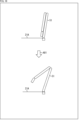
FIG. 1 is a perspective view showing a configuration example of the appearance of a
ロボットキッチン1は、AI(Artificial Intelligence)などを用いて全体の動作を制御するコンピュータ、調理アームなどの駆動系の装置、および、各種のセンサを有し、調理を自律的に行うロボット機能を搭載した調理システムである。ロボットキッチン1は、例えば家庭内に設置される。
The
図1に示すように、ロボットキッチン1は、横長直方体状の筐体11を有する。ロボットキッチン1の本体となる筐体11の内部に、コンピュータなどの各種の装置が設けられる。
As shown in FIG. 1, the
筐体11の背面側には、筐体11の上面から立設する形で調理補助システム31が設けられる。調理補助システム31は、冷蔵庫、オーブンレンジ、収納などの各種の調理補助ユニットが並べて構成される。調理補助ユニットなどの各部の詳細については後述する。
A
筐体11の略中央には、長手方向に溝が形成される。溝に沿ってレールが設けられており、そのレールに調理アーム51-1乃至51-4が設けられる。調理アーム51-1乃至51-4は、移動機構としてのレールに沿って位置を変えることが可能とされる。
A groove is formed in the longitudinal direction in substantially the center of the
調理アーム51-1乃至51-4は、円筒状の部材を関節部で接続することによって構成されるロボットアームである。調理や片付けなどの各種の作業が、調理アーム51-1乃至51-4により行われる。 The cooking arms 51-1 to 51-4 are robot arms configured by connecting cylindrical members with joints. Various tasks such as cooking and cleaning are performed by the cooking arms 51-1 to 51-4.
筐体11の正面側の天板21Aの上方の空間が、調理アーム51-1乃至51-4が調理を行う調理空間となる。尚、調理空間とは、調理アーム51-1乃至51-4またはユーザが調理を行う空間の総称である。調理空間は、調理アーム51-1乃至51-4またはユーザが調理を行う空間と完全に一致する空間だけでなく、そのような空間に包含される部分的な空間をも含む。
The space above the
図1においては4本の調理アームが示されているが、調理アームの数は4本に限定されるものではない。以下、適宜、調理アーム51-1乃至51-4のそれぞれを区別する必要がない場合、まとめて調理アーム51という。
Although four cooking arms are shown in FIG. 1, the number of cooking arms is not limited to four. Hereinafter, the cooking arms 51-1 to 51-4 will be collectively referred to as the
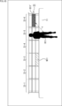
図2は、作業中の調理アーム51の様子を示す図である。
FIG. 2 is a diagram showing the state of the
図2に示すように、調理アーム51の先端には、各種の調理機能を有するアタッチメントが取り付けられる。アタッチメントとして、食材や食器などを掴むマニピュレーター機能(ハンド機能)を有するアタッチメント、食材をカットするナイフ機能を有するアタッチメント、調味料などの液体を混ぜるミキサー機能を有するアタッチメントなどが用意される。
As shown in FIG. 2, attachments having various cooking functions are attached to the tip of the
図2の例においては、ナイフ機能を有するアタッチメントであるナイフアタッチメントが調理アーム51-1に取り付けられている。ナイフアタッチメントを用いて、天板21Aの上に置かれた肉の塊がカットされている。
In the example of FIG. 2, a knife attachment, which is an attachment having a knife function, is attached to the cooking arm 51-1. A chunk of meat placed on the
調理アーム51-2には、食材を固定させたり、食材を回転させたりすることに用いられるアタッチメントであるスピンドルアタッチメントが取り付けられている。 The cooking arm 51-2 is attached with a spindle attachment, which is an attachment used for fixing food and rotating the food.
調理アーム51-3には、食材の皮をむくピーラーの機能を有するアタッチメントであるピーラーアタッチメントが取り付けられている。 The cooking arm 51-3 is attached with a peeler attachment that has a peeler function for peeling food ingredients.
スピンドルアタッチメントを用いて調理アーム51-2により持ち上げられているジャガイモの皮が、ピーラーアタッチメントを用いて調理アーム51-3によりむかれている。このように、複数の調理アーム51が連携して1つの作業を行うことも可能とされる。
A potato being lifted by cooking arm 51-2 using a spindle attachment is being peeled by cooking arm 51-3 using a peeler attachment. In this way, it is also possible for a plurality of
調理アーム51-4には、マニピュレーター機能を有するアタッチメントであるマニピュレーターアタッチメントが取り付けられている。マニピュレーターアタッチメントを用いて、チキンを載せたフライパンが、オーブン機能を有する調理補助ユニットに運ばれている。 A manipulator attachment, which is an attachment having a manipulator function, is attached to the cooking arm 51-4. Using a manipulator attachment, a frying pan with chicken is brought to a cooking aid unit with oven functionality.
このような調理アーム51による調理は、作業の内容に応じてアタッチメントを適宜取り替えて進められる。アタッチメントの取り替えも、ロボットキッチン1により自動的に行われる。
Cooking by the
<人との協同作業>
調理アーム51を用いて行われるロボットキッチン1における調理は、一部の作業をユーザと協同するようにして行われる。ロボットキッチン1が家庭内に設置される場合、家族などと協同して調理が行われることになる。<Collaborative work with people>
Cooking in the
どの作業をユーザが行うのかは、例えば、料理毎に用意されるレシピデータにおいて規定される。後述するように、レシピデータには、各作業時における、各調理アーム51の動作を表す情報なども記述される。ロボットキッチン1は、レシピデータの記述に従って、調理アーム51などの各部の動作を制御し、調理を行う。
Which work is to be performed by the user is defined, for example, in recipe data prepared for each dish. As will be described later, the recipe data also includes information representing the operation of each
全ての作業がロボットキッチン1により行われるようにしたり、より多くの作業をユーザが自分で行うようにしたりするように、調理への関与の度合いをユーザが自ら選択することが可能とされる。ユーザが選択した関与度合いに応じて、レシピデータの記述が加工される。
The user can select the degree of involvement in cooking by himself so that all the work is done by the
例えば難易度の高い料理を作る場合、ユーザは、関与度合いを低く設定することによって、自分では出来ないような調理をロボットキッチン1に任せることができる。
For example, when cooking a dish with a high degree of difficulty, the user can entrust the
また、調理を趣味としているユーザは、関与度合いを高く設定することによって、多くの作業を楽しむことができる。 Also, a user whose hobby is cooking can enjoy many tasks by setting the degree of involvement high.
なお、料理は、調理を経て出来上がる成果物のことを意味する。調理は、料理を作る過程や、料理を作る行為のことを意味する。 In addition, a dish means a product produced through cooking. Cooking means the process of cooking or the act of cooking.
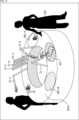
図3は、協同作業の第1の例を示す図である。 FIG. 3 is a diagram showing a first example of collaborative work.
図3の上段には、ユーザが、包丁を使ってジャガイモをカットしている様子が示されている。ユーザがカットしているジャガイモの近くには、カット前のジャガイモが用意されている。ユーザの近くには、ナイフアタッチメントが取り付けられた調理アーム51-1が待機している。 The upper part of FIG. 3 shows the user cutting potatoes with a kitchen knife. An uncut potato is prepared near the potato being cut by the user. A cooking arm 51-1 with a knife attachment is waiting near the user.
ユーザが使っている包丁やジャガイモなどの食材は、調理アーム51により用意されたものである。
Food such as kitchen knives and potatoes used by the user are prepared by the
例えば、1つのジャガイモのカットを終えた段階で、矢印A1の先に示すように、「こんな感じで、あとやっといて」とユーザが発話した場合、ロボットキッチン1においては、カット前のジャガイモを対象としてカットの続きを行うことが特定される。ロボットキッチン1からは、「かしこまりました」の合成音声が出力される。
For example, when the user has finished cutting one potato, as indicated by the arrow A1, if the user utters, "Like this, please finish later." It is specified that the continuation of the cut is performed as From the
すなわち、ロボットキッチン1には、ユーザの行動を学習する機能、ユーザの発話の意味を認識し、応答する機能なども用意されている。ロボットキッチン1の所定の位置には、ユーザの行動を撮影するためのカメラ、音声を検出するためのマイク(マイクロフォン)、合成音声を出力するためのスピーカが設けられている。
In other words, the
カットの続きを行うことが特定された場合、矢印A2の先に示すように、残りのジャガイモを対象として、調理アーム51-1によりカットが続けられる。カットの方向、カットの幅などは、学習によって得られた、ユーザのやり方が踏襲される。 If it is specified to continue the cutting, the cooking arm 51-1 continues to cut the remaining potatoes, as indicated by the arrow A2. The cutting direction, cutting width, etc. follow the user's method obtained through learning.
同じ食材をいくつもカットするといったような単純作業は、調理の作業の中でもユーザにとっては極力省きたい作業といえる。ユーザの行動を学習し、ユーザの行動と同じ行動をロボットキッチン1がとることにより、ユーザは、そのような単純作業を行わないで済むことになる。
It can be said that simple work such as cutting the same food several times is work that users want to avoid as much as possible among cooking work. By learning the user's behavior and having the
図4は、協同作業の第2の例を示す図である。 FIG. 4 is a diagram showing a second example of collaborative work.
図4の上段には、スライス済みのバゲットとスモークサーモンが天板21Aに置かれている様子が示されている。食材の用意、食材のスライス、および、サーモンのスモーク調理は、調理アーム51により行われたものである。
The upper part of FIG. 4 shows how sliced baguettes and smoked salmon are placed on the
調理アーム51-1には、マニピュレーターアタッチメントが取り付けられている。一切れのスモークサーモンが調理アーム51-1により持ち上げられ、バゲットの方に運ばれている。この例においては、スモークサーモンを載せたバゲットの調理が行われている。 A manipulator attachment is attached to the cooking arm 51-1. A piece of smoked salmon is being lifted by the cooking arm 51-1 and carried towards the baguette. In this example, a baguette with smoked salmon is cooked.
スモークサーモンがバゲットに載せられた場合、矢印A11の先に示すように、完成した料理であるバゲットが調理アーム51-1によりユーザに差し出される。また、「味見をどうぞ」の合成音声が出力され、味見を行うことがユーザに対して要求される。 When the smoked salmon is placed on the baguette, the cooking arm 51-1 presents the baguette, which is a completed dish, to the user as indicated by arrow A11. Also, a synthesized voice saying "please taste" is output, requesting the user to taste.
ユーザは、差し出されたバゲットを受け取り、味見を行うことになる。味見を行ったユーザが例えば「おいしい」といったような肯定的な発話を行った場合、バゲットにスモークサーモンを載せる作業が続けられる。 The user receives the presented baguette and tastes it. If the user who tasted the baguette makes a positive utterance, for example, "delicious", the work of placing the smoked salmon on the baguette continues.
味見は、調理の作業の中でも重要な作業であり、また、ユーザにとって楽しい作業でもある。ユーザは、楽しい作業を自分で行うことができる。 Tasting is an important task among cooking tasks, and is also an enjoyable task for the user. The user can do pleasant work by himself.
図5は、協同作業の第3の例を示す図である。 FIG. 5 is a diagram showing a third example of collaborative work.
図5の上段には、スポンジをクリームでコーティングするナッペの作業が調理アーム51-1により行われている様子が示されている。調理アーム51-1には、ヘラの機能を有するヘラアタッチメントが取り付けられている。スポンジやクリームは、調理アーム51により用意されたものである。
The upper part of FIG. 5 shows how the cooking arm 51-1 performs the nappe work of coating the sponge with cream. A spatula attachment having a spatula function is attached to the cooking arm 51-1. The sponge and cream are those prepared by the
ナッペの作業が終了した場合、矢印A21の先に示すように、「仕上げをお願いします」の合成音声がロボットキッチン1から出力され、仕上げの作業を行うことがユーザに対して要求される。
When the nappe work is finished, the
矢印A22の先に示すように、ユーザは、ロボットキッチン1による要求に応じて、クリームでデコレーションする作業を仕上げの作業として行うことになる。
As indicated by the arrow A22, the user performs the task of decorating with cream in response to a request from the
ケーキ作りにおけるクリームでのデコレーションや、料理の盛り付けといった仕上げの作業は、ユーザが創造性を発揮させて行う作業であり、楽しい作業といえる。ユーザは、そのような楽しい作業を自分で行うことができる。 Finishing tasks such as decorating cakes with cream and arranging food are tasks that allow users to exercise their creativity, and can be said to be enjoyable tasks. A user can do such a pleasant task by himself.
このように、ロボットキッチン1による調理は、適宜、ユーザと協同して進められる。準備などの単純作業についてはロボットキッチン1が行うように作業が分担されるから、ユーザは、楽しい作業だけを自分で行い、面倒な作業についてはロボットキッチン1に任せることができる。
In this way, cooking by the
ユーザは、ロボットキッチン1と協同で調理を行うといったような、新たな調理体験を得ることができる。
The user can obtain a new cooking experience such as cooking in cooperation with the
また、ユーザは、天板21Aの上で調理アーム51により行われる作業を見て楽しむこともできる。仮に、筐体11の内部で調理が行われ、出来上がった料理が出てくるとした場合、そのようなキッチンは、料理の単なる製造装置といえるものであり、便利ではあるものの面白みに欠ける。
The user can also enjoy watching the work performed by the
人が調理に使うツールとは異なる各種のアタッチメントを用いて、ユーザに見せる形で調理が行われることにより、ロボットキッチン1は、調理の作業そのものによって、部屋などの空間を演出することができる。
The
調理の作業によって空間を演出することができ、また、楽しむことができる作業にユーザが関与することができることから、ロボットキッチン1は、エンターテインメント性のあるキッチンといえる。
The
<<2.ロボットキッチンの構成の詳細>>
<ロボットキッチンの変形>
図6および図7は、スリープモード時のロボットキッチン1の外観を示す図である。<<2. Details of the configuration of the robot kitchen >>
<Transformation of Robot Kitchen>
6 and 7 are diagrams showing the appearance of the
図6は、スリープモード時のロボットキッチン1を正面から見た状態を示し、図7は、スリープモード時のロボットキッチン1を右前方から見た状態を示す。図6に示すように、横長直方体状の筐体11は、床に固定された柱状のベース部12の上に設けられる。筐体11の底面と床の間には所定の高さのスペースが形成される。
FIG. 6 shows the
スリープモード時、調理補助システム31は筐体11内に収納された状態となる。調理補助システム31は天板部21より低い位置に設けられる。
In the sleep mode, the
図7に示すように、天板部21を構成する天板21Aと天板21Bは、同じ高さに、僅かな隙間を挟んで設けられる状態となる。天板21Aと天板21Bが同じ高さに接した状態で設けられることにより、筐体11の上面は略フラットな面となる。
As shown in FIG. 7, the
図8は、アクティブモード時のロボットキッチン1の外観を示す図である。
FIG. 8 is a diagram showing the appearance of the
ロボットキッチン1の動作モードがスリープモードからアクティブモードに切り替わった場合、調理補助システム31が上昇し、図8に示すように、筐体11の背面側に調理補助システム31が立設した状態となる。天板21Bが上昇することに連動して、天板21Bの底面側に設けられた調理補助システム31が現れる。
When the operation mode of the
スリープモードからアクティブモードへの切り替えは、予め設定された調理の開始時刻になったタイミング、協同作業を行う人がロボットキッチン1の近くにいることが検出されたタイミングなどの所定のタイミングで行われる。このようなロボットキッチン1の変形は、電動で行われる。
Switching from the sleep mode to the active mode is performed at a predetermined timing, such as timing when a preset cooking start time is reached, timing when it is detected that a person performing collaborative work is near the
図9は、調理補助システム31の正面図である。
FIG. 9 is a front view of the
箱状の調理補助システム31を囲む正面、背面、および左右の両側面は、断熱性を有する強化ガラスなどの透明な部材によって構成される。調理補助システム31の内部は、透けて見える状態となる。
The front, back, and left and right side surfaces surrounding the box-shaped
調理補助システム31は、調理補助ユニット31-1乃至31-6から構成される。調理補助ユニット31-1乃至31-6は、ロボットキッチン1の調理を補助するための機能を有する装置である。
The
各調理補助ユニットは薄板状の部材によって区切られる。薄板状の2枚の棚板で仕切られることによって、各調理補助ユニットの内部には上下に3段の空間が形成される。例えば、正面の部材がスライドして開くことにより、各調理補助ユニットの各段にアクセスすることが可能となる。 Each cooking assistance unit is separated by a thin plate member. A three-level space is formed vertically inside each cooking assistance unit by being partitioned by two thin shelf plates. For example, by sliding the front member open, it becomes possible to access each stage of each cooking assistance unit.
調理補助ユニット31-1は、冷凍機能を有する装置である。調理補助ユニット31-1には、肉や魚などが冷凍された状態で保存される。 The cooking assistance unit 31-1 is a device having a freezing function. Meat, fish, and the like are stored in a frozen state in the cooking assistance unit 31-1.
調理補助ユニット31-2は、冷蔵機能を有する装置である。調理補助ユニット31-2には、フルーツや飲料類などが冷却した状態で保存される。 The cooking assistance unit 31-2 is a device having a refrigeration function. In the cooking assistance unit 31-2, fruits and beverages are stored in a cooled state.
調理補助ユニット31-3は、低温の状態を維持する機能を有する装置である。調理補助ユニット31-3には、野菜などが低温の状態で保存される。例えば調理補助ユニット31-3の下段には、調理アーム51に取り付けられるアタッチメントや調理器具(人間により使用される包丁、まな板、ピーラー、およびヘラなど)が収納される。低温の状態でアタッチメントが収納されることにより、雑菌の繁殖を抑えることが可能となる。
The cooking assistance unit 31-3 is a device having a function of maintaining a low temperature state. Vegetables and the like are stored at a low temperature in the cooking assistance unit 31-3. For example, in the lower stage of the cooking assistance unit 31-3, attachments to be attached to the
調理補助ユニット31-4は、常温の収納庫としての機能を有する。調理補助ユニット31-4には、パン、パスタ、調味料などが収納される。調理補助ユニット31-4には、食器、カトラリーなども収納される。 The cooking assistance unit 31-4 functions as a room temperature storage. The cooking assistance unit 31-4 stores bread, pasta, seasonings, and the like. Tableware, cutlery and the like are also stored in the cooking assistance unit 31-4.
調理補助ユニット31-5は、保温機能を有する装置である。調理補助ユニット31-5には、スープ、解凍中の食品、低温調理中の食品などが保存される。 The cooking assistance unit 31-5 is a device having a heat retaining function. The cooking assistance unit 31-5 stores soup, food being thawed, food being cooked at a low temperature, and the like.
調理補助ユニット31-6は、オーブン機能を有する装置である。調理補助ユニット31-6を用いて、パンを焼く、肉を焼くなどの加熱調理が行われる。 The cooking assistance unit 31-6 is a device having an oven function. Using the cooking assistance unit 31-6, heat cooking such as baking bread and grilling meat is performed.
調理補助ユニット31-1乃至31-6の並びは、食材などをより低い温度で収納する機能を有するユニットほど左側に位置し、より高い温度で収納する機能を有するユニットほど右側に位置する並びとなる。 In the arrangement of the cooking assistance units 31-1 to 31-6, the units having the function of storing foodstuffs at lower temperatures are located on the left side, and the units having the functions of storing foodstuffs at higher temperatures are located on the right side. Become.
各調理補助ユニット内の温度を調整する装置が、各調理補助ユニットの下などの所定の位置に設けられる。温度調整装置が排出する冷気や熱気が送られることにより、各ユニット内の温度が調整される。 A device for regulating the temperature within each cooking aid unit is provided at a predetermined location, such as below each cooking aid unit. The temperature inside each unit is adjusted by sending cool air or hot air discharged by the temperature adjustment device.
ロボットキッチン1の動作モードがスリープモードからアクティブモードに切り替わり、調理補助システム31が出現した場合、調理補助システム31に続けて、図10に示すように、調理アーム51が調理補助システム31の正面側に現れる。
When the operation mode of the
調理アーム51は、天板21Bが上昇することに応じて現れる溝部に収納されていたものである。調理補助システム31の奥行き方向の幅は、図10に示すように、天板21Bの奥行き方向の幅より狭い。スリープモード時に天板21Bによって塞がれていた溝部が、天板21Bが上昇することに応じて現れ、その溝部から、調理アーム51が起動することになる。
The
また、ロボットキッチン1を上方から見た場合、図10の筐体11の側面断面に斜線を付して示すように、溝部101は、天板21Aと天板21Bの境界近傍に、筐体11の長手方向に形成される。溝部101の長さは、左側面側と右側面側の所定の幅の壁面部を除いて、筐体11の長手方向の長さとほぼ同じ長さとなる。
When the
溝部101の開口近傍には、溝部101の側面に沿ってレール102が設けられる。図13の例においては、色を付して示すように、溝部101の正面側の側面に沿って、レール102が設けられている。レール102に沿って溝部101が形成されていると言うこともできる。調理アーム51は、レール102に沿って移動可能な状態で取り付けられる。
A
また、溝部101は、洗浄機能として、紫外線の照射口111、ジェット風の噴出口112、水の噴出口113(いずれも図13参照)のセットを備えており、このセットは、溝部101の長手方向に所定の間隔で複数設けられる。ユーザが手を入れた位置にあるセットが駆動し、手の洗浄が行われる。
Further, the
食器、カトラリー、調理アーム51に装着されるアタッチメントなども、溝部101の洗浄機能を用いて洗浄される。洗浄だけでなく、食器、カトラリー、アタッチメントの乾燥と消毒も、人の手と同様にして行われる。
Tableware, cutlery, and attachments attached to the
また、溝部101には、調理時に発生したごみなどの廃棄物を処理する廃棄物処理機能が設けられる。例えば、天板21A上に散らばった廃棄物が、調理アーム51で掃くようにして溝部101に投入される。
Further, the
<調理アーム>
・調理アームの構成
図11は、調理アーム51の外観を示す図である。<Cooking arm>
Configuration of Cooking Arm FIG. 11 is a diagram showing the appearance of the
図11に示すように、調理アーム51は、全体的に、細い円筒状の部材を、関節部となるヒンジ部で接続することによって構成される。各ヒンジ部には、各部材を駆動させるための力を生じさせるモータなどが設けられる。
As shown in FIG. 11, the
円筒状の部材として、先端から順に、着脱部材501、中継部材503、およびベース部材505が設けられる。着脱部材501は、中継部材503の長さの略1/5程度の長さを有する部材である。着脱部材501の長さと中継部材503の長さを合わせた長さが、ベース部材505の長さとほぼ同じ長さとなる。
As cylindrical members, a
着脱部材501と中継部材503はヒンジ部502によって接続され、中継部材503とベース部材505はヒンジ部504によって接続される。中継部材503の両端にはヒンジ部502とヒンジ部504が設けられる。
The
この例においては、3本の円筒状の部材によって調理アーム51が構成されているが、4本以上の円筒状の部材によって構成されるようにしてもよい。この場合、中継部材503が複数設けられる。
In this example, the
着脱部材501の先端には、アタッチメントが着脱される着脱部501Aが設けられる。着脱部材501は、各種の調理機能を有するアタッチメントが着脱される着脱部501Aを有し、アタッチメントを動作させることによって調理を行う調理機能アーム部として機能する。
An attachment/
ベース部材505の後端には、レール102に嵌め込まれたアーム移動部131に取り付けられる着脱部506が設けられる。ベース部材505は、アーム移動部131に取り付けられる着脱部506を有し、調理アーム51の移動を実現する移動機能アーム部として機能する。
The rear end of the
図12は、調理アーム51の各部の可動域の例を示す図である。
FIG. 12 is a diagram showing an example of the range of motion of each part of the
楕円#1で囲んで示すように、着脱部材501は、円形断面の中心軸を中心として回転可能とされる。楕円#1の中心に示す扁平の小円は、一点鎖線の回転軸の方向を示す。
As indicated by an
着脱部材501の回転範囲は、着脱部501Aにアタッチメントが取り付けられている場合には、アタッチメントの配管が外れない範囲として設定される。アタッチメントに応じて回転範囲が切り替わる。
The rotation range of the attachment/
円#2で囲んで示すように、着脱部材501は、ヒンジ部502との嵌合部501Bを通る軸を中心として回転可能とされる。また、中継部材503は、ヒンジ部502との嵌合部503Aを通る軸を中心として回転可能とされる。
As indicated by the
円#2の内側に示す2つの小円はそれぞれの回転軸の方向(紙面垂直方向)を示す。嵌合部501Bを通る軸を中心とした着脱部材501の可動範囲と、嵌合部503Aを通る軸を中心とした中継部材503の可動範囲は、それぞれ例えば90度の範囲である。
The two small circles shown inside
中継部材503は、先端側の部材503-1と、後端側の部材503-2により分離して構成される。楕円#3で囲んで示すように、中継部材503は、部材503-1と部材503-2との連結部503Bにおいて、円形断面の中心軸を中心として回転可能とされる。
The
他の可動部も、基本的に同様の可動域を有する。 Other movable parts basically have the same range of motion.
すなわち、円#4で囲んで示すように、中継部材503は、ヒンジ部504との嵌合部503Cを通る軸を中心として回転可能とされる。また、ベース部材505は、ヒンジ部504との嵌合部505Aを通る軸を中心として回転可能とされる。
That is, as indicated by a
ベース部材505は、先端側の部材505-1と、後端側の部材505-2により分離して構成される。楕円#5で囲んで示すように、ベース部材505は、部材505-1と部材505-2との連結部505Bにおいて、円形断面の中心軸を中心として回転可能とされる。
The
円#6で囲んで示すように、ベース部材505は、着脱部506との嵌合部505Cを通る軸を中心として回転可能とされる。
As indicated by a
楕円#7で囲んで示すように、着脱部506は、円形断面の中心軸を中心として回転可能となるようにアーム移動部131に取り付けられる。
As indicated by an
このように、先端に着脱部501Aを有する着脱部材501、着脱部材501とベース部材505を連結する中継部材503、後端に着脱部506が接続されるベース部材505は、それぞれ、ヒンジ部により回転可能に接続される。各可動部の動きが、ロボットキッチン1内のコントローラにより制御される。
In this way, the
これにより、自由度の高い動きを実現することが可能となる。 This makes it possible to realize a movement with a high degree of freedom.
・移動機構
図13は、レール102の近傍を拡大して示す断面図である。- Moving mechanism FIG. 13 : is sectional drawing which expands and shows the vicinity of the
天板21Aの縁に設けられたレール102にはアーム移動部131が嵌め込まれる。レール102の上面と下面には小さな溝102A,102Bが形成されており、溝102A,102Bに、アーム移動部131の上面と下面に設けられたローラー131A,131Bが嵌め込まれる。
An
アーム移動部131の先端は緩やかな曲面として形成され、この曲面に着脱部131C(図14)が設けられる。着脱部506が着脱部131Cに差し込まれることによって、調理アーム51がアーム移動部131に取り付けられる。
The distal end of the
なお、図13においては、配管132の図示が省略されている。配管132は、アーム移動部131の内部を通って着脱部131Cに導かれる。着脱部131Cに着脱部506が差し込まれたとき、配管132が、調理アーム51内の配管に接続される。
13, illustration of the pipe 132 is omitted. The pipe 132 passes through the inside of the
図14は、アーム移動部131の移動方向を示す図である。
FIG. 14 is a diagram showing the moving direction of the
図14には、レール102に嵌め込まれたアーム移動部131を、溝部101の内側から見た状態が示されている。
FIG. 14 shows a state in which the
双方向の矢印A61で示すように、アーム移動部131は、レール102に沿って水平方向に移動する。アーム移動部131を移動させることにより、アーム移動部131に取り付けられた調理アーム51を任意の位置に移動させることが可能となる。各可動部の動きだけでなく、調理アーム51の位置も、ロボットキッチン1内のコントローラにより制御される。
The
図15は、調理アーム51の着脱の様子を示す図である。
FIG. 15 is a diagram showing how the
図15に示すように、調理アーム51は、レール102に嵌め込まれたアーム移動部131に対して着脱可能とされる。例えば、調理アーム51は単体で販売される。ユーザは、追加で購入することによって、レール102に用意されているアーム移動部131の数を上限として、調理アーム51を増やすことができる。
As shown in FIG. 15 , the
調理アーム51が増えることに応じて、同時にできる作業が増えたり、複数の調理アーム51が連携して行う作業の内容が変わったりすることになる。ロボットキッチン1には、同じ料理を作成するためのレシピデータとして、調理アーム51の数に応じて記述内容が異なるデータが用意される。
As the number of
<アタッチメント>
・アタッチメントの着脱機構
アタッチメントを用いて調理を行うためには、調理に用いる水などを調理アーム51側からアタッチメント側に供給する必要がある。<Attachment>
Attachment/Detachment Mechanism of Attachment In order to cook using the attachment, it is necessary to supply water or the like used for cooking from the
図16は、調理アーム51の機能の例を示す図である。
FIG. 16 is a diagram showing an example of the functions of the
図16の矢印で示すように、調理アーム51は、電気をアタッチメントに供給する機能を有する。調理アーム51から供給された電気によってアタッチメントが駆動する。アタッチメントに供給する電気は、例えばレール102を介して調理アーム51に供給される。
As indicated by the arrow in FIG. 16, the
また、調理アーム51は、熱や冷気をアタッチメントに供給する機能を有する。調理アーム51から供給された熱によって、アタッチメントにおいて例えば加熱調理が行われる。また、調理アーム51から供給された冷気によって、食材の温度調整が行われる。
The
アタッチメントに供給する熱や冷気は、アーム機能制御装置133において発生し、配管132を介して調理アーム51に供給される。アーム機能制御装置133において発生した熱や冷気は、圧縮した空気などをアーム機能制御装置133から配管132に送り込むことによって調理アーム51に伝えられる。
Heat and cold air supplied to the attachment are generated in the arm
調理アーム51は、オリーブオイル、サラダ油などの食用油をアタッチメントに供給する機能を有する。調理アーム51から供給された食用油によって、アタッチメントにおいて例えば揚げ物の調理が行われる。また、オリーブオイルを食材に振りかけるなどの調理が行われる。
The
アタッチメントに供給する食用油は、アーム機能制御装置133から、配管132を介して調理アーム51に供給される。アーム機能制御装置133内に設けられた容器に貯められていた食用油は、配管132に流し込むことによってアーム機能制御装置133から調理アーム51に供給される。
The cooking oil supplied to the attachment is supplied from the arm
調理アーム51は、水をアタッチメントに供給する機能を有する。調理アーム51から供給された水によって、例えば食材の洗浄、天板21Aの洗浄が行われる。食材の洗浄、天板21Aの洗浄も、調理として行われる作業である。
The
アタッチメントに供給する水は、アーム機能制御装置133から、配管132を介して調理アーム51に供給される。アーム機能制御装置133によって水道管から引き込まれた水は、配管132に流し込むことによって調理アーム51に供給される。アーム機能制御装置133において温度が調整された水が調理アーム51に供給されるようにしてもよい。
Water to be supplied to the attachment is supplied from the arm
調理アーム51は、空気をアタッチメントに供給する機能を有する。例えば、蒸気、煙、ガスがアタッチメントに対して供給される。調理アーム51から供給された蒸気によって、例えば蒸し物の調理、天板21Aや他の調理アーム51に取り付けられたアタッチメントの消毒が行われる。
The
また、調理アーム51から供給された煙によって、例えばスモーク調理がアタッチメントにより行われる。調理アーム51から供給されたガスを用いた炎によって、例えば焼き物の調理がアタッチメントにより行われる。
In addition, the smoke supplied from the
アタッチメントに供給する空気は、アーム機能制御装置133から、配管132を介して調理アーム51に供給される。アーム機能制御装置133において発生した蒸気、煙は、圧縮した空気とともにアーム機能制御装置133から配管132に送り込むことによって調理アーム51に供給される。アーム機能制御装置133によってガス管から引き込まれたガスは、配管132に送り込むことによってアーム機能制御装置133から調理アーム51に供給される。
Air supplied to the attachment is supplied from the
調理アーム51は、液体や気体を吸引する機能を有する。アーム機能制御装置133において生じた吸引力が配管132と調理アーム51を介してアタッチメントに伝えられ、アタッチメントの吸い込み口にある液体や気体が吸引される。
The
図16に示す全ての機能が調理アーム51に搭載されるのではなく、少なくともいずれかの機能が調理アーム51に搭載されていればよい。 Not all the functions shown in FIG.
清涼飲料水やアルコール飲料などの飲料水をアタッチメントに供給する機能、砂糖や塩などの調味料をアタッチメントに供給する機能などの他の機能が調理アーム51に用意されるようにしてもよい。
The
図17は、アタッチメントの着脱機構の例を示す図である。 FIG. 17 is a diagram showing an example of an attachment attaching/detaching mechanism.
図17に示すように、調理アーム51側の着脱部材501の先端に形成された着脱部501Aの中央には、凹状の挿入孔521が形成される。
As shown in FIG. 17, a recessed
一方、アタッチメント601側には着脱部611が設けられる。着脱部611の先端には、凸状の突起が挿入部621として形成される。
On the other hand, a
挿入部621が挿入孔521に挿入されたとき、挿入孔521に設けられたロック部521Aが挿入部621の周側面に形成された溝部621Aに嵌合し、アタッチメント601が調理アーム51に固定される。
When the
挿入部621の挿入孔521に対する挿入は、着脱部501A側と着脱部611側にそれぞれ設けられたマグネットが引き合うことによって誘導される。図18に色を付して示すように、着脱部501A側と着脱部611側の対応する位置には、マグネット533-1,533-2と、マグネット633-1,633-2がそれぞれ設けられる。図18は、着脱部501Aと着脱部611の当接面の構成を示す。
The insertion of the
挿入孔521の最奥部には配管531が設けられる。図18に示すように、配管531の上側と下側に配管が3本ずつ設けられる。各配管が、調理アーム51を構成する各部材の中に配設される。
A
一方、挿入部621の先端面には配管631が設けられる。図18に示すように、配管631の上側と下側に配管が3本ずつ設けられる。
On the other hand, a
調理アーム51側の配管531とアタッチメント601側の配管631は、図17の矢印A71に示すように、液体や気体を吸引することに用いられる。
The
調理アーム51側の配管532-1,532-2と、アタッチメント601側の配管632-1,632-2は、例えば、図17の矢印A72に示すように、水を供給することに用いられる。
The pipes 532-1 and 532-2 on the
また、調理アーム51側の配管532-3,532-4と、アタッチメント601側の配管632-3,632-4は、食用油を供給することに用いられる。
Also, the pipes 532-3, 532-4 on the
調理アーム51側の配管532-5,532-6と、アタッチメント601側の配管632-5,632-6は、気体を供給することに用いられる。配管532-5,532-6と配管632-5,632-6を用いて、熱や冷気の供給、蒸気、煙、ガスの供給などが行われる。
The pipes 532-5 and 532-6 on the
調理アーム51側においては、同じ機能に用いられる2本の配管が、中心の配管531を挟んで対角の位置に設けられる。アタッチメント601側においても同様に、同じ機能に用いられる2本の配管が中心の配管631を挟んで対角の位置に設けられる。
On the
図19および図20は、アタッチメント601の装着の流れを示す図である。
19 and 20 are diagrams showing the flow of mounting the
起動直後の調理アーム51の状態は、図19の上段に示すようにスタンバイ状態となる。アタッチメントを取り付けることがレシピデータなどに基づいて特定された後、矢印A81の先に示すように、調理アーム51の駆動が開始される。
The state of the
調理補助ユニット31-3に収納されている複数のアタッチメントのうち、取り付け対象となるアタッチメントの位置が認識される。それぞれのアタッチメントの位置は、例えば、カメラにより撮影された画像を解析することによって認識される。 Among the plurality of attachments housed in the cooking assistance unit 31-3, the position of the attachment to be attached is recognized. The position of each attachment is recognized, for example, by analyzing images taken by the camera.
各アタッチメントの収納位置が固定されているようにしてもよい。各アタッチメントは、例えば、溝部101に着脱部611を向けた状態で調理補助ユニット31-3に収納される。
The storage position of each attachment may be fixed. Each attachment is housed in the cooking assistance unit 31-3 with the attachment/
図20の上段に示すように、取り付け対象となるアタッチメント601の着脱部611に着脱部501Aを近付けるように調理アーム51の各部が駆動する。
As shown in the upper part of FIG. 20, each part of the
アタッチメント601の着脱部611に着脱部501Aが近付けられたとき、着脱部501A側と着脱部611側に設けられたマグネットの引力によって、矢印A82の先に示すように、着脱部501Aにアタッチメント601が取り付けられる。
When the attachment/
これにより、矢印A83の先に示すように、アタッチメント601を用いた調理を行うことが可能となる。図20の例においては、アタッチメント601を振ることによって、材料を混ぜる調理が行われている。
This enables cooking using the
以上のように、調理アーム51側とアタッチメント601側にそれぞれ着脱部を設けることにより、アタッチメント601の取り替えが可能となる。
As described above, by providing detachable portions on the
また、アタッチメント601を取り付けたときに調理アーム51側の配管とアタッチメント601側の配管が連結することにより、アタッチメント601に各種の調理機能を持たせることが可能となる。
Further, when the
図17の説明に戻り、アタッチメント601全体の構成のうち、着脱部611以外の部分が、調理機能を実現する調理部612となる。調理アーム51の動作に従って、調理工程に応じた作業が調理部612において実現される。適宜、協同作業を行うユーザの状態に応じて調理部612の動作が切り替えられる。調理部612の構成は、アタッチメントの種類に応じて異なるものとなる。
Returning to the description of FIG. 17, of the overall configuration of the
図17、図18の例においては主に配管の連結について説明したが、電気を供給するケーブル、各種の制御信号をアタッチメント601側に供給する信号線を連結する構成なども、調理アーム51側とアタッチメント601側にそれぞれ設けられる。
In the examples of FIGS. 17 and 18, the connection of pipes has been mainly described, but the configuration of connecting cables for supplying electricity and signal lines for supplying various control signals to the
調理部612は、ロボットキッチン1の制御装置(図32のコントローラ201)に対して接続され、制御装置から送信されてきた制御信号を受信する接続部としての機能を有する。また、調理部612は、接続部において受信された制御信号に基づいて、調理部612自身が有する調理機能を制御する制御部としての機能を有する。
The
・アタッチメントの種類
ここで、以上のようにして調理アーム51に取り付けられるアタッチメントの種類について説明する。Types of Attachments Here, types of attachments that can be attached to the
図21乃至図24は、アタッチメントの例を示す図である。 21 to 24 are diagrams showing examples of attachments.
図21乃至図24においては、各アタッチメントが、調理アーム51に取り付けられた状態で示されている。各アタッチメントの根元には着脱部611が設けられる。着脱部611より先の部分が、各アタッチメントの調理部612に対応する。
21 to 24 each attachment is shown attached to the
図21のAは、食材や食器などを掴むマニピュレーター機能を有するアタッチメントであるマニピュレーターアタッチメント651の外観を示す。マニピュレーターアタッチメント651の詳細については後述する。
FIG. 21A shows the appearance of a
図21のBは、ヘラの機能を有するアタッチメントであるヘラアタッチメント652の外観を示す。
FIG. 21B shows the appearance of a
ヘラアタッチメント652は、先端が半円弧状に丸められた、細幅の薄板状の形状を有する。ヘラアタッチメント652は、ステンレスなどの金属、セラミック、樹脂などにより構成される。
The
ヘラアタッチメント652を用いて、上述したようにナッペなどの作業が行われる。ヘラアタッチメント652の素材が金属である場合、ヘラアタッチメント652を食材に当てることによって、調理アーム51から供給された熱で食材を焼いたり、調理アーム51から供給された冷気で食材を冷却したりする作業が行われるようにしてもよい。
Using the
図21のCは、ナイフの機能を有するアタッチメントであるナイフアタッチメント653の外観を示す。
FIG. 21C shows the appearance of a
ナイフアタッチメント653は、細幅の薄板状の形状を有する。ナイフアタッチメント653の下方に刃が形成される。ナイフアタッチメント653は、ステンレスなどの金属、セラミック、樹脂などにより構成される。
The
ナイフアタッチメント653を用いて、上述したように食材をカットする作業が行われる。ナイフアタッチメント653の素材が金属である場合、ナイフアタッチメント653の内部の電熱線が発生した熱によって、切断面を焼きながら食材がカットされる。
The
図22のAは、万能棒アタッチメント654の外観を示す。
FIG. 22A shows the exterior of the
万能棒アタッチメント654は、先端が丸められた細い棒状の形状を有する。万能棒アタッチメント654は、ステンレスなどの金属により構成される。
The
万能棒アタッチメント654を用いて、鍋に入ったスープをかき混ぜたり、スープを温めたりする作業が行われる。例えば、スープに万能棒アタッチメント654が差し込まれたとき、調理アーム51から供給された熱によって万能棒アタッチメント654が加熱され、万能棒アタッチメント654の熱によってスープが温められる。
The
図22のBは、シェイカーアタッチメント655の外観を示す。
FIG. 22B shows the appearance of the
シェイカーアタッチメント655は、中が空洞の円筒状の形状を有する。シェイカーアタッチメント655は、ベース部655-1と、ベース部655-1の先に設けられたカプセル部655-2から構成される。カプセル部655-2は、強化ガラス、アクリル樹脂などの透明な素材により構成される。図19、図20等を参照して説明したアタッチメント601はシェイカーアタッチメント655である。
The
シェイカーアタッチメント655全体を揺らすことにより、カプセル部655-2に入れた調味料を混ぜる作業が行われる。カプセル部655-2の一部はスライド可能な蓋部として構成される。蓋部を空けたときに形成される開口から、混ぜ合わせる調味料などの食材がカプセル部655-2内に入れられる。
By shaking the
カプセル部655-2に入れた食材を調理アーム51から供給された熱で加熱したり、カプセル部655-2に入れた食材と、調理アーム51から供給された水、オリーブオイルを混ぜたりする作業が行われるようにしてもよい。
The work of heating the ingredients put in the capsule part 655-2 with the heat supplied from the
図22のCは、スピンドルアタッチメント656の外観を示す。
FIG. 22C shows the appearance of the
スピンドルアタッチメント656は、先端が尖った細い棒状の形状を有する。可動部656Aより先の棒状部分は回転可能とされる。スピンドルアタッチメント656は、ステンレスなどの金属により構成される。
The
スピンドルアタッチメント656を用いて、上述したように野菜の皮をむく作業が行われる。ジャガイモの皮をむく場合、スピンドルアタッチメント656が取り付けられた調理アーム51は、スピンドルアタッチメント656の先端を刺してジャガイモを持ち上げ、その状態でジャガイモを回転させる。例えばピーラーアタッチメントが取り付けられた別の調理アーム51は、回転しているジャガイモの表面にピーラーアタッチメントを押し当て、ジャガイモの皮をむく作業を行う。
The
図23のAは、ピーラーアタッチメント657の外観を示す。
23A shows the appearance of the
ピーラーアタッチメント657は、横長の楕円形の形状を有し、その中心に楕円形の孔部が形成される。孔部に沿って、皮をむくための刃が形成される。ピーラーアタッチメント657は、ステンレスなどの金属、セラミック、樹脂などにより構成される。
The
ピーラーアタッチメント657を用いて、スピンドルアタッチメント656が取り付けられた調理アーム51と連携して野菜の皮をむく作業が行われる。
The
図23のBは、クリーナーアタッチメント658の外観を示す。
FIG. 23B shows the appearance of
クリーナーアタッチメント658は、根元から先端に向かうにつれて広がる略三角形の形状を有する。クリーナーアタッチメント658は、ステンレスなどの金属、樹脂などにより構成される。
The
クリーナーアタッチメント658を用いて、天板21Aの掃除が行われる。クリーナーアタッチメント658の詳細については後述する。
The
図24は、カバーアタッチメント659,660の外観を示す。
FIG. 24 shows the appearance of
カバーアタッチメント659,660は、中が空洞の円柱状の筐体を有する。カバーアタッチメント659の方が、カバーアタッチメント660より幅広となる。カバーアタッチメント659,660は、強化ガラス、アクリル樹脂などの透明な素材により構成される。カバーアタッチメント659,660の上面中央には、それぞれ、着脱部611が設けられる。
The
カバーアタッチメント659,660の筐体の底面全体は開口となっている。カバーアタッチメント659,660は、天板21Aに置かれた食材に被せ、中の空洞で各種の作業を行うことに用いられる。カバーアタッチメント659,660の詳細については後述する。
The entire bottom surface of the housing of the
このように、ロボットキッチン1には、人が調理に使うツールとは異なる専用のアタッチメントが各種用意される。アタッチメントを取り替えることにより、調理アーム51に各種の調理機能を持たせることが可能となる。
In this way, the
これらのアタッチメントは、調理工程や使用頻度に応じてグループ化され、管理される。例えば、使用頻度が高いアタッチメントは、取り出しやすい位置にある、調理補助ユニット31-3の上段の棚に収納される。この場合、使用頻度が低いアタッチメントは、調理補助ユニット31-3の下段の棚に収納される。 These attachments are grouped and managed according to the cooking process and frequency of use. For example, frequently used attachments are stored on the upper shelf of the cooking assistance unit 31-3, which is located at a position that is easy to take out. In this case, infrequently used attachments are stored on the lower shelf of the cooking assistance unit 31-3.
例えば、アタッチメントはそれぞれ単体で販売される。ユーザは、追加で購入することによって、ロボットキッチン1に行わせることができる調理のバリエーションを増やすことができる。
For example, each attachment is sold separately. The user can increase the variety of cooking that the
アタッチメントが増えることに応じて、作ることができる料理が変わったり、作業の内容が変わったりすることになる。ある料理を作成するためのレシピデータとして、ロボットキッチン1に用意されているアタッチメントの組み合わせに応じて記述内容が異なるデータが用意される。
Depending on the number of attachments, the dishes that can be made will change, and the contents of the work will change. As recipe data for preparing a certain dish, data with different description contents according to the combination of attachments prepared in the
・マニピュレーターアタッチメント
図25は、マニピュレーターアタッチメント651の構成例を示す図である。- Manipulator Attachment FIG. 25 is a diagram showing a configuration example of the
図25の上段に示すように、マニピュレーターアタッチメント651の先端側には把持部671が設けられる。把持部671は、シリコンなどの変形可能な素材により形成される。
As shown in the upper part of FIG. 25 , a gripping
把持部671には、三つ叉に分かれることによって、3本の指となる指部671A乃至671Cが形成される。図25の下段は、把持部671をマニピュレーターアタッチメント651の先端側から見た状態を示す。指部671A乃至671Cは曲面状の表面を有する。指部671B,671Cの幅に対して、指部671Aの幅の方が広い。
図25の上段に透過して示すように、それぞれの指部の内部には、関節部681-1乃至681-3が設けられる。各関節部がワイヤー682によって接続される。
As shown transparently in the upper part of FIG. 25, joints 681-1 to 681-3 are provided inside each finger. Each joint is connected by a
関節部681-1は、指部671A乃至671Cに分岐する把持部671の根元近傍に設けられ、関節部681-3は、各指部の先端近傍に設けられる。関節部681-2は、関節部681-1と関節部681-3の中間位置より僅かに関節部681-3寄りの位置に設けられる。把持部671の先端側の関節部の間隔は、後端側の関節部の間隔より短い。
The joint portion 681-1 is provided near the base of the
関節部681-1乃至681-3とワイヤー682が駆動することによって、食材を掴む動きなどの各種の動きが実現される。
By driving the joints 681-1 to 681-3 and the
図26は、把持部671の動きの例を示す図である。
26A and 26B are diagrams showing an example of movement of the
図26の左側に示す把持部671の状態は、待機時の状態である。
The state of the
図26の中央に示す把持部671の状態は、大きな物体を掴んでいる状態である。
The state of the
この場合、指部671A乃至671Cのそれぞれの関節部681-1は、関節部681-1より先の部分を外側に開くように駆動する。また、指部671A乃至671Cのそれぞれの関節部681-2は、関節部681-2より先の部分を緩やかに内側に閉じるように駆動する。
In this case, the joints 681-1 of the
図26の右側に示す把持部671の状態は、小さな物体をつまんでいる状態である。
The state of the grasping
この場合、指部671A乃至671Cのそれぞれの関節部681-1は、物体を掴んでいるときと同様に、関節部681-1より先の部分を外側に開くように駆動する。また、指部671A乃至671Cのそれぞれの関節部681-2は、関節部681-2より先の部分を、物体を掴んでいるときより大きく内側に閉じるように駆動する。指部671A乃至671Cのそれぞれの関節部681-3は、関節部681-3より先の部分を外側に開くように駆動する。
In this case, the joints 681-1 of the
指部671A乃至671Cが同じ動きをするのではなく、それぞれ異なる動きをすることも可能とされる。
Instead of the
図27、図28は、食材を把持している様子を示す図である。 27 and 28 are diagrams showing how the food is being gripped.
図27、図28の例においては、指部671Aを曲げ、指部671Bと指部671Cをほぼまっすぐの状態とすることにより、スモークサーモンを載せたバゲットがマニピュレーターアタッチメント651により把持されている。
27 and 28, a baguette with smoked salmon is gripped by
このように、指部671A乃至671Cのそれぞれの関節部を駆動させることにより、様々な指の動きを実現することが可能となる。
By driving the joints of the
例えば、マニピュレーターアタッチメント651の把持部671は、指部671A乃至671Cのそれぞれの関節部を駆動させることにより、ユーザが使用する一般的な調理器具を把持して、使用することもできる。すなわち、把持部671は、例えば、一般的な調理器具である、まな板を把持することで引き出して、食材をまな板の上に置き、一般的な包丁を把持して、まな板の上の食材を刻んだりすることもできる。
For example, the gripping
指部671A乃至671Cの内側の表面には、空気の吸引口が設けられる。指部671A乃至671Cの内側の表面に物体を吸着させることにより、食材などの物体を把持する力をサポートすることが可能となる。
Air suction ports are provided on the inner surfaces of the
・クリーナーアタッチメント
図29は、クリーナーアタッチメント658を拡大して示す図である。- Cleaner Attachment FIG. 29 is an enlarged view of the
図29に示すように、三角形の形状を有するクリーナーアタッチメント658の先端には細幅の開口部658Aが形成される。
As shown in FIG. 29, a
矢印A111で示すように、開口部658Aからは温水が噴出される。開口部658Aから噴出される温水によって、天板21Aの表面の洗浄が行われる。洗浄に用いられた温水は、矢印A112で示すように開口部658Aに吸引される。温水の噴出と吸引は例えば同時に行われる。
Hot water is jetted from the
ロボットキッチン1は、クリーナーアタッチメント658の先端でなぞるように調理アーム51を駆動させることにより、天板21Aの表面を洗浄することができる。
The
開口部658Aから蒸気を排出することによって、天板21Aの表面の洗浄が行われるようにしてもよい。
The surface of the
図30は、クリーナーアタッチメント658の他の用途の例を示す図である。
FIG. 30 is a diagram showing another application example of the
上述したように、溝部101には廃棄物を処理する機能が設けられる。図30に示すように、クリーナーアタッチメント658は、天板21A上の廃棄物を溝部101に投入するためにも用いられる。
As described above, the
ロボットキッチン1は、廃棄物の位置を認識し、廃棄物の位置から溝部101の位置まで、クリーナーアタッチメント658の先端で掃くように調理アーム51を駆動させることにより、廃棄物を溝部101に投入することができる。
The
このような機能を有するクリーナーアタッチメント658は、天板21Aの表面だけでなく、溝部101の内部、レール102などの、ロボットキッチン1の他の部分の洗浄にも用いられる。
The
・カバーアタッチメント
図31は、カバーアタッチメント659の用途の例を示す図である。· Cover Attachment FIG. 31 is a diagram showing an example of use of the
図31に示すように、カバーアタッチメント659は、例えば、天板21Aに置かれた食材に被せて用いられる。図31の例においては、調理アーム51によって、2個のジャガイモにカバーアタッチメント659が被されている。
As shown in FIG. 31, the
カバーアタッチメント659が被された場合、調理アーム51から供給された水によって、図31に示すようにカバーアタッチメント659の内部が満たされる。カバーアタッチメント659の内部が水で満たされた後、調理アーム51から供給された空気によって、カバーアタッチメント659内に対流が生じ、食材が洗浄される。
When the
食材の洗浄が終わった場合、カバーアタッチメント659の内部を満たしていた水が調理アーム51によって吸引される。全ての水が吸引された後、カバーアタッチメント659を外すことによって、洗浄された食材が取り出される。
When the food has been washed, the water filling the inside of the
このように、カバーアタッチメント659は、開口を天板21Aの表面に密着させて、内部の空間で食材を洗浄するために用いられる。
Thus, the
また、カバーアタッチメント659は、内部の空間で食材のスモーク調理を行うために用いられる。
Also, the
この場合、食材にカバーアタッチメント659が被され、調理アーム51から供給された煙によって、カバーアタッチメント659の内部の空間でスモーク調理が行われる。
In this case, the food is covered with the
所定の時間が経過し、スモーク調理が終わった場合、カバーアタッチメント659の内部を満たしていた煙が調理アーム51によって吸引される。煙が吸引された後、カバーアタッチメント659を外すことによって、スモーク調理が終わった食材が取り出される。
When the predetermined time has passed and the smoke cooking is finished, the smoke filling the interior of the
カバーアタッチメント659は、内部の空間で揚げ物の調理を行うためにも用いられる。
The
この場合、食材にカバーアタッチメント659が被され、調理アーム51から吹き付ける高温の食用油によって、カバーアタッチメント659の内部の空間で揚げ物の調理が行われる。
In this case, the food is covered with the
所定の時間が経過し、揚げ物の調理が終わった場合、カバーアタッチメント659を外すことによって、調理が終わった食材が取り出される。
When the predetermined time has passed and the fried food is finished cooking, the cooked food is taken out by removing the
このように、カバーアタッチメント659は、内部の空間で各種の作業を行うために用いられる。閉じた空間で作業が行われるため、周りを汚してしまうことを防ぐことが可能となる。
Thus, the
カバーアタッチメント660の用途も、基本的にカバーアタッチメント659の用途と同様である。例えば、カバーアタッチメント659は、食材の量が多い場合や大きな食材を扱う場合に用いられ、カバーアタッチメント660は、食材の量が少ない場合や小さな食材を扱う場合に用いられる。
The use of the
食材の洗浄とスモーク調理にはカバーアタッチメント659が用いられ、揚げ物の調理にはカバーアタッチメント660が用いられるといったように、用途に応じてカバーアタッチメント659とカバーアタッチメント660が使い分けられるようにしてもよい。
The
<<3.ロボットキッチンの他の構成例>>
<外観構成>
図32、図33は、ロボットキッチンの他の外観の例を示す図である。上述したロボットキッチン1の構成と同じ構成には同じ符号を付してある。<<3. Other configuration examples of the robot kitchen>>
<External configuration>
32 and 33 are diagrams showing other examples of the appearance of the robot kitchen. The same symbols are attached to the same configurations as those of the
図32、図33のロボットキッチン901は、例えば、空港のラウンジ、ホテルのパーティー会場などの多くの人がいる空間に設けられる。当然のことながら、ロボットキッチン901は、ロボットキッチン1と同様に、家庭内に設けられるようにしてもよい。
The
図32に示すように、ロボットキッチン1は、円柱状の筐体911を有する。図32に示す面が筐体911の正面となる。筐体911の内部に、コンピュータなどの各種の装置が設けられる。
As shown in FIG. 32 , the
筐体911の上面には、図33に示すように背面側に一部が突出した状態で天板部921が設けられる。筐体911の背面側の周側面に沿って椅子が並べられる。
As shown in FIG. 33, a
天板部921は、環状の天板921Aと、円形状の天板921Bとから構成される。天板921Bは、天板921Aにより囲まれる位置に設けられる。
The
図34は、ロボットキッチン901の上面図である。
FIG. 34 is a top view of the
スリープモード時、図34に示すように、天板部921を構成する天板921Aと天板921Bは、同じ高さに、僅かな隙間を挟んで設けられる状態となる。天板921Aと天板921Bが同じ高さに接した状態で設けられることにより、筐体911の上面は略フラットな面となる。
In the sleep mode, as shown in FIG. 34, the
調理アーム51は、天板921Aと天板921Bの間の隙間に沿って設けられる。天板921Aの内側の縁近傍にはレールが設けられている。調理アーム51は、上述した構成と同様の構成を有している。この例においては、6本の調理アーム51が設けられている。
The
ロボットキッチン901の動作モードがスリープモードからアクティブモードに切り替わった場合、天板部921の一部が移動し、調理を行うことができる状態となる。天板部921の一部の移動がレシピデータに記述される調理工程に従って行われるようにしてもよい。
When the operation mode of the
図35は、動作モードの切り替え時の天板部921の移動の例を示す図である。
FIG. 35 is a diagram showing an example of movement of the
図35の上段に示す状態は、天板部921の移動が開始される前の状態である。
The state shown in the upper part of FIG. 35 is the state before the movement of the
動作モードがアクティブモードに切り替わった場合、矢印A151,A152の先に示すように、天板921Bが徐々に降下する。すなわち、ロボットキッチン901の天板部921の一部の移動方向は、垂直下方向である。
When the operation mode is switched to the active mode, the
天板921Bが下降しきった後、調理アーム51が動作を開始する。各種のアタッチメントを用いて、天板921A上、または、天板921B上で調理が行われる。
After the
図36は、調理アーム51の動作時の様子を示す図である。
FIG. 36 is a diagram showing how the
図36の例においては、調理アーム51-1乃至51-6のうち、調理アーム51-1,51-2,51-6により作業が行われている。 In the example of FIG. 36, among the cooking arms 51-1 to 51-6, the cooking arms 51-1, 51-2 and 51-6 are working.
ナイフアタッチメントが取り付けられた調理アーム51-1はバゲットをスライスし、マニピュレーターアタッチメントが取り付けられた調理アーム51-6は、一切れのスモークサーモンを持ち上げ、バゲットの方に運ぶ作業を行っている。この例においても、スモークサーモンを載せたバゲットの調理が行われている。 The cooking arm 51-1 to which the knife attachment is attached slices the baguette, and the cooking arm 51-6 to which the manipulator attachment is attached lifts a piece of smoked salmon and carries it toward the baguette. In this example, too, a baguette with smoked salmon is cooked.
また、マニピュレーターアタッチメントが取り付けられた調理アーム51-2は、スモークサーモンが載せられたバゲットを、ロボットキッチン901の近くにいる人に差し出している。
Also, the cooking arm 51 - 2 to which the manipulator attachment is attached presents a baguette with smoked salmon to a person near the
図37は、調理空間の位置を示す図である。 FIG. 37 is a diagram showing the position of the cooking space.
図37に色を付して示すように、下降した天板921Bの上方の円柱状の空間が、調理アーム51が調理を行う調理空間となる。ロボットキッチン901においては、天板921Bが下降することによって、調理空間が形成されることになる。また、天板921Aの上方の空間は、料理を置く空間であると共に、調理空間としても使用する。すなわち、天板921Aの上方の空間は、主に料理を置く場所とされるため、主たる調理は、天板921Bの上方の円柱状の空間が使用される。しかしながら、ユーザとの協同作業がなされるときや、ユーザの目の前でサーブするようなときには、天板921Aの上方の空間の一部も調理空間とされる。
As shown in color in FIG. 37, the columnar space above the lowered
なお、図36において、ロボットキッチン901の近くにいる2人の前に用意されている料理やグラスは、調理アーム51により用意されたものである。
In FIG. 36 , the dishes and glasses prepared in front of the two people near the
ロボットキッチン901による料理の提供は、例えば、部分的に温度を調整することが可能な天板921Aの上に料理を直接置くことによって行われる。電熱線を用いた加熱装置、空冷式、風冷式などの所定の方式の冷却装置が筐体911の内部に設けられる。
Food is provided by the
このように、ロボットキッチン901による調理は、ロボットキッチン901を取り囲む人の中心に形成された天板921B上の調理空間または天板921A上の調理空間のいずれかにおいて行われる。
Thus, cooking by the
取り囲む人の誰からも見やすい場所をあたかもステージとするような形で調理を行うことにより、ロボットキッチン901は、調理を行う様子をエンターテインメントとして魅せ、空間を演出することが可能となる。
The
また、下降した天板921Bの上方の空間において調理を行うことにより、ロボットキッチン901は、筐体911の側面から調理空間までの距離を確保することが可能となる。筐体911の側面から調理空間までの距離を確保することにより、調理中の調理アーム51や、調理に用いられているアタッチメントが人にぶつかることを防ぐことが可能となる。
Moreover, by cooking in the space above the lowered
<内部構成>
次に、ロボットキッチン901の内部構成について説明する。<Internal configuration>
Next, the internal configuration of the
・調理補助ユニットの配置例
図38は、調理補助ユニットの配置例を示す図である。Layout Example of Cooking Assistance Units FIG. 38 is a diagram showing an example of the layout of the cooking assistance units.
図38に斜線を付して示すように、ロボットキッチン901の調理を補助するための機能を有する調理補助ユニット31-1乃至31-6は、筐体911の内部に、環状に配列して設けられる。調理補助ユニット31-1乃至31-6の位置は、天板921Aの底面側の位置となる。
As hatched in FIG. 38, cooking assistance units 31-1 to 31-6 having a function of assisting cooking in the
図38においては、調理アーム51の図示が省略されている。図39等においても同様である。
In FIG. 38, illustration of the
図39は、筐体911の内側の周側面の例を示す斜視図である。
FIG. 39 is a perspective view showing an example of the peripheral side surface inside the
天板921Bが下降したときに現れる筐体911の内側の周側面は、所定の方向にスライド可能な扉となる部材によって構成される。図39の例においては、扉部931-1乃至931-3が示されている。
The inner peripheral side surface of the
例えば、扉部931-1が開いたとき、図38の調理補助ユニット31-1が現れる。また、扉部931-2が開いたとき、調理補助ユニット31-2が現れる。扉部931-3が開いたとき、調理補助ユニット31-3が現れる。調理補助ユニット31-4乃至31-6も同様に、それぞれの正面に設けられる扉部が開いたときに現れる。調理補助ユニット31-1乃至31-6は、正面を筐体911の中心に向けて設けられる。
For example, when the door 931-1 is opened, the cooking assistance unit 31-1 of FIG. 38 appears. Also, when the door portion 931-2 is opened, the cooking assistance unit 31-2 appears. When the door portion 931-3 is opened, the cooking assistance unit 31-3 appears. Similarly, the cooking assistance units 31-4 to 31-6 appear when the doors provided on the respective fronts are opened. The cooking assistance units 31-1 to 31-6 are provided with the front facing the center of the
このように、それぞれの調理補助ユニットは、天板921Bが下降したときに形成される調理空間からアクセスすることが可能な形で、調理空間を囲む側面に設けられる。それぞれの調理補助ユニットは、天板921Bが下降することに応じて、調理空間とともに現れる。
Thus, each cooking assistance unit is provided on the side surface surrounding the cooking space in such a manner that it can be accessed from the cooking space formed when the
調理空間を囲むように調理補助ユニットが設けられることにより、ロボットキッチン901は、調理アーム51によって所定の調理補助ユニットにアクセスし、調理補助ユニットを用いて調理を行うことが可能となる。
By providing the cooking assistance units so as to surround the cooking space, the
・溝部の配置の例
ロボットキッチン901にも、洗浄機能や廃棄物処理機能を有する溝部が形成される。- Example of Arrangement of Grooves The
図40は、溝部の配置例を示す図である。 FIG. 40 is a diagram showing an arrangement example of grooves.
図40に斜線を付して示すように、上方から見たときの溝部101の位置は、天板921Aと天板921Bの境界近傍の下の位置となる。下降した天板921Bを囲むように溝部101が形成される。
As shown by hatching in FIG. 40, the position of the
図41は、筐体911の断面を示す図である。
FIG. 41 is a diagram showing a cross section of the
斜線を付して示すように、溝部101は、下降した天板921Bの周りに、天板921Bより低い位置に形成される。下降した天板921Bを囲むように溝部101が設けられることから、調理アーム51は、レール102上のどの位置からでも、溝部101を用いてアタッチメントや食器を洗浄したり、廃棄物を処理したりすることができる。筐体911に形成される溝部101にも、図10、図13を参照して説明した各構成が設けられる。
As indicated by hatching, the
図42は、廃棄物の処理の様子を示す図である。 FIG. 42 is a diagram showing how waste is treated.
図42に示すように、ロボットキッチン901は、クリーナーアタッチメントの先端で天板921Bの表面を掃くように調理アーム51-1を動作させることにより、天板921B上の廃棄物を溝部101に投入することができる。
As shown in FIG. 42, the
ロボットキッチン901の溝部101が調理アーム51の収納機能を有しているようにしてもよい。調理アーム51の収納空間として溝部101が用いられる。例えば、スリープモード時、または、調理工程に応じて、調理アーム51が溝部101に収納される。
The
以上のように、ロボットキッチン901は、筐体の形状や各構成の配置が異なるものの、基本的に、ロボットキッチン1と同様の構成を有する。
As described above, the
<内部構成>
・ハードウェア構成
図43は、ロボットキッチン1のハードウェアの構成例を示すブロック図である。なお、基本的に、ロボットキッチン1とロボットキッチン901のハードウェアの構成については同一であるので、ここでは、ロボットキッチン1を例にして説明するものとし、ロボットキッチン901についての説明は省略する。<Internal configuration>
·Hardware Configuration FIG. 43 is a block diagram showing an example of the hardware configuration of the
ロボットキッチン1は、コントローラ201に対して各部が接続されることによって構成される。図43に示す構成のうち、上述した構成と同じ構成には同じ符号を付してある。重複する説明については適宜省略する。
The
コントローラ201に対しては、調理補助システム31、調理アーム51、アーム機能制御装置133などの上述した構成が接続される。
The
また、コントローラ201に対しては、アーム移動制御部202、洗浄部203、天板駆動部204、天板温度調整部205が接続される。コントローラ201に対しては、カメラ206、マイク207、プロジェクタ208、スピーカ209、センサ210、および通信部211が接続される。
Further, an arm
コントローラ201は、CPU(Central Processing Unit),ROM(Read Only Memory),RAM(Random Access Memory)、フラッシュメモリなどを有するコンピュータにより構成される。コントローラ201は、CPUにより所定のプログラムを実行し、ロボットキッチン1の全体の動作を制御する。コントローラ201を構成するコンピュータは、筐体11の内部に収納され、ロボットキッチン1の動作を制御する制御装置として機能する。
The
アーム移動制御部202は、アーム移動部131をレール102に沿って移動させるモータ、アーム移動部131の位置を検出するセンサなどにより構成される。
The arm
洗浄部203は、紫外線消毒器、ハンドドライヤー、水の噴出装置により構成される。洗浄部203には、ユーザの手が溝部101に入れられたことを検出するセンサなども設けられる。紫外線消毒器、ハンドドライヤー、水の噴出装置の全てが設けられるのではなく、紫外線消毒器、ハンドドライヤー、水の噴出装置のうちの少なくともいずれかが洗浄部203に設けられるようにしてもよい。
The
洗浄部203を構成する紫外線消毒器が発生した紫外線が、溝部101に設けられた照射口111から照射される。また、洗浄部203を構成するハンドドライヤーが発生したジェット風が、溝部101に設けられた噴出口112から排出される。洗浄部203を構成する噴出装置により加圧された水が、溝部101に設けられた噴出口113から排出される。
Ultraviolet rays generated by an ultraviolet sterilizer that constitutes the
天板駆動部204は、調理補助システム31とともに天板21Bを駆動させるモータ、調理補助システム31などの位置を検出するセンサなどにより構成される。
The top drive unit 204 is configured by a motor that drives the
天板温度調整部205は、天板21Aの表面を温める加熱装置、天板21Aの表面を冷却する冷却装置、および、天板21Aの各部の温度を測定する温度センサなどにより構成される。天板21Aの表面の温度を位置毎に調整することが可能とされる。天板21Aの表面の温度は、例えば調理工程に応じて調整される。
The top plate
カメラ206は、ロボットキッチン1が設置された部屋を撮影し、撮影によって得られた画像をコントローラ201に出力する。カメラ206は、筐体11の側面、調理補助システム31の正面、溝部101の内部、およびロボットキッチン1が設置された部屋の全体を俯瞰できる天井などの様々な位置に設けられる。また、カメラ206は、通常の2次元画像を撮影するカメラであってもよいし、距離画像を撮影するデプスカメラなどであってもよい。
The
マイク207は、ユーザの音声を検出し、ユーザの音声のデータをコントローラ201に出力する。ロボットキッチン1が設置された部屋の環境音などもマイク207により検出される。環境音のデータは、周囲の状態の解析などに用いられる。
The
プロジェクタ208は、料理のメニュー、調理の工程の情報などの各種の情報を投影する。おかわりを要求するなどのロボットキッチン1に対する各種の要求も、プロジェクタ208が投影するUIを用いて入力される。
The
プロジェクタ208による情報の投影面として、例えば天板21Aの表面が用いられる。床面、ロボットキッチン1の背面側に設けられた壁面、ロボットキッチン1の前方に設けられたダイニングテーブルの天板面などの他の平面が投影面して用いられるようにしてもよい。また、ロボットキッチン901の場合、プロジェクタ208による情報の投影面としては、調理補助ユニット31の棚板、環状の天板921A、および円形状の天板921Bが用いられる。
For example, the surface of the
プロジェクタ208に代えて、または、プロジェクタ208とともに、LCDや有機ELディスプレイなどのディスプレイがロボットキッチン1の所定の位置に設けられるようにしてもよい。
Instead of the
スピーカ209は、合成音声、効果音、BGMなどの所定の音を出力する。
A
センサ210は、温湿度センサ、圧力センサ、光センサ、距離センサ、人感センサ、測位センサなどの各種のセンサにより構成される。センサ210による検出は所定の周期で行われる。センサ210による検出結果を表すデータはコントローラ201に出力される。
The sensor 210 is composed of various sensors such as a temperature/humidity sensor, a pressure sensor, an optical sensor, a distance sensor, a motion sensor, and a positioning sensor. Detection by the sensor 210 is performed at a predetermined cycle. Data representing the detection result by the sensor 210 is output to the
通信部211は、無線LANモジュール、LTE(Long Term Evolution)に対応した携帯通信モジュールなどの無線通信モジュールである。通信部211は、インターネット上のサーバなどの外部の装置との間で通信を行う。コントローラ201と調理アーム51の間の通信が通信部211により行われるようにしてもよい。
The communication unit 211 is a wireless communication module such as a wireless LAN module or a mobile communication module compatible with LTE (Long Term Evolution). The communication unit 211 communicates with an external device such as a server on the Internet. Communication between the
また、通信部211は、ユーザが使うスマートフォンやタブレット端末などの携帯端末と通信を行う。ロボットキッチン1に対するユーザの要求が、携帯端末上の操作によって入力されるようにしてもよい。
Also, the communication unit 211 communicates with a mobile terminal such as a smartphone or a tablet terminal used by the user. The user's request for the
また、ロボットキッチン1からユーザに対する通知が、携帯端末の画面表示などを用いて行われるようにしてもよい。例えば、ユーザと協同で行う作業のタイミングになった場合、そのことが携帯端末の画面表示を用いてユーザに対して通知される。このように、ロボットキッチン1は、ユーザの携帯端末との連携機能を有する。
Further, the notification to the user from the
カメラ206、マイク207、プロジェクタ208、スピーカ209、センサ210については、ロボットキッチン1に設けられるのではなく、ロボットキッチン1から離れた位置に設けられるようにしてもよい。
The
ロボットキッチン1から離れた位置に設けられる各装置は、無線通信を介してコントローラ201に対して接続される。
Each device provided at a position away from the
例えば、ロボットキッチン1から離れた位置に設けられたプロジェクタ208は、コントローラ201から送信されてきた情報に基づいて、所定の情報を投影面に投影する。また、ロボットキッチン1から離れた位置に設けられたセンサ210は、検出データをコントローラ201に送信する。
For example, the
図44は、調理アーム51のハードウェアの構成例を示すブロック図である。
FIG. 44 is a block diagram showing a hardware configuration example of the
調理アーム51は、コントローラ231、通信部232、センサ233、およびモータ234から構成される。
The
コントローラ231は、CPU,ROM,RAM、フラッシュメモリなどを有する。コントローラ231は、所定のプログラムを実行し、ロボットキッチン1の本体側の制御装置となるコントローラ201から送信されてきた情報に基づいてモータ234の駆動を制御する。また、コントローラ231は、センサ233による検出結果に応じて、モータ234の駆動を制御する。
The
コントローラ231は、アタッチメントの駆動を制御する。コントローラ231は、アタッチメントの調理機能を制御する調理制御部として機能する。
A
通信部232は、コントローラ201から送信されてきた情報を受信し、受信した情報をコントローラ231に出力する。コントローラ201からは、例えば、各関節部の駆動を制御するための情報、アタッチメントの駆動を制御するための情報が送信されてくる。
The
また、通信部232は、適宜、調理アーム51の状態に関する情報をコントローラ201に送信する。調理アーム51の状態に関する情報には、センサ233による検出結果により表される、各関節部の駆動状態を表す情報などが含まれる。
Further, the
このように、通信部232は、ロボットキッチン1の本体側の制御装置としてのコントローラ201に対して接続され、コントローラ201との間で各種の情報の送受信を行う接続部として機能する。
In this manner, the
センサ233は、例えばジャイロセンサ、加速度センサ、タッチセンサ、およびカメラ(イメージセンサ)などにより構成される。センサ233は、調理アーム51の動作中、各関節部の角速度、加速度などを検出すると共に、周囲の画像等を撮影し、検出結果を表す情報や撮影画像をコントローラ231に出力する。
The
また、センサ233は、加速度センサ、タッチセンサ、およびカメラなどの検出結果に基づいて、調理アーム51の動作中の、調理アーム51の各部材に対するユーザの接触状態を検出し、ユーザの接触状態を表す情報をコントローラ231に出力する。例えば、調理アーム51と協同で作業を行っているユーザの接触状態がセンサ233により検出される。
Further, the
センサ233による検出結果を表す情報は、適宜、コントローラ231から通信部232に出力され、本体側のコントローラ201に対して送信される。センサ233により検出された情報に基づいて、調理アーム51の動作がコントローラ201により制御される。
Information representing the result of detection by the
コントローラ201による制御に従って動作するだけでなく、自律的に動作する機能が調理アーム51に設けられるようにしてもよい。
The
モータ234は各関節部に設けられる。モータ234は、コントローラ231による制御に従って軸周りの回転動作を行う。モータ234は、コントローラ231による制御に従って駆動する駆動部として機能する。
A
モータ234の回転量を検出するエンコーダ、モータ234の回転をエンコーダによる検出結果に基づいて適応的に制御するドライバなども各関節部に設けられる。
An encoder for detecting the amount of rotation of the
・機能構成
図45は、図43のコントローラ201の機能構成例を示すブロック図である。-Functional Configuration FIG. 45 is a block diagram showing an example of the functional configuration of the
図45に示す機能部のうちの少なくとも一部は、コントローラ201を構成するコンピュータのCPUにより所定のプログラムが実行されることによって実現される。
At least some of the functional units shown in FIG. 45 are realized by executing a predetermined program by the CPU of the computer that constitutes the
コントローラ201においては、調理工程管理部241、動作モード管理部242、アーム制御部243、ユニット制御部244、レシピデータ記憶部245、レシピデータ取得部246、レシピデータ加工部247、調理ログ管理部248が実現される。また、コントローラ201においては、解析部249、周囲状態認識部250、人物状態認識部251、音声解析部252、音声認識部253、音声UI制御部254、投影制御部255が実現される。
The
調理工程管理部241は、レシピデータに記述される調理の工程に従って各部を制御する。調理工程管理部241による各部の制御は、適宜、周囲状態認識部250、人物状態認識部251、音声認識部253による認識結果などに応じて行われる。
The cooking
また、調理工程管理部241は、調理の一部の作業をユーザと協同する協同作業を行う際、協同作業に伴って生じる危険を回避するため安全性を管理する。さらに、調理工程管理部241は、ユーザの行動を予測して、ユーザに対して予測結果に応じた提示を行う。
In addition, the cooking
動作モード管理部242は、ロボットキッチン1の動作モードを管理する。動作モード管理部242は、天板駆動部204を制御し、動作モードに応じてロボットキッチン1を変形させる。
The operation
例えば、動作モード管理部242は、ロボットキッチン1の動作モードがスリープモードである場合、図8等を参照して説明したように、調理補助システム31などを筐体11の内部に収納させる。
For example, when the operation mode of the
また、動作モード管理部242は、特定のユーザが近くにいることが人物状態認識部251により認識された場合、ロボットキッチン1の動作モードをスリープモードからアクティブモードに切り替える。動作モード管理部242は、天板21Bとともに調理補助システム31を上昇させ、調理補助システム31や溝部101などの調理補助空間を露出させる。尚、調理補助空間とは、天井部の一部の移動があったときに現れる、調理を補助する機能が発揮される空間の総称である。調理補助空間は、調理を補助する機能が発揮される空間と完全に一致する空間だけでなく、そのような空間に包含される部分的な空間をも含む。
Further, when the person
アーム制御部243は、アーム移動制御部202を駆動させることによって、調理アーム51のレール102上の位置を制御する。
The arm control section 243 controls the position of the
また、アーム制御部243は、調理アーム51の各関節部を駆動させることによって、調理アーム51の姿勢や動作を制御する。
The arm control unit 243 also controls the attitude and motion of the
アーム制御部243は、調理アーム51に取り付けられたアタッチメントの駆動を制御する。
The arm control section 243 controls driving of attachments attached to the
ユニット制御部244は、各部のユニットの駆動を制御する。ユニット制御部244による制御に従って、調理補助システム31を構成する各調理補助ユニット、洗浄部203の各装置、アーム機能制御装置133などが駆動する。
The
レシピデータ記憶部245は、調理の工程が記述されたレシピデータを記憶する。レシピデータ記憶部245はコントローラ201のメモリにより実現される。
The recipe
レシピデータ取得部246は、調理を開始する場合、料理のレシピデータをレシピデータ記憶部245から読み出して取得する。図46に示すように、レシピデータは料理毎に用意される。
The recipe
どの料理を作るのかは、例えば、プロジェクタ208により投影されたメニューの中からユーザにより選択される。
Which dish to cook is selected by the user from a menu projected by the
また、調理補助システム31に用意されている食材に応じて、どの料理を作るのかが選択されるようにしてもよい。この場合、調理補助システム31に用意されている食材が周囲状態認識部250により認識され、調理補助システム31に用意されている食材で作ることができる料理が調理工程管理部241により選択される。
Also, which dish to cook may be selected according to ingredients prepared in the
料理を食べる人に応じて、どの料理を作るのかが選択されるようにしてもよい。この場合、ロボットキッチン1の近くにいる人が人物状態認識部251により認識され、認識された人の嗜好にあう料理が調理工程管理部241により選択される。調理工程管理部241には、ロボットキッチン1が設置された家に住む人の嗜好に関する情報が登録されている。この場合、調理アーム51を用いた調理が、料理を食べる人の嗜好に応じて行われることになる。
Which dish to prepare may be selected according to the person who eats the dish. In this case, a person near the
性別、年齢などの、料理を食べる人の属性に応じた料理が調理工程管理部241により選択されるようにしてもよいし、性格、気分などの、料理を食べる人の性質に応じた料理が調理工程管理部241により選択されるようにしてもよい。料理を食べる人の属性や性質も、人物状態認識部251により認識される。
The cooking
季節、気温、時間帯などの、料理を食べるタイミングに応じた料理が調理工程管理部241により選択されるようにしてもよい。
The cooking
レシピデータ取得部246は、作ることが選択された料理のレシピデータをレシピデータ記憶部245から読み出して取得し、調理工程管理部241に出力する。レシピデータ取得部246により取得されたレシピデータは、レシピデータ加工部247にも適宜出力される。
The recipe
レシピデータがロボットキッチン1内のレシピデータ記憶部245から取得されるのではなく、図47に示すように、インターネットを介して接続されるサーバから取得されるようにしてもよい。
The recipe data may be obtained not from the recipe
図47に示すレシピデータ管理サーバ271においては、各種のレシピデータが管理されている。レシピデータ取得部246による要求に応じたレシピデータが、レシピデータ管理サーバ271からロボットキッチン1に対して送信され、レシピデータ取得部246により取得される。
Various recipe data are managed in the recipe
レシピデータ加工部247は、レシピデータ取得部246から供給されたレシピデータを加工し、加工後のレシピデータを調理工程管理部241に出力する。レシピデータの加工については後述する。
The recipe
調理ログ管理部248は、ロボットキッチン1において行われた調理の履歴である調理ログを管理する。調理ログには、例えば、料理を食べた人の情報、ロボットキッチン1において作られた料理の情報、ロボットキッチン1がどのような工程で料理を作ったのかを表す調理に関する情報が記録される。
The cooking
解析部249は、カメラ206により撮影された画像や、センサ210の検出データを解析する。解析部249による解析結果は、周囲状態認識部250と人物状態認識部251に供給される。
The
周囲状態認識部250は、解析部249による解析結果に基づいて周囲の状態を認識する。周囲の状態の認識結果は、調理工程管理部241に出力される。
The surrounding
例えば、周囲状態認識部250は、調理補助システム31に用意されている食材の種類と量、食器の種類と数、カトラリーの種類と数、アタッチメントの種類などの、調理補助システム31の状態を認識する。また、周囲状態認識部250は、調理補助システム31の調理補助ユニット31-5や調理補助ユニット31-6において加熱調理が行われている場合、加熱調理中の食材の状態をも、調理補助システム31の状態として認識する。
For example, the surrounding
周囲状態認識部250は、それぞれの調理アーム51の位置や動作などの、調理アーム51の状態、調理アーム51が扱っている食材の状態を認識する。
The surrounding
人物状態認識部251は、解析部249による解析結果に基づいて人物の状態を認識する。人物の動作だけでなく、人物の性別、年齢、背の高さ、表情、感情、食事の進み具合なども認識される。人物の状態の認識結果は、調理工程管理部241に出力される。
The human
例えば、人物状態認識部251は、ユーザと協同して作業を行っている場合、ユーザの立ち位置、ユーザの体の各部位の動きなどの、ユーザの作業の状態を認識する。
For example, when working in cooperation with a user, the human
図3を参照して説明したように、ユーザが行っていた作業の続きをロボットキッチン1が行う場合、人物状態認識部251による認識結果に基づいて、ユーザが行っていた作業が調理工程管理部241により学習される。調理工程管理部241によりアーム制御部243などが制御されることによって、作業の続きが行われる。
As described with reference to FIG. 3, when the
また、図4を参照して説明したように、ユーザが味見を行っている場合、味見の結果が人物状態認識部251により認識される。味見を行ったユーザがおいしいと感じているか否かが、ユーザの表情に基づいて認識されるようにしてもよい。
Also, as described with reference to FIG. 4, when the user is tasting, the result of the tasting is recognized by the person
人物状態認識部251により認識されたユーザの作業の状態は、ユーザの安全の確保、ユーザが作業を間違っていないかなどの判断などにも調理工程管理部241において用いられる。
The work state of the user recognized by the person
例えば、ナイフアタッチメント653が取り付けられた調理アーム51が作業を行っている場合、調理アーム51の可動範囲が危険領域として設定される。また、加熱調理がなされている範囲、直前まで加熱された料理が置いてあったため高温状態である範囲、および刃物からなる調理器具が置いてある範囲も危険領域として設定される。ユーザの体が危険領域の近くにある場合、警告を出力したり、調理アーム51の作業を停止させたりすることによって、ユーザの安全性が確保される。ユーザと協同して作業が行われることから、このような安全性に対する配慮が必要となる。なお、安全性を確保するための安全性の管理については詳細を後述する。
For example, when the
また、人物状態認識部251は、料理を食べる人の数、料理を食べる人の属性などの、ロボットキッチン1の近くにいる人の状態を認識する。例えば、ロボットキッチン1の近くにいる人が、料理を食べる人として扱われる。
In addition, the human
周囲状態認識部250による周囲の状態の認識と人物状態認識部251による人物の状態の認識が、マイク207により検出された音の解析結果を用いて行われるようにしてもよい。
The recognition of the surrounding state by the surrounding
音声解析部252は、マイク207により検出されたユーザの音声を解析し、解析結果を音声認識部253に出力する。
The
音声認識部253は、音声解析部252による解析結果に基づいて、ユーザの発話の内容を認識する。例えば、ロボットキッチン1に対する要求が音声によって入力される。ユーザの発話の内容の認識結果は、調理工程管理部241と音声UI制御部254に出力される。
The
音声UI制御部254は、音声認識部253による認識結果に基づいて、ユーザの発話に対する応答内容を決定し、合成音声をスピーカ209から出力させる。また、音声UI制御部254は、調理工程管理部241による制御に従って、ユーザに対する問い合わせや通知などの各種の合成音声をスピーカ209から出力させる。
The voice
投影制御部255は、プロジェクタ208による投影を制御する。
A projection control unit 255 controls projection by the
<レシピデータ>
ここで、調理時の各部の動作を記述するレシピデータについて説明する。<Recipe data>
Here, recipe data describing the operation of each part during cooking will be described.
図48は、レシピデータの記述の例を示す図である。 FIG. 48 is a diagram showing an example of description of recipe data.
図48に示すように、料理Aのレシピデータには、料理Aの調理工程に関する情報が記述される。調理工程は作業の順番を表す。調理工程を構成する作業の種類には、ロボットキッチン1(調理アーム51)が単独で行う作業、ユーザと協同で行う作業などがある。 As shown in FIG. 48, the recipe data of the dish A describes information about the cooking process of the dish A. As shown in FIG. The cooking process represents the order of operations. The types of work that constitute the cooking process include work that is performed independently by the robot kitchen 1 (cooking arm 51), work that is performed in cooperation with the user, and the like.
以下、適宜、ロボットキッチン1が単独で行う作業を単独作業といい、ユーザと協同で行う作業を協同作業という。
Hereinafter, work performed by the
調理工程に関する情報には、作業に関する情報である作業情報が複数含まれる。 The information on the cooking process includes a plurality of pieces of work information that are information on work.
図48の例においては、作業の順番通りに、作業#0に関する作業情報、作業#1に関する作業情報、作業#2に関する作業情報、・・・が記述される。
In the example of FIG. 48, work information about work #0, work information about
吹き出しに示すように、1つの作業情報には、調理アームID、アタッチメント種別、アタッチメント機能、調理補助ユニット種別、調理アーム位置、調理アーム動作、材料、食器の情報が含まれる。 As shown in balloons, one work information includes cooking arm ID, attachment type, attachment function, cooking auxiliary unit type, cooking arm position, cooking arm motion, material, and tableware information.
調理アームIDは、作業を行う調理アーム51の識別子である。調理アームIDに基づいて、作業を担当する調理アーム51が特定される。複数の調理アーム51が連携して1つの作業を行う場合、その作業の作業情報には複数の調理アームIDが記述される。
The cooking arm ID is the identifier of the
アタッチメント種別は、作業に用いるアタッチメントの種別を表す。アタッチメント種別により表されるアタッチメントが、作業を担当する調理アーム51に取り付けられる。尚、アタッチメントがマニピュレーターアタッチメント651などの場合、その把持部671により一般的な調理器具を把持して使用するときには、アタッチメント種別の情報として、把持部671が把持して使用する調理器具の情報を含めるようにしてもよい。
The attachment type represents the type of attachment used for work. An attachment represented by the attachment type is attached to the
アタッチメント機能は、水の供給、空気の吸引などの、作業に用いるアタッチメントの機能を表す。 The attachment function represents the function of the attachment used for the task, such as supplying water, sucking air, and the like.
調理補助ユニット種別は、作業に用いる調理補助ユニット31の種別を表す。例えば食器を用意する場合、食器が収納された調理補助ユニット31-4を用いることが調理補助ユニット種別により指定される。
The cooking assistance unit type represents the type of the
調理アーム位置は、作業を行うときの調理アーム51のレール102上の位置を表す。調理アーム位置により表される位置に移動するように、調理アーム51の位置が制御される。
The cooking arm position represents the position of the
調理アーム動作は、作業を行うときの調理アーム51の動作を表す。具体的には、各関節部の角度、関節部を駆動させるモータ234のトルクなどの時系列によって調理アーム51の動作が表される。調理アーム動作により表される動作を行うように、調理アーム51の各部が制御される。
The cooking arm motion represents the motion of the
材料は、作業に用いられる調味料、食材などの材料を表す。 Ingredients represent ingredients such as seasonings and foodstuffs used in the work.
食器は、作業に用いられる食器、カトラリーなどを表す。 Tableware represents tableware, cutlery, etc. used for work.
また、協同作業である場合には、作業の中でユーザが使用する必要のある調理器具の情報を含めておくようにしてもよい。 Also, in the case of collaborative work, information on cooking utensils that the user needs to use in the work may be included.
このような各種の情報が、それぞれの作業に関する情報として作業情報に記述される。 Such various types of information are described in the work information as information relating to each work.
図49は、レシピデータの記述の具体例を示す図である。 FIG. 49 is a diagram showing a specific example of description of recipe data.
図49に示す調理工程は「サラダ」に関する調理工程である。図49の例においては、「サラダ」に関する調理工程として、作業#0乃至#12が示されている。 The cooking process shown in FIG. 49 is a cooking process for "salad". In the example of FIG. 49, operations #0 to #12 are shown as the cooking steps for "salad".
作業#0は、食材1を用意する作業である。作業#0は、ロボットキッチン1が単独で行う単独作業となる。
Work #0 is a work of preparing
作業#0の作業情報の記述に従って、例えばマニピュレーターアタッチメント651が取り付けられた調理アーム51-1により、1つ目の食材である食材1が調理補助システム31から取り出され、天板21Aに置かれる。
According to the description of the work information of work #0, the cooking arm 51-1 attached with the
作業#1は、2つ目の食材である食材2を用意する単独作業である。作業#0と同様に、作業#1の作業情報の記述に従って食材2が用意される。
作業#2は、3つ目の食材である食材3を用意する単独作業である。作業#0と同様に、作業#2の作業情報の記述に従って食材3が用意される。
図49のレシピデータに基づいて作られる「サラダ」は、3種類の食材を使った料理である。 A “salad” made based on the recipe data in FIG. 49 is a dish using three kinds of ingredients.
各作業は、適宜、他の作業と並行して行われる。調理アーム51の状態によっては、調理工程において後に記述される作業が、前に記述される作業より先に行われることもある。
Each task is performed in parallel with other tasks as appropriate. Depending on the state of the
作業#3は、ユーザ用の包丁を用意する単独作業である。
作業#3の作業情報の記述に従って、例えばマニピュレーターアタッチメント651が取り付けられた調理アーム51-1により、ユーザ用の包丁が調理補助システム31から取り出され、ユーザに差し出される。ユーザは、差し出された包丁を受け取る。
According to the description of the work information of
作業#4は、食材1をカットするユーザの動作を学習し、ユーザの動作と同じ動作で食材1をカットする作業である。作業#4は、ユーザと協同で行う協同作業となる。
作業#4の作業情報の記述に従って、例えば、食材1のカットを促すための通知が行われる。このような通知に関する情報が、協同作業の作業情報には記述される。
In accordance with the description of the work information of
ユーザに対する通知は、例えば、プロジェクタ208を用いて所定の情報を投影することにより、または、スピーカ209から合成音声を出力することにより行われる。
The user is notified, for example, by projecting predetermined information using the
天板21Aの所定の位置に設けられたLEDを発光させることによってユーザに対する通知が行われるようにしてもよい。ユーザの携帯端末に情報を送信し、画面に表示させることによってユーザに対する通知が行われるようにすることも可能である。
The user may be notified by lighting an LED provided at a predetermined position on the
このようなロボットキッチン1からの通知に応じて、ユーザは、差し出された作業に必要な調理器具である包丁を使って食材1のカットを行う。
In response to such notification from the
ユーザが食材1をカットしている間、ユーザの動作が人物状態認識部251により認識され、学習が行われる。学習が終わった場合、学習が終わったことがユーザに対して通知される。この通知を受けたユーザは、食材1のカットの続きをロボットキッチン1に任せることができる。
While the user is cutting the
食材1のカットの続きを行うことがユーザにより要求された場合、例えばナイフアタッチメント653が取り付けられた調理アーム51-2により、ユーザの動作と同じ動作によって食材1がカットされる。
When the user requests to continue cutting the
作業#5は、食材2をカットする協同作業である。作業#4と同様に、食材2をカットするユーザの動作が学習され、学習結果に基づいて、調理アーム51により食材2のカットが続けられる。
Work #5 is a collaborative work of cutting
作業#6は、食材3をカットする協同作業である。作業#4と同様に、食材3をカットするユーザの動作が学習され、学習結果に基づいて、調理アーム51により食材3のカットが続けられる。
作業#7は、ドレッシングの材料を用意する単独作業である。
作業#7の作業情報の記述に従って、例えばマニピュレーターアタッチメント651が取り付けられた調理アーム51-1により、調理補助システム31から調味料が取り出される。また、シェイカーアタッチメント655が取り付けられた調理アーム51-3により、シェイカーアタッチメント655の蓋部が開けられ、調味料を把持した調理アーム51-1にシェイカーアタッチメント655が近付けられる。このように、作業#7は、複数の調理アーム51が連携して行う作業である。
According to the description of the work information of
調理アーム51-3によってシェイカーアタッチメント655が近付けられた後、調理アーム51-1により、シェイカーアタッチメント655内に調味料が注がれる。このようにして例えば複数の調味料がシェイカーアタッチメント655内に順に注がれる。
After the
作業#8は、ドレッシングの材料として注がれた調味料をかき混ぜる単独作業である。 Operation #8 is a single operation that stirs the seasonings poured into the dressing ingredients.
作業#8の作業情報の記述に従って、例えば調理アーム51-3によりシェイカーアタッチメント655が振られ、シェイカーアタッチメント655内に注がれた調味料がかき混ぜられる。シェイカーアタッチメント655内には、オリーブオイルなども調理アーム51-3から供給される。
According to the description of the work information of work #8, the
作業#9は、ドレッシングの味見の作業である。作業#9は協同作業となる。 Task #9 is the task of tasting the dressing. Work #9 is a collaborative work.
作業#9の作業情報の記述に従って、例えば調理アーム51-3により、蓋が開いた状態のシェイカーアタッチメント655がユーザに差し出される。また、味見を促すための通知が行われる。ロボットキッチン1からの通知に応じて、ユーザは、ドレッシングの味見を行う。
According to the description of the work information of work #9, for example, the cooking arm 51-3 presents the
例えば味に問題がないといった内容の発話がユーザにより行われた場合、味見の作業は終了となる。 For example, when the user utters an utterance stating that there is no problem with the taste, the tasting operation ends.
作業#10は、食器を用意する単独作業である。 Work #10 is a single work of preparing tableware.
作業#10の作業情報の記述に従って、例えばマニピュレーターアタッチメント651が取り付けられた調理アーム51-1により、サラダを盛り付けるための皿が調理補助システム31から取り出され、天板21Aに置かれる。
According to the description of the work information of work #10, for example, the cooking arm 51-1 to which the
作業#11は、サラダを盛り付ける協同作業である。
作業#11の作業情報の記述に従って、カット済みの食材1,2,3を食器に盛り付けることが促される。ロボットキッチン1からの通知に応じて、ユーザは、カット済みの食材1,2,3を皿に盛り付ける。
According to the description of the work information of
食材の盛り付けが終わったことが人物状態認識部251の認識結果に基づいて特定された場合、例えば調理アーム51-3により、シェイカーアタッチメント655内のドレッシングをサラダにかける動作が行われる。
When it is specified based on the recognition result of the person
作業#12は、片付け作業である。作業#12は単独作業となる。
作業#12の作業情報の記述に従って、例えばクリーナーアタッチメント658が取り付けられた調理アーム51-4により、食材の切り残しが溝部101に投入される。また、天板21Aの表面が温水や蒸気を用いて洗浄される。
According to the description of the work information of
以上の一連の作業からなる調理工程により、「サラダ」の調理が行われる。それぞれのレシピデータには、以上のような各作業を実現するための情報が記述される。 The “salad” is cooked through the cooking process consisting of the series of operations described above. Each recipe data describes information for realizing each work as described above.
各作業の内容は、料理を食べる人の条件などの各種の条件によって変化する。同じ料理を作る場合であっても、例えば料理を食べる人が多ければ、必要になる食材の量が多くなるし、同じ作業を繰り返す回数も多くなる。 The contents of each work change depending on various conditions such as the condition of the person who eats the food. Even when cooking the same dish, for example, if there are many people eating the dish, the amount of ingredients required will increase, and the number of times the same work will be repeated will also increase.
1つの料理のレシピデータとして、例えば、条件の組み合わせに応じて記述内容が異なる複数のレシピデータが用意される。 As the recipe data for one dish, for example, a plurality of recipe data with different description contents depending on the combination of conditions are prepared.
図50は、レシピデータの記述内容が決まる条件の例を示す図である。 FIG. 50 is a diagram showing an example of conditions for determining the description content of recipe data.
図50に示すように、レシピデータの記述内容が決まる条件には、調理に関する条件と料理を食べる人に関する条件がある。 As shown in FIG. 50, the conditions for determining the description of recipe data include conditions related to cooking and conditions related to the person who eats the food.
調理に関する条件には、例えば、調理アーム51の数、利用可能なアタッチメントの種別、調理に関与するユーザ(人)の数、調理への関与度合いがある。
Conditions related to cooking include, for example, the number of
調理アーム51の数に応じて、同時に行うことが可能な作業の数や種類が変化する。
Depending on the number of
また、調理補助システム31に用意されているアタッチメントの種別に応じて、行うことが可能な作業の種類が変化する。
Also, the type of work that can be performed changes according to the type of attachment prepared for the
調理に関与するユーザの数に応じて、同時に行うことが可能な協同作業の数や種類が変化する。 Depending on the number of users involved in the cooking, the number and types of collaborative work that can be performed at the same time change.
調理への関与度合いに応じて、協同作業の数、内容、割合が変化する。例えば関与度合いが高いほど、協同作業の数が多くなったり、より高度な作業がユーザに要求されたりすることになる。 Depending on the degree of involvement in cooking, the number, content, and ratio of collaborative work will change. For example, the higher the degree of involvement, the greater the number of collaborative works, and the more advanced work the user is required to do.
上述したように、ユーザは、関与度合いを自ら選択することができる。関与度合いの選択は、例えば、調理の開始前などの所定のタイミングで行われる。 As described above, users can choose their degree of involvement. The degree of involvement is selected at a predetermined timing, such as before the start of cooking, for example.
料理を食べる人に関する条件には、料理を食べる人の数、性別、年齢がある。 Conditions related to people who eat food include the number of people who eat food, gender, and age.
これらの条件に応じて、必要になる食材の量、同じ作業を繰り返す回数、味付け具合、盛り付け方などが変化する。 Depending on these conditions, the amount of ingredients needed, the number of times the same work is repeated, the degree of seasoning, the way of serving, etc. will change.
料理を食べる人に関する条件として、体重や身長などの外見に関する条件の他に、料理を食べる人のスケジュールに関するスケジュール情報、生体情報などの、ユーザの情報として取得可能な情報により表される各種の条件が含まれるようにしてもよい。 As the conditions for the person who eats food, in addition to conditions related to appearance such as weight and height, various conditions represented by information that can be acquired as user information, such as schedule information related to the schedule of the person who eats food, biological information, etc. may be included.
例えば、予定があることから食事にかけることができる時間が短い場合、食材の量を減らして調理が行われる。また、生体情報により表される血圧が高い場合、塩分を抑えた調理が行われる。 For example, when the time available for eating is short due to a schedule, cooking is performed with a reduced amount of ingredients. Also, when the blood pressure represented by the biological information is high, cooking with reduced salt content is performed.
このような条件の組み合わせに応じて記述内容が異なる複数のレシピデータが、それぞれの料理のレシピデータとして用意される。例えば料理Aのレシピデータとして、記述内容が異なるデータが、条件の組み合わせの数だけ用意される。 A plurality of recipe data with different description contents according to such a combination of conditions is prepared as recipe data for each dish. For example, as recipe data for dish A, data with different description contents are prepared for the number of combinations of conditions.
図45のレシピデータ取得部246は、作る料理が選択された場合、選択された料理のレシピデータのうち、条件に応じたレシピデータをレシピデータ記憶部245から読み出して取得することになる。
When a dish to be prepared is selected, the recipe
条件に応じた複数のレシピデータが予め用意されるのではなく、基準となる1つのレシピデータに基づいて、条件に応じたレシピデータが生成されるようにしてもよい。 Instead of preparing a plurality of recipe data corresponding to the conditions in advance, recipe data corresponding to the conditions may be generated based on one reference recipe data.
この場合、レシピデータ加工部247は、レシピデータ取得部246により取得された基準となる1つのレシピデータを加工し、条件に応じたレシピデータを生成することになる。
In this case, the recipe
図51は、レシピデータの加工の例を示す図である。 FIG. 51 is a diagram showing an example of processing recipe data.
図51に示す学習済みモデルは、調理に関する条件、料理を食べる人に関する条件、およびレシピデータを入力として、条件に応じたレシピデータを出力するモデルである。例えば、各種のレシピデータと条件を入力とした機械学習が行われ、学習済みのモデルが生成される。調理に関する条件と料理を食べる人に関する条件以外の条件がモデルの学習に用いられるようにしてもよい。 The learned model shown in FIG. 51 is a model that outputs recipe data according to the input of conditions related to cooking, conditions related to the person who eats the food, and recipe data. For example, machine learning is performed with various recipe data and conditions as input to generate a trained model. Conditions other than the conditions related to cooking and the conditions related to the person who eats the food may be used for model learning.
レシピデータ加工部247は、料理Aを作ることが選択された場合、基準となる料理Aのレシピデータを、調理に関する条件や料理を食べる人に関する条件とともに学習済みのモデルに入力する。レシピデータ加工部247は、推論結果として出力されたレシピデータを、料理Aの、条件に応じたレシピデータとして取得する。
When cooking A is selected, the recipe
このようなモデルがレシピデータ加工部247に用意され、レシピデータの加工が行われるようにしてもよい。
Such a model may be prepared in the recipe
図52は、レシピデータの加工の他の例を示す図である。 FIG. 52 is a diagram showing another example of recipe data processing.
複数種類の料理を作る場合、1種類ずつ順に作るのではなく、作業を並行に進めることによって同時に作ることが可能とされる。各作業の内容は、同時に作る料理の組み合わせによって変化する。 When cooking multiple kinds of dishes, it is possible to cook them simultaneously by advancing the work in parallel, rather than making each kind one by one. The content of each task changes depending on the combination of dishes to be cooked at the same time.
例えば料理Aと料理Bを作ることが選択された場合、レシピデータ加工部247は、図52に示すように、料理Aのレシピデータと料理Bのレシピデータをマージし、料理Aと料理Bを作るためのレシピデータを生成する。
For example, if cooking A and B is selected, the recipe
マージ後のレシピデータにおいては、料理Aを作るための作業と料理Bを作るための作業が前後して組み合わされたものとなっている。 In the recipe data after merging, the work for making the dish A and the work for making the dish B are combined back and forth.
調理アーム51の数や利用可能なアタッチメントの種別によっては、料理Aを作るためのある作業中に、料理Bを作るための他の作業を行うことができることがある。
Depending on the number of
複数種類の料理を作る場合に、それぞれの料理を作るための作業が適宜並行して行われるようにレシピデータの記述内容を変更することにより、ロボットキッチン1は、調理時間を短縮することが可能となる。
When cooking multiple types of dishes, the
・安全性の管理
調理工程管理部241は、安全性の管理とユーザの動作をサポートするための構成として、危険領域検出部261、確保領域特定部262、危険判定部263、行動予測部264、および予測結果対応部265を備えている。・Safety management The cooking
危険領域検出部261は、周囲状態認識部250および人物状態認識部251の認識結果に基づいて、危険領域を検出して設定する。
Dangerous
危険領域は、例えば、調理アーム51の可動範囲、加熱調理がなされている範囲、直前まで加熱調理された料理が置いてあったため高温状態である範囲、油跳ねする範囲、および刃物からなる調理器具が置いてある範囲等である。
The dangerous areas include, for example, the movable range of the
また、危険領域は、協同作業を行うユーザが危険にさらされる恐れがある範囲であれば、上記以外の範囲も含む。 In addition, the dangerous area includes areas other than the above, as long as it is an area in which the users performing collaborative work may be exposed to danger.
確保領域特定部262は、レシピデータに基づいて、現在の工程の次の工程において作業がなされるために必要とされる範囲を確保領域として特定する。確保領域特定部262は、作業内容に応じたサイズで確保領域を特定する。
The reserved
調理工程管理部241は、危険領域検出部261において設定された危険領域、および確保領域特定部262により特定された確保領域の情報に基づいて、投影制御部255を制御してプロジェクタ208により確保領域、および危険領域を提示(投影)する。
The cooking
危険判定部263は、周囲状態認識部250および人物状態認識部251の認識結果に基づいて、設定された危険領域とユーザとの距離を認識し、両者の距離が所定の距離よりも接近したか否かに基づいて、危険が迫っているか否かを判定する。
そして、危険判定部263は、危険が迫っていると判定した場合、投影制御部255、および音声UI制御部254を制御して、プロジェクタ208による提示状態(投影状態)を変化させたり、スピーカ209から音声により危険が迫っていることを提示(通知)する。
When the
行動予測部264は、周囲状態認識部250および人物状態認識部251の認識結果に基づいて、ユーザの行動を予測し、予測結果を予測結果対応部265に供給する。
The
より具体的には、行動予測部264は、レシピデータとユーザの行動に基づいて、次のユーザの行動を予測する。行動予測部264の行動の予測に当たっては、例えば、機械学習を用いるようにしてもよい。
More specifically, the
例えば、行動予測部264は、調理補助ユニット31等から野菜を取り出す行動を検出すると、取り出した野菜の種別とレシピデータとを照合して、次にその野菜を切るのか、皮を剥くのか、湯掻くのか、焼くのかなど、取り出した野菜を使って取り得る行動を予測する。
For example, when the
予測結果対応部265は、行動の予測結果に基づいて、ユニット制御部244、投影制御部255、および音声UI制御部254を制御して、調理補助ユニット31を動作させたり、プロジェクタ208による投影状態を変化させたり、スピーカ209から音声により、ユーザの行動をサポートする対応動作を実行する。
The prediction
例えば、行動の予測結果が、取り出した野菜を切ることであるような場合、予測結果対応部265は、取り出した野菜を切る上で必要な調理器具をスムーズに取り出せるようにユーザをサポートする対応動作を実行する。
For example, when the prediction result of the action is to cut the vegetables that have been taken out, the prediction
より具体的には、予測結果対応部265は、ユニット制御部244を制御して、調理補助システム31を動作させて、包丁とまな板が収納された調理補助ユニット31-3の正面の部材をスライドさせて開放し、必要な調理器具を取り出せるようにする。
More specifically, the prediction
この際、予測結果対応部265は、投影制御部255、および音声UI制御部254を制御して必要な調理器具が収納されている調理補助ユニット31-3を視認し易い色や模様などで投影させ、「調理補助ユニット31-3に包丁とまな板が収納されています」といったガイダンス音声を出力するようにしてもよい。このようなユーザをサポートするための対応動作により、ユーザは、必要な調理器具を迅速に取り出すことができるので、調理作業をスムーズに進めることが可能となる。
At this time, the prediction
尚、ユーザの行動予測については、レシピデータに関わらず、または、単独作業であるか、協同作業であるかに関わらず、想定される行動が予測され、予測結果となる行動をサポートする対応動作が実行される。 Regarding user behavior prediction, expected behavior is predicted regardless of recipe data, independent work or collaborative work, and a corresponding action that supports the behavior resulting from the prediction result. is executed.
これによりユーザは、ロボットキッチン1がレシピデータに基づいて調理を行っている間に、全く無関係な料理を調理することもできる。また、その際にも、ロボットキッチン1が調理をサポートする。
This allows the user to cook completely unrelated dishes while the
例えば、ユーザは、ロボットキッチン1に主菜を調理させつつ、自らは、副菜を調理するといったことを同時にすることも可能となる。
For example, the user can simultaneously cook side dishes while having the
また、行動予測部264は、調理に関する行動のみならず、危険領域へと接近するような行動などの安全性の管理に必要な行動も予測する。
In addition, the
例えば、行動予測部264は、ユーザのロボットキッチン1付近における動線と、ユーザの動作とを対応付けて記憶し、危険領域に接近する動線を移動するときの動作のパターンを学習する。そして、行動予測部264は、危険領域に接近する動線を移動するときの動作パターンの有無により、ユーザが危険領域に接近することを予測する。
For example, the
この場合、予測結果対応部265は、行動の予測結果に基づいて、ユーザの行動をサポートする対応動作の1つとして、ユーザに対して、危険領域へと接近しており、危険が迫っていることを通知する。危険が迫っているときの通知については、基本的に、危険判定部263により危険が迫っていることを通知する処理と同様の通知である。また、危険判定部263が、行動予測部264の行動予測結果に基づいて、ユーザに対して危険領域へと接近しており、危険が迫っていることを通知するようにしてもよい。
In this case, the prediction
<確保領域と危険領域の提示例(図1のロボットキッチンの天板に投影する例)(その1-1)>
次に、図1のロボットキッチンの天板21Aに投影する確保領域と危険領域の提示例について説明する。<Example of presentation of secured area and dangerous area (example of projection on the top plate of the robot kitchen in Fig. 1) (Part 1-1)>
Next, a presentation example of the secured area and the dangerous area projected onto the
図53に示されるように、例えば、図中の左端の調理アーム51-1によりナイフアタッチメント653が使用されている範囲が、危険領域D1として設定される場合、プロジェクタ208により、天板21Aの対応する範囲に危険領域D1を示す色や模様が表示される。
As shown in FIG. 53, for example, when the range in which the
すなわち、ユーザは、ロボットキッチン1が単独で作業を行っている間、作業がなされていない空間において、自らで自由な作業をすることができる。このとき、ユーザが、自由に作業を行った結果、調理アーム51の動きに干渉してしまったり、天板21Aが高温状態になっているような範囲やナイフアタッチメント653のような刃物などに触れてしまうといった危険にさらされる可能性があった。
In other words, while the
しかしながら、図53に示されるように、危険領域D1が設定されて、視覚的に認識できる状態とされるため、ユーザは自らが接近すると危険な状態になる領域を認識することができ、危険にさらされるリスクをユーザ自らで回避することが可能となる。 However, as shown in FIG. 53, the dangerous area D1 is set and is visually recognizable, so that the user can recognize the area that will become dangerous if he/she approaches it, and will be in danger. It is possible for the user to avoid the risk of exposure by himself/herself.
結果として、ユーザは、自らが危険にさらされる可能性のある領域を認識することができるので、安全性を管理しつつ、自らが思う自由な作業を行うことが可能となる。 As a result, the user can be aware of areas in which he or she may be at risk, and thus be free to work as he sees fit while managing safety.
また、図53に示されるように、例えば、図中の左端の調理アーム51-1により、次の作業を行うために料理が移動される範囲が、確保領域N1として設定され、プロジェクタ208により、天板21Aの対応する範囲に確保領域N1を示す色や模様が表示される。
Further, as shown in FIG. 53, for example, the range in which food is moved by the cooking arm 51-1 at the left end in the drawing to perform the next work is set as a secured area N1. A color or pattern indicating the reserved area N1 is displayed in the corresponding range of the
すなわち、ユーザは、ロボットキッチン1が単独で作業を行っている間、作業がなされていない空間において、自らで自由な作業をすることができるが、ユーザが、自由に作業を行った結果、次の作業工程が開始されて、調理アーム51の動きに干渉してしまう恐れがあった。
That is, while the
しかしながら、次の作業工程が行われる空間が確保領域N1として提示されることにより、ユーザは、次の作業工程における調理アーム51の動きを予見することができる。これにより、ユーザは、自らが自由に作業をする際にも、確保領域N1の範囲を意識的に避けることが可能となる。
However, by presenting the space in which the next work process is performed as the reserved area N1, the user can foresee the movement of the
結果として、ロボットキッチン1による調理をスムーズに実現させつつ、ユーザは、安全性を管理しながら、自由な作業を行うことが可能となる。
As a result, the user can work freely while managing safety while smoothly realizing cooking by the
また、例えば、図54で示されるように、危険領域D1として設定されている領域にユーザH1が所定の距離より接近している場合、危険判定部263は、危険が迫っていると判定する。
Further, for example, as shown in FIG. 54, when the user H1 is closer than a predetermined distance to the area set as the danger area D1, the
そして、危険判定部263は、投影制御部255を制御して、図53の危険領域D1の投影状態を、危険を示す、例えば、黄色や赤色の原色に近い色や点滅などによる図54の危険領域D1’に示されるような提示状態に変化を与えて、危険が迫っていることをユーザに通知する。
Then, the
また、危険が迫っている場合、危険判定部263は、音声UI制御部254を制御して、図54に示されるように「危険領域に接近しています。」といったような音声V11を出力させて、ユーザに危険が迫っていること通知する。
Further, when danger is imminent, the
結果として、ユーザは、自らが危険領域を意識していない状態で、不用意な動きをして危険領域に接近してしまうようなことがあっても、視覚や聴覚で危険領域に接近していることを認識することが可能となり、安全性を管理することが可能となる。 As a result, even if the user moves carelessly and approaches the dangerous area without being conscious of the dangerous area, the user cannot approach the dangerous area visually or audibly. It becomes possible to recognize that the
尚、確保領域や危険領域の提示に際して使用する模様としては、天板21Aに馴染む模様を選択するようにしてもよく、例えば、一見するとテーブルクロスに見えるような模様を使用するようにしてもよい。
As for the pattern used when presenting the secured area and the dangerous area, a pattern that fits well with the
<確保領域と危険領域の提示例(図1の調理補助ユニットに投影する例)(その1-2)>
以上においては、図1のロボットキッチン1における天板21A上に確保領域と危険領域を提示する例について説明してきたが、それ以外の範囲に提示されるようにしてもよく、例えば、調理補助ユニット31-1乃至31-6のそれぞれの棚に提示されるようにしてもよい。<Example of presentation of secured area and dangerous area (example of projection on the cooking assistance unit in FIG. 1) (part 1-2)>
In the above, an example of presenting the secured area and the dangerous area on the
確保領域と危険領域は、例えば、図55で示されるように調理補助ユニット31-1乃至31-6の棚に投影されるようにしてもよい。 The reserved area and the dangerous area may be projected onto the shelves of the cooking assistance units 31-1 to 31-6 as shown in FIG. 55, for example.
すなわち、オーブン機能を備えた調理補助ユニット31-6が高温状態にあり、危険領域とみなされた場合、図55で示されるように、高温状態となっている2段目の棚に対して、危険領域D11であることを示す色や模様が投影される。 That is, when the cooking assistance unit 31-6 having an oven function is in a high temperature state and is regarded as a dangerous area, as shown in FIG. A color or pattern indicating the danger area D11 is projected.
このように危険領域D11が投影されることにより、ユーザは、危険領域D11とされた範囲が、高温等の何らかの危険が存在することを認識することができる。 By projecting the dangerous area D11 in this way, the user can recognize that there is some kind of danger such as high temperature in the range defined as the dangerous area D11.
結果として、ユーザは、自らが危険にさらされる可能性のある領域を認識することができるので、安全性を管理しつつ、自らが思う自由な作業を行うことが可能となる。 As a result, the user can be aware of areas in which he or she may be at risk, and thus be free to work as he sees fit while managing safety.
また、次の作業工程で使用される対象食材などが低温状態で保存されている調理補助ユニット31-3が、確保領域として認識される場合、図55に示されるように、対象食材が保存された3段目の棚に対して、確保領域N11であることを示す色や模様が投影される。 In addition, when the cooking assistance unit 31-3 in which the target food material to be used in the next work process is stored in a low temperature state is recognized as the reserved area, the target food material is stored as shown in FIG. A color or pattern indicating the reserved area N11 is projected onto the third shelf.
このように確保領域N11が投影されることにより、ユーザは、確保領域N11とされた調理補助ユニット31-3の棚に次の作業工程における対象食材を取り出すために、調理アーム51が稼働する可能性があることを認識することができる。
By projecting the reserved area N11 in this way, the user can operate the
結果として、ユーザは、確保領域の付近での作業を回避することで、次の作業工程における、調理アーム51との干渉を回避することで安全性を管理しつつ、自らで自由に何か作業をすることが可能となる。
As a result, by avoiding work near the secured area, the user can freely perform any work by himself while managing safety by avoiding interference with the
さらに、例えば、危険領域として設定されている領域にユーザH11が所定の距離より接近し、危険が迫っていると判定された場合、図55の危険領域D11の投影状態(提示状態)を変化させて、図56の危険領域D11’に示されるように、危険が迫っていることをユーザに提示する。 Further, for example, when it is determined that the user H11 approaches an area set as a dangerous area within a predetermined distance and danger is imminent, the projection state (presentation state) of the dangerous area D11 in FIG. 55 is changed. 56, the user is presented with the imminent danger.
より具体的には、例えば、図55の危険領域D11の投影状態に対して、図56の危険領域D11’に示されるように、危険を示す赤色や黄色の原色に近い色や点滅などにより投影状態に変化を与えて、危険が迫っていることをユーザに提示する。 More specifically, for example, for the projected state of the dangerous area D11 in FIG. 55, as shown in the dangerous area D11' in FIG. Give a change to the state to show the user that danger is imminent.
また、図56に示されるように「危険領域に接近しています。」といったような音声V11を出力させて、ユーザに危険が迫っていることが通知されるようにする。 Also, as shown in FIG. 56, a voice V11 such as "We are approaching a dangerous area" is output to notify the user that danger is approaching.
結果として、ユーザは、自らが危険領域を意識していない状態で、不用意な動きをして危険領域に接近してしまうようなことがあっても、視覚や聴覚で危険領域に接近していることを認識することが可能となり、安全性を管理することが可能となる。 As a result, even if the user moves carelessly and approaches the dangerous area without being conscious of the dangerous area, the user cannot approach the dangerous area visually or audibly. It becomes possible to recognize that the
<確保領域と危険領域の提示例(図32のロボットキッチンの天板に投影する例)(その1-3)>
以上においては、図1のロボットキッチン1における調理補助ユニット31-1乃至31-6のそれぞれの棚に確保領域と危険領域を提示する例について説明してきたが、それ以外の範囲に提示されるようにしてもよく、例えば、図32のロボットキッチン901の天板921A上に提示されるようにしてもよい。<Example of presentation of secured area and dangerous area (example of projection on the top plate of the robot kitchen in Fig. 32) (Part 1-3)>
In the above, an example of presenting the secured area and the dangerous area on each shelf of the cooking assistance units 31-1 to 31-6 in the
すなわち、図57で示されるように、ロボットキッチン901の天板921A上で、調理アーム51-1にナイフアタッチメントが装着されて、バゲットがスライスされている付近が危険領域とみなされる場合、天板921A上に危険領域D21が投影される。
That is, as shown in FIG. 57, on the
危険領域D21は、危険な領域であることが認識できるような色や模様により投影される。このように危険領域D21が投影されることにより、ユーザは、危険領域D21とされた範囲が、ナイフアタッチメントのような刃物を装着した調理アーム51-1が動作している危険な範囲であることを認識することができる。 The dangerous area D21 is projected in a color or pattern that makes it recognizable as a dangerous area. By projecting the dangerous area D21 in this way, the user can understand that the range designated as the dangerous area D21 is a dangerous range in which the cooking arm 51-1 equipped with a knife such as a knife attachment is operating. can be recognized.
結果として、ユーザは、自らが危険にさらされる可能性のある領域を認識することができるので、安全性を管理しつつ、自らが思う自由な作業や飲食を行うことが可能となる。 As a result, users can be aware of areas where they may be exposed to danger, allowing them to work, eat and drink as they see fit, while still managing their safety.
また、図57に示されるように、次の作業工程で使用される領域が、確保領域として認識されて、確保領域N21であることを示す色や模様が投影される。 Further, as shown in FIG. 57, the area to be used in the next work process is recognized as the reserved area, and a color or pattern indicating that it is the reserved area N21 is projected.
このように確保領域N21が投影されることにより、ユーザは、確保領域N21とされた範囲で次の作業工程において調理アーム51が稼働する可能性があることを認識することができる。
By projecting the secured area N21 in this way, the user can recognize that the
結果として、ユーザは、確保領域の付近での作業や飲食を回避することで、次の作業工程における、調理アーム51との干渉を回避することが可能となるので、安全性を管理しつつ、自らで自由に何か作業や飲食をすることが可能となる。
As a result, the user can avoid working or eating or drinking in the vicinity of the secured area, thereby avoiding interference with the
さらに、例えば、図58に示されるように、危険領域D21として設定されている領域にユーザH21が所定の距離より接近し、危険が迫っていると判定された場合、図57の危険領域D21の投影状態を変化させて、危険が迫っていることをユーザに提示する。 Further, for example, as shown in FIG. 58, when the user H21 approaches the area set as the dangerous area D21 by a predetermined distance and it is determined that danger is imminent, the dangerous area D21 shown in FIG. To present to a user that danger is approaching by changing the projection state.
より具体的には、例えば、図57の危険領域D21の投影状態に対して、図58の危険領域D21’に示されるように、危険を示す赤色や黄色の原色に近い色や点滅などにより、投影状態に変化を与えて、危険が迫っていることをユーザに提示する。 More specifically, for example, in the projected state of the dangerous area D21 in FIG. 57, as shown in the dangerous area D21' in FIG. To present to a user that danger is imminent by giving a change to a projection state.
また、図58に示されるように音声で「危険領域に接近しています。」といったような音声V11を出力させて、ユーザに危険が迫っていることが通知されるようにする。 Also, as shown in FIG. 58, a voice V11 such as "We are approaching a dangerous area" is output to notify the user that danger is approaching.
結果として、ユーザは、自らが危険領域を意識していない状態で、不用意な動きをして危険領域に接近してしまうようなことがあっても、視覚や聴覚により、危険領域に接近していることを認識することが可能となり、安全性を管理することが可能となる。 As a result, even if the user moves carelessly and approaches the dangerous area without being conscious of the dangerous area, the user will be able to approach the dangerous area visually and audibly. It becomes possible to recognize that the
<確保領域と危険領域の提示の応用例>
以上においては、プロジェクタ208により確保領域と危険領域を提示する例について説明してきたが、安全性を管理することができるように物理的な方法で確保領域や危険領域を認識できるようにしてもよい。<Application example of presentation of secured area and dangerous area>
In the above, an example in which the secured area and the dangerous area are presented by the
例えば、図59で示されるように、天板部921上に外周部とほぼ同サイズの直径の円筒状のカバー1171を設け、さらに、カバー1171の内部に、円形状の天板部921の中心位置からの距離を変化させることが可能なカーテン1172を設けるようにしてもよい。なお、図59においては、図中の上段が、カーテン1172、および天板部921の上面図であり、下段がカバー1171、カーテン1172、および天板部921の側面図である。
For example, as shown in FIG. 59, a
このカーテン1172は、天板部921の中心921Cからの距離を、天板921Aの範囲で可変に変化することが可能な構成とされている。また、カーテン1172は、耐火耐熱素材で、かつ、防刃素材とされている。
The
また、カーテン1172は、天板部921と対向するように設けられたカバー1171内の金属製の天井板に張り付いた状態で、移動可能な、例えば、マグネット状の留め具を介して吊り下げられている。この留め具は、危険領域検出部261、確保領域特定部262、および危険判定部263により移動が制御され、カバー1171内を張り付いた状態で移動させることができる。
In addition, the
このような構成により、カーテン1172は、危険領域検出部261において設定された危険領域、および確保領域特定部262により特定された確保領域の情報に基づいて、図59の上段で示されるように、確保領域NZおよび危険領域DZを覆い隠すように動作する。
With such a configuration, the
すなわち、図59の上段で示されるように、カーテン1172は、確保領域NZおよび危険領域DZ上の空間と、ユーザが作業や飲食を行う空間を隔絶するように形状を変化させる。
That is, as shown in the upper part of FIG. 59, the
このような構成により、ユーザが確保領域NZおよび危険領域DZに手を入れてしまうようなことが生じても、調理アーム51と干渉する前に、カーテン1172と接触することで、確保領域NZや危険領域DZに手を入れてしまったことを認識することができる。
With such a configuration, even if the user puts his or her hand into the secured area NZ and the dangerous area DZ, the secured area NZ and the dangerous area DZ are prevented from contacting the
このため、ユーザは、カーテン1172に接触することで、危険を認識し、手を確保領域NZや危険領域DZから離すことができる。また、万が一完全に確保領域NZや危険領域DZに手を入れてしまうことがあっても、カーテン1172は、耐火耐熱素材で、かつ、防刃素材であるので、危険領域内における火傷、刃物による裂傷、飛び散った食材などを被ってしまうといった被害を防止することができる。
Therefore, by touching the
確保領域NZおよび危険領域DZについては、プロジェクタ208により投影されるようにし、危険判定部263が、危険領域DZに対して所定の距離より近い位置にユーザが接近したとき、ユーザに危険が及ばないように、図59の上段で示されるように、カーテン1172により危険領域DZを覆い隠すように動作させてもよい。尚、プロジェクタ208は、図59の下部に示されるように、カバー1171の天井部から下部に向けて設置されている。
The reserved area NZ and the dangerous area DZ are projected by the
<<4.ロボットキッチンの動作>>
ここで、以上のような構成を有するロボットキッチン1(または901)の動作について説明する。<<4. How the robot kitchen works>>
Here, the operation of the robot kitchen 1 (or 901) having the configuration described above will be described.
<レシピデータ取得処理>
はじめに、図60のフローチャートを参照して、レシピデータを取得するロボットキッチン1の処理について説明する。<Recipe data acquisition process>
First, the processing of the
ステップS1において、調理工程管理部241は、どの料理を作るのかを選択する。
In step S1, the cooking
ステップS2において、調理工程管理部241は、調理に関する条件を取得する。ここでは、調理アーム51の数、利用可能なアタッチメントの種別などの条件が検出され、取得される。
In step S2, the cooking
ステップS3において、調理工程管理部241は、料理を食べる人に関する条件を取得する。ここでは、人の数、性別、年齢などの条件が検出され、取得される。
In step S3, the cooking
調理に関する条件の取得と料理を食べる人に関する条件の取得においては、適宜、周囲状態認識部250による周囲の状態の認識結果、人物状態認識部251による人物の状態の認識結果などが用いられる。作ることが選択された料理に関する情報と、調理工程管理部241により取得された条件に関する情報は、レシピデータ取得部246に供給される。
Acquisition of the conditions related to cooking and the acquisition of conditions related to the person who eats the food use, as appropriate, the result of recognition of the surrounding state by the surrounding
ステップS4において、レシピデータ取得部246は、条件に応じたレシピデータをレシピデータ記憶部245から読み出して取得する。上述したような加工が行われることによって、条件に応じたレシピデータがレシピデータ加工部247により生成されるようにしてもよい。
In step S<b>4 , the recipe
レシピデータ取得部246により取得されたレシピデータは調理工程管理部241に供給され、その後、調理に用いられる。
The recipe data acquired by the recipe
<調理処理(その1)>
次に、図61のフローチャートを参照して、調理を行うロボットキッチン1の調理処理(その1)について説明する。<Cooking process (Part 1)>
Next, the cooking process (part 1) of the
図61の処理は、例えば、協同作業を行うユーザがロボットキッチン1の近くにいることが検出されたタイミングなどの所定のタイミングで開始される。
The process of FIG. 61 is started at a predetermined timing, such as when it is detected that the user performing the collaborative work is near the
ステップS11において、調理工程管理部241は、レシピデータに記述される1つの作業に注目する。以下、注目する作業を注目作業とも称する。
In step S11, the cooking
ステップS12において、調理工程管理部241は、注目作業が、ロボットキッチン1が単独で行う単独作業であるか否かを判定する。
In step S12, the cooking
注目する作業が単独作業であるとステップS12において判定された場合、処理は、ステップS13に進む。 If it is determined in step S12 that the work of interest is a single work, the process proceeds to step S13.
ステップS13において、危険領域検出部261は、周囲状態認識部250および人物状態認識部251の認識結果に基づいて、危険領域を検出して設定する。
In step S<b>13 , dangerous
ステップS14において、調理工程管理部241は、投影制御部255を制御してプロジェクタ208により検出した危険領域を、対応する範囲に投影させる。
In step S14, the cooking
この処理によりユーザは、視覚的に危険領域を認識することが可能となる。 This process enables the user to visually recognize the dangerous area.
ステップS15において、確保領域特定部262は、レシピデータに基づいて、次の作業を特定する。
In step S15, the reserved
ステップS16において、確保領域特定部262は、レシピデータに基づいて、次の作業がなされるために必要とされる範囲を確保領域として特定する。尚、次の工程が存在しない場合、ステップS15,S16の処理はスキップされる。
In step S16, the reserved
ステップS17において、調理工程管理部241は、投影制御部255を制御してプロジェクタ208により特定した確保領域を、対応する範囲に投影させる。このとき、確保領域には、例えば、レシピデータや調理の進行状況に応じて、あと何分後に使用される状態になるのかを予測する時間等を示す情報を投影するようにしてもよい。より具体的には、例えば、「あと約10分後に使用される領域です」といったメッセージを、確保領域上に投影するようにしてもよい。
In step S17, the cooking
この処理によりユーザは、次の作業において、調理アーム51が稼働する可能性がある範囲を、視覚的に確保領域として認識することが可能となる。
This processing enables the user to visually recognize the range in which the
ステップS18において、アーム制御部243は、レシピデータの記述に従って、それぞれの調理アーム51の位置や動作を制御する。アーム制御部243に対しては、注目する作業の作業情報が調理工程管理部241から供給される。
In step S18, the arm control section 243 controls the position and operation of each
ステップS19において、危険判定部263は、周囲状態認識部250および人物状態認識部251の認識結果に基づいて、設定された危険領域とユーザとの距離を認識し、両者の距離Tが所定の距離dよりも接近したか否かを判定する。
In step S19,
ステップS19において、危険領域とユーザとの距離Tが所定の距離dよりも接近しており、危険が迫っていると判定された場合、処理は、ステップS20に進む。 If it is determined in step S19 that the distance T between the dangerous area and the user is shorter than the predetermined distance d and danger is imminent, the process proceeds to step S20.
ステップS20において、危険判定部263は、投影制御部255、および音声UI制御部254を制御して、プロジェクタ208による危険領域の投影状態を変化させたり、スピーカ209から音声により危険が迫っていることを通知する。
In step S20, the
ステップS21において、調理工程管理部241は、注目作業が終了したか否かを判定し、終了していない場合、処理は、ステップS19に戻る。
In step S21, the cooking
また、ステップS19において、危険領域とユーザとの距離が所定の距離dよりも接近しておらず、危険が迫っていると判定されない場合、処理は、ステップS24に進む。 Further, in step S19, if the distance between the dangerous area and the user is not closer than the predetermined distance d and it is not determined that danger is imminent, the process proceeds to step S24.
ステップS24において、行動予測部264は、周囲状態認識部250および人物状態認識部251の認識結果に基づいて、ユーザの行動を予測し、予測結果を予測結果対応部265に供給する。
In step S<b>24 , the
ステップS25において、予測結果対応部265は、行動の予測結果に基づいて、ユニット制御部244、投影制御部255、および音声UI制御部254を制御して、調理補助システム31を動作させたり、プロジェクタ208による投影状態を変化させたり、スピーカ209から音声により、ユーザの行動をサポートする対応動作を実行する。
In step S25, the prediction
尚、ステップS24において、次の行動について予測できない場合については、ステップS24,S25の処理はスキップされるようにしてもよい。 In step S24, if the next action cannot be predicted, the processing of steps S24 and S25 may be skipped.
すなわち、注目作業が終了するまで、ステップS19乃至S21,S24,S25の処理が繰り返される。 That is, the processes of steps S19 to S21, S24, and S25 are repeated until the work of interest is completed.
ステップS21において、注目作業が終了したと判定された場合、処理は、ステップS22に進む。 If it is determined in step S21 that the work of interest has ended, the process proceeds to step S22.
ステップS22において、調理工程管理部241は、全ての作業が終了したか否かを判定する。全ての作業が終了していないとステップS22において判定した場合、調理工程管理部241は、ステップS11に戻り、次の作業を注目作業としてそれ以降の処理を繰り返す。
In step S22, the cooking
注目作業が単独作業ではないとステップS12において判定した場合、注目作業は共同作業とみなされて、処理は、ステップS23に進む。 If it is determined in step S12 that the work of interest is not an independent work, the work of interest is regarded as collaborative work, and the process proceeds to step S23.
注目する作業が協同作業である場合、ステップS23において、調理工程管理部241は、音声UI制御部254や投影制御部255を制御するなどして、所定の作業を行うことをユーザに通知し、処理は、ステップS13に進む。
If the work of interest is a collaborative work, in step S23, the cooking
これにより、ユーザとロボットキッチン1による協同作業が行われる。
As a result, cooperative work is performed by the user and the
ステップS13乃至S21,S23乃至S25の処理において単独作業、もしくは協同作業が行われた後、処理はステップS22に進む。全ての作業が終了したとステップS22において判定された場合、処理は終了となる。 After the independent work or cooperative work is performed in the processes of steps S13 to S21 and S23 to S25, the process proceeds to step S22. If it is determined in step S22 that all the work has been completed, the process ends.
以上の処理により、ユーザに対して確保領域と危険領域とが提示され、さらに、危険領域への接近が検出されると、危険領域に接近していることがユーザに視覚や聴覚で認識できるように提示される。結果として、安全性を管理しつつ、調理を楽しむことが可能となる。 By the above processing, the secured area and the dangerous area are presented to the user, and further, when approaching the dangerous area is detected, the user can visually and audibly recognize that the dangerous area is approaching. presented to. As a result, it is possible to enjoy cooking while managing safety.
また、以上の処理により、ユーザの行動が予測されて、予測された行動に対するサポート動作がなされることにより、ユーザは、必要な調理器具をスムーズに使用することが可能となる。 In addition, the user's behavior is predicted by the above-described processing, and a support operation for the predicted behavior is performed, thereby enabling the user to smoothly use necessary cooking utensils.
さらに、ユーザの行動が予測されて、ユーザが危険領域に接近することが予測される場合、予測された行動に対するサポート動作がなされることにより、危険領域に接近していることが視覚や聴覚で認識できるように提示される。 Furthermore, when the user's behavior is predicted and it is predicted that the user will approach a dangerous area, a support operation is performed for the predicted behavior, thereby visually and audibly indicating that the user is approaching the dangerous area. recognizably presented.
尚、以上においては、危険領域が常に提示される例について説明してきたが、ユーザと危険領域との距離が所定の距離内となったときに提示され、ユーザと危険領域との距離が所定の距離ではなくなったときには再び提示されないようにしてもよい。 In the above description, an example in which the dangerous area is always presented has been described. When the distance is no longer displayed, it may not be presented again.
結果として、新たな調理体験を安全に提供しつつ、調理する喜びや楽しみをユーザに享受させることが可能となる。 As a result, it is possible to safely provide a new cooking experience and allow the user to enjoy the joy and enjoyment of cooking.
<確保領域と危険領域の提示例(図1のロボットキッチンの天板に投影する例)(その2-1)>
以上においては、確保領域と危険領域が提示される例について説明してきたが、危険領域については、ユーザと危険領域との距離に応じて提示を変化させるようにしてもよい。<Example of presentation of secured area and dangerous area (example of projection on the top plate of the robot kitchen in Fig. 1) (Part 2-1)>
In the above, an example in which a secure area and a dangerous area are presented has been described, but the presentation of the dangerous area may be changed according to the distance between the user and the dangerous area.
例えば、図62で示されるように、危険領域D1’’と危険領域D51とが提示されている場合、ユーザH1と危険領域D51との距離T1は、所定の距離d1よりも近く、所定の距離d2より遠い(d2<T1<d1)ので、図中の上段で示されるように、距離に応じて設定される色や模様であるパターンPT1で危険領域D51が提示されるようにする。 For example, as shown in FIG. 62, when a dangerous area D1'' and a dangerous area D51 are presented, the distance T1 between the user H1 and the dangerous area D51 is shorter than the predetermined distance d1 and Since it is farther than d2 (d2<T1<d1), as shown in the upper part of the figure, the dangerous area D51 is presented with a pattern PT1 of colors and patterns set according to the distance.
一方、図62で示されるように、ユーザH1と危険領域D1’’との距離T2は、所定の距離d1よりもさらに近い距離d2よりも近い(T2<d2)ので危険領域D51において提示される色や模様よりも濃い危険度が高いことを示す色や模様であるパターンPT2で提示するようにする。 On the other hand, as shown in FIG. 62, since the distance T2 between the user H1 and the dangerous area D1'' is shorter than the predetermined distance d1 and shorter than the distance d2 (T2<d2), the dangerous area D51 is presented. The pattern PT2, which is a color or pattern that is darker than the color or pattern and indicates that the degree of risk is high, is presented.
尚、図62においては、格子状の模様で表現される危険領域D1’’,D5の線の間隔により色の濃さを表現しており、パターンPT2は、パターンPT1に比べて、線の間隔が密であるので濃い色が提示されており、より危険な状態であることが表現されている。 In FIG. 62, the color depth is represented by the line spacing of the dangerous areas D1'' and D5 represented by a lattice pattern. Since the area is dense, a dark color is presented, expressing a more dangerous state.
すなわち、図62の場合、危険判定部263は、周囲状態認識部250および人物状態認識部251の認識結果に基づいて、危険領域D1’’やD51とユーザH1との距離に応じて提示する色や模様を変化させ、距離に応じた危険度を視覚により認識し易くする。
That is, in the case of FIG. 62, the
また、この際、危険判定部263は、危険領域D1’’やD51とユーザH1との距離に応じて、音声UI制御部254を制御して、音声により危険が迫っていることを通知するようにしてもよい。
Also, at this time, the
すなわち、この場合、ユーザH1と危険領域D1’’やD51との距離がまだある程度あり、比較的離れた位置である場合については、「危険領域に接近しています。」といった穏やかな表現を用いるようにする。 That is, in this case, there is still some distance between the user H1 and the dangerous areas D1'' and D51, and when the positions are relatively distant, a gentle expression such as "approaching the dangerous area" is used. make it
一方、危険領域に対して距離が近く、危険を回避するための緊急性が高い場合については、「危ない」、「危険」、または「離れて」といった、より大きな音量で、短く、かつ、伝わり易い表現で緊急性が高いことを認識し易くし、危険領域からの回避を迅速に行えるように提示するようにしてもよい。 On the other hand, when the distance to the danger area is close and there is a high degree of urgency to avoid the danger, the words "danger", "danger", or "stay away" should be louder, shorter and more audible. An easy-to-understand expression may be used to make it easy to recognize the high degree of urgency, and the information may be presented so as to enable quick avoidance from the dangerous area.
このように危険領域とユーザとの距離に応じて危険領域の提示方法が変化することで、危険度の違いを視覚的、または聴覚的に認識させることが可能となる。 By changing the presentation method of the dangerous area according to the distance between the dangerous area and the user in this way, it is possible to visually or audibly recognize the difference in the degree of danger.
尚、図62を参照して説明した危険領域の提示例については、距離に応じて、2種類の色や模様に変化させて提示(投影)する例について説明してきたが、距離に応じてより多くの色や模様に変化させるようにしてもよい。 In the example of presentation of the dangerous area described with reference to FIG. 62, an example of presenting (projecting) with two different colors and patterns depending on the distance has been described. You may make it change to many colors and patterns.
また、距離に応じて提示状態を変化させる例について説明してきたが、危険領域における危険の種別や危険度に応じて、危険領域の提示状態を変化させるようにしてもよい。 Also, the example of changing the presentation state according to the distance has been described, but the presentation state of the dangerous area may be changed according to the type and degree of danger in the dangerous area.
さらに、確保領域の提示においても、次の作業内容に応じた危険の種別や危険度に応じて、確保領域の提示状態を変化させるようにしてもよい。 Furthermore, in the presentation of the reserved area, the presentation state of the reserved area may be changed according to the type and degree of danger according to the next work content.
<確保領域と危険領域の提示例(図1の調理補助ユニットに投影する例)(その2-2)>
以上においては、図1の天板21A上に、ユーザと危険領域との距離に応じて、危険領域の提示方法を変化させる例について説明してきたが、調理補助ユニット31-1乃至31-6のそれぞれの棚に投影する場合についても同様に提示を変化させるようにしてもよい。<Example of presentation of secured area and dangerous area (example of projection on the cooking assistance unit in FIG. 1) (Part 2-2)>
An example has been described above in which the method of presenting a dangerous area on the
すなわち、図63に示されるように、調理補助ユニット31-6の2段目の棚が、危険領域D11’として提示される例が示されているが、ここで、危険領域D11’として提示される色の濃さはユーザH11と危険領域D11’との距離に応じて変化する。 That is, as shown in FIG. 63, the second shelf of the cooking assistance unit 31-6 is presented as the dangerous area D11'. The depth of the color displayed changes according to the distance between the user H11 and the dangerous area D11'.
尚、図63の危険領域D11’は、図62におけるパターンPT2で提示されており、図55における危険領域D11は、図62におけるパターンPT1で提示されている。すなわち、図63の危険領域D11’は、図55における危険領域D11に対して、ユーザH11との距離Tがより近い状態であり、ユーザH11に対して、より危険が迫っている状態が表現されている。 The dangerous area D11' in FIG. 63 is presented by the pattern PT2 in FIG. 62, and the dangerous area D11 in FIG. 55 is presented by the pattern PT1 in FIG. That is, the dangerous area D11' in FIG. 63 is closer to the user H11 than the dangerous area D11 in FIG. ing.
また、図63に示されるように、調理補助ユニット31-1乃至31-6のそれぞれの棚に危険領域とユーザH11との距離に応じて変化する危険領域D11’が提示される場合についても、ユーザH11と危険領域D11’との距離に応じて音声による危険領域の提示方法を変化させるようにしてもよい。 Also, as shown in FIG. 63, when a dangerous area D11′ that changes according to the distance between the dangerous area and the user H11 is presented on each shelf of the cooking assistance units 31-1 to 31-6, The method of presenting the dangerous area by voice may be changed according to the distance between the user H11 and the dangerous area D11'.
このように危険領域とユーザとの距離に応じて危険領域の提示方法が変化することで、危険度の違いを視覚、または聴覚により認識させることが可能となる。 By changing the presentation method of the dangerous area according to the distance between the dangerous area and the user in this way, it is possible to visually or audibly recognize the difference in the degree of danger.
<確保領域と危険領域の提示例(図32のロボットキッチンの天板に投影する例)(その2-3)>
以上においては、図1のロボットキッチン1における調理補助ユニット31-1乃至31-6のそれぞれの棚にユーザとの距離に応じて危険領域の提示を変化させる例について説明してきたが、それ以外の範囲に提示されるようにしてもよく、例えば、図32のロボットキッチン901の天板921A上に提示される危険領域についても、ユーザとの距離に応じて変化させるようにしてもよい。<Example of presentation of secured area and dangerous area (example of projection on the top plate of the robot kitchen in Fig. 32) (Part 2-3)>
In the above, an example has been described in which the presentation of the dangerous area on each shelf of the cooking assistance units 31-1 to 31-6 in the
すなわち、図64に示されるように、ロボットキッチン901の天板921A上で、調理アーム51-1にナイフアタッチメントが装着されて、バゲットがスライスされている付近が危険領域とみなされて、天板921A上に危険領域D21’が投影されている。
That is, as shown in FIG. 64, on the
この場合についても、ユーザH21と危険領域D21’との距離に応じて、危険領域D21’の提示方法を変化させるようにしてもよい。 Also in this case, the method of presenting the dangerous area D21' may be changed according to the distance between the user H21 and the dangerous area D21'.
尚、図64の危険領域D21’は、図62におけるパターンPT2で提示されており、図57における危険領域D21は、図62におけるパターンPT1で提示されている。すなわち、図64の危険領域D21’は、図57における危険領域D21に対して、ユーザH21との距離Tがより近い状態であり、ユーザH21に対して、より危険が迫っている状態が表現されている。 The dangerous area D21' in FIG. 64 is presented by the pattern PT2 in FIG. 62, and the dangerous area D21 in FIG. 57 is presented by the pattern PT1 in FIG. That is, the dangerous area D21' in FIG. 64 is closer to the user H21 than the dangerous area D21 in FIG. ing.
また、図64に示されるように、ユーザH21と危険領域D21’との距離に応じて、変化する危険領域D21’が天板921A上に投影されて提示されている場合についてもユーザH21と危険領域D21’との距離に応じて音声による危険領域の提示方法を変化させるようにしてもよい。
Further, as shown in FIG. 64, when a dangerous area D21' that changes according to the distance between the user H21 and the dangerous area D21' is projected on the
このように危険領域とユーザとの距離に応じて危険領域の提示方法が変化することで、危険度の違いを視覚、または聴覚により認識させることが可能となる。 By changing the presentation method of the dangerous area according to the distance between the dangerous area and the user in this way, it is possible to visually or audibly recognize the difference in the degree of danger.
<調理処理(その2)>
次に、図65のフローチャートを参照して、調理を行う際に、危険領域とユーザとの距離とに応じて、危険領域の提示方法を変化させるロボットキッチン1の調理処理(その2)について説明する。<Cooking process (Part 2)>
Next, with reference to the flowchart of FIG. 65, the cooking process (part 2) of the
尚、図65のフローチャートにおいて、ステップS31乃至S38,S43乃至S47の処理は、図61のフローチャートにおけるステップS11乃至S18,S21乃至S25の処理と同様であるので、その説明は適宜省略する。 In addition, in the flowchart of FIG. 65, the processes of steps S31 to S38 and S43 to S47 are the same as the processes of steps S11 to S18 and S21 to S25 in the flowchart of FIG.
また、図65のフローチャートにおけるステップS34において、提示される危険領域の提示方法は、デフォルトの提示方法であり、例えば、図61を参照して説明した提示方法でもよい。 In step S34 in the flowchart of FIG. 65, the presentation method of the dangerous area presented is the default presentation method, and may be the presentation method described with reference to FIG. 61, for example.
さらに、ステップS39において、危険判定部263は、周囲状態認識部250および人物状態認識部251の認識結果に基づいて、危険領域とユーザとの距離Tがd2<T<d1であるか否かを判定する。すなわち、危険判定部263は、デフォルトの状態よりも1段階高い危険度であるか否かを判定する。
Further, in step S39,
ステップS39において、危険領域とユーザとの距離Tがd2<T<d1であると判定された場合、処理は、ステップS40に進む。 If it is determined in step S39 that the distance T between the dangerous area and the user satisfies d2<T<d1, the process proceeds to step S40.
ステップS40において、危険判定部263は、デフォルトの状態よりも1段階高い危険度の危険が迫っていることを認識できるように、投影制御部255を制御してプロジェクタ208により危険領域の色や模様を変化させて投影させる。このように危険領域の色や模様を変化させて提示することにより、ユーザに対して、危険領域に接近したことを提示する。
In step S40, the
尚、ステップS39において、危険領域とユーザとの距離Tがd2<T<d1であると判定されなかった場合、ステップS40の処理はスキップされる。 If it is determined in step S39 that the distance T between the dangerous area and the user does not satisfy d2<T<d1, the process of step S40 is skipped.
ステップS41において、危険判定部263は、周囲状態認識部250および人物状態認識部251の認識結果に基づいて、危険領域とユーザとの距離TがT<d2であるか否かを判定する。すなわち、危険判定部263は、デフォルトの状態よりも2段階以上高い危険度の危険が差し迫った緊急性の高い状態であるか否かを判定する。
In step S41, the
ステップS41において、危険領域とユーザとの距離TがT<d2であると判定された場合、処理は、ステップS42に進む。 If it is determined in step S41 that the distance T between the dangerous area and the user is T<d2, the process proceeds to step S42.
ステップS42において、危険判定部263は、デフォルトの状態よりも2段階以上高い危険度であって、危険回避までの緊急性の高い危険が迫っていることを認識できるように、投影制御部255を制御してプロジェクタ208により危険領域の色や模様を変化させて投影させる。
In step S42, the
また、この際、危険判定部263は、危険領域とユーザとの距離に応じて、音声UI制御部254を制御して、音声により危険が迫っていることを通知するようにしてもよい。
Also, at this time, the
尚、ステップS41において、危険領域とユーザとの距離TがT<d2であると判定されなかった場合、処理は、ステップS46に進む。 If it is not determined in step S41 that the distance T between the dangerous area and the user is T<d2, the process proceeds to step S46.
以上の処理により、危険領域とユーザとの距離に応じて、危険領域の提示方法が変化し、距離が近いほど、すなわち、危険に対しての緊急性が高いほど、濃い色など、より視認性の高い色や模様で提示されるようにすることで、緊急性の高さを認識させることができる。 With the above processing, the method of presenting the dangerous area changes according to the distance between the dangerous area and the user. By presenting it in a color or pattern with a high degree of urgency, the level of urgency can be recognized.
結果として、新たな調理体験を安全に提供しつつ、調理する喜びや楽しみをユーザに享受させることが可能となる。 As a result, it is possible to safely provide a new cooking experience and allow the user to enjoy the joy and enjoyment of cooking.
<確保領域と危険領域の提示例(図1のロボットキッチンの天板に投影する例)(その3-1)>
以上においては、危険領域の提示方法をユーザとの距離に応じて変化させる例について説明してきたが、確保領域と危険領域については、ユーザが子供であるか大人であるかなどにより提示方法を変化させるようにしてもよい。<Example of presentation of secured area and dangerous area (example of projection on the top plate of the robot kitchen in Fig. 1) (Part 3-1)>
In the above, an example of changing the presentation method of the dangerous area according to the distance from the user has been explained. You can let it run.
例えば、図66で示されるように、ユーザが子供である場合、子供の身長では、天板21A上に提示された情報を視認することができない恐れがあり、この場合、確保領域や危険領域を認識することができない恐れがある。
For example, as shown in FIG. 66, when the user is a child, there is a possibility that the information presented on the
特に、調理アーム51は、天板21A上に存在するものであり、また、キッチンにはケガを発生させる可能性のある調理器具などが存在する。このため、安全性の管理の観点からすると、むしろ大人よりも子供に対して、より確実に、確保領域や危険領域の存在を認識させる必要がある。
In particular, the
そこで、危険判定部263は、協同作業を行う場合、ユーザが子供であるか否かを判定する。また、危険判定部263は、デフォルトで提示される確保領域N1や危険領域D1から所定の距離内にユーザが接近した場合、接近したユーザが子供であるか否かを判定する。
Therefore, the
より具体的には、危険判定部263は、周囲状態認識部250および人物状態認識部251の認識結果に基づいて、例えば、画像認識による、身長、体形、喉仏の有無、および音声による声の高低などにより子供であるか否かを判定する。尚、図66においては、ユーザH-Kは子供のユーザを表している。
More specifically, based on the recognition results of the surrounding
すなわち、図66の場合、協同作業を行うユーザは子供である、または、確保領域N1や危険領域D1から所定の距離内に接近したユーザが子供であると判定される。そして、危険判定部263は、実線で示される、通常の確保領域N1や危険領域D1の提示範囲よりも広い範囲となる、図中の点線で示される確保領域N1-Kや危険領域D1-Kを提示する。
That is, in the case of FIG. 66, it is determined that the user performing the collaborative work is a child, or that the user who has approached within a predetermined distance from the secured area N1 or the dangerous area D1 is a child. Then, the
図66で示されるように、確保領域N1-Kや危険領域D1-Kは、天板21Aよりも広い範囲として提示される。
As shown in FIG. 66, the secured area N1-K and the dangerous area D1-K are presented as areas wider than the
このような提示により、天板21A上のみならず、ロボットキッチン1本体側面部や床面にまで提示されるので、身長が低い子供であっても、確保領域N1-Kや危険領域D1-Kを認識することができる。
With this presentation, not only on the
尚、緊急性が高い危険領域からの回避を要求する場合については、危険判定部263は、音声UI制御部254を制御して、スピーカ209から音声により確保領域N1-Kや危険領域D1-Kから離れるように指示するようにしてもよい。
When a request is made to avoid a dangerous area with high urgency, the
また、ユーザが子供であるので、確保領域N1-Kや危険領域D1-Kを提示する際に、子供に親しみやすいマークやパターンなどで提示したり、やさしい表現を用いた音声により指示するようにしてもよい。 In addition, since the user is a child, when presenting the secured area N1-K and the dangerous area D1-K, it should be presented with marks or patterns that are familiar to children, or instructed by voice using easy expressions. may
このようにユーザが子供であるか否かに応じて、確保領域や危険領域の提示方法を変化させることで、確保領域や危険領域を子供のユーザに対しても適切に認識させることが可能となる。 In this way, by changing the method of presenting the secured area and the dangerous area depending on whether the user is a child or not, it is possible to make even a child user appropriately recognize the secured area and the dangerous area. Become.
<確保領域と危険領域の提示例(図1の調理補助ユニットに投影する例)(その3-2)>
以上においては、ユーザが子供である場合の図1の天板21A上における確保領域および危険領域を提示する例について説明してきたが、調理補助ユニット31-1乃至31-6の棚に投影する場合についても同様に提示してもよい。<Example of presentation of secured area and dangerous area (example of projection on the cooking assistance unit in FIG. 1) (Part 3-2)>
In the above, an example of presenting the secured area and the dangerous area on the
すなわち、図67においては、調理補助ユニット31-3の3段目の棚が、確保領域N11として、調理補助ユニット31-6の2段目の棚が、危険領域D11として、それぞれデフォルトで提示される例が示されている。ここで、図67で示されるように、ユーザH11-Kが子供である場合、通常の確保領域N11および危険領域D11が提示されると共に、点線で示されるように、確保領域N11-Kおよび危険領域D11-Kが提示される。 That is, in FIG. 67, the third shelf of the cooking assistance unit 31-3 is presented as the reserved area N11, and the second shelf of the cooking assistance unit 31-6 is presented as the danger area D11 by default. Examples are given. Here, as shown in FIG. 67, when the user H11-K is a child, the normal reserved area N11 and the dangerous area D11 are presented, and the reserved area N11-K and the dangerous area are shown by dotted lines. Area D11-K is presented.
このようにユーザが子供であるか否かに応じて、確保領域や危険領域の提示方法を変化させることで、確保領域や危険領域を子供のユーザに対しても適切に認識させることが可能となる。 In this way, by changing the method of presenting the secured area and the dangerous area depending on whether the user is a child or not, it is possible to make even a child user appropriately recognize the secured area and the dangerous area. Become.
<確保領域と危険領域の提示例(図32のロボットキッチンの天板に投影する例)(その3-3)>
以上においては、図1のロボットキッチン1における調理補助ユニット31-1乃至31-6のそれぞれの棚にユーザが子供である場合に確保領域や危険領域の範囲を変化させて提示する例について説明してきたが、それ以外の範囲に提示されるようにしてもよく、例えば、図32のロボットキッチン901の天板921A上に提示されるようにしてもよい。<Example of presentation of secured area and dangerous area (example of projection on the top plate of the robot kitchen in Fig. 32) (Part 3-3)>
In the above, an example has been described in which each shelf of the cooking assistance units 31-1 to 31-6 in the
すなわち、図68に示されるように、ロボットキッチン901の天板921A上で、調理アーム51-1にナイフアタッチメントが装着されて、バゲットがスライスされている付近が危険領域とみなされて、天板921A上に危険領域D21が投影されている。
That is, as shown in FIG. 68, on the
また、危険領域D21の図中左側に確保領域N21が提示されている。 Also, a reserved area N21 is presented on the left side of the dangerous area D21 in the figure.
ここでも、子供のユーザH21-Kである場合、実線で示される確保領域N21と危険領域D21に対して、より広い範囲の確保領域N21-Kと危険領域D21-Kとが提示される。 Here again, in the case of the child user H21-K, a wider range of the reserved area N21-K and the dangerous area D21-K are presented with respect to the reserved area N21 and the dangerous area D21 indicated by solid lines.
このようにユーザが子供であるか否かに応じて、確保領域や危険領域の提示方法を変化させることで、確保領域や危険領域を子供のユーザに対しても適切に認識させることが可能となる。 In this way, by changing the method of presenting the secured area and the dangerous area depending on whether the user is a child or not, it is possible to make even a child user appropriately recognize the secured area and the dangerous area. Become.
<調理処理(その3)>
次に、図69のフローチャートを参照して、調理を行う際に、ユーザが子供であるか否かに基づいて、確保領域と危険領域の提示方法を変化させるロボットキッチン1の調理処理(その3)について説明する。<Cooking process (Part 3)>
Next, with reference to the flowchart of FIG. 69, the cooking process of the
尚、図69のフローチャートにおいて、ステップS61乃至S65,S69,S70,S76乃至S80の処理は、図61のフローチャートにおけるステップS11乃至S15,S17,S18,S21乃至S25の処理と同様であるので、その説明は適宜省略する。 69, steps S61 to S65, S69, S70, S76 to S80 are the same as steps S11 to S15, S17, S18, S21 to S25 in the flow chart of FIG. Description is omitted as appropriate.
すなわち、ステップS66において、確保領域特定部262は、作業が協同作業で、かつ、ユーザが子供であるか否かを判定する。ステップS66において、作業が協同作業で、かつ、ユーザが子供である場合、処理は、ステップS67に進む。
That is, in step S66, the reserved
ステップS67において、確保領域特定部262は、レシピデータに基づいて、次の作業がなされるために必要とされる範囲を、ユーザが子供であることを考慮して、広めのサイズの確保領域として特定する。
In step S<b>67 , based on the recipe data, the reserved
より詳細には、確保領域特定部262は、レシピデータに基づいて、次の作業がなされるために必要とされる範囲を、デフォルトの確保領域として特定し、さらに、デフォルトの確報領域に対して、所定の割合だけ広い範囲を、ユーザが子供であることを考慮した確保領域にとして特定する。
More specifically, the reserved
一方、ステップS66において、作業が協同作業ではなく、また、ユーザが子供ではない場合、処理は、ステップS68に進み、レシピデータに基づいて、次の作業がなされるために必要とされる通常の範囲が、すなわち、デフォルトの確保領域が特定される。 On the other hand, if in step S66 the work is not collaborative work and the user is not a child, the process proceeds to step S68 where the normal routine required for the next work to be done is done based on the recipe data. A range, ie, a default reserve area, is specified.
ステップS68において、調理工程管理部241は、投影制御部255を制御してプロジェクタ208により特定した確保領域を、対応する範囲に投影させる。このとき、ユーザが子供であれば、子供であることが考慮された広めの確保領域が提示される。
In step S68, the cooking
また、ステップS71において、危険判定部263は、周囲状態認識部250および人物状態認識部251の認識結果に基づいて、危険領域とユーザとの距離Tが所定の距離dより近いか否かを判定する。ステップS71において、危険領域とユーザとの距離Tが所定の距離dより近いと判定された場合、処理は、ステップS72に進む。
Further, in step S71, the
ステップS72において、危険判定部263は、周囲状態認識部250および人物状態認識部251の認識結果に基づいて、危険領域との距離Tが所定の距離dより近いユーザを認識する。より詳細には、危険判定部263は、危険領域との距離Tが所定の距離dより近い位置に存在するユーザが大人であるのか、または、子供であるのかを認識する。
In step S<b>72 ,
ステップS73において、危険判定部263は、認識結果に基づいて、危険領域とユーザとの距離Tが所定の距離dより近いユーザが子供であるか否かを判定する。
In step S73, the
尚、ステップS66において、確保領域を特定する際にユーザが子供であるか否かが判定されているが、作業を行うために登録されたユーザとは全く異なる子供が侵入する可能性もあるため、危険判定部263は、所定の距離より接近したユーザの全てが子供であるか否かを判定する。
In step S66, it is determined whether or not the user is a child when specifying the reserved area. , and the
ただし、確保領域を特定する際のユーザが子供であるか否かの判定結果をそのまま用いるようにしてもよい。 However, the determination result of whether or not the user is a child when specifying the reserved area may be used as it is.
ステップS73において、ユーザが子供であると判定された場合、処理は、ステップS74に進む。 If it is determined in step S73 that the user is a child, the process proceeds to step S74.
ステップS74において、危険判定部263は、投影制御部255を制御して、プロジェクタ208より、デフォルトの危険領域よりも広い、子供であることを考慮したサイズの危険領域に投影状態を変化させて提示させる。この際、危険判定部263は、音声UI制御部254を制御して、スピーカ209から音声により危険が迫っていることを通知させる。
In step S74, the
一方、ステップS73において、ユーザが子供ではないと判定された場合、処理は、ステップS75に進む。 On the other hand, if it is determined in step S73 that the user is not a child, the process proceeds to step S75.
ステップS75において、危険判定部263は、投影制御部255、および音声UI制御部254を制御して、プロジェクタ208による危険領域の投影状態を変化させたり、スピーカ209から音声により危険が迫っていることを通知する。この場合、危険領域のサイズはデフォルトのままである。
In step S75, the
以上の処理により、ユーザが子供であるか否かに基づいて、確保領域および危険領域の提示方法を変化させることが可能となり、ユーザが子供であるときには、背の低い子供でも認識し易い提示方法で確保領域や危険領域を提示させることが可能となる。 With the above processing, it is possible to change the presentation method of the secured area and the dangerous area based on whether the user is a child or not. , it is possible to present the secured area and the dangerous area.
尚、ステップS63における危険領域の提示処理を行う際に、確保領域が提示される場合のように、事前にユーザが子供であるか否かに基づいて提示方法を変更するようにしてもよい。 It should be noted that when performing the dangerous area presentation process in step S63, the presentation method may be changed in advance based on whether or not the user is a child, as in the case where the reserved area is presented.
しかしながら、図69のフローチャートにおける処理にすることで、子供が所定の距離d内に接近したときにのみ、危険領域が広く提示されるようにすることで、危険領域の提示に変化をつけることができる。結果として、子供への注意喚起を高めることが可能となる。 However, by performing the processing in the flowchart of FIG. 69, it is possible to change the presentation of the dangerous area by presenting the dangerous area widely only when the child approaches within the predetermined distance d. can. As a result, it becomes possible to heighten the alertness of the child.
また、以上においては、ユーザが子供であるか否かに基づいて、危険領域の提示方法を変化させる例について説明してきたが、ユーザが子供か、大人か、女性か、男性か、青年か、高齢者か、身障者か、健常人かなど、様々な属性を認識し、認識した属性に応じて危険領域の提示方法を変化させるようにしてもよい。 Also, in the above, an example of changing the presentation method of the dangerous area based on whether the user is a child has been described. Various attributes, such as whether the person is elderly, disabled, or healthy, may be recognized, and the method of presenting the dangerous area may be changed according to the recognized attributes.
また、以上においては、危険領域のサイズをユーザの属性に応じて変化させる例について説明してきたが、確保領域については作業内容に応じてサイズを変化させるようにしてもよい。例えば、調理アーム51によりなされる作業範囲の確保領域については狭く設定し、ユーザが作業する作業範囲の確保領域については広く設定するようにしてもよい。
In the above description, an example has been described in which the size of the dangerous area is changed according to the attributes of the user, but the size of the reserved area may be changed according to the work content. For example, the secured area for the work range of the
結果として、新たな調理体験を安全に提供しつつ、調理する喜びや楽しみをユーザに享受させることが可能となる。 As a result, it is possible to safely provide a new cooking experience and allow the user to enjoy the joy and enjoyment of cooking.
<確保領域と危険領域の提示例(図1のロボットキッチンの天板に投影する例)(その4-1)>
以上においては、確保領域の提示については、レシピデータに基づいて設定される例について説明してきたが、確保領域に特定しようとした領域を既にユーザが使用している場合、代替領域が確保できるときには、代替領域を確保領域に変更するようにしてもよい。<Example of presentation of secured area and dangerous area (example of projection on the top plate of the robot kitchen in Fig. 1) (Part 4-1)>
In the above, the presentation of the reserved area has been described with respect to the example set based on the recipe data. , the alternative area may be changed to the reserved area.
例えば、図70に示されるように、確保領域特定部262がレシピデータに基づいて、次の作業がなされるために必要とされる範囲を確保領域として領域N1-Cを候補に特定しようとしたところ、ユーザH1がレシピデータとは異なる何らかの作業や飲食をしていた場合を想定する。
For example, as shown in FIG. 70, the reserved
このような場合、確保領域特定部262は、次の作業がなされるために必要とされる範囲として代替領域が存在するか否かを判定する。例えば、図70において、領域N1-Nが代替領域として存在するようなときには、領域N1-Nを確保領域として提示する。図70においては、領域N1-Nが確保領域として提示されている。
In such a case, the reserved
尚、このように確保領域が代替領域に変更されて提示された場合については、以降の作業は代替領域に変更された確保領域においてなされることになる。 Incidentally, when the reserved area is changed to the alternative area and presented in this way, subsequent work will be performed in the reserved area that has been changed to the alternative area.
また、代替領域が存在しない場合については、確保領域特定部262は、投影制御部255を制御して、確保領域の開放を要求するメッセージを投影させたり、音声UI制御部254を制御して、確保領域の開放を要求するメッセージを音声として出力させる。
Further, when the alternative area does not exist, the reserved
メッセージとしては、例えば、「その領域は次の作業で必要な領域となりますので、速やかに作業を中止して開放して下さい」や「その場所は使用しますので、別の場所でお願いします」などであり、ユーザH1に対して、確保領域の開放を要求するメッセージとする。 As a message, for example, "This area will be necessary for the next work, so please stop working immediately and release it" or "I will use that area, so please use another area , etc., requesting the user H1 to release the reserved area.
さらに、以上においては、確保領域を特定する際にユーザが既に使用していた場合の処理について説明しているが、既に提示されている確保領域に対して、ユーザから「この場所が使いたいんだけど」といったリクエストに応じるようにしてもよい。すなわち、「この場所が使いたいんだけど」といったリクエストがあった場合、確保領域特定部262は、代替領域を検索して、代替領域が検索された場合には、代替領域を確保領域に設定し、リクエストがあった領域をユーザに開放するようにしてもよい。
Furthermore, in the above description, the processing in the case where the user has already used the reserved area when identifying the reserved area has been described. However, you may make it respond to the request such as ". That is, when there is a request such as "I want to use this place", the reserved
このような提示により、ロボットキッチン1による調理処理を滞らせることなく、ユーザH1は、確保領域の代替領域が存在する限り、自由な空間で作業をしたり、飲食したりすることが可能となる。
With such a presentation, the user H1 can work, eat, and drink in a free space as long as there is an alternative area for the reserved area without delaying the cooking process by the
<確保領域と危険領域の提示例(図32のロボットキッチンの天板に投影する例)(その4-2)>
以上においては、図1のロボットキッチン1において、確保領域でユーザが作業をしているような場合であって、代替領域が存在するようなときには、代替領域を確保領域として提示する例について説明してきた。しかしながら、図32のロボットキッチン901においても同様の提示をするようにしてもよい。<Example of presentation of secured area and dangerous area (example of projection on the top plate of the robot kitchen in Fig. 32) (Part 4-2)>
In the above, in the case where the user is working in the reserved area in the
すなわち、確保領域特定部262がレシピデータに基づいて、例えば、図71に示されるように、天板921A上において、確保領域として領域N21-Cを提示しようとしたが、領域N21-Cにおいて、ユーザH21が既に何らかの作業をしている場合を想定する。
That is, based on the recipe data, for example, as shown in FIG. 71, the reserved
このような場合、確保領域特定部262は、代替領域を検索し、例えば、図71に示されるように、代替領域として、領域N21-Nが検索されるようなときには、領域N21-Nを確保領域として提示する。
In such a case, the reserved
このような提示により、ロボットキッチン1による調理処理を滞らせることなく、ユーザH21は、確保領域の代替領域が存在する限り、自由な空間で作業をしたり、飲食したりすることが可能となる。
With such a presentation, the user H21 can work, eat, and drink in a free space as long as there is an alternative area for the reserved area without delaying the cooking process by the
<調理処理(その4)>
次に、図72のフローチャートを参照して、確保領域を提示する際、既にユーザが使用している場合には代替領域を検索し、代替領域があるときには、代替領域を確保領域として提示するようにしたロボットキッチン1の調理処理(その4)について説明する。<Cooking process (Part 4)>
Next, referring to the flowchart of FIG. 72, when presenting the reserved area, if the user already uses it, the alternative area is searched, and if there is an alternative area, the alternative area is presented as the reserved area. The cooking process (part 4) of the
尚、図72のフローチャートにおいて、ステップS91乃至S96,S101乃至S109の処理は、図61のフローチャートにおけるステップS11乃至S27の処理と同様であるので、その説明は適宜省略する。 In the flowchart of FIG. 72, the processes of steps S91 to S96 and S101 to S109 are the same as the processes of steps S11 to S27 in the flowchart of FIG.
すなわち、ステップS97において、確保領域特定部262は、周囲状態認識部250および人物状態認識部251の認識結果に基づいて、レシピデータに基づいて、特定された確保領域において、ユーザが何らかの作業をしているか否かを判定する。
That is, in step S97, the reserved
ステップS97において、例えば、図70で示されるように、ユーザH1が、確保領域として特定された領域N1-Cにおいて、何らかの作業をしている場合、処理は、ステップS98に進む。 In step S97, for example, as shown in FIG. 70, if the user H1 is doing some work in the area N1-C specified as the reserved area, the process proceeds to step S98.
ステップS98において、確保領域特定部262は、確保領域の代替領域が存在するか否かを判定する。すなわち、確保領域特定部262は、次の作業の作業内容を実行することができる領域を、確保領域として特定した以外の領域から検索し、存在するか否かを判定する。
In step S98, the reserved
代替領域は、例えば、次の作業を実行するにあたって、確保領域としてはベストな領域ではないが、必要とされる調理アーム51を確保でき、また、確保した調理アーム51により次の作業に必要な調理補助ユニット31-1乃至31-6のそれぞれの棚にアクセス可能な範囲等である。また、次の作業がユーザによる作業である場合には、ユーザによる作業が可能な範囲である。
For example, the alternative area is not the best area as a reserved area for executing the next work, but the
ステップS98において、代替領域が存在すると判定された場合、ステップS99において、確保領域特定部262は、代替領域を確保領域として特定する。
If it is determined in step S98 that there is an alternative area, then in step S99 the reserved
一方、ステップS98において、代替領域が存在しないと判定された場合、処理は、ステップS100に進む。 On the other hand, if it is determined in step S98 that no alternative area exists, the process proceeds to step S100.
ステップS100において、確保領域特定部262は、投影制御部255を制御して、確保領域の開放を促すメッセージを投影させると共に、音声UI制御部254を制御して、確保領域の開放を促すメッセージを音声として出力させる。そして、処理は、ステップS97に戻る。
In step S100, the reserved
すなわち、代替領域が存在しない場合、確保領域が開放された状態になるまで、ステップS97,S98,S100の処理が繰り返されて、確保領域の開放を促すメッセージの投影と音声の出力が繰り返される。 That is, when the alternative area does not exist, the processes of steps S97, S98, and S100 are repeated until the reserved area is released, and the projection of the message prompting the release of the reserved area and the output of voice are repeated.
そして、ステップS97において、確保領域が開放された状態となった場合、すなわち、使用されていない状態になった場合、処理は、ステップS101に進む。すなわち、この場合、最初に特定された確保領域が提示されることになる。 Then, in step S97, if the reserved area is released, that is, if it is not in use, the process proceeds to step S101. That is, in this case, the first specified reserved area is presented.
このような処理により、ロボットキッチン1による調理処理を滞らせることなく、ユーザH1は、確保領域の代替領域が存在する限り、自由な空間で作業をしたり、飲食したりすることが可能となる。
Through such processing, the user H1 can work, eat, and drink in a free space as long as there is an alternative area for the reserved area without delaying the cooking process by the
結果として、新たな調理体験を安全に提供しつつ、調理する喜びや楽しみをユーザに享受させることが可能となる。 As a result, it is possible to safely provide a new cooking experience and allow the user to enjoy the joy and enjoyment of cooking.
<確保領域と危険領域の提示例(図1のロボットキッチンの天板に投影する例)(その5-1)>
以上においては、確保領域を提示するにあたって、ユーザが既に何らかの作業をしている場合には、代替領域が存在する限り、代替領域を確保領域として提示する例について説明してきた。<Example of presentation of secured area and dangerous area (example of projection on the top plate of the robot kitchen in Fig. 1) (Part 5-1)>
An example has been described above in which, in presenting the reserved area, if the user has already performed some work, the alternative area is presented as the reserved area as long as the alternative area exists.
しかしながら、各種の作業は、危険領域から離れた領域でなされるようにすることで、ユーザの安全性を高めることができる。 However, the user's safety can be improved by performing various operations in an area away from the dangerous area.
そこで、確保領域を設定する際に、危険領域から近い場合には、危険領域から離れた代替領域が存在するか否かが確認されるようにして、代替領域が存在するときには、代替領域が確保領域として提示されるようにしてもよい。 Therefore, when setting the reserved area, if it is close to the dangerous area, it is checked whether or not there is an alternative area away from the dangerous area. It may be presented as a region.
例えば、図73で示されるように、確保領域特定部262がレシピデータに基づいて、次の作業がなされるために必要とされる範囲を確保領域として領域N1-Cを特定する場合を想定する。
For example, as shown in FIG. 73, it is assumed that the reserved
このような場合、確保領域特定部262は、確保領域として特定した領域N1-Cの付近に危険領域が存在するか否かを判定する。図73においては、領域N1-Cの右隣りの領域が危険領域D1とされている。これにより、図73の場合においては、確保領域として特定した領域N1-Cの付近に危険領域D1が存在するものとみなされる。
In such a case, the reserved
そこで、確保領域特定部262は、危険領域D1から離れた代替領域が存在するか否かを判定する。図73においては、危険領域D1から離れた領域N1-Nが代替領域として検索されているので、代替領域が存在するものとみなされる。
Therefore, the reserved
これにより、確保領域特定部262は、代替領域である領域N1-Nを、確保領域として特定する。
Thereby, the reserved
このような提示により、確保領域は、代替領域が存在する限り、危険領域から離れた領域に設定されることになるので、ユーザが危険領域に接近する頻度が低下することになる。換言すれば、この処理は、危険領域から離れた位置へとユーザを誘導する処理でもあり、ユーザに対して危険領域の位置を意識させることなく、危険領域への接近を回避させることで、安全性を管理することが可能となる。結果として、より高い精度で安全性を管理することが可能となる。 With such presentation, the reserved area is set in an area away from the dangerous area as long as the alternative area exists, so that the frequency with which the user approaches the dangerous area is reduced. In other words, this process is also a process of guiding the user to a position away from the dangerous area. It becomes possible to manage sexuality. As a result, it is possible to manage safety with higher accuracy.
<確保領域と危険領域の提示例(図1の調理補助ユニットに投影する例)(その5-2)>
以上においては、確保領域が危険領域に近い場合、代替領域を検索して、代替領域が検索されたときには、検索された代替領域を確保領域として、図1の天板21A上に提示する例について説明してきたが、調理補助ユニット31-1乃至31-6のそれぞれの棚に投影する場合についても同様に提示してもよい。<Example of presentation of secured area and dangerous area (example of projection on the cooking assistance unit in FIG. 1) (No. 5-2)>
In the above, when the reserved area is close to the dangerous area, an alternative area is searched for, and when the alternative area is found, the searched alternative area is presented as the reserved area on the
すなわち、図74の場合、確保領域として特定された領域が、調理補助ユニット31-5の上から2段目の棚からなる領域N11-Cであるが、隣の棚である、調理補助ユニット31-6の上から2段目の棚が危険領域D11として設定されている。
That is, in the case of FIG. 74, the area identified as the secured area is the area N11-C consisting of the second shelf from the top of the cooking assistance unit 31-5, but the adjacent shelf, the
そこで、このようなとき、確保領域特定部262は、危険領域D11から離れた代替領域が存在するか否かを判定する。図74においては、危険領域D11から離れた調理補助ユニット31-3の上から3段目の棚からなる領域N11-Nが代替領域として検索されているので、代替領域が存在するものとみなされる。
Therefore, in such a case, the reserved
確保領域特定部262は、代替領域である領域N11-Nを、確保領域として提示する。
The reserved
このような提示により、調理補助ユニット31-1乃至31-6のそれぞれの棚においても、確保領域は、代替領域が存在する限り、危険領域から離れた領域に設定されることになるので、ユーザが危険領域に接近する頻度が低下することになる。結果として、より高い精度で安全性を管理することが可能となる。 With this presentation, the reserved area is set to an area away from the dangerous area as long as there is an alternative area on each shelf of the cooking assistance units 31-1 to 31-6. will approach the danger zone less frequently. As a result, it is possible to manage safety with higher accuracy.
尚、調理補助ユニット31-1乃至31-6のそれぞれの棚においては、各棚がそれぞれ個別の機能を有しているため、代替領域として検索される棚は、確保領域として検索された棚と同一の機能、または、代用が可能な機能を備えた棚となる。 Since each shelf of the cooking assistance units 31-1 to 31-6 has an individual function, the shelf searched as the alternative area is the same as the shelf searched as the reserved area. It becomes a shelf with the same function or a substitute function.
<確保領域と危険領域の提示例(図32のロボットキッチンの天板に投影する例)(その5-3)>
以上においては、図1のロボットキッチン1において、確保領域の付近に危険領域が存在する場合であって、代替領域が存在するようなときには、代替領域を確保領域として提示する例について説明してきた。しかしながら、図32のロボットキッチン901においても同様の提示をするようにしてもよい。<Example of presentation of secured area and dangerous area (example of projection on the top plate of the robot kitchen in Fig. 32) (No. 5-3)>
In the above description, in the
すなわち、確保領域特定部262がレシピデータに基づいて、例えば、図75に示されるように、天板921A上において、確保領域として領域N21-Cを提示しようとしたが、領域N21-Cの付近に、危険領域D21が存在する場合を想定する。
That is, based on the recipe data, for example, as shown in FIG. 75, the reserved
このような場合、確保領域特定部262は、代替領域を検索し、例えば、図75に示されるように、代替領域として、領域N21-Nが検索されるようなときには、領域N21-Nを確保領域として提示する。
In such a case, the reserved
このような提示により、ロボットキッチン901においても、確保領域は、代替領域が存在する限り、危険領域から離れた領域に設定されることになるので、ユーザが危険領域に接近する頻度が低下することになる。
With this presentation, even in the
<調理処理(その5)>
次に、図76のフローチャートを参照して、レシピデータに基づいて確保領域を提示する際、付近に危険領域が存在するときには代替領域を検索し、代替領域があるときには、代替領域を確保領域として提示するようにしたロボットキッチン1の調理処理(その5)について説明する。<Cooking process (Part 5)>
Next, referring to the flowchart of FIG. 76, when presenting the reserved area based on the recipe data, if there is a dangerous area nearby, an alternative area is searched for, and if there is an alternative area, the alternative area is used as the reserved area. The cooking process (No. 5) of the
尚、図76のフローチャートにおいて、ステップS121乃至S126,S130乃至S138の処理は、図61のフローチャートにおけるステップS11乃至S25の処理と同様であるので、その説明は適宜省略する。 76, steps S121 to S126 and S130 to S138 are the same as steps S11 to S25 in the flow chart of FIG. 61, so description thereof will be omitted as appropriate.
すなわち、ステップS127において、確保領域特定部262は、周囲状態認識部250および人物状態認識部251の認識結果に基づいて、レシピデータに基づいて、特定された確保領域の付近に危険領域が存在するか否かを判定する。
That is, in step S127, the reserved
ステップS127において、例えば、図73で示されるように、確保領域として特定された領域N1-Cの隣に危険領域D1が存在する場合、特定された確保領域の付近に危険領域が存在するものとみなされて、処理は、ステップS128に進む。 In step S127, for example, as shown in FIG. 73, when the dangerous area D1 exists next to the area N1-C identified as the reserved area, it is assumed that the dangerous area exists near the identified reserved area. It is considered, and the process proceeds to step S128.
ステップS128において、確保領域特定部262は、危険領域から離れた位置に、確保領域の代替領域が存在するか否かを判定する。すなわち、確保領域特定部262は、次の作業の作業内容を実行することができる領域であって、危険領域から所定の距離よりも離れた領域を、確保領域として特定した以外の領域から検索し、存在するか否かを判定する。
In step S128, the reserved
ステップS128において、代替領域が存在すると判定された場合、ステップS129において、確保領域特定部262は、代替領域を確保領域として特定する。
If it is determined in step S128 that the alternative area exists, in step S129 the reserved
一方、ステップS127において、特定された確保領域の付近に危険領域が存在しない場合、または、ステップS128において、代替領域が存在しないと判定された場合、ステップS129の処理がスキップされる。すなわち、この場合、ステップS129において特定された確保領域がそのまま提示される。 On the other hand, if the dangerous area does not exist near the specified reserved area in step S127, or if it is determined that the alternative area does not exist in step S128, the process of step S129 is skipped. That is, in this case, the reserved area specified in step S129 is presented as it is.
このような処理により、確保領域は、代替領域が存在する限り、危険領域から離れた領域に設定されることで、危険領域から離れた位置へとユーザを誘導することが可能となり、ユーザに対して危険領域の位置を意識させることなく、危険領域への接近を回避させることが可能となる。 With such processing, the reserved area is set in an area away from the dangerous area as long as the alternative area exists, thereby making it possible to guide the user to a position away from the dangerous area. It is possible to avoid approaching the dangerous area without making the driver aware of the position of the dangerous area.
結果として、新たな調理体験を安全に提供しつつ、調理する喜びや楽しみをユーザに享受させることが可能となる。 As a result, it is possible to safely provide a new cooking experience and allow the user to enjoy the joy and enjoyment of cooking.
<確保領域と危険領域の提示例のその他の応用例>
以上においては、現在の工程の次の工程において作業がなされるために必要とされる範囲が確保領域として提示され、危険な範囲において危険領域が提示される例について説明してきた。<Other application examples of presentation examples of secure areas and dangerous areas>
In the above, an example has been described in which the range required for the work to be performed in the next process of the current process is presented as the reserved area, and the dangerous area is presented in the dangerous range.
しかしながら、現在の工程の作業で必要とされる調理器具をユーザに提示するようにしてもよい。 However, the user may be presented with the cooking utensils required for the current process task.
より具体的には、例えば、図77で示されるように天板21A上に3本の包丁291-1乃至291-3が置いてある状態を想定する。尚、包丁291-1乃至291-3を特に区別する必要がない場合、単に包丁291と称する。
More specifically, it is assumed that three kitchen knives 291-1 to 291-3 are placed on the
包丁291-1乃至291-3は、IoT(Internet of Things)包丁であり、ロボットキッチン1(または901)と通信し、作業に必要な調理器具である場合、内蔵する発光部304(図78,図79)を発光させる。 The kitchen knives 291-1 to 291-3 are IoT (Internet of Things) kitchen knives, communicate with the robot kitchen 1 (or 901), and if they are cooking utensils necessary for work, the built-in light emitting unit 304 (FIG. 78, 79) is illuminated.
図77においては、包丁291-1乃至291-3のうち、包丁291-2の柄の部分が発光しており、包丁291-2が現在の作業に必要な調理器具であることが表されている。 In FIG. 77, the handle of knife 291-2 among knives 291-1 to 291-3 emits light, indicating that knife 291-2 is a cooking utensil necessary for the current work. there is
このように作業に必要な調理器具を発光させるようにすることで、ユーザは、発光する調理器具を目視により選択することで、作業に必要な料理器具をスムーズに選択して使用することが可能となる。 By making the cooking utensils necessary for work to emit light in this way, the user can smoothly select and use the cooking utensils necessary for the work by visually selecting the cooking utensils that emit light. becomes.
<IoT包丁の構成例>
次に、図78,図79を参照して、IoT包丁291の構成例について説明する。尚、図78は、IoT包丁291の外観透視図であり、図79は、IoT包丁291のハードウェア構成図である。<Configuration example of IoT kitchen knife>
Next, a configuration example of the
IoT包丁291は、刃291Aと柄291Bとから構成され、ユーザは、柄291Bを把持して、刃291Aにより食材を切断する。すなわち、IoT包丁291の外形構造は、調理器具としての一般的な包丁と同様である。
The
また、柄291Bは、例えば、スケルトン構造とされ、コントローラ301、通信部302、バイブレータ303、発光部304、およびスピーカ305を備えている。
The
コントローラ301は、CPU(Central Processing Unit),ROM(Read Only Memory),RAM(Random Access Memory)、フラッシュメモリなどを有するコンピュータにより構成される。コントローラ301は、CPUにより所定のプログラムを実行し、IoT包丁291の全体の動作を制御する。コントローラ301を構成するコンピュータは、柄291Bの内部に収納され、IoT包丁291の動作を制御する制御装置として機能する。
The
通信部302は、コントローラ301により制御され、ロボットキッチン1または901と通信し、各種のデータやプログラムを授受する。また、通信部302は、ロボットキッチン1または901より、レシピデータに基づいて、作業に使用される調理器具であることを示すコマンドが通知されるとき、そのコマンドを受信してコントローラ301に出力する。
The
バイブレータ303は、コントローラ301により制御される振動子より構成され、例えば、所定のタイミングや通知の有無などを振動によりユーザに認識させる。
The
発光部304は、例えば、LED(Light Emission Diode)などから構成されており、コントローラ301により制御されて、例えば、作業において使用される調理器具であることを示すコマンドが受信される場合に発光する。
The
スピーカ305は、コントローラ301により制御され、例えば、作業において使用される調理器具である場合に所定の音声を出力する。
The
<調理処理(その6)>
次に、図80のフローチャートを参照して、レシピデータに基づいて、作業に使用するIoT包丁291を発光させるようにすることで、ユーザに作業に使用する調理器具であることを提示するようにしたロボットキッチン1の調理処理(その6)について説明する。<Cooking process (Part 6)>
Next, referring to the flowchart of FIG. 80, based on the recipe data, the
尚、図80のフローチャートにおいて、ステップS151乃至S163,S166,S167の処理は、図61のフローチャートにおけるステップS11乃至S25の処理と同様であるので、その説明は適宜省略する。 In the flowchart of FIG. 80, the processing of steps S151 to S163, S166, and S167 is the same as the processing of steps S11 to S25 in the flowchart of FIG. 61, so the description thereof will be omitted as appropriate.
すなわち、ステップS164において、調理工程管理部241は、レシピデータに基づいて、作業に必要とされる調理器具を特定する。
That is, in step S164, the cooking
ステップS165において、調理工程管理部241は、通信部211を制御して、特定した調理器具に対して、作業に必要な調理器具であることを示すように発光させるコマンドを通知する。ここでは、作業に必要な調理器具がIoT包丁291である場合、調理工程管理部241は、通信部211を制御して、IoT包丁291に対して、発光部304を発光させることを指示するコマンドを送信する。
In step S165, the cooking
IoT包丁291のコントローラ301は、通信部302を制御して、このコマンドを受信すると、発光部304を制御して発光させる。
The
このようにIoT包丁291の柄291Bの発光部304が発光することにより、ユーザは、IoT包丁291のうち、柄291Bの発光部304が発光しているものが作業に必要な調理器具であることを認識することが可能となる。
As the light-emitting
また、ステップS167において、予測結果対応部265は、行動の予測結果に基づいて、ユニット制御部244、投影制御部255、および音声UI制御部254を制御して、調理補助ユニット31-1乃至31-6のそれぞれの棚を動作させたり、プロジェクタ208による投影状態を変化させたり、スピーカ209から音声により、ユーザの行動をサポートする対応動作を実行する。
Further, in step S167, the prediction
この際、ユーザが食材を取り出すといった行動が検出されることによって、予測された次の行動が、例えば、取り出した食材をIoT包丁291-2により刻む作業である場合を想定する。 At this time, it is assumed that the action of the user taking out food is detected, and the predicted next action is, for example, chopping the taken-out food with the IoT kitchen knife 291-2.
このような場合、予測結果対応部265は、ユーザの行動をサポートする対応動作として、通信部211を制御して、選択したIoT包丁291-2に対して柄291Bの発光部304を発光させるコマンドを送信する。
In such a case, the prediction
これに応じて、IoT包丁291-2のコントローラ301は、通信部302を制御して、送信されてきたコマンドを受信し、コマンドに応じて、柄291Bの発光部304を発光させる。
In response to this, the
この際、コントローラ301は、発光部304を発光させると共に、作業に必要な調理器具であることを示すメッセージ音声をスピーカ305から出力させるようにしてもよいし、所定のリズムでバイブレータ303を振動させるようにしてもよい。
At this time, the
また、発光部304等の機能を備えていない通常の包丁などの場合については、調理工程管理部241が投影制御部255を制御して、プロジェクタ208により、対象となる作業に必要な包丁の柄や刃の部分に、作業に必要な調理器具であることを示すマーク、模様、またはメッセージなどをプロジェクションマッピング等で投影させるようにしてもよい。
In addition, in the case of a normal kitchen knife that does not have a function such as the
さらに、この例においては、作業に必要とされる調理器具としてIoT包丁291-2が選択される例について説明してきたが、調理器具であれば、その他のものであってもよく、例えば、まな板やフライパン等の他の調理器具についてもバイブレータ303、発光部304、およびスピーカ305と同様の機能を持たせるようにしてもよい。その場合、作業に必要な調理器具である場合には、バイブレータ303を振動させる、発光部304を発光させる、およびスピーカ305より音声を出力させるといった動作の少なくともいずれかを実行させるようにしてもよい。
Furthermore, in this example, an example in which the IoT kitchen knife 291-2 is selected as the cooking utensil required for the work has been described, but other cooking utensils may be used, such as a cutting board. Other cooking utensils such as a frying pan may also have the same functions as the
以上の処理により、ユーザに対して作業に必要な調理器具を認識し易く提示することが可能となる。 By the above processing, it is possible to present the cooking utensils necessary for the work to the user in an easy-to-recognize manner.
尚、以上においては、作業が開始されるときに、使用対象となる調理器具を発光させる、音声を出力させる、または、振動させるといった提示をする例について説明してきたが、例えば、上述した確保領域を提示する場合と同様に、現在の作業の次の作業で必要な調理器具を提示させるようにしてもよい。 In the above, an example has been described in which, when the work is started, the cooking utensil to be used is made to emit light, output sound, or be vibrated. is presented, cooking utensils necessary for the next task of the current task may be presented.
すなわち、次の作業において使用されることがわかるように、調理器具を提示することで、次の作業で必要な調理器具を他のユーザが使ってしまうようなことを防止させることができる。 That is, by presenting the cooking utensils so that it is known that they will be used in the next work, it is possible to prevent other users from using the cooking utensils necessary for the next work.
結果として、新たな調理体験を安全に提供しつつ、調理する喜びや楽しみをユーザに享受させることが可能となる。 As a result, it is possible to safely provide a new cooking experience and allow the user to enjoy the joy and enjoyment of cooking.
<サーバによる制御>
ロボットキッチン1の動作が、ロボットキッチン1に搭載されたコントローラ201により制御されるものとしたが、外部の装置により制御されるようにしてもよい。<Control by server>
Although the operation of the
図81は、制御システムの構成例を示す図である。 FIG. 81 is a diagram showing a configuration example of a control system.
図81の制御システムは、ロボットキッチン1と調理制御サーバ1501がインターネットなどのネットワークを介して接続されることによって構成される。ロボットキッチン1と調理制御サーバ1501は、ネットワークを介して通信を行う。
The control system of FIG. 81 is configured by connecting the
図81の制御システムにおいては、上述したようなロボットキッチン1の処理が、ロボットキッチン1の外部の装置である調理制御サーバ1501により行われる。すなわち、図45を参照して説明したコントローラ201の機能部のうちの少なくとも一部が、所定のプログラムが実行されることによって調理制御サーバ1501において実現される。
In the control system of FIG. 81, the processing of the
ロボットキッチン1から調理制御サーバ1501に対しては、ロボットキッチン1において撮影された画像、検出されたセンサデータなどの、調理アーム51を含む各部の動作に必要な情報が送信される。
The
調理制御サーバ1501は、ロボットキッチン1から送信されてきた情報を受信し、レシピデータに基づいて調理アーム51の動作を制御することによって、ロボットキッチン1において調理の各作業を行わせる。調理制御サーバ1501は、ロボットキッチン1の行動を制御する制御装置として機能する。
The
このように、ロボットキッチン1の行動を制御する制御装置が、ロボットキッチン1の外部に設けられるようにしてもよい。PC、スマートフォン、タブレット端末などの、ロボットキッチン1と通信可能な他の装置が制御装置として用いられるようにしてもよい。
In this way, the control device that controls the behavior of the
<コンピュータの構成例>
上述した一連の処理は、ハードウェアにより実行することもできるし、ソフトウェアにより実行することもできる。一連の処理をソフトウェアにより実行する場合には、そのソフトウェアを構成するプログラムが、専用のハードウェアに組み込まれているコンピュータ、または汎用のパーソナルコンピュータなどに、プログラム記録媒体からインストールされる。<Computer configuration example>
The series of processes described above can be executed by hardware or by software. When executing a series of processes by software, a program that constitutes the software is installed from a program recording medium into a computer built into dedicated hardware or a general-purpose personal computer.
図82は、上述した一連の処理をプログラムにより実行するコンピュータのハードウェアの構成例を示すブロック図である。 FIG. 82 is a block diagram showing a hardware configuration example of a computer that executes the series of processes described above by a program.
CPU(Central Processing Unit)2001、ROM(Read Only Memory)2002、RAM(Random Access Memory)2003は、バス2004により相互に接続されている。
A CPU (Central Processing Unit) 2001 , a ROM (Read Only Memory) 2002 and a RAM (Random Access Memory) 2003 are interconnected by a
バス2004には、さらに、入出力インタフェース2005が接続されている。入出力インタフェース2005には、キーボード、マウスなどよりなる入力部2006、ディスプレイ、スピーカなどよりなる出力部2007が接続される。また、入出力インタフェース2005には、ハードディスクや不揮発性のメモリなどよりなる記憶部2008、ネットワークインタフェースなどよりなる通信部2009、リムーバブルメディア2011を駆動するドライブ2010が接続される。
An input/
以上のように構成されるコンピュータでは、CPU2001が、例えば、記憶部2008に記憶されているプログラムを入出力インタフェース2005及びバス2004を介してRAM2003にロードして実行することにより、上述した一連の処理が行われる。
In the computer configured as described above, the
CPU2001が実行するプログラムは、例えばリムーバブルメディア2011に記録して、あるいは、ローカルエリアネットワーク、インターネット、デジタル放送といった、有線または無線の伝送媒体を介して提供され、記憶部2008にインストールされる。
A program to be executed by the
なお、コンピュータが実行するプログラムは、本明細書で説明する順序に沿って時系列に処理が行われるプログラムであっても良いし、並列に、あるいは呼び出しが行われたとき等の必要なタイミングで処理が行われるプログラムであっても良い。 The program executed by the computer may be a program that is processed in chronological order according to the order described in this specification, or may be executed in parallel or at a necessary timing such as when a call is made. It may be a program in which processing is performed.
本明細書において、システムとは、複数の構成要素(装置、モジュール(部品)等)の集合を意味し、すべての構成要素が同一筐体中にあるか否かは問わない。したがって、別個の筐体に収納され、ネットワークを介して接続されている複数の装置、及び、1つの筐体の中に複数のモジュールが収納されている1つの装置は、いずれも、システムである。 In this specification, a system means a set of multiple components (devices, modules (parts), etc.), whether or not all components are in the same housing. Therefore, a plurality of devices housed in separate housings and connected via a network, and a single device housing a plurality of modules in one housing, are both systems. .
本明細書に記載された効果はあくまで例示であって限定されるものでは無く、また他の効果があってもよい。 The effects described herein are only examples and are not limiting, and other effects may also occur.
本技術の実施の形態は、上述した実施の形態に限定されるものではなく、本技術の要旨を逸脱しない範囲において種々の変更が可能である。 Embodiments of the present technology are not limited to the above-described embodiments, and various modifications are possible without departing from the gist of the present technology.
例えば、本技術は、1つの機能をネットワークを介して複数の装置で分担、共同して処理するクラウドコンピューティングの構成をとることができる。 For example, the present technology can take a configuration of cloud computing in which one function is shared by a plurality of devices via a network and processed jointly.
また、上述のフローチャートで説明した各ステップは、1つの装置で実行する他、複数の装置で分担して実行することができる。 Further, each step described in the flowchart above can be executed by one device, or can be shared by a plurality of devices and executed.
さらに、1つのステップに複数の処理が含まれる場合には、その1つのステップに含まれる複数の処理は、1つの装置で実行する他、複数の装置で分担して実行することができる。 Furthermore, when one step includes a plurality of processes, the plurality of processes included in the one step can be executed by one device or shared by a plurality of devices.
<構成の組み合わせ例>
本技術は、以下のような構成をとることもできる。<Configuration example combination>
This technique can also take the following configurations.
<1> 調理空間の状態を検出する調理空間状態検出部と、
調理工程と前記調理空間の状態に基づいて、前記調理空間におけるユーザの危険領域を検出する危険領域検出部と、
前記危険領域検出部により検出された前記危険領域を、前記調理空間に提示する制御を行う提示制御部と
を備える調理システム。
<2> 前記提示制御部は、前記調理空間の状態に基づいて、前記ユーザと前記危険領域との距離に応じて、前記調理空間内における前記危険領域の提示方法を変化させる
<1>に記載の調理システム。
<3> 前記提示制御部は、前記調理空間の状態に基づいて、前記ユーザと前記危険領域との距離が所定の距離より近いとき、前記調理空間内における前記危険領域を提示する制御を行う
<2>に記載の調理システム。
<4> 前記提示制御部は、前記調理空間の状態に基づいて、前記ユーザと前記危険領域との距離が、第1の距離より近く、前記第1の距離より近い第2の距離より遠いとき、前記調理空間内における前記危険領域を第1の提示方法で提示し、
前記ユーザと前記危険領域との距離が、前記第2の距離より近いとき、前記調理空間内における前記危険領域を第1の提示方法よりもユーザに認識し易い提示方法で提示する制御を行う
<3>に記載の調理システム。
<5> 前記提示制御部は、前記ユーザの属性に応じて、前記調理空間内における前記危険領域の提示方法を変化させる
<1>乃至<4>のいずれかに記載の調理システム。
<6> 前記提示制御部は、前記ユーザの属性が子供である時、前記調理空間内における前記危険領域を、前記ユーザの属性が大人である時よりも広い範囲にして提示する制御を行う
<5>に記載の調理システム。
<7> 前記ユーザの行動を予測する行動予測部をさらに備え、
前記提示制御部は、前記調理空間の状態と、前記行動予測部により予測される前記ユーザの行動に基づいて、前記調理空間内における前記危険領域の提示方法を変化させる
<1>乃至<6>のいずれかに記載の調理システム。
<8> 前記調理工程に従って調理機能を有する調理アームと、
前記調理アームの駆動を制御するアーム制御部とをさらに備え、
前記危険領域検出部は、前記調理工程に基づいて、前記アーム制御部により制御されて駆動する前記調理アームの駆動範囲を、前記危険領域として検出する
<1>乃至<7>のいずれかに記載の調理システム。
<9> 前記調理工程に基づいて、次の作業がなされる領域を、前記調理空間における確保領域として特定する確保領域特定部をさらに備え、
前記提示制御部は、前記確保領域特定部により特定された前記確保領域を提示する制御を行う
<1>乃至<8>のいずれかに記載の調理システム。
<10> 前記提示制御部は、前記ユーザの属性に応じて、前記調理空間内における前記確保領域の提示方法を変化させる
<9>に記載の調理システム。
<11> 前記提示制御部は、前記調理工程の各作業内容に応じて、前記調理空間内における前記確保領域の提示方法を変化させる
<9>に記載の調理システム。
<12> 前記調理工程に従って調理機能を有する調理アームと、
前記調理アームの駆動を制御するアーム制御部とをさらに備え、
前記提示制御部は、前記調理工程の各作業内容に応じて、前記調理アームにおける作業に必要とされる前記確保領域の提示範囲を、前記ユーザによる作業に必要とされる前記確保領域の提示範囲よりも狭くする
<11>に記載の調理システム。
<13> 前記確保領域特定部は、前記調理工程に基づいて、前記次の作業がなされる領域を特定した場合、既に、前記ユーザにより作業がなされているとき、前記次の作業をすることが可能な代替領域を検索し、検索された前記代替領域を前記確保領域として特定する
<9>に記載の調理システム。
<14> 前記確保領域特定部は、前記次の作業をすることが可能な代替領域を検索できない場合、前記提示制御部を制御して、前記ユーザに対して、現在作業をしている領域を開放するように促す情報を出力する
<13>に記載の調理システム。
<15> 前記確保領域特定部は、前記提示制御部を制御して、前記ユーザに対して、前記ユーザが現在作業をしている領域を開放するように促す情報を出力することにより、前記ユーザが現在作業している領域が開放されたとき、前記領域を前記確保領域として特定する
<13>に記載の調理システム。
<16> 前記確保領域特定部は、前記調理工程に基づいて、前記次の作業がなされる領域を特定した場合、特定された前記領域が、前記危険領域に対して所定の距離よりも近いとき、前記次の作業をすることが可能な代替領域を検索し、検索された前記代替領域を前記確保領域として特定する
<9>に記載の調理システム。
<17> 前記ユーザの行動を予測する行動予測部をさらに備え、
前記提示制御部は、前記調理空間の状態と、前記行動予測部により予測される前記ユーザの行動に基づいて、前記調理空間内における前記確保領域の提示方法を変化させる
<9>に記載の調理システム。
<18> 前記ユーザに対して光、音、または振動により状態を提示する提示機能を有する調理器具をさらに備え、
前記提示制御部は、前記調理工程に基づいて、現在の作業において使用する前記調理器具に対して、前記ユーザに対して使用することを示す状態となるように前記提示機能を動作させる
<1>乃至<17>のいずれかに記載の調理システム。
<19> 調理空間の状態を検出し、
調理工程と前記調理空間の状態に基づいて、前記調理空間におけるユーザの危険領域を検出し、
検出された前記危険領域を、前記調理空間に提示する制御を行う
を備える調理システムの制御方法。
<20> 調理空間の状態を検出する調理空間状態検出部と、
調理工程と前記調理空間の状態に基づいて、前記調理空間におけるユーザの危険領域を検出する危険領域検出部と、
前記危険領域検出部により検出された前記危険領域を、前記調理空間に提示する提示制御部と
してコンピュータを機能させるプログラム。<1> a cooking space state detection unit that detects the state of the cooking space;
a dangerous area detection unit that detects a dangerous area for the user in the cooking space based on the cooking process and the state of the cooking space;
and a presentation control section that performs control to present the dangerous area detected by the dangerous area detection section in the cooking space.
<2> The presentation control unit changes the presentation method of the dangerous area in the cooking space according to the distance between the user and the dangerous area based on the state of the cooking space. cooking system.
<3> The presentation control unit performs control to present the dangerous area in the cooking space when the distance between the user and the dangerous area is shorter than a predetermined distance based on the state of the cooking space. 2>.
<4> When the distance between the user and the dangerous area is shorter than a first distance and longer than a second distance, which is shorter than the first distance, the presentation control unit determines based on the state of the cooking space. , presenting the dangerous area in the cooking space by a first presentation method;
When the distance between the user and the dangerous area is shorter than the second distance, control is performed to present the dangerous area in the cooking space by a presentation method that is easier for the user to recognize than the first presentation method. 3>.
<5> The cooking system according to any one of <1> to <4>, wherein the presentation control unit changes a presentation method of the dangerous area in the cooking space according to the attribute of the user.
<6> When the attribute of the user is a child, the presentation control unit performs control to present the dangerous area in the cooking space in a wider range than when the attribute of the user is an adult. 5>.
<7> further comprising a behavior prediction unit that predicts behavior of the user;
<1> to <6>, wherein the presentation control unit changes a presentation method of the dangerous area in the cooking space based on the state of the cooking space and the behavior of the user predicted by the behavior prediction unit. The cooking system according to any one of .
<8> a cooking arm having a cooking function according to the cooking process;
An arm control unit that controls driving of the cooking arm,
According to any one of <1> to <7>, the dangerous area detection unit detects, as the dangerous area, a driving range of the cooking arm controlled and driven by the arm control unit based on the cooking process. cooking system.
<9> further comprising a secured area specifying unit that specifies, based on the cooking process, an area where the next work is to be performed as a secured area in the cooking space;
The cooking system according to any one of <1> to <8>, wherein the presentation control unit performs control to present the reserved area specified by the reserved area specifying unit.
<10> The cooking system according to <9>, wherein the presentation control unit changes a presentation method of the reserved area in the cooking space according to the attribute of the user.
<11> The cooking system according to <9>, wherein the presentation control unit changes a method of presenting the reserved area in the cooking space according to each work content of the cooking process.
<12> a cooking arm having a cooking function according to the cooking process;
An arm control unit that controls driving of the cooking arm,
The presentation control unit adjusts the presentation range of the secured area required for the work in the cooking arm according to the content of each work in the cooking process. The cooking system according to <11>.
<13> When the secured area identifying unit identifies the area where the next work is to be performed based on the cooking process, the next work may be performed when the user has already performed the work. The cooking system according to <9>, searching for a possible alternative area and specifying the searched alternative area as the reserved area.
<14> When the reserved area specifying unit cannot search for the alternative area where the next work can be performed, the reserved area specifying unit controls the presentation control unit to prompt the user to select the area in which the user is currently working. The cooking system according to <13>, which outputs information prompting to open.
<15> The reserved area specifying unit controls the presentation control unit to output information to prompt the user to release the area in which the user is currently working. The cooking system according to <13>, wherein when the area in which the is currently working is released, the area is specified as the reserved area.
<16> When the secured area specifying unit specifies the area where the next work is to be performed based on the cooking process, the specified area is closer than a predetermined distance to the dangerous area , the cooking system according to <9>, searching for an alternative area in which the next work can be performed, and specifying the searched alternative area as the reserved area.
<17> further comprising a behavior prediction unit that predicts behavior of the user;
The cooking according to <9>, wherein the presentation control unit changes a presentation method of the reserved area in the cooking space based on the state of the cooking space and the behavior of the user predicted by the behavior prediction unit. system.
<18> further comprising a cooking utensil having a presentation function of presenting a state to the user by light, sound, or vibration,
<1> The presentation control unit operates the presentation function so as to indicate to the user that the cooking utensil used in the current work is to be used, based on the cooking process. The cooking system according to any one of <17>.
<19> Detecting the state of the cooking space,
detecting a user's danger zone in the cooking space based on the cooking process and the state of the cooking space;
A control method for a cooking system, comprising: controlling to present the detected dangerous area to the cooking space.
<20> a cooking space state detection unit that detects the state of the cooking space;
a dangerous area detection unit that detects a dangerous area for the user in the cooking space based on the cooking process and the state of the cooking space;
A program that causes a computer to function as a presentation control section that presents the dangerous area detected by the dangerous area detection section in the cooking space.
1 ロボットキッチン, 21A,21B 天板, 31 調理補助システム, 51-1乃至51-4 調理アーム, 101 溝部, 102 レール, 131 アーム移動部, 132-1乃至132-4 配管, 133 アーム機能制御装置, 201 コントローラ, 202 アーム移動制御部, 203 洗浄部, 204 天板駆動部, 205 天板温度調整部, 206 カメラ, 207 マイク, 208 プロジェクタ, 209 スピーカ, 210 センサ, 211 通信部, 241 調理工程管理部, 242 動作モード管理部, 243 アーム制御部, 244 ユニット制御部, 245 レシピデータ記憶部, 246 レシピデータ取得部, 247 レシピデータ加工部, 248 調理ログ管理部, 249 解析部, 250 周囲状態認識部, 251 人物状態認識部, 252 音声解析部, 253 音声認識部, 254 音声UI制御部, 255 投影制御部, 261 危険領域検出部, 262 確保領域特定部, 263 危険判定部, 264 行動予測部, 265 予測結果対応部, 301 コントローラ, 302 通信部, 303 バイブレータ, 304 発光部, 305 スピーカ, 501 着脱部材, 503 中継部材, 505 ベース部材, 651 マニピュレーターアタッチメント, 652 ヘラアタッチメント, 653 ナイフアタッチメント, 654 万能棒アタッチメント, 655 シェイカーアタッチメント, 656 スピンドルアタッチメント, 657 ピーラーアタッチメント, 658 クリーナーアタッチメント, 659,660 カバーアタッチメント, 901 ロボットキッチン, 921A,921B 天板, 1201 ベース部, 1202 天板, 1203 支持アーム, 1251 コントローラ, 1252 天板昇降駆動部, 1253 加熱/冷却部, 1254 タイヤ駆動部, 1255 センサ, 1256 通信部, 1271 経路情報取得部, 1272 測位制御部, 1273 移動制御部, 1274 動作モード管理部, 1275 姿勢制御部, 1276 解析部, 1277 周囲状態認識部, 1278 人物状態認識部, 1401 ロボットキッチン, 1501 調理制御サーバ 1 robot kitchen, 21A, 21B top plate, 31 cooking assistance system, 51-1 to 51-4 cooking arm, 101 groove, 102 rail, 131 arm moving part, 132-1 to 132-4 piping, 133 arm function control device , 201 controller, 202 arm movement control unit, 203 washing unit, 204 top drive unit, 205 top plate temperature adjustment unit, 206 camera, 207 microphone, 208 projector, 209 speaker, 210 sensor, 211 communication unit, 241 cooking process management Section 242 Operation Mode Management Section 243 Arm Control Section 244 Unit Control Section 245 Recipe Data Storage Section 246 Recipe Data Acquisition Section 247 Recipe Data Processing Section 248 Cooking Log Management Section 249 Analysis Section 250 Surrounding State Recognition 251 Human state recognition unit 252 Voice analysis unit 253 Voice recognition unit 254 Voice UI control unit 255 Projection control unit 261 Danger area detection unit 262 Secured area identification unit 263 Danger determination unit 264 Action prediction unit , 265 prediction result corresponding unit, 301 controller, 302 communication unit, 303 vibrator, 304 light emitting unit, 305 speaker, 501 detachable member, 503 relay member, 505 base member, 651 manipulator attachment, 652 spatula attachment, 653 knife attachment, 654 universal Rod Attachment, 655 Shaker Attachment, 656 Spindle Attachment, 657 Peeler Attachment, 658 Cleaner Attachment, 659, 660 Cover Attachment, 901 Robot Kitchen, 921A, 921B Top Board, 1201 Base Part, 1202 Top Board, 1203 Support Arm, 1251 Controller, 1252 top plate elevation drive unit, 1253 heating/cooling unit, 1254 tire drive unit, 1255 sensor, 1256 communication unit, 1271 route information acquisition unit, 1272 positioning control unit, 1273 movement control unit, 1274 operation mode management unit, 1275 attitude control Section 1276 Analysis Section 1277 Surrounding State Recognition Section 1278 Person State Recognition Section 1401 Robot Kitchen 1501 Cooking Control Server
Claims (19)
前記調理空間におけるユーザである人物の状態を検出する人物状態検出部と、
調理工程、前記調理空間における調理に係る前記周囲の状態、および前記ユーザの状態に基づいて、前記調理空間における前記ユーザの危険領域を検出する危険領域検出部と、
前記危険領域検出部により検出された前記危険領域を、前記調理空間に提示する制御を行う提示制御部と、
前記調理工程に基づいて、次の作業がなされる領域を、前記調理空間における確保領域として特定し、前記確保領域の状態に応じて、さらに、前記次の作業をすることが可能な前記確保領域とは異なる代替領域を検索し、検索した前記代替領域を前記確保領域として特定する確保領域特定部とを備え、
前記提示制御部は、前記確保領域特定部により特定された前記確保領域を提示する制御を行う
調理システム。 an ambient condition detection unit that detects an ambient condition related to cooking in the cooking space;
a person state detection unit that detects the state of a person who is a user in the cooking space;
a dangerous area detection unit that detects a dangerous area of the user in the cooking space based on the cooking process, the surrounding conditions related to cooking in the cooking space, and the user 's condition ;
a presentation control unit that performs control to present the dangerous area detected by the dangerous area detection unit in the cooking space ;
Based on the cooking process, an area where the next work is to be performed is specified as a secured area in the cooking space, and the secured area where the next work can be performed is specified according to the state of the secured area. a reserved area identifying unit that searches for an alternative area different from the reserved area and identifies the searched alternative area as the reserved area;
The presentation control unit performs control to present the reserved area specified by the reserved area specifying unit.
cooking system.
請求項1に記載の調理システム。 2. The cooking system according to claim 1, wherein the presentation control unit changes the presentation method of the dangerous area in the cooking space according to the distance between the user and the dangerous area based on the state of the cooking space. .
請求項2に記載の調理システム。 3. Based on the state of the cooking space, the presentation control unit performs control to present the dangerous area in the cooking space when the distance between the user and the dangerous area is shorter than a predetermined distance. Cooking system as described.
前記ユーザと前記危険領域との距離が、前記第2の距離より近いとき、前記調理空間内における前記危険領域を第1の提示方法よりもユーザに認識し易い提示方法で提示する制御を行う
請求項3に記載の調理システム。 When the distance between the user and the dangerous area is shorter than a first distance and longer than a second distance, which is shorter than the first distance, the presentation control unit controls the cooking space based on the state of the cooking space. presenting the dangerous area in space by a first presentation method;
When the distance between the user and the dangerous area is shorter than the second distance, control is performed to present the dangerous area in the cooking space by a presentation method that is easier for the user to recognize than the first presentation method. Item 4. The cooking system according to item 3.
請求項1に記載の調理システム。 The cooking system according to claim 1, wherein the presentation control section changes a presentation method of the dangerous area in the cooking space according to the attribute of the user.
請求項5に記載の調理システム。 6. When the attribute of the user is a child, the presentation control unit controls to present the dangerous area in the cooking space in a wider range than when the attribute of the user is an adult. Cooking system as described.
前記提示制御部は、前記調理空間の状態と、前記行動予測部により予測される前記ユーザの行動に基づいて、前記調理空間内における前記危険領域の提示方法を変化させる
請求項1に記載の調理システム。 further comprising a behavior prediction unit that predicts behavior of the user;
The cooking according to claim 1, wherein the presentation control section changes the presentation method of the dangerous area in the cooking space based on the state of the cooking space and the behavior of the user predicted by the behavior prediction section. system.
前記調理アームの駆動を制御するアーム制御部とをさらに備え、
前記危険領域検出部は、前記調理工程に基づいて、前記アーム制御部により制御されて駆動する前記調理アームの駆動範囲を、前記危険領域として検出する
請求項1に記載の調理システム。 a cooking arm having a cooking function according to the cooking process;
An arm control unit that controls driving of the cooking arm,
The cooking system according to claim 1, wherein the dangerous area detection section detects, as the dangerous area, a drive range of the cooking arm controlled and driven by the arm control section based on the cooking process.
請求項1に記載の調理システム。 The cooking system according to claim 1 , wherein the presentation control unit changes a presentation method of the reserved area in the cooking space according to the attribute of the user.
請求項1に記載の調理システム。 2. The cooking system according to claim 1 , wherein the presentation control unit changes a presentation method of the reserved area in the cooking space according to each work content of the cooking process.
前記調理アームの駆動を制御するアーム制御部とをさらに備え、
前記提示制御部は、前記調理工程の各作業内容に応じて、前記調理アームにおける作業に必要とされる前記確保領域の提示範囲を、前記ユーザによる作業に必要とされる前記確保領域の提示範囲よりも狭くする
請求項10に記載の調理システム。 a cooking arm having a cooking function according to the cooking process;
An arm control unit that controls driving of the cooking arm,
The presentation control unit adjusts the presentation range of the secured area required for the work in the cooking arm according to the content of each work in the cooking process. 11. The cooking system of claim 10 , narrower than.
請求項1に記載の調理システム。 When the secured area specifying unit specifies the secured area as the secured area based on the cooking process, when the user has already performed the next task in the secured area , the next 2. The cooking system according to claim 1 , wherein an alternative area different from the reserved area in which work can be performed is searched for, and the searched alternative area is specified as the reserved area.
請求項12に記載の調理システム。 The reserved area specifying unit controls the presentation control unit to release the currently working area to the user when the alternative area in which the next work can be performed cannot be retrieved. 13. The cooking system according to claim 12 , which outputs information prompting to.
請求項12に記載の調理システム。 The reserved area identifying unit controls the presentation control unit to output information prompting the user to release the area in which the user is currently working so that the user is currently working. 13. The cooking system according to claim 12 , wherein, when an area in which cooking is performed is released, the released area is identified as the reserved area.
請求項1に記載の調理システム。 When the secured area specifying unit specifies the secured area as the secured area based on the cooking process, the specified secured area is more than a predetermined distance from the dangerous area. 2. The cooking system according to claim 1 , wherein when it is near, an alternative area different from the reserved area in which the next work can be performed is searched, and the searched alternative area is specified as the reserved area.
前記提示制御部は、前記調理空間の状態と、前記行動予測部により予測される前記ユーザの行動に基づいて、前記調理空間内における前記確保領域の提示方法を変化させる
請求項1に記載の調理システム。 further comprising a behavior prediction unit that predicts behavior of the user;
The cooking according to claim 1 , wherein the presentation control unit changes a presentation method of the secured area in the cooking space based on the state of the cooking space and the behavior of the user predicted by the behavior prediction unit. system.
前記提示制御部は、前記調理工程に基づいて、現在の作業において使用する前記調理器具に対して、前記ユーザに対して使用することを示す状態となるように前記提示機能を動作させる
請求項1に記載の調理システム。 Further comprising a cooking utensil having a presentation function for presenting a state to the user by light, sound, or vibration,
2. The presentation control unit operates the presentation function so as to indicate to the user that the cooking utensil used in the current work is to be used, based on the cooking process. The cooking system described in .
前記調理空間におけるユーザである人物の状態を検出し、
調理工程、前記調理空間における調理に係る前記周囲の状態、および前記ユーザの状態に基づいて、前記調理空間における前記ユーザの危険領域を検出し、
検出された前記危険領域を、前記調理空間に提示する制御を行い、
前記調理工程に基づいて、次の作業がなされる領域を、前記調理空間における確保領域として特定し、前記確保領域の状態に応じて、さらに、前記次の作業をすることが可能な前記確保領域とは異なる、代替領域を検索し、検索した前記代替領域を前記確保領域として特定するステップを含み、
特定された前記確保領域を提示する制御が行われる
調理システムの制御方法。 Detecting the surrounding conditions related to cooking in the cooking space,
detecting the state of a person who is a user in the cooking space;
detecting a dangerous area for the user in the cooking space based on the cooking process , the surrounding conditions related to cooking in the cooking space, and the user 's condition;
performing control to present the detected dangerous area in the cooking space;
Based on the cooking process, an area where the next work is to be performed is specified as a secured area in the cooking space, and the secured area where the next work can be performed is specified according to the state of the secured area. Searching for an alternative area different from and identifying the searched alternative area as the reserved area;
Control is performed to present the identified reserved area.
How to control the cooking system.
前記調理空間におけるユーザである人物の状態を検出する人物状態検出部と、
調理工程、前記調理空間における調理に係る前記周囲の状態、および前記ユーザの状態に基づいて、前記調理空間における前記ユーザの危険領域を検出する危険領域検出部と、
前記危険領域検出部により検出された前記危険領域を、前記調理空間に提示する制御を行う提示制御部と、
前記調理工程に基づいて、次の作業がなされる領域を、前記調理空間における確保領域として特定し、前記確保領域の状態に応じて、さらに、前記次の作業をすることが可能な前記確保領域とは異なる、代替領域を検索し、検索した前記代替領域を前記確保領域として特定する確保領域特定部と
してコンピュータを機能させ、
前記提示制御部は、前記確保領域特定部により特定された前記確保領域を提示する制御を行う
プログラム。 an ambient condition detection unit that detects an ambient condition related to cooking in the cooking space;
a person state detection unit that detects the state of a person who is a user in the cooking space;
a dangerous area detection unit that detects a dangerous area of the user in the cooking space based on the cooking process, the surrounding conditions related to cooking in the cooking space, and the user 's condition ;
a presentation control unit that performs control to present the dangerous area detected by the dangerous area detection unit in the cooking space ;
Based on the cooking process, an area where the next work is to be performed is specified as a secured area in the cooking space, and the secured area where the next work can be performed is specified according to the state of the secured area. a reserved area identification unit that searches for an alternative area and identifies the searched alternative area as the reserved area, which is different from
to make the computer work ,
The presentation control unit performs control to present the reserved area specified by the reserved area specifying unit.
program.
Applications Claiming Priority (3)
| Application Number | Priority Date | Filing Date | Title |
|---|---|---|---|
| JP2018193153 | 2018-10-12 | ||
| JP2018193153 | 2018-10-12 | ||
| PCT/JP2019/038089 WO2020075526A1 (en) | 2018-10-12 | 2019-09-27 | Food preparation system, method for controlling food preparation system, and program |
Publications (2)
| Publication Number | Publication Date |
|---|---|
| JPWO2020075526A1 JPWO2020075526A1 (en) | 2021-09-02 |
| JP7338633B2 true JP7338633B2 (en) | 2023-09-05 |
Family
ID=70164518
Family Applications (1)
| Application Number | Title | Priority Date | Filing Date |
|---|---|---|---|
| JP2020550383A Active JP7338633B2 (en) | 2018-10-12 | 2019-09-27 | COOKING SYSTEM, COOKING SYSTEM CONTROL METHOD, AND PROGRAM |
Country Status (5)
| Country | Link |
|---|---|
| US (1) | US20210387363A1 (en) |
| EP (1) | EP3865032B1 (en) |
| JP (1) | JP7338633B2 (en) |
| CN (1) | CN113015471A (en) |
| WO (1) | WO2020075526A1 (en) |
Families Citing this family (2)
| Publication number | Priority date | Publication date | Assignee | Title |
|---|---|---|---|---|
| US11945117B2 (en) | 2021-03-10 | 2024-04-02 | Samsung Electronics Co., Ltd. | Anticipating user and object poses through task-based extrapolation for robot-human collision avoidance |
| US11833691B2 (en) | 2021-03-30 | 2023-12-05 | Samsung Electronics Co., Ltd. | Hybrid robotic motion planning system using machine learning and parametric trajectories |
Citations (8)
| Publication number | Priority date | Publication date | Assignee | Title |
|---|---|---|---|---|
| JP2000202790A (en) | 1999-01-14 | 2000-07-25 | Sharp Corp | Robot device |
| JP2001048317A (en) | 1999-08-05 | 2001-02-20 | Itoki Crebio Corp | Tag device for article control system, article storing method in the system, and article control system |
| JP2005242495A (en) | 2004-02-24 | 2005-09-08 | Matsushita Electric Works Ltd | Cooking information retrieval system |
| JP2010120139A (en) | 2008-11-21 | 2010-06-03 | New Industry Research Organization | Safety control device for industrial robot |
| JP2012236244A (en) | 2011-05-10 | 2012-12-06 | Sony Corp | Robot device, method of controlling the same, and program for controlling the same |
| JP2014008562A (en) | 2012-06-28 | 2014-01-20 | Honda Motor Co Ltd | Control device for mobile robot |
| JP2014148027A (en) | 2013-02-04 | 2014-08-21 | Seiko Epson Corp | Warning device |
| JP2017013203A (en) | 2015-07-03 | 2017-01-19 | 株式会社デンソーウェーブ | Robot system |
Family Cites Families (6)
| Publication number | Priority date | Publication date | Assignee | Title |
|---|---|---|---|---|
| US8276505B2 (en) * | 2004-02-18 | 2012-10-02 | David Benjamin Buehler | Food preparation system |
| JP2008296308A (en) * | 2007-05-30 | 2008-12-11 | Panasonic Corp | Movement control system, movement control method, and movement control program for housework support robot arm |
| WO2009071567A1 (en) * | 2007-12-05 | 2009-06-11 | Abb Research Ltd | A production line and a method for operating a such |
| RU2699690C2 (en) * | 2014-02-20 | 2019-09-09 | Марк ОЛЕЙНИК | Methods and systems for cooking in robotic kitchen |
| JP6824622B2 (en) | 2015-05-01 | 2021-02-03 | キヤノン株式会社 | Robot controls, control methods and systems |
| WO2018165038A1 (en) * | 2017-03-06 | 2018-09-13 | Miso Robotics, Inc. | Augmented reality-enhanced food preparation system and related methods |
-
2019
- 2019-09-27 EP EP19872123.5A patent/EP3865032B1/en active Active
- 2019-09-27 JP JP2020550383A patent/JP7338633B2/en active Active
- 2019-09-27 US US17/282,905 patent/US20210387363A1/en active Pending
- 2019-09-27 WO PCT/JP2019/038089 patent/WO2020075526A1/en unknown
- 2019-09-27 CN CN201980065745.7A patent/CN113015471A/en not_active Withdrawn
Patent Citations (8)
| Publication number | Priority date | Publication date | Assignee | Title |
|---|---|---|---|---|
| JP2000202790A (en) | 1999-01-14 | 2000-07-25 | Sharp Corp | Robot device |
| JP2001048317A (en) | 1999-08-05 | 2001-02-20 | Itoki Crebio Corp | Tag device for article control system, article storing method in the system, and article control system |
| JP2005242495A (en) | 2004-02-24 | 2005-09-08 | Matsushita Electric Works Ltd | Cooking information retrieval system |
| JP2010120139A (en) | 2008-11-21 | 2010-06-03 | New Industry Research Organization | Safety control device for industrial robot |
| JP2012236244A (en) | 2011-05-10 | 2012-12-06 | Sony Corp | Robot device, method of controlling the same, and program for controlling the same |
| JP2014008562A (en) | 2012-06-28 | 2014-01-20 | Honda Motor Co Ltd | Control device for mobile robot |
| JP2014148027A (en) | 2013-02-04 | 2014-08-21 | Seiko Epson Corp | Warning device |
| JP2017013203A (en) | 2015-07-03 | 2017-01-19 | 株式会社デンソーウェーブ | Robot system |
Also Published As
| Publication number | Publication date |
|---|---|
| CN113015471A (en) | 2021-06-22 |
| WO2020075526A1 (en) | 2020-04-16 |
| US20210387363A1 (en) | 2021-12-16 |
| JPWO2020075526A1 (en) | 2021-09-02 |
| EP3865032A4 (en) | 2021-12-08 |
| EP3865032A1 (en) | 2021-08-18 |
| EP3865032B1 (en) | 2023-03-29 |
Similar Documents
| Publication | Publication Date | Title |
|---|---|---|
| US11117253B2 (en) | Methods and systems for food preparation in a robotic cooking kitchen | |
| WO2020071146A1 (en) | Cooking arm, cooking system | |
| AU2018306475A1 (en) | Systems and methods for operations a robotic system and executing robotic interactions | |
| KR20220028104A (en) | Robotic manipulation methods and systems for executing a domain-specific application in an instrumented environment with electronic minimanipulation libraries | |
| JP7338633B2 (en) | COOKING SYSTEM, COOKING SYSTEM CONTROL METHOD, AND PROGRAM | |
| WO2020071148A1 (en) | Conveyance moving body | |
| WO2020071150A1 (en) | Food preparation system | |
| WO2020071151A1 (en) | Food preparation system | |
| US20220048196A1 (en) | Information processing device, scheduling method, and computer program | |
| WO2020071147A1 (en) | Attachment for cooking arm | |
| US20220279975A1 (en) | Cooking arm, measuring method, and attachment for cooking arm | |
| KR20220039707A (en) | Information processing device, information processing method, cooking robot, cooking method, and cooking utensil | |
| Jurgensen | Spiced: A Pastry Chef's True Stories of Trials by Fire, After-hours Exploits, and what Really Goes on in the Kitchen |
Legal Events
| Date | Code | Title | Description |
|---|---|---|---|
| A621 | Written request for application examination |
Free format text: JAPANESE INTERMEDIATE CODE: A621 Effective date: 20220805 |
|
| A131 | Notification of reasons for refusal |
Free format text: JAPANESE INTERMEDIATE CODE: A131 Effective date: 20230509 |
|
| A521 | Request for written amendment filed |
Free format text: JAPANESE INTERMEDIATE CODE: A523 Effective date: 20230703 |
|
| TRDD | Decision of grant or rejection written | ||
| A01 | Written decision to grant a patent or to grant a registration (utility model) |
Free format text: JAPANESE INTERMEDIATE CODE: A01 Effective date: 20230725 |
|
| A61 | First payment of annual fees (during grant procedure) |
Free format text: JAPANESE INTERMEDIATE CODE: A61 Effective date: 20230807 |
|
| R151 | Written notification of patent or utility model registration |
Ref document number: 7338633 Country of ref document: JP Free format text: JAPANESE INTERMEDIATE CODE: R151 |