JP2017013203A - Robot system - Google Patents
Robot system Download PDFInfo
- Publication number
- JP2017013203A JP2017013203A JP2015134678A JP2015134678A JP2017013203A JP 2017013203 A JP2017013203 A JP 2017013203A JP 2015134678 A JP2015134678 A JP 2015134678A JP 2015134678 A JP2015134678 A JP 2015134678A JP 2017013203 A JP2017013203 A JP 2017013203A
- Authority
- JP
- Japan
- Prior art keywords
- area
- robot
- latent
- region
- visible light
- Prior art date
- Legal status (The legal status is an assumption and is not a legal conclusion. Google has not performed a legal analysis and makes no representation as to the accuracy of the status listed.)
- Granted
Links
- 230000002159 abnormal effect Effects 0.000 claims description 17
- 230000001678 irradiating effect Effects 0.000 claims description 16
- 230000001133 acceleration Effects 0.000 description 40
- 238000000034 method Methods 0.000 description 37
- 230000008569 process Effects 0.000 description 19
- 230000008859 change Effects 0.000 description 13
- 238000009434 installation Methods 0.000 description 13
- 238000013459 approach Methods 0.000 description 10
- 238000012545 processing Methods 0.000 description 8
- 238000001514 detection method Methods 0.000 description 5
- 241000282412 Homo Species 0.000 description 4
- 230000005856 abnormality Effects 0.000 description 4
- 230000007423 decrease Effects 0.000 description 3
- 230000007246 mechanism Effects 0.000 description 2
- 230000004048 modification Effects 0.000 description 2
- 238000012986 modification Methods 0.000 description 2
- 230000000007 visual effect Effects 0.000 description 2
- 239000003086 colorant Substances 0.000 description 1
- 238000004891 communication Methods 0.000 description 1
- 230000000694 effects Effects 0.000 description 1
- 230000001771 impaired effect Effects 0.000 description 1
- 239000003973 paint Substances 0.000 description 1
Images


Classifications
-
- B—PERFORMING OPERATIONS; TRANSPORTING
- B25—HAND TOOLS; PORTABLE POWER-DRIVEN TOOLS; MANIPULATORS
- B25J—MANIPULATORS; CHAMBERS PROVIDED WITH MANIPULATION DEVICES
- B25J9/00—Programme-controlled manipulators
- B25J9/16—Programme controls
- B25J9/1674—Programme controls characterised by safety, monitoring, diagnostic
- B25J9/1676—Avoiding collision or forbidden zones
-
- B—PERFORMING OPERATIONS; TRANSPORTING
- B25—HAND TOOLS; PORTABLE POWER-DRIVEN TOOLS; MANIPULATORS
- B25J—MANIPULATORS; CHAMBERS PROVIDED WITH MANIPULATION DEVICES
- B25J19/00—Accessories fitted to manipulators, e.g. for monitoring, for viewing; Safety devices combined with or specially adapted for use in connection with manipulators
- B25J19/06—Safety devices
-
- H—ELECTRICITY
- H05—ELECTRIC TECHNIQUES NOT OTHERWISE PROVIDED FOR
- H05B—ELECTRIC HEATING; ELECTRIC LIGHT SOURCES NOT OTHERWISE PROVIDED FOR; CIRCUIT ARRANGEMENTS FOR ELECTRIC LIGHT SOURCES, IN GENERAL
- H05B47/00—Circuit arrangements for operating light sources in general, i.e. where the type of light source is not relevant
- H05B47/10—Controlling the light source
- H05B47/105—Controlling the light source in response to determined parameters
- H05B47/115—Controlling the light source in response to determined parameters by determining the presence or movement of objects or living beings
-
- Y—GENERAL TAGGING OF NEW TECHNOLOGICAL DEVELOPMENTS; GENERAL TAGGING OF CROSS-SECTIONAL TECHNOLOGIES SPANNING OVER SEVERAL SECTIONS OF THE IPC; TECHNICAL SUBJECTS COVERED BY FORMER USPC CROSS-REFERENCE ART COLLECTIONS [XRACs] AND DIGESTS
- Y02—TECHNOLOGIES OR APPLICATIONS FOR MITIGATION OR ADAPTATION AGAINST CLIMATE CHANGE
- Y02B—CLIMATE CHANGE MITIGATION TECHNOLOGIES RELATED TO BUILDINGS, e.g. HOUSING, HOUSE APPLIANCES OR RELATED END-USER APPLICATIONS
- Y02B20/00—Energy efficient lighting technologies, e.g. halogen lamps or gas discharge lamps
- Y02B20/40—Control techniques providing energy savings, e.g. smart controller or presence detection
Abstract
Description
本発明は、ロボットシステムに関する。 The present invention relates to a robot system.
従来、ロボットの周囲に安全柵を設けず、エリアセンサを用いてロボットに対する人間の接近を検出するものがある(特許文献1参照)。特許文献1に記載のものでは、人間がロボットに接近したことがエリアセンサにより検出された場合に、そのロボットを停止させる。
Conventionally, there is one that detects an approach of a human to a robot using an area sensor without providing a safety fence around the robot (see Patent Document 1). In the device described in
しかしながら、人間がロボットに接近する度にロボットを停止させると、ロボットの作業効率が低下することとなる。また、ロボットを停止させる必要のあるエリア内へ人間が入ること自体が、安全面から望ましくない。 However, if the robot is stopped each time a human approaches the robot, the working efficiency of the robot will be reduced. In addition, it is not desirable from the viewpoint of safety that a person enters the area where the robot needs to be stopped.
本発明は、こうした実情に鑑みてなされたものであり、ロボットの周囲に安全柵がない場合であっても、ロボットの動作領域に人間が入ることを未然に抑制することのできるロボットシステムを提供することを主たる目的とするものである。 The present invention has been made in view of such circumstances, and provides a robot system that can prevent humans from entering the operation area of the robot even when there is no safety fence around the robot. The main purpose is to do.
以下、上記課題を解決するための手段、及びその作用効果について記載する。 Hereinafter, means for solving the above-described problems and the operation and effects thereof will be described.
第1の手段は、ロボットシステムであって、床面に設置されたロボットと、前記ロボットが所定作業において動作する空間が前記床面を占める領域である動作領域を、前記床面に視認可能に表示する表示手段と、を備えることを特徴とする。 The first means is a robot system in which a robot installed on the floor surface and an operation region in which a space in which the robot operates in a predetermined operation occupies the floor surface can be visually recognized on the floor surface. Display means for displaying.
上記構成によれば、ロボットが床面に設置されている。ロボットが所定作業において動作する空間である動作空間は予め決まっている。そこで、ロボットの動作空間が床面を占める領域である動作領域が、床面に視認可能に表示される。このため、ロボットの動作領域を人間に視認させることができ、動作領域に人間が入る以前に、動作領域に入らないように人間に働きかけることができる。したがって、ロボットの周囲に安全柵がない場合であっても、ロボットの動作領域に誤って人間が入ることを未然に抑制することができる。 According to the above configuration, the robot is installed on the floor surface. An operation space that is a space in which the robot operates in a predetermined operation is determined in advance. Therefore, an operation area, which is an area in which the operation space of the robot occupies the floor, is displayed on the floor so as to be visible. For this reason, the operation area of the robot can be visually recognized by a human, and the person can be encouraged not to enter the operation area before the human enters the operation area. Therefore, even when there is no safety fence around the robot, it is possible to prevent humans from entering the operation area of the robot by mistake.
第2の手段では、前記ロボットシステムの異常時に前記ロボットを強制停止させる強制停止部を備え、前記表示手段は、前記所定作業において前記強制停止部により前記ロボットが強制停止させられるまでに動作する可能性のある空間が前記床面を占める領域である潜在領域を、さらに前記床面に視認可能に表示する。 The second means includes a forced stop unit for forcibly stopping the robot when the robot system is abnormal, and the display unit can operate until the robot is forcibly stopped by the forced stop unit in the predetermined operation. A latent region, which is a region in which a space having a characteristic occupies the floor surface, is further displayed on the floor surface so as to be visible.
上記構成によれば、強制停止部により、ロボットシステムの異常時にロボットが強制停止される。しかしながら、所定作業において強制停止部によりロボットが強制停止させられるまでに、ロボットが動作空間よりも外側の空間まで動作するおそれがある。 According to the above configuration, the forcible stop unit forcibly stops the robot when the robot system is abnormal. However, there is a possibility that the robot moves to a space outside the operation space before the robot is forcibly stopped by the forcible stop unit in a predetermined operation.
ここで、所定作業においてロボットが強制停止させられるまでに動作する可能性のある空間である潜在空間は、予測することができる。ひいては、ロボットの潜在空間が床面を占める領域である潜在領域も、予測することができる。上記構成によれば、ロボットの潜在領域が床面に視認可能に表示される。このため、ロボットの潜在領域を人間に視認させることができ、潜在領域にも入らないように人間に働きかけることができる。 Here, a latent space that is a space that may move until the robot is forcibly stopped in a predetermined operation can be predicted. As a result, the latent area where the robot's latent space occupies the floor surface can also be predicted. According to the above configuration, the latent area of the robot is displayed on the floor so as to be visible. For this reason, the latent area of the robot can be visually recognized by a human and the human can be encouraged not to enter the latent area.
第3の手段では、前記表示手段は、前記床面に可視光を照射する照射部と、前記動作領域に可視光が照射されるように前記照射部を制御する制御部とを備える。 In a third means, the display means includes an irradiation unit that irradiates the floor surface with visible light and a control unit that controls the irradiation unit so that the operation region is irradiated with visible light.
上記構成によれば、照射部により床面に可視光を照射させることができる。そして、制御部により、ロボットの動作領域に可視光が照射されるように照射部が制御される。このため、ロボットの動作領域を、容易且つ正確に表示することができる。さらに、人間の体のうち動作領域に入った部分が可視光により照らし出されるため、動作領域に入っていることを人間に明確に視認させることができる。 According to the said structure, visible light can be irradiated to a floor surface by an irradiation part. Then, the irradiation unit is controlled by the control unit so that visible light is irradiated onto the operation region of the robot. For this reason, the operation area of the robot can be displayed easily and accurately. Furthermore, since the portion of the human body that has entered the motion region is illuminated by visible light, it is possible for the human to clearly see that it has entered the motion region.
第4の手段では、前記表示手段は、前記床面に可視光を照射する照射部と、前記動作領域及び前記潜在領域に可視光が照射されるように前記照射部を制御する制御部とを備える。 In a fourth means, the display means includes an irradiation unit that irradiates the floor surface with visible light, and a control unit that controls the irradiation unit so that the operation region and the latent region are irradiated with visible light. Prepare.
上記構成によれば、制御部により、ロボットの動作領域及び潜在領域に可視光が照射されるように照射部が制御される。このため、ロボットの動作領域及び潜在領域を、容易且つ正確に表示することができる。さらに、人間の体のうち動作領域や潜在領域に入った部分が可視光により照らし出されるため、動作領域や潜在領域に入っていることを人間に明確に視認させることができる。 According to the above configuration, the irradiation unit is controlled by the control unit so that visible light is irradiated to the operation region and the latent region of the robot. For this reason, the operation area and the latent area of the robot can be displayed easily and accurately. Furthermore, since the portion of the human body that has entered the motion area or the latent area is illuminated by visible light, it can be clearly seen by the human that it is in the motion area or the latent area.
第5の手段では、前記照射部は、前記床面に可視光の第1光を照射する第1照射部と、前記床面に前記第1光とは異なる可視光の第2光を照射する第2照射部とを備え、前記制御部は、前記動作領域に前記第1照射部により前記第1光を照射させ、前記潜在領域に前記第2照射部により前記第2光を照射させる。 In the fifth means, the irradiating unit irradiates the floor surface with a first irradiating unit that irradiates the floor surface with first visible light, and the floor surface with a second light beam that is different from the first light. A second irradiation unit, and the control unit causes the first irradiation unit to irradiate the operation region with the first light and causes the second region to irradiate the second light to the latent region.
上記構成によれば、第1照射部により、床面に可視光の第1光を照射させることができる。また、第2照射部により、床面に第1光とは異なる可視光の第2光を照射させることができる。そして、制御部は、ロボットの動作領域に第1照射部により第1光を照射させ、ロボットの潜在領域に第2照射部により第2光を照射させる。このため、ロボットの動作領域と潜在領域とを区別して、人間に視認させることができる。 According to the said structure, a 1st light of visible light can be irradiated to a floor surface by a 1st irradiation part. Moreover, the 2nd irradiation part can irradiate the 2nd light of visible light different from 1st light on a floor surface. The control unit causes the first irradiation unit to irradiate the operation region of the robot with the first light, and causes the second irradiation unit to irradiate the second light to the latent region of the robot. For this reason, it is possible to distinguish between the operation area and the latent area of the robot and allow a human to visually recognize it.
第6の手段では、前記制御部は、前記ロボットが前記所定作業を実行する実行速度が所定速度よりも高い場合の前記潜在領域を、前記実行速度が前記所定速度よりも低い場合の前記潜在領域よりも広く設定する。 In a sixth means, the control unit displays the latent area when the execution speed at which the robot executes the predetermined work is higher than a predetermined speed, and the latent area when the execution speed is lower than the predetermined speed. Set wider than.
ロボットが所定作業を実行する実行速度が高いほど、ロボットシステムの異常時におけるロボットの潜在空間は大きくなる。この点、上記構成によれば、ロボットが所定作業を実行する実行速度が所定速度よりも高い場合の潜在領域が、実行速度が所定速度よりも低い場合の潜在領域よりも広く設定される。したがって、ロボットの実行速度に応じて、潜在領域の広さを適切に設定することができる。さらに、ロボットの実行速度が変化するのに伴って、表示される潜在領域が変化することから、潜在領域が変化しない場合と比較して人間の注意を引くことができる。 The higher the execution speed at which the robot performs a predetermined task, the larger the latent space of the robot when the robot system is abnormal. In this regard, according to the above configuration, the latent area when the execution speed at which the robot executes the predetermined work is higher than the predetermined speed is set wider than the latent area when the execution speed is lower than the predetermined speed. Therefore, the size of the latent area can be appropriately set according to the execution speed of the robot. Furthermore, since the displayed latent area changes as the robot execution speed changes, it is possible to draw human attention compared to the case where the latent area does not change.
第7の手段では、前記制御部は、前記ロボットが前記所定作業の実行中において、前記動作領域に対する前記ロボットの現在の動作位置に応じて、前記潜在領域を可変とする。 In a seventh means, the control unit makes the latent area variable according to a current movement position of the robot with respect to the movement area while the robot is performing the predetermined work.
ロボットが所定作業の実行中において、動作領域に対するロボットの現在の動作位置によって、ロボットシステムの異常時におけるロボットの潜在空間は変化する。例えば、現在の動作位置が動作領域の中央付近であれば潜在空間は小さくなり、現在の動作位置が動作領域の端部付近であれば潜在空間は大きくなる。 While the robot is performing a predetermined work, the latent space of the robot when the robot system is abnormal changes depending on the current movement position of the robot with respect to the movement area. For example, if the current motion position is near the center of the motion area, the latent space is small, and if the current motion position is near the end of the motion area, the latent space is large.
この点、上記構成によれば、ロボットが所定作業の実行中において、動作領域に対するロボットの現在の動作位置に応じて、潜在領域が可変とされる。したがって、動作領域に対するロボットの現在の動作位置に応じて、潜在領域を適切に変化させることができる。さらに、所定作業の実行中において、ロボットの現在の動作位置が変化するのに伴って、表示される潜在領域が変化することから、潜在領域が変化しない場合と比較して人間の注意を引くことができる。 In this regard, according to the above configuration, the latent area can be changed according to the current movement position of the robot with respect to the movement area while the robot is performing the predetermined work. Therefore, the latent area can be appropriately changed according to the current movement position of the robot with respect to the movement area. In addition, during the execution of a predetermined task, the displayed latent area changes as the current movement position of the robot changes, so it draws human attention compared to the case where the latent area does not change. Can do.
第8の手段では、前記制御部は、前記ロボットが前記所定作業の実行中において、前記動作領域に対する前記ロボットの現在の動作方向に応じて、前記潜在領域を可変とする。 In an eighth means, the control unit makes the latent area variable according to a current movement direction of the robot with respect to the movement area while the robot is performing the predetermined work.
ロボットが所定作業の実行中において、動作領域に対するロボットの現在の動作方向によって、ロボットシステムの異常時におけるロボットの潜在空間は変化する。例えば、現在の動作方向が動作領域の中央へ向かう方向であれば潜在空間は小さくなり、現在の動作方向が動作領域の端部へ向かう方向であれば潜在空間は大きくなる。 While the robot is performing a predetermined work, the latent space of the robot when the robot system is abnormal changes depending on the current movement direction of the robot with respect to the movement area. For example, if the current motion direction is toward the center of the motion region, the latent space is small, and if the current motion direction is toward the end of the motion region, the potential space is large.
この点、上記構成によれば、ロボットが所定作業の実行中において、動作領域に対するロボットの現在の動作方向に応じて、潜在領域が可変とされる。したがって、動作領域に対するロボットの現在の動作方向に応じて、潜在領域を適切に変化させることができる。さらに、所定作業の実行中において、ロボットの現在の動作方向が変化するのに伴って、表示される潜在領域が変化することから、潜在領域が変化しない場合と比較して人間の注意を引くことができる。 In this regard, according to the above configuration, the latent area can be changed according to the current movement direction of the robot with respect to the movement area while the robot is performing the predetermined work. Therefore, the latent area can be appropriately changed according to the current movement direction of the robot with respect to the movement area. In addition, during the execution of a predetermined task, the displayed latent area changes as the robot's current direction of movement changes, so it draws human attention compared to the case where the latent area does not change. Can do.
第9の手段では、前記制御部は、前記ロボットの減速特性に応じて、前記潜在領域を設定する。 In a ninth means, the control unit sets the latent area according to a deceleration characteristic of the robot.
ロボットの減速特性によって、ロボットシステムの異常時におけるロボットの潜在空間は変化する。例えば、ロボットの減速特性が、減速させやすい特性であれば潜在空間は小さくなり、減速させにくい特性であれば潜在空間は大きくなる。この点、上記構成によれば、ロボットの減速特性に応じて潜在領域が設定されるため、設定される潜在領域の精度を向上させることができる。 Depending on the deceleration characteristics of the robot, the latent space of the robot when the robot system is abnormal changes. For example, if the robot's deceleration characteristic is a characteristic that makes it easy to decelerate, the latent space becomes small, and if the characteristic that makes it difficult to decelerate, the latent space becomes large. In this regard, according to the above configuration, since the latent area is set according to the deceleration characteristics of the robot, the accuracy of the set latent area can be improved.
第10の手段では、前記照射部は、前記床面に可視光を照射する範囲が互いに異なる複数のLEDを備え、前記制御部は、前記複数のLEDのうち前記動作領域に可視光を照射する前記LEDを点灯させる。 In a tenth means, the irradiating unit includes a plurality of LEDs having different ranges in which the floor surface is irradiated with visible light, and the control unit irradiates the operating region of the plurality of LEDs with visible light. The LED is turned on.
上記構成によれば、照射部は、床面に可視光を照射する範囲が互いに異なる複数のLEDを備えている。そして、制御部により、複数のLEDのうち動作領域に可視光を照射するLEDが点灯させられる。このため、LEDを選択して点灯させることで、動作領域に可視光を容易に照射することができる。 According to the said structure, the irradiation part is equipped with several LED from which the range which irradiates visible light to a floor surface mutually differs. And the LED which irradiates visible light to an operation area | region among several LED is lighted by the control part. For this reason, visible light can be easily irradiated to an operation area | region by selecting and lighting LED.
第11の手段では、前記照射部は、前記床面に可視光を照射する範囲が互いに異なる複数のLEDを備え、前記制御部は、前記複数のLEDのうち、前記動作領域に可視光を照射する前記LED、及び前記潜在領域に可視光を照射する前記LEDを点灯させる。 In an eleventh means, the irradiating unit includes a plurality of LEDs having different ranges for irradiating the floor with visible light, and the control unit irradiates the operating region with visible light among the plurality of LEDs. The LED that emits visible light to the LED and the latent area is turned on.
上記構成によれば、動作領域に可視光を照射するLED、及び潜在領域に可視光を照射するLEDを選択して点灯させることで、動作領域及び潜在領域に可視光を容易に照射することができる。 According to the above configuration, the LED that irradiates the visible light to the operation region and the LED that irradiates the visible light to the latent region can be selected and lit to easily irradiate the operation region and the latent region with visible light. it can.
(第1実施形態)
以下、垂直多関節型ロボットを備えるロボットシステムに具体化した第1実施形態について、図面を参照しつつ説明する。本実施形態のロボットは、例えば産業用ロボットとして機械組立工場などの組立ラインにて用いられる。
(First embodiment)
Hereinafter, a first embodiment embodied in a robot system including a vertical articulated robot will be described with reference to the drawings. The robot of this embodiment is used in an assembly line such as a machine assembly factory as an industrial robot, for example.
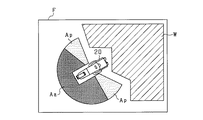
はじめに、ロボットシステム10の概略を図1に基づいて説明する。同図に示すように、ロボットシステム10は、ロボット20、コントローラ30、設置台40等を備えている。
First, an outline of the
設置台40は、円柱状に形成されており、工場内の床50に固定されている。設置台40の中心軸線は、床50に垂直となっている。設置台40は、その上にロボット20及びコントローラ30を設置するための台である。設置台40の上には、ロボット20及びコントローラ30が設置されている。換言すれば、ロボット20及びコントローラ30は、設置台40を介して床50(すなわち床面)に設置されている。
The installation table 40 is formed in a columnar shape and is fixed to a
ロボット20は、多関節のアームを備える垂直多関節型ロボットである。ロボット20は、各関節を駆動するモータ、各関節を制動するブレーキ、各関節の回転角度を検出する角度センサ等を備えている。ロボット20の動作は、コントローラ30により制御される。
The
コントローラ30(すなわち制御部)は、CPU、ROM、RAM、駆動回路、及び位置検出回路等を備えている。ROMは、ロボット20のシステムプログラムや動作プログラム等を記憶している。RAMは、これらのプログラムを実行する際にパラメータの値等を記憶する。位置検出回路には、各角度センサの検出信号がそれぞれ入力される。位置検出回路は、各角度センサの検出信号に基づいて、各関節(詳しくはモータ)の回転角度を検出する。
The controller 30 (that is, the control unit) includes a CPU, a ROM, a RAM, a drive circuit, a position detection circuit, and the like. The ROM stores system programs and operation programs for the
ロボット20は、アームを動作させることにより種々の作業を行う。例えば、ロボット20が所定作業において動作する空間である動作空間は、同図に示すように動作空間Saとなる。動作空間Saは、ロボット20のアームの長さ、及び所定作業におけるアームの動作軌跡により予め決まっている。そして、動作空間Saが床50を占める領域である動作領域は、動作領域Aaとなる。動作領域Aaは、動作空間Saを床50に投影した領域であり、ロボット20を中心とした扇形に設定されている。
The
コントローラ30(すなわち強制停止部)は、ロボットシステム10の異常時にロボット20を強制停止させる。例えば、ロボット20の動作異常や、コントローラ30の通信異常が検出された場合に、ロボット20のアームを制動して直ちに停止させる。しかしながら、所定作業においてロボット20が強制停止させられるまでに、ロボット20が動作空間Saよりも外側の空間まで動作するおそれがある。
The controller 30 (that is, the forced stop unit) forcibly stops the
ここで、所定作業においてロボット20が強制停止させられるまでに動作する可能性のある空間である潜在空間は、潜在空間Spとしてコントローラ30により予測することができる。潜在空間Spは、動作空間Saよりも外側の空間である。そして、ロボット20の潜在空間Spが床50を占める領域である潜在領域は、潜在領域Apとなる。潜在領域Apは、潜在空間Spを床50に投影した領域であり、ロボット20を中心とした扇形に設定されている。本実施形態では、ロボット20の上記動作領域Aa及び潜在領域Apを、床50に視認可能に表示する。
Here, the latent space, which is a space that may move until the
具体的には、上記設置台40には、床50に可視光を照射する照射部41が設けられている。照射部41は、床50に赤色光(すなわち可視光の第1光)を照射する第1照射部と、床50に黄色光(すなわち第1光とは異なる可視光の第2光)を照射する第2照射部とを備えている。
Specifically, the installation table 40 is provided with an
第1照射部は、設置台40の周方向に所定間隔(例えば中心角10°毎)で並ぶ複数の赤色LEDを備えている。複数の赤色LEDは、床50に赤色光を照射する範囲が互いに異なっており、設置台40の全周にわたって配置されている。複数の赤色LEDのうち、点灯させる赤色LEDを選択することにより、任意の動作領域Aaに赤色光を照射することができる。第2照射部は、第1照射部の赤色LEDに代えて、同様に配置された黄色LEDを備えている。そして、複数の黄色LEDのうち、点灯させる黄色LEDを選択することにより、任意の潜在領域Apに黄色光を照射することができる。
The first irradiation unit includes a plurality of red LEDs arranged in the circumferential direction of the installation table 40 at a predetermined interval (for example, every central angle of 10 °). The plurality of red LEDs have different ranges in which the
コントローラ30は、複数の赤色LEDのうち、動作領域Aaに赤色光を照射する赤色LEDを点灯させる。すなわち、コントローラ30は、動作領域Aaに赤色光が照射されるように第1照射部を制御する。また、コントローラ30は、複数の黄色LEDのうち、潜在領域Apに黄色光を照射する黄色LEDを点灯させる。すなわち、コントローラ30は、潜在領域Apに黄色光が照射されるように第2照射部を制御する。なお、照射部41及びコントローラ30によって、動作領域Aa及び潜在領域Apを床50に視認可能に表示する表示手段が構成されている。
The
図2は、作業者の作業領域W、ロボット20の動作領域Aa及び潜在領域Apを示す平面図である。
FIG. 2 is a plan view showing the work area W of the worker, the operation area Aa of the
工場内の設備領域Fにおいて、ロボット20が設置されている。ロボット20の周囲には、安全柵が設けられていない。上述したように、動作領域Aaに赤色光が照射され、潜在領域Apに黄色光が照射される。このため、作業者(すなわち人間)は、ロボット20の動作領域Aa及び潜在領域Apを視認することができる。したがって、作業者は、設備領域Fにおいて、動作領域Aa及び潜在領域Apに入らないようになり、作業領域Wにおいて作業を行うこととなる。
In the equipment area F in the factory, the
ここで、ロボット20が所定作業を実行する実行速度が高いほど、ロボットシステム10の異常時におけるロボット20の潜在空間Spは大きくなる。実行速度は、ロボット20が所定作業を最短の時間で実行する場合を100%として、その何%の速度に相当するかを示す値である。なお、ロボット20の瞬間的な速度である動作速度も、実行速度に応じて変化する。例えば、実行速度が高いほど、動作速度も高くなる。このため、動作速度に基づく場合は、実行速度にも基づくこととなる。
Here, the higher the execution speed at which the
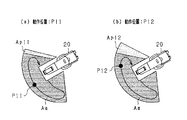
図3(a)は実行速度100%における動作領域Aa及び潜在領域Ap1を示す平面図であり、図3(b)は実行速度50%における動作領域Aa及び潜在領域Ap2を示す平面図である。 FIG. 3A is a plan view showing the operation area Aa and the latent area Ap1 when the execution speed is 100%, and FIG. 3B is a plan view showing the operation area Aa and the latent area Ap2 when the execution speed is 50%.
同図に示すように、ロボット20の実行速度が100%の場合と50%の場合とで、動作領域Aaは同一である。これは、所定作業におけるロボット20の動作軌跡は、実行速度にかかわらず予め決まっていることによる。しかしながら、実行速度100%の場合の潜在領域Ap1を、実行速度50%の場合の潜在領域Ap2よりも広く設定している。これは、実行速度が高いほど動作速度も高くなるため、コントローラ30がロボット20を停止させようとしてから停止するまでの移動距離が大きくなることによる。したがって、本実施形態では、ロボット20が所定作業を実行する実行速度が所定速度よりも高い場合の潜在領域Ap1を、実行速度が前記所定速度よりも低い場合の潜在領域Ap2よりも広く設定する。
As shown in the figure, the operation area Aa is the same when the execution speed of the
図4は、動作領域Aa及び潜在領域Apに可視光を照射する処理の手順を示すフローチャートである。この一連の処理は、ロボット20が所定作業を開始する前に、コントローラ30によって実行される。
FIG. 4 is a flowchart showing the procedure of the process of irradiating the operation area Aa and the latent area Ap with visible light. This series of processing is executed by the
まず、所定作業におけるロボット20の動作空間Saを算出する(S11)。詳しくは、所定作業におけるロボット20のアームの動作軌跡、アームの長さ、ロボット20の座標に基づいて、動作空間Saを算出する。
First, an operation space Sa of the
続いて、所定作業におけるロボット20の動作領域Aaを算出する(S12)。詳しくは、ロボット20の座標に基づいて、動作空間Saを床50に投影して動作領域Aaを算出する。
Subsequently, an operation area Aa of the
続いて、所定作業におけるロボット20の潜在空間Spを算出する(S13)。詳しくは、ロボット20が所定作業を実行する実行速度、及びロボット20の減速特性に基づいて、潜在空間Spを算出する。実行速度が高いほど、潜在空間Spを大きく設定する。また、減速特性は、アームが長いほど、アームが重いほど、モータの慣性が大きいほど、搬送するワークが重いほど、減速させにくい特性となる。そして、減速特性が、減速させにくい特性であるほど、潜在空間Spを大きく設定する。
Subsequently, the latent space Sp of the
続いて、所定作業におけるロボット20の潜在領域Apを算出する(S14)。詳しくは、ロボット20の座標に基づいて、潜在空間Spを床50に投影して潜在領域Apを算出する。
Subsequently, the latent area Ap of the
続いて、動作領域Aaに赤色光を照射させる(S15)。詳しくは、照射部41の複数の赤色LEDのうち、動作領域Aaに赤色光を照射する赤色LEDを選択して点灯させる。換言すれば、照射部41の複数の赤色LEDのうち、上記選択された赤色LED以外の赤色LEDは点灯させない。
Subsequently, the operation area Aa is irradiated with red light (S15). Specifically, among the plurality of red LEDs of the
続いて、潜在領域Apに黄色光を照射させる(S16)。詳しくは、照射部41の複数の黄色LEDのうち、潜在領域Apに黄色光を照射する黄色LEDを選択して点灯させる。換言すれば、照射部41の複数の黄色LEDのうち、上記選択された黄色LED以外の黄色LEDは点灯させない。その後、この一連の処理を終了する(END)。
Subsequently, the latent area Ap is irradiated with yellow light (S16). Specifically, among the plurality of yellow LEDs of the
そして、動作領域Aaに赤色光を照射させ、潜在領域Apに黄色光を照射させた状態で、ロボット20は所定作業を実行する。
Then, the
以上詳述した本実施形態は、以下の利点を有する。 The embodiment described in detail above has the following advantages.
・ロボット20が所定作業において動作する空間である動作空間Saは予め決まっている。そこで、ロボット20の動作空間Saが床50を占める領域である動作領域Aaが、床50に視認可能に表示される。このため、ロボット20の動作領域Aaを作業者に視認させることができ、動作領域Aaに作業者が入る以前に、動作領域Aaに入らないように作業者に働きかけることができる。したがって、ロボット20の周囲に安全柵がない場合であっても、ロボット20の動作領域Aaに誤って作業者が入ることを未然に抑制することができる。
The operation space Sa that is a space in which the
・所定作業においてロボット20が強制停止させられるまでに動作する可能性のある空間である潜在空間Spは、コントローラ30により予測することができる。ひいては、ロボット20の潜在空間Spが床50を占める領域である潜在領域Apも、コントローラ30により予測することができる。本実施形態によれば、ロボット20の潜在領域Apが床50に視認可能に表示される。このため、ロボット20の潜在領域Apを作業者に視認させることができ、潜在領域Apにも入らないように作業者に働きかけることができる。
The
・コントローラ30により、ロボット20の動作領域Aa及び潜在領域Apに可視光が照射されるように照射部41が制御される。このため、ロボット20の動作領域Aa及び潜在領域Apを、容易且つ正確に表示することができる。さらに、作業者の体のうち動作領域Aaや潜在領域Apに入った部分が可視光により照らし出されるため、動作領域Aaや潜在領域Apに入っていることを作業者に明確に視認させることができる。
The
・コントローラ30は、ロボット20の動作領域Aaに第1照射部により赤色光を照射させ、ロボット20の潜在領域Apに第2照射部により黄色光を照射させる。このため、ロボット20の動作領域Aaと潜在領域Apとを区別して、作業者に視認させることができる。
The
・ロボット20が所定作業を実行する実行速度が所定速度よりも高い場合の潜在領域Apが、実行速度が所定速度よりも低い場合の潜在領域Apよりも広く設定される。したがって、ロボット20の実行速度に応じて、潜在領域Apの広さを適切に設定することができる。
The latent area Ap when the execution speed at which the
・ロボット20の減速特性によって、ロボットシステム10の異常時におけるロボット20の潜在空間Spは変化する。本実施形態によれば、ロボット20の減速特性に応じて潜在領域Apが設定されるため、設定される潜在領域Apの精度を向上させることができる。
The latent space Sp of the
・照射部41は、床50に可視光を照射する範囲が互いに異なる複数のLEDを備えている。動作領域Aaに可視光を照射するLED、及び潜在領域Apに可視光を照射するLEDを選択して点灯させることで、動作領域Aa及び潜在領域Apに可視光を容易に照射することができる。
The
なお、第1実施形態を以下のように変更して実施することもできる。 Note that the first embodiment may be modified as follows.
・実行速度として、ロボット20が所定作業を実行する際の動作速度のピーク値が、ロボット20の定格最高速度の何%に相当するかを示す値を用いてもよい。
As the execution speed, a value indicating what percentage of the rated maximum speed of the
・第1実施形態では、照射部41は、床50に可視光を照射する範囲が互いに異なる複数のLEDを備えていた。しかしながら、照射部41が、可視光を広角度に照射するランプと、そのランプの光を遮蔽する範囲を調節する遮蔽機構とで構成されていてもよい。そして、コントローラ30は、遮蔽機構を制御することによりランプの光が床50に照射される範囲を調節して、ロボット20の動作領域Aaや潜在領域Apに可視光を照射させてもよい。
-In 1st Embodiment, the
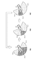
・ロボット20が所定作業の実行中において、動作領域Aaに対するロボット20の現在の動作位置によって、ロボットシステム10の異常時におけるロボット20の潜在空間Spは変化する。図5(a)は、中央付近の動作位置P11における動作領域Aa及び潜在領域Ap11を示す平面図である。同図に示すように、現在の動作位置P11が動作領域Aaの中央付近であれば潜在空間Sp、ひいては潜在領域Ap11は小さくなる。一方、図5(b)は、端部付近の動作位置P12における動作領域Aa及び潜在領域Ap12を示す平面図である。同図に示すように、現在の動作位置P12が動作領域Aaの端部付近であれば潜在空間Sp、ひいては潜在領域Ap12は大きくなる。
While the
そこで、コントローラ30は、ロボット20が所定作業の実行中において、動作領域Aaに対するロボット20の現在の動作位置に応じて、潜在領域Apを可変とする。こうした構成によれば、動作領域Aaに対するロボット20の現在の動作位置に応じて、潜在領域Apを適切に変化させることができる。さらに、所定作業の実行中において、ロボット20の現在の動作位置が変化するのに伴って、表示される潜在領域Apが変化することから、潜在領域Apが変化しない場合と比較して人間の注意を引くことができる。
Therefore, the
・ロボット20が所定作業の実行中において、動作領域Aaに対するロボット20の現在の動作方向によって、ロボットシステム10の異常時におけるロボット20の潜在空間Spは変化する。図6(a)は、中央へ向かう動作方向D1(動作位置P21)における動作領域Aa及び潜在領域Ap21を示す平面図である。同図に示すように、現在の動作方向D1が動作領域Aaの中央へ向かう方向であれば潜在空間Sp21、ひいては潜在領域Ap21は小さくなる。一方、図6(b)は、端部へ向かう動作方向D2(動作位置P22)における動作領域Aa及び潜在領域Ap22を示す平面図である。同図に示すように、現在の動作方向D2が動作領域Aaの端部へ向かう方向であれば潜在空間Sp22、ひいては潜在領域Ap22は大きくなる。
While the
そこで、コントローラ30は、ロボット20が所定作業の実行中において、動作領域Aaに対するロボット20の現在の動作方向に応じて、潜在領域Apを可変とする。こうした構成によれば、動作領域Aaに対するロボット20の現在の動作方向に応じて、潜在領域Apを適切に変化させることができる。さらに、所定作業の実行中において、ロボット20の現在の動作方向が変化するのに伴って、表示される潜在領域Apが変化することから、潜在領域Apが変化しない場合と比較して人間の注意を引くことができる。
Therefore, the
・ロボット20が所定作業を実行する実行加速度によって、ロボットシステム10の異常時におけるロボット20の潜在空間Spは変化する。実行加速度は、上述した実行速度と同様にして、ロボット20が所定作業を最短の時間で実行する場合を100%として、その何%の加速度に相当するかを示す値である。なお、ロボット20の瞬間的な加速度である動作加速度も、実行加速度に応じて変化する。例えば、実行加速度が大きいほど、動作加速度も大きくなる。このため、動作加速度に基づく場合は、実行加速度にも基づくこととなる。
The latent space Sp of the
例えば、図3の実行速度と同様に、実行加速度が大きければ動作速度が高くなることから、潜在空間Sp(ひいては潜在領域Ap1)は大きくなる。また、実行加速度が小さければ動作速度が低くなることから、潜在空間Sp(ひいては潜在領域Ap2)は小さくなる。そこで、コントローラ30は、ロボット20が所定作業を実行する実行加速度が所定加速度よりも高い場合の潜在領域Ap1を、実行加速度が所定加速度よりも低い場合の潜在領域Ap2よりも広く設定する。詳しくは、実行加速度が高いほど、潜在領域Apを広く設定する。したがって、ロボット20の実行加速度に応じて、潜在領域Apを適切に変化させることができる。
For example, as with the execution speed of FIG. 3, the higher the execution acceleration, the higher the operation speed, and thus the latent space Sp (and thus the latent area Ap1) becomes larger. Also, if the execution acceleration is small, the operation speed is low, so the latent space Sp (and thus the latent area Ap2) is small. Therefore, the
・図7は、動作加速度の絶対値に基づいて動作領域Aaの外縁を設定する態様を示す平面図である。同図の動作位置P31,P32のように、ロボット20の動作位置が動作空間Saの外縁に近付くと、動作速度を徐々に低下させるために動作減速度を含めた動作加速度の絶対値が小さくなる。動作位置P31,P32は、動作加速度の絶対値が極小値となる臨界動作位置である。図8は、臨界動作位置P32付近における時間と動作加速度の絶対値との関係を示すグラフである。同図に示すように、臨界動作位置P32付近では、動作加速度の絶対値が減少して極小値となった後、再び増加する。時刻tmでの動作位置が臨界動作位置P32である。
FIG. 7 is a plan view showing a mode in which the outer edge of the motion area Aa is set based on the absolute value of the motion acceleration. When the operation position of the
そこで、コントローラ30は、所定作業におけるロボット20の各動作位置に対して動作加速度の絶対値を算出し、算出された動作加速度の絶対値が極小値となる臨界動作位置に基づいて、動作領域Aaの外縁を設定する。詳しくは、図7に示すように、臨界動作位置P31の座標に基づいて動作領域Aaの外縁E1を設定し、臨界動作位置P32の座標に基づいて動作領域Aaの外縁E2を設定する。そして、ロボット20を中心とした扇形に動作領域Aaを設定する。このため、動作領域Aaの外縁を容易且つ正確に設定することができる。
Therefore, the
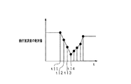
・臨界動作位置付近でのロボット20の動作速度によって、ロボットシステム10の異常時におけるロボット20の潜在空間Sp、ひいては潜在領域Apは変化する。そして、ロボット20の動作速度は動作加速度に応じて変化する。そこで、図9に示すように、コントローラ30は、所定作業における臨界動作位置P36よりも手前の所定範囲に含まれる動作位置P33〜P35での動作加速度の絶対値に基づいて、潜在領域Ap32を設定する。図10は、臨界動作位置P36付近の各動作位置P33〜P35での動作加速度の絶対値を示すグラフである。動作位置P33〜P36は、時刻t11〜t14にそれぞれ対応している。詳しくは、時刻t11〜t13における動作加速度の絶対値が大きいほど、潜在領域Apを広く設定する。こうした構成によれば、コントローラ30の処理負荷を軽減しつつ、設定される潜在領域Apの精度を向上させることができる。
The latent space Sp of the
・ロボット20が所定作業を実行する実行速度、所定作業の実行中における動作領域Aaに対するロボット20の現在の動作位置、所定作業の実行中における動作領域Aaに対するロボット20の現在の動作方向、及びロボット20が所定作業を実行する実行加速度を組み合わせて、潜在領域Apを設定してもよい。要するに、所定作業を実行する実行速度、動作領域Aaに対するロボット20の現在の動作位置、動作領域Aaに対するロボット20の現在の動作方向、及び所定作業を実行する実行加速度の少なくとも1つに基づいて、潜在領域Apを設定すればよい。
The execution speed at which the
・動作領域Aaや潜在領域Apを予め算出して記憶させておき、ロボット20が所定作業を開始する前に、記憶された動作領域Aaや潜在領域Apを読み込んでもよい。
The motion area Aa and the latent area Ap may be calculated and stored in advance, and the stored motion area Aa and the latent area Ap may be read before the
・第1実施形態では、コントローラ30は、ロボット20の動作領域Aaに第1照射部により赤色光を照射させ、ロボット20の潜在領域Apに第2照射部により黄色光を照射させた。しかしながら、赤色と黄色とに限らず、その他の色(すなわち波長)の可視光を動作領域Aaと潜在領域Apとに照射させてもよい。また、動作領域Aa及び潜在領域Apに、同一色(すなわち同一波長)の可視光で明度の異なる可視光を照射させてもよい。その場合であっても、人間は動作領域Aaと潜在領域Apとを区別することができる。さらに、動作領域Aa及び潜在領域Apに、同一色で同一明度の可視光を照射させることもできる。その場合であっても、ロボット20の動作領域Aa及び潜在領域Apを人間に視認させることができる。また、動作領域Aaのみに可視光を照射させることもできる。その場合であっても、ロボット20の動作領域Aaを人間に視認させることができ、動作領域Aaに人間が入る以前に、動作領域Aaに入らないように人間に働きかけることはできる。
In the first embodiment, the
・照射部41を、設置台40に限らず、ロボット20のベース部や、工場の天井等に設けることもできる。要するに、照射部41は、床50の動作領域Aaや潜在領域Apに、可視光を照射することができるものであればよい。また、ロボット20を床50に直接設置してもよい。
The
・ロボット20の設置された設置台40が十分な広さを有しており、設置台40の上面を作業者が移動する場合は、設置台40の上面を可視光が照射される床面とみなすことができる。
When the installation table 40 on which the
・動作領域Aaや潜在領域Apを、床50(すなわち床面)に視認可能に表示する態様は、動作領域Aaや潜在領域Apの全体に可視光を照射する態様に限らない。例えば、動作領域Aaや潜在領域Apの外縁にのみ可視光を照射してもよい。また、動作領域Aaや潜在領域Apに可視光を照射する態様に限らず、動作領域Aaや潜在領域Apをペイントやテープにより表示することもできる。 The mode of displaying the motion region Aa and the latent region Ap so as to be visible on the floor 50 (that is, the floor surface) is not limited to the mode of irradiating visible light to the entire motion region Aa and the latent region Ap. For example, visible light may be irradiated only on the outer edge of the operation area Aa or the latent area Ap. Moreover, not only the aspect which irradiates visible light to operation area | region Aa and latent area Ap, but operation area | region Aa and latent area Ap can also be displayed with a paint or a tape.
・ロボット20として、垂直多関節型ロボットに限らず、水平多関節型ロボット等を採用することもできる。
The
(第2実施形態)
以下、第2実施形態について、第1実施形態との相違点を中心に説明する。本実施形態では、ロボット20は複数の作業を実行する。その他の構成は、第1実施形態と同様である。そして、コントローラ30は、ロボット20が実行中の作業における動作領域Aa及び潜在領域Apに、第1実施形態と同様に可視光が照射されるように照射部41を制御する。
(Second Embodiment)
Hereinafter, the second embodiment will be described focusing on differences from the first embodiment. In the present embodiment, the
図11は、各作業におけるロボット20の動作領域及び潜在領域を示す平面図である。同図に示すように、ロボット20は作業A〜Cを順に繰り返す。作業は、1つの作業を所定時間実行後に次の作業に切り替えられてもよいし、1つの作業を終了後に次の作業に切り替えられてもよい。
FIG. 11 is a plan view showing an operation area and a latent area of the
動作領域Aaa〜Aacは互いに異なっており、潜在領域Apa〜Apcも互いに異なっている。作業Aでは、コントローラ30は、動作領域Aaaに赤色光を照射させ、潜在領域Apaに黄色光を照射させる。作業Bでは、コントローラ30は、動作領域Aabに赤色光を照射させ、潜在領域Apbに黄色光を照射させる。作業Cでは、コントローラ30は、動作領域Aacに赤色光を照射させ、潜在領域Apcに黄色光を照射させる。
The operation areas Aaa to Aac are different from each other, and the latent areas Apa to Apc are also different from each other. In operation A, the
ここで、作業Cにおいて、作業者mの位置は、動作領域Aac及び潜在領域Apcよりも外側である。しかしながら、作業Cから作業Aに切り替わると、作業者mの位置は動作領域Aaa若しくは潜在領域Apaに含まれることとなる。その場合に、作業Aが開始されるまでに、作業者mが動作領域Aaa及び潜在領域Apaの外側へ出ないと、作業者mの安全を損ねるおそれがある。 Here, in the work C, the position of the worker m is outside the operation area Aac and the latent area Apc. However, when the work C is switched to the work A, the position of the worker m is included in the motion area Aaa or the latent area Apa. In this case, if the worker m does not go outside the operation area Aaa and the latent area Apa before the work A is started, the safety of the worker m may be impaired.
そこで、本実施形態では、コントローラ30は、各作業における潜在領域Apa,Apb,Apcを加算した加算潜在領域(Apa+Apb+Apc)のうち、ロボット20が実行中の作業における動作領域(例えば動作領域Aac)に含まれない領域に、第2照射部により黄色光を照射させる。
Therefore, in the present embodiment, the
図12は、現作業の動作領域及び加算潜在領域に可視光を照射する処理の手順を示すフローチャートである。この一連の処理は、ロボット20が作業A〜Cを開始する前に、すなわち作業A〜Cのいずれも開始していない状態で、コントローラ30によって実行される。
FIG. 12 is a flowchart showing the procedure of the process of irradiating visible light to the operation area and the addition latent area of the current work. This series of processing is executed by the
まず、各作業A〜Cにおけるロボット20の動作空間Saa〜Sacを算出する(S21)。1つの作業における動作空間Saを算出する方法は、図4のS11の処理と同一である。各作業A〜Cにおけるロボット20の動作領域Aaa〜Aacを算出する(S22)。1つの作業における動作領域Aaを算出する方法は、図4のS12の処理と同一である。各作業におけるロボット20の潜在空間Spa〜Spcを算出する(S23)。1つの作業における潜在空間Spを算出する方法は、図4のS13の処理と同一である。各作業A〜Cにおけるロボット20の潜在領域Apa〜Apcを算出する(S24)。1つの作業における潜在領域Apを算出する方法は、図4のS14の処理と同一である。
First, the operation spaces Saa to Sac of the
続いて、各作業A〜Cにおける潜在領域Apa,Apb,Apcを加算した加算潜在領域Aptを算出する(S25)。詳しくは、重複を省いて潜在領域Apa,Apb,Apcを加算して、加算潜在領域Aptを算出する。換言すれば、潜在領域Apa,Apb,Apcのいずれも含む最小の領域を加算潜在領域Aptとして算出する。 Subsequently, an addition latent area Apt obtained by adding the latent areas Apa, Apb, Apc in the operations A to C is calculated (S25). Specifically, the latent areas Apa, Apb, and Apc are added without overlapping and the added latent area Apt is calculated. In other words, the minimum area including any of the latent areas Apa, Apb, and Apc is calculated as the added latent area Apt.
続いて、現在実行中の作業の動作領域Aaに赤色光を照射させる(S26)。動作領域Aaに赤色光を照射させる方法は、図4のS15の処理と同一である。 Subsequently, red light is irradiated to the operation area Aa of the work currently being performed (S26). The method of irradiating the operation area Aa with red light is the same as the process of S15 in FIG.
続いて、加算潜在領域Aptに黄色光を照射させる(S27)。詳しくは、加算潜在領域Aptに黄色光を照射させる際には、加算潜在領域Aptのうち、ロボット20が現在実行中の作業における動作領域Aaに含まれない領域に、第2照射部により黄色光を照射させる。黄色光を照射させる方法は、図4のS16の処理と同一である。その後、この一連の処理を終了する(END)。なお、S26,S27の処理は、作業が切り替わる度に実行する。
Subsequently, yellow light is irradiated to the addition latent area Apt (S27). Specifically, when the additional latent area Apt is irradiated with yellow light, the second irradiation unit applies yellow light to an area of the additional latent area Apt that is not included in the operation area Aa in the work currently being performed by the
そして、図13に示すように、現在実行中の作業の動作領域Aaに赤色光を照射させ、加算潜在領域Aptに黄色光を照射させた状態で、ロボット20は作業A〜Cを実行する。
Then, as shown in FIG. 13, the
以上詳述した本実施形態は、以下の利点を有する。なお、ここでは、第1実施形態と異なる利点のみを述べる。 The embodiment described in detail above has the following advantages. Here, only the advantages different from the first embodiment will be described.
・ロボット20が実行する複数の作業A〜Cのうち、実行中の作業における動作領域Aaに可視光が照射される。このため、作業が切り替えられたとしても、実行中の作業における動作領域Aaを人間に視認させることができる。しかも、照射される動作領域Aaが変化することから、動作領域Aaが変化しない場合と比較して人間の注意を引くことができる。また、人間の体のうち動作領域Aaに入った部分が可視光により照らし出されるため、動作領域Aaに入っていることを人間に明確に視認させることができる。
-Visible light is irradiated to operation area | region Aa in the operation | work in execution among several work AC which the
・各作業A〜Cにおける潜在領域Apa〜Apcを加算した加算潜在領域Aptのうち、ロボット20が実行中の作業における動作領域Aaに含まれない領域に可視光が照射される。このため、作業が切り替えられた場合に潜在領域Apとなる領域に人間が入ることを、未然に抑制することができる。さらに、照射される加算潜在領域Aptと動作領域Aaとの割合が変化することから、この割合が変化しない場合と比較して人間の注意を引くことができる。
-Visible light is irradiated to the area | region which is not contained in operation | movement area | region Aa in the operation | work in which the
なお、第2実施形態を以下のように変更して実施することもできる。 Note that the second embodiment may be modified as follows.
・各作業A〜Cにおいて、動作領域Aaや潜在領域Apを視認可能に表示する態様として、第1実施形態の各変更例を組み合わせ可能な範囲で適用することができる。 -In each operation | work AC, as a mode which displays operation | movement area | region Aa and latent area Ap so that visual recognition is possible, it can apply in the range which can combine each modification of 1st Embodiment.
・加算潜在領域Aptは、ロボット20が実行する全作業の潜在領域Apを加算した領域であってもよいし、複数の作業を含む一部の作業の潜在領域Apを加算した領域であってもよい。また、加算潜在領域Aptに黄色光を照射させる構成に代えて、各作業A〜Cにおいてそれぞれ潜在領域Apa〜Apcに黄色光を照射させる構成を採用することもできる。
The addition latent area Apt may be an area obtained by adding up the latent areas Ap of all works executed by the
・コントローラ30は、各作業A〜Cにおける動作領域Aaa〜Aacを加算した加算動作領域Aatに、可視光が照射されるように照射部を制御してもよい。こうした構成によれば、作業が切り替えられた場合に動作領域Aaとなる領域に人間が入ることを、未然に抑制することができる。
-The
・加算動作領域Aatは、ロボット20が実行する全作業の動作領域Aaを加算した領域であってもよいし、複数の作業を含む一部の作業の動作領域Aaを加算した領域であってもよい。
The addition operation area Aat may be an area obtained by adding up the operation areas Aa of all works executed by the
・コントローラ30は、各作業A〜Cにおける動作領域Aaa〜Aacを加算した加算動作領域Aatに、第1照射部により赤色光を照射させ、各作業A〜Cにおける潜在領域Apa〜Apcを加算した加算潜在領域Aptのうち、加算動作領域Aatに含まれない領域に、第2照射部により黄色光を照射させてもよい。こうした構成によれば、ロボット20の加算動作領域Aatと加算潜在領域Aptとを区別して、人間に視認させることができる。
The
(第3実施形態)
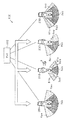
以下、第3実施形態について、第1実施形態との相違点を中心に説明する。本実施形態では、図14に示すように、ロボットシステム100は、隣り合うように床50に設置された複数のロボット20A〜20Dと、PLC(Programmable Logic Controller)110とを備えている。PLC110は、CPU、ROM、RAM等を備え、ロボット20A〜20Dの各コントローラ30を制御する上位のコントローラである。その他の構成は、第1実施形態と同様である。
(Third embodiment)
Hereinafter, the third embodiment will be described focusing on differences from the first embodiment. In the present embodiment, as shown in FIG. 14, the
ロボット20A〜20Dは、第1実施形態のロボット20と同様の構成を備えており、各コントローラ30(図示略)により制御される。そして、ロボット20A〜20Dは、それぞれ所定作業を実行する。ロボット20A〜20Dの各コントローラ30は、第1実施形態と同様に、動作領域Raa〜Radにそれぞれ赤色光を照射させ、潜在領域Rpa〜Rpdにそれぞれ黄色光を照射させる。作業者mは、ロボット20A〜20Dにそれぞれ近付いて作業を実行する。作業者mは、動作領域Raa〜Rad及び潜在領域Rpa〜Rpdを視認することができる。
The
ロボット20A〜20Dは、主照射部である照射部41に加えて、照射部41が照射する可視光とは異なる可視光を照射する副照射部を備えている。詳しくは、主照射部は、赤色光を照射する第1照射部と黄色光を照射する第2照射部とを備え、副照射部は緑色光を照射する。副照射部は、第1照射部や第2照射部と同様の構成を備え、詳しくは複数の緑色LEDを備えている。
The
隣り合うように設置されたロボットのうち、一方のロボットを第1ロボットとし、他方のロボットを第2ロボットとする。そして、第1ロボットの主照射部を第1主照射部とし、第2ロボットの主照射部を第2主照射部とする。また、第1ロボットの副照射部を第1副照射部とし、第2ロボットの副照射部を第2副照射部とする。さらに、第1ロボットの動作領域を第1動作領域とし、第2ロボットの動作領域を第2動作領域とする。また、第1ロボットの強制停止部を第1強制停止部とし、第2ロボットの強制停止部を第2強制停止部とする。第1ロボットの潜在領域を第1潜在領域とし、第2ロボットの潜在領域を第2潜在領域とする。 Of the robots installed adjacent to each other, one robot is a first robot and the other robot is a second robot. And let the main irradiation part of a 1st robot be a 1st main irradiation part, and let the main irradiation part of a 2nd robot be a 2nd main irradiation part. The sub-irradiation unit of the first robot is a first sub-irradiation unit, and the sub-irradiation unit of the second robot is a second sub-irradiation unit. Further, the operation area of the first robot is set as the first operation area, and the operation area of the second robot is set as the second operation area. Further, the forced stop portion of the first robot is a first forced stop portion, and the forced stop portion of the second robot is a second forced stop portion. The latent area of the first robot is the first latent area, and the latent area of the second robot is the second latent area.
ここで、第2潜在領域が、第1動作領域に第1潜在領域を加えた領域よりも広い場合がある。例えば、図14において、ロボット20Bの近くに作業者mがいる場合、ロボット20A(第2ロボット)の潜在領域Rpaは、ロボット20B(第1ロボット)の動作領域Rabに潜在領域Rpbを加えた領域よりも広い。この場合に、作業者mが潜在領域Rpaと潜在領域Rpbとが同程度の広さと思い込んでロボット20Aに近付くと、作業者mが潜在領域Rpaに入るおそれがある。
Here, the second latent area may be wider than an area obtained by adding the first latent area to the first operation area. For example, in FIG. 14, when the worker m is near the
そこで、本実施形態では、基準を合わせて第2潜在領域及び第2動作領域を第1動作領域及び第1潜在領域に重ねた場合に、第2潜在領域及び第2動作領域が第1動作領域及び第1潜在領域から外れる領域に基づいて予報領域を設定する。そして、PLC110は、コントローラ30を通じて、副照射部により予報領域に緑色光を照射させる。
Therefore, in the present embodiment, when the second latent area and the second motion area are overlapped with the first motion area and the first latent area in accordance with the reference, the second latent area and the second motion area are the first motion area. And a prediction area | region is set based on the area | region which remove | deviates from a 1st latent area. Then, the
図15は、動作領域、潜在領域、及び予報領域に可視光を照射する処理の手順を示すフローチャートである。この一連の処理は、ロボット20A〜20Dが所定作業を開始する前に、すなわちロボット20A〜20Dのいずれも作業を開始していない状態で、PLC110及び各コントローラ30によって実行される。
FIG. 15 is a flowchart illustrating a procedure of a process for irradiating the operation area, the latent area, and the forecast area with visible light. This series of processing is executed by the
まず、各ロボット20A〜20Dの所定作業における動作空間を算出する(S31)。1つのロボットの所定作業における動作空間を算出する方法は、図4のS11の処理と同一である。各ロボット20A〜20Dの所定作業における動作領域Raa〜Radを算出する(S32)。1つのロボットの所定作業における動作領域を算出する方法は、図4のS12の処理と同一である。各ロボット20A〜20Dの所定作業における潜在空間を算出する(S33)。1つのロボットの所定作業における潜在空間を算出する方法は、図4のS13の処理と同一である。各ロボット20A〜20Dの所定作業における潜在領域Rpa〜Rpdを算出する(S34)。1つロボットの所定作業における潜在領域を算出する方法は、図4のS14の処理と同一である。
First, an operation space in a predetermined work of each
続いて、基準を合わせて第2潜在領域及び第2動作領域を第1動作領域及び第1潜在領域に重ねた場合に、第2潜在領域及び第2動作領域が第1動作領域及び第1潜在領域から外れる領域に基づいて予報領域Rfを算出する(S35)。詳しくは、ロボット同士の基準位置(例えば基準座標)を合わせて、第2潜在領域及び第2動作領域を加算した領域から、第1動作領域及び第1潜在領域を加算した領域を減算した領域の所定割合を予報領域として算出する。第1ロボットの両側に第2ロボットが存在する場合は、両側の第2ロボットの第2潜在領域及び第2動作領域を考慮する。 Subsequently, when the second latent area and the second motion area are overlapped with the first motion area and the first latent area in accordance with the reference, the second latent area and the second motion area are the first motion area and the first latent area. The forecast area Rf is calculated based on the area outside the area (S35). Specifically, a region obtained by subtracting a region obtained by adding the first motion region and the first latent region from a region obtained by adding the second latent region and the second motion region by matching the reference positions (for example, reference coordinates) of the robots. A predetermined ratio is calculated as a forecast area. When the second robot exists on both sides of the first robot, the second latent area and the second motion area of the second robot on both sides are considered.
続いて、各ロボット20A〜20Dの動作領域Raa〜Radに赤色光を照射させる(S36)。動作領域に赤色光を照射させる方法は、図4のS15の処理と同一である。
Subsequently, red light is irradiated to the operation regions Raa to Rad of the
続いて、各ロボット20A〜20Dの潜在領域Rpa〜Rpdに黄色光を照射させる(S37)。潜在領域に黄色光を照射させる方法は、図4のS16の処理と同一である。
Subsequently, yellow light is irradiated to the latent areas Rpa to Rpd of the
続いて、予報領域Rfに副照射部により緑色光を照射させる(S38)。その後、この一連の処理を終了する(END)。なお、S35,S38の処理は、作業者mの移動により第1ロボットが切り替わる度に実行する。 Subsequently, the forecast region Rf is irradiated with green light by the sub-irradiation unit (S38). Thereafter, this series of processing ends (END). The processes of S35 and S38 are executed every time the first robot is switched by the movement of the worker m.
そして、図16に示すように、例えばロボット20Bの近くに作業者mがいる場合、ロボット20Bに対応して予報領域Rfbに緑色光を照射させた状態で、ロボット20A〜20Dは所定作業を実行する。なお、例えばロボット20Dの近くに作業者mがいる場合、ロボット20Dに対応して予報領域Rfdに緑色光を照射させた状態で、ロボット20A〜20Dは所定作業を実行する。
Then, as shown in FIG. 16, for example, when the worker m is near the
以上詳述した本実施形態は、以下の利点を有する。なお、ここでは、第1実施形態及び第2実施形態と異なる利点のみを述べる。 The embodiment described in detail above has the following advantages. Here, only the advantages different from the first embodiment and the second embodiment will be described.
・基準を合わせて第2潜在領域及び第2動作領域を第1動作領域及び第1潜在領域に重ねた場合に、第2潜在領域及び第2動作領域が第1動作領域及び第1潜在領域から外れる領域に基づいて予報領域Rfが設定される。そして、予報領域Rfに副照射部により緑色光が照射される。このため、第1ロボットの近くにいる人間に、予め第2潜在領域が第1潜在領域よりも広いことを認識させることができる。したがって、第1ロボットの近くにいる作業者mが第2ロボットに近付いた場合に、作業者mが第2潜在領域に入ることを抑制することができる。 When the second latent area and the second movement area are overlapped with the first movement area and the first latent area with matching the reference, the second latent area and the second movement area are separated from the first movement area and the first latent area. The forecast area Rf is set on the basis of the deviating area. Then, green light is irradiated onto the forecast region Rf by the sub-irradiation unit. For this reason, it is possible to make a person in the vicinity of the first robot recognize in advance that the second latent area is wider than the first latent area. Therefore, when the worker m near the first robot approaches the second robot, the worker m can be prevented from entering the second latent area.
なお、第3実施形態を以下のように変更して実施することもできる。
・副照射部は、黄色光を照射するものでもよく、赤色光を照射するものでもよい。すなわち、副照射部が主照射部と同一の可視光を照射するものでもよい。その場合であっても、第1ロボットの近くにいる人間に、予め第1潜在領域よりも広い領域を警戒させることができる。
Note that the third embodiment may be modified as follows.
-A subirradiation part may irradiate yellow light, and may irradiate red light. That is, the sub-irradiation unit may emit the same visible light as the main irradiation unit. Even in that case, a person near the first robot can be alerted in advance to an area wider than the first latent area.
・第2ロボットが所定作業を実行する実行速度が高いほど、ロボットシステム100の異常時における第2ロボットの潜在空間(第2潜在空間)は大きくなる。そこで、PLC100及びコントローラ30は、第2ロボットが所定作業を実行する実行速度が所定速度よりも高い場合の第2潜在領域を、実行速度が前記所定速度よりも低い場合の第2潜在領域よりも広く設定してもよい。こうした構成によれば、第2ロボットの実行速度に応じて、第2潜在領域の広さを適切に設定することができる。ひいては、基準を合わせて第2動作領域及び第2潜在領域を第1動作領域及び第1潜在領域に重ねた場合に、第2動作領域及び第2潜在領域が、第1動作領域及び第1潜在領域から外れる領域に基づいて設定される予報領域を、適切に設定することができる。
-The higher the execution speed at which the second robot performs a predetermined operation, the larger the latent space (second latent space) of the second robot when the
・第2ロボットが所定作業を実行する実行加速度が大きいほど動作速度が高くなることから、ロボットシステム100の異常時における第2潜在空間は大きくなる。そこで、PLC100及びコントローラ30は、第2ロボットが所定作業を実行する実行加速度が所定加速度よりも高い場合の第2潜在領域を、実行加速度が前記所定速度よりも低い場合の第2潜在領域よりも広く設定してもよい。こうした構成によれば、第2ロボットの実行加速度に応じて、第2潜在領域の広さを適切に設定することができる。ひいては、基準を合わせて第2動作領域及び第2潜在領域を第1動作領域及び第1潜在領域に重ねた場合に、第2動作領域及び第2潜在領域が、第1動作領域及び第1潜在領域から外れる領域に基づいて設定される予報領域を、適切に設定することができる。
-The higher the execution acceleration at which the second robot performs a predetermined work, the higher the operation speed, and thus the second latent space when the
・第2ロボットが所定作業の実行中において、第2動作領域に対する第2ロボットの現在の動作位置によって、ロボットシステム100の異常時における第2潜在空間は変化する。例えば、現在の動作位置が第2動作領域の中央付近であれば第2潜在空間は小さくなり、現在の動作位置が第2動作領域の端部付近であれば第2潜在空間は大きくなる。そこで、PLC100及びコントローラ30は、第2ロボットが所定作業の実行中において、第2動作領域に対する第2ロボットの現在の動作位置に応じて、第2潜在領域を可変としてもよい。こうした構成によれば、第2動作領域に対する第2ロボットの現在の動作位置に応じて、第2潜在領域、ひいては予報領域を適切に変化させることができる。さらに、第2ロボットの現在の動作位置が変化するのに伴って、表示される予報領域が変化することから、予報領域が変化しない場合と比較して人間の注意を引くことができる。
-While the 2nd robot is performing predetermined work, the 2nd potential space at the time of abnormality of
・第2ロボットが所定作業の実行中において、第2動作領域に対するロボットの現在の動作方向によって、ロボットシステム100の異常時における第2潜在空間は変化する。例えば、現在の動作方向が第2動作領域の中央へ向かう方向であれば第2潜在空間は小さくなり、現在の動作方向が第2動作領域の端部へ向かう方向であれば第2潜在空間は大きくなる。そこで、PLC100及びコントローラ30は、第2ロボットが所定作業の実行中において、第2動作領域に対する第2ロボットの現在の動作方向に応じて、第2潜在領域を可変としてもよい。こうした構成によれば、第2動作領域に対する第2ロボットの現在の動作方向に応じて、第2潜在領域、ひいては予報領域を適切に変化させることができる。さらに、第2ロボットの現在の動作方向が変化するのに伴って、表示される予報領域が変化することから、予報領域が変化しない場合と比較して人間の注意を引くことができる。
-While the 2nd robot is performing predetermined work, the 2nd potential space at the time of abnormality of
・第2ロボットの減速特性によって、ロボットシステム100の異常時における第2潜在空間は変化する。例えば、第2ロボットの減速特性が、減速させやすい特性であれば第2潜在空間は小さくなり、減速させにくい特性であれば第2潜在空間は大きくなる。そこで、PLC100及びコントローラ30は、第2ロボットの減速特性に応じて、第2潜在領域を設定してもよい。こうした構成によれば、第2ロボットの減速特性に応じて第2潜在領域、ひいては予報領域が設定されるため、設定される予報領域の精度を向上させることができる。
The second latent space when the
・ロボット20A〜20D所定作業において、動作領域や潜在領域を視認可能に表示する態様として、第1実施形態の他の各変更例も組み合わせ可能な範囲で適用することができる。
-In the
・ロボット20A〜20Dが、それぞれ複数の作業を実行してもよい。その場合、各作業において、動作領域や潜在領域を視認可能に表示する態様として、第2実施形態及びその各変更例を組み合わせ可能な範囲で適用することができる。
The
・第2動作領域が第1動作領域よりも広い場合がある。この場合に、作業者mが第2動作領域と第1動作領域とが同程度の広さと思い込んで第2ロボットに近付くと、作業者mが第2動作領域に入るおそれがある。そこで、PLC100及びコントローラ30は、第1動作領域に第1照射部により赤色を照射させ、第2動作領域を、基準を合わせて第1動作領域に重ねた場合に第1動作領域から外れる領域に基づいて予報領域Rfを設定する。そして、予報領域Rfに副照射部により緑色光を照射させることもできる。こうした構成によれば、第1ロボットの近くにいる作業者mに予め第2動作領域が第1動作領域よりも広いことを認識させることができる。したがって、第1ロボットの近くにいる作業者mが第2ロボットに近付いた場合に、作業者mが第2動作領域に入ることを抑制することができる。
The second operating area may be wider than the first operating area. In this case, if the worker m thinks that the second motion area and the first motion area are about the same size and approaches the second robot, the worker m may enter the second motion area. Therefore, the
・第2動作領域が、第1動作領域に第1潜在領域を加えた領域よりも広い場合がある。この場合に、作業者mが、第1動作領域に第1潜在領域を加えた領域と同程度の広さを警戒して第2ロボットに近付くと、人間が第2動作領域に入るおそれがある。そこで、PLC100及びコントローラ30は、基準を合わせて第2動作領域を第1動作領域及び第1潜在領域に重ねた場合に、第2動作領域が第1動作領域及び第1潜在領域から外れる領域に基づいて予報領域を設定することもできる。こうした構成によれば、第1ロボットの近くにいる人間が第2ロボットに近付いた場合に、人間が第2動作領域に入ることを抑制することができる。
The second operation area may be wider than an area obtained by adding the first latent area to the first operation area. In this case, if the worker m approaches the second robot with a warning about the same area as the area in which the first latent area is added to the first movement area, there is a possibility that a human may enter the second movement area. . Therefore, when the second operating area is overlapped with the first operating area and the first latent area by matching the reference, the
・ロボット20A〜20Dは、同型のロボットに限らず、異なる型のロボットを含んでいてもよい。
The
・ロボット20A〜20Dは、向きを揃えて設置されている構成に限らず、異なる向きに設置されている構成であってもよい。その場合も、第2動作領域及び第2潜在領域を、基準を合わせて第1動作領域及び第1潜在領域に重ねた場合に第1動作領域及び第1潜在領域から外れる領域に基づいて予報領域を設定すればよい。また、第2動作領域を、基準を合わせて第1動作領域に重ねた場合に第1動作領域から外れる領域に基づいて予報領域を設定してもよい。
The
10…ロボットシステム、20…ロボット、20A…ロボット、20B…ロボット、20C…ロボット、20D…ロボット、30…コントローラ(制御部、強制停止部)、41…照射部(第1照射部、第2照射部、主照射部)、50…床(床面)、100…ロボットシステム、110…PLC(制御部)。
DESCRIPTION OF
Claims (11)
前記ロボットが所定作業において動作する空間が前記床面を占める領域である動作領域を、前記床面に視認可能に表示する表示手段と、
を備えることを特徴とするロボットシステム。 A robot installed on the floor,
Display means for displaying an operation area in which the space in which the robot operates in a predetermined operation occupies the floor surface so as to be visible on the floor surface;
A robot system comprising:
前記表示手段は、前記所定作業において前記強制停止部により前記ロボットが強制停止させられるまでに動作する可能性のある空間が前記床面を占める領域である潜在領域を、さらに前記床面に視認可能に表示する請求項1に記載のロボットシステム。 A forced stop unit for forcibly stopping the robot when the robot system is abnormal;
The display means can further visually recognize a latent area on the floor surface, in which the space that may move until the robot is forcibly stopped by the forced stop unit in the predetermined work is an area that occupies the floor surface. The robot system according to claim 1, which is displayed on the screen.
前記制御部は、前記動作領域に前記第1照射部により前記第1光を照射させ、前記潜在領域に前記第2照射部により前記第2光を照射させる請求項4に記載のロボットシステム。 The irradiation unit includes: a first irradiation unit that irradiates the floor surface with first visible light; and a second irradiation unit that irradiates the floor surface with visible light second light different from the first light. Prepared,
5. The robot system according to claim 4, wherein the control unit causes the first irradiation unit to irradiate the operation region with the first light, and causes the latent region to irradiate the second light with the second irradiation unit.
前記制御部は、前記複数のLEDのうち前記動作領域に可視光を照射する前記LEDを点灯させる請求項3に記載のロボットシステム。 The irradiation unit includes a plurality of LEDs having different ranges for irradiating the floor surface with visible light,
The robot system according to claim 3, wherein the control unit turns on the LED that emits visible light to the operation region among the plurality of LEDs.
前記制御部は、前記複数のLEDのうち、前記動作領域に可視光を照射する前記LED、及び前記潜在領域に可視光を照射する前記LEDを点灯させる請求項4〜9のいずれか1項に記載のロボットシステム。 The irradiation unit includes a plurality of LEDs having different ranges for irradiating the floor surface with visible light,
The said control part makes the said LED which irradiates visible light to the said operation | movement area | region, and the said LED which irradiates visible light to the said latent area among these several LED to any one of Claims 4-9 The robot system described.
Priority Applications (3)
| Application Number | Priority Date | Filing Date | Title |
|---|---|---|---|
| JP2015134678A JP6554945B2 (en) | 2015-07-03 | 2015-07-03 | Robot system |
| CN201610509760.4A CN106313040B (en) | 2015-07-03 | 2016-06-30 | Robot system |
| US15/200,469 US10434666B2 (en) | 2015-07-03 | 2016-07-01 | Industrial robot system optically indicating motion area of robot |
Applications Claiming Priority (1)
| Application Number | Priority Date | Filing Date | Title |
|---|---|---|---|
| JP2015134678A JP6554945B2 (en) | 2015-07-03 | 2015-07-03 | Robot system |
Publications (2)
| Publication Number | Publication Date |
|---|---|
| JP2017013203A true JP2017013203A (en) | 2017-01-19 |
| JP6554945B2 JP6554945B2 (en) | 2019-08-07 |
Family
ID=57683465
Family Applications (1)
| Application Number | Title | Priority Date | Filing Date |
|---|---|---|---|
| JP2015134678A Active JP6554945B2 (en) | 2015-07-03 | 2015-07-03 | Robot system |
Country Status (3)
| Country | Link |
|---|---|
| US (1) | US10434666B2 (en) |
| JP (1) | JP6554945B2 (en) |
| CN (1) | CN106313040B (en) |
Cited By (4)
| Publication number | Priority date | Publication date | Assignee | Title |
|---|---|---|---|---|
| JP2019010704A (en) * | 2017-06-30 | 2019-01-24 | Idec株式会社 | Illumination light display device |
| CN110340941A (en) * | 2018-04-05 | 2019-10-18 | 发那科株式会社 | Robot and robot system with protective fence |
| JP2021053801A (en) * | 2020-12-11 | 2021-04-08 | Idec株式会社 | Illumination light display device |
| JP7338633B2 (en) | 2018-10-12 | 2023-09-05 | ソニーグループ株式会社 | COOKING SYSTEM, COOKING SYSTEM CONTROL METHOD, AND PROGRAM |
Families Citing this family (6)
| Publication number | Priority date | Publication date | Assignee | Title |
|---|---|---|---|---|
| US11751966B2 (en) | 2017-07-27 | 2023-09-12 | Intuitive Surgical Operations, Inc. | Medical device handle |
| JP2019066971A (en) * | 2017-09-29 | 2019-04-25 | キヤノン株式会社 | Image forming apparatus, control method for image forming apparatus, and program |
| ES2919649T3 (en) * | 2018-06-19 | 2022-07-27 | Bae Systems Plc | workbench system |
| JP7294880B2 (en) * | 2019-05-20 | 2023-06-20 | ファナック株式会社 | ROBOT CONTROL DEVICE, ROBOT SYSTEM, AND ROBOT CONTROL METHOD |
| US20210186644A1 (en) * | 2019-12-20 | 2021-06-24 | Auris Health, Inc. | Functional indicators for robotic medical systems |
| US20240034502A1 (en) * | 2022-07-26 | 2024-02-01 | Signode Bulgaria Eood | Wrapping machine with wrapping-zone indicator |
Citations (11)
| Publication number | Priority date | Publication date | Assignee | Title |
|---|---|---|---|---|
| JP2006007342A (en) * | 2004-06-23 | 2006-01-12 | Mitsubishi Heavy Ind Ltd | Robot control program updating method and system |
| JP2006329263A (en) * | 2005-05-24 | 2006-12-07 | Honda Motor Co Ltd | Working station safety system |
| WO2007085330A1 (en) * | 2006-01-30 | 2007-08-02 | Abb Ab | A method and a system for supervising a work area including an industrial robot |
| JP2008155351A (en) * | 2006-12-26 | 2008-07-10 | Olympus Corp | Robot |
| JP2009123045A (en) * | 2007-11-16 | 2009-06-04 | Toyota Motor Corp | Traveling robot and method for displaying dangerous range of traveling robot |
| JP2012215394A (en) * | 2011-03-31 | 2012-11-08 | Dainippon Screen Mfg Co Ltd | Three-dimensional measuring apparatus and three-dimensional measuring method |
| JPWO2011089885A1 (en) * | 2010-01-25 | 2013-05-23 | パナソニック株式会社 | Danger presentation device, danger presentation system, danger presentation method and program |
| US20130201292A1 (en) * | 2010-04-16 | 2013-08-08 | Otto-Von Guericke-Universitat Magdeburg | Device For Monitoring At Least One Three-Dimensional Safety Area |
| JP2014140920A (en) * | 2013-01-23 | 2014-08-07 | Denso Wave Inc | System and method for monitoring intrusion of object around robot |
| JP2014180723A (en) * | 2013-03-19 | 2014-09-29 | Yaskawa Electric Corp | Robot system and manufacturing method of work piece |
| WO2016173609A1 (en) * | 2015-04-27 | 2016-11-03 | Abb Technology Ltd | A movement indicator for a robot |
Family Cites Families (13)
| Publication number | Priority date | Publication date | Assignee | Title |
|---|---|---|---|---|
| JPH01262498A (en) * | 1988-04-14 | 1989-10-19 | Toshiba Corp | Surveillance device |
| US7729511B2 (en) * | 2002-09-24 | 2010-06-01 | Pilz Gmbh & Co. Kg | Method and device for safeguarding a hazardous area |
| DE102004041821A1 (en) * | 2004-08-27 | 2006-03-16 | Abb Research Ltd. | Device and method for securing a machine-controlled handling device |
| US8415609B2 (en) * | 2009-01-31 | 2013-04-09 | Keyence Corporation | Safety photoelectric switch |
| JP5473044B2 (en) * | 2009-01-31 | 2014-04-16 | 株式会社キーエンス | Safety photoelectric switch |
| DE102009010460B4 (en) * | 2009-02-13 | 2010-11-25 | Pilz Gmbh & Co. Kg | Device and method for determining the follow-up time of a machine |
| CN102448681B (en) * | 2009-12-28 | 2014-09-10 | 松下电器产业株式会社 | Operating space presentation device, operating space presentation method, and program |
| JP2012236244A (en) * | 2011-05-10 | 2012-12-06 | Sony Corp | Robot device, method of controlling the same, and program for controlling the same |
| EP2624017B1 (en) * | 2012-02-02 | 2020-06-17 | Rockwell Automation Switzerland GmbH | Integrated laser alignment aid using multiple laser spots out of one single laser |
| US9043025B2 (en) * | 2012-08-31 | 2015-05-26 | Rethink Robotics, Inc. | Systems and methods for safe robot operation |
| JP5776716B2 (en) * | 2013-03-15 | 2015-09-09 | 株式会社安川電機 | Robot system and workpiece manufacturing method |
| JP2014188645A (en) | 2013-03-28 | 2014-10-06 | Seiko Epson Corp | Robot group system |
| US9452531B2 (en) * | 2014-02-04 | 2016-09-27 | Microsoft Technology Licensing, Llc | Controlling a robot in the presence of a moving object |
-
2015
- 2015-07-03 JP JP2015134678A patent/JP6554945B2/en active Active
-
2016
- 2016-06-30 CN CN201610509760.4A patent/CN106313040B/en active Active
- 2016-07-01 US US15/200,469 patent/US10434666B2/en active Active
Patent Citations (11)
| Publication number | Priority date | Publication date | Assignee | Title |
|---|---|---|---|---|
| JP2006007342A (en) * | 2004-06-23 | 2006-01-12 | Mitsubishi Heavy Ind Ltd | Robot control program updating method and system |
| JP2006329263A (en) * | 2005-05-24 | 2006-12-07 | Honda Motor Co Ltd | Working station safety system |
| WO2007085330A1 (en) * | 2006-01-30 | 2007-08-02 | Abb Ab | A method and a system for supervising a work area including an industrial robot |
| JP2008155351A (en) * | 2006-12-26 | 2008-07-10 | Olympus Corp | Robot |
| JP2009123045A (en) * | 2007-11-16 | 2009-06-04 | Toyota Motor Corp | Traveling robot and method for displaying dangerous range of traveling robot |
| JPWO2011089885A1 (en) * | 2010-01-25 | 2013-05-23 | パナソニック株式会社 | Danger presentation device, danger presentation system, danger presentation method and program |
| US20130201292A1 (en) * | 2010-04-16 | 2013-08-08 | Otto-Von Guericke-Universitat Magdeburg | Device For Monitoring At Least One Three-Dimensional Safety Area |
| JP2012215394A (en) * | 2011-03-31 | 2012-11-08 | Dainippon Screen Mfg Co Ltd | Three-dimensional measuring apparatus and three-dimensional measuring method |
| JP2014140920A (en) * | 2013-01-23 | 2014-08-07 | Denso Wave Inc | System and method for monitoring intrusion of object around robot |
| JP2014180723A (en) * | 2013-03-19 | 2014-09-29 | Yaskawa Electric Corp | Robot system and manufacturing method of work piece |
| WO2016173609A1 (en) * | 2015-04-27 | 2016-11-03 | Abb Technology Ltd | A movement indicator for a robot |
Cited By (5)
| Publication number | Priority date | Publication date | Assignee | Title |
|---|---|---|---|---|
| JP2019010704A (en) * | 2017-06-30 | 2019-01-24 | Idec株式会社 | Illumination light display device |
| CN110340941A (en) * | 2018-04-05 | 2019-10-18 | 发那科株式会社 | Robot and robot system with protective fence |
| JP7338633B2 (en) | 2018-10-12 | 2023-09-05 | ソニーグループ株式会社 | COOKING SYSTEM, COOKING SYSTEM CONTROL METHOD, AND PROGRAM |
| JP2021053801A (en) * | 2020-12-11 | 2021-04-08 | Idec株式会社 | Illumination light display device |
| JP7137609B2 (en) | 2020-12-11 | 2022-09-14 | Idec株式会社 | Illuminated display device |
Also Published As
| Publication number | Publication date |
|---|---|
| US10434666B2 (en) | 2019-10-08 |
| JP6554945B2 (en) | 2019-08-07 |
| CN106313040A (en) | 2017-01-11 |
| CN106313040B (en) | 2020-03-20 |
| US20170001315A1 (en) | 2017-01-05 |
Similar Documents
| Publication | Publication Date | Title |
|---|---|---|
| JP6554945B2 (en) | Robot system | |
| JP6464945B2 (en) | Robot system | |
| JP6554946B2 (en) | Robot system | |
| CN105313136B (en) | Robot device | |
| CN105555490B (en) | work station | |
| JP2019502617A5 (en) | ||
| CN108290292B (en) | Display of variable guard area | |
| US10035267B2 (en) | Robot system and method for controlling a robot system | |
| JP2008191823A (en) | Safety management method, safety management system and safety control equipment | |
| US20160031084A1 (en) | Double arm robot | |
| KR20190022433A (en) | Guide robot and its moving area calibration method, computer readable storage medium | |
| KR102053557B1 (en) | Motion control device of motion device, motion control system and motion control method of motion device | |
| US10265860B2 (en) | Method and apparatus for controlling operations of robot | |
| JP2009123045A (en) | Traveling robot and method for displaying dangerous range of traveling robot | |
| JP2017013206A (en) | Robot system | |
| JP2017148905A (en) | Robot system and robot control unit | |
| US20170276468A1 (en) | Method for monitoring a coordinate measuring device | |
| US20150290853A1 (en) | Injection molding machine provided with elevation type signal lamp | |
| US9760070B2 (en) | Variable speed device and variable speed system | |
| JP5590057B2 (en) | Work system and work method | |
| WO2017221171A9 (en) | Collaborative robot, signalling system and process of signalling a displacement of a collaborative robot | |
| CN111246978B (en) | Method and system for operating a robotic arm | |
| JP2021080063A (en) | Movement operation method of ceiling crane apparatus, moving direction display device, and movement operation system | |
| JP2017149506A (en) | Load factor display device and construction machine | |
| JPH0424809A (en) | Robot controller |
Legal Events
| Date | Code | Title | Description |
|---|---|---|---|
| A621 | Written request for application examination |
Free format text: JAPANESE INTERMEDIATE CODE: A621 Effective date: 20180111 |
|
| A977 | Report on retrieval |
Free format text: JAPANESE INTERMEDIATE CODE: A971007 Effective date: 20181212 |
|
| A131 | Notification of reasons for refusal |
Free format text: JAPANESE INTERMEDIATE CODE: A131 Effective date: 20190115 |
|
| A521 | Request for written amendment filed |
Free format text: JAPANESE INTERMEDIATE CODE: A523 Effective date: 20190208 |
|
| TRDD | Decision of grant or rejection written | ||
| A01 | Written decision to grant a patent or to grant a registration (utility model) |
Free format text: JAPANESE INTERMEDIATE CODE: A01 Effective date: 20190611 |
|
| A61 | First payment of annual fees (during grant procedure) |
Free format text: JAPANESE INTERMEDIATE CODE: A61 Effective date: 20190624 |
|
| R150 | Certificate of patent or registration of utility model |
Ref document number: 6554945 Country of ref document: JP Free format text: JAPANESE INTERMEDIATE CODE: R150 |
|
| R250 | Receipt of annual fees |
Free format text: JAPANESE INTERMEDIATE CODE: R250 |
|
| R250 | Receipt of annual fees |
Free format text: JAPANESE INTERMEDIATE CODE: R250 |