JP7335711B2 - game machine - Google Patents
game machine Download PDFInfo
- Publication number
- JP7335711B2 JP7335711B2 JP2019059582A JP2019059582A JP7335711B2 JP 7335711 B2 JP7335711 B2 JP 7335711B2 JP 2019059582 A JP2019059582 A JP 2019059582A JP 2019059582 A JP2019059582 A JP 2019059582A JP 7335711 B2 JP7335711 B2 JP 7335711B2
- Authority
- JP
- Japan
- Prior art keywords
- game
- special
- state
- value
- display result
- Prior art date
- Legal status (The legal status is an assumption and is not a legal conclusion. Google has not performed a legal analysis and makes no representation as to the accuracy of the status listed.)
- Active
Links
Images


Classifications
-
- Y—GENERAL TAGGING OF NEW TECHNOLOGICAL DEVELOPMENTS; GENERAL TAGGING OF CROSS-SECTIONAL TECHNOLOGIES SPANNING OVER SEVERAL SECTIONS OF THE IPC; TECHNICAL SUBJECTS COVERED BY FORMER USPC CROSS-REFERENCE ART COLLECTIONS [XRACs] AND DIGESTS
- Y02—TECHNOLOGIES OR APPLICATIONS FOR MITIGATION OR ADAPTATION AGAINST CLIMATE CHANGE
- Y02E—REDUCTION OF GREENHOUSE GAS [GHG] EMISSIONS, RELATED TO ENERGY GENERATION, TRANSMISSION OR DISTRIBUTION
- Y02E60/00—Enabling technologies; Technologies with a potential or indirect contribution to GHG emissions mitigation
- Y02E60/10—Energy storage using batteries
Description
本発明は、遊技を行うことが可能な遊技機に関する。 The present invention relates to a game machine capable of playing games.
従来の遊技機として、各種の異常を検知するための複数種類の検出手段であるセンサを設けて、各センサ(検出手段)から出力される信号を制御手段に入力し、該制御手段において、入力された信号にもとづいて異常を判定し、異常報知を行うものがある(例えば、特許文献1参照)。 A conventional game machine is provided with sensors, which are a plurality of types of detection means for detecting various kinds of abnormalities, and inputs signals output from each sensor (detection means) to a control means. There is a system in which an abnormality is determined based on the received signal and an abnormality is reported (see, for example, Patent Document 1).
しかしながら、特許文献1にあっては、異常を検知して信号を出力するセンサ(検出手段)等の数が増大してしまうと、制御手段への入力信号を増やさなければならず、制御手段への入力信号を増やすことができなければ、増えた異常信号に対応した異常制御を制御手段が実行できなくなってしまうという問題があった。
However, in
本発明は、このような問題点に着目してなされたもので、制御手段への入力信号を増やすことなく、入力信号に対応した異常制御を実行することのできる遊技機を提供することを目的とする。 SUMMARY OF THE INVENTION It is an object of the present invention to provide a gaming machine capable of executing abnormal control corresponding to an input signal without increasing the number of input signals to the control means. and
手段Aの遊技機は、
遊技を行うことが可能な遊技機であって、
特定検出手段を含む複数の検出手段と、
前記検出手段から出力される検出信号が入力され、該入力に関する所定異常を検出可能であるとともに、該所定異常の検出にもとづく所定異常信号を出力可能なインターフェース手段と、
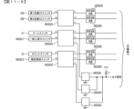
各検出手段からの検出信号が入力される複数の前記インターフェース手段の各々から出力される複数の前記所定異常信号のワイヤードオア接続による合成信号を生成する合成信号出力手段と、
前記特定検出手段から出力される検出信号の出力状況を監視する特定信号監視手段と、
前記合成信号出力手段から出力される前記合成信号と、前記特定信号監視手段による監視状況にもとづいて、異常に関する異常制御を実行可能な遊技制御手段と、
異常に関する報知を実行可能な演出制御手段と、
を備え、
前記合成信号出力手段は、
第1部材に設けられた各検出手段からの検出信号が入力される複数の前記インターフェース手段の各々から出力される複数の前記所定異常信号のワイヤードオア接続による第1合成信号を生成する第1合成信号出力手段と、
第2部材に設けられた各検出手段からの検出信号が入力される複数の前記インターフェース手段の各々から出力される複数の前記所定異常信号のワイヤードオア接続による第2合成信号を生成する第2合成信号出力手段と、を含み、
前記第1部材は、遊技盤の部材であり、
前記第2部材は、遊技機用枠の部材であり、
前記インターフェース手段は、前記検出手段から出力された検出信号に対応する信号を出力可能であるとともに、前記検出手段からの検出信号の出力の有無に関係なく前記所定異常信号を出力可能であり、
前記遊技制御手段は、
前記第1合成信号に基づいて、第1前記異常制御として、異常通知信号を前記演出制御手段に送信するとともに、遊技の実行を禁止する制御を行い、
前記第2合成信号に基づいて、第2異常通知信号を前記演出制御手段に送信するが、遊技の実行を禁止する制御を行わず、
前記特定信号監視手段が前記特定検出手段から出力される検出信号の出力状況について異常を検知した場合に、第3異常通知信号を前記演出制御手段に送信するとともに、遊技の実行を禁止する制御を行う、
ことを特徴としている。
手段1の遊技機は、
遊技を行うことが可能な遊技機(例えば、特徴部045SGのパチンコ遊技機1)であって、
特定検出手段(例えば、確変領域スイッチ045SG12)を含む複数の検出手段(例えば、盤側部材の第1始動口スイッチ22Aやカウントスイッチ23等の6つのスイッチと、枠側部材の第1アウト確認スイッチ045SG21や第1入賞確認スイッチ045SG23等の4つのスイッチ)と、
前記検出手段から出力される検出信号が入力され、該入力に関する所定異常(例えば、入力側信号線の断線(抜け)や短絡)を検出可能であるとともに、該所定異常の検出にもとづく所定異常信号(例えば、異常検知信号)を出力可能なインターフェース手段(例えば、インターフェース集積回路045SG30)と、
各検出手段からの検出信号が入力される複数のインターフェース手段(例えば、盤側部材に設けられた6つの各種スイッチが接続される3つのインターフェース集積回路045SG30)の各々から出力される複数の前記所定異常信号のワイヤードオア接続による合成信号(例えば、B-IF信号)を生成する合成信号出力手段(例えば、各インターフェース集積回路045SG30に対応して設けられた3つのB-IF信号用ワイヤードオア接続用スイッチ045SG41)と、
前記特定検出手段から出力される検出信号の出力状況を監視する特定信号監視手段(例えば、遊技制御用マイクロコンピュータ100がメイン側エラー処理において確変領域信号監視処理を実行する部分)と、
前記合成信号出力手段から出力される前記合成信号と、前記特定信号監視手段による監視状況にもとづいて、異常に関する異常制御を実行可能な制御手段(例えば、確変領域スイッチが接続されているインターフェース集積回路045SG30の異常検出信号のワイヤードオア信号であるB-IF信号により盤側インターフェースエラーを判定したことにより遊技禁止フラグをオン状態とする制御だけではなく、確変領域信号監視処理において確変領域信号により確変領域エラーと判定したことにより遊技禁止フラグをオン状態とする制御を行う遊技制御用マイクロコンピュータ100)と、
を備える
ことを特徴としている。
この特徴によれば、制御手段への入力信号を増やすことなく、適切に異常制御を実行することができる。
The game machine of means A is
A gaming machine capable of playing games,
a plurality of detection means including specific detection means;
interface means for receiving a detection signal output from the detection means, capable of detecting a predetermined abnormality related to the input, and capable of outputting a predetermined abnormality signal based on the detection of the predetermined abnormality;
combined signal output means for generating a combined signal by wired OR connection of the plurality of predetermined abnormal signals output from each of the plurality of interface means to which detection signals from the respective detection means are input;
a specific signal monitoring means for monitoring the output status of the detection signal output from the specific detection means;
game control means capable of executing abnormality control regarding an abnormality based on the composite signal output from the composite signal output means and the monitoring situation by the specific signal monitoring means;
Production control means capable of executing notification regarding abnormality;
with
The combined signal output means is
A first synthesis for generating a first synthesis signal by a wired OR connection of a plurality of the predetermined abnormal signals output from each of the plurality of interface means to which detection signals from the detection means provided in the first member are input. a signal output means;
A second synthesis for generating a second synthesized signal by a wired OR connection of the plurality of predetermined abnormal signals output from each of the plurality of interface means to which the detection signals from the detection means provided in the second member are input. a signal output means;
The first member is a member of a game board,
The second member is a member of a game machine frame,
The interface means can output a signal corresponding to the detection signal output from the detection means, and can output the predetermined abnormality signal regardless of whether or not the detection signal is output from the detection means,
The game control means is
Based on the first synthesized signal, as the first abnormality control, an abnormality notification signal is transmitted to the effect control means, and control is performed to prohibit execution of the game ,
Based on the second synthesized signal, a second abnormality notification signal is transmitted to the effect control means, but control to prohibit execution of the game is not performed,
When the specific signal monitoring means detects an abnormality in the output status of the detection signal output from the specific detection means, it transmits a third abnormality notification signal to the effect control means and controls to prohibit the execution of the game. conduct,
It is characterized by
The game machine of
A gaming machine capable of playing a game (for example, a
A plurality of detection means (for example, six switches such as the
A detection signal output from the detection means is input, and a predetermined abnormality related to the input (for example, disconnection (disconnection) or short circuit of the input side signal line) can be detected, and a predetermined abnormality signal based on the detection of the predetermined abnormality interface means (eg, interface integrated circuit 045SG30) capable of outputting (eg, anomaly detection signal);
A plurality of predetermined signals output from each of a plurality of interface means (for example, three interface integrated circuits 045SG30 to which six various switches provided on the board-side member are connected) to which detection signals from each detection means are input Composite signal output means for generating a composite signal (for example, B-IF signal) by wired OR connection of abnormal signals (for example, for wired OR connection for three B-IF signals provided corresponding to each interface integrated circuit 045SG30 switch 045SG41);
Specific signal monitoring means for monitoring the output status of the detection signal output from the specific detection means (for example, the part where the
Based on the synthesized signal output from the synthesized signal output means and the monitoring status by the specific signal monitoring means, a control means (for example, an interface integrated circuit to which a probability variable area switch is connected) that can execute abnormality control related to abnormality Not only control to turn on the game prohibition flag by determining a board side interface error by the B-IF signal which is a wired OR signal of the abnormality detection signal of 045SG30, but also the probability variable area by the probability variable area signal in the probability variable area signal monitoring process A game control microcomputer 100) that performs control to turn on the game prohibition flag by determining that it is an error;
It is characterized by having
According to this feature, it is possible to appropriately execute the abnormality control without increasing the number of input signals to the control means.
手段2の遊技機は、手段1に記載の遊技機であって、
前記制御手段は、前記特定検出手段から所定期間(例えば、1秒)に亘って継続して検出信号が出力されている出力状況であることが前記特定信号監視手段による監視(確変領域信号監視処理)によって検知されたときに異常(例えば、確変領域エラー)に関する異常制御(例えば、遊技禁止フラグをオン状態とするとともに、確変領域エラーを通知するエラー指定コマンドの送信設定をする制御)を実行する
ことを特徴としている。
この特徴によれば、特定検出手段に対応した適切な異常制御を実行することができる。
The gaming machine of
The control means monitors the output state in which the detection signal is continuously output from the specific detection means for a predetermined period (for example, one second) by the specific signal monitoring means (probability variable region signal monitoring processing). ) When an abnormality (for example, probability variable area error) is detected by abnormal control (for example, the game prohibition flag is turned on and an error designation command that notifies the probability variable area error is set to be transmitted) Execute control) It is characterized by
According to this feature, appropriate abnormality control corresponding to the specific detection means can be executed.
手段3の遊技機は、手段1または手段2に記載の遊技機であって、
第1部材(例えば、盤側部材)と該第1部材と異なる第2部材(例えば、枠側部材)とを有し、
前記第1部材および前記第2部材の各々に、複数の検出手段(例えば、盤側部材の第1始動口スイッチ22Aやカウントスイッチ23等の6つのスイッチと、枠側部材の第1アウト確認スイッチ045SG21や第1入賞確認スイッチ045SG23等の4つのスイッチ)が設けられており、
前記合成信号出力手段は、
前記第1部材に設けられた各検出手段からの検出信号が入力される複数のインターフェース手段(例えば、盤側部材に設けられた6つの各種スイッチが接続される3つのインターフェース集積回路045SG30)の各々から出力される複数の前記所定異常信号のワイヤードオア接続による第1合成信号(例えば、B-IF信号)を生成する第1合成信号出力手段(例えば、各インターフェース集積回路045SG30に対応して設けられた3つのB-IF信号用ワイヤードオア接続用スイッチ045SG41)と、
前記第2部材に設けられた各検出手段からの検出信号が入力される複数のインターフェース手段(例えば、枠側部材に設けられた4つの各種スイッチが接続される2つのインターフェース集積回路045SG30)の各々から出力される複数の前記所定異常信号のワイヤードオア接続による第2合成信号(例えば、W-IF信号)を生成する第2合成信号出力手段(例えば、各インターフェース集積回路045SG30に対応して設けられた2つのW-IF信号用ワイヤードオア接続用スイッチ045SG42)と、
を含み、
前記制御手段は、前記第1合成信号と前記第2合成信号とにもとづいて前記異常制御を実行可能である(例えば、遊技制御用マイクロコンピュータ100が、B-IF信号については、メイン側エラー処理によってエラー指定コマンドの送信設定を行う異常制御を実行するのに対し、W-IF信号については、W-IF信号判定処理においてエラー指定コマンドを送信する異常制御を実行する部分)
ことを特徴としている。
この特徴によれば、各部材毎に所定異常の発生の有無を容易に検知することができる。
The gaming machine of
Having a first member (e.g., board-side member) and a second member (e.g., frame-side member) different from the first member,
Each of the first member and the second member has a plurality of detection means (for example, six switches such as the
The combined signal output means is
Each of a plurality of interface means (for example, three interface integrated circuits 045SG30 to which six various switches provided on the board-side member are connected) to which detection signals from the detection means provided on the first member are input. First synthesized signal output means (for example, provided corresponding to each interface integrated circuit 045SG30) for generating a first synthesized signal (for example, B-IF signal) by wired OR connection of the plurality of predetermined abnormal signals output from three B-IF signal wired-OR connection switches 045SG41);
Each of a plurality of interface means (for example, two interface integrated circuits 045SG30 to which four various switches provided on the frame-side member are connected) to which detection signals from the detection means provided on the second member are input Second synthesized signal output means (for example, provided corresponding to each interface integrated circuit 045SG30) for generating a second synthesized signal (for example, W-IF signal) by wired OR connection of the plurality of predetermined abnormal signals output from two W-IF signal wired-OR connection switches 045SG42);
including
The control means can execute the abnormal control based on the first synthesized signal and the second synthesized signal (for example, the
It is characterized by
According to this feature, it is possible to easily detect whether or not the predetermined abnormality has occurred for each member.
手段4に記載の遊技機は、手段3に記載の遊技機であって、
前記制御手段が、前記第1合成信号にもとづいて前記異常制御を実行する条件は、前記第2合成信号にもとづいて前記異常制御を実行する条件とは異なる(例えば、遊技制御用マイクロコンピュータ100が、B-IF信号については、メイン側エラー処理によってB-IF信号が検知(L)状態となったと判定されたときに遊技禁止並びに盤側インターフェースエラーを通知するエラー指定コマンドを送信する異常制御を実行するのに対し、W-IF信号については、タイマ割り込みによって遊技が可能となる前のW-IF信号判定処理においてW-IF信号が検知(L)状態となったと判定されたときに、遊技禁止にすることなく枠側インターフェースエラーを通知するエラー指定コマンドを送信する異常制御を実行する部分)
ことを特徴としている。
この特徴によれば、各信号に応じたより適切な異常制御を実行することができる。
The gaming machine according to
The conditions under which the control means executes the abnormal control based on the first synthesized signal are different from the conditions for executing the abnormal control based on the second synthesized signal (for example,
It is characterized by
According to this feature, more appropriate abnormality control can be executed according to each signal.
手段5の遊技機は、手段4に記載の遊技機であって、
前記条件は、前記第1合成信号(例えば、B-IF信号)にもとづいて前記異常制御を実行するか否かを判定する時期である第1判定時期(例えば、タイマ割り込みにより遊技が可能化されている期間におけるタイマ割り込み時)の条件と、前記第2合成信号にもとづいて前記異常制御を実行するか否かを判定する時期である第2判定時期(例えば、タイマ割り込みの設定がなされる前の遊技が可能化されていない時)の条件とを含み、
前記第1判定時期と前記第2判定時期とが異なる
ことを特徴としている。
この特徴によれば、各信号に対応した適切な判定時期が条件に含まれているので、より適切に異常制御を実行することができる。
The gaming machine of
The condition is a first judgment timing (for example, when a game is enabled by a timer interrupt), which is a timing for judging whether or not to execute the abnormal control based on the first synthesized signal (for example, B-IF signal). A second decision time (for example, before a timer interrupt is set), which is a time to decide whether or not to execute the abnormality control, based on the condition of a timer interrupt during a period in which the timer interrupt is set and the second synthesized signal. (when play is not enabled); and
The first determination time and the second determination time are different.
According to this feature, since the condition includes the appropriate determination timing corresponding to each signal, the abnormality control can be executed more appropriately.
手段6に記載の遊技機は、手段4または手段5に記載の遊技機であって、
前記第1判定時期は、遊技が可能となった後における所定期間毎の複数回のタイミング(例えば、タイマ割り込みにより遊技が可能化されている期間におけるタイマ割り込み毎の複数回)であるが、前記第2判定時期は、電源投入から遊技が可能となるまでの起動期間内の所定タイミングの1回のみである(例えば、タイマ割り込みの設定がなされるS11の処理の前の045SGS01の実行タイミングの1回のみ)
ことを特徴としている。
この特徴によれば、各信号に対応した適切な時期と回数を条件に含むことにより、より適切に異常制御を実行することができる。
The gaming machine according to
The first determination time is a plurality of timings for each predetermined period after the game becomes possible (for example, a plurality of times for each timer interruption during the period when the game is enabled by timer interruption). The second determination time is only once at a predetermined timing within the start-up period from when the power is turned on until the game becomes available (for example, one time at the execution timing of 045SGS01 before the processing of S11 where the timer interrupt is set). times only)
It is characterized by
According to this feature, it is possible to execute the abnormality control more appropriately by including the appropriate timing and number of times corresponding to each signal in the conditions.
手段7に記載の遊技機は、手段3~手段6のいずれかに記載の遊技機であって、
前記制御手段は、前記第1合成信号(例えば、B-IF信号)にもとづく前記異常制御においては遊技を不能とする制御を実行する(例えば、メイン側エラー処理において045SGS40の処理を実行する部分)
ことを特徴としている。
この特徴によれば、部材に応じて、遊技を不能としない制御と遊技を不能とする制御とを実行できるので、部材に対応した適切な異常制御を実行することができる。
The gaming machine according to
The control means executes control to disable the game in the abnormal control based on the first synthesized signal (for example, B-IF signal) (for example, a portion that executes 045SGS40 processing in main side error processing).
It is characterized by
According to this feature, since it is possible to execute control that does not disable the game and control that disables the game according to the member, it is possible to execute appropriate abnormality control corresponding to the member.
尚、本発明は、本発明の請求項に記載された発明特定事項のみを有するものであって良いし、本発明の請求項に記載された発明特定事項とともに該発明特定事項以外の構成を有するものであっても良い。 The present invention may include only the matters specifying the invention described in the claims of the present invention, or may include the matters specifying the invention described in the claims of the present invention as well as the matters specifying the invention other than the matters specifying the invention. It can be anything.
(基本説明)
まず、パチンコ遊技機1の基本的な構成及び制御(一般的なパチンコ遊技機の構成及び制御でもある。)について説明する。
(Basic explanation)
First, the basic configuration and control of the pachinko game machine 1 (also the configuration and control of a general pachinko game machine) will be described.
(パチンコ遊技機1の構成等)
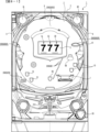
図1は、パチンコ遊技機1の正面図であり、主要部材の配置レイアウトを示す。パチンコ遊技機(遊技機)1は、大別して、遊技盤面を構成する遊技盤(ゲージ盤)2と、遊技盤2を支持固定する遊技機用枠(台枠)3とから構成されている。遊技盤2には、遊技領域が形成され、この遊技領域には、遊技媒体としての遊技球が、所定の打球発射装置から発射されて打ち込まれる。
(Structure of
FIG. 1 is a front view of the
遊技盤2の所定位置(図1に示す例では、遊技領域の右側方)には、複数種類の特別識別情報としての特別図柄(特図ともいう)の可変表示(特図ゲームともいう)を行う第1特別図柄表示装置4A及び第2特別図柄表示装置4Bが設けられている。これらは、それぞれ、7セグメントのLEDなどからなる。特別図柄は、「0」~「9」を示す数字や「-」などの点灯パターンなどにより表される。特別図柄には、LEDを全て消灯したパターンが含まれてもよい。
At a predetermined position of the game board 2 (in the example shown in FIG. 1, on the right side of the game area), a variable display (also called a special game) of special symbols (also called special symbols) as a plurality of types of special identification information is displayed. A first special
尚、特別図柄の「可変表示」とは、例えば、複数種類の特別図柄を変動可能に表示することである(後述の他の図柄についても同じ)。変動としては、複数の図柄の更新表示、複数の図柄のスクロール表示、1以上の図柄の変形、1以上の図柄の拡大/縮小などがある。特別図柄や後述の普通図柄の変動では、複数種類の特別図柄又は普通図柄が更新表示される。後述の飾り図柄の変動では、複数種類の飾り図柄がスクロール表示又は更新表示されたり、1以上の飾り図柄が変形や拡大/縮小されたりする。尚、変動には、ある図柄を点滅表示する態様も含まれる。可変表示の最後には、表示結果として所定の特別図柄が停止表示(導出又は導出表示などともいう)される(後述の他の図柄の可変表示についても同じ)。尚、可変表示を変動表示、変動と表現する場合がある。 The "variable display" of the special symbols means, for example, that a plurality of types of special symbols are variably displayed (the same applies to other symbols described later). Variations include updating display of a plurality of patterns, scrolling display of a plurality of patterns, deformation of one or more patterns, enlargement/reduction of one or more patterns, and the like. In the variation of special symbols and normal symbols, which will be described later, a plurality of types of special symbols or normal symbols are updated and displayed. In the variation of decorative patterns, which will be described later, a plurality of types of decorative patterns are scrolled or updated, and one or more decorative patterns are deformed or enlarged/reduced. Incidentally, the variation includes a mode of blinking a certain symbol. At the end of the variable display, a predetermined special symbol is stopped and displayed (also referred to as derivation or derivation display) as a display result (the same applies to variable display of other symbols to be described later). Variable display may be expressed as variable display or variation.
尚、第1特別図柄表示装置4Aにおいて可変表示される特別図柄を「第1特図」ともいい、第2特別図柄表示装置4Bにおいて可変表示される特別図柄を「第2特図」ともいう。また、第1特図を用いた特図ゲームを「第1特図ゲーム」といい、第2特図を用いた特図ゲームを「第2特図ゲーム」ともいう。尚、特別図柄の可変表示を行う特別図柄表示装置は1種類であってもよい。
The special symbols variably displayed on the first special
遊技盤2における遊技領域の中央付近には画像表示装置5が設けられている。画像表示装置5は、例えばLCD(液晶表示装置)や有機EL(Electro Luminescence)等から構成され、各種の演出画像を表示する。画像表示装置5は、プロジェクタ及びスクリーンから構成されていてもよい。画像表示装置5には、各種の演出画像が表示される。
An
例えば、画像表示装置5の画面上では、第1特図ゲームや第2特図ゲームと同期して、特別図柄とは異なる複数種類の装飾識別情報としての飾り図柄(数字などを示す図柄など)の可変表示が行われる。ここでは、第1特図ゲーム又は第2特図ゲームに同期して、「左」、「中」、「右」の各飾り図柄表示エリア5L、5C、5Rにおいて飾り図柄が可変表示(例えば上下方向のスクロール表示や更新表示)される。尚、同期して実行される特図ゲーム及び飾り図柄の可変表示を総称して単に可変表示ともいう。
For example, on the screen of the
画像表示装置5の画面上には、実行が保留されている可変表示に対応する保留表示や、実行中の可変表示に対応するアクティブ表示を表示するための表示エリアが設けられていてもよい。保留表示及びアクティブ表示を総称して可変表示に対応する可変表示対応表示ともいう。
A display area may be provided on the screen of the
保留されている可変表示の数は保留記憶数ともいう。第1特図ゲームに対応する保留記憶数を第1保留記憶数、第2特図ゲームに対応する保留記憶数を第2保留記憶数ともいう。また、第1保留記憶数と第2保留記憶数との合計を合計保留記憶数ともいう。 The number of variable representations that are reserved is also referred to as the number of reserved memories. The reserved memory number corresponding to the first special game is also referred to as the first reserved memory number, and the reserved memory number corresponding to the second special game is also referred to as the second reserved memory number. The sum of the first reserved memory count and the second reserved memory count is also referred to as the total reserved memory count.
また、遊技盤2の所定位置には、複数のLEDを含んで構成された第1保留表示器25Aと第2保留表示器25Bとが設けられ、第1保留表示器25Aは、LEDの点灯個数によって、第1保留記憶数を表示し、第2保留表示器25Bは、LEDの点灯個数によって、第2保留記憶数を表示する。
At a predetermined position of the
画像表示装置5の下方には、入賞球装置6Aと、可変入賞球装置6Bとが設けられている。
Below the
入賞球装置6Aは、例えば所定の玉受部材によって常に遊技球が進入可能な一定の開放状態に保たれる第1始動入賞口を形成する。第1始動入賞口に遊技球が進入したときには、所定個(例えば3個)の賞球が払い出されるとともに、第1特図ゲームが開始され得る。
Winning
可変入賞球装置6B(普通電動役物)は、ソレノイド81(図2参照)によって閉鎖状態と開放状態とに変化する第2始動入賞口を形成する。可変入賞球装置6Bは、例えば、一対の可動翼片を有する電動チューリップ型役物を備え、ソレノイド81がオフ状態であるときに可動翼片が垂直位置となることにより、当該可動翼片の先端が入賞球装置6Aに近接し、第2始動入賞口に遊技球が進入しない閉鎖状態になる(第2始動入賞口が閉鎖状態になるともいう。)。その一方で、可変入賞球装置6Bは、ソレノイド81がオン状態であるときに可動翼片が傾動位置となることにより、第2始動入賞口に遊技球が進入できる開放状態になる(第2始動入賞口が開放状態になるともいう。)。第2始動入賞口に遊技球が進入したときには、所定個(例えば3個)の賞球が払い出されるとともに、第2特図ゲームが開始され得る。尚、可変入賞球装置6Bは、閉鎖状態と開放状態とに変化するものであればよく、電動チューリップ型役物を備えるものに限定されない。
The variable winning
遊技盤2の所定位置(図1に示す例では、遊技領域の左右下方4箇所)には、所定の玉受部材によって常に一定の開放状態に保たれる一般入賞口10が設けられる。この場合には、一般入賞口10のいずれかに進入したときには、所定個数(例えば10個)の遊技球が賞球として払い出される。
At predetermined positions of the game board 2 (in the example shown in FIG. 1, four positions on the left and right sides of the game area), there are provided general winning holes 10 which are always kept open by predetermined ball receiving members. In this case, when the player enters one of the general winning
入賞球装置6Aと可変入賞球装置6Bの下方には、大入賞口を有する特別可変入賞球装置7が設けられている。特別可変入賞球装置7は、ソレノイド82(図2参照)によって開閉駆動される大入賞口扉を備え、その大入賞口扉によって開放状態と閉鎖状態とに変化する特定領域としての大入賞口を形成する。
Below the winning
一例として、特別可変入賞球装置7では、大入賞口扉用(特別電動役物用)のソレノイド82がオフ状態であるときに大入賞口扉が大入賞口を閉鎖状態として、遊技球が大入賞口に進入(通過)できなくなる。その一方で、特別可変入賞球装置7では、大入賞口扉用のソレノイド82がオン状態であるときに大入賞口扉が大入賞口を開放状態として、遊技球が大入賞口に進入しやすくなる。
As an example, in the special variable winning
大入賞口に遊技球が進入したときには、所定個数(例えば14個)の遊技球が賞球として払い出される。大入賞口に遊技球が進入したときには、例えば第1始動入賞口や第2始動入賞口及び一般入賞口10に遊技球が進入したときよりも多くの賞球が払い出される。
When game balls enter the big winning hole, a predetermined number (for example, 14) of game balls are paid out as prize balls. When the game balls enter the big winning hole, more prize balls are paid out than when the game balls enter the first starting winning hole, the second starting winning hole and the general winning
一般入賞口10を含む各入賞口に遊技球が進入することを「入賞」ともいう。特に、始動口(第1始動入賞口、第2始動入賞口始動口)への入賞を始動入賞ともいう。
Entering a game ball into each winning hole including the general winning
遊技盤2の所定位置(図1に示す例では、遊技領域の左側方)には、普通図柄表示器20が設けられている。一例として、普通図柄表示器20は、7セグメントのLEDなどからなり、特別図柄とは異なる複数種類の普通識別情報としての普通図柄の可変表示を行う。普通図柄は、「0」~「9」を示す数字や「-」などの点灯パターンなどにより表される。普通図柄には、LEDを全て消灯したパターンが含まれてもよい。このような普通図柄の可変表示は、普図ゲームともいう。
A
画像表示装置5の左方には、遊技球が通過可能な通過ゲート41が設けられている。遊技球が通過ゲート41を通過したことに基づき、普図ゲームが実行される。
A
普通図柄表示器20の上方には、普図保留表示器25Cが設けられている。普図保留表示器25Cは、例えば4個のLEDを含んで構成され、実行が保留されている普図ゲームの数である普図保留記憶数をLEDの点灯個数により表示する。
Above the
遊技盤2の表面には、上記の構成以外にも、遊技球の流下方向や速度を変化させる風車及び多数の障害釘が設けられている。遊技領域の最下方には、いずれの入賞口にも進入しなかった遊技球が取り込まれるアウト口が設けられている。
The surface of the
遊技機用枠3の左右上部位置には、効果音等を再生出力するためのスピーカ8L、8Rが設けられており、さらに遊技領域周辺部には、遊技効果用の遊技効果ランプ9が設けられている。遊技効果ランプ9は、LEDを含んで構成されている。
遊技盤2の所定位置(図1では図示略)には、演出に応じて動作する可動体32が設けられている。
At a predetermined position (not shown in FIG. 1) of the
遊技機用枠3の右下部位置には、遊技球を打球発射装置により遊技領域に向けて発射するために遊技者等によって操作される打球操作ハンドル(操作ノブ)30が設けられている。
A ball hitting operation handle (operation knob) 30 operated by a player or the like to shoot a game ball toward the game area by the ball shooting device is provided at the lower right portion of the
遊技領域の下方における遊技機用枠3の所定位置には、賞球として払い出された遊技球や所定の球貸機により貸し出された遊技球を、打球発射装置へと供給可能に保持(貯留)する打球供給皿(上皿)が設けられている。上皿の下方には、上皿満タン時に賞球が払い出される打球供給皿(下皿)が設けられている。
At a predetermined position of the
遊技領域の下方における遊技機用枠3の所定位置には、遊技者が把持して傾倒操作が可能なスティックコントローラ31Aが取り付けられている。スティックコントローラ31Aには、遊技者が押下操作可能なトリガボタンが設けられている。スティックコントローラ31Aに対する操作は、コントローラセンサユニット35A(図2参照)により検出される。
A
遊技領域の下方における遊技機用枠3の所定位置には、遊技者が押下操作などにより所定の指示操作を可能なプッシュボタン31Bが設けられている。プッシュボタン31Bに対する操作は、プッシュセンサ35B(図2参照)により検出される。
At a predetermined position of the
パチンコ遊技機1では、遊技者の動作(操作等)を検出する検出手段として、スティックコントローラ31Aやプッシュボタン31Bが設けられるが、これら以外の検出手段が設けられていてもよい。
The
(遊技の進行の概略)
パチンコ遊技機1が備える打球操作ハンドル30への遊技者による回転操作により、遊技球が遊技領域に向けて発射される。遊技球が通過ゲート41を通過すると、普通図柄表示器20による普図ゲームが開始される。尚、前回の普図ゲームの実行中の期間等に遊技球が通過ゲート41を通過した場合(遊技球が通過ゲート41を通過したが当該通過に基づく普図ゲームを直ちに実行できない場合)には、当該通過に基づく普図ゲームは所定の上限数(例えば4)まで保留される。
(Overview of Game Progress)
A game ball is shot toward a game area by a player's rotation operation of a ball hitting operation handle 30 provided in the
この普図ゲームでは、特定の普通図柄(普図当り図柄)が停止表示されれば、普通図柄の表示結果が「普図当り」となる。その一方、確定普通図柄として、普図当り図柄以外の普通図柄(普図はずれ図柄)が停止表示されれば、普通図柄の表示結果が「普図はずれ」となる。「普図当り」となると、可変入賞球装置6Bを所定期間開放状態とする開放制御が行われる(第2始動入賞口が開放状態になる)。
In this general pattern game, if a specific normal pattern (normal pattern winning pattern) is stopped and displayed, the display result of the normal pattern becomes "normal pattern winning". On the other hand, if a normal pattern (normal pattern lost pattern) other than the normal pattern winning pattern is stop-displayed as the fixed normal pattern, the display result of the normal pattern becomes "normal pattern lost". When it comes to "normal game", the variable winning
入賞球装置6Aに形成された第1始動入賞口に遊技球が進入すると、第1特別図柄表示装置4Aによる第1特図ゲームが開始される。
When a game ball enters the first starting winning hole formed in the winning
可変入賞球装置6Bに形成された第2始動入賞口に遊技球が進入すると、第2特別図柄表示装置4Bによる第2特図ゲームが開始される。
When the game ball enters the second starting winning hole formed in the variable winning
尚、特図ゲームの実行中の期間や、後述する大当り遊技状態や小当り遊技状態に制御されている期間に、遊技球が始動入賞口へ進入(入賞)した場合(始動入賞が発生したが当該始動入賞に基づく特図ゲームを直ちに実行できない場合)には、当該進入に基づく特図ゲームは所定の上限数(例えば4)までその実行が保留される。 In addition, when the game ball enters (wins) the start winning opening during the period during execution of the special game or during the period when it is controlled to the big win game state or the small win game state described later (although the start win has occurred If the special game based on the starting prize cannot be executed immediately), the execution of the special game based on the entry is suspended up to a predetermined upper limit number (for example, 4).
特図ゲームにおいて、確定特別図柄として特定の特別図柄(大当り図柄、例えば「7」、後述の大当り種別に応じて実際の図柄は異なる。)が停止表示されれば、「大当り」となり、大当り図柄とは異なる所定の特別図柄(小当り図柄、例えば「2」)が停止表示されれば、「小当り」となる。また、大当り図柄や小当り図柄とは異なる特別図柄(はずれ図柄、例えば「-」)が停止表示されれば「はずれ」となる。 In the special symbol game, when a specific special symbol (a big hit symbol, for example, "7", the actual symbol varies depending on the type of the big hit to be described later) is stopped and displayed as a fixed special symbol, it becomes a "big hit" and a big winning symbol. If a predetermined special symbol (a small winning symbol, for example, "2") different from the symbol is stop-displayed, it becomes a "small winning". Also, if a special symbol (losing symbol, for example, "-") different from the big-hit symbol or the small-hit symbol is stopped and displayed, it becomes "lost".
特図ゲームでの表示結果が「大当り」になった後には、遊技者にとって有利な有利状態として大当り遊技状態に制御される。特図ゲームでの表示結果が「小当り」になった後には、小当り遊技状態に制御される。 After the display result in the special game becomes "big win", the game is controlled to a big win game state as an advantageous state for the player. After the display result in the special game becomes "small hit", it is controlled to the small win game state.
大当り遊技状態においては、遊技者は、遊技球を大入賞口に進入させることで、賞球を得ることができる。従って、大当り遊技状態は、遊技者にとって有利な状態である。大当り遊技状態におけるラウンド数が多い程、また、開放上限期間が長い程遊技者にとって有利となる。 In the jackpot game state, the player can get a prize ball by entering the game ball into the big winning hole. Therefore, the jackpot gaming state is an advantageous state for the player. The larger the number of rounds in the jackpot game state and the longer the upper limit period of opening, the more advantageous the player is.
尚、「大当り」には、大当り種別が設定されている。例えば、大入賞口の開放態様(ラウンド数や開放上限期間)や、大当り遊技状態後の遊技状態(後述の、通常状態、時短状態、確変状態など)を複数種類用意し、これらに応じて大当り種別が設定されている。大当り種別として、多くの賞球を得ることができる大当り種別や、賞球の少ない又はほとんど賞球を得ることができない大当り種別が設けられていてもよい。 In addition, a jackpot type is set in the "jackpot". For example, a plurality of types of opening modes (number of rounds and upper limit period of opening) of the big winning opening and game states after the jackpot game state (normal state, time saving state, variable probability state, etc. described later) are prepared, and the jackpot is obtained according to these. type is set. As the jackpot type, there may be provided a jackpot type in which a large number of prize balls can be obtained, and a jackpot type in which a small number of prize balls or almost no prize balls can be obtained.
小当り遊技状態では、特別可変入賞球装置7により形成される大入賞口が所定の開放態様で開放状態となる。例えば、小当り遊技状態では、一部の大当り種別のときの大当り遊技状態と同様の開放態様(大入賞口の開放回数が上記ラウンド数と同じであり、かつ、大入賞口の閉鎖タイミングも同じ等)で大入賞口が開放状態となる。尚、大当り種別と同様に、「小当り」にも小当り種別を設けてもよい。
In the small winning game state, the big winning opening formed by the special variable winning
大当り遊技状態が終了した後は、上記大当り種別に応じて、時短状態や確変状態に制御されることがある。 After the jackpot game state is finished, depending on the jackpot type, it may be controlled to a time-saving state or a variable probability state.
時短状態では、平均的な特図変動時間(特図を変動させる期間)を通常状態よりも短縮させる制御(時短制御)が実行される。時短状態では、平均的な普図変動時間(普図を変動させる期間)を通常状態よりも短縮させたり、普図ゲームで「普図当り」となる確率を通常状態よりも向上させる等により、第2始動入賞口に遊技球が進入しやすくなる制御(高開放制御、高ベース制御)も実行される。時短状態は、特別図柄(特に第2特別図柄)の変動効率が向上する状態であるので、遊技者にとって有利な状態である。 In the time saving state, the control (time saving control) that shortens the average special figure fluctuation time (period of varying the special figure) than the normal state is executed. In the time-saving state, by shortening the average normal figure fluctuation time (the period during which the normal figure is changed) than in the normal state, and by improving the probability of becoming a "normal figure hit" in the general figure game than in the normal state, etc. Control (high opening control, high base control) that makes it easier for game balls to enter the second start winning opening is also executed. Since the time-saving state is a state in which the variation efficiency of the special symbols (especially the second special symbols) is improved, it is an advantageous state for the player.
確変状態(確率変動状態)では、時短制御に加えて、表示結果が「大当り」となる確率が通常状態よりも高くなる確変制御が実行される。確変状態は、特別図柄の変動効率が向上することに加えて「大当り」となりやすい状態であるので、遊技者にとってさらに有利な状態である。 In the variable probability state (probability variable state), in addition to the time-saving control, the variable probability control in which the probability that the display result is a "jackpot" is higher than in the normal state is executed. The variable probability state is a state in which the variation efficiency of the special symbols is improved, and in addition, a "big hit" is likely to occur, so it is a further advantageous state for the player.
時短状態や確変状態は、所定回数の特図ゲームが実行されたことと、次回の大当り遊技状態が開始されたこと等といった、いずれか1つの終了条件が先に成立するまで継続する。所定回数の特図ゲームが実行されたことが終了条件となるものを、回数切り(回数切り時短、回数切り確変等)ともいう。 The time saving state and the variable probability state are continued until one of the end conditions such as execution of the special game for a predetermined number of times and start of the next big win game state is established first. The end condition that the special figure game of a predetermined number of times has been executed is also referred to as a number cut (number cut time reduction, number cut probability variable, etc.).
通常状態とは、遊技者にとって有利な大当り遊技状態等の有利状態、時短状態、確変状態等の特別状態以外の遊技状態のことであり、普図ゲームにおける表示結果が「普図当り」となる確率及び特図ゲームにおける表示結果が「大当り」となる確率などのパチンコ遊技機1が、パチンコ遊技機1の初期設定状態(例えばシステムリセットが行われた場合のように、電源投入後に所定の復帰処理を実行しなかったとき)と同一に制御される状態である。
The normal state means a game state other than a special state such as an advantageous state such as a jackpot game state that is advantageous to the player, a time saving state, a probability variable state, etc., and the display result in the normal game is "normal game". The
確変制御が実行されている状態を高確状態、確変制御が実行されていない状態を低確状態ともいう。時短制御が実行されている状態を高ベース状態、時短制御が実行されていない状態を低ベース状態ともいう。これらを組み合わせて、時短状態は低確高ベース状態、確変状態は高確高ベース状態、通常状態は低確低ベース状態などともいわれる。高確状態かつ低ベース状態は高確低ベース状態ともいう。 The state in which probability variable control is executed is also called a high probability state, and the state in which probability variable control is not executed is also called a low probability state. A state in which time-saving control is performed is also referred to as a high-based state, and a state in which time-saving control is not performed is also referred to as a low-based state. Combining these, the short-time state is also called a low-probability-high base state, the probability-variable state is a high-probability-high base state, and the normal state is a low-probability-low base state. The high probability state and the low base state are also referred to as the high probability low base state.
小当り遊技状態が終了した後は、遊技状態の変更が行われず、特図ゲームの表示結果が「小当り」となる以前の遊技状態に継続して制御される(但し、「小当り」発生時の特図ゲームが、上記回数切りにおける上記所定回数目の特図ゲームである場合には、当然遊技状態が変更される)。尚、特図ゲームの表示結果として「小当り」がなくてもよい。 After the small win game state is over, the game state is not changed, and the game state before the display result of the special figure game becomes "small win" is continuously controlled (however, "small win" occurs If the special game at the time is the special game for the predetermined number of times in the above cut, the game state is naturally changed). In addition, there may not be a "small hit" as a display result of a special figure game.
尚、遊技状態は、大当り遊技状態中に遊技球が特定領域(例えば、大入賞口内の特定領域)を通過したことに基づいて、変化してもよい。例えば、遊技球が特定領域を通過したとき、その大当り遊技状態後に確変状態に制御してもよい。 Incidentally, the game state may change based on the fact that the game ball has passed through a specific area (for example, a specific area within the big winning opening) during the jackpot game state. For example, when the game ball passes through the specific area, it may be controlled to the probability variable state after the big hit game state.
(演出の進行など)
パチンコ遊技機1では、遊技の進行に応じて種々の演出(遊技の進行状況を報知したり、遊技を盛り上げたりする演出)が実行される。当該演出について以下説明する。尚、当該演出は、画像表示装置5に各種の演出画像を表示することによって行われるが、当該表示に加えて又は代えて、スピーカ8L、8Rからの音声出力、及び/又は、遊技効果ランプ9の点等/消灯、可動体32の動作等により行われてもよい。
(Progress of production, etc.)
In the
遊技の進行に応じて実行される演出として、画像表示装置5に設けられた「左」、「中」、「右」の飾り図柄表示エリア5L、5C、5Rでは、第1特図ゲーム又は第2特図ゲームが開始されることに対応して、飾り図柄の可変表示が開始される。第1特図ゲームや第2特図ゲームにおいて表示結果(確定特別図柄ともいう。)が停止表示されるタイミングでは、飾り図柄の可変表示の表示結果となる確定飾り図柄(3つの飾り図柄の組合せ)も停止表示(導出)される。 As an effect executed according to the progress of the game, the first special game or the second In response to the start of the 2 special figure game, the variable display of the decoration pattern is started. At the timing when the display result (also called fixed special pattern) is stopped and displayed in the first special game or the second special game, a fixed decorative pattern (combination of three decorative patterns) that is the display result of variable display of decorative patterns ) is also stopped (derived).
飾り図柄の可変表示が開始されてから終了するまでの期間では、飾り図柄の可変表示の態様が所定のリーチ態様となる(リーチが成立する)ことがある。ここで、リーチ態様とは、画像表示装置5の画面上にて停止表示された飾り図柄が後述の大当り組合せの一部を構成しているときに未だ停止表示されていない飾り図柄については可変表示が継続している態様などのことである。
During the period from the start of the variable display of the decorative design to the end of the variable display, the variable display of the decorative design may be in a predetermined ready-to-win state (ready-to-win state is established). Here, the ready-to-win mode means that when the decorative symbols stopped and displayed on the screen of the
また、飾り図柄の可変表示中に上記リーチ態様となったことに対応してリーチ演出が実行される。パチンコ遊技機1では、演出態様に応じて表示結果(特図ゲームの表示結果や飾り図柄の可変表示の表示結果)が「大当り」となる割合(大当り信頼度、大当り期待度とも呼ばれる。)が異なる複数種類のリーチ演出が実行される。リーチ演出には、例えば、ノーマルリーチと、ノーマルリーチよりも大当り信頼度の高いスーパーリーチと、がある。
Further, a ready-to-win effect is executed in response to the above-described ready-to-win mode during the variable display of decorative symbols. In the
特図ゲームの表示結果が「大当り」となるときには、画像表示装置5の画面上において、飾り図柄の可変表示の表示結果として、予め定められた大当り組合せとなる確定飾り図柄が導出される(飾り図柄の可変表示の表示結果が「大当り」となる)。一例として、「左」、「中」、「右」の飾り図柄表示エリア5L、5C、5Rにおける所定の有効ライン上に同一の飾り図柄(例えば、「7」等)が揃って停止表示される。
When the display result of the special game is a "big hit", a fixed decorative pattern that is a predetermined big hit combination is derived as a display result of the variable display of decorative patterns on the screen of the image display device 5 (decoration The display result of the variable display of the pattern becomes a "jackpot"). As an example, the same decoration patterns (for example, "7" etc.) are stop-displayed together on predetermined effective lines in the "left", "middle" and "right" decoration
大当り遊技状態の終了後に確変状態に制御される「確変大当り」である場合には、奇数の飾り図柄(例えば、「7」等)が揃って停止表示され、大当り遊技状態の終了後に確変状態に制御されない「非確変大当り(通常大当り)」である場合には、偶数の飾り図柄(例えば、「6」等)が揃って停止表示されるようにしてもよい。この場合、奇数の飾り図柄を確変図柄、偶数の飾り図柄を非確変図柄(通常図柄)ともいう。非確変図柄でリーチ態様となった後に、最終的に「確変大当り」となる昇格演出を実行するようにしてもよい。 In the case of the ``variable probability big hit'' controlled to the variable probability state after the end of the big win game state, odd decorative patterns (for example, "7" etc.) are stopped and displayed, and the variable probability state is entered after the end of the big win game state. In the case of an uncontrolled "non-probability variable jackpot (normal jackpot)", even-numbered decorative symbols (for example, "6") may be stopped and displayed together. In this case, odd-numbered decorative patterns are also called probability variable patterns and even-numbered decorative patterns are also called non-probable variable patterns (normal patterns). After becoming a ready-to-win mode with non-probability variation symbols, a promotion performance may be executed to finally become a "probability variation big hit".
特図ゲームの表示結果が「小当り」となるときには、画像表示装置5の画面上において、飾り図柄の可変表示の表示結果として、予め定められた小当り組合せとなる確定飾り図柄(例えば、「1 3 5」等)が導出される(飾り図柄の可変表示の表示結果が「小当り」となる)。一例として、「左」、「中」、「右」の飾り図柄表示エリア5L、5C、5Rにおける所定の有効ライン上にチャンス目を構成する飾り図柄が停止表示される。尚、特図ゲームの表示結果が、一部の大当り種別(小当り遊技状態と同様の態様の大当り遊技状態の大当り種別)の「大当り」となるときと、「小当り」となるときとで、共通の確定飾り図柄が導出表示されてもよい。
When the display result of the special figure game is "small hit", on the screen of the
特図ゲームの表示結果が「はずれ」となる場合には、飾り図柄の可変表示の態様がリーチ態様とならずに、飾り図柄の可変表示の表示結果として、非リーチ組合せの確定飾り図柄(「非リーチはずれ」ともいう。)が停止表示される(飾り図柄の可変表示の表示結果が「非リーチはずれ」となる)ことがある。また、表示結果が「はずれ」となる場合には、飾り図柄の可変表示の態様がリーチ態様となった後に、飾り図柄の可変表示の表示結果として、大当り組合せでない所定のリーチ組合せ(「リーチはずれ」ともいう)の確定飾り図柄が停止表示される(飾り図柄の可変表示の表示結果が「リーチはずれ」となる)こともある。 When the display result of the special game is "lost", the variable display mode of the decorative pattern does not become the ready-to-win mode, and the fixed decorative pattern of the non-reach combination (" (Also referred to as non-reach lost") may be stopped (the display result of the variable display of the decorative pattern becomes "non-reach lost"). In addition, when the display result is "lost", after the mode of variable display of decorative patterns becomes the ready-to-win mode, the display result of variable display of decorative patterns is a predetermined ready-to-win combination ("no reach") that is not a big hit combination. ”) is stopped and displayed (the display result of the variable display of the decorative pattern becomes “reach lost”).
パチンコ遊技機1が実行可能な演出には、上記の可変表示対応表示(保留表示やアクティブ表示)を表示することも含まれる。また、他の演出として、例えば、大当り信頼度を予告する予告演出等が飾り図柄の可変表示中に実行される。予告演出には、実行中の可変表示における大当り信頼度を予告する予告演出や、実行前の可変表示(実行が保留されている可変表示)における大当り信頼度を予告する先読み予告演出がある。先読み予告演出として、可変表示対応表示(保留表示やアクティブ表示)の表示態様を通常とは異なる態様に変化させる演出が実行されるようにしてもよい。
The effects that can be executed by the
また、画像表示装置5において、飾り図柄の可変表示中に飾り図柄を一旦仮停止させた後に可変表示を再開させることで、1回の可変表示を擬似的に複数回の可変表示のように見せる擬似連演出を実行するようにしてもよい。
Also, in the
大当り遊技状態中にも、大当り遊技状態を報知する大当り中演出が実行される。大当り中演出としては、ラウンド数を報知する演出や、大当り遊技状態の価値が向上することを示す昇格演出が実行されてもよい。また、小当り遊技状態中にも、小当り遊技状態を報知する小当り中演出が実行される。尚、小当り遊技状態中と、一部の大当り種別(小当り遊技状態と同様の態様の大当り遊技状態の大当り種別で、例えばその後の遊技状態を高確状態とする大当り種別)での大当り遊技状態とで、共通の演出を実行することで、現在が小当り遊技状態中であるか、大当り遊技状態中であるかを遊技者に分からないようにしてもよい。そのような場合であれば、小当り遊技状態の終了後と大当り遊技状態の終了後とで共通の演出を実行することで、高確状態であるか低確状態であるかを識別できないようにしてもよい。 During the big winning game state, the performance during the big winning is executed to report the big winning game state. As the effect during the big win, the effect of notifying the number of rounds or the promotion effect indicating that the value of the big win game state is improved may be executed. Also, during the small-hit game state, an effect during the small-hit game for notifying the small-hit game state is executed. In addition, during the small-hit game state, some big-hit types (jackpot types in the same manner as the small-hit game state, for example, the jackpot type in which the subsequent game state is a high probability state) By executing a common performance in both states, the player may not know whether the current state is a small win game state or a big win game state. In such a case, by executing a common performance after the end of the small winning game state and after the end of the big winning game state, it is made impossible to distinguish whether the state is a high probability state or a low probability state. may
また、例えば特図ゲーム等が実行されていないときには、画像表示装置5にデモ(デモンストレーション)画像が表示される(客待ちデモ演出が実行される)。 Further, for example, when a special game or the like is not being executed, a demonstration (demonstration) image is displayed on the image display device 5 (customer waiting demonstration effect is executed).
(基板構成)
パチンコ遊技機1には、例えば図2に示すような主基板11、演出制御基板12、音声制御基板13、ランプ制御基板14、中継基板15などが搭載されている。その他にも、パチンコ遊技機1の背面には、例えば払出制御基板、情報端子基板、発射制御基板、電源基板などといった、各種の基板が配置されている。
(Substrate configuration)
The
主基板11は、メイン側の制御基板であり、パチンコ遊技機1における上記遊技の進行(特図ゲームの実行(保留の管理を含む)、普図ゲームの実行(保留の管理を含む)、大当り遊技状態、小当り遊技状態、遊技状態など)を制御する機能を有する。主基板11は、遊技制御用マイクロコンピュータ100、スイッチ回路110、ソレノイド回路111などを有する。
The
主基板11に搭載された遊技制御用マイクロコンピュータ100は、例えば1チップのマイクロコンピュータであり、ROM(Read Only Memory)101と、RAM(Random Access Memory)102と、CPU(Central Processing Unit)103と、乱数回路104と、I/O(Input/Output port)105とを備える。
The
CPU103は、ROM101に記憶されたプログラムを実行することにより、遊技の進行を制御する処理(主基板11の機能を実現する処理)を行う。このとき、ROM101が記憶する各種データ(後述の変動パターン、後述の演出制御コマンド、後述の各種決定を行う際に参照される各種テーブルなどのデータ)が用いられ、RAM102がメインメモリとして使用される。RAM102は、その一部または全部がパチンコ遊技機1に対する電力供給が停止しても、所定期間記憶内容が保存されるバックアップRAMとなっている。尚、ROM101に記憶されたプログラムの全部又は一部をRAM102に展開して、RAM102上で実行するようにしてもよい。
The
乱数回路104は、遊技の進行を制御するときに使用される各種の乱数値(遊技用乱数)を示す数値データを更新可能にカウントする。遊技用乱数は、CPU103が所定のコンピュータプログラムを実行することで更新されるもの(ソフトウェアで更新されるもの)であってもよい。
The
I/O105は、例えば各種信号(後述の検出信号)が入力される入力ポートと、各種信号(第1特別図柄表示装置4A、第2特別図柄表示装置4B、普通図柄表示器20、第1保留表示器25A、第2保留表示器25B、普図保留表示器25Cなどを制御(駆動)する信号、ソレノイド駆動信号)を伝送するための出力ポートとを含んで構成される。
The I/
スイッチ回路110は、遊技球検出用の各種スイッチ(ゲートスイッチ21、始動口スイッチ(第1始動口スイッチ22Aおよび第2始動口スイッチ22B)、カウントスイッチ23)からの検出信号(遊技球が通過又は進入してスイッチがオンになったことを示す検出信号など)を取り込んで遊技制御用マイクロコンピュータ100に伝送する。検出信号の伝送により、遊技球の通過又は進入が検出されたことになる。
The
ソレノイド回路111は、遊技制御用マイクロコンピュータ100からのソレノイド駆動信号(例えば、ソレノイド81やソレノイド82をオンする信号など)を、普通電動役物用のソレノイド81や大入賞口扉用のソレノイド82に伝送する。
主基板11(遊技制御用マイクロコンピュータ100)は、遊技の進行の制御の一部として、遊技の進行に応じて演出制御コマンド(遊技の進行状況等を指定(通知)するコマンド)を演出制御基板12に供給する。主基板11から出力された演出制御コマンドは、中継基板15により中継され、演出制御基板12に供給される。当該演出制御コマンドには、例えば主基板11における各種の決定結果(例えば、特図ゲームの表示結果(大当り種別を含む。)、特図ゲームを実行する際に使用される変動パターン(詳しくは後述))、遊技の状況(例えば、可変表示の開始や終了、大入賞口の開放状況、入賞の発生、保留記憶数、遊技状態)、エラーの発生等を指定するコマンド(エラー指定コマンド)等が含まれる。
The main board 11 (game control microcomputer 100), as part of the control of the progress of the game, produces a production control command (a command to specify (notify) the progress of the game, etc.) according to the progress of the game. 12. The effect control command output from the
演出制御基板12は、主基板11とは独立したサブ側の制御基板であり、演出制御コマンドを受信し、受信した演出制御コマンドに基づいて演出(遊技の進行に応じた種々の演出であり、可動体32の駆動、エラー報知、電断復旧の報知等の各種報知を含む)を実行する機能を有する。
The
演出制御基板12には、演出制御用CPU120と、ROM121と、RAM122と、表示制御部123と、乱数回路124と、I/O125とが搭載されている。
The
演出制御用CPU120は、ROM121に記憶されたプログラムを実行することにより、表示制御部123とともに演出を実行するための処理(演出制御基板12の上記機能を実現するための処理であり、実行する演出の決定等を含む)を行う。このとき、ROM121が記憶する各種データ(各種テーブルなどのデータ)が用いられ、RAM122がメインメモリとして使用される。
The
演出制御用CPU120は、コントローラセンサユニット35Aやプッシュセンサ35Bからの検出信号(遊技者による操作を検出したときに出力される信号であり、操作内容を適宜示す信号)に基づいて演出の実行を表示制御部123に指示することもある。
The
表示制御部123は、VDP(Video Display Processor)、CGROM(Character Generator ROM)、VRAM(Video RAM)などを備え、演出制御用CPU120からの演出の実行指示に基づき、演出を実行する。
The
表示制御部123は、演出制御用CPU120からの演出の実行指示に基づき、実行する演出に応じた映像信号を画像表示装置5に供給することで、演出画像を画像表示装置5に表示させる。表示制御部123は、さらに、演出画像の表示に同期した音声出力や、遊技効果ランプ9の点灯/消灯を行うため、音指定信号(出力する音声を指定する信号)を音声制御基板13に供給したり、ランプ信号(ランプの点灯/消灯態様を指定する信号)をランプ制御基板14に供給したりする。また、表示制御部123は、可動体32を動作させる信号を当該可動体32又は当該可動体32を駆動する駆動回路に供給する。
The
音声制御基板13は、スピーカ8L、8Rを駆動する各種回路を搭載しており、当該音指定信号に基づきスピーカ8L、8Rを駆動し、当該音指定信号が指定する音声をスピーカ8L、8Rから出力させる。
The
ランプ制御基板14は、遊技効果ランプ9を駆動する各種回路を搭載しており、当該ランプ信号に基づき遊技効果ランプ9を駆動し、当該ランプ信号が指定する態様で遊技効果ランプ9を点灯/消灯する。このようにして、表示制御部123は、音声出力、ランプの点灯/消灯を制御する。
The
尚、音声出力、ランプの点灯/消灯の制御(音指定信号やランプ信号の供給等)、可動体32の制御(可動体32を動作させる信号の供給等)は、演出制御用CPU120が実行するようにしてもよい。
The
乱数回路124は、各種演出を実行するために使用される各種の乱数値(演出用乱数)を示す数値データを更新可能にカウントする。演出用乱数は、演出制御用CPU120が所定のコンピュータプログラムを実行することで更新されるもの(ソフトウェアで更新されるもの)であってもよい。
The
演出制御基板12に搭載されたI/O125は、例えば主基板11などから伝送された演出制御コマンドを取り込むための入力ポートと、各種信号(映像信号、音指定信号、ランプ信号)を伝送するための出力ポートとを含んで構成される。
I /
演出制御基板12、音声制御基板13、ランプ制御基板14といった、主基板11以外の基板をサブ基板ともいう。パチンコ遊技機1のようにサブ基板が機能別に複数設けられていてもよいし、1のサブ基板が複数の機能を有するように構成してもよい。
Boards other than the
(動作)
次に、パチンコ遊技機1の動作(作用)を説明する。
(motion)
Next, the operation (action) of the
(主基板11の主要な動作)
まず、主基板11における主要な動作を説明する。パチンコ遊技機1に対して電力供給が開始されると、遊技制御用マイクロコンピュータ100が起動し、CPU103によって遊技制御メイン処理が実行される。図3は、主基板11におけるCPU103が実行する遊技制御メイン処理を示すフローチャートである。
(Major operations of the main substrate 11)
First, main operations in the
図3に示す遊技制御メイン処理では、CPU103は、まず、割込禁止に設定する(ステップS1)。続いて、必要な初期設定を行う(ステップS2)。初期設定には、スタックポインタの設定、内蔵デバイス(CTC(カウンタ/タイマ回路)、パラレル入出力ポート等)のレジスタ設定、RAM102をアクセス可能状態にする設定等が含まれる。
In the game control main process shown in FIG. 3, the
次いで、クリアスイッチからの出力信号がオンであるか否かを判定する(ステップS3)。クリアスイッチは、例えば電源基板に搭載されている。クリアスイッチがオンの状態で電源が投入されると、出力信号(クリア信号)が入力ポートを介して遊技制御用マイクロコンピュータ100に入力される。クリアスイッチからの出力信号がオンである場合(ステップS3;Yes)、初期化処理(ステップS8)を実行する。初期化処理では、CPU103は、RAM102に記憶されるフラグ、カウンタ、バッファをクリアするRAMクリア処理を行い、作業領域に初期値を設定する。
Next, it is determined whether or not the output signal from the clear switch is ON (step S3). The clear switch is mounted, for example, on the power board. When the clear switch is turned on and the power is turned on, an output signal (clear signal) is input to the
また、CPU103は、初期化を指示する演出制御コマンドを演出制御基板12に送信する(ステップS9)。演出制御用CPU120は、当該演出制御コマンドを受信すると、例えば画像表示装置5において、遊技機の制御の初期化がなされたことを報知するための画面表示を行う。
Moreover, CPU103 transmits the production|presentation control command which instruct|indicates initialization to the production|presentation control board 12 (step S9). When the
クリアスイッチからの出力信号がオンでない場合には(ステップS3;No)、RAM102(バックアップRAM)にバックアップデータが保存されているか否かを判定する(ステップS4)。不測の停電等(電断)によりパチンコ遊技機1への電力供給が停止したときには、CPU103は、当該電力供給の停止によって動作できなくなる直前に、電源供給停止時処理を実行する。この電源供給停止時処理では、RAM102にデータをバックアップすることを示すバックアップフラグをオン状態とする処理、RAM102のデータ保護処理等が実行される。データ保護処理には、誤り検出符号(チェックサム、パリティビット等)の付加、各種データをバックアップする処理が含まれる。バックアップされるデータには、遊技を進行するための各種データ(各種フラグ、各種タイマの状態等を含む)の他、前記バックアップフラグの状態や誤り検出符号も含まれる。ステップS4では、バックアップフラグがオン状態であるか否かを判定する。バックアップフラグがオフ状態でRAM102にバックアップデータが記憶されていない場合(ステップS4;No)、初期化処理(ステップS8)を実行する。
If the output signal from the clear switch is not ON (step S3; No), it is determined whether backup data is stored in the RAM 102 (backup RAM) (step S4). When the power supply to the
RAM102にバックアップデータが記憶されている場合(ステップS4;Yes)、CPU103は、バックアップしたデータのデータチェックを行い(誤り検出符号を用いて行われる)、データが正常か否かを判定する(ステップS5)。ステップS5では、例えば、パリティビットやチェックサムにより、RAM102のデータが、電力供給停止時のデータと一致するか否かを判定する。これらが一致すると判定された場合、RAM102のデータが正常であると判定する。
If backup data is stored in the RAM 102 (step S4; Yes), the
RAM102のデータが正常でないと判定された場合(ステップS5;No)、内部状態を電力供給停止時の状態に戻すことができないので、初期化処理(ステップS8)を実行する。
If it is determined that the data in the
RAM102のデータが正常であると判定された場合(ステップS5;Yes)、CPU103は、主基板11の内部状態を電力供給停止時の状態に戻すための復旧処理(ステップS6)を行う。復旧処理では、CPU103は、RAM102の記憶内容(バックアップしたデータの内容)に基づいて作業領域の設定を行う。これにより、電力供給停止時の遊技状態に復旧し、特別図柄の変動中であった場合には、後述の遊技制御用タイマ割込み処理の実行によって、復旧前の状態から特別図柄の変動が再開されることになる。
If it is determined that the data in the
そして、CPU103は、電断からの復旧を指示する演出制御コマンドを演出制御基板12に送信する(ステップS7)。これに合わせて、バックアップされている電断前の遊技状態を指定する演出制御コマンドや、特図ゲームの実行中であった場合には当該実行中の特図ゲームの表示結果を指定する演出制御コマンドを送信するようにしてもよい。これらコマンドは、後述の特別図柄プロセス処理で送信設定されるコマンドと同じコマンドを使用できる。演出制御用CPU120は、電断からの復旧時を特定する演出制御コマンドを受信すると、例えば画像表示装置5において、電断からの復旧がなされたこと又は電断からの復旧中であることを報知するための画面表示を行う。演出制御用CPU120は、前記演出制御コマンドに基づいて、適宜の画面表示を行うようにしてもよい。
And CPU103 transmits the production|presentation control command which instruct|indicates restoration from a power failure to the production|presentation control board 12 (step S7). In accordance with this, an effect control command that designates the game state before the power cut that is backed up, and if the special game is being executed, the effect control that designates the display result of the special game that is being executed You may make it transmit a command. These commands can use the same commands as the commands set for transmission in the special symbol process described later. When the
復旧処理または初期化処理を終了して演出制御基板12に演出制御コマンドを送信した後には、CPU103は、乱数回路104を初期設定する乱数回路設定処理を実行する(ステップS10)。そして、所定時間(例えば2ms)毎に定期的にタイマ割込がかかるように遊技制御用マイクロコンピュータ100に内蔵されているCTCのレジスタの設定を行い(ステップS11)、割込みを許可する(ステップS12)。その後、ループ処理に入る。以後、所定時間(例えば2ms)ごとにCTCから割込み要求信号がCPU103へ送出され、CPU103は定期的にタイマ割込み処理を実行することができる。
After completing the recovery process or the initialization process and transmitting the effect control command to the
こうした遊技制御メイン処理を実行したCPU103は、CTCからの割込み要求信号を受信して割込み要求を受け付けると、図4のフローチャートに示す遊技制御用タイマ割込み処理を実行する。図4に示す遊技制御用タイマ割込み処理を開始すると、CPU103は、まず、所定のスイッチ処理を実行することにより、スイッチ回路110を介してゲートスイッチ21、第1始動口スイッチ22A、第2始動口スイッチ22B、カウントスイッチ23といった各種スイッチからの検出信号の受信の有無を判定する(ステップS21)。続いて、所定のメイン側エラー処理を実行することにより、パチンコ遊技機1の異常診断を行い、その診断結果に応じて必要ならば警告を発生可能とする(ステップS22)。この後、所定の情報出力処理を実行することにより、例えばパチンコ遊技機1の外部に設置されたホール管理用コンピュータに供給される大当り情報(大当りの発生回数等を示す情報)、始動情報(始動入賞の回数等を示す情報)、確率変動情報(確変状態となった回数等を示す情報)などのデータを出力する(ステップS23)。
When the
情報出力処理に続いて、主基板11の側で用いられる遊技用乱数の少なくとも一部をソフトウェアにより更新するための遊技用乱数更新処理を実行する(ステップS24)。この後、CPU103は、特別図柄プロセス処理を実行する(ステップS25)。CPU103がタイマ割込み毎に特別図柄プロセス処理を実行することにより、特図ゲームの実行及び保留の管理や、大当り遊技状態や小当り遊技状態の制御、遊技状態の制御などが実現される(詳しくは後述)。
Following the information output process, a game random number update process for updating at least part of the game random numbers used on the
特別図柄プロセス処理に続いて、普通図柄プロセス処理が実行される(ステップS26)。CPU103がタイマ割込み毎に普通図柄プロセス処理を実行することにより、ゲートスイッチ21からの検出信号に基づく(通過ゲート41に遊技球が通過したことに基づく)普図ゲームの実行及び保留の管理や、「普図当り」に基づく可変入賞球装置6Bの開放制御などを可能にする。普図ゲームの実行は、普通図柄表示器20を駆動することにより行われ、普図保留表示器25Cを点灯させることにより普図保留数を表示する。
Following the special symbol process, the normal symbol process is executed (step S26). By the
普通図柄プロセス処理を実行した後、遊技制御用タイマ割込み処理の一部として、電断が発生したときの処理、賞球を払い出すための処理等などが行われてもよい。その後、CPU103は、コマンド制御処理を実行する(ステップS27)。CPU103は、上記各処理にて演出制御コマンドを送信設定することがある。ステップS27のコマンド制御処理では、送信設定された演出制御コマンドを演出制御基板12などのサブ側の制御基板に対して伝送させる処理が行われる。コマンド制御処理を実行した後には、割込みを許可してから、遊技制御用タイマ割込み処理を終了する。
After executing the normal symbol process processing, as part of the game control timer interrupt processing, processing when power failure occurs, processing for paying out prize balls, and the like may be performed. After that, the
図5は、特別図柄プロセス処理として、図4に示すステップS25にて実行される処理の一例を示すフローチャートである。この特別図柄プロセス処理において、CPU103は、まず、始動入賞判定処理を実行する(ステップS101)。
FIG. 5 is a flow chart showing an example of the process executed in step S25 shown in FIG. 4 as the special symbol process process. In this special symbol process process, the
始動入賞判定処理では、始動入賞の発生を検出し、RAM102の所定領域に保留情報を格納し保留記憶数を更新する処理が実行される。始動入賞が発生すると、表示結果(大当り種別を含む)や変動パターンを決定するための乱数値が抽出され、保留情報として記憶される。また、抽出した乱数値に基づいて、表示結果や変動パターンを先読み判定する処理が実行されてもよい。保留情報や保留記憶数を記憶した後には、演出制御基板12に始動入賞の発生、保留記憶数、先読み判定等の判定結果を指定するための演出制御コマンドを送信するための送信設定が行われる。こうして送信設定された始動入賞時の演出制御コマンドは、例えば特別図柄プロセス処理が終了した後、図4に示すステップS27のコマンド制御処理が実行されることなどにより、主基板11から演出制御基板12に対して伝送される。
In the starting prize determination process, the process of detecting the occurrence of the starting prize, storing pending information in a predetermined area of the
S101にて始動入賞判定処理を実行した後、CPU103は、RAM102に設けられた特図プロセスフラグの値に応じて、ステップS110~S120の処理のいずれかを選択して実行する。尚、特別図柄プロセス処理の各処理(ステップS110~S120)では、各処理に対応した演出制御コマンドを演出制御基板12に送信するための送信設定が行われる。
After executing the starting prize determination process in S101, the
ステップS110の特別図柄通常処理は、特図プロセスフラグの値が“0”(初期値)のときに実行される。この特別図柄通常処理では、保留情報の有無などに基づいて、第1特図ゲーム又は第2特図ゲームを開始するか否かの判定が行われる。また、特別図柄通常処理では、表示結果決定用の乱数値に基づき、特別図柄や飾り図柄の表示結果を「大当り」または「小当り」とするか否かや「大当り」とする場合の大当り種別を、その表示結果が導出表示される以前に決定(事前決定)する。さらに、特別図柄通常処理では、決定された表示結果に対応して、特図ゲームにおいて停止表示させる確定特別図柄(大当り図柄や小当り図柄、はずれ図柄のいずれか)が設定される。その後、特図プロセスフラグの値が“1”に更新され、特別図柄通常処理は終了する。尚、第2特図を用いた特図ゲームが第1特図を用いた特図ゲームよりも優先して実行されるようにしてもよい(特図2優先消化ともいう)。また、第1始動入賞口及び第2始動入賞口への遊技球の入賞順序を記憶し、入賞順に特図ゲームの開始条件を成立させるようにしてもよい(入賞順消化ともいう)。 The special symbol normal process of step S110 is executed when the value of the special symbol process flag is "0" (initial value). In this special symbol normal process, it is determined whether or not to start the first special symbol game or the second special symbol game based on the presence or absence of pending information. In addition, in the special symbol normal processing, based on the random number value for determining the display result, whether or not the display result of the special symbol or the decorative symbol is a "big hit" or "small hit", and the type of the big hit in the case of "big hit". is determined (predetermined) before the display result is derived and displayed. Furthermore, in the special symbol normal process, a fixed special symbol (any one of a big hit symbol, a small winning symbol, or a losing symbol) to be stopped and displayed in the special symbol game is set according to the determined display result. After that, the value of the special figure process flag is updated to "1", and the special symbol normal process ends. In addition, the special figure game using the second special figure may be executed with priority over the special figure game using the first special figure (also called special figure 2 priority digestion). Also, the winning order of the game balls to the first start winning opening and the second starting winning opening may be stored, and the condition for starting the special game may be established in the order of winning (also called winning order).
乱数値に基づき各種の決定を行う場合には、ROM101に格納されている各種のテーブル(乱数値と比較される決定値が決定結果に割り当てられているテーブル)が参照される。主基板11における他の決定、演出制御基板12における各種の決定についても同じである。演出制御基板12においては、各種のテーブルがROM121に格納されている。
When making various decisions based on random numbers, various tables stored in the ROM 101 (tables in which decision values to be compared with random numbers are assigned to decision results) are referred to. Other decisions on the
ステップS111の変動パターン設定処理は、特図プロセスフラグの値が“1”のときに実行される。この変動パターン設定処理には、表示結果を「大当り」または「小当り」とするか否かの事前決定結果等に基づき、変動パターン決定用の乱数値を用いて変動パターンを複数種類のいずれかに決定する処理などが含まれている。変動パターン設定処理では、変動パターンを決定したときに、特図プロセスフラグの値が“2”に更新され、変動パターン設定処理は終了する。 The variation pattern setting process of step S111 is executed when the value of the special figure process flag is "1". In this variation pattern setting process, one of a plurality of variation patterns is selected using random numbers for determining the variation pattern based on the result of pre-determination as to whether the display result is a "big hit" or a "small hit." including the process of determining In the variation pattern setting process, when the variation pattern is determined, the value of the special figure process flag is updated to "2", and the variation pattern setting process ends.
変動パターンは、特図ゲームの実行時間(特図変動時間)(飾り図柄の可変表示の実行時間でもある)や、飾り図柄の可変表示の態様(リーチの有無等)、飾り図柄の可変表示中の演出内容(リーチ演出の種類等)を指定するものであり、可変表示パターンとも呼ばれる。 The variation pattern is the execution time of the special game (special figure fluctuation time) (also the execution time of variable display of decorative patterns), the form of variable display of decorative patterns (whether or not there is a reach, etc.), and the variable display of decorative patterns. It specifies the content of the production (type of reach production, etc.), and is also called a variable display pattern.
ステップS112の特別図柄変動処理は、特図プロセスフラグの値が“2”のときに実行される。この特別図柄変動処理には、第1特別図柄表示装置4Aや第2特別図柄表示装置4Bにおいて特別図柄を変動させるための設定を行う処理や、その特別図柄が変動を開始してからの経過時間を計測する処理などが含まれている。また、計測された経過時間が変動パターンに対応する特図変動時間に達したか否かの判定も行われる。そして、特別図柄の変動を開始してからの経過時間が特図変動時間に達したときには、特図プロセスフラグの値が“3”に更新され、特別図柄変動処理は終了する。
The special symbol variation process of step S112 is executed when the value of the special symbol process flag is "2". This special symbol variation processing includes a process of setting for varying the special symbols in the first special
ステップS113の特別図柄停止処理は、特図プロセスフラグの値が“3”のときに実行される。この特別図柄停止処理には、第1特別図柄表示装置4Aや第2特別図柄表示装置4Bにて特別図柄の変動を停止させ、特別図柄の表示結果となる確定特別図柄を停止表示(導出)させるための設定を行う処理が含まれている。そして、表示結果が「大当り」である場合には特図プロセスフラグの値が“4”に更新される。その一方で、大当りフラグがオフ状態であり、表示結果が「小当り」である場合には、特図プロセスフラグの値が“8”に更新される。また、表示結果が「はずれ」である場合には、特図プロセスフラグの値が“0”に更新される。表示結果が「小当り」又は「はずれ」である場合、時短状態や確変状態に制御されているときであって、回数切りの終了成立する場合には、遊技状態も更新される。特図プロセスフラグの値が更新されると、特別図柄停止処理は終了する。
The special symbol stop processing of step S113 is executed when the value of the special symbol process flag is "3". In this special symbol stop processing, the first special
ステップS114の大当り開放前処理は、特図プロセスフラグの値が“4”のときに実行される。この大当り開放前処理には、表示結果が「大当り」となったことなどに基づき、大当り遊技状態においてラウンドの実行を開始して大入賞口を開放状態とするための設定を行う処理などが含まれている。大入賞口を開放状態とするときには、大入賞口扉用のソレノイド82に対してソレノイド駆動信号を供給する処理が実行される。このときには、例えば大当り種別がいずれであるかに対応して、大入賞口を開放状態とする開放上限期間や、ラウンドの上限実行回数を設定する。これらの設定が終了すると、特図プロセスフラグの値が“5”に更新され、大当り開放前処理は終了する。
The jackpot opening preprocessing of step S114 is executed when the value of the special figure process flag is "4". This jackpot opening pre-processing includes processing for making settings for starting a round in the jackpot game state and opening the jackpot, based on the fact that the display result is a "jackpot". is When opening the big winning opening, a process of supplying a solenoid drive signal to the
ステップS115の大当り開放中処理は、特図プロセスフラグの値が“5”のときに実行される。この大当り開放中処理には、大入賞口を開放状態としてからの経過時間を計測する処理や、その計測した経過時間やカウントスイッチ23によって検出された遊技球の個数などに基づいて、大入賞口を開放状態から閉鎖状態に戻すタイミングとなったか否かを判定する処理などが含まれている。そして、大入賞口を閉鎖状態に戻すときには、大入賞口扉用のソレノイド82に対するソレノイド駆動信号の供給を停止させる処理などを実行した後、特図プロセスフラグの値が“6”に更新し、大当り開放中処理を終了する。
The process during jackpot opening of step S115 is performed when the value of a special figure process flag is "5". In this process during the opening of the big win, there is a process of measuring the elapsed time from opening the big winning hole, and based on the measured elapsed time and the number of game balls detected by the
ステップS116の大当り開放後処理は、特図プロセスフラグの値が“6”のときに実行される。この大当り開放後処理には、大入賞口を開放状態とするラウンドの実行回数が設定された上限実行回数に達したか否かを判定する処理や、上限実行回数に達した場合に大当り遊技状態を終了させるための設定を行う処理などが含まれている。そして、ラウンドの実行回数が上限実行回数に達していないときには、特図プロセスフラグの値が“5”に更新される一方、ラウンドの実行回数が上限実行回数に達したときには、特図プロセスフラグの値が“7”に更新される。特図プロセスフラグの値が更新されると、大当り解放後処理は終了する。 The jackpot opening post-processing of step S116 is executed when the value of the special figure process flag is "6". This jackpot opening post-processing includes processing for determining whether or not the number of executions of rounds in which the jackpot is opened has reached a set upper limit execution count, and a jackpot gaming state when the upper limit execution count is reached. It includes processing to make settings for terminating . Then, when the number of executions of the round has not reached the upper limit number of executions, the value of the special process flag is updated to "5", while when the number of executions of the round reaches the upper limit number of executions, the special process flag The value is updated to "7". When the value of the special figure process flag is updated, the jackpot release post-processing ends.
ステップS117の大当り終了処理は、特図プロセスフラグの値が“7”のときに実行される。この大当り終了処理には、大当り遊技状態の終了を報知する演出動作としてのエンディング演出が実行される期間に対応した待ち時間が経過するまで待機する処理や、大当り遊技状態の終了に対応して確変制御や時短制御を開始するための各種の設定を行う処理などが含まれている。こうした設定が行われたときには、特図プロセスフラグの値が“0”に更新され、大当り終了処理は終了する。 The jackpot end processing of step S117 is executed when the value of the special figure process flag is "7". This jackpot end processing includes a process of waiting until a waiting time corresponding to a period in which an ending production is executed as a production operation for notifying the end of the jackpot game state, and a probability change corresponding to the end of the jackpot game state. It includes processing for performing various settings for starting control and time saving control. When such setting is performed, the value of the special figure process flag is updated to "0", and the jackpot ending process ends.
ステップS118の小当り開放前処理は、特図プロセスフラグの値が“8”のときに実行される。この小当り開放前処理には、表示結果が「小当り」となったことに基づき、小当り遊技状態において大入賞口を開放状態とするための設定を行う処理などが含まれている。このときには、特図プロセスフラグの値が“9”に更新され、小当り開放前処理は終了する。 Small hit opening pretreatment of step S118 is executed when the value of the special figure process flag is "8". This small hit opening pre-processing includes a process of setting to open the big winning opening in the small win game state based on the display result being "small win". At this time, the value of the special figure process flag is updated to "9", and the small hit opening preprocessing ends.
ステップS119の小当り開放中処理は、特図プロセスフラグの値が“9”のときに実行される。この小当り開放中処理には、大入賞口を開放状態としてからの経過時間を計測する処理や、その計測した経過時間などに基づいて、大入賞口を開放状態から閉鎖状態に戻すタイミングとなったか否かを判定する処理などが含まれている。大入賞口を閉鎖状態に戻して小当り遊技状態の終了タイミングとなったときには、特図プロセスフラグの値が“10”に更新され、小当り開放中処理は終了する。 Small hit during opening processing of step S119 is executed when the value of the special figure process flag is "9". In this process during opening of the small prize, there is a process of measuring the elapsed time from opening the big winning opening, and the timing of returning the big winning opening from the open state to the closed state based on the measured elapsed time. It includes processing for determining whether or not When the big winning opening is returned to the closed state and the end timing of the small winning game state comes, the value of the special figure process flag is updated to "10", and the small winning open processing is ended.
ステップS120の小当り終了処理は、特図プロセスフラグの値が“10”のときに実行される。この小当り終了処理には、小当り遊技状態の終了を報知する演出動作が実行される期間に対応した待ち時間が経過するまで待機する処理などが含まれている。ここで、小当り遊技状態が終了するときには、小当り遊技状態となる以前のパチンコ遊技機1における遊技状態を継続させる。小当り遊技状態の終了時における待ち時間が経過したときには、特図プロセスフラグの値が“0”に更新され、小当り終了処理は終了する。
Small hit end processing of step S120 is executed when the value of the special figure process flag is "10". This small-hit end processing includes processing of waiting until a waiting time corresponding to the period in which the performance operation for informing the end of the small-hit game state is executed elapses. Here, when the small winning game state ends, the game state in the
(演出制御基板12の主要な動作)
次に、演出制御基板12における主要な動作を説明する。演出制御基板12では、電源基板等から電源電圧の供給を受けると、演出制御用CPU120が起動して、図6のフローチャートに示すような演出制御メイン処理を実行する。図6に示す演出制御メイン処理を開始すると、演出制御用CPU120は、まず、所定の初期化処理を実行して(ステップS71)、RAM122のクリアや各種初期値の設定、また演出制御基板12に搭載されたCTC(カウンタ/タイマ回路)のレジスタ設定等を行う。また、初期動作制御処理を実行する(ステップS72)。初期動作制御処理では、可動体32を駆動して初期位置に戻す制御、所定の動作確認を行う制御といった可動体32の初期動作を行う制御が実行される。
(Major operations of production control board 12)
Next, main operations in the
その後、タイマ割込みフラグがオン状態となっているか否かの判定を行う(ステップS73)。タイマ割込みフラグは、例えばCTCのレジスタ設定に基づき、所定時間(例えば2ミリ秒)が経過するごとにオン状態にセットされる。このとき、タイマ割込みフラグがオフ状態であれば(ステップS73;No)、ステップS73の処理を繰り返し実行して待機する。 Thereafter, it is determined whether or not the timer interrupt flag is on (step S73). The timer interrupt flag is set to ON every time a predetermined time (for example, 2 milliseconds) elapses based on, for example, the CTC register setting. At this time, if the timer interrupt flag is off (step S73; No), the process of step S73 is repeated and waits.
また、演出制御基板12の側では、所定時間が経過するごとに発生するタイマ割込みとは別に、主基板11からの演出制御コマンドを受信するための割込みが発生する。この割込みは、例えば主基板11からの演出制御INT信号がオン状態となることにより発生する割込みである。演出制御INT信号がオン状態となることによる割込みが発生すると、演出制御用CPU120は、自動的に割込み禁止に設定するが、自動的に割込み禁止状態にならないCPUを用いている場合には、割込み禁止命令(DI命令)を発行することが望ましい。演出制御用CPU120は、演出制御INT信号がオン状態となることによる割込みに対応して、例えば所定のコマンド受信割込み処理を実行する。このコマンド受信割込み処理では、I/O125に含まれる入力ポートのうちで、中継基板15を介して主基板11から送信された制御信号を受信する所定の入力ポートより、演出制御コマンドを取り込む。このとき取り込まれた演出制御コマンドは、例えばRAM122に設けられた演出制御コマンド受信用バッファに格納する。その後、演出制御用CPU120は、割込み許可に設定してから、コマンド受信割込み処理を終了する。
Also, on the side of the
ステップS73にてタイマ割込みフラグがオン状態である場合には(ステップS73;Yes)、タイマ割込みフラグをクリアしてオフ状態にするとともに(ステップS74)、コマンド解析処理を実行する(ステップS75)。コマンド解析処理では、例えば主基板11の遊技制御用マイクロコンピュータ100から送信されて演出制御コマンド受信用バッファに格納されている各種の演出制御コマンドを読み出した後に、その読み出された演出制御コマンドに対応した設定や制御などが行われる。例えば、どの演出制御コマンドを受信したかや演出制御コマンドが特定する内容等を演出制御プロセス処理等で確認できるように、読み出された演出制御コマンドをRAM122の所定領域に格納したり、RAM122に設けられた受信フラグをオン状態としたりする。また、演出制御コマンドが遊技状態を特定する場合、遊技状態に応じた背景の表示を表示制御部123に指示してもよい。
If the timer interrupt flag is ON at step S73 (step S73; Yes), the timer interrupt flag is cleared and turned off (step S74), and command analysis processing is executed (step S75). In the command analysis process, for example, after reading various effect control commands that are transmitted from the
ステップS75にてコマンド解析処理を実行した後には、演出制御プロセス処理を実行する(ステップS76)。演出制御プロセス処理では、例えば画像表示装置5の表示領域における演出画像の表示動作、スピーカ8L、8Rからの音声出力動作、遊技効果ランプ9及び装飾用LEDといった装飾発光体における点灯動作、可動体32の駆動動作といった、各種の演出装置を動作させる制御が行われる。また、各種の演出装置を用いた演出動作の制御内容について、主基板11から送信された演出制御コマンド等に応じた判定や決定、設定などが行われる。
After executing the command analysis process in step S75, the effect control process process is executed (step S76). In the effect control process processing, for example, the display operation of the effect image in the display area of the
ステップS76の演出制御プロセス処理に続いて、演出用乱数更新処理が実行され(ステップS77)、演出制御基板12の側で用いられる演出用乱数の少なくとも一部がソフトウェアにより更新される。その後、ステップS73の処理に戻る。ステップS73の処理に戻る前に、他の処理が実行されてもよい。
Random number update processing for production|presentation is performed following the production|presentation control process processing of step S76 (step S77), and at least one part of the random number for production|presentation used by the production|
図7は、演出制御プロセス処理として、図6のステップS76にて実行される処理の一例を示すフローチャートである。図7に示す演出制御プロセス処理において、演出制御用CPU120は、まず、先読予告設定処理を実行する(ステップS161)。先読予告設定処理では、例えば、主基板11から送信された始動入賞時の演出制御コマンドに基づいて、先読み予告演出を実行するための判定や決定、設定などが行われる。また、当該演出制御コマンドから特定される保留記憶数に基づき保留表示を表示するための処理が実行される。
FIG. 7 is a flow chart showing an example of processing executed in step S76 of FIG. 6 as the effect control process processing. In the effect control process shown in FIG. 7, the
ステップS161の処理を実行した後、演出制御用CPU120は、例えばRAM122に設けられた演出プロセスフラグの値に応じて、以下のようなステップS170~S177の処理のいずれかを選択して実行する。
After executing the process of step S161, the
ステップS170の可変表示開始待ち処理は、演出プロセスフラグの値が“0”(初期値)のときに実行される処理である。この可変表示開始待ち処理は、主基板11から可変表示の開始を指定するコマンドなどを受信したか否かに基づき、画像表示装置5における飾り図柄の可変表示を開始するか否かを判定する処理などを含んでいる。画像表示装置5における飾り図柄の可変表示を開始すると判定された場合、演出プロセスフラグの値を“1”に更新し、可変表示開始待ち処理を終了する。
The variable display start waiting process in step S170 is a process executed when the value of the effect process flag is "0" (initial value). This variable display start waiting process is a process of determining whether or not to start variable display of decorative patterns on the
ステップS171の可変表示開始設定処理は、演出プロセスフラグの値が“1”のときに実行される処理である。この可変表示開始設定処理では、演出制御コマンドにより特定される表示結果や変動パターンに基づいて、飾り図柄の可変表示の表示結果(確定飾り図柄)、飾り図柄の可変表示の態様、リーチ演出や各種予告演出などの各種演出の実行の有無やその態様や実行開始タイミングなどを決定する。そして、その決定結果等を反映した演出制御パターン(表示制御部123に演出の実行を指示するための制御データの集まり)を設定する。その後、設定した演出制御パターンに基づいて、飾り図柄の可変表示の実行開始を表示制御部123に指示し、演出プロセスフラグの値を“2”に更新し、可変表示開始設定処理を終了する。表示制御部123は、飾り図柄の可変表示の実行開始の指示により、画像表示装置5において、飾り図柄の可変表示を開始させる。
The variable display start setting process in step S171 is a process executed when the value of the effect process flag is "1". In this variable display start setting process, based on the display result and the variation pattern specified by the effect control command, the display result of the variable display of the decorative pattern (determined decorative pattern), the form of the variable display of the decorative pattern, the ready-to-win effect, and various other Whether or not to execute various effects such as advance notice effects, its mode, execution start timing, etc. are determined. Then, an effect control pattern (collection of control data for instructing the
ステップS172の可変表示中演出処理は、演出プロセスフラグの値が“2”のときに実行される処理である。この可変表示中演出処理において、演出制御用CPU120は、表示制御部123を指示することで、ステップS171にて設定された演出制御パターンに基づく演出画像を画像表示装置5の表示画面に表示させることや、可動体32を駆動させること、音声制御基板13に対する指令(効果音信号)の出力によりスピーカ8L、8Rから音声や効果音を出力させること、ランプ制御基板14に対する指令(電飾信号)の出力により遊技効果ランプ9や装飾用LEDを点灯/消灯/点滅させることといった、飾り図柄の可変表示中における各種の演出制御を実行する。こうした演出制御を行った後、例えば演出制御パターンから飾り図柄の可変表示終了を示す終了コードが読み出されたこと、あるいは、主基板11から確定飾り図柄を停止表示させることを指定するコマンドを受信したことなどに対応して、飾り図柄の表示結果となる確定飾り図柄を停止表示させる。確定飾り図柄を停止表示したときには、演出プロセスフラグの値が“3”に更新され、可変表示中演出処理は終了する。
The effect process during variable display in step S172 is a process executed when the value of the effect process flag is "2". In this variable display effect processing, the
ステップS173の特図当り待ち処理は、演出プロセスフラグの値が“3”のときに実行される処理である。この特図当り待ち処理において、演出制御用CPU120は、主基板11から大当り遊技状態又は小当り遊技状態を開始することを指定する演出制御コマンドの受信があったか否かを判定する。そして、大当り遊技状態又は小当り遊技状態を開始することを指定する演出制御コマンドを受信したきに、そのコマンドが大当り遊技状態の開始を指定するものであれば、演出プロセスフラグの値を“6”に更新する。これに対して、そのコマンドが小当り遊技状態の開始を指定するものであれば、演出プロセスフラグの値を小当り中演出処理に対応した値である“4”に更新する。また、大当り遊技状態又は小当り遊技状態を開始することを指定するコマンドを受信せずに、当該コマンドの受信待ち時間が経過したときには、特図ゲームにおける表示結果が「はずれ」であったと判定して、演出プロセスフラグの値を初期値である“0”に更新する。演出プロセスフラグの値を更新すると、特図当り待ち処理を終了する。
The special figure per waiting process of step S173 is a process executed when the value of the production process flag is "3". In this special figure hit waiting process, the
ステップS174の小当り中演出処理は、演出制御プロセスフラグの値が“4”のときに実行される処理である。この小当り中演出処理において、演出制御用CPU120は、例えば小当り遊技状態における演出内容に対応した演出制御パターン等を設定し、その設定内容に基づく小当り遊技状態における各種の演出制御を実行する。また、小当り中演出処理では、例えば主基板11から小当り遊技状態を終了することを指定するコマンドを受信したことに対応して、演出プロセスフラグの値を小当り終了演出に対応した値である“5”に更新し、小当り中演出処理を終了する。
The production process during the small hit of step S174 is a process executed when the value of the production control process flag is "4". In this small-hit mid-performance process, the
ステップS175の小当り終了演出処理は、演出制御プロセスフラグの値が“5”のときに実行される処理である。この小当り終了演出処理において、演出制御用CPU120は、例えば小当り遊技状態の終了などに対応した演出制御パターン等を設定し、その設定内容に基づく小当り遊技状態の終了時における各種の演出制御を実行する。その後、演出プロセスフラグの値を初期値である“0”に更新し、小当り終了演出処理を終了する。
The small hit end production process of step S175 is a process executed when the value of the production control process flag is "5". In this small hit end effect processing, the
ステップS176の大当り中演出処理は、演出プロセスフラグの値が“6”のときに実行される処理である。この大当り中演出処理において、演出制御用CPU120は、例えば大当り遊技状態における演出内容に対応した演出制御パターン等を設定し、その設定内容に基づく大当り遊技状態における各種の演出制御を実行する。また、大当り中演出処理では、例えば主基板11から大当り遊技状態を終了することを指定するコマンドを受信したことに対応して、演出制御プロセスフラグの値をエンディング演出処理に対応した値である“7”に更新し、大当り中演出処理を終了する。
The effect process during the big hit in step S176 is a process executed when the value of the effect process flag is "6". In this big-hit production process, the
ステップS177のエンディング演出処理は、演出プロセスフラグの値が“7”のときに実行される処理である。このエンディング演出処理において、演出制御用CPU120は、例えば大当り遊技状態の終了などに対応した演出制御パターン等を設定し、その設定内容に基づく大当り遊技状態の終了時におけるエンディング演出の各種の演出制御を実行する。その後、演出プロセスフラグの値を初期値である“0”に更新し、エンディング演出処理を終了する。
The ending effect process of step S177 is a process executed when the value of the effect process flag is "7". In this ending effect processing, the
(基本説明の変形例)
この発明は、上記基本説明で説明したパチンコ遊技機1に限定されず、本発明の趣旨を逸脱しない範囲で、様々な変形及び応用が可能である。
(Modified example of basic explanation)
The present invention is not limited to the
上記基本説明のパチンコ遊技機1は、入賞の発生に基づいて所定数の遊技媒体を景品として払い出す払出式遊技機であったが、遊技媒体を封入し入賞の発生に基づいて得点を付与する封入式遊技機であってもよい。
The
特別図柄の可変表示中に表示されるものは1種類の図柄(例えば、「-」を示す記号)だけで、当該図柄の表示と消灯とを繰り返すことによって可変表示を行うようにしてもよい。さらに可変表示中に当該図柄が表示されるものも、可変表示の停止時には、当該図柄が表示されなくてもよい(表示結果としては「-」を示す記号が表示されなくてもよい)。 Only one type of pattern (for example, a symbol indicating "-") is displayed during the variable display of the special pattern, and the variable display may be performed by repeating display and extinguishing of the pattern. Further, even if the pattern is displayed during the variable display, the pattern may not be displayed when the variable display is stopped (the symbol indicating "-" may not be displayed as a display result).
上記基本説明では、遊技機としてパチンコ遊技機1を示したが、メダルが投入されて所定の賭け数が設定され、遊技者による操作レバーの操作に応じて複数種類の図柄を回転させ、遊技者によるストップボタンの操作に応じて図柄を停止させたときに停止図柄の組合せが特定の図柄の組み合わせになると、所定数のメダルが遊技者に払い出されるゲームを実行可能なスロット機(例えば、ビッグボーナス、レギュラーボーナス、RT、AT、ART、CZ(以下、ボーナス等)のうち1以上を搭載するスロット機)にも本発明を適用可能である。
In the above basic explanation, the
本発明を実現するためのプログラム及びデータは、パチンコ遊技機1に含まれるコンピュータ装置などに対して、着脱自在の記録媒体により配布・提供される形態に限定されるものではなく、予めコンピュータ装置などの有する記憶装置にインストールしておくことで配布される形態を採っても構わない。さらに、本発明を実現するためのプログラム及びデータは、通信処理部を設けておくことにより、通信回線等を介して接続されたネットワーク上の、他の機器からダウンロードすることによって配布する形態を採っても構わない。
The program and data for realizing the present invention are not limited to being distributed/provided on a detachable recording medium to a computer device or the like included in the
そして、ゲームの実行形態も、着脱自在の記録媒体を装着することにより実行するものだけではなく、通信回線等を介してダウンロードしたプログラム及びデータを、内部メモリ等に一旦格納することにより実行可能とする形態、通信回線等を介して接続されたネットワーク上における、他の機器側のハードウェア資源を用いて直接実行する形態としてもよい。さらには、他のコンピュータ装置等とネットワークを介してデータの交換を行うことによりゲームを実行するような形態とすることもできる。 The game can be executed not only by inserting a detachable recording medium, but also by temporarily storing programs and data downloaded via a communication line or the like in an internal memory or the like. Alternatively, it may be directly executed using hardware resources of other devices on a network connected via a communication line or the like. Furthermore, the game may be executed by exchanging data with another computer device or the like via a network.
尚、本明細書において、演出の実行割合などの各種割合の比較の表現(「高い」、「低い」、「異ならせる」などの表現)は、一方が「0%」の割合であることを含んでもよい。例えば、一方が「0%」の割合で、他方が「100%」の割合又は「100%」未満の割合であることも含む。 In this specification, expressions for comparing various ratios such as the execution ratio of effects (expressions such as “high”, “low”, “different”) indicate that one is a ratio of “0%”. may contain. For example, the ratio of one is "0%" and the other is "100%" or less than "100%".
(特徴部208SGに関する説明)
次に、本実施の形態の特徴部208SGにおける遊技機につき、図8-1~図8-32を参照して説明する。
(Description of Characteristic Portion 208SG)
Next, the game machine in the characterizing part 208SG of this embodiment will be described with reference to FIGS. 8-1 to 8-32.
まず、図8-1は、本実施の形態の特徴部208SGにおけるパチンコ遊技機1の正面図であり、主要部材の配置レイアウトを示す。図8-1及び図8-3に示すように、パチンコ遊技機(遊技機)1は、大別して、縦長の方形枠状に形成された外枠208SG001aと、遊技盤面を構成する遊技盤(ゲージ盤)2と、遊技盤2を支持固定する遊技機用枠(台枠)208SG003とから構成されている。遊技盤2には、遊技領域が形成され、この遊技領域には、遊技媒体としての遊技球が所定の打球発射装置から発射されて打ち込まれる。また、遊技機用枠208SG003には、ガラス窓を有するガラス扉枠208SG003aが左側辺を中心として遊技機用枠208SG003の前面を開放する扉開放位置と該前面を閉鎖する扉閉鎖位置との間で回動可能に設けられ、該ガラス扉枠208SG003aにより遊技領域を開閉できるようになっており、ガラス扉枠208SG003aを閉鎖したときにガラス窓を通して遊技領域を透視できるようになっている。
First, FIG. 8-1 is a front view of the
また、遊技機用枠208SG003は、遊技場の店員等が所有する扉キーを図示しない錠前に挿入して解錠することで開放可能となり、店員以外の遊技者等は遊技機用枠208SG003及びガラス扉枠208SG003aを開放することはできないようになっている。 In addition, the game machine frame 208SG003 can be opened by inserting a door key owned by a store clerk or the like into a lock (not shown) to unlock it. The door frame 208SG003a cannot be opened.
左遊技領域208SG002Lは、打球操作ハンドル30の操作によって比較的弱く打ち出された(左打ち)遊技球が流下する遊技領域であり、右遊技領域208SG002Rは、打球操作ハンドル30の操作によって左遊技領域208SG002Lを流下する遊技球よりも強く打ち出された(右打ち)遊技球が、画像表示装置5の上方経路208SG002Cを通過して流下する遊技領域である。
The left game area 208SG002L is a game area in which a game ball that is relatively weakly struck (left-handed) by operating the
また、左遊技領域208SG002Lには、一般入賞口10が配置されており、右遊技領域208SG002Rには、該右遊技領域208SG002Rの上流方から下流側にかけて、通過ゲート41、可変入賞球装置6B、一般入賞口10、特別可変入賞球装置7が配置されている。つまり、左遊技領域208SG002Lを流下する遊技球は、一般入賞口10と入賞球装置6Aが形成する第1始動入賞口に入賞可能となっており、右遊技領域208SG002Rを流下する遊技球は、可変入賞球装置6Bが形成する第2始動入賞口、一般入賞口10及び特別可変入賞球装置7が形成する大入賞口に入賞可能となっているとともに、通過ゲート41を通過可能となっている。
In addition, the left game area 208SG002L is provided with a general winning
図8-1に示すように、入賞球装置6Aと可変入賞球装置6B及び特別可変入賞球装置7の間には、複数の障害釘208SGK1が配設されている。このため、左遊技領域208SG002Lを流下する遊技球は、第2始動入賞口や大入賞口に入賞不能であるとともに、右遊技領域208SG002Rを流下する遊技球は、第1始動入賞口に入賞不能となっている。
As shown in FIG. 8-1, between the winning
図8-2及び図8-3に示すように、本実施の形態の特徴部208SGにおける主基板11は、第1部材と第2部材とにより開放可能に構成された基板ケース208SG201に収納された状態でパチンコ遊技機1の背面に搭載されている。また、主基板11には、パチンコ遊技機1の設定値を変更可能な設定値変更状態に切り替えるための錠スイッチ208SG051と、設定値変更状態において後述する大当りの当選確率(出玉率)等の設定値を変更するための設定スイッチとして機能する設定切替スイッチ208SG052と、遊技機用枠208SG003の開放を検知する開放センサ208SG090と、が設けられている。尚、本実施の形態の特徴部208SGにおける設定値変更状態は、遊技場の店員等がパチンコ遊技機1に設定されている設定値を確認可能な状態(設定値確認状態)でもある。
As shown in FIGS. 8-2 and 8-3, the
これら錠スイッチ208SG051及び設定切替スイッチ208SG052といった遊技者が操作可能な操作部が設けられた設定切替本体部は、主基板11とともに基板ケース208SG201内に収容されており、錠スイッチ208SG051及び設定切替スイッチ208SG052は、基板ケース208SG201を開放しなくても操作可能となるように基板ケース208SG201の背面に形成された開口を介して背面側に露出している。
A setting switching main body portion provided with operation portions that can be operated by a player such as the lock switch 208SG051 and the setting switching switch 208SG052 is accommodated in the substrate case 208SG201 together with the
錠スイッチ208SG051及び設定切替スイッチ208SG052を有する基板ケース208SG201は、パチンコ遊技機1の背面に設けられているため、遊技機用枠208SG003を閉鎖した状態では操作が極めて困難であり、所定の扉キーを用いて遊技機用枠208SG003を開放することで操作が可能となる。また、錠スイッチ208SG051は、遊技場の店員等が所有する設定キーの操作を要することから、設定キーを所持する店員のみ操作が可能とされている。また、錠スイッチ208SG051は、設定キーによって、後述するオン状態とオフ状態の切替操作を実行可能なスイッチでもある。尚、本実施の形態の特徴部208SGでは、扉キーと設定キーとが別個のキーである形態を例示しているが、これらは1のキーにて兼用されていてもよい。
Since the substrate case 208SG201 having the lock switch 208SG051 and the setting changeover switch 208SG052 is provided on the back of the
また、基板ケース208SG201には、設定値や後述するベース値を表示可能な表示モニタ208SG029が配置されている。該表示モニタ208SG029は、主基板11に接続されているとともに、基板ケース208SG201の上部に配置されている。つまり、表示モニタ208SG029は、基板ケース208SG201における主基板11を視認する際の正面に配置されている。主基板11は、遊技機用枠208SG003を開放していない状態では視認できないので、主基板11を視認する際の正面とは、遊技機用枠208SG003を開放した状態における遊技盤2の裏面側を視認する際の正面であり、パチンコ遊技機1の正面とは異なる。ただし、主基板11を視認する際の正面とパチンコ遊技機1の正面とが共通するようにしてもよい。
A display monitor 208SG029 capable of displaying set values and base values, which will be described later, is arranged on the substrate case 208SG201. The display monitor 208SG029 is connected to the
尚、本特徴部208SGにおけるパチンコ遊技機1では、電源の投入時に錠スイッチ208SG051と開放センサ208SG09とがオン状態となっていれば、設定値変更状態として、セットされている設定値が表示モニタ208SG029に表示される。このとき、設定切替スイッチ208SG052を操作することによって表示モニタ208SG029に表示されている数値(設定値)を更新表示させることができる。
In addition, in the
そして、表示モニタ208SG029に1~6のうちの任意の数値が表示されている状態で錠スイッチ208SG051をオフ状態にすることで、該表示モニタ208SG029に表示されている数値が新たな設定値としてセットされる。尚、CPU103は、パチンコ遊技機1が起動した際に、新たな設定値がセット(設定)されたか否かにかかわらず後述の設定値指定コマンドを演出制御基板12に対して送出する。このようにすることで、演出制御用CPU120は、パチンコ遊技機1に設定されている設定値を設定値指定コマンドから特定可能となっている。
By turning off the lock switch 208SG051 in a state in which any number from 1 to 6 is displayed on the display monitor 208SG029, the number displayed on the display monitor 208SG029 is set as a new set value. be done. When the
また、図8-1及び図8-2に示すように、本実施の形態の特徴部208SGにおけるパチンコ遊技機1の遊技盤2の所定位置(例えば、遊技領域の左下方位置)には、第1特図の可変表示を実行可能な第1特別図柄表示装置208SG004A、第2特図の可変表示を実行可能な第2特別図柄表示装置208SG004B、第1保留記憶数を表示可能な第1保留表示器208SG025A、第2保留記憶数を表示可能な第2保留表示器208SG025B、普通図柄の可変表示を実行可能な普通図柄表示器208SG020、普図保留記憶数を表示可能な普図保留表示器208SG025C、大当り遊技中に当該大当り遊技のラウンド数(大当り種別)を表示可能なラウンド表示器208SG131、高ベース状態(時短状態)や大当り遊技状態等の遊技球を右遊技領域208SG002Rに向けて打ち出す遊技状態において点灯する右打ちランプ208SG132、確変状態であるとき点灯する確変ランプ208SG133、高ベース状態(時短状態)において点灯する時短ランプ208SG134が纏めて配置されている遊技情報表示部208SG200が設けられている。
Further, as shown in FIGS. 8-1 and 8-2, at a predetermined position (for example, the lower left position of the game area) of the
第1特別図柄表示装置208SG004Aと第2特別図柄表示装置208SG004Bとは、それぞれ8セグメントのLEDから構成されている。また、第1特別図柄表示装置208SG004Aと第2特別図柄表示装置208SG004Bとでは、特別図柄の可変表示結果がはずれや小当りである場合は、共通の組合せで該可変表示結果を導出表示可能となっている。 Each of the first special symbol display device 208SG004A and the second special symbol display device 208SG004B is composed of an 8-segment LED. In addition, in the first special symbol display device 208SG004A and the second special symbol display device 208SG004B, when the variable display result of the special symbol is a loss or a small hit, the variable display result can be derived and displayed by a common combination. ing.
第1特別図柄の可変表示において該可変表示結果が大当りとなる場合について、第1特別図柄表示装置208SG004Aは、大当り種別毎に2種類の大当り図柄(点灯するLEDの組合せ)にて可変表示結果と導出表示可能となっている。また、第2特別図柄の可変表示において該可変表示結果が大当りとなる場合について、第2特別図柄表示装置208SG004Bは、大当り種別毎に2種類の大当り図柄(点灯するLEDの組合せ)にて可変表示結果を導出表示可能となっている。 When the variable display result is a big hit in the variable display of the first special symbol, the first special symbol display device 208SG004A uses two kinds of big hit symbols (combination of LEDs that light up) for each big win type as the variable display result. Derivation display is possible. In addition, in the variable display of the second special symbol, when the variable display result becomes a big hit, the second special symbol display device 208SG004B variably displays two kinds of big win symbols (a combination of lit LEDs) for each big win type. Results can be derived and displayed.
尚、本実施の形態の特徴部208SGにおいては、第1特別図柄表示装置208SG004Aと第2特別図柄表示装置208SG004Bとで導出表示可能な大当り図柄は全て異なっているが、第1特別図柄表示装置208SG004Aで導出表示可能な大当り図柄と第2特別図柄表示装置208SG004Bで導出表示可能な大当り図柄は少なくとも一部が重複していてもよい。 In addition, in the characteristic part 208SG of the present embodiment, the jackpot symbols that can be derived and displayed are all different between the first special symbol display device 208SG004A and the second special symbol display device 208SG004B, but the first special symbol display device 208SG004A At least a part of the jackpot symbols that can be derived and displayed in the second special symbol display device 208SG004B may overlap.
第1保留表示器208SG025Aと第2保留表示器208SG025Bとは、それぞれ4セグメントのLEDが左右方向に並列して配置されている。これら第1保留表示器208SG025Aと第2保留表示器208SG025Bとでは、保留記憶数が1個であれば左端部のLEDのみが点灯し、保留記憶数が増加していく毎に左から2番目、左から3番目、左から4番目のLEDが順次点灯する。そして、可変表示が実行される毎に、保留記憶が減少する(消費される)ことに応じて、該可変表示に対応する保留表示器でのLEDが所定のシフト方向(本実施の形態の特徴部208SGでは左方向)に向けて消灯していく。 The first suspension display 208SG025A and the second suspension display 208SG025B each have four segments of LEDs arranged in parallel in the horizontal direction. With these first pending display 208SG025A and second pending display 208SG025B, if the number of pending memories is 1, only the LED at the left end lights up, and as the number of pending memories increases, the second LED from the left, The third LED from the left and the fourth LED from the left light up in sequence. Each time the variable display is executed, the reserve memory is reduced (consumed), so that the LED in the reserve display device corresponding to the variable display is shifted in a predetermined shift direction (feature of the present embodiment). In the part 208SG, the lights are extinguished toward the left direction).
尚、本実施の形態の特徴部208SGでは、第1特図保留記憶と第2特図保留記憶とが両方存在する場合は、第2特図保留記憶にもとづく可変表示が優先して実行される様になっている。このため例えば第1特図保留記憶が1個存在するとともに第2特図保留記憶が2個存在する場合(第1保留表示器208SG025Aの左端部のLEDのみが点灯しているとともに、第2保留表示器208SG25Bの左2個のLEDが点灯している場合)は、第2特図保留記憶にもとづく可変表示の実行によって第2特図保留記憶が0個となった後に、第1特図保留記憶にもとづく可変表示が実行される。 In addition, in the characteristic part 208SG of the present embodiment, when both the first special figure pending memory and the second special figure pending memory exist, the variable display based on the second special figure pending memory is preferentially executed. It looks like For this reason, for example, when there is one first special figure pending memory and two second special figure pending memories exist (only the LED at the left end of the first pending indicator 208SG025A is lit and the second pending If the two LEDs on the left of the display 208SG25B are lit), after the second special figure pending memory becomes 0 by executing the variable display based on the second special figure pending memory, the first special figure pending A memory-based variable display is performed.
また、ラウンド表示器208SG131は5個のセグメント(LED)から構成されている。尚、本実施の形態の特徴部208SGにおける大当り種別としては、5ラウンド大当りである大当りA、10ラウンド大当りである大当りB、15ラウンド大当りである大当りCの計3個の大当り種別が設けられており、これら大当り種別に応じてラウンド表示器208SG131を構成するセグメントのうちいずれのセグメントが点灯するかが異なっている。 Also, the round indicator 208SG131 is composed of five segments (LEDs). In addition, as the jackpot types in the characterizing part 208SG of the present embodiment, a total of three jackpot types are provided: a jackpot A that is a 5-round jackpot, a jackpot B that is a 10-round jackpot, and a jackpot C that is a 15-round jackpot. Which of the segments constituting the round indicator 208SG131 lights up differs depending on the types of these jackpots.
主基板11から演出制御基板12に向けて伝送される制御信号は、中継基板15によって中継される。中継基板15を介して主基板11から演出制御基板12に対して伝送される制御コマンドは、例えば電気信号として送受信される演出制御コマンドである。演出制御コマンドには、例えば画像表示装置5における画像表示動作を制御するために用いられる表示制御コマンドや、スピーカ8L、8Rからの音声出力を制御するために用いられる音声制御コマンド、遊技効果ランプ9や装飾用LEDの点灯動作などを制御するために用いられるLED制御コマンドが含まれている。
A control signal transmitted from the
尚、本実施の形態の特徴部208SGにおける演出制御基板12には、可変表示中等にそれぞれの原点位置と演出位置との間で動作可能な第1可動体208SG321及び第2可動体208SG322と、第1可動体208SG321が該第1可動体208SG321の原点位置に位置していることを検出可能な原点検出センサ208SG331と、第2可動体208SG322が該第2可動体208SG322の原点位置に位置していることを検出可能な原点検出センサ208SG332と、が接続されている。
Note that the
図8-4(A)は、本実施の形態における特徴部208SGで用いられる演出制御コマンドの内容の一例を示す説明図である。演出制御コマンドは、例えば2バイト構成であり、1バイト目はMODE(コマンドの分類)を示し、2バイト目はEXT(コマンドの種類)を表す。MODEデータの先頭ビット(ビット7)は必ず「1」とされ、EXTデータの先頭ビットは「0」とされる。尚、図8-4(A)に示されたコマンド形態は一例であって、他のコマンド形態を用いてもよい。また、この例では、制御コマンドが2つの制御信号で構成されることになるが、制御コマンドを構成する制御信号数は、1であってもよいし、3以上の複数であってもよい。 FIG. 8-4(A) is an explanatory diagram showing an example of the content of the effect control command used in the characteristic portion 208SG in this embodiment. The effect control command has, for example, a 2-byte configuration, where the first byte indicates MODE (class of command) and the second byte indicates EXT (type of command). The leading bit (bit 7) of MODE data is always set to "1", and the leading bit of EXT data is set to "0". The command form shown in FIG. 8-4(A) is an example, and other command forms may be used. Also, in this example, the control command is made up of two control signals, but the number of control signals that make up the control command may be one, or three or more.
図8-4(A)に示す例において、コマンド8001Hは、第1特別図柄表示装置208SG004Aにおける第1特図を用いた特図ゲームにおける可変表示の開始を指定する第1可変表示開始コマンドである。コマンド8002Hは、第2特別図柄表示装置208SG004Bにおける第2特図を用いた特図ゲームにおける可変表示の開始を指定する第2可変表示開始コマンドである。コマンド81XXHは、特図ゲームにおける特別図柄の可変表示に対応して画像表示装置5における「左」、「中」、「右」の各飾り図柄表示エリア5L,5C,5Rで可変表示される飾り図柄などの変動パターン(変動時間)を指定する変動パターン指定コマンドである。ここで、XXHは不特定の16進数であることを示し、演出制御コマンドによる指示内容に応じて任意に設定される値であればよい。尚、変動パターン指定コマンドでは、指定する変動パターンなどに応じて、異なるEXTデータが設定される。
In the example shown in FIG. 8-4 (A), the command 8001H is the first variable display start command that designates the start of variable display in the special symbol game using the first special symbol in the first special symbol display device 208SG004A. . Command 8002H is a second variable display start command that designates the start of variable display in the special symbol game using the second special symbol in the second special symbol display device 208SG004B. The command 81XXH is a decoration that is variably displayed in each of the "left", "middle" and "right" decoration
コマンド8CXXHは、可変表示結果通知コマンドであり、特別図柄や飾り図柄などの可変表示結果を指定する演出制御コマンドである。可変表示結果通知コマンドでは、例えば図8-4(B)に示すように、可変表示結果が「はずれ」であるか「大当り」であるか「小当り」であるかの決定結果(事前決定結果)や、可変表示結果が「大当り」となる場合の大当り種別を複数種類のいずれとするかの決定結果(大当り種別決定結果)に応じて、異なるEXTデータが設定される。 Command 8CXXH is a variable display result notification command, and is an effect control command that designates variable display results such as special symbols and decorative symbols. In the variable display result notification command, for example, as shown in FIG. 8-4(B), the determination result (predetermined result ), and different EXT data are set according to the determination result (jackpot type determination result) as to which of a plurality of types the jackpot type should be set when the variable display result is "big hit".
可変表示結果通知コマンドでは、例えば図8-4(B)に示すように、コマンド8C00Hは、可変表示結果が「はずれ」となる旨の事前決定結果を示す第1可変表示結果指定コマンドである。コマンド8C01Hは、可変表示結果が「大当り」で大当り種別が「大当りA」となる旨の事前決定結果及び大当り種別決定結果を通知する第2可変表示結果指定コマンドである。コマンド8C02Hは、可変表示結果が「大当り」で大当り種別が「大当りB」となる旨の事前決定結果及び大当り種別決定結果を通知する第3可変表示結果指定コマンドである。コマンド8C03Hは、可変表示結果が「大当り」で大当り種別が「大当りC」となる旨の事前決定結果及び大当り種別決定結果を通知する第4可変表示結果指定コマンドである。コマンド8C04Hは、可変表示結果が「小当り」となる旨の事前決定結果を通知する第5可変表示結果指定コマンドである。 In the variable display result notification command, for example, as shown in FIG. 8-4(B), command 8C00H is a first variable display result specifying command indicating a predetermined result that the variable display result is "no". The command 8C01H is a second variable display result specifying command for notifying the pre-determined result that the variable display result is "jackpot" and the jackpot type is "jackpot A" and the jackpot type determination result. The command 8C02H is a third variable display result designation command for notifying the pre-determined result that the variable display result is "jackpot" and the jackpot type is "jackpot B" and the jackpot type determination result. The command 8C03H is a fourth variable display result designation command for notifying the pre-determined result that the variable display result is "jackpot" and the jackpot type is "jackpot C" and the jackpot type determination result. The command 8C04H is a fifth variable display result specification command for notifying a pre-determined result that the variable display result will be a "minor win".
コマンド8F00Hは、画像表示装置5における「左」、「中」、「右」の各飾り図柄表示エリア5L,5C,5Rで飾り図柄の変動停止(確定)を指定する図柄確定コマンドである。コマンド95XXHは、パチンコ遊技機1における現在の遊技状態を指定する遊技状態指定コマンドである。遊技状態指定コマンドでは、例えばパチンコ遊技機1における現在の遊技状態に応じて、異なるEXTデータが設定される。具体的な一例として、コマンド9500Hを時短制御が行われない遊技状態(低ベース状態、通常状態)に対応した第1遊技状態指定コマンドとし、コマンド9501Hを時短制御が行われる遊技状態(高ベース状態、時短状態)に対応した第2遊技状態指定コマンドとする。
The command 8F00H is a pattern confirmation command that designates stoppage (confirmation) of the decorative patterns in the “left”, “middle” and “right” decorative
コマンド96XXHは、パチンコ遊技機1においてエラー(異常)の発生および発生したエラー(異常)の種別を指定するエラー(異常)指定コマンドである。エラー(異常)指定コマンドでは、例えば、各エラー(異常)に対応するEXTデータが設定されることにより、演出制御基板12側において、いずれのエラー(異常)の発生が判定されたのかを特定することができ、特定したエラー(異常)の発生が、後述するエラー報知処理によって報知される。
The command 96XXH is an error (abnormality) designation command for designating the type of error (abnormality) that has occurred and the type of error (abnormality) that has occurred in the
コマンドA0XXHは、大当り遊技状態または小当り遊技状態の開始を示す演出画像の表示を指定する当り開始指定コマンド(「ファンファーレコマンド」ともいう)である。コマンドA1XXHは、大当り遊技状態または小当り遊技状態において、大入賞口が開放状態となっている期間であることを通知する大入賞口開放中通知コマンドである。コマンドA2XXHは、大当り遊技状態または小当り遊技状態において、大入賞口が開放状態から閉鎖状態に変化した期間であることを通知する大入賞口開放後通知コマンドである。コマンドA3XXHは、大当り遊技状態または小当り遊技状態の終了時における演出画像の表示を指定する当り終了指定コマンドである。 The command A0XXH is a win start designation command (also referred to as "fanfare command") for designating the display of an effect image indicating the start of the big win game state or the small win game state. The command A1XXH is a large winning opening open notification command for notifying that the large winning opening is open in the big winning game state or the small winning game state. The command A2XXH is a post-opening notification command for a large winning opening that notifies that the large winning opening changes from the open state to the closed state in the big winning game state or the small winning game state. The command A3XXH is a winning end designation command for designating the display of the performance image at the end of the big winning game state or the small winning game state.
当り開始指定コマンドや当り終了指定コマンドでは、例えば可変表示結果通知コマンドと同様のEXTデータが設定されることなどにより、事前決定結果や大当り種別決定結果に応じて異なるEXTデータが設定されてもよい。あるいは、当り開始指定コマンドや当り終了指定コマンドでは、事前決定結果及び大当り種別決定結果と設定されるEXTデータとの対応関係を、可変表示結果通知コマンドにおける対応関係とは異ならせるようにしてもよい。大入賞口開放中通知コマンドや大入賞口開放後通知コマンドでは、大当り遊技状態または小当り遊技状態におけるラウンドの実行回数(例えば「1」~「15」)に対応して、異なるEXTデータが設定される。 In the winning start designation command and the winning end designation command, for example, by setting the same EXT data as the variable display result notification command, different EXT data may be set according to the pre-determined result or the jackpot type determination result. . Alternatively, in the winning start designation command and the winning end designation command, the correspondence relationship between the pre-determined result and the jackpot type determination result and the set EXT data may be different from the correspondence relationship in the variable display result notification command. . In the notification command during the opening of the big winning mouth and the notification command after opening the big winning mouth, different EXT data is set according to the number of rounds executed in the big win game state or the small win game state (for example, "1" to "15"). be done.
コマンドB100Hは、入賞球装置6Aが形成する第1始動入賞口を通過(進入)した遊技球が第1始動口スイッチ22Aにより検出されて始動入賞(第1始動入賞)が発生したことに基づき、第1特別図柄表示装置208SG004Aにおける第1特図を用いた特図ゲームを実行するための第1始動条件が成立したことを通知する第1始動口入賞指定コマンドである。コマンドB200Hは、可変入賞球装置6Bが形成する第2始動入賞口を通過(進入)した遊技球が第2始動口スイッチ22Bにより検出されて始動入賞(第2始動入賞)が発生したことに基づき、第2特別図柄表示装置208SG004Bにおける第2特図を用いた特図ゲームを実行するための第2始動条件が成立したことを通知する第2始動口入賞指定コマンドである。
The command B100H is based on the fact that the game ball passing through (entering) the first starting winning opening formed by the winning
コマンドC1XXHは、画像表示装置5などにて特図保留記憶数を特定可能に表示するために、第1特図保留記憶数を通知する第1保留記憶数通知コマンドである。コマンドC2XXHは、画像表示装置5などにて特図保留記憶数を特定可能に表示するために、第2特図保留記憶数を通知する第2保留記憶数通知コマンドである。第1保留記憶数通知コマンドは、例えば第1始動入賞口を遊技球が通過(進入)して第1始動条件が成立したことに基づいて、第1始動口入賞指定コマンドが送信されるときに、主基板11から演出制御基板12に対して送信される。第2保留記憶数通知コマンドは、例えば第2始動入賞口を遊技球が通過(進入)して第2始動条件が成立したことに基づいて、第2始動口入賞指定コマンドが送信されるときに、主基板11から演出制御基板12に対して送信される。また、第1保留記憶数通知コマンドや第2保留記憶数通知コマンドは、第1開始条件と第2開始条件のいずれかが成立したとき(保留記憶数が減少したとき)に、特図ゲームの実行が開始されることなどに対応して送信されるようにしてもよい。
Command C1XXH is a first reserved storage number notification command for notifying the first special figure reserved storage number, in order to display the number of special figure reserved storage so that it can be specified on the
第1保留記憶数通知コマンドや第2保留記憶数通知コマンドに代えて、合計保留記憶数を通知する合計保留記憶数通知コマンドを送信するようにしてもよい。すなわち、合計保留記憶数の増加(または減少)を通知するための合計保留記憶数通知コマンドが用いられてもよい。 Instead of the first reserved storage number notification command and the second reserved storage number notification command, a total reserved storage number notification command for notifying the total reserved storage number may be transmitted. That is, a total pending storage number notification command may be used to report an increase (or decrease) in the total pending storage number.
コマンドC4XXH及びコマンドC6XXHは、入賞時判定結果の内容を示す演出制御コマンド(入賞時判定結果指定コマンド)である。このうち、コマンドC4XXHは、入賞時判定結果として、可変表示結果が「大当り」となるか否か及び大当り種別(確変や非確変や突確)の判定結果を示す図柄指定コマンドである。また、コマンドC6XXHは、入賞時判定結果として、変動パターン判定用の乱数値MR3が、「非リーチ」、「スーパーリーチ」、「その他」のいずれの変動パターンとなるかの判定結果を示す変動カテゴリコマンドである。 The command C4XXH and the command C6XXH are effect control commands (winning determination result specification commands) indicating the content of the winning determination result. Among them, the command C4XXH is a symbol designating command indicating whether or not the variable display result will be a "big win" and the judgment result of the big win type (probable variation, non-probability variation, and sudden probability) as a result of determination at the time of winning. In addition, the command C6XXH is a variation category indicating whether the random number MR3 for variation pattern determination is a variation pattern of "non-reach", "super reach", and "other" as a result of determination at the time of winning. is a command.
コマンドD0XXHは、新たに設定された設定値を主基板11から演出制御基板12(演出制御用CPU120)に指定するための設定値指定コマンドである。
The command D0XXH is a set value designation command for designating a newly set set value from the
主基板11に搭載された遊技制御用マイクロコンピュータ100は、例えば1チップのマイクロコンピュータであり、遊技制御用のプログラムや固定データ等を記憶するROM(Read Only Memory)101と、遊技制御用のワークエリアを提供するRAM(Random Access Memory)102と、遊技制御用のプログラムを実行して制御動作を行うCPU(Central Processing Unit)103と、CPU103とは独立して乱数値を示す数値データの更新を行う乱数回路104と、I/O(Input/Output port)105と、時刻情報を出力可能なリアルタイムクロック(RTC)106とを備えて構成される。
The
一例として、遊技制御用マイクロコンピュータ100では、CPU103がROM101から読み出したプログラムを実行することにより、パチンコ遊技機1における遊技の進行を制御するための処理が実行される。このときには、CPU103がROM101から固定データを読み出す固定データ読出動作や、CPU103がRAM102に各種の変動データを書き込んで一時記憶させる変動データ書込動作、CPU103がRAM102に一時記憶されている各種の変動データを読み出す変動データ読出動作、CPU103がI/O105を介して遊技制御用マイクロコンピュータ100の外部から各種信号の入力を受け付ける受信動作、CPU103がI/O105を介して遊技制御用マイクロコンピュータ100の外部へと各種信号を出力する送信動作なども行われる。
As an example, in the
図8-5は、主基板11の側においてカウントされる乱数値を例示する説明図である。図8-5に示すように、この実施の形態の特徴部208SGでは、主基板11の側において、特図表示結果判定用の乱数値MR1の他、大当り種別判定用の乱数値MR2、変動パターン判定用の乱数値MR3、普図表示結果判定用の乱数値MR4、MR4の初期値決定用の乱数値MR5のそれぞれを示す数値データが、カウント可能に制御される。尚、遊技効果を高めるために、これら以外の乱数値が用いられてもよい。これらの乱数値MR1~MR5は、CPU103にて、異なるランダムカウンタを用いて、ソフトウェアによる更新によってカウントするようにしてもよいし、乱数回路104によって更新されてもよい。乱数回路104は、遊技制御用マイクロコンピュータ100に内蔵されるものであってもよいし、遊技制御用マイクロコンピュータ100とは異なる乱数回路チップとして構成されるものであってもよい。こうした遊技の進行を制御するために用いられる乱数は、遊技用乱数ともいう。
FIG. 8-5 is an explanatory diagram illustrating random numbers counted on the
尚、本実施の形態では各乱数値MR1~MR5をそれぞれ図8-5に示す範囲の値として用いる形態を例示しているが、本発明はこれに限定されるものではなく、これら各乱数値MR1~MR5の範囲は、パチンコ遊技機1に設定されている設定値に応じて異ならせてもよい。
In this embodiment, the random numbers MR1 to MR5 are used as values within the range shown in FIG. 8-5. However, the present invention is not limited to this. The range of MR1 to MR5 may be varied according to the set values set in the
図8-6は、本実施の形態における変動パターンを示している。本実施の形態では、可変表示結果が「はずれ」となる場合のうち、飾り図柄の可変表示態様が「非リーチ」である場合と「リーチ」である場合のそれぞれに対応して、また、可変表示結果が「大当り」となる場合などに対応して、複数の変動パターンが予め用意されている。また、可変表示結果が「小当り」となる場合などに対応して、1の変動パターンが予め用意されている。尚、可変表示結果が「はずれ」で飾り図柄の可変表示態様が「非リーチ」である場合に対応した変動パターンは、非リーチ変動パターン(「非リーチはずれ変動パターン」ともいう)と称され、可変表示結果が「はずれ」で飾り図柄の可変表示態様が「リーチ」である場合に対応した変動パターンは、リーチ変動パターン(「リーチはずれ変動パターン」ともいう)と称される。また、非リーチ変動パターンとリーチ変動パターンは、可変表示結果が「はずれ」となる場合に対応したはずれ変動パターンに含まれる。可変表示結果が「大当り」である場合に対応した変動パターンは、大当り変動パターンと称される。可変表示結果が「小当り」である場合に対応した変動パターンは、小当り変動パターンと称される。 FIG. 8-6 shows variation patterns in this embodiment. In the present embodiment, among the cases where the variable display result is "missing", the variable A plurality of variation patterns are prepared in advance for cases such as when the display result is a "big hit". In addition, one variation pattern is prepared in advance in response to a case where the variable display result is a "minor hit". In addition, the variation pattern corresponding to the case where the variable display result is "loss" and the variable display mode of the decoration pattern is "non-reach" is called a non-reach variation pattern (also referred to as "non-reach loss variation pattern"), A variation pattern corresponding to the case where the variable display result is "loss" and the variable display mode of the decoration pattern is "reach" is called a reach variation pattern (also referred to as a "reach loss variation pattern"). Also, the non-reach variation pattern and the reach variation pattern are included in the loss variation pattern corresponding to the case where the variable display result is "loss". A variation pattern corresponding to the case where the variable display result is a "big hit" is called a big hit variation pattern. A variation pattern corresponding to the case where the variable display result is "small hit" is called a small hit variation pattern.
大当り変動パターンやリーチ変動パターンには、ノーマルリーチのリーチ演出が実行されるノーマルリーチ変動パターンと、スーパーリーチα、スーパーリーチβ、スーパーリーチγ、スーパーリーチδといったスーパーリーチのリーチ演出が実行されるスーパーリーチ変動パターンとがある。尚、本実施の形態では、ノーマルリーチ変動パターンを1種類のみしか設けていないが、本発明はこれに限定されるものではなく、スーパーリーチと同様に、ノーマルリーチα、ノーマルリーチβ、…のように、複数のノーマルリーチ変動パターンを設けてもよい。また、スーパーリーチ変動パターンでも、5以上のスーパーリーチ変動パターンを設けてもよい。 The jackpot variation pattern and the reach variation pattern include the normal reach variation pattern in which the reach production of the normal reach is executed, and the super reach in which the reach production of the super reach such as super reach α, super reach β, super reach γ, and super reach δ is executed. There is a variation pattern. In the present embodiment, only one type of normal reach variation pattern is provided, but the present invention is not limited to this, and similar to super reach, normal reach α, normal reach β, . A plurality of normal reach fluctuation patterns may be provided. Moreover, even in the super reach fluctuation pattern, five or more super reach fluctuation patterns may be provided.
図8-6に示すように、本実施の形態の特徴部208SGにおけるノーマルリーチのリーチ演出が実行されるノーマルリーチ変動パターンの特図変動時間については、スーパーリーチ変動パターンであるスーパーリーチα、スーパーリーチβ、スーパーリーチγ、スーパーリーチδよりも短く設定されている。また、本実施の形態の特徴部208SGにおけるスーパーリーチα、スーパーリーチβ、スーパーリーチγ、スーパーリーチδといったスーパーリーチのリーチ演出が実行されるスーパーリーチ変動パターンの特図変動時間については、スーパーリーチδ、スーパーリーチγ、スーパーリーチβ、スーパーリーチαの順で特図変動パターンが長く設定されている。 As shown in FIG. 8-6, for the special figure fluctuation time of the normal reach fluctuation pattern in which the reach effect of the normal reach in the characteristic part 208SG of the present embodiment is executed, the super reach fluctuation pattern super reach α, super reach β , super reach γ, and super reach δ. In addition, super reach α, super reach β, super reach γ, super reach δ in the characterizing part 208SG of the present embodiment Super reach variation pattern special figure fluctuation time in which super reach effect such as super reach is executed Super reach δ, super reach γ, super reach β, super reach α in order of special figure fluctuation pattern is set long.
尚、本実施の形態では、前述したようにスーパーリーチβ、スーパーリーチα、ノーマルリーチの順に可変表示結果が「大当り」となる大当り期待度が高くなるように設定されているため、ノーマルリーチ変動パターン及びスーパーリーチ変動パターンにおいては変動時間が長いほど大当り期待度が高くなっている。 In addition, in the present embodiment, as described above, the variable display result is set in the order of super reach β, super reach α, and normal reach so that the degree of expectation for a big hit becomes high, so the normal reach variation pattern and In the super reach fluctuation pattern, the longer the fluctuation time, the higher the expectation of a big hit.
ただし、本実施の形態の特徴部208SGでは、スーパーリーチγの変動パターンとして、スーパーリーチγのリーチ演出として可変表示結果がはずれであることを一旦報知した後に可変表示結果が大当りであることを報知する復活演出を実行する変動パターン(図8-6に示すPB1-5)が設けられている。このため、該復活演出を実行するスーパーリーチγの変動パターンは、通常のスーパーリーチγの変動パターンよりも特図変動時間が長く且つスーパーリーチδの変動パターンよりも特図変動時間が短く設定されているが、例外的に大当り期待度が最も高い(100%)変動パターンである。 However, in the characterizing part 208SG of the present embodiment, as the variation pattern of the super reach γ, after once notifying that the variable display result is a win as the reach performance of the super reach γ, it is notified that the variable display result is a big hit. There is provided a variation pattern (PB1-5 shown in FIG. 8-6) for executing a resurrection effect. For this reason, the variation pattern of super reach γ for executing the resurrection effect is set to have a special figure variation time longer than the variation pattern of normal super reach γ and a special figure variation time shorter than the variation pattern of super reach δ. However, it is exceptionally the highest (100%) variation pattern for the expectation of a big hit.
尚、本実施の形態の特徴部208SGにおいては、後述するように、これら変動パターンを、例えば、非リーチの種別や、ノーマルリーチの種別や、スーパーリーチの種別等のように、変動パターンの種別を先に決定してから、該決定した種別に属する変動パターンに属する変動パターンから実行する変動パターンを決定するのではなく、これらの種別を決定することなしに変動パターン判定用の乱数値MR3のみを用いて決定するようにしているが、本発明はこれに限定されるものではなく、たとえば、変動パターン判定用の乱数値MR3に加えて、変動パターン種別判定用の乱数値を設けて、これら変動パターン種別判定用の乱数値から変動パターンの種別を先に決定してから、該決定した種別に属する変動パターンに属する変動パターンから実行する変動パターンを決定するようにしてもよい。 In addition, in the characteristic unit 208SG of the present embodiment, as described later, these fluctuation patterns are classified into types of fluctuation patterns, such as non-reach type, normal reach type, super reach type, etc. Rather than first determining and then determining the variation pattern to be executed from the variation patterns belonging to the determined type, only the random number MR3 for determining the variation pattern is determined without determining these types. However, the present invention is not limited to this. For example, in addition to the random number MR3 for determining the variation pattern, a random number for determining the type of variation pattern is provided, and these variations After determining the type of the variation pattern from the random number value for determining the pattern type, the variation pattern to be executed may be determined from the variation patterns belonging to the determined type.
また、本実施の形態の特徴部208SGでは、図8-6に示すように、変動パターン毎に変動内容(演出内容)が予め決定されている形態を例示しているが、本発明はこれに限定されるものではなく、設定されている設定値に応じて同じ変動パターンであっても変動内容(演出内容)が異なるようにしてもよい。例えば、ノーマルリーチはずれの変動パターンPA2-1の場合は、設定されている設定値が1の場合は、ノーマルリーチはずれとなる変動パターンとし、設定されている設定値が2の場合は、擬似連演出を2回実行して非リーチはずれとなる変動パターンとして、設定されている設定値が3の場合は、擬似連演出を3回実行してスーパーリーチはずれとなる変動パターン…等とすればよい。 Further, in the characterizing portion 208SG of the present embodiment, as shown in FIG. 8-6, the variation content (performance content) is determined in advance for each variation pattern. This is not a limitation, and even if the variation pattern is the same, the content of variation (content of presentation) may differ according to the set value. For example, in the case of the normal reach loss variation pattern PA2-1, if the set value is 1, the normal reach variation pattern will be lost, and if the set value is 2, a pseudo-continuous effect will be performed. If the set value is 3 as a variation pattern that results in non-reach loss by executing twice, a variation pattern that results in super reach loss by executing pseudo-continuous effect three times, and so on may be used.
遊技制御用マイクロコンピュータ100では、CPU103がROM101から読み出したプログラムを実行し、RAM102をワークエリアとして用いることで、パチンコ遊技機1における遊技の進行を制御するための各種の処理が実行される。また、CPU103は、乱数生成プログラムを実行することで、主基板11の側において用いられる各種の乱数の全てを生成可能とされている。
In the
遊技制御用マイクロコンピュータ100が備えるROM101には、ゲーム制御用のプログラムの他にも、遊技の進行を制御するために用いられる各種のテーブルデータなどが記憶されている。例えば、ROM101には、CPU103が各種の判定や決定を行うために用意された、図8-7~図8-14などに示す複数の判定テーブルを構成するテーブルデータが記憶されている。また、ROM101には、CPU103が主基板11から各種の制御信号を出力させるために用いられる複数の制御パターンテーブルを構成するテーブルデータや、特別図柄や普通図柄などの可変表示における各図柄の変動態様となる変動パターンを複数種類格納する変動パターンテーブルなどが記憶されている。
The
ROM101が記憶する判定テーブルには、例えば図8-7及び図8-8に示す第1特図用表示結果判定テーブル、図8-9及び図8-10に示す第2特図用表示結果判定テーブル、図8-11(A)に示す大当り種別判定テーブル(第1特別図柄用)、図8-11(B)に示す大当り種別判定テーブル(第2特別図柄用)の他、大当り変動パターン判定テーブル、小当り変動パターン判定テーブル、はずれ変動パターン判定テーブル、普図表示結果判定テーブル(図示略)、普図変動パターン決定テーブル(図示略)などが含まれている。
The determination table stored in the
本実施の形態の特徴部208SGのパチンコ遊技機1は、設定値に応じて大当りの当選確率(出玉率)が変わる構成とされている。詳しくは、後述する特別図柄プロセス処理の特別図柄通常処理において、設定値に応じた表示結果判定テーブル(当選確率)を用いることにより、大当りの当選確率(出玉率)が変わるようになっている。設定値は1~6の6段階からなり、6が最も出玉率が高く、6、5、4、3、2、1の順に値が小さくなるほど出玉率が低くなる。すなわち、設定値として6が設定されている場合には遊技者にとって最も有利度が高く、5、4、3、2、1の順に値が小さくなるほど有利度が段階的に低くなる。換言すれば、設定値とは、最も大きい値である6が最も遊技場側にとって不利な値であり、5、4、3、2、1の順に値が小さくなるほど遊技場側にとって有利な値となる。
The
図8-7~図8-10は、表示結果判定テーブルを示す説明図である。表示結果判定テーブルとは、ROM101に記憶されているデータの集まりであって、MR1と比較される当り判定値が設定値毎に設定されているテーブルである。本実施の形態の特徴部208SGでは、表示結果判定テーブルとして、第1特図と第2特図とで個別の表示結果判定テーブルを用いているが、本発明はこれに限定されるものではなく、第1特図と第2特図とで共通の表示結果判定テーブルを用いるようにしても良い。
8-7 to 8-10 are explanatory diagrams showing display result determination tables. The display result determination table is a collection of data stored in the
図8-7(A)は、変動特図が第1特図であるとともに、設定値が1であり遊技状態が通常状態(低確低ベース状態)または時短状態(低確高ベース状態)である場合に選択される第1特図用表示結果判定テーブルである。該第1特図用表示結果判定テーブルでは、0~65535の範囲で値を取り得る数値であり特図表示結果判定用の乱数値MR1と比較される当り判定値のうち、1020~1237までが「大当り」に割り当てられており、32767~33094までが「小当り」に割り当てられており、その他の数値範囲が「はずれ」に割り当てられている。
Figure 8-7 (A) shows that the fluctuation special figure is the first special figure, the setting value is 1, and the game state is the normal state (low probability low base state) or time saving state (low probability high base state) It is a first special figure display result determination table that is selected in a certain case. In the first special figure display result determination table, 1020 to 1237 out of the hit determination values that are numerical values that can take values in the range of 0 to 65535 and are compared with the random number MR1 for special figure
図8-7(B)は、変動特図が第1特図であるとともに、設定値が1であり遊技状態が確変状態(高確高ベース状態)である場合に選択される第1特図用表示結果判定テーブルである。該第1特図用表示結果判定テーブルでは、0~65535の範囲で値を取り得る数値であり特図表示結果判定用の乱数値MR1と比較される当り判定値のうち、1020~1346までが「大当り」に割り当てられており、32767~33094までが「小当り」に割り当てられており、その他の数値範囲が「はずれ」に割り当てられている。
FIG. 8-7 (B) is the first special figure selected when the variable special figure is the first special figure, and the setting value is 1 and the gaming state is a probability variable state (high probability high base state) 10 is a display result determination table for In the first special figure display result determination table, 1020 to 1346 out of the hit determination values that are numerical values that can take values in the range of 0 to 65535 and are compared with the random number MR1 for special figure
図8-7(C)は、変動特図が第1特図であるとともに、設定値が2であり遊技状態が通常状態(低確低ベース状態)または時短状態(低確高ベース状態)である場合に選択される第1特図用表示結果判定テーブルである。該第1特図用表示結果判定テーブルでは、0~65535の範囲で値を取り得る数値であり特図表示結果判定用の乱数値MR1と比較される当り判定値のうち、1020~1253までが「大当り」に割り当てられており、32767~33094までが「小当り」に割り当てられており、その他の数値範囲が「はずれ」に割り当てられている。 In Figure 8-7 (C), the variable special figure is the first special figure, the setting value is 2, and the game state is normal state (low probability low base state) or time saving state (low probability high base state) It is a first special figure display result determination table that is selected in a certain case. In the first special figure display result determination table, 1020 to 1253 are among the hit determination values that are numerical values that can take values in the range of 0 to 65535 and are compared with the random number MR1 for special figure display result determination. 32767 to 33094 are assigned to "small hits", and other numerical ranges are assigned to "losers".
図8-7(D)は、変動特図が第1特図であるとともに、設定値が2であり遊技状態が確変状態(高確高ベース状態)である場合に選択される第1特図用表示結果判定テーブルである。該第1特図用表示結果判定テーブルでは、0~65535の範囲で値を取り得る数値であり特図表示結果判定用の乱数値MR1と比較される当り判定値のうち、1020~1383までが「大当り」に割り当てられており、32767~33094までが「小当り」に割り当てられており、その他の数値範囲が「はずれ」に割り当てられている。 FIG. 8-7 (D) is the first special figure selected when the variable special figure is the first special figure, and the setting value is 2 and the gaming state is the probability variable state (high probability high base state) 10 is a display result determination table for In the first special figure display result determination table, 1020 to 1383 are among the hit determination values that are numerical values that can take values in the range of 0 to 65535 and are compared with the random number MR1 for special figure display result determination. 32767 to 33094 are assigned to "small hits", and other numerical ranges are assigned to "losers".
図8-7(E)は、変動特図が第1特図であるとともに、設定値が3であり遊技状態が通常状態(低確低ベース状態)または時短状態(低確高ベース状態)である場合に選択される第1特図用表示結果判定テーブルである。該第1特図用表示結果判定テーブルでは、0~65535の範囲で値を取り得る数値であり特図表示結果判定用の乱数値MR1と比較される当り判定値のうち、1020~1272までが「大当り」に割り当てられており、32767~33094までが「小当り」に割り当てられており、その他の数値範囲が「はずれ」に割り当てられている。
Figure 8-7 (E) shows that the variable special figure is the first special figure, the setting value is 3, and the game state is the normal state (low probability low base state) or time saving state (low probability high base state) It is a first special figure display result determination table that is selected in a certain case. In the first special figure display result determination table, 1020 to 1272 out of the hit determination values that are numerical values that can take values in the range of 0 to 65535 and are compared with the random number MR1 for special figure
図8-7(F)は、変動特図が第1特図であるとともに、設定値が3であり遊技状態が確変状態(高確高ベース状態)である場合に選択される第1特図用表示結果判定テーブルである。該第1特図用表示結果判定テーブルでは、0~65535の範囲で値を取り得る数値であり特図表示結果判定用の乱数値MR1と比較される当り判定値のうち、1020~1429までが「大当り」に割り当てられており、32767~33094までが「小当り」に割り当てられており、その他の数値範囲が「はずれ」に割り当てられている。
FIG. 8-7 (F) is the first special figure selected when the variable special figure is the first special figure, and the setting value is 3 and the gaming state is a variable probability state (high probability high base state) 10 is a display result determination table for In the first special figure display result determination table, 1020 to 1429 out of the hit determination values that are numerical values that can take values in the range of 0 to 65535 and are compared with the random number MR1 for special figure
図8-8(A)は、変動特図が第1特図であるとともに、設定値が4であり遊技状態が通常状態(低確低ベース状態)または時短状態(低確高ベース状態)である場合に選択される第1特図用表示結果判定テーブルである。該第1特図用表示結果判定テーブルでは、0~65535の範囲で値を取り得る数値であり特図表示結果判定用の乱数値MR1と比較される当り判定値のうち、1020~1292までが「大当り」に割り当てられており、32767~33094までが「小当り」に割り当てられており、その他の数値範囲が「はずれ」に割り当てられている。
In Figure 8-8 (A), the variable special figure is the first special figure, the setting value is 4, and the game state is normal state (low probability low base state) or time saving state (low probability high base state) It is a first special figure display result determination table that is selected in a certain case. In the first special figure display result determination table, 1020 to 1292 out of the hit determination values that are numerical values that can take values in the range of 0 to 65535 and are compared with the random number MR1 for special figure
図8-8(B)は、変動特図が第1特図であるとともに、設定値が4であり遊技状態が確変状態(高確高ベース状態)である場合に選択される第1特図用表示結果判定テーブルである。該第1特図用表示結果判定テーブルでは、0~65535の範囲で値を取り得る数値であり特図表示結果判定用の乱数値MR1と比較される当り判定値のうち、1020~1487までが「大当り」に割り当てられており、32767~33049までが「小当り」に割り当てられており、その他の数値範囲が「はずれ」に割り当てられている。
FIG. 8-8 (B) is the first special figure selected when the variable special figure is the first special figure and the setting value is 4 and the gaming state is the probability variable state (high probability high base state) 10 is a display result determination table for In the first special figure display result determination table, 1020 to 1487 out of the hit determination values that are numerical values that can take values in the range of 0 to 65535 and are compared with the random number MR1 for special figure
図8-8(C)は、変動特図が第1特図であるとともに、設定値が5であり遊技状態が通常状態(低確低ベース状態)または時短状態(低確高ベース状態)である場合に選択される第1特図用表示結果判定テーブルである。該第1特図用表示結果判定テーブルでは、0~65535の範囲で値を取り得る数値であり特図表示結果判定用の乱数値MR1と比較される当り判定値のうち、1020~1317までが「大当り」に割り当てられており、32767~33094までが「小当り」に割り当てられており、その他の数値範囲が「はずれ」に割り当てられている。
In Figure 8-8 (C), the variable special figure is the first special figure, the setting value is 5, and the game state is the normal state (low probability low base state) or time saving state (low probability high base state) It is a first special figure display result determination table that is selected in a certain case. In the first special figure display result determination table, 1020 to 1317 out of the hit determination values that are numerical values that can take values in the range of 0 to 65535 and are compared with the random number MR1 for special figure
図8-8(D)は、変動特図が第1特図であるとともに、設定値が5であり遊技状態が確変状態(高確高ベース状態)である場合に選択される第1特図用表示結果判定テーブルである。該第1特図用表示結果判定テーブルでは、0~65535の範囲で値を取り得る数値であり特図表示結果判定用の乱数値MR1と比較される当り判定値のうち、1020~1556までが「大当り」に割り当てられており、32767~33094までが「小当り」に割り当てられており、その他の数値範囲が「はずれ」に割り当てられている。
FIG. 8-8 (D) is the first special figure selected when the variable special figure is the first special figure, and the setting value is 5 and the gaming state is a probability variable state (high probability high base state) 10 is a display result determination table for In the first special figure display result determination table, 1020 to 1556 out of the hit determination values that are numerical values that can take values in the range of 0 to 65535 and are compared with the random number MR1 for special figure
図8-8(E)は、変動特図が第1特図であるとともに、設定値が6であり遊技状態が通常状態(低確低ベース状態)または時短状態(低確高ベース状態)である場合に選択される第1特図用表示結果判定テーブルである。該第1特図用表示結果判定テーブルでは、0~65535の範囲で値を取り得る数値であり特図表示結果判定用の乱数値MR1と比較される当り判定値のうち、1020~1346までが「大当り」に割り当てられており、32767~33094までが「小当り」に割り当てられており、その他の数値範囲が「はずれ」に割り当てられている。
Figure 8-8 (E) shows that the fluctuation special figure is the first special figure, the setting value is 6, and the game state is the normal state (low probability low base state) or time saving state (low probability high base state) It is a first special figure display result determination table that is selected in a certain case. In the first special figure display result determination table, 1020 to 1346 out of the hit determination values that are numerical values that can take values in the range of 0 to 65535 and are compared with the random number MR1 for special figure
図8-8(F)は、変動特図が第1特図であるとともに、設定値が6であり遊技状態が確変状態(高確高ベース状態)である場合に選択される第1特図用表示結果判定テーブルである。該第1特図用表示結果判定テーブルでは、0~65535の範囲で値を取り得る数値であり特図表示結果判定用の乱数値MR1と比較される当り判定値のうち、1020~1674までが「大当り」に割り当てられており、32767~33094までが「小当り」に割り当てられており、その他の数値範囲が「はずれ」に割り当てられている。
FIG. 8-8 (F) is the first special figure selected when the variable special figure is the first special figure and the setting value is 6 and the gaming state is the probability variable state (high probability high base state) 10 is a display result determination table for In the first special figure display result determination table, 1020 to 1674 out of the hit determination values that are numerical values that can take values in the range of 0 to 65535 and are compared with the random number MR1 for special figure
図8-9(A)は、変動特図が第2特図であるとともに、設定値が1であり遊技状態が通常状態(低確低ベース状態)または時短状態(低確高ベース状態)である場合に選択される第2特図用表示結果判定テーブルである。該第2特図用表示結果判定テーブルでは、0~65535の範囲で値を取り得る数値であり特図表示結果判定用の乱数値MR1と比較される当り判定値のうち、1020~1237までが「大当り」に割り当てられており、32767~33421までが「小当り」に割り当てられており、その他の数値範囲が「はずれ」に割り当てられている。 In Figure 8-9 (A), the variable special figure is the second special figure, the setting value is 1, and the game state is the normal state (low probability low base state) or time saving state (low probability high base state) It is a second special figure display result determination table that is selected in a certain case. In the second special figure display result determination table, 1020 to 1237 are among the hit determination values that are numerical values that can take values in the range of 0 to 65535 and are compared with the random number MR1 for special figure display result determination. 32767 to 33421 are assigned to "small hits", and other numerical ranges are assigned to "losers".
図8-9(B)は、変動特図が第2特図であるとともに、設定値が1であり遊技状態が確変状態(高確高ベース状態)である場合に選択される第2特図用表示結果判定テーブルである。該第2特図用表示結果判定テーブルでは、0~65535の範囲で値を取り得る数値であり特図表示結果判定用の乱数値MR1と比較される当り判定値のうち、1020~1346までが「大当り」に割り当てられており、32767~33421までが「小当り」に割り当てられており、その他の数値範囲が「はずれ」に割り当てられている。
FIG. 8-9 (B) shows that the variable special figure is the second special figure, and the second special figure selected when the setting value is 1 and the gaming state is a probability variable state (high probability high base state) 10 is a display result determination table for In the second special figure display result determination table, 1020 to 1346 out of the hit determination values that are numerical values that can take values in the range of 0 to 65535 and are compared with the random number MR1 for special figure
図8-9(C)は、変動特図が第2特図であるとともに、設定値が2であり遊技状態が通常状態(低確低ベース状態)または時短状態(低確高ベース状態)である場合に選択される第1特図用表示結果判定テーブルである。該第2特図用表示結果判定テーブルでは、0~65535の範囲で値を取り得る数値であり特図表示結果判定用の乱数値MR1と比較される当り判定値のうち、1020~1253までが「大当り」に割り当てられており、32767~33421までが「小当り」に割り当てられており、その他の数値範囲が「はずれ」に割り当てられている。 Figure 8-9 (C) shows that the fluctuation special figure is the second special figure, the setting value is 2, and the game state is the normal state (low probability low base state) or time saving state (low probability high base state) It is a first special figure display result determination table that is selected in a certain case. In the second special figure display result determination table, 1020 to 1253 are among the hit determination values that are numerical values that can take values in the range of 0 to 65535 and are compared with the random number MR1 for special figure display result determination. 32767 to 33421 are assigned to "small hits", and other numerical ranges are assigned to "losers".
図8-9(D)は、変動特図が第2特図であるとともに、設定値が2であり遊技状態が確変状態(高確高ベース状態)である場合に選択される第2特図用表示結果判定テーブルである。該第2特図用表示結果判定テーブルでは、0~65535の範囲で値を取り得る数値であり特図表示結果判定用の乱数値MR1と比較される当り判定値のうち、1020~1383までが「大当り」に割り当てられており、32767~33421までが「小当り」に割り当てられており、その他の数値範囲が「はずれ」に割り当てられている。
FIG. 8-9 (D) is the second special figure selected when the variable special figure is the second special figure, and the setting value is 2 and the gaming state is a probability variable state (high probability high base state) 10 is a display result determination table for In the second special figure display result determination table, 1020 to 1383 out of the hit determination values that are numerical values that can take values in the range of 0 to 65535 and are compared with the random number MR1 for special figure
図8-9(E)は、変動特図が第2特図であるとともに、設定値が3であり遊技状態が通常状態(低確低ベース状態)または時短状態(低確高ベース状態)である場合に選択される第2特図用表示結果判定テーブルである。該第2特図用表示結果判定テーブルでは、0~65535の範囲で値を取り得る数値であり特図表示結果判定用の乱数値MR1と比較される当り判定値のうち、1020~1272までが「大当り」に割り当てられており、32767~33421までが「小当り」に割り当てられており、その他の数値範囲が「はずれ」に割り当てられている。
FIG. 8-9 (E) shows that the variable special figure is the second special figure, the setting value is 3, and the game state is the normal state (low probability low base state) or time saving state (low probability high base state) It is a second special figure display result determination table that is selected in a certain case. In the second special figure display result determination table, 1020 to 1272 out of the hit determination values that are numerical values that can take values in the range of 0 to 65535 and are compared with the random number MR1 for special figure
図8-9(F)は、変動特図が第2特図であるとともに、設定値が3であり遊技状態が確変状態(高確高ベース状態)である場合に選択される第2特図用表示結果判定テーブルである。該第2特図用表示結果判定テーブルでは、0~65535の範囲で値を取り得る数値であり特図表示結果判定用の乱数値MR1と比較される当り判定値のうち、1020~1429までが「大当り」に割り当てられており、32767~33421までが「小当り」に割り当てられており、その他の数値範囲が「はずれ」に割り当てられている。 FIG. 8-9 (F) shows that the variable special figure is the second special figure, and the second special figure selected when the setting value is 3 and the gaming state is a probability variable state (high probability high base state) 10 is a display result determination table for In the second special figure display result determination table, 1020 to 1429 are among the hit determination values that are numerical values that can take values in the range of 0 to 65535 and are compared with the random number MR1 for special figure display result determination. 32767 to 33421 are assigned to "small hits", and other numerical ranges are assigned to "losers".
図8-10(A)は、変動特図が第2特図であるとともに、設定値が4であり遊技状態が通常状態(低確低ベース状態)または時短状態(低確高ベース状態)である場合に選択される第2特図用表示結果判定テーブルである。該第2特図用表示結果判定テーブルでは、0~65535の範囲で値を取り得る数値であり特図表示結果判定用の乱数値MR1と比較される当り判定値のうち、1020~1292までが「大当り」に割り当てられており、32767~33421までが「小当り」に割り当てられており、その他の数値範囲が「はずれ」に割り当てられている。 In Figure 8-10 (A), the variable special figure is the second special figure, the setting value is 4, and the game state is normal state (low probability low base state) or short time state (low probability high base state) It is a second special figure display result determination table that is selected in a certain case. In the second special figure display result determination table, 1020 to 1292 are among the hit determination values that are numerical values that can take values in the range of 0 to 65535 and are compared with the random number MR1 for special figure display result determination. 32767 to 33421 are assigned to "small hits", and other numerical ranges are assigned to "losers".
図8-10(B)は、変動特図が第2特図であるとともに、設定値が4であり遊技状態が確変状態(高確高ベース状態)である場合に選択される第2特図用表示結果判定テーブルである。該第2特図用表示結果判定テーブルでは、0~65535の範囲で値を取り得る数値であり特図表示結果判定用の乱数値MR1と比較される当り判定値のうち、1020~1487までが「大当り」に割り当てられており、32767~33421までが「小当り」に割り当てられており、その他の数値範囲が「はずれ」に割り当てられている。 FIG. 8-10 (B) shows that the variable special figure is the second special figure, and the second special figure selected when the setting value is 4 and the game state is a variable probability state (high probability high base state) 10 is a display result determination table for In the second special figure display result determination table, 1020 to 1487 are among the hit determination values that are numerical values that can take values in the range of 0 to 65535 and are compared with the random number MR1 for special figure display result determination. 32767 to 33421 are assigned to "small hits", and other numerical ranges are assigned to "losers".
図8-10(C)は、変動特図が第2特図であるとともに、設定値が5であり遊技状態が通常状態(低確低ベース状態)または時短状態(低確高ベース状態)である場合に選択される第2特図用表示結果判定テーブルである。該第2特図用表示結果判定テーブルでは、0~65535の範囲で値を取り得る数値であり特図表示結果判定用の乱数値MR1と比較される当り判定値のうち、1020~1317までが「大当り」に割り当てられており、32767~33421までが「小当り」に割り当てられており、その他の数値範囲が「はずれ」に割り当てられている。
In Figure 8-10 (C), the fluctuation special figure is the second special figure, the setting value is 5, and the game state is normal state (low probability low base state) or short time state (low probability high base state) It is a second special figure display result determination table that is selected in a certain case. In the second special figure display result determination table, 1020 to 1317 out of the hit determination values that are numerical values that can take values in the range of 0 to 65535 and are compared with the random number MR1 for special figure
図8-10(D)は、変動特図が第2特図であるとともに、設定値が5であり遊技状態が確変状態(高確高ベース状態)である場合に選択される第2特図用表示結果判定テーブルである。該第2特図用表示結果判定テーブルでは、0~65535の範囲で値を取り得る数値であり特図表示結果判定用の乱数値MR1と比較される当り判定値のうち、1020~1556までが「大当り」に割り当てられており、32767~33421までが「小当り」に割り当てられており、その他の数値範囲が「はずれ」に割り当てられている。
FIG. 8-10 (D) is the second special figure selected when the variable special figure is the second special figure, and the setting value is 5 and the gaming state is a variable probability state (high probability high base state) 10 is a display result determination table for In the second special figure display result determination table, 1020 to 1556 out of the hit determination values that are numerical values that can take values in the range of 0 to 65535 and are compared with the random number MR1 for special figure
図8-10(E)は、変動特図が第2特図であるとともに、設定値が6であり遊技状態が通常状態(低確低ベース状態)または時短状態(低確高ベース状態)である場合に選択される第2特図用表示結果判定テーブルである。該第2特図用表示結果判定テーブルでは、0~65535の範囲で値を取り得る数値であり特図表示結果判定用の乱数値MR1と比較される当り判定値のうち、1020~1346までが「大当り」に割り当てられており、32767~33421までが「小当り」に割り当てられており、その他の数値範囲が「はずれ」に割り当てられている。
In Figure 8-10 (E), the variable special figure is the second special figure, the setting value is 6, and the game state is normal state (low probability low base state) or time saving state (low probability high base state) It is a second special figure display result determination table that is selected in a certain case. In the second special figure display result determination table, 1020 to 1346 out of the hit determination values that are numerical values that can take values in the range of 0 to 65535 and are compared with the random number MR1 for special figure
図8-10(F)は、変動特図が第1特図であるとともに、設定値が6であり遊技状態が確変状態(高確高ベース状態)である場合に選択される第1特図用表示結果判定テーブルである。該第1特図用表示結果判定テーブルでは、0~65535の範囲で値を取り得る数値であり特図表示結果判定用の乱数値MR1と比較される当り判定値のうち、1020~1674までが「大当り」に割り当てられており、32767~33421までが「小当り」に割り当てられており、その他の数値範囲が「はずれ」に割り当てられている。
FIG. 8-10 (F) is the first special figure selected when the variable special figure is the first special figure and the setting value is 6 and the gaming state is the probability variable state (high probability high base state) 10 is a display result determination table for In the first special figure display result determination table, 1020 to 1674 out of the hit determination values that are numerical values that can take values in the range of 0 to 65535 and are compared with the random number MR1 for special figure
以上のように、各表示結果判定テーブルにおいては、遊技状態が確変状態(高確状態)であるときに、通常状態または時短状態であるときよりも多くの判定値が、「大当り」の特図表示結果に割り当てられている。これにより、パチンコ遊技機1において確変制御が行われる確変状態では、通常状態または時短状態であるときに特図表示結果を「大当り」として大当り遊技状態に制御すると決定される確率(本実施の形態の特徴部208SGでは、設定値が1の場合は1/300、設定値が2の場合は1/280、設定値が3の場合は1/260、設定値が4の場合は1/240、設定値が5の場合は1/220、設定値が6の場合は1/200)に比べて、特図表示結果を「大当り」として大当り遊技状態に制御すると決定される確率が高くなる(本実施の形態の特徴部208SGでは、設定値が1の場合は1/200、設定値が2の場合は1/180、設定値が3の場合は1/160、設定値が4の場合は1/140、設定値が5の場合は1/120、設定値が6の場合は1/100)。即ち、各表示結果判定テーブルでは、パチンコ遊技機1における遊技状態が確変状態であるときに、通常状態や時短状態であるときに比べて大当り遊技状態に制御すると決定される確率が高くなるように、判定値が大当り遊技状態に制御するか否かの決定結果に割り当てられている。
As described above, in each display result determination table, when the gaming state is a probability variable state (high probability state), more determination values than when the normal state or time saving state, "big hit" special figure assigned to display results. As a result, in the variable probability state in which the variable probability control is performed in the
尚、本実施の形態の特徴部208SGでは、図8-7~図8-10に示すように、各設定値に応じて通常状態や時短状態における大当り確率に対する確変状態における大当り確率の倍率がそれぞれ異なる(例えば、設定値1であれば通常状態や時短状態における大当り確率に対する確変状態における大当り確率の倍率は1.5倍であり、設定値2であれば通常状態や時短状態における大当り確率に対する確変状態における大当り確率の倍率は約1.56倍であり、設定値3であれば通常状態や時短状態における大当り確率に対する確変状態における大当り確率の倍率は1.625倍である)ように設定されている形態を例示しているが、本発明はこれに限定されるものではなく、各設定値での通常状態や時短状態における大当り確率に対する確変状態における大当り確率の倍率は全て一定(例えば、5倍)に設定してもよい。 It should be noted that, in the characteristic portion 208SG of the present embodiment, as shown in FIGS. 8-7 to 8-10, the magnification of the jackpot probability in the variable state with respect to the jackpot probability in the normal state and time saving state according to each setting value respectively Different (for example, if the setting value is 1, the multiplier of the jackpot probability in the probability variable state for the jackpot probability in the normal state or the time-saving state is 1.5 times, and if the setting value is 2, the probability for the jackpot probability in the normal state or the time-saving state The multiplier of the jackpot probability in the state is about 1.56 times, and if the setting value is 3, the multiplier of the jackpot probability in the variable state with respect to the jackpot probability in the normal state or the short-time state is 1.625 times). However, the present invention is not limited to this, and the magnification of the jackpot probability in the probability variable state with respect to the jackpot probability in the normal state and time saving state at each setting value is all constant (for example, 5 times ) may be set.
また、各第1特図用表示結果判定テーブルにおいては、遊技状態や設定値にかかわらず、特図表示結果を「小当り」として小当り遊技状態に制御すると決定される確率が同一値となるように判定値が割り当てられている。具体的には、図8-7及び図8-8に示すように、第1特図用表示結果判定テーブルにおいては、遊技状態や設定値にかかわらず、特図表示結果を「小当り」として小当り遊技状態に制御すると決定される確率が1/200に設定されている。 In addition, in each first special figure display result determination table, regardless of the game state or setting value, the probability that the special figure display result is set to "small hit" and controlled to the small win game state is the same value. A judgment value is assigned as follows. Specifically, as shown in FIGS. 8-7 and 8-8, in the first special figure display result determination table, the special figure display result is regarded as a "small hit" regardless of the game state or setting value. The probability of being determined to control to the small winning game state is set to 1/200.
一方で、各第2特図用表示結果判定テーブルにおいては、遊技状態や設定値にかかわらず、特図表示結果を「小当り」として小当り遊技状態に制御すると決定される確率が第1特図用表示結果判定テーブルとは異なる同一値となるように判定値が割り当てられている。具体的には、図8-9及び図8-10に示すように、第2特図用表示結果判定テーブルにおいては、遊技状態や設定値にかかわらず、特図表示結果を「小当り」として小当り遊技状態に制御すると決定される確率が1/100に設定されている。 On the other hand, in each second special figure display result determination table, regardless of the game state or set value, the probability that the special figure display result is controlled to the small hit game state as "small hit" is the first special figure. Judgment values are assigned so as to be the same values different from those in the graphic display result judgment table. Specifically, as shown in FIGS. 8-9 and 8-10, in the second special figure display result determination table, the special figure display result is regarded as a "small hit" regardless of the game state or setting value. The probability of being determined to control to the small winning game state is set to 1/100.
尚、本実施の形態の特徴部208SGでは、設定値にかかわらず特図表示結果を「小当り」として小当り遊技状態に制御すると決定される確率が同一確率である形態を例示しているが、本発明はこれに限定されるものではなく、設定値に応じて特図表示結果を「小当り」として小当り遊技状態に制御すると決定される確率を異ならせてもよい。更に、本実施の形態の特徴部208SGでは、変動特図に応じて特図表示結果を「小当り」として小当り遊技状態に制御すると決定される確率が異なる形態を例示しているが、本発明はこれに限定されるものではなく、変動特図にかかわらず特図表示結果を「小当り」として小当り遊技状態に制御すると決定される確率を同一確率としてもよい。 In addition, in the characteristic portion 208SG of the present embodiment, the probability that the special figure display result is controlled to the small hit game state as "small hit" regardless of the set value is the same probability. , The present invention is not limited to this, and the probability of determining that the special figure display result is controlled to a small hit game state as a "small hit" may be varied according to the set value. Furthermore, in the characteristic portion 208SG of the present embodiment, the probability that the special figure display result is controlled to the small hit gaming state as "small hit" according to the variation special figure is exemplified. The invention is not limited to this, and the probability of determining that the special figure display result is controlled to the small winning game state as "small hit" regardless of the variable special figure may be the same probability.
ここで、各表示結果判定テーブルにおいて「大当り」や「小当り」に割り当てられている当り判定値の数値範囲に着目すると、遊技状態が通常状態または時短状態の場合における第1特図用表示結果判定テーブルにおいては、当り判定値のうち1020~1237までの範囲が、設定値にかかわらず大当りを判定するための大当り判定値の共通数値範囲に設定されている。 Here, focusing on the numerical range of the hit determination value assigned to the "big hit" or "small hit" in each display result determination table, the first special figure display result in the case where the game state is the normal state or the time saving state In the determination table, the range from 1020 to 1237 of the hit determination values is set as the common value range of the big hit determination values for determining the big hit regardless of the set value.
尚、設定値が1の場合は、大当りを判定するための大当り判定値の共通数値範囲のみが設定されている(1020~1237までが「大当り」に割り当てられている)一方で、設定値2~設定値6の場合は、該大当り判定値の共通数値範囲から連続するように、1238から各設定値に応じた数値範囲が大当り判定値の非共通数値範囲に設定されている。この大当り判定値の非共通数値範囲は、設定値2では1238~1253の範囲、設定値3では1238~1272の範囲、設定値4では1238~1292の範囲、設定値5では1238~1317の範囲、設定値6では1238~1346の範囲にそれぞれ設定されている。
In addition, when the set value is 1, only the common numerical range of the jackpot determination value for judging the jackpot is set (1020 to 1237 are assigned to the "jackpot"), while the
つまり、本実施の形態の特徴部208SGでは、遊技状態が通常状態または時短状態である場合における第1特図用表示結果判定テーブルにおいては、設定値が1の場合は0~65535の範囲で値を取り得る当り判定値のうち、共通数値範囲(1020~1237)内の数値のみが「大当り」に割り当てられている一方で、設定値が2以上である場合は、大当り判定値のうち、共通数値範囲に非共通数値範囲を加えた範囲内の数値が「大当り」に割り当てられている。更に、非共通数値範囲は、設定値の値が大きくなるに連れて1238を基準として増加していく。 That is, in the characteristic portion 208SG of the present embodiment, in the first special figure display result determination table when the gaming state is the normal state or the time saving state, if the setting value is 1, the value in the range of 0 to 65535 Of the hit judgment values that can be taken, only numbers within the common numerical range (1020 to 1237) are assigned to "jackpot", while if the set value is 2 or more, among the jackpot judgment values, common Numbers within the numerical range plus the non-common numerical range are assigned to the "jackpot". Furthermore, the non-common numerical range increases from 1238 as the set value increases.
このため、大当り確率は、1020を大当り判定値の基準値(大当り基準値)として、設定値が大きくなるに連れて共通数値範囲に連続する非共通数値範囲が増加していくことによって高くなっていく。 For this reason, the jackpot probability increases as the non-common numerical range that is continuous with the common numerical range increases as the set value increases, with 1020 as the reference value for the jackpot determination value (jackpot reference value). go.
尚、遊技状態が通常状態または時短状態である場合における第1特図用表示結果判定テーブルにおいては、当り判定値のうち32767~33094までの範囲が、設定値にかかわらず小当りを判定するための小当り判定値の共通数値範囲に設定されている。ここで設定値が6の場合に注目すると、該設定値が6の場合は、前述したように当り判定値のうち1020~1346までが大当り判定値の数値範囲に設定されている一方で、小当り判定値は、前記設定値6の場合の大当り判定値の範囲(1020~1346)とは異なる数値範囲において、32767を小当り判定値の基準値(小当り基準値)として、32767~33094の範囲に設定されているので、小当り判定値の数値範囲が各設定値に応じて変化する大当り判定値の範囲に重複することが防止されている。
In addition, in the first special figure display result determination table when the game state is the normal state or the time saving state, the range from 32767 to 33094 of the hit determination values determines the small hit regardless of the set value It is set to the common numerical range of the small hit judgment value. Focusing on the case where the set value is 6, when the set value is 6, as described above, 1020 to 1346 of the hit judgment values are set in the numerical range of the big hit judgment value, while the small hit judgment value The hit determination value is a numerical range different from the range of the big hit determination value (1020 to 1346) in the case of the
次に、遊技状態が確変状態の場合における第1特図用表示結果判定テーブルにおいては、当り判定値のうち1020~1346までの範囲が、設定値にかかわらず大当りを判定するための大当り判定値の共通数値範囲に設定されている。 Next, in the first special figure display result determination table when the gaming state is the variable probability state, the range of 1020 to 1346 among the hit determination values is the jackpot determination value for determining the big hit regardless of the set value. is set to a common numeric range for
尚、設定値が1の場合は、大当りを判定するための大当り判定値の共通数値範囲のみが設定されている(1020~1346までが「大当り」に割り当てられている)一方で、設定値2~設定値6の場合は、該大当り判定値の共通数値範囲から連続するように、1347から各設定値に応じた数値範囲が大当り判定値の非共通数値範囲に設定されている。この大当り判定値の非共通数値範囲は、設定値2では1347~1383の範囲、設定値3では1347~1429の範囲、設定値4では1347~1487の範囲、設定値5では1347~1556の範囲、設定値6では1347~1674の範囲にそれぞれ設定されている。
In addition, when the set value is 1, only the common numerical range of the jackpot determination value for judging the jackpot is set (1020 to 1346 are assigned to the "jackpot"), while the
つまり、本実施の形態の特徴部208SGでは、遊技状態が確変状態である場合における第1特図用表示結果判定テーブルにおいては、設定値が1の場合は0~65535の範囲で値を取り得る当り判定値のうち、共通数値範囲(1020~1346)内の数値のみが「大当り」に割り当てられている一方で、設定値が2以上である場合は、大当り判定値のうち、共通数値範囲に非共通数値範囲を加えた範囲内の数値が「大当り」に割り当てられている。更に、非共通数値範囲は、設定値の値が大きくなるに連れて1347を基準として増加していく。 That is, in the characterizing portion 208SG of the present embodiment, in the first special figure display result determination table when the gaming state is a variable probability state, when the setting value is 1, the value can be in the range of 0 to 65535 Of the hit judgment values, only numbers within the common numerical range (1020 to 1346) are assigned to the "jackpot", while if the set value is 2 or more, among the jackpot judgment values, the common numerical range Numbers within the range plus the non-common number range are assigned to the "jackpot". Furthermore, the non-common numerical range increases with 1347 as the reference as the set value increases.
このため、大当り確率は、1020を大当り判定値の基準値(大当り基準値)として、設定値が大きくなるに連れて共通数値範囲に連続する非共通数値範囲が増加していくことによって高くなっていく。 For this reason, the jackpot probability increases as the non-common numerical range that is continuous with the common numerical range increases as the set value increases, with 1020 as the reference value for the jackpot determination value (jackpot reference value). go.
尚、遊技状態が確変状態である場合における第1特図用表示結果判定テーブルにおいては、遊技状態が通常状態または時短状態である場合における第1特図用表示結果判定テーブルと同じく、当り判定値のうち32767~33094までの範囲が、設定値にかかわらず小当りを判定するための小当り判定値の共通数値範囲に設定されている。ここで設定値が6の場合に注目すると、該設定値が6の場合は、前述したように当り判定値のうち1020~1674までが大当り判定値の数値範囲に設定されている一方で、小当り判定値は、前記設定値6の場合の大当り判定値の範囲(1020~1674)とは異なる数値範囲において、32767を小当り判定値の基準値(小当り基準値)として、32767~33094の範囲に設定されているので、小当り判定値の数値範囲が各設定値に応じて変化する大当り判定値の範囲に重複することが防止されている。 In addition, in the first special figure display result determination table when the game state is the variable probability state, the same as the first special figure display result determination table when the game state is the normal state or the time saving state, hit determination value Among them, the range from 32767 to 33094 is set to the common numerical range of the small hit determination value for judging the small hit regardless of the set value. Focusing on the case where the set value is 6 here, when the set value is 6, as described above, 1020 to 1674 of the hit determination values are set in the numerical range of the big hit determination value, while the small hit determination value The hit determination value is a numerical range different from the range of the big hit determination value in the case of the set value 6 (1020 to 1674), with 32767 as a reference value for the small hit determination value (small hit reference value), 32767 to 33094 Since it is set within the range, the numerical range of the small hit determination value is prevented from overlapping with the range of the big hit determination value which changes according to each set value.
遊技状態が通常状態または時短状態の場合における第2特図用表示結果判定テーブルにおいては、当り判定値のうち1020~1237までの範囲が、設定値にかかわらず大当りを判定するための大当り判定値の共通数値範囲に設定されている。 In the second special figure display result determination table in the case where the game state is the normal state or the time saving state, the range from 1020 to 1237 of the hit determination values is the jackpot determination value for determining the big hit regardless of the set value. is set to a common numeric range for
尚、設定値が1の場合は、大当りを判定するための大当り判定値の共通数値範囲のみが設定されている(1020~1237までが「大当り」に割り当てられている)一方で、設定値2~設定値6の場合は、該大当り判定値の共通数値範囲から連続するように、1238から各設定値に応じた数値範囲が大当り判定値の非共通数値範囲に設定されている。この大当り判定値の非共通数値範囲は、設定値2では1238~1253の範囲、設定値3では1238~1272の範囲、設定値4では1238~1292の範囲、設定値5では1238~1317の範囲、設定値6では1238~1346の範囲にそれぞれ設定されている。
In addition, when the set value is 1, only the common numerical range of the jackpot determination value for judging the jackpot is set (1020 to 1237 are assigned to the "jackpot"), while the
つまり、本実施の形態の特徴部208SGでは、遊技状態が通常状態または時短状態である場合における第2特図用表示結果判定テーブルにおいては、設定値が1の場合は0~65535の範囲で値を取り得る当り判定値のうち、共通数値範囲(1020~1237)内の数値のみが「大当り」に割り当てられている一方で、設定値が2以上である場合は、大当り判定値のうち、共通数値範囲に非共通数値範囲を加えた範囲内の数値が「大当り」に割り当てられている。更に、非共通数値範囲は、設定値の値が大きくなるに連れて1238を基準として増加していく。 That is, in the characteristic portion 208SG of the present embodiment, in the second special figure display result determination table in the case where the gaming state is the normal state or the time saving state, when the setting value is 1, the value in the range of 0 to 65535 Of the hit judgment values that can be taken, only numbers within the common numerical range (1020 to 1237) are assigned to "jackpot", while if the set value is 2 or more, among the jackpot judgment values, common Numbers within the numerical range plus the non-common numerical range are assigned to the "jackpot". Furthermore, the non-common numerical range increases from 1238 as the set value increases.
このため、大当り確率は、1020を大当り判定値の基準値(大当り基準値)として、設定値が大きくなるに連れて共通数値範囲に連続する非共通数値範囲が増加していくことによって高くなっていく。 For this reason, the jackpot probability increases as the non-common numerical range that is continuous with the common numerical range increases as the set value increases, with 1020 as the reference value for the jackpot determination value (jackpot reference value). go.
尚、遊技状態が通常状態または時短状態である場合における第2特図用表示結果判定テーブルにおいては、当り判定値のうち32767~33421までの範囲が、設定値にかかわらず小当りを判定するための小当り判定値の共通数値範囲に設定されている。ここで設定値が6の場合に注目すると、該設定値が6の場合は、前述したように当り判定値のうち1020~1346までが大当り判定値の数値範囲に設定されている一方で、小当り判定値は、前記設定値6の場合の大当り判定値の範囲(1020~1346)とは異なる数値範囲において、32767を小当り判定値の基準値(小当り基準値)として、32767~33421の範囲に設定されているので、小当り判定値の数値範囲が各設定値に応じて変化する大当り判定値の範囲に重複することが防止されている。 In addition, in the second special figure display result determination table when the game state is the normal state or the time saving state, the range from 32767 to 33421 of the hit determination values determines the small hit regardless of the set value It is set to the common numerical range of the small hit judgment value. Focusing on the case where the set value is 6, when the set value is 6, as described above, 1020 to 1346 of the hit judgment values are set in the numerical range of the big hit judgment value, while the small hit judgment value The hit determination value is a numerical range different from the range of the big hit determination value in the case of the set value 6 (1020 to 1346), with 32767 as a reference value for the small hit determination value (small hit reference value), 32767 to 33421 Since it is set within the range, the numerical range of the small hit determination value is prevented from overlapping with the range of the big hit determination value which changes according to each set value.
次に、遊技状態が確変状態の場合における第2特図用表示結果判定テーブルにおいては、当り判定値のうち1020~1346までの範囲が、設定値にかかわらず大当りを判定するための大当り判定値の共通数値範囲に設定されている。 Next, in the second special figure display result determination table when the gaming state is the variable probability state, the range of 1020 to 1346 of the hit determination values is the jackpot determination value for determining the big hit regardless of the set value. is set to a common numeric range for
尚、設定値が1の場合は、大当りを判定するための大当り判定値の共通数値範囲のみが設定されている(1020~1346までが「大当り」に割り当てられている)一方で、設定値2~設定値6の場合は、該大当り判定値の共通数値範囲から連続するように、1347から各設定値に応じた数値範囲が大当り判定値の非共通数値範囲に設定されている。この大当り判定値の非共通数値範囲は、設定値2では1347~1383の範囲、設定値3では1347~1429の範囲、設定値4では1347~1487の範囲、設定値5では1347~1556の範囲、設定値6では1347~1674の範囲にそれぞれ設定されている。
In addition, when the set value is 1, only the common numerical range of the jackpot determination value for judging the jackpot is set (1020 to 1346 are assigned to the "jackpot"), while the
つまり、本実施の形態の特徴部208SGでは、遊技状態が確変状態である場合における第2図用表示結果判定テーブルにおいては、設定値が1の場合は0~65535の範囲で値を取り得る当り判定値のうち、共通数値範囲(1020~1346)内の数値のみが「大当り」に割り当てられている一方で、設定値が2以上である場合は、大当り判定値のうち、共通数値範囲に非共通数値範囲を加えた範囲内の数値が「大当り」に割り当てられている。更に、非共通数値範囲は、設定値の値が大きくなるに連れて1347を基準として増加していく。 That is, in the characterizing part 208SG of the present embodiment, in the display result determination table for FIG. Of the judgment values, only numbers within the common numerical range (1020 to 1346) are assigned to the "jackpot", while if the set value is 2 or more, among the jackpot judgment values, non-common numerical range Numerical values within the range plus the common numerical range are assigned to "jackpots." Furthermore, the non-common numerical range increases with 1347 as the reference as the set value increases.
このため、大当り確率は、1020を大当り判定値の基準値(大当り基準値)として、設定値が大きくなるに連れて共通数値範囲に連続する非共通数値範囲が増加していくことによって高くなっていく。 For this reason, the jackpot probability increases as the non-common numerical range that is continuous with the common numerical range increases as the set value increases, with 1020 as the reference value for the jackpot determination value (jackpot reference value). go.
尚、遊技状態が確変状態である場合における第2特図用表示結果判定テーブルにおいては、遊技状態が通常状態または時短状態である場合における第2特図用表示結果判定テーブルと同じく、当り判定値のうち32767~33421までの範囲が、設定値にかかわらず小当りを判定するための小当り判定値の共通数値範囲に設定されている。ここで設定値が6の場合に注目すると、該設定値が6の場合は、前述したように当り判定値のうち1020~1674までが大当り判定値の数値範囲に設定されている一方で、小当り判定値は、前記設定値6の場合の大当り判定値の範囲(1020~1674)とは異なる数値範囲において、32767を小当り判定値の基準値(小当り基準値)として、32767~33421の範囲に設定されているので、小当り判定値の数値範囲が各設定値に応じて変化する大当り判定値の範囲に重複することが防止されている。 In addition, in the second special figure display result determination table when the gaming state is the variable probability state, the same as the second special figure display result determination table when the gaming state is the normal state or the time saving state, hit determination value Among them, the range from 32767 to 33421 is set to the common numerical range of the small hit determination value for judging the small hit regardless of the set value. Focusing on the case where the set value is 6 here, when the set value is 6, as described above, 1020 to 1674 of the hit determination values are set in the numerical range of the big hit determination value, while the small hit determination value The hit determination value is a numerical range different from the range of the big hit determination value in the case of the set value 6 (1020 to 1674), with 32767 as the reference value of the small hit determination value (small hit reference value), 32767 to 33421 Since it is set within the range, the numerical range of the small hit determination value is prevented from overlapping with the range of the big hit determination value which changes according to each set value.
以上、本実施の形態の特徴部208SGにおいては、各表示結果判定テーブルにおいて、遊技状態及び設定値にかかわらず、当り判定値の1020を基準として共通数値範囲または共通数値範囲と非共通数値範囲とからなる連続した1の数値範囲内に含まれる判定値を大当り判定値の数値範囲とするとともに、遊技状態及び設定値にかかわらず、当り判定値の32767を基準として連続した1の数値範囲(共通数値範囲)内に含まれる判定値を小当り判定値の数値範囲として可変表示結果を判定するようになっている。 As described above, in the characteristic part 208SG of the present embodiment, in each display result determination table, regardless of the game state and the setting value, the common numerical range or the common numerical range and the non-common numerical range are determined based on the hit determination value of 1020. The determination value included in the continuous numerical range of 1 is set as the numerical range of the big hit determination value, and regardless of the game state and the set value, the continuous numerical range of 1 based on the hit determination value of 32767 (common The variable display result is determined with the determination value included in the numerical range) as the numerical range of the small hit determination value.
更に、これら各表示結果判定テーブルにおいては、変動特図が同一である場合は、遊技状態にかかわらず小当り判定値の数値範囲は同一(小当り判定値の数値範囲に含まれる判定値数が同一)である。また、変動特図が第1特図であるか第2特図であるかに応じて小当り判定値の数値範囲に含まれる判定値数が異なる(第1特図用表示結果判定テーブルにおける小当り判定値の数値範囲に含まれる判定値数は328個であるのに対して、第2特図用表示結果判定テーブルにおける小当り判定値の数値範囲に含まれる判定値数は655個と約2倍である)一方で、小当り判定値の数値範囲自体は、32767を基準値(小当り基準値)として設定されている。 Furthermore, in each of these display result determination tables, if the variation special figure is the same, the numerical range of the small hit judgment value is the same regardless of the game state (the number of judgment values included in the numerical range of the small hit judgment value is identical). In addition, depending on whether the variable special figure is the first special figure or the second special figure, the number of judgment values included in the numerical range of the small hit judgment value differs (small value in the display result judgment table for the first special figure) The number of determination values included in the numerical range of the hit determination value is 328, while the number of determination values included in the numerical range of the small hit determination value in the second special figure display result determination table is about 655. 2 times) On the other hand, the numerical range itself of the small hit determination value is set to 32767 as a reference value (small hit reference value).
更に、前述したように、各遊技状態においては、パチンコ遊技機1に設定されている設定値が1の場合が最も特図表示結果を「大当り」として大当り遊技状態に制御すると決定される確率が低く、設定値の値が大きくなるほど特図表示結果を「大当り」として大当り遊技状態に制御すると決定される確率が高くなるように判定値が割り当てられている(大当り確率:設定値6>設定値5>設定値4>設定値3>設定値2>設定値1)。
Furthermore, as described above, in each game state, when the setting value set in the
つまり、CPU103は、その時点で設定されている設定値に対応する表示結果判定テーブルを参照して、MR1の値が大当りに対応するいずれかの当り判定値に一致すると、特別図柄に関して大当り(大当りA~大当りC)とすることを決定する。また、MR1が小当りに対応するいずれかの当り判定値に一致すると、特別図柄に関して小当りとすることを決定する。すなわち、設定値に応じた確率で大当り及び小当りの当選を決定する。尚、図8-7~図8-10に示す「確率」は、大当りになる確率(割合)並びに小当りになる確率(割合)を示す。また、大当りにするか否か決定するということは、大当り遊技状態に制御するか否か決定するということであるが、第1特別図柄表示装置208SG004Aまたは第2特別図柄表示装置208SG004Bにおける停止図柄を大当り図柄にするか否か決定するということでもある。また、小当りにするか否か決定するということは、小当り遊技状態に制御するか否か決定するということであるが、第1特別図柄表示装置208SG004Aまたは第2特別図柄表示装置208SG004Bにおける停止図柄を小当り図柄にするか否か決定するということでもある。
That is, the
尚、本実施の形態の特徴部208SGでは、パチンコ遊技機1に設定可能な設定値として1~6の計6個の設定値を設けているが、本発明はこれに限定されるものではなく、パチンコ遊技機1に設定可能な設定値は、5個以下や7個以上であってもよい。
In addition, in the characteristic part 208SG of the present embodiment, a total of six set
図8-11(A)及び図8-11(B)は、ROM101に記憶されている大当り種別判定テーブル(第1特別図柄用)、大当り種別判定テーブル(第2特別図柄用)を示す説明図である。このうち、図8-11(A)は、遊技球が第1始動入賞口に入賞したことに基づく保留記憶を用いて(すなわち、第1特別図柄の可変表示が行われるとき)大当り種別を決定する場合のテーブルである。また、図8-11(B)は、遊技球が第2始動入賞口に入賞したことに基づく保留記憶を用いて(すなわち、第2特別図柄の可変表示が行われるとき)大当り種別を決定する場合のテーブルである。
8-11 (A) and FIG. 8-11 (B) are explanatory diagrams showing the jackpot type determination table (for the first special symbol) and the jackpot type determination table (for the second special symbol) stored in the
大当り種別判定テーブルは、可変表示結果を大当り図柄にする旨の判定がなされたときに、当り種別判定用の乱数(MR2)に基づいて、大当りの種別を大当りA~大当りCのうちのいずれかに決定するために参照されるテーブルである。 The jackpot type determination table selects a jackpot type from jackpot A to jackpot C based on a random number (MR2) for hit type determination when it is determined that the variable display result is a jackpot pattern. This table is referenced to determine
ここで、本実施の形態の特徴部208SGにおける大当り種別について、図8-12を用いて説明する。本実施の形態の特徴部208SGでは、大当り種別として、大当り遊技状態の終了後において時短制御のみが実行されて低確高ベース状態に移行する大当りA(非確変大当りともいう)と、大当り遊技の終了後において高確制御と時短制御とが実行されて高確高ベース状態に移行する大当りBや大当りC(確変大当りともいう)が設定されている。 Here, the jackpot type in the characterizing portion 208SG of the present embodiment will be described with reference to FIGS. 8-12. In the characteristic portion 208SG of the present embodiment, as the jackpot type, only time-saving control is executed after the jackpot game state ends and the jackpot A (also referred to as a non-probability variable jackpot) that shifts to a low-probability high base state, and the jackpot game A big hit B and a big hit C (also referred to as a variable probability big hit) are set in which high-probability control and time-saving control are executed after the end and shift to a high-probability-high base state.
「大当りA」による大当り遊技状態は、特別可変入賞球装置7を遊技者にとって有利な第1状態に変化させるラウンドが5回(いわゆる5ラウンド)、繰返し実行される通常開放大当りであり、「大当りB」による大当り遊技状態は、特別可変入賞球装置7を遊技者にとって有利な第1状態に変化させるラウンドが10回(いわゆる10ラウンド)、繰返し実行される通常開放大当りである。更に、「大当りC」による大当り遊技状態は、特別可変入賞球装置7を遊技者にとって有利な第1状態に変化させるラウンドが15回(いわゆる15ラウンド)、繰返し実行される通常開放大当りである。
The jackpot game state by the "jackpot A" is a normal open jackpot in which five rounds (so-called five rounds) are repeated to change the special variable winning
「大当りA」による大当り遊技状態の終了後において実行される時短制御は、所定回数(本実施の形態の特徴部208SGでは100回)の特図ゲームが実行されること、或いは該所定回数の特図ゲームが実行される前に大当り遊技状態となることにより終了する。 The time-saving control executed after the end of the jackpot gaming state by "jackpot A" is that the special figure game is executed a predetermined number of times (100 times in the feature part 208SG of the present embodiment), or the special figure game of the predetermined number of times is executed. Before the game is executed, the game ends by entering a jackpot game state.
一方、大当りBや大当りCの大当り遊技状態の終了後において実行される高確制御と時短制御は、該大当り遊技状態の終了後において再度大当りが発生するまで継続して実行される。よって、再度発生した大当りが大当りBや大当りCである場合には、大当り遊技状態の終了後に再度、高確制御と時短制御が実行されるので、大当り遊技状態が通常状態を介することなく連続的に発生する、いわゆる連荘状態となる。 On the other hand, the high-precision control and time-saving control executed after the end of the big win game state of the big win B or big win C are continuously executed until the big win occurs again after the end of the big win game state. Therefore, when the reoccurring big win is the big win B or the big win C, the high accuracy control and the time saving control are executed again after the big win game state ends, so that the big win game state is continuous without going through the normal state. It is a so-called continuous state that occurs in
尚、本実施の形態の特徴部208SGにおいては、大当り種別として大当りA~大当りCの3種類を設ける形態を例示しているが、本発明はこれに限定されるものではなく、大当り種別は2種類以下、または4種類以上設けてもよい。 In addition, in the characterizing portion 208SG of the present embodiment, three types of jackpot A to jackpot C are provided as jackpot types, but the present invention is not limited to this, and there are two jackpot types. You may provide less than a kind or four kinds or more.
また、図8-11(A)に示すように、大当り種別判定テーブル(第1特別図柄用)においては、MR2の判定値の範囲0~299のうち、0~99までが大当りAに割り当てられており、100~249までが大当りBに割り当てられており、250~299までが大当りCに割り当てられている。一方で、図8-11(B)に示すように、大当り種別判定テーブル(第2特別図柄用)においては、MR2の判定値の範囲0~299のうち、0~99までが大当りAに割り当てられており、100~199までが大当りBに割り当てられており、200~299までが大当りCに割り当てられている。つまり、本実施の形態の特徴部208SGでは、遊技球が入賞した入賞口が第1始動入賞口であるか第2始動入賞口であるかに応じて大当り種別の決定割合が異なっている一方で、パチンコ遊技機1に設定されている設定値にかかわらず共通の割合にて大当り種別を決定するようになっている。
Further, as shown in FIG. 8-11 (A), in the big hit type determination table (for the first special symbol), 0 to 99 out of the
尚、本実施の形態の特徴部208SGでは、大当り種別を大当り種別判定用の乱数値であるMR2を用いて決定しているが、本発明はこれに限定されるものではなく、大当り種別は、特図表示結果判定用の乱数値であるMR1を用いて決定してもよい。 In addition, in the characterizing part 208SG of the present embodiment, the jackpot type is determined using MR2, which is a random number for judging the jackpot type, but the present invention is not limited to this, and the jackpot type is You may determine using MR1 which is a random number value for special figure display result determination.
また、ROM101には、変動パターン判定用の乱数値MR3に基づいて変動パターンを決定するための変動パターン判定テーブルも記憶されており、変動パターンを、事前決定結果に応じて前述した複数種類のうちのいずれかの変動パターンに決定する。
In addition, the
具体的には、変動パターン判定テーブルとしては、可変表示結果を「大当り」にすることが事前決定されたときに使用される大当り用変動パターン判定テーブルと、可変表示結果を「小当り」にすることが事前決定されたときに使用される大当り用変動パターン判定テーブルと、可変表示結果を「はずれ」にすることが事前決定されたときに使用されるはずれ用変動パターン判定テーブルとが予め用意されている。 Specifically, as the variation pattern determination table, the variation pattern determination table for big hits used when it is determined in advance that the variable display result will be a "big hit", and the variable display result will be a "small hit". A big hit variation pattern determination table used when it is determined in advance, and a variation pattern determination table for loss used when it is determined in advance that the variable display result will be "loss" are prepared in advance. ing.
大当り用変動パターン判定テーブルにおいては、ノーマルリーチ大当りの変動パターン(PB1-1)、スーパーリーチα大当りの変動パターン(PB1-2)、スーパーリーチβ大当りの変動パターン(PB1-3)、復活演出を実行しないスーパーリーチγ大当りの変動パターン(PB1-4)、復活演出を実行するスーパーリーチγ大当りの変動パターン(PB1-5)、スーパーリーチδ大当りの変動パターン(PB1-6)の各変動パターンに対して、変動パターン判定用の乱数値MR3がとりうる範囲のうち所定の乱数値が判定値として割り当てられている。 In the jackpot variation pattern determination table, the variation pattern of the normal reach jackpot (PB1-1), the variation pattern of the super reach α jackpot (PB1-2), the variation pattern of the super reach β jackpot (PB1-3), and the resurrection effect are executed. Super reach γ jackpot variation pattern (PB1-4), Super reach γ jackpot variation pattern (PB1-5) with resurrection effect, Super reach δ jackpot variation pattern (PB1-6) for each variation pattern A predetermined random number within the range that the random number MR3 for determining the variation pattern can take is assigned as the determination value.
具体的には、図8-13(A)に示すように、大当り用変動パターン判定テーブルにおいては、MR3の判定値の範囲1~997のうち、1~50までがノーマルリーチ大当りの変動パターン(PB1-1)に割り当てられており、51~200までがスーパーリーチα大当りの変動パターン(PB1-2)に割り当てられており、201~400までがスーパーリーチβ大当りの変動パターン(PB1-3)に割り当てられており、401~650までが復活演出を実行しないスーパーリーチγ大当りの変動パターン(PB1-4)に割り当てられており、651~700までが復活演出を実行するスーパーリーチγ大当りの変動パターン(PB1-5)に割り当てられており、701~997までがスーパーリーチδ大当りの変動パターン(PB1-6)に割り当てられている。
Specifically, as shown in FIG. 8-13 (A), in the big hit variation pattern determination table, 1 to 50 out of the
また、本実施の形態の特徴部208SGでは、パチンコ遊技機1に設定されている設定値にかかわらず、大当り用の変動パターンを1の変動パターン判定テーブルを用いて決定している、つまり、パチンコ遊技機1に設定されている設定値にかかわらず可変表示結果が大当りとなる場合の変動パターンの決定割合が同一である形態を例示しているが、本発明はこれに限定されるものではなく、パチンコ遊技機1に設定されている設定値毎に各変動パターンの決定割合を異ならせるようにしてもよい。
In addition, in the characteristic part 208SG of the present embodiment, regardless of the setting value set in the
また、小当り用変動パターン判定テーブルにおいては、小当りの変動パターン(PC1-1)の変動パターンに対して、変動パターン判定用の乱数値MR3がとりうる範囲のうち所定の乱数値が判定値として割り当てられている。具体的には、図8-13(B)に示すように、小当り用変動パターン判定テーブルにおいては、MR3の判定値の範囲0~997のうち、0~997までが小当りの変動パターン(PC1-1)に割り当てられている。尚、本実施の形態の特徴部208SGにおける小当りの変動パターンとしてはPC1-1のみが設けられているが、本発明はこれに限定されるものではなく、小当りの変動パターンとしては2以上の変動パターンを設けてもよい。
Further, in the small hit variation pattern determination table, for the variation pattern of the small hit variation pattern (PC1-1), a predetermined random value out of the range that the random number MR3 for determining the variation pattern can take is the determination value. assigned as. Specifically, as shown in FIG. 8-13 (B), in the small hit variation pattern determination table, 0 to 997 out of the
また、はずれ用変動パターン判定テーブルには、遊技状態が時短制御の実施されていない低ベース状態において保留記憶数が1個以下である場合に使用されるはずれ用変動パターン判定テーブルAと、低ベース状態において合計保留記憶数が2~4個である場合に使用されるはずれ用変動パターン判定テーブルBと、低ベース状態において合計保留記憶数が5~8個である場合に使用されるはずれ用変動パターン判定テーブルCと、遊技状態が時短制御の実施されている高ベース状態である場合に使用されるはずれ用変動パターン判定テーブルDとが予め用意されている。 In addition, in the variation pattern determination table for loss, the variation pattern determination table A for loss used when the number of pending memories is 1 or less in the low base state where the time saving control is not performed, and the low base Loss variation pattern determination table B used when the total number of reserved memories is 2 to 4 in the state, and loss variation used when the total number of reserved memories is 5 to 8 in the low base state A pattern determination table C and a loss variation pattern determination table D used when the game state is a high base state in which time reduction control is implemented are prepared in advance.
はずれ用変動パターン判定テーブルAにおいては、短縮なしの非リーチはずれの変動パターン(PA1-1)、ノーマルリーチはずれの変動パターン(PA2-1)、スーパーリーチαはずれの変動パターン(PA2-2)、スーパーリーチβはずれの変動パターン(PA2-3)、スーパーリーチγはずれの変動パターン(PA2-4)、スーパーリーチδはずれの変動パターン(PA2-5)に対して変動パターン判定用の乱数値MR3がとりうる範囲のうち所定の乱数値が判定値として割り当てられている。 In the variation pattern determination table for loss A, the variation pattern of non-reach loss without shortening (PA1-1), the variation pattern of normal reach loss (PA2-1), the variation pattern of super reach α loss (PA2-2), the super A random number MR3 for determining the fluctuation pattern is taken for the fluctuation pattern of reach β deviation (PA2-3), the fluctuation pattern of super reach γ deviation (PA2-4), and the fluctuation pattern of super reach δ deviation (PA2-5). A predetermined random value within the possible range is assigned as a judgment value.
図8-14(A)に示すように、はずれ用変動パターン判定テーブルA(低ベース中合算保留記憶数1個以下用)においては、MR3の判定値の範囲1~997のうち、1~450までが非リーチはずれの変動パターン(PA1-1)に割り当てられており、451~700までがノーマルリーチはずれの変動パターン(PA2-1)に割り当てられており、701~850までがスーパーリーチαはずれの変動パターン(PA2-2)に割り当てられており、851~930までがスーパーリーチβはずれの変動パターン(PA2-3)に割り当てられており、931~970までがスーパーリーチγはずれの変動パターン(PA2-4)に割り当てられており、971~997までがスーパーリーチδはずれの変動パターン(PA2-5)に割り当てられている。
As shown in FIG. 8-14 (A), in the variation pattern determination table A for loss (for 1 or less total pending storage in low base), 1 to 450 out of the
また、はずれ用変動パターン判定テーブルBにおいては、合計保留記憶数が2~4個に対応する短縮の非リーチはずれの変動パターン(PA1-2)、ノーマルリーチはずれの変動パターン(PA2-1)、スーパーリーチαはずれの変動パターン(PA2-2)、スーパーリーチβはずれの変動パターン(PA2-3)スーパーリーチγはずれの変動パターン(PA2-4)、スーパーリーチδはずれの変動パターン(PA2-5)に対して変動パターン判定用の乱数値MR3がとりうる範囲のうち所定の乱数値が判定値として割り当てられている。 In addition, in the variation pattern determination table for loss B, the variation pattern of shortened non-reach loss corresponding to the total number of retained memories of 2 to 4 (PA1-2), the variation pattern of normal reach loss (PA2-1), super Reach α deviation variation pattern (PA2-2), super reach β deviation variation pattern (PA2-3), super reach γ deviation variation pattern (PA2-4), super reach δ deviation variation pattern (PA2-5) On the other hand, a predetermined random number within the range that the random number MR3 for fluctuation pattern judgment can take is assigned as a judgment value.
図8-14(B)に示すように、はずれ用変動パターン判定テーブルB(低ベース中合算保留記憶数2~4個用)においては、MR3の判定値の範囲1~997のうち、1~500までが非リーチはずれの変動パターン(PA1-2)に割り当てられており、501~700までがノーマルリーチはずれの変動パターン(PA2-1)に割り当てられており、701~850までがスーパーリーチαはずれの変動パターン(PA2-2)に割り当てられており、851~930までがスーパーリーチβはずれの変動パターン(PA2-3)に割り当てられており、931~970までがスーパーリーチγはずれの変動パターン(PA2-4)に割り当てられており、971~997までがスーパーリーチδはずれの変動パターン(PA2-5)に割り当てられている。 As shown in FIG. 8-14 (B), in the variation pattern determination table B for loss (for 2 to 4 total pending storage numbers in low base), 1 to Up to 500 is assigned to the non-reach fluctuation pattern (PA1-2), 501 to 700 is assigned to the normal reach fluctuation pattern (PA2-1), and 701 to 850 is super reach α. is assigned to the variation pattern (PA2-2), 851 to 930 are assigned to the variation pattern of super reach β deviation (PA2-3), and 931 to 970 are assigned to the variation pattern of super reach γ deviation ( PA2-4), and 971 to 997 are assigned to the super reach δ variation pattern (PA2-5).
また、はずれ用変動パターン判定テーブルCにおいては、合計保留記憶数が5~8個に対応する短縮の非リーチはずれの変動パターン(PA1-3)、ノーマルリーチはずれの変動パターン(PA2-1)、スーパーリーチαはずれの変動パターン(PA2-2)、スーパーリーチβはずれの変動パターン(PA2-3)、スーパーリーチγはずれの変動パターン(PA2-4)、スーパーリーチδはずれの変動パターン(PS2-5)に対して変動パターン判定用の乱数値MR3がとりうる範囲のうち所定の乱数値が判定値として割り当てられている。 In addition, in the variation pattern determination table for loss C, the variation pattern of shortened non-reach loss corresponding to the total number of retained memories of 5 to 8 (PA1-3), the variation pattern of normal reach loss (PA2-1), super Variation pattern of loss of reach α (PA2-2), variation pattern of loss of super reach β (PA2-3), variation pattern of loss of super reach γ (PA2-4), variation pattern of loss of super reach δ (PS2-5) , a predetermined random number within the range that the random number MR3 for determining the fluctuation pattern can take is assigned as a determination value.
図8-14(C)に示すように、はずれ用変動パターン判定テーブルC(低ベース中合算保留記憶数5個以上用)においては、MR3の判定値の範囲1~997のうち、1~550までが非リーチはずれの変動パターン(PA1-3)に割り当てられており、551~700までがノーマルリーチはずれの変動パターン(PA2-1)に割り当てられており、701~850までがスーパーリーチαはずれの変動パターン(PA2-2)に割り当てられており、851~930までがスーパーリーチβはずれの変動パターン(PA2-3)に割り当てられており、931~970までがスーパーリーチγはずれの変動パターン(PA2-4)に割り当てられており、971~997までがスーパーリーチδはずれの変動パターン(PA2-5)に割り当てられている。
As shown in FIG. 8-14 (C), in the variation pattern determination table C for loss (for 5 or more total pending memories in low base), 1 to 550 out of the
また、はずれ用変動パターン判定テーブルDにおいては、時短制御中に対応する短縮の非リーチはずれの変動パターン(PA1-4)、ノーマルリーチはずれの変動パターン(PA2-1)、スーパーリーチαはずれの変動パターン(PA2-2)、スーパーリーチβはずれの変動パターン(PA2-3)、スーパーリーチγはずれの変動パターン(PA2-4)、スーパーリーチδはずれの変動パターン(PA2-5)に対して変動パターン判定用の乱数値MR3がとりうる範囲のうち所定の乱数値が判定値として割り当てられている。 In addition, in the deviation pattern determination table D, the variation pattern (PA1-4) of the shortened non-reach deviation corresponding to the time saving control, the variation pattern of the deviation of the normal reach (PA2-1), the variation pattern of the deviation of the super reach α (PA2-2), variation pattern of deviation of super reach β (PA2-3), variation pattern of deviation of super reach γ (PA2-4), variation pattern of deviation of super reach δ (PA2-5) A predetermined random number within the range that the random number MR3 for is possible is assigned as a judgment value.
図8-14(D)に示すように、はずれ用変動パターン判定テーブルD(高ベース中用)においては、MR3の判定値の範囲1~997のうち、1~550までが非リーチはずれの変動パターン(PA1-4)に割り当てられており、551~700までがノーマルリーチはずれの変動パターン(PA2-1)に割り当てられており、701~850までがスーパーリーチαはずれの変動パターン(PA2-2)に割り当てられており、851~930までがスーパーリーチβはずれの変動パターン(PA2-3)に割り当てられており、931~970までがスーパーリーチγはずれの変動パターン(PA2-4)に割り当てられており、971~997までがスーパーリーチδはずれの変動パターン(PA2-5)に割り当てられている。
As shown in FIG. 8-14 (D), in the deviation pattern determination table D (high base medium), 1 to 550 out of the MR3
このように、はずれ用変動パターン判定テーブルA~Dを用いる場合、非リーチ変動パターンやノーマルリーチ変動パターンを決定する割合は、スーパーリーチ変動パターンを決定する割合よりも高設定されている。また、はずれ用変動パターン判定テーブルA~Dを用いる場合は、変動パターン判定テーブルにかかわらず判定値のうち701~850までがスーパーリーチαはずれの変動パターン、851~930までがスーパーリーチβはずれの変動パターン、931~970までがスーパーリーチγはずれの変動パターン、971~997までがスーパーリーチδはずれの変動パターンにそれぞれ割り当てられている、つまり、可変表示結果がはずれである場合は、スーパーリーチの変動パターンを共通の決定割合で決定するので、スーパーリーチの変動パターンによる可変表示が実行されないことにより演出効果が低下してしまうことを防ぐことができる。 Thus, when using the fluctuation pattern determination tables A to D for loss, the ratio of determining the non-reach fluctuation pattern and the normal reach fluctuation pattern is set higher than the ratio of deciding the super reach fluctuation pattern. Also, when using the variation pattern determination table A to D for deviation, 701 to 850 of the determination values are super reach α deviation variation patterns, and 851 to 930 are super reach β deviation, regardless of the variation pattern determination table. Variation patterns, 931 to 970 are assigned to super reach γ deviation variation patterns, and 971 to 997 are assigned to super reach δ deviation variation patterns, that is, if the variable display result is deviation, super reach Since the variation pattern is determined by a common determination ratio, it is possible to prevent the performance effect from deteriorating due to the variable display based on the super reach variation pattern not being executed.
尚、本実施の形態の特徴部208SGにおいては、はずれ用変動パターンとしてスーパーリーチαはずれの変動パターン、スーパーリーチβはずれの変動パターン、スーパーリーチγはずれの変動パターン、スーパーリーチδはずれの変動パターンのそれぞれの決定割合が各設定値間にて完全に同一の形態を例示しているが、本発明はこれに限定されるものではなく、これらスーパーリーチαはずれの変動パターン、スーパーリーチβはずれの変動パターン、スーパーリーチγはずれの変動パターン、スーパーリーチδはずれの変動パターンの決定割合は各設定値において異なっていてもよい。 In addition, in the characteristic part 208SG of the present embodiment, the variation pattern for loss is a variation pattern for loss of super reach α, a variation pattern for loss of super reach β, a variation pattern for loss of super reach γ, and a variation pattern for loss of super reach δ. Although each determination ratio exemplifies a form that is completely the same between each set value, the present invention is not limited to this. The determination rate of the pattern, the variation pattern of the deviation of super reach γ, and the variation pattern of deviation of super reach δ may be different for each set value.
尚、本実施の形態の特徴部208SGでは、可変表示結果がはずれである場合は、スーパーリーチの変動パターンの決定割合が同一である形態を例示しているが、本発明はこれに限定されるものではなく、可変表示結果がはずれである場合は、非リーチ、ノーマルリーチ、スーパーリーチの全ての変動パターンの決定割合が同一であってもよいし、また、非リーチとノーマルリーチとのいずれかの変動パターンの決定割合のみが同一であってもよい。 In addition, in the characterizing part 208SG of the present embodiment, when the variable display result is lost, the determination ratio of the variation pattern of super reach is the same, but the present invention is limited to this. However, if the variable display result is out of range, the determination ratio of all variation patterns of non-reach, normal reach, and super reach may be the same, and any variation between non-reach and normal reach Only the determining proportions of the patterns may be identical.
尚、短縮なしの非リーチはずれの変動パターン(PA1-1)よりも非リーチはずれの変動パターン(PA1-2)の方が変動時間は短く、さらに、変動パターン(PA1-2)よりも非リーチはずれの変動パターン(PA1-3)の方が変動時間は短い(図8-6参照)。よって、保留記憶数が増加した場合には、変動時間が短い非リーチはずれの変動パターンが決定されることにより、保留記憶が消化されやすくなって、保留記憶数が上限数である4に達しているときに始動入賞することで、保留記憶がなされない無駄な始動入賞が発生し難くなるようになるとともに、保留記憶数が減少した場合には、変動時間が長い短縮なしの非リーチはずれの変動パターン(PA1-1)が決定されることによって、可変表示の時間が長くなることにより、可変表示が実行されないことによる遊技の興趣低下を防ぐことができるようになる。 In addition, the variation pattern (PA1-2) of non-reach deviation is shorter than the variation pattern (PA1-1) of non-reach deviation without shortening, and the fluctuation time is shorter than the fluctuation pattern (PA1-2). The deviation fluctuation pattern (PA1-3) has a shorter fluctuation time (see FIG. 8-6). Therefore, when the number of retained memories increases, a non-reach variation pattern with a short variation time is determined, making it easier to digest the retained memories, and the number of retained memories reaches the upper limit of 4. By starting winning when there is no reserve memory, it becomes difficult to generate useless starting prizes that are not reserved, and when the number of reserved memories is reduced, the fluctuation time is long. Determining the pattern (PA1-1) lengthens the variable display time, thereby preventing the loss of interest in the game due to non-execution of the variable display.
また、本実施の形態の特徴部208SGでは、図8-14(A)~図8-14(C)に示すように、合算保留記憶数に応じて異なるはずれ用変動パターン判定テーブルを用いて変動パターンを決定する形態を例示しているが、本発明はこれに限定されるものではなく、変動対象の特別図柄における保留記憶数(例えば、第1特別図柄の可変表示を実行する場合は第1特別図柄の保留記憶数、第2特別図柄の可変表示を実行する場合は第2特別図柄の保留記憶数)に応じて異なるはずれ用変動パターン判定テーブルを用いて変動パターンを決定してもよい。 Further, in the characteristic unit 208SG of the present embodiment, as shown in FIGS. Although the form of determining the pattern is exemplified, the present invention is not limited to this, and the number of pending memories in the special symbol to be changed (for example, when executing the variable display of the first special symbol, the first A variation pattern may be determined using a different variation pattern determination table for losing according to the reserved memory number of special symbols, or the reserved memory number of the second special symbol when variable display of the second special symbol is executed.
また、本実施の形態の特徴部208SGでは、決定した変動パターン毎にリーチ演出を実行するか否かといずれのリーチ演出を実行するかが1対1で対応付いている形態を例示しているが、本発明はこれに限定されるものではなく、演出制御用CPU120が、変動パターンの特図変動時間や可変表示結果等にもとづいてリーチ演出を実行するか否かや、いずれのリーチ演出を実行するかを抽選して決定してもよい。
Further, in the characterizing part 208SG of the present embodiment, whether or not to execute the ready-to-win effect for each determined variation pattern and which ready-to-win effect is to be executed are associated one-to-one. , The present invention is not limited to this, and whether or not the
図8-1に示す遊技制御用マイクロコンピュータ100が備えるRAM102は、その一部または全部が所定の電源基板において作成されるバックアップ電源によってバックアップされているバックアップRAMであればよい。すなわち、パチンコ遊技機1に対する電力供給が停止しても、所定期間(バックアップ電源としてのコンデンサが放電してバックアップ電源が電力供給不能になるまで)は、RAM102の一部または全部の内容は保存される。特に、少なくとも、遊技状態すなわち遊技制御手段の制御状態に応じたデータ(特図プロセスフラグなど)と未払出賞球数を示すデータとは、バックアップRAMに保存されるようにすればよい。遊技制御手段の制御状態に応じたデータとは、停電等が生じた後に復旧した場合に、そのデータにもとづいて、制御状態を停電等の発生前に復旧させるために必要なデータである。また、制御状態に応じたデータと未払出賞球数を示すデータとを遊技の進行状態を示すデータと定義する。
The
このようなRAM102には、パチンコ遊技機1における遊技の進行などを制御するために用いられる各種のデータを保持する領域として、図示しない遊技制御用データ保持エリアが設けられている。遊技制御用データ保持エリアは、第1特図保留記憶部と、第2特図保留記憶部と、普図保留記憶部と、遊技制御フラグ設定部と、遊技制御タイマ設定部と、遊技制御カウンタ設定部と、遊技制御バッファ設定部とを備えている。
The
第1特図保留記憶部は、入賞球装置6Aが形成する第1始動入賞口を遊技球が通過(進入)して始動入賞(第1始動入賞)が発生したものの未だ開始されていない特図ゲーム(第1特別図柄表示装置208SG004Aにおける第1特図を用いた特図ゲーム)の保留データを記憶する。一例として、第1特図保留記憶部は、第1始動入賞口への入賞順(遊技球の検出順)に保留番号と関連付けて、その遊技球の通過(進入)における第1始動条件の成立に基づいてCPU103により乱数回路104等から抽出された特図表示結果判定用の乱数値MR1や大当り種別判定用の乱数値MR2、変動パターン判定用の乱数値MR3を示す数値データなどを保留データとして、その記憶数が所定の上限値(例えば「4」)に達するまで記憶する。こうして第1特図保留記憶部に記憶された保留データは、第1特図を用いた特図ゲームの実行が保留されていることを示し、この特図ゲームにおける可変表示結果(特図表示結果)に基づき大当りとなるか否かなどを判定可能にする保留情報となる。
In the first special figure reservation storage unit, the game ball passes (enters) the first start prize opening formed by the
第2特図保留記憶部は、可変入賞球装置6Bが形成する第2始動入賞口を遊技球が通過(進入)して始動入賞(第2始動入賞)が発生したものの未だ開始されていない特図ゲーム(第2特別図柄表示装置208SG004Bにおける第2特図を用いた特図ゲーム)の保留データを記憶する。一例として、第2特図保留記憶部は、第2始動入賞口への入賞順(遊技球の検出順)に保留番号と関連付けて、その遊技球の通過(進入)における第2始動条件の成立に基づいてCPU103により乱数回路104等から抽出された特図表示結果判定用の乱数値MR1や大当り種別判定用の乱数値MR2、変動パターン判定用の乱数値MR3を示す数値データなどを保留データとして、その数が所定の上限値(例えば「4」)に達するまで記憶する。こうして第2特図保留記憶部に記憶された保留データは、第2特図を用いた特図ゲームの実行が保留されていることを示し、この特図ゲームにおける可変表示結果(特図表示結果)に基づき大当りとなるか否かなどを判定可能にする保留情報となる。
The second special figure reservation storage unit is a special feature that has not yet started although the game ball has passed (entered) the second start prize opening formed by the variable
尚、第1始動入賞口を遊技球が通過(進入)したことによる第1始動条件の成立に基づく保留情報(第1保留情報)と、第2始動入賞口を遊技球が通過(進入)したことによる第2始動入賞の成立に基づく保留情報(第2保留情報)とを、共通の保留記憶部にて保留番号と対応付けて記憶するようにしてもよい。この場合には、第1始動入賞口と第2始動入賞口のいずれを遊技球が通過(進入)したかを示す始動口データを保留情報に含め、保留番号と対応付けて記憶させればよい。 In addition, hold information (first hold information) based on the establishment of the first start condition due to the game ball passing (entering) the first start winning hole, and the game ball passing (entering) the second start winning hole The suspension information (second suspension information) based on the establishment of the second starting prize by chance may be stored in association with the suspension number in the common suspension storage unit. In this case, starting opening data indicating which of the first starting winning opening and the second starting winning opening the game ball has passed through (entered) should be included in the holding information and stored in association with the holding number. .
普図保留記憶部は、通過ゲート41を通過した遊技球がゲートスイッチ21によって検出されたにもかかわらず、未だ普通図柄表示器208SG020により開始されていない普図ゲームの保留情報を記憶する。例えば、普図保留記憶部は、遊技球が通過ゲート41を通過した順に保留番号と対応付けて、その遊技球の通過に基づいてCPU103により乱数回路104等から抽出された普図表示結果判定用の乱数値MR4を示す数値データなどを保留データとして、その数が所定の上限値(例えば「4」)に達するまで記憶する。
The general pattern holding storage unit stores the holding information of the general pattern game which has not yet been started by the normal pattern display device 208SG020 even though the game ball passing through the
遊技制御フラグ設定部には、パチンコ遊技機1における遊技の進行状況などに応じて状態を更新可能な複数種類のフラグが設けられている。例えば、遊技制御フラグ設定部には、複数種類のフラグそれぞれについて、フラグの値を示すデータや、オン状態あるいはオフ状態を示すデータが記憶される。
The game control flag setting unit is provided with a plurality of types of flags whose states can be updated according to the progress of the game in the
遊技制御タイマ設定部には、パチンコ遊技機1における遊技の進行を制御するために用いられる各種のタイマが設けられている。例えば、遊技制御タイマ設定部には、複数種類のタイマそれぞれにおけるタイマ値を示すデータが記憶される。
Various timers used for controlling the progress of the game in the
遊技制御カウンタ設定部には、パチンコ遊技機1における遊技の進行を制御するために用いられるカウント値を計数するための複数種類のカウンタが設けられている。例えば、遊技制御カウンタ設定部には、複数種類のカウンタそれぞれにおけるカウント値を示すデータが記憶される。ここで、遊技制御カウンタ設定部には、遊技用乱数の一部または全部をCPU103がソフトウェアにより更新可能にカウントするためのランダムカウンタが設けられてもよい。
The game control counter setting unit is provided with a plurality of types of counters for counting count values used to control the progress of the game in the
遊技制御カウンタ設定部のランダムカウンタには、乱数回路104で生成されない乱数値、例えば、乱数値MR2~MR4を示す数値データが、ランダムカウント値として記憶され、CPU103によるソフトウェアの実行に応じて、定期的あるいは不定期に、各乱数値を示す数値データが更新される。CPU103がランダムカウント値を更新するために実行するソフトウェアは、ランダムカウント値を乱数回路104における数値データの更新動作とは別個に更新するためのものであってもよいし、乱数回路104から抽出された数値データの全部または一部にスクランブル処理や演算処理といった所定の処理を施すことによりランダムカウント値を更新するためのものであってもよい。
In the random counter of the game control counter setting unit, a random number that is not generated by the
遊技制御バッファ設定部には、パチンコ遊技機1における遊技の進行を制御するために用いられるデータを一時的に記憶する各種のバッファが設けられている。例えば、遊技制御バッファ設定部には、複数種類のバッファそれぞれにおけるバッファ値を示すデータが記憶される。
The game control buffer setting unit is provided with various buffers for temporarily storing data used to control the progress of the game in the
また、演出制御基板12に搭載されたRAM122には、演出動作を制御するために用いられる各種データを保持する領域として、演出制御用データ保持エリアが設けられている。演出制御用データ保持エリアは、演出制御フラグ設定部と、演出制御タイマ設定部と、演出制御カウンタ設定部と、演出制御バッファ設定部とを備えている。
Also, the
演出制御フラグ設定部には、例えば画像表示装置5の画面上における演出画像の表示状態などといった演出動作状態や主基板11から送信された演出制御コマンド等に応じて状態を更新可能な複数種類のフラグが設けられている。例えば、演出制御フラグ設定部には、複数種類のフラグそれぞれについて、フラグの値を示すデータや、オン状態あるいはオフ状態を示すデータが記憶される。
The effect control flag setting unit includes a plurality of types of effect operation states, such as the display state of effect images on the screen of the
演出制御タイマ設定部には、例えば画像表示装置5の画面上における演出画像の表示動作などといった各種演出動作の進行を制御するために用いられる複数種類のタイマが設けられている。例えば、演出制御タイマ設定部には、複数種類のタイマそれぞれにおけるタイマ値を示すデータが記憶される。
The effect control timer setting section is provided with a plurality of types of timers used for controlling the progress of various effect operations such as display operations of effect images on the screen of the
演出制御カウンタ設定部には、各種演出動作の進行を制御するために用いられる複数種類のカウンタが設けられている。例えば、演出制御カウンタ設定部には、複数種類のカウンタそれぞれにおけるカウント値を示すデータが記憶される。 The production control counter setting section is provided with a plurality of types of counters used for controlling the progress of various production operations. For example, the effect control counter setting unit stores data indicating the count value of each of a plurality of types of counters.
演出制御バッファ設定部には、各種演出動作の進行を制御するために用いられるデータを一時的に記憶する各種のバッファが設けられている。例えば、演出制御バッファ設定部には、複数種類のバッファそれぞれにおけるバッファ値を示すデータが記憶される。 The effect control buffer setting section is provided with various buffers for temporarily storing data used for controlling the progress of various effect operations. For example, the effect control buffer setting unit stores data indicating buffer values in each of a plurality of types of buffers.
また、演出制御バッファ設定部の所定領域には、始動入賞時受信コマンドバッファを構成するデータが記憶されている。始動入賞時受信コマンドバッファには、第1特図保留記憶の合計保留記憶数の最大値(例えば「4」)に対応した格納領域(バッファ番号「1-1」~「1-4」に対応した領域)と可変表示中の第1特図に対応した格納領域(バッファ番号「1-0」に対応した領域)とが設けられている。また、始動入賞時受信コマンドバッファには、第2特図保留記憶の合計保留記憶数の最大値(例えば「4」)に対応した格納領域(バッファ番号「2-1」~「2-4」に対応した領域)と可変表示中の第2特図に対応した格納領域(バッファ番号「2-0」に対応した領域)とが設けられている。第1始動入賞口や第2始動入賞口への始動入賞があったときには、始動口入賞指定コマンド(第1始動口入賞指定コマンドまたは第2始動口入賞指定コマンド)、や保留記憶数通知コマンド(第1保留記憶数通知コマンドまたは第2保留記憶数通知コマンド)といったコマンドが1セットとして、主基板11から演出制御基板12へと送信される。始動入賞時受信コマンドバッファにおける第1特図保留記憶に対応した格納領域と第2特図保留記憶に対応した格納領域は、これらのコマンドを対応付けて、第1特図保留記憶と第2特図保留記憶とに分けて格納するための格納領域(エントリ)が確保されている。
Further, in a predetermined area of the effect control buffer setting portion, data constituting a reception command buffer at the time of start winning is stored. In the start winning command buffer, the storage area corresponding to the maximum value (for example, "4") of the total number of reserved memories of the first special figure reserved memory (corresponding to the buffer number "1-1" to "1-4" area) and a storage area (area corresponding to the buffer number "1-0") corresponding to the first special figure being variably displayed. In addition, in the reception command buffer at the time of starting winning, the storage area (buffer number "2-1" to "2-4" area corresponding to) and a storage area corresponding to the second special figure being variably displayed (area corresponding to the buffer number "2-0") are provided. When there is a start prize to the first start prize mouth or the second start prize mouth, a start mouth prize designation command (first start mouth prize designation command or second start mouth prize designation command), or a pending memory number notification command ( Commands such as the first reserved memory number notification command or the second reserved memory number notification command) are transmitted from the
これら格納領域(エントリ)の記憶内容は、開始条件が成立して最上位の保留記憶(バッファ番号「1-1」またはバッファ番号「2-1」)の可変表示が開始されるときに、後述するように1つずつ上位にシフトされていく。 The storage contents of these storage areas (entries) will be described later when the start condition is satisfied and variable display of the highest reserved storage (buffer number "1-1" or buffer number "2-1") is started. It is shifted upward one by one as shown in FIG.
演出制御用CPU120は、第1始動入賞口への始動入賞時には、コマンドを始動入賞時受信コマンドバッファの第1特図保留記憶に対応する空きエントリにおける先頭(バッファ番号の最も若いエントリ)から格納していき、第2始動入賞口への始動入賞時には、コマンドを始動入賞時受信コマンドバッファの第2特図保留記憶に対応する空きエントリにおける先頭(バッファ番号の最も若いエントリ)から格納していく。始動入賞時には、始動口入賞指定コマンドから保留記憶数通知コマンドまでが順次送信される。従って、コマンド受信が行われれば、第1特図保留記憶または第2特図保留記憶に対応するバッファ番号の末尾「1」~「4」のそれぞれに対応する格納領域に、各コマンドが格納されていくことになる。 Effect control CPU120, at the time of starting winning to the first starting winning opening, stores the command from the beginning (the entry with the youngest buffer number) in the empty entry corresponding to the first special figure reservation storage of the receiving command buffer at the time of starting winning. Then, at the time of starting winning to the second starting winning opening, commands are stored from the top (the entry with the smallest buffer number) in the empty entry corresponding to the second special figure reservation storage of the receiving command buffer at the time of starting winning. At the time of starting winning, from the starting opening winning designation command to the reservation storage number notification command are sequentially transmitted. Therefore, if the command is received, each command is stored in the storage area corresponding to each of the end "1" to "4" of the buffer number corresponding to the first special figure pending storage or the second special figure pending storage. I will go.
次に、本実施の形態の特徴部208SGにおいてCPU103が実行する処理について説明する。図8-15は、図5に示す始動入賞判定処理(S101)を示すフローチャートである。始動入賞判定処理では、図8-15に示すように、CPU103は、まず、入賞球装置6Aが形成する第1始動入賞口に対応して設けられた第1始動口スイッチ22Aからの検出信号に基づき、第1始動口スイッチ22Aがオン状態であるか否かを判定する(208SGS501a)。このとき、第1始動口スイッチ22Aがオン状態であれば(208SGS501a;Y)、第1特図を用いた特図ゲームの保留記憶数である第1特図保留記憶数が、所定の上限値(例えば上限記憶数としての「4」)となっているか否かを判定する(208SGS502)。CPU103は、例えば遊技制御カウンタ設定部に設けられた第1保留記憶数カウンタの格納値である第1保留記憶数カウント値を読み取ることにより、第1特図保留記憶数を特定できればよい。第1特図保留記憶数が上限値ではないときには(208SGS502;N)、例えば遊技制御バッファ設定部に設けられた始動口バッファの格納値を、「1」に設定する(208SGS503)。
Next, processing executed by the
208SGS501aにて第1始動口スイッチ22Aがオフ状態であるときや(208SGS501a;N)、208SGS502にて第1特図保留記憶数が上限値に達しているときには(208SGS502;Y)、可変入賞球装置6Bが形成する第2始動入賞口に対応して設けられた第2始動口スイッチ22Bからの検出信号に基づき、第2始動口スイッチ22Bがオン状態であるか否かを判定する(208SGS501b)。このとき、第2始動口スイッチ22Bがオン状態であれば(208SGS501b;Y)、第2特図を用いた特図ゲームの保留記憶数である第2特図保留記憶数が、所定の上限値(例えば上限記憶数としての「4」)となっているか否かを判定する(208SGS505)。CPU103は、例えば遊技制御カウンタ設定部に設けられた第2保留記憶数カウンタの格納値である第2保留記憶数カウント値を読み取ることにより、第2特図保留記憶数を特定できればよい。208SGS505にて第2特図保留記憶数が上限値ではないときには(208SGS505;N)、例えば遊技制御バッファ設定部に設けられた始動口バッファの格納値を、「2」に設定する(208SGS506)。
At 208SGS501a when the first
尚、第2始動口スイッチがオン状態でない場合(208SGS501b;N)や第2特図保留記憶数が上限値である場合(208SGS505;Y)は、始動入賞判定処理を終了する。 In addition, when the second starting port switch is not in the ON state (208SGS501b; N) or when the second special figure reservation storage number is the upper limit value (208SGS505; Y), the starting prize determination process is terminated.
208SGS503,208SGS506の処理のいずれかを実行した後には、始動口バッファの格納値である始動口バッファ値に応じた特図保留記憶数を1加算するように更新する(208SGS507)。例えば、始動口バッファ値が「1」であるときには第1保留記憶数カウント値を1加算する一方で、始動口バッファ値が「2」であるときには第2保留記憶数カウント値を1加算する。こうして、第1保留記憶数カウント値は、第1始動入賞口を遊技球が通過(進入)して第1特図を用いた特図ゲームに対応した第1始動条件が成立したときに、1増加するように更新される。また、第2保留記憶数カウント値は、第2始動入賞口を遊技球が通過(進入)して第2特図を用いた特図ゲームに対応した第2始動条件が成立したときに、1増加するように更新される。このときには、合計保留記憶数も1加算するように更新する(208SGS508)。例えば、遊技制御カウンタ設定部に設けられた合計保留記憶数カウンタの格納値である合計保留記憶数カウント値を、1加算するように更新すればよい。 After executing either of the processes of 208SGS503 and 208SGS506, the number of special figure pending storage corresponding to the starting opening buffer value, which is the stored value of the starting opening buffer, is updated so as to add 1 (208SGS507). For example, when the starting buffer value is "1", the first reserved storage number count value is incremented by 1, while when the starting buffer value is "2", the second reserved storage number count value is incremented by 1. In this way, the first reserved memory number count value is set to 1 when the game ball passes (enters) the first start winning opening and the first start condition corresponding to the special figure game using the first special figure is established. Updated to increase. In addition, the second reserved memory number count value is 1 when the game ball passes (enters) the second start winning opening and the second start condition corresponding to the special figure game using the second special figure is established. Updated to increase. At this time, the total reserved storage number is also updated by adding 1 (208SGS508). For example, the total reserved memory number count value, which is the stored value of the total reserved memory number counter provided in the game control counter setting section, may be updated so as to add 1.
208SGS508の処理を実行した後に、CPU103は、乱数回路104や遊技制御カウンタ設定部のランダムカウンタによって更新されている数値データのうちから、特図表示結果判定用の乱数値MR1や大当り種別判定用の乱数値MR2、変動パターン判定用の乱数値MR3を示す数値データを抽出する(208SGS509)。こうして抽出した各乱数値を示す数値データは、始動口バッファ値に応じた特図保留記憶部における空きエントリの先頭に、保留情報としてセットされることで記憶される(208SGS510)。例えば、始動口バッファ値が「1」であるときには、第1特図保留記憶部に乱数値MR1~MR3を示す数値データが格納される一方、始動口バッファ値が「2」であるときには、第2特図保留記憶部に乱数値MR1~MR3を示す数値データが格納される。
After executing the process of 208SGS508, the
特図表示結果判定用の乱数値MR1や大当り種別判定用の乱数値MR2を示す数値データは、特別図柄や飾り図柄の可変表示結果を「大当り」とするか否か、更には可変表示結果を「大当り」とする場合の大当り種別を判定するために用いられる。変動パターン判定用の乱数値MR3は、特別図柄や飾り図柄の可変表示時間を含む変動パターンを判定するために用いられる。CPU103は、208SGS509の処理を実行することにより、特別図柄や飾り図柄の可変表示結果や可変表示時間を含む可変表示態様の判定に用いられる乱数値のうち全部を示す数値データを抽出する。
The numerical data indicating the random number MR1 for judging the result of the special figure display and the random number MR2 for judging the type of the big hit determine whether or not the variable display result of the special symbol or the decorative symbol is to be a "big hit", and whether or not the variable display result is determined. It is used to determine the jackpot type in the case of "jackpot". The random number MR3 for determining the variation pattern is used to determine the variation pattern including the variable display time of the special symbols and decorative symbols. By executing the process of 208SGS509, the
208SGS510の処理に続いて、始動口バッファ値に応じた始動口入賞指定コマンドの送信設定が行われる(208SGS511)。例えば、始動口バッファ値が「1」であるときにはROM101における第1始動口入賞指定コマンドテーブルの記憶アドレスを送信コマンドバッファにおいて送信コマンドポインタにより指定されたバッファ領域に格納することなどにより、演出制御基板12に対して第1始動口入賞指定コマンドを送信するための設定を行う。これに対して、始動口バッファ値が「2」であるときにはROM101における第2始動口入賞指定コマンドテーブルの記憶アドレスを送信コマンドバッファのバッファ領域に格納することなどにより、演出制御基板12に対して第2始動口入賞指定コマンドを送信するための設定を行う。こうして設定された始動口入賞指定コマンドは、例えば特別図柄プロセス処理が終了した後、図4に示すS27のコマンド制御処理が実行されることなどにより、主基板11から演出制御基板12に対して伝送される。
Following the processing of 208SGS510, the transmission setting of the starting opening winning designation command according to the starting opening buffer value is performed (208SGS511). For example, when the starting opening buffer value is "1", by storing the storage address of the first starting opening winning designation command table in the
208SGS511の処理に続いて、入賞時乱数値判定処理を実行する(208SGS512)。その後、例えばROM101における保留記憶数通知コマンドテーブルの記憶アドレスを送信コマンドバッファにおいて送信コマンドポインタによって指定されたバッファ領域に格納することなどにより、演出制御基板12に対して保留記憶数通知コマンドを送信するための設定を行う(208SGS513)。こうして設定された保留記憶数通知コマンドは、例えば特別図柄プロセス処理が終了した後、図4に示すS27のコマンド制御処理が実行されることなどにより、主基板11から演出制御基板12に対して伝送される。
Following the process of 208SGS511, the winning random number determination process is executed (208SGS512). After that, for example, by storing the storage address of the pending storage number notification command table in the
208SGS513の処理を実行した後には、始動口バッファ値が「1」であるか否かを判定する(208SGS514)。このとき、始動口バッファ値が「1」であれば(208SGS514;Y)始動口バッファをクリアして、その格納値を「0」に初期化してから(208SGS515)、208SGS501bの処理に進む。これに対して、始動口バッファ値が「2」であるときには(208SGS514;N)、始動口バッファをクリアして、その格納値を「0」に初期化してから(208SGS516)、始動入賞判定処理を終了する。これにより、第1始動口スイッチ22Aと第2始動口スイッチ22Bの双方が同時に有効な遊技球の始動入賞を検出した場合でも、確実に双方の有効な始動入賞の検出に基づく処理を完了できる。
After executing the processing of 208SGS513, it is determined whether or not the start buffer value is "1" (208SGS514). At this time, if the start buffer value is "1" (208SGS514; Y), the start buffer is cleared, the stored value is initialized to "0" (208SGS515), and the process proceeds to 208SGS501b. On the other hand, when the start buffer value is "2" (208SGS514; N), after clearing the start buffer and initializing the stored value to "0" (208SGS516), the start prize determination process is performed. exit. Thus, even when both the
図8-16(A)は、入賞時乱数値判定処理として、図8-15の208SGS512にて実行される処理の一例を示すフローチャートである。本特徴部208SGにおいて、特別図柄や飾り図柄の可変表示が開始されるときには、特別図柄通常処理(図5のステップS22)において、遊技状態、可変表示を実行する特別図柄、設定値に応じた表示結果判定用テーブル(図8-7~図8-10参照)を選択肢、該選択した表示結果判定用テーブルを用いて特図表示結果(特別図柄の可変表示結果)を「大当り」として大当り遊技状態に制御するか否かの判定や特図表示結果を「小当り」として小当り遊技状態に制御するか否かの判定が行われる。 FIG. 8-16(A) is a flow chart showing an example of the process executed by the 208SGS 512 of FIG. 8-15 as the winning random number determination process. In this characteristic portion 208SG, when the variable display of the special symbols and decorative symbols is started, in the special symbol normal process (step S22 in FIG. 5), the display corresponding to the game state, the special symbol for executing the variable display, and the set value Result determination table (see FIGS. 8-7 to 8-10) is selected, and the selected display result determination table is used to set the special figure display result (variable display result of special symbols) as "jackpot" and the jackpot game state It is determined whether or not to control to a small hit game state as a determination of whether to control to a special figure display result as a "small hit".
他方、これらの判定とは別に、遊技球が始動入賞口(第1始動入賞口または第2始動入賞口)にて検出されたタイミングで、CPU103が208SGS512の入賞時乱数値判定処理を実行することにより、特図表示結果として大当り図柄や小当り図柄を停止表示すると判定されるか否かの判定や、飾り図柄の可変表示態様がスーパーリーチを伴う所定表示態様となるか否かの判定などを行う。これにより、始動入賞口に進入した遊技球の検出に基づく特別図柄や飾り図柄の可変表示が開始されるより前、つまり、該可変表示の開始時に大当りや小当りとするか否かが決定されるよりも前に、特図表示結果が「大当り」や「小当り」となることや、飾り図柄の可変表示態様がいずれのカテゴリの可変表示態様となるかを判定し、この判定結果に基づいて、演出制御用CPU120などにより、後述するように、保留表示予告演出等の先読予告演出が実行されるようになる。
On the other hand, apart from these determinations, at the timing when the game ball is detected at the starting winning opening (first starting winning opening or second starting winning opening), the
図8-16(A)に示す入賞時乱数値判定処理において、CPU103は、まず、例えば遊技制御フラグ設定部208SG152などに設けられた時短フラグや確変フラグの状態を確認することなどにより、パチンコ遊技機1における現在の遊技状態を特定する(208SGS521)。CPU103は、確変フラグがオン状態であるときには確変状態(高確高ベース状態)であることを特定し、確変フラグがオフ状態で時短フラグがオン状態であるときには時短状態(低確高ベース状態)であることを特定し、確変フラグと時短フラグがともにオフ状態であるときには通常状態(低確低ベース状態)であることを特定すればよい。
In the winning random number value determination process shown in FIG. 8-16 (A), the
208SGS521の処理に続いて、CPU103は、パチンコ遊技機1に設定されている設定値を特定する(208SGS522)。次いで、現在の遊技状態、始動口バッファ値及び設定値に応じた表示結果判定テーブルを選択してセットする(208SGS524)。
Following the processing of 208SGS521, the
具体的には、始動口バッファ値が「1」であるとき、設定値が1であり且つ遊技状態が通常状態または時短状態である場合は図8-7(A)に示す第1特図用表示結果判定テーブルをセットし、設定値が1であり且つ遊技状態が確変状態である場合は図8-7(B)に示す第1特図用表示結果判定テーブルをセットし、設定値が2であり且つ遊技状態が通常状態または時短状態である場合は図8-7(C)に示す第1特図用表示結果判定テーブルをセットし、設定値が2であり且つ遊技状態が確変状態である場合は図8-7(D)に示す第1特図用表示結果判定テーブルをセットし、設定値が3であり且つ遊技状態が通常状態または時短状態である場合は図8-7(E)に示す第1特図用表示結果判定テーブルをセットし、設定値が3であり且つ遊技状態が確変状態である場合は図8-7(F)に示す第1特図用表示結果判定テーブルをセットする。 Specifically, when the starting port buffer value is "1", if the set value is 1 and the gaming state is the normal state or the time saving state, the first special figure shown in FIG. 8-7 (A) Set the display result determination table, if the setting value is 1 and the game state is a variable probability state, set the first special figure display result determination table shown in FIG. 8-7 (B), and the setting value is 2 And if the game state is a normal state or a time saving state, the first special figure display result determination table shown in FIG. 8-7 (C) is set, the set value is 2 and the game state is a variable If there is, set the first special figure display result determination table shown in FIG. ) to set the first special figure display result determination table shown in FIG. to set.
また、始動口バッファ値が「1」であるとき、設定値が4であり且つ遊技状態が通常状態または時短状態である場合は図8-8(A)に示す第1特図用表示結果判定テーブルをセットし、設定値が4であり且つ遊技状態が確変状態である場合は図8-8(B)に示す第1特図用表示結果判定テーブルをセットし、設定値が5であり且つ遊技状態が通常状態または時短状態である場合は図8-8(C)に示す第1特図用表示結果判定テーブルをセットし、設定値が5であり且つ遊技状態が確変状態である場合は図8-8(D)に示す第1特図用表示結果判定テーブルをセットし、設定値が6であり且つ遊技状態が通常状態または時短状態である場合は図8-8(E)に示す第1特図用表示結果判定テーブルをセットし、設定値が6であり且つ遊技状態が確変状態である場合は図8-8(F)に示す第1特図用表示結果判定テーブルをセットする。 Further, when the starting port buffer value is "1", if the set value is 4 and the game state is the normal state or the time saving state, the first special figure display result determination shown in FIG. 8-8 (A) Set the table, set the setting value is 4 and when the gaming state is a variable probability state, set the first special figure display result determination table shown in FIG. 8-8 (B), the setting value is 5 and When the game state is a normal state or a time saving state, the first special figure display result determination table shown in FIG. Set the first special figure display result determination table shown in FIG. 8-8 (D), the set value is 6 and the game state is normal state or time saving state shown in FIG. 8-8 (E) Set the first special figure display result determination table, and set the first special figure display result determination table shown in FIG. 8-8 (F) when the set value is 6 and the game state is a variable probability state .
また、始動口バッファ値が「2」であるとき、設定値が1であり且つ遊技状態が通常状態または時短状態である場合は図8-9(A)に示す第2特図用表示結果判定テーブルをセットし、設定値が1であり且つ遊技状態が確変状態である場合は図8-9(B)に示す第2特図用表示結果判定テーブルをセットし、設定値が2であり且つ遊技状態が通常状態または時短状態である場合は図8-9(C)に示す第2特図用表示結果判定テーブルをセットし、設定値が2であり且つ遊技状態が確変状態である場合は図8-9(D)に示す第2特図用表示結果判定テーブルをセットし、設定値が3であり且つ遊技状態が通常状態または時短状態である場合は図8-9(E)に示す第2特図用表示結果判定テーブルをセットし、設定値が3であり且つ遊技状態が確変状態である場合は図8-9(F)に示す第2特図用表示結果判定テーブルをセットする。 Further, when the starting port buffer value is "2", if the set value is 1 and the gaming state is the normal state or the time saving state, the second special figure display result determination shown in FIG. 8-9 (A) Set the table, set the setting value is 1 and if the gaming state is a variable probability state, set the second special figure display result determination table shown in FIG. 8-9 (B), the setting value is 2 and When the game state is a normal state or a time saving state, the second special figure display result determination table shown in FIG. Set the second special figure display result determination table shown in FIG. 8-9 (D), and if the setting value is 3 and the game state is a normal state or a time saving state, it is shown in FIG. 8-9 (E) Set the second special figure display result determination table, and set the second special figure display result determination table shown in FIG. .
また、始動口バッファ値が「2」であるとき、設定値が4であり且つ遊技状態が通常状態または時短状態である場合は図8-10(A)に示す第2特図用表示結果判定テーブルをセットし、設定値が4であり且つ遊技状態が確変状態である場合は図8-10(B)に示す第2特図用表示結果判定テーブルをセットし、設定値が5であり且つ遊技状態が通常状態または時短状態である場合は図8-10(C)に示す第2特図用表示結果判定テーブルをセットし、設定値が5であり且つ遊技状態が確変状態である場合は図8-10(D)に示す第2特図用表示結果判定テーブルをセットし、設定値が6であり且つ遊技状態が通常状態または時短状態である場合は図8-10(E)に示す第2特図用表示結果判定テーブルをセットし、設定値が6であり且つ遊技状態が確変状態である場合は図8-10(F)に示す第2特図用表示結果判定テーブルをセットする。 Further, when the starting port buffer value is "2", if the set value is 4 and the gaming state is the normal state or the time saving state, the second special figure display result determination shown in FIG. 8-10 (A) Set the table, if the set value is 4 and the game state is a variable probability state, set the second special figure display result determination table shown in FIG. 8-10 (B), set the set value is 5 and If the game state is a normal state or a time saving state, set the second special figure display result determination table shown in FIG. The second special figure display result determination table shown in FIG. 8-10 (D) is set, and if the set value is 6 and the game state is the normal state or the time saving state, it is shown in FIG. 8-10 (E) Set the second special figure display result determination table, and set the second special figure display result determination table shown in FIG. 8-10 (F) when the set value is 6 and the game state is a variable probability state .
表示結果判定テーブルをセットした後は、可変表示結果判定モジュール(208SGS525)において、特図表示結果が「大当り」、「小当り」、「はずれ」のいずれになるかを判定する処理を行う。尚、可変表示結果判定モジュールでは、セットした可変表示結果判定テーブルにおける大当り判定値の数値範囲や小当り判定値の数値範囲と特図表示結果判定用の乱数値MR1の値を比較し、該乱数値MR1の値が大当り判定値の数値範囲内であれば可変表示結果を大当りと判定し、該乱数値MR1の値が小当り判定値の数値範囲内であれば可変表示結果を小当りと判定し、該乱数値MR1の値が大当り判定値の数値範囲外且つ小当り判定値の数値範囲外であれば可変表示結果をはずれと判定すればよい。 After setting the display result determination table, the variable display result determination module (208SGS525) performs processing to determine whether the special figure display result is "big hit", "small hit", or "loss". In addition, in the variable display result judgment module, the numerical range of the big hit judgment value and the numerical range of the small hit judgment value in the set variable display result judgment table are compared with the value of the random number MR1 for judging the special figure display result, If the value of the numerical value MR1 is within the numerical range of the big hit determination value, the variable display result is determined as a big hit, and if the value of the random number MR1 is within the numerical range of the small hit determination value, the variable display result is determined as a small hit. However, if the value of the random number MR1 is out of the numerical range of the big hit determination value and out of the numerical range of the small hit determination value, the variable display result may be determined as lost.
そして、CPU103は、208SGS525にて可変表示結果が大当りとなると判定したか否かを判定する(208SGS526)。大当りとならないと判定した場合(208SGS526;N)は、208SGS525において可変表示結果が小当りとなると判定したか否かを判定する(208SGS527)。小当りとならないと判定した場合、つまり、可変表示においてはずれとなると判定した場合には(208SGS527;N)、可変表示結果が「はずれ」となることに応じた図柄指定コマンドである第1図柄指定コマンドの送信設定を実行し(208SGS527a)、時短フラグがオン状態であるか否か、つまり、現在の遊技状態が時短状態であるか否かを判定する(208SGS528)。
Then, the
時短フラグがオン状態ではない場合は(208SGS528;N)、図8-14に示すはずれ用変動パターン判定テーブルAを選択してセットして208SGS536に進み(208SGS529)、時短フラグがオン状態である場合は(208SGS528;Y)、図8-14(D)に示すはずれ用変動パターン判定テーブルDを選択してセットして208SGS536に進む(208SGS530)。 If the time saving flag is not on (208SGS528; N), select and set the change pattern determination table A for deviation shown in FIG. (208SGS528; Y), selects and sets the deviation pattern determination table D shown in FIG. 8-14(D), and proceeds to 208SGS536 (208SGS530).
208SGS526にて可変表示が大当りとなると判定した場合には(208SGS526;Y)、大当り種別判定用の乱数値MR2と大当り種別判定テーブルとに基づいて、大当り種別を判定する(208SGS533)。このとき、CPU103は、始動口バッファ値に対応して特定される変動特図(「1」に対応する「第1特図」または「2」に対応する「第2特図」)に応じて、大当り種別判定テーブルを構成するテーブルデータから大当り種別判定用テーブルデータを選択する。そして、選択した大当り種別判定用テーブルデータを参照することにより、大当り種別が複数種別のいずれに判定されるかを判定する。
When it is determined at 208SGS526 that the variable display will result in a big hit (208SGS526; Y), the big hit type is determined based on the big hit type determination random number MR2 and the big hit type determination table (208SGS533). At this time, the
また、判定した大当り種別に応じた図柄指定コマンド、つまり、大当りAである場合には第2図柄指定コマンド、大当りBである場合には第3図柄指定コマンド、大当りCである場合には第4図柄指定コマンドの送信設定を実行し(208SGS534)、その後、大当り変動パターンを判定するためのテーブルとして、図8-13(A)に示す大当り用変動パターン判定テーブルを選択してセットして(208SGS535)、208SGS536に進む。 Also, a pattern designation command corresponding to the determined big hit type, that is, a second pattern designation command in the case of a big hit A, a third design designation command in the case of a big hit B, and a fourth pattern designation command in the case of a big hit C. Execute the transmission setting of the symbol designation command (208SGS534), then select and set the big hit variation pattern determination table shown in FIG. ), go to 208SGS536.
また、208SGS527にて可変表示において小当りとなると判定した場合には(208SGS527;Y)、可変表示結果が「小当り」となることに応じた図柄指定コマンドである第6図柄指定コマンドの送信設定を実行し(208SGS531)、図8-13(B)に示す小当り用変動パターン判定テーブルを選択してセットして(208SGS532)、208SGS536に進む。 In addition, when it is determined at 208SGS527 that the variable display results in a small hit (208SGS527; Y), transmission setting of the sixth symbol designation command, which is a symbol designation command corresponding to the variable display result becoming "small hit". Execute (208SGS531), select and set the small hit variation pattern determination table shown in FIG. 8-13 (B) (208SGS532), and proceed to 208SGS536.
尚、本特徴部208SGでは、これらのはずれ用変動パターン判定テーブルA~はずれ用変動パターン判定テーブルDでは、共通して非リーチの変動パターンとノーマルリーチの変動パターンとに1~700の判定値が割り当てられており、701~997にスーパーリーチの変動パターンが割り当てられている。 In addition, in this feature part 208SG, in these variation pattern determination table A to variation pattern determination table D for loss, a determination value of 1 to 700 is assigned to the non-reach variation pattern and the normal reach variation pattern in common. 701 to 997 are assigned super reach fluctuation patterns.
このため、可変表示結果がはずれである場合は、はずれ用変動パターン判定テーブルAまたははずれ用変動パターン判定テーブルDを用いて変動パターンを判定することで、非リーチとスーパーリーチの判定は、該判定後に保留記憶数が変化しても必ず非リーチまたはスーパーリーチの変動パターンとなるので、始動入賞時の判定においては、はずれ用変動パターン判定テーブルAまたははずれ用変動パターン判定テーブルDを用いて変動パターンを判定するようになっている。 Therefore, if the variable display result is a loss, the variation pattern is determined using the variation pattern determination table A for loss or the variation pattern determination table D for loss. Even if the number of pending memories changes later, it will always be a non-reach or super reach variation pattern, so in the determination at the time of starting winning, the variation pattern determination table A for loss or the variation pattern determination table D for loss is used. is determined.
208SGS529,208SGS530,208SGS532,208SGS535の処理のいずれかを実行した後には、これらの各ステップにおいてセットされた各変動パターン判定テーブルと変動パターン判定用の乱数値MR3を示す数値データとを用いて、乱数値MR3が含まれる判定値の範囲に応じた変動カテゴリを判定する(208SGS536)。本特徴部208SGでは、図8-16(B)に示すように、少なくとも可変表示結果が「はずれ」となる場合に、合計保留記憶数にかかわらず共通して「非リーチ」の可変表示態様となる変動カテゴリと、「スーパーリーチ」の可変表示態様となる変動カテゴリと、「非リーチ」と「スーパーリーチ」以外の可変表示態様(例えばノーマルリーチや小当り)となる「その他」の変動カテゴリと、を設け、乱数値MR3に基づいて、このような変動カテゴリに決定されるか否かを判定できればよい。 After executing any of the processes of 208SGS529, 208SGS530, 208SGS532, and 208SGS535, using numerical data indicating each variation pattern determination table and the random number MR3 for variation pattern determination set in each of these steps, random A variation category is determined according to the range of determination values that include the numerical value MR3 (208SGS536). In this characteristic part 208SG, as shown in FIG. A variation category that is a variable display mode of "super reach", and a variable display mode other than "non-reach" and "super reach" (for example, normal reach and small hit) "Other" variation category, and whether or not it is determined to be in such a fluctuation category based on the random value MR3.
その後、208SGS536の処理による判定結果に応じた変動カテゴリ指定コマンドを、演出制御基板12に対して送信するための設定を行ってから(208SGS537)、入賞時乱数値判定処理を終了する。 After that, after performing the setting for transmitting the variable category designation command according to the determination result by the process of 208SGS536 to the effect control board 12 (208SGS537), the random value determination process at the time of winning is ended.
尚、図柄指定コマンドや変動カテゴリ指定コマンドは、CPU103がコマンド制御処理を実行することで送信される。
Incidentally, the symbol designation command and the variation category designation command are transmitted by the
次に、本実施の形態の特徴部208SGにおいて演出制御用CPU120が実行する処理について説明する。図8-17は、図7に示す可変表示開始設定処理(S171)を示すフローチャートである。
Next, processing executed by the
可変表示開始設定処理において、演出制御用CPU120は、まず、第1可変表示開始コマンド受信フラグがオン状態であるか否かを判定する(208SGS271)。第1可変表示開始コマンド受信フラグがオン状態である場合は(208SGS271;Y)、始動入賞時受信コマンドバッファにおける第1特図保留記憶のバッファ番号「1-0」~「1-4」に対応付けて格納されている各種コマンドデータと各種フラグを、バッファ番号1個分ずつ上位にシフトする(S272)。尚、バッファ番号「1-0」の内容については、シフトする先が存在しないためにシフトすることはできないので消去される。
In the variable display start setting process, the
また、208SGS271において第1可変表示開始コマンド受信フラグがオン状態ではない場合は(208SGS271;N)、第2可変表示開始コマンド受信フラグがオン状態であるか否かを判定する(208SGS273)。第2可変表示開始コマンド受信フラグがオン状態ではない場合は(208SGS273;N)、可変表示開始設定処理を終了し、第2可変表示2開始コマンド受信フラグがオン状態である場合は(208SGS273;Y)、始動入賞時受信コマンドバッファにおける第2特図保留記憶のバッファ番号「2-0」~「2-4」に対応付けて格納されている各種コマンドデータと各種フラグを、バッファ番号1個分ずつ上位にシフトする(208SGS274)。尚、バッファ番号「2-0」の内容については、シフトする先が存在しないためにシフトすることはできないので消去される。
If the first variable display start command reception flag is not ON at 208SGS271 (208SGS271; N), it is determined whether or not the second variable display start command reception flag is ON (208SGS273). If the second variable display start command reception flag is not ON (208SGS273; N), the variable display start setting process is terminated, and if the second
208SGS272または208SGS274の実行後、演出制御用CPU120は、変動パターン指定コマンド格納領域から変動パターン指定コマンドを読み出す(208SGS275)。
After executing 208SGS272 or 208SGS274, the
次いで、表示結果指定コマンド格納領域に格納されているデータ(即ち、受信した表示結果指定コマンド)と変動パターン指定コマンド格納領域に格納されているデータ(即ち、受信した変動パターン指定コマンド)に応じて飾り図柄の表示結果(停止図柄)を決定する(208SGS276)。この場合、演出制御用CPU120は、決定した飾り図柄の停止図柄を示すデータを飾り図柄表示結果格納領域に格納する。
Then, according to the data stored in the display result specification command storage area (that is, the received display result specification command) and the data stored in the variation pattern specification command storage area (that is, the received variation pattern specification command) The display result of the decorative pattern (stopped pattern) is determined (208SGS276). In this case, the
尚、本実施の形態の特徴部208SG、受信した表示結果指定コマンドが大当りAに該当する第2可変表示結果指定コマンドである場合は、例えば、停止図柄として3図柄が偶数で揃った飾り図柄の組合せ(大当り図柄)を決定する。また、受信した表示結果指定コマンドが大当りBに該当する第3可変表示結果指定コマンドである場合は、例えば、停止図柄として3図柄が「7」や「3」以外の奇数で揃った飾り図柄の組合せ(大当り図柄)を決定する。そして、受信した表示結果指定コマンドが大当りCに該当する第4可変表示結果指定コマンドである場合は、例えば、停止図柄として3図柄が「7」や「3」で揃った飾り図柄の組合せ(大当り図柄)を決定する。また、受信した表示結果指定コマンドが小当りを示す第5可変表示結果指定コマンドである場合は、例えば、「123」や「246」等の連続する3つの数、連続する3つの偶数(または奇数)等の飾り図柄の組合せ(小当り図柄)を決定する。そして、受信した表示結果指定コマンドがはずれを示す第1可変表示結果指定コマンドである場合は、例えば、上述した大当り図柄や小当り図柄とは異なる飾り図柄の組合せ(はずれ図柄)を決定する。 In addition, in the characteristic part 208SG of the present embodiment, when the received display result designation command is the second variable display result designation command corresponding to the jackpot A, for example, a decorative pattern in which three patterns are even-numbered as the stop pattern is displayed. Determine the combination (jackpot pattern). Also, if the received display result designation command is the third variable display result designation command corresponding to the big hit B, for example, a decoration pattern in which 3 patterns are arranged in an odd number other than "7" or "3" as the stop pattern. Determine the combination (jackpot pattern). Then, if the received display result designation command is the fourth variable display result designation command corresponding to the jackpot C, for example, a combination of decorative patterns in which the three patterns are "7" or "3" as the stop pattern (jackpot design). Also, if the received display result designation command is the fifth variable display result designation command indicating a small hit, for example, three consecutive numbers such as "123" or "246", three consecutive even numbers (or odd numbers ) and other decorative patterns (small winning patterns) are determined. When the received display result designation command is the first variable display result designation command indicating a loss, for example, a combination of decorative patterns (lost pattern) different from the above-described big win patterns and small win patterns is determined.
これら停止図柄の決定においては、演出制御用CPU120は、例えば、停止図柄を決定するための乱数を抽出し、飾り図柄の組合せを示すデータと数値とが対応付けられている停止図柄判定テーブルを用いて、飾り図柄の停止図柄を決定すれば良い。即ち、抽出した乱数に一致する数値に対応する飾り図柄の組合せを示すデータを選択することによって停止図柄を決定すれば良い。
In determining these stop symbols, the
208SGS276の実行後、演出制御用CPU120は、当該可変表示の変動パターンがスーパーリーチの変動パターンであるか否かを判定する(208SG277)。当該可変表示の変動パターンがスーパーリーチの変動パターンであるか否かは、208SG275において読み出した変動パターン指定コマンドから特定すればよい。当該可変表示の変動パターンがスーパーリーチの変動パターンである場合(208SG277;Y)は、リーチ演出中に後述するカットイン演出を実行するか否か及びカットイン演出の演出パターンを決定するためのカットイン演出決定処理(208SGS278)を実行して208SGS279に進む。また、当該可変表示の変動パターンがスーパーリーチの変動パターンでない場合(208SG277;N)は、208SGS278の処理を実行せずに208SGS279に進む。
After executing 208SGS276, the
そして、208SGS279において演出制御用CPU120は、当該可変表示において後述の予告演出を実行するか否か及び予告演出の演出パターンを決定するための予告演出決定処理を実行する(208SGS279)。尚、予告演出は、図8-27~図8-29に示すように、非リーチの変動パターンでは可変表示中に実行可能な演出であり、ノーマルリーチやスーパーリーチの変動パターンでは可変表示が開始してからリーチとなるタイミングまでの期間において実行可能な演出である。
Then, at 208SGS279, the
208SGS279の実行後、演出制御用CPU120は、変動パターン指定コマンドに応じた演出制御パターン(プロセステーブル)を選択する(208SGS280)。そして、選択したプロセステーブルのプロセスデータ1におけるプロセスタイマをスタートさせる(208SGS281)。
After executing 208SGS279, the
尚、プロセステーブルには、画像表示装置5の表示を制御するための表示制御実行データ、各LEDの点灯を制御するためのランプ制御実行データ、スピーカ8L,8Rから出力する音の制御するための音制御実行データや、プッシュボタン31Bやスティックコントローラ31Aの操作を制御するための操作部制御実行データ等が、各プロセスデータn(1~N番まで)に対応付けて時系列に順番配列されている。
The process table contains display control execution data for controlling the display of the
次いで、演出制御用CPU120は、プロセスデータ1の内容(表示制御実行データ1、ランプ制御実行データ1、音制御実行データ1、操作部制御実行データ1)に従って演出装置(演出用部品としての画像表示装置5、演出用部品としての各種ランプ及び演出用部品としてのスピーカ8L,8R、操作部(プッシュボタン31B、スティックコントローラ31A等))の制御を実行する(208SGS282)。例えば、画像表示装置5において変動パターンに応じた画像を表示させるために、表示制御部123に指令を出力する。また、各種ランプを点灯/消灯制御を行わせるために、ランプ制御基板14に対して制御信号(ランプ制御実行データ)を出力する。また、スピーカ8L,8Rからの音声出力を行わせるために、音声制御基板13に対して制御信号(音番号データ)を出力する。
Next, the
尚、本実施の形態における特徴部208SGでは、演出制御用CPU120は、変動パターン指定コマンドに1対1に対応する変動パターンによる飾り図柄の可変表示が行われるように制御するが、演出制御用CPU120は、変動パターン指定コマンドに対応する複数種類の変動パターンから、使用する変動パターンを選択するようにしてもよい。
In addition, in the characterizing portion 208SG in the present embodiment, the
そして、変動時間タイマに、変動パターン指定コマンドで特定される変動時間(可変表示時間)に相当する値を設定する(208SGS283)。また、変動制御タイマに所定時間を設定する(208SGS284)。尚、所定時間は例えば30msであり、演出制御用CPU120は、所定時間が経過する毎に左中右の飾り図柄の表示状態を示す画像データをVRAMに書き込み、表示制御部123がVRAMに書き込まれた画像データに応じた信号を画像表示装置5に出力し、画像表示装置5が信号に応じた画像を表示することによって飾り図柄の可変表示が実現される。次いで、演出制御プロセスフラグの値を可変表示中演出処理(S172)に対応した値に更新して可変表示開始設定処理を終了する(208SGS285)。
Then, a variable time timer is set to a value corresponding to the variable time (variable display time) specified by the variable pattern designation command (208SGS283). Also, a predetermined time is set in the fluctuation control timer (208SGS284). The predetermined time is, for example, 30 ms, and the
図8-18~図8-20は、図8-17に示すカットイン演出決定処理を示すフローチャートである。カットイン演出決定処理において演出制御用CPU120は、先ず、変動パターンがスーパーリーチαまたはスーパーリーチβの変動パターンであるか否かを判定する(208SGS301)。変動パターンがスーパーリーチαまたはスーパーリーチβの変動パターンである場合(208SGS301;Y)はカットイン演出決定処理を終了し、変動パターンがスーパーリーチγまたはスーパーリーチδの変動パターンである場合(208SGS301;N)は、更に変動パターンがスーパーリーチγの変動パターンであるか否かを判定する(208SGS302)。
8-18 to 8-20 are flowcharts showing the cut-in effect determination process shown in FIG. 8-17. In the cut-in effect determination process, the
変動パターンがスーパーリーチγの変動パターンである場合(208SGS301;Y)は、変動パターンがPB1-5、つまり、復活演出を実行するスーパーリーチγの変動パターンであるか否かを判定する(208SGS303)。変動パターンがPB1-5である場合(208SGS303;Y)、演出制御用CPU120は、大当り種別を特定し(208SGS304)、該大当り種別が大当りAまたは大当りBであるか否かを判定する(208SGS305)。
When the variation pattern is the variation pattern of super reach γ (208SGS301; Y), it is determined whether the variation pattern is PB1-5, that is, whether it is the variation pattern of super reach γ for executing the resurrection effect (208SGS303). . When the variation pattern is PB1-5 (208SGS303; Y), the
大当り種別が大当りAまたは大当りBである場合(208SGS305;Y)は、大当り種別が大当りAまたは大当りBであることに基づいてカットイン演出の実行の有無及び演出パターンを決定し(208SGS306)、208SGS308に進む。尚、208SGS306では、図8-21(A)に示すように、変動パターンがPB1-5、可変表示結果(大当り種別)が大当りAまたは大当りBであることに基づいて、カットイン演出の非実行を10%の割合で決定する。また、カットイン演出の実行として、演出パターンを30%の割合でパターンCI-1に決定し、55%の割合でパターンCI-2に決定し、5%の割合でパターンCI-3に決定し、0%の割合でパターンCI-4に決定する。 When the jackpot type is jackpot A or jackpot B (208SGS305; Y), the presence or absence of cut-in performance and the pattern of performance are determined based on the fact that the jackpot type is jackpot A or jackpot B (208SGS306), and 208SGS308. proceed to In addition, in 208SGS306, as shown in FIG. 8-21 (A), the cut-in effect is not executed based on the fact that the variation pattern is PB1-5 and the variable display result (jackpot type) is jackpot A or jackpot B. is determined at a rate of 10%. In addition, as the cut-in effect execution, the effect pattern is determined to be pattern CI-1 at a rate of 30%, pattern CI-2 at a rate of 55%, and pattern CI-3 at a rate of 5%. , to pattern CI-4 at a rate of 0%.
尚、本実施の形態の特徴部208SGにおけるカットイン演出は、図8-28及び図8-31に示すように、スーパーリーチγのリーチ演出中において画像表示装置5にプッシュボタン31Bの画像を表示し、遊技者に対してプッシュボタン31Bの操作を促す。そして、プッシュボタン31Bの操作受付期間中にプッシュボタン31Bが操作された場合や、プッシュボタン31Bが操作されることなくプッシュボタン31Bの操作受付期間が終了した場合は、画像表示装置5において各演出パターンに応じたエフェクトとカットイン画像を表示する。
Note that the cut-in effect in the characterizing part 208SG of the present embodiment is, as shown in FIGS. and prompts the player to operate the
具体的には、図8-23及び図8-31に示すように、演出パターンがパターンCI-1であれば、画像表示装置5においてカットイン画像208SG005wを青色のエフェクトと共に表示し、演出パターンがパターンCI-2であれば、画像表示装置5においてカットイン画像208SG005xを赤色のエフェクトと共に表示し、演出パターンがパターンCI-3であれば、画像表示装置5においてカットイン画像208SG005yを金色のエフェクトと共に表示し、演出パターンがパターンCI-4であれば、画像表示装置5においてカットイン画像208SG005zを虹色のエフェクトと共に表示する。
Specifically, as shown in FIGS. 8-23 and 8-31, if the effect pattern is pattern CI-1, the
また、大当り種別が大当りCである場合(208SGS305;N)、演出制御用CPU120は、大当り種別が大当りCであることに基づいてカットイン演出の実行の有無及び演出パターンを決定し(208SGS307)、208SGS308に進む。尚、208SGS307では、図8-21(A)に示すように、変動パターンがPB1-5、可変表示結果(大当り種別)が大当りCであることに基づいて、カットイン演出の非実行を10%の割合で決定する。また、カットイン演出の実行として、演出パターンを30%の割合でパターンCI-1に決定し、54%の割合でパターンCI-2に決定し、5%の割合でパターンCI-3に決定し、1%の割合でパターンCI-4に決定する。
Further, when the jackpot type is the jackpot C (208SGS305; N), the
208SGS306または208SGS307の実行後、演出制御用CPU120は、カットイン演出の実行を決定したか否かを判定する(208SGS308)。カットイン演出の実行を決定した場合(208SGS308;Y)は、決定した演出パターンを記憶するとともにカットイン演出の開始までの期間に応じた値をカットイン演出開始待ちタイマにセットし(208SGS309、208SGS310)、カットイン演出決定処理を終了する。
After executing 208SGS306 or 208SGS307, the
また、208SGS303において変動パターンが復活演出を実行しないスーパーリーチγの変動パターン(PA2-4またはPB1-4)である場合(208SGS303;N)、演出制御用CPU120は、パチンコ遊技機1に設定されている設定値を特定し(208SGS311)、該特定した設定値が1~3のいずれかであるか否かを判定する(208SGS312)。尚、パチンコ遊技機1に設定されている設定値は、CPU103から受信した設定値指定コマンドに基づいて特定すればよい。
Also, in 208SGS303, if the variation pattern is a super reach γ variation pattern (PA2-4 or PB1-4) that does not execute the resurrection effect (208SGS303; N), the
尚、カットイン演出決定処理においてカットイン演出の実行を決定した場合、演出制御用CPU120は、可変表示中演出処理(S172)を実行する毎にカットイン演出開始待ちタイマの値を-1していき、カットイン演出開始待ちタイマがタイマアウトした場合は、決定した演出パターンに応じたカットイン演出用プロセステーブルをセットする。以降、演出制御用CPU120は、可変表示中演出処理を実行する毎にカットイン演出用プロセステーブル内のデータ(プロセスデータ)の内容に従って演出装置(画像表示装置5、スピーカ8L,8R、遊技効果ランプ9等)の制御を行うことによってカットイン演出を実行すればよい。
In addition, when execution of the cut-in effect is determined in the cut-in effect determination process, the
パチンコ遊技機1に設定されている設定値が1~3のいずれかである場合(208SGS312;Y)は、更に可変表示結果が大当りであるか否かを判定する(308SGS313)。尚、可変表示結果が大当りであるか否かは、変動パターンがスーパーリーチγ大当りのPB1-4であるか否かを判定すればよい。可変表示結果が大当りである場合(208SGS313;Y)は、大当り種別を特定し(208SGS314)、該大当り種別が大当りAまたは大当りBであるか否かを判定する(208SGS315)。
If the setting value set in the
大当り種別が大当りAまたは大当りBである場合(208SGS3315;Y)は、設定値が1~3のいずれかであることと大当り種別が大当りAまたは大当りBであることに基づいてカットイン演出の実行の有無及び演出パターンを決定し(208SGS3316)、208SGS308~208SGS310の処理を実行する。尚、208SGS316では、図8-21(B)に示すように、設定値が1~3のいずれかであり可変表示結果(大当り種別)が大当りAまたは大当りBであることに基づいて、カットイン演出の非実行を10%の割合で決定する。また、カットイン演出の実行として、演出パターンを30%の割合でパターンCI-1に決定し、50%の割合でパターンCI-2に決定し、10%の割合でパターンCI-3に決定し、0%の割合でパターンCI-4に決定する。 When the jackpot type is jackpot A or jackpot B (208SGS3315; Y), a cut-in effect is executed based on the fact that the set value is one of 1 to 3 and the jackpot type is jackpot A or jackpot B. 208SGS3316 determines the presence/absence of and effect pattern (208SGS3316), and executes the processing of 208SGS308 to 208SGS310. In addition, in the 208SGS316, as shown in FIG. 8-21 (B), the cut-in Non-execution of production is determined at a rate of 10%. In addition, as the cut-in effect execution, the effect pattern is determined to be pattern CI-1 at a rate of 30%, pattern CI-2 at a rate of 50%, and pattern CI-3 at a rate of 10%. , to pattern CI-4 at a rate of 0%.
また、大当り種別が大当りCである場合(208SGS315;N)、演出制御用CPU120は、設定値が1~3のいずれかであることと大当り種別が大当りCであることに基づいてカットイン演出の実行の有無及び演出パターンを決定し(208SGS317)、208SGS308~208SGS310の処理を実行する。尚、208SGS317では、図8-21(B)に示すように、設定値が1~3のいずれかであり可変表示結果(大当り種別)が大当りCであることに基づいて、カットイン演出の非実行を10%の割合で決定する。また、カットイン演出の実行として、演出パターンを30%の割合でパターンCI-1に決定し、45%の割合でパターンCI-2に決定し、10%の割合でパターンCI-3に決定し、5%の割合でパターンCI-4に決定する。
In addition, when the jackpot type is the jackpot C (208SGS315; N), the
尚、208SGS313において可変表示結果がはずれである場合(208SGS313;N)、演出制御用CPU120は、設定値が1~3のいずれかであることと可変表示結果がはずれであることに基づいてカットイン演出の実行の有無及び演出パターンを決定し(208SGS318)、208SGS308~208SGS310の処理を実行する。尚、208SGS318では、図8-21(B)に示すように、設定値が1~3のいずれかであり可変表示結果がはずれであることに基づいて、カットイン演出の非実行を55%の割合で決定する。また、カットイン演出の実行として、演出パターンを35%の割合でパターンCI-1に決定し、10%の割合でパターンCI-2に決定し、0%の割合でパターンCI-3に決定し、0%の割合でパターンCI-4に決定する。
In addition, when the variable display result is a failure in 208SGS313 (208SGS313; N), the
また、208SGS312においてパチンコ遊技機1に設定されている設定値が4~6のいずれかである場合(208SGS312;N)、演出制御用CPU120は、パチンコ遊技機1に設定されている設定値が4であるか否かを判定する(208SGS221)。パチンコ遊技機1に設定されている設定値が4である場合(208SGS321;Y)は、更に可変表示結果が大当りであるか否かを判定する(208SGS322)。尚、可変表示結果が大当りであるか否かは、変動パターンがスーパーリーチγ大当りのPB1-4であるか否かを判定すればよい。
Further, when the set value set in the
可変表示結果が大当りである場合(208SGS322;Y)は、大当り種別を特定し(208SGS323)、該大当り種別が大当りAまたは大当りBであるか否かを判定する(208SGS324)。 When the variable display result is a big hit (208SGS322; Y), the jackpot type is specified (208SGS323), and it is determined whether the jackpot type is jackpot A or jackpot B (208SGS324).
大当り種別が大当りAまたは大当りBである場合(208SGS324;Y)は、設定値が4であることと大当り種別が大当りAまたは大当りBであることに基づいてカットイン演出の実行の有無及び演出パターンを決定し(208SGS325)、208SGS308~208SGS310の処理を実行する。尚、208SGS325では、図8-21(C)に示すように、設定値が4であり大当り種別が大当りAまたは大当りBであることに基づいて、カットイン演出の非実行を10%の割合で決定する。また、カットイン演出の実行として、演出パターンを30%の割合でパターンCI-1に決定し、50%の割合でパターンCI-2に決定し、10%の割合でパターンCI-3に決定し、0%の割合でパターンCI-4に決定する。 When the jackpot type is jackpot A or jackpot B (208SGS324; Y), whether or not to execute cut-in effects and the pattern of effects based on the fact that the set value is 4 and the jackpot type is jackpot A or jackpot B is determined (208SGS325), and the processes of 208SGS308 to 208SGS310 are executed. In the 208SGS325, as shown in FIG. 8-21(C), based on the setting value being 4 and the jackpot type being jackpot A or jackpot B, the cut-in effect is not executed at a rate of 10%. decide. In addition, as the execution of the cut-in effect, the effect pattern is determined to be pattern CI-1 at a rate of 30%, pattern CI-2 at a rate of 50%, and pattern CI-3 at a rate of 10%. , to pattern CI-4 at a rate of 0%.
また、大当り種別が大当りCである場合(208SGS324;N)は、設定値が4であることと大当り種別が大当りCであることに基づいてカットイン演出の実行の有無及び演出パターンを決定し(208SGS326)、208SGS308~208SGS310の処理を実行する。尚、208SGS326では、図8-21(C)に示すように、設定値が4であり大当り種別が大当りCであることに基づいて、カットイン演出の非実行を10%の割合で決定する。また、カットイン演出の実行として、演出パターンを30%の割合でパターンCI-1に決定し、45%の割合でパターンCI-2に決定し、10%の割合でパターンCI-3に決定し、5%の割合でパターンCI-4に決定する。 Also, if the jackpot type is the jackpot C (208SGS324; N), based on the fact that the set value is 4 and the jackpot type is the jackpot C, the presence or absence of the execution of the cut-in effect and the effect pattern are determined ( 208SGS326), 208SGS308 to 208SGS310 are executed. Incidentally, in 208SGS326, as shown in FIG. 8-21(C), based on the fact that the set value is 4 and the jackpot type is jackpot C, the non-execution of the cut-in effect is determined at a rate of 10%. In addition, as the execution of the cut-in production, the production pattern is determined to be pattern CI-1 at a rate of 30%, pattern CI-2 at a rate of 45%, and pattern CI-3 at a rate of 10%. , to pattern CI-4 at a rate of 5%.
尚、208SGS322において可変表示結果がはずれである場合(208SGS322;N)は、更に遊技状態が高確高ベース状態であるか否かを判定する(208SGS327)。尚、遊技状態は、CPU103から受信した遊技状態指定コマンドから特定すればよい。
In addition, when the variable display result is lost in 208SGS322 (208SGS322; N), it is further determined whether or not the game state is the high probability high base state (208SGS327). Incidentally, the game state may be specified from the game state designation command received from the
遊技状態が高確高ベース状態である場合(208SGS327;Y)は、設定値が4であることと可変表示結果がはずれであること及び遊技状態が高確高ベース状態であることに基づいてカットイン演出の実行の有無及び演出パターンを決定し(208SGS328)、208SGS308~208SGS310の処理を実行する。尚、208SGS328では、図8-21(C)に示すように、設定値が4であることと可変表示結果がはずれであること及び遊技状態が高確高ベース状態であることに基づいて、カットイン演出の非実行を40%の割合で決定する。また、カットイン演出の実行として、演出パターンを30%の割合でパターンCI-1に決定し、10%の割合でパターンCI-2に決定し、20%の割合でパターンCI-3に決定し、0%の割合でパターンCI-4に決定する。 If the game state is the high-probability-high base state (208SGS327; Y), cut based on the fact that the set value is 4, that the variable display result is a failure, and that the game state is the high-probability-high base state. Whether or not to execute an in effect and the effect pattern are determined (208SGS328), and the processes of 208SGS308 to 208SGS310 are executed. In addition, in 208SGS328, as shown in FIG. 8-21 (C), the cut is based on the fact that the set value is 4, that the variable display result is wrong, and that the game state is a high-accuracy-high base state. Non-execution of the in effect is determined at a rate of 40%. In addition, as the execution of the cut-in effect, the effect pattern is determined to be pattern CI-1 at a rate of 30%, pattern CI-2 at a rate of 10%, and pattern CI-3 at a rate of 20%. , to pattern CI-4 at a rate of 0%.
また、遊技状態が低確高ベース状態または低確低ベース状態である場合(208SGS327;N)は、設定値が4であることと可変表示結果がはずれであること及び遊技状態が低確高ベース状態または低確低ベース状態であることに基づいてカットイン演出の実行の有無及び演出パターンを決定し(208SGS329)、208SGS308~208SGS310の処理を実行する。尚、208SGS329では、図8-21(C)に示すように、設定値が4であることと可変表示結果がはずれであること及び遊技状態が低確高ベース状態または低確低ベース状態であることに基づいて、カットイン演出の非実行を59%の割合で決定する。また、カットイン演出の実行として、演出パターンを30%の割合でパターンCI-1に決定し、10%の割合でパターンCI-2に決定し、1%の割合でパターンCI-3に決定し、0%の割合でパターンCI-4に決定する。 Also, if the game state is a low probability high base state or a low probability low base state (208SGS327; N), the set value is 4 and the variable display result is off and the game state is a low probability high base Based on the state or the low-probability-low base state, the presence or absence of cut-in effect execution and the effect pattern are determined (208SGS329), and the processing of 208SGS308 to 208SGS310 is executed. In addition, in 208SGS329, as shown in FIG. 8-21 (C), the setting value is 4, the variable display result is out, and the game state is a low probability high base state or a low probability low base state Based on this, the non-execution of the cut-in effect is determined at a rate of 59%. In addition, as the cut-in effect execution, the effect pattern is determined to be pattern CI-1 at a rate of 30%, pattern CI-2 at a rate of 10%, and pattern CI-3 at a rate of 1%. , to pattern CI-4 at a rate of 0%.
また、208SGS321においてパチンコ遊技機1に設定されている設定値が4ではない場合(208SGS321;N)、演出制御用CPU120は、パチンコ遊技機1に設定されている設定値が5であるか否かを判定する(208SGS330)。パチンコ遊技機1に設定されている設定値が5である場合(208SGS330;Y)は、更に可変表示結果が大当りであるか否かを判定する(208SGS331)。尚、可変表示結果が大当りであるか否かは、変動パターンがスーパーリーチγ大当りのPB1-4であるか否かを判定すればよい。
In addition, when the set value set in the
可変表示結果が大当りである場合(208SGS331;Y)は、大当り種別を特定し(208SGS332)、該大当り種別が大当りAまたは大当りBであるか否かを判定する(208SGS333)。 When the variable display result is a big hit (208SGS331; Y), the big win type is specified (208SGS332), and it is determined whether the big win type is a big win A or a big win B (208SGS333).
大当り種別が大当りAまたは大当りBである場合(208SGS333;Y)は、設定値が5であることと大当り種別が大当りAまたは大当りBであることに基づいてカットイン演出の実行の有無及び演出パターンを決定し(208SGS334)、208SGS308~208SGS310の処理を実行する。尚、208SGS334では、図8-21(D)に示すように、設定値が5であり大当り種別が大当りAまたは大当りBであることに基づいて、カットイン演出の非実行を10%の割合で決定する。また、カットイン演出の実行として、演出パターンを30%の割合でパターンCI-1に決定し、50%の割合でパターンCI-2に決定し、10%の割合でパターンCI-3に決定し、0%の割合でパターンCI-4に決定する。 When the jackpot type is jackpot A or jackpot B (208SGS333; Y), whether or not to execute cut-in effects and the pattern of effects based on the fact that the set value is 5 and the jackpot type is jackpot A or jackpot B is determined (208SGS334), and the processes of 208SGS308 to 208SGS310 are executed. In addition, in the 208SGS334, as shown in FIG. 8-21(D), based on the setting value being 5 and the jackpot type being jackpot A or jackpot B, the cut-in effect is not executed at a rate of 10%. decide. In addition, as the cut-in effect execution, the effect pattern is determined to be pattern CI-1 at a rate of 30%, pattern CI-2 at a rate of 50%, and pattern CI-3 at a rate of 10%. , to pattern CI-4 at a rate of 0%.
また、大当り種別が大当りCである場合(208SGS333;N)は、設定値が5であることと大当り種別が大当りCであることに基づいてカットイン演出の実行の有無及び演出パターンを決定し(208SGS335)、208SGS308~208SGS310の処理を実行する。尚、208SGS335では、図8-21(D)に示すように、設定値が5であり大当り種別が大当りCであることに基づいて、カットイン演出の非実行を10%の割合で決定する。また、カットイン演出の実行として、演出パターンを30%の割合でパターンCI-1に決定し、45%の割合でパターンCI-2に決定し、10%の割合でパターンCI-3に決定し、5%の割合でパターンCI-4に決定する。 Also, if the jackpot type is the jackpot C (208SGS333; N), based on the fact that the set value is 5 and the jackpot type is the jackpot C, the presence or absence of execution of the cut-in effect and the effect pattern are determined ( 208SGS335), 208SGS308 to 208SGS310 are executed. In addition, in 208SGS335, as shown in FIG. 8-21(D), based on the fact that the set value is 5 and the jackpot type is jackpot C, the non-execution of the cut-in effect is determined at a rate of 10%. In addition, as the execution of the cut-in production, the production pattern is determined to be pattern CI-1 at a rate of 30%, pattern CI-2 at a rate of 45%, and pattern CI-3 at a rate of 10%. , to pattern CI-4 at a rate of 5%.
尚、208SGS331において可変表示結果がはずれである場合(208SGS331;N)は、更に遊技状態が高確高ベース状態であるか否かを判定する(208SGS336)。尚、遊技状態は、CPU103から受信した遊技状態指定コマンドから特定すればよい。
In addition, when the variable display result is lost in 208SGS331 (208SGS331; N), it is further determined whether or not the game state is the high-probability-high base state (208SGS336). Incidentally, the game state may be specified from the game state designation command received from the
遊技状態が高確高ベース状態である場合(208SGS336;Y)は、設定値が5であることと可変表示結果がはずれであること及び遊技状態が高確高ベース状態であることに基づいてカットイン演出の実行の有無及び演出パターンを決定し(208SGS337)、208SGS308~208SGS310の処理を実行する。尚、208SGS337では、図8-21(D)に示すように、設定値が5であることと可変表示結果がはずれであること及び遊技状態が高確高ベース状態であることに基づいて、カットイン演出の非実行を35%の割合で決定する。また、カットイン演出の実行として、演出パターンを30%の割合でパターンCI-1に決定し、10%の割合でパターンCI-2に決定し、25%の割合でパターンCI-3に決定し、0%の割合でパターンCI-4に決定する。 If the game state is the high-probability-high base state (208SGS336; Y), cut based on the fact that the set value is 5, that the variable display result is a failure, and that the game state is the high-probability-high base state. Whether or not to execute an in effect and the effect pattern are determined (208SGS337), and the processes of 208SGS308 to 208SGS310 are executed. In addition, in 208SGS337, as shown in FIG. 8-21 (D), cut based on the fact that the set value is 5, that the variable display result is wrong, and that the game state is a high probability high base state Non-execution of the in effect is determined at a rate of 35%. Also, as the execution of cut-in production, the production pattern is determined to be pattern CI-1 at a rate of 30%, pattern CI-2 at a rate of 10%, and pattern CI-3 at a rate of 25%. , to pattern CI-4 at a rate of 0%.
また、遊技状態が低確高ベース状態または低確低ベース状態である場合(208SGS336;N)は、設定値が5であることと可変表示結果がはずれであること及び遊技状態が低確高ベース状態または低確低ベース状態であることに基づいてカットイン演出の実行の有無及び演出パターンを決定し(208SGS338)、208SGS308~208SGS310の処理を実行する。尚、208SGS338では、図8-21(D)に示すように、設定値が5であることと可変表示結果がはずれであること及び遊技状態が低確高ベース状態または低確低ベース状態であることに基づいて、カットイン演出の非実行を58%の割合で決定する。また、カットイン演出の実行として、演出パターンを30%の割合でパターンCI-1に決定し、10%の割合でパターンCI-2に決定し、2%の割合でパターンCI-3に決定し、0%の割合でパターンCI-4に決定する。 Also, if the game state is a low probability high base state or a low probability low base state (208SGS336; N), the set value is 5 and the variable display result is out, and the game state is a low probability high base Based on the state or the low-probability-low base state, the presence or absence of the cut-in effect and the effect pattern are determined (208SGS338), and the processing of 208SGS308 to 208SGS310 is executed. In addition, in 208SGS338, as shown in FIG. 8-21 (D), the setting value is 5, the variable display result is out, and the game state is a low probability high base state or a low probability low base state Based on this, the non-execution of the cut-in effect is determined at a rate of 58%. In addition, as the cut-in effect execution, the effect pattern is determined to be pattern CI-1 at a rate of 30%, pattern CI-2 at a rate of 10%, and pattern CI-3 at a rate of 2%. , to pattern CI-4 at a rate of 0%.
また、208SGS330においてパチンコ遊技機1に設定されている設定値が5ではない場合(208SGS330;N)、演出制御用CPU120は、パチンコ遊技機1に設定されている設定値が6であるとして、可変表示結果が大当りであるか否かを判定する(208SGS339)。尚、可変表示結果が大当りであるか否かは、変動パターンがスーパーリーチγ大当りのPB1-4であるか否かを判定すればよい。
Further, when the set value set in the
可変表示結果が大当りである場合(208SGS339;Y)は、大当り種別を特定し(208SGS340)、該大当り種別が大当りAまたは大当りBであるか否かを判定する(208SGS341)。 When the variable display result is a big hit (208SGS339; Y), the jackpot type is specified (208SGS340), and it is determined whether the jackpot type is jackpot A or jackpot B (208SGS341).
大当り種別が大当りAまたは大当りBである場合(208SGS341;Y)は、設定値が6であることと大当り種別が大当りAまたは大当りBであることに基づいてカットイン演出の実行の有無及び演出パターンを決定し(208SGS342)、208SGS308~208SGS310の処理を実行する。尚、208SGS342では、図8-21(E)に示すように、設定値が6であり大当り種別が大当りAまたは大当りBであることに基づいて、カットイン演出の非実行を10%の割合で決定する。また、カットイン演出の実行として、演出パターンを30%の割合でパターンCI-1に決定し、50%の割合でパターンCI-2に決定し、10%の割合でパターンCI-3に決定し、0%の割合でパターンCI-4に決定する。 When the jackpot type is jackpot A or jackpot B (208SGS341; Y), whether or not to execute cut-in effects and the pattern of effects based on the fact that the set value is 6 and the jackpot type is jackpot A or jackpot B is determined (208SGS342), and the processes of 208SGS308 to 208SGS310 are executed. In the 208SGS342, as shown in FIG. 8-21(E), the set value is 6 and the jackpot type is jackpot A or jackpot B, so the cut-in effect is not executed at a rate of 10%. decide. In addition, as the execution of the cut-in effect, the effect pattern is determined to be pattern CI-1 at a rate of 30%, pattern CI-2 at a rate of 50%, and pattern CI-3 at a rate of 10%. , to pattern CI-4 at a rate of 0%.
また、大当り種別が大当りCである場合(208SGS341;N)は、設定値が6であることと大当り種別が大当りCであることに基づいてカットイン演出の実行の有無及び演出パターンを決定し(208SGS343)、208SGS308~208SGS310の処理を実行する。尚、208SGS343では、図8-21(E)に示すように、設定値が6であり大当り種別が大当りCであることに基づいて、カットイン演出の非実行を10%の割合で決定する。また、カットイン演出の実行として、演出パターンを30%の割合でパターンCI-1に決定し、45%の割合でパターンCI-2に決定し、10%の割合でパターンCI-3に決定し、5%の割合でパターンCI-4に決定する。 Also, if the jackpot type is the jackpot C (208SGS341; N), based on the fact that the set value is 6 and the jackpot type is the jackpot C, the presence or absence of execution of the cut-in effect and the effect pattern are determined ( 208SGS343), 208SGS308 to 208SGS310 are executed. In addition, in 208SGS343, as shown in FIG. 8-21(E), based on the fact that the set value is 6 and the jackpot type is jackpot C, the non-execution of the cut-in effect is determined at a rate of 10%. In addition, as the execution of the cut-in production, the production pattern is determined to be pattern CI-1 at a rate of 30%, pattern CI-2 at a rate of 45%, and pattern CI-3 at a rate of 10%. , to pattern CI-4 at a rate of 5%.
尚、208SGS339において可変表示結果がはずれである場合(208SGS339;N)は、更に遊技状態が高確高ベース状態であるか否かを判定する(208SGS344)。尚、遊技状態は、CPU103から受信した遊技状態指定コマンドから特定すればよい。
In addition, when the variable display result is lost in 208SGS339 (208SGS339; N), it is further determined whether or not the game state is the high-probability-high base state (208SGS344). Incidentally, the game state may be specified from the game state designation command received from the
遊技状態が高確高ベース状態である場合(208SGS344;Y)は、設定値が6であることと可変表示結果がはずれであること及び遊技状態が高確高ベース状態であることに基づいてカットイン演出の実行の有無及び演出パターンを決定し(208SGS345)、208SGS308~208SGS310の処理を実行する。尚、208SGS345では、図8-21(E)に示すように、設定値が6であることと可変表示結果がはずれであること及び遊技状態が高確高ベース状態であることに基づいて、カットイン演出の非実行を30%の割合で決定する。また、カットイン演出の実行として、演出パターンを30%の割合でパターンCI-1に決定し、10%の割合でパターンCI-2に決定し、30%の割合でパターンCI-3に決定し、0%の割合でパターンCI-4に決定する。 If the game state is the high-probability-high base state (208SGS344; Y), cut based on the fact that the set value is 6, that the variable display result is a failure, and that the game state is the high-probability-high base state. Whether or not to execute an in-effect and the effect pattern are determined (208SGS345), and the processes of 208SGS308 to 208SGS310 are executed. In addition, in 208SGS345, as shown in FIG. 8-21 (E), based on the fact that the set value is 6, that the variable display result is wrong, and that the game state is a high-accuracy-high-base state, cut Non-execution of the in effect is determined at a rate of 30%. Also, as the execution of cut-in production, the production pattern is determined to be pattern CI-1 at a rate of 30%, pattern CI-2 at a rate of 10%, and pattern CI-3 at a rate of 30%. , to pattern CI-4 at a rate of 0%.
また、遊技状態が低確高ベース状態または低確低ベース状態である場合(208SGS344;N)は、設定値が6であることと可変表示結果がはずれであること及び遊技状態が低確高ベース状態または低確低ベース状態であることに基づいてカットイン演出の実行の有無及び演出パターンを決定し(208SGS346)、208SGS308~208SGS310の処理を実行する。尚、208SGS346では、図8-21(E)に示すように、設定値が6であることと可変表示結果がはずれであること及び遊技状態が低確高ベース状態または低確低ベース状態であることに基づいて、カットイン演出の非実行を57%の割合で決定する。また、カットイン演出の実行として、演出パターンを30%の割合でパターンCI-1に決定し、10%の割合でパターンCI-2に決定し、3%の割合でパターンCI-3に決定し、0%の割合でパターンCI-4に決定する。 Also, if the game state is a low probability high base state or a low probability low base state (208SGS344; N), the set value is 6 and the variable display result is out and the game state is a low probability high base Based on the state or the low-probability-low base state, the presence or absence of cut-in effect execution and the effect pattern are determined (208SGS346), and the processing of 208SGS308 to 208SGS310 is executed. In addition, in 208SGS346, as shown in FIG. 8-21 (E), the setting value is 6, the variable display result is out, and the game state is a low probability high base state or a low probability low base state Based on this, the non-execution of the cut-in effect is determined at a rate of 57%. In addition, as the cut-in effect execution, the effect pattern is determined to be pattern CI-1 at a rate of 30%, pattern CI-2 at a rate of 10%, and pattern CI-3 at a rate of 3%. , to pattern CI-4 at a rate of 0%.
また、208SGS302においてスーパーリーチδの変動パターン(PS2-5またはPB1-6)である場合(202SGS302;N)、演出制御用CPU120は、可変表示結果が大当りであるか否かを判定する(208SGS351)。尚、可変表示結果が大当りであるか否かは、変動パターンがスーパーリーチγ大当りのPB1-4であるか否かを判定すればよい。
In addition, when the variation pattern of super reach δ is (PS2-5 or PB1-6) in 208SGS302 (202SGS302; N), the
可変表示結果が大当りである場合(208SGS351;Y)は、大当り種別を特定し(208SGS352)、該大当り種別が大当りAまたは大当りBであるか否かを判定する(208SGS353)。 When the variable display result is a big hit (208SGS351; Y), the jackpot type is specified (208SGS352), and it is determined whether the jackpot type is jackpot A or jackpot B (208SGS353).
大当り種別が大当りAまたは大当りBである場合(208SGS353;Y)は、大当り種別が大当りAまたは大当りBであることに基づいてカットイン演出の実行の有無及び演出パターンを決定し(208SGS354)、208SGS308~208SGS310の処理を実行する。尚、208SGS354では、図8-22に示すように、大当り種別が大当りAまたは大当りBであることに基づいて、カットイン演出の非実行を10%の割合で決定する。また、カットイン演出の実行として、演出パターンを30%の割合でパターンCI-1に決定し、50%の割合でパターンCI-2に決定し、10%の割合でパターンCI-3に決定し、0%の割合でパターンCI-4に決定する。 When the jackpot type is jackpot A or jackpot B (208SGS353; Y), the presence or absence of cut-in performance and the pattern of performance are determined based on the fact that the jackpot type is jackpot A or jackpot B (208SGS354), and 208SGS308. 208SGS310 is executed. As shown in FIG. 8-22, 208SGS354 determines non-execution of the cut-in effect at a rate of 10% based on the jackpot type being jackpot A or jackpot B. In addition, as the execution of the cut-in effect, the effect pattern is determined to be pattern CI-1 at a rate of 30%, pattern CI-2 at a rate of 50%, and pattern CI-3 at a rate of 10%. , to pattern CI-4 at a rate of 0%.
また、大当り種別が大当りCである場合(208SGS353;N)は、大当り種別が大当りCであることに基づいてカットイン演出の実行の有無及び演出パターンを決定し(208SGS355)、208SGS308~208SGS310の処理を実行する。尚、208SGS355では、図8-22に示すように、大当り種別が大当りCであることに基づいて、カットイン演出の非実行を10%の割合で決定する。また、カットイン演出の実行として、演出パターンを30%の割合でパターンCI-1に決定し、45%の割合でパターンCI-2に決定し、10%の割合でパターンCI-3に決定し、5%の割合でパターンCI-4に決定する。 Further, when the jackpot type is the jackpot C (208SGS353; N), based on the fact that the jackpot type is the jackpot C, the presence or absence of cut-in performance and the performance pattern are determined (208SGS355), and the processing of 208SGS308 to 208SGS310 is performed. to run. Incidentally, in 208SGS355, as shown in FIG. 8-22, based on the fact that the jackpot type is the jackpot C, the non-execution of the cut-in effect is determined at a rate of 10%. In addition, as the execution of the cut-in production, the production pattern is determined to be pattern CI-1 at a rate of 30%, pattern CI-2 at a rate of 45%, and pattern CI-3 at a rate of 10%. , to pattern CI-4 at a rate of 5%.
尚、208SGS351において可変表示結果がはずれである場合(208SGS351;N)は、可変表示結果がはずれであることに基づいてカットイン演出の実行の有無及び演出パターンを決定し(208SGS356)、208SGS308~208SGS310の処理を実行する。尚、208SGS356では、図8-22に示すように、可変表示結果がはずれであることに基づいて、カットイン演出の非実行を35%の割合で決定する。また、カットイン演出の実行として、演出パターンを30%の割合でパターンCI-1に決定し、10%の割合でパターンCI-2に決定し、25%の割合でパターンCI-3に決定し、0%の割合でパターンCI-4に決定する。 In addition, when the variable display result is a failure in 208SGS351 (208SGS351; N), whether or not to execute a cut-in effect and the effect pattern are determined based on the fact that the variable display result is a failure (208SGS356), and 208SGS308 to 208SGS310. process. Incidentally, in 208SGS356, as shown in FIG. 8-22, based on the result of the variable display being a failure, the cut-in effect is decided not to be executed at a rate of 35%. Also, as the execution of cut-in production, the production pattern is determined to be pattern CI-1 at a rate of 30%, pattern CI-2 at a rate of 10%, and pattern CI-3 at a rate of 25%. , to pattern CI-4 at a rate of 0%.
以上のように本実施の形態の特徴部208SGでは、図8-21及び図8-22に示すように、スーパーリーチγやスーパーリーチδの変動パターンにて可変表示を実行するときは、カットイン演出を実行しない場合が最も可変表示結果が大当りとなる割合(大当り期待度)が低く、カットイン演出がパターンCI-1にて実行される場合、カットイン演出がパターンCI-2にて実行される場合、カットイン演出がパターンCI-3にて実行される場合、カットイン演出がパターンCI-4にて実行される場合の順に可変表示結果が大当りとなる割合が高まっていくように設定されている(カットイン演出における大当り期待度:非実行<パターンCI-1<パターンCI-2<パターンCI-3<パターンCI-4)。 As described above, in the characterizing portion 208SG of the present embodiment, as shown in FIGS. When the performance is not executed, the ratio of the variable display result to the big win (the degree of expectation of the big win) is the lowest, and when the cut-in performance is executed in the pattern CI-1, the cut-in performance is executed in the pattern CI-2. In this case, when the cut-in effect is executed in the pattern CI-3, it is set so that the ratio of the variable display result to be a big hit increases in the order of the case where the cut-in effect is executed in the pattern CI-4. (Big hit expectation in cut-in effect: non-execution<pattern CI-1<pattern CI-2<pattern CI-3<pattern CI-4).
特にカットイン演出がパターンCI-4にて実行される場合は、パチンコ遊技機1に設定されている設定値にかかわらず可変表示結果が大当りとなり且つ大当り種別が大当りCとなることが確定する。
In particular, when the cut-in performance is executed in the pattern CI-4, regardless of the setting value set in the
また、図8-21、図8-22及び図8-24に示すように、スーパーリーチγやスーパーリーチδの変動パターンにて可変表示を実行するときにカットイン演出をパターンCI-3にて実行する割合については、設定値が1~3のいずれかで変動パターンがスーパーリーチγはずれ・スーパーリーチδはずれである場合が最も低く設定(0%)されている。そして、変動パターンが復活演出を実行するスーパーリーチγ大当りである場合、設定値が1~3のいずれかで変動パターンが復活演出を実行しないーパーリーチγ大当り・スーパーリーチδ大当りである場合、設定値が4であり変動パターンが復活演出を実行しないスーパーリーチγ大当りである場合、設定値が5であり変動パターンが復活演出を実行しないスーパーリーチγ大当りである場合、設定値が6であり変動パターンが復活演出を実行しないスーパーリーチγ大当りである場合の順でカットイン演出をパターンCI-3にて実行する割合が高まるように設定されている。 In addition, as shown in FIGS. 8-21, 8-22 and 8-24, the cut-in effect is performed in pattern CI-3 when performing variable display with the fluctuation patterns of super reach γ and super reach δ. The execution ratio is set to be the lowest (0%) when the set value is any one of 1 to 3 and the variation pattern is super reach γ deviation/super reach δ deviation. Then, when the variation pattern is the super reach γ jackpot for executing the resurrection performance, the set value is any one of 1 to 3 and the variation pattern does not execute the resurrection performance - the super reach γ jackpot/super reach δ jackpot, the set value. is 4 and the variation pattern is a super ready-to-win γ jackpot that does not execute the resurrection performance, the set value is 5 and the variation pattern is a super ready-to-win γ jackpot that does not execute the resurrection performance, the set value is 6 and the variation pattern. is a super ready-to-win γ jackpot that does not execute the resurrection effect, the ratio of executing the cut-in effect in the pattern CI-3 is set to increase.
また、変動パターンが復活演出を実行しないスーパーリーチγの変動パターン(PA2-4とPB1-4)であるときに注目すると、パチンコ遊技機1に設定されている設定値が1~3のときには、カットイン演出がパターンCI-3にて実行される場合に可変表示結果が大当り(大当りA~大当りCのいずれか)となることが確定する一方で、パチンコ遊技機1に設定されている設定値が4~6のときには、カットイン演出がパターンCI-3にて実行される場合であっても可変表示結果がはずれとなる場合がある。つまり、パチンコ遊技機1に設定されている設定値が4~6のいずれかであるときは、パチンコ遊技機1に設定されている設定値が1~3のいずれかであるときよりもカットイン演出がパターンCI-3にて実行される場合の大当り期待度が低く設定されている。このため、本実施の形態の特徴部208SGにおいて、スーパーリーチγのリーチ演出が実行される場合にカットイン演出がパターンCI-3にて実行されて可変表示結果がはずれとなると、パチンコ遊技機1に設定されている設定値が4~6のいずれかであることが確定する。
Also, when the variation pattern is the super reach γ variation pattern (PA2-4 and PB1-4) that does not execute the resurrection effect, when the set value set in the
一方で復活演出を実行するスーパーリーチγ大当りの変動パターン(PB1-5)に注目すると、復活演出を実行するスーパーリーチγ大当りの変動パターン(PB1-4)よりもカットイン演出がパターンCI-3やパターンCI-4にて実行される割合が低く設定されている。このため、復活演出を実行しないスーパーリーチγ大当りの変動パターンにて可変表示が実行される場合については、カットイン演出がCI-3にて実行されてはずれが報知されたことにより、パチンコ遊技機1に設定されている設定値が4~6のいずれかであることが確定したと遊技者が認識したにもかかわらず、後に復活演出が実行されて大当りであることが報知されることでパチンコ遊技機1に設定されている設定値が4~6のいずれかであるか否かが不定となってしまい遊技者が落胆してしまうことが抑制されている。
On the other hand, if we focus on the super reach γ jackpot variation pattern (PB1-5) that executes the resurrection effect, the cut-in effect is pattern CI-3 more than the super reach γ jackpot variation pattern (PB1-4) that executes the resurrection effect. and pattern CI-4 are set low. Therefore, in the case where the variable display is executed in the super reach γ jackpot variation pattern in which the resurrection effect is not executed, the cut-in effect is executed in CI-3 and the failure is notified, so that the pachinko game machine In spite of the player recognizing that the set value set to 1 is one of 4 to 6, the resurrection performance is executed later and the big win is notified, thereby pachinko. This prevents the player from being discouraged when the set value set in the
また、パチンコ遊技機1に設定されている設定値が4~6のいずれかであり且つ変動パターンが復活演出を実行しないスーパーリーチγの変動パターン(PA2-4とPB1-4)であるときに注目すると、可変表示結果が大当りとなる場合についてはいずれの設定値においてもカットイン演出がパターンCI-3にて実行される割合が同一に設定されているが、可変表示結果がはずれとなる場合については、高設定値ほどカットイン演出がパターンCI-3にて実行される割合が高く設定されている(設定値4~6のときのはずれ時のパターンCI-3実行割合:設定値4<設定値5<設定値6)。
Also, when the set value set in the
このため、本実施の形態の特徴部208SGでは、パチンコ遊技機1に設定されている設定値が高設定値であるほどカットイン演出がパターンCI-3にて実行されて可変表示結果がはずれとなる頻度が高くなるので、パチンコ遊技機1に設定されている設定値が4~6のいずれかであることに対して遊技者を期待させることができ、遊技興趣の向上を図れるようになっている。
Therefore, in the characteristic part 208SG of the present embodiment, the higher the set value set in the
また、パチンコ遊技機1に設定されている設定値が4~6のいずれかであり且つ変動パターンが復活演出を実行しないスーパーリーチγの変動パターン(PA2-4とPB1-4)であるときについては、パチンコ遊技機1に設定されている設定値が同一であり可変表示結果がはずれであれば、遊技状態が高確高ベース状態である場には遊技状態が低確高ベース状態や低確低ベース状態である場合よりも高い割合でカットイン演出がパターンCI-3で実行されるように設定されている。
Also, when the set value set in the
このため、本実施の形態の特徴部208SGでは、高確高ベース状態の可変表示においてカットイン演出がパターンCI-3にて実行されて可変表示結果がはずれとなることで、遊技状態が低確低ベース状態に移行した後もパチンコ遊技機1に4~6のいずれかの設定値が設定されていることにより遊技者に遊技の継続を促すことができるので、遊技興趣を向上できるようになっている。
Therefore, in the characteristic part 208SG of the present embodiment, the cut-in effect is executed in the pattern CI-3 in the variable display of the high-probability-high base state, and the variable display result is lost, so that the game state is low-probability. Since the
また、図8-21(B)~図8-21(E)に示すように、可変表示結果がはずれとなる場合について注目すると、パチンコ遊技機1に設定されている設定値が高いほどカットイン演出の実行割合が高く設定されている。つまり、本特徴部208SGでは、可変表示結果がはずれとなるときにカットイン演出が実行される割合自体がパチンコ遊技機1に4~6の設定値のいずれかが設定されていることの示唆となるので、カットイン演出が大当り期待度の高い演出パターンにて実行されるか否かに加えて、カットイン演出が実行されるか否か自体に対しても遊技者を注目させることができ、遊技興趣を向上させることが可能となっている。
Also, as shown in FIGS. 8-21(B) to 8-21(E), focusing on the case where the variable display result is lost, the higher the setting value set in the
また、図8-21及び図8-22に示すカットイン演出の演出パターンの決定割合はあくまで一例であり、これらカットイン演出の演出パターンの決定割合は本発明を適用する遊技機に応じて本特徴部208SGとは適宜異ならせてもよい。但し、これらカットイン演出の演出パターンの決定割合を適宜異ならせる場合には、各演出パターンの大当り期待度の傾向(カットイン演出における大当り期待度:非実行<パターンCI-1<パターンCI-2<パターンCI-3<パターンCI-4)自体は維持することによって、カットイン演出の実行時に遊技者が当該カットイン演出の演出パターンに応じた大当り期待度を誤認してしまわないようにすることが望ましい。 8-21 and 8-22 are merely examples, and the determination ratio of the cut-in effect pattern is determined according to the gaming machine to which the present invention is applied. You may make it differ from the characteristic part 208SG suitably. However, if the determination ratio of the effect pattern of these cut-in effects is appropriately changed, the tendency of the degree of expectation of the jackpot of each effect pattern (the degree of expectation of the jackpot in the cut-in effect: non-execution < pattern CI-1 < pattern CI-2 <Pattern CI-3 <Pattern CI-4) itself is maintained so that a player does not misunderstand the degree of expectation for a big win according to the production pattern of the cut-in production when the cut-in production is executed. is desirable.
また、本実施の形態の特徴部208SGでは、図8-21及び図8-22に示すように、スーパーリーチγやスーパーリーチδの変動パターンにて可変表示を実行する場合に、パチンコ遊技機1に設定されている設定値や可変表示結果に応じて該可変表示中にカットイン演出を実行する割合を異ならせる形態を例示しているが、本発明はこれに限定されるものではなく、スーパーリーチγやスーパーリーチδの変動パターンにて可変表示を実行する場合には、該可変表示中に必ずカットイン演出を実行するようにしてもよい。尚、このようにスーパーリーチγやスーパーリーチδの可変表示中に必ずカットイン演出を実行する場合については、パチンコ遊技機1に設定されている設定値が4~6のいずれかであれば、可変表示結果がはずれである場合にカットイン演出の非実行に割り当てられていた割合(図8-21(C)~図8-21(E)参照)を大当り期待度の低いパターンCI-1またはパターンCI-1とパターンCI-2との両方に割り当てることで、カットイン演出がパターンCI-3にて実行される割合を本特徴部208SGから異ならないよう維持してもよい。このようにすることで、スーパーリーチγやスーパーリーチδの可変表示中においてカットイン演出が実行されることによる興趣向上を図りつつ、過度にカットイン演出がパターンCI-3にて実行されることにより容易にパチンコ遊技機1に設定されている設定値が4~6のいずれかであることを遊技者に認識されてしまうことを防ぐことができる。
Further, in the characteristic part 208SG of the present embodiment, as shown in FIGS. In this example, the ratio of executing the cut-in effect during the variable display is changed according to the setting value set in the variable display and the variable display result, but the present invention is not limited to this, and the super In the case of performing variable display with the variation pattern of reach γ or super reach δ, cut-in effect may be performed without fail during the variable display. In this way, when the cut-in effect is always executed during the variable display of super reach γ and super reach δ, if the setting value set in the
図8-25は、図8-17における予告演出決定処理を示すフローチャートである。予告演出決定処理では、演出制御用CPU120は、先ず、可変表示結果と変動パターンを特定する(208SGS361)。そして、可変表示結果が小当りであるか否かを判定する(208SGS362)。可変表示結果が小当りである場合(208SGS362;Y)は予告演出決定処理を終了し、可変表示結果が大当りまたははずれである場合(208SGS362;N)は、更にカットイン演出の実行が決定されているか否か、すなわち、カットイン演出のいずれかの演出パターンが記憶されているか否かを判定する(208SGS363)。
FIG. 8-25 is a flow chart showing the advance notice effect determination process in FIG. 8-17. In the announcement effect determination process, the
カットイン演出の実行が決定されている場合(208SGS363;Y)は、更に、記憶されているカットイン演出の演出パターンがパターンCI-3またはパターンCI-4であるか否かを判定する(208SGS364)。記憶されているカットイン演出の演出パターンがパターンCI-3またはパターンCI-4である場合(208SGS364;Y)は、カットイン演出がパターンCI-3またはパターンCI-4にて実行されることと、特定した可変表示結果及び変動パターンに基づいて予告演出の実行の有無と演出パターンを決定する(208SGS365)。 If execution of cut-in effect is determined (208SGS363; Y), it is further determined whether or not the stored effect pattern of cut-in effect is pattern CI-3 or pattern CI-4 (208SGS364 ). If the stored effect pattern of the cut-in effect is pattern CI-3 or pattern CI-4 (208SGS364; Y), the cut-in effect is executed in pattern CI-3 or pattern CI-4. Then, based on the specified variable display result and variation pattern, whether or not to execute the advance notice effect and the effect pattern are determined (208SGS365).
一方で、カットイン演出の非実行が決定されている場合(208SGS363;N)や記憶されている演出パターンがパターンCI-1やCI-2である場合(208SGS364;N)は、可変表示結果が大当りであるか否かを判定する(208SGS366)。可変表示結果が大当りである場合(208SGS366;Y)は、大当り種別を特定し(208SGS367)、該特定した大当り種別に基づいて予告演出の実行の有無と演出パターンを決定する(208SGS368)。 On the other hand, when it is decided not to execute the cut-in effect (208SGS363; N) or when the stored effect pattern is pattern CI-1 or CI-2 (208SGS364; N), the variable display result is It is determined whether or not it is a big hit (208SGS366). When the variable display result is a big win (208SGS366; Y), the big win type is specified (208SGS367), and whether or not to execute the notice effect and the effect pattern are determined based on the specified big win type (208SGS368).
また、可変表示結果がはずれである場合(208SGS366;N)は、特定した可変表示結果と変動パターンに基づいて予告演出の実行の有無と演出パターンを決定する(208SGS369)。 Also, if the variable display result is a failure (208SGS366; N), the presence or absence of execution of the announcement effect and the effect pattern are determined based on the specified variable display result and variation pattern (208SGS369).
具体的には、208SGS365の処理では、図8-26(A)に示すように、可変表示結果が大当りである場合は、予告演出の非実行を15%の割合で決定する。また、予告演出の実行として、演出パターンを30%の割合でパターンYE-1に決定し、55%の割合でパターンYE-2に決定し、0%の割合でパターンYE-3に決定し、0%の割合でパターンYE-4に決定する。また、可変表示結果がはずれであり変動パターンがスーパーリーチ(スーパーリーチはずれ)である場合は、予告演出の非実行を50%の割合で決定する。また、予告演出の実行として、演出パターンを30%の割合でパターンYE-1に決定し、20%の割合でパターンYE-2に決定し、0%の割合でパターンYE-3に決定し、0%の割合でパターンYE-4に決定する。 Specifically, in the processing of 208SGS365, as shown in FIG. 8-26(A), when the result of the variable display is a big hit, the non-execution of the advance notice effect is determined at a rate of 15%. In addition, as the execution of the advance notice effect, the pattern YE-1 is determined at a rate of 30%, the pattern YE-2 is determined at a rate of 55%, and the pattern YE-3 is determined at a rate of 0%, Pattern YE-4 is determined at a rate of 0%. In addition, when the variable display result is lost and the variation pattern is super reach (super reach lost), non-execution of the notice effect is determined at a rate of 50%. In addition, as the execution of the advance notice effect, the pattern YE-1 is determined at a rate of 30%, the pattern YE-2 is determined at a rate of 20%, and the pattern YE-3 is determined at a rate of 0%, Pattern YE-4 is determined at a rate of 0%.
また、可変表示結果がはずれであり変動パターンがノーマルリーチ(ノーマルリーチはずれ)である場合は、予告演出の非実行を80%の割合で決定する。また、予告演出の実行として、演出パターンを15%の割合でパターンYE-1に決定し、5%の割合でパターンYE-2に決定し、0%の割合でパターンYE-3に決定し、0%の割合でパターンYE-4に決定する。また、可変表示結果がはずれであり変動パターンが非リーチ(非リーチはずれ)である場合は、予告演出の非実行を95%の割合で決定する。また、予告演出の実行として、演出パターンを5%の割合でパターンYE-1に決定し、0%の割合でパターンYE-2に決定し、0%の割合でパターンYE-3に決定し、0%の割合でパターンYE-4に決定する。 In addition, when the variable display result is lost and the variation pattern is normal reach (normal reach lost), non-execution of the notice effect is determined at a rate of 80%. In addition, as the execution of the advance notice effect, the pattern YE-1 is determined at a rate of 15%, the pattern YE-2 is determined at a rate of 5%, and the pattern YE-3 is determined at a rate of 0%, Pattern YE-4 is determined at a rate of 0%. Further, when the variable display result is lost and the variation pattern is non-reach (non-reach lost), non-execution of the notice effect is determined at a rate of 95%. In addition, as the execution of the advance notice effect, the pattern YE-1 is determined at a rate of 5%, the pattern YE-2 is determined at a rate of 0%, and the pattern YE-3 is determined at a rate of 0%, Pattern YE-4 is determined at a rate of 0%.
尚、前述したように、本実施の形態の特徴部208SGでは、カットイン演出がパターンCI-3にて実行されて可変表示結果がはずれとなる場合とは、パチンコ遊技機1に設定されている設定値が4~6のいずれかであり、且つ変動パターンがスーパーリーチγはずれ(PA2-4)の変動パターンである場合である。
Incidentally, as described above, in the characterizing part 208SG of the present embodiment, the case where the cut-in effect is executed in the pattern CI-3 and the variable display result is lost is set to the
図8-26(C)及び図8-30に示すように、パターンYE-1は、画像表示装置5においてキャラクタAの画像208SG005sを青色のエフェクトと共に表示する演出パターンであり、パターンYE-2は、画像表示装置5においてキャラクタBの画像208SG005tを赤色のエフェクトと共に表示する演出パターンであり、パターンYE-3は、画像表示装置5においてキャラクタCの画像208SG005uを金色のエフェクトと共に表示する演出パターンであり、パターンYE-4は、画像表示装置5においてキャラクタA~Cの集合画像208SG005vを虹色のエフェクトと共に表示する演出パターンである。
As shown in FIGS. 8-26(C) and 8-30, pattern YE-1 is a production pattern for displaying an image 208SG005s of character A on the
また、208SGS368の処理では、図8-26(B)に示すように、大当り種別が大当りAまたは大当りBである場合は、予告演出の非実行を10%の割合で決定する。また、予告演出の実行として、演出パターンを30%の割合でパターンYE-1に決定し、45%の割合でパターンYE-2に決定し、15%の割合でパターンYE-3に決定し、0%の割合でパターンYE-4に決定する。また、大当り種別が大当りCである場合は、予告演出の非実行を10%の割合で決定する。また、予告演出の実行として、演出パターンを30%の割合でパターンYE-1に決定し、40%の割合でパターンYE-2に決定し、15%の割合でパターンYE-3に決定し、5%の割合でパターンYE-4に決定する。 Further, in the process of 208SGS368, as shown in FIG. 8-26(B), when the jackpot type is jackpot A or jackpot B, non-execution of the notice effect is determined at a rate of 10%. In addition, as the execution of the notice effect, the effect pattern is determined to be the pattern YE-1 at a rate of 30%, the pattern YE-2 at a rate of 45%, and the pattern YE-3 at a rate of 15%, Pattern YE-4 is determined at a rate of 0%. Further, when the jackpot type is the jackpot C, non-execution of the notice effect is determined at a rate of 10%. In addition, as the execution of the advance notice effect, the effect pattern is determined to be the pattern YE-1 at a rate of 30%, the pattern YE-2 at a rate of 40%, and the pattern YE-3 at a rate of 15%, Pattern YE-4 is determined at a rate of 5%.
また、208SGS369の処理では、図8-26(B)に示すように、可変表示結果がはずれであり変動パターンがスーパーリーチ(スーパーリーチはずれ)である場合は、予告演出の非実行を50%の割合で決定する。また、予告演出の実行として、演出パターンを30%の割合でパターンYE-1に決定し、15%の割合でパターンYE-2に決定し、5%の割合でパターンYE-3に決定し、0%の割合でパターンYE-4に決定する。また、
更に、可変表示結果がはずれであり変動パターンがノーマルリーチ(ノーマルリーチはずれ)である場合は、予告演出の非実行を80%の割合で決定する。また、予告演出の実行として、演出パターンを15%の割合でパターンYE-1に決定し、5%の割合でパターンYE-2に決定し、0%の割合でパターンYE-3に決定し、0%の割合でパターンYE-4に決定する。また、可変表示結果がはずれであり変動パターンが非リーチ(非リーチはずれ)である場合は、予告演出の非実行を95%の割合で決定する。また、予告演出の実行として、演出パターンを5%の割合でパターンYE-1に決定し、0%の割合でパターンYE-2に決定し、0%の割合でパターンYE-3に決定し、0%の割合でパターンYE-4に決定する。
In addition, in the processing of 208SGS369, as shown in FIG. 8-26(B), when the variable display result is lost and the variation pattern is super reach (super reach lost), the non-execution of the notice effect is reduced by 50%. Decide on a percentage. In addition, as execution of the advance notice effect, the effect pattern is determined to be pattern YE-1 at a rate of 30%, pattern YE-2 at a rate of 15%, and pattern YE-3 at a rate of 5%, Pattern YE-4 is determined at a rate of 0%. Also,
Furthermore, when the variable display result is a loss and the variation pattern is normal reach (normal reach loss), non-execution of the advance notice effect is determined at a rate of 80%. In addition, as the execution of the advance notice effect, the pattern YE-1 is determined at a rate of 15%, the pattern YE-2 is determined at a rate of 5%, and the pattern YE-3 is determined at a rate of 0%, Pattern YE-4 is determined at a rate of 0%. Further, when the variable display result is lost and the variation pattern is non-reach (non-reach lost), non-execution of the notice effect is determined at a rate of 95%. In addition, as the execution of the advance notice effect, the pattern YE-1 is determined at a rate of 5%, the pattern YE-2 is determined at a rate of 0%, and the pattern YE-3 is determined at a rate of 0%, Pattern YE-4 is determined at a rate of 0%.
以上のように本実施の形態の特徴部208SGでは、可変表示中に予告演出が実行されない場合が最も可変表示結果が大当りとなる割合(大当り期待度)が低く設定されており、予告演出がパターンYE-1で実行される場合、予告演出がパターンYE-2で実行される場合、予告演出がYE-3で実行される場合、予告演出がYE-4で実行される場合の順で可変表示結果が大当りとなる割合が高くなるように設定されている(予告演出の大当り期待度:予告演出非実行<パターンYE-1で実行<パターンYE-2で実行<パターンYE-3で実行<パターンYE-4で実行)。 As described above, in the characterizing portion 208SG of the present embodiment, the ratio of the variable display result to a big hit (big hit expectation) is set to be the lowest when the notice effect is not executed during the variable display, and the notice effect is patterned. When executed in YE-1, when the notice effect is executed in pattern YE-2, when the notice effect is executed in YE-3, when the notice effect is executed in YE-4. It is set so that the ratio of the result to be a big hit is high (Expectation of the big hit of the advance notice effect: non-execution of notice effect <execution in pattern YE-1<execution in pattern YE-2<execution in pattern YE-3<pattern YE-4).
特に、図8-26(B)に示すように、カットイン演出の非実行が決定されている場合やカットイン演出がパターンCI-3やパターンCI-4よりも大当り期待度の低いパターンCI-1やパターンCI-2での実行が決定されている場合については、大当り種別が大当りCである場合のみ予告演出をパターンYE-4にて実行する場合が設けられている。このため、本実施の形態の特徴部208SGでは、予告演出がパターンYE-3にて実行されるか否かに加えて、予告演出がパターンYE-4にて実行されるか否かについても遊技者を注目させることが可能となっている。 In particular, as shown in FIG. 8-26 (B), when it is determined that the cut-in effect is not to be executed, or the cut-in effect is a pattern CI- in which the expectation of a big hit is lower than that of the pattern CI-3 and the pattern CI-4. 1 or pattern CI-2 is determined, there is provided a case where the announcement effect is executed in pattern YE-4 only when the jackpot type is jackpot C. For this reason, in the characterizing portion 208SG of the present embodiment, in addition to whether or not the notice effect is executed in the pattern YE-3, it is also determined whether or not the notice effect is executed in the pattern YE-4. It is possible to attract people's attention.
また、図8-26(A)に示すように、既にカットイン演出の演出パターンとしてパターンCI-1やパターンCI-2よりも大当り期待度が高いパターンCI-3、または可変表示結果が大当りとなることと大当り種別が大当りCであることが確定するパターンCI-4が決定されている場合については、可変表示結果や変動パターンにかかわらず予告演出の演出パターンとしてYE-3やYE-4が実行されることが無いように設定されている。このため、可変表示結果が大当りとなる場合については、カットイン演出がパターンYE-1やパターンYE-2のみで実行可能であることにより、可変表示結果が大当りとなることがカットイン演出の開始タイミングよりも前のタイミング(予告演出の開始タイミング)にて遊技者に認識されてしまうことが防止されている。更に、可変表示結果がはずれとなる場合については、予告演出とカットイン演出とが共に大当り期待度の高い演出パターンにて実行されないため、可変表示結果が大当りとなることに対して遊技者が過度に期待してしまうことが防止されている。 In addition, as shown in FIG. 8-26 (A), pattern CI-3, which has a higher expectation for a big hit than pattern CI-1 or pattern CI-2, or a variable display result is a big hit as an effect pattern of cut-in effect. In the case where the pattern CI-4 that determines that the jackpot type is the jackpot C is determined, YE-3 or YE-4 will be used as the effect pattern of the notice effect regardless of the variable display result or the variation pattern. It is set to never run. Therefore, when the variable display result is a big hit, the cut-in effect can be executed only with pattern YE-1 or pattern YE-2, so that the cut-in effect is started when the variable display result is a big hit. This prevents the player from recognizing it at a timing (starting timing of the advance notice effect) before the timing. Furthermore, when the variable display result is a loss, both the advance notice effect and the cut-in effect are not executed in a pattern with a high expectation of a big hit, so the player is excessively concerned about the variable display result being a big win. It is prevented to expect
208SGS365、208SGS368、208SGS369のいずれかの処理を実行した後、演出制御用CPU120は、予告演出の実行を決定したか否かを判定する(208SGS370)。予告演出の実行を決定している場合(208SGS370;Y)は、208SGS365、208SGS368、208SGS369のいずれかの処理で決定した演出パターンを記憶するとともに(208SGS371)、予告演出開始待ちタイマをセットして予告演出決定処理を終了する(208SGS372)。予告演出の非実行を決定している場合(208SGS370;N)は、208SGS371、208SGS372の処理を実行することなく予告演出決定処理を終了する。
After executing any of the processes 208SGS365, 208SGS368, and 208SGS369, the
尚、予告演出決定処理において予告演出の実行を決定した場合、演出制御用CPU120は、可変表示中演出処理(S172)を実行する毎に予告演出開始待ちタイマの値を-1していき、予告演出開始待ちタイマがタイマアウトした場合は、決定した演出パターンに応じた予告演出用プロセステーブルをセットする。以降、演出制御用CPU120は、可変表示中演出処理を実行する毎に予告演出用プロセステーブル内のデータ(プロセスデータ)の内容に従って演出装置(画像表示装置5、スピーカ8L,8R、遊技効果ランプ9等)の制御を行うことによって予告演出を実行すればよい。
It should be noted that, when the execution of the notice effect is determined in the notice effect determination process, the
以上のように可変表示開始設定処理内においてカットイン演出と予告演出との実行を決定可能とすることによって、図8-27(A)~図8-27(C)に示すように、非リーチはずれの変動パターンにおいては、可変表示中に予告演出をパターンYE-1でのみ実行可能となっており、ノーマルリーチはずれの変動パターンにおいては、可変表示中のリーチ前の期間において予告演出をパターンYE-1とパターンYE-2とで実行可能となっており、スーパーリーチαはずれやスーパーリーチβはずれの変動パターンにおいては、可変表示中のリーチ前の期間において予告演出をパターンYE-1~パターンYE-3で実行可能となっている。尚、ノーマルリーチはずれやスーパーリーチαはずれ、スーパーリーチγはずれの変動パターンでは、リーチ後の期間においてカットイン演出を実行不能となっている。 As described above, by making it possible to determine the execution of the cut-in effect and the advance notice effect within the variable display start setting process, as shown in FIGS. In the fluctuation pattern of loss, the notice effect can be executed only in pattern YE-1 during variable display, and in the fluctuation pattern of normal reach loss, the notice effect is performed in the period before reach during variable display. 1 and pattern YE-2, and in the variation pattern of super reach α and super reach β, the notice effect is performed in the period before reach during variable display from pattern YE-1 to pattern YE-. 3 is executable. It should be noted that, in the fluctuation pattern of the loss of the normal reach, the loss of the super reach α, and the loss of the super reach γ, the cut-in effect cannot be executed in the period after the reach.
更に、図8-28に示すように、スーパーリーチγはずれやスーパーリーチδはずれの変動パターンにおいては、リーチ前の期間において予告演出をパターンYE-1~パターンYE-3で実行可能となっており、リーチ後の期間においてカットイン演出をパターンCI-1~パターンCI-3で実行可能となっている。但し、カットイン演出がパターンCI-3での実行が決定されている場合は、予告演出はパターンYE-1とパターンYE-2のみで実行可能となっている。 Furthermore, as shown in FIG. 8-28, in the fluctuation patterns of super reach γ and super reach δ, it is possible to execute the notice effects in patterns YE-1 to YE-3 in the period before the reach. , cut-in effects can be executed in patterns CI-1 to CI-3 in the period after reach. However, when execution of the cut-in effect in pattern CI-3 is determined, the advance notice effect can be executed only in pattern YE-1 and pattern YE-2.
また、図8-29(A)及び図8-29(B)に示すように、復活演出を実行しないスーパーリーチγ大当りの変動パターンにおいては、リーチ前の期間において予告演出をパターンYE-1~パターンYE-4で実行可能となっており、リーチ後の期間においてカットイン演出をパターンCI-1~パターンCI-4で実行可能となっている。但し、カットイン演出がパターンCI-3またはパターンCI-4での実行が決定されている場合は、予告演出はパターンYE-1とパターンYE-2のみで実行可能となっている。 In addition, as shown in FIGS. 8-29 (A) and 8-29 (B), in the fluctuation pattern of the super reach γ jackpot in which the resurrection effect is not executed, the notice effect is performed in patterns YE-1 to YE-1 in the period before the reach. Pattern YE-4 can be executed, and cut-in effects can be executed in patterns CI-1 to CI-4 in the period after reach. However, when execution of the cut-in effect in pattern CI-3 or pattern CI-4 is determined, the advance notice effect can be executed only in pattern YE-1 and pattern YE-2.
次に、本実施の形態の特徴部208SGにおける可変表示実行時の画像表示装置5の表示態様について図8-30~図8-32に基づいて説明する。先ず、図8-30(A)~図8-30(E)に示すように、可変表示の開始時に予告演出の実行が決定されている場合は、画像表示装置5において予告演出がパターンYE-1~パターンYE-4のいずれかで実行される。具体的には、予告演出がパターンYE-1で実行される場合は、画像表示装置5においてキャラクタAの画像208SG005sが青色のエフェクトと共に表示され、予告演出がパターンYE-2で実行される場合は、画像表示装置5においてキャラクタBの画像208SG005tが赤色のエフェクトと共に表示され、予告演出がパターンYE-3で実行される場合は、画像表示装置5においてキャラクタCの画像208SG005uが金色のエフェクトと共に表示され、予告演出がパターンYE-4で実行される場合は、画像表示装置5においてキャラクタA~Cの集合画像208SG005vが虹色のエフェクトと共に表示される。
Next, the display mode of the
このとき、遊技者は、画像表示装置5に表示された画像がいずれのキャラクタの画像208SG005s、208SG005t、208SG005u、208SG005vのいずれであるか及び、これらキャラクタの画像とともに表示されるエフェクトの色によって大当り期待度を認識することが可能となっている。
At this time, the player expects a big hit according to which of the character images 208SG005s, 208SG005t, 208SG005u, and 208SG005v the image displayed on the
尚、前述したように、可変表示の開始時にカットイン演出がパターンCI-3やパターンCI-4で実行が決定している場合は、予告演出がパターンYE-1またはパターンYE-2でのみ実行可能となっている。 As described above, when the cut-in effect is determined to be executed in pattern CI-3 or pattern CI-4 at the start of the variable display, the notice effect is executed only in pattern YE-1 or pattern YE-2. It is possible.
そして、当該可変表示がスーパーリーチγの可変表示である場合は、図8-31(A)~図8-31(C)に示すように飾り図柄がリーチの組合せで表示された後、スーパーリーチγのリーチ演出(本特徴部208SGでは味方キャラクタと敵キャラクタとが戦うバトル演出)が実行される。 Then, when the variable display is the variable display of super reach γ, as shown in FIGS. 8-31 (A) to FIG. A ready-to-reach effect of γ (a battle effect in which a friend character and an enemy character fight in this characteristic portion 208SG) is executed.
次いで、図8-31(D)に示すように、該スーパーリーチγのリーチ演出中のカットイン演出実行開始タイミングとなると、画像表示装置5においてプッシュボタン31Bの画像の表示が開始され、遊技者に対してプッシュボタン31Bを操作するように促す促進報知が実施される。このとき、遊技者がプッシュボタン31Bの操作受付期間中にプッシュボタン31Bを操作する、または、遊技者がプッシュボタン31Bの操作受付期間中にプッシュボタン31Bを操作することなく該プッシュボタン31Bの操作受付期間が経過すると、画像表示装置5においてカットイン演出の演出パターンに応じたカットイン画像とともにエフェクトが表示される。
Next, as shown in FIG. 8-31(D), when it comes time to start executing the cut-in effect during the ready-to-win effect of the super reach γ, the
具体的には、カットイン演出の演出パターンがパターンCI-1である場合は、
画像表示装置5においてカットイン画像208SG005wが青色のエフェクトと共に表示され、カットイン演出がパターンCI-2で実行される場合は、画像表示装置5においてカットイン画像208SG005xが赤色のエフェクトと共に表示され、カットイン演出がパターンCI-3で実行される場合は、画像表示装置5においてカットイン画像208SG005yが金色のエフェクトと共に表示され、予告演出がパターンYE-4で実行される場合は、画像表示装置5においてカットイン画像208SG005zが虹色のエフェクトと共に表示される。
Specifically, when the effect pattern of the cut-in effect is pattern CI-1,
When the cut-in image 208SG005w is displayed with a blue effect on the
このとき、遊技者は、画像表示装置5に表示されたカットイン画像がいずれのカットイン画像208SG005w、208SG005x、208SG005y、208SG005zのいずれであるか及び、これらカットイン画像とともに表示されるエフェクトの色によって大当り期待度を認識することが可能となっている。
At this time, the player can determine which of the cut-in images 208SG005w, 208SG005x, 208SG005y, and 208SG005z the cut-in images displayed on the
そして、図8-32(A)及び図8-32(B)に示すように、当該可変表示の変動パターンがPS2-4(スーパーリーチγはずれの変動パターン)である場合は、スーパーリーチγのリーチ演出結果(バトル演出結果)として味方キャラクタが敵キャラクタに負けることによって可変表示結果がはずれであることが報知されて可変表示が終了する。また、図8-32(A)及び図8-32(C)に示すように、当該可変表示の変動パターンがPB1-4(復活演出を実行しないスーパーリーチγ大当りの変動パターン)である場合は、スーパーリーチγのリーチ演出結果(バトル演出結果)として味方キャラクタが敵キャラクタに勝利することによって可変表示結果が大当りであることが報知されて可変表示が終了する。 Then, as shown in FIGS. 8-32 (A) and 8-32 (B), when the variation pattern of the variable display is PS2-4 (super reach γ deviation variation pattern), super reach γ As a result of the ready-to-win effect (battle effect), the ally character loses to the enemy character, and it is notified that the result of the variable display is lost, and the variable display ends. Also, as shown in FIGS. 8-32 (A) and 8-32 (C), when the variation pattern of the variable display is PB1-4 (super reach γ jackpot variation pattern that does not execute the resurrection effect) , as a result of ready-to-reach effect (battle effect result) of super reach-gamma, it is notified that the variable display result is a big hit when the ally character wins over the enemy character, and the variable display ends.
また、図8-32(A)、図8-32(D)~図8-32(F)に示すように、当該可変表示の変動パターンがPB1-5(復活演出を実行するスーパーリーチγ大当りの変動パターン)である場合は、スーパーリーチγのリーチ演出結果(バトル演出結果)として味方キャラクタが敵キャラクタに敗北することによって一旦可変表示結果がはずれであることが報知される。そして、復活演出が実行されることで、スーパーリーチγのリーチ演出結果(バトル演出結果)として味方キャラクタが敵キャラクタに逆転して勝利することによって可変表示結果が大当りであることが改めて報知され、可変表示が終了する。 Also, as shown in FIGS. 8-32 (A), 8-32 (D) to 8-32 (F), the variation pattern of the variable display is PB1-5 (super reach γ jackpot for executing resurrection effect variation pattern), it is once notified that the variable display result is lost when the ally character is defeated by the enemy character as the reach effect result (battle effect result) of super reach γ. Then, by executing the resurrection effect, it is once again notified that the variable display result is a big hit by the ally character winning against the enemy character as the reach effect result (battle effect result) of the super reach γ, Variable display ends.
尚、特に図示はしないが、当該可変表示がスーパーリーチδの可変表示である場合は、飾り図柄がリーチの組合せで表示された後、スーパーリーチγのリーチ演出と同様に味方キャラクタと敵キャラクタとが戦うバトル演出)が実行される。そして、該バトル演出中にカットイン演出が実行される場合は、該カットイン演出がパターンCI-3にて実行されることによって可変表示結果が必ず大当りとなる。尚、スーパーリーチδのリーチ演出としてのバトル演出は、スーパーリーチγのリーチ演出としてのバトル演出と同一態様の演出であってもよいが、対戦するキャラクタやバトルの展開の一部異なるものであってもよい。 Although not shown in the figure, when the variable display is the variable display of super reach δ, after the decoration pattern is displayed in combination with the reach, the ally character and the enemy character are displayed in the same way as the reach performance of super reach γ. battle production) is executed. Then, when the cut-in effect is executed during the battle effect, the variable display result is always a big hit by executing the cut-in effect in the pattern CI-3. It should be noted that the battle production as the ready-to-reach production of super reach δ may be produced in the same manner as the battle production as the ready-to-reach production of super reach γ. may
以上、本実施の形態の特徴部208SGでは、図8-21に示すように、パチンコ遊技機1に設定されている設定値が1~3のいずれかであるときは、カットイン演出がパターンCI-3にて実行されることによって可変表示結果が大当りとなることが確定する一方で、パチンコ遊技機1に設定されている設定値が4~6のいずれかであるときは、カットイン演出がパターンCI-3にて実行されて可変表示結果がはずれとなる場合が設けられている。つまり、カットイン演出がパターンCI-3にて実行されて可変表示結果がはずれとなる場合は、パチンコ遊技機1に設定されている設定値が4~6のいずれかであることが確定するので、カットイン演出がパターンCI-3にて実行された場合に可変表示結果が大当りとなるかはずれとなるかに遊技者を注目させることができ、遊技興趣を向上させることができるようになっている。
As described above, in the characterizing part 208SG of the present embodiment, as shown in FIG. While it is determined that the variable display result will be a big hit by executing at -3, when the set value set in the
加えて、本実施の形態の特徴部208SGでは、図8-21に示すように、リーチ演出中にカットイン演出を実行可能な変動パターンとして、一旦可変表示結果がはずれであることを報知した後に復活演出を実行して可変表示結果が大当りであることを報知するスーパーリーチγ大当りの変動パターン(復活演出を実行するスーパーリーチγ大当りの変動パターン、PB1-5)と復活演出を実行しないスーパーリーチγ大当りの変動パターン(PB1-4)とが設けられており、復活演出を実行するスーパーリーチγ大当りの変動パターンにて可変表示を実行する場合は、復活演出を実行しないスーパーリーチγ大当りの変動パターンにて可変表示を実行する場合よりもカットイン演出をパターンCI-3で実行する割合が低く設定されている。このため、スーパーリーチγのリーチ演出中にカットイン演出がパターンCI-3で実行されて可変表示がはずれであることが報知された場合、遊技者がパチンコ遊技機1に設定されている設定値が4~6のいずれかであると認識しても、復活演出が実行されて可変表示が大当りであることが報知されることによって、パチンコ遊技機1に設定されている設定値が4~6のいずれかであると認識したことが誤りとなることによる遊技興趣の低下を軽減することができる。
In addition, in the characteristic part 208SG of the present embodiment, as shown in FIG. Super ready-to-win γ jackpot variation pattern (super ready-to-win γ jackpot variation pattern to execute revival presentation, PB1-5) and super ready-to-win not to perform revival presentation to inform that the variable display result is a big win by executing revival presentation γ jackpot variation patterns (PB1-4) are provided, and when variable display is executed in the super reach γ jackpot variation pattern that executes the revival performance, the super reach γ jackpot variation that does not execute the revival performance. The ratio of executing the cut-in effect in the pattern CI-3 is set lower than in the case of executing the variable display in the pattern. For this reason, when the cut-in effect is executed in the pattern CI-3 during the ready-to-win effect of the super reach γ and it is notified that the variable display is not displayed, the set value set in the
尚、本実施の形態の特徴部208SGでは、パチンコ遊技機1に設定される設定値として、不利設定値を1~3、有利設定値を4~6とし、パチンコ遊技機1に設定されている設定値がこれら不利設定値であるか有利設定値であるかに応じてカットイン演出や予告演出の演出パターンの決定割合を異ならせているが、本発明はこれに限定されるものではなく、不利設定値は1、有利設定値は6を含んでいれば、お互いに値が重複しない任意の範囲に設定してもよい。具体的には、不利設定値を1~5、有利設定値を6のみとしてもよいし、不利設定値を1のみ、有利設定値を2~6としてもよい。
In addition, in the characterizing portion 208SG of the present embodiment, as setting values set in the
また、本実施の形態の特徴部208SGでは、本発明における示唆演出をリーチ演出として説明する形態を例示したが、発明はこれに限定されるものではなく、本発明における示唆演出は、可変表示中に実行可能な演出であれば、例えば、飾り図柄の仮停止と再可変表示を繰り返し実行する擬似連演出等、リーチ演出以外の演出であってもよい。 Further, in the characterizing portion 208SG of the present embodiment, the suggestive effect in the present invention is described as a ready-to-win effect, but the present invention is not limited to this. Effect other than the ready-to-win effect, such as a pseudo-continuous effect in which the temporary stop and the re-variable display of the decorative symbols are repeatedly executed, may be used as long as the effect can be executed immediately.
また、図8-21(C)~図8-21(E)に示すように、パチンコ遊技機1に設定されている設定値が4~6のいずれかであるときにスーパーリーチγはずれの変動パターンにて可変表示が実行される場合には、パチンコ遊技機1に設定されている設定値が6である場合が最もカットイン演出がパターンCI-3にて実行される割合が高く、パチンコ遊技機1に設定されている設定値が4である場合が最もカットイン演出がパターンCI-3にて実行される割合が低く設定されている。このため、パチンコ遊技機1に設定されている設定値が高いほど、カットイン演出がパターンCI-3にて高頻度で実行されて可変表示結果がはずれとなり、パチンコ遊技機1により高い設定値が設定されていることに対して遊技者を期待させることができるので、遊技興趣を向上できる。
Also, as shown in FIGS. 8-21 (C) to 8-21 (E), when the setting value set in the
尚、実施の形態の特徴部208SGでは、パチンコ遊技機1に設定されている設定値が4~6のいずれかであるときにスーパーリーチγはずれの変動パターンにて可変表示が実行される場合については、パチンコ遊技機1に設定されている設定値が高設定値であるほどカットイン演出がパターンCI-3にて実行される割合が高くなる形態を例示しているが、本発明はこれに限定されるものではなく、パチンコ遊技機1に設定されている設定値が4~6のいずれかであるときにスーパーリーチγはずれの変動パターンにて可変表示が実行される場合には、パチンコ遊技機1に設定されている設定値にかかわらずカットイン演出がパターンCI-3にて実行される割合を同一割合としてもよい。このようにすることでスーパーリーチγはずれの可変表示においてカットイン演出がパターンCI-3にて実行される場合に、パチンコ遊技機1に設定されている設定値が4~6のいずれかであるかが遊技者に特定され難くすることができる。
In addition, in the characteristic part 208SG of the embodiment, when the setting value set in the
また、図8-6に示すように、いずれのリーチ演出を実行するか否か及び復活演出を実行するか否かは、各変動パターンに対応付けて予め決定されているとともに、図8-13(A)に示すように、可変表示結果が大当りとなる場合は、CPU103がパチンコ遊技機1に設定されている設定値にかかわらず1の大当り用変動パターン判定テーブルを用いて変動パターンを決定するので、可変表示結果が大当りとなる場合に可変表示中に復活演出を実行する割合はパチンコ遊技機1に設定されている設定値にかかわらず同一となっている。このため、可変表示中の復活演出の実行割合は可変表示結果が大当りとなる割合を決める設定値に追随するため、可変表示中に復活演出が実行されるか否かに遊技者を注目させることができ、遊技興趣を向上できる。
Further, as shown in FIG. 8-6, whether or not to execute any ready-to-win effect and whether or not to execute the resurrection effect are determined in advance in association with each variation pattern, and FIG. 8-13 As shown in (A), when the variable display result is a big win, the
尚、本実施の形態の特徴部208SGでは、いずれのリーチ演出を実行するか否か及び復活演出を実行するか否かは、各変動パターンに対応付けて予め決定されている形態を例示しているが、本発明はこれに限定されるものではなく、いずれのリーチ演出を実行するか否か及び復活演出を実行するか否かは、CPU103が変動パターンを決定した後に演出制御用CPU120が可変表示結果等から適宜決定してもよい。
In addition, in the characteristic part 208SG of the present embodiment, whether or not to execute any reach effect and whether or not to execute the resurrection effect are exemplified in a form that is previously determined in association with each variation pattern. However, the present invention is not limited to this, and whether or not to execute any ready-to-win effect and whether or not to execute the resurrection effect can be changed by the
また、図8-6及び図8-22に示すように、本実施の形態の特徴部208SGにおける変動パターンとしては、スーパーリーチδのリーチ演出を実行する変動パターン(PA2-5とPB1-6)が設けられており、該スーパーリーチδのリーチ演出中にカットイン演出がパターンCI-3にて実行される場合は必ず可変表示結果が大当りとなるので、スーパーリーチ演出のバリエーションが増えるとともに、スーパーリーチδのリーチ演出中にカットイン演出がパターンCI-3にて実行されて可変表示結果が大当りとなるか否かに遊技者を注目させることができるので、遊技興趣を向上できる。 Further, as shown in FIGS. 8-6 and 8-22, as the variation pattern in the feature part 208SG of the present embodiment, the variation pattern (PA2-5 and PB1-6) for executing the reach effect of super reach δ is provided, and when the cut-in effect is executed in the pattern CI-3 during the reach effect of the super reach δ, the variable display result always becomes a big hit, so the variations of the super reach effect increase and the super Since the cut-in performance is executed in the pattern CI-3 during the ready-to-win performance of the reach δ, and the variable display result can make the player pay attention to whether or not the result will be a big hit, the amusement of the game can be improved.
尚、本実施の形態の特徴部208SGでは、スーパーリーチδのリーチ演出を実行する変動パターン(PA2-5とPB1-6)を設ける形態を例示したが、本発明はこれに限定されるものではなく、スーパーリーチδのリーチ演出を実行する変動パターンを設けないようにしてもよい。 In addition, in the characteristic part 208SG of the present embodiment, an example is provided in which variation patterns (PA2-5 and PB1-6) for executing the reach effect of super reach δ are provided, but the present invention is not limited to this. Instead, the variation pattern for executing the reach effect of super reach δ may not be provided.
また、本実施の形態の特徴部208SGでは、可変表示中に実行可能な演出として、可変表示の開始からリーチまで(若しくは可変表示の終了タイミングまで)の期間中に実行可能な予告演出と、リーチ演出中に実行可能なカットイン演出と、が設けられている。更に、予告演出は、大当り期待度が異なる複数の演出パターン(パターンYE-1~パターンYE-4)のいずれかで実行可能となっている。更に、図8-26に示すように、可変表示結果が大当りであり、カットイン演出が大当り期待度の高い演出パターンであるパターンCI-3やパターンCI-4での実行が決定しているときは、予告演出を実行する場合、大当り期待度の高いパターンYE-3とパターンYE-4を除く演出パターン(パターンYE-1とパターンYE-2)から演出パターンを決定するので、予告演出がパターンYE-3やYE-4にて実行されることにより可変表示結果が大当りとなることが予め遊技者に認識されることを防止できる。このため、カットイン演出のパターンCI-4での実行が決定している場合は、予告演出をパターンYE-1やパターンYE-2にて実行することによって、可変表示結果が大当りとなるか否かに可変表示が終了するまで注目させることができ、遊技興趣の向上を図ることができる。 Further, in the characterizing portion 208SG of the present embodiment, as effects that can be executed during the variable display, a notice effect that can be executed during the period from the start of the variable display to the ready-to-win state (or until the end timing of the variable display) and a ready-to-reach state. A cut-in effect that can be executed during the effect is provided. Furthermore, the advance notice effect can be executed in any one of a plurality of effect patterns (pattern YE-1 to pattern YE-4) with different degrees of expectation for big hits. Further, as shown in FIG. 8-26, when the variable display result is a big hit and the cut-in effect is decided to be executed in pattern CI-3 or pattern CI-4, which are effect patterns with a high expectation of a big win. When executing the notice effect, the effect pattern is determined from the effect patterns (pattern YE-1 and pattern YE-2) excluding pattern YE-3 and pattern YE-4, which are highly expected to hit the jackpot. By executing YE-3 or YE-4, it is possible to prevent the player from recognizing in advance that the variable display result will be a big hit. Therefore, when it is decided to execute the cut-in effect pattern CI-4, whether or not the variable display result will be a big hit by executing the notice effect pattern YE-1 or YE-2. It is possible to keep the player's attention until the end of the variable display, thereby improving the amusement of the game.
また、本実施の形態の特徴部208SGでは、図8-27及び図8-28に示すように、1の可変表示中において、予告演出をカットイン演出よりも前のタイミング(可変表示の開始からリーチまでの期間中)に実行可能とすることで、可変表示結果が大当りとなる場合に、カットイン演出が実行されるよりも前のタイミングから可変表示結果が大当りとなると遊技者に認識されることを防いで遊技興趣の低下を防ぐことができる。 Further, in the characteristic part 208SG of the present embodiment, as shown in FIGS. 8-27 and 8-28, during the variable display of 1, the notice effect is set at a timing before the cut-in effect (from the start of the variable display). When the variable display result becomes a big win, the player recognizes that the variable display result becomes a big win from the timing before the cut-in effect is executed. It is possible to prevent the deterioration of the game interest by preventing this.
尚、本実施の形態の特徴部208SGでは、1の可変表示中において、予告演出をカットイン演出よりも前にタイミングに実行可能とする形態を例示したが、本発明はこれに限定されるものではなく、予告演出は、カットイン演出を実行する可変表示よりも前に実行する可変表示中において先読み演出として実行してもよい。更に、予告演出は、カットイン演出を開始してからリーチ演出が終了するまでの期間中に実行することで、該カットイン演出を開始してからリーチ演出が終了するまでの期間において可変表示結果が大当りとなることを遊技者に認識されることを防ぎ、遊技興趣の低下を防ぐようにしてもよい。 In addition, in the characterizing part 208SG of the present embodiment, during the variable display of 1, the form in which the announcement effect can be executed at the timing before the cut-in effect has been exemplified, but the present invention is limited to this. Instead, the advance notice effect may be executed as a pre-reading effect during the variable display executed before the variable display for executing the cut-in effect. Furthermore, the notice effect is executed during the period from the start of the cut-in effect to the end of the ready-to-win effect, so that the variable display result is obtained during the period from the start of the cut-in effect to the end of the ready-to-win effect. It is also possible to prevent the player from recognizing that is a big hit and to prevent the decline in the interest in the game.
また、図8-21及び図8-22に示すように、可変表示結果が大当りとなるときについては、カットイン演出がパターンCI-4にて実行される場合は必ず大当り種別が大当りCとなる一方で、カットイン演出がパターンCI-3にて実行される場合は大当り種別が大当りA、大当りB、大当りCのいずれにもなり得るので、可変表示中にカットイン演出がパターンCI-4にて実行されるか否かに遊技者を注目させることができる。更に、カットイン演出がパターンCI-3にて実行される場合は、大当り種別として大当りAや大当りBとなる可能性も有るので、カットイン演出がパターンCI-3にて実行されて可変表示結果がはずれとなる場合については、遊技者に対して仮に大当りとなったとしても大当りAや大当りBであったかもしれないと思わせることができるので、可変表示結果がはずれとなったことに対する遊技興趣の低下を軽減することができる。 Also, as shown in FIGS. 8-21 and 8-22, when the variable display result is a big win, the big win type is always the big win C when the cut-in effect is executed in the pattern CI-4. On the other hand, when the cut-in effect is executed in the pattern CI-3, the jackpot type can be any one of the jackpot A, the jackpot B, and the jackpot C, so the cut-in effect is set to the pattern CI-4 during the variable display. It is possible to draw the player's attention to whether or not it is executed. Furthermore, when the cut-in effect is executed in the pattern CI-3, there is a possibility that the jackpot type will be the jackpot A or the jackpot B. Therefore, the cut-in effect is executed in the pattern CI-3 and the variable display result is obtained. In the case of losing, the player can be made to think that even if the player wins a big win, it might have been a big win A or B. can reduce the decrease in
また、図8-26に示すように、パチンコ遊技機1に設定値として4~6のいずれかが設定されており(つまり、カットイン演出がパターンCI-3にて実行されて可変表示結果がはずれとなる可能性があるとき)、カットイン演出が大当り期待度の高い演出パターンであるパターンCI-3での実行が決定している場合は、予告演出を実行する場合、大当り期待度の高いパターンYE-3とパターンYE-4を除く演出パターン(パターンYE-1とパターンYE-2)から演出パターンを決定するので、予告演出がパターンYE-3やYE-4にて実行されることにより可変表示結果が大当りとなることが予め遊技者に認識されることを防止できる。このため、可変表示結果が大当りとならないにもかかわらず、同一可変表示中においてパターンCI-3とパターンYE-3やYE-4が実行されることにより可変表示結果が大当りとなることに対する遊技者の期待感を過度に高めてしまうことを防止することができる。 Further, as shown in FIG. 8-26, one of 4 to 6 is set as a set value in the pachinko game machine 1 (that is, the cut-in effect is executed in pattern CI-3 and the variable display result is When there is a possibility of losing), when the cut-in performance is determined to be executed in pattern CI-3, which is a performance pattern with a high degree of expectation for a big hit, when the advance notice performance is executed, the degree of expectation for a big hit is high. Since the production pattern is determined from the production patterns (pattern YE-1 and pattern YE-2) excluding pattern YE-3 and pattern YE-4, by executing the advance notice production in pattern YE-3 and YE-4 It is possible to prevent the player from recognizing in advance that the variable display result will be a big hit. Therefore, even though the variable display result does not result in a big hit, the pattern CI-3 and the pattern YE-3 or YE-4 are executed during the same variable display, so that the variable display result becomes a big win. It is possible to prevent excessively increasing expectations of
尚、本実施の形態の特徴部208SGでは、パチンコ遊技機1に設定値として4~6のいずれかが設定されており、カットイン演出が大当り期待度の高い演出パターンであるパターンCI-3での実行が決定しているときに予告演出のパターンYE-3やパターンYE-4での実行を制限する形態として、パターンYE-3やパターンYE-4の実行割合を0%とする(予告演出をパターンYE-3やパターンYE-4にて実行不能とする)形態を例示したが、本発明はこれに限定されるものではなく、パチンコ遊技機1に設定値として4~6のいずれかが設定されており、カットイン演出が大当り期待度の高い演出パターンであるパターンCI-3での実行が決定しているときは、予告演出をパターンYE-1やパターンYE-2よりも低い割合でパターンYE-3やパターンYE-4にて実行可能としてもよい。つまり、本請求項における『前記有利設定値に設定されており、かつ前記決定手段によって前記有利状態に制御されることが決定されていないときに、前記特定演出を含む態様にて前記示唆演出が実行される場合には、前記第2所定演出の実行を制限する』ことには、予告演出をパターンYE-3やパターンYE-4にて実行しないことと、予告演出をパターンYE-1やパターンYE-2にて実行する場合よりも低い割合でパターンYE-3やパターンYE-4にて実行する形態も含まれている。
In addition, in the characterizing part 208SG of the present embodiment, one of 4 to 6 is set as the setting value for the
また、図8-21に示すように、パチンコ遊技機1に設定されている設定値が4~6のいずれかであり、且つ変動パターンがスーパーリーチγはずれの変動パターン(PA2-4)である場合は、設定値が同一値であれば、高確高ベース状態においてカットイン演出がパターンCI-3にて実行される割合が、低確低ベース状態や低確高ベース状態においてカットイン演出がパターンCI-3にて実行される割合よりも高く設定されている。このため、遊技状態が高確高ベース状態である場合は、遊技状態が低確低ベース状態である場合や低確高ベース状態である場合よりもスーパーリーチγはずれの可変表示においてカットイン演出をパターンCI-3にて実行する割合が高くなるので、高確高ベース状態において遊技者がパチンコ遊技機1に設定されている設定値が4~6のいずれかであると認識し易くなる。尚、高確高ベース状態においてカットイン演出がパターンCI-3にて実行されることによってパチンコ遊技機1に設定されている設定値が4~6のいずれかであると遊技者が認識した後は、遊技状態が低確低ベース状態に移行した後も遊技者が遊技を継続し易くなるので、パチンコ遊技機1の稼動を向上させることができる。
Further, as shown in FIG. 8-21, the setting value set in the
尚、本実施の形態の特徴部208SGでは、パチンコ遊技機1に設定されている設定値が4~6のいずれかであり、且つスーパーリーチγはずれの変動パターン(PA2-4)で可変表示が実行されるとき、遊技状態が高確高ベース状態である場合は、設定値が同一値であれば遊技状態が低確低ベース状態や低確高ベース状態である場合よりも高い割合でカットイン演出をパターンCI-3で実行可能な形態を例示しているが、本発明はこれに限定されるものではなく、パチンコ遊技機1に設定されている設定値が4~6のいずれかであり、且つスーパーリーチγはずれの変動パターン(PA2-4)で可変表示が実行されるとき、遊技状態が高確高ベース状態である場合はカットイン演出をパターンCI-3で実行可能である一方で、遊技状態が低確低ベース状態や低確高ベース状態である場合はカットイン演出をパターンCI-3で実行不能としてもよい。
In addition, in the characteristic part 208SG of the present embodiment, the setting value set in the
尚、前述した特徴部208SGでは、図8-21に示すように、復活演出を実行する変動パターン(PB1-5)にて可変表示を実行する場合は、復活演出を実行しない変動パターン(PA2-4やPB1-4)にて可変表示を実行する場合よりも低い割合にてカットイン演出をパターンCI-3にて実行可能な形態を例示したが、本発明はこれに限定されるものではなく、変形例208SG-1として図8-33(A)~図8-33(E)に示すように、復活演出を実行する変動パターン(PB1-5)にて可変表示を実行する場合は、カットイン演出をパターンCI-3にて実行不可能としてもよい。このようにすることで、カットイン演出がパターンCI-3にて実行されて可変表示結果がはずれであることが報知された場合に、パチンコ遊技機1に設定値として4~6のいずれかが設定されていると遊技者が認識したにもかかわらず、復活演出が実行されて可変表示結果が大当りであることが報知されることによる遊技興趣の低下を防止することができる。
In addition, in the characteristic portion 208SG described above, as shown in FIG. 4 and PB1-4) exemplified a form in which the cut-in effect can be executed in pattern CI-3 at a lower rate than in the case of executing variable display, but the present invention is not limited to this. , as shown in FIGS. 8-33 (A) to 8-33 (E) as a modification 208SG-1, when executing variable display in the variation pattern (PB1-5) for executing the resurrection effect, cut The IN effect may be disabled in pattern CI-3. By doing so, when the cut-in effect is executed in the pattern CI-3 and it is notified that the variable display result is lost, any one of 4 to 6 is set to the
(特徴部136IWに関する説明)
次に、特徴部136IWについて説明する。図9-1は、磁気検出器、設定基板および主基板の一例を示すブロック図である。図9-1に示すように、主基板11には、設定基板136IW300を介して第1磁気検出器136IW100および第2磁気検出器136IW101が接続されている。第1磁気検出器136IW100および第2磁気検出器136IW101は、パチンコ遊技機1の外部における磁石を用いた不正操作を検出するためのセンサであって、不正操作による外部磁界を検出した場合、遊技制御用マイクロコンピュータ100にエラー信号を出力する。遊技制御用マイクロコンピュータ100は、エラー信号を受信した場合、画像表示装置5や、スピーカ8L、8R、ホール管理用コンピュータと通信可能な通信部を使用してホールスタッフ等の管理者に対し、パチンコ遊技機1に異常があったことを報知する異常報知処理を実行する。
(Description of Characteristic Portion 136IW)
Next, the characteristic portion 136IW will be described. FIG. 9-1 is a block diagram showing an example of the magnetic detector, setting board and main board. As shown in FIG. 9-1, the
例えば、遊技制御用マイクロコンピュータ100は、ステップS22のメイン側エラー処理において、第1磁気検出器136IW100または第2磁気検出器136IW101からのエラー信号が磁界検出(磁石検出)に対応する状態(例えば、ハイレベル)になっているか否かを確認する。尚、以下、エラー信号が磁界検出(磁石検出)に対応する状態になっていることをエラー信号が出力されているといい、エラー信号が磁界未検出(磁石未検出)に対応する状態(例えば、ローレベル)になっていることをエラー信号が出力されていないという。
For example, the
エラー信号が出力されている場合には、異常が検知されたことを報知するための異常報知処理を実行する。本特徴部136IWでは、異常報知処理として、遊技制御用マイクロコンピュータ100は、演出制御基板12に対し、例えば「磁石発見」を示す画像や異常検出の旨を示す画像を画像表示装置5に表示する制御を行う。また、遊技制御用マイクロコンピュータ100は、演出制御基板12に対し、異常報知音に対応する音番号データを音声制御基板130に出力させ、スピーカ8L、8Rから異常報知音が出力させる。また、遊技制御用マイクロコンピュータ100は、ステップS23の情報出力処理において、異常が検知されたパチンコ遊技機1の識別情報等を含む情報を、通信部を介してホール管理用コンピュータに送信する処理を行う。
If an error signal is output, an abnormality notification process is executed to notify that an abnormality has been detected. In this characteristic portion 136IW, as an abnormality notification process, the
以上のような異常報知処理によって、遊技球を入賞領域に不正に誘導するような不正行為に使用される可能性がある磁石、または不正行為に使用されている磁石が発見された場合には、パチンコ遊技機1において、画像表示装置5において異常を示す状態が表示されるとともに、スピーカ8L、8Rから異常報知音が出力される。そして、ホール管理用コンピュータに対しても通報が行われる。
If a magnet that may be used for cheating such as illegally guiding game balls to the winning area or a magnet that is used for cheating is found by the abnormality notification process as described above, In the
尚、第1磁気検出器136IW100または第2磁気検出器136IW101からエラー信号が出力されたときに実行する異常報知処理としては、画像表示装置5のみを用いて異常報知を行うことや、スピーカ8L、8Rのみを用いて異常報知を行う等、適宜形態を採用することが可能である。また、他の演出装置(例えば、LED等の発光体)を用いて異常報知を行うことや、画像表示装置5やスピーカ8L、8Rと、他の演出装置(例えば、LED等の発光体)とを併用してもよい。
The abnormality notification process executed when an error signal is output from the first magnetic detector 136IW100 or the second magnetic detector 136IW101 may include notification of an abnormality using only the
また、本特徴部136IWでは、この異常報知処理を遊技制御用マイクロコンピュータ100で実行することとしているが、異常報知処理は、演出制御用マイクロコンピュータ100等、遊技制御用マイクロコンピュータ100以外の構成を使用して実行することとしてもよい。
In addition, in this characterizing section 136IW, this abnormality notification process is executed by the
本特徴部136IWでは、第1磁気検出器136IW100または第2磁気検出器136IW101からエラー信号が出力されると、ホールスタッフ等の管理者により所定の解除操作が行われるまで、異常報知処理は継続して実行される。異常報知処理は、この他、パチンコ遊技機1に対する電力供給が停止されるまで継続して実行する、あるいは、第1磁気検出器136IW100または第2磁気検出器136IW101からのエラー信号の出力が無くなると(エラー信号が磁界未検出(磁石未検出)に対応する状態になると)、異常報知を終了する等、各種継続の形態を採用することが可能である。
In this characteristic part 136IW, when an error signal is output from the first magnetic detector 136IW100 or the second magnetic detector 136IW101, the abnormality notification process continues until a manager such as a hall staff performs a predetermined cancellation operation. is executed. In addition, the abnormality notification process is continuously executed until the power supply to the
本特徴部136IWでは、第1磁気検出器136IW100および第2磁気検出器136IW101には、第1磁気検出器136IW100および第2磁気検出器136IW101への電源供給の設定や、有効検出方向の設定をするための設定基板136IW300が接続されている。尚、本特徴部136IWでは、2つの磁気検出器を設ける構成となっているが、1つの磁気検出器を設ける構成であってもよいし、3つ以上の磁気検出器を設ける構成であってもよい。 In this characteristic portion 136IW, the first magnetic detector 136IW100 and the second magnetic detector 136IW101 are set to supply power to the first magnetic detector 136IW100 and the second magnetic detector 136IW101, and to set the effective detection direction. A setting board 136IW300 for this is connected. Although the characteristic portion 136IW has a configuration in which two magnetic detectors are provided, a configuration in which one magnetic detector is provided, or a configuration in which three or more magnetic detectors are provided may be employed. good too.
本特徴部136IWの第1磁気検出器136IW100および第2磁気検出器136IW101は、直方体形状で形成される6面の内、2面(第1取付面S1、第2取付面S2)をパチンコ遊技機1に対する取付面として使用可能としている。取付面の選定(取付態様の選定)は、パチンコ遊技機1の機種毎に異なるパチンコ遊技機1の背面の状況によって選定される。本特徴部136IWでは、2面の内の何れかの取付面を選定した際、パチンコ遊技機1に対する取付面積(取付面の面積に相当)、パチンコ遊技機1の背面における磁気検出器の突出し量、磁気検出器のケーブル導出孔から導出されるケーブルの導出方向が異なるため、パチンコ遊技機1の背面の状況に対応することが可能となる。ここで、磁気検出器について座標系を定義しておく。第1取付面S1がxy平面と平行となるように、そして、第2取付面S2がzx平面と平行となるように、互いに直交するx軸、y軸、z軸を定義する。
The first magnetic detector 136IW100 and the second magnetic detector 136IW101 of this characteristic part 136IW are configured such that two of the six surfaces formed in a rectangular parallelepiped shape (first mounting surface S1, second mounting surface S2) are used in the pachinko game machine. 1 can be used as a mounting surface. The selection of the mounting surface (selection of the mounting mode) is selected according to the situation of the back surface of the
本特徴部136IWの第1磁気検出器136IW100および第2磁気検出器136IW101は、互いに直交するx軸、y軸、z軸を磁気検出方向として検出することが可能である。具体的には、磁気検出器に搭載されている、x軸センサがx軸方向の磁気を検出し、y軸センサがy軸方向の磁気を検出し、z軸センサがz軸方向の磁気を検出する。本特徴部136IWの磁気検出器は、x軸、y軸、z軸中、2軸を有効検出方向として設定することが可能である。すなわち、xy平面、zx平面の内、何れかの平面を磁気を検出する有効平面として設定することが可能である。本特徴部136IWにおける有効平面の設定は、設定基板136IW300の回路構成(ハード仕様)によって実現しているが、有効平面の設定は、この他、設定基板136IW300あるいは磁気検出器に設けた機械的スイッチを切り換えることで行う(ハード仕様)、あるいは、遊技制御用マイクロコンピュータ100、あるいは、演出制御用マイクロコンピュータ100等のプログラム処理で行う(ソフト仕様)等、各種形態を採用することが可能である。
The first magnetic detector 136IW100 and the second magnetic detector 136IW101 of the characteristic portion 136IW can detect the mutually orthogonal x-axis, y-axis, and z-axis as magnetic detection directions. Specifically, the x-axis sensor mounted on the magnetic detector detects magnetism in the x-axis direction, the y-axis sensor detects magnetism in the y-axis direction, and the z-axis sensor detects magnetism in the z-axis direction. To detect. The magnetic detector of this characteristic portion 136IW can set two of the x-axis, y-axis, and z-axis as effective detection directions. That is, it is possible to set any one of the xy plane and the zx plane as an effective plane for detecting magnetism. The setting of the effective plane in this characteristic portion 136IW is realized by the circuit configuration (hardware specifications) of the setting board 136IW300, but the setting of the effective plane can also be performed by mechanical switches provided on the setting board 136IW300 or the magnetic detector. It is possible to adopt various forms such as performing by switching (hardware specification), or performing program processing of the
図9-2は、第1磁気検出器136IW100の構成例を、設定基板136IW300および主基板11とともに示すブロック図である。尚、図9-2には、第1磁気検出器136IW100の構成のみが示されているが、第2磁気検出器136IW101の構成は第1磁気検出器136IW100と同様であるため、図示は省略されている。以下、第1磁気検出器136IW100および第2磁気検出器136IW101を総称して単に磁気検出器ともいう。
FIG. 9-2 is a block diagram showing a configuration example of the first magnetic detector 136IW100 together with the setting board 136IW300 and the
図9-2に示すように、本特徴部136IWでは、第1磁気検出器136IW100は、磁気検出素子136IW110と制御回路136IW120とを含んで構成されている。制御回路136IW120は、AD変換器136IW121と、制御部136IW122を含んで構成されている。AD変換器136IW121は、磁気検出素子136IW110が出力するアナログ信号である検出電圧をデジタル信号に変換する。また、制御回路136IW120は、平均処理、基準値設定処理、有効面設定処理、比較処理を実行可能としている。尚、制御回路136IW120には、プログラムに従って制御動作を行うマイクロコントローラを使用することができる。制御回路136IW120としてマイクロコントローラを使用する場合には、上述する各処理はプログラムで実現される。 As shown in FIG. 9-2, in this characteristic portion 136IW, the first magnetic detector 136IW100 includes a magnetic detection element 136IW110 and a control circuit 136IW120. The control circuit 136IW120 includes an AD converter 136IW121 and a control section 136IW122. The AD converter 136IW121 converts the detection voltage, which is an analog signal output from the magnetic detection element 136IW110, into a digital signal. Further, the control circuit 136IW120 can execute averaging processing, reference value setting processing, effective surface setting processing, and comparison processing. A microcontroller that performs control operations according to a program can be used for the control circuit 136IW120. When using a microcontroller as the control circuit 136IW120, each of the processes described above is implemented by a program.
磁気検出素子136IW110は、互いに直交する3軸(x軸、y軸、z軸)に沿って配置されたアモルファスワイヤに外部から与えられた磁界によるインピーダンスの変化を検出して各々の変化量にもとづく検出電圧を出力する構成であり、制御回路136IW120は、磁気検出素子136IW110に対してチャネル信号を出力する機能を有する。チャネル信号は、x軸の検出素子(x軸センサ)、y軸の検出素子(y軸センサ)、z軸の検出素子(z軸センサ)のうちのどの検出素子からの検出電圧を出力させるのかを選択するための信号である。 The magnetic detection element 136IW110 detects changes in impedance due to magnetic fields externally applied to amorphous wires arranged along three axes (x-axis, y-axis, and z-axis) that are orthogonal to each other. It is configured to output a detection voltage, and the control circuit 136IW120 has a function of outputting a channel signal to the magnetic detection element 136IW110. Which of the x-axis detection element (x-axis sensor), the y-axis detection element (y-axis sensor), and the z-axis detection element (z-axis sensor) outputs the detection voltage for the channel signal is a signal for selecting the
平均処理は、第1磁気検出器136IW100が出力する検出電圧値を時間平均する処理である。基準値設定処理は、第1磁気検出器136IW100が出力する検出電圧に基づいて、合成磁界変化量を検出するための基準値を設定する処理である。有効面設定処理は、磁気検出素子136IW110が出力する3軸の磁気検出方向中、2軸を有効検出方向に有する有効平面を設定する処理である。本特徴部136IWでは、xy平面、zx平面に平行な2面中の1面を、磁気検出器の取り付け態様に応じて有効平面として設定している。比較処理は、有効平面上における合成磁界変化量が、磁石を使用した不正検出判定のための閾値を超えた場合、エラー信号を遊技制御用マイクロコンピュータ100に対して出力する処理である。
The averaging process is a process of time-averaging the detected voltage values output by the first magnetic detector 136IW100. The reference value setting process is a process of setting a reference value for detecting the synthetic magnetic field change amount based on the detection voltage output by the first magnetic detector 136IW100. The effective plane setting process is a process of setting an effective plane having two axes as effective detection directions among three axes of magnetic detection directions output by the magnetic detection element 136IW110. In this characteristic portion 136IW, one of two planes parallel to the xy plane and the zx plane is set as an effective plane according to the manner in which the magnetic detector is attached. The comparison process is a process of outputting an error signal to the
図9-2に示すように、本特徴部136IWでは、設定基板136IW300は、主基板11(遊技制御用マイクロコンピュータ100)から磁気検出器CLRT信号が入力されると、パチンコ遊技機1の電源から供給される電源電圧に基づいて各磁気検出器(第1磁気検出器136IW100および第2磁気検出器136IW101)に電源電圧を供給するとともに、各磁気検出器(第1磁気検出器136IW100および第2磁気検出器136IW101)に対応する、有効検出方向を選択するため選択信号Saを出力する機能を備えている。換言すれば、設定基板136IW300は、パチンコ遊技機1への電源供給が開始されても、主基板11(遊技制御用マイクロコンピュータ100)から磁気検出器CLRT信号が入力されなければ、各磁気検出器に電源電圧を供給せず、選択信号Saも出力しない。
As shown in FIG. 9-2, in this characteristic portion 136IW, the setting board 136IW300 receives the magnetic detector CLRT signal from the main board 11 (game control microcomputer 100), and the power supply of the
設定基板136IW300は、主基板11(遊技制御用マイクロコンピュータ100)からの磁気検出器CLRT信号の入力に基づいて、各磁気検出器(第1磁気検出器136IW100および第2磁気検出器136IW101)への電源電圧の供給をオフ状態からオン状態に切り替えるトランジスタを有して構成されている。また、設定基板136IW300は、主基板11(遊技制御用マイクロコンピュータ100)からの磁気検出器CLRT信号の入力に基づいて、電源電圧を各磁気検出器(第1磁気検出器136IW100および第2磁気検出器136IW101)の設定に応じた選択信号Saに変換して出力する回路を有して構成されている。主基板11ではROM101やRAM102の容量に制限が設けられているが、本特徴部136IWでは、各磁気検出器(第1磁気検出器136IW100および第2磁気検出器136IW101)の各種設定を設定基板136IW300で行うことで、遊技制御用マイクロコンピュータ100における処理負担を削減することが可能となっている。
Setting board 136IW300, based on the input of the magnetic detector CLRT signal from the main board 11 (game control microcomputer 100), to each magnetic detector (first magnetic detector 136IW100 and second magnetic detector 136IW101) It is configured with a transistor that switches the supply of power supply voltage from an off state to an on state. In addition, the setting board 136IW300, based on the input of the magnetic detector CLRT signal from the main board 11 (game control microcomputer 100), each magnetic detector (first magnetic detector 136IW100 and second magnetic detection 136IW101) and converts it into a selection signal Sa according to the setting of the device 136IW101). The capacity of the
本特徴部136IWでは、一の磁気検出器CLRT信号の入力に基づいて、複数の磁気検出器への電源供給を行うように構成されているため、部品の増加を抑制することができるとともに、遊技制御用マイクロコンピュータ100等における処理負担を軽減することができる。尚、本特徴部136IWで示す構成例に限らず、複数の磁気検出器の電源供給を個別にコントロールするために、電源電圧の供給をオン状態とオフ状態とに切り替え可能なトランジスタを複数設けるようにしてもよい。この場合、各トランジスタに対して磁気検出器CLRT信号を個別に入力する構成としてもよいし、一の磁気検出器CLRT信号を入力すると各トランジスタが対応する磁気検出器への電源電圧の供給をオフ状態からオン状態に切り替える構成としてもよい。
This characteristic portion 136IW is configured to supply power to a plurality of magnetic detectors based on the input of one magnetic detector CLRT signal. The processing load on the
本特徴部136IWでは、各磁気検出器(第1磁気検出器136IW100および第2磁気検出器136IW101)への電源電圧の供給をオフ状態からオン状態に切り替えると、パチンコ遊技機1への電源供給が停止されるまでオン状態が継続されるが、例えば、各磁気検出器への電源電圧の供給がオン状態になった後に、遊技機用枠3が開放状態になったときには、一時的に各磁気検出器への電源電圧の供給をオン状態からオフ状態に切り替える制御を行うようにしてもよいし、各磁気検出器からエラー信号を出力させない制御を行うようにしてもよいし、エラー信号が出力されても異常報知処理を行わない制御を行うようにしてもよい。このような制御は、遊技制御用マイクロコンピュータ100や演出制御用マイクロコンピュータ100等のプログラム処理で行う(ソフト仕様)ことにより実現可能である。このような構成により、遊技機用枠3が開放状態となることによる磁界変化によって、不適当な異常報知が行われてしまうことを防止することができる。
In this characteristic portion 136IW, when the supply of power supply voltage to each magnetic detector (the first magnetic detector 136IW100 and the second magnetic detector 136IW101) is switched from the OFF state to the ON state, the power supply to the
また、本特徴部136IWでは、遊技制御用マイクロコンピュータ100のプログラム処理(ソフト仕様)により、磁気検出器CLRT信号が出力され、各磁気検出器(第1磁気検出器136IW100および第2磁気検出器136IW101)への電源電圧の供給がオフ状態からオン状態に切り替えられる構成であるが、他の構成を採用してもよい。例えば、本特徴部136IWの扉開放センサ136IW090および設定キー136IW051(詳細については後述する)からの出力信号は主基板11に入力されるが、これを分岐させて設定基板136IW300にも入力される構成とし、扉開放センサ136IW090および設定キー136IW051がいずれもオフ状態であるときに、設定基板136IW300において各磁気検出器(第1磁気検出器136IW100および第2磁気検出器136IW101)への電源電圧の供給をオン状態にする回路構成(ハード仕様)としてもよい。このような構成により、遊技制御用マイクロコンピュータ100における処理負担を削減することが可能となる。
In addition, in this characteristic part 136IW, a magnetic detector CLRT signal is output by program processing (software specification) of the
本特徴部136IWでは、設定基板136IW300において各磁気検出器への電源供給をコントロールしているが、他の部品(例えば、ソレノイド81,82や、可動体32を駆動させるためのモータ、各種スイッチなど。具体的には、ソレノイド(34V)やモータ(12V、15V、18V、20V)、スイッチ(12V)など)への電源供給とともにコントロールする構成であってもよい。すなわち、電源供給をコントロールする設定基板136IW300は、磁気検出器専用でなくてもよい。尚、本特徴部136IWでは、設定基板136IW300のトランジスタ等のコントロール用の部品により分けられているが、磁気検出器に供給されている電圧は、他の部品(例えば、ソレノイド81,82や、可動体32を駆動させるためのモータなど)に供給されている電圧と同じである。
In this characteristic part 136IW, the setting board 136IW300 controls the power supply to each magnetic detector, but other parts (for example,
本特徴部136IWでは、主基板11→電源供給をコントロールする機能を有する中継基板(本例では、設定基板136IW300)→磁気検出器という経路で磁気検出器への電源供給をコントロールする構成となっているが、このような構成に限らず、主基板11→電源供給をコントロールする機能を有する電源基板→主基板11(または中継基板)→磁気検出器という経路で磁気検出器への電源供給をコントロールする構成としてもよい。具体的には、電源基板において、交流電源(AC24V)から直流電圧に変化(DC34V)した後、磁気検出器用の電源を直接作成するようにしてもよく、その際に主基板11から電源基板に対してコントロール用の信号を出力するようにしてもよい。すなわち、主基板11から電源基板にコントロール用の信号が入力されると、電源基板において作成された磁気検出器用の電源が磁気検出器に供給されるようにしてもよい。また、主基板11から電源基板での専用電圧の生成をコントロールする場合には、磁気検出器に限らず、遊技球を検出するための各種スイッチや、遊技機の振動を検出するための振動センサ、ソレノイドやモータ等への電力供給をコントロールするようにしてもよい。この場合には、遊技の進行や制御上、動作をコントロールしたいときに対象となる部品へ電源供給が行われることになる。
In this characteristic portion 136IW, the power supply to the magnetic detector is controlled through the route of the
図9-3は、磁気検出器の構成の一例を示すブロック図であり、図9-4は、磁気検出器の入出力部(入出力端子)端子の機能を説明する説明図である。本特徴部136IWの第1磁気検出器136IW100は、磁気検出素子136IW110と、制御回路136IW120とを含んで構成された装置である。図9-3に示す例では、第1磁気検出器136IW100は、磁気検出素子136IW110と、制御回路136IW120と、外部から入力される+12Vの電圧を安定化して磁気検出素子136IW110と制御回路136IW120に供給するレギュレータ136IW183と、選択信号Sa(SELECTから入力)を入力して、制御回路136IW120に出力するバッファ回路136IW186と、エラー信号を出力する出力トランジスタ136IW184とを含んで構成されている。 FIG. 9-3 is a block diagram showing an example of the configuration of the magnetic detector, and FIG. 9-4 is an explanatory diagram explaining the functions of the input/output unit (input/output terminal) terminals of the magnetic detector. The first magnetic detector 136IW100 of the characteristic portion 136IW is a device including a magnetic detection element 136IW110 and a control circuit 136IW120. In the example shown in FIG. 9-3, the first magnetic detector 136IW100 includes a magnetic detection element 136IW110, a control circuit 136IW120, and an externally input voltage of +12 V that is stabilized and supplied to the magnetic detection element 136IW110 and the control circuit 136IW120. a buffer circuit 136IW186 for inputting a selection signal Sa (input from SELECT) and outputting it to the control circuit 136IW120; and an output transistor 136IW184 for outputting an error signal.
本特徴部136IWでは、選択信号Saとして、Hi(例えば、電源電圧12[V])とLow(例えば、0[V]GND)とがあり、SELECT端子にHi(例えば、電源電圧12[V])の選択信号Saを供給するときには、12V端子への電源供給がコントロールされている電源と同じ電源を供給するように構成されている。このような構成により、配線が複雑になってしまうことを防止することができる。尚、本特徴部136IWの構成例に限らず、それぞれ専用電源を設けるようにしてもよい。そのように構成することにより、磁気検出器の検出精度を高める効果や、誤作動の発生を抑制する効果を得ることができる。 In this characteristic portion 136IW, there are Hi (eg, power supply voltage 12 [V]) and Low (eg, 0 [V] GND) as the selection signal Sa, and the SELECT terminal is Hi (eg, power supply voltage 12 [V] ) is supplied, the same power supply as the power supply whose power supply to the 12V terminal is controlled is supplied. Such a configuration can prevent the wiring from becoming complicated. A dedicated power supply may be provided for each of the characteristic portions 136IW without being limited to the configuration example of the characteristic portion 136IW. With such a configuration, it is possible to obtain the effect of improving the detection accuracy of the magnetic detector and the effect of suppressing the occurrence of malfunction.
本特徴部136IWでは、制御回路136IW120を実現するマイクロコントローラのソフトウェアによって、センサの特性のばらつき等や地磁気の影響を排除する。具体的には、磁気検出器に対する電力供給が開始されたときに磁気検出素子136IW110から検出電圧を入力して、入力した検出電圧に基づいて基準値を設定する。そして、有効平面について磁気検出器からの検出電圧の基準値からの変化量(合成磁界変化量)を算出し、変化量が閾値を越えた場合に、パチンコ遊技機1の近傍に磁石が存在すると判定し、エラー信号を出力する。尚、設定した基準値を適宜補正することで、電磁部品の着磁等による環境の変化にも対応可能とするようにしてもよい。
In this characteristic portion 136IW, the software of the microcontroller that implements the control circuit 136IW120 eliminates variations in sensor characteristics and the effects of geomagnetism. Specifically, the detection voltage is input from the magnetic detection element 136IW110 when power supply to the magnetic detector is started, and the reference value is set based on the input detection voltage. Then, the amount of change from the reference value of the detected voltage from the magnetic detector for the effective plane (the amount of change in the synthetic magnetic field) is calculated, and when the amount of change exceeds the threshold, it is determined that the magnet exists in the vicinity of the
図9-5は、制御部136IW122の制御構成例を示すブロック図である。本特徴部136IWの制御回路136IW120は、x軸、y軸、z軸に対応する磁界変化量算出部136IW202x、202y、202zと、合成ベクトル算出部136IW233と、磁界検出部136IW234とを備えて構成されている。磁界変化量算出部136IW202x、202y、202zは、磁気検出素子136IW110の出力に基づいて、各軸方向の磁界変化量(周囲磁場の変化)を監視する監視処理を実行する。合成ベクトル算出部136IW233は、各軸方向の磁界変化量に基づいて、2軸で構成された平面内の合成磁界変化量を算出する。磁界検出部136IW234は、ある平面(選択信号Saにて設定される平面)内における合成磁界変化量を閾値と比較し閾値を超えた場合、不正な磁場変化を示すエラー信号を出力する検出処理を実行する。本特徴部136IWでは、このように監視処理、検出処理を磁気検出器内の制御部136IW122で実行することとしている。このような形態に代え、監視処理および検出処理の何れか1つの処理は、磁気検出器以外で行うこととしてもよい。磁気検出器以外で行う場合、パチンコ遊技機1内の遊技制御用マイクロコンピュータ100や、演出制御用マイクロコンピュータ100等で実行することが考えられる。
FIG. 9-5 is a block diagram showing a control configuration example of the control unit 136IW122. The control circuit 136IW120 of the characteristic portion 136IW includes magnetic field variation calculators 136IW202x, 202y, and 202z corresponding to the x-, y-, and z-axes, a combined vector calculator 136IW233, and a magnetic field detector 136IW234. ing. The magnetic field change amount calculators 136IW202x, 202y, and 202z execute a monitoring process of monitoring magnetic field change amounts (changes in the ambient magnetic field) in each axial direction based on the output of the magnetic detection element 136IW110. The synthetic vector calculation unit 136IW233 calculates the amount of synthetic magnetic field change in a plane formed by two axes based on the amount of magnetic field change in each axial direction. The magnetic field detection unit 136IW234 compares the synthetic magnetic field change amount in a certain plane (the plane set by the selection signal Sa) with a threshold value, and when the threshold value is exceeded, the magnetic field detection unit 136IW234 performs detection processing to output an error signal indicating an illegal magnetic field change. Execute. In the characteristic part 136IW, the monitoring process and detection process are executed by the control part 136IW122 in the magnetic detector. Alternatively, one of the monitoring process and the detection process may be performed by a device other than the magnetic detector. In the case of using a device other than the magnetic detector, the
磁界変化量算出部136IW202x、202y、202zは、それぞれ、x軸センサ、y軸センサ、z軸センサの検出電圧値について基準値を算出し、現在の検出電圧値(平均化された検出電圧値)と基準値の差である磁界変化量を各軸について算出する。図9-5には、x軸についての磁界変化量算出部136IW202xの構成例が示されているが、y軸、z軸についての磁界変化量算出部136IW202y、202zは、磁界変化量算出部136IW202xの構成例と同様である。 The magnetic field change amount calculation units 136IW 202x, 202y, and 202z calculate reference values for the detected voltage values of the x-axis sensor, the y-axis sensor, and the z-axis sensor, respectively, and calculate the current detected voltage value (averaged detected voltage value). and the reference value, that is, the amount of change in the magnetic field is calculated for each axis. FIG. 9-5 shows a configuration example of the magnetic field change amount calculation unit 136IW202x for the x-axis. is the same as the configuration example of .
制御部136IW122は、x軸センサ、y軸センサ、z軸センサから出力され、AD変換器136IW121でデジタル信号化されたデータを2msの周期で順に選択する。すなわち、2ms毎に、x軸、y軸、z軸のデータが制御部136IW122に入力される。各軸のデータは、対応する磁界変化量算出部136IW202x~202zに入力され、各軸について磁界変化量が算出される。 The control unit 136IW122 sequentially selects data output from the x-axis sensor, y-axis sensor, and z-axis sensor and digitized by the AD converter 136IW121 at a cycle of 2 ms. That is, the data of the x-axis, the y-axis, and the z-axis are input to the control unit 136IW122 every 2ms. The data of each axis is input to the corresponding magnetic field change amount calculation units 136IW202x to 202z, and the magnetic field change amount is calculated for each axis.
磁界変化量算出部136IW202xに入力されたデータは、レジスタ136IW251に記憶され、2ms経過する毎に、次段のレジスタ136IW252~258に順次シフト転送される。尚、最終段のレジスタ258に記憶したデータは、新しいデータがシフト転送される毎に破棄される。第1平均化部136IW203は、レジスタ136IW251~258に記憶するデータを平均化することで、x軸センサの出力するデータを時間平均する。本特徴部136IWでは、このようにデータを時間平均することで、瞬間的な磁界変化の検出を排除している。 The data input to the magnetic field variation calculator 136IW202x is stored in the register 136IW251, and is sequentially shifted and transferred to the registers 136IW252 to 258 in the next stage every 2 ms. The data stored in the final stage register 258 is discarded each time new data is shifted. The first averaging unit 136IW203 averages the data stored in the registers 136IW251 to 258, thereby time-averaging the data output from the x-axis sensor. In this characteristic portion 136IW, by time-averaging data in this way, the detection of instantaneous magnetic field changes is eliminated.
図9-5に示す基準磁界設定部136IW204は、磁気検出器への電源供給が開始されてから所定期間(例えば5秒間)経過したときに、基準値を算出する。具体的には、基準磁界設定部136IW204は、第1平均化部136IW203が出力するデータを、基準磁界設定部136IW204のレジスタ136IW261~268(図示せず)に順次シフト転送して格納する。第1平均化部136IW203は2ms毎にデータを出力するため、14ms経過後に全てのレジスタ136IW261~268にデータが格納される。基準磁界設定部136IW204の第2平均化部136IW273(図示せず)は、レジスタ136IW261~268に格納したデータを平均化して基準値として出力する。 The reference magnetic field setting unit 136IW204 shown in FIG. 9-5 calculates a reference value when a predetermined period of time (for example, 5 seconds) has passed since power supply to the magnetic detector was started. Specifically, reference magnetic field setting section 136IW204 sequentially shifts and transfers data output from first averaging section 136IW203 to registers 136IW261 to 268 (not shown) of reference magnetic field setting section 136IW204 and stores the data. Since the first averaging unit 136IW203 outputs data every 2 ms, the data is stored in all the registers 136IW261 to 268 after 14 ms. A second averaging unit 136IW273 (not shown) of the reference magnetic field setting unit 136IW204 averages the data stored in the registers 136IW261 to 268 and outputs the result as a reference value.
図9-5に示す減算部136IW205は、第1平均化部136IW203が出力する現在値から、基準磁界設定部136IW204が出力する基準値を減算し、その絶対値をとった値を各軸に関する磁界変化量として算出する。算出された各軸に関する磁界変化量は合成ベクトル算出部136IW233に出力される。したがって、合成ベクトル算出部136IW233には、磁界変化量(基準値に対する磁界変化の絶対値)が入力されることになる。制御部136IW122は、y軸センサ、z軸センサの出力についても、x軸センサの出力に対する処理と同様の処理を実行する。したがって、合成ベクトル算出部136IW233には、3軸(x軸、y軸、z軸)に関する磁界変化量が入力される。 The subtraction unit 136IW205 shown in FIG. 9-5 subtracts the reference value output by the reference magnetic field setting unit 136IW204 from the current value output by the first averaging unit 136IW203, and calculates the absolute value of the reference value as the magnetic field for each axis. Calculated as the amount of change. The calculated amount of change in the magnetic field for each axis is output to the combined vector calculator 136IW233. Therefore, the magnetic field change amount (the absolute value of the magnetic field change with respect to the reference value) is input to the combined vector calculator 136IW233. The control unit 136IW122 also performs the same processing as the output of the x-axis sensor on the outputs of the y-axis sensor and the z-axis sensor. Therefore, the magnetic field change amounts regarding the three axes (x-axis, y-axis, and z-axis) are input to the combined vector calculation unit 136IW233.
合成ベクトル算出部136IW233は、入力された3つの磁界変化量の値からx軸とy軸、y軸とz軸、z軸とx軸の組について合成磁界変化量を算出する。例えば、x軸とy軸の組の合成磁界変化量は、x軸の磁界変化量の2乗とy軸の磁界変化量の2乗の和の平方根として算出される。すなわち、xy平面における合成磁界変化量となる。他の2組(y軸とz軸、z軸とx軸)についても同様に演算が行われることで、それぞれ、yz平面、zx平面における合成磁界変化量が算出される。算出された各平面(xy平面、yz平面、zx平面)に関する合成磁界変化量は磁界検出部136IW234に出力される。 The combined vector calculation unit 136IW233 calculates combined magnetic field change amounts for the sets of the x-axis and y-axis, the y-axis and z-axis, and the z-axis and x-axis from the three input values of the magnetic field change amount. For example, the combined magnetic field change amount of the x-axis and y-axis pair is calculated as the square root of the sum of the square of the x-axis magnetic field change amount and the square of the y-axis magnetic field change amount. That is, it becomes the synthetic magnetic field change amount in the xy plane. Similar calculations are performed for the other two pairs (y-axis and z-axis, z-axis and x-axis) to calculate synthetic magnetic field change amounts in the yz plane and zx plane, respectively. The calculated synthetic magnetic field change amount for each plane (xy plane, yz plane, zx plane) is output to the magnetic field detection unit 136IW234.
磁界検出部136IW234は、パチンコ遊技機1の外部(ガラス扉枠2の側)から磁石による不正操作によって発生する不正磁場の有無を検出する。不正磁場が検出された場合、磁界検出部136IW234は、主基板11の遊技制御用マイクロコンピュータ100にエラー信号を出力する。本特徴部136IWでは、この磁界検出部136IW234にて、有効面設定機能を実現している。有効面設定機能は、磁気検出素子136IW110が出力する3軸の磁気検出方向中、2軸を有効検出方向に有する有効平面を設定する機能である。本特徴部136IWでは、xy平面、zx平面中の2面中の1面を、磁気検出器の取り付け態様に応じて有効平面として設定している。
The magnetic field detection unit 136IW234 detects the presence or absence of an illegal magnetic field generated by illegal operation with a magnet from the outside of the pachinko game machine 1 (side of the glass door frame 2). When an illegal magnetic field is detected, the magnetic field detection section 136IW234 outputs an error signal to the
パチンコ遊技機1への電源供給開始に伴い、設定基板136IW300に電源電圧が印加開始され、かつ主基板11(遊技制御用マイクロコンピュータ100)から設定基板136IW300に対して磁気検出器CLRT信号が出力されると、設定基板136IW300は、電源電圧を第1磁気検出器136IW100の端子(12V)に供給するとともに、電源電圧に基づいて発生させた所定の選択信号Saを、第1磁気検出器136IW100の端子(SELECT)に供給する。第1磁気検出器136IW100の制御回路136IW120は、この選択信号Saに基づいて2軸の有効検出方向を有する有効平面を設定する。磁界検出部136IW234は、合成ベクトル算出部136IW233から出力する3つの合成磁界変化量の内、有効平面に対応する1の合成磁界変化量を判定のために使用する。
With the start of power supply to the
本特徴部136IWでは、制御回路136IW120は、入力された選択信号Saに応じて2軸の有効検出方向を有する有効平面を設定する。選択信号SaがHi(例えば、電源電圧)を示す場合、磁気検出器のx軸とy軸を有効検出方向(xy平面が有効平面)として設定し、z軸方向を無効軸として設定する。選択信号SaがLow(例えば、0[V]GND)を示す場合、磁気検出器のz軸とx軸を有効検出方向(zx平面が有効平面)として設定し、y軸方向を無効軸として設定する。 In this characteristic portion 136IW, the control circuit 136IW120 sets an effective plane having biaxial effective detection directions according to the input selection signal Sa. When the selection signal Sa indicates Hi (for example, power supply voltage), the x-axis and y-axis of the magnetic detector are set as effective detection directions (the xy plane is an effective plane), and the z-axis direction is set as an ineffective axis. When the selection signal Sa indicates Low (for example, 0 [V] GND), the z-axis and x-axis of the magnetic detector are set as effective detection directions (the zx plane is an effective plane), and the y-axis direction is set as an ineffective axis. do.
このように、本特徴部136IWでは、設定基板136IW300に対する電源供給に基づいて発生する選択信号Saによって、2軸の有効検出方向を有する有効平面を設定している。有効平面の設定は、本特徴部136IWのように設定基板136IW300を使用した形態のみならず、磁気検出器を主基板11あるいは演出制御基板12の制御によって行う形態としてもよい。
In this manner, in the present characteristic portion 136IW, an effective plane having biaxial effective detection directions is set by the selection signal Sa generated based on power supply to the setting board 136IW300. The setting of the effective plane is not limited to the form using the setting board 136IW300 like the characteristic part 136IW, but the magnetic detector may be controlled by the
磁界検出部136IW234は、選択信号Saに基づいて選択された有効平面に対応する合成磁界変化量を閾値と比較して、合成磁界変化量が閾値を超えた場合、遊技制御用マイクロコンピュータ100に対してエラー信号を出力する比較機能を有している。
The magnetic field detection unit 136IW234 compares the synthetic magnetic field change amount corresponding to the effective plane selected based on the selection signal Sa with the threshold value, and when the synthetic magnetic field change amount exceeds the threshold value, the
(特徴部136IWにおける設定値の変更および確認)
次に、特徴部136IWにおける設定値の変更および確認について説明する。特徴部136IWでは、主基板11は、第1部材と第2部材とにより開放可能に構成された基板ケースに収納された状態でパチンコ遊技機1の背面に搭載されている。また、主基板11には、設定変更状態または設定確認状態に切り替えるための設定キー136IW051と、設定変更状態において大当りの当選確率(出玉率)等の設定値を変更するための設定スイッチとして機能する設定切替スイッチ136IW052とが設けられている。
(Change and confirmation of setting value in characteristic part 136IW)
Next, change and confirmation of the set value in the characteristic portion 136IW will be described. In the characteristic part 136IW, the
これら設定キー136IW051及び設定切替スイッチ136IW052といった遊技者が操作可能な操作部が設けられた設定切替本体部は、主基板11とともに基板ケース内に収容されており、設定キー136IW051及び設定切替スイッチ136IW052は、基板ケースを開放しなくても操作可能となるように基板ケースの背面右部に形成された開口を介して背面側に露出している。
A setting-switching main body provided with operation units that can be operated by the player, such as the setting key 136IW051 and the setting-switching switch 136IW052, is accommodated in the board case together with the
設定キー136IW051及び設定切替スイッチ52を有する基板ケースは、パチンコ遊技機1の背面に設けられているため、遊技機用枠3を閉鎖した状態ではパチンコ遊技機1の正面側からの操作が不可能であり、所定の扉キーを用いて遊技機用枠3を開放することで操作が可能となる。また、設定キー136IW051は、遊技場の店員等が所有する設定キーの操作を要することから、設定キーを所持する店員のみ操作が可能とされている。また、設定キー136IW051は、ONとOFFの切替操作を実行可能なスイッチでもある。尚、この特徴部136IWでは、扉キーと設定キーとが別個のキーである形態を例示したが、一のキーにて兼用されていてもよい。
Since the substrate case having the setting key 136IW051 and the setting changeover switch 52 is provided on the back side of the
(特徴部136IWにおける遊技制御メイン処理)
図9-6および図9-7は、特徴部136IWにおける遊技制御メイン処理を示すフローチャートである。尚、本特徴部136IWにおいて、ステップIWS001~S002の処理は、図3で示したステップS1~S2の処理と同様である。
(Game control main processing in characteristic portion 136IW)
9-6 and 9-7 are flowcharts showing the game control main processing in the characterizing portion 136IW. In this characteristic portion 136IW, the processing of steps IWS001-S002 is the same as the processing of steps S1-S2 shown in FIG.
初期設定を行うと、CPU103は、設定基板136IW300に対する磁気検出器CTRL信号の出力をオフとする(すなわち磁気検出器CTRL信号を出力しない)制御を行う(ステップS136IWS002a)。
After initial setting, the
ステップS136IWS002aの処理が実行されることによって、本特徴部136IWでは、パチンコ遊技機1への電源供給が開始されても、直ちに設定基板136IW300に対する磁気検出器CTRL信号が出力されることはない。すなわち、パチンコ遊技機1への電源供給が開始されても、直ちに磁気検出器への電源供給が開始され、基準磁界設定部136IW204において基準値が設定されることはない。
By executing the process of step S136IWS002a, the characteristic part 136IW does not immediately output the magnetic detector CTRL signal to the setting board 136IW300 even when the power supply to the
次いで、CPU103は、遊技機への電源供給を開始したときに演出制御手段(具体的には、演出制御用CPU120)が起動するまでの時間を計測するための演出制御手段起動待ちタイマをセットする(ステップ136IWS003)。この場合、演出制御手段起動待ちタイマには、遊技機への電源供給を開始してから演出制御用CPU120が起動するまでに十分な時間がセットされる。次いで、CPU103は、演出制御手段起動待ちタイマの値を1減算し(ステップ136IWS004)、減算後の演出制御手段起動待ちタイマの値が0となっているか否かを確認する(ステップ136IWS005)。演出制御手段起動待ちタイマの値が0となっていなければ、ステップ136IWS004に戻り、ステップ136IWS004~S005の処理を繰り返し実行する。演出制御手段起動待ちタイマの値が0となっていれば、ステップ136IWS006に移行する。
Next, the
次いで、CPU103は、例えば、RAM102に工場出荷時の設定のままであることを示す工場出荷時設定フラグ(例えば、このフラグは、後述するRAMクリア処理1,2や復旧処理が実行されてもクリアされないようにし、後述する設定変更処理が実行されたときにクリアされる)がオン状態とされるようにしておき、ステップ136IWS006では、この工場出荷時設定フラグがオン状態とされているか否かを確認するようにすればよい。尚、そのような態様にかぎらず、例えば、設定値として工場出荷時のままであることを示す値(例えば、「0」や「-」)をセットするようにし、ステップ136IWS006で設定値の値が工場出荷時の値のままであるか否かを確認するようにしてもよい。工場出荷時の設定のままであれば(ステップ136IWS006;No)、ステップIWS010に移行する。
Next, the
工場出荷時の設定でなければ(ステップ136IWS006;Yes)、すなわち少なくとも既に1回は設定値の変更が行われていれば、CPU103は、ステップS4と同様の処理により、RAM102(バックアップRAM)にバックアップデータが保存されているか否かを判定する(ステップ136IWS007)。具体的には、ステップ136IWS007では、CPU103は、バックアップフラグがオン状態であるか否かを判定する。バックアップフラグがオフ状態でRAM102にバックアップデータが記憶されていない場合(ステップ136IWS007;No)、ステップ136IWS010に移行する。
If it is not the factory default setting (step 136IWS006; Yes), that is, if the setting value has already been changed at least once, the
RAM102にバックアップデータが記憶されている場合(ステップ136IWS007;Yes)、CPU103は、ステップS5と同様の処理により、バックアップしたデータのデータチェックを行い(誤り検出符号を用いて行われる)、データが正常か否かを判定する(ステップ136IWS008)。ステップ136IWS008では、例えば、パリティビットやチェックサムにより、RAM102のデータが、電力供給停止時のデータと一致するか否かを判定する。これらが一致すると判定された場合、RAM102のデータが正常であると判定する。RAM102のデータが正常でないと判定された場合(ステップ136IWS008;No)、ステップ136IWS010に移行する。
If backup data is stored in the RAM 102 (step 136IWS007; Yes), the
RAM102のデータが正常であると判定された場合(ステップ136IWS008;Yes)、CPU103は、現在設定値の変更中であることを示す設定変更中フラグがオン状態とされているか否かを確認する(ステップ136IWS009)。設定変更中フラグがオン状態とされていれば(ステップ136IWS009;No)、すなわち設定値の変更中に電断などが発生して遊技機への電源供給が再開された場合、ステップ136IWS010に移行する。
If it is determined that the data in the
ステップ136IWS010では、CPU103は、RAM異常エラー報知コマンドを演出制御用CPU120に対して送信する制御を行う(ステップ136IWS010)。
At step 136IWS010, the
次いで、CPU103は、扉開放センサ136IW090からの出力信号がオンであるか否かを判定する(ステップ136IWS011)。扉開放センサ136IW090からの出力信号がオンであれば(すなわち、遊技機用枠3が開放状態であれば)、CPU103は、設定キー136IW051がオンであるか否かを判定する(ステップ136IWS012)。設定キー136IW051がオンであれば、CPU103は、クリアスイッチからの出力信号がオンであるか否かを判定する(ステップ136IWS013)。クリアスイッチからの出力信号がオンであれば、CPU103は、RAMクリア1処理を実行する(ステップ136IWS014)。RAMクリア1処理では、CPU103は、RAM102に記憶されるフラグ、カウンタ、バッファをクリアするRAMクリア処理を行い、作業領域に初期値を設定する。ただし、RAMクリア1処理では、RAM102の記憶領域のうち連比や役比、ベースなどの性能表示用の情報を記憶する領域以外の領域がクリアされ、連比や役比、ベースなどの性能表示用の情報はクリアされず保持される。また、RAMクリア1処理では、RAM102に記憶される設定値の値もクリアされる。そして、ステップ136IWS027に移行する。
Next, the
一方、扉開放センサ136IW090からの出力信号がオフである場合や(すなわち、遊技機用枠3が閉鎖状態である場合。ステップ136IWS011のN)、設定キー136IW051がオフである場合(ステップ136IWS012のN)、クリアスイッチからの出力信号がオフである場合(ステップ136IWS013のN)には、ステップ136IWS014には移行せず、ループ処理に移行する。
On the other hand, when the output signal from the door open sensor 136IW090 is off (that is, when the
ステップ136IWS006~S014の処理が実行されることによって、本特徴部136IWでは、バックアップRAMが正常でない場合や(ステップ136IWS007,S008のN)、工場出荷時用の設定のままとなっている場合(ステップ136IWS006のY)、設定変更中に電断などが発生した場合(ステップ136IWS009のY)には、遊技機用枠3が開放された状態で設定キー136IW051がオン操作され且つクリアスイッチがオン操作されたことを条件にRAMクリアされてステップ136IWS027以降の設定値の変更が可能となる。一方で、遊技機用枠3が開放され、設定キー136IW051およびクリアスイッチがオン操作されないかぎり、ループ処理が実行され、設定値の変更を行えず、遊技制御も進行しない。
By executing the processing of steps 136IWS006 to S014, in this characteristic part 136IW, if the backup RAM is not normal (steps 136IWS007, N of S008) or if the settings for factory shipment remain unchanged (step 136IWS006 Y), if power failure or the like occurs during the setting change (step 136IWS009 Y), the setting key 136IW051 is turned on and the clear switch is turned on while the
設定変更中フラグがオン状態とされていなければ(ステップ136IWS009;No)、CPU103は、クリアスイッチからの出力信号がオンであるか否かを判定する(ステップ136IWS015)。
If the setting change flag is not ON (step 136IWS009; No), the
クリアスイッチからの出力信号がオンでなければ、CPU103は、扉開放センサ136IW090からの出力信号がオンであるか否かを判定する(ステップ136IWS016)。扉開放センサ136IW090からの出力信号がオンであれば、CPU103は、設定キー136IW051がオンであるか否かを判定する(ステップ136IWS017)。設定キー136IW051がオンであれば、CPU103は、設定確認処理を開始することを示す設定確認処理開始コマンドを演出制御基板12に送信する(ステップ136IWS018)。
If the output signal from the clear switch is not ON, the
演出制御基板12側では、設定確認処理開始コマンドを受信すると、設定確認中である旨を報知する制御を行う(例えば、画像表示装置5において所定の画像を表示したり、スピーカ8L、8Rから所定の音を出力したり、装飾用LEDといった装飾発光体を所定の態様により発光させたりする)。尚、この場合、演出制御基板12側において、プッシュボタン31Bなど演出用の操作ボタンが押下されることによって、「メンテナンスモード」などと表示してメンテナンスモードに移行するように構成してもよい。「メンテナンスモード」とは、例えば、リアルタイムクロックの日時設定や、各種エラーの発生履歴(いつどのようなエラーが発生したかの記録)、設定変更履歴(いつ設定値を変更したかや変更後の設定値の記録)を確認できるモードである。尚、設定キー136IW051がオフとなり設定確認処理や設定変更処理が終了すると、メンテナンスモードも終了する。
On the
次いで、CPU103は、設定確認処理(ステップ136IWS019)を実行する。設定確認処理では、CPU103は、RAM102のバックアップ領域に格納されている設定値を特定し、特定した設定値を表示モニタに表示する。そして、遊技機用枠3が開放状態であり且つ設定キー136IW051がオンの間は設定値を表示モニタに表示する。設定キー136IW051がオンではなく、かつ扉開放センサ136IW090からの出力信号がオンでなければ(すなわち、遊技機用枠3が閉鎖状態であれば)、設定確認処理を終了する。
Next, the
設定確認処理を終了すると、CPU103は、ステップS6と同様の処理により、主基板11の内部状態を電力供給停止時の状態に戻すための復旧処理(ステップ136IWS020)を行う。復旧処理では、CPU103は、RAM102の記憶内容(バックアップしたデータの内容)に基づいて作業領域の設定を行う。次いで、CPU103は、設定確認処理が終了したことを示す設定確認処理終了コマンドを演出制御基板12に送信する(ステップ136IWS021)。そして、ステップ136IWS034aに移行する。
After completing the setting confirmation process, the
一方、扉開放センサ136IW090からの出力信号がオンでなかった場合(ステップ136IWS016のN)や設定キー136IW051がオンでなかった場合(ステップ136IWS017のN)には、CPU103は、ステップS6と同様の処理により、主基板11の内部状態を電力供給停止時の状態に戻すための復旧処理(ステップ136IWS022)を行う。復旧処理では、CPU103は、RAM102の記憶内容(バックアップしたデータの内容)に基づいて作業領域の設定を行う。また、CPU103は、ステップS7と同様の処理により、電断からの復旧を指示する演出制御コマンドを演出制御基板12に送信する(ステップ136IWS023)。そして、ステップ136IWS034bに移行する。
On the other hand, if the output signal from the door open sensor 136IW090 is not ON (N at step 136IWS016) or if the setting key 136IW051 is not ON (N at step 136IWS017), the
クリアスイッチからの出力信号がオンであれば、CPU103は、RAMクリア2処理を実行する(ステップ136IWS024)。RAMクリア2処理では、CPU103は、RAM102に記憶されるフラグ、カウンタ、バッファをクリアするRAMクリア処理を行い、作業領域に初期値を設定する。ただし、RAMクリア2処理では、RAM102の記憶領域のうち連比や役比、ベースなどの性能表示用の情報を記憶する領域、および設定値を記憶する領域以外の領域がクリアされ、連比や役比、ベースなどの性能表示用の情報、および設定値の情報はクリアされず保持される。
If the output signal from the clear switch is on, the
次いで、CPU103は、扉開放センサ136IW090からの出力信号がオンであるか否かを判定する(ステップ136IWS025)。扉開放センサ136IW090からの出力信号がオンであれば、CPU103は、設定キー136IW051がオンであるか否かを判定する(ステップ136IWS026)。設定キー136IW051がオンであれば、CPU103は、設定変更中フラグをオン状態とする(ステップ136IWS027)。
Next, the
次いで、CPU103は、設定変更処理を開始することを示す設定変更処理開始コマンドを演出制御基板12に送信する(ステップ136IWS028)。演出制御基板12側では、設定変更処理開始コマンドを受信すると、設定変更中である旨を報知する制御を行う(例えば、画像表示装置5において所定の画像を表示したり、スピーカ8L、8Rから所定の音を出力したり、装飾用LEDといった装飾発光体を所定の態様により発光させたりする)。
Next, the
次いで、CPU103は、設定変更処理(ステップ136IWS029)を実行する。設定変更処理では、CPU103は、RAM102のバックアップ領域に格納されている設定値を特定し、特定した設定値を表示モニタに表示する。次いで、CPU103は、設定切替スイッチ136IW052からの出力信号がオンであれば、表示モニタに表示されている設定値を更新表示する。また、表示モニタに表示されている設定値(更新後の設定値)をRAM102のバックアップ領域に記憶(既に記憶されている設定値に対して更新記憶)させる。そして、設定キー136IW051がオンではなく、かつ扉開放センサ136IW090からの出力信号がオンでなければ(すなわち、遊技機用枠3が閉鎖状態であれば)、設定変更処理を終了する。
Next, the
設定変更処理を終了すると、CPU103は、設定変更中フラグをクリアしてオフ状態とする(ステップ136IWS030)。また、CPU103は、設定された設定値を示す設定値コマンドを演出制御基板12に送信する(ステップ136IWS031)。また、設定変更処理が終了したことを示す設定変更処理終了コマンドを演出制御基板12に送信する(ステップ136IWS032)。そして、ステップ136IWS034aに移行する。
After completing the setting change process, the
一方、扉開放センサ136IW090からの出力信号がオンでなかった場合(ステップ136IWS025のN)や設定キー136IW051がオンでなかった場合(ステップ136IWS026のN)には、CPU103は、ステップS9と同様の処理により、初期化を指示する演出制御コマンドを演出制御基板12に送信する(ステップS136IWS033)。そして、ステップ136IWS034bに移行する。
On the other hand, if the output signal from the door open sensor 136IW090 is not ON (N at step 136IWS025) or if the setting key 136IW051 is not ON (N at step 136IWS026), the
ステップS136IW034aでは、所定の待機期間(例えば30秒)がセットされた待機期間タイマの値を1減算して、減算後の待機期間タイマの値が0となっているか否かを確認する。待機期間タイマの値が0となっていなければ、ステップS136IW034aの処理を繰り返し実行する。待機期間タイマの値が0となっていれば、ステップ136IWS034bに移行する。 In step S136IW034a, 1 is subtracted from the value of the waiting period timer in which a predetermined waiting period (for example, 30 seconds) is set, and it is confirmed whether or not the value of the waiting period timer after the subtraction is 0. If the value of the waiting period timer is not 0, the process of step S136IW034a is repeatedly executed. If the value of the waiting period timer is 0, the process proceeds to step 136IWS034b.
ステップS136IW034bでは、CPU103は、設定基板136IW300に対する磁気検出器CTRL信号の出力をオンとする(すなわち磁気検出器CTRL信号を出力する)制御を行う(ステップS136IWS034b)。その後、ステップIWS035~S037の処理を行うが、これらの処理は、図3で示したステップS10~S12の処理と同様である。
At step S136IW034b, the
本特徴部136IWでは、パチンコ遊技機1への電源供給が開始されたときに、設定基板136IW300に対する磁気検出器CTRL信号を出力可能であるが、ステップS136IWS002a,ステップS136IWS034bの処理が実行されることによって、遊技機用枠3が開放されている場合(または設定確認処理もしくは設定変更処理が行われている場合)には、少なくとも遊技機用枠3が閉鎖されるまで(または設定確認処理もしくは設定変更処理が終了するまで)、設定基板136IW300に対する磁気検出器CTRL信号が出力されることはない。すなわち、少なくとも遊技機用枠3が閉鎖されるまで(または設定確認処理もしくは設定変更処理が終了するまで)、磁気検出器への電源供給が開始され、基準磁界設定部136IW204において不正磁場を判定するための基準値が設定されることはない。このような構成により、パチンコ遊技機1への電源供給が開始されたときに、遊技機用枠3が開放されている状態(または設定確認処理もしくは設定変更処理が行われている状態)で、不正磁場を判定するための基準値が設定されること、すなわち、不適切な基準値が設定されることを防止することができる。
In this characteristic part 136IW, when the power supply to the
また、ステップS136IWS034aの処理が実行されることによって、本特徴部136IWでは、パチンコ遊技機1への電源供給が開始されたときに、遊技機用枠3が開放されている場合(または設定確認処理もしくは設定変更処理が行われている場合)には、遊技機用枠3が閉鎖された後(または設定確認処理もしくは設定変更処理が終了した後)、所定の待機期間が経過するまで設定基板136IW300に対する磁気検出器CTRL信号が出力されることはない。すなわち、遊技機用枠3が閉鎖された後(または設定確認処理もしくは設定変更処理が終了した後)、所定の待機期間が経過するまで、磁気検出器への電源供給が開始され、基準磁界設定部136IW204において不正磁場を判定するための基準値が設定されることはない。このような構成により、開放している遊技機用枠3を閉鎖したものの、半開き等の状態であったために再度開放してから閉鎖するという操作が行われたとしても、しっかり閉鎖されるまでに十分な期間を待機期間として確保し、待機期間が経過した後に基準値が設定されるため、不適切な基準値が設定されることを防止することができる。
In addition, by executing the process of step S136IWS034a, in this characteristic part 136IW, when the power supply to the
尚、本特徴部136IWでは、設定値の変更や確認を行うために、遊技機用枠3を開放する必要があるように構成されているが、遊技機用枠3を開放しなくても設定値の変更や確認を行うことができる構成であるときにも、設定確認処理もしくは設定変更処理が終了した後、所定の待機期間が経過するまで設定基板136IW300に対する磁気検出器CTRL信号が出力されないようにすることにより、設定値の変更や確認後に遊技機用枠3が開閉されたとしても、閉鎖されるまでに十分な期間を待機期間として確保し、不適切な基準値が設定されることを防止することができる。
Note that this characteristic portion 136IW is configured so that it is necessary to open the
図9-8には、磁気検出器による磁気変化の検出と各種信号の関係を示すタイムチャートが示されている。このタイムチャートには、磁気検出器で検出するx軸磁気変化の様子が示されている。磁気検出器で検出する磁気変化は、y軸、z軸についても変化するが、ここでの図示は省略する。 FIG. 9-8 shows a time chart showing the relationship between detection of magnetic changes by the magnetic detector and various signals. This time chart shows how the x-axis magnetic field changes detected by the magnetic detector. The magnetic change detected by the magnetic detector also changes with respect to the y-axis and z-axis, but illustration thereof is omitted here.
図9-8(A)には、一般的な構成による磁気検出器による磁気変化の検出と各種信号の関係を示すタイムチャートが示されており、図9-8(B)には、本特徴部136IWの構成による磁気検出器による磁気変化の検出と各種信号の関係を示すタイムチャートが示されている。 FIG. 9-8 (A) shows a time chart showing the relationship between detection of magnetic changes by a magnetic detector with a general configuration and various signals, and FIG. 9-8 (B) shows this characteristic A time chart showing the relationship between detection of magnetic change by the magnetic detector configured by the unit 136IW and various signals is shown.
ここで、一般的な構成とは、パチンコ遊技機1への電源供給が開始されたときに磁気検出器への電源供給が開始され、不正磁場を判定するための基準値が設定される構成であり、本特徴部136IWの構成とは、パチンコ遊技機1への電源供給が開始されたときに設定確認処理または設定変更処理が行われている場合(または遊技機用枠3が開放されている場合)には、設定確認処理または設定変更処理が終了した後(または遊技機用枠3が閉鎖された後)、所定の待機期間が経過するまで不正磁場を判定するための基準値が設定されない構成である。
Here, the general configuration is a configuration in which power supply to the magnetic detector is started when power supply to the
図9-8(A)に示す一般的な構成の例では、パチンコ遊技機1への電源供給が開始された時点(t1)で、磁気検出器への電源供給が開始されるとともに、選択信号Saが入力される。そして、磁気検出器において、不正磁場を判定するための基準値が設定される。このとき、設定値の変更や確認、エラー解除、遊技再開操作等のために遊技機用枠3が開放されている場合には、基準値の設定後に遊技機用枠3が閉鎖されることになる。ここで、遊技機用枠3の状態の変化(具体的には、開放状態から閉鎖状態への変化)によって磁気検出器の周囲の磁界変化が生じると、図9-8(A)に示すように、遊技機用枠3が閉鎖された時点(t2)で磁気検出器が検出するx軸磁気の検出値が大きく変化し、合成磁界変化量が閾値を超えた時点(t3)で、磁気検出器からエラー信号が出力される。
In the example of the general configuration shown in FIG. 9-8 (A), at the time (t1) when the power supply to the
図9-8(A)に示すように、一般的な構成では、遊技機用枠3の状態の変化による磁気検出器の周囲の磁界変化を不正磁気と誤検出してしまい、遊技者を不快にさせてしまうとともに、管理者の管理負担を増加させてしまうおそれがある。また、図9-8(A)に示すケースでは、基準値が適切に設定されないため、遊技機用枠3の状態の変化による磁気検出器の周囲の磁界変化が生じたタイミングに限らず、不正磁気ではないものを不正磁気と誤検出してしまうおそれもある。また、逆に本来検出したい不正磁気を検出できなくなるおそれもある。
As shown in FIG. 9-8(A), in a general configuration, a change in the magnetic field around the magnetic detector caused by a change in the state of the
一方、図9-8(B)に示す本特徴部136IWの構成の例では、パチンコ遊技機1への電源供給が開始された時点(T1)で、設定値の変更や確認、エラー解除、遊技再開操作等のために遊技機用枠3が開放されている場合には、主基板11(遊技制御用マイクロコンピュータ100)から設定基板136IW300に対して磁気検出器CLRT信号が出力されない。そのため、磁気検出器への電源供給が開始されず、不正磁場を判定するための基準値も設定されない。その後、図9-8(B)に示すように、遊技機用枠3が閉鎖されると(T2)、所定の待機期間(T2~T3)が経過した後に、主基板11(遊技制御用マイクロコンピュータ100)から設定基板136IW300に対して磁気検出器CLRT信号が出力される。すると、磁気検出器への電源供給が開始されるとともに、選択信号Saが入力される。そして、磁気検出器において、不正磁場を判定するための基準値が設定される。この場合には、基準値の設定後に遊技機用枠3の状態の変化することがないため、誤検出を抑制することができる。
On the other hand, in the example of the configuration of this characteristic portion 136IW shown in FIG. When the
以上に説明したように、本特徴部136IWには、以下に示す第1発明が含まれている。つまり、従来、設定操作にもとづいて複数段階の設定値のうちのいずれかの設定値に設定可能に構成され、設定されている設定値にもとづいて有利状態の制御を実行可能に構成されたパチンコ遊技機として、例えば、特開2010-200902号公報に記載されたものがある。特開2010-200902号公報には、パチンコ遊技機の前枠を開放した状態で設定値の変更等の操作が可能であることが記載されている。他方で、例えば、特開2009-279247号公報には、互いに直交する3軸に沿って配置されたアモルファスワイヤに外部から与えられた磁界によるインピーダンスの変化を検出して各々の変化量にもとづく検出電圧を出力する構成の磁気センサを用いて、磁石が遊技機近傍に存在するか否かを検出する構成が記載されており、このような構成を特開2010-200902号公報に記載されたパチンコ遊技機に適用することが考えられる。しかしながら、単純に適用すると、設定値の変更等の操作を行うために前枠が開閉されること(すなわち前枠の状態の変化)が、磁気センサの検出値(例えば基準値)に影響を及ぼし、誤検出が生じるおそれがある。そのため、該問題点に着目した場合に、該問題を解決する第1発明の手段1の遊技機として、
遊技者にとって有利な有利状態(例えば、大当り遊技状態)に制御可能な遊技機であって、
複数の設定値(例えば、設定値「1」~設定値「3」)のうちのいずれかの設定値に設定可能な設定手段(例えば、遊技制御用マイクロコンピュータ100におけるステップ136IWS029を実行する部分)と、
設定されている設定値にもとづいて前記有利状態に関する制御を実行可能な遊技制御手段(例えば、遊技制御用マイクロコンピュータ100におけるステップS114~S117を実行する部分)と、
電源投入されたときに基準値(例えば、基準磁界設定部136IW204において設定される不正磁場を判定するための基準値)を設定可能であり、該基準値にもとづいて不正な磁界の変化を検出する磁気検出器(例えば、第1磁気検出器136IW100や第2磁気検出器136IW101)と、
前記磁気検出器により不正な磁界の変化が検出されたことにもとづいて、異常の発生を報知する報知手段(例えば、遊技制御用マイクロコンピュータ100が、ステップS22のメイン側エラー処理において、第1磁気検出器136IW100または第2磁気検出器136IW101からのエラー信号が磁界検出(磁石検出)に対応する状態(例えば、ハイレベル)になっている場合には、異常が検知されたことを報知するための異常報知処理を実行する)と、を備え、
前記基準値は、電源投入されたときに設定値の変更が行われている場合には、少なくとも設定値の変更が終了するまで設定されない(例えば、遊技制御用マイクロコンピュータ100は、設定変更処理が実行されている場合には、少なくとも設定変更処理が終了するまでは、磁気検出器CTRL信号を出力せず(図9-7参照)、設定基板136IW300は、磁気検出器CTRL信号が出力されるまで磁気検出器への電源供給を開始せず、基準値は、磁気検出器への電源供給が開始されるまで設定されない(図9-2参照))
ことを特徴とする遊技機が記載されており、この特徴によれば、誤検出を防ぎ、好適に異常の発生を報知することができる。
As described above, the characteristic portion 136IW includes the following first invention. In other words, conventionally, a pachinko machine configured to be able to set one of a plurality of set values based on a setting operation and capable of executing control in an advantageous state based on the set set value. As a game machine, for example, there is one described in Japanese Unexamined Patent Application Publication No. 2010-200902. Japanese Unexamined Patent Application Publication No. 2010-200902 describes that it is possible to perform operations such as changing setting values while the front frame of the pachinko gaming machine is open. On the other hand, for example, in Japanese Unexamined Patent Application Publication No. 2009-279247, a change in impedance due to a magnetic field externally applied to amorphous wires arranged along three axes orthogonal to each other is detected, and detection based on the amount of each change is performed. A configuration for detecting whether or not a magnet exists in the vicinity of the game machine using a magnetic sensor configured to output a voltage is described, and such a configuration is disclosed in Japanese Unexamined Patent Application Publication No. 2010-200902. Application to game machines is conceivable. However, when applied simply, the opening and closing of the front frame (that is, the change in the state of the front frame) in order to perform operations such as changing the setting value affects the detection value (for example, the reference value) of the magnetic sensor. , false positives may occur. Therefore, when focusing on the problem, as a game machine of
A gaming machine that can be controlled to an advantageous state (for example, a jackpot game state) that is advantageous to a player,
A plurality of setting values (for example, setting value "1" ~ setting value "3") can be set to one of the setting means (for example, the part that executes step 136IWS029 in the game control microcomputer 100) and,
A game control means (for example, a portion that executes steps S114 to S117 in the game control microcomputer 100) capable of executing control related to the advantageous state based on the set value that has been set;
A reference value (for example, a reference value for determining an illegal magnetic field set in the reference magnetic field setting unit 136IW204) can be set when the power is turned on, and an illegal magnetic field change is detected based on the reference value. a magnetic detector (for example, the first magnetic detector 136IW100 and the second magnetic detector 136IW101);
Based on the detection of illegal magnetic field change by the magnetic detector, reporting means for reporting the occurrence of an abnormality (for example, the
If the setting value is changed when the power is turned on, the reference value is not set until at least the change of the setting value is completed (for example, the
According to this feature, it is possible to prevent erroneous detection and suitably notify the occurrence of an abnormality.
更には、第1発明の手段2の遊技機として、
基準値は、電源投入されたときに設定値の変更が行われている場合には、設定値の変更が終了した後、所定期間経過するまで設定されない(例えば、遊技制御用マイクロコンピュータ100は、設定変更処理が実行されている場合には、設定変更処理の終了後、所定の待機期間が経過するまでは、磁気検出器CTRL信号を出力しない(図9-7参照))ようにしてもよいことが記載されており、このような構成によれば、好適に不正な磁界の変化を検出することができる。
Furthermore, as a game machine of
If the setting value is changed when the power is turned on, the reference value is not set until a predetermined period elapses after the setting value is changed (for example, the
更には、第1発明の手段3の遊技機として、
磁気検出器への電源供給を制御する電源制御手段(例えば、設定基板136IW300)を備え、
前記電源制御手段は、電源投入されたときに設定値の変更が行われている場合には、前記磁気検出器への電源供給を行わない(例えば、遊技制御用マイクロコンピュータ100は、設定変更処理が実行されている場合には、磁気検出器CTRL信号を出力せず(図9-7参照)、設定基板136IW300は、磁気検出器CTRL信号が出力されるまで磁気検出器への電源供給を開始しない(図9-2参照))ようにしてもよいことが記載されており、このような構成によれば、好適に不正な磁界の変化を検出することができる。
Furthermore, as a game machine of
Power supply control means (for example, setting board 136IW300) for controlling power supply to the magnetic detector,
The power control means does not supply power to the magnetic detector when the setting value is changed when the power is turned on (for example, the
更には、第1発明の手段4の遊技機として、
複数の磁気検出器(例えば、第1磁気検出器136IW100や第2磁気検出器136IW101)を備え、
電源制御手段は、一の信号にもとづいて複数の前記磁気検出器への電源供給を行う(例えば、設定基板136IW300は、磁気検出器CTRL信号が出力されると、第1磁気検出器136IW100および第2磁気検出器136IW101への電源供給を開始する。図9-1,図9-2参照)ようにしてもよいことが記載されており、このような構成によれば、部品の増加を抑制することができるとともに、処理負担を軽減することができる。
Furthermore, as a game machine of
A plurality of magnetic detectors (for example, the first magnetic detector 136IW100 and the second magnetic detector 136IW101),
The power control means supplies power to the plurality of magnetic detectors based on one signal (for example, when the magnetic detector CTRL signal is output, the setting board 136IW300 controls the first magnetic detector 136IW100 and the second magnetic detector 136IW100). 2 start supplying power to the magnetic detector 136IW101 (see FIGS. 9-1 and 9-2). In addition, the processing load can be reduced.
また、本特徴部136IWには、以下に示す第2発明が含まれている。つまり、従来、設定操作にもとづいて複数段階の設定値のうちのいずれかの設定値に設定可能に構成され、設定されている設定値にもとづいて有利状態の制御を実行可能に構成されたパチンコ遊技機として、例えば、特開2010-200902号公報に記載されたものがある。特開2010-200902号公報には、パチンコ遊技機の前枠を開放した状態で設定値の変更等の操作が可能であることが記載されている。他方で、例えば、特開2009-279247号公報には、互いに直交する3軸に沿って配置されたアモルファスワイヤに外部から与えられた磁界によるインピーダンスの変化を検出して各々の変化量にもとづく検出電圧を出力する構成の磁気センサを用いて、磁石が遊技機近傍に存在するか否かを検出する構成が記載されており、このような構成を特開2010-200902号公報に記載されたパチンコ遊技機に適用することが考えられる。しかしながら、単純に適用すると、設定値の変更等の操作を行うために前枠が開閉されること(すなわち前枠の状態の変化)が、磁気センサの検出値(例えば基準値)に影響を及ぼし、誤検出が生じるおそれがある。そのため、該問題点に着目した場合に、該問題を解決する第2発明の手段1の遊技機として、
遊技者にとって有利な有利状態(例えば、大当り遊技状態)に制御可能な遊技機であって、
複数の設定値(例えば、設定値「1」~設定値「3」)のうちのいずれかの設定値に設定可能な設定手段(例えば、遊技制御用マイクロコンピュータ100におけるステップ136IWS029を実行する部分)と、
設定されている設定値にもとづいて前記有利状態に関する制御を実行可能な遊技制御手段(例えば、遊技制御用マイクロコンピュータ100におけるステップS114~S117を実行する部分)と、
電源投入されたときに基準値(例えば、基準磁界設定部136IW204において設定される不正磁場を判定するための基準値)を設定可能であり、該基準値にもとづいて不正な磁界の変化を検出する磁気検出器(例えば、第1磁気検出器136IW100や第2磁気検出器136IW101)と、
前記磁気検出器により不正な磁界の変化が検出されたことにもとづいて、異常の発生を報知する報知手段(例えば、遊技制御用マイクロコンピュータ100が、ステップS22のメイン側エラー処理において、第1磁気検出器136IW100または第2磁気検出器136IW101からのエラー信号が磁界検出(磁石検出)に対応する状態(例えば、ハイレベル)になっている場合には、異常が検知されたことを報知するための異常報知処理を実行する)と、
開閉可能な開閉体(例えば、遊技機用枠3)と、を備え、
前記基準値は、電源投入されたときに前記開閉体が開放されている場合には、少なくとも前記開閉体が閉鎖されるまで設定されない(例えば、遊技制御用マイクロコンピュータ100は、遊技機用枠3が開放されている場合には、少なくとも遊技機用枠3が閉鎖されるまでは、磁気検出器CTRL信号を出力せず(図9-7参照)、設定基板136IW300は、磁気検出器CTRL信号が出力されるまで磁気検出器への電源供給を開始せず、基準値は、磁気検出器への電源供給が開始されるまで設定されない(図9-2参照))
In addition, the characteristic portion 136IW includes a second invention described below. In other words, conventionally, a pachinko machine configured to be able to set one of a plurality of set values based on a setting operation and capable of executing control in an advantageous state based on the set set value. As a game machine, for example, there is one described in Japanese Unexamined Patent Application Publication No. 2010-200902. Japanese Unexamined Patent Application Publication No. 2010-200902 describes that it is possible to perform operations such as changing setting values while the front frame of the pachinko gaming machine is open. On the other hand, for example, in Japanese Unexamined Patent Application Publication No. 2009-279247, a change in impedance due to a magnetic field externally applied to amorphous wires arranged along three axes orthogonal to each other is detected, and detection based on the amount of each change is performed. A configuration for detecting whether or not a magnet exists in the vicinity of the game machine using a magnetic sensor configured to output a voltage is described, and such a configuration is disclosed in Japanese Unexamined Patent Application Publication No. 2010-200902. Application to game machines is conceivable. However, when applied simply, the opening and closing of the front frame (that is, the change in the state of the front frame) in order to perform operations such as changing the setting value affects the detection value (for example, the reference value) of the magnetic sensor. , false positives may occur. Therefore, when focusing on the problem, as a game machine of
A gaming machine that can be controlled to an advantageous state (for example, a jackpot game state) that is advantageous to a player,
A plurality of setting values (for example, setting value "1" ~ setting value "3") can be set to one of the setting means (for example, the part that executes step 136IWS029 in the game control microcomputer 100) and,
A game control means (for example, a portion that executes steps S114 to S117 in the game control microcomputer 100) capable of executing control related to the advantageous state based on the set value that has been set;
A reference value (for example, a reference value for determining an illegal magnetic field set in the reference magnetic field setting unit 136IW204) can be set when the power is turned on, and an illegal magnetic field change is detected based on the reference value. a magnetic detector (for example, the first magnetic detector 136IW100 and the second magnetic detector 136IW101);
Based on the detection of illegal magnetic field change by the magnetic detector, reporting means for reporting the occurrence of an abnormality (for example, the
an openable and closable opening and closing body (for example, a game machine frame 3),
If the opening/closing body is opened when the power is turned on, the reference value is not set until at least the opening/closing body is closed (for example, the
ことを特徴とする遊技機が記載されており、この特徴によれば、誤検出を防ぎ、好適に異常の発生を報知することができる。 According to this feature, it is possible to prevent erroneous detection and suitably notify the occurrence of an abnormality.
更には、第2発明の手段2の遊技機として、
基準値は、電源投入されたときに開閉体が開放されている場合には、開閉体が閉鎖された後、所定期間経過するまで設定されない(例えば、遊技制御用マイクロコンピュータ100は、遊技機用枠3が開放されている場合には、遊技機用枠3が閉鎖された後、所定の待機期間が経過するまでは、磁気検出器CTRL信号を出力しない(図9-7参照))ようにしてもよいことが記載されており、このような構成によれば、好適に不正な磁界の変化を検出することができる。
Furthermore, as a game machine of
If the opening/closing body is opened when the power is turned on, the reference value is not set until a predetermined period elapses after the opening/closing body is closed (for example, the
更には、第2発明の手段3の遊技機として、
磁気検出器への電源供給を制御する電源制御手段(例えば、設定基板136IW300)を備え、
前記電源制御手段は、電源投入されたときに開閉体が開放されている場合には、前記磁気検出器への電源供給を行わない(例えば、遊技制御用マイクロコンピュータ100は、遊技機用枠3が開放されている場合には、磁気検出器CTRL信号を出力せず(図9-7参照)、設定基板136IW300は、磁気検出器CTRL信号が出力されるまで磁気検出器への電源供給を開始しない(図9-2参照))ようにしてもよいことが記載されており、このような構成によれば、好適に不正な磁界の変化を検出することができる。
Furthermore, as a game machine of
Power supply control means (for example, setting board 136IW300) for controlling power supply to the magnetic detector,
The power control means does not supply power to the magnetic detector when the opening/closing body is opened when the power is turned on (for example, the
更には、第2発明の手段4の遊技機として、
複数の磁気検出器(例えば、第1磁気検出器136IW100や第2磁気検出器136IW101)を備え、
電源制御手段は、一の信号にもとづいて複数の前記磁気検出器への電源供給を行う(例えば、設定基板136IW300は、磁気検出器CTRL信号が出力されると、第1磁気検出器136IW100および第2磁気検出器136IW101への電源供給を開始する。図9-1,図9-2参照)ようにしてもよいことが記載されており、このような構成によれば、部品の増加を抑制することができるとともに、処理負担を軽減することができる。
Furthermore, as a game machine of
A plurality of magnetic detectors (for example, the first magnetic detector 136IW100 and the second magnetic detector 136IW101),
The power control means supplies power to the plurality of magnetic detectors based on one signal (for example, when the magnetic detector CTRL signal is output, the setting board 136IW300 controls the first magnetic detector 136IW100 and the second magnetic detector 136IW100). 2 start supplying power to the magnetic detector 136IW101 (see FIGS. 9-1 and 9-2). In addition, the processing load can be reduced.
尚、この特徴部136IWで示した構成は、他の特徴部で示した構成と適宜組み合わせて遊技機を構成することが可能である。 It should be noted that the configuration indicated by this characterizing portion 136IW can be appropriately combined with the configuration indicated by other characterizing portions to form a game machine.
(特徴部149IWに関する説明)
次に、特徴部149IWについて説明する。先ず、パチンコ遊技機(遊技機)1は、大別して、縦長の方形枠状に形成された外枠と、遊技盤面を構成する遊技盤(ゲージ盤)2(図1参照)と、遊技盤2を支持固定する遊技機用枠(台枠)3とから構成されている。遊技盤2には、遊技領域が形成され、この遊技領域には、遊技媒体としての遊技球が所定の打球発射装置から発射されて打ち込まれる。また、遊技機用枠3には、ガラス窓を有するガラス扉枠が左側辺を中心として遊技機用枠3の前面を開放する扉開放位置と該前面を閉鎖する扉閉鎖位置との間で回動可能に設けられ、該ガラス扉枠により遊技領域を開閉できるようになっており、ガラス扉枠を閉鎖したときにガラス窓を通して遊技領域を透視できるようになっている。
(Description of Characteristic Portion 149IW)
Next, the characteristic portion 149IW will be described. First, a pachinko game machine (game machine) 1 is roughly divided into an outer frame formed in the shape of a vertically long rectangular frame, a game board (gauge board) 2 (see FIG. 1) constituting a game board surface, and a
また、遊技機用枠3は、遊技場の店員等が所有する扉キーを図示しない錠前に挿入して解錠することで開放可能となり、店員以外の遊技者等は遊技機用枠3及びガラス扉枠を開放することはできないようになっている。
In addition, the
また、遊技盤2およびその周辺部材(例えば、主基板11等を含む基板ケース)は、遊技機用枠3から着脱可能に構成されている。以下、遊技盤2およびその周辺部材(例えば、主基板11等を含む基板ケース)を「盤側部材」、遊技機用枠3およびその周辺部材(例えば、電源基板149IW17、払出制御基板149IW18)を「枠側部材」と呼ぶことがある。
Also, the
また、特徴部149IWでは、主基板11は、第1部材と第2部材とにより開放可能に構成された基板ケースに収納された状態でパチンコ遊技機1の背面に搭載されている。
Further, in the characteristic portion 149IW, the
これら設定キー149IW06といった遊技者が操作可能な操作部が設けられた設定切替本体部は、主基板11に搭載されており、設定キー149IW06は、基板ケースを開放しなくても操作可能となるように基板ケースの背面右部に形成された開口を介して背面側に露出している。
A setting switching main body provided with an operating portion such as the setting keys 149IW06 that can be operated by the player is mounted on the
設定キー149IW06を有する基板ケースは、パチンコ遊技機1の背面に設けられているため、遊技機用枠3を閉鎖した状態ではパチンコ遊技機1の正面側からの操作が不可能であり、所定の扉キーを用いて遊技機用枠3を開放することで操作が可能となる。また、設定キー149IW06は、遊技場の店員等が所有する設定キーの操作を要することから、設定キーを所持する店員のみ操作が可能とされている。すなわち、遊技場の店員等が扉キーにより遊技機用枠3を開放しない限り設定キー149IW06を操作して設定値を変更することはできない。また、設定キー149IW06は、ONとOFFの切替操作を実行可能なスイッチでもある。尚、この特徴部149IWでは、扉キーと設定キーとが別個のキーである形態を例示したが、一のキーにて兼用されていてもよい。
Since the substrate case having the setting keys 149IW06 is provided on the back side of the
また、特徴部149IWにおけるクリアスイッチ149IW16は、初期化処理を実行するための機能(図3参照)に加え、設定変更状態において大当りの当選確率(出玉率)等の設定値を変更するための設定切替スイッチとしての機能も有する。これにより、初期化処理を実行するためのスイッチと設定値を変更するための設定切替スイッチとを異なる部材にて設けるよりも部材点数を少なくすることができ、製造コストを削減することができる。 In addition, the clear switch 149IW16 in the characterizing part 149IW has a function for executing the initialization process (see FIG. 3), and also a function for changing the set values such as the winning probability of the big hit (ball output rate) in the setting change state. It also functions as a setting switch. As a result, the number of members can be reduced compared to providing the switch for executing the initialization process and the setting changeover switch for changing the set value with different members, and the manufacturing cost can be reduced.
ここで、設定値について簡単に説明する。特徴部149IWにおけるパチンコ遊技機1は、設定値に応じて大当りの当選確率(出玉率)が変わる構成とされている。具体的には、特別図柄プロセス処理の特別図柄通常処理において、設定値に応じた表示結果判定テーブル(当選確率)を用いることにより、大当りの当選確率(出玉率)が変わるようになっている。設定値は1~3の3段階からなり、1が最も出玉率が低く、1、2、3の順に値が大きくなるほど出玉率が高くなる。すなわち、設定値として1が設定されている場合には遊技者にとって最も有利度が低く、2、3の順に値が大きくなるほど有利度が段階的に高くなる。
Here, setting values will be briefly described. The
具体的に、電源投入時に、扉開放センサ149IW15がオン(扉が開放状態)であって、設定キー149IW06がオンであって、クリアスイッチ149IW16がオンであることにもとづいて設定値を変更するための設定変更処理を実行可能な設定変更状態に制御される。設定変更処理では、クリアスイッチ149IW16が操作される度に設定値が切り替わり、更新後の設定値が表示モニタ149IW07に表示されるようになっている。 Specifically, when the power is turned on, the set value is changed based on the fact that the door open sensor 149IW15 is on (the door is open), the setting key 149IW06 is on, and the clear switch 149IW16 is on. is controlled to a setting change state in which setting change processing can be executed. In the setting change process, the setting value is switched each time the clear switch 149IW16 is operated, and the updated setting value is displayed on the display monitor 149IW07.
また、電源投入時に、扉開放センサ149IW15がオン(扉が開放状態)であって、設定キー149IW06がオンであって、クリアスイッチ149IW16がオフであることにもとづいて設定値を確認するための設定確認処理を実行可能な設定確認状態に制御される。設定確認処理では、設定値が切り替わることなく、現在の設定値が表示モニタ149IW07に表示されるようになっている。 Also, when the power is turned on, the setting for confirming the set value is based on the fact that the door open sensor 149IW15 is on (the door is open), the setting key 149IW06 is on, and the clear switch 149IW16 is off. It is controlled to a setting confirmation state in which confirmation processing can be executed. In the setting confirmation process, the current setting values are displayed on the display monitor 149IW07 without switching the setting values.
尚、設定変更状態や設定確認状態への制御、設定変更処理および設定確認処理については、遊技制御用マイクロコンピュータ100が行うものである。
Incidentally, the
また、特徴部149IWにおけるパチンコ遊技機1は、特別可変入賞球装置7の他に、内部に所定の確変領域が設けられた特殊可変入賞球装置を備え、大当り遊技中に特殊可変入賞球装置内における確変領域を遊技球が通過したことにもとづいて確変が確定し、大当り遊技終了後に確変状態に制御されるものである。
In addition, the
図10-1は、特徴部149IWにおけるパチンコ遊技機1に搭載された各種の制御基板などを示す構成図である。
FIG. 10-1 is a configuration diagram showing various control boards and the like mounted on the
図10-1に示すように、主基板11には、中継基盤149IW05を介して磁力センサ149IW01、カウントスイッチ23、一般入賞口スイッチ149IW02、確変領域スイッチ149IW03、ゲートスイッチ21、およびソレノイド81,82,149IW04が接続されている。
As shown in FIG. 10-1, the
また、図10-1に示すように、主基板11には、第1始動口スイッチ22Aおよび第2始動口スイッチ22Bが接続されている。
Further, as shown in FIG. 10-1, the
また、図10-1に示すように、主基板11には、中継基盤149IW08,149IW09および払出制御基板149IW18を介して第1アウト確認スイッチ149IW10、第2アウト確認スイッチ149IW11、第1入賞確認スイッチ149IW12および第2入賞確認スイッチ149IW13が接続されている。
Further, as shown in FIG. 10-1, the
また、図10-1に示すように、主基板11には、中継基盤149IW08および払出制御基板149IW18を介してタッチセンサ149IW14および扉開放センサ149IW15が接続されている。
Further, as shown in FIG. 10-1, the
また、図10-1に示すように、主基板11には、中継基盤149IW08および電源基板149IW17を介してクリアスイッチ149IW16が接続されている。
Further, as shown in FIG. 10-1, a clear switch 149IW16 is connected to the
また、図10-1に示すように、主基板11は、遊技制御用マイクロコンピュータ100の他、設定キー149IW06および表示モニタ149IW07を搭載している。
Further, as shown in FIG. 10-1, the
磁力センサ149IW01は、パチンコ遊技機1の外部における磁石を用いた不正操作を検出するための検出手段であって、不正操作による外部磁界の検出状態を示す磁気センサ信号を遊技制御用マイクロコンピュータ100に出力する。遊技制御用マイクロコンピュータ100は、不正操作による外部磁界を検出したことを示す磁気センサ信号が入力された場合、画像表示装置5や、スピーカ8L、8R、ホール管理用コンピュータと通信可能な通信部を使用してホールスタッフ等の管理者に対し、パチンコ遊技機1に異常があったことを報知する異常報知処理を実行する。
The magnetic force sensor 149IW01 is a detection means for detecting unauthorized operation using a magnet outside the
カウントスイッチ23は、大入賞口への遊技球の入賞を検出するための検出手段であって、遊技制御用マイクロコンピュータ100に大入賞口への遊技球の入賞状態を示す大入賞口入賞信号を出力する。遊技制御用マイクロコンピュータ100は、大入賞口への遊技球の入賞を検出したことを示す大入賞口入賞信号が入力された場合、払出制御基板149IW18に対して所定個数(例えば14個)の遊技球を賞球として払い出す旨を示す信号を送信する。該信号を受信した払出制御基板149IW18は、所定個数(例えば14個)の遊技球を賞球として払い出す制御を行うとともに、賞球を正常に払い出したことを示す賞球制御信号を遊技制御用マイクロコンピュータ100に送信する。
The
一般入賞口スイッチ149IW02は、一般入賞口10への遊技球の入賞を検出するための検出手段であって、遊技制御用マイクロコンピュータ100に一般入賞口10への遊技球の入賞状態を示す一般入賞口入賞信号を出力する。遊技制御用マイクロコンピュータ100は、一般入賞口10への遊技球の入賞を検出したことを示す一般入賞口入賞信号が入力された場合、払出制御基板149IW18に対して所定個数(例えば10個)の遊技球を賞球として払い出す旨を示す信号を送信する。該信号を受信した払出制御基板149IW18は、所定個数(例えば10個)の遊技球を賞球として払い出す制御を行うとともに、賞球を正常に払い出したことを示す賞球制御信号を遊技制御用マイクロコンピュータ100に送信する。
The general winning slot switch 149IW02 is detection means for detecting the winning of a game ball into the general winning
確変領域スイッチ149IW03は、確変領域への遊技球の入賞を検出するための検出手段であって、確変領域への遊技球の入賞状態を示す確変領域入賞信号を遊技制御用マイクロコンピュータ100に出力する。遊技制御用マイクロコンピュータ100は、確変領域への遊技球の入賞を検出したことを示す確変領域入賞信号が入力された場合、大当り遊技終了後に確変状態に制御する。
The probability variable area switch 149IW03 is a detection means for detecting the winning of the game ball to the probability variable area, and outputs a probability variable area winning signal indicating the winning state of the game ball to the probability variable area to the
ゲートスイッチ21は、通過ゲート41への遊技球の通過を検出するための検出手段であって、遊技制御用マイクロコンピュータ100に通過ゲート41への遊技球の通過状態を示すゲート通過信号を出力する。遊技制御用マイクロコンピュータ100は、通過ゲート41への遊技球の通過を検出したことを示すゲート通過信号が入力された場合、普図保留記憶を記憶するための制御を行う。
The
ソレノイド81は、可変入賞球装置6B(第2始動入賞口)を閉鎖状態と開放状態とに変化させるための駆動部材である。遊技制御用マイクロコンピュータ100は、可変入賞球装置6B(第2始動入賞口)への遊技球の入賞を許容するときに、可変入賞球装置6B(第2始動入賞口)を開放状態に変化させるためのソレノイド駆動信号をソレノイド81に出力する。
The
ソレノイド82は、特別可変入賞球装置7を閉鎖状態と開放状態とに変化させるための駆動部材である。遊技制御用マイクロコンピュータ100は、特別可変入賞球装置7への遊技球の入賞を許容するときに、特別可変入賞球装置7を開放状態に変化させるためのソレノイド駆動信号をソレノイド82に出力する。
The
ソレノイド149IW04は、内部に所定の確変領域が設けられた特殊可変入賞球装置を閉鎖状態と開放状態とに変化させるための駆動部材である。遊技制御用マイクロコンピュータ100は、確変領域への遊技球の入賞を許容するときに、特殊可変入賞球装置を開放状態に変化させるためのソレノイド駆動信号をソレノイド149IW04に出力する。
Solenoid 149IW04 is a driving member for changing a special variable winning ball device having a predetermined variable probability area inside between a closed state and an open state. The
第1始動口スイッチ22Aは、入賞球装置6A(第1始動入賞口)への遊技球の入賞を検出するための検出手段であって、入賞球装置6A(第1始動入賞口)への遊技球の入賞状態を示す第1始動口入賞信号を遊技制御用マイクロコンピュータ100に出力する。遊技制御用マイクロコンピュータ100は、入賞球装置6A(第1始動入賞口)への遊技球の入賞を検出したことを示す第1始動口入賞信号が入力された場合、第1保留記憶を記憶するための制御を行うとともに、払出制御基板149IW18に対して所定個数(例えば3個)の遊技球を賞球として払い出す旨を示す信号を送信する。該信号を受信した払出制御基板149IW18は、所定個数(例えば3個)の遊技球を賞球として払い出す制御を行うとともに、賞球を正常に払い出したことを示す賞球制御信号を遊技制御用マイクロコンピュータ100に送信する。
The first
第2始動口スイッチ22Bは、可変入賞球装置6B(第2始動入賞口)への遊技球の入賞を検出するための検出手段であって、可変入賞球装置6B(第2始動入賞口)への遊技球の入賞状態を示す第1始動口入賞信号を遊技制御用マイクロコンピュータ100に出力する。遊技制御用マイクロコンピュータ100は、可変入賞球装置6B(第2始動入賞口)への遊技球の入賞を検出したことを示す第2始動口入賞信号が入力された場合、第2保留記憶を記憶するための制御を行うとともに、払出制御基板149IW18に対して所定個数(例えば3個)の遊技球を賞球として払い出す旨を示す信号を送信する。該信号を受信した払出制御基板149IW18は、所定個数(例えば3個)の遊技球を賞球として払い出す制御を行うとともに、賞球を正常に払い出したことを示す賞球制御信号を遊技制御用マイクロコンピュータ100に送信する。
The second
第1アウト確認スイッチ149IW10は、アウト口への遊技球の入球(排出)を検出するための検出手段であって、アウト口への遊技球の入球状態を示す第1アウト確認信号を遊技制御用マイクロコンピュータ100に出力する。また、第2アウト確認スイッチ149IW11は、アウト口への遊技球の入球を検出するための検出手段であって、アウト口への遊技球の入球状態を示す第2アウト確認信号を遊技制御用マイクロコンピュータ100に出力する。尚、第1アウト確認スイッチ149IW10は、第2アウト確認スイッチ149IW11よりも上流側に設けられているものである。すなわち、正常にアウト口から遊技球が排出された場合には、まず第1アウト確認スイッチ149IW10によって該遊技球の排出が検知され、次に第2アウト確認スイッチ149IW11によって該遊技球の排出が検知されるものである。
The first out confirmation switch 149IW10 is detecting means for detecting entry (ejection) of a game ball into the out port, and outputs a first out confirmation signal indicating the entry state of the game ball into the out port. Output to the
例えば、遊技制御用マイクロコンピュータ100は、アウト口への遊技球の入球を検出したことを示す第1アウト確認信号を受信した場合、カウント値を「1」加算し、アウト口への遊技球の入球を検出したことを示す第2アウト確認信号を受信した場合、カウント値を「1」減算する。カウント値が所定の閾値を超えた場合、遊技制御用マイクロコンピュータ100は、エラーが発生したものとして、画像表示装置5や、スピーカ8L、8R、ホール管理用コンピュータと通信可能な通信部を使用してホールスタッフ等の管理者に対し、パチンコ遊技機1に異常があったことを報知する異常報知処理を実行する。
For example, when the
第1入賞確認スイッチ149IW12は、入賞球装置6A(第1始動入賞口)への遊技球の入賞が正常に行われていることを検出するための検出手段であって、入賞球装置6A(第1始動入賞口)への遊技球の入賞状態を示す第1入賞確認信号を遊技制御用マイクロコンピュータ100に出力する。尚、第1入賞確認スイッチ149IW12は、第1始動口スイッチ22Aよりも下流側に設けられているものである。すなわち、正常に入賞球装置6A(第1始動入賞口)へ遊技球が入賞した場合には、まず第1始動口スイッチ22Aによって該遊技球の入賞が検知され、次に第1入賞確認スイッチ149IW12によって該遊技球の入賞が検知されるものである。
The first winning confirmation switch 149IW12 is a detection means for detecting that the winning of the game ball to the winning
第2入賞確認スイッチ149IW13は、可変入賞球装置6B(第2始動入賞口)への遊技球の入賞が正常に行われていることを検出するための検出手段であって、可変入賞球装置6B(第2始動入賞口)への遊技球の入賞状態を示す第2入賞確認信号を遊技制御用マイクロコンピュータ100に出力する。尚、第2入賞確認スイッチ149IW13は、第2始動口スイッチ22Bよりも下流側に設けられているものである。すなわち、正常に可変入賞球装置6B(第2始動入賞口)へ遊技球が入賞した場合には、まず第2始動口スイッチ22Bによって該遊技球の入賞が検知され、次に第2始動口スイッチ22Bによって該遊技球の入賞が検知されるものである。
The second winning confirmation switch 149IW13 is a detection means for detecting that the game balls are normally entered into the variable winning
例えば、遊技制御用マイクロコンピュータ100は、入力された第1始動口入賞信号と第1入賞確認信号に整合が取れない場合、または入力された第2始動口入賞信号と第2入賞確認信号に整合が取れない場合、エラーが発生したものとして、画像表示装置5や、スピーカ8L、8R、ホール管理用コンピュータと通信可能な通信部を使用してホールスタッフ等の管理者に対し、パチンコ遊技機1に異常があったことを報知する異常報知処理を実行する。
For example, if the
第1アウト確認スイッチ149IW10および第2アウト確認スイッチ149IW11により検出された遊技球の数(アウト口へ入球した遊技球(アウト球)の数)と、第1入賞確認スイッチ149IW12により検出された遊技球(入賞球装置6A(第1始動入賞口)へ入賞した遊技球(第1始動入賞球)の数)と、第2入賞確認スイッチ149IW13により検出された遊技球の数(可変入賞球装置6B(第2始動入賞口)へ入賞した遊技球(第2始動入賞球)の数)との総和は、発射された遊技球の総数(総発射球数)となる。そこで、総発射球数および各入賞口へ入賞した遊技球の数にもとづいて、打ち出した遊技球に対する賞球数の割合(いわゆるベース)や、役物比率(可変入賞球装置6B(第2始動入賞口)や大入賞口への入賞による賞球数と、他の入賞口への入賞による賞球数の比率)を算出することとしてもよい。該算出結果は、表示モニタ149IW07に表示される。また、算出結果が予め定められた範囲外の値である場合には、画像表示装置5や、スピーカ8L、8R、ホール管理用コンピュータと通信可能な通信部を使用して、ホールスタッフ等の管理者に対して、算出結果が予め定められた範囲外の値である旨を報知可能としてもよい。
The number of game balls detected by the first out confirmation switch 149IW10 and the second out confirmation switch 149IW11 (the number of game balls entering the out port (out balls)), and the game detected by the first winning confirmation switch 149IW12 The number of balls (the number of game balls (first start-up winning balls) that have entered the winning
また、第1入賞確認スイッチ149IW12および第2入賞確認スイッチ149IW13は、入賞球装置6A(第1始動入賞口)および可変入賞球装置6B(第2始動入賞口)への入賞を確認するために設けられていることとしたが、他の入賞口(大入賞口、一般入賞口10、確変領域)への入賞をも確認可能となっていてもよい。例えば、入賞球装置6A(第1始動入賞口)へ入賞した遊技球の流下通路と、可変入賞球装置6B(第2始動入賞口)へ入賞した遊技球の流下通路と、大入賞口へ入賞した遊技球の流下通路と、一般入賞口10へ入賞した遊技球の流下通路と、確変領域へ入賞した遊技球の流下通路とが、第1入賞確認スイッチ149IW12または第2入賞確認スイッチ149IW13が設けられた通路と合流するよう構成されていてもよい。その場合、各検出手段(第1始動口スイッチ22A、第2始動口スイッチ22B、カウントスイッチ23、一般入賞口スイッチ149IW02、確変領域スイッチ149IW03)が検出した遊技球の数の総和と、第1入賞確認スイッチ149IW12および第2入賞確認スイッチ149IW13が検出した遊技球の数の総和との間に、所定数以上の差が生じていたときには、糸付き球等を用いた不正行為による入賞の虞があるため、画像表示装置5や、スピーカ8L、8R、ホール管理用コンピュータと通信可能な通信部を使用してホールスタッフ等の管理者に対し、パチンコ遊技機1に異常があったことを報知する異常報知処理を実行することとしてもよい。ここで「所定数」とは、例えば、各検出手段と第1入賞確認スイッチ149IW12および第2入賞確認スイッチ149IW13との間の通路に遊技球が詰まった場合に想定される最大の検出差である。
In addition, the first winning confirmation switch 149IW12 and the second winning confirmation switch 149IW13 are provided to confirm the winning of the winning
タッチセンサ149IW14は、打球操作ハンドル30に遊技者が接触していることを検出するための検出手段であって、打球操作ハンドル30への遊技者の接触状態を示すタッチ信号を、払出制御基板149IW18を介して遊技制御用マイクロコンピュータ100に出力する。払出制御基板149IW18は、打球操作ハンドル30への遊技者の接触を検出したことを示すタッチ信号が入力された場合、遊技球の発射を許可する制御を行う。すなわち、打球操作ハンドル30への遊技者の接触を検出したことを示すタッチ信号が入力されていない状態で打球操作ハンドル30への回転操作が行われても遊技球は発射されず、打球操作ハンドル30への遊技者の接触を検出したことを示すタッチ信号が入力されている状態で打球操作ハンドル30への回転操作が行われたときに遊技球が発射されるものである。
The touch sensor 149IW14 is a detection means for detecting that the player is in contact with the ball-hitting
扉開放センサ149IW15は、遊技機用枠3の状態(開放状態または閉鎖状態)を検知するための検出手段であって、遊技機用枠3の状態(開放状態または閉鎖状態)を示す開閉状態信号を遊技制御用マイクロコンピュータ100に出力する。
The door open sensor 149IW15 is detection means for detecting the state (open state or closed state) of the
クリアスイッチ149IW16は、初期化を実行するための検出手段であるとともに、設定変更状態において大当りの当選確率(出玉率)等の設定値を変更するための設定切替スイッチであって、操作の状態(押下または非押下)を示すクリアスイッチ信号を遊技制御用マイクロコンピュータ100に出力する。
The clear switch 149IW16 is a detection means for executing initialization, and is a setting changeover switch for changing set values such as the probability of winning a big hit (ball output rate) in the setting change state. A clear switch signal indicating (pressed or not pressed) is output to the
尚、特徴部149IWではクリアスイッチ149IW16が電源基板149IW17を介して主基板11に接続されていることとしたが、電源基板149IW17や中継基板149IW08に搭載されていることとしてもよいし、または主基板11に搭載されていることとしてもよい。
Although the clear switch 149IW16 is connected to the
設定キー149IW06は、設定変更状態または設定確認状態に切り替えるための検出手段であって、操作の状態(ONまたはOFF)を示す設定キー信号を遊技制御用マイクロコンピュータ100に出力する。
The setting key 149IW06 is detection means for switching to a setting change state or a setting confirmation state, and outputs a setting key signal indicating an operation state (ON or OFF) to the
上述したように、遊技制御用マイクロコンピュータ100は、電源投入時に、遊技機用枠3が開放状態であることを示す開閉状態信号と、クリアスイッチ149IW16が押下されていることを示すクリアスイッチ信号と、設定キー149IW06がONであることを示す設定キー信号とが入力された場合に設定変更状態に制御するものである。また、遊技制御用マイクロコンピュータ100は、電源投入時に、遊技機用枠3が開放状態であることを示す開閉状態信号と、設定キー149IW06がONであることを示す設定キー信号とが入力されたが、クリアスイッチ149IW16が押下されていることを示すクリアスイッチ信号は入力されていない場合に設定確認状態に制御するものである。
As described above, when the power is turned on, the
表示モニタ149IW07は、現在の設定値を表示するための表示装置である。遊技制御用マイクロコンピュータ100は、設定変更状態および設定確認状態において、現在の設定値を表示させるための表示制御信号を表示モニタ149IW07に出力する。
The display monitor 149IW07 is a display device for displaying the current set values. The
また、設定キー149IW06は主基板11上に設けられるとともに、磁力センサ149IW01、カウントスイッチ23、一般入賞口スイッチ149IW02、確変領域スイッチ149IW03、ゲートスイッチ21、第1始動口スイッチ22Aおよび第2始動口スイッチ22Bは遊技盤2の裏面に設けられており、すなわち、これらの検出手段は盤側部材に設けられているものである。
In addition, a setting key 149IW06 is provided on the
他方、クリアスイッチ149IW16は電源基板149IW17に接続されて設けられているとともに、タッチセンサ149IW14および扉開放センサ149IW15は払出制御基板149IW18に接続されて設けられており、さらに第1アウト確認スイッチ149IW10、第2アウト確認スイッチ149IW11、第1入賞確認スイッチ149IW12、第2入賞確認スイッチ149IW13は遊技機用枠3に設けられており、すなわち、これらの検出手段は枠側部材に設けられているものである。
On the other hand, the clear switch 149IW16 is connected to the power supply board 149IW17, the touch sensor 149IW14 and the door opening sensor 149IW15 are connected to the payout control board 149IW18, and the first out confirmation switch 149IW10 and the second The 2-out confirmation switch 149IW11, the first winning confirmation switch 149IW12, and the second winning confirmation switch 149IW13 are provided on the
尚、各検出手段はそれぞれ盤側部材または枠側部材に設けられているものであるが、各検出手段が設けられている部材については特徴部149IWに示すものに限られない。例えば、特徴部149IWにおいては盤側部材に設けられていることとして説明した複数の検出手段のうち一部または全部が枠側部材に設けられているよう構成してもよいし、逆に、特徴部149IWにおいては枠側部材に設けられていることとして説明した複数の検出手段のうち一部または全部が盤側部材に設けられているよう構成してもよい。 Each detecting means is provided on the board-side member or the frame-side member, respectively, but the member provided with each detecting means is not limited to that shown in the characteristic portion 149IW. For example, in the characteristic portion 149IW, some or all of the plurality of detection means described as being provided in the board-side member may be provided in the frame-side member, or conversely, the feature In the section 149IW, some or all of the plurality of detecting means described as being provided on the frame-side member may be provided on the board-side member.
図10-2は、特徴部149IWにおける各検出手段と主基板11との接続例を示すブロック図である。
FIG. 10-2 is a block diagram showing an example of connection between each detecting means and the
図10-2に示すように、磁力センサ149IW01、カウントスイッチ23、一般入賞口スイッチ149IW02、および確変領域スイッチ149IW03からの検出信号は、入力ポート149IW20に入力される。
As shown in FIG. 10-2, detection signals from the magnetic force sensor 149IW01, the
図10-2に示すように、第1アウト確認スイッチ149IW10、第2アウト確認スイッチ149IW11、第1入賞確認スイッチ149IW12、第2入賞確認スイッチ149IW13、タッチセンサ149IW14、扉開放センサ149IW15、クリアスイッチ149IW16および設定キー149IW06からの検出信号は、入力ポート149IW21に入力される。 As shown in FIG. 10-2, first out confirmation switch 149IW10, second out confirmation switch 149IW11, first winning confirmation switch 149IW12, second winning confirmation switch 149IW13, touch sensor 149IW14, door open sensor 149IW15, clear switch 149IW16 and A detection signal from the setting key 149IW06 is input to the input port 149IW21.
図10-2に示すように、ゲートスイッチ21、第1始動口スイッチ22Aおよび第2始動口スイッチ22Bからの検出信号と、電源確認信号と、払出制御基板149IW18からの賞球制御信号は、入力ポート149IW22に入力される。
As shown in FIG. 10-2, the detection signals from the
図10-2に示すように、ソレノイド81,82,149IW04へのソレノイド駆動信号は、出力ポート149IW23から出力される。
As shown in FIG. 10-2, solenoid drive signals for
図10-2に示すように、表示モニタ149IW07への表示制御信号は、入力ポート149IW24から出力される。 As shown in FIG. 10-2, the display control signal to display monitor 149IW07 is output from input port 149IW24.
図10-2に示すように、設定キー149IW06は主基板11上に設けられ、主基板11において、設定キー149IW06からの信号の伝送路と、第1アウト確認スイッチ149IW10、第2アウト確認スイッチ149IW11、第1入賞確認スイッチ149IW12、第2入賞確認スイッチ149IW13、タッチセンサ149IW14、扉開放センサ149IW15、およびクリアスイッチ149IW16からの検出信号の伝送路とが合流するようになっている。これにより、基板の設計変更や配線の引き回しが少なく、セキュリティ性を向上させることができる。
As shown in FIG. 10-2, the setting key 149IW06 is provided on the
また、図10-2に示すように、設定キー149IW06および表示モニタ149IW07は主基板11上に電子部品として実装されているものであるが、これに限るものではない。例えば、主基板11とは異なる特定の基板上に設定キー149IW06および表示モニタ149IW07が搭載され、主基板11および該特定の基板が同一の基板ケース内に収納されていることとしてもよい。
Also, as shown in FIG. 10B, the setting key 149IW06 and the display monitor 149IW07 are mounted on the
以下、入力ポート149IW20を「入力ポート0」、入力ポート149IW21を「入力ポート1」、入力ポート149IW22を「入力ポート2」とすることがある。
Hereinafter, the input port 149IW20 may be referred to as "
図10-3は、遊技制御用マイクロコンピュータ100における入力ポートのビット割り当ての例を示す説明図である。複数の検出手段からの信号が入力される複数の入力ポートを設ける場合には、検出手段が設けられている部材(枠側部材、盤側部材)毎に入力ポートを区分することが考えられる。そこで、まず、検出手段が設けられている部材(枠側部材、盤側部材)毎に入力ポートを区分する第1の例(図10-2に示したブロック図とは対応しない例)について、図10-3(A)を用いて説明する。
FIG. 10-3 is an explanatory diagram showing an example of bit allocation of input ports in the
例えば、第1の例では、図10-3(A)に示すように、盤側部材に設けられた検出手段からの検出信号が入力ポート0,2に入力し、枠側部材に設けられた検出手段からの検出信号が入力ポート1に入力するよう接続した場合、入力ポート0のビット0,1,5には、それぞれ、設定キー149IW06、カウントスイッチ23、一般入賞口スイッチ149IW02の検出信号が入力される。
For example, in the first example, as shown in FIG. When the detection signal from the detection means is input to the
また、入力ポート1のビット0~7には、それぞれ、第1アウト確認スイッチ149IW10、第2アウト確認スイッチ149IW11、磁力センサ149IW01、第1入賞確認スイッチ149IW12、第2入賞確認スイッチ149IW13、タッチセンサ149IW14、扉開放センサ149IW15、およびクリアスイッチ149IW16の検出信号が入力される。
また、入力ポート1のビット0,1,3には、それぞれ、第1始動口スイッチ22A、第2始動口スイッチ22B、ゲートスイッチ21の検出信号が入力され、入力ポート1のビット6,7には、それぞれ、電源確認信号および払出制御基板149IW18からの賞球制御信号が入力される。
このように、盤側部材に設けられた検出手段からの検出信号が入力ポート0,2に入力し、枠側部材に設けられた検出手段からの検出信号が入力ポート1に入力するよう接続した場合、設定キー149IW06の検出信号が入力ポート0に入力される一方、扉開放センサ149IW15およびクリアスイッチ149IW16の検出信号が入力ポート1に入力されることとなる。その場合、遊技制御用マイクロコンピュータ100は、電源投入時に設定変更状態または設定確認状態に制御するか否かを判定する際に、設定キー149IW06の検出信号を入力ポート0から読み込む処理と、扉開放センサ149IW15およびクリアスイッチ149IW16の検出信号を入力ポート1から読み込む処理とをそれぞれ行う必要があり、処理負担が大きい。
In this manner, the detection signals from the detection means provided on the board-side member are input to the
そこで、図10-3(B)に示すように、検出手段が設けられている部材(枠側部材、盤側部材)毎に入力ポートを区分するとともに、設定キー149IW06を枠側部材用の入力ポート1に接続する第2の例(図10-2に示したブロック図と対応する例)について説明する。 Therefore, as shown in FIG. 10-3(B), the input port is classified for each member (frame-side member, board-side member) provided with the detection means, and the setting key 149IW06 is used for inputting the frame-side member. A second example of connection to port 1 (an example corresponding to the block diagram shown in FIG. 10-2) will now be described.
例えば、図10-3(B)に示すように、主に盤側部材に設けられた検出手段からの検出信号が入力ポート0,2に入力し、主に枠側部材に設けられた検出手段からの検出信号が入力ポート1に入力するよう接続するとともに、設定キー149IW06の検出信号が入力ポート1に入力されるよう構成することにより、設定キー149IW06、扉開放センサ149IW15およびクリアスイッチ149IW16の検出信号が入力ポート1に入力されることとなる。その場合、遊技制御用マイクロコンピュータ100は、電源投入時に設定変更状態または設定確認状態に制御するか否かを判定する際に、設定キー149IW06、扉開放センサ149IW15およびクリアスイッチ149IW16の検出信号を読み込む処理を一括して行うことができるため、処理負担の増加を防止することができる。
For example, as shown in FIG. 10-3(B), detection signals from detection means provided mainly on the board-side member are input to input
尚、特徴部149IWにおいて、「主に」とは、過半数を占めることを示す概念である。例えば、3つの要素を含むグループが存在し、該3つの要素のうち2つ以上の要素に特別な性質を有するものであれば、該グループに含まれる要素は主に特別な性質を有するものであるといえる。具体的に、「主に盤側部材に設けられた検出手段からの検出信号が特定の入力ポートに入力する」とした場合には、特定の入力ポートに入力される複数の検出信号のうち、過半数の検出信号が盤側部材に設けられた検出手段からの検出信号であることを示すものである。 In addition, in the characterizing portion 149IW, "mainly" is a concept indicating that it occupies a majority. For example, if there is a group containing three elements, and two or more of the three elements have special properties, then the elements included in the group mainly have special properties. It can be said that there is. Specifically, when it is assumed that "mainly detection signals from detection means provided on the board-side member are input to a specific input port", among the plurality of detection signals input to a specific input port, This indicates that the majority of detection signals are detection signals from the detection means provided on the board-side member.
また、盤側部材に設けられた検出手段からの信号が主に入力ポート0に入力され、枠側部材に設けられた検出手段からの信号が主に入力ポート1に入力されるよう構成されている。これにより、処理負担の増加を抑制することができる。具体的に、盤側部材/枠側部材に設けられた複数の検出手段から入力された信号を読み込む際に、一の入力ポートから一括して読み込むことができるため、処理負担の増加を抑制することができる。また、主に盤側部材に設けられた検出手段の検出信号が入力される入力ポートと、主に枠側部材に設けられた検出手段の検出信号が入力される入力ポートとをそれぞれ設けることにより、それぞれの入力ポートに対応する記憶領域を設ければよいため、記憶容量の圧縮(節減)に効果的である。
In addition, the signal from the detecting means provided on the board-side member is mainly input to the
また、上述したように盤側部材に設けられた検出手段からの信号が主に入力ポート0,2に入力され、枠側部材に設けられた検出手段からの信号が主に入力ポート1に入力されるよう構成されているが、設定キー149IW06については盤側部材に設けられているものの入力ポート1に入力されるよう構成されている。これにより、各検出手段が設けられている位置に応じた入力ポートに各検出手段が接続されるよう構成された遊技機(図10-3(A)に示した接続がなされた遊技機)から少ない変更をもって設定キー149IW06、扉開放スイッチ149IW15およびクリアスイッチ149IW16からの信号が一の入力ポートに入力されることを実現できる。
Further, as described above, signals from the detection means provided on the board-side member are mainly input to the
具体的に、図10-3(A)に示した接続がなされた遊技機から、設定キー149IW06を入力ポート1に接続し直した方が、扉開放スイッチ149IW15およびクリアスイッチ149IW16を入力ポート0に接続し直すよりも少ない変更をもって、設定キー149IW06、扉開放スイッチ149IW15およびクリアスイッチ149IW16からの信号が一の入力ポートに入力されることを実現できる。
Specifically, if the setting key 149IW06 is reconnected to the
尚、クリアスイッチ149IW16が盤側部材に設けられていることとしてもよく、その場合、「各検出手段が設けられている位置に応じた入力ポートに各検出手段が接続されるよう構成された遊技機」としては、クリアスイッチ149IW16からの信号と設定キー149IW06からの信号が入力ポート0に入力され、扉開放スイッチ149IW15からの信号が入力ポート1に入力されるよう接続された遊技機が想定されることから、扉開放スイッチ149IW15を入力ポート1に接続し直した方が、クリアスイッチ149IW16および設定キー149IW06を入力ポート0に接続し直すよりも少ない変更をもって、設定キー149IW06、扉開放スイッチ149IW15およびクリアスイッチ149IW16からの信号が一の入力ポートに入力されることを実現できる。
In addition, the clear switch 149IW16 may be provided on the board side member, and in that case, "a game configured so that each detection means is connected to an input port corresponding to the position where each detection means is provided" As the machine, it is assumed that the game machine is connected such that the signal from the clear switch 149IW16 and the signal from the setting key 149IW06 are input to the
尚、初期化処理を実行するためのクリア専用スイッチと設定値を変更するための設定切替スイッチとを異なる部材にて設けるものであってもよく、その場合にはスイッチ毎の機能が明確に区別されるため、操作性を向上させることができる。その場合、設定切替スイッチは主基板11上に設けられ、枠側部材に設けられたクリア専用スイッチからの信号は入力ポート1に入力されることが想定されるが、該設定切替スイッチからの信号はいずれの入力ポートに入力されることとしてもよい。
The clear switch for executing the initialization process and the setting switch for changing the setting value may be provided by different members, in which case the function of each switch is clearly distinguished. Therefore, operability can be improved. In that case, it is assumed that the setting changeover switch is provided on the
例えば、扉開放センサ149IW15、設定キー149IW06、クリア専用スイッチおよび設定切替スイッチからの信号が一の入力ポートに入力されることとすれば、扉開放センサ149IW15、設定キー149IW06、クリア専用スイッチおよび設定切替スイッチからの信号を一括して読み込むことができるため、処理負担の増加を抑制することができる。 For example, if signals from the door open sensor 149IW15, the setting key 149IW06, the clear switch and the setting changeover switch are input to one input port, the door open sensor 149IW15, the setting key 149IW06, the clear only switch and the setting changeover switch are input to one input port. Since the signals from the switches can be read collectively, an increase in processing load can be suppressed.
また、例えば、扉開放センサ149IW15、設定キー149IW06およびクリア専用スイッチからの信号は、設定変更状態に制御するか否かを判定するために読み出すとともに、設定切替スイッチからの信号は、設定変更状態において設定値を切り替えるか否かを判定するために読み出すこととなるため、扉開放センサ149IW15、設定キー149IW06およびクリア専用スイッチからの信号を読み出すタイミングと、設定切替スイッチからの信号を読み出すタイミングとが異なることから、設定切替スイッチからの信号が、扉開放センサ149IW15、設定キー149IW06およびクリア専用スイッチからの信号が入力される入力ポートとは異なる入力ポートに入力されることとしても処理負担は増加しないものである。 Further, for example, the signals from the door opening sensor 149IW15, the setting key 149IW06, and the clear switch are read to determine whether or not to control to the setting change state, and the signal from the setting changeover switch is read in the setting change state. Since the setting value is read to determine whether or not to switch, the timing of reading the signal from the door opening sensor 149IW15, the setting key 149IW06, and the clear switch differs from the timing of reading the signal from the setting changeover switch. Therefore, even if the signal from the setting changeover switch is input to an input port different from the input port to which the signals from the door open sensor 149IW15, the setting key 149IW06 and the clear switch are input, the processing load does not increase. is.
また、図10-3(B)に示すように、入力ポート0に入力される信号は主に「0」となる(入力がローレベルになる)ことでオフ状態となる一方で「1」となる(入力がハイレベルになる)ことでオン状態となる正論理のものである一方、入力ポート1に入力される信号は主に「1」となることでオフ状態となる一方で「0」となることでオン状態となる負論理のものである。これにより、いわゆる電波ゴトによる不正電波が発信されて不正に各検出手段をオン状態にさせる不正行為が生じた場合にも、入力ポート0に入力される信号および入力ポート1に入力される信号の両方が同時にオン状態にされることを防止することができる。
As shown in FIG. 10-3(B), the signal input to input
また、遊技盤側部材に設けられた検出手段から主基板11に接続される盤側配線と、枠側部材に設けられた検出手段から主基板11に接続される枠側配線とを有するものであるが、盤側配線よりも枠側配線の方が長く、ノイズの影響を受けやすいことが考えられる。そこで、上述したように枠側配線にて伝送される検出信号(主に入力ポート1に入力される検出信号)を負論理とすることにより、オフ状態であるときにノイズが発生してもオン状態であると誤検知することを防止することができる。
In addition, it has a board-side wiring connected to the
尚、図10-3(B)に示す例では、賞球制御信号(入力ポート2のビット7)については論理および状態が記載されていないが、これは払出制御基板149IW18から出力される賞球制御信号は、他の検出手段からの検出信号とは信号の形式が異なるためである。賞球制御信号は複数ビットで構成される信号であってもよいし、他の検出信号と同様に、「0」であれば賞球の払出を完了したことを示し、「1」であれば賞球の払出を完了したことを示す信号であってもよい。
In the example shown in FIG. 10-3(B), the logic and state of the prize ball control signal (
また、図10-1には電源確認信号が示されていないが、これは、電源確認信号を検出するための検出回路が主基板11上に搭載されていることとしたためである。このように、電源確認信号を検出するための検出回路が主基板11上に搭載されていることにより、主基板11における制御状況に合わせて電源確認信号の状態を監視可能であるため、電源電圧が低下した際に、主基板11におけるバックアップ等の処理をより安全に行うことができる。
10-1 does not show a power supply confirmation signal, this is because a detection circuit for detecting the power supply confirmation signal is mounted on the
また、電源確認信号を検出するための検出回路を電源基板149IW17に搭載するものであってもよく、例えば、電源基板149IW17における制御手段が電源確認信号にもとづいて電源電圧の低下を検知した際に、その旨を示す信号を他の基板(主基板11、払出制御基板149IW18、演出制御基板12など)に対して送信することとしてもよい。その場合、各基板上に電源確認信号を検出するための検出回路を搭載するよりも少ない部品数にて電断時の処理を行うことができるため、製造コストを削減することができる。尚、電源基板149IW17から電源電圧の低下を示す信号を受信した各基板では、各種データをバックアップする処理が行われるものであってもよい。
Also, a detection circuit for detecting the power supply confirmation signal may be mounted on the power supply board 149IW17. , It is good also as transmitting the signal which shows that to other board|substrates (main board|
以上に説明したように、本特徴部149IWには、以下に示す発明が含まれている。つまり、従来、設定操作にもとづいて複数段階の設定値のうちのいずれかの設定値に設定可能に構成され、設定されている設定値にもとづいて有利状態の制御を実行可能に構成されたパチンコ遊技機として、例えば、特開2010-200902号公報に記載されたものがある。特開2010-200902号公報には、パチンコ遊技機の前枠を開放した状態で設定値の変更等の操作が可能であることが記載されている。他方で、例えば、特開2016-77349号公報には、複数の入力ポートが設けられた制御手段(例えば、主基板)を備えた構成が記載されており、このような構成を特開2010-200902号公報に記載されたパチンコ遊技機に適用することが考えられる。しかしながら、単純に適用すると、所定の信号を出力する部材を、該部材が設けられた位置に応じた入力ポートに接続すること(例えば、部材が遊技枠に設けられていれば第1の入力ポートに接続し、部材が遊技盤に設けられていれば第2の入力ポートに接続すること)が想定されるが、複数の入力ポートに入力された信号を読み込む際に処理負担が大きくなるおそれがある。そのため、該問題点に着目した場合に、該問題を解決する発明の手段1の遊技機として、
遊技者にとって有利な有利状態(例えば、大当り遊技状態)に制御可能な遊技機であって、
開閉可能な開閉体(例えば、枠側部材(遊技機用枠3、電源基板149IW17、払出制御基板149IW18を含む))と、
前記開閉体の状態を検出する開閉検出手段(例えば、扉開放センサ149IW15)と、
第1操作を検出可能な第1操作検出手段(例えば、クリアスイッチ149IW16)と、
第2操作を検出可能な第2操作検出手段(例えば、設定キー149IW06)と、
信号を入力可能な複数の入力ポート(例えば、入力ポート149IW20~入力ポート149IW22(入力ポート0~入力ポート2))を備える制御手段(例えば、主基板11)と、を備え、
前記開閉検出手段の検出信号(例えば、扉開放センサ149IW15からの信号)と、前記第1操作検出手段の検出信号(例えば、クリアスイッチ149IW16からの信号)と、前記第2操作検出手段の検出信号(例えば、設定キー149IW06からの信号)とは、前記複数の入力ポートのうち特定の入力ポート(例えば、入力ポート149IW21(入力ポート1))に入力され、
前記制御手段は、
前記開閉検出手段の検出信号と、前記第1操作検出手段の検出信号と、前記第2操作検出手段の検出信号とが特定の入力状態であるときに複数段階の設定値(例えば、設定値「1」~設定値「3」)のうちのいずれかの設定値に設定可能な設定手段(例えば、遊技制御用マイクロコンピュータ100における、電源投入時に、扉開放センサ149IW15がオン(扉が開放状態)であって、設定キー149IW06がオンであって、クリアスイッチ149IW16がオンであることにもとづいて設定値を変更する部分)と、
設定されている設定値にもとづいて前記有利状態の制御を実行可能な遊技制御手段(例えば、遊技制御用マイクロコンピュータ100におけるステップS114~S117を実行する部分)とを含む
As described above, the characteristic portion 149IW includes the following inventions. In other words, conventionally, a pachinko machine configured to be able to set one of a plurality of set values based on a setting operation and capable of executing control in an advantageous state based on the set set value. As a game machine, for example, there is one described in Japanese Unexamined Patent Application Publication No. 2010-200902. Japanese Unexamined Patent Application Publication No. 2010-200902 describes that it is possible to perform operations such as changing setting values while the front frame of the pachinko gaming machine is open. On the other hand, for example, Japanese Unexamined Patent Application Publication No. 2016-77349 describes a configuration including control means (for example, a main board) provided with a plurality of input ports. Application to the pachinko game machine described in Japanese Patent No. 200902 is conceivable. However, when simply applied, a member that outputs a predetermined signal is connected to an input port corresponding to the position where the member is provided (for example, if the member is provided in the game frame, the first input port and connect to the second input port if the member is provided on the game board), but there is a risk that the processing load will increase when reading signals input to multiple input ports. be. Therefore, when focusing on the problem, as a game machine of
A gaming machine that can be controlled to an advantageous state (for example, a jackpot game state) that is advantageous to a player,
An opening/closing body that can be opened and closed (for example, a frame side member (including the
an opening/closing detection means (for example, a door opening sensor 149IW15) for detecting the state of the opening/closing body;
a first operation detecting means (for example, clear switch 149IW16) capable of detecting the first operation;
a second operation detection means (for example, setting key 149IW06) capable of detecting a second operation;
A control means (eg, main board 11) having a plurality of input ports capable of inputting signals (eg, input port 149IW20 to input port 149IW22 (input
A detection signal from the opening/closing detection means (for example, a signal from the door opening sensor 149IW15), a detection signal from the first operation detection means (for example, a signal from the clear switch 149IW16), and a detection signal from the second operation detection means. (For example, a signal from the setting key 149IW06) is input to a specific input port (for example, input port 149IW21 (input port 1)) among the plurality of input ports,
The control means is
When the detection signal of the opening/closing detection means, the detection signal of the first operation detection means, and the detection signal of the second operation detection means are in a specific input state, a plurality of set values (for example, a set value "1" ~ set value "3") setting means that can be set to one of the set values (for example, in the
Game control means (for example, the part that executes steps S114 to S117 in the game control microcomputer 100) that can execute the control of the advantageous state based on the set value that has been set.
ことを特徴とする遊技機が記載されており、この特徴によれば、処理負担が増加することを抑制することができる。 According to this feature, it is possible to suppress an increase in the processing load.
更には、発明の手段2の遊技機として、
遊技機は、開閉体に着脱可能な着脱体(例えば、盤側部材(遊技盤2、主基板11等を含む基板ケースを含む))を更に備え、
前記着脱体に設けられ、第1の事象を検出する着脱体側検出手段(例えば、磁力センサ149IW01、カウントスイッチ23、一般入賞口スイッチ149IW02、第1始動口スイッチ22A、第2始動口スイッチ22B、およびゲートスイッチ21)と、
前記開閉体に設けられ、第2の事象を検出する開閉体側検出手段(例えば、第1アウト確認スイッチ149IW10、第2アウト確認スイッチ149IW11、第1入賞確認スイッチ149IW12、第2入賞確認スイッチ149IW13、タッチセンサ149IW14、扉開放センサ149IW15、およびクリアスイッチ149IW16)とを備え、
制御手段は、前記着脱体側検出手段の検出信号が主に入力される第1入力ポート(例えば、入力ポート149IW20,149IW22(入力ポート0,2))と、前記開閉体側検出手段の検出信号が主に入力される第2入力ポートとを含む複数の入力ポート(例えば、入力ポート149IW21(入力ポート1))を備えるようにしてもよいことが記載されており、このような構成によれば、処理負担が増加することを抑制することができる。
Furthermore, as a game machine of
The game machine further includes a detachable body (for example, a board side member (including a board case containing the
Detachable body-side detection means provided in the detachable body to detect the first event (for example, magnetic force sensor 149IW01,
Opening/closing body detection means provided in the opening/closing body for detecting a second event (for example, first out confirmation switch 149IW10, second out confirmation switch 149IW11, first winning confirmation switch 149IW12, second winning confirmation switch 149IW13, touch sensor 149IW14, door open sensor 149IW15, and clear switch 149IW16),
The control means has a first input port (for example, input ports 149IW20 and 149IW22 (
更には、発明の手段3の遊技機として、
第2操作検出手段は、着脱体に設けられ(例えば、設定キー149IW06は遊技盤2とともに着脱可能な主基板11に設けられ)、
前記第2操作検出手段の検出信号は第2入力ポートに入力される(例えば、設定キー149IW06からの信号は入力ポート149IW21(入力ポート1)に入力される)ようにしてもよいことが記載されており、このような構成によれば、処理負担が増加することを抑制することができる。
Furthermore, as a game machine of
The second operation detection means is provided on the detachable body (for example, the setting key 149IW06 is provided on the
It is described that the detection signal of the second operation detection means may be input to the second input port (for example, the signal from the setting key 149IW06 may be input to the input port 149IW21 (input port 1)). Therefore, according to such a configuration, it is possible to suppress an increase in the processing load.
更には、発明の手段4の遊技機として、
制御手段は、制御基板(例えば、主基板11)を含み、
第2操作検出手段は、前記制御基板上に設けられ(例えば、設定キー149IW06は主基板11に設けられ)、
前記制御基板において、前記第2操作検出手段の検出信号の伝送路と開閉体側検出手段の検出信号の伝送路とが合流する(例えば、主基板11において、設定キー149IW06からの信号の伝送路と、第1アウト確認スイッチ149IW10、第2アウト確認スイッチ149IW11、第1入賞確認スイッチ149IW12、第2入賞確認スイッチ149IW13、タッチセンサ149IW14、扉開放センサ149IW15、およびクリアスイッチ149IW16からの検出信号の伝送路とが合流する)ようにしてもよいことが記載されており、このような構成によれば、基板の設計変更や配線の引き回しが少なく、セキュリティ性を向上させることができる。
Furthermore, as a game machine of
The control means includes a control board (eg, main board 11),
The second operation detection means is provided on the control board (for example, the setting key 149IW06 is provided on the main board 11),
In the control board, the transmission path of the detection signal of the second operation detection means and the transmission path of the detection signal of the opening/closing body side detection means merge (for example, in the
更には、発明の手段5の遊技機として、
制御手段は、
前記第1操作検出手段の検出信号が入力されたことにもとづいて初期化処理を行う初期化手段(例えば、遊技制御用マイクロコンピュータ100における、ステップS3のYである場合(クリアスイッチ149IW16からの出力信号がオンである場合)にステップS8を実行する部分)と、
設定変更状態において、前記第1操作手段の検出信号が入力されたことにもとづいて設定値を更新する処理を行う設定値更新手段(例えば、遊技制御用マイクロコンピュータ100における、設定変更処理でクリアスイッチ149IW16が操作される度に設定値を切り替える部分)とを含むようにしてもよいことが記載されており、このような構成によれば、遊技機の部材数を節減することができ、製造コストを削減することができる。
Furthermore, as a game machine of
The control means are
Initialization means (for example, in the
In the setting change state, setting value updating means (for example, in the
更には、発明の手段6の遊技機として、
第3操作を検出可能な第3操作検出手段(例えば、設定切替スイッチ)を備え、
制御手段は、
前記第1操作検出手段の検出信号が入力されたことにもとづいて初期化処理を行う初期化手段(例えば、遊技制御用マイクロコンピュータ100における、ステップS3のYである場合(クリアスイッチ149IW16からの出力信号がオンである場合)にステップS8を実行する部分)と、
設定変更状態において、前記第3操作手段の検出信号が入力されたことにもとづいて設定値を更新する処理を行う設定値更新手段(例えば、遊技制御用マイクロコンピュータ100における、設定変更処理で設定切替スイッチが操作される度に設定値を切り替える部分)とを含むようにしてもよいことが記載されており、このような構成によれば、操作性を向上させることができる。
Furthermore, as a game machine of
A third operation detection means (for example, a setting changeover switch) capable of detecting a third operation is provided,
The control means are
Initialization means (for example, in the
In the setting change state, setting value updating means (for example, in the
尚、この特徴部149IWで示した構成も、他の特徴部で示した構成と適宜組み合わせて遊技機を構成することが可能である。 It should be noted that the configuration indicated by this characterizing portion 149IW can also be appropriately combined with the configuration indicated by other characterizing portions to form a gaming machine.
(特徴部045SGに関する説明)
次に、特徴部045SGについて説明する。パチンコ遊技機(遊技機)1は、大別して、縦長の方形枠状に形成された外枠と、遊技盤面を構成する遊技盤(ゲージ盤)2(図1参照)と、遊技盤2を支持固定する遊技機用枠(台枠)3とから構成されている。遊技盤2には、遊技領域が形成され、この遊技領域には、遊技媒体としての遊技球が所定の打球発射装置から発射されて打ち込まれる。また、遊技機用枠3には、ガラス窓を有するガラス扉枠が左側辺を中心として遊技機用枠3の前面を開放する扉開放位置と該前面を閉鎖する扉閉鎖位置との間で回動可能に設けられ、該ガラス扉枠により遊技領域を開閉できるようになっており、ガラス扉枠を閉鎖したときにガラス窓を通して遊技領域を透視できるようになっている。
(Description on Characteristic Portion 045SG)
Next, the characteristic portion 045SG will be described. A pachinko game machine (game machine) 1 is roughly divided into an outer frame formed in the shape of a vertically long rectangular frame, a game board (gauge board) 2 (see FIG. 1) constituting a game board surface, and a
また、遊技機用枠3は、遊技場の店員等が所有する扉キーを図示しない錠前に挿入して解錠することで開放可能となり、店員以外の遊技者等は遊技機用枠3及びガラス扉枠を開放することはできないようになっている。
In addition, the
また、遊技盤2およびその周辺部材(例えば、主基板11等を含む基板ケース)は、遊技機用枠3から着脱可能に構成されている。以下、遊技盤2およびその周辺部材(例えば、主基板11等を含む基板ケースや中継基板045SG01)を「盤側部材」、遊技機用枠3およびその周辺部材(例えば、図11-1に示す中継基板045SG02、払出制御基板045SG03、中継基板045SG04、電源基板045SG05)を「枠側部材」と呼ぶことがある。
Also, the
本特徴部045SGの遊技盤2の遊技領域の構成は、前述した基本説明にて説明した図1の構成と同様構成とされているが、遊技領域内に、閉鎖状態と開放状態とに変化可能な特殊可変入賞球装置が、遊技盤2の特定領域である右側領域(右打領域)に設けられており、該特殊可変入賞球装置の内部に設けられた所定の確変領域に遊技球が進入することにより、確変状態(高確状態)に制御されるようになっている。
The configuration of the game area of the
これら特殊可変入賞球装置を閉鎖状態と開放状態とするソレノイド045SG16が、ソレノイド81やソレノイド82と同様に遊技盤2に設けられているとともに主基板11のソレノイド回路111に接続されており、主基板11に搭載されている遊技制御用マイクロコンピュータ100によってソレノイド045SG16の駆動が制御されることによって、特殊可変入賞球装置の閉鎖状態と開放状態とが制御されるようになっている。尚、本特徴部045SGにおいて遊技制御用マイクロコンピュータ100は、特定種類の大当りとなったときの大当り遊技状態における特定のラウンド遊技(例えば、最終ラウンド)において、特殊可変入賞球装置を開放状態とする制御を行う。
A solenoid 045SG16 for closing and opening these special variable winning ball devices is provided on the
このように、特殊可変入賞球装置内部には、遊技球が進入可能とされた確変領域が設けられているため、特殊可変入賞球装置が開放状態されたときに、パチンコ遊技機1に振動が加えられると、開放状態となることによって特殊可変入賞球装置内に進入した遊技球の進路が変化して、確変領域に不正に侵入させることが可能となってしまうので、後述するように、これらパチンコ遊技機1を振動させることを検出するための振動センサ045SG15が、遊技盤2に設けられている(図11-1)。尚、本特徴部045SGにおいて「検出」と「検知」の双方を用いているが、これら「検出」と「検知」とは同義である。
In this way, since the variable probability area into which the game balls can enter is provided inside the special variable winning ball device, the
また、本特徴部045SGにおいても、前述した特徴部208SGや149IWと同様に、主基板11は、第1部材と第2部材とにより開放可能に構成された基板ケースに収納された状態でパチンコ遊技機1の背面に搭載されている(図8-3参照)。
Also, in the present characteristic portion 045SG, similarly to the characteristic portions 208SG and 149IW described above, the
また、本特徴部045SGにおけるクリアスイッチ045SG28は、前述した特徴部208SGや149IWと同様に、初期化処理を実行するための機能(図3参照)に加え、設定変更状態において大当りの当選確率(出玉率)等の設定値を変更するための設定切替スイッチとしての機能も有する。これにより、初期化処理を実行するためのスイッチと設定値を変更するための設定切替スイッチとを異なる部材にて設けるよりも部材点数を少なくすることができ、製造コストを削減することができる。 In addition, the clear switch 045SG28 in the characteristic portion 045SG has a function for executing initialization processing (see FIG. 3), as well as the characteristic portion 208SG and 149IW described above, in addition to the probability of winning the jackpot in the setting change state. It also has a function as a setting changeover switch for changing set values such as ball rate). As a result, the number of members can be reduced compared to providing the switch for executing the initialization process and the setting changeover switch for changing the set value with different members, and the manufacturing cost can be reduced.
図11-1は、特徴部045SGにおけるパチンコ遊技機の構成例を示すブロック図である。尚、図11-1においては、図2における中継基板15、演出制御基板12並びに該演出制御基板12に接続されている画像表示装置5や可動体32等の各種演出装置については、省略している。
FIG. 11-1 is a block diagram showing a configuration example of a pachinko game machine in the characteristic part 045SG. 11-1, the
また、ゲートスイッチ21、第1始動口スイッチ22A、第2始動口スイッチ22B,カウントスイッチ23、ソレノイド81,82、第1特別図柄表示装置4A、第2特別図柄表示装置4B、普通図柄表示器20、第1保留表示器25A、第1保留表示器25B、普図保留表示器25C、遊技制御用マイクロコンピュータ100、スイッチ回路110、ソレノイド回路111については、基本説明において既に説明済みであるので、ここでの説明は省略する。
In addition,
遊技盤2には、図11-1に示すように、ゲートスイッチ21、第1始動口スイッチ22A、第2始動口スイッチ22B、カウントスイッチ23に加えて、一般入賞口に進入した遊技球を検出するための一般入賞口スイッチ045SG11、上記した、特殊可変入賞球装置内部の確変領域に進入した遊技球を検出するための確変領域スイッチ045SG12、磁石の不正使用を検出するための磁力センサ045SG13、例えばカウントスイッチ23等の入賞を検出するスイッチの出力信号を不正にオン状態にする不正電波を検出するための第1電波センサ045SG14、振動を検出するための振動センサ045SG15が中継基板045SG01を介して主基板11に接続されており、これら各種スイッチによる遊技球の検出状況や各センサによる検出状況を、主基板11に搭載された遊技制御用マイクロコンピュータ100が把握できるようになっている。
As shown in FIG. 11-1, the
また、図11-1に示すように、枠側部材には、第1アウト確認スイッチ045SG21、第2アウト確認スイッチ045SG22、第1入賞確認スイッチ045SG23、第2入賞確認スイッチ045SG24、第2電波センサ045SG25が設けられており、これらは、いずれも、中継基盤045SG02,045SG04および払出制御基板045SG03を介して主基板11に接続されており、これら各種スイッチによる遊技球の検出状況や各センサによる検出状況を、主基板11に搭載された遊技制御用マイクロコンピュータ100が把握できるようになっている。
In addition, as shown in FIG. 11-1, the frame side member includes a first out confirmation switch 045SG21, a second out confirmation switch 045SG22, a first winning confirmation switch 045SG23, a second winning confirmation switch 045SG24, and a second radio wave sensor 045SG25. are provided, and these are all connected to the
第1アウト確認スイッチ045SG21は、アウト口への遊技球の入球(排出)を検出するための検出手段であって、アウト口への遊技球の入球状態を示す第1アウト確認信号を遊技制御用マイクロコンピュータ100に出力する。また、第2アウト確認スイッチ045SG22は、アウト口への遊技球の入球を検出するための検出手段であって、アウト口への遊技球の入球状態を示す第2アウト確認信号を遊技制御用マイクロコンピュータ100に出力する。尚、第1アウト確認スイッチ045SG21は、第2アウト確認スイッチ045SG22よりも上流側に設けられているものである。すなわち、正常にアウト口から遊技球が排出された場合には、まず第1アウト確認スイッチ045SG21によって該遊技球の排出が検知され、次に第2アウト確認スイッチ045SG22によって該遊技球の排出が検知されるものである。
The first out confirmation switch 045SG21 is detecting means for detecting entry (ejection) of a game ball into the out port, and outputs a first out confirmation signal indicating the entry state of the game ball into the out port. Output to the
例えば、遊技制御用マイクロコンピュータ100は、アウト口への遊技球の入球を検出したことを示す第1アウト確認信号を受信した場合、カウント値を「1」加算し、アウト口への遊技球の入球を検出したことを示す第2アウト確認信号を受信した場合、カウント値を「1」減算する。カウント値が所定の閾値を超えた場合、遊技制御用マイクロコンピュータ100は、エラーが発生したものとして、画像表示装置5や、スピーカ8L、8R、ホール管理用コンピュータと通信可能な通信部を使用してホールスタッフ等の管理者に対し、パチンコ遊技機1に異常があったことを報知する異常報知処理を実行する。
For example, when the
第1入賞確認スイッチ045SG23は、入賞球装置6A(第1始動入賞口)への遊技球の入賞が正常に行われていることを検出するための検出手段であって、入賞球装置6A(第1始動入賞口)への遊技球の入賞状態を示す第1入賞確認信号を遊技制御用マイクロコンピュータ100に出力する。尚、第1入賞確認スイッチ045SG23は、第1始動口スイッチ22Aよりも下流側に設けられているものである。すなわち、正常に入賞球装置6A(第1始動入賞口)へ遊技球が入賞した場合には、まず第1始動口スイッチ22Aによって該遊技球の入賞が検知され、次に第1入賞確認スイッチ045SG23によって該遊技球の入賞が検知される。
The first winning confirmation switch 045SG23 is a detection means for detecting that the winning of game balls to the winning
第2入賞確認スイッチ045SG24は、可変入賞球装置6B(第2始動入賞口)への遊技球の入賞が正常に行われていることを検出するための検出手段であって、可変入賞球装置6B(第2始動入賞口)への遊技球の入賞状態を示す第2入賞確認信号を遊技制御用マイクロコンピュータ100に出力する。尚、第2入賞確認スイッチ045SG24は、第2始動口スイッチ22Bよりも下流側に設けられているものである。すなわち、正常に可変入賞球装置6B(第2始動入賞口)へ遊技球が入賞した場合には、まず第2始動口スイッチ22Bによって該遊技球の入賞が検知され、次に第2始動口スイッチ22Bによって該遊技球の入賞が検知される。
The second winning confirmation switch 045SG24 is a detecting means for detecting that the game balls are normally entered into the variable winning
例えば、遊技制御用マイクロコンピュータ100は、入力された第1始動口入賞信号と第1入賞確認信号に整合が取れない場合、または入力された第2始動口入賞信号と第2入賞確認信号に整合が取れない場合、エラーが発生したものとして、画像表示装置5や、スピーカ8L、8R、ホール管理用コンピュータと通信可能な通信部を使用してホールスタッフ等の管理者に対し、パチンコ遊技機1に異常があったことを報知する異常報知処理を実行する。
For example, if the
尚、本特徴部045SGにおいては、第1入賞確認スイッチ045SG23と第2入賞確認スイッチ045SG24だけを設けた例を示したが、本発明はこれに限定されるものではなく、カウントスイッチ23に対応した大入賞口確認スイッチや、一般入賞口スイッチ045SG11に対応した一般入賞口確認スイッチや、確変領域スイッチ045SG12に対応した確変領域確認スイッチ等を設けるようにしてもよい。
In addition, in this characteristic portion 045SG, an example in which only the first winning confirmation switch 045SG23 and the second winning confirmation switch 045SG24 are provided has been shown, but the present invention is not limited to this, and the
第2電波センサ045SG25は、第1電波センサ045SG14と同じく不正電波を検出するためのセンサであるが、第1電波センサ045SG14が検出可能な周波数帯とは異なる周波数帯の電波を検出可能とされており、このように、検出可能な周波数帯が異なるセンサを複数使用することで、電波による不正(電波ゴト)をより確実に把握できるようになっている。尚、本特徴部045SGでは、2つの電波センサを用いているが、本発明はこれに限定されるものではなく、3つ以上の電波センサを用いてもよいし、検出可能な周波数帯が非常に広いセンサを用いる場合には、電波センサを1つのみ用いるようにしてもよい。 The second radio wave sensor 045SG25 is a sensor for detecting illegal radio waves like the first radio wave sensor 045SG14, but is capable of detecting radio waves in a frequency band different from the frequency band detectable by the first radio wave sensor 045SG14. By using a plurality of sensors with different detectable frequency bands in this way, it is possible to more reliably ascertain illegalities using radio waves (radio waves). Although two radio wave sensors are used in the characteristic part 045SG, the present invention is not limited to this. If a wide sensor is used, only one radio wave sensor may be used.
また、枠側部材には、タッチセンサ045SG26および扉開放センサ045SG27も設けられており、これら各センサが払出制御基板045SG03および中継基盤045SG02を介して主基板11に接続されており、各センサによる検出状況を、主基板11に搭載された遊技制御用マイクロコンピュータ100が把握できるようになっている。
In addition, the frame side member is also provided with a touch sensor 045SG26 and a door opening sensor 045SG27, each of these sensors is connected to the
タッチセンサ045SG26は、打球操作ハンドル30に遊技者が接触していることを検出するための検出手段であって、打球操作ハンドル30への遊技者の接触状態を示すタッチ信号を、払出制御基板045SG03を介して遊技制御用マイクロコンピュータ100に出力する。払出制御基板045SG03は、打球操作ハンドル30への遊技者の接触を検出したことを示すタッチ信号が入力された場合、遊技球の発射を許可する制御を行う。すなわち、打球操作ハンドル30への遊技者の接触を検出したことを示すタッチ信号が入力されていない状態で打球操作ハンドル30への回転操作が行われても遊技球は発射されず、打球操作ハンドル30への遊技者の接触を検出したことを示すタッチ信号が入力されている状態で打球操作ハンドル30への回転操作が行われたときに遊技球が発射されるものである。
The touch sensor 045SG26 is a detection means for detecting that the player is in contact with the ball-hitting
扉開放センサ045SG27は、遊技機用枠3の状態(開放状態または閉鎖状態)を検知するための検出手段であって、遊技機用枠3の状態(開放状態または閉鎖状態)を示す開閉状態信号を出力する。
The door opening sensor 045SG27 is detecting means for detecting the state (open state or closed state) of the
枠側部材には、図11-1に示すように、中継基盤045SG02,045SG04や払出制御基板045SG03とともに電源基板045SG05やクリアスイッチ045SG28が設けられており、該クリアスイッチ045SG28が、電源基板045SG05および中継基盤045SG02を介して主基板11に接続され、該クリアスイッチ045SG28の操作を、主基板11に搭載された遊技制御用マイクロコンピュータ100が把握できるようになっている。
As shown in FIG. 11-1, the frame side member is provided with a power supply board 045SG05 and a clear switch 045SG28 together with relay boards 045SG02 and 045SG04 and a payout control board 045SG03. It is connected to the
クリアスイッチ045SG28は、初期化を実行するための検出手段であるとともに、設定変更状態において大当りの当選確率(出玉率)等の設定値を変更するための設定切替スイッチであって、操作の状態(押下または非押下)を示すクリアスイッチ信号を出力する。 The clear switch 045SG28 is a detection means for executing initialization, and is a setting changeover switch for changing set values such as the probability of winning a big hit (percentage of winning balls) in the setting change state. Outputs a clear switch signal indicating (pressed or not pressed).
次に、振動センサ045SG15、第1電波センサ045SG14、第2電波センサ045SG25の接続状況について、図11-2を用いて説明する。 Next, the connection status of the vibration sensor 045SG15, the first radio wave sensor 045SG14, and the second radio wave sensor 045SG25 will be described with reference to FIG. 11-2.
盤側部材に共に設けられている振動センサ045SG15、第1電波センサ045SG14は、図11-2に示すように、インターフェース集積回路045SG30の入力側端子にそれぞれ接続されており、同じく盤側部材(主基板11)に設けられているインターフェース集積回路045SG30に対して検出信号を出力可能とされている。 The vibration sensor 045SG15 and the first radio wave sensor 045SG14, which are both provided on the board-side member, are connected to the input terminals of the interface integrated circuit 045SG30, as shown in FIG. A detection signal can be output to an interface integrated circuit 045SG30 provided on the substrate 11).
尚、これらインターフェース集積回路045SG30は、振動センサ045SG15や第1電波センサ045SG14等の各種センサや後述する各種スイッチから出力される検出信号を、主基板11に搭載されている遊技制御用マイクロコンピュータ100に入力可能な所定仕様(電圧等)の信号とするためのものであり、図11-2に示すインターフェース集積回路045SG30については主基板11に搭載されているが、本発明はこれに限定されるものではなく、これらインターフェース集積回路045SG30を、盤側部材に設けられている中継基板045SG01やその他の専用基板に設けるようにしてもよい。
These interface integrated circuits 045SG30 transmit detection signals output from various sensors such as the vibration sensor 045SG15 and the first radio wave sensor 045SG14 and various switches described later to the
インターフェース集積回路045SG30には、図11-2、図11-3に示すように、第1系統回路045SG31と、第2系統回路045SG32の2系統の経路が並列して設けられているとともに、これら、第1系統回路045SG31と第2系統回路045SG32に入力される信号入力に関する異常を検知するための異常検知処理回路045SG33が設けられており、これら第1系統回路045SG31と第2系統回路045SG32の出力側から、入力側に入力された検出信号に対応した出力信号が出力されるようになっているとともに、異常検知処理回路045SG33において異常が検出された場合に異常検知信号が専用の出力端子(異常出力端子E)から出力されるようになっている。尚、本特徴部045SGにおいては、第1系統回路045SG31の入力側(入力端子A1)に振動センサ045SG15が接続され、第2系統回路045SG32の入力側(入力端子A2)に第1電波センサ045SG14が接続されている。 In the interface integrated circuit 045SG30, as shown in FIGS. 11-2 and 11-3, two paths of a first system circuit 045SG31 and a second system circuit 045SG32 are provided in parallel. An anomaly detection processing circuit 045SG33 is provided for detecting an anomaly related to the signal input to the first system circuit 045SG31 and the second system circuit 045SG32. , an output signal corresponding to the detection signal input to the input side is output, and when an abnormality is detected in the abnormality detection processing circuit 045SG33, the abnormality detection signal is sent to a dedicated output terminal (abnormal output terminal). It is designed to be output from the terminal E). In this characteristic portion 045SG, the vibration sensor 045SG15 is connected to the input side (input terminal A1) of the first system circuit 045SG31, and the first radio wave sensor 045SG14 is connected to the input side (input terminal A2) of the second system circuit 045SG32. It is connected.
また、第1電波センサ045SG14とインターフェース集積回路045SG30の入力側(入力端子A2)とを接続する信号線には、図11-2に示すように、枠側部材に設けられている第2電波センサ045SG25も接続されており、第2電波センサ045SG25から出力される検出信号も、第1電波センサ045SG14からの検出信号と同じく、第2系統回路045SG32の入力端子A2に入力されるようになっている。このように、設けられている部材が異なっているが同種類のセンサから出力される信号をまとめてインターフェース集積回路045SG30の同一の端子に入力することで、盤側部材と枠側部材との双方にインターフェース集積回路045SG30を設けなくてもよくなり、インターフェース集積回路045SG30の数を低減できるとともに、遊技制御用マイクロコンピュータ100に入力する信号の数も低減することができる。
Further, as shown in FIG. 11-2, the signal line connecting the first radio wave sensor 045SG14 and the input side (input terminal A2) of the interface integrated circuit 045SG30 is connected to the second radio wave sensor provided on the frame side member. 045SG25 is also connected, and the detection signal output from the second radio wave sensor 045SG25 is also input to the input terminal A2 of the second system circuit 045SG32, like the detection signal from the first radio wave sensor 045SG14. . In this way, by collectively inputting the signals output from the sensors of the same type, although the members provided are different, to the same terminal of the interface integrated circuit 045SG30, both the board-side member and the frame-side member can be controlled. , the number of interface integrated circuits 045SG30 can be reduced, and the number of signals input to the
第1系統回路045SG31の出力側(出力端子Y1)並びに第2系統回路045SG32の出力側(出力端子Y2)と主基板11(遊技制御用マイクロコンピュータ100の入力ポート)とを接続する信号線は、いずれも、所定値の抵抗Rを介して所定電圧VCC(5V)に常時プルアップされている。よって、第1系統回路045SG31の出力側(出力端子Y1)並びに第2系統回路045SG32の出力側(出力端子Y2)から出力される信号は、アクティブロー信号(負論理信号)である。このように、アクティブロー信号(負論理信号)とするのは、電波不正においては、不正な電波によって遊技球を検出するスイッチ、例えば、大入賞口に入賞した遊技球を検出するカウントスイッチ23からの信号が不正にON状態とされるので、電波センサの信号論理をアクティブロー信号(負論理信号)とすることで、不正電波が存在する状況下においても正確に信号を把握できるようにするためのものであるが、本発明はこれに限定されるものではなく、使用するセンサやスイッチに応じてアクティブハイ信号(正論理信号)を用いるようにしてもよい。
The signal line connecting the output side of the first system circuit 045SG31 (output terminal Y1) and the output side of the second system circuit 045SG32 (output terminal Y2) and the main board 11 (input port of the game control microcomputer 100) is Both of them are constantly pulled up to a predetermined voltage VCC (5V) via a resistor R of a predetermined value. Therefore, the signals output from the output side (output terminal Y1) of the first system circuit 045SG31 and the output side (output terminal Y2) of the second system circuit 045SG32 are active low signals (negative logic signals). In this way, the active low signal (negative logic signal) is used in radio wave fraud, from a switch that detects a game ball by means of a fraudulent radio wave, for example, a
尚、図11-2には明示していないが、振動センサ045SG15、第1電波センサ045SG14、第2電波センサ045SG25とインターフェース集積回路045SG30とを接続する各信号線(入力側信号線)も、VCC(5V)とは異なる電圧VDD(12V)にプルアップされており、アクティブロー信号(負論理信号)がインターフェース集積回路045SG30に入力される。 Although not shown in FIG. 11-2, each signal line (input side signal line) connecting the vibration sensor 045SG15, the first radio wave sensor 045SG14, the second radio wave sensor 045SG25, and the interface integrated circuit 045SG30 is also VCC. It is pulled up to a voltage VDD (12V) different from (5V), and an active low signal (negative logic signal) is input to the interface integrated circuit 045SG30.
また、インターフェース集積回路045SG30の異常出力端子Eには、図11-2に示すように、ワイヤードオア接続用スイッチ(トランジスタスイッチ)045SG40の入力側が接続されていて、該ワイヤードオア接続用スイッチ045SG40に異常検知信号が入力されるようになっており、これら異常検知信号が遊技制御用マイクロコンピュータ100の入力ポートに直接入力されることはない。尚、ワイヤードオア接続用スイッチ045SG40(後述するB-IF信号用ワイヤードオア接続用スイッチ045SG41やW-IF信号用ワイヤードオア接続用スイッチ045SG42を含む)は、接続されるインターフェース集積回路045SG30が実装されている同一の基板に設けられていればよいが、これらワイヤードオア接続用スイッチ045SG40の配置位置は、適宜に決定すればよい。
Further, as shown in FIG. 11-2, the input side of a wired OR connection switch (transistor switch) 045SG40 is connected to the abnormal output terminal E of the interface integrated circuit 045SG30. A detection signal is input, and these abnormality detection signals are not directly input to the input port of the
ワイヤードオア接続用スイッチ045SG40の出力側は、図11-2に示すように、第1系統回路045SG31の出力側(出力端子Y1)並びに第2系統回路045SG32の出力側(出力端子Y2)に接続されている各信号線に接続されているとともに、ワイヤードオア接続用スイッチ045SG40の一方の端子は接地(GND)されており、ワイヤードオア接続用スイッチ045SG40の入力側に異常検知信号が入力されることによってワイヤードオア接続用スイッチ045SG40が作動して出力側を接地(GND)することにより、第1系統回路045SG31の出力側(出力端子Y1)並びに第2系統回路045SG32の出力側(出力端子Y2)に接続されている各信号線がいずれも、異常検知信号が入力されている期間においLo状態とされる。 The output side of the wired OR connection switch 045SG40 is connected to the output side (output terminal Y1) of the first system circuit 045SG31 and the output side (output terminal Y2) of the second system circuit 045SG32, as shown in FIG. and one terminal of the wired OR connection switch 045SG40 is grounded (GND). The wired OR connection switch 045SG40 operates to ground (GND) the output side, thereby connecting to the output side (output terminal Y1) of the first system circuit 045SG31 and the output side (output terminal Y2) of the second system circuit 045SG32. All of the signal lines that are connected are in the Lo state during the period in which the abnormality detection signal is being input.
よって、図11-7に示すように、主基板11に搭載された遊技制御用マイクロコンピュータ100の入力ポート1の第6ビット対応端子に振動センサ045SG15の検出信号と異常出力端子Eから出力される異常検知信号とのワイヤードオア信号(振動Wired-OR信号)が入力されるとともに、遊技制御用マイクロコンピュータ100の入力ポート1の第7ビット対応端子に、第1電波センサ045SG14または第2電波センサ045SG25の検出信号と異常出力端子Eから出力される異常検知信号とのワイヤードオア信号(電波Wired-OR信号)が入力される。
Therefore, as shown in FIG. 11-7, the detection signal of the vibration sensor 045SG15 and the abnormal output terminal E are output to the terminal corresponding to the 6th bit of the
ここで、本特徴部045SGにおいて用いたインターフェース集積回路045SG30の構成を、図11-3を用いて説明すると、インターフェース集積回路045SG30は、電源端子VS、電源端子VCC、接地端子GND、入力端子A1,A2、出力端子Y1,Y2、異常出力端子Eの8つの端子を有するパッケージICとされており、上記したように、内部に第1系統回路045SG31、第2系統回路045SG32、異常検知処理回路045SG33とが設けられている。 Here, the configuration of the interface integrated circuit 045SG30 used in the characteristic part 045SG will be described with reference to FIG. 11-3. A2, output terminals Y1 and Y2, and an abnormal output terminal E. As described above, the package IC has a first system circuit 045SG31, a second system circuit 045SG32, and an abnormality detection processing circuit 045SG33. is provided.
図11-3に示すように、第1系統回路045SG31と第2系統回路045SG32とは同一構成の回路とされており、電源端子VS並びに電源端子VCCから入力される各電圧が第1系統回路045SG31と第2系統回路045SG32の双方に供給される。 As shown in FIG. 11-3, the first system circuit 045SG31 and the second system circuit 045SG32 have the same configuration, and each voltage input from the power supply terminal VS and the power supply terminal VCC is applied to the first system circuit 045SG31. and the second system circuit 045SG32.
尚、インターフェース集積回路045SG30の内部には、電源監視回路045SG34が設けられていて、電源端子VS並びに電源端子VCCから入力される各電圧は、電源監視回路045SG34にも供給されることで、電源端子VS並びに電源端子VCCから入力される各電圧の低下や供給停止等が監視されているとともに、電源監視回路045SG34は異常検知処理回路045SG33に接続されて、入力される各電圧に異常がある場合には、電源監視回路045SG34から異常検知処理回路045SG33に対して電源異常が通知され、該電源異常の通知に応じて異常検知処理回路045SG33により異常出力端子Eから異常検知信号が出力されるようになっている。 A power supply monitoring circuit 045SG34 is provided inside the interface integrated circuit 045SG30. The power supply monitoring circuit 045SG34 is connected to the abnormality detection processing circuit 045SG33 so as to detect any abnormality in the input voltages. The power monitoring circuit 045SG34 notifies the abnormality detection processing circuit 045SG33 of the power abnormality, and the abnormality detection processing circuit 045SG33 outputs an abnormality detection signal from the abnormality output terminal E in response to the notification of the power abnormality. ing.
第1系統回路045SG31と第2系統回路045SG32には、図11-3に示すように、入力端子A1,A2に接続された増幅アンプ045SG36と該増幅アンプ045SG36に接続された出力信号用トランジスタスイッチ045SG38とが設けられており、入力端子A1,A2からの検出信号の入力に応じて出力信号用トランジスタスイッチ045SG38がon状態となって接地(GND)に接続されることで、出力端子Y1,Y2からアクティブロー信号(負論理信号)が出力される。尚、インターフェース集積回路045SG30には、上記した振動センサ045SG15や第1電波センサ045SG14、第2電波センサ045SG25からのクティブロー信号(負論理信号)に対応する増幅アンプを有するものと、後述するように、第1始動口スイッチ等の遊技球の通過を検出する各種スイッチから出力されるクティブハイ信号(正論理信号)に対応する増幅アンプを有するものの2種類があるが、本特徴部045SGにおいては、便宜上、同一の符号を付するものとする。尚、当然のことながら、各種スイッチから出力されるクティブハイ信号(正論理信号)を信号反転回路045SG50によりアクティブロー信号(負論理信号)としてインターフェース集積回路045SG30に入力してもよい。 As shown in FIG. 11-3, the first system circuit 045SG31 and the second system circuit 045SG32 include an amplifier 045SG36 connected to the input terminals A1 and A2 and an output signal transistor switch 045SG38 connected to the amplifier 045SG36. are provided, and the output signal transistor switch 045SG38 is turned on in response to the input of the detection signal from the input terminals A1 and A2, and is connected to the ground (GND). An active low signal (negative logic signal) is output. The interface integrated circuit 045SG30 has an amplifier corresponding to the Kutibrow signal (negative logic signal) from the vibration sensor 045SG15, the first radio wave sensor 045SG14, and the second radio wave sensor 045SG25, as will be described later. , There are two types, one having an amplification amplifier corresponding to the active high signal (positive logic signal) output from various switches such as the first start switch that detects the passage of the game ball, but in this characteristic part 045SG, For the sake of convenience, the same reference numerals are used. Of course, an active high signal (positive logic signal) output from various switches may be input to the interface integrated circuit 045SG30 as an active low signal (negative logic signal) by the signal inverting circuit 045SG50.
また、第1系統回路045SG31と第2系統回路045SG32には、異常検知処理回路045SG33に接続されている断線検知回路045SG35および短絡検知回路045SG37が設けられており、これら断線検知回路045SG35および短絡検知回路045SG37によって各入力端子A1,A2に接続される入力側信号線の断線や短絡である入力に関する異常が検知されて、異常検知処理回路045SG33に対して通知される。 The first system circuit 045SG31 and the second system circuit 045SG32 are provided with a disconnection detection circuit 045SG35 and a short circuit detection circuit 045SG37 connected to the abnormality detection processing circuit 045SG33. The 045SG37 detects an input abnormality such as disconnection or short circuit of the input signal lines connected to the input terminals A1 and A2, and notifies the abnormality detection processing circuit 045SG33.
異常検知処理回路045SG33は、前述したように、電源監視回路045SG34から電源異常が通知された場合や、第1系統回路045SG31または第2系統回路045SG32の断線検知回路045SG35や短絡検知回路045SG37から異常が通知された場合には、専用の異常出力端子Eから異常検知信号を出力する。 As described above, the abnormality detection processing circuit 045SG33 is notified of a power supply abnormality from the power supply monitoring circuit 045SG34, or when an abnormality is detected from the disconnection detection circuit 045SG35 or the short circuit detection circuit 045SG37 of the first system circuit 045SG31 or the second system circuit 045SG32. When notified, an abnormality detection signal is output from a dedicated abnormality output terminal E.
次に、図11-2に示す回路構成における各種センサの検出状態と各信号との関係は、図11-4に示すようになっている。尚、図11-4において(L)は、信号がLow状態(低電位状態)であることを示し、(H)は、信号がHigh状態(低電位状態)であることを示しているとともに、第1電波センサ045SG14(第2電波センサ045SG25)は、「第1電波センサ045SG14と第2電波センサ045SG25のいずれか」であることを示している。 FIG. 11-4 shows the relationship between the detection states of various sensors and each signal in the circuit configuration shown in FIG. 11-2. In FIG. 11-4, (L) indicates that the signal is in a Low state (low potential state), (H) indicates that the signal is in a High state (low potential state), The first radio wave sensor 045SG14 (the second radio wave sensor 045SG25) indicates that it is "one of the first radio wave sensor 045SG14 and the second radio wave sensor 045SG25".
具体的には、振動センサ045SG15と電波センサとがともに検知(L)であって、インターフェース集積回路045SG30の異常検知処理回路045SG33が検知(L)である場合には、振動Wired-OR信号と電波Wired-OR信号のいずれもが検知(L)となるので、遊技制御用マイクロコンピュータ100は、何らかの異常が発生しているものと判定することができる。
Specifically, when both the vibration sensor 045SG15 and the radio wave sensor are detection (L), and the abnormality detection processing circuit 045SG33 of the interface integrated circuit 045SG30 is detection (L), the vibration Wired-OR signal and the radio wave Since both of the Wired-OR signals are detected (L), the
また、振動センサ045SG15と第1電波センサ045SG14(第2電波センサ045SG25)とがともに検知(L)であって、インターフェース集積回路045SG30の異常検知処理回路045SG33が非検知(H)である場合には、振動Wired-OR信号と電波Wired-OR信号のいずれもが検知(L)となるので、遊技制御用マイクロコンピュータ100は、何らかの異常が発生しているものと判定することができる。
Also, when both the vibration sensor 045SG15 and the first radio wave sensor 045SG14 (second radio wave sensor 045SG25) are in detection (L) and the abnormality detection processing circuit 045SG33 of the interface integrated circuit 045SG30 is in non-detection (H) Since both the vibration Wired-OR signal and the radio wave Wired-OR signal are detected (L), the
また、第1電波センサ045SG14(第2電波センサ045SG25)が非検知(H)であって、振動センサ045SG15と異常検知処理回路045SG33が検知(L)である場合には、振動Wired-OR信号と電波Wired-OR信号のいずれもが検知(L)となるので、遊技制御用マイクロコンピュータ100は、何らかの異常が発生しているものと判定することができる。
Further, when the first radio wave sensor 045SG14 (second radio wave sensor 045SG25) is non-detection (H) and the vibration sensor 045SG15 and the abnormality detection processing circuit 045SG33 are detection (L), the vibration Wired-OR signal and Since both of the radio wave Wired-OR signals are detected (L), the
また、振動センサ045SG15が検知(L)であって、第1電波センサ045SG14(第2電波センサ045SG25)および異常検知処理回路045SG33が非検知(H)である場合には、振動Wired-OR信号が検知(L)であるが、電波Wired-OR信号は非検知(H)となるので、遊技制御用マイクロコンピュータ100は、振動エラーの発生を判定することができる。
Further, when the vibration sensor 045SG15 is detected (L) and the first radio wave sensor 045SG14 (second radio wave sensor 045SG25) and the abnormality detection processing circuit 045SG33 are not detected (H), the vibration Wired-OR signal is Although it is detection (L), the radio wave Wired-OR signal is non-detection (H), so the
また、振動センサ045SG15が非検知(H)であって、第1電波センサ045SG14(第2電波センサ045SG25)および異常検知処理回路045SG33が検知(L)である場合には、振動Wired-OR信号と電波Wired-OR信号のいずれもが検知(L)となるので、遊技制御用マイクロコンピュータ100は、何らかの異常が発生しているものと判定することができる。
Further, when the vibration sensor 045SG15 is non-detection (H) and the first radio wave sensor 045SG14 (second radio wave sensor 045SG25) and the abnormality detection processing circuit 045SG33 are detection (L), the vibration Wired-OR signal and Since both of the radio wave Wired-OR signals are detected (L), the
また、振動センサ045SG15と異常検知処理回路045SG33とが非検知(H)であって、第1電波センサ045SG14(第2電波センサ045SG25)のみが検知(L)である場合には、振動Wired-OR信号が非検知(H)であるが、電波Wired-OR信号は検知(L)となるので、遊技制御用マイクロコンピュータ100は、電波エラーの発生を判定することができる。
Further, when the vibration sensor 045SG15 and the abnormality detection processing circuit 045SG33 are non-detecting (H) and only the first radio wave sensor 045SG14 (second radio wave sensor 045SG25) is detecting (L), vibration Wired-OR Although the signal is non-detection (H), the radio wave Wired-OR signal is detection (L), so the
また、振動センサ045SG15と第1電波センサ045SG14(第2電波センサ045SG25)とが共に非検知(H)であって、異常検知処理回路045SG33のみが検知(L)である場合には、振動Wired-OR信号と電波Wired-OR信号のいずれもが検知(L)となるので、遊技制御用マイクロコンピュータ100は、何らかの異常が発生しているものと判定することができる。
Further, when both the vibration sensor 045SG15 and the first radio wave sensor 045SG14 (the second radio wave sensor 045SG25) are non-detecting (H) and only the abnormality detection processing circuit 045SG33 is detecting (L), the vibration Wired- Since both the OR signal and the radio wave Wired-OR signal are detected (L), the
また、振動センサ045SG15と第1電波センサ045SG14(第2電波センサ045SG25)と異常検知処理回路045SG33の全てが非検知(H)である場合には、振動Wired-OR信号と電波Wired-OR信号のいずれもが非検知(H)となるので、遊技制御用マイクロコンピュータ100は、異常が発生していない通常の状態であるものと判定することができる。
Further, when all of the vibration sensor 045SG15, the first radio wave sensor 045SG14 (the second radio wave sensor 045SG25), and the abnormality detection processing circuit 045SG33 are non-detection (H), the vibration Wired-OR signal and the radio wave Wired-OR signal Since both are non-detection (H), the
このように、遊技制御用マイクロコンピュータ100は、振動Wired-OR信号と電波Wired-OR信号の2つの信号の組み合わせで、電波エラーと振動エラーだけではなく、インターフェース集積回路045SG30の異常検知処理回路045SG33により検知された、入力に関する異常や電源異常についても異常と判定することができる。尚、電波エラーと振動エラーは、双方のエラーが同時に発生する確率は、非常に低いので、振動Wired-OR信号と電波Wired-OR信号の双方が検知(L)である場合には、遊技制御用マイクロコンピュータ100は、異常検知処理回路045SG33によって異常が検知された可能性が高いものと判定することができる。
In this way, the
また、本特徴部045SGでは、図11-5および図11-6に示すように、振動センサ045SG15や第1電波センサ045SG14(第2電波センサ045SG25)に加えて、遊技球の通過を検出する各種スイッチについても、図11-3に示すインターフェース集積回路045SG30を介して信号を遊技制御用マイクロコンピュータ100に入力するようにしている。尚、図11-5および図11-6においては、プルアップ抵抗等は、適宜省略している。
11-5 and 11-6, in addition to the vibration sensor 045SG15 and the first radio wave sensor 045SG14 (the second radio wave sensor 045SG25), the characteristic part 045SG has various As for the switches, signals are input to the
具体的には、盤側部材に設けられている遊技球の通過を検出する6種類のスイッチについて、2種類のスイッチ毎に1つのインターフェース集積回路045SG30を設けているとともに、枠側部材に設けられている遊技球の通過を検出する4種類のスイッチについても、2種類のスイッチ毎に1つのインターフェース集積回路045SG30を設けている。 Specifically, one interface integrated circuit 045SG30 is provided for each of the six types of switches provided on the board side member for detecting the passage of game balls, and the frame side member is provided with an interface integrated circuit 045SG30. One interface integrated circuit 045SG30 is provided for every two types of switches for four types of switches for detecting the passage of game balls.
盤側部材に設けられている遊技球の通過を検出する6種類のスイッチのうち、第1始動口スイッチ22A、第2始動口スイッチ22Bについては、1つのインターフェース集積回路045SG30に接続し、インターフェース集積回路045SG30の出力端子Y1から出力される第1始動口信号と、インターフェース集積回路045SG30の出力端子Y2から出力される第2始動口信号とが、遊技制御用マイクロコンピュータ100の入力ポート3の第0ビット対応端子と第1ビット対応端子とに入力される(図11-7)。
Of the six types of switches provided on the board-side member for detecting the passage of game balls, the
また、ゲートスイッチ21、一般入賞口スイッチ045SG11についても、1つのインターフェース集積回路045SG30に接続し、インターフェース集積回路045SG30の出力端子Y1から出力されるゲート信号と、インターフェース集積回路045SG30の出力端子Y2から出力される一般入賞口信号とが、遊技制御用マイクロコンピュータ100の入力ポート0の第5ビット対応端子と第6ビット対応端子に入力される(図11-7)。
In addition, the
また、カウントスイッチ23、確変領域スイッチ045SG12についても、1つのインターフェース集積回路045SG30に接続し、インターフェース集積回路045SG30の出力端子Y1から出力されるカウント信号と、インターフェース集積回路045SG30の出力端子Y2から出力される確変領域信号とが、遊技制御用マイクロコンピュータ100の入力ポート0の第1ビット対応端子と第3ビット対応端子とに入力される(図11-7)。
Also, the
尚、インターフェース集積回路045SG30と入力ポートの間には、図11-5に示すように、信号反転回路045SG50が各信号線毎に設けられており、上記した第1始動口信号、第2始動口信号、ゲート信号、一般入賞口信号、カウント信号、確変領域信号は、いずれも、アクティブハイ信号に変換されて遊技制御用マイクロコンピュータ100の入力ポートに入力されるようになっている(図11-7参照) Between the interface integrated circuit 045SG30 and the input port, as shown in FIG. 11-5, a signal inverting circuit 045SG50 is provided for each signal line. Signals, gate signals, general winning hole signals, count signals, probability variable area signals are all converted to active high signals and input to the input port of the game control microcomputer 100 (Fig. 11- 7)
また、盤側部材に設けられている6種類のスイッチに接続された3つのインターフェース集積回路045SG30の異常出力端子Eから出力される異常検知信号は、図11-5に示すように、3つのインターフェース集積回路045SG30の各々に対応して設けられた3つのB-IF信号用ワイヤードオア接続用スイッチ045SG41に出力されるようになっており、3つのB-IF信号用ワイヤードオア接続用スイッチ045SG41のWired-OR信号であるB-IF信号が遊技制御用マイクロコンピュータ100の入力ポートに入力される。
In addition, as shown in FIG. 11-5, the abnormality detection signal output from the abnormality output terminal E of the three interface integrated circuits 045SG30 connected to the six types of switches provided on the board-side member is Output to three B-IF signal wired OR connection switches 045SG41 provided corresponding to each of the integrated circuits 045SG30. A B-IF signal, which is an OR signal, is input to the input port of the
つまり、盤側部材に設けられている6種類のスイッチに接続された3つのインターフェース集積回路045SG30のいずれか、例えば、第1始動口スイッチ22A、第2始動口スイッチ22Bが接続されているインターフェース集積回路045SG30において異常が検知されて異常検知信号が出力された場合には、B-IF信号が検知(L)となることから、遊技制御用マイクロコンピュータ100は、B-IF信号が検知(L)となることで、盤側部材の各スイッチが接続されているインターフェース集積回路045SG30のいずれかにおいて異常が検知されたことを把握できるとともに、例えば、インターフェース集積回路045SG30の不具合によって第1始動口信号と第2始動口信号のいずれもが検知(H)となっていることにもとづいて、盤側部材の各スイッチが接続された3つのインターフェース集積回路045SG30のうち、第1始動口スイッチ22A、第2始動口スイッチ22Bが接続されているインターフェース集積回路045SG30において異常が検知されたものと特定することができる。
That is, any of the three interface integrated circuits 045SG30 connected to the six types of switches provided on the board-side member, for example, the interface integrated to which the
尚、B-IF信号用ワイヤードオア接続用スイッチ045SG41は、前述したワイヤードオア接続用スイッチ045SG40同じく、一方の端子が接地(GND)されているトランジスタスイッチである。 The B-IF signal wired-OR connection switch 045SG41 is a transistor switch having one terminal grounded (GND), like the wired-OR connection switch 045SG40 described above.
本特徴部045SGでは、上述したように、Wired-OR信号として、盤側部材に設けられている各インターフェース集積回路045SG30から出力される異常検知信号のWired-OR信号であるB-IF信号を生成して、遊技制御用マイクロコンピュータ100に入力するようにしているが、本発明はこれに限定されるものではなく、例えば、図11-16に示すように、各インターフェース集積回路045SG30毎にワイヤードオア接続用スイッチ045SG40を設けて、各インターフェース集積回路045SG30の出力端子Y1,Y2から出力される信号と異常検知信号とのWired-OR信号である第1始動口Wired-OR信号と第2始動口Wired-OR信号、ゲートWired-OR信号と一般入賞口Wired-OR信号、カウントWired-OR信号と確変領域Wired-OR信号を、B-IF信号とともに、或いは、B-IF信号に代えて遊技制御用マイクロコンピュータ100に入力するようにしてもよく、この場合にあっては、これら各組み合わせのWired-OR信号のうち、共に検知(H)となっている状態が一定期間以上継続したときに、遊技制御用マイクロコンピュータ100が、当該組み合わせに対応するインターフェース集積回路045SG30の異常と判定するようにしてもよい。
As described above, the characteristic part 045SG generates, as a Wired-OR signal, a B-IF signal that is a Wired-OR signal of anomaly detection signals output from each interface integrated circuit 045SG30 provided on the board-side member. and input to the
更に、図11-6に示すように、枠側部材に設けられている4種類のスイッチのうち、
第1アウト確認スイッチ045SG21、第2アウト確認スイッチ045SG22についても、1つのインターフェース集積回路045SG30に接続し、インターフェース集積回路045SG30の出力端子Y1から出力される第1アウト信号と、インターフェース集積回路045SG30の出力端子Y2から出力される第2アウト信号とが、遊技制御用マイクロコンピュータ100の入力ポート1の第2ビット対応端子と第3ビット対応端子とに入力される(図11-7)。
Furthermore, as shown in FIG. 11-6, among the four types of switches provided on the frame side member,
The first OUT confirmation switch 045SG21 and the second OUT confirmation switch 045SG22 are also connected to one interface integrated circuit 045SG30, and the first OUT signal output from the output terminal Y1 of the interface integrated circuit 045SG30 and the output of the interface integrated circuit 045SG30 The second OUT signal output from the terminal Y2 is input to the second bit corresponding terminal and the third bit corresponding terminal of the
また、図11-6に示すように、枠側部材に設けられている4種類のスイッチのうち、第1入賞確認スイッチ045SG23、第2入賞確認スイッチ045SG24についても、1つのインターフェース集積回路045SG30に接続し、インターフェース集積回路045SG30の出力端子Y1から出力される第1入賞確認信号と、インターフェース集積回路045SG30の出力端子Y2から出力される第2入賞確認信号とが、遊技制御用マイクロコンピュータ100の入力ポート1の第0ビット対応端子と第1ビット対応端子とに入力される(図11-7)。
Further, as shown in FIG. 11-6, among the four types of switches provided on the frame side member, the first winning confirmation switch 045SG23 and the second winning confirmation switch 045SG24 are also connected to one interface integrated circuit 045SG30. The first winning confirmation signal output from the output terminal Y1 of the interface integrated circuit 045SG30 and the second winning confirmation signal output from the output terminal Y2 of the interface integrated circuit 045SG30 are input to the input port of the
尚、インターフェース集積回路045SG30と入力ポートの間には、図11-6に示すように、信号反転回路045SG50が各信号線毎に設けられており、上記した第1アウト信号、第2アウト信号、第1入賞確認信号、第2入賞確認信号は、いずれも、アクティブハイ信号に変換されて遊技制御用マイクロコンピュータ100の入力ポートに入力されるようになっている(図11-7参照)。 As shown in FIG. 11-6, between the interface integrated circuit 045SG30 and the input port, a signal inverting circuit 045SG50 is provided for each signal line. Both the first winning confirmation signal and the second winning confirmation signal are converted into active high signals and input to the input port of the game control microcomputer 100 (see FIG. 11-7).
また、これら枠側部材に設けられている4種類のスイッチに接続された2つのインターフェース集積回路045SG30の異常出力端子Eから出力される異常検知信号は、2つのインターフェース集積回路045SG30の各々に対応して設けられた2つのW-IF信号用ワイヤードオア接続用スイッチ045SG42に出力されるようになっており、2つのW-IF信号用ワイヤードオア接続用スイッチ045SG42のWired-OR信号であるB-IF信号が遊技制御用マイクロコンピュータ100の入力ポート0の第7ビット対応端子に入力される(図11-7)。
Further, the abnormality detection signals output from the abnormality output terminals E of the two interface integrated circuits 045SG30 connected to the four types of switches provided on these frame-side members correspond to each of the two interface integrated circuits 045SG30. B-IF which is a Wired-OR signal of the two W-IF signal wired OR connection switches 045SG42. A signal is input to the terminal corresponding to the 7th bit of the
つまり、枠側部材に設けられている4種類のスイッチに接続された2つのインターフェース集積回路045SG30のいずれか、例えば、第1アウト確認スイッチ045SG21、第2アウト確認スイッチ045SG22が接続されているインターフェース集積回路045SG30において異常が検知されて異常検知信号が出力された場合には、W-IF信号が検知(L)となることから、遊技制御用マイクロコンピュータ100は、W-IF信号が検知(L)となることにより、枠側部材の各スイッチが接続されているインターフェース集積回路045SG30のいずれかにおいて異常が検知されたことを把握できるとともに、例えば、インターフェース集積回路045SG30の不具合によって第1入賞確認信号と第2入賞確認信号のいずれもが検知(H)となっていることにもとづいて、枠側部材の各スイッチが接続された2つのインターフェース集積回路045SG30のうち、第1アウト確認スイッチ045SG21、第2アウト確認スイッチ045SG22が接続されているインターフェース集積回路045SG30において異常が検知されたものと特定することができる。
That is, one of the two interface integrated circuits 045SG30 connected to the four types of switches provided on the frame side member, for example, the interface integrated circuit to which the first out confirmation switch 045SG21 and the second out confirmation switch 045SG22 are connected. When an abnormality is detected in the circuit 045SG30 and an abnormality detection signal is output, the W-IF signal is detected (L), so the
尚、W-IF信号用ワイヤードオア接続用スイッチ045SG42は、前述したワイヤードオア接続用スイッチ045SG40同じく、一方の端子が接地(GND)されているトランジスタスイッチである。 The W-IF signal wired-OR connection switch 045SG42 is a transistor switch having one terminal grounded (GND), like the wired-OR connection switch 045SG40 described above.
本特徴部045SGでは、上記したように、Wired-OR信号として、枠側部材に設けられている各インターフェース集積回路045SG30から出力される異常検知信号のWired-OR信号であるW-IF信号を生成して、遊技制御用マイクロコンピュータ100に入力するようにしているが、本発明はこれに限定されるものではなく、例えば、前述した図11-16に示した場合と同様に、各インターフェース集積回路045SG30毎にワイヤードオア接続用スイッチ045SG40を設けて、各インターフェース集積回路045SG30の出力端子Y1,Y2から出力される信号と異常検知信号とのWired-OR信号である第1アウトWired-OR信号と第2アウトWired-OR信号、第1入賞確認Wired-OR信号と第2入賞確認Wired-OR信号を、W-IF信号とともに、或いは、W-IF信号に代えて遊技制御用マイクロコンピュータ100に入力するようにしてもよく、この場合にあっては、これら各組み合わせのWired-OR信号のうち、共に検知(H)となっている状態が一定期間以上継続したときに、遊技制御用マイクロコンピュータ100が、当該組み合わせに対応するインターフェース集積回路045SG30の異常と判定するようにしてもよい。
As described above, the characteristic part 045SG generates, as a Wired-OR signal, a W-IF signal that is a Wired-OR signal of anomaly detection signals output from each interface integrated circuit 045SG30 provided in the frame side member. and input to the
尚、図11-6に示すインターフェース集積回路045SG30やワイヤードオア接続用スイッチ045SG40やW-IF信号用ワイヤードオア接続用スイッチ045SG42は、本特徴部045SGにおいては、各スイッチに最も近い中継基板045SG04に設けているが、本発明はこれに限定されるものではなく、これらを払出制御基板045SG03や、中継基板045SG02に設けてもよい。 The interface integrated circuit 045SG30, the wired OR connection switch 045SG40, and the W-IF signal wired OR connection switch 045SG42 shown in FIG. However, the present invention is not limited to this, and they may be provided on the payout control board 045SG03 or the relay board 045SG02.
図11-7は、本特徴部045SGの遊技制御用マイクロコンピュータ100の入力ポートの構成例を示す図である。本特徴部045SGでは、第0~第7の各ビットに割り当てられた8つの端子を備える4つの入力ポート0~入力ポート3が設けている。
FIG. 11-7 is a diagram showing a configuration example of an input port of the
これらの入力ポートのうち、入力ポート0、3は、盤側部材に関係する信号が主に入力されるポートとされている一方、入力ポート1,2は、枠側部材に関係する信号が主に入力されるポートとされている。特に、入力ポート2には、前述した特徴部149IWと同じく、主基板11に設けられた設定キー(図示略)、扉開放センサ045SG27およびクリアスイッチ045SG28の検出信号が入力されることとなるので、遊技制御用マイクロコンピュータ100は、電源投入時に設定変更状態または設定確認状態に制御するか否かを判定する際に、設定キー、扉開放センサ045SG27およびクリアスイッチ045SG28の検出信号を読み込む処理を一括して行うことができるため、処理負担の増加を防止することができる。
Among these input ports,
更に、本特徴部045SGでは、これら入力ポート2に、W-IF信号も入力するようにしているので、上記した設定変更状態または設定確認状態に制御するか否かを判定に際して、枠側部材に設けられているインターフェース集積回路045SG30等に電源異常等がないか否かについても、W-IF信号から確認することができるとともに、これらの確認を、扉開放センサ045SG27およびクリアスイッチ045SG28の検出信号を読み込む処理を一括して行うことができるため、処理負担のさらなる増加を防止することができる。
Furthermore, in this characteristic part 045SG, since the W-IF signal is also input to these
次に、W-IF信号にもとづく異常(エラー)に係わる処理の流れについて図11-8を用いて説明する。図11-8は、特徴部045SGにおける遊技制御メイン処理を示すフロー図である。 Next, the flow of processing related to abnormality (error) based on the W-IF signal will be described with reference to FIG. 11-8. FIG. 11-8 is a flow chart showing game control main processing in the characterizing portion 045SG.
特徴部045SGにおける遊技制御メイン処理は、基本的には、基本説明における図3に示す遊技制御メイン処理と同一であるが、S10の乱数回路設定処理が実行されてタイマ割り込みが発生することによって遊技が可能となる前に、W-IF信号にもとづく異常(エラー)の有無を判定するW-IF信号判定処理を実行するようになっている。 The game control main process in the characteristic part 045SG is basically the same as the game control main process shown in FIG. W-IF signal determination processing is executed to determine the presence or absence of an abnormality (error) based on the W-IF signal before the W-IF signal becomes possible.
つまり、前述した基本説明におけるS7またはS9の処理を実行した後に遊技制御用マイクロコンピュータ100は、W-IF信号が検知(L)状態であるか否かを判定する(045SGS01)。
In other words, the
そして、W-IF信号が検知(L)状態でない場合(045SGS01;N)、つまり、枠側部材に設けられているインターフェース集積回路045SG30のいずれにおいても異常が検知されていない場合には、そのまま、S10に進む一方、W-IF信号が検知(L)状態である場合(045SGS01;Y)、つまり、枠側部材に設けられているインターフェース集積回路045SG30のいずれかにおいて異常が検知されている場合には、枠側インターフェース(IF)エラーを通知するエラー指定コマンドを、演出制御基板12(演出制御用CPU120)に送信したのち(045SGS02)、S10に進む。よって、遊技制御用マイクロコンピュータ100が枠側インターフェース(IF)エラーの発生を判定したときには、遊技を実行可能とし、遊技禁止状態には移行しない。
Then, when the W-IF signal is not in the detection (L) state (045SGS01; N), that is, when no abnormality is detected in any of the interface integrated circuits 045SG30 provided on the frame-side member, While proceeding to S10, when the W-IF signal is in the detection (L) state (045SGS01; Y), that is, when an abnormality is detected in any of the interface integrated circuits 045SG30 provided on the frame side member After sending an error designation command for notifying the frame side interface (IF) error to the effect control board 12 (effect control CPU 120) (045SGS02), the process proceeds to S10. Therefore, when the
尚、図11-8に示す例では、枠側部材に設けられている2つのインターフェース集積回路045SG30のうち、いずれのインターフェース集積回路045SG30にて異常、例えば、配線の断線や抜け等が発生しているかを特定することなく枠側インターフェース(IF)エラーのエラー指定コマンドを送信する形態を例示しているが、本発明はこれに限定されるものではなく、異常を検知しているインターフェース集積回路045SG30が、第1アウト確認スイッチ045SG21と第2アウト確認スイッチ045SG22とが接続されているインターフェース集積回路045SG30であるのか、第1入賞確認スイッチ045SG23と第2入賞確認スイッチ045SG24とが接続されているインターフェース集積回路045SG30であるのか、或いは、双方のインターフェース集積回路045SG30であるのかを、第1アウト信号と第2アウト信号の入力状態や、第1入賞確認信号と第2入賞確認信号の入力状態から特定し、特定した異常を検知したインターフェース集積回路045SG30に応じて異なるエラー指定コマンドを、演出制御基板12(演出制御用CPU120)に送信することで、特定した異常を検知したインターフェース集積回路045SG30に対応したエラー報知を実行するようにしてもよい。 In the example shown in FIG. 11-8, any of the two interface integrated circuits 045SG30 provided on the frame side member has an abnormality such as disconnection or disconnection of wiring. Although a mode is exemplified in which an error designation command for a frame side interface (IF) error is transmitted without specifying whether the error is detected in the interface integrated circuit 045SG30 detecting an abnormality, the present invention is not limited to this. Is the interface integrated circuit 045SG30 to which the first out confirmation switch 045SG21 and the second out confirmation switch 045SG22 are connected, or the interface integrated circuit to which the first winning confirmation switch 045SG23 and the second winning confirmation switch 045SG24 are connected? Whether it is the circuit 045SG30 or both of the interface integrated circuits 045SG30 is specified from the input states of the first out signal and the second out signal and the input states of the first winning confirmation signal and the second winning confirmation signal. , By transmitting a different error designation command according to the interface integrated circuit 045SG30 that has detected the identified abnormality to the effect control board 12 (effect control CPU 120), an error corresponding to the interface integrated circuit 045SG30 that has detected the identified abnormality You may make it alert|report.
このようにして、遊技が実行可能となる前に枠側インターフェース(IF)エラーを通知するエラー指定コマンドが演出制御基板12(演出制御用CPU120)に送信されることに応じて、図11-9に示すように、演出制御用CPU120は、受信したエラー指定コマンドから、枠側インターフェース(IF)エラーが発生していることを特定し、枠側インターフェース(IF)エラーが発生していることを、枠側インターフェース(IF)エラーに対応したエラーメッセージを含むエラー画面を画像表示装置5に表示して報知する。
In this way, before the game can be executed, the error designation command for notifying the frame side interface (IF) error is transmitted to the effect control board 12 (effect control CPU 120), FIG. 11-9 , the
尚、これら枠側インターフェース(IF)エラーのエラー画面による報知は、解除条件である、例えば5分経過、或いは、プッシュボタン31Bが操作されたことのいずれかが成立したことによって終了されて、画像表示装置5のエラー画面の表示も終了するので、その後においては、遊技を実行することが可能となる。また、これらのエラー報知処理は、例えば、演出メイン処理の演出用乱数更新処理(S77)の後のS78の処理として実行すればよい。
Note that the notification of these frame-side interface (IF) errors on the error screen is terminated when either of the cancellation conditions, for example, the passage of 5 minutes or the operation of the
このように、枠側インターフェース(IF)エラーについては、パチンコ遊技機が、遊技場が開店する前に、係員等によって起動されるときにおいてだけ報知されることで、パチンコ遊技機の性能表示等に大きく関係するが、遊技において遊技者に不利益を発生する可能性が著しく低い第1アウト確認スイッチ045SG21と第2アウト確認スイッチ045SG22の断線や配線抜け等が発生していること等を、遊技場の係員等が確認できることで性能表示が不正確になってしまうことを事前に防ぐことができる一方、遊技中においては、これらの枠側インターフェース(IF)エラーの判定自体が主基板11(遊技制御用マイクロコンピュータ100)において実行されないので、遊技者に不利益を発生する可能性が著しく低い枠側インターフェース(IF)エラーの報知によって、遊技に支障が発生することも防ぐことができる。 In this way, frame-side interface (IF) errors are reported only when the pachinko machine is activated by a staff member or the like before the opening of the pachinko hall, so that the performance display, etc. of the pachinko machine Although it is closely related, the occurrence of disconnection or disconnection of the first out confirmation switch 045SG21 and the second out confirmation switch 045SG22, which have a remarkably low possibility of causing a disadvantage to the player in the game, has occurred. While it is possible to prevent the performance display from becoming inaccurate in advance by being able to check the staff, etc., during the game, the judgment itself of these frame side interface (IF) errors is the main board 11 (game control Since it is not executed in the internal microcomputer 100), it is possible to prevent the game from being disturbed by the notification of the frame-side interface (IF) error, which is extremely unlikely to cause disadvantages to the player.
次に、盤側部材からの振動Wired-OR信号、電波Wired-OR信号、B-IF信号にもとづく異常(エラー)に係わる本特徴部045SGのメイン側エラー処理について、図11-10を用いて説明する。メイン側エラー処理において遊技制御用マイクロコンピュータ100は、まず、遊技禁止フラグがオン状態であるか否かを判定する(045SGS10)。遊技禁止フラグがオン状態である場合(045SGS10;Y)、つまり、既に遊技が禁止されるエラー(異常)が判定されて遊技が禁止されている状態であれば、045SGS11以降の処理を実行せずにメイン側エラー処理を終了することで、既に遊技が禁止されるエラー(異常)と異なるエラー(異常)が新たに判定されてしまうことによって、遊技が禁止されたエラー(異常)の報知が、他のエラー(異常)の報知に切り替わってしまうことによって不明となってしまうことを防ぐことができるようになっている。
Next, using FIG. 11-10, the main side error processing of this characteristic part 045SG related to an abnormality (error) based on the vibration Wired-OR signal, the radio wave Wired-OR signal, and the B-IF signal from the board side member explain. In the main side error processing, the
一方、遊技禁止フラグがオン状態でない場合には(045SGS10;N)、振動Wired-OR信号が検知(L)状態であるか否かを判定する(045SGS11)。 On the other hand, if the game prohibition flag is not ON (045SGS10; N), it is determined whether or not the vibration Wired-OR signal is in the detection (L) state (045SGS11).
振動Wired-OR信号が検知(L)状態である場合(045SGS11;Y)には、更に、電波Wired-OR信号が検知(L)状態であるか否かを判定する(045SGS12)。電波Wired-OR信号が検知(L)状態である場合(045SGS12;Y)、つまり、振動Wired-OR信号と電波Wired-OR信号のいずれもが検知(L)状態である場合には、特定インターフェース(IF)エラーと判定して(045SGS13)、特定インターフェース(IF)エラーを通知するエラー指定コマンドの送信設定をした後(045SGS14)、電波不正や振動不正の検知が不能な状態にて遊技を継続(実行)させてしまことによって遊技場に不利益が発生する可能性が高いので、遊技禁止フラグをオン状態として遊技の実行を禁止した後(045SGS40)、メイン側エラー処理を終了する。 If the vibration Wired-OR signal is in the detection (L) state (045SGS11; Y), it is further determined whether the radio wave Wired-OR signal is in the detection (L) state (045SGS12). When the radio wave Wired-OR signal is in the detection (L) state (045SGS12; Y), that is, when both the vibration Wired-OR signal and the radio wave Wired-OR signal are in the detection (L) state, the specific interface (IF) After judging that there is an error (045SGS13) and setting the transmission of an error designation command to notify of a specific interface (IF) error (045SGS14), the game continues in a state in which it is impossible to detect radio fraud or vibration fraud. Since there is a high possibility that the gaming facility will be disadvantaged if it is (executed), the game prohibition flag is turned on to prohibit the execution of the game (045SGS40), and then the main side error processing is terminated.
尚、本特徴部045SGにおいては、045SGS14や、後述する045SGS16、045SGS19、045SGS22、045SGS29にて送信設定されるエラー指定コマンドをコマンド制御処理(S27)において送信できるようにするために、メイン側エラー処理を終了して、遊技禁止状態においても図4に示す遊技制御用タイマ割込処理を実行できるようにしているが、本発明はこれに限定されるものではなく、遊技禁止フラグをオン状態とする045SGS40の処理において、エラー指定コマンドを送信する処理を実行するとともに、該045SGS40にて処理を中断することにより、遊技禁止した後において、遊技制御用タイマ割込処理を実行不能なデットエンド状態とするようにしてもよい。 In addition, in this characteristic part 045SG, in order to be able to transmit error designation commands set to be transmitted by 045SGS14 and 045SGS16, 045SGS19, 045SGS22, and 045SGS29 described later, in the command control processing (S27), main side error processing is performed. , and the game control timer interrupt process shown in FIG. 4 can be executed even in the game prohibited state, but the present invention is not limited to this, and the game prohibited flag is turned on. In the process of 045SGS40, the process of transmitting an error designation command is executed, and by interrupting the process in the 045SGS40, after the game is prohibited, the timer interrupt process for game control is put into a dead end state in which execution is impossible. You may do so.
一方、電波Wired-OR信号が検知(L)状態ではない場合(045SGS12;N)、つまり、振動Wired-OR信号が検知(L)状態であるが電波Wired-OR信号は非検知(H)状態である場合には、振動エラーと判定して(045SGS15)、振動エラーを通知するエラー指定コマンドの送信設定をした後(045SGS16)、遊技禁止フラグをオン状態として遊技の実行を禁止する(045SGS40)。 On the other hand, if the radio wave Wired-OR signal is not in the detection (L) state (045SGS12; N), that is, the vibration Wired-OR signal is in the detection (L) state, but the radio wave Wired-OR signal is in the non-detection (H) state. If it is, it is determined that there is a vibration error (045SGS15), and after setting the transmission of an error designation command for notifying the vibration error (045SGS16), the game prohibition flag is turned on to prohibit the execution of the game (045SGS40). .
また、振動Wired-OR信号が検知(L)状態でない場合(045SGS11;N)には、更に、電波Wired-OR信号が検知(L)状態であるか否かを判定する(045SGS17)。 If the vibration Wired-OR signal is not in the detection (L) state (045SGS11; N), it is further determined whether the radio wave Wired-OR signal is in the detection (L) state (045SGS17).
電波Wired-OR信号が検知(L)状態である場合(045SGS17;Y)、つまり、電波Wired-OR信号は検知(L)状態であるが、振動Wired-OR信号は非検知(H)状態である場合には、電波エラーと判定して(045SGS18)、電波エラーを通知するエラー指定コマンドの送信設定をした後(045SGS19)、遊技禁止フラグをオン状態として遊技の実行を禁止する(045SGS40)。 If the radio wave Wired-OR signal is in the detection (L) state (045SGS17; Y), that is, the radio wave Wired-OR signal is in the detection (L) state, but the vibration Wired-OR signal is in the non-detection (H) state. If there is, it is determined that there is a radio wave error (045SGS18), and after setting the transmission of an error designation command for notifying the radio wave error (045SGS19), the game prohibition flag is turned on to prohibit the execution of the game (045SGS40).
電波Wired-OR信号も非検知(H)状態である場合(045SGS17;N)、つまり、振動Wired-OR信号と電波Wired-OR信号のいずれもが非検知(H)状態である場合には、B-IF信号が検知(L)状態であるか否かを判定する(045SGS20)。 If the radio Wired-OR signal is also in the non-detection (H) state (045SGS17; N), that is, if both the vibration Wired-OR signal and the radio wave Wired-OR signal are in the non-detection (H) state, It is determined whether or not the B-IF signal is in the detection (L) state (045SGS20).
B-IF信号が検知(L)状態である場合には(045SGS20;Y)、盤側インターフェース(IF)エラーと判定して(045SGS21)、盤側インターフェース(IF)エラーを通知するエラー指定コマンドの送信設定をした後(045SGS22)、遊技禁止フラグをオン状態として遊技の実行を禁止する(045SGS40)。 When the B-IF signal is in the detection (L) state (045SGS20; Y), it is determined that there is an interface (IF) error on the board side (045SGS21), and an error designation command for notifying the interface (IF) error on the board side is issued. After setting the transmission (045SGS22), the game prohibition flag is turned on to prohibit the execution of the game (045SGS40).
また、B-IF信号が非検知(H)状態である場合(045SGS20;N)、つまり、盤側部材に設けられている3つのインターフェース集積回路045SG30のいずれもが異常を検知していない場合には、確変領域スイッチ045SG12から出力される確変領域信号を監視する確変領域信号監視処理を実行する。 Also, when the B-IF signal is in a non-detection (H) state (045SGS20; N), that is, when none of the three interface integrated circuits 045SG30 provided on the board-side member detects an abnormality. executes probability variable region signal monitoring processing for monitoring the probability variable region signal output from the probability variable region switch 045SG12.
確変領域信号監視処理においては、まず、確変領域信号が検知(H)状態であるか否かを判定する(045SGS23)。確変領域信号が検知(H)状態でない場合には(045SGS23;N)、確変領域信号異常判定タイマが動作中であるか否かを判定し(045SGS30)、確変領域信号異常判定タイマが動作中でない場合には(045SGS30;N)、045SGS32に進んで、その他の異常判定処理を実行した後、メイン側エラー処理を終了する一方、確変領域信号異常判定タイマが動作中である場合には(045SGS30;Y)、確変領域信号異常判定タイマのタイマカウントを終了した後(045SGS31)、045SGS32に進んで、その他の異常判定処理を実行した後、メイン側エラー処理を終了する。 In the probability variable region signal monitoring process, first, it is determined whether or not the probability variable region signal is in the detection (H) state (045SGS23). If the probability variable region signal is not in the detection (H) state (045SGS23; N), it is determined whether the probability variable region signal abnormality determination timer is in operation (045SGS30), and the probability variable region signal abnormality determination timer is not in operation. In the case (045SGS30; N), proceed to 045SGS32, execute other abnormality determination processing, and then terminate the main side error processing, while the probability variable region signal abnormality determination timer is in operation (045SGS30; Y), after ending the timer count of the variable probability region signal abnormality determination timer (045SGS31), proceed to 045SGS32, execute other abnormality determination processing, and then terminate the main side error processing.
また、確変領域信号が検知(H)状態である場合には(045SGS23;Y)、確変領域信号異常判定タイマが動作中であるか否かを判定する(045SGS24)。確変領域信号異常判定タイマが動作中でない場合には(045SGS24;N)、確変領域信号異常判定タイマに所定の判定時間(例えば、1秒)に対応する値をセットしてから(045SGS25)、045SGS32に進んで、その他の異常判定処理を実行した後、メイン側エラー処理を終了する。 Also, when the probability variable region signal is in the detection (H) state (045SGS23; Y), it is determined whether or not the probability variable region signal abnormality determination timer is in operation (045SGS24). When the probability variable region signal abnormality determination timer is not in operation (045SGS24; N), the value corresponding to the predetermined determination time (for example, 1 second) is set to the probability variable region signal abnormality determination timer (045SGS25), 045SGS32 , and after executing other abnormality determination processing, the main-side error processing ends.
一方、確変領域信号異常判定タイマが動作中である場合には(045SGS24;Y)、確変領域信号異常判定タイマを1減算更新した後(045SGS26)、減算更新後の確変領域信号異常判定タイマがタイマアップしたか否かを判定する(045SGS27)。 On the other hand, when the probability variable region signal abnormality determination timer is in operation (045SGS24; Y), after the probability variable region signal abnormality determination timer is updated by subtracting 1 (045SGS26), the probability variable region signal abnormality determination timer after the subtraction update is the timer. It is determined whether or not it is up (045SGS27).
確変領域信号異常判定タイマがタイマアップしていない場合には(045SGS27;N)、045SGS32に進んで、その他の異常判定処理を実行した後、メイン側エラー処理を終了する。一方、確変領域信号異常判定タイマがタイマアップしている場合(045SGS27;N)、つまり、通常においては、長くても数十ミリ秒程度にて検知(H)状態となる確変領域信号が、通常においてはあり得ない所定時間である1秒に亘って継続して検知(H)状態となった場合には、確変領域に遊技球が詰まっているか、或いは、確変領域スイッチ045SG12が故障しているか、或いは、確変領域スイッチ045SG12への不正が行われている可能性があるので、確変領域エラーと判定して(045SGS28)、確変領域エラーを通知するエラー指定コマンドの送信設定をした後(045SGS29)、遊技禁止フラグをオン状態として遊技の実行を禁止する(045SGS40)。 If the probability variable area signal abnormality determination timer has not timed up (045SGS27; N), proceed to 045SGS32, execute other abnormality determination processing, and then terminate the main side error processing. On the other hand, if the probability variable region signal abnormality determination timer is up (045SGS27; N), that is, normally, the probability variable region signal that becomes the detection (H) state in about several tens of milliseconds at the longest is usually If the detection (H) state continues for 1 second, which is an impossible predetermined time, the game ball is clogged in the probability variable area, or the probability variable area switch 045SG12 is out of order Or, since there is a possibility that the probability variable region switch 045SG12 has been tampered with, it is determined as a probability variable region error (045SGS28), and after setting the transmission setting of the error designation command to notify the probability variable region error (045SGS29) , the game prohibition flag is turned on to prohibit the execution of the game (045SGS40).
そして、上記したメイン側エラー処理にて送信設定された特定インターフェース(IF)エラー、振動エラー、電波エラー、確変領域エラーを通知するいずれのエラー指定コマンドも、図11-11に示すように、コマンド制御処理(S27)において演出制御基板12(演出制御用CPU120)に送信され、該送信後に遊技が禁止(中止)される。 Then, any error specification command for notifying the specific interface (IF) error, vibration error, radio wave error, probability variable area error set for transmission in the main side error processing described above is a command as shown in FIG. 11-11. It is transmitted to the effect control board 12 (effect control CPU 120) in the control process (S27), and the game is prohibited (stopped) after the transmission.
そして、送信されたエラー通知コマンドは、演出制御用CPU120が実行するコマンド解析処理(図6;S75)にて解析されて、主基板11(遊技制御用マイクロコンピュータ100)にて判定された異常(エラー)の種類が、演出制御基板12(演出制御用CPU120)において特定される。
Then, the transmitted error notification command is analyzed by the command analysis processing (FIG. 6; S75) executed by the
そして、演出制御用CPU120は、特定した種類の異常(エラー)が発生したことを報知するエラー報知処理を、例えば、演出メイン処理の演出用乱数更新処理(S77)の後のS78の処理として実行する。尚、エラー報知処理においては、コマンド解析処理にて特定されたエラーの種類が、特定インターフェース(IF)エラーである場合には、特定インターフェース(IF)エラーに対応したエラーメッセージとエラーコードとを含むエラー報知画面が画像表示装置5に表示され、特定されたエラーの種類が振動エラーである場合には、振動エラーに対応したエラーメッセージとエラーコードとを含むエラー報知画面が画像表示装置5に表示され、特定されたエラーの種類が電波エラーである場合には、電波エラーに対応したエラーメッセージとエラーコードとを含むエラー報知画面が画像表示装置5に表示され、特定されたエラーの種類が確変領域エラーである場合には、確変領域エラーに対応したエラーメッセージとエラーコードとを含むエラー報知画面が画像表示装置5に表示されて、各エラーの発生が報知される。尚、このエラー報知画面の表示とともに、エラー報知音がスピーカ8L、8Rから最大音量にて出力される。
Then, the
また、これら特定インターフェース(IF)エラー、振動エラー、電波エラー、確変領域エラーは、いずれも、遊技禁止(中止)のエラーであるので、エラーを解除するには、パチンコ遊技機の電源を落として、再起動させる必要がある。 In addition, these specific interface (IF) errors, vibration errors, radio wave errors, and probability variable area errors are all game prohibition (stop) errors. , need to reboot.
以上、特徴部045SGによれば、Wired-OR信号であるW-IF信号(第1合成信号)により異常を判定するW-IF信号判定処理は、電源投入から遊技を実行可能となるまでの期間において1回のみ実行されるのに対し、Wired-OR信号であるB-IF信号により異常を判定するメイン側エラー処理は、タイマ割り込みの設定がされてタイマ割り込みによって遊技が可能となった後のタイマ割り込み毎に複数回実行されるので、制御手段である遊技制御用マイクロコンピュータ100への入力信号を増やすことなく、適切に異常制御を実行することができる。特に、W-IF信号の異常制御に関する処理負荷を低減しつつ、各信号に応じた適切なタイミングにおいて異常報知を実行することができる。
As described above, according to the characteristic part 045SG, the W-IF signal determination process for determining an abnormality by the W-IF signal (first synthesized signal), which is a Wired-OR signal, is performed during the period from when the power is turned on until the game can be executed. is executed only once, the main side error processing that determines an abnormality by the B-IF signal, which is a Wired-OR signal, is performed after the timer interrupt is set and the game is enabled by the timer interrupt. Since it is executed multiple times for each timer interrupt, the abnormal control can be properly executed without increasing the number of input signals to the
また、特徴部045SGによれば、W-IF信号(第1合成信号)による特定インターフェース(IF)異常に関しては、遊技を不能とせず、B-IF信号(第2合成信号)による枠側インターフェース(IF)異常に関しては、遊技を不能としており、部材に応じて、遊技を不能としない制御と遊技を不能とする制御とを実行できるので、部材に対応した適切な異常制御を実行することができる。 In addition, according to the characteristic part 045SG, regarding the specific interface (IF) abnormality due to the W-IF signal (first synthesized signal), the game is not disabled, and the frame side interface ( IF) Regarding abnormalities, the game is disabled, and depending on the member, control that does not disable the game and control that disables the game can be executed, so appropriate abnormality control corresponding to the member can be executed. .
また、特徴部045SGによれば、確変領域スイッチ045SG12については、確変領域スイッチ045SG12が接続されている盤側部材に設けられたインターフェース集積回路045SG30の異常検知信号のWired-OR信号であるB-IF信号により異常判定と異常制御(遊技禁止フラグのセット並びに盤側インターフェース(IF)エラーを通知するエラー指定コマンドの送信設定をする制御)を行うだけではなく、確変領域スイッチ045SG12における検出にもとづく確変領域信号の監視によっても異常判定と異常制御(遊技禁止フラグのセット並びに確変領域エラーを通知するエラー指定コマンドの送信設定をする制御)を行うことで遊技が禁止されるようになるので、特定検出手段である確変領域スイッチ045SG12に対応した適切な異常制御である遊技禁止の制御を実行することができ、パチンコ遊技機のセキュリテイ機能を向上できる。 In addition, according to the characteristic part 045SG, for the probability variable area switch 045SG12, B-IF which is a Wired-OR signal of the abnormality detection signal of the interface integrated circuit 045SG30 provided on the board side member to which the probability variable area switch 045SG12 is connected In addition to performing abnormality determination and abnormality control by signal (control to set the game prohibition flag and the transmission setting of the error designation command to notify the board side interface (IF) error), the probability variable area based on the detection by the probability variable area switch 045SG12 Since the game is prohibited by performing abnormality determination and abnormality control (control to set the game prohibition flag and the transmission setting of the error designation command to notify the probability variable area error) even by monitoring the signal, the specific detection means The game prohibition control, which is appropriate abnormal control corresponding to the probability variable area switch 045SG12, can be executed, and the security function of the pachinko game machine can be improved.
尚、特徴部045SGにおいては、特定検出手段を確変領域スイッチ045SG12とした形態を例示しているが、本発明はこれに限定されるものではなく、これら特定検出手段を、第1始動口スイッチ22Aや第2始動口スイッチ22Bやカウントスイッチ23等の盤側部材にもうけられているその他のスイッチや、スイッチ以外の検出手段である振動センサ045SG15や第1電波センサ045SG14としてもよいし、盤側部材に設けられた各スイッチやセンサとしてもよい。また、例えば、小当りにて開放される小当り用可変入賞装置に設けられ、遊技球が通過することによって大当り状態に制御される特定領域における遊技球の通過を検出する特定領域スイッチ等のように、特には、遊技に重大な影響を及ぼすスイッチを対象とすることができる。尚、確変領域信号監視処理においては、判定時間を1秒とした形態を例示しているが、本発明はこれに限定されるものではなく、これら異常判定に用いる時間や信号間隔や頻度(規定時間内の検出回数)等の条件は、監視対象とするスイッチに応じて適宜に設定すればよい。
In addition, in the characteristic portion 045SG, a form in which the specific detection means is the variable probability region switch 045SG12 is exemplified, but the present invention is not limited to this, and these specific detection means are the first
また、特徴部045SGにおいては、2重に異常判定を実施する対象を、確変領域スイッチ045SG12とした形態を例示しているが、本発明はこれに限定されるものではなく、例えば、2重に異常判定を実施する対象を、盤側部材或いは枠側部材に設けられている特定のインターフェース集積回路045SG30から出力される信号とし、これら特定のインターフェース集積回路045SG30については2重に異常判定を実施する一方、その他のインターフェース集積回路045SG30については、W-IF信号やB-IF信号による異常判定だけを実行するようにしてもよい。 Further, in the characteristic portion 045SG, the object to perform the double abnormality determination is exemplified as a form in which the variable probability region switch 045SG12 is used, but the present invention is not limited to this. A signal output from a specific interface integrated circuit 045SG30 provided on a board-side member or a frame-side member is subjected to abnormality determination, and the abnormality determination is performed doubly for these specific interface integrated circuits 045SG30. On the other hand, other interface integrated circuits 045SG30 may be configured to perform only abnormality determination based on the W-IF signal or the B-IF signal.
また、特徴部045SGによれば、振動Wired-OR信号や電波Wired-OR信号とすることで、制御手段となる遊技制御用マイクロコンピュータ100への入力信号を増やすことなく、図11-4に示すように、振動エラーや電波エラーだけではなく、インターフェース集積回路045SG30に設けられた異常検知処理回路045SG33における異常の検知(検出)にもとづく異常も、遊技制御用マイクロコンピュータ100が特定できるようになり、これらインターフェース集積回路045SG30における異常に対応した異常制御、例えば、インターフェース異常を、画像表示装置5において報知するためのエラー通知コマンドを送信するための制御を行うことが可能となる。
Further, according to the characteristic portion 045SG, by using the vibration Wired-OR signal or the radio wave Wired-OR signal, without increasing the input signal to the
また、特徴部045SGによれば、遊技制御用マイクロコンピュータ100は、図11-4に示すように、振動Wired-OR信号と電波Wired-OR信号の出力状態の組み合わせにもとづいて、振動センサ045SG15にて検出された振動エラーであるのか、第1電波センサ045SG14や第2電波センサ045SG25にて検出された電波エラーであるのか、インターフェース異常であるのかを適切に判定できる。
Further, according to the characteristic portion 045SG, the
また、特徴部045SGによれば、分離可能な盤側部材と枠側部材との双方に電波センサが設けられており、盤側部材に設けられた第1電波センサ045SG14から出力される検出信号と、枠側部材に設けられた第2電波センサ045SG25から出力される検出信号とが、1の統合信号とされて同一のインターフェース集積回路045SG30に入力されているので、電波エラーの発生を適切に把握しつつ、インターフェース集積回路045SG30の数を低減できる。 Further, according to the characteristic portion 045SG, radio wave sensors are provided in both the separable board-side member and the frame-side member, and the detection signal output from the first radio wave sensor 045SG14 provided in the board-side member and , and the detection signal output from the second radio wave sensor 045SG25 provided on the frame side member are input to the same interface integrated circuit 045SG30 as one integrated signal. while reducing the number of interface integrated circuits 045SG30.
尚、前述した特徴部045SGにおいては、枠側部材に設けられた第2電波センサ045SG25も、盤側部材に設けられた第1電波センサ045SG14が接続されるインターフェース集積回路045SG30に接続する形態を例示しているが、本発明はこれに限定されるものではなく、これら第2電波センサ045SG25から出力される検出信号を、枠側部材に設けられたインターフェース集積回路045SG30に接続し、図11-15の変形例に示すように、盤側部材に設けられたインターフェース集積回路045SG30には、盤側部材に設けられた振動センサ045SG15と第1電波センサ045SG14のみを接続するようにしてもよく、このようにすることで、振動センサ045SG15と第1電波センサ045SG14とが共に、同じ盤側部材に設けられているので、検出信号の信号線が、盤側部材と枠側部材とに跨がって配線されてしまい、盤側部材と枠側部材との分離に手間がかかってしまうことを防ぐことができるようにしてもよい。 In the characteristic part 045SG described above, the second radio wave sensor 045SG25 provided on the frame side member is also connected to the interface integrated circuit 045SG30 to which the first radio wave sensor 045SG14 provided on the board side member is connected. However, the present invention is not limited to this, and the detection signals output from these second radio wave sensors 045SG25 are connected to the interface integrated circuit 045SG30 provided on the frame-side member, and shown in FIGS. , only the vibration sensor 045SG15 and the first radio wave sensor 045SG14 provided on the board-side member may be connected to the interface integrated circuit 045SG30 provided on the board-side member. By doing so, since both the vibration sensor 045SG15 and the first radio wave sensor 045SG14 are provided on the same board-side member, the signal line of the detection signal is wired across the board-side member and the frame-side member. It may be possible to prevent the board-side member from being separated from the frame-side member from being troublesome.
また、前述した特徴部045SGにおいては、図11-2に示すように、ワイヤードオア接続用スイッチ045SG40の出力側に、インターフェース集積回路045SG30の第1系統回路045SG31の出力側(出力端子Y1)に接続された信号線と、第2系統回路045SG32の出力側(出力端子Y2)に接続された信号線の双方を接続した形態を例示しているが、本発明はこれに限定されるものではなく、図11-12の変形例に示すように、ワイヤードオア接続用スイッチ045SG40の出力側に、第1系統回路045SG31の出力側(出力端子Y1)に接続された信号線、または第2系統回路045SG32の出力側(出力端子Y2)に接続された信号線のいずれか一方のみを接続し、一方の信号のみをWired-OR信号化するようにしてもよい。 11-2, the output side of the wired OR connection switch 045SG40 is connected to the output side (output terminal Y1) of the first system circuit 045SG31 of the interface integrated circuit 045SG30. and the signal line connected to the output side (output terminal Y2) of the second system circuit 045SG32 are connected, but the present invention is not limited to this. 11-12, a signal line connected to the output side of the wired-OR connection switch 045SG40 and the output side (output terminal Y1) of the first system circuit 045SG31, or the signal line of the second system circuit 045SG32 Only one of the signal lines connected to the output side (output terminal Y2) may be connected to convert only one signal into a Wired-OR signal.
尚、図11-12に示す変形例の場合にあっては、遊技制御用マイクロコンピュータ100は、図11-13に示す信号の組み合わせにより、異常を判定すればよい。尚、図11-13において(L)は、信号がLow状態(低電位状態)であることを示し、(H)は、信号がHigh状態(低電位状態)であることを示している。
Incidentally, in the case of the modification shown in FIGS. 11-12, the
振動センサ045SG15が検知(L)である場合には、インターフェース集積回路045SG30の第1系統回路045SG31の出力側(出力端子Y1)から出力される振動検出信号も検知(L)となり、振動センサ045SG15が非検知(H)である場合には、遊技制御用マイクロコンピュータ100は、振動検出信号も非検知(H)となるので、振動検出信号が検知(L)となることによって振動エラーの発生を判定できる。
When the vibration sensor 045SG15 is at detection (L), the vibration detection signal output from the output side (output terminal Y1) of the first system circuit 045SG31 of the interface integrated circuit 045SG30 is also at detection (L), and the vibration sensor 045SG15 is at detection (L). In the case of non-detection (H), the
一方、第1電波センサ045SG14が検知(L)であって、インターフェース集積回路045SG30の異常検知処理回路045SG33も検知(L)である場合には、電波Wired-OR信号は検知(L)となるので、遊技制御用マイクロコンピュータ100は、電波Wired-OR信号が検知(L)となることにより、電波エラーまたはインターフェース異常のいずれかが発生したことを判定することができる。
On the other hand, when the first radio wave sensor 045SG14 is in detection (L) and the abnormality detection processing circuit 045SG33 of the interface integrated circuit 045SG30 is also in detection (L), the radio wave Wired-OR signal becomes detection (L). , the
第1電波センサ045SG14が検知(L)であって、インターフェース集積回路045SG30の異常検知処理回路045SG33が非検知(H)である場合には、電波Wired-OR信号は検知(L)となるので、遊技制御用マイクロコンピュータ100は、電波Wired-OR信号が検知(L)となることにより、電波エラーまたはインターフェース異常のいずれかが発生したことを判定することができる。
When the first radio wave sensor 045SG14 is detected (L) and the abnormality detection processing circuit 045SG33 of the interface integrated circuit 045SG30 is not detected (H), the radio wave Wired-OR signal is detected (L). The
第1電波センサ045SG14が非検知(H)であって、インターフェース集積回路045SG30の異常検知処理回路045SG33が検知(L)である場合には、電波Wired-OR信号は検知(L)となるので、遊技制御用マイクロコンピュータ100は、電波Wired-OR信号が検知(L)となることにより、電波エラーまたはインターフェース異常のいずれかが発生したことを判定することができる。
When the first radio wave sensor 045SG14 is non-detection (H) and the abnormality detection processing circuit 045SG33 of the interface integrated circuit 045SG30 is detection (L), the radio wave Wired-OR signal becomes detection (L). The
第1電波センサ045SG14が非検知(H)であって、インターフェース集積回路045SG30の異常検知処理回路045SG33も非検知(H)である場合には、電波Wired-OR信号は非検知(H)となるので、遊技制御用マイクロコンピュータ100は、電波Wired-OR信号が検知(H)となることにより、電波エラーまたはインターフェース異常のいずれもが発生していないと判定することができ、このとき、振動センサ045SG15が検知(L)である場合には、振動エラーのみが発生していると判定でき、振動センサ045SG15が非検知(H)である場合には、いずれの異常の発生していない通常状態であると判定することができる。
When the first radio wave sensor 045SG14 is non-detection (H) and the abnormality detection processing circuit 045SG33 of the interface integrated circuit 045SG30 is also non-detection (H), the radio wave Wired-OR signal becomes non-detection (H). Therefore, the
これら図11-12に示す例については、インターフェース集積回路045SG30に接続されるセンサの重要度に大きな差がある場合に有用となる。つまり、重要度の高いセンサの信号についてはWired-OR信号化せずに、重要度の低いセンサの信号についてWired-OR信号化することで、遊技制御用マイクロコンピュータ100へ入力する信号の数を増大させることなく、遊技制御用マイクロコンピュータ100が、Wired-OR信号化された複数の異常のいずれかが発生していることを把握できるようになる。
The examples shown in FIGS. 11-12 are useful when the sensors connected to the interface integrated circuit 045SG30 are of significantly different importance. That is, without Wired-OR signal for the signal of the sensor with high importance, by making Wired-OR signal for the signal of the sensor with low importance, the number of signals to be input to the
また、前述した特徴部045SGにおいては、振動が加わることによって影響が生じる確変領域を有する特殊可変入賞球装置を備えた機種のパチンコ遊技機1であることから、盤側部材に振動センサ045SG15を設けたものを例示しているが、これら特殊可変入賞球装置に変えて或いは加えて、進入した遊技球が転動可能であって特定領域が形成された転動面を有する、所謂クルーン等の役物装置を備え、特定領域に遊技球が進入することによって大当り状態に制御されるものであってもよいし、これら特殊可変入賞球装置や役物装置を備えておらず、可変表示装置の表示結果のみで大当り状態に制御されるもの(所謂1種パチンコ機)であってもよい。尚、これら1種パチンコ機である場合には、振動が加えられることによって影響を受けに難いことから、振動センサ045SG15を省く場合があるが、このように振動センサ045SG15を省く場合には、図11-14のように抵抗Rを接続して、振動センサ045SG15が接続される入力端子A1への入力電圧を約6.0Vに調整するようにすればよい。このようにすることで、インターフェース集積回路045SG30が設けられている主基板11を、振動センサ045SG15が設けられている機種だけでなく、振動センサ045SG15が設けなれていない機種についても、共通して使用することができ、パチンコ遊技機1のコストを低減できる。尚、図11-14において、各抵抗やコンデンサについては、主基板11以外の中継基板045SG01等に設ければよい。
Further, in the characteristic part 045SG described above, since the
また、図11-15に示すように、盤側部材に設けられている第1電波センサ045SG14を、同じく盤側部材に設けられたインターフェース集積回路045SG30に接続し、枠側部材に設けられている第2電波センサ045SG25を、同じく枠側部材に設けられたインターフェース集積回路045SG30に接続する場合においては、各インターフェース集積回路045SG30から出力される異常検知信号を個別に遊技制御用マイクロコンピュータ100の入力ポートに入力すると、遊技制御用マイクロコンピュータ100に入力される信号の数が増大してしまうことから、盤側部材に設けられたインターフェース集積回路045SG30の異常検知信号が入力されるワイヤードオア接続用スイッチ045SG40の出力信号と、枠側部材に設けられたインターフェース集積回路045SG30の異常検知信号が入力されるワイヤードオア接続用スイッチ045SG40の出力信号とのWired-OR信号を生成して遊技制御用マイクロコンピュータ100の入力ポートに入力するようにして、遊技制御用マイクロコンピュータ100に入力される信号の数が増大してしまうことを防ぎつつ、遊技制御用マイクロコンピュータ100がインターフェース集積回路045SG30のインターフェース異常を判定できるようにしてもよい。
Further, as shown in FIGS. 11-15, the first radio wave sensor 045SG14 provided on the board-side member is connected to the interface integrated circuit 045SG30 similarly provided on the board-side member, and is provided on the frame-side member. When connecting the second radio wave sensor 045SG25 to the interface integrated circuit 045SG30 also provided on the frame side member, the abnormality detection signal output from each interface integrated circuit 045SG30 is individually input to the input port of the
また、特徴部045SGでは、図11-2に示すように、1のインターフェース集積回路045SG30に接続するセンサとして、振動センサ045SG15や第1電波センサ045SG14や第2電波センサ045SG25を例示しているが、本発明はこれに限定されるものではなく、これらセンサは、適宜に選択すればよい。 Further, in the characteristic portion 045SG, as shown in FIG. 11-2, the sensors connected to the first interface integrated circuit 045SG30 include the vibration sensor 045SG15, the first radio wave sensor 045SG14, and the second radio wave sensor 045SG25. The present invention is not limited to this, and these sensors may be selected appropriately.
また、図11-7に示した入力ポートの信号割り当ての形態は、機種に応じた一例であって、例えば、図11-17に示す変形例に示すように、ゲートの数や一般入賞口の数、センサの種類、条件装置作動領域の有無等の機種仕様に応じて各ポートの信号割り当てを変更するようにしてもよい。尚、図11-17では、Wired-OR信号については、表記を省略している。 Also, the input port signal allocation form shown in FIG. The signal allocation of each port may be changed according to model specifications such as the number, types of sensors, presence/absence of condition device operating regions, and the like. 11 to 17, the Wired-OR signal is omitted.
また、特徴部045SGでは、2系統の検出信号を入力可能なインターフェース集積回路045SG30を用いた例を示したが、本発明はこれに限定されるものではなく、これらインターフェース集積回路045SG30としては、1系統の検出信号のみを入力可能なものであっても良いし、3系統以上の検出信号を入力可能なものであってもよく、これら入力可能な検出信号の数が異なるものを組み合わせて使用するようにしてもよい。 In addition, in the characteristic part 045SG, an example using the interface integrated circuit 045SG30 capable of inputting two systems of detection signals has been shown, but the present invention is not limited to this. It may be possible to input only detection signals of one system, or it may be possible to input detection signals of three or more systems, and those capable of inputting different numbers of detection signals are used in combination. You may do so.
また、特徴部045SGでは、分離可能な第1部材と第2部材の例として、盤側部材と枠側部材とを例示しているが、本発明はこれに限定されるものではなく、例えば、第1部材が盤側部材であり、第2部材がガラス扉枠のように、分離可能な第1部材と第2部材であってもよい。また、例えば、遊技領域として、通常状態において遊技球が打ち込まれる左打ち領域と、時短状態や大当り遊技中において遊技球が打ち込まれる右打ち領域とを有するパチンコ遊技機においては、左打ち領域を第1部、右打ち領域を第2部のように、分離不能な部材の異なる部分であってもよく、このように、第1部と第2部とを左打ち領域と右打ち領域とすることで、遊技が主に実行される通常状態にて遊技球の検出がなされる左打ち領域に設けられているスイッチと、時短状態や大当り遊技中において遊技球の検出がなされる右打ち領域に設けられているスイッチとを分けることで、インターフェース手段の異常について判定する対象を、第1部のスイッチ或いは第2部のスイッチのいずれに接続されているインターフェース手段とするのかを遊技状態に応じて切り替えることで、無用な判定処理を省いて判断処理の処理負荷を低減できる。尚、このように、遊技状態に応じて異常判定の対象を切り替える場合にあっては、電源投入時については、第1部と第2部の双方のインターフェース手段を対象として、異常の判定をすればよい。 Further, in the characteristic portion 045SG, the board-side member and the frame-side member are illustrated as examples of the separable first member and second member, but the present invention is not limited to this. The first member may be a board-side member, and the second member may be a separable first member and second member, such as a glass door frame. Further, for example, in a pachinko machine having, as a game area, a left-handed area in which a game ball is hit in a normal state and a right-handed area in which a game ball is hit in a time-saving state or during a jackpot game, the left-handed area is the first. The first part and the right-handed area may be different parts of an inseparable member, such as the second part. A switch is provided in the left hitting area where the game ball is detected in the normal state where the game is mainly executed, and a switch is provided in the right hitting area where the game ball is detected in the time saving state or during the jackpot game. By separating the switch connected to the interface means, it is switched according to the game state whether the interface means connected to the switch of the first part or the switch of the second part is determined as the object for determining the abnormality of the interface means. This makes it possible to omit useless determination processing and reduce the processing load of the determination processing. In this way, in the case of switching the target of abnormality determination according to the game state, when the power is turned on, the interface means of both the first part and the second part are subject to the abnormality determination. Just do it.
また、特徴部045SGでは、盤側部材と枠側部材の双方に、第1電波センサ045SG14と第2電波センサ045SG25とを設けた例を示しているが、本発明はこれに限定されるものではなく、盤側部材と枠側部材の双方に、例えば、振動の検出方向が異なる第1振動センサと第2振動センサとを、第1電波センサ045SG14と第2電波センサ045SG25に変えて或いは加えて設けるようにしてもよい。 Further, in the characteristic portion 045SG, an example is shown in which the first radio wave sensor 045SG14 and the second radio wave sensor 045SG25 are provided on both the board-side member and the frame-side member, but the present invention is not limited to this. Instead, for both the board-side member and the frame-side member, for example, a first vibration sensor and a second vibration sensor that detect vibration in different directions are replaced with or added to the first radio wave sensor 045SG14 and the second radio wave sensor 045SG25. You may make it provide.
また、特徴部045SGでは、ワイヤードオア接続用スイッチ045SG40を、インターフェース集積回路045SG30とは個別に設けた形態を例示しているが、本発明はこれに限定されるものではなく、これらワイヤードオア接続用スイッチ045SG40をインターフェース集積回路045SG30内部に設けてもよいし、インターフェース集積回路045SG30内部と外部の双方に設けて、いずれか一方に不具合が生じても、Wired-OR信号が遊技制御用マイクロコンピュータ100に入力されるようにしてもよい。
Further, in the characteristic portion 045SG, the wired-OR connection switch 045SG40 is provided separately from the interface integrated circuit 045SG30, but the present invention is not limited to this. The switch 045SG40 may be provided inside the interface integrated circuit 045SG30, or provided both inside and outside the interface integrated circuit 045SG30, and if a problem occurs in either one, the Wired-OR signal is sent to the
また、特徴部045SGでは、W-IF信号は、前述したように、枠側部材に設けられた第1アウト確認スイッチ045SG21、第2アウト確認スイッチ045SG22、第1入賞確認スイッチ045SG23、第2入賞確認スイッチ045SG24のように、遊技球の排出を伴わないアウト球の検出や、第1始動口スイッチ22Aや第2始動口スイッチ22Bにて既に検出された遊技球の再確認を行うためのものであるので、これら枠側部材に設けられた各スイッチが接続されている図11-6に示すインターフェース集積回路045SG30から出力される異常検知信号のWired-OR信号であるW-IF信号による異常判定については、電源投入時においてタイマ割り込みについての設定がなされるS11の処理の前におけるW-IF信号判定処理において実行するのみとし、タイマ割り込みによって実行されるメイン側エラー処理においては実行しないようにしているが、本発明はこれに限定されるものではなく、例えば、B-IF信号やW-IF信号によるエラー判定を、いずれもタイマ割り込みによって実行されるメイン側エラー処理において実行するようにしてもよい。
In addition, in the characteristic part 045SG, as described above, the W-IF signal is the first out confirmation switch 045SG21, the second out confirmation switch 045SG22, the first winning confirmation switch 045SG23, and the second winning confirmation switch 045SG23 provided on the frame side member. Like the switch 045SG24, it is for detecting an out ball without discharging the game ball, and reconfirming the game ball already detected by the first
また、特徴部045SGでは、確変領域信号監視処理を遊技制御用マイクロコンピュータ100が実行する形態を例示したが、本発明はこれに限定されるものではなく、これら特定検出手段の検出信号を監視する専用監視回路を設けておき、該専用監視回路が検出信号の監視を行うものであってもよい。
In addition, in the feature section 045SG, the
また、特徴部045SGでは、B-IF信号ついての異常制御を実行する条件と、W-IF信号についての異常制御を実行する条件との違いの形態として、時期(タイミング)と回数を例示しているが、本発明はこれに限定されるものではなく、例えば、W-IF信号についてはエラーを判定する信号継続入力期間が長いが、B-IF信号についてはエラーを判定する信号継続入力期間が短い等のように、判定とする信号入力期間が異なること等のように、その他の項目の条件であってもよい。 In addition, in the characteristic part 045SG, timing and the number of times are shown as examples of the difference between the condition for executing the abnormality control for the B-IF signal and the condition for executing the abnormality control for the W-IF signal. However, the present invention is not limited to this. For example, the W-IF signal has a long signal continuous input period for error determination, while the B-IF signal has a long signal continuous input period for error determination. Conditions for other items, such as different signal input periods to be determined, such as short, may be used.
また、特徴部045SGでは、特定検出手段を確変領域スイッチ045SG12の1つのみとした形態を例示しているが、本発明はこれに限定されるものではなく、これら特定検出手段を、同じ盤側部材に設けられた複数の検出手段(スイッチ)としてもよいし、盤側部材の検出手段(スイッチ)と盤側部材の検出手段(スイッチ)との組み合わせを含む複数の検出手段(スイッチ)としてもよい。 In addition, in the characteristic portion 045SG, a form in which only one specific detection means is the probability variable area switch 045SG12 is exemplified, but the present invention is not limited to this, and these specific detection means are provided on the same board side. It may be a plurality of detection means (switches) provided on the member, or a plurality of detection means (switches) including a combination of a board-side member detection means (switch) and a board-side member detection means (switch). good.
尚、この特徴部045SGで示した構成も、他の特徴部で示した構成と適宜組み合わせて遊技機を構成することが可能であり、特には、性能表示が可能な特徴部208SGに示す表示モニタ208SG029を有するものとすることで、性能表示への影響が大きい第1アウト確認スイッチ045SG21、第2アウト確認スイッチ045SG22の断線(配線抜け)等を、枠側インターフェースエラーが報知されることによってパチンコ遊技機の起動時において把握することができ、表示モニタに不適切な性能表示が表示されてしまうことを防ぐことができるようになる。 It should be noted that the configuration indicated by the characteristic portion 045SG can also be appropriately combined with the configuration indicated by other characteristic portions to form a game machine. 208SG029, the frame-side interface error is notified of the disconnection (wiring disconnection) of the first out confirmation switch 045SG21 and the second out confirmation switch 045SG22, etc., which greatly affects the performance display. It is possible to grasp the information when the machine is started, and to prevent inappropriate performance display from being displayed on the display monitor.
以上、本発明の実施例を図面により説明してきたが、具体的な構成はこれら実施例に限られるものではなく、本発明の要旨を逸脱しない範囲における変更や追加があっても本発明に含まれる。 Although the embodiments of the present invention have been described above with reference to the drawings, the specific configuration is not limited to these embodiments, and any changes or additions within the scope of the present invention are included in the present invention. be
例えば、前述した各特徴部においては、所謂パチンコ機を用いて説明したが、本発明はこれに限定されるものではなく、他の遊技機、例えば、スロットマシン(パチスロ)などであってもよい。スロットマシンは、一般的に、外周部に識別情報としての複数種類の図柄が描かれた複数(通常は3つ)のリールを有する変動表示部を備えており、各リールは、遊技者がスタートレバーを操作することにより回転を開始し、また、遊技者が各リールに対応して設けられた停止ボタンを操作することにより、その操作タイミングから予め定められた最大遅延時間の範囲内で回転を停止する。そして、全てのリールの回転を停止したときに導出された表示結果に従って入賞が発生するものである。 For example, in each characteristic portion described above, a so-called pachinko machine was used for explanation, but the present invention is not limited to this, and other game machines such as a slot machine (pachislot) may be used. . A slot machine is generally provided with a variable display section having a plurality of reels (usually three) on which a plurality of types of symbols are drawn as identification information on the outer periphery. Rotation is started by operating a lever, and rotation is started within a predetermined maximum delay time range from the operation timing by the player operating a stop button provided corresponding to each reel. Stop. Winning occurs according to the display result derived when all the reels stop rotating.
例えば、前述した設定キーと、クリアスイッチと、開閉可能な筐体部(筐体および電源基板等の周辺部材を含む)の開閉状態を検出する扉開放センサとを備え、設定キーからの検出信号と、クリアスイッチからの検出信号と、扉開放センサからの検出信号とが、制御手段が備える複数の入力ポートのうち一の入力ポートに入力されるスロットマシンであってもよい。 For example, the above-described setting key, clear switch, and door open sensor for detecting the open/closed state of the openable/closable housing (including peripheral members such as the housing and power supply board) are provided, and the detection signal from the setting key is provided. , a detection signal from the clear switch, and a detection signal from the door opening sensor may be input to one of a plurality of input ports of the control means.
また、例えば、筐体部に着脱可能な変動表示部(リール、液晶表示装置および主基板等の周辺部材を含む)を備え、筐体部に設けられた検出手段の検出信号が主に入力される筐体部側入力ポートと、変動表示部に設けられた検出手段の検出信号が主に入力される変動表示部側入力ポートとがそれぞれ備えたスロットマシンであってもよい。 In addition, for example, a variable display unit (including peripheral members such as a reel, a liquid crystal display device, and a main substrate) that can be attached to and detached from the housing is provided, and a detection signal of a detection means provided in the housing is mainly input. and a variable display unit side input port into which detection signals from the detection means provided in the variable display unit are mainly inputted.
また、例えば、変動表示部に設けられた設定キーの検出信号は筐体部側入力ポートに入力されるスロットマシンであってもよいし、主基板に設けられた設定キーの検出信号の伝送路と、変動表示部に設けられた検出手段の検出信号の伝送路とが主基板において合流するスロットマシンであってもよい。 Further, for example, the detection signal of the setting key provided in the variable display section may be a slot machine input to the housing section side input port, or the transmission path of the detection signal of the setting key provided on the main board. and a transmission path of a detection signal of a detection means provided in a variable display section may be joined on a main board.
尚、遊技を行うことが可能な遊技機とは、少なくとも所定の遊技を行うことが可能なものであればよく、パチンコ遊技機に限らず、スロットマシンや一般ゲーム機であってもよい。 Note that the gaming machine capable of playing a game is not limited to a pachinko gaming machine, and may be a slot machine or a general gaming machine as long as it is capable of playing at least a predetermined game.
1 パチンコ遊技機
4A 第1特別図柄表示装置
4B 第2特別図柄表示装置
5 画像表示装置
100 遊技制御用マイクロコンピュータ
120 演出制御用CPU
1
Claims (1)
特定検出手段を含む複数の検出手段と、
前記検出手段から出力される検出信号が入力され、該入力に関する所定異常を検出可能であるとともに、該所定異常の検出にもとづく所定異常信号を出力可能なインターフェース手段と、
各検出手段からの検出信号が入力される複数の前記インターフェース手段の各々から出力される複数の前記所定異常信号のワイヤードオア接続による合成信号を生成する合成信号出力手段と、
前記特定検出手段から出力される検出信号の出力状況を監視する特定信号監視手段と、
前記合成信号出力手段から出力される前記合成信号と、前記特定信号監視手段による監視状況にもとづいて、異常に関する異常制御を実行可能な遊技制御手段と、
異常に関する報知を実行可能な演出制御手段と、
を備え、
前記合成信号出力手段は、
第1部材に設けられた各検出手段からの検出信号が入力される複数の前記インターフェース手段の各々から出力される複数の前記所定異常信号のワイヤードオア接続による第1合成信号を生成する第1合成信号出力手段と、
第2部材に設けられた各検出手段からの検出信号が入力される複数の前記インターフェース手段の各々から出力される複数の前記所定異常信号のワイヤードオア接続による第2合成信号を生成する第2合成信号出力手段と、を含み、
前記第1部材は、遊技盤の部材であり、
前記第2部材は、遊技機用枠の部材であり、
前記インターフェース手段は、前記検出手段から出力された検出信号に対応する信号を出力可能であるとともに、前記検出手段からの検出信号の出力の有無に関係なく前記所定異常信号を出力可能であり、
前記遊技制御手段は、
前記第1合成信号に基づいて、第1異常通知信号を前記演出制御手段に送信するとともに、遊技の実行を禁止する制御を行い、
前記第2合成信号に基づいて、第2異常通知信号を前記演出制御手段に送信するが、遊技の実行を禁止する制御を行わず、
前記特定信号監視手段が前記特定検出手段から出力される検出信号の出力状況について異常を検知した場合に、第3異常通知信号を前記演出制御手段に送信するとともに、遊技の実行を禁止する制御を行う、
ことを特徴とする遊技機。 A gaming machine capable of playing games,
a plurality of detection means including specific detection means;
interface means for receiving a detection signal output from the detection means, capable of detecting a predetermined abnormality related to the input, and capable of outputting a predetermined abnormality signal based on the detection of the predetermined abnormality;
combined signal output means for generating a combined signal by wired OR connection of the plurality of predetermined abnormal signals output from each of the plurality of interface means to which detection signals from the respective detection means are input;
a specific signal monitoring means for monitoring the output status of the detection signal output from the specific detection means;
game control means capable of executing abnormality control regarding an abnormality based on the composite signal output from the composite signal output means and the monitoring situation by the specific signal monitoring means;
Production control means capable of executing notification regarding abnormality;
with
The combined signal output means is
A first synthesis for generating a first synthesis signal by a wired OR connection of a plurality of the predetermined abnormal signals output from each of the plurality of interface means to which detection signals from the detection means provided in the first member are input. a signal output means;
A second synthesis for generating a second synthesized signal by a wired OR connection of the plurality of predetermined abnormal signals output from each of the plurality of interface means to which the detection signals from the detection means provided in the second member are input. a signal output means;
The first member is a member of a game board,
The second member is a member of a game machine frame,
The interface means can output a signal corresponding to the detection signal output from the detection means, and can output the predetermined abnormality signal regardless of whether or not the detection signal is output from the detection means,
The game control means is
Based on the first synthesized signal, a first abnormality notification signal is transmitted to the effect control means, and control is performed to prohibit execution of the game,
Based on the second synthesized signal, a second abnormality notification signal is transmitted to the effect control means, but control to prohibit execution of the game is not performed,
When the specific signal monitoring means detects an abnormality in the output status of the detection signal output from the specific detection means, it transmits a third abnormality notification signal to the effect control means and controls to prohibit the execution of the game. conduct,
A gaming machine characterized by:
Priority Applications (1)
| Application Number | Priority Date | Filing Date | Title |
|---|---|---|---|
| JP2019059582A JP7335711B2 (en) | 2019-03-27 | 2019-03-27 | game machine |
Applications Claiming Priority (1)
| Application Number | Priority Date | Filing Date | Title |
|---|---|---|---|
| JP2019059582A JP7335711B2 (en) | 2019-03-27 | 2019-03-27 | game machine |
Publications (3)
| Publication Number | Publication Date |
|---|---|
| JP2020156765A JP2020156765A (en) | 2020-10-01 |
| JP2020156765A5 JP2020156765A5 (en) | 2022-03-22 |
| JP7335711B2 true JP7335711B2 (en) | 2023-08-30 |
Family
ID=72640568
Family Applications (1)
| Application Number | Title | Priority Date | Filing Date |
|---|---|---|---|
| JP2019059582A Active JP7335711B2 (en) | 2019-03-27 | 2019-03-27 | game machine |
Country Status (1)
| Country | Link |
|---|---|
| JP (1) | JP7335711B2 (en) |
Citations (5)
| Publication number | Priority date | Publication date | Assignee | Title |
|---|---|---|---|---|
| JP2005318358A (en) | 2004-04-30 | 2005-11-10 | Omron Corp | Interface circuit and method, pachinko game machine and operating method thereof, information processing apparatus and method, and information processing system |
| JP2008125816A (en) | 2006-11-21 | 2008-06-05 | Fujishoji Co Ltd | Game machine |
| JP2017113441A (en) | 2015-12-25 | 2017-06-29 | 株式会社藤商事 | Game machine |
| JP2017131515A (en) | 2016-01-29 | 2017-08-03 | 株式会社ソフイア | Game machine |
| JP2018134152A (en) | 2017-02-20 | 2018-08-30 | 株式会社平和 | Game machine |
-
2019
- 2019-03-27 JP JP2019059582A patent/JP7335711B2/en active Active
Patent Citations (5)
| Publication number | Priority date | Publication date | Assignee | Title |
|---|---|---|---|---|
| JP2005318358A (en) | 2004-04-30 | 2005-11-10 | Omron Corp | Interface circuit and method, pachinko game machine and operating method thereof, information processing apparatus and method, and information processing system |
| JP2008125816A (en) | 2006-11-21 | 2008-06-05 | Fujishoji Co Ltd | Game machine |
| JP2017113441A (en) | 2015-12-25 | 2017-06-29 | 株式会社藤商事 | Game machine |
| JP2017131515A (en) | 2016-01-29 | 2017-08-03 | 株式会社ソフイア | Game machine |
| JP2018134152A (en) | 2017-02-20 | 2018-08-30 | 株式会社平和 | Game machine |
Also Published As
| Publication number | Publication date |
|---|---|
| JP2020156765A (en) | 2020-10-01 |
Similar Documents
| Publication | Publication Date | Title |
|---|---|---|
| JP2019136181A (en) | Game machine | |
| JP6731446B2 (en) | Amusement machine | |
| JP7263141B2 (en) | game machine | |
| JP7263139B2 (en) | game machine | |
| JP6909249B2 (en) | Pachinko machine | |
| JP6909248B2 (en) | Pachinko machine | |
| JP7335711B2 (en) | game machine | |
| JP7258623B2 (en) | game machine | |
| JP7237680B2 (en) | game machine | |
| JP7237679B2 (en) | game machine | |
| JP2009261766A (en) | Game machine | |
| JP7313992B2 (en) | game machine | |
| JP2007111106A (en) | Game machine | |
| JP6967544B2 (en) | Pachinko machine | |
| JP6967543B2 (en) | Pachinko machine | |
| JP7267050B2 (en) | game machine | |
| JP2020099389A (en) | Game machine | |
| JP2020099391A (en) | Game machine | |
| JP2019166182A (en) | Game machine | |
| JP2019205500A (en) | Game machine | |
| JP7134898B2 (en) | game machine | |
| JP2019208817A (en) | Game machine | |
| JP7313993B2 (en) | game machine | |
| JP7313994B2 (en) | game machine | |
| JP7175829B2 (en) | game machine |
Legal Events
| Date | Code | Title | Description |
|---|---|---|---|
| A621 | Written request for application examination |
Free format text: JAPANESE INTERMEDIATE CODE: A621 Effective date: 20211209 |
|
| A521 | Request for written amendment filed |
Free format text: JAPANESE INTERMEDIATE CODE: A523 Effective date: 20220311 |
|
| A977 | Report on retrieval |
Free format text: JAPANESE INTERMEDIATE CODE: A971007 Effective date: 20221017 |
|
| A131 | Notification of reasons for refusal |
Free format text: JAPANESE INTERMEDIATE CODE: A131 Effective date: 20221025 |
|
| A521 | Request for written amendment filed |
Free format text: JAPANESE INTERMEDIATE CODE: A523 Effective date: 20221114 |
|
| A131 | Notification of reasons for refusal |
Free format text: JAPANESE INTERMEDIATE CODE: A131 Effective date: 20230117 |
|
| A521 | Request for written amendment filed |
Free format text: JAPANESE INTERMEDIATE CODE: A523 Effective date: 20230207 |
|
| A02 | Decision of refusal |
Free format text: JAPANESE INTERMEDIATE CODE: A02 Effective date: 20230404 |
|
| A521 | Request for written amendment filed |
Free format text: JAPANESE INTERMEDIATE CODE: A523 Effective date: 20230616 |
|
| A911 | Transfer to examiner for re-examination before appeal (zenchi) |
Free format text: JAPANESE INTERMEDIATE CODE: A911 Effective date: 20230626 |
|
| TRDD | Decision of grant or rejection written | ||
| A01 | Written decision to grant a patent or to grant a registration (utility model) |
Free format text: JAPANESE INTERMEDIATE CODE: A01 Effective date: 20230817 |
|
| A61 | First payment of annual fees (during grant procedure) |
Free format text: JAPANESE INTERMEDIATE CODE: A61 Effective date: 20230818 |
|
| R150 | Certificate of patent or registration of utility model |
Ref document number: 7335711 Country of ref document: JP Free format text: JAPANESE INTERMEDIATE CODE: R150 |