JP7334149B2 - Method and system for obtaining operating parameters for x-ray data acquisition - Google Patents
Method and system for obtaining operating parameters for x-ray data acquisition Download PDFInfo
- Publication number
- JP7334149B2 JP7334149B2 JP2020518543A JP2020518543A JP7334149B2 JP 7334149 B2 JP7334149 B2 JP 7334149B2 JP 2020518543 A JP2020518543 A JP 2020518543A JP 2020518543 A JP2020518543 A JP 2020518543A JP 7334149 B2 JP7334149 B2 JP 7334149B2
- Authority
- JP
- Japan
- Prior art keywords
- patient
- ray
- maxillofacial
- region
- interest
- Prior art date
- Legal status (The legal status is an assumption and is not a legal conclusion. Google has not performed a legal analysis and makes no representation as to the accuracy of the status listed.)
- Active
Links
- 238000000034 method Methods 0.000 title claims description 70
- 238000007408 cone-beam computed tomography Methods 0.000 claims description 57
- 238000003384 imaging method Methods 0.000 claims description 47
- 210000002455 dental arch Anatomy 0.000 claims description 29
- 238000005259 measurement Methods 0.000 claims description 11
- 210000001847 jaw Anatomy 0.000 claims description 9
- 230000003287 optical effect Effects 0.000 claims description 7
- 210000004283 incisor Anatomy 0.000 claims description 6
- 230000037182 bone density Effects 0.000 claims description 5
- 238000000053 physical method Methods 0.000 claims description 3
- 230000001678 irradiating effect Effects 0.000 claims description 2
- 230000008569 process Effects 0.000 description 24
- 238000004590 computer program Methods 0.000 description 11
- 230000000712 assembly Effects 0.000 description 10
- 238000000429 assembly Methods 0.000 description 10
- 238000004422 calculation algorithm Methods 0.000 description 8
- 210000003128 head Anatomy 0.000 description 7
- 230000000877 morphologic effect Effects 0.000 description 7
- 238000007689 inspection Methods 0.000 description 6
- 210000000988 bone and bone Anatomy 0.000 description 5
- 210000004373 mandible Anatomy 0.000 description 5
- 238000004364 calculation method Methods 0.000 description 4
- 210000001061 forehead Anatomy 0.000 description 4
- 238000004519 manufacturing process Methods 0.000 description 4
- 230000001419 dependent effect Effects 0.000 description 3
- 238000010586 diagram Methods 0.000 description 3
- 230000006870 function Effects 0.000 description 3
- 230000014759 maintenance of location Effects 0.000 description 3
- 238000012545 processing Methods 0.000 description 3
- 238000007796 conventional method Methods 0.000 description 2
- 230000002452 interceptive effect Effects 0.000 description 2
- 210000002050 maxilla Anatomy 0.000 description 2
- 230000007246 mechanism Effects 0.000 description 2
- 210000003625 skull Anatomy 0.000 description 2
- 238000002591 computed tomography Methods 0.000 description 1
- 238000012937 correction Methods 0.000 description 1
- 238000006073 displacement reaction Methods 0.000 description 1
- 230000001815 facial effect Effects 0.000 description 1
- 230000003993 interaction Effects 0.000 description 1
- 238000012986 modification Methods 0.000 description 1
- 230000004048 modification Effects 0.000 description 1
- 230000005855 radiation Effects 0.000 description 1
- 239000007787 solid Substances 0.000 description 1
- 230000002123 temporal effect Effects 0.000 description 1
- 238000003325 tomography Methods 0.000 description 1
Images


Classifications
-
- A—HUMAN NECESSITIES
- A61—MEDICAL OR VETERINARY SCIENCE; HYGIENE
- A61B—DIAGNOSIS; SURGERY; IDENTIFICATION
- A61B6/00—Apparatus or devices for radiation diagnosis; Apparatus or devices for radiation diagnosis combined with radiation therapy equipment
- A61B6/54—Control of apparatus or devices for radiation diagnosis
- A61B6/542—Control of apparatus or devices for radiation diagnosis involving control of exposure
-
- A—HUMAN NECESSITIES
- A61—MEDICAL OR VETERINARY SCIENCE; HYGIENE
- A61B—DIAGNOSIS; SURGERY; IDENTIFICATION
- A61B6/00—Apparatus or devices for radiation diagnosis; Apparatus or devices for radiation diagnosis combined with radiation therapy equipment
- A61B6/50—Apparatus or devices for radiation diagnosis; Apparatus or devices for radiation diagnosis combined with radiation therapy equipment specially adapted for specific body parts; specially adapted for specific clinical applications
- A61B6/51—Apparatus or devices for radiation diagnosis; Apparatus or devices for radiation diagnosis combined with radiation therapy equipment specially adapted for specific body parts; specially adapted for specific clinical applications for dentistry
-
- A—HUMAN NECESSITIES
- A61—MEDICAL OR VETERINARY SCIENCE; HYGIENE
- A61B—DIAGNOSIS; SURGERY; IDENTIFICATION
- A61B6/00—Apparatus or devices for radiation diagnosis; Apparatus or devices for radiation diagnosis combined with radiation therapy equipment
- A61B6/02—Arrangements for diagnosis sequentially in different planes; Stereoscopic radiation diagnosis
- A61B6/03—Computed tomography [CT]
- A61B6/032—Transmission computed tomography [CT]
-
- A—HUMAN NECESSITIES
- A61—MEDICAL OR VETERINARY SCIENCE; HYGIENE
- A61B—DIAGNOSIS; SURGERY; IDENTIFICATION
- A61B6/00—Apparatus or devices for radiation diagnosis; Apparatus or devices for radiation diagnosis combined with radiation therapy equipment
- A61B6/04—Positioning of patients; Tiltable beds or the like
-
- A—HUMAN NECESSITIES
- A61—MEDICAL OR VETERINARY SCIENCE; HYGIENE
- A61B—DIAGNOSIS; SURGERY; IDENTIFICATION
- A61B6/00—Apparatus or devices for radiation diagnosis; Apparatus or devices for radiation diagnosis combined with radiation therapy equipment
- A61B6/40—Arrangements for generating radiation specially adapted for radiation diagnosis
- A61B6/4064—Arrangements for generating radiation specially adapted for radiation diagnosis specially adapted for producing a particular type of beam
- A61B6/4085—Cone-beams
-
- A—HUMAN NECESSITIES
- A61—MEDICAL OR VETERINARY SCIENCE; HYGIENE
- A61B—DIAGNOSIS; SURGERY; IDENTIFICATION
- A61B6/00—Apparatus or devices for radiation diagnosis; Apparatus or devices for radiation diagnosis combined with radiation therapy equipment
- A61B6/46—Arrangements for interfacing with the operator or the patient
- A61B6/467—Arrangements for interfacing with the operator or the patient characterised by special input means
- A61B6/469—Arrangements for interfacing with the operator or the patient characterised by special input means for selecting a region of interest [ROI]
-
- A—HUMAN NECESSITIES
- A61—MEDICAL OR VETERINARY SCIENCE; HYGIENE
- A61B—DIAGNOSIS; SURGERY; IDENTIFICATION
- A61B6/00—Apparatus or devices for radiation diagnosis; Apparatus or devices for radiation diagnosis combined with radiation therapy equipment
- A61B6/48—Diagnostic techniques
- A61B6/488—Diagnostic techniques involving pre-scan acquisition
-
- A—HUMAN NECESSITIES
- A61—MEDICAL OR VETERINARY SCIENCE; HYGIENE
- A61B—DIAGNOSIS; SURGERY; IDENTIFICATION
- A61B6/00—Apparatus or devices for radiation diagnosis; Apparatus or devices for radiation diagnosis combined with radiation therapy equipment
- A61B6/52—Devices using data or image processing specially adapted for radiation diagnosis
- A61B6/5211—Devices using data or image processing specially adapted for radiation diagnosis involving processing of medical diagnostic data
- A61B6/5217—Devices using data or image processing specially adapted for radiation diagnosis involving processing of medical diagnostic data extracting a diagnostic or physiological parameter from medical diagnostic data
-
- A—HUMAN NECESSITIES
- A61—MEDICAL OR VETERINARY SCIENCE; HYGIENE
- A61B—DIAGNOSIS; SURGERY; IDENTIFICATION
- A61B6/00—Apparatus or devices for radiation diagnosis; Apparatus or devices for radiation diagnosis combined with radiation therapy equipment
- A61B6/54—Control of apparatus or devices for radiation diagnosis
- A61B6/542—Control of apparatus or devices for radiation diagnosis involving control of exposure
- A61B6/544—Control of apparatus or devices for radiation diagnosis involving control of exposure dependent on patient size
-
- A—HUMAN NECESSITIES
- A61—MEDICAL OR VETERINARY SCIENCE; HYGIENE
- A61B—DIAGNOSIS; SURGERY; IDENTIFICATION
- A61B6/00—Apparatus or devices for radiation diagnosis; Apparatus or devices for radiation diagnosis combined with radiation therapy equipment
- A61B6/54—Control of apparatus or devices for radiation diagnosis
- A61B6/545—Control of apparatus or devices for radiation diagnosis involving automatic set-up of acquisition parameters
-
- A—HUMAN NECESSITIES
- A61—MEDICAL OR VETERINARY SCIENCE; HYGIENE
- A61B—DIAGNOSIS; SURGERY; IDENTIFICATION
- A61B6/00—Apparatus or devices for radiation diagnosis; Apparatus or devices for radiation diagnosis combined with radiation therapy equipment
- A61B6/06—Diaphragms
-
- A—HUMAN NECESSITIES
- A61—MEDICAL OR VETERINARY SCIENCE; HYGIENE
- A61B—DIAGNOSIS; SURGERY; IDENTIFICATION
- A61B6/00—Apparatus or devices for radiation diagnosis; Apparatus or devices for radiation diagnosis combined with radiation therapy equipment
- A61B6/46—Arrangements for interfacing with the operator or the patient
- A61B6/461—Displaying means of special interest
- A61B6/466—Displaying means of special interest adapted to display 3D data
-
- A—HUMAN NECESSITIES
- A61—MEDICAL OR VETERINARY SCIENCE; HYGIENE
- A61B—DIAGNOSIS; SURGERY; IDENTIFICATION
- A61B6/00—Apparatus or devices for radiation diagnosis; Apparatus or devices for radiation diagnosis combined with radiation therapy equipment
- A61B6/50—Apparatus or devices for radiation diagnosis; Apparatus or devices for radiation diagnosis combined with radiation therapy equipment specially adapted for specific body parts; specially adapted for specific clinical applications
- A61B6/505—Apparatus or devices for radiation diagnosis; Apparatus or devices for radiation diagnosis combined with radiation therapy equipment specially adapted for specific body parts; specially adapted for specific clinical applications for diagnosis of bone
Landscapes
- Health & Medical Sciences (AREA)
- Life Sciences & Earth Sciences (AREA)
- Engineering & Computer Science (AREA)
- Medical Informatics (AREA)
- Heart & Thoracic Surgery (AREA)
- Animal Behavior & Ethology (AREA)
- Biophysics (AREA)
- Nuclear Medicine, Radiotherapy & Molecular Imaging (AREA)
- Optics & Photonics (AREA)
- Pathology (AREA)
- Radiology & Medical Imaging (AREA)
- Biomedical Technology (AREA)
- Physics & Mathematics (AREA)
- Molecular Biology (AREA)
- Surgery (AREA)
- High Energy & Nuclear Physics (AREA)
- General Health & Medical Sciences (AREA)
- Public Health (AREA)
- Veterinary Medicine (AREA)
- Pulmonology (AREA)
- Theoretical Computer Science (AREA)
- Dentistry (AREA)
- Oral & Maxillofacial Surgery (AREA)
- Human Computer Interaction (AREA)
- Physiology (AREA)
- Computer Vision & Pattern Recognition (AREA)
- Apparatus For Radiation Diagnosis (AREA)
Description
本開示は、全般的には歯科x線イメージングの分野に関し、具体的にはx線CBCT(Cone Beam Computed Tomography)イメージングの分野に関する。より具体的には、本開示は、x線データ獲得を介して患者の顎顔面領域のx線画像を入手する方法、x線CBCTイメージング・インターフェース・システム、およびx線CBCTイメージグ装置に関する。 TECHNICAL FIELD This disclosure relates generally to the field of dental x-ray imaging, and specifically to the field of x-ray Cone Beam Computed Tomography (CBCT) imaging. More specifically, the present disclosure relates to methods of obtaining x-ray images of a maxillofacial region of a patient via x-ray data acquisition, x-ray CBCT imaging interface systems, and x-ray CBCT imaging devices.
x線イメージングを介して患者の顎顔面領域のx線画像を入手する従来の方法およびシステムは、患者形態に応じて、x線線量、x線線量への露出時間、その他など、使用されるx線イメージング装置の動作パラメータまたは獲得パラメータを調整することを必要とする。 Conventional methods and systems for obtaining x -ray images of a patient's maxillofacial region via x-ray imaging depend on patient morphology, x-ray dose used, exposure time to x-ray dose, etc. It is necessary to adjust the operating or acquisition parameters of the line imaging device.
これに関して、開業医は、装置の動作パラメータが患者に適合されるようにするために、事前定義の患者の体格のセットの中の患者の体格、事前定義の患者の弓のセットの中の患者の弓の形状、骨密度、その他を、装置の動作を制御するプログラムのインターフェース内で手動で選択しなければならない。 In this regard, the practitioner may specify the patient's size in a predefined set of patient sizes, the patient's size in a predefined set of patient arches, and the Arch shape, bone density, etc. must be manually selected within the interface of the program that controls the operation of the device.
そのような方法およびシステムは、その特定の応用分野である程度の成功を達成した場合があるが、それでも、これらの方法およびシステムを改善する必要がある。 Although such methods and systems may have achieved some degree of success in their particular application, there is nevertheless a need to improve these methods and systems.
本開示の目的は、患者をx線検査にかける前に、x線イメージング装置の動作パラメータまたは獲得パラメータを入手しまたは調整する新規の方法および装置を提供することである。 SUMMARY OF THE DISCLOSURE It is an object of the present disclosure to provide novel methods and apparatus for obtaining or adjusting operating or acquisition parameters of an x-ray imaging device prior to subjecting a patient to an x-ray examination.
本発明の別の目的は、x線検査を受ける時に患者の不必要なx線線量を回避することである。 Another object of the present invention is to avoid unnecessary x-ray dose to the patient when undergoing an x-ray examination.
本開示のさらなる目的は、患者をx線検査にかける前に、x線イメージング装置の動作パラメータまたは獲得パラメータの調整を最適化することである。 A further object of the present disclosure is to optimize the adjustment of operating or acquisition parameters of an x-ray imaging device prior to subjecting a patient to an x-ray examination.
本開示のさらなる目的は、x線イメージング装置の動作パラメータまたは獲得パラメータを調整する時に、開業医の仕事を単純化することである A further object of the present disclosure is to simplify the practitioner's task when adjusting operating or acquisition parameters of x-ray imaging equipment.
これらの目的は、例示的な例としてのみ与えられ、そのような目的は、本発明の1つまたは複数の実施形態の例示とすることができる。本発明によって固有に達成可能な他の望ましい目的および利点は、当業者の心に浮かび、または当業者に明白になる可能性がある。本発明は、添付の特許請求の範囲によって定義される。 These objectives are provided as illustrative examples only and such objectives may be illustrative of one or more embodiments of the present invention. Other desirable objectives and advantages inherently achievable by the present invention may occur to, or become apparent to, those skilled in the art. The invention is defined by the appended claims.
本開示の一態様によれば、患者の顎顔面領域のx線イメージングに関する動作パラメータを入手する方法であって、
-患者の顎顔面第1関心領域ROI1を識別することと、
-患者が咬合位置にあるか、患者位置決めアセンブリを咬む時に、前記患者の顎顔面第1関心領域(ROI1)の水平面の高さを判定することであって、前記水平面は、歯および顎の骨を通過する、判定することと、
-x線CBCTイメージングおよび第1のx線線量を使用して、スリット形状のコリメータ・ウィンドウを介して、前記水平面を含む前記患者の顎顔面第1関心領域ROI1に対する相対的なデータの第1のセットを獲得することであって、データの前記第1のセットは、CBCTスライスを生成するのに適する、獲得することと、
-患者の顎顔面第1関心領域ROI1に対する相対的なデータの第1のセットに基づいて水平面を含むCBCTスライスを再構成することと、
-第2のx線線量を使用する患者の顎顔面第2関心領域ROI2のデータの第2のセットの獲得を考慮して、再構成されたCBCTスライスに基づいてx線イメージング装置の動作パラメータを入手することであって、第1のx線線量は、第2のx線線量より低い、入手することと
を含む方法が提供される。
According to one aspect of the present disclosure, a method of obtaining operating parameters for x-ray imaging of the maxillofacial region of a patient, comprising:
- identifying the first maxillofacial region of interest ROI1 of the patient;
- determining the height of a horizontal plane of a first maxillofacial region of interest (ROI1) of said patient when the patient is in the occlusal position or bites the patient positioning assembly, said horizontal plane being the teeth and jaw bones; passing through, judging
- using x-ray CBCT imaging and a first x-ray dose, through a slit-shaped collimator window, a first acquisition of data relative to said patient's maxillofacial first region of interest ROI1 comprising said horizontal plane; obtaining a set, wherein the first set of data is suitable for generating a CBCT slice;
- reconstructing a CBCT slice containing a horizontal plane based on the first set of data relative to the maxillofacial first region of interest ROI1 of the patient;
- operating parameters of the x-ray imaging device based on the reconstructed CBCT slices, considering the acquisition of a second set of data of the second maxillofacial region of interest ROI2 of the patient using a second x-ray dose; obtaining, wherein the first x-ray dose is lower than the second x-ray dose.
本発明の実施形態による方法は、x線イメージング装置の動作パラメータがそこから入手される患者の顎顔面第1関心領域ROI1を含むCBCTスライスを入手し、再構成するために、第1のx線線量(低線量)を有する第1のx線「発射」を使用する新規の方法である。第1のx線線量は、CBCTスライスが多くの詳細を必要とせず、患者がx線にあまりに多く露出されてはならないので、入手されたパラメータと共に使用される第2の線量より低い。しかし、CBCTスライス情報は、動作パラメータの入手を可能にする形態情報を提供するのに十分でなければならない。CBCTスライスから抽出される情報が、患者に適当であるならば、この情報は、患者に特に適合された動作パラメータの入手を可能にする。CBCTスライスは、一般に、ROI1を含む薄いスライスである。 A method according to an embodiment of the present invention obtains and reconstructs a CBCT slice containing a maxillofacial first region of interest ROI1 of a patient from which the operating parameters of the x-ray imaging device are obtained, to obtain and reconstruct a first x-ray A novel method using a first x-ray "fire" with a dose (low dose). The first x-ray dose is lower than the second dose used with the parameters obtained because the CBCT slice does not require much detail and the patient should not be exposed to too much x-ray. However, the CBCT slice information must be sufficient to provide morphological information that allows the acquisition of operating parameters. If the information extracted from the CBCT slice is relevant to the patient, this information allows obtaining operating parameters specifically adapted to the patient. A CBCT slice is generally a thin slice containing ROI1.
可能な特徴または態様によれば、
-患者の水平面の高さを判定することは、事前に、
患者の顎顔面第1関心領域(ROI1)を含む横x線スカウト・ビューを獲得することと、
ランドマークを含む患者の顎顔面第1関心領域(ROI1)を含む光学画像を獲得することと、
患者位置決めデバイスを使用して患者の顎顔面第1関心領域(ROI1)に対する物理測定を実行することと
のうちの1つを含み、
-この方法は、再構成されたCBCTスライスに基づいて、患者の顎顔面第1領域形態に対するまたは患者の顎顔面第1領域内のx線患者減衰に対する相対的な特徴を判定することを含み、動作パラメータの入手は、判定された特徴に基づき、
-患者の顎顔面第1領域形態に対する相対的な判定された特徴は、患者の顎顔面第1領域の歯列弓の幅、奥行き、および形状のうちの少なくとも1つを含み、
-患者の顎顔面第1領域の歯列弓の幅は、患者の下顎枝の2つの端の間の幅を判定することによって判定され、
-患者の顎顔面第1領域形態に対する相対的な判定された特徴は、歯列弓に関する歯の相対位置を含み、
-患者の形態は、顎顔面第1領域の幅と、異なる患者の形態の所定のモデルまたは所定の異なる患者の形態特性とのこの幅の比較との両方に基づいて判定され、
-患者の形態は、切歯の位置に対する相対的な患者の下顎枝の奥行きに基づいても判定され、
-所定の異なる患者の形態特性は、U形状、V形状、および正方形形状を含む歯列弓形状の所定のセットを含み、
-再構成されたCBCTスライスに基づいてx線源および少なくとも1つのx線センサを含むx線イメージング装置の動作パラメータを入手することは、形態データに基づいて、線源とx線センサとの両方の軌跡を調整することを含み、
-再構成されたCBCTスライスに基づいてx線源および少なくとも1つのx線センサを含むx線イメージング装置の動作パラメータを入手することは、形態データに基づいて、x線源のx線線量を調整することを含み、
-再構成されたCBCTスライスに基づいてx線源および少なくとも1つのx線センサを含むx線イメージング装置の動作パラメータを入手することは、再構成されたCBCTスライス上の患者の顎顔面第1領域骨密度によるx線減衰の測定に基づいて、x線源のx線線量を調整することを含み、
-x線イメージング装置の動作パラメータを入手することは、
動作パラメータの所定のセットを選択することと、
所定のモデルに基づいて動作パラメータを判定することと
のうちの1つを含み、
-第1のx戦線量は、第2のx線線量の20%を超えない。
According to possible features or aspects,
- Determining the horizontal height of the patient is a priori
acquiring a lateral x-ray scout view including a first maxillofacial region of interest (ROI1) of the patient;
Acquiring an optical image including a first maxillofacial region of interest (ROI1) of a patient including landmarks;
performing physical measurements on the patient's first maxillofacial region of interest (ROI1) using the patient positioning device;
- the method comprises determining features relative to the patient's maxillofacial first region morphology or to x-ray patient attenuation within the patient's maxillofacial first region, based on the reconstructed CBCT slices; Obtaining operating parameters based on the determined characteristics,
- the determined features relative to the patient's maxillofacial first region morphology include at least one of the width, depth, and shape of the dental arch of the patient's maxillofacial first region;
- the width of the patient's maxillofacial first dental arch is determined by determining the width between the two ends of the patient's mandibular ramus;
- the determined features relative to the patient's maxillofacial first region morphology include the relative positions of the teeth with respect to the dental arch;
- the patient's morphology is determined based on both the width of the maxillofacial first region and a comparison of this width with a predetermined model of different patient morphology or with predetermined different patient morphology characteristics,
- the patient's morphology is also determined based on the depth of the patient's mandibular ramus relative to the position of the incisors,
- the predetermined different patient morphology characteristics include a predetermined set of arch shapes including U-shapes, V-shapes, and square shapes;
- obtaining operating parameters of an x-ray imaging device comprising an x-ray source and at least one x-ray sensor based on the reconstructed CBCT slices, based on the morphology data, for both the source and the x-ray sensor comprising adjusting the trajectory of
- obtaining operating parameters of an x-ray imaging device comprising an x-ray source and at least one x-ray sensor based on the reconstructed CBCT slices, adjusting the x-ray dose of the x-ray source based on the morphology data; including doing
- Obtaining operating parameters of an x-ray imaging device comprising an x-ray source and at least one x-ray sensor based on the reconstructed CBCT slice is performed on a maxillofacial first region of the patient on the reconstructed CBCT slice. adjusting the x-ray dose of the x-ray source based on the measurement of x-ray attenuation by bone density;
- obtaining the operating parameters of the x-ray imaging device,
selecting a predetermined set of operating parameters;
determining an operating parameter based on a predetermined model; and
- The first x-ray dose does not exceed 20% of the second x-ray dose.
本開示のさらなる別の態様によれば、患者の顎顔面領域のx線イメージングに関する動作パラメータを入手するシステムであって、
-患者が咬合位置にあるか患者位置決めアクセサリを咬む時に患者の顎顔面第1関心領域に対する相対的なデータの第1のセットを獲得するために、第1のx線線量から形成されるスリット形状のx線ビームを用いて患者の顎顔面第1関心領域を照射する間に患者の顎顔面第1関心領域の周囲を移動するように構成されたx線源および少なくとも1つのx線センサであって、前記患者の顎顔面第1関心領域は、歯および顎の骨を通過する水平面を含み、データの前記第1のセットは、CBCTスライスを生成するのに適する、x線源および少なくとも1つのx線センサと、
-
患者の顎顔面第1関心領域に対する相対的なデータの第1のセットに基づいて水平面を含むCBCTスライスを再構成し、
第2のx線線量を使用する患者の顎顔面第2領域のデータの第2のセットの獲得を考慮して、再構成されたCBCTスライスに基づいて、x線イメージング装置の動作パラメータを入手し、第1のx線線量は、第2のx線線量より低い
ように構成されたマイクロプロセッサと
を含むシステムが提供される。
According to yet another aspect of the present disclosure, a system for obtaining operating parameters for x-ray imaging of a maxillofacial region of a patient, comprising:
- a slit shape formed from a first x-ray dose to obtain a first set of data relative to a patient's maxillofacial first region of interest when the patient is in the occlusal position or bites the patient positioning accessory; an x-ray source and at least one x-ray sensor configured to move around a patient's maxillofacial first region of interest while irradiating the patient's maxillofacial first region of interest with an x-ray beam of wherein the patient's maxillofacial first region of interest comprises a horizontal plane passing through the teeth and jawbone, and the first set of data is an x-ray source and at least one suitable for generating CBCT slices; an x-ray sensor;
-
reconstructing a CBCT slice comprising a horizontal plane based on the first set of data relative to the first maxillofacial region of interest of the patient;
Obtaining operating parameters of the x-ray imaging device based on the reconstructed CBCT slices in view of acquisition of a second set of data of a second maxillofacial region of the patient using a second x-ray dose. and a microprocessor configured such that the first x-ray dose is lower than the second x-ray dose.
また、このマイクロプロセッサは、上の方法のステップ、動作、特徴、または態様のいずれをも実行するように構成され得る。 Also, the microprocessor may be configured to perform any of the steps, acts, features, or aspects of the above methods.
本開示のさらなる別の態様によれば、コンピュータまたはマイクロプロセッサに上で短く説明した方法を実行させる命令をその中に記憶されたコンピュータ記憶媒体が提供される。 According to yet another aspect of the present disclosure, there is provided a computer storage medium having stored therein instructions that cause a computer or microprocessor to perform the method briefly described above.
本発明の前述および他の目的、特徴、および利点は、添付図面に示された本発明の実施形態の以下のより具体的な説明から明白になる。 The foregoing and other objects, features, and advantages of the present invention will become apparent from the following more specific description of embodiments of the invention illustrated in the accompanying drawings.
図面の要素は、必ずしもお互いに対して原寸通りではない。 The elements of the drawings are not necessarily drawn to scale with respect to each other.
以下は、好ましい実施形態の詳細な説明であり、図面が参照され、図面では、同一の符号が、複数の図面のそれぞれで構造の同一の要素を識別する。 DETAILED DESCRIPTION OF THE INVENTION The following is a detailed description of the preferred embodiments, reference being made to the drawings in which like numerals identify like elements of structure in each of the several drawings.
図1は、x線イメージング装置の実施形態、具体的には口外イメージング装置10を示す。装置10は、支柱とすることのできる支持フレーム12を含む支持構造を含む。 FIG. 1 shows an embodiment of an x-ray imaging device, specifically an extraoral imaging device 10 . Apparatus 10 includes a support structure including a support frame 12, which may be a stanchion.
支持構造は、垂直柱12によって支持されまたは保持され得る水平マウント14をも含む。水平マウント14は、垂直柱12から離れて延び、これに実質的に垂直とすることができる。水平マウント14は、垂直に垂直柱12に対して相対的に移動することができる。
The support structure also includes
より具体的には、水平マウント14は、固定された垂直部分12bに滑動可能に取り付けられた垂直部分12aに固定して取り付けられる。たとえば、たとえば電気タイプの、垂直柱の背後に配置されたアクチュエータ(この図には図示せず)が、水平マウント14を制御された形で垂直移動に駆動するように指令され得る。
More specifically,
水平マウント14は、ガントリ16を支持することができる。ガントリ16は、支持構造に対して、より具体的には水平マウント14に対して相対的に移動可能である。ガントリ16は、より具体的には、水平マウント14に対して相対的に回転可能とすることができる。ガントリ16は、イメージング・プロセスの動作中に静止しているものとすることができ、あるいは、選択されたイメージング・プロセスに従って複数の所定の軌跡の中の1つに従うことのできる、回転の垂直軸の回りで回転可能とすることができる。ガントリ16を所与の移動に駆動する、駆動する既知の機構(この図には図示せず)が、水平マウント14の内部に一体化される。たとえば、そのような駆動機構は、たとえば2つのステッピング・モーターなど、XY平面内での第1の移動を与えるモーターと、たとえばブラシレス・モーターなど、垂直軸zの回りでの回転移動を与えるモーターとを含む。
A
ガントリ16は、x線源18と、x線源に対応して配置された少なくとも1つのx線センサ20との両方を支持する。x線源18および少なくとも1つのx線センサ20は、お互いに面して配置され得る。ガントリ16は、2つの対向する下向きに延びる腕すなわち、それに取り付けられたx線源18を支持する第1の腕16aと、それに取り付けられた少なくとも1つのx線センサ20を支持する第2の対向する腕16bとを含むことができる。x線源18は、従来のコリメータ(図1には図示せず)を含む。垂直軸zに沿ったコリメータの位置およびスリット・コリメータ・ウィンドウの開口は、コリメートされたx線ビームが患者の頭部または患者の顎顔面領域の関心領域を照射するようになるように、調整され得る。
アクティブ化された時に、x線源18は、コリメートされたx線ビームを放ち、このコリメートされたx線ビームは、ここでは、少なくとも1つのx線センサ20に衝突する前に、患者の顎顔面領域(または患者の顎顔面関心領域)のイメージング・エリアを照射する。
When activated, the
この実施形態では、x線源18および少なくとも1つのx線センサ20は、患者の顎顔面領域のイメージング・エリアを照射しながら、所定の軌跡に沿って患者の顎顔面領域の周囲を移動するように構成される。
In this embodiment, the
この実施形態では、装置10は、後でわかるように、3D CBCTスライスを入手するためにx線CBCT動作モードで使用される。装置10は、ボリュメトリック・トモグラフィまたはコンピュータ断層撮影を実行し、3D画像を入手するx線CBCTイメージング装置と考えることができる。 In this embodiment, apparatus 10 is used in an x-ray CBCT mode of operation to acquire 3D CBCT slices, as will be seen. Apparatus 10 can be considered an x-ray CBCT imaging apparatus that performs volumetric tomography or computed tomography and acquires 3D images.
しかし、装置10は、パノラマ、頭蓋計測、その他など、1つまたは複数の他の動作モードまたはイメージング・プロセスに従って機能することもできる。 However, device 10 may also function according to one or more other modes of operation or imaging processes, such as panorama, cephalometric, and the like.
装置10は、図3の実施形態方法を介して入手される動作パラメータに基づいて、そのような異なる動作モードまたはそれらの動作モードの一部のみに従って、動作することができる。 Apparatus 10 may operate according to such different operating modes, or only some of those operating modes, based on operating parameters obtained via the embodiment method of FIG.
これに関して、別のセンサまたは他のセンサを使用することができ、x線は、それに従って、選択された動作モードおよび開業医の選択に応じて、特定の形状を有する患者の顎顔面領域(または患者の頭部全体)として患者の頭部の領域を照射するようにコリメートされ得る。 In this regard, a separate or other sensor can be used, and the x-rays accordingly illuminate the patient's maxillofacial region (or can be collimated to irradiate a region of the patient's head as a whole head).
少なくとも1つのx線センサ20は、装置の動作モードの1つに適合されたセンサを含む。たとえば、このセンサは、CBCTスキャンを実行するように適合されたセンサ、たとえばボリュメトリック・センサまたはコンピュータ化されたセンサ(たとえば、長方形、正方形形状)、または前のタイプの複数のセンサとすることができる。
At least one
支持構造は、ここでは腕である患者位置決めアクセサリ支持部材22をも含むことができる。腕22は、支持フレーム、より具体的には垂直柱12に接続される。患者位置決め腕22は、支持フレームに対して相対的に移動可能である。より具体的には、腕22は、たとえば電気タイプの適当なアクチュエータ(1つまたは複数)を介して指令された時に上下に移動するために、垂直柱12に沿って滑動することができる。患者位置決め腕22は、固定された垂直部分12bに対して相対的に滑動可能に取り付けられた腕支持部22aから延びる。患者位置決め腕22は、水平マウント14の延びる方向に実質的に対応する方向に装置に沿って延びる。患者位置決め腕22は、ここでは、水平マウント14と実質的に平行の関係で装置に対して横向きに配置される。
The support structure may also include patient positioning
患者位置決め腕22は、患者を装置内の所与の位置に位置決めするように働く。
A
患者位置決め腕22は、腕の自由端22bまたはそれに近接して全体的に配置された複数の患者位置決めアクセサリのうちの1つを含むことができる。これらのアクセサリは、やはりまたはその代わりに、保持システムと考えることができる。
The
これらの患者位置決めアクセサリは、異なる方位に従って患者の頭部の解剖学的構造を位置決めし、可能なすべての移動を減らすために検査中に患者の頭部を固定することを可能にする。 These patient positioning accessories position the patient's head anatomy according to different orientations and allow the patient's head to be fixed during examination to reduce any possible movement.
装置によって異なる動作モードに従って実行される特定の検査のタイプごとに、1つまたは複数のタイプの患者位置決めアクセサリが存在する。腕22は、一般に一時に1つずつ、異なるタイプのこれらの患者位置決めアクセサリのそれぞれに対処するように構成される。
There are one or more types of patient positioning accessories for each type of specific examination performed by the device according to different modes of operation.
図1に示されているように、これらの患者位置決めアクセサリの、24と注記された1つは、それらが除去可能に取り付けられた腕22から上に延びる2つの一時保持部材を含む。1つの一時保持部材だけが表され、他方は、腕16bによって隠されている
As shown in FIG. 1, one of these patient positioning accessories, noted 24, includes two temporary retention members extending up from
患者位置決めアクセサリ24は、それが除去可能に取り付けられる腕22から上向きに延びる顎当て26をも含むことができる。顎当て26は、パノラマ検査のために患者の頭部を位置決めするために2つの一時保持部材の間に配置される。標準的なバイト・ブロックを、顎当てにさらに追加することができる。代替案では、Frankfortガイド・バイト・ブロックをパノラマ検査に使用することができる。
患者支持アクセサリの他の可能なタイプすなわち、開いた口および閉じた口での時間的下顎関節検査を行うための鼻部支持、3D検査(くつわタイプ)用の咬合支持、3D検査(額タイプ)用の額支持、咬合支持および額支持の組合せ、その他を考えることができる。 Other possible types of patient support accessories: nose support for open and closed mouth temporal mandibular joint examination, occlusal support for 3D examination (bridle type), 3D examination (forehead type) ), a combination of occlusal and forehead supports, etc. can be envisioned.
図1に示されているように、ハンドル・アセンブリ34を、腕の自由端22bで、腕の下に、腕と平行の関係で位置決めすることができる。このハンドル・アセンブリ34は、動かないままになるためにイメージング・プロセスを受ける時に患者がつかむことのできる2つの垂直の別々のハンドル部分34a、34bを含む。
As shown in FIG. 1, a
全体的に、このハンドル・アセンブリ34は、水平ベース部分34cと、腕22に固定される2つの垂直の上向きに延びる分岐34a、34bとを含むU字形を有する。各分岐は、垂直ハンドル部分の役割を演じる。
Generally, the
その代わりに、他のハンドル・アセンブリを腕22のハンドリングに使用することができる。
Alternatively, other handle assemblies can be used for handling
患者位置決め腕22は、装置の開業医が、そこに表示された画像を見、それと対話し、装置のある種の機能を駆動することを可能にするモニタまたはディスプレイ・アセンブリ36をも支持することができる。
The
図2は、この実施形態で使用されるシステム40の主要な機能構成要素またはアセンブリの概略図である。これらの構成要素またはアセンブリの一部またはすべてを、装置10の一部としてもしなくてもよい。
FIG. 2 is a schematic diagram of the major functional components or assemblies of
この実施形態では、システム40は、装置10内に配置される。
In this embodiment,
システム40は、図1の装置のx線源およびx線センサを含む獲得アセンブリ42を含む。
システム40は、獲得アセンブリ42に接続され、本発明の実施形態方法に従って獲得アセンブリ42の動作を制御するように構成された制御アセンブリ44を含む。
制御アセンブリ44は、より従来の形での装置10およびその様々な構成要素/アセンブリの動作を可能にするのに、具体的には、CBCTスキャンを実行し、3D体積(3D x線画像データ)を再構成し、パノラマ、頭蓋計測などのデータ獲得を実行するのにも使用され得る。
制御アセンブリ44は、具体的には、プロセッサと、おそらくは、本発明による1つまたは複数の実施形態方法を実践するようにシステム40を制御する命令を有するコンピュータ・プログラムを記憶する1つまたは複数の記憶媒体とを含む。マイクロプロセッサが、1つまたは複数の記憶媒体内に記憶されたコンピュータ・プログラムを実行する時に、マイクロプロセッサは、本発明による実施形態方法のステップまたは動作を実行するように構成されると考えられる。
本発明の一態様は、1つまたは複数の記憶媒体を含むコンピュータ・プログラム製品をも対象とする。 One aspect of the invention is also directed to a computer program product including one or more storage media.
上記の1つまたは複数の記憶媒体は、たとえば、磁気ディスク(フロッピ・ディスクなど)または磁気テープなどの磁気記憶媒体か、光ディスク、光テープ、または機械可読バー・コードなどの光学記憶媒体か、ランダム・アクセス・メモリ(RAM)または読取専用メモリ(ROM)などのソリッド・ステート電子記憶デバイスか、そのようなコンピュータ・プログラムを記憶するのに使用される任意の他の物理デバイスまたは媒体とすることができる。 The one or more storage media are, for example, magnetic storage media such as magnetic disks (such as floppy disks) or magnetic tapes, or optical storage media such as optical disks, optical tapes, or machine-readable bar codes, or random - can be a solid state electronic storage device such as access memory (RAM) or read only memory (ROM) or any other physical device or medium used to store such computer programs; can.
記憶されたコンピュータ・プログラム(1つまたは複数)または他の記憶されたコンピュータ・プログラム(1つまたは複数)は、3D体積を入手する方法などのより従来の方法を実践するように装置10を制御する命令をも有することができる。 A stored computer program(s) or other stored computer program(s) controls the apparatus 10 to practice more conventional methods such as obtaining 3D volumes. can also have instructions to
システム40は、ここではx線イメージング・プロセス、たとえばCBCTイメージング・プロセスの途中で装置によって再構成されたデータの異なる体積を記憶する、1つまたは複数の外部記憶媒体46をも含むことができる。1つまたは複数の外部記憶媒体46を、上で説明したものと同一のタイプとすることもできる。
1つまたは複数の外部記憶媒体46は、制御アセンブリ44に固有の1つまたは複数の記憶媒体の代わりに、システム40を制御するための、および/またはより一般的に、装置10を制御するための、上記のコンピュータ・プログラム(1つまたは複数)を記憶することもできる。
One or more
システム40は、図1のディスプレイ・アセンブリ36に対応することのできる、ディスプレイ・アセンブリ48、ここでは1つまたは複数のモニタまたはスクリーンをさらに含む。ディスプレイ・アセンブリ48は、制御アセンブリ44に接続される。
ディスプレイ・アセンブリ48は、装置10によって実行されたx線イメージング・プロセスから入手された患者の顎顔面領域の選択された画像を自動的にまたはオン・デマンドで表示することができる。
ディスプレイ・アセンブリは、制御アセンブリ44の制御下にある。
The display assembly is under control of
システム40は、ディスプレイ・アセンブリ48および制御アセンブリ44に接続されたユーザ・インターフェース・アセンブリ50をさらに含むことができる。ユーザ・インターフェース・アセンブリ50は、ユーザ、たとえば開業医または技師が、様々なタスクを実行するために、ディスプレイ・アセンブリ48およびおそらくは画像処理/アルゴリズムを実行する制御アセンブリ44と対話することを可能にする。
ユーザ・インターフェース・アセンブリ50は、ポインティング・デバイス、たとえばコンピュータ・マウス・ジョイスティック、スタイレット、キーパッド、タッチパッドなどであるがこれに限定されない、ディスプレイ・アセンブリ48に接続された1つまたは複数の対話デバイスを含むことができる。
タッチ・スクリーン、スクリーン上に表示されまたは指令時に表示され得るツール・アイコンなど、他のタイプの対話デバイスまたはツール(ユーザ・インターフェース・ツール)を、その代わりにまたはそれに加えて使用することができる。 Other types of interactive devices or tools (user interface tools) may alternatively or additionally be used, such as touch screens, tool icons that may be displayed on the screen or displayed when commanded.
アセンブリ44、46、48、および50は、全体的にまたは部分的に、装置10の腕22内に配置され、あるいは、装置に対して相対的にリモートに(たとえば、同一室内または別々の室内または別の場所に)配置され得る。制御アセンブリ44が、装置10内に配置されない場合には、獲得アセンブリ42を制御するためおよび全般的な形で装置の動作を制御するために、別の制御アセンブリが装置内に存在することができる。しかし、この説明全体が、アセンブリの位置に関わりなく同等にあてはまる。
上記は、アセンブリ42、44、46、48、および50が、別のタイプのx線イメージング装置に関する場合にもあてはまる。
The above also applies if
本発明による実施形態方法を、これから、対応するコンピュータ・プログラム(1つまたは複数)のアルゴリズムを示す図3を参照して説明する。このアルゴリズムは、他の図に示され、同一のコンピュータ・プログラムの一部であっても他のコンピュータ・プログラムに対応してもよい、他のアルゴリズムを参照する。 An embodiment method according to the present invention will now be described with reference to FIG. 3 which shows the algorithm of the corresponding computer program(s). This algorithm refers to other algorithms that are shown in other figures and that may be part of the same computer program or correspond to other computer programs.
その動作に関して、実施形態方法は、図1の装置10に関連して上で説明したものとすることのできる機能構成要素またはアセンブリを利用する。代替案では、この方法を実行するのに必要な機能構成要素またはアセンブリは、別のx線イメージング装置の機能構成要素またはアセンブリとすることができ、図2の構成に従うものとすることができる(しかし、図2のすべての構成要素が存在する必要はない)。 In its operation, the embodiment method utilizes functional components or assemblies, which may be as described above in connection with apparatus 10 of FIG. Alternatively, the functional components or assemblies required to carry out this method may be functional components or assemblies of another x-ray imaging apparatus and may follow the configuration of FIG. However, not all components of FIG. 2 need be present).
患者は、まず、装置10の作業空間内で獲得アセンブリ42のx線源18とx線センサ20との間に、たとえば座位で位置決めされる。この方法は、ROI1と表される患者の顎顔面第1関心領域を識別する識別ステップS1から始まる。開業医は、患者の顎顔面領域の第2の関心領域ROI2に対して実行される検査のタイプ、第2の関心領域ROI2自体、その他などの所定の判断基準に基づいて、ROI1を識別する。
A patient is first positioned in the workspace of apparatus 10 between
たとえば、ROI1は、開業医の関心に応じて、上顎および下顎、両方の顎の一部、一方の顎だけ、単一の顎の一部などを含むことができる。後者は、下顎の顎または下顎の2つの上向きに延びる部分すなわち枝、具体的には、各枝の前端および/または後端などによって特に関心を持たれる可能性がある。 For example, ROI1 may include upper and lower jaws, portions of both jaws, only one jaw, portions of a single jaw, etc., depending on the practitioner's interest. The latter may be of particular interest due to the mandible or the two upwardly extending portions or branches of the mandible, specifically the anterior and/or posterior ends of each branch.
図4Aは、患者の顎顔面領域の横ビュー上で開業医によって識別されたROI1を示す。このステップの結果を、図4Aに示されているように図2のディスプレイ・アセンブリ上で見ることができることに留意されたい。 FIG. 4A shows ROI1 identified by the practitioner on a lateral view of the patient's maxillofacial region. Note that the result of this step can be viewed on the display assembly of FIG. 2 as shown in FIG. 4A.
この方法は、高さ判定ステップS2をさらに含む。このステップの実行のために、患者は、咬合位置になることができる、すなわち、彼/彼女の上顎および下顎は、お互いと接触しなければならない。 The method further includes a height determination step S2. For the performance of this step the patient can be in an occlusal position, ie his/her upper and lower jaws must be in contact with each other.
代替案では、患者は、患者位置決め部材または患者位置決めアクセサリ内で咬み、彼/彼女の歯は、その後、2~3ミリメートルだけ離される。そのような患者位置決め部材または患者位置決めアクセサリを、解放可能な形で腕22に取り付けることができる。そのような患者位置決め部材または患者位置決めアクセサリは、バイト・ブロック、たとえばパノラマ検査に使用されるFrankfurtガイド・バイト・ブロック、標準バイト・ブロック、咬まれた3D支持体などとすることができる。
Alternatively, the patient bites within the patient positioning member or patient positioning accessory and his/her teeth are then separated by a few millimeters. Such patient positioning members or patient positioning accessories can be releasably attached to
この実施形態では、患者は、咬合位置にあり、彼/彼女の頭部は、顎当て、顎当てを含む額支持などを介して定位置に維持され得る。識別されるROI1は、咬合平面を含む。 In this embodiment, the patient is in an occlusal position and his/her head can be kept in place via a chinrest, forehead support including a chinrest, or the like. The identified ROI1 contains the occlusal plane.
このステップの目的は、ROI1内の水平面の高さを判定することである。この高さは、次に、第1のx線データ獲得に使用される。水平面は、方法の次のステップ中に有用な形態学データを抽出できるようにするために、歯および顎の骨を通過しなければならない。優先的に、水平面は、歯根および下顎の骨を通過しなければならない。別の実施形態では、水平面は、歯根および上顎の骨を通過しなければならない。 The purpose of this step is to determine the height of the horizontal plane within ROI1. This height is then used for the first x-ray data acquisition. The horizontal plane must pass through the teeth and jawbone in order to be able to extract useful morphological data during the next steps of the method. Preferentially, the horizontal plane must pass through the roots and the bone of the mandible. In another embodiment, the horizontal plane must pass through the root and maxillary bone.
この水平面は、ROI1の正中面またはROI1内の別の平面とすることができる。このステップの実行に関して、患者は、彼/彼女のカンペル平面またはフランクフルト平面が水平になるように位置決めされてもよい。 This horizontal plane can be the median plane of ROI1 or another plane within ROI1. For performing this step, the patient may be positioned so that his/her Camper or Frankfurt plane is horizontal.
図4Bは、水平面の高さを判定する異なる形を示す。 FIG. 4B shows a different way of determining the height of the horizontal plane.
第1の形は、図2の制御アセンブリ44の制御の下で操作される獲得アセンブリ42を介して患者のx線横スカウト・ビューを獲得すること(ステップS2.1)である。
The first is to acquire an x-ray lateral scout view of the patient (step S2.1) via
図5Aは、従来の形で獲得された患者のx線横スカウト・ビュー(元の画像)を示す。そのようなビューは、上顎、下顎、および開業医によって以前に識別されたROI1に関する情報を提供することができる。しかし、スカウト・ビューに依存して、1つの顎だけに関する情報が入手可能である場合がある。この実施形態では、スカウト・ビューが、図4Aで識別されたROI1に対応するものとして選択されていることに留意されたい。患者の顎に対する相対的なスカウト・ビューの位置は、所定の平均値に基づいて以前に判定されたものとすることができる。 FIG. 5A shows a conventionally acquired x-ray lateral scout view (original image) of a patient. Such views can provide information about the upper jaw, lower jaw, and ROI1 previously identified by the practitioner. However, depending on the scout view, information may be available for only one jaw. Note that in this embodiment, the scout view is selected as corresponding to ROI1 identified in FIG. 4A. The position of the scout view relative to the patient's jaw may have been previously determined based on a predetermined mean value.
変形実施形態では、スカウト・ビューが、以前に識別されたROI1(たとえば、この例の実施形態では図4AのROI1)に対応しない場合に、スカウト・ビューは、所望のROIを入手するために患者の平均形態学データに関してさらにクロッピングされ得る。 In an alternate embodiment, if the scout view does not correspond to the previously identified ROI1 (eg, ROI1 in FIG. 4A in this example embodiment), the scout view may be used by the patient to obtain the desired ROI. can be further cropped with respect to the average morphological data of .
図5B~図5Dは、ROI1内の関心を持たれている水平面およびその高さを判定するための、図5Aの獲得されたx線横スカウト・ビューに基づくプロセスの少数のステップを示す。 5B-5D illustrate a few steps in a process based on the acquired x-ray lateral scout view of FIG. 5A for determining the horizontal plane of interest within ROI1 and its height.
これらのステップは、図5Aのグレイ画素値に補正係数を適用することと、そのように入手された補正された画素値の勾配を計算することと、所定のしきい値を介して後者を2値化することと(図5B~図5C)を含む畳み込み画像処理ステップである。 These steps consist of applying a correction factor to the gray pixel values of FIG. 5A, calculating the slope of the corrected pixel values so obtained, and dividing the latter by a predetermined threshold. A convolution image processing step, including valuing and (FIGS. 5B-5C).
その後、咬合平面が、畳み込みステップ、たとえば交差する直線のセットを見つけるためにハフ変換を使用することと、図5D内で第1の直線L1によって表されるこれらの交差する直線の平均値を識別することとを介して判定される。 The occlusal plane then identifies a convolution step, e.g., using a Hough transform to find a set of intersecting straight lines, and the average value of these intersecting straight lines, represented by the first straight line L1 in FIG. 5D. It is determined through
この実施形態では、線L1は、下顎切歯の頂点を通過する。 In this embodiment, line L1 passes through the apex of the mandibular incisors.
所与の患者(成人、小児など)の切歯の平均サイズ(高さ)は、既知であり、したがって、図5DのROI1の水平面を高さ(z軸)にそって幾何学的に位置決めすることは、簡単な仕事である。ここで歯根および下顎の骨を通過するこの水平面の位置は、計算によって判定され(たとえば、ROI1が識別された後に開業医によって選択された後に)、または図5D上で開業医によって直接に選択される。 The average size (height) of the incisors for a given patient (adult, child, etc.) is known, so the horizontal plane of ROI1 in FIG. 5D is geometrically positioned along the height (z-axis). that is a simple task. The position of this horizontal plane, which now passes through the root and mandibular bone, is determined by calculation (e.g., after being selected by the practitioner after ROI1 is identified) or directly by the practitioner on FIG. 5D.
この実施形態では、水平であり、線L1から間隔を置かれ、ここでは線L1の下(たとえば、2~3ミリメートル下)の第2の線L2が、図示されている。この第2の線L2は、図5Dの平面内のこの水平面の射影を表す。 In this embodiment, a second line L2 is shown that is horizontal and spaced from line L1, here below (eg, 2-3 millimeters below) line L1. This second line L2 represents the projection of this horizontal plane into the plane of FIG. 5D.
次に、ステップS2.2では、L2の高さが、従来の形で、使用される患者の位置決めアクセサリに対する相対的なスカウト・ビューの既知の位置と、x線装置、具体的には腕22に対する相対的な後者の既知の位置とに基づいて判定される。腕に対する相対的なx線源の位置も既知であることに留意されたい。 Next, in step S2.2, the height of L2 is conventionally combined with the known position of the scout view relative to the patient positioning accessory used and the x-ray device, specifically arm 22. and the known position of the latter relative to . Note that the position of the x-ray source relative to the arm is also known.
変形実施形態では、データの第1のセットを獲得することを目指す水平面およびその高さが、咬合平面の判定による通過なしで判定され得る。 In a variant embodiment, the horizontal plane and its height aimed at acquiring the first set of data can be determined without passing through the determination of the occlusal plane.
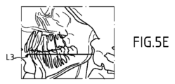
図5Eは、そのような変形実施形態に従って判定され得る水平面L3の位置の例を示す。 FIG. 5E shows an example of the position of the horizontal plane L3 that can be determined according to such variant embodiments.
水平面の高さを判定する2つの他の形が、図4Bに示されている。 Two other ways of determining the height of the horizontal plane are shown in FIG. 4B.
第2の形(ステップS2.3)は、ランドマークを含む患者の顎顔面第1関心領域ROI1を含む患者の少なくとも1つの光学画像(咬合位での)を獲得する準備をする。少なくとも1つの画像は、より具体的には、カメラによって撮影された顔画像であり、ランドマークは、解剖学的タイプ(たとえば口の角)のランドマークまたは患者の顔に追加されたランドマークとすることができる。カメラを、装置10上でたとえば腕22上で、または装置とは独立に位置決めすることができる。図1では、カメラ52の例が、x線源18の隣に配置されている。代替案では、カメラの別の位置を選択することができる。
The second form (step S2.3) prepares to acquire at least one optical image (in occlusion) of the patient including the patient's maxillofacial first region of interest ROI1 containing landmarks. The at least one image is more particularly a facial image captured by the camera, and the landmarks are anatomical type (e.g. corners of the mouth) landmarks or landmarks added to the patient's face. can do. A camera can be positioned on the device 10, for example on the
代替案では、患者の横光学画像が、額画像より便利である場合がある。 Alternatively, a lateral optical image of the patient may be more convenient than the forehead image.
1つまたは複数のランドマークは、既知であるか歯根に対する相対的な計算によって簡単に知ることのできる幾何学的位置の代表である。 The landmark or landmarks are representative of geometric locations that are either known or easily known by calculation relative to the tooth root.
その結果、第1のx線データ獲得に使用され得る歯根および下顎の骨を通過する水平面の高さは、したがって、1つまたは複数のランドマークの位置に基づく計算(ステップS2.2)によって判定され得る。 As a result, the height of the horizontal plane passing through the root and mandibular bone that can be used for the first x-ray data acquisition is therefore determined by calculation (step S2.2) based on the position of one or more landmarks. can be
第3の形(ステップS2.4)は、患者位置決めデバイスまたは患者位置決めアクセサリを使用して、患者の(咬合位での)、より具体的には患者の顎顔面第1関心領域(ROI1)の物理的測定を実行する準備をする。 A third form (step S2.4) is to use a patient positioning device or patient positioning accessory to examine the patient (in occlusion), more specifically the patient's maxillofacial first region of interest (ROI1). Prepare to perform physical measurements.
図1の腕22に取り付けられた患者位置決めアクセサリ、たとえばバイト・ブロックまたは類似物を使用することができる。バイト・ブロックは、固定された位置で腕に取り付けられ、腕に対する相対的なバイト・ブロックの高さは、既知であるか測定され得る。所与の患者(成人、幼児など)の歯の平均サイズ(高さ)も既知であり、これは、歯根の位置、したがって歯の先端すなわちバイト・ブロックに対する相対的な歯根の位置を定めることを可能にする。
A patient positioning accessory attached to
その結果、腕に対する相対的なROI1の水平面の高さまたは位置を、上記に基づく測定および/または計算によって判定することができる。代替案では、バイト・ブロックまたは類似物内に配置されたセンサが、適当な測定データを提供することができ、腕に対する相対的な水平面の高さまたは位置が、次に、それから判定され得る。 As a result, the horizontal height or position of ROI1 relative to the arm can be determined by measurements and/or calculations based on the above. Alternatively, sensors placed in the bite block or the like can provide suitable measurement data, from which the height or position of the horizontal plane relative to the arm can then be determined.
その後、第1のx線データ獲得に使用できる水平面の高さが、判定され得る(ステップS2.2)。 A horizontal plane height that can be used for the first x-ray data acquisition can then be determined (step S2.2).
この以前の判定フェーズは、ROI1に関するデータの第1のセットが獲得される高さの判定を目指すものである。 This previous determination phase aims at determining the height at which the first set of data for ROI1 is obtained.
水平面の高さが判定された後に、装置10は、図3のステップS3によって供給されるデータの第1のセットの獲得を可能にする構成で、制御アセンブリ44によってそれに従ってセットされる。データの第1のセットは、ROI1全体またはその選択された部分に対応することができる。
After the horizontal plane height is determined, apparatus 10 is set accordingly by
-第1に、x線源およびx線センサのセットが、x線源が獲得に適当な高さにあるようにするために判定された高さに移動するように制御アセンブリ44によって指令され、この配置は、x線線量を簡単に減らすことを可能にし、
-第2に、x線源が、同一の高度のままになり、x線コリメータが、平面の判定された高さに向かって上向きにx線ビームを方位付けるように移動される
という2つの形が、装置を獲得構成にセットするのに使用される。
- first, the x-ray source and set of x-ray sensors are commanded by the
- Secondly, the x-ray source remains at the same altitude and the x-ray collimator is moved to orient the x-ray beam upwards towards the determined height of the plane. is used to set the device to the acquisition configuration.
この第1のデータ獲得に関して、患者は、咬合位のままになるか、前のステップS2で提供されるバイト・サポートを咬む。患者は、彼/彼女のカンペル平面またはフランクフルト平面がステップS2に関して水平になるようにも位置決めされ得る。 For this first data acquisition, the patient remains in occlusion or bites on the bite support provided in the previous step S2. The patient may also be positioned so that his/her Camper or Frankfurt plane is horizontal with respect to step S2.
この第1のデータ獲得に関して、装置10は、制御アセンブリ44の制御の下で動作CBCTモードである。
For this first data acquisition, device 10 is in the CBCT mode of operation under control of
このモードによれば、x線コリメータ開口は、水平面を含む患者の顎顔面第1関心領域(ROI1)に焦点を合わされたスリット形状のx線ビームを作るために、スリット形状のコリメータ・ウィンドウとして調整される。x線ビームが、ROI1全体に焦点を合わされるものとして説明されたが、ここおよびこの説明の残りでは、x線ビームがROI1の水平面を含む部分(たとえば、スライス)だけに焦点を合わされ得ることを理解されたい。 According to this mode, the x-ray collimator aperture is adjusted as a slit-shaped collimator window to produce a slit-shaped x-ray beam focused on the first maxillofacial region of interest (ROI1) of the patient, including the horizontal plane. be done. Although the x-ray beam has been described as being focused over the entire ROI1, here and in the remainder of this description it will be appreciated that the x-ray beam can be focused only on portions (eg, slices) of ROI1 that contain horizontal planes. be understood.
ビームのこのスリット形状は、2つの枝を有し高さにおいて薄い体積を有する歯列弓全体を横にカバーするように調整される。ROI1の水平面は、コリメータ位置およびコリメータ・ウィンドウ開口での調整のおかげで狙われる。 This slit shape of the beam is adjusted to laterally cover the entire dental arch with two branches and a thin volume in height. The horizontal plane of ROI1 is aimed thanks to adjustments in the collimator position and collimator window opening.
図6Aは、x線コリメータ19の異なる開口を伴う、x線源18とROI1と(ROI1は、その代わりにその一部によって置換され得、この説明の残りは同等にあてはまる)の間の2つの異なる相対位置を示す。図示されているように、x線源18は、センサ20の下端に整列され、源およびセンサからなるセットの回転軸Aも図示されている。CBCTスライスを取り込み、再構成するために、垂直方向のコリメータの開口は、源-センサ整列に対する相対的なコリメータの位置に依存する。最小の開口は、源-センサ軸がコリメータを通る時に得られる。言い換えると、コリメートされたx線ビームの正中面は、スライス再構成に必要な最小の開口をコリメータに関して入手するように調整される。
FIG. 6A shows two polarizers between
優先的に、源-センサ軸は、コリメータ・ウィンドウの基礎およびROI1の下端または境界を通過する。 Preferentially, the source-sensor axis passes through the base of the collimator window and the bottom edge or boundary of ROI1.
x線源は、後続の第2のx線データ獲得に使用されるx線線量に関して低線量として定量化され得る第1のx線線量を用いて操作される。 The x-ray source is operated with a first x-ray dose that can be quantified as a low dose with respect to the x-ray dose used for subsequent second x-ray data acquisition.
第1のx線線量は、患者のx線露出を最小にするように選択される。x線線量は、獲得されるデータの体積に依存する。体積は、第1のx線データ獲得に関して、できる限り小さく、高分解能である必要はない。というのは、この方法の残りに必要な有用な情報が、患者顎顔面領域の形態学的特性またはデータ(歯の位置、歯の形態、特性寸法など)に存するからである。そのような情報は、獲得されたデータ内の多数の詳細を必要としない。 The first x-ray dose is selected to minimize patient x-ray exposure. The x-ray dose depends on the volume of data acquired. The volume is as small as possible and need not be high resolution for the first x-ray data acquisition. This is because the useful information required for the remainder of the method resides in the morphological characteristics or data of the patient's maxillofacial region (tooth position, tooth morphology, characteristic dimensions, etc.). Such information does not require many details in the acquired data.
通常、第1のx線線量は、後続の第2のデータ獲得に使用される第2の線量の20%を超えない。 Typically, the first x-ray dose does not exceed 20% of the second dose used for subsequent second data acquisition.
優先的に、第1のx線線量は、第2の線量の10%を超えず、より優先的には第2の線量の5%を超えない。 Preferentially, the first x-ray dose does not exceed 10% of the second dose, more preferentially does not exceed 5% of the second dose.
たとえば、第1のx線線量は、CBCTスライスの生成に関して4μSv程度とすることができる。 For example, the first x-ray dose may be on the order of 4 μSv for the production of CBCT slices.
図3に戻って、データの第1のセット(3D体積)を獲得する第3のステップS3は、上記のセッティングおよび調整に基づく。この第1の獲得を、後続の「発射」に使用される有用な情報を抽出するための「事前発射」と見なすことができる。この事前発射の露出時間は、どちらかといえば短く、たとえば5秒程度である。 Returning to FIG. 3, the third step S3 of acquiring the first set of data (3D volume) is based on the above settings and adjustments. This first acquisition can be viewed as a "pre-fire" to extract useful information used in subsequent "fires." The exposure time for this pre-fire is rather short, for example on the order of 5 seconds.
次のステップS4は、従来のCBCTデータ処理技法(たとえば、FDKアルゴリズム)を使用してデータの獲得された第1のセットに基づいてCBCTスライスを再構成する再構成ステップである。 The next step S4 is a reconstruction step that reconstructs the CBCT slices based on the acquired first set of data using conventional CBCT data processing techniques (eg the FDK algorithm).
再構成されたCBCTスライスは、ROI1の水平面を含み、患者の顎顔面第1関心領域(ROI1)に対する相対的なデータの獲得された第1のセットに基づく。 The reconstructed CBCT slice includes the horizontal plane of ROI1 and is based on the acquired first set of data relative to the maxillofacial first region of interest (ROI1) of the patient.
第1の獲得されるデータの低分解能の例として、再構成されたCBCTスライス内の約500μmのボクセル・サイズを入手することができる。たとえば、スライスの厚さまたは高さは、10ボクセルと30ボクセルとの間にあり、これによって、1mmと15mmとの間の範囲に対応する。1mmと5mmとの間の範囲を、優先的に選択することができる。再構成されたCBCTスライスは、円筒の形状をとることができ(別の形状が便利である場合がある)、直径は120mm(小さい頭骨寸法に関する)と160mmとの間にある。そのような寸法は、歯列弓全体の獲得を可能にする。 As an example of low resolution of the first acquired data, a voxel size of about 500 μm in the reconstructed CBCT slice can be obtained. For example, the slice thickness or height is between 10 and 30 voxels, thereby corresponding to a range of between 1 mm and 15 mm. A range between 1 mm and 5 mm can be preferentially selected. The reconstructed CBCT slice can be cylindrical in shape (another shape may be convenient), with a diameter between 120 mm (for small skull sizes) and 160 mm. Such dimensions allow acquisition of the entire dental arch.
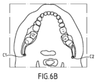
オプションで、この方法は、図6Bに示された再構成された3D体積の軸スライスを表示するさらなる表示ステップS5を含む。図6Bは、歯列弓、具体的には2つの枝および切歯を示す。このステップは、ROI1を見、その後に歯列弓の形状を制御することを可能にする。歯列弓に対して実行された測定に使用された点を見ることもできる。 Optionally, the method includes a further display step S5 of displaying axial slices of the reconstructed 3D volume shown in FIG. 6B. FIG. 6B shows the dental arch, specifically the two branches and the incisors. This step allows viewing ROI1 and subsequently controlling the shape of the dental arch. It is also possible to see the points used for the measurements performed on the dental arch.
次のステップS6は、第2のx線線量を使用する患者の顎顔面第2関心領域(ROI2)のデータの第2のセットの獲得を考慮して、再構成されたCBCTスライスに基づいて、x線イメージング装置の動作パラメータの入手の準備をする。 A next step S6 is based on the reconstructed CBCT slices, considering acquisition of a second set of data of a second maxillofacial region of interest (ROI2) of the patient using a second x-ray dose, Prepare to obtain the operating parameters of the x-ray imaging device.
このステップを、図7Aおよび図7Bのアルゴリズムでさらに詳細に説明する。 This step is explained in more detail in the algorithms of FIGS. 7A and 7B.
図7Aは、再構成されたCBCTスライス、具体的にはそれに固有の情報に基づいて、患者の顎顔面第1関心領域形態に関する特徴を判定するステップS6.1を含む。 FIG. 7A includes a step S6.1 of determining features relating to the maxillofacial first region of interest morphology of the patient based on the reconstructed CBCT slice, specifically information specific thereto.
患者の顎顔面第1関心領域形態に関する特徴は、幅、奥行き、患者の顎顔面第1関心領域の歯列弓の形状、および歯列弓に関する歯の相対位置のうちの少なくとも1つを含む。 The features related to the patient's first maxillofacial region of interest morphology include at least one of width, depth, dental arch shape of the patient's maxillofacial first region of interest, and relative positions of the teeth with respect to the dental arch.
この実施形態では、歯列弓の幅および奥行きは、再構成されたCBCTスライスに基づいて判定される。 In this embodiment, the width and depth of the dental arch are determined based on the reconstructed CBCT slices.
歯列弓の幅および奥行きは、図8A~図8Eに示されているように判定される。 The width and depth of the dental arch are determined as shown in Figures 8A-8E.
図8Aは、図6Bと同様に再構成されたスライスの軸方向ビューを示す。 FIG. 8A shows an axial view of a reconstructed slice similar to FIG. 6B.
図8Bは、データのグレイ値にしきい値を適用することと、脊椎エリアを除去することとによって図8Aから入手される。 FIG. 8B is obtained from FIG. 8A by applying a threshold to the gray values of the data and removing the spine area.
図8Cは、図8Bのしきい値化された画像の左半分を表す。このプロセスは、白画素をその中に有する最初の線を見つけるために画像の最下部から開始し、白画素は、骨の存在に対応する。これは、歯列弓限界のY値に対応する。同一のプロセスが、右半分の画像に対して行われる。 FIG. 8C represents the left half of the thresholded image of FIG. 8B. The process starts at the bottom of the image to find the first line that has white pixels in it, the white pixels corresponding to the presence of bone. This corresponds to the Y value of the arch limit. The same process is performed for the right half image.
その後、検出されたY値の前後の左半分画像の線が考慮される。このプロセスは、白画素をその中に有する最初の列を見つけるために左半分画像の左部分(頭骨の外部)から開始し、白画素は、骨の存在に対応する。これは、図8Dに示されているように、歯列弓限界のX値に対応する。同一のプロセスが、右半分画像に対して行われる。 Then the left half image lines before and after the detected Y value are considered. The process starts from the left portion of the left half image (outside the skull) to find the first row that has white pixels in it, the white pixels corresponding to the presence of bone. This corresponds to the X value of the arch limit, as shown in FIG. 8D. The same process is performed for the right half image.
図8Eは、図6Bおよび図8A内の再構成されたスライスの元の画像上に、2つの別々の円C1およびC2によって示された、検出された限界を示す。 FIG. 8E shows the detected limits indicated by two separate circles C1 and C2 on the original images of the reconstructed slices in FIGS. 6B and 8A.
歯列弓の幅は、それぞれ2つの別々の円C1およびC2によって示された患者の下顎枝の2つの端の間の幅を判定することによって判定され得る。具体的には、ここで関心を持たれている両端は、枝の後端である。別の目的のために、枝の前端が関心を持たれる場合がある。この幅は、メモリ内に記憶された再構成されたスライスから計算によって判定される。 The width of the dental arch can be determined by determining the width between the two ends of the patient's mandibular ramus indicated by two separate circles C1 and C2, respectively. Specifically, the ends of interest here are the trailing ends of the branches. For other purposes, the front ends of branches may be of interest. This width is determined computationally from the reconstructed slices stored in memory.
歯列弓の奥行きは、切歯のY位置と患者の下顎枝の後端のうちの1つのY位置との間での、メモリ内に記憶された再構成されたスライス・データからの計算によって判定される。 The depth of the dental arch is calculated from the reconstructed slice data stored in memory between the Y position of the incisors and the Y position of one of the posterior ends of the mandibular rami of the patient. be judged.
歯列弓に対する相対的な歯の位置は、高い正確さで源-センサ軌跡を入手するのに役立つ可能性がある。これは、たとえば、パノラマ画像の一部がぼけるのを防ぐために、軌跡が歯に垂直でり、したがって、特徴を表される必要がある、パノラマ検査に重要である。ぼけた画像の入手は、完全な全体獲得を必要とするはずであり、これは、患者のx線線量を増やすはずである。 The position of the tooth relative to the dental arch can help obtain the source-sensor trajectory with high accuracy. This is important, for example, for panoramic examinations, where the trajectory must be perpendicular to the teeth and therefore characterized, to prevent blurring of parts of the panoramic image. Obtaining a blurred image would require a complete global acquisition, which would increase the patient's x-ray dose.
図7Aは、上で判定された特徴のうちの少なくとも一部、ここでは患者の歯列弓の幅および奥行きに基づいて患者の体格を判定する第2のステップS6.2を含む。 FIG. 7A includes a second step S6.2 of determining the patient's build based at least in part on the characteristics determined above, here the width and depth of the patient's dental arch.
このステップは、2つの異なるプロセスに従って実行され得る。 This step can be performed according to two different processes.
第1のプロセスS6.2.1では、患者の体格は、幅および奥行きの判定された値を使用して、異なる患者の形態または体格の所定のモデルから判定される。そのようなモデルは、複数の患者に対して実行された複数の測定および経験的データから以前に着想された。 In a first process S6.2.1, the patient's build is determined from predetermined models of different patient morphologies or builds using the determined values of width and depth. Such models were previously conceived from empirical data and multiple measurements performed on multiple patients.
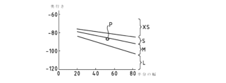
図9Aは、値の連続体ならびに複数の患者の形態または体格を上から下までXS(極小)、S(小)、M(中)、およびL(大)として定義する複数の領域またはエリアを有するそのようなモデルを示す。 FIG. 9A shows a continuum of values and regions or areas defining patient morphology or build from top to bottom as XS (very small), S (small), M (medium), and L (large). We show such a model with
幅(半分の幅)および奥行きの判定された値によって識別される点Pは、図8A~図8Eを参照して判定された弓限界に対応する。ここで、点Pは、M領域内に配置されている。したがって、患者の体格は、中として分類される。 The point P identified by the determined values of width (half width) and depth corresponds to the bow limit determined with reference to FIGS. 8A-8E. Here, the point P is located within the M region. Therefore, the patient's build is classified as medium.
第2の代替のプロセスS6.2.2では、患者の体格は、幅および奥行きの判定された値を使用して、所定の特性のセットから判定される。 In a second alternative process S6.2.2, the patient's build is determined from the predetermined set of properties using the determined values of width and depth.
図7Aは、上で判定された特徴の少なくとも一部、ここでは患者の歯列弓の幅および奥行きに基づいて、患者の歯列弓の形状を判定するさらなるステップS6.3を含む。 FIG. 7A includes a further step S6.3 of determining the shape of the patient's dental arch based at least in part on the characteristics determined above, here the width and depth of the patient's dental arch.
このステップは、2つの異なるプロセスに従って実行され得る。 This step can be performed according to two different processes.
第1のプロセスS6.3.1では、歯列弓形状が、幅および奥行きの判定された値を使用して、異なる患者の形態または歯列弓形状の所定のモデルから判定される。そのようなモデルは、複数の患者に対して実行された複数の測定および経験的データから以前に着想されたものであり、値の連続体を含む。 In a first process S6.3.1, an arch shape is determined from predetermined models of different patient morphologies or arch shapes using the determined values of width and depth. Such models were previously conceived from multiple measurements performed on multiple patients and empirical data, and involve a continuum of values.
歯列弓のモデルの使用が、源-センサ軌跡のより高い正確さにつながる可能性があり、これが、既に上で説明したように、パノラマ画像の一部がぼけるのを防ぐためにパノラマ検査にとって重要であることに留意されたい。 The use of a model of the dental arch can lead to higher accuracy of the source-sensor trajectory, which, as already explained above, is important for panoramic examinations to avoid blurring of parts of the panoramic image. Note that .
第2の代替のプロセスS6.3.2では、患者の歯列弓形状が、幅および奥行きの判定された値を使用して、U形状、V形状、および正方形形状を含む所定の歯列弓のセットから判定される。 In a second alternative process S6.3.2, the patient's arch shape is determined using the determined values of width and depth to determine a predetermined arch shape including U-shape, V-shape and square shape. is determined from the set of
さらなる代替のプロセスでは、歯列弓の形状は、メモリ内に記憶された再構成されたスライス・データから測定される。 In a further alternative process, the shape of the dental arch is measured from reconstructed slice data stored in memory.
ステップS6.2およびS6.3を時間的に逆転でき、ステップS6.3をステップS6.2の前に実行できることに留意されたい。 Note that steps S6.2 and S6.3 can be reversed in time and step S6.3 can be performed before step S6.2.
したがって、4つの体格および3つの歯列弓形状を考慮すると、患者に関して12個の組合せを入手することができる。 Therefore, considering 4 body types and 3 arch shapes, 12 combinations are available for the patient.
各組合せは、使用されるx線線量、x線への露出時間、イメージング・プロセス(パノラマなど)中にx線源およびx線センサによってたどられる軌跡、その他など、使用される適当な動作パラメータによって特徴を表され得る。 Each combination has the appropriate operating parameters to be used, such as the x-ray dose used, the time of exposure to x-ray, the trajectory followed by the x-ray source and x-ray sensor during the imaging process (panorama, etc.), etc. can be characterized by
患者の形態(体格および歯列弓)のこれらの特性が、再構成されたCBCTスライスから判定された後に、動作パラメータを、それに従って入手することができる。 After these characteristics of the patient's morphology (body size and dental arch) have been determined from the reconstructed CBCT slices, operating parameters can be obtained accordingly.
次に、ステップS6.4は、前に判定された特徴または特性に基づく動作パラメータの入手または調整を提供する。 Step S6.4 then provides for obtaining or adjusting operating parameters based on previously determined characteristics or characteristics.
実際には、x線線量にリンクされた以下のパラメータを調整することができる。
-x線源のx線管に現在印加されているピーク電圧(単位:kVp)は、x線光子の最大エネルギを決定し、
-x線管に現在印加されている電流(単位:mA)は、x線管内部の電子の生成をもたらし、電流の増加は、電子のより多くの生成をもたらし、これは、放射の量を増やし、したがってセンサに達する光子の量を増やし、したがってx線密度を高め、
-時間係数(単位:秒)は、x線管内の電子生成密度を表し、したがって、電流密度の印加の持続時間を示す。
In practice, the following parameters linked to x-ray dose can be adjusted.
- the peak voltage (in kVp) currently applied to the x-ray tube of the x-ray source determines the maximum energy of the x-ray photons;
- The current (in mA) currently applied to the x-ray tube results in the production of electrons inside the x-ray tube, and an increase in current results in the production of more electrons, which increases the amount of radiation. increase, thus increasing the amount of photons reaching the sensor and thus increasing the x-ray density,
- The time factor (in seconds) describes the electron production density in the x-ray tube and thus indicates the duration of the current density application.
源-センサ・セットの軌跡を含む他の動作パラメータを調整することもできる。パノラマ検査に関して、軌跡は、上で見たように、ぼけた画像を回避するためにできる限り正確にしなければならない。 Other operating parameters can also be adjusted, including the trajectory of the source-sensor set. For panoramic inspection, the trajectory should be as accurate as possible to avoid blurry images, as seen above.
図9Bは、方法実施形態の実行を介して、具体的には患者の歯列弓に対する相対的な歯の位置に基づいて入手され得る、大きい患者の体格のパノラマ軌跡の例を表す。 FIG. 9B represents an example of a panoramic trajectory of a large patient's body that can be obtained through execution of a method embodiment, specifically based on the position of teeth relative to the patient's dental arch.
歯列弓の形状は、a1とマークされている。 The shape of the dental arch is marked a1.
x線源-x線セグメントの異なる瞬間の異なる連続する位置が、軌跡の半分のみ(軌跡の右部分のみ)に関してa2とマークされている。 Different successive positions at different instants of the x-ray source-x-ray segment are marked a2 for only half of the trajectory (only the right part of the trajectory).
x線源-x線センサ・セットの回転中心の軌跡が、a3とマークされている。 The locus of the center of rotation of the x-ray source-x-ray sensor set is marked a3.
a4およびa5とマークされた2つの曲線は、その間に、軌跡に依存する焦点トラフ(focal trough)の幅または厚さを画定する。 The two curves marked a4 and a5 define between them the trajectory-dependent width or thickness of the focal trough.
a6とマークされた線は、x線源-x線センサ・セットの最も遠い位置を表し、患者の歯列弓のの幅および奥行きに、したがって患者の体格に依存する。したがって、図9Aに示された線は、それぞれ、異なる患者の体格に関する図9Bに示されたa6線に対応する。 The line marked a6 represents the furthest position of the x-ray source-x-ray sensor set and is dependent on the width and depth of the patient's dental arch and thus on the patient's size. Thus, the lines shown in FIG. 9A respectively correspond to the a6 lines shown in FIG. 9B for different patient sizes.
上記のモデルおよび所定の特徴、特性、値、歯列弓形状、その他が、下顎に関して議論されたことに留意されたい。これらは、下顎(本体および枝)上で選択された基準点および水平面の高さに適合される。上記の議論は、上顎にもあてはまる。しかし、モデルおよび所定の特徴、特性、値、歯列弓形状、その他は、上顎に関して異なる。 Note that the above models and certain features, properties, values, arch shapes, etc. were discussed with respect to the mandible. These are fitted to the selected reference point and horizontal plane height on the mandible (body and branch). The above discussion also applies to the maxilla. However, the models and predetermined features, properties, values, arch shapes, etc. differ for the upper jaw.
上記の動作パラメータは、所定の動作パラメータのセットから動作パラメータを選択すること、または動作パラメータの所定のモデルに基づいて動作パラメータを判定することのいずれかによって、簡単に入手され得る。 The above operating parameters can be obtained simply by either selecting the operating parameters from a predetermined set of operating parameters or determining the operating parameters based on a predetermined model of the operating parameters.
この実施形態では、上で説明した方法は、後続のx線データ獲得に使用されるx線線量と比較して、どちらかといえば低いx線線量を用いて、患者に関して獲得されたデータの第1のセットから直接に患者の形態学的特徴または特性を判定することを可能にする。したがって、そのように判定された患者の形態学的特徴または特性は、複数の患者に対して以前に実行された平均測定に基づく平均データより信頼できる、より正確なデータである。その後、この方法は、そのような信頼でき正確な判定された患者の形態学的特徴または特性み基づいて動作パラメータを入手することを可能にする。したがって、入手された/調整されたパラメータは、過去よりも患者に適合され/最適化され、これは、これらのパラメータを使用する後続のx線データ獲得での患者のより高品質な画像およびより低いx線線量につながる。 In this embodiment, the method described above uses a relatively low x-ray dose, compared to the x-ray dose used for subsequent x-ray data acquisition, to obtain the first dose of data acquired on the patient. It makes it possible to determine the patient's morphological features or characteristics directly from one set. Thus, the patient's morphological characteristics or characteristics so determined are more reliable and accurate data than average data based on average measurements previously performed on multiple patients. The method then enables operational parameters to be obtained based on such reliably and accurately determined patient morphological features or characteristics. The obtained/adjusted parameters are therefore better fitted/optimized to the patient than in the past, which translates into higher quality images of the patient on subsequent x-ray data acquisitions using these parameters and more Leads to lower x-ray doses.
さらなる実施形態では、上で説明した方法が、自動的に実行され(すなわち、おそらくはROI1の識別を除く、この方法のすべてのステップが、コンピュータベースまたはプロセッサベースの装置によって実行され)、これは、開業医の対話なしで動作パラメータを入手することを可能にする。したがって、上で述べた利点に加えて、この方法は、人間の誤りをはるかに受けにくく、したがってはるかに信頼できる。 In a further embodiment, the method described above is performed automatically (i.e. all steps of the method, except perhaps the identification of ROI1, are performed by a computer- or processor-based device), which includes Allows operational parameters to be obtained without practitioner interaction. Therefore, in addition to the advantages mentioned above, the method is much less susceptible to human error and therefore much more reliable.
たとえば、x線装置内で入手可能な事前定義の体格および弓の中での患者の体格および歯列弓の選択は、開業医にとって簡単な仕事ではない。この選択を介して誤りが発生する場合には、動作パラメータまたは獲得パラメータが、患者に適合されない可能性がある。その場合に、たとえば、患者が受け取るx線線量が、必要であったはずの線量より相対的に高すぎるか、その代わりに、低すぎ、患者が別のより高いx線線量に露出されることが必要になる可能性がある。 For example, selecting a patient's body size and dental arch among the predefined body sizes and arches available in the x-ray machine is not an easy task for the practitioner. If errors occur through this selection, the operating or acquisition parameters may not be adapted to the patient. In that case, for example, the x-ray dose received by the patient may be relatively too high or, alternatively, too low and the patient exposed to another higher x-ray dose than would have been required. may be required.
これは、開業医によってなされる可能性がある解釈誤りを回避することのできる、開業医にとって単純化された方法を表す。 This represents a simplified method for the practitioner that can avoid possible misinterpretations made by the practitioner.
図7Bは、図3のステップS4の再構成されたCBCTスライスに基づいて、患者の顎顔面関心領域骨密度によるx線減衰に関する特徴の測定を介して動作パラメータを入手する別の実施形態方法を示す。 FIG. 7B illustrates another embodiment method of obtaining operating parameters via feature measurements related to x-ray attenuation by patient's maxillofacial region of interest bone density based on the reconstructed CBCT slices of step S4 of FIG. show.
第1のステップS6.10は、再構成されたCBCTスライスからx線患者の減衰に関する特徴を判定するステップである。 The first step S6.10 is to determine the features of x-ray patient attenuation from the reconstructed CBCT slices.
x線患者の減衰に関する可能な特徴が、コントラスト・ノイズ比(CNR)である。そのような特徴は、照射ゾーン(患者の減衰)および空気を通るx線の伝搬に関して入手されたコントラストのレベルならびに第1のx線線量に関する雑音レベルを考慮に入れたものである。 A possible feature of x-ray patient attenuation is the contrast-to-noise ratio (CNR). Such features take into account the exposure zone (patient attenuation) and the level of contrast obtained with respect to x-ray propagation through air and the noise level with respect to the first x-ray dose.
再構成されたスライスは、照射されたゾーンの厚さを用いることなく、x線センサ上で「患者の減衰」を直接に入手することを可能にする。 The reconstructed slice makes it possible to obtain the "patient attenuation" directly on the x-ray sensor without using the thickness of the irradiated zone.
図10は、x線線量の関数としてCNR値を示す図である。この図は、複数の患者に対して実行された測定に基づいて確立され、所定のCNR値-x線線量のモデルを表す。 FIG. 10 shows CNR values as a function of x-ray dose. This figure was established based on measurements performed on a number of patients and represents a given CNR value-x-ray dose model.
たとえば、第1の低線量1に関して、第1のx線データ獲得および再構成されたスライスを伴う第1のCNTが達成されている(CNR線量1患者A)。原点と達成されたCNRとを通過する直線のうちの1つに従い、獲得される後続画像に関して達成すべきCNR目標を考慮すると、これは、所与のx線線量すなわち患者AのCRN目標に関する線量A(矢印によって与えられる表示を参照されたい)につながる。 For example, for the first low dose 1, the first CNT with the first x-ray data acquisition and reconstructed slice has been achieved (CNR dose 1 patient A). Following one of the straight lines passing through the origin and the achieved CNR, and considering the CNR target to be achieved for subsequent images acquired, this means that for a given x-ray dose, i. A (see representation given by arrow).
したがって、これは、それに従ってx線線量として動作パラメータを入手することを可能にする(ステップS6.11)。 This therefore makes it possible to obtain the operating parameters accordingly as x-ray dose (step S6.11).
上で既に説明したように、x線線量にリンクされた実用的な動作パラメータすなわち、ピーク電圧(単位:kVp)、電流(単位:mA)、および時間係数(単位:秒)を調整することができる。 As already explained above, it is possible to adjust practical operating parameters linked to x-ray dose: peak voltage (in kVp), current (in mA), and time factor (in seconds). can.
源-センサ・セットの軌跡を含む他の動作パラメータを調整することもできる。 Other operating parameters can also be adjusted, including the trajectory of the source-sensor set.
上記の動作パラメータは、所定の動作パラメータのセットから動作パラメータを選択すること、または動作パラメータの所定のモデルに基づいて動作パラメータを判定することのいずれかによって、判定された患者のx線減衰に基づいて簡単に入手され得る。 The above operating parameters are dependent on the x-ray attenuation of the patient determined by either selecting the operating parameters from a set of predetermined operating parameters or determining the operating parameters based on a predetermined model of the operating parameters. can be obtained easily based on
ステップS6(図7A~図7Bの上の説明を参照されたい)で入手された動作パラメータまたは獲得パラメータは、第2のx線線量を使用して患者の顎顔面第2関心領域(ROI2)のデータの第2のセットを獲得する後続ステップS7の過程で使用され得る。この獲得ステップは、たとえば数時間、数日、数ヶ月など、第1のステップS1からS6までから時間的に分離され得る。その場合に、入手された動作パラメータまたは獲得パラメータは、使用されるのを待っている間に記憶され得る。 The operating or acquisition parameters obtained in step S6 (see description above FIGS. 7A-7B) are used to determine the patient's maxillofacial second region of interest (ROI2) using a second x-ray dose. It can be used during the subsequent step S7 of obtaining the second set of data. This acquisition step may be temporally separated from the first steps S1 to S6, eg hours, days, months. In that case, the obtained operational or acquisition parameters can be stored while waiting to be used.
患者が第1のデータ獲得に関するものと同一の位置を占める必要がないことに留意されたい。しかし、単純さのために、患者は同一位置に留まる。パノラマ検査に関して、同一の患者の位置が使用されることが好ましい。 Note that the patient need not occupy the same position as for the first data acquisition. However, for simplicity, the patient remains in the same position. Preferably, the same patient position is used for the panoramic examination.
入手された動作パラメータまたは獲得パラメータを使用して、CBCT、パノラマ、頭蓋計測、その他、患者に関連するデータの獲得を考慮してx線イメージング装置(必ずしも装置10ではない)を調整することができる。 The obtained operating or acquisition parameters can be used to calibrate the x-ray imaging device (not necessarily device 10) for acquisition of CBCT, panoramic, cephalometric, or other patient-related data. .
この第2のデータ獲得に使用されるx線線量は、スライスの生成に関する第1のx線線量より高く、第1のx線線量は、第2のx線線量の20%以下である。 The x-ray dose used for this second data acquisition is higher than the first x-ray dose for slice generation, the first x-ray dose being 20% or less than the second x-ray dose.
たとえば、第1のx線線量は、4μSvであり、第2のx線線量は、
-パノラマ検査では20μSvと30μSvとの間、
-広い視野(17×13cm)の3D検査では200μSv、
-5×5cm視野の3D検査では20μSv
である。
For example, the first x-ray dose is 4 μSv and the second x-ray dose is
- between 20 and 30 μSv for panoramic examinations,
- 200 μSv for 3D inspection with a wide field of view (17 x 13 cm),
-20 μSv for 3D inspection with a 5×5 cm field of view
is.
たとえば、第2のデータ獲得のx線の露出の持続時間は、第1のデータ獲得の約5秒持続時間と比較して、
-パノラマ検査では10秒と20秒との間、
-3D検査では5秒と20秒との間
である。
For example, the duration of the x-ray exposure of the second data acquisition compared to about 5 seconds duration of the first data acquisition is:
- between 10 and 20 seconds for panoramic examinations,
- Between 5 and 20 seconds for 3D examinations.
たとえば、第2のデータ獲得を介して入手される画像(1つまたは複数)の解像度は、第1のデータ獲得の500μmボクセル・サイズと比較して、
-パノラマ検査では100μm画素サイズ
-3D検査では100μmボクセル・サイズ
によって画定される。
For example, the resolution of the image(s) obtained via the second data acquisition is:
- 100 μm pixel size for panoramic inspection; - 100 μm voxel size for 3D inspection.
本発明が、詳細に説明され、適切なまたは現在好ましい実施形態を具体的に参照して説明された場合があるが、本発明の趣旨および範囲内で変形形態および修正形態をもたらすことができることを理解されたい。したがって、現在開示されている実施形態は、すべての面で、例示的であって制限的ではないと考えられる。本発明の範囲は、添付の特許請求の範囲によって示され、その同等物の意味および範囲に含まれるすべての変更は、添付の特許請求の範囲に包含されることが意図されている。 Although the present invention has been described in detail and may have been described with specific reference to suitable or presently preferred embodiments, it is understood that variations and modifications can be effected within the spirit and scope of the invention. be understood. Accordingly, the presently disclosed embodiments are considered in all respects to be illustrative and not restrictive. The scope of the invention is indicated by the appended claims and all changes that come within the meaning and range of equivalency thereof are intended to be embraced therein.
Claims (13)
-患者の顎顔面第1関心領域(ROI1)を識別するステップ;、
-前記患者が咬合位置にあるか、患者位置決めアクセサリを咬む時に、前記患者の顎顔面第1関心領域(ROI1)の水平面の高さを判定する、事前判定フェーズのステップであって、前記水平面は、歯および顎の骨を通過する、ステップ; -前記患者の顎顔面第1関心領域(ROI1)の水平面の高さを判定した場合に、x線CBCTイメージングおよび第1のx線線量を使用して、スリット形状のコリメータ・ウィンドウを介して、前記水平面を含む前記患者の顎顔面第1関心領域(ROI1)に対する相対的なデータの第1のセットを獲得するステップであって、データの前記第1のセットは、CBCTスライスを生成するのに適する、ステップ;
-前記患者の顎顔面第1関心領域(ROI1)に対する相対的なデータの前記第1のセットに基づいて前記水平面を含む前記CBCTスライスを再構成するステップ;
-第2のx線線量を使用する患者の顎顔面第2関心領域(ROI2)のデータの第2のセットの獲得を考慮して、前記再構成されたCBCTスライスに基づいてx線イメージング装置の動作パラメータを入手するステップであって、当該ステップは、前記再構成されたCBCTスライス上の前記患者の顎顔面第1領域骨密度によるx線減衰の測定に基づいて、前記x線源のx線線量を調整するステップを含み、前記第1のx線線量は、前記第2のx線線量の20%を超えない、ステップ、
を含む方法。 A method of obtaining operating parameters for x-ray imaging of a maxillofacial region of a patient, said method comprising:
- identifying the first maxillofacial region of interest (ROI1) of the patient;
- a step of a pre-determining phase of determining the height of a horizontal plane of a first maxillofacial region of interest (ROI1) of said patient when said patient is in an occlusal position or bites a patient positioning accessory, said horizontal plane being , passing through the teeth and jaw bone; - using x-ray CBCT imaging and a first x-ray dose when determining the level of a horizontal plane of a maxillofacial first region of interest (ROI1) of said patient; acquiring a first set of data relative to a first maxillofacial region of interest (ROI1) of said patient comprising said horizontal plane through a slit-shaped collimator window, said first set of data comprising: A set of 1 is suitable for generating CBCT slices, step;
- reconstructing said CBCT slice comprising said horizontal plane based on said first set of data relative to said first maxillofacial region of interest (ROI1) of said patient;
- of the x-ray imaging device on the basis of said reconstructed CBCT slices, considering acquisition of a second set of data of a second maxillofacial region of interest (ROI2) of the patient using a second x-ray dose; obtaining operating parameters based on measurements of x-ray attenuation due to maxillofacial first region bone density of the patient on the reconstructed CBCT slice; adjusting the dose, wherein the first x-ray dose does not exceed 20% of the second x-ray dose;
method including.
-前記患者の顎顔面第1関心領域(ROI1)を含む横x線スカウト・ビューを獲得するステップ;
-ランドマークを含む前記患者の顎顔面第1関心領域(ROI1)を含む光学画像を獲得するステップ;
-患者位置決めデバイスを使用して前記患者の顎顔面第1関心領域(ROI1)に対する物理測定を実行するステップ、
のうちの1つを含む、請求項1に記載の方法。 The step of determining the height of the horizontal plane of the patient includes, in advance,
- acquiring a lateral x-ray scout view including the first maxillofacial region of interest (ROI1) of said patient;
- acquiring an optical image containing a first maxillofacial region of interest (ROI1) of said patient containing landmarks;
- performing physical measurements on said patient's first maxillofacial region of interest (ROI1) using a patient positioning device;
2. The method of claim 1, comprising one of:
-動作パラメータの所定のセットを選択するステップ、
-所定のモデルに基づいて動作パラメータを判定するステップ
のうちの1つを含む、請求項1から10のいずれか1項に記載の方法。 The step of obtaining operating parameters of the x-ray imaging device comprises:
- selecting a predetermined set of operating parameters;
- determining operating parameters based on a predetermined model.
-患者が咬合位置にあるか患者位置決めアクセサリを咬む時に前記患者の顎顔面第1関心領域に対する相対的なデータの第1のセットを獲得するために、第1のx線線量から形成されるスリット形状のx線ビームを用いて前記患者の顎顔面第1関心領域を照射する間に前記患者の顎顔面第1関心領域の周囲を移動するように構成されたx線源および少なくとも1つのx線センサであって、前記患者の顎顔面第1関心領域は、歯および顎の骨を通過する水平面を含み、データの前記第1のセットは、CBCTスライスを生成するのに適する、x線源および少なくとも1つのx線センサと、
-前記患者の顎顔面第1関心領域に対する相対的なデータの前記第1のセットに基づいて前記水平面を含む前記CBCTスライスを再構成し、
第2のx線線量を使用する前記患者の顎顔面第2領域のデータの第2のセットの獲得を考慮して、前記再構成されたCBCTスライスに基づいて、x線イメージング装置の動作パラメータを入手し、前記再構成されたCBCTスライス上の前記患者の顎顔面第1領域骨密度によるx線減衰の測定に基づいて、前記x線源のx線線量を調整し、前記第1のx線線量は、前記第2のx線線量の20%を超えない
ように構成されたマイクロプロセッサと
を備えるシステム。 An x-ray CBCT (Cone Beam Computed Tomography) imaging system for obtaining operating parameters for x-ray imaging of a maxillofacial region of a patient, comprising:
- a slit formed from a first x-ray dose to acquire a first set of data relative to a maxillofacial first region of interest of said patient when the patient is in an occlusal position or bites on a patient positioning accessory; An x-ray source and at least one x-ray configured to move around a first maxillofacial region of interest of the patient while irradiating the first maxillofacial region of interest of the patient with a shaped x-ray beam. a sensor, wherein the patient's maxillofacial first region of interest comprises a horizontal plane passing through the teeth and jawbone, and the first set of data is suitable for generating a CBCT slice; at least one x-ray sensor;
- reconstructing said CBCT slice comprising said horizontal plane based on said first set of data relative to said first maxillofacial region of interest of said patient;
considering acquisition of a second set of data of a second maxillofacial region of said patient using a second x-ray dose, operating parameters of an x-ray imaging device based on said reconstructed CBCT slices; adjusting the x-ray dose of the x-ray source based on a measurement of x-ray attenuation due to maxillofacial first region bone density of the patient on the reconstructed CBCT slice; a microprocessor configured such that the dose does not exceed 20% of the second x-ray dose.
Applications Claiming Priority (3)
| Application Number | Priority Date | Filing Date | Title |
|---|---|---|---|
| EP17306307.4A EP3461418B1 (en) | 2017-09-29 | 2017-09-29 | A method and a system for obtaining operating parameters for x ray data acquisition |
| EP17306307.4 | 2017-09-29 | ||
| PCT/EP2018/076173 WO2019063640A1 (en) | 2017-09-29 | 2018-09-26 | A method and a system for obtaining operating parameters for x ray data acquisition |
Publications (3)
| Publication Number | Publication Date |
|---|---|
| JP2020534970A JP2020534970A (en) | 2020-12-03 |
| JP2020534970A5 JP2020534970A5 (en) | 2021-11-04 |
| JP7334149B2 true JP7334149B2 (en) | 2023-08-28 |
Family
ID=60080730
Family Applications (1)
| Application Number | Title | Priority Date | Filing Date |
|---|---|---|---|
| JP2020518543A Active JP7334149B2 (en) | 2017-09-29 | 2018-09-26 | Method and system for obtaining operating parameters for x-ray data acquisition |
Country Status (6)
| Country | Link |
|---|---|
| US (2) | US20200261038A1 (en) |
| EP (1) | EP3461418B1 (en) |
| JP (1) | JP7334149B2 (en) |
| KR (1) | KR20200100039A (en) |
| ES (1) | ES2934233T3 (en) |
| WO (1) | WO2019063640A1 (en) |
Families Citing this family (4)
| Publication number | Priority date | Publication date | Assignee | Title |
|---|---|---|---|---|
| KR102292080B1 (en) * | 2019-11-07 | 2021-08-20 | 부산대학교 산학협력단 | Individualized Dental Panorama System using Arch Shape and Method for Controlling the same |
| JP7222947B2 (en) * | 2020-04-01 | 2023-02-15 | 株式会社モリタ製作所 | X-ray imaging device and X-ray imaging method |
| WO2021230114A1 (en) * | 2020-05-15 | 2021-11-18 | キヤノン株式会社 | Radiation imaging system, imaging control device, radiation imaging device, radiation imaging method, and program |
| CN116019474B (en) * | 2023-02-22 | 2023-09-19 | 有方(合肥)医疗科技有限公司 | Multi-source imaging device and method |
Citations (2)
| Publication number | Priority date | Publication date | Assignee | Title |
|---|---|---|---|---|
| WO2009133937A1 (en) | 2008-05-01 | 2009-11-05 | 株式会社モリタ製作所 | Medical x-ray ct imaging apparatus, medical x-ray ct image display apparatus, and display method thereof |
| JP2013135765A (en) | 2011-12-28 | 2013-07-11 | Nihon Univ | X-ray ct imaging apparatus, and x-ray ct imaging method |
Family Cites Families (6)
| Publication number | Priority date | Publication date | Assignee | Title |
|---|---|---|---|---|
| JP3331274B2 (en) * | 1995-03-06 | 2002-10-07 | 株式会社モリタ製作所 | Medical X-ray equipment |
| US7787586B2 (en) * | 2007-02-22 | 2010-08-31 | J. Morita Manufacturing Corporation | Display method of X-ray CT image of maxillofacial area, X-ray CT apparatus and X-ray image display apparatus |
| US10231681B2 (en) * | 2013-12-02 | 2019-03-19 | Cefla Societá Cooperativa | Method and apparatus for adjusting technical exposure factors during radiographic acquisition |
| JP2015177963A (en) * | 2014-02-27 | 2015-10-08 | 株式会社テレシステムズ | X-ray imaging apparatus and teaching apparatus |
| US10278666B2 (en) * | 2014-06-13 | 2019-05-07 | Palodex Group Oy | Systems and methods of automated dose control in x-ray imaging |
| JP6780948B2 (en) * | 2016-03-28 | 2020-11-04 | キヤノンメディカルシステムズ株式会社 | X-ray CT device |
-
2017
- 2017-09-29 EP EP17306307.4A patent/EP3461418B1/en active Active
- 2017-09-29 ES ES17306307T patent/ES2934233T3/en active Active
-
2018
- 2018-09-26 US US16/652,030 patent/US20200261038A1/en not_active Abandoned
- 2018-09-26 WO PCT/EP2018/076173 patent/WO2019063640A1/en active Application Filing
- 2018-09-26 JP JP2020518543A patent/JP7334149B2/en active Active
- 2018-09-26 KR KR1020207012518A patent/KR20200100039A/en unknown
-
2022
- 2022-02-04 US US17/592,825 patent/US11793476B2/en active Active
Patent Citations (2)
| Publication number | Priority date | Publication date | Assignee | Title |
|---|---|---|---|---|
| WO2009133937A1 (en) | 2008-05-01 | 2009-11-05 | 株式会社モリタ製作所 | Medical x-ray ct imaging apparatus, medical x-ray ct image display apparatus, and display method thereof |
| JP2013135765A (en) | 2011-12-28 | 2013-07-11 | Nihon Univ | X-ray ct imaging apparatus, and x-ray ct imaging method |
Also Published As
| Publication number | Publication date |
|---|---|
| KR20200100039A (en) | 2020-08-25 |
| EP3461418B1 (en) | 2022-11-30 |
| EP3461418A1 (en) | 2019-04-03 |
| US20200261038A1 (en) | 2020-08-20 |
| WO2019063640A1 (en) | 2019-04-04 |
| US11793476B2 (en) | 2023-10-24 |
| US20220361830A1 (en) | 2022-11-17 |
| JP2020534970A (en) | 2020-12-03 |
| ES2934233T3 (en) | 2023-02-20 |
Similar Documents
| Publication | Publication Date | Title |
|---|---|---|
| JP7334149B2 (en) | Method and system for obtaining operating parameters for x-ray data acquisition | |
| JP6297504B2 (en) | Apparatus and method for digital radiography | |
| JP6370297B2 (en) | Device for partial CT imaging | |
| JP5878121B2 (en) | X-ray tomography system | |
| US11051771B2 (en) | Stationary intraoral tomosynthesis imaging systems, methods, and computer readable media for three dimensional dental imaging | |
| JP5878117B2 (en) | Radiation imaging apparatus and phantom used in the apparatus | |
| CN109803586B (en) | Static intraoral analytical synthetic imaging system, method and computer readable medium for three-dimensional dental imaging | |
| EP2975578A2 (en) | System and method of artifact correction in 3d imaging | |
| JP6925779B2 (en) | Small irradiation field X-ray imaging system and method | |
| US11793475B2 (en) | Method and system for obtaining operating parameters for 3D x ray acquisition | |
| EP2123223A1 (en) | Method and Apparatus for Simplified Patient Positioning in Dental Tomographic X-Ray Imaging | |
| US20080232539A1 (en) | Method for the reconstruction of a panoramic image of an object, and a computed tomography scanner implementing said method | |
| JP2014138911A (en) | X-ray ct photographing apparatus and method for displaying x-ray ct image | |
| JP2003230556A (en) | X-ray diagnostic equipment | |
| KR102203610B1 (en) | Method and Apparatus for generating panoramic image, computer-readable recording medium | |
| Kharbanda et al. | Functional and technical characteristics of different cone beam computed tomography units | |
| Niu et al. | Conebeam CT for Medical Imaging and Image-Guided Interventions |
Legal Events
| Date | Code | Title | Description |
|---|---|---|---|
| A521 | Request for written amendment filed |
Free format text: JAPANESE INTERMEDIATE CODE: A523 Effective date: 20210921 |
|
| A621 | Written request for application examination |
Free format text: JAPANESE INTERMEDIATE CODE: A621 Effective date: 20210921 |
|
| A977 | Report on retrieval |
Free format text: JAPANESE INTERMEDIATE CODE: A971007 Effective date: 20220824 |
|
| A131 | Notification of reasons for refusal |
Free format text: JAPANESE INTERMEDIATE CODE: A131 Effective date: 20220830 |
|
| A601 | Written request for extension of time |
Free format text: JAPANESE INTERMEDIATE CODE: A601 Effective date: 20221129 |
|
| A521 | Request for written amendment filed |
Free format text: JAPANESE INTERMEDIATE CODE: A523 Effective date: 20230127 |
|
| A131 | Notification of reasons for refusal |
Free format text: JAPANESE INTERMEDIATE CODE: A131 Effective date: 20230214 |
|
| A601 | Written request for extension of time |
Free format text: JAPANESE INTERMEDIATE CODE: A601 Effective date: 20230511 |
|
| A521 | Request for written amendment filed |
Free format text: JAPANESE INTERMEDIATE CODE: A523 Effective date: 20230711 |
|
| TRDD | Decision of grant or rejection written | ||
| A01 | Written decision to grant a patent or to grant a registration (utility model) |
Free format text: JAPANESE INTERMEDIATE CODE: A01 Effective date: 20230725 |
|
| A61 | First payment of annual fees (during grant procedure) |
Free format text: JAPANESE INTERMEDIATE CODE: A61 Effective date: 20230816 |
|
| R150 | Certificate of patent or registration of utility model |
Ref document number: 7334149 Country of ref document: JP Free format text: JAPANESE INTERMEDIATE CODE: R150 |