JP7332904B2 - pachinko machine - Google Patents
pachinko machine Download PDFInfo
- Publication number
- JP7332904B2 JP7332904B2 JP2020188387A JP2020188387A JP7332904B2 JP 7332904 B2 JP7332904 B2 JP 7332904B2 JP 2020188387 A JP2020188387 A JP 2020188387A JP 2020188387 A JP2020188387 A JP 2020188387A JP 7332904 B2 JP7332904 B2 JP 7332904B2
- Authority
- JP
- Japan
- Prior art keywords
- game
- display
- symbol
- main
- main game
- Prior art date
- Legal status (The legal status is an assumption and is not a legal conclusion. Google has not performed a legal analysis and makes no representation as to the accuracy of the status listed.)
- Active
Links
Images


Classifications
-
- Y—GENERAL TAGGING OF NEW TECHNOLOGICAL DEVELOPMENTS; GENERAL TAGGING OF CROSS-SECTIONAL TECHNOLOGIES SPANNING OVER SEVERAL SECTIONS OF THE IPC; TECHNICAL SUBJECTS COVERED BY FORMER USPC CROSS-REFERENCE ART COLLECTIONS [XRACs] AND DIGESTS
- Y02—TECHNOLOGIES OR APPLICATIONS FOR MITIGATION OR ADAPTATION AGAINST CLIMATE CHANGE
- Y02E—REDUCTION OF GREENHOUSE GAS [GHG] EMISSIONS, RELATED TO ENERGY GENERATION, TRANSMISSION OR DISTRIBUTION
- Y02E60/00—Enabling technologies; Technologies with a potential or indirect contribution to GHG emissions mitigation
- Y02E60/10—Energy storage using batteries
Description
ぱちんこ遊技機に関する。 It relates to a pachinko game machine.
近年のぱちんこ遊技機としては、遊技盤面(遊技領域)上の始動口に遊技球が入球したことを契機として所定確率の大当り抽選がなされ、当該大当り抽選に当選した場合には大当り(特別遊技)状態へと移行し、遊技盤面に備えられた大入賞口が開放して大量の賞球を獲得できるぱちんこ遊技機が主流である。このように構成されたぱちんこ遊技機の内には、当該大当り抽選における当選確率を上昇させる確率変動遊技状態や当該大当り抽選における抽選結果を報知するための図柄変動の効率を上昇させる時間短縮遊技状態等を備え、これら遊技状態によって遊技者にとって有利な遊技進行状態を創り出すことで遊技の興趣性を高める遊技機も存在している。また、遊技機に不具合が生じることで、遊技場の管理者にとっても遊技者にとっても不利益が生じるおそれがあった。 As a recent pachinko game machine, a jackpot lottery with a predetermined probability is triggered when a game ball enters the starting hole on the game board (game area), and if you win the jackpot lottery, you win a big hit (special game ) state, and a large winning opening provided on the game board can be opened to win a large number of prize balls. Among the pachinko gaming machines constructed in this way, there are a probability variable game state for increasing the probability of winning in the big win lottery and a time shortening game state for increasing the efficiency of pattern variation for notifying the lottery result in the big win lottery. There is also a gaming machine which has such a game state and creates a game progress state that is advantageous for the player, thereby enhancing the interest of the game. In addition, there is a possibility that a malfunction of the gaming machine may cause disadvantages for both the manager of the gaming facility and the players.
円滑に遊技を進行できるぱちんこ遊技機の提供が望まれている。 It is desired to provide a pachinko game machine that allows smooth progress of games.
本態様に係る遊技機は、
遊技球が流下可能な遊技領域が設けられた遊技盤と、
遊技領域に向けて遊技球を発射する発射手段と、
発射手段によって発射された遊技球を遊技領域に案内する案内レールと、
案内レールの出口近傍に設けられ、遊技領域に流入した遊技球が案内レール内に戻ることを防止する防止片と、
遊技盤の所定位置に設けられ、遊技球が入球可能な主遊技始動口と、
主遊技始動口に入球した遊技球を検出可能な遊技球検出装置と、
基体部と、
基体部に取り付けられており、開閉可能な扉部と
を備え、
基体部は、基体部の前面であって正面視にて扉部の上面よりも高い領域である段差部を有しており、
前記段差部に接するように載置された遊技球は、正面視にて手前側に転動しないよう構成されており、
発射手段によって遊技球が発射され、遊技球が案内レールに沿って移動している状況にて遊技機への電源供給が遮断され、遊技球が案内レールに沿って移動している状況にて電源供給が再開され、前記発射された遊技球が防止片を通過してから主遊技始動口を介して遊技球検出装置を通過する場合、電源供給が再開されてから遊技球検出装置によって遊技球の検出が可能となるまでの時間が、前記発射された遊技球が防止片を通過してから主遊技始動口を介して遊技球検出装置を通過するまでの時間よりも長時間であるよう構成されている
ことを特徴とする遊技機である。
<付記>
尚、本態様とは異なる別態様について以下に列記しておくが、これらには何ら限定されることなく実施することが可能である。
本別態様に係る遊技機は、
画像を表示可能な演出表示部と、
動作可能な演出用可動物と
を備え、
演出用可動物が所定の動作を実行する場合、演出表示部の前方に位置するタイミングを有しており、
演出用可動物は、
正面から視認可能な表側表面部と、
正面から視認不可能な裏側表面部と
を有し、
演出表示部は、複数の画素を有しており、
演出表示部の画素は、赤色に対応したRと、緑色に対応したGと、青色に対応したBとのそれぞれを0~255の256段階の階調で表したRGB階調値に基づいた表示色にて表示可能であり、
遊技進行に関する状態として、遊技が進行している状態である遊技中状態と、遊技が進行していない状態である待機中状態と、を少なくとも有しており、
待機中状態では、所定の待機演出を演出表示部に表示し得るよう構成されており、
前記所定の待機演出の表示中における所定のタイミングでは、演出表示部のすべての画素のRGB階調値において、Rの値が1以上でありGの値が1以上でありBの値が1以上であるよう構成されており、
演出表示部の画素のRGB階調値において、Rの値が0でありGの値が0でありBの値が0である表示色と、裏側表示部の色のうち最も広い面積を占める色とは同系統の色である
ことを特徴とする遊技機である。
The game machine according to this aspect is
a game board provided with a game area in which game balls can flow down;
a shooting means for shooting game balls toward the game area;
a guide rail for guiding the game ball shot by the shooting means to the game area;
a prevention piece provided near the exit of the guide rail for preventing the game ball that has flowed into the game area from returning into the guide rail;
A main game start opening provided at a predetermined position of the game board and into which a game ball can enter;
A game ball detection device capable of detecting a game ball that has entered the main game start opening;
a base portion;
It is attached to the base part and has a door part that can be opened and closed,
The base portion has a stepped portion which is a front surface of the base portion and is a region higher than the upper surface of the door portion when viewed from the front,
The game ball placed so as to be in contact with the stepped portion is configured so as not to roll forward when viewed from the front,
The power supply to the gaming machine is interrupted when the game ball is shot by the shooting means and the game ball is moving along the guide rail, and the power is turned off when the game ball is moving along the guide rail. When the supply is resumed and the fired game ball passes through the prevention piece and then passes through the game ball detection device via the main game start port, the game ball is detected by the game ball detection device after the power supply is restarted. The time until detection becomes possible is longer than the time from when the launched game ball passes through the prevention piece to when it passes through the game ball detection device via the main game start port. The game machine is characterized in that
<Appendix>
Other aspects different from this aspect will be listed below, but the present invention can be implemented without being limited to these.
The game machine according to this alternative aspect is
a performance display section capable of displaying an image;
Equipped with an operable production movable object,
When the production movable object executes a predetermined action, it has a timing to be positioned in front of the production display unit,
The movable object for production is
A front surface portion that is visible from the front,
and a back surface part that is invisible from the front,
The effect display unit has a plurality of pixels,
The pixels of the effect display portion are displayed based on RGB gradation values in which each of R corresponding to red, G corresponding to green, and B corresponding to blue is expressed in 256 levels of gradation from 0 to 255. can be displayed in color,
As states related to game progress, at least a playing state in which the game is in progress and a waiting state in which the game is not in progress,
In the standby state, it is configured so that a predetermined standby effect can be displayed on the effect display unit,
At a predetermined timing during display of the predetermined standby effect, the value of R is 1 or more, the value of G is 1 or more, and the value of B is 1 or more in the RGB gradation values of all pixels of the effect display portion. is configured to be
A display color with an R value of 0, a G value of 0, and a B value of 0 in the RGB gradation values of the pixels of the effect display area, and the color occupying the largest area among the colors of the reverse display area. is a game machine characterized by having the same color.
本態様に係るぱちんこ遊技機によれば、円滑に遊技を進行できる遊技機を提供することができる、という効果を奏する。 According to the pachinko game machine according to this aspect, it is possible to provide a game machine that allows the game to proceed smoothly.
はじめに、本明細書における各用語の意義について説明する。「入球」とは、賞球が払い出される入賞のみならず、賞球払い出しの無いゲートへの通過も含む。「開状態、開放状態」及び「閉状態、閉鎖状態」とは、例えば、一般的な大入賞口(いわゆる、アタッカー)の構成においては、開状態(大入賞口の蓋が開いている状態)=入賞容易状態であり、閉状態(大入賞口の蓋が閉まっている状態)=入賞非容易状態となる。また、例えば、遊技盤(遊技者側)から蓋(シャッタ)が突き出した状態(以下、進出状態と呼ぶことがある)と遊技盤内(遊技者側と反対側)に引っ込んだ状態(以下、退避状態と呼ぶことがある)とを採り得る構成(いわゆる、ベロ型アタッカー)においては、進出状態=入賞容易状態であり、退避状態=入賞非容易状態となる。「乱数」とは、ぱちんこ遊技機において何らかの遊技内容を決定するための抽選(電子計算機によるくじ)に使用される乱数であり、狭義の乱数の他に擬似乱数も含む(例えば、乱数としてはハード乱数、擬似乱数としてはソフト乱数)。例えば、遊技の結果に影響を与えるいわゆる「基本乱数」、具体的には、特別遊技の移行と関連した「当選乱数(当否抽選用乱数)」、識別情報の変動態様(又は変動時間)を決定するための「変動態様決定乱数」、停止図柄を決定する「図柄決定乱数」、特別遊技後に特定遊技(例えば確率変動遊技)に移行するか否かを決定する「当り図柄決定乱数」等を挙げることができる。尚、変動態様の内容や確定識別情報の内容等を決定する際、これらすべての乱数を使用する必要はなく、互いに同一又は相違する、少なくとも一つの乱数を使用すればよい。また、本明細書では、乱数の数とか複数個の乱数、といった形で乱数を個数表示していることがあるが、乱数取得の契機となる入球口(例えば始動口やゲート、一般入賞口)の一回の入球により取得された乱数を一個と称している(即ち、前記の例だと、当選乱数+変動態様決定乱数+図柄決定乱数・・・という乱数の束を一個の乱数と称している)。また、例えば、一種の乱数(例えば当選乱数)が、別種の乱数(例えば図柄決定乱数)を兼ねていてもよい。「遊技状態」とは、例えば、大入賞口が開放状態となり得る特別遊技状態、特別遊技状態への移行抽選確率が予め定められた値である非確率変動遊技状態(低確率状態)よりも特別遊技状態への移行抽選確率が高い確率変動遊技状態(高確率状態)、特別遊技への移行抽選契機となる始動口への入賞に対する補助が有る補助遊技状態(いわゆる、高ベース状態、例えば、始動口に可変部材が取り付けられている場合では、可変部材の開放期間を長くする、可変部材の開放当選確率を高くする、可変部材の開放抽選の結果報知の時間を短くすることが可能な状態であり、これらすべてを有効とする状態又は少なくとも1つを有効とする状態)、特別遊技への移行抽選契機となる始動口への入賞に対する補助が無い非補助遊技状態(低ベース状態)等の任意の一又は複数の組合せである。「変動表示停止時間」とは、識別情報の変動表示が停止した際に識別情報を停止した状態で保持する時間であり、変動表示の停止後に保留が残っている場合、この変動表示停止時間が経過した後に、残っている保留に係る変動が開始される(変動開始条件、当否判定許可条件が充足される)。また、本明細書においては「識別情報」を、主遊技図柄(特別図柄)や装飾図柄(演出用図柄、装図)と呼ぶことがある。主遊技図柄(特別図柄)は、主制御基板側にて表示制御される識別情報であり、装飾図柄(演出用図柄、装図)は、副制御基板側にて表示される演出としての識別情報である。「識別情報を表示可能」とは、表示方法には何ら限定されず、例えば、発光手段(例えば液晶、LED、7セグ)の発光(発光の有無だけでなく、色の違いも含む)、物理的な表示(例えば、リール帯に描かれた図柄を所定位置に停止表示する)等、を挙げることができる。「演出」とは、遊技の興趣性を高める表示内容を指し、例えば、識別情報の変動・停止や予告等をはじめ、アニメーションや実写等の動画像や絵、写真、文字等の静止画像又はこれらの組み合わせを挙げることができる。そして、「装飾図柄」は、五感(視覚、聴覚、触覚等)を通じて図柄の種類を識別可能であればどのような形態でもよいが、好適には、カード型やキャラクタ型等の画像オブジェクトに、視覚的なもの、例えば、数字(漢数字含む)、アルファベット、文字、記号、絵柄、図柄等の形状のあるものが記載されているものである。そして、この数字や記号が同一となる組み合わせにて当該画像オブジェクトを有効ライン上にて最終的に停止表示することで大当りが発生した旨が報知される。「第1装飾図柄(第一演出用図柄)」及び「第2装飾図柄(第二演出用図柄)」とは、その双方が「装飾図柄(演出用図柄、装図)」となるものであるが、夫々が独立して大当りの発生を報知可能に構成されているものが相当する(例えば、「第1装飾図柄(第一演出用図柄)」が「777」となって大当りの発生を報知可能でもあるし、「第2装飾図柄(第二演出用図柄)」が「777」となって大当りの発生を報知可能でもある)。「変動態様」とは、例えば、変動時間(主遊技図柄(特別図柄)の変動時間、装飾図柄(演出用図柄、装図)の変動時間、普通図柄の変動時間のいずれも含む)、装飾図柄(演出用図柄、装図)が上から下へスクロール表示(その他、下から上へ、左から右へ、右から左へのスクロール表示なども可能である)して遊技者が視認できる装飾図柄(演出用図柄、装図)の種類を切り替えること、装飾図柄(演出用図柄、装図)がその場で回転表示し半回転又は1回転することで遊技者が視認できる装飾図柄(演出用図柄、装図)の種類を切り替えること(このようなスクロール表示や回転表示などは「切替表示態様」と称することもある)等を含む。「装飾図柄(演出用図柄、装図)を暫定的に停止(或いは仮停止)する/しない」とは、「暫定的に停止させる→再変動させる」を1セットとし、この1セットを行う/行わないということと同義である。「再変動」とは、「装飾図柄(演出用図柄、装図)を暫定的に停止させる→再変動させる」といった状況、「変動開始→装飾図柄(演出用図柄、装図)を暫定的に停止させる」といった状況、「再変動開始→装飾図柄(演出用図柄、装図)を暫定的に停止させる(2回目以降の暫定的な停止)」といった状況を含む用語であり、擬似連演出における擬似変動や、復活演出における復活変動(例えば、スーパーリーチ演出中にはハズレを示す装飾図柄(演出用図柄、装図)の組合せを暫定的に停止させて、スーパーリーチ演出終了後に移行する演出ステージにて再変動を行ったうえで当りを示す装飾図柄へと暫定的に停止したうえで確定的に停止する変動)等を示す用語である。また、大当りの発生有無を報知する最終的な停止表示タイミング(典型的にはその後に、いわゆる主遊技図柄の停止表示とあわせて確定的に停止表示される)を除くこととも同義である。また、「装飾図柄(演出用図柄、装図)」は第2要素(例えば、数字)を基調としており、第1要素(キャラクタや「SUPER」等の付帯情報の有無/内容)や第3要素(例えば、色彩エフェクト)等を付帯して構成されていてもよい。また、「装飾図柄(演出用図柄、装図)」は、演出モードが異なる場合には、第2要素が同一(同じ数字、同じアルファベット、同じ文字、同じ記号など)であっても、第1要素及び/又は第3要素が異なるよう構成されていてもよい。また、第1要素及び/又は第3要素が異なることにより、リーチ変動が大当りとなる期待度、先読み演出実行時における特定の図柄組み合わせ停止時の当該先読み演出に係る図柄変動にて大当りとなる期待度、大当りした際のラウンド数や当該大当り終了後の遊技状態等の遊技者にとっての利益率が異なるよう構成してもよい。また、そのように構成した場合には、高確率状態かつ高ベース状態(高確高ベース状態)や低確率状態かつ高ベース状態(低確高ベース状態)、高確率状態かつ低ベース状態(高確低ベース状態)には、通常遊技状態である低確率状態かつ低ベース状態(低確低ベース状態)の場合に比べて、第1要素及び/又は第3要素が遊技者にとって有利な要素となるように構成してもよい。また、「情報表示部」とは、予告演出等を含む情報を表示するものであり、例えば、演出表示装置、7セグメントLED、LEDランプ、等であり、これら夫々の単体を示していてもよいし、演出表示装置+7セグメントLED+LEDランプといった複数の表示媒体の組み合わせ(ユニット全体)を示していてもよい。また、「演出表示部」とは、予告演出等を含む演出を表示するものであり、例えば、演出表示装置、7セグメントLED、LEDランプ、等であり、これら夫々の単体を示していてもよいし、演出表示装置+7セグメントLED+LEDランプといった複数の表示媒体の組み合わせ(ユニット全体)を示していてもよい。 First, the meaning of each term used in this specification will be explained. "Entering a ball" includes not only winning a prize in which prize balls are paid out, but also passing through a gate where prize balls are not paid out. "Open state, open state" and "closed state, closed state" mean, for example, in the configuration of a general prize winning port (so-called attacker), an open state (a state in which the lid of the prize winning port is open). = easy-to-win state, and closed state (state in which the cover of the big-winning opening is closed) = non-easy-to-win state. Also, for example, a state in which the lid (shutter) protrudes from the game board (player side) (hereinafter sometimes referred to as an advanced state) and a state in which it is retracted into the game board (on the side opposite to the player side) (hereinafter referred to as In the case of a configuration (so-called tongue-type attacker) that can take the state of retreating (sometimes referred to as a retracted state), the advance state is an easy win state, and the retracted state is a non-easy win state. “Random numbers” are random numbers used in lotteries (computer-based lotteries) to determine certain game content in pachinko gaming machines, and include pseudo-random numbers in addition to strictly-defined random numbers (for example, random numbers are hard soft random numbers as random numbers, pseudo-random numbers). For example, the so-called "basic random numbers" that affect the results of games, specifically, "random numbers (random numbers for lottery)" related to the transition to special games, and the variation mode (or variation time) of identification information are determined. ``variation mode determination random number'' for determining the stop pattern, ``symbol determination random number'' for determining the stop pattern, and ``hit pattern determination random number'' for determining whether to shift to a specific game (for example, probability variation game) after a special game. be able to. It is not necessary to use all these random numbers when determining the content of the variation mode, the content of the definite identification information, etc., and at least one random number that is the same or different from each other may be used. In addition, in this specification, the number of random numbers may be indicated in the form of a number of random numbers or a plurality of random numbers, but the entrance that triggers the acquisition of random numbers (for example, the start gate, the gate, the general winning entrance) ) is called one random number obtained by one ball entry. called). Also, for example, one type of random number (for example, winning random number) may serve as another type of random number (for example, symbol determination random number). The "game state" is, for example, a special game state in which the large winning port can be open, a non-probability variable game state (low probability state) in which the lottery probability of transition to the special game state is a predetermined value. Probability fluctuation game state (high probability state) with a high transition lottery probability to the game state, auxiliary game state (so-called high base state, for example, start In the case where the variable member is attached to the mouth, it is possible to lengthen the open period of the variable member, increase the winning probability of opening the variable member, and shorten the time for notifying the result of the opening lottery of the variable member. Optional, such as a state in which all of these are valid or a state in which at least one is valid), a non-assisted game state (low base state) without assistance for winning a prize at the starting gate that triggers the transition to a special game lottery is a combination of one or more of "Variable display stop time" means the time to hold the identification information in a stopped state when the variable display of the identification information is stopped. After the lapse of time, the change related to the remaining suspension is started (the change start condition and the acceptance/rejection determination permission condition are satisfied). In addition, in this specification, the "identification information" may be referred to as a main game pattern (special pattern) or a decorative pattern (drawing pattern, design). The main game symbols (special symbols) are identification information whose display is controlled on the main control board side, and the decorative symbols (designs for production, design) are identification information as effects displayed on the sub control board side. is. The term “identification information can be displayed” is not limited to any display method, and includes, for example, light emission from a light emitting means (e.g., liquid crystal, LED, 7-segment) (including not only the presence or absence of light emission but also the difference in color), physical typical display (for example, a pattern drawn on the reel band is stopped and displayed at a predetermined position). “Production” refers to the display content that enhances the interest of the game, such as changes, stops, notices, etc. of identification information, moving images such as animation and live action, still images such as pictures, photographs, characters, etc. A combination of The "decorative pattern" may be in any form as long as the type of pattern can be identified through the five senses (visual, auditory, tactile, etc.). Visual items, such as figures (including Chinese numerals), alphabets, letters, symbols, pictures, patterns, etc., are described. Then, by finally stopping and displaying the image object on the activated line with a combination of the same numbers and symbols, it is notified that a big win has occurred. "First decorative design (first design for production)" and "second decorative design (second design for production)" are both "decorative designs (design for production, design)". However, it corresponds to one that is configured to be able to independently notify the occurrence of a big hit (for example, the "first decorative pattern (first effect symbol)" becomes "777" to notify the occurrence of a big hit) It is also possible, and it is also possible to notify the occurrence of a big hit with the "second decorative pattern (second effect pattern)" becoming "777"). "Variation mode" means, for example, variation time (variation time of main game pattern (special pattern), variation time of decorative pattern (drawing pattern, design), fluctuation time of normal pattern), decorative pattern A decoration pattern that can be visually recognized by the player by scrolling display (drawing pattern, design) from top to bottom (otherwise, scrolling display from bottom to top, left to right, right to left, etc. is also possible) A decorative design (design design, design) that can be visually recognized by the player by switching the type of design (design design, design), rotating and displaying the decorative design (design design, design) on the spot and rotating it halfway or once. , binding) (Such scrolling display, rotating display, etc. may be referred to as "switching display mode") and the like. ``Temporarily stop (or temporarily stop) / not to temporarily stop (or temporarily stop) decorative patterns (drawing patterns, design)'' means that ``temporarily stop → change again'' is one set, and this one set is performed / It is synonymous with not doing it. "Re-fluctuation" refers to the situation of "temporarily stopping decorative patterns (drawing patterns, layout) → re-fluctuation", "starting fluctuation → temporarily changing decorative patterns (drawing patterns, layout) It is a term that includes the situation such as "stop" and "start of re-fluctuation → temporarily stop the decorative pattern (drawing pattern, design) (temporary stop after the second time)", and in pseudo-continuous production Pseudo fluctuations and revival fluctuations in the revival production (for example, during the super reach production, the combination of decorative patterns (drawing patterns, design) that indicate a loss are temporarily stopped, and the production stage that shifts after the super reach production ends. It is a term that indicates a variation that stops deterministically after temporarily stopping to a decorative pattern that indicates a hit after performing a re-fluctuation at . It is also synonymous with excluding the final stop display timing (typically, after that, the so-called main game symbols are stop-displayed together with the stop-display) to notify the occurrence or non-occurrence of a big hit. In addition, the "decorative pattern (drawing pattern, design)" is based on the second element (for example, numbers), and the first element (presence/content of accompanying information such as characters and "SUPER") and the third element (For example, a color effect) or the like may be attached. In addition, "decorative pattern (drawing pattern, design)", when the production mode is different, even if the second element is the same (same number, same alphabet, same letter, same symbol, etc.), the first The element and/or the third element may be configured differently. In addition, due to the difference in the first element and / or the third element, the degree of expectation that the reach variation will be a big hit, and the expectation that the symbol variation related to the look-ahead effect will be a big hit when a specific symbol combination is stopped during the execution of the look-ahead effect. Each time, the profit rate for the player, such as the number of rounds at the time of winning the big win and the game state after the end of the big win, may be different. In addition, when configured in such a way, a high probability state and high base state (high probability high base state), a low probability state and high base state (low probability high base state), a high probability state and low base state (high In the low probability base state), the first element and / or the third element is advantageous for the player compared to the case of the low probability state and low base state (low probability low base state) which is the normal game state It may be configured to be In addition, the "information display unit" is for displaying information including an advance notice effect, etc., and is, for example, an effect display device, a 7-segment LED, an LED lamp, etc., and may indicate each of these alone. Alternatively, a combination of a plurality of display media (entire unit) such as effect display device + 7-segment LED + LED lamp may be shown. In addition, the "effect display section" is for displaying effects including advance notice effects, etc., and includes, for example, effect display devices, 7-segment LEDs, LED lamps, etc., and may indicate each of these alone. Alternatively, a combination of a plurality of display media (entire unit) such as effect display device + 7-segment LED + LED lamp may be shown.
以下の実施形態は、従来の第1種ぱちんこ遊技機を二つ混在させたような機種(第1種第1種複合機)である。但し、これには何ら限定されず、他の遊技機(例えば、従来の第1種、第2種、第3種、一般電役等のぱちんこ遊技機)に応用された場合も範囲内である。尚、本実施形態は、あくまで一例であり、各手段が存在する場所や機能等、各種処理に関しての各ステップの順序、フラグのオン・オフのタイミング、各ステップの処理を担う手段名等に関し、以下の態様に限定されるものではない。また、上記した実施形態や変更例は、特定のものに対して適用されると限定的に解すべきでなく、どのような組み合わせであってもよい。例えば、ある実施形態についての変更例は、別の実施形態の変更例であると理解すべきであり、また、ある変更例と別の変更例が独立して記載されていたとしても、当該ある変更例と当該別の変更例を組み合わせたものも記載されていると理解すべきである。また、本実施形態では、各種テーブルに関し、抽選テーブルと参照テーブルとが存在するが、これらも限定的ではなく、抽選テーブルを参照テーブルとしたり或いはこの逆としたりしてもよい。
The following embodiment is a model (first class first class compound machine) in which two conventional first class pachinko game machines are mixed. However, it is not limited to this in any way, and it is within the scope even if it is applied to other game machines (for example,
(本実施形態)
ここで、各構成要素について説明する前に、本実施形態に係るぱちんこ遊技機の特徴(概略)を説明する。以下、図面を参照しながら、各要素について詳述する。
(this embodiment)
Here, before describing each component, the features (outline) of the pachinko gaming machine according to the present embodiment will be described. Each element will be described in detail below with reference to the drawings.
まず、図1を参照しながら、本実施形態に係るぱちんこ遊技機の前面側の基本構造を説明する。ぱちんこ遊技機は、主に遊技機枠と遊技盤で構成される。以下、これらを順に説明する。 First, referring to FIG. 1, the basic structure of the front side of the pachinko game machine according to the present embodiment will be described. A pachinko machine mainly consists of a machine frame and a game board. These will be described in order below.
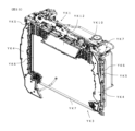
はじめに、ぱちんこ遊技機の遊技機枠は、外枠D12、前枠D14、透明板D16、扉D18、上球皿D20、下球皿D22及び発射ハンドルD44を含む。まず、外枠D12は、ぱちんこ遊技機を設置すべき位置に固定するための枠体である。前枠D14は、外枠D12の開口部分に整合する枠体であり、図示しないヒンジ機構を介して外枠D12に開閉可能に取り付けられる。前枠D14は、遊技球を発射する機構、遊技盤を着脱可能に収容させるための機構、遊技球を誘導又は回収するための機構等を含む。透明板D16は、ガラス等により形成され、扉D18により支持される。扉D18は、図示しないヒンジ機構を介して前枠D14に開閉可能に取り付けられる。上球皿D20は、遊技球の貯留、発射レールへの遊技球の送り出し、下球皿D22への遊技球の抜き取り等の機構を有する。下球皿D22は、遊技球の貯留、抜き取り等の機構を有する。また、遊技機の上部左右等にはスピーカD24が設けられており、遊技状態等に応じた演出音(効果音)が出力される。 First, the game machine frame of the pachinko game machine includes an outer frame D12, a front frame D14, a transparent plate D16, a door D18, an upper ball tray D20, a lower ball tray D22 and a firing handle D44. First, the outer frame D12 is a frame for fixing the pachinko game machine to a position to be installed. The front frame D14 is a frame that matches the opening of the outer frame D12, and is attached to the outer frame D12 via a hinge mechanism (not shown) so that it can be opened and closed. The front frame D14 includes a mechanism for shooting game balls, a mechanism for detachably housing a game board, a mechanism for guiding or collecting game balls, and the like. The transparent plate D16 is made of glass or the like and supported by the door D18. The door D18 is attached to the front frame D14 via a hinge mechanism (not shown) so that it can be opened and closed. The upper ball tray D20 has a mechanism for storing game balls, delivering game balls to the launch rail, extracting game balls to the lower ball tray D22, and the like. The lower ball tray D22 has a mechanism for storing and extracting game balls. In addition, speakers D24 are provided on the upper left and right sides of the game machine, and output sounds (sound effects) according to the game state and the like.
次に、遊技盤は、外レールD32と内レールD34とにより区画された遊技領域D30が形成されている。そして、当該遊技領域D30には、風車D49、図示しない複数の遊技釘や各種一般入賞口の他、第1主遊技始動口A10、第2主遊技始動口B10、補助遊技始動口H10、第1大入賞口C10、第2大入賞口C20、第1主遊技図柄表示装置A20、第2主遊技図柄表示装置B20、演出表示装置SG、補助遊技図柄表示装置H20、センター飾りD38及びアウト口D36が設置されている。以下、各要素を順番に詳述する。 Next, the game board has a game area D30 defined by an outer rail D32 and an inner rail D34. In addition, in the game area D30, there are a windmill D49, a plurality of game nails (not shown) and various general winning openings, as well as a first main game start opening A10, a second main game start opening B10, an auxiliary game start opening H10, a first A large winning slot C10, a second large winning slot C20, a first main game symbol display device A20, a second main game symbol display device B20, an effect display device SG, an auxiliary game symbol display device H20, a center decoration D38 and an out port D36. is set up. Each element will be described in detail below.
次に、第1主遊技始動口A10は、第1主遊技に対応する始動口として設置されている。具体的構成としては、第1主遊技始動口A10は、第1主遊技始動口入球検出装置A11sを備える。ここで、第1主遊技始動口入球検出装置A11sは、第1主遊技始動口A10への遊技球の入球を検出するセンサであり、入球時にその入球を示す第1主遊技始動口入球情報を生成する。 Next, the first main game start port A10 is installed as a start port corresponding to the first main game. As a specific configuration, the first main game start opening A10 includes a first main game start opening ball detection device A11s. Here, the first main game start opening detection device A11s is a sensor that detects the entry of a game ball to the first main game start opening A10, and the first main game start that indicates the entry at the time of entry. Generate entry ball information.
次に、第2主遊技始動口B10は、第2主遊技に対応する始動口として設置されている。具体的構成としては、第2主遊技始動口B10は、第2主遊技始動口入球検出装置B11sと、第2主遊技始動口電動役物B11dと、を備える。ここで、第2主遊技始動口入球検出装置B11sは、第2主遊技始動口B10への遊技球の入球を検出するセンサであり、入球時にその入球を示す第2主遊技始動口入球情報を生成する。次に、第2主遊技始動口電動役物B11dは、第2主遊技始動口B10に遊技球が入賞し難い閉鎖状態と当該通常状態よりも遊技球が入賞し易い開放状態に可変する。 Next, the second main game start port B10 is installed as a start port corresponding to the second main game. Specifically, the second main game start opening B10 includes a second main game start opening ball detection device B11s and a second main game start electric accessory B11d. Here, the second main game start opening ball detection device B11s is a sensor that detects the entry of a game ball to the second main game start opening B10, and the second main game start indicating the entry at the time of entry. Generate entry ball information. Next, the second main game starter electric accessory B11d changes between a closed state in which game balls are less likely to enter the second main game starter B10 and an open state in which game balls are easier to enter than in the normal state.
ここで、本実施形態においては、第1主遊技始動口A10と第2主遊技始動口B10とが上下に重ねるように配置されており、且つ、第1主遊技始動口A10の存在により、第2主遊技始動口B10の上部が塞がれている。また、遊技領域D30の左側(遊技領域中央を基準)を流下する遊技球と、遊技領域D30の右側(遊技領域中央を基準)を流下する遊技球のどちらもが、第1主遊技始動口A10及び第2主遊技始動口B10に誘導されるよう構成されている。 Here, in this embodiment, the first main game start port A10 and the second main game start port B10 are arranged so as to overlap vertically, and due to the presence of the first main game start port A10, the The upper part of the 2 main game start port B10 is blocked. In addition, both the game ball flowing down the left side of the game area D30 (based on the center of the game area) and the game ball flowing down the right side of the game area D30 (based on the center of the game area) are the first main game start opening A10 And it is configured to be guided to the second main game start port B10.
尚、本実施形態では、第2主遊技始動口B10側に電動役物を設けるよう構成したが、これには限定されず、第1主遊技始動口A10側に電動役物を設けるよう構成してもよい。更には、本実施形態では、第1主遊技始動口A10と第2主遊技始動口B10とが、上下に重ねるように配置されているが、これにも限定されず、第1主遊技始動口A10と第2主遊技始動口B10とを離隔して配置するよう構成してもよい。そのように構成した場合、第2主遊技始動口電動役物B11dの上部を塞ぐ部材を設けてもよい。また、遊技領域D30の左側(遊技領域中央を基準)を流下する遊技球が、第1主遊技始動口A10に誘導され易い一方、第2主遊技始動口B10に誘導され難く、遊技領域D30の右側(遊技領域中央を基準)を流下する遊技球が、第1主遊技始動口A10に誘導され難い一方、第2主遊技始動口B10に誘導され易いよう構成してもよい。尚、「誘導され易い」及び「誘導され難い」は、例えば、遊技球を右側及び左側にそれぞれ10000球発射した際の、入球数の大小で決定するものとする。 In this embodiment, the electric accessory is provided on the side of the second main game start port B10, but it is not limited to this, and the electric accessory is provided on the side of the first main game start port A10. may Furthermore, in the present embodiment, the first main game starter A10 and the second main game starter B10 are arranged so as to overlap vertically, but the present invention is not limited to this, and the first main game starter is arranged. A10 and the second main game start port B10 may be arranged apart from each other. In such a configuration, a member may be provided to cover the upper portion of the second main game starter electric accessory B11d. In addition, while the game ball flowing down the left side of the game area D30 (based on the center of the game area) is easily guided to the first main game start port A10, it is difficult to be guided to the second main game start port B10. A game ball flowing down the right side (with reference to the center of the game area) may be configured to be easily guided to the second main game start port B10 while being less likely to be guided to the first main game start port A10. It should be noted that "easily guided" and "difficult to be guided" are determined, for example, by the number of incoming balls when 10,000 game balls are shot to the right and left respectively.
次に、補助遊技始動口H10は、補助遊技始動口入球検出装置H11sを備える。ここで、補助遊技始動口入球検出装置H11sは、補助遊技始動口H10への遊技球の入球を検出するセンサであり、入球時にその入球を示す補助遊技始動口入球情報を生成する。尚、補助遊技始動口H10への遊技球の入球は、第2主遊技始動口B10の第2主遊技始動口電動役物B11dを拡開させるための抽選の契機となる。 Next, the auxiliary game starting port H10 is provided with an auxiliary game starting port entering ball detection device H11s. Here, the auxiliary game start entrance ball detection device H11s is a sensor that detects the entrance of the game ball to the auxiliary game start hole H10, and generates auxiliary game start entrance ball information indicating the entrance ball at the time of entrance. do. The entry of the game ball into the auxiliary game starter H10 triggers a lottery for expanding the second main game starter electric accessory B11d of the second main game starter B10.
ここで、本実施形態においては、補助遊技始動口H10は、遊技領域D30の右側(遊技領域中央を基準)を流下する遊技球が、誘導され易く、遊技領域D30の左側を流下する遊技球が誘導され難いよう構成されている{但し、これには限定されず、遊技領域D30の左側(遊技領域中央を基準)を流下する遊技球が、補助遊技始動口H10に誘導され易いよう構成してもよい(例えば、遊技領域D30に左右に夫々、補助遊技始動口H10を設けてもよい)}。 Here, in the present embodiment, the auxiliary game start opening H10 is such that the game ball flowing down the right side of the game area D30 (based on the center of the game area) is easily guided, and the game ball flowing down the left side of the game area D30 is easily guided. It is configured so as not to be easily guided {However, it is not limited to this, and the game ball flowing down the left side of the game area D30 (based on the center of the game area) is configured to be easily guided to the auxiliary game start opening H10. (For example, the auxiliary game starting openings H10 may be provided on the left and right sides of the game area D30)}.
次に、アウト口D36の右上方には、第1大入賞口C10と第2大入賞口C20とが重なるように配置されており、遊技領域D30の右側(遊技領域中央を基準)を流下する遊技球は、アウト口D36に到達する前に、第1大入賞口C10及び第2大入賞口C20が配置されている領域を通過し易いよう構成されている。 Next, on the upper right side of the out-port D36, the first big prize-winning port C10 and the second big prize-winning port C20 are arranged so as to overlap each other, and flow down the right side of the game area D30 (based on the center of the game area). The game ball is configured to easily pass through the area where the first big winning hole C10 and the second big winning hole C20 are arranged before reaching the out hole D36.
次に、第1大入賞口C10は、第1主遊技図柄(第1特別図柄)又は第2主遊技図柄(第2特別図柄)が大当り図柄にて停止した場合に開状態となる、横長方形状を成しアウト口D36の右上方、且つ、第2大入賞口C20の下方に位置した、主遊技に対応した入賞口である。具体的構成としては、第1大入賞口C10は、遊技球の入球を検出するための第1大入賞口入賞検出装置C11sと、第1大入賞口電動役物C11d(及び第1大入賞口ソレノイドC13)と、を備える。ここで、第1大入賞口入賞検出装置C11sは、第1大入賞口C10への遊技球の入球を検出するセンサであり、入球時にその入球を示す第1大入賞口入球情報を生成する。第1大入賞口電動役物C11dは、第1大入賞口C10に遊技球が入賞不能又は入賞困難な通常状態と遊技球が入賞し易い開放状態に第1大入賞口C10を可変させる(第1大入賞口ソレノイドC13を励磁して可変させる)。尚、本実施形態では、大入賞口の態様を、横長方形状を成し遊技球が入賞不能又は入賞困難な通常状態と遊技球が入賞し易い開放状態とに可変させる態様としているが、これには限定されない。その場合には、例えば、大入賞口内に設けられたシャッタ(棒状部材)が遊技者側に突き出した状態である進出状態と遊技者側に対して引っ込んだ状態である退避状態とを採り得る態様(いわゆる、ベロ型アタッカー)としてもよく、大入賞口への入球数を所定数(例えば、10個)とすることを担保したい場合において好適である。 Next, the first big winning hole C10 is horizontally long and is opened when the first main game symbol (first special symbol) or the second main game symbol (second special symbol) stops at the big hit symbol. It is a prize winning opening corresponding to the main game, which is shaped and positioned above the upper right of the out opening D36 and below the second big winning opening C20. As a specific configuration, the first big winning hole C10 includes a first big winning hole winning detection device C11s for detecting the entry of a game ball, a first big winning hole electric accessory C11d (and a first big winning and a solenoid C13). Here, the first big winning hole winning detection device C11s is a sensor that detects the entry of a game ball into the first big winning hole C10, and the first big winning hole entering ball information indicating the ball entering the first big winning hole C10. to generate The first big winning opening electric accessory C11d changes the first big winning opening C10 between a normal state in which the game ball cannot or is difficult to win in the first big winning opening C10 and an open state in which the game ball easily wins (the first 1. Excite the big winning opening solenoid C13 to make it variable). In the present embodiment, the mode of the big winning opening is changed between a normal state in which a game ball cannot or is difficult to win a horizontal rectangular shape and an open state in which a game ball can easily win a prize. is not limited to In this case, for example, the shutter (bar-shaped member) provided in the big winning opening can adopt an advance state in which it protrudes toward the player and a retracted state in which it retracts toward the player. (A so-called tongue type attacker) may be used, and is suitable when it is desired to ensure that the number of balls entering the big winning opening is a predetermined number (for example, 10).
次に、第2大入賞口C20は、第1主遊技図柄(第1特別図柄)又は第2主遊技図柄(第2特別図柄)が大当り図柄で停止した場合に開状態となる、横長方形状を成しアウト口D36の右上方、且つ、第1大入賞口C10の上方に位置した、主遊技に対応した入賞口である。具体的構成としては、第2大入賞口C20は、遊技球の入球を検出するための第2大入賞口入賞検出装置C21sと、第2大入賞口電動役物C21d(及び第2大入賞口ソレノイドC23)と、を備える。ここで、第2大入賞口入賞検出装置C21sは、第2大入賞口C20への遊技球の入球を検出するセンサであり、入球時にその入球を示す第2大入賞口入球情報を生成する。そして、第2大入賞口C20内に入球した遊技球は、第2大入賞口入賞検出装置C21sよって検出されるよう構成されている。次に、第2大入賞口電動役物C21dは、第2大入賞口C20に遊技球が入賞不能又は入賞困難な通常状態と遊技球が入賞し易い開放状態とに第2大入賞口C20を可変させる。尚、本実施形態では、大入賞口の態様を、横長方形状を成し遊技球が入賞不能又は入賞困難な通常状態と遊技球が入賞し易い開放状態とに可変させる態様としているが、これには限定されない。その場合には、例えば、大入賞口内に設けられたシャッタが遊技者側に突き出した状態である進出状態と遊技者側に対して引っ込んだ状態である退避状態とを採り得る態様(いわゆる、ベロ型アタッカー)としてもよく、大入賞口への入球数を所定数(例えば、10個)とすることを担保したい場合において好適である。 Next, the second big winning hole C20 has a horizontal rectangular shape that opens when the first main game symbol (first special symbol) or the second main game symbol (second special symbol) stops with a big hit symbol. This is a winning opening corresponding to the main game, which is positioned above the upper right of the out opening D36 and above the first big winning opening C10. As a specific configuration, the second large winning opening C20 includes a second large winning opening winning detection device C21s for detecting the entry of a game ball, a second large winning opening electric accessory C21d (and a second large winning opening and a solenoid C23). Here, the second large winning opening detection device C21s is a sensor that detects the entry of a game ball into the second large winning opening C20, and the second large winning opening entry ball information indicating the entry of the ball at the time of entry. to generate A game ball entered into the second large winning opening C20 is configured to be detected by the second large winning opening winning detection device C21s. Next, the second big winning hole electric accessory C21d changes the second big winning hole C20 into a normal state in which the game ball cannot or is difficult to win in the second big winning hole C20 and an open state in which the game ball easily wins. variable. In the present embodiment, the mode of the big winning opening is changed between a normal state in which a game ball cannot or is difficult to win a horizontal rectangular shape and an open state in which a game ball can easily win a prize. is not limited to In that case, for example, the shutter provided in the big winning opening can adopt an advanced state in which it protrudes toward the player and a retracted state in which it retracts toward the player (so-called bell type attacker), which is suitable when it is desired to ensure that the number of balls entering the big winning hole is a predetermined number (for example, 10).
次に、第1主遊技図柄表示装置A20(第2主遊技図柄表示装置B20)は、第1主遊技(第2主遊技)に対応する第1主遊技図柄(第2主遊技図柄)に関連した表示等を実行する装置である。具体的構成としては、第1主遊技図柄表示装置A20(第2主遊技図柄表示装置B20)は、第1主遊技図柄表示部A21g(第2主遊技図柄表示部B21g)と、第1主遊技図柄保留表示部A21h(第2主遊技図柄保留表示部B21h)とを備える。ここで、第1主遊技図柄保留表示部A21h(第2主遊技図柄保留表示部B21h)は、4個のランプから構成され、当該ランプの点灯個数が、第1主遊技(第2主遊技)に係る乱数の保留数(実行されていない主遊技図柄の変動数)に相当する。尚、第1主遊技図柄表示部A21g(第2主遊技図柄表示部B21g)は、例えば7セグメントLEDで構成され、第1主遊技図柄(第2主遊技図柄)は、「0」~「9」の10種類の数字及びハズレの「-」で表示される{但し、これには限定されず、いずれの主遊技図柄が表示されたのかを遊技者が認識困難となるよう、7セグメントLEDを用いて記号等によって表示することが好適である。また、保留数表示においても、4個のランプから構成されていることには限定されず、最大4個分の保留数を表示可能に構成(例えば、1個のランプから構成されており、保留数1:点灯、保留数2:低速点滅、保留数3:中速点滅、保留数4:高速点滅、するよう構成)されていればよい}。 Next, the first main game symbol display device A20 (second main game symbol display device B20) is associated with the first main game symbol (second main game symbol) corresponding to the first main game (second main game). It is a device that executes display, etc. As a specific configuration, the first main game symbol display device A20 (second main game symbol display device B20) includes a first main game symbol display portion A21g (second main game symbol display portion B21g) and a first main game symbol display portion A21g (second main game symbol display portion B21g). A symbol reservation display portion A21h (second main game symbol reservation display portion B21h) is provided. Here, the first main game symbol reservation display portion A21h (second main game symbol reservation display portion B21h) is composed of four lamps, and the number of lighting of the lamps is equal to the first main game (second main game). It corresponds to the number of pending random numbers (the number of fluctuations in the main game symbols that have not been executed). The first main game symbol display portion A21g (second main game symbol display portion B21g) is composed of, for example, a 7-segment LED, and the first main game symbol (second main game symbol) is "0" to "9". ” and ``-'' for failure {However, it is not limited to this, and the 7-segment LED is displayed so that it is difficult for the player to recognize which main game pattern is displayed. It is preferable to display by a symbol or the like using In addition, the display of the number of holds is not limited to being composed of four lamps, and is configured to be able to display the number of holds for up to four (for example, it is composed of one lamp, number 1: lighting, number of holds 2: flashing at low speed, number of holds 3: flashing at medium speed, number of holds 4: flashing at high speed}.
尚、第1主遊技図柄(第2主遊技図柄)は必ずしも演出的な役割を持つ必要が無いため、本実施形態では、第1主遊技図柄表示装置A20(第2主遊技図柄表示装置B20)の大きさは、目立たない程度に設定されている。しかしながら、第1主遊技図柄(第2主遊技図柄)自体に演出的な役割を持たせて第1主遊技側の装飾図柄(第2主遊技側の装飾図柄)を表示させないような手法を採用する場合には、後述する演出表示装置SGのような液晶ディスプレイに、第1主遊技図柄(第2主遊技図柄)を表示させるように構成してもよい。 It should be noted that the first main game symbol (second main game symbol) does not necessarily have a role in production, so in this embodiment, the first main game symbol display device A20 (second main game symbol display device B20) is used. is set to an inconspicuous size. However, a method is adopted in which the first main game pattern (second main game pattern) itself has a role in production and the decorative pattern on the first main game side (decorative pattern on the second main game side) is not displayed. In this case, the first main game symbols (second main game symbols) may be displayed on a liquid crystal display such as the effect display device SG, which will be described later.
次に、演出表示装置SGは、第1主遊技図柄・第2主遊技図柄と連動して変動・停止する装飾図柄(第1装飾図柄及び第2装飾図柄)を含む演出画像の表示等を実行する装置である。ここで、具体的構成としては、演出表示装置SGは、装飾図柄の変動表示等を含めて演出が実行される表示領域SG10を備える。ここで、表示領域SG10は、主遊技保留情報を表示する第1保留表示領域SG12(及び第2保留表示領域SG13)と、例えば、スロットマシンのゲームを模した複数列の装飾図柄(第1装飾図柄及び第2装飾図柄)変動の動画像を表示する装飾図柄表示領域SG11と、を有している。尚、演出表示装置SGは、本実施形態では液晶ディスプレイで構成されているが、機械式のドラムやLED等の他の表示手段で構成されていてもよい。次に、第1保留表示領域SG12(及び第2保留表示領域SG13)は、4個のランプから構成され、当該ランプは、主遊技図柄の保留ランプと連動している。 Next, the performance display device SG executes the display of performance images including decorative symbols (first decorative symbols and second decorative symbols) that fluctuate and stop interlocking with the first main game symbols and second main game symbols. It is a device that Here, as a specific configuration, the effect display device SG includes a display area SG10 in which effects including variable display of decorative symbols are executed. Here, the display area SG10 includes a first reservation display area SG12 (and a second reservation display area SG13) that displays the main game reservation information, and a plurality of rows of decorative symbols (first decorations) imitating a slot machine game, for example. and a decorative design display area SG11 for displaying moving images of patterns and second decorative patterns). In this embodiment, the performance display device SG is composed of a liquid crystal display, but may be composed of other display means such as mechanical drums or LEDs. Next, the first reservation display area SG12 (and the second reservation display area SG13) is composed of four lamps, and the lamps are interlocked with the reservation lamps of the main game symbols.
次に、補助遊技図柄表示装置H20は、補助遊技図柄に関する表示等を実行する装置である。具体的構成としては、補助遊技図柄表示装置H20は、補助遊技図柄表示部H21gと、補助遊技図柄保留表示部H21hとを備える。ここで、補助遊技図柄保留表示部H21hは、4個のランプから構成され、当該ランプの点灯個数が、補助遊技図柄変動の保留数(実行されていない補助遊技図柄変動の数)に相当する。 Next, the auxiliary game symbol display device H20 is a device that executes display and the like regarding auxiliary game symbols. Specifically, the auxiliary game symbol display device H20 includes an auxiliary game symbol display portion H21g and an auxiliary game symbol reserve display portion H21h. Here, the auxiliary game symbol reservation display portion H21h is composed of four lamps, and the number of lights of the lamps corresponds to the number of auxiliary game symbol variations pending (the number of auxiliary game symbol variations that have not been executed).
次に、センター飾りD38は、演出表示装置SGの周囲に設置され、遊技球の流路、演出表示装置SGの保護、装飾等の機能を有する。また、遊技効果ランプD26は、遊技領域D30又は遊技領域D30以外の領域に設けられ、点滅等することで演出の役割を果たす。 Next, the center decoration D38 is installed around the performance display device SG, and has functions such as the passage of game balls, the protection of the performance display device SG, decoration, and the like. In addition, the game effect lamp D26 is provided in the game area D30 or an area other than the game area D30, and plays a role of effect by blinking or the like.
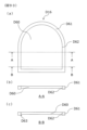
次に、図2を参照しながら、ぱちんこ遊技機の背面側における基本構造を説明する。ぱちんこ遊技機は、ぱちんこ遊技機の全体動作を制御し、特に第1主遊技始動口A10(第2主遊技始動口B10)へ入球したときの抽選等、遊技動作全般の制御(即ち、遊技者の利益と直接関係する制御)を行う主制御基板Mと、遊技内容に興趣性を付与する演出表示装置SG上での各種演出に係る表示制御等を行うサブメイン制御部SMと、主に演出表示を実行するサブサブ制御部SSとを備え演出全般を制御する副制御基板Sと、賞球タンクKT、賞球レールKR及び各入賞口への入賞に応じて賞球タンクKTから供給される遊技球を上球皿D20へ払い出す払出ユニットKE10等を備える賞球払出装置(セット基盤)KEと、払出ユニットKE10による払出動作を制御する賞球払出制御基板KHと、上球皿D20の遊技球(貯留球)を遊技領域D30へ1球ずつ発射する発射装置D42と、発射装置D42の発射動作を制御する発射制御基板D40と、ぱちんこ遊技機の各部へ電力を供給する電源供給ユニットEと、ぱちんこ遊技機の電源をオン・オフするスイッチである電源スイッチEa等が、前枠D14裏面(遊技側と反対側)に設けられている。 Next, the basic structure on the back side of the pachinko game machine will be described with reference to FIG. The pachinko game machine controls the overall operation of the pachinko game machine, and controls the overall game operation (i.e., the game A main control board M that performs control directly related to the interests of players), and a sub-main control unit SM that performs display control etc. related to various effects on the effect display device SG that adds interest to the game content. Supplied from the prize ball tank KT according to the winning to the prize ball tank KT, the prize ball rail KR, and the prize winning holes, the sub control board S having a sub-sub control unit SS for executing the performance display and controlling the overall performance. A prize ball payout device (set base) KE including a payout unit KE10 for paying out game balls to the upper ball tray D20, a prize ball payout control board KH for controlling the payout operation of the payout unit KE10, and a game of the upper ball tray D20. A launching device D42 that shoots balls (stored balls) into the game area D30 one by one, a launch control board D40 that controls the shooting operation of the launching device D42, and a power supply unit E that supplies power to each part of the pachinko game machine. , a power switch Ea, which is a switch for turning on/off the power of the pachinko game machine, is provided on the rear surface of the front frame D14 (opposite side to the game side).
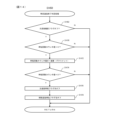
次に、図3のブロック図を参照しながら、本実施形態に係るぱちんこ遊技機の電気的な概略構成を説明する。はじめに、本実施形態に係るぱちんこ遊技機は、前述したように、遊技の進行を制御する主制御基板Mと、主制御基板Mからの情報(信号、コマンド等)に基づいて遊技球の払出を制御する賞球払出制御基板KHと、主制御基板Mからの情報(信号、コマンド等)に基づいて装飾図柄(第1装飾図柄及び第2装飾図柄)の変動・停止等の演出表示装置SG上での各種演出、スピーカD24からの音響、遊技効果ランプD26の点灯、エラー報知等の実行を制御する副制御基板S(本例では、サブメイン制御部SMとサブサブ制御部SSとが一つの基板上に配置されている)と、これらの制御基板を含む遊技機全体に電源を供給する電源供給ユニットEと、を主体として構成されている。ここで、副制御基板Sは、装飾図柄(第1装飾図柄及び第2装飾図柄)の変動・停止等の演出表示装置SG上での各種演出、スピーカD24からの音響、遊技効果ランプD26の点灯、エラー報知を制御するサブメイン制御部SMと、演出表示装置SG上での装飾図柄(第1装飾図柄及び第2装飾図柄)の変動表示・停止表示及び保留表示や予告表示等の表示処理を実行するサブサブ制御部SSの2つの制御部とを備えている。尚、主制御基板M、賞球払出制御基板KH、サブメイン制御部SM及びサブサブ制御部SSには、様々な演算処理を行うCPU、CPUの演算処理を規定したプログラムを予め記憶するROM、CPUが取り扱うデータ(遊技中に発生する各種データやROMから読み出されたコンピュータプログラム等)を一時的に記憶するRAMが搭載されている。ここで、特に図示していないが、主制御基板Mが搭載するROMに関しては、不正行為によって改造されたプログラム等を書き込まれることを防止するため、未使用の領域を設けないよう構成することが好適である(例えば、未使用領域を全て0によって充填、使用している領域を若い番地に詰めて書き込む、等)。また、ノイズや不正行為によって、通常時には参照しないデータを参照してしまうことを防止するため、未使用のデータ(例えば、スペック違いの遊技機において参照するデータや、開発段階でのテストにのみ使用するデータ等)を設けないよう構成することが好適である。また、RAMの領域を使用する際についても同様に、若い番地に詰めて領域を使用し、未使用のプログラム領域を設けないよう構成することが好適である。以下、各基板の概略構成及び各基板・装置間の電気的な接続態様について概説する。 Next, a schematic electrical configuration of the pachinko gaming machine according to the present embodiment will be described with reference to the block diagram of FIG. First, the pachinko gaming machine according to the present embodiment, as described above, has a main control board M that controls the progress of the game, and pays out game balls based on information (signals, commands, etc.) from the main control board M. On the effect display device SG such as variation and stop of the decorative pattern (first decorative pattern and second decorative pattern) based on the information (signal, command, etc.) from the prize ball payout control board KH to control and the main control board M , sound from the speaker D24, lighting of the game effect lamp D26, error notification, etc. (In this example, the sub-main control unit SM and sub-sub control unit SS are one board ) and a power supply unit E that supplies power to the entire gaming machine including these control boards. Here, the sub-control board S performs various effects on the effect display device SG such as fluctuation and stoppage of decorative patterns (first decorative pattern and second decorative pattern), sound from the speaker D24, and lighting of the game effect lamp D26. , a sub-main control unit SM that controls error notification, and display processing such as variable display, stop display, pending display and advance notice display of decorative patterns (first decorative pattern and second decorative pattern) on the effect display device SG. It comprises two controls of a sub-sub-control SS for execution. In addition, the main control board M, prize ball payout control board KH, sub-main control unit SM and sub-sub control unit SS include a CPU for performing various arithmetic processing, a ROM for pre-storing a program defining the arithmetic processing of the CPU, and a CPU. Equipped with a RAM that temporarily stores data handled by (various data generated during games, computer programs read from ROM, etc.). Here, although not shown, the ROM mounted on the main control board M may be configured so as not to have an unused area in order to prevent a modified program or the like from being written by fraud. It is preferable (eg, filling unused areas with all 0's, writing used areas down to younger addresses, etc.). In addition, in order to prevent data that is not normally referenced from being referenced due to noise or fraud, unused data (for example, data referenced by game machines with different specifications, or used only for testing at the development stage) It is preferable to configure so as not to provide data such as data for Similarly, when using the RAM area, it is preferable to use the area at a lower address so as not to provide an unused program area. Schematic configurations of the substrates and electrical connections between the substrates and devices will be described below.
まず、主制御基板Mは、入賞口センサNs{前述した第1主遊技始動口入球検出装置A11s、第2主遊技始動口入球検出装置B11s、補助遊技始動口入球検出装置H11s、第1大入賞口入賞検出装置C11s、第2大入賞口入賞検出装置C21s、一般入賞検出装置(不図示であるが、一般入球口とは、賞球はあるが図柄抽選を行わない入球口である)}、図示略する駆動ソレノイド(前述した、第1大入賞口ソレノイドC13、第2大入賞口ソレノイドC23等)、情報表示LED(不図示)等、遊技の進行に必須となる入出力装置と電気的に接続され、各入力装置からの入力信号に基づいて遊技の進行を制御している。更に、主制御基板Mは、賞球払出制御基板KHと、副制御基板S(サブメイン制御部SM・サブサブ制御部SS)とも電気的に接続されており、遊技進行に基づいて、賞球払出等に関する情報(コマンド)を賞球払出制御基板KHに、演出・遊技の進行状態等に関する情報(コマンド)を副制御基板Sにそれぞれ送信可能に構成されている。尚、主制御基板Mは、外部接続端子(不図示)を介してホールコンピュータHC等と接続可能となっており、外部接続端子を介してホールコンピュータHCと配線接続することで、主制御基板Mから外部の装置に対して遊技関連情報を出力できるよう構成されている。 First, the main control board M has a winning opening sensor Ns {the first main game starting entrance entrance detection device A11s, the second main game start entrance entrance detection device B11s, the auxiliary game start entrance entrance detection device H11s, the second 1 large winning entrance winning detection device C11s, 2nd large winning winning winning detection device C21s, general winning detection device (although not shown, a general winning entrance is an entrance that has prize balls but does not carry out a symbol lottery. )}, drive solenoids (not shown above, first big winning opening solenoid C13, second big winning opening solenoid C23, etc.), information display LED (not shown), etc., input and output essential for progress of the game It is electrically connected to the device and controls the progress of the game based on the input signal from each input device. Furthermore, the main control board M is electrically connected to the prize ball payout control board KH and the sub-control board S (sub-main control section SM, sub-sub control section SS), and prize ball payout is performed based on the game progress. etc. to the prize ball payout control board KH, and information (commands) to the sub control board S about the performance/game progress and the like. The main control board M can be connected to the hall computer HC or the like via an external connection terminal (not shown). It is configured to be able to output game-related information from to an external device.
また、本実施形態では、図3の矢印表記の通り、主制御基板Mと賞球払出制御基板KHとは、双方向通信が可能となるよう構成されている一方、主制御基板Mとサブメイン制御部SMとは、主制御基板Mからサブメイン制御部SMへの一方向通信が可能となるよう構成されている(通信方法は、シリアル通信、パラレル通信のいずれを用いてもよい)。尚、制御基板間(制御装置間)の通信については一方向通信でも双方向通信でもよい。 In addition, in this embodiment, as indicated by the arrows in FIG. The control unit SM is configured to enable one-way communication from the main control board M to the sub-main control unit SM (either serial communication or parallel communication may be used for the communication method). Communication between control boards (between control devices) may be one-way communication or two-way communication.
次に、賞球払出制御基板KHは、遊技球の払出を実行する賞球払出装置KEと、遊技者によって操作可能な装置であって遊技球の貸出要求を受付けて賞球払出制御基板KHに伝達する遊技球貸出装置Rとに接続されている。また、図示略するが、本実施形態では、賞球払出制御基板内に、発射装置の制御回路部が併設されており、賞球払出制御基板と発射装置(発射ハンドル・発射モータ・球送り装置等)とも接続されている。尚、本実施形態では、遊技球貸出装置Rを別体として遊技機に隣接する形態を採用しているが、遊技機と一体としてもよく、その場合には、賞球払出制御基板KHにより貸出制御及び電子マネー等貸出用の記録媒体の管理制御等を統括して行ってもよい。 Next, the prize ball payout control board KH includes a prize ball payout device KE for executing game ball payout, and a device operable by the player that accepts a game ball lending request and sends the prize ball payout control board KH. It is connected to the game ball lending device R that transmits. In addition, although not shown, in this embodiment, a control circuit unit of the launching device is provided in the prize ball payout control board, and the prize ball payout control board and the launching device (shooting handle, launching motor, ball feeding device etc.) are also connected. In this embodiment, the game ball lending device R is a separate unit adjacent to the gaming machine, but it may be integrated with the gaming machine. Control and management control of recording media for lending electronic money or the like may be performed in an integrated manner.
次に、副制御基板Sは、前述したように装飾図柄(第1装飾図柄及び第2装飾図柄)等を表示する演出表示装置SGと、スピーカD24と、遊技効果ランプD26と、その他演出用の駆動装置(不図示)と接続されている。本実施形態では、前述の通り、副制御基板S内にサブメイン制御部SMとサブサブ制御部SSとを有しており、サブメイン制御部SMによりスピーカD24から出力させる音声の制御、遊技効果(電飾)ランプD26の点灯制御並びに、演出表示装置上で表示する表示内容の決定制御が行われ、サブサブ制御部SSにより、演出表示装置上の表示制御(実体的な表示制御)が行われるように構成されている。尚、本実施形態では、サブメイン制御部SMとサブサブ制御部SSとを、副制御基板Sにて一体化されるよう構成されているが、これに限定されるわけではない(別基板として構成してもよいが、一体化するよう構成することでスペースメリットや配線等にノイズが混入してしまう事態を低減できるといったメリットが生ずる)。また、両制御部での作業分担についても、例えばサブサブ制御部SSにより音声制御を実行させる(VDPに音声制御回路が一体化されたものを採用する場合に好適)等、適宜変更できる。また、賞球として物理的な賞球を付与せずに電子的な価値を付与してもよい。 Next, the sub-control board S includes an effect display device SG for displaying decorative patterns (first decorative pattern and second decorative pattern), etc., a speaker D24, a game effect lamp D26, and other effects for effects, as described above. It is connected to a drive (not shown). In this embodiment, as described above, the sub-control board S has the sub-main control unit SM and the sub-sub-control unit SS. Lighting control of the illumination lamp D26 and determination control of display contents to be displayed on the effect display device are performed, and display control (substantial display control) on the effect display device is performed by the sub-sub control unit SS. is configured to In this embodiment, the sub-main control section SM and the sub-sub-control section SS are configured to be integrated on the sub-control board S, but the present invention is not limited to this (configured as separate boards). (Although it may be possible to do so, there are merits such as a space merit and a reduction in the situation where noise is mixed in the wiring etc.). Also, the division of work between the two controllers can be appropriately changed, for example, the sub-sub-controller SS executes voice control (preferable when adopting a VDP integrated with a voice control circuit). Also, instead of giving physical prize balls as prize balls, electronic values may be given.
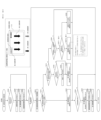
次に、図4のブロック図を参照しながら、本実施形態に係るぱちんこ遊技機の各種機能について説明する。はじめに、主制御基板Mは、遊技に係る遊技周辺機器(第1主遊技周辺機器A、第2主遊技周辺機器B、第1・第2主遊技共用周辺機器C、補助遊技周辺機器H)、演出に係るサブメイン制御部SM(副遊技制御手段SM)、主制御基板Mからの払出指示に基づき所定数の賞球の払出制御を行う賞球払出制御基板KHと、情報伝達可能に接続されている。また、サブメイン制御部SM(副遊技制御手段SM)は、画像演出を実行するサブサブ制御部SS(演出表示手段SS)、各種遊技効果ランプD26(例えばサイドランプ)やスピーカD24等とも電気的に接続されている。更に、賞球払出制御基板KHは、ステッピングモータやスプロケット等を備えた賞球払出装置KEと電気的に接続されている。尚、主制御基板M、サブメイン制御部SM(副遊技制御手段SM)、サブサブ制御部SS(演出表示手段SS)、賞球払出制御基板KH等は、ハードウエア的にはデータやプログラムを格納するROMやRAM、演算処理に用いるCPU等の素子等から構成される。尚、以下で主制御基板Mに含まれるとする各手段を周辺機器(例えば、遊技周辺機器)に搭載される形で構成してもよい。例えば、周辺機器(例えば、遊技周辺機器)に含まれるとする各手段を主制御基板Mに搭載される形で構成してもよい。以下、上記各手段(装置)の詳細を説明する。 Next, various functions of the pachinko gaming machine according to the present embodiment will be described with reference to the block diagram of FIG. First, the main control board M includes game peripherals related to games (first main game peripheral A, second main game peripheral B, first and second main game shared peripheral C, auxiliary game peripheral H), A sub-main control unit SM (sub-game control means SM) related to production, and a prize ball payout control board KH that controls payout of a predetermined number of prize balls based on payout instructions from the main control board M, and are connected so that information can be transmitted. ing. In addition, the sub-main control unit SM (sub-game control means SM) is electrically connected to the sub-sub control unit SS (effect display means SS) that executes image effects, various game effect lamps D26 (for example, side lamps), speakers D24, and the like. It is connected. Further, the prize ball payout control board KH is electrically connected to a prize ball payout device KE having a stepping motor, a sprocket, and the like. The main control board M, sub-main control section SM (sub-game control means SM), sub-sub-control section SS (effect display means SS), prize ball payout control board KH, etc. store data and programs in terms of hardware. It consists of elements such as a ROM and a RAM that are used for processing, and a CPU that is used for arithmetic processing. Incidentally, each means included in the main control board M below may be configured to be mounted on a peripheral device (for example, a game peripheral device). For example, each means included in a peripheral device (for example, a game peripheral device) may be configured to be mounted on the main control board M. FIG. The details of each means (apparatus) will be described below.
まず、主制御基板Mは、遊技用の情報の取得を制御する遊技用情報制御手段MJと、遊技の内容を決定するための遊技内容決定手段MNと、特別遊技や特定遊技等の遊技の進行を司る遊技進行手段MPと、現在及び過去の遊技状態[例えば、主遊技に関する状態{通常遊技状態、特定遊技状態(確率変動遊技状態、時間短縮遊技状態)、特別遊技状態}、補助遊技に関する状態(易開放状態、非易開放状態)、主遊技図柄や補助遊技図柄に係る停止図柄及び変動態様情報、各種フラグのオン・オフ状況、特別遊技中の遊技状態(例えばラウンド数や入賞個数情報)]等を一時記憶するための遊技状態一時記憶手段MBと、遊技周辺機器側に各種遊技情報{例えば、停止図柄情報、停止図柄の属性情報{例えば、10R大当り、8R大当り、4R大当り、ハズレ}、変動態様に関する情報(例えば、変動時間)、特別遊技の開始信号・状態情報・終了信号、保留情報等}を送信するための情報送信制御手段MT(及び未送信コマンドを蓄積するコマンド送信用バッファMT10)と、各種入賞口への遊技球の入賞に基づき所定の賞球の払出を行うように賞球払出制御基板KHを制御する賞球払出決定手段MHと、を有している。 First, the main control board M comprises game information control means MJ for controlling the acquisition of game information, game content determination means MN for determining the content of the game, and progress of the game such as a special game or a specific game. and the game progress means MP that governs the current and past game states [for example, states related to the main game {normal game state, specific game state (probability fluctuation game state, time shortened game state), special game state}, state related to the auxiliary game (easy open state, non-easy open state), stop symbols and variation mode information related to main game symbols and auxiliary game symbols, on/off status of various flags, game state during special game (for example, number of rounds and winning number information) ], etc., and various game information {for example, stop pattern information, stop pattern attribute information {for example, 10R jackpot, 8R jackpot, 4R jackpot, loss} on the game peripheral device side. , Information on variation mode (for example, variation time), start signal/state information/end signal of special game, hold information, etc.} Information transmission control means MT (and command transmission buffer for accumulating unsent commands MT10) and prize ball payout determination means MH for controlling the prize ball payout control board KH to pay out predetermined prize balls based on the winning of game balls into various prize winning openings.
ここで、遊技用情報制御手段MJは、各入球口(始動口等)への遊技球の流入を判定するための入球判定手段MJ10と、各乱数の取得可否を判定し、当該判定結果に基づき当該各乱数を取得するための乱数取得判定実行手段MJ20と、変動表示中における各始動口への入球を保留球として上限個数以内で一時記憶するための保留制御手段MJ30と、を有している。また、遊技進行手段MPは、各図柄の変動及び停止表示する制御を行うための表示制御手段MP10と、第2主遊技始動口B10の第2主遊技始動口電動役物B11dの開閉決定に直接関連する各種処理を行うための第2主遊技始動口電動役物開閉制御手段MP20‐Bと、通常遊技よりも遊技者に有利な特別遊技に関する制御を司る特別遊技制御手段MP30と、第1主遊技及び第2主遊技並びに補助遊技に関し、現在の遊技状態をどの遊技状態に移行させるかの決定と、当該決定に基づき遊技状態を移行させる処理を行うための特定遊技制御手段MP50と、を有している。以下、各手段について詳述する。 Here, the game information control means MJ includes a ball entry determination means MJ10 for determining the inflow of game balls into each ball entrance (starting opening, etc.), and determines whether or not each random number can be obtained, and determines the result of the determination. Random number acquisition determination execution means MJ20 for acquiring each random number based on the above, and holding control means MJ30 for temporarily storing the number of balls entered into each starting hole during variable display as holding balls within the upper limit number. are doing. In addition, the game progress means MP directly determines the opening and closing of the second main game starter electric accessory B11d of the second main game starter B10, and the display control means MP10 for controlling the variation and stop display of each pattern. A second main game starter electric accessory opening/closing control means MP20-B for performing various related processes, a special game control means MP30 for controlling a special game that is more advantageous to the player than a normal game, and a first main With respect to the game, the second main game and the auxiliary game, there is a specific game control means MP50 for determining to which game state the current game state is to be shifted, and for performing processing for shifting the game state based on the decision. are doing. Each means will be described in detail below.
まず、入球判定手段MJ10は、第1主遊技始動口A10に遊技球が入球したか否かを判定する第1主遊技始動口入球判定手段MJ11‐Aと、第2主遊技始動口B10に遊技球が入球したか否かを判定する第2主遊技始動口入球判定手段MJ11‐Bと、補助遊技始動口H10に遊技球が流入したか否かを判定する補助遊技始動口入球判定手段MJ11‐Hと、第1大入賞口C10に遊技球が入球したか否かを判定する、第1大入賞口入球判定手段MJ11‐C10と、第2大入賞口C20に遊技球が入球したか否かを判定する、第2大入賞口入球判定手段MJ11‐C20と、を有している。 First, the ball entry determination means MJ10 includes a first main game start entrance ball entry determination means MJ11-A for determining whether or not a game ball has entered the first main game start opening A10, and a second main game start opening. A second main game start opening ball entry determination means MJ11-B for determining whether or not a game ball has entered B10, and an auxiliary game start opening for determining whether or not a game ball has flowed into the auxiliary game start opening H10. A ball entry determination means MJ11-H, a first big winning hole entry ball determining means MJ11-C10 for determining whether or not a game ball has entered the first big winning hole C10, and a second big winning hole C20 It has a second big winning hole entrance ball determination means MJ11-C20 for determining whether or not a game ball has entered.
次に、乱数取得判定実行手段MJ20は、第1主遊技始動口A10への遊技球の入球に基づき第1主遊技側乱数を取得するか否かを判定すると共に、判定結果に応じて当該乱数(例えば、第1当選乱数、第1変動態様決定乱数、第1主遊技図柄決定乱数等)を取得する第1主遊技乱数取得判定実行手段MJ21‐Aと、第2主遊技始動口B10への遊技球の入球に基づき第2主遊技側乱数を取得するか否かを判定すると共に、判定結果に応じて当該乱数(例えば、第2当選乱数、第2変動態様決定乱数、第2主遊技図柄決定乱数等)を取得する第2主遊技乱数取得判定実行手段MJ21‐Bと、補助遊技側選乱数の取得の可否を判定し、当該判定結果に基づき当該乱数を取得するための補助遊技乱数取得判定実行手段MJ21‐Hと、を有している。 Next, the random number acquisition determination execution means MJ20 determines whether or not to acquire the first main game side random number based on the entry of the game ball into the first main game start port A10, and according to the determination result, the To the first main game random number acquisition determination execution means MJ21-A for acquiring random numbers (for example, the first winning random number, the first variation mode determination random number, the first main game symbol determination random number, etc.) and the second main game start port B10 It is determined whether or not to acquire the second main game side random number based on the entry of the game ball, and the random number according to the determination result (for example, the second winning random number, the second variation mode determination random number, the second main A second main game random number acquisition determination execution means MJ21-B that acquires game pattern determination random numbers, etc.), and an auxiliary game for determining whether or not to acquire the auxiliary game side selection random number and acquiring the random number based on the determination result and random number acquisition determination execution means MJ21-H.
ここで、上記を含め本特許請求の範囲及び本明細書における「乱数」は、例えば、乱数の種類(例えば、当選乱数や変動態様決定乱数)により割り振られた「0」~「65535」や「0」~「255」といった所定範囲からランダムに選択された値である。また、乱数としては、数学的に発生させる乱数でなくともよく、ハードウエア乱数やソフトウエア乱数等により発生させる擬似乱数でもよい。例えば、乱数にある夫々の値の発現方式が、乱数の数列に沿って順々に値を発現させる方式(プラスワン方式)、乱数の数列の最終値が発現したときの次の値(初期値)を偶然性のある値によって定める方式(初期値更新方式)、これらの組み合わせ等を挙げることができる。このような方法で乱数を取得することにより、遊技者に予想され難い、非周期的な乱数を発生させることが可能である。逆に、例えば、ある抽選に使用した乱数を使用して、次回の乱数を生成する方法の場合、当該次回の乱数を予想され易くなってしまう。そのため、乱数を発生させるに際し、前回の抽選で使用された乱数を用いることなく、新たな乱数を発生させることが好適である。 Here, the "random number" in the claims and this specification including the above is, for example, "0" to "65535" or " It is a value randomly selected from a predetermined range of 0 to 255. Moreover, the random numbers may not be mathematically generated random numbers, but may be pseudo-random numbers generated by hardware random numbers, software random numbers, or the like. For example, the expression method of each value in the random number is a method of expressing the value in order along the sequence of random numbers (plus one method), the next value when the final value of the sequence of random numbers is expressed (initial value ) is determined by an accidental value (initial value update method), a combination of these methods, and the like. Obtaining random numbers in this way makes it possible to generate non-periodic random numbers that are difficult for the player to predict. Conversely, for example, in the case of the method of generating the next random number using the random number used in a certain lottery, the next random number is likely to be predicted. Therefore, when generating random numbers, it is preferable to generate new random numbers without using the random numbers used in the previous lottery.
次に、保留制御手段MJ30は、保留消化及び変動開始に係る処理を制御する保留消化制御手段MJ31と、第1主遊技図柄変動許可が下りていない状況で取得した当該第1主遊技側乱数を一時記憶するか否かを判定し、当該判定結果に基づき前記乱数を図柄変動許可が下りるまで第1主遊技図柄保留情報一時記憶手段MJ32b‐Aに保留するための第1主遊技図柄保留手段MJ32‐Aと、第2主遊技図柄変動許可が下りていない状況で取得した当該第2主遊技側乱数を一時記憶するか否かを判定し、当該判定結果に基づき前記乱数を図柄変動許可が下りるまで第2主遊技図柄保留情報一時記憶手段MJ32b‐Bに保留するための第2主遊技図柄保留手段MJ32‐Bと、補助遊技図柄変動許可が下りていない状況で取得した補助遊技側乱数を一時記憶するか否かを判定し、当該判定結果に基づき当該乱数を図柄変動許可が下りるまで補助遊技図柄保留情報一時記憶手段MJ32b‐Hに保留するための補助遊技図柄保留手段MJ32‐Hと、を有している。 Next, the holding control means MJ30 controls the holding digestion control means MJ31 that controls the processing related to holding digestion and fluctuation start, and the first main game side random number obtained in the situation where the first main game symbol fluctuation permission is not granted. A first main game symbol reservation means MJ32 for determining whether or not to temporarily store the random number in the first main game symbol reservation information temporary storage means MJ32b-A until the permission for symbol variation is obtained based on the determination result. - A, in a situation where the second main game symbol variation permission has not been granted, it is determined whether or not to temporarily store the second main game side random number obtained, and based on the determination result, symbol variation permission is granted for the random number. Second main game symbol holding means MJ32-B for holding second main game symbol holding information temporary storage means MJ32b-B until the second main game pattern holding information temporary storage means MJ32-B, and auxiliary game side random numbers obtained in the situation where auxiliary game pattern fluctuation permission is not granted are temporarily stored. Auxiliary game symbol holding means MJ32-H for judging whether or not to store, and holding the random number in the auxiliary game symbol holding information temporary storage means MJ32b-H until the symbol variation permission is granted based on the judgment result. have.
ここで、保留消化制御手段MJ31は、変動を開始する条件を充足したか否かを判定する変動開始条件充足判定手段MJ31jを有している。 Here, the pending digestion control means MJ31 has a variation start condition satisfaction determination means MJ31j for determining whether or not the conditions for starting the variation are satisfied.
次に、第1主遊技図柄保留手段MJ32‐A、第2主遊技図柄保留手段MJ32‐B及び補助遊技図柄保留手段MJ32‐Hは、最大4個まで記憶可能な、乱数を保留順序と結合した形で一時記憶するための、第1主遊技図柄保留情報一時記憶手段MJ32b‐A、第2主遊技図柄保留情報一時記憶手段MJ32b‐B及び補助遊技図柄保留情報一時記憶手段MJ32b‐Hを夫々有している。 Next, the first main game symbol reservation means MJ32-A, the second main game symbol reservation means MJ32-B, and the auxiliary game symbol reservation means MJ32-H are combined with a reservation order of random numbers that can store up to four numbers. 1st main game symbol reserved information temporary storage means MJ32b-A, 2nd main game symbol reserved information temporary storage means MJ32b-B and auxiliary game symbol reserved information temporary storage means MJ32b-H for temporarily storing in the form of are doing.
次に、遊技内容決定手段MNは、特別遊技の当否及び第2主遊技始動口電動役物B11dの開放可否を抽選する当否抽選手段MN10と、当否抽選の結果、当りである場合に特別遊技への移行決定をする(例えば、内部的に当りフラグをオンにする)特別遊技移行決定手段MN20と、各乱数に基づき、各図柄の停止図柄を決定するための図柄内容決定手段MN40と、各乱数に基づき、各図柄の変動態様(変動時間等)を決定するための変動態様決定手段MN50とを、有している。ここで、当否抽選手段MN10は、第1主遊技図柄に関しての当否抽選を行う第1主遊技当否抽選手段MN11‐Aと、第2主遊技図柄に関しての当否抽選を行う第2主遊技当否抽選手段MN11‐Bと、補助遊技図柄に関しての当否抽選を行う補助遊技当否抽選手段MN11‐Hとを、有している。ここで、第1主遊技当否抽選手段MN11‐A、第2主遊技当否抽選手段MN11‐B及び補助遊技当否抽選手段MN11‐Hは、第1主遊技図柄に関しての当否抽選を行う際に参照される第1主遊技用当否抽選テーブルMN11ta‐Aと、第2主遊技図柄に関しての当否抽選を行う際に参照される第2主遊技用当否抽選テーブルMN11ta‐Bと、補助遊技図柄に関しての当否抽選を行う際に参照される補助遊技用当否抽選テーブルMN11ta‐Hを夫々有している。尚、詳細なテーブル構成の一例については後述する。 Next, the game content determining means MN includes a lottery lottery means MN10 for determining whether the special game is successful and whether or not the second main game starter electric accessory B11d can be opened. special game transition determining means MN20 (for example, turning on the winning flag internally), symbol content determining means MN40 for determining the stop symbol of each symbol based on each random number, and each random number and a variation mode determination means MN50 for determining the variation mode (variation time, etc.) of each symbol based on. Here, the success/failure lottery means MN10 consist of a first main game success/failure lottery means MN11-A that performs a success/failure lottery with respect to the first main game symbols, and a second main game success/failure lottery means that performs a success/failure lottery with respect to the second main game symbols. It has MN11-B and an auxiliary game success/failure lottery means MN11-H for performing a success/failure lottery for the auxiliary game symbols. Here, the first main game success/failure lottery means MN11-A, the second main game success/failure lottery means MN11-B, and the auxiliary game success/failure lottery means MN11-H are referred to when performing a success/failure lottery for the first main game symbols. a first main game success/failure lottery table MN11ta-A, a second main game success/failure lottery table MN11ta-B referred to when performing a success/failure lottery for the second main game symbols, and a success/failure lottery for the auxiliary game symbols. Each has an auxiliary game success or failure lottery table MN11ta-H that is referred to when performing. An example of detailed table configuration will be described later.
ここで、主遊技乱数に基づいて当否抽選を実行する際、当否抽選手段MN10は、主遊技乱数値が、すべての当り乱数値のいずれかと同じ値であるか否かを判定する、又は、当り乱数値の一部又は全部が連続した数値である場合には、主遊技乱数値が当り乱数値の上限値以下であり下限値以上であるか否かを判定することにより、当否判定を実行する。このような当否判定を実行することで、正確な判定処理を実行できることとなる。逆に、当り乱数範囲の上限のみとの比較、又は下限のみとの比較によって当否判定を実行する場合、乱数範囲の端の値(例えば、乱数値の範囲が0~1023である場合、0又は1023)を当り乱数値とする必要があるため、不正(例えば、主制御基板Mに電流を流す不正行為であり、記憶領域のビットがすべて0又は1になり易い)に対して脆弱になってしまう危険性がある。また、本例では、一つの乱数を用いて1回の抽選を実行するよう構成している{1回の抽選に複数の乱数を用いる(いわゆる、2段階抽選を実行する)場合、二つの乱数が同期することを防ぐ必要があるため}。 Here, when executing the win/loss lottery based on the main game random numbers, the win/fail lottery means MN10 determines whether or not the main game random number value is the same value as any of all the winning random number values, or determines whether or not the winning random number value is When part or all of the random numbers are continuous numbers, the winning/failure judgment is executed by judging whether or not the main game random number is equal to or less than the upper limit of the winning random number and equal to or more than the lower limit. . Accurate determination processing can be performed by executing such a right/wrong determination. Conversely, if the success/fail judgment is performed by comparing only the upper limit of the hit random number range or comparing only the lower limit, the value at the end of the random number range (for example, if the range of random numbers is 0 to 1023, 0 or 1023) as a random value, it is vulnerable to fraud (for example, it is a fraudulent act of flowing current to the main control board M, and all the bits in the storage area are likely to be 0 or 1). There is a danger of being lost. In addition, in this example, one random number is used to execute one lottery. }.
次に、図柄内容決定手段MN40は、取得した遊技内容決定乱数(第1主遊技乱数)に基づき、第1主遊技図柄の停止図柄を決定する第1主遊技図柄決定手段MN41‐Aと、取得した遊技内容決定乱数(第2主遊技乱数)に基づき、第2主遊技図柄の停止図柄を決定する第2主遊技図柄決定手段MN41‐Bと、取得した補助遊技図柄当選乱数に基づき補助遊技図柄の停止図柄を決定する補助遊技図柄決定手段MN41‐Hと、を有している。 Next, the symbol content determination means MN40 includes a first main game symbol determination means MN41-A that determines the stop symbol of the first main game symbol based on the acquired game content determination random number (first main game random number), A second main game symbol determining means MN41-B for determining a stop symbol of the second main game symbol based on the game content determination random number (second main game random number) obtained, and an auxiliary game symbol based on the obtained auxiliary game symbol winning random number. and an auxiliary game symbol determination means MN41-H for determining the stop symbols of the MN41-H.
ここで、第1主遊技図柄決定手段MN41‐Aは、第1主遊技図柄に係る停止図柄を決定する際に参照される第1主遊技図柄決定用抽選テーブルMN41ta‐Aを有しており、当該第1主遊技図柄決定用抽選テーブルMN41ta‐Aは、当否結果・遊技状態に応じて異なる各種抽選テーブルを備えている(例えば、遊技状態に関しては、通常遊技→第1主遊技通常遊技状態用抽選テーブル、確率変動遊技→第1主遊技確率変動遊技状態用抽選テーブル、時間短縮遊技→第1主遊技時間短縮遊技状態用抽選テーブル)。また、第2主遊技図柄決定手段MN41‐Bは、第2主遊技図柄に係る停止図柄を決定する際に参照される第2主遊技図柄決定用抽選テーブルMN41ta‐Bを有しており、当該第2主遊技図柄決定用抽選テーブルMN41ta‐Bは、当否結果・遊技状態に応じて異なる各種抽選テーブルを備えている(例えば、遊技状態に関しては、通常遊技→第2主遊技通常遊技状態用抽選テーブル、確率変動遊技→第2主遊技確率変動遊技状態用抽選テーブル、時間短縮遊技→第2主遊技時間短縮遊技状態用抽選テーブル)。尚、詳細なテーブル構成の一例については後述する。更に、補助遊技図柄決定手段MN41‐Hは、補助遊技図柄に係る停止図柄を決定する際に参照される補助遊技図柄決定用抽選テーブルMN41ta‐Hを有しており、当該補助遊技図柄決定用抽選テーブルMN41ta‐Hは、遊技状態に応じて異なる各種当選テーブルを備えている(通常遊技→補助遊技通常用抽選テーブル、確率変動遊技及び時間短縮遊技→補助遊技時間短縮用抽選テーブル)。 Here, the first main game symbol determination means MN41-A has a first main game symbol determination lottery table MN41ta-A referred to when determining stop symbols related to the first main game symbols, The lottery table MN41ta-A for determining the first main game pattern includes various lottery tables that differ according to the win/fail result and game state (for example, regarding the game state, normal game → first main game normal game state lottery table, probability variable game → lottery table for first main game probability variable game state, time reduction game → lottery table for first main game time reduction game state). In addition, the second main game symbol determination means MN41-B has a second main game symbol determination lottery table MN41ta-B that is referred to when determining stop symbols related to the second main game symbols. The lottery table MN41ta-B for determining the second main game pattern includes various lottery tables that differ according to the win/fail result and game state (for example, regarding the game state, normal game → second main game normal game state lottery table, probability variation game → lottery table for second main game probability variation game state, time reduction game → lottery table for second main game time reduction game state). An example of detailed table configuration will be described later. Further, the auxiliary game symbol determination means MN41-H has an auxiliary game symbol determination lottery table MN41ta-H referred to when determining the stop symbols related to the auxiliary game symbols, and the auxiliary game symbol determination lottery. The table MN41ta-H has various winning tables that differ according to the game state (normal game → normal auxiliary game lottery table, probability variable game and time reduction game → auxiliary game time reduction lottery table).
次に、変動態様決定手段MN50は、取得した遊技内容決定乱数(第1主遊技乱数)に基づき、第1主遊技図柄の変動態様(変動時間等)を決定する第1主遊技変動態様決定手段MN51‐Aと、取得した遊技内容決定乱数(第2主遊技乱数)に基づき、第2主遊技図柄の変動態様(変動時間等)を決定する第2主遊技変動態様決定手段MN51‐Bと、取得した補助遊技図柄当選乱数に基づき補助遊技図柄の変動態様(変動時間等)を決定する補助遊技変動態様決定手段MN51‐Hと、を有している。 Next, the variation mode determination means MN50 is the first main game variation mode determination means for determining the variation mode (variation time, etc.) of the first main game symbols based on the acquired game content determination random number (first main game random number). MN51-A, second main game variation mode determination means MN51-B that determines the variation mode (variation time, etc.) of the second main game pattern based on the obtained game content determination random number (second main game random number), It has an auxiliary game variation mode determination means MN51-H that determines the variation mode (variation time, etc.) of the auxiliary game pattern based on the acquired auxiliary game symbol winning random number.
ここで、第1主遊技変動態様決定手段MN51‐Aは、第1主遊技図柄に係る変動態様を決定する際に参照される第1主遊技変動態様決定用抽選テーブルMN51ta‐Aを有しており、当該第1主遊技変動態様決定用抽選テーブルMN51ta‐Aは、当否結果・遊技状態に応じて異なる各種抽選テーブルを備えている(例えば、遊技状態に関しては、通常遊技→第1主遊技通常遊技状態用抽選テーブル、確率変動遊技→第1主遊技確率変動遊技状態用抽選テーブル、時間短縮遊技→第1主遊技時間短縮遊技状態用抽選テーブル)。また、第2主遊技変動態様決定手段MN51‐Bは、第2主遊技図柄に係る変動態様を決定する際に参照される第2主遊技変動態様決定用抽選テーブルMN51ta‐Bを有しており、当該第2主遊技変動態様決定用抽選テーブルMN51ta‐Bは、当否結果・遊技状態に応じて異なる各種抽選テーブルを備えている(例えば、遊技状態に関しては、通常遊技→第2主遊技通常遊技状態用抽選テーブル、確率変動遊技→第2主遊技確率変動遊技状態用抽選テーブル、時間短縮遊技→第2主遊技時間短縮遊技状態用抽選テーブル)。尚、詳細なテーブル構成の一例については後述する。更に、補助遊技変動態様決定手段MN51‐Hは、補助遊技図柄に係る変動態様を決定する際に参照される補助遊技変動態様決定用抽選テーブルMN51ta‐Hを有しており、当該補助遊技変動態様決定用抽選テーブルMN51ta‐Hは、遊技状態に応じて異なる各種当選テーブルを備えている(通常遊技→補助遊技通常用抽選テーブル、確率変動遊技及び時間短縮遊技→補助遊技時間短縮用抽選テーブル)。 Here, the first main game variation mode determination means MN51-A has a first main game variation mode determination lottery table MN51ta-A referred to when determining the variation mode related to the first main game symbols. The lottery table MN51ta-A for determining the first main game variation mode includes various lottery tables that differ according to the win/fail result and game state (for example, regarding the game state, normal game → first main game normal lottery table for game state, probability variable game → first main game probability variable game state lottery table, time reduction game → lottery table for first main game time reduction game state). In addition, the second main game variation mode determination means MN51-B has a second main game variation mode determination lottery table MN51ta-B that is referred to when determining the variation mode related to the second main game symbols. , The lottery table MN51ta-B for determining the second main game variation mode includes various lottery tables that differ according to the win/fail result and game state (for example, regarding the game state, normal game → second main game normal game status lottery table, probability variable game→second main game probability variable game state lottery table, time reduction game→second main game time reduction game state lottery table). An example of detailed table configuration will be described later. Furthermore, the auxiliary game variation mode determination means MN51-H has an auxiliary game variation mode determination lottery table MN51ta-H referred to when determining the variation mode related to the auxiliary game pattern, and the auxiliary game variation mode The determination lottery table MN51ta-H includes various winning tables that differ according to the game state (normal game→auxiliary game normal lottery table, probability variation game and time reduction game→auxiliary game time reduction lottery table).
次に、表示制御手段MP10は、第1主遊技図柄表示装置A20の第1主遊技図柄表示部A21g上及び第2主遊技図柄表示装置B20の第2主遊技図柄表示部B21g上で、所定時間第1主遊技図柄を変動させた後に停止表示する制御を行う第1・第2主遊技図柄制御手段MP11‐Cと、補助遊技図柄表示装置H20の補助遊技図柄表示部H21g上で、所定時間補助遊技図柄を変動させた後に停止表示する制御を行う補助遊技図柄制御手段MP11‐Hとを有している。 Next, the display control means MP10 displays the first main game symbol display portion A21g of the first main game symbol display device A20 and the second main game symbol display portion B21g of the second main game symbol display device B20 for a predetermined time. 1st and 2nd main game symbol control means MP11-C for controlling the stop display after changing the 1st main game symbol, and on the auxiliary game symbol display part H21g of the auxiliary game symbol display device H20, the auxiliary game symbol for a predetermined time. It has an auxiliary game symbol control means MP11-H that performs control to stop and display after varying the game symbols.
ここで、第1・第2主遊技図柄制御手段MP11‐Cは、ゼロクリア可能な第1・第2主遊技図柄変動管理用タイマMP11t‐C(デクリメントカウンタ)を有している。更に、補助遊技図柄制御手段MP11‐Hは、時間を計測可能な補助遊技図柄変動管理用タイマMP11t‐Hを更に備えている。 Here, the first/second main game symbol control means MP11-C has a first/second main game symbol variation management timer MP11t-C (decrement counter) that can be cleared to zero. Further, the auxiliary game symbol control means MP11-H is further provided with an auxiliary game symbol variation management timer MP11t-H capable of measuring time.
次に、第2主遊技始動口電動役物開閉制御手段MP20‐Bは、第2主遊技始動口電動役物B11dを開閉する処理を行うための条件を充足しているか否かを判定するための第2主遊技始動口電動役物開閉条件判定手段MP21‐Bと、第2主遊技始動口電動役物B11dの駆動(開放)時間を計測する第2主遊技始動口電動役物開放タイマMP22t‐Bとを有している。 Next, the second main game starter electric accessory opening/closing control means MP20-B is used to determine whether or not the conditions for opening and closing the second main game starter electric accessory B11d are satisfied. The second main game starter electric accessory opening/closing condition determination means MP21-B and the second main game starter electric accessory opening timer MP22t that measures the driving (opening) time of the second main game starter electric accessory B11d. -B.
次に、特別遊技制御手段MP30は、特別遊技に移行するための条件を充足しているか否かを判定する条件判定手段MP31と、特別遊技移行条件を充足している場合、当該特別遊技の内容(具体的には、開状態となる大入賞口、ラウンド数、ラウンド間時間等)を決定し、特別遊技関連情報一時記憶手段MB20b内にセットする特別遊技内容決定手段MP32と、第1大入賞口C10又は第2大入賞口C20を所定条件で開状態にする特別遊技(大当り)を実行するための特別遊技実行手段MP33と、特別遊技に関する各種処理の時間管理(例えば、第1大入賞口C10及び第2大入賞口C20の開閉時間)を行うための特別遊技時間管理手段MP34と、を有している。ここで、特別遊技実行手段MP33は、第1大入賞口電動役物C11dと第2大入賞口電動役物C21dを開閉させる第1・第2大入賞口電動役物開閉制御手段MP33‐Cと、第1大入賞口C10と第2大入賞口C20への入賞球を計測する入賞球カウンタMP33cを有している。特別遊技時間管理手段MP34は、ラウンド時間を管理する特別遊技用タイマMP34tを更に有している。また、特別遊技内容決定手段MP32は、特別遊技関連情報一時記憶手段MB20bにセットされるべき前記特別遊技の内容を特定する際に参照される特別遊技内容参照テーブルMP32taを更に有している(テーブルの詳細については不図示)。 Next, the special game control means MP30 includes a condition determination means MP31 for determining whether or not the conditions for shifting to the special game are satisfied, and the content of the special game when the special game transition conditions are satisfied. (Specifically, a special game content determination means MP32 that determines the big winning opening to be opened, the number of rounds, the time between rounds, etc.) and sets it in the special game related information temporary storage means MB20b, and the first big winning Special game execution means MP33 for executing a special game (big hit) that opens the opening C10 or the second big winning opening C20 under a predetermined condition, and time management of various processes related to the special game (for example, the first big winning opening C10 and a special game time management means MP34 for opening and closing the opening and closing times of the C10 and the second big winning hole C20. Here, the special game executing means MP33 includes the first and second big winning opening electric role opening/closing control means MP33-C for opening and closing the first big winning opening electric role C11d and the second big winning opening electric role C21d. , and a winning ball counter MP33c for counting winning balls to the first big winning hole C10 and the second big winning hole C20. The special game time management means MP34 further has a special game timer MP34t for managing the round time. In addition, the special game content determination means MP32 further has a special game content reference table MP32ta referred to when specifying the content of the special game to be set in the special game related information temporary storage means MB20b (table details are not shown).
次に、特定遊技制御手段MP50は、確率変動遊技状態の終了条件を充足しているか否かを判定する確変遊技終了条件判定手段MP51と、時間短縮遊技状態の終了条件を充足しているか否かを判定する時短遊技終了条件判定手段MP52を有している。ここで、時短遊技終了条件判定手段MP52は、時短回数をカウント可能な時短回数カウンタMP52c、を有している。ここで、「特定遊技」とは、例えば、特別遊技への抽選確率が通常遊技時よりも高い確率変動遊技や、主遊技図柄の変動時間が通常遊技時よりも相対的に短い時間短縮遊技を指す。 Next, the specific game control means MP50 includes probability variation game end condition determination means MP51 for determining whether or not the end condition of the probability variable game state is satisfied, and whether or not the end condition of the time reduction game state is satisfied. It has a time saving game end condition determination means MP52 for determining. Here, the time saving game end condition determination means MP52 has a time saving number counter MP52c capable of counting the number of times of time saving. Here, the "specific game" is, for example, a probability variable game in which the lottery probability to the special game is higher than in the normal game, or a time-reduced game in which the fluctuation time of the main game pattern is relatively shorter than in the normal game. Point.
ここで、本実施形態においては、時間短縮遊技中には、非時間短縮遊技中と比較して、第1主遊技図柄及び第2主遊技図柄の変動時間が相対的に短縮される(時間短縮機能)。更に、補助遊技図柄の変動時間も相対的に短縮されると共に、第2主遊技始動口電動役物B11dの開放延長時間が相対的に延長される(開放時間延長機能)。また、本実施形態における時間短縮遊技は、第1主遊技図柄の変動回数と第2主遊技図柄の変動回数の合計値が所定回数を超えた場合に終了する(時短回数制限無しの確率変動遊技を除く)。即ち、時短回数は、第1主遊技図柄及び第2主遊技図柄の変動(停止)毎に減算されるよう構成されている。尚、上記の確変遊技終了条件判定手段MP51及び時短遊技終了条件判定手段MP52は、例えば、図柄変動の度に所定確率で特定遊技(例えば確率変動遊技や時間短縮遊技)から通常遊技への移行抽選を行う機能を有していてもよい(いわゆる、転落抽選機能を有するぱちんこ遊技機の場合)。尚、本例に係る時間短縮遊技状態とは、主遊技時短フラグがオンであることであってもよいし、補助遊技時短フラグがオンであることであってもよい、即ち、時間短縮遊技状態は開放時間延長機能が作動している(高確高ベース状態、低確高ベース状態が含まれる)ことを示していてもよいし、非時間短縮遊技状態は開放時間延長機能が未作動である(低確低ベース状態が含まれる)ことを示していてもよい。尚、時間短縮遊技状態は特定遊技状態と称することがあり、非時間短縮遊技状態は通常遊技状態と称することがある。また、確率変動遊技状態は高確率抽選状態と称することがあり、非確率変動遊技状態は低確率抽選状態と称することがある。また、他の遊技状態としての高確低ベース状態は、主遊技図柄の変動時間が通常遊技状態時よりも相対的に短い時間短縮遊技を実行する場合は、時間短縮遊技状態とし、主遊技図柄の変動時間が通常遊技状態時よりも相対的に短い時間短縮遊技としない場合は、非時間短縮遊技状態とするのが好適である。 Here, in this embodiment, during the time reduction game, the fluctuation time of the first main game symbols and the second main game symbols is relatively shortened (time reduction function). Furthermore, the variation time of the auxiliary game symbols is relatively shortened, and the opening extension time of the second main game starter electric accessory B11d is relatively extended (opening time extension function). In addition, the time reduction game in this embodiment ends when the total value of the number of fluctuations of the first main game pattern and the number of fluctuations of the second main game pattern exceeds a predetermined number (a probability fluctuation game without time reduction number limit except for). That is, the number of times of time saving is configured to be subtracted each time the first main game pattern and the second main game pattern change (stop). In addition, the probability variation game end condition determination means MP51 and the time reduction game end condition determination means MP52 are, for example, a specific game (for example, a probability variation game or a time reduction game) with a predetermined probability every time the pattern changes. (in the case of a pachinko game machine having a so-called falling lottery function). It should be noted that the time-reduction gaming state according to this example may be that the main game time-reduction flag is on, or that the auxiliary game time-reduction flag is on, that is, the time-reduction gaming state may indicate that the open time extension function is operating (including high probability high base state, low probability high base state), and non-time reduction game state is open time extension function is not operating (low probability low base state is included). It should be noted that the time-reduced game state may be referred to as a specific game state, and the non-time-reduced game state may be referred to as a normal game state. Also, the probability variation gaming state may be referred to as a high probability lottery state, and the non-probability variation gaming state may be referred to as a low probability lottery state. In addition, the high-probability-low base state as another game state is a time-reduced game state when executing a time-reduced game in which the fluctuation time of the main game symbols is relatively shorter than that in the normal game state, and the main game symbols. When the variation time of is not a time shortening game relatively shorter than that in the normal game state, it is preferable to set it as a non-time shortening game state.
次に、遊技状態一時記憶手段MBは、第1主遊技(第1主遊技図柄の変動から停止に至るまでの遊技)及び第2主遊技(第2主遊技図柄の変動から停止に至るまでの遊技)における現在の遊技状態を一時記憶するための第1・第2主遊技状態一時記憶手段MB10‐Cと、補助遊技における現在の遊技状態を一時記憶するための補助遊技状態一時記憶手段MB10‐Hと、特別遊技における現在の遊技状態(例えば、ラウンド数、任意のラウンドにおける遊技球の入賞個数、特別遊技に関する各種フラグのオン・オフ等)を一時記憶するための特別遊技関連情報一時記憶手段MB20bと、特定遊技における現在の遊技状態(例えば、時短の残り回数、特定遊技に関する各種フラグのオン・オフ等)を一時記憶するための特定遊技関連情報一時記憶手段MB30bと、を有している。 Next, the game state temporary storage means MB stores the first main game (the game from the fluctuation of the first main game symbols to the stop) and the second main game (the game from the fluctuation of the second main game symbols to the stop). first and second main game state temporary storage means MB10-C for temporarily storing the current game state in the game), and auxiliary game state temporary storage means MB10-C for temporarily storing the current game state in the auxiliary game H and special game-related information temporary storage means for temporarily storing the current game state in the special game (for example, the number of rounds, the number of winning game balls in an arbitrary round, ON/OFF of various flags related to the special game, etc.) MB20b, and a specific game related information temporary storage means MB30b for temporarily storing the current game state in the specific game (for example, the remaining number of times of time saving, ON / OFF of various flags related to the specific game, etc.) .
ここで、第1・第2主遊技状態一時記憶手段MB10‐Cは、現在変動中の第1又は第2主遊技図柄(変動開始条件が成立した第1又は第2主遊技図柄)に係る停止図柄及び変動態様情報を一時記憶するための第1・第2主遊技図柄情報一時記憶手段MB11b‐Cを有している。 Here, the first and second main game state temporary storage means MB10-C stop the currently varying first or second main game symbol (the first or second main game symbol for which the variation start condition is satisfied). It has first and second main game symbol information temporary storage means MB11b-C for temporarily storing symbols and variation mode information.
また、補助遊技状態一時記憶手段MB10‐Hは、現在変動中の補助遊技図柄(変動開始条件が成立した補助遊技図柄)に係る停止図柄等の情報を一時記憶するための補助遊技図柄情報一時記憶手段MB11b‐Hを有している。 In addition, the auxiliary game state temporary storage means MB10-H temporarily stores auxiliary game pattern information for temporarily storing information such as stop patterns related to the currently fluctuating auxiliary game patterns (auxiliary game patterns in which the fluctuation start condition is satisfied). It has means MB11b-H.
次に、遊技周辺機器について説明する。尚、一部の周辺機器については既に詳細構成を述べたので、残る構成について簡潔に説明する。まず、遊技周辺機器は、第1主遊技側の周辺機器である第1主遊技周辺機器Aと、第2主遊技側の周辺機器である第2主遊技周辺機器Bと、第1主遊技側と第2主遊技側の共用周辺機器である第1・第2主遊技共用周辺機器Cと、補助遊技に関する補助遊技周辺機器Hと、副遊技制御手段(サブメイン制御部)SM、サブサブ制御部SS(及び演出表示装置SG)等、を有している。ここで、サブメイン制御部SMにより制御される演出は、第1主遊技図柄及び第2主遊技図柄の変動と時間的に同期の取れた形での装飾図柄(第1装飾図柄及び第2装飾図柄)の変動を含め、遊技の結果に影響を与えない情報のみの表示に係るものである。以下、これらの周辺機器を順番に説明する。 Next, game peripherals will be described. Since the detailed configuration of some peripheral devices has already been described, the remaining configuration will be briefly described. First, the game peripheral devices are the first main game peripheral device A, which is the peripheral device on the first main game side, the second main game peripheral device B, which is the peripheral device on the second main game side, and the first main game side. And the first and second main game shared peripheral device C which is a shared peripheral device on the second main game side, auxiliary game peripheral device H related to the auxiliary game, sub game control means (sub main control unit) SM, sub sub control unit SS (and effect display device SG) and the like. Here, the effects controlled by the sub-main control section SM are the decorative patterns (the first decorative patterns and the second decorative It relates to the display of only information that does not affect the outcome of the game, including variations in symbols). These peripheral devices will be described in order below.
まず、第1主遊技周辺機器Aは、特別遊技移行の契機となる第1主遊技始動口A10と、第1主遊技図柄の停止表示及び変動表示が可能な第1主遊技図柄表示装置A20と、を有している。 First, the first main game peripheral device A consists of a first main game starting port A10 that triggers the shift to a special game, and a first main game symbol display device A20 that is capable of displaying the first main game symbols in a stationary and variable manner. ,have.
次に、第2主遊技周辺機器Bは、特別遊技移行の契機となる第2主遊技始動口B10と、第2主遊技図柄の停止表示及び変動表示が可能な第2主遊技図柄表示装置B20と、を有している。 Next, the second main game peripheral device B includes a second main game starting port B10 that triggers the transition to the special game, and a second main game symbol display device B20 that is capable of displaying the second main game symbols in a stationary and variable manner. and have
次に、第1・第2主遊技共用周辺機器Cは、通常遊技の際には閉状態にあり、特別遊技(大当り)の際には所定条件下で開状態となる第1大入賞口C10及び第2大入賞口C20を有している。 Next, the shared peripheral device C for the first and second main games is in the closed state during the normal game, and in the special game (big win), the first big winning port C10 is opened under predetermined conditions. and a second big winning opening C20.
次に、補助遊技周辺機器Hは、第2主遊技始動口B10の第2主遊技始動口電動役物B11dの開放の契機となる補助遊技始動口H10と、補助遊技図柄の停止表示及び変動表示が可能な補助遊技図柄表示装置H20とを有している。 Next, the auxiliary game peripheral device H is the auxiliary game start opening H10 that triggers the opening of the second main game start electric accessory B11d of the second main game start opening B10, and the stop display and change display of the auxiliary game symbols. It has an auxiliary game symbol display device H20 capable of.
次に、副遊技制御手段(サブメイン制御部)SMは、主制御基板M側からの各種情報を受信するための表示情報受信手段SM10と、演出表示に係る演出内容の決定処理及び表示制御処理を司る演出表示制御手段SM20と、サブサブ制御部SS側との情報送受信を制御する情報送受信制御手段SM40と、を有している。以下、上記各手段を詳述する。 Next, sub-game control means (sub-main control unit) SM, display information receiving means SM10 for receiving various information from the main control board M side, determination processing and display control processing of the effect content related to the effect display and an information transmission/reception control means SM40 for controlling information transmission/reception with the sub-sub control unit SS. Each of the above means will be described in detail below.
まず、表示情報受信手段SM10は、主制御基板M側からの第1主遊技及び第2主遊技に関する図柄情報や表示指示情報を一時記憶するためのメイン側情報一時記憶手段SM11bを有している。 First, the display information receiving means SM10 has a main side information temporary storage means SM11b for temporarily storing pattern information and display instruction information relating to the first main game and the second main game from the main control board M side. .
次に、演出表示制御手段SM20は、装飾図柄(第1装飾図柄及び第2装飾図柄)の変動態様や停止図柄の決定処理及び表示制御処理を司る装飾図柄表示制御手段SM21と、装飾図柄(第1装飾図柄及び第2装飾図柄)の保留個数管理や保留表示処理を司る装図保留情報表示制御手段SM22と、背景画像の決定処理及び表示制御処理を司る背景演出表示制御手段SM23と、予告演出内容の決定処理及び表示制御処理を司る予告演出表示制御手段SM24と、リーチ演出内容の決定処理及び表示制御処理を司るリーチ演出表示制御手段SM25と、を有している。 Next, the effect display control means SM20 includes a decorative symbol display control means SM21 that governs the variation mode of the decorative symbols (the first decorative symbol and the second decorative symbol), the determination process of the stop symbol, and the display control process, and the decorative symbol display control means SM21. 1 decorative pattern and second decorative pattern) reserved number management and reserved display processing; background effect display control means SM23 responsible for background image determination processing and display control processing; It has an advance notice effect display control means SM24 that controls content determination processing and display control processing, and a ready-to-win effect display control means SM25 that controls reach effect content determination processing and display control processing.
ここで、装飾図柄表示制御手段SM21は、主制御基板M側からの情報に基づいて、装飾図柄{本実施形態では、2種類の装飾図柄(以下、第1装飾図柄、第2装飾図柄と呼ぶことがある)を有しており、第1装飾図柄と第2装飾図柄とは、夫々が独立しており、当該第1装飾図柄又は第2装飾図柄の数字図柄が3つ組み合わされることにより遊技結果を報知可能となっている}の停止図柄及び変動態様を決定する装図表示内容決定手段SM21nと、装飾図柄(第1装飾図柄及び第2装飾図柄)の図柄変動に係る各種情報(変動態様情報、停止図柄情報、各種フラグ等)を一時記憶するための装図表示関連情報一時記憶手段SM21bと、装飾図柄(第1装飾図柄及び第2装飾図柄)の変動時間を計時するための第1装図変動時間管理タイマSM21t‐1と、を有している。ここで、装図表示内容決定手段SM21nは、装飾図柄(第1装飾図柄及び第2装飾図柄)の停止図柄及び変動態様を決定する際に参照される装図変動内容決定用抽選(参照)テーブルSM21ta(テーブルの詳細については不図示)と、装飾図柄(第1装飾図柄及び第2装飾図柄)の演出内容、表示更新タイミング、表示更新内容を決定(又は、セット)する際に参照される装飾図柄演出テーブルSM21ta‐2と、を更に有している。尚、第1装飾図柄と第2装飾図柄とは共に、主制御基板M側からの情報に基づいて演出表示制御手段SM20側で、夫々が独立して表示制御されるものであり、この2種類の装飾図柄を上手く利用することで、演出上の興趣性を高めたり、遊技の進行状況を把握し易くしたりするよう構成されているのであるが、この点については後述する。 Here, the decorative design display control means SM21, based on the information from the main control board M side, the decorative design (in this embodiment, two types of decorative design (hereinafter referred to as the first decorative design, the second decorative design The first decorative pattern and the second decorative pattern are independent from each other, and the game is played by combining three number patterns of the first decorative pattern or the second decorative pattern. The result can be notified} and the design display content determination means SM21n for determining the stop design and the variation mode, and various information (variation mode design display related information temporary storage means SM21b for temporarily storing information, stop design information, various flags, etc.); and a drawing fluctuation time management timer SM21t-1. Here, the design display content determination means SM21n is a lottery (reference) table for determining the content of design variation referred to when determining the stop design and variation mode of the decorative design (first decorative design and second decorative design). SM21ta (details of the table are not shown) and decorative patterns (first decorative pattern and second decorative pattern) effect content, display update timing, display update content are determined (or set) decorations that are referred to It further has a symbol effect table SM21ta-2. Both the first decorative pattern and the second decorative pattern are displayed and controlled independently by the performance display control means SM20 based on the information from the main control board M side. By making good use of the decorative patterns, it is configured to increase the interest in the performance and to make it easier to grasp the progress of the game, but this point will be described later.
次に、装図保留情報表示制御手段SM22は、装飾図柄(第1装飾図柄及び第2装飾図柄)に係る保留に関する情報を一時記憶するための装図保留情報一時記憶手段SM22bを有している。 Next, the design reservation information display control means SM22 has a design reservation information temporary storage means SM22b for temporarily storing information regarding the reservation related to the decorative design (the first decorative design and the second decorative design). .
次に、背景演出表示制御手段SM23は、主制御基板M側からの情報に基づいて、背景演出の表示内容を決定する背景演出表示内容決定手段SM23nと、背景演出表示に係る情報を一時記憶するための背景演出関連情報一時記憶手段SM23bと、を有している。 Next, based on the information from the main control board M side, the background effect display control means SM23 temporarily stores the background effect display content determination means SM23n for determining the display contents of the background effect and the information related to the background effect display. and background effect related information temporary storage means SM23b.
次に、予告演出表示制御手段SM24は、主制御基板M側からの情報に基づいて、予告演出の表示内容や表示タイミング等を決定する予告演出表示内容決定手段SM24nと、予告演出表示に係る情報を一時記憶するための予告演出関連情報一時記憶手段SM24bと、を有している。 Next, based on the information from the main control board M side, the notice effect display control means SM24 includes the notice effect display content determination means SM24n for determining the display contents and display timing of the notice effect, and the information relating to the notice effect display. and a temporary storage means SM24b for information related to the announcement effect for temporarily storing the.
次に、リーチ演出表示制御手段SM25は、主制御基板M側からの情報に基づいて、リーチ演出の表示内容や表示タイミング等を決定するリーチ演出表示内容決定手段SM25nと、リーチ演出表示に係る情報を一時記憶するためのリーチ演出関連情報一時記憶手段SM25bと、を有している。 Next, the ready-to-win effect display control means SM25, based on the information from the main control board M side, the ready-to-win effect display content determining means SM25n for determining the display content and display timing of the ready-to-win effect, and information related to the ready-to-win effect display. and a ready-to-win effect related information temporary storage means SM25b for temporarily storing.
また、演出表示手段(サブサブ制御部)SSは、サブメイン制御部SM側との情報送受信を制御する副情報送受信制御手段SS10と、演出表示装置SG上の表示領域SG10へ画像を表示する画像表示制御手段SS20と、を有している。ここで、画像表示制御手段SS20は、サブメイン制御部SM側から受信したコマンドや各種画像表示に係る情報を一時記憶するための画像表示関連情報一時記憶手段SS21bを更に有している。 The effect display means (sub-sub control unit) SS includes sub-information transmission/reception control means SS10 for controlling information transmission/reception with the sub-main control unit SM, and image display for displaying an image in the display area SG10 on the effect display device SG. and a control means SS20. Here, the image display control means SS20 further has an image display related information temporary storage means SS21b for temporarily storing commands received from the sub-main control section SM side and information relating to various image displays.
また、演出表示手段(サブサブ制御部)SSは、演出表示手段(サブサブ制御部)SSからの情報に基づいて演出に係る画像を表示する演出表示装置SGと電気的に接続されている。ここで、演出表示装置SGは、画像を表示する表示領域SG10を有している。 The performance display means (sub-sub control section) SS is electrically connected to a performance display device SG that displays an image related to the performance based on information from the performance display means (sub-sub control section) SS. Here, the effect display device SG has a display area SG10 for displaying an image.
ここで、表示領域SG10は、装飾図柄(第1装飾図柄及び第2装飾図柄)を変動表示するための装飾図柄表示領域SG11と、主遊技保留情報を表示する第1保留表示領域SG12(及び第2保留表示領域SG13)と、を有している。 Here, the display area SG10 includes a decorative design display area SG11 for variably displaying decorative designs (first decorative design and second decorative design), and a first reservation display area SG12 (and second display area) for displaying main game reservation information. 2 reserved display area SG13).
尚、第1主遊技図柄表示装置A20、第2主遊技図柄表示装置B20及び補助遊技図柄表示装置H20が、主制御基板Mと情報伝達可能に接続されており、残る演出表示手段(サブサブ制御部)SSが、副遊技制御手段(サブメイン制御部)SMと情報伝達可能に接続されている。即ち、第1主遊技図柄表示装置A20、第2主遊技図柄表示装置B20及び補助遊技図柄表示装置H20は、主制御基板Mにより制御され、演出表示手段(サブサブ制御部)SSは、副遊技制御手段(サブメイン制御部)SMにより制御されることを意味する。尚、主制御基板Mと片方向通信(一方向通信)により制御される他の周辺機器を介して、別の周辺機器を制御するように構成してもよい。 In addition, the first main game symbol display device A20, the second main game symbol display device B20 and the auxiliary game symbol display device H20 are connected to the main control board M so as to be capable of transmitting information, and the remaining effect display means (sub-sub control unit ) SS is connected to the sub-game control means (sub-main control unit) SM so that information can be transmitted. That is, the first main game symbol display device A20, the second main game symbol display device B20 and the auxiliary game symbol display device H20 are controlled by the main control board M, and the effect display means (sub-sub control unit) SS is the sub-game control. means controlled by means (sub-main control unit) SM. It should be noted that another peripheral device may be controlled via another peripheral device controlled by the main control board M and one-way communication (one-way communication).
ここから、フローチャートを用いて、本実施形態に係る遊技機における一般的な処理の流れの一例について説明する。フローチャートは主に、処理ステップ(長方形にて図示)、判断(ひし形にて図示)、流れ線(矢印)、開始・終了・復帰等を示す端子(角丸長方形にて図示)によって構成されている。また、処理ステップの内、別のフローチャートにて詳細を図示している場合、当該別のフローチャートを参照するものをサブルーチン(左右の線が二重線である長方形にて図示)として図示している。ここで、遊技機の開発段階においては、スペック違いの遊技機を同時に開発することも行われているが、本例においては、メイン側の処理内に、スペック違いの遊技機で実行するサブルーチン(通常は使用しないサブルーチン)を残さないよう構成しており、ノイズや不正行為によって、通常時には実行されない未使用サブルーチンに係る処理が実行されることを防止している。 From here, an example of the flow of general processing in the gaming machine according to the present embodiment will be described using a flowchart. The flowchart mainly consists of processing steps (indicated by rectangles), judgments (indicated by diamonds), flow lines (arrows), and terminals (indicated by rounded rectangles) indicating start, end, return, etc. . Further, when the details of the processing steps are shown in a separate flowchart, those referring to the separate flowchart are shown as subroutines (indicated by rectangles with double lines on the left and right sides). . Here, in the development stage of a game machine, game machines with different specifications are sometimes developed at the same time, but in this example, a subroutine ( (subroutines that are not normally used) are configured not to be left behind, thereby preventing execution of processing related to unused subroutines that are not normally executed due to noise or fraud.
はじめに、図5は、主制御基板Mが行う一般的な処理の流れを示したメインフローチャートである。遊技機の電源投入後、同図(a)の処理が実行される。即ち、遊技機の電源投入後、初期設定を行った後(不図示)、ステップ1002で、主制御基板Mは、RAMクリアボタンの入力ポートを確認し、電源供給ユニットEのリセットボタン(RAMクリアボタン)が操作されたか否か、即ち、遊技場の管理者等によって意図的にRAMの内容をクリアさせる操作が行われたか否かを判定する。ステップ1002でYesの場合、ステップ1004で、主制御基板Mは、主制御基板M側のRAM内容(例えば、遊技状態一時記憶手段MB内の情報等)を全てクリアする。次に、ステップ1006で、情報送信制御手段MTは、主制御基板MのRAMをクリアしたことを示すラムクリア情報(コマンド)をサブメイン制御部SM側に送信し(当該タイミングにて送信してもよいし、当該タイミングではコマンドをセットしておき後述する制御コマンド送信処理にて送信するよう構成してもよい)、ステップ1016の処理に移行する。他方、ステップ1002でNoの場合は、ステップ1008で、主制御基板Mは、主制御基板MにおけるRAM領域の内容をチェックする(例えば、電断時に記録されたチェックサムとRAM領域に保存されている情報量との比較を行う)。次に、ステップ1010で、主制御基板Mは、当該チェック結果に基づきRAMの内容が正常でないか否か(正確に電断時の情報がRAMにバックアップされていないか否か)を判定する。ステップ1010でYes、即ちRAMにバックアップされていたデータが異常な場合には、ステップ1004の処理(前述したRAMクリア処理)に移行する。他方、ステップ1010でNo、即ちRAMにバックアップされていたデータが正常な場合、ステップ1012で、主制御基板Mは、主制御基板MにおけるRAM内に記憶(バックアップ)されている電断時の各種情報コマンドを取得し、ステップ1014で、取得した各種情報コマンドをサブメイン制御部SM側に送信し(当該タイミングにて送信してもよいし、当該タイミングではコマンドをセットしておき後述する制御コマンド送信処理にて送信するよう構成してもよい)、ステップ1016の処理に移行する。次に、ステップ1016で、主制御基板Mは、同図(b)によって示される主制御基板M側のメイン処理に係る実行定時割り込み(例えば、約4.0ms毎のハードウエア割り込みを契機とするが、本例では、当該割り込み周期をTとする)を許可し{その結果、当該実行定時割り込みタイミング到達時には、同図(b)が実行されることとなる}、ステップ1018の処理に移行する。尚、ステップ1018後は、次の定時割り込みタイミングに到達するまで、主制御基板Mは、各種乱数更新処理(例えば、乱数カウンタのインクリメント処理)を繰り返し実行することとなる。 First, FIG. 5 is a main flow chart showing the flow of general processing performed by the main control board M. As shown in FIG. After the game machine is powered on, the process of FIG. 1(a) is executed. That is, after turning on the power of the game machine and performing initial settings (not shown), in step 1002, the main control board M confirms the input port of the RAM clear button, and presses the reset button (RAM clear) of the power supply unit E. button) has been operated, that is, whether or not an operation to clear the contents of the RAM has been intentionally carried out by the manager of the game arcade or the like. In the case of Yes at step 1002, at step 1004, the main control board M clears all the contents of the RAM on the main control board M side (for example, the information in the game state temporary storage means MB). Next, at step 1006, the information transmission control means MT transmits RAM clear information (command) indicating that the RAM of the main control board M has been cleared to the sub-main control unit SM side (even if it is transmitted at this timing (Alternatively, a command may be set at this timing and transmitted by a control command transmission process, which will be described later), and the process proceeds to step 1016 . On the other hand, in the case of No in step 1002, in step 1008, the main control board M checks the contents of the RAM area in the main control board M (for example, the checksum recorded at the time of power failure and the contents stored in the RAM area). comparison with the amount of information available). Next, at step 1010, the main control board M determines whether or not the contents of the RAM are normal (whether or not the information at the time of power failure is accurately backed up in the RAM) based on the check result. If Yes in step 1010, that is, if the data backed up in the RAM is abnormal, the process proceeds to step 1004 (RAM clearing process described above). On the other hand, if No in step 1010, that is, if the data backed up in the RAM is normal, in step 1012, the main control board M will store (backed up) in the RAM of the main control board M. An information command is acquired, and in step 1014, the acquired various information commands are transmitted to the sub-main control unit SM side (they may be transmitted at that timing, or the command may be set at that timing and a control command (to be described later) may be sent). may be configured to transmit in the transmission process), the process proceeds to step 1016. Next, in step 1016, the main control board M is triggered by a scheduled execution interrupt (for example, a hardware interrupt at approximately every 4.0 ms) related to the main processing on the main control board M side shown in FIG. However, in this example, the interrupt cycle is set to T) is permitted {as a result, when the execution scheduled interrupt timing arrives, (b) in the figure is executed}, and the process proceeds to step 1018. . After step 1018, the main control board M repeatedly executes various random number updating processes (for example, random number counter incrementing process) until the next scheduled interrupt timing is reached.
尚、主制御基板Mが搭載する一時記憶領域(RAM等)の初期値は、特別遊技が実行される値とならないよう構成することが好適である(プログラムの処理開始直後に、ノイズや不正行為により、特別遊技の実行判定を行う処理を実行してしまった場合に特別遊技が誤って実行されることを防止するため)。 In addition, it is preferable that the initial value of the temporary storage area (RAM, etc.) mounted on the main control board M is configured so as not to be a value that causes a special game to be executed (immediately after the start of program processing, noise or fraudulent to prevent the special game from being erroneously executed when the process for determining the execution of the special game is executed.
次に、タイマ割り込み処理について説明する。主制御基板Mは、定時割り込みタイミングに到達した場合に発生する割り込み要求に基づいて、同図(b)の処理を実行する。即ち、定時割り込み周期Tの到達時(例えば、約4.0ms毎のハードウエア割り込み)を契機として、ステップ1100で、主制御基板Mは、後述の補助遊技内容決定乱数取得処理を実行する。次に、ステップ1200で、主制御基板Mは、後述の電動役物駆動判定処理を実行する。次に、ステップ1300で、主制御基板Mは、後述の主遊技内容決定乱数取得処理を実行する。次に、ステップ1400で、主制御基板Mは、後述の主遊技図柄表示処理を実行する。次に、ステップ1500で、主制御基板Mは、後述の特別遊技作動条件判定処理を実行する。次に、ステップ1600で、主制御基板Mは、後述の特別遊技制御処理を実行する。次に、ステップ1997で、主制御基板M(特に賞球払出決定手段MH)は、遊技球が入賞した入賞口に基づき、賞球払出制御処理(賞球払出装置KEの駆動制御等を賞球払出制御基板KHに実行させ、その結果を管理するための処理等)を実行する。次に、ステップ1998で、主制御基板Mは、外部信号の出力処理(外部端子板、ホールコンピュータHC等への情報出力)を実行する。次に、ステップ1999で、主制御基板Mは、制御コマンド送信処理(前述の各処理でセットされたコマンドをサブメイン制御部側に送信する)を実行し、本割り込み処理の実行直前に実行されていた処理に復帰する。尚、制御コマンド送信処理においては、サブメイン制御部SM側でコマンドを受信する順序が重要である(例えば、あるコマンドを受信した後に他のコマンドを受信することで正常に処理が実行される)場合があるため、主制御基板M側でコマンドを送信することを決定した順(コマンドをセットした順)に、コマンドを送信するよう構成されている。 Next, timer interrupt processing will be described. The main control board M executes the processing shown in FIG. That is, triggered by the arrival of the scheduled interrupt cycle T (for example, hardware interrupt at approximately 4.0 ms intervals), at step 1100, the main control board M executes auxiliary game content determination random number acquisition processing, which will be described later. Next, at step 1200, the main control board M executes an electric accessary product drive determination process, which will be described later. Next, at step 1300, the main control board M executes main game content determination random number acquisition processing, which will be described later. Next, at step 1400, the main control board M executes main game symbol display processing, which will be described later. Next, at step 1500, the main control board M executes special game operation condition determination processing, which will be described later. Next, at step 1600, the main control board M executes a special game control process which will be described later. Next, in step 1997, the main control board M (especially the prize ball payout determination means MH) performs prize ball payout control processing (drive control of the prize ball payout device KE, etc.) based on the prize winning opening into which the game ball has entered. The payout control board KH is caused to execute and the processing for managing the results, etc.) is executed. Next, in step 1998, the main control board M executes external signal output processing (output of information to an external terminal board, hall computer HC, etc.). Next, in step 1999, the main control board M executes control command transmission processing (transmits the command set in each processing described above to the sub-main control unit side), and is executed immediately before execution of this interrupt processing. Return to the processing that was in progress. In the control command transmission process, the order in which commands are received by the sub-main control unit SM is important (for example, by receiving another command after receiving a certain command, the process is normally executed). Therefore, the commands are transmitted in the order in which the main control board M side decided to transmit the commands (in the order in which the commands were set).
次に、NMI割り込み処理について説明する。前述の通り、主制御基板Mは、リセットICからの電断信号がCPUのNMI端子に入力されるように構成されており、遊技機における電源断時において、同図(c)の処理が実行される。即ち、遊技機の電源断時(本例では、NMI割り込み時)において、ステップ1020で、主制御基板Mは、RAM領域の情報に基づき電断時情報(例えば、チェックサム)をセットする。次に、ステップ1022で、主制御基板Mは、RAM領域への書き込みを禁止すると共に、タイマ割り込み処理を禁止し、電源断待ちループ処理に移行する。 Next, NMI interrupt processing will be described. As described above, the main control board M is configured so that the power interruption signal from the reset IC is input to the NMI terminal of the CPU, and when the game machine is powered off, the process of FIG. be done. That is, at step 1020, when the gaming machine is powered off (in this example, at NMI interrupt), the main control board M sets power failure information (for example, checksum) based on the information in the RAM area. Next, at step 1022, the main control board M prohibits writing to the RAM area, prohibits timer interrupt processing, and shifts to power-off waiting loop processing.
次に、図6は、図5におけるステップ1100のサブルーチンに係る、補助遊技内容決定乱数取得処理のフローチャートである。まず、ステップ1102で、補助遊技始動口入球判定手段MJ11‐Hは、補助遊技始動口H10に遊技球が入球(流入、ゲートの場合は通過)したか否かを判定する。ステップ1102でYesの場合、ステップ1104で、補助遊技乱数取得判定実行手段MJ21‐Hは、補助遊技図柄保留情報一時記憶手段MJ32b‐Hを参照し、保留球が上限(例えば4個)でないか否かを判定する。ステップ1104でYesの場合、ステップ1106で、補助遊技乱数取得判定実行手段MJ21‐Hは、補助遊技内容決定乱数(例えば、補助遊技図柄当選乱数)を取得する。次に、ステップ1108で、補助遊技図柄保留手段MJ32‐Hは、何個目の保留であるかという情報と共に、当該乱数を補助遊技図柄保留情報一時記憶手段MJ32b‐Hにセットする形で保留球を1加算し、次の処理(ステップ1200の処理)に移行する。尚、ステップ1102又はステップ1104でNoの場合も、次の処理(ステップ1200の処理)に移行する。 Next, FIG. 6 is a flowchart of the auxiliary game content determination random number acquisition process according to the subroutine of step 1100 in FIG. First, in step 1102, the auxiliary game start opening ball determination means MJ11-H determines whether or not the game ball has entered the auxiliary game start opening H10 (inflow, passage in the case of a gate). In the case of Yes in step 1102, in step 1104, the auxiliary game random number acquisition determination execution means MJ21-H refers to the auxiliary game symbol reservation information temporary storage means MJ32b-H, and whether or not the number of reserved balls is the upper limit (for example, 4). determine whether In the case of Yes in step 1104, in step 1106, the auxiliary game random number acquisition judgment executing means MJ21-H acquires an auxiliary game content determination random number (for example, an auxiliary game symbol winning random number). Next, in step 1108, the auxiliary game symbol holding means MJ32-H sets the random number in the auxiliary game symbol holding information temporary storage means MJ32b-H together with the information indicating how many balls are reserved. is incremented by 1, and the process proceeds to the next process (process of step 1200). Incidentally, even if No in step 1102 or step 1104, the process proceeds to the next process (process of step 1200).
次に、図7は、図5におけるステップ1200のサブルーチンに係る、電動役物駆動判定処理のフローチャートである。まず、ステップ1202で、第2主遊技始動口電動役物開閉制御手段MP20‐Bは、補助遊技状態一時記憶手段MB10‐Hのフラグエリアを参照して、電動役物開放中フラグがオフであるか否かを判定する。ステップ1202でYesの場合、ステップ1204で、補助遊技図柄制御手段MP11‐Hは、補助遊技状態一時記憶手段MB10‐Hを参照して、補助遊技図柄変動中フラグがオフであるか否かを判定する。ステップ1204でYesの場合、ステップ1206で、補助遊技図柄保留手段MJ32‐Hは、補助遊技図柄保留情報一時記憶手段MJ32b‐Hにアクセスし、補助遊技図柄に関する保留球があるか否かを判定する。ステップ1206でYesの場合、ステップ1216で、補助遊技図柄決定手段MN41‐Hは、補助遊技状態一時記憶手段MB10‐Hを参照して補助遊技側の遊技状態(補助遊技時短フラグのフラグ状態)を取得すると共に、補助遊技図柄決定用抽選テーブルMN41ta‐Hを参照し、当該取得した補助遊技側の遊技状態及び当該保留球に基づく補助遊技図柄乱数に基づき停止図柄を決定(例えば、補助遊技時短フラグがオンである場合には、オフである場合と比して高確率で当選図柄を選択)して補助遊技図柄情報一時記憶手段MB11b‐Hに一時記憶する。次に、ステップ1218で、補助遊技図柄制御手段MP11‐Hは、補助遊技側の遊技状態(補助遊技時短フラグのフラグ状態)に基づき、補助遊技図柄変動管理用タイマMP11t‐Cに補助遊技図柄の変動時間に係る所定時間(例えば、補助遊技時短フラグがオンの場合には5秒、補助遊技時短フラグがオフの場合には30秒)をセットする。そして、ステップ1220で、補助遊技図柄制御手段MP11‐Hは、補助遊技状態一時記憶手段MB10‐Hのフラグエリア内にある、補助遊技図柄変動中フラグをオンにする。次に、ステップ1222で、補助遊技図柄保留手段MJ32‐Hは、補助遊技図柄に関する当該保留球を1減算した上で補助遊技図柄保留情報一時記憶手段MJ32b‐Hに記録されている保留情報を更新すると共に、補助遊技図柄制御手段MP11‐Hは、補助遊技図柄変動管理用タイマMP11t‐Hをスタートした後、補助遊技図柄表示部H21g上で補助遊技図柄の変動表示を開始する。 Next, FIG. 7 is a flow chart of the electric accessary product driving determination process according to the subroutine of step 1200 in FIG. First, in step 1202, the second main game start opening electric accessary product opening/closing control means MP20-B refers to the flag area of the auxiliary game state temporary storage means MB10-H, and the electric accessary product open flag is off. Determine whether or not In the case of Yes in step 1202, in step 1204, the auxiliary game symbol control means MP11-H refers to the auxiliary game state temporary storage means MB10-H and determines whether or not the auxiliary game symbol fluctuating flag is off. do. In the case of Yes in step 1204, in step 1206, the auxiliary game symbol reservation means MJ32-H accesses the auxiliary game symbol reservation information temporary storage means MJ32b-H and determines whether or not there is a reserved ball related to the auxiliary game symbols. . In the case of Yes in step 1206, in step 1216, the auxiliary game symbol determination means MN41-H refers to the auxiliary game state temporary storage means MB10-H and sets the auxiliary game side game state (flag state of the auxiliary game time reduction flag). Along with acquiring, referring to the auxiliary game symbol determination lottery table MN41ta-H, the stop symbol is determined based on the auxiliary game symbol random number based on the acquired auxiliary game side game state and the holding ball (for example, the auxiliary game time reduction flag is on, the winning symbol is selected with a higher probability than when is off) and is temporarily stored in the auxiliary game symbol information temporary storage means MB11b-H. Next, in step 1218, the auxiliary game symbol control means MP11-H sets the auxiliary game symbol variation management timer MP11t-C based on the auxiliary game side game state (flag state of the auxiliary game time reduction flag). A predetermined time (for example, 5 seconds when the auxiliary game time saving flag is on, and 30 seconds when the auxiliary game time saving flag is off) is set. Then, in step 1220, the auxiliary game symbol control means MP11-H turns on the auxiliary game symbol changing flag in the flag area of the auxiliary game state temporary storage means MB10-H. Next, in step 1222, the auxiliary game symbol reservation means MJ32-H updates the reservation information recorded in the auxiliary game symbol reservation information temporary storage means MJ32b-H after subtracting 1 from the relevant reservation ball related to the auxiliary game symbols. At the same time, the auxiliary game symbol control means MP11-H starts the auxiliary game symbol variation management timer MP11t-H, and then starts the variable display of the auxiliary game symbols on the auxiliary game symbol display section H21g.
次に、ステップ1224で、補助遊技図柄制御手段MP11‐Hは、補助遊技図柄変動管理用タイマMP11t‐Cを参照して、補助遊技図柄の変動時間に係る所定時間に到達したか否かを判定する。ステップ1224でYesの場合、ステップ1226で、補助遊技図柄制御手段MP11‐Hは、補助遊技図柄情報一時記憶手段MB11b‐Hを参照して補助遊技図柄の停止図柄を取得すると共に、当該取得した補助遊技図柄の停止図柄を補助遊技図柄表示部H21g上で確定表示する。そして、ステップ1228で、補助遊技図柄制御手段MP11‐Hは、補助遊技状態一時記憶手段MB10‐Hのフラグエリア内にある、補助遊技図柄変動中フラグをオフにする。次に、ステップ1230で、第2主遊技始動口電動役物開閉条件判定手段MP21‐Bは、当該補助遊技図柄の停止図柄が「当り」であるか否かを判定する。ステップ1230でYesの場合、ステップ1232で、第2主遊技始動口電動役物開閉制御手段MP20‐Bは、補助遊技側の遊技状態(補助遊技時短フラグのフラグ状態)に基づき、第2主遊技始動口電動役物開放タイマMP22t‐Bに電動役物の開放時間に係る所定時間(例えば、補助遊技時短フラグがオンの場合には6秒、補助遊技時短フラグがオフの場合には0.5秒)をセットする。次に、ステップ1234で、第2主遊技始動口電動役物開閉制御手段MP20‐Bは、補助遊技状態一時記憶手段MB10‐Hのフラグエリア内にある、電動役物開放中フラグをオンにする。そして、ステップ1236で、第2主遊技始動口電動役物開閉制御手段MP20‐Bは、第2主遊技始動口電動役物B11dを開放する。次に、ステップ1238で、第2主遊技始動口電動役物開閉制御手段MP20‐Bは、第2主遊技始動口電動役物開放タイマMP22t‐Bを参照して、電動役物の開放時間に係る所定時間に到達したか否かを判定する。ステップ1238でYesの場合、ステップ1240及びステップ1242で、第2主遊技始動口電動役物開閉制御手段MP20‐Bは、第2主遊技始動口電動役物B11dを閉鎖すると共に、補助遊技状態一時記憶手段MB10‐Hのフラグエリア内にある、電動役物開放中フラグをオフにし、次の処理(ステップ1300の処理)に移行する。 Next, in step 1224, the auxiliary game symbol control means MP11-H refers to the auxiliary game symbol variation management timer MP11t-C, and determines whether or not the predetermined time related to the variation time of the auxiliary game symbols has reached. do. In the case of Yes in step 1224, in step 1226, the auxiliary game symbol control means MP11-H refers to the auxiliary game symbol information temporary storage means MB11b-H to acquire the stop symbol of the auxiliary game symbol, and the acquired auxiliary game symbol. The stop symbols of the game symbols are fixedly displayed on the auxiliary game symbol display part H21g. Then, in step 1228, the auxiliary game symbol control means MP11-H turns off the auxiliary game symbol changing flag in the flag area of the auxiliary game state temporary storage means MB10-H. Next, at step 1230, the second main game starter electric accessory opening/closing condition determination means MP21-B determines whether or not the stop symbol of the auxiliary game symbol is "hit". In the case of Yes in step 1230, in step 1232, the second main game starter electric accessory opening/closing control means MP20-B, based on the auxiliary game side game state (flag state of the auxiliary game time reduction flag), the second main game A predetermined time related to the opening time of the electric accessory to the starter electric accessory opening timer MP22t-B (for example, 6 seconds when the auxiliary game short time flag is on, 0.5 when the auxiliary game short time flag is off seconds). Next, in step 1234, the second main game start opening electric accessary product opening/closing control means MP20-B turns on the electric accessary product open flag in the flag area of the auxiliary game state temporary storage means MB10-H. . Then, in step 1236, the second main game starter electric accessory opening/closing control means MP20-B opens the second main game starter electric accessory B11d. Next, in step 1238, the second main game starter electric accessory opening/closing control means MP20-B refers to the second main game starter electric accessory opening timer MP22t-B, and at the opening time of the electric accessory It is determined whether or not the predetermined time has been reached. In the case of Yes in step 1238, in steps 1240 and 1242, the second main game starter electric accessory opening/closing control means MP20-B closes the second main game starter electric accessory B11d, and the auxiliary game state temporary The electric accessary product open flag in the flag area of the storage means MB10-H is turned off, and the process proceeds to the next process (step 1300).
尚、ステップ1202でNoの場合にはステップ1238に移行し、ステップ1204でNoの場合にはステップ1224に移行し、ステップ1206、ステップ1224、ステップ1230又はステップ1238でNoの場合には次の処理(ステップ1300の処理)に移行する。 If No in step 1202, the process proceeds to step 1238; if No in step 1204, the process proceeds to step 1224; (Processing of step 1300).
また、本フローチャートでは、便宜上、ステップ1226での停止図柄表示後、すぐに次のステップに移行しているが、これには限定されない。その場合には、500ms程度の停止表示固定時間を経てから次の処理に移行するよう構成してもよい(例えば、停止表示固定中フラグ及びタイマを利用して分岐処理を行うことによりこの処理を達成可能である)。 Further, in this flowchart, for the sake of convenience, the process proceeds to the next step immediately after displaying the stop symbol in step 1226, but the present invention is not limited to this. In that case, it may be configured to move to the next process after a stop display fixing time of about 500 ms (for example, this process may be performed by branching using the stop display fixing flag and timer. achievable).
次に、図8は、図5におけるステップ1300のサブルーチンに係る、主遊技内容決定乱数取得処理のフローチャートである。まず、ステップ1302で、第1主遊技始動口入球判定手段MJ11‐Aは、第1主遊技始動口A10の第1主遊技始動口入球検出装置A11sから第1主遊技始動口入球情報を受信したか否かを判定する。ステップ1302でYesの場合、ステップ1304で、第1主遊技乱数取得判定実行手段MJ21‐Aは、第1主遊技図柄保留情報一時記憶手段MJ32b‐Aを参照し、主遊技(特に第1主遊技側)に関する保留球が上限(例えば4個)でないか否かを判定する。ステップ1304でYesの場合、ステップ1306で、第1主遊技乱数取得判定実行手段MJ21‐Aは、第1主遊技内容決定乱数を取得する。尚、本実施形態では、第1主遊技内容決定乱数として、当否を決定するための当否抽選乱数、当り時の図柄を決定するための図柄抽選乱数、主遊技図柄(特別図柄)の変動パターン(変動時間)を決定するための変動態様抽選乱数の3つの乱数を取得している。ちなみに、これら3つの乱数は夫々更新周期・乱数範囲の異なる乱数生成手段から生成され、本タイミングで一連的に取得するようになっている。次に、ステップ1308で、第1主遊技図柄保留手段MJ32‐Aは、当該取得した第1主遊技内容決定乱数を第1主遊技図柄保留情報一時記憶手段MJ32b‐Aに一時記憶(保留)する。次に、ステップ1310で、保留制御手段MJ30は、第1主遊技乱数が取得された旨の情報(第1主遊技保留発生コマンド)を、サブメイン制御部SMへ送信するためのコマンド送信用バッファMT10にセット(ステップ1999の制御コマンド送信処理によってサブメイン制御部SM側に送信される)し、ステップ1312に移行する。尚、ステップ1302又はステップ1304でNoの場合にもステップ1312に移行する。 Next, FIG. 8 is a flow chart of main game content determination random number acquisition processing according to the subroutine of step 1300 in FIG. First, in step 1302, the first main game start entrance ball determination means MJ11-A detects first main game start entrance ball information from the first main game start entrance ball detection device A11s of the first main game start entrance A10. is received. In the case of Yes in step 1302, in step 1304, the first main game random number acquisition determination execution means MJ21-A refers to the first main game symbol reservation information temporary storage means MJ32b-A, and the main game (especially the first main game side) is not the upper limit (for example, 4). In the case of Yes at step 1304, at step 1306, the first main game random number acquisition determination execution means MJ21-A acquires the first main game content determination random number. In this embodiment, as the first main game content determination random number, the winning lottery random number for determining winning or losing, the symbol lottery random number for determining the symbol at the time of winning, the variation pattern of the main game symbol (special symbol) ( Three random numbers of the variation mode lottery random number for determining the variation time) are obtained. Incidentally, these three random numbers are generated by random number generation means with different update cycles and random number ranges, and are obtained in succession at this timing. Next, in step 1308, the first main game symbol holding means MJ32-A temporarily stores (holds) the obtained first main game content determination random number in the first main game symbol holding information temporary storage means MJ32b-A. . Next, at step 1310, the suspension control means MJ30 sends the command transmission buffer for transmitting information indicating that the first main game random number has been obtained (first main game suspension generation command) to the sub-main control unit SM. It is set in MT10 (transmitted to the sub-main control section SM side by the control command transmission processing in step 1999), and the process proceeds to step 1312. FIG. It should be noted that the process proceeds to step 1312 also in the case of No in step 1302 or step 1304 .
次に、ステップ1312で、第2主遊技始動口入球判定手段MJ11‐Bは、第2主遊技始動口B10の第2主遊技始動口入球検出装置B11sから第2主遊技始動口入球情報を受信したか否かを判定する。ステップ1312でYesの場合、ステップ1314で、第2主遊技乱数取得判定実行手段MJ21‐Bは、第2主遊技図柄保留情報一時記憶手段MJ32b‐Bを参照し、主遊技(特に第2主遊技側)に関する保留球が上限(例えば4個)でないか否かを判定する。ステップ1314でYesの場合、ステップ1316で、第2主遊技乱数取得判定実行手段MJ21‐Bは、第2主遊技内容決定乱数を取得する。なお、本実施形態では、第2主遊技内容決定乱数として、第1主遊技内容決定手段と同様に当否抽選乱数、図柄抽選乱数、変動態様抽選乱数の3つの乱数を取得している。ちなみに、第1主遊技内容決定乱数の各乱数の取得範囲と第2主遊技内容決定乱数の各乱数の取得範囲(例えば第1主遊技用の当否抽選乱数と第2主遊技用の当否抽選乱数の取得範囲)を同じに設定している。次に、ステップ1318で、第2主遊技図柄保留手段MJ32‐Bは、当該取得した第2主遊技内容決定乱数を第2主遊技図柄保留情報一時記憶手段MJ32b‐Bに一時記憶(保留)する。次に、ステップ1320で、保留制御手段MJ30は、第2主遊技乱数が取得された旨の情報(第2主遊技保留発生コマンド)を、サブメイン制御部SMへ送信するためのコマンド送信用バッファMT10にセット(ステップ1999の制御コマンド送信処理によってサブメイン制御部SM側に送信される)し、次の処理(ステップ1400の処理)に移行する。尚、ステップ1312又はステップ1314でNoの場合にも次の処理(ステップ1400の処理)に移行する。 Next, in step 1312, the second main game start entrance ball determination means MJ11-B detects the second main game start entrance ball from the second main game start entrance ball detection device B11s of the second main game start entrance B10. Determine whether information has been received. In the case of Yes in step 1312, in step 1314, the second main game random number acquisition determination execution means MJ21-B refers to the second main game symbol reservation information temporary storage means MJ32b-B, and the main game (especially the second main game side) is not the upper limit (for example, 4). In the case of Yes at step 1314, at step 1316, the second main game random number acquisition determination execution means MJ21-B acquires the second main game content determination random number. In this embodiment, three random numbers are acquired as the second main game content determination random numbers, the winning/failure lottery random number, the pattern lottery random number, and the variation mode lottery random number, as in the case of the first main game content determining means. Incidentally, the acquisition range of each random number of the first main game content determination random number and the acquisition range of each random number of the second main game content determination random number (for example, the winning lottery random number for the first main game and the winning lottery random number for the second main game acquisition range) are set to the same. Next, at step 1318, the second main game symbol holding means MJ32-B temporarily stores (holds) the obtained second main game content determination random number in the second main game symbol holding information temporary storage means MJ32b-B. . Next, at step 1320, the suspension control means MJ30 sends information indicating that the second main game random number has been obtained (second main game suspension generation command) to the sub-main control unit SM. It is set in the MT10 (transmitted to the sub-main control section SM side by the control command transmission process of step 1999), and the process proceeds to the next process (process of step 1400). It should be noted that even if No in step 1312 or step 1314, the process proceeds to the next process (process of step 1400).
尚、本実施形態では、ステップ1310、ステップ1320にてサブメイン制御部SMへ送信する情報として、乱数が取得された旨の情報を送信しているが、当該乱数値の情報や主遊技図柄の保留数を付帯して送信してもよく、これらの情報により乱数が取得された旨の情報として代用することも可能である。 In this embodiment, as the information to be transmitted to the sub-main control section SM in steps 1310 and 1320, information indicating that the random number has been obtained is transmitted. The pending number may be sent together, and these pieces of information can be used as information indicating that the random number has been acquired.
次に、図9は、図5におけるステップ1400のサブルーチンに係る、主遊技図柄表示処理のフローチャートである。まず、ステップ1401で、保留消化制御手段MJ31は、第2主遊技図柄保留情報一時記憶手段MJ32b‐Bを参照し、第2主遊技図柄の保留が存在していないか否かを確認する。ステップ1401でYesの場合、ステップ1400(1)で、遊技内容決定手段MNは、後述の第1主遊技図柄表示処理を実行し、次の処理(ステップ1500の処理)に移行する。他方、ステップ1401でNoの場合、ステップ1400(2)で、遊技内容決定手段MNは、後述の第2主遊技図柄表示処理を実行し、次の処理(ステップ1500の処理)に移行する。
Next, FIG. 9 is a flow chart of the main game symbol display process according to the subroutine of step 1400 in FIG. First, in
このように、本実施形態においては、第2主遊技図柄の保留球が存在する場合には、第1主遊技図柄の保留球の存在に係らず(たとえ入賞順序が第1主遊技図柄の保留の方が先でも)、第2主遊技図柄の保留消化を優先して実行するよう構成されているが、これには限定されない(入賞順序に基づく保留消化や、双方の主遊技図柄を同時並行的に抽選する並列抽選を実行するよう構成してもよい)。 Thus, in this embodiment, when there is a reserved ball of the second main game pattern, regardless of the presence of a reserved ball of the first main game pattern (even if the winning order is the reserved ball of the first main game pattern) Although it is configured to preferentially execute the pending digestion of the second main game symbol, it is not limited to this (pending digestion based on the winning order, and simultaneous parallel execution of both main game symbols It may be configured to execute a parallel lottery that randomly draws lots).
次に、図10は、図9におけるステップ1400(1){ステップ1400(2)}のサブルーチンに係る、第1主遊技図柄表示処理(第2主遊技図柄表示処理)のフローチャートである。尚、本処理は、第1主遊技図柄側と第2主遊技図柄とで略同一の処理となるため、第1主遊技図柄側について主に説明し、第2主遊技図柄側の処理については括弧書きとする。まず、ステップ1403で、保留消化制御手段MJ31は、変動開始条件が成立しているか否かを判定する。ここで、当該変動開始条件は、特別遊技中(又は条件装置作動中)でない、且つ、主遊技図柄変動中でない、且つ、主遊技図柄の保留が存在することが条件となる。尚、本例では図示していないが、変動固定時間(主遊技図柄の確定表示後、当該確定表示図柄を停止表示する時間)を設ける場合、変動固定時間中には、次変動の変動開始条件を満たさないよう構成してもよい。 Next, FIG. 10 is a flow chart of the first main game symbol display process (second main game symbol display process) relating to the subroutine of step 1400 (1) {step 1400 (2)} in FIG. Since this process is substantially the same for the first main game symbol side and the second main game symbol side, the first main game symbol side will be mainly described, and the second main game symbol side will be described. Use parentheses. First, at step 1403, the pending digestion control means MJ31 determines whether or not the fluctuation start condition is satisfied. Here, the fluctuation start condition is that the special game is not in progress (or the condition device is in operation), the main game symbols are not fluctuating, and the main game symbols are on hold. Although not shown in this example, if a variable fixed time (time to stop and display the finalized display pattern after the main game pattern is confirmed) is provided, during the variable fixed time, the next fluctuation start condition may be configured so as not to satisfy
ステップ1403でYesの場合、ステップ1405及びステップ1406で、保留消化制御手段MJ31は、第1主遊技図柄保留情報一時記憶手段MJ32b‐A(第2主遊技図柄保留情報一時記憶手段MJ32b‐B)に一時記憶されている、今回の図柄変動に係る第1主遊技内容決定乱数(第2主遊技内容決定乱数)を読み出すと共に、第1主遊技図柄保留情報一時記憶手段MJ32b‐A(第2主遊技図柄保留情報一時記憶手段MJ32b‐B)から削除し、当該一時記憶されている残りの情報をシフトする(保留消化処理)。次に、ステップ1410‐1で、当否抽選手段MN10は、各遊技状態に対応する第1主遊技用当否抽選テーブルMN11ta‐A(第2主遊技用当否抽選テーブルMN11ta‐B)を参照し、第1主遊技内容決定乱数(第2主遊技内容決定乱数)(特に、当選抽選乱数)に基づき、主遊技図柄当否抽選を実行する。 If Yes at step 1403, at steps 1405 and 1406, the pending digestion control means MJ31 stores the first main game symbol pending information temporary storage means MJ32b-A (second main game symbol pending information temporary storage means MJ32b-B). While reading the temporarily stored first main game content determination random number (second main game content determination random number) related to the current symbol change, the first main game symbol reservation information temporary storage means MJ32b-A (second main game Deletion from the design reservation information temporary storage means MJ32b-B), and shifting the remaining information temporarily stored (holding digestion process). Next, at step 1410-1, the success/failure lottery means MN10 refers to the first main game success/failure lottery table MN11ta-A (second main game success/failure lottery table MN11ta-B) corresponding to each game state, A main game pattern winning lottery is executed based on a main game content determination random number (second main game content determination random number) (especially, a winning lottery random number).
ここで、図11(主遊技テーブル1)は、第1主遊技用当否抽選テーブルMN11ta‐A(第2主遊技用当否抽選テーブルMN11ta‐B)の一例である。本例に示されるように、本実施形態においては、確率変動遊技状態時における大当り当選確率は、非確率変動遊技状態時における大当り当選確率よりも高確率となるよう構成されている。尚、当選確率はあくまでも一例であり、これには何ら限定されない。また、本実施形態においては、遊技状態を移行させ得ない当り(いわゆる小当り)については例示していないが、小当りが発生(小当りに当選)するよう構成してもよい。また、そのように構成した場合には、例えば、(1)小当りの当選確率は第1主遊技側と第2主遊技側とで異なる、第1主遊技側のほうが第2主遊技側よりも当選し易い(第2主遊技側は小当りを設けなくともよい)、(2)小当りに当選した場合、当該小当り終了後の遊技状態は、当該小当り開始前の遊技状態と同一のままである(大当りに当選した場合は、当該大当り終了後の遊技状態は、当該大当り開始前の遊技状態と相違し得る)、(3)大当りは第1主遊技側と第2主遊技側とで当選確率が同一であり、且つ、確率変動遊技状態となることで当該当選確率が高くなることに対し、小当りは第1主遊技側と第2主遊技側とで当選確率が相違し得る、且つ、確率変動遊技状態となることで当該当選確率は変更されない、(4)小当りに当選した図柄変動の装飾図柄の停止図柄として、小当り当選時専用の「特殊図柄」(例えば、「2★2」や「3★9」等の★が「特殊図柄」に該当)が停止し得る、(5)小当りに当選した図柄変動の装飾図柄の停止図柄として、同一図柄の3つ揃いではなく、且つ、一定の規則性をもった数字の組み合わせである特定出目(例えば、「234」等の順目や、「432」等逆目や、「357」等の奇数の順目等)が停止し得る、(6)遊技者から見て、小当りと同様の(又は、類似した)大入賞口の開放態様{視認性)となる大当り(2R以上であり、ラウンド数は異なるが遊技者から見た場合に同様の開放態様に見える(小当りは1ラウンドのみであり、当該1ラウンドにて大入賞口が複数回開放し、大当りは当該複数回と同一回数の開放を複数ラウンド内で実行する)}を設ける(そのように構成した場合には、小当りであるか大当りであるかを遊技者が見分け難い装飾図柄の組合せを停止表示することが好適である)、(8)第2装飾図柄では小当り専用の「特殊図柄」が停止しない(又は、停止しないことがある)、(9)小当りであるか大当りであるかを遊技者が見分け難い装飾図柄の組合せを停止表示される構成においても、当該遊技者が見分け難い装飾図柄の組合せの種類によって小当りであるか大当りであるかの割合が相違する(例えば、3つ揃いすることによって、大当り終了後に確率変動遊技状態に移行することが略確定的となる装飾図柄が停止図柄に含まれる場合には、含まれない場合よりも大当りである確率が高い)、のように構成してもよい。 Here, FIG. 11 (main game table 1) is an example of the first main game success/failure lottery table MN11ta-A (second main game success/failure lottery table MN11ta-B). As shown in this example, in the present embodiment, the probability of winning a big win in the probability varying gaming state is higher than that in the non-probability varying gaming state. It should be noted that the winning probability is merely an example, and is not limited to this at all. Further, in the present embodiment, a hit (so-called small win) that cannot shift the game state is not exemplified, but it may be configured so that a small win occurs (a small win is won). In addition, in the case of such a configuration, for example, (1) the probability of winning a small win is different between the first main game side and the second main game side, and the first main game side is better than the second main game side. (2) If a small win is won, the game state after the end of the small win is the same as the game state before the start of the small win. (If a big win is won, the game state after the end of the big win may be different from the game state before the start of the big win.) (3) Big wins are on the first main game side and the second main game side. The probability of winning is the same between and, and the probability of winning increases due to the state of the probability variable game, whereas the probability of winning is different between the first main game side and the second main game side for the small win. and the winning probability is not changed by entering the probability fluctuation gaming state. ★ such as "2 ★ 2" and "3 ★ 9" correspond to "special symbols") can be stopped, (5) As a stop symbol of the decorative symbol of the symbol variation that won the small hit, three of the same symbol Specific numbers that are combinations of numbers that are not uniform and have a certain regularity (for example, order such as "234", reverse order such as "432", odd number order such as "357" etc.) can be stopped, (6) From the player's point of view, a big win (2R or more, the number of rounds is different When viewed from the player's point of view, it looks like a similar opening mode (the small win is only one round, and the big win opening is opened multiple times in that one round, and the big win is opened the same number of times as the multiple times). Executed within a round)} (in the case of such a configuration, it is preferable to stop and display a combination of decorative symbols that makes it difficult for the player to distinguish whether it is a small win or a big win), ( 8) In the second decorative pattern, the "special pattern" dedicated to the small win does not stop (or sometimes does not stop); is stopped and displayed, the ratio of whether it is a small win or a big win depends on the type of combination of decorative patterns that are difficult for the player to distinguish. If the stop symbols include decorative symbols that make it almost certain that the game will shift to the variable gaming state, the probability of a big hit is higher than when they are not included).
次に、ステップ1410‐2で、第1主遊技図柄決定手段MN41‐A(第2主遊技図柄決定手段MN41‐B)は、第1主遊技図柄決定用抽選テーブルMN41ta‐A(第2主遊技図柄決定用抽選テーブルMN41ta‐B)を参照し、主遊技図柄当否抽選結果及び第1主遊技内容決定乱数(第2主遊技内容決定乱数)(特に、図柄抽選乱数)に基づいて主遊技図柄に関する停止図柄を決定し、これらを第1・第2主遊技図柄情報一時記憶手段MB11b‐Cに一時記憶する。 Next, at step 1410-2, the first main game symbol determination means MN41-A (second main game symbol determination means MN41-B) selects the first main game symbol determination lottery table MN41ta-A (second main game With reference to the symbol determination lottery table MN41ta-B), the main game symbols are related based on the main game symbol lottery result and the first main game content determination random number (second main game content determination random number) (especially, the symbol lottery random number). Stop symbols are determined and temporarily stored in the first and second main game symbol information temporary storage means MB11b-C.
ここで、図11(主遊技テーブル2)は、第1主遊技図柄決定用抽選テーブルMN41ta‐A(第2主遊技図柄決定用抽選テーブルMN41ta‐B)の一例である。本例に示されるように、本実施形態においては、大当りに当選した場合、複数の主遊技図柄候補(本例では、「4A・5A・7A」及び「4B・5B・7B」)の内から一つの主遊技図柄が大当り図柄として決定されるよう構成されている。尚、当該主遊技図柄を参照して決定される特別遊技のラウンド数は、4A及び5Aが4R、4B及び5Bが8R、7A及び7Bが10Rとなっている。尚、乱数値や停止図柄の種類についても、あくまで一例であり、これには限定されない{例えば、ハズレ図柄は一種類の図柄であることには限定されず、複数種類の図柄を設けるよう構成してもよく、特定の図柄が停止表示された場合には当該特定の図柄が停止表示される前とは、主遊技図柄の変動態様の種類及び/又は選択率が異なる状態(限定頻度状態)へ移行するよう構成してもよい}。 Here, FIG. 11 (main game table 2) is an example of the first main game symbol determination lottery table MN41ta-A (second main game symbol determination lottery table MN41ta-B). As shown in this example, in this embodiment, when a big hit is won, a plurality of main game symbol candidates ("4A, 5A, 7A" and "4B, 5B, 7B" in this example) are selected. It is configured such that one main game symbol is determined as a jackpot symbol. The number of rounds of the special game determined with reference to the main game symbols is 4R for 4A and 5A, 8R for 4B and 5B, and 10R for 7A and 7B. In addition, the types of random numbers and stop symbols are only examples and are not limited to these {for example, the lost symbols are not limited to one type of symbol, and may be configured to provide multiple types of symbols. Alternatively, when a specific symbol is stopped and displayed, the type of variation and/or selection rate of the main game pattern is different from before the specific symbol is stopped and displayed (limited frequency state). may be configured to migrate}.
次に、ステップ1410‐3で、第1主遊技変動態様決定手段MN51‐A(第2主遊技変動態様決定手段MN51‐B)は、各遊技状態に対応する第1主遊技変動態様決定用抽選テーブルMN51ta‐A(第2主遊技変動態様決定用抽選テーブルMN51ta‐B)を参照し、主遊技図柄当否抽選結果及び第1主遊技内容決定乱数(第2主遊技内容決定乱数)(特に、変動態様抽選乱数)に基づいて主遊技図柄の変動態様を決定し、これらを第1・第2主遊技図柄情報一時記憶手段MB11b‐Cに一時記憶して、ステップ1414に移行する。 Next, in step 1410-3, the first main game variation mode determination means MN51-A (second main game variation mode determination means MN51-B) draws the lottery for determining the first main game variation mode corresponding to each game state. With reference to the table MN51ta-A (lottery table MN51ta-B for determining the second main game variation mode), the main game pattern win-or-fail lottery result and the first main game content determination random number (second main game content determination random number) (in particular, variation A variation mode of the main game symbols is determined based on the mode lottery random number), temporarily stored in the first and second main game symbol information temporary storage means MB11b-C, and the process proceeds to step 1414.
ここで、図12及び図13(主遊技テーブル3)は、第1主遊技変動態様決定用抽選テーブルMN51ta‐A(第2主遊技変動態様決定用抽選テーブルMN51ta‐B)の一例である。本例に示されるように、本実施形態においては、第1主遊技側、第2主遊技側共に、主遊技図柄の当否抽選結果、主遊技時短フラグ状態及び変動開始時の保留数に基づき、主遊技図柄の変動態様(変動時間)が決定されるよう構成されている。即ち、主遊技図柄の当否抽選結果が当りの場合には相対的に変動時間が長時間となる変動態様が決定され易く、主遊技時短フラグがオンである場合(時間短縮遊技状態)には相対的に変動時間が短時間となる変動態様が決定され易く、保留数が2~3個の場合には保留数が0~1個の場合に比べて相対的に変動時間が短時間となる変動態様が決定され易い(ハズレ時のみ)よう構成されている。尚、本例はあくまでも一例であり、停止図柄の種類や選択率等には何ら限定されない。また、時間短縮遊技状態(主遊技時短フラグがオンの場合)における第1主遊技側の図柄変動時間が相対的に長時間となるよう構成してもよい{第2主遊技側での図柄変動が実行されることが遊技者にとって有利となるよう構成されていた際、第1主遊技側の図柄変動効率を低下させることで第2主遊技側の保留が生起し易い(遊技者にとって有利となる)状況を構築することを趣旨とするため、第1主遊技側の始動口と第2主遊技側の始動口とを打ち分けできない場合において特に効果を発揮する}。尚、「サブ側で実行される演出態様」に、各変動態様選択時に実行される演出の一例を示している。尚、サブ側で実行される演出態様として、後述する擬似連続変動(主遊技図柄の1回の変動表示中において、恰も複数回の図柄変動が発生しているようにみえる演出)が実行されるか否かを遊技者に対して煽った後に擬似連続変動が実行されないことを報知する演出である「擬似連失敗演出」を設けてもよく、そのように構成した場合、例えば、ハズレ時且つ同一の遊技状態において「擬似連失敗演出→ハズレ出目停止」の乱数振分(実行頻度)を、保留数が0~1個の場合のほうが、保留数が2~3個の場合よりも多くなるよう構成してもよい(非時間短縮遊技状態と時間短縮遊技状態とのどちらでもそのように構成してよい)、尚、「擬似連成功演出」が実行された場合には、後述する擬似連続変動が実行されるか否かを遊技者に対して煽った後に擬似連続変動が実行されることを報知するよう構成してもよい。また、「擬似連失敗演出」及び「擬似連成功演出」は後述する「特殊図柄」又は特定出目を用いた演出であり、例えば、「擬似連失敗演出」が実行される場合には、「特殊図柄」が中列に仮停止するか否かを遊技者に煽った後、「特殊図柄」の1コマ後の装飾図柄が中列に停止(仮停止)し、「擬似連成功演出」が実行される場合には、「特殊図柄」が中列に仮停止するか否かを遊技者に煽った後、「特殊図柄」が中列に停止(仮停止)するような演出態様となっている。また、イレギュラーな図柄変動である時間短縮遊技状態における第1主遊技図柄の変動中に第2主遊技保留を生起させるために、当該時間短縮遊技状態のハズレに係る第1主遊技図柄に係る変動態様決定テーブル内容を、保留数に拘らず短時間の変動態様が選択されない(例えば、すべて5秒以上の変動時間となる)よう構成してもよい。尚、同図に示される保留数とは、第1主遊技保留と第2主遊技保留との合計数ではなく、第1主遊技変動態様決定用抽選テーブルMN51ta‐Aの場合には第1主遊技保留数であり、第2主遊技変動態様決定用抽選テーブルMN51ta‐Bの場合には第2主遊技保留数である。 Here, FIGS. 12 and 13 (main game table 3) are examples of the first main game variation mode determination lottery table MN51ta-A (second main game variation mode determination lottery table MN51ta-B). As shown in this example, in this embodiment, both the first main game side and the second main game side are based on the lottery result of the main game pattern, the main game time saving flag state, and the number of reservations at the start of fluctuation, It is configured to determine the variation mode (variation time) of the main game symbols. That is, when the winning lottery result of the main game pattern is a win, it is easy to determine a variation mode in which the variation time is relatively long, and when the main game time reduction flag is on (time shortening game state) Generally, it is easy to determine a variation mode in which the variation time is short, and when the number of reservations is 2 to 3, the variation time is relatively short compared to when the number of reservations is 0 to 1. It is configured so that the mode can be determined easily (only when losing). It should be noted that this example is merely an example, and the types of stop symbols, the selection rate, and the like are not limited at all. In addition, it may be configured so that the pattern fluctuation time on the first main game side in the time shortening game state (when the main game time saving flag is ON) is relatively long {symbol fluctuation on the second main game side is configured to be advantageous to the player, the pattern fluctuation efficiency of the first main game side is reduced, and the second main game side is likely to be suspended (which is advantageous to the player). (because it is intended to construct a situation, it is particularly effective when the first main game side start opening and the second main game side start opening cannot be separated). In addition, an example of the effect executed when each variation mode is selected is shown in the "effect mode executed on the sub side". In addition, as an effect mode executed on the sub-side, a pseudo-continuous variation (effect in which multiple symbol variations appear to occur during one time variation display of the main game symbols), which will be described later, is performed. After prompting the player whether or not, a "pseudo continuous failure effect" that notifies that the pseudo continuous variation will not be executed may be provided. Random number allocation (execution frequency) of ``Pseudo continuous failure effect → stop losing results'' in the game state is higher when the number of reservations is 0 to 1 than when the number of reservations is 2 to 3. (Both the non-time-reduced gaming state and the time-reduced gaming state may be configured as such). It may be configured to inform the player that the pseudo-continuous variation will be performed after prompting the player whether or not the variation will be performed. In addition, "pseudo consecutive failure effect" and "pseudo consecutive success effect" are effects using "special symbols" or specific numbers described later, for example, when "pseudo consecutive failure effect" is executed, After prompting the player whether or not the "special pattern" will temporarily stop in the middle row, the decorative pattern after one frame of the "special pattern" will stop (temporarily stop) in the middle row, and the "pseudo continuous success effect" will be performed. When it is executed, after prompting the player whether or not the "special symbol" should be temporarily stopped in the middle row, the "special symbol" is stopped (temporarily stopped) in the middle row. there is In addition, in order to cause the second main game suspension during the variation of the first main game symbols in the time shortened game state, which is an irregular symbol variation, the first main game symbols related to the loss in the time shortened game state The contents of the variation mode determination table may be configured so that short-time variation modes are not selected regardless of the number of holds (for example, the variation time is all five seconds or longer). In addition, the number of reservations shown in the figure is not the total number of the first main game reservation and the second main game reservation, but in the case of the first main game variation mode determination lottery table MN51ta-A, the first main game It is the game pending number, and in the case of the second main game variation mode determination lottery table MN51ta-B, it is the second main game pending number.
次に、ステップ1414で、遊技内容決定手段MNは、第1・第2主遊技図柄情報一時記憶手段MB11b‐Cに一時記憶された図柄変動表示開始指示コマンド(停止図柄情報、停止図柄の属性情報、変動態様情報等の決定した主遊技図柄に関する情報及び現在の遊技状態に係るコマンド等)を、サブメイン制御部SM側に送信するためのコマンド送信用バッファMT10にセット(ステップ1999の制御コマンド送信処理によってサブメイン制御部SM側に送信される)する。次に、ステップ1416で、第1・第2主遊技図柄制御手段MP11‐Cが、主遊技図柄の変動時間に係る所定時間を第1・第2主遊技図柄変動管理用タイマMP11t‐Cにセットする。次に、ステップ1417で、第1・第2主遊技図柄制御手段MP11‐Cは、第1主遊技図柄表示装置A20(第2主遊技図柄表示装置B20)の第1主遊技図柄表示部A21g(第2主遊技図柄表示部B21g)上で、第1・第2主遊技図柄情報一時記憶手段MB11b‐Cに記憶された変動態様に従い、主遊技図柄の変動表示を開始する。次に、ステップ1418で、第1・第2主遊技図柄制御手段MP11‐Cは、第1・第2主遊技状態一時記憶手段MB10‐Cのフラグエリア内にある、変動中フラグをオンにし、ステップ1420に移行する。 Next, at step 1414, the game content determination means MN outputs the symbol variation display start instruction command (stop symbol information, stop symbol attribute information) temporarily stored in the first and second main game symbol information temporary storage means MB11b-C. , information related to the determined main game symbols such as variation mode information, commands related to the current game state, etc.) are set in the command transmission buffer MT10 for transmitting to the sub-main control unit SM side (control command transmission in step 1999 (transmitted to the sub-main control unit SM side by processing). Next, at step 1416, the first and second main game symbol control means MP11-C sets a predetermined time period related to the main game symbol variation time to the first and second main game symbol variation management timer MP11t-C. do. Next, at step 1417, the first and second main game symbol control means MP11-C causes the first main game symbol display unit A21g ( On the second main game symbol display portion B21g), the main game symbols are displayed in a variable manner according to the variation modes stored in the first and second main game symbol information temporary storage means MB11b-C. Next, at step 1418, the first and second main game symbol control means MP11-C turn on the fluctuating flag in the flag area of the first and second main game state temporary storage means MB10-C, Go to step 1420 .
他方、ステップ1403でNoの場合、ステップ1419で、第1・第2主遊技図柄制御手段MP11‐Cは、第1・第2主遊技状態一時記憶手段MB10‐Cのフラグエリアを参照し、変動中フラグがオンであるか否かを判定する。ステップ1419でYesの場合にはステップ1420に移行し、ステップ1419でNoの場合には次の処理(ステップ1500の処理)に移行する。 On the other hand, if No at step 1403, at step 1419, the first and second main game symbol control means MP11-C refer to the flag area of the first and second main game state temporary storage means MB10-C, and change It is determined whether or not the medium flag is on. If Yes in step 1419, the process proceeds to step 1420. If No in step 1419, the process proceeds to the next process (process of step 1500).
次に、ステップ1420で、第1・第2主遊技図柄制御手段MP11‐Cは、主遊技図柄の変動時間に係る所定時間に到達したか否かを判定する。ステップ1420でYesの場合、ステップ1422で、第1・第2主遊技図柄制御手段MP11‐Cは、図柄変動が終了する旨の情報(図柄確定表示指示コマンド)を、サブメイン制御部SM側に送信するためのコマンド送信用バッファMT10にセット(ステップ1999の制御コマンド送信処理によってサブメイン制御部SM側に送信される)する。次に、ステップ1423で、第1・第2主遊技図柄制御手段MP11‐Cは、第1主遊技図柄表示装置A20(第2主遊技図柄表示装置B20)の第1主遊技図柄表示部A21g(第2主遊技図柄表示部B21g)上での主遊技図柄の変動表示を停止し、第1・第2主遊技図柄情報一時記憶手段MB11b‐Cに記憶されている停止図柄を確定停止図柄として表示制御する。次に、ステップ1428で、第1・第2主遊技図柄制御手段MP11‐Cは、第1・第2主遊技状態一時記憶手段MB10‐Cのフラグエリア内にある、変動中フラグをオフにする。 Next, at step 1420, the first and second main game symbol control means MP11-C determines whether or not a predetermined time relating to the fluctuation time of the main game symbols has been reached. In the case of Yes at step 1420, at step 1422, the first and second main game symbol control means MP11-C sends information (symbol confirmation display instruction command) to the effect that the symbol variation will end to the sub-main control unit SM side. It is set in the command transmission buffer MT10 for transmission (transmitted to the sub-main control unit SM side by the control command transmission processing in step 1999). Next, at step 1423, the first and second main game symbol control means MP11-C causes the first main game symbol display unit A21g ( The variable display of the main game symbols on the second main game symbol display section B21g) is stopped, and the stop symbols stored in the first and second main game symbol information temporary storage means MB11b-C are displayed as fixed stop symbols. Control. Next, at step 1428, the first and second main game symbol control means MP11-C turn off the fluctuating flag in the flag area of the first and second main game state temporary storage means MB10-C. .
次に、ステップ1430で、遊技内容決定手段MNは、第1・第2主遊技図柄情報一時記憶手段MB11b‐Cを参照し、当該主遊技図柄の停止図柄が大当り図柄であるか否かを判定する。ステップ1430でYesの場合、ステップ1432で、遊技内容決定手段MNは、特別遊技関連情報一時記憶手段MB20bのフラグエリア内にある、条件装置作動フラグをオンにする。他方、ステップ1430でNoの場合には、ステップ1432をスキップする。 Next, at step 1430, the game content determination means MN refers to the first and second main game symbol information temporary storage means MB11b-C, and determines whether or not the stop symbol of the main game symbol is a jackpot symbol. do. In the case of Yes at step 1430, at step 1432, the game content determining means MN turns on the condition device operation flag in the flag area of the special game related information temporary storage means MB20b. On the other hand, if No in step 1430, step 1432 is skipped.
次に、ステップ1450で、特定遊技制御手段MP50は、後述の特定遊技終了判定処理を実行し、次の処理(ステップ1500の処理)に移行する。尚、ステップ1420でNoの場合にも、次の処理(ステップ1500の処理)に移行する。 Next, at step 1450, the specific game control means MP50 executes a specific game end determination process, which will be described later, and proceeds to the next process (process of step 1500). Incidentally, even if No in step 1420, the process proceeds to the next process (process of step 1500).
次に、図14は、図10におけるステップ1450のサブルーチンに係る、特定遊技終了判定処理のフローチャートである。まず、ステップ1452で、特定遊技制御手段MP50は、特定遊技関連情報一時記憶手段MB30bのフラグエリアを参照し、主遊技確変フラグがオフであるか否かを判定する。ステップ1452でYesの場合、ステップ1470で、特定遊技制御手段MP50は、時短回数カウンタMP52cの値を参照し、当該カウンタ値が0よりも大きいか否かを判定する。ステップ1470でYesの場合、ステップ1472で、特定遊技制御手段MP50は、時短回数カウンタMP52cのカウンタ値を1減算(デクリメント)する。次に、ステップ1474で、特定遊技制御手段MP50は、時短回数カウンタMP52cの値を参照し、当該カウンタ値(残り時短回数)が0であるか否かを判定する。ステップ1474でYesの場合、ステップ1476及びステップ1478で、特定遊技制御手段MP50は、特定遊技関連情報一時記憶手段MB30bのフラグエリア内にある、主遊技時短フラグ及び補助遊技時短フラグをオフにし、次の処理(ステップ1500の処理)に移行する。尚、ステップ1452、ステップ1470又はステップ1474でNoの場合にも、次の処理(ステップ1500の処理)に移行する。
Next, FIG. 14 is a flow chart of specific game end determination processing according to the subroutine of step 1450 in FIG. First, at step 1452, the specific game control means MP50 refers to the flag area of the specific game related information temporary storage means MB30b, and determines whether or not the main game probability variation flag is off. In the case of Yes in step 1452, in
次に、図15は、図5におけるステップ1500のサブルーチンに係る、特別遊技作動条件判定処理のフローチャートである。まず、ステップ1502で、条件判定手段MP31は、特別遊技関連情報一時記憶手段MB20bのフラグエリアを参照し、条件装置作動フラグがオンであるか否かを判定する。ステップ1502でYesの場合、ステップ1514で、特別遊技制御手段MP30は、特定遊技関連情報一時記憶手段MB30bのフラグエリア内にある、特定遊技フラグ(主遊技確変フラグ・主遊技時短フラグ・補助遊技時短フラグ)をオフにする。次に、ステップ1518で、特定遊技制御手段MP50は、時短回数カウンタMP52cの値をクリアする。次に、ステップ1520で、特別遊技制御手段MP30は、特別遊技関連情報一時記憶手段MB20bのフラグエリア内にある、特別遊技移行許可フラグをオンにする。次に、ステップ1522で、特別遊技制御手段MP30は、特別遊技関連情報一時記憶手段MB20bのフラグエリア内にある、条件装置作動フラグをオフにし、次の処理(ステップ1600の処理)に移行する。尚、ステップ1502でNoの場合も、次の処理(ステップ1600の処理)に移行する。 Next, FIG. 15 is a flow chart of the special game operating condition determination process according to the subroutine of step 1500 in FIG. First, at step 1502, the condition determination means MP31 refers to the flag area of the special game related information temporary storage means MB20b and determines whether or not the condition device operation flag is ON. In the case of Yes in step 1502, in step 1514, the special game control means MP30 is in the flag area of the specific game related information temporary storage means MB30b, the specific game flag (main game probability variation flag, main game time reduction flag, auxiliary game time reduction flag). Next, at step 1518, the specific game control means MP50 clears the value of the time saving counter MP52c. Next, at step 1520, the special game control means MP30 turns on the special game transition permission flag in the flag area of the special game related information temporary storage means MB20b. Next, at step 1522, the special game control means MP30 turns off the condition device operation flag in the flag area of the special game related information temporary storage means MB20b, and proceeds to the next process (process of step 1600). Incidentally, even if No in step 1502, the process proceeds to the next process (process of step 1600).
次に、図16は、図5におけるステップ1600のサブルーチンに係る、特別遊技制御処理のフローチャートである。まず、ステップ1602で、特別遊技実行手段MP33は、特別遊技関連情報一時記憶手段MB20bのフラグエリアを参照し、特別遊技移行許可フラグがオンであるか否かを判定する。ステップ1602でYesの場合、ステップ1604及びステップ1606で、特別遊技実行手段MP33は、特別遊技関連情報一時記憶手段MB20bのフラグエリア内にある、特別遊技移行許可フラグをオフにすると共に特別遊技実行フラグをオンにする。次に、ステップ1607で、特別遊技実行手段MP33は、特別遊技関連情報一時記憶手段MB20b内のラウンド数カウンタ(不図示)に初期値(本例では、1)をセットする。次に、ステップ1608で、特別遊技実行手段MP33は、特別遊技を開始する旨の情報(特別遊技開始表示指示コマンド)を、サブメイン制御部側に送信するためのコマンド送信用バッファMT10にセット(ステップ1999の制御コマンド送信処理にて、サブメイン制御部SM側に送信される)し、ステップ1612に移行する。 Next, FIG. 16 is a flow chart of special game control processing according to the subroutine of step 1600 in FIG. First, at step 1602, the special game execution means MP33 refers to the flag area of the special game related information temporary storage means MB20b, and determines whether or not the special game transition permission flag is ON. In the case of Yes at step 1602, at steps 1604 and 1606, the special game execution means MP33 turns off the special game shift permission flag and the special game execution flag in the flag area of the special game related information temporary storage means MB20b. to turn on. Next, at step 1607, the special game execution means MP33 sets an initial value (1 in this example) to a round number counter (not shown) in the special game related information temporary storage means MB20b. Next, at step 1608, the special game executing means MP33 sets information (special game start display instruction command) to the effect of starting a special game in the command transmission buffer MT10 for transmitting to the sub-main control unit side ( (transmitted to the sub-main control unit SM side in the control command transmission process of step 1999), and the process proceeds to step 1612. FIG.
他方、ステップ1602でNoの場合、ステップ1610で、特別遊技実行手段MP33は、特別遊技関連情報一時記憶手段MB20bを参照し、特別遊技実行フラグがオンであるか否かを判定する。そして、ステップ1610でYesの場合には、ステップ1612に移行する。尚、ステップ1610でNoの場合には、特別遊技実行手段MP33は、特別遊技の許可が下りていないと判定し、次の処理(ステップ1997の処理)に移行する。 On the other hand, if No at step 1602, at step 1610, the special game execution means MP33 refers to the special game related information temporary storage means MB20b and determines whether or not the special game execution flag is ON. Then, if Yes in step 1610 , the process proceeds to step 1612 . Incidentally, in the case of No in step 1610, the special game executing means MP33 determines that the special game is not permitted, and proceeds to the next process (process of step 1997).
次に、ステップ1612で、特別遊技実行手段MP33は、特別遊技関連情報一時記憶手段MB20bのフラグエリアを参照し、ラウンド継続フラグがオフであるか否か、換言すれば、各ラウンドの開始直前であるか否かを判定する。ステップ1612でYesの場合、即ち、各ラウンドの開始直前である場合、まず、ステップ1614で、特別遊技実行手段MP33は、特別遊技関連情報一時記憶手段MB20bに開放パターンをセットする。次に、ステップ1616で、特別遊技実行手段MP33は、入賞球カウンタMP33cのカウンタ値をゼロクリアする。次に、ステップ1618で、特別遊技実行手段MP33は、特別遊技関連情報一時記憶手段MB20bのフラグエリア内にある、ラウンド継続フラグをオンにする。次に、ステップ1620で、特別遊技実行手段MP33は、第1大入賞口C10の第1大入賞口電動役物C11d(又は第2大入賞口電動役物C21d)を駆動して第1大入賞口C10(又は第2大入賞口C20)を開放し、特別遊技用タイマMP34t(特に開放時間タイマ)に所定時間(例えば、30秒)をセットしてスタートし、ステップ1622に移行する。他方、ステップ1612でNoの場合、即ち、大入賞口が開放中である場合、ステップ1614~1620の処理を行うことなく、ステップ1622に移行する。 Next, at step 1612, the special game executing means MP33 refers to the flag area of the special game related information temporary storage means MB20b to determine whether or not the round continuation flag is off. Determine whether or not there is If Yes in step 1612, that is, if it is just before the start of each round, first, in step 1614, the special game execution means MP33 sets the release pattern in the special game related information temporary storage means MB20b. Next, at step 1616, the special game executing means MP33 clears the counter value of the winning ball counter MP33c to zero. Next, at step 1618, the special game execution means MP33 turns on the round continuation flag in the flag area of the special game related information temporary storage means MB20b. Next, in step 1620, the special game executing means MP33 drives the first big winning mouth electric accessory C11d (or the second big winning mouth electric role C21d) of the first big winning mouth C10 to make the first big winning. The opening C10 (or the second big winning opening C20) is opened, the special game timer MP34t (especially the opening time timer) is set to a predetermined time (for example, 30 seconds) and started. On the other hand, if No in step 1612, that is, if the big winning opening is open, the process proceeds to step 1622 without performing the processing of steps 1614-1620.
次に、ステップ1622で、特別遊技実行手段MP33は、現在の特別遊技中に係る遊技状態コマンド(例えば、現在のラウンド数や遊技球の入賞個数等)を、サブメイン制御部SM側に送信するためのコマンド送信用バッファMT10にセット(ステップ1999の制御コマンド送信処理にて、サブメイン制御部SM側に送信される)する。次に、ステップ1624で、特別遊技実行手段MP33は、入賞球カウンタMP33cのカウンタ値を参照し、当該ラウンドで第1大入賞口C10(又は第2大入賞口C20)に所定個数(例えば、10球)の入賞球があったか否かを判定する。ステップ1624でYesの場合には、ステップ1628に移行する。他方、ステップ1624でNoの場合、ステップ1626で、特別遊技実行手段MP33は、特別遊技用タイマMP34t(特に開放時間タイマ)を参照して大入賞口開放に係る所定時間(例えば、30秒)が経過したか否かを判定する。ステップ1626でYesの場合にも、ステップ1628に移行する。尚、ステップ1626でNoの場合には、次の処理(ステップ1997の処理)に移行する。 Next, at step 1622, the special game execution means MP33 transmits a game state command (for example, the current number of rounds, the number of winning game balls, etc.) related to the current special game to the side of the sub-main control unit SM. (transmitted to the sub-main control unit SM side in the control command transmission process of step 1999). Next, at step 1624, the special game executing means MP33 refers to the counter value of the winning ball counter MP33c, and in the round, a predetermined number (for example, 10 It is determined whether or not there is a prize-winning ball. If Yes at step 1624 , go to step 1628 . On the other hand, in the case of No in step 1624, in step 1626, the special game executing means MP33 refers to the special game timer MP34t (especially the opening time timer) and determines that the predetermined time (for example, 30 seconds) relating to the opening of the big winning opening is Determine whether or not it has passed. If Yes at step 1626 , the process also proceeds to step 1628 . If No in step 1626, the process proceeds to the next process (step 1997).
次に、ステップ1628で、特別遊技実行手段MP33は、第1大入賞口C10の第1大入賞口電動役物C11d(又は第2大入賞口C20の第2大入賞口電動役物C21d)の駆動を停止して第1大入賞口C10(又は第2大入賞口C20)を閉鎖する。次に、ステップ1630で、特別遊技実行手段MP33は、特別遊技用タイマMP34t(特に開放時間タイマ)をリセットする。次に、ステップ1632で、特別遊技実行手段MP33は、特別遊技関連情報一時記憶手段MB20bのフラグエリア内にある、ラウンド継続フラグをオフにする。次に、ステップ1633で、特別遊技実行手段MP33は、特別遊技関連情報一時記憶手段MB20b内のラウンド数カウンタ(不図示)のカウンタ値に1を加算する。次に、ステップ1634で、特別遊技実行手段MP33は、特別遊技関連情報一時記憶手段MB20bを参照し、最終ラウンドが終了したか否か(例えば、特別遊技関連情報一時記憶手段MB20b内のラウンド数カウンタ(不図示)のカウンタ値が最大ラウンド数を超過したか否か)を判定する。ステップ1634でYesの場合、ステップ1636で、特別遊技実行手段MP33は、特別遊技関連情報一時記憶手段MB20bのフラグエリア内にある、特別遊技実行フラグをオフにする。次に、ステップ1638で、特別遊技実行手段MP33は、特別遊技を終了する旨の情報(特別遊技終了表示指示コマンド)を、サブメイン制御部SM側に送信するためのコマンド送信用バッファMT10にセット(ステップ1999の制御コマンド送信処理にて、サブメイン制御部SM側に送信される)する。そして、ステップ1650で、特定遊技制御手段MP50は、後述の特別遊技終了後の遊技状態決定処理を実行し、次の処理(ステップ1997の処理)に移行する。尚、ステップ1634でNoの場合にも、次の処理(ステップ1997の処理)に移行する。 Next, in step 1628, the special game executing means MP33 executes the first big winning opening electric accessory C11d of the first big winning opening C10 (or the second big winning opening electric accessory C21d of the second big winning opening C20). The drive is stopped to close the first big winning hole C10 (or the second big winning hole C20). Next, at step 1630, the special game executing means MP33 resets the special game timer MP34t (especially the opening time timer). Next, at step 1632, the special game execution means MP33 turns off the round continuation flag in the flag area of the special game related information temporary storage means MB20b. Next, at step 1633, the special game execution means MP33 adds 1 to the counter value of the round number counter (not shown) in the special game related information temporary storage means MB20b. Next, at step 1634, the special game execution means MP33 refers to the special game related information temporary storage means MB20b to determine whether the final round has ended (for example, the round number counter in the special game related information temporary storage means MB20b). (not shown) has exceeded the maximum number of rounds). In the case of Yes at step 1634, at step 1636, the special game execution means MP33 turns off the special game execution flag in the flag area of the special game related information temporary storage means MB20b. Next, at step 1638, the special game executing means MP33 sets the information (special game end display instruction command) to the effect that the special game is to end in the command transmission buffer MT10 for transmitting to the sub-main control section SM side. (Sent to the sub-main control unit SM side in the control command transmission process of step 1999). Then, at step 1650, the specific game control means MP50 executes a game state determination process after the end of the special game, which will be described later, and proceeds to the next process (process of step 1997). Incidentally, even if No in step 1634, the process proceeds to the next process (process of step 1997).
次に、図17は、図16におけるステップ1650のサブルーチンに係る、特別遊技終了後の遊技状態決定処理のフローチャートである。まず、ステップ1652で、特定遊技制御手段MP50は、第1・第2主遊技図柄情報一時記憶手段MB11b‐Cを参照し、停止図柄が確変大当り図柄(特別遊技の実行終了後に確率変動遊技状態に移行する大当り図柄であり、本例では、5A・5B・7A・7B)であるか否かを判定する。ステップ1652でYesの場合、ステップ1654で、特定遊技制御手段MP50は、特定遊技関連情報一時記憶手段MB30bのフラグエリア内にある、主遊技確変フラグをオンにし、ステップ1658に移行する。他方、ステップ1652でNoの場合、即ち、停止図柄が非確変大当り図柄(特別遊技の実行終了後に確率変動遊技状態に移行しない大当り図柄であり、本例では、4A・4B)の場合、ステップ1656で、特定遊技制御手段MP50は、時短回数カウンタMP52cのカウンタ値に所定回数(本例では、100回)をセットし、ステップ1658に移行する。 Next, FIG. 17 is a flowchart of the game state determination processing after the end of the special game, according to the subroutine of step 1650 in FIG. First, in step 1652, the specific game control means MP50 refers to the first and second main game symbol information temporary storage means MB11b-C, and the stop symbol is a probability variable jackpot symbol (after the execution of the special game, the probability variable game state It is a big hit pattern to be shifted, and in this example, it is determined whether or not it is 5A, 5B, 7A, 7B). In the case of Yes at step 1652, at step 1654, the specific game control means MP50 turns on the main game probability variation flag in the flag area of the specific game related information temporary storage means MB30b, and proceeds to step 1658. On the other hand, if No in step 1652, that is, if the stop symbol is a non-probability variable jackpot symbol (a jackpot symbol that does not shift to the probability variable game state after the execution of the special game, 4A and 4B in this example), step 1656. Then, the specific game control means MP50 sets a predetermined number of times (in this example, 100 times) to the counter value of the time saving number counter MP52c, and proceeds to step 1658.
次に、ステップ1658及びステップ1660で、特定遊技制御手段MP50は、特定遊技関連情報一時記憶手段MB30bのフラグエリア内にある、主遊技時短フラグ及び補助遊技時短フラグをオンにし、次の処理(ステップ1997の処理)に移行する。 Next, in steps 1658 and 1660, the specific game control means MP50 turns on the main game time saving flag and auxiliary game time saving flag in the flag area of the specific game related information temporary storage means MB30b, and the next process (step 1997 process).
次に、図18~図26を参照して、サブメイン制御部SM側で実行される制御処理を説明する。まず、図18は、本実施形態に係るぱちんこ遊技機における、副制御基板S側(特に、サブメイン制御部SM側)のメインフローチャートである。ここで、同図(a)の処理は、遊技機への電源投入時等のリセット後に実行されるサブメイン制御部SM側での処理である。即ち、遊技機への電源投入時において、ステップ2002で、サブメイン制御部SMは、メイン側(主制御基板M側)から受信した情報に基づき、初期処理を実行する(例えば、RAMクリア情報を受信した場合→サブ側のRAMを初期化、各種情報コマンドを受信した場合→電断時の演出関連情報をサブ側のRAMに再セット)。次に、ステップ2003で、サブメイン制御部SMは、メイン側(主制御基板M側)から受信した情報に基づき、保留数(例えば、装図保留カウンタ値)を復元する。尚、実行中の演出等は復元されず、次変動の開始時までは「準備中」画面を表示する。その後、サブメイン制御部SMの繰り返し処理ルーチンである(b)を繰り返し実行するループ処理に移行する。ここで、(b)が実行された場合、同図(b)の処理に示されるように、まず、ステップ2100で、副遊技制御手段(サブメイン制御部)SMは、後述する保留情報管理処理を実行する。次に、ステップ2200で、副遊技制御手段(サブメイン制御部)SMは、後述する装飾図柄表示内容決定処理を実行する。次に、ステップ2300で、副遊技制御手段(サブメイン制御部)SMは、後述する第1装飾図柄表示制御処理を実行する。次に、ステップ2350で、副遊技制御手段(サブメイン制御部)SMは、後述する第2装飾図柄表示制御処理を実行する。次に、ステップ2400で、副遊技制御手段(サブメイン制御部)SMは、後述する特別遊技関連表示制御処理を実行する。次に、ステップ2500で、副遊技制御手段(サブメイン制御部)SMは、後述する背景演出制御処理を実行する。次に、ステップ2999で、副遊技制御手段(サブメイン制御部)SMは、表示コマンド送信制御処理(これら一連のサブルーチンでセットされたコマンドをサブサブ制御部SS側に送信する)を実行し、本繰り返し処理ルーチンを終了する。 Next, with reference to FIGS. 18 to 26, control processing executed by the sub-main control unit SM will be described. First, FIG. 18 is a main flowchart on the side of the sub-control board S (especially on the side of the sub-main control unit SM) in the pachinko game machine according to this embodiment. Here, the process of FIG. 1(a) is the process on the side of the sub-main control unit SM that is executed after reset such as when power is turned on to the gaming machine. That is, when the game machine is powered on, in step 2002, the sub-main control section SM executes initial processing based on information received from the main side (main control board M side) (for example, RAM clear information is When received → Initialize the RAM on the sub side, When various information commands are received → Reset the information related to the performance at the time of power failure in the RAM on the sub side). Next, at step 2003, the sub-main control unit SM restores the number of reservations (for example, the value of the drawing reservation reservation counter) based on the information received from the main side (main control board M side). It should be noted that the effect being executed is not restored, and the "preparing" screen is displayed until the start of the next variation. After that, the process shifts to loop processing for repeatedly executing (b), which is the repetitive processing routine of the sub-main control unit SM. Here, when (b) is executed, as shown in the process of FIG. to run. Next, at step 2200, the sub-game control means (sub-main control section) SM executes a decorative symbol display content determination process, which will be described later. Next, at step 2300, the sub-game control means (sub-main control section) SM executes a first decorative symbol display control process, which will be described later. Next, at step 2350, the sub-game control means (sub-main control section) SM executes a second decorative symbol display control process which will be described later. Next, at step 2400, the sub-game control means (sub-main control section) SM executes a special game-related display control process, which will be described later. Next, at step 2500, the sub-game control means (sub-main control section) SM executes a background effect control process which will be described later. Next, in step 2999, the sub-game control means (sub-main control unit) SM executes the display command transmission control process (transmits the commands set in these series of subroutines to the sub-sub control unit SS side), and this End the iterative processing routine.
以上のように、サブメイン制御部SMは、リセット後、サブメイン側ルーチン(S2100~S2999)をループ処理する形態を採用している。また、同図(c)の処理は、サブメイン制御部SMの割り込み処理であり、前述した主制御基板MにおけるSTB信号線からの信号がサブメイン制御部SMのCPUの一端子(本例では、NMI端子)に接続されていた場合における処理フロー(c)である。即ち、サブメイン制御部SMのCPUにおいてNMI割り込みが発生した場合(STB信号線がオンとなった場合)、ステップ2004で、サブメイン制御部SMは、主制御基板M側からのコマンド入力ポート(前述したデータ信号線の入力ポート)を確認する。そして、ステップ2006で、サブメイン制御部SMは、当該確認結果に基づき、サブメイン制御部SM側のRAM(例えば、メイン側情報一時記憶手段SM11b)に、主制御基板M側から送信されたコマンドを一時記憶し、本割り込み処理直前に実行されていた処理へ復帰する。 As described above, the sub-main control unit SM adopts a mode of performing loop processing of the sub-main side routine (S2100 to S2999) after resetting. Further, the processing of FIG. 1(c) is the interrupt processing of the sub-main control unit SM, and the signal from the STB signal line of the main control board M is transmitted to one terminal of the CPU of the sub-main control unit SM (in this example, , NMI terminal). That is, when an NMI interrupt occurs in the CPU of the sub-main control unit SM (when the STB signal line is turned on), in step 2004, the sub-main control unit SM receives the command input port ( Check the input port of the data signal line described above). Then, at step 2006, the sub-main control unit SM stores the command sent from the main control board M side in the RAM (for example, the main-side information temporary storage means SM11b) of the sub-main control unit SM based on the confirmation result. is temporarily stored, and the process executed immediately before this interrupt process is resumed.
次に、図19は、図18におけるステップ2100のサブルーチンに係る、保留情報管理処理のフローチャートである。まず、ステップ2102で、装図保留情報表示制御手段SM22は、メイン側情報一時記憶手段SM11bを参照し、主制御基板M側から新たな保留発生に係るコマンド(第1主遊技図柄又は第2主遊技図柄に係る保留情報)を受信したか否かを判定する。ステップ2102でYesの場合、ステップ2104で、装図保留情報表示制御手段SM22は、装図保留情報一時記憶手段SM22b内の装図保留カウンタ(本例では、第1主遊技用が最大4個、第2主遊技用が最大4個)に「1」を加算する。次に、ステップ2106で、装図保留情報表示制御手段SM22は、主制御基板M側から送信された保留発生コマンドに基づき、保留情報(特に、主遊技図柄抽選に係る乱数値及び保留先読みグループ情報)を、装図保留情報一時記憶手段SM22bに一時記憶し、ステップ2118に移行する。 Next, FIG. 19 is a flowchart of the pending information management process related to the subroutine of step 2100 in FIG. First, in step 2102, the binding reservation information display control means SM22 refers to the main side information temporary storage means SM11b, and from the main control board M side, a command (first main game symbol or second main game symbol) related to new reservation occurrence It is determined whether or not the reservation information related to the game design has been received. In the case of Yes in step 2102, in step 2104, the binding reservation information display control means SM22 controls the binding reservation counter in the binding reservation information temporary storage means SM22b (in this example, a maximum of 4 for the first main game, Add "1" to the maximum of 4 for the second main game). Next, in step 2106, the design reservation information display control means SM22, based on the reservation generation command transmitted from the main control board M side, the reservation information (especially, the random number and the reservation prefetch group information related to the main game symbol lottery) ) is temporarily stored in the temporary storage means for book binding information SM22b, and the process proceeds to step 2118.
他方、ステップ2102でNoの場合、ステップ2111で、装図保留情報表示制御手段SM22は、メイン側情報一時記憶手段SM11bを参照し、主制御基板M側から図柄変動表示開始指示コマンドを受信したか否かを判定する。ステップ2111でYesの場合、ステップ2112で、装図保留情報表示制御手段SM22は、装図保留情報一時記憶手段SM22b内の装図保留カウンタから「1」を減算する。次に、ステップ2114で、装図保留情報表示制御手段SM22は、当該図柄変動に係る保留情報(特に、主遊技図柄抽選に係る乱数値)を、装図保留情報一時記憶手段SM22bから削除すると共に、残りの保留情報をシフトする。次に、ステップ2116で、装図保留情報表示制御手段SM22は、装図表示関連情報一時記憶手段SM21bのフラグエリア内にある、図柄内容決定許可フラグをオンにし、ステップ2118に移行する。尚、ステップ2111でNoの場合にもステップ2118に移行する。 On the other hand, in the case of No in step 2102, in step 2111, the design reserve information display control means SM22 refers to the main side information temporary storage means SM11b to see if it has received a pattern variation display start instruction command from the main control board M side. determine whether or not In the case of Yes at step 2111, at step 2112, the drawing reservation information display control means SM22 subtracts "1" from the drawing reservation counter in the drawing reservation information temporary storage means SM22b. Next, in step 2114, the design reservation information display control means SM22 deletes the design reservation information related to the pattern variation (particularly, the random number value related to the main game symbol lottery) from the design reservation information temporary storage means SM22b. , to shift the remaining pending information. Next, at step 2116, the design reservation information display control means SM22 turns on the design content determination permission flag in the flag area of the design display related information temporary storage means SM21b, and proceeds to step 2118. It should be noted that the process proceeds to step 2118 also in the case of No in step 2111 .
次に、ステップ2118で、装図保留情報表示制御手段SM22は、演出表示手段SSを駆使して演出表示装置SG上(特に、第1保留表示領域SG12、第2保留表示領域SG13)に、装図保留情報一時記憶手段SM22b内の装図保留カウンタ値と同数の保留画像を点灯表示し、次の処理(ステップ2200の処理)に移行する。 Next, in step 2118, the design reservation information display control means SM22 makes full use of the effect display means SS to display the display on the effect display device SG (in particular, the first reservation display area SG12 and the second reservation display area SG13). The same number of reserved images as the drawing reservation counter value in the drawing reservation information temporary storage means SM22b are lit and displayed, and the process proceeds to the next process (step 2200).
次に、図20は、図18におけるステップ2200のサブルーチンに係る、装飾図柄表示内容決定処理のフローチャートである。まず、ステップ2202で、装図表示内容決定手段SM21nは、装図表示関連情報一時記憶手段SM21bのフラグエリアを参照し、図柄内容決定許可フラグがオンであるか否かを判定する。ステップ2202でYesの場合、ステップ2204で、装図表示内容決定手段SM21nは、装図表示関連情報一時記憶手段SM21bのフラグエリア内にある、図柄内容決定許可フラグをオフにする。次に、ステップ2206で、装図表示内容決定手段SM21n(及び予告演出表示内容決定手段SM24n、リーチ演出表示内容決定手段SM25n)は、メイン側情報一時記憶手段SM11b内に一時記憶された図柄情報(主遊技図柄に係る停止図柄・変動態様)と、装図変動内容決定用抽選テーブルSM21taとを参照して、第1装飾図柄(前述したように、主制御基板M側からの情報に基づいて表示制御される、いわゆる装飾図柄であり、その表示サイズや動作内容についての詳細は後述する)の停止図柄{例えば、主遊技図柄に係る停止図柄が大当り図柄である場合には、「7・7・7」等の数字ゾロ目(当り出目)、ハズレ図柄である場合には、「1・3・5」等の数字バラケ目}及び変動態様{例えば、主遊技図柄に係る変動態様が短時間変動である場合には、非リーチ、長時間変動である場合には、ノーマルリーチやスーパーリーチ等}を決定し装図表示関連情報一時記憶手段SM21b(及び予告演出関連情報一時記憶手段SM24b、リーチ演出関連情報一時記憶手段SM25b)に一時記憶する。ここで、本実施形態においては、第1装飾図柄は、左列、中列、右列の3列で構成されており、有効ライン(数字図柄が3つ並ぶことによって当否結果を報知可能なライン)は1ラインであり、当該有効ラインに同一の数字図柄が揃えば大当りを意味する(逆に、当該有効ラインに同一の数字図柄が揃わなければハズレとなる)。また、左列、中列、右列には(又は、中列のみには)、数字図柄以外に「特殊図柄」(当該有効ラインに表示された場合、大当りを意味しないものの、その後においては大当りが発生し得る旨を予告する図柄であり、その表示サイズや動作内容についての詳細は後述する)が停止(仮停止)し得る、且つ、数字図柄についても図柄変動途中に仮停止し得るよう構成されている。尚、仮停止とは、主遊技図柄の変動表示開始から停止表示までの期間中に、全列の装飾図柄を暫定的に停止表示することであり、当該暫定的に停止表示された装飾図柄が、当該期間中において再び変動表示を開始可能な状態のことをいう(以下、同じ意味で使用する)。尚、詳細は後述することとなるが、擬似連続変動における「特殊図柄」は、仮停止(暫定停止)し得る、且つ、確定停止しない、且つ、大当りを報知する停止態様には含まれないよう構成されており、先読み演出実行時における「特殊図柄」は、仮停止(暫定停止)し得る、且つ、確定停止し得る、且つ、大当りを報知する停止態様には含まれないよう構成されている。 Next, FIG. 20 is a flow chart of the decorative symbol display content determination process according to the subroutine of step 2200 in FIG. First, at step 2202, the design display content determination means SM21n refers to the flag area of the design display related information temporary storage means SM21b to determine whether or not the design content determination permission flag is ON. If Yes at step 2202, at step 2204, the design display content determination means SM21n turns off the design content determination permission flag in the flag area of the design display related information temporary storage means SM21b. Next, at step 2206, the design display content determination means SM21n (and the advance notice effect display content determination means SM24n, the ready-to-win effect display content determination means SM25n) determine the pattern information ( The first decorative symbol (as described above, displayed based on the information from the main control board M side) by referring to the stop symbol/variation mode related to the main game symbol and the lottery table SM21ta for determining the contents of the design variation. is a so-called decorative symbol to be controlled, and details of its display size and operation contents will be described later). 7" and other numbers (hitting numbers), and in the case of a losing pattern, numbers such as "1, 3, 5"} and a variation mode {for example, a variation mode related to the main game pattern is for a short time In the case of fluctuation, non-reach, and in the case of long-term fluctuation, normal reach, super reach, etc.} are determined, and the design display related information temporary storage means SM21b (and notice performance related information temporary storage means SM24b, reach performance) Temporarily stored in related information temporary storage means SM25b). Here, in the present embodiment, the first decorative pattern is composed of three columns, the left row, the middle row, and the right row. ) is one line, and if the same number patterns are aligned on the effective line, it means a big hit (conversely, if the same number patterns are not aligned on the effective line, it means a loss). In addition, in the left, middle and right rows (or only in the middle row), in addition to number patterns, "special patterns" (when displayed on the effective line, do not mean a big hit, but after that The display size and details of the operation will be described later) can be stopped (temporarily stopped), and the number patterns can also be temporarily stopped during the pattern fluctuation. It is It should be noted that the temporary stop is to temporarily stop and display the decorative symbols of all rows during the period from the start of the variable display of the main game symbols to the stop display, and the temporarily stopped and displayed decorative symbols are , refers to a state in which variable display can be started again during the relevant period (hereinafter used with the same meaning). In addition, although the details will be described later, the "special symbol" in the pseudo-continuous variation is not included in the stop mode that can be temporarily stopped (provisional stop), is not fixed, and notifies the big hit. It is constructed so that the "special symbol" at the time of execution of the look-ahead effect can be temporarily stopped (provisional stop), can be fixedly stopped, and is not included in the stop mode for informing a big hit. .
次に、ステップ2208で、装図表示内容決定手段SM21n(及び予告演出表示内容決定手段SM24n、リーチ演出表示内容決定手段SM25n)は、メイン側情報一時記憶手段SM11b内に一時記憶された図柄情報(主遊技図柄に係る停止図柄・変動態様)と、装図変動内容決定用抽選テーブルSM21taとを参照し、第2装飾図柄(前述したように、主制御基板M側からの情報に基づいて表示制御される、いわゆる装飾図柄であり、その表示サイズや動作内容についての詳細は後述する)の停止図柄{例えば、主遊技図柄に係る停止図柄が大当り図柄である場合には、「7・7・7」等の数字ゾロ目(当り出目)、ハズレ図柄である場合には、「1・3・5」等の数字バラケ目}及び変動態様{例えば、主遊技図柄に係る変動態様が短時間変動である場合には、非リーチ、長時間変動である場合には、ノーマルリーチやスーパーリーチ等}を決定し装図表示関連情報一時記憶手段SM21b(及び予告演出関連情報一時記憶手段SM24b、リーチ演出関連情報一時記憶手段SM25b)に一時記憶する。ここで、本実施形態においては、第2装飾図柄は、左列、中列、右列の3列で構成されており、有効ライン(同一の数字図柄並ぶことが有効となるライン)は1ラインであり、当該有効ラインに同一の数字図柄が揃えば大当りを意味する(逆に、当該有効ラインに同一の数字図柄が揃わなければハズレとなる)。また、左列、中列、右列には数字図柄のみが停止し得る(第1装飾図柄のように「特殊図柄」が停止しない)、且つ、図柄変動途中に仮停止しないよう構成されている。このように、第1装飾図柄と第2装飾図柄とは、主遊技図柄に係る当否を報知するための表示内容を独立して決定するよう構成されており、即ち、第1装飾図柄と第2装飾図柄とは、双方がその基本的な性質として、主遊技図柄に係る当否結果を独立して報知可能であるという性質を有している。 Next, at step 2208, the design display content determination means SM21n (and the advance notice effect display content determination means SM24n and the ready-to-win effect display content determination means SM25n) determine the pattern information ( With reference to the stop symbol/variation mode related to the main game symbol and the lottery table SM21ta for determining the contents of the design variation, the second decorative symbol (as described above, the display is controlled based on the information from the main control board M side. (The details of the display size and operation contents will be described later). (For example, when the stop symbol related to the main game symbol is a jackpot symbol, "7.7.7 ”, and in the case of a losing pattern, a random number such as “1, 3, 5”} and a variation mode {for example, the variation mode related to the main game pattern fluctuates for a short time In the case of , non-reach, if it is a long-time fluctuation, normal reach, super reach, etc.} is determined, and the design display related information temporary storage means SM21b (and notice effect related information temporary storage means SM24b, reach effect related Temporarily stored in information temporary storage means SM25b). Here, in the present embodiment, the second decorative pattern is composed of three columns, the left row, the middle row, and the right row. , and if the same number patterns are aligned on the effective line, it means a big hit (conversely, if the same number patterns are not aligned on the effective line, it means a loss). In addition, only number patterns can be stopped in the left, middle, and right columns (the "special pattern" does not stop like the first decorative pattern), and it is configured so as not to temporarily stop during the pattern fluctuation. . In this way, the first decorative symbols and the second decorative symbols are configured to independently determine the display contents for notifying the success or failure of the main game symbols, that is, the first decorative symbols and the second decorative symbols The decorative symbols have, as their basic properties, the property that they can independently report the winning/losing results related to the main game symbols.
次に、ステップ2216で、装図表示内容決定手段SM21nは、メイン側情報一時記憶手段SM11b内に一時記憶された主遊技図柄の当否結果及び装飾図柄(第1装飾図柄及び第2装飾図柄)の変動態様に基づき、装図変動内容決定用抽選テーブルSM21ta内の装飾図柄演出テーブルSM21ta‐2(例えば、装飾図柄演出テーブル1~装飾図柄演出テーブル2)を参照して装飾図柄演出内容を決定し、表示更新タイミング、表示更新内容をセットすると共に、装図表示関連情報一時記憶手段SM21b内に一時記憶する。次に、ステップ2218で、装図表示内容決定手段SM21nは、装図表示関連情報一時記憶手段SM21bのフラグエリア内にある、図柄内容決定フラグをオンにし、次の処理(ステップ2300の処理)に移行する。尚、ステップ2202でNoの場合にも、次の処理(ステップ2300の処理)に移行する。 Next, at step 2216, the design display content determination means SM21n determines the winning/failure result of the main game symbols and the decorative symbols (first and second decorative symbols) temporarily stored in the main side information temporary storage means SM11b. Based on the variation mode, determine the details of the decorative design performance by referring to the decorative design performance table SM21ta-2 (for example, the decorative design performance table 1 to the decorative design performance table 2) in the lottery table SM21ta for determining the design variation details, The display update timing and display update contents are set and temporarily stored in the layout display related information temporary storage means SM21b. Next, at step 2218, the design display content determination means SM21n turns on the design content determination flag in the flag area of the design display related information temporary storage means SM21b, and proceeds to the next process (step 2300). Transition. Note that even if No in step 2202, the process proceeds to the next process (process of step 2300).
尚、前述した説明においては、主制御基板M側で表示制御されている主遊技図柄が、第1主遊技側のもの(第1主遊技図柄)であるか、第2主遊技側のもの(第2主遊技図柄)であるかについては言及していないが、基本的には、第1主遊技図柄と対応させて第1装飾図柄及び第2装飾図柄の双方の表示内容を決定してもよいし、第2主遊技図柄と対応させて第1装飾図柄及び第2装飾図柄の双方の表示内容を決定してもよく、即ち、第1主遊技図柄の変動表示及び第2主遊技図柄の変動表示のいずれが行われる場合であっても、それと連動させて第1装飾図柄及び第2装飾図柄の双方の変動表示を実行可能な状態としておいてよい。但し、時間短縮遊技状態時(いわゆる電サポ状態を伴う状態)においては、その限りではなく、例えば、時間短縮遊技状態時においては、第1主遊技図柄の変動表示及び第2主遊技図柄の変動表示のいずれが行われる場合であっても、それと連動させて第1装飾図柄及び第2装飾図柄のいずれか一方のみ変動表示を実行可能な状態としておくことを例示することができる。 In the above description, the main game symbols whose display is controlled on the main control board M side are those on the first main game side (first main game symbols) or those on the second main game side ( Although it is not mentioned whether it is the second main game symbol), basically, even if the display contents of both the first decorative symbol and the second decorative symbol are determined in correspondence with the first main game symbol Alternatively, the display contents of both the first decorative symbols and the second decorative symbols may be determined in correspondence with the second main game symbols. Regardless of which of the variable displays is performed, the variable display of both the first decorative pattern and the second decorative pattern may be executed in conjunction with it. However, in the time shortened game state (state accompanied by so-called power supply state), this is not the case. It is possible to exemplify a state in which only one of the first decorative pattern and the second decorative pattern is allowed to perform the variable display in conjunction with any of the display.
ここで、図21及び図22(装飾図柄演出テーブル1、装飾図柄演出テーブル2)は、装飾図柄演出テーブルSM21ta‐2(装飾図柄演出テーブル1、特に、当否結果がハズレである場合の一部、及び、装飾図柄演出テーブル2、特に、当否結果が大当りである場合の一部)の一例である。尚、図中では簡易的に、第1装飾図柄を第1装図、第2装飾図柄を第2装図と記載している場合がある(以下同様)。本例に示されるように、本実施形態においては、主遊技図柄の当否結果(左端列にて図示されており、本例では、「ハズレ」又は「大当り」)及び装飾図柄(第1装飾図柄及び第2装飾図柄)の変動態様(左2列目にて図示されており、本例では「擬似連失敗(総演出時間30秒)」「スーパーリーチ(総演出時間60秒)」の場合のみ例示)と取得乱数値(サブメイン基板SM側で取得した乱数値であって、当該乱数値の一部を左3列目にて図示)とに基づき、装飾図柄演出内容(左4列目にて図示されており、本例では、「主演出A‐1(ハズレ)擬似連1」や「主演出B‐1(大当り)擬似連なし」等)を決定可能に構成されている。そして、装飾図柄演出内容が決定された場合には、「表示更新タイミング」と「表示更新内容」とを一義的に決定可能に構成されている。例えば、装飾図柄演出内容=「A‐1(ハズレ)擬似連1」であった場合には、「表示更新タイミング」=「変動開始時(0秒後)」において「表示更新内容」=「装図変動開始(第1装飾図柄及び第2装飾図柄の全列)」と決定され、「表示更新タイミング」=「変動開始12秒後」において「表示更新内容」=「第1装図仮停止表示(左列)、第2装図非表示」と決定される。そして、後述するように、装飾図柄(第1装飾図柄及び第2装飾図柄)の変動時間に係る経過時間に応じて、「表示更新タイミング」に到達した「表示更新内容」が第1装飾図柄と第2装飾図柄との夫々に対して順次実行されることとなる。即ち、「A‐1(ハズレ)擬似連1」が決定された場合、第1装飾図柄の全列及び第2装飾図柄の全列が変動表示された後、「表示更新タイミング」=「変動開始12秒後」に到達するまでにおいて、第1装飾図柄に関して、全列が非表示(変動表示されている様子をも表示されない)となるよう表示制御される場合には、第2装飾図柄に関しては、全列が変動表示される(変動表示されている様子が視認可能となる)よう表示制御され、「表示更新タイミング」=「変動開始12秒後」に到達した際には、第1装飾図柄に関しては、左列のみが停止するよう表示制御される一方で、第2装飾図柄に関しては、全列が非表示(変動表示されている様子をも表示されない)となるよう表示制御されるのである。このように、本例の例示での基本的な動作は、第1装飾図柄が遊技者に対して視認可能(視認容易)な状態である場合には、第2装飾図柄が遊技者に対して視認不能(視認困難)な状態となる一方で、第1装飾図柄が遊技者に対して視認不能(視認困難)な状態である場合には、第2装飾図柄が遊技者に対して視認可能(視認容易)な状態となり、即ち、図柄変動中である旨を遊技者に対して報知することを担保するため、第2装飾図柄が補完的に表示されるよう構成されているのである。尚、「A‐1(ハズレ)擬似連1」で定義される演出パターン(一連の表示内容)と他の装飾図柄演出内容の名称で定義される演出パターンとは異なる(即ち、表示内容が異なる)ものであることを補足しておく。また、乱数値の範囲はすべての変動態様で「0~1023」となっており、本図は装図変動態様における乱数範囲の一部を抜粋している(よって、ある装図変動態様に対応する取得乱数値の乱数範囲と、当該ある装図変動態様とは異なる装図変動態様に対応する取得乱数値の乱数範囲とは、夫々別個のものであるが、いずれも「0~1023」の範囲となる)。
Here, FIG. 21 and FIG. 22 (decorative symbol effect table 1, decorative symbol effect table 2) are the decorative symbol effect table SM21ta-2 (decorative symbol effect table 1; And, it is an example of the decorative symbol production table 2, especially a part of the case where the winning result is a big hit. In the drawings, for simplicity, the first decorative design may be referred to as the first design, and the second decorative design may be referred to as the second design (the same shall apply hereinafter). As shown in this example, in this embodiment, the result of winning or failing the main game pattern (illustrated in the leftmost column, in this example, "losing" or "big hit") and decorative patterns (first decorative pattern and second decorative pattern) variation mode (illustrated in the second column on the left, in this example only in the case of "pseudo continuous failure (
ここで、本実施形態においては、いわゆる擬似連続変動を実行可能に構成されており、具体的には、本例における装飾図柄演出内容「A‐1(ハズレ)擬似連1」、「A‐2(ハズレ)擬似連2」、「B‐2(大当り)擬似連2」によって示されている。例えば、装飾図柄演出内容「A‐2(ハズレ)擬似連2」においては、「表示更新タイミング」=「変動開始時(0秒後)」において「表示更新内容」=「装図変動開始(第1装飾図柄及び第2装飾図柄の全列)」が実行された後、「表示更新タイミング」=「変動開始12秒後」、「変動開始13秒後」、「変動開始14秒後」において「表示更新内容」=「第1装図仮停止表示(左列)」(第1装飾図柄の左列が停止表示)、「第1装図仮停止表示(右列)」(第1装飾図柄の右列が停止表示)、「第1装図特殊図柄仮停止表示」(第1装飾図柄の中列が前述した「特殊図柄」にて停止表示)が順次実行される。そして、その後、「表示更新タイミング」=「変動開始15秒後」において「表示更新内容」=「第1装図変動開始(全列)」(第1装飾図柄のみ全列が再び変動表示)が実行された後、「表示更新タイミング」=「変動開始26秒後」、「変動開始27秒後」、「変動開始28秒後」において「表示更新内容」=「第1装図仮停止表示(左列)」(第1装飾図柄の左列が停止表示)、「第1装図仮停止表示(右列)」(第1装飾図柄の右列が停止表示)、「第1装図特殊図柄仮停止表示」(第1装飾図柄の中列が前述した「特殊図柄」にて停止表示)が順次実行されることで、遊技者にとっては、主遊技図柄の1回の変動表示中において、第1装飾図柄については恰も複数回の図柄変動が発生しているようにみえるのである。 Here, in the present embodiment, so-called pseudo-continuous variation can be executed. (Losing) pseudo-run 2” and “B-2 (big hit) pseudo-run 2”. For example, in the decorative pattern effect content “A-2 (losing) pseudo-continuation 2”, “display update timing” = “at the start of fluctuation (after 0 seconds)”, “display update content” = “start of design fluctuation (first 1 decorative design and all rows of the second decorative design)" is executed, "Display update timing" = "12 seconds after start of fluctuation", "13 seconds after start of fluctuation", "14 seconds after start of fluctuation" Display update content” = “1st drawing temporary stop display (left column)” (left column of the first decorative pattern is stopped display), “1st drawing temporary stop display (right column)” (1st decorative pattern The right column is the stop display), and the "first design special design temporary stop display" (the middle row of the first decoration design is the above-mentioned "special design" stop display) are sequentially executed. Then, after that, in the "display update timing" = "15 seconds after the start of fluctuation", "display update content" = "first decoration fluctuation start (all columns)" (only the first decoration pattern is displayed again with fluctuation) After execution, "display update timing" = "26 seconds after start of fluctuation", "27 seconds after start of fluctuation", "28 seconds after start of fluctuation", "display update content" = "1st layout temporary stop display ( left column)” (the left column of the first decorative pattern is stopped display), “first binding temporary stop display (right column)” (the right column of the first decorative pattern is stopped display), “first binding special pattern "Temporary stop display" (the middle row of the first decorative symbols is stopped and displayed with the above-mentioned "special symbols") is sequentially executed, so that for the player, during the one-time fluctuation display of the main game symbols, the As for one decorative pattern, it seems as if a plurality of pattern fluctuations have occurred.
また、本実施形態においては、第1装飾図柄が非表示(停止表示・変動表示されている様子が表示されない状態)の場合、及び、第1装飾図柄の中列が前述した「特殊図柄」にて仮停止している場合に、第2装飾図柄が変動表示され、その他の場合には、第2装飾図柄が非表示となるよう構成されている。即ち、遊技者が第1装飾図柄を視認し得る、又は、第1装飾図柄としてどの図柄が停止しているかが判別可能である場合には、第2装飾図柄が非表示となり(第1装飾図柄のみの表示で、遊技の進行に差支えがないため)、遊技者が第1装飾図柄を視認できない、又は、第1装飾図柄としてどの図柄が停止しているかが判別不可能である場合{例えば、「特殊図柄」が停止しており、中列(又は、全列)の数字が判別不可能である場合}には、第2装飾図柄が変動表示されることで、遊技者は常にいずれかの装飾図柄(第1装飾図柄と第2装飾図柄とのいずれか)を視認することができ、遊技の進行状況を把握容易に構成されている。尚、本実施形態においては、第2装飾図柄は「特殊図柄」が仮停止しないよう構成されているが、これは第1装飾図柄に関しては遊技の進行状況を把握困難にしつつ演出上の興趣性を高めることを主眼としているため、遊技の進行状況を把握容易にすることを担保するために設けている第2装飾図柄に関しては「特殊図柄」(即ち、有効ラインに表示された場合、大当りを意味しないものの、その後においては大当りが発生し得る旨を予告する図柄)のような遊技の進行状況を把握困難にしてしまう恐れのある図柄は表示しないよう構成されているためである。尚、前述した「非表示」(第1装飾図柄及び第2装飾図柄のどちらも含む)の場合には、高速で変動表示されている状態(残像が見える変動状態)を含めてもよく、前述した「表示」(第1装飾図柄及び第2装飾図柄のどちらも含む)の場合には、低速で変動表示されている状態(上から下へと変動する表示態様である場合は、上からゆっくりと(仮)停止予定位置に向かっていく変動状態)を含めてもよい。 In addition, in the present embodiment, when the first decorative pattern is not displayed (a state in which the stationary display/variable display is not displayed), and the middle row of the first decorative pattern is the above-mentioned "special pattern" The second decorative pattern is variably displayed when the game is temporarily stopped by pressing the second decorative pattern, and the second decorative pattern is not displayed in other cases. That is, when the player can visually recognize the first decorative symbol or can determine which symbol is stopped as the first decorative symbol, the second decorative symbol is hidden (the first decorative symbol If the player cannot visually recognize the first decorative symbol or cannot determine which symbol is stopped as the first decorative symbol {for example, When the "special symbol" is stopped and the numbers in the middle row (or all rows) cannot be distinguished}, the second decorative symbol is variably displayed, so that the player can always choose one of them. The decoration pattern (either the first decoration pattern or the second decoration pattern) can be visually recognized, and the progress of the game can be easily grasped. In this embodiment, the second decorative symbol is configured so that the "special symbol" does not temporarily stop. Since the main purpose is to increase This is because symbols that may make it difficult to grasp the progress of the game, such as symbols that foretell the possibility of a big win afterward, are not displayed. In addition, in the case of the above-mentioned "non-display" (including both the first decorative pattern and the second decorative pattern), it may include a state of being displayed fluctuating at high speed (a fluctuating state in which an afterimage is visible). In the case of "display" (including both the first decorative pattern and the second decorative pattern), the state of being displayed fluctuating at a low speed (in the case of a display mode that fluctuates from top to bottom, slowly from above and (temporary) fluctuation state toward the planned stop position) may be included.
また、本実施形態においては、第2装飾図柄は変動途中において仮停止しないよう(また、「特殊図柄」が停止しないよう)構成されているが、これには限定されず、第2装飾図柄も第1装飾図柄と同様に、変動途中において仮停止し得る(また、擬似変動が発生し得る)よう構成してもよい。即ち、このような構成とする場合、第1装飾図柄の全列と第2装飾図柄の全列とは、変動表示及び停止表示(仮停止を含む)の動作内容が略同一となり、停止表示される図柄の種類が異なるよう構成されることとなる。 In addition, in the present embodiment, the second decorative design is configured so as not to temporarily stop in the middle of the fluctuation (and the "special design" does not stop), but it is not limited to this, and the second decorative design As with the first decorative symbol, it may be configured such that a temporary stop can be made during the fluctuation (or a pseudo fluctuation can occur). That is, in the case of such a configuration, all the rows of the first decorative symbols and all the rows of the second decorative symbols have substantially the same operation contents of the variable display and the stop display (including the temporary stop), and the stop display is performed. It is configured so that the types of symbols to be displayed are different.
また、第2装飾図柄に関しては、主遊技図柄の変動表示中において常時表示しておく必要はなく、第2装飾図柄の表示条件や表示態様は適宜変更してもよい。例えば、(1)特定の演出発生中(第1装飾図柄を視認不能とする代わりに、演出表示装置SG上の表示領域全域を用いてムービー動画像を再生するような演出であったり、いわゆる演出用の可動役物が演出表示装置SG上の表示領域を覆い隠す状態に進出するような演出を挙げることができる)において、第2装飾図柄を表示する、(2)特定のリーチ演出時(第1装飾図柄を視認不能とする代わりに、大当り期待度が著しく上昇するリーチ演出の実行時であり、例えば、演出表示装置SG上で行われていた演出の表示内容を強制的に一時停止させるような、いわゆるフリーズリーチ演出の実行時)のみ第2装飾図柄を表示し、その他のリーチ演出(特に、大当り期待度が低いリーチ演出の実行時)では、第2装飾図柄を非表示とする、(3)演出パターンに応じて演出表示装置SG上における第2装飾図柄の出現位置を相違させる(例えば、前述した演出用の可動役物が演出表示装置SG上の表示領域を覆い隠す状態に進出するような演出の場合、この演出用の可動役物によっては覆い隠されない演出表示装置SG上の表示領域へ移動させる)、(4)第1装飾図柄については移動・縮小・拡大表示が実行可能である一方、第2装飾図柄については移動・縮小・拡大表示が実行不可能である、又は、移動・縮小・拡大表示が実行される確率、移動幅、縮小率、拡大率等が第1装飾図柄よりも低い、等としてもよい。 Further, the second decorative symbols need not always be displayed during the variable display of the main game symbols, and the display conditions and display mode of the second decorative symbols may be changed as appropriate. For example, (1) During the occurrence of a specific effect (instead of making the first decorative pattern invisible, an effect such as playing a movie moving image using the entire display area on the effect display device SG, or a so-called effect (2) At the time of a specific ready-to-win effect (the second decorative pattern can be displayed), It is time to execute a ready-to-win performance in which the degree of expectation for a big hit remarkably increases instead of making the 1 decorative pattern invisible, and for example, the content of the performance displayed on the performance display device SG is forcibly stopped temporarily. The second decorative pattern is displayed only when executing the so-called freeze reach production), and the second decorative pattern is hidden in other ready-to-win productions (especially during the execution of ready-to-win production with low expectations for big hits), 3) Differentiate the appearance position of the second decorative pattern on the effect display device SG according to the effect pattern (for example, the above-described movable accessory for effect moves into a state where it covers the display area on the effect display device SG). (4) The first decorative pattern can be moved, reduced, or enlarged. On the other hand, the second decorative design cannot be moved, reduced, or enlarged, or the probability of execution of movement, reduction, or enlargement, movement width, reduction rate, enlargement rate, etc. is the same as the first decorative design. It may be lower than, etc.
なお、特定のリーチ演出時や第1装飾図柄がリーチ状態を形成している状況(例えば、左列と右列とが同一の図柄で仮停止している状況)において、第2装飾図柄が変動表示しているように構成してもよい。 In addition, during a specific ready-to-win effect or in a situation where the first decorative pattern forms a ready-to-win state (for example, in a situation where the left column and the right column are temporarily stopped with the same pattern), the second decorative pattern fluctuates. It may be configured as shown.
次に、図23は、図18におけるステップ2300のサブルーチンに係る、第1装飾図柄表示制御処理のフローチャートである。まず、ステップ2302で、装飾図柄表示制御手段SM21は、装図表示関連情報一時記憶手段SM21bのフラグエリアを参照し、図柄内容決定フラグがオンであるか否かを判定する。ステップ2302でYesの場合、ステップ2304で、装飾図柄表示制御手段SM21は、装図表示関連情報一時記憶手段SM21bのフラグエリア内にある、図柄内容決定フラグをオフにする。次に、ステップ2306で、装飾図柄表示制御手段SM21は、装図表示関連情報一時記憶手段SM21bのフラグエリア内にある、図柄変動中フラグをオンにする。次に、ステップ2309で、装飾図柄表示制御手段SM21は、第1装図変動時間管理タイマSM21t‐1をスタートし、ステップ2310に移行する。尚、ステップ2302でNoの場合にも、ステップ2310に移行する。 Next, FIG. 23 is a flow chart of the first decorative symbol display control process according to the subroutine of step 2300 in FIG. First, at step 2302, the decorative design display control means SM21 refers to the flag area of the design display related information temporary storage means SM21b to determine whether or not the design content determination flag is ON. If Yes at step 2302, at step 2304, the decorative design display control means SM21 turns off the design content decision flag in the flag area of the design display related information temporary storage means SM21b. Next, at step 2306, the decorative design display control means SM21 turns on the design changing flag in the flag area of the design display related information temporary storage means SM21b. Next, at step 2309, the decorative design display control means SM21 starts the first design variation time management timer SM21t-1, and proceeds to step 2310. It should be noted that even if No in step 2302 , the process proceeds to step 2310 .
次に、ステップ2310で、装飾図柄表示制御手段SM21は、装図表示関連情報一時記憶手段SM21bのフラグエリアを参照し、図柄変動中フラグがオンであるか否かを判定する。ステップ2310でYesの場合、ステップ2312で、装飾図柄表示制御手段SM21は、第1装図変動時間管理タイマSM21t‐1のタイマ値を確認する。次に、ステップ2314で、装飾図柄表示制御手段SM21は、第1装図変動時間管理タイマSM21t‐1と装図表示関連情報一時記憶手段SM21bに一時記憶された変動態様とに基づき、第1装飾図柄の変動開始タイミングに到達したか否かを判定する。ステップ2314でYesの場合、ステップ2316で、装飾図柄表示制御手段SM21は、第1装飾図柄の変動表示コマンドをセット(ステップ2999の表示コマンド送信制御処理にて、サブサブ制御部SS側に送信される)し、ステップ2330に移行する。 Next, at step 2310, the decorative design display control means SM21 refers to the flag area of the design display related information temporary storage means SM21b, and determines whether or not the design changing flag is ON. In the case of Yes at step 2310, at step 2312, the decorative design display control means SM21 confirms the timer value of the first design variation time management timer SM21t-1. Next, at step 2314, the decorative design display control means SM21 performs the first decoration based on the first decoration variation time management timer SM21t-1 and the variation mode temporarily stored in the design display related information temporary storage means SM21b. It is determined whether or not the pattern variation start timing has been reached. In the case of Yes in step 2314, in step 2316, the decorative design display control means SM21 sets the variable display command of the first decorative design (in the display command transmission control process of step 2999, it is transmitted to the sub-sub control unit SS side ) and go to step 2330 .
他方、ステップ2314でNoの場合、ステップ2318で、装飾図柄表示制御手段SM21は、第1装図変動時間管理タイマSM21t‐1と装図表示関連情報一時記憶手段SM21bに一時記憶された変動態様とに基づき、第1装飾図柄の停止表示タイミング(仮停止表示タイミング)に到達したか否かを判定する。ステップ2318でYesの場合、ステップ2320で、装飾図柄表示制御手段SM21は、装図表示関連情報一時記憶手段SM21bを参照し、前述した「特殊図柄」の停止タイミングであるか否かを判定する(本例では、「特殊図柄」は中図柄にのみ仮停止するよう構成されている)。ステップ2320でYesの場合、ステップ2322で、装飾図柄表示制御手段SM21は、装図表示関連情報一時記憶手段SM21bのフラグエリア内にある、天使ゾーンフラグ(大当り期待度が高まる旨を報知するための背景画像を表示する契機となるフラグ)をオンにしステップ2324に移行する。他方、ステップ2320でNoの場合にも、ステップ2324に移行する。次に、ステップ2324で、装飾図柄表示制御手段SM21は、第1装飾図柄の停止表示コマンド(仮停止表示コマンド)をセット(ステップ2999の表示コマンド送信制御処理にて、サブサブ制御部SS側に送信される)し、ステップ2330に移行する。尚、本実施形態においては、天使ゾーンフラグがオンとなることによって、背景演出として「天使ゾーン背景」が表示されるよう構成されているが、当該天使ゾーンフラグがオンとなるタイミングとしては、例えば、(1)大当り期待度が相対的に高い図柄変動(例えば、リーチとなる図柄変動)中、(2)大当り期待度が高い図柄変動よりも先に消化予定の保留に係る図柄変動停止時、等が挙げられる。また、詳細は後述することとなるが、天使ゾーンフラグがオンとなる契機となる「特殊図柄」は、前述した(1)の場合に仮停止してもよいし、前述した(2)の場合に確定停止してもよい。 On the other hand, if No at step 2314, at step 2318, the decorative design display control means SM21 changes the first design variation time management timer SM21t-1 and the variation mode temporarily stored in the design display related information temporary storage means SM21b. Based on, it is determined whether or not the stop display timing (temporary stop display timing) of the first decorative pattern has been reached. In the case of Yes at step 2318, at step 2320, the decorative design display control means SM21 refers to the design display related information temporary storage means SM21b, and determines whether or not it is time to stop the above-mentioned "special design" ( In this example, the "special symbol" is configured to temporarily stop only in the middle symbol). In the case of Yes in step 2320, in step 2322, the decorative symbol display control means SM21 puts an angel zone flag (for notifying that the expectation of a big hit will increase) in the flag area of the temporary storage means SM21b of the decoration display related information. A flag that triggers the display of the background image) is turned on, and the process proceeds to step 2324 . On the other hand, if the answer to step 2320 is No, the process proceeds to step 2324 as well. Next, at step 2324, the decorative design display control means SM21 sets a stop display command (temporary stop display command) for the first decorative design (transmitted to the sub-sub control unit SS side in the display command transmission control process at step 2999). is executed) and the process proceeds to step 2330 . In the present embodiment, when the angel zone flag is turned on, an "angel zone background" is displayed as a background effect. , (1) during pattern fluctuations with relatively high expectations for big hits (for example, pattern fluctuations that result in reach), (2) at the time of stoppage of pattern fluctuations related to holding scheduled to be completed before pattern fluctuations with high expectations for big hits, etc. In addition, although the details will be described later, the "special symbol" that triggers the angel zone flag to turn on may be temporarily stopped in the case of (1) described above, or may be temporarily stopped in the case of (2) described above. You may stop after confirming.
他方、ステップ2318でNoの場合、ステップ2326で、予告演出表示制御手段SM24(及びリーチ演出表示制御手段SM25)は、第1装図変動時間管理タイマSM21t‐1と予告演出関連情報一時記憶手段SM24b(及びリーチ演出関連情報一時記憶手段SM25b)に一時記憶された変動態様とに基づき、予告画像やリーチ画像の表示タイミングに到達したか否かを判定する。ステップ2326でYesの場合、ステップ2328で、予告演出表示制御手段SM24(及びリーチ演出表示制御手段SM25)は、当該予告画像やリーチ画像に係る画像表示コマンドをセット(ステップ2999の表示コマンド送信制御処理にて、サブサブ制御部SS側に送信される)し、ステップ2330に移行する。尚、ステップ2326でNoの場合にも、ステップ2330に移行する。 On the other hand, in the case of No in step 2318, in step 2326, the notice effect display control means SM24 (and the ready-to-win effect display control means SM25) store the first composition variation time management timer SM21t-1 and the notice effect related information temporary storage means SM24b. (and the ready-to-win effect related information temporary storage means SM25b), it is determined whether or not the display timing of the preview image and the ready-to-win image has been reached. In the case of Yes at step 2326, at step 2328, the notice effect display control means SM24 (and the ready-to-win effect display control means SM25) sets an image display command for the notice image and reach image (display command transmission control process at step 2999). , the data is transmitted to the sub-sub-controller SS side), and the process proceeds to step 2330 . It should be noted that even if No in step 2326 , the process proceeds to step 2330 .
次に、ステップ2330で、装飾図柄表示制御手段SM21は、装図表示関連情報一時記憶手段SM21bを参照し、第1装飾図柄は通常表示中(前述した、遊技者が第1装飾図柄を視認し得る、又は、第1装飾図柄としてどの図柄が停止しているかが判別可能な場合であり、第2装飾図柄が非表示である場合)であるか否かを判定する。ステップ2330でYesの場合、ステップ2332で、装飾図柄表示制御手段SM21は、装図表示関連情報一時記憶手段SM21bのフラグエリア内にある第2図柄表示フラグ(第2装飾図柄に関して、非表示状態とする=オフか、表示状態とする=オンか、を切り替えるためのフラグ)をオフにし、ステップ2336に移行する。他方、ステップ2330でNoの場合、ステップ2334で、装飾図柄表示制御手段SM21は、装図表示関連情報一時記憶手段SM21bのフラグエリア内にある第2図柄表示フラグをオンにし、ステップ2336に移行する。 Next, in step 2330, the decorative design display control means SM21 refers to the design display related information temporary storage means SM21b, and the first decorative design is normally displayed (as described above, when the player visually recognizes the first decorative design). or when it is possible to determine which symbol is stopped as the first decorative symbol, and when the second decorative symbol is hidden). In the case of Yes at step 2330, at step 2332, the decorative design display control means SM21 sets the second design display flag (with regard to the second decorative design to the non-display state) in the flag area of the design display related information temporary storage means SM21b. flag for switching between ON=OFF and display=ON) is turned OFF, and the process proceeds to step 2336 . On the other hand, if No at step 2330, at step 2334, the decorative design display control means SM21 turns on the second design display flag in the flag area of the design display related information temporary storage means SM21b, and proceeds to step 2336. .
次に、ステップ2336で、装飾図柄表示制御手段SM21は、装図表示関連情報一時記憶手段SM21bを参照し、主遊技図柄が停止表示されたか否かを判定する(例えば、メイン側情報一時記憶手段SM11bを参照し、主制御基板M側から主遊技図柄が停止表示される旨の情報を受信したか否かを判定する)。ステップ2336でYesの場合、ステップ2338で、装飾図柄表示制御手段SM21は、第1装飾図柄の停止表示コマンド(確定表示コマンド)をセット(ステップ2999の表示コマンド送信制御処理にてサブサブ制御部SS側に送信される)する。次に、ステップ2340で、装飾図柄表示制御手段SM21は、第1装図変動時間管理タイマSM21t‐1を停止すると共にリセット(ゼロクリア)する。次に、ステップ2342で、装飾図柄表示制御手段SM21は、装図表示関連情報一時記憶手段SM21bのフラグエリア内にある、図柄変動中フラグをオフにし、次の処理(ステップ2350の処理)に移行する。尚、ステップ2310又はステップ2336でNoの場合にも、次の処理(ステップ2350の処理)に移行する。 Next, at step 2336, the decoration symbol display control means SM21 refers to the decoration display related information temporary storage means SM21b, and determines whether or not the main game symbol is stopped and displayed (for example, the main side information temporary storage means With reference to SM11b, it is determined whether or not information indicating that the main game symbols are to be stopped and displayed has been received from the main control board M side). In the case of Yes in step 2336, in step 2338, the decorative design display control means SM21 sets the stop display command (fixed display command) of the first decorative design (in the display command transmission control process of step 2999, the sub-sub control unit SS side sent to). Next, at step 2340, the decorative design display control means SM21 stops and resets (clears to zero) the first design variation time management timer SM21t-1. Next, at step 2342, the decorative design display control means SM21 turns off the design changing flag in the flag area of the design display related information temporary storage means SM21b, and proceeds to the next process (process of step 2350). do. Note that even if No in step 2310 or step 2336, the process proceeds to the next process (process of step 2350).
尚、本実施形態においては、サブメイン制御部SMによって、第1装図変動時間管理タイマSM21t‐1を用いて第1装飾図柄の変動表示に係るタイミングや背景演出の実行タイミング等を管理するよう構成したが、第1装飾図柄の変動に係るタイミングや背景演出の実行タイミング等の管理方法はこれには限定されず、ステップ2200の装飾図柄表示内容決定処理にて、第1装飾図柄の仮停止タイミング、予告画像・リーチ画像表示タイミング、背景演出表示タイミング(背景演出の表示切替タイミング)、等の内容をすべて決定してサブサブ制御部SSに送信し、サブサブ制御部SSが、受信した内容に沿ったタイミングにて演出を随時実行(表示)するよう構成してもよい(第2装飾図柄についても同様である)。 In this embodiment, the sub-main control unit SM uses the first design variation time management timer SM21t-1 to manage the timing related to the variation display of the first decorative pattern, the execution timing of the background effect, and the like. However, the method of managing the timing related to the variation of the first decorative pattern, the execution timing of the background effect, etc. is not limited to this. Timing, notice image/reach image display timing, background effect display timing (background effect display switching timing), etc. are all determined and transmitted to the sub-sub control unit SS, and the sub-sub control unit SS follows the received content. The effect may be executed (displayed) at any time (the same applies to the second decorative pattern).
次に、図24は、図18におけるステップ2350のサブルーチンに係る、第2装飾図柄表示制御処理のフローチャートである。まず、ステップ2352で、装飾図柄表示制御手段SM21は、装図表示関連情報一時記憶手段SM21bのフラグエリアを参照し、第1図柄変動中フラグがオンであるか否かを判定する。ステップ2352でYesの場合、ステップ2354で、装飾図柄表示制御手段SM21は、装図表示関連情報一時記憶手段SM21bのフラグエリアを参照し、第2図柄表示フラグがオンであるか否かを判定する。ステップ2354でYesの場合、ステップ2356で、装飾図柄表示制御手段SM21は、第2装飾図柄の変動表示実行コマンド(第2装飾図柄を変動表示するためのコマンド)をセット(ステップ2999の表示コマンド送信制御処理にてサブサブ制御部SS側に送信される)し、ステップ2360に移行する。他方、ステップ2354でNoの場合、ステップ2358で、装飾図柄表示制御手段SM21は、第2装飾図柄の変動表示消去コマンド(第2装飾図柄を非表示とするためのコマンド)をセット(ステップ2999の表示コマンド送信制御処理にてサブサブ制御部SS側に送信される)し、ステップ2360に移行する。 Next, FIG. 24 is a flow chart of the second decorative symbol display control process according to the subroutine of step 2350 in FIG. First, at step 2352, the decorative design display control means SM21 refers to the flag area of the design display related information temporary storage means SM21b, and determines whether or not the first design fluctuating flag is ON. In the case of Yes in step 2352, in step 2354, the decorative design display control means SM21 refers to the flag area of the design display related information temporary storage means SM21b, and determines whether or not the second design display flag is ON. . In the case of Yes at step 2354, at step 2356, the decorative design display control means SM21 sets the second decorative design variable display execution command (command for variably displaying the second decorative design) (display command transmission at step 2999). (transmitted to the sub-sub control unit SS side in the control process), and the process proceeds to step 2360 . On the other hand, in the case of No at step 2354, at step 2358, the decorative design display control means SM21 sets the second decorative design variable display erase command (command for hiding the second decorative design) (step 2999). (transmitted to the sub-sub control unit SS side in the display command transmission control process), and the process proceeds to step 2360 .
次に、ステップ2360で、装飾図柄表示制御手段SM21は、装図表示関連情報一時記憶手段SM21bを参照し、主遊技図柄が停止表示されたか否かを判定する(例えば、メイン側情報一時記憶手段SM11bを参照し、主制御基板M側から主遊技図柄が停止表示される旨の情報を受信したか否かを判定する)。ステップ2360でYesの場合、ステップ2362で、装飾図柄表示制御手段SM21は、第2装飾図柄の停止表示コマンド(確定表示コマンド)をセット(ステップ2999の表示コマンド送信制御処理にてサブサブ制御部SS側に送信される)する。次に、ステップ2364で、装飾図柄表示制御手段SM21は、装図表示関連情報一時記憶手段SM21bのフラグエリア内にある、第2図柄表示フラグをオフにし、次の処理(ステップ2400の処理)に移行する。尚、ステップ2352又はステップ2360でNoの場合にも、次の処理(ステップ2400の処理)に移行する。 Next, at step 2360, the decoration symbol display control means SM21 refers to the decoration display related information temporary storage means SM21b, and determines whether or not the main game symbols are stopped and displayed (for example, the main side information temporary storage means With reference to SM11b, it is determined whether or not information indicating that the main game symbols are to be stopped and displayed has been received from the main control board M side). In the case of Yes in step 2360, in step 2362, the decorative design display control means SM21 sets the stop display command (determined display command) of the second decorative design (in the display command transmission control process of step 2999, the sub-sub control unit SS side sent to). Next, at step 2364, the decorative design display control means SM21 turns off the second design display flag in the flag area of the design display related information temporary storage means SM21b, and proceeds to the next process (process of step 2400). Transition. Incidentally, even if No in step 2352 or step 2360, the process proceeds to the next process (process of step 2400).
ここで、同図下段は装飾図柄表示領域イメージ図である。同図に示されるように、第1装飾図柄と第2装飾図柄と保留表示(第1主遊技図柄に関する保留と第2主遊技図柄に関する保留とを同時に表示してもよい)とが演出表示装置SG上にて表示され得るよう構成されており、本実施形態においては、確定表示タイミング(主遊技図柄が停止表示されるタイミング)では第1装飾図柄が停止表示される等、遊技の進行上、第1装飾図柄がメインの装飾図柄となるため、第1装飾図柄は第2装飾図柄よりも視認性が高くなっている(表示される領域が想定的に大きくなっている)。また、本実施形態においては、第1装飾図柄と第2装飾図柄との変動開始タイミング及び変動終了タイミング(確定表示タイミング)は同一タイミングとなっている。 Here, the lower part of the figure is an image diagram of the decorative pattern display area. As shown in the figure, the first decorative symbol, the second decorative symbol, and the pending display (the pending for the first main game pattern and the pending for the second main game pattern may be displayed at the same time) are the effects display device. It is configured so that it can be displayed on the SG, and in this embodiment, the first decorative symbol is stopped and displayed at the fixed display timing (timing when the main game symbol is stopped and displayed), etc. Since the first decorative pattern is the main decorative pattern, the visibility of the first decorative pattern is higher than that of the second decorative pattern (the displayed area is presumably larger). Further, in the present embodiment, the variation start timing and the variation end timing (determined display timing) of the first decorative symbol and the second decorative symbol are the same timing.
次に、図25は、図18におけるステップ2400のサブルーチンに係る、特別遊技関連表示制御処理のフローチャートである。まず、ステップ2402で、背景演出表示制御手段SM23は、背景演出関連情報一時記憶手段SM23bのフラグエリアを参照し、特別遊技中フラグがオフであるか否かを判定する。ステップ2402でYesの場合、ステップ2404で、背景演出表示制御手段SM23は、メイン側情報一時記憶手段SM11bを参照し、メイン側から特別遊技開始表示指示コマンドを受信したか否かを判定する。ステップ2404でYesの場合、ステップ2406及びステップ2408で、背景演出表示制御手段SM23は、背景演出関連情報一時記憶手段SM23bのフラグエリア内にある、特別遊技中フラグをオンにすると共に、演出表示装置SG上で大当り開始表示を行い(大当りの種類に基づき適宜表示を行う)、ステップ2412に移行する。尚、ステップ2402でNoの場合にも、ステップ2412に移行する。 Next, FIG. 25 is a flowchart of special game-related display control processing according to the subroutine of step 2400 in FIG. First, in step 2402, the background effect display control means SM23 refers to the flag area of the background effect related information temporary storage means SM23b, and determines whether or not the special game flag is off. In the case of Yes at step 2402, at step 2404, background effect display control means SM23 refers to main side information temporary storage means SM11b and determines whether or not a special game start display instruction command has been received from the main side. In the case of Yes in step 2404, in steps 2406 and 2408, the background effect display control means SM23 turns on the special game flag in the flag area of the background effect related information temporary storage means SM23b, and the effect display device. Big hit start display is performed on the SG (appropriate display is performed based on the type of big win), and the process proceeds to step 2412 . It should be noted that even if No in step 2402 , the process proceeds to step 2412 .
次に、ステップ2412で、背景演出表示制御手段SM23は、メイン側から逐次送信されている遊技情報に基づき、演出表示装置SG上にてラウンド数と入賞個数を逐次表示する(遊技性や大当りの種類等に基づき、必要に応じて適宜実行すればよい)。 Next, at step 2412, the background effect display control means SM23 sequentially displays the number of rounds and the number of winning prizes on the effect display device SG based on the game information sequentially transmitted from the main side. It may be executed appropriately as necessary based on the type, etc.).
次に、ステップ2413で、背景演出表示制御手段SM23は、当該実行中の大当りの当選時の遊技状態と停止中の大当り図柄に基づき、実行中の特別遊技に係る演出を表示するコマンドをセット(ステップ2999の表示コマンド送信制御処理にてサブサブ制御部SS側に送信される)する(例えば、潜伏確変大当り図柄に係る特別遊技の場合には、特別遊技終了後に確率変動遊技状態に移行することを遊技者が認識できないような演出が実行される)。次に、ステップ2414で、背景演出表示制御手段SM23は、メイン側情報一時記憶手段SM11bを参照し、メイン側から特別遊技終了表示指示コマンドを受信したか否かを判定する。ステップ2414でYesの場合、ステップ2416で、背景演出表示制御手段SM23は、演出表示装置SG上で、大当り終了表示を行う(大当りの種類に基づき適宜表示を行う)。次に、ステップ2418で、背景演出表示制御手段SM23は、背景演出関連情報一時記憶手段SM23bのフラグエリア内にある、特別遊技中フラグをオフにし、次の処理(ステップ2500の処理)に移行する。尚、ステップ2404又はステップ2414でNoの場合にも、次の処理(ステップ2500の処理)に移行する。 Next, at step 2413, the background effect display control means SM23 sets a command to display an effect related to the special game being executed based on the game state at the time of winning the jackpot being executed and the jackpot symbols being stopped ( It is transmitted to the sub-sub control unit SS side in the display command transmission control process of step 2999) (For example, in the case of a special game related to the latent probability variable jackpot symbol, the transition to the probability variable game state after the special game is completed. An effect that the player cannot recognize is executed). Next, at step 2414, the background effect display control means SM23 refers to the main side information temporary storage means SM11b and determines whether or not a special game end display instruction command has been received from the main side. In the case of Yes at step 2414, at step 2416, the background effect display control means SM23 displays the end of the big win on the effect display device SG (performs appropriate display based on the type of the big win). Next, at step 2418, the background effect display control means SM23 turns off the special game flag in the flag area of the background effect related information temporary storage means SM23b, and proceeds to the next process (process of step 2500). . Note that even if No in step 2404 or step 2414, the process proceeds to the next process (process of step 2500).
次に、図26は、図18におけるステップ2500のサブルーチンに係る、背景演出制御処理のフローチャートである。まず、ステップ2502で、背景演出表示制御手段SM23は、装図表示関連情報一時記憶手段SM21bのフラグエリアを参照し、天使ゾーンフラグがオンであるか否かを判定する。ステップ2502でYesの場合、ステップ2504で、背景演出表示制御手段SM23は、背景演出として「天使ゾーン背景」(「特殊図柄」の仮停止を契機として表示し得る背景演出)をセットし、ステップ2506に移行する。次に、ステップ2506で、背景演出表示制御手段SM23は、メイン側情報一時記憶手段SM11bを参照し、「天使ゾーン」の移行契機となった変動(擬似連続変動の一部)が終了したか否かを判定する。ステップ2506でYesの場合、ステップ2508で、背景演出表示制御手段SM23は、装図表示関連情報一時記憶手段SM21bのフラグエリア内にある、天使ゾーンフラグをオフにする。次に、ステップ2509で、背景演出表示制御手段SM23は、所定の背景演出をセット(例えば、「天使ゾーン背景」がセットされる前にセットされていた背景演出をセット)し、ステップ2520に移行する。 Next, FIG. 26 is a flow chart of background effect control processing related to the subroutine of step 2500 in FIG. First, in step 2502, the background effect display control means SM23 refers to the flag area of the design display related information temporary storage means SM21b to determine whether or not the angel zone flag is on. In the case of Yes at step 2502, at step 2504, the background effect display control means SM23 sets the "angel zone background" (background effect that can be displayed when the "special symbol" is temporarily stopped) as the background effect, and step 2506. transition to Next, at step 2506, the background effect display control means SM23 refers to the main side information temporary storage means SM11b to determine whether or not the change (a part of the pseudo-continuous change) that triggered the transition to the "Angel Zone" has ended. determine whether If Yes at step 2506, at step 2508, the background effect display control means SM23 turns off the angel zone flag in the flag area of the design display related information temporary storage means SM21b. Next, at step 2509, the background effect display control means SM23 sets a predetermined background effect (for example, sets the background effect that was set before the "angel zone background" was set), and proceeds to step 2520. do.
他方、ステップ2502でNoの場合、ステップ2512で、背景演出表示制御手段SM23は、メイン側情報一時記憶手段SM11bを参照し、メイン側から図柄変動表示開始指示コマンドを受信したか否かを判定する。ステップ2512で、Yesの場合、ステップ2514で、所定確率(本例では、1/20)で当選するステージ移行抽選を実行する(ステージ移行抽選は各変動の変動開始時に実行されることとなる)。次に、ステップ2516で、背景演出表示制御手段SM23は、ステップ2514の抽選結果を参照し、当該ステージ移行抽選に当選したか否かを判定する。ステップ2516でYesの場合、ステップ2518で、背景演出表示制御手段SM23は、所定のステージ移行パターン(例えば、平地ステージ→宇宙ステージ→火山ステージ→平地ステージの順に各ステージをループする用に移行していく)に基づき、背景演出をセットし、ステップ2520に移行する。尚、ステップ2506、ステップ2512又はステップ2516でNoの場合にもステップ2520に移行する。 On the other hand, if No at step 2502, at step 2512, the background effect display control means SM23 refers to the main side information temporary storage means SM11b and determines whether or not a symbol variation display start instruction command has been received from the main side. . If Yes at step 2512, at step 2514, a stage transition lottery that wins with a predetermined probability (1/20 in this example) is executed (stage transition lottery is executed at the start of each fluctuation). . Next, at step 2516, the background effect display control means SM23 refers to the lottery result of step 2514 and determines whether or not the stage transition lottery has been won. In the case of Yes at step 2516, at step 2518, the background effect display control means SM23 performs a predetermined stage transition pattern (for example, the stages are looped in the order of flatland stage→space stage→volcano stage→flatland stage). Go), the background effect is set, and the process proceeds to step 2520 . It should be noted that step 2520 is also executed when the result of step 2506, step 2512 or step 2516 is No.
次に、ステップ2520で、背景演出表示制御手段SM23は、セットされている背景演出を演出表示装置SGに表示するコマンドをセット(ステップ2999の表示コマンド送信制御処理にて、サブサブ制御部SS側に送信される)し、次の処理(ステップ2999の処理)に移行する。 Next, at step 2520, the background effect display control means SM23 sets a command to display the set background effect on the effect display device SG (in the display command transmission control process at step 2999, the command is sent to the sub-sub control unit SS side). is transmitted), and the process proceeds to the next process (process of step 2999).
以上のように構成することで、本実施形態に係るぱちんこ遊技機においては、装飾図柄として、第1装飾図柄と第2装飾図柄との2種類を設けて、第1装飾図柄が非表示(停止表示・変動表示されている様子が表示されない状態)、又は、視認し難い状況にて、第2装飾図柄を表示(変動表示)するよう構成することで、遊技者は常にいずれかの装飾図柄を視認することができ、停止している図柄や、大当り図柄が停止しているか否か等を正確に判別することができるというユーザーフレンドリーな遊技機とすることができる。 By configuring as described above, in the pachinko gaming machine according to the present embodiment, two types of decorative patterns, the first decorative pattern and the second decorative pattern, are provided, and the first decorative pattern is hidden (stopped). By configuring the second decorative pattern to be displayed (variable display) in a state where the display/variation display is not displayed) or in a situation where it is difficult to visually recognize, the player can always select one of the decorative symbols. A user-friendly game machine can be provided that can be visually recognized and can accurately determine whether or not the stopped symbols and the jackpot symbols are stopped.
(本実施形態からの変更例1)
ここで、本実施形態では、擬似連続変動が実行される場合には、中列の仮停止図柄は必ず「特殊図柄」が停止する、且つ、第1装飾図柄の変動表示中には、常に第2装飾図柄が非表示となるよう構成したが、装飾図柄の表示制御方法はこれには限定されない。そこで、そのような構成の一例を本実施形態からの変更例1とし、以下、本実施形態からの変更点についてのみ、詳述する。
(
Here, in the present embodiment, when the pseudo-continuous variation is executed, the temporary stop symbol in the middle row always stops the "special symbol", and during the variable display of the first decorative symbol, the first 2 The decorative pattern is configured to be hidden, but the display control method of the decorative pattern is not limited to this. Therefore, an example of such a configuration is referred to as
はじめに、図27及び図28(装飾図柄演出テーブル3、装飾図柄演出テーブル4)は、装飾図柄演出テーブルSM21ta‐2(装飾図柄演出テーブル3、特に、当否結果がハズレである場合の一部、及び、装飾図柄演出テーブル4、特に、当否結果が大当りである場合の一部)の一例である。本実施形態からの変更点を、まず、第1装飾図柄について詳述する。本実施形態からの変更例1においては、第1装飾図柄が変動中においても表示されるよう構成されている。また、例えば、「A‐6(ハズレ)擬似連2(特定出目)」等の擬似連続変動実行時において、中図柄の仮停止タイミングにて、「特殊図柄」以外に、特定出目が停止し得るよう構成されている。ここで、特定出目とは、「特殊図柄」とは異なり、全列(左列、中列、右列)が数字で停止するが、一定の規則に従った停止態様となっている出目(例えば、「345」等の順目)であり、当該特定出目が停止することにより遊技者に擬似連続変動が実行されていることを報知するよう構成されている。また、本実施形態からの変更例1においては、擬似連続変動実行時において、ハズレの場合には、中列の仮停止タイミングにて、「特殊図柄」よりも特定出目が停止し易くなっている一方、大当りの場合には、中列の仮停止タイミングにて、特定出目よりも「特殊図柄」が停止し易くなっている、即ち、特定出目が停止した場合よりも「特殊図柄」が停止した場合の方が大当りとなる期待度が高くなっている。尚、これには限定されず、「特殊図柄」が停止した場合よりも特定出目が停止した場合の方が大当りとなる期待度が高くなるよう構成しても何ら問題ない。また、擬似連続変動において擬似変動が実行される際には、すべての図柄が再変動、即ち3つの図柄が仮停止した後に当該3つの図柄が再変動することとなるが、そのような場合において、「特殊図柄」が中列に仮停止し、その後、中列が再変動した場合、当該再変動開始時の中列の装飾図柄は「特殊図柄」ではなくなっている{例えば、「6★7」(★=特殊図柄)で仮停止した場合は、「667」となった状態で再変動する(中図柄は、右図柄もしくは左図柄の「±1」コマの図柄であることが望ましい)}よう構成してもよいし、「特殊図柄」が中列に仮停止する際に「特殊図柄」の背後に「667」の3つの図柄を仮停止させ、その後、「特殊図柄」が再変動し消去される際に、左列の第1装飾図柄、中列の第1装飾図柄、右列の第1装飾図柄が再変動するよう構成してもよい。このような場合、中列の第1装飾図柄よりも中列の「特殊図柄」の画像の表示プライオリティを高く設定することで、特定出目を表示する擬似連変動の態様に「特殊図柄」を表示するだけでよいため、第1装飾図柄の決定方法が複雑化することを防止することができる。
First, FIG. 27 and FIG. 28 (decorative symbol effect table 3, decorative symbol effect table 4) are the decorative symbol effect table SM21ta-2 (decorative symbol effect table 3, especially part of the case where the win/loss result is a loss, and , a decorative symbol production table 4, especially a part of the case where the winning result is a big hit). First, the first decorative pattern will be described in detail as to the changes from the present embodiment. In
次に、本実施形態からの変更点を、第2装飾図柄について詳述する。本実施形態からの変更例1においては、第2装飾図柄は主遊技図柄の変動中には、常に表示されるよう構成されている。また、リーチとなる場合には、第1装飾図柄の仮停止タイミングにおいても、第2装飾図柄も同時に仮停止し、第1装飾図柄の確定表示タイミングにおいても、第2装飾図柄も同時に確定表示されることとなる(第1装飾図柄と第2装飾図柄とで同一の図柄が停止表示されることとなる)。尚、第2装飾図柄の変動表示態様はこれには限定されず、例えば、第1装飾図柄が視認可能であり、且つ、遊技者が第1装飾図柄を視認することで遊技進行状況が把握容易となる場合には、第2装飾図柄を非表示とする、即ち、第1装飾図柄の変動表示中、左列と右列の仮停止中、中列の仮停止タイミングにて特定出目が停止中である場合においては、第2装飾図柄を非表示とする一方、中列の仮停止タイミングにて「特殊図柄」が停止中である場合においては、第2装飾図柄を変動表示(又は、仮停止表示)とするよう構成してもよい。また、第1装飾図柄の停止及び仮停止に合わせて、第2装飾図柄をすべて停止及び仮停止するよう構成してもよい。また、第2装飾図柄を、第1装飾図柄の変動状況に拘らず常に変動表示とし、第1装飾図柄が確定停止した場合のみ、第2装飾図柄も確定停止するよう構成してもよい。
Next, changes from the present embodiment will be described in detail with respect to the second decorative design. In
以上のように構成することで、本実施形態からの変更例1に係る遊技機においては、中列の仮停止タイミングにて、特定出目が仮停止し得るよう構成することで、擬似連続変動実行時における、仮停止時の停止態様を複数種類設けることができると共に、当該停止態様により大当りとなる期待度を相違させることで、遊技者は、当該停止態様がいずれであるかに着目することとなり、遊技の興趣性が高まることとなる。 With the configuration as described above, in the gaming machine according to Modification Example 1 from the present embodiment, the pseudo-continuous variation can be achieved by configuring so that the specific number can be temporarily stopped at the temporary stop timing of the middle row. It is possible to provide a plurality of types of stop modes at the time of temporary stop at the time of execution, and to make the degree of expectation for a big win different depending on the stop modes, so that the player can pay attention to which of the stop modes is. As a result, the amusement of the game is enhanced.
尚、本実施形態からの変更例1においては、第1装飾図柄を変動表示するよう構成したが、これには限定されず、リーチ演出中等の特定の演出の実行中には、第1装飾図柄を変動表示しない(非表示とする)よう構成してもよいし、特定の列(例えば、中列)のみを非表示とするよう構成してもよい。
In addition, in
尚、本実施形態からの変更例1においては、中列の仮停止タイミングにて特定出目(又は「特殊図柄」)が仮停止し得るよう構成したが、特定出目(又は「特殊図柄」)が表示される際の左列及び右列の表示態様等は変更してもよく、例えば、(1)左列と右列とを同一の数字として、中列を当該同一の数字の±1の数字とする(例えば、「4・5・4」或いは、中列の5の位置に「特殊図柄」が配されている)、(2)特定出目ではないハズレ目と同一の停止態様であるが、サウンドや色の変化によって特定出目であることを報知する、(3)全列同時に仮停止する、(4)左列及び/又は右列の数字が中列の仮停止タイミングにて変更される、(5)左列と右列の装飾図柄が「2」以上離れている数字である場合、中列の装飾図柄が、左列及び/又は右列と「2」以上離れた数字にてハズレで仮停止した場合、等としてもよい。また、特定出目の出現条件も変更してもよく、例えば、左列と右列の仮停止図柄(数字)が同一である場合に出現し易い(又は、同一である場合にのみ出現する)等として、「特殊図柄」の出現条件と相違させるよう構成してもよい。また、リーチ後に「特殊図柄」(又は、特定出目)が出現するほうが、リーチではない場合に「特殊図柄」(又は、特定出目)が出現した場合よりも大当り期待度が高い、又は、その後当該図柄変動中に「特殊図柄」が再度仮停止する可能性が高い{例えば、「7★8」(★=特殊図柄)よりも、「7★7」の方が大当り期待度が高い、又は、再度仮停止する可能性が高い}よう構成してもよい。なお、(1)に示したような左列と右列とを同一の数字として、中列を当該同一の数字の±1の数字とする場合や、中列、右列を左列の数字の±1や±2等の数字とする場合、つまり左列の数字を基準として中列、右列の数字を予め定めた数字とする場合においては、左列に表示する数字のみを抽選等によって決定すればよく、中列、右列に表示する数字については、抽選により決定された左列に表示する数字と同じ数字や抽選により決定された左列に表示する数字に対して±1や±2の数字と決定する(つまり、中列、右列に表示する数字を抽選等により決定するわけではなく、左列に表示する数字に対応した数字を決定する)だけでよい。例えば、左列をN(Nは、例えば1~8までの数字)、中列をN+1、右列をNとする場合、左列に表示する数字を1~8の中から抽選等によって決定する。左列の数字が、「4」に決定された場合、中列は4+1=「5」となり、右列は左列と同じ「4」となり、特定出目として、「4・5・4」が設定される。このように構成することにより、左列、中列、右列の組み合わせとなる特定出目を複数設定したテーブルを用いることなく、左列の数字のみを設定したテーブルを用いて特定出目の設定が可能となるため、ステップ2200の装飾図柄表示内容決定処理において特定出目の決定を容易とすることができるという効果を奏する。なお、左列の数字を抽選により決定して左列の数字に基づき中列、右列の数字が決定される場合を例示したが、中列又は右列の数字を抽選等によって決定し、中列の数字の場合は左列および右列の数字、右列の場合は左列および中列の数字を決定してもよい。
In addition, in
(本実施形態からの変更例2)
ここで、本実施形態及び本実施形態からの変更例1にて擬似連続変動時の第1装飾図柄の表示態様の構成を挙げたが、当該構成以外の擬似連続変動時の第1装飾図柄の表示態様の構成にて、新たな遊技性を創出することができる。そこで、そのような構成の一例を本実施形態からの変更例2とし、以下、本実施形態からの変更例1に対しての変更点についてのみ、詳述する。
(
Here, although the configuration of the display mode of the first decorative symbol during pseudo continuous variation was mentioned in the present embodiment and Modified Example 1 from the present embodiment, the first decorative symbol during pseudo continuous variation other than the configuration New playability can be created by the configuration of the display mode. Therefore, an example of such a configuration is Modified Example 2 from the present embodiment, and only the points changed from Modified Example 1 from the present embodiment will be described in detail below.
はじめに、図29及び図30(装飾図柄演出テーブル5、装飾図柄演出テーブル6)は、装飾図柄演出テーブルSM21ta‐2(装飾図柄演出テーブル5、特に、当否結果がハズレである場合の一部、及び、装飾図柄演出テーブル6、特に、当否結果が大当りである場合の一部)の一例である。本実施形態からの変更例1に対しての変更点を、まず、第1装飾図柄について詳述する。本実施形態からの変更例2においては、第1装飾図柄が変動中に表示され、且つ、擬似連続変動における中列の仮停止タイミングにおいて停止し得る「特殊図柄」が「特殊図柄A」と「特殊図柄B」との2種類設けられている。ここで、「特殊図柄A」は、擬似連続変動における1回目の中列の仮停止タイミングから(当該タイミング以降も)仮停止し得るよう構成されている一方、「特殊図柄B」は、擬似連続変動における2回目の中列の仮停止タイミングから仮停止し得るよう構成されている。また、特定出目は、擬似連続変動における1回目の中列の仮停止タイミングから(当該タイミング以降も)仮停止し得るよう構成されている。即ち、擬似連続変動における1回目の中列の仮停止タイミングにおいては、停止態様として、「特殊図柄A」と特定出目の2種類が仮停止し得る一方、擬似連続変動における2回目の中列の仮停止タイミングにおいては、停止態様として、「特殊図柄A」と「特殊図柄B」と特定出目の3種類が仮停止し得るよう構成されており、擬似連続変動における1回目の中列の仮停止タイミングよりも、擬似連続変動における2回目の中列の仮停止タイミングの方が、停止し得る停止態様の種類が多くなっている。このように、擬似連続変動の中列の仮停止タイミングにおいては、後半の仮停止タイミングとなるほど停止態様の種類が多くなるよう構成してもよいし、後半の仮停止タイミングとなるほど停止態様の種類が少なくなるよう構成してもよい。また、後半の仮停止タイミングとなるほど停止態様の種類が多くなるような構成の場合には、擬似変動が実行される毎に選択候補の種類として当該変動が大当りとなる期待度が高い停止態様が新たに追加されるよう構成してもよく、そのように構成することにより、擬似変動が実行される毎に遊技者は注目することとなる。また、後半の仮停止タイミングとなるほど停止態様の種類が少なくなるような構成の場合には、擬似変動が実行される毎に選択候補の種類として当該変動が大当りとなる期待度が低い停止態様が削除されるよう構成してもよく、そのように構成することにより、擬似変動が実行される毎に当該変動が大当りとなる期待度の担保ができることとなる。尚、第2装飾図柄については、本実施形態からの変更例1と同様の構成となっているため説明は割愛する。
First, FIGS. 29 and 30 (decorative symbol effect table 5, decorative symbol effect table 6) are the decorative symbol effect table SM21ta-2 (decorative symbol effect table 5, in particular, part of the case where the win/loss result is a loss, and , the decorative pattern production table 6, especially a part of the case where the winning result is a big hit). First, the first decorative design will be described in detail with respect to the
以上のように構成することで、本実施形態からの変更例2に係る遊技機においては、擬似連続変動における中列の仮停止タイミングにて、当該仮停止タイミングが後半となるほど、仮停止し得る停止態様が多くなるよう構成することで、遊技者は、中列が仮停止する回数及び仮停止時の停止態様に着目することとなり、遊技の興趣性が高まることとなる。
By configuring as described above, in the gaming machine according to
(本実施形態からの変更例3)
ここで、本実施形態においては、装飾図柄として、第1装飾図柄と第2装飾図柄との2種類を設けて、第1装飾図柄が非表示(停止表示・変動表示されている様子が表示されない状態)、又は、視認し難い状況にて、第2装飾図柄を表示(変動表示)するよう構成したが、第2装飾図柄を用いた構成は本実施形態の構成には限定されない。そこで、そのような構成の一例を本実施形態からの変更例3とし、以下、本実施形態からの変更点についてのみ、詳述する。
(
Here, in the present embodiment, two kinds of decorative patterns, a first decorative pattern and a second decorative pattern, are provided. state), or in a situation where it is difficult to see, the second decorative design is displayed (variable display), but the configuration using the second decorative design is not limited to the configuration of this embodiment. Therefore, an example of such a configuration is referred to as modification example 3 from this embodiment, and only the modifications from this embodiment will be described in detail below.
はじめに、図31は、本実施形態からの変更例3における、図18でのステップ2200のサブルーチンに係る、装飾図柄表示内容決定処理のフローチャートである。本実施形態からの変更点は、ステップ2232(変3)~ステップ2236(変3)、ステップ2900(変3)、ステップ2246(変3)及びステップ2248(変3)であり、即ち、ステップ2204で、図柄内容決定許可フラグをオフにした後、ステップ2232(変3)で、装図表示内容決定手段SM21nは、メイン側情報一時記憶手段SM11bを参照し、現在の遊技状態が確率変動遊技状態であるか否かを判定する。ステップ2232(変3)でYesの場合、ステップ2234(変3)で、装図表示内容決定手段SM21nは、第1装飾図柄及び第2装飾図柄の表示態様を確変表示態様(確率変動遊技状態中に表示されることとなる装飾図柄の表示態様)に決定し、ステップ2900(変3)に移行する。他方、ステップ2232(変3)でNoの場合には、ステップ2236(変3)で、装図表示内容決定手段SM21nは、第1装飾図柄及び第2装飾図柄の表示態様を非確変表示態様(非確率変動遊技状態中に表示されることとなる装飾図柄の表示態様)に決定し、ステップ2900(変3)に移行する。このように、本実施形態からの変更例3においては、第1装飾図柄及び第2装飾図柄の表示態様は確率変動遊技状態であるか否かによって相違するよう構成されていると共に、第1装飾図柄の表示態様が変化する場合(例えば、非確率変動遊技状態から確率変動遊技状態に移行した場合)には、当該変化に伴って第2装飾図柄の表示態様も変化するよう構成されている。尚、第1装飾図柄及び第2装飾図柄の表示態様は確率変動遊技状態であるか否かによってのみ相違するような構成には限定されず、例えば、時間短縮遊技状態であるか否か、背景演出(演出ステージ)がいずれであるか、等によって相違するよう構成してもよい。
First, FIG. 31 is a flow chart of the decorative pattern display content determination process according to the subroutine of step 2200 in FIG. 18 in
次に、ステップ2900(変3)で、装図表示内容決定手段SM21nは、後述する、装図停止図柄決定処理を実行する。次に、ステップ2246(変3)で、装図表示内容決定手段SM21nは、主遊技図柄の変動態様に関する情報に基づき、第1装飾図柄の変動態様を決定する。次に、ステップ2248(変3)で、装図表示内容決定手段SM21nは、主遊技図柄の変動態様に関する情報に基づき、第2装飾図柄の変動態様を決定し、ステップ2216に移行する。 Next, at step 2900 (Variation 3), the design display content determining means SM21n executes design stop design determination processing, which will be described later. Next, at step 2246 (Variation 3), the design display content determining means SM21n determines the variation mode of the first decorative symbols based on the information regarding the variation mode of the main game symbols. Next, at step 2248 (Variation 3), the design display content determination means SM21n determines the variation mode of the second decorative symbols based on the information regarding the variation mode of the main game symbols, and proceeds to step 2216.
次に、図32は、本実施形態からの変更例3における、図31でのステップ2900(変3)のサブルーチンに係る、装図停止図柄決定処理のフローチャートである。まず、ステップ2902で、装図表示内容決定手段SM21nは、メイン側情報一時記憶手段SM11bを参照し、当該図柄変動に係る主遊技図柄の停止図柄は大当り図柄であるか否かを判定する。ステップ2902でYesの場合、ステップ2904で、装図表示内容決定手段SM21nは、メイン側情報一時記憶手段SM11bを参照し、当該大当り図柄に係る特別遊技にて実行されるラウンド数が最大ラウンド数(本例では、10R)であるか否かを判定する。ステップ2904でYesの場合、ステップ2906で、装図表示内容決定手段SM21nは、第1装飾図柄及び第2装飾図柄の停止図柄を「白抜き」図柄の3つ揃い(例えば、「777」)及び「黒色」図柄の3つ揃い(例えば、「444」)のうちのいずれかに決定(「白抜き」図柄の3つ揃いが選択される合計の振分率と「黒色」図柄の3つ揃いが選択される合計の振分率とは1:1となっている)し、次の処理{ステップ2246(変3)の処理}に移行する。他方、ステップ2904でNoの場合、ステップ2908で、装図表示内容決定手段SM21nは、第1装飾図柄及び第2装飾図柄の停止図柄を「黒色」図柄の3つ揃い(例えば、「444」)のうちのいずれかに決定し、次の処理{ステップ2246(変3)の処理}に移行する。このように、本実施形態からの変更例3においては、「白抜き」図柄の3つ揃い(例えば、「777」)は、最大ラウンド数(本例では、10R)となる特別遊技の場合にのみ停止し得る、即ち、白抜き図柄の3つ揃いが停止した場合には、最大ラウンド数(本例では、10R)の特別遊技が実行されることが略確定的となるよう構成されている(「黒色」図柄の3つ揃いよりも遊技者にとって相対的に高利益としてもよい)。
Next, FIG. 32 is a flow chart of the design stopping design determination process according to the subroutine of step 2900 (variant 3) in FIG. 31 in the third modification from the present embodiment. First, at step 2902, the design display content determination means SM21n refers to the main side information temporary storage means SM11b, and determines whether or not the main game symbol stop symbol related to the symbol variation is a jackpot symbol. In the case of Yes in step 2902, in step 2904, the design display content determination means SM21n refers to the main side information temporary storage means SM11b, and determines that the number of rounds to be executed in the special game related to the jackpot symbol is the maximum number of rounds ( In this example, it is determined whether or not 10R). In the case of Yes in step 2904, in step 2906, the design display content determining means SM21n sets the stop design of the first decorative design and the second decorative design to three "outline" designs (for example, "777") and Decide on one of the three sets of "black" patterns (for example, "444") (three sets of "white" patterns are selected) is 1:1 with the total allocation ratio selected), and the process proceeds to the next process {process of step 2246 (variant 3)}. On the other hand, in the case of No in step 2904, in step 2908, the design display content determining means SM21n sets the stop design of the first decorative design and the second decorative design to three "black" designs (for example, "444"). One of them is determined, and the process proceeds to the next process {process of step 2246 (variant 3)}. Thus, in the
他方、ステップ2902でNoの場合、ステップ2910で、装図表示内容決定手段SM1nは、主遊技図柄の停止図柄に関する情報に基づき、第1装飾図柄の停止図柄を決定する。次に、ステップ2912で、装図表示内容決定手段SM21nは、第2装飾図柄の停止図柄を所定のハズレ図柄(本例では、「345」であり、第2装飾図柄の停止図柄は1パターンのみとなっている)に決定し、次の処理{ステップ2246(変3)の処理}に移行する。尚、第2装飾図柄の停止図柄の種類は1パターンのみでなくてもよいが、第1装飾図柄の停止図柄の種類よりも少ないことが望ましい。また、第2装飾図柄のハズレ時の停止図柄は所定のハズレ図柄(本例では、「345」)であることに対して、第1装飾図柄のハズレ時の停止図柄は複数の候補から選択される(例えば、300種類の停止図柄候補からランダムに選択される)ため、ハズレ時に当該所定のハズレ図柄が停止する頻度は、第1装飾図柄よりも第2装飾図柄の方が高くなっている(第1装飾図柄の停止図柄として所定のハズレ図柄が停止しないよう構成してもよい)。また、第2装飾図柄の停止し得るすべてのハズレ図柄(例えば、「375」の1パターンのみでもよい)には、同一図柄が3つ揃った場合にいずれの遊技状態においても遊技者にとって最も高利益となる図柄(例えば、「7」図柄)が必ず1つ以上含まれるよう構成してもよい(例えば、「375」と「276」とが停止し得る)。 On the other hand, in the case of No in step 2902, in step 2910, the design display content determination means SM1n determines the stop design of the first decorative design based on the information regarding the stop design of the main game design. Next, at step 2912, the design display content determining means SM21n sets the stop design of the second decorative design to a predetermined lost design (in this example, "345"), and the stop design of the second decorative design is only one pattern. ), and shifts to the next process {process of step 2246 (variant 3)}. It should be noted that the number of types of stop symbols of the second decorative design may not be limited to one pattern, but it is desirable that the number of types of stop designs of the first decorative design is smaller than that of the first decorative design. Further, the stop symbol when the second decorative symbol is lost is a predetermined missing symbol (in this example, "345"), while the stop symbol when the first decorative symbol is lost is selected from a plurality of candidates. (for example, randomly selected from 300 types of stop symbol candidates), the frequency of stopping the predetermined losing symbol at the time of losing is higher for the second decorative symbol than for the first decorative symbol ( It may be configured such that a predetermined lost symbol does not stop as the stop symbol of the first decorative symbol). In addition, for all the stoppable losing symbols of the second decorative symbols (for example, only one pattern of "375" may be used), when three of the same symbols are aligned, the highest value for the player is obtained in any game state. It may be configured such that at least one profitable symbol (eg, "7" symbol) is always included (eg, "375" and "276" may stop).
次に、図33は、本実施形態からの変更例3における、装飾図柄の表示態様に係るイメージ図である。同図に示されるように、本実施形態からの変更例3においては、遊技状態が非確率変動遊技状態である場合と確率変動遊技状態である場合とで第1装飾図柄及び第2装飾図柄の表示態様(本例では、表示色であり、配色パターン、形状、大きさ、等の表示属性である)が相違し得るよう構成されている。具体的には、非確率変動遊技状態である場合には、第1装飾図柄及び第2装飾図柄と共に「7」図柄のみが「白抜き」にて表示され、「7」以外の図柄はすべて「黒色」にて表示される(非確変表示態様となる)よう構成されている一方、確率変動遊技状態である場合には、第1装飾図柄及び第2装飾図柄と共に「3」図柄及び「7」図柄が「白抜き」にて表示され、「3」図柄及び「7」以外の図柄はすべて「黒色」にて表示されるよう構成されている。即ち、第1装飾図柄及び第2装飾図柄と共に、「3」図柄は遊技状態によって表示態様が相違し得る(確変表示態様となる)よう構成されている。表示態様が相違する条件は確率変動遊技状態であるか否かには限定されず、時間短縮遊技状態であるか否かとしてもよいし、どの背景演出(演出ステージ)が実行されているかによって相違し得るよう構成してもよい。尚、本実施形態からの変更例3においては、確率変動遊技状態であるか否かによって表示属性が変化し得る図柄は「3」図柄となっているが、当該「3」図柄は、前述したハズレ時に第2装飾図柄が停止することとなる所定のハズレ図柄(本例では、「345」)の組み合わせの中に含まれており(左列の停止図柄となる)、非確率変動遊技状態においては、ハズレ時の第2装飾図柄の停止図柄はすべて「黒色」にて表示される一方、確率変動遊技状態においては、ハズレ時の第2装飾図柄の停止図柄は左列から、「白抜き」、「黒色」、「黒色」にて表示されることとなる。なお、本図では非確率変動遊技状態と確率変動遊技状態とで比較したうえでの構成であるが、これについては、非時間短縮遊技状態と時間短縮遊技状態とで比較したうえでの構成であってもよく(本図における非確率変動遊技状態を非時間短縮遊技状態とし、確率変動遊技状態を時間短縮遊技状態としてもよく)、非時間短縮遊技状態且つ非確率変動遊技状態と時間短縮遊技状態且つ確率変動遊技状態とで比較したうえでの構成であってもよい(本図における非確率変動遊技状態を非時間短縮遊技状態且つ非確率変動遊技状態とし、確率変動遊技状態を時間短縮遊技状態且つ確率変動遊技状態としてもよい)。なお、このような比較の当て嵌めの置換は、本件のいずれの実施形態及び変形例などのすべての構成に適用可能であることを補足しておく。
Next, FIG. 33 is an image diagram relating to the display mode of the decorative design in
次に、図34及び図35(装飾図柄演出テーブル7、装飾図柄演出テーブル8)は、装飾図柄演出テーブルSM21ta‐2(装飾図柄演出テーブル7、特に、当否結果がハズレである場合の一部、及び、装飾図柄演出テーブル8、特に、当否結果が大当りである場合の一部)の一例である。本実施形態からの変更点は、装飾図柄種別の項目を表示更新種別とし、「第1装飾図柄」と「第2装飾図柄」と「透過液晶」との3つの項目を設けたことであり、本実施形態からの変更例3においては、演出表示装置SGの表示領域SG10が透過することとなる透過演出を実行可能に構成されており、透過演出が実行されている期間は、第1装飾図柄は非表示となるが、第2装飾図柄は表示されている状態となる(表示更新タイミングの「33秒」を参照)。 Next, FIG. 34 and FIG. 35 (decorative symbol effect table 7, decorative symbol effect table 8) are the decorative symbol effect table SM21ta-2 (decorative symbol effect table 7, in particular, part of the case where the win/loss result is a loss, And, it is an example of the decorative symbol production table 8, especially a part of the case where the hit/fail result is a big hit). The difference from the present embodiment is that the item of decorative design type is changed to display update type, and three items of "first decorative design", "second decorative design" and "transmissive liquid crystal" are provided. In the modification example 3 from the present embodiment, the display area SG10 of the effect display device SG is configured to be able to execute a transparent effect, and during the period when the transparent effect is being executed, the first decorative symbol is hidden, but the second decorative pattern is displayed (see "33 seconds" of the display update timing).
次に、図36は、本実施形態からの変更例3における、図18でのステップ2200のサブルーチンに係る、装飾図柄表示内容決定処理のフローチャートである。本実施形態からの変更点は、ステップ2327‐1(変3)及びステップ2327‐2(変3)であり、即ち、ステップ2326で予告画像又はリーチ画像表示タイミングに到達した場合に、ステップ2327‐1(変3)で、予告演出表示制御手段SM24は、第1装図変動時間管理タイマSM21t‐1と予告演出関連情報一時記憶手段SM24bに一時記憶された変動態様とに基づき、透過演出(演出表示装置SGの表示領域SG10が透過することとなる演出)の実行タイミングであるか否かを判定する。ステップ2327‐1(変3)でYesの場合、ステップ2327‐2(変3)で、予告演出表示制御手段SM24は、透過演出に係る画像表示コマンドをセット(ステップ2999の表示コマンド送信制御処理にて、サブサブ制御部SS側に送信される)し、ステップ2336に移行する。他方、ステップ2327‐1(変3)でNoの場合にはステップ2328に移行する。尚、透過演出が実行された場合には、演出表示装置SGの表示領域SG10が透過して、演出表示装置SG内の役物が駆動している状態が視認可能となると共に、第1装飾図柄の表示が消去され(非表示となり)、第2装飾図柄は演出表示装置SG内の第2装飾図柄表示装置によって継続して表示されることとなる(詳細は後述する)。また、本実施形態からの変更例3においては、演出表示装置SGの第2装飾図柄の表示と隣接し(遊技者から見て右方向)、保留数表示領域が設けられている。このように構成することにより、透過演出実行中においても遊技者は保留数を視認することができることとなる。
Next, FIG. 36 is a flow chart of the decorative design display content determination process according to the subroutine of step 2200 in FIG. 18 in
次に、図37は、本実施形態からの変更例3における、図18でのステップ2400のサブルーチンに係る、特別遊技関連表示制御処理のフローチャートである。本実施形態からの変更点は、ステップ2410(変3)であり、即ち、ステップ2408で大当り表示に係るコマンドをセットした後、又は、特別遊技中フラグがオンであった場合に、ステップ2410(変3)で、背景演出表示制御手段SM23は、第2装飾図柄を当該特別遊技に係る大当り図柄の停止時から継続して表示(例えば、「777」が停止し続ける)するコマンドをセット(ステップ2999の表示コマンド送信制御処理にて、サブサブ制御部SS側に送信される)し、ステップ2412に移行する。このように、本実施形態からの変更例3においては、特別遊技実行中においても第2装飾図柄は表示されることとなり、遊技者はどの装飾図柄(第1装飾図柄及び第2装飾図柄)に係る特別遊技実行中であるかを特別遊技実行中においても判断することができることとなる。
Next, FIG. 37 is a flowchart of special game-related display control processing according to the subroutine of step 2400 in FIG. 18 in
次に、図38は、本実施形態からの変更例3における、演出表示装置の構成に係るイメージ図である。まず、演出表示装置の概念斜視図及び概念上面図に示すように、表示領域SG10から奥側(遊技者から見て)に第2装飾図柄表示装置が設けられており、当該装置が発光する(光が表示領域SG10の方向に出力される)ことにより表示領域SG10に第2装飾図柄及び保留数表示領域が表示されることとなる。また、光源から光を出力することにより表示領域SG10にて演出の表示が可能となるのだが、表示領域SG10のうちの第2装飾図柄表示装置に隣接する領域には演出が表示されず、第2装飾図柄表示装置による第2装飾図柄及び保留数表示領域の表示が遊技者に視認可能となるよう構成されている。また、透過演出が実行された際には、表示領域SG10における演出が表示されなくなり、演出表示装置SG内部の役物が視認可能となるよう構成されている。尚、透過演出の実行中も第2装飾図柄表示装置における演出表示は実行されているため、遊技者に視認可能となっている。このように構成することにより、透過演出が実行されている状況においても、遊技者は、第2装飾図柄表示装置における演出表示を視認することにより、装飾図柄の変動状況及び保留数を認識できることとなる。尚、当該保留数の表示は、遊技状態によって表示する保留の種類を相違させてもよいし(例えば、非時間短縮遊技状態においては第1主遊技保留数を表示し、時間短縮遊技状態においては第2主遊技保留数を表示する)、常に第1主遊技保留数と第2主遊技保留数とを表示してもよいし、第1主遊技保留数と第2主遊技保留数との合計の保留数を表示するよう構成してもよい。尚、表示領域SG10に演出を表示する構成は、これには限定されず、表示領域SG10が透過状態と非透過状態とに切り替えられるよう構成されていればよく、例えば、光源の位置を変更してもよいし(例えば、表示領域の斜め後方から光を出力する、等)、導光板(側面から入射した発光素子から発せられた光を垂直方向に散乱させる透過可能な板状の部材)を介して表示を行う表示領域(いわゆる、エッジライト型)、有機ELからなる表示領域、等としてもよい。尚、導光板を用いた構成例としては、遊技者側から見て、手前から「透過液晶(液晶シャッター)」、「導光板{透過液晶に近接配置(約5mm)されており、当該導光板の外周近傍には当該導光板に光を行き渡らせるための光源Aが配置されている}」、「表示領域SG10の左下に常時光を出力している光源B」、「役物」、「役物を強調して遊技者に見せるための光源C」の順に配置し、透過演出を実行する場合(役物を強調して遊技者に見せたい場合)には、光源Aの出力をOFF(光源Aの出力は透過演出非実行時よりも出力低減としてもよい)にして、光源B及び光源Cの出力をONにし、透過演出を実行しない場合(役物を遊技者に見せたくない、且つ、表示領域SG10での演出を遊技者に見せたい場合)には、光源A及び光源Bの出力をONにして、光源Cの出力をOFF(光源Cの出力は透過演出実行時よりも出力低減としてもよい)にするよう構成してもよい。また、第2装飾図柄及び保留数表示領域の表示は本例の構成には限定されず、例えば、第2装飾図柄表示装置が発光する(光が表示領域SG10の方向に出力される)ことにより、光源から表示領域SG10に向けて光が出力されることによって演出が表示される仕組みと同様の仕組みにて、表示領域SG10に第2装飾図柄及び保留数表示領域を表示可能とする、即ち、第2装飾図柄表示装置が光源の代わりになることにより、透過演出が実行されて光源が光を出力しなくなっても、第2装飾図柄表示装置が常時光を出力することにより、第2装飾図柄及び保留数表示領域の表示は常時視認可能となるよう構成してもよい(導光板は、透過液晶を透過させないために用いている)。
Next, FIG. 38 is an image diagram relating to the configuration of the effect display device in
次に、図39は、本実施形態からの変更例3における、透過演出実行イメージ図である。本例においては、通常遊技状態(非確率変動遊技状態且つ非時間短縮遊技状態)にて擬似連続変動が2回実行されることとなる(擬似連2の変動)1回の図柄変動が実行された場合を例示している。まず、ある装飾図柄(第1装飾図柄及び第2装飾図柄)の変動が開始され、その後、1回目の中列仮停止図柄として特殊図柄が仮停止する。その後、再度ある装飾図柄(第1装飾図柄及び第2装飾図柄)の変動が開始され、その後、2回目の中列仮停止図柄として特殊図柄が再度仮停止する。その後、再度ある装飾図柄(第1装飾図柄及び第2装飾図柄)の変動が開始され、透過演出が実行されたことに起因して表示領域SG10が透過状態となり、当該表示領域SG10の奥(遊技者から見て)にある役物が駆動している状態が遊技者に視認可能となる。その後、透過演出が終了し(表示領域SG10が非透過状態となり)、当該表示領域SG10の奥(遊技者から見て)にある役物が視認不可能となり、再度第1装飾図柄の変動表示が視認可能となる(表示される)。その後、ハズレの場合には、第1装飾図柄と第2装飾図柄とがハズレ図柄にて停止する{第2装飾図柄は所定のハズレ図柄(「345」)にて停止し、第1装飾図柄のハズレ図柄(「787」)とは相違し得る停止図柄の組み合わせとなっている}。また、大当りの場合には、第1装飾図柄と第2装飾図柄とが大当り図柄にて停止する{第1装飾図柄の大当り図柄と第2装飾図柄の大当り図柄とは同様の停止図柄の組み合わせとなっている}。その後、特別遊技が実行され、当該特別遊技の実行中においても、第2装飾図柄は当該特別遊技の開始時と同様の大当り図柄にて停止表示され続けることとなる。尚、特別遊技実行中においても、透過演出を実行してもよく(表示領域SG10を透過状態にしてもよく)、例えば、特別遊技終了後に確率変動遊技状態となるか否かを報知する演出の実行直前に透過演出を実行し得るよう構成することで、遊技者は透過演出を視認することにより、当該特別遊技終了後に確率変動遊技状態に移行する期待を高めることができる。尚、特別遊技実行中に透過演出を実行したとしても、第2装飾図柄及び保留数表示領域の表示は維持されているため(視認可能となっているため)、遊技の進行を妨げることはないよう構成されている。特別遊技中の装飾図柄の表示例としては、例えば、特別遊技中は、どの装飾図柄が3つ揃って大当りとなったのかを遊技者に報知するため、当該揃った図柄を1つだけ表示しておく(例えば、「777」で大当りとなったら、「7」を表示)よう構成し、透過演出の実行時には、当該揃った図柄の表示が視認不能となるため、遊技者に当該揃った図柄を認識可能とするために特別遊技中においても第2装飾図柄及び保留数表示領域の表示を維持するよう構成してもよい。
Next, FIG. 39 is an image diagram of execution of a transparent effect in
以上のように構成することで、本実施形態からの変更例3に係る遊技機においては、演出表示装置SGの表示領域SG10が透過状態となり演出表示装置SG内の役物が視認可能となる透過演出を実行可能に構成し、当該透過演出の実行中に第1装飾図柄が非表示となっても第2装飾図柄表示装置における演出表示は実行されているため、遊技者は、第2装飾図柄表示装置における演出表示を視認することにより、装飾図柄の変動状況及び保留数を認識できることとなり、よりユーザーフレンドリーな遊技機とすることができる。また、第1主遊技始動口A10への入球に係る特別遊技終了後の遊技状態移行振分率と第2主遊技始動口B10への入球に係る特別遊技終了後の遊技状態移行振分率を相違させると共に、確率変動遊技状態であるか否かによって装飾図柄(第1装飾図柄及び第2装飾図柄)の表示属性を相違させ、遊技者に高利益である旨を示唆又は報知可能な図柄の種類数を相違させることにより、第1主遊技始動口A10へ遊技球を入球させて遊技を進行することとなる非確率変動遊技状態よりも、第2主遊技始動口B10へ遊技球を入球させて遊技を進行することとなる確率変動遊技状態の方が、特別遊技終了後に確率変動遊技状態への移行が略確定的となる大当り図柄の表示属性の種類数が多くなり、現在の遊技状態が遊技者とって高利益であるか否かを遊技者に対して適切に示唆又は報知可能に構成することができることとなる。
With the configuration as described above, in the gaming machine according to
また、本実施形態からの変更例3においては、第1主遊技図柄及び第2主遊技図柄のいずれの変動であっても、現在の遊技状態や演出表示モード(背景演出、等)に対応した表示属性の装飾図柄を変動表示させ、且つ、第1主遊技図柄の変動に対応した装飾図柄と第2主遊技図柄の変動に対応した装飾図柄とは共通の表示(及び、表示属性)となる(第1主遊技図柄と第2主遊技図柄とで装飾図柄の表示属性や表示領域を差別化していない)よう構成している。
In addition, in the
次に、図40を参照しながら、ぱちんこ遊技機の遊技盤D35における遊技部品(遊技盤前面部品ともいう)を説明する。まず、方向の説明をする。図40の(a)に示すように遊技盤D35を正面に見て、上下方向をY軸、左右方向をX軸とする。また、図40の(b)に示すように、遊技盤D35の遊技部品が取り付けられている面を左に向けた状態で見て、上下方向をY軸、左右方向をZ軸とする。そして、図40の(a)において、上をY方向+(プラス)、下をY方向-(マイナス)、右をX方向+(プラス)、左をX方向-(マイナス)とし、図40の(b)において、上をY方向+(プラス)、下をY方向-(マイナス)、前(図で見ると左)をZ方向+(プラス)、後(図で見ると右)をZ方向-(マイナス)とする。 Next, with reference to FIG. 40, a game component (also referred to as a game board front component) on the game board D35 of the pachinko game machine will be described. First, let me explain the directions. As shown in FIG. 40(a), when the game board D35 is viewed from the front, the vertical direction is the Y axis and the horizontal direction is the X axis. Also, as shown in FIG. 40(b), when the surface of the game board D35 on which the game parts are attached faces left, the vertical direction is the Y axis and the horizontal direction is the Z axis. In (a) of FIG. 40, the Y direction + (plus) is on the top, the Y direction - (minus) is on the bottom, the X direction + (plus) is on the right, and the X direction - (minus) is on the left. In (b), up is the Y direction + (plus), down is the Y direction - (minus), front (left in the figure) is the Z direction + (plus), back (right in the figure) is the Z direction. - (minus).
図40の(a)に示すように、遊技部品としてのセンター飾りD38が、遊技領域D30の遊技球の流路上にねじ込まれるビス(小ネジ)BS1、ビスBS2、ビスBS5、ビスBS8、ビスBS11、ビスBS12、ビスBS13等を用いて、遊技盤D35の前面の略中央に取り付けられている。なお、遊技盤D35の前面に取り付けられている遊技部品は、センター飾りD38に限定されず、第1主遊技始動口A10、第2主遊技始動口B10、補助遊技始動口H10、第1大入賞口C10、第2大入賞口C20、左一般入賞口P10、右一般入賞口P20、アウト口D36、外レールD32、内レールD34、球戻り防止部材D39、メイン表示装置MH20(第1主遊技図柄表示装置A20、第2主遊技図柄表示装置B20)、サブ表示装置SH20等でもよく、これらの遊技部品は、センター飾りD38と同様に遊技領域D30の遊技球の流路上にねじ込まれるビスを用いて、遊技盤D35の前面に取り付けられている。また、遊技盤D35の後面には、可動役物YK、演出表示装置SGが取り付けられた裏ユニット(図示せず)、各種入賞口に入球した遊技球を外部に排出するための排出流路(図示せず)が取り付けられている。なお、排出流路は、裏ユニットに設けられていてもよい。また、センター飾りD38を、遊技盤D35に取り付ける例を示したが、遊技盤D35ではなく、裏ユニットに取り付けるように構成してもよく、センター飾りD38が遊技領域D30に配置されるように構成していればよい。 As shown in FIG. 40(a), a center decoration D38 as a game part is screwed into the flow path of the game ball in the game area D30. , screw BS12, screw BS13, etc., and is attached to the approximate center of the front surface of the game board D35. In addition, the game parts attached to the front surface of the game board D35 are not limited to the center decoration D38. Opening C10, second big winning opening C20, left general winning opening P10, right general winning opening P20, out opening D36, outer rail D32, inner rail D34, ball return prevention member D39, main display device MH20 (first main game pattern The display device A20, the second main game symbol display device B20), the sub display device SH20, etc., may be used, and these game parts are screwed onto the flow path of the game ball in the game area D30 in the same way as the center decoration D38. , is attached to the front surface of the game board D35. In addition, on the rear surface of the game board D35, there are a movable accessory YK, a back unit (not shown) to which a performance display device SG is attached, and a discharge channel for discharging game balls that have entered various winning holes to the outside. (not shown) is attached. Note that the discharge channel may be provided in the back unit. Also, although an example of attaching the center decoration D38 to the game board D35 has been shown, it may be configured to be attached to the back unit instead of the game board D35, and the center decoration D38 is configured to be arranged in the game area D30. It's fine if you do.
第1主遊技始動口A10は、遊技領域D30の遊技球の流路上にねじ込まれるビスBS9とビスBS14等を用いて遊技盤D35に取り付けられている。第2主遊技始動口B10は、図示していないが遊技領域D30の遊技球の流路上にねじ込まれるビスを用いて遊技盤D35に取り付けられている。補助遊技始動口H10は、図示していないが遊技領域D30の遊技球の流路上にねじ込まれるビスを用いて遊技盤D35に取り付けられている。第1大入賞口C10は、遊技領域D30の遊技球の流路上にねじ込まれるビスBS15とビスBS16等を用いて遊技盤D35に取り付けられている。第2大入賞口C20は、遊技領域D30の遊技球の流路上にねじ込まれるビスBS15とビスBS16等を用いて遊技盤D35に取り付けられている。左一般入賞口P10は、遊技領域D30の遊技球の流路上にねじ込まれるビスBS6とビスBS7等を用いて遊技盤D35に取り付けられている。右一般入賞口P20は、遊技領域D30の遊技球の流路上にねじ込まれるビスBS15とビスBS16等を用いて遊技盤D35に取り付けられている。アウト口D36は、図示していないが遊技領域D30の遊技球の流路上にねじ込まれるビスを用いて遊技盤D35に取り付けられている。外レールD32は、図示していないが遊技領域D30の遊技球の流路上にねじ込まれるビスを用いて遊技盤D35に取り付けられている。内レールD34は、図示していないが遊技領域D30の遊技球の流路上にねじ込まれるビスを用いて遊技盤D35に取り付けられている。球戻り防止部材D39は、遊技領域D30の遊技球の流路上にねじ込まれるビスBS3とビスBS4等を用いて遊技盤D35に取り付けられている。メイン表示装置MH20は、図示していないが遊技領域D30の遊技球の流路上にねじ込まれるビスを用いて遊技盤D35に取り付けられている。サブ表示装置SH20は、遊技領域D30の遊技球の流路上にねじ込まれるビスBS6とビスBS7等を用いて遊技盤D35に取り付けられている。 The first main game starting port A10 is attached to the game board D35 using screws BS9 and BS14 which are screwed onto the flow path of the game balls in the game area D30. The second main game start port B10 is attached to the game board D35 using screws (not shown) that are screwed onto the flow path of game balls in the game area D30. The auxiliary game starting port H10 is attached to the game board D35 using screws (not shown) that are screwed onto the flow path of the game balls in the game area D30. The first big winning hole C10 is attached to the game board D35 using screws BS15 and BS16 which are screwed onto the flow path of the game balls in the game area D30. The second big winning hole C20 is attached to the game board D35 using screws BS15 and BS16 which are screwed onto the flow path of the game balls in the game area D30. The left general prize winning port P10 is attached to the game board D35 using screws BS6 and BS7 which are screwed onto the flow path of the game balls in the game area D30. The right general winning hole P20 is attached to the game board D35 using screws BS15 and BS16 that are screwed onto the flow path of the game balls in the game area D30. The out port D36 is attached to the game board D35 using a screw (not shown) that is screwed onto the flow path of the game balls in the game area D30. The outer rail D32 is attached to the game board D35 using screws (not shown) that are screwed onto the flow path of the game balls in the game area D30. The inner rail D34 is attached to the game board D35 using screws (not shown) that are screwed onto the flow path of the game balls in the game area D30. The ball return prevention member D39 is attached to the game board D35 using screws BS3 and BS4 which are screwed onto the flow path of the game balls in the game area D30. The main display device MH20 is attached to the game board D35 using screws (not shown) that are screwed onto the flow path of the game balls in the game area D30. The sub-display device SH20 is attached to the game board D35 using screws BS6 and BS7 that are screwed onto the flow path of the game balls in the game area D30.
図40の(b)は、図40の(a)のA-A断面の図である。この図で示すように、センター飾りD38は、正面視の上領域の上側の面(上面)に発射された遊技球が転動可能な庇部(所定部)D38-1を有している。庇部D38-1は、遊技領域D30のうち第一領域に位置しており、ぱちんこ遊技機の後側から前側へ向かって下がるような傾斜面(手前下方向に傾斜している)となっている。なお、庇部D38-1は、第一領域の範囲に位置するセンター飾りD38の正面視の上領域の上側の面(上面)であればよく、この上面の一部または全てが該当する。なお、庇部D38-1は、センター飾りD38の上面における最も手前下がりに傾斜している部分としてもよいし、センター飾りD38の上面の任意の範囲としてもよい。庇部D38-1の傾斜面の傾斜の角度は、図40の(b)に示すように遊技盤D35に対してα度(90度よりも大きい角度であって、例えば95度。後側から前側に向かって下る5度の傾斜。換言すると、Z方向+側のZ軸がZ軸とY軸の交点からY方向-のY軸に向けて5度変位している。)に構成されている。一方、庇部D38-1の下面の傾斜の角度は、図40の(b)に示すように遊技盤D35に対してβ度(90度よりも小さい角度であって、例えば85度。β度=180度-α度)に構成されている。そして、ぱちんこ遊技機自体は、前側から後側へ傾斜(例えば、前側から後側へ向かって下る1度の傾斜)するように遊技島に設置されているが、庇部D38-1の傾斜面の傾斜は、ぱちんこ遊技機自体の前側から後側への傾斜(例えば、前側から後側へ向かって下る1度の傾斜。換言すると、Z方向+側のZ軸がZ軸とY軸の交点からY方向+のY軸に向けて1度変位している。)を考慮しても後側から前側へ向かって下がるような傾斜(例えば、後側から前側へ向かって下る4度の傾斜。換言すると、Z方向+側のZ軸がZ軸とY軸の交点からY方向-のY軸に向けて4度変位している。)するように構成されている。したがって、遊技領域D30の第一領域を目標に発射された場合であって、遊技領域D30に発射された遊技球が庇部D38-1の傾斜面に載った場合は、遊技球が後側から前側へ向かって転動(流下)可能に構成されている。 FIG. 40(b) is a cross-sectional view taken along line AA of FIG. 40(a). As shown in this figure, the center ornament D38 has an eaves (predetermined portion) D38-1 on which a game ball shot to the upper surface (upper surface) of the upper area in front view can roll. The canopy part D38-1 is located in the first area of the game area D30, and forms an inclined surface (inclining in the downward direction) that descends from the rear side to the front side of the pachinko game machine. there is Incidentally, the eaves portion D38-1 may be the upper surface (upper surface) of the upper area of the center decoration D38 located in the range of the first area when viewed from the front, and a part or all of this upper surface corresponds. The eaves portion D38-1 may be a portion of the upper surface of the center decoration D38 that slopes downward most toward the front, or may be an arbitrary range of the upper surface of the center decoration D38. The angle of inclination of the inclined surface of the eaves D38-1 is α degrees (an angle greater than 90 degrees, for example, 95 degrees with respect to the game board D35, as shown in FIG. 40(b). 5 degrees downward toward the front side.In other words, the Z axis on the + side of the Z direction is displaced 5 degrees from the intersection of the Z axis and the Y axis toward the Y axis on the Y direction -. there is On the other hand, the angle of inclination of the lower surface of the canopy D38-1 is β degrees (an angle smaller than 90 degrees, for example, 85 degrees with respect to the game board D35, as shown in FIG. 40(b). = 180 degrees - α degrees). The pachinko game machine itself is installed on the game island so as to be inclined from the front side to the rear side (for example, one degree inclination from the front side to the rear side). is an inclination from the front side to the rear side of the pachinko machine itself (for example, a 1 degree inclination from the front side to the rear side. In other words, the Z axis on the + side of the Z direction is the intersection point of the Z axis and the Y axis is shifted 1 degree toward the Y-axis in the Y direction from the rear side to the front side. In other words, the Z axis on the positive side in the Z direction is displaced 4 degrees from the intersection of the Z axis and the Y axis toward the Y axis in the negative Y direction. Therefore, when the first area of the game area D30 is shot as a target and the game ball shot to the game area D30 lands on the inclined surface of the canopy part D38-1, the game ball is shot from the rear side. It is configured to be able to roll (flow down) toward the front side.
ここで、センター飾りD38を遊技領域D30に設けたぱちんこ遊技機を前側から後側に向かって傾斜させた状態で遊技島に設置すると、遊技領域D30を流下する遊技球がセンター飾りD38上で滞留してしまう事態が生じて他の遊技球の流下を妨げてしまうと遊技ができない状態となってしまう為、遊技者の遊技の興趣を損なう一因となってしまう。 Here, when the pachinko game machine provided with the center decoration D38 in the game area D30 is installed on the game island in a state inclined from the front side to the rear side, the game balls flowing down the game area D30 stay on the center decoration D38. If such a situation occurs that the other game balls are prevented from flowing down, the game cannot be played, which is one of the reasons why the player loses interest in the game.
このような問題を解決するために、遊技球が流下可能な遊技領域D30が設けられた遊技盤D35の遊技領域D30の所定位置(略中央)にセンター飾りD38を設け、さらに、遊技盤D35に遊技釘を打ち込む(植設する)。また、遊技球の流路上に設けられる(ねじ込まれる)部品であって、遊技部品であるセンター飾りD38を遊技盤に取り付ける(螺設する、締結する、係止する)ビス(螺子、締結手段、係止手段、取付具)を設ける。センター飾りD38の正面視上領域の上面に庇部(所定部)D38-1を有し、後側から前側に向かって下がるように庇部(所定部)D38-1を構成する。 In order to solve such a problem, a center decoration D38 is provided at a predetermined position (approximately in the center) of the game area D30 of the game board D35 on which the game area D30 in which the game ball can flow down is provided. Driving (implanting) game nails. In addition, screws (screws, fastening means, locking means, fixtures) are provided. An eaves portion (predetermined portion) D38-1 is provided on the upper surface of the front view region of the center ornament D38, and the eaves portion (predetermined portion) D38-1 is configured to descend from the rear side toward the front side.
このように構成することにより、ぱちんこ遊技機を前側から後側に向かって傾斜させた状態で遊技島に設置した場合であっても、遊技球が遊技部品上に滞留してしまう事態を防止することができる。 By constructing in this way, even when the pachinko game machine is installed on the game island with the pachinko game machine tilted from the front side to the rear side, it is possible to prevent the game balls from remaining on the game parts. be able to.
また、図40の(a)に示すように、第一領域であってセンター飾りD38の庇部D38-1の近傍且つ左側には、遊技釘(例えば、遊技釘1)が遊技盤D35に打ち込まれている。この遊技釘は、図40の(b)に示すように遊技盤D35に対して90度に打ち込まれており、庇部D38-1の上面である傾斜面の遊技盤D35に対する角度であるα度よりも小さく構成されている。換言すると、庇部D38-1の上面である傾斜面の遊技盤D35に対する角度であるα度は、遊技釘の遊技盤D35に対する角度である90度よりも大きく構成されている。なお、ぱちんこ遊技機自体は、前側から後側へ傾斜(例えば、前側から後側へ向かって下る1度の傾斜)するように遊技島に設置されるため、遊技釘の角度は、遊技島に設置された状態では、ぱちんこ遊技機自体の前側から後側への傾斜の角度と同じ角度となるが、ぱちんこ遊技機が遊技島に設置された状態で水平となるように、予めぱちんこ遊技機が遊技島に設置される角度とは反対の角度で遊技盤D35に遊技釘を打ち込んでいてもよい。 Further, as shown in FIG. 40(a), a game nail (for example, a game nail 1) is driven into the game board D35 in the first region near and to the left of the eaves D38-1 of the center ornament D38. is This game nail is driven at an angle of 90 degrees with respect to the game board D35 as shown in FIG. 40(b). configured to be smaller than In other words, α degrees, which is the angle of the inclined surface, which is the upper surface of the eaves D38-1, with respect to the game board D35 is set larger than 90 degrees, which is the angle of the game nail with respect to the game board D35. Since the pachinko game machine itself is installed on the game island so as to tilt from the front side to the rear side (for example, a 1-degree tilt from the front side to the rear side), the angle of the game nail does not match the angle of the game island. When the pachinko machine is installed, the angle is the same as the angle of inclination from the front side to the rear side of the pachinko machine itself. A game nail may be driven into the game board D35 at an angle opposite to that set on the game island.
庇部D38-1と、遊技釘との突出長さ(遊技盤D35から透明板D16方向に向かって突出する長さ)は、図40の(b)では同じ突出長さになっているが、遊技釘の方が庇部D38-1よりも突出長さを長く構成しても良いし、庇部D38-1の方が遊技釘よりも突出長さを長く構成しても良い。遊技釘と透明板D16との距離が、遊技球の直径よりも短くなるように構成するとともに、庇部D38-1と透明板D16との距離が、遊技球の直径よりも短くなるように構成してあればよい。このように構成することによって、遊技球が遊技釘と透明板D16との間及び庇部D38-1と透明板D16との間を通過不可能とする一方、後述するように遊技球がビスと透明板D16との間を通過可能とすることにより、意図した流路を遊技球が流下するよう構成することが可能となっている。 The protrusion length of the eaves D38-1 and the game nail (the length of protrusion from the game board D35 toward the transparent plate D16) is the same length in FIG. 40(b), The game nail may have a longer projecting length than the eaves D38-1, or the eaves D38-1 may have a longer projecting length than the game nails. The distance between the game nail and the transparent plate D16 is configured to be shorter than the diameter of the game ball, and the distance between the canopy part D38-1 and the transparent plate D16 is configured to be shorter than the diameter of the game ball. I wish I had. With this configuration, the game ball cannot pass between the game nail and the transparent plate D16 and between the eaves D38-1 and the transparent plate D16, while the game ball cannot pass through the screws as described later. By making it possible to pass between the transparent plate D16, it is possible to configure the game ball to flow down the intended flow path.
また、図40の(a)に示すように、センター飾りD38の正面視の左領域(第三領域)に流路(特定部)D38-2が設けられており、さらに、センター飾りD38の正面視の下領域に、流路(特定部)D38-2から流下してきた遊技球が左右に転動する部位であって、その後に第1主遊技始動口A10への入球するように落下させる転動部D38-3が設けられている。詳細には、流路D38-2は、転動部D38-3の左横であって、転動部D38-3よりも上側に位置しており、センター飾りD38の左領域に設けられたワープ入り口WPから入球した遊技球を転動部D38-3に流下させる流路となっている。流路D38-2の下面は、庇部D38-1のようにぱちんこ遊技機の後側から前側へ向かって下がるような傾斜となっておらず、ぱちんこ遊技機を遊技島に設置せずに自立させた状態で、水平(ぱちんこ遊技機の外枠D12の上面、下面と並行であり、遊技盤D35に対して90度である。Z方向+側のZ軸の傾斜が0度である。つまり、Z方向+側のZ軸がZ軸とY軸の交点からY方向+やY方向-のY軸に向けて変位していない。)になるように形成されている。なお、ぱちんこ遊技機自体は、前側から後側へ傾斜(例えば、前側から後側へ向かって下る1度の傾斜。)するように遊技島に設置されるため、流路D38-2の下面は、遊技島に設置された状態では、ぱちんこ遊技機自体の前側から後側への傾斜の角度と同じ傾斜の角度となるが、流路D38-2の下面を、ぱちんこ遊技機が遊技島に設置された状態で水平となるように、予めぱちんこ遊技機が遊技島に設置される傾斜の角度とは反対の傾斜の角度である後側から前側へ向かって下がるような傾斜となるように構成してもよい。なお、流路D38-2の下面は、正面視においてX軸が左側から右側へ向かって下がるような傾斜になっている。 Further, as shown in FIG. 40(a), a flow path (specific portion) D38-2 is provided in the left area (third area) of the center decoration D38 when viewed from the front. A game ball flowing down from the channel (specific part) D38-2 rolls to the left and right in the area under the eye, and is then dropped so that the ball enters the first main game start port A10. A rolling part D38-3 is provided. Specifically, the flow path D38-2 is located on the left side of the rolling part D38-3 and above the rolling part D38-3, and the warp provided in the left area of the center decoration D38 It is a flow path through which a game ball entered from the entrance WP flows down to the rolling part D38-3. The lower surface of the flow path D38-2 is not inclined downward from the rear side to the front side of the pachinko game machine like the canopy part D38-1, and the pachinko game machine is self-supporting without being installed on the game island. in the horizontal position (parallel to the upper and lower surfaces of the outer frame D12 of the pachinko game machine, and is 90 degrees with respect to the game board D35. The inclination of the Z-axis on the + side in the Z direction is 0 degrees. That is, , the Z-axis on the Z-direction + side is not displaced from the intersection of the Z-axis and the Y-axis toward the Y-axis in the Y-direction + or the Y-direction −. Incidentally, the pachinko game machine itself is installed on the game island so as to incline from the front side to the rear side (for example, a one-degree incline from the front side to the rear side). , When the pachinko game machine is installed on the game island, the inclination angle is the same as the inclination angle from the front side to the rear side of the pachinko game machine itself, but the lower surface of the flow path D38-2 is set on the game island by the pachinko game machine. The pachinko machine is configured so that the pachinko machine is inclined downward from the rear side to the front side, which is the angle of inclination opposite to the angle of inclination at which the pachinko machine is installed on the game island in advance so that it is horizontal in the state where it is installed. may The bottom surface of the flow path D38-2 is inclined such that the X-axis descends from the left side to the right side when viewed from the front.
また、センター飾りD38の正面視の右領域に流路D38-4が設けられている。流路D38-4は、転動部D38-3の右横であって、転動部D38-3よりも上側に位置しており、センター飾りD38の左領域に設けられたワープ入り口WPから入球した遊技球が転動部D38-3に流下した後に流下する流路となっている。流路D38-4の下面は、庇部D38-1のようにぱちんこ遊技機の後側から前側へ向かって下がるような傾斜となっておらず、ぱちんこ遊技機を遊技島に設置せずに自立させた状態で、水平(ぱちんこ遊技機の外枠D12の上面、下面と並行であり、遊技盤D35に対して90度である。Z方向+側のZ軸の傾斜が0度である。つまり、Z方向+側のZ軸がZ軸とY軸の交点からY方向+やY方向-のY軸に向けて変位していない。)になるように形成されている。なお、ぱちんこ遊技機自体は、前側から後側へ傾斜(例えば、前側から後側へ向かって下る1度の傾斜。)するように遊技島に設置されるため、流路D38-4の下面は、遊技島に設置された状態では、ぱちんこ遊技機自体の前側から後側への傾斜の角度と同じ傾斜の角度となるが、流路D38-4の下面を、ぱちんこ遊技機が遊技島に設置された状態で水平となるように、予めぱちんこ遊技機が遊技島に設置される傾斜の角度とは反対の傾斜の角度である後側から前側へ向かって下がるような傾斜となるように構成してもよい。なお、流路D38-4の下面は、正面視においてX軸が右側から左側へ向かって下がるような傾斜になっている。 In addition, a flow path D38-4 is provided in the right region of the center decoration D38 when viewed from the front. The flow path D38-4 is located on the right side of the rolling part D38-3 and above the rolling part D38-3, and enters from the warp entrance WP provided in the left area of the center decoration D38. It is a flow path through which the hit game ball flows down after flowing down to the rolling part D38-3. The lower surface of the flow path D38-4 is not inclined downward from the back side to the front side of the pachinko game machine like the eaves part D38-1, and the pachinko game machine is self-supporting without being installed on the game island. in the horizontal position (parallel to the upper and lower surfaces of the outer frame D12 of the pachinko game machine, and is 90 degrees with respect to the game board D35. The inclination of the Z-axis on the + side in the Z direction is 0 degrees. That is, , the Z-axis on the Z-direction + side is not displaced from the intersection of the Z-axis and the Y-axis toward the Y-axis in the Y-direction + or the Y-direction −. Since the pachinko game machine itself is installed on the game island so as to be inclined from the front side to the rear side (for example, a one-degree inclination from the front side to the rear side), the lower surface of the flow path D38-4 is , When the pachinko game machine is installed on the game island, the inclination angle is the same as the inclination angle from the front side to the rear side of the pachinko game machine itself. The pachinko machine is configured so that the pachinko machine is inclined downward from the rear side to the front side, which is the angle of inclination opposite to the angle of inclination at which the pachinko machine is installed on the game island in advance so that it is horizontal in the state where it is installed. may The bottom surface of the flow path D38-4 is inclined such that the X-axis descends from the right side to the left side when viewed from the front.
また、流路(特定部)D38-2の下面を、ぱちんこ遊技機が遊技島に設置された状態で後側から前側へ向かって下がるような傾斜面(例えば、後側から前側に向かって下る1度の傾斜の角度)となるように構成してもよい。つまり、転動部D38-3の横であって、転動部D38-3よりも上側の位置に遊技球の流路としての流路(特定部)D38-2を設け、この流路D38-2の傾斜面(下面)の角度(例えば、1度)を、庇部D38-1の傾斜面の角度(例えば、5度)よりも小さく構成(庇部D38-1の傾斜面の角度は、流路D38-2の傾斜面の角度よりも大きく構成)する。このように構成することによって、転動部D38-3の左横に位置する流路D38-2については、庇部D38-1よりも傾斜面の角度を小さくすることにより、遊技球が手前に落ちにくくなり、転動部上に遊技球が滞留する機会を増加させることができ、遊技の興趣性を向上させることができる。 In addition, the lower surface of the flow path (specific part) D38-2 is an inclined surface that descends from the rear side to the front side in a state where the pachinko game machine is installed on the game island (for example, angle of inclination of 1 degree). In other words, a flow path (specific portion) D38-2 as a flow path for the game ball is provided at a position above the rolling part D38-3 beside the rolling part D38-3, and this flow path D38- The angle (eg, 1 degree) of the inclined surface (lower surface) of 2 is configured to be smaller than the angle (eg, 5 degrees) of the inclined surface of the eaves portion D38-1 (the angle of the inclined surface of the eaves portion D38-1 is The angle of the inclined surface of the channel D38-2 is larger than that of the inclined surface of the channel D38-2). With this configuration, the angle of the inclined surface of the flow path D38-2 located on the left side of the rolling part D38-3 is made smaller than that of the canopy part D38-1, thereby allowing the game ball to move forward. It becomes difficult for the game ball to fall, and the opportunity for the game ball to stay on the rolling part can be increased, and the amusement of the game can be improved.
なお、遊技釘や流路D38-2のような庇部D38-1の傾斜面の角度よりも、後側から前側へ向かって下がるような傾斜面の角度が小さく構成される傾斜面は、発射レールの一部の傾斜面又は全部の傾斜面、前後にスライドするシャッタ(蓋)を有する大入賞口(第1大入賞口C10、第2大入賞口C20)の上面(大入賞口回りの遊技球が転動く可能な場所)の傾斜面、遊技領域D30の最下部の傾斜面(例えば、アウト口D36の底部の傾斜面)等がある。 In addition, the inclined surface configured such that the angle of the inclined surface that descends from the rear side to the front side is smaller than the angle of the inclined surface of the eaves D38-1 such as the game nail and the flow path D38-2 Partial or all inclined surfaces of the rails, the top surface of the large winning opening (first large winning opening C10, second large winning opening C20) having a shutter (lid) that slides back and forth (game around the large winning opening (where the ball can roll), the lowermost inclined surface of the game area D30 (for example, the inclined surface of the bottom of the out port D36), and the like.
また、庇部D38-1の近傍であって、遊技釘1の右側には、遊技領域D30の遊技球の流路上にねじ込まれる部品であって、センター飾りD38を取り付けるビスBS1が設けられている。さらに、第一領域を流下した遊技球が流下する第二領域であって、球戻り防止部材D39(防止片D39-1)の近傍には、遊技釘2と、遊技領域D30の遊技球の流路上にねじ込まれる部品であって、センター飾りD38を取り付けるビスBS2とが設けられている。また、第二領域には、球戻り防止部材D39と、遊技領域D30の遊技球の流路上にねじ込まれる部品であって、球戻り防止部材D39を取り付けるビスBS3とが設けられている。そして、庇部D38-1は、図40の(a)で示したビスBS1付近を頂点として左側及び右側に傾斜するように構成されている。遊技領域D30の第一領域を目標に遊技球が発射された場合において、遊技領域D30に発射された遊技球は、左側の左打ち領域または右打ち領域に流下するようになっている。左打ち領域に流下した場合、遊技領域D30の遊技球の流路上にねじ込まれる部品であって、センター飾りD38を取り付けるビスBS1、ビスBS2等の上(Z軸のZ方向+の方向、つまり、遊技者から見て手前方向を上と称している)を流下、又は、遊技領域D30の遊技球の流路上にねじ込まれる部品であって、球戻り防止部材D39を取り付けるビスBS3上を流下する。一方、右打ち領域に流下した場合、遊技領域D30の遊技球の流路上にねじ込まれる部品であって、センター飾りD38を取り付けるビスBS11等の上を流下する。
In the vicinity of the eaves D38-1, on the right side of the
次に、図41の遊技盤D35の断面図を参照しながら、遊技球、ビス、遊技釘の長さについて説明する。ここで、遊技領域D30の遊技球の流路上にねじ込まれる部品であって、遊技部品を取り付けるビスBS1乃至BS16等は、図41の(a)に示すように、ビスの長手方向の長さ(全長)をAmmとなるように構成している。また、遊技球の長さ(直径)をBmm(詳細には11mm)、遊技釘の長手方向の長さ(全長)をDmm(詳細には27mm)、遊技盤D35の前面から透明板D16の後面までの長さ(距離)をEmm(詳細には19mm)、遊技盤D35(詳細には、遊技板)の長さ(厚さ)をFmmとなるように構成している。このようにビス等の長さを構成した場合、E-A=Cと表す。 Next, the lengths of the game balls, screws, and game nails will be described with reference to the cross-sectional view of the game board D35 in FIG. Here, screws BS1 to BS16, etc., which are parts to be screwed onto the flow path of the game ball in the game area D30 and which attach the game parts, have a length in the longitudinal direction of the screw ( total length) is A mm. Also, the length (diameter) of the game ball is B mm (11 mm in detail), the length of the game nail in the longitudinal direction (total length) is D mm (27 mm in detail), and the front surface of the game board D35 to the rear surface of the transparent plate D16. The length (distance) to the game board D35 (specifically, the game board) is E mm (specifically, 19 mm), and the length (thickness) of the game board D35 (specifically, the game board) is configured to be F mm. When the lengths of the screws are configured in this way, EA=C.
図41の(b)に示すように、遊技盤D35に埋もれておらず突き出ている遊技釘の長さをD1、遊技盤D35に埋もれている(植設されている)遊技釘の長さをD2とする。詳細には、遊技釘の長手方向の長さ(全長)であるDは27mm、D1は18mm、D2は9mmとなっており、遊技釘の長手方向の長さ(全長)の所定の割合である1/3の長さ(9mm)が遊技盤D35に埋もれている。そして、遊技釘が正常に遊技盤D35に打ち込まれて設置されている状況では、D1の18mmが遊技盤D35から突出している。つまり、遊技釘の全長27mmの2/3である18mm以上が遊技盤D35から突き出ていることになる。また、遊技釘が正常に遊技盤D35に打ち込まれ設置されている状況において、遊技盤D35から透明板D16までの長さ(距離)であるE(19mm)から遊技盤D35に埋もれておらず突き出ている遊技釘の長さであるD1(18mm)を減算した値(長さ)であるG(1mm)は、遊技球の直径であるB(11mm)よりも短くなるように構成されている。 As shown in FIG. 41(b), the length of the game nail that is not buried in the game board D35 and protruding is D1, and the length of the game nail that is buried (planted) in the game board D35 is D1. D2. Specifically, the longitudinal length (total length) of the game nail D is 27 mm, D1 is 18 mm, and D2 is 9 mm. 1/3 of the length (9 mm) is buried in the game board D35. In a situation where the game nail is normally driven into the game board D35 and installed, 18 mm of D1 protrudes from the game board D35. In other words, 18 mm or more, which is 2/3 of the total length of the game nail, 27 mm, protrudes from the game board D35. In addition, in a situation where the game nail is normally driven into the game board D35 and installed, it is not buried in the game board D35 and protrudes from E (19 mm), which is the length (distance) from the game board D35 to the transparent plate D16. G (1 mm), which is the value (length) obtained by subtracting D1 (18 mm), which is the length of the game nail, is configured to be shorter than B (11 mm), which is the diameter of the game ball.
遊技釘の長手方向の長さD(D1であってもよい)は、ビスの長手方向の長さAよりも長くなるように構成している。換言すると、ビスの長手方向の長さAは、遊技釘の長手方向の長さD(D1であってもよい)よりも短くなるように構成している。さらに、遊技盤D35の遊技領域D30に設置されたビスの本数は、遊技盤D35の遊技領域D30に設置された遊技釘の本数よりも少なくなるように構成している。さらに、遊技釘が遊技盤D35に打ち込まれている状態において、遊技釘の先端と透明板D16との距離である図41の(a)で示すGの長さが、遊技球の直径であるBよりも短くなるように構成(遊技釘と透明板D16との距離Gよりも遊技球の直径Bの方が長い構成)している。このように構成することによって、遊技球が遊技釘と透明板D16との間を通過不可能とする一方、遊技球がビスと透明板D16との間を通過可能とすることにより、意図した遊技球の流路を設計することが可能となる。 The length D (which may be D1) of the game nail in the longitudinal direction is configured to be longer than the length A in the longitudinal direction of the screw. In other words, the length A in the longitudinal direction of the screw is configured to be shorter than the length D in the longitudinal direction of the game nail (which may be D1). Further, the number of screws installed in the game area D30 of the game board D35 is configured to be smaller than the number of game nails installed in the game area D30 of the game board D35. Furthermore, in the state where the game nail is driven into the game board D35, the length G shown in FIG. (The diameter B of the game ball is longer than the distance G between the game nail and the transparent plate D16). With this configuration, the game ball cannot pass between the game nail and the transparent plate D16, while the game ball can pass between the screw and the transparent plate D16, so that the intended game can be played. It becomes possible to design a sphere flow path.
図41の(b)に示すように、遊技球が、遊技盤面上のビスBS1~BS16等が止められている位置である遊技部品の取付位置を流下し得るように構成されている。例えば、遊技領域D30の第一領域を目標に遊技球が発射された場合において、遊技領域D30に発射された遊技球は、左側の左打ち領域または右打ち領域に流下するようになっている。左打ち領域に流下した場合、遊技領域D30の遊技球の流路上にねじ込まれる部品であって、センター飾りD38を取り付けるビスBS1、ビスBS2等の上や、球戻り防止部材D39を取り付けるビスBS3の上を流下する。一方、右打ち領域に流下した場合、遊技領域D30の遊技球の流路上にねじ込まれる部品であって、センター飾りD38を取り付けるビスBS11等の上を流下する。そして、流下する遊技球が、遊技盤D35に遊技部品(センター飾りD38、球戻り防止部材D39等)を取り付けているビスBS1、ビスBS2、ビスBS3、ビスBS11等に衝突や当接することによってビスが緩んでしまう場合がある。こうして、ビスが緩んでしまいビスが遊技部品から外れずにビスが緩んだ状態であると、ビスの緩んだ部位で遊技球が重なりあって遊技球の流下を妨げる状態、所謂ぶどうと呼ばれる状態となってしまい、遊技者が遊技をできない状態になってしまうという問題が生じる。そして、遊技者により遊技ができなくなってしまうと、遊技者の遊技の興趣を損なってしまうという問題も生じてくる。 As shown in FIG. 41(b), the game ball is configured to flow down the mounting positions of the game parts, which are the positions where the screws BS1 to BS16 and the like on the game board surface are stopped. For example, when a game ball is shot aiming at the first area of the game area D30, the game ball shot to the game area D30 flows down to the left-hand hitting area or the right-hand hitting area. When it flows down to the left-handed area, it is a part that is screwed on the flow path of the game ball in the game area D30, and is on the screws BS1, BS2, etc. that attach the center decoration D38, and on the screw BS3 that attaches the ball return prevention member D39. flow up. On the other hand, when it flows down to the right-handed area, it flows down on the screw BS11, which is a part screwed onto the flow path of the game ball in the game area D30 and attaches the center decoration D38. Then, the falling game ball collides with or comes into contact with the screw BS1, screw BS2, screw BS3, screw BS11, etc. that attach game parts (center decoration D38, ball return prevention member D39, etc.) to the game board D35. may become loose. In this way, if the screw is loosened and the screw is not removed from the game part and the screw is loosened, the game balls overlap at the loosened portion of the screw and prevent the game ball from flowing down, a state called grape. This causes a problem that the player cannot play the game. In addition, if the player is unable to play the game, there is a problem that the interest in the game of the player is spoiled.
このような問題を解決するために、遊技釘の長手方向の長さの所定の割合である1/3の長さである第一の長さが遊技盤D35に植設されており、ビスの長手方向の長さであるAの所定の割合(遊技釘が植設されている割合と同一の割合)である1/3の長さである第二の長さとしての1/3×Aが遊技盤内にねじ込まれた状態(螺入した状態)であって、ビスの第三の長さとしての2/3×Aが遊技盤D35に対して突出且つ自立(以下、突出状態という)している図41の(c)の突出状態において、遊技盤D35から透明板D16までの長さであるEから、第三の長さである2/3×Aを減算した値としてのC3=E-2/3×Aが、遊技球の直径であるB以上となるように構成されている。なお、ビスの長手方向の長さ(全長)をAとしたが、ビスの全長はピッチであらわすと15ピッチであり、ビスの長手方向の長さであるAの2/3の部位が遊技盤D35から突出している図41の(c)の状態を10ピッチの突出状態となる。なお、1/3の長さが遊技盤D35にねじ込まれている所定のビスと遊技釘とを比較する場合、所定のビスと当該所定のビスの最も近傍に設けられた遊技釘とで比較してもよい。 In order to solve such a problem, a first length, which is 1/3 of the length of the game nail in the longitudinal direction, is planted in the game board D35, and a screw is attached. 1/3 × A as the second length, which is 1/3 of the length of A, which is the length in the longitudinal direction (the same ratio as the ratio at which the game nail is implanted), is In the state of being screwed into the game board (screwed state), 2/3×A as the third length of the screw protrudes from the game board D35 and is self-supporting (hereinafter referred to as the protruding state). In the protruded state of FIG. 41 (c), C3=E as a value obtained by subtracting 2/3×A, which is the third length, from E, which is the length from the game board D35 to the transparent plate D16 -2/3×A is configured to be equal to or larger than B, which is the diameter of the game ball. The length (total length) of the screw in the longitudinal direction is defined as A, but the total length of the screw is 15 pitches when expressed in terms of pitches, and 2/3 of A, which is the length in the longitudinal direction of the screw, is the game board. The state of (c) in FIG. 41 protruding from D35 is changed to a protruding state of 10 pitches. When comparing the game nail with a predetermined screw whose 1/3 length is screwed into the game board D35, the predetermined screw and the game nail provided closest to the predetermined screw are compared. may
また、ビスの長手方向の長さであるAの半分の部位が遊技盤D35にねじ込まれた状態(螺入した状態)であって、ビスの長手方向の長さであるAの半分の部位が遊技盤D35に対して突出且つ自立した突出状態において、遊技盤D35から透明板D16までの長さであるEから、ビスの長手方向の長さAの半分の長さである1/2×Aを減算した値であるC2=E-1/2×Aが、遊技球の直径であるB以上となるように構成されている。なお、ビスの長手方向の長さ(全長)をAとしたが、ビスの全長はピッチであらわすと15ピッチであり、ビスの長手方向の長さであるAの半分の部位が遊技盤D35から突出している状態を8ピッチの突出状態としてもよい。 In addition, a half portion of A, which is the length of the screw in the longitudinal direction, is screwed into the game board D35 (screwed state), and a half portion of A, which is the length of the screw in the longitudinal direction, is screwed into the game board D35. 1/2×A, which is half the length A of the screw in the longitudinal direction, from E, which is the length from the game board D35 to the transparent plate D16, in the protruding state in which it protrudes and is independent from the game board D35. C2=E−1/2×A, which is the value obtained by subtracting , is configured to be greater than or equal to B, which is the diameter of the game ball. The length (total length) of the screw in the longitudinal direction is defined as A, but the total length of the screw is 15 pitches when expressed in terms of pitches. The protruding state may be an 8-pitch protruding state.
このように構成することにより、遊技部品を遊技盤D35に取り付けているビスが自立可能な状態のぎりぎりまで緩んでしまった場合においても、突出したビスの先端から透明板D16までの距離を遊技球の直径よりも大きく(長く)構成することにより、遊技球は遊技盤の遊技領域D30を流下(通過)することができるため、遊技ができない状態となることがないので、遊技者の興趣の低下を防止することが可能となる。なお、ビスは、ビスBS1~BS16を対象としているが、特に、庇部D38-1の近傍に設けられたビスBS1、球戻り防止部材D39(防止片D39-1)の近傍に設けられたビスBS2、球戻り防止部材D39を取り付けるために設けられたビスBS3、センター飾りD38を取り付けるために設けられたビスBS11が緩んでしまった場合において有効である。 By configuring in this way, even if the screws attaching the game parts to the game board D35 are loosened to the point where they can stand on their own, the distance from the tip of the protruding screw to the transparent plate D16 can be maintained by the game ball. , the game ball can flow down (pass through) the game area D30 of the game board, so that the game is not disabled, and the player's interest is reduced. can be prevented. The screws are BS1 to BS16, but in particular, the screw BS1 provided near the eaves D38-1 and the screw provided near the ball return prevention member D39 (prevention piece D39-1) This is effective when BS2, the screw BS3 provided for attaching the ball return preventing member D39, and the screw BS11 provided for attaching the center ornament D38 are loosened.
庇部D38-1の近傍に設けられたビスBS1に対しては、庇部D38-1の傾斜面によって、透明板D16側に遊技球が流下するため、ビスBS1と透明板D16との間を確実に遊技球が流下できるので、緩んだビスによって遊技球の流下を妨げない構造としている。また、球戻り防止部材D39(防止片D39-1)の近傍に設けられたビスBS2、球戻り防止部材D39を取り付けるために設けられたビスBS3に対しては、左打ちした遊技球が通過する領域となっているため、緩んだビスによって遊技球の流下を妨げない構造としている。また、センター飾りD38を取り付けるために設けられたビスBS11に対しては、右打ちした遊技球が必ず通過する領域となっているため、緩んだビスによって遊技球の流下を妨げない構造としている。 With respect to the screw BS1 provided in the vicinity of the eaves D38-1, the inclined surface of the eaves D38-1 causes the game ball to flow down to the side of the transparent plate D16. Since the game ball can surely flow down, the structure is such that loosened screws do not hinder the flow of the game ball. In addition, a left-handed game ball passes through the screw BS2 provided near the ball return prevention member D39 (prevention piece D39-1) and the screw BS3 provided for attaching the ball return prevention member D39. Because it is an area, it has a structure that does not hinder the flow of game balls due to loose screws. In addition, since the screw BS11 provided for attaching the center decoration D38 is an area through which the right-handed game ball must pass, the structure is such that the loosened screw does not hinder the flow of the game ball.
ここで、ビスの種類は複数あり、取り付ける遊技部品や取付位置に応じて長さが異なるように構成されている。そして、使用する遊技部品や取付位置に対応したビスを用いて、遊技部品を取り付けるように構成されている。例えば、以下、7種類のビス(ビス1~7)を用いるように構成されており、ビス1~7の長さAは、以下の長さに構成されている。また、Cの長さ、A+Bの長さ、AとBとの関係、BとCとの関係も以下に示す。
(ビス1)A=10.2mm、C=8.8mm、A+C=19mm、A≦B、C≦B
(ビス2)A=10.1mm、C=8.9mm、A+C=19mm、A≦B、C≦B
(ビス3)A=7.6mm、C=11.4mm、A+C=19mm、A≦B、C≧B
(ビス4)A=12.4mm、C=6.6mm、A+C=19mm、A≧B、C≦B
(ビス5)A=8.4mm、C=10.6mm、A+C=19mm、A≦B、C≦B
(ビス6)A=9.4mm、C=9.6mm、A+C=19mm、A≦B、C≦B
(ビス7)A=10.3mm、C=8.7mm、A+C=19mm、A≦B、C≦B
Here, there are a plurality of types of screws, and they are configured to have different lengths depending on the game part to be attached and the attachment position. The game parts are attached using screws corresponding to the game parts to be used and the attachment positions. For example, seven types of screws (
(Screw 1) A = 10.2 mm, C = 8.8 mm, A + C = 19 mm, A ≤ B, C ≤ B
(Screw 2) A = 10.1 mm, C = 8.9 mm, A + C = 19 mm, A ≤ B, C ≤ B
(Screw 3) A=7.6 mm, C=11.4 mm, A+C=19 mm, A≦B, C≧B
(Screw 4) A=12.4mm, C=6.6mm, A+C=19mm, A≧B, C≦B
(Screw 5) A = 8.4 mm, C = 10.6 mm, A + C = 19 mm, A ≤ B, C ≤ B
(Screw 6) A = 9.4 mm, C = 9.6 mm, A + C = 19 mm, A ≤ B, C ≤ B
(Screw 7) A=10.3 mm, C=8.7 mm, A+C=19 mm, A≦B, C≦B
ビスの長さAと遊技球の直径Bとの関係は、基本的には、A≦Bとなるが、A≧Bの関係を充足するビス(例えば、ビス4)を少なくとも1個有しており、そのようなビスを使用して遊技部品を取り付けている。そして、A≦Bの関係を充足するビスの方が、A≧Bの関係を充足するビスよりも多く使用している。また、遊技球の直径BとCとの関係は、基本的には、C≦Bとなるが、C≧Bの関係を充足するビス(例えば、ビス3)を少なくとも1個有しており、そのようなビスを使用して遊技部品を取り付けている。そして、C≦Bの関係を充足するビスの方が、C≧Bの関係を充足するビスよりも多く使用している。なお、遊技盤D35で使用されているビスの本数(72本)は、遊技盤D35で使用されている遊技釘の本数(182本)よりも少なく、ビスの長さAは遊技釘の長さDよりも短く構成されている。 The relationship between the length A of the screw and the diameter B of the game ball is basically A≤B. The game parts are attached using such screws. Screws satisfying the relationship A≦B are used more than screws satisfying the relationship A≧B. In addition, the relationship between the diameters B and C of the game ball is basically C≤B, but at least one screw (for example, screw 3) that satisfies the relationship C≥B is provided, The game parts are attached using such screws. Screws satisfying the relationship C≦B are used more than screws satisfying the relationship C≧B. The number of screws (72) used in the game board D35 is less than the number of game nails (182) used in the game board D35, and the screw length A is the length of the game nail. It is constructed shorter than D.
次に、上述した7種類のビスの長手方向の長さであるAの半分の部位が遊技盤D35にねじ込まれた状態であって、ビスの長手方向の長さであるAの半分の部位が遊技盤D35に対して突出且つ自立した突出状態において、遊技盤D35から透明板D16までの長さであるEから、ビスの長手方向の長さAの半分の長さである1/2×Aを減算した値であるC2の長さと、1/2×A+C2の長さと、1/2×AとBとの関係と、BとC2との関係とを以下に示す。
(ビス1)1/2×A=5.1mm、C2=13.9mm、1/2×A+C2=19mm、1/2×A≦B、C2≧B
(ビス2)1/2×A=5.1mm、C2=13.9mm、1/2×A+C2=19mm、1/2×A≦B、C2≧B
(ビス3)1/2×A=3.8mm、C2=15.2mm、1/2×A+C2=19mm、1/2×A≦B、C2≧B
(ビス4)1/2×A=6.2mm、C2=12.8mm、1/2×A+C2=19mm、1/2×A≦B、C2≧B
(ビス5)1/2×A=4.2mm、C2=14.8mm、1/2×A+C2=19mm、1/2×A≦B、C2≧B
(ビス6)1/2×A=4.7mm、C2=14.3mm、1/2×A+C2=19mm、1/2×A≦B、C2≧B
(ビス7)1/2×A=5.2mm、C2=13.8mm、1/2×A+C2=19mm、1/2×A≦B、C2≧B
Next, half of A, which is the length of the screw in the longitudinal direction, is screwed into the game board D35. 1/2×A, which is half the length A of the screw in the longitudinal direction, from E, which is the length from the game board D35 to the transparent plate D16, in the protruding state in which it protrudes and is independent from the game board D35. , the length of 1/2*A+C2, the relationship between 1/2*A and B, and the relationship between B and C2 are shown below.
(Screw 1) 1/2×A=5.1 mm, C2=13.9 mm, 1/2×A+C2=19 mm, 1/2×A≦B, C2≧B
(Screw 2) 1/2×A=5.1 mm, C2=13.9 mm, 1/2×A+C2=19 mm, 1/2×A≦B, C2≧B
(Screw 3) 1/2×A=3.8 mm, C2=15.2 mm, 1/2×A+C2=19 mm, 1/2×A≦B, C2≧B
(Screw 4) 1/2×A=6.2 mm, C2=12.8 mm, 1/2×A+C2=19 mm, 1/2×A≦B, C2≧B
(Screw 5) 1/2×A=4.2 mm, C2=14.8 mm, 1/2×A+C2=19 mm, 1/2×A≦B, C2≧B
(Screw 6) 1/2×A=4.7mm, C2=14.3mm, 1/2×A+C2=19mm, 1/2×A≦B, C2≧B
(Screw 7) 1/2×A=5.2 mm, C2=13.8 mm, 1/2×A+C2=19 mm, 1/2×A≦B, C2≧B
1/2×A≦Bとなるように構成すること、つまり、ビスが半分緩んでしまった場合であっても、遊技球の直径がビスの半分の長さよりも長いため、遊技球の流下がビスによって止められることがないので、所謂ぶどうと呼ばれる状態となることもなく遊技球が遊技領域D30を流下(通過)することができるため、遊技者が遊技をできない状態になってしまうという問題を回避することができる。また、C2≧Bとなるように構成すること、つまり、ビスが半分緩んでしまった場合においても、ビスからガラス板までの距離が遊技球の直径よりも長くなるように構成することによって、遊技球の流下がビスによって止められることがないので、所謂ぶどうと呼ばれる状態となることもなく遊技球が遊技領域D30を流下(通過)することができるため、遊技者が遊技をできない状態になってしまうという問題を回避することができる。 1/2 × A ≤ B, that is, even if the screw is half loosened, the diameter of the game ball is longer than half the length of the screw, so the game ball does not flow down. Since it is not stopped by screws, the game ball can flow down (pass through) the game area D30 without being in a so-called grape state, so that the problem that the player cannot play the game can be solved. can be avoided. In addition, by configuring so that C2≧B, that is, by configuring so that the distance from the screw to the glass plate is longer than the diameter of the game ball even when the screw is half loosened, Since the flow of the ball is not stopped by screws, the game ball can flow down (pass through) the game area D30 without causing a so-called "grape" state, so that the player cannot play the game. You can avoid the problem of stuttering.
次に、上述した7種類のビスの長手方向の長さであるAの1/3の部位が遊技盤D35にねじ込まれた状態であって、ビスの長手方向の長さであるAの2/3の部位が遊技盤D35に対して突出且つ自立した突出状態において、遊技盤D35から透明板D16までの長さであるEから、ビスの長手方向の長さAの2/3の長さである2/3×Aを減算した値であるC3の長さと、2/3×A+C3の長さと、2/3×AとBとの関係と、BとC3との関係とを以下に示す。
(ビス1)2/3×A=6.8mm、C3=12.2mm、2/3×A+C=19mm、2/3×A≦B、C3≧B
(ビス2)2/3×A=6.7mm、C3=12.3mm、2/3×A+C=19mm、2/3×A≦B、C3≧B
(ビス3)2/3×A=5.1mm、C3=13.9mm、2/3×A+C=19mm、2/3×A≦B、C3≧B
(ビス4)2/3×A=8.3mm、C3=10.7mm、2/3×A+C=19mm、2/3×A≦B、C3≦B
(ビス5)2/3×A=5.6mm、C3=13.4mm、2/3×A+C=19mm、2/3×A≦B、C3≧B
(ビス6)2/3×A=6.3mm、C3=12.7mm、2/3×A+C=19mm、2/3×A≦B、C3≧B
(ビス7)2/3×A=6.9mm、C3=12.1mm、2/3×A+C=19mm、2/3×A≦B、C3≧B
Next, the 1/3 portion of A, which is the length of the screw in the longitudinal direction, is screwed into the game board D35, and 2/2 of A, which is the length of the screw in the longitudinal direction, is screwed into the game board D35. In the projecting state where the
(Screw 1) 2/3×A=6.8 mm, C3=12.2 mm, 2/3×A+C=19 mm, 2/3×A≦B, C3≧B
(Screw 2) 2/3×A=6.7 mm, C3=12.3 mm, 2/3×A+C=19 mm, 2/3×A≦B, C3≧B
(Screw 3) 2/3×A=5.1 mm, C3=13.9 mm, 2/3×A+C=19 mm, 2/3×A≦B, C3≧B
(Screw 4) 2/3×A=8.3 mm, C3=10.7 mm, 2/3×A+C=19 mm, 2/3×A≦B, C3≦B
(Screw 5) 2/3×A=5.6 mm, C3=13.4 mm, 2/3×A+C=19 mm, 2/3×A≦B, C3≧B
(Screw 6) 2/3×A=6.3 mm, C3=12.7 mm, 2/3×A+C=19 mm, 2/3×A≦B, C3≧B
(Screw 7) 2/3×A=6.9 mm, C3=12.1 mm, 2/3×A+C=19 mm, 2/3×A≦B, C3≧B
2/3×A≦Bとなるように構成すること、つまり、ビスが自立できるぎりぎりの状態であっても、遊技球の直径がビスの2/3の長さよりも長いため、遊技球の流下がビスによって止められ難くなり、所謂ぶどうと呼ばれる状態とならずに遊技球が遊技領域D30を流下(通過)することができるため、遊技者が遊技をできない状態になってしまうという問題を回避することができる。また、ビス4以外のビスにおいて、C3≧Bとなるように構成すること、つまり、ビスの2/3の長さが緩んでしまった場合においても、ビスからガラス板までの距離が遊技球の直径よりも長くなるように構成することによって、遊技球の流下がビスによって止められ難くなり、所謂ぶどうと呼ばれる状態とならずに遊技球が遊技領域D30を流下(通過)することができるため、遊技者が遊技をできない状態になってしまうという問題を回避することができる。
2/3×A≦B, that is, even if the screw is barely able to stand on its own, the diameter of the game ball is longer than 2/3 of the length of the screw, so the game ball flows down. is difficult to be stopped by a screw, and the game ball can flow down (pass through) the game area D30 without being in a so-called grape state, thereby avoiding the problem that the player cannot play the game. be able to. In addition, screws other than
なお、遊技領域D30の中心より右側の右打ち領域の方が、遊技領域D30の中心より左側の左打ち領域よりもビスの本数を多く使用するように構成している。これは、右打ち領域の方が遊技部品の数が多く、さらに、右打ち領域に発射された遊技球の勢いが非常に強いため遊技部品のビスに接触や当接することにより、ビスが緩みやすくなっているので、このように構成することによって、右打ち領域の遊技部品をより強固に遊技盤D35に取り付けることが可能となる。なお、右打ち領域の方が、左打ち領域よりもビスの本数を少なく使用するように構成してもよい。さらに、右打ち領域の方が、左打ち領域よりも遊技釘の本数を少なく使用するように構成しているが、右打ち領域の方が、左打ち領域よりも遊技釘の本数を多く使用するように構成してもよい。 The right-handed area on the right side of the center of the game area D30 uses more screws than the left-handed area on the left side of the center of the game area D30. This is because the number of game parts is larger in the right-handed area, and the force of the game ball fired into the right-handed area is very strong. Therefore, by configuring in this way, it is possible to more firmly attach the game parts in the right-handed area to the game board D35. The number of screws used in the right-handed area may be smaller than that in the left-handed area. Furthermore, the right-handed area uses fewer game nails than the left-handed area, but the right-handed area uses more game nails than the left-handed area. It may be configured as
また、右打ち領域の方が、左打ち領域よりもビスの本数を多く使用する一方、右打ち領域の方が、左打ち領域よりも遊技釘の本数を少なく使用する構成としても良い。また、右打ち領域の方が、左打ち領域よりもビスの本数を多く使用するとともに、右打ち領域の方が、左打ち領域よりも遊技釘の本数も多く使用する構成としても良い。また、右打ち領域の方が、左打ち領域よりもビスの本数を少なく使用する一方、右打ち領域の方が、左打ち領域よりも遊技釘の本数を多く使用する構成としても良い。また、右打ち領域の方が、左打ち領域よりもビスの本数を少なく使用するとともに、右打ち領域の方が、左打ち領域よりも遊技釘の本数も少なく使用する構成としても良い。 Further, the right-handed area may use more screws than the left-handed area, and the right-handed area may use fewer game nails than the left-handed area. Further, the right-handed area may use more screws than the left-handed area, and the right-handed area may use more game nails than the left-handed area. Further, the right-handed area may use fewer screws than the left-handed area, while the right-handed area may use more game nails than the left-handed area. Further, the right-handed area may use fewer screws than the left-handed area, and the right-handed area may use fewer game nails than the left-handed area.
また、右打ち領域のビスの長手方向の長さが、左打ち領域のビスの長手方向の長さよりも長くなるように構成している(右打ち領域の複数のビスの長手方向の長さの平均が左打ち領域の複数のビスの長手方向の長さの平均よりも長くなるよう構成してもよいし、右打ち領域の所定のビスの長手方向の長さが左打ち領域の特定のビスの長手方向の長さよりも長くなるよう構成してもよい)。これは、右打ち領域に発射された遊技球の勢いが非常に強いため遊技部品のビスに接触や当接することにより、ビスが緩みやすくなっているので、このように構成することによって、右打ち領域の遊技部品をより強固に遊技盤D35に取り付けることが可能となる。さらに、前述したように右打ち領域の方が、左打ち領域よりもビスの本数を多く使用するように構成することで、さらに、右打ち領域の遊技部品をより強固に遊技盤D35に取り付けることが可能となる。なお、右打ち領域の方が、左打ち領域よりもビスの長手方向の長さを長くするように構成してもよい。 In addition, the length of the screw in the right-handed area in the longitudinal direction is longer than the length of the screw in the left-handed area (the length of the screws in the right-handed area in the longitudinal direction is longer than the length of the screw in the left-handed area). The average length in the longitudinal direction of a plurality of screws in the left-handed area may be longer than the average length of the screws in the left-handed area. may be configured to be longer than the longitudinal length of ). This is because the momentum of the game ball shot to the right-handed area is so strong that it comes into contact with or comes into contact with the screw of the game part, and the screw is easily loosened. It becomes possible to more firmly attach the game parts in the area to the game board D35. Furthermore, as described above, the right-handed area uses more screws than the left-handed area, so that the game parts in the right-handed area can be more firmly attached to the game board D35. becomes possible. It should be noted that the length of the screw in the longitudinal direction may be longer in the right-handed area than in the left-handed area.
また、ビスには左ビスと右ビスがあるが、特に、ビスBS1~BS3、BS11については、時計回りにビスを回すとZ方向の後側の方向(Z軸のZ方向-の方向)に進む右ビスを用いることが好適である。なお、その他の位置に設けられるビスにおいても右ビスを用いても良い。このように適切な場所の遊技部品を遊技盤に取り付ける際に右ビスを用いることによって、遊技領域に発射された遊技球がビスにぶつかった場合に、時計周りの方向に力が加わりやすく、ビスが閉まる方向であるため、遊技中にビスが緩みにくくすることができる。 There are left-hand screws and right-hand screws. In particular, screws BS1 to BS3 and BS11 move in the rearward direction in the Z direction (Z direction - of the Z axis) when the screws are turned clockwise. It is preferred to use a forward right screw. Note that right-hand screws may also be used for screws provided at other positions. By using the right screw when attaching the game parts in the appropriate place to the game board in this way, when the game ball fired into the game area collides with the screw, force is likely to be applied in the clockwise direction, is the closing direction, it is possible to prevent the screw from loosening during the game.
次に、図42を参照しながら、ぱちんこ遊技機の遊技盤D35における球戻り防止部材D39を説明する。図42に示すように、遊技盤D35には、外レールD32と内レールD34とにより区画された遊技領域D30が形成されている。また、遊技盤D35には、外レールD32の一部と内レールD34の一部とにより区画された案内レールD33が形成されている。なお、発射レールと、外レールD32の一部と、内レールD34の一部とによって、案内レールD33を形成してもよい。そして、遊技領域D30に流入した遊技球が案内レール内に戻ることを防止する防止片D39-1を備えた球戻り防止部材D39が、案内レールD33の出口近傍に設けられている。詳細には、内レールD34の先端に球戻り防止部材D39が設けられている。 Next, the ball return preventing member D39 in the game board D35 of the pachinko game machine will be described with reference to FIG. As shown in FIG. 42, the game board D35 has a game area D30 defined by an outer rail D32 and an inner rail D34. A guide rail D33 partitioned by a part of the outer rail D32 and a part of the inner rail D34 is formed on the game board D35. The guide rail D33 may be formed by the launch rail, part of the outer rail D32, and part of the inner rail D34. A ball return prevention member D39 having a prevention piece D39-1 for preventing the game ball that has flowed into the game area D30 from returning into the guide rail is provided near the exit of the guide rail D33. Specifically, a ball return prevention member D39 is provided at the tip of the inner rail D34.
防止片D39-1は、ベースD39-2に揺動可能に取り付けられており、図42の(a)に示すように、遊技領域D30に流入した遊技球が案内レール内に戻ることを防止する第二位置(初期位置)と、遊技領域D30に発射された遊技球を案内可能な第一位置(案内位置)との間で揺動可能となっている。なお、防止片D39-1は、初期位置から右側に揺動して案内位置へ揺動するが、初期位置から左側へは揺動せず規制されるように構成されている。つまり、初期位置から左側に揺動しないため、遊技領域へ案内された遊技球が案内レールへ戻ってくることを防止することができる構造となっている。 The prevention piece D39-1 is swingably attached to the base D39-2, and as shown in FIG. 42(a), prevents the game ball that has flowed into the game area D30 from returning into the guide rail. It is swingable between a second position (initial position) and a first position (guide position) capable of guiding the game ball launched into the game area D30. The prevention piece D39-1 is configured so as to swing rightward from the initial position to the guide position, but not swing leftward from the initial position and be restricted. That is, since it does not swing to the left from the initial position, it has a structure that can prevent the game ball guided to the game area from returning to the guide rail.
また、図42の(a)に示すように、防止片D39-1が初期位置にいる状態において、防止片D39-1は、上方向(略垂直方向)を向いており、先端が左上に向かって傾斜(左上から右下への傾斜)し、先端が鋭角な形状となっている。防止片D39-1の先端を左上に向かって傾斜するように形成することにより、図42の(b)に示すように、防止片D39-1の上側に遊技球が滞留しないようになっている。また、ベースD39-2は、図42の(c)に示すように、防止片D39-1の右側に遊技球が滞留しないように、防止片D39-1の右側の部位を丸く形成している。つまり、防止片D39-1が初期位置にいる状態においては、防止片D39-1が上方向に向いており、防止片D39-1の上側においても、防止片D39-1の右側においても遊技球が滞留しないように構成されている。 Further, as shown in FIG. 42(a), when the prevention piece D39-1 is in the initial position, the prevention piece D39-1 faces upward (substantially vertically), and the tip thereof points toward the upper left. It is slanted from the top left to the bottom right, and has a sharp tip. By forming the tip of the prevention piece D39-1 so as to incline toward the upper left, as shown in FIG. 42(b), game balls are prevented from staying above the prevention piece D39-1. . Also, as shown in FIG. 42(c), the base D39-2 has a rounded portion on the right side of the prevention piece D39-1 so that the game ball does not stay on the right side of the prevention piece D39-1. . In other words, when the prevention piece D39-1 is at the initial position, the prevention piece D39-1 faces upward, and the game ball is located above the prevention piece D39-1 and on the right side of the prevention piece D39-1. are configured so that they do not accumulate.
また、図42の(b)に示すように、防止片D39-1が初期位置にいる状態において、防止片D39-1の先端から外レールD32までの距離をLとする。そして、Lが、遊技球の直径であるBよりも小さく(L<B)なるように防止片D39-1をベースD39-2に取り付けている。このように構成することによって、防止片D39-1が初期位置にいる状態において、防止片D39-1の上側を遊技球が通過できないため、遊技領域D30へ案内された遊技球が案内レールD33へ戻ってくることを防止することができる。なお、図42の(b)は、防止片D39-1の左側の面から延長した線(図の一点鎖線)を引き、外レールD32との交点までの距離をLとしているが、防止片D39-1の先端から外レールD32までの距離が、最も短くなる距離をLとするのが好適である。 Also, as shown in FIG. 42(b), the distance from the tip of the prevention piece D39-1 to the outer rail D32 is L when the prevention piece D39-1 is in the initial position. The prevention piece D39-1 is attached to the base D39-2 so that L is smaller than B, which is the diameter of the game ball (L<B). With this configuration, when the prevention piece D39-1 is in the initial position, the game ball cannot pass above the prevention piece D39-1, so the game ball guided to the game area D30 is guided to the guide rail D33. You can prevent it from coming back. In FIG. 42(b), a line (one-dot chain line in the figure) extending from the left side surface of the prevention piece D39-1 is drawn, and the distance to the intersection with the outer rail D32 is L, but the prevention piece D39 It is preferable to set L to the shortest distance from the tip of -1 to the outer rail D32.
また、図42の(d)に示すように、防止片D39-1が初期位置にいる状態において、防止片D39-1の先端を右側(遊技領域側)に突出するように形成(突出部を形成)してもよい。このように構成することで、防止片D39-1の右側に位置する遊技釘に遊技球が衝突して防止片D39-1に向かって跳ね返ってきたとしても、突出部によって遊技球が案内レールへ戻ってくることを防止することができる。 Also, as shown in (d) of FIG. 42, when the prevention piece D39-1 is in the initial position, the tip of the prevention piece D39-1 is formed to protrude to the right (game area side) (protruding portion form). With this configuration, even if the game ball collides with the game nail positioned on the right side of the prevention piece D39-1 and bounces back toward the prevention piece D39-1, the game ball is pushed to the guide rail by the projecting portion. You can prevent it from coming back.
ここで、従来の球戻り防止部材を遊技領域に設けた状態において、発射された遊技球が一旦遊技領域に流入した後に案内レール側へ逆流してしまう事態が生じたり、発射された遊技球が遊技領域に流入した際に、球戻り防止部材の先端で遊技球が滞留してしまう事態が生じたりして、以降に発射された遊技球の遊技領域への流入及び遊技の進行を妨げてしまう為、遊技者の遊技の興趣を損なう一因となってしまう。 Here, in a state in which a conventional ball return prevention member is provided in the game area, a situation may occur in which the shot game ball flows back to the guide rail side after once flowing into the game area, or the shot game ball may When flowing into the game area, the game ball may stay at the tip of the ball return prevention member, which hinders the subsequent flow of the game ball into the game area and the progress of the game. Therefore, it becomes one of the factors that impair the interest of the player in the game.
このような問題を解決するために、遊技球が流下可能な遊技領域D30が設けられた遊技盤D35と、遊技領域に向けて遊技球を発射する発射手段(発射装置D42)と、発射手段によって発射された遊技球を遊技領域D30に案内する案内レールと、案内レールの出口近傍に設けられ、遊技領域D30に流入した遊技球が案内レール内に戻ることを防止する防止片D39-1とを備え、防止片は、発射された遊技球を遊技領域に案内可能な第一位置と、遊技領域に流入した遊技球が案内レール内に戻ることを防止する第二位置に変位可能であり、防止片が第二位置に位置している状態においては、防止片が上方向に向いており、防止片の右側に遊技球が滞留しないように構成されている。 In order to solve such a problem, a game board D35 provided with a game area D30 in which game balls can flow down, a launching means (shooting device D42) for shooting game balls toward the game area, and a launching means A guide rail that guides the shot game ball to the game area D30, and a prevention piece D39-1 that is provided near the exit of the guide rail and prevents the game ball that has flowed into the game area D30 from returning into the guide rail. The prevention piece is displaceable between a first position capable of guiding the shot game ball to the game area and a second position preventing the game ball flowing into the game area from returning into the guide rail. In the state where the piece is positioned at the second position, the prevention piece faces upward, and is configured so that the game ball does not stay on the right side of the prevention piece.
このように構成することにより、発射された遊技球が一旦遊技領域に流入した後に案内レール側へ逆流することを防止しつつ、遊技球が遊技領域に滞留することも防止できる。 By configuring in this way, it is possible to prevent the game ball from staying in the game area while preventing the shot game ball from flowing back to the guide rail side after once flowing into the game area.
また、防止片D39-1の右側にビスBS1乃至3が設けられている。そして、このビスBS1乃至3が緩んでしまった場合を想定して対策を以下のように構成する。ビスBS1乃至3の長手方向の長さであるAの所定の割合である1/3の長さである第二の長さとしての1/3×Aが遊技盤内にねじ込まれた状態であって、ビスの第三の長さとしての2/3×Aが遊技盤D35に対して突出状態である場合において、遊技盤D35から透明板D16までの長さであるEから、第三の長さである2/3×Aを減算した値としてのC3=E-2/3×Aが、遊技球の直径であるB以上となるように構成する。 Further, screws BS1 to BS3 are provided on the right side of the prevention piece D39-1. Assuming that the screws BS1 to BS3 are loosened, countermeasures are configured as follows. 1/3×A as the second length, which is 1/3 of the length of A, which is the length of the screws BS1 to BS3 in the longitudinal direction, is screwed into the game board. Then, when 2/3×A as the third length of the screw protrudes from the game board D35, from E which is the length from the game board D35 to the transparent plate D16, the third length C3=E−2/3×A, which is the value obtained by subtracting 2/3×A, which is the diameter of the game ball, is set to be equal to or larger than B, which is the diameter of the game ball.
また、ビスBS1乃至3が緩んでしまった場合のうち、ビスの長さの半分が緩んでしまった場合を想定した対策を以下のように構成する。ビスの長手方向の長さであるAの半分の長さが遊技盤D35にねじ込まれた状態であって、ビスが遊技盤D35に対して1/2×Aの突出状態である場合において、遊技盤D35から透明板D16までの長さであるEから、ビスの長手方向の長さAの半分の長さである1/2×Aを減算した値としてのC2=E-1/2×Aが、遊技球の直径であるB以上となるように構成する。 Further, among the cases where the screws BS1 to BS3 are loosened, countermeasures assuming that half the length of the screws are loosened are configured as follows. A half length of A, which is the length of the screw in the longitudinal direction, is screwed into the game board D35, and the screw protrudes from the game board D35 by 1/2×A. C2=E−1/2×A as a value obtained by subtracting 1/2×A, which is half the length of the screw in the longitudinal direction, from E, which is the length from the disc D35 to the transparent plate D16 is set to be equal to or larger than B, which is the diameter of the game ball.
このように構成することにより、遊技部品を遊技盤D35に取り付けているビスが自立可能な状態で緩んでしまった場合においても、突出したビスの先端から透明板D16までの距離を遊技球の直径よりも大きく(長く)構成することにより、遊技球は遊技盤の遊技領域D30を流下(通過)することができるため、遊技ができない状態となることがないので、遊技者の興趣の低下を防止することが可能となる。 With this configuration, even if the screw that attaches the game part to the game board D35 is loosened in a self-sustaining state, the distance from the tip of the protruding screw to the transparent plate D16 is equal to the diameter of the game ball. Since the game ball can flow down (pass through) the game area D30 of the game board by configuring it to be larger (longer) than the game board, the game will not be in a state where it can not be played, preventing the player from losing interest. It becomes possible to
次に、遊技盤D35に取り付けられた第1主遊技始動口A10の側面図である図43を参照しながら、第1主遊技始動口A10の入口に対する第1主遊技始動口入球検出装置A11sの取付位置について説明する。 Next, referring to FIG. 43, which is a side view of the first main game starter A10 attached to the game board D35, the first main game starter entrance ball detection device A11s for the entrance of the first main game starter A10 will be described.
図43の(a)は、第1主遊技始動口A10の入口から、第1主遊技始動口A10の内部を覗いた場合に、入球センサである第1主遊技始動口入球検出装置A11sが視認不可能な位置にあることを示す図である。なお、以下に第1主遊技始動口A10の例を示すが、その他の入賞口においても適用可能である。 (a) of FIG. 43 shows a first main game start entrance detection device A11s, which is a ball entry sensor, when looking into the inside of the first main game start A10 from the entrance of the first main game start entrance A10. is in an invisible position. An example of the first main game starter A10 will be shown below, but it can also be applied to other winning openings.
まず、第1主遊技始動口A10は、遊技領域D30を流下する遊技球が入球可能な入口と、入口よりも下流であって入口から入球した遊技球が下方向に流下する流路(案内流路)である流路1と、流路1の下流の曲り角1で後方向に曲がる流路であって、遊技球が後方向に流下する流路(案内流路)である流路2と、流路2の下流の曲り角2で下方向に曲がる流路であって、遊技球が下方向に流下する流路(案内流路)である流路3と、流路3に取り付けられた第1主遊技始動口入球検出装置A11sと、を備えるように構成されている。なお、流路2について、図では水平な流路になっているが、前方向から後方向に下り傾斜になっている流路であることが好ましい。
First, the first main game start opening A10 includes an entrance into which game balls flowing down the game area D30 can enter, and a flow path ( A
流路1は、前面1である前側の案内流路構成部と、後面1である後側の案内流路構成部と、左側面である左側の案内流路構成部と、右側面である右側の案内流路構成部と、下面である下側の案内流路構成部と、から構成されている。なお、流路1は、遊技球が流下可能であれば良く、いずれかの面(案内流路構成部)が存在しない流路であっても良いし、矩形ではなく円形や楕円形の流路であっても良い。円形や楕円形の流路の場合は、円弧状の案内流路構成部である、前側、後側、左側、右側、下側の案内流路構成部から構成される。また、流路1は入口を含んで一の部材で構成されているが、複数の部材から構成されていても良い。
The
流路2は、前面1である前側の案内流路構成部と、後面2である後側の案内流路構成部と、左面である左側の案内流路構成部と、右面である右側の案内流路構成部と、上面である上側の案内流路構成部と、下面である下側の案内流路構成部と、から構成されている。なお、流路2は、遊技球が流下可能であれば良く、いずれかの面(案内流路構成部)が存在しない流路であっても良いし、矩形ではなく円形や楕円形の流路であっても良い。円形や楕円形の流路の場合は、円弧状の案内流路構成部である、前側、後側、左側、右側、上側、下側の案内流路構成部から構成される。また、流路2は、流路1と別体に構成されているが、流路1と一体に構成されていても良い。また、流路2は一の部材で構成されているが、複数の部材から構成されていても良い。
The
流路3は、前面2である前側の案内流路構成部と、後面2である後側の案内流路構成部と、左面である左側の案内流路構成部と、右面である右側の案内流路構成部と、上面である上側の案内流路構成部と、から構成されている。なお、流路3は、遊技球が流下可能であれば良く、いずれかの面(案内流路構成部)が存在しない流路であっても良いし、矩形ではなく円形や楕円形の流路であっても良い。円形や楕円形の流路の場合は、円弧状の案内流路構成部である、前側、後側、左側、右側、上側の案内流路構成部から構成される。また、流路3は、流路2と別体に構成されているが、流路2と一体に構成されていても良い。また、流路3は一の部材で構成されているが、複数の部材から構成されていても良い。さらに、流路1~3を一体に構成しても良いし、流路1~3を複数の部材で構成しても良い。
The
ここで、第1主遊技始動口A10の入口の任意の箇所と、第1主遊技始動口入球検出装置A11sの任意の箇所とを直線(図の2点鎖線1~3)で結ぶ。なお、第1主遊技始動口A10の入口の任意の箇所について、図43の(a)では、入口の最も前方向の位置を例示しているが、この位置に限定されず、入口を構成する面(換言すると、遊技球が通過可能な空間によって構成される面)のいずれの位置であって良い。また、第1主遊技始動口入球検出装置A11sの任意の箇所について、図43の(a)では、第1主遊技始動口入球検出装置A11sの上面の最も前方向の位置(2点鎖線1)と、最も後方向の位置(2点鎖線2)と、最も前方向と最も後方向との間(2点鎖線3)とを例示しているが、これらの位置に限定されず、第1主遊技始動口入球検出装置A11sの入口方向にある面のいずれの位置であっても良い。
Here, an arbitrary point of the entrance of the first main game starter A10 and an arbitrary point of the first main game starter entrance ball detection device A11s are connected with a straight line (two-
そして、図43の(a)の2点鎖線1に沿って遊技者が第1主遊技始動口A10の入口から内部を覗いても、第1主遊技始動口A10の入口から第1主遊技始動口入球検出装置A11sまでに設けられる下側の案内流路構成部(下面)によって第1主遊技始動口入球検出装置A11sが視認不可能になっている。また、2点鎖線2に沿って遊技者が第1主遊技始動口A10の入口から内部を覗いても、第1主遊技始動口A10の入口から第1主遊技始動口入球検出装置A11sまでに設けられる後側の案内流路構成部(後面1)によって第1主遊技始動口入球検出装置A11sが視認不可能になっている。さらに、2点鎖線3に沿って遊技者が第1主遊技始動口A10の入口から内部を覗いても、第1主遊技始動口A10の入口から第1主遊技始動口入球検出装置A11sまでに設けられる下側の案内流路構成部(下面)によって第1主遊技始動口入球検出装置A11sが視認不可能になっている。このように、第1主遊技始動口A10の入口の任意の箇所と、第1主遊技始動口入球検出装置A11sの任意の箇所とを結んだ直線は、どのように直線を引いた場合においても、流路1、流路2及び流路3のいずれかの案内流路構成部とぶつかるようになっているため、第1主遊技始動口A10の入口から、第1主遊技始動口A10の内部を覗いた場合に、入球センサである第1主遊技始動口入球検出装置A11sが遊技者から視認不可能な位置にあるように構成されている。
Then, even if the player looks inside from the entrance of the first main game starter A10 along the two-
ここで、第1主遊技始動口A10の入口の任意の箇所と、第1主遊技始動口入球検出装置A11sの任意の箇所とを結んだ直線ではないが、第1主遊技始動口A10の入口の最も後方向の箇所(後面1の位置)と、流路1を構成する後面1と流路2を構成する上面との交点の箇所とを直線(図43の2点鎖線4)で結び、2点鎖線4に沿って遊技者が第1主遊技始動口A10の入口から内部を覗いても、第1主遊技始動口A10の入口から第1主遊技始動口入球検出装置A11sまでに設けられる下側の案内流路構成部(下面)によって第1主遊技始動口入球検出装置A11sが視認不可能になっている。
Here, although it is not a straight line connecting an arbitrary point of the entrance of the first main game starter A10 and an arbitrary point of the first main game starter entrance detection device A11s, the first main game starter A10 A straight line (chain double-dashed
なお、2点鎖線4は、第1主遊技始動口A10の入口の最も後方向の位置から下方向に覗き込む場合の線を示しているが、入口の位置はこの位置に限定されず、入口を構成する面(換言すると、遊技球が通過可能な空間によって構成される面)のいずれの位置であって良く、2点鎖線4は、その入口の位置から下方向に覗き込む場合の線であれば良い。
In addition, the two-
ここで、第1主遊技始動口A10を遊技盤D35に取り付けた状態であって、第1主遊技始動口A10を通過した遊技球を検出する第1主遊技始動口入球検出装置A11sが遊技者から視認可能な位置に取り付けられた状態であると、釣り糸を取り付けた遊技球を発射させて、第1主遊技始動口A10への不正な入球によって賞球を得たり、特別遊技を狙ったりする不正行為がなされてしまい遊技場において問題となってしまう。 Here, in the state where the first main game starter A10 is attached to the game board D35, the first main game starter entrance ball detection device A11s for detecting a game ball that has passed through the first main game starter A10 is used to play the game. If it is attached at a position visible to the player, the game ball attached with the fishing line is shot, and a prize ball is obtained by illegally entering the first main game start opening A10, or a special game is aimed. Such fraudulent acts are committed, which causes a problem in the game arcade.
このような問題を解決するために、遊技球が流下可能な遊技領域D30が設けられた遊技盤D35と、遊技盤D35の前面に設けられた透明板D16と、遊技盤D35に植設された複数の遊技釘と、遊技盤D35の所定位置に設けられ、遊技球が入球可能な第1主遊技始動口A10と、遊技球の流路上に設けられ、第1主遊技始動口A10を遊技盤に螺設する所定の螺子と、第1主遊技始動口A10に入球した遊技球が流下可能な案内流路(流路1~3)と、案内流路(例えば、流路3)の所定位置に設けられ、第1主遊技始動口A10に入球した遊技球を検出可能な第1主遊技始動口入球検出装置A11sとを備え、案内流路には、第1主遊技始動口A10に入球した遊技球を入球方向とは異なる方向に案内する案内流路構成部が設けられ、第1主遊技始動口A10の入口の所定箇所と第1主遊技始動口入球検出装置A11sの所定箇所とを結ぶ直線上に、案内流路を構成する案内流路構成部が介在するよう構成する。
In order to solve such a problem, a game board D35 provided with a game area D30 in which game balls can flow down, a transparent plate D16 provided in front of the game board D35, and a transparent plate D16 installed on the game board D35 A plurality of game nails, a first main game start opening A10 provided at a predetermined position of the game board D35 and capable of receiving a game ball, and a first main game start opening A10 provided on the flow path of the game ball. Predetermined screws screwed into the board, guide channels (
また、第1主遊技始動口A10の入口から第1主遊技始動口入球検出装置A11sまでの流路には、第1主遊技始動口入球検出装置A11sの直前の曲り角2以外に少なくとも1つ曲り角(図43の曲り角1)を有するよう構成している。また、曲り角を2つ設けた流路(流路1、2、3)を例示したが、曲り角を3つ以上設けた流路としても良い。
In addition, in the flow path from the entrance of the first main game start opening A10 to the first main game start entrance detection device A11s, at least 1 It is configured to have a curved angle (
このように構成することにより、釣り糸を取り付けた遊技球を発射させて、第1主遊技始動口A10への不正な入球によって賞球を得たり、特別遊技を狙ったりする不正行為を防止することができる。 By constructing in this way, it is possible to prevent cheating such as shooting a game ball attached with a fishing line to obtain a prize ball by illegally entering the first main game start opening A10 or aiming at a special game. be able to.
また、2点鎖線1、3、4では、下面(流路2を構成する下側の案内流路構成部)によって第1主遊技始動口入球検出装置A11sが入口から視認不可能になっており、2点鎖線2では、後面1(流路1を構成する後側の案内流路構成部)によって第1主遊技始動口入球検出装置A11sが入口から視認不可能になっている例を示したが、これらの面(案内流路構成部)に限定されず、流路の形状に対応した面(案内流路構成部)によって、第1主遊技始動口入球検出装置A11sが入口から視認不可能になっていれば良い。また、1の面(案内流路構成部)によって第1主遊技始動口入球検出装置A11sが入口から視認不可能となっている例を示したが、2以上の面(案内流路構成部)によって第1主遊技始動口入球検出装置A11sが入口から視認不可能となるように構成しても良い。
Also, in the two-
次に、図43の(b)は、第1主遊技始動口A10の入口から遊技球が入球し、入球した遊技球が流路1、流路2、流路3を経由して流下し、第1主遊技始動口入球検出装置A11sで遊技球が検出される直前までを示す図である。なお、以下に第1主遊技始動口A10の例を示すが、その他の入賞口においても適用可能である。
Next, in (b) of FIG. 43, a game ball enters from the entrance of the first main game start port A10, and the entering game ball flows down through the
図43の(b)に示すように、第1主遊技始動口A10の入口から入球した遊技球は、流路1を下方向に向かって流下する。その後、遊技球は、曲り角1まで流下すると、曲り角1によって後方向に流下し、そのまま流路2を流下する。その後、遊技球は、曲り角2まで流下すると、曲り角2によって下方向に流下し、そのまま流路3を流下する。なお、流路3には、遊技球を通過可能な球入口を有する入球センサである第1主遊技始動口入球検出装置A11sが設けられており、流路3を下方向に流下する遊技球が第1主遊技始動口入球検出装置A11sによって検出されるように構成されている。
As shown in FIG. 43(b), a game ball entered from the entrance of the first main game start opening A10 flows down the
ここで、流下する2個の遊技球の流下速度が非常に速くなってしまうような流路の場合、第1主遊技始動口A10の第1主遊技始動口入球検出装置A11sによって、連続して流下してきた2個の遊技球を1個の遊技球として誤検出してしまう場合がある。 Here, in the case of a flow path in which the flow speed of two game balls flowing down becomes very fast, the first main game start entrance ball detection device A11s of the first main game start entrance A10 continuously There is a case where the two game balls that have flowed down are erroneously detected as one game ball.
このような第1主遊技始動口A10に入球した遊技球の誤検出を解決するために、図43の(b)に示すように、第1主遊技始動口A10の入口から第1主遊技始動口入球検出装置A11sまでの案内流路(流路1~3)における第1主遊技始動口入球検出装置A11sの直前の曲り角2(例えば、流路2から流路3へ曲がる位置)から第1主遊技始動口入球検出装置A11sまでの距離であるKを、遊技球の直径であるB未満となるように構成する。換言すると、第1主遊技始動口入球検出装置A11sに最も近い曲り角である曲り角2の頂点から第1主遊技始動口入球検出装置A11sまでの最短の長さであるKが、遊技球の直径であるBよりも短くなるように、流路3に第1主遊技始動口入球検出装置A11sを設ける。つまり、K<Bの関係になるように、流路3に第1主遊技始動口入球検出装置A11sを配置するよう構成する。
In order to solve such erroneous detection of the game ball entering the first main game start port A10, as shown in FIG.
曲り角2の角度(流路2の遊技球の流下方向と流路3の遊技球の流下方向とがなす角度)を直角の例で示したが、鋭角や鈍角でも良く、この場合は、第1主遊技始動口入球検出装置A11sから最も近い鋭角や鈍角の曲り角2の頂点までの最短の長さが、遊技球の直径であるBよりも短く構成されていれば良い。また、円弧状に曲がっていても良く、この場合は、第1主遊技始動口入球検出装置A11sから最も近い円弧状の曲り角2の中点までの最短の長さが、遊技球の直径であるBよりも短く構成されていれば良い。なお、流路3は、流路3の手前の流路である流路2の遊技球の流下方向とは異なる方向(または、異なる角度)に案内する流路であれば良い。
The angle of the turn 2 (the angle formed by the flowing direction of the game ball in the
また、曲り角1の角度(流路1の遊技球の流下方向と流路2の遊技球の流下方向とがなす角度)を直角の例で示したが、鋭角や鈍角でも良く、また、円弧状に曲がっていても良い。なお、流路2は、流路2の手前の流路である流路1の遊技球の流下方向(第1主遊技始動口A10に入球する遊技球の入球方向)とは異なる方向(または、異なる角度)に案内する流路であれば良い。
In addition, although the angle of the bending angle 1 (the angle formed by the flowing direction of the game ball in the
また、第1主遊技始動口入球検出装置A11sの遊技球が入球する入口を構成する面に対面する上面から第1主遊技始動口入球検出装置A11sまでの距離であるJを、遊技球2個分の直径である2×B未満となるように構成する。換言すると、第1主遊技始動口入球検出装置A11sに最も近い曲り角である曲り角2を構成する面(案内流路構成部)であって、第1主遊技始動口入球検出装置A11sの遊技球が入球する入口を構成する面に対面する面である上面から第1主遊技始動口入球検出装置A11sまでの最短の長さであるJが、遊技球2個分の直径である2×B未満となるように、流路3に第1主遊技始動口入球検出装置A11sを設けるよう構成する。つまり、J<2×Bの関係になるように流路3に第1主遊技始動口入球検出装置A11sを配置するよう構成する。
In addition, J, which is the distance from the upper surface of the first main game start entrance ball entrance detection device A11s facing the surface constituting the entrance where the game ball enters to the first main game start entrance ball entrance detection device A11s, is the game It is configured to be less than 2×B, which is the diameter of two spheres. In other words, the surface (guidance path forming part) forming the
このように構成することにより、流路3の後面2(流路構成部)に突き当たることで、遊技球の勢いがなくなった直後の状態にて第1主遊技始動口入球検出装置A11sで遊技球を検出することができ、遊技球の2個分が1個であると誤検知されることを防止することができる。なお、JやKを長くしすぎると、遊技球が加速して、第1主遊技始動口入球検出装置A11sに到達した時点での速度が速くなってしまい、遊技球の2個分が1個であると誤検知される可能性が増加してしまうことを補足しておく。
By configuring in this way, by hitting the rear surface 2 (flow path forming part) of the
図43の(a)、図43の(b)の案内流路(流路1~3)では、流路1は遊技球が下方向に流下する流路、流路2は遊技球が後方向に流下する流路、流路3は遊技球が下方向に流下する流路、となる例を示したが、流路1は遊技球が左方向、右方向、後方向のいずれかの方向に流下する流路であっても良く、流路2は遊技球が下方向、左方向、右方向のいずれかの方向に流下する流路であっても良く、流路3は遊技球が左方向、右方向、後方向のいずれかの方向に流下する流路であっても良い。
In the guide flow paths (flow
例えば、流路1が下方向に流下する流路の場合、流路2、流路3を以下のように構成する。
(1)流路2は後方向に流下する流路、流路3は左方向に流下する流路。
(2)流路2は後方向に流下する流路、流路3は右方向に流下する流路。
(3)流路2は左方向に流下する流路、流路3は下方向に流下する流路。
(4)流路2は左方向に流下する流路、流路3は後方向に流下する流路。
(5)流路2は左方向に流下する流路、流路3は右方向に流下する流路。
(6)流路2は右方向に流下する流路、流路3は下方向に流下する流路。
(7)流路2は右方向に流下する流路、流路3は後方向に流下する流路。
(8)流路2は右方向に流下する流路、流路3は左方向に流下する流路。
For example, when the
(1) The
(2) The
(3)
(4)
(5)
(6)
(7)
(8)
例えば、流路1が後方向に流下する流路の場合、流路2、流路3を以下のように構成する。
(1)流路2は下方向に流下する流路、流路3は後方向に流下する流路。
(2)流路2は下方向に流下する流路、流路3は左方向に流下する流路。
(3)流路2は下方向に流下する流路、流路3は右方向に流下する流路。
(4)流路2は左方向に流下する流路、流路3は下方向に流下する流路。
(5)流路2は左方向に流下する流路、流路3は後方向に流下する流路。
(6)流路2は左方向に流下する流路、流路3は右方向に流下する流路。
(7)流路2は右方向に流下する流路、流路3は下方向に流下する流路。
(8)流路2は右方向に流下する流路、流路3は後方向に流下する流路。
(9)流路2は右方向に流下する流路、流路3は左方向に流下する流路。
For example, when the
(1) The
(2) The
(3)
(4)
(5)
(6)
(7)
(8)
(9)
例えば、流路1が左方向に流下する流路の場合、流路2、流路3を以下のように構成する。
(1)流路2は下方向に流下する流路、流路3は後方向に流下する流路。
(2)流路2は下方向に流下する流路、流路3は左方向に流下する流路。
(3)流路2は下方向に流下する流路、流路3は右方向に流下する流路。
(4)流路2は後方向に流下する流路、流路3は下方向に流下する流路。
(5)流路2は後方向に流下する流路、流路3は左方向に流下する流路。
(6)流路2は後方向に流下する流路、流路3は右方向に流下する流路。
(7)流路2は右方向に流下する流路、流路3は下方向に流下する流路。
(8)流路2は右方向に流下する流路、流路3は後方向に流下する流路。
(9)流路2は右方向に流下する流路、流路3は左方向に流下する流路。
For example, when the
(1) The
(2) The
(3)
(4) The
(5)
(6)
(7)
(8)
(9)
例えば、流路1が右方向に流下する流路の場合、流路2、流路3を以下のように構成する。
(1)流路2は下方向に流下する流路、流路3は後方向に流下する流路。
(2)流路2は下方向に流下する流路、流路3は左方向に流下する流路。
(3)流路2は下方向に流下する流路、流路3は右方向に流下する流路。
(4)流路2は後方向に流下する流路、流路3は下方向に流下する流路。
(5)流路2は後方向に流下する流路、流路3は左方向に流下する流路。
(6)流路2は後方向に流下する流路、流路3は右方向に流下する流路。
(7)流路2は左方向に流下する流路、流路3は下方向に流下する流路。
(8)流路2は左方向に流下する流路、流路3は後方向に流下する流路。
(9)流路2は左方向に流下する流路、流路3は右方向に流下する流路。
For example, when the
(1) The
(2) The
(3)
(4) The
(5)
(6)
(7)
(8)
(9)
このような流路1、流路2、流路3を構成した場合であっても、図43の(b)に示すように、第1主遊技始動口A10の入口から第1主遊技始動口入球検出装置A11sまでの案内流路(流路1~3)における第1主遊技始動口入球検出装置A11sの直前の曲り角2(例えば、流路2から流路3へ曲がる位置)から第1主遊技始動口入球検出装置A11sまでの距離であるKを、遊技球の直径であるB未満となるように構成する。換言すると、第1主遊技始動口入球検出装置A11sに最も近い曲り角である曲り角2の頂点から第1主遊技始動口入球検出装置A11sまでの最短の長さであるKが、遊技球の直径であるBよりも短くなるように、流路3に第1主遊技始動口入球検出装置A11sを設ける。つまり、K<Bの関係になるように、流路3に第1主遊技始動口入球検出装置A11sを配置するよう構成する。
Even if
また、このような流路1、流路2、流路3を構成した場合であっても、第1主遊技始動口入球検出装置A11sの遊技球が入球する入口を構成する面に対面する上面から第1主遊技始動口入球検出装置A11sまでの距離であるJを、遊技球2個分の直径である2×B未満となるように構成する。換言すると、第1主遊技始動口入球検出装置A11sに最も近い曲り角である曲り角2を構成する面(案内流路構成部)であって、第1主遊技始動口入球検出装置A11sの遊技球が入球する入口を構成する面に対面する面である上面から第1主遊技始動口入球検出装置A11sまでの最短の長さであるJが、遊技球2個分の直径である2×B未満となるように、流路3に第1主遊技始動口入球検出装置A11sを設けるよう構成する。つまり、J<2×Bの関係になるように流路3に第1主遊技始動口入球検出装置A11sを配置するよう構成する。
In addition, even if the
なお、左方向、右方向、後方向に流下する案内流路(流路1~3)については、流路の下流に遊技球が流下するように下方向の傾斜を設けることが好ましい。また、案内流路(流路1~3)は、第1主遊技始動口A10に入球した遊技球を入球方向とは異なる方向(または、異なる角度)に案内する流路であればよく、同じ方向(または、同じ角度)の流路(例えば、流路3)であっても手前の流路(例えば、流路2)が異なる方向(または、異なる角度)に案内する流路であれば良い。また、曲り角を2つ設けた流路(流路1、2、3)を例示したが、曲り角を3つ以上設けた流路としても良い。また、流路3に第1主遊技始動口入球検出装置A11sを設けるように構成したが、その他の流路に設けるように構成しても良い。さらに、第1主遊技始動口入球検出装置A11sを水平に設けるような例を示したが、垂直や傾斜して設けるように構成しても良い。
It should be noted that the guide channels (
また、第1主遊技始動口A10を遊技盤D35に取り付けるためにビスBS9及び14(図40参照)が設けられている。そして、このビスBS9及び14が緩んでしまった場合を想定して対策を以下のように構成する。ビスBS9及び14の長手方向の長さであるAの所定の割合である1/3の長さである第二の長さとしての1/3×Aが遊技盤内にねじ込まれた状態であって、ビスの第三の長さとしての2/3×Aが遊技盤D35に対して突出状態である場合において、遊技盤D35から透明板D16までの長さであるEから、第三の長さである2/3×Aを減算した値としてのC3=E-2/3×Aが、遊技球の直径であるB以上となるように構成する。 Further, screws BS9 and BS14 (see FIG. 40) are provided to attach the first main game starting port A10 to the game board D35. Assuming that the screws BS9 and BS14 are loosened, countermeasures are configured as follows. 1/3×A as a second length which is 1/3 which is a predetermined ratio of A which is the length of the screws BS9 and 14 in the longitudinal direction is screwed into the game board. Then, when 2/3×A as the third length of the screw protrudes from the game board D35, from E which is the length from the game board D35 to the transparent plate D16, the third length C3=E−2/3×A, which is the value obtained by subtracting 2/3×A, which is the diameter of the game ball, is set to be equal to or larger than B, which is the diameter of the game ball.
また、ビスBS9及び14が緩んでしまった場合のうち、ビスの長さの半分が緩んでしまった場合を想定した対策を以下のように構成する。ビスの長手方向の長さであるAの半分の長さが遊技盤D35にねじ込まれた状態であって、ビスが遊技盤D35に対して1/2×Aの突出状態である場合において、遊技盤D35から透明板D16までの長さであるEから、ビスの長手方向の長さAの半分の長さである1/2×Aを減算した値としてのC2=E-1/2×Aが、遊技球の直径であるB以上となるように構成する。 Further, among the cases where the screws BS9 and BS14 are loosened, countermeasures assuming that half the length of the screws are loosened are configured as follows. A half length of A, which is the length of the screw in the longitudinal direction, is screwed into the game board D35, and the screw protrudes from the game board D35 by 1/2×A. C2=E−1/2×A as a value obtained by subtracting 1/2×A, which is half the length of the screw in the longitudinal direction, from E, which is the length from the disc D35 to the transparent plate D16 is set to be equal to or larger than B, which is the diameter of the game ball.
このように構成することにより、第1主遊技始動口A10を遊技盤D35に取り付けているビスが自立可能な状態で緩んでしまった場合においても、突出したビスの先端から透明板D16までの距離を遊技球の直径よりも大きく(長く)構成することにより、遊技球は遊技盤の遊技領域D30を流下(通過)することができるため、遊技ができない状態となることがないので、遊技者の興趣の低下を防止することが可能となる。 By configuring in this way, even if the screw attaching the first main game starter A10 to the game board D35 is loosened in a self-supporting state, the distance from the tip of the projecting screw to the transparent plate D16 is larger (longer) than the diameter of the game ball, the game ball can flow down (pass through) the game area D30 of the game board, so that the game will not be disabled. It is possible to prevent a decline in interest.
次に、図44を参照しながら、遊技球が発射された後に電源供給が遮断され、その後に電源供給が再開された際の遊技について説明する。図44は、遊技球が発射された後に電源供給が遮断され、その後に電源供給が再開された場合を示す図である。一般的に、通常の遊技では、発射装置D42によって遊技球が発射され、発射された遊技球が外レールD32の一部と内レールD34の一部とにより区画された案内レールD33に沿って移動し、遊技領域D30の第二領域(第一領域であっても良い)に到達するように構成されている。そして、第二領域に到達した遊技球は、複数の遊技釘や遊技球を所定方向に流下させる障害物D48、風車D49等に衝突しながら図44の2点鎖線で示す『遊技球の流下ルート』を流下し、第1主遊技始動口A10に入球するように構成されている。 Next, referring to FIG. 44, the game when the power supply is interrupted after the game ball is shot and then the power supply is resumed will be described. FIG. 44 is a diagram showing a case where the power supply is interrupted after the game ball is shot, and then the power supply is resumed. Generally, in a normal game, a game ball is shot by the shooting device D42, and the shot game ball moves along the guide rail D33 partitioned by a part of the outer rail D32 and a part of the inner rail D34. Then, it is configured to reach the second area (it may be the first area) of the game area D30. Then, the game ball that has reached the second area collides with a plurality of game nails, an obstacle D48 that causes the game ball to flow down in a predetermined direction, a windmill D49, and the like, and the "flowing route of the game ball" indicated by the two-dot chain line in FIG. ] and enter the first main game start port A10.
ここで、遊技球を発射した後に意図的にぱちんこ遊技機の電源供給を遮断させ、その後に電源供給を再開させることによって、特別遊技に対応する乱数を取得して特別遊技を狙うような不正行為が問題となっている。また、何らかの要因により、刹那的な電断(電源供給の遮断)及び復帰(電源供給の再開)といった異常事態が発生することもある。 Here, after shooting a game ball, intentionally cut off the power supply to the pachinko game machine, and then restart the power supply to acquire random numbers corresponding to the special game and aim for the special game. is a problem. In addition, an abnormal situation such as a momentary power failure (interruption of power supply) and recovery (restart of power supply) may occur due to some factor.
このような問題を解決するため、まず、図44の『電断復帰1』と示された位置に遊技球が存在するタイミングで電源供給が再開された場合を説明する。まず、発射装置D42によって遊技球が発射される。発射された遊技球が外レールD32の一部と内レールD34の一部とにより区画された案内レールD33の所定の位置(図44の『電断が発生』と示された位置)にあるタイミングで電源供給が遮断され、電源がオンからオフとなる。その直後、発射された遊技球が球戻り防止部材D39(防止片D39-1)に到達するまでの位置であって、案内レールD33の所定の位置(図44の『電断復帰1』と示された位置)にあるタイミングで電源供給が再開され電源がオフからオンとなる。その後、球戻り防止部材D39(防止片D39-1)を通過した遊技球が遊技領域D30の第二領域に到達する。ここで、第二領域は、発射装置D42の発射強度として、遊技領域D30に到達可能な最も弱い発射強度で発射された遊技球が到達する領域となっている。
In order to solve such a problem, first, the case where the power supply is restarted at the timing when the game ball is present at the position shown as "recovery from
第二領域に到達した遊技球は、複数の遊技釘や遊技球を所定方向に流下させる障害物D48、風車D49に衝突しながら図44の2点鎖線で示す『遊技球の流下ルート』を流下し、第1主遊技始動口A10に入球する。しかしながら、第1主遊技始動口A10内に入球した遊技球が第1主遊技始動口入球検出装置A11sを通過するタイミングにおいて、主制御基板Mのメインプログラムが起動していないため、第1主遊技始動口A10内に入球した遊技球が第1主遊技始動口入球検出装置A11sを通過しても、入球が検知されないように構成されている。 The game ball that has reached the second area collides with a plurality of game nails and obstacles D48 that cause the game ball to flow down in a predetermined direction, and a windmill D49, and flows down the "flowing route of the game ball" indicated by the two-dot chain line in FIG. and enter the first main game start gate A10. However, at the timing when the game ball that entered the first main game start opening A10 passes through the first main game start opening detection device A11s, the main program of the main control board M is not started, so the first Even if a game ball entered into the main game start opening A10 passes through the first main game start opening detection device A11s, the entry is not detected.
つまり、電源供給が再開し、主制御基板Mのメインプログラムが起動して第1主遊技始動口入球検出装置A11sによって遊技球の検出が可能となるまでの時間(図46で説明するta)は、電源供給が遮断される前に発射された遊技球が球戻り防止部材D39(防止片D39-1)に到達するまでの位置であって、案内レールD33の所定の位置を起点として遊技領域D30の『遊技球の流下ルート』を流下して第1主遊技始動口A10に入球し、第1主遊技始動口入球検出装置A11sを遊技球が通過するまでの時間(t5)よりも長時間となるように構成されている。つまり、ta>t5となるように構成されている。 That is, the time until the power supply is restarted, the main program of the main control board M is activated, and the game ball can be detected by the first main game start entrance ball detection device A11s (ta described in FIG. 46) is the position until the game ball shot before the power supply is cut off reaches the ball return prevention member D39 (prevention piece D39-1), and the game area with a predetermined position of the guide rail D33 as a starting point Than the time (t5) for the game ball to pass through the first main game start opening ball detection device A11s after flowing down the "flowing route of the game ball" of D30 and entering the first main game start opening A10 It is designed to last for a long time. That is, it is configured to satisfy ta>t5.
ここで、電源供給が遮断される前に発射された遊技球が球戻り防止部材D39(防止片D39-1)に到達するまでの位置であって、案内レールD33の所定の位置を起点として遊技領域D30の『遊技球の流下ルート』を流下して第1主遊技始動口A10に入球し、第1主遊技始動口入球検出装置A11sを遊技球が通過するまでの時間であるt5は、遊技釘や障害物D48、風車D49の影響によりばらつきが生じる時間となるが、『遊技球の流下ルート』を流下した場合の最大の時間をt5とした場合であっても、ta>t5となるように構成されている。なお、センター飾りD38の左領域に設けられたワープ入り口WPに入球してから第1主遊技始動口入球検出装置A11sを遊技球が通過する場合やぶどうと呼ばれる状態が発生した状態において第1主遊技始動口入球検出装置A11sを遊技球が通過する場合については、ta>t5とならない場合がある。即ち、正常に遊技が進行している状況にて、左打ち領域を遊技球が流下する場合においては、遊技球の流下ルートに拘らず、ta>t5となるよう構成されている。 Here, the position until the game ball shot before the power supply is cut off reaches the ball return prevention member D39 (prevention piece D39-1), and the game is started from a predetermined position of the guide rail D33 t5 is the time from when the game ball flows down the "flowing route of the game ball" in the area D30 and enters the first main game start opening A10 until the game ball passes through the first main game start opening ball detection device A11s. , the time varies due to the effects of game nails, obstacles D48, and windmills D49. is configured to be In addition, when the game ball passes through the first main game start entrance ball detection device A11s after entering the warp entrance WP provided in the left area of the center decoration D38, or when a state called grape occurs, When the game ball passes through the 1 main game start entrance ball detection device A11s, it may not be ta>t5. That is, when the game ball flows down the left-handed area while the game is progressing normally, ta>t5 regardless of the flow-down route of the game ball.
次に、図44の『電断復帰2』と示された位置に遊技球が存在するタイミングで電源供給が再開された場合を説明する。まず、発射装置D42によって遊技球が発射される。発射された遊技球が外レールD32の一部と内レールD34の一部とにより区画された案内レールD33の所定の位置(図44の『電断が発生』と示された位置)にあるタイミングで電源供給が遮断され、電源がオンからオフとなる。その直後、発射された遊技球が球戻り防止部材D39(防止片D39-1)を通過した直後の所定の位置(図44の『電断復帰2』と示された位置)にあるタイミングで電源供給が再開され電源がオフからオンとなる。その後、球戻り防止部材D39(防止片D39-1)を通過した遊技球が遊技領域D30の第二領域に到達する。ここで、第二領域は、発射装置D42の発射強度として、遊技領域D30に到達可能な最も弱い発射強度で発射された遊技球が到達する領域となっている。
Next, the case where the power supply is restarted at the timing when the game ball is present at the position shown as "recovery from
第二領域に到達した遊技球は、複数の遊技釘や遊技球を所定方向に流下させる障害物D48、風車D49に衝突しながら図44の2点鎖線で示す『遊技球の流下ルート』を流下し、第1主遊技始動口A10に入球する。しかしながら、第1主遊技始動口A10内に入球した遊技球が第1主遊技始動口入球検出装置A11sを通過するタイミングにおいて、主制御基板Mのメインプログラムが起動していないため、第1主遊技始動口A10内に入球した遊技球が第1主遊技始動口入球検出装置A11sを通過しても、入球が検知されないように構成されている。 The game ball that has reached the second region collides with a plurality of game nails and obstacles D48 that cause the game ball to flow down in a predetermined direction, and a windmill D49, and flows down the "flowing route of the game ball" indicated by the two-dot chain line in FIG. and enter the first main game start gate A10. However, since the main program of the main control board M is not started at the timing when the game ball entering the first main game start opening A10 passes through the first main game start opening detection device A11s, the first Even if a game ball entered into the main game start opening A10 passes through the first main game start opening detection device A11s, the entry is not detected.
つまり、電源供給が再開し、主制御基板Mのメインプログラムが起動して第1主遊技始動口入球検出装置A11sによって遊技球の検出が可能となるまでの時間(図46で説明するta)は、電源供給が遮断される前に発射された遊技球が球戻り防止部材D39(防止片D39-1)を通過したタイミングの所定の位置を起点として遊技領域D30の『遊技球の流下ルート』を流下して第1主遊技始動口A10に入球し、第1主遊技始動口入球検出装置A11sを遊技球が通過するまでの時間(t4)よりも長時間となるように構成されている。つまり、ta>t4となるように構成されている。 That is, the time until the power supply is restarted, the main program of the main control board M is activated, and the game ball can be detected by the first main game start entrance ball detection device A11s (ta described in FIG. 46) is a game ball shot before the power supply is cut off, starting from a predetermined position at the timing when the ball return prevention member D39 (prevention piece D39-1) is the starting point. is set to be longer than the time (t4) for the game ball to enter the first main game start opening A10 and pass through the first main game start opening detection device A11s. there is That is, it is configured to satisfy ta>t4.
ここで、電源供給が遮断される前に発射された遊技球が球戻り防止部材D39(防止片D39-1)を通過したタイミングの所定の位置を起点として遊技領域D30の『遊技球の流下ルート』を流下して第1主遊技始動口A10に入球し、第1主遊技始動口入球検出装置A11sを遊技球が通過するまでの時間であるt4は、遊技釘や障害物D48、風車D49の影響によりばらつきが生じる時間となるが、『遊技球の流下ルート』を流下した場合の最大の時間をt4とした場合であっても、ta>t4となるように構成されている。なお、センター飾りD38の左領域に設けられたワープ入り口WPに入球してから第1主遊技始動口入球検出装置A11sを遊技球が通過する場合やぶどうと呼ばれる状態が発生した状態において第1主遊技始動口入球検出装置A11sを遊技球が通過する場合については、ta>t4とならない場合がある。即ち、正常に遊技が進行している状況にて、左打ち領域を遊技球が流下する場合においては、遊技球の流下ルートに拘らず、ta>t4となるよう構成されている。 Here, starting from a predetermined position at the timing when the game ball shot before the power supply is cut off passed the ball return prevention member D39 (prevention piece D39-1), the "flowing route of the game ball" of the game area D30 ] and enters the first main game start opening A10, and t4, which is the time until the game ball passes through the first main game start opening ball detection device A11s, includes game nails, obstacles D48, and windmills. Although the time varies due to the influence of D49, ta>t4 is established even when the maximum time when the "game ball flows down" is set to t4. In addition, when the game ball passes through the first main game start entrance ball detection device A11s after entering the warp entrance WP provided in the left area of the center decoration D38, or when a state called grape occurs, When the game ball passes through the ball detecting device A11s entering the main game starting port, ta>t4 may not be satisfied. That is, when the game ball flows down the left-handed area while the game is progressing normally, ta>t4 is established irrespective of the flow-down route of the game ball.
ここで、t5>t4との関係となっているため、『電断復帰1』の場合において以下のようにも構成できる。まず、発射装置D42によって遊技球が発射される。発射された遊技球が外レールD32の一部と内レールD34の一部とにより区画された案内レールD33の所定の位置(図44の『電断が発生』と示された位置)にあるタイミングで電源供給が遮断され、電源がオンからオフとなる。その直後、発射された遊技球が球戻り防止部材D39(防止片D39-1)に到達するまでの位置であって、案内レールD33の所定の位置(図44の『電断復帰1』と示された位置に遊技球が存在するタイミングで電源供給が再開され電源がオフからオンとなる。その後、球戻り防止部材D39(防止片D39-1)を通過した遊技球が遊技領域D30の第二領域に到達する。ここで、第二領域は、発射装置D42の発射強度として、遊技領域D30に到達可能な最も弱い発射強度で発射された遊技球が到達する領域となっている。
Here, since there is a relationship of t5>t4, in the case of "recovery from
第二領域に到達した遊技球は、複数の遊技釘や遊技球を所定方向に流下させる障害物D48、風車D49に衝突しながら図44の2点鎖線で示す『遊技球の流下ルート』を流下し、第1主遊技始動口A10に入球する。しかしながら、第1主遊技始動口A10内に入球した遊技球が第1主遊技始動口入球検出装置A11sを通過するタイミングにおいて、主制御基板Mのメインプログラムが起動していないため、第1主遊技始動口A10内に入球した遊技球が第1主遊技始動口入球検出装置A11sを通過しても、入球が検知されないように構成されている。 The game ball that has reached the second region collides with a plurality of game nails and obstacles D48 that cause the game ball to flow down in a predetermined direction, and a windmill D49, and flows down the "flowing route of the game ball" indicated by the two-dot chain line in FIG. and enter the first main game start gate A10. However, since the main program of the main control board M is not started at the timing when the game ball entering the first main game start opening A10 passes through the first main game start opening detection device A11s, the first Even if a game ball entered into the main game start opening A10 passes through the first main game start opening detection device A11s, the entry is not detected.
つまり、電源供給が再開し、主制御基板Mのメインプログラムが起動して第1主遊技始動口入球検出装置A11sによって遊技球の検出が可能となるまでの時間(図46で説明するta)は、発射された遊技球が球戻り防止部材D39(防止片D39-1)を通過したタイミングの所定の位置を起点として遊技領域D30の『遊技球の流下ルート』を流下して第1主遊技始動口A10に入球し、第1主遊技始動口入球検出装置A11sを遊技球が通過するまでの時間(t4)よりも長時間となるように構成されている。つまり、『電断復帰1』の場合において、ta>t4となるように構成されている。
That is, the time until the power supply is restarted, the main program of the main control board M is activated, and the game ball can be detected by the first main game start entrance ball detection device A11s (ta described in FIG. 46) , the launched game ball flows down the "flowing down route of the game ball" of the game area D30 starting from a predetermined position at the timing when the ball return prevention member D39 (prevention piece D39-1) is passed, and the first main game It is configured to be longer than the time (t4) from entering the starting hole A10 until the game ball passes through the first main game starting hole entry detecting device A11s. That is, in the case of "recovery from
このように構成することにより、不正行為を防止することができる。また、異常な事態となった場合には第1主遊技始動口A10への入球を認めないようにすることができ、遊技場の意図しない不利益を防止することができる。 By configuring in this way, fraud can be prevented. In addition, when an abnormal situation occurs, it is possible to prevent the ball from entering the first main game start gate A10, thereby preventing unintended disadvantages of the game hall.
なお、主制御基板Mのメインプログラムが起動して第1主遊技始動口入球検出装置A11sによって遊技球の検出が可能となるのは、例えば、図5におけるステップ1016の実行後のタイマ割り込み処理の実行時としてもよい。 It should be noted that the main program of the main control board M is activated and the game ball can be detected by the first main game start entrance ball detection device A11s, for example, timer interrupt processing after execution of step 1016 in FIG. may be executed.
なお、電源供給が遮断される前に発射された遊技球が球戻り防止部材D39(防止片D39-1)に到達するまでの位置であって、案内レールD33の所定の位置を起点として、遊技領域D30の『遊技球の流下ルート』を流下して第1主遊技始動口A10に入球し、第1主遊技始動口入球検出装置A11sを遊技球が通過するまでの時間をt5としたが、電源供給が遮断される前に発射された遊技球が案内レールD33より下流の発射レールの所定の位置を起点として、遊技領域D30の『遊技球の流下ルート』を流下して第1主遊技始動口A10に入球し、第1主遊技始動口入球検出装置A11sを遊技球が通過するまでの時間をt6としても良い。この場合においても、ta>t6となるように構成されている。 In addition, the position until the game ball fired before the power supply is cut off reaches the ball return prevention member D39 (prevention piece D39-1), and the predetermined position of the guide rail D33 is the starting point. The time from when the game ball flows down the "flowing route of the game ball" in the area D30 and enters the first main game start opening A10 until the game ball passes through the first main game start opening ball detection device A11s is set to t5. However, the game ball shot before the power supply is cut off starts from a predetermined position on the shooting rail downstream of the guide rail D33 and flows down the "flowing route of the game ball" in the game area D30 to the first main. The time from entering the game start opening A10 until the game ball passes through the first main game start opening detection device A11s may be t6. Also in this case, it is configured to satisfy ta>t6.
なお、第1主遊技始動口A10における例を示したが、その他の入賞口においても適用可能である。なお、第二領域ではなく第一領域に到達するように発射するようにしても良く、この場合、第一領域に到達した遊技球が第二領域を流下して、『遊技球の流下ルート』を流下するように構成されていれば良い。また、遊技盤D35で使用されている遊技釘の本数は182本であるが、左打ち領域に117本の遊技釘が設けられ、右打ち領域に65本の遊技釘が設けられるように構成されている。なお、遊技釘の本数についてはあくまで一例であることを補足しておく。 Although the example of the first main game starter A10 has been shown, it can also be applied to other winning openings. It should be noted that the ball may be shot to reach the first area instead of the second area. It is sufficient if it is configured to flow down. In addition, although the number of game nails used in the game board D35 is 182, it is configured such that 117 game nails are provided in the left-handed area and 65 game nails are provided in the right-handed area. ing. It should be noted that the number of game nails is merely an example.
また、防止片D39-1の右側にビスBS1乃至3が設けられている。そして、このビスBS1乃至3が緩んでしまった場合を想定して対策を以下のように構成する。ビスBS1乃至3の長手方向の長さであるAの所定の割合である1/3の長さである第二の長さとしての1/3×Aが遊技盤内にねじ込まれた状態であって、ビスの第三の長さとしての2/3×Aが遊技盤D35に対して突出状態である場合において、遊技盤D35から透明板D16までの長さであるEから、第三の長さである2/3×Aを減算した値としてのC3=E-2/3×Aが、遊技球の直径であるB以上となるように構成する。 Further, screws BS1 to BS3 are provided on the right side of the prevention piece D39-1. Assuming that the screws BS1 to BS3 are loosened, countermeasures are configured as follows. 1/3×A as the second length, which is 1/3 of the length of A, which is the length of the screws BS1 to BS3 in the longitudinal direction, is screwed into the game board. Then, when 2/3×A as the third length of the screw protrudes from the game board D35, from E which is the length from the game board D35 to the transparent plate D16, the third length C3=E−2/3×A, which is the value obtained by subtracting 2/3×A, which is the diameter of the game ball, is set to be equal to or larger than B, which is the diameter of the game ball.
また、ビスBS1乃至3が緩んでしまった場合のうち、ビスの長さの半分が緩んでしまった場合を想定した対策を以下のように構成する。ビスの長手方向の長さであるAの半分の長さが遊技盤D35にねじ込まれた状態であって、ビスが遊技盤D35に対して1/2×Aの突出状態である場合において、遊技盤D35から透明板D16までの長さであるEから、ビスの長手方向の長さAの半分の長さである1/2×Aを減算した値としてのC2=E-1/2×Aが、遊技球の直径であるB以上となるように構成する。 Further, among the cases where the screws BS1 to BS3 are loosened, countermeasures assuming that half the length of the screws are loosened are configured as follows. A half length of A, which is the length of the screw in the longitudinal direction, is screwed into the game board D35, and the screw protrudes from the game board D35 by 1/2×A. C2=E−1/2×A as a value obtained by subtracting 1/2×A, which is half the length of the screw in the longitudinal direction, from E, which is the length from the disc D35 to the transparent plate D16 is equal to or larger than B, which is the diameter of the game ball.
このように構成することにより、遊技部品を遊技盤D35に取り付けているビスが自立可能な状態で緩んでしまった場合においても、突出したビスの先端から透明板D16までの距離を遊技球の直径よりも大きく(長く)構成することにより、遊技球は遊技盤の遊技領域D30を流下(通過)することができるため、遊技ができない状態となることがないので、遊技者の興趣の低下を防止することが可能となる。 With this configuration, even if the screw that attaches the game part to the game board D35 is loosened in a self-supporting state, the distance from the tip of the protruding screw to the transparent plate D16 is the diameter of the game ball. , the game ball can flow down (pass through) the game area D30 of the game board, preventing the game from being disabled, thereby preventing the player from losing interest. It becomes possible to
次に、図45を参照しながら、入球センサ及び排出センサを備えたぱちんこ遊技機における遊技球が発射された後に電源供給が遮断され、その後に電源供給が再開された際に遊技球が入球センサと排出センサとの間に位置する場合の遊技について説明する。 Next, referring to FIG. 45, the power supply is cut off after the game ball is shot in the pachinko game machine equipped with the ball entry sensor and the discharge sensor. A game when positioned between the ball sensor and the ejection sensor will be described.
近年、第1主遊技始動口A10に入球した遊技球を検出する入球センサとしての第1主遊技始動口入球検出装置A11sと、この第1主遊技始動口入球検出装置A11sの下流側に位置した排出センサA12sとを設け、第1主遊技始動口A10に入球した遊技球の数と排出した遊技球の数との整合を取るように構成されたぱちんこ遊技機が普及してきている。このようなぱちんこ遊技機において、電源供給が遮断し、その後に電源供給が再開した際に、入球センサで遊技球の通過を検出せず排出センサA12sのみで遊技球の通過を検出してしまうと、入球した遊技球の数と排出した遊技球の数との整合が合わない不整合エラーとなってしまい、遊技ができなくなってしまうといった問題が生じている。 In recent years, a first main game start entrance detection device A11s as a ball entry sensor that detects a game ball that has entered the first main game start entrance A10, and a downstream of this first main game start entrance entrance detection device A11s A pachinko game machine configured to match the number of game balls entering the first main game start port A10 with the number of game balls discharged has become widespread. there is In such a pachinko game machine, when the power supply is interrupted and then restarted, the passing of the game ball is detected only by the discharge sensor A12s without detecting the passing of the game ball by the entering sensor. Then, a mismatch error occurs in which the number of game balls entered and the number of game balls discharged do not match, resulting in a problem that the game cannot be played.
このような問題を解決するため、以下のように構成する。まず、発射装置D42によって遊技球が発射される。発射された遊技球が外レールD32の一部と内レールD34の一部とにより区画された案内レールD33の所定の位置(例えば、図44の『電断が発生』と示された位置)や遊技領域D30の所定の位置、図45の(a)の位置などにあるタイミングで電源供給が遮断され、電源がオンからオフとなる。その後、図45の(b)に示すように第1主遊技始動口入球検出装置A11sと排出センサA12sとの間の所定の位置に遊技球が存在しているタイミングで電源供給が再開され電源がオフからオンとなる。その後、排出センサA12sを遊技球が通過する。しかしながら、この遊技球が排出センサA12sを通過するタイミングにおいて、主制御基板Mのメインプログラムが起動していないため、排出センサA12sを遊技球が通過しても、入球が検知されないように構成されている。つまり、電源供給が再開し、主制御基板Mのメインプログラムが起動して排出センサA12sによって遊技球の検出が可能となるまでの時間(図46で説明するta)は、電源供給が遮断される前に発射された遊技球が第1主遊技始動口入球検出装置A11sを通過したタイミングにおける流路3の所定の位置(第1主遊技始動口入球検出装置A11sを遊技球が完全に通過した直後の位置)を起点として排出センサA12sを遊技球が通過するまでの時間(t3)よりも長時間となるように構成されている。つまり、ta>t3となるように構成されている。なお、電源供給が再開したタイミングと、第1主遊技始動口入球検出装置A11sを遊技球が通過したタイミングとが同じタイミングであっても、異なるタイミングであっても良い。
To solve this problem, configure as follows. First, a game ball is shot by the shooting device D42. A predetermined position of the guide rail D33 partitioned by a part of the outer rail D32 and a part of the inner rail D34 (for example, the position indicated as "power failure occurred" in FIG. 44) or At a predetermined position in the game area D30, such as the position of (a) in FIG. 45, the power supply is interrupted and the power is turned off. After that, as shown in FIG. 45(b), the power supply is resumed at the timing when the game ball exists at a predetermined position between the first main game start entrance ball detection device A11s and the discharge sensor A12s. turns from off to on. After that, the game ball passes through the discharge sensor A12s. However, since the main program of the main control board M is not started at the timing when the game ball passes through the discharge sensor A12s, even if the game ball passes through the discharge sensor A12s, the entering ball is not detected. ing. In other words, the power supply is interrupted during the time (ta described in FIG. 46) until the main program of the main control board M is activated and the game ball can be detected by the discharge sensor A12s. A predetermined position of the
なお、主制御基板Mのメインプログラムが起動して排出センサA12sによって遊技球の検出が可能となるのは、例えば、図5におけるステップ1016の実行後のタイマ割り込み処理の実行時としてもよい。 It should be noted that the time when the main program of the main control board M is activated and the game ball can be detected by the discharge sensor A12s may be, for example, when the timer interrupt process is executed after the execution of step 1016 in FIG.
なお、発射された遊技球が外レールD32の一部と内レールD34の一部とにより区画された案内レールD33の所定の位置(例えば、図44の『電断が発生』と示された位置)や遊技領域D30の所定の位置、図45の(a)の位置などにあるタイミングで電源供給が遮断された例を示したが、これらに限定されず、発射された遊技球が第1主遊技始動口入球検出装置A11sによって検出される前に電源供給が遮断されるような場合であれば良い。また、排出センサA12sは、第1主遊技始動口入球検出装置A11sにのみ対応する排出センサとなるよう説明したが、複数の入賞口に対応する排出センサA12sとして機能させても良い。 It should be noted that the launched game ball is located at a predetermined position of the guide rail D33 defined by a part of the outer rail D32 and a part of the inner rail D34 (for example, the position indicated as "power failure occurs" in FIG. 44). ), a predetermined position in the game area D30, and the position of (a) in FIG. It is sufficient if the power supply is interrupted before the ball is detected by the game start entrance detection device A11s. Also, the discharge sensor A12s was explained as being a discharge sensor corresponding only to the first main game start entrance ball detection device A11s, but it may function as a discharge sensor A12s corresponding to a plurality of winning openings.
このように構成することにより、異常な事態となった場合には排出センサA12sへの入球を認めないようにすることができるので、入賞口に入球した遊技球の数と排出した遊技球の数との不整合を防止することができる。 By configuring in this way, it is possible to prevent the entry of balls into the ejection sensor A12s in the event of an abnormal situation. can prevent inconsistency with the number of
図46は、ぱちんこ遊技機への電源供給が開始されたタイミングと、電源供給が遮断される前に発射された遊技球が、電源供給が開始された後に入球センサによって検出されるタイミングとを示すタイミングチャートである。 FIG. 46 shows the timing at which the power supply to the pachinko gaming machine is started, and the timing at which the game ball launched before the power supply is cut off is detected by the ball entry sensor after the power supply is started. It is a timing chart showing.
まず、ぱちんこ遊技機への電源供給が遮断された(電源供給が停止した)とは、ぱちんこ遊技機の電源スイッチがオフになった状態のことや、電源ケーブルが抜けた状態のことや、電源ケーブルが断線した状態のことや、遊技場自体が停電になった状態のことをいう。なお、遊技場において意図せずに電源供給が遮断された場合なども含む。 First of all, when the power supply to the pachinko machine is interrupted (the power supply is stopped), it means that the power switch of the pachinko machine is turned off, the power cable is disconnected, or the power supply is disconnected. It refers to a state in which a cable is disconnected, or a state in which the game center itself is out of power. In addition, cases such as when the power supply is unintentionally cut off at the game arcade are also included.
時刻t1からぱちんこ遊技機への電源供給が開始される。ぱちんこ遊技機への電源供給により、電源供給ユニットEは、時刻t1から主制御基板Mに電源供給を開始する。電源供給ユニットEから主制御基板Mに供給される電源電圧は、オフレベル(時刻t1)から供給電圧レベル(時刻t2)まで増加し、時刻t2から供給電圧レベルで一定となる。尚、同図においては、主制御基板Mに電源供給を開始してから電源電圧が供給電圧レベルに到達するまでの時間が一定である場合を例示しているが、これには限定されず、主制御基板Mに電源供給を開始してから電源電圧が供給電圧レベルに到達するまでの時間にばらつきが生じ得るよう(ランダムとなるよう)構成してもよい。なお、ΔT1は、電源供給の開始から主制御基板Mへの電源供給のレベルが供給電圧レベルに達するまでの時間である。 Power supply to the pachinko game machine is started from time t1. By supplying power to the pachinko game machine, the power supply unit E starts supplying power to the main control board M from time t1. The power supply voltage supplied from the power supply unit E to the main control board M increases from the off level (time t1) to the supply voltage level (time t2), and becomes constant at the supply voltage level from time t2. In addition, in the same figure, a case is illustrated in which the time from the start of power supply to the main control board M until the power supply voltage reaches the supply voltage level is constant, but it is not limited to this. It may be configured so that the time from the start of power supply to the main control board M until the power supply voltage reaches the supply voltage level may vary (randomly). ΔT1 is the time from the start of power supply until the level of power supply to the main control board M reaches the supply voltage level.
主制御基板Mで実行されるメインプログラムは、電源電圧が一定になった時刻t2からΔT2まで経過した時刻taから起動する。このメインプログラムの実行により、図5に示した主制御基板側メイン処理のSTART(電源投入)の処理が実行される。図5のステップ1016の処理では、タイマ割り込みを許可し、タイマ割り込みが起動される。タイマ割り込みが起動された後には、所定の周期T毎に、図5に示すタイマ割り込み処理が呼び出されて実行される。タイマ割り込みが実行される周期Tは、4.0msecである。なお、ΔT2は、主制御基板Mへの供給電圧が供給電圧レベルに達してから主制御基板Mのメインプログラムが起動するまでの時間である。ここで、ΔT2>ΔT1という関係が成立する。 The main program executed on the main control board M starts at time ta when ΔT2 has elapsed from time t2 when the power supply voltage becomes constant. By executing this main program, the START (power-on) process of the main control board side main process shown in FIG. 5 is executed. In the processing of step 1016 in FIG. 5, the timer interrupt is permitted and the timer interrupt is activated. After the timer interrupt is activated, the timer interrupt process shown in FIG. 5 is called and executed at predetermined intervals T. FIG. A cycle T for executing the timer interrupt is 4.0 msec. ΔT2 is the time from when the supply voltage to the main control board M reaches the supply voltage level to when the main program of the main control board M starts up. Here, the relationship ΔT2>ΔT1 is established.
また、第1主遊技始動口入球検出装置A11sを遊技球が通過したタイミングにおける流路3の所定の位置を起点(ぱちんこ遊技機への電源供給が開始された時刻t1を起点)として、排出センサA12sを遊技球が通過する時刻がt3となる。
In addition, the starting point is a predetermined position of the
また、電源供給が遮断される前に発射された遊技球が球戻り防止部材D39(防止片D39-1)を通過したタイミングの所定の位置を起点(ぱちんこ遊技機への電源供給が開始された時刻t1を起点)として、遊技領域D30の『遊技球の流下ルート』を流下して第1主遊技始動口A10に入球し、第1主遊技始動口入球検出装置A11sを遊技球が通過する時刻がt4となる。 In addition, a predetermined position at the timing when the game ball shot before the power supply is cut off passes the ball return prevention member D39 (prevention piece D39-1) is the starting point (power supply to the pachinko game machine is started). Starting from time t1), the game ball flows down the “flowing route of the game ball” in the game area D30 and enters the first main game start opening A10, and the game ball passes through the first main game start opening ball detection device A11s. t4 is the time at which the
また、電源供給が遮断される前に発射された遊技球が球戻り防止部材D39(防止片D39-1)に到達するまでの位置であって、案内レールD33の所定の位置を起点(ぱちんこ遊技機への電源供給が開始された時刻t1を起点)として、遊技領域D30の『遊技球の流下ルート』を流下して第1主遊技始動口A10に入球し、第1主遊技始動口入球検出装置A11sを遊技球が通過する時刻がt5となる。 In addition, the position until the game ball fired before the power supply is cut off reaches the ball return prevention member D39 (prevention piece D39-1), and the starting point (pachinko game Starting from the time t1 when the power supply to the machine is started), the ball flows down the "flowing route of the game ball" in the game area D30, enters the first main game start port A10, and enters the first main game start port. The time when the game ball passes through the ball detection device A11s is t5.
また、電源供給が遮断される前に発射された遊技球が案内レールD33より下流の発射レールの所定の位置を起点(ぱちんこ遊技機への電源供給が開始された時刻t1を起点)として、遊技領域D30の『遊技球の流下ルート』を流下して第1主遊技始動口A10に入球し、第1主遊技始動口入球検出装置A11sを遊技球が通過する時刻がt6となる。 In addition, the game ball fired before the power supply is cut off starts from a predetermined position on the launch rail downstream of the guide rail D33 (starting from the time t1 when the power supply to the pachinko game machine is started). The game ball flows down the "flowing route of the game ball" in the region D30, enters the first main game start opening A10, and passes through the first main game start opening ball detection device A11s at time t6.
次に、図47を参照しながら、センター飾りD38の取付部D38-6上を流下する遊技球と、取付部D38-6との重複関係について説明する。図47の(a)は、遊技領域D30の第一領域に位置する取付部D38-6上(図47において手前側)を流下する遊技球が遊技釘1に接触した状態を示す図である。
Next, referring to FIG. 47, the overlapping relationship between the game ball flowing down on the mounting portion D38-6 of the center ornament D38 and the mounting portion D38-6 will be described. (a) of FIG. 47 is a view showing a state in which a game ball flowing down on the attachment portion D38-6 located in the first area of the game area D30 (front side in FIG. 47) contacts the
センター飾りD38は、図44に示すように、センター飾りD38に設けられた複数の取付部D38-6の取付孔に取付具であるビスをねじ込むことによって、遊技盤D35にセンター飾りD38を取り付けるように構成されている。センター飾りD38の取付部D38-6は、遊技球を平面視した際の遊技球の面積よりも面積が広くなるように構成されており、遊技球が取付部D38-6上を流下可能に構成されている。また、取付部D38-6の外縁には、図41に示すように外側に向かって徐々に取付部D38-6の厚みが薄くなる傾斜面(遊技領域側に下っている傾斜面)であるテーパー部D38-5が形成されている。テーパー部D38-5の幅は、遊技球の直径の半分よりも短く構成され、遊技球がテーパー部D38-5からはみ出すようにしてテーパー部D38-5上を流下可能に構成されている。そして、テーパー部D38-5上を流下する遊技球は、下方向に流下するだけではなく、テーパー部D38-5に接触することによって前後方向(図41に示す前、後方向を参照)に移動しながら下方向に流下するようになっている。また、センター飾りD38には、遊技領域D30を仕切る壁部D38-7が設けられており、図47の(a)では、壁部D38-7を基準として取付部D38-6側(図の左側)が、遊技球が流下可能な遊技領域D30となっており、演出表示装置SG側(図の右側)が、遊技球の流下が不可能な非遊技領域となっている。 As shown in FIG. 44, the center decoration D38 is attached to the game board D35 by screwing screws, which are mounting fixtures, into mounting holes of a plurality of mounting portions D38-6 provided on the center decoration D38. is configured to The mounting portion D38-6 of the center decoration D38 is configured to have an area larger than the area of the game ball when viewed from above, so that the game ball can flow down on the mounting portion D38-6. It is In addition, as shown in FIG. 41, the outer edge of the mounting portion D38-6 has a taper which is an inclined surface (an inclined surface descending toward the game area) in which the thickness of the mounting portion D38-6 gradually decreases toward the outside. A portion D38-5 is formed. The width of the tapered portion D38-5 is configured to be shorter than half the diameter of the game ball, and the game ball is configured to protrude from the tapered portion D38-5 and flow down on the tapered portion D38-5. The game ball flowing down on the tapered portion D38-5 not only flows downward, but also moves in the front-rear direction (see the front and rear directions shown in FIG. 41) by contacting the taper portion D38-5. It is designed to flow downward while doing so. In addition, the center decoration D38 is provided with a wall portion D38-7 that partitions the game area D30. ) is a game area D30 where game balls can flow down, and the effect display device SG side (right side in the figure) is a non-game area where game balls cannot flow down.
図47の(a)は、遊技領域D30の第一領域に位置する取付部D38-6から最も近い遊技釘である遊技釘1の中心とビスBS1の中心とを結ぶ1点鎖線の直線1上に遊技球の中心が位置している状態であって、遊技球が遊技釘1に接触している状態を示している。なお、遊技釘と遊技球とが接触した状態を分かり易く表現するため、遊技釘は、遊技釘の胴部(胴部については図41を参照)の断面を示している。なお、遊技領域D30の第一領域に位置する取付部D38-6から最も近い遊技釘である遊技釘1の領域は、発射装置D42の発射強度として、遊技領域D30に到達可能な通常の発射強度で発射された遊技球が到達する領域であり、遊技釘1とこの遊技釘1の隣に位置する遊技釘との間に遊技球が通過可能な第一のぶっこみ領域と称されることもある。
FIG. 47(a) is on a
この状態において、遊技球の直径であるBの50%以上の長さであるBaが取付部D38-6に対して重なった状態となるように、センター飾りD38の取付部D38-6を、壁部D38-7を起点として遊技領域D30側であって遊技釘1側に延設するとともに、遊技球の直径であるBの50%以上の長さであるBaが取付部D38-6に対して重なった状態となるように、遊技釘1をテーパー部D38-5の外縁から遊技球の直径であるBの50%未満の長さであるBbの位置に設ける。
In this state, the mounting portion D38-6 of the center decoration D38 is attached to the wall so that the length Ba, which is 50% or more of the diameter B of the game ball, overlaps the mounting portion D38-6. Starting from the part D38-7, it is on the game area D30 side and extends to the
このように構成することによって、センター飾りD38の取付部D38-6のテーパー部D38-5と遊技釘1によって遊技球を下方向に流下可能にするだけではなく、前後方向(図41に示す方向を参照)に移動しながら下方向に流下可能にすることで、遊技球の動きを不規則にすることができ、遊技の興趣性を向上させることができる。
By configuring in this way, not only can the game ball flow downward by the tapered portion D38-5 of the mounting portion D38-6 of the center decoration D38 and the
なお、第一領域の取付部D38-6と遊技釘1とによって遊技球の動きを不規則にする例を示したが、図40、図44に示す第二領域に位置する取付部D38-6、テーパー部D38-5、壁部D38-7、第二領域に位置する取付部D38-6から最も近い遊技釘である遊技釘2、ビスBS2においても、同様に構成されている。また、図40、図44に示す第三領域に位置する取付部D38-6、テーパー部D38-5、壁部D38-7、第三領域に位置する取付部D38-6と連釘1のうち第三領域に位置する取付部D38-6から最も近い遊技釘、ビスBS5においても、同様に構成されている。なお、遊技領域D30の第二領域に位置する取付部D38-6から最も近い遊技釘である遊技釘2の領域は、発射装置D42の発射強度として、遊技領域D30に到達可能な最も弱い発射強度で発射された遊技球が到達する領域であり、遊技釘2とこの遊技釘2の隣に位置する遊技釘との間に遊技球が通過可能な第二のぶっこみ領域と称されることもある。
Although an example in which the movement of the game ball is made irregular by the attachment portion D38-6 in the first area and the
図47の(b)は、第一領域に位置する取付部D38-6から最も近い遊技釘である遊技釘1の中心とビスBS1の中心とを結ぶ1点鎖線の直線1上に遊技球の中心が位置している状態であって、遊技球がセンター飾りD38の壁部D38-7に接触している状態を示している。この状態において、遊技球の直径であるBが取付部D38-6に対して、正面視で100%重なった状態(完全に重なった状態)となるように、センター飾りD38の取付部D38-6を、壁部D38-7を基点として遊技領域D30側であって遊技釘1側にBcの長さだけ延設する。つまり、Bc>Bとなるように、センター飾りD38の取付部D38-6を、壁部D38-7を基点として遊技領域D30側であって遊技釘1側に延設する。また、この状態において、遊技球がテーパー部D38-5上には位置しないように取付部D38-6が構成されている。つまり、Bcの長さからテーパー部D38-5の幅を引いた長さが遊技球の直径であるBより長く構成されている。
FIG. 47(b) shows a game ball on a
このように構成することによって、センター飾りD38の壁部D38-7に衝突した遊技球が取付部D38-6からはみ出すことなく取付部D38-6上を流下可能とすることにより、前後方向(図41に示す前、後方向を参照)に移動しながら下方向に流下するような不規則な遊技球の動きではなく、前後方向に移動することなく安定した状態で下方向に遊技球を流下させることができる。したがって、センター飾りD38の壁部D38-7に沿って遊技球が流下する場合は、安定した遊技球の流下となり、テーパー部D38-5上を流下する不規則な遊技球の動きとは異なった遊技球の動きを遊技者に見せることができるため、遊技者の遊技の興趣を向上させることができる。また、遊技釘は遊技球の動きを不規則にすることで遊技の興趣性を向上させることが目的であるため、遊技釘と取付部D38-6とによって遊技球の動きを不規則にし得るよう構成されている一方、センター飾りD38の壁部D38-7はセンター飾りD38の内部に遊技球が流入しないようにすることが目的であるため、壁部D38-7によっては必要以上に遊技球の動きを不規則にしないように構成されている。 By configuring in this way, the game ball that collides with the wall portion D38-7 of the center decoration D38 can flow down on the mounting portion D38-6 without protruding from the mounting portion D38-6. 41 (see the front and back directions shown in 41), instead of the irregular movement of the game ball flowing down while moving in the front and back direction, the game ball is made to flow down in a stable state without moving in the front and back direction. be able to. Therefore, when the game ball flows down along the wall portion D38-7 of the center decoration D38, the game ball flows down stably, and is different from the irregular movement of the game ball flowing down on the tapered portion D38-5. Since the movement of the game ball can be shown to the player, the player's interest in the game can be improved. In addition, since the purpose of the game nail is to improve the interest of the game by making the movement of the game ball irregular, it is possible to make the movement of the game ball irregular by the game nail and the mounting portion D38-6. On the other hand, the wall portion D38-7 of the center decoration D38 is intended to prevent game balls from flowing into the interior of the center decoration D38. It is constructed so as not to make the movement irregular.
なお、第一領域の取付部D38-6と壁部D38-7とによって遊技球の動きを安定させる例を示したが、図40、図44に示す第二領域に位置する取付部D38-6、壁部D38-7、第二領域に位置する取付部D38-6から最も近い遊技釘である遊技釘2、ビスBS2においても、同様に構成されている。また、図40、図44に示す第三領域に位置する取付部D38-6、壁部D38-7、第三領域に位置する取付部D38-6と連釘1のうち第三領域に位置する取付部D38-6から最も近い遊技釘、ビスBS5においても、同様に構成されている。
Although an example of stabilizing the movement of the game ball by the mounting portion D38-6 in the first area and the wall portion D38-7 has been shown, the mounting portion D38-6 located in the second area shown in FIGS. , the wall portion D38-7, and the
また、センター飾りD38には、ビスBS1、BS2、BS5等多数のビスが設けられている。そして、このビスBS1、2、5が緩んでしまった場合を想定して対策を以下のように構成する。ビスBS1、BS2、BS5の長手方向の長さであるAの所定の割合である1/3の長さである第二の長さとしての1/3×Aが遊技盤内にねじ込まれた状態であって、ビスの第三の長さとしての2/3×Aが遊技盤D35に対して突出状態である場合において、遊技盤D35から透明板D16までの長さであるEから、第三の長さである2/3×Aを減算した値としてのC3=E-2/3×Aが、遊技球の直径であるB以上となるように構成する。 A large number of screws such as screws BS1, BS2, and BS5 are provided on the center decoration D38. Assuming that the screws BS1, BS2, BS5 are loosened, countermeasures are configured as follows. A state in which 1/3×A as the second length, which is 1/3 of the length of A, which is the length of the screws BS1, BS2, and BS5 in the longitudinal direction, is screwed into the game board. In the case where 2/3×A as the third length of the screw protrudes from the game board D35, from E which is the length from the game board D35 to the transparent plate D16, the third C3=E−2/3×A as a value obtained by subtracting 2/3×A, which is the length of the ball, is set to be equal to or larger than B, which is the diameter of the game ball.
また、ビスBS1、BS2、BS5が緩んでしまった場合のうち、ビスの長さの半分が緩んでしまった場合を想定した対策を以下のように構成する。ビスの長手方向の長さであるAの半分の長さが遊技盤D35にねじ込まれた状態であって、ビスが遊技盤D35に対して1/2×Aの突出状態である場合において、遊技盤D35から透明板D16までの長さであるEから、ビスの長手方向の長さAの半分の長さである1/2×Aを減算した値としてのC2=E-1/2×Aが、遊技球の直径であるB以上となるように構成する。 Further, among the cases where the screws BS1, BS2, and BS5 are loosened, countermeasures assuming that half the length of the screws are loosened are configured as follows. A half length of A, which is the length of the screw in the longitudinal direction, is screwed into the game board D35, and the screw protrudes from the game board D35 by 1/2×A. C2=E−1/2×A as a value obtained by subtracting 1/2×A, which is half the length of the screw in the longitudinal direction, from E, which is the length from the disc D35 to the transparent plate D16 is set to be equal to or larger than B, which is the diameter of the game ball.
このように構成することにより、センター飾りD38を遊技盤D35に取り付けているビスが自立可能な状態で緩んでしまった場合においても、突出したビスの先端から透明板D16までの距離を遊技球の直径よりも大きく(長く)構成することにより、遊技球は遊技盤の遊技領域D30を流下(通過)することができるため、遊技ができない状態となることがないので、遊技者の興趣の低下を防止することが可能となる。 With this configuration, even if the screw attaching the center decoration D38 to the game board D35 is loosened in a self-sustaining state, the distance from the tip of the projecting screw to the transparent plate D16 can be removed from the game ball. By configuring the game ball to be larger (longer) than the diameter, the game ball can flow down (pass through) the game area D30 of the game board, so that the game will not be in a state where the game cannot be played, thereby reducing the interest of the player. can be prevented.
次に、図48を参照しながら、連釘を構成する一部の遊技釘が遊技盤D35から抜けてしまった場合にも、遊技球が滞留せずに流下可能であることについて説明する。図48の(a)は、連釘1を構成する遊技釘が抜けていない状態において、遊技球が連釘1の上を流下している状態を示す図である。なお、遊技釘と遊技球とが接触した状態を分かり易く表現するため、遊技釘は、遊技釘の胴部(胴部については図41を参照)の断面を示している。連釘は3本以上の遊技釘で構成されていれば良いが、図48の(a)では、第1の遊技釘、第2の遊技釘、第3の遊技釘、第4の遊技釘の4本の遊技釘で構成される連釘1を例示する。連釘1は、第三領域に設けられ、水平に対し右下方に傾斜する方向に略直線的に並ぶ4本の遊技釘で構成され、左から第1の遊技釘、第2の遊技釘、第3の遊技釘、第4の遊技釘の順に遊技盤D35に植設されている。なお、図44に図示するように、連釘1は連釘のうち正面視において最も左側に位置する連釘である。
Next, with reference to FIG. 48, it will be described that the game ball can flow down without being retained even when some of the game nails that make up the chain nail have fallen out of the game board D35. FIG. 48(a) is a diagram showing a state in which a game ball is flowing down over the
連釘1の各遊技釘の正面視における高さ方向(上下方向)の配置については、遊技領域D30の上から下へ第1の遊技釘、第2の遊技釘、第3の遊技釘、第4の遊技釘の順に配置されている。つまり、正面視において、図48の(b)に示すように第4の遊技釘よりも第3の遊技釘の方が高い位置に設けられ、第3の遊技釘よりも第2の遊技釘の方が高い位置に設けられ、第2の遊技釘よりも第1の遊技釘の方が高い位置に設けられている。なお、高さの基準を各遊技釘の胴部の上端としたが、胴部の下端、胴部の中心、頭部(頭部については図41を参照)の上端、頭部の下端、頭部の中心(胴部の中心と同じである)を基準としても良い。なお、同図における、「高い」、「低い」とは、正面視における上下方向を示している。
Regarding the arrangement of the game nails of the
また、図48の(b)に示すように、第1の遊技釘と第2の遊技釘との間隔1、第2の遊技釘と第3の遊技釘との間隔2、第3の遊技釘と第4の遊技釘との間隔3は、遊技球の直径であるBの半分の1/2×Bよりも短い間隔となっている。なお、間隔1、間隔2、間隔3は同じ間隔であっても良く、異なる間隔であっても良い。また、第1の遊技釘と第3の遊技釘との間隔4、第2の遊技釘と第4の遊技釘との間隔5は、遊技球の直径であるBよりも短い間隔となっている。なお、間隔4、間隔5は同じ間隔であっても良く、異なる間隔であっても良い。なお、間隔とは、一方の遊技釘の胴部と他方の遊技釘の胴部との距離を示している。
Further, as shown in FIG. 48(b), the
次に、図48の(c)は、連釘1を構成する遊技釘のうち第2の遊技釘が抜けた状態において、遊技球が連釘1の上を流下している状態を示す図である。このように連釘1の一部が抜けてしまった場合にも、遊技球が滞留せずに流下させることができることを説明する。連釘1を構成する遊技釘のうち第2の遊技釘が遊技盤D35から抜けた状態であって、第1の遊技釘と第3の遊技釘、第4の遊技釘が抜けずに遊技領域D30に設けられた状態において、遊技球が連釘1の上を流下する際、特に第1の遊技釘と第3の遊技釘との上を遊技球が流下する際、遊技球の中心は、第1の遊技釘と第3の遊技釘の遊技球との間に位置し、遊技球は、第1の遊技釘の胴部と第3の遊技釘の胴部とに接してから下流に流下するようになっている。
Next, FIG. 48(c) is a diagram showing a state in which a game ball is flowing down over the
ここで、連釘1を構成する遊技釘のうち第2の遊技釘が遊技盤D35から抜けた状態であって、遊技球が第1の遊技釘の胴部と第3の遊技釘の胴部とに接している状態において、第1の遊技釘の上端よりも遊技球の中心の方が高い位置となるように、第1の遊技釘と第3の遊技釘とを遊技盤D35に植設するよう構成している。また、連釘1を構成する遊技釘のうち第2の遊技釘が遊技盤D35から抜けた状態であって、遊技球が第1の遊技釘の胴部と第3の遊技釘の胴部とに接している状態において、第1の遊技釘の左端を、遊技球の左端よりも左側に位置させ、第3の遊技釘の右端を、遊技球の右端よりも左側に位置させるように第1の遊技釘と第3の遊技釘とを遊技盤D35に植設するよう構成している。このように構成することによって、連釘1の一部が度重なる遊技球の衝突によって抜けてしまった場合にも、遊技球が滞留せずに第1主遊技始動口A10に向かって流下することができる。なお、第4の遊技釘の右端は、遊技球の右端よりも右側に位置するように遊技盤D35に植設するよう構成している。
Here, the second game nail among the game nails constituting the
また、連釘1を構成する遊技釘のうち第2の遊技釘が遊技盤D35から抜けた状態であって、遊技球が第1の遊技釘の胴部と第3の遊技釘の胴部とに接している状態において、第3の遊技釘の下端よりも遊技球の底部の方が高い位置となるように、第1の遊技釘と第3の遊技釘とを遊技盤D35に植設するよう構成している。ここで、遊技球の底部とは、図48の(c)に示す通り、遊技球の中心を通る上下の直線と、遊技球の外縁が交わる点である。このように構成することによって、連釘1の一部が抜けてしまった場合にも、遊技球が滞留せずに第1主遊技始動口A10に向かって流下することができる。
In addition, the second game nail among the game nails constituting the
なお、第3の遊技釘の上端よりも遊技球の底部の方が低い位置となるように、第1の遊技釘と第3の遊技釘とを遊技盤D35に植設するよう構成している。また、第1の遊技釘と遊技球の底部との距離よりも第3の遊技釘と遊技球の底部との距離の方が短くなるように、第1の遊技釘と第3の遊技釘とを遊技盤D35に植設するよう構成している。このように構成することによって、連釘1の一部が抜けてしまった場合にも、遊技球が滞留せずに流下することができる。
The first and third game nails are planted on the game board D35 so that the bottom of the game ball is positioned lower than the upper end of the third game nail. . Further, the first game nail and the third game nail are arranged so that the distance between the third game nail and the bottom of the game ball is shorter than the distance between the first game nail and the bottom of the game ball. are installed on the game board D35. By constructing in this way, even when a part of the
本例では、連釘1を構成する遊技釘のうち第2の遊技釘が遊技盤D35から抜けた状態を説明したが、これに限定されず連釘1を構成する遊技釘のうち第3の遊技釘が遊技盤D35から抜けた状態であっても同様の関係となる(例えば、第2の遊技釘と第4の遊技釘と遊技球が接している状況にて同様の関係となる)。また、連釘を構成する遊技釘のうち両端を除く何れかの遊技釘が抜けた状態であっても同様の関係となる。
In this example, a state in which the second game nail among the game nails constituting the
また、連釘1から最も近いセンター飾りD38の取付部D38-6には、ビスBS5が設けられている。そして、このビスBS5が緩んでしまった場合を想定して対策を以下のように構成する。ビスBS5の長手方向の長さであるAの所定の割合である1/3の長さである第二の長さとしての1/3×Aが遊技盤内にねじ込まれた状態であって、ビスの第三の長さとしての2/3×Aが遊技盤D35に対して突出状態である場合において、遊技盤D35から透明板D16までの長さであるEから、第三の長さである2/3×Aを減算した値としてのC3=E-2/3×Aが、遊技球の直径であるB以上となるように構成する。
A screw BS5 is provided at the mounting portion D38-6 of the center ornament D38 closest to the
また、ビスBS5が緩んでしまった場合のうち、ビスの長さの半分が緩んでしまった場合を想定した対策を以下のように構成する。ビスの長手方向の長さであるAの半分の長さが遊技盤D35にねじ込まれた状態であって、ビスが遊技盤D35に対して1/2×Aの突出状態である場合において、遊技盤D35から透明板D16までの長さであるEから、ビスの長手方向の長さAの半分の長さである1/2×Aを減算した値としてのC2=E-1/2×Aが、遊技球の直径であるB以上となるように構成する。 In addition, among the cases where the screw BS5 is loosened, countermeasures assuming that half the length of the screw is loosened are configured as follows. A half length of A, which is the length of the screw in the longitudinal direction, is screwed into the game board D35, and the screw protrudes from the game board D35 by 1/2×A. C2=E−1/2×A as a value obtained by subtracting 1/2×A, which is half the length of the screw in the longitudinal direction, from E, which is the length from the disc D35 to the transparent plate D16 is set to be equal to or larger than B, which is the diameter of the game ball.
このように構成することにより、センター飾りD38を遊技盤D35に取り付けているビスが自立可能な状態で緩んでしまった場合においても、突出したビスの先端から透明板D16までの距離を遊技球の直径よりも大きく(長く)構成することにより、遊技球は遊技盤の遊技領域D30を流下(通過)することができるため、遊技ができない状態となることがないので、遊技者の興趣の低下を防止することが可能となる。 With this configuration, even if the screw attaching the center decoration D38 to the game board D35 is loosened in a self-sustaining state, the distance from the tip of the projecting screw to the transparent plate D16 can be removed from the game ball. By configuring the game ball to be larger (longer) than the diameter, the game ball can flow down (pass through) the game area D30 of the game board, so that the game will not be in a state where the game cannot be played, thereby reducing the interest of the player. can be prevented.
以上の実施形態において示した構成に基づき、以下のような概念を抽出(列記)することができる。但し、以下に列記する概念はあくまで一例であり、これら列記した概念の結合や分離(上位概念化)は勿論のこと、以上の実施形態において示した更なる構成に基づく概念を、これら概念に付加してもよい。 The following concepts can be extracted (listed) based on the configurations shown in the above embodiments. However, the concepts listed below are only examples, and the concepts listed below can be added to these concepts based on the further configurations shown in the above embodiments, as well as the combination and separation (higher-level concepts) of these concepts. may
ぱちんこ遊技機(A1)の背景技術、現在最も普及しているぱちんこ遊技機は、始動口に遊技球が入球したことを契機として、7セグ等の表示部上で「特別図柄」(或いは主遊技図柄)と称される図柄が変動表示され、当該特別図柄が特定態様(例えば「7」)となった場合、通常遊技状態よりも遊技者にとって利益状態の高い特別遊技状態{通常時は閉状態にある大入賞口(いわゆるアタッカー)が所定条件で開放する内容の遊技}に移行するタイプの機種(いわゆる「第一種ぱちんこ遊技機」)である。ここで、遊技者の利益に直結する特別図柄の表示制御の負担を軽減するために、前記の「特別図柄」とは別に、遊技の興趣性を高めるための演出用の「装飾図柄」と称される演出用図柄が、前記特別図柄の変動とシンクロした形で、前記表示部よりもサイズが大きい液晶等のディスプレイ上で変動表示される。そして、特別図柄の変動が開始されると装飾図柄もこれに合わせて変動を開始し、特別図柄が特定態様(例えば「7」)で停止した場合、装飾図柄もこれに合わせて所定態様(例えば「777」)で停止することとなる。そして、遊技者は、装飾図柄が所定態様で停止したことにより、特別遊技へ移行が確定したことを認識する。ここで、当該仕組みはこの種のぱちんこ遊技機で共通するので、他種との差別化を図るためには、前記図柄の変動態様を含めた演出全般に対し、いかに工夫を凝らし高い興趣性を付与するかということに注力されている。例えば、変動表示している「装飾図柄」を一旦停止した後に再始動させたり、変動表示している「装飾図柄」を非表示にしておき、その代わりに興趣性の高い動画像を表示する、といった演出手法により遊技の興趣性を向上させる手法がその一つである。また、この種のぱちんこ遊技機においては、遊技盤にセンター飾り等の遊技部品を設けることで遊技の興趣性の向上の一助としている。 Background technology of the pachinko machine (A1), currently the most popular pachinko machine, is triggered by a game ball entering the start opening, and a "special pattern" (or main pattern) is displayed on the display part such as 7 segments game pattern) is variably displayed, and when the special pattern becomes a specific mode (for example, "7"), a special game state with a higher profit state for the player than in the normal game state {normally closed It is a type of machine (so-called “first-class pachinko game machine”) that shifts to a game in which a large winning opening (so-called attacker) in a state is opened under a predetermined condition. Here, in order to reduce the burden of controlling the display of special symbols, which are directly linked to the player's profits, in addition to the above-mentioned "special symbols", "decorative symbols" are used to enhance the interest of the game. The design for performance to be displayed is variably displayed on a display such as a liquid crystal having a size larger than that of the display unit in a manner synchronized with the variation of the special design. Then, when the special pattern starts to fluctuate, the decorative pattern also starts to fluctuate accordingly, and when the special pattern stops in a specific mode (for example, "7"), the decorative pattern also follows in a predetermined mode (for example, "777"). Then, the player recognizes that the transition to the special game has been confirmed by stopping the decorative symbols in a predetermined mode. Here, since the mechanism is common to this type of pachinko game machine, in order to differentiate it from other types, it is necessary to devise ways to make the overall performance including the variation of the pattern as highly interesting as possible. The focus is on whether or not to give. For example, the variably displayed "decorative pattern" is temporarily stopped and then restarted, or the variably displayed "decorative pattern" is hidden and instead an interesting moving image is displayed. One of them is a method of improving the interest of the game by such a production method. In addition, in this type of pachinko game machine, providing a game part such as a center decoration on the game board helps to improve the amusement of the game.
<<可動役物に関する構成>>
次に、本明細書に適用可能な、可動役物に関する構成について説明するが、上述の実施形態と同様な箇所には同一の符号を付することによって、その説明を省略又は簡略化するものとする。また、本実施形態では、既出ではあるが上述の実施形態では符号を付していない部材に対して新たに符号を付す等を行うが、この種の部材については本実施形態のみに存在するものではなく、上述の各実施形態にも同様に存在しているものであることは言うまでもない。なお、これについては、本実施形態に限らず、上述の各実施形態についても同様であることは言うまでもない。
<<Configuration related to movable accessories>>
Next, a description will be given of the configuration related to the movable accessory applicable to the present specification, but the description will be omitted or simplified by assigning the same reference numerals to the same parts as in the above-described embodiment. do. In addition, in this embodiment, members that have already been mentioned but are not given reference numerals in the above-described embodiment are newly given reference numerals, but such members exist only in this embodiment. Instead, it goes without saying that it is also present in each of the above-described embodiments. Needless to say, this applies not only to this embodiment but also to each of the above-described embodiments.
図49は、本実施形態に係るぱちんこ遊技機の正面図であり、図50は、本実施形態に係るぱちんこ遊技機の遊技盤の斜視図であり、図51は、本実施形態に係るぱちんこ遊技機の大入賞口装置の分解斜視図であり、図52は、本実施形態に係る大入賞口装置の内部構造を示す図であり、(a)は大入賞口装置の内部構造を示す正面図、(b)は大入賞口装置の内部構造を示す斜視図である。図53は、本実施形態に係る大入賞口装置の前面カバー及び第1ベース部を示す図であり、(a)は前面カバーを背面側から見た正面図であり、(b)は第1ベース部の正面図である。図54は、本実施形態に係る変形例を説明するイメージ図である。 49 is a front view of the pachinko game machine according to the present embodiment, FIG. 50 is a perspective view of the game board of the pachinko game machine according to the present embodiment, and FIG. 51 is a pachinko game according to the present embodiment. FIG. 52 is an exploded perspective view of the big winning gate device of the machine, FIG. 52 is a diagram showing the internal structure of the big winning gate device according to the present embodiment, and (a) is a front view showing the internal structure of the big winning gate device. , (b) is a perspective view showing the internal structure of the big winning slot device. 53A and 53B are views showing the front cover and the first base portion of the big winning slot device according to the present embodiment, in which (a) is a front view of the front cover as seen from the back side, It is a front view of a base part. FIG. 54 is an image diagram for explaining a modification according to this embodiment.
<本実施形態に係るぱちんこ遊技機の概略構成>
図49及び図50に示すように、遊技盤が取り付けられた前枠D14は、外枠D12に開閉自在に取り付けられており、この前枠D14には、透明板D16、上球皿D20及びスピーカD24等を有する扉D18が図示しないヒンジ機構を介して開閉自在に取り付けられている。遊技盤には、外レールD32と内レールD34とにより区画された遊技領域D30が形成されている。この遊技領域D30は、図示しない複数の遊技釘及び風車等の機構や各種一般入賞口の他、遊技領域D30下部の略中央に設けられた第1主遊技始動口A10、この第1主遊技始動口A10の右側に設けられた2つの第2主遊技始動口B12、B13(図52参照)及び大入賞口(第1入賞口)C30等を有する大入賞口装置C50、遊技領域D30の略中央でかつ遊技領域D30よりも一回り小さい範囲に亘って表示領域を有する演出表示装置SG、この演出表示装置SGの週縁に亘って設けられ、その外周面が遊技領域D30を流下する遊技球の通路を構成することで遊技領域D30の一部を形成した(遊技領域D30と演出表示装置SGの表示面とを区画した)センター飾り(センターフレーム)D38、遊技領域D30の上部に位置し、演出表示装置SGの前面側にて可動可能な可動役物装置YK1、この可動役物装置YK1の前面側に設けられた導光板DK1を含む導光板ユニットDK及び第1主遊技始動口A10の下方に設けられたアウト口D36等を有している。また、前述した実施形態と同様に、発射ハンドルD44と透明板D16とを有している。
<Schematic configuration of the pachinko game machine according to the present embodiment>
As shown in FIGS. 49 and 50, the front frame D14 to which the game board is attached is attached to the outer frame D12 so as to be openable and closable. A door D18 having D24 and the like is attached so as to be openable and closable via a hinge mechanism (not shown). A game area D30 defined by an outer rail D32 and an inner rail D34 is formed on the game board. This game area D30 includes a plurality of mechanisms such as game nails and windmills (not shown), various general winning openings, a first main game start opening A10 provided substantially in the center of the lower part of the game area D30, and this first main game start opening. Two second main game start openings B12 and B13 (see FIG. 52) provided on the right side of the opening A10, a large winning opening device C50 having a large winning opening (first winning opening) C30, etc., approximately in the center of the game area D30 A performance display device SG having a display area over a range one size smaller than the game area D30, provided over the edge of the performance display device SG, and the outer peripheral surface of the game ball flowing down the game area D30. A center decoration (center frame) D38 that forms a part of the game area D30 by forming a path (divides the game area D30 and the display surface of the effect display device SG), is positioned above the game area D30, and provides an effect. A movable accessory device YK1 movable on the front side of the display device SG, a light guide plate unit DK including the light guide plate DK1 provided on the front side of the movable accessory device YK1, and below the first main game start port A10 It has an out port D36 and the like provided. It also has a firing handle D44 and a transparent plate D16 as in the previous embodiment.
<大入賞口装置C50の内部構造>
大入賞口装置C50を説明するにあたり、先ず、その内部構造から説明する。図52に示すように、大入賞口装置C50は、その右上端部に、矢印Aで示す方向に遊技球が通過する通過口B15が形成され、その左隣には矢印Bで示す方向に入球(通過)するゲートB14が形成され、このゲートB14の下方には、上述の第2主遊技始動口B12が形成されている。この第2主遊技始動口B12は、後述する第2シャッタ部材C30cの出没によって開閉されるようになっている。このゲートB14の左側において、大入賞口装置C50に形成された傾斜面C50Aには、上述の第2主遊技始動口B13が形成されており、矢印Cで示す方向に入球可能になっている。この遊技球のうち、第2主遊技始動口B13に入球しなかった遊技球は、矢印Dで示す方向に流下して、アウト通路OR1を介してアウト口D36にて回収されるようになっている。また、通過口B15又はゲートB14の下流側には、大入賞口C30が設けられており、この大入賞口C30は、後述する第1シャッタ部材C30bの出没によって開閉されるようになっている。
<Internal structure of the big winning gate device C50>
Before explaining the big winning slot device C50, first, its internal structure will be explained. As shown in FIG. 52, the big winning opening device C50 is formed with a passage opening B15 through which game balls pass in the direction indicated by the arrow A at its upper right end, and an entrance opening in the direction indicated by the arrow B on the left side thereof. A gate B14 through which the ball (passes) is formed, and below the gate B14, the above-mentioned second main game start port B12 is formed. The second main game start opening B12 is opened and closed by the emergence and disappearance of a second shutter member C30c, which will be described later. On the left side of this gate B14, the above-described second main game start opening B13 is formed on the inclined surface C50A formed in the big winning opening device C50, and a ball can be entered in the direction indicated by the arrow C. . Of these game balls, the game balls that did not enter the second main game start port B13 flow down in the direction indicated by the arrow D and are collected at the out port D36 via the out passage OR1. ing. In addition, a large winning opening C30 is provided downstream of the passage opening B15 or the gate B14, and the large winning opening C30 is opened and closed by the emergence and disappearance of a first shutter member C30b, which will be described later.
また、大入賞口装置C50には、通過口B15を通過した遊技球を大入賞口C30に向けて案内する第1通路SR1と、第2シャッタ部材C30cが退避位置に位置して第2主遊技始動口B12が開放状態にあるときに、ゲートB14を通過した遊技球や第1通路(流路)SR1を介して流下して第2主遊技始動口B12に入球した遊技球を下方に案内する第2通路SR2と、第2シャッタ部材C30cが閉鎖位置に位置して第2主遊技始動口B12が閉鎖状態にあるときに、第1通路SR1によって案内された遊技球又はゲートB14を通過した遊技球を、大入賞口C30に向けて案内する下り傾斜した後述する第4リブRB4を有する第3通路(案内通路)SR3と、この第3通路SR3の下流側に設けられ、遊技球を大入賞口C30に案内する入賞通路部S10、及び、その入口S12aが入賞通路部S10の入口S10aよりも上流側に設けられ、遊技球をアウト口D36に案内する他通路部S12を有する分岐通路SR4と、第1通路SR1の下流側及びゲートB14の下流側とが重なる部分において、第1通路SR1からの遊技球及びゲートB14を通過した遊技球が合流可能な合流通路SR5とが設けられている。 Also, in the big winning hole device C50, a first path SR1 for guiding game balls that have passed through the passing hole B15 toward the big winning hole C30, and a second shutter member C30c are located at the retracted position, and the second main game When the starting port B12 is in an open state, the game ball that has passed through the gate B14 or the game ball that has flowed down through the first passage (channel) SR1 and entered the second main game starting port B12 is guided downward. When the second shutter member C30c is positioned at the closed position and the second main game start port B12 is in the closed state, the game ball or the gate B14 guided by the first path SR1 is passed through. A third passage (guiding passage) SR3 having a downwardly inclined fourth rib RB4, which guides the game ball toward the big winning opening C30, and is provided on the downstream side of the third passage SR3 to guide the game ball to the large winning opening C30. A branch passage SR4 having a prize winning passage portion S10 that guides to a prize winning port C30 and another passage portion S12 whose entrance S12a is provided upstream of the entrance S10a of the prize winning passage portion S10 and that guides game balls to an out port D36. and the downstream side of the first path SR1 and the downstream side of the gate B14 overlap each other, a confluence path SR5 is provided in which the game balls from the first path SR1 and the game balls that have passed through the gate B14 can join. .
<大入賞口装置C50の全体構成>
次に、大入賞口装置C50の各構成を説明する。図51に示すように、大入賞口装置C50は、前面部C51と、この前面部C51の背後に設けられた背面部C53とを有しており、前面部C51は、遊技盤における遊技領域D30の右下部(図49参照)に固定されている。この前面部C51は、遊技領域D30におけるゲージ構成や意匠の一部を担うものであり、背面部C53は、遊技盤に形成された図示しない開口に挿通されて、その一部を遊技盤の背面から突出させるようになっている。
<Overall Configuration of Big Winning Port Device C50>
Next, each configuration of the big winning slot device C50 will be described. As shown in FIG. 51, the big winning opening device C50 has a front part C51 and a rear part C53 provided behind the front part C51. is fixed to the lower right portion of the (see FIG. 49). The front part C51 is responsible for part of the gauge configuration and design in the game area D30, and the back part C53 is inserted into an opening (not shown) formed in the game board, and a part of the opening is formed on the back of the game board. It is designed to protrude from
図51に示すように、前面部C51は、遊技盤の表面にビス止めされて固定される平板状の部材で、かつその中央部に後述する球通路部C30aが挿通された挿通孔C55Aが形成された第1ベース部C55、この第1ベース部C55を前面側から覆う前面カバーC57、この前面カバーC57の表面に貼付されたシールCL等を有している。この前面カバー57は、平板状の本体部C57Aと、この本体部C57Aの周縁から第1ベース部C55に向けて延びる周壁部C57Bとを有している。この前面カバーC57が第1ベース部C55の前面を覆うことで、遊技領域D30を流下する遊技球が通過可能な所定の内部空間が形成されるようになっている。また、前面カバーC57は、光透過性のある透明なプラスチックといった樹脂等によって形成されて、外側から内部空間を視認できるようになっており、この内部空間は、第1ベース部C55の下部に設けられたLEDユニットC55Bによって、光を照射されることにより、より視認性を高められるようになっている。
As shown in FIG. 51, the front part C51 is a flat plate-shaped member that is fixed to the surface of the game board by screwing, and an insertion hole C55A is formed in the central part thereof through which a ball passage part C30a, which will be described later, is inserted. a first base portion C55, a front cover C57 covering the first base portion C55 from the front side, a seal CL attached to the surface of the front cover C57, and the like. The
さらに、シールCLには、所定のキャラクタや文字等のデザイン(意匠)をあしらった意匠部CL1と、上述の各通路SR1乃至5を視認可能とするために、これらの通路SR1乃至5に沿った形状に透明にした透明部分CL2とを有しており、遊技者は、この透明部分CL2を介して、各通路SR1乃至5を通過する遊技球を視認できるようになっている。なお、LEDユニットC55Bによって内部空間を照らすタイミングとしては、例えば、上述の右打ち遊技時(例えば、大当り時、時短時等)といったように、この内部空間に遊技球が通過し得る遊技状態といったタイミングとしたり、常時照射するようにしたり、或いは、この内部空間を通過する遊技球を検知したタイミングとしても良く、そのタイミングについては適宜設定可能である。 Furthermore, the sticker CL has a design portion CL1 with a design (design) such as a predetermined character or characters, and a design along the passages SR1 to 5 in order to make the passages SR1 to SR5 visible. It has a transparent portion CL2 made transparent in shape, and the player can visually recognize game balls passing through each of the paths SR1 to SR5 through this transparent portion CL2. The timing of illuminating the internal space by the LED unit C55B is, for example, the timing of the game state in which the game ball can pass through the internal space, such as during the above-mentioned right-handed game (for example, at the time of a big hit, time saving, etc.). Alternatively, the light may be emitted at all times, or the timing may be set when a game ball passing through the internal space is detected, and the timing can be set as appropriate.
ここで、図53(b)の符号YGは、遊技釘であり、この遊技釘YGと大入賞口装置C50との位置関係を模式的に示している)。この図53(b)に示すように、前面カバーC57の上端(換言すれば、大入賞口装置C50の上端)は、ゲートB14に遊技球を導くための一対の遊技釘YGに近接(例えば、遊技釘YGと前面カバーC57との間隔が、遊技釘YGの先端部の径よりも小さい等)するように設けられ、遊技釘YGを少しでも前面カバーC57に向けて曲げると、この遊技釘YGが前面カバーC57に当たってそれ以上曲がらないようにしている。すなわち、遊技釘YGを曲げるために工具を用いて遊技釘YGを叩こうとしても、遊技釘YGと前面カバーC57が近接しているため(換言すれば、遊技釘YGを叩く際において、その工具と前面カバーC57が近接した位置関係となっているため)、その工具が前面カバーC57に接触して、前面カバーC57が破損し易くなるので、前面カバーC57を破損しないように遊技釘YGを工具で叩くことが困難となる。この結果、上述の工具を用いて遊技釘YGを叩いて曲げることを防止することができる。このように、前面カバーC57を遊技釘YGに近接するように配置することで、不正行為による遊技釘YGの調整を行い難くすることができる。なお、本実施形態では、前面カバーC57を遊技釘YGに近接するように設けたが、これに代えて、センター飾りD38の一部を遊技領域D30のいずれかの遊技釘に近接するような形状にすることで、遊技釘への調整を行い難くするようにしても良い。要は、センター飾りD38や上述の前面カバーC57等といった遊技領域D30に設けられる構造物を遊技釘に近接させたり、或いは、構造物の少なくとも一部の形状を遊技釘の近傍まで延ばしたり等、構造物が遊技釘に近接するような形状や配置にして、遊技釘の調整を行い難くするようにすれば良い。 Here, symbol YG in FIG. 53(b) is a game nail, and schematically shows the positional relationship between this game nail YG and the big winning opening device C50). As shown in FIG. 53(b), the upper end of the front cover C57 (in other words, the upper end of the big winning opening device C50) is close to a pair of game nails YG for guiding game balls to the gate B14 (for example, The gap between the game nail YG and the front cover C57 is set to be smaller than the diameter of the tip of the game nail YG, and if the game nail YG is bent toward the front cover C57 even a little, the game nail YG is bent. hits the front cover C57 to prevent further bending. That is, even if an attempt is made to hit the game nail YG using a tool to bend the game nail YG, the game nail YG and the front cover C57 are close to each other (in other words, when hitting the game nail YG, the tool cannot be used). and the front cover C57 are close to each other), the tool contacts the front cover C57 and the front cover C57 is easily damaged. It becomes difficult to hit with As a result, it is possible to prevent the game nail YG from being hit and bent with the above tool. By arranging the front cover C57 close to the game nail YG in this way, it is possible to make it difficult to adjust the game nail YG by cheating. In this embodiment, the front cover C57 is provided so as to be close to the game nail YG. By doing so, it may be made difficult to adjust the game nail. In short, the structures provided in the game area D30 such as the center decoration D38 and the front cover C57 described above are brought close to the game nail, or the shape of at least a part of the structure is extended to the vicinity of the game nail. The shape and arrangement of the structures should be such that they are close to the game nails, so that it is difficult to adjust the game nails.
背面部C53は、第1ベース部C55の背面側に位置する第2ベース部C59、シャッタ駆動ユニット61等を有している。第2ベース部B59の前面側には、ゲートB14を通過する遊技球を検知するゲート通過センサC60aと、このゲート通過センサC60bの下方に位置して第2主遊技始動口B12を通過する遊技球を検知する入賞検知センサC60bと、ゲート通過センサC60aの左側に位置して、第2主遊技始動口B13を通過する遊技球を検知する入賞検知センサC60cとが取り付けられ、第2ベース部C59の背面側にはシャッタ駆動ユニットC61が取り付けられている。シャッタ駆動ユニットC61は、図示しないソレノイド等の駆動部の駆動によって、大入賞口C30を閉鎖する閉鎖位置及びこの閉鎖位置から退避して大入賞口C30を開放する開放位置に進退可能に設けられた大入賞口シャッタ部材C30bと、図示しないソレノイド等の駆動部の駆動によって、第2主遊技始動口B12を閉鎖する閉鎖位置及びこの閉鎖位置から退避して第2主遊技始動口B12を開放する開放位置に進退可能な始動口シャッタ部材C30cとを有している。なお、大入賞口C30の入賞センサ(図示せず)は、大入賞口C30の内部に設けられている。 The rear portion C53 has a second base portion C59 positioned on the rear side of the first base portion C55, a shutter driving unit 61, and the like. On the front side of the second base portion B59, there is a gate passing sensor C60a that detects a game ball passing through the gate B14, and a game ball that passes through the second main game start port B12 located below the gate passing sensor C60b. and a winning detection sensor C60c located on the left side of the gate passage sensor C60a and detecting a game ball passing through the second main game start opening B13 is attached, and the second base portion C59 A shutter drive unit C61 is attached to the rear side. The shutter driving unit C61 is provided so as to move forward and backward to a closed position for closing the big prize winning opening C30 and an open position for retracting from this closing position and opening the big winning prize opening C30 by driving a driving part such as a solenoid (not shown). A closed position for closing the second main game starting port B12 and an opening for opening the second main game starting port B12 after retreating from this closed position by driving a large winning opening shutter member C30b and a drive unit such as a solenoid (not shown). It has a starting opening shutter member C30c that can move back and forth to a position. A winning sensor (not shown) of the big winning opening C30 is provided inside the big winning opening C30.
<前面カバー及び第1ベース部B55の構成>
図53(a)に示すように、前面カバーC57の上端部には、上述の通過口B15、ゲートB14、第2主遊技始動口B13が形成されている。図53(a)に示すように、前面カバーC57の裏面には、通過口B15を通過した遊技球をスムーズに下流側に案内できるように湾曲した第1リブRB1と、この第1リブRB1の下端から下方に延びた第2リブRB2と、この第2リブRB2に遊技球よりも大きい間隔をあけて対向するとともに下方に延びた第3リブRB3と、この第3リブRB3の上端から下り傾斜するように延びた第4リブRB4と、この第4リブRB4の上方において略水平に延びる水平部分rb1、この水平部分の図53で見て右端部から下方に延びるとともに、その途中から図53で見て右側に下り傾斜して第3通路SR3に案内された遊技球が突き当たる突き当て部rb2を有する連結部分rb3、この連結部分rb3の下端から下り傾斜するように延びる下り傾斜部分rb4を有する第5リブRB5、第3リブRBの右方において下方に延びた第6リブRB6、及びこの第6リブRB6に遊技球よりも大きい間隔をあけて対向するとともに下方に延びた第7リブRB7等といった球通路を構成するための複数のリブが、前面カバーC57の裏面から第1ベース部C55に向けて突出して設けられている。この突出量は、遊技球が通過可能なように遊技球の直径よりも大きくなっている。
<Configuration of front cover and first base portion B55>
As shown in FIG. 53(a), the upper end of the front cover C57 is formed with the above-described passage port B15, gate B14, and second main game start port B13. As shown in FIG. 53(a), on the back surface of the front cover C57, there are a first rib RB1 curved so as to smoothly guide the game ball passing through the passage B15 to the downstream side, and a first rib RB1. A second rib RB2 extending downward from the lower end, a third rib RB3 extending downward while facing the second rib RB2 with a gap larger than the game ball, and a downward slope from the upper end of the third rib RB3. and a horizontal portion rb1 extending substantially horizontally above the fourth rib RB4. A connecting portion rb3 having an abutting portion rb2 against which the game ball guided to the third passage SR3 collides downwardly to the right as viewed, and a downwardly inclined portion rb4 extending downwardly from the lower end of the connecting portion rb3. A fifth rib RB5, a sixth rib RB6 extending downward to the right of the third rib RB, and a seventh rib RB7 extending downward while facing the sixth rib RB6 with an interval larger than the game ball. A plurality of ribs for forming ball passages are provided so as to protrude from the rear surface of the front cover C57 toward the first base portion C55. This protrusion amount is larger than the diameter of the game ball so that the game ball can pass through.
図52及び図53で示すように、前面カバーC57が第1ベース部C55を覆った状態(以後、単に、「被覆状態」という。)において、第1リブRB1と、前面カバーC57の裏面のうち、第1リブRB1の上方に対応する部分と、この部分と対向する第1ベース部C55の表面とで、第1通路部SR1が構成されている。また、被覆状態において、第2リブRB2と、第3リブRB3と、前面カバーC57の裏面のうち、これらの第2及び第3リブRB2、3との間に対応する部分と、この部分と対向する第1ベース部C55の表面とで、第2通路部SR2が構成されている。さらに、被覆状態において、第4リブRB4と、第5リブRB5の水平部分rb1と、前面カバーC57の裏面のうち、第4リブRB4と水平部分rb1との間に対応する部分と、この部分と対向する第1ベース部C55の表面とで、第3通路SR3が構成されている。また、被覆状態において、第6リブRB6と、第7リブRB7と、前面カバーC57の裏面のうち、これらの第6及び第7リブRB6、7の間に対応する部分と、この部分に対向する第1ベース部C55の表面とで、分岐通路SR4の他通路部S12が構成されている。さらに、被覆状態において、第5リブRB5の下り傾斜部分rb4と、閉鎖位置にある第1シャッタ部材C30bと、前面カバーC57の裏面のうち、下り傾斜部分rb4及び第1シャッタ部材C30bの間に対応する部分と、この部分に対向する第1ベース部C55の表面とで、分岐通路SR4の入賞通路部S10が構成されている。また、被覆状態において、閉鎖位置にある第2シャッタ部材C30cと、前面カバーC57の裏面のうち、第2シャッタ部材C30cの上側に対応する部分と、この部分に対向する第1ベース部C55の表面とで、第5通路SR5を構成している。 As shown in FIGS. 52 and 53, in a state where the front cover C57 covers the first base portion C55 (hereinafter simply referred to as “covered state”), the first rib RB1 and the back surface of the front cover C57 are , the portion corresponding to the upper side of the first rib RB1 and the surface of the first base portion C55 facing this portion constitute the first passage portion SR1. In addition, in the covered state, among the second rib RB2, the third rib RB3, and the back surface of the front cover C57, a portion corresponding to between these second and third ribs RB2 and RB3 and a portion facing this portion A second passage portion SR2 is formed by the surface of the first base portion C55. Furthermore, in the covered state, the fourth rib RB4, the horizontal portion rb1 of the fifth rib RB5, the portion of the rear surface of the front cover C57 corresponding to the space between the fourth rib RB4 and the horizontal portion rb1, and the portion A third passage SR3 is configured with the facing surface of the first base portion C55. Further, in the covered state, among the sixth rib RB6, the seventh rib RB7, and the back surface of the front cover C57, a portion corresponding to between the sixth and seventh ribs RB6 and RB7 and a portion facing this portion The other passage portion S12 of the branch passage SR4 is formed together with the surface of the first base portion C55. Furthermore, in the covering state, the downwardly inclined portion rb4 of the fifth rib RB5, the first shutter member C30b in the closed position, and the back surface of the front cover C57 correspond to the downwardly inclined portion rb4 and the first shutter member C30b. A winning passage portion S10 of the branch passage SR4 is constituted by the portion where the winning portion is formed and the surface of the first base portion C55 facing this portion. In the covered state, the second shutter member C30c in the closed position, the portion of the rear surface of the front cover C57 corresponding to the upper side of the second shutter member C30c, and the surface of the first base portion C55 facing this portion and constitute the fifth passage SR5.
本実施形態では、第3通路SR3を通過した(第3通路SR3を抜けた)遊技球は、その勢いて、突き当て部rb2に突き当てられることがあり、この突き当て部rb2に突き当たった遊技球は、突き当たった際の勢いに応じて下方に落下したり、跳ね返ったりする。また、この突き当て部rb2の下方には、分岐通路SR4の入賞通路部S10の入口S10aが位置しているとともに、この入口S10aの上流側には、分岐通路SR4の他通路部S12の入口S12aが位置している。このため、突き当て部rb2に突き当たって下方に落下した遊技球は、入賞通路部S10内に流入するようになる。また、突き当て部rb2に突き当たって跳ね返った遊技球は、入賞通路部S10の入口10aよりも上流側に位置する他通路部S12の入口S12aに向かい、この入口S12aを介して他通路部S12内を流下することがある。さらに、突き当て部rb2に突き当たって跳ね返った遊技球は、他通路部S12の入口S12aの縁部に当たって再度跳ね返されて入賞通路部S10内に流入することもある。また、突き当て部rb2に突き当たって跳ね返った遊技球は、再び、第3流路SR3に戻されることもある。 In this embodiment, the game ball that has passed through the third passage SR3 (passed through the third passage SR3) may be hit against the hitting portion rb2 with its momentum, and the game ball that hits the hitting portion rb2 The ball falls downward or bounces back depending on the momentum when it hits. An entrance S10a of the winning passage portion S10 of the branch passage SR4 is located below the hitting portion rb2, and an entrance S12a of the other passage portion S12 of the branch passage SR4 is located upstream of the entrance S10a. is located. For this reason, the game ball that hits the hitting portion rb2 and falls downward flows into the winning passage portion S10. In addition, the game ball that hits the hitting portion rb2 and bounces back is directed to the entrance S12a of the other passage portion S12 located upstream of the entrance 10a of the winning passage portion S10, and enters the other passage portion S12 via the entrance S12a. may flow down. Furthermore, the game ball that hits the hitting portion rb2 and rebounds may hit the edge of the entrance S12a of the other passage portion S12 and be rebounded to flow into the winning passage portion S10. Also, the game ball that hits the hitting part rb2 and bounces back may be returned to the third flow path SR3 again.
第1通路SR1には、この第1通路SR1を通過する遊技球に干渉することによってその速度を減速(低下)させるための第1減速部GS1が設けられている。この第1減速部GS1は、第1通路SR1を構成する前面カバーC57の裏面及び第1ベース部C55の表面にそれぞれ2つずつ設けられたリブ状の突起C57a、C55aにより構成されている。すなわち、第1通路SR1を構成する前面カバーC57の裏面における2つの突起C57a、57aは、第1ベース部C55の表面に向けて突出し、第1通路SR1を構成する第1ベース部C55の表面における2つの突起C55aは、前面カバーC57の裏面に向けて突出している。これらの突起C55aと、突起C57aとは、互いに交互でかつ互いに間隔をあけるように配置されている。また、これらの突起C55a、C57aはそれぞれ、湾曲形状の第1通路SR1を通過する遊技球が略垂直に突き当たる(干渉する)ように、湾曲形状の第1リブRBに対して略垂直に延びるように互いに角度を変えて配置されている。 The first path SR1 is provided with a first deceleration section GS1 for decelerating (decreasing) the speed of the game ball passing through the first path SR1 by interfering with it. The first deceleration section GS1 is composed of rib-like protrusions C57a and C55a provided two each on the rear surface of the front cover C57 and the front surface of the first base portion C55 that constitute the first passage SR1. That is, the two projections C57a, 57a on the back surface of the front cover C57 that constitutes the first passage SR1 protrude toward the surface of the first base portion C55, and the projections on the surface of the first base portion C55 that constitute the first passage SR1 The two protrusions C55a protrude toward the rear surface of the front cover C57. These projections C55a and projections C57a are arranged alternately and spaced apart from each other. In addition, these projections C55a and C57a extend substantially perpendicularly to the curved first rib RB so that the game ball passing through the curved first passage SR1 hits (interferes) substantially perpendicularly. are arranged at different angles to each other.
第3通路SR3にも、この第3通路SR3を通過する遊技球の速度を減速させるための第2減速部GS2が設けられている。この第2減速部GS2は、第3通路SR3を構成する前面カバーC57の裏面から第1ベース部C55の表面に向けて突出したリブ状の突起C57bと、第1ベース部C55の表面から前面カバーC57の裏面に向けて突出したリブ状の突起C55bとにより構成されている。また、突起C57bは、第3通路SR3を構成する第4リブRB4の先端部の上方に配置されており、突起C55bは、この突起C57bと第2シャッタ部材C30cの間に位置するように配置されている。これらの突起C55b、C57bもそれぞれ、第3通路SR3を通過する遊技球、換言すれば、第4リブRB4上を転動するように流下する遊技球が略垂直に突き当たるように、下り傾斜した第4リブRB4に対して垂直方向に延びるように配置されている。 The third path SR3 is also provided with a second deceleration section GS2 for decelerating the speed of the game ball passing through the third path SR3. The second deceleration unit GS2 includes a rib-like protrusion C57b protruding from the back surface of the front cover C57 forming the third passage SR3 toward the surface of the first base portion C55, and and a rib-shaped protrusion C55b protruding toward the back surface of C57. The projection C57b is arranged above the tip of the fourth rib RB4 that forms the third passage SR3, and the projection C55b is arranged between the projection C57b and the second shutter member C30c. ing. Each of these protrusions C55b and C57b is also inclined downward so that a game ball passing through the third passage SR3, in other words, a game ball flowing down to roll on the fourth rib RB4 collides substantially vertically. It is arranged so as to extend in a direction perpendicular to the four ribs RB4.
また、第4通路SR4にも、この第4通路SR4を通過する遊技球の速度を減速させるための第3減速部GS3が設けられている。この第3減速部GS3は、第4通路SR4を構成する前面カバーC57の裏面から第1ベース部C55の表面に向けて突出した3つのリブ状の突起C57cと、第1ベース部C55の表面から前面カバーC57の裏面に向けて突出した4つのリブ状の突起C55cとにより構成されている。これらの突起C57c、C55cは、それぞれ等間隔でかつ互いに交互になるように配置されている。これらの突起C57c、C55cもそれぞれ、第4通路SR4を通過する遊技球、換言すれば、第1シャッタ部材C30b上を転動するように流下する遊技球が略垂直に突き当たるように、下り傾斜した第1シャッタ部材C30bに対して略垂直方向に延びるように配置されている。 Further, the fourth path SR4 is also provided with a third deceleration section GS3 for decelerating the speed of the game ball passing through the fourth path SR4. The third deceleration unit GS3 includes three rib-like protrusions C57c protruding from the back surface of the front cover C57 forming the fourth passage SR4 toward the surface of the first base portion C55, and It is composed of four rib-like projections C55c projecting toward the rear surface of the front cover C57. These protrusions C57c and C55c are arranged at equal intervals and alternately with each other. These protrusions C57c and C55c are also inclined downward so that the game ball passing through the fourth passage SR4, in other words, the game ball flowing down so as to roll on the first shutter member C30b hits substantially vertically. It is arranged so as to extend in a substantially vertical direction with respect to the first shutter member C30b.
さらに、第5通路SR5にも、この第5通路SR5を通過する遊技球の速度を減速させるための第4減速部GS4が設けられている。この第4減速部GS4は、第5通路SR5を構成する第1ベース部C55の表面に形成された減速凹部C55dと、第5通路SR5を構成する前面カバーC57の裏面から上述の減速凹部C55dの底面に向けて突出した3つのリブ状の突起C57dとにより構成されている。減速凹部C55dは、第1ベース部C55の表面に形成され、この表面側の面積よりも底面側の面積の方が小さい略四角錐台状をなした凹部であり、その深さは遊技球の外径よりも小さくなっている。また、第4減速部GSの突起C57dは、左右方向に略等間隔で並べられているとともに、第5通路SR5を通過する遊技球、換言すれば、第1通路SR1を抜けて図52における左方向に投げ出された遊技球が略垂直に突き当たるように、略鉛直方向に延びるように配置されている。 Furthermore, the fifth path SR5 is also provided with a fourth deceleration section GS4 for decelerating the speed of the game ball passing through the fifth path SR5. The fourth speed reduction portion GS4 includes a speed reduction recess C55d formed on the surface of the first base portion C55 that constitutes the fifth passage SR5, and a speed reduction recess C55d from the rear surface of the front cover C57 that constitutes the fifth passage SR5. and three rib-like protrusions C57d protruding toward the bottom surface. The deceleration recess C55d is formed on the surface of the first base portion C55, and is a recess in the shape of a substantially quadrangular truncated pyramid whose area on the bottom side is smaller than the area on the surface side. smaller than the outer diameter. In addition, the projections C57d of the fourth deceleration part GS are arranged in the left-right direction at substantially equal intervals, and the game balls passing through the fifth passage SR5, in other words, passing through the first passage SR1 to the left in FIG. It is arranged so as to extend in a substantially vertical direction so that a game ball thrown in the direction hits substantially vertically.
ここで、図52(b)及び図53(a)に示すように、大入賞口装置C50の側端部には、第2主遊技始動口13に入球せずに矢印D方向に流下する遊技球が通過する上述のアウト通路OR1が形成されている。このアウト通路OR1は、第2主始動遊技口13から斜め傾斜した傾斜通路部SR14と、この傾斜通路部SR14の下端部から略鉛直に延びる垂下通路部SR16とで構成されている。すなわち、被覆状態において、前面カバーC57の裏面側の側端部には、下り傾斜して傾斜通路部SR14の底面部とされている第8リブRB8と、このリブRB8に対して遊技球の外径よりも大きい間隔をあけているとともにこのリブRB8と略平行に設けられて傾斜通路部SR14の上面部とされている第9リブRB9と、第8リブRB8の下端から下方に延びて垂下通路部SR16の右側面部とされた第10リブRB10「と、第9リブRB9の下端から下方に延びて垂下通路部SR16の左側面部とされた第11リブRB11とが設けられている。これらのリブRB8乃至11と、前面カバーC57のうち、これらのリブRB8乃至11で囲まれた部分と、この部分に対向する第1ベース部C55の表面とで、アウト通路OR1が形成されている。本実施形態では、第11リブRB11には、遊技球が通過可能な通過口RB11aが形成されて、アウト通路OR1を通過した遊技球は、通過口RB11aを介してアウト口D36に向けて流下するようになっている。
Here, as shown in FIGS. 52(b) and 53(a), at the side end of the big winning opening device C50, the ball flows down in the direction of the arrow D without entering the second main
このアウト通路OR1においても、このアウト通路OR1を通過する遊技球の速度を減速させるための第5減速部GS5が設けられている。この第5減速部GS5は、アウト通路OR1を構成する前面カバーC57の裏面から第1ベース部C55の表面に向けて突出したリブ状の突起C57eと、第1ベース部C55の表面から前面カバーC57の裏面に向けて突出した3つのリブ状の突起C55eとにより構成されている。これらの突起C55eもそれぞれ、アウト通路OR1を流下する遊技球が略垂直に突き当たるように、傾斜通路部S14に設けられた突起C55eは傾斜通路部S14を構成する第8及び第9リブRB8、9に対して略垂直に延び、垂下通路部S16の上部に設けられた突起C55eは、第10リブRB10に対して略垂直に延び、垂下通路部S16の下端部であって、遊技球が図52で見て左側に抜ける通過口RB11aの近傍に設けられた突起C55eは、第10リブRBに対して略平行に延びるように配置されている。本実施形態では、通過口RB11aは、図53(b)にも示すように、その上端が第1シャッタ部材C30bと略同じ高さにあり、その下端が球通路部C30aの下端部と略同一平面状にあって、上下に長く伸びる形状をなしている。このため、この通過口RB11aの近傍に設けられた突起C55eは、この通過口RB11aの高さ方向よりも長く(換言すれば、他の突起C55eよりも長く)形成されて、通過口RB11aに向かう遊技球がどの位置にあっても、突起C55eに干渉し得るようになっている。 This out path OR1 is also provided with a fifth deceleration section GS5 for decelerating the speed of the game ball passing through this out path OR1. The fifth speed reduction unit GS5 includes a rib-like protrusion C57e protruding from the back surface of the front cover C57 forming the out passage OR1 toward the surface of the first base portion C55, and three rib-like protrusions C55e protruding toward the back surface of the . The projections C55e provided in the inclined passage portion S14 are arranged in the eighth and ninth ribs RB8 and 9 forming the inclined passage portion S14 so that the game balls flowing down the out passage OR1 collide with each other substantially vertically. , and the protrusion C55e provided on the upper part of the hanging passage portion S16 extends substantially perpendicular to the tenth rib RB10, is the lower end portion of the hanging passage portion S16, and the game ball is shown in FIG. The projection C55e provided near the passage opening RB11a that passes through to the left side as viewed in FIG. In this embodiment, as shown in FIG. 53(b), the passage port RB11a has an upper end at approximately the same height as the first shutter member C30b, and a lower end approximately at the same height as the lower end of the ball passage portion C30a. It is flat and has a shape that extends vertically. Therefore, the projection C55e provided near the passage opening RB11a is formed to be longer than the height direction of the passage opening RB11a (in other words, longer than the other projections C55e) and directed toward the passage opening RB11a. No matter where the game ball is, it can interfere with the projection C55e.
<本実施形態に係る大入賞口装置C50の作用>
右打ち時において、遊技領域D30を流下して大入賞口装置C50に到達した遊技球は、図52(a)の矢印A方向又は矢印Bに流下して、通過口B15又はゲートB14を通過し、第2主遊技始動口B12が閉鎖状態にあるときは、第2主遊技始動口B12を閉鎖している第2シャッタ部材C30c上を転動して第3通路SR3に向かう。また、第2主遊技始動口B12が開放状態にあるときは、第2主遊技始動口B12に入球するか、或いは、第2主遊技始動口B12を乗り越えて第3通路SR3に向かう。また、第1通路SR1又は第5通路SR5を遊技球が通過する際に、第1又は第4減速部GS1、GS4のいずれかの突起C55a、C57a、C55d又は減速凹部55dに遊技球が干渉すると、遊技球はその勢いが低下した状態となって下流側に向けて流下する。
<Action of the large winning opening device C50 according to the present embodiment>
At the time of hitting to the right, the game ball flowing down the game area D30 and reaching the big winning opening device C50 flows down in the direction of arrow A or arrow B in FIG. , When the second main game start port B12 is in the closed state, it rolls on the second shutter member C30c closing the second main game start port B12 and heads toward the third passage SR3. Also, when the second main game start port B12 is in the open state, the player enters the second main game start port B12, or crosses the second main game start port B12 and heads for the third passage SR3. Further, when the game ball passes through the first path SR1 or the fifth path SR5, if the game ball interferes with any of the projections C55a, C57a, C55d or the deceleration recess 55d of the first or fourth deceleration section GS1, GS4 , the game ball flows down toward the downstream side in a state where its momentum is reduced.
このように、第1及び第4減速部GS1、GS4を設けることにより、第1又は第5通路SR1、SR5を流下する遊技球の勢いを低下させることができるので、第2主遊技始動口B12が開放状態にあるときにおいて、第1及び第4減速部GS1、GS4によって減速されなかった場合に比して、第2主遊技始動口B12に遊技球を入賞しやすくすることができる。また、第1及び第4減速部GS1、GS4にて遊技球の勢いを低下することによって、遊技球が暴れ難くなってその挙動を安定させることができる。その結果、第2主遊技始動口B12を通過した遊技球の挙動も安定し、この遊技球を検知する入賞検知センサC60cのチャタリングの発生や破損等を防止することができる。 Thus, by providing the first and fourth deceleration units GS1 and GS4, the force of the game ball flowing down the first or fifth path SR1 or SR5 can be reduced, thus the second main game start port B12. is in the open state, it is possible to make it easier for the game ball to enter the second main game start port B12 as compared with the case where it is not decelerated by the first and fourth deceleration parts GS1 and GS4. In addition, by reducing the momentum of the game ball in the first and fourth deceleration units GS1 and GS4, the game ball becomes less likely to run wild and its behavior can be stabilized. As a result, the behavior of the game ball that has passed through the second main game start opening B12 is stabilized, and it is possible to prevent chattering and breakage of the winning detection sensor C60c that detects this game ball.
第5通路SR5を通過した遊技球は、第3通路SR3に沿って流下し、この第3通路SR3を抜けた遊技球は、そのまま落下するか、或いは、突き当て部rb2に突き当たる。この突き当て部rbに突き当たって跳ね返った遊技球が、他通路部S12の入口S12aに入ると、他通路部S12内を流下する。また、突き当て部rbに突き当たって跳ね返った遊技球が、他通路部S12の入口12aの周縁等に当たる等によって入らなかった場合には、入賞通路部S10内を流下する。この第3通路SR3を遊技球が通過している際に、第2減速部GS2の突起C55b、C55bに遊技球が干渉すると、遊技球はその勢いが低下した状態となって下流側に向けて流下する。 The game ball passing through the fifth path SR5 flows down along the third path SR3, and the game ball passing through the third path SR3 falls as it is or hits the hitting part rb2. When the game ball hits and bounces off the hitting portion rb enters the entrance S12a of the other passage portion S12, it flows down inside the other passage portion S12. In addition, when the game ball hits the hitting portion rb and rebounds does not enter due to hitting the peripheral edge of the entrance 12a of the other passage portion S12 or the like, it flows down inside the winning passage portion S10. While the game ball is passing through the third passage SR3, if the game ball interferes with the projections C55b, C55b of the second deceleration part GS2, the momentum of the game ball is lowered and the game ball moves toward the downstream side. flow down
このように、第2減速部GS2を設けることにより、第3通路SR3を流下する遊技球の勢いを低下させることができるので、第3通路SR3を抜けた遊技球がそのまま下方に落下し易くなる。また、勢いが低下した状態で突き当て部rb2に突き当たった場合も、そのまま下方に落下し易くなる。したがって、第2減速部GS2によって減速されなかった場合に比して、流下経路中に大入賞口30が位置している分岐通路SR4の入賞通路部S10に遊技球を流下させ易くすることができ、アウト口D36に遊技球を案内する他通路部S12に遊技球を導き難くすることができる。この結果、分岐通路SR4において、他通路部S12を通過する遊技球の割合よりも、入賞通路部S10を通過する遊技球の割合を高くすることができ、遊技の興趣を損なわずに遊技の興趣の向上を図ることができる。しかも、第2減速部GS2の上流側に、第1又は第4減速部GS1、GS4が設けられているので、上流側の第1又は第4減速部GS1、GS4によって勢いを低下した後に、さらに第2減速部GS2によってその勢いを弱めることができ、この場合、他通路部S12を通過する遊技球の割合よりも、入賞通路部S10を通過する遊技球の割合をさらに高くすることができる。
Thus, by providing the second deceleration part GS2, the momentum of the game ball flowing down the third passage SR3 can be reduced, so that the game ball that has passed through the third passage SR3 can easily fall downward as it is. . In addition, even if it collides with the abutting portion rb2 in a state where the momentum is reduced, it is likely to fall downward as it is. Therefore, compared to the case where the game ball is not decelerated by the second deceleration part GS2, it is possible to make it easier to flow down the game ball to the prize winning passage portion S10 of the branch passage SR4 in which the big
第3通路SR3を介して、分岐通路SR4の入賞通路部S10を流下する遊技球は、大入賞口C30が開放状態にあるときには、大入賞口C30に入球し、大入賞口C30が閉鎖状態にあるときには、第1シャッタ部材C30b上を転動する。このとき、第3減速部GS3の突起C55c、C57dに遊技球が干渉すると、遊技球はその勢いが低下した状態となって下流側に向けて流下する。 A game ball flowing down the winning path part S10 of the branch path SR4 via the third path SR3 enters the big winning opening C30 when the big winning opening C30 is in the open state, and the big winning opening C30 is in the closed state. , it rolls on the first shutter member C30b. At this time, if the game ball interferes with the projections C55c and C57d of the third deceleration section GS3, the game ball will flow down toward the downstream side in a state where the momentum is reduced.
このように、第3減速部GS3を設けることにより、入賞通路部S10を流下する遊技球の勢いを低下させることができるので、第1シャッタ部材C30b上を遊技球が転動する時間を長くすることができ、第1シャッタ部材C30b上において遊技球を滞留させ易くなる。これにより、大当り時において、1ラウンドの規定数(例えば、9個)よりも多くの遊技球を入球させるといった、いわゆる超過入賞を発生しやすくすることができ、遊技の興趣の向上を図ることができる。ここで、本実施形態のように、小当たりラッシュを搭載しているぱちんこ遊技機においては、上述のように、本実施形態の小当りは、1ラウンドのみであり、また、大当りに比して大入賞口C30の開放時間が短いため、一般的に、小当りの1ラウンドにおいて大入賞口C30に入球する遊技球の数が、大当りの1ラウンドにおいて大入賞口C30に入球する数よりも少なくなる。しかしながら、本実施形態では、上述のように超過入賞を発生し易くすることができるので、上述の減速部SG1乃至4を有していないぱちんこ遊技機に比して、小当りラッシュの遊技の興趣を向上させることができる。 Thus, by providing the third deceleration section GS3, the momentum of the game ball flowing down the winning path section S10 can be reduced, so that the rolling time of the game ball on the first shutter member C30b is lengthened. This makes it easier for the game ball to stay on the first shutter member C30b. As a result, at the time of a big hit, it is possible to easily generate so-called excess prize winning, such as entering more game balls than the prescribed number (for example, 9) of one round, and to improve the interest of the game. can be done. Here, as in the present embodiment, in a pachinko game machine equipped with a small hit rush, as described above, the small hit of the present embodiment is only one round, and compared to the big hit Since the opening time of the big winning hole C30 is short, the number of game balls entering the big winning hole C30 in one round of the small win is generally larger than the number of balls entering the big winning hole C30 in one round of the big win. will also be less. However, in the present embodiment, it is possible to easily generate excessive winning as described above. can be improved.
<前面カバーC57等の変形例>
本実施形態においては、前面カバーC57の上端部を遊技釘YGに近接させたが、これに代えて、前面カバーC57の上端部を上方に延ばして、この上端部が遊技釘YGの手前側に位置するように設けるとともに、この上端部を透明にした上で、図54(a)に示すように、この上端部に縦横に等間隔に直交する複数のグリット線を付すようにしても良い。この場合、このグリット線によって、遊技盤の盤面に対する遊技釘YGの位置が明確になるため、図54(b)に示すように、遊技釘YGを不正行為等によって曲げた(遊技釘の調整を行った)としても、この曲げた状態が一目瞭然となり、この種の不正行為を防止することができる。
<Modified example of front cover C57 etc.>
In this embodiment, the upper end of the front cover C57 is brought close to the game nail YG. In addition to making the upper end transparent, as shown in FIG. 54(a), a plurality of grid lines may be attached to the upper end at regular intervals and perpendicular to each other. In this case, since the position of the game nail YG with respect to the board surface of the game board is clarified by the grid lines, as shown in FIG. ), the bent state is obvious at a glance, and this kind of fraudulent act can be prevented.
なお、上述の例では、前面カバーC57に直接グリット線を付したが、これに代えて、例えば、前面カバーC57に貼付されるシールCLの該当部分にグリット線を付すようにしても良い。また、グリット線を配置する個所は、上述のように前面カバーC57に限定されず、例えば、センター飾りD38の一部を遊技領域D30内のいずれかの遊技釘の手前側に位置するように延ばし、この部分に直接グリット線を付したり、この部分にグリット線を付した透明シールを貼付するようにしたり、或いは、透明板16の裏面側において、チェックしたい遊技釘に対応する個所に、グリット線を付した透明シールを貼付するようにしたり等しても良い。要は、遊技領域D30のいずれかの遊技釘の手前側にグリット線といった、遊技釘の位置の基準となる目印を付すようにすれば良い。
In the above example, the grid lines are attached directly to the front cover C57, but instead of this, for example, the grid lines may be attached to the relevant portion of the seal CL attached to the front cover C57. Also, the place where the grid lines are arranged is not limited to the front cover C57 as described above. Alternatively, grid lines may be directly attached to this portion, or a transparent seal having grid lines attached thereto may be attached to this portion, or grid lines may be attached to a portion corresponding to a game nail to be checked on the back side of the
また、本実施形態では、各減速部SG1乃至4における突起C55a、C57a等においては、リブ状に形成していたが、その形状については、これに限定されず、適宜の形状を採用することが可能であるし、また、これらの突起の数や配置個所についても適宜設定可能であることは言うまでもない。さらに、本実施形態では、上述の突起C55a、C57a等においては、前面カバーC57や第1ベース部C55に対して略垂直に延びるように形成したが、これに限定されず、例えば、突起C55a、C57a等の先端部がその基端部よりも上流側或いは下流側に向けて傾斜するように形成しても良い。要は、流下する遊技球と干渉することが可能であれば、その形状、大きさ、数、傾斜角度、配置位置等については、仕様などに応じて適宜設定可能である。さらに、各減速部SG1乃至4の配置個所については、大入賞口装置C50内に限定されず、遊技球の通路(流路)において、減速が必要な箇所に配置されていれば良い。 Further, in the present embodiment, the protrusions C55a, C57a, etc. of the deceleration sections SG1 to SG4 are formed in a rib shape, but the shape thereof is not limited to this, and an appropriate shape may be adopted. It is possible, and needless to say, the number and locations of these projections can be set as appropriate. Furthermore, in the present embodiment, the projections C55a, C57a, etc. described above are formed to extend substantially perpendicularly to the front cover C57 and the first base portion C55. The distal end portion of C57a or the like may be formed so as to be inclined toward the upstream side or the downstream side from the proximal end portion thereof. In short, as long as it is possible to interfere with the flowing game balls, the shape, size, number, inclination angle, arrangement position, etc. can be appropriately set according to the specifications. Further, the location of the deceleration units SG1 to SG4 is not limited to the inside of the big winning opening device C50, and may be located at any location where deceleration is required in the path (channel) of the game ball.
<可動役物装置YK1の構成>
次に、可動役物装置YK1について説明する。図55は、本実施形態に係る可動役物装置YK1を示す斜視図であり、図56は、本実施形態に係る可動役物装置のロゴ役物と導光板との位置関係を説明するための図であり、図57は、本実施形態に係る可動役物装置の分解斜視図であり、図58は、本実施形態に係る可動役物装置の駆動部を示す斜視図であり、図59は、本実施形態に係る可動役物装置の動作を説明する図であり、図60は、本実施形態に係る可動役物装置のロゴ役物の可動可能な範囲を説明する正面図であり、図61は、本実施形態に係る可動役物装置のロゴ役物の位置を検知するセンサ及びこのセンサの検知状態を説明する図であり、図62は、本実施形態に係る可動役物装置のロゴ役物の初期動作処理の流れを示すフローチャートであり、図63は、本実施形態に係る可動役物装置のガイド部材を説明する斜視図であり、図64は、本実施形態に係るガイド部材の作用を説明するイメージ図である。
<Configuration of Movable Accessory Device YK1>
Next, the movable accessory device YK1 will be described. FIG. 55 is a perspective view showing the movable accessory device YK1 according to this embodiment, and FIG. 56 is a diagram for explaining the positional relationship between the logo accessory and the light guide plate of the movable accessory device according to this embodiment. 57 is an exploded perspective view of the movable accessory device according to the present embodiment, FIG. 58 is a perspective view showing the drive section of the movable accessory device according to the present embodiment, and FIG. 60 is a diagram for explaining the operation of the movable accessory device according to the present embodiment, and FIG. 60 is a front view for explaining the movable range of the logo accessory of the movable accessory device according to the present embodiment. 61 is a diagram for explaining a sensor for detecting the position of the logo accessory of the movable accessory device according to this embodiment and the detection state of this sensor, and FIG. FIG. 63 is a flowchart showing the flow of initial action processing for a role object, FIG. 63 is a perspective view for explaining the guide member of the movable role object device according to this embodiment, and FIG. It is an image figure explaining an effect|action.
図55に示すように、可動役物装置YK1は、枠状をなす枠状ベース部YK3、枠状ベース部YK3の前面側に設けられ、枠状ベース部YK3の左右の縦枠部YK5に沿って上下に移動可能でかつ左右に延びる長板状の可動ベース部YK10、及びこの可動ベース部YK10の前面側に位置して可動ベース部YK10の長手方向に沿って移動可能でかつ左右に延びる長板状のロゴ役物(可動演出部)YK12等を有している。なお、ロゴ役物を可動役物と称することがある。 As shown in FIG. 55, the movable accessory device YK1 is provided on the front side of the frame-shaped base YK3 and the frame-shaped base YK3, along the left and right vertical frame portions YK5 of the frame-shaped base YK3. a long plate-shaped movable base portion YK10 that can move up and down and extend to the left and right, and a long plate that is positioned on the front side of the movable base portion YK10 and that can move along the longitudinal direction of the movable base portion YK10 and extends to the left and right; It has a plate-shaped logo accessory (movable effect part) YK12 and the like. In addition, the logo accessory may be referred to as a movable accessory.
枠状ベース部YK3の左右の縦枠部YK5の正面側にはそれぞれ、キャラクタや文字等の意匠が施された装飾部YK4が設けられている。また、縦枠部YK5にはそれぞれ、それぞれの装飾部YK4の裏面側に、スパイラルシャフト(寸切りボルト)YK6が、枠状ベース部YK3の上下の横枠部YK7間に亘って上下に延びるように設けられている。 Decorative portions YK4 having designs such as characters and characters are provided on the front sides of the left and right vertical frame portions YK5 of the frame-shaped base portion YK3. In addition, in each of the vertical frame portions YK5, on the back side of each decorative portion YK4, a spiral shaft (slotted bolt) YK6 extends vertically between the upper and lower horizontal frame portions YK7 of the frame-shaped base portion YK3. is provided in
この枠状ベース部YK3は、センター飾り(センターフレーム)D38の背面側に設けられている。すなわち、本実施形態では、図56に示すように、ぱちんこ遊技機の前面側から、透明板D16、導光板DK1、センター飾りD38、可動役物装置YK1の順に配置されている。この図56に示すように、可動役物装置YK1のロゴ役物YK12の前面は、センター飾りD38の最前面と最背面との間に位置している(換言すれば、ロゴ役物YK12の両側面とセンター飾りD38の内側面とが対峙する位置関係にある)とともに、導光板DK1と近接した位置関係(例えば、ロゴ役物YK12が振動すると導光板DK1と干渉するぐらいに近接した位置関係)となっている。なお、図56の右図は、上記位置関係を模式的に示し、図56の左図については、上記右図のどこから見た位置関係であるのかを分かりやすくするために簡略的に示している(左図においては、右図のロゴ役物等の記載は省略している)。 This frame-shaped base portion YK3 is provided on the back side of the center decoration (center frame) D38. That is, in this embodiment, as shown in FIG. 56, the transparent plate D16, the light guide plate DK1, the center decoration D38, and the movable accessory device YK1 are arranged in this order from the front side of the pachinko game machine. As shown in FIG. 56, the front surface of the logo accessory YK12 of the movable accessory device YK1 is positioned between the frontmost and rearmost sides of the center decoration D38 (in other words, both sides of the logo accessory YK12 and the inner surface of the center decoration D38) and close to the light guide plate DK1 (for example, close enough to interfere with the light guide plate DK1 when the logo accessory YK12 vibrates). It has become. The right diagram of FIG. 56 schematically shows the positional relationship, and the left diagram of FIG. 56 is simply shown to make it easy to understand from where in the right diagram the positional relationship is seen. (In the diagram on the left, descriptions of the logo accessories, etc. in the diagram on the right are omitted).
図57に示すように、可動ベース部YK10の両端部にはそれぞれ、枠状ベース部YK3の一対のスパイラルシャフトYK6に螺合する螺合部YK10aが設けられており、図示しないモータ等の駆動源からの動力を伝達されたスパイラルシャフトYK6の回転によって、可動ベース部YK10がスパイラルシャフトYK6に沿って上下動するようになっている。また、可動ベース部YK10の中央部左寄りの部分には、正面視で略矩形状の挿通口YK10bが形成されている。なお、本実施形態では、可動ベース部YK10は、スパイラルシャフトYK6及び螺合部YK10aによって上下動したが、これに代えて、例えば、可動ベース部YK10にラックギアを設け、このラックギアに歯合するピニオンギアの駆動によって上下動するようにしても良く、可動ベース部YK10の上下動させるための駆動部や動力伝達機構等については特に限定されないことは言うまでもない。 As shown in FIG. 57, both ends of the movable base YK10 are provided with threaded portions YK10a that are screwed to the pair of spiral shafts YK6 of the frame-shaped base YK3. By the rotation of the spiral shaft YK6 to which the power is transmitted from, the movable base portion YK10 moves up and down along the spiral shaft YK6. Further, an insertion hole YK10b having a substantially rectangular shape when viewed from the front is formed in a portion of the movable base portion YK10 on the left side of the central portion thereof. In this embodiment, the movable base YK10 is vertically moved by the spiral shaft YK6 and the threaded portion YK10a. It goes without saying that the drive unit, the power transmission mechanism, and the like for vertically moving the movable base YK10 are not particularly limited.
この可動ベース部YK10に取り付けられたロゴ役物YK12の表面には、ぱちんこ遊技機のキャラクタや文字等のロゴがあしらわれている。このロゴ役物YKの裏面には、可動ベース部YK10の挿通口YK10bに挿通された図示しない挿通片が設けられている。この挿通片は、図58にも示すように、可動ベース部YK10の背面側に設けられたラックギアRG1に固定されており、このラックギアRG1に歯合したピニオンギアPN1の回転によって、ラックギアRG1とともに、ロゴ役物YK12が可動ベース部YK10に対して左右に移動するようになっている。 The surface of the logo accessory YK12 attached to the movable base YK10 is decorated with a logo such as characters or letters of the pachinko game machine. An insertion piece (not shown) that is inserted into the insertion opening YK10b of the movable base YK10 is provided on the back surface of the logo accessory YK. As also shown in FIG. 58, this insertion piece is fixed to a rack gear RG1 provided on the rear side of the movable base YK10. The logo accessory YK12 moves left and right with respect to the movable base YK10.
したがって、ロゴ役物YK12の挿通片が、可動ベース部YK10の挿通口YK10bの左端又は右端に突き当たるまで移動可能であり(換言すれば、これらの挿通口YK10bの左端及び右端はそれぞれ、ロゴ役物YK12のそれ以上の移動を阻止する左ストッパ及び右ストッパとなっている)、この挿通片が挿通口YK10bの左端又は右端に突き当たった位置の間が、可動ベース部YK10に対するロゴ役物YK12の最大移動範囲(最大可動範囲)となっている。本実施形態では、ロゴ役物YK12は、図60に破線にて模式的に示すように、左方向においては、略円形の遊技領域D30の内側の仕切りを形成するセンター飾りD38よりも左側に、右方向においてはセンター飾りD38よりも右側にそれぞれ移動可能となっており、ロゴ役物YK12がセンター飾りD38に突き当たり得る(干渉し得る)構造となっている。 Therefore, the insertion piece of the logo accessory YK12 can move until it hits the left end or the right end of the insertion hole YK10b of the movable base YK10 (in other words, the left end and the right end of the insertion hole YK10b are the logo accessory). A left stopper and a right stopper that prevent further movement of YK12), and the maximum position of the logo accessory YK12 with respect to the movable base YK10 is between the positions where the insertion piece abuts the left end or right end of the insertion hole YK10b. It has a movement range (maximum movable range). In the present embodiment, the logo accessory YK12 is located on the left side of the center decoration D38 that forms the inner partition of the substantially circular game area D30 in the left direction, as schematically shown by the broken line in FIG. In the right direction, they are movable to the right side of the center decoration D38, and the structure is such that the logo accessory YK12 can hit (interfere with) the center decoration D38.
なお、本実施形態では、ロゴ役物YK12の最大移動範囲として、センター飾りD38よりも左側及び右側の範囲としていたが、これに限定されず、例えば、左方向においては、センター飾りD38よりも右側(センター飾りD38の左内側)、右方向においては、センター飾りD38よりも左側(センター飾りD38の右内側)の範囲を最大移動範囲としても良い。この場合においては、ロゴ役物YK12が、センター飾りD38の内側において、上下方向の中央部に位置している(例えば、図59(b)の位置)場合においては、左右方向に最大限に移動したとしても、センター飾りD38に干渉し得ないが、ロゴ役物YK12が、図60で示す初期位置(センター飾りD38の内側において、上下方向の上部。以後、ここをセンター飾りD38の上端内側という。)に位置している場合においては、センター飾りD38の内側における左右方向の内径が、上述の上下方向の中央部よりも上部の方が狭いため、ロゴ役物YK12が左右方向に最大限に移動すると、センター飾りD38に干渉し得ることとなる。 In this embodiment, the maximum movement range of the logo accessory YK12 is the range to the left and right of the center decoration D38, but it is not limited to this. (left inner side of the center decoration D38), and in the right direction, the range to the left of the center decoration D38 (right inner side of the center decoration D38) may be set as the maximum movement range. In this case, when the logo accessory YK12 is positioned in the center in the vertical direction inside the center decoration D38 (for example, the position shown in FIG. 59(b)), it moves to the maximum in the horizontal direction. Even if it does, it cannot interfere with the center decoration D38, but the logo accessory YK12 is positioned at the initial position shown in FIG. ), the inside diameter of the center decoration D38 in the horizontal direction is narrower at the upper portion than at the center portion in the vertical direction, so the logo accessory YK12 can be maximized in the horizontal direction. If it moves, it can interfere with the center decoration D38.
図57に示すように、上述のピニオンギアPN1は、枠状ベース部YK3に固定された固定ベース部YK16に取り付けられたモータYK17の駆動によって、そのギア軸を中心に左右方向(時計回り方向(以後、単に「CW方向」と言う。)及び反時計回り方向(以後、単に、「CCW方向」と言う。)に回転可能となっている。本実施形態では、モータTK17がCCW方向に駆動した場合には、ロゴ役物YK12が左方向に移動し、モータYK17がCW方向に駆動した場合には、ロゴ役物YK12が右方向に移動するようになっている(図61参照)。本実施形態では、上述のピニオンギアPN1、ラックギアRG1、モータYK17、スパイラルシャフトYK6、可動ベース部YK10の螺合部YK10a等によって、ロゴ役物YK12の駆動部を構成している。 As shown in FIG. 57, the pinion gear PN1 described above is driven by a motor YK17 attached to a fixed base portion YK16 fixed to the frame-shaped base portion YK3 so as to rotate in the lateral direction (clockwise direction ( hereinafter simply referred to as "CW direction") and counterclockwise direction (hereinafter simply referred to as "CCW direction") In this embodiment, the motor TK17 is driven in the CCW direction. In this case, the logo character YK12 moves to the left, and when the motor YK17 is driven in the CW direction, the logo character YK12 moves to the right (see FIG. 61). In terms of form, the pinion gear PN1, the rack gear RG1, the motor YK17, the spiral shaft YK6, the threaded portion YK10a of the movable base YK10, and the like constitute a driving portion of the logo accessory YK12.
図58に示すように、固定ベース部YK16は、左右に延びる板状をなしており、その表面側に左右に延びる角柱状のレールRL1が設けられている。そして、挿通片を介してロゴ役物YK12が固定されたYK12ラックギアGR1が、レールRL1に沿って左右方向に移動自在に取り付けられている。また、固定ベース部YK16には、レールRL1に沿った凹溝条YK16aが形成されており、この溝条16a内には、ラックギアGR1の左端部から固定ベース部YK16に向けて突出した検知片GR1aが挿入され、この検知片GR1aは、ラックギアGR1の左右の移動に伴って、凹溝条YK16aに沿って左右に移動するようになっている。 As shown in FIG. 58, the fixed base portion YK16 has a plate shape extending in the left and right direction, and a prism-shaped rail RL1 extending in the left and right direction is provided on the surface side thereof. A YK12 rack gear GR1 to which a logo accessory YK12 is fixed via an insertion piece is attached so as to be movable in the horizontal direction along the rail RL1. Further, the fixed base portion YK16 is formed with a recessed groove YK16a along the rail RL1, and a detection piece GR1a protruding from the left end portion of the rack gear GR1 toward the fixed base portion YK16 is provided in the groove 16a. is inserted, and the detection piece GR1a moves left and right along the concave groove YK16a as the rack gear GR1 moves left and right.
固定ベース部YK16の表面において、レールRL1の左端部に対応する個所には、ロゴ役物YK12が可動ベース部YK10に対して左側に位置していることを検知する左可動位置センサSN1が設けられ、この左可動位置センサSN1から右方に沿って、ロゴ役物YK12が初期位置に位置していることを検知する初期位置センサSN2、ロゴ役物YK12が可動ベース部に対して右側に位置していることを検知する右可動位置センサSN3、ロゴ役物YK12の可動方向(左右方向のいずれか)を確認するための可動方向確認センサSN4が、互いに間隔をあけてこの順に配置されている。これらのセンサSN1乃至4のうち、センサSN1乃至3については、上述の検知片GR1aがこれらのセンサSN1乃至3を遮光状態及び受光状態にすることによってロゴ役物YK12の左右方向の位置を検知し、可動方向確認センサSN4については、ラックギアGR1の右端部GR1bが、センサSN4を遮光状態及び受光状態とすることによってロゴ役物YK12の可動方向を検知するようになっている。すなわち、本実施形態では、ラックギアGR1の右端部GR1bは、可動方向確認センサSN4によって検知される検知片として機能している。 A left movable position sensor SN1 for detecting that the logo accessory YK12 is positioned on the left side of the movable base YK10 is provided on the surface of the fixed base YK16 at a location corresponding to the left end of the rail RL1. , an initial position sensor SN2 for detecting that the logo accessory YK12 is positioned at the initial position along the right side from the left movable position sensor SN1, and the logo accessory YK12 is positioned on the right side of the movable base. A right movable position sensor SN3 for detecting that the logo accessory YK12 is movable, and a movable direction confirmation sensor SN4 for confirming the movable direction (either left or right) of the logo accessory YK12 are arranged in this order at intervals. Of these sensors SN1 to 4, sensors SN1 to SN3 are detected by the above-described detection piece GR1a, which detects the horizontal position of the logo accessory YK12 by putting these sensors SN1 to SN3 into the light blocking state and the light receiving state. As for the movable direction confirmation sensor SN4, the right end portion GR1b of the rack gear GR1 detects the movable direction of the logo accessory YK12 by setting the sensor SN4 to the light blocking state and the light receiving state. That is, in this embodiment, the right end portion GR1b of the rack gear GR1 functions as a detection piece that is detected by the movable direction confirmation sensor SN4.
左可動位置センサSN1は、凹溝条YK16aの上下にそれぞれ配置された発光素子HK及び受光素子JKを有するフォトセンサを用いている。また、初期位置センサSN2及び右位置センサSN3も、上述の左可動位置センサSN1と同様に発行素子及び受光素子を有するフォトセンサを用いている。一方、可動方向確認センサSN4は、その内側にラックギアGR1の右端部が通過可能なフック部材FKの内面に設けられた発光素子(図示せず)と、固定ベース部YK16の表面において、この発光素子に対応する位置に設けられた受光素子とを有するフォトセンサを用いている。なお、本実施形態では、各センサSN1乃至4として、上述のようなフォトセンサを用いているが、これに代えて、例えば、反射センサ、磁気センサ等の適宜のセンサを用いても良く、要は、ロゴ役物YK12の位置を検知可能なセンサを用いれば良いことは言うまでもない。また、本実施形態における他のセンサ類についても同様であることも言うまでもない。 The left movable position sensor SN1 uses a photosensor having a light-emitting element HK and a light-receiving element JK arranged above and below the recessed groove YK16a. Further, the initial position sensor SN2 and the right position sensor SN3 also use photosensors having a light emitting element and a light receiving element like the left movable position sensor SN1 described above. On the other hand, the movable direction confirmation sensor SN4 includes a light emitting element (not shown) provided on the inner surface of the hook member FK through which the right end of the rack gear GR1 can pass, and a light emitting element (not shown) on the surface of the fixed base YK16. A photosensor having a light receiving element provided at a position corresponding to is used. In this embodiment, the photosensors as described above are used as the sensors SN1 to SN4. Needless to say, a sensor capable of detecting the position of the logo accessory YK12 may be used. It goes without saying that the same applies to other sensors in this embodiment.
ロゴ役物YK12は、通常状態においては、図59(a)で示すように、枠状ベース部YK3の上部で且つ略中央の位置である初期位置に位置しており、上述の小当りラッシュ時においては、図59(c)に示すように、枠状ベース部YK3の下部である可動位置に位置するようになっている。また、図59(b)及び(c)に示すように、初期位置から可動位置(最下段位置)に向けて落下している際において、ロゴ役物YK12が左右に移動するようになっている。なお、上記ロゴ役物YK12の位置については、例えば、通常状態においては図59(c)に示す位置を初期位置とし、小当りラッシュの際には図59(a)や(b)に示す位置を可動位置としても良いし、また、上述の初期位置や可動位置に対応した遊技状態としては、通常時や小当りラッシュ時の他、大当たり時やリーチ時等であっても良いことは言うまでもない。要は、どの遊技状態において、ロゴ役物YK12をどの位置に位置させるのかは適宜変更可能であり、ロゴ役物は、所定の遊技状態(高確高ベース状態、低確高ベース状態、大当り遊技状態(単に、「大当り」と言うこともある。)、小当り遊技状態(単に、「小当り」と言うこともある。)、主遊技の時短フラグがオンの遊技状態、リーチの状態等)に対応した所定の位置(上下左右のいずれかの位置)に位置するようにしていれば良い。さらに、ロゴ役物YK12については、図168の(a)乃至(n2)のタイミングで移動可能とすることができる。このように構成することによって、演出表示装置SGに表示された第1装飾図柄や第2装飾図柄の各種アクションがより一層強調されるため、遊技の興趣を向上させることが可能となる。
As shown in FIG. 59(a), the logo accessory YK12 is located at the initial position, which is the upper part and substantially the center position of the frame-shaped base part YK3, in the normal state. 59(c), it is positioned at the movable position below the frame-shaped base portion YK3. Further, as shown in FIGS. 59(b) and (c), the logo accessory YK12 moves left and right while falling from the initial position toward the movable position (lowest position). . Regarding the position of the logo accessory YK12, for example, the position shown in FIG. 59(c) is the initial position in the normal state, and the positions shown in FIGS. may be the movable position, and the game state corresponding to the above-mentioned initial position and movable position may of course be the normal time, the time of the small winning rush, the time of the big winning, the time of reach, etc. . In short, in which game state, the position of the
また、ロゴ役物YK12は、演出動作を行う際においては、図59(a)で示すように、可動ベース部YK10の略中央の初期位置に対して、図59(b)で示す左可動位置と、図59(c)で示す右可動位置とのいずれかの位置に移動するようになっている。本実施形態では、演出動作を行う際のロゴ役物YK12の左右方向の移動については、図59(b)で示す左可動位置、換言すれば、左可動位置センサSN1に検知されている状態が最も左側に位置している状態であり、図59(c)で示す右可動位置、換言すれば、右可動位置センサSN3に検知されている状態が最も左側に位置している状態となっている。すなわち、ロゴ役物YK12は、上述のように、左方向においては、センター飾りD38よりも左側に、右方向においてはセンター飾りD38よりも右側にそれぞれ移動可能な構造とはなっているが、演出動作を行う際においては、左可動位置においてはセンター飾りD38よりも右側に、右可動位置においてはセンター飾りD38よりも左側に位置するようになっており、連出動作を行う際において、ロゴ役物はこの左可動位置及び右可動位置の範囲内で左右に移動するようになっている。 Further, when the logo accessory YK12 performs the performance action, as shown in FIG. 59(a), the left movable position shown in FIG. and the right movable position shown in FIG. 59(c). In this embodiment, the movement of the logo accessory YK12 in the left-right direction during the production operation is performed at the left movable position shown in FIG. This is the leftmost position, and the right movable position shown in FIG. 59(c), in other words, the state detected by the right movable position sensor SN3, is the leftmost position. . That is, as described above, the logo accessory YK12 can move to the left of the center decoration D38 in the left direction and to the right of the center decoration D38 in the right direction. When performing the action, it is positioned to the right of the center decoration D38 at the left movable position, and to the left of the center decoration D38 at the right movable position. The object moves left and right within the range of the left movable position and the right movable position.
なお、本実施形態におけるロゴ役物YK12の演出動作としては例えば、可動ベース部YK10とともに下方に移動しつつ、可動ベース部YK12に対して左右に移動したり、図59(a)の初期位置にあるときに、可動ベース部YK10に対して左右に微少量の往復動作(左右のガタガタ動作)をしたり、或いは、可動ベース部YK10が上下に微少量の往復動作することでロゴ役物YK12が上下に往復動作(上下のガタガタ動作)するように見えるようにしたり等を挙げられるが、演出動作としてはこれに限定されないし、また、どのタイミングで行うのかも適宜設定可能であることは言うまでもない。 Note that the logo accessory YK12 in the present embodiment can be directed, for example, to move downward together with the movable base YK10, move left and right with respect to the movable base YK12, or return to the initial position shown in FIG. 59(a). At some point, when the movable base YK10 makes a slight reciprocating motion to the left and right (right and left rattling motion), or the movable base YK10 makes a slight reciprocating motion up and down, the logo accessory YK12 is displayed. For example, it can be made to appear to reciprocate up and down (rattling up and down), but the production action is not limited to this, and it goes without saying that the timing of the action can be set as appropriate. .
また、ロゴ役物YK12は、可動ベース部YK10によって上下に移動可能であるとともに、可動ベース部YK10に対して左右に移動可能としているが、これに代えて、ロゴ役物YK12が可動ベース部YK10によって左右に移動可能であるとともに、可動ベース部YK10に対して上下に移動可能に設けても良いし、弧を描くように移動するようにしても良く、要は、ロゴ役物YK12や可動ベース部YK10においては、センター飾りD38内を可動可能であれば、その移動方向については特に限定しない。さらに、本実施形態では、可動演出部としてロゴ役物YK12を適用したが、これに代えて、例えば、上述の演出表示装置SGを移動可能にした可動演出表示装置(この場合、大きさとしては本実施形態のロゴ役物YK12程度の大きさ或いはこれよりも小さいことが、その可動範囲を大きくする観点で好ましい。)や、後述する導光板DK1等、移動可能な役物であれば、ぱちんこ遊技機の仕様等に応じて適宜適用可能であることは言うまでもない。 Further, the logo accessory YK12 can be moved up and down by the movable base YK10 and can be moved left and right with respect to the movable base YK10. It can be moved left and right by the movable base YK10 and can be moved up and down with respect to the movable base YK10, or it can be moved in an arc. In the section YK10, the moving direction is not particularly limited as long as it can move within the center decoration D38. Furthermore, in the present embodiment, the logo accessory YK12 is used as the movable effect part, but instead of this, for example, a movable effect display device (in this case, the size is The size of the logo accessory YK12 of the present embodiment or smaller is preferable from the viewpoint of increasing the movable range.), and the light guide plate DK1 described later, etc. Needless to say, it can be appropriately applied according to the specifications of the game machine.
<ロゴ役物YK12の検知>
次に、上述の各センサSN1乃至SN4に係るロゴ役物YKの検知について説明する。本実施形態では、ロゴ役物YK12が固定されたラックギアGR1の検知片GR1aおよびラックギアGR1の右端部GR1bが、いずれかのセンサSN1乃至4を遮光状態としているときには、ロゴ役物YK12がそのセンサに対応した位置にいることを検知している検知状態とされ、上述の検知片GR1aがいずれかのセンサSN1乃至4を遮光していない受光状態であるときには、センサSN1乃至4がロゴ役物YK12を検知していない非検知状態とされている。なお、検知状態及び非検知状態としては、遮光状態を非検知状態、受光状態を非検知状態とするように設定しても良いことは言うまでもない。要は、ロゴ役物YK12がどこにいるのかを判断することができれば、そのセンサの配置個所や、そのセンサの遮光状態及び受光状態のいずれかを検知状態或いは非検知状態とするのかについては適宜設定可能である。
<Detection of logo accessory YK12>
Next, detection of the logo character YK by the sensors SN1 to SN4 described above will be described. In this embodiment, when the detection piece GR1a of the rack gear GR1 to which the logo accessory YK12 is fixed and the right end portion GR1b of the rack gear GR1 light-shield any one of the sensors SN1 to SN4, the logo accessory YK12 is applied to that sensor. When the sensor SN1 to SN4 is in a light-receiving state in which the detection strip GR1a does not block light from any of the sensors SN1 to SN4, the sensor SN1 to SN4 detects the logo character YK12. It is considered as a non-detection state where it is not detected. Needless to say, the detection state and the non-detection state may be set such that the light shielding state is the non-detection state and the light reception state is the non-detection state. In short, if it is possible to determine where the
ここで、各センサに対する検知片GR1aおよびラックギアGR1の右端部GR1bの遮光状態及び受光状態について説明する。図61(a)は、可動ベース部YK10設けられたロゴ役物YK12を検知する各センサSN1乃至4の位置関係を模式的に示した図であり、(b)はロゴ役物YK12が固定されたラックギアGR1の検知片GR1aの移動範囲を示す図であり、(c)は各センサSN1乃至4の検知状態及び非検知状態を示す図であり、(d)はロゴ役物YK12が左可動位置及び右可動位置に位置している状態を示す図である。 Here, the light blocking state and light receiving state of the detection piece GR1a and the right end portion GR1b of the rack gear GR1 for each sensor will be described. FIG. 61(a) is a diagram schematically showing the positional relationship of the sensors SN1 to SN4 for detecting the logo accessory YK12 provided on the movable base YK10, and FIG. 61(b) is a diagram where the logo accessory YK12 is fixed. FIG. 10C is a view showing the movement range of the detection piece GR1a of the rack gear GR1, FIG. and a state of being positioned at the right movable position.
図61(b)は、上述のように検知片GR1aの左右方向の移動範囲(換言すれば、ロゴ役物YK12の左右方向の移動範囲)を示す図であり、この図では、検知片GR1aの左右方向の移動範囲を区間(1)乃至(9)に区分けしている。すなわち、検知片GR1aの左右方向の移動範囲としては、検知片GR1aが固定ベース部YK16の凹溝条YK16a(図58参照)の左端(左ストッパ)に突き当たった位置(換言すれば、左方向における最大移動範囲の位置。このときにおいて、左可動位置センサSN1は遮光状態かつロゴ役物YK12は左可動位置の左側に位置している)から少し右方向に移動した位置(このときにおいても、左可動位置センサSN1は遮光状態であり、ロゴ役物YK12は図61(d)に示す左可動位置に位置している)までの区間(1)、検知片GR1aがこの区間(1)の最終位置から左可動位置センサSN1を抜ける直前まで移動した区間(2)、検知片GR1aがこの区間(2)の最終位置から初期位置センサSN2の手前の位置まで移動した区間(3)、検知片GR1aがこの区間(3)の最終位置から初期位置センサSN2を遮光する位置まで移動したとともに、ラックギアGR1の右端部GR1bが可動方向確認センサSN4を遮光する直前の位置まで移動した区間(4)、検知片GR1aがこの区間(4)の最終位置から少し右方向に移動した(このときにおいては、初期位置センサSN2は遮光状態であり、ロゴ役物YK12は図61(a)に示す初期位置に位置している。)とともに、ラックギアGR1の右端部1bが可動方向確認センサSN4を遮光する位置(これ以降の区間(6)乃至(9)においては、可動方向確認センサSN4は遮光状態を維持し続ける)まで移動した区間(5)、検知片GR1aがこの区間(5)の最終位置から初期位置センサSN2を抜ける直前まで移動した区間(6)、検知片GR1aがこの区間(6)の最終位置から右可動位置センサSN3の直前まで移動した区間(7)、検知片GR1aがこの区間(7)の最終位置から少し右方向に移動した(このときにおいては、右可動位置センサSN3は遮光位置であり、ロゴ役物YK12は図61(d)に示す右可動位置に位置している)区間(8)、及び検知片GR1aがこの区間(8)の最終位置から凹溝条YK16aの右端(右ストッパ)に突き当たった位置(換言すれば、右方向における最大移動範囲の位置)までの区間(9)といった9つの区間に区分けしている。 FIG. 61(b) is a diagram showing the movement range of the detection piece GR1a in the horizontal direction (in other words, the movement range of the logo accessory YK12 in the horizontal direction) as described above. The movement range in the horizontal direction is divided into sections (1) to (9). That is, the moving range of the detection piece GR1a in the left-right direction is the position where the detection piece GR1a hits the left end (left stopper) of the recessed groove YK16a (see FIG. 58) of the fixed base portion YK16 (in other words, the leftward movement range). The position of the maximum movement range.At this time, the left movable position sensor SN1 is in a light-shielded state and the logo accessory YK12 is positioned to the left of the left movable position. The movable position sensor SN1 is in a light blocking state, and the logo accessory YK12 is positioned at the left movable position shown in FIG. 61(d). to just before passing the left movable position sensor SN1, the section (3) in which the detection piece GR1a moves from the final position of this section (2) to the position before the initial position sensor SN2, and the detection piece GR1a moves from Section (4), in which the right end portion GR1b of the rack gear GR1 moves from the final position of this section (3) to the position where the initial position sensor SN2 is shielded from the light, is moved to the position just before the movement direction confirmation sensor SN4 is shielded from the light. GR1a has moved slightly to the right from the final position of this section (4) (At this time, the initial position sensor SN2 is in a light-shielded state, and the logo accessory YK12 is positioned at the initial position shown in FIG. 61(a). ), and the position where the right end 1b of the rack gear GR1 shields the movement direction confirmation sensor SN4 (in the subsequent sections (6) to (9), the movement direction confirmation sensor SN4 continues to maintain the light shielding state). section (5) where the detection piece GR1a moves from the final position of this section (5) to just before passing the initial position sensor SN2, section (6) where the detection piece GR1a moves to the right from the final position of this section (6) In the section (7) in which it moved to just before the movable position sensor SN3, the detection piece GR1a moved slightly to the right from the final position of this section (7) (at this time, the right movable position sensor SN3 is at the light shielding position, The logo accessory YK12 is positioned at the right movable position shown in FIG. It is divided into nine sections such as section (9) up to the position where it hits (in other words, the position of the maximum movement range in the right direction).
また、上記各区間(1)乃至(9)において、各センサSN1乃至4の検知状況は図61(c)に示す通りである。すなわち、区間(1)では、左可動位置センサSN1のみが検知状態(左可動位置センサSN1が検知片GR1aによって遮光状態)であり、初期位置センサSN2、右可動位置センサSN3及び可動方向位置センサSN4はそれぞれ非検知状態(それぞれのセンサSN2乃至3が検知片GR1aやラックギアGR1の右端部GR1bによって遮光されていない受光状態)という検知パターンとなっている。区間(2)においても、左可動位置センサSN1のみが検知状態という検知パターンであり、これらの区間(1)及び(2)では、ロゴ役物YK12が左可動位置に位置していることを検知している状態となっている。区間(3)では、どのセンサSN1乃至4においても非検知状態という検知パターンとなっており、センサSN1乃至4からは、ロゴ役物YK12がどこにいるのかが把握できないが、可動方向確認センサSN4が非検知状態であることによって、ロゴ役物YK12が初期位置よりも左寄りに位置していることが把握できる状態となっている。 Further, in each of the sections (1) to (9), the detection conditions of the sensors SN1 to SN4 are as shown in FIG. 61(c). That is, in section (1), only the left movable position sensor SN1 is in the detection state (the left movable position sensor SN1 is in a light-shielded state by the detection piece GR1a), the initial position sensor SN2, the right movable position sensor SN3, and the movable direction position sensor SN4. are in a non-detection state (the respective sensors SN2 to SN3 are in a light-receiving state in which light is not blocked by the detection piece GR1a or the right end portion GR1b of the rack gear GR1). Also in the section (2), the detection pattern is such that only the left movable position sensor SN1 is in the detection state, and in these sections (1) and (2), it is detected that the logo accessory YK12 is positioned at the left movable position. It is in a state of being In section (3), all sensors SN1 to SN4 are in a non-detection state, and the sensors SN1 to 4 cannot grasp where the logo accessory YK12 is. By being in the non-detection state, it is possible to grasp that the logo accessory YK12 is positioned to the left of the initial position.
また、区間(4)では、初期位置センサSN3のみが検知状態という検知パターンであり、区間(5)及び(6)では、初期位置センサSN3及び可動方向確認センサSN4が検知状態という検知パターンであり、これらの区間(5)乃至(6)では、ロゴ役物YK12が初期位置に位置していることを検知している状態となっている。区間(7)では、可動方向確認センサSN4のみが検知状態という検知パターンであり、これ以外の各センサSN1乃至3ではロゴ役物YK12がどこにいるのかが把握できないが、検知状態にある可動方向確認センサSN4によって、ロゴ役物YK12が初期位置よりも右寄りに位置していることが把握できている状態となっている。 Further, in the section (4), only the initial position sensor SN3 is in the detection state, and in sections (5) and (6), the initial position sensor SN3 and the movable direction confirmation sensor SN4 are in the detection state. In these sections (5) to (6), it is detected that the logo accessory YK12 is positioned at the initial position. In the section (7), the detection pattern is such that only the movable direction confirmation sensor SN4 is in the detection state, and the other sensors SN1 to SN3 cannot grasp where the logo accessory YK12 is, but the movement direction confirmation is in the detection state. The sensor SN4 is in a state where it can be grasped that the logo accessory YK12 is positioned to the right of the initial position.
さらに、区間(8)及び(9)では、右可動位置センサSN3及び可動方向確認センサSN4が検知状態という検知パターンであり、これらの区間(8)及び(9)では、ロゴ役物YK12が右可動位置に位置していることを検知している状態となっている。 Furthermore, in sections (8) and (9), the detection pattern is such that the right movable position sensor SN3 and the movable direction confirmation sensor SN4 are in the detection state. It is in a state of detecting that it is positioned at the movable position.
ここで、上記区間(3)及び(7)においては、左可動位置センサSN1、初期位置センサSN1及び右可動位置センサSN3がいずれも非検知状態という検知パターンであり、これらのセンサSN1乃至3では、ロゴ役物YK12がどこにいるのかが精確に把握できない状態となっている。しかしながら、上記区間(7)では、上述のように右可動位置センサSN4が検知状態となっており、ロゴ役物YK12が初期位置よりも右寄りに位置していることが把握できる。これに対応するように、上記区間(3)では、可動方向確認センサSN4が非検知状態となっているため、この状態では、ロゴ役物YK12は、初期位置よりも左寄りに位置していることを把握することができる。すなわち、区間(3)における各センサSN1乃至4の検知・非検知のパターンは、「×、×、×、×」である一方、区間(7)における各センサSN1乃至4の検知・非検知のパターンは、「×、×、×、〇」であり、それぞれの検知パターンが異なっているため、このパターンの相違によって、左可動位置センサSN1、初期位置センサSN1及び右可動位置センサSN3がいずれも非検知状態であっても、ロゴ役物TK12のおおよその位置(初期位置よりも左寄りか右寄りか)を把握することができる。換言すれば、本実施形態では、全てのセンサSN1乃至4が非検知状態のときには、ロゴ役物(可動役物)YK12が、初期位置よりも左寄りの位置(全てのセンサが非検知状態であることに対応した所定の位置)に位置していると判定(判断)するようになっている。 Here, in the above sections (3) and (7), the left movable position sensor SN1, the initial position sensor SN1, and the right movable position sensor SN3 are all in the non-detection state. , the location of the logo accessory YK12 cannot be accurately grasped. However, in the section (7), the right movable position sensor SN4 is in the detection state as described above, and it can be understood that the logo accessory YK12 is positioned to the right of the initial position. Correspondingly, in the section (3), since the movable direction confirmation sensor SN4 is in a non-detecting state, in this state, the logo accessory YK12 is positioned to the left of the initial position. can be grasped. That is, the detection/non-detection pattern of each sensor SN1 to SN4 in section (3) is "x, x, x, x", while the detection/non-detection pattern of each sensor SN1 to 4 in section (7) is The pattern is "x, x, x, o", and the respective detection patterns are different. Even in the non-detection state, it is possible to grasp the approximate position of the logo accessory TK12 (whether it is to the left or to the right of the initial position). In other words, in this embodiment, when all the sensors SN1 to SN4 are in the non-detection state, the logo character (movable character) YK12 is positioned to the left of the initial position (all sensors are in the non-detection state). It is determined (determined) that it is located at a predetermined position corresponding to the event.
このように、可動方向確認センサSN4を設けることで、ロゴ役物YK12の位置を検知するそれぞれのセンサSN1乃至3が全て非検知状態であっても、ロゴ役物YKのおおよその位置を把握することができる。また、可動方向確認センサSN4によってロゴ役物YKのおおよその位置を把握することができるため、ロゴ役物YKの位置を検知するセンサSN1乃至3の全てのセンサが非検知状態とならないように、この種のセンサを多く設けたり、検知片1aの長さを長くしたり、或いは検知片を増やしたり等する必要がなくなるので、部品点数の削減を図ることができる。また、必要以上のセンサを設けなくても済むので、センサの増加に伴う制御の複雑化を防止することができる。 By providing the movable direction confirmation sensor SN4 in this way, even if the sensors SN1 to SN3 for detecting the position of the logo character YK12 are all in a non-detection state, the approximate position of the logo character YK can be grasped. be able to. In addition, since the movable direction confirmation sensor SN4 can grasp the approximate position of the logo character YK, all the sensors SN1 to SN3 that detect the position of the logo character YK are not in a non-detection state. Since there is no need to provide many sensors of this type, lengthen the length of the detection piece 1a, or increase the number of detection pieces, the number of parts can be reduced. Moreover, since it is not necessary to provide more sensors than necessary, it is possible to prevent complication of control due to an increase in the number of sensors.
次に、副制御基板(駆動制御部でもある)Sによるロゴ役物YK12の初期動作処理(初期位置に戻す処理)について説明する。本実施形態では、副制御基板Sにおいて、客待ちデモ時、大当たり時、変動開始時、変動停止時等の遊技の節目に行われるロゴ役物YK12の位置を確認するポジションチェックのとき、ロゴ役物YK12が初期位置に位置しているべき状況(例えば、通常状態等)において、所定時間(例えば、5秒)経過しても初期位置にいない(初期位置センサSN3が非検知状態)にあるとき、及び電断復帰のとき、といった所定の状況において、図62に示すようなロゴ役物YK12の初期動作処理を行うようにしている。
Next, the initial operation processing (returning to the initial position) of the logo accessory YK12 by the sub control board (which is also the drive control unit) S will be described. In this embodiment, in the sub-control board S, when the position check for confirming the position of the
すなわち、副制御基板Sは、先ず、各センサSN1乃至4の検知パターンによって区間(4)乃至(6)のいずれかに(初期位置のいずれかに)ロゴ役物YK12が位置しているかどうか判定し、ロゴ役物YK12が初期位置にいない場合には(ステップ3551でNo)、ロゴ役物YK12が左位置にいるか否かを判定する。ロゴ役物YK12が左端位置、換言すれば、各センサSN1乃至4の検知パターンによって区間(1)又は(2)にロゴ役物YK12が位置していると判定した場合には(ステップ3552でYes)、副制御基板Sは、区間(1)又は(2)から初期位置まで(例えば区間(4)まで。以下同様。)に必要なモータYK17の第1ステップ数を算出し、この値だけモータYK17をCW方向に駆動する旨のコマンド(ロゴ役物YKの動作リクエスト)を決定する。このコマンドを受けたモータYK17がCW方向に上記所定ステップ数だけ駆動することによって、ロゴ役物YK12が右方向に移動して初期位置に戻る(ステップ3553)。
That is, the sub control board S first determines whether the logo character YK12 is positioned in any of the sections (4) to (6) (at any of the initial positions) based on the detection patterns of the sensors SN1 to SN4. However, if the logo character YK12 is not at the initial position (No at step 3551), it is determined whether the logo character YK12 is at the left position. If it is determined that the logo character YK12 is positioned at the left end position, in other words, that the logo character YK12 is positioned in the section (1) or (2) according to the detection patterns of the sensors SN1 to SN4 (Yes in step 3552). ), the sub-control board S calculates the first step number of the
また、ロゴ役物YK12が左端位置にいない場合には(ステップ3552でN0)、副制御基板Sは、ロゴ役物YK12が右端位置、換言すれば、各センサSN1乃至4の検知パターンによって、区間(8)又は(9)にロゴ役物YK12が位置していると判定した場合には(ステップ3554でYes)、副制御基板Sは、区間(8)又は(9)から初期位置までに必要なモータYK17の第2ステップ数を算出し、この値だけモータYK17をCCW方向に駆動する旨のコマンドを決定する。このコマンドを受けたモータYK17がCCW方向に上記所定ステップ数だけ駆動することによって、ロゴ役物YK12が左方向に移動して初期位置に戻る(ステップ3555)。なお、本実施形態では、区間(4)乃至(6)のいずれかにロゴ役物YK12が位置していれば初期位置に位置しているという扱いをしているが、可動方向確認センサSN4が検知状態であり、初期位置よりも若干右寄りに位置している区間(5)及び(6)においては、右端位置と判定して、ステップ3555と同様に制御するようにしても良い。このようにした場合、初期位置のズレを防止することができ、初期位置の微調整を行うことができる。 Further, when the logo accessory YK12 is not at the left end position (NO in step 3552), the sub-control board S detects the logo accessory YK12 at the right end position, in other words, according to the detection patterns of the sensors SN1 to SN4, the section If it is determined that the logo accessory YK12 is located at (8) or (9) (Yes at step 3554), the sub control board S is required from section (8) or (9) to the initial position. A second step number of the motor YK17 is calculated, and a command to drive the motor YK17 in the CCW direction by this value is determined. Upon receipt of this command, the motor YK17 drives the predetermined number of steps in the CCW direction, thereby moving the logo character YK12 leftward and returning to the initial position (step 3555). In this embodiment, if the logo accessory YK12 is positioned in any of the sections (4) to (6), it is treated as being positioned in the initial position. In sections (5) and (6), which are in the detection state and are located slightly to the right of the initial position, the right end position may be determined, and the same control as in step 3555 may be performed. In this case, deviation of the initial position can be prevented, and fine adjustment of the initial position can be performed.
ステップ3554においても、ロゴ役物YK12が右端位置に位置していない場合、すなわち、ここまでの判定結果、ロゴ役物YK12が初期位置にも、左端位置にも、右端位置にも位置していない場合には、副制御基板Sは、ロゴ役物YK12がセンサ外(左寄り)か否かを判定する。ロゴ役物YK12がセンサ外(左寄り)、換言すれば、各センサSN1乃至4の検知パターンによって区間(3)にロゴ役物YK12が位置していると判定した場合には(ステップ3557でYes)、副制御基板Sは、区間(3)から初期位置までに必要なモータYK17の第3ステップ数を算出し、この値だけモータYK17をCW方向に駆動する旨のコマンドを決定する。このコマンドを受けたモータYK17がCW方向に上記所定ステップ数だけ駆動することによって、ロゴ役物YK12が右方向に移動して初期位置に戻る(ステップ3557)。 Also in step 3554, if the logo accessory YK12 is not positioned at the right end position, that is, according to the determination results so far, the logo accessory YK12 is not positioned at the initial position, the left end position, or the right end position. In this case, the sub control board S determines whether or not the logo accessory YK12 is outside the sensor (toward the left). If it is determined that the logo character YK12 is outside the sensor (toward the left), in other words, that the logo character YK12 is located in the section (3) according to the detection patterns of the sensors SN1 to SN4 (Yes in step 3557). , the sub-control board S calculates the third step number of the motor YK17 required from section (3) to the initial position, and determines a command to drive the motor YK17 in the CW direction by this value. Upon receipt of this command, the motor YK17 drives the predetermined number of steps in the CW direction, thereby moving the logo accessory YK12 rightward and returning to the initial position (step 3557).
一方、ロゴ役物YK12がセンサ外(左寄り)でない場合(ステップ3556でNo)には、ロゴ役物YK12がセンサ外(右寄り)ということ、換言すえば、各センサSN1乃至4の検知パターンによって区間(7)にロゴ役物YK12が位置していることということになるので、副制御基板Sは、区間(7)から初期位置までに必要なモータYK17の第4ステップ数を算出し、この値だけモータYK17をCCW方向に駆動する旨のコマンドを決定する。このコマンドを受けたモータYK17がCCW方向に上記所定ステップ数だけ駆動することによって、ロゴ役物YK12が左方向に移動して初期位置に戻る(ステップ3558)。なお、上述の実施形態では、ロゴ役物YK12を初期位置に戻す際には、滞在している区間から初期位置までの必要なステップ数だけモータYK17を駆動するという制御を行っていたが、これに代えて、ステップ数を算出せずに、初期位置センサSN3が検知片GR1aを検知するまでモータYK17を駆動し続ける制御を行うようにしても良いことは言うまでもない。 On the other hand, if the logo character YK12 is not outside the sensor (toward the left) (No in step 3556), the logo character YK12 is outside the sensor (toward the right). Since the logo accessory YK12 is positioned at (7), the sub-control board S calculates the number of fourth steps of the motor YK17 required from section (7) to the initial position, and this value A command to drive the motor YK17 in the CCW direction is determined. Upon receipt of this command, the motor YK17 drives the predetermined number of steps in the CCW direction, thereby moving the logo character YK12 leftward and returning to the initial position (step 3558). In the above-described embodiment, when the logo accessory YK12 is returned to the initial position, the motor YK17 is driven by the required number of steps from the staying section to the initial position. Instead of calculating the number of steps, it goes without saying that the motor YK17 may continue to be driven until the initial position sensor SN3 detects the detection piece GR1a.
ここで、本実施形態のように可動方向確認センサSN4を設けていない場合には、上述の区間(3)や(7)のように、ロゴ役物YK12の位置を検知する各センサSN1乃至3がその位置を検知できず、おおよその位置も把握できない状態では、例えば、ロゴ役物YK12を左方向或いは右方向のいずれかの方向に、その上述の最大移動範囲だけ移動させて、ロゴ役物YK12が左右端のいずれかに位置していることを確実に担保した後、そこから初期位置に戻すという制御が必要となる。この場合、ロゴ役物YK12の移動距離が長くなるため、これに伴って初期位置に復帰する時間も長くなることとなるとともに、モータYK17の駆動時間も長くなる(状況1)。これに対し、本実施形態では、可動方向位置センサSN4を設けているので、初期動作処理を行う際に、ロゴ役物YK12の位置を検知する各センサSN1乃至3が、その位置を検知できない状態であっても、初期位置から左寄りなのか右寄りなのかを把握することができ、その位置から初期位置までという最短距離だけモータYK17を駆動すれば足りるので、初期位置から外れたロゴ役物YK12を最小時間で初期位置に戻すことができ、モータYK17の負担も軽減することができる。
Here, when the movable direction confirmation sensor SN4 is not provided as in the present embodiment, each of the sensors SN1 to SN3 for detecting the position of the logo accessory YK12 is detected as in the above-described sections (3) and (7). cannot detect its position and cannot grasp its approximate position, for example, the logo function YK12 is moved leftward or rightward by the above-mentioned maximum movement range, and the logo function YK12 After ensuring that the
また、本実施形態では、ロゴ役物YK12が最大移動範囲だけ移動した場合には、上述のようにロゴ役物YK12がセンター飾りD38と干渉してしまう仕様となっており、上記状況1では、初期動作処理を行う際に、ロゴ役物YK12を最大移動範囲だけ移動させると、可動ベース部YK10の動作状況(上下位置)によっては、ロゴ役物YK12がセンター飾りD38に干渉するという事態が発生するのに対し、本実施形態では、上述のようにロゴ役物YK12を最大移動範囲移動させる必要がないため、そのような事態を防止することができる。これにより、可動ベース部YK10に対するロゴ役物YK12の可動範囲を設定するにあたり、センター飾りD38との干渉を考慮しなくても済むので、その可動範囲の設計の自由度の向上を図ることができる。 Further, in this embodiment, when the logo accessory YK12 moves by the maximum movement range, the logo accessory YK12 interferes with the center decoration D38 as described above. When the logo accessory YK12 is moved by the maximum movement range when performing the initial operation process, depending on the operation status (vertical position) of the movable base YK10, the logo accessory YK12 may interfere with the center decoration D38. In contrast, in the present embodiment, it is not necessary to move the logo accessory YK12 within the maximum movement range as described above, so such a situation can be prevented. As a result, when setting the movable range of the logo accessory YK12 with respect to the movable base YK10, it is not necessary to consider interference with the center decoration D38, so that the degree of freedom in designing the movable range can be improved. .
次に、可動役物装置YK1のガイド部材について説明する。図63に示すように、可動ベース部YK10の右側端部の前面側には、可動ベース部YK10に向けて突出したガイド部材YK20が設けられている。このガイド部材YK20における上述の可動ベース部YK10に対向する対向面YK20aは、その上下方向の途中から下の部分において、下方に向かうにつれて次第にその肉厚が狭くなるようなテーパ面部YK20bとされており、このテーパ面部YK20bが初期位置に戻ろうとする可動ベース部YK10の前面のうち、右側端部に接触することで、この可動ベース部YK10を背面方向に押し戻すように押さえつけるようになっている。 Next, the guide member of the movable accessory device YK1 will be described. As shown in FIG. 63, a guide member YK20 projecting toward the movable base YK10 is provided on the front side of the right end of the movable base YK10. A facing surface YK20a of the guide member YK20, which faces the movable base YK10, has a tapered surface YK20b whose thickness gradually decreases from the middle to the bottom in the vertical direction. , the tapered surface portion YK20b contacts the right end portion of the front surface of the movable base portion YK10 which is about to return to the initial position, thereby pushing the movable base portion YK10 back in the rear direction.
すなわち、図64に模式的に示すように、ガイド部材YK20の下方に位置した可動ベース部YK10が初期位置(センター飾り(センターフレーム)D38の上端内側にロゴ役物YK12が位置する高さ)に戻るために上昇すると、ガイド部材YK20のテーパ面部YK20bに接触することで、可動ベース部YK10の右側端部はこのテーパ面部YK20bに沿って摺動する。これによって、初期位置に復帰したロゴ役物YK12及び可動ベース部YK10が、背面方向に押し付けられつつ押さえられるようになっている。なお、本実施形態では、ガイド部材YK20は、可動ベース部YK10の前面のうち、右側端部に接触したが、これに限定されず、例えば、ガイド部材YK20が可動ベース部YK10の前面のうち、左側端部等に接触するようにしても良く、要は、可動ベース部YK10の前面においてロゴ役物YK12を回避した個所であれば、その接触位置は特に限定しない。また、設置スペースの問題で、可動ベース部YK10の前面のいずれかにガイド部材YK20を接触させられない場合には、ロゴ役物YK12の前面等にガイド部材YK20を接触させるようにしても同様の作用効果を奏するが、ガイド部材YK20と接触するのは可動ベース部YK10の前面であることが好ましい。 That is, as schematically shown in FIG. 64, the movable base YK10 located below the guide member YK20 is at the initial position (the height at which the logo accessory YK12 is located inside the upper end of the center decoration (center frame) D38). When raised to return, the right end of the movable base YK10 slides along the tapered surface YK20b by contacting the tapered surface YK20b of the guide member YK20. As a result, the logo accessory YK12 and the movable base YK10, which have returned to their initial positions, are pressed and held in the rear direction. In the present embodiment, the guide member YK20 is in contact with the right end of the front surface of the movable base YK10, but the present invention is not limited to this. The contact may be made to the left end or the like. In short, the contact position is not particularly limited as long as it avoids the logo accessory YK12 on the front surface of the movable base YK10. Also, if the guide member YK20 cannot be brought into contact with any of the front surfaces of the movable base YK10 due to installation space issues, the guide member YK20 may be brought into contact with the front surface of the logo accessory YK12 or the like. It is preferable that the front surface of the movable base portion YK10 is in contact with the guide member YK20, although the effect is obtained.
このように、上述のガイド部材YK20を設けることで、このガイド部材YK20がロゴ役物YK12及び可動ベース部YK10の初期位置において、ロゴ役物YK12及び可動ベース部YK10を背面側に向けて押さえつけるので、ロゴ役物YK12及び可動ベース部YK10を安定して初期位置に位置させることができる。しかも、本実施形態のように、ロゴ役物YK12と導光板DK1とが近接している仕様(図56参照)であって、ロゴ役物YK12及び可動ベース部YK10が上述のように左右上下のガタガタ動作等の演出動作を行ったとしても、ロゴ役物YK12が導光板DK1とが干渉することを防止することができる。 By providing the guide member YK20 as described above, the guide member YK20 presses the logo accessory YK12 and the movable base YK10 toward the back side at the initial positions of the logo accessory YK12 and the movable base YK10. , the logo accessory YK12 and the movable base YK10 can be stably positioned at the initial positions. Moreover, as in the present embodiment, the logo accessory YK12 and the light guide plate DK1 are in close proximity to each other (see FIG. 56), and the logo accessory YK12 and the movable base YK10 are arranged in the horizontal and vertical directions as described above. It is possible to prevent the logo accessory YK12 from interfering with the light guide plate DK1 even if a performance action such as rattling action is performed.
<<可動役物の裏側に関する構成>>
次に、本明細書に適用可能な、可動役物の裏側に関する構成を以下に詳述する。以下に詳述する構成は、演出表示装置SGの前面側に位置し得る可動役物であれば、どのような形状のものであっても適用可能である。なお、以下に詳述する実施形態においては、上述の実施形態と同様な箇所には同一の符号を付することによって、その説明を省略又は簡略化するものとする。また、本実施形態では、既出ではあるが上述の実施形態では符号を付していない部材に対して新たに符号を付す等を行うが、この種の部材については本実施形態のみに存在するものではなく、上述の各実施形態にも同様に存在しているものであることは言うまでもない。なお、これについては、本実施形態に限らず、他の実施形態についても同様であることは言うまでもない。
<<Configuration on the back side of the movable accessory>>
Next, the configuration of the back side of the movable character applicable to this specification will be described in detail below. The configuration described in detail below can be applied to any shape of movable accessory that can be positioned on the front side of the effect display device SG. In addition, in the embodiments described in detail below, the same reference numerals are assigned to the same portions as those in the above-described embodiment, and the description thereof will be omitted or simplified. In addition, in this embodiment, members that have already been mentioned but are not given reference numerals in the above-described embodiment are newly given reference numerals, but such members exist only in this embodiment. Instead, it goes without saying that it is also present in each of the above-described embodiments. Needless to say, this applies not only to this embodiment but also to other embodiments.
はじめに、図65は、本実施形態に係るぱちんこ遊技機が有する可動役物装置YK1の一部に関する表側と裏側の図である。同図では、図57にて前述した可動役物装置YK1の一部であり、ロゴ役物YK12と可動ベース部YK10とについて図示している。ロゴ役物YK12と可動ベース部YK10と(可動役物装置YK1における図65にて図示する部分)を総称して可動役物と称することがある。 First, FIG. 65 is a front side and back side view of a part of the movable accessory device YK1 that the pachinko game machine according to the present embodiment has. 57, which is a part of the movable accessory device YK1 described above with reference to FIG. 57, illustrates the logo accessory YK12 and the movable base YK10. The logo accessory YK12 and the movable base YK10 (the portion of the movable accessory device YK1 shown in FIG. 65) may be collectively referred to as a movable accessory.
<表側表面部YK30>
まず、同図上段の(a)は、可動役物の表側を示す図である。同図においては、可動役物における遊技者から見て手前側(正面視で視認できる部分)を表側と称している。可動役物の表側は、ロゴ役物YK12と可動ベース部YK10とが主に視認可能となっており、(a)に図示している表面部全体を表側表面部YK30と称している。また、可動ベース部YK10には、点灯可能な役物ランプYK21を複数有しており、電源投入後の初期動作時や演出動作時(役物演出の実行時とも称することがある)に点灯するよう構成されている。なお、本実施形態に係る可動役物は、電源投入後に初期動作として駆動する場合と、図柄変動の実行に対応した役物演出(演出動作)として駆動する場合とを有しており、初期動作として実行され得る役物ランプYK21の点灯パターンは、役物演出としては実行されないよう構成してもよいし、初期動作として実行され得る役物ランプYK21の点灯パターンが、役物演出としては実行され得るように構成してもよい。
<Front side surface portion YK30>
First, (a) in the upper part of the figure shows the front side of the movable accessory. In the figure, the front side of the movable accessory as viewed from the player (the portion that can be visually recognized when viewed from the front) is called the front side. On the front side of the movable accessory, the logo accessory YK12 and the movable base YK10 are mainly visible. In addition, the movable base YK10 has a plurality of lightable character object lamps YK21, which are lit during the initial operation after the power is turned on and during the production operation (sometimes referred to as the execution of the character object production). is configured as follows. The movable accessory according to the present embodiment has a case where it is driven as an initial action after the power is turned on, and a case where it is driven as a role production (drawing action) corresponding to the execution of pattern variation. The lighting pattern of the role product lamp YK21 that can be executed as a role product production may be configured not to be executed as a role product production, and the lighting pattern of the role product lamp YK21 that can be executed as an initial operation may be configured to be executed as a role product production. may be configured to obtain
なお、役物ランプYK21における「点灯・点滅・消灯」の組み合わせや「点灯・消灯」の組み合わせを点灯パターンと称することがあり、具体的には、以下を点灯パターンと称することがある。
(1)あるタイミングにおける、複数のランプの点灯・点滅・消灯の組み合わせ
(2)1のランプにおける、時系列で変化していく点灯・点滅・消灯のパターン
(3)複数のランプにおける、時系列で変化していく点灯・点滅・消灯のパターン
なお、上記(1)~(3)には、点滅を含んでいなくともよい。
A combination of "lighting/flashing/lighting out" or a combination of "lighting/lighting out" of the accessory lamp YK21 may be referred to as a lighting pattern. Specifically, the following may be referred to as a lighting pattern.
(1) A combination of lighting, blinking, and extinguishing of multiple lamps at a certain timing (2) The pattern of lighting, blinking, and extinguishing of one lamp that changes in chronological order (3) Time sequence of multiple lamps The pattern of lighting, blinking, and extinguishing that changes with the above (1) to (3) may not include blinking.
また、ロゴ役物YK12の表側(ロゴ役物YK12に対応した表側表面部YK30)にも、複数の役物ランプYK21を有するよう構成してもよい。また、可動ベース部YK10の表側(可動ベース部YK10に対応した表側表面部YK30)には、可動役物の各種部材等を固定する複数の皿ネジYK22が用いられている。皿ネジYK22に関する詳細は後述することとする。 Also, the front side of the logo accessory YK12 (the front side surface portion YK30 corresponding to the logo accessory YK12) may be configured to have a plurality of accessory lamps YK21. A plurality of countersunk screws YK22 for fixing various members of the movable accessory are used on the front side of the movable base YK10 (front surface YK30 corresponding to the movable base YK10). The details of the countersunk screw YK22 will be described later.
<裏側表面部YK40>
次に、同図下段の(b)は、可動役物の裏側を示す図である。同図においては、可動役物における遊技者から見て奥側(正面視で視認できない部分)を裏側と称している。
<Back surface YK40>
Next, (b) at the bottom of the figure shows the back side of the movable accessory. In the figure, the back side of the movable accessory seen from the player (the part that cannot be seen when viewed from the front) is called the back side.
(b)に図示している表面部全体を裏側表面部YK40と称している。換言すると、裏側表面部YK40は、表側表面部YK30の反対側の表面部であり、演出表示装置SGの表示領域SG10と対向している。また、可動役物の裏側にはモータYK17が設けられている。また、可動ベース部YK10に対応した裏側表面部YK40とロゴ役物YK12に対応した裏側表面部YK40とには、可動役物の各種部材等を固定する複数の皿ネジYK22が用いられている。 The entire surface portion illustrated in (b) is referred to as the back surface portion YK40. In other words, the back surface portion YK40 is a surface portion on the opposite side of the front surface portion YK30, and faces the display area SG10 of the effect display device SG. A motor YK17 is provided on the back side of the movable accessory. In addition, a plurality of countersunk screws YK22 for fixing various members of the movable accessory are used on the back surface YK40 corresponding to the movable base YK10 and the back surface YK40 corresponding to the logo accessory YK12.
ここで、本実施形態においては、図60にて前述したように、ロゴ役物YK12が動作した場合(電源投入後の初期動作または役物演出の実行時)には、演出表示装置SGの表示領域SG10の前方に位置するタイミングを有するよう構成されている。ロゴ役物YK12が演出表示装置SGの表示領域SG10の前方に位置した場合には、ロゴ役物YK12の後方に位置する表示領域SG10を遊技者が視認できなくなる。また、遊技効果ランプD26などが発する光が裏側表面部YK40に反射して、演出表示装置SGに映り込んでしまう虞がある。 Here, in this embodiment, as described above with reference to FIG. 60, when the logo character YK12 operates (initial operation after power-on or execution of character production), the effect display device SG displays It is configured to have a timing located in front of the region SG10. When the logo character YK12 is positioned in front of the display area SG10 of the effect display device SG, the player cannot visually recognize the display area SG10 positioned behind the logo character YK12. Also, there is a possibility that the light emitted by the game effect lamp D26 or the like may be reflected on the back surface portion YK40 and reflected in the effect display device SG.
そこで、本実施形態においては、裏側表面部YK40は、演出表示装置SGが表示を行っていない状況(遊技機に電源が供給されていない状況など)における表示領域SG10の色(遊技者が正面から視認した際の見た目上の色)である黒色と同様(または略同一)の色となっている。なお、遊技機に電源が供給されている状況においても演出表示装置SGの表示領域SG10は黒色の表示を行う場合を有している(このような場合を、黒色の表示を実行していると称してもよいし表示を実行していないと称してもよい)。このように構成することで、演出表示装置SGが黒色で表示を行っている状況(または、表示を行っていない状況)にて、演出表示装置SGの前方を可動役物が動作した場合においても、演出表示装置SGに可動役物が映り込んでしまうことを防止することができ、遊技効果ランプD26が発する光が裏側表面部YK40に反射することによって表示領域SG10における表示の視認性を低下させ難くすることができ、可動役物の駆動によって遊技者がストレスを抱えることを防止することができる。 Therefore, in the present embodiment, the back surface portion YK40 is the color of the display area SG10 in a situation where the effect display device SG is not displaying (such as a situation in which power is not supplied to the gaming machine) (when the player sees from the front). It is a color similar to (or substantially the same as) black, which is the visual color when visually recognizing. It should be noted that the display area SG10 of the effect display device SG may display black even in a situation where power is supplied to the gaming machine (such a case is considered to be displaying black). You may call it not performing the display). By configuring in this way, even when the movable accessory moves in front of the effect display device SG in a situation where the effect display device SG is displaying in black (or a situation in which it is not displaying), , it is possible to prevent the movable accessory from being reflected on the effect display device SG, and the light emitted by the game effect lamp D26 is reflected on the back surface portion YK40, thereby reducing the visibility of the display in the display area SG10. It is possible to prevent the player from being stressed by the driving of the movable accessory.
なお、裏側表面部YK40の色については、以下のように構成してもよい。
(1)表示領域SG10の色と同様の色である
(2)表示領域SG10の色と類似した色または同系統の色である
(3)表示領域SG10の色と同様の色が表面積の半分以上を占めている
(4)表示領域SG10の色と類似した色または同系統の色が表面積の半分以上を占めている
上記のように構成してもよい。このように、裏側表面部YK40の色のうち、最も広い面積を占める色(複数の色で構成されている場合が前提であるが、1色しかない場合には、裏側表面部YK40全体の色となる)が、上記のようになっていればよい。
The color of the back surface portion YK40 may be configured as follows.
(1) A color similar to the color of the display region SG10 (2) A color similar or similar to the color of the display region SG10 (3) A color similar to the color of the display region SG10 covers more than half of the surface area (4) A color similar or similar to the color of the display region SG10 occupies half or more of the surface area. In this way, among the colors of the back surface portion YK40, the color that occupies the largest area (assuming that it is composed of a plurality of colors, but if there is only one color, the color of the entire back surface portion YK40 ) should be as described above.
なお、不図示であるが、ロゴ役物YK12のみではなく、可動ベース部YK10も、演出表示装置SGの表示領域SGの前方に位置する場合を有しており、可動ベース部YK10に対応した裏側表面部YK40も黒色となっているため、ロゴ役物YK12と同様に、可動役物が動作した場合においても、演出表示装置SGや遊技効果ランプD26が発する光が裏側表面部YK40に反射することによって表示領域SG10における表示の視認性を低下させ難くすることができ、可動役物の駆動によって遊技者がストレスを抱えることを防止することができる。 Although not shown, not only the logo accessory YK12 but also the movable base YK10 may be positioned in front of the display area SG of the effect display device SG. Since the surface portion YK40 is also black, the light emitted from the effect display device SG and the game effect lamp D26 is reflected on the back surface portion YK40 even when the movable accessory moves, similarly to the logo accessory YK12. This makes it difficult to lower the visibility of the display in the display area SG10, and can prevent the player from being stressed by the driving of the movable role.
また、前述したように、ロゴ役物YK12が動作した場合(電源投入後の初期動作または役物演出の実行時)には、演出表示装置SGの表示領域SG10の前方に位置するタイミングを有するよう構成されているため、動作するロゴ役物YK12が表示領域SG10に接触してしまわないように構成することが好適である。 Further, as described above, when the logo character YK12 operates (initial operation after power-on or execution of character production), it is positioned in front of the display area SG10 of the effect display device SG. Therefore, it is preferable to configure so that the logo character YK12 that operates does not come into contact with the display area SG10.
ここで、不図示であるが、可動ベース部YK10の内部には、役物ランプYK21を点灯させるために所定の電子部品が実装された役物ランプ基板(電子部品の実装については、いわゆる片面実装、或いは両面実装のいずれであってもよい)を有しており、役物ランプ基板にはコネクタ(複数有していてもよい)を有している。役物ランプ基板は裏側表面部YK40から突出しないよう構成されており、役物ランプYK21は裏側表面部YK40から突出しないよう構成されている。このように構成されていることにより、可動役物が動作する場合に不具合が生じたとしても、可動役物の役物ランプ基板やコネクタと演出表示装置SGの表示領域SG10とが接触してしまう事態を防止することができるし、遊技機を遊技場に出荷するために輸送している最中における振動によっても、可動役物の役物ランプ基板やコネクタと演出表示装置SGの表示領域SG10とが接触してしまう事態を防止することができる。 Here, although not shown, inside the movable base YK10, there is a character lamp substrate on which predetermined electronic components are mounted for lighting the character lamp YK21. , or double-sided mounting), and the accessory lamp board has a connector (which may have a plurality of connectors). The accessory lamp substrate is configured not to protrude from the back surface portion YK40, and the accessory lamp YK21 is configured not to protrude from the back surface portion YK40. With this configuration, even if a problem occurs when the movable role is operated, the role product lamp substrate or connector of the movable role will come into contact with the display area SG10 of the effect display device SG. It is possible to prevent the situation, and even if the game machine is transported to the game hall, the vibration during transportation may cause the character lamp substrate or connector of the movable character and the display area SG10 of the effect display device SG. contact can be prevented.
また、近年の遊技機に設けられた可動役物は、片持ちで構成(例えば、正面視で演出表示装置SGの右側に設けられた1本のアームで支えられている構成を片持ちと称している)されていることが多く、片持ちで構成されている可動役物においては、駆動機構の異常により可動役物が前後に揺れてしまい、可動役物の役物ランプ基板やコネクタと演出表示装置SGの表示領域SG10とが接触してしまう事態が発生することが増加している。ここで、上述した構成は片持ちで構成されている可動役物にも適用可能であり、すなわち、役物ランプ基板を裏側表面部YK40から突出しないよう構成し、役物ランプYK21を裏側表面部YK40から突出しないよう構成することで、片持ちで構成されている可動役物においても、可動役物の役物ランプ基板やコネクタと演出表示装置SGの表示領域SG10とが接触してしまう事態を防止することができる。なお、片持ちで構成されている可動役物を、演出表示装置SGの左右一方側から片持ち支持された可動役物と称することがある。 In recent years, movable accessories provided in game machines have a cantilever structure (for example, a structure supported by one arm provided on the right side of the effect display device SG in a front view is called a cantilever). In many cases, it is a cantilevered movable accessory, and the movable accessory swings back and forth due to an abnormality in the drive mechanism, and the movable accessory lamp board and connector of the movable accessory and the production. Occurrences of contact with the display region SG10 of the display device SG are increasing. Here, the above-described configuration can also be applied to a movable accessory configured as a cantilever. By constructing so as not to protrude from the YK40, even in the case of a movable accessory configured as a cantilever, the situation in which the accessory lamp substrate or connector of the movable accessory comes into contact with the display area SG10 of the effect display device SG is prevented. can be prevented. Note that the movable accessory that is cantilevered may be referred to as a movable accessory that is cantilevered from one of the left and right sides of the effect display device SG.
また、裏側表面部YK40は略平面状となるよう構成してもよい。より具体的には、裏側表面部YK40が有する最大の段差の高さ(高さ方向の長さと称することがある)は、遊技球の半径よりも短くしてもよいし、遊技メダルの厚さ(厚さ方向の長さと称することがある)よりも短くしてもよいし、可動役物と表示領域SG10との距離よりも短くしてもよい。なお、一例として、遊技球の直径は11mmとなっている。 Also, the back surface portion YK40 may be configured to be substantially planar. More specifically, the maximum step height (sometimes referred to as the length in the height direction) of the back surface portion YK40 may be shorter than the radius of the game ball or the thickness of the game medal. (sometimes referred to as the length in the thickness direction), or may be shorter than the distance between the movable accessory and the display area SG10. As an example, the diameter of the game ball is 11 mm.
また、不図示であるが、裏側表面部YK40は、透過性を有していないよう構成されており、裏側表面部YK40の外部からは、役物ランプ基板及びコネクタを視認できない(または、視認し難い)ように構成されている。 In addition, although not shown, the back surface portion YK40 is configured so as not to have transparency, and from the outside of the back surface portion YK40, the accessory lamp substrate and the connector cannot be seen (or cannot be seen). difficult).
<皿ネジ>
次に、図66は、本実施形態に係るぱちんこ遊技機に用いられるネジの一例である。(a)は皿ネジYK22であり、皿ネジYK22は、上面が平らになっており、接地面から頭部(ネジのネジ頭)が突出しないように構成されている(図66においては、皿ネジYK22の上面と接地面とが面一となっているが、皿ネジYK22の上面が、接地面よりも低くても良い)。前述した可動役物に使用されており、表側表面部YK30や裏側表面部YK40から突出しないように構成されており、このように構成することにより、可動役物に使用するネジのネジ頭と演出表示装置SGの表示領域SG10とが接触してしまう事態を防止することができる。
<Flat screw>
Next, FIG. 66 is an example of a screw used in the pachinko game machine according to this embodiment. (a) is a countersunk screw YK22. The countersunk screw YK22 has a flat upper surface and is configured so that the head (screw head) does not protrude from the ground surface (in FIG. 66, the countersunk screw YK22 Although the upper surface of the screw YK22 and the ground surface are flush with each other, the upper surface of the countersunk screw YK22 may be lower than the ground surface). It is used for the movable accessory described above, and is configured so as not to protrude from the front surface portion YK30 and the back surface portion YK40. It is possible to prevent contact with the display area SG10 of the display device SG.
<ナベネジ>
次に、図66の(b)は、ナベネジであり、ナベネジは、頭部(ネジのネジ頭)が鍋底に似た形状となっているネジで、接地面から頭部が突出するように構成されている。
<Pan head screw>
Next, (b) of FIG. 66 is a pan head screw, which is a screw whose head (screw head) has a shape similar to the bottom of a pot, and is configured so that the head protrudes from the ground surface. It is
また、頭部の形状がR半径の小さい曲面形状となっているナベネジ等のネジを可動役物に使用した場合、当該曲面形状の頭部によって演出表示装置SGから出力した光が変色して反射し、演出表示装置SGに映り込んでしまう虞がある。そこで、本実施形態に係る遊技機においては、可動役物に使用するネジを全て皿ネジYK22とすることで、変色した光が演出表示装置SGに映り込む事態を防止することができる。 In addition, when a screw such as a round head screw whose head shape is a curved shape with a small radius R is used for a movable accessory, the light output from the effect display device SG is discolored and reflected by the head of the curved shape. However, there is a possibility that it will be reflected on the effect display device SG. Therefore, in the gaming machine according to the present embodiment, by using countersunk screws YK22 for all the screws used for the movable accessories, it is possible to prevent a situation in which discolored light is reflected in the effect display device SG.
また、可動役物に使用されているネジによる光の乱反射を防止するために、可動役物に使用する皿ネジYK22は、黒色クロメートめっき等の黒色のめっき処理を行っているネジとすることが好適である。 In addition, in order to prevent irregular reflection of light by the screws used in the movable parts, the countersunk screws YK22 used in the movable parts may be black-plated screws such as black chromate plating. preferred.
また、遊技盤に取り付けられたネジは、全て皿ネジYK22となっている、または、皿ネジYK22の方がナベネジよりも多くなっているように構成してもよい。なお、図47などで前述したビスBS1も皿ネジである。このように、遊技球が流下し得る領域には、ナベネジではなく皿ネジを使用することで、遊技球の流下を妨げないように構成することができる。 Further, all the screws attached to the game board are countersunk screws YK22, or the number of countersunk screws YK22 may be larger than that of pan screws. Note that the screw BS1 described above in FIG. 47 and the like is also a countersunk screw. In this way, by using countersunk screws instead of pan head screws in areas where game balls can flow down, it is possible to configure so as not to hinder the flow down of game balls.
<<演出表示装置SGの構成>>
次に、本明細書に適用可能な、演出表示装置SGに関する構成を以下に詳述する。なお、以下に詳述する実施形態においては、上述の実施形態と同様な箇所には同一の符号を付することによって、その説明を省略又は簡略化するものとする。また、本実施形態では、既出ではあるが上述の実施形態では符号を付していない部材に対して新たに符号を付す等を行うが、この種の部材については本実施形態のみに存在するものではなく、上述の各実施形態にも同様に存在しているものであることは言うまでもない。なお、これについては、本実施形態に限らず、他の実施形態についても同様であることは言うまでもない。
<<Configuration of effect display device SG>>
Next, the configuration of the effect display device SG applicable to the present specification will be described in detail below. In addition, in the embodiments described in detail below, the same reference numerals are assigned to the same portions as those in the above-described embodiment, and the description thereof will be omitted or simplified. In addition, in this embodiment, members that have already been mentioned but are not given reference numerals in the above-described embodiment are newly given reference numerals, but such members exist only in this embodiment. Instead, it goes without saying that it is also present in each of the above-described embodiments. Needless to say, this applies not only to this embodiment but also to other embodiments.
<表示領域SG10>
本実施形態に係るぱちんこ遊技機が有する演出表示装置SGの表示領域SG10は、TFT(Thin Film Transistor)液晶ディスプレイとなっている。なお、TFTは薄膜トランジスタのことである。また、以降における液晶ディスプレイの構成は、すべて表示領域SG10に適用可能である。
<Display area SG10>
The display area SG10 of the performance display device SG of the pachinko game machine according to this embodiment is a TFT (Thin Film Transistor) liquid crystal display. Note that TFT is a thin film transistor. Further, all the configurations of the liquid crystal display described below are applicable to the display region SG10.
<TFT液晶ディスプレイの構造>
まず、図67を参照してTFT液晶ディスプレイの構造の概要について詳述する。図67においては、図示するように、上側から下側に向かってバックライトが照射され、遊技者の視線は下側から上側に向かっているものとする。
<Structure of TFT liquid crystal display>
First, the outline of the structure of the TFT liquid crystal display will be described in detail with reference to FIG. In FIG. 67, it is assumed that the backlight is illuminated from the upper side to the lower side, and the line of sight of the player is from the lower side to the upper side.
各構成要素の役割について詳述する。偏光フィルターは、出入りする光をコントロールすることができる。次に、ガラス基板は、電気を漏れないようにする。次に、透明電極は、液晶ディスプレイを駆動するための電極であり、表示を妨げないように透明度の高い材料で構成することが好適である。次に、配向膜は、液晶層の分子を一定方向に並べるための膜である。次に、カラーフィルターは色を表示するためのものであり、R(赤)、G(緑)、B(青)の3つの色のフィルターを有している。 The role of each component is explained in detail. A polarizing filter can control the incoming and outgoing light. The glass substrate then prevents electricity from leaking out. Next, the transparent electrode is an electrode for driving the liquid crystal display, and is preferably made of a highly transparent material so as not to interfere with the display. Next, the alignment film is a film for aligning the molecules of the liquid crystal layer in a certain direction. Next, the color filter is for displaying colors, and has three color filters of R (red), G (green), and B (blue).
次に、TFT液晶ディスプレイの表示の仕組みを詳述する。バックライトから照射された光は、偏光フィルターを通ることで一部の光(特定の方向の振幅成分を持つ光)のみが通過することとなり、当該通過した光は液晶層に到達する。 Next, the display mechanism of the TFT liquid crystal display will be described in detail. Light emitted from the backlight passes through a polarizing filter, so that only part of the light (light having an amplitude component in a specific direction) passes through, and the light that has passed through reaches the liquid crystal layer.
ここで、2つの配向膜は直線状の溝を有しており、2つの配向膜の溝は90度方向が異なっている。当該溝を有していることで、液晶層の液晶分子は溝に沿って配列されるようになる。2つの配向膜の溝は90度方向が異なっていることから、透明電極間に電圧がかかっていない時には、1の配向膜から他の配向膜に向かって、液晶層の液晶分子は90度捻れて配列されることとなる。この状態で、バックライトから照射された光が液晶層に到達すると、当該光は液晶分子の並ぶ隙間に沿って90度捻れて進んでいき、液晶層の先の偏光フィルターを通過することができる。 Here, the two alignment films have linear grooves, and the directions of the grooves of the two alignment films are different by 90 degrees. By having the grooves, the liquid crystal molecules of the liquid crystal layer are arranged along the grooves. Since the directions of the grooves of the two alignment films are different by 90 degrees, when no voltage is applied between the transparent electrodes, the liquid crystal molecules of the liquid crystal layer are twisted by 90 degrees from one alignment film to the other alignment film. will be arranged as follows. In this state, when the light emitted from the backlight reaches the liquid crystal layer, the light is twisted 90 degrees along the gaps between the liquid crystal molecules and can pass through the polarizing filter in front of the liquid crystal layer. .
他方、透明電極間に電圧がかかっている時には、液晶層の液晶分子は垂直方向に並び方を変えて(電界に沿って)配列されることとなる。この状態で、バックライトから照射された光が液晶層に到達すると、当該光は液晶分子の並ぶ隙間に沿って直進することとなり、液晶層の先の偏光フィルターを通過することができない。 On the other hand, when a voltage is applied between the transparent electrodes, the liquid crystal molecules in the liquid crystal layer are aligned in the vertical direction (along the electric field). In this state, when the light emitted from the backlight reaches the liquid crystal layer, the light travels straight along the gaps between the liquid crystal molecules and cannot pass through the polarizing filter beyond the liquid crystal layer.
表示領域SG10は、上述した電圧をかけるか否かによって偏光フィルターを光が通過できるか否かを調整できる構成を、カラーフィルターR、カラーフィルターG、カラーフィルターBのそれぞれに対応して有している。このように構成されているため、例えば、カラーフィルターRに向けた光は偏光フィルターを通過させ、カラーフィルターG及びカラーフィルターBに向けた光は偏光フィルターを通過させないことで、カラーフィルターRとカラーフィルターGとカラーフィルターBに対応した液晶ディスプレイは赤色に表示されることとなり、カラーフィルターGに向けた光は偏光フィルターを通過させ、カラーフィルターR及びカラーフィルターBに向けた光は偏光フィルターを通過させないことで、カラーフィルターRとカラーフィルターGとカラーフィルターBに対応した液晶ディスプレイは緑色に表示されることとなり、カラーフィルターBに向けた光は偏光フィルターを通過させ、カラーフィルターR及びカラーフィルターGに向けた光は偏光フィルターを通過させないことで、カラーフィルターRとカラーフィルターGとカラーフィルターBに対応した液晶ディスプレイは青色に表示されることとなる。 The display area SG10 has a configuration that can adjust whether or not light can pass through the polarizing filter by applying or not applying the voltage described above, corresponding to each of the color filters R, G, and B. there is Because of this configuration, for example, the light directed toward the color filter R is allowed to pass through the polarizing filter, and the light directed toward the color filter G and the color filter B is not allowed to pass through the polarizing filter. The liquid crystal display corresponding to filter G and color filter B will be displayed in red, and the light directed to color filter G will pass through the polarizing filter, and the light directed to color filter R and color filter B will pass through the polarizing filter. By not doing so, the liquid crystal display corresponding to color filter R, color filter G, and color filter B will be displayed in green, and the light directed to color filter B will pass through the polarizing filter, and color filter R and color filter G. By not allowing the light directed to pass through the polarizing filter, the liquid crystal display corresponding to the color filter R, the color filter G, and the color filter B is displayed in blue.
また、一例として、カラーフィルターR及びカラーフィルターBに向けた光は偏光フィルターを通過させ、カラーフィルターGに向けた光は偏光フィルターを通過させないことで、カラーフィルターRとカラーフィルターGとカラーフィルターBに対応した液晶ディスプレイは、赤色と青色が混ざった紫色に表示されることとなる。 Further, as an example, the light directed to the color filters R and B is allowed to pass through the polarizing filters, and the light directed to the color filters G is not allowed to pass through the polarizing filters. A liquid crystal display that supports , will be displayed in a purple color that is a mixture of red and blue.
このように、カラーフィルターRとカラーフィルターGとカラーフィルターBとの光の通過を組み合わせることで様々な色を液晶ディスプレイに表示することができる。このような、カラーフィルターRとカラーフィルターGとカラーフィルターBとの組み合わせを1画素や1ピクセルと称することがある。なお、カラーフィルターRとカラーフィルターGとカラーフィルターBとの3つのフィルターの組み合わせを1画素(1ピクセル)としてもよいし、カラーフィルターRとカラーフィルターGとカラーフィルターBとの所定の組み合わせ(フィルターの数や配置などの組み合わせ)を1画素(1ピクセル)としてもよい。 Thus, by combining the passage of light through the color filters R, G, and B, various colors can be displayed on the liquid crystal display. Such a combination of color filter R, color filter G, and color filter B is sometimes referred to as one pixel or one pixel. A combination of three filters, color filter R, color filter G, and color filter B, may be one pixel (one pixel), or a predetermined combination of color filter R, color filter G, and color filter B (filter (a combination of the number and arrangement of the pixels) may be set as one pixel (one pixel).
また、カラーフィルターR及びカラーフィルターBに向けた光を通過させて紫色を表示し、そのカラーフィルターの近傍のカラーフィルターにおいては、カラーフィルターRに向けた光を通過させて赤色を表示することで、見た目上は紫色と赤色が混ざることとなり、紫色よりも赤色が強くなった色を表現することができる。このように、1画素(1ピクセル)あたりのフィルターの数を増やすことにより、より多彩な表示色を表現することができることとなる。 In addition, the light directed toward the color filter R and the color filter B is transmitted to display purple, and the color filter near the color filter transmits the light directed toward the color filter R to display red. , purple and red are mixed in appearance, and a color in which red is stronger than purple can be expressed. In this way, by increasing the number of filters per pixel, it is possible to express a wider variety of display colors.
前述したように、本実施形態における演出表示装置SGの表示領域SG10は、TFT液晶ディスプレイとなっており、前述した画素を所定数(例えば、1000万個)有している(画素が所定数配列されている)。 As described above, the display area SG10 of the effect display device SG in this embodiment is a TFT liquid crystal display, and has a predetermined number of pixels (for example, 10 million) (a predetermined number of pixels are arranged). is being used).
また、1画素に対応した液晶ディスプレイに表示される色を、赤色、緑色、青色の明度として表現することもできる。換言すると、赤色、緑色、青色の各要素がどれだけ含まれているかで表現することもできる。例えば、赤色、緑色、青色の明度をそれぞれ0~255の256段階として表現できる。具体例としては、(255,0,0)は赤色、(0,255,0)は緑色、(0,0,255)は青色、(0,0,0)は黒色、(255,255,255)は白色となる。すなわち、左からR、G、Bの順に表すことができる。このように、R、G、Bの各要素が最小の場合に表示される色は黒色となり、R、G、Bの各要素が最小の場合に表示される色は白色となる。なお、(0,0,0)のように液晶ディスプレイに表示される色を表す場合においては、最も左の数字を、Rの値、Rに対応する値、赤色に対応する値、カラーフィルターRに対応する値などと称することがあり、左から2番目の数字を、Gの値、Gに対応する値、緑色に対応する値、カラーフィルターGに対応する値などと称することがあり、最も右の数字を、Bの値、Bに対応する値、青色に対応する値、カラーフィルターBに対応する値などと称することがある。また、(255,0,0)のように、赤色、緑色、青色の明度をそれぞれ0~255の256段階として表現したものをRGB階調値と称することがある。 Also, the colors displayed on the liquid crystal display corresponding to one pixel can be expressed as the brightness of red, green, and blue. In other words, it can also be expressed by how many red, green, and blue elements are included. For example, the brightness of red, green, and blue can be expressed in 256 levels from 0 to 255, respectively. As a specific example, (255,0,0) is red, (0,255,0) is green, (0,0,255) is blue, (0,0,0) is black, (255,255, 255) becomes white. That is, it can be represented in order of R, G, and B from the left. Thus, the displayed color is black when each of the R, G, and B elements is minimum, and the displayed color is white when each of the R, G, and B elements is minimum. When representing the color displayed on the liquid crystal display like (0, 0, 0), the leftmost number is the value of R, the value corresponding to R, the value corresponding to red, the color filter R The second number from the left is sometimes referred to as the value of G, the value corresponding to G, the value corresponding to green, the value corresponding to the color filter G, etc. The numbers on the right are sometimes referred to as the value of B, the value corresponding to B, the value corresponding to blue, the value corresponding to color filter B, and the like. In addition, as in (255, 0, 0), the brightness of red, green, and blue is expressed in 256 levels from 0 to 255, respectively, and is sometimes referred to as RGB gradation value.
<待機デモ画面>
ここで、本実施形態に係るぱちんこ遊技機は、演出表示装置SGに待機デモ画面を表示可能に構成されている。待機デモ画面とは、遊技者に対して、図柄変動の実行中でない(遊技が進行していない)ことを報知する動画像であり、待機デモ画面を表示することにより、空き台となっており新たに遊技可能である遊技機を報知することができ、稼働率の向上に貢献することができる。なお、待機デモ画面を、待機デモ、待機デモ演出、待機デモ表示、デモ画面、デモ演出、デモ表示、などと称することがある。なお、待機デモ画面を表示している状況を待機中状態と称することがあり、主遊技図柄が変動している状況を遊技中状態と称することがある。
<Standby demo screen>
Here, the pachinko game machine according to the present embodiment is configured to be able to display a standby demonstration screen on the effect display device SG. The standby demo screen is a moving image that informs the player that the symbol variation is not being executed (the game is not progressing). A game machine that can be newly played can be notified, contributing to the improvement of the operation rate. Note that the standby demonstration screen may be referred to as standby demonstration, standby demonstration effect, standby demonstration display, demo screen, demonstration effect, demonstration display, and the like. The state in which the standby demo screen is displayed may be referred to as a waiting state, and the state in which the main game symbols are fluctuating may be referred to as a playing state.
また、ハズレ図柄が停止し、且つ保留が存在していない状態となってから、新たに図柄変動が実行されず、且つ新たに保留が生起しない状態が所定時間継続した場合に、待機デモ画面が表示されることとなる。なお、大当り図柄(または、小当り図柄)が停止した場合には、保留が存在していなくとも、その後デモ画面は表示されず、大当りが実行開始する(または、小当りが実行開始する)こととなる。また、ハズレ図柄が停止し、且つ保留が存在している場合は、その後変動固定時間が経過すると新たな図柄変動が開始することとなり、他方、大当り図柄(または、小当り図柄)が停止し、且つ保留が存在している場合は、その後変動固定時間が経過すると大当りが実行開始される(または、小当りが実行開始される)こととなる。 In addition, when the state in which no new pattern variation is executed and no new suspension occurs for a predetermined period of time after the losing symbols have stopped and the suspension does not exist, the standby demonstration screen is displayed. will be displayed. It should be noted that when the big winning pattern (or small winning pattern) stops, the demonstration screen is not displayed after that even if there is no hold, and the big winning starts (or the small winning starts). becomes. In addition, when the losing pattern is stopped and there is a hold, after the fluctuation fixing time has elapsed, a new pattern fluctuation will start, and on the other hand, the big winning pattern (or small winning pattern) will stop, In addition, when there is a hold, the execution of the big win (or the execution of the small win) is started after the elapse of the variable fixed time.
<待機デモ画面表示イメージ>
次に、図68は、待機画面表示イメージである。同図においては、本実施形態に係るぱちんこ遊技機において待機デモ画面が表示される場合の一例を図示している。
<Standby demo screen display image>
Next, FIG. 68 shows a standby screen display image. This figure shows an example of the case where the standby demo screen is displayed in the pachinko gaming machine according to the present embodiment.
また、同図(a)にて、主遊技図柄の変動中であり、演出表示装置SGの表示領域SG10にて、装飾図柄が変動表示されている。また、表示領域SG10には背景画像なども表示されており、表示領域SG10には様々な色彩が使用されている。なお、前述したように、表示領域SG10は、TFT液晶ディスプレイである。 In addition, in FIG. 4(a), the main game symbols are changing, and the decorative symbols are displayed in the display area SG10 of the effect display device SG. A background image or the like is also displayed in the display area SG10, and various colors are used in the display area SG10. In addition, as described above, the display area SG10 is a TFT liquid crystal display.
次に、同図(b)にて、主遊技図柄の変動が終了し、演出表示装置SGの表示領域SG10にて、装飾図柄が停止表示される。また、背景画像は継続して表示されている。なお、保留が存在していないため、同図(b)のタイミングから待機デモ画面の表示に係るタイマ計測が開始することとなる。 Next, in the same figure (b), the variation of the main game symbols is completed, and the decorative symbols are stopped and displayed in the display area SG10 of the effect display device SG. Also, the background image is continuously displayed. Since there is no hold, timer measurement for display of the standby demonstration screen starts at the timing shown in FIG. 8(b).
次に、同図(b)のタイミングから、保留が新たに生起しないまま待機デモ画面に係る所定時間(例えば、180秒)が経過した(待機デモ画面の表示に係るタイマ値が所定時間を計時した)ことにより、同図(c)にて演出表示装置SGに待機デモ画面が表示開始される。なお、本実施形態においては、主遊技図柄の停止から所定時間が経過すると待機デモ画面が表示されるよう構成したが、待機デモ画面の表示開始前に他の画面を表示するよう構成してもよい。一例としては、主遊技図柄が停止し、且つ保留が生起していない状態から、新たに保留が生起しないまま60秒が経過すると、第1待機状態となる。第1待機状態においては、装飾図柄の絵柄(例えば、装飾図柄に付帯するキャラクタ画像)が揺れるようなアクションをする画像、音量調整に係る画像、光量調整に係る画像、等が表示領域SG10に表示される。第1待機状態となってから120秒(主遊技図柄の停止から180秒)が経過すると第2待機状態となる。第2待機状態においては、待機デモ画面が表示され、装飾図柄が非表示となる(保留画像も非表示である)。 Next, a predetermined time (for example, 180 seconds) related to the standby demo screen has elapsed without any new suspension from the timing of FIG. ), the standby demonstration screen starts to be displayed on the effect display device SG in FIG. In this embodiment, the standby demo screen is displayed after a predetermined period of time has passed since the main game symbols are stopped. good. As an example, when 60 seconds elapse from the state where the main game symbols are stopped and no suspension occurs, and no new suspension occurs, the first standby state is entered. In the first standby state, an image of a decorative pattern (for example, a character image attached to the decorative pattern) performing an action such as shaking, an image relating to volume adjustment, an image relating to light amount adjustment, etc. are displayed in the display area SG10. be done. When 120 seconds (180 seconds from the stop of the main game symbols) have passed since the first standby state, the second standby state is entered. In the second standby state, the standby demonstration screen is displayed, and the decoration pattern is hidden (the suspended image is also hidden).
図68の説明に戻ると、同図(c)にて、待機デモ画面が表示され、装飾図柄が非表示となる(保留画像も非表示である)。また、表示領域SG10には様々な色彩が使用されている。その後、同図(d)にて、表示領域SG10のすべての領域が黒色のみにて表示され、その後、同図(e)にて、同図(c)とは異なる動画像が表示されることとなる。このように、本実施形態においては、待機デモ画面の表示中にて、表示領域SG10のすべての領域が黒色のみとなるタイミングを有している。なお、表示領域SG10のすべての領域が黒色のみにて表示される(黒色のみとなる)ことを、表示領域SG10のすべての領域が非表示、表示領域SG10のすべての領域が表示オフと称することがある。 Returning to the description of FIG. 68, in FIG. 68(c), the standby demonstration screen is displayed and the decoration pattern is hidden (the suspended image is also hidden). Various colors are used in the display area SG10. After that, in FIG. 4(d), the entire area of the display area SG10 is displayed only in black, and then in FIG. 4(e), a moving image different from that in FIG. becomes. As described above, in the present embodiment, there is a timing when the display area SG10 is entirely black while the standby demonstration screen is being displayed. Displaying the entire area of the display area SG10 only in black (becomes only black) is referred to as "the entire area of the display area SG10 is non-display and the entire area of the display area SG10 is display off". There is
その後、同図(f)にて、表示領域SG10のすべての領域が白色のみにて表示される。このように、本実施形態においては、待機デモ画面の表示中にて、表示領域SG10のすべての領域が白色のみとなるタイミングを有している。なお、図68においては、同図(c)から同図(f)までが待機デモ画面であり、同図(f)の後においても待機デモ画面の表示は継続する。なお、不図示であるが、待機デモ画面の表示は、特定時間(例えば、30秒)の動画像がループするよう構成されており、一例としては、図68における「(c)→(d)→(e)→(f)→(c)→(d)→・・」のように表示されることとなる。この場合における「(c)→(d)→(e)→(f)を待機デモ画面の1周期と称することがある。 After that, in the same figure (f), the entire area of the display area SG10 is displayed only in white. As described above, in the present embodiment, there is a timing during which the standby demonstration screen is displayed, and the entire area of the display area SG10 becomes only white. In FIG. 68, from (c) to (f) in FIG. 68 is the standby demonstration screen, and the display of the standby demonstration screen continues even after (f) in FIG. Although not shown, the display of the standby demonstration screen is configured such that a moving image of a specific time (for example, 30 seconds) loops. →(e)→(f)→(c)→(d)→...". In this case, "(c)→(d)→(e)→(f)" may be referred to as one cycle of the standby demo screen.
同図(a)、(b)、(c)、(e)においては、表示領域SG10には様々な色彩が使用されているため、演出表示装置SGが有する画素には、カラーフィルターRとカラーフィルターGとカラーフィルターBとのすべてに光が通過する画素もあれば、カラーフィルターRとカラーフィルターGとカラーフィルターBとのすべてに光が通過しない画素もあれば、カラーフィルターRとカラーフィルターGとカラーフィルターBとの一部のカラーフィルターにのみ光が通過する画素もあるよう構成されている。換言すると、赤色、緑色、青色の明度として表現した場合、(0,0,0)で表示されている画素もあれば、(255,255,255)で表示されている画素もあれば、(120,0,90)などで表示されている画素もあるよう構成されている。 In (a), (b), (c), and (e) of the same figure, since various colors are used in the display region SG10, the pixels of the effect display device SG include a color filter R and a color filter R. There are pixels that allow light to pass through all of the filters G and B, pixels that do not pass through all of the color filters R, G, and B, and pixels that do not pass through all of the color filters R and G. and the color filter B are configured so that there are pixels through which light passes only through some of the color filters. In other words, when expressing the brightness of red, green, and blue, some pixels are displayed as (0, 0, 0), some pixels are displayed as (255, 255, 255), and some pixels are displayed as ( 120, 0, 90) and so on.
なお、本実施形態においては、演出表示装置SGにおける1つの画素は、カラーフィルターRとカラーフィルターGとカラーフィルターBとをそれぞれ複数有しており、一部のカラーフィルターにのみ光が通過する画素とは、複数のカラーフィルターRのすべてに光が通過しないなどの1種類のカラーフィルターのすべてに光が通過しない場合を含み、複数のカラーフィルターRの一部には光が通過するが、一部には光が通過しないなどの1種類のカラーフィルターの一部にのみ光が通過する場合を含んでいる。 In this embodiment, one pixel in the effect display device SG has a plurality of color filters R, color filters G, and color filters B, and a pixel through which light passes only through some of the color filters. This includes the case where light does not pass through all of one type of color filter, such as the case where light does not pass through all of the plurality of color filters R, and light passes through some of the plurality of color filters R, but there A part includes a case where light passes through only a part of one type of color filter, such as no light passes through.
また、同図(d)においては、表示領域SG10のすべての領域が黒色のみにて表示されているため、演出表示装置SGが有する画素には、カラーフィルターRとカラーフィルターGとカラーフィルターBとのすべてに光が通過しない画素のみとなるよう構成されている。換言すると、赤色、緑色、青色の明度として表現した場合、(0,0,0)で表示されている画素のみとなるよう構成されている。このように構成することで、遊技場の管理者は遊技を実行しなくとも待機デモ画面を表示させることによって、演出表示装置SGの表示領域SG10の不具合(主に輝点の有無)を確認することができ、複数台の遊技機が設置されている遊技場においても簡易的に演出表示装置SGの管理を行うことができる。なお、輝点とは、常に所定の色(白色)などで表示され続けてしまう不具合を生じている画素である。なお、同図(d)においては、すべての画素において赤色に対応する値が0であり、すべての画素において緑色に対応する値が0であり、すべての画素において青色に対応する値が0となっている。 In addition, in FIG. 4D, since the entire area of the display area SG10 is displayed only in black, the pixels of the effect display device SG include color filters R, G, and B. are configured to have only pixels through which light does not pass. In other words, when expressed as the brightness of red, green, and blue, only pixels displayed as (0, 0, 0) are configured. With such a configuration, the manager of the game parlor can confirm defects (mainly presence/absence of bright spots) of the display area SG10 of the performance display device SG by displaying the standby demonstration screen without executing the game. Therefore, even in a game arcade where a plurality of game machines are installed, the effect display device SG can be easily managed. Note that a bright spot is a pixel that causes a problem that it is always displayed in a predetermined color (white) or the like. In FIG. 4D, all pixels have a value of 0 corresponding to red, all pixels have a value of 0 corresponding to green, and all pixels have a value of 0 corresponding to blue. It's becoming
また、前述したように、裏側表面部YK40の色は、表示領域SG10のすべての領域(画素)が(0,0,0)で表示されている場合の黒色と同様の色となるよう構成してもよい。 Further, as described above, the color of the back surface portion YK40 is configured to be the same color as black when all areas (pixels) of the display area SG10 are displayed as (0, 0, 0). may
また、同図(f)においては、表示領域SG10のすべての領域が白色のみにて表示されているため、演出表示装置SGが有する画素には、カラーフィルターRとカラーフィルターGとカラーフィルターBとのすべてに光が通過する画素のみとなるよう構成されている。換言すると、赤色、緑色、青色の明度として表現した場合、(255,255,255)で表示されている画素のみとなるよう構成されている。このように構成することで、遊技場の管理者は遊技を実行しなくとも待機デモ画面を表示させることによって、演出表示装置SGの表示領域SG10の不具合(主に滅点の有無)を確認することができ、複数台の遊技機が設置されている遊技場においても簡易的に演出表示装置SGの管理を行うことができる。なお、滅点とは、常に黒色で表示され続けてしまう(非表示となってしまう)不具合を生じている画素である。なお、同図(f)においては、すべての画素において赤色に対応する値が1以上であり、すべての画素において緑色に対応する値が1以上であり、すべての画素において青色に対応する値が1以上となっている。なお、同図においては、すべての画素において赤色に対応する値が1以上であり、すべての画素において緑色に対応する値が1以上であり、すべての画素において青色に対応する値が1以上である状況の一例として、表示領域SG10が黒色で表示される場合を例示したが、これには限定されず、待機デモ画面の表示中においては、黒色以外の色で、すべての画素において緑色に対応する値が1以上であり、すべての画素において青色に対応する値が1以上である状況を有するよう構成してもよい。 In addition, in FIG. 4F, since the entire area of the display area SG10 is displayed only in white, the pixels of the effect display device SG include color filters R, G, and B. are configured to be only pixels through which light passes. In other words, when expressed as the brightness of red, green, and blue, only pixels displayed as (255, 255, 255) are configured. With such a configuration, the manager of the game parlor can confirm the malfunction (mainly the presence or absence of dead spots) of the display area SG10 of the performance display device SG by displaying the standby demonstration screen without executing the game. Therefore, even in a game arcade where a plurality of game machines are installed, the effect display device SG can be easily managed. A dark dot is a pixel that causes a problem that it is always displayed in black (becomes invisible). It should be noted that in FIG. 4F, all pixels have a value corresponding to red of 1 or more, all pixels have a value of 1 or more corresponding to green, and all pixels have a value of 1 or more corresponding to blue. 1 or more. In the figure, all pixels have a value corresponding to red of 1 or more, all pixels have a value of 1 or more corresponding to green, and all pixels have a value of 1 or more corresponding to blue. As an example of a certain situation, the case where the display area SG10 is displayed in black has been illustrated, but this is not a limitation, and while the standby demo screen is being displayed, all pixels correspond to green in colors other than black. is greater than or equal to 1 and the value corresponding to blue is greater than or equal to 1 in all pixels.
このように、本実施形態における待機デモ画面においては、表示領域SG10のすべての領域が黒色のみにて表示されているタイミングと表示領域SG10のすべての領域が白色のみにて表示されているタイミングとを有するように構成されている。このように構成することで、遊技場の管理者は遊技を実行しなくとも待機デモ画面を表示させることによって、演出表示装置SGの表示領域SG10の不具合(主に滅点の有無)を確認することができ、複数台の遊技機が設置されている遊技場においても簡易的に演出表示装置SGの管理を行うことができる。 As described above, in the standby demonstration screen in the present embodiment, the timing when all the areas of the display area SG10 are displayed only in black and the timing when all the areas of the display area SG10 are displayed only in white are different. is configured to have With this configuration, the manager of the game parlor can confirm the defect (mainly the presence or absence of dead spots) of the display area SG10 of the performance display device SG by displaying the standby demonstration screen without executing the game. Therefore, even in a game arcade where a plurality of game machines are installed, the performance display device SG can be easily managed.
なお、本実施形態における演出表示装置SGの表示領域SG10は、待機デモ画面の表示中において以下のように構成してもよい。
(1)待機デモ画面の1周期において、カラーフィルターRとカラーフィルターGとカラーフィルターBとのすべてに光が通過しない画素のみとなるタイミングを有する。
(2)待機デモ画面の1周期において、赤色、緑色、青色の明度として表現した場合、(0,0,0)で表示されている画素のみとなるタイミングを有する。
(3)待機デモ画面の1周期において、すべての画素において赤色に対応する値が0であり、すべての画素において緑色に対応する値が0であり、すべての画素において青色に対応する値が0となるタイミングを有する。
(4)待機デモ画面の1周期において、すべての画素において赤色に対応する値が0となるタイミングを有する。
(5)待機デモ画面の1周期において、すべての画素において緑色に対応する値が0となるタイミングを有する。
(6)待機デモ画面の1周期において、すべての画素において青色に対応する値が0となるタイミングを有する。
(7)待機デモ画面の1周期において、すべてのカラーフィルターRに光が通過しない画素のみとなるタイミングを有する。
(8)待機デモ画面の1周期において、すべてのカラーフィルターGに光が通過しない画素のみとなるタイミングを有する。
(9)待機デモ画面の1周期において、すべてのカラーフィルターBに光が通過しない画素のみとなるタイミングを有する。
(10)待機デモ画面の1周期において、カラーフィルターRとカラーフィルターGとカラーフィルターBとのすべてに光が通過する画素のみとなるタイミングを有する。
(11)待機デモ画面の1周期において、赤色、緑色、青色の明度として表現した場合、(255,255,255)で表示されている画素のみとなるタイミングを有する。
(12)待機デモ画面の1周期において、すべての画素において赤色に対応する値が1以上となるタイミングを有する。
(13)待機デモ画面の1周期において、すべての画素において緑色に対応する値が1以上となるタイミングを有する。
(14)待機デモ画面の1周期において、すべての画素において青色に対応する値が1以上となるタイミングを有する。
(15)待機デモ画面の1周期において、すべてのカラーフィルターRに光が通過する画素のみとなるタイミングを有する。
(16)待機デモ画面の1周期において、すべてのカラーフィルターGに光が通過する画素のみとなるタイミングを有する。
(17)待機デモ画面の1周期において、すべてのカラーフィルターBに光が通過する画素のみとなるタイミングを有する。
The display area SG10 of the effect display device SG in this embodiment may be configured as follows while the standby demonstration screen is being displayed.
(1) In one cycle of the standby demo screen, there is a timing when all of the color filters R, G, and B are pixels through which light does not pass.
(2) In one period of the standby demo screen, when expressed as the brightness of red, green, and blue, there is a timing at which only the pixels displayed are (0, 0, 0).
(3) In one cycle of the standby demo screen, all pixels have a value corresponding to red of 0, all pixels have a value of 0 corresponding to green, and all pixels have a value of 0 corresponding to blue. has a timing of
(4) In one period of the standby demo screen, there is a timing at which the value corresponding to red becomes 0 in all pixels.
(5) In one period of the standby demo screen, there is a timing at which the value corresponding to green becomes 0 in all pixels.
(6) In one cycle of the standby demo screen, there is a timing at which the value corresponding to blue becomes 0 in all pixels.
(7) In one cycle of the standby demonstration screen, there is a timing in which only pixels through which light does not pass through all of the color filters R are present.
(8) In one cycle of the standby demo screen, there is a timing in which only pixels through which light does not pass through all the color filters G are present.
(9) In one cycle of the standby demo screen, there is a timing when all the color filters B are pixels through which light does not pass.
(10) In one cycle of the standby demo screen, there is a timing when only pixels through which light passes through all of the color filters R, G, and B are present.
(11) In one cycle of the standby demo screen, when expressed as the brightness of red, green, and blue, there is a timing at which only the pixels displayed at (255, 255, 255) are present.
(12) In one cycle of the standby demo screen, there is a timing at which the value corresponding to red becomes 1 or more in all pixels.
(13) In one cycle of the standby demo screen, there is a timing at which the value corresponding to green in all pixels becomes 1 or more.
(14) In one cycle of the standby demo screen, there is a timing at which the value corresponding to blue becomes 1 or more in all pixels.
(15) In one cycle of the standby demo screen, there is a timing when all the color filters R are pixels through which light passes.
(16) In one cycle of the standby demonstration screen, there is a timing when all the color filters G are pixels through which light passes.
(17) In one cycle of the standby demo screen, there is a timing when all the color filters B are pixels through which light passes.
なお、上記(1)~(17)の構成は、待機デモ画面の表示中における構成であるが、上記(1)~(17)の構成は他の状況にも適用可能である。一例としては、所定の大当りの実行中における演出、所定の小当りの実行中における演出、所定のリーチ演出の実行中、などに上記(1)~(17)の構成を適用してもよい。また、待機デモ画面を複数種類有するように構成してもよく、このように構成した場合には、所定の待機デモ画面のみ上記(1)~(17)の構成を適用してもよい。 Although the above configurations (1) to (17) are configurations during display of the standby demo screen, the above configurations (1) to (17) are also applicable to other situations. As an example, the above configurations (1) to (17) may be applied to effects during execution of a predetermined big win, effects during execution of a predetermined small win, execution of a predetermined ready-to-win effect, and the like. Further, it may be configured to have a plurality of types of standby demonstration screens, and in such a configuration, the above configurations (1) to (17) may be applied only to predetermined standby demonstration screens.
<<上面部の構成>>
次に、本明細書に係るぱちんこ遊技機に適用可能な、ぱちんこ遊技機の上面部に関する構成を以下に詳述する。なお、以下に詳述する実施形態においては、上述の実施形態と同様な箇所には同一の符号を付することによって、その説明を省略又は簡略化するものとする。また、本実施形態では、既出ではあるが上述の実施形態では符号を付していない部材に対して新たに符号を付す等を行うが、この種の部材については本実施形態のみに存在するものではなく、上述の各実施形態にも同様に存在しているものであることは言うまでもない。なお、これについては、本実施形態に限らず、他の実施形態についても同様であることは言うまでもない。
<<Configuration of the top surface>>
Next, the configuration of the upper surface of the pachinko game machine, which is applicable to the pachinko game machine according to the present specification, will be described in detail below. In addition, in the embodiments described in detail below, the same reference numerals are assigned to the same portions as those in the above-described embodiment, and the description thereof will be omitted or simplified. In addition, in this embodiment, members that have already been mentioned but are not given reference numerals in the above-described embodiment are newly given reference numerals, but such members exist only in this embodiment. Instead, it goes without saying that it is also present in each of the above-described embodiments. Needless to say, this applies not only to this embodiment but also to other embodiments.
<ぱちんこ遊技機の正面図>
はじめに、図69は、本明細書に適用可能なぱちんこ遊技機の正面図である。図69に係るぱちんこ遊技機は、図1に係るぱちんこ遊技機と同様の構成であるため、前述した構成についての説明は省略することとする。
<Front view of pachinko machine>
First, FIG. 69 is a front view of a pachinko game machine applicable to this specification. Since the pachinko game machine according to FIG. 69 has the same configuration as the pachinko game machine according to FIG. 1, description of the configuration described above will be omitted.
まず、本実施形態に係るぱちんこ遊技機は、外枠D12と前枠D14との上面側である上面部D50を有している。本実施形態に係るぱちんこ遊技機における上面部D50の構成について以下に詳述する。 First, the pachinko game machine according to the present embodiment has an upper surface portion D50 that is the upper surface side of the outer frame D12 and the front frame D14. The configuration of the upper surface portion D50 in the pachinko game machine according to this embodiment will be described in detail below.
<上面部D50の斜視図>
次に、図70は、本明細書に適用可能なぱちんこ遊技機の上面部D50の斜視図である。図示するように、同図における右上方向が遊技者から見た奥方向であり、同図における左下方向が遊技者から見た手前方向であり、同図における右下方向が遊技者から見た右方向であり、同図における左上方向が遊技者から見た左方向となっている。
<Perspective view of upper surface portion D50>
Next, FIG. 70 is a perspective view of the upper surface part D50 of the pachinko game machine applicable to this specification. As shown, the upper right direction in the figure is the depth direction seen from the player, the lower left direction in the figure is the front direction seen from the player, and the lower right direction in the figure is the right direction seen from the player. The upper left direction in the drawing is the left direction as seen from the player.
図示するように、上面部D50は、外枠D12と前枠D14とで構成されている。前枠上面D52は前枠D14の上面であり、外枠上面D53は外枠D12の上面である。上面部D50においては、外枠D12と前枠D14とで段差を有しており、当該段差となっている外枠D12の前面を段差面D51と称している。なお、段差面D51を段差部と称することがあり、外枠D12を基体部と称することがあり、前枠D14を扉部と称することがある。 As illustrated, the upper surface portion D50 is composed of an outer frame D12 and a front frame D14. The front frame upper surface D52 is the upper surface of the front frame D14, and the outer frame upper surface D53 is the upper surface of the outer frame D12. The upper surface portion D50 has a step between the outer frame D12 and the front frame D14, and the front surface of the outer frame D12 forming the step is called a step surface D51. The step surface D51 may be referred to as a stepped portion, the outer frame D12 may be referred to as a base portion, and the front frame D14 may be referred to as a door portion.
なお、段差面D51は、正面視において前枠D14に対して外枠D12のうち上方に突出している突出部における、外枠D12の前面としてもよい。また、段差面D51は、外枠D12の前面のうち前枠上面D52よりも高い部分としてもよい。また、段差面D51は、外枠D12の前面における上部のうち前枠D14の背面と当接(または近接)していない部分としてもよい。 Note that the stepped surface D51 may be the front surface of the outer frame D12 at a projecting portion of the outer frame D12 that projects upward with respect to the front frame D14 in a front view. Further, the step surface D51 may be a portion of the front surface of the outer frame D12 that is higher than the front frame upper surface D52. Also, the step surface D51 may be a portion of the upper portion of the front surface of the outer frame D12 that is not in contact with (or close to) the rear surface of the front frame D14.
<上面部D50の側面図>
次に、図71は、本明細書に適用可能なぱちんこ遊技機の上面部D50の側面図である。図示するように、同図における右方向が遊技者から見た奥方向であり、同図における左方向が遊技者から見た手前方向であり、同図における上方向が遊技者から見た上方向であり、同図における下方向が遊技者から見た下方向となっている。なお、上方向と下方向とを鉛直方向と称することがある。
<Side view of upper surface portion D50>
Next, FIG. 71 is a side view of the upper surface part D50 of the pachinko game machine applicable to this specification. As shown, the right direction in the figure is the back direction seen from the player, the left direction in the figure is the front direction seen from the player, and the upward direction in the figure is the upward direction seen from the player. , and the downward direction in the drawing is the downward direction viewed from the player. Note that the upward direction and the downward direction may be referred to as the vertical direction.
図示するように、前枠上面D52は遊技者から見て手前から奥に向かって下方向になるよう傾斜している(下り傾斜になっている)。このように構成しているため、図示するように、遊技球が段差面D51に接するように載置した場合においても、遊技球が手前方向に転動しないこととなり、このように構成することにより、前枠上面D52に遊技球が載ってしまった場合にも、遊技者に向かって落下しないように構成することができる。なお、前枠上面D52上であれば、遊技球をどこに載置したとしても、外枠D12の方向に転動していくように構成されている。 As shown in the figure, the front frame upper surface D52 is inclined downward from the front to the back as viewed from the player (downward inclination). Because of this configuration, even when the game ball is placed in contact with the stepped surface D51 as shown in the figure, the game ball does not roll forward. , even if the game ball lands on the upper surface D52 of the front frame, it can be constructed so as not to fall toward the player. In addition, if it is on the front frame upper surface D52, it is configured to roll in the direction of the outer frame D12 regardless of where the game ball is placed.
なお、図70及び図71で詳述した構成は、遊技場に遊技機を設置した状態における構成であり、例えば、遊技機を水平な面に設置した場合には、前枠上面D52は遊技者から見て奥から手前に向かって下方向になるよう構成されていてもよいし、水平に構成されていてもよい。このように構成した場合には、遊技場に設置する際には遊技者から見て手前から奥に向かって傾斜して設置されることとなる。 70 and 71 are the configurations in the state where the game machine is installed in the game hall. For example, when the game machine is installed on a horizontal surface, the front frame upper surface D52 can It may be configured to be downward from the back to the front when viewed from the side, or may be configured to be horizontal. In the case of such a configuration, when it is installed in the game hall, it is installed with an inclination from the front side to the back side as viewed from the player.
また、同図右下部には、段差面D51と遊技球の周辺を拡大した構成を図示している。図示するように、段差面D51の高さ(鉛直方向の高さであり、高さ方向の長さと称することがある)をAとし、遊技球の半径をBとした場合に、A<Bとなっている。すなわち、段差面D51の高さ方向の長さは遊技球の半径よりも短いように構成されている。このように構成することにより、遊技機を遊技場に出荷するために輸送している最中に前枠上面D52に遊技球が載ってしまっていた場合において、他の遊技機や壁面などによって当該遊技球に奥方向の圧力がかかった場合であっても、当該遊技球は外枠上面D53に乗り上げることとなり、遊技球によって外枠D12が圧迫されることを防止することができる。 Also, in the lower right part of the same figure, the stepped surface D51 and the configuration in which the surroundings of the game ball are enlarged are illustrated. As shown in the figure, when the height of the step surface D51 (height in the vertical direction, sometimes referred to as the length in the height direction) is A and the radius of the game ball is B, then A<B. It's becoming That is, the height direction length of the step surface D51 is configured to be shorter than the radius of the game ball. With this configuration, when a game ball is placed on the upper surface D52 of the front frame while the game machine is being transported to the game hall, the game ball may be hit by another game machine or a wall surface. Even if the game ball is pressed in the depth direction, the game ball rides on the upper surface D53 of the outer frame, thereby preventing the outer frame D12 from being pressed by the game ball.
なお、不図示であるが、段差面D51の高さ(高さ方向の長さ)Aは、回胴式遊技機などで使用する遊技メダルの厚さ(厚さ方向の長さ)よりも長いように構成されている。この場合の遊技メダルの厚さは、φ25の遊技メダルの厚さであってもよいし、φ30の遊技メダルの厚さであってもよい。なお、一例として、φ25の遊技メダルの厚さは約1.6mm、φ30の遊技メダルの厚さは約1.7mmとなっている。このように構成することで、ぱちんこ遊技機と回胴式遊技機とが設置されている遊技場において、前枠上面D52に遊技メダルが載ってしまった場合にも、遊技者に向かって落下しないように構成することができる。また、ぱちんこ遊技機の奥側にはアウト口に流入した遊技球が流下する球タンクなどが設けられており、遊技メダルがぱちんこ遊技機の奥側に落下してしまうと、遊技場の設備に不具合が発生する虞が生じてしまう。当該構成によれば、前枠上面D52に遊技メダルが載ってしまった場合にも、遊技メダルは外枠上面D53に乗り上げないこととなり、遊技機の奥側に遊技メダルが落下してしまうことを防止することができる。 Although not shown, the height (length in the direction of height) A of the step surface D51 is longer than the thickness (length in the direction of thickness) of game medals used in a reel-type game machine or the like. is configured as The thickness of the game medal in this case may be the thickness of the φ25 game medal or the thickness of the φ30 game medal. As an example, the thickness of a φ25 game medal is about 1.6 mm, and the thickness of a φ30 game medal is about 1.7 mm. By configuring in this way, in a game hall where pachinko game machines and reel-type game machines are installed, even if game medals are placed on the upper surface D52 of the front frame, they do not fall toward the player. can be configured as In addition, a ball tank or the like is provided on the back side of the pachinko machine to allow the game balls that flow into the out slot to flow down. There is a risk that trouble will occur. According to this configuration, even when the game medals are put on the front frame upper surface D52, the game medals do not run on the outer frame upper surface D53, thereby preventing the game medals from falling to the back side of the gaming machine. can be prevented.
<<上面部D50の構成の変更例>>
次に、本実施形態に係るぱちんこ遊技機に適用可能な上面部D50の変更例を以下に詳述する。
<<Example of Modification of Configuration of Upper Surface Part D50>>
Next, a modified example of the upper surface portion D50 applicable to the pachinko game machine according to the present embodiment will be described in detail below.
<上面部D50の斜視図>
次に、図72は、本明細書に適用可能なぱちんこ遊技機の上面部D50の変更例の斜視図である。図示するように、同図における右上方向が遊技者から見た奥方向であり、同図における左下方向が遊技者から見た手前方向であり、同図における右下方向が遊技者から見た右方向であり、同図における左上方向が遊技者から見た左方向となっている。
<Perspective view of upper surface portion D50>
Next, FIG. 72 is a perspective view of a modified example of the upper surface portion D50 of the pachinko game machine applicable to this specification. As shown, the upper right direction in the figure is the depth direction seen from the player, the lower left direction in the figure is the front direction seen from the player, and the lower right direction in the figure is the right direction seen from the player. The upper left direction in the drawing is the left direction as seen from the player.
図示するように、上面部D50は、外枠D12と前枠D14とで構成されている。前枠上面D52は前枠D14の上面であり、外枠上面D53は外枠D12の上面である。上面部D50においては、外枠D12と前枠D14とで段差を有しており、当該段差となっている外枠D12の前面を段差面D51と称している。また、上面部D50における前枠D14側には(前枠上面D52には)溝部D54を有している。 As illustrated, the upper surface portion D50 is composed of an outer frame D12 and a front frame D14. The front frame top surface D52 is the top surface of the front frame D14, and the outer frame top surface D53 is the top surface of the outer frame D12. The upper surface portion D50 has a step between the outer frame D12 and the front frame D14, and the front surface of the outer frame D12 forming the step is called a step surface D51. Further, the upper surface portion D50 has a groove portion D54 on the front frame D14 side (on the front frame upper surface D52).
<上面部D50の側面図>
次に、図73は、本明細書に適用可能なぱちんこ遊技機の上面部D50の変更例の側面図である。図示するように、同図における右方向が遊技者から見た奥方向であり、同図における左方向が遊技者から見た手前方向であり、同図における上方向が遊技者から見た上方向であり、同図における下方向が遊技者から見た下方向となっている。なお、上方向と下方向とを鉛直方向と称することがある。また、溝部D54の底となる面を溝部底面D55と称しており、溝部D54の側面を溝部側面D56と称している。
<Side view of upper surface portion D50>
Next, FIG. 73 is a side view of a modified example of the upper surface part D50 of the pachinko game machine applicable to this specification. As shown, the right direction in the figure is the back direction seen from the player, the left direction in the figure is the front direction seen from the player, and the upward direction in the figure is the upward direction seen from the player. , and the downward direction in the drawing is the downward direction viewed from the player. Note that the upward direction and the downward direction may be referred to as the vertical direction. Further, the surface that becomes the bottom of the groove D54 is called a groove bottom surface D55, and the side surface of the groove D54 is called a groove side surface D56.
図示するように、前枠上面D52は遊技者から見て手前から奥に向かって下方向になるよう傾斜している(下り傾斜になっている)。また、図示するように、溝部D54に遊技球が保持され得るよう構成されている。すなわち、前枠上面D52における溝部D54よりも手前方向に遊技球が載置した場合には、遊技球が手前方向に転動せずに奥方向に転動し、溝部D54に保持される、もしくは溝部D54を超えて段差面D51に接して停止するよう構成されている。このように構成することにより、前枠上面D52に遊技球が載ってしまった場合にも、遊技者に向かって落下しないように構成することができる。さらに、段差面D51に接して載置されている遊技球においては、遊技機が遊技者側に傾いた場合においても、溝部D54にて保持され得るよう構成されているため、遊技者に向かって落下することを防止できる。 As shown in the figure, the front frame upper surface D52 is inclined downward from the front to the back as viewed from the player (downward inclination). Also, as shown in the figure, it is configured such that a game ball can be held in the groove portion D54. That is, when the game ball is placed in the front direction than the groove D54 on the front frame upper surface D52, the game ball rolls in the depth direction without rolling in the front direction, and is held in the groove D54, or It is configured to cross over the groove portion D54 and stop in contact with the stepped surface D51. By constructing in this way, even if a game ball is put on the front frame upper surface D52, it can be constructed so as not to fall toward the player. Furthermore, the game ball placed in contact with the stepped surface D51 is configured to be held by the groove D54 even when the gaming machine is tilted toward the player. You can prevent it from falling.
また、同図右下部には、溝部D54と遊技球の周辺を拡大した構成を図示している。図示するように、溝部D54に遊技球が保持されており、溝部D54における溝部底面D55に対して垂直方向の高さ(高さ方向の長さ)をAとし、遊技球の半径をBとした場合に、A<Bとなっている。すなわち、溝部D54の溝部底面D55に対して垂直方向の高さ(高さ方向の長さ)は遊技球の半径よりも短いように構成されている。また、溝部D54における溝部側面D56の高さ(溝部D54の鉛直方向の高さ)をCとし、遊技球の半径をBとした場合に、C<Bとなっている。すなわち、溝部D54の鉛直方向の高さ(高さ方向の長さ)は遊技球の半径よりも短いように構成されている。このように構成することにより、遊技機を遊技場に出荷するために輸送している最中に溝部D54に遊技球が保持されてしまった場合において、他の遊技機や壁面などによって当該遊技球に奥方向の圧力がかかった場合であっても、当該遊技球は溝部D54から外枠上面D53に乗り上げることとなり、遊技球によって溝部D54に圧力がかからないように構成することができる。 Further, in the lower right part of the same figure, an enlarged configuration of the groove portion D54 and the periphery of the game ball is illustrated. As shown, the game ball is held in the groove D54, the height of the groove D54 perpendicular to the groove bottom D55 (the length in the height direction) is A, and the radius of the game ball is B. In this case, A<B. That is, the height of the groove D54 perpendicular to the groove bottom D55 (the length in the height direction) is shorter than the radius of the game ball. Further, when C is the height of the groove side D56 in the groove D54 (the vertical height of the groove D54) and B is the radius of the game ball, C<B. That is, the vertical height (length in the height direction) of the groove portion D54 is configured to be shorter than the radius of the game ball. With this configuration, when a game ball is held in the groove portion D54 while the game machine is being transported to a game hall, the game ball is held by another game machine or a wall surface. Even if pressure is applied in the depth direction, the game ball rides on the upper surface D53 of the outer frame from the groove D54, so that the groove D54 is not pressured by the game ball.
なお、図72及び図73で詳述した、本明細書に適用可能なぱちんこ遊技機の上面部D50の変更例においては、前枠上面D52は傾斜を有しておらず、水平になるように構成してもよいし、遊技者から見て奥から手前に向かって下方向に傾斜しているように構成してもよい。このように構成した場合にも上述した構成と同様に、溝部D54に遊技球が保持され得ることとなる。 72 and 73, in a modified example of the upper surface portion D50 of the pachinko game machine applicable to the present specification, the front frame upper surface D52 does not have an inclination and is horizontal. Alternatively, it may be configured such that it slopes downward from the back toward the front as viewed from the player. Even when configured in this manner, the game ball can be held in the groove portion D54 in the same manner as in the configuration described above.
なお、図72及び図73で詳述した構成は、遊技場に遊技機を設置した状態における構成であり、例えば、遊技機を水平な面に設置した場合には、前枠上面D52は遊技者から見て奥から手前に向かって下方向になるよう構成されていてもよいし、水平に構成されていてもよい。このように構成した場合には、遊技場に設置する際には遊技者から見て手前から奥に向かって傾斜して設置されることとなる。 72 and 73 are the configurations in the state where the game machine is installed in the game hall. For example, when the game machine is installed on a horizontal surface, the front frame upper surface D52 can be It may be configured to be downward from the back to the front when viewed from above, or may be configured to be horizontal. In the case of such a configuration, when it is installed in the game hall, it is installed with an inclination from the front side to the back side as viewed from the player.
なお、段差部を、上面部D50以外の部分に有しているよう構成してもよく、例えば、図1における、遊技機下部の外枠D12と内枠D16との間にも段差部を有するように構成してもよい。なお、当該段差部は、外枠D12側に設けてもよい(外枠D12が遊技者から見て手前側にせり出していてもよい)し、内枠D16側に設けてもよい(内枠D16が遊技者から見て手前側にせり出していてもよい)。また、当該段差部の高さ(遊技者から見て手前側方向の高さ)は、遊技球の半径未満となるよう構成してもよい。 It should be noted that the stepped portion may be provided in a portion other than the upper surface portion D50. For example, in FIG. It may be configured as The stepped portion may be provided on the side of the outer frame D12 (the outer frame D12 may protrude forward from the player's perspective) or may be provided on the side of the inner frame D16 (the inner frame D16 may protrude in front of the player). Also, the height of the stepped portion (the height in the front side direction as seen from the player) may be configured to be less than the radius of the game ball.
<<のめり込み防止表示に関する構成>>
次に、本明細書に係るぱちんこ遊技機に適用可能な構成として、のめり込み防止表示を表示する構成を以下に詳述する。なお、以下に詳述する実施形態においては、上述の実施形態と同様な箇所には同一の符号を付することによって、その説明を省略又は簡略化するものとする。また、本実施形態では、既出ではあるが上述の実施形態では符号を付していない部材に対して新たに符号を付す等を行うが、この種の部材については本実施形態のみに存在するものではなく、上述の各実施形態にも同様に存在しているものであることは言うまでもない。なお、これについては、本実施形態に限らず、他の実施形態についても同様であることは言うまでもない。
<<Configuration for immersion prevention display>>
Next, as a configuration applicable to the pachinko gaming machine according to the present specification, a configuration for displaying an immersion prevention display will be described in detail below. In addition, in the embodiments described in detail below, the same reference numerals are assigned to the same portions as those in the above-described embodiment, and the description thereof will be omitted or simplified. In addition, in this embodiment, members that have already been mentioned but are not given reference numerals in the above-described embodiment are newly given reference numerals, but such members exist only in this embodiment. Instead, it goes without saying that it is also present in each of the above-described embodiments. Needless to say, this applies not only to this embodiment but also to other embodiments.
以下においては、一例として、回胴式遊技機における演出表示装置に注意喚起画像(のめり込み防止表示)を表示する構成について詳述するが、注意喚起画像を演出表示装置に表示する構成は、本明細書に係るぱちんこ遊技機に適用可能であることを補足しておく。 In the following, as an example, a configuration for displaying a warning image (prevention display) on the effect display device in a reel-type game machine will be described in detail. It is supplemented that it can be applied to the pachinko game machine related to the book.
遊技機では、従来からのめり込み対策(自身の資力を超えて遊技を行う遊技者を減らすための策)として、待機デモ画面の表示中に注意喚起を行っている。しかしながら、待機デモ期間で演出表示装置S40(ぱちんこ遊技機においては、演出表示装置SG)に表示される待機デモ画面を見ている遊技者の大半は、すでにのめり込んでいる(自身の資力を超えて遊技を行っている)遊技者ではなく、これから遊技を開始しようとしている遊技者であるため、のめり込み対策として期待されている効果を発揮することができず、自身の資力を超えて遊技を行う遊技者が減ることはなかった。 In game machines, as a measure against addiction (a measure for reducing the number of players who play games beyond their means), attention is called during display of a standby demo screen. However, most of the players who are watching the standby demonstration screen displayed on the effect display device S40 (in the pachinko game machine, the effect display device SG) during the standby demonstration period are already absorbed (beyond their means). A player who is about to start playing a game rather than a player who is currently playing a game, and therefore cannot exert the expected effect as a countermeasure against addiction, and plays beyond his means. there was no shortage of people.
のめり込みは、遊技者が冷静な判断ができなくなった結果として生じると考えられる。冷静な判断ができなくなる可能性が高いタイミングとしては、以下のタイミングが挙げられる。 Preoccupation is thought to occur as a result of the player's inability to make cool decisions. The timings when there is a high possibility that you will not be able to make calm judgments include the following timings.
(1)AT中状態の終了等のタイミング
ATに関する状態がAT中状態であるときには、多くの遊技メダルが付与される場合があるため、遊技者の分別がつかなくなり、冷静な判断ができなくなる可能性が高いといえる。また、さらなるAT中状態が潜伏しているのではないか(AT抽選に当選しているのではないか)という期待を持ってしまい易く、冷静な判断ができなくなる可能性が高い状況といえる。さらに、AT中状態が終了するときには、AT中状態で付与された遊技メダルの総数などが演出表示装置S40に表示される。その際、その時点までに遊技をするために使用した金額に対応する遊技メダルの数よりもAT中状態で付与された遊技メダルの数が少なければ、取り返そう(AT抽選に当選させよう)という気持ちに陥り易く、冷静は判断ができなくなる可能性が高いといえる。尚、この現象は、AT中状態が実際に終了するときのみならず、ATカウンタ値が0となったとき場合や、押し順ナビが終了した場合や、AT中状態が実際に終了していない状態であるが、副制御基板Sの制御によってAT中状態が終了したかのように示唆する画面が演出表示装置S40に表示されるときなどにも発生する。
(1) Timing of end of AT state, etc. When the state related to AT is AT state, a large number of game medals may be awarded, so the player may not be able to distinguish between them and make a calm decision. It can be said that the quality is high. In addition, it is easy to have expectations that a further AT state may be hidden (maybe winning the AT lottery), and there is a high possibility that it will not be possible to make calm judgments. Furthermore, when the AT state ends, the total number of game medals granted in the AT state is displayed on the effect display device S40. At that time, if the number of game medals granted in the AT state is smaller than the number of game medals corresponding to the amount of money used to play the game up to that point, it is said to take it back (let's win the AT lottery). It can be said that it is easy to fall into feelings, and there is a high possibility that a calm person will not be able to make decisions. This phenomenon occurs not only when the AT state is actually terminated, but also when the AT counter value becomes 0, when push order navigation is terminated, or when the AT state is not actually terminated. However, it also occurs when a screen is displayed on the effect display device S40 to suggest that the AT in progress state has ended under the control of the sub-control board S.
(2)ボーナス遊技が終了するタイミング
ボーナス遊技中は、多くの遊技メダルが付与される場合があるため、遊技者の分別がつかなくなり、冷静な判断ができなくなる可能性が高いといえる。また、遊技を開始してからその時点までの間にボーナス役に当選した回数が多ければ、高設定(例えば、設定値が5以上)ではないかという期待を持ってしまい易く、冷静な判断ができなくなる可能性が高いといえる。さらに、ボーナス遊技終了時には、ボーナス遊技中に付与された遊技メダルの総数などが演出表示装置S40に表示される。その際、遊技を開始してからその時点までに使った金額に対応する遊技メダルの数よりもボーナス遊技中に付与された遊技メダルの数が少なければ、取り返そう(ボーナス役に当選させよう)という気持ちに陥り易く、冷静は判断ができなくなる可能性が高いといえる。
(2) Timing at which the bonus game ends During the bonus game, a large number of game medals may be awarded, so there is a high possibility that the player will not be able to distinguish between them and will not be able to make a calm decision. In addition, if the number of times the bonus role is won from the start of the game to that time is large, it is easy to expect that the setting is high (for example, the set value is 5 or more), and it is difficult to make a calm judgment. It is highly likely that this will not be possible. Furthermore, at the end of the bonus game, the total number of game medals awarded during the bonus game and the like are displayed on the effect display device S40. At that time, if the number of game medals granted during the bonus game is less than the number of game medals corresponding to the amount spent from the start of the game up to that point, take it back (win the bonus role). It is easy to fall into this feeling, and it can be said that there is a high possibility that a calm person will not be able to make decisions.
そこで、本実施形態では、AT中状態やボーナス遊技といった多くの遊技メダルが付与され得る遊技者に有利な遊技(以下では、遊技者に有利な遊技を有利遊技と称することがある)が終了するタイミングにおいて、注意喚起を行うようにした。尚、以下では、有利遊技は、ボーナス遊技又はAT中状態のいずれ一方を意味する場合のほか、ボーナス遊技及びAT中状態の双方を意味する場合もある。 Therefore, in the present embodiment, a game advantageous to the player, such as an AT state or a bonus game, in which many game medals can be awarded (hereinafter, a game advantageous to the player may be referred to as an advantageous game) ends. At the timing, I tried to call attention. In the following description, the advantageous game may mean either one of the bonus game or the AT state, or may mean both the bonus game and the AT state.
次に、図74は、有利遊技の終了時において、演出表示装置S40で表示されるボーナス遊技の終了画面やAT中状態の終了画面と注意喚起を行うための画像(以下、「注意喚起画像」と称することがある)の一例である。終了画面は、少なくとも有利遊技中に付与された遊技メダルの総枚数(TOTAL XXX枚)と背景(・・・)を示す画像である。なお、有利遊技中に付与された遊技メダルの総枚数(TOTAL XXX枚)を示す画像を、背景を示す画像(以下、「背景画像」と称することがある)と別の画像として表示してもよい。また、注意喚起画像は、演出表示装置S40にて表示される、上述したのめり込みを防止するための画像であり、「のめり込みに注意しましょう。パチスロは適度に楽しむ遊びです。」と明記された画像である。 Next, FIG. 74 shows an end screen of the bonus game displayed on the effect display device S40 at the end of the advantageous game, an end screen of the AT state, and an image for calling attention (hereinafter referred to as "attention image"). is an example of The end screen is an image showing at least the total number of game medals awarded during the advantageous game (TOTAL XXX) and the background (...). It should be noted that the image showing the total number of game medals granted during the advantageous game (TOTAL XXX) may be displayed as a separate image from the image showing the background (hereinafter sometimes referred to as the "background image"). good. In addition, the warning image is an image displayed on the effect display device S40 to prevent the above-mentioned addiction, and is an image that clearly states, "Beware of addiction. Pachislot is a game to be enjoyed moderately." is.
「注意喚起画像」は、遊技者に対して注意を喚起させるための画像であるが故に、遊技の画面よりも優先して演出表示装置S40に表示するのが好ましい。すなわち、演出用の画面よりも最前面となるように表示するのが好ましく、例えば、複数のグラフィックレイヤを重ね合わせて各種の画像を演出表示装置S40に表示する場合には、最表(最前面)のグラフィックレイヤに「注意喚起画像」に表示する。具体的には、最表のグラフィックレイヤに「注意喚起画像」に表示するようにし、押し順ナビ演出を「注意喚起画像」のグラフィックレイヤよりも背面側のグラフィックレイヤに表示するようにし、背景画像を押し順ナビ演出のグラフィックレイヤよりも背面側のグラフィックレイヤに表示するように構成するのが好ましい。このようにすることで、「注意喚起画像」は、常に、遊技者に向かった最前面側に表示されることになり、演出用の画面に妨げられることなく表示され、「注意喚起画像」を遊技者に視認させることができる。 Since the "attention calling image" is an image for calling the player's attention, it is preferable to display it on the effect display device S40 prior to the game screen. That is, it is preferable to display so as to be in the foreground rather than the effect screen. ) in the graphic layer of the "reminder image". Specifically, display the "Attention image" on the top graphic layer, display the push order navigation effect on the graphic layer behind the "Attention image" graphic layer, and display the background image It is preferable to configure so that it is displayed on the graphic layer on the back side rather than the graphic layer of the forward navigation effect by pressing . By doing so, the "attention calling image" is always displayed on the front side facing the player, and is displayed without being obstructed by the effect screen, and the "attention calling image" is displayed. It can be visually recognized by the player.
次に、図75を参照し、有利遊技の終了時において、演出表示装置S40に表示する注意喚起画像の表示領域の大きさについて説明する。注意喚起画像は、表示領域が小さすぎると、遊技者が認識し難いためにのめり込み対策として期待されている効果を発揮できない。他方、表示領域が大きすぎると、演出表示装置S40における他の画像を視認する際の妨げになる可能性がある。換言すると、注意喚起画像によって遊技者に不快感を与える可能性がある。そこで、本実施形態では、注意喚起画像を表示する演出表示装置S40の表示領域の大きさが7インチ未満の場合には(換言すると、小型の演出表示装置の場合には)、注意喚起画像の大きさを縦が10,00mm以上とし、横が64,12mmとするのが好ましい。また、注意喚起画像を表示する演出表示装置S40の表示領域の大きさが7インチ以上の場合には(換言すると、大型の演出表示装置S40の場合には)、注意喚起画像の大きさを縦が30,00mm、横が192,37mmとしている。 Next, with reference to FIG. 75, the size of the display area of the attention calling image displayed on the effect display device S40 at the end of the advantageous game will be described. If the display area of the attention calling image is too small, it is difficult for the player to recognize the image, and thus the expected effect as a countermeasure against addiction cannot be exhibited. On the other hand, if the display area is too large, it may interfere with viewing other images on the effect display device S40. In other words, the alert image may make the player feel uncomfortable. Therefore, in the present embodiment, if the size of the display area of the effect display device S40 that displays the attention calling image is less than 7 inches (in other words, in the case of a small effect display device), the attention calling image Preferably, the size is 10,00 mm or more in length and 64,12 mm in width. In addition, when the size of the display area of the effect display device S40 that displays the attention calling image is 7 inches or more (in other words, in the case of a large effect display device S40), the size of the attention calling image is set vertically. is 30,00 mm and the width is 192,37 mm.
次に、図76を参照して、演出表示装置S40に終了画面と注意喚起画像とを表示するタイミングについて説明する。図76における(a)及び(b)は、いずれも有利遊技の最終遊技について例示しており、有利遊技の最終遊技において遊技メダルが付与される場合(小役が入賞した場合)は、クレジット数として加算した後または遊技メダルを払い出した後に演出表示装置S40にて終了画面と注意喚起画像との双方を表示する(図76(a))。また、有利遊技の最終遊技において遊技メダルが付与されない場合(リプレイ役が入賞した場合など)は、有利遊技の最終遊技におけるすべてのリールM50の回転が停止した後に演出表示装置S40に終了画面と注意喚起画像との双方を表示する(図76(b))。 Next, with reference to FIG. 76, the timing of displaying the end screen and the attention calling image on the effect display device S40 will be described. (a) and (b) in FIG. 76 both exemplify the final game of the advantageous game, and when game medals are given in the final game of the advantageous game (when a small win is won), the number of credits , or after paying out the game medals, both the end screen and the caution image are displayed on the effect display device S40 (FIG. 76(a)). Further, when game medals are not awarded in the final game of the advantageous game (such as when a replay combination wins), after the rotation of all the reels M50 in the final game of the advantageous game has stopped, the effect display device S40 will display an end screen. Both the rousing image is displayed (FIG. 76(b)).
次に、演出表示装置S40にて終了画面を非表示とするタイミングについて説明する。終了画面を表示する理由の1つは、有利遊技中に付与された遊技メダルの総枚数を遊技者に報知するためである。すなわち、遊技者が有利遊技中に付与された遊技メダルの総枚数を認識するために十分な時間終了画面を表示していれば終了画面を非表示としても問題ないため、終了画面を非表示とするタイミングとしては、最終遊技の次ゲームに係るスタートレバーD50の操作タイミング、最終遊技の次ゲームに係る遊技メダル投入タイミング、採取遊技の次ゲームに係るベットボタン操作タイミング、等としてもよい。 Next, the timing at which the effect display device S40 hides the end screen will be described. One of the reasons for displaying the end screen is to notify the player of the total number of game medals awarded during the advantageous game. That is, if the end screen is displayed for a time sufficient for the player to recognize the total number of game medals awarded during the advantageous game, there is no problem even if the end screen is hidden. The timing may be the operation timing of the start lever D50 related to the next game of the final game, the game medal insertion timing related to the next game of the final game, the bet button operation timing related to the next game of the collecting game, and the like.
また、本実施形態では、スタートレバーD50が操作されたときに、そのときの遊技状況に応じた演出画面を演出表示装置S40で表示する。例えば、AT中状態が終了して遊技区間が通常区間となったときに、小役の1つであるチェリーに当選したのであれば、図77(a)に示すようなチェリー役に当選したことを示唆する演出画面が表示可能である。また、ボーナス遊技の終了後に、AT準備状態1に移行し、小役の1つである押し順ベル役に当選したのであれば、図77(b)に示すような如何なる順番で停止ボタンを操作すべきかを示す押し順画像(以下、「押し順ナビ演出」又は「押し順ナビ表示」とも称する)とAT準備状態1の演出画面が表示可能である(AT準備状態2についても同様)。
Further, in this embodiment, when the start lever D50 is operated, the effect display device S40 displays an effect screen corresponding to the game situation at that time. For example, when the state during AT ends and the game section becomes a normal section, if a cherry win, which is one of the minor wins, is won, the winning of a cherry win as shown in FIG. 77(a). It is possible to display a production screen suggesting Further, after the bonus game is completed, the state shifts to the
次に、注意喚起画像を表示し続ける時間について説明する。注意喚起画像を表示する時間が短すぎると、遊技者が注意喚起画像を十分に認識できずにのめり込み対策として期待されている効果を発揮できない。また、注意喚起画像を認識できたとしてもさほど気にかけずにのめり込み対策として期待されている効果を発揮できない。他方、注意喚起画像を表示する時間が長すぎると、他の画像を視認する際の妨げになる可能性がある。換言すると、遊技に対して気が削がれることによって、遊技者に不快感を与える可能性がある。そこで、本実施形態では、のめり込み対策として期待されている効果(のめり込んでいると遊技者に自覚させる)を発揮でき、かつ遊技者に不快感を与えない時間だけ、注意喚起画像を表示し続けるようにしている。注意喚起画像を表示し続けるのに適当な時間については、以下、順を追って説明していく。 Next, the time for which the alert image is displayed will be described. If the time for displaying the attention calling image is too short, the player cannot sufficiently recognize the attention calling image, and the effect expected as a countermeasure against addiction cannot be exhibited. Moreover, even if the attention-calling image can be recognized, the expected effect as a countermeasure against addiction cannot be exhibited without worrying about it. On the other hand, if the display time of the alert image is too long, it may interfere with viewing other images. In other words, there is a possibility that the player will feel uncomfortable by being distracted from the game. Therefore, in the present embodiment, the attention-calling image is continuously displayed for a period of time during which the effect expected as a countermeasure against addiction (to make the player aware that the player is addicted) can be exhibited and the player does not feel uncomfortable. I have to. The time appropriate for continuing to display the alert image will be described in order below.
まず、図78を参照して、遊技者が最短時間で遊技した場合に費やす時間について説明する。スタートレバーD50が操作された後、リールM50の回転が開始してからリールM50の回転速度が一定となるまでに費やす時間が約180msである。また、停止ボタンが操作されてからリールM50の回転が停止するまでに費やす時間が最大でも190msである(遊技機の認定及び型式の検討等に関する規則第六条(遊技機の型式に関する技術上の規格)に示された別表第五(1)イ(ト)において定められている)。さらに、付与される遊技メダルをクレジット数として加算するのに費やす時間又は実際に遊技メダルを払い出すのに費やす時間が1枚当たり約40msである。すなわち、遊技者が最短時間で遊技した場合に費やす時間は、付与される遊技メダルの枚数によって変化するものの、複数の停止ボタンが同時に操作できない(複数のリールM50を同時に停止制御できない)仕様であれば約750ms~約1070ms(付与される遊技メダルが0枚~8枚のとき)であり、複数の停止ボタンが同時に操作できる(複数のリールM50を同時に停止制御できる)仕様であれば約370ms~約690ms(付与される遊技メダルが0枚~8枚のとき)であるといえる。
First, with reference to FIG. 78, the time spent by the player when playing the game in the shortest time will be described. After the start lever D50 is operated, it takes about 180 ms from when the reel M50 starts to rotate until the rotation speed of the reel M50 becomes constant. In addition, the maximum time from when the stop button is operated to when the rotation of the reel M50 stops is 190 ms (
尚、遊技者が最短時間で遊技した場合であっても、最小遊技時間(本実施形態にて前述したように1回の遊技に要する最小の時間は、4100ms以上)未満で1回の遊技を終了することはできない。これは、遊技機の認定及び型式の検討等に関する規則第六条(遊技機の型式に関する技術上の規格)に示された別表第五(1)リ(イ)とその技術上の規格の解釈基準において定められている。そこで、本実施形態では、図79に示すように前回の遊技が最短時間で遊技され、且つ、前回の遊技終了直後に今回の遊技に係るスタートレバーD50が操作されたときであっても、今回の遊技に係るリールM50の回転が開始するのは、前回の遊技に係るリールM50の回転が開始したときから4100msが経過した後とすることで、最小遊技時間未満で1回の遊技が終了してしまうことがないようになっている。
In addition, even if the player plays the game in the shortest time, it is possible to play one game in less than the minimum playing time (the minimum time required for one game is 4100 ms or more as described above in this embodiment). cannot be terminated. This is the interpretation of Table 5 (1) R (a) shown in
一般的に、ボーナス遊技の1つであるBB遊技では、目押しが不要な小役(停止ボタンの操作タイミングに拘らず入賞可能な小役)が高確率で当選する(必ず当選する仕様としてもよい)。また、AT中状態では、停止ボタンを特定の順番で操作することが必要な押し順ベル(前述した入賞‐A1~入賞‐A6のいずれか)や押し順再遊技(前述した再遊技‐D1~D3、再遊技‐E1~E3、再遊技‐F1~F3)が当選した場合に、どの順番で操作すべきかを報知している。さらに、ボーナス遊技中やAT中状態は、遊技者は達成感を感じている状態にある。そのため、少なくともボーナス遊技中やAT中状態などの有利遊技中(遊技者にとって相対的に有利な遊技状態)は、多くの遊技者が有利遊技中でない場合よりも相対的に短時間で遊技を進行している。 In general, in a BB game, which is one of the bonus games, a small combination that does not require eye pressing (a small combination that can be won regardless of the operation timing of the stop button) is won with a high probability (it is also possible to win good). In addition, in the AT state, it is necessary to operate the stop button in a specific order. D3, replay-E1 to E3, and replay-F1 to F3) are notified in which order the operation should be performed. Furthermore, during a bonus game or during an AT state, the player feels a sense of accomplishment. Therefore, at least during an advantageous game such as a bonus game or an AT state (a game state relatively advantageous to the player), the game progresses in a relatively short time compared to when many players are not in an advantageous game. are doing.
尚、上述したように、遊技者が最短時間で遊技した場合であっても、最小遊技時間未満で1回の遊技を終了することはできない。すなわち、図80に示すように有利遊技の最終遊技が最短時間で遊技された場合、すぐにスタートレバーD50が操作されたとしても、リールM50の回転を開始するまでにはある程度の時間がある。また、リールM50の回転が開始してもリールM50の回転速度が一定となるまでにもある程度の時間がある。これらの時間は、遊技者による如何なる操作も無効であるため、注意喚起画像を表示し続けていても、遊技者に不快感を与えることはないが、これらの時間を超えても注意喚起画像を表示し続けていると、遊技者に不快感を与える可能性がある。なぜなら、これらの時間を超えると、少なくとも停止ボタンの操作は有効となるが、図77(a)に示すようなチェリー役に当選したことの示唆と注意喚起画像が重なっているせいで、停止ボタンD40を操作できなかったり(遊技者はどの役を狙えばよいのかを視認できないため)、注意喚起画像が最前面のグラフィックレイヤに表示されているため、停止ボタンD40を操作してはいけないのではないかという不安感が生じたりするからである。ゆえに、注意喚起画像を表示し続ける時間は、これらの時間を超えないことが好ましいといえる。 It should be noted that, as described above, even if the player plays the game in the shortest time, it is not possible to finish one game in less than the minimum playing time. That is, as shown in FIG. 80, when the final game of the advantageous game is played in the shortest time, even if the start lever D50 is operated immediately, there is a certain amount of time before the reel M50 starts rotating. Further, even after the reel M50 starts rotating, it takes a certain amount of time until the rotational speed of the reel M50 becomes constant. During these times, any operation by the player is invalid, so even if the attention calling image continues to be displayed, the player will not feel uncomfortable. If it continues to be displayed, it may make the player feel uncomfortable. This is because, when these times are exceeded, at least the operation of the stop button is effective, but the stop button is not possible because of the superimposition of the warning image and the suggestion of winning the cherry hand as shown in FIG. 77(a). D40 cannot be operated (because the player cannot see which role to aim for), or the attention calling image is displayed on the front graphic layer, so the stop button D40 should not be operated. This is because there is a feeling of uneasiness that there is no such thing. Therefore, it can be said that it is preferable that the time for which the alert image is continued to be displayed does not exceed these times.
そこで、本実施形態では、注意喚起画像を表示し続けるのに適当な時間を3000ms以上、3210ms以下としている。なお、3000ms以上としているのは、注意喚起画像を表示し続ける時間が長ければ長い程注意喚起画像による注意喚起を遊技者がしっかりと認識し、のめり込み対策として期待されている効果を発揮できると考えられるからである。 Therefore, in the present embodiment, the appropriate time for continuing to display the attention calling image is set to 3000 ms or more and 3210 ms or less. The reason why 3000 ms or more is set is that the longer the attention-calling image continues to be displayed, the more firmly the player will recognize the attention-calling by the attention-calling image, and the expected effect as a countermeasure against addiction can be exhibited. because it will be
図81に示すように、有利遊技中において、最短時間で遊技せずに時間をかけて遊技を行う遊技者も僅かながらいると思われる。その場合、注意喚起画像を3210ms表示し続けると、注意喚起画像の表示中に少なくとも有利遊技終了後のゲームに係る停止ボタンの操作が有効になるため、遊技者に不快感を与える可能性はある。ただし、有利遊技中も時間をかけて遊技を行う遊技者は、最短時間で遊技を行う遊技者よりは不快感に思わない可能性が高い。ちなみに、注意喚起画像を非表示とした後に最短時間で遊技を行えば、最小遊技時間が経過する前に1回の遊技を終了することができる。そのため、本来であれば最小遊技時間が経過する前に1回の遊技を終了することができるのに、注意喚起画像が表示され続けていたせいで、最小遊技時間が経過する前に1回の遊技を終了することができなかった(損をした)というような不満を遊技者に感じさせにくくすることができる。 As shown in FIG. 81, it is thought that there are a few players who do not play in the shortest time but spend more time playing during the advantageous game. In that case, if the attention calling image is displayed continuously for 3210 ms, the operation of the stop button related to the game after the end of the advantageous game is valid at least during the display of the attention calling image, so there is a possibility that the player will feel uncomfortable. . However, a player who spends a lot of time playing a game even during an advantageous game is more likely to feel less discomfort than a player who plays the game in the shortest possible time. By the way, if the game is played in the shortest time after the attention calling image is hidden, one game can be finished before the minimum game time elapses. Therefore, although one game could normally be finished before the minimum playing time elapses, the warning image continued to be displayed. It is possible to make it difficult for the player to feel dissatisfaction that the game could not be finished (lost).
次に、演出表示装置S40に注意喚起画像を表示する位置について説明する。基本的には、遊技者が認識し易い位置に表示されることが好ましい。遊技者が認識し易い位置の1つとして、筐体の中央より上側の位置が挙げられる。これは、遊技者の目の高さが筺体の中央より上側にあるからである。 Next, the position where the attention calling image is displayed on the effect display device S40 will be described. Basically, it is preferable to display at a position that is easy for the player to recognize. One of the positions that the player can easily recognize is the position above the center of the housing. This is because the player's eye level is above the center of the housing.
本実施形態では、本実施形態の図1に示すように演出表示装置S40を筺体の中央より上側(遊技者から見た場合)に位置づけられており、図74に示すように演出表示装置S40の中央より上側に注意喚起画像を表示するようにしている。もちろん、演出表示装置S40が筺体の中央より上側に備えられているのであれば、演出表示装置S40の中央より上側、中央より上側右隅(遊技者から見た場合)、中央より上側左隅(遊技者から見た場合)、中央より下側(遊技者から見た場合)、中央より下側右隅(遊技者から見た場合)、中央より下側左隅(遊技者から見た場合)に注意喚起画像を表示してもよい。即ち、演出表示装置S40が配置された位置に応じて、注意喚起画像を遊技者に的確に視認させるべく、注意喚起画像の演出表示装置S40における表示位置を適宜に定めればよい。 In this embodiment, as shown in FIG. 1 of this embodiment, the effect display device S40 is positioned above the center of the housing (when viewed from the player), and as shown in FIG. The alert image is displayed above the center. Of course, if the effect display device S40 is provided above the center of the housing, it is above the center of the effect display device S40, the upper right corner from the center (when viewed from the player), the upper left corner from the center (game from the player's point of view), below the center (from the player's point of view), below the center on the right corner (from the player's point of view), below the center on the left corner (from the player's point of view) A wake-up image may be displayed. That is, the display position of the attention calling image on the performance display device S40 may be appropriately determined so that the player can accurately view the attention calling image according to the position where the performance display device S40 is arranged.
また、注意喚起画像以外の画像が表示される位置を考慮して、演出表示装置S40における注意喚起画像を表示する位置を決めることが好ましい。たとえば、有利遊技中に付与された遊技メダルの総枚数(TOTAL XXX枚)やチェリー役に当選したことの示唆などの画像とは、可能な限り重ならない位置に注意喚起画像を表示することが好ましい。また、押し順ナビ演出とは、可能な限り重ならない位置に注意喚起画像を表示することが好ましい。前述したように、最表のグラフィックレイヤに「注意喚起画像」に表示するのが好ましいが、演出用の画像を表示するためのグラフィックレイヤに「注意喚起画像」を表示する構成の場合には、押し順ナビ演出と重ならない位置に表示するのが好ましい。また、最表のグラフィックレイヤに「注意喚起画像」に表示する構成として場合であっても、押し順ナビ演出のタイミングと「注意喚起画像」に表示するタイミングとが重なることが想定される場合には、押し順ナビ演出と重ならない位置に「注意喚起画像」を表示するのが好ましい。 Further, it is preferable to determine the position of displaying the attention calling image in the effect display device S40 in consideration of the position where the image other than the attention calling image is displayed. For example, it is preferable to display the attention-calling image at a position that does not overlap as much as possible with the total number of game medals awarded during advantageous games (TOTAL XXX) or the image suggesting that the player has won the cherry role. . In addition, it is preferable to display the attention calling image at a position that does not overlap as much as possible with the push order navigation effect. As described above, it is preferable to display the "attention image" on the topmost graphic layer, but in the case of a configuration in which the "attention image" is displayed on the graphic layer for displaying the image for effect, It is preferable to display it at a position that does not overlap with the push order navigation effect. Also, even if it is configured to display the "attention image" on the top graphic layer, if it is assumed that the timing of the push order navigation effect and the timing of displaying the "attention image" overlap , it is preferable to display the "attention image" at a position that does not overlap with the push order navigation effect.
更に、本実施形態では、待機デモ画面の表示中においても、注意喚起を行う(注意喚起画像を表示する)ようにしている。図82に、演出表示装置S40で表示される待機デモ画面の一例を示す。尚、前述したように、待機デモ画面の表示中とは、所定期間遊技を実行していない場合に表示される。 Furthermore, in the present embodiment, even during the display of the standby demonstration screen, attention is called (a warning image is displayed). FIG. 82 shows an example of a standby demonstration screen displayed on the effect display device S40. As described above, "during display of the standby demo screen" is displayed when the game is not executed for a predetermined period of time.
待機デモ画面の表示中になると、最初に遊技機の製造業者を示す画像が表示される(図82(a))。そして、所定時間の経過後は、注意喚起画像が表示される(図82(b))。その後、所定時間が経過すると、回胴式遊技機の演出に登場するキャラクタやオブジェクトなどを含み、演出の主題や背景などを紹介する画像(以下、デモ画面と称する)が動画形式で表示される(図82(c))。このように、待機デモ画面の表示中は、演出表示装置S40に図82(a)から図82(c)が繰り返し表示されるようになっている。 When the standby demo screen is being displayed, first an image showing the manufacturer of the gaming machine is displayed (FIG. 82(a)). Then, after a predetermined period of time has elapsed, a warning image is displayed (FIG. 82(b)). After that, after a predetermined period of time has passed, an image (hereinafter referred to as a demo screen) that introduces the theme, background, etc. of the performance including the characters and objects appearing in the performance of the reel-type game machine is displayed in a moving image format. (FIG. 82(c)). In this manner, during the display of the standby demonstration screen, the effect display device S40 repeatedly displays the images from Fig. 82(a) to Fig. 82(c).
上述したように、デモ画面を見ている遊技者の大半は、現にのめり込んでいる遊技者ではなく、これから遊技を始めようとしている遊技者である。のめり込み対策として、遊技を始めようとする遊技者に、予めのめり込んではいけないということを印象づけるという方法も考えられるが、過度な注意喚起を行ってしまうと、遊技意欲を低下させてしまう虞がある。そこで、本実施形態では、待機デモ画面の表示中に注意喚起を行うための画像(注意喚起画像)が表示され続ける時間を、有利遊技の終了時に注意喚起を行うための画像(注意喚起画像)が表示され続ける時間よりも短くしている。換言すると、3000ms未満としている。具体的には、最長でも2000ms以下とするのが好ましい。ただし、これに限られるものではない。 As described above, most of the players watching the demo screen are players who are about to start the game, not players who are actually into the game. As a countermeasure against addiction, it is conceivable to give an impression in advance to a player who is about to start a game that he/she should not become addicted, but if excessive attention is given, there is a risk that the desire to play will be lowered. Therefore, in the present embodiment, the time during which the image for calling attention (attention calling image) continues to be displayed during the display of the standby demonstration screen is changed to the image for calling attention at the end of the advantageous game (attention image). is shorter than the time it continues to be displayed. In other words, it is less than 3000ms. Specifically, it is preferable that the longest time is 2000 ms or less. However, it is not limited to this.
尚、待機デモ画面の表示中に注意喚起画像を表示する場合の注意喚起画像の位置及び大きさは、有利遊技の終了時に注意喚起画像を表示する場合の位置及び大きさと同一としている。これは、表示する位置を状況によって変更するようにすると、副制御基板Sの負担が増大する可能性があるためである。また、状況によって大きさを変更するようにすると、複数の画像を用意する必要があるためである。 The position and size of the attention calling image when the attention calling image is displayed during the display of the standby demonstration screen are the same as the position and size when the attention calling image is displayed at the end of the advantageous game. This is because the load on the sub-control board S may increase if the display position is changed depending on the situation. Also, if the size is changed depending on the situation, it is necessary to prepare a plurality of images.
尚、副制御基板Sの処理の負担に影響しない範囲で、演出表示装置S40に表示する注意喚起画像の大きさは、有利遊技終了時の大きさを待機デモ中における大きさよりも大きくしてもよい。待機デモ中よりも有利遊技終了時の方が、のめり込みを遊技者に自覚させる必要性が高くなっている可能性があるからである。 It should be noted that the size of the attention-calling image displayed on the performance display device S40 may be larger at the end of the advantageous game than during the standby demonstration within a range that does not affect the processing load of the sub-control board S. good. This is because there is a possibility that the need to make the player aware of his addiction is higher at the end of the advantageous game than during the standby demonstration.
次に、図86を参照して、有利遊技の最終遊技でエラーが発生した場合について説明する。本実施形態では、スタートレバーD50が操作されてからすべてのリールM50の回転が停止するまでの間にエラーが発生しても、すべてのリールM50の回転が停止するまでは、遊技の進行を停止しないようになっている。これは、スタートレバーD50が操作されてからすべてのリールM50の回転が停止するまでの間におけるエラー発生時に遊技の進行を停止してしまうと、遊技者の集中力が切れ、停止ボタンを操作する際に操作ミス(任意のタイミングで停止ボタンを操作できない等)が起きやすくなってしまう可能性があるからである。なお、遊技の進行が停止している間も、最小遊技時間(4100ms)の計測は行われるようになっている。 Next, referring to FIG. 86, the case where an error occurs in the final game of the advantageous game will be described. In this embodiment, even if an error occurs during the period from when the start lever D50 is operated until all the reels M50 stop rotating, the progress of the game is stopped until all the reels M50 stop rotating. It is designed not to. This is because if the progress of the game is stopped when an error occurs during the period from when the start lever D50 is operated to when all the reels M50 stop rotating, the player loses concentration and presses the stop button. This is because there is a possibility that an operation mistake (such as being unable to operate the stop button at an arbitrary timing) may easily occur. Note that the minimum game time (4100 ms) is measured even while the progress of the game is stopped.
その後、すべてのリールM50の回転が停止すると(遊技の進行が停止すると)、演出表示装置S40にエラー画像を表示する。これは、エラーが発生したときにエラー画像を表示してしまうと、遊技者が驚いた拍子に操作ミス(任意のタイミングで停止ボタンを操作できない等)をしてしまう可能性があるからである。その後、エラーが解除されると、遊技の進行が再開され(遊技メダルの付与がある場合は、付与される遊技メダルがクレジット数として加算または実際に遊技メダルが払い出される)、演出表示装置S40に終了画面と注意喚起画像が表示される。 After that, when all the reels M50 stop rotating (when the progress of the game stops), an error image is displayed on the effect display device S40. This is because if an error image is displayed when an error occurs, the player may be surprised and make an operation mistake (such as being unable to operate the stop button at an arbitrary timing). . After that, when the error is canceled, the progress of the game is resumed (if game medals are given, the given game medals are added as credits or the game medals are actually paid out), and the effect display device S40 is displayed. An end screen and a warning image are displayed.
エラーが解除されるまでにある程度の時間を費やすことになるが、予め定められた時間(3000ms以上、且つ、3210ms以下)は注意喚起画像を表示し続けるようにしている。もちろん、停止ボタンの操作が有効となった後も注意喚起画像は表示し続けることになるため、遊技者に不快感を与える可能性があるが、注意喚起画像を表示し続ける時間を短くすると、のめり込み対策として期待されている効果が発揮できなくなる虞が僅かながらもあるため停止ボタンの操作が有効となった後も注意喚起画像が表示し続けるよう構成している。また、エラーが解除されるまでにある程度の時間を費やすことになるので、停止ボタンの操作が有効になった後も注意喚起画像が表示され続けることぐらいでは、不快感があると思わない可能性が高いためである。 Although it takes a certain amount of time until the error is cleared, the warning image is kept displayed for a predetermined time (3000 ms or more and 3210 ms or less). Of course, since the attention calling image continues to be displayed even after the operation of the stop button becomes effective, the player may feel uncomfortable. Since there is a slight possibility that the effect expected as a countermeasure against immersion will not be exhibited, the warning image is configured to continue to be displayed even after the operation of the stop button becomes effective. Also, since it will take a certain amount of time to clear the error, there is a possibility that the warning image will continue to be displayed even after the operation of the stop button is enabled, which may not cause discomfort. This is because the
次に、図87を参照して、有利遊技の終了時に注意喚起画像が表示されている状況下でエラーが発生した場合について説明する。本実施形態では、ある遊技が終了してから次回の遊技に係るスタートレバーD50が操作されるまでの間にエラーが発生した場合には遊技の進行が停止するようになっている。なお、エラーの発生によって遊技の進行が停止している間も、最小遊技時間(4100ms)の計測は行われるようになっている。 Next, with reference to FIG. 87, the case where an error occurs under the condition that the caution image is displayed at the end of the advantageous game will be described. In this embodiment, if an error occurs between the end of a certain game and the operation of the start lever D50 for the next game, the progress of the game is stopped. Note that the minimum game time (4100 ms) is measured even while the progress of the game is stopped due to the occurrence of an error.
また、エラーの発生によって遊技の進行が停止すると、演出表示装置S40では注意喚起画像に重ねてエラー画像を表示する。ちなみに、エラーが発生したことを速やかに遊技者や遊技店員などに報知する必要があるため、エラー画像は注意喚起画像よりも優先度が高く設定されている。尚、前述したように、最表のグラフィックレイヤに「注意喚起画像」に表示するようにしているが、最表のグラフィックレイヤにエラー画像を表示し、「注意喚起画像」をエラー画像よりも背面側のグラフィックレイヤに表示するようにすることができる。また、「注意喚起画像」とエラー画像とをともに最表のグラフィックレイヤに表示するように構成してもよい。その後、エラーが解除されると、遊技の進行が再開され(遊技メダルの付与がある場合は、付与される遊技メダルがクレジット数として加算または実際に遊技払い出される)、演出表示装置S40ではエラー画像を非表示とする。 Further, when the progress of the game is stopped due to the occurrence of an error, the effect display device S40 displays an error image superimposed on the caution image. By the way, since it is necessary to quickly notify the player, the game staff, etc. that an error has occurred, the priority of the error image is set higher than that of the warning image. In addition, as mentioned above, it is designed to be displayed in the "attention image" on the top graphic layer, but the error image is displayed on the top graphic layer, and the "attention image" is displayed behind the error image It can be displayed on the side graphic layer. Alternatively, both the "attention calling image" and the error image may be displayed on the uppermost graphic layer. After that, when the error is canceled, the progress of the game is resumed (if game medals are given, the given game medals are added as credits or the game is actually paid out), and an error image is displayed on the effect display device S40. is hidden.
エラーが解除されるまでにある程度の時間を費やすことになるが、エラー画像を表示し続けている時間(エラーが解除されるまでに費やした時間)を含めず、予め定められた時間(3000ms以上、且つ、3210ms以下)は注意喚起画像を表示し続けるようにしている。なお、エラー画像を表示する(エラーが発生する)前に表示され続けていた時間は含めており、エラー解除後に残りの時間の分だけ注意喚起画像を表示する。もちろん、停止ボタンの操作が有効となった後も注意喚起画像は表示し続けることになるため、遊技者に不快感を与える可能性があるが、注意喚起画像を表示し続ける時間を短くすると、のめり込み対策として期待されている効果が発揮できなくなる虞が僅かながらもあるため停止ボタンの操作が有効となった後も注意喚起画像が表示し続けるよう構成している。また、エラーが解除されるまでにある程度の時間を費やすことになるので、停止ボタンの操作が有効になった後も注意喚起画像が表示され続けることぐらいでは、不快感があると思わない可能性が高いためである。 It will take a certain amount of time to clear the error, but it does not include the time that the error image continues to be displayed (the time spent until the error is cleared), and the predetermined time (3000 ms or more) , and 3210 ms or less), the alert image continues to be displayed. The time during which the error image was displayed before the error image was displayed (the error occurred) is included, and the caution image is displayed for the remaining time after the error is cleared. Of course, since the attention calling image continues to be displayed even after the operation of the stop button becomes effective, the player may feel uncomfortable. Since there is a slight possibility that the effect expected as a countermeasure against immersion may not be exhibited, the warning image is configured to continue to be displayed even after the operation of the stop button becomes effective. Also, since it will take a certain amount of time to clear the error, there is a possibility that the warning image will continue to be displayed even after the operation of the stop button is enabled, which may not cause discomfort. This is because the
次に、図88を参照して、有利遊技の終了時に注意喚起画像が表示されている状況下で電力の供給が停止した場合について説明する。本実施形態では、電力の供給が停止すると、最小遊技時間(4100ms)の計測も停止(一時停止)し、電力の供給が再開されると、最小遊技時間(4100ms)の計測も再開する。 Next, with reference to FIG. 88, the case where the power supply is stopped under the condition that the caution image is displayed at the end of the advantageous game will be described. In this embodiment, when power supply is stopped, measurement of the minimum game time (4100 ms) is also stopped (temporarily stopped), and when power supply is restarted, measurement of the minimum game time (4100 ms) is restarted.
また、電力の供給が停止すると、演出表示装置S40における表示も停止し(非表示となり)、電力の供給が再開されると、演出表示装置S40における表示を再開する。なお、電力の供給が停止する前に表示され続けていた時間を含め、予め定められた時間(3000ms以上、且つ、3210ms以下)は注意喚起画像を表示し続けるようにしている。これにより、最短時間で遊技していれば、停止ボタンの操作が有効になった後も注意喚起画像が表示され続けることはなく、遊技者に不快感を与えることもない。 Further, when the power supply is stopped, the display on the effect display device S40 is also stopped (becomes non-display), and when the power supply is restarted, the display on the effect display device S40 is resumed. Note that the alert image continues to be displayed for a predetermined time (3000 ms or more and 3210 ms or less) including the time during which the image was displayed before the power supply was stopped. As a result, if the game is played in the shortest time, the attention calling image will not continue to be displayed even after the operation of the stop button becomes effective, and the player will not feel uncomfortable.
電力の供給が再開されると、常に演出表示装置S40にデモ画面を表示するようにしてもよい。デモ画面においても、注意喚起画像を表示するようにしているため、問題がない。 The demonstration screen may be always displayed on the effect display device S40 when the power supply is restarted. Even on the demo screen, there is no problem because the warning image is displayed.
次に、図89を参照して、有利遊技の終了時に注意喚起画像が表示されている状況下で演出スイッチが操作された場合について説明する。本実施形態では、遊技メダルが付与される場合、付与される遊技メダルがクレジット数として加算または実際に払い出されてから遊技メダルが投入(ベットボタンが操作、投入口より投入)されるまでの間に、サブ入力ボタンが操作されると、演出表示装置S40にメニュー画面を表示するようにしている。また、演出表示装置S40にメニュー画面が表示されているときは、パスワード入力、QRコード(登録商標)表示、配当表といた項目が十字キーの操作によって選択できるようになっている。具体的には、十字キー及びサブ入力ボタンを操作することで、各項目を選択できるようになっている。 Next, with reference to FIG. 89, the case where the effect switch is operated under the condition that the caution image is displayed at the end of the advantageous game will be described. In the present embodiment, when game medals are given, the amount of time from when the given game medals are added as the number of credits or when the game medals are actually paid out to when the game medals are inserted (operated by the bet button and inserted from the insertion port) is When the sub-input button is operated during this period, the menu screen is displayed on the effect display device S40. Also, when the menu screen is displayed on the effect display device S40, items such as password input, QR code (registered trademark) display, and payout table can be selected by operating the cross key. Specifically, each item can be selected by operating the cross key and the sub-input button.
サブ入力ボタンが操作されてメニュー画面が表示されても、予め定められた時間(3000ms以上、且つ、3210ms以下)は注意喚起画像を表示し続けるようにしている。これは、メニュー画面が表示されたときに、注意喚起画像を非表示としてしまうと、のめり込み対策として期待されている効果が発揮できなくなる虞があるからである。 Even if the sub-input button is operated and the menu screen is displayed, the warning image continues to be displayed for a predetermined time (3000 ms or more and 3210 ms or less). This is because if the warning image is not displayed when the menu screen is displayed, there is a possibility that the effect expected as a countermeasure against addiction cannot be exhibited.
ただし、メニュー画面が表示されている状況における注意喚起画像を表示する位置は、選択されている項目が分かるような位置(選択されている項目の視認性を妨げない位置)としている。換言すると、選択されている項目が分かる範囲であれば、重ねて表示してもよい。また、注意喚起画像を表示する位置は、QRコード(登録商標)表示が選択された際に表示されるQRコード(登録商標)と可能な限り重ならない位置としている。これは、注意喚起画像が表示され続けることにより、遊技を終えようとする遊技者が、すぐに遊技を終えることができなくなることを防止するためである。 However, the position to display the attention-calling image in the situation where the menu screen is displayed is a position where the selected item can be seen (a position that does not interfere with the visibility of the selected item). In other words, as long as the selected item can be identified, the items may be displayed in an overlapping manner. In addition, the position where the attention calling image is displayed is set so as not to overlap with the QR code (registered trademark) displayed when the QR code (registered trademark) display is selected as much as possible. This is to prevent a player who wants to finish the game from being unable to finish the game immediately due to the continued display of the attention calling image.
本実施形態では、有利遊技の終了時において、終了画面とともに注意喚起画像を演出表示装置S40に表示するようにしたが、有利遊技中に付与された遊技メダルが極端に少ない場合は、有利遊技の終了時において、注意喚起画像を演出表示装置S40で表示しないようにしてもよい。 In this embodiment, at the end of the advantageous game, the attention calling image is displayed on the effect display device S40 together with the end screen. At the time of ending, the attention calling image may not be displayed on the effect display device S40.
これは、有利遊技中に付与される遊技メダルが極端に少なければ、遊技者の分別がつかなくなることもないし、これまでに使用した金額に対応する遊技メダルの数よりも有利遊技中に付与された遊技メダルの数が少なくても、取り返そうという気持ちに陥り難い(取り返すことが不可能に近いため)からである。 This is because if the number of game medals awarded during an advantageous game is extremely small, the player will not be able to distinguish between them, and the number of game medals awarded during an advantageous game is greater than the number of game medals corresponding to the amount of money used so far. This is because even if the number of game medals collected is small, it is difficult for the player to fall into the desire to retrieve them (because it is almost impossible to retrieve them).
有利遊技中に付与された遊技メダルが極端に少ない場合の一例としては、AT中状態であれば300枚未満の場合、ボーナス遊技中であれば50枚未満の場合などが挙げられる。 Examples of cases where the number of game medals awarded during an advantageous game are extremely small include a case where the number is less than 300 during an AT state, and a case where the number is less than 50 during a bonus game.
本実施形態では、有利遊技の終了時において、終了画面とともに注意喚起画像を演出表示装置S40に表示するようにしたが、終了画面を表示しないときは、注意喚起画像も表示しないようにしてもよい。たとえば、AT中状態でゲームが20回連続で行われるときは、AT中状態の20回目のゲームに演出表示装置S40で動画像を表示するようになっている。そして、AT中状態の20回目のゲームでボーナス役が当選しても、ボーナス遊技中でも、ボーナス遊技の終了時にも、演出表示装置S40では動画像を表示し続けたいため、ボーナス遊技の終了時に演出表示装置S40で終了画面を表示しないようになっている。このようなときには、表示されている動画像を視認する際の妨げにもなるため、注意喚起画像も表示しないようにしてもよい。ただし、AT中状態の20回目のゲームの終了時には、演出表示装置S40で終了画面を表示するとともに注意喚起画像を表示することが好ましい。 In this embodiment, when the advantageous game ends, the end screen and the attention calling image are displayed on the effect display device S40, but when the end screen is not displayed, the attention calling image may not be displayed. . For example, when the game is played 20 times in succession in the AT state, the moving image is displayed on the effect display device S40 in the 20th game in the AT state. Even if a bonus combination is won in the 20th game in the AT state, even during the bonus game and at the end of the bonus game, the effect display device S40 wants to continue displaying the moving image, so the effect is produced at the end of the bonus game. The end screen is not displayed on the display device S40. In such a case, the attention-calling image may not be displayed because it interferes with viewing the displayed moving image. However, at the end of the twentieth game in the AT state, it is preferable to display the end screen and the caution image on the effect display device S40.
本実施形態では、注意喚起画像の大きさを図75に示す大きさとしたが、のめり込み対策として期待されている効果を発揮できる大きさであればよく、図75に示す大きさよりも大きい注意喚起画像であってもよい。 In this embodiment, the size of the attention-calling image is set to the size shown in FIG. 75, but any size may be used as long as the size of the attention-calling image can exhibit the expected effect as a countermeasure against addiction, and the size of the attention-calling image larger than the size shown in FIG. may be
また、有利遊技の終了時に表示する注意喚起画像の大きさを状況によって変更するようにしてもよい。たとえば、有利遊技の終了画面とともに表示するときの大きさと、演出画面とともに表示するときの大きさは異なる大きさであってもよい。例えば、有利区間においては多量の遊技メダルが付与された可能性があるため、遊技区間が有利区間から通常区間に戻るタイミングでは、注意喚起画像の大きさを最も大きく表示したり他のタイミングよりも長い時間で表示したりするのが好ましい。 Also, the size of the attention calling image displayed at the end of the advantageous game may be changed depending on the situation. For example, the size when displayed with the end screen of the advantageous game and the size when displayed with the effect screen may be different sizes. For example, since there is a possibility that a large amount of game medals were awarded in the advantageous section, at the timing when the game section returns from the advantageous section to the normal section, the size of the attention calling image is displayed at the maximum or It is preferable to display for a long time.
本実施形態では、遊技メダルが付与される場合は、クレジット数として加算または遊技のメダルの払い出し後に演出表示装置S40で終了画面と注意喚起画像を表示するようにしたが、すべてのリールM50の回転が停止した後に演出表示装置S40で表示するようにしてもよいし、最後の停止ボタンD40が離されたときに演出表示装置S40で表示するようにしてもよい。また、遊技メダルが付与されない場合は、すべてのリールM50の回転が停止した後に演出表示装置S40で終了画面と注意喚起画像を表示するようにしたが、最後の停止ボタンD40が離されたとき演出表示装置S40で表示するようにしてもよい。 In the present embodiment, when game medals are awarded, the effect display device S40 displays the end screen and the caution image after the number of credits is added or after the game medals are paid out. may be displayed on the effect display device S40 after the stop button D40 is stopped, or may be displayed on the effect display device S40 when the last stop button D40 is released. In addition, when game medals are not awarded, the effect display device S40 displays the end screen and the caution image after the rotation of all the reels M50 stops, but the effect is produced when the last stop button D40 is released. It may be displayed on the display device S40.
本実施形態では、終了画面と注意喚起画像を同じタイミングで演出表示装置S40に表示するようにしたが、終了画面を表示した後に注意喚起画像を表示するようにしてもよい。さらには、終了画面を表示してから所定時間の経過後に注意喚起画像を表示するようにしてもよい。 In this embodiment, the end screen and the attention calling image are displayed on the effect display device S40 at the same timing, but the attention calling image may be displayed after the end screen is displayed. Furthermore, the alert image may be displayed after a predetermined period of time has elapsed since the end screen was displayed.
本実施形態では、最終遊技において遊技メダルが付与されるか否かに関わらず、次ゲームに係る遊技メダル投入後にスタートレバーD50が操作されたときに終了画面を非表示とするようにしたが、最終遊技において遊技メダルが付与される場合は、次ゲームに係る遊技メダルが投入(ベットボタンD220が操作されたときや、メダル投入口D170から遊技メダルが投入されたとき)されたときに終了画面を非表示としてもよい。 In this embodiment, the end screen is hidden when the start lever D50 is operated after the game medals for the next game are inserted, regardless of whether game medals are awarded in the final game. When game medals are awarded in the final game, the end screen is displayed when the game medals for the next game are inserted (when the bet button D220 is operated or when the game medals are inserted from the medal insertion slot D170). may be hidden.
また、終了画面を表示してから所定時間が経過したときに注意喚起画像を非表示としてもよい。これは、演出表示装置S40には、終了画面だけでなく注意喚起画像も表示されているため、不安を感じた遊技者がスタートレバーD50を操作しない可能性があるからである。 Also, the alert image may not be displayed when a predetermined time has passed since the end screen was displayed. This is because not only the end screen but also the attention calling image is displayed on the effect display device S40, so there is a possibility that the player who feels uneasy does not operate the start lever D50.
本実施形態では、演出表示装置S40を筺体の中央より上側に備えるようにしたが、演出表示装置S40は筺体の中央付近に備えてもよい。その場合、演出表示装置S40の中央より上側、中央より上側右隅、中央より上側左隅、又は中央に注意喚起画像を表示すれば、遊技者の目の高さに近い位置に表示されることになる。なお、1つの演出表示装置S40しか備えないのであれば、遊技者の視線はそこに集まるのだから、中央より下側、中央より下側右隅、又は中央より下側左隅に注意喚起画像を表示しても問題ない。 In this embodiment, the effect display device S40 is provided above the center of the housing, but the effect display device S40 may be provided near the center of the housing. In that case, if the attention-calling image is displayed above the center of the effect display device S40, in the upper right corner of the center, in the upper left corner of the center, or in the center, it will be displayed at a position close to the eye level of the player. Become. It should be noted that if only one effect display device S40 is provided, the player's line of sight will gather there, so the attention calling image is displayed below the center, below the center below the right corner, or below the center below the left corner. No problem.
また、筐体のデザインなどの影響により演出表示装置S40が筺体の中央より下側に備えられることがある。なお、1つの演出表示装置S40しか備えないのであれば、遊技者の視線はそこに集まるのだから、中央より上側、中央より上側右隅、中央より上側左隅、中央、中央より下側、中央より下側右隅、又は中央より下側左隅に注意喚起画像を表示してもよい。 Also, the effect display device S40 may be provided below the center of the housing due to the influence of the design of the housing. If only one effect display device S40 is provided, the player's line of sight will gather there. A warning image may be displayed in the lower right corner or the lower left corner than the center.
また、有利遊技の終了時に表示する注意喚起画像の位置を状況によって変更するようにしてもよい。たとえば、終了画面とともに注意喚起画像を表示するときの位置と、終了画面以外の演出画面(例えば、予告演出画面)とともに表示するときの位置は異なる位置であってもよい。 Also, the position of the attention calling image displayed at the end of the advantageous game may be changed depending on the situation. For example, the position where the alert image is displayed together with the end screen may be different from the position where it is displayed together with the effect screen (for example, the preview effect screen) other than the end screen.
本実施形態では、待機デモ画面の表示中に図82(a)から図82(c)が繰り返し表示されるようにしたが、表示する順番は入れ替えてもよい。たとえば、図83(a)から図83(c)が繰り返し表示されるようにしてもよい。遊技者が遊技を始める前にデモ画面を見るのは、遊技を始めようとする回胴式遊技機の題材が如何なるものであるかを確認するためである。本実施形態のように回胴式遊技機の題材を紹介する画像が表示される前に、注意喚起を行うための画像が表示されることにより、遊技意欲が著しく低下する虞がある場合には、表示する順番を入れ替えることが好ましい。なお、入れ替える順番は、これに限られるものではない。 In this embodiment, FIGS. 82(a) to 82(c) are repeatedly displayed while the standby demonstration screen is being displayed, but the display order may be changed. For example, FIGS. 83(a) to 83(c) may be repeatedly displayed. The reason why the player sees the demo screen before starting the game is to confirm what the theme of the reel-type game machine to start the game is. When an image for calling attention is displayed before an image introducing the subject matter of the reel-type gaming machine is displayed as in the present embodiment, there is a possibility that the player's desire to play will be significantly reduced. , the display order is preferably changed. Note that the order of replacement is not limited to this.
本実施形態では、待機デモ画面の表示中に注意喚起画像を表示し続ける時間を3000ms未満にしたが、遊技を始めようとする遊技者にも、予めのめり込んではいけないということを印象づける必要があれば、3000ms以上表示し続けるようにしてもよい。 In this embodiment, the time for which the attention calling image is displayed during the display of the standby demonstration screen is set to less than 3000 ms. , may continue to be displayed for 3000 ms or more.
本実施形態では、待機デモ画面の表示中に表示される注意喚起画像の位置と大きさを、有利遊技の終了時に表示されるときの位置と大きさと同じにしたが、表示する位置や大きさを状況によって、変更するようにしてもよい。たとえば、図84に示すように、待機デモ画面の表示中に注意喚起画像を常時表示する場合には、演出表示装置S40の中央より上側右隅に小さく表示してもよい。これは、注意喚起画像が表示され続ける時間が長くなるため、少しでも過度な注意喚起とならないようにするための工夫である。なお、表示する位置と大きさは、これに限られるものではない。 In this embodiment, the position and size of the attention calling image displayed during the display of the standby demo screen are the same as the position and size when displayed at the end of the advantageous game. may be changed depending on the situation. For example, as shown in FIG. 84, when the attention calling image is always displayed during the display of the standby demonstration screen, the image may be displayed small in the upper right corner from the center of the effect display device S40. This is a device for avoiding even a little excessive attention since the time for which the attention-calling image continues to be displayed becomes longer. Note that the display position and size are not limited to these.
本実施形態では、スタートレバーD50が操作されてからすべてのリールM50の回転が停止するまでの間にエラーが発生しても、すべてのリールM50の回転が停止するまでは、遊技の進行を停止しないようにしたが、付与される遊技メダルがクレジット数として加算または実際に払い出されるまでは、遊技の進行を停止しないようにしてもよい(遊技メダルが付与されない場合は除く)。 In this embodiment, even if an error occurs during the period from when the start lever D50 is operated until all the reels M50 stop rotating, the progress of the game is stopped until all the reels M50 stop rotating. However, the progress of the game may not be stopped until the given game medals are added as credits or are actually paid out (except when no game medals are given).
本実施形態では、スタートレバーD50が操作されてからすべてのリールM50の回転が停止するまでの間にエラーが発生した場合、遊技の進行が停止すると、演出表示装置S40にエラー画像を表示するようにしたが、エラーが発生したときにエラー画像を表示するようにしてもよい。これにより、遊技店員が駆けつけることができ、遊技の進行が停止後すぐにエラーを解除することができる。 In this embodiment, when an error occurs during the period from when the start lever D50 is operated to when all the reels M50 stop rotating, when the progress of the game stops, an error image is displayed on the effect display device S40. However, an error image may be displayed when an error occurs. As a result, the game clerk can rush to the game, and the error can be canceled immediately after the progress of the game is stopped.
本実施形態では、スタートレバーD50が操作されてからすべてのリールM50の回転が停止するまでの間にエラーが発生した場合、遊技の進行が停止している間も最小遊技時間(4100ms)の計測を続行するようにしたが、最小遊技時間の計測を一時的に停止させるようにしてもよい。これにより、最短時間で遊技していれば、停止ボタンの操作が有効になった後も注意喚起画像が表示され続けることはなく、遊技者に不快感を与えることもない。 In this embodiment, if an error occurs during the period from when the start lever D50 is operated until all the reels M50 stop rotating, the minimum playing time (4100 ms) is measured even while the progress of the game is stopped. However, the measurement of the minimum playing time may be temporarily stopped. As a result, if the game is played in the shortest time, the attention calling image will not continue to be displayed even after the operation of the stop button becomes effective, and the player will not feel uncomfortable.
本実施形態では、スタートレバーD50が操作されてからすべてのリールM50の回転が停止するまでの間にエラーが発生した場合、エラーの解除までに費やした時間に関わらず、予め定められた時間(3000ms以上、且つ、3210ms以下)は注意喚起画像を表示し続けるようにしたが、エラーの解除までに費やした時間またはその時間に対応する時間だけ、注意喚起画像を表示し続ける時間を短くしてもよい。たとえば、エラーの解除までに60000ms以上費やしたときは、注意喚起画像を1000ms表示し続けるようにしてもよい。 In the present embodiment, if an error occurs between when the start lever D50 is operated and when all the reels M50 stop rotating, a predetermined time ( 3000 ms or more and 3210 ms or less), the warning image continues to be displayed, but the time for which the warning image continues to be displayed is shortened by the time spent until the error is canceled or the time corresponding to that time. good too. For example, when it takes 60000 ms or more to clear the error, the alert image may be displayed continuously for 1000 ms.
本実施形態では、有利遊技の終了時に注意喚起画像が表示されている状況下でエラーが発生した場合、注意喚起画像に重ねてエラー画像を表示するようにしたが、有利遊技の終了時に注意喚起画像が表示されている状況下でエラーが発生した場合には、注意喚起画像を非表示とし、エラー画像を表示するようにしてもよい。そして、エラーが解除されたときは、エラー画像を非表示とし、注意喚起画像を表示するようにしてもよい(注意喚起画像を表示し続ける時間は予め定められた時間(3000ms以上、且つ、3210ms以下)としてもよい)。これは、エラー画像と注意喚起画像の優先度を同じにしたい場合に好適である。 In the present embodiment, if an error occurs in a situation where the caution image is displayed at the end of the advantageous game, the error image is displayed superimposed on the caution image. If an error occurs while an image is being displayed, the alert image may be hidden and an error image may be displayed. Then, when the error is cleared, the error image may be hidden and the attention image may be displayed (the time for which the attention image is continued to be displayed is a predetermined time (3000 ms or more and 3210 ms). below)). This is suitable when it is desired to give the same priority to the error image and the caution image.
本実施形態では、有利遊技の終了時に注意喚起画像が表示されている状況下でエラーが発生した場合、エラー画像を表示し続けている時間(エラーが解除されるまでに費やした時間)を含めず、予め定められた時間(3000ms以上、3210ms以下)は注意喚起画像を表示し続けるようにしたが、エラー画像を表示し続けている時間(エラーが解除されるまでに費やした時間)を含め、予め定められた時間(3000ms以上、3210ms以下)は注意喚起画像を表示し続けるようにしてもよい。エラー画像を表示しているか否か(エラーが発生したか否か)に関わらず、予め定められた時間(3000ms以上、3210ms以下)だけ注意喚起画像を表示し続ければよいので、副制御基板S側の負担を増大させなくて済む。 In this embodiment, if an error occurs while the alert image is displayed at the end of the advantageous game, the time during which the error image continues to be displayed (the time spent until the error is canceled) is included. Instead, the warning image is kept displayed for a predetermined time (3000 ms or more and 3210 ms or less). , the alert image may continue to be displayed for a predetermined period of time (3000 ms or more and 3210 ms or less). Regardless of whether or not an error image is displayed (whether or not an error has occurred), it is only necessary to continue to display the alert image for a predetermined time (3000 ms or more and 3210 ms or less), so the sub control board S You don't have to increase the burden on your side.
本実施形態では、有利遊技の終了時に注意喚起画像が表示されている状況下でエラーが発生した場合、エラー画像を表示する(エラーが発生する)前に表示され続けていた時間を含めるようにしているが、エラー画像を表示する(エラーが発生する)前に表示され続けていた時間を含めないようにしてもよい。これは、エラー画像が表示されることにより、遊技者の意識が注意喚起画像から逸れる可能性が高い場合に好適である。 In this embodiment, if an error occurs while the alert image is displayed at the end of the advantageous game, the time that the error image was displayed before the error image was displayed (the error occurred) is included. However, it is possible not to include the time during which the error image was displayed before it was displayed (an error occurred). This is suitable when there is a high possibility that the player's attention will be diverted from the attention-calling image due to the error image being displayed.
本実施形態では、有利遊技の終了時に注意喚起画像が表示されている状況下でエラーが発生した場合、遊技の進行が停止している間も、最小遊技時間(4100ms)の計測は行われるようにしたが、最小遊技時間の計測を一時的に停止させるようにしてもよい。これにより、最短時間で遊技していれば、停止ボタンの操作が有効になった後も注意喚起画像が表示され続けることはなく、遊技者に不快感を与えることもない。 In this embodiment, if an error occurs while the caution image is being displayed at the end of the advantageous game, the minimum game time (4100 ms) is measured even while the progress of the game is stopped. However, the measurement of the minimum playing time may be temporarily stopped. As a result, if the game is played in the shortest time, the attention calling image will not continue to be displayed even after the operation of the stop button becomes effective, and the player will not feel uncomfortable.
本実施形態では、有利遊技の終了時に注意喚起画像が表示されている状況下でエラーが発生した場合、エラー画像の優先度(表示優先度、表示プライオリティ、とも称する)を注意喚起画像よりも高く設定したが、注意喚起画像の優先度をエラー画像よりも高く設定してもよい。ただし、注意喚起画像によって、発生したエラーの種類が特定できなくなることは好ましくないため、注意喚起画像を表示する位置は、発生したエラーの種類が明記される位置と重ならない位置にすることが好ましい。なお、発生したエラーの種類が特定できる程度であれば、エラー画像と注意喚起画像とが重なっていても構わない。 In the present embodiment, when an error occurs in a situation where a warning image is displayed at the end of an advantageous game, the priority of the error image (also referred to as display priority, display priority) is set higher than the warning image. However, the priority of the alert image may be set higher than that of the error image. However, it is not preferable that the type of error that has occurred cannot be identified by the image that calls attention, so it is preferable that the position where the image that calls attention does not overlap with the position where the type of error that has occurred is specified. . Note that the error image and the alert image may overlap as long as the type of error that has occurred can be identified.
また、この場合は、エラー画像を表示し続けている時間(エラーが解除されるまでに費やした時間)を含め、予め定められた時間(3000ms以上、且つ、3210ms以下)は注意喚起画像を表示し続けるようにしてもよい。 In this case, the warning image is displayed for a predetermined time (3000 ms or more and 3210 ms or less) including the time during which the error image continues to be displayed (the time spent until the error is cleared). You may continue to do so.
本実施形態では、有利遊技の終了時に注意喚起画像が表示されている状況下で電力の供給が停止した場合、電力の供給が停止する前に表示され続けていた時間を含めるようにしているが、電力の供給が停止する前に表示され続けていた時間を含めず、電力の供給が再開した後に、再度予め定められた時間(3000ms以上、且つ、3210ms以下)注意喚起画像を表示し続けるようにしてもよい。これは、電力の供給が停止したことにより、遊技者の意識が注意喚起画像から逸れる可能性が高い場合に好適である。 In the present embodiment, when the power supply is stopped while the alert image is displayed at the end of the advantageous game, the time during which the power supply was stopped is included. , the warning image continues to be displayed again for a predetermined time (3000 ms or more and 3210 ms or less) after the power supply is restarted, excluding the time that it was displayed before the power supply was stopped. can be This is suitable when there is a high possibility that the player's consciousness will deviate from the attention-calling image due to the stoppage of power supply.
本実施形態では、電力の供給が再開すると、すぐに起動(表示を再開)する演出表示装置S40を用いたが、起動するまでに時間がかかる演出表示装置S40を用いる場合も、電力の供給が停止する前に表示され続けていた時間を含め、予め定められた時間(3000ms以上、且つ、3210ms以下)は注意喚起画像を表示し続けるようにしてもよい。起動するまでの時間によっては、停止ボタンの操作が有効になった後も注意喚起画像が表示し続けることになるため、遊技者に不快感を与える可能性があるが、注意喚起画像を表示し続ける時間を短くすると、のめり込み対策として期待されている効果が発揮できなくなる虞が僅かながらもあるためである。ただし、遊技者に多大なる不快感を与える可能性があれば、起動するまでの時間またはその時間に対応する所定の時間だけ、注意喚起画像を表示し続ける時間を短くしてもよい。なお、電力の供給が停止する前に表示され続けていた時間を、注意喚起画像を表示し続ける時間に含めないようにしてもよい。 In the present embodiment, the effect display device S40 that starts up (resumes the display) immediately after power supply is resumed is used. The attention-calling image may continue to be displayed for a predetermined period of time (3000 ms or more and 3210 ms or less), including the time during which it was displayed before it stopped. Depending on the time it takes to start up, the warning image will continue to be displayed even after the operation of the stop button becomes effective, which may cause discomfort to the player. This is because if the continuous time is shortened, there is a slight possibility that the effect expected as a countermeasure against immersion cannot be exhibited. However, if there is a possibility that the player will feel a great deal of discomfort, the time during which the attention-calling image continues to be displayed may be shortened by the time until activation or a predetermined time corresponding to that time. Note that the time during which the attention-calling image is continuously displayed before the power supply is stopped may not be included in the time during which the attention-calling image is continuously displayed.
本実施形態では、遊技メダルが付与される場合、付与される遊技メダルがクレジット数として加算または実際に払い出されてから遊技メダルが投入(ベットボタンD220が操作されたときや、メダル投入口D170から遊技メダルが投入されたとき)されるまでの間に、サブ入力ボタンSBが操作されると、演出表示装置S40にメニュー画面を表示するようにしたが、遊技メダルが付与されるか否かに関わらず、スタートレバーD50が操作されるまでの間に、サブ入力ボタンSBが操作されると、演出表示装置S40にメニュー画面を表示するようにしてもよい。尚、メニュー画面は、スピーカS20から出力される音量や演出表示装置S40の輝度などの遊技環境を遊技者の好みに合わせた設定をするための画面などである。 In the present embodiment, when game medals are given, the game medals are inserted after the given game medals are added as the number of credits or are actually paid out (when the bet button D220 is operated, or when the medal insertion slot D170 When the sub-input button SB is operated during the period from (1) to (2) when game medals are inserted), the menu screen is displayed on the effect display device S40. Regardless, if the sub-input button SB is operated before the start lever D50 is operated, the menu screen may be displayed on the effect display device S40. The menu screen is a screen for setting the game environment, such as the volume output from the speaker S20 and the brightness of the effect display device S40, according to the preferences of the player.
本実施形態では、注意喚起画像を表示する位置を、前述したメニュー画面が表示されたときに、選択されている項目が分かるような位置にしたが、選択されている項目が分からなくなるような位置にしてもよい。このようにすることで、遊技者の意識を注意喚起画像に積極的に向けさせ、のめり込みを認識させることができる。 In the present embodiment, the position where the attention-calling image is displayed is set to a position where the selected item can be seen when the menu screen described above is displayed. can be By doing so, it is possible to positively turn the player's attention to the attention-calling image and make him/her aware that he/she is absorbed in the game.
本実施形態では、図80や図81に示すように、注意喚起画像が表示され続けていても、スタートレバーD50などの操作が有効となっている(遊技が進行する)が、これには限定されず、注意喚起画像が表示され続けている間は、前述したフリーズ演出と同様のフリーズを実行してもよい。換言すると、スタートレバーD50などの操作が無効となる(遊技の進行を停止させる)ようにしてもよい。遊技者に不快感を与えることになるが、のめり込み対策として期待される効果を最大限発揮することができる。具体的には、長時間に亘って遊技の進行が停止するため、遊技意欲をある程低下させることができる。この場合の注意喚起画像が表示され続ける時間は、遊技意欲をある程度低下させることができる時間であることが適当である。しかし、過度に長すぎる(たとえば、最小遊技時間以上の時間である)と、遊技者が遊技を終了する可能性がでてくる。ゆえに、注意喚起画像が表示され続ける時間は3000ms以上、且つ、4100ms未満であることが好ましい。 In this embodiment, as shown in FIGS. 80 and 81, even if the attention calling image continues to be displayed, the operation of the start lever D50 or the like is valid (the game progresses), but this is not the only option. Instead, while the alert image continues to be displayed, a freeze effect similar to the freeze effect described above may be executed. In other words, the operation of the start lever D50 or the like may be disabled (progress of the game may be stopped). Although it gives the player a sense of displeasure, the effect expected as a countermeasure against addiction can be maximized. Specifically, since the progress of the game is stopped for a long period of time, it is possible to reduce the desire to play the game to some extent. In this case, it is appropriate that the time during which the attention calling image continues to be displayed is a time during which the player's desire to play can be reduced to some extent. However, if it is too long (for example, the time is longer than the minimum playing time), the player may end the game. Therefore, it is preferable that the time for which the alert image continues to be displayed is 3000 ms or more and less than 4100 ms.
また、フリーズさせる場合であれば、図85に示すように、演出表示装置S40に終了画面を表示させた後、終了画面を非表示とするとともに注意喚起画像のみ表示するようにしてもよい。注意喚起画像のみ表示することで、遊技者の意識を確実に注意喚起画像に向けさせることができるため、のめり込み対策として期待される効果をより発揮することができる。なお、注意喚起画像を表示してから所定時間(3000ms以上、且つ、4100未満のうち、予め定めた時間)が経過した後、注意喚起画像を非表示とするとともに再び終了画面を表示するようにしてもよいし、注意喚起画像のみを表示し続けてもよい。 In the case of freezing, as shown in FIG. 85, after the end screen is displayed on the effect display device S40, the end screen may be hidden and only the attention calling image may be displayed. By displaying only the attention calling image, the player's attention can be surely directed to the attention calling image, so that the effect expected as a countermeasure against addiction can be exhibited more effectively. After a predetermined period of time (predetermined time of 3000 ms or more and less than 4100) has elapsed since the alert image was displayed, the alert image is hidden and the end screen is displayed again. Alternatively, only the alert image may continue to be displayed.
まず、待機デモ画面は図82(b)、図82(a)、図82(c)の順番で表示されるようにしたうえで、図85(b)を表示するタイミングのときに、図82(b)を表示し続けるようにしてもよい。これにより、図85(b)を表示するための画像を用意する必要がなくなる。 First, the standby demo screen is displayed in the order of FIG. 82(b), FIG. 82(a), and FIG. 82(c). (b) may continue to be displayed. This eliminates the need to prepare an image for displaying FIG. 85(b).
本実施形態では、演出表示装置S40で注意喚起を行うようにしたが、演出表示装置S40以外でも注意喚起を行うようにしてもよい。たとえば、遊技者が認識し易い位置にある筐体のパネル部分に注意喚起画像と同等の内容の画像を表示してもよい。 In this embodiment, the attention is called by the effect display device S40, but the attention may be called by a device other than the effect display device S40. For example, an image having the same content as the attention-calling image may be displayed on the panel portion of the housing located at a position that the player can easily recognize.
注意喚起画像は、例示したものに限られるものではない。たとえば、「パチンコ・パチスロは適度に楽しむ遊びです。のめり込みに注意しましょう。」や「のめり込みに注意しましょう。パチンコ・パチスロは適度に楽しむ遊びです。」が明記された画像(表示)であってもよい。 The alert image is not limited to the illustrated one. For example, an image (display) that clearly states, "Pachinko/Pachislot is a game to be enjoyed moderately. Be careful not to get addicted." or "Be careful not to be addicted. good too.
なお、文字の色やフォントは、遊技者が認識し難いものでなければ自由である。たとえば、注意喚起画像を表示する際の背景画像と色が似ていると、遊技者が認識し難くなる虞があるため、背景画像(演出表示装置S40の表示領域)の大部分を占める色とは異なる色である方が好ましい。特に、色相環で正反対に位置する色(以下、「反対色」とも称する)または反対色に近しい色である方が、色が引き立つため好ましい。 Note that the color and font of the characters are free as long as they are not difficult for the player to recognize. For example, if the color of the background image when displaying the attention calling image is similar, it may be difficult for the player to recognize it. are preferably different colors. In particular, it is preferable to use a color that is directly opposite in the color wheel (hereinafter also referred to as "opposite color") or a color that is close to the opposite color because the color stands out.
本実施形態では、有利遊技中に付与される遊技メダルが最大で8枚のときを例に、注意喚起画像を表示し続けるのに適当な時間を算出したが、有利遊技中に付与される遊技メダルが最大で9枚以上15以下のときも、注意喚起画像を表示し続けるのに適当な時間は、3000ms以上、且つ、3210ms以下であることが好ましい。たしかに、15枚の遊技メダルが付与されるときは、8枚の遊技メダルが付与されるときよりも、払い出しに費やす時間が約280ms増えるため、その分だけ、注意喚起画像を表示し続けるのに適当な時間を短くすれば、停止ボタンの操作が有効になる前に、注意喚起画像を非表示とすることはできる。ただし、停止ボタンの操作が有効になってから約280ms後に、注意喚起画像を非表示としても、遊技者がそれに気づく可能性は著しく低いといえる。であれば、長ければ長い程、のめり込み対策として期待される効果を発揮することができるため、注意喚起画像を表示し続けるのに適当な時間は、3000ms以上、且つ、3210ms以下であることが好ましい。 In the present embodiment, an appropriate time for continuing to display the attention calling image is calculated by taking as an example the maximum number of game medals to be awarded during an advantageous game of eight. Even when the maximum number of medals is 9 or more and 15 or less, the appropriate time for continuing to display the attention calling image is preferably 3000 ms or more and 3210 ms or less. Indeed, when 15 game medals are awarded, it takes about 280 ms more to pay out than when 8 game medals are awarded. By appropriately shortening the time, it is possible to hide the alert image before the operation of the stop button becomes effective. However, even if the attention-calling image is hidden about 280 ms after the operation of the stop button becomes effective, it is extremely unlikely that the player will notice it. In that case, the longer it is, the more expected effects can be achieved as a countermeasure against addiction. Therefore, it is preferable that the appropriate time for continuing to display the alert image is 3000 ms or more and 3210 ms or less. .
<待機デモ画面における注意喚起画像>
図82にて前述したように、待機デモ画面が表示されると、最初に遊技機の製造業者を示す画像が表示される(図82(a))。そして、所定時間の経過後は、注意喚起画像が表示される(図82(b))。その後、所定時間が経過すると、遊技機の演出に登場するキャラクタやオブジェクトなどを含み、演出の主題や背景などを紹介する画像(待機デモ画面と称することがある)が動画形式で表示される(図82(c))。このように、待機デモ画面の表示中は、演出表示装置S40に図82(a)から図82(c)が繰り返し表示されるようになっている。
<Warning image on standby demo screen>
As described above with reference to FIG. 82, when the standby demo screen is displayed, an image indicating the manufacturer of the gaming machine is first displayed (FIG. 82(a)). Then, after a predetermined period of time has elapsed, a warning image is displayed (FIG. 82(b)). After that, after a predetermined period of time has passed, an image (sometimes referred to as a standby demo screen) that introduces the theme and background of the production, including characters and objects that appear in the production of the game machine, is displayed in video format ( FIG. 82(c)). In this manner, during the display of the standby demonstration screen, the effects display device S40 repeatedly displays the images from Fig. 82(a) to Fig. 82(c).
ここで、図82(b)においては、待機デモ画面の表示中に注意喚起画像が表示されており、注意喚起画像の色彩としては、例えば、黄色と黒色とを主体とした色彩となっている。他方、注意喚起画像以外の表示領域においては、すべて白色にて表示されており、注意喚起画像と背景画像の大部分を占める色とは反対色または反対色に近しい色となっている。 Here, in FIG. 82(b), the attention calling image is displayed while the standby demonstration screen is being displayed, and the colors of the attention calling image are mainly yellow and black, for example. . On the other hand, the display areas other than the attention-calling image are all displayed in white, and the color that occupies most of the attention-calling image and the background image is the opposite color or a color close to the opposite color.
すなわち、待機デモ画面における注意喚起画像の表示中の背景画像(注意喚起画像以外の表示領域に表示されている画像)は、すべての画素が白色にて表示されており、換言すると、カラーフィルターRとカラーフィルターGとカラーフィルターBとのすべてに光が通過する画素のみとなっており、赤色、緑色、青色の明度として表現した場合、(255,255,255)で表示されている画素のみとなるよう構成されている。このように構成することで、遊技者が注意喚起画像に注目し易くなるとともに、注意喚起画像の視認性(特に文字情報の視認性)も向上することとなる。 That is, the background image (the image displayed in the display area other than the attention-calling image) during the display of the attention-calling image on the standby demonstration screen has all pixels displayed in white. , color filters G, and color filters B are the only pixels through which light passes. is configured to be By configuring in this way, the player can more easily pay attention to the attention calling image, and the visibility of the attention calling image (especially the visibility of the character information) is also improved.
なお、待機デモ画面の表示中に注意喚起画像が表示されている状況における背景画像は、すべて白色でなくてもよく、背景画像を構成する画素のうち半分以上の画素が白色となるよう構成してもよいし、背景画像を構成するすべての画素が白色に類似する色で表示されるよう構成してもよい。また、このような背景画像に関する構成は、注意喚起画像が表示されている期間にて常に適用するよう構成してもよいし、注意喚起画像が表示されている期間の所定タイミング(所定期間)に適用するよう構成してもよい。 In addition, the background image in the situation where the caution image is displayed while the standby demo screen is being displayed does not have to be all white. Alternatively, all the pixels forming the background image may be displayed in a color similar to white. In addition, such a configuration related to the background image may be configured to always be applied during the period in which the attention image is displayed, or may be configured to be applied at a predetermined timing (predetermined period) during the period in which the attention image is displayed. may be configured to apply
<注意喚起画像と遊技効果ランプの関係>
前述したように、図82(b)のような、待機デモ画面の表示中に注意喚起画像が表示されている状況においては、背景画像は白色にて表示されるよう構成したが、このような状況においては、遊技効果ランプD26のLEDも演出表示装置の背景画像と同一の白色で点灯するように構成してもよい。このように構成する場合には、遊技効果ランプD26のすべてのLEDが白色で点灯するタイミングを有するよう構成してもよいし、遊技効果ランプD26の半分以上のLEDが白色で点灯するタイミングを有するよう構成してもよいし、遊技効果ランプD26のすべてのLEDが白色に類似する色で点灯するタイミングを有するよう構成してもよいし、遊技効果ランプD26の半分以上のLEDが白色に類似する色で点灯するタイミングを有するよう構成してもよい。また、このような遊技効果ランプD26に関する構成は、注意喚起画像が表示されている期間にて常に適用するよう構成してもよいし、注意喚起画像が表示されている期間の所定タイミング(所定期間)に適用するよう構成してもよい。
<Relationship between alert image and game effect lamp>
As described above, the background image is configured to be displayed in white in the situation where the attention calling image is displayed while the standby demonstration screen is being displayed, as shown in FIG. 82(b). Under certain circumstances, the LED of the game effect lamp D26 may be configured to light up in the same white color as the background image of the effect display device. In such a configuration, all the LEDs of the game effect lamps D26 may be configured to have a timing at which they are lit in white, or have a timing at which more than half of the LEDs of the game effect lamps D26 are lit in white. Alternatively, all the LEDs of the game effect lamp D26 may be configured to have a timing to light up in a color similar to white, or more than half of the LEDs of the game effect lamp D26 may be similar to white. It may be configured to have a timing for lighting in different colors. In addition, such a configuration relating to the game effect lamp D26 may be configured to always be applied during the period when the attention calling image is displayed, or at a predetermined timing (predetermined period of time) during the period when the attention calling image is displayed. ) may be configured to apply to
また、図82(b)のような、待機デモ画面の表示中に注意喚起画像が表示されている状況において、背景画像を白色に類似する色で表示するタイミングにて遊技効果ランプD26の半分以上のLEDを白色に類似する色で表示するよう構成してもよい。 Also, in a situation where the attention calling image is displayed while the standby demonstration screen is being displayed, as shown in FIG. may be configured to display a color similar to white.
このように構成することにより、遊技者が注意喚起画像に注目し易くなるとともに、注意喚起画像の視認性(特に文字情報の視認性)も向上することとなる。 By configuring in this way, the player can easily pay attention to the alert image, and the visibility of the alert image (especially the visibility of the character information) is also improved.
なお、前述したが、演出表示装置における待機デモ画面の表示中に注意喚起画像を表示する構成については、ぱちんこ遊技機にも回胴式遊技機にも適用することが可能である。 In addition, as described above, the configuration for displaying the attention calling image during the display of the standby demonstration screen on the effect display device can be applied to both the pachinko game machine and the reel-type game machine.
<<透明板D16に関する構成>>
次に、本明細書に係るぱちんこ遊技機に適用可能な構成として、透明板D16に関する構成を以下に詳述する。なお、以下に詳述する実施形態においては、上述の実施形態と同様な箇所には同一の符号を付することによって、その説明を省略又は簡略化するものとする。また、本実施形態では、既出ではあるが上述の実施形態では符号を付していない部材に対して新たに符号を付す等を行うが、この種の部材については本実施形態のみに存在するものではなく、上述の各実施形態にも同様に存在しているものであることは言うまでもない。なお、これについては、本実施形態に限らず、他の実施形態についても同様であることは言うまでもない。
<<Structure Regarding Transparent Plate D16>>
Next, as a configuration applicable to the pachinko game machine according to the present specification, the configuration regarding the transparent plate D16 will be described in detail below. In addition, in the embodiments described in detail below, the same reference numerals are assigned to the same portions as those in the above-described embodiment, and the description thereof will be omitted or simplified. In addition, in this embodiment, members that have already been mentioned but are not given reference numerals in the above-described embodiment are newly given reference numerals, but such members exist only in this embodiment. Instead, it goes without saying that it is also present in each of the above-described embodiments. Needless to say, this applies not only to this embodiment but also to other embodiments.
はじめに、図90は、本明細書に係るぱちんこ遊技機に適用可能な透明板D16に関する図である。同図における透明板D16は遊技機から取り外した状態を図示している。 First, FIG. 90 is a diagram relating to a transparent plate D16 applicable to the pachinko game machine according to the present specification. The transparent plate D16 in the figure shows a state removed from the game machine.
図90の(a)は、透明板D16の正面図である。透明板D16は、ガラス板D60と透明板枠部D61とから構成されている。ガラス板D60は透明板D16の大部分を占めるガラスの板であり、透明板枠部D61はガラス板の周囲に設けられたプラスチックなどで構成される部材である。透明板D16に透明板枠部D61を設けることにより、ガラス板D60が衝撃や振動等によって破損してしまうことを防止している。 (a) of FIG. 90 is a front view of the transparent plate D16. The transparent plate D16 is composed of a glass plate D60 and a transparent plate frame portion D61. The glass plate D60 is a glass plate that occupies most of the transparent plate D16, and the transparent plate frame portion D61 is a member made of plastic or the like provided around the glass plate. By providing the transparent plate frame portion D61 on the transparent plate D16, the glass plate D60 is prevented from being damaged by impact, vibration, or the like.
次に、図90の(b)は、透明板D16のA-A断面図である。同図における上方向が遊技者から見て手前側方向であり、同図における下方向が遊技者から見て奥側方向である。 Next, FIG. 90(b) is a cross-sectional view of the transparent plate D16 taken along the line AA. The upward direction in the figure is the front side direction as seen from the player, and the downward direction in the same figure is the back side direction as seen from the player.
図示するように、透明板枠部D61にはガラス板D60との段差である、枠段差部D62を有している。また、枠段差部D62は、遊技者から見て奥側方向のみに設けられており、手前側方向には設けられていない。なお、同図はあくまで一例であり、枠段差部D62が、遊技者から見て手前側方向のみに設けられており、奥側方向には設けられていないよう構成してもよい。また、枠段差部D62の高さ方向の最大の長さは、遊技球の半径よりも短いように構成してもよいし、φ25の遊技メダルの厚さよりも短いように構成してもよいし、φ30の遊技メダルの厚さよりも短いように構成してもよい。 As illustrated, the transparent plate frame portion D61 has a frame stepped portion D62 that is a stepped portion from the glass plate D60. In addition, the frame stepped portion D62 is provided only in the depth side direction when viewed from the player, and is not provided in the front side direction. It should be noted that this figure is only an example, and the frame stepped portion D62 may be configured so that it is provided only in the front side direction as seen from the player, and is not provided in the depth side direction. Also, the maximum length in the height direction of the frame stepped portion D62 may be configured to be shorter than the radius of the game ball, or shorter than the thickness of a φ25 game medal. , and shorter than the thickness of a game medal of φ30.
このように、透明板枠部D61の片側のみに枠段差部D62を設けることにより、透明板D16を扉D18に取り付ける際に、向きを間違ってしまうことを防止することができる。 By providing the frame stepped portion D62 only on one side of the transparent plate frame portion D61 in this way, it is possible to prevent the transparent plate D16 from being oriented in the wrong direction when it is attached to the door D18.
次に、図90の(c)は、透明板D16のB-B断面図である。同図における上方向が遊技者から見て手前側方向であり、同図における下方向が遊技者から見て奥側方向である。 Next, FIG. 90(c) is a BB sectional view of the transparent plate D16. The upward direction in the figure is the front side direction as seen from the player, and the downward direction in the same figure is the back side direction as seen from the player.
図示するように、透明板枠部D61とガラス板D60との間には、透明板間隙D63が遊技者から見て奥側にのみ設けられている。また、A-A断面図には透明板間隙D63が図示されていないように、遊技者から見て奥側方向におけるガラス板D60の外周には、一部のみ透明板間隙D63が設けられており、不図示であるが、透明板間隙D63におけるガラス板D60の遊技者から見て奥側の面と透明板枠部D61との距離(隙間幅と称することがある)は、均一ではなく複数種類の隙間幅を有している。なお、隙間幅の最大の長さは遊技球の直径よりも短くなっており、このように構成することにより、遊技領域を流下する遊技球が遊技機外に飛び出してしまう事態を防止することができる。 As shown in the figure, a transparent plate gap D63 is provided only on the back side as viewed from the player between the transparent plate frame portion D61 and the glass plate D60. In addition, as the AA sectional view does not show the transparent plate gap D63, only a part of the transparent plate gap D63 is provided on the outer circumference of the glass plate D60 in the depth side direction as seen from the player. Although not shown, the distance (sometimes referred to as the gap width) between the surface of the glass plate D60 on the back side as seen from the player and the transparent plate frame portion D61 in the transparent plate gap D63 is not uniform, but has a plurality of types. has a gap width of In addition, the maximum length of the gap width is shorter than the diameter of the game ball, and by configuring in this way, it is possible to prevent the game ball flowing down the game area from jumping out of the game machine. can.
なお、同図における透明板間隙D63の構成はあくまで一例であり、ガラス板D60における透明板間隙D63の位置は図90の位置には限定されず、ガラス板D60の外周の一部に透明板間隙D63を有しており、ガラス板D60の外周におけるその他の部分には透明板間隙D63を有していないように構成していれば、どのように構成してもよい。 The configuration of the transparent plate gap D63 in the figure is only an example, and the position of the transparent plate gap D63 on the glass plate D60 is not limited to the position shown in FIG. D63 may be provided, and other portions of the outer circumference of the glass plate D60 may be configured so as not to have the transparent plate gap D63.
このように、ガラス板D60における透明板間隙D63を、遊技者から見て奥側に設ける一方、遊技者から見て手前側には設けないことにより、透明板D16を扉D18に取り付ける際に、向きを間違ってしまうことを防止することができる。なお、透明板間隙D63は遊技者から見て手前側のみに設けるよう構成してもよい。 In this manner, the transparent plate gap D63 in the glass plate D60 is provided on the back side as seen from the player, but is not provided on the front side as seen from the player. Wrong orientation can be prevented. It should be noted that the transparent plate gap D63 may be configured to be provided only on the near side as seen from the player.
また、透明板間隙D63におけるガラス板D60の遊技者から見て奥側の面と透明板枠部D61との距離(隙間幅と称することがある)は、均一ではなく複数種類の隙間幅を有しているように構成することにより、透明板D16の強度を低くし過ぎることなく、遊技領域の換気を行うことができ、遊技領域に熱がこもって変形してしまうなどの不具合が発生し難くなり、遊技機の寿命を長くすることができる。 In addition, the distance between the surface of the glass plate D60 on the far side as seen from the player and the transparent plate frame portion D61 in the transparent plate gap D63 (sometimes referred to as gap width) is not uniform, and there are multiple types of gap widths. By constructing the transparent plate D16 in such a manner that the strength of the transparent plate D16 is not excessively lowered, the game area can be ventilated, and problems such as deformation due to heat buildup in the game area are less likely to occur. As a result, the life of the gaming machine can be extended.
また、前述した枠段差部D62の高さに関する構成については、透明板間隙D63を有していない箇所における枠段差部D62の高さ(高さ方向の長さ)を、遊技球の直径よりも短いように構成してもよいし、遊技球の半径よりも短いように構成してもよいし、φ25の遊技メダルの厚さよりも短いように構成してもよいし、φ30の遊技メダルの厚さよりも短いように構成してもよいし、透明板間隙D63を有していない箇所も含めて最も高くなる枠段差部D62の高さ(高さ方向の長さ)を、遊技球の直径よりも短いように構成してもよいし、遊技球の半径よりも短いように構成してもよいし、φ25の遊技メダルの厚さよりも短いように構成してもよいし、φ30の遊技メダルの厚さよりも短いように構成してもよい。 In addition, regarding the configuration related to the height of the frame stepped portion D62 described above, the height (length in the height direction) of the frame stepped portion D62 at a portion not having the transparent plate gap D63 is set to be larger than the diameter of the game ball. It may be configured to be shorter, may be configured to be shorter than the radius of a game ball, may be configured to be shorter than the thickness of a φ25 game medal, or may be configured to be shorter than the thickness of a φ30 game medal. Alternatively, the height (length in the height direction) of the frame stepped portion D62, which is the highest including the portion not having the transparent plate gap D63, is set to be less than the diameter of the game ball. It may be configured to be shorter than the radius of the game ball, it may be configured to be shorter than the thickness of the game medal of φ25, or the thickness of the game medal of φ30. It may be configured to be shorter than the thickness.
<<演出表示装置SGに関する構成>>
また、本明細書におけるぱちんこ遊技機における演出表示装置SGの構成として、以下の構成を適用してもよい。
<<Structure Regarding Effect Display Device SG>>
Further, the following configuration may be applied as the configuration of the effect display device SG in the pachinko game machine in this specification.
演出表示装置SGにおける表示領域SG10の外周には、遊技者から見て手前方向にせり出した外周面を設けてもよい。このように構成した場合には、以下のように構成してもよい。
(1)外周面における表示領域SG10側の面は黒色(または、黒色と略同一の色)になっている
(2)外周面における表示領域SG10側の面には基板が実装されていない
(3)外周面における表示領域SG10側の面における少なくとも一部の面は黒色(または、黒色と略同一の色)になっている
(4)外周面を遊技者が見ても基板が視認できないように構成されている
上記の1または複数の構成を適用してもよく、このように構成することにより、演出表示装置SGが発する光が外周面に反射して、演出表示装置SGに映り込んでしまうことを防止(または、軽減)することができる。
An outer peripheral surface that protrudes forward when viewed from the player may be provided on the outer periphery of the display area SG10 in the effect display device SG. When configured in this manner, the configuration may be as follows.
(1) The display region SG10 side surface of the outer peripheral surface is black (or a color substantially the same as black). (2) The display region SG10 side surface of the outer peripheral surface is not mounted with a substrate. ) At least a part of the surface on the side of the display area SG10 on the outer peripheral surface is black (or a color substantially the same as black). One or more of the above-described configurations may be applied, and by configuring in this way, the light emitted by the effect display device SG is reflected on the outer peripheral surface and reflected in the effect display device SG. can be prevented (or reduced).
<<間隙に関する構成>>
また、本明細書におけるぱちんこ遊技機に適用可能な構成として、外枠D12と扉D18との間の一部に間隙を有するよう構成してもよい。このように構成する場合には、当該間隙の最大の幅の長さは、遊技球の直径未満の長さとすることが好適である。このように構成することにより、遊技球が誤って扉D18の内側に入り込むことがなく、遊技機外からの不正行為を防止することができるとともに、遊技領域の換気を行うことができ、遊技領域に熱がこもって変形してしまうなどの不具合が発生し難くなり、遊技機の寿命を長くすることができる。
<<Gap Related Configuration>>
Further, as a configuration applicable to the pachinko game machine in this specification, it may be configured to have a gap in a part between the outer frame D12 and the door D18. In such a configuration, the length of the maximum width of the gap is preferably less than the diameter of the game ball. With this configuration, game balls will not accidentally enter the inside of the door D18, and cheating from the outside of the game machine can be prevented, and the game area can be ventilated. Problems such as deformation due to heat build-up in the game machine are less likely to occur, and the life of the game machine can be lengthened.
<<案内レールD33を転動する遊技球>>
図42にて前述したように、本明細書におけるぱちんこ遊技機においては、発射装置D42によって遊技球が発射された場合、当該発射された遊技球は、外レールD32の一部と内レールD34の一部とにより区画された案内レールD33に沿って移動し、球戻り防止部材D39(防止片D39-1)を通過して、遊技領域D30を流下していくように構成されている。
<<Game ball rolling on guide rail D33>>
As described above with reference to FIG. 42, in the pachinko game machine in this specification, when a game ball is shot by the shooting device D42, the shot game ball is part of the outer rail D32 and the inner rail D34. It is configured to move along the guide rail D33 partitioned by the part, pass through the ball return prevention member D39 (prevention piece D39-1), and flow down the game area D30.
このように遊技球が発射される場合において、遊技領域D30に到達する遊技球(防止片D39-1を通過する遊技球)が、発射強度に拘らず透明板D16(ガラス板D60)に接触しないように構成してもよい。具体例としては、外レールD32の一部(例えば、外レールD32全体における防止片D39-1よりも発射装置D42に近い部分)が遊技者から見て手前から奥に下方向に傾いているように構成することにより、遊技盤D35に接触し続けて(または、接触し易い)遊技領域に到達するように構成する、発射装置D42が遊技球を発射する方向を、所定角度(例えば、5度)だけ遊技者から見て奥方向(遊技盤D35方向)に発射するように構成するなどとしてもよい。 When the game ball is shot in this way, the game ball reaching the game area D30 (the game ball passing through the prevention piece D39-1) does not come into contact with the transparent plate D16 (the glass plate D60) regardless of the shooting intensity. It may be configured as As a specific example, a portion of the outer rail D32 (for example, a portion closer to the launcher D42 than the prevention piece D39-1 in the entire outer rail D32) is inclined downward from the front to the back when viewed from the player. , the direction in which the game ball is shot by the shooting device D42 is set at a predetermined angle (for example, 5 degrees ) may be shot in the depth direction (the game board D35 direction) as seen from the player.
ぱちんこ遊技機(A1)の課題、このような遊技部品を遊技盤に取り付けた状態において、遊技盤を流下する遊技球が遊技部品を取り付けているビスに衝突したりすることによって、ビスが緩んでしまう場合がある。こうして、ビスが緩んだ状態であると、ビスの緩んだ部位で遊技球が重なりあって遊技球の流下を妨げてしまい、遊技ができない状態となってしまう為、遊技者の遊技の興趣を損なう一因となってしまう。このため、遊技者の遊技の興趣を損なうのを防止することができるぱちんこ遊技機の提供が要望されている。 The problem with the pachinko game machine (A1) is that when such game parts are attached to the game board, the game balls flowing down the game board collide with the screws that attach the game parts, causing the screws to loosen. may be lost. In this way, if the screw is loosened, the game balls overlap at the loosened part of the screw, which hinders the flow of the game balls, making it impossible to play the game. It becomes a factor. Therefore, it is desired to provide a pachinko game machine capable of preventing the loss of interest in the game of the player.
態様(1)に係るぱちんこ遊技機(A1)は、
遊技球が流下可能な遊技盤と、
遊技盤の前面に設けられた透明板と、
遊技盤に植設された複数の遊技釘と、
遊技球の流路上に設けられ、遊技部品(例えば、センター飾りD38)を遊技盤に螺設する所定の螺子と
を備え、
前記所定の螺子と最も近い位置に植設された所定の遊技釘の長手方向の長さ(例えば、D)の所定の割合(例えば、1/3)の長さである第一の長さ(例えば、D2)が遊技盤に植設されており、
前記所定の螺子の長手方向の長さ(例えば、A)の前記所定の割合(例えば、1/3)の長さである第二の長さ(例えば、1/3×A)が遊技盤内に螺入した状態であって、前記所定の螺子の第三の長さ(例えば、2/3×A)が遊技盤に対して突出した状態において、
遊技盤から透明板までの長さ(例えば、E)から前記第三の長さを減算した値(例えば、C3)が、遊技球の直径(例えば、B)以上となるよう構成する
ことを特徴とするぱちんこ遊技機である。
The pachinko gaming machine (A1) according to aspect (1) is
a game board on which game balls can flow;
A transparent plate provided in front of the game board;
a plurality of game nails planted on the game board;
A predetermined screw provided on the flow path of the game ball and screwing the game part (for example, the center decoration D38) to the game board,
A first length (e.g., 1/3) of the longitudinal length (e.g., D) of a predetermined game nail implanted at the position closest to the predetermined screw For example, D2) is planted on the game board,
A second length (eg, 1/3×A), which is the length of the predetermined ratio (eg, 1/3) of the length of the predetermined screw in the longitudinal direction (eg, A), is within the game board. in a state in which the third length (for example, 2/3×A) of the predetermined screw protrudes from the game board,
A value (eg, C3) obtained by subtracting the third length from the length (eg, E) from the game board to the transparent plate is configured to be equal to or larger than the diameter of the game ball (eg, B). It is a pachinko machine.
ぱちんこ遊技機(A1)の効果、本態様に係るぱちんこ遊技機によれば、遊技部品を遊技盤に取り付けているビスが緩んでしまった場合であっても、遊技球の流下を妨げることがないようにすることができるという効果を奏する。 According to the effect of the pachinko game machine (A1), according to the pachinko game machine according to this aspect, even if the screws attaching the game parts to the game board are loosened, the downflow of the game ball is not hindered. There is an effect that it can be made like this.
ぱちんこ遊技機(A2)の背景技術、現在最も普及しているぱちんこ遊技機は、始動口に遊技球が入球したことを契機として、7セグ等の表示部上で「特別図柄」(或いは主遊技図柄)と称される図柄が変動表示され、当該特別図柄が特定態様(例えば「7」)となった場合、通常遊技状態よりも遊技者にとって利益状態の高い特別遊技状態{通常時は閉状態にある大入賞口(いわゆるアタッカー)が所定条件で開放する内容の遊技}に移行するタイプの機種(いわゆる「第一種ぱちんこ遊技機」)である。ここで、遊技者の利益に直結する特別図柄の表示制御の負担を軽減するために、前記の「特別図柄」とは別に、遊技の興趣性を高めるための演出用の「装飾図柄」と称される演出用図柄が、前記特別図柄の変動とシンクロした形で、前記表示部よりもサイズが大きい液晶等のディスプレイ上で変動表示される。そして、特別図柄の変動が開始されると装飾図柄もこれに合わせて変動を開始し、特別図柄が特定態様(例えば「7」)で停止した場合、装飾図柄もこれに合わせて所定態様(例えば「777」)で停止することとなる。そして、遊技者は、装飾図柄が所定態様で停止したことにより、特別遊技へ移行が確定したことを認識する。ここで、当該仕組みはこの種のぱちんこ遊技機で共通するので、他種との差別化を図るためには、前記図柄の変動態様を含めた演出全般に対し、いかに工夫を凝らし高い興趣性を付与するかということに注力されている。例えば、変動表示している「装飾図柄」を一旦停止した後に再始動させたり、変動表示している「装飾図柄」を非表示にしておき、その代わりに興趣性の高い動画像を表示する、といった演出手法により遊技の興趣性を向上させる手法がその一つである。また、この種のぱちんこ遊技機においては、遊技盤にセンター飾り等の遊技部品を設けることで遊技の興趣性の向上の一助としている。 Background technology of the pachinko machine (A2), currently the most popular pachinko machine, is triggered by a game ball entering the start opening, and a "special pattern" (or main pattern) is displayed on the display part such as 7 segments game pattern) is variably displayed, and when the special pattern becomes a specific mode (for example, "7"), a special game state with a higher profit state for the player than in the normal game state {normally closed It is a type of machine (so-called “first-class pachinko game machine”) that shifts to a game in which a large winning opening (so-called attacker) in a state is opened under a predetermined condition. Here, in order to reduce the burden of controlling the display of special symbols that are directly linked to the profits of the player, in addition to the above-mentioned “special symbols”, “decorative symbols” are used to enhance the interest of the game. The design for performance to be displayed is variably displayed on a display such as a liquid crystal having a size larger than that of the display unit in a manner synchronized with the variation of the special design. Then, when the special pattern starts to fluctuate, the decorative pattern also starts to fluctuate accordingly, and when the special pattern stops in a specific mode (for example, "7"), the decorative pattern also follows in a predetermined mode (for example, "777"). Then, the player recognizes that the transition to the special game has been confirmed by stopping the decorative symbols in a predetermined manner. Here, since the mechanism is common to this type of pachinko game machine, in order to differentiate it from other types, it is necessary to devise ways to make the overall performance including the variation of the pattern as highly interesting as possible. The focus is on whether or not to give. For example, the variably displayed "decorative pattern" is temporarily stopped and then restarted, or the variably displayed "decorative pattern" is hidden and instead an interesting moving image is displayed. One of them is a method of improving the interest of the game by such a production method. In addition, in this type of pachinko game machine, providing a game part such as a center decoration on the game board helps to improve the amusement of the game.
ぱちんこ遊技機(A2)の課題、このような遊技部品を遊技盤に設けたぱちんこ遊技機を前側から後側に向かって傾斜させた状態で遊技島に設置すると、遊技領域を流下する或る遊技球が遊技部品上で滞留してしまう事態が生じて他の遊技球の流下を妨げてしまい遊技ができない状態となってしまう為、遊技者の遊技の興趣を損なう一因となってしまう。このため、遊技者の遊技の興趣を損なうのを防止することができるぱちんこ遊技機の提供が要望されている。 Problems with the pachinko game machine (A2), when the pachinko game machine with such game parts provided on the game board is installed on the game island in a state where it is tilted from the front side to the rear side, a certain game that flows down the game area A situation occurs in which the ball stays on the game parts, preventing other game balls from flowing down and making it impossible to play the game. Therefore, it is desired to provide a pachinko game machine capable of preventing the loss of interest in the game of the player.
態様(2)に係るぱちんこ遊技機(A2)は、
遊技球が流下可能な遊技領域が設けられた遊技盤と、
遊技盤の前面に設けられた透明板と、
遊技盤に植設された複数の遊技釘と、
遊技盤の所定位置に設けられ、上面で遊技球が転動可能な遊技部品(例えば、センター飾りD38)と、
遊技球の流路上に設けられ、前記遊技部品を遊技盤に螺設する所定の螺子と
を備え、
前記遊技部品の上面に所定部(例えば、庇部D38-1)を有し、
前記所定部は、手前下方向に傾斜している
ことを特徴とするぱちんこ遊技機である。
The pachinko gaming machine (A2) according to aspect (2) is
a game board provided with a game area in which game balls can flow down;
A transparent plate provided in front of the game board;
a plurality of game nails planted on the game board;
A game part (for example, center decoration D38) provided at a predetermined position of the game board and capable of rolling a game ball on the upper surface;
A predetermined screw provided on the flow path of the game ball and screwing the game part to the game board,
Having a predetermined portion (eg, eaves portion D38-1) on the upper surface of the game part,
The predetermined part is a pachinko game machine characterized in that it is inclined downward toward the front.
ぱちんこ遊技機(A2)の効果、本態様に係るぱちんこ遊技機によれば、ぱちんこ遊技機を前側から後側に向かって傾斜させた状態で遊技島に設置した場合であっても、遊技球が遊技部品上に滞留してしまう事態を防止することができるという効果を奏する。 Effect of the pachinko gaming machine (A2), according to the pachinko gaming machine according to this aspect, even if the pachinko gaming machine is installed on the game island in a state of being inclined from the front side to the rear side, the game balls There is an effect that it is possible to prevent the situation of staying on the game parts.
ぱちんこ遊技機(A3)の背景技術、現在最も普及しているぱちんこ遊技機は、始動口に遊技球が入球したことを契機として、7セグ等の表示部上で「特別図柄」(或いは主遊技図柄)と称される図柄が変動表示され、当該特別図柄が特定態様(例えば「7」)となった場合、通常遊技状態よりも遊技者にとって利益状態の高い特別遊技状態{通常時は閉状態にある大入賞口(いわゆるアタッカー)が所定条件で開放する内容の遊技}に移行するタイプの機種(いわゆる「第一種ぱちんこ遊技機」)である。ここで、遊技者の利益に直結する特別図柄の表示制御の負担を軽減するために、前記の「特別図柄」とは別に、遊技の興趣性を高めるための演出用の「装飾図柄」と称される演出用図柄が、前記特別図柄の変動とシンクロした形で、前記表示部よりもサイズが大きい液晶等のディスプレイ上で変動表示される。そして、特別図柄の変動が開始されると装飾図柄もこれに合わせて変動を開始し、特別図柄が特定態様(例えば「7」)で停止した場合、装飾図柄もこれに合わせて所定態様(例えば「777」)で停止することとなる。そして、遊技者は、装飾図柄が所定態様で停止したことにより、特別遊技へ移行が確定したことを認識する。ここで、当該仕組みはこの種のぱちんこ遊技機で共通するので、他種との差別化を図るためには、前記図柄の変動態様を含めた演出全般に対し、いかに工夫を凝らし高い興趣性を付与するかということに注力されている。例えば、変動表示している「装飾図柄」を一旦停止した後に再始動させたり、変動表示している「装飾図柄」を非表示にしておき、その代わりに興趣性の高い動画像を表示する、といった演出手法により遊技の興趣性を向上させる手法がその一つである。また、この種のぱちんこ遊技機においては、遊技盤に球戻り防止部材等の遊技部品を設けることで遊技の興趣性の向上の一助としている。 Background technology of the pachinko machine (A3), currently the most popular pachinko machine, is triggered by the entry of a game ball into the start opening, and a "special pattern" (or main pattern) is displayed on the display part such as 7 segments. game pattern) is variably displayed, and when the special pattern becomes a specific mode (for example, "7"), a special game state with a higher profit state for the player than in the normal game state {normally closed It is a type of machine (so-called “first-class pachinko game machine”) that shifts to a game in which a large winning opening (so-called attacker) in a state is opened under a predetermined condition. Here, in order to reduce the burden of controlling the display of special symbols, which are directly linked to the player's profits, in addition to the above-mentioned "special symbols", "decorative symbols" are used to enhance the interest of the game. The design for performance to be displayed is variably displayed on a display such as a liquid crystal having a size larger than that of the display unit in a manner synchronized with the variation of the special design. Then, when the special pattern starts to fluctuate, the decorative pattern also starts to fluctuate accordingly, and when the special pattern stops in a specific mode (for example, "7"), the decorative pattern also follows in a predetermined mode (for example, "777"). Then, the player recognizes that the transition to the special game has been confirmed by stopping the decorative symbols in a predetermined mode. Here, since the mechanism is common to this type of pachinko game machine, in order to differentiate it from other types, it is necessary to devise ways to make the overall performance including the variation of the pattern as highly interesting as possible. The focus is on whether or not to give. For example, the variably displayed "decorative pattern" is temporarily stopped and then restarted, or the variably displayed "decorative pattern" is hidden and instead an interesting moving image is displayed. One of them is a method of improving the interest of the game by such a production method. In addition, in this type of pachinko game machine, game components such as a ball return prevention member are provided on the game board to help improve the amusement of the game.
ぱちんこ遊技機(A3)の課題、このような球戻り防止部材を遊技領域に設けた状態において、発射された遊技球が一旦遊技領域に流入した後に案内レール側へ逆流してしまう事態が生じたり、発射された遊技球が遊技領域に流入した際に、球戻り防止部材の先端で遊技球が滞留してしまう事態が生じたりして、以降に発射された遊技球の遊技領域への流入及び遊技の進行を妨げてしまう為、遊技者の遊技の興趣を損なう一因となってしまう。このため、遊技者の遊技の興趣を損なうのを防止することができるぱちんこ遊技機の提供が要望されている。 The problem with the pachinko game machine (A3) is that in the state where such a ball return prevention member is provided in the game area, a situation occurs in which the fired game ball flows back to the guide rail side after once flowing into the game area. , when the shot game ball flows into the game area, a situation occurs in which the game ball stays at the tip of the ball return prevention member, and the subsequent shot game ball flows into the game area and Since the progress of the game is hindered, it becomes one of the factors that impair the player's interest in the game. Therefore, it is desired to provide a pachinko game machine capable of preventing the loss of interest in the game of the player.
態様(3)に係るぱちんこ遊技機(A3)は、
遊技球が流下可能な遊技領域が設けられた遊技盤と、
遊技領域に向けて遊技球を発射する発射手段と、
発射手段によって発射された遊技球を遊技領域に案内する案内レールと、
案内レールの出口近傍に設けられ、遊技領域に流入した遊技球が案内レール内に戻ることを防止する防止片(例えば、防止片D39-1)と
を備え、
前記防止片は、遊技領域に発射された遊技球を案内可能な第一位置(例えば、案内位置)と、遊技領域に流入した遊技球が案内レール内に戻ることを防止する第二位置(例えば、初期位置)に変位可能であり、
前記防止片が第二位置に位置している状態においては、前記防止片が上方向を向いており、前記防止片の右側に遊技球が滞留しない
ことを特徴とするぱちんこ遊技機である。
The pachinko gaming machine (A3) according to aspect (3) is
a game board provided with a game area in which game balls can flow down;
a shooting means for shooting game balls toward the game area;
a guide rail for guiding the game ball shot by the shooting means to the game area;
A prevention piece (for example, prevention piece D39-1) that is provided near the exit of the guide rail and prevents the game ball that has flowed into the game area from returning into the guide rail,
The prevention piece has a first position (for example, a guide position) that can guide the game ball launched into the game area, and a second position that prevents the game ball that has flowed into the game area from returning to the guide rail (for example, , initial position), and
The pachinko game machine is characterized in that when the prevention piece is located at the second position, the prevention piece faces upward, and game balls do not stay on the right side of the prevention piece.
ぱちんこ遊技機(A3)の効果、本態様に係るぱちんこ遊技機によれば、発射された遊技球が一旦遊技領域に流入した後に案内レール側へ逆流することを防止しつつ、遊技球が遊技領域に滞留することも防止できるという効果を奏する。 According to the effect of the pachinko game machine (A3), according to the pachinko game machine according to this aspect, the game ball is prevented from flowing back to the guide rail side after once flowing into the game area, and the game ball is released into the game area. It is effective in that it can also be prevented from staying in the water.
ぱちんこ遊技機(B1)の背景技術、現在最も普及しているぱちんこ遊技機は、始動口に遊技球が入球したことを契機として、7セグ等の表示部上で「特別図柄」(或いは主遊技図柄)と称される図柄が変動表示され、当該特別図柄が特定態様(例えば「7」)となった場合、通常遊技状態よりも遊技者にとって利益状態の高い特別遊技状態{通常時は閉状態にある大入賞口(いわゆるアタッカー)が所定条件で開放する内容の遊技}に移行するタイプの機種(いわゆる「第一種ぱちんこ遊技機」)である。ここで、遊技者の利益に直結する特別図柄の表示制御の負担を軽減するために、前記の「特別図柄」とは別に、遊技の興趣性を高めるための演出用の「装飾図柄」と称される演出用図柄が、前記特別図柄の変動とシンクロした形で、前記表示部よりもサイズが大きい液晶等のディスプレイ上で変動表示される。そして、特別図柄の変動が開始されると装飾図柄もこれに合わせて変動を開始し、特別図柄が特定態様(例えば「7」)で停止した場合、装飾図柄もこれに合わせて所定態様(例えば「777」)で停止することとなる。そして、遊技者は、装飾図柄が所定態様で停止したことにより、特別遊技へ移行が確定したことを認識する。ここで、当該仕組みはこの種のぱちんこ遊技機で共通するので、他種との差別化を図るためには、前記図柄の変動態様を含めた演出全般に対し、いかに工夫を凝らし高い興趣性を付与するかということに注力されている。例えば、変動表示している「装飾図柄」を一旦停止した後に再始動させたり、変動表示している「装飾図柄」を非表示にしておき、その代わりに興趣性の高い動画像を表示する、といった演出手法により遊技の興趣性を向上させる手法がその一つである。また、この種のぱちんこ遊技機においては、遊技盤に始動口等の入賞口を設け、始動口に遊技球が入球することに基づいて遊技者に賞球や特別遊技を付与している。 Background technology of the pachinko machine (B1), the most popular pachinko machine at present, is triggered by the entry of a game ball into the start opening, and a "special pattern" (or main game pattern) is variably displayed, and when the special pattern becomes a specific mode (for example, "7"), a special game state with a higher profit state for the player than in the normal game state {normally closed It is a type of machine (so-called “first-class pachinko game machine”) that shifts to a game in which a large winning opening (so-called attacker) in a state is opened under a predetermined condition. Here, in order to reduce the burden of controlling the display of special symbols, which are directly linked to the player's profits, in addition to the above-mentioned "special symbols", "decorative symbols" are used to enhance the interest of the game. The design for performance to be displayed is variably displayed on a display such as a liquid crystal having a size larger than that of the display unit in a manner synchronized with the variation of the special design. Then, when the special pattern starts to fluctuate, the decorative pattern also starts to fluctuate accordingly, and when the special pattern stops in a specific mode (for example, "7"), the decorative pattern also follows in a predetermined mode (for example, "777"). Then, the player recognizes that the transition to the special game has been confirmed by stopping the decorative symbols in a predetermined manner. Here, since the mechanism is common to this type of pachinko game machine, in order to differentiate it from other types, it is necessary to devise ways to make the overall performance including the variation of the pattern as highly interesting as possible. The focus is on whether or not to give. For example, the variably displayed "decorative pattern" is temporarily stopped and then restarted, or the variably displayed "decorative pattern" is hidden and instead an interesting moving image is displayed. One of them is a method of improving the interest of the game by such a production method. In addition, in this type of pachinko game machine, the game board is provided with a winning opening such as a starting opening, and a prize ball or special game is given to the player based on the entry of the game ball into the starting opening.
ぱちんこ遊技機(B1)の課題、このような始動口等の入賞口の遊技部品を遊技盤に取り付けた状態であって、始動口を通過した遊技球を検出する入球センサが遊技者から視認可能な位置に取り付けられた状態において、釣り糸を取り付けた遊技球を発射させて、始動口への不正な入球によって賞球を得たり、特別遊技を狙ったりする不正行為が問題となっている。このため、このような不正行為を防止することができるぱちんこ遊技機の提供が要望されている。 The problem with the pachinko game machine (B1) is that when the game parts of the winning opening such as the starting opening are attached to the game board, the ball entry sensor that detects the game ball that has passed through the starting opening is visually recognized by the player. There is a problem of cheating such as shooting a game ball attached to a fishing line while it is attached in a possible position and getting a prize ball by illegally entering the starting hole or aiming for a special game. . Therefore, there is a demand for a pachinko game machine capable of preventing such fraudulent acts.
態様(4)に係るぱちんこ遊技機(B1)は、
遊技球が流下可能な遊技領域が設けられた遊技盤と、
遊技盤の所定位置に設けられ、遊技球が入球可能な主遊技始動口と、
主遊技始動口に入球した遊技球が流下可能な案内流路と、
主遊技始動口に入球した遊技球を検出可能な遊技球検出装置と
を備え、
案内流路には、主遊技始動口に入球した遊技球を入球方向とは異なる方向に案内する案内流路構成部が設けられ、
主遊技始動口の入口の所定箇所と遊技球検出装置の所定箇所とを結ぶ直線上に、案内流路構成部が介在している
ことを特徴とするぱちんこ遊技機である。
The pachinko gaming machine (B1) according to aspect (4) is
a game board provided with a game area in which game balls can flow down;
A main game start opening provided at a predetermined position of the game board and into which a game ball can enter;
a guide channel through which a game ball that has entered the main game start port can flow down;
Equipped with a game ball detection device capable of detecting a game ball that has entered the main game start port,
The guide channel is provided with a guide channel configuration part that guides a game ball that enters the main game start port in a direction different from the ball entering direction,
The pachinko game machine is characterized in that a guide flow passage forming part is interposed on a straight line connecting a predetermined portion of the entrance of the main game start port and a predetermined portion of the game ball detection device.
ぱちんこ遊技機(B1)の効果、本態様に係るぱちんこ遊技機によれば、不正行為を防止することができるという効果を奏する。 According to the effect of the pachinko game machine (B1) and the pachinko game machine according to this aspect, it is possible to prevent cheating.
ぱちんこ遊技機(B2)の背景技術、現在最も普及しているぱちんこ遊技機は、始動口に遊技球が入球したことを契機として、7セグ等の表示部上で「特別図柄」(或いは主遊技図柄)と称される図柄が変動表示され、当該特別図柄が特定態様(例えば「7」)となった場合、通常遊技状態よりも遊技者にとって利益状態の高い特別遊技状態{通常時は閉状態にある大入賞口(いわゆるアタッカー)が所定条件で開放する内容の遊技}に移行するタイプの機種(いわゆる「第一種ぱちんこ遊技機」)である。ここで、遊技者の利益に直結する特別図柄の表示制御の負担を軽減するために、前記の「特別図柄」とは別に、遊技の興趣性を高めるための演出用の「装飾図柄」と称される演出用図柄が、前記特別図柄の変動とシンクロした形で、前記表示部よりもサイズが大きい液晶等のディスプレイ上で変動表示される。そして、特別図柄の変動が開始されると装飾図柄もこれに合わせて変動を開始し、特別図柄が特定態様(例えば「7」)で停止した場合、装飾図柄もこれに合わせて所定態様(例えば「777」)で停止することとなる。そして、遊技者は、装飾図柄が所定態様で停止したことにより、特別遊技へ移行が確定したことを認識する。ここで、当該仕組みはこの種のぱちんこ遊技機で共通するので、他種との差別化を図るためには、前記図柄の変動態様を含めた演出全般に対し、いかに工夫を凝らし高い興趣性を付与するかということに注力されている。例えば、変動表示している「装飾図柄」を一旦停止した後に再始動させたり、変動表示している「装飾図柄」を非表示にしておき、その代わりに興趣性の高い動画像を表示する、といった演出手法により遊技の興趣性を向上させる手法がその一つである。 Background technology of the pachinko machine (B2), the most popular pachinko machine at present, is triggered by the entry of a game ball into the start opening, and a "special pattern" (or main game pattern) is variably displayed, and when the special pattern becomes a specific mode (for example, "7"), a special game state with a higher profit state for the player than in the normal game state {normally closed It is a type of machine (so-called “first-class pachinko game machine”) that shifts to a game in which a large winning opening (so-called attacker) in a state is opened under a predetermined condition. Here, in order to reduce the burden of controlling the display of special symbols, which are directly linked to the player's profits, in addition to the above-mentioned "special symbols", "decorative symbols" are used to enhance the interest of the game. The design for performance to be displayed is variably displayed on a display such as a liquid crystal having a size larger than that of the display unit in a manner synchronized with the variation of the special design. Then, when the special pattern starts to fluctuate, the decorative pattern also starts to fluctuate accordingly, and when the special pattern stops in a specific mode (for example, "7"), the decorative pattern also follows in a predetermined mode (for example, "777"). Then, the player recognizes that the transition to the special game has been confirmed by stopping the decorative symbols in a predetermined mode. Here, since the mechanism is common to this type of pachinko game machine, in order to differentiate it from other types, it is necessary to devise ways to make the overall performance including the variation of the pattern as highly interesting as possible. The focus is on whether or not to give. For example, the variably displayed "decorative pattern" is temporarily stopped and then restarted, or the variably displayed "decorative pattern" is hidden and instead an interesting moving image is displayed. One of them is a method of improving the interest of the game by such a production method.
ぱちんこ遊技機(B2)の課題、このようなぱちんこ遊技機において、始動口に遊技球が入球したことを契機として、特別遊技に移行させるか否かを決定する乱数を取得するように構成されている。そして、意図的にぱちんこ遊技機の電源供給を遮断させ、その後に電源供給を再開させることによって、特別遊技に対応する乱数を狙う不正行為が問題となっている。このため、このような不正行為を防止することができるぱちんこ遊技機の提供が要望されている。 Problem of the pachinko gaming machine (B2), in such a pachinko gaming machine, it is configured to acquire a random number for determining whether to shift to a special game, triggered by the game ball entering the start opening. ing. In addition, there is a problem of fraudulent acts aimed at random numbers corresponding to special games by intentionally cutting off the power supply to the pachinko gaming machine and then restarting the power supply. Therefore, there is a demand for a pachinko game machine capable of preventing such fraudulent acts.
態様(5)に係るぱちんこ遊技機(B2)は、
遊技球が流下可能な遊技領域が設けられた遊技盤と、
遊技領域に向けて遊技球を発射する発射手段と、
発射手段によって発射された遊技球を遊技領域に案内する案内レールと、
案内レールの出口近傍に設けられ、遊技領域に流入した遊技球が案内レール内に戻ることを防止する防止片と、
遊技盤の所定位置に設けられ、遊技球が入球可能な主遊技始動口と、
主遊技始動口に入球した遊技球を検出可能な遊技球検出装置と
を備え、
発射装置によって遊技球が発射され、遊技球が案内レールに沿って移動している状況にてぱちんこ遊技機への電源供給が遮断され、遊技球が案内レールに沿って移動している状況にて電源供給が再開され、前記発射された遊技球が防止片を通過してから主遊技始動口を介して遊技球検出装置を通過する場合、電源供給が再開されてから遊技球検出装置によって遊技球の検出が可能となるまでの時間(例えば、ta)が、前記発射された遊技球が防止片を通過してから主遊技始動口を介して遊技球検出装置を通過するまでの時間(例えば、t4)よりも長時間であるよう構成されている
ことを特徴とするぱちんこ遊技機である。
The pachinko gaming machine (B2) according to aspect (5) is
a game board provided with a game area in which game balls can flow down;
a shooting means for shooting game balls toward the game area;
a guide rail for guiding the game ball shot by the shooting means to the game area;
a prevention piece provided near the exit of the guide rail for preventing the game ball that has flowed into the game area from returning into the guide rail;
A main game start opening provided at a predetermined position of the game board and into which a game ball can enter;
Equipped with a game ball detection device capable of detecting a game ball that has entered the main game start port,
A game ball is shot by the launcher and is moving along the guide rail. When the power supply is restarted and the launched game ball passes through the prevention piece and then passes through the game ball detection device through the main game start port, the game ball is detected by the game ball detection device after the power supply is restarted. The time (for example, ta) until it becomes possible to detect is the time from when the fired game ball passes through the prevention piece to when it passes through the game ball detection device via the main game start port (for example, The pachinko game machine is characterized by being configured to be longer than t4).
ぱちんこ遊技機(B2)の効果、本態様に係るぱちんこ遊技機によれば、不正行為を防止することができるという効果を奏する。 According to the effect of the pachinko game machine (B2) and the pachinko game machine according to this aspect, it is possible to prevent cheating.
ぱちんこ遊技機(B3)の背景技術、現在最も普及しているぱちんこ遊技機は、始動口に遊技球が入球したことを契機として、7セグ等の表示部上で「特別図柄」(或いは主遊技図柄)と称される図柄が変動表示され、当該特別図柄が特定態様(例えば「7」)となった場合、通常遊技状態よりも遊技者にとって利益状態の高い特別遊技状態{通常時は閉状態にある大入賞口(いわゆるアタッカー)が所定条件で開放する内容の遊技}に移行するタイプの機種(いわゆる「第一種ぱちんこ遊技機」)である。ここで、遊技者の利益に直結する特別図柄の表示制御の負担を軽減するために、前記の「特別図柄」とは別に、遊技の興趣性を高めるための演出用の「装飾図柄」と称される演出用図柄が、前記特別図柄の変動とシンクロした形で、前記表示部よりもサイズが大きい液晶等のディスプレイ上で変動表示される。そして、特別図柄の変動が開始されると装飾図柄もこれに合わせて変動を開始し、特別図柄が特定態様(例えば「7」)で停止した場合、装飾図柄もこれに合わせて所定態様(例えば「777」)で停止することとなる。そして、遊技者は、装飾図柄が所定態様で停止したことにより、特別遊技へ移行が確定したことを認識する。ここで、当該仕組みはこの種のぱちんこ遊技機で共通するので、他種との差別化を図るためには、前記図柄の変動態様を含めた演出全般に対し、いかに工夫を凝らし高い興趣性を付与するかということに注力されている。例えば、変動表示している「装飾図柄」を一旦停止した後に再始動させたり、変動表示している「装飾図柄」を非表示にしておき、その代わりに興趣性の高い動画像を表示する、といった演出手法により遊技の興趣性を向上させる手法がその一つである。また、この種のぱちんこ遊技機においては、遊技盤にセンター飾り等の遊技部品を設けることで遊技の興趣性の向上の一助としている。 Background technology of the pachinko machine (B3), currently the most popular pachinko machine, is triggered by a game ball entering the start opening, and a "special pattern" (or main pattern) is displayed on the display part such as 7 segments. game pattern) is variably displayed, and when the special pattern becomes a specific mode (for example, "7"), a special game state with a higher profit state for the player than in the normal game state {normally closed It is a type of machine (so-called “first-class pachinko game machine”) that shifts to a game in which a large winning opening (so-called attacker) in a state is opened under a predetermined condition. Here, in order to reduce the burden of controlling the display of special symbols, which are directly linked to the player's profits, in addition to the above-mentioned "special symbols", "decorative symbols" are used to enhance the interest of the game. The design for performance to be displayed is variably displayed on a display such as a liquid crystal having a size larger than that of the display unit in a manner synchronized with the variation of the special design. Then, when the special pattern starts to fluctuate, the decorative pattern also starts to fluctuate accordingly, and when the special pattern stops in a specific mode (for example, "7"), the decorative pattern also follows in a predetermined mode (for example, "777"). Then, the player recognizes that the transition to the special game has been confirmed by stopping the decorative symbols in a predetermined manner. Here, since the mechanism is common to this type of pachinko game machine, in order to differentiate it from other types, it is necessary to devise ways to make the overall performance including the variation of the pattern as highly interesting as possible. The focus is on whether or not to give. For example, the variably displayed "decorative pattern" is temporarily stopped and then restarted, or the variably displayed "decorative pattern" is hidden and instead an interesting moving image is displayed. One of them is a method of improving the interest of the game by such a production method. In addition, in this type of pachinko game machine, providing a game part such as a center decoration on the game board helps to improve the amusement of the game.
ぱちんこ遊技機(B3)の課題、このような遊技部品を遊技盤に取り付けた状態において、遊技盤を流下する遊技球が遊技釘や遊技部品に衝突したりすることによって、遊技球の流下を不規則にしているが、遊技部品の内部の保護する役割である遊技部品の保護壁に遊技球が衝突した後においても遊技球の流下が不規則になってしまうと意図した領域に遊技球を流下させることができないため、遊技者の遊技の興趣を損なう一因となってしまう。このため、遊技者の遊技の興趣を損なうのを防止することができるぱちんこ遊技機の提供が要望されている。 The problem with the pachinko game machine (B3) is that when such game parts are attached to the game board, the game balls flowing down the game board collide with the game nails and game parts, causing the game balls to flow down unnecessarily. Although it is a rule, even after the game ball collides with the protective wall of the game part, which plays a role of protecting the inside of the game part, the flow of the game ball becomes irregular. Since it cannot be played, it becomes one of the factors that impair the interest of the player in the game. Therefore, it is desired to provide a pachinko game machine capable of preventing the loss of interest in the game of the player.
態様(6)に係るぱちんこ遊技機(B3)は、
遊技球が流下可能な遊技領域が設けられた遊技盤と、
遊技盤に植設された複数の遊技釘と、
遊技盤の所定位置に取り付けられ、遊技領域を仕切る壁部(例えば、壁部D38-7)と、取付部(例えば、第一領域の取付部D38-6)とを少なくとも有するセンター飾り(例えば、センター飾りD38)と
を備え、
所定の取付具(例えば、ビスBS1)によって、遊技盤と取付部とが取り付けられるよう構成され、
取付部から最も近い遊技釘の中心と所定の取付具の中心とを結ぶ直線上に遊技球の中心が位置している状態であって、壁部に遊技球が接触している状態において、正面視にて遊技球の全体が取付部に対して重なった状態となるよう構成されている
ことを特徴とするぱちんこ遊技機である。
The pachinko gaming machine (B3) according to aspect (6) is
a game board provided with a game area in which game balls can flow down;
a plurality of game nails planted on the game board;
A center decoration (for example, a center decoration (for example, Equipped with a center decoration D38),
The game board and the mounting portion are configured to be attached by a predetermined attachment (for example, a screw BS1),
In a state in which the center of the game ball is positioned on a straight line connecting the center of the game nail closest to the mounting portion and the center of the predetermined fixture, and in a state in which the game ball is in contact with the wall portion, the front side This pachinko game machine is characterized in that it is constructed such that the entire game ball is superimposed on the mounting portion when viewed.
ぱちんこ遊技機(B3)の効果、本態様に係るぱちんこ遊技機によれば、遊技者の遊技の興趣を損なうのを防止することができるという効果を奏する。 According to the effect of the pachinko game machine (B3) and the pachinko game machine according to this aspect, there is an effect that it is possible to prevent the player from losing interest in the game.
ぱちんこ遊技機(B4)の背景技術、現在最も普及しているぱちんこ遊技機は、始動口に遊技球が入球したことを契機として、7セグ等の表示部上で「特別図柄」(或いは主遊技図柄)と称される図柄が変動表示され、当該特別図柄が特定態様(例えば「7」)となった場合、通常遊技状態よりも遊技者にとって利益状態の高い特別遊技状態{通常時は閉状態にある大入賞口(いわゆるアタッカー)が所定条件で開放する内容の遊技}に移行するタイプの機種(いわゆる「第一種ぱちんこ遊技機」)である。ここで、遊技者の利益に直結する特別図柄の表示制御の負担を軽減するために、前記の「特別図柄」とは別に、遊技の興趣性を高めるための演出用の「装飾図柄」と称される演出用図柄が、前記特別図柄の変動とシンクロした形で、前記表示部よりもサイズが大きい液晶等のディスプレイ上で変動表示される。そして、特別図柄の変動が開始されると装飾図柄もこれに合わせて変動を開始し、特別図柄が特定態様(例えば「7」)で停止した場合、装飾図柄もこれに合わせて所定態様(例えば「777」)で停止することとなる。そして、遊技者は、装飾図柄が所定態様で停止したことにより、特別遊技へ移行が確定したことを認識する。 Background technology of the pachinko machine (B4), the most popular pachinko machine at present, is triggered by the entry of a game ball into the starting port, and a "special pattern" (or main game pattern) is variably displayed, and when the special pattern becomes a specific mode (for example, "7"), a special game state with a higher profit state for the player than in the normal game state {normally closed It is a type of machine (so-called “first-class pachinko game machine”) that shifts to a game in which a large winning opening (so-called attacker) in a state is opened under a predetermined condition. Here, in order to reduce the burden of controlling the display of special symbols, which are directly linked to the player's profits, in addition to the above-mentioned "special symbols", "decorative symbols" are used to enhance the interest of the game. The design for performance to be displayed is variably displayed on a display such as a liquid crystal having a size larger than that of the display unit in a manner synchronized with the variation of the special design. Then, when the special pattern starts to fluctuate, the decorative pattern also starts to fluctuate accordingly, and when the special pattern stops in a specific mode (for example, "7"), the decorative pattern also follows in a predetermined mode (for example, "777"). Then, the player recognizes that the transition to the special game has been confirmed by stopping the decorative symbols in a predetermined manner.
ここで、当該仕組みはこの種のぱちんこ遊技機で共通するので、他種との差別化を図るためには、前記図柄の変動態様を含めた演出全般に対し、いかに工夫を凝らし高い興趣性を付与するかということに注力されている。例えば、変動表示している「装飾図柄」を一旦停止した後に再始動させたり、変動表示している「装飾図柄」を非表示にしておき、その代わりに興趣性の高い動画像を表示する、といった演出手法により遊技の興趣性を向上させる手法がその一つである。また、この種のぱちんこ遊技機においては、遊技盤に遊技釘を設けることで遊技の興趣性の向上の一助としている。 Here, since the mechanism is common to this type of pachinko game machine, in order to differentiate it from other types, it is necessary to devise ways to make the overall performance including the variation of the pattern as highly interesting as possible. The focus is on whether or not to give. For example, the variably displayed "decorative pattern" is temporarily stopped and then restarted, or the variably displayed "decorative pattern" is hidden and instead an interesting moving image is displayed. One of them is a method of improving the interest of the game by such a production method. In addition, in this type of pachinko game machine, game nails are provided on the game board to help improve the amusement of the game.
ぱちんこ遊技機(B4)の課題、このような遊技釘を遊技盤に設けた状態において、遊技盤を流下する遊技球が遊技釘に衝突したりすることによって、遊技釘が遊技盤から抜けてしまう場合がある。こうして、遊技釘が抜けた状態であると、遊技釘が抜けた部位の両隣の遊技釘の間に遊技球が挟まった後、遊技球が重なりあって遊技球の流下を妨げてしまい、遊技ができない状態となってしまう為、遊技者の遊技の興趣を損なう一因となってしまう。このため、遊技者の遊技の興趣を損なうのを防止することができるぱちんこ遊技機の提供が要望されている。 A problem with the pachinko game machine (B4) is that in a state where such a game nail is provided on the game board, the game nail falls out of the game board due to the game balls flowing down the game board colliding with the game nail. Sometimes. In this way, if the game nail is pulled out, after the game ball is caught between the game nails on both sides of the part where the game nail is pulled out, the game balls overlap and prevent the game ball from flowing down, and the game is stopped. Since it becomes impossible, it becomes a factor that spoils the interest of the player in the game. Therefore, it is desired to provide a pachinko game machine capable of preventing the loss of interest in the game of the player.
態様(7)に係るぱちんこ遊技機(B4)は、
遊技球が流下可能な遊技領域が設けられた遊技盤と、
遊技盤に設けられる複数の遊技釘が並んで構成される連釘と
を備え、
連釘は、
少なくとも第1の遊技釘、第2の遊技釘、第3の遊技釘の順に並ぶよう設けられており、
正面視において、第3の遊技釘よりも第2の遊技釘の方が高い位置に設けられるとともに、第2の遊技釘よりも第1の遊技釘の方が高い位置に設けられており、
第2の遊技釘が遊技盤から抜けた状態であって、遊技球が第1の遊技釘と第3の遊技釘とに接している状態において、第1の遊技釘の上端よりも遊技球の中心の方が正面視にて高い位置となるよう構成されている
ことを特徴とするぱちんこ遊技機である。
The pachinko gaming machine (B4) according to aspect (7) is
a game board provided with a game area in which game balls can flow down;
a continuous nail configured by arranging a plurality of game nails provided on the game board,
The chain nail is
At least the first game nail, the second game nail, and the third game nail are arranged in order,
In front view, the second game nail is provided at a higher position than the third game nail, and the first game nail is provided at a higher position than the second game nail,
In a state where the second game nail is pulled out from the game board and the game ball is in contact with the first game nail and the third game nail, the height of the game ball is higher than the upper end of the first game nail. This pachinko game machine is characterized in that it is constructed such that the center is positioned higher when viewed from the front.
ぱちんこ遊技機(B4)の効果、本態様に係るぱちんこ遊技機によれば、遊技釘が遊技盤から抜けてしまった場合であっても、遊技球の流下を妨げることがないようにすることができるという効果を奏する。 Effect of the pachinko game machine (B4), according to the pachinko game machine according to this aspect, even if the game nail is pulled out from the game board, it is possible to prevent the flow of the game ball from being hindered. It has the effect of being able to
M 主制御基板、MJ 遊技用情報制御手段
MJ10 入球判定手段、
MJ11‐A 第1主遊技始動口入球判定手段
MJ11‐B 第2主遊技始動口入球判定手段、MJ11‐H 補助遊技入球口入球判定手段
MJ11‐C10 第1大入賞口入球判定手段、MJ11‐C20 第2大入賞口入球判定手段
MJ20 乱数取得判定実行手段、MJ21‐A 第1主遊技乱数取得判定実行手段
MJ21‐B 第2主遊技乱数取得判定実行手段、MJ21‐H 補助遊技乱数取得判定実行手段
MJ30 保留制御手段、MJ31 保留消化制御手段
MJ31j 変動開始条件充足判定手段、MJ32 図柄保留手段
MJ32‐A 第1主遊技図柄保留手段、MJ32b‐A 第1主遊技図柄保留情報一時記憶手段
MJ32‐B 第2主遊技図柄保留手段、MJ32b‐B 第2主遊技図柄保留情報一時記憶手段
MJ32‐H 補助遊技図柄保留手段、MJ32b‐H 補助遊技図柄保留情報一時記憶手段
MN 遊技内容決定手段、MN10 当否抽選手段
MN11‐A 第1主遊技当否抽選手段、MN11ta‐A 第1主遊技用当否抽選テーブル
MN11‐B 第2主遊技当否抽選手段、MN11ta‐B 第2主遊技用当否抽選テーブル
MN11‐H 補助遊技当否抽選手段、MN11ta‐H 補助遊技用当否抽選テーブル
MN20 特別遊技移行決定手段、MN40 図柄内容決定手段
MN41‐A 第1主遊技図柄決定手段、MN41ta‐A 第1主遊技図柄決定用抽選テーブル
MN41‐B 第2主遊技図柄決定手段、MN41ta‐B 第2主遊技図柄決定用抽選テーブル
MN41‐H 補助遊技図柄決定手段、MN41ta‐H 補助遊技図柄決定用抽選テーブル
MN50 変動態様決定手段、MN51‐A 第1主遊技変動態様決定手段
MN51ta‐A 第1主遊技変動態様決定用抽選テーブル、MN51‐B 第2主遊技変動態様決定手段
MN51ta‐B 第2主遊技変動態様決定用抽選テーブル、MN51‐H 補助遊技変動態様決定手段
MN51ta‐H 補助遊技変動態様決定用抽選テーブル、MP 遊技進行手段
MP10 表示制御手段、MP11‐C 第1・第2主遊技図柄制御手段
MP11t‐C 第1・第2主遊技図柄変動管理用タイマ、MP11‐H 補助遊技図柄制御手段
MP11t‐H 補助遊技図柄変動管理用タイマ、MP20‐B 第2主遊技始動口電動役物開閉制御手段
MP21‐B 第2主遊技始動口電動役物開閉条件判定手段、MP22t‐B 第2主遊技始動口電動役物開放タイマ
MP30 特別遊技制御手段、MP31 条件判定手段
MP32 特別遊技内容決定手段、MP32ta 特別遊技内容参照テーブル
MP33 特別遊技実行手段、MP33‐C 第1・第2大入賞口電動役物開閉制御手段
MP33c 入賞球カウンタ、MP34 特別遊技時間管理手段
MP34t 特別遊技用タイマ、MP50 特定遊技制御手段
MP51 確変終了条件判定手段、MP52 時短終了条件判定手段
MP52c 時短回数カウンタ、MB 遊技状態一時記憶手段
MB10‐C 第1・第2主遊技状態一時記憶手段、MB11b‐C 第1・第2主遊技図柄情報一時記憶手段
MB10‐H 補助遊技状態一時記憶手段、MB11b-H 補助遊技図柄情報一時記憶手段
MB20b 特別遊技関連情報一時記憶手段、MB30b 特定遊技関連情報一時記憶手段
MT 情報送信制御手段
MT10 コマンド送信用バッファ、MH 賞球払出決定手段
A 第1主遊技周辺機器、A10 第1主遊技始動口
A11s 第1主遊技始動口入球検出装置、A20 第1主遊技図柄表示装置
A21g 第1主遊技図柄表示部、A21h 第1主遊技図柄保留表示部
B 第2主遊技周辺機器、B10 第2主遊技始動口
B11s 第2主遊技始動口入球検出装置、B11d 第2主遊技始動口電動役物
B20 第2主遊技図柄表示装置、B21g 第2主遊技図柄表示部
B21h 第2主遊技図柄保留表示部、C 第1・第2主遊技共用周辺機器
C10 第1大入賞口、C11s 第1大入賞口入賞検出装置
C11d 第1大入賞口電動役物、C20 第2大入賞口
C21s 第2大入賞口入賞検出装置、C21d 第2大入賞口電動役物
D38 センター飾り、D38-1 庇部、D38-2 流路、D38-4 流路
D38-5 テーパー部、D38-6 取付部、D38-7 壁部
D39 球戻り防止部材、D39-1 防止片、D39-2 ベース
H 補助遊技周辺機器、H10 補助遊技始動口
H11s 補助遊技始動口入球検出装置、H20 補助遊技図柄表示装置
H21g 補助遊技図柄表示部、H21h 補助遊技図柄保留表示部
P10 左一般入賞口、P20 右一般入賞口
S 副制御基板、SM 副遊技制御手段(サブメイン制御部)
MH20 メイン表示装置、SH20 サブ表示装置
SM10 表示情報受信手段、SM11b メイン側情報一時記憶手段
SM20 演出表示制御手段、SM21 装飾図柄表示制御手段
SM21n 装図表示内容決定手段、SM21ta 装図変動内容決定用抽選テーブル
SM21ta‐2 装飾図柄演出テーブル、SM21b 装図関連情報一時記憶手段
SM21t‐1 第1装図変動時間管理タイマ、SM22 装図保留情報表示制御手段、
SM22b 装図保留情報一時記憶手段、SM23 背景演出表示制御手段
SM23n 背景演出表示内容決定手段、SM23b 背景演出関連情報一時記憶手段
SM24 予告演出表示制御手段、SM24n 予告演出表示内容決定手段
SM24b 予告演出関連情報一時記憶手段、SM25 リーチ演出表示制御手段
SM25n リーチ演出表示内容決定手段、SM25b リーチ演出関連情報一時記憶手段
SM27 右打ち表示制御手段、SM40 情報送受信制御手段
SS 演出表示手段(サブサブ制御部)、SS10 副情報送受信制御手段
SS20 画像表示制御手段、SS21b 画像表示関連情報一時記憶手段
SG 演出表示装置、SG10 表示領域
SG11 装飾図柄表示領域、SG12 第1保留表示領域
SG13 第2保留表示領域
KH 賞球払出制御基板、KE 賞球払出装置
YK1 可動役物装置、YK12 ロゴ役物
YK10 可動ベース部、YK30 表側表面部
YK40 裏側表面部、YK21 役物ランプ
YK22 皿ネジ、D50 上面部
D51 段差面、D52 前枠上面
D53 外枠上面、D54 溝部
D55 溝部底面、D56 溝部側面
D60 ガラス板、D61 透明板枠部
D62 枠段差部、D63 透明板間隙
M main control board, MJ game information control means MJ10 entering ball determination means,
MJ11-A 1st main game start entrance ball determination means MJ11-B 2nd main game start entrance ball determination means MJ11-H Auxiliary game entrance ball entrance determination means MJ11-C10 1st major winning entrance determination Means, MJ11-C20 2nd big winning entrance ball determination means MJ20 Random number acquisition judgment execution means, MJ21-A First main game random number acquisition judgment execution means MJ21-B Second main game random number acquisition judgment execution means, MJ21-H Auxiliary Game random number acquisition determination execution means MJ30 Reservation control means MJ31 Reservation digestion control means MJ31j Fluctuation start condition sufficiency determination means MJ32 Symbol reservation means MJ32-A First main game symbol reservation means MJ32b-A First main game symbol reservation information temporary Storage means MJ32-B Second main game symbol reservation means, MJ32b-B Second main game symbol reservation information temporary storage means MJ32-H Auxiliary game symbol reservation means, MJ32b-H Auxiliary game symbol reservation information temporary storage means MN Game content determination Means, MN10 Winner lottery means MN11-A First main game lottery means, MN11ta-A First main game lottery table MN11-B Second main game lottery means, MN11ta-B Second main game lottery table MN11-H Auxiliary game success/failure lottery means, MN11ta-H Auxiliary game success/failure lottery table MN20 Special game transition determination means, MN40 Symbol content determination means MN41-A First main game symbol determination means, MN41ta-A First main game symbol determination lottery table MN41-B Second main game symbol determination means, MN41ta-B Second main game symbol determination lottery table MN41-H Auxiliary game symbol determination means, MN41ta-H Auxiliary game symbol determination lottery table MN50 Fluctuation mode determination means , MN51-A First main game variation mode determination means MN51ta-A First main game variation mode determination lottery table, MN51-B Second main game variation mode determination means MN51ta-B Second main game variation mode determination lottery table , MN51-H Auxiliary game variation mode determination means MN51ta-H Auxiliary game variation mode determination lottery table, MP Game progress means MP10 Display control means, MP11-C First and second main game symbol control means MP11t-C First and Second main game symbol variation management timer, MP11-H Auxiliary game symbol control means MP11t-H Auxiliary game symbol variation management timer, MP20-B Second main game start opening electric accessory opening/closing control means MP21-B Second main Game starter electric accessory opening/closing condition determination means MP22t-B Second main game starter electric accessory open timer MP30 Special game control means MP31 Condition determination means MP32 Special game content determination means MP32ta Special game content reference table MP33 Special Game execution means, MP33-C 1st and 2nd big prize mouth electric role item opening and closing control means MP33c Winning ball counter, MP34 Special game time management means MP34t Special game timer, MP50 Specific game control means MP51 Probability variation end condition determination means, MP52 Time saving end condition determination means MP52c Time saving number counter, MB Game state temporary storage means MB10-C First and second main game state temporary storage means, MB11b-C First and second main game pattern information temporary storage means MB10-H Auxiliary game state temporary storage means, MB11b-H Auxiliary game symbol information temporary storage means MB20b Special game related information temporary storage means, MB30b Specific game related information temporary storage means MT Information transmission control means MT10 Command transmission buffer, MH Prize ball payout determination Means A 1st main game peripheral device A10 1st main game start port A11s 1st main game start port entry detection device A20 1st main game symbol display device A21g 1st main game symbol display unit A21h 1st main game Symbol reserve display unit B 2nd main game peripheral device, B10 2nd main game start opening B11s 2nd main game start entrance detection device, B11d 2nd main game start electric accessory B20 2nd main game pattern display device, B21g 2nd main game symbol display portion B21h 2nd main game symbol reservation display portion, C 1st and 2nd main game shared peripheral device C10 1st big winning port, C11s 1st big winning port winning detection device C11d 1st big winning Mouth electric accessory, C20 2nd big prize opening C21s 2nd big prize opening winning detection device, C21d 2nd big prize opening electric accessory D38 Center decoration, D38-1 canopy part, D38-2 flow path, D38-4 flow Road D38-5 taper part, D38-6 mounting part, D38-7 wall part D39 ball return prevention member, D39-1 prevention piece, D39-2 base H auxiliary game peripheral device, H10 auxiliary game start opening H11s auxiliary game start opening Entering ball detection device, H20 Auxiliary game symbol display device H21g Auxiliary game symbol display unit, H21h Auxiliary game symbol reservation display unit P10 Left general winning opening, P20 Right general winning opening S Sub control board, SM Sub game control means (sub main control part)
MH20 Main display device, SH20 Sub display device SM10 Display information receiving means, SM11b Main side information temporary storage means SM20 Effect display control means, SM21 Decorative design display control means SM21n Design display content determination means, SM21ta Design variation content determination lottery Table SM21ta-2 Decorative design effect table, SM21b Design related information temporary storage means SM21t-1 First design variation time management timer, SM22 Design pending information display control means,
SM22b Design pending information temporary storage means SM23 Background effect display control means SM23n Background effect display content determination means SM23b Background effect related information temporary storage means SM24 Notice effect display control means SM24n Notice effect display content determination means SM24b Notice effect related information Temporary storage means SM25 Ready-to-win effect display control means SM25n Ready-to-win effect display content determination means SM25b Ready-to-win effect related information temporary storage means SM27 Right hitting display control means SM40 Information transmission/reception control means SS Effects display means (sub-sub control unit) SS10 Sub Information transmission/reception control means SS20 Image display control means SS21b Image display related information temporary storage means SG Effect display device SG10 Display area SG11 Decorative pattern display area SG12 First reservation display area SG13 Second reservation display area KH Prize ball payout control board , KE prize ball dispensing device YK1 movable accessory device, YK12 logo accessory YK10 movable base portion, YK30 front surface portion YK40 back surface portion, YK21 accessory lamp YK22 countersunk screw, D50 upper surface portion D51 stepped surface, D52 front frame upper surface D53 Outer frame upper surface D54 Groove D55 Groove bottom D56 Groove side D60 Glass plate D61 Transparent plate frame D62 Frame stepped portion D63 Transparent plate gap
Claims (1)
遊技領域に向けて遊技球を発射する発射手段と、
発射手段によって発射された遊技球を遊技領域に案内する案内レールと、
案内レールの出口近傍に設けられ、遊技領域に流入した遊技球が案内レール内に戻ることを防止する防止片と、
遊技盤の所定位置に設けられ、遊技球が入球可能な主遊技始動口と、
主遊技始動口に入球した遊技球を検出可能な遊技球検出装置と、
基体部と、
基体部に取り付けられており、開閉可能な扉部と
を備え、
基体部は、基体部の前面であって正面視にて扉部の上面よりも高い領域である段差部を有しており、
前記段差部に接するように載置された遊技球は、正面視にて手前側に転動しないよう構成されており、
発射手段によって遊技球が発射され、遊技球が案内レールに沿って移動している状況にて遊技機への電源供給が遮断され、遊技球が案内レールに沿って移動している状況にて電源供給が再開され、前記発射された遊技球が防止片を通過してから主遊技始動口を介して遊技球検出装置を通過する場合、電源供給が再開されてから遊技球検出装置によって遊技球の検出が可能となるまでの時間が、前記発射された遊技球が防止片を通過してから主遊技始動口を介して遊技球検出装置を通過するまでの時間よりも長時間であるよう構成されている
ことを特徴とする遊技機。 a game board provided with a game area in which game balls can flow down;
a shooting means for shooting game balls toward the game area;
a guide rail for guiding the game ball shot by the shooting means to the game area;
a prevention piece provided near the exit of the guide rail for preventing the game ball that has flowed into the game area from returning into the guide rail;
A main game start opening provided at a predetermined position of the game board and into which a game ball can enter;
A game ball detection device capable of detecting a game ball that has entered the main game start opening;
a base portion;
It is attached to the base part and has a door part that can be opened and closed,
The base portion has a stepped portion which is a front surface of the base portion and is a region higher than the upper surface of the door portion when viewed from the front,
The game ball placed so as to be in contact with the stepped portion is configured so as not to roll forward when viewed from the front,
The power supply to the gaming machine is interrupted when the game ball is shot by the shooting means and the game ball is moving along the guide rail, and the power is turned off when the game ball is moving along the guide rail. When the supply is resumed and the fired game ball passes through the prevention piece and then passes through the game ball detection device via the main game start port, the game ball is detected by the game ball detection device after the power supply is restarted. The time until detection becomes possible is longer than the time from when the launched game ball passes through the prevention piece to when it passes through the game ball detection device via the main game start port. A gaming machine characterized in that
Priority Applications (1)
| Application Number | Priority Date | Filing Date | Title |
|---|---|---|---|
| JP2020188387A JP7332904B2 (en) | 2020-11-12 | 2020-11-12 | pachinko machine |
Applications Claiming Priority (1)
| Application Number | Priority Date | Filing Date | Title |
|---|---|---|---|
| JP2020188387A JP7332904B2 (en) | 2020-11-12 | 2020-11-12 | pachinko machine |
Publications (3)
| Publication Number | Publication Date |
|---|---|
| JP2022077562A JP2022077562A (en) | 2022-05-24 |
| JP2022077562A5 JP2022077562A5 (en) | 2023-05-11 |
| JP7332904B2 true JP7332904B2 (en) | 2023-08-24 |
Family
ID=81706859
Family Applications (1)
| Application Number | Title | Priority Date | Filing Date |
|---|---|---|---|
| JP2020188387A Active JP7332904B2 (en) | 2020-11-12 | 2020-11-12 | pachinko machine |
Country Status (1)
| Country | Link |
|---|---|
| JP (1) | JP7332904B2 (en) |
Families Citing this family (3)
| Publication number | Priority date | Publication date | Assignee | Title |
|---|---|---|---|---|
| JP7332903B2 (en) | 2020-11-12 | 2023-08-24 | サミー株式会社 | pachinko machine |
| JP7332898B2 (en) | 2020-11-12 | 2023-08-24 | サミー株式会社 | pachinko machine |
| JP7332902B2 (en) | 2020-11-12 | 2023-08-24 | サミー株式会社 | pachinko machine |
Citations (11)
| Publication number | Priority date | Publication date | Assignee | Title |
|---|---|---|---|---|
| JP2000014887A (en) | 1998-06-30 | 2000-01-18 | Taiyo Elec Co Ltd | Pachinko game machine |
| JP2006280515A (en) | 2005-03-31 | 2006-10-19 | Samii Kk | Game machine |
| JP2006296838A (en) | 2005-04-22 | 2006-11-02 | Samii Kk | Game machine |
| JP2008264239A (en) | 2007-04-20 | 2008-11-06 | Daiichi Shokai Co Ltd | Pachinko game machine |
| JP2012019938A (en) | 2010-07-14 | 2012-02-02 | Kyoraku Sangyo Kk | Game machine |
| JP2012020041A (en) | 2010-07-16 | 2012-02-02 | Kyoraku Sangyo Kk | Game machine |
| JP2014073247A (en) | 2012-10-04 | 2014-04-24 | Fujishoji Co Ltd | Game machine |
| JP2021094340A (en) | 2019-12-19 | 2021-06-24 | サミー株式会社 | Pachinko game machine |
| JP2021122661A (en) | 2020-02-07 | 2021-08-30 | サミー株式会社 | Pachinko game machine |
| JP2022077560A (en) | 2020-11-12 | 2022-05-24 | サミー株式会社 | Pachinko game machine |
| JP2022077555A5 (en) | 2020-11-12 | 2023-05-11 |
Family Cites Families (6)
| Publication number | Priority date | Publication date | Assignee | Title |
|---|---|---|---|---|
| JPS60104178U (en) * | 1983-12-23 | 1985-07-16 | 株式会社 ソフイア | Pachinko machine ball winning device |
| JP2020188380A (en) * | 2019-05-15 | 2020-11-19 | 京セラドキュメントソリューションズ株式会社 | Information processing system, user terminal, and electronic apparatus |
| JP2020188386A (en) * | 2019-05-15 | 2020-11-19 | ソニーセミコンダクタソリューションズ株式会社 | Solid-state imaging apparatus and electronic apparatus |
| JP7374611B2 (en) * | 2019-05-15 | 2023-11-07 | キヤノン株式会社 | Imaging system |
| JP7332898B2 (en) | 2020-11-12 | 2023-08-24 | サミー株式会社 | pachinko machine |
| JP7332903B2 (en) | 2020-11-12 | 2023-08-24 | サミー株式会社 | pachinko machine |
-
2020
- 2020-11-12 JP JP2020188387A patent/JP7332904B2/en active Active
Patent Citations (12)
| Publication number | Priority date | Publication date | Assignee | Title |
|---|---|---|---|---|
| JP2000014887A (en) | 1998-06-30 | 2000-01-18 | Taiyo Elec Co Ltd | Pachinko game machine |
| JP2006280515A (en) | 2005-03-31 | 2006-10-19 | Samii Kk | Game machine |
| JP2006296838A (en) | 2005-04-22 | 2006-11-02 | Samii Kk | Game machine |
| JP2008264239A (en) | 2007-04-20 | 2008-11-06 | Daiichi Shokai Co Ltd | Pachinko game machine |
| JP2012019938A (en) | 2010-07-14 | 2012-02-02 | Kyoraku Sangyo Kk | Game machine |
| JP2012020041A (en) | 2010-07-16 | 2012-02-02 | Kyoraku Sangyo Kk | Game machine |
| JP2014073247A (en) | 2012-10-04 | 2014-04-24 | Fujishoji Co Ltd | Game machine |
| JP2021094340A (en) | 2019-12-19 | 2021-06-24 | サミー株式会社 | Pachinko game machine |
| JP2021122661A (en) | 2020-02-07 | 2021-08-30 | サミー株式会社 | Pachinko game machine |
| JP2022077560A (en) | 2020-11-12 | 2022-05-24 | サミー株式会社 | Pachinko game machine |
| JP2022077555A5 (en) | 2020-11-12 | 2023-05-11 | ||
| JP2022077561A5 (en) | 2020-11-12 | 2023-05-11 |
Also Published As
| Publication number | Publication date |
|---|---|
| JP2022077562A (en) | 2022-05-24 |
Similar Documents
| Publication | Publication Date | Title |
|---|---|---|
| JP7185142B2 (en) | pachinko machine | |
| JP7332904B2 (en) | pachinko machine | |
| JP7332902B2 (en) | pachinko machine | |
| JP7332898B2 (en) | pachinko machine | |
| JP7332903B2 (en) | pachinko machine | |
| JP7421083B2 (en) | pachinko machine | |
| JP7450153B2 (en) | Pachinko machine | |
| JP7332901B2 (en) | pachinko machine | |
| JP7332897B2 (en) | pachinko machine | |
| JP7332900B2 (en) | pachinko machine | |
| JP7332899B2 (en) | pachinko machine | |
| JP7450155B2 (en) | pachinko machine | |
| JP2023110057A (en) | Pachinko game machine | |
| JP7252472B2 (en) | pachinko machine | |
| JP7303446B2 (en) | pachinko machine | |
| JP7307350B2 (en) | pachinko machine | |
| JP7252473B2 (en) | pachinko machine | |
| JP7216300B2 (en) | pachinko machine | |
| JP7216299B2 (en) | pachinko machine | |
| JP7216301B2 (en) | pachinko machine | |
| JP7277783B2 (en) | pachinko machine | |
| JP7450154B2 (en) | pachinko machine | |
| JP7450152B2 (en) | pachinko machine | |
| JP7421087B2 (en) | pachinko machine | |
| JP7421088B2 (en) | Pachinko machine |
Legal Events
| Date | Code | Title | Description |
|---|---|---|---|
| A521 | Request for written amendment filed |
Free format text: JAPANESE INTERMEDIATE CODE: A523 Effective date: 20230428 |
|
| A621 | Written request for application examination |
Free format text: JAPANESE INTERMEDIATE CODE: A621 Effective date: 20230511 |
|
| A871 | Explanation of circumstances concerning accelerated examination |
Free format text: JAPANESE INTERMEDIATE CODE: A871 Effective date: 20230512 |
|
| A131 | Notification of reasons for refusal |
Free format text: JAPANESE INTERMEDIATE CODE: A131 Effective date: 20230523 |
|
| RD13 | Notification of appointment of power of sub attorney |
Free format text: JAPANESE INTERMEDIATE CODE: A7433 Effective date: 20230524 |
|
| A521 | Request for written amendment filed |
Free format text: JAPANESE INTERMEDIATE CODE: A523 Effective date: 20230704 |
|
| TRDD | Decision of grant or rejection written | ||
| A01 | Written decision to grant a patent or to grant a registration (utility model) |
Free format text: JAPANESE INTERMEDIATE CODE: A01 Effective date: 20230711 |
|
| A61 | First payment of annual fees (during grant procedure) |
Free format text: JAPANESE INTERMEDIATE CODE: A61 Effective date: 20230724 |
|
| R150 | Certificate of patent or registration of utility model |
Ref document number: 7332904 Country of ref document: JP Free format text: JAPANESE INTERMEDIATE CODE: R150 |